Learning Software Development through Modeling using ...
19
ISSN: 2311-1550 2021, Vol. 8, No. 1, pp. 74-92 This work is licensed under a Creative Commons Attribution ShareAlike 4.0 International License. Learning Software Development through Modeling using Object Oriented Approach with Unified Modeling Language: A Case of an Online Interview System Ellen A. Kalinga University of Dar es Salaam, Tanzania Abstract: This paper demonstrates the learning of software engineering through modeling using Object-Oriented Analysis and Design approach with Unified Modeling Language. An online interview management system case project to the whole class was used to develop the software requirement specification. Through modelling, the processes to be considered in software development were also elaborated, where it starts with the identification of major or basic processes of the domain of application, followed by the identification of activities to be performed under each basic process and, finally, transforming the activities highlighted in the functional requirements presentation. Modeling was practised by students through group case projects, and students were active, engaging and focusing on the learning process in such a way that more than 85.9% of students had the courage to attempt design questions during university examinations. Keywords: learning through modeling, Object-Oriented Analysis and Design, Unified Modeling Language, model-driven approach, software engineering, software development process. Introduction Many researchers encourage teaching techniques that engage students to actively participate in the learning process. McGlynn, (2005) and Peck, Ali, Matchock, and Levine, (2006) state that classroom engagement has been found to promote deeper levels of thinking and to better facilitate encoding, storage, and retrieval than traditional lectures, where lecturers are verbally communicating new information to students and students are passively listening and encoding in their memories. There are a number of ways of creating active and engaging teaching environments for learners, for example, learning by doing (LBD). Kalinga (2018) presented a step-wise procedure on how a learning by doing approach can be applied in a teaching and learning OOAD approach in software development to Bachelor of Science students studying computer science and computer engineering. A Challenge Based Learning (CBL) approach, mainly used in science and engineering education, that focuses on helping students develop self-directed learning skills (Kwame et al, 2017) and learning through modelling to hold students’ attention, is often difficult to sustain by talk alone (Salisu & Ransom, 2014). This paper is motivated to demonstrate learning through modelling in teaching a software engineering course using an OOAD approach with UML. Roussev and Rousseva (2004) state that the Information System (IS) component is the core curriculum at their school of business and it includes a programming in JavaScript course, which is mandatory for all business students. It is a basic hands-on-experience course, where students develop Web-based e- commerce applications. According to Roussey et al (2004) business students lack the notion of layers
-
Upload
khangminh22 -
Category
Documents
-
view
0 -
download
0
Transcript of Learning Software Development through Modeling using ...
ISSN: 2311-1550
2021, Vol. 8, No. 1, pp. 74-92
This work is licensed under a Creative Commons Attribution ShareAlike 4.0 International License.
Learning Software Development through Modeling using Object Oriented Approach with Unified Modeling Language: A Case of an
Online Interview System
Ellen A. Kalinga
University of Dar es Salaam, Tanzania
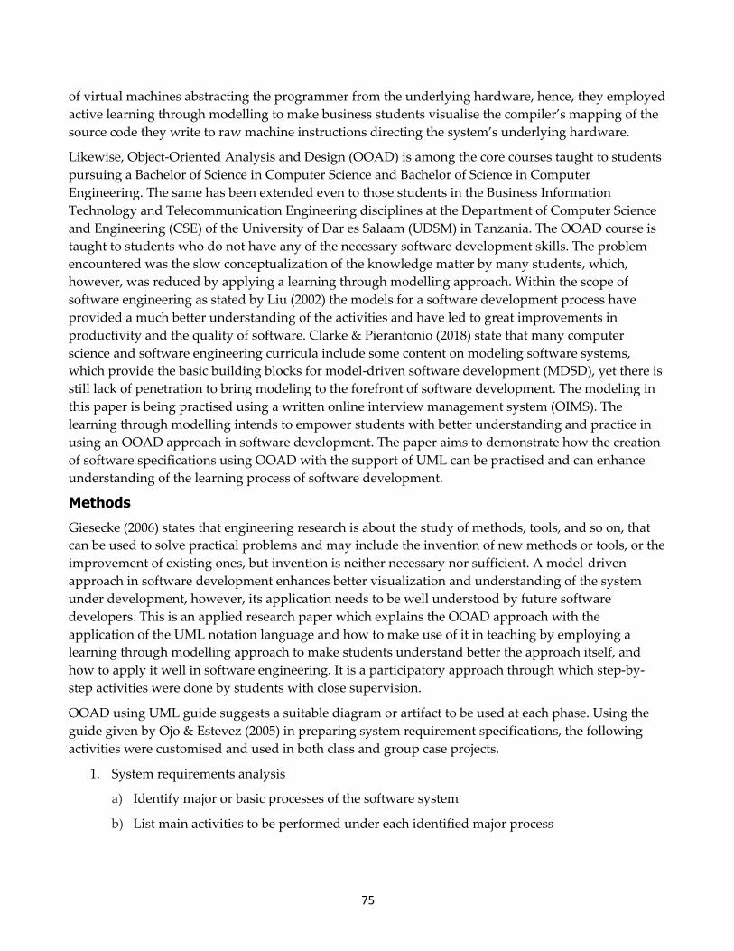
Abstract: This paper demonstrates the learning of software engineering through modeling using Object-Oriented Analysis and Design approach with Unified Modeling Language. An online interview management system case project to the whole class was used to develop the software requirement specification. Through modelling, the processes to be considered in software development were also elaborated, where it starts with the identification of major or basic processes of the domain of application, followed by the identification of activities to be performed under each basic process and, finally, transforming the activities highlighted in the functional requirements presentation. Modeling was practised by students through group case projects, and students were active, engaging and focusing on the learning process in such a way that more than 85.9% of students had the courage to attempt design questions during university examinations.
Keywords: learning through modeling, Object-Oriented Analysis and Design, Unified Modeling Language, model-driven approach, software engineering, software development process.
Introduction Many researchers encourage teaching techniques that engage students to actively participate in the learning process. McGlynn, (2005) and Peck, Ali, Matchock, and Levine, (2006) state that classroom engagement has been found to promote deeper levels of thinking and to better facilitate encoding, storage, and retrieval than traditional lectures, where lecturers are verbally communicating new information to students and students are passively listening and encoding in their memories. There are a number of ways of creating active and engaging teaching environments for learners, for example, learning by doing (LBD). Kalinga (2018) presented a step-wise procedure on how a learning by doing approach can be applied in a teaching and learning OOAD approach in software development to Bachelor of Science students studying computer science and computer engineering. A Challenge Based Learning (CBL) approach, mainly used in science and engineering education, that focuses on helping students develop self-directed learning skills (Kwame et al, 2017) and learning through modelling to hold students’ attention, is often difficult to sustain by talk alone (Salisu & Ransom, 2014). This paper is motivated to demonstrate learning through modelling in teaching a software engineering course using an OOAD approach with UML.
Roussev and Rousseva (2004) state that the Information System (IS) component is the core curriculum at their school of business and it includes a programming in JavaScript course, which is mandatory for all business students. It is a basic hands-on-experience course, where students develop Web-based e-commerce applications. According to Roussey et al (2004) business students lack the notion of layers
75
of virtual machines abstracting the programmer from the underlying hardware, hence, they employed active learning through modelling to make business students visualise the compiler’s mapping of the source code they write to raw machine instructions directing the system’s underlying hardware.
Likewise, Object-Oriented Analysis and Design (OOAD) is among the core courses taught to students pursuing a Bachelor of Science in Computer Science and Bachelor of Science in Computer Engineering. The same has been extended even to those students in the Business Information Technology and Telecommunication Engineering disciplines at the Department of Computer Science and Engineering (CSE) of the University of Dar es Salaam (UDSM) in Tanzania. The OOAD course is taught to students who do not have any of the necessary software development skills. The problem encountered was the slow conceptualization of the knowledge matter by many students, which, however, was reduced by applying a learning through modelling approach. Within the scope of software engineering as stated by Liu (2002) the models for a software development process have provided a much better understanding of the activities and have led to great improvements in productivity and the quality of software. Clarke & Pierantonio (2018) state that many computer science and software engineering curricula include some content on modeling software systems, which provide the basic building blocks for model-driven software development (MDSD), yet there is still lack of penetration to bring modeling to the forefront of software development. The modeling in this paper is being practised using a written online interview management system (OIMS). The learning through modelling intends to empower students with better understanding and practice in using an OOAD approach in software development. The paper aims to demonstrate how the creation of software specifications using OOAD with the support of UML can be practised and can enhance understanding of the learning process of software development.
Methods Giesecke (2006) states that engineering research is about the study of methods, tools, and so on, that can be used to solve practical problems and may include the invention of new methods or tools, or the improvement of existing ones, but invention is neither necessary nor sufficient. A model-driven approach in software development enhances better visualization and understanding of the system under development, however, its application needs to be well understood by future software developers. This is an applied research paper which explains the OOAD approach with the application of the UML notation language and how to make use of it in teaching by employing a learning through modelling approach to make students understand better the approach itself, and how to apply it well in software engineering. It is a participatory approach through which step-by-step activities were done by students with close supervision.
OOAD using UML guide suggests a suitable diagram or artifact to be used at each phase. Using the guide given by Ojo & Estevez (2005) in preparing system requirement specifications, the following activities were customised and used in both class and group case projects.
1. System requirements analysis
a) Identify major or basic processes of the software system
b) List main activities to be performed under each identified major process
76
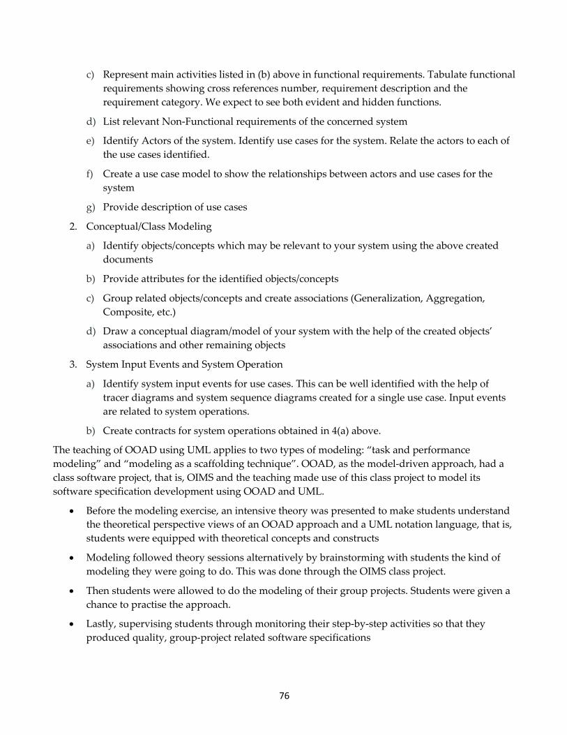
c) Represent main activities listed in (b) above in functional requirements. Tabulate functional requirements showing cross references number, requirement description and the requirement category. We expect to see both evident and hidden functions.
d) List relevant Non-Functional requirements of the concerned system
e) Identify Actors of the system. Identify use cases for the system. Relate the actors to each of the use cases identified.
f) Create a use case model to show the relationships between actors and use cases for the system
g) Provide description of use cases
2. Conceptual/Class Modeling
a) Identify objects/concepts which may be relevant to your system using the above created documents
b) Provide attributes for the identified objects/concepts
c) Group related objects/concepts and create associations (Generalization, Aggregation, Composite, etc.)
d) Draw a conceptual diagram/model of your system with the help of the created objects’ associations and other remaining objects
3. System Input Events and System Operation
a) Identify system input events for use cases. This can be well identified with the help of tracer diagrams and system sequence diagrams created for a single use case. Input events are related to system operations.
b) Create contracts for system operations obtained in 4(a) above.
The teaching of OOAD using UML applies to two types of modeling: “task and performance modeling” and “modeling as a scaffolding technique”. OOAD, as the model-driven approach, had a class software project, that is, OIMS and the teaching made use of this class project to model its software specification development using OOAD and UML.
• Before the modeling exercise, an intensive theory was presented to make students understand the theoretical perspective views of an OOAD approach and a UML notation language, that is, students were equipped with theoretical concepts and constructs
• Modeling followed theory sessions alternatively by brainstorming with students the kind of modeling they were going to do. This was done through the OIMS class project.
• Then students were allowed to do the modeling of their group projects. Students were given a chance to practise the approach.
• Lastly, supervising students through monitoring their step-by-step activities so that they produced quality, group-project related software specifications
77
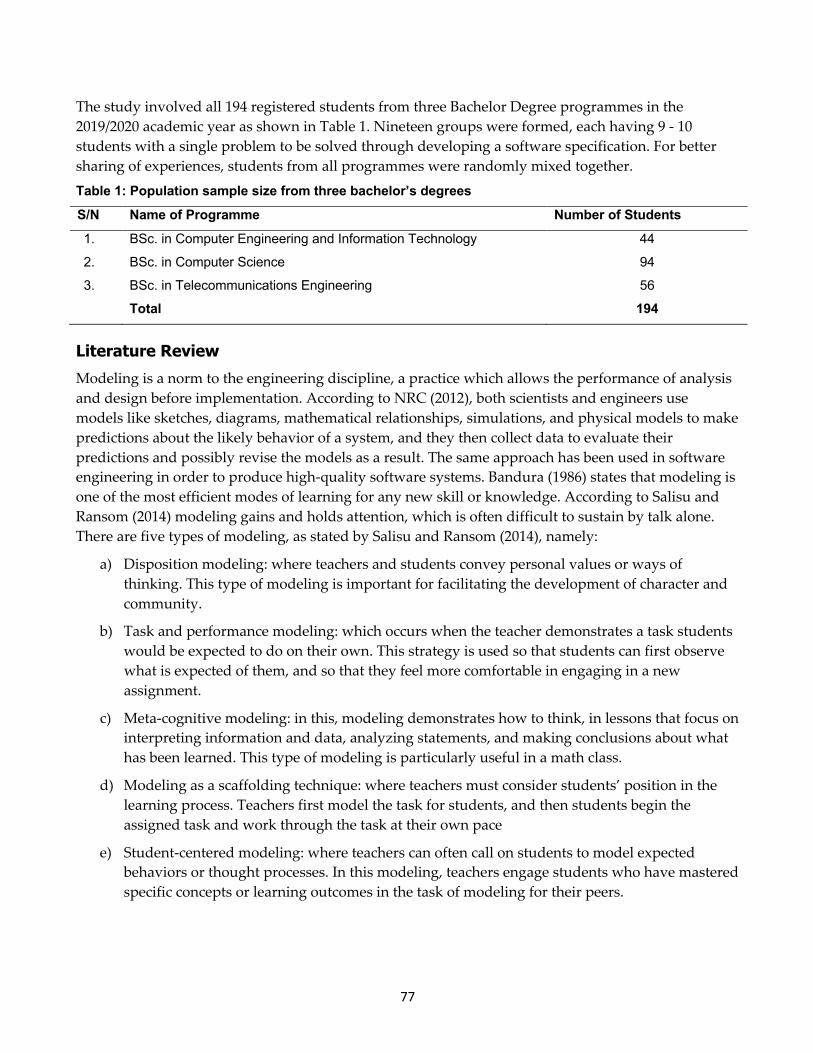
The study involved all 194 registered students from three Bachelor Degree programmes in the 2019/2020 academic year as shown in Table 1. Nineteen groups were formed, each having 9 - 10 students with a single problem to be solved through developing a software specification. For better sharing of experiences, students from all programmes were randomly mixed together. Table 1: Population sample size from three bachelor’s degrees S/N Name of Programme Number of Students 1. BSc. in Computer Engineering and Information Technology 44
2. BSc. in Computer Science 94
3. BSc. in Telecommunications Engineering 56
Total 194
Literature Review Modeling is a norm to the engineering discipline, a practice which allows the performance of analysis and design before implementation. According to NRC (2012), both scientists and engineers use models like sketches, diagrams, mathematical relationships, simulations, and physical models to make predictions about the likely behavior of a system, and they then collect data to evaluate their predictions and possibly revise the models as a result. The same approach has been used in software engineering in order to produce high-quality software systems. Bandura (1986) states that modeling is one of the most efficient modes of learning for any new skill or knowledge. According to Salisu and Ransom (2014) modeling gains and holds attention, which is often difficult to sustain by talk alone. There are five types of modeling, as stated by Salisu and Ransom (2014), namely:
a) Disposition modeling: where teachers and students convey personal values or ways of thinking. This type of modeling is important for facilitating the development of character and community.
b) Task and performance modeling: which occurs when the teacher demonstrates a task students would be expected to do on their own. This strategy is used so that students can first observe what is expected of them, and so that they feel more comfortable in engaging in a new assignment.
c) Meta-cognitive modeling: in this, modeling demonstrates how to think, in lessons that focus on interpreting information and data, analyzing statements, and making conclusions about what has been learned. This type of modeling is particularly useful in a math class.
d) Modeling as a scaffolding technique: where teachers must consider students’ position in the learning process. Teachers first model the task for students, and then students begin the assigned task and work through the task at their own pace
e) Student-centered modeling: where teachers can often call on students to model expected behaviors or thought processes. In this modeling, teachers engage students who have mastered specific concepts or learning outcomes in the task of modeling for their peers.
78
Object-Oriented Analysis and Design Use with UML
OpenLearn (2019) states that modeling techniques in software development are defined under the Unified Modeling Language (UML). The UML presents the culmination of best practices in practical object-oriented modeling and has been designed to support Object Orientation and is the visual modeling language of choice for building object-oriented and component-based systems.
Dennis, Wixom and Tegarden (2015), explain that version 2.5 of the UML defines a set of fifteen diagramming techniques used to model a system. The diagrams are broken into two major groupings: one for modeling the structure of a system and another for modeling behavior. Structure diagrams provide a way to represent the data and static relationships in an information system. The structure includes class, object, package, deployment, component, composite structure, and profile diagrams. Behavior diagrams provide the analyst with a way to depict the dynamic relationships among the instances or objects that present the business information system. The behavior diagrams support the analyst in modeling the functional requirements of an evolving information system. The behavior modeling diagrams include activity, sequence, collaboration, communication, interaction overview, timing, behavior state machine, protocol state machine, and use-case diagrams. The reason UML has different diagrams is to make it possible for the system to be looked at from many different viewpoints. Some diagrams used during requirement specification have been elaborated by Kalinga (2010), Liu (2002) and OMG (2003) as follows:
a) The Use Case is a description of the system’s behaviour from a user’s viewpoint. Developing Use Cases helps in understanding the requirements. With a use case as a requirement, there is a user or actor who performs that functionality. An actor is identified in terms of their role or privilege to use that system.
b) Class Diagram or conceptual diagram is an essential aspect of any OO method. Class Diagram can be used at the analysis as well as at the design stage. Class Diagram syntax is used to draw a plan of the major concepts for system stakeholders to understand. Together with Use Cases, a Conceptual Model is a powerful technique in analyzing requirements.
c) Collaboration diagrams, in developing OO software, anything that software needs to do is going to be achieved when objects collaborate or interact with each other. Collaboration diagrams are used to describe how the objects collaborate.
d) The sequence diagram is, in fact, directly related to the collaboration diagram and displays the same information but in a slightly different form. A sequence diagram is a description of how the objects in a system interact over time. This diagram can be used in three different areas of the software development process:
• During the software system analysis phase known as “system sequence diagram (SSD)” it is used to understand the system operations in response to system input events.
• SSD can be preceded with the system event tracer diagram, showing both system input and system output events.
• Also, the sequence diagram is applied during the system design phase where its aim is to show the interaction of objects to perform a system operation.

79
The UML guide gives the categories of UML documents relating to software development phases as follows:
(a) During the requirement gathering phase, apart from listing functional requirements, Use Case and actors of the system are identified and represented in a use case diagram. Each use case is again described at High Level Use Cases, famously known as the use case scenario. A use case scenario strengthens the understanding of a use case functionality in terms of the main steps to be used to achieve it.
(b) During the requirement analysis phase: objects or classes are identified from the documented information at (a) above. With the help of standard relationships like generalisation, aggregation, composition, to mention but a few, a class diagram, also known as a domain model or conceptual model is created. This stage will also involve providing attributes to classes or concepts in a class diagram. However not all classes may have attributes. This stage will need to show multiplicity or cardinalities.
A transition from the requirement analysis phase to the design phase involves understanding a use case in terms of events generated by an actor in a system, which are directly related to operations the system performs. Liu (2001) states that a system’s operations are identified by identifying events that actors generate, while a system input event is an external input generated by an actor to a system.
Related Works
Roussev and Rousseva (2004) employed a model-based approach to teach an introduction to programming in JavaScript to business students. Learning through modeling was used to introduce the basic programming constructs and their semantics applied in software development.
Higgs and McMillan (2010) employed teaching through modeling to secondary schools in North America in modeling sustainability to their students. For schools, modeling sustainability appears to be one effective way to achieve the goals of sustainability education (SE). According to Higgs and McMillan (2010) modeling is a valuable approach to sustainability education, promoting learning in schools. In the case of SE, where educators hope that students will not only understand sustainability concepts but also incorporate them into their behaviors, modeling can play a particularly important role.
Demonstrating Modeling of OIMS Software Requirement Specification OIMS Functional Requirements
Looking into the context of the online interview system, students were tasked to identify major business processes performed to accomplish a written interview. Four possible major functions of the system were identified as presented in Figure 1, namely: Preparation or Management of Interview Questions and their Answers, Management of Interviewees, Management of Interview and Management of Interview Process and Results. For each major process, a number of respective activities were listed, as presented in Table 2.

80
Figure 1: OIMS basic functional processes
Table 2: OIMS major processes and activities S/N Major Processes Major Business Processes Activities 1. Preparation or
Management of Interview Questions and their Answers
i. Register area of expertise to be interviewed
ii. Prepare the job/vacancy descriptions (e.g., job title, qualifications needed, etc.)
iii. Register expert area specialist who can create interview questions
iv. Create interview questions
v. Create answers for created questions
vi. Allocate marks to each question’s answer 2. Management of
Interviewees i. Publication of vacancy description
ii. Guests apply online, at this stage they are called applicants
iii. Applicants upload relevant supporting documents
iv. Filter applicants on qualification bases. Remain with only qualified applicants who will be called interviewees
v. Register interviewees to the system
vi. Notify qualified interviewees for being selected, job type applied, time and location of interview
vii. Assign login credentials to Interviewees
3. Management of Interview
i. Create an interview
ii. Allocate questions to an interview
iii. Create time schedule (time, venue, program)
iv. Link interview and interviewee
Online Interview Management Systemmajor business process or functions
Preparation or Management ofInterview Questions and their
answers
Management of Interview
Management of Interviewee
Management of InterviewProcess and Results
81
S/N Major Processes Major Business Processes Activities 4. Management of
Interview Process and Results
i. Make Interviewee provide login credentials
ii. Make Interviewee view instructions
iii. Interviewee does questions (i.e., answer interview questions)
iv. Control time to do interview
v. Mark each completed question
vi. Calculate the total marks obtained for each interviewee
vii. Grade each total mark obtained by an interviewee
viii. Sort results based on performance: total marks, grading
ix. Pick only best interviewees based on the number of interviewees needed as per the job description
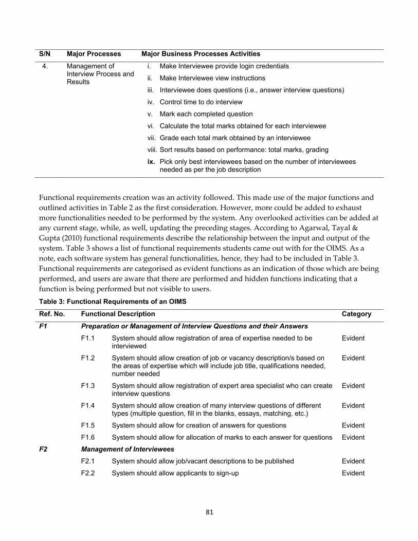
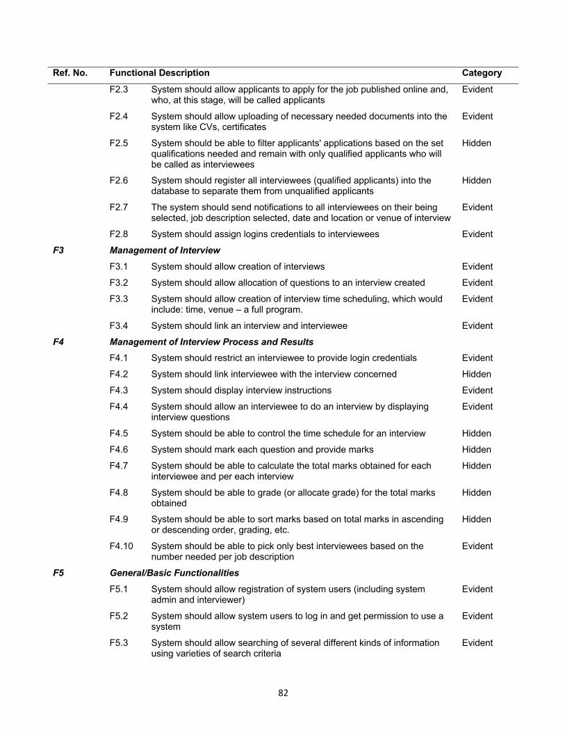
Functional requirements creation was an activity followed. This made use of the major functions and outlined activities in Table 2 as the first consideration. However, more could be added to exhaust more functionalities needed to be performed by the system. Any overlooked activities can be added at any current stage, while, as well, updating the preceding stages. According to Agarwal, Tayal & Gupta (2010) functional requirements describe the relationship between the input and output of the system. Table 3 shows a list of functional requirements students came out with for the OIMS. As a note, each software system has general functionalities, hence, they had to be included in Table 3. Functional requirements are categorised as evident functions as an indication of those which are being performed, and users are aware that there are performed and hidden functions indicating that a function is being performed but not visible to users. Table 3: Functional Requirements of an OIMS Ref. No. Functional Description Category F1 Preparation or Management of Interview Questions and their Answers F1.1 System should allow registration of area of expertise needed to be
interviewed Evident
F1.2 System should allow creation of job or vacancy description/s based on the areas of expertise which will include job title, qualifications needed, number needed
Evident
F1.3 System should allow registration of expert area specialist who can create interview questions
Evident
F1.4 System should allow creation of many interview questions of different types (multiple question, fill in the blanks, essays, matching, etc.)
Evident
F1.5 System should allow for creation of answers for questions Evident
F1.6 System should allow for allocation of marks to each answer for questions Evident
F2 Management of Interviewees F2.1 System should allow job/vacant descriptions to be published Evident
F2.2 System should allow applicants to sign-up Evident
82
Ref. No. Functional Description Category F2.3 System should allow applicants to apply for the job published online and,
who, at this stage, will be called applicants Evident
F2.4 System should allow uploading of necessary needed documents into the system like CVs, certificates
Evident
F2.5 System should be able to filter applicants' applications based on the set qualifications needed and remain with only qualified applicants who will be called as interviewees
Hidden
F2.6 System should register all interviewees (qualified applicants) into the database to separate them from unqualified applicants
Hidden
F2.7 The system should send notifications to all interviewees on their being selected, job description selected, date and location or venue of interview
Evident
F2.8 System should assign logins credentials to interviewees Evident
F3 Management of Interview F3.1 System should allow creation of interviews Evident
F3.2 System should allow allocation of questions to an interview created Evident
F3.3 System should allow creation of interview time scheduling, which would include: time, venue – a full program.
Evident
F3.4 System should link an interview and interviewee Evident
F4 Management of Interview Process and Results
F4.1 System should restrict an interviewee to provide login credentials Evident
F4.2 System should link interviewee with the interview concerned Hidden
F4.3 System should display interview instructions Evident
F4.4 System should allow an interviewee to do an interview by displaying interview questions
Evident
F4.5 System should be able to control the time schedule for an interview Hidden
F4.6 System should mark each question and provide marks Hidden
F4.7 System should be able to calculate the total marks obtained for each interviewee and per each interview
Hidden
F4.8 System should be able to grade (or allocate grade) for the total marks obtained
Hidden
F4.9 System should be able to sort marks based on total marks in ascending or descending order, grading, etc.
Hidden
F4.10 System should be able to pick only best interviewees based on the number needed per job description
Evident
F5 General/Basic Functionalities F5.1 System should allow registration of system users (including system
admin and interviewer) Evident
F5.2 System should allow system users to log in and get permission to use a system
Evident
F5.3 System should allow searching of several different kinds of information using varieties of search criteria
Evident
83
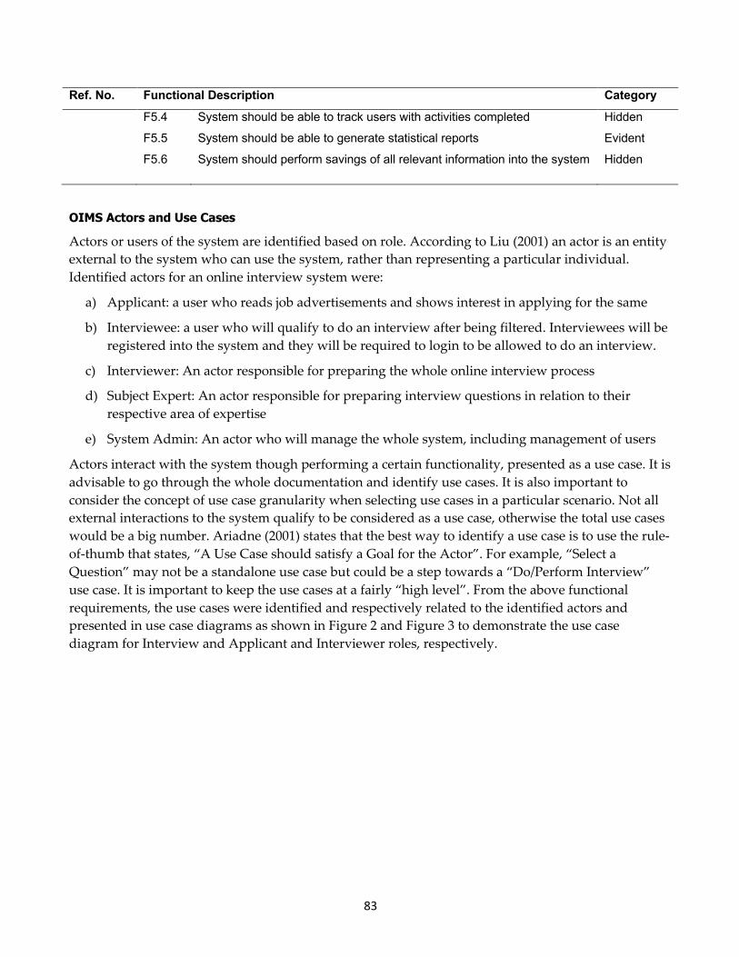
Ref. No. Functional Description Category F5.4 System should be able to track users with activities completed Hidden
F5.5 System should be able to generate statistical reports Evident
F5.6 System should perform savings of all relevant information into the system Hidden
OIMS Actors and Use Cases
Actors or users of the system are identified based on role. According to Liu (2001) an actor is an entity external to the system who can use the system, rather than representing a particular individual. Identified actors for an online interview system were:
a) Applicant: a user who reads job advertisements and shows interest in applying for the same
b) Interviewee: a user who will qualify to do an interview after being filtered. Interviewees will be registered into the system and they will be required to login to be allowed to do an interview.
c) Interviewer: An actor responsible for preparing the whole online interview process
d) Subject Expert: An actor responsible for preparing interview questions in relation to their respective area of expertise
e) System Admin: An actor who will manage the whole system, including management of users
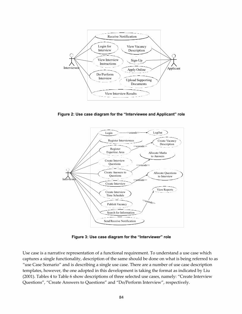
Actors interact with the system though performing a certain functionality, presented as a use case. It is advisable to go through the whole documentation and identify use cases. It is also important to consider the concept of use case granularity when selecting use cases in a particular scenario. Not all external interactions to the system qualify to be considered as a use case, otherwise the total use cases would be a big number. Ariadne (2001) states that the best way to identify a use case is to use the rule-of-thumb that states, “A Use Case should satisfy a Goal for the Actor”. For example, “Select a Question” may not be a standalone use case but could be a step towards a “Do/Perform Interview” use case. It is important to keep the use cases at a fairly “high level”. From the above functional requirements, the use cases were identified and respectively related to the identified actors and presented in use case diagrams as shown in Figure 2 and Figure 3 to demonstrate the use case diagram for Interview and Applicant and Interviewer roles, respectively.
84
Figure 2: Use case diagram for the “Interviewee and Applicant” role
Figure 3: Use case diagram for the “Interviewer” role
Use case is a narrative representation of a functional requirement. To understand a use case which captures a single functionality, description of the same should be done on what is being referred to as “use Case Scenario” and is describing a single use case. There are a number of use case description templates, however, the one adopted in this development is taking the format as indicated by Liu (2001). Tables 4 to Table 6 show descriptions of three selected use cases, namely: “Create Interview Questions”, “Create Answers to Questions” and “Do/Perform Interview”, respectively.
View VacancyDescription
Login forInterview
View InterviewInstructions
Do/PerformInterview
View Interview Results
Sign-Up
Apply Online
Upload SupportingDocuments
Receive Notification
Interviewee Applicant
RegisterExpertise Area
Create VacancyDescription
Create InterviewQuestions
Create Answers toQuestions
Allocate Marksto Answers
Publish Vacancy
Register Interviewees
Send/Receive Notification
Login LogOut
Search for Information
View Reports
Create Interview
Allocate Questionsto Interview
Create InterviewTime Schedule
Interviewer
<<extends>>
<<extends>>
<<extends>>
<<extends>>
<<extends>>

85
Table 4: “Create Interview Questions” use case description
Field Description Use Case: Create Interview Questions Actors: Interviewer Short description: It allows an Interviewer to create a bank of Interview Questions Pre-condition: Interviewer must be recognised by the system to have that privilege. Post-condition: A good number of interview questions will be created and stored into a system Main flow: 1. Interviewer requests a provision to create questions
2. System displays a number of options, tools possible to create questions (tools could be for multiple choice, fill in the blanks, etc.)
3. Interviewer selects a question tool needed 4. System displays a related selected tool template to an interviewer 5. Interviewer creates a question and submits 6. System validates the submitted question and saves the question into the system 7. The process from 2 to 6 repeats till an interviewer clicks the “end” button 8. The system acknowledges successfully creation of questions to an interviewer
Alternative flow(s):
Exception flow(s) If the submitted question is not complete, the system should display an error and prompt an interviewer to recreate the question.
Table 5: “Create Answers to Questions” use case description
Field Description Use Case: Create Answers to Questions Actors: Interviewer Short description: It allows an Interviewer to create answers to the already created Interview Questions Pre-condition: A bank of interview questions stored into the system. Post-condition: Interview questions will have answers Main flow: 1. Interviewer requests a provision to create answers to questions
2. System displays a list of question and lets an interviewer select a question to answer
3. An interviewer selects a question 4. System displays question description and a form/means to provide an answer 5. Interviewer creates an answer to a question and saves/submits 6. System validates the submitted answer and saves the answer into the system 7. System acknowledges the successful creation of an answer 8. The process from 3 to 6 repeats till an interviewer clicks the “end” button
Alternative flow(s): Exception flow(s) If the submitted answer is not complete, the system should display an error and prompt
an interviewer to recreate an answer
86
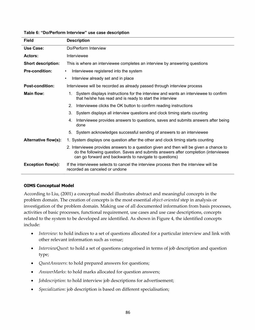
Table 6: “Do/Perform Interview” use case description
Field Description
Use Case: Do/Perform Interview
Actors: Interviewee
Short description: This is where an interviewee completes an interview by answering questions
Pre-condition: • Interviewee registered into the system
• Interview already set and in place
Post-condition: Interviewee will be recorded as already passed through interview process
Main flow: 1. System displays instructions for the interview and wants an interviewee to confirm that he/she has read and is ready to start the interview
2. Interviewee clicks the OK button to confirm reading instructions
3. System displays all interview questions and clock timing starts counting
4. Interviewee provides answers to questions, saves and submits answers after being done
5. System acknowledges successful sending of answers to an interviewee
Alternative flow(s): 1. System displays one question after the other and clock timing starts counting
2. Interviewee provides answers to a question given and then will be given a chance to do the following question. Saves and submits answers after completion (interviewee can go forward and backwards to navigate to questions)
Exception flow(s): If the interviewee selects to cancel the interview process then the interview will be recorded as canceled or undone
OIMS Conceptual Model
According to Liu, (2001) a conceptual model illustrates abstract and meaningful concepts in the problem domain. The creation of concepts is the most essential object-oriented step in analysis or investigation of the problem domain. Making use of all documented information from basis processes, activities of basic processes, functional requirement, use cases and use case descriptions, concepts related to the system to be developed are identified. As shown in Figure 4, the identified concepts include:
• Interview: to hold indices to a set of questions allocated for a particular interview and link with other relevant information such as venue;
• InterviewQuest: to hold a set of questions categorised in terms of job description and question type;
• QuestAnswers: to hold prepared answers for questions;
• AnswerMarks: to hold marks allocated for question answers;
• Jobdescription: to hold interview job descriptions for advertisement;
• Specialization: job description is based on different specialisation;
87
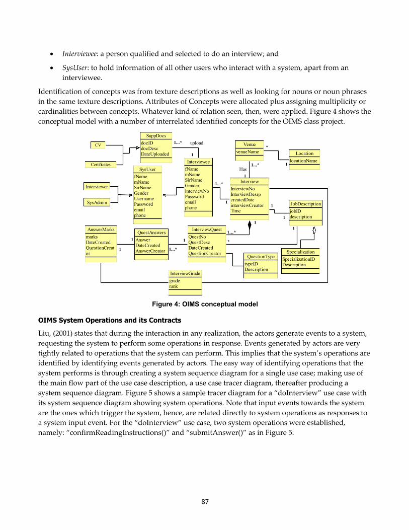
• Interviewee: a person qualified and selected to do an interview; and
• SysUser: to hold information of all other users who interact with a system, apart from an interviewee.
Identification of concepts was from texture descriptions as well as looking for nouns or noun phrases in the same texture descriptions. Attributes of Concepts were allocated plus assigning multiplicity or cardinalities between concepts. Whatever kind of relation seen, then, were applied. Figure 4 shows the conceptual model with a number of interrelated identified concepts for the OIMS class project.
Figure 4: OIMS conceptual model
OIMS System Operations and its Contracts
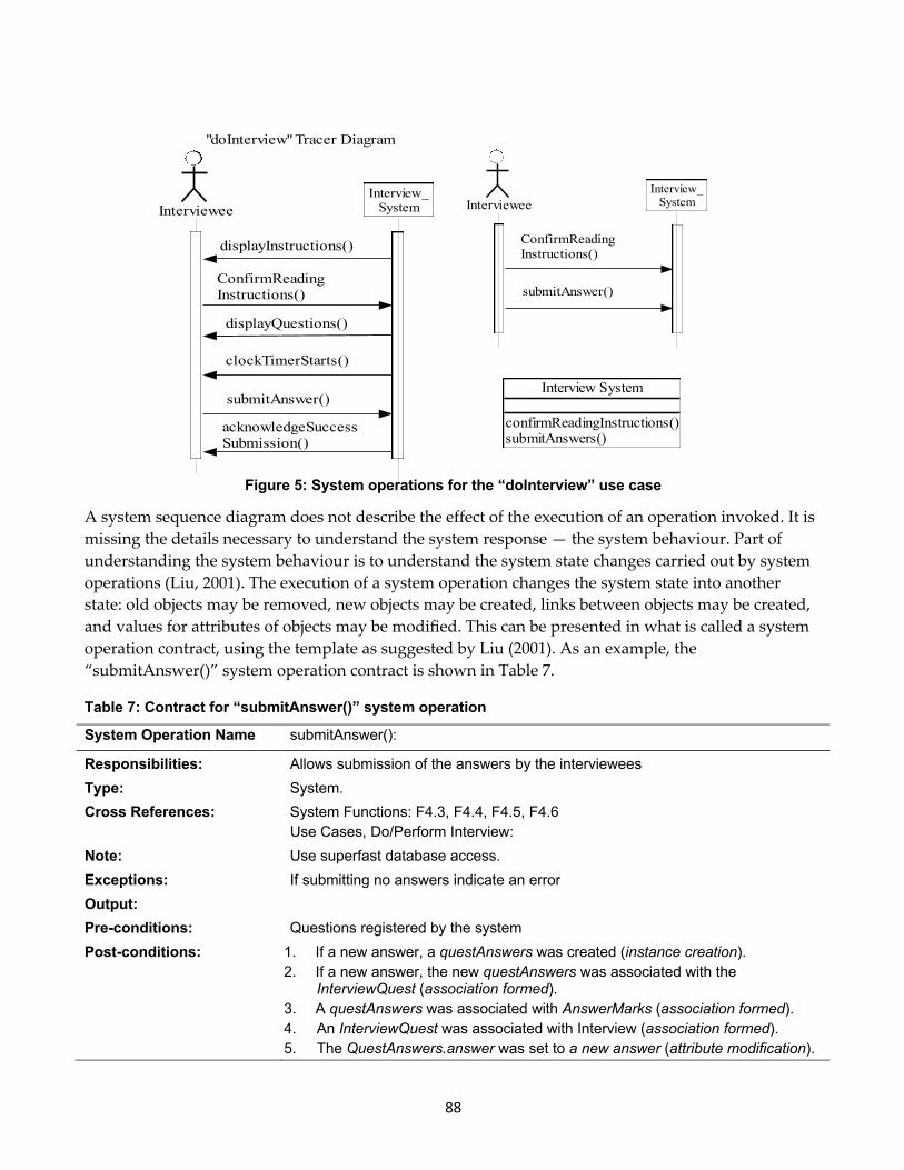
Liu, (2001) states that during the interaction in any realization, the actors generate events to a system, requesting the system to perform some operations in response. Events generated by actors are very tightly related to operations that the system can perform. This implies that the system’s operations are identified by identifying events generated by actors. The easy way of identifying operations that the system performs is through creating a system sequence diagram for a single use case; making use of the main flow part of the use case description, a use case tracer diagram, thereafter producing a system sequence diagram. Figure 5 shows a sample tracer diagram for a “doInterview” use case with its system sequence diagram showing system operations. Note that input events towards the system are the ones which trigger the system, hence, are related directly to system operations as responses to a system input event. For the “doInterview” use case, two system operations were established, namely: “confirmReadingInstructions()” and “submitAnswer()” as in Figure 5.
Interviewer
SysAdmin
Certificates
CV
SysUserfNamemNameSirNameGenderUsernamePasswordemailphone
IntervieweefNamemNameSirNameGenderinterviewNoPasswordemailphone
InterviewInterviewNoInterviewDesrpcreatedDateinterviewCreatorTime
InterviewQuestQuestNoQuestDescDateCreatedQuestionCreator
QuestAnswersAnswerDateCreatedAnswerCreator
AnswerMarksmarksDateCreatedQuestionCreator
InterviewGradegraderank
LocationlocationName
VenuevenueName
JobDescriptionjobIDdescription
SpecializationSpecializationIDDescription
QuestionTypetypeIDDescription
SuppDocsdocIDdocDescDateUploaded
1
1...*
1
1
1
1
1
11
1
1
1...*
1...*
1...*
1...* upload
*
*
Has
1
88
Figure 5: System operations for the “doInterview” use case
A system sequence diagram does not describe the effect of the execution of an operation invoked. It is missing the details necessary to understand the system response — the system behaviour. Part of understanding the system behaviour is to understand the system state changes carried out by system operations (Liu, 2001). The execution of a system operation changes the system state into another state: old objects may be removed, new objects may be created, links between objects may be created, and values for attributes of objects may be modified. This can be presented in what is called a system operation contract, using the template as suggested by Liu (2001). As an example, the “submitAnswer()” system operation contract is shown in Table 7.
Table 7: Contract for “submitAnswer()” system operation
System Operation Name submitAnswer():
Responsibilities: Allows submission of the answers by the interviewees Type: System. Cross References: System Functions: F4.3, F4.4, F4.5, F4.6
Use Cases, Do/Perform Interview: Note: Use superfast database access. Exceptions: If submitting no answers indicate an error Output: Pre-conditions: Questions registered by the system Post-conditions: 1. If a new answer, a questAnswers was created (instance creation).
2. If a new answer, the new questAnswers was associated with the InterviewQuest (association formed).
3. A questAnswers was associated with AnswerMarks (association formed). 4. An InterviewQuest was associated with Interview (association formed). 5. The QuestAnswers.answer was set to a new answer (attribute modification).
IntervieweeInterview_
System
ConfirmReadingInstructions()
submitAnswer()
displayInstructions()
displayQuestions()
clockTimerStarts()
acknowledgeSuccessSubmission()
"doInterview" Tracer Diagram
IntervieweeInterview_System
ConfirmReadingInstructions()
submitAnswer()
Interview System
confirmReadingInstructions()submitAnswers()
89
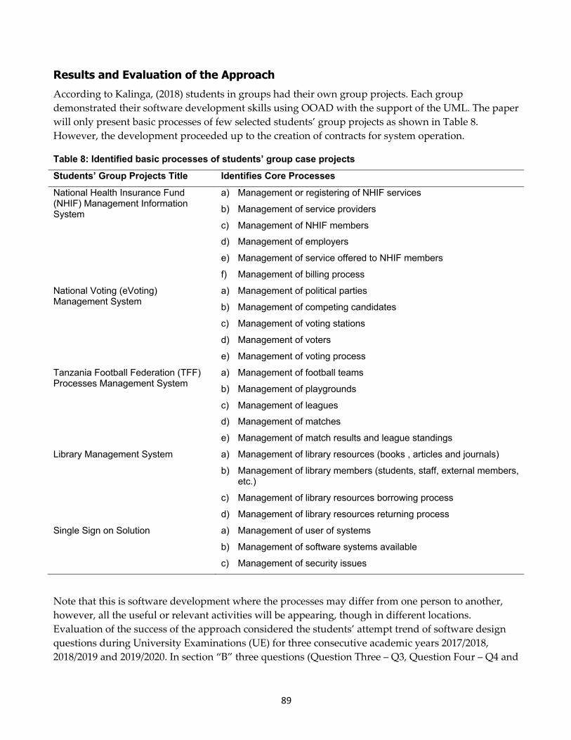
Results and Evaluation of the Approach According to Kalinga, (2018) students in groups had their own group projects. Each group demonstrated their software development skills using OOAD with the support of the UML. The paper will only present basic processes of few selected students’ group projects as shown in Table 8. However, the development proceeded up to the creation of contracts for system operation.
Table 8: Identified basic processes of students’ group case projects Students’ Group Projects Title Identifies Core Processes National Health Insurance Fund (NHIF) Management Information System
a) Management or registering of NHIF services
b) Management of service providers
c) Management of NHIF members
d) Management of employers
e) Management of service offered to NHIF members
f) Management of billing process
National Voting (eVoting) Management System
a) Management of political parties
b) Management of competing candidates
c) Management of voting stations
d) Management of voters
e) Management of voting process
Tanzania Football Federation (TFF) Processes Management System
a) Management of football teams
b) Management of playgrounds
c) Management of leagues
d) Management of matches
e) Management of match results and league standings
Library Management System a) Management of library resources (books , articles and journals)
b) Management of library members (students, staff, external members, etc.)
c) Management of library resources borrowing process
d) Management of library resources returning process
Single Sign on Solution a) Management of user of systems
b) Management of software systems available
c) Management of security issues
Note that this is software development where the processes may differ from one person to another, however, all the useful or relevant activities will be appearing, though in different locations. Evaluation of the success of the approach considered the students’ attempt trend of software design questions during University Examinations (UE) for three consecutive academic years 2017/2018, 2018/2019 and 2019/2020. In section “B” three questions (Question Three – Q3, Question Four – Q4 and
90
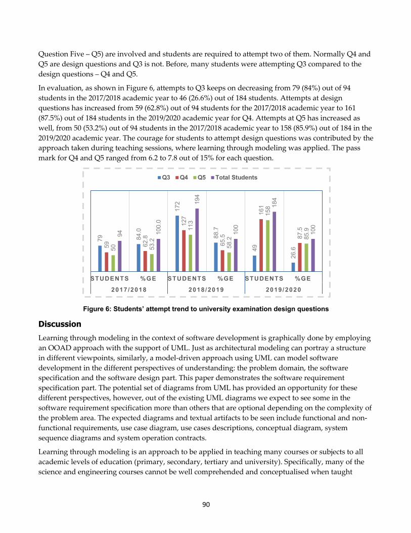
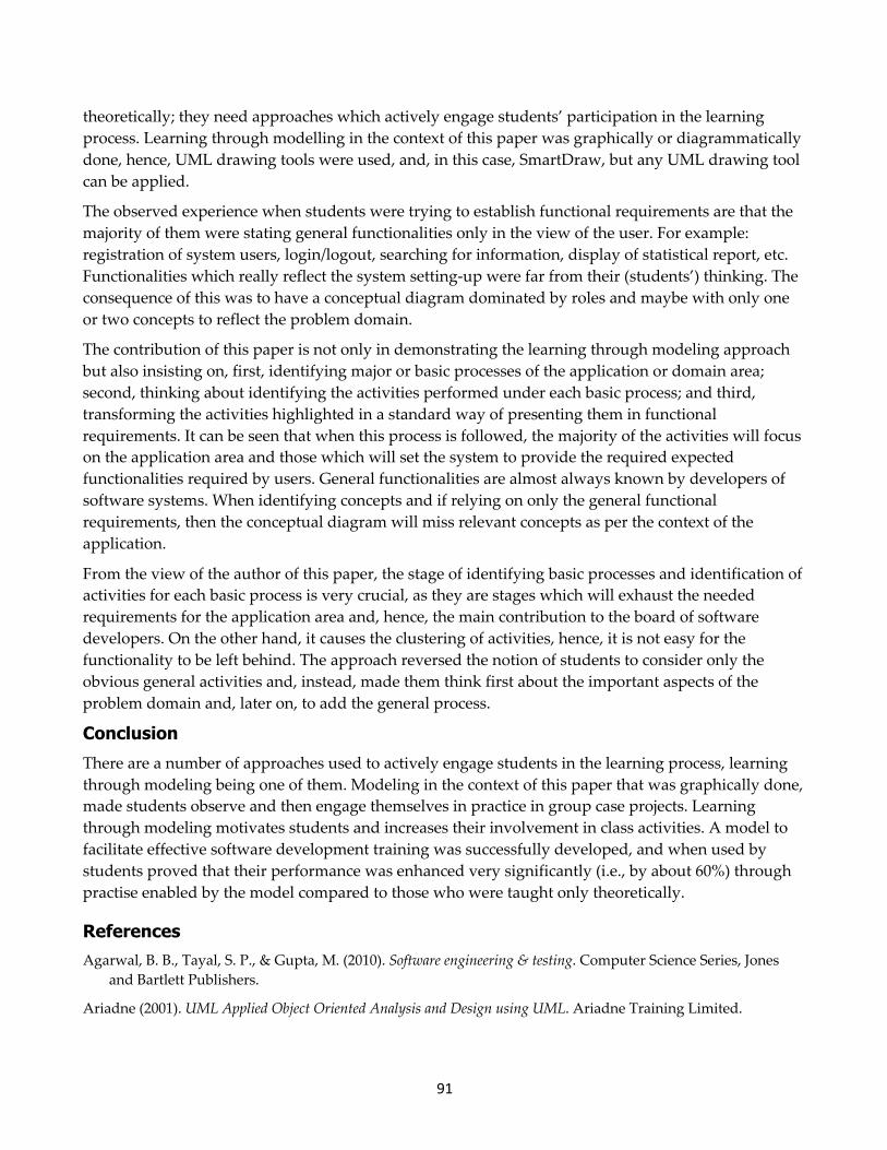
Question Five – Q5) are involved and students are required to attempt two of them. Normally Q4 and Q5 are design questions and Q3 is not. Before, many students were attempting Q3 compared to the design questions – Q4 and Q5.
In evaluation, as shown in Figure 6, attempts to Q3 keeps on decreasing from 79 (84%) out of 94 students in the 2017/2018 academic year to 46 (26.6%) out of 184 students. Attempts at design questions has increased from 59 (62.8%) out of 94 students for the 2017/2018 academic year to 161 (87.5%) out of 184 students in the 2019/2020 academic year for Q4. Attempts at Q5 has increased as well, from 50 (53.2%) out of 94 students in the 2017/2018 academic year to 158 (85.9%) out of 184 in the 2019/2020 academic year. The courage for students to attempt design questions was contributed by the approach taken during teaching sessions, where learning through modeling was applied. The pass mark for Q4 and Q5 ranged from 6.2 to 7.8 out of 15% for each question.
Figure 6: Students’ attempt trend to university examination design questions
Discussion Learning through modeling in the context of software development is graphically done by employing an OOAD approach with the support of UML. Just as architectural modeling can portray a structure in different viewpoints, similarly, a model-driven approach using UML can model software development in the different perspectives of understanding: the problem domain, the software specification and the software design part. This paper demonstrates the software requirement specification part. The potential set of diagrams from UML has provided an opportunity for these different perspectives, however, out of the existing UML diagrams we expect to see some in the software requirement specification more than others that are optional depending on the complexity of the problem area. The expected diagrams and textual artifacts to be seen include functional and non-functional requirements, use case diagram, use cases descriptions, conceptual diagram, system sequence diagrams and system operation contracts.
Learning through modeling is an approach to be applied in teaching many courses or subjects to all academic levels of education (primary, secondary, tertiary and university). Specifically, many of the science and engineering courses cannot be well comprehended and conceptualised when taught
79 84.0
172
88.7
49
26.659 62
.8
127
65.5
161
87.5
50 53.2
113
58.2
158
85.994 100.0
194
100
184
100
STUDENTS %GE STUDENTS %GE STUDENTS %GE
2017/2018 2018/2019 2019/2020
Q3 Q4 Q5 Total Students
91
theoretically; they need approaches which actively engage students’ participation in the learning process. Learning through modelling in the context of this paper was graphically or diagrammatically done, hence, UML drawing tools were used, and, in this case, SmartDraw, but any UML drawing tool can be applied.
The observed experience when students were trying to establish functional requirements are that the majority of them were stating general functionalities only in the view of the user. For example: registration of system users, login/logout, searching for information, display of statistical report, etc. Functionalities which really reflect the system setting-up were far from their (students’) thinking. The consequence of this was to have a conceptual diagram dominated by roles and maybe with only one or two concepts to reflect the problem domain.
The contribution of this paper is not only in demonstrating the learning through modeling approach but also insisting on, first, identifying major or basic processes of the application or domain area; second, thinking about identifying the activities performed under each basic process; and third, transforming the activities highlighted in a standard way of presenting them in functional requirements. It can be seen that when this process is followed, the majority of the activities will focus on the application area and those which will set the system to provide the required expected functionalities required by users. General functionalities are almost always known by developers of software systems. When identifying concepts and if relying on only the general functional requirements, then the conceptual diagram will miss relevant concepts as per the context of the application.
From the view of the author of this paper, the stage of identifying basic processes and identification of activities for each basic process is very crucial, as they are stages which will exhaust the needed requirements for the application area and, hence, the main contribution to the board of software developers. On the other hand, it causes the clustering of activities, hence, it is not easy for the functionality to be left behind. The approach reversed the notion of students to consider only the obvious general activities and, instead, made them think first about the important aspects of the problem domain and, later on, to add the general process.
Conclusion There are a number of approaches used to actively engage students in the learning process, learning through modeling being one of them. Modeling in the context of this paper that was graphically done, made students observe and then engage themselves in practice in group case projects. Learning through modeling motivates students and increases their involvement in class activities. A model to facilitate effective software development training was successfully developed, and when used by students proved that their performance was enhanced very significantly (i.e., by about 60%) through practise enabled by the model compared to those who were taught only theoretically.
References Agarwal, B. B., Tayal, S. P., & Gupta, M. (2010). Software engineering & testing. Computer Science Series, Jones
and Bartlett Publishers.
Ariadne (2001). UML Applied Object Oriented Analysis and Design using UML. Ariadne Training Limited.
92
Clarke, P. J., & Pierantonio, A. (2018) Teaching modeling: A software perspective. Computer Science Education, 28(1), 1-4. doi:10.1080/08993408.2018.1486535
Dennis, A., Wixom, B. H., & Tegarden D. (2015). System analysis & design: An Object Oriented Approach with UML (5th ed.). Wiley & Sons.
Giesecke, S. (2006). Research methods in software engineering (Vol. 1). GITO mbH Verlag.
Higgs, A. L., & McMillan, V. M. (2010). Teaching through modeling: Four schools’ experiences in sustainability education. The Journal of Environmental Education, 38(1), 39-53. doi:10.3200/JOEE.38.1.39-53.
Kalinga, E. A. (2010). Development of an interactive e-Learning Management System (e-LMS) for Tanzanian secondary schools. Blekinge Institute of Technology.
Kalinga, E. A. (2018). Learning by doing in teaching and learning Object-Oriented Analysis and Design approach to software development. Proceedings of the 12th International Multi-Conference on Society, Cybernetics and Informatics (IMSCI 2018).
McGlynn, A. P. (2005). Teaching millennials, Our newest cultural cohort. Education Digest, 71(4), 12.
OpenLearn (2019). An introduction to software development, modeling and the UML. Open University. https://www.open.edu/openlearn/science-maths-technology/introduction-software-development/content-section-6
Ojo A., & Estevez E. (2005). Object-Oriented Analysis and Design with UML. Training Course, e-Macao Report 19, Version 1.0, October.
Peck, A. C., Ali, R. S., Matchock, R. L., & Levine, M. E. (2006). Introductory psychology topics and student performance: Where’s the challenge? Teaching of Psychology, 33(3), 167-170.
Roussev, B., & Rousseva, Y. (2004). Active learning through modeling: Introduction to software development in the business curriculum. Decision Sciences Journal of Innovative Education, 2(2).
Salisu A., & Ransom, E. N. (2014). The role of modeling towards impacting quality education. International Letters of Social and Humanistic Sciences, 32, 54-61. doi:10.18052/www.scipress.com/ILSHS.32.54
Author: Ellen A. Kalinga is a Lecturer at the Department of Computer Science and Engineering, College of ICT of the University of Dar es Salaam. She is involved in e-Learning and software development research areas. Email: [email protected]
Cite this paper as: Kalinga, E. A. (2021). Learning software development through modeling using Object Oriented Approach with Unified Modeling Language: A case of an online interview system. Journal of Learning for Development, 8(1), 74-92.