LAW Facility Design Description - emcbc
190
24590-ENG-F00130 Rev 6 (Revised 5/14/2015) Ref: 24590-WTP-3DP-G04B-00093 Document title: LAW Facility Design Description Document number: 24590-LAW-3ZD-20-00002 Revision number: 3 Type: System Design Description Facility Design Description Originator(s): P. Townsend Checked by: D. Markman Checker’s signature: Signature Date Concurrence: Ian Milgate Concurrence signature: Manager of Production Engineering and Design Authority Signature Date Approved by: Sarah Barker Approver’s position: Systems Engineering Manager Approver’s signature: Signature Date 04/29/2020 4/29/2020 4/29/2020 Issued by RPP-WTP PDC
-
Upload
khangminh22 -
Category
Documents
-
view
2 -
download
0
Transcript of LAW Facility Design Description - emcbc
24590-ENG-F00130 Rev 6 (Revised 5/14/2015) Ref: 24590-WTP-3DP-G04B-00093
Document title:
LAW Facility Design Description
Document number: 24590-LAW-3ZD-20-00002
Revision number: 3
Type: System Design Description Facility Design Description
Originator(s): P. Townsend
Checked by: D. Markman
Checker’s signature: Signature Date
Concurrence: Ian Milgate
Concurrence signature: Manager of Production Engineering
and Design Authority Signature
Date
Approved by: Sarah Barker
Approver’s position: Systems Engineering Manager
Approver’s signature: Signature Date
04/29/2020
4/29/2020
4/29/2020
Issued byRPP-WTP PDC
24590-LAW-3ZD-20-00002, Rev 3
LAW Facility Design Description
24590-ENG-F00130 Rev 3 (Revised 4/2/2015) Page ii Ref: 24590-WTP-3DP-G04B-00093
Validation
Appl. Requirement Area Requirement Developer Signature Date Architectural Design Civil/Structural Design Controls & Instrumentation Design Commissioning Electrical Design & AHJ Fire Protection Engineering HVAC Design Mechanical Handling Design Mechanical Systems Design Plant Design Process Engineering Interface (External) Interface (Internal) System Functions and Requirements Equipment Environmental
Qualification
Materials Engineering / Technology Plant Software Design Environmental Protection Nuclear Safety Engineering Chemical Safety P. Townsend email concurrence
3/27/2020
Criticality Safety Radiological Engineering Industrial Safety/Hygiene (ESH) Mission (WTP Contract
functional/performance rqmts)
Operations Requirements Document Quality Assurance Safeguards & Security Startup Transportation & Logistics
* Validation signatures above are for new requirements and/or changes to requirements reflected in this SDD revision only. This revision incorporates outstanding change notices and includes additional content as identified in the Reason for revision content of the History Sheet. Validation signatures from previously approved requirements are documented in previous revisions and/or change notices as appropriate.

24590-LAW-3ZD-20-00002, Rev 3
LAW Facility Design Description
24590-ENG-F00130 Rev 3 (Revised 4/2/2015) Page iii Ref: 24590-WTP-3DP-G04B-00093
History Sheet
Rev Reason for revision Revised by
0 Initial issue.
Supersedes 24590-LAW-3YD-20-00005, Facility Description for the LAW Vitrification Facility (LAW), Rev 1
C. Knauss / M. Kulp
1 Incorporated the following SDDCNs:
• 24590-LAW-3ZN-20-00002 (for DFLAW) • 24590-LAW-3ZN-20-00004
Incorporated Phase 2A requirements and SDD FDD Desktop Information Rev 2c. Revised verification abbreviations (A) Analysis, (R) Review, (I) Inspection, and (T) Test. Revised multiple requirements in separate lines of the verification tables. Updated section 4, removed codes and standards from requirements. Removed holds.
Tilak Gandhi
2 Incorporated the following SDDCNs:
• 24590-LAW-3ZN-20-00008 • 24590-LAW-3ZN-20-00001
Incorporate statements from 24590-DB-ENG-01-001, Rev. 7 (Per CR 18-00411, Action/Object identifiers; ID#10982, ID#10984, ID#10985, ID#10987, ID#10989, ID#11097, ID#11100, ID#11359, ID#11398, ID#11414, ID#12242, ID#12243).
Incorporate Technical Safety Requirements (TSR) and Key Element Requirements (Section 3.10) per EIE 24590-LAW-EIE-NS-18-0005.
Incorporate minor ‘tracked’ editorial changes.
Brandon Rivera
3 Incorporated SDDCNs 24590-LAW-3ZN-20-00007 and 24590-WTP-3ZN-20-00001. Incorporated the following EIEs: 24590-LAW-EIE-HV-18-0024, 24590-LAW-EIE-M-18-0044, 24590-LAW-EIE-NAS-19-0003, 24590-WTP-EIE-SYSE-19-0022.
Treatment, storage or disposal of dangerous waste in the LAW facility systems cannot commence until the requirement to certify the LAW facility has been constructed in accordance with the WTP Dangerous Waste Permit. The addition of Section 3.11 of the LAW FDD facilitates the development of a Special RVM to submit to Washington State Department of Ecology in support of construction certification.
P. Townsend

24590-LAW-3ZD-20-00002, Rev 3
LAW Facility Design Description
24590-ENG-F00130 Rev 3 (Revised 4/2/2015) Page iv Ref: 24590-WTP-3DP-G04B-00093
Contents Validation................................................................................................................................................... ii History Sheet ............................................................................................................................................ iii 1 Introduction .......................................................................................................................................1
1.1 Facility Identification ........................................................................................................................................... 1 1.2 Limitations & Scope ............................................................................................................................................. 1 1.3 Ownership & Maintenance .................................................................................................................................. 3 1.4 Definitions/Glossary ............................................................................................................................................. 3 1.5 Acronyms and System Designators ..................................................................................................................... 4
2 General Overview ..............................................................................................................................8 2.1 Facility Functions/Safety Functions .................................................................................................................. 10 2.2 Facility Classification ......................................................................................................................................... 15 2.3 Basic Operational Overview .............................................................................................................................. 15
3 Requirements and Bases .................................................................................................................22 3.1 Requirements ...................................................................................................................................................... 22 3.2 Bases .................................................................................................................................................................... 23 3.3 References ........................................................................................................................................................... 23 3.4 General Requirements ....................................................................................................................................... 23
3.4.1 Sustainable Design ................................................................................................................................. 23 3.4.2 LAW Facility Production Requirements ................................................................................................ 24 3.4.3 Waste Characteristics ............................................................................................................................. 25 3.4.4 Future Third LAW Melter ...................................................................................................................... 26 3.4.5 ILAW Container Support ....................................................................................................................... 27 3.4.6 LAW Facility Design for DFLAW Operation ....................................................................................... 28 3.4.7 LAW Facility Design for Full-WTP Operation ..................................................................................... 28
3.5 Requirements Related to Off-Normal / Emergency (Design Basis) Conditions and Configurations .......... 29 3.5.1 External Events ...................................................................................................................................... 29 3.5.2 Internal Events ....................................................................................................................................... 30 3.5.3 Beyond Design Basis Conditions ........................................................................................................... 33
3.6 Nuclear Safety, ALARA, Environmental Protection, and Regulatory Requirements ................................. 33 3.6.1 Nuclear Safety ........................................................................................................................................ 33 3.6.2 ALARA .................................................................................................................................................. 39 3.6.3 Environmental Protection ...................................................................................................................... 47 3.6.4 Deleted ................................................................................................................................................... 68 3.6.5 Fire Protection ........................................................................................................................................ 68
3.7 Facility Interface Requirements ........................................................................................................................ 69 3.7.1 Deleted ................................................................................................................................................... 69 3.7.2 Facility Interfaces ................................................................................................................................... 69
3.8 Other Technical, Specialty, Operations and Maintenance Requirements .................................................... 74 3.8.1 Required Service Life ............................................................................................................................ 74 3.8.2 Specialty Requirements .......................................................................................................................... 75 3.8.3 Monitoring, Controls & Communication ............................................................................................... 76
24590-LAW-3ZD-20-00002, Rev 3
LAW Facility Design Description
24590-ENG-F00130 Rev 3 (Revised 4/2/2015) Page v Ref: 24590-WTP-3DP-G04B-00093
3.8.4 Safeguards and Security ......................................................................................................................... 81 3.8.5 Operations and Design Requirements .................................................................................................... 81 3.8.6 Maintenance Requirements .................................................................................................................... 97
3.9 Other Facility-Level Requirements ................................................................................................................ 106 3.9.1 Waste Management .............................................................................................................................. 106 3.9.2 Decommissioning ................................................................................................................................ 107 3.9.3 Simulant and Reagent Management ..................................................................................................... 109 3.9.4 Engineered Safeguards ......................................................................................................................... 109 3.9.5 Sampling During Commissioning ........................................................................................................ 109
3.10 Technical Safety Requirements and Key Elements ....................................................................................... 110 3.10.1 Features Facilitating LCO Surveillance Requirements ........................................................................ 110 3.10.2 Features Facilitating Safety Management Program Key Elements ...................................................... 110
3.11 Dangerous Waste Permit (DWP) and Washington Administrative Code (WAC) for the LAW Facility Construction and Installation Certification ..................................................................................... 110 3.11.1 Water for Fire Control .......................................................................................................................... 110 3.11.2 Internal Communications ..................................................................................................................... 110 3.11.3 External Communications .................................................................................................................... 111 3.11.4 Containment Areas ............................................................................................................................... 111 3.11.5 Secondary Containment ....................................................................................................................... 112 3.11.6 Structural Integrity ............................................................................................................................... 113 3.11.7 Containment Coatings .......................................................................................................................... 115 3.11.8 Leak Detection System ........................................................................................................................ 116 3.11.9 Prevention of Water Run-in ................................................................................................................. 116 3.11.10 Containment Buildings Design and Construction ................................................................................ 117 3.11.11 Containment Buildings Structure ......................................................................................................... 117 3.11.12 Backfill Material .................................................................................................................................. 119 3.11.13 Containment Seal Penetrations ............................................................................................................ 120
3.12 Relevant Codes and Standards........................................................................................................................ 122 3.12.1 Codes of Record ................................................................................................................................... 122 3.12.2 WTP Design Criteria, Guides and General Specifications ................................................................... 124
4 Facility Description .......................................................................................................................130 4.1 Configuration Information .............................................................................................................................. 130
4.1.1 Description of System, Subsystems, and Major Components .............................................................. 133 4.1.2 Boundaries and Interfaces .................................................................................................................... 143 4.1.3 Physical Layout and Location .............................................................................................................. 143 4.1.4 Principles of Operations ....................................................................................................................... 152 4.1.5 System Reliability Features.................................................................................................................. 153 4.1.6 System Control Features ...................................................................................................................... 154
4.2 Operations ......................................................................................................................................................... 155 4.2.1 Initial Configuration (Pre-startup) ........................................................................................................ 156 4.2.2 System Startup ..................................................................................................................................... 163 4.2.3 Normal Operations ............................................................................................................................... 165 4.2.4 Off-Normal Operations ........................................................................................................................ 166 4.2.5 System Shutdown ................................................................................................................................. 167 4.2.6 Safety Management Programs and Administrative Controls ............................................................... 167
4.3 Testing and Maintenance ................................................................................................................................. 168 4.3.1 Temporary Configurations ................................................................................................................... 168 4.3.2 Technical Safety Requirement (TSR)-Required Surveillances ............................................................ 169 4.3.3 Non-TSR Inspections and Testing ....................................................................................................... 169 4.3.4 Maintenance ......................................................................................................................................... 169

24590-LAW-3ZD-20-00002, Rev 3
LAW Facility Design Description
24590-ENG-F00130 Rev 3 (Revised 4/2/2015) Page vi Ref: 24590-WTP-3DP-G04B-00093
4.4 Supplemental Information ............................................................................................................................... 169
5 References and Design Documents List .......................................................................................170 5.1 Source / Basis References ................................................................................................................................. 170 5.2 Other References .............................................................................................................................................. 170 5.3 System Design Documents ............................................................................................................................... 174
Appendices Appendix A Test Objectives, Conditions, and Acceptance Criteria .............................................. A-1
Appendix B Description of System Functional Flow and Interactions ..........................................B-1
Appendix C Active Safety Instruments and Functions ..................................................................... C-2
Appendix D Facility Level Procedures ............................................................................................. D-1
Appendix E Facility History ...............................................................................................................E-1
Appendix F Programmatic (Non-Design) System/Facility Requirements ..................................... F-1
Appendix G Reserved ......................................................................................................................... G-2 Tables Table 2-1 Functional Analysis and Crosswalk to Requirements............................................................... 12
Table 2-2 LAW Facility Interface Boundaries ............................................................................................ 16
Table 3-1 LAW Facility Safety Classifications ........................................................................................... 38
Table 3-2 Preliminary Personnel Support Counts for DFLAW Base and DFLAW Contingency ......... 96
Table 3-3 LCOs and Supporting Features ................................................................................................ 110
Table 3-4 Safety Management Program Key Element Features ............................................................. 110
Table 3-5 Law Vitrification Facility Containment Buildings .................................................................. 111
Table 3-6 Containment Seal Penetration .................................................................................................. 120
Table 3-7 LAW Facility Applicable Codes and Standards ...................................................................... 122
Table 3-8 WTP Design Criteria, Guides and General Specifications Applicable to LAW Facility ......................................................................................................................................... 124
Figures Figure 2-1 Facility Context Diagram ............................................................................................................ 10
Figure 2-2 LAW Facility Functional Block Diagram - Baseline and DFLAW Configurations ............... 11
Figure 4-1 LAW Facility Process Flow ....................................................................................................... 132
Figure 4-2 LAW Facility Overview ............................................................................................................. 144
Figure 4-3 LAW Facility EL 3’-0” ............................................................................................................... 148
Figure 4-4 LAW Facility EL -21’-0” ........................................................................................................... 150
24590-LAW-3ZD-20-00002, Rev 3
LAW Facility Design Description
24590-ENG-F00130 Rev 3 (Revised 4/2/2015) Page vii Ref: 24590-WTP-3DP-G04B-00093
Figure 4-5 LAW Facility EL +28’-0” .......................................................................................................... 151
Figure 4-6 LAW Facility EL +48’-0” .......................................................................................................... 152

24590-LAW-3ZD-20-00002, Rev 3
LAW Facility Design Description
24590-ENG-F00130 Rev 5 (Revised 4/2/2015) Page 1 Ref: 24590-WTP-3DP-G04B-00093
1 Introduction 1.1 Facility Identification
This Facility Design Description (FDD) defines the technical and operational requirements of the Low Activity Waste Vitrification Facility (LAW). The Low-Activity Waste (LAW) facility consists of Building 20 and Building 24. This document defines the waste treatment requirements, environmental compliance requirements, and authorization basis requirements of the facility as currently known and understood. This document describes the facility operating modes and requirements pertinent to the design of the LAW facility, exclusive of internal systems. This document, and its collective set of requirements, supports the following WTP Contract (DE-AC27-01RV14136) requirements. Section C.6, Standard 4, Paragraph (i)
Certification of Facility Acceptance Completion: The Contractor shall certify to DOE that facility acceptance has been completed. “Completion of Facility Acceptance” is defined when all components and systems associated with the LBL for DFLAW operations and subsequently PT and HLW facilities have been installed and functionally tested, and the facility design as-built has been submitted in accordance with the Construction, Procurement, and Acceptance Testing Plan (Table C.5-1.1, Deliverable 4.1).
Section C.6, Standard 5, Paragraph (e)(1) The Contractor shall carry out the Cold Commissioning performance tests of the Pretreatment, LAW Vitrification, and HLW Vitrification facilities to:
(i) Verify through the Waste Form Qualification Tests (e)(3)(i) that the WTP can produce qualified waste products (Specification 1, “Immobilized High Level Waste” and Specification 2, “Immobilized Low-Activity Waste”) and secondary wastes based upon DOE-approved waste compliance plans (Table C.5-1.1, Deliverable 6.1, 6.2, and 6.3).
(ii) Demonstrate through the Cold Commissioning capacity tests (e)(3)(ii) the WTP capacity for process systems as defined in Table C.6-5.1.
(iii) Demonstrate through the remotability test (e)(3)(iv) the remotability of components installed in areas designed for remote maintenance.
(iv) Demonstrate through the Environmental Performance test (e)(3)(v) that the WTP is operating in accordance with applicable permit requirements.
Section C.6, Standard 5, Paragraph (e)(3) (refer to WTP Contract).
1.2 Limitations & Scope
The scope of this document is to provide an authoritative source for the collected set of requirements applicable to the LAW facility, inclusive of interface requirements with other facilities. Direct Feed Low Activity Waste (DFLAW) scope and associated applicable design requirements have been incorporated in

24590-LAW-3ZD-20-00002, Rev 3
LAW Facility Design Description
24590-ENG-F00130 Rev 5 (Revised 4/2/2015) Page 2 Ref: 24590-WTP-3DP-G04B-00093
Sections 1-3 of this document. Updates to Section 4 will be incorporated later once the detailed design process for DFLAW has been completed. The FDD is prepared in accordance with 24590-WTP-3DP-G04B-00093, System and Facility Design Descriptions. The intended use of these collected requirements is to:
• Inform the overall LAW facility design effort; • Provide a basis for the flow-down and incorporation of interfacing requirements into system and
facility designs; • Provide a validated basis upon which to confirm implementation of requirements in design, and • Provide a basis for means of verification of requirements beyond design – i.e., startup and
commissioning test objectives and acceptance criteria. All requirements established in this document are intended to be verified to be implemented in design and or physical configuration using a graded approach commensurate with importance and risk. Where numeric values are provided within requirements in Section 3, these values are provided without additional margin. For example, if a value is established in the Basis of Design, no attempt is made to remove any margin that may or may not have gone into the establishment of that value, neither has any margin been added. Where values are stated as minimums or maximums, there is no expectation that any additional margin be applied in the verifications that the design requirements have been met. The required testing that is to be performed in accordance with external codes and standards, must follow the rules established in those documents. The scope of this document is limited to LAW facility features that support production and/or protects equipment, personnel, and the environment. This includes, but is not limited to the civil, structural and architectural features such as building roof, walls, floors, embeds and anchors, portals, bulges and enclosures, sumps, penetrations, coatings and liners, as well as those requirements tied to the overall functioning of the facility. The contents are specifically intended to not include or be redundant to requirements more appropriately allocated to and defined in System Design Descriptions (SDDs) and System Descriptions (SDs). Where appropriate, from a “system of systems” perspective, some requirements that are overarching to the facility mission or function are included even though they may depend on contributions from multiple individual systems. A listing of all the systems that interface with LAW facility/systems or that are internal to the LAW facility are listed in Appendix D, along with identification of the supporting System Descriptions or System Design Descriptions. This document is used in support of design development, design verification, turnover, startup testing, and commissioning activities. It is intended to be maintained current relative to changes to source requirements documents. Updates shall be made concurrent with changes to source requirements and implementation shall be tracked for completion in accordance with 24590-WTP-3DP-G04B-00004, Technical Requirements Management. Impacts to design, test procedures, or other Project documentation resulting from changes to source requirements and/or this document shall be identified and resolved in accordance with 24590-WTP-3DP-G04B-00004 and 24590-WTP-3DP-G04B-00061, Disposition of Nonconformance Reports. Engineers are expected to be able to use the requirements in Section 3 of this document as input for design development without recourse to the upper-tier source documents or searches of the Technical

24590-LAW-3ZD-20-00002, Rev 3
LAW Facility Design Description
24590-ENG-F00130 Rev 5 (Revised 4/2/2015) Page 3 Ref: 24590-WTP-3DP-G04B-00093
Requirements Management System. Design engineers are still required to ensure that requirements contained with the discipline/functional standards incorporated by reference in section 3 are followed. These documents contain additional criteria that are based on applications of external codes/standards, corporate best practices, and engineering management expectations for a consistent approach to design. Section 4 of this document is currently reserved for future inclusion of contents related to system operations and maintenance. This further content will be provided consistent with expectations of DOE-STD-3024-2011, Content of System Design Descriptions. The contents of Sections 4 are being developed in a phased approach in support of future operations and maintenance. At this revision, only the contents of Sections 4.1.1 through 4.1.4 and 4.1.6 have been updated and verified. Information in Sections 4.1.5, 4.2, 4.3 and 4.4 has been included in some cases to allow cancellation of, or removal of related content from, the associated System Description document, but may be incomplete and has not been verified to be up to date. Information will be updated in a later phase after the work has been completed to support completion of these sections. Additional Appendices may be added in the future as needed. Note: Although Sections 1-3 are updated for DFLAW scope and requirements, Section 4 of this document does not include description of the design enabling and supporting the direct feed of low activity waste from the Hanford Tank Farms to the LAW facility or transfer of effluents between the LAW and Effluent Management Facility (EMF).
1.3 Ownership & Maintenance
The Design Authority (DA) organization is responsible for the preparation and maintenance of this document through turnover of the included systems to Operations. Thereafter, maintenance of this document is the responsibility of the Plant Engineering organization; however, the Engineering DA organization retains responsibility for the establishment and definition of design requirements.
1.4 Definitions/Glossary
Confinement. For consistency, regardless of usage elsewhere, confinement is used in this document to denote the controls used to prevent or minimize the release or migration of airborne contaminants, including aerosols, and hazardous vapors or gases. Containment. For consistency, regardless of usage elsewhere, containment is used in this document to denote the controls used to prevent or minimize the release or migration of liquid or liquid-entrained contaminants. Primary confinement / containment. The Structures, Systems, and Components (SSCs) and their associated boundaries that confine/contain airborne, solid and liquid contaminants under normal conditions. Secondary confinement / containment. The backup structures or other design features that capture and prevent further spread or migration of airborne, solid and liquid contaminants once they have escaped primary confinement/containment.

24590-LAW-3ZD-20-00002, Rev 3
LAW Facility Design Description
24590-ENG-F00130 Rev 5 (Revised 4/2/2015) Page 4 Ref: 24590-WTP-3DP-G04B-00093
1.5 Acronyms and System Designators
Acronyms ACU air conditioning unit ACGIH American Congress of Government Industrial Hygienists ACI American Concrete Institute ADR ALARA design review ADS air displacement slurry AHU air handling unit ALARA as low as reasonably achievable ANSI American National Standards Institute API American Petroleum Institute ARM area radiation monitor ASCE American Society of Civil Engineers ASD adjustable speed drive ASHRAE American Society of Heating, Refrigerating, and Air-Conditioning Engineers BOD Basis of Design BOF Balance of Facilities BSA Breathing Service Air CAM continuous air monitor CCB consumable changeout box CCTV Closed-Circuit Television CFR Code of Federal Regulations C&I controls and instrumentation COM Commissioning CON Construction CRV concentrate receipt vessel CS chemical safety CSMPD Chemical Safety Management Program Description D&D decontamination & decommissioning DBE design basis event DFLAW direct feed low-activity waste DOE US Department of Energy DSA documented safety analysis DVR design verification report DWP Dangerous Waste Permit E&I electrical and instrumentation EMF effluent management facility ESPS external steel panel system and structure girts FCR facility control room
24590-LAW-3ZD-20-00002, Rev 3
LAW Facility Design Description
24590-ENG-F00130 Rev 5 (Revised 4/2/2015) Page 5 Ref: 24590-WTP-3DP-G04B-00093
FCU fan coil unit FDD facility design description GA general arrangement GBS gypsum board shaft wall GFC glass forming chemical GWB gypsum wall board HEPA high efficiency particulate air HGV heavy goods vehicle HLW High-Level Waste HP health physics (radiological health protection) HVAC Heating, Ventilation and Air Conditioning HSEAS Hanford Site Emergency Alerting System IBC International Building Code ICD Interface Control Document ICN integrated control network ICP incident command post IDF Integrated Disposal Facility IDLH immediately dangerous to life and health ILAW immobilized low active waste IQRPE independent, qualified, registered professional engineer Lab Analytical Laboratory LAW Low-Activity Waste (Facility) LCO limiting condition for operation LERF Liquid Effluent Retention Facility LOI local operator interface LSC Life Safety Code LSM locally shielded melter MCC motor control center MCR main control room MFPV melter feed preparation vessel MFV melter feed vessel MoD Method of Detection MSM master–slave manipulator M&TE measuring and testing equipment NFPA National Fire Protection Association NPH natural phenomenon hazard ORD Operations Requirements Document OSHA Occupational Safety and Health Administration PAM post-accident monitoring PC-X Performance Category - X

24590-LAW-3ZD-20-00002, Rev 3
LAW Facility Design Description
24590-ENG-F00130 Rev 5 (Revised 4/2/2015) Page 6 Ref: 24590-WTP-3DP-G04B-00093
PCM personnel contamination monitor PIN Plant Information Network PPE personal protective equipment PrHA process hazards analysis PSD personal survey device PSV pressure safety valve PT pretreatment PTF Pretreatment Facility PTS pneumatic transfer line RCRA Resource Conservation and Recovery Act of 1976 RCM Radiological Control Manual RSW radioactive solid waste SBS submerged bed scrubber SC-X Seismic Category-X (X = seismic category, where I is highest, IV is lowest) SDC Safety Design Class / Structural Design Criteria SDD System Design Description SPAD shielded personnel access door SRD safety requirements document SS safety significant SSC structures, systems, and components SU startup TEDF Treated Effluent Disposal Facility TFC Tank Farm Contractor TLAW treated low activity waste TOC tank operations contractor TSR technical safety requirement UBC Uniform Building Code UL Underwriters Laboratories, Inc. VDC volts direct current VRLA valve-regulated lead-acid VOC volatile organic constituent WAC Washington (State) Administrative Code WESP wet electrostatic precipitator WTP Hanford Tank Waste Treatment and Immobilization Plant
System Designators AMR ammonia reagent system ARV atmospheric reference ventilation system ASX autosampling system BSA breathing service air system

24590-LAW-3ZD-20-00002, Rev 3
LAW Facility Design Description
24590-ENG-F00130 Rev 5 (Revised 4/2/2015) Page 7 Ref: 24590-WTP-3DP-G04B-00093
C#V C# ventilation system (# = contamination classification number, e.g. C5V) CDG carbon dioxide gas system CHW chilled water system CME communications electrical system CPE cathodic protection electrical system DEP DFLAW effluent management facility process system DIW demineralized water system DOW domestic (potable) water system DWJ plant data warehousing and reporting system EMJ environmental monitoring system FDE fire detection and alarm system FNJ facility network infrastructure system FPW fire protection water system FSW fire service water storage & distribution system GFR glass former reagent system GRE grounding and lightning protection electrical system HPS high pressure steam system ISA instrument service air system LAWPS Low-Activity Waste Pretreatment System LCP LAW concentrate receipt process system LEH LAW container export handling system LFH LAW container finishing handling system LFP LAW melter feed process system LMP LAW melter process system LOP LAW primary offgas process system LPH LAW container pour handling system LPS Low pressure steam system LRH LAW container receipt handling system LSH LAW melter equipment support handling system LVP LAW secondary offgas/vessel vent process system LVE low voltage electrical system (480V/208V/120V) LVP law secondary offgas/vessel vent process system MHJ mechanical handling control system MVE medium voltage electrical system (13.8/4.16 kV) NAR nitric acid reagent system NLD non-radioactive liquid waste disposal system PCJ process control system PCW plant cooling water system PPJ programmable protection system PSA plant service air system
24590-LAW-3ZD-20-00002, Rev 3
LAW Facility Design Description
24590-ENG-F00130 Rev 5 (Revised 4/2/2015) Page 8 Ref: 24590-WTP-3DP-G04B-00093
PSW process service water system PTJ process & mechanical handling CCTV system PWD plant wash and disposal system RLD radioactive liquid waste disposal system RWH radioactive solid waste handling system SCW steam condensate water system SDJ stack discharge monitoring (rad and non-rad) System SHR sodium hydroxide reagent system SND sanitary disposal system TCP treated low-activity waste concentrate storage process system TLP treated law evaporation process system UPE uninterruptible power electrical system
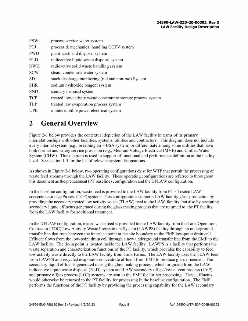
2 General Overview Figure 2-1 below provides the contextual depiction of the LAW facility in terms of its primary interrelationships with other facilities, systems, utilities and contractors. This diagram does not include every internal system (e.g., breathing air – BSA system) or differentiate among some utilities that have both normal and safety service provision (e.g., Medium Voltage Electrical (MVE) and Chilled Water System (CHW). This diagram is used in support of functional and performance definition at the facility level. See section 1.5 for the list of relevant system designations. As shown in Figure 2-1 below, two operating configurations exist for WTP that permit the processing of waste feed streams through the LAW facility. These operating configurations are referred to throughout this document as the pretreatment (PT baseline) configuration and the DFLAW configuration. In the baseline configuration, waste feed is provided to the LAW facility from PT’s Treated LAW concentrate storage Process (TCP) system. This configuration supports LAW facility glass production by providing the necessary treated low activity waste (TLAW) feed to the LAW facility, but also by accepting secondary liquid effluents generated during the glass making process that are returned to the PT facility from the LAW facility for additional treatment. In the DFLAW configuration, treated waste feed is provided to the LAW facility from the Tank Operations Contractor (TOC) Low Activity Waste Pretreatment System (LAWPS) facility through an underground transfer line that runs between the interface point at the site boundary to the EMF low-point drain cell. Effluent flows from the low-point drain cell through a new underground transfer line from the EMF to the LAW facility. The tie-in point is located inside the LAW facility. LAWPS is a facility that performs the waste separation and characterization functions of the PT facility, which provides the capability to feed low activity waste directly to the LAW facility from Tank Farms. The LAW facility uses the TLAW feed from LAWPS and recycled evaporator concentrate effluent from EMF to produce glass if needed. The secondary liquid effluents generated during the glass making process, which originate from the LAW radioactive liquid waste disposal (RLD) system and LAW secondary offgas/vessel vent process (LVP) and primary offgas process (LOP) systems are sent to the EMF for further processing. These effluents would otherwise be returned to the PT facility for processing in the baseline configuration. The EMF performs the functions of the PT facility by providing the processing capability for the LAW secondary

24590-LAW-3ZD-20-00002, Rev 3
LAW Facility Design Description
24590-ENG-F00130 Rev 5 (Revised 4/2/2015) Page 9 Ref: 24590-WTP-3DP-G04B-00093
waste streams, thereby allowing waste feed to be fed directly to the LAW facility independent of the PT facility. Isolations for transfer of secondary effluents from the LAW facility are within the scope of those process systems (LAW RLD, LVP and LOP), and are discussed in the LAW RLD, LVP and LOP system design description documents. Throughout this SDD, any reference to “safety” (e.g., in the following figures) is to be understood for the LAW facility as being in support of chemical safety per the CSMPD (24590-WTP-PD-RAWS-SS-0003, Chemical Safety Management Program Description).

24590-LAW-3ZD-20-00002, Rev 3
LAW Facility Design Description
24590-ENG-F00130 Rev 5 (Revised 4/2/2015) Page 10 Ref: 24590-WTP-3DP-G04B-00093
Figure 2-1 shows the inputs and outputs to the LAW facility for the two operating configurations. The configuration is identified in the individual boxes. Boxes in the figure that do not have the configuration identified applies to both configurations. Figure 2-1 Facility Context Diagram
LAW Facility
Vitrified LAW (LEH System - to DOE
contractor)
Sample Analysis (ASX System - to/
from LAB)
Stack Exhaust (C3V, C5V, LOP, LVP,
SDJ Systems – to atmosphere)
Radioactive Liquid Effluent (RLD
System – to PT Facility in Baseline
Config)
Non-Radioactive Liquid Effluent (NLD
System – to BOF)
Rad Solid Waste incl. Spent Melters
(RWH and LMH Systems - to DOE
contractor)
Non-Radioactive Solid Waste - to
other contractor)
Utility Systems:• Chilled Water Return (CHW)• Steam Condensate (SCW)• Sanitary Disposal (SND)• WTP Grounding System
(GRE)• Plant Cooling Water (PCW)
LAW Feed/Concentrate from PTF (TCP System
in Baseline Config)
Glassformers from BOF (GFR
System)
New Melters and Containers (LRH,
LMH Systems)
Chem Reagents (e.g., AMR, SHR)
Utility Systems:• Steam (LPS, HPS)• Plant Service Air (PSA)• Demineralized Water (DIW)• Fire Protection (FSW, FPW, FDE)• Chilled Water (CHW)• Electrical Power (MVE, LVE)• Instrument Service Air (ISA)• Domestic (potable) Water (DOW)• Process Service Water (PSW)• Uninterrupt. Power Elec. Sys. (UPE)• Plant Cooling Water (PCW)• DC Elect. (125 V) System (DCE)
Decontamination Chemicals (SHR,
NAR, CDG)
data
Monitoring and Communication Safety
Systems (PPJ)
Monitoring and Communication Non-Safety Systems (CME,
PCJ, DWJ, SDJ, MHJ, PTJ, FNJ, ASJ)
LAW Feed from LAWPS (in
DFLAW Config)
Radioactive Liquid Effluent (RLD
System – to EMF in DFLAW Config)
LAW Feed from EMF-DEP
Concentrate Recycle (in
DFLAW Config)
Secondary Off-gas Effluent (LVP System
– to EMF-DEP in DFLAW Config)
Secondary Off-gas Effluent (LVP System
– to PT-RLD in Baseline Config)
Sample
SYSTEM
X .#
Function Description
= Function of LEH System with an unique alpha numeric identifier for referencing to the Functional Analysis
= Input or Output Interfacing System with the LEH System
Legend
= Primary flow path= Supporting systems, utilities, and secondary flow paths
2.1 Facility Functions/Safety Functions
This section defines the facility functions and attributes that need to be addressed by the facility design. Figure 2-2 and Section 3 provide the design requirements to meet both functional and other requirements. Figure 2-2 provides the functional block diagram for the LAW facility in both the base line and DFLAW configurations, indicating the internal and external systems and utilities that provide the primary support

24590-LAW-3ZD-20-00002, Rev 3
LAW Facility Design Description
24590-ENG-F00130 Rev 5 (Revised 4/2/2015) Page 11 Ref: 24590-WTP-3DP-G04B-00093
or interface for that function in each configuration (baseline or DFLAW). The LAW facility houses the systems that perform the functions shown in Figure 2-2. System interfaces are provided for reference only. Except where a level of interface with the facility needs to be defined, no attempt is made in this document to define system-level functions, performance or design requirements. (See section 1.5 for the list of relevant system designators.) Figure 2-2 LAW Facility Functional Block Diagram - Baseline and DFLAW Configurations
A.1
Receive Waste
LCP
Facility Civil, Struct, & Arch
Design
LMP, LPH, LRH
RLD, NLD/SND
ASX
H.1
Provide Ancillary
System and Utility
Interfaces
E.4
Protect Workers
F.1
Provide Operations
Space
E.3
Provide Containment/Confinement
E.2
Provide Protection
from Internal Events/
Conditions
E.1
Provide Protection
from External Events/
Conditions
A.3
Export ILAW Containers
F.2
Provide Maintenance
Space
F.6
Provide Space for Specialty Tools & Eqpt
F.5
Provide Admin Space
F.4
Provide Waste Mgmt Space
F.3
Provide RadCon Space
All Functions
LCP/LFP/ GFR LFH/CDG
D.1
Manage Secondary
Solid Waste
C.1
Manage Secondary Liquid Waste
LMH, RWH, LSHB.1
Ventilate Facility, Remove/Treat Gases, Monitor
ExhaustC3V, C5V, LOP,
LVP, SDJ
Facility Civil, Struct, & Arch
Design
(multiple)
LEH
D.2
Support Maintenance
Transporter to DOE Disposal Site
To Atmosphere & PT-RLD(In Baseline
Configuration)To Other Hanford
Contractor for Disposal
G.1
Provide Monitoring, Control & Comms
All FunctionsPPJ, PCJ, MHJ, PTJ, DWJ, CME, FDE,
EMJ, FN, ASJ
From PT Facility(in baseline
Configuration)A .2
Collect Waste Sample; Blend/Prepare Waste; Collect Feed Sample; Vitrify Waste & Transfer to Canister; Sample, Seal, Decontaminate Canisters
Note: C#V is used to designate the facility
ventilation systems C1V, C2V, C3V, and C5V
SYSTEM
X .#
Function Description
= Function of LEH System with an unique alpha numeric identifier for referencing to the Functional Analysis
= Input or Output Interfacing System with the LEH System
Legend
From LAWPS and EMF-DEP (in DFLAW
Configuration)
To Atmosphere & EMF-DEP (in DFLAW
Configuration)
RLD To PTF (TLP and PWD, in Baseline Configuration)
NLD To BOF
RLD To EMF (DEP, in DFLAW Configuration)
NLD To BOF
= Primary flow path
= Supporting systems, utilities, and secondary flow paths
The functions included in Table 2-1 are the primary and secondary level functions of the facility. These functions are further described below. Where appropriate to support definition of functional/design requirements, functions have been further decomposed and additional levels of supporting functions are also described.

24590-LAW-3ZD-20-00002, Rev 3
LAW Facility Design Description
24590-ENG-F00130 Rev 5 (Revised 4/2/2015) Page 12 Ref: 24590-WTP-3DP-G04B-00093
Table 2-1 Functional Analysis and Crosswalk to Requirements
Reference Functional Analysis Description Requirement Section No.
A. Vitrify Tank Farm Waste N/A A.1 Receive Waste – LAW concentrate receipt process system (LCP) receives
treated low-active waste from either the Pretreatment facility (PTF) in the baseline configuration or from LAWPS in the direct feed low-activity waste (DFLAW) configuration for further processing. LCP also receives recycled evaporator concentrate effluent from the DFLAW effluent management facility process system (EMF-DEP) system during operations in the DFLAW configuration.
3.4.2, 3.7.2.1, 3.7.2.4
A.2.1 Sample Waste – autosampling system (ASX) collects waste samples 3.4.2 A.2.2 Blend/Prepare Waste – LAW melter feed process system (LFP) blends the
waste with glass formers. 3.4.2
A.2.3 Collect Samples – LFP/ASX collects feed sample and interfaces with Analytical Laboratory (LAB) facility to analyze blended waste to ensure defined waste envelope requirements are met.
3.4.3,
A.2.4 Vitrify & Canister Waste – LAW melter process system/ LAW container pour handling system (LMP/LPH) vitrifies the blended waste and transfers to a designated waste container.
3.4.2, 3.4.3, 3.4.4, 3.4.5
A.2.5 Sample, Seal, Decontaminate Containers – LAW container receipt handling system/ LAW container finishing handling system/ carbon dioxide gas system (LRH/LFH/CDG) supports the preparation of container for export, including shard collection, sealing, decontamination, and station-to-station movement.
3.4.5
A.3 Export Immobilized Low Active Waste (ILAW) Waste – the facility supports the export of containerized waste, including staging, placement of waste container in transport vehicle LAW container export handling system (LEH)
3.4.2, 3.4.5
B. Ventilate Facility, Remove/Treat Gases, Monitor Exhaust N/A B.1 Ventilate the Facility -- Control and minimize the spread of contamination;
maintain air balance; provide temperature and humidity control; filtered offgas and exhaust; monitor outside atmospheric conditions relative to building pressures.(C2V – C5V, atmospheric reference ventilation system (ARV)) Remove/Treat Gases – Provide a path for offgases from the melters, selected vessels and other SSCs that may contain radioactive or chemical contamination and treat or remove potentially harmful constituents. In the baseline configuration, effluent collected in the LVP/LOP caustic collection tank is routed to the PT RLD system for treatment. In the DFLAW configuration, effluent collected in the LVP caustic collection tank is routed to the EMF-DEP system for treatment. LOP/LVP Monitor exhaust – Monitor exhaust prior to discharge to the atmosphere in keeping with regulatory, permit and other requirements. (SDJ)
3.6.2.8, 3.8.1.1, 3.8.2.3

24590-LAW-3ZD-20-00002, Rev 3
LAW Facility Design Description
24590-ENG-F00130 Rev 5 (Revised 4/2/2015) Page 13 Ref: 24590-WTP-3DP-G04B-00093
Table 2-1 Functional Analysis and Crosswalk to Requirements
Reference Functional Analysis Description Requirement Section No.
C. Manage Secondary Liquid Waste N/A C.1 Manage Radioactive Liquid Waste – Provide space and secondary
containment for systems and components used to accumulate, store, agitate, sample and transfer radioactive liquid waste (RLD). In the baseline configuration, these waste streams are routed from the LAW RLD system to PT treated law evaporation process system (TLP) or Plant Wash Disposal (PWD) systems for treatment and sampling. In the DFLAW configuration, these waste streams are routed from the LAW RLD system to EMF-DEP system for treatment and sampling. Manage Non-Radioactive Liquid Waste – Provide space for systems and components used to accumulate, store, sample and transfer non-radioactive liquid waste (NLD). Manage Sanitary Waste -- Provide space for systems and components used to drain and transfer sanitary liquid wastes (SND).
3.6.2.2, 3.6.2.3, 3.6.3.10, 3.7.2.5
D. Manage Secondary Solid Waste and Support N/A D.1 Manage Secondary Solid Waste – Provide space, tools, and equipment to
support the accumulation, internal transfer, packaging, surveying, staging, and export of radioactive and mixed secondary solid waste. Manage Dangerous Secondary Solid Waste – Provide space, tools, and equipment to support the accumulation, internal transfer, packaging, surveying, staging, and export of dangerous secondary solid waste. Manage Sanitary (Non-Dangerous) Solid Waste – Provide space, tools, and equipment to support the accumulation, internal transfer, packaging, surveying, staging, and export of sanitary solid waste.
3.8.5.11, 3.9.1.1, 3.9.1.2, 3.9.2.1
D.2 Support Maintenance - Provide space, tools and equipment to support the accumulation, internal transfer, packaging, surveying, staging, and export of recyclable materials and product streams, including any streams intended for outside treatment and return (e.g., laundering of anti-contamination clothing, oily rags, etc.) as determined by pollution prevention and waste minimization planning.
3.8.5.8, 3.8.5.9, 3.8.5.10, 3.8.5.11, 3.8.5.12, 3.8.5.13,
3.9.1.2, 3.9.2.2, 3.9.2.3
E. Support Safety and Environmental Permit Requirements N/A E.1 Provide protection from external events/ conditions such as NPH (Natural
Phenomenon Hazard)/external DBE (Design Basis Event) Survivability, protect SSCs – the facility ensures the survivability and continuous operation of designated safety SSCs, including structural integrity in the event of external DBE events (e.g., seismic event, ashfall, high winds).
3.5.1.1, 3.6.1.11, 3.6.3.8, 3.8.1.1, 3.8.1.2, 3.8.2.1
E.2 Provide protection from internal events/conditions such as internal DBE Survivability – the facility and its internal systems ensure the survivability and continuous operation of designated safety SSCs, including interaction effects, during internal DBE events (e.g., leak/spill, internal flooding, and loss of normal cooling).
3.6.3.8, 3.8.1.1, 3.8.1.2, 3.8.2.1
E.3 Provide Containment/Confinement – the facility provides confinement and containment as established by regulatory and permit requirements, and safety analyses, to protect workers, the public, and the environment.
3.6.3.5.7, 3.6.3.5.8, 3.6.3.5.10, 3.6.3.6.5, 3.6.3.6.4, 3.6.3.6.6, 3.6.3.6.7 3.6.3.7.2, 3.6.3.7.4, 3.6.3.7.6, 3.6.3.8, 3.6.3.10,
3.6.3.10.5

24590-LAW-3ZD-20-00002, Rev 3
LAW Facility Design Description
24590-ENG-F00130 Rev 5 (Revised 4/2/2015) Page 14 Ref: 24590-WTP-3DP-G04B-00093
Table 2-1 Functional Analysis and Crosswalk to Requirements
Reference Functional Analysis Description Requirement Section No.
E.4 Protect Workers – the facility provides protection to employees and minimize exposure in keeping with ALARA (As Low As Reasonably Achievable) principles of design.
3.6.1.2, 3.6.2.1, 3.6.2.2, 3.6.2.3, 3.6.2.4, 3.6.2.5, 3.6.2.6, 3.6.2.7, 3.6.2.8, 3.6.2.9,
3.6.2.10, 3.6.2.11, 3.6.2.12, 3.8.6.4
F. Support Operations and Maintenance N/A F.1 Provide Operations Space - Equipment space (including clearances,
operability, and access) – the facility provides sufficient space for all primary and support functions and their associated SSCs, including clearances for anticipated operating and maintenance activities. Operations space – the facility provides space for operations activities, including but not limited to work stations, control rooms, change rooms, transition areas.
3.7.2.7, 3.7.2.8, 3.8.5.2, 3.8.5.3, 3.8.5.4, 3.8.5.5, 3.8.5.6, 3.8.5.7, 3.8.5.8, 3.8.6.1, 3.8.6.2, 3.8.6.3,
3.8.6.4 F.2 Provide Maintenance Space – the facility provides space for maintenance
activities, including but not limited to maintenance shops, equipment transfer routes and handling capability, decontamination areas, tool storage, work benches, spare parts and consumables storage, calibrated equipment storage.
3.8.5.8, 3.8.5.9, 3.8.5.10, 3.8.5.11, 3.8.5.12, 3.8.5.13,
3.8.6.1, 3.8.6.2, 3.8.6.3, 3.8.6.4
F.3 Provide Radiological Controls space – the facility provides space for radiological activities, including but not limited to portable and fixed monitoring and surveying activities and equipment, counting stations, radiological source storage.
3.6.1.2, 3.6.2.6, 3.8.5.7
F.4 Provide Waste Management Space – the facility provides space for waste management activities, including but not limited to space necessary for waste accumulation, handling, packaging, surveying and staging.
3.9.1.1, 3.9.1.2
F.5 Provide Administrative Space – the facility provides space for facility administration, including but not limited to offices, meeting rooms, lunch rooms, restrooms, locker rooms, data/records storage, and briefing/meeting rooms.
3.8.5.2, 3.8.5.3, 3.8.5.4, 3.8.5.5, 3.8.5.6, 3.8.5.7,
3.8.5.8 F.6 Provide Specialty Tools and Support Equipment – the facility provides
space for specialty tools and support equipment, including but not limited to breathing air, specialty carts for equipment transfer, below-the-hook lifting devices.
3.8.5.9, 3.8.5.10, 3.8.5.11, 3.8.5.12,
3.8.5.13
G. Support Monitoring, Controls and Communication N/A G.1 Provide Safety/Non-Safety Monitoring and Control for Facility Systems,
including communication. 3.7.2.3, 3.7.2.7, 3.7.2.8, 3.7.2.9, 3.8.3.1, 3.8.4.1,
3.8.5.15 H. Support Ancillary and Utility System Interfaces N/A H.1 Provide the connections to external utility and support systems, including
internal distribution. 3.7.2.7, 3.7.2.8, 3.8.4.1, 3.8.6.17
24590-LAW-3ZD-20-00002, Rev 3
LAW Facility Design Description
24590-ENG-F00130 Rev 5 (Revised 4/2/2015) Page 15 Ref: 24590-WTP-3DP-G04B-00093
2.2 Facility Classification
The LAW facility contains components with the following classifications/designations:
Safety Class Safety Significant Chemical Safety Dangerous Waste Permit affecting Air Permit affecting Waste Acceptance Impacting General
2.3 Basic Operational Overview
The LAW facility is located on the Hanford nuclear reservation, managed by the Department of Energy (DOE) in southeastern Washington State. It is part of the Hanford Tank Waste Treatment and Immobilization Plant (WTP), being designed and constructed to treat millions of gallons of nuclear and chemical waste currently stored in underground tanks. The LAW facility will receive waste for treatment from the Pretreatment (PT) facility in the baseline configuration or from the LAWPS in the DFLAW configuration. The LAW facility also receives recycled evaporator concentrate effluent from the EMF-DEP system during operations in the DFLAW configuration. LAW is a mixed, characteristic, and listed waste regulated under the Resource Conservation and Recovery Act (RCRA), as administered under the Washington Administrative Code (WAC) and meets specific treatment and performance standards for storage and disposal of the final waste form in accordance with the specific requirements of the WTP Contract. In the LAW facility, low activity waste is mixed with glass-forming materials and vitrified in two joule-heated melters. The mixture will be poured into stainless steel containers that are approximately 4 feet (1.22 m) in diameter, 7.5 feet (2.286 m) tall and that will weigh not more than 10,000 kilograms (22,046 lbs.) when filled. When fully operational, the LAW Facility will produce 30 MT/day glass (6 MT/container) at 70% availability. Immobilized LAW (ILAW) product is certified to meet DOE and regulatory requirements for additional treatment or disposal; therefore, the facility and associated internal and interfacing systems are capable of coordinated functions to safely produce and deliver a certified waste product. The full containers are removed by transport vehicle to the Hanford Integrated Disposal Facility (IDF). [ICD-15] For an overview of the facility and its major systems the reader is directed to 24590-LAW-DSA-NS-18-0001, Documented Safety Analysis for the Low-Activity Waste Facility. Chapter 4 of this facility design description contains a thorough overview of the facility and major systems. Because this high-level design information was used in preparation of the facility safety/hazard analyses and determination of safety functions and controls, these described design features are subject to configuration management, and any deviations from the design as described in Chapter 2 needs to have a safety evaluation performed for potential impact to the safety/hazard evaluation and established controls.

24590-LAW-3ZD-20-00002, Rev 3
LAW Facility Design Description
24590-ENG-F00130 Rev 5 (Revised 4/2/2015) Page 16 Ref: 24590-WTP-3DP-G04B-00093
Table 2-2 LAW Facility Interface Boundaries
System Interface Boundaries AMR Ammonia/air dilution skid (LVP-SKID-
00003) receives ammonia for processing melter offgas in the LVP system.
See 24590-LAW-3ZD-LOP-00001, Law Primary Offgas (LOP) and Secondary Offgas/Vessel Vent (LVP) System Design Description, for additional information. -
ARV Provides a common pressure reference point to outside ambient air for the differential pressure instrumentation used in monitoring and controlling the building ventilation system.
The C2V, C3V, and C5V supply and exhaust fans utilize pressure inputs from the ARV system to modulate the fan speed to achieve a pressure gradient. See 24590-LAW-3ZD-20-00001, LAW Ventilation Systems Design Description, for additional detail.
ASX Transfers process samples from LAW to the Lab.
Autosamplers (ASX-SMPLR-00012 and ASX-SMPLR-00013). See 24590-WTP-3ZD-ASX-00001, System Design Description of the Autosampling System (ASX), for additional detail.
BSA Supplies breathing air to the LAW by a dedicated, stand-alone compressor.
The LAW BSA compressor, located in Room L-0137. See 24590-WTP-3YD-BSA-00001, System Description for the Waste Treatment Plant Breathing Service Air (BSA), for additional detail.
C1V, C2V, C3V, and C5V
Provides heating, cooling, humidification, and ventilation for the LAW Facility.
Inlets/outlets of fans, filters, air handlers, and ductwork located throughout the LAW Facility. C1V, C2V, C3V, and C5V each exhaust through an individual stack. See 24590-LAW-3ZD-20-00001, LAW Ventilation Systems Design Description, for additional detail.
CDG Provides CO2 pellets to decontaminate ILAW containers.
The CO2 vessel is anchored to the concrete slab that is part of the LAW Facility. See 24590-LAW-3ZD-CDG-00001, LAW Carbon Dioxide Gas (CDG) System Design Description for additional detail.
CHW Provides chilled water for fan coils and air handling units as well as the BSA, LOP and LFP systems in the LAW Facility.
See 24590-WTP-3YD-CHW-00001, System Description for the WTP Chilled Water System (CHW), for additional detail.
CME/FNJ The communications electrical system (CME) provides communications, alarms and public address and building evacuation services to ensure worker safety in the WTP site. The Facility Network Infrastructure (FNJ) implements a fiber optic backbone providing connectivity within the WTP facilities as well as provides external links to off-site WTP facilities and offices. The FNJ ties in the CME system components as well as the WTP data networks (ICN, PTJ, and ITN).
CME/FNJ system equipment is incorporated in the design of the EMF and other facilities to provide connectivity, communications, alarms and public address, and building evacuation services as necessary. Details of the CME/FNJ system design is contained in 24590-WTP-3YD-CME-00001, System Description for the Communications Electrical System (CME) and Facility Network Infrastructure (FNJ System Description for the Communications Electrical System (CME) and Facility Network Infrastructure (FNJ).

24590-LAW-3ZD-20-00002, Rev 3
LAW Facility Design Description
24590-ENG-F00130 Rev 5 (Revised 4/2/2015) Page 17 Ref: 24590-WTP-3DP-G04B-00093
Table 2-2 LAW Facility Interface Boundaries
System Interface Boundaries CPE Provides cathodic protection to
underground piping as needed throughout the LAW Facility.
Cathodic protection is provided on the dangerous waste transfer piping from the LAW-RLD to the PT Facility. See 24590-WTP-3YD-CPE-00001, System Description for Waste Treatment Plant Cathodic Protection (CPE), for additional detail.
DCE Provides DCE control power to LAW MVE switchgear
See 24590-WTP-3ZD-MVE-00001, LAW BOF and LAB Medium Voltage Electrical (MVE) Low Voltage Electrical (LVE) and DC Electrical (DCE) System Design Description, for additional detail.
DIW Provides demineralized water to WESP misting in LOP and decontamination and flushes for multiple systems in the LAW Facility.
See 24590-WTP-3YD-DIW-00001, System Description for the Demineralized Water System (DIW), and Section 4.1.3.3.2 of this SDD for additional detail.
DOW Provides a continuous supply of potable water to the LAW Facility for wash/ decontamination stations, BSA moisture and humidifiers in the HVAC systems.
See 24590-WTP-3YD-DOW-00001, System Description for the Waste Treatment Plant Domestic Water System (DOW), for additional detail.
EMF-DEP Provides feed from the Tank Farm to the LCP system. Mixed waste from the LAW-RLD and LVP SBS is sent to EMF-DEP. EMF-DEP will be used under the DFLAW configuration.
The waste transfer lines 5 ft. from the LAW Facility. See 24590-BOF-3ZD-25-00001, WTP Direct Feed Low Activity Waste (DFLAW) Facility and System Design Descriptions, for additional detail.
EMJ Provides detection of airborne contamination or radiation and warns personnel in the immediate vicinity
Instruments used to detect airborne contamination or radiation, located throughout the LAW Facility. See 24590-WTP-3YD-EMJ-00001, System Description for Environmental Monitoring System (EMJ), for additional detail.
FDE Monitors the FPW system as well as other initiating devices
Instruments and panels used to detect fire in the LAW, located throughout the facility. See 24590-WTP-3YD-FSW-00001, System Description for the Fire Service Water (FSW), Fire Protection Water (FPW), and the Fire Detection and Alarm (FDE) Systems, for additional information.
FPW/FSW/FDE Distributes firewater throughout the LAW Facility and provides fire detection for the LAW Facility.
Piping, sprinklers, and detection instruments located throughout the LAW facility. See 24590-WTP-3YD-FSW-00001, System Description for the Fire Service Water (FSW), Fire Protection Water (FPW), and the Fire Detection and Alarm (FDE) Systems, for additional information.
GFR Provides glass formers to the LFP system.
See 24590-WTP-3YD-GFR-00001, System Description for the WTP Glass Formers Reagent System (GFR), and Section 4.1.3.4 of this SDD for additional information.
GRE Provides grounding and lightning protection
Alternate paths directly to the ground for electrical currents. See 24590-WTP-3YD-GRE-00001, System Description for Grounding and Lighting Protection System, for additional detail.

24590-LAW-3ZD-20-00002, Rev 3
LAW Facility Design Description
24590-ENG-F00130 Rev 5 (Revised 4/2/2015) Page 18 Ref: 24590-WTP-3DP-G04B-00093
Table 2-2 LAW Facility Interface Boundaries
System Interface Boundaries ISA Provides instrument quality air to LAW
systems. The ISA tank and skid is in room L-0307. The LAW facility provides seismic anchorage for the tank and protection from other natural forces. See 24590-WTP-3YD-PSA-00002, System Description for the Waste Treatment Plant (WTP) Plant Service Air (PSA) System for additional detail.
HPS Provides high pressure steam to the Law Facility that is reduced to low pressure steam for use in LAW HVAC systems.
The HPS system enters the building in a 6-inch diameter pipe at the +3-ft. elevation in the southwest corner of the LAW Facility. See 24590-WTP-3YD-HPS-00001, System Description for The Waste Treatment Plant High Pressure Steam (HPS), Low Pressure Steam (LPS) and Steam Condensate Water (SCW) and Section 4.1.3.3.4 of this SDD for additional information.
HTE Provides freeze protection for pipes, instrument air lines, and instrument sensing lines that are exposed to outdoor ambient temperatures.
The HTE serves the following LAW systems: ASX, HPS, SCW, SHR, DOW, PCW, PSW. See 24590-WTP-3YD-HTE-00001, System Description for the Waste Treatment Plant, Heat Trace Electrical System (HTE)
LCP Receives, samples and stores batches of pretreated LAW concentrate from the PT Facility (baseline configuration) and EMF-DEP (DFLAW configuration).
LCP tanks are in the LAW Facility process cell, rooms L-0123 and L-0124. See 24590-LAW-3ZD-LFP-00001, LAW Melter Feed Process (LFP) and Concentrate Receipt Process (LCP) System Design Description, for additional information. -
LEH Exports the filled ILAW container for disposal.
The LEH crane is in the LAW export bay, room L-0127 of the Law Facility. See 24590-LAW-3ZD-LEH-00001, LAW Container Export Handling (LEH) System Design Description, for additional information.
LFH Adds inert fill as needed, lids, and decontaminates ILAW containers.
The LFH process takes place along the north and south finishing lines, rooms L-0109D/C/B/E and L-0115D/C/B/E at the +3 ft. elevation in the southeast corner of the LAW Facility. See 24590-LAW-3ZD-LFH-00001, LAW-Container Finishing Handling (LFH) System Design Description, for additional information.
LFP Stores the LAW concentrate and mixes it with sucrose and glass formers from the Glass Former Reagent System (GFR) to form a uniform batch of slurry feed to the LAW melters.
LFP tanks are in the LAW Facility process cell, rooms L-0123 and L-0124. See 24590-LAW-3ZD-LFP-00001, LAW Melter Feed Process (LFP) and Concentrate Receipt Process (LCP) System Design Description, for additional information.
24590-LAW-3ZD-20-00002, Rev 3
LAW Facility Design Description
24590-ENG-F00130 Rev 5 (Revised 4/2/2015) Page 19 Ref: 24590-WTP-3DP-G04B-00093
Table 2-2 LAW Facility Interface Boundaries
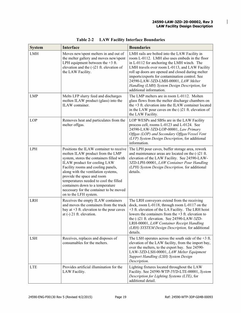
System Interface Boundaries LMH Moves new/spent melters in and out of
the melter gallery and moves new/spent LPH equipment between the +3 ft. elevation and the (-)21 ft. elevation of the LAW Facility.
LMH rails are bolted into the LAW Facility in room L-0112. LMH also uses embeds in the floor in L-0112 for anchoring the LMH winch. The LMH travels over room L-0113, and LAW Facility roll up doors are opened and closed during melter imports/exports for contamination control. See 24590-LAW-3ZD-LMH-00001, LAW Melter Handling (LMH) System Design Description, for additional information.
LMP Melts LFP slurry feed and discharges molten ILAW product (glass) into the ILAW container.
The LMP melters are in room L-0112. Molten glass flows from the melter discharge chambers on the +3 ft. elevation into the ILAW container located in the LAW pour caves on the (-)21 ft. elevation of the LAW Facility.
LOP Removes heat and particulates from the melter offgas.
LOP WESPs and SBSs are in the LAW Facility process cell, rooms L-0123 and L-0124. See 24590-LAW-3ZD-LOP-00001, Law Primary Offgas (LOP) and Secondary Offgas/Vessel Vent (LVP) System Design Description, for additional information.
LPH Positions the ILAW container to receive molten ILAW product from the LMP system, stores the containers filled with ILAW product for cooling LAW Facility rooms and cooling panels, along with the ventilation systems, provide the space and room temperatures needed to cool the filled containers down to a temperature necessary for the container to be moved on to the LFH system.
The LPH pour caves, buffer storage area, rework and maintenance areas are located on the (-)21 ft. elevation of the LAW Facility. See 24590-LAW-3ZD-LPH-00001, LAW Container Pour Handling (LPH) System Design Description, for additional details.
LRH Receives the empty ILAW containers and moves the containers from the truck bay at +3 ft. elevation to the pour caves at (-) 21 ft. elevation.
The LRH conveyors extend from the receiving dock, room L-0118, through room L-0117 on the +3 ft. elevation of the LA Facility. The LRH hoist lowers the containers from the +3 ft. elevation to the (-)21 ft. elevation. See 24590-LAW-3ZD-LRH-00001, LAW Container Receipt Handling (LRH) SYSTEM Design Description, for additional details.
LSH Receives, replaces and disposes of consumables for the melters.
The LSH operates across the south side of the +3 ft. elevation of the LAW facility, from the import bay, over the melters, to the export bay. See 24590-LAW-3ZD-LSH-00001, LAW Melter Equipment Support Handling (LSH) System Design Description.
LTE Provides artificial illumination for the LAW Facility.
Lighting fixtures located throughout the LAW Facility. See 24590-WTP-3YD-LTE-00001, System Description for Lighting Systems (LTE), for additional detail.

24590-LAW-3ZD-20-00002, Rev 3
LAW Facility Design Description
24590-ENG-F00130 Rev 5 (Revised 4/2/2015) Page 20 Ref: 24590-WTP-3DP-G04B-00093
Table 2-2 LAW Facility Interface Boundaries
System Interface Boundaries LPS Supplies the HVAC coils and
humidifiers with low pressure steam. The LPS begins in room L-0305, where the HPS is transformed into the LPS. The LPS runs to elevations +28 ft. and +48 ft. See 24590-WTP-3YD-HPS-00001, System Description for The Waste Treatment Plant High Pressure Steam (HPS), Low Pressure Steam (LPS) and Steam Condensate Water (SCW), and Section 4.1.3.3.5 of this SDD for additional details.
LVE Provides low voltage electrical power to the LAW Facility processes and functions.
See 24590-WTP-3ZD-MVE-00001, LAW BOF and LAB Medium Voltage Electrical (MVE) Low Voltage Electrical (LVE) and DC Electrical (DCE) System Design Description, for additional detail.
LVP Provides secondary treatment for melter offgas downstream of the LOP and provides ventilation outlets for LAW vessels.
The LVP begins where the melter offgas streams combine downstream of the WESP, and extends through the LVP exhaust stack. See 24590-LAW-3ZD-LOP-00001, Law Primary Offgas (LOP) and Secondary Offgas/Vessel Vent (LVP) System Design Description, for additional information.
MVE Provides high voltage electrical power to the LAW Facility processes and functions.
See 24590-WTP-3ZD-MVE-00001, LAW BOF and LAB Medium Voltage Electrical (MVE) Low Voltage Electrical (LVE) and DC Electrical (DCE) System Design Description, for additional detail.
MXG Provides argon gas for the LMP. The MXG vessel is in room L-0137 of the LAW Facility. See 24590-LAW-3YD-MXG-00001, System Description for Law Miscellaneous Gases System (MXG).
NLD Collects non-dangerous, non-radioactive effluent from the LAW Facility.
Floor drains located throughout the LAW Facility. See 24590-WTP-3YD-NLD-00001, System Description for the Waste Treatment Plant Non-Radioactive Liquid Waste Disposal (NLD) System, for additional detail.
PCJ/MHJ/ASJ The PCJ system provides non-safety process monitoring and control of non-safety LAW SSCs. The MHJ provides non-safety monitoring and control of equipment used in mechanical handling systems, the ASJ provides monitoring and control within the ASX.
Process monitoring and control is provided for various system equipment, and the interfaces occur at the system level sensing instruments. See 24590-WTP-3ZD-PCJ-00001, Process Control (PCJ), Mechanical Handling Control (MHJ), and Auto Sampling Control (ASJ) System Design Description for additional detail.
PPJ The PPJ system provides process monitoring and control for (chemical) safety LAW SSCs.
Monitoring and control is provided for various CS equipment and functions, and the interfaces occur at the system level sensing instruments and final elements. See 24590-WTP-3ZD-PPJ-00001, WTP Programmable Protection (PPJ) System Design Description - System Design Description for additional detail.

24590-LAW-3ZD-20-00002, Rev 3
LAW Facility Design Description
24590-ENG-F00130 Rev 5 (Revised 4/2/2015) Page 21 Ref: 24590-WTP-3DP-G04B-00093
Table 2-2 LAW Facility Interface Boundaries
System Interface Boundaries PCW The LAW PCW receives PCW cooling
water from the BOF primary loop to provide cooling to LAW equipment through the four closed secondary loops, and returns primary loop PCW cooling water to the BOF for heat rejection by the BOF cooling towers.
Heat exchangers PCW-HX-00007A/B, PCW-HX-00004A/B, PCW-HX-00005A/B, PCW-HX-00019A/B. See 24590-LAW-3ZD-PCW-00001, LAW Plant Cooling Water (PCW) System Design Description for additional detail.
PSA Provide dry filtered air for many LAW process systems including vessel venting and propulsion of CO2 particles.
The PSA tank is in room L-0307. The LAW facility provides seismic anchorage for the tank and protection from other natural forces. See 24590-WTP-3YD-PSA-00002, System Description for the Waste Treatment Plant (WTP) Plant Service Air (PSA) System for additional detail.
PSW Distributes process service water throughout the LAW facility to hose connections in different locations inside the LAW Facility including the LVP Caustic Scrubber and the LVP Caustic Collection tank.
The boundary between LAW-PSW and BOF-PSW is located at the flange at least 5 ft. outside of the LAW Facility wall and is depicted at 24590-LAW-M6-PSW-00001001, P&ID, LAW Process Service Water System. See 24590-WTP-3YD-PSW-00001, System Description for the Process Service Water System (PSW).
RLD Collects radioactive liquid effluents for interim storage.
Floor drains, sumps and cells located throughout the LAW Facility. See 24590-LAW-3ZD-RLD-00001, LAW Facility Radioactive Liquid Waste Disposal (RLD) System Design Description for additional detail.
RWH Provides the equipment, controls, and instrumentation to contain and transport radioactive solid waste, floor hatches and equipment from LOP, LCP, LFP, and LW-RLD systems.
RWH equipment that is anchored to the LAW Facility. See 24590-LAW-3ZD-RWH-00001, LAW Radioactive Solid Waste Handling (RWH) System Design Description– System Design Description, for additional detail.
SCW Collects steam condensate in tanks. See 24590-WTP-3YD-HPS-00001, System Description for The Waste Treatment Plant High Pressure Steam (HPS), Low Pressure Steam (LPS) and Steam Condensate Water (SCW) for additional information.
SDJ Monitors and samples Lab air emissions Instruments and associated panels used to monitor and sample air emissions from the LAW process and ventilation stacks. See 24590-WTP-3YD-SDJ-00001, System Description for Stack Discharge Monitoring (Rad and Non-Rad), for additional detail.
SHR Provides sodium hydroxide (caustic) the LCP, LVP and LAW-RLD systems.
See 24590-WTP-3YD-SHR-00001, System Description for the WTP Reagents (SHR, NAR, AFR, SPR, STR), 24590-LAW-M6-RLD-00002001 001, P&ID - LAW Radioactive Liquid Waste Disposal System C3/C5 Drains/Sump Collection RLD-VSL-00004
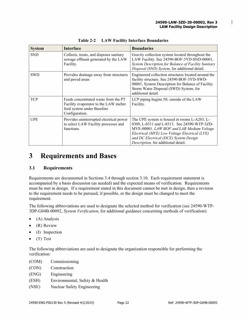
24590-LAW-3ZD-20-00002, Rev 3
LAW Facility Design Description
24590-ENG-F00130 Rev 5 (Revised 4/2/2015) Page 22 Ref: 24590-WTP-3DP-G04B-00093
Table 2-2 LAW Facility Interface Boundaries
System Interface Boundaries SND Collects, treats, and disposes sanitary
sewage effluent generated by the LAW Facility.
Gravity collection system located throughout the LAW Facility. See 24590-BOF-3YD-SND-00001, System Description for Balance of Facility Sanitary Disposal (SND) System, for additional detail.
SWD Provides drainage away from structures and paved areas
Engineered collection structures located around the facility structure. See 24590-BOF-3YD-SWD-00001, System Description for Balance of Facility Storm Water Disposal (SWD) System, for additional detail.
TCP Feeds concentrated waste from the PT Facility evaporator to the LAW melter feed system under Baseline Configuration.
LCP piping begins 5ft. outside of the LAW Facility.
UPE Provides uninterrupted electrical power to select LAW Facility processes and functions.
The UPE system is housed in rooms L-A203, L-0309, L-0311 and L-0313. See 24590-WTP-3ZD-MVE-00001, LAW BOF and LAB Medium Voltage Electrical (MVE) Low Voltage Electrical (LVE) and DC Electrical (DCE) System Design Description, for additional detail.
3 Requirements and Bases 3.1 Requirements
Requirements are documented in Sections 3.4 through section 3.10. Each requirement statement is accompanied by a basis discussion (as needed) and the expected means of verification. Requirements must be met in design. If a requirement stated in this document cannot be met in design, then a revision to the requirement needs to be pursued, if possible, or the design must be changed to meet the requirement.
The following abbreviations are used to designate the selected method for verification (see 24590-WTP-3DP-G04B-00092, System Verification, for additional guidance concerning methods of verification):
• (A) Analysis • (R) Review • (I) Inspection • (T) Test The following abbreviations are used to designate the organization responsible for performing the verification:
(COM) Commissioning (CON) Construction (ENG) Engineering (ESH) Environmental, Safety & Health (NSE) Nuclear Safety Engineering

24590-LAW-3ZD-20-00002, Rev 3
LAW Facility Design Description
24590-ENG-F00130 Rev 5 (Revised 4/2/2015) Page 23 Ref: 24590-WTP-3DP-G04B-00093
(OPS) Plant Operations (SAS) Safeguards & Security (SU) Startup (SUP) Supplier
3.2 Bases
Basis discussions are provided as needed to explain the decomposition or interpretation from the originating source requirement(s). Where included, basis discussions provide supplementary information to help the reader understand the origin or intent of a requirement. With minor exceptions, this document is dedicated to the requirements associated with the facility structure and its interfaces with systems and not the functional or design requirements for individual systems, which are left for other documents to define. No attempt is made to identify all component level requirements that are more appropriately left to design agency efforts (e.g., the dimensions of individual structural members, the application of codes and standards to individual sections of gypsum board wall design, the routings of internal systems and the design or performance requirements of individual penetrations, supports, hangers, embeds, etc.).
3.3 References
The requirements include a source document reference. Each unique source document reference is bracketed separately. Requirements may include a reference to Section 2.1, System Functions/Safety Functions, listed in parentheses following the source document. A complete listing of all source references is provided in Section 5.1.
3.4 General Requirements
Sustainable Design
Requirement: The LAW facility shall be designed using principles of sustainable design to the siting, design, and construction of new facilities which shall be incorporated into the WTP design. The facility design shall also reduce energy loads through climate-responsive design by maximizing the use of high-performance building envelopes; select walls, roofs, and other assemblies based on long-term insulation and durability requirements. [Section 14.16.1, BOD] Basis Discussion: Sustainable design and development is a comprehensive strategy to create buildings, facilities, and infrastructure that minimize the use of resources. Verification: Verification is expected to be achieved through
Verif. Method
Verif. by Plan Notes/Comments
R ENG Review design evidence of sustainable design/construction.
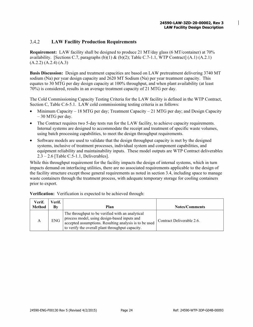
24590-LAW-3ZD-20-00002, Rev 3
LAW Facility Design Description
24590-ENG-F00130 Rev 5 (Revised 4/2/2015) Page 24 Ref: 24590-WTP-3DP-G04B-00093
LAW Facility Production Requirements
Requirement: LAW facility shall be designed to produce 21 MT/day glass (6 MT/container) at 70% availability. [Sections C.7, paragraphs (b)(1) & (b)(2); Table C.7-1.1, WTP Contract] (A.1) (A.2.1) (A.2.2) (A.2.4) (A.3) Basis Discussion: Design and treatment capacities are based on LAW pretreatment delivering 3740 MT sodium (Na) per year design capacity and 2620 MT Sodium (Na) per year treatment capacity. This equates to 30 MTG per day design capacity at 100% throughput, and when plant availability (at least 70%) is considered, results in an average treatment capacity of 21 MTG per day. The Cold Commissioning Capacity Testing Criteria for the LAW facility is defined in the WTP Contract, Section C, Table C.6-5.1. LAW cold commissioning testing criteria is as follows: • Minimum Capacity – 18 MTG per day; Treatment Capacity – 21 MTG per day; and Design Capacity
– 30 MTG per day. • The Contract requires two 5-day tests run for the LAW facility, to achieve capacity requirements.
Internal systems are designed to accommodate the receipt and treatment of specific waste volumes, using batch processing capabilities, to meet the design throughput requirements.
• Software models are used to validate that the design throughput capacity is met by the designed systems, inclusive of treatment processes, individual system and component capabilities, and equipment reliability and maintainability inputs. These model outputs are WTP Contract deliverables 2.3 – 2.6 [Table C.5-1.1, Deliverables].
While this throughput requirement for the facility impacts the design of internal systems, which in turn impacts demand on interfacing utilities, there are no associated requirements applicable to the design of the facility structure except those general requirements as noted in section 3.4, including space to manage waste containers through the treatment process, with adequate temporary storage for cooling containers prior to export.
Verification: Verification is expected to be achieved through:
Verif. Method
Verif. By Plan Notes/Comments
A ENG
The throughput to be verified with an analytical process model, using design-based inputs and accepted assumptions. Resulting analysis is to be used to verify the overall plant throughput capacity.
Contract Deliverable 2.6.
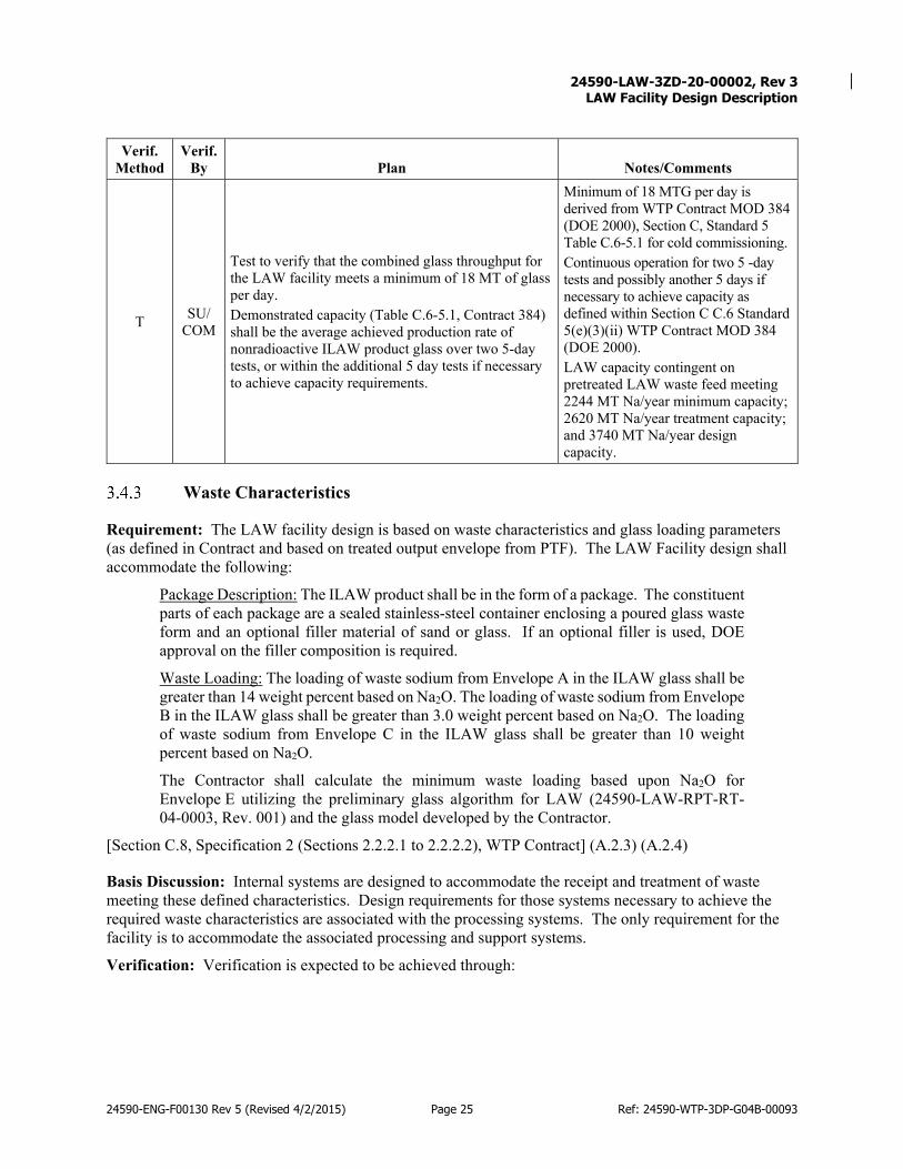
24590-LAW-3ZD-20-00002, Rev 3
LAW Facility Design Description
24590-ENG-F00130 Rev 5 (Revised 4/2/2015) Page 25 Ref: 24590-WTP-3DP-G04B-00093
Verif. Method
Verif. By Plan Notes/Comments
T SU/ COM
Test to verify that the combined glass throughput for the LAW facility meets a minimum of 18 MT of glass per day. Demonstrated capacity (Table C.6-5.1, Contract 384) shall be the average achieved production rate of nonradioactive ILAW product glass over two 5-day tests, or within the additional 5 day tests if necessary to achieve capacity requirements.
Minimum of 18 MTG per day is derived from WTP Contract MOD 384 (DOE 2000), Section C, Standard 5 Table C.6-5.1 for cold commissioning. Continuous operation for two 5 -day tests and possibly another 5 days if necessary to achieve capacity as defined within Section C C.6 Standard 5(e)(3)(ii) WTP Contract MOD 384 (DOE 2000). LAW capacity contingent on pretreated LAW waste feed meeting 2244 MT Na/year minimum capacity; 2620 MT Na/year treatment capacity; and 3740 MT Na/year design capacity.
Waste Characteristics
Requirement: The LAW facility design is based on waste characteristics and glass loading parameters (as defined in Contract and based on treated output envelope from PTF). The LAW Facility design shall accommodate the following:
Package Description: The ILAW product shall be in the form of a package. The constituent parts of each package are a sealed stainless-steel container enclosing a poured glass waste form and an optional filler material of sand or glass. If an optional filler is used, DOE approval on the filler composition is required.
Waste Loading: The loading of waste sodium from Envelope A in the ILAW glass shall be greater than 14 weight percent based on Na2O. The loading of waste sodium from Envelope B in the ILAW glass shall be greater than 3.0 weight percent based on Na2O. The loading of waste sodium from Envelope C in the ILAW glass shall be greater than 10 weight percent based on Na2O.
The Contractor shall calculate the minimum waste loading based upon Na2O for Envelope E utilizing the preliminary glass algorithm for LAW (24590-LAW-RPT-RT-04-0003, Rev. 001) and the glass model developed by the Contractor.
[Section C.8, Specification 2 (Sections 2.2.2.1 to 2.2.2.2), WTP Contract] (A.2.3) (A.2.4)
Basis Discussion: Internal systems are designed to accommodate the receipt and treatment of waste meeting these defined characteristics. Design requirements for those systems necessary to achieve the required waste characteristics are associated with the processing systems. The only requirement for the facility is to accommodate the associated processing and support systems.
Verification: Verification is expected to be achieved through:
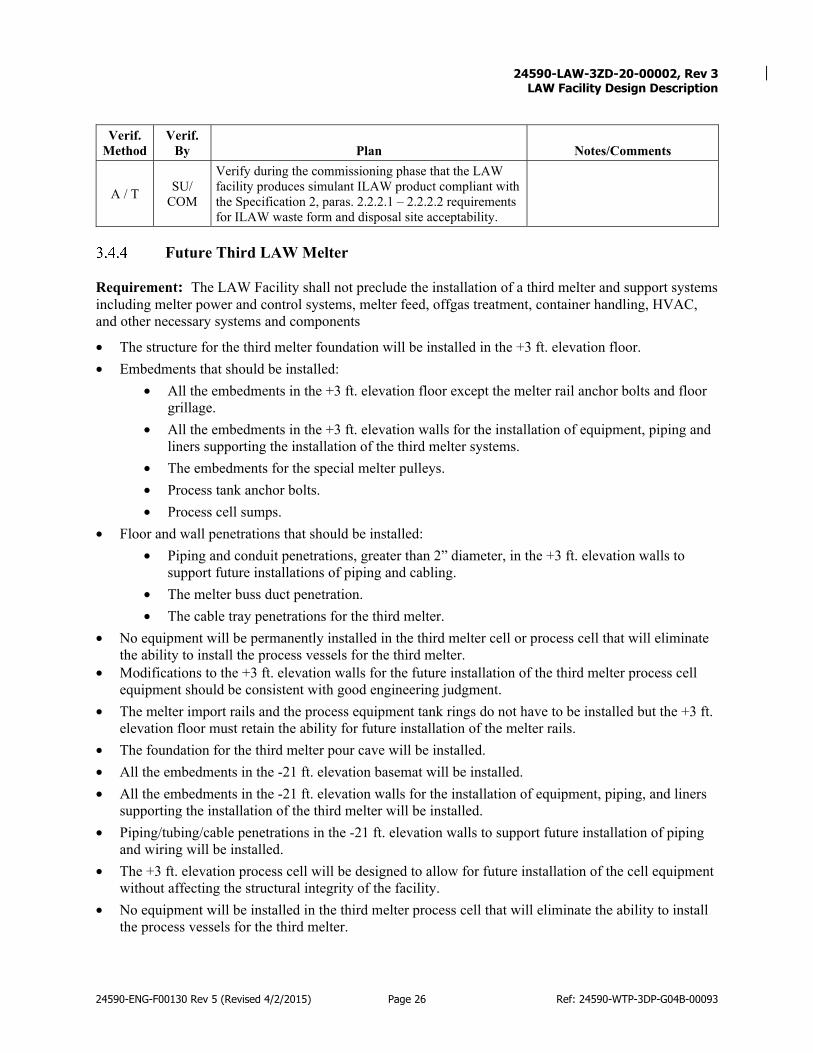
24590-LAW-3ZD-20-00002, Rev 3
LAW Facility Design Description
24590-ENG-F00130 Rev 5 (Revised 4/2/2015) Page 26 Ref: 24590-WTP-3DP-G04B-00093
Verif. Method
Verif. By Plan Notes/Comments
A / T SU/ COM
Verify during the commissioning phase that the LAW facility produces simulant ILAW product compliant with the Specification 2, paras. 2.2.2.1 – 2.2.2.2 requirements for ILAW waste form and disposal site acceptability.
Future Third LAW Melter
Requirement: The LAW Facility shall not preclude the installation of a third melter and support systems including melter power and control systems, melter feed, offgas treatment, container handling, HVAC, and other necessary systems and components
• The structure for the third melter foundation will be installed in the +3 ft. elevation floor. • Embedments that should be installed:
• All the embedments in the +3 ft. elevation floor except the melter rail anchor bolts and floor grillage.
• All the embedments in the +3 ft. elevation walls for the installation of equipment, piping and liners supporting the installation of the third melter systems.
• The embedments for the special melter pulleys. • Process tank anchor bolts. • Process cell sumps.
• Floor and wall penetrations that should be installed: • Piping and conduit penetrations, greater than 2” diameter, in the +3 ft. elevation walls to
support future installations of piping and cabling. • The melter buss duct penetration. • The cable tray penetrations for the third melter.
• No equipment will be permanently installed in the third melter cell or process cell that will eliminate the ability to install the process vessels for the third melter.
• Modifications to the +3 ft. elevation walls for the future installation of the third melter process cell equipment should be consistent with good engineering judgment.
• The melter import rails and the process equipment tank rings do not have to be installed but the +3 ft. elevation floor must retain the ability for future installation of the melter rails.
• The foundation for the third melter pour cave will be installed. • All the embedments in the -21 ft. elevation basemat will be installed. • All the embedments in the -21 ft. elevation walls for the installation of equipment, piping, and liners
supporting the installation of the third melter will be installed. • Piping/tubing/cable penetrations in the -21 ft. elevation walls to support future installation of piping
and wiring will be installed. • The +3 ft. elevation process cell will be designed to allow for future installation of the cell equipment
without affecting the structural integrity of the facility. • No equipment will be installed in the third melter process cell that will eliminate the ability to install
the process vessels for the third melter.

24590-LAW-3ZD-20-00002, Rev 3
LAW Facility Design Description
24590-ENG-F00130 Rev 5 (Revised 4/2/2015) Page 27 Ref: 24590-WTP-3DP-G04B-00093
• The common pipeline sizes will be for three-melter service; however, the pumps and heat exchanges will be based on two melters.
• Secondary offgas piping and equipment will be sized to support two melters and a peak glass throughput of 30 MTG/day.
• Electrical transformers, switchgear and bus ducts will be sized for three-melter service. However, downstream equipment exclusively for the third melter will not be installed.
[Section C.7(c), WTP Contract][Section 6.3.2, BOD] (A.2.4)
Basis Discussion: None. Verification: Verification is expected to be achieved through:
Verif. Method
Verif. By Plan Notes/Comments
R ENG
Review LAW design that can physically accommodate a third melter and associated power and control systems, melter feed, , container handling, HVAC, and other systems and components. Verify that no permanent systems, structures, or components are installed in the melter cell, pour cave or wet process cell for the third melter that would preclude future installation of the third melter.
Only verify adequate space for third melter, melter power and control systems, melter feed, , container handling, HVAC, and other systems and components, and the capability / capacity to make appropriate system connections.
ILAW Container Support
3.4.5.1 Facility Requirements for Design ILAW Container Support
Requirement: Design of the LAW facility shall support physical transfer of the ILAW containers (in accordance with ICD 15- Interface Control Document for Immobilized Low Activity Waste and the Contract. The design requirements for ILAW support are:
• The Design Container shall be a 304L stainless-steel right circular cylinder. The height of the package shall be 2.286 m (90”), and the diameter shall be 1.22 m (48”). At the time of acceptance, the ILAW package shall stand without support on a flat, horizontal surface.
• The Design Container shall not exceed 22,046 lbs. (10,000 kg). • The Design Container contact dose shall not exceed 500 mRem/hr. • The Design Container external temperature shall not exceed 465°F (alternating pour) or 550°F (single
pour) before transferring to LFH inert fill station. This temperature constraint shall assume a shaded, still air environment at an ambient temperature of 38°C (100.4°F).
[Section 2.1.1, ICD-15][Section C.8, Specification 2, paragraphs 2.2.2.3, 2.2.2.4, 2.2.2.9, 2.2.2.13, WTP Contract][Sections 4.1.13, ILAW Product Compliance Plan] (A.2.4) (A.2.5) (A.3)
Basis Discussion: The LAW facility must be able to import, store, stage, and fill empty containers, and subsequently seal, decontaminate, store, and export ILAW containers meeting the above specifications. Requirements related to the ILAW container design are included within this FDD as they are not specified within any other System Design Document.

24590-LAW-3ZD-20-00002, Rev 3
LAW Facility Design Description
24590-ENG-F00130 Rev 5 (Revised 4/2/2015) Page 28 Ref: 24590-WTP-3DP-G04B-00093
Verification: Verification is expected to be achieved through:
Verif. Method
Verif. By Plan Notes/Comments
R ENG Review the LAW facility design that supports physical transfer of empty and filled Containers.
A ENG Perform analysis to confirm external temperature of the container is not exceeded before transferring to LFH inert fill station.
3.4.5.2 Measurement of Gamma Dose on Container
Requirement: The LAW facility shall be designed with capabilities to measure the gamma dose rates for each container prior to exporting from the LAW finishing line. [Section 14.12, ORD] Basis Discussion: Gamma dose rates are taken to ensure the container is within acceptable limits. [ALARA] Verification: Verification is expected to be achieved through:
Verif. Method Verif. By Plan Notes/Comments
R ENG Review design to verify capability to measure the gamma dose rates for each container prior to exporting from the LAW finishing line.
LAW Facility Design for DFLAW Operation
Requirement: The LAW facility shall be designed to operate independent of the PT and HLW facilities in the DFLAW configuration. [Section 6.1.2, BOD]
Basis Discussion: The DFLAW configuration is expected to be used to process low-activity waste until the completion of the PT and HLW facilities. Designing the LAW facility to operate independently of the PT and HLW facilities supports the DFLAW mission.
Verification: Verification is expected to be achieved through:
Verif. Method
Verif. By Plan Notes/Comments
R ENG Review the LAW facility design to verify that the LAW facility is capable of operating independent of the PT and HLW facilities in the DFLAW configuration.
LAW Facility Design for Full-WTP Operation
Requirement: The LAW facility shall be designed to be integrated with the PT and HLW facilities for full-WTP operation from the DFLAW configuration. [Section 6.1.2, BOD ]

24590-LAW-3ZD-20-00002, Rev 3
LAW Facility Design Description
24590-ENG-F00130 Rev 5 (Revised 4/2/2015) Page 29 Ref: 24590-WTP-3DP-G04B-00093
Basis Discussion: Upon completion of the PT and HLW facilities, the EMF and associated systems that support DFLAW operation will have the capability to be isolated from the rest of the WTP facilities, placed into lay-up, and maintained for future use.
Verification: Verification is expected to be achieved through:
Verif. Method
Verif. By Plan Notes/Comments
R ENG Review the LAW facility design to verify that the LAW facility is capable of being integrated with the PT and HLW facilities for full-WTP operation.
3.5 Requirements Related to Off-Normal / Emergency (Design Basis) Conditions and Configurations
General and emergency conditions and site parameters to be used as the basis for design are included in Basis of Design (BOD) Chapter 4. Safety analyses used to develop specific requirements for design are performed in accordance with Section C.4 of the WTP Contract. The LAW facility is classified as a Hazard Category 3, Nonreactor Nuclear Facility (reference 24590-LAW-Z0C-U10T-00001, Final Hazard Categorization for LAW).
External Events
The only identified external Design Basis Events applicable to the LAW facility are seismic events. Other Natural Phenomenon Hazards (non-DBE) discussed are: • High winds and wind-blown missiles. • Local and wide area flooding; ash / snowfall / precipitation. • Lightning strikes; loss of site electrical power; and range fires.
3.5.1.1 Seismic Event
3.5.1.1.1 Seismic and Other Load Combinations
Requirement: Design of the LAW facility structure shall incorporate the design loads provided in Table 10-1 in the BOD. [BOD section 10.2.7 Table 10-1] (E.1)
Basis Discussion: The LAW facility structural element NPH requirements are based on safeguarding against various chemical hazards (e.g., a melter offgas release). The LAW structure is classified as “chemical safety” (CS) to provide support for the melters, exhaust stack, and offgas confinement systems during normal, abnormal, and accident conditions.
Verification: Verification is expected to be achieved through:
Verif. Method
Verif. By Plan Notes/Comments
R ENG Review design to verify that designated loads from BOD Table 10-1 have been accounted for in the facility structural and architectural design

24590-LAW-3ZD-20-00002, Rev 3
LAW Facility Design Description
24590-ENG-F00130 Rev 5 (Revised 4/2/2015) Page 30 Ref: 24590-WTP-3DP-G04B-00093
3.5.1.1.2 Deleted
3.5.1.2 Deleted
3.5.1.3 Deleted
3.5.1.4 Deleted
3.5.1.4.1 Deleted
3.5.1.5 Deleted
3.5.1.6 Local and Wide Area Flood Events
The design basis precipitation event poses no threat from river flooding, and local flooding is precluded by site grading and drainage. Flooding of the site due to inundation by the Columbia River, including failure of upstream dams on the Columbia River is not credible. Therefore, there are no design features related to external flooding. [Section 4.5, BOD]
3.5.1.7 Deleted
3.5.1.8 Deleted
3.5.1.9 Deleted
3.5.1.10 Deleted
Internal Events
3.5.2.1 Deleted
3.5.2.2 Deleted
3.5.2.3 Deleted
3.5.2.4 Deleted
3.5.2.5 Deleted
3.5.2.6 Deleted
3.5.2.7 Deleted
3.5.2.8 Deleted
3.5.2.9 Deleted

24590-LAW-3ZD-20-00002, Rev 3
LAW Facility Design Description
24590-ENG-F00130 Rev 5 (Revised 4/2/2015) Page 31 Ref: 24590-WTP-3DP-G04B-00093
3.5.2.10 Hazardous Gas Monitoring
Requirement: The LAW facility design shall include installed monitoring equipment and warning devices in accessible areas with hazardous/toxic gases or asphyxiants that pose a risk to personnel in the event of a leak or mis-operation. Local alarm shall be visible, audible and capable of being reset and shall be forwarded remotely to allow for identification of atmospheric hazard prior to room entry. [Section 8.1.4.3, ORD]
Basis Discussion: Potential air quality problems in the LAW facility include hazardous/toxic gases such as oxides of nitrogen, carbon monoxide, ammonia, refrigerant, etc., or asphyxiant (oxygen displacing) gases such as argon or carbon dioxide. Examples of air monitoring applications include; carbon monoxide monitors, ammonia monitors in ammonia storage areas, and oxygen monitors in potentially low-oxygen areas.
Verification: Verification is expected to be achieved by the following:
Verif. Method
Verif. By Plan Notes/Comments
R ENG Review the design to verify that local visible and audible alarms are provided.
3.5.2.11 Deleted
3.5.2.12 Deleted
3.5.2.13 Personnel Protection from Hazardous Gases
Requirement: Where sufficient warning cannot be provided to personnel for self-evacuation prior to concentrations of hazardous gases reaching the immediately dangerous to life and health (IDLH) concentration (i.e., 30 minutes from the start of the initiating event), the associated rooms are to be considered inaccessible to personnel while the hazard is present in the system piping and shall include the following design provisions: • Facility design shall maintain the room breathing zone below the Immediately Dangerous to Life and
Health (IDLH) concentration during maintenance and operation activities, such as instrument tubing break or mis-operation of vent valves.
• If the facility design cannot prevent reaching IDLH concentrations, the time from the event to reaching IDLH concentration in the room shall be greater than 30 minutes.
• Where the system design cannot provide 30 minutes for identification and evacuation, the affected room must be considered inaccessible to personnel while the hazard is present in the system piping.
• Maintenance requirements and plant availability must be evaluated to ensure Contract requirements are met by the design with this limitation on access.
• Systems containing the hazardous gases shall be capable of eliminating the hazardous gases by isolation, vent, purge, or decay, and verifying elimination or reduction below a hazardous threshold, prior to entry.
• Rooms containing these systems shall include access control (e.g., locks or other controls providing similar safeguarding against inadvertent entry).
[Section 8.1.4.4, ORD]
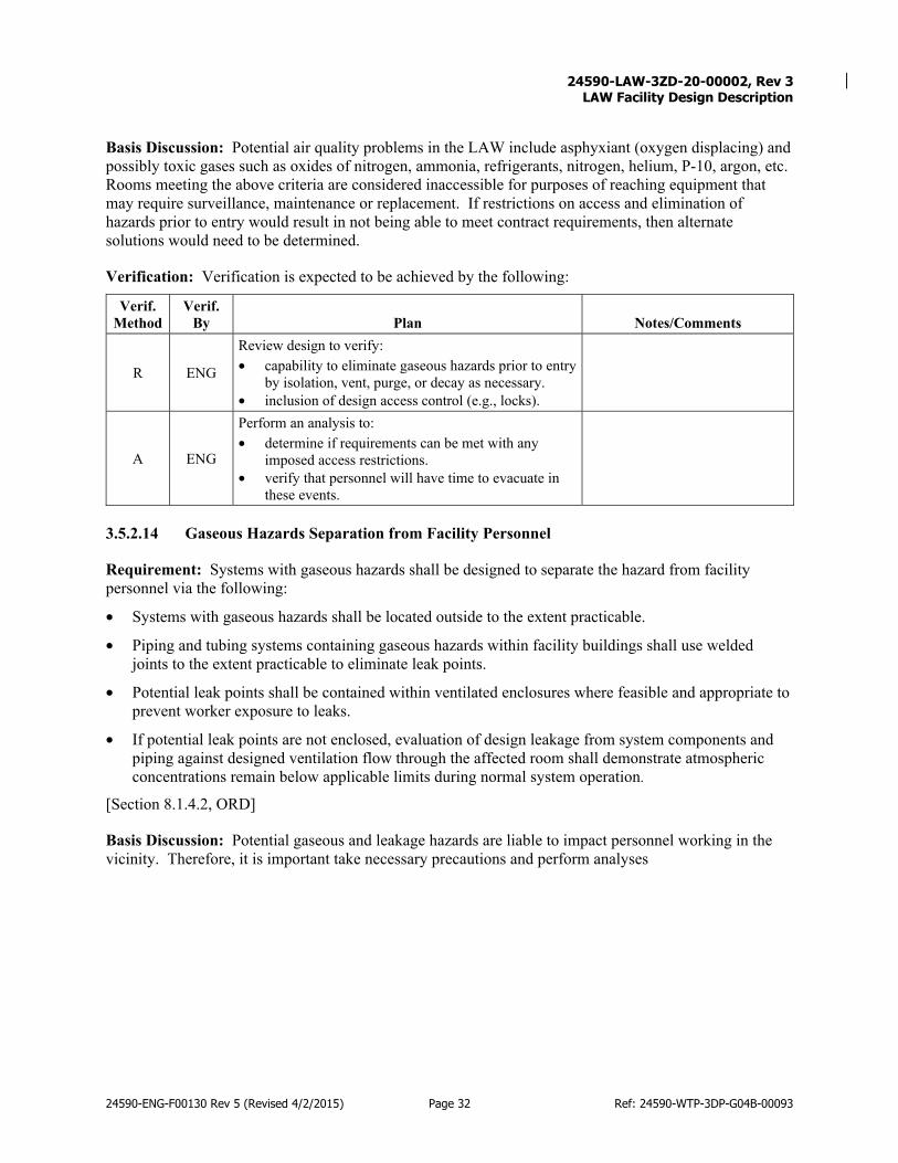
24590-LAW-3ZD-20-00002, Rev 3
LAW Facility Design Description
24590-ENG-F00130 Rev 5 (Revised 4/2/2015) Page 32 Ref: 24590-WTP-3DP-G04B-00093
Basis Discussion: Potential air quality problems in the LAW include asphyxiant (oxygen displacing) and possibly toxic gases such as oxides of nitrogen, ammonia, refrigerants, nitrogen, helium, P-10, argon, etc. Rooms meeting the above criteria are considered inaccessible for purposes of reaching equipment that may require surveillance, maintenance or replacement. If restrictions on access and elimination of hazards prior to entry would result in not being able to meet contract requirements, then alternate solutions would need to be determined.
Verification: Verification is expected to be achieved by the following:
Verif. Method
Verif. By Plan Notes/Comments
R ENG
Review design to verify: • capability to eliminate gaseous hazards prior to entry
by isolation, vent, purge, or decay as necessary. • inclusion of design access control (e.g., locks).
A ENG
Perform an analysis to: • determine if requirements can be met with any
imposed access restrictions. • verify that personnel will have time to evacuate in
these events.
3.5.2.14 Gaseous Hazards Separation from Facility Personnel
Requirement: Systems with gaseous hazards shall be designed to separate the hazard from facility personnel via the following:
• Systems with gaseous hazards shall be located outside to the extent practicable.
• Piping and tubing systems containing gaseous hazards within facility buildings shall use welded joints to the extent practicable to eliminate leak points.
• Potential leak points shall be contained within ventilated enclosures where feasible and appropriate to prevent worker exposure to leaks.
• If potential leak points are not enclosed, evaluation of design leakage from system components and piping against designed ventilation flow through the affected room shall demonstrate atmospheric concentrations remain below applicable limits during normal system operation.
[Section 8.1.4.2, ORD]
Basis Discussion: Potential gaseous and leakage hazards are liable to impact personnel working in the vicinity. Therefore, it is important take necessary precautions and perform analyses

24590-LAW-3ZD-20-00002, Rev 3
LAW Facility Design Description
24590-ENG-F00130 Rev 5 (Revised 4/2/2015) Page 33 Ref: 24590-WTP-3DP-G04B-00093
Verification: Verification is expected to be achieved by the following:
Verif. Method
Verif. By Plan Notes/Comments
R ENG
Review design to verify that: • gaseous hazards are located outside the building to
the extend practical • piping and tubing containing gaseous hazards have
used the welded joints to eliminate leak points to the extend practical
• potential leak points are contained within ventilated enclosures to the extend practical.
Beyond Design Basis Conditions
When conditions are encountered that are beyond the design basis for the facility or its associated SSCs, affected SSCs are to be considered incapable of performing their design functions until they have been subjected to performance verification. SSCs subjected to conditions outside of their environmental qualification parameters or other design limits are to be considered unqualified to perform their function. Suspension of use and replacement are governed by operational procedures and other administrative controls. There are no design requirements for beyond design basis conditions.
3.6 Nuclear Safety, ALARA, Environmental Protection, and Regulatory Requirements
Nuclear Safety
3.6.1.1 Deleted
3.6.1.2 Radiological Monitoring Equipment and Waste Storage
Requirement: The facility design shall provide sufficient space to accommodate radiological monitoring equipment at the C3/C2 and C2/C1 control area boundaries. Space for temporary radioactive waste storage and packaging area shall be provided. [Sections 9.4.13.1, 9.4.13.2, BOD][Sections 8.1.3.1.2, 12.6.1, ORD] (E.4) (F.3)
Basis Discussion: Personnel contamination monitors (PCMs) are to be installed at sub change areas and at the main C2/C1 access control point within the WTP, as identified on the plant layout drawings. These monitors are powered from the normal electrical supply (wall outlets). Calibration gas, if required, may be supplied locally (bottle) or remotely via supply line. Frisk monitors are provided at all operation exits, and at sub change areas and at the main C2/C1 access control point as a backup to PCMs. The equipment is powered from the normal electrical supply (wall outlets) or by internal batteries (friskers only). [ALARA]
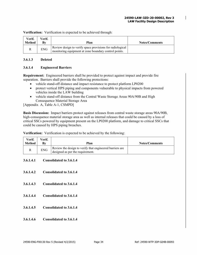
24590-LAW-3ZD-20-00002, Rev 3
LAW Facility Design Description
24590-ENG-F00130 Rev 5 (Revised 4/2/2015) Page 34 Ref: 24590-WTP-3DP-G04B-00093
Verification: Verification is expected to be achieved through:
Verif. Method
Verif. By Plan Notes/Comments
R ENG Review design to verify space provisions for radiological monitoring equipment at zone boundary control points.
3.6.1.3 Deleted
3.6.1.4 Engineered Barriers
Requirement: Engineered barriers shall be provided to protect against impact and provide fire separation. Barriers shall provide the following protections:
• vehicle stand-off distance and impact resistance to protect platform LP0200 • protect vertical HPS piping and components vulnerable to physical impacts from powered
vehicles inside the LAW building • vehicle stand-off distance from the Central Waste Storage Areas 90A/90B and High
Consequence Material Storage Area [Appendix A, Table A-1, CSMPD] Basis Discussion: Impact barriers protect against releases from central waste storage areas 90A/90B, high-consequence material storage area as well as internal releases that could be caused by a loss of critical SSCs powered by equipment present on the LP0200 platform, and damage to critical SSCs that could be caused by HPS piping breaches.
Verification: Verification is expected to be achieved by the following:
Verif. Method
Verif. By Plan Notes/Comments
R ENG Review the design to verify that engineered barriers are designed as per the requirement.
3.6.1.4.1 Consolidated to 3.6.1.4
3.6.1.4.2 Consolidated to 3.6.1.4
3.6.1.4.3 Consolidated to 3.6.1.4
3.6.1.4.4 Consolidated to 3.6.1.4
3.6.1.4.5 Consolidated to 3.6.1.4
3.6.1.4.6 Consolidated to 3.6.1.4

24590-LAW-3ZD-20-00002, Rev 3
LAW Facility Design Description
24590-ENG-F00130 Rev 5 (Revised 4/2/2015) Page 35 Ref: 24590-WTP-3DP-G04B-00093
3.6.1.4.7 Consolidated to 3.6.1.4
3.6.1.4.8 Consolidated to 3.6.1.4
3.6.1.5 Deleted
3.6.1.6 Deleted
3.6.1.7 Deleted
3.6.1.8 Deleted
3.6.1.9 Deleted
3.6.1.10 Consolidated in 3.6.1.11
3.6.1.10.1 Consolidated in 3.6.1.11.1
3.6.1.10.2 Consolidated in 3.6.1.11.1
3.6.1.11 LAW Building Structure – Seismic, Other Natural Phenomena, and Impacts
3.6.1.11.1 LAW Building Structure
Requirement: The LAW building structure, including platform LP200, shall maintain structural stability under design basis natural phenomena events. The following shall also be protected during design basis natural phenomena events:
• The structures above the LOP piping in the process area shall prevent impacting the LOP piping beneath it.
• The structures above the process and effluent cells shall protect the vertical run of LOP piping, the vessel vent line, and the bypass line from impacts.
[Appendix A, Table A-1, CSMPD] (E.1)
Basis Discussion: The structure reduces the probability of a release of radioactive and chemically hazardous material by maintaining structural stability under design basis natural phenomena events.
Verification: Verification is expected to be achieved by the following:
Verif. Method
Verif. By Plan Notes/Comments
A ENG
Perform an analysis to verify that LAW building structure, including platform LP2000, is designed to retain its structural integrity in design basis natural phenomena events, including protection of LOP piping, vessel vent lines and bypass lines.

24590-LAW-3ZD-20-00002, Rev 3
LAW Facility Design Description
24590-ENG-F00130 Rev 5 (Revised 4/2/2015) Page 36 Ref: 24590-WTP-3DP-G04B-00093
Verif. Method
Verif. By Plan Notes/Comments
R ENG Review design to verify that the LAW building structure is designed in conformance with the analyses for design basis natural phenomena events.
3.6.1.11.2 Consolidated to 3.6.1.11.1
3.6.1.12 North Melter Platform
Requirement: The North Melter Platform (LM0130) shall provide protection from design basis load impacts to offgas piping. [Appendix A, Table A-1, CSMPD]
Basis Discussion: The North Melter Platform (LM0130) framing above the LOP piping in the lower melter gallery (L-0112) protects LOP piping from design basis load impacts. The North Melter platform, LM0130, reduces the probability of a release of radioactive and chemically hazardous material caused by an impact to the offgas piping above the melter, by providing impact protection. [ALARA]
Verification: Verification is expected to be achieved through:
Verif. Method
Verif. By Plan Notes/Comments
A ENG Perform an analysis to verify that the North Melter Platform provide sufficient structural integrity to prevent design basis loads from impacting the LOP piping.
R ENG Review design to verify that the North Melter Platform conforms to the analysis to protect offgas piping from design basis load impacts.
3.6.1.13 Sloped Pads – High-Consequence Material Storage Area
Requirement: The design of the sloped pad shall prevent accumulation of flammable/combustible liquids on f the high-consequence material storage area [Appendix A, Table A-1, CSMPD]
Basis Discussion: Reduces the probability of a release of radioactive and/or chemically hazardous material by preventing the potential accumulation of flammable/combustible liquids on the High Consequence Material Storage Area, specifically around spent carbon media containers. [ALARA]
Verification: Verification is expected to be achieved through:
Verif. Method
Verif. By Plan Notes/Comments
R ENG Review civil design to verify high-consequence material storage area pad sloping.
Per 2000 International Fire Code 2704.2.2.6

24590-LAW-3ZD-20-00002, Rev 3
LAW Facility Design Description
24590-ENG-F00130 Rev 5 (Revised 4/2/2015) Page 37 Ref: 24590-WTP-3DP-G04B-00093
3.6.1.14 Spent Carbon Disposal Container
Requirement: The design of the spent carbon disposal container shall limit available oxygen and provide structural confinement of spent carbon bed media during internal and external fires and drum drops. The Spent Carbon Disposal Container shall be a DOT 7A Type A steel drum. The drum vent will limit oxygen ingress and will prevent drum over pressurization during a fire. [Appendix A, Table A-1, CSMPD] Basis Discussion: Fire-resistive spent carbon disposal containers mitigate the consequences of a release by limiting available oxygen and providing structural confinement of spent carbon bed media.
Verification: Verification is expected to be achieved through:
Verif. Method
Verif. By Plan Notes/Comments
A ENG
Perform an analysis to verify the spent carbon bed media disposal container design will maintain integrity under the design basis heat load of an internal or external fire. This includes design of the drum vent to prevent over pressurization.
R Plant ENG
Review the design to verify that the spent carbon disposal containers conform to the design analysis, including the drum vent, and that they are specified to be a DOT 7A Type A steel drum.
3.6.1.14.1 Consolidated to 3.6.1.14
3.6.1.14.2 Consolidated to 3.6.1.14
3.6.1.14.3 Consolidated to 3.6.1.14
3.6.1.14.4 Consolidated to 3.6.1.14
3.6.1.15 LAW Facility Fire Barriers
Requirement: The facility design shall provide fire separation between LVP exhauster trains to mitigate the consequence of a release of chemically hazardous material from a fire. Each LVP exhauster shall be separated by 2 hour-rated fire barriers. [Appendix A, Table A-1, CSMPD] Basis Discussion: Fire barriers mitigate the consequence of a release of radioactive and chemically hazardous material, from a fire, by providing fire separation between LVP exhauster trains (LVP-EXHR-00001A, -00001B, and -00001C).

24590-LAW-3ZD-20-00002, Rev 3
LAW Facility Design Description
24590-ENG-F00130 Rev 5 (Revised 4/2/2015) Page 38 Ref: 24590-WTP-3DP-G04B-00093
Verification: Verification is expected to be achieved through:
Verif. Method
Verif. By Plan Notes/Comments
R ENG Review design to verify each LVP exhauster train is separated from the other LVP exhauster trains by 2 hr rated fire barriers.
3.6.1.16 Safety Classifications
Requirement: The following LAW Facility SSCs shall have a safety classification of CS in accordance with the CSMPD.
Table 3-1 LAW Facility Safety Classifications
Equipment / Component Description Safety Function / Functional Requirement Classification Reference
LAW Building Structure
The LAW Building Structure, including platform LP0200 maintains structural stability under design basis natural phenomena events. The LAW Building Structure, including platform LP0200 must retain its structural integrity in design basis natural phenomena events. The structures above the LOP piping in the process area must prevent impacting the LOP piping beneath it. The structures above the process and effluent cells must protect the vertical run of LOP piping, the vessel vent line, and the bypass line from impacts .
CS Item 1, Table A-1, Appendix A, CSMPD
LAW Facility Fire Barriers (limited to fire barriers that support the credited CS function)
Provide fire separation between LVP exhauster trains to mitigate the consequence of a release of chemically hazardous material from a fire. Each LVP exhauster train shall be separated by 2 hour-rated fire barriers.
CS Item 2, Table A-1, Appendix A, CSMPD
North Melter Platform
The North Melter Platform, LM0130, provides impact protection to offgas piping. The North Melter Platform (LM0130) framing above the LOP piping in the lower melter gallery (L-0112) must protect LOP piping from design basis load impacts.
CS Item 3, Table A-1, Appendix A, CSMPD

24590-LAW-3ZD-20-00002, Rev 3
LAW Facility Design Description
24590-ENG-F00130 Rev 5 (Revised 4/2/2015) Page 39 Ref: 24590-WTP-3DP-G04B-00093
Equipment / Component Description Safety Function / Functional Requirement Classification Reference
Engineered Barriers Provides engineered barriers to protect against impact and provide fire separation. Barriers must provide the following: - vehicle stand-off distance and impact resistance to protect platform LP0200 - protect vertical HPS piping and components vulnerable to physical impacts from powered vehicles inside the LAW building - vehicle stand-off distance from the Central Waste Storage Areas 90A/90B and High Consequence Material Storage Area.
CS Item 5, Table A-1, Appendix A, CSMPD
Sloped Pads
Sloped pad prevents accumulation of flammable/combustible liquids on the High Consequence Material Storage Area. Prevent flammable liquid accumulation around spent carbon media containers. .
CS
Item 6, Table A-1, Appendix A, CSMPD
Spent Carbon Disposal Container
Limit available oxygen and providing structural confinement of spent carbon bed media during internal and external fires and drum drops. The Spent Carbon Disposal Container shall be a DOT 7A Type A steel drum. Drum vent will limit oxygen ingress and will prevent drum over pressurization during a fire.
CS
Item 53, Table A-1, Appendix A, CSMPD
[Appendix A, Table A-1, CSMPD]
Basis Discussion: None.
Verification: Verification is expected to be achieved through:
Verif. Method
Verif. By Plan Notes/Comments
R ENG Review design to verify inclusion of the assigned classifications.
ALARA
3.6.2.1 Off-Site Dose
Requirement: The LAW facility design shall support the overall WTP design requirement to ensure that exposure to the maximally exposed off-site individual (non-acute) is ALARA but not more than 1.5 mRem per year. [Section C.7, paragraph (a)(13), WTP Contract] (E.4)

24590-LAW-3ZD-20-00002, Rev 3
LAW Facility Design Description
24590-ENG-F00130 Rev 5 (Revised 4/2/2015) Page 40 Ref: 24590-WTP-3DP-G04B-00093
Basis Discussion: These limits are for WTP as a whole, taken in conjunction with the other facilities.
Verification: Verification is expected to be achieved through:
Verif. Method
Verif. By Plan Notes/Comments
R NSE
Review dose estimate from LAW and WTP, based on process model and facility design, to verify not more than 1.5 mRem per year to off-site dose receptor.
3.6.2.2 Bulges
Requirement: Design of bulges (see definition in basis discussion below) shall incorporate the following design features: • Wash rings and drains shall be provided for wash-down of all areas of the bulge. • Bulges shall include the provision of remote tools or flasks for removal and replacement of valves,
pumps, and instrumentation. • Equipment requiring maintenance (for example, process isolation valves, pumps, and instruments)
that comes into contact with the radioactive process fluids (gaseous and liquid) shall be located in stainless steel bulges/enclosures that resist the gradual buildup of contamination and are easily decontaminated. The enclosures will have installed flushing capability and drains.
• Equipment such as relief valves and rupture disks shall not release waste into the bulge area in order to minimize contamination and exposure.
• Design shall include hoists for lifting equipment in and out of the bulges. • Design shall include adequate provision for shielding to allow access to the bulge internals. • Design shall include a layout allowing maintenance access (e.g., work platform) and survey room for
removal and installation of equipment. [Sections 10.4, 14.1, ORD][Section 11.3.2.7, BOD] (C.1) (E.4)
Basis Discussion: The terms “bulge”, “cabinet”, and “enclosure” are synonymous for purposes of this requirement and refer to radiological confinement /containment structures. Bulges are an extension of the R5/C5 process cells and the equipment is contained in an appropriately shielded area within adjacent galleries or corridors with lower radiation/contamination levels to improve access. Exceptions to the requirements for bulges, cabinets, and enclosures should be approved by either the LAW facility Operations Lead/Manager or the Commissioning Operations Manager. Exceptions should primarily be considered for systems containing only post-ion-exchange process fluids. Examples of exceptions include:
• Use of hardened piping and double sealed valves in lieu of placing components in an enclosure or bulge;
• Use of a non-stainless steel enclosure designed for confinement only, without flush or drain capability or hoisting and lifting equipment.
[ALARA]

24590-LAW-3ZD-20-00002, Rev 3
LAW Facility Design Description
24590-ENG-F00130 Rev 5 (Revised 4/2/2015) Page 41 Ref: 24590-WTP-3DP-G04B-00093
Verification: Verification is expected to be achieved through:
Verif. Method
Verif. By Plan Notes/Comments
A ENG Verify analyses prepared documenting bulge shielding requirements
R ENG Review bulge/enclosure designs to verify conformance to identified requirements, including shielding analysis.
3.6.2.3 In-Cell/Cave Decontamination Capabilities
Requirement: LAW facility design shall include provisions for decontamination of designated cell/cave areas to reduce contamination levels and personnel exposure.
Accommodating features include impermeable wall and floor coverings, such as epoxy coatings or stainless steel liners and alternate methods of decontamination, such as CO2 pellets or steam will be employed. • In-cell/cave wash down capabilities, including spray rings and water jets in inaccessible areas, shall
be provided in the areas listed above to aid decontamination and deactivation of the stainless steel lined areas and floors with special protective coatings.
• Cells shall have special protective coatings/sealants applied to surfaces where required by environmental permits or regulations.
• Special protective coatings/sealants (to allow wet decontamination of surfaces with water, dilute nitric, and/or dilute caustic solutions without damaging the coated surface) shall be applied in C3 and C3/C5 areas, and where required by environmental permits or regulations
• Vertical and horizontal surfaces in C3 and C3/C5 areas shall be decontaminatable as required for ALARA operational or maintenance exposure
• Sumps shall be installed at a low point in the cave/cell areas noted above (i.e., those areas that have a decontamination/wash-down capability).
• The sumps shall have a means of emptying. • In-cell/cave handling equipment shall be maintained in a dedicated C3/R3 maintenance area or
workshop after being decontaminated to a level that will allow hands-on maintenance. • Features in place to facilitate in-cell/cave cleaning and periodic decontamination (for the stainless-
steel-lined portion). Also, where possible, periodic line flushes and tank clean-out capability shall be provided for use during operations.
• Vaults shall be constructed with chemical-resistant water stops in place at all joints. [Sections 9.1, 13.1, 13.4, 20.0, ORD][Section 14.10.1.2.2, BOD] (C.1) (E.4)
Basis Discussion: This design requirement is based on ALARA and WAC design principles. Decontamination capabilities are appropriate for areas anticipated to have significant contamination, e.g., C5 areas, especially areas requiring worker access. Decontamination of inaccessible areas may be appropriate to lower radiological dose levels and to support decommissioning. The following provisions support this requirement:
The designated C5 cells/caves that include provisions to accommodate spray decontamination include: • L-0123 Wet Process Cell

24590-LAW-3ZD-20-00002, Rev 3
LAW Facility Design Description
24590-ENG-F00130 Rev 5 (Revised 4/2/2015) Page 42 Ref: 24590-WTP-3DP-G04B-00093
• L-0124 Wet Process Cell • L-0126 Effluent Cell Accommodating features include impermeable wall and floor coverings, such as epoxy coatings or stainless steel liners and fixed spray heads for remote decontamination or hose outlets for manual wash-down, and sumps to direct decontaminated wastes to the RLD system.
Areas that cannot accommodate liquid spray decontamination due to thermally hot containers include: • L-B025B Container Transfer Corridor • L-B025C Container Buffer Storage Area • L-B025D Container Rework • L-B015A Melter 1 Pour Cave • L-B013C Melter 1 Pour Cave • L-B013B Melter 2 Pour Cave • L-B011C Melter 2 Pour Cave [ALARA]
Verification: Verification is expected to be achieved through:
Verif. Method
Verif. By Plan Notes/Comments
R ENG Review design to verify decontamination provisions (e.g., sumps, floor coatings, spray rings, etc.) are provided as applicable for the area
3.6.2.4 Floor Hatches
Requirement: Where there is potential for equipment failure within a high radiation area (not black cells), means shall be provided for recovery of that equipment. Recovery shall be accomplished by using either routine remote maintenance or, where permissible, manned intervention. [Section 9.1, ORD] (E.4)
Basis Discussion: Room L-0202 is classified as C3/R3. Where there is potential for equipment failure within higher than normal radiation areas, means shall be provided for recovery of that equipment. Recovery is to be accomplished by using remote equipment and manned intervention. Manned intervention is not an acceptable means for routine maintenance, but the capability shall be designed into the facility for off-normal recovery operations, such as strategically located plugs in cave or cell walls, roofs with special lifting and handling equipment, specially designed systems, a means of isolation in the cell or cave, and equipment connections. [ALARA]
Verification: Verification is expected to be achieved through:
Verif. Method
Verif. By Plan Notes/Comments
R ENG Review design to verify the means for recovery is provided where necessary.

24590-LAW-3ZD-20-00002, Rev 3
LAW Facility Design Description
24590-ENG-F00130 Rev 5 (Revised 4/2/2015) Page 43 Ref: 24590-WTP-3DP-G04B-00093
3.6.2.5 Stainless Steel Liners/ Protective Coating
Requirement: Stainless steel liners shall be used where appropriate. The walls above the steel shall be sealed with suitable finishes depending upon the conditions and as established by ALARA Design Review for the special protective coatings. Stainless steel liners and special protective coatings/sealants shall be applied to surfaces where required by environmental permits or regulations. [Sections 13.4, 14.9, 20.0, ORD] (E.4)
Basis Discussion: Design features that simplify and facilitate decontamination and decommissioning, minimize contaminated equipment, and minimize the generation of radioactive waste during deactivation, decontamination, and decommissioning are identified during the planning and design phase based upon anticipated decommissioning methods. Consideration of design features in support of this requirement is through the ALARA Design Review process, which establishes requirements specific to individual SSCs. [ALARA]
Verification: Verification is expected to be achieved through:
Verif. Method
Verif. By Plan Notes/Comments
R ENG
Review design to verify facility conforms to requirement to provide stainless steel liners/coating in locations identified in the facility coating schedule (as accepted in the DWP).
3.6.2.6 Provide for Rapid Evacuation Under Emergency Conditions
Requirement: No physical control(s) shall be installed at any security, radiological, or other area exit that would prevent rapid evacuation of personnel under emergency conditions (Life Safety Code). [Section 8.1.3, ORD] (E.4) (F.3)
Basis Discussion: It is imperative that radiological control area design permits rapid evacuation in the event of an emergency. Immediate threats to life or health due to an emergency outweigh concerns of potential inadvertent spread of contamination from evacuating personnel. [ALARA]
Verification: Verification is expected to be achieved through:
Verif. Method
Verif. By Plan Notes/Comments
R ENG
Review design to verify no physical control(s) are installed at any security, radiological, or other area exit that would prevent rapid evacuation of personnel under emergency conditions (Life Safety Code).
3.6.2.7 Access Control to High Radiation Areas
Requirement: The LAW facility shall be designed with one or more of the following physical controls to be used for each entrance or access point to a high radiation area (area classified R5):
• A control device that prevents entry to the area when high radiation levels exist or that, upon entry, causes the radiation level to be reduced below the level that defines a high radiation area;

24590-LAW-3ZD-20-00002, Rev 3
LAW Facility Design Description
24590-ENG-F00130 Rev 5 (Revised 4/2/2015) Page 44 Ref: 24590-WTP-3DP-G04B-00093
• A device that functions automatically to prevent use or operation of the radiation source or field while individuals are in the area;
• A control device that energizes a conspicuous visible or audible alarm signal so that the individual entering the high radiation area and the supervisor of the activity are made aware of the entry;
• Entryways that are locked. During periods when access to the area is required, positive control over each entry is maintained;
• Continuous direct or electronic surveillance that is capable of preventing unauthorized entry; • A control device that will automatically generate audible and visual alarm signals to alert personnel in
the area before use or operation of the radiation source and in sufficient time to permit evacuation of the area or activation of a secondary control device that will prevent use or operation of the source.
[Appendix A, Subpart F, Requirement 63, RPP] (E.4) Basis Discussion: While 10 CFR 835.502(b) specifies the imposition of the above requirement for physical controls where radiation levels exist such that an individual could exceed an equivalent dose to the whole body of 1 rem (0.01 Sv) in any one hour at 30 centimeters from the source or from any surface that the radiation penetrates, for purposes of conservatism and worker safety, the above controls are to be applied at the entry point for a high radiation area (see definitions below). High radiation area: “Any area, accessible to individuals, in which radiation levels could result in an individual receiving an equivalent dose to the whole body in excess of 0.1 rem (0.001 Sv) in 1 hour at 30 centimeters from the radiation source or from any surface that the radiation penetrates.” (10 CFR 835.2) [ALARA]
Verification: Verification is expected to be achieved through:
Verif. Method
Verif. By Plan Notes/Comments
R ENG
Review of design for conformance to specified requirements for access controls, including any additional requirements or restrictions imposed by associated ALARA Design Review (ADR).
3.6.2.8 Allowances for Breathing Air
Requirement: The following allowances shall be made for breathing air services:
• Wall/door penetrations shall be available to alleviate doors needing to be propped open and hoses potentially being pinched and damaged.
• Protective access doors shall remain open, with a second non-shielded door with access ports provided to allow hoses to be routed into area without being pinched.
[Section 14.6, ORD] (B.1) (E.4)
Basis Discussion: These design requirements implement ALARA design principles and Dangerous Waste Permit conditions. [ALARA]

24590-LAW-3ZD-20-00002, Rev 3
LAW Facility Design Description
24590-ENG-F00130 Rev 5 (Revised 4/2/2015) Page 45 Ref: 24590-WTP-3DP-G04B-00093
Verification: Verification is expected to be achieved through:
Verif. Method
Verif. By Plan Notes/Comments
R ENG Review design to confirm allowances for breathing air services are included.
3.6.2.9 Decontamination and Functionality Degradation
Requirement: The equipment subject to decontamination shall be designed to withstand the process without any reduction of functionality through degradation of the electrical, mechanical, or any other components involved. [Section 9.1, ORD] (E.4)
Basis Discussion: The process equipment needs to be designed to bear the effects of decontamination without negative impacts to the functionality. [ALARA]
Verification: Verification is expected to be achieved through:
Verif. Method
Verif. By Plan Notes/Comments
R ENG Review the design to verify equipment can withstand decontamination as necessary.
3.6.2.10 Area Radiation Monitors
Requirement: The Area Radiation Monitors (ARMs) measure gamma radiation levels and shall be provided as follows: • ARMs shall be provided as required in the LAW facility at appropriate locations. Each monitor shall
have local audible and visual alarms and be of sufficient sensitivity to alert individuals near the monitor that immediate action is necessary to minimize exposure to radiation.
• Local and remote alarms shall be provided for instrument failure and for high radiation. Failure alarms shall be separate from high-radiation alarms.
• Audible and visible alarm signals and real-time readout shall be available at the rate meter via an Alarm Beacon and sounder. The design shall support the use of slave alarms (audible and visual) when detectors are located in rooms separate from the rate meters. The audible and visual alarm signal shall remain energized until manually reset (shall not self-clear).
• The ARM system design shall provide for a minimum of one radiation alarms with adjustable set points and for the transmission of a real-time readout of the detected signal to the facility Process Control System.
• Interlocking the gamma detectors with doors in high-radiation areas shall be considered, to provide access control.
[Section 12.6.2.1, ORD] (E.4)
Basis Discussion: Area radiation monitors are provided to alert personnel to evacuate the facility and to inform the control room operator regarding the release of radiation. The requirement states “as required”. Since Radiological Engineering has performed an evaluation to determine that ARMs are not required for LAW. Therefore, the requirement need not be implemented.

24590-LAW-3ZD-20-00002, Rev 3
LAW Facility Design Description
24590-ENG-F00130 Rev 5 (Revised 4/2/2015) Page 46 Ref: 24590-WTP-3DP-G04B-00093
Verification: Verification is expected to be achieved through:
Verif. Method
Verif. By Plan Notes/Comments
R ENG Review of design for conformance to specified requirements for area radiation monitors
3.6.2.11 Decontamination Means
Requirement: Where decontamination is applicable, a means for decontamination shall be provided, such as carbon dioxide, pressurized warm water, detergent solution, steam, or other appropriate method. Facilities for the decontamination shall be provided, including disposal of the waste liquid. [Section 14.16, ORD] (E.4)
Basis Discussion: The decontamination process needs the means for appropriate functionality. [ALARA]
Verification: Verification is expected to be achieved through:
Verif. Method
Verif. By Plan Notes/Comments
R ENG
Review design of decontamination areas for availability of carbon dioxide, pressurized warm water, detergent solution, steam, or other appropriate method, and provisions for disposal of waste liquid.
3.6.2.12 Glove Boxes
Requirement: The glove boxes shall satisfy the following design requirements: • Access to plant equipment shall be maximized. • Assessment of normal, abnormal, and maintenance conditions shall be required in the design of the
glove box. • The accessibility of all maintainable items shall be demonstrated through mock up, simulation, or
start-up. • Glove port positioning shall take into account typical operator size and strength within the limiting
environment of a glove box. • There shall be no sharp edges or the potential to generate sharp edges within a glove box or wash
cabinet. • The use of braided metal hosing, glass, or plastic (that is likely to degrade) is to be avoided unless
suitable justification is provided. • Equipment within glove boxes shall be minimized and the use of common supplies maximized. • Gloveboxes shall be held at negative pressure relative to their room location. A differential pressure
indicator should be mounted to the gloveboxes. • To prevent the potential for siphoning of hot liquid into the secondary containment, the glove box
shall be located at least one barometric head above the primary vessel. • Wherever practical glove boxes will be designed to contain the minimum volume of active liquid
bearing piping.

24590-LAW-3ZD-20-00002, Rev 3
LAW Facility Design Description
24590-ENG-F00130 Rev 5 (Revised 4/2/2015) Page 47 Ref: 24590-WTP-3DP-G04B-00093
• The impact of temperature, shielding, and environment (acid vapor and corrosion) shall be taken into account in the design, in terms of corrosion of mild steel, degradation of gloves, and accessibility to equipment.
• Dismantling of plant and equipment contained within glove boxes shall be simple and easy. Direct handling will be minimized through modularization or lifting equipment.
• All valves and instruments within a glove box shall be labeled clearly. • Suitable design precautions shall be taken to prevent the migration of contaminates into the secondary
containment via the process line (for example, seal pots/loops, vacuum breakers, or air purges). [Section 14.15, ORD] (E.4) Basis Discussion: The design of glove boxes plays an important role in preventing the migration of contamination in the facility. [ALARA] Verification: Verification is expected to be achieved through:
Verif. Method
Verif. By Plan Notes/Comments
R ENG Review LAW glove box design to adequately satisfies the stated requirements.
A/T ENG/ SUP
Verify the accessibility of all maintainable items are demonstrated through mock up, simulation, or start-up
Environmental Protection
A tank system, as defined in WAC 173-303-040, means a dangerous waste storage or treatment tank and it’s associated ancillary equipment and secondary containment system. Requirements for tank system design and integrity assessments are identified in WAC 173-303-640. Design requirements for tank systems are allocated to either this FDD or to SDDs as applicable. The tank systems design requirements in this FDD are specific to the physical structure of the LAW facility (i.e., liners, sumps, slabs, vaults, cells, leak detection systems etc.).
3.6.3.1 Deleted
3.6.3.2 Deleted
3.6.3.3 Deleted
3.6.3.4 Facility Design Requirements for Dangerous Waste Tanks
3.6.3.4.1 Tank Foundations
Requirement: The tank foundations shall be designed to maintain the load imparted by the filled tank, plus the secondary containment structure. (WAC 173-303-640 [3][a][v][A]) [Section 14.10.1, 14.10.2.1, BOD] (E3)
Basis Discussion: Requirement applies to LAW dangerous waste tanks in vessel cells or vaults that provide structural support for dangerous waste tanks or vessels This requirement is implemented through

24590-LAW-3ZD-20-00002, Rev 3
LAW Facility Design Description
24590-ENG-F00130 Rev 5 (Revised 4/2/2015) Page 48 Ref: 24590-WTP-3DP-G04B-00093
design in accordance with structural codes and standards as defined in the codes of record established in the BOD.
Verification: Verification is expected to be achieved through:
Verif. Method
Verif. By Plan Notes/Comments
R ENG Review of design and associated analyses to verify the facility supports the load of filled DWP tanks/vessels along with ancillary equipment.
Document in IQRPE report prepared in accordance with WAC requirements
3.6.3.4.2 Frost Heave Effects
Requirement: The tank system shall be designed to withstand the effects of frost heave, if applicable (WAC 173-303-640 [3][a][v][C]). [Section 14.10.1, BOD]
Basis Discussion: Requirement applies to LAW dangerous waste tanks in vessel cells or vaults that provide structural support for dangerous waste tanks or vessels. Note that base slabs of process buildings are well below the frost penetration level and therefore preclude frost penetration beneath the building.
Verification: Verification is expected to be achieved through:
Verif. Method
Verif. By Plan Notes/Comments
R ENG Verify that tank system will withstand the effects of frost heave, if applicable.
Document in IQRPE report prepared in accordance with WAC requirements
3.6.3.4.3 Support and Protect Ancillary Equipment
Requirement: Ancillary equipment shall be designed in such a way that it is supported and protected against physical damage and excessive stress due to settlement, vibration, expansion, or contraction (WAC 173-303-640[3][f]). [Section III.10.E.9, DWP][Section 14.10.1, BOD]
Basis Discussion: Requirement applies to LAW dangerous waste tanks in vessel cells or vaults that provide structural support for dangerous waste tanks or vessels.
Verification: Verification is expected to be achieved through:
Verif. Method
Verif. By Plan Notes/Comments
R ENG
Verify that ancillary equipment has been designed so it is supported and protected against physical damage and excessive stress due to settlement, vibration, expansion, or contraction.
Document in IQRPE report prepared in accordance with WAC requirements
3.6.3.4.4 Backfill Material
Requirement: Backfill material for tank systems or components that are placed underground shall be specified to be non-corrosive, porous, and homogeneous. Backfill material shall be placed completely around the tank system components and compacted so that the components are uniformly supported

24590-LAW-3ZD-20-00002, Rev 3
LAW Facility Design Description
24590-ENG-F00130 Rev 5 (Revised 4/2/2015) Page 49 Ref: 24590-WTP-3DP-G04B-00093
(WAC 173-303-640[3][d]). [Sections III.10.E.3.b, III.10.H.1.a, III.10.J.1.a.v, DWP][Section 14.10.1, BOD]
Basis Discussion: Requirement applies to dangerous waste tanks in vessel cells or vaults that provide structural support for dangerous waste tanks or vessels.
Verification: Verification is expected to be achieved through:
Verif. Method
Verif. By Plan Notes/Comments
R ENG
Verify that backfill materials for tank systems or components are specified non-corrosive, porous, and homogeneous and that backfill placement will be completely around the tank system components and properly compacted.
Document in IQRPE report prepared in accordance with WAC requirements
3.6.3.4.5 Prevent Escape of Vapors
Requirement: The tank system shall be designed to prevent escape of vapors, fumes, or other emissions into the air if the tank holds materials that are acutely or chronically toxic by inhalation (WAC 173-303-640[5][e]). [Section III.10.E.5.m, DWP][Section 14.10.1, BOD]
Basis Discussion: Requirement applies to LAW dangerous waste tanks in vessel cells or vaults that provide structural support for dangerous waste tanks or vessels.
Verification: Verification is expected to be achieved through:
Verif. Method
Verif. By Plan Notes/Comments
R ENG Verify that tank system design prevents release of toxic vapors, fumes, or other emissions.
Document in IQRPE report prepared in accordance with WAC requirements
3.6.3.4.6 Deleted
3.6.3.4.7 Spill Prevention
Requirement: The design shall include: • Spill prevention controls (for example, check valves, dry-disconnect couplings). (WAC 173-303-
640[5][b][i]) • Appropriate controls used to prevent spills and overflows from tank or containment systems. (WAC
173-303-640[5][b]) [Section 14.10.1.1, BOD]
Basis Discussion: Requirement applies to LAW dangerous waste tanks, containment systems, check valves and dry-disconnect couplings. Overfill prevention controls are needed (for example, level sensing devices, high-level alarms, automatic feed cutoff, pressure-sensing devices, or bypass to a standby tank).

24590-LAW-3ZD-20-00002, Rev 3
LAW Facility Design Description
24590-ENG-F00130 Rev 5 (Revised 4/2/2015) Page 50 Ref: 24590-WTP-3DP-G04B-00093
Verification: Verification is expected to be achieved through:
Verif. Method
Verif. By Plan Notes/Comments
R ENG Review design to verify appropriate controls are used to prevent spills and overflows from tanks or containment systems.
3.6.3.5 General Secondary Containment System Design Requirements and Performance Standards
3.6.3.5.1 Secondary Containment Design for Tank Systems
Requirement: The LAW Facility vessels and ancillary equipment that handle dangerous waste shall have secondary containment or be visually inspected for leaks on a daily basis in accordance with WAC 173-303-640(4) to prevent migration of wastes or accumulated liquid out of the system. Liners, vaults, double-walled tanks or equivalent devices, as approved by Ecology, shall be used as secondary containment for tank systems (WAC 173-303-640[4][d][i], -[ii], -[iii], and [-iv]). Tank systems including sumps that serve as part of a secondary containment system are exempted from the requirements for secondary containment (WAC 173-303-640[1][c]). [Section 14.10.1.2, BOD] (E3)
Basis Discussion: Requirement applies to secondary containment provided by the LAW facility for tank systems. Stainless steel liners and special protective coatings/sealants are applied to surfaces where required by environmental permits or regulations.
Verification: Verification is expected to be achieved through:
Verif. Method
Verif. By Plan Notes/Comments
R ENG
Review design to verify that liners, vaults, double-walled tanks or equivalent devices, approved by Ecology, are included as secondary containment for tank systems.
Document in IQRPE report prepared in accordance with WAC requirements
3.6.3.5.2 Migration of Liquids/Leak Collection and Construction Material
Requirement: The secondary containment system shall be designed and constructed to: • Prevent any migration of wastes or accumulated liquid out of the system to the soil, ground water, or
surface water at any time during the use of the tank system. (WAC 173-303-640[4][b][i]) • Detect and collect releases and accumulated liquids until the collected material is removed (WAC
173-303-640[4][b][ii]) • Material that is compatible with the waste to be placed in the tank system (WAC 173-303-
640[4][c][i]) [Section 14.10.1.2, BOD] (E3)
Basis Discussion: Requirement applies to secondary containment provided by the LAW facility.

24590-LAW-3ZD-20-00002, Rev 3
LAW Facility Design Description
24590-ENG-F00130 Rev 5 (Revised 4/2/2015) Page 51 Ref: 24590-WTP-3DP-G04B-00093
Verification: Verification is expected to be achieved through:
Verif. Method
Verif. By Plan Notes/Comments
R ENG
Review the design to verify that the secondary containment: • Prevents wastes or accumulated liquids from
migrating to the soil, ground water, or surface water.
• Detects and collects released liquids. • Material used for construction is compatible
with waste placed in system.
Document in IQRPE report prepared in accordance with WAC requirements
3.6.3.5.3 Deleted
3.6.3.5.4 Deleted
3.6.3.5.5 Strength and Thickness
Requirement: The design of tank secondary containment shall provide sufficient strength and thickness to prevent failure owing to: • Pressure gradients, including static head and external hydrological forces • Physical contact with the waste • Climatic conditions • The stress of daily operation, including stresses from nearby vehicle traffic (WAC 173-303-640[4][c][i]) (WAC 173-303-640[4][c][ii])
[Section III.10.E.9.b, DWP][Section 14.10.1.2, BOD] (E3)
Basis Discussion: This requirement is implemented through design in accordance with structural codes and standards as defined in the codes of record established in the BOD. [ALARA]
Verification: Verification is expected to be achieved through:
Verif. Method
Verif. By Plan Notes/Comments
R ENG Review secondary containment design to verify conformance with WAC 173-303-640[4][c][i].
Document in IQRPE report prepared in accordance with WAC requirements
3.6.3.5.6 Foundation or Base
Requirement: The secondary containment system shall be placed on a foundation or base capable of • Supporting the secondary containment system • Resisting the pressure gradients above and below the system • Preventing failure due to settlement, compression, or uplift (WAC 173-303-640[4][c][ii])
[Section III.10.E.9.b, DWP][Section 14.10.1.2, BOD] (E3)

24590-LAW-3ZD-20-00002, Rev 3
LAW Facility Design Description
24590-ENG-F00130 Rev 5 (Revised 4/2/2015) Page 52 Ref: 24590-WTP-3DP-G04B-00093
Basis Discussion: This requirement is implemented through design in accordance with structural codes and standards as defined in the codes of record established in the BOD. [ALARA]
Verification: Verification is expected to be achieved through:
Verif. Method
Verif. By Plan Notes/Comments
R ENG Review secondary containment design to verify conformance with WAC 173-303-640[4][c][ii].
Document in IQRPE report prepared in accordance with WAC requirements
3.6.3.5.7 Leak Detection
Requirement: The secondary containment system shall provide a leak-detection system that will detect the failure of primary tank system or the secondary containment system, the presence of any release of mixed or dangerous waste, or accumulated liquid in the secondary containment system within 24 hours of a leak (WAC 173-303-640[3][f]).
Note: Ecology must be notified if the releases or accumulated liquid cannot be accomplished within 24 hours.
[Sections III.10.E.9.d, III.10.E.9.e, III.10.E.5.b, DWP][Section 14.10.1.2, BOD] (E.3)
Basis Discussion: This requirement is implemented through design in accordance with structural codes and standards as defined in the codes of record established in the BOD. Note: Ecology has interpreted this requirement to mean the detection of 0.1 gallons per hour based on DWP condition III.10.E.9.e.ii. [ALARA]
Verification: Verification is expected to be achieved through:
Verif. Method
Verif. By Plan Notes/Comments
R ENG Review secondary containment design to verify conformance with the requirement.
Document in IQRPE report prepared in accordance with WAC requirements
3.6.3.5.8 Secondary Containment Drainage
Requirement: The secondary containment system shall slope or be operated to drain and remove liquids resulting from leaks, spills, or precipitation within 24 hours of a leak detection. (WAC 173-303-640[4][c][iv]) Provide a minimum of 1% floor slope as specified in the Secondary Containment Design Document located in Appendix 7.5 of the DWP. [Section III.10.G.5.k, DWP][Section 14.10.1.2, BOD] (E.3)
Basis Discussion: This requirement is implemented through design in accordance with structural codes and standards as defined in the codes of record established in the BOD. [ALARA]
Verification: Verification is expected to be achieved through:
Verif. Method
Verif. By Plan Notes/Comments
R ENG Review secondary containment design to verify conformance with the requirement.
Document in IQRPE report prepared in accordance with WAC requirements

24590-LAW-3ZD-20-00002, Rev 3
LAW Facility Design Description
24590-ENG-F00130 Rev 5 (Revised 4/2/2015) Page 53 Ref: 24590-WTP-3DP-G04B-00093
3.6.3.5.9 Liquids Removal
Requirement: The secondary containment system shall be designed to remove spills, leaks, or accumulated liquid from the secondary containment system within 24 hours or in as timely a manner as possible (WAC 173-303- 640[4][c][iv]). [Section 14.10.1.2, BOD]
Basis Discussion: This requirement is implemented through design in accordance with structural codes and standards as defined in the codes of record established in the BOD. Note: Ecology must be notified if the releases or accumulated liquid cannot be accomplished within 24 hours. [ALARA]
Verification: Verification is expected to be achieved through: Verif.
Method Verif.
By Plan Notes/Comments
R ENG Review secondary containment design to verify conformance with WAC 173-303-640[4][c][iv].
Document in IQRPE report prepared in accordance with WAC requirements
3.6.3.5.10 Inspectability – Secondary Containment
Requirement: The secondary containment system shall provide means to inspect the visible portion of the secondary containment system on a daily basis (WAC 173-303-640[6][b][iii]). [Section III.10.E.9.b, DWP][Section 14.10.1.2, BOD] (E.3)
Basis Discussion: This requirement is implemented through design in accordance with structural codes and standards as defined in the codes of record established in the BOD. [ALARA]
Verification: Verification is expected to be achieved through:
Verif. Method
Verif. By Plan Notes/Comments
R ENG Review secondary containment design to verify conformance with the requirement.
Document in IQRPE report prepared in accordance with WAC requirements
3.6.3.5.11 Moved to 3.6.3.6.7
3.6.3.6 Design and Performance Standards for Vaults and External Liners
The following applies to vaults and external liners used as secondary containment for dangerous waste.
3.6.3.6.1 Vaults - Capacity
Requirement: Vaults shall contain 100 % of the capacity of the largest tank plus volume of fire-protection water, if applicable, over the minimum design area for a period of 20 minutes. [Sections 14.10.1.2.1, 14.10.1.2.2, BOD] (E3)
Basis Discussion: One hundred percent capacity means the total volume of the largest tank in the secondary containment area. It is not the expected process volume of the tank or the volume at the level where overflow prevention measures are implemented (WAC 173-303-640[4][e][ii][A]). Fire protection volume requirement is not applicable to vaults or cells without water fire suppression. Liner heights for vaults are calculated in 24590-LAW-PER-M-02-002, Dangerous Waste Permit (DWP) Liner Heights in the LAW Facility.
24590-LAW-3ZD-20-00002, Rev 3
LAW Facility Design Description
24590-ENG-F00130 Rev 5 (Revised 4/2/2015) Page 54 Ref: 24590-WTP-3DP-G04B-00093
Verification: Verification is expected to be achieved through:
Verif. Method
Verif. By Plan Notes/Comments
R ENG
Review design to verify that each vault (cell) can contain 100% of the largest vessel’s total volume plus volume of fire-protection water, if applicable, over the minimum design area for a period of 20 minutes.
Document in IQRPE report prepared in accordance with WAC requirements
3.6.3.6.2 Vaults - Run-on or Infiltration
Requirement: Vaults shall prevent run-on or infiltration into the containment system, unless the containment system has the capacity to contain precipitation from a 25-year, 24-hour rainfall event (WAC 173-303-640[4][e][ii][B]). [Section 14.10.1.2.2, BOD]
Basis Discussion: None.
Verification: Verification is expected to be achieved through:
Verif. Method
Verif. By Plan Notes/Comments
R ENG Verify that run-on or infiltration into the containment is prevented.
3.6.3.6.3 Vaults - Water Stops
Requirement: Vaults shall be constructed with chemical-resistant water stops in place at all joints (if any) (WAC 173-303-640[4][e][ii][C]). [Section 14.10.1.2.2, BOD] (E3)
Basis Discussion: Requirement applies to secondary containment systems. [ALARA].
Verification: Verification is expected to be achieved through:
Verif. Method
Verif. By Plan Notes/Comments
R ENG
Review design to verify vaults have chemical-resistant water stops in place at all joints. Water stops are not required in secondary containment areas provided with stainless steel liners.
3.6.3.6.4 Vaults - Liners and Coatings
Requirement: Vaults shall be provided with an impermeable interior coating or lining that is compatible with the stored waste that will prevent migration of waste into the concrete (WAC 173-303-640[4][e][ii][D]). [Section 14.10.1.2.2, BOD](E.3)
Basis Discussion: Requirement applies to secondary containment systems. [ALARA]

24590-LAW-3ZD-20-00002, Rev 3
LAW Facility Design Description
24590-ENG-F00130 Rev 5 (Revised 4/2/2015) Page 55 Ref: 24590-WTP-3DP-G04B-00093
Verification: Verification is expected to be achieved through:
Verif. Method
Verif. By Plan Notes/Comments
R ENG Review design to verify that impermeable interior coating or lining is provided in vaults used for secondary confinement
3.6.3.6.5 Vaults - Ignition of Vapors
Requirement: Vaults shall provide a means to protect against the formation of ignitable vapors within the vault if the waste being stored or treated (WAC 173-303-640[4][e][ii][E]) • Meets the definition of ignitable waste under WAC 173-303-090(5) or • Meets the definition of reactive waste under WAC 173-303-090(7) and may form an ignitable or
explosive vapor. [Section 14.10.1.2.2, BOD]
Basis Discussion: None.
Verification: Verification is expected to be achieved through:
Verif. Method
Verif. By Plan Notes/Comments
R ENG Verify that vaults have a means to protect against the formation of ignitable vapors
3.6.3.6.6 Vaults - Moisture Barrier
Requirement: Vaults shall be provided with an exterior moisture barrier or be otherwise designed or operated to prevent migration of moisture into the vault if the vault is subject to hydraulic pressure (WAC 173-303-640[4][e][ii][F]). [Section 14.10.1.2.2, BOD] (E.3)
Basis Discussion: Requirement applies to secondary containment systems.
Verification: Verification is expected to be achieved through:
Verif. Method
Verif. By Plan Notes/Comments
R ENG Verify that exterior moisture barrier is provided if the vault is subject to hydraulic pressure
3.6.3.6.7 External Liners - Liner Capacity (moved from 3.6.3.5.11)
Requirement: External liners shall be designed to handle 100% capacity of the largest tank plus volume of fire-protection water over the minimum design area for a period of 20 minutes (WAC 173-303-640[4][e][ii][A]). [Section 14.10.1.2.1, BOD] (E.3)
Basis Discussion: One hundred percent capacity means the total internal volume of the tank. It is not the expected process volume of the tank or the volume at the level where overflow prevention measures are

24590-LAW-3ZD-20-00002, Rev 3
LAW Facility Design Description
24590-ENG-F00130 Rev 5 (Revised 4/2/2015) Page 56 Ref: 24590-WTP-3DP-G04B-00093
implemented. Typical civil structural details can be found in Appendix 7.5 of the dangerous waste permit. Some of the specified means of verification may be satisfied by review documented in a report by an Independent Qualified Registered Professional Engineer (IQRPE) prepared in accordance with WAC requirements. NOTE: Transfer capability of the sumps covered by the DWP leak detection requirement should be verified under the RLD System verifications. Requirement applies to secondary containment systems. Fire protection volume requirement is not applicable to vaults or cells without water fire suppression. [ALARA]
Verification: Verification is expected to be achieved through:
Verif. Method
Verif. By Plan Notes/Comments
R ENG Verify liner design can accommodate 100% capacity of the largest vessel plus 20 minutes of fire suppression (if applicable).
Document in IQRPE report prepared in accordance with WAC requirements.
3.6.3.6.8 External Liners - Run-on or Infiltration
Requirement: External liners shall prevent run-on or infiltration into the containment system, unless the containment system has the capacity to contain precipitation from a 25-year, 24-hour rainfall event (WAC 173-303-640[4][e][i][B]). [Section 14.10.1.2.1, BOD]
Basis Discussion: None.
Verification: Verification is expected to be achieved through:
Verif. Method
Verif. By Plan Notes/Comments
R ENG/ ESH
Verify that run-on or infiltration into the containment is prevented.
3.6.3.6.9 External Liners - Liner Coverage
Requirement: External liners shall surround the tank completely and cover all surrounding earth likely to come into contact with the waste if it were released from the tank (that is, be capable of preventing lateral as well as vertical migration of the waste) (WAC 173-303-640[4][e][i][D]). [Section 14.10.1.2.1, BOD]
Basis Discussion: None.
Verification: Verification is expected to be achieved through:
Verif. Method
Verif. By Plan Notes/Comments
R ENG/ ESH
Verify that liner design surrounds the tank completely and covers all surrounding earth likely to come into contact with the waste if it were released from the tank.

24590-LAW-3ZD-20-00002, Rev 3
LAW Facility Design Description
24590-ENG-F00130 Rev 5 (Revised 4/2/2015) Page 57 Ref: 24590-WTP-3DP-G04B-00093
3.6.3.6.10 External Liners – Liners and Coatings
Requirement: Secondary containment systems with external liners shall be free of cracks or gaps (WAC 173-303-640[4][e][i][C]). [Section 14.10.1.2.1, BOD] (E.3) Basis Discussion: Requirement applies to secondary containment systems. [ALARA] Verification: Verification is expected to be achieved through:
Verif. Method
Verif. By Plan Notes/Comments
R ENG Review design to verify that impermeable interior coating or lining is provided in vaults used for secondary confinement is free of cracks or gaps.
3.6.3.6.11 Liners – Process Cells
Requirement: Liners are provided, as required by the WAC. Liners shall be sized to contain 100 % of the total volume of the largest tank in the respective cells or 110 % of volume up to the overflow of the largest vessel, whichever is larger. Lines shall contain sumps to allow for leak collection and detection and shall be fitted with transfer devices for emptying purposes. For gaseous releases, the C5 cell ventilation extract systems shall be fitted with radiation detection systems. [Section 11.3.5.1, BOD] Basis Discussion: None Verification: Verification is expected to be achieved through:
Verif. Method
Verif. By Plan Notes/Comments
A ENG Perform an analysis to confirm the size of the liner.
R ENG
Verify lines is sized to accommodate 110% of the fluid volume of the largest tank contained within the respective cell; 110% is based on the overflow height the vessel or tank.
3.6.3.7 Secondary Containment for Ancillary Equipment
The following applies to secondary containment for ancillary equipment used to contain dangerous wastes. 3.6.3.7.1 Migration of Liquids
Requirement: Ancillary equipment secondary containment shall be designed to prevent any migration of wastes or accumulated liquid out of the system to the soil, ground water, or surface water at any time during the use of the tank system (WAC 173-303-640[4][b][i]). [Section 14.10.1.3, BOD] (E3)

24590-LAW-3ZD-20-00002, Rev 3
LAW Facility Design Description
24590-ENG-F00130 Rev 5 (Revised 4/2/2015) Page 58 Ref: 24590-WTP-3DP-G04B-00093
Basis Discussion: Requirement applies to tank system ancillary equipment that manages dangerous waste in the LAW facility. [ALARA]
Verification: Verification is expected to be achieved through:
Verif. Method
Verif. By Plan Notes/Comments
R ENG Verify that all leaks or accumulated liquids shall be prevented from migrating to the soil, ground water, or surface water
Document in IQRPE report prepared in accordance with WAC requirements
3.6.3.7.2 Detect Releases
Requirement: Ancillary equipment secondary containment shall be designed to detect and collect releases and accumulated liquids until the collected material is removed (WAC 173-303-640[4][b][ii]). [Section 14.10.1.3, BOD] (E.3)
Basis Discussion: This requirement is implemented through design in accordance with structural codes and standards as defined in the codes of record established in the BOD. [ALARA]
Verification: Verification is expected to be achieved through:
Verif. Method
Verif. By Plan Notes/Comments
R ENG Review design to verify the ability to detect and collect releases and accumulated liquids.
Document in IQRPE report prepared in accordance with WAC requirements
3.6.3.7.3 Construction Materials
Requirement: Ancillary equipment secondary containment shall be constructed of material that is compatible with the waste to be placed in the tank system (WAC 173-303-640[4][c][i]). [Section 14.10.1.3, BOD]
Basis Discussion: Requirement applies to tank system ancillary equipment that manages dangerous waste in the LAW facility. [ALARA]
Verification: Verification is expected to be achieved through:
Verif. Method
Verif. By Plan Notes/Comments
R ENG Review design to verify conformance with WAC 173-303-640[4][c][i].
Document in IQRPE report prepared in accordance with WAC requirements
3.6.3.7.4 System Strength
Requirement: Ancillary equipment secondary containment shall provide sufficient strength and thickness to prevent failure owing to (WAC 173-303-640[4][c][i]): • Pressure gradients, including static head and external hydrological forces • Physical contact with the waste
24590-LAW-3ZD-20-00002, Rev 3
LAW Facility Design Description
24590-ENG-F00130 Rev 5 (Revised 4/2/2015) Page 59 Ref: 24590-WTP-3DP-G04B-00093
• Climatic conditions • The stress of daily operation, including stresses from nearby vehicle traffic [Section 14.10.1.3, BOD] (E.3)
Basis Discussion: Requirement applies to tank system ancillary equipment that manages dangerous waste in the LAW facility. [ALARA]
Verification: Verification is expected to be achieved through:
Verif. Method
Verif. By Plan Notes/Comments
R ENG Review design to verify conformance with WAC 173-303-640[4][c][i].
Document in IQRPE report prepared in accordance with WAC requirements
3.6.3.7.5 Foundation or Base
Requirement: Ancillary equipment secondary containment shall be placed on a foundation or base capable of (WAC 173-303-640[4][c][ii]): • Supporting the secondary containment system • Resisting the pressure gradients above and below the system • Preventing failure due to settlement, compression, or uplift [Section 14.10.1.3, BOD] (E3)
Basis Discussion: Requirement applies to tank system ancillary equipment that manages dangerous waste in the LAW facility. [ALARA]
Verification: Verification is expected to be achieved through:
Verif. Method
Verif. By Plan Notes/Comments
R ENG Review design to verify conformance with WAC 173-303-640[4][c][ii].
Document in IQRPE report prepared in accordance with WAC requirements
3.6.3.7.6 Leak Detection
Requirement: Ancillary equipment secondary containment shall provide a leak detection system that will detect within 24 hours the failure of the primary tank system or the secondary containment system, the presence of any release of mixed or dangerous waste, or accumulated liquid in the ancillary equipment secondary containment system (WAC 173-303-640[4][c][iii]).
Note: Ecology has interpreted this requirement to mean the detection of 0.1 gallons per hour based on dangerous waste permit condition III.10.E.9.e.ii.
[Section 14.10.1.3, BOD] (E.3)
Basis Discussion: Requirement applies to tank system ancillary equipment that manages dangerous waste in the LAW facility. [ALARA]
24590-LAW-3ZD-20-00002, Rev 3
LAW Facility Design Description
24590-ENG-F00130 Rev 5 (Revised 4/2/2015) Page 60 Ref: 24590-WTP-3DP-G04B-00093
Verification: Verification is expected to be achieved through:
Verif. Method
Verif. By Plan Notes/Comments
R ENG Review design to verify ancillary conformance with WAC 173-303-640[4][c][iii].
Document in IQRPE report prepared in accordance with WAC requirements
3.6.3.7.7 Drainage
Requirement: Ancillary equipment secondary containment shall slope or be operated to drain and remove within 24 hours liquids resulting from leaks, spills, or precipitation (WAC 173-303-640[4][c][iv]). [Section 14.10.1.3, BOD] (E3)
Basis Discussion: Requirement applies to tank system ancillary equipment that manages dangerous waste in the LAW facility. [ALARA]
Verification: Verification is expected to be achieved through:
Verif. Method
Verif. By Plan Notes/Comments
R ENG Review design to verify conformance with WAC 173-303-640[4][c][iv].
Document in IQRPE report prepared in accordance with WAC requirements
3.6.3.7.8 Liquids Removal
Requirement: Ancillary equipment secondary containment shall remove within 24 hours, or in as timely a manner as possible, spills, leaks, or accumulated liquid from the ancillary equipment secondary containment system. [Section 14.10.1.3, BOD] (E3)
Basis Discussion: Requirement applies to tank system ancillary equipment that manages dangerous waste in the LAW facility. [ALARA]
Verification: Verification is expected to be achieved through:
Verif. Method
Verif. By Plan Notes/Comments
R ENG Verify that liquids can be removed within 24 hours, or in a timely manner, from ancillary equipment secondary containment.
Document in IQRPE report prepared in accordance with WAC requirements
3.6.3.7.9 Inspectability – Ancillary Equipment
Requirement: Ancillary equipment secondary containment shall provide a means to inspect the visible portion of the ancillary equipment secondary containment system on daily basis (WAC 173-303-640[6][b][iii]). [Section 14.10.1.3, BOD]
Basis Discussion: Requirement applies to tank system ancillary equipment that manages dangerous waste in the LAW facility. [ALARA]
24590-LAW-3ZD-20-00002, Rev 3
LAW Facility Design Description
24590-ENG-F00130 Rev 5 (Revised 4/2/2015) Page 61 Ref: 24590-WTP-3DP-G04B-00093
Verification: Verification is expected to be achieved through:
Verif. Method
Verif. By Plan Notes/Comments
R ENG Review design to verify conformance with WAC 173-303-640[6][b][iii].
Document in IQRPE report prepared in accordance with WAC requirements
3.6.3.8 Tank System Inspection Requirements
Requirement: The facility shall support tank systems inspections on a regular basis to identify leaks and faulty equipment. In terms of the inspection requirements, the design shall provide means to: • Inspect aboveground portions of the tank systems for corrosion (WAC 173-303-640[6][b][i]) • Gather data from leak detection equipment (for example, leak detection, level detection, pressure or
temperature gauges, monitoring wells) to ensure proper system operation (WAC 173-303-640[6][b][ii])
• Inspect the construction materials and the area immediately surrounding the externally-accessible portion of the tank system, including the secondary containment to detect erosion or signs of releases of waste (WAC 173-303-640[6][b][iii])
• Perform daily inspection of tank systems for areas without secondary containment (WAC 173-303-640[4][f])
• Inspect the cathodic protection system, if present, according to the following schedule (WAC 173-303-640[6][c]) – Within six months after initial installation and annually thereafter (WAC 173-303-640[6][c][i]) – Impressed current systems inspected and/or tested every other month (WAC 173-303-
640[6][c][ii]) [Sections 14.10.1.3, 14.10.1.5, BOD] (E.1) (E.2) (E.3)
Basis Discussion: This requirement is implemented through design to facilitate access for required inspections. [ALARA]
Verification: Verification is expected to be achieved through:
Verif. Method
Verif. By Plan Notes/Comments
R ENG
Review design to verify the inclusion: • leak detection system data collection capabilities • access to visible portion of the secondary
containment system • access to tank systems without secondary
containment system • access to perform initial and bimonthly
inspections of cathodic protection system
3.6.3.9 Requirements for Dangerous Waste Container Storage Areas
The design requirements for areas used to store containers that manage dangerous waste are found in WAC 173-303-630. A container is defined as any portable device in which a material is stored, transported, treated, disposed of, or otherwise handled. WTP container storage areas are identified in the

24590-LAW-3ZD-20-00002, Rev 3
LAW Facility Design Description
24590-ENG-F00130 Rev 5 (Revised 4/2/2015) Page 62 Ref: 24590-WTP-3DP-G04B-00093
dangerous waste permit, Table III.10.D.A, which include areas for the storage dangerous waste, mixed waste, and immobilized glass. In the LAW facility, there are no dangerous waste container storage areas. Secondary waste and ILAW containers are managed in containment buildings (See Section 3.6.3.10).
3.6.3.9.1 Separation of Dangerous Waste and ILAW Containers
Requirement: Dangerous waste storage areas shall be sized to allow a minimum 30 inches of separation between rows of dangerous waste containers (WAC 173-303-630[5][c]). [Section III.10.D.4.b, DWP][Sections 14.11.1, BOD]
Basis Discussion: None.
Verification: Verification is expected to be achieved through:
Verif. Method
Verif. By Plan Notes/Comments
R ENG Review design and physical separation to verify that rows of dangerous waste containers are separated by at least 30 inches.
3.6.3.10 Requirements for Containment Buildings
The LAW rooms listed below are designated as containment buildings, which shall be designed to meet the subsequently listed requirements (see Table III.10.D.A of DWP and Section 14.12, of the BOD)
L-0112 LAW LSM Gallery Containment Building ILAW Container Finishing Containment Building
• L-0109B Swabbing Area Line 2 • L-0109C Decontamination Area Line 2 • L-0109D Inert Fill Area Line 2 • L-0115B Swabbing Area Line 1 • L-0115C Decontamination Area Line 1 • L-0115D Inert Fill Area Line 1 • L-0109E Container Monitoring/Export Area • L-0115E Container Monitoring/Export Area
L-0119B LAW Consumable Import/ Export Containment Building
L-0226A LAW C3 Workshop Containment Building
LAW Pour Cave Containment Building
• L-B015A Melter 1 Pour Cave • L-B013C Melter 1 Pour Cave • L-B013B Melter 2 Pour Cave • L-B011C Melter 2 Pour Cave • L-B011B Future Melter 3 Pour Cave • L-B009B Future Melter 3 Pour Cave

24590-LAW-3ZD-20-00002, Rev 3
LAW Facility Design Description
24590-ENG-F00130 Rev 5 (Revised 4/2/2015) Page 63 Ref: 24590-WTP-3DP-G04B-00093
ILAW Buffer Container Containment Building
• L-B025C Container Buffer Store • L-B025D Container Rework
3.6.3.10.1 Complete Enclosure
Requirement: The containment building shall be completely enclosed by a floor, walls, and a roof to prevent exposure to the elements and to ensure containment of managed wastes (40 CFR 264.1101[a][1]). [Section 14.12, BOD]
Basis Discussion: None. [ALARA]
Verification: Verification is expected to be achieved through:
Verif. Method
Verif. By Plan Notes/Comments
R ENG Review design to verify that containment building is completely enclosed by a floor, walls, and a roof.
3.6.3.10.2 Strength and Thickness of the Building
Requirement: The containment building floor and walls of the unit, including the secondary containment system if required by this section, shall be designed and constructed of materials of sufficient strength and thickness to support themselves, the waste contents, and any personnel and heavy equipment that operate within the unit, and to prevent failure due to (40 CFR 264.1101[a][1]): • Pressure gradients • Settlements, compression, or uplift • Physical contact with the hazardous wastes to which they are exposed • Climatic conditions • The stresses of daily operation, including the movement of heavy equipment within the unit and
contact of such equipment with containment walls [Section 14.12, BOD] (E3)
Basis Discussion: None.
Verification: Verification is expected to be achieved through:
Verif. Method
Verif. By Plan Notes/Comments
R ENG
Review design to verify that containment building is designed and constructed to prevent failure due to pressure gradients, settlements, compression, uplift, physical contact with wastes, climate conditions, and stress form daily operations.

24590-LAW-3ZD-20-00002, Rev 3
LAW Facility Design Description
24590-ENG-F00130 Rev 5 (Revised 4/2/2015) Page 64 Ref: 24590-WTP-3DP-G04B-00093
3.6.3.10.3 Structural Strength of the Building
Requirement: The unit shall be designed to have sufficient structural strength to prevent collapse or other failure (40 CFR 264.1101[a][1]). [Section 14.12, BOD]
Basis Discussion: None.
Verification: Verification is expected to be achieved through:
Verif. Method
Verif. By Plan Notes/Comments
R ENG Review design to verify that containment building is designed to prevent collapse or other failure.
3.6.3.10.4 Materials of Construction for the Building
Requirement: All surfaces to be in contact with hazardous wastes shall be chemically compatible with those wastes (40 CFR 264.1101[a][1]). [Section 14.12, BOD]
Basis Discussion: Covers waste spills and sprays and decontamination chemicals. [ALARA]
Verification: Verification is expected to be achieved through:
Verif. Method
Verif. By Plan Notes/Comments
R ENG Review design to verify that containment building is designed with materials chemically compatible with wastes and decontamination chemicals.
3.6.3.10.5 Limitations on Hazardous Wastes and Treatment Reagents
Requirement: Incompatible hazardous wastes or treatment reagents shall not be placed in the unit or its secondary containment system if they could cause the unit or secondary containment system to leak, corrode, or otherwise fail (40 CFR 264.1101[a][3]). [Sections 14.10.1, 14.12, BOD][Section III.10.E.1.c., DWP] (E.3)
Basis Discussion: Containers with incompatible corrosives, reactives, or ignitable wastes should not be stored in LAW facility.
Verification: Verification is expected to be achieved through:
Verif. Method
Verif. By Plan Notes/Comments
R ENG Review design to verify that containment building construction materials are compatible with stored wastes.
3.6.3.10.6 Durability of the Primary Barrier
Requirement: A containment building shall have a primary barrier appropriate for the physical and chemical characteristics of the waste to be managed, which is designed to withstand the movement of

24590-LAW-3ZD-20-00002, Rev 3
LAW Facility Design Description
24590-ENG-F00130 Rev 5 (Revised 4/2/2015) Page 65 Ref: 24590-WTP-3DP-G04B-00093
personnel, waste, and handling equipment in the unit during its operating life (40 CFR 264.1101[a][4]). [Section 14.12, BOD]
Basis Discussion: None. [ALARA]
Verification: Verification is expected to be achieved through:
Verif. Method
Verif. By Plan Notes/Comments
R ENG Review design to verify that containment building has a primary barrier resistant to physical loading and chemical hazards.
3.6.3.10.7 Protection of the Primary Barrier
Requirement: The containment building shall include a primary barrier that is designed and constructed of materials to prevent the migration of hazardous constituents into the barrier (that is, a geomembrane covered by a concrete wear surface) (40 CFR 264.1101[b][1]). [Section 14.12, BOD]
Basis Discussion: The requirement applies to the containment building that is used to manage hazardous waste. [ALARA]
Verification: Verification is expected to be achieved through:
Verif. Method
Verif. By Plan Notes/Comments
R ENG Review design to verify that primary barrier is designed appropriate for the hazardous constituents in LAW.
3.6.3.10.8 Liquid Collection and Removal
Requirement: In the containment building a liquid collection and removal system shall be provided to minimize the accumulation of liquid on the primary barrier of the containment building: • The primary barrier shall be sloped to drain liquids to the associated collection system, and liquids
and waste shall be collected and removed, to minimize hydraulic head on the containment system, at the earliest practicable time (40 CFR 264.1101[b][2]).
[Section 14.12, BOD] (E3)
Basis Discussion: Collection and removal requirements similar to secondary containment system requirements. [ALARA]
Verification: Verification is expected to be achieved through:
Verif. Method
Verif. By Plan Notes/Comments
R ENG Review design to verify that primary barrier is sloped for drainage and facilitates collection and removal of liquids.

24590-LAW-3ZD-20-00002, Rev 3
LAW Facility Design Description
24590-ENG-F00130 Rev 5 (Revised 4/2/2015) Page 66 Ref: 24590-WTP-3DP-G04B-00093
3.6.3.10.9 Secondary Barrier
Requirement: The containment building shall include a secondary barrier that is designed and constructed to prevent migration of hazardous constituents into the barrier, and a leak-detection system capable of detecting failure of the primary barrier and of collecting accumulated hazardous wastes and liquids at the earliest practicable time. The requirements of the leak-detection component of the secondary containment system are satisfied by installation of a system that is, at a minimum: (40 CFR 264.1101[b][2]). • Constructed with a bottom slope of 1 % or more; • Constructed of a granular drainage material with a hydraulic conductivity of 1 × 10⁻² cm/s or more
and a thickness of 12 inches (30.5 cm) or more, or constructed of synthetic or geonet drainage materials with a transmissivity of 3 × 10⁻⁵ m2/s or more.
[Section 14.12, BOD] (E3)
Basis Discussion: None. [ALARA]
Verification: Verification is expected to be achieved through:
Verif. Method
Verif. By Plan Notes/Comments
R ENG/ ESH
Review design to verify that secondary barrier is designed to meet secondary containment standards.
3.6.3.10.10 Isolation of Treatment Areas of the Building
Requirement: If treatment is to be conducted in the containment building, it shall be carried out in an area designated to prevent the release of liquids, wet materials, or liquid aerosols to other portions of the building (40 CFR 264.1101[b][3][ii]). [Section 14.12, BOD]
Basis Discussion: LAW facility is subdivided into a number of containment buildings which effectively isolate various process functions from the rest of the facility. [ALARA]
Verification: Verification is expected to be achieved through:
Verif. Method
Verif. By Plan Notes/Comments
R ENG Review design to verify that treatment areas prevent the escape of liquids, wet materials, or liquid aerosols.
3.6.3.10.11 Durability of the Secondary Containment System
Requirement: In the containment building the secondary containment system shall be constructed of materials that are chemically resistant to the waste and liquids managed in the containment building, and of sufficient strength and thickness to prevent collapse under the pressure exerted by overlaying materials and by any equipment used in the containment building (40 CFR 264.1101[b][3][ii]). [Section 14.12, BOD] (E3)
24590-LAW-3ZD-20-00002, Rev 3
LAW Facility Design Description
24590-ENG-F00130 Rev 5 (Revised 4/2/2015) Page 67 Ref: 24590-WTP-3DP-G04B-00093
Basis Discussion: The BOD requirement is derived from the Dangerous Waste Permit, which invokes Washington Administrative Code (WAC) 173-303-695, which incorporates 40 CFR Part 264 Subpart DD by reference. The facility structure (concrete floors and walls), inclusive of special protective coatings and liners, provides both primary aerosol confinement and secondary containment of liquids. Areas where liquids are to be used in support of waste treatment/management activities are to meet the sloping and collection requirements, with direct drainage to a collection tank or the ability to pump to one (i.e., from a sump). [ALARA]
Verification: Verification is expected to be achieved through:
Verif. Method
Verif. By Plan Notes/Comments
R ENG
Review design to verify that the secondary containment barrier is designed chemically resistant to the waste and liquids and of sufficient strength to prevent collapse under the pressure exerted facility loads.
3.6.3.10.12 Requirements for the Secondary Containment Function
Requirement: If a containment building serves as the secondary containment for a tank system, the unit shall meet the secondary containment design requirements for tank systems (40 CFR 264.1101[b][3][ii]). [Section 14.12, BOD] (E3)
Basis Discussion: The BOD requirement is derived from the Dangerous Waste Permit, which invokes Washington Administrative Code (WAC) 173-303-695, which incorporates 40 CFR Part 264 Subpart DD by reference. The facility structure (concrete floors and walls), inclusive of special protective coatings and liners, provides both primary aerosol confinement and secondary containment of liquids. Areas where liquids are to be used in support of waste treatment/management activities are to meet the sloping and collection requirements, with direct drainage to a collection tank or the ability to pump to one (i.e., from a sump). [ALARA]
Verification: Verification is expected to be achieved through:
Verif. Method
Verif. By Plan Notes/Comments
R ENG
Review design to verify that the containment building design meets the requirements for tank system secondary containment in areas where liquids are to be used in support of waste treatment/management activities.
3.6.3.11 Requirements for Storage of Secondary Solid Waste
3.6.3.11.1 Segregate Solid Waste
Requirement: The design shall provide for waste segregation as near the source of the waste generation as practical. [Section 18.0, ORD]
Basis Discussion: This requirement is part of the waste management design strategy. [ALARA]
24590-LAW-3ZD-20-00002, Rev 3
LAW Facility Design Description
24590-ENG-F00130 Rev 5 (Revised 4/2/2015) Page 68 Ref: 24590-WTP-3DP-G04B-00093
Verification: Verification is expected to be achieved through:
Verif. Method
Verif. By Plan Notes/Comments
R ENG
Review design to verify that adequate space is provided for placement of multiple waste receptacles to accommodate waste segregation as near the source of the waste generation as practical.
3.6.3.11.2 Solid Waste Control
Requirement: The LAW facility design shall provide for solid waste materials to be controlled and located so that an accident or release of the materials will not jeopardize the safe conditions in the WTP. [Section 18.0, ORD]
Basis Discussion: Storing separately chemicals that have the potential to react and limiting the quantities of chemicals during use are ways to apply this requirement.
Verification: Verification is expected to be achieved through:
Verif. Method
Verif. By Plan Notes/Comments
R ENG
Review design to verify that solid waste materials are controlled and located such that an accidental release will not jeopardize the safe conditions in the LAW.
Deleted
Fire Protection
3.6.5.1 Fire Barrier Openings and Penetrations
Requirement: All components penetrating fire barriers shall be designed with materials and methods of construction that do not reduce the required fire-resistance rating of the barrier they penetrate. [Section 10.3.4.7, BOD] Basis Discussion: None. Verification: Verification is expected to be achieved through:
Verif. Method
Verif. By Plan Notes/Comments
R ENG
Review design to verify that all components penetrating fire barriers are designed with materials and methods of construction that do not reduce the required fire-resistance rating of the barrier they penetrate.

24590-LAW-3ZD-20-00002, Rev 3
LAW Facility Design Description
24590-ENG-F00130 Rev 5 (Revised 4/2/2015) Page 69 Ref: 24590-WTP-3DP-G04B-00093
3.7 Facility Interface Requirements
Deleted
3.7.1.1 Deleted
Facility Interfaces
3.7.2.1 Interface with PT (Pretreatment) Facility
Requirement: The LAW facility shall be designed to receive up to 3740 MT waste sodium per year design capacity and up to 2620 MT waste sodium per year treatment capacity from PTF. In the baseline configuration, the LAW facility shall also have the capability to transfer waste effluent back to the PT facility for further processing. [Section C.7, paragraph (b)(1); Table C.7-1.1, WTP Contract] (A.1)
Basis Discussion: None
Verification: Verification is expected to be achieved through:
Verif. Method
Verif. By Plan Notes/Comments
A ENG A software model and analysis to be produced verifying LAW capacity to receive and process required LAW waste quantities from PT facility.
Contract deliverable 2.6
R ENG Review the design to verify conformance to the results of the analysis.
R ENG Review the design to verify LAW facility is capable of transferring effluent back to the PT facility.
3.7.2.2 Deleted
3.7.2.3 Interface with WTP Main Control Room
Requirement: LAW facility shall be operated from its own control room, within or adjacent to the facility building. For the baseline configuration, the Standby Control Room (SCR) for the LAW facility shall be provided at the Main Control Room (MCR) in the PT Facility. For the DFLAW configuration, the SCR for the LAW facility shall be provided at the Lab Facility. [Sections 11.1, 11.2, ORD] (G.1)
Basis Discussion: A standby control room (SCR) function is provided with the capability to shut down and/or monitor the PT, LAW, and HLW Facilities should the MCR or either FCR require evacuation. The SCR has the capability to allow the operators to initiate a shutdown and to monitor status to verify safe-state shutdown.
Verification: Verification is expected to be achieved through:
Verif. Method
Verif. By Plan Notes/Comments
R ENG Review the LAW facility design to verify that there is an interface with the WTP Main Control Room when operating in the baseline configuration.

24590-LAW-3ZD-20-00002, Rev 3
LAW Facility Design Description
24590-ENG-F00130 Rev 5 (Revised 4/2/2015) Page 70 Ref: 24590-WTP-3DP-G04B-00093
3.7.2.4 Interface with LAWPS
Requirement: While operating in the DFLAW configuration, the LAW facility shall be designed with the capability to receive waste feed from the LAWPS facility in support of LAW facility production requirements and in accordance with ICD-30 requirements. [Sections 6, 6.1.2, 6.2.1, 6.2.2, BOD] (A.1)
Basis Discussion: An interface between the TOC LAWPS Facility and LAW Facility is required to accommodate the DFLAW operating configuration. LAWPS supports DFLAW operation with treated LAW feed storage, characterization (sampling), transfer monitoring, and treated LAW feed delivery. Requirements for underground waste transfer piping are within the scope of the EMF-DEP and LAW-LCP systems, and are located in the DFLAW FDD/SDD (24590-BOF-3ZD-25-00001) and LAW LCP/LFP SDD (24590-LAW-3ZD-LFP-00001) respectively. The LAWPS interface is defined in 24590-WTP-ICD-MG-01-019, ICD 30 - Interface Control Document for Direct LAW Feed.
Verification: Verification is expected to be achieved through:
Verif. Method
Verif. By Plan Notes/Comments
A ENG
The throughput is verified with software model and analysis verifying LAW capacity to receive and process required TLAW waste quantities from LAWPS in support of LAW facility production requirements and in accordance with ICD-30 requirements.
Contract Deliverable 2.6
R ENG Review the design to verify conformance to the results of the analysis.
3.7.2.5 Interface with Effluent Management Facility
Requirement: While operating in the DFLAW configuration, the LAW facility shall be designed with the capability to transfer secondary effluents to EMF in support of the LAW facility production requirements. The LAW facility shall have the capability to receive available concentrated effluent to be returned to the LAW facility from the LAW Effluent Process Building in support of the LAW facility production requirements. [Sections 6, 6.1.2, 6.1.4, BOD] (C.1)
Basis Discussion: LAW facility production requirements are contained in Section 3.4.2. While operating in the DFLAW configuration, effluents streams (including scrubbers, condensate, and decontamination waste from the LAW facility) are transferred to the LAW Effluent Process Building within EMF for further processing. The LAW Effluent Process Building will generate two effluent streams via the DEP system for transfer – concentrated and dilute. The primary destination for concentrated effluent is return to the LAW facility to blend with the LAWPS feed stream for reprocessing into ILAW. Interface with the EMF supports the LAW facility production requirements by providing a path for treatment of secondary effluents generated as part of glass making operations and a path for return of concentrated effluents for subsequent glass production. [ALARA]
Verification: Verification is expected to be achieved through:
24590-LAW-3ZD-20-00002, Rev 3
LAW Facility Design Description
24590-ENG-F00130 Rev 5 (Revised 4/2/2015) Page 71 Ref: 24590-WTP-3DP-G04B-00093
Verif. Method
Verif. By Plan Notes/Comments
R ENG
Review the design to verify that the LAW facility has the capability to: • transfer effluent to EMF for further processing
in support of LAW facility production requirements.
• receive available concentrated effluent from the LAW Effluent Process Building for processing in support of LAW facility production requirements.
3.7.2.6 Interface with Wet Chemical Storage Facility
Requirement: While operating in the DFLAW configuration, the LAW facility shall be designed to receive the sodium hydroxide solution independently of the Wet Chemical Storage Facility. [Section 6.4, BOD]
Basis Discussion: While operating in the DFLAW configuration, it is anticipated the Wet Chemical Storage Facility will not be fully operational. Sodium hydroxide needed to support LAW facility glass-making operations will be delivered to the LAW facility sodium hydroxide tank (LAW-SHR-TK-00003) by tanker truck for use by the appropriate systems within the LAW facility. When operating in the baseline configuration, sodium hydroxide and other chemicals will be pumped from storage tanks in the Wet Chemical Storage Facility to end users in operating WTP facilities.
Verification: Verification is expected to be achieved through:
Verif. Method
Verif. By Plan Notes/Comments
R ENG
Review the LAW facility design to verify that sodium hydroxide solution is provided to the LAW Facility independently of the Wet Chemical Storage Facility.
3.7.2.7 Interface for Control of the Effluent Management Facility
Requirement: While operating in the DFLAW configuration, the EMF shall be controlled from the LAW facility control room. [Sections 7.2.1 and 7.2.1.2.1, BOD] (F.1) (G.1) (H.1)
Basis Discussion: The EMF does not have a dedicated control room. Control of EMF will occur from the LAW facility control room. [ALARA]
Verification: Verification is expected to be achieved through:
Verif. Method
Verif. By Plan Notes/Comments
R ENG Review the LAW facility design to verify that there is an interface between the EMF and the LAW Facility Control Room.
24590-LAW-3ZD-20-00002, Rev 3
LAW Facility Design Description
24590-ENG-F00130 Rev 5 (Revised 4/2/2015) Page 72 Ref: 24590-WTP-3DP-G04B-00093
3.7.2.8 Interface for DFLAW Incident Command Post (ICP)
Requirement: The DFLAW ICP shall be located in a C1 area of the LAW facility and shall have sufficient space to accommodate 15 people. The room shall include the following: • Telephone communications • Radio communications • Convenient access (may be located adjacent to LAW FCR) to building access control
information for all buildings • Convenient access to public address communications for all buildings • Convenient access to plant operations data for all buildings • Access to PIN • Emergency Response Procedures [Sections 7.2.1.4.1, BOD] [Section 11.4.1, ORD] (F.1) (G.1) (H.1)
Basis Discussion: The ICP is required to manage the DFLAW Operating Area and coordinate with Hanford Site emergency management organizations and the local authorities during either an emergency caused by the DFLAW Operating Area or affecting the DFLAW Operating Area. The DFLAW Operating Area includes all facilities in use in the DFLAW configuration (i.e., LAW, Lab, BOF, and EMF). The ICP will be located adjacent to the LAW FCR, in order that information from the systems therein may be relayed quickly and efficiently to the team dealing with the emergency. The room will share the ventilation system with the LAW FCR. Verification: Verification is expected to be achieved through:
Verif. Method
Verif. By Plan Notes/Comments
R ENG
Review the LAW facility design to verify that the DFLAW ICP is located in a C1 area of the LAW facility, has sufficient space to accommodate 15 people, and has included the appropriate design features.
3.7.2.9 Standby Control Room
Requirement: The LAW facility shall interface with the Standby Control Room (SCR) to provide the following functions: • Emergency shutdown initiation and indication • Monitoring of (chemical) safety instrumented systems • Capacity for control and monitoring for plant processes and CCTV monitoring • Environmental surveillance, including radiological (functions to be determined) • Public address communications • Telephone communications, including Hanford Site Emergency Alerting System (HSEAS) • Radio communications (base station required) • Computerized access to operations and maintenance documentation • Access to plant information network (PIN)
24590-LAW-3ZD-20-00002, Rev 3
LAW Facility Design Description
24590-ENG-F00130 Rev 5 (Revised 4/2/2015) Page 73 Ref: 24590-WTP-3DP-G04B-00093
[Sections 11.1, 11.2, ORD] (G.1)
Basis Discussion: The control room for the PT Facility will be considered the WTP main control room (MCR). The MCR is the standby control room (SCR) for the LAB, BOF, LAW, and HLW facilities when operating in the baseline configuration. For the DFLAW configuration, the SCR for the operating facilities shall be provided at the Lab Facility.
Verification: Verification is expected to be achieved through:
Verif. Method
Verif. By Plan Notes/Comments
R ENG Review the LAW facility design to verify that there is an interface with the WTP Standby Control Room when operating in the baseline configuration.
3.7.2.10 DFLAW Incident Command Post
Requirement: An Incident Command Post (ICP) shall be provided while operating in the DFLAW configuration for the initial response to manage the DFLAW Operating Area and coordinate with Hanford Site emergency management organizations during either an emergency caused by or affecting the DFLAW Operating Area. The ICP shall be located in the LAW Annex in a C1 area, and the ventilation system shall offer the same protection as the LAW FCR. The room shall include the following: • Sufficient space to accommodate 15 people • Telephone communications • Radio communications • Convenient access (may be located adjacent to the LAW FCR) to building access control information
for all buildings • Convenient access to public address communications for all buildings • Convenient access to plant operations data for all buildings • Access to PIN • Emergency Response Procedures [Sections 11.4.1, ORD]
Basis Discussion: The ICP is needed in case of an incidence when many people are needed to make decision. Therefore, the listed functions are needed for coordination process. The command post for LAW facility shall be located in the PT Annex in a C1 area
Verification: Verification is expected to be achieved through:
Verif. Method
Verif. By Plan Notes/Comments
R ENG Review the LAW facility design to verify that there is an interface with the WTP incident command post with the listed functions.
3.7.2.11 Electrical and Instrument Rooms
Requirement: Electrical and instrument equipment rooms shall have the following capabilities:
• Telephone communications

24590-LAW-3ZD-20-00002, Rev 3
LAW Facility Design Description
24590-ENG-F00130 Rev 5 (Revised 4/2/2015) Page 74 Ref: 24590-WTP-3DP-G04B-00093
• Connection points for engineer workstations for software and equipment maintenance in the instrument rooms
• Connection points for computerized access to WTP information networks, and direct actuation for drives through motor control centers
[Sections 11.7, ORD]
Basis Discussion: The connection points and facilities are needed for trouble shooting and startup.
Verification: Verification is expected to be achieved through:
Verif. Method
Verif. By Plan Notes/Comments
R ENG Review the LAW facility design to verify that electrical and instrument rooms are equipped with the telephone, workstation and computerized access.
3.8 Other Technical, Specialty, Operations and Maintenance Requirements
Required Service Life
3.8.1.1 Facility 40-Year Design Life
Requirement: The LAW facility shall have a 40-year minimum service (operating) life, including confinement function of cells/caves/tunnels and other rooms to minimize out-leakage into lower contamination areas, given operation of the ventilation system. [Section C.7, paragraph (a)(1), WTP Contract][Sections 7.4.1.3, 10.3.4.3, BOD] (B.1) (E.1) (E.2)
Basis Discussion: This requirement covers the facility structure. Design life requirements for internal systems are not included. Note: Contract uses the term “operating life” and BOD uses the term “design life”. Both are defined as being 40 years in duration. [ALARA]
Verification: Verification is expected to be achieved through:
Verif. Method
Verif. By Plan Notes/Comments
R ENG
Perform design review to verify construction materials for the facility structure, and internal structure associated with confinement area boundaries, are specified or demonstrated for 40-year service life.
3.8.1.2 Design (Operating) Life
Requirement: Non-replaceable, non-maintainable, LAW equipment shall be designed to last the life of the facility (40 years). Selection of materials of construction for design life of equipment shall consider the effects of chemical, radiological and thermal exposure. [Sections 11.1.1, 11.7.4, 16.4.1.4, BOD][Section 14.2, ORD] (E.1) (E.2)
24590-LAW-3ZD-20-00002, Rev 3
LAW Facility Design Description
24590-ENG-F00130 Rev 5 (Revised 4/2/2015) Page 75 Ref: 24590-WTP-3DP-G04B-00093
Basis Discussion: Equipment and material selection is based on proven performance, value engineering principles, and fit-for-function principles. The selection of equipment and materials is further addressed in detail as the design progresses. Equipment design needs to consider the routine environmental exposures under normal operations. This minimizes the need for equipment maintenance, exposure, and radiological waste generation in radiological areas. [ALARA]
Verification: Verification is expected to be achieved through the following:
Verif. Method
Verif. By Plan Notes/Comments
R ENG Review the facility civil and architectural design to verify the design life of non-replaceable, non-maintainable SSCs.
Specialty Requirements
3.8.2.1 Deleted
3.8.2.2 Internal Environmental Design for Facility SSCs
Requirement: The LAW facility equipment and components shall be designed to operate and withstand the internal environment conditions of the LAW Facility. [Section 12, Table 12-1, BOD][Sections 11.16, 16.1, 20.0, ORD]
Basis Discussion: SSCs are designed to function as intended in the room environment conditions associated with their location. [ALARA]
Verification: Verification is expected to be achieved through the following:
Verif. Method
Verif. By Plan Notes/Comments
R ENG Review facility civil and architectural design to verify compliance with BOD Table 12-1 conditions.
3.8.2.3 External Environmental Design Validation for Facility SSCs
Requirement: The LAW facility shall be designed to perform its required functions in the external temperature and humidity conditions established in Table 4-4, Hanford Site Climatological Data, BOD, and shall support internal temperature and humidity conditions specified in Table 12-1, Internal Design Conditions, BOD. [Sections 4.12, Table 12-1, BOD] (B.1) Basis Discussion: While the LAW facility design should integrate with the ventilation system design (see 24590-LAW-3ZD-20-00001, System Design Description – LAW Ventilation Systems Design Description), the requirements stated in BOD Table 12-1 are applicable to design of the Heating, Ventilation and Air Conditioning (HVAC) system. As needed, the facility structure and layout (e.g., penetrations for ductwork, balancing dampers, cooling water lines, etc.) need to accommodate the HVAC system design, i.e., structural and architectural detail design requirements should be utilized in the development of the HVAC system design. These are derived interface requirements that are beyond the scope of this document.
24590-LAW-3ZD-20-00002, Rev 3
LAW Facility Design Description
24590-ENG-F00130 Rev 5 (Revised 4/2/2015) Page 76 Ref: 24590-WTP-3DP-G04B-00093
Verification: Verification is expected to be achieved through:
Verif. Method
Verif. By Plan Notes/Comments
R ENG Verify facility construction materials selected are appropriate for design internal and external environmental conditions.
3.8.2.4 Anti-Condensation Heaters
Requirement: Where required by ambient conditions, anti-condensation heaters shall be provided. [Section 16.1, ORD]
Basis Discussion: Placement of anti-condensation heaters are helpful in reducing the corrosion in metal components and keeping the electrical components’ insulation resistance within limits
Verification: Verification is expected to be achieved through the following:
Verif. Method
Verif. By Plan Notes/Comments
R ENG Review design to verify that anti-condensation heaters are provided where required by ambient conditions.
Monitoring, Controls & Communication
3.8.3.1 LAW Control Room
Requirement: The LAW Control Room(s) shall have monitoring capability of the following operations and systems: • Control and monitoring of EMF systems and functions while operating in the DFLAW configuration. • Control and monitoring of startup, operation, and shutdown for the process operations • Control and monitoring of ventilation startup, operation, and shutdown • Initiation, control and monitoring of mechanical handling process operations • Control and monitoring of services and utilities operations • Fire surveillance • Environmental surveillance • Emergency shutdown initiation and indication where applicable (non-SC/SS) • Monitoring of (chemical) safety instrumented systems • Diagnostics and physical condition monitoring techniques may be included for forecasting incipient
failures of plant components and reducing unplanned outages. • Closed circuit television viewing of facility equipment where adequate viewing is not possible from
the cave face • Access to plant information • Control and monitoring of EMF systems and functions while operating in the DFLAW configuration • Control at caveface shall be provided, where an operation within the cave requires constant operator
intervention or requires direct viewing.

24590-LAW-3ZD-20-00002, Rev 3
LAW Facility Design Description
24590-ENG-F00130 Rev 5 (Revised 4/2/2015) Page 77 Ref: 24590-WTP-3DP-G04B-00093
[Sections 7.2.1, 7.2.1.2.1, 7.2.1.3, BOD][Section 11.1, 11.5, ORD] (G.1)
Basis Discussion: LAW processes and systems are to be monitored and/or controlled from the LAW facility control room in the LAW annex, local control points within the LAW facility, and when necessary, such as after a DBE, the main control room in the PT facility when operating in the baseline configuration. The LAW control room is the primary control point for that facility. For some areas, consideration is given to monitoring of cave functions by the LAW control room. [ALARA]
While operating in the DFLAW configuration, the EMF is controlled from the LAW facility control room. The EMF does not have a dedicated control room.
Verification: Verification is expected to be achieved through:
Verif. Method
Verif. By Plan Notes/Comments
R ENG Review design to verify that all identified functions and systems are adequately monitored by control room.
Note that this is expected to be accomplished through individual system testing to be tracked for the overall facility.
3.8.3.2 Deleted
3.8.3.3 Standardization of Control and Instrument Design
Requirement: To the extent practical, engineering shall standardize the control and instrument design to minimize the types of testing and test equipment required. The control system shall be designed such that individual systems and components of the system can be independently isolated. Design shall provide for the control system hardware to be tested before installation. [Section 19.7, ORD]
Basis Discussion: Standardization of control and instrument design and provision for independent isolation of components supports efficiency in commissioning control and instrumentation systems. In addition, standardization of control and instrument design and provision for independent isolation of components should:
• Improve operator familiarity, reduce maintenance training, minimize spare parts inventories, reduce maintenance procedures, and reduce design effort
• Support consistency in operation and allow maintenance and operations personnel to work in different facilities with minimum retraining requirements
• Minimize the types of testing and test equipment required
• Improve testing efficiencies and reduce potential for error
Verification: Verification is expected to be achieved through:
Verif. Method
Verif. By Plan Notes/Comments
R ENG
Review the design to verify that control and instrument design are standardized to the extent practicable to minimize the types of testing and test equipment required.

24590-LAW-3ZD-20-00002, Rev 3
LAW Facility Design Description
24590-ENG-F00130 Rev 5 (Revised 4/2/2015) Page 78 Ref: 24590-WTP-3DP-G04B-00093
Verif. Method
Verif. By Plan Notes/Comments
R ENG
Review the design to verify that the individual systems and components of the control and instruments systems design can be independently isolated and allow for testing before installation.
3.8.3.4 Deleted
3.8.3.5 Fail Safe Condition
Requirement: Systems used to control and monitor plant processes and equipment including valves shall be engineered to fail to a safe condition to the extent practical. [Section 11.10, ORD]
Basis Discussion: None
Verification: Verification is expected to be achieved through:
Verif. Method
Verif. By Plan Notes/Comments
R ENG
Review the design to verify that Systems used to control and monitor plant processes and equipment including valves are engineered to fail to a safe condition.
3.8.3.6 Level of Automation
Requirement: Mechanical handling operations requiring remote control shall be controlled through the mechanical handling control system (MHJ) using manual control to the extent practical. Automatic control shall be used for repetitive sequences, or where operating complexity or event timing requirements preclude manual operation. Automatic control for repetitive sequences shall utilize operator-initiated sequence control, where practical and safe, up to critical steps requiring operator decision or verification. Sequences shall also be capable of stepping through each step, provided that doing so does not create safety hazards. Manual mode (direct actuation) shall be provided for equipment operated in automatic mode to enable equipment operation outside of automatic mode. [Sections 7.3.5.1, 7.3.5.2, BOD][Sections 11.10, 11.12.3, 11.12.3.1, 11.12.3.2, 11.12.3.4, 14.1, ORD]
Basis Discussion: A combination of automatic and manual control ensures sequences are completed correctly until operator decision or verification is necessary. Manual mode is considered the normal control mode of any control loop or devices operated by a sequence.
Verification: Verification is expected to be achieved through:
Verif. Method
Verif. By Plan Notes/Comments
R ENG
Review the design to verify automation of repetitive sequences using sequence control and inclusion of manual mode for device operation outside of automatic mode.

24590-LAW-3ZD-20-00002, Rev 3
LAW Facility Design Description
24590-ENG-F00130 Rev 5 (Revised 4/2/2015) Page 79 Ref: 24590-WTP-3DP-G04B-00093
3.8.3.7 Emergency Stop (E-Stop)
Requirement: Where operators will be co-located with operating equipment and physical injury is credible, dedicated emergency stop (E-Stop) buttons shall be provided near the equipment. The location of such stops will depend on the equipment’s physical and operational characteristics. [Sections 7.3.9.1, BOD][Section 11.12.5.3, ORD]
Basis Discussion: E-Stops avert or reduce an existing hazard to persons, machinery or work in progress and can be initiated by a single human action when the normal stopping function is inadequate. Guidance for the application of E-Stops for equipment at the WTP is provided in 24590-WTP-ES-J-11-001.
Verification: Verification is expected to be achieved through:
Verif. Method
Verif. By Plan Notes/Comments
A ENG
Evaluate any potential credible events that may lead to operator injury for every piece of equipment located in normally accessible areas to determine which equipment requires E-stops.
R ENG Review of design to verify incorporation of emergency stops on equipment deemed to have a credible injury hazard.
R ENG
Perform an inspection to verify the equipment identified by the analysis has an e-stop provided near the equipment.
3.8.3.8 Emergency Stop Reporting and Reset
Requirement: When the e-stops are activated, the equipment shall immediately de-energize and remain in a shutdown state until the circuit is physically reset to prevent equipment restart while the dangerous condition exists. Each individual e-stop, however configured, shall report its status back to their respective control system. Equipment with an ICN connection shall report e-stop status both to the ICN and to the local control system. Equipment with no ICN connection shall only provide e-stop status to the local control system. [Section 11.12.5.3, ORD]
Basis Discussion: E-stops are normally implemented by programmable electronic system dedicated for that purpose. For systems with (chemical) safety instrumented functions, e-stops may also be implemented in conjunction with related controls (for example, using an existing PPJ controller).
Verification: Verification is expected to be achieved through:
Verif. Method
Verif. By Plan Notes/Comments
R ENG
Review design to verify e-stops provide the appropriate status reporting and equipment immediately de-energizes and remains in a shutdown state until the circuit is physically reset.
T SU/ COM
Perform a test to verify e-stops reporting, equipment shutdown, and reset functions.

24590-LAW-3ZD-20-00002, Rev 3
LAW Facility Design Description
24590-ENG-F00130 Rev 5 (Revised 4/2/2015) Page 80 Ref: 24590-WTP-3DP-G04B-00093
3.8.3.9 Local Control Stations
Requirement: In addition to the control rooms and the cave face, other local control points shall be located for the following purposes:
• Control of services and feed material receipt • Startup and shutdown of services and utilities equipment • Where direct viewing of out-cave and cell equipment is required for maintenance operations
The following shall be available at the local control points:
• Manual mode control of mechanical handling operations • Direct actuation for mechanical handling equipment • Telephone communications
Systems used to control and monitor plant processes and equipment shall include the following provisions: • Devices operated at local control points shall be subject to independent protection interlocks. • Direct actuation for drives via a maintenance control switch.
[Section 11.6, 11.10 ORD]
Basis Discussion: In case of emergency or in maintenance mode Local Control Stations are helpful to validate modifications and startup confirmations. Independent protection is needed for the personnel safety.
Verification: Verification is expected to be achieved through:
Verif. Method
Verif. By Plan Notes/Comments
R ENG Review of design to verify incorporation of local control stations.
3.8.3.10 Emergency Shutdown Zones
Requirement: Emergency shutdown zones shall be designed around the cell and system boundaries or other logical grouping. Each emergency shutdown zone shall be initiated at the control room or from suitable locations within the facility (such as in or near an FCR, MCR or FCR). [Section 11.12.5.1, 11.12.5.2 ORD]
Basis Discussion: In design event situations, process and ventilation emergency zones/cells may need to be shutdown. Therefore, the capability of emergency shutdowns needs to be provided at suitable locations for personnel and equipment safety.

24590-LAW-3ZD-20-00002, Rev 3
LAW Facility Design Description
24590-ENG-F00130 Rev 5 (Revised 4/2/2015) Page 81 Ref: 24590-WTP-3DP-G04B-00093
Verification: Verification is expected to be achieved through:
Verif. Method
Verif. By Plan Notes/Comments
R ENG Review of design to verify incorporation of zones/ cells shutdown capability.
Safeguards and Security
3.8.4.1 Access Control
Requirement: Design shall provide control over personal access to the facility. Exterior access points shall be limited to the minimum number required to support the function of the facility. [Sections 13.2, ORD] (G.1) (H.1)
Basis Discussion: None.
Verification: Verification is expected to be achieved through:
Verif. Method
Verif. By Plan Notes/Comments
R ENG Review design documentation to verify conformance with design requirement.
3.8.4.2 Deleted
Operations and Design Requirements
3.8.5.1 Facility Handicap Access Exemption
The LAW Facility and its annex shall be exempted from providing access for the physically handicapped (Section 10.3.4.9, BOD)
3.8.5.2 General Facility Requirement
Requirement: The LAW Facility and its annex shall comply with the following general requirements if not specifically covered elsewhere in this document: • Loading bays/docks shall be weather protected for safe receipt and shipment of supplies, waste, and
equipment except as exempted by Plant Operations. Exemptions shall be approved by the respective Facility Operations Lead or Commissioning Operations Manager.
• Awning-type structures shall be provided at personnel exterior doors located below eves for icicle protection, except as exempted by Plant Operations. Architectural features used in lieu of awnings shall be approved by the respective Facility Operations Lead or Commissioning Operations Manager.
• A floor drain system shall be provided in areas such as bulges, galleries, and shops, to dispose of leakage, fire water, or wash-down liquids.
24590-LAW-3ZD-20-00002, Rev 3
LAW Facility Design Description
24590-ENG-F00130 Rev 5 (Revised 4/2/2015) Page 82 Ref: 24590-WTP-3DP-G04B-00093
• Personnel movement between clean and regulated areas of the building shall be controlled to eliminate potential contamination of clean areas. Sub change rooms and/or air locks shall be provided for personnel movement from C5 to C3 areas and from C3 to C2 areas. This applies to normal access doors (not emergency exits).
• Freight/passenger elevators shall be required in the processing buildings. The number and the levels they service will be determined during design.
• Areas for receiving truck shipments of chemicals shall be equipped with suitable drain systems (in accordance with Resource Conservation and Recovery Act of 1976) to collect spills, safety showers, and eye wash stations.
• Conveniently located dumpster pads for waste dumpsters shall be provided. • Doors shall be designed to meet Life Safety codes for the force required to open them during normal
and adverse ventilation conditions. This ensures large, heavy doors or doors with differential pressure between zones are able to be opened and do not injure personnel.
• Storage pads shall be provided for low level waste drums awaiting pickup. • Process Facility floors shall be designed to accommodate movement of loads to support operations
(e.g., pallets with drums) and maintenance (e.g., motors, shield windows, MSMs Master – slave manipulator).
• Bollard posts shall be at doorways with expected vehicle travel to protect service piping and components.
• The LAW facility control room shall contain storage space for documents necessary to Operations personnel and a wall status board.
• Paved parking for at least four vehicles at each building near main maintenance shop area access shall be provided.
• Building air intakes shall be located so that they are protected from inclement weather (for instance, prevailing wind direction will be considered, to minimize wind pressure effects). Air intake design shall limit ice and frost buildup. Air intakes shall also be located so that emergency power equipment exhaust fumes cannot enter.
• Air intake design shall provide for appropriate stack height and location to prevent re-entry of exhaust air to the building supply. Stack discharge velocity shall ensure adequate dispersal and prevent rainwater intrusion during operation.
• Resistance temperature detectors shall use dual 100-Ω platinum three-wire design. • Process wetted transmitters, such as pressure transmitters, shall be located in C3 areas. • Pneumatic signals shall only used for transmission of control signals to a final control actuator where
Foundation Fieldbus technology is not available, such as a control valve. A transducer-mounted local to the control valve converts the output signal from the control device (Fieldbus or 4 to 20 mA) to a pneumatic signal (typically 3 to 15 lb/in2).
• Pressure differential transmitters used as part of bubbler level/density measurements, except those in LAW and LAW Effluent Process and Drain Tank Buildings, shall be located above the point of measurement (as a design principle, a minimum of one barometric head above liquid surfaces) to prevent possible moisture collection and contamination. The LAW and LAW Effluent Process and Drain Tank Buildings transmitters shall be located above process connections as high as practical. Since some contamination is inevitable, these transmitters are located in C3 areas.

24590-LAW-3ZD-20-00002, Rev 3
LAW Facility Design Description
24590-ENG-F00130 Rev 5 (Revised 4/2/2015) Page 83 Ref: 24590-WTP-3DP-G04B-00093
• Standard Foundation Fieldbus pressure/DP transmitters shall be used. These are located as close to the point of application as possible to ensure sensing line lengths are kept to a minimum. Non-wetted sensing lines utilize tubing rather than pipe to minimize volume.
• Temperature measurements shall be made by using either Resistance Temperature Detectors (RTD) or Thermocouples (TC). Wiring layouts for RTD and TC shall be minimized during installation. For both units, a 2-wire, 4-20 mA or fieldbus transmitter shall be normally provided. Wherever possible, these devices are located in sensor heads, on racks, or within instrument enclosures. A thermowell is provided, made of stainless steel or other material suitable for the process conditions. On active duties, extended thermowell guide tubes shall be used to allow insertion and removal of the active service thermal elements from a non-active area.
• Power supplies for SIS equipment shall be separate from power supplies for normal process control instrumentation.
[Sections 13.1, 13.3, 15.1 ORD]
[Sections 9.4.6.1, 9.4.5.2, 9.5.3.5, 9.4.5.1, 9.4.6, 9.5.4, BOD] (F.1) (F.5)
Basis Discussion: This requirement assists with contamination control, and general operation and storage of the facility. The fourth bullet in this requirement applies to ALARA. [ALARA]
Verification: Verification is expected to be achieved through:
Verif. Method
Verif. By Plan Notes/Comments
R ENG Review the design for acceptance and conformance to general facility requirements.
3.8.5.3 Change Rooms
Requirement: Facilities shall be provided for changing between personal clothing and contractor-provided clothing. Additional specific requirements shall include: • Change rooms with showers, lockers, and benches at the LAW facility for plant personnel to change
between personal clothing and contractor-provided clothing. • Lockers sized for storage of worker personal clothing, including coats and shoes. • Change room design to assume 70/30 % male/female worker ratio, with an additional 20 %
contingency (for varying ratios) for estimating numbers of lockers and other change facilities. In addition, there shall be 10 % more locker facilities to accommodate non-routine and visitor personnel in the same ratio.
• Storage for (clean and used) and contractor-provided clothing. • As a sub-facility of LAW, the EMF will utilize LAW change rooms to provide this capability. [Section 10.3.1, ORD] (F.1) (F.5)
Basis Discussion: Contractor provided clothing (non-PPE) is donned or removed in the clean change rooms (C1) in the Annex.
24590-LAW-3ZD-20-00002, Rev 3
LAW Facility Design Description
24590-ENG-F00130 Rev 5 (Revised 4/2/2015) Page 84 Ref: 24590-WTP-3DP-G04B-00093
Verification: Verification is expected to be achieved through:
Verif. Method
Verif. By Plan Notes/Comments
R ENG Review design of change rooms to verify alignment with the requirements.
3.8.5.4 Subchange Areas
Requirement: Personnel movement between clean and regulated areas of the building shall be controlled to eliminate potential contamination of clean areas. Subchange areas shall be provided for changing into radiological protective clothing (directly adjacent to controlled radiological areas), for personnel movement between C3 and C2 areas, and when applicable, between C5 and C3 areas. This applies to normal access points (not emergency exits). Additional specific requirements for subchange areas shall include: • Storage for regulated (clean and used) personal protective equipment • Step-off pads • Laundry bags for reusables or drums for disposables • Provisions for prevention of co-mingling (workers in the same areas with and without the required
protective clothing or respiratory protection) • Portable personnel survey device (frisker) outlets or automatic whole-body frisking booths installed
near the C2 exits of subchange airlocks
[Sections 12.7, 12.7.1, 13.1, ORD][Sections 9.4.13.2, BOD] (F.1) (F.5)
Basis Discussion: Subchange areas should be incorporated where needed to control the spread of contamination. PPE are donned or removed in the subchange areas (C3 to C2, or when applicable, C5 to C3). Containment tents and other temporary controls are used to control the spread of contamination during non-routine work in areas not supported by subchange rooms. Subchange areas are an ALARA feature to prevent the spread of radioactive contamination to occupied areas. [ALARA]
Verification: Verification is expected to be achieved through:
Verif. Method
Verif. By Plan Notes/Comments
R ENG Review design of subchange areas to verify alignment with the requirements
3.8.5.5 Lunchrooms
Requirement: Lunchrooms shall be provided for each of the major processing plants, sized to accommodate both rotating shift and day shift personnel. The rooms shall be equipped with refrigerators, sinks, counters, and storage cabinets for kitchen supplies. Kitchen appliances are not to be built-in to facilitate easy repair and replacement. There shall also be space provided for an ice machine, microwaves, and multiple food and beverage vending machines. [Section 10.3.2, ORD] (F.1) (F.5)
Basis Discussion: None

24590-LAW-3ZD-20-00002, Rev 3
LAW Facility Design Description
24590-ENG-F00130 Rev 5 (Revised 4/2/2015) Page 85 Ref: 24590-WTP-3DP-G04B-00093
Verification: Verification is expected to be achieved through:
Verif. Method
Verif. By Plan Notes/Comments
R ENG Review design on the lunchrooms to verify alignment with the requirements.
3.8.5.6 Offices and Administrative Support Areas
Requirement: Personnel offices and miscellaneous rooms (such as conference rooms, restrooms, and janitor closets) shall be provided for in the LAW facility design. Provisions shall include: • With the exception of field personnel such as operations and maintenance personnel, all other
personnel provided individual (for management and supervisory personnel) or shared offices. • Areas provided, adjacent to the control room, for rotating shift turnover briefings and pre-job
meetings. • Areas provided for watch-stander rooms. Provisions shall include space for chairs, tables to read
prints and maintain narrative logbooks, bookcases for procedures and reference materials, and communications. In addition, the area shall contain a computer for use by operators.
• A work release office for control of ongoing work and storage of locks and tags. It shall accommodate up to six personnel.
• As a sub-facility of LAW, the EMF will utilize LAW offices and miscellaneous rooms. [Section 10.3.3, ORD] (F.1) (F.5)
Basis Discussion: Requirements are generic. More quantitative definition of needs based on estimated number of personnel (watch-standers, office personnel) is needed to support verification.
Verification: Verification is expected to be achieved through:
Verif. Method
Verif. By Plan Notes/Comments
R ENG Review the design of office and administrative areas to verify alignment with the requirements.
3.8.5.7 Health Physics Support Areas
Requirement: Health physics (HP) support area shall be provided close to the LAW facility change rooms and the main entrance to the process areas. The HP support area shall include rooms from which HP staff stage their activities and carry out their facility support tasks and shall include: • A personnel ready room and office for non-management HP technician staff. The HP ready room
shall be the primary staging area for the HP technician staff. This room shall be equipped with work tables and chairs. Adequate space shall be provided for bookcases and file cabinets for the storage of HP-related plant manuals, safety documents, and other reference material.
• An office for a radiological area access control system. • A storage room for portable survey instruments and other radiological monitoring equipment.
Workbenches and shelves shall be provided with adequate space for the storage of all required
24590-LAW-3ZD-20-00002, Rev 3
LAW Facility Design Description
24590-ENG-F00130 Rev 5 (Revised 4/2/2015) Page 86 Ref: 24590-WTP-3DP-G04B-00093
equipment with capability to segregate contaminated equipment. A lockable shielded locker shall be provided for the storage of radiation check sources.
• A counting room for counting samples such as smears, wipes, and filters. The room shall be equipped with appropriate alpha and beta/gamma counting equipment and instrumentation, with backup, for the analysis of all required samples. Space and support utilities (for example, power) shall be provided for a computer work station (dedicated to support of the counting equipment), sample counting instruments, shelves, counters, and support equipment.
• A HP supervisor’s office. • Decontamination room(s) provided with the following features:
• Sufficient space for decontamination of two or more individuals at one time. • Adequate privacy features both men and women’s clothing change during and after
decontamination steps have been taken. • Rooms equipped with cabinets, counter space, shower, and portable monitor(s). • Adequate storage space for decontamination supplies and radiation monitoring and survey
equipment used in this area. • The shower and sink drains shall be routed to either the facility’s contaminated liquid waste
handling system, or the non-radioactive liquid waste system (NLD). If the liquid is routed to the NLD, provisions to isolate and sample the vessel and transfer routing for contaminated liquid shall be provided.
• Sinks that allow decontamination of facial areas and hair in a reclined position. • The EMF will utilize the LAW radiological health protection area. The HP operations area shall
include rooms from which HP staff shall stage their activities and carry out their facility support tasks for each of the process facilities and shall include: • Additional workspace (such as desks, chairs, and telephone service) provided for HP personnel
and HP activities at major plant operations areas. [Sections 10.3.4, ORD] (F.1) (F.3) (F.5)
Basis Discussion: [ALARA]
Verification: Verification is expected to be achieved through:
Verif. Method
Verif. By Plan Notes/Comments
R ENG Review design of the health physics support areas to verify alignment with the requirements.
3.8.5.8 Storage Areas
Requirement: General storage areas shall be provided at the LAW facility for supplies and equipment needed to operate the plant and for process by-products awaiting permanent disposal. Specific provisions shall include: • Clean and used regulated and non-regulated clothing storage (four types). • Storage facilities for miscellaneous operations support equipment and supplies in each major area of
LAW facility depending on the level of support required.
24590-LAW-3ZD-20-00002, Rev 3
LAW Facility Design Description
24590-ENG-F00130 Rev 5 (Revised 4/2/2015) Page 87 Ref: 24590-WTP-3DP-G04B-00093
• Weather protected storage for low-level waste in cardboard cartons. [Section 10.3.5, ORD] (D.2) (F.1) (F.2) (F.5)
Basis Discussion: None.
Verification: Verification is expected to be achieved through:
Verif. Method
Verif. By Plan Notes/Comments
R ENG Review design to verify alignment with the requirements for designated storage areas.
3.8.5.9 Equipment Maintenance Areas
Requirement: Facilities shall be provided: • For those items of plant and equipment that require maintenance/repair and the size of the facility
shall be determined by the largest item. • To test equipment after repair, especially for equipment that has been repaired coming from R3 or R5
areas. • For remotely disassembling and decontaminating equipment prior to performing contact repair and
rebuild of equipment. Disassembly shall be limited to the capability of manipulators and cranes. • That incorporate human factors practices, including workstation layout and design, tool ergonomics,
and equipment and material handling. [Section 9.2, ORD] (D.2) (F.2) (F.6)
Basis Discussion: Equipment removal and transfer, decontamination, and reinstallation after maintenance shall be limited to the capability of manipulators and cranes. Maintenance shop design is to incorporate human factors practices, including workstation layout and design, tool ergonomics, and equipment and material handling. [ALARA]
Verification: Verification is expected to be achieved through:
Verif. Method
Verif. By Plan Notes/Comments
R ENG
Review design to verify alignment with the requirements for Decontamination and Maintenance Areas.
3.8.5.10 C1/C2 Equipment Maintenance Areas
Requirement: The LAW facility design shall include a maintenance shop(s) in a C1 or C2 area, with sizing and access to accommodate the largest individual equipment piece anticipated to be repaired within the shop(s). The shop(s) design shall accommodate the following: • Space for hand/powered tools, toolboxes, storage cabinets, and utilities (e.g., compressed air, water,
and electrical power). • Welding shop with layout burn tables, welding rod ovens, and both gas and electric welding.

24590-LAW-3ZD-20-00002, Rev 3
LAW Facility Design Description
24590-ENG-F00130 Rev 5 (Revised 4/2/2015) Page 88 Ref: 24590-WTP-3DP-G04B-00093
• Measuring and Testing Equipment (M&TE) storage area separate from the instrument shop. The M&TE storage area shall be temperature and humidity controlled.
• Individual work stations with the instrumentation to allow for the calibration of instrument and specialty items.
• Electrical shop with motor run test station, work benches, toolboxes, and storage cabinets for test equipment.
• Mechanical shop with drill press, hydraulic bearing press, grinders, work benches, pipe threading machine, band saw, cut off saw, tool boxes, test bench for valves and pressure relief valves, and storage cabinets.
• Computers for technicians to access maintenance systems and records. • Each facility C1 shop shall have supervisor’s offices adjacent to C1-workshops. • Space for a limited supply of spare parts and consumables. [Section 9.2, ORD] (D.2) (F.2) (F.6)
Basis Discussion: This includes determination of expected maintenance needs. This also includes determination of sufficient adjacency of supervisor(s) offices. Maintenance shop design is expected to incorporate, to the extent practical, human factors practices, including workstation layout and design, tool ergonomics, and equipment and material handling.
Verification: Verification is expected to be achieved through:
Verif. Method
Verif. By Plan Notes/Comments
R ENG Review design to verify alignment with the requirements for Equipment Maintenance Areas
3.8.5.11 C3/R3 Maintenance Area
Requirement: The LAW facility design shall include a regulated (C3/R3) shop(s), located consistent with the need for repair and replacement of contaminated equipment, including sizing and access to accommodate the largest individual equipment anticipated to be repaired within the shop(s). Each regulated shop shall be designed to accommodate the following: • Appropriately sized maintenance facilities are provided for equipment maintenance and repair.
Decontamination facilities are included where necessary to support maintenance and repair. Routes are provided for shielded removal of major equipment requiring maintenance or repair, as appropriate. Centralization of common maintenance activities is provided to the extent practical.
• Space for hand/power tools, and utilities (e.g., compressed air, water, breathing air, electrical power, welding machine outlets), and toolboxes, consistent with the needs in the facilities.
• Welding, using both gas and electric welding. • Space for contaminated tool storage. • Facilities to support regulated Instrument and Control process equipment repair. • Floor wash-down equipment and sumps or drains for removal of liquid. • Communication systems consistent with CME (Communications Electrical System) system
requirements. • Test equipment used to troubleshoot and repair component failures.
24590-LAW-3ZD-20-00002, Rev 3
LAW Facility Design Description
24590-ENG-F00130 Rev 5 (Revised 4/2/2015) Page 89 Ref: 24590-WTP-3DP-G04B-00093
• Fixtures to accommodate both rebuilding and, as practicable, run-in and/or pre-installation testing. • Provisions for local storage, including proper ventilation, of both hazardous and flammable materials
such as paints, solvents, hydraulic oil in quantities required for immediate work. • Layout of the facilities minimizes the potential for personnel hazards, such as the following:
• Spread of contamination • Radiation exposure • Hazardous chemicals exposure
[Section 9.2, ORD][Sections 11.3.1, 11.5.1, BOD] (D.1) (D.2) (F.2) (F.6)
Basis Discussion: Dedicated maintenance areas provide a safe environment for maintenance personnel to perform work. [ALARA]
Verification: Verification is expected to be achieved through:
Verif. Method
Verif. By Plan Notes/Comments
R ENG Review design to verify alignment with the requirements for C3/R3 maintenance areas.
3.8.5.12 Manipulator Decontamination, Maintenance and Storage Areas
Requirement: The LAW facility design shall include shop(s) and/or facility(ies) for decontamination, maintenance, and storage of manipulators in a C3/R3 area. Each repair shop shall be designed to accommodate the following: • Sufficient size to work on multiple manipulators (number to be determined during design. • Storage space for all spare parts that may be required to completely rebuild a manipulator, as well as
space to test repaired equipment; • Adequate (10 % of the installed manipulators) lag storage for repaired manipulators; • An adequate number of hydraulic or electric manipulator repair carts to handle anticipated repair
requirements; • A monorail system to service all repair stations; • Tool storage; • Decontamination capabilities [Section 9.2, ORD] (D.2) (F.2) (F.6)
Basis Discussion: Dedicated maintenance areas provide a safe environment for maintenance personnel to perform work. [ALARA]
Verification: Verification is expected to be achieved through:
Verif. Method
Verif. By Plan Notes/Comments
R ENG Review design to verify alignment with the requirements.

24590-LAW-3ZD-20-00002, Rev 3
LAW Facility Design Description
24590-ENG-F00130 Rev 5 (Revised 4/2/2015) Page 90 Ref: 24590-WTP-3DP-G04B-00093
3.8.5.13 Manipulator Removal and Transport Accommodation
Requirement: The LAW facility design shall accommodate the removal and transport routes of equipment and master/slave manipulators (MSM) from their installed location, through operating galleries, via transfer carts and/or monorail hoists, to the designated maintenance shop(s). [Sections 9.1, ORD][Sections 11.3.2.2, 11.5.1, BOD] (D.2) (F.2) (F.6)
Basis Discussion: None.
Verification: Verification is expected to be achieved through:
Verif. Method
Verif. By Plan Notes/Comments
R ENG Review design for accommodation of MSM removal and transport needs.
3.8.5.14 Deleted
3.8.5.15 Windows to Support Operations Viewing of In-Cell Activities
Requirement: LAW facility design shall provide shield windows to support operation of cranes and manipulators where operations are not, or cannot, be supported through use of cameras. [Section 14.16, ORD] (G.1)
Basis Discussion: None. [ALARA]
Verification: Verification is expected to be achieved through:
Verif. Method
Verif. By Plan Notes/Comments
R ENG Review the design to verify that shield windows are provided in areas where operations cannot be viewed by cameras.
3.8.5.16 Portable Fire Extinguishers
Requirement: For C3 areas, portable fire extinguishers shall be located near, but outside of, the C5 and/or R5 areas. [Section 13.3.2, BOD] Basis Discussion: ALARA. This is to ensure that the portable fire extinguishers are not inadvertently installed in a non-accessible area.
Verification: Verification is expected to be achieved through:
Verif. Method
Verif. By Plan Notes/Comments
R ENG Review the location of fire extinguishers to verify they are located near, but outside of C5 and/or R5 areas.

24590-LAW-3ZD-20-00002, Rev 3
LAW Facility Design Description
24590-ENG-F00130 Rev 5 (Revised 4/2/2015) Page 91 Ref: 24590-WTP-3DP-G04B-00093
3.8.5.17 Deleted
3.8.5.18 Deleted
3.8.5.19 Mobile Mechanical Lifting Equipment
Requirement: The facility shall provide for installed equipment or space for mobile equipment to provide mechanical lifting capability for any routine or anticipated lifts of equipment or supplies that exceed 40 lbs. [Section 8.1.1, ORD]
Basis Discussion: Routine manual lifting of more than 40 pounds of equipment or materials is to be avoided where possible per NIOSH Lifting Guide, 1991. The number of lifts, location, and how far load is to be carried, may be taken into consideration in determining the type and location of lifting equipment that is needed.
Verification: Verification is expected to be achieved through:
Verif. Method
Verif. By Plan Notes/Comments
R ENG
Review design to verify that anticipated/routine lifts of equipment and materials of more than 40 lbs. are provided with the capability to use installed or mobile mechanical lifting equipment.
3.8.5.20 Valve Lockout
Requirement: Valves shall be designed/procured where possible to support lockout using commercially manufactured devices other than chains. Any exceptions must be approved in accordance with ORD Section 2.1. [Section 7.1, ORD]
Basis Discussion: None.
Verification: Verification is expected to be achieved through:
Verif. Method
Verif. By Plan Notes/Comments
R ENG Review design to verify that valves are designed and procured to support lockout using commercially manufactured devices other than chains
3.8.5.21 Valves Reach Rod Design
Requirement: Valve reach rods, shall be designed to be removed easily and, when reinstalled, only engage the valve in the correct alignment, using no more than two universals. [Section 14.4, ORD]
Basis Discussion: None. [ALARA]

24590-LAW-3ZD-20-00002, Rev 3
LAW Facility Design Description
24590-ENG-F00130 Rev 5 (Revised 4/2/2015) Page 92 Ref: 24590-WTP-3DP-G04B-00093
Verification: Verification is expected to be achieved through:
Verif. Method
Verif. By Plan Notes/Comments
R ENG
Review design to verify that reach rods, are designed to be removed easily and, when reinstalled, only engage the valve in the correct alignment, using no more than two universals
3.8.5.22 Automatic Valve Closure Rate
Requirement: Automatic valve operator closure device shall be sufficiently slow to prevent damage from water hammer. [Section 14.4, ORD]
Basis Discussion: None
Verification: Verification is expected to be achieved through:
Verif. Method
Verif. By Plan Notes/Comments
R ENG Review design to verify that valves have sufficiently closure.
3.8.5.23 Pressure Relief Valves
Requirement: Pressure relief valves shall be configured using a three-way valve, dual PSVs, and drain valves on each leg (unless a redundant train is provided) to preclude a service outage when servicing any relief valve. The three-way valve shall have the following design provisions: • Designed such that there is no position where the internal plug, disc, or ball would isolate or block
both PSV's simultaneously. • Capable of being locked (with use of either an integral or commercially available after market locking
device) in a position that only allows one port to be fully open and the other port fully closed.
[Section 14.4, ORD] Basis Discussion: The capability of being locked in a position that only allows one port to be fully open and other port fully closed - is required on vessels and systems that cannot be easily isolated, or when system draining and isolation would have a negative impact on safety or productivity.
Verification: Verification is expected to be achieved through:
Verif. Method
Verif. By Plan Notes/Comments
R ENG
Review design to verify that: • pressure relief valves are configured using a
three-way valve. such that there is no position where the internal plug, disc, or ball would isolate or block both PSVs simultaneously
R ENG Review design to verify that pressure relief valves are capable of being locked in a position that only

24590-LAW-3ZD-20-00002, Rev 3
LAW Facility Design Description
24590-ENG-F00130 Rev 5 (Revised 4/2/2015) Page 93 Ref: 24590-WTP-3DP-G04B-00093
Verif. Method
Verif. By Plan Notes/Comments
allows one port to be fully open and the other port fully closed
3.8.5.24 Plant Equipment Standardization
Requirement: Standardized equipment shall be used between WTP facilities and within the LAW for similar equipment performing similar duties to help improve operator familiarity, reduce maintenance training, minimize spare parts inventory, reduce maintenance procedures, and reduce design effort. [Section 11.4.5, BOD][Section 7.2, ORD]
Basis Discussion: Equipment standardization is employed throughout the facility design where safety requirements and cost requirements can be satisfied. The WTP Project uses these standardized equipment designs whenever possible. Where identified as cost-efficient, the WTP Project develops new standardized equipment designs. [ALARA]
Verification: Verification is expected to be achieved through:
Verif. Method
Verif. By Plan Notes/Comments
R ENG Review design to verify facility conforms to requirement to provide for standardized equipment.
3.8.5.25 Plugs and Connectors
Requirement: Plugs shall be used for power and instrumentation instead of hard wiring where practical. The design shall utilize other techniques for minimizing maintenance labor to reduce the time, number and type of crafts required to perform work. In higher risk areas, design shall be provided for wire connectors that cannot be reconnected incorrectly after maintenance is completed. This applies to locations where there are multiple wires and the possibility exists to mix the wires. [Section 9.1, 16.1, ORD]
Basis Discussion: None. [ALARA]
Verification: Verification is expected to be achieved through:
Verif. Method
Verif. By Plan Notes/Comments
R ENG
Review design to verify that: • plugs are provided for power and
instrumentation in place of hard wiring. • higher risk areas are equipped with wire
connectors that cannot be reconnected incorrectly after maintenance is completed.
3.8.5.26 Operator Interface
Requirement: LAW facility design shall provide following flexible and consistent operator interface:

24590-LAW-3ZD-20-00002, Rev 3
LAW Facility Design Description
24590-ENG-F00130 Rev 5 (Revised 4/2/2015) Page 94 Ref: 24590-WTP-3DP-G04B-00093
• Control room consoles consisting of high resolution screen terminals providing detailed plant mimics/graphic screens, sequence initiation, alarms handling, diagnostics, and trending information.
• Local operator interfaces in the plant, shall be adjacent to the cave face windows. These panels shall provide control in automatic and manual modes and display plant mimics. Hardwired interfaces shall be provided for systems that are independent of the normal control systems, rather than installing new equipment.
• Devices on the process graphic that dynamically indicate status, but do not have feedback relating their field status will be differentiated from devices with feedback. For example, solenoid valves that do not have position indication shall appear differently than those that have open/close feedback.
[Section 11.12.4.1, ORD]
Basis Discussion: During automatic operation, the operator is stationed at these consoles, which shall provide automatic and manual modes for process and ventilation; automatic mode of operation for services and utilities; and automatic mode of operation for some mechanical handling.
New indicators, buttons, and displays in the local operator interfaces can be added via software configuration options, rather than installing new equipment. Hardwired interfaces may be provided for systems that are independent of the normal control systems (such as public address, building evacuation, fire surveillance).
Equipment standardization is employed throughout the facility design where safety requirements and cost requirements can be satisfied. The WTP Project uses these standardized equipment designs whenever possible. Where identified as cost-efficient, the WTP Project develops new standardized equipment designs. [ALARA]
Verification: Verification is expected to be achieved through:
Verif. Method
Verif. By Plan Notes/Comments
R ENG Review design to verify facility conforms to requirement to provide for standardized, flexible and consistent operator interface equipment.
3.8.5.27 Valves Remote Operation
Requirement: Remote operation of valves shall be provided where accessibility is difficult, and for valves used in routine operations. [Section 14.4, ORD]
Basis Discussion: None. [ALARA]
Verification: Verification is expected to be achieved through:
Verif. Method
Verif. By Plan Notes/Comments
R ENG Review design to verify that remote operation of valves is provided where the accessibility is difficult
24590-LAW-3ZD-20-00002, Rev 3
LAW Facility Design Description
24590-ENG-F00130 Rev 5 (Revised 4/2/2015) Page 95 Ref: 24590-WTP-3DP-G04B-00093
3.8.5.28 Valves Remote Operation with Chain
Requirement: When utilizing chain operators for remote operation of valves, the chain shall be 41"+/-7" above the floor. If the chain operators are in walkways, a provision shall be installed to stow the chain out of the walkways when not in use. The chain shall be stowed < 72" above the floor.
The chain operator must be stowed by attaching it to a wall or structural support. The chain operator will be routed so it does not contact SSC when used to operate the valve.
[Section 14.4, ORD]
Basis Discussion: None.
Verification: Verification is expected to be achieved through:
Verif. Method
Verif. By Plan Notes/Comments
R ENG
Review design to verify that chains of remote operated valves meet the stated requirement and route does not contact SSC when used to operate the valve.
3.8.5.29 Battery Rooms Environment Control
Requirement: Battery rooms shall be environmentally controlled to optimize cell service life. [Section 16.3, ORD]
Basis Discussion: The temperature, humidity and ventilation effects the performance and life of batteries.
Verification: Verification is expected to be achieved through:
Verif. Method
Verif. By Plan Notes/Comments
R ENG Review design to verify that battery room is environmentally controlled
3.8.5.30 Temporary Cell Access and Other Commissioning Support
Requirement: The LAW facility shall include access provisions for cells that do not normally require personnel access during routine operations, but will require access during commissioning, with provisions for personnel access, habitability, and life safety. [Section 19.13, ORD]
Basis Discussion: Access provisions typically include inserting temporary flow, pressure, and temperature measuring equipment (to support commissioning). The requirement is established in support of commissioning to maintain cell accessibility, including temporary ventilation, to permit commissioning or other personnel to access cell areas before shield window installation or radioactive material is introduced. [ALARA]

24590-LAW-3ZD-20-00002, Rev 3
LAW Facility Design Description
24590-ENG-F00130 Rev 5 (Revised 4/2/2015) Page 96 Ref: 24590-WTP-3DP-G04B-00093
Verification: Verification is expected to be achieved through:
Verif. Method
Verif. By Plan Notes/Comments
R ENG Review the design to verify inclusion of access provisions for cells that do not normally provide access.
3.8.5.31 Operation Staffing Accommodation
Requirement: For continuing operations, the following office space shall be required for these types of staff or functions in each of the three processing facilities: • Facility Operations Manager • Facility Manager • Facility Engineering Manager • Shift Technical Engineer • Maintenance/Electrical Supervisor • Outage Manager • Shift Manager • Operations Supervisor • Maintenance Supervisor • Shift Work Control Planner • Document control and records storage • Work release area (work authorization, lockouts, locks, key control) • Shift turnover room (space for off-going and on-coming crews and pre-job briefings), adjacent to
control rooms • Spare offices for needs such as commissioning manager and turnaround offices for support personnel
as shown in Table 3-2. Table 3-2 Preliminary Personnel Support Counts for DFLAW Base and DFLAW Contingency
DFLAW Base DFLAW Contingency On-site Head Count
• Manual head count 374 449
• Non-manual head count 670 804
• Total on-site head count 1044 1253
[Section 6.5.1, ORD] Basis Discussion: Staffing estimates are provided in the ORD for design of parking, office, lunchroom, breakroom, conference room and change room space. The estimates provided are a preliminary estimate of the staffing level required to commission and operate DFLAW. Base staffing level is the staffing profile for DFLAW from 24590-WTP-IFT-PC-15-0488 LBL/DFLAW Completion. A contingency of

24590-LAW-3ZD-20-00002, Rev 3
LAW Facility Design Description
24590-ENG-F00130 Rev 5 (Revised 4/2/2015) Page 97 Ref: 24590-WTP-3DP-G04B-00093
20% is added to the staffing estimates for visitors and oversite based on recommended contingency from ERPI-NP-4350 Human Engineered Design Guidelines for Maintainability.
Verification: Verification is expected to be achieved through:
Verif. Method
Verif. By Plan Notes/Comments
R ENG Review the design to verify inclusion of listed requirements and support the preliminary personnel count.
3.8.5.32 Requirements for Containment Buildings
Requirement: The LAW facility shall be designed to have buffer store/container and canister re-work areas for over-packing and addressing out-of-specification glass or containers.
[Section 14.12, ORD] (C.1) (E.3)
Basis Discussion: None. [ALARA]
Verification: Verification is expected to be achieved through:
Verif. Method
Verif. By Plan Notes/Comments
R ENG
Review design to verify that buffer store/container and canister re-work areas for over- packing and addressing out-of-specification glass or containers are included.
Maintenance Requirements
3.8.6.1 Equipment and Instrumentation Accessibility
Requirement: LAW facility equipment and instrumentation design shall include:
• Where maintenance, repair, or replacement activities are deemed necessary, the design provides adequate access for lifting and handling devices, and provides adequate provisions for transfer of equipment.
• Equipment to be positioned to avoid unnecessary dismantling to gain maintenance access.
• Adequate clearances around equipment to accommodate maintenance and operation personnel and any encumbrances such as protective garments, respirators, portable lifting devices, and alignment equipment for pumps, etc.
• Equipment and plant structural elements such as columns and beams shall be arranged to allow access to equipment by maintenance personnel.
• All fixed ladders or stairs, catwalks, platforms, docks, wall and floor openings shall meet code per appropriate codes.

24590-LAW-3ZD-20-00002, Rev 3
LAW Facility Design Description
24590-ENG-F00130 Rev 5 (Revised 4/2/2015) Page 98 Ref: 24590-WTP-3DP-G04B-00093
• Equipment, instrumentation, and electrical components that are located more than 5 feet from ground level will have adequate space to allow for access with a ladder, portable man lift, or scaffolding for operation and maintenance.
• Equipment, instrumentation, and electrical components that are 6 feet and over from floor level shall be provided with permanent work platform with fixed ladder/stair access to perform operation and maintenance. Any exceptions shall be approved in accordance with ORD Section 2.1.
• Adequate space and support provided for installing permanent and temporary shielding in areas where it may be needed. Dual trains of radioactive systems, for example, shall have adequate space to be separated by shielding and still permit access by maintenance and operation personnel.
• In-plant controls shall be easily accessible and shall not require double staffing.
• Instrument cables shall be routed so that they do not interfere with the maintenance or removal of unrelated equipment, avoid hot environments, and are not subject to mechanical abuse.
• There shall be an engineered method for removal of equipment from cells, caves, and bulges (except for black cells or cells with no access), taking into consideration containment and radiation control.
• Equipment and instruments requiring personnel access for periodic calibration or maintenance shall be located in areas where personnel exposures are ALARA.
• Staggering dual components systems in each of two redundant trains to allow access to both systems, rather than inboard or outboard configuration.
• Cranes in non-radioactive areas that are readily accessible by platform or scissors lift shall be evaluated on a case-by-case basis as to the need for fixed ladders, catwalks, or work platforms.
• Mater-Slave Manipulators (MSMs) (1, 2, and 3 piece) shall be designed for removal through the in-cell wall to the operating gallery using a special removal cart or monorail. In addition, the use of an in-cell crane shall be required for 3 piece MSM removal/installation.
• Provision shall be made in the facility design to perform instrument calibrations, preventive maintenance, and remotely periodic functional testing of protective circuits while the plant is in normal operation. Consideration shall be given to performance of routine calibrations and preventive maintenance of equipment during normal operation.
• Temperature elements installed in thermowells to allow removal without interrupting the process. • Where flow interruption is not acceptable, flowmeters shall be provided with bypass piping. • When thermal insulation is required around valves and in-line instruments it shall be sectionalized to
allow easy removal and replacement. • Where termination is made to a measuring element that has to be withdrawn, sufficient cable length
will be provided so that the element can be withdrawn without disconnecting.
[Section 11.3.1, BOD][Sections 8.1.3, 9.1, 9.2, 10.1, 11.16, 16.1, ORD] (F.1) (F.2)
Basis Discussion: Design is expected to incorporate, to the extent practical, human factors practices, including tool use, ergonomics, and equipment and material handling. [ALARA] Verification: Verification is expected to be achieved through:

24590-LAW-3ZD-20-00002, Rev 3
LAW Facility Design Description
24590-ENG-F00130 Rev 5 (Revised 4/2/2015) Page 99 Ref: 24590-WTP-3DP-G04B-00093
Verif. Method
Verif. By Plan Notes/Comments
R ENG Review the design to verify that the LAW facility meets the listed accessibility requirements.
3.8.6.2 Clearances Around Valves and In-Line Equipment
Requirement: LAW facility design shall include adequate headroom above or around valves and in-line instrumentation to facilitate maintenance and removal. Space shall be allowed for temporary shielding, ladders, scaffold, etc. Indicators shall be positioned to give a clear line-of-sight and safe accessibility. [Sections 9.1, 11.16, ORD] (F.1) (F.2)
Basis Discussion: Design is expected to incorporate, to the extent practical, human factors practices, including tool use, ergonomics, and equipment and material handling. [ALARA]
Verification: Verification is expected to be achieved through:
Verif. Method
Verif. By Plan Notes/Comments
R ENG
Review the design to verify: • Adequate headroom above or around valves and
in-line instrumentation. • Space is allowed for temporary shielding,
ladders, scaffold, etc. • Indicators are positioned to give a clear line-of-
sight and safe accessibility.
3.8.6.3 Operating Galleries
Requirement: LAW facility design shall include the following general requirements for operating galleries:
• Space for movement of large pieces of equipment, temporary confinement / containment enclosures for change areas, maintenance, and change out of large equipment
• The integration of hoisting equipment into the facility design to remove equipment designed to be replaced during the operating life of the facility.
• Space for removal and re-insertion of manipulators will start from the near edge of the wall through which the manipulator is installed. The space reserved will be dependent on the type of manipulator to be installed (1 piece, 2 piece or 3 piece) as well as the method for removal (cart, monorail, etc.) Space allocation shall take into account whether the type and removal method requires the full extension of the inside portion of the arm during the removal process.
• The entire operating area for manipulators in the X-Y-Z dimensions designed with no obstructions adjacent to the shield window area.
• Storage areas for equipment and supplies needed for operation of equipment, decontamination, and entries to C3-C5 areas.

24590-LAW-3ZD-20-00002, Rev 3
LAW Facility Design Description
24590-ENG-F00130 Rev 5 (Revised 4/2/2015) Page 100 Ref: 24590-WTP-3DP-G04B-00093
• Acceptable ventilation and noise levels (consistent with American Conference of Governmental Industrial Hygienists ACGIH 2090 and 04-008 guidelines) to allow continuous occupancy of personnel.
• Floors sealed or painted to facilitate decontamination.
• Warning and alarm systems designed to ensure that they can be heard at the local noise levels of the area they are intended to cover. Flashing lights should be used in high noise areas.
[Sections 8.1.5, 10.5, 11.16, ORD] (F.1) (F.2)
Basis Discussion: Design is expected to incorporate, to the extent practical, human factors practices, including tool use, ergonomics, and equipment and material handling. Operating galleries include those spaces with remote handling, manipulation, and/or equipment transfer. Requirements for storage of equipment and supplies should need more detail to determine what equipment and supplies and how much of each. Noise levels are generally a function of equipment design or selection, not facility design requirements. Acceptable noise levels for individual equipment should be specified based on OSHA and/or ACGIH standards for continuous occupancy areas. High noise level areas are posted for hearing protection. Modifications to the facility design may be employed to reduce excessive noise levels determined during startup/commissioning. Surface treatment of floors to facilitate decontamination and decommissioning (D&D) should be based on accepted project standard materials. [ALARA]
Verification: Verification is expected to be achieved through:
Verif. Method
Verif. By Plan Notes/Comments
R ENG
Review design to verify space allowance, storage area for equipment and supplies and mechanical handling equipment, meet requirements for removal of large pieces of equipment including manipulators.
3.8.6.4 Crane Maintenance Areas
Requirement: LAW facility design shall include provision for cranes and hoists to be moved to a “park position” (crane maintenance area), where inspections can be performed in low radiation/contamination areas and without unsafe interferences occurring during the inspections. [Section 11.8.3.1, BOD] (E.4) (F.1) (F.2)
Basis Discussion: This design requirement is based on ALARA design principles and industrial safety. [ALARA]
Verification: Verification is expected to be achieved through:
Verif. Method
Verif. By Plan Notes/Comments
R ENG Review design to verify all permanently installed cranes, bogies and below-the-hook lifting devices can be moved to an accessible maintenance area suitable for routine maintenance and inspections.
24590-LAW-3ZD-20-00002, Rev 3
LAW Facility Design Description
24590-ENG-F00130 Rev 5 (Revised 4/2/2015) Page 101 Ref: 24590-WTP-3DP-G04B-00093
3.8.6.5 Crane Inspection Areas
Requirement: Crane service areas shall be equipped with permanently installed ladder or stair access and catwalks or platforms in the crane maintenance area to enable inspection and maintenance, without unsafe interference of all critical crane components. Fall protection tie-off points or handrails shall be provided where appropriate. [Sections 9.1, 14.16, ORD][Sections 10.3.4.6, BOD]
Basis Discussion: Platforms and catwalks are required to accomplish the inspection of critical crane components before use. The Export High Bay Crane and Export Maintenance Jib Cranes can be inspected in the Export High Bay by personnel using maintenance platforms. In case of crane failure, the cranes are to be retrieved to the maintenance / inspection areas.
Verification: Verification is expected to be achieved through:
Verif. Method
Verif.By Plan Notes/Comments
R ENG
Review the design to verify that: • crane service areas are equipped with ladders,
stairs, catwalks, or platforms. • fall protection tie-off points or handrails are
provided where appropriate.
3.8.6.6 Crane Control Room
Requirement: Provide an area for remote crane operations. This area may be located in the control room, in a separate control room, or alternate control area.
• There should be at least one fully functional console. • The area should be separate from the process control area with glass partitioning (or equivalent)
to allow view of the process control area. This view is informational only and is not bound by view limitations for the console area.
• Control and monitoring of mechanical handling process operations (where applicable). [Sections 11.3, ORD] Basis Discussion: None. Verification: Verification is expected to be achieved through the following:
Verif. Method
Verif. By Plan Notes/Comments
R ENG Review the design to verify an area is provided for remote crane operation.
3.8.6.7 Standardization of Hoist Components
Requirement: Components shall be standardized and interchangeable between cranes (and hoists) to the maximum extent possible [Section 14.16, ORD] Basis Discussion: Differences to accommodate specialized crane/hoist operations are acceptable. [ALARA]
24590-LAW-3ZD-20-00002, Rev 3
LAW Facility Design Description
24590-ENG-F00130 Rev 5 (Revised 4/2/2015) Page 102 Ref: 24590-WTP-3DP-G04B-00093
Verification: Verification is expected to be achieved through the following:
Verif. Method
Verif. By Plan Notes/Comments
R ENG Review the design to verify similar components are provided for similar equipment.
3.8.6.8 Deleted
3.8.6.9 Maintenance Shop Sizing
Requirement: The LAW facility maintenance shops shall be sized to allow maintenance on the largest size structures, systems, and components (SSCs). [Section 9.2, ORD] Basis Discussion: None. Verification: Verification is expected to be achieved through the following:
Verif. Method
Verif. By Plan Notes/Comments
R ENG
Review the design to verify that the maintenance shops are sized to allow maintenance on the largest size SSCs for which maintenance is to be performed on in maintenance shops.
3.8.6.10 Hoists Anchor Points
Requirement: Engineered anchor points shall be provided in order to accommodate the use of rigging and portable hoists/cranes. [Section 14.16, ORD] Basis Discussion: None Verification: Verification is expected to be achieved through the following:
Verif. Method
Verif. By Plan Notes/Comments
R ENG Review the design to verify engineered anchor points are provided in order to accommodate the use of rigging and portable hoists/cranes
3.8.6.11 Component Seals
3.8.6.11.1 Sealed for Life Components
Requirement: Permanently lubricated, sealed for life components shall be used wherever possible in order to reduce maintenance requirement [Section 9.1, ORD]
Basis Discussion: None. [ALARA]

24590-LAW-3ZD-20-00002, Rev 3
LAW Facility Design Description
24590-ENG-F00130 Rev 5 (Revised 4/2/2015) Page 103 Ref: 24590-WTP-3DP-G04B-00093
Verification: Verification is expected to be achieved through the following:
Verif. Method
Verif. By Plan Notes/Comments
R ENG Review the design to verify that the components are permanently lubricated, lubricated for life in order to reduce maintenance requirement.
3.8.6.11.2 Seals for Pathways
Requirement: Pump seals or other design features, upon failure, shall not provide a pathway for liquids or gases to personnel or to the environment. In some cases, protection from sprays or leakage will need to be provided. [Section 14.1, ORD] Basis Discussion: None. [ALARA]
Verification: Verification is expected to be achieved through the following:
Verif. Method
Verif. By Plan Notes/Comments
R ENG Review the design to verify that the pump seals and other design features do not provide pathway for liquids and gases to personnel or to environment.
3.8.6.12 Maintenance/Direct Control
Requirement: Maintenance control (also called direct control) shall be available as a means of operating devices independent of the control systems from a local panel, pendant, or motor control center, where appropriate. It will be used in the event of control system failure or to perform operational tests as a result of equipment repair or maintenance. [Section 11.12.3.6, ORD]
Basis Discussion: None.
Verification: Verification is expected to be achieved through:
Verif. Method
Verif. By Plan Notes/Comments
R ENG Review facility design to verify that local control is available to perform test and maintenance in case of PCJ failure.
3.8.6.13 Diagnostics and Maintenance Facilities
Requirement: The following facilities for diagnostics and maintenance shall be provided:
• Software diagnostics shall be provided sufficient to quickly determine the reason for control sequence hold-up or sequence trip.
• To aid in maintenance, sequences shall be capable of stepping through each step.
• Local operator interface (LOI) panels, or connection ports to plug-in LOIs, shall be provided within easy access of maintenance areas for testing purposes.

24590-LAW-3ZD-20-00002, Rev 3
LAW Facility Design Description
24590-ENG-F00130 Rev 5 (Revised 4/2/2015) Page 104 Ref: 24590-WTP-3DP-G04B-00093
• Control system documentation to support maintenance shall be available in key locations via the EDMS or comparable system. User friendly search and retrieval facilities shall be provided.
[Section 11.12.6, ORD]
Basis Discussion: None.
Verification: Verification is expected to be achieved through:
Verif. Method
Verif. By Plan Notes/Comments
R ENG Review facility design to verify that diagnostics and maintenance facilities are available.
3.8.6.14 General Drainage
Requirement: The following design requirements shall be followed:
• Adequate drainage systems for rain runoff and snowmelt. • Adequate facility drainage systems to be provided.
o Floor drains or sumps shall be provided in areas requiring eyewash/safety shower stations to collect water drainage from eyewash/shower usage and testing.
o All building floor drains shall be routed to a collection vessel or sump via piping system. o The design should not assume that drums or other portable containers will be used routinely for
removing anticipated sump contents during normal operations. Provisions shall be made, using installed mechanical pumps, to remove vessel or sump contents to a pipe effluent system for treatment and/or disposal.
[Section 10.2, ORD]
Basis Discussion: None.
Verification: Verification is expected to be achieved through:
Verif. Method
Verif. By Plan Notes/Comments
R ENG Review facility design to verify that general drainage requirements for LAW facility are available.
3.8.6.15 Temporary Measurements
Requirement: Access points for connecting or inserting temporary flow, pressure, and temperature measuring equipment for commissioning purposes shall be provided. Locations and requirements for temporary measuring devices to be used during commissioning shall be identified. [Section 19.12, ORD]
Basis Discussion: Accessible systems or components, such as cooling water or heat exchangers, are equipped with access points for performance testing.
24590-LAW-3ZD-20-00002, Rev 3
LAW Facility Design Description
24590-ENG-F00130 Rev 5 (Revised 4/2/2015) Page 105 Ref: 24590-WTP-3DP-G04B-00093
Verification: Verification is expected to be achieved through:
Verif. Method
Verif. By Plan Notes/Comments
R ENG Review design to verify access points for connecting temporary instruments are provided.
3.8.6.16 Equipment Isolation
Requirement: The facility design shall provide for the complete and safe isolation of electrically powered equipment. Isolation points shall be readily accessible, lockable in the de-energized position, and prevent unintentional or inadvertent re-energization. The design shall address the requirement for items of equipment and systems to be periodically locked out and isolated for commissioning or maintenance activities. Isolating devices shall be capable of being locked out and shall provide visible indication of the device position required.
[Section 16.1, 19.14, ORD] Basis Discussion: Isolation points that are needed to support testing are identified by the design agency, startup, and commissioning during the design development and review process, with consideration given to the tests and demonstration activities required for requirement verifications specified in Appendix A. Isolations and test points are provided within the design as necessary to support the testing plan. [ALARA]
Verification: Verification is expected to be achieved through:
Verif. Method
Verif. By Plan Notes/Comments
R ENG
Review design to verify provisions for the complete and safe isolation and lock out of applicable equipment, and the ability to provide visible indication of device position required.
3.8.6.17 Partial Outages
Requirement: LAW facility shall have utilities designed to allow partial outages and preclude total facility utility outages during maintenance. [Section 14.1, ORD] Basis Discussion: None. [ALARA] Verification: Verification is expected to be achieved through:
Verif. Method
Verif. By Plan Notes/Comments
R ENG Review design to verify facility conforms to requirement of partial outages.

24590-LAW-3ZD-20-00002, Rev 3
LAW Facility Design Description
24590-ENG-F00130 Rev 5 (Revised 4/2/2015) Page 106 Ref: 24590-WTP-3DP-G04B-00093
3.8.6.18 Minimize Noise Exposure Levels
Requirement: For acoustic hazard controls, plant spaces shall be designed to allow continuous occupancy under ACGIH limits without personal protective equipment (PPE). Where this is not practical, the design shall minimize noise exposure levels to allow continuous occupancy with PPE up to the use of double hearing protection (i.e., less than 109 dBA). Equipment within rooms shall be designed to be below 109 dBA when equipment is in operation. Rooms with equipment that require PPE for entry shall be considered “high-noise areas” for compliance with the ORD, Section 12.5, Communications. [Section 8.1.5, ORD]
Basis Discussion: None.
Verification: Verification is expected to be achieved through:
Verif. Method
Verif. By Plan Notes/Comments
T SU/ COM
Perform noise level measurements to verify normal operating noise levels are minimized within EMF occupied plant spaces.
3.9 Other Facility-Level Requirements
Waste Management
3.9.1.1 Secondary Waste Management
Requirement: All waste streams, including mixed waste (hazardous and radioactive), shall have identified, minimized, and designated disposal routes. The LAW facility design shall accommodate disposal routes, size reduction, encapsulation/packaging, accumulation, staging, surveying, transfer and export of secondary waste streams. [Sections 18.0, 20.0, ORD] (D.1) (F.4)
Basis Discussion: The ability to implement and verify this requirement depends on the development of an analysis of all secondary waste streams anticipated to be generated and an associated management plan. This does not include the primary ILAW waste stream. [ALARA]
Verification: Verification is expected to be achieved through:
Verif. Method
Verif. By Plan Notes/Comments
R ENG Review design to verify that all requirements are met relative to supporting the management of all secondary wastes anticipated to be generated.
3.9.1.2 Provide Failed Equipment Size Reduction Capability
Requirement: Where there is a need for size reduction to support the removal of waste (e.g., failed equipment) in contaminated (non-black cell) areas, a system or tools shall be provided to meet this need. This includes sufficient space, including laydown space, utility connections, and ability to manipulate tools and remove waste and tools at the completion of work. [Section 18.0, ORD] (D.1) (D.2) (F.4)

24590-LAW-3ZD-20-00002, Rev 3
LAW Facility Design Description
24590-ENG-F00130 Rev 5 (Revised 4/2/2015) Page 107 Ref: 24590-WTP-3DP-G04B-00093
Basis Discussion: The ability to implement and verify this requirement depends on the development of an analysis of secondary solid waste anticipated to be generated and an associated management plan, inclusive of the identification of size-reduction needs and any specific tooling required. [ALARA]
Verification: Verification is expected to be achieved through:
Verif. Method
Verif. By Plan Notes/Comments
R ENG
Review design to verify that all needs are met relative to supporting the management of secondary wastes anticipated to be generated, including relocation to a space established and equipped for size reduction, if needed.
Decommissioning
3.9.2.1 Design for Future Volume Reduction
Requirement: Facility shall be designed, where possible, using materials amenable to volume reduction and eventual disposal. [Section 20, ORD] (D.1)
Basis Discussion: Where possible, the LAW facility is to be constructed of materials that can be readily demolished and crushed or compacted for disposal, or that can be salvaged and reprocessed pending free release. This is a design objective that is lower in precedence than the need for the facility to be designed to survive design basis conditions and still maintain safe containment and confinement of hazardous materials. [ALARA]
Verification: Verification is expected to be achieved through:
Verif. Method
Verif. By Plan Notes/Comments
R ENG Review design to the facility materials used are amenable to decontamination and volume reduction.
3.9.2.2 Decontamination and Decommissioning (D & D) Requirements
Requirement: The LAW facility design shall include process and facility design features to safely and efficiently facilitate deactivation, decontamination, decommissioning, and the Resource Conservation and Recovery Act of 1976 (RCRA) closure of the facilities. Typical design features to be considered to support decommissioning include the following:
• Facilities to changeout and decontaminate equipment during deactivation for those components designed to be changed out during the operating life.
• In-cell sumps and periodic wash-downs of cells will help reduce the decommissioning period. Sumps shall be installed at a low level in the cells with an accessible emptying system in place.
• Built-in decontamination facilities with spray rings and water jets shall be installed where practicable at locations where significant contamination could arise.
• Surfaces in C3 and C3/C5 areas shall be decontaminated as required for ALARA operational or maintenance exposure.
• Piping and valve systems with the capability to add decontamination chemicals to the process vessels.
24590-LAW-3ZD-20-00002, Rev 3
LAW Facility Design Description
24590-ENG-F00130 Rev 5 (Revised 4/2/2015) Page 108 Ref: 24590-WTP-3DP-G04B-00093
• Exhaust filtration equipment at or near individual enclosures to minimize long runs of ventilation ducting.
• Pipelines carrying contaminated (or potentially contaminated) liquid shall be designed to be fully drainable and flushable. Physical provision shall be made for the cleaning and draining (to minimum heel volume) of hardware, vessels, and associated piping.
• Plant layout that minimize “dead spaces” where contamination could build up and be difficult to remove.
• Hoisting equipment designed into the facility to remove equipment designed to be replaced during the operating life of the facility.
• Architectural material and product selection shall minimize the quantity of radioactive waste generated during decontamination, deactivation, and decommissioning activities. Interior finishes in areas of potential contamination shall be non-porous for ease of decontamination.
• The melter feed and offgas mechanical equipment is generally designed to be removable through removal routes into maintenance areas. These maintenance areas are shielded if necessary and maintained accessible for decontamination and operator access. Provisions are made in the layout for adequate maintenance areas that allow access around the equipment for servicing, inspecting, and replacing equipment and components.
[Section 20.0, ORD][Section C.7 (a)(12), WTP Contract][Sections 11.10, 10.3.4.11, 11.3.2.3, BOD] (D.2)
Basis Discussion: Design features that simplify and facilitate decontamination and decommissioning, minimize contaminated equipment, and minimize the generation of radioactive waste during deactivation, decontamination, and decommissioning are identified during the planning and design phase based upon anticipated decommissioning methods. Consideration of design features in support of this requirement is through the ALARA Design Review process, which establishes requirements specific to individual SSCs. This is a design objective that is lower in precedence that the need for the facility to be designed to survive design basis conditions and still maintain safe containment and confinement of hazardous materials. [ALARA]
Verification: Verification is expected to be achieved through:
Verif. Method
Verif. By Plan Notes/Comments
R ENG Review design to verify alignment with the requirements for decontamination and decommissioning. .
3.9.2.3 Provide Capability to Seal In-Cell Penetrations
Requirement: The design shall have the capability to seal in-cell penetrations when justified. [Section 20.0, ORD] (D.2)
Basis Discussion: None. [ALARA]
24590-LAW-3ZD-20-00002, Rev 3
LAW Facility Design Description
24590-ENG-F00130 Rev 5 (Revised 4/2/2015) Page 109 Ref: 24590-WTP-3DP-G04B-00093
Verification: Verification is expected to be achieved through:
Verif. Method
Verif. By Plan Notes/Comments
R ENG Review design to verify facility conforms to requirement to provide for sealing off of penetrations including providing pipe stubs or threaded connections to add pipe stubs.
Simulant and Reagent Management
Requirement: The LAW facility design shall provide for managing simulants and reagents during cold commissioning. Provisions shall include the storage, makeup and delivery, and disposal systems, including appropriate levels of containment for the chemicals concerned. [Section 19.6, ORD]
Basis Discussion: Provisions are made to support simulant testing of each facility independent of others. Sampling and analysis systems are to be in place for both temporary and installed plant systems to demonstrate control of the simulants and reagents and provide test results.
Verification: Verification is expected to be achieved through:
Verif. Method
Verif. By Plan Notes/Comments
R ENG Review design to verify that provisions for managing simulants and reagents are available.
Engineered Safeguards
Requirement: Engineered safeguards shall be designed into the facility that will protect plant personnel, the public, and the environment from undue risk and hazards during the conduct of commissioning. [Section 19.1, ORD]
Basis Discussion: None
Verification: Verification is expected to be achieved through:
Verif. Method
Verif. By Plan Notes/Comments
R ENG Review facility design to verify that engineered safeguards are in place.
Sampling During Commissioning
Requirement: The design shall provide for additional manual sampling to accommodate the additional sampling requirements for environmental performance testing. [Section 19.8, ORD]
Basis Discussion: The design, research and technology, commissioning, and environmental organizations shall jointly identify these requirements.
24590-LAW-3ZD-20-00002, Rev 3
LAW Facility Design Description
24590-ENG-F00130 Rev 5 (Revised 4/2/2015) Page 110 Ref: 24590-WTP-3DP-G04B-00093
Verification: Verification is expected to be achieved through:
Verif. Method
Verif. By Plan Notes/Comments
R ENG Review facility design to verify that sampling during commissioning can be performed.
3.10 Deleted
3.11 Dangerous Waste Permit (DWP) and Washington Administrative Code (WAC) for the LAW Facility Construction and Installation Certification
The requirements delineated in this section are construction and installation certification requirements and do not include design or operational requirements. These WTP construction certification requirements will document that the WTP Dangerous Waste Management Units have been constructed in accordance with the WTP – Operating Unit Group 10 DWP requirements, Permit Number WA7890008967, Condition III.10.C.2.a, and Washington Administrative Code (WAC) 173-303-810(14)(a).
Water for Fire Control
Requirement: The WTP Unit fire protection systems shall be constructed to the applicable codes as follows:
• The distribution system in the LAW shall follow the various appropriate codes and standards that apply to their specific occupancy. The standards include NFPA 13, Standard for the Installation of Sprinkler Systems (NFPA 1999b); NFPA 14, Standard for the Installation of Standpipe, private Hydrant, and Hose Systems (NFPA 2000); NFPA 15, Standard for Water Spray Fixed Systems for Fire Protection (NFPA 1996); and the appropriate Factory Mutual standards, as required.
[Chapter 6, Section 6.2.1.4, DWP]
Basis Discussion: This requirement is derived from the DWP, Chapter 6, Section 6.2.1.4. Verification: Verification is expected to be achieved through the following:
Verif. Method
Verif. By Plan Notes/Comments
R/I ENV
Perform a review of the fire protection system design and installation documentation to verify the construction conforms to the applicable NFPA codes, and FM (Factory Mutual) data sheets and standards. Perform a walk-down (as needed) to complete the verification.
Internal Communications
Requirement: The LAW facility shall be constructed with the following internal communications systems: An onsite communication system that provides immediate emergency information to the facility personnel, and includes a public address and alarm systems. The public address system provides for verbal instruction and communication to WTP personnel. The internal communication system will notify personnel of the following local or plant-wide alarm-activated emergency situations: building
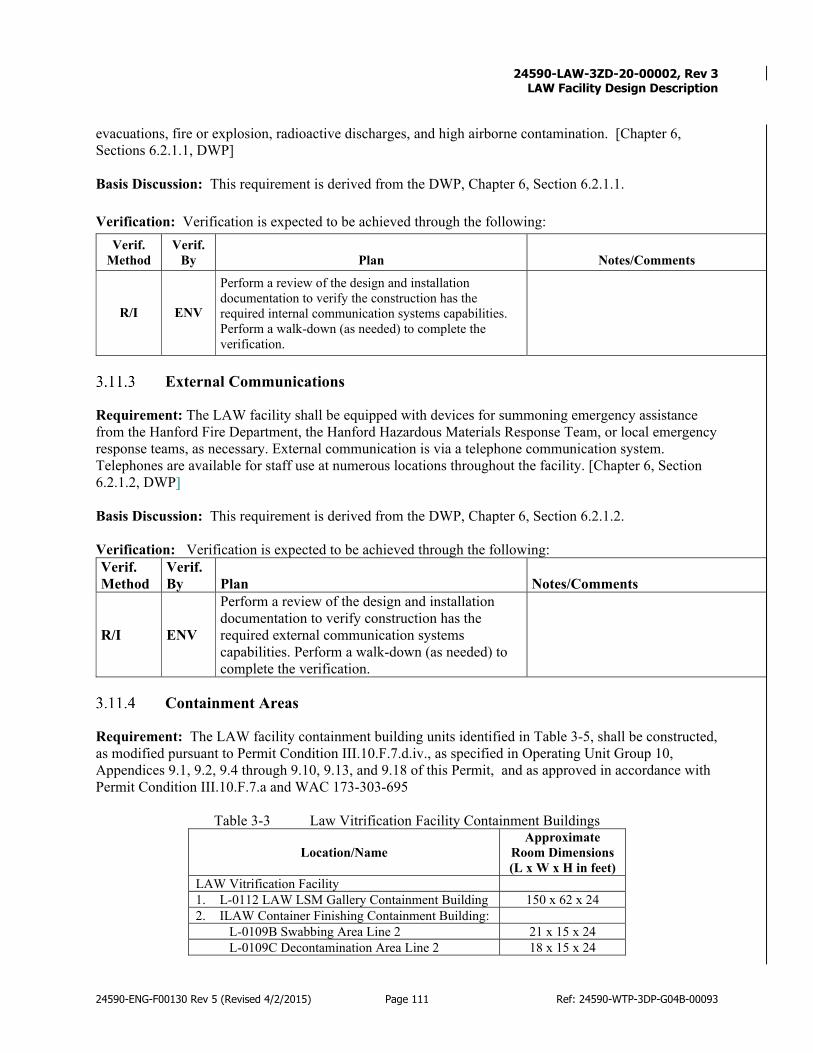
24590-LAW-3ZD-20-00002, Rev 3
LAW Facility Design Description
24590-ENG-F00130 Rev 5 (Revised 4/2/2015) Page 111 Ref: 24590-WTP-3DP-G04B-00093
evacuations, fire or explosion, radioactive discharges, and high airborne contamination. [Chapter 6, Sections 6.2.1.1, DWP] Basis Discussion: This requirement is derived from the DWP, Chapter 6, Section 6.2.1.1. Verification: Verification is expected to be achieved through the following:
Verif. Method
Verif. By Plan Notes/Comments
R/I ENV
Perform a review of the design and installation documentation to verify the construction has the required internal communication systems capabilities. Perform a walk-down (as needed) to complete the verification.
External Communications
Requirement: The LAW facility shall be equipped with devices for summoning emergency assistance from the Hanford Fire Department, the Hanford Hazardous Materials Response Team, or local emergency response teams, as necessary. External communication is via a telephone communication system. Telephones are available for staff use at numerous locations throughout the facility. [Chapter 6, Section 6.2.1.2, DWP] Basis Discussion: This requirement is derived from the DWP, Chapter 6, Section 6.2.1.2. Verification: Verification is expected to be achieved through the following: Verif. Method
Verif. By Plan Notes/Comments
R/I ENV
Perform a review of the design and installation documentation to verify construction has the required external communication systems capabilities. Perform a walk-down (as needed) to complete the verification.
Containment Areas
Requirement: The LAW facility containment building units identified in Table 3-5, shall be constructed, as modified pursuant to Permit Condition III.10.F.7.d.iv., as specified in Operating Unit Group 10, Appendices 9.1, 9.2, 9.4 through 9.10, 9.13, and 9.18 of this Permit, and as approved in accordance with Permit Condition III.10.F.7.a and WAC 173-303-695
Table 3-3 Law Vitrification Facility Containment Buildings
Location/Name Approximate
Room Dimensions (L x W x H in feet)
LAW Vitrification Facility 1. L-0112 LAW LSM Gallery Containment Building 150 x 62 x 24 2. ILAW Container Finishing Containment Building:
L-0109B Swabbing Area Line 2 21 x 15 x 24 L-0109C Decontamination Area Line 2 18 x 15 x 24
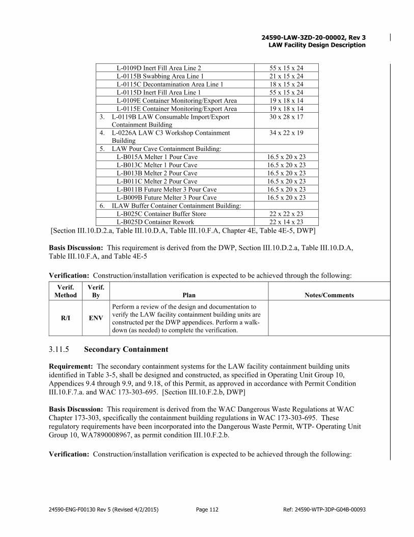
24590-LAW-3ZD-20-00002, Rev 3
LAW Facility Design Description
24590-ENG-F00130 Rev 5 (Revised 4/2/2015) Page 112 Ref: 24590-WTP-3DP-G04B-00093
L-0109D Inert Fill Area Line 2 55 x 15 x 24 L-0115B Swabbing Area Line 1 21 x 15 x 24 L-0115C Decontamination Area Line 1 18 x 15 x 24 L-0115D Inert Fill Area Line 1 55 x 15 x 24 L-0109E Container Monitoring/Export Area 19 x 18 x 14 L-0115E Container Monitoring/Export Area 19 x 18 x 14
3. L-0119B LAW Consumable Import/Export Containment Building
30 x 28 x 17
4. L-0226A LAW C3 Workshop Containment Building
34 x 22 x 19
5. LAW Pour Cave Containment Building: L-B015A Melter 1 Pour Cave 16.5 x 20 x 23 L-B013C Melter 1 Pour Cave 16.5 x 20 x 23 L-B013B Melter 2 Pour Cave 16.5 x 20 x 23 L-B011C Melter 2 Pour Cave 16.5 x 20 x 23 L-B011B Future Melter 3 Pour Cave 16.5 x 20 x 23 L-B009B Future Melter 3 Pour Cave 16.5 x 20 x 23
6. ILAW Buffer Container Containment Building: L-B025C Container Buffer Store 22 x 22 x 23 L-B025D Container Rework 22 x 14 x 23
[Section III.10.D.2.a, Table III.10.D.A, Table III.10.F.A, Chapter 4E, Table 4E-5, DWP] Basis Discussion: This requirement is derived from the DWP, Section III.10.D.2.a, Table III.10.D.A, Table III.10.F.A, and Table 4E-5 Verification: Construction/installation verification is expected to be achieved through the following:
Verif. Method
Verif. By Plan Notes/Comments
R/I ENV Perform a review of the design and documentation to verify the LAW facility containment building units are constructed per the DWP appendices. Perform a walk-down (as needed) to complete the verification.
Secondary Containment
Requirement: The secondary containment systems for the LAW facility containment building units identified in Table 3-5, shall be designed and constructed, as specified in Operating Unit Group 10, Appendices 9.4 through 9.9, and 9.18, of this Permit, as approved in accordance with Permit Condition III.10.F.7.a. and WAC 173-303-695. [Section III.10.F.2.b, DWP] Basis Discussion: This requirement is derived from the WAC Dangerous Waste Regulations at WAC Chapter 173-303, specifically the containment building regulations in WAC 173-303-695. These regulatory requirements have been incorporated into the Dangerous Waste Permit, WTP- Operating Unit Group 10, WA7890008967, as permit condition III.10.F.2.b. Verification: Construction/installation verification is expected to be achieved through the following:
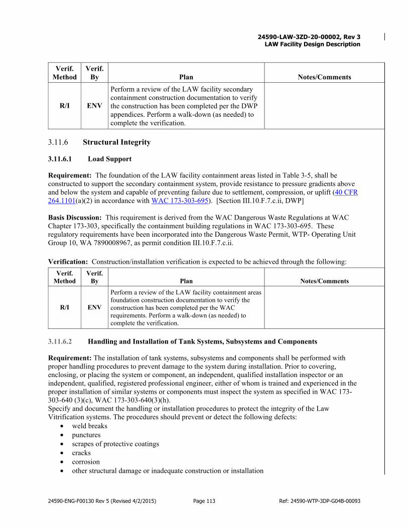
24590-LAW-3ZD-20-00002, Rev 3
LAW Facility Design Description
24590-ENG-F00130 Rev 5 (Revised 4/2/2015) Page 113 Ref: 24590-WTP-3DP-G04B-00093
Verif. Method
Verif. By Plan Notes/Comments
R/I ENV
Perform a review of the LAW facility secondary containment construction documentation to verify the construction has been completed per the DWP appendices. Perform a walk-down (as needed) to complete the verification.
Structural Integrity
3.11.6.1 Load Support
Requirement: The foundation of the LAW facility containment areas listed in Table 3-5, shall be constructed to support the secondary containment system, provide resistance to pressure gradients above and below the system and capable of preventing failure due to settlement, compression, or uplift (40 CFR 264.1101(a)(2) in accordance with WAC 173-303-695). [Section III.10.F.7.c.ii, DWP] Basis Discussion: This requirement is derived from the WAC Dangerous Waste Regulations at WAC Chapter 173-303, specifically the containment building regulations in WAC 173-303-695. These regulatory requirements have been incorporated into the Dangerous Waste Permit, WTP- Operating Unit Group 10, WA 7890008967, as permit condition III.10.F.7.c.ii. Verification: Construction/installation verification is expected to be achieved through the following:
Verif. Method
Verif. By Plan Notes/Comments
R/I ENV
Perform a review of the LAW facility containment areas foundation construction documentation to verify the construction has been completed per the WAC requirements. Perform a walk-down (as needed) to complete the verification.
3.11.6.2 Handling and Installation of Tank Systems, Subsystems and Components
Requirement: The installation of tank systems, subsystems and components shall be performed with proper handling procedures to prevent damage to the system during installation. Prior to covering, enclosing, or placing the system or component, an independent, qualified installation inspector or an independent, qualified, registered professional engineer, either of whom is trained and experienced in the proper installation of similar systems or components must inspect the system as specified in WAC 173-303-640 (3)(c), WAC 173-303-640(3)(h). Specify and document the handling or installation procedures to protect the integrity of the Law Vitrification systems. The procedures should prevent or detect the following defects:
• weld breaks • punctures • scrapes of protective coatings • cracks • corrosion • other structural damage or inadequate construction or installation

24590-LAW-3ZD-20-00002, Rev 3
LAW Facility Design Description
24590-ENG-F00130 Rev 5 (Revised 4/2/2015) Page 114 Ref: 24590-WTP-3DP-G04B-00093
Specify and document the remedies for any handling or installation procedure discrepancies identified before the tank system is covered, enclosed, or placed in use. (WAC 173-303-640(3)(c)) [Sections III.10.H.1.a.iv, III.10.E.3.a, Chp. 4.0, Section 4.2.5, DWP] Basis Discussion: This requirement is derived from the Washington Administrative Code (WAC) Dangerous Waste Regulations at WAC Chapter 173-303, specifically the Tank System regulations in WAC 173-303-640. These regulatory requirements have been incorporated into the Dangerous Waste Permit, WTP- Operating Unit Group 10, WA 7890008967, as permit condition III.10.E.3.a (WAC 173-303-640(3)(c), WAC 173-303-640(3)(h)). Verification: Verification is expected to be achieved through the following:
Verif. Method
Verif. By Plan Notes/Comments
R ENV Review completed independent installation inspector documentation. Perform walkdown as necessary to complete verification.
3.11.6.3 Secondary Containment Integrity
Requirement: The Permittees will ensure that the secondary containment systems for the Tank Systems listed in Permit Tables III.10.E.B as approved/modified pursuant to Permit Condition III.10.E.9., are free of cracks or gaps to prevent any migration of dangerous and/or mixed waste or accumulated liquid out of the system to the soil, ground water, or surface water at any time that waste is in the tank system. Any indication that a crack or gap may exist in the containment systems will be investigated and repaired in accordance with Operating Unit Group 10, Appendices 9.18, of this Permit, as approved pursuant to Permit Condition III.10.E.9.e.v [WAC 173-303-320, WAC 173-303-640(4)(b)(i), WAC 173-303-640(4)(e)(i)(C), WAC 173-303-640(6), and WAC 173-303-806(4)(c)(vii)]. [Section III.10.E.5.g, DWP] Basis Discussion: This requirement is derived from the Washington Administrative Code (WAC) Dangerous Waste Regulations at WAC Chapter 173-303, specifically the Tank System regulations in WAC 173-303-640. These regulatory requirements have been incorporated into the Dangerous Waste Permit, WTP- Operating Unit Group 10, WA 7890008967, as permit condition III.10.E.5.g (WAC 173-303-320, WAC 173-303-640(4)(b)(i), WAC 173-303-640(4)(e)(i)(C), WAC 173-303-640(6), and WAC 173-303-806(4)(c)(vii)). Verification: Verification is expected to be achieved through the following:
Verif. Method
Verif. By Plan Notes/Comments
I ENV
Perform a permitted facility and system inspection of the tank system secondary containment to verify construction and installation is free of cracks or gaps to prevent any migration of dangerous and/or mixed waste.
3.11.6.4 Corrosion Protection ( Tank Systems and Miscellaneous Units)
Requirement: The Permittees shall provide the type and degree of corrosion protection recommended by an independent corrosion expert, based on the information provided in Operating Unit Group 10,

24590-LAW-3ZD-20-00002, Rev 3
LAW Facility Design Description
24590-ENG-F00130 Rev 5 (Revised 4/2/2015) Page 115 Ref: 24590-WTP-3DP-G04B-00093
Appendices 9.9 and 9.11 of this Permit, as approved pursuant to Permit Conditions III.10.E.9.b.i., III.10.E.9.b.iv., III.10.E.9.b.v., III.10.E.9.c.i., III.10.E.9.c.iv., III.10.E.9.c.v., III.10.E.9.d.i., III.10.E.9.d.iv., III.10.E.9.d.v, III.10.H.5.b.i, III.10.H.5.b.iv, III.10.H.5.b.v, III.10.H.5.c.i, III.10.H.5.c.iv., III.10.H.5.c.v., III.10.H.5.d.i., III.10.H.5.d.iv., and III.10.H.5.d.v or other corrosion protection if the Ecology believes other corrosion protection is necessary to ensure the integrity of the tank system during use of the tank system. The installation of a corrosion protection system that is field fabricated must be supervised by an independent corrosion expert to ensure proper installation [WAC 173-303-640(3)(g)].[section III.10.e.3.e, DWP] Basis Discussion: This requirement is derived from the Washington Administrative Code (WAC) Dangerous Waste Regulations at WAC Chapter 173-303, specifically the Tank System regulations in WAC 173-303-640. These regulatory requirements have been incorporated into the Dangerous Waste Permit, WTP- Operating Unit Group 10, WA 7890008967, as permit condition III.10.E.3.e (WAC 173-303-640(3)(g)). This requirement is not applicable to tank systems with components that are not in contact with soil or water. Verification: Construction/installation verification is expected to be achieved through the following:
Verif. Method
Verif. By Plan Notes/Comments
R ENV Review the independent corrosion engineering reports to verify credentials and corrosion protection conformance through design, procurement, and installation.
Containment Coatings
Requirement: The LAW facility containment areas listed in Table 3-5, must be constructed with coatings that withstand the movement of personnel, waste and equipment during the operating life of the containment building per 40 CFR 264.1101(a)(2), (a)(4), and (b) in accordance with WAC 173-303-695. [Section III.10.F.7.c.iii, DWP] Basis Discussion: This requirement is derived from the WAC Dangerous Waste Regulations at WAC Chapter 173-303, specifically the containment building regulations in WAC 173-303-695. These regulatory requirements have been incorporated into the Dangerous Waste Permit, WTP- Operating Unit Group 10, WA 7890008967, as permit condition III.10.F.7.c.iii. Verification: Construction/installation verification is expected to be achieved through the following:
Verif. Method
Verif. By Plan Notes/Comments
R/I ENV
Perform a review of the LAW facility containment areas construction documentation to verify the construction has been completed per the WAC requirements. Perform a walk-down (as needed) to complete the verification.

24590-LAW-3ZD-20-00002, Rev 3
LAW Facility Design Description
24590-ENG-F00130 Rev 5 (Revised 4/2/2015) Page 116 Ref: 24590-WTP-3DP-G04B-00093
Leak Detection System
Requirement: The LAW facility containment areas listed in Table 3-5, must be constructed (as appropriate) with a leak detection system and instruments as detailed in Table III.10.F.D, 40 CFR 264.1101(a)(4) and (b) in accordance with WAC 173-303-695. [Sections III.10.F.7.c.iv, III.10.F.7.c.v, Table III.10.F.D, DWP] Basis Discussion: This requirement is derived from the WAC Dangerous Waste Regulations at WAC Chapter 173-303, specifically the containment building regulations in WAC 173-303-695. These regulatory requirements have been incorporated into the Dangerous Waste Permit, WTP- Operating Unit Group 10, WA 7890008967, as permit condition III.10.F.7.c.iv and III.10.F.7.c.v. Verification: Construction/installation verification is expected to be achieved through the following:
Verif. Method
Verif. By Plan Notes/Comments
R/I ENV
Perform a review of the LAW facility containment areas construction documentation to verify the construction of the required leak detection systems has been completed per the WAC requirements. Perform a walk-down (as needed) to complete the verification.
Prevention of Water Run-in
Requirement: The LAW facility containment buildings (LAW LSM Gallery Containment Building, ILAW Container Finishing Containment Building, LAW Consumable Import/Export Containment Building, LAW C3 Workshop Containment Building, LAW Pour Cave Containment Building, and ILAW Buffer Container Containment Building) shall be certified by a registered professional engineer to meet the 40 CFR 264.1101(a) and (c) requirements listed below: • The containment building must be completely enclosed with a floor, walls, and a roof to prevent
exposure to the elements, (e.g., precipitation, wind, run-on), and to assure containment of managed wastes. Construction of the containment buildings will prevent precipitation from entering. The roof will consist of metal roofing, roof insulation, and vapor barrier. Roof drains and drainage system with overflow drains will collect the run-off (40 CFR 264.1101(a)(1)).
• The floor and containment walls of the unit, including the secondary containment system if required under paragraph (b) of this section(40 CFR 264.1101) , must be constructed of materials of sufficient strength and thickness to support themselves, the waste contents, and any personnel and heavy equipment that operate within the unit, and to prevent failure due to pressure gradients, settlement, compression, or uplift, physical contact with the hazardous wastes to which they are exposed; climatic conditions; and the stresses of daily operation, including the movement of heavy equipment within the unit and contact of such equipment with containment walls. All surfaces to be in contact with hazardous wastes must be chemically compatible with those wastes (40 CFR 264.1101(a)(2)and 40 CFR 264.1101(a)(4)).
[Chapter 4E, Sections 4E.3.1, 4E.3.2, 4E.3.3, 4E.3.4, 4E.3.5, 4E.3.6, DWP] Basis Discussion: This requirement is derived from the WAC Dangerous Waste Regulations in WAC 173-303-695. These regulatory requirements reflect the 40 Code of Federal Regulations Part 264 Subpart DD.

24590-LAW-3ZD-20-00002, Rev 3
LAW Facility Design Description
24590-ENG-F00130 Rev 5 (Revised 4/2/2015) Page 117 Ref: 24590-WTP-3DP-G04B-00093
Verification: Construction/installation verification is expected to be achieved through the following: Verif.
Method Verif.
By Plan Notes/Comments
R/I ENV
Perform a review of the LAW facility building construction documentation to verify the construction has been completed per the WAC requirements. Perform a walk-down (as needed) to complete the verification.
Containment Buildings Design and Construction
Requirement: The LAW facility containment buildings identified in Table 3-5, must be constructed to protect containers from contact with accumulated liquids (e.g., leaks, spills, precipitation, fire water, liquids from damaged or broken pipes) (WAC 173-303-630(7)(a)(i) and WAC 173-303-630(7)(c)(ii)). [Section III.10.D.2.c, DWP] Basis Discussion: This requirement is derived from the WAC Dangerous Waste Regulations in WAC 173-303-630. These regulatory requirements have been incorporated into the Dangerous Waste Permit, WTP- Operating Unit Group 10, WA 7890008967, as permit condition III.10.D.2.c. Verification: Construction/installation verification is expected to be achieved through the following:
Verif. Method
Verif. By Plan Notes/Comments
R ENV Perform a review of the LAW facility container areas construction documentation to verify the construction has been completed per the WAC requirements.
Containment Buildings Structure
3.11.11.1 Steel-Reinforced Concrete and Interior Floor and Wall Coating
Requirement: The LAW facility containment buildings listed in Table 3-5, shall be constructed of steel‑reinforced concrete. Each containment building interior floor and a portion of the walls of the decontamination rooms shall be coated with an epoxy coating to facilitate decontamination of the concrete. The epoxy coated concrete floor and walls of the containment buildings shall be constructed in a manner that will be free of significant cracks, gaps, corrosion, or other deterioration. [Chapter 4E, Sections 4E.3.1, 4E.3.2, 4E.3.3, 4E.3.4, 4E.3.5, 4E.3.6, DWP] Basis Discussion: This requirement is derived from the WAC Dangerous Waste Regulations in WAC 173-303-695. Verification: Construction/installation verification is expected to be achieved through the following:
Verif. Method
Verif. By Plan Notes/Comments
R/I ENV Perform a review of the LAW facility building construction documentation to verify the construction
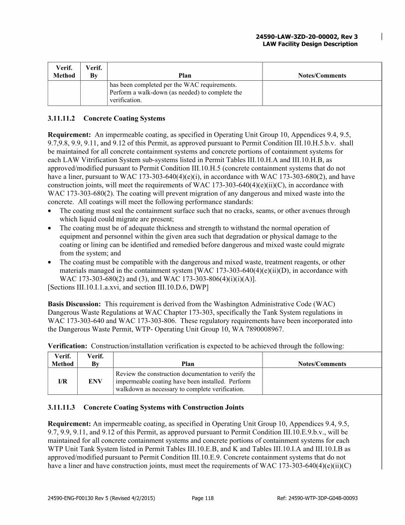
24590-LAW-3ZD-20-00002, Rev 3
LAW Facility Design Description
24590-ENG-F00130 Rev 5 (Revised 4/2/2015) Page 118 Ref: 24590-WTP-3DP-G04B-00093
Verif. Method
Verif. By Plan Notes/Comments
has been completed per the WAC requirements. Perform a walk-down (as needed) to complete the verification.
3.11.11.2 Concrete Coating Systems
Requirement: An impermeable coating, as specified in Operating Unit Group 10, Appendices 9.4, 9.5, 9.7,9.8, 9.9, 9.11, and 9.12 of this Permit, as approved pursuant to Permit Condition III.10.H.5.b.v. shall be maintained for all concrete containment systems and concrete portions of containment systems for each LAW Vitrification System sub-systems listed in Permit Tables III.10.H.A and III.10.H.B, as approved/modified pursuant to Permit Condition III.10.H.5 (concrete containment systems that do not have a liner, pursuant to WAC 173-303-640(4)(e)(i), in accordance with WAC 173-303-680(2), and have construction joints, will meet the requirements of WAC 173-303-640(4)(e)(ii)(C), in accordance with WAC 173-303-680(2). The coating will prevent migration of any dangerous and mixed waste into the concrete. All coatings will meet the following performance standards: • The coating must seal the containment surface such that no cracks, seams, or other avenues through
which liquid could migrate are present; • The coating must be of adequate thickness and strength to withstand the normal operation of
equipment and personnel within the given area such that degradation or physical damage to the coating or lining can be identified and remedied before dangerous and mixed waste could migrate from the system; and
• The coating must be compatible with the dangerous and mixed waste, treatment reagents, or other materials managed in the containment system [WAC 173-303-640(4)(e)(ii)(D), in accordance with WAC 173-303-680(2) and (3), and WAC 173-303-806(4)(i)(i)(A)].
[Sections III.10.I.1.a.xvi, and section III.10.D.6, DWP] Basis Discussion: This requirement is derived from the Washington Administrative Code (WAC) Dangerous Waste Regulations at WAC Chapter 173-303, specifically the Tank System regulations in WAC 173-303-640 and WAC 173-303-806. These regulatory requirements have been incorporated into the Dangerous Waste Permit, WTP- Operating Unit Group 10, WA 7890008967. Verification: Construction/installation verification is expected to be achieved through the following:
Verif. Method
Verif. By Plan Notes/Comments
I/R ENV Review the construction documentation to verify the impermeable coating have been installed. Perform walkdown as necessary to complete verification.
3.11.11.3 Concrete Coating Systems with Construction Joints
Requirement: An impermeable coating, as specified in Operating Unit Group 10, Appendices 9.4, 9.5, 9.7, 9.9, 9.11, and 9.12 of this Permit, as approved pursuant to Permit Condition III.10.E.9.b.v., will be maintained for all concrete containment systems and concrete portions of containment systems for each WTP Unit Tank System listed in Permit Tables III.10.E.B, and K and Tables III.10.I.A and III.10.I.B as approved/modified pursuant to Permit Condition III.10.E.9. Concrete containment systems that do not have a liner and have construction joints, must meet the requirements of WAC 173-303-640(4)(e)(ii)(C)

24590-LAW-3ZD-20-00002, Rev 3
LAW Facility Design Description
24590-ENG-F00130 Rev 5 (Revised 4/2/2015) Page 119 Ref: 24590-WTP-3DP-G04B-00093
and -806(4)(c)(vii). The coating will prevent migration of any dangerous and/or mixed waste into the concrete. All coatings will meet the following performance standards:
• III.10.E.5.h.i The coating must seal the containment surface such that no cracks, seams, or other avenues through which liquid could migrate are present;
• III.10.E.5.h.ii The coating must be of adequate thickness and strength to withstand the normal operation of equipment and personnel within the given area such that degradation or physical damage to the coating or lining can be identified and remedied before dangerous and/or mixed waste could migrate from the system; and
• III.10.E.5.h.iii The coating must be compatible with the dangerous and/or mixed waste, treatment reagents, or other materials managed in the containment system [WAC 173-303- 640(4)(e)(ii)(D), WAC 173-303-806(4)(c)(vii)].
[Section III.10.E.5.h, DWP]
Basis Discussion: This requirement is derived from the Washington Administrative Code (WAC) Dangerous Waste Regulations at WAC Chapter 173-303, specifically the Tank System regulations in WAC 173-303-640 and WAC 173-303-806. These regulatory requirements have been incorporated into the Dangerous Waste Permit, WTP- Operating Unit Group 10, WA 7890008967, as permit condition III.10.E.5.h. Verification: Construction/installation verification is expected to be achieved through the following:
Verif. Method
Verif. By Plan Notes/Comments
I/R ENV Review the construction documentation to verify the impermeable coating have been installed. Perform walkdown as necessary to complete verification.
Backfill Material
Requirement: Backfill material for LAW vitrification system (tank systems and components) that are placed underground shall be specified to be non-corrosive, porous, and homogeneous. Backfill material shall be placed completely around the tank system components and compacted so that the components are uniformly supported (WAC 173-303-640[3][d]). [Sections III.10.E.3.b and III.10.H.1.a DWP]
Basis Discussion: Requirement applies to dangerous waste tanks in vessel cells or vaults that provide structural support for dangerous waste tanks or vessels.
Verification: Verification is expected to be achieved through:
Verif. Method
Verif. By Plan Notes/Comments
R ENV
Verify that backfill materials for tank systems or components are specified non-corrosive, porous, and homogeneous and that backfill placement will be completely around the tank system components and properly compacted.
Document in IQRPE report prepared in accordance with WAC requirements

24590-LAW-3ZD-20-00002, Rev 3
LAW Facility Design Description
24590-ENG-F00130 Rev 5 (Revised 4/2/2015) Page 120 Ref: 24590-WTP-3DP-G04B-00093
Containment Seal Penetrations
Requirement: The leak detection system shall be operated so that it detects the failure of either the primary or secondary containment structure or the presence of any release of dangerous and/or mixed waste or accumulated liquid in the secondary containment system within twenty-four (24) hours [WAC 173-303-640(4)(c)(iii)]. Detection of a leak of at least 0.1 gallons per hour within twenty-four (24) hours is defined as being able to detect a leak within twenty-four (24) hours. Any exceptions to this criteria shall be approved by Ecology in accordance with WAC 173-303-680, WAC 173-303-640(4)(c)(iii), and WAC 173-303-806(4)(i)(i)(b).
A. Dangerous waste pipe penetrations that require a penetration seal in accordance with the IBC and DOE-STD-1066, DOE Standard for Fire Protection Design Criteria, or meet ventilation sealing requirements identified in Permit Table III.10.H.G (Table 3-6), are not required to meet the 0.1 gallons per hour within twenty-four (24) hours leak detection rate for those sections of piping that are in contact with approved silicone or equivalent low-permeability seal material.
B. Piping on either side of the penetration seal shall meet the requirements of III.10.H.5.e.ii. C. Revisions (including additions or deletions) to Table III.10.H.G shall be submitted to Ecology for
review and approval pursuant to Conditions III.10.C.2.e and III.10.C.2.f. Addition of penetration seal locations to Table III.10.H.G shall be approved by Ecology prior to installation of the penetration seal.
Table 3-4 Containment Seal Penetration Row
Number Room
Number Orientation1 Discipline2 Sequence
Number 1. L-0112 E PD 02097 2. L-0123 E PD 01823 3. L-0123 E PD 01834 4. L-0123 E PD 01828 5. L-0123 E PD 01837 6. L-0123 E PD 01822 7. L-0123 E PD 01824 8. L-0123 E PD 01826 9. L-0123 E PD 01821
10. L-0123 E PD 01825 11. L-0123 E PD 01827 12. L-0123 E PD 01836 13. L-0123 E PD 01820 14. L-0123 E PD 01832 15. L-0123 S PD 01797 16. L-0124 E PD 01843 17. L-0124 E PD 01844 18. L-0124 E PD 01845 19. L-0124 E PD 01842 20. L-0124 E PD 01847 21. L-0124 E PD 01841 22. L-0124 E PD 01846 23. L-0124 E PD 01850 24. L-0124 E PD 01848 25. L-0124 E PD 01852 26. L-0124 E PD 01840 27. L-0124 E PD 01839
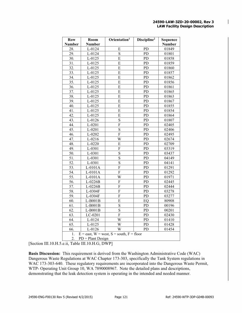
24590-LAW-3ZD-20-00002, Rev 3
LAW Facility Design Description
24590-ENG-F00130 Rev 5 (Revised 4/2/2015) Page 121 Ref: 24590-WTP-3DP-G04B-00093
Row Number
Room Number
Orientation1 Discipline2 Sequence Number
28. L-0124 E PD 01849 29. L-0124 S PD 01801 30. L-0125 E PD 01858 31. L-0125 E PD 01859 32. L-0125 E PD 01860 33. L-0125 E PD 01857 34. L-0125 E PD 01862 35. L-0125 E PD 01856 36. L-0125 E PD 01861 37. L-0125 E PD 01865 38. L-0125 E PD 01863 39. L-0125 E PD 01867 40. L-0125 E PD 01855 41. L-0125 E PD 01854 42. L-0125 E PD 01864 43. L-0126 S PD 01807 44. L-0201 F PD 02405 45. L-0201 S PD 02406 46. L-0202 F PD 02495 47. L-0216 W PD 02674 48. L-0220 E PD 02709 49. L-0301 F PD 03319 50. L-0301 S PD 03437 51. L-0301 S PD 04149 52. L-0301 S PD 04141 53. L-0101A F PD 01291 54. L-0101A F PD 01292 55. L-0101A W PD 01971 56. L-0226B F PD 02445 57. L-0226B F PD 02444 58. L-0304F F PD 03278 59. L-0304F F PD 03277 60. L-B001B E EQ 80908 61. L-B001B S PD 00196 62. L-B001B S PD 00201 63. LC-0201 F PD 02430 64. L-0124 W PD 01410 65. L-0125 W PD 01428 66. L-0126 W PD 01454
1. E = east, W = west, S = south, F = floor 2. PD = Plant Design
[Section III.10.H.5.e.ii, Table III.10.H.G, DWP] Basis Discussion: This requirement is derived from the Washington Administrative Code (WAC) Dangerous Waste Regulations at WAC Chapter 173-303, specifically the Tank System regulations in WAC 173-303-640. These regulatory requirements are incorporated into the Dangerous Waste Permit, WTP- Operating Unit Group 10, WA 7890008967. Note the detailed plans and descriptions, demonstrating that the leak detection system is operating in the intended and needed manner.

24590-LAW-3ZD-20-00002, Rev 3
LAW Facility Design Description
24590-ENG-F00130 Rev 5 (Revised 4/2/2015) Page 122 Ref: 24590-WTP-3DP-G04B-00093
Verification: Construction/installation verification is expected to be achieved through the following: Verif.
Method Verif.
By Plan Notes/Comments
R ENV
Perform a review of the LAW facility building design and construction documentation to verify the construction has been completed per the WAC requirements. Perform a walk-down (as needed) to complete the verification.
3.12 Relevant Codes and Standards
Codes of Record
Table 3-7 identifies relevant external codes and standards applicable to the LAW facility design. Use of these documents is typically invoked in the design process through the documents identified in Section 3.12.2 Beyond inclusion here, no attempt is made in this document to extract individual design requirements from these documents for allocation to SSCs. In some cases, the expected means of verification may be established on the basis of tests or other criteria required by the codes and standards. This does not necessarily include verification or testing more appropriately defined in the procurement of individual sub-systems, components, verification or testing that is a routine activity defined by specifications and/or procedures used by construction and startup.
Table 3-7 LAW Facility Applicable Codes and Standards Implementing Codes and Standards: [24590-WTP-COR-MGT-15-00001, Rev 0, Engineering, Procurement, and Construction (EPC) Code of Record]
• ACI 318-99, Building Code Requirements for Structural Concrete, as tailored in Appendix C of the SRD. • ACI 318R-99, Commentary on Building Code Requirements for Structural Concrete • ACI 349-01, Code Requirements for Nuclear Safety-Related Concrete Structures, as tailored in Appendix C. • ACI 349R-01, Commentary on Code Requirements for Nuclear Safety-Related Concrete Structures • AISC M016-89, Manual for Steel Construction – Allowable Stress Design, Ninth Edition, as tailored in
Appendix C of the SRD. • ANSI/AISC N690-94, Specification for the Design, Fabrication, and Erection of Steel Safety-Related
Structures for Nuclear Facilities, as tailored in Appendix C of the SRD. • ANSI/HPS N13.1-1999, Sampling and Monitoring Releases of Airborne Radioactive Substances from the
Stacks and Ducts of Nuclear Facilities • ASCE 1992 Engineering Practice No. 78, Structural Fire Protection • ASCE 4-98, Seismic Analysis of Safety-Related Nuclear Structures and Commentary • ASCE 7-98, Minimum Design Loads for Buildings and Other Structures • DOE-STD-1020-94 (Change 1, 1996), Natural Phenomena Hazards Design and Evaluation Criteria for
Department of Energy Facilities, as tailored in Appendix C of the SRD. • DOE-STD-1066-97, Fire Protection Design Criteria. Also as tailored in Appendix C of the SRD • 1997, UBC Uniform Building Code, as tailored in Appendix C. NOTE: The tailoring of UBC 97 is required for use by the WTP contractor as a daughter standard referenced by the implementing standard for the fire protection. For the LAW process building, replace Chapters 1 through 15 and 24 through 35 of the 1997 UBC with corresponding Chapters of the 2000 International Building Code (IBC).
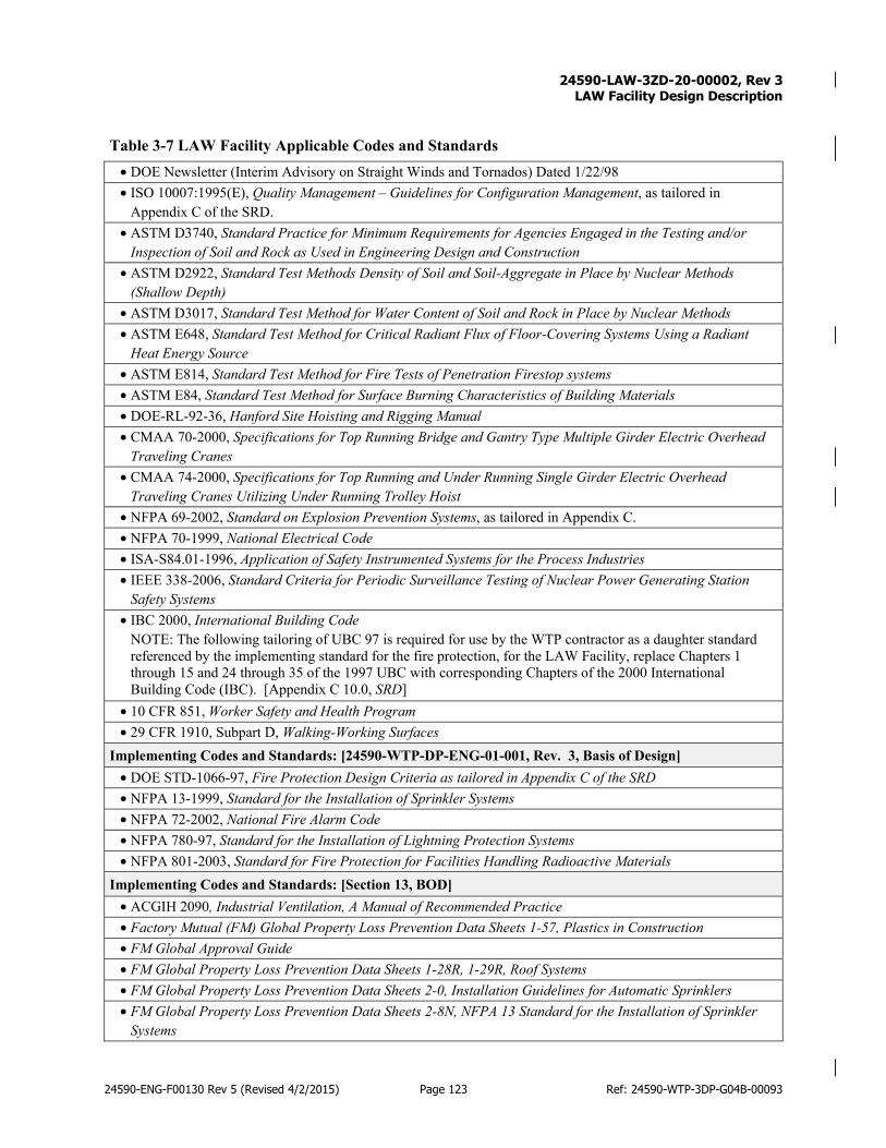
24590-LAW-3ZD-20-00002, Rev 3
LAW Facility Design Description
24590-ENG-F00130 Rev 5 (Revised 4/2/2015) Page 123 Ref: 24590-WTP-3DP-G04B-00093
Table 3-7 LAW Facility Applicable Codes and Standards • DOE Newsletter (Interim Advisory on Straight Winds and Tornados) Dated 1/22/98 • ISO 10007:1995(E), Quality Management – Guidelines for Configuration Management, as tailored in
Appendix C of the SRD. • ASTM D3740, Standard Practice for Minimum Requirements for Agencies Engaged in the Testing and/or
Inspection of Soil and Rock as Used in Engineering Design and Construction • ASTM D2922, Standard Test Methods Density of Soil and Soil-Aggregate in Place by Nuclear Methods
(Shallow Depth) • ASTM D3017, Standard Test Method for Water Content of Soil and Rock in Place by Nuclear Methods • ASTM E648, Standard Test Method for Critical Radiant Flux of Floor-Covering Systems Using a Radiant
Heat Energy Source • ASTM E814, Standard Test Method for Fire Tests of Penetration Firestop systems • ASTM E84, Standard Test Method for Surface Burning Characteristics of Building Materials • DOE-RL-92-36, Hanford Site Hoisting and Rigging Manual • CMAA 70-2000, Specifications for Top Running Bridge and Gantry Type Multiple Girder Electric Overhead
Traveling Cranes • CMAA 74-2000, Specifications for Top Running and Under Running Single Girder Electric Overhead
Traveling Cranes Utilizing Under Running Trolley Hoist • NFPA 69-2002, Standard on Explosion Prevention Systems, as tailored in Appendix C. • NFPA 70-1999, National Electrical Code • ISA-S84.01-1996, Application of Safety Instrumented Systems for the Process Industries • IEEE 338-2006, Standard Criteria for Periodic Surveillance Testing of Nuclear Power Generating Station
Safety Systems • IBC 2000, International Building Code
NOTE: The following tailoring of UBC 97 is required for use by the WTP contractor as a daughter standard referenced by the implementing standard for the fire protection, for the LAW Facility, replace Chapters 1 through 15 and 24 through 35 of the 1997 UBC with corresponding Chapters of the 2000 International Building Code (IBC). [Appendix C 10.0, SRD]
• 10 CFR 851, Worker Safety and Health Program • 29 CFR 1910, Subpart D, Walking-Working Surfaces
Implementing Codes and Standards: [24590-WTP-DP-ENG-01-001, Rev. 3, Basis of Design] • DOE STD-1066-97, Fire Protection Design Criteria as tailored in Appendix C of the SRD • NFPA 13-1999, Standard for the Installation of Sprinkler Systems • NFPA 72-2002, National Fire Alarm Code • NFPA 780-97, Standard for the Installation of Lightning Protection Systems • NFPA 801-2003, Standard for Fire Protection for Facilities Handling Radioactive Materials
Implementing Codes and Standards: [Section 13, BOD] • ACGIH 2090, Industrial Ventilation, A Manual of Recommended Practice • Factory Mutual (FM) Global Property Loss Prevention Data Sheets 1-57, Plastics in Construction • FM Global Approval Guide • FM Global Property Loss Prevention Data Sheets 1-28R, 1-29R, Roof Systems • FM Global Property Loss Prevention Data Sheets 2-0, Installation Guidelines for Automatic Sprinklers • FM Global Property Loss Prevention Data Sheets 2-8N, NFPA 13 Standard for the Installation of Sprinkler
Systems
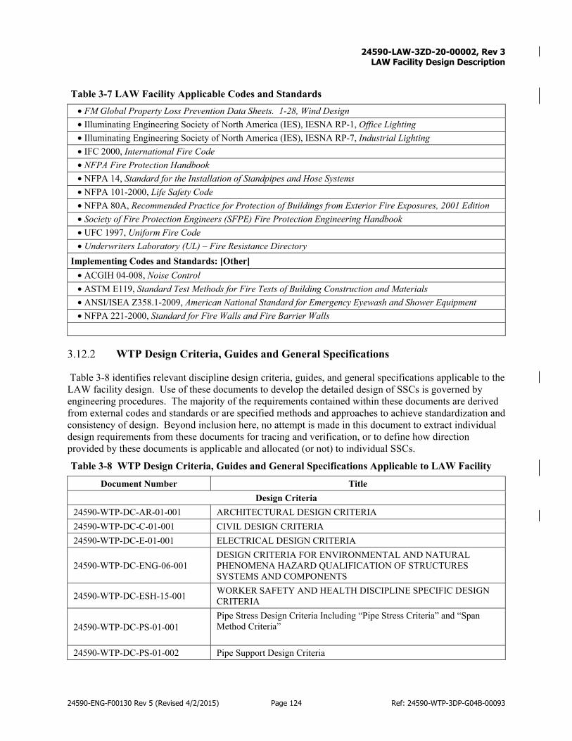
24590-LAW-3ZD-20-00002, Rev 3
LAW Facility Design Description
24590-ENG-F00130 Rev 5 (Revised 4/2/2015) Page 124 Ref: 24590-WTP-3DP-G04B-00093
Table 3-7 LAW Facility Applicable Codes and Standards • FM Global Property Loss Prevention Data Sheets. 1-28, Wind Design • Illuminating Engineering Society of North America (IES), IESNA RP-1, Office Lighting • Illuminating Engineering Society of North America (IES), IESNA RP-7, Industrial Lighting • IFC 2000, International Fire Code • NFPA Fire Protection Handbook • NFPA 14, Standard for the Installation of Standpipes and Hose Systems • NFPA 101-2000, Life Safety Code • NFPA 80A, Recommended Practice for Protection of Buildings from Exterior Fire Exposures, 2001 Edition • Society of Fire Protection Engineers (SFPE) Fire Protection Engineering Handbook • UFC 1997, Uniform Fire Code • Underwriters Laboratory (UL) – Fire Resistance Directory
Implementing Codes and Standards: [Other] • ACGIH 04-008, Noise Control • ASTM E119, Standard Test Methods for Fire Tests of Building Construction and Materials • ANSI/ISEA Z358.1-2009, American National Standard for Emergency Eyewash and Shower Equipment • NFPA 221-2000, Standard for Fire Walls and Fire Barrier Walls
WTP Design Criteria, Guides and General Specifications
Table 3-8 identifies relevant discipline design criteria, guides, and general specifications applicable to the LAW facility design. Use of these documents to develop the detailed design of SSCs is governed by engineering procedures. The majority of the requirements contained within these documents are derived from external codes and standards or are specified methods and approaches to achieve standardization and consistency of design. Beyond inclusion here, no attempt is made in this document to extract individual design requirements from these documents for tracing and verification, or to define how direction provided by these documents is applicable and allocated (or not) to individual SSCs.
Table 3-8 WTP Design Criteria, Guides and General Specifications Applicable to LAW Facility Document Number Title
Design Criteria 24590-WTP-DC-AR-01-001 ARCHITECTURAL DESIGN CRITERIA 24590-WTP-DC-C-01-001 CIVIL DESIGN CRITERIA 24590-WTP-DC-E-01-001 ELECTRICAL DESIGN CRITERIA
24590-WTP-DC-ENG-06-001 DESIGN CRITERIA FOR ENVIRONMENTAL AND NATURAL PHENOMENA HAZARD QUALIFICATION OF STRUCTURES SYSTEMS AND COMPONENTS
24590-WTP-DC-ESH-15-001 WORKER SAFETY AND HEALTH DISCIPLINE SPECIFIC DESIGN CRITERIA
24590-WTP-DC-PS-01-001 Pipe Stress Design Criteria Including “Pipe Stress Criteria” and “Span Method Criteria”
24590-WTP-DC-PS-01-002 Pipe Support Design Criteria

24590-LAW-3ZD-20-00002, Rev 3
LAW Facility Design Description
24590-ENG-F00130 Rev 5 (Revised 4/2/2015) Page 125 Ref: 24590-WTP-3DP-G04B-00093
Table 3-8 WTP Design Criteria, Guides and General Specifications Applicable to LAW Facility Document Number Title
24590-WTP-DC-ST-01-001 STRUCTURAL DESIGN CRITERIA 24590-WTP-DC-ST-04-001 SEISMIC ANALYSIS AND DESIGN CRITERIA
Design Guides
24590-WTP-GPG-CSA-0007 GUIDANCE FOR THE APPLICATION OF EMERGENCY STOPS ON EQUIPMENT AT THE WTP
24590-WTP-GPG-CSA-0007 COORDINATION OF WTP STEEL DESIGN WITH STEEL SUPPLIERS
24590-WTP-GPG-ENG-004 DESIGN GUIDE PIPE STRESS, PIPE LAYOUT AND SUPPORT SPACING
24590-WTP-GPG-ENG-005 ENGINEERING DESIGN GUIDE FOR PIPE SUPPORT
24590-WTP-GPG-ENG-009 RELIABILITY, AVAILABILITY, MAINTAINABILITY, AND INSPECTABILITY (RAMI)
24590-WTP-GPG-ENG-0099 DESIGN VERIFICATION OF PLANT DESIGN DELIVERABLES
24590-WTP-GPG-ENG-0124 SELECTION PROCESS FOR THE USE OF WSGM FOR DESIGN AND QUALIFICATION OF EQUIPMENT
24590-WTP-GPG-ENG-0150 PLANT DESIGN/MECHANICAL SYSTEMS EQUIPMENT INTERFACES: TERMINAL END EQUIPMENT
24590-WTP-GPG-ENG-0162 UPDATING PLANTSPACE DESIGN SERIES SPECIFICATION TABLES
24590-WTP-GPG-ENG-029 SEISMIC CATEGORY III/IV CABLE TRAY AND CONDUIT SUPPORT DESIGN
24590-WTP-GPG-ENG-034 AUTOMATION WORK PROCESS FOR PIPE STRESS ANALYSIS AND SUPPORT DESIGN
24590-WTP-GPG-ENG-039 QUALITY DESIGNATION & GRADING 24590-WTP-GPG-ENG-086 EQUIPMENT ENVIRONMENTAL QUALIFICATION
24590-WTP-GPG-M-0059 AVOIDING CHEMICAL LINE PLUGGING – PLANT DESIGN CONSIDERATIONS
24590-WTP-GPG-M-013 PLANT WASH SYSTEM DESIGN 24590-WTP-GPG-M-052 SPECIFYING DESIGN CYCLES FOR EQUIPMENT AND PIPING 24590-WTP-GPG-MGT-0026 DESIGN & OPERATING MARGIN TERMS 24590-WTP-GPG-PL-002 PLANT DESIGN MATERIAL CONTROL GUIDE 24590-WTP-GPG-SRAD-001 DESIGN GUIDE FOR ALARA
Specifications
24590-WTP-3PS-DD00-T0001 ENGINEERING SPECIFICATION FOR PURCHASE OF STANDARD AND NON-STANDARD EMBEDDED STEEL ITEMS
24590-WTP-3PS-DG00-T0001 ENGINEERING SPECIFICATION FOR FURNISHING OF REINFORCING STEEL
24590-WTP-3PS-F000-T0001 ENGINEERING SPECIFICATION FOR Q BULK FASTENERS
24590-WTP-3PS-FA01-T0001 ENGINEERING SPECIFICATION FOR FURNISHING OF ANCHOR BOLTS (RODS)
24590-WTP-3PS-G000-T0015 ENVIORNMENTAL QUALIFICATION OF MECHANICAL EQUIPMENT

24590-LAW-3ZD-20-00002, Rev 3
LAW Facility Design Description
24590-ENG-F00130 Rev 5 (Revised 4/2/2015) Page 126 Ref: 24590-WTP-3DP-G04B-00093
Table 3-8 WTP Design Criteria, Guides and General Specifications Applicable to LAW Facility Document Number Title
24590-WTP-3PS-NLLR-T0002 ENGINEERING SPECIFICATION FOR FURNISHING, DETAILING, FABRICATION, DELIVERY AND INSTALLATION OF STAINLESS STEEL LINER PLATES
24590-WTP-3PS-SS01-T0001 ENGINEERING SPECIFICATION FOR PURCHASE OF MISCELLANEOUS STEEL
24590-WTP-3PS-SS01-T0002 ENGINEERING SPECIFICATION FOR PURCHASE OF STRUCTURAL STEEL
24590-WTP-3PS-SS02-T0001 ENGINEERING SPECIFICATION FOR ERECTION OF STRUCTURAL STEEL
24590-WTP-3PS-SS25-T0001 ENGINEERING SPECIFICATION FOR PURCHASE OF STEEL DECK
24590-WTP-3PS-SS25-T0002 ENGINEERING SPECIFICATION FOR PURCHASE OF STEEL ROOF DECK
24590-WTP-3PS-SY00-T0001 ENGINEERING SPECIFICATION FOR PURCHASE OF STANDARD STRUTS, FITTINGS AND ACCESSORIES
24590-WTP-3PS-D000-T0001 ENGINEERING SPECIFICATION FOR CONCRETE WORK
24590-WTP-3PS-DB01-T0001 ENGINEERING SPECIFICATION FOR FURNISHING AND DELIVERING READY-MIX CONCRETE
24590-WTP-3PS-DB01-T0002 ENGINEERING SPECIFICATION FOR FURNISHING AND DELIVERING READY MIX LIGHTWEIGHT CONCRETE
24590-WTP-3PS-FA02-T0001 ENGINEERING SPECIFICATION FOR PURCHASE OF POST INSTALLED CONCRETE ANCHORS FOR NON-IMPORTANT TO SAFETY (NON-ITS) APPLICATIONS
24590-WTP-3PS-FA02-T0002 ENGINEERING SPECIFICATION FOR PURCHASE OF POST INSTALLED CONCRETE ANCHORS FOR IMPORTANT TO SAFETY (ITS) APPLICATION
24590-WTP-3PS-FA02-T0003 ENGINEERING SPECIFICATION FOR DESIGN OF POSTED INSTALLED CONCRETE ANCHORS FOR CM APPLICATIONS
24590-WTP-3PS-FA02-T0004 ENGINEERING SPECIFICATION FOR INSTALLATION AND TESTING OF POST INSTALLED CONCRETE ANCHORS AND DRILLING/CORING OF CONCRETE
24590-WTP-3PS-FA02-T0005 ENGINEERING SPECIFICATION FOR DESIGN OF POST INSTALLED CONCRETE ANCHORS FOR Q APPLICATIONS
24590-WTP-3PS-ACEE-T0001 ENGINEERING SPECIFICATION FOR ELECTRIC PASSENGER TRACTION ELEVATORS
24590-WTP-3PS-ACEE-T0002 ENGINEERING SPECIFICATION FOR ELECTRIC FREIGHT TRACTION ELEVATORS 14211
24590-WTP-3PS-ACEH-T0001 ENGINEERING SPECIFICATION FOR HYDRAULIC PASSENGER ELEVATORS 14240
24590-WTP-3PS-ADDS-T0001 ENGINEERING SPECIFICATION FOR STEEL DOORS AND FRAMES 08110
24590-WTP-3PS-ADDW-T0001 ENGINEERING SPECIFICATION FOR FLUSH WOOD DOORS 08211
24590-WTP-3PS-ADDX-T0001 ENGINEERING SPECIFICATION FOR SEVERE WEATHER DOOR SYSTEM

24590-LAW-3ZD-20-00002, Rev 3
LAW Facility Design Description
24590-ENG-F00130 Rev 5 (Revised 4/2/2015) Page 127 Ref: 24590-WTP-3DP-G04B-00093
Table 3-8 WTP Design Criteria, Guides and General Specifications Applicable to LAW Facility Document Number Title
24590-WTP-3PS-ADDZ-T0001 ENGINEERING SPECIFICATION FOR ACCESS DOORS AND FRAMES 08311
24590-WTP-3PS-ADEL-T0001 ENGINEERING SPECIFICATION FOR ALUMINUM ENTRANCES AND WINDOW SYSTEMS 08410
24590-WTP-3PS-ADGG-T0001 SPECIFICATION FOR GLAZING 08800 24590-WTP-3PS-ADHD-T0001 ENGINEERING SPECIFICATION FOR DOOR HARDWARE 08711
24590-WTP-3PS-ADRC-T0001 ENGINEERING SPECIFICATION FOR VERTICAL AND HORIZONTAL COILING DOORS 08331
24590-WTP-3PS-ADRS-T0001 ENGINEERING SPECIFICATION FOR OVERHEAD SECTIONAL DOORS 08361
24590-WTP-3PS-ADWA-T0001 ENGINEERING SPECIFICATION FOR PASS-THRU WINDOWS 08582
24590-WTP-3PS-AEDL-T0001 ENGINEERING SPECIFICATION FOR LOADING DOCK EQUIPMENT 11160
24590-WTP-3PS-AESP-T0001 ENGINEERING SPECIFICATION FOR PROJECTION SCREENS 11132
24590-WTP-3PS-AFBR-T0001 ENGINEERING SPECIFICATION FOR RESILIENT WALL BASE AND ACCESSORIES 09653
24590-WTP-3PS-AFCP-T0001 ENGINEERING SPECIFICATION FOR ACOUSTICAL PANEL CEILINGS 09511
24590-WTP-3PS-AFFC-T0001 ENGINEERING SPECIFICATION FOR CARPET 09680 24590-WTP-3PS-AFFC-T0002 ENGINEERING SPECIFICATION FOR CARPET TILE 09681
24590-WTP-3PS-AFFR-T0001 ENGINEERING SPECIFICATION FOR RESILIENT FLOOR TILE 09651
24590-WTP-3PS-AFFV-T0001 ENGINEERING SPECIFICATION FOR SHEET VINYL FLOOR COVERINGS 09652
24590-WTP-3PS-AFGB-T0001 ENGINEERING SPECIFICATION FOR GYPSUM BOARD ASSEMBLIES 09260
24590-WTP-3PS-AFGB-T0005 ENGINEERING SPECIFICATION FOR QUALITY REQUIREMENTS FOR PROCUREMENT OF FIRE AND PRESSURE RATED SAFETY EQUIPMENT, ASSEMBLIES AND COMPONENTS
24590-WTP-3PS-AFGW-T0001 ENGINEERING SPECIFICATION FOR GYPSUM BOARD SHAFT-WALL ASSEMBLIES 09265
24590-WTP-3PS-AFTC-T0001 ENGINEERING SPECIFICATION FOR CERAMIC TILE 09310
24590-WTP-3PS-AFWA-T0001 ENGINEERING SPECIFICATION FOR ACOUSTICAL WALL PANELS 09840
24590-WTP-3PS-AICK-T0001 ENGINEERING SPECIFICATION FOR INTERIOR ARCHITECTURAL CASEWORK 06402
24590-WTP-3PS-AIWH-T0001 ENGINEERING SPECIFICATION FOR HORIZONTAL LOUVER BLINDS 12491
24590-WTP-3PS-ANEJ-T0001 ENGINEERING SPECIFICATION FOR ARCHITECTURAL JOINT SYSTEMS 05811

24590-LAW-3ZD-20-00002, Rev 3
LAW Facility Design Description
24590-ENG-F00130 Rev 5 (Revised 4/2/2015) Page 128 Ref: 24590-WTP-3DP-G04B-00093
Table 3-8 WTP Design Criteria, Guides and General Specifications Applicable to LAW Facility Document Number Title
24590-WTP-3PS-ANFC-T0001 ENGINEERING SPECIFICATION FOR COLD-FORMED METAL FRAMING 05400
24590-WTP-3PS-ATFR-T0001 ENGINEERING SPECIFICATION FOR THIN FILM INTUMESCENT FIREPROOFING 07811
24590-WTP-3PS-ATFR-T0002 ENGINEERING SPECIFICATION FOR CEMENTITIOUS FIREPROOFING 07831
24590-WTP-3PS-ATFS-T0001 ENGINEERING SPECIFICATION FOR THROUGH-PENETRATION FIRESTOP SYSTEM 07841
24590-WTP-3PS-ATFS-T0002 ENGINEERING SPECIFICATION FOR FIRE RESISTIVE JOINT SYSTEMS 07842
24590-WTP-3PS-ATIB-T0001 ENGINEERING SPECIFICATION FOR BUILDING INSULATION 07210
24590-WTP-3PS-ATJS-T0001 ENGINEERING SPECIFICATION FOR JOINT SEALANTS 07901 24590-WTP-3PS-ATPR-T0001 ENGINEERING SPECIFICATION FOR METAL ROOF PANELS 07411
24590-WTP-3PS-ATPW-T0001 SPECIFICATION FOR FIELD ASSEMBLED METAL WALL PANEL SYSTEM 07412
24590-WTP-3PS-ATPW-T0002 ENGINEERING SPECIFICATION FOR FACTORY FOAM INSULATED METAL WALL PANEL SYSTEM 07413
24590-WTP-3PS-ATPW-T0003 ENGINEERING SPECIFICATION FOR FACTORY INSULATED METAL WALL PANEL SYSTEM (Q) 07420
24590-WTP-3PS-ATPW-T0004 ENGINEERING SPECIFICATION FOR INSPECTION OF FACTORY FOAM INSULATED METAL WALL PANEL SYSTEM INSTALLATION
24590-WTP-3PS-ATRC-T0001 ENGINEERING SPECIFICATION FOR THERMOPLASTIC MEMBRANE ROOFING 07540
24590-WTP-3PS-ATRY-T0001 ENGINEERING SPECIFICATION FOR PROTECTIVE CANOPIES 10530
24590-WTP-3PS-ATRZ-T0001 ENGINEERING SPECIFICATION FOR ROOF ACCESSORIES 07720
24590-WTP-3PS-ATTF-T0001 ENGINEERING SPECIFICATION FOR SHEET METAL FLASHING AND TRIM 07620
24590-WTP-3PS-ATWF-T0001 SPECIFICATION FOR BITUMINOUS DAMPPROOFING 07115
24590-WTP-3PS-AVTC-T0001 ENGINEERING SPECIFICATION FOR TOILET COMPARTMENTS 10155
24590-WTP-3PS-AWCR-T0001 SPECIFICATION FOR ROUGH CARPENTRY 06100 24590-WTP-3PS-AYAF-T0001 ENGINEERING SPECIFICATION FOR ACCESS FLOORING 10270
24590-WTP-3PS-AYBD-T0001 ENGINEERING SPECIFICATION FOR VISUAL DISPLAY BOARDS 10100
24590-WTP-3PS-AYFP-T0001 ENGINEERING SPECIFICATION FOR FIRE PROTECTION SPECIALTIES 10520
24590-WTP-3PS-AYML-T0001 ENGINEERING SPECIFICATION FOR METAL LOCKERS 10505
24590-WTP-3PS-AYPW-T0001 ENGINEERING SPECIFICATION FOR WIRE MESH PARTITIONS 10605
24590-WTP-3PS-AYSF-T0001 ENGINEERING SPECIFICATION FOR FLAGPOLES 10350

24590-LAW-3ZD-20-00002, Rev 3
LAW Facility Design Description
24590-ENG-F00130 Rev 5 (Revised 4/2/2015) Page 129 Ref: 24590-WTP-3DP-G04B-00093
Table 3-8 WTP Design Criteria, Guides and General Specifications Applicable to LAW Facility Document Number Title
24590-WTP-3PS-AYSS-T0001 ENGINEERING SPECIFICATION FOR ARCHITECTURAL SIGNAGE 10431
24590-WTP-3PS-AYTA-T0001 ENGINEERING SPECIFICATION FOR TOILET AND BATH ACCESSORIES 10801
24590-WTP-3PS-AYVL-T0001 ENGINEERING SPECIFICATION FOR LOUVERS AND VENTS 10200
24590-WTP-3PS-AYWP-T0001 ENGINEERING SPECIFICATION FOR IMPACT RESISTANT WALL PROTECTION 10265
24590-WTP-3PS-FB01-T0001 ENGINEERING SPECIFICATION FOR STRUCTURAL DESIGN LOADS FOR SEISMIC CATEGORY III & IV EQUIPMENT AND TANKS
24590-WTP-3PS-SS90-T0001 ENGINEERING SPECIFICATION FOR SEISMIC QUALIFICATION OF SEISMIC CATEGORY I/II EQUIPMENT AND TANKS
24590-WTP-3PS-SS90-T0002 ENGINEERING SPECIFICATION FOR WTP PROJECT TAILORING OF ANSI/AISC N690 & IEEE 323, 344 & 382
24590-WTP-3PS-PY00-T0001 ENGINEERING SPECIFICATION FOR WALL/FLOOR-BOXES
24590-WTP-3PS-G000-T0014 ENGINEERING SPECIFICATION FOR SUPPLIER DESIGN ANALYSIS
24590-WTP-3PS-G000-T0015 ENGINEERING SPECIFICATION FOR ENVIRONMENTAL QUALIFICATION OF MECHANICAL EQUIPMENT
24590-WTP-3PS-G000-T0045 ENGINEERING SPECIFICATION FOR SUPPLIER DESIGN ANALYSIS WITH DEVELOPED SOFTWARE
24590-WTP-3PS-F000-T0002 ENGINEERING SPECIFICATION FOR FASTENER TORQUE AND TENSIONING
24590-WTP-3PS-AFPS-T0001 ENGINEERING SPECIFICATION FOR SHOP APPLIED SPECIAL PROTECTIVE COATINGS FOR STEEL ITEMS AND EQUIPMENT
24590-WTP-3PS-AFPS-T0002 ENGINEERING SPECIFICATION FOR SPECIAL PROTECTIVE COATING LIMITED-COMBUSTIBLE TESTING PROTOCOL
24590-WTP-3PS-AFPS-T0003 ENGINEERING SPECIFICATION FOR FIELD APPLIED SPECIAL PROTECTIVE COATINGS FOR STEEL ITEMS AND EQUIPMENT
24590-WTP-3PS-AFPS-T0004 ENGINEERING SPECIFICATION FOR FIELD APPLIED SPECIAL PROTECTIVE COATINGS FOR CONCRETE SURFACES
24590-WTP-3PS-AFPS-T0006 ENGINEERING SPECIFICATION FOR FIELD APPLIED SPECIAL PROTECTIVE COATINGS FOR SECONDARY CONTAINMENT AREA
24590-WTP-3PS-AFPS-T0007 ENGINEERING SPECIFICATION FOR ENVIRONMENTAL QUALIFICATION OF CONTROL AND ELECTRICAL SYSTEMS AND COMPONENTS
24590-WTP-3PS-JQ06-T0005 ENGINEERING SPECIFICATION FOR COLD GALVANIZING FIELD TOUCH-UP/REPAIR OF STEEL OR GALVANIZED STEEL ITEMS AND EQUIPMENT
24590-WTP-3PS-SS00-T0001 ENGINEERING SPECIFICATION FOR WELDING OF STRUCTURAL CARBON STEEL

24590-LAW-3ZD-20-00002, Rev 3
LAW Facility Design Description
24590-ENG-F00130 Rev 5 (Revised 4/2/2015) Page 130 Ref: 24590-WTP-3DP-G04B-00093
Table 3-8 WTP Design Criteria, Guides and General Specifications Applicable to LAW Facility Document Number Title
24590-WTP-3PS-SS00-T0002 ENGINEERING SPECIFICATION FOR WELDING OF STRUCTURAL STAINLESS STEEL AND WELDING OF STRUCTURAL CARBON STEEL TO STRUCTURAL STAINLESS STEEL
24590-WTP-3PS-SS00-T0005 ENGINEERING SPECIFICATION FOR THERMITE WELDING OF RAILS
4 Facility Description This section summarizes design output information, describing the current design and the operational and maintenance aspects of the LAW Facility. The information provided below does not contain design requirements and should not be used as design input. The description of the current design contained in this section may not fully align with design requirements. This is acceptable within the context of this document. Areas of misalignment are to be resolved through appropriate mechanisms and the FDD updated to reflect changes made to the design. Changes to the descriptive text will be made following the changes to the lower tiered Engineering documents.
4.1 Configuration Information
Note: The process conditions that are described in here are nominal operating parameters (unless otherwise noted) to provide the necessary context for description of system, subsystems and major components. The nominal operating parameters are not to be used directly for input to the design or design analysis of safety functions related to structures, systems, or components. The Low Activity Waste (LAW) Facility is designed and constructed to treat millions of gallons of nuclear and chemical waste currently stored in underground tanks. The LAW Facility will receive waste for treatment from the Pretreatment (PT) Facility (baseline) or Direct Feed Low Activity Waste (DFLAW) system. In the LAW Facility, low activity waste is mixed with glass-forming materials and vitrified in two joule-heated melters. The glass mixture will be poured into stainless steel containers. The LAW Facility is designed to produce 30 MT/day glass (6 MT/container) at 70% availability. The full containers are removed by transport vehicle to the Hanford Integrated Disposal Facility (IDF). The DFLAW operating configuration impacts the LAW FDD through the interfaces that have been added between the LAW facility and LAWPS and between the LAW facility and the new EMF facility. In the DFLAW configuration, the LAW facility receives TLAW feed directly from LAWPS. Also in the DFLAW configuration, radioactive liquid effluents that would normally be returned to the PT facility (in the baseline configuration) from the LAW facility are sent to EMF for further processing. While operating in the DFLAW configuration, the PT facility will be isolated from the WTP facilities required to accommodate the DFLAW configuration (i.e., LAW, BOF, Lab, and EMF). Conversely, w h i l e operating in the baseline configuration, the EMF will have the capability to be isolated from the WTP facilities required to accommodate the baseline configuration (i.e., PT, HLW, LAW, BOF, and Lab). Design details associated with the incorporation of the DFLAW operating configuration have not been included in Section 4 of this document at this time. Section 4 will be updated to include DFLAW content at a later date once the detailed design process for DFLAW has been completed.

24590-LAW-3ZD-20-00002, Rev 3
LAW Facility Design Description
24590-ENG-F00130 Rev 5 (Revised 4/2/2015) Page 131 Ref: 24590-WTP-3DP-G04B-00093
The building structure houses the process and protects the worker and the environment. Containers are transported through the facility where they are filled, decontaminated, and loaded on trucks for transport to storage. The vitrification process consists of material feed systems, melter, and complex exhaust system. Additionally, a number of utility systems support the LAW operations. See Figure 4-1 for overview of the LAW vitrification process.

24590-LAW-3ZD-20-00002, Rev 3
LAW Facility Design Description
24590-ENG-F00130 Rev 5 (Revised 4/2/2015) Page 132 Ref: 24590-WTP-3DP-G04B-00093
Figure 4-1 LAW Facility Process Flow

24590-LAW-3ZD-20-00002, Rev 3
LAW Facility Design Description
24590-ENG-F00130 Rev 5 (Revised 4/2/2015) Page 133 Ref: 24590-WTP-3DP-G04B-00093
Description of System, Subsystems, and Major Components
4.1.1.1 LAW Building Structures
The Low-Activity Waste (LAW) Facility consists of two separate buildings: Building 20 and Building 24. Building 20 is the LAW vitrification building that includes a three-story (above ground) main process building (with one level below grade), a two-story LAW annex building, and loading docks/bays. Building 24 is the one-story switchgear building that is located north of the main process building and east of the annex building. The LAW vitrification building houses the LAW melters, process cells, pour caves, and process support equipment. The annex building houses primarily the LAW Facility Control Room (FCR), administrative support areas, and change rooms. The switchgear (electrical) building houses switchgear enclosures and transformers. The LAW Facility contains operating/inhabitable space, structural support and protection for equipment; provides enclosures to allow control of temperature, humidity and pressure within the buildings; helps prevent and/or mitigate the release of hazardous materials; limits personnel exposure to hazardous work areas and equipment as well as provide shielding to protect workers; and provides the space required to manage solid secondary waste. The facility provides protection for the on-site worker and off-site person from radiological and chemical hazards; protection from industrial hazards; and protection for the environment. Aerosol confinement, ventilation, remote handling, and shielding are the primary control methods used in the LAW process facility. The LAW Facility incorporates features and the capability necessary to support a 40-year design life. In areas where the need for decontamination is anticipated, exposed surfaces are coated as necessary to provide durability and ease of decontamination. Radioactive Liquid Disposal (RLD) vessel cells, pump pits, and pipe pits are concrete and lined with stainless steel for ease of decontamination. The stainless steel liners of the process and effluent cell concrete floors are sloped towards a sump to allow for the collection and removal of spills and periodic system wash-down solutions. The LAW building structure and siding envelope provide protection of structures, systems, and components (SSCs) that are CS within the facility from natural phenomena hazard (NPH) forces, seismic events, fire, and internal flooding and are designed to not fail causing a release. The platform structure supporting the CS components, such as the condensing units, are designed to meet requirements for seismic and other Natural Phenomena Hazard (NPH) events. The vertical steel members above the process cells and effluent cell are positioned so that the vertical run of LAW Primary Offgas Process (LOP) system piping, the vessel vent line, and the bypass line cannot be failed due to design basis impacts. The vertical steel members are therefore CS for their role in preventing impacts to the off gas system. The steel platforms and multi-commodity support framing structures above the LOP piping in the process area prevents crane loads and associated lifting devices from impacting the LOP piping beneath it. These SSCs are therefore CS for their role in preventing impacts to the offgas system. The fire barriers prevent the spread of fire to multiple fire areas, thus limiting the consequence of fire events at the LAW Facility. The fire barriers are designed for the penetration of all required piping,

24590-LAW-3ZD-20-00002, Rev 3
LAW Facility Design Description
24590-ENG-F00130 Rev 5 (Revised 4/2/2015) Page 134 Ref: 24590-WTP-3DP-G04B-00093
mechanical handling equipment, electrical, and HVAC ductwork. All penetrations are appropriately sleeved and protected to maintain the integrity of the fire barrier. The LAW Facility is designed to withstand 100 lbs./ft.2 live load through implementation of Structural Design Criteria, 24590-WTP-DC-ST-01-001, section 4.4 (19 in. of water accumulation). The process cell hatch covers located over rooms L-0123, L-0124, L-0125, and L-0126 and the associated penetration sealing devices prevent water ingress to the process cells from internal flooding. The pressure relief path devices (weirs or other engineered features) will allow water to flow from areas being flooded to distribute over a larger area or leave the building to prevent unacceptable floor loadings and submergence of CS equipment.
4.1.1.2 Mechanical Handling Systems
There are four mechanical handling subsystems associated with Immobilized Low-Activity Waste (ILAW) container handling operations in the LAW Facility: the LAW Container Receipt Handling System (LRH), the LAW Container Pour Handling system (LPH), the LAW Container Finishing Handling system (LFH), and the LAW Container Export Handling system (LEH). These systems provide the ability to bring an empty container into the LAW Facility and move it through the LAW mechanical processing steps. The LFH and LEH systems facilitate lidding and sealing of the container, decontaminating externally by a CO2 pellet decontamination process, swabbing, storing, inspecting and exporting it to disposal areas on the Hanford Site.
4.1.1.2.1 LAW Container Receipt Handling System (LRH)
The LRH system picks up clean, new, empty ILAW containers from a transport trailer and moves them onto the receipt conveyors in the LAW receiving dock, where they are inspected and transferred into the clean container receipt area. The containers are then conveyed through an airlock and into the import hatch areas where they are transferred by a monorail hoist to a LPH system container transport bogie, which is positioned in the transfer tunnel at the -21 ft. level.
4.1.1.2.2 LAW Container Pour Handling system (LPH)
The LPH system provides all the Mechanical Handling (MH) operations required to import and export new or filled ILAW product containers through the LAW. Bogies are used to move the empty containers to the pour caves where they are transferred to the container turntables via monorail hoists. The turntable moves the containers under the melter pour spout to be filled with glass by the LAW Melter Process (LMP) system. Once the container is filled, the turntable moves the container to preliminary container cooling position. The container is transferred back to the bogies where they continue to move in the container transfer corridor to buffer storage. The cooled container is transferred to the LFH system by LFH hoists.
4.1.1.2.3 LAW Container Finishing Handling system (LFH)
The LFH system receives ILAW product containers from the LPH system. The containers are inspected to ensure that the minimum fill level is met using laser level measurement, and if it is not, inert fill is added from the Glass Forming Reagent (GFR) system. Then they are lidded, decontaminated by the use of CO2 pellets from the Carbon Dioxide Gas (CDG) system, swabbed, monitored to verify that the surface dose rate is allowable, and subsequently delivered to the LEH system.
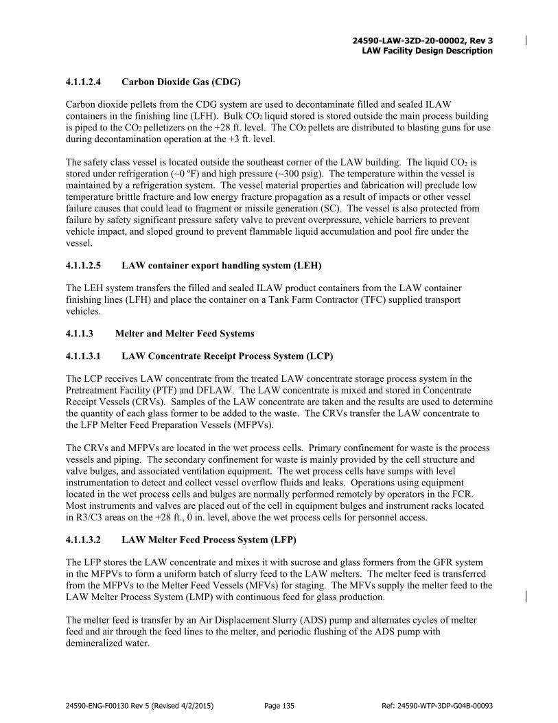
24590-LAW-3ZD-20-00002, Rev 3
LAW Facility Design Description
24590-ENG-F00130 Rev 5 (Revised 4/2/2015) Page 135 Ref: 24590-WTP-3DP-G04B-00093
4.1.1.2.4 Carbon Dioxide Gas (CDG)
Carbon dioxide pellets from the CDG system are used to decontaminate filled and sealed ILAW containers in the finishing line (LFH). Bulk CO2 liquid stored is stored outside the main process building is piped to the CO2 pelletizers on the +28 ft. level. The CO2 pellets are distributed to blasting guns for use during decontamination operation at the +3 ft. level. The safety class vessel is located outside the southeast corner of the LAW building. The liquid CO2 is stored under refrigeration (~0 oF) and high pressure (~300 psig). The temperature within the vessel is maintained by a refrigeration system. The vessel material properties and fabrication will preclude low temperature brittle fracture and low energy fracture propagation as a result of impacts or other vessel failure causes that could lead to fragment or missile generation (SC). The vessel is also protected from failure by safety significant pressure safety valve to prevent overpressure, vehicle barriers to prevent vehicle impact, and sloped ground to prevent flammable liquid accumulation and pool fire under the vessel.
4.1.1.2.5 LAW container export handling system (LEH)
The LEH system transfers the filled and sealed ILAW product containers from the LAW container finishing lines (LFH) and place the container on a Tank Farm Contractor (TFC) supplied transport vehicles.
4.1.1.3 Melter and Melter Feed Systems
4.1.1.3.1 LAW Concentrate Receipt Process System (LCP)
The LCP receives LAW concentrate from the treated LAW concentrate storage process system in the Pretreatment Facility (PTF) and DFLAW. The LAW concentrate is mixed and stored in Concentrate Receipt Vessels (CRVs). Samples of the LAW concentrate are taken and the results are used to determine the quantity of each glass former to be added to the waste. The CRVs transfer the LAW concentrate to the LFP Melter Feed Preparation Vessels (MFPVs). The CRVs and MFPVs are located in the wet process cells. Primary confinement for waste is the process vessels and piping. The secondary confinement for waste is mainly provided by the cell structure and valve bulges, and associated ventilation equipment. The wet process cells have sumps with level instrumentation to detect and collect vessel overflow fluids and leaks. Operations using equipment located in the wet process cells and bulges are normally performed remotely by operators in the FCR. Most instruments and valves are placed out of the cell in equipment bulges and instrument racks located in R3/C3 areas on the +28 ft., 0 in. level, above the wet process cells for personnel access.
4.1.1.3.2 LAW Melter Feed Process System (LFP)
The LFP stores the LAW concentrate and mixes it with sucrose and glass formers from the GFR system in the MFPVs to form a uniform batch of slurry feed to the LAW melters. The melter feed is transferred from the MFPVs to the Melter Feed Vessels (MFVs) for staging. The MFVs supply the melter feed to the LAW Melter Process System (LMP) with continuous feed for glass production. The melter feed is transfer by an Air Displacement Slurry (ADS) pump and alternates cycles of melter feed and air through the feed lines to the melter, and periodic flushing of the ADS pump with demineralized water.

24590-LAW-3ZD-20-00002, Rev 3
LAW Facility Design Description
24590-ENG-F00130 Rev 5 (Revised 4/2/2015) Page 136 Ref: 24590-WTP-3DP-G04B-00093
The MFPVs and MFVs are located in the wet process cells. Primary confinement for waste is the process vessels and piping. The secondary confinement for waste is mainly provided by the cell structure and valve bulges, and associated ventilation equipment. The wet process cells have sumps with level instrumentation to detect and collect vessel overflow fluids and leaks. Operations using equipment located in the wet process cells and bulges are normally performed remotely by operators in the FCR. Most instruments and valves are placed out-cell in equipment bulges and instrument racks located in R3/C3 areas on the +28 ft., 0 in. level, above the wet process cells for personnel access. To facilitate periodic hands on maintenance for equipment in the wet process cell, the vessels are equipped with wash rings used for decontamination purposes. DIW and other utilities can be attached to the water supply line into the wet process cells for use during maintenance activities.
4.1.1.3.3 Autosampling System (ASX)
The ASX system uses autosamplers to collect samples from the LCP system vessels, LAW melter feed process system (LFP) vessels, and LAW RLD vessels. Sample vial carriers are transported to the LAW via the pneumatic transport system (PTS) to the autosamplers where samples are injected into sample vials, which are placed back inside carriers and pneumatically transported back to the Lab for analysis.
4.1.1.3.4 Glass Former Reagent System (GFR)
The GFR System stores supplies a blend of glass formers and sucrose for addition to the to the LFP system. GFR system also supplies silica to the LFH system to provide inert fill for void space in ILAW containers.
4.1.1.3.5 Plant Service Air (PSA)
The PSA system distributes a regulated supply dry, oil free, compressed air throughout the LAW Facility. The PSA consists of a pressure regulation station, a process air receiver, and a distribution piping system. Pressure is monitored and transmitted, as needed. The air is supplied to the LCP and LFP tanks for hydrogen mitigation.
4.1.1.3.6 LAW Melter Process (LMP)
The LMP system continuously converts the non-volatile materials in the melter feed into molten glass in a ceramic lined, joule-heated glass melter. Water and other volatile material in the melter are evaporated and removed by the offgas system. The LAW melter systems are designed to immobilize pretreated wastes and entrained solids that meet LAW Vitrification Facility waste acceptance requirements when blended with the appropriate glass formers. The quantity of glass produced will depend on the composition of the LAW feed to Hanford Tank Waste Treatment and Immobilization Plant (WTP). The LAW Facility is designed to support a facility design capacity of 30 MTG/d (metric tons of glass per day). The waste treatment capacity for the installed LAW Facility is 21 MTG/d, which is 70 % of the facility design capacity. The current design capacities of the LAW systems are as follows:
• Melter capacity: 2 melters, each sized to support 15 MTG/d
• Melter primary offgas system: 2 primary offgas systems, each sized to support 15 MTG/d
• Melter secondary offgas system: 1 secondary offgas system, each sized to support 30 MTG/d

24590-LAW-3ZD-20-00002, Rev 3
LAW Facility Design Description
24590-ENG-F00130 Rev 5 (Revised 4/2/2015) Page 137 Ref: 24590-WTP-3DP-G04B-00093
• Container handling system: two lines (inert fill, lidding, decontamination, and swabbing), each sized to support 15 MTG/d
• Two pour caves per melter and buffer store cooling: sized to support 30 MTG/d Provisions have been made for a third melter, but additional design changes shall be required to expand the current facility capacity from 30 MTG/d to 45 MTG/d.
4.1.1.3.7 Plant Cooling Water (PCW)
The PCW system circulates cooling water to the secondary cooling circuits that serve active process equipment cooling coils, including melter cooling, pour cave cooling panels, and melter electrical power supply cooling. The secondary circuits are cooled by heat exchangers on the primary loop, with BOF-supplied cooling water.
4.1.1.3.8 Argon Gas (MXG)
Argon gas is used by the melter airlift lance and level/density detection bubblers located in the LMP system and the lidding stations in the LFH system. The argon equipment includes an argon vaporizer skid (MXG-SKID-0000l) that is located in the BSA building, an ancillary building of the main process building. Piping circuits allow argon liquid stored in the vessel to expand to vapor. The argon gas is piped from the argon vaporizer skid in the BSA room to the +3 ft. elevation of the main process building where it is distributed to the argon gas users. The argon gas supply is available on demand 24 hours a day.
4.1.1.3.9 Bottled Nitrogen Gas
Bottled nitrogen gas is used for blanket gas for purging shielded viewing windows in the LAW Facility. The bottled nitrogen is stored near where it is required throughout facility.
4.1.1.4 Melter Exhaust
The melter exhaust is made up of two systems LAW Primary Offgas Process (LOP) and the LAW Secondary Offgas/Vessel Vent Process (LVP) systems, which treat the melter offgas with a series of abatement equipment. Each LAW melter system has its own LOP equipment, including an offgas film cooler, Submerged Bed Scrubber (SBS), and Wet Electrostatic Precipitator (WESP). The treated offgas from the LOP systems joins the exhaust gases from the LAW vessel vent header system (PVV) for further treatment in the LVP system. The LVP provides a single train for treatment of exhaust and consist of a HEPA preheater and filter, mercury mitigation skid (carbon bed), Selective Catalytic Oxidizer/Reducer Bed, Caustic Scrubber and exhausters. Stack exhaust is monitored continuously by the Stack Discharge Monitoring system (SDJ) to ensure compliance with environmental permits.
4.1.1.4.1 LAW Primary Offgas Process (LOP)
In the LOP system particulates and condensables, including entrained or volatilized radionuclides in the melter offgas stream, are captured in the SBS and WESP. The SBS cools and removes particulates from the melter offgas. The WESP removes aerosols and micron-sized particulate matter from the offgas stream. Condensates and captured solids from the SBS and the WESP are collected in the condensate vessel.

24590-LAW-3ZD-20-00002, Rev 3
LAW Facility Design Description
24590-ENG-F00130 Rev 5 (Revised 4/2/2015) Page 138 Ref: 24590-WTP-3DP-G04B-00093
Submerged Bed Scrubber Each melter system has a dedicated SBS. After the film cooler, the offgas enters the SBS, which is designed for aqueous scrubbing of entrained radioactive particulates, removal of aerosols from the melter offgas, and further cooling the offgas. From the SBS the offgas moves to the WESP. Wet Electrostatic Precipitator
After larger particulates and aerosols are removed in the SBS, the cooled offgas is routed to the offgas WESP to remove additional particulates and aerosols thereby reducing the loading on the HEPA filters of the LVP, which is downstream from LOP. Each melter has a dedicated WESP, in the same process cell as the SBS.
4.1.1.4.2 LAW Secondary Offgas/Vessel Vent Process (LVP)
The purpose of the LVP system is to remove particulates, miscellaneous acid gases, nitrogen oxides, volatile organic constituents (VOCs), and mercury. The individual LOP exhaust pathways come together and enter the LVP system, at which point the exhaust paths combine and share a common pathway to the exhaust stack. In addition, concentrate receipt vessels, melter feed preparation vessels, melter feed vessels, a plant wash vessel, C3/C5 drains/sump collection vessel, and SBS condensate collection vessel are vented to the common LVP header through a control valve that maintains a negative pressure in the header. The LVP consists of HEPA filters, carbon bed absorber, selective catalytic oxidizer/reducer, and caustic scrubber to treat offgas prior to release via the elevated stack. The offgas exhausters downstream of the caustic scrubber maintain the offgas equipment at a negative pressure relative to atmospheric. The LVP exhausters are each rated at 50 % of the system capacity. Two exhausters will normally be running at a time with the third exhauster in standby. If one exhauster should fail, the standby exhauster is started automatically via PCJ (not Safety) controls. The PCJ controls normally adjust the exhauster speeds by means of adjustable speed drives to maintain depression in the melters within an acceptable range. VOCs are removed by catalytic oxidation and the remaining NOx is removed by SCR. Following ammonia injection, the offgas is passed through the SCR catalyst to reduce NOx to nitrogen and water vapor. The treated offgas stream is then sent through the heat exchanger and to the caustic scrubber for acid gas removal and final cooling. HEPA Filters
The LVP HEPA filters remove any remaining particulate in the offgas stream. Each filter has a preheater that keeps the flow stream temperatures high enough to prevent condensation and blinding of the HEPA filters, which could restrict the melter offgas system flow path and result in a melter offgas release event. This also prevents condensation-related corrosion effects within the carbon absorbers and protects against the potential for the failure of the confinement boundary and the resulting toxicological release from the melter offgas system. Each preheater is capable of providing the needed safety functions independent of the other. Mercury Mitigation Skid (Carbon Bed)
The Mercury Mitigation Skid consists of a carbon bed to remove mercury from the melter offgas stream. In the event of a fire in the carbon bed, a manual valve on the water addition line is opened to flood the carbon beds. The water line connection contains a flow restriction device that limits the maximum water addition rate to the carbon beds. The flow restriction device ensures that once opened, water addition to the carbon absorbers is limited to a rate that prevents the blockage of the melter offgas system due to
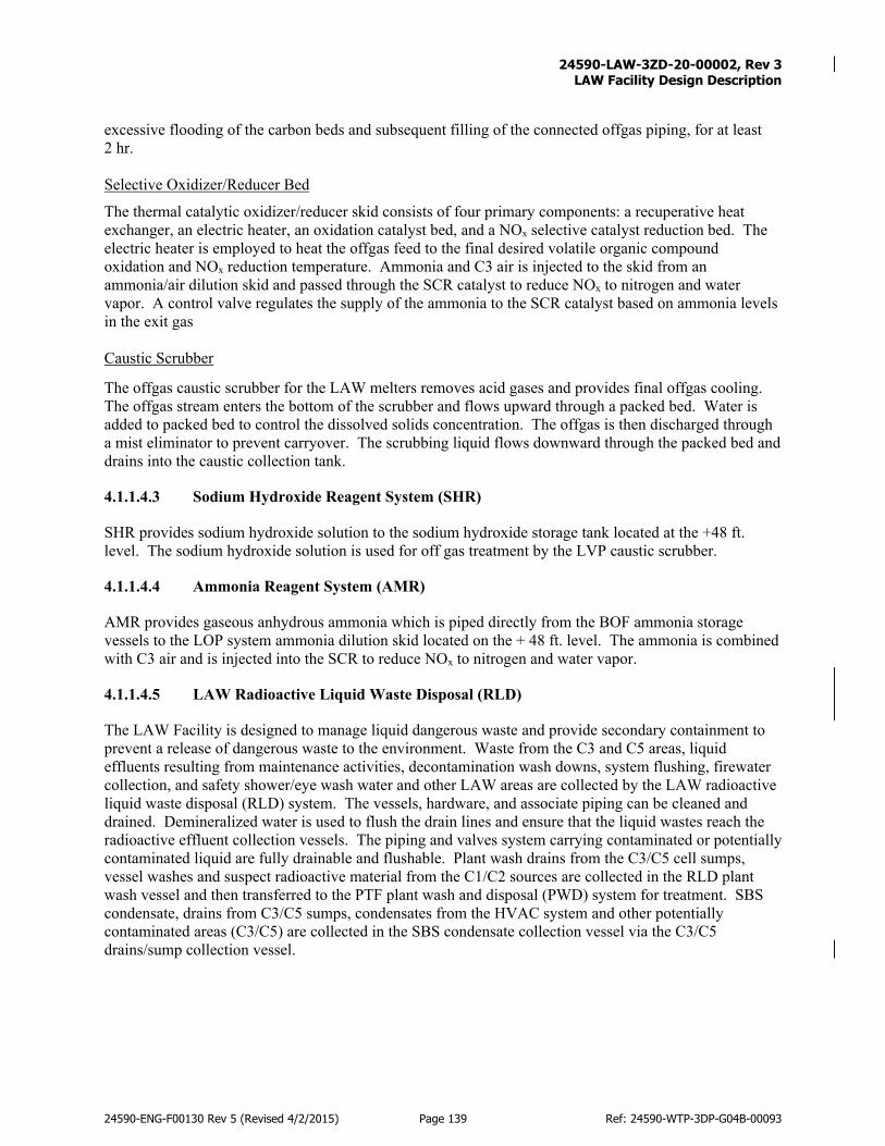
24590-LAW-3ZD-20-00002, Rev 3
LAW Facility Design Description
24590-ENG-F00130 Rev 5 (Revised 4/2/2015) Page 139 Ref: 24590-WTP-3DP-G04B-00093
excessive flooding of the carbon beds and subsequent filling of the connected offgas piping, for at least 2 hr. Selective Oxidizer/Reducer Bed
The thermal catalytic oxidizer/reducer skid consists of four primary components: a recuperative heat exchanger, an electric heater, an oxidation catalyst bed, and a NOx selective catalyst reduction bed. The electric heater is employed to heat the offgas feed to the final desired volatile organic compound oxidation and NOx reduction temperature. Ammonia and C3 air is injected to the skid from an ammonia/air dilution skid and passed through the SCR catalyst to reduce NOx to nitrogen and water vapor. A control valve regulates the supply of the ammonia to the SCR catalyst based on ammonia levels in the exit gas Caustic Scrubber
The offgas caustic scrubber for the LAW melters removes acid gases and provides final offgas cooling. The offgas stream enters the bottom of the scrubber and flows upward through a packed bed. Water is added to packed bed to control the dissolved solids concentration. The offgas is then discharged through a mist eliminator to prevent carryover. The scrubbing liquid flows downward through the packed bed and drains into the caustic collection tank.
4.1.1.4.3 Sodium Hydroxide Reagent System (SHR)
SHR provides sodium hydroxide solution to the sodium hydroxide storage tank located at the +48 ft. level. The sodium hydroxide solution is used for off gas treatment by the LVP caustic scrubber.
4.1.1.4.4 Ammonia Reagent System (AMR)
AMR provides gaseous anhydrous ammonia which is piped directly from the BOF ammonia storage vessels to the LOP system ammonia dilution skid located on the + 48 ft. level. The ammonia is combined with C3 air and is injected into the SCR to reduce NOx to nitrogen and water vapor.
4.1.1.4.5 LAW Radioactive Liquid Waste Disposal (RLD)
The LAW Facility is designed to manage liquid dangerous waste and provide secondary containment to prevent a release of dangerous waste to the environment. Waste from the C3 and C5 areas, liquid effluents resulting from maintenance activities, decontamination wash downs, system flushing, firewater collection, and safety shower/eye wash water and other LAW areas are collected by the LAW radioactive liquid waste disposal (RLD) system. The vessels, hardware, and associate piping can be cleaned and drained. Demineralized water is used to flush the drain lines and ensure that the liquid wastes reach the radioactive effluent collection vessels. The piping and valves system carrying contaminated or potentially contaminated liquid are fully drainable and flushable. Plant wash drains from the C3/C5 cell sumps, vessel washes and suspect radioactive material from the C1/C2 sources are collected in the RLD plant wash vessel and then transferred to the PTF plant wash and disposal (PWD) system for treatment. SBS condensate, drains from C3/C5 sumps, condensates from the HVAC system and other potentially contaminated areas (C3/C5) are collected in the SBS condensate collection vessel via the C3/C5 drains/sump collection vessel.

24590-LAW-3ZD-20-00002, Rev 3
LAW Facility Design Description
24590-ENG-F00130 Rev 5 (Revised 4/2/2015) Page 140 Ref: 24590-WTP-3DP-G04B-00093
4.1.1.5 LAW Non-Radioactive Liquid Waste Disposal (NLD)
Non-radioactive liquid effluents from C1/C2 area floor washes, plant cooling water purge, fire protection water, and condensate from the C1/C2 HVAC system are processed by the LAW NLD system and transferred to the BOF NLD system. If sampling results indicate that the effluent is contaminated, the contents will be transferred to the plant wash vessel. BOF receives and transfers secondary aqueous wastes discharged from the WTP processes to the Liquid Effluent Retention Facility / Effluent Treatment Facility (LERF/ETF) and Treated Effluent Disposal Facility (TEDF). Sanitary sewage effluent generated in the LAW Facility are collected, treated, and processed in the BOF sanitary disposal (SND) system.
4.1.1.6 Utilities
The functionality of the LAW Facility is dependent upon many of the services supplied to the LAW building. Steam, air, and water used for various purposes are piped to the LAW Facility from BOF. Within the LAW Facility hot cell areas, plant service air (PSA), water (Domestic Water (DOW) and Demineralized Water (DIW), and gases are piped to the outer surface of the cave/cell. Cooling water is piped to the pour caves. Utilities are piped to the caves/cells through penetrations (with seals) in the concrete walls.
4.1.1.6.1 Ventilation System (C2V, C3V, and C5V)
The LAW ventilation systems support contamination control by providing a cascading ventilation arrangement. This system is designed to create pressure gradients and cause air to flow from areas of lesser contamination potential to areas of greater contamination potential. Air will not be recirculated within the building, except for the use of local cooling units as required for heat removal from the C2, C3, and C5 areas. The LAW C2V, C3V, and C5V ventilation systems provide ducts, exhaust fans, and HEPA filters to remove airborne radioactive contamination and non-radioactive particulates to maintain emissions below applicable limits before the treated vent gases are discharged to the atmosphere. The C5 exhaust fans and the C5 HEPA filter housings maintain a negative pressure on the most contaminated portions of the facility. The exhaust stack offgas piping rises about 200 ft. above grade, and is surrounded by an exposed steel lattice structure supporting separate ventilation pipes for the C3 exhaust, C5 exhaust, and the melter offgas system (including vessel vents). The C2V and C3V CS DX air conditioning systems provide a safety function of area cooling to prevent the loss of the safety function of CS SSCs due to overheating. The C2 DX cooling system maintains a desired temperature, which allows the safety equipment within the room to operate normally. The safety function protects the Programmable Protection system (PPJ) cabinets and related components from entering indeterminate states as a result of high temperatures such as those experienced during a loss of facility cooling.
4.1.1.6.2 Stack Discharge Monitoring (SDJ)
Effluent radiological monitoring and sampling systems are provided on the C2, C3, C5, and melter offgas lines. Non-radiological monitoring systems are provided on the process melter offgas lines. Sample lines and the SDJ components they interface with are designed to prevent seismic interaction hazards to the melter offgas lines. This is accomplished by sampling line routing and seismic restraints, as needed. SDJ system information is displayed centrally on the Process Control system (PCJ) displays in the main

24590-LAW-3ZD-20-00002, Rev 3
LAW Facility Design Description
24590-ENG-F00130 Rev 5 (Revised 4/2/2015) Page 141 Ref: 24590-WTP-3DP-G04B-00093
control room (MCR) and LAW Control Room. Information is also available through the PCJ in the LAW Facility control room.
4.1.1.6.3 High Pressure Steam (HPS) and Low Pressure Steam (LPS)
The HPS system is supplied from the BOF. The LAW HPS system reduces the pressure of the high-pressure steam and supplies the LAW LPS system. The HPS system enters the building at the +3 ft. elevation and rises through a chase to the +48 ft. elevation, and then runs the length of the building to room L-0305. In room L-0305, the HPS enters a letdown station, which forms the transition from HPS to LPS. Temperature and pressure instrumentation in room L-0305 is associated with an interlock that can isolate the HPS steam supply in the event that a significant steam release is detected. The LPS system supplies steam to the C2V supply system for the purposes of building heating and humidity control. The LPS system piping also exits this room through the floor, and continues through areas on the +28 ft. elevation until leaving the facility through the north wall to supply HVAC needs for the LAW Annex building. The high pressure and low-pressure steam systems are considered SS and are credited with maintaining steam confinement and isolation as necessary to prevent steam exposure to those safety components whose safety functions can be challenged by exposure to steam.
4.1.1.6.4 Steam Condensate (SCW)
The primary function of the SCW is to collect the steam condensate throughout the LAW Facility and send it to a condensate tank. The SCW is pumped back to the BOF Facility via SCW condensate pumps.
4.1.1.6.5 Medium Voltage Electrical (MVE) and Low Voltage Electrical Systems (LVE) and Direct Current Electrical (DCE)
The onsite 13.8 kV electrical system (MVE) in the BOF area supplies 13.8 kV power to LAW 13.8kV Switchgear and 13.8kV-480V outdoor transformers. The 13.8 kV Switchgear feed the Melter Electrode Power Supplies and 13.8kV – 480V outdoor transformers, which feed 480V Switchboards. Switchboards feed the motor control center (MCC). The Switchboards and MCCs distribute 480V electric power to the LAW Facility. The Direct Current Electrical (DCE) system provides battery racks and two associated battery chargers in the LAW electrical building (Building 24), which supply power at 125 VDC (volts direct current) for electrical switchgear controls in the LAW Facility. Note that LAW 13.8 kV switchgear is located in adjacent Building 24.
4.1.1.6.6 Uninterruptible Power Electrical System (UPE)
LAW UPE provide limited backup power primarily for the melter offgas system exhausters (LVP), the stack monitoring system (SDJ) system, the process control system (PCJ), the mechanical handling control system (MHJ), the auto sampling control system (ASX), emergency lighting (LTE), C5 ventilation system, Safety UPS battery room cooling (C2V), and melter offgas exhauster room ventilation (C3V). The power source for control system of C5V exhaust fans has battery backup, but the fans are on non-safety BOF standby diesel backup power system SDX. For complete list of systems interfaced with UPE refer to section 2.3 of 24590-LAW-3ZD-UPE-00001.
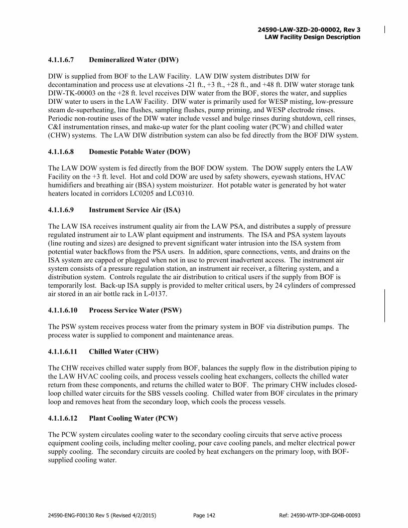
24590-LAW-3ZD-20-00002, Rev 3
LAW Facility Design Description
24590-ENG-F00130 Rev 5 (Revised 4/2/2015) Page 142 Ref: 24590-WTP-3DP-G04B-00093
4.1.1.6.7 Demineralized Water (DIW)
DIW is supplied from BOF to the LAW Facility. LAW DIW system distributes DIW for decontamination and process use at elevations -21 ft., +3 ft., +28 ft., and +48 ft. DIW water storage tank DIW-TK-00003 on the +28 ft. level receives DIW water from the BOF, stores the water, and supplies DIW water to users in the LAW Facility. DIW water is primarily used for WESP misting, low-pressure steam de-superheating, line flushes, sampling flushes, pump priming, and WESP electrode rinses. Periodic non-routine uses of the DIW water include vessel and bulge rinses during shutdown, cell rinses, C&I instrumentation rinses, and make-up water for the plant cooling water (PCW) and chilled water (CHW) systems. The LAW DIW distribution system can also be fed directly from the BOF DIW system.
4.1.1.6.8 Domestic Potable Water (DOW)
The LAW DOW system is fed directly from the BOF DOW system. The DOW supply enters the LAW Facility on the +3 ft. level. Hot and cold DOW are used by safety showers, eyewash stations, HVAC humidifiers and breathing air (BSA) system moisturizer. Hot potable water is generated by hot water heaters located in corridors LC0205 and LC0310.
4.1.1.6.9 Instrument Service Air (ISA)
The LAW ISA receives instrument quality air from the LAW PSA, and distributes a supply of pressure regulated instrument air to LAW plant equipment and instruments. The ISA and PSA system layouts (line routing and sizes) are designed to prevent significant water intrusion into the ISA system from potential water backflows from the PSA users. In addition, spare connections, vents, and drains on the ISA system are capped or plugged when not in use to prevent inadvertent access. The instrument air system consists of a pressure regulation station, an instrument air receiver, a filtering system, and a distribution system. Controls regulate the air distribution to critical users if the supply from BOF is temporarily lost. Back-up ISA supply is provided to melter critical users, by 24 cylinders of compressed air stored in an air bottle rack in L-0137.
4.1.1.6.10 Process Service Water (PSW)
The PSW system receives process water from the primary system in BOF via distribution pumps. The process water is supplied to component and maintenance areas.
4.1.1.6.11 Chilled Water (CHW)
The CHW receives chilled water supply from BOF, balances the supply flow in the distribution piping to the LAW HVAC cooling coils, and process vessels cooling heat exchangers, collects the chilled water return from these components, and returns the chilled water to BOF. The primary CHW includes closed-loop chilled water circuits for the SBS vessels cooling. Chilled water from BOF circulates in the primary loop and removes heat from the secondary loop, which cools the process vessels.
4.1.1.6.12 Plant Cooling Water (PCW)
The PCW system circulates cooling water to the secondary cooling circuits that serve active process equipment cooling coils, including melter cooling, pour cave cooling panels, and melter electrical power supply cooling. The secondary circuits are cooled by heat exchangers on the primary loop, with BOF-supplied cooling water.

24590-LAW-3ZD-20-00002, Rev 3
LAW Facility Design Description
24590-ENG-F00130 Rev 5 (Revised 4/2/2015) Page 143 Ref: 24590-WTP-3DP-G04B-00093
4.1.1.6.13 Breathing Service Air (BSA)
The LAW BSA equipment is in room L-0137 located in an ancillary building south of the main process building. The BSA piping system distributes it to hose stations located near rooms that require entry for maintenance, at all the levels in the LAW buildings. The system consists of a compressor, purification package vessel receiver, analyzers, and manifolds with hose stations. Back-up BSA supply is provided by 24 cylinders of compressed air stored in an air bottle rack in L-0137.
4.1.1.6.14 Programmable Protection System (PPJ)
The Programmable Protection System (PPJ) is the logic solver, which receives the chemical safety instrumentation inputs and determines when the chemical safety instrumented function (SIF) must actuate the final element to its safe state. The PPJ System is CS for the role it plays in the performance of safety instrumented functions.
Boundaries and Interfaces
Refer to Table 2-2 for a detailed table of interfaces and boundaries for the LAW Facility. If additional information that enhances system performance or functionality is required, it is discussed below.
Physical Layout and Location
Reference: 24590-LAW-P1-P01T-00001 through 24590-LAW-P1-P01T-00006 The Low-Activity Waste (LAW) Facility consists of two separate buildings: Building 20 and Building 24. Building 20 is the LAW vitrification building that includes a three-story (above ground) main process building (with one level below grade), a two-story LAW annex building, and Liquid CO2 storage tank. (Refer to Figure 4-2 for the LAW Facility overview.)
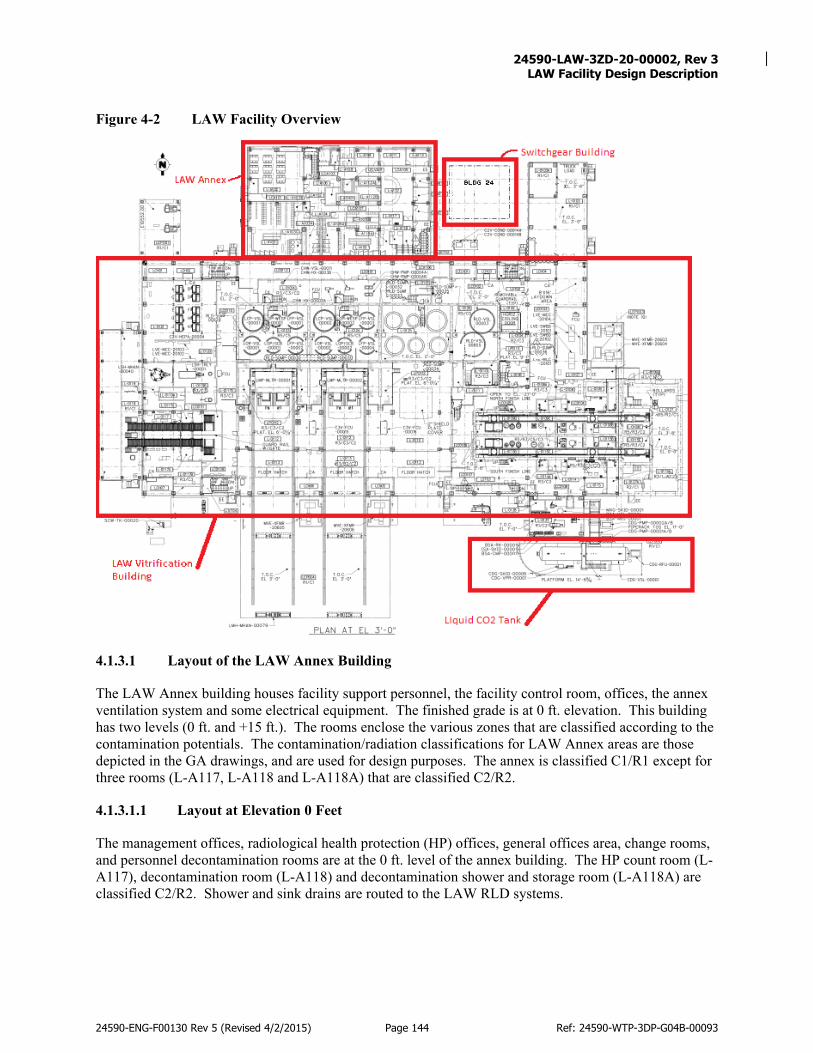
24590-LAW-3ZD-20-00002, Rev 3
LAW Facility Design Description
24590-ENG-F00130 Rev 5 (Revised 4/2/2015) Page 144 Ref: 24590-WTP-3DP-G04B-00093
Figure 4-2 LAW Facility Overview
4.1.3.1 Layout of the LAW Annex Building
The LAW Annex building houses facility support personnel, the facility control room, offices, the annex ventilation system and some electrical equipment. The finished grade is at 0 ft. elevation. This building has two levels (0 ft. and +15 ft.). The rooms enclose the various zones that are classified according to the contamination potentials. The contamination/radiation classifications for LAW Annex areas are those depicted in the GA drawings, and are used for design purposes. The annex is classified C1/R1 except for three rooms (L-A117, L-A118 and L-A118A) that are classified C2/R2.
4.1.3.1.1 Layout at Elevation 0 Feet
The management offices, radiological health protection (HP) offices, general offices area, change rooms, and personnel decontamination rooms are at the 0 ft. level of the annex building. The HP count room (L-A117), decontamination room (L-A118) and decontamination shower and storage room (L-A118A) are classified C2/R2. Shower and sink drains are routed to the LAW RLD systems.

24590-LAW-3ZD-20-00002, Rev 3
LAW Facility Design Description
24590-ENG-F00130 Rev 5 (Revised 4/2/2015) Page 145 Ref: 24590-WTP-3DP-G04B-00093
4.1.3.1.2 Layout at Elevation +15 Feet
The control rooms, offices, and electrical rooms are at the +15 ft. level of the annex building. The facility control rooms (L-A201 and L-A201D) provide space for local operation of the LAW systems, and are located in the upper level of the annex building. The control room (L-A201) is the main control room area where the PCJ consoles and control panels are located. The crane control room (L-A201D) where the console for Mechanical Handling Control System (MHJ) console is located.
4.1.3.2 Layout of Switch Gear Building
Building 24 is the one-story switchgear building that is located north of the main process building and east of the annex building. The Switchgear Building is one-story at level 0ft. This structure houses switchgear enclosures, transformers, and power distribution equipment.
4.1.3.3 Liquid CO2 Storage
A liquid CO2 storage tank is located outside the southeast corner of the main building at grade level. On the southeast corner of the process building is a liquid CO2 storage vessel (CDG-VSL-00001) that is part of the CDG system. Liquid CO2 delivered by vendor is stored in this insulated, refrigerated, and pressurized vessel.
4.1.3.4 Layout of the LAW Vitrification Main Process Building
Refer to: General Arrangement (GA) drawings, 24590-LAW-P1-P01T-00001 through 24590-LAW-P1-P01T-00006 The LAW vitrification main process building houses process activities, equipment for LAW vitrification process systems, equipment for ventilation systems, waste packaging and finishing areas, and maintenance and sub-change areas. The finished grade of this building is at elevation +3 ft. The below grade portion of the building is at elevation -21 ft. There are three above grade stories at elevations +3 ft., +28 ft., and +48 ft. There is an intermediate level of primarily platforms at elevation +22 ft. The roof is at elevation +68 ft. The contamination/ radiation classifications listed for LAW building areas are shown in the GA drawings. Personnel access is not normally permitted to C5/R5 areas, where radioactive equipment or waste is located. Controlled access points to areas that are potentially contaminated are used to reduce the possibility of a spread of contamination. The LAW Facility layout design is configured to comply with ALARA by segregating and classifying areas based on their potential for contamination and radiological dose rates. Dedicated maintenance areas are provided where equipment located in areas of higher contamination can be decontaminated and brought into an area of lower contamination for hands-on maintenance activities.
4.1.3.4.1 Layout at Elevation +3 Feet
The +3 ft. level of the LAW main process building provides space for equipment, operation and maintenance associated with the LAW melters, melter feed systems, melter exhaust systems, liquid waste cells, clean containers import, glass-filled container finishing and export, and process support systems. See Figure 4-3 for overview of the LAW Building +3 ft. elevation. Process cells (L-0123 and L-0124) provide space for melter feed vessels, primary offgas system (LOP) vessels and associated pumps and agitators. In each installed process cell are six vessels that support the corresponding installed melter. There are three melter feed vessels in each cell, a concentrate feed receipt

24590-LAW-3ZD-20-00002, Rev 3
LAW Facility Design Description
24590-ENG-F00130 Rev 5 (Revised 4/2/2015) Page 146 Ref: 24590-WTP-3DP-G04B-00093
vessel (CRV), a melter feed preparation vessel (MFPV), and a melter feed vessel (MFV). Each process cell also contains the SBS column, SBS condensate vessel, and WESP for treating the offgas stream from each melter. The effluent cell (L-0126) provides space for the Plant Wash Vessel (RLD-VSL-00003) and the SBS Condensate Collection Vessel (RLD-VSL-00005) and associated pumps. Penetrations that could allow liquids to flow into the cell are sealed to prevent potential excessive floor loading from internal flooding. The Clean Container Receipt Area (L-0117) provides space for staging containers prior to importing to the pour tunnel. This area is located in the southwest part of the main process building. This area is adjacent to and east of the Receiving Dock L-0118, that is used for importing new glass product containers. There are two container staging conveyor lines in L-0117. Each line moves clean containers from the west end of this area, through a C2 airlock, to the corresponding import hatch area east of the airlock. L-0117 also provides space for LRH enclosures, panels and utility pipe racks. The ILAW Container Finishing area contains the ILAW glass container finishing lines that are used for preparing and monitoring the filled containers (that are passed up from the -21 ft. level) for export out of the LAW Facility. The ILAW container finishing area consists of the Sampling/Inert Fill/Lidding Areas (L-0109D and L-0115D), the Decontamination Areas (L-0109C and L-0115C), the Swabbing Areas (L-0109B and L-0115B), and the Container Monitoring/Export Areas (L-0109E and L-0115E). The fill line/lidding areas, L-0109D (north line) and L-0115D (south line), provide space for LFH system equipment used for placing lids onto the filled ILAW containers, and for filling containers with inert material, and sampling, as needed. Each lidding area includes a shard sampling area that contains equipment that collects and exports glass shard samples for analysis and measures the fill level of the product container. A posting port and glovebox are used to export the shard sample to system ASX. The inert fill area contains equipment that fills a partially glass-filled container with inert silica to comply with the contract void space requirements. Decontamination area north line (L-0109C) and Decontamination area south line (L-0115C) provide space for equipment used to decontaminate product containers. Contamination control from the effluent gases from LFH container decontamination station is facilitated by the C5 ventilation system. These gaseous effluents comprise CO2 gas formed from the CO2 pellets (CDG) and ventilation air. The swabbing cells (L-0109B, north line) and (L-0115B, south line) provide space for equipment used for verifying that the product container does not exceed contamination limits. Each cell provides space for the dual-rail swabbing hoist that is used for lifting the container and transporting it to the swabbing station; swabbing power manipulator that perform swabbing; bogie-mounted swabbing turntable that rotates the container to expose all surfaces of the container to swabbing. Each finishing line has a posting port and glovebox for export of the swabs to be counted. Container monitoring/export areas north line (L-0109E) and container monitoring/export areas south line (L-0115E) provide space for container surface radiation dose rate monitors, and LFH bogies that transfer the accepted ILAW glass container from swabbing cells L-0109B (north line) and L-0115B (south line) to system LEH in the export bay (L-0127). A trap door is located on the roof of each export/monitoring area. The trap door provides access for the LEH export bridge crane to retrieve the ILAW containers deemed acceptable for export; and provides

24590-LAW-3ZD-20-00002, Rev 3
LAW Facility Design Description
24590-ENG-F00130 Rev 5 (Revised 4/2/2015) Page 147 Ref: 24590-WTP-3DP-G04B-00093
radiation shielding and contamination barrier when closed. The export crane is located in the export bay L-0127.
Process support system on the +3 ft. elevation of LAW building includes C2V filters, chilled water vessels, consumables imports and export, breathing air, and argon. The C2 Exhaust Filter Room L-0121 provides space for the C2 HEPA filters and associated ductwork. The C2 exhaust filter room, L-0121, contains 10 single-stage HEPA filter units with four filters in each unit. The C2 exhaust fans are located outside the building, at the northwest corner. The SBS Cooling Room (L-0101A) provides space for the chilled water system equipment and the chilled water vessel. This room is located on the north side of the main process building, just north of the process cells. The BSA equipment room L-0137, houses equipment for BSA system and ISA, and the MXG skid. Space is provided for storage of 48 cylinders of compressed air for back-up BSA and ISA supply. The LAW MXG system stores liquid argon, converts liquid argon to gas, and distributes argon gas to the LAW LMP Melters airlift lance and level/density detection bubblers. Consumable Preparation Area (L-0119) provides space for personnel and LAW melter equipment support handling (LSH) system equipment for transfer, preparation, staging, and inspection of the imported consumables from the receiving dock area (L-0118) and to the import/export area (L-0119B). This area is also used for packaging and proper labeling of the bagged, spent bubblers and other consumable equipment into a waste disposal box.

24590-LAW-3ZD-20-00002, Rev 3
LAW Facility Design Description
24590-ENG-F00130 Rev 5 (Revised 4/2/2015) Page 148 Ref: 24590-WTP-3DP-G04B-00093
Figure 4-3 LAW Facility EL 3’-0”
4.1.3.4.2 Layout at Elevation -21 Feet
The -21 ft. level of the LAW main process building provides space for equipment associated with the operation and maintenance of primarily the LPH system, C5V ventilation system, and process support systems. The LPH system areas include the waste container transport corridor, LAW melter pour caves, container buffer storage and rework areas, and dedicated equipment maintenance areas. The container transfer corridor (L-B025B) contains two container transport bogie lines, north and south lines, and occupies almost the entire length of the -21 ft. level. This transfer corridor’s concrete walls have openings that interface with the bogie maintenance area, pour caves, monorail maintenance areas, container rework area, and container buffer storage area. These openings are equipped with steel doors that support maintenance activities by providing shielding and/or containment. On the north side of corridor L-B025B, there are four 3-inch thick pour cave steel shield doors for the pour caves for monorail passage. There are two pour caves associated with each installed LMS melter. Pour caves L-B015A and L-B013C are associated with locally shielded melter (LSM) melter #1 while

24590-LAW-3ZD-20-00002, Rev 3
LAW Facility Design Description
24590-ENG-F00130 Rev 5 (Revised 4/2/2015) Page 149 Ref: 24590-WTP-3DP-G04B-00093
pour caves L-B013B and L-B011C are associated with LSM melter #2. Each pour cave provides space for lifting and transport equipment for the product containers, including one container turntable, and a 10-ton monorail hoist. The monorail hoists are used to transport the containers between the pour caves and the transfer corridor. Pour cave cooling panels are located between rooms L-B015A and L-B013C and between rooms L-B013B and L-B011C. Pour Cave Cooling Panel Manifold Area Melter #1 (L-B013) and Pour Cave Cooling Panel Manifold Area Melter #2 (L-B011) provide space for pour cave cooling panel manifolds. Room L-B013 services the LSM melter #1 pour caves, and is located between pour cave mechanical rooms L-B014 and L-B012, and north of pour cave airlock L-B013A. Room L-B011 services LSM melter #2 pour caves, and is located between pour cave mechanical room L-B012 and spare room L-B010, and north of pour cave airlock L-B011A. The container buffer store area (L-B025C) provides space to store ILAW containers after they are filled with glass and prior to being transported to the finishing line. The buffer storage area is sized for storage of 12 full product containers on container park stands. The concrete walls are lined with insulated stainless steel cladding/panels. The container rework area (L-B025D) provides space for storage and rework capabilities of the out-of-specification glass or containers. Master slave manipulator penetrations and a shielded glass window facilitate rework operations. Melter #1 LSM power supply room (L-B002) and Melter #2 LSM power supply room (L-B004) provide space for the LVE and MVE power supplies, LVE Motor Control Center (MCC) and other electrical equipment that provide power to the LMP system. Electrical Room (L-B006) provides space for the future LVE MCC and other electrical equipment that will supply power to the future melter #3 process system. The C5 filter room (L-B029) provides space primarily for filter housing units that contain C5V HEPA filters, which are upstream of the C5 exhaust fans. There is also space for chilled water Fan Coiled Units (FCU) for supplemental cooling of the room. C5 exhaust fan room (L-B028) provides space primarily for C5V exhaust fans and C5V instrumentation rack. There is also space for C3V FCUs for supplemental cooling of this room. The process support systems on the elevation -21 ft. level include the C3/C5 and C1/C2 drain collection systems and process cooling water. The C3/C5 Drain Collection Cell (L-B001B) provides space for and secondary liquid containment for the C3/C5 Drains/Sump Collection Vessel (RLD-VSL-00004). C1/C2 Drain Collection Area (L-B003) provides space for the C1/C2 drains/sump collection vessel (NLD-VSL-00005). The Pour Cave Cooling Room (L-B030) provides space for the PCW system equipment that is used to cool the Container Turntable in order to protect the concrete floor in melter pour caves. The Melter Power Supply Cooling Room (L-B016) provides space for the PCW system equipment that is used to cool the electrical bus that supplies power to the melters. (Refer to Figure 4-4 for an overhead view of the LAW Facility at elevation -21 ft.)
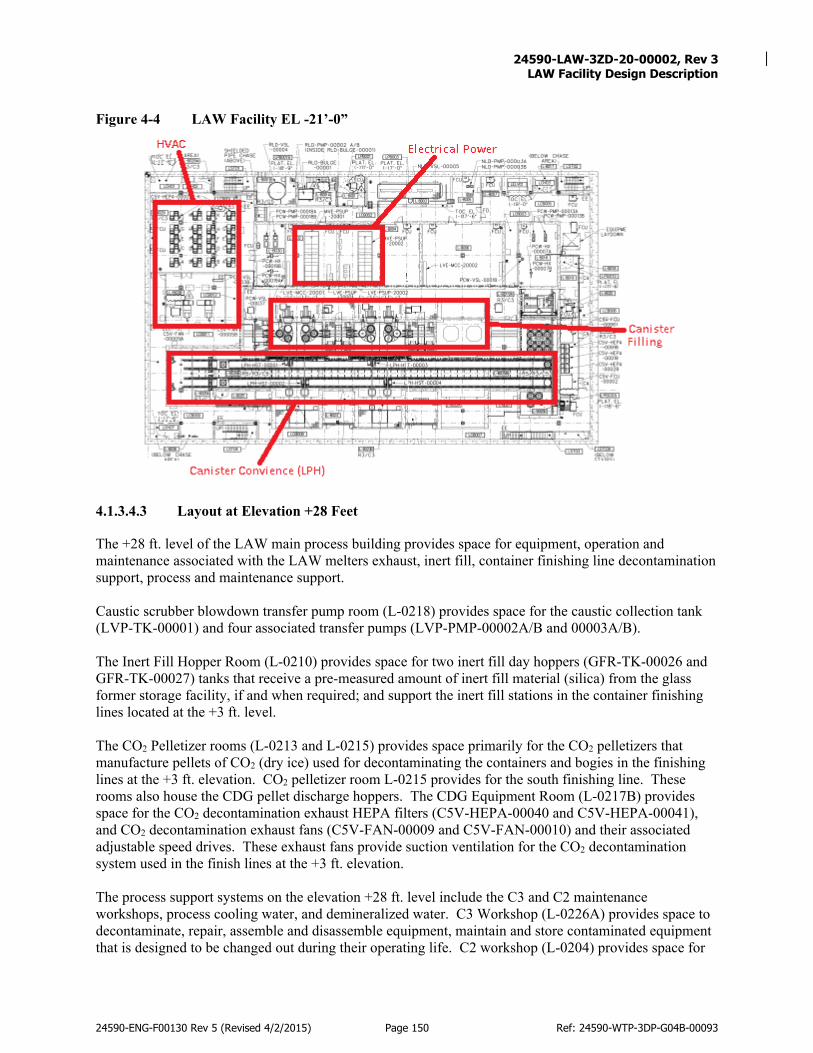
24590-LAW-3ZD-20-00002, Rev 3
LAW Facility Design Description
24590-ENG-F00130 Rev 5 (Revised 4/2/2015) Page 150 Ref: 24590-WTP-3DP-G04B-00093
Figure 4-4 LAW Facility EL -21’-0”
4.1.3.4.3 Layout at Elevation +28 Feet
The +28 ft. level of the LAW main process building provides space for equipment, operation and maintenance associated with the LAW melters exhaust, inert fill, container finishing line decontamination support, process and maintenance support. Caustic scrubber blowdown transfer pump room (L-0218) provides space for the caustic collection tank (LVP-TK-00001) and four associated transfer pumps (LVP-PMP-00002A/B and 00003A/B). The Inert Fill Hopper Room (L-0210) provides space for two inert fill day hoppers (GFR-TK-00026 and GFR-TK-00027) tanks that receive a pre-measured amount of inert fill material (silica) from the glass former storage facility, if and when required; and support the inert fill stations in the container finishing lines located at the +3 ft. level. The CO2 Pelletizer rooms (L-0213 and L-0215) provides space primarily for the CO2 pelletizers that manufacture pellets of CO2 (dry ice) used for decontaminating the containers and bogies in the finishing lines at the +3 ft. elevation. CO2 pelletizer room L-0215 provides for the south finishing line. These rooms also house the CDG pellet discharge hoppers. The CDG Equipment Room (L-0217B) provides space for the CO2 decontamination exhaust HEPA filters (C5V-HEPA-00040 and C5V-HEPA-00041), and CO2 decontamination exhaust fans (C5V-FAN-00009 and C5V-FAN-00010) and their associated adjustable speed drives. These exhaust fans provide suction ventilation for the CO2 decontamination system used in the finish lines at the +3 ft. elevation. The process support systems on the elevation +28 ft. level include the C3 and C2 maintenance workshops, process cooling water, and demineralized water. C3 Workshop (L-0226A) provides space to decontaminate, repair, assemble and disassemble equipment, maintain and store contaminated equipment that is designed to be changed out during their operating life. C2 workshop (L-0204) provides space for

24590-LAW-3ZD-20-00002, Rev 3
LAW Facility Design Description
24590-ENG-F00130 Rev 5 (Revised 4/2/2015) Page 151 Ref: 24590-WTP-3DP-G04B-00093
the maintenance/repair of equipment that is not expected to be radioactively contaminated. The melter cooling water room (L-0224) provides space for two plant PCW pumps, four heat exchangers, two expansion vessels, two air separation vessels, and cable trays. The DIW tank (DIW-TK-00003) and pumps (DIW-PMP-00002A/B) are located in area LC0203. (Refer to Figure 4-5 for an overhead view of the LAW Facility at elevation +28 ft.) Figure 4-5 LAW Facility EL +28’-0”
4.1.3.4.4 Layout at Elevation +48 Feet
The +48 ft. level of the LAW main process building provides space for equipment, operation and maintenance associated with Auto Samplers, LAW melter offgas and process vessel vents treatment, C3V ventilation, and stack monitoring. The Auto Sampler Transfer Station (L-0301) provides space for equipment associated with the LAW ASX system. This room contains two auto samplers, which sample the vessels in the wet process cell and send the samples to the analytical laboratory for analysis via a pneumatic transfer system. Secondary Off-gas Equipment Room (L-0304F) provides space primarily for equipment and operation of the secondary offgas treatment of gases from the melters and process vessels prior to their release to the atmosphere through the elevated facility stack. The equipment is used to remove mercury, volatile organic compounds, nitrogen oxides, miscellaneous acid gases from the stack exhaust gases. This room is located in the central part of this level. The LVP-SKID-00001 (includes the LVP mercury absorbers), LVP-SKID-00002 (includes the LVP catalytic oxidizer/reducer and heaters), LVP-SKID-00003 (includes the LVP ammonia injection equipment), and the LVP Caustic Scrubber (LVP-SCB-00001) are located in this room.

24590-LAW-3ZD-20-00002, Rev 3
LAW Facility Design Description
24590-ENG-F00130 Rev 5 (Revised 4/2/2015) Page 152 Ref: 24590-WTP-3DP-G04B-00093
Secondary Offgas Exhaust Room 1A (L-0304C), Room 1B (L-0304D), and Room 1C (L-0304E) provide space for the LVP exhausters that provide suction for the LVP off gas treatment system. The HEPA Offgas Filter Room (L-0304H) provides space for the operation and maintenance of the LVP HEPA preheaters and filters that are used to remove radioactive particulates from the LVP offgas stream. The process support systems on the elevation +28 ft. level include the sodium hydroxide tank and associated pumps (L-0312), two C3V exhaust fans (L-0317), C3V exhaust HEPA filters (L-0319A), and stack monitoring equipment for the C2V, C3V, and C5V exhaust systems (L-0320). (Refer to Figure 4-6 for an overhead view of the LAW Facility at elevation +48 ft.)
Figure 4-6 LAW Facility EL +48’-0”
Principles of Operations
This section provides a general description of the LAW processes. In the LAW vitrification building, the pretreated LAW feed is blended with glass forming chemicals (GFCs) and then vitrified in the LAW melters. The ILAW form product is packaged in ILAW product containers for transport to the ILAW disposal facility for storage or disposal. Waste form products and secondary wastes are produced in accordance with the qualification strategies and requirements identified in the Secondary Wastes Compliance Plan, ILAW Product Compliance Plan, and meet the relevant specification and interface requirements. The primary and secondary offgas systems including the stack are designed to comply with applicable Federal, State and local requirements, including environmental permits and other regulatory approvals and authorizations. Figure 4-1 is a flow diagram that illustrates the major process flow for the LAW Facility.

24590-LAW-3ZD-20-00002, Rev 3
LAW Facility Design Description
24590-ENG-F00130 Rev 5 (Revised 4/2/2015) Page 153 Ref: 24590-WTP-3DP-G04B-00093
The LAW Facility receives pretreated LAW concentrate from the PTF or DFLAW. The concentrate is sampled (ASX) and stores batches (LFP). The stored concentrate is mixed with sucrose and glass formers from the GFR system to form a uniform batch of slurry feed to the LAW melters. The slurry is fed continuously to the LAW melters (LMP). In the LAW ceramic lined, joule-heated glass melter (LMP) the non-volatile materials are continuously converted into molten glass. Water and other volatile material in the melter are evaporated and removed by the offgas system. The empty waste containers are brought in to the import dock. Using the LRH overhead crane, the container is moved from the transport vehicle to the receipt conveyor (LRH). The container is inspected and moved by the conveyor to the import hatch. The LRH hoist lifts the container and lowers it through the hatch on to the LPH bogie. LPH transports the container to one of four pour cave transfer positions. The pour cave monorail hoist transfers the container from the bogie to the container turntable in the pour cave. LMP fills the container with glass. When the filling is complete, the turntable moves the filled container to the cool position. The monorail hoist transfers the cooled, filled container from the turntable import/export position to an empty bogie. The bogie transports the filled container to the export position, where the buffer store crane transfers the filled container from the bogie to buffer storage for further cooling. The buffer store crane transfers the cooled, filled container from buffer storage to the export stand, where the system LFH hoist picks up the container and lifts it to the conveyors at the +3 ft. elevation. If required, the operator obtains a glass shard sample. The container glass fill height level is measured. If the glass level is low, the bogie moves container to the inert fill position and inert fill is added. The bogie moves back to sampling station. The bogie moves the container to the lidding station. If needed the container flange sealing area is cleaned. The lid press inserts and seals the lid onto container. When the lid is properly engaged on the container, the lidding bogie moves the container to the decontamination area. The container is decontaminated by a nozzle directing CO2 pellets to impact the container surface removing any contamination. The container is moved to the swabbing area. The power manipulator swabs the container. The swabbing bogie is moved to the export station. The LEH hoist lifts the container through the LFH trap door and moves the container to the transport vehicle. Hot, particulate-laden offgas exits the melter and is first cooled by the film cooler, then quenched in the SBS. The quenched offgas is then sprayed with a fine mist of water at the inlet of the WESP, which enhances the effectiveness of the charged plates of the WESP. The offgas then passes through HEPA filters. The offgas is passed through the mercury absorber, a sulfur impregnated activated carbon bed, to react with the mercury and hold it on the bed. Gases from the carbon beds are sent to an economizer heat exchanger to collect energy from the hot gases exiting the catalyst skid. Residual organic constituents and products of incomplete combustion are oxidized on platinum catalyst, and then NOx reacts with ammonia gas over a catalyst to form nitrogen gas and water. Liquid ammonia is supplied from the ammonia skid, which includes an evaporator and air dilution steps, prior to delivering the ammonia-air mixture to the catalyst skid in the LAW Facility. The gases from the heat exchanger are further cooled by an atomized water spray prior to entering a caustic scrubber for final acid gas removal. The caustic in the scrub solution absorbs acid gases, including CO2. A mist eliminator at the scrubber is the final treatment step. The cooled gases from the caustic scrubber are sent to the stack by the seven stage turbine exhausters. The offgas is monitored for NOx, CO, total hydrocarbons and radioactivity at the exhaust stack.
System Reliability Features
Refer to system level SDD for system reliability features.

24590-LAW-3ZD-20-00002, Rev 3
LAW Facility Design Description
24590-ENG-F00130 Rev 5 (Revised 4/2/2015) Page 154 Ref: 24590-WTP-3DP-G04B-00093
System Control Features
Refer to the detailed design documents for description of system indications, alarms and control features that are used for operation and performance monitoring.
4.1.6.1 System Monitoring
Refer to respective system level SDD/SD for system monitoring:
• 24590-BOF-3ZD-AMR-00001, Ammonia Reagent System (AMR) System Design Description • 24590-WTP-3ZD-ASX-00001, System Design Description of the Autosampling System (ASX) • 24590-WTP-3YD-BSA-00001, System Description for the Waste Treatment Plant Breathing Service
Air (BSA) • 24590-LAW-3ZD-20-00001, LAW Ventilation Systems Design Description • 24590-LAW-3ZD-CDG-00001, LAW Carbon Dioxide Gas (CDG) System Design Description • 24590-WTP-3YD-CHW-00001, System Description for LAB, BOF, LAW, HLW and BOF-Supplied
PTF Chilled Water System (CHW) • 24590-WTP-3YD-DIW-00001, System Description for the Demineralized Water System (DIW) • 24590-WTP-3YD-DOW-00001, System Description for the Waste Treatment Plant Domestic Water
System (DOW) • 24590-WTP-3YD-GFR-00001, System Description for the WTP Glass Formers Reagent System
(GFR) • 24590-LAW-3ZD-HPS-00001, LAW High Pressure Steam (HPS) and Low Pressure Steam (LPS)
System Design Description • 24590-LAW-3ZD-LEH-00001, LAW Container Export Handling (LEH) System Design Description • 24590-LAW-3ZD-LFH-00001, LAW Container Finishing Handling (LFH) System Design
Description • 24590-LAW-3ZD-LFP-00001, LAW Melter Feed Process (LFP) and Concentrate Receipt Process
(LCP) System Design Description • 24590-LAW-3ZD-LMH-00001, LAW Melter Handling (LMH) System Design Description • 24590-LAW-3ZD-LMP-00001, Low-Activity Waste Melter Process System Design Description • 24590-LAW-3ZD-LOP-00001, LAW Primary Offgas (LOP) and Secondary Offgas/Vessel Vent (LVP)
System Design Description • 24590-LAW-3ZD-LPH-00001, LAW Container Pour Handling (LPH) System Design Description • 24590-LAW-3ZD-LRH-00001, LAW Container Receipt Handling (LRH) System Design Description • 24590-LAW-3ZD-LSH-00001, LAW Melter Equipment Support Handling (LSH) System Design
Description • 24590-WTP-3ZD-MVE-00001, LAW, BOF and LAB Medium Voltage Electrical (MVE) Low Voltage
Electrical (LVE) and DC Electrical (DCE) System Design Description • 24590-LAW-3YD-MXG-00001, System Description for LAW Miscellaneous Gases System (MXG) • 24590-WTP-3YD-NLD-00001, System Description for the Waste Treatment Plant Non-Radioactive
Liquid Waste Disposal (NLD) System • 24590-WTP-3ZD-PCJ-00001, Process Control (PCJ), Mechanical Handling Control (MHJ), and
Auto Sampling Control (ASJ) System Design Description

24590-LAW-3ZD-20-00002, Rev 3
LAW Facility Design Description
24590-ENG-F00130 Rev 5 (Revised 4/2/2015) Page 155 Ref: 24590-WTP-3DP-G04B-00093
• 24590-LAW-3ZD-PCW-00001, LAW Plant Cooling Water (PCW) System Design Description • 24590-WTP-3ZD-PPJ-00001, WTP Programmable Protection (PPJ) System Design Description • 24590-WTP-3YD-PSA-00002, System Description for the Waste Treatment Plant (WTP) Plant
Service Air (PSA) System • 24590-WTP-3YD-PSW-00001, System Description for the Process Service Water System (PSW) • 24590-LAW-3ZD-RLD-00001, LAW Facility Radioactive Liquid Waste Disposal (RLD) System
Design Description • 24590-LAW-3ZD-RWH-00001, LAW Radioactive Solid Waste Handling (RWH) System Design
Description • 24590-WTP-3YD-SHR-00001, System Description for the WTP Reagents (SHR, NAR, AFR, SPR,
STR) • 24590-LAW-3ZD-UPE-00001, LAW Uninterruptible Power Electrical (UPE) System Design
Description
4.1.6.2 Control Capability and Locations
Refer to respective system level SDD/SD for system Control Capability and Locations.
4.1.6.3 Automatic and Manual Actions
Refer to respective system level SDD/SD for system Automatic and Manual Actions.
4.1.6.4 Setpoints and Ranges
Refer to respective system level SDD/SD for system Setpoints and Ranges.
4.1.6.5 Interlocks, Bypasses, and Permissives
Refer to:24590-LAW-DSA-NS-18-0001, Documented Safety Analysis for the Low-Activity Waste Facility, 24590-LAW-3PS-PPJ-T0012, Safety System Requirement Specification for LAW Facility. Refer to respective system level SDD/SD for system interlocks, bypasses, and permissives.
4.2 Operations
The scope of this section is to provide an overview of the LAW Facility operations to provide an understanding of the scope and intent of approved documents. The facility operations will be described in a general manner that will aid the reader in understanding the detailed procedure steps, their required sequence, and how the facility operates. This section is intended to be used in support of startup testing and commissioning activities. This section is limited to LAW Facility features that support production and/or protects equipment, personnel, and the environment. This includes, but is not limited to the civil, structural, and architectural features such as building roof, walls, floors, embeds/anchors, portals, bulges/enclosures, sumps, penetrations, coatings and liners, as well as those operations tied to the overall functioning of the facility. The contents are specifically intended to not include or be redundant to operations more appropriately allocated to and defined in System Descriptions (SDs) or System Design Descriptions (SDDs), if available. Where appropriate, from a “system of systems” perspective, some
24590-LAW-3ZD-20-00002, Rev 3
LAW Facility Design Description
24590-ENG-F00130 Rev 5 (Revised 4/2/2015) Page 156 Ref: 24590-WTP-3DP-G04B-00093
operations that are overarching to the facility mission or function are included, even though they may depend on contributions from multiple individual systems. The purpose of the LAW Facility is to treat nuclear and chemical waste currently stored in underground tanks. The LAW Facility will receive waste for treatment from the Pretreatment (PT) Facility (baseline) or Direct Feed Low Activity Waste (DFLAW) system. In the LAW Facility, low activity waste is mixed with glass-forming materials and vitrified. The glass mixture will be poured into stainless steel containers, which are decontaminated and transported to the Hanford Integrated Disposal Facility (IDF).
Initial Configuration (Pre-startup)
This section describes the pre-startup configuration in general terms and provides reference to applicable documentation. The initial configuration check has two areas of focus, the physical structures of the LAW Facility Buildings 20 and 24, and the interfacing systems (utility and safety) present in the facility.
4.2.1.1 Structures
The LAW Facility structures provide two primary purposes: radiation and chemical confinement boundary to protect the facility workers and the environment and provide protection from Natural Phenomena Hazard (NPH). The LAW structural steel and concrete are considered SS to support the following credited safety functions: structurally support safety SSCs during a seismic event and normal operations, provide confinement of radioactive liquids and particulates, and provide radiation shielding for facility workers. No testing needs to be performed relative to this feature to support its credited safety function. Additionally, the steel and concrete structure will limit structural degradation due to NPH events. The initial configuration review of the LAW Facility structure shall include inspections to identify any structural cracking and any significant air infiltration. The exterior of the structure shall also be undamaged and capable of providing protection from wind driven missiles. Confinement is considered SS to provide confinement of radioactive materials during a release event. The LAW Facility is designed to limit the spread of contamination, facilitate decontamination, and minimize the dose to the facility worker and minimize the generation of secondary wastes. In addition to the safety functions, the LAW Facility provides space, structural support, and anchorage for analytical processes, utilities, and maintenance equipment and activities. The LAW Facility provides the enclosure and enclosure integrity to allow for environmental control of temperature, humidity, and pressure within the various spaces of the facility.
4.2.1.2 Utility/Safety
Prior to startup of the LAW Melters, the following systems must be in the normal operation mode. As part of the initial configuration check of the LAW Facility, the following systems must be ready for normal operation to allow the startup of the other LAW systems listed in section 4.2.2. Startup of the following systems shall be conducted in accordance with the listed documentation and other startup procedures.

24590-LAW-3ZD-20-00002, Rev 3
LAW Facility Design Description
24590-ENG-F00130 Rev 5 (Revised 4/2/2015) Page 157 Ref: 24590-WTP-3DP-G04B-00093
4.2.1.2.1 Ammonia Reagent (AMR) System
AMR provides gaseous anhydrous ammonia which is piped directly from the BOF ammonia storage vessels to the LOP system ammonia dilution skid. To reflect the boundary of AMR the skid is considered part of LVP system. The ammonia is combined with C3 air and is injected into the SCR to reduce NOx to nitrogen and water vapor. AMR initial configuration, startup, and normal operation procedures are described in the Ammonia Reagent Systems Design Description, 24590-BOF-3ZD-20-00001 and LAW Ammonia Reagent System Operating Manual, 24590-LAW-AMR-SOM-0001.
4.2.1.2.2 Autosampling (ASX) System
The ASX system collects samples within the LAW Facility and transfers them to the LAB via a pneumatic transfer system (PTS). The ASX consists of sampling stations, diverters, piping, vacuum pumps, filters, and instruments. The sampling process is initiated and controlled by the ASJ. ASX initial configuration, startup, and normal operation procedures are described in System Description for Auto Sampling System, 24590-WTP-3YD-ASX-00001.
4.2.1.2.3 Breathing Service Air (BSA) System
Breathing air is supplied to LAW by a dedicated, stand-alone compressor. The BSA system is a low pressure breathing air system that distributes compressed air to manifold. The manifold stations are located near rooms that require breathing air to meet operations and maintenance requirements to enter these rooms. The BSA system consists of: air compressor package, air purification package, air moisturizer (moisture provided by DOW system), air receiving vessel, pressure reducing station, air quality monitor, intake and distribution piping, valves, and back-up air bottles with rack and manifold. BSA initial configuration, startup, and normal operation procedures are described in the System Description for Waste Treatment Plant Breathing Air System, 24590-WTP-3YD-BSA-00001.
4.2.1.2.4 LAW Ventilation System (C1V, C2V, C3V, and C5V)
The LAW Facility heating, ventilating, and air conditioning (HVAC) system provides heating, cooling, humidification, and ventilation through a low airflow confinement ventilation system. The facility ventilation system contains four subsystems. The subsystems are classified by radioactive contamination zones Cl, C2, C3, and C5 to establish a hierarchy for pressure control and decrease likelihood of contamination spread. The facility control philosophy uses a cascading ventilation system wherein air cascades from areas of less potential contamination to areas of greater potential for contamination, to provide confinement of contamination at or near the source. The LAW HVAC system connects to other systems including ARV, ASX, CDG, CHW, Diesel Generator Power (SDX), DOW, Fire Detection and Alarm System (FDE), ISA, LFH, LMP, LPS, LVE, LVP, Non-Radioactive Non-Dangerous Liquid Waste Disposal System (NLD), PCJ, RLD, Steam Condensate Water System (SCW), Stack Discharge Monitoring (rad and non-rad) System (SDJ), and UPE. HVAC initial configuration, startup, and normal operation procedures are described in the LAW Ventilation Systems Design Description, 24590-LAW-3ZD-20-00001 and LAW C1 Ventilation System Operating Manual, 24590-LAW-C1V-SOM-0001.
4.2.1.2.5 Carbon Dioxide Gas (CDG) System
Carbon dioxide pellets from the CDG system are used to decontaminate filled and sealed ILAW containers in the finishing line (LFH). Bulk CO2 liquid is stored outside the main process building and piped to the CO2 pelletizers. The CO2 pellets are distributed to blasting guns for use during decontamination operation. Initial configuration, startup, and normal operation procedures of CDG
24590-LAW-3ZD-20-00002, Rev 3
LAW Facility Design Description
24590-ENG-F00130 Rev 5 (Revised 4/2/2015) Page 158 Ref: 24590-WTP-3DP-G04B-00093
system are described in the Carbon Dioxide Gas System Design Description, 24590-LAW-3ZD-CDG-00001.
4.1.1.1.1 Chilled Water (CHW) System
The WTP CHW system provides a continuous supply of chilled water for cooling of selected equipment within LAW. The CHW system supplies chilled water from the Chiller/Compressor Plant to LAW. LAW is equipped with a secondary CHW loop that draws from the primary yard distribution. The secondary loop supplies water to the HVAC system and breathing air compressor. The BOF CHW system consists of chillers, pumps, vessels, air separator, piping, valves, and instruments. CHW initial configuration, startup, and normal operation procedures are described in the System Description for LAB, BOF, LAW, HLW, and BOF – Supplied PTF Chilled Water System (CHW), 24590-WTP-3YD-CHW-00001 and LAW Chilled Water System Operating Manual, 24590-LAW-CHW-SOM-0001.
4.2.1.2.6 Communication Electrical (CME) System
The WTP plant-wide CME uses Voice over Internet Protocol (VoIP) and includes: Telephone/PC, wireless access, public address and building evacuation, take-cover alarms, building electronic access and control system, keep out warning lights, and noisy area warning lights. CME initial configuration, startup, and normal operation procedures are described in the System Description for the Communication Electrical System (CME) and Facility Network Infrastructure (FNJ), 24590-WTP-3YD-CME-00001.
4.2.1.2.7 DC Electrical (DCE) System
The DCE system provides power at 125 VDC (volts direct current) for electrical switchgear controls in the LAW Facility. DCE initial configuration, startup, and normal operation procedures are described in the LAW, BOF, and LAB Medium Voltage Electrical (MVE) Low Voltage Electrical (LVE) and DC Electrical (DCE) System Design Description, 24590-WTP-3ZD-MVE-00001 and LAW DC Electrical System Operating Manual, 24590-LAW-DCE-SOM-0001.
4.2.1.2.8 Demineralized Water (DIW) System
The DIW system treats process service water to produce demineralized water. The demineralized water is stored and distributed to LAW. The DIW system includes ultraviolet disinfection, reverse osmosis filters, storage tanks, pumps, backflow preventers, piping, valves, and instruments. System boundaries are at the manual isolation valves on supply and return header. DIW initial configuration, startup, and normal operation procedures are described in the System Description Demineralized Water System, 24590-WTP-3YD-DIW-00001 and LAW Demineralized Water System, Operating Manual, 24590-LAW-DIW-SOM-0001.
4.2.1.2.9 Domestic Water (DOW) System
The DOW system provides a continuous supply of potable water to LAW. The system is an open loop design. Users served by the DOW system include emergency showers and eyewash stations, decontamination showers, building plumbing fixtures, BSA moisturizer, and HVAC humidifiers. The DOW system includes storage tanks, expansion vessels, strainer, piping, valves, pumps, chorine injection, instruments, safety shower eyewash stations, backflow preventers, and water heaters. DOW initial configuration, startup, and normal operation procedures are described in the System Description Waste Treatment Plant Domestic Water System, 24590-WTP-3YD-DOW-00001 and LAW Domestic Water System Operating Manual, 24590-LAW-DOW-SOM-0001.

24590-LAW-3ZD-20-00002, Rev 3
LAW Facility Design Description
24590-ENG-F00130 Rev 5 (Revised 4/2/2015) Page 159 Ref: 24590-WTP-3DP-G04B-00093
4.2.1.2.10 Plant Data Warehousing and Reporting (DWJ) System
The DWJ system serves as the primary data repository and reporting platform. The data warehouse: provides a common repository, maintains data availability, provides a common platform for standard report development and generation, and provides long-term data archive. The primary generators of data for these historians include PCJ, MHJ, ASJ, PPJ, Environmental Monitoring System (EMJ), and SDJ. DWJ initial configuration, startup, and normal operation procedures are described in the System Description Plant Data Warehousing and Reporting System, 24590-WTP-3YD-DWJ-00001.
4.2.1.2.11 Fire Detection and Alarm (FDE) System
The FDE system monitors the Fire Protection Water System (FPW) system as well as other initiating devices. The FDE device signals will summon the Hanford Fire Department and be displayed in the MCR. FDE initial configuration, startup, and normal operation procedures are described in the System Description for Fire Service Water (FSW), Fire Protection Water (FPW), and Fire Detection and Alarm (FDE) System, 24590-WTP-3YD-FSW-00001.
4.2.1.2.12 Fire Protection Water (FPW) System
The FPW system distributes firewater throughout the LAW Facility. FPW initial configuration, startup, and normal operation procedures are described in the System Description for Fire Service Water (FSW), Fire Protection Water (FPW), and Fire Detection and Alarm (FDE) System, 24590-WTP-3YD-FSW-00001.
4.2.1.2.13 Fire Service Water Storage and Distribution (FSW) System
The FSW system stores and delivers water to the LAW sprinkler system. The FSW system consists of water storage tanks, piping, fire hydrants, diesel driven fire pumps, jockey pumps, tank heaters, and diesel day tanks. FSW initial configuration, startup, and normal operation procedures are described in the System Description for Fire Service Water (FSW), Fire Protection Water (FPW), and Fire Detection and Alarm (FDE) System, 24590-WTP-3YD-FSW-00001.
4.2.1.2.14 Glass Former Reagent System (GFR)
The GFR System stores supplies a blend of glass formers and sucrose for addition to the to the LFP system. GFR system also supplies silica to the LFH system to provide inert fill for void space in ILAW containers. GFR initial configuration, startup, and normal operation procedures are described in the System Description for Glass Former Reagent System, 24590-WTP-3YD-GFR-00001 and LAW Glass Forming Reagent System Operating Manual, 24590-LAW-GFR-SOM-0001.
4.2.1.2.15 Grounding and Lightning Protection Electrical (GRE) System
The GRE system consists of two interconnecting sub-systems: the grounding system and lightning protection system. The grounding system provides protection of plant personnel from electric shock and provides protection to electrical equipment and instruments from electrical noise. The lightning protection system protects the LAW buildings and equipment against damage due to lightning strikes and protects site personnel from shock hazards associated with lightning strikes. GRE initial configuration, startup, and normal operation procedures are described in the System Description for Grounding and Lightning Protection System, 24590-WTP-3YD-GRE-00001.

24590-LAW-3ZD-20-00002, Rev 3
LAW Facility Design Description
24590-ENG-F00130 Rev 5 (Revised 4/2/2015) Page 160 Ref: 24590-WTP-3DP-G04B-00093
4.2.1.2.16 High Pressure Steam (HPS)/Low Pressure Steam (LPS) System
The HPS system and LPS system provide a continuous supply of steam to LAW for process HVAC uses. The saturated HPS received from the BOF HPS via an above-ground piping system to the LAW. The LP steam is generated within the LAW for HVAC heating by taking a portion of the HP steam and reducing the pressure. HPS initial configuration, startup, and normal operation procedures are described in the LAW High Pressure Steam (HPS) and Low Pressure Steam (LPS) System Design Description, 24590-LAW-3ZD-HPS-00001.
4.2.1.2.17 Instrument Service Air (ISA) System
The ISA system distributes the air it produces to distribution piping networks within LAW. The LAW PSA system is a distribution-piping network that reduces the supply pressure, maintains a reservoir of compressed air to accommodate load fluctuations, and in turn, supplies compressed air to designated instruments, pneumatic tools, and other end users located throughout LAW. The ISA system consists of: air compressor packages, air dryer packages, air receiver vessels, pressure reducing stations, compressor intake and distribution piping, pressure relief valves, filters, backup-bottled-air storage racks, and instrumentation. ISA initial configuration, startup, and normal operation procedures are described in the System Description for the Waste Treatment Plant (WTP) Plant Service Air (PSA) system, 24590-WTP-3YD-PSA-00001 and LAW Instrument Process Air System Operating Manual, 24590-LAW-ISA-SOM-0001.
4.2.1.2.18 Lighting Electrical (LTE) System
The LTE system provides artificial illumination for LAW. LTE provides normal lighting and emergency lighting. Normal lighting includes general lighting, outdoor lighting, security lighting, and lighting in high radiation cell areas viewable via shielded glass windows. Emergency lighting includes egress lighting and exit lighting. LTE initial configuration, startup, and normal operation procedures are described in the System Description for Lighting System, 24590-WTP-3YD-LTE-00001 and LAW Lighting Electrical System Operating Manual, 24590-LAW-LTE-SOM-0001.
4.2.1.2.19 Low Voltage Electrical (LVE) System
The LVE system provides 480/208/120 VAC low voltage electrical power to the LAW Facility for all processes and functions. The LVE system receives electrical power from the BOF and transforms and distributes it to loads. LVE initial configuration, startup, and normal operation procedures are described in the LAW, BOF, and LAB Medium Voltage Electrical (MVE) Low Voltage Electrical (LVE) and DC Electrical (DCE) System, 24590-WTP-3ZD-MVE-00001 and LAW Low Voltage Electrical System Operating Manual, 24590-LAW-LVE-SOM-0001.
4.2.1.2.20 LAW Container Export Handling (LEH) System
The LEH system facilitates exporting of the container to disposal areas on the Hanford Site. LEH initial configuration, startup, and normal operation procedures are described in the LAW Container Export Handling (LEH) System Design Description, 24590-LAW-3ZD-LEH-00001.
4.2.1.2.21 LAW Container Finishing Handling (LFH) System
The LFH system facilitates lidding and sealing of the container, decontaminating externally by a CO2 pellet decontamination process, swabbing, storing, and inspecting. LFH initial configuration, startup, and
24590-LAW-3ZD-20-00002, Rev 3
LAW Facility Design Description
24590-ENG-F00130 Rev 5 (Revised 4/2/2015) Page 161 Ref: 24590-WTP-3DP-G04B-00093
normal operation procedures are described in the LAW Container Finishing Handling (LFH) System Design Description, 24590-LAW-3ZD-LFH-00001.
4.2.1.2.22 LAW Container Receipt Handling (LRH) System
The LRH system facilitates the transfer of clean containers from the Receiving Dock. LRH initial configuration, startup, and normal operation procedures are described in the superseding System Design Description, 24590-LAW-3ZD-LRH-00001.
4.2.1.2.23 Argon Gas (MXG) System
Argon gas system provides gas to the melter airlift lance and level/density detection bubblers located in the LMP system; and the lidding stations in the LFH system. MXG initial configuration, startup, and normal operation procedures are described in System Description for LAW Miscellaneous Gases System (MXG), 24590-LAW-3YD-MXG-00001 and LAW Miscellaneous Gases System Operating Manual, 24590-LAW-MXG-SOM-0001.
4.2.1.2.24 Medium Voltage Electrical (MVE) System
The MVE system provides 13.8kV medium voltage electrical power to the LAW facilities. The MVE system receives the electrical power from BOF, transforms, and distributes to the LVE system. MVE initial configuration, startup, and normal operation procedures are described in the LAW, BOF, and LAB Medium Voltage Electrical (MVE) Low Voltage Electrical (LVE) and DC Electrical (DCE) System, 24590-WTP-3ZD-MVE-00001 and LAW Medium Voltage Electrical System Operating Manual, 24590-LAW-MVE-SOM-0001.
4.2.1.2.25 Non-Radioactive and Non-Dangerous Liquid Waste Disposal (NLD) System
The NLD system collects non-dangerous, non-radioactive effluent from LAW. The effluent sources for the NLD system are HVAC condensate, C2 floor drains, and C1/C2 fire protection system. NLD initial configuration, startup, and normal operation procedures are described in the System Description for Non-Radioactive Liquid Waste Disposal System, 24590-WTP-3YD-NLD-00001 and LAW Non-Radioactive Liquid Waste Disposal System Operating Manual, 24590-LAW-NLD-SOM-0001.
4.2.1.2.26 Process Cooling Water (PCW) System
The PCW system circulates cooling water to the secondary cooling circuits that serve active process equipment cooling coils, including melter cooling, pour cave cooling panels, and melter electrical power supply cooling. The secondary circuits are cooled by heat exchangers on the primary loop, with BOF-supplied cooling water. PCW initial configuration, startup, and normal operation procedures are described in the LAW Plant Cooling Water (PCW) System Design Description, 24590-LAW-3ZD-PCW-00001 and LAW Process Cooling Water System Operating Manual, 24590-LAW-PCW-SOM-0001.
4.2.1.2.27 Process Control (PCJ) System
The PCJ system is responsible for monitoring and control of process, ventilation, utility, and electrical services. PCJ controls the computer-based data verification access control at each facility entrance and restriction of access to areas with potential air quality problems. PCJ initial configuration, startup, and normal operation procedures are described in Process Control (PCJ), Mechanical Handling Control (MHJ), and Auto Sampling Control (ASJ) System Design Description, 24590-WTP-3ZD-PCJ-00001.

24590-LAW-3ZD-20-00002, Rev 3
LAW Facility Design Description
24590-ENG-F00130 Rev 5 (Revised 4/2/2015) Page 162 Ref: 24590-WTP-3DP-G04B-00093
4.2.1.2.28 Programmable Protection System (PPJ)
The Programmable Protection System (PPJ) is the logic solver, which receives the safety instrumentation inputs and determines when the safety instrumented function (SIF) must actuate the final element to its safe state. The PPJ System is CS for the role it plays in the performance of safety instrumented functions. PPJ initial configuration, startup, and normal operation procedures are described in WTP Programmable Protection (PPJ) System Design Description, 24590-WTP-3ZD-PPJ-00001.
4.2.1.2.29 Plant Service Air (PSA) System
The PSA system distributes the air it produces to distribution piping networks within LAW. The LAW PSA system is a distribution-piping network that reduces the supply pressure, maintains a reservoir of compressed air to accommodate load fluctuations, and in turn, supplies compressed air to designated instruments, pneumatic tools, and other end users located throughout LAW. The PSA system consists of: air compressor packages, air dryer packages, air receiver vessels, pressure reducing stations, compressor intake and distribution piping, pressure relief valves, filters, backup-bottled-air storage racks, and instrumentation. PSA initial configuration, startup, and normal operation procedures are described in the System Description for the Waste Treatment Plant (WTP) Plant Service Air (PSA) System, 24590-WTP-3YD-PSA-00001 and LAW Plant Service Air System Operating Manual, 24590-LAW-PSA-SOM-0001.
4.2.1.2.30 Process Service Water (PSW)
The PSW system receives process water from the primary system in BOF via distribution pumps. The process water is supplied to component and maintenance areas. PSW initial configuration, startup, and normal operation procedures are described in the System Description for Process Service Water (PSW) System, 24590-WTP-3YD-PSW-00001 and LAW Plant Service Water System Operating Manual, 24590-LAW-PSW-SOM-0001.
4.2.1.2.31 Radioactive Liquid Waste Disposal (RLD) System
The RLD system collects liquid effluent for eventual transfer to other facilities for final disposal. The RLD system includes vessels, instruments, pumps, valves, mixers, and piping. RLD initial configuration, startup, and normal operation procedures are described in the LAW Radioactive Liquid Waste Disposal (RLD) System Design Description, 24590-LAW-3ZD-RLD-00001 and LAW Radioactive Liquid Waste Disposal System Operating Manual, 24590-LAW-PSW-SOM-0001.
4.2.1.2.32 Radiological Solid Waste Handling (RWH) System
The RWH system provides mechanical handling equipment necessary to package and handle radioactive solid waste. The RWH equipment includes compactor, lift beams, forklifts, carts, and drums. RWH initial configuration, startup, and normal operation procedures are described in the System Description for the WTP System RWH Radioactive Solid Waste Handling, 24590-WTP-3YD-RWH-00001.
4.2.1.2.33 Steam Condensate (SCW) System
The SCW system removes condensate that results from the use of high pressure and low-pressure steam. SCW initial configuration, startup, and normal operation procedures are described in the System Description for the Waste Treatment Plant High Pressure Steam (HPS), Low Pressure Steam (LPS) and Steam Condensate Water (SCW), 24590-WTP-3YD-HPS-00001.
24590-LAW-3ZD-20-00002, Rev 3
LAW Facility Design Description
24590-ENG-F00130 Rev 5 (Revised 4/2/2015) Page 163 Ref: 24590-WTP-3DP-G04B-00093
4.2.1.2.34 Stack Discharge Monitoring (SDJ) System
The SDJ system monitors and samples the LAW ventilation and process stacks. The stack discharge monitoring and sampling systems are provided to comply with the regulatory requirements for radiological and non-radiological air emissions. The stack discharge monitoring and sampling system components include modernized probes, sample transport system, instrumentation, radiological monitoring equipment, radiological sampling equipment, and non-radiological monitoring equipment. SDJ initial configuration, startup, and normal operation procedures are described in the System Description for Stack Discharge Monitoring System, 24590-WTP-3YD-SDJ-00001.
4.2.1.2.35 Sodium Hydroxide Reagent (SHR) System
Sodium hydroxide solution is piped from the BOF to the LAW sodium hydroxide storage tank. Sodium hydroxide solution is used for off gas treatment by the caustic scrubber in LVP system. SHR initial configuration, startup, and normal operation procedures are described in the System Description for the WTP Reagents (SHR, NAR, AFR, SPR, STR), 24590-WTP-3YD-SHR-00001 and LAW Sodium Hydroxide Reagent System Operating Manual, 24590-LAW-SHR-SOM-0001.
4.2.1.2.36 Sanitary Disposal (SND) System
The SND system collects, treats, and disposes sanitary sewage effluent generated by LAW. The SND system consists of gravity collection system, septic tanks, dosing chambers and pumps, drain fields, and controls. SND initial configuration, startup, and normal operation procedures are described in the System Description for Balance of Facility Sanitary Disposal (SND) System, 24590-BOF-3YD-SND-00001.
4.2.1.2.37 Storm Water Disposal (SWD) System
The SWD system provides positive drainage of surface water away from structures and paved areas to prevent flooding. The storm drainage system is a network of pipes and open channels that convey surface drainage to an outfall. SWD initial configuration, startup, and normal operation procedures are described in the System Description for Balance of Facility Storm Water Disposal (SWD) System, 24590-BOF-3YD-SWD-00001.
4.2.1.2.38 Uninterruptible Power Electrical (UPE) System
The UPE system provides power from battery-backed source of acceptable quality without delay or transients, when normal power is not available. The UPE consists of: battery bank, rectifier, inverter, instruments, cables, and panel. UPE initial configuration, startup, and normal operation procedures are described in the System Description for Uninterruptible Power Electrical System, 24590-WTP-3YD-UPE-00001.
System Startup
The LAW houses the following systems; each system shall be started in accordance with the listed documentation and any other startup procedures. All utility/safety systems listed in section 4.2.1.2 must be in normal operational mode prior to startup of the following systems:
24590-LAW-3ZD-20-00002, Rev 3
LAW Facility Design Description
24590-ENG-F00130 Rev 5 (Revised 4/2/2015) Page 164 Ref: 24590-WTP-3DP-G04B-00093
4.2.2.1 LAW Concentrate Receipt Process System (LCP)
The LCP receives LAW concentrate from the treated LAW concentrate storage process system in the PTF and DFLAW. The LAW concentrate is mixed and stored in Concentrate Receipt Vessels (CRVs). The CRVs transfer the LAW concentrate to the LFP Melter Feed Preparation Vessels (MFPVs). LCP initial configuration, startup, and normal operation procedures are described in the LAW Melter Feed Process (LFP) and Concentrate Receipt Process (LCP) System Design Description, 24590-LAW-3ZD-LFP-00001 and LAW Concentrate Receipt Process System Operating Manual, 24590-LAW-LCP-SOM-0001.
4.2.2.2 LAW Container Export Handling System (LEH)
The LEH system transfers the filled and sealed ILAW product containers from the LAW container finishing lines (LFH) and place the container on a Tank Farm Contractor (TFC) supplied transport vehicles. LEH initial configuration, startup, and normal operation procedures are described in the LAW Container Export Handling System Design Description, 24590-LAW-3ZD-LEH-00001 and LAW Container Export Handling System Operating Manual, 24590-LAW-LEH-SOM-0001.
4.2.2.3 LAW Container Finishing Handling System (LFH)
The LFH system receives ILAW product containers from the LPH system. The containers are inspected to ensure that the minimum fill level is met using laser level measurement, and if it is not, inert fill is added from the GFR system. Then they are lidded, decontaminated by the use of CO2 pellets from the CDG system, swabbed, monitored to verify that the surface dose rate is allowable, and subsequently delivered to the LEH system. LFH initial configuration, startup, and normal operation procedures are described in the LAW Container Finishing Handling System Design Description, 24590-LAW-3ZD-LFH-00001 and LAW Container Finishing Handling System Operating Manual, 24590-LAW-LFH-SOM-0001.
4.2.2.4 LAW Container Finishing Handling System (LFP)
The LFP stores the LAW concentrate and mixes it with sucrose and glass formers from the GFR system in to form a uniform batch of slurry feed to the LAW melters. LFP supplies the LMP system with continuous feed for glass production. LFP initial configuration, startup, and normal operation procedures are described in the LAW Melter Handling (LMH) System Design Description, 24590-LAW-3ZD-LMH-00001.
4.2.2.5 LAW Melter Feed Process System (LMH)
The LMH system provides mechanical handling equipment necessary to handle LAW Melters. LMH initial configuration, startup, and normal operation procedures are described in the LAW Melter Handling (LMH) System Design Description, 24590-LAW-3ZD-LMH-00001.
4.2.2.6 LAW Primary Offgas Process (LOP)
The LOP system captures particulates and condensables, including entrained or volatilized radionuclides in the melter offgas stream, in the SBS and WESP. LOP initial configuration, startup, and normal operation procedures are described in the LAW Primary Offgas (LOP) and Secondary Offgas/Vessel Vent (LVP) System Design Description, 24590-LAW-3ZD-LOP-00001.

24590-LAW-3ZD-20-00002, Rev 3
LAW Facility Design Description
24590-ENG-F00130 Rev 5 (Revised 4/2/2015) Page 165 Ref: 24590-WTP-3DP-G04B-00093
4.2.2.7 LAW Container Pour Handling System (LPH)
The LPH system provides all the mechanical handling operations required to import and export new or filled ILAW product containers through the LAW pour. The turntable moves the containers under the melter pour spout to be filled with glass by the LAW Melter Process (LMP) system. Once the container is filled, the container is moved to buffer storage. After the container is cooled it is transferred to the LFH system by LFH hoists. LPH initial configuration, startup, and normal operation procedures are described in the LAW Container Pour Handling System Design Description, 24590-LAW-3ZD-LPH-00001 and LAW Container Pour Handling System Operating Manual, 24590-LAW-LPH-SOM-0001.
4.2.2.8 LAW Container Receipt Handling System (LRH)
The LRH system picks up clean, new, empty ILAW containers from a transport trailer and moves them onto the receipt conveyors in the LAW receiving dock. The containers are then conveyed to a monorail hoist and transferred to a LPH system container transport bogie. LRH initial configuration, startup, and normal operation procedures are described in the LAW Container Receipt Handling System Design Description, 24590-LAW-3ZD-LRH-00001 and LAW Container Receipt Handling System Operating Manual, 24590-LAW-LRH-SOM-0001.
4.2.2.9 LAW Equipment Support Handling System (LSH)
The LSH system transfers, prepares, stages, and inspections imported consumables. LSH initial configuration, startup, and normal operation procedures are described in the LAW Equipment Support Handling System Design Description, 24590-LAW-3ZD-LSH-00001 and LAW Equipment Support System Operating Manual, 24590-LAW-LSH-SOM-0001.
4.2.2.10 LAW Secondary Offgas/Vessel Vent Process (LVP)
The LVP system removes particulates, miscellaneous acid gases, nitrogen oxides, VOCs, and mercury from the melter exhaust and vessel vents. LVP initial configuration, startup, and normal operation procedures are described in the LAW Primary Offgas (LOP) and Secondary Offgas/Vessel Vent (LVP) System Design Description, 24590-LAW-3ZD-LOP-00001 and LAW Secondary Offgas/Vessel Vent Process System Operating Manual, 24590-LAW-LVP-SOM-0001.
Normal Operations
Normal operations is defined as the operating condition in which all LAW internal and external interfacing systems are operational and functioning without limitations to achieve the design throughput for the facility. Normal operation includes routine operational activities, such as flushing of transfer piping, that are to be performed in concert with production/processing activities. During normal operations, the LAW Facility receives waste from the PTF or DFLAW. The waste is mixed with glass forming reagents and vitrified. The resulting glass is poured in to ILAW containers, which are cooled and decontaminated. The ILAW containers are then loaded on truck for transport to disposal area. Refer to respective system level SDD/SD and Operation Manuals for system operating procedures.

24590-LAW-3ZD-20-00002, Rev 3
LAW Facility Design Description
24590-ENG-F00130 Rev 5 (Revised 4/2/2015) Page 166 Ref: 24590-WTP-3DP-G04B-00093
Off-Normal Operations
4.2.4.1 Fire
In order to accommodate the off normal event of a fire, LAW structures are designed and built to provide 2-hour rated fire barriers to provide protection from fire internal and external to the structure. The structures are equipped with a Fire Protection System.
• Two hour rated fire barriers are provided throughout the facility in accordance with Fire Hazard Analysis (FHA), Building Code, and Life Safety Code requirements to prevent the propagation of fires between areas and limit the impact of fires.
• The SS fire barriers provide a minimum 2-hour fire resistance rated enclosure based on the fire exposure and acceptance criteria specified in ASTM E119 and NFPA 101, Chapter 8.
• HEPA filter enclosures located inside the process facilities are separated from all process areas of the building with 2-hour fire barriers.
• Design of mechanical and electrical penetrations of fire barriers are fire stopped by materials listed in accordance with ASTM E814 or approved engineering evaluation and are to be of a fire rating not less than the barrier or enclosure as required by IBC 2000 and DOE-STD-1066-97 (Tailoring).
• Fire dampers and doors are rated as required in the UBC/IBC (Uniform Building Code/International Building Code) and in NFPA 101, Chapter 7.
• Design of interior finish materials are Class A in accordance with ASTM E84. • Design of interior floor coverings are Class I in accordance with ASTM E648. • Design of LAW roofing system are Class I as listed by Factory Mutual. • Fireproofing of structural steel are provided in accordance with UBC/IBC and where applicable, the
requirements of DOE O 420.1B and DOE STD 1066-97 (Tailoring). • The fire barriers mitigate the consequences of an airborne release to the public and/or co-located
workers by providing a high-integrity confinement boundary evaluated for accident (seismic and fire) conditions.
4.2.4.2 Earthquake
All components and parts of the equipment that provide or contribute to the safety functions and accident monitoring functions, including equipment supports and anchorage, are qualified accordingly. This qualification ensures SSCs meet the designated seismic design requirements. SSCs designated as safety SSCs can withstand the effects of NPH events (e.g., earthquakes, wind, and floods) without loss of capability to perform specified safety functions. In areas containing equipment designated to have safety functions following a design basis event, the piping for standpipe and hose valve stations located within the stairwells have been analyzed for the earthquake loads.
4.2.4.3 Lightning
In the off normal event of the LAW Facility being struck by lightning, the facility is protected by the GRE system. The design basis lightning event poses a potential threat to the safety designated electrical power supply that could result in temporary loss of facility power and safety designated control and instrumentation systems resulting in component degradation or failure. Safety-designated SSCs internal to the LAW Facility are protected from environmental conditions and events such that they are available

24590-LAW-3ZD-20-00002, Rev 3
LAW Facility Design Description
24590-ENG-F00130 Rev 5 (Revised 4/2/2015) Page 167 Ref: 24590-WTP-3DP-G04B-00093
to perform their designated safety function when called upon. The LAW Facility safety motor control centers (MCCs), switchgear, distribution, and UPE for control and instrumentation are protected for lightning. This protection consists of the grounding grid connection to the surge protection device on the safety control and instrumentation and safety power supplies.
4.2.4.4 Loss of Power
In the off-normal event of loss of power, the UPE system will provide SS UPS power to safety loads until batteries are drained and non-safety UPS back-up power until the Standby Diesel Generator (SDG) provides power. For more detail on the loads on the safety and non-safety UPS refer to 24590-LAW-3ZD-UPE-00001, LAW Uninterruptible Power Electrical (UPE) System Design Description. For description of the SDG operation refer to 24590-BOF-3ZD-SDX-00001, BOF Standby Diesel Generator (SDX) System Design Description. The emergency light will aid the employees in evacuation. Emergency Operating Lighting energizes within 30 seconds of outage to facilitate safe shutdown and provide a sustained minimum illumination level of 10 foot-candles, measured at 30 inches above the finished floor level in work activity areas. Egress Lighting is self-contained battery backed light fixture assemblies. The dry type batteries for egress lighting fixtures are rated to provide illumination levels consistent with the requirements of NFPA 101-2000, Section 7.9.2.1. Emergency (Exit Travel Path) lighting shall be provided at locations that will aid safe evacuation.
4.2.4.5 Low Ambient Temperature Conditions
Per 24590-LAW-M8C-C2V-00002, Rev. 4, section 6.1.35, room L-0137 will only require heating to maintain its design temperature when it is below 34.3°F outside and to prevent freezing when it is below 8.3°F outside. Therefore, an operational constraint is required that below the respective outdoor temperatures, operations will monitor temperature in the room for abnormal temperatures below 50⁰F design temperature (ref 9.1.1 table 12-1), and will take appropriate action to provide an additional 6.5 Kw additional heat if required.
System Shutdown
The melters are in shutdown mode when 1) joule heating has been terminated; 2) water, feed, or other material is not permitted to be introduced to the melter glass pool (except for startup frit for a new or replacement melter); and 3) the glass has solidified to the point where it cannot be re-melted with joule heating. The melter support systems, such as melter cooling and offgas treatment, will continue to operate to maintain aerosol confinement until it is determined that they are no longer needed. The melters will be packaged for transit to the Hanford Integrated Disposal Facility. The affected process area shall be placed in a stable condition that is unlikely to challenge Limiting Conditions of Operation (LCOs) or to result in an uncontrolled release of hazardous chemical or radioactive material. Maintenance activities and SRs may be performed unless prohibited by an LCO.
Safety Management Programs and Administrative Controls
The LAW Facility will comply with all Safety Management Programs applicable and available to this system, including ALARA programs and radiological procedures. Additional administrative controls unique to this system are discussed below.

24590-LAW-3ZD-20-00002, Rev 3
LAW Facility Design Description
24590-ENG-F00130 Rev 5 (Revised 4/2/2015) Page 168 Ref: 24590-WTP-3DP-G04B-00093
Safety management programs and administrative controls are in place to protect workers and minimize exposure, to the greatest extent practical, in keeping with ALARA principles of design. LAW is designed to limit personnel exposure by limiting access to high dose areas, limiting spread of contamination by controlling personnel movement and airflow, and providing leak detection and built-in decontamination methods. Interior walls and structure that are part of the C5V boundary are designated as SS and Seismic Category (SC)-III to provide secondary containment/confinement. Other LAW building interior and exterior walls and structure are designated as non-safety and SC-III, as a minimum.
4.2.6.1 Personnel Exposure
The LAW Facility has one or more of the following physical controls at each entrance or access point to a high radiation area:
• Continuous direct or electronic surveillance that is capable of preventing unauthorized entry.
• Where there is potential for equipment failure within higher than normal radiation areas, means are to be provided for recovery of that equipment. Floor access plates are provided to access vaults/pits for removal or replacement of vessel ancillary equipment located in below grade C5/C3/C2 effluent cells that will require routine maintenance, calibration, recovery, etc. Floor plates shall provide shielding.
• LAW Facility instrumentation is located outside of R5/C5 areas, wherever possible. For instrumentation required to be located, in-cell will be run to failure. Instrumentation is located on remotely removable and maintainable jumpers, or in areas where the dose rate can be readily reduced to acceptable radiation levels, unless exempted by Operations (OPS).
• When equipment located in high radiation cell areas cannot be designed to last the life of the facility, LAW Facility are designed to include provisions for in-cell maintenance or replacement of equipment without human intervention.
4.2.6.2 Control of Contamination
The LAW Facility decreases the spread of contamination by sealing wall penetrations and by monitoring personnel movement between clean and regulated areas. Penetrations are designed such that the safety function of the structure they penetrate is not impaired and will support the function of the SSC using the penetration. All wall and floor penetrations are sealed as per UL listing requirements for penetrations. Personnel movement between clean and regulated areas of the building are controlled to eliminate potential contamination of clean areas. Change rooms are provided to control the spread of contamination.
4.3 Testing and Maintenance
This section describes the LAW testing and maintenance requirements but does not cover details related to specific systems within the Lab Facility, which are covered under their own system descriptions or system design descriptions.
Temporary Configurations
Temporary modifications used to support maintenance are developed in accordance with 24590-WTP-GPP-RAEN-EN-0013, Temporary Modification Control. Temporary modifications are not considered

24590-LAW-3ZD-20-00002, Rev 3
LAW Facility Design Description
24590-ENG-F00130 Rev 5 (Revised 4/2/2015) Page 169 Ref: 24590-WTP-3DP-G04B-00093
changes to the permanent plant configuration, and therefore do not need to conform to the design requirements established in section 3, but they are screened for engineering and operational acceptability. They may also be subject to review for acceptability in accordance with unreviewed safety question/safety evaluation process.
Technical Safety Requirement (TSR)-Required Surveillances
Refer to system level SDD for system procedures that implement any TSR- Required Surveillances.
Non-TSR Inspections and Testing
Refer to system level SDD for system Non-TSR Inspections and Testing.
Maintenance
Periodicities for periodic maintenance activities are established in accordance with 24590-WTP-GPP-CMNT-004, Periodic Maintenance and Surveillance Process, and documented in the Computerized Maintenance Management System (CMMS).
4.3.4.1 Post Maintenance Testing
Refer to system level SDD for system Post Maintenance Testing.
4.3.4.2 Post Modification Testing
Refer to system level SDD for system Post Modification Testing.
4.4 Supplemental Information
No additional information is appropriate or applicable at this time. This section is reserved for future use as needed.

24590-LAW-3ZD-20-00002, Rev 3 LAW Facility Design Description
24590-ENG-F00130 Rev 5 (Revised 4/2/2015) Page 170 Ref: 24590-WTP-3DP-G04B-00093
5 References and Design Documents List 5.1 Source / Basis References
Document Number Title Text Ref. 24590-WTP-DB-ENG-01-001 Basis of Design (BOD)
24590-WTP-ICD-MG-01-015 ICD 15- Interface Control Document for Immobilized Low Activity Waste (ICD-15)
24590-WTP-PD-RAWS-SS-0003 Chemical Safety Management Program Description (CSMPD)
24590-WTP-RPP-ESH-01-001 Radiation Protection Program for Design and Construction (RPP)
24590-WTP-RPT-OP-01-001 Operations Requirements Document (ORD)
DE-AC27-01RV14136 DOE/BNI Contract (WTP Contract) WA7890008967 Dangerous Waste Portion of RCRA Permit (DWP)
5.2 Other References
Document Number Title 24590-WTP-3YD-50-00002 WTP Integrated Processing Strategy Description 24590-WTP-RPT-MGT-12-014 Initial Data Quality Objectives for WTP Monitoring and Process Control 24590-BOF-C2-C12T-00037 Firewater, Potable Water, Plant Service Air Yard Utility Sections and Details Sheet 4. 24590-BOF-CS-C12T-00068 Barrier Details24590-LAW-3ZD-20-00001 LAW VENTILATION SYSTEMS DESIGN DESCRIPTION 24590-LAW-3ZD-CDG-00001 System Description for Low Activity Waste Carbon Dioxide Gas System 24590-LAW-3ZD-LFH-00001 LAW Container Finishing Handling (LFH) System Design Description 24590-LAW-3ZD-LRH-00001 System Description for the Container Receipt Handling System (LRH) 24590-LAW-3YD-MXG-00001 System Description for LAW Miscellaneous Gases System (MXG) 24590-LAW-A1-A10T-01205001 LAW Vitrification Building Architectural Roof Plan El 68’-0” Zone 1 24590-LAW-A1-A10T-01205002 LAW Vitrification Building Architectural Roof Plan El 68’-0” Zone 2 24590-LAW-A1-A10T-01205003 LAW Vitrification Building Architectural Roof Plan El 68’-0” Zone 3 24590-LAW-A1-A10T-01205004 LAW Vitrification Building Architectural Roof Plan El 68’-0” Zone 4 24590-LAW-A1-A10T-01300001 LAW Vitrification Building Architectural Elevator Plans and Sections 24590-LAW-A1-A10T-01301003 LAW Vitrification Building Architectural Annex Elevator Plans and Sections 24590-LAW-A1-A10T-01505001 LAW Vitrification Building Architectural Roof Plan 24590-LAW-A2-A10T-03100001 LAW Vitrification Building Architectural Building Sections K & L 24590-LAW-A2-A10T-03100002 LAW Vitrification Building Architectural Building Sections G H & J 24590-LAW-A2-A10T-03100003 LAW Vitrification Building Architectural Building Sections A B & C 24590-LAW-A3-A10T-04700005 LAW Vitrification Building Architectural Miscellaneous Details 24590-LAW-A4-A10T-02201001 LAW Vitrification Building Architectural Interior Elevations EL 0’-0” 24590-LAW-A5-A10T-05300001 LAW Vitrification Building Architectural Signage Schedules 24590-LAW-A5-A10T-05300002 LAW Vitrification Building Architectural Signage Schedules 24590-LAW-A5-A10T-05301001 LAW Vitrification Building Architectural Signage Schedules 24590-LAW-A5-A10T-05301002 LAW Vitrification Building Architectural Signage Schedules 24590-LAW-A5-A10T-05302001 LAW Vitrification Building Architectural Signage Schedules 24590-LAW-A5-A10T-05303001 LAW Vitrification Building Architectural Signage Schedules

24590-LAW-3ZD-20-00002, Rev 3
LAW Facility Design Description
24590-ENG-F00130 Rev 5 (Revised 4/2/2015) Page 171 Ref: 24590-WTP-3DP-G04B-00093
Document Number Title 24590-LAW-A5-A10T-05304001 LAW Vitrification Building Architectural Signage Schedules 24590-LAW-A5-A10T-05305001 LAW Vitrification Building Architectural Signage Schedules 24590-LAW-A5-A19T-05200001 LAW Vitrification Building Architectural Room Finish Schedule El (-)21’-0” 24590-LAW-A5-A19T-05200002 LAW Vitrification Building Architectural Room Finish Schedule El (-)21’-0” 24590-LAW-A5-A19T-05201001 LAW Vitrification Building Architectural Room Finish Schedule El 0’-0’’ & 3’-0’’ 24590-LAW-A5-A19T-05201002 LAW Vitrification Building Architectural Room Finish Schedule El 0 Ft – 0 In & 3 Ft
– 0 In 24590-LAW-A5-A19T-05202001 LAW Vitrification Building Architectural Room Finish Schedule El 15’-0’’ & 22’-0’’ 24590-LAW-A5-A19T-05203001 LAW Vitrification Building Architectural Room Finish Schedule El 28’ – 0” 24590-LAW-A5-A19T-05204001 LAW Vitrification Building Architectural Room Finish Schedule El 48’- 0” 24590-LAW-A5-A19T-05205001 LAW Vitrification Building Architectural Room Finish Schedule El 68’-0” 24590-LAW-DBC-S13T-00010 Load Drop Evaluation 24590-LAW-DBC-S13T-00020 Load Drop For Elevation +3 Ft – 0 In 24590-LAW-DBC-S13T-00029 Load Drop For Elevation +28 Ft -0 In 24590-LAW-DB-S13T-00177 Miscellaneous Concrete Filled Floor Openings @ EL 3’-0”, 28’-0” & 48’-0” 24590-WTP-DC-AR-01-001 Architectural Design Criteria 24590-WTP-DC-ST-01-001 Structural Design Criteria 24590-LAW-DD-S13T-00001 LAW Vitrification Building Main Building Liner Plate Grillage Details
24590-LAW-DD-S13T-00002 LAW Vitrification Building Main Building Conc Embedment C3/C5 Grillage At El (-)21ft-0in
24590-LAW-DD-S13T-00003 LAW Vitrification Building Main Building Conc Embedment Pour Cave Grillage At El (-)21ft-0in
24590-LAW-DD-S13T-00004 LAW Vitrification Building Main Building Process Cell Melter #1 Support Ring & Grillage Sub-Assembly
24590-LAW-DD-S13T-00005 LAW Vitrification Building Main Building Process Cell Melter #2 Support Ring & Grillage Sub-Assembly
24590-LAW-DD-S13T-00006 LAW Vitrification Building Main Building Effluent Cell Ring Support Ring & Grillage Sub-Assembly
24590-LAW-DD-S13T-00007 LAW Vitrification Building Main Building Process Cells Wall Elevations
24590-LAW-DD-S13T-00008 LAW Vitrification Building Main Building Process And Effluent Cells Wall Elevations
24590-LAW-DD-S13T-00009 LAW Vitrification Building Main Building Process And Effluent Cell Vessel Anchorage/ Support Ring Schedule & Details
24590-LAW-DD-S13T-00010 LAW Vitrification Building Main Building Process Cell & Effluent Cell Grillage Inside Vessel Anchorage/Support Ring
24590-LAW-DD-S13T-00012 LAW Vitrification Building Main Building C3/C5 Collection Vessel Embed Assy 24590-LAW-DD-S13T-00013 LAW Vitrification Building Main Building Concrete Embedment (Turntable) 24590-LAW-DD-S13T-00014 LAW Vitrification Building Main Building 24” And 30” Dia. Sump Detail
24590-LAW-DD-S13T-00015 LAW Vitrification Building Main Building C3/C5 Bulge Embed Plate/Sleeve Assembly
24590-LAW-DD-S13T-00016 LAW Vitrification Building Main Building C3/C5 Pipe Penetration Sections & Details
24590-LAW-DD-S13T-00018 LAW Vitrification Building Main Building Special Embed Plates 24590-LAW-DD-S13T-00019 LAW Vitrification Building Main Building Special Embed Plates 24590-LAW-DD-S13T-00021 LAW Vitrification Building Main Building Special Embed Plates 24590-LAW-DD-S13T-00025 LAW Vitrification Building Main Building Penetration Details

24590-LAW-3ZD-20-00002, Rev 3
LAW Facility Design Description
24590-ENG-F00130 Rev 5 (Revised 4/2/2015) Page 172 Ref: 24590-WTP-3DP-G04B-00093
Document Number Title
24590-LAW-DD-S13T-00026 LAW Vitrification Building Main Building Process Cell Bulge Embed Plate Sleeve Assembly
24590-LAW-DVM-CSA-03-001 LAW Facility – CSA Structural Design Verification Matrix 24590-LAW-E2C-LTE-00001 LAW Lighting Calculation EL. -21’-0” 24590-LAW-E2C-LTE-00002 LAW Lighting Calculation EL. 3’-0” 24590-LAW-E2C-LTE-00003 LAW Lighting Calculation for El. 28’-0” 24590-LAW-EF-CME-00001 LAW Vitrification Building Communications Layout Plans 24590-LAW-EF-CME-00002 LAW Vitrification Building Communications Layout Plans 24590-LAW-EF-CME-00003 LAW Vitrification Building Communications Layout Plans 24590-LAW-EF-CME-00004 LAW Vitrification Building Communications Layout Plans 24590-LAW-EF-CME-00005 LAW Vitrification Building Communications Layout Plans 24590-LAW-EF-CME-00006 LAW Vitrification Building Communications Layout Plans 24590-LAW-EF-CME-00007 LAW Vitrification Building Communications Layout Plans 24590-LAW-EF-CME-00008 LAW Vitrification Building Communications Layout Plans 24590-LAW-EF-CME-00009 LAW Vitrification Building Communications Layout Plans 24590-LAW-FHA-RAFP-FP-0001 FIRE HAZARDS ANALYSIS (FHA) FOR THE LOW-ACTIVITY WASTE
FACILITY (LAW) 24590-LAW-J0-RPJ -00005 LAW Vitrification System RPJ Supplemental Instrument Diagram, Friskers & PCM’s
Plans 24590-LAW-J0-RPJ-00001 LAW Vitrification System RPJ Supplemental Instrument Diagram, Friskers & PCM’s
Plans 24590-LAW-J0-RPJ-00002 LAW Vitrification System RPJ Supplemental Instrument Diagram, Friskers & PCM’s
Plans 24590-LAW-J0-RPJ-00004 LAW Vitrification System RPJ Supplemental Instrument Diagram, Friskers & PCM’s
Plans 24590-LAW-LSCE-AR-02-001 Life Safety Code Evaluation for Low-Activity Waste Vitrification Building (LAW)
24590-LAW-M0D-20-00001 24590-WTP-MJ-20-CRN-00005 – RWH Laydown Area Bridge Crane
24590-LAW-M0D-20-00002 24590-WTP-MJ-20-CRN-00004 – Laydown Area Bridge Crane (Room L-310) 24590-LAW-M0D-20-00015 24590-WTP-MJ-20-CRN-00021 – Bulge Maintenance JIB Crane 24590-LAW-M0D-20-00024 24590-WTP-MJ-20-CRN-00003 – C3 WORKSHOP CRANE
24590-LAW-MVD-LCP-00004 Mechanical Data Sheet: Vessel (LCP-VSL_00001)
24590-LAW-P1-P01T-00001 LAW Vitrification Building General Arrangement Plan At El. (-) 21’-0”
24590-LAW-P1-P01T-00002 LAW Vitrification Building General Arrangement Plan At El. 3’ Feet-0 Inches
24590-LAW-P1-P01T-00003 LAW Vitrification Building General Arrangement Plan At El. 22 Feet-0 Inches
24590-LAW-P1-P01T-00004 LAW Vitrification Building General Arrangement Plan At El. 28’-0”
24590-LAW-P1-P01T-00005 LAW Vitrification Building General Arrangement Plan At El. 48 FEET – 0 Inches
24590-LAW-P1-P01T-00006 LAW Vitrification Building General Arrangement Plan At El. 68 FT. – 0 IN.
24590-LAW-P1-P01T-00012 LAW Switchgear Building General Arrangement Plan At El. 0’-0”
24590-LAW-P1-P01T-00013 LAW Switchgear Building General Arrangement Sections
24590-LAW-P1-P23T-00009 LAW Vitrification Building Equipment Location Plan 24590-LAW-P1-P23T-00025 LAW VITRIFICATION BUILDING EQUIPMENT LOCATION PLAN EL. 3'-
0"/AREA 18 24590-LAW-PER-M-05-002 Leak Detection Capability in the Low Activity Waste Facility

24590-LAW-3ZD-20-00002, Rev 3
LAW Facility Design Description
24590-ENG-F00130 Rev 5 (Revised 4/2/2015) Page 173 Ref: 24590-WTP-3DP-G04B-00093
Document Number Title
24590-LAW-RPT-ENS-07-002 HEPA Filter Fire Hazard Analysis of Low-Activity Waste Facility (LAW) C5 Filter Room L-B029
24590-LAW-RPT-ENV-09-001 Dangerous Waste Permit Secondary Containment Requirements for LAW Facility 24590-LAW-S0C-S15T-00001 GTSTRUDL Finite Element Analysis Model 24590-LAW-S0C-S15T-00009 GTSTRUDL Finite Element Analysis Model Update 1 24590-LAW-S0C-S15T-00010 GTSTRUDL Finite Element Analysis Model Update 2 24590-LAW-S0C-S15T-00013 GTSTRUDL FEA Model Update 3 24590-LAW-S0C-S15T-00014 GTSTRUDL FEA Model Update 4 24590-LAW-S0C-S15T-00018 GTSTRUDL FEA Model For LAW Annex 24590-LAW-S0C-S15T-00019 GTSTRUDL FEA Model Update 5 24590-LAW-S0C-S15T-00021 Mobile Crane Load Analysis 24590-LAW-S0C-S15T-00022 GSTRUDL FEA For The LAW Export Bay 24590-LAW-S0C-S15T-00023 GTSTRUDL FEA Model For LAW NE Truckbay 24590-LAW-S0C-S15T-00024 GTSTRUDL FEA Model For BSA Building 24590-LAW-S0C-S15T-00025 GTSTRUDL FEA Model For Import Bay Building
24590-LAW-S0C-S15T-00026 LAW Vitrification Building: Settlement Analysis. Structural Analysis Model (GTStrudl)
24590-LAW-S0E-S15T-00005 Evaluate Cover Plate @El 28’ For Manlift Load
24590-LAW-S0-S15T-00054 Law Vitrification Building Main Building Structural Steel Vent Stack Lifting Lug Details
24590-LAW-S1-S15T-00065 Main Building Process Cell Hatch Cover Frame Schedule and Details @ EL (+) 28’-0 24590-LAW-S1-S15T-00066 Main Building Structural Steel Process Cell Hatch Cover Sections and Details 24590-LAW-S1-S15T-00122 Offgas Pipe Barriers Plans Sections & Details 24590-LAW-S1-S15T-00137 LAW Vitrification Building Bollard Location Plan 24590-LAW-S1-S15T-00807 LAW Vitrification Building Main Building Notch Process Cell Hatch Covers Plan,
Sections & Details 24590-LAW-S1-S15T-00808 LAW Vitrification Building Main Building Notch Process Cell Hatch Covers Plan,
Sections & Details
24590-LAW-S1-S15T-00809 LAW Vitrification Building Main Building South Floor Hatch Cover Plates Plan, Sections & Details
24590-LAW-SS-S15T-00024 LAW Vitrification Building Main Building Structural Steel Partial Floor Framing Plan Zone 1 @ TOS El (+) 47 Ft – 0 In
24590-LAW-SS-S15T-00025 LAW Vitrification Building Main Building Structural Steel Partial Floor Framing Plan Zone 2 @ TOS El (+) 47 Ft – 0 In
24590-LAW-SS-S15T-00026 LAW Vitrification Building Main Building Structural Steel Partial Floor Framing Plan Zone 3 @ TOS El (+) 47 Ft – 0 In
24590-LAW-SS-S15T-00150 LAW Vitrification Building Main Building Structural Steel Pour Cave 1 And 2 Plan Cover Plates And Details
24590-LAW-SS-S15T-00151 LAW Vitrification Building Main Building Structural Steel Pour Cave 3 Plan Cover Plates And Details
24590-LAW-U1-60-00001 LAW Vitrification Building Fire Barrier Drawing Plan at El (-) 21'-0" 24590-LAW-U1-60-00002 LAW Vitrification Building Fire Barrier Drawing Plan at El 0'-0" & 3’-0” 24590-LAW-U1-60-00003 LAW Vitrification Building Fire Barrier Drawing Plan at El 25'-0" & 22’-0” 24590-LAW-U1-60-00004 LAW Vitrification Building Fire Barrier Drawing Plan at El 28'-0" 24590-LAW-U1-60-00005 LAW Vitrification Building Fire Barrier Drawing Plan at El 48'-0" 24590-LAW-U1-60-00006 LAW Vitrification Building Fire Barrier Drawing Plan at El 68'-0" 24590-WTP-3DP-G04B-00004 Technical Requirements Management

24590-LAW-3ZD-20-00002, Rev 3
LAW Facility Design Description
24590-ENG-F00130 Rev 5 (Revised 4/2/2015) Page 174 Ref: 24590-WTP-3DP-G04B-00093
Document Number Title 24590-WTP-3DP-G04B-00046 Engineering Drawings 24590-WTP-3DP-G04B-00093 System and Facility Design Descriptions 24590-WTP-3DP-G04B-00061 Disposition of Nonconformance Reports 24590-WTP-3DP-G04T-00903 System and Facility Descriptions
24590-WTP-3YD-PSA-00002 System Description for the Waste Treatment Plant (WTP) Plant Service Air (PSA) System
24590-WTP-A3-A10T-04600001 WTP Process Buildings Architectural Common Interior/Exterior Sign Types 24590-WTP-A3-A10T-04600002 WTP Process Buildings Architectural Common Interior Signage Details 24590-WTP-DC-ESH-15-001 WORKER SAFETY AND HEALTH DISCIPLINE SPECIFIC DESIGN CRITERIA 24590-WTP-DD-S13T-00001 Civil/Structural Standards Sump And Floor Drain Details 24590-WTP-DD-S13T-00005 Civil/Structural Standards Miscellaneous Concrete Details & Embedments 24590-WTP-DD-S13T-00008 Civil/Structural Standards Penetration Details 24590-WTP-DD-S13T-00009 Civil/Structural Standards Wall Penetration Details 24590-WTP-DD-S13T-00010 Civil/Structural Standards Floor Penetration Details 24590-WTP-DD-S13T-00011 Civil/Structural Standards Penetration Details 24590-WTP-DD-S13T-00012 Civil/Structural Standards Penetration Details 24590-WTP-3DI-G04T-00004 Technical Requirements Management 24590-WTP-GPG-ENG-033 Evaluation for Seismic Interaction Effects 24590-WTP-GPP-RAFP-FP-0005 Conrtol of Flammable and Combustible Materials 24590-WTP-GPP-RAFP-FP-0006 Control of Compressed Gasses 24590-WTP-ICD-MG-01-003 ICD 03 – Interface Control Document For Radioactive Solid Waste 24590-WTP-ICD-MG-01-019 ICD 19 – Interface Control Document For Waste Feed 24590-WTP-ICD-MG-01-030 ICD 30 – Interface Control Document For Direct LAW Feed
24590-WTP-REQM-RARP-RP-0001 Waste Treatment Plant Construction and Commissioning Radiological Control Manual
24590-WTP-PL-G-01-001 Functional Specification 24590-WTP-PL-NS-01-002 RPP-WTP Occupational ALARA Program 24590-WTP-PL-RACT-RT-0001 WTP Remotability Verification Plan 24590-WTP-RPT-ENG-01-001 Technical Baseline Description
24590-WTP-RPT-ENG-02-009 System and Area Locators List and System Division of Responsibility
24590-WTP-RPT-ENS-05-004 Implementation of Structural Steel Fireproofing in the High-Level Waste (HLW) Facility, PTF, LAW, and Lab
24590-WTP-SE-ENS-08-0068 Administrative Control Changes for LAW Davit Cranes on LOP Bulge CCN 160152 Illumination Levels for Essential Lighting – PTF Main Control Room
CCN 170033 Meeting minutes by M. A. Medsker, 28 March 2008 meeting, ISM III – LAW Topography Review for Davit Cranes on LOP Bulges
CCN 224589 Memorandum, Compliance with FM Global Loss Prevention Data Sheets WAC 173-303 Washington Administrative Code – Dangerous Waste Regulations
5.3 System Design Documents
Document Number Title 24590-BOF-C2-C12T-00002 RPP-WTP Site General Arrangement Plan
24590-BOF-P1-50-00001 RPP-WTP Plot Plan

24590-LAW-3ZD-20-00002, Rev 3
LAW Facility Design Description
24590-ENG-F00130 Rev 5 (Revised 4/2/2015) Page 175 Ref: 24590-WTP-3DP-G04B-00093
24590-LAW-M6-RLD-00002005 P&ID – LAW Radioactive Liquid Waste Disposal System – C3/C5 Sumps – RLD-Sump-00010/11/28
24590-LAW-M6-RLD-00003002 P&ID – LAW Radioactive Liquid Waste Disposal System – Process Cell Sumps at EL 2 Ft
24590-LAW-M6-RLD-00003003 P&ID – LAW Radioactive Liquid Waste Disposal System – Process and Effluent Cell Sumps at EL 2 Ft
24590-LAW-P1-P23T-00001 LAW Vitrification Building Equipment Location Index Key Plan

24590-LAW-3ZD-20-00002, Rev 3
LAW Facility Design Description
24590-ENG-F00130 Rev 6 (Revised 5/14/2015) Page A-1 Ref: 24590-WTP-3DP-G04B-00093
Appendix A Test Objectives, Conditions, and Acceptance Criteria The testing activities included in this appendix are limited to those identified as needing to be performed by Startup or Commissioning to support the verification of requirements in Section 3. This appendix does not restrict Startup or Commissioning from performing other routine system functional testing or grooming.
Requirement (para #) Plan (including SSCs) Acceptance Criteria
(TAC or GTC)* Notes/Comments Test Conditions
3.4.2 Test to verify that the combined glass throughput for the LAW facility meets a minimum of 18 MT of glass per day. Demonstrated capacity (Table C.6-5.1, Contract 384) shall be the average achieved production rate of nonradioactive ILAW product glass over two 5-day tests, or within the additional 5 day tests if necessary to achieve capacity requirements.
(GTC) Confirm that the combined glass production for both LAW melters is a minimum of 18 MT of glass per day over two 5-day tests.
Minimum of 18 MTG per day is derived from WTP Contract MOD 384 (DOE 2000), Section C, Standard 5 Table C.6-5.1 for cold commissioning. Continuous operation for two 5 -day tests and possibly another 5 days if necessary to achieve capacity as defined within Section C C.6 Standard 5(e)(3)(ii) WTP Contract MOD 384 (DOE 2000).
Testing performed prior to hazardous feed testing Section C, C.6 Standard 5(e)(3)(ii) Cold Commissioning Capacity Tests: The LAW Facility shall be operated continuously for two 5-day tests. The Contractor may choose to run additional 5-day tests if necessary to achieve capacity requirements (Table C.6-5.1). All systems that assist in meeting the minimum 18 MT glass/day throughput requirement are operational.
3.4.3 Verify during the commissioning phase that the LAW facility produces simulant ILAW product compliant with the Specification 2, paras. 2.2.2.1 – 2.2.2.2 requirements for ILAW waste form and disposal site acceptability.
(GTC) 1. Package: Confirm that the ILAW product is in the
form of a package. The constituent parts of each package are a sealed stainless-steel container enclosing a poured glass waste form and an optional filler material of sand or glass.
2. Waste Loading: confirm that the loading of waste sodium from Envelope A in the ILAW glass shall be greater than 14 weight percent based on Na2O. The loading of waste sodium from Envelope B in the ILAW glass is greater than 3.0 weight percent based on Na2O. The loading of waste sodium from Envelope C in the ILAW glass is greater than 10 weight percent based on Na2O.
(GTC) If an optional filler is used, DOE approval on the filler composition is required.
Calculate the minimum waste loading based upon Na2O for Envelope E utilizing the preliminary glass algorithm for LAW (24590-LAW-RPT-RT-04-0003, Rev. 001) and the developed glass model. Consistent with Standard 6(c)(11), the proposed ILAW glass composition ranges is to be provided to DOE for approval no less than two (2) years before hot commissioning as Table C.5-1.1, Deliverable C.8-2. DOE approval (or non) will be provided within six (6) months of receipt of the proposal. Plant is to produce glasses that have received DOE approval.
Plant is to be in operation for the test.
3.8.3.8 Verify that equipment immediately de-energizes when an E-Stop is engaged.
(GTC) Upon engaging each e-stop button, equipment immediately de-energizes and remains shutdown until the circuit is reset. The e-stops report their status back to their respective control system(s).
Test each e-stop individually.
3.8.6.18 Test to verify that the facilities have acoustic level below 109dBA
(GTC) The acoustic levels are below 109dBA
The measurements will be made by ES&H using M&TE. Spaces where acoustic levels are measured to be greater than 85dBA and less than 109dBA, need appropriate signage/controls to be determined by ES&H.
All equipment in the space needs to be in its normal operating configuration.
*Note: Test Acceptance Criteria (TAC) are based on requirements from AB documents and General Test Criteria (GTC) are requirements from other sources.

24590-LAW-3ZD-20-00002, Rev 3
LAW Facility Design Description
24590-ENG-F00130 Rev 6 (Revised 5/14/2015) Page B-1 Ref: 24590-WTP-3DP-G04B-00093
Appendix B Description of System Functional Flow and Interactions Not used.
24590-LAW-3ZD-20-00002, Rev 3
LAW Facility Design Description
24590-ENG-F00130 Rev 6 (Revised 5/14/2015) Page C-2 Ref: 24590-WTP-3DP-G04B-00093
Appendix C Active Safety Instruments and Functions Not used.

24590-LAW-3ZD-20-00002, Rev 3
LAW Facility Design Description
24590-ENG-F00130 Rev 6 (Revised 5/14/2015) Page D-1 Ref: 24590-WTP-3DP-G04B-00093
Appendix D Facility Level Procedures Not used.

24590-LAW-3ZD-20-00002, Rev 3
LAW Facility Design Description
24590-ENG-F00130 Rev 6 (Revised 5/14/2015) Page E-1 Ref: 24590-WTP-3DP-G04B-00093
Appendix E Facility History Not used.
24590-LAW-3ZD-20-00002, Rev 3
LAW Facility Design Description
24590-ENG-F00130 Rev 6 (Revised 5/14/2015) Page F-1 Ref: 24590-WTP-3DP-G04B-00093
Appendix F Programmatic (Non-Design) System/Facility Requirements Not used.

24590-LAW-3ZD-20-00002, Rev 3
LAW Facility Design Description
24590-ENG-F00130 Rev 6 (Revised 5/14/2015) Page G-2 Ref: 24590-WTP-3DP-G04B-00093
Appendix G Reserved Not used.

This document has been digitally signed using the Electrosign process.
Document for Signature
Document Number: 24590-LAW-3ZD-20-00002 Rev: 003
Participants Signature Completed Status Result Comments
Signers 4/29/2020 9:35 AM
Markman, Dennis 4/29/2020 9:43 AM Completed Approve
Milgate, Ian 4/29/2020 10:08 AM Completed Approve
Final Approver 4/29/2020 10:08 AM
Barker, Sarah 4/29/2020 4:16 PM Completed Approve