
Laser Tag - An Application of Infrared Communication - Digital ...
47
Laser Tag An Application of Infrared Communication By Michael Altschuler Michael Peterson Elmer Pres Urbano Senior Project Computer Engineering Department California Polytechnic State University San Luis Obispo June 2014 1
-
Upload
khangminh22 -
Category
Documents
-
view
3 -
download
0
Transcript of Laser Tag - An Application of Infrared Communication - Digital ...
Laser Tag An Application of Infrared Communication
By
Michael Altschuler Michael Peterson Elmer Pres Urbano
Senior Project
Computer Engineering
Department
California Polytechnic State University
San Luis Obispo
June 2014
1

Contents List of Figures List of Tables List of Diagrams Abstract Chapter 1: Introduction Chapter 2: Design Considerations
Infrared Emitter and Receiver vs. Low Power Lasers and Photoresistors Bluetooth vs. RFID
Chapter 3: User Guide Setup Gameplay Postgame
Chapter 4: Developer Guide Software Architecture Infrared Library Bluetooth Library LCD Library Creating New Game Modes
Chapter 5: Conclusion References Appendix A: Bill of Materials Appendix B: Source Code Appendix C: Final Project Schematics Appendix D: Senior Project Analysis
Summary of Functional Requirements Primary Constraints Economic If manufactured on a commercial basis Environmental Manufacturability Sustainability Ethical Health and Safety Social and Political Development
Appendix E: Revision History
2
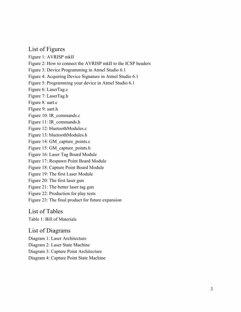
List of Figures Figure 1: AVRISP mkII Figure 2: How to connect the AVRISP mkII to the ICSP headers Figure 3: Device Programming in Atmel Studio 6.1 Figure 4: Acquiring Device Signature in Atmel Studio 6.1 Figure 5: Programming your device in Atmel Studio 6.1 Figure 6: LaserTag.c Figure 7: LaserTag.h Figure 8: uart.c FIgure 9: uart.h Figure 10: IR_commands.c Figure 11: IR_commands.h Figure 12: bluetoothModules.c Figure 13: bluetoothModules.h Figure 14: GM_capture_points.c Figure 15: GM_capture_points.h Figure 16: Laser Tag Board Module Figure 17: Respawn Point Board Module Figure 18: Capture Point Board Module Figure 19: The first Laser Module Figure 20: The first laser gun Figure 21: The better laser tag gun Figure 22: Production for play tests Figure 23: The final product for future expansion
List of Tables Table 1: Bill of Materials
List of Diagrams Diagram 1: Laser Architecture Diagram 2: Laser State Machine Diagram 3: Capture Point Architecture Diagram 4: Capture Point State Machine
3

Abstract The purpose of this project is to design, build, and test laser tag system from the ground up.
Much of the laser tag equipment that is available on the market right now use infrared technology to track and register “hits” between players. Our goal is to take this system and redesign it to shoot farther, be more energy efficient, and make it cheaper to produce.
Chapter 1: Introduction Laser tag is a fun game, but current methods of purchasing laser tag products are very
expensive. Companies that host laser tag in large indoor environments charge up to $10 for a single 15 minute game. Commercial laser tag systems can cost up to $30 per person. Several open source laser tag systems claim to provide a customizable game for use at affordable prices, but fail to deliver. MilesTag offers their fully populated board for $85. Skirmos, a relatively new system, is asking for $120 per gun.We believe that laser tag should be available to anyone. We wanted to remove this financial barrier to anyone who wanted to be able to play. Our primary goal is to produce a small laser tag system for under $20 per gun.
In order to do so, we have decided to center our design around the ATMega328P microcontroller from Atmel. This cheap microcontroller will greatly reduce the price of each blaster, while providing the processing speed needed to handle fast infrared communication. We also want to explore the possibility of using low powered lasers to detect hits from other players. At the end of the project, our goal is to have a laser blaster that could reliably send and receives codes at a range of 100 feet. However, we came to a decision that trying to improve the accuracy of the laser tag blasters was not part of the scope for this project. We felt that this problem falls into the realm of optics. It is not something that we can control electronically. As such, we felt that it was more prudent to focus on aspects of the design that we can control with our technical knowledge.
Along with the blasters, we felt the game needed another aspect to keep from getting repetitive. This led us to try to design a capture point module for use with our laser tag system. The capture point automatically detects and registers which players are within range. Laser tag systems currently on the market usually do not include a capture point device. Those that do require a manual input to the device, something that can be done even if the player is “down” and supposedly out of play. Our goal is to take the “honor system” out of the game and make the capture point detect and react only to players that are still eligible to capture. Overall, we want to design a laser tag system that has all of the functionality of a commercial laser tag company. This includes giving feedback to players at the end of the game.
4
Chapter 2: Design Considerations
Infrared Emitter and Receiver vs. Low Power Lasers and Photoresistors For the laser blaster, there were two main choices for shooting a beam at an opposing player.
There is the traditional infrared emitter and receiver, or low power lasers and photoresistors. The primary constraints of this choice are accuracy of the beam and the ability to send data.
There were two main properties to look at when comparing infrared emitters: wavelength and beamwidth. Wavelength is important because infrared receivers are sensitive to specific wavelengths, so one must purchase the emitter and receiver to match. 940nm is a common wavelength for emitters and receivers. Beamwidth of the infrared emitter refers to how far out the infrared beam will spread. A smaller beamwidth indicates smaller spread. This spread can be mitigated by adding a series of lenses to focus the beam. Infrared receivers have a band pass filter around 38KHz. If your emitter is pulsing outside of this frequency, the receiver will not pick it up. Most infrared receivers will demodulate the signal, meaning it will not show every individual pulse. Instead, the output signal from the receiver will show when the infrared pulse begins and ends. As this is the method used in tv remotes, we know this is a valid choice for our “laser beam”.
Another option we considered were low power lasers and photoresistors. Lasers do not have any spread in their trajectory. Therefore, they are way more accurate than infrared emitters could be. However, photoresistors are not meant to be used for fast transmission of data as they respond too slowly. They would also be many differences between use outdoors and indoors due to ambient light. Although the lasers would provide a much more accurate shot, it would be useless to try transfer data. Since one of our goals is to provide feedback to players, it is important to send data through the laser blaster. For this reason, we chose to use infrared emitters and receivers for the blaster.
Bluetooth vs. RFID When designing the capture points, we had two main choices for sensors. We could either go
with Bluetooth modules, or use RFID tags. We had two primary constraints for this sensor, the distance at which readings could start and the price of each device.
The bluetooth module we decided to test was the HC05. Bluetooth works in a master/slave relationship. The master can be connected with up to seven slave devices at once and can communicate between them freely. Slaves can only connect to bluetooth devices designated as a master. This model makes it perfect to use in our capture point set up. Each capture point will have a master bluetooth module and each laser blaster will have a slave bluetooth module. Bluetooth devices work within a 30ft radius. However, each HC05 module cost $9.28 off of ebay. This would make it the most expensive device on the laser blaster and drive up the cost of each gun by quite a bit. However, this specific module can be programmed to be either a master or slave. It is possible to buy modules that are already programmed to be a master or a slave. This would reduce the cost of each gun by $2.
5
RFID works slightly differently. The central RFID reader continually checks for new tags to enter the area and reads them. The reader is the biggest purchase in this set up. Buying each additional RFID tag is relatively cheap. There are two different types of tags, passive and active. Passive tags do not need to be externally powered and are cheap. In this model, the capture point will contain the RFID reader and each laser blaster will contain a corresponding RFID tag. However, the range of passive tags only spans a few inches. Active tags, can be read over 100ft away, but are much more expensive. Using active RFID tags on each gun would drive the price of each gun too much. However, the range of passive tags are much too small for the purposes of this project.
Due to these design considerations, we decided that the HC05 bluetooth module would be the best choice to implement the capture point module.
Chapter 3: User Guide
Set-up A small amount of setup is required to get the games started. The first step is to program the
ATMega328P chip. There are two different gun setups right now, and require slightly different methods of programming. In the Laser Tag code, the first thing to do is set up the game type you want to play. Other modifications such as lives, ammo count, and health can be changed quickly based on the your preferences for each game type. Fresh off the press, the guns are programmed to engage in the Capture Point game mode. Users, once happy with the current setup, must build the Laser Tag project to create the various files needed for each of the guns.
If using an Arduino board, the traditional method of programming one of them will work just fine. Navigating a terminal window to the Debug folder of the LaserTag project, and then using the program command on the LaserTag.hex file to the correct COM port is all that is necessary to set up each system. Once programmed and unplugged from the computer, the system requires a 9V battery plugged into the barrel jack of the Arduino to run.
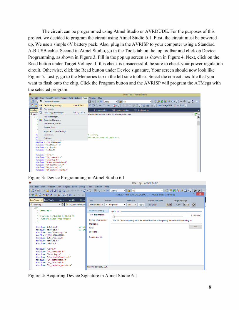
The final version of the laser blasters are taken off Arduino board. The circuit is built onto a breadboardlike protoboard containing only the bare minimum essentials. These boards are programmed using ICSP headers and an AVRISP mkII, as seen below in Figure 1. The AVRISP allows AVR microcontrollers to be flashed with new programs without taking the AVR chip out of the existing circuit. The 6 pin header connected to the ribbon attaches to the ICSP headers on the circuit board, as seen in Figure 2. Note that the red wire in the ribbon is the topmost wire.
6
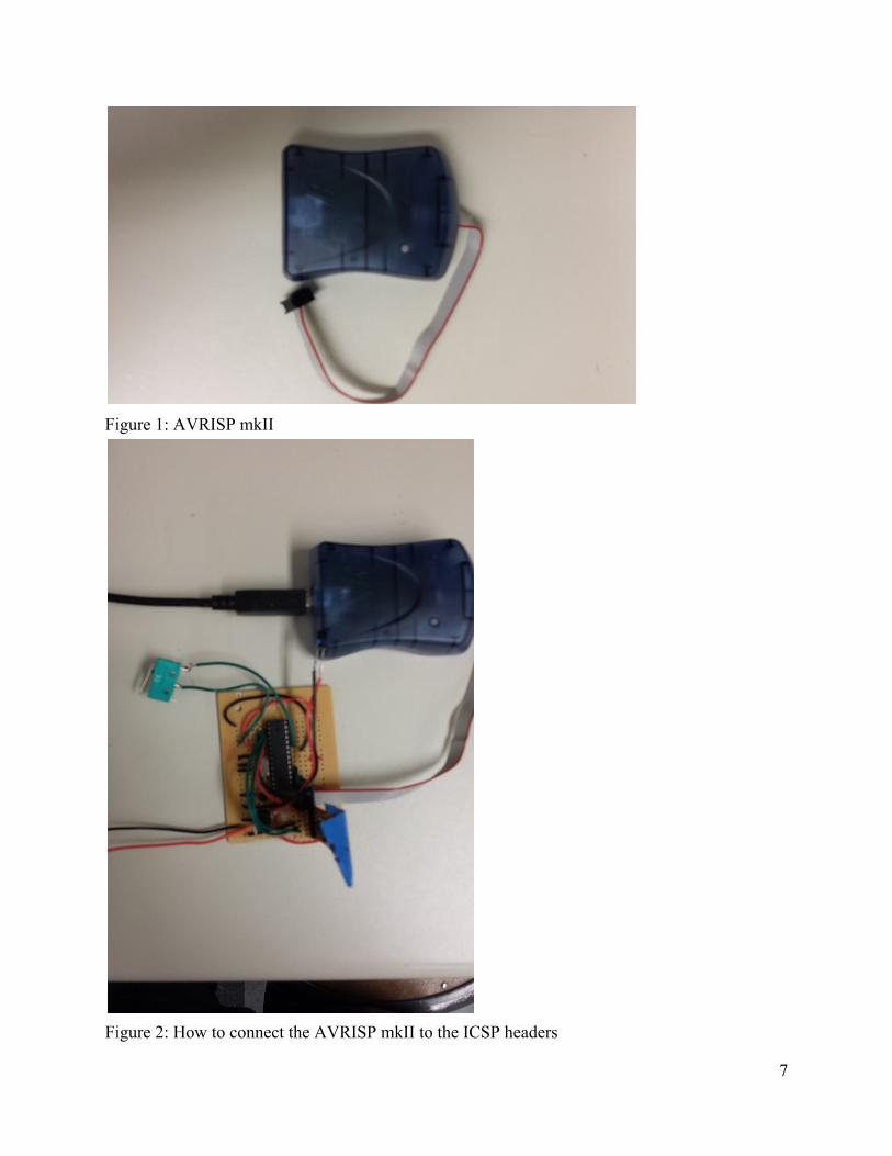
Figure 1: AVRISP mkII
Figure 2: How to connect the AVRISP mkII to the ICSP headers
7
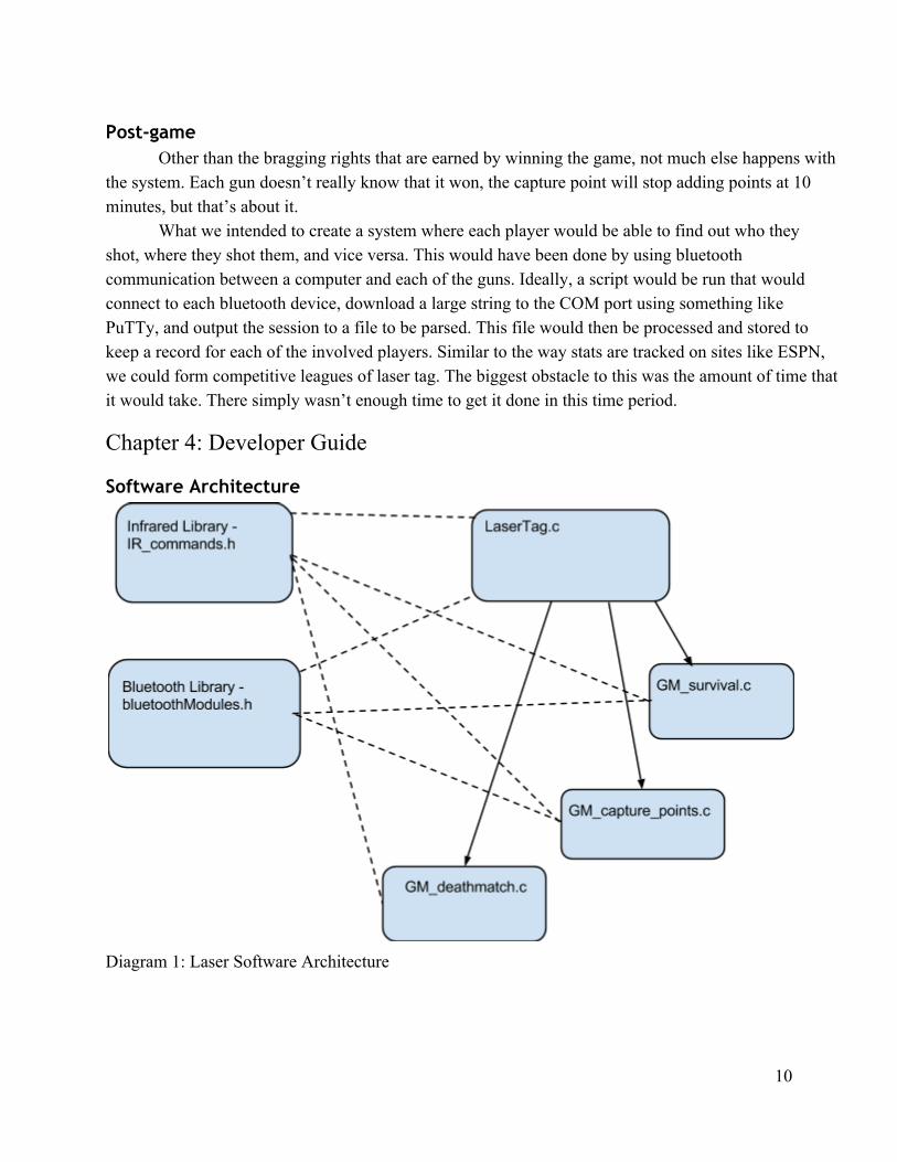
The circuit can be programmed using Atmel Studio or AVRDUDE. For the purposes of this project, we decided to program the circuit using Atmel Studio 6.1. First, the circuit must be powered up. We use a simple 6V battery pack. Also, plug in the AVRISP to your computer using a Standard AB USB cable. Second in Atmel Studio, go in the Tools tab on the top toolbar and click on Device Programming, as shown in Figure 3. Fill in the pop up screen as shown in Figure 4. Next, click on the Read button under Target Voltage. If this check is unsuccessful, be sure to check your power regulation circuit. Otherwise, click the Read button under Device signature. Your screen should now look like Figure 5. Lastly, go to the Memories tab in the left side toolbar. Select the correct .hex file that you want to flash onto the chip. Click the Program button and the AVRISP will program the ATMega with the selected program.
Figure 3: Device Programming in Atmel Studio 6.1
Figure 4: Acquiring Device Signature in Atmel Studio 6.1
8
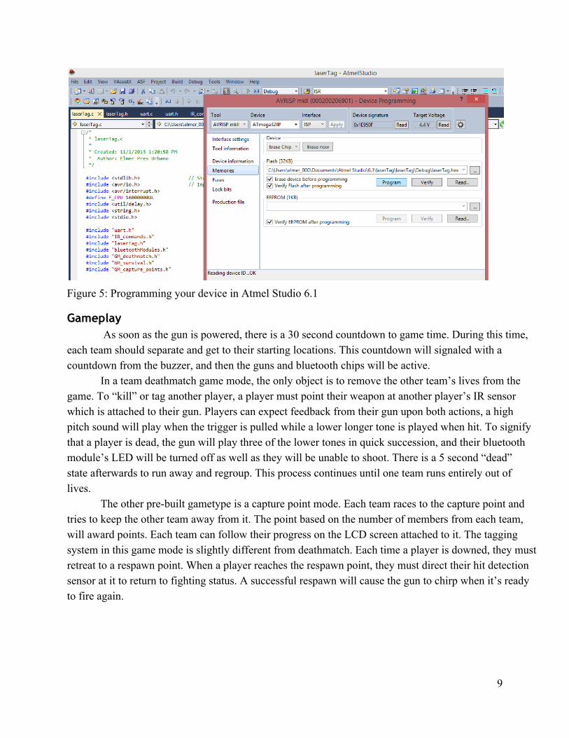
Figure 5: Programming your device in Atmel Studio 6.1
Gameplay As soon as the gun is powered, there is a 30 second countdown to game time. During this time,
each team should separate and get to their starting locations. This countdown will signaled with a countdown from the buzzer, and then the guns and bluetooth chips will be active.
In a team deathmatch game mode, the only object is to remove the other team’s lives from the game. To “kill” or tag another player, a player must point their weapon at another player’s IR sensor which is attached to their gun. Players can expect feedback from their gun upon both actions, a high pitch sound will play when the trigger is pulled while a lower longer tone is played when hit. To signify that a player is dead, the gun will play three of the lower tones in quick succession, and their bluetooth module’s LED will be turned off as well as they will be unable to shoot. There is a 5 second “dead” state afterwards to run away and regroup. This process continues until one team runs entirely out of lives.
The other prebuilt gametype is a capture point mode. Each team races to the capture point and tries to keep the other team away from it. The point based on the number of members from each team, will award points. Each team can follow their progress on the LCD screen attached to it. The tagging system in this game mode is slightly different from deathmatch. Each time a player is downed, they must retreat to a respawn point. When a player reaches the respawn point, they must direct their hit detection sensor at it to return to fighting status. A successful respawn will cause the gun to chirp when it’s ready to fire again.
9
Post-game Other than the bragging rights that are earned by winning the game, not much else happens with
the system. Each gun doesn’t really know that it won, the capture point will stop adding points at 10 minutes, but that’s about it.
What we intended to create a system where each player would be able to find out who they shot, where they shot them, and vice versa. This would have been done by using bluetooth communication between a computer and each of the guns. Ideally, a script would be run that would connect to each bluetooth device, download a large string to the COM port using something like PuTTy, and output the session to a file to be parsed. This file would then be processed and stored to keep a record for each of the involved players. Similar to the way stats are tracked on sites like ESPN, we could form competitive leagues of laser tag. The biggest obstacle to this was the amount of time that it would take. There simply wasn’t enough time to get it done in this time period.
Chapter 4: Developer Guide
Software Architecture
Diagram 1: Laser Software Architecture
10
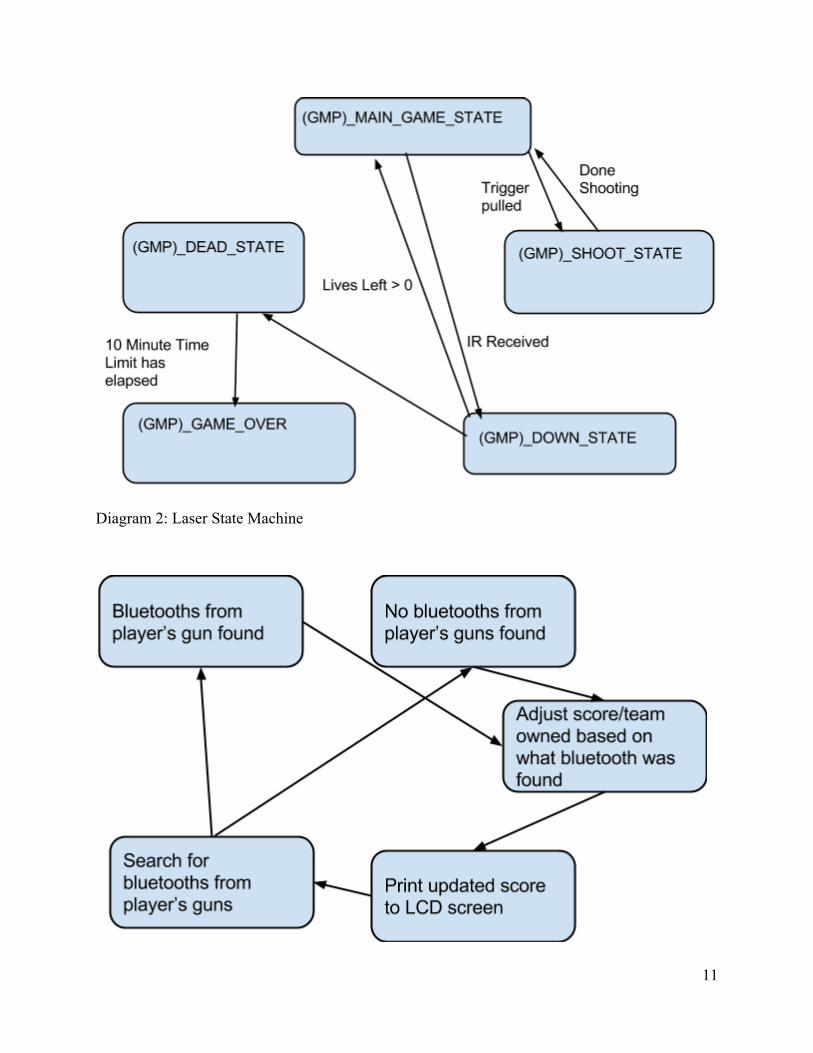
Diagram 2: Laser State Machine
11
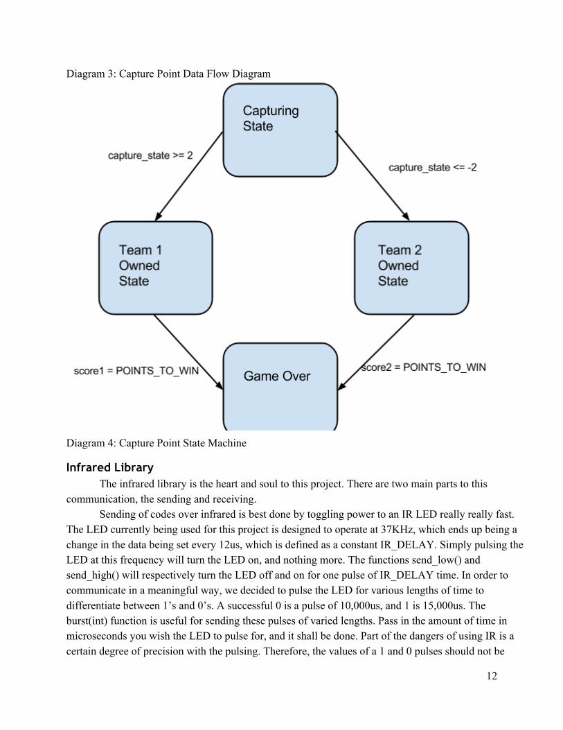
Diagram 3: Capture Point Data Flow Diagram
Diagram 4: Capture Point State Machine
Infrared Library The infrared library is the heart and soul to this project. There are two main parts to this
communication, the sending and receiving. Sending of codes over infrared is best done by toggling power to an IR LED really really fast.
The LED currently being used for this project is designed to operate at 37KHz, which ends up being a change in the data being set every 12us, which is defined as a constant IR_DELAY. Simply pulsing the LED at this frequency will turn the LED on, and nothing more. The functions send_low() and send_high() will respectively turn the LED off and on for one pulse of IR_DELAY time. In order to communicate in a meaningful way, we decided to pulse the LED for various lengths of time to differentiate between 1’s and 0’s. A successful 0 is a pulse of 10,000us, and 1 is 15,000us. The burst(int) function is useful for sending these pulses of varied lengths. Pass in the amount of time in microseconds you wish the LED to pulse for, and it shall be done. Part of the dangers of using IR is a certain degree of precision with the pulsing. Therefore, the values of a 1 and 0 pulses should not be
12
close together in value. We kept the difference in our project at 5000us because we had very few if any problems with this separation and so no reason to put them further apart, however it is something to keep in mind for future improvements.
The next logical step is to send groups of bursts() as to send a code. The number of bits in a code is currently defined in BITS_PER_CODE as 8. This function is HARD CODED in a different way for EACH GUN, so that the code each gun sends is unique. In terms of what code each gun sends, it is highly recommended that you test thoroughly the new combination. The communication system is not perfect, so having codes that are only one bit different from each other can be problematic. Adding more bits is a possible solution, and so is being very clever with the ID code sent from each gun.
Sending the codes seems rather simple compared to the receiving portion of this project. The reception of any IR signal by the IR receiver on each gun will trigger an interrupt. This interrupt captures the value from timer interrupt vector PCINT0_vect, stored in the TCNT1 register. It is stored into target_data for further processing. Putting more code into this ISR will cause problems with the project’s functionality. With any new additions, be sure to test thoroughly that codes are being properly received. When this interrupt has registered 17 interrupts, it sets the flag dataReady to 1 (a true value) so that the main will know to process the input. It may seem strange that it requires 17 interrupts with only 8 bits being sent. The reason for 17 is that the first interrupt the microcontroller sees will have a garbage value more than likely. This is because we can not know how long it will be in between the last bit of a previous code and the first bit of another. Therefore, the first capture value is always ignored and simply allows the controller to be prepared for further interrupts. The function within_range(int timerValue, int target) returns whether or not the timerValue is within PERCENT (defined as 12) percent value of the value target. This is the receiver’s way of filtering out rogue data bits. Currently, only one interrupt at a time is working, but there is code already featured in IR_commands.c. After the TCNT values are captured and stored, they must be translated to data. Use the function translate_IR to do this, as it will return the 8 bit value captured and stored into the target_data array. If a valid code is detected, it will return 1 and a hit will be registered. It is up to the user to determine whether or not friendly fire is tolerated in the game type.
Bluetooth Library There is a lot more functionality that these bluetooth devices can perform than was used in for
the current revision of this project. First thing’s first, the bluetoothSetup() function must be called to initialize the necessary pins. Then, the bluetoothModuleOn/Off() functions can be used to toggle the power on the device. A red LED will blink on the module if it is powered on correctly.
The next step is to set up the module for normal use. This can be done by using firstTimeInitMaster(char*) or firstTimeInitSlave(char*). The parameter is the name you wish to bind to the device. Currently, they are named according to the code that they send out and team they belong to. It is only necessary to call this function the very first time a device is programmed, and it will not break anything to call it every time you program it. However, one issue we kept running into was leaving an old device name as the parameter leading to misnamed guns. These functions will set the device to
13
communicate at 38400 HZ, so you must configure the Arduino’s own UART to run at 38400, using the UART functions found in our uart.c.
The bluetooth modules use UART to communicate to each other, and with the device that is controlling them, thus it is necessary that the Tx/Rx pins of your microcontroller are hooked up accordingly. In order to send commands to the device, commandModeOn() must be called. This allows you to change the settings of the module and various other things. Each of the functions in this library already call this function, so it is unnecessary to call it before the function call.
Also included in this library is the function sendBTMessage(char*, int). If you find it necessary to send a specific command to the bluetooth modules, which can be found in [7], you simply pass the command string into the function as the first parameter. Pass a nonzero value as the int parameter for the device to Arduino to wait for the bluetooth module’s response to your message to be placed into the global variable “buffer”. At any point you want to view the responses, sending the “buffer” string to the UART to be printed to the screen is the best way to do that. When devices are connected, it can be used to pass ordinary UART messages through the bluetooth module to devices it’s connected to, however it is not necessary to use it. A simple uart_send_string() call will accomplish the same thing.
In order for the master to change which device it is talking to, the changeBTSlave(char* address) was written. Passing in the MAC address of the bluetooth module you want to connect with to it will allow the bluetooth to form a new connection and allow the passage of data. However, this functionality is not used in the current lasertag.c. This functionality was written with the intent to be able to download all of the hit information from the previous game to a single device/computer. From our brief research into the matter, the best way appeared to make a PuTTy connection over bluetooth to each of the guns, send out a request for data, and then receive the data from the gun into the terminal session. Then, save the bluetooth session into a file, run a script on it to analyze the data, and then put it into a database to catalogue the result.
The remaining functions are designed with the capture point in mind. actDev() puts the capture point into an inquire mode for it to find all local bluetooth devices. Ideally, it would find every single bluetooth device in an area, and the module would return the result in an orderly print. However, while testing it in this function, the device never was able to find more than one device. This may have been related to some sort of screw up in the delays used in reading data off the line, or something else wrong with the bluetooth setup. So, currently it reads the one device address it can, parses away unnecessary information, and puts it into the char ** devices as the first entry. This function should be called often in any capture point gametype, as this is the only time it could find any new device in the area. To check what device was most recently found, updateConnectedTeams() should be called. It currently returns a one if team zero is connected, and two if team one is found.
Overall, this bluetooth library is far from complete, but it should provide a useful starting point into developing more functionality for laser tag.
14
LCD Library The LCD screen is currently being used exclusively for the capture point to display the score for
each point. The LCD can be used in two different modes, 8 bit mode and 4 bit “nibble” mode. For this project 8 bit mode was used. The two most important functions of this library are the lcd_wr_cmd() and lcd_wr_sym(). The lcd_wr_cmd() writes a specified command to the LCD screen by setting the 8 character bits to the value passed to the function. Once those values are set to the proper values the R/W and RS pins are set to 0 putting the lcd into command mode, after that the Enable pin is set to 1 telling the lcd that the command is on the pins. The lcd_wr_sym() writes a symbol the LCD screen by setting the 8 character bits to the ascii value passed to the function as a parameter. After that, it sets the R/W and RS pins to 0 and 1 respectively to put the LCD into symbol mode. The Enable pin is then set to 1 allowing the character to be displayed on the screen.
In order to use the LCD the first thing that you have to do is call the lcd_init() function. This function just calls the lcd_wr_cmd() passing FUNCTION_SET and then DISPLAY_SET. Once the init function has been called, all the other functions can be used. The lcd_print_string() function can be used to print any string of characters to the LCD. Before a string is printed to the LCD, the function lcd_clear_display() should be called to clear the LCD of any characters that were already printed to the screen. If you wish to print on the second line of the screen, then the lcd_move_cursor_to_second_line() function should be used. This function calls lcd_wr_cmd() with the value SECOND_LINE.
All the other functions in this library are designed specifically for the capture point. The lcd_print_one_team_score() prints the given teams score. On the other hand, the lcd_print_all_scores() prints the first teams score on the first line then moves the cursor to the second line and prints the second teams score.
Overall, this LCD library is pretty complete and allows for most of the functionality the LCD screen allows.
Creating New Game Modes There are many ways to play Laser Tag and with that in mind, we wanted to design our system
so that it would be very easy to expand upon. The IR, Bluetooth, and LCD libraries make it easy for new users to jump into our code and make their own unique twist.
The process for jumping into a new game mode is straightforward. In the LaserTag.c file, under the switch (current_game_mode) , include the master function that runs your game into a new case. For example, if you wanted to play the survival game mode, you would set the current_game_mode value to SURVIVAL. Each of these gametype selections jumps into a different file that takes over into an infinite loop to run the selected game mode. In each game mode, the user must first create the state machine that will define their game mode. The basic game states are: a waiting state, a shooting state, a down state, a dead state, and a game over state. Transition from state to state is fairly straightforward and can be seen in states that have already been made. Using the library’s functionality,
15

the user is abstracted away from how all of the shooting and receiving works. Or, rather than creating an entire new game state, one can go to a current game mode and modify the defined values for that game type.
16
Chapter 5: Conclusion During the course of this project, we were unable to accomplish some of the goals that we had
set out at the start. We were unable to create a central uploading station for the laser tag system. This makes us unable to give feedback to a player at the end of a game. This is due to a problem in Windows 8 where bluetooth devices can not always be found and connected to. Having multiple sensors for each laser blaster never worked as reliably as we needed it to. We tried to turn off the other infrared sensors as soon as one sensor was tripped, however this did not always work. We believe this problem has to do with the sensors not being turned on correctly again after the data had been correctly taken.
Despite all of these drawbacks, we were able to accomplish a lot. We developed a reliable infrared library. We wrote and tested a bluetooth library. We learned how to prototype projects using an AVR microprocessor. We developed a laser tag platform that can be added to and improved upon. Users can program their own game modes and upload them to the laser blasters easily. The laser tag blasters have a maximum range of 45ft. We developed a capture point device that automatically detects players within range. It does not “down” players into account, thus removing the “honor system” involved in laser tag. We learned about programming embedded systems and rapid prototyping. In general, we are satisfied with the progress that we have made, despite not completing all of our objectives.
17
References [1] Atmel. “8bit AVR Microcontroller with 4/8/16/32K Bytes InSystem Programmable Flash”.
ATMega328P datasheet. 2009. [2] Vishay Semiconductors. “IR Receiver Modules for Remote Control Systems”.
TSOP34838 datasheet. 2014. [3] Rectron Semiconductor. “TO92 Bipolar Transistors (NPN)”.
PN2222AT datasheet. 2011. [4] Fairchild Semiconductor. “3Terminal 1 A Positive Voltage Regulator”.
LM7805ACT datasheet. 2011. [5] Vishay Semiconductors. “High Powered Infrared Emitting Diode, 950nm, GaAlAs/GaAs”.
TSAL6100 datasheet. 2008. [6] “An Arduino ICSP Board”. Kerry D.Wong. n.p., Apr. 24, 2010. Web. May 18, 2014. [7] “HC05 Bluetooth”. Edoardo De Marchi. mbed, Nov. 2, 2013. Web. May 3, 2014.
18

Appendix A: Bill of Materials Item Distributor Quantity Cost Total Cost
ATmega328p chip Mouser 1 $3.39 $3.39
16MHz Crystal Sparkfun 1 $.95 $.95
75 Ohm Resistor Mouser 2 $.09 $.18
33k Ohm Resistor Mouser 3 $.07 $.21
22 pF capacitor Sparkfun 2 $.25 $.50
LM7805ACT Voltage Regulator Mouser 1 $.69 $.69
HC05 Bluetooth Module Ebay 1 $9.28 $9.28
PN2222AT BJT Mouser 1 $.18 $.18
TSAL6100 IR LED Mouser 1 $.55 $.55
TSOP34838 IR Sensor Mouser 1 $.76 $.76
Microswitch Sparkfun 1 $1.79 $1.79
Protoboard Radioshack 1 $3.49 $3.49
Thin Speaker Sparkfun 1 $.95 $.95
2X3 ICSP Header Sparkfun 1 $.50 $.50
*10’ PVC Pipe Home Depot 1/2 $1.89 $.95
PVC TConnector Home Depot 2 $.34 $.68
PVC Elbow Connector Home Depot 3 $.22 $.66
Sum Total $25.71
Table X: Bill of Materials Table X shows the cost of every component needed to recreate a single laser gun. *10 feet of PVC pipe is enough to create 2 guns
19
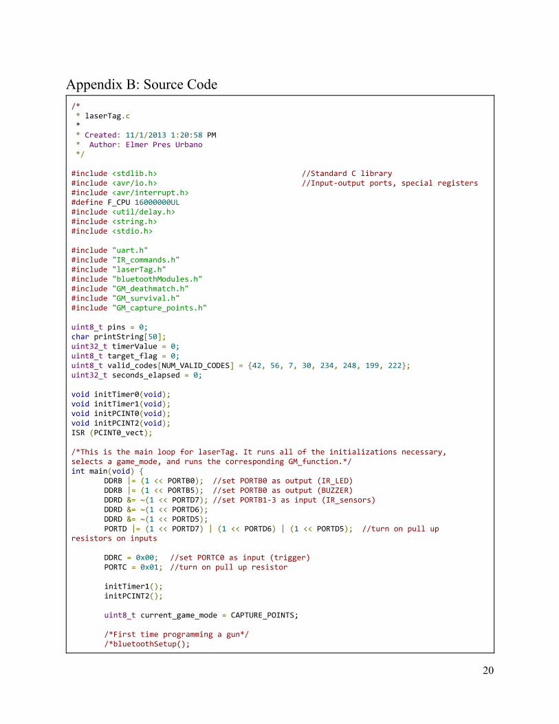
Appendix B: Source Code /* * laserTag.c * * Created: 11/1/2013 1:20:58 PM * Author: Elmer Pres Urbano */ #include <stdlib.h> //Standard C library #include <avr/io.h> //Input-output ports, special registers #include <avr/interrupt.h> #define F_CPU 16000000UL #include <util/delay.h> #include <string.h> #include <stdio.h> #include "uart.h" #include "IR_commands.h" #include "laserTag.h" #include "bluetoothModules.h" #include "GM_deathmatch.h" #include "GM_survival.h" #include "GM_capture_points.h" uint8_t pins = 0; char printString[50]; uint32_t timerValue = 0; uint8_t target_flag = 0; uint8_t valid_codes[NUM_VALID_CODES] = {42, 56, 7, 30, 234, 248, 199, 222}; uint32_t seconds_elapsed = 0; void initTimer0(void); void initTimer1(void); void initPCINT0(void); void initPCINT2(void); ISR (PCINT0_vect); /*This is the main loop for laserTag. It runs all of the initializations necessary, selects a game_mode, and runs the corresponding GM_function.*/ int main(void) {
DDRB |= (1 << PORTB0); //set PORTB0 as output (IR_LED) DDRB |= (1 << PORTB5); //set PORTB0 as output (BUZZER) DDRD &= ~(1 << PORTD7); //set PORTB1-3 as input (IR_sensors) DDRD &= ~(1 << PORTD6); DDRD &= ~(1 << PORTD5); PORTD |= (1 << PORTD7) | (1 << PORTD6) | (1 << PORTD5); //turn on pull up
resistors on inputs DDRC = 0x00; //set PORTC0 as input (trigger) PORTC = 0x01; //turn on pull up resistor initTimer1(); initPCINT2(); uint8_t current_game_mode = CAPTURE_POINTS; /*First time programming a gun*/ /*bluetoothSetup();
20
blueToothUart(); firstTimeInitSlave("ID7-TEAM0"); usart_send_string(buffer); _delay_ms(100);*/ /*Any time after that*/ usart_init(9600, 16000000); bluetoothSetup(); bluetoothModuleOn(); sei(); while (1) {
switch (current_game_mode) { case DEATHMATCH:
GM_deathmatch(); break;
case SURVIVAL: GM_survival(); break;
case CAPTURE_POINTS: GM_capture_points(); break;
default: usart_send_string("ERROR - WRONG STATE\r\n"); break;
} }
} /*This function initializes timer0*/ void initTimer0() {
TCCR0A = 1 << COM1A1; //counter mode TCCR0B = (1 << CS02) | (1 << CS00); //clock/1024 TIMSK0 = 1 << TOIE0; //turn on interrupt on overflow TIFR0 = 1 << TOV0; //clear timer interrupts
} /*This function initializes timer1*/ void initTimer1() {
TCCR1A = 1 << COM1A1; //counter mode //TCCR1B = 1 << CS10; //clock/1 //TCCR1B = 1 << CS11; //clock/8 TCCR1B = 1 << CS12; //clock/256 //TCCR1B |= (1 << CS12) | (1 << CS10); //clock/1024 TIMSK1 = 1 << TOIE1; //turn on interrupt on overflow TIFR1 = 1 << TOV1; //clear timer interrupts
} /*This function initializes PCINT0. It will accept interrupts on PB1, PB2, and PB3*/ void initPCINT0(void) {
PCICR |= (1 << PCIE0); // enable PCINT7..0 PCMSK0 |= (1 << PCINT1) | (1 << PCINT2) | (1 << PCINT3); // enable PCINT1
interrupt (PB1), PCINT2 interrupt (PB2), and PCINT3 interrupt (PB3) PCIFR |= (1 << PCIF0); // clear previous interrupts
} /*This function initializes PCINT2. It will accept interrupts on PB1, PB2, and PB3*/ void initPCINT2(void) {
PCICR |= (1 << PCIE2); // enable PCINT23..16 PCMSK2 |= (1 << PCINT21) | (1 << PCINT22) | (1 << PCINT23); // enable PCINT21
interrupt (PD5), PCINT22 interrupt (PD6), and PCINT23 interrupt (PD7)
21
PCIFR |= (1 << PCIF2); // clear previous interrupts } /*This function turns on pin change interrupts on PB1, PB2, and PB3.*/ void turnOnPCINT0(void) {
PCMSK0 |= (1 << PCINT1) | (1 << PCINT2) | (1 << PCINT3); } /*This function turns on pin change interrupts on PB1, PB2, and PB3.*/ void turnOnPCINT2(void) {
PCMSK2 |= (1 << PCINT21) | (1 << PCINT22) | (1 << PCINT23); } /*This function turns off pin change interrupts on the given pin.*/ void turnOffPCINT(uint8_t turn_Off) {
PCMSK2 &= ~(1 << turn_Off); } /*This function takes in single 8-bit int. This number represents which sound to play*/ void playSound(uint8_t sound) {
uint8_t counter = 0; switch (sound) {
case DOWN_SOUND: while (counter < 50) {
PORTB |= (1 << BUZZER); _delay_us(2300); PORTB &= ~(1 << BUZZER); _delay_us(2300); counter++;
} break;
case FIRE_SOUND: while (counter < 20) {
PORTB |= (1 << BUZZER); _delay_us(500); PORTB &= ~(1 << BUZZER); _delay_us(500); counter++;
} break;
default: break;
} } /*This function takes in an 8 bit code. It checks the code against a list of valid codes of registered guns. If the code is on the list, this function returns 1. If the code is not on the list, this functions returns 0.*/ uint8_t verify_IR(uint8_t code) {
int i = 0; if (code == 0) return 0; for (i = 0; i < NUM_VALID_CODES; i++) {
if (code == valid_codes[i]) return 1;
} return 0;
}
22
/*This function checks the first 2 bits of the code to determine which team that player is on*/ uint8_t get_team(uint8_t code) {
uint8_t team = TEAM_MASK & code; return team;
} /*This function sends the code specified. 1000us bursts are translated to logical 0s. 1500us bursts are translated to logical 1s. This code and function is unique to each gun.*/ void send_code(void) { //sends 0b00101010 -> 42
burst(1500); _delay_us(500); burst(1500); _delay_us(500); burst(1000); _delay_us(500); burst(1000); _delay_us(500); burst(1000); _delay_us(500); burst(1500); _delay_us(500); burst(1500); _delay_us(500); burst(1500); _delay_us(500);
} /*This function sends your code multiple times via the IR_LED.*/ void fire_blaster(uint8_t times) {
for (uint8_t i = 0; i < times; i++) { send_code();
} } /*This ISR activates whenever the IR_SENSOR activates. On every interrupt, it takes the current value of timer and stores it in target_data[]. target_counter is incremented and TCNT1 is reset to 0 to time how long it takes for the next interrupt to occur.*/ ISR (PCINT2_vect) {
cli(); pins = PIND;
timerValue = TCNT1; if (target_flag == 0) {
if (!(pins & (1 << 7))) { //PCINT23 PCMSK2 &= ~(1 << PCINT21); PCMSK2 &= ~(1 << PCINT22); target_flag = 1;
} else if (!(pins & (1 << 6))) {
PCMSK2 &= ~(1 << PCINT21); PCMSK2 &= ~(1 << PCINT23); target_flag = 2;
} else if (!(pins & (1 << 5))) {
PCMSK2 &= ~(1 << PCINT22); PCMSK2 &= ~(1 << PCINT23); target_flag = 3;
} } target_data[target_counter++] = timerValue; if (target_counter == 17) {
target_counter = 0;
23
data_ready = 1; } TCNT1 = 0; sei();
} ISR (TIMER1_OVF_vect) { // occurs about 1/second
//sprintf(printString, "pcmask is - %d\r\n", PCMSK0); //usart_send_string(printString); //sprintf(printString, "target_flag is %d\r\n", target_flag); //usart_send_string(printString); //sprintf(printString, "pins are %d\r\n", pins); //usart_send_string(printString); seconds_elapsed++; turnOnPCINT2(); clear_data(); target_flag = 0;
}
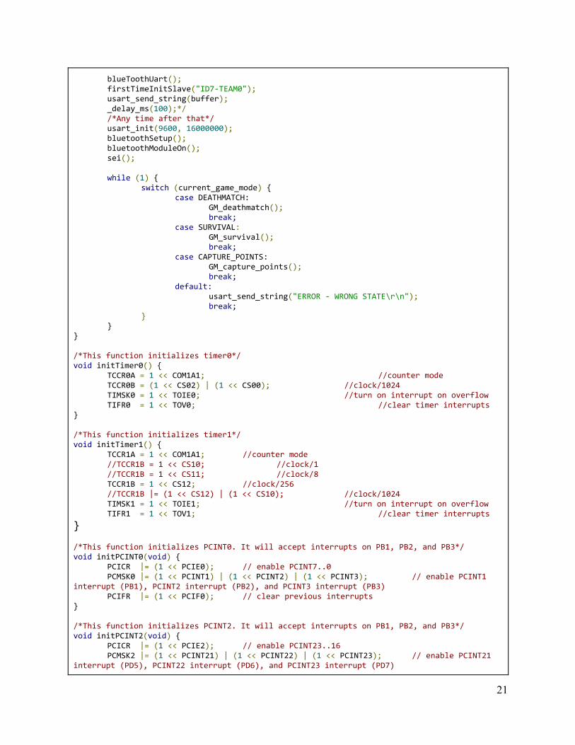
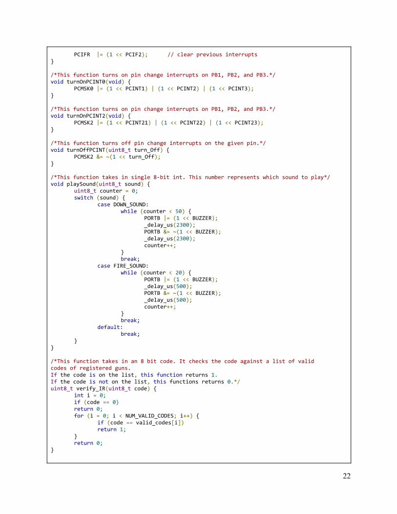
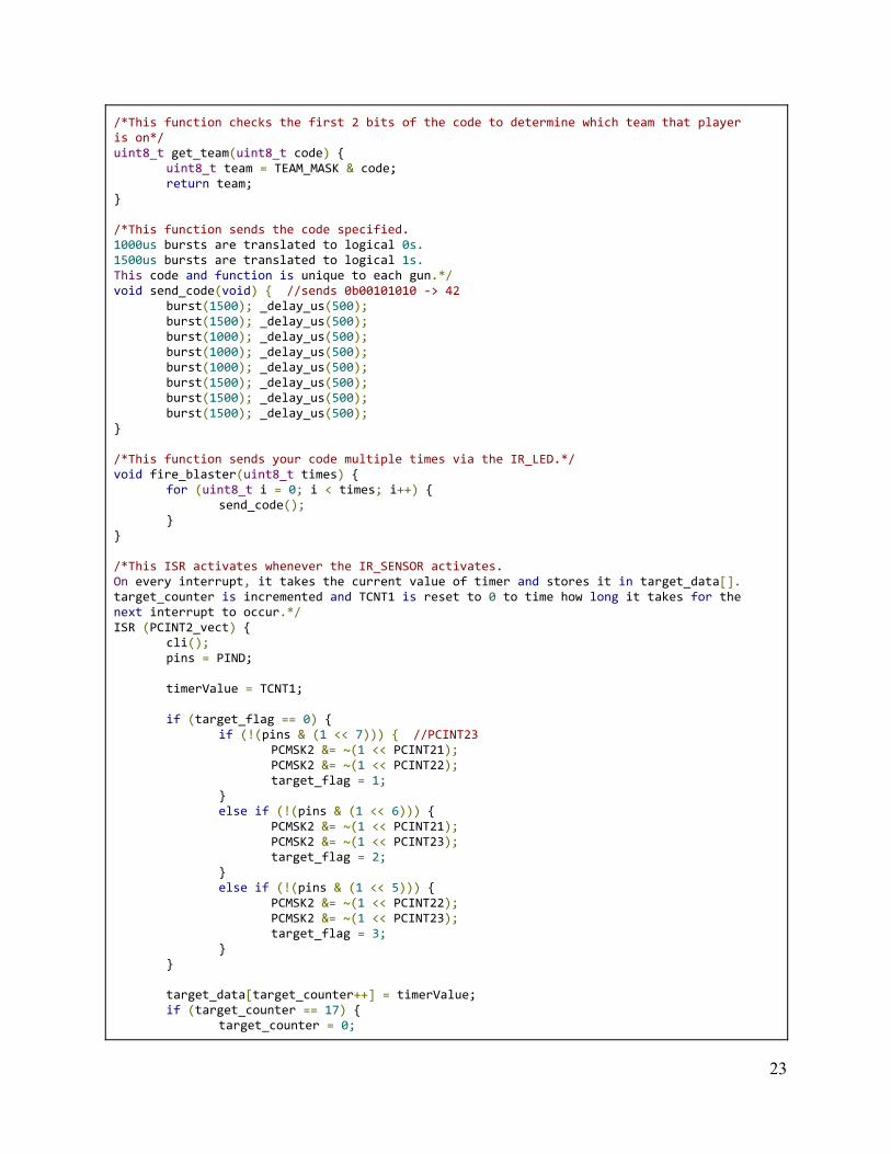
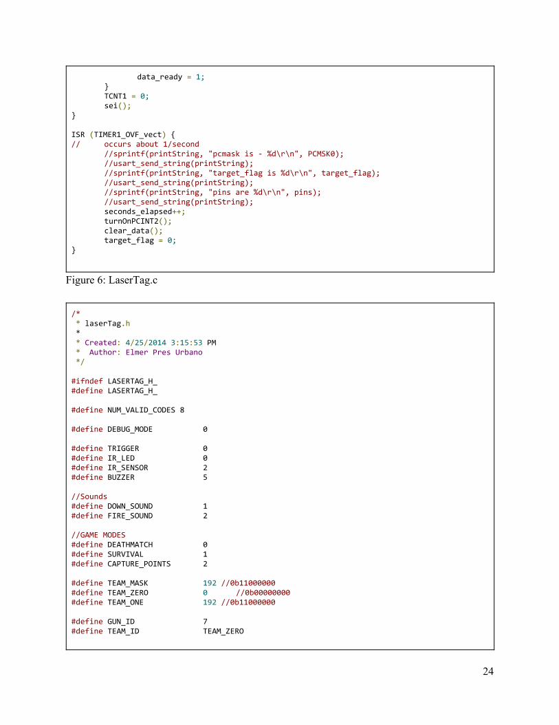
Figure 6: LaserTag.c /* * laserTag.h * * Created: 4/25/2014 3:15:53 PM * Author: Elmer Pres Urbano */ #ifndef LASERTAG_H_ #define LASERTAG_H_ #define NUM_VALID_CODES 8 #define DEBUG_MODE 0 #define TRIGGER 0 #define IR_LED 0 #define IR_SENSOR 2 #define BUZZER 5 //Sounds #define DOWN_SOUND 1 #define FIRE_SOUND 2 //GAME MODES #define DEATHMATCH 0 #define SURVIVAL 1 #define CAPTURE_POINTS 2 #define TEAM_MASK 192 //0b11000000 #define TEAM_ZERO 0 //0b00000000 #define TEAM_ONE 192 //0b11000000 #define GUN_ID 7 #define TEAM_ID TEAM_ZERO
24
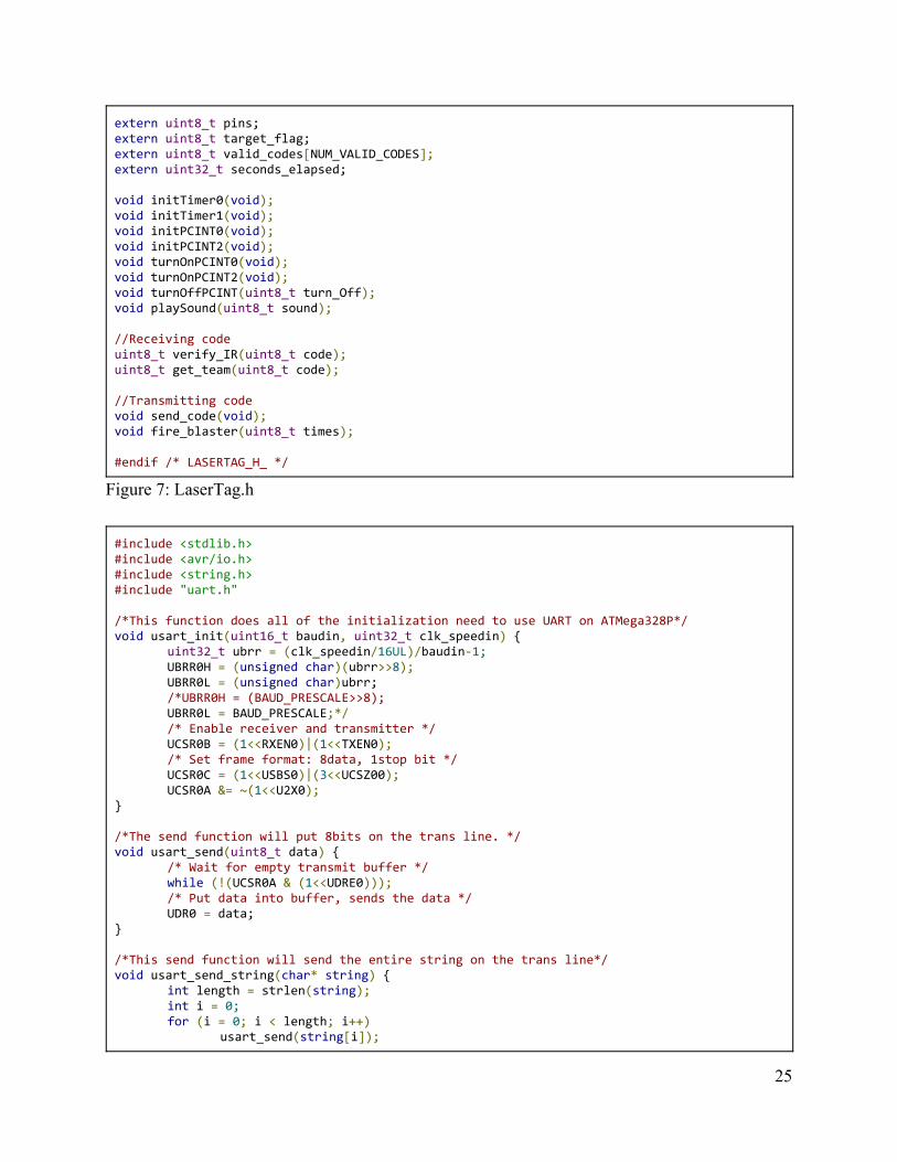
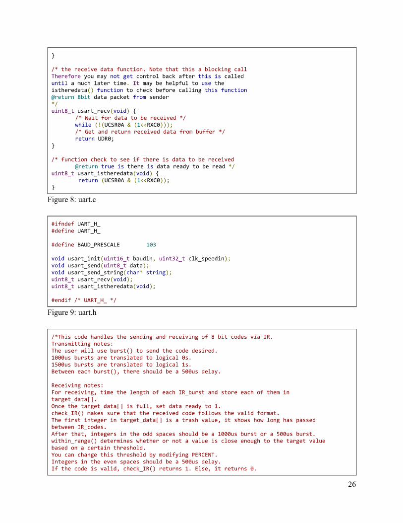
extern uint8_t pins; extern uint8_t target_flag; extern uint8_t valid_codes[NUM_VALID_CODES]; extern uint32_t seconds_elapsed; void initTimer0(void); void initTimer1(void); void initPCINT0(void); void initPCINT2(void); void turnOnPCINT0(void); void turnOnPCINT2(void); void turnOffPCINT(uint8_t turn_Off); void playSound(uint8_t sound); //Receiving code uint8_t verify_IR(uint8_t code); uint8_t get_team(uint8_t code); //Transmitting code void send_code(void); void fire_blaster(uint8_t times); #endif /* LASERTAG_H_ */ Figure 7: LaserTag.h #include <stdlib.h> #include <avr/io.h> #include <string.h> #include "uart.h" /*This function does all of the initialization need to use UART on ATMega328P*/ void usart_init(uint16_t baudin, uint32_t clk_speedin) {
uint32_t ubrr = (clk_speedin/16UL)/baudin-1; UBRR0H = (unsigned char)(ubrr>>8); UBRR0L = (unsigned char)ubrr; /*UBRR0H = (BAUD_PRESCALE>>8); UBRR0L = BAUD_PRESCALE;*/ /* Enable receiver and transmitter */ UCSR0B = (1<<RXEN0)|(1<<TXEN0); /* Set frame format: 8data, 1stop bit */ UCSR0C = (1<<USBS0)|(3<<UCSZ00); UCSR0A &= ~(1<<U2X0);
} /*The send function will put 8bits on the trans line. */ void usart_send(uint8_t data) {
/* Wait for empty transmit buffer */ while (!(UCSR0A & (1<<UDRE0))); /* Put data into buffer, sends the data */ UDR0 = data;
} /*This send function will send the entire string on the trans line*/ void usart_send_string(char* string) {
int length = strlen(string); int i = 0; for (i = 0; i < length; i++)
usart_send(string[i]);
25
} /* the receive data function. Note that this a blocking call Therefore you may not get control back after this is called until a much later time. It may be helpful to use the istheredata() function to check before calling this function @return 8bit data packet from sender */ uint8_t usart_recv(void) {
/* Wait for data to be received */ while (!(UCSR0A & (1<<RXC0))); /* Get and return received data from buffer */ return UDR0;
} /* function check to see if there is data to be received
@return true is there is data ready to be read */ uint8_t usart_istheredata(void) {
return (UCSR0A & (1<<RXC0)); } Figure 8: uart.c #ifndef UART_H_ #define UART_H_ #define BAUD_PRESCALE 103 void usart_init(uint16_t baudin, uint32_t clk_speedin); void usart_send(uint8_t data); void usart_send_string(char* string); uint8_t usart_recv(void); uint8_t usart_istheredata(void); #endif /* UART_H_ */ Figure 9: uart.h /*This code handles the sending and receiving of 8 bit codes via IR. Transmitting notes: The user will use burst() to send the code desired. 1000us bursts are translated to logical 0s. 1500us bursts are translated to logical 1s. Between each burst(), there should be a 500us delay. Receiving notes: For receiving, time the length of each IR_burst and store each of them in target_data[]. Once the target_data[] is full, set data_ready to 1. check_IR() makes sure that the received code follows the valid format. The first integer in target_data[] is a trash value, it shows how long has passed between IR_codes. After that, integers in the odd spaces should be a 1000us burst or a 500us burst. within_range() determines whether or not a value is close enough to the target value based on a certain threshold. You can change this threshold by modifying PERCENT. Integers in the even spaces should be a 500us delay. If the code is valid, check_IR() returns 1. Else, it returns 0.
26
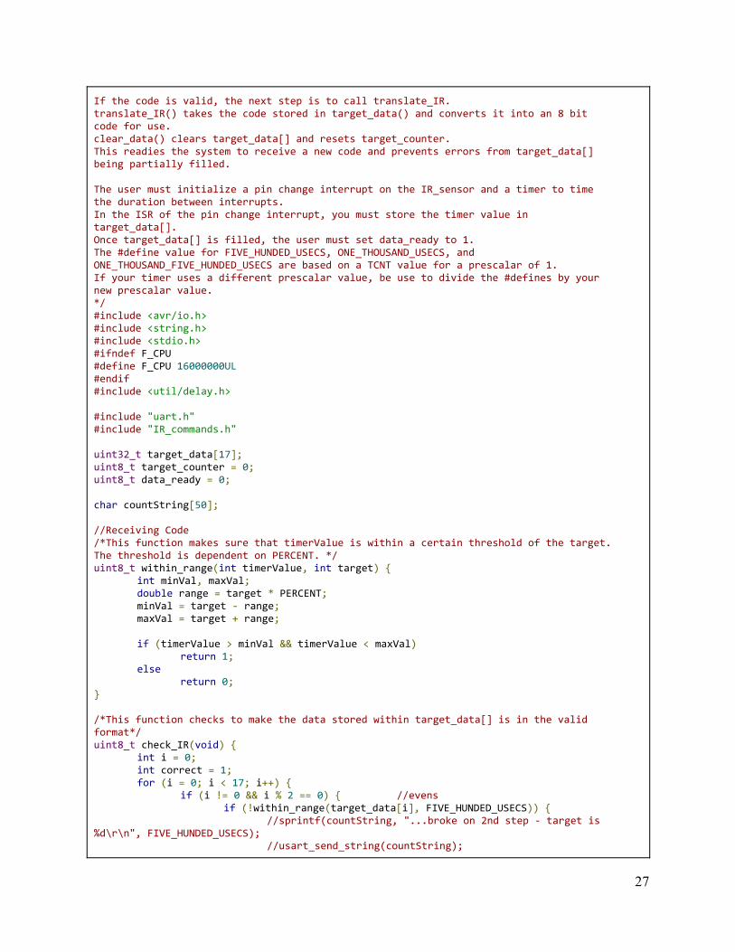
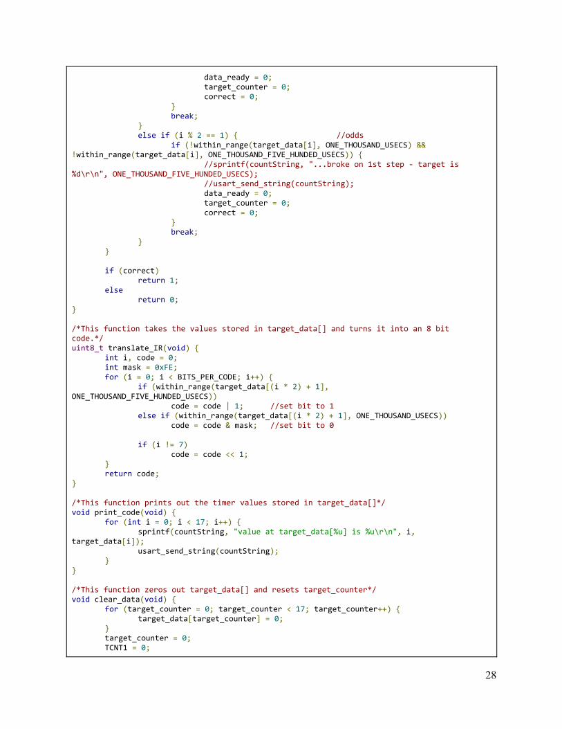
If the code is valid, the next step is to call translate_IR. translate_IR() takes the code stored in target_data() and converts it into an 8 bit code for use. clear_data() clears target_data[] and resets target_counter. This readies the system to receive a new code and prevents errors from target_data[] being partially filled. The user must initialize a pin change interrupt on the IR_sensor and a timer to time the duration between interrupts. In the ISR of the pin change interrupt, you must store the timer value in target_data[]. Once target_data[] is filled, the user must set data_ready to 1. The #define value for FIVE_HUNDED_USECS, ONE_THOUSAND_USECS, and ONE_THOUSAND_FIVE_HUNDED_USECS are based on a TCNT value for a prescalar of 1. If your timer uses a different prescalar value, be use to divide the #defines by your new prescalar value. */ #include <avr/io.h> #include <string.h> #include <stdio.h> #ifndef F_CPU #define F_CPU 16000000UL #endif #include <util/delay.h> #include "uart.h" #include "IR_commands.h" uint32_t target_data[17]; uint8_t target_counter = 0; uint8_t data_ready = 0; char countString[50]; //Receiving Code /*This function makes sure that timerValue is within a certain threshold of the target. The threshold is dependent on PERCENT. */ uint8_t within_range(int timerValue, int target) {
int minVal, maxVal; double range = target * PERCENT; minVal = target - range; maxVal = target + range; if (timerValue > minVal && timerValue < maxVal)
return 1; else
return 0; } /*This function checks to make the data stored within target_data[] is in the valid format*/ uint8_t check_IR(void) {
int i = 0; int correct = 1; for (i = 0; i < 17; i++) {
if (i != 0 && i % 2 == 0) { //evens if (!within_range(target_data[i], FIVE_HUNDED_USECS)) {
//sprintf(countString, "...broke on 2nd step - target is %d\r\n", FIVE_HUNDED_USECS);
//usart_send_string(countString);
27
data_ready = 0; target_counter = 0; correct = 0;
} break;
} else if (i % 2 == 1) { //odds
if (!within_range(target_data[i], ONE_THOUSAND_USECS) && !within_range(target_data[i], ONE_THOUSAND_FIVE_HUNDED_USECS)) {
//sprintf(countString, "...broke on 1st step - target is %d\r\n", ONE_THOUSAND_FIVE_HUNDED_USECS);
//usart_send_string(countString); data_ready = 0; target_counter = 0; correct = 0;
} break;
} } if (correct)
return 1; else
return 0; } /*This function takes the values stored in target_data[] and turns it into an 8 bit code.*/ uint8_t translate_IR(void) {
int i, code = 0; int mask = 0xFE; for (i = 0; i < BITS_PER_CODE; i++) {
if (within_range(target_data[(i * 2) + 1], ONE_THOUSAND_FIVE_HUNDED_USECS))
code = code | 1; //set bit to 1 else if (within_range(target_data[(i * 2) + 1], ONE_THOUSAND_USECS))
code = code & mask; //set bit to 0 if (i != 7)
code = code << 1; } return code;
} /*This function prints out the timer values stored in target_data[]*/ void print_code(void) {
for (int i = 0; i < 17; i++) { sprintf(countString, "value at target_data[%u] is %u\r\n", i,
target_data[i]); usart_send_string(countString);
} } /*This function zeros out target_data[] and resets target_counter*/ void clear_data(void) {
for (target_counter = 0; target_counter < 17; target_counter++) { target_data[target_counter] = 0;
} target_counter = 0; TCNT1 = 0;
28
} //Transmitting Code /*This function turns off IR_LED and delays for 12us*/ void send_low(void) {
PORTB &= ~(1 << IR_LED); //turn off IR_LED _delay_us(IR_DELAY);
} /*This function turns on IR_LED and delays for 12us*/ void send_high(void) {
PORTB |= (1 << IR_LED); //turn on IR_LED _delay_us(IR_DELAY);
} /*This function sends IR bursts for time specified, in microseconds*/ void burst(int length) {
while (length > 0) { send_high(); send_low(); length -= IR_DELAY * 2;
} PORTB &= ~(1 << IR_LED);
}
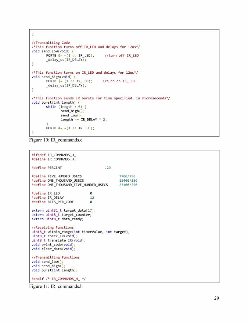
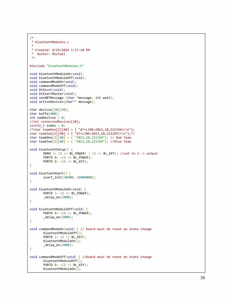
Figure 10: IR_commands.c #ifndef IR_COMMANDS_H_ #define IR_COMMANDS_H_ #define PERCENT .20 #define FIVE_HUNDED_USECS 7700/256 #define ONE_THOUSAND_USECS 15400/256 #define ONE_THOUSAND_FIVE_HUNDED_USECS 23100/256 #define IR_LED 0 #define IR_DELAY 12 #define BITS_PER_CODE 8 extern uint32_t target_data[17]; extern uint8_t target_counter; extern uint8_t data_ready; //Receiving Functions uint8_t within_range(int timerValue, int target); uint8_t check_IR(void); uint8_t translate_IR(void); void print_code(void); void clear_data(void); //Transmitting Functions void send_low(); void send_high(); void burst(int length); #endif /* IR_COMMANDS_H_ */ Figure 11: IR_commands.h
29
/* * bluetoothModules.c * * Created: 4/29/2014 1:17:18 PM * Author: Michael */ #include "bluetoothModules.h" void bluetoothModuleOn(void); void bluetoothModuleOff(void); void commandModeOn(void); void commandModeOff(void); void BtReset(void); void btStartMaster(void); void sendBTMessage (char *message, int wait); void activeDevices(char** message); char devices[10][50]; char buffa[400]; int numDevices = 0; //int connectedDevices[20]; uint32_t index = 0; /*char teamOne[2][40] = { "AT+LINK=2013,10,221194\r\n"}; char teamTwo[2][40] = { "AT+LINK=2013,10,221299\r\n"};*/ char teamOne[2][40] = { "2013,10,221194"}; // Red Team char teamTwo[2][40] = { "2013,10,221299"}; //Blue Team void bluetoothSetup() {
DDRD |= (1 << BL_POWER) | (1 << BL_KEY); //set to 1 -> output PORTD &= ~(1 << BL_POWER); PORTD &= ~(1 << BL_KEY);
} void blueToothUart() {
usart_init(38400, 16000000); } void bluetoothModuleOn(void) {
PORTD |= (1 << BL_POWER); _delay_ms(1000);
} void bluetoothModuleOff(void) {
PORTD &= ~(1 << BL_POWER); _delay_ms(1000);
} void commandModeOn(void) { // board must be reset on state change
bluetoothModuleOff(); PORTD |= (1 << BL_KEY); bluetoothModuleOn(); _delay_ms(1000);
} void commandModeOff(void) { //board must be reset on state change
bluetoothModuleOff(); PORTD &= ~(1 << BL_KEY); bluetoothModuleOn();
30
_delay_ms(1000); } void changeBTSlave (char *address) {
char pairMessage[50] = "AT+PAIR="; char linkMessage[50] = "AT+LINK="; strcat(pairMessage, address); strcat(linkMessage, address); strcat(pairMessage, ",5\r\n"); strcat(linkMessage, "\r\n"); commandModeOn(); sendBTMessage("AT+ROLE=1\r\n", 1); sendBTMessage("AT+CMODE=1\r\n", 1); sendBTMessage("AT+INIT\r\n", 1); sendBTMessage("AT+INQM=1,9,20\r\n", 1); sendBTMessage(pairMessage, 1); sendBTMessage(linkMessage, 1);
} void firstTimeInitMaster (char *incname) {
char name[50] = "AT+NAME="; strcat(name, incname); strcat(name, "\r\n"); commandModeOn(); sendBTMessage("AT+ORGL\r\n", 1); sendBTMessage("AT+UART=38400,0,0\r\n", 1); sendBTMessage("AT\r\n", 1); sendBTMessage("AT+VERSION?\r\n", 1); sendBTMessage("AT+ADDR?\r\n", 1); sendBTMessage(name, 1); sendBTMessage("AT+ROLE=1\r\n", 1);
} void firstTimeInitSlave(char *incname) {
char name[50] = "AT+NAME="; strcat(name, incname); strcat(name, "\r\n"); commandModeOn(); sendBTMessage("AT+ORGL\r\n", 1); sendBTMessage("AT+UART=38400,0,0\r\n", 1); sendBTMessage("AT+ROLE=0\r\n", 1); sendBTMessage("AT+CMODE=1\r\n", 1); sendBTMessage("AT+ADDR?\r\n", 1); sendBTMessage(name, 1); sendBTMessage("AT+INIT\r\n", 1);
} void sendBTMessage (char *message, int wait) {
char inc; usart_send_string(message); if (wait) {
while (!usart_istheredata()); //wait until we get a response while (usart_istheredata()) {
31
inc = usart_recv(); _delay_us(280); buffer[(index++)%400] = inc;
} //usart_send_string(buffer);
} } void waitingForInq(char *message) {
char inc; int i = 0; usart_send_string(message); while (i < 4) {
while (!usart_istheredata()); //wait until we get a response while (usart_istheredata()) {
inc = usart_recv(); _delay_us(280); buffer[index++] = inc;
} i++; //usart_send_string(buffer);
} } void actDev(void) {
//char returnBuffer[10][20]; int ndx = 0; int wordNum = 0; int i = 0; int j = 0; char incoming; sendBTMessage("AT+INIT\r\n", 1); sendBTMessage("AT+INQM=1,9,4\r\n", 1); usart_send_string("AT+INQ\r\n"); while (!usart_istheredata()); //wait until we get a response while (usart_istheredata()) {
//usart_send_string("here\n"); incoming = usart_recv(); buffa[ndx++] = incoming; _delay_us(280);
} usart_send_string("done with inquire\r\n"); _delay_ms(100); ndx = 0;
//usart_send_string(buffa); //_delay_ms(1000);
for (i = 5; i < 28; i++) {
if (buffa[i] == ':') {
devices[j][ndx++] = ','; } else if (buffa[i] == '\n') {
devices[j][ndx] = buffa[i]; j++;
32
ndx = 0; i += 11; wordNum++;
} else {
devices[j][ndx++] = buffa[i]; }
} usart_send_string("print out devs\r\n"); _delay_ms(200); numDevices = wordNum;
} int updateConnectedTeams(void) {
int i = 0;
actDev(); //usart_send_string("update team one\r\n"); //_delay_ms(100);
while (i < TEAM_ONE_MEMBERS) { // number of team one members
if (strstr(devices[0], teamOne[i] ) != NULL) { return 1;
} i++;
} i = 0; //usart_send_string("update team two\r\n");
//_delay_ms(100); while (i < TEAM_TWO_MEMBERS) {
if (strstr(devices[0], teamTwo[i]) != NULL) { return 2;
} i++;
} return 0;
}
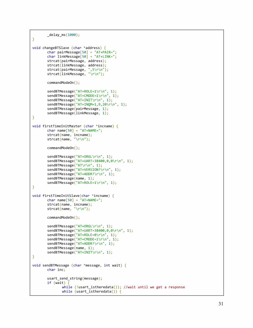
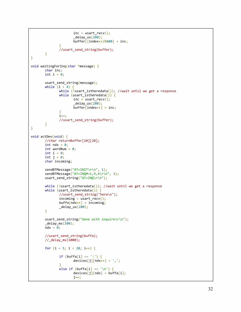
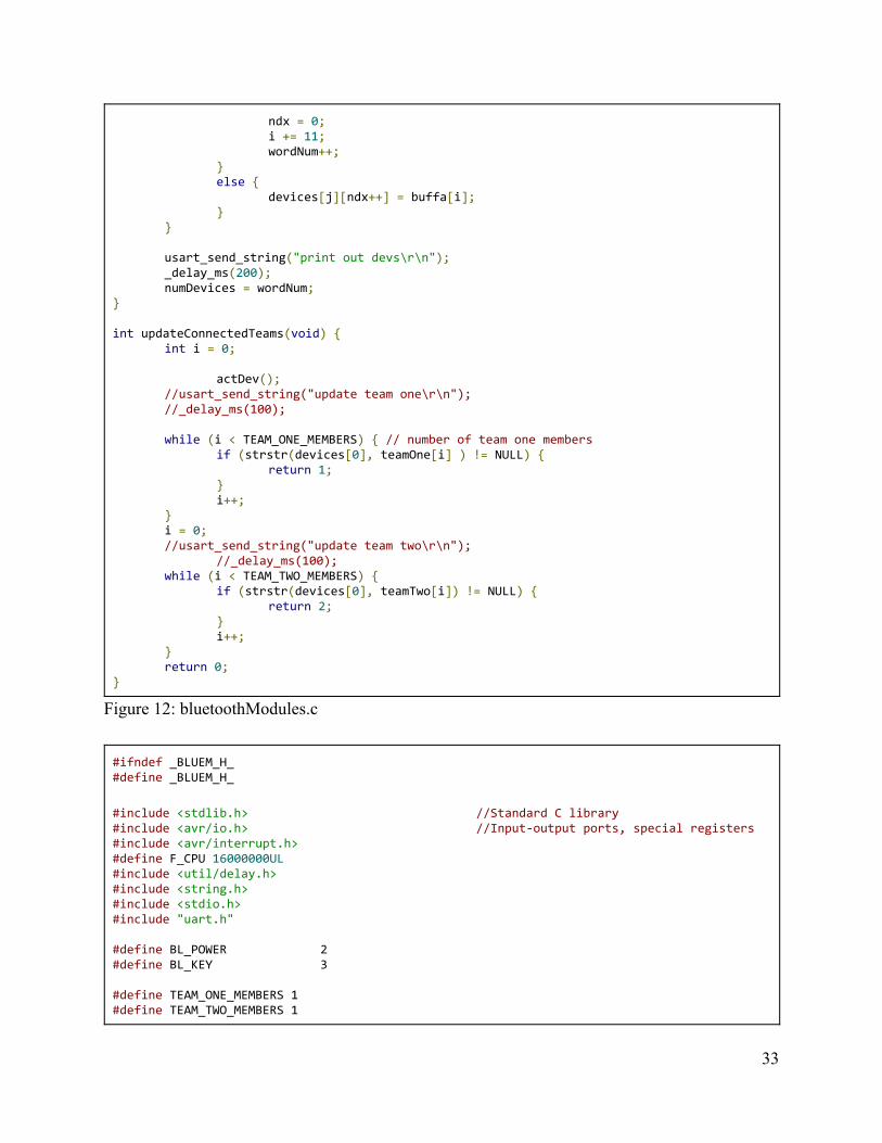
Figure 12: bluetoothModules.c #ifndef _BLUEM_H_ #define _BLUEM_H_
#include <stdlib.h> //Standard C library #include <avr/io.h> //Input-output ports, special registers #include <avr/interrupt.h> #define F_CPU 16000000UL #include <util/delay.h> #include <string.h> #include <stdio.h> #include "uart.h" #define BL_POWER 2 #define BL_KEY 3 #define TEAM_ONE_MEMBERS 1 #define TEAM_TWO_MEMBERS 1
33

char buffer[100]; //char deviceNames[2][40] = { "AT+FSAD=2013,10,221194\r\n", "AT+FSAD=2013,10,221299\r\n"}; int connectedDevices[20]; //uint32_t index = 0; /* This function initializes the microcontroller for use with the HC-05 BlueTooth Modules. It sets the DDRD and starts up the UART at 38400HZ */ void bluetoothSetup(void); /* Turns on power to the BlueTooth Module */ void bluetoothModuleOn(void); /* Turns power off to the BlueTooth Module */ void bluetoothModuleOff(void); /* Turns off the BlueTooth Module, sets the Command Mode Pin high, turns the module back on, and delays for 1000ms to prepare for future functions. */ void commandModeOn(void); /* Turns off the BlueTooth Module, sets the Command Mode Pin low turns the module back on, and delays for 1000ms to prepare for future functions. */ void commandModeOff(void); /* Allows a master BlueTooth Module to connect with a slave BlueTooth Module, ready for communication. The parameter is the target slave's Mac Address */ void changeBTSlave (char *address); /* Sets up Master functionality to a BlueTooth Module. The parameter allows the user to set a unique name to the module it is currently connected to. It is meant to be used ONLY the first time a module is programmed, but can be used each time without breaking. */ void firstTimeInitMaster (char *incname); /* Sets up Slave functionality to a BlueTooth Module. The parameter allows the user to set a unique name to the module it is currently connected to. It is meant to be used ONLY the first time a module is programmed, but can be used each time without breaking. */ void firstTimeInitSlave(char *incname); /* Sends a message over UART to the connected module. If a module is currently connected to another properly, it also allows the user to send data across it. The wait parameter will cause a module to send a message, and wait for a response. It is used mainly for setting up the modules initially and debug. Can be used by the master to prompt a response from the slave module. */ void sendBTMessage (char *message, int wait); void actDev(); void waitingForInq(char *message); int updateConnectedTeams(void); void blueToothUart(); #endif Figure 13: bluetoothModules.h
34
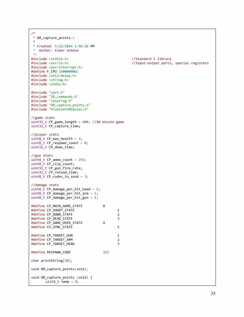
/* * GM_capture_points.c * * Created: 5/22/2014 1:46:56 PM * Author: Elmer Urbano */ #include <stdlib.h> //Standard C library #include <avr/io.h> //Input-output ports, special registers #include <avr/interrupt.h> #define F_CPU 16000000UL #include <util/delay.h> #include <string.h> #include <stdio.h> #include "uart.h" #include "IR_commands.h" #include "laserTag.h" #include "GM_capture_points.h" #include "bluetoothModules.h" //game stats uint32_t CP_game_length = 600; //10 minute game uint32_t CP_capture_time; //player stats uint8_t CP_max_health = 3; uint8_t CP_respawn_count = 0; uint32_t CP_down_time; //gun stats uint8_t CP_ammo_count = 255; uint8_t CP_clip_count; uint32_t CP_gun_fire_rate; uint32_t CP_reload_time; uint8_t CP_codes_to_send = 3; //damage stats uint8_t CP_damage_per_hit_head = 1; uint8_t CP_damage_per_hit_arm = 1; uint8_t CP_damage_per_hit_gun = 1; #define CP_MAIN_GAME_STATE 0 #define CP_SHOOT_STATE 1 #define CP_DOWN_STATE 2 #define CP_DEAD_STATE 3 #define CP_GAME_OVER_STATE 4 #define CP_SYNC_STATE 5 #define CP_TARGET_GUN 1 #define CP_TARGET_ARM 2 #define CP_TARGET_HEAD 3 #define RESPAWN_CODE 255 char printString[50]; void GM_capture_points(void); void GM_capture_points (void) {
uint8_t temp = 0;
35
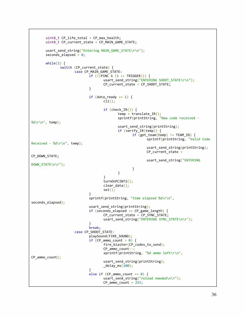
uint8_t CP_life_total = CP_max_health; uint8_t CP_current_state = CP_MAIN_GAME_STATE; usart_send_string("Entering MAIN_GAME_STATE\r\n"); seconds_elapsed = 0; while(1) {
switch (CP_current_state) { case CP_MAIN_GAME_STATE:
if (!(PINC & (1 << TRIGGER))) { usart_send_string("ENTERING SHOOT_STATE\r\n"); CP_current_state = CP_SHOOT_STATE;
}
if (data_ready == 1) { cli();
if (check_IR()) {
temp = translate_IR(); sprintf(printString, "New code received -
%d\r\n", temp); usart_send_string(printString); if (verify_IR(temp)) {
if (get_team(temp) != TEAM_ID) { sprintf(printString, "Valid Code
Received - %d\r\n", temp); usart_send_string(printString); CP_current_state =
CP_DOWN_STATE; usart_send_string("ENTERING
DOWN_STATE\n\r"); }
} } turnOnPCINT2(); clear_data(); sei();
} sprintf(printString, "time elapsed %d\r\n",
seconds_elapsed); usart_send_string(printString); if (seconds_elapsed >= CP_game_length) {
CP_current_state = CP_SYNC_STATE; usart_send_string("ENTERING SYNC_STATE\n\r");
} break;
case CP_SHOOT_STATE: playSound(FIRE_SOUND); if (CP_ammo_count > 0) {
fire_blaster(CP_codes_to_send); CP_ammo_count--; sprintf(printString, "%d ammo left\r\n",
CP_ammo_count); usart_send_string(printString); _delay_ms(100);
} else if (CP_ammo_count == 0) {
usart_send_string("reload needed\n\r"); CP_ammo_count = 255;
36
} CP_current_state = CP_MAIN_GAME_STATE; break;
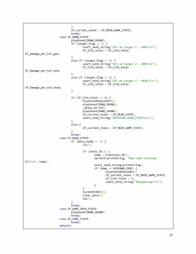
case CP_DOWN_STATE: playSound(DOWN_SOUND); if (target_flag == 1) {
usart_send_string("Hit on target 1 - GUN\r\n"); CP_life_total = CP_life_total-
CP_damage_per_hit_gun; } else if (target_flag == 2) {
usart_send_string("Hit on target 2 - ARM\r\n"); CP_life_total = CP_life_total -
CP_damage_per_hit_arm; } else if (target_flag == 3) {
usart_send_string("Hit on target 3 - HEAD\r\n"); CP_life_total = CP_life_total -
CP_damage_per_hit_head; } if (CP_life_total <= 0) {
bluetoothModuleOff(); playSound(DOWN_SOUND); _delay_ms(500); playSound(DOWN_SOUND); CP_current_state = CP_DEAD_STATE; usart_send_string("ENTERING DEAD_STATE\n\r");
} else {
CP_current_state = CP_MAIN_GAME_STATE; } break;
case CP_DEAD_STATE: if (data_ready == 1) {
cli(); if (check_IR()) {
temp = translate_IR(); sprintf(printString, "New code received -
%d\r\n", temp); usart_send_string(printString); if (temp == RESPAWN_CODE) {
bluetoothModuleOn(); CP_current_state = CP_MAIN_GAME_STATE; CP_life_total = 3; usart_send_string("Respawning\r\n");
} } turnOnPCINT2(); clear_data(); sei();
} break;
case CP_GAME_OVER_STATE: playSound(DOWN_SOUND); break;
case CP_SYNC_STATE: break;
default:
37
usart_send_string("ERROR - UNKNOWN STATE\n\r"); break;
} }
} Figure 14: GM_capture_points.c #ifndef GM_CAPTURE_POINTS_H_ #define GM_CAPTURE_POINTS_H_ void GM_capture_points(void); #endif /*GM_CAPTURE_POINTS_H_*/ Figure 15: GM_capture_points.h
38
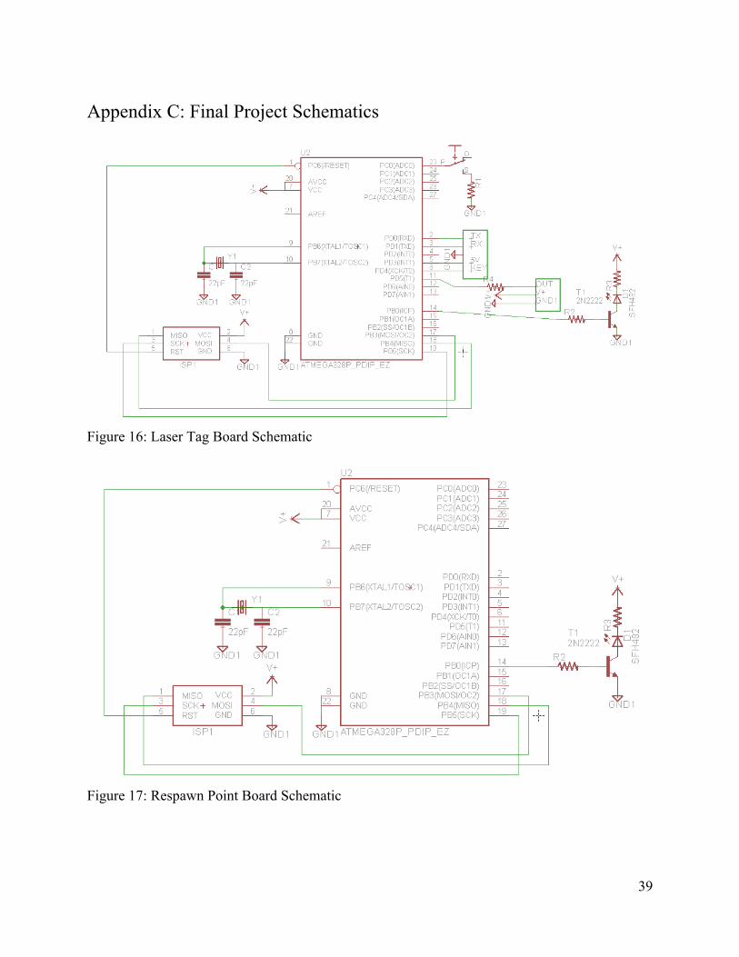
Appendix C: Final Project Schematics
Figure 16: Laser Tag Board Schematic
Figure 17: Respawn Point Board Schematic
39
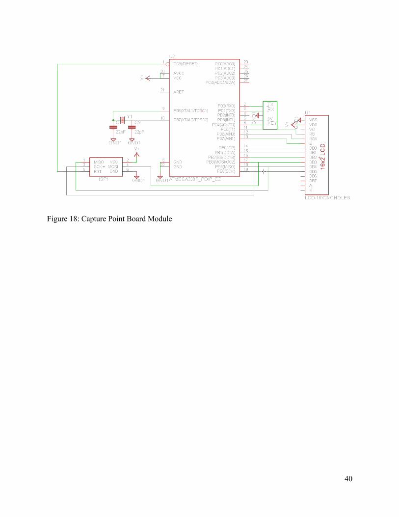
Figure 18: Capture Point Board Module
40
Appendix D: Senior Project Analysis
Summary of Functional Requirements Our project enables a group of 6 individuals to form 2 teams and battle against each other in an
extreme game of laser tag. There are multiple game modes to choose from including the always popular Team Deathmatch (TDM) and Domination game modes.
● TDM is straightforward, each player on a team has a set amount of lives. The teams battle it out until one team is completely eliminated from the game. There is no time limit on the game, nor hard boundaries set by the system. However, each player receives a 10 second respawn time when shot, at which time their gun is disabled.
● Domination is fairly similar to TDM, except it has a few twists thrown in. First off, victory is not determined by eliminations as respawns are unlimited. Upon death, a player must return to their designated respawn point before returning to battle. Second, teams must remain in close proximity to capture a location in order to gain points. Once one team reaches the max score, the game is over.
What this project really does is take infrared communication and some bluetooth protocols and
combine them to form a game. Each of the guns “shoots” infrared light pulses at other players which can be received by the other guns. In order to capture points, bluetooth inquire protocols were used to discover devices that were close by to determine which team is awarded points.
Primary Constraints The biggest constraint in the laser tag system pertains to the communication/shooting system.
Using infrared LED’s greatly limited the range that guns can tag each other from. During testing, the range at which an infrared signal could successfully transferred was about 60 feet, but more than one bit would be needed to send meaningful data. Communication required more bits to be transferred, and was successful at a max range of about 45 feet. The difference between these two distances is due to ambient light and the max current that the LED could handle. These two obstacles tend to go hand in hand, as ambient light would blot out the infrared signal, and there was no amount of current that would allow the chosen LED’s to flash bright enough to overcome this obstacle at distances greater than 60 feet.
Before using LED’s, using an actual laser or some other form of high powered devices were considered. However, the cost of these items was an insurmountable roadblock in this approach for a laser tag system designed for poor college students. Safety was also a concern as pointing high powered lasers at people could only have ended with someone going blind, or possibly free laser eye surgery. The former was much more likely so the idea was scrapped for a more practical one.
41

Economic One of our biggest priorities of this project was to provide a unique laser tag experience for an
affordable price. It is of the utmost importance to try to reduce the price point of each gun as much as possible. Using a cheap Atmel AVR microcontroller was one of the reasons we could reduce the price of each gun so much. At this stage, we are able to provide a 4 player game of laser tag for just over $100.
If manufactured on a commercial basis If put into manufacturing, we would expect to sell around 20 devices per year. As seen in our
bill of materials in Appendix B, it takes $25.71 to build a single laser blaster. A parts kit for a single blaster would be available to purchase for $30. A fully completed blaster might be available to purchase for $40. Based on our estimate of devices sold, there would a profit of $85.80 per year.
Environmental The environmental impacts of the Laser Tag system should be minimal. There are already many
ewaste disposal systems set up for use, so any devices that break could be either repaired or just sent to these services. The manufacturing environmental impact would not be great because of this system, as it is composed of premanufactured materials that are just assembled on site.
Manufacturability The only issue with manufacturing this system would be the labor put into it or establishing
cheaper ways to make each of the components. It might require a sophisticated system to form an effective assembly line with the large amount of soldering needed.
Sustainability There really aren’t any issues with maintaining the completed device, other than replacing the
batteries when they run low. The entire circuit is attached to the board with clear wiring so anything broken can be fixed rather easily. A redesign of the PVC used as a chassis would be the best improvement that could be made to the system. Being able to move the boards inside of the guns would leave them less exposed to the elements and to damage in general.
Ethical The main ethical concern we had with this project would have been if we had used actual lasers
in it. They then could have been used to blind people, and in some contexts been a very dangerous asset. Also, they are alike in shape to actual guns, so it’s a possibility, however unlikely, they could be used to fake having a real gun.
42
Health and Safety As stated in the ethical section, the main health concern would have been the misuse of a laser
whilst playing the game. Included in the dangers of this game are any related to running around and being a kid again, such as tripping and scraping up a knee, faceplanting into the sidewalk, etc.
Social and Political This project has no social or political impacts.
Development One new skill that we learned independently for this project was designing around a AVR
microcontroller. Before, we all had minor experience with AVR programming. However, it centered around programming the ATMega328P chip that resided on an Arduino. Although we were programming the chip directly, we never had a chance to remove it from the board. We learned how to design a circuit around an ATMega chip. One has to ensure that the chip is powered at the correct levels and is provided with the correct crystal. We learned how to use an AVRISP mkII in conjunctions with AVRDUDE to program the AVR chip. This allowed us to program the chip using ICSP headers and change the fuses on the ATMega328P correctly. Being able to design this circuit and program the chip in serial, allowed us to move away from the Arduino board. We were finally able to take the circuit off of the prototyping breadboard and move it onto a more long term PCB. Using the ATMega chip also helped to achieve our goal of offering a cheap laser tag system by greatly reducing the price point of each laser blaster.
43
Appendix E: Revision History
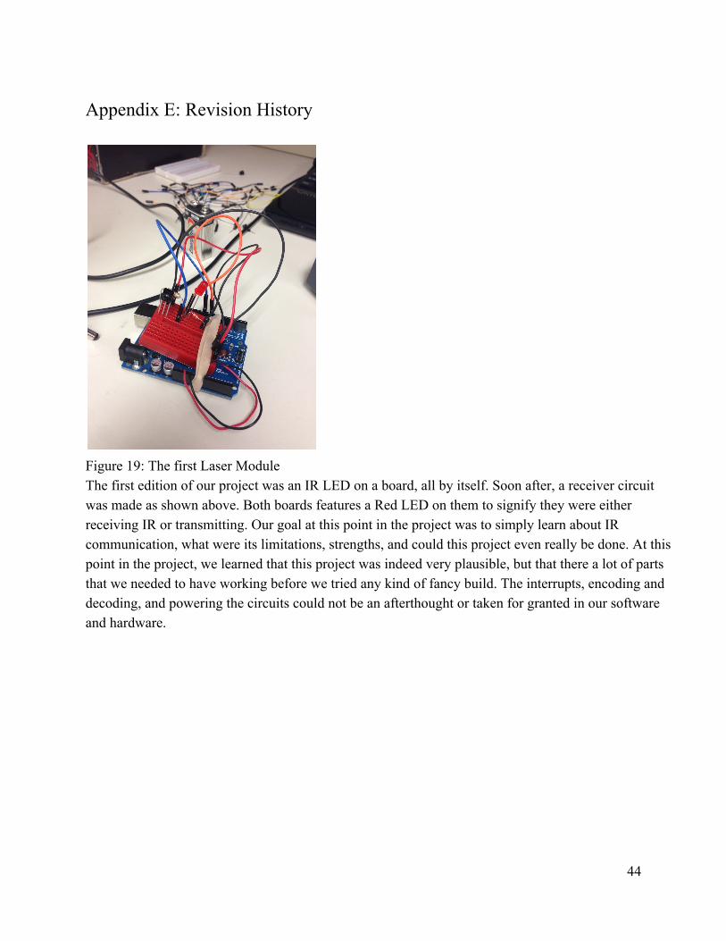
Figure 19: The first Laser Module The first edition of our project was an IR LED on a board, all by itself. Soon after, a receiver circuit was made as shown above. Both boards features a Red LED on them to signify they were either receiving IR or transmitting. Our goal at this point in the project was to simply learn about IR communication, what were its limitations, strengths, and could this project even really be done. At this point in the project, we learned that this project was indeed very plausible, but that there a lot of parts that we needed to have working before we tried any kind of fancy build. The interrupts, encoding and decoding, and powering the circuits could not be an afterthought or taken for granted in our software and hardware.
44
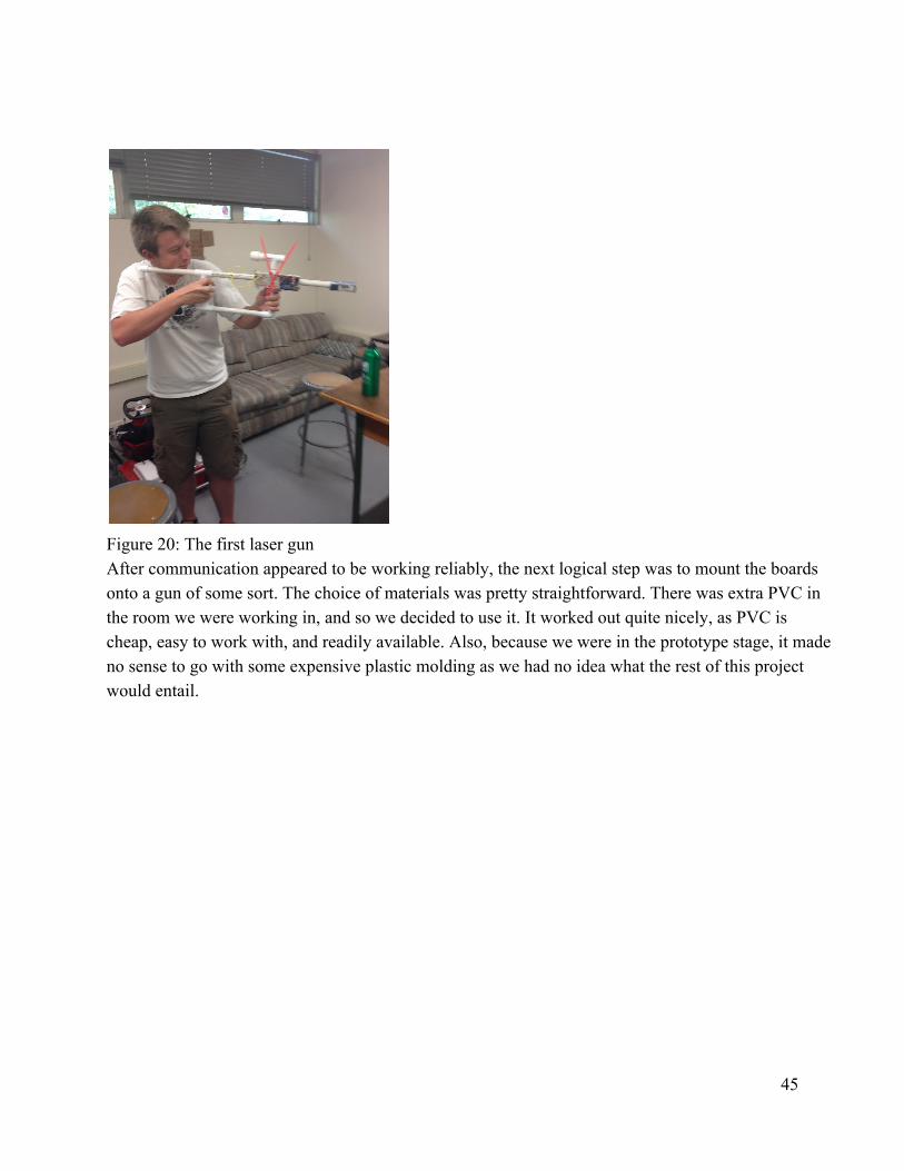
Figure 20: The first laser gun After communication appeared to be working reliably, the next logical step was to mount the boards onto a gun of some sort. The choice of materials was pretty straightforward. There was extra PVC in the room we were working in, and so we decided to use it. It worked out quite nicely, as PVC is cheap, easy to work with, and readily available. Also, because we were in the prototype stage, it made no sense to go with some expensive plastic molding as we had no idea what the rest of this project would entail.
45
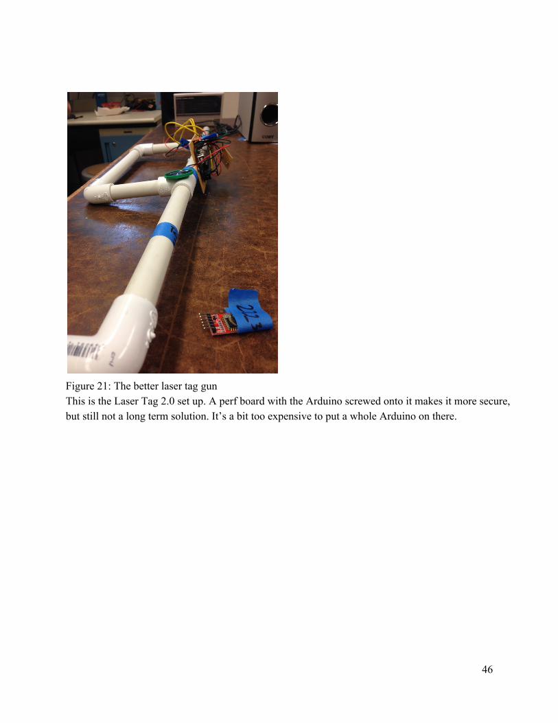
Figure 21: The better laser tag gun This is the Laser Tag 2.0 set up. A perf board with the Arduino screwed onto it makes it more secure, but still not a long term solution. It’s a bit too expensive to put a whole Arduino on there.
46
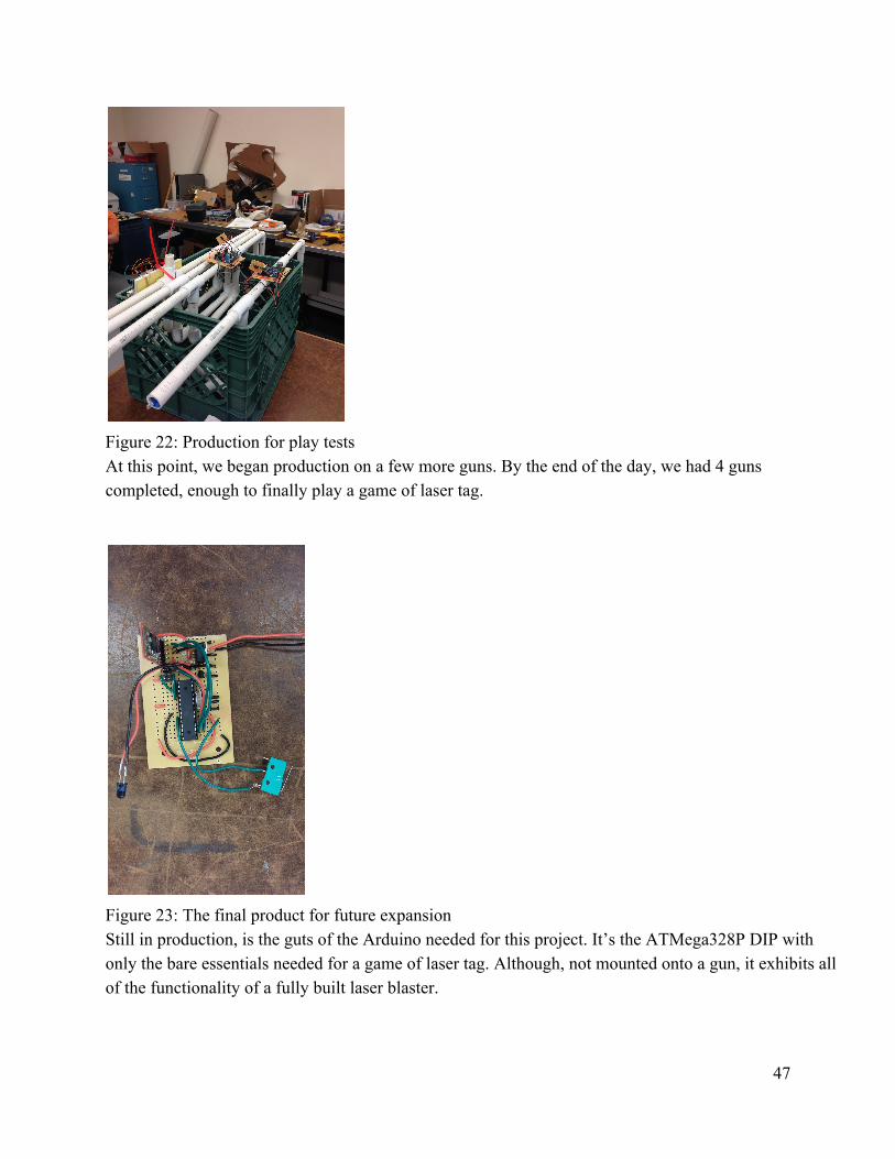
Figure 22: Production for play tests At this point, we began production on a few more guns. By the end of the day, we had 4 guns completed, enough to finally play a game of laser tag.
Figure 23: The final product for future expansion Still in production, is the guts of the Arduino needed for this project. It’s the ATMega328P DIP with only the bare essentials needed for a game of laser tag. Although, not mounted onto a gun, it exhibits all of the functionality of a fully built laser blaster.
47