Large-Deformation Analysis and Experimental Validation of a Flexure-Based Mobile Sensor Node
11
This article has been accepted for inclusion in a future issue of this journal. Content is final as presented, with the exception of pagination. IEEE/ASME TRANSACTIONS ON MECHATRONICS 1 Large-Deformation Analysis and Experimental Validation of a Flexure-Based Mobile Sensor Node Jiajie Guo, Kok-Meng Lee, Fellow, IEEE, Dapeng Zhu, Xiaohua Yi, and Yang Wang Abstract—This paper presents a new magnetic wall-climbing car as a mobile sensor node for health monitoring and dynamic testing of large civil (ferromagnetic) structures. Unlike traditional design, where the distance between the front and rear wheel pairs is fixed, the electromagnetically driven compliant beam connecting the axles not only offers an effective means to negotiate corners when maneuvering on ferromagnetic surfaces, but also serves as a sensor attachment device. Specifically, this paper presents the design concept of a novel magnetic flexonic mobile node incor- porating a compliant beam and permanent magnets, and a 2-D model for simulating the deformed shape of the compliant beam. Simulation results show that there exist consistent relations be- tween input/output displacements and rotation angle for control implementation in sensor attachment and corner negotiation re- gardless of gravity direction or the critical force for buckling. Ex- periment results are also provided to validate the theoretical model and compare with the analysis for sensor attachment and corner negotiation. Index Terms—Buckling, compliant mechanism, constraint, flex- ible (mobile) robot, flexible structure, large deformation, sensor network. I. INTRODUCTION I N recent years, wireless sensor networks have attracted growing interest for the structural health monitoring (SHM) of civil structures [1]. The leap from traditional cable-based sensing systems to wireless sensor networks can significantly reduce installation time/cost, potentially enable dense instru- mentation, and bring unprecedented improvements to structural monitoring. As another transformative change to sensor net- works, the next revolution is predicted to be the networks of mo- bile sensor nodes (MSNs) [2]. In a mobile sensor network, each MSN can be a sensor-carrying robot capable of autonomously exploring surroundings and exchanging information with peers through wireless communication. Motivated by these emerg- ing needs, this paper presents a design method for developing flexure-based MSNs [3], [4] for negotiating obstacles (such as Manuscript received October 4, 2010; revised December 14, 2010; accepted December 31, 2010. Recommended by Technical Editor D. Sun. This work was supported in part by the National Science Foundation under Grant CMMI- 0928095 and in part by the Agricultural Technology Research Program. J. Guo and K.-M. Lee are with the George W. Woodruff School of Mechanical Engineering, Georgia Institute of Technology, Atlanta, GA 30332 USA (e-mail: [email protected]). D. Zhu, X. Yi, and Y. Wang are with the School of Civil and Environmental Engineering, Georgia Institute of Technology, Atlanta, GA 30332 USA (e-mail: [email protected]). Color versions of one or more of the figures in this paper are available online at http://ieeexplore.ieee.org. Digital Object Identifier 10.1109/TMECH.2011.2107579 corners and reinforced ridges) while moving on ferromagnetic surfaces for SHM applications [5]. In general, three important factors in designing a wall- climbing robot are adherence, mobility, and flexibility. In [6], the prototype robot was designed with suction cups for adherence to crawl on nonferrous surfaces to inspect aircraft wings and fuse- lages. Using an induction pin, a magnetic wheeled robot can be easily detached by manipulating the magnetic flux direction [7]. For steel pipe inspection, a magnetic actuator incorporating shape-memory-alloy coils has been developed to move in the complicated environment of pipes [8]. Most existing wheeled robots for similar applications are often designed and analyzed under small deformations to avoid nonlinearity of lateral bend- ing and buckling. While designs based on rigid links/joints sim- plify analysis, they potentially limit the versatile functionality of a robot. To overcome this difficulty, multiagent networks, such as a self-assembly modular robot [9], provide a flexible architec- ture, and relevant control methods for coordinated motions have been developed for multiple mobile robots [10], [11]. This pa- per offers an alternative solution to design compliant structures allowing large deformation to provide flexible manipulation of a wall-climbing robot, and hence, improves mobility and flexi- bility of an MSN for SHM. While illustrated in the context of an MSN, this design concept can potentially enhance the flexibility of existing modular robots. Flexible mechanisms, such as joints and compliant mecha- nisms, can be explored for such purpose. For example, an active pin joint is incorporated in a magnetic wheeled robot for inter- nal piping inspection [12]. Various compliant mechanisms have also been studied for robot development, owing to the advan- tage of having no relative moving parts, and thus, no contact frictional dissipation [13]–[17]. For commanding robot move- ments through real-time feedback, control strategies have been developed based on various modeling methods [18] including rigid body motions [19]–[21], vibration modes [22], and finite- element methods (FEMs) [23], [24]. In many compliant mechanisms, flexible beams are used as a fundamental component. For a 2-D beam capable of large deflection under various load conditions, closed-form solutions can be found in [25]; however, expressed in terms of ellip- tic integrals, these solutions are computationally cumbersome for use in design and real-time control. More recently, a 3-D beam model was developed in [26] and solved through the multiple shooting method (MSM) [27], [28]. Early study con- cerning the stability and buckling was motivated by structure design and analysis [29], [30]. Given the instability nature of buckling, its occurrence is usually not desirable; as a result, most studies have been concentrated on the critical forces and load-displacement relation of buckling mechanisms [31]. With 1083-4435/$26.00 © 2011 IEEE
Transcript of Large-Deformation Analysis and Experimental Validation of a Flexure-Based Mobile Sensor Node

This article has been accepted for inclusion in a future issue of this journal. Content is final as presented, with the exception of pagination.
IEEE/ASME TRANSACTIONS ON MECHATRONICS 1
Large-Deformation Analysis and ExperimentalValidation of a Flexure-Based Mobile Sensor Node
Jiajie Guo, Kok-Meng Lee, Fellow, IEEE, Dapeng Zhu, Xiaohua Yi, and Yang Wang
Abstract—This paper presents a new magnetic wall-climbingcar as a mobile sensor node for health monitoring and dynamictesting of large civil (ferromagnetic) structures. Unlike traditionaldesign, where the distance between the front and rear wheel pairsis fixed, the electromagnetically driven compliant beam connectingthe axles not only offers an effective means to negotiate cornerswhen maneuvering on ferromagnetic surfaces, but also serves asa sensor attachment device. Specifically, this paper presents thedesign concept of a novel magnetic flexonic mobile node incor-porating a compliant beam and permanent magnets, and a 2-Dmodel for simulating the deformed shape of the compliant beam.Simulation results show that there exist consistent relations be-tween input/output displacements and rotation angle for controlimplementation in sensor attachment and corner negotiation re-gardless of gravity direction or the critical force for buckling. Ex-periment results are also provided to validate the theoretical modeland compare with the analysis for sensor attachment and cornernegotiation.
Index Terms—Buckling, compliant mechanism, constraint, flex-ible (mobile) robot, flexible structure, large deformation, sensornetwork.
I. INTRODUCTION
IN recent years, wireless sensor networks have attractedgrowing interest for the structural health monitoring (SHM)
of civil structures [1]. The leap from traditional cable-basedsensing systems to wireless sensor networks can significantlyreduce installation time/cost, potentially enable dense instru-mentation, and bring unprecedented improvements to structuralmonitoring. As another transformative change to sensor net-works, the next revolution is predicted to be the networks of mo-bile sensor nodes (MSNs) [2]. In a mobile sensor network, eachMSN can be a sensor-carrying robot capable of autonomouslyexploring surroundings and exchanging information with peersthrough wireless communication. Motivated by these emerg-ing needs, this paper presents a design method for developingflexure-based MSNs [3], [4] for negotiating obstacles (such as
Manuscript received October 4, 2010; revised December 14, 2010; acceptedDecember 31, 2010. Recommended by Technical Editor D. Sun. This workwas supported in part by the National Science Foundation under Grant CMMI-0928095 and in part by the Agricultural Technology Research Program.
J. Guo and K.-M. Lee are with the George W. Woodruff School of MechanicalEngineering, Georgia Institute of Technology, Atlanta, GA 30332 USA (e-mail:[email protected]).
D. Zhu, X. Yi, and Y. Wang are with the School of Civil and EnvironmentalEngineering, Georgia Institute of Technology, Atlanta, GA 30332 USA (e-mail:[email protected]).
Color versions of one or more of the figures in this paper are available onlineat http://ieeexplore.ieee.org.
Digital Object Identifier 10.1109/TMECH.2011.2107579
corners and reinforced ridges) while moving on ferromagneticsurfaces for SHM applications [5].
In general, three important factors in designing a wall-climbing robot are adherence, mobility, and flexibility. In [6], theprototype robot was designed with suction cups for adherence tocrawl on nonferrous surfaces to inspect aircraft wings and fuse-lages. Using an induction pin, a magnetic wheeled robot canbe easily detached by manipulating the magnetic flux direction[7]. For steel pipe inspection, a magnetic actuator incorporatingshape-memory-alloy coils has been developed to move in thecomplicated environment of pipes [8]. Most existing wheeledrobots for similar applications are often designed and analyzedunder small deformations to avoid nonlinearity of lateral bend-ing and buckling. While designs based on rigid links/joints sim-plify analysis, they potentially limit the versatile functionality ofa robot. To overcome this difficulty, multiagent networks, suchas a self-assembly modular robot [9], provide a flexible architec-ture, and relevant control methods for coordinated motions havebeen developed for multiple mobile robots [10], [11]. This pa-per offers an alternative solution to design compliant structuresallowing large deformation to provide flexible manipulation ofa wall-climbing robot, and hence, improves mobility and flexi-bility of an MSN for SHM. While illustrated in the context of anMSN, this design concept can potentially enhance the flexibilityof existing modular robots.
Flexible mechanisms, such as joints and compliant mecha-nisms, can be explored for such purpose. For example, an activepin joint is incorporated in a magnetic wheeled robot for inter-nal piping inspection [12]. Various compliant mechanisms havealso been studied for robot development, owing to the advan-tage of having no relative moving parts, and thus, no contactfrictional dissipation [13]–[17]. For commanding robot move-ments through real-time feedback, control strategies have beendeveloped based on various modeling methods [18] includingrigid body motions [19]–[21], vibration modes [22], and finite-element methods (FEMs) [23], [24].
In many compliant mechanisms, flexible beams are used asa fundamental component. For a 2-D beam capable of largedeflection under various load conditions, closed-form solutionscan be found in [25]; however, expressed in terms of ellip-tic integrals, these solutions are computationally cumbersomefor use in design and real-time control. More recently, a 3-Dbeam model was developed in [26] and solved through themultiple shooting method (MSM) [27], [28]. Early study con-cerning the stability and buckling was motivated by structuredesign and analysis [29], [30]. Given the instability nature ofbuckling, its occurrence is usually not desirable; as a result,most studies have been concentrated on the critical forces andload-displacement relation of buckling mechanisms [31]. With
1083-4435/$26.00 © 2011 IEEE
This article has been accepted for inclusion in a future issue of this journal. Content is final as presented, with the exception of pagination.
2 IEEE/ASME TRANSACTIONS ON MECHATRONICS
few exceptions (such as [32], where the postbuckling equilib-rium was analyzed), very little study has been conducted ondisplacement relations in large deflection and buckling analysisof flexible beams.
This paper presents the design concept, model, and analysis ofa flexure-based-mechatronic flexonic mobile node (FMN) [3],[4] for maneuvering on ferromagnetic surfaces. In operation, theFMN utilizes large deflection and buckling of a compliant beamenabling it to flexibly negotiate different kinds of obstacles (suchas abrupt angle changes) commonly encountered in complexcivil structures. The remainder of this paper is organized asfollows.
1) With the applications, such as [5], in mind, we presenthere the design concept of a novel magnet-wheeled FMNincorporating a flexible beam to achieve two importantfunctions (sensor attachment and corner negotiation) witha simple mechanism. Besides being designed to negotiatecommon obstacles encountered in complex civil struc-tures, the compliant beam offers an effective means toattach/detach an accelerometer (onto or from the surfaceof a structure) for vibration measurements.
2) A general quasi-static compliant beam model for simulat-ing 2-D beam deformation is then given. To exploit beambuckling for SHM applications, the work starts from aconventional viewpoint of load-displacement relation, andthen evolves to the displacement–displacement relations.As will be shown, these forward and inverse models pro-vide the essential basis for the design and control of aFMN.
3) Performed on a prototype FMN developed at Georgia Tech[3], Atlanta, we then discuss experimental results demon-strating three loading scenarios for the compliant beam.The first validates the basic beam model under its ownweight and a concentrated load. The second investigatesthe effect of gravity on the process of attaching a sensorof different weights. The third evaluates the FMN designby examining the torque provided by compliant beam formaneuvering around a corner on ferromagnetic surfaces.
II. DESIGN CONCEPT OF AN FMN
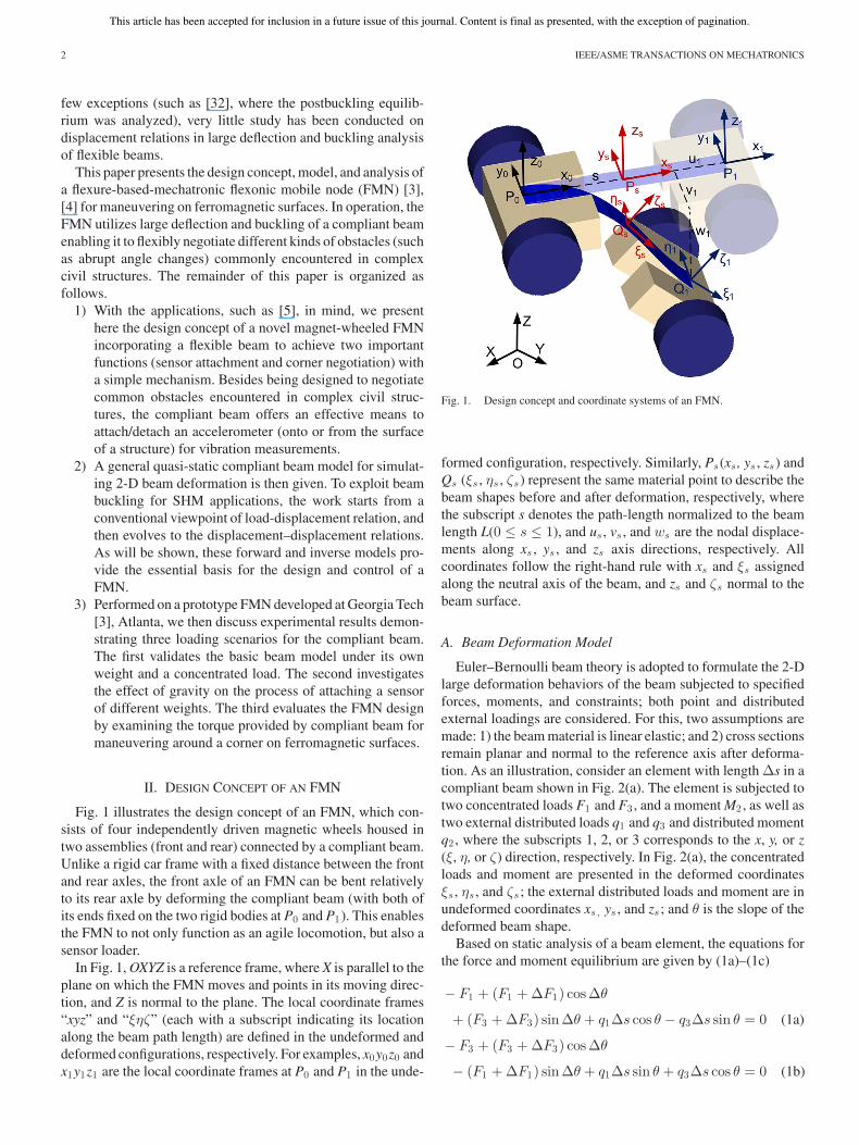
Fig. 1 illustrates the design concept of an FMN, which con-sists of four independently driven magnetic wheels housed intwo assemblies (front and rear) connected by a compliant beam.Unlike a rigid car frame with a fixed distance between the frontand rear axles, the front axle of an FMN can be bent relativelyto its rear axle by deforming the compliant beam (with both ofits ends fixed on the two rigid bodies at P0 and P1). This enablesthe FMN to not only function as an agile locomotion, but also asensor loader.
In Fig. 1, OXYZ is a reference frame, where X is parallel to theplane on which the FMN moves and points in its moving direc-tion, and Z is normal to the plane. The local coordinate frames“xyz” and “ξηζ” (each with a subscript indicating its locationalong the beam path length) are defined in the undeformed anddeformed configurations, respectively. For examples, x0y0z0 andx1y1z1 are the local coordinate frames at P0 and P1 in the unde-
Fig. 1. Design concept and coordinate systems of an FMN.
formed configuration, respectively. Similarly, Ps (xs , ys , zs) andQs (ξs , ηs , ζs) represent the same material point to describe thebeam shapes before and after deformation, respectively, wherethe subscript s denotes the path-length normalized to the beamlength L(0 ≤ s ≤ 1), and us , vs , and ws are the nodal displace-ments along xs , ys , and zs axis directions, respectively. Allcoordinates follow the right-hand rule with xs and ξs assignedalong the neutral axis of the beam, and zs and ζs normal to thebeam surface.
A. Beam Deformation Model
Euler–Bernoulli beam theory is adopted to formulate the 2-Dlarge deformation behaviors of the beam subjected to specifiedforces, moments, and constraints; both point and distributedexternal loadings are considered. For this, two assumptions aremade: 1) the beam material is linear elastic; and 2) cross sectionsremain planar and normal to the reference axis after deforma-tion. As an illustration, consider an element with length Δs in acompliant beam shown in Fig. 2(a). The element is subjected totwo concentrated loads F1 and F3 , and a moment M2 , as well astwo external distributed loads q1 and q3 and distributed momentq2 , where the subscripts 1, 2, or 3 corresponds to the x, y, or z(ξ, η, or ζ) direction, respectively. In Fig. 2(a), the concentratedloads and moment are presented in the deformed coordinatesξs , ηs , and ζs ; the external distributed loads and moment are inundeformed coordinates xs , ys , and zs ; and θ is the slope of thedeformed beam shape.
Based on static analysis of a beam element, the equations forthe force and moment equilibrium are given by (1a)–(1c)
− F1 + (F1 + ΔF1) cos Δθ
+ (F3 + ΔF3) sin Δθ + q1Δs cos θ − q3Δs sin θ = 0 (1a)
− F3 + (F3 + ΔF3) cos Δθ
− (F1 + ΔF1) sin Δθ + q1Δs sin θ + q3Δs cos θ = 0 (1b)

This article has been accepted for inclusion in a future issue of this journal. Content is final as presented, with the exception of pagination.
GUO et al.: LARGE-DEFORMATION ANALYSIS AND EXPERIMENTAL VALIDATION OF A FLEXURE-BASED MOBILE SENSOR NODE 3
Fig. 2. Formulation of a beam model. (a) Force and moment equilibrium. (b)Displacements and orientation relations.
− M2 + M2 + ΔM2 − (1 + e)Δs(F3 + ΔF3)
+ q1Δs2/2 − q3Δs2/2 + q2Δs = 0 (1c)
where e is the axial strain. For an infinitesimally small Δs, sinΔθ≈Δθ and cosΔθ ≈1. Neglecting higher order terms, (1a)–(1c)can be rewritten in differential forms with respect to s
F ′1 = −F3θ
′ − q1 cos θ + q3 sin θ (2a)
F ′3 = −F1θ
′ − q1 sin θ − q3 cos θ (2b)
M ′2 = (1 + e)F3 − q2 . (2c)
The element displaces as well as deforms, as illustrated inFig. 2(b), where Δs and [(1+e)Δs] are the original and de-formed element lengths, respectively. From Fig. 2(b), the nodaldisplacements and orientation can be obtained as follows:
Δs + Δu
(1 + e)Δs= cos θ
Δw
(1 + e)Δs= − sin θ.
These aforementioned relations can be rewritten in differen-tial forms as follows:
u′ = (1 + e) cos θ − 1 (3a)
w′ = −(1 + e) sin θ. (3b)
Denoting
θ′ = ρ2 (3c)
(2) can be recast as follows:
F ′1 = −F3ρ2 − q1 cos θ + q3 sin θ (3d)
F ′3 = F1ρ2 − q1 sin θ − q3 cos θ (3e)
M ′2 = (1 + e)F3 − q2 (3f)
where e and ρ2 are given by
e =F1
EA(4a)
ρ2 =M2
EI. (4b)
In (4a) and (4b), E is the elastic modulus, A is the cross sectionarea, and I is the moment of inertia. In addition, the axial strainon the upper surface is given by
ε11 =e − ρ2h
2(5)
where h is the beam thickness.The boundary value problem (BVP) of the compliant beam
can be written compactly in the following form:
X′ = f(s,X) (6a)
g(X(0),X(1)) = 0 (6b)
where X is a vector of the six variables (u, w, θ, F1 , F3 , M2)T ,0 ≤ s ≤1, and g(•) is the boundary conditions (BCs) specifyingthe geometrical and/or loading constraints at both ends. TheBVP [(6a) and (6b)] can be solved using a MSM [27] givenin the Appendix, which recasts the BVP into an initial valueproblem (IVP).
B. Boundary Conditions
Appropriate BCs must be specified to solve (3a)–(3f) for thesix unknowns in X that are physically relevant. Table I summa-rizes four typical BCs, which are also commonly specified foranalyzing columns. For a cantilever (type 1), where the slopeand displacements are zeros at the fixed end, the forces andmoment at the free end must be specified. For a beam withboth ends constrained with pin joints (type 2), the displacementconstraints cannot sustain any moment; M2 = 0 but F1 mustbe specified. As will be illustrated, types 3 and 4 are specifiedfor sensor attachment and for negotiating a convex corner, re-spectively. Type 3 is similar to type 2, but can resist nonzeromoments while maintaining zero slopes at both ends. In type4, a nonzero moment can be exerted against an offset pinnedend. Unlike buckling analyses, where the critical load causinga column to buckle is of particular concern, the models devel-oped here relax several commonly made ideal-beam assump-tions (such as massless and small deflection) for practical FMNapplications.
C. Illustrative Examples
The beam model is best illustrated by numerically simulatingthe two basic functions of an existing FMN [5], where a com-pliant beam connects the front and rear axles of the FMN (seeFig. 1).
1) The first function attaches or detaches an accelerometeron/from the surface to be measured. The compliantbeam is normally straight. When a measurement is tobe made, the front axle is driven toward the rear axleto buckle the compliant beam allowing the accelerom-eter to be pressed against the surface to be measured.

This article has been accepted for inclusion in a future issue of this journal. Content is final as presented, with the exception of pagination.
4 IEEE/ASME TRANSACTIONS ON MECHATRONICS
TABLE IBCS FOR GENERALIZED CONSTRAINTS
2) The second function provides a means to overcome obsta-cles when moving on a structure. Among the challengesis negotiating sharp corners. Magnetic forces at the cornergreatly decrease when negotiating a convex corner but in-crease (because of multiple contacts) when moving up ordown a concave corner.
As illustrated in Fig. 3(a), the FMN consists of two U-shaped structural frames, on which the motors and electron-ics are housed, and a spring steel (0.254 mm thick) laminateincluding a compliant beam (shaded in gray). The nonshadedportions are fastened by screws onto the U-shaped frames. Theaccelerometer (50 g) is pinned in the middle of the beam byscrews (at locations shaded in black). The geometrical and me-chanical properties of the compliant beam are given in Fig. 3(b).The beam has nonuniform cross sections; thus, A and I are func-tions of s. Fig. 3(c) shows a steel (A36) structure as the workingenvironment, where the FMN will cross corner A and attach asensor at B and C.
Numerical simulations using MSM were performed, wherecomputation time (especially when there is buckling) dependson the number of segments N and initial values for the iterativeprocess. The MSM computation involves a 6(N+1) × 6(N+1)matrix inverse. To reduce computation time, the beam is equallydivided into three segments (N = 3 and m = 4 in Fig. 14) withthe beam cross-sectional area presented as a piecewise linearfunction of path length. As given in Table I, some of the ini-tial values are zeros. The remaining nonzero initial values aredetermined by physics. Consider a cantilever as an illustration;the values of F1 and F3 at s = 0 can be obtained from equi-librium, and M2 can be chosen as the multiplication of theforces by a characteristic length (such as one half of the beamlength).
Example 1 (Sensor Attachment): In modeling the sensor at-tachment on a plane, the rear axle is treated as a fixed end andthe front axle acts as a slider subjected to a uniaxial loading F1 ,as shown in Fig. 4. In addition, it is assumed that the compli-ant beam is constrained to bend only in the −z direction. Fora given wheel radius, the uniaxial loading F1 required to movethe sensor to its desired displacement ws (at s = 1/2) dependson the direction of the sensor displacement relative to gravity,as compared in Fig. 4, which compares two cases. Unlike case1, where the weights of the sensor and beam facilitate the sen-sor attaching, the beam must compensate for these weights incase 2. To explain the effect of the gravity, we normalize thespecified F1 to the critical buckling force for a beam subjected
Fig. 3. CAD model of compliant structure for a magnetic FMN. (a) CADmodel. (b) Spring-steel laminate. (E = 207 GPa, G = 79.3 GPa, Poisson ratio =0.3, density = 7.63 g/cm3 , and thickness = 0.254 mm). (c) Steel (A36) framestructure.
to both ends fixed [33] as follows:
n = F1
(4L2
π2EIn
)(7)
where In is the moment of inertia for the narrowest section(width = 20.32 mm in Fig. 3) of the beam, and L is the beamlength. For the sensor, the gravity normalized using (7) is about0.8. With type-3 BCs, the deformed shape (or w as a function

This article has been accepted for inclusion in a future issue of this journal. Content is final as presented, with the exception of pagination.
GUO et al.: LARGE-DEFORMATION ANALYSIS AND EXPERIMENTAL VALIDATION OF A FLEXURE-BASED MOBILE SENSOR NODE 5
Fig. 4. Effect of gravity. (a) Case 1: ϕ = 0. (b) Case 2: ϕ = 0.
of path length s) and u1 for specified F1 can be computed bysolving the BVP (6). The results for the two cases (with ϕ = 0)are compared in Figs. 4 and 5, where n varies from 0 to 25.
Some observations are discussed as follows.1) Figs. 4(a) and 5(a) show that the beam deforms continu-
ously as the normalized force increases in case 1.2) Although the carrying mass (50 g sensor) is relatively light
causing negligible deformation under its own weight (seered curves in Fig. 4, F1 = 0), this little weight, however,has a significant buckling effect on the beam in case 2. Asillustrated in Figs. 4(b) and 5(a), both the displacements(u1 and ws ) in case 2 do not change until the normal-ized force exceeds a critical value nc at which the beambuckles drastically to a new shape [see black dash curvein Fig. 4(b)] without any intermediate shapes. The valuesof u1 and ws , which correspond to nc for ϕ = 0◦, 45◦,and 90◦, are summarized in Table II, which also shows theeffects of sensor weights on these values. These criticalvalues that cause buckling to set off in case 2 decrease (re-quiring less compensation against gravity) as ϕ increases.For the same reason, a heavier weight tends to give rise toa larger critical value for ϕ < 45◦. On the other hand, asmaller critical value for a heavier weight for ϕ > 45◦ isobserved as gravity facilitates buckling.
3) For ϕ = 90◦, the theoretical value of 16 given in [33] for aweightless beam is somewhat larger than nc of 15.5. Thebeam model given in (3a)–(3f) accounts for the gravityalong −x, which contributes to the onset of buckling.
4) The values of ws for different ϕ values converge to the caseϕ = 90◦ for large F1 when the gravity becomes negligible.This is also true for u1 because of the monotonous relationbetween ws and u1 , as shown in Fig. 5(b). The maximumnormalized force required is n = 25, from which the re-
Fig. 5. Relationship between normalized force and displacements. (a) Relationbetween force n and displacement ws /L. (b) Relation between u1 and ws .
TABLE IISLOPE ANGLE AND CRITICAL VALUES
quired motor torque can be estimated by multiplying F1computed from (7) by the wheel radius rw .
5) The solution to the beam model provides two alternativemanipulating variables (F1 or u1) of controlling ws for at-taching a sensor. As illustrated in Fig. 5(a), the relationshipbetween F1 and ws is not only highly nonlinear, but alsodepends on ϕ. On the other hand, the relationship betweenws and u1 is monotonically smooth and independent of ϕ,as shown in Fig. 5(b). Thus, it is a preferable variable for

This article has been accepted for inclusion in a future issue of this journal. Content is final as presented, with the exception of pagination.
6 IEEE/ASME TRANSACTIONS ON MECHATRONICS
Fig. 6. Convex corner negotiation.
controlling the compliant beam of the FMN by manipulat-ing the input displacement u1 rather than the input forceF1 . For the compliant design given in Fig. 3, the inversemodel that computes u1 for a specified ws for attachingsensor is given by curve fitting the data in Fig. 5(b) fordifferent ϕ’s in both cases
u1
L= 18
(ws
L
)3+ 5.3
(ws
L
)2− 0.85ws
L. (8)
This result is due to the lightweight of the combined beamand sensor. For detaching a sensor, the command becomes −u1for a reversed process.
Example 2 (Convex Corner Negotiation): Fig. 6 shows thefree body diagram of the front assembly (mass m1 at masscenter C1 and wheel radius rw ) at an instant crossing a convexcorner A. The reference OXYZ is defined such that X is on theplane, where the FMN initially locates and points in the movingdirection before crossing the corner, and Z is normal to theplane. In Fig. 6, ψ is the angle between Z and the gravity, N isthe reaction force, f (= μN) is the friction, μ is the coefficientof friction between the wheel and surface, and Mm is the torqueprovided by the motors. The following assumptions are made inthis discussion.
1) The wheels are designed with magnets such that they at-tach on the steel surfaces as the FMN moves.
2) The motor torque satisfying the nonslip condition: Mm =frw ≤ μN(α)rw .
3) The moment due to the magnets is small as compared tothat due to gravity, and thus, neglected in the analysis.
The following discussion considers a worst scenario, wherethe wheel has a point contact at the corner. The strategy for anFMN to negotiate a convex corner comprises three steps.
Step 1: The rear axle exerts forces/torque (Fx , Fz , and My )through the compliant beam to rotate the front axleabout A.
Step 2: As soon as the front axle crosses over the corner (α= θ, where θ is the corner angle), the two assembliesmove together.
Step 3: Once the rear axle arrives at the corner, the front axlepulls it over via the compliant beam.
The following details step 1 as this initiation dictates thesuccess of the corner negotiation. Fig. 7 shows the beam de-
Fig. 7. Simulation of corner negotiation. (a) Beam deformations. (b) Coordi-nates.
formations as the front assembly crosses the corner. As will beshown, the other steps follow similar principles.
To rotate the front assembly over the corner, the followingcondition (9) with respect to A must be satisfied:
Mr iy + rC1 × m1g ≥ 0 (9)
where Mr iy = rP1 × (Fx ix1 + Fz iz1 ) + My iy is the requiredmoment to compensate for the torque due to gravity, and isshown in Fig. 8 for different ψ values. For negativeψ, Mr can beobtained from the mirror images of Fig. 8. Since the compliantbeam attaches the front assembly at P1
Fx = −F1 (10a)
Fz = −F3 (10b)
My = −M2 . (10c)
The BCs (M2 , u, and w) for negotiating a convex corner, whichtake the form of type 4 in Table I, can be obtained from (11) and(12)
M2 = −rP1 · (F1 iz1 − F3 ix1 ) − Mr (11)
[u w] = [iX iz ][
cos α − sin αsin α cos α
]rP1 . (12)
Solving (3a)–(3f) with (11) and (12) as constraints usingMSM, the simulation results are given in Fig. 8 showing therelation between α and the applied force (for ψ equal to 0,±π/4, ±π/2), which are highly nonlinear. The larger the ψ,the larger the force required for a desired rotation angle, andthe maximum normalized force is about 4.5 (smaller than themaximum force of 25 for sensor attachment).
III. EXPERIMENTAL RESULTS AND DISCUSSION
A prototype FMN that has two (front and rear) wheel as-semblies is shown in Fig. 9(a). Each assembly has a pair of

This article has been accepted for inclusion in a future issue of this journal. Content is final as presented, with the exception of pagination.
GUO et al.: LARGE-DEFORMATION ANALYSIS AND EXPERIMENTAL VALIDATION OF A FLEXURE-BASED MOBILE SENSOR NODE 7
Fig. 8. Relation between rotation angle α and normalized force n.
magnetic wheels (independently driven by electric motors), amicroprocessor-based pulse width modulation controller, andwireless communication circuits. The overall weight of the FMNis 1 kg contributed primarily by the magnets, motors, and bat-teries. Details of the frame structure and compliant beam aregiven in Fig. 3(a) and (b). The beam is mainly designed to at-tach/detach an accelerometer [see Fig. 9(b) and (c)] by bending,as well as negotiate corners [see Fig. 9(d) and (e)] and reinforce-ment ridges [see Fig. 9(f)]. Although the beam can be subjectedto some limited twisting that would allow the FMN to moveout-of-plane to another surface, as illustrated in Fig. 9(g) and(h), results discussed here focus on two functional examples(see Section II) that require only 2-D bending.
The objectives of the experiments are as follows.1) The first objective is to validate the beam model (that
reduces the problem from 2-D to 1-D, depending only onthe path length s) by comparing against experiments andthose computed using FEM. To achieve this objective, thespring-steel laminate alone was used (with one U-shapeframe for fixation) so that the complexities of the frontand rear assemblies can be avoided.
Fig. 9. Prototype FMN. (a) Prototype FMN. (b) Not buckled. (c) Buckled.(d) Convex corner. (e) Concave corner. (f) Crossing reinforced ridge. (g) 90◦
twisting to another surface. (h) Twist/bend onto different surfaces.
2) The second objective is to investigate the effect of gravityon sensor attachment by comparing simulations for thestructure at ϕ = 0 and 90◦ [see Fig. 5(b)] against thoseobtained experimentally. The comparison also provides abasis for validating (8) that relates the displacement ws
(for attaching a sensor) to the input displacement u1 .3) The third objective is to examine the effectiveness of the
proposed strategy for crossing a corner. Of particular in-terest is to determine the required input displacement u0for a desired rotation angle α, as shown in Fig. 7.
For quantitative comparison, experimental results of the sen-sor attachment and corner negotiation processes were computedfrom images filmed by a camcorder (Sony HDR-SR11).
A. Validation of the Beam Model
Fig. 10(a) shows the experimental setup to examine the va-lidity of the beam model, where the spring-steel laminate onone of two housing structures [see Fig. 3(a)] was clamped asa cantilever, and thus, has type 1 constraints (see Table I). Theremaining U-shaped portion [see nonshaded area in Fig. 3(b)]in the spring-steel laminate serves as a load at the end of thecompliant beam (that has a nonuniform shape and thus nonuni-form distributed weight). As the mass center of this U-shapedportion is located at 10.1 mm from the free end of the beam [seeFig. 3(b)], the weight of this U-shaped portion also contributesto a lateral force FU and a moment MU in addition to the ex-ternal payload mp at the free end of the beam. As a result, the

This article has been accepted for inclusion in a future issue of this journal. Content is final as presented, with the exception of pagination.
8 IEEE/ASME TRANSACTIONS ON MECHATRONICS
Fig. 10. Validation of beam model. (a) Experiment setup. (b) Finite-elementanalysis.
values of F1 , F3 , and M2 in the BCs are given by
F1 = 0 F3 = FU + mpg M2 = MU . (13)
In this experiment, a strain gauge (with negligible weightas compared to the beam) was attached on the upper surfaceat the middle of the beam. To provide an alternative basis forcomparisons, a numerical model was built in Abaqus using 6319shell elements (S4R type). In finite element analysis, only one-half of the beam is simulated because of symmetry, and theexternal load is applied at one coupling element so that FU isuniformly distributed over the cross section at the beam tip. Allcomputations were performed on a computer with a 2.99-GHzCPU and 4.00 GB memory; the FEM took about 365 s, whilethe beam model (three-segment MSM) requires only 95 s. Theresults are given in Fig. 11, which compares the results of twobeam models, uniform width of 20.32 mm and nonuniformshape (that accounts for the geometry of the sensor holder),against those of FEM and experiment.
The results are discussed as follows.1) Fig. 11(a) shows that the FEM-computed beam shapes and
the uniform/nonuniform beam models closely agree witheach other for two different loadings; external payloadmp = 0 and 50 grams exerted at the beam tip.
2) Fig. 11(b) shows that the strain ε11 increases monotoni-cally with payload. The beam model agrees well with the
Fig. 11. Comparison of results. (a) Comparison of deformed shapes. (b) Com-parison of upper surface strains at the middle of the beam.
experimental measurements. Some discrepancies at largepayloads are observed in FEM possibly due to the follow-ing local effects.
a) Because of FE meshes, the node at which straininformation is extracted does not locate exactly atthe middle of the beam.
b) Besides, the FEM model can capture the local stressconcentration while the strain gauge is actually mea-suring the average strain over its area, and the stressconcentration is not accounted in this beam model.When comparing this local information, the beammodel matches with experiments, but some discrep-ancy exists in the FEM.
It is noted that the ten-hole area takes up to 8% of that ofthe sensor holder, which was compensated for by a functioncharacterizing the change in beam widths; thus, the results fromtwo beam models, uniform and nonuniform shapes, do not differsignificantly in this specific application.
B. Effect of Gravity on Sensor Attachment
In this experiment, the sensor was attached on the plane bymoving both axles toward each other to prevent slippage, asshown in Fig. 12(a)–(c). For comparing against analytical sim-ulations, where sensor attachments were modeled as a process

This article has been accepted for inclusion in a future issue of this journal. Content is final as presented, with the exception of pagination.
GUO et al.: LARGE-DEFORMATION ANALYSIS AND EXPERIMENTAL VALIDATION OF A FLEXURE-BASED MOBILE SENSOR NODE 9
Fig. 12. Sensor attachment. (a) Case 1: ϕ = 0. (b) Case 2: ϕ = 0. (c) ϕ =90◦. (d) Displacement comparison between simulation and experiment.
of moving the front axle toward the fixed rear axle, the net dis-placement u1 was obtained by measuring the distance changebetween the front and rear wheel centers from captured images.
Fig. 12(d) is a zoom-in comparison of Fig. 5(b) showing goodagreements between analyses and experiment results for ϕ = 0,45◦, and 90◦. It is worth noting that the deviation in case 2 forϕ = 0 was a result of the onset of buckling; once the critical forceis overcome, ws /L jumps from zero to −0.1559. This nonlineardynamic is essentially unstable. Thus, in case 2, the requiredinput displacement u1 for ws /L > −0.1559 is of the same value(u1 /L = −0.06) as that when buckling starts. However, all theintermediate experiment data follows the continuous curve givenby (8), which is independent of slope angle ϕ; therefore, therelation between u1 and ws obtained from static analysis is alsovalid for the dynamic process of case 2. This also justifies forthe conclusion obtained from Fig. 5 to control the compliantbeam deformation by manipulating the input displacement u1rather than the input force F1 .
C. Validation of the Corner Negotiation
Fig. 13(a)–(c) shows the three steps in negotiating a convexright corner by pushing the front axle, both axles moving to-gether, and finally pulling the rear axle. Following the earlier
Fig. 13. Convex right corner negotiation. (a) Push the front axle. (b) Movetogether. (c) Pull the rear axle. (d) Relation between rotation angle α anddisplacement u0 /L.
analysis, the rotation angle α of the front axle is obtained by theorientation of the line connecting the front wheel center and thecorner point, while the displacement u0 of the rear axle is deter-mined by the rear wheel center. Although the relation betweenthe applied force F1 and the desired rotation angle α is nonlin-ear, depending on the gravity direction, a highly linear relationu0 /L = 0.0051α exists between u0 and α regardless of the grav-ity direction in simulation, as shown in Fig. 13(d). Experimentresults also confirm with this linear relation. It is noted that er-rors may come from the required torque that is calculated fromthe assembly mass and the distance from the corner to the masscenter. Another source of error can be the image processing ofthe video frames when detecting the front and rear axle locationsby wheel centers, and determining the corner point by manuallypicking one pixel. Since the steel structure and the camcorderare fixed throughout the experiment, this corner point A is fixedin all the images, while small vibration can exist in the steelstructure because of the FMN dynamics. It can also be seen thatboth the pushing and pulling processes follow the same curvein experiment, implying that the aforementioned analysis for

This article has been accepted for inclusion in a future issue of this journal. Content is final as presented, with the exception of pagination.
10 IEEE/ASME TRANSACTIONS ON MECHATRONICS
Fig. 14. Multiple shooting method.
the pushing process (see step 1) can be applied throughout thecorner negotiation.
IV. CONCLUSION
Along with an analytical model for simulating the large de-formation of a compliant beam in 2-D space, a magnetic FMNincorporating a compliant mechanism has been designed to ne-gotiate corners and carry a sensor for placing on a ferromag-netic structure. Two illustrative examples of sensor attachmentand corner negotiation are presented for different constraintsfor the same mechanical design of FMN. Simulation resultsshow that there exist consistent relations between input/outputdisplacements and rotation angle for control implementation insensor attachment and corner negotiation, regardless of gravitydirection. In sensor attachment, a nonlinear relation betweenthe front assembly displacement and the sensor displacement isvalid for different critical forces for buckling, which is affectedby the working surface slope. In corner negotiation, a linearrelation can be obtained between the displacement of the rearassembly and the rotation angle of the front assembly within thehighly nonlinear load-displacement behaviors of a compliantbeam. However, the gravity affects the loading and displace-ment/rotation angle relation. To set off the beam buckling forthe sensor attachment, the smaller the surface slope angle, thelarger the critical force needed; a heavier sensor weight tends togive rise to a larger critical force for slope angle ϕ ≤ 45◦ whilesmaller critical force for ϕ > 45◦. For a desired rotation anglein corner negotiation, a larger pushing force is required with alarger angle ψ between the gravity and the norm of the initialplane. The analytical model is validated by an experiment ona cantilever beam and the corresponding finite-element model.Finally, the experimental results of two functionalities of sensorattachment and corner negotiation are provided to validate thesimulation analysis.
APPENDIX
MULTIPLE SHOOTING METHOD
The BC problem (BVP) of a 2-D compliant beam can bewritten in the following form:
X′ = f(s,X) g(X(0),X(L)) = 0 (A1)
where X is a vector of the six variables, 0 ≤ s ≤ 1, and g(•) isthe BCs specifying the geometrical loading constraints at bothends. The BVP (A1) is recast as an IVP and solved using anMSM [27]. For this, the region [0, 1] is divided into m − 1sections by m nodes, as shown in Fig. 14, where si is the arc
length from the root of the beam to the ith node, x(n)i is the
initial guesses for the ith section, and the superscript (n) denotesthe nth guess.
The BVP can then be posed as a set of m first-order nonlinearequations (A2) subject to a set of m constraints (A3) as functionsof the initial guesses
X′ = f(s,X) X(si) = x(n)i (A2)
C(x(n)) :=
⎡⎢⎢⎢⎢⎢⎣
C1(x(n)1 ,x(n)
2 )...
Cm−1(x(n)m−1 ,x
(n)m )
Cm (x(n)1 ,x(n)
m )
⎤⎥⎥⎥⎥⎥⎦
:=
⎡⎢⎢⎢⎢⎢⎣
X(s2 ; s1 ,x(n)1 ) − x(n)
2...
X(sm ; sm−1 ,x(n)m−1) − x(n)
m
g(x(n)1 ,x(n)
m )
⎤⎥⎥⎥⎥⎥⎦
. (A3)
Using the Newton method, the initial guesses are updatedusing (A4)
x(n+1) = x(n) − α[DC(x(n))]−1C(x(n)), n = 0, 1, . . .(A4)
where DC = ∂C/∂x(n) is a matrix, and α is a coefficient forthe iteration step size. The iteration process of (A4) stops untilC(x(n))→0 (or a small tolerance error Errtol), implying that thesolution is continuous and satisfies the BCs. The MSM can beimplemented using the following steps:
1) set the initial guess x(0) = [x(0)1 x(0)
2 · · · x(0)m ];
2) solve the IVP (9a) with X(0) = x(0) ;3) calculate the residual ‖C(x(0))‖ and corresponding DC =
∂C/∂x(0) ;4) update the initial guess by (A4);5) repeat steps 2–4 (replacing x(0) with x(n)) until ‖C(x(n))‖
< tolerance error Errtol .
REFERENCES
[1] J. P. Lynch and K. J. Loh, “A summary review of wireless sensors andsensor networks for structural health monitoring,” Shock Vib. Dig., vol. 38,no. 2, pp. 91–128, 2006.
[2] I. F. Akyildiz, W. Su, Y. Sankarasubramaniam, and E. Cayirci, “A surveyon sensor networks,” IEEE Commun. Mag., vol. 40, no. 8, pp. 102–144,Aug. 2002.
[3] K.-M. Lee, Y. Wang, D. Zhu, J. Guo, and X. Yi, “Flexure-based mecha-tronic mobile sensors for structure damage detection,” presented at the 7thInt. Workshop Struct., Health Monitoring, Stanford, CA, 2009.
[4] J. Guo, K.-M. Lee, D. Zhu, and Y. Wang, “A flexonic magnetic car forferro-structural health monitoring,” presented at the ASME Dyn. Syst.Control Conf., Hollywood, CA, 2009.
[5] D. Zhu, X. Yi, Y. Wang, K.-M. Lee, and J. Guo, “A mobile sensing systemfor structural health monitoring: Design and validation,” Smart Mater.Struct., vol. 19, 055011, 2010.
[6] J. Z. Shang, T. Sattar, S. Chen, and B. Bridge, “Design of a climbing robotfor inspecting aircraft wings and fuselage,” Int. J. Ind. Robot, vol. 34,pp. 495–502, 2007.
[7] S. C. Han, J. Kim, and H. C. Yi, “A novel design of permanent magnetwheel with induction pin for mobile robot,” Int. J. Precision Eng. Manuf.,vol. 10, no. 4, pp. 143–146, 2009.

This article has been accepted for inclusion in a future issue of this journal. Content is final as presented, with the exception of pagination.
GUO et al.: LARGE-DEFORMATION ANALYSIS AND EXPERIMENTAL VALIDATION OF A FLEXURE-BASED MOBILE SENSOR NODE 11
[8] H. Yaguchi and N. Sato, “Globular magnetic actuator capable of free move-ment in a complex pipe,” IEEE Trans. Magn., vol. 46, no. 6, pp. 1350–1355, Jun. 2010.
[9] H. Wei, Y. Chen, J. Tan, and T. Wang, “Sambot: A self-assembly modularswarm robot system,” IEEE/ASME Trans. Mechatronics, Nov. 11, 2010.
[10] S. Liu, D. Sun, and C. Zhu, “Coordinated motion planning for multi-ple mobile robots along designed paths with formation requirement,”IEEE/ASME Trans. Mechatronics, Sep. 23, 2010.
[11] H. Mehrjerdi, M. Saad, and J. Ghommam, “Hierarchical fuzzy cooperativecontrol and path following for a team of mobile robots,” IEEE/ASMETrans. Mechatronics, Jul. 23, 2010.
[12] F. Tache, W. Fischer, G. Caprari, R. Siegwart, R. Moser, and F. Mondada,“Magnebike: A magnetic wheeled robot with high mobility for inspectingcomplex shaped structures,” J. Field Robot., vol. 26, pp. 453–476, 2009.
[13] M. Filipovic and M. Vukobratovic, “Expansion of source equation ofelastic line,” Robotica, vol. 26, pp. 739–751, 2008.
[14] J. G. Garcia, A. Robertsson, J. G. Ortega, and R. Johansson, “Sensorfusion for compliant robot motion control,” IEEE Trans. Robot., vol. 24,no. 2, pp. 430–441, 2008.
[15] U.-X. Tan, W. T. Latt, C. Y. Shee, and W. T. Ang, “A low-cost flexure-based handheld mechanism for micromanipulation,” IEEE/ASME Trans.Mechatronics, Sep. 27, 2010.
[16] C.-C. Lan, C.-M. Lin, and C.-H. Fan, “A self-sensing microgripper modulewith wide handling ranges,” IEEE/ASME Trans. Mechatronics, vol. 16,no. 1, pp. 141–150, 2011.
[17] H. Xie and S. Regnier, “Development of a flexible robotic system formultiscale applications of micro/nanoscale manipulation and assembly,”IEEE/ASME Trans. Mechatronics, vol. 16, no. 2, pp. 266–276, 2011.
[18] S. K. Dwivedy and P. Eberhard, “Dynamic analysis of flexiblemanipulators—A literature review,” Mechanism Mach. Theory, vol. 41,no. 7, pp. 749–777, 2006.
[19] M. A. Arteaga and B. Siciliano, “On tracking control of flexible robotarms,” IEEE Trans. Autom. Control, vol. 45, no. 3, pp. 520–527, Mar.2000.
[20] G. J. M. Tuijthof and J. L. Herder, “Design, actuation and control of ananthropomorphic robot arm,” Mechanism Mach Theory, vol. 35, no. 7,pp. 945–962, 2000.
[21] L. Gaudiller and F. Matichard, “A nonlinear method for improving theactive control efficiency of smart structures subjected to rigid body mo-tions,” IEEE/ASME Trans. Mechatronics, vol. 12, no. 5, pp. 542–548,Oct. 2007.
[22] C. La-orpacharapan and L. Y. Pao, “Fast and robust control of systemswith multiple flexible modes,” IEEE/ASME Trans. Mechatronics, vol. 10,no. 5, pp. 521–534, Oct. 2005.
[23] R. Caracciolo and A. Trevisani, “Simultaneous rigid-body motion and vi-bration control of a flexible four-bar linkage,” Mechanism Mach. Theory,vol. 36, no. 2, pp. 221–243, 2001.
[24] A. Trevisani and M. E. Valcher, “An energy-based adaptive control designtechnique for multibody-mechanisms with flexible links,” IEEE/ASMETrans. Mechatronics, vol. 10, no. 5, pp. 571–580, Oct. 2005.
[25] R. Frisch-Fay, Flexible Bars, Washington, D.C.: Butterworths, 1962.[26] P. F. Pai and A. H. Nayfeh, “A fully nonlinear-theory of curved and twisted
composite rotor blades accounting for warpings and 3-dimensional stresseffects,” Int. J. Solids Struct, vol. 31, no. 9, pp. 1309–1340, 1994.
[27] J. Stoer and R. Bulirsch,, Introduction to Numerical Analysis, 2nd ed.New York: Springer-Verlag, 1980, pp. 476–477.
[28] P. F. Pai and A. N. Palazotto, “Large-deformation analysis of flexiblebeams,” Int. J. Solids Struct, vol. 33, no. 9, pp. 1335–1353, 1996.
[29] J. N. Goodier, “Torsional and flexural buckling of bars of thin-walled opensection under compressive and bending loads,” J. Appl. Mech., ASME,vol. 64, pp. A103–A107, 1942.
[30] S. P. Timoshenko and J. M. Gere, Theory of Elastic Stability, 2nd ed. NewYork: McGraw-Hill, 1961.
[31] F. S. M. Jarrar and M. N. Hamdan, “Nonlinear vibrations and bucklingof a flexible rotating beam: A prescribed torque approach,” MechanismMach Theory, vol. 42, no. 8, pp. 919–939, 2007.
[32] J. L. Batoz and G. Dhatt, “Incremental displacement algorithms for non-linear problems,” Int. J. Numer. Methods Eng., vol. 14, pp. 1262–1267,1979.
[33] J. M. Gere and S. P. Timoshenko, Mechanics of Material, 4th ed. Boston,MA: PWS Publishing, 1997.
Jiajie Guo (S’07) received the B.S. degree fromthe Department of Engineering Mechanics and Sci-ence, Peking University, Beijing, China, in 2006, andthe M.S. degree in mechanical engineering from theGeorgia Institute of Technology, Atlanta, in 2009,where he is currently working toward the Ph.D. de-gree in mechanical engineering
His current research interests include compli-ant mechanisms, mechatronics, and system dynam-ics/control.
Mr. Guo is a student member of the America So-ciety of Mechanical Engineers.
Kok-Meng Lee (M’89–SM’02–F’05) received theB.S. degree from the State University of New York,Buffalo, in 1980, and the S.M. and Ph.D. degrees fromthe Massachusetts Institute of Technology, Cam-bridge, in 1982 and 1985, respectively.
He is currently a Professor in the WoodruffSchool of Mechanical Engineering, Georgia Insti-tute of Technology, Atlanta. He is the holder of eightpatents on machine vision, a 3 DOF spherical mo-tor/encoder, and a live-bird handling system. Hisresearch interests include system dynamics/control,
robotics, automation, and mechatronics.Dr. Lee is a Fellow of the America Society of Mechanical Engineers. He is
the recipient of the National Science Foundation Presidential Young InvestigatorAward, Sigma Xi Junior Faculty Research Award, International Hall of FameNew Technology Award, and Kayamori Best Paper Award.
Dapeng Zhu , received the B.S. degree in civil en-gineering and the M.S. degree in engineering me-chanics from Tsinghua University, Beijing, China, in2005 and 2008, respectively. He is currently workingtoward the Ph.D. degree in civil engineering at theGeorgia Institute of Technology, Atlanta.
His current research interests include wireless sen-sor networks, smart materials, and structures.
Xiaohua Yi received the B.Sc. degree in civil engi-neering from Zhejiang University, Zhejiang, China,in 2006. He is currently working toward the Ph.D.degree in the School of Civil and Environmental En-gineering, Georgia Institute of Technology, Atlanta.
His current research interests include wireless sen-sor networks, smart materials, and structures.
Yang Wang received the M.S. degree in electricalengineering and the Ph.D. degree in civil engineer-ing, both in 2007 from Stanford University, Stanford,CA.
He is currently an Assistant Professor in theSchool of Civil and Environmental Engineering,Georgia Institute of Technology, Atlanta. He has pub-lished one book chapter and over 60 articles in jour-nals and conference proceedings. His research inter-ests include structural health monitoring and damagedetection, decentralized structural control, smart ma-
terials and structures, wireless sensor networks, structural dynamics, and earth-quake engineering.