INTEGRATED SERVICES ACCESS NODE WITH LINUX
106
Jan-Erik Luukkonen INTEGRATED SERVICES ACCESS NODE WITH LINUX
-
Upload
khangminh22 -
Category
Documents
-
view
1 -
download
0
Transcript of INTEGRATED SERVICES ACCESS NODE WITH LINUX

Jan-Erik Luukkonen
INTEGRATED SERVICES ACCESS NODE WITH LINUX

INTEGRATED SERVICES ACCESS NODE WITH LINUX
Jan-Erik Luukkonen Mater’s Thesis Autumn 2016 Information Technology Oulu University of Applied Sciences

3
ABSTRACT
Oulu University of Applied Sciences Degree programme, M.Eng in Information Technology Author: Jan-Erik Luukkonen Title of the thesis: Integrated Services Access Node With Linux Supervisor: Lauri Pirttiaho Term and year of completion: Autumn 2016 Number of pages: 94 + 4 appendices The objective of this thesis was to study an integrated all-IP device for the most common network infrastructure services. The thesis studied various services that could be added into the device. Finally it demonstrated such physical device, with data, VoIP and security focus. The work was commissioned by Tele-entre Oy The work was done using regular, server grade components and freely available open source applications. First different services that an integrated access node would need were studied. Secondly we decided which particular operating system and applications we would use. At the end all components were installed, configured and a test plan was made for checking the functionality. The result of the study is a functional, multiservice router and firewall with basic VoIP services. The platform can flexibly accommodate any additional services; as well it can also be easily fitted in any PC hardware. If this device would be productized in the future, it would need a more detailed documentation and throughput measurements. Also the hardware would have to be more long term supported. A self-built device is mostly suitable for small and medium size installations, large scale operations are always better off with commercial devices.
Keywords: TCP/IP, Linux, Router, Firewall

4
TABLE OF CONTENTS
ABSTRACT 3
TABLE OF CONTENTS 4
VOCABULARY 7
1 INTRODUCTION 10
1.1 Environment 10
1.2 Target 10
2 IP NETWORK BASICS 12
2.1 Network concepts 12
2.2 TCP/IP briefly 13
2.3 IP addressing 14
2.3.1 IPv4 15
2.3.2 IPv4 address types 17
2.3.3 IPv6 address composition 19
2.3.4 IPv6 address types 20
2.3.5 IPv6 address assignment 21
2.4 Internet 22
2.5 Network devices 23
3 NETWORK SERVICES AND APPLICABLE PROTOCOLS 25
3.1 Routing – the core of network traffic 25
3.1.1 Static routing 26
3.1.2 Dynamic routing 26
3.2 DHCP 28
3.3 DNS 29
3.4 VPN 30
3.4.1 Types of VPN 31
3.4.2 CIA 31
3.4.3 Authentication factors 31
3.4.4 Encryption 32
3.4.5 Hashing in integrity 32
3.5 QoS – Quality of service 33
3.6 Marking principles 35

5
3.7 Queue discipline 36
3.8 VoIP - Voice over IP 37
3.8.1 Voice sampling - codec 37
3.8.2 SIP – Session Initiation Protocol 39
4 NETWORK SECURITY 42
4.1 Firewall 42
4.2 Network Address Translation 43
4.3 Intrusion detection and prevention 44
4.4 PKI 46
5 BUILDING BLOCKS FOR THE DEVICE 48
5.1 General requirements 48
5.2 Hardware 49
5.3 Software and applications 49
5.3.1 Operating system 49
5.3.2 Routing protocols 50
5.3.3 DNS server 50
5.3.4 DHCP server 51
5.3.5 VPN software 51
5.3.6 VoIP service 51
5.3.7 Firewall 52
5.3.8 IPS software 54
6 BUILDING AND CONFIGURING THE SYSTEM 56
6.1 Topology 56
6.2 Building hardware 57
6.3 Installing software 58
6.3.1 Installing OS 58
6.3.2 Configuring basic network settings 61
6.3.3 Securing router access 65
6.3.4 Configuring firewall 67
6.3.5 Configuring DHCP 68
6.3.6 Configuring DNS 69
6.3.7 Configuring VPN 71
6.3.8 Configuring VoIP 75

6
6.3.9 Configuring Suricata 80
6.3.10 Configuring QoS settings 84
6.4 Testing the system 88
7 CONCLUSIONS 89
REFERENCES 90
APPENDICES 94
7
VOCABULARY
AAA Authentication, Authorization and Accounting
AS Autonomous System. An Internet domain or entity,
which advertises its address space to other domains.
Identified by an Autonomous System Number (ASN)
Broadcast domain The area in which a broadcast message is heard. Sep-
arated by routers.
CIDR Classless Inter-Domain Routing. A system for subnet-
ing the classful IP networks into different size networks.
Collision domain An area where a packet collision is affecting traffic.
Cost Cost is a synonym for metric. It describes a routes de-
sirability. It can be used to distinguish the best route
from several candidates.
CRL Certificate Revokation List. A list where the certifica-
tion authority can put information on revoked certifi-
cates. This can be utilized to check certificate validity.
DHCP Dynamic Host Configuration Protocol. An automated
host IP configuration service.
DNS Domain Name Service. A service for resolving a name
to an IP address and vice versa.
DoS/DDoS (Distributed) Denial of Service. Attacks that aim to
paralyze services from or towards the Internet.
FXO Analogue phone interface (Foreign eXchange Office).
An interface which can send off-hook/on-hook signals.
This interface connects towards the operator.

8
FXS Analogue phone interface (Foreign eXchange Sub-
scriber). An interface that provides a dial tone and sup-
plies battery power and ringing voltage. This interface
connects towards the end user.
HFSC Hierarchical Fair-Service Curve. An algorithm for a
queueing discipline where bandwidth and delay con-
straints can be set.
IDS Intrusion Detection System. A system for tracking intru-
sion events. It can be used to alert in case of preset
events happen. This service is parallel to the commu-
nication system.
IFB Intermediate Functional Block. An iptables module that
allows incoming traffic to be shaped or policed.
IPS Intrusion Prevention System. A system for tracking and
dropping intrusion events. This service is inline with the
communication system.
ISP Internet Service Provider.
Metric Look at Cost.
MPLS Multi-Protocol Label Switching. A way to assign paths
for a packet based on an outer label on the packet.
NAT Network Address Translation. It changes the source or
destination IP address of a packet before forwarding it.
A variety of NAT is NAPT, where the same address is
used under different layer 4 ports.
NGFW Next generation firewall
NTP Network Time Protocol. This is a method of getting au-
toconfiguration of accurate time from time servers.
9
PAN Personal Area Network.
PKI Public Key Infrastructure. An infrastructure for authen-
tication and secure transfer of information.
PRI Primary rate interface. A T1/E1 line for voice, which
has 23/30 voice channels available.
PSK Pre-shared key. An authentication key that is shared
between peers.
QoS Quality of service. This is the tool for ensuring that
each IP service gets their individual communication re-
quirements fulfilled, like throughput or delay.
RTP Real-Time Protocol. A best effort protocol for delivering
real-time data.
SFQ Stochastic Fairness Queueing. A queueing discipline
for dividing the available bandwidth fairly to different
users.
SIP Session Initiation Protocol. A protocol for handling call
setup.
SOFO Small Office/Home Office.
TCP/IP Transmission Control Protocol/Intenet Protocol. This is
the suite that IP communication is based on, and it in-
cludes a variety of other protocols.
TLS Traffic Layer Security. A security protocol for encrypting
data on network layer 4. It used to be called SSL.
VLAN Virtual Local Area Network. A way to convey traffic for
several different networks in one interface. Here each
network is tagged with a VLAN ID, which identifies
which network the traffic is for.

10
1 INTRODUCTION
1.1 Environment
Data networks and the Internet are growing bigger and more complicated all the
time. All services tend to run over IP nowadays, and all premises - both private
and commercial - are continuously connected to the Internet. While this is ena-
bling more sophisticated businesses and services, this has also become a
threat for businesses. Many companies are susceptible to data communication
failures, both intentional and unintentional. This is because companies use
cloud services and IP-based ordering systems. For example, if a bakery has a
one day outage in Internet services, it could in theory lose a whole day of sales.
Security breaches are much more likely today than they were before, as the
exploit tools have developed. Anyone can download an exploit kit and start ex-
ploiting vulnerable devices, and it does not need much technical savviness.
Internet and security services will incur cost in the terms of continuous service
and/or hardware purchase. Usually, different services will add on the cost,
meaning that each provider brings in their own device or online services. To
avoid some of these costs, private persons, small and even midsized organiza-
tions can build their own equipment for the services and Internet edge. This will
have associated labor cost, but if there is technical knowhow and spare time,
this can save some external costs. There are additional benefits, like custom
configurations and rules that can be set up. Infrastructure know-how is kept
within the company. On top of that, any kind of service can be added into the
network infrastructure.
1.2 Target
The purpose of this thesis was to build an all-IP integrated device, which would
fulfill various tasks using inexpensive software solutions. The intention was that
this device could safely connect to the Internet, and it would give adequate se-
curity and filtering against hostile attacks and denial of service.

11
The main areas of this device would be:
IP connectivity and routing
Network services
End user services and applications
Security; threat detection and prevention
Actual access node hardware and software selection
Additional service elements
The feature set that was selected for the device is following:
IP router with static routing, option for dynamic protocols
DHCP server
DNS server
NTP server
VoIP server
VPN server
Firewall and IPS device
As an outcome, we will have an access node device which can take care of
these various tasks in one inexpensive open source device.

12
2 IP NETWORK BASICS
2.1 Network concepts
Network is a wildly used term with different meaning in different contexts. In
communications, the term is divided into sub terms, which describe the size and
function of the network more accurately. The size comparison is illustrated in
figure 1.
FIGURE 1. Network size comparison
PAN is a personal area network, its radius is up to ≈10m. Current technologies
used in this area are e.g. Bluetooth, RFID, IEEE 802.15.4 based protocols,
DASH7.
LAN is a local area network, ranging from 10m…1km. Usually, this network is
privately owned, belonging to an individual property or organization. The wire-
less version of this is called WLAN, using some IEEE802.11 based protocol.
Several LANs in the same area comprise a campus network, covering multiple
buildings.
MAN is a metropolitan area network, i.e. it is regional, and its coverage is
around tens of kilometers. It could be a city wide network, serving a regional
operator or municipality. The wireless version of this is WMAN and a common
technology is among others WiMax.
WAN is a wide area network. It serves a state or a country and its size is hun-

13
dreds of kilometers. WWAN is the wireless version of it. PLMN (Public Landline
Mobile Network) is an example of a WWAN.
GAN is a global area network, covering the whole globe. The satellite network is
one such network. GAN is also a loose synonym for the Internet, which is a
global network too. However, the Internet consists of a combination of millions
of these smaller network blocks that are just interconnected.
2.2 TCP/IP briefly
TCP/IP is a protocol suite, a kind of an umbrella, where underlying protocols do
their tasks. Different TCP/IP protocols are defined as RFCs, requests for com-
ments. These RFCs are hosted and managed by IETF, the Internet Engineering
Task Force.
The TCP/IP suite is derived from the OSI-model, a 7-layer abstraction of data
layers. The correspondence of each TCP/IP layer to an OSI layer is represent-
ed in figure 2.
FIGURE 2. OSI-model compared to TCP/IP model

14
Each of the layers can consist of several protocol options. The basic idea in
TCP/IP is encapsulation; Each layer has its own data header and the layer
above is encapsulated as the payload. When data moves downwards on the
stack, headers are added. When data moves upwards, headers are stripped.
When addressing a particular layer, usually the OSI-model layers are referred
to, not the TCP/IP layers.
L1 – Physical. This is the medium, e.g. copper, fiber or air.
L2 – Data Link. This is the data representation on the physical media. The lay-
er includes modulation, framing, timing and physical addressing. As physical
and data link layers are often very tightly defined together, they have been
combined in the TCP/IP model. The most common IP L1/L2 technology is
Ethernet (IEEE 802.3 and its wireless companion IEEE 802.11).
L3 – Network. This is the logical address layer. In case of TCP/IP it has the IP
address. It provides an unreliable, best effort service.
L4 – Transport. It provides a session based, reliable or unreliable transporta-
tion service. The reliable protocol is called the Transmission Control Protocol
(TCP, RFC 793) and the unreliable one is the User Datagram Protocol (UDP,
RFC 768)
L5 through L7 – Application. These comprise the TCP/IP application layer,
which is mostly not relevant to the network operation. An exception is modern
network equipment, which does check the application layer headers and data
for making decisions on the treatment.
2.3 IP addressing
There are entire books written on IP addressing, and to understand it complete-
ly one would need more information that this thesis can cover. A short introduc-
tion is put here.
The IP address is the logical address of a host or a network. This is how the
device is known to the domain it resides in, whether it is local or global. There

15
are two generations of IP addressing in use currently: IPv4 (RFC 791) and IPv6
(RFC 2460). IPv4 is a 32-bit number, whereas the length of an IPv6 address is
128 bits. IPv4 is still the major addressing scheme, but it is running out of free
numbers. That is the main reason why the new version IPv6 was developed.
This should provide enough numbers for a long time, maybe indefinitely. Cur-
rently both addressing systems are existing side-by-side and various techniques
exist to allow traffic to flow between these networks.
2.3.1 IPv4
IPv4 is the original specification, initially built for DARPA to provide a network
capability for the ARPA-net. An IPv4 address is 32 bits long and provides over 4
billion addresses. In practice the address space is much smaller, as it was quite
generously given out in the beginning, and big blocks remain unusable as they
were assigned for special purposes.
The IPv4 address is presented in octets, four groups of 8 bits each. Each group
is written out in decimal numbers in a range from 0 to 255. An example of such
an address is: 200.20.20.130.
Leading zeros in each octet can be left out. The address is divided into 2 parts,
the network portion and the host portion. The network portion is the leftmost
portion and host portion is the leftover. When referring to the network portion, a
network mask or prefix is used. The prefix is also known as a CIDR notation. In
the mask the network portion is given as a bit mask, i.e. the network portion is
all ‘1’ and host portion zeros. When a logical AND operation between the host
address and mask is performed, the result will be the network address. The pre-
fix notation corresponds to the mask notation by telling how many bits in the
mask are ‘1’ from the beginning. (see figure 3)

16
Host address 200.20.20.130
Subnet mask = /25 255.255.255.128
Subnet address is bitwise AND of host address and subnet mask
Host 200 20 20 130 Binary 1100 1000 0001 0100 0001 0100 1000 0010 Subnet mask 255 255 255 128 &
Binary 1111 1111 1111 1111 1111 1111 1000 0000 & Result 1100 1000 0001 0100 0001 0100 1000 0000 =
Subnet ad-dress 200 20 20 128
FIGURE 3. IPv4 subnet determination example
The correspondence between bitmask and prefix is shown in the following fig-
ure 4.

17
FIGURE 4. IPv4 classless network chart (19)
2.3.2 IPv4 address types
Originally, the IP address space was divided into different classes: A, B and C-
class addresses were regular unicast addresses handed over to localities need-
ing them. A, B and C class addresses have different network lengths, but in to-
day’s classless network concept it has little or no meaning. The D-class is mul-
ticast and E-class is for experimental/future use.

18
These addresses are divided into different types of addresses based on their
locality or purpose.
Loopback address (127.0.0.0/8) - This is an address, that points to the device
itself. It is not used for communication between devices. It can be used to send
traffic internally from an application to another, or to test the TCP/IP stack.
Link Local (169.254.0.0/16) - This is a non-routable link specific address. It can
only be used within the same layer2 network (broadcast domain).
Private address space is unique within a certain scope, such as a site. It can be
used within one entity; this kind of address is not routable towards the Internet.
Operators will block them from entering. Private networks are 10.0.0.0/8,
172.16.0.0/12 and 192.168.0.0/16, and they are defined in RFC1918.
Global – Globally routable unicast. This address type can be routed over the
Internet. This group includes the A,B and C classes, i.e. addresses where first
octet is 1 to 126, and 128 to 223, with the exception of the private networks, link
local addresses and some other exceptions. This address type enables Internet
communication. It is referred to as a one-to-one address.
Anycast – This is closely related to unicast, and it uses the same address
space. This is referred to as one-to-nearest. It is useful if an identical service
exists in multiple geographical locations and clients are wanted to use the near-
est advertised address. In practice this address is a regular unicast address that
is advertised from several different Autonomous Systems.
Multicast – This is a group address type. It could be referred to as one-to-
many. A device can join a group which has been given a certain multicast ad-
dress. All participants of this group then receive the messages destined to the
group. The first octet of a multicast address is 224…239. Some of the address-
es are reserved, but most of them can be used freely.
Broadcast – This is the last address of a network. It is used to deliver messag-
es that have no set recipient.

19
2.3.3 IPv6 address composition
An IPv6 address is 128 bits long, and it provides a vast amount of different ad-
dresses, more than 1 address per grain of sand on earth. This is enormous
compared to IPv4’s 32-bit long addresses.
The format of the number is hexadecimal and it is arranged in 16-bit blocks
separated by a colon. An example of an IPv6 address looks as follow:
2a00:5240:1111:2222:3333:4444:5555:6666
It can be abbreviated by removing leading zeros in a block. Also16-bit blocks of
zeros can be left out once in an address and they can be replaced with “::” as
shown below:
2a00:5240:0000:0000:0000:0002:0000:0001 -> 2a00:5240::2:0:1
It should be noticed that zeros can be removed only once, otherwise the ad-
dress presentation is not unique anymore.
Like IPv4, an IPv6 address consists of a network portion and a host portion. The
network portion can further be divided into subnets and aggregated into sum-
marized networks. The routing is done based on the network portion, and the
host in a target network is identified based on the host portion. The network por-
tion of an address is given in a CIDR notation, which is a slash followed by a
number, telling how many bits the network portion consists of, starting from the
beginning. Figure 5 shows how many subnets are available using certain net-
work masks.

20
FIGURE 5. Subnets of an IPv6 address (20)
The beginning of the address tells us the type of address, which in this case is
global unicast (starting with 2). Unicast addresses are globally routable ad-
dresses used for one-to-one connections. There are also other types of ad-
dresses, which will be described later. The length of the network mask tells how
many bits in the address belong to the network portion. In practice, usually an
operator gets an assignment of a /32, of course based on the need and request.
Then the operator usually assigns its’ customer a /48. A common practice is
that the final network portion is a /64, so that the host portion consists of 64 last
bits of the address. It could be considered a waste of addresses, but then again
there are a lot of them available. A 64-bit mask provides for stateless auto con-
figuration (SLAAC), as explained in chapter 2.3.5.
2.3.4 IPv6 address types
IPv6 address types are roughly the same as in IPv4, with some differences. Pri-
vate addresses (RFC 1918) are called Unique Local (RFC 4193). The broad-
cast category is also obsoleted and does not exist.
21
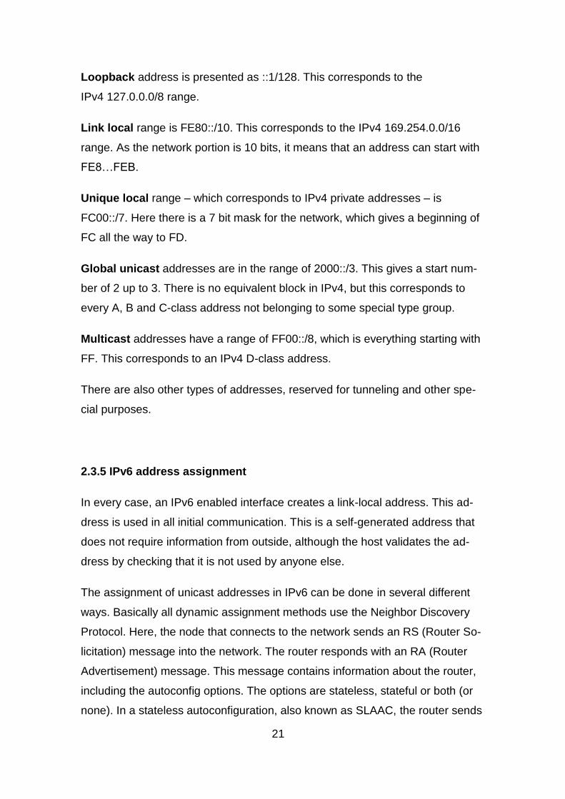
Loopback address is presented as ::1/128. This corresponds to the
IPv4 127.0.0.0/8 range.
Link local range is FE80::/10. This corresponds to the IPv4 169.254.0.0/16
range. As the network portion is 10 bits, it means that an address can start with
FE8…FEB.
Unique local range – which corresponds to IPv4 private addresses – is
FC00::/7. Here there is a 7 bit mask for the network, which gives a beginning of
FC all the way to FD.
Global unicast addresses are in the range of 2000::/3. This gives a start num-
ber of 2 up to 3. There is no equivalent block in IPv4, but this corresponds to
every A, B and C-class address not belonging to some special type group.
Multicast addresses have a range of FF00::/8, which is everything starting with
FF. This corresponds to an IPv4 D-class address.
There are also other types of addresses, reserved for tunneling and other spe-
cial purposes.
2.3.5 IPv6 address assignment
In every case, an IPv6 enabled interface creates a link-local address. This ad-
dress is used in all initial communication. This is a self-generated address that
does not require information from outside, although the host validates the ad-
dress by checking that it is not used by anyone else.
The assignment of unicast addresses in IPv6 can be done in several different
ways. Basically all dynamic assignment methods use the Neighbor Discovery
Protocol. Here, the node that connects to the network sends an RS (Router So-
licitation) message into the network. The router responds with an RA (Router
Advertisement) message. This message contains information about the router,
including the autoconfig options. The options are stateless, stateful or both (or
none). In a stateless autoconfiguration, also known as SLAAC, the router sends

22
the network prefix, i.e. the network portion of the IPv6 address. The host then
generates an address based on this prefix. The other option is stateful, in which
case there is a separate server, DHCPv6 server, taking care of the address
assignment. If this is the case, the host sends a DHCP solicit messages to find
the server, and acquires the address that way. The last option is static, where
the address is manually put into the interface. There are many improvements in
IPv6 compared to IPv4. A well-structured guide to IPv6 is available from Cis-
co(15).
2.4 Internet
As it was concluded in the beginning, the Internet is a worldwide network con-
sisting of interconnected smaller networks. A vital part of the networks is the
global IP address. The governing agency of Internet addressing is IANA, which
is allocating addresses for regional Internet registries, RIRs, such as ARIN and
RIPE. The regional registries allocate address space to local Internet registries,
LIRs. These local registries are either various size Internet operators or compa-
nies, and their task is to assign these addresses to end users or customers. In
this way we ensure that there are globally no unintended overlaps in addresses.
LIRs can apply for an ASN (autonomous system number) which allows it to par-
ticipate in the Internet routing. The Internet consists of either peering or transit
relationships between different ASNs. Peering means that an ASN exchanges
its own network and customer information with a peer. The ASN is allowed to
send data towards the neighbor ASN’s networks and its’ transit customers only.
Peering is free - once it has been established. Transit means that an ASN is
allowed to send data through the provider ASN to any other ASN, and the trans-
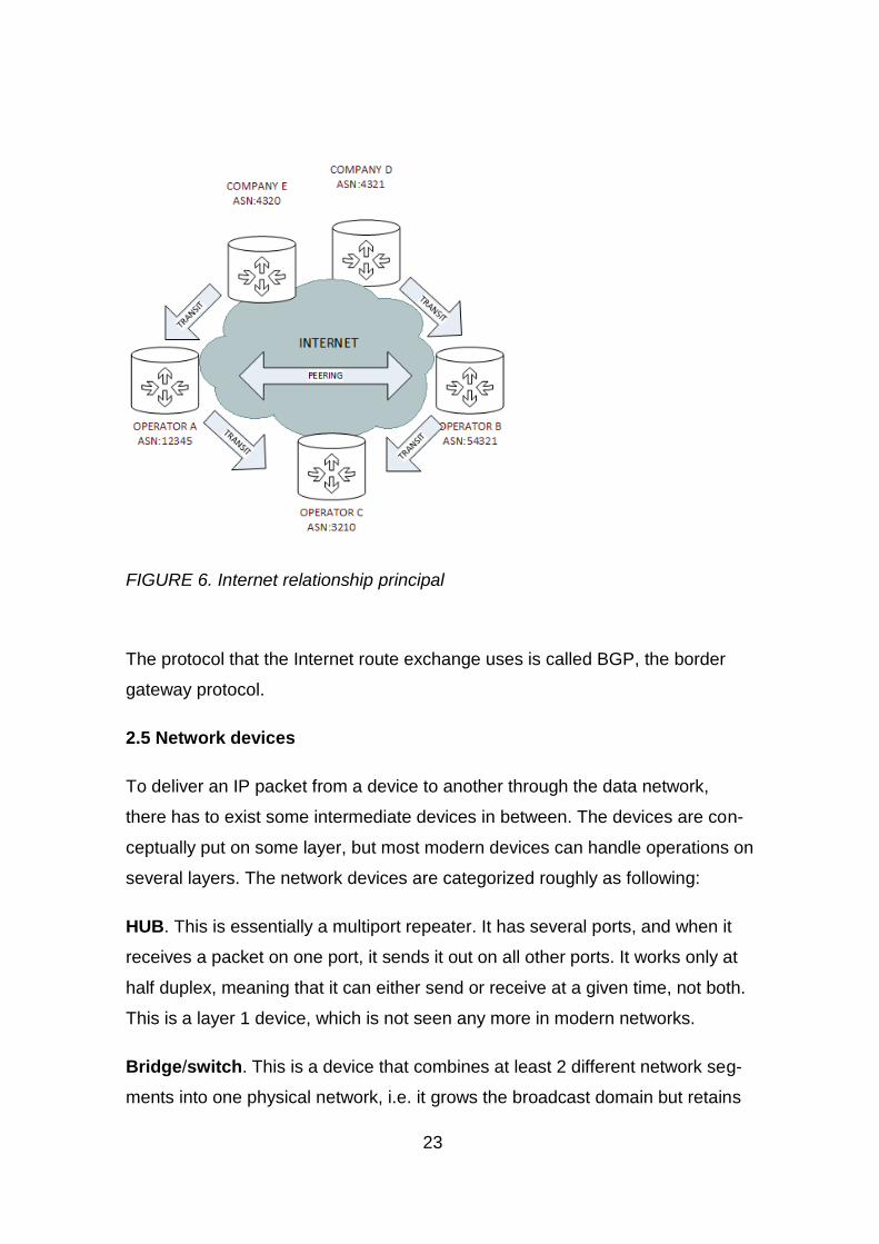
it customer pays for the transit according to a contract. In figure 6, the company
D has transit relationships with an operator B and the company E with an opera-
tor A. Traffic between them would go E-A-B-D and vice versa. However, if the-
operator A’s connection to the operator C would go down, it and its customers
would not reach C through the operator B, as B is not advertising C’s routes to
A.
23
FIGURE 6. Internet relationship principal
The protocol that the Internet route exchange uses is called BGP, the border
gateway protocol.
2.5 Network devices
To deliver an IP packet from a device to another through the data network,
there has to exist some intermediate devices in between. The devices are con-
ceptually put on some layer, but most modern devices can handle operations on
several layers. The network devices are categorized roughly as following:
HUB. This is essentially a multiport repeater. It has several ports, and when it
receives a packet on one port, it sends it out on all other ports. It works only at
half duplex, meaning that it can either send or receive at a given time, not both.
This is a layer 1 device, which is not seen any more in modern networks.
Bridge/switch. This is a device that combines at least 2 different network seg-
ments into one physical network, i.e. it grows the broadcast domain but retains

24
the collision domains. Functionally, it listens to ongoing traffic, learning layer 2
addresses. If it has learned an address, it will forward traffic destined to that
address only through the port where it was learned on. These are mostly full
duplex devices, though a port can be configured as half duplex. Conceptually
these devices are L2 devices. The difference between a bridge and a switch is
a bit obscure, but essentially a switch is a multiport bridge.
Router. A router combines different networks. It has segments in multiple net-
works and route traffic between them. This is a layer 3 device, and it performs
routing based on the logical address information in a routing table or a table
derived from it, called a forwarding information base (FIB). It can be a separate
device or part of a so called multilayer switch.
Firewall. This is a device that permits or denies traffic in a network and does
network address translation. It operates on the layer 4, though modern firewalls
can inspect traffic all the way to the layer 7. This can be a separate device or
part of a router.
VPN gateway. This is a device that functions as an endpoint for outside con-
nections. It can be used for allowing access to a trusted network via an untrust-
ed network. It can be a separate device or server, or it can be part of a router or
firewall.
Connections between devices are usually made by using different types of
Ethernet cabling. There exist other protocols besides Ethernet, however Ether-
net is becoming more and more dominant. Ethernet media is nowadays using
twisted pair copper cable, fiber-optic cable or it is wireless. There are several
categories of Ethernet, all of which are defined in IEEE 802.3 and IEEE802.11.
Ethernet can currently reach speeds up to 100Gbps, and 400Gbps is under de-
velopment (it uses multiplexing).

25
3 NETWORK SERVICES AND APPLICABLE PROTOCOLS
3.1 Routing – the core of network traffic
For an IP packet to reach the receiver, it needs to know the route to it. For this
purpose, there can be either static routes or dynamically learned ones. The lat-
ter becomes more important as the network grows. Usually, smaller networks
will imply the static routing. Major elements of a route are a destination network,
a next hop address or interface, a cost and an administrative distance. The des-
tination network is the network where the packet is headed for. The next hop
address is the address of the adjacent router. The cost is the value that is given
to a route, i.e. the most preferred way of getting to the network in question. The
administrative distance is the route trustworthiness. This is describing the relia-
bility of the manner the route was injected into the system. Directly connected
networks have the best trustworthiness, after that comes static routing. The dif-
ferent dynamic routing protocols come after them. It should be remembered that
the AD values may be vendor specific.
The routing information is used to build up a routing table. This table exists in
the router memory and it is used for looking up routes for packets. Some pur-
pose-built routers use the routing table to build faster lookup methods, like a
FIB, the forwarding information base , and an adjacency table. The FIB is a
hardware optimized routing table for quicker lookups and the adjacency table
includes the hardware addresses of the next-hop IP addresses.
When evaluating routes, it is important to understand the priority order in which
a route is selected.
1. Longest match. The route having the longest match in the network por-
tion of the address is preferred
2. Lowest administrative distance (AD). The lower the AD, the more trust-
worthy the route source is.
3. Lowest cost. If a route has the same network mask and AD, the cost or
metric is used to determine the preference of the route. In dynamic pro-

26
tocols the cost is created based on different network characteristics, such
as bandwidth, a hop count or a delay.
4. If all the above are the same, the system usually starts using equal-cost
load balancing, i.e. some packets are sent using the other route and
some using the other. Some routing protocols allow using unequal cost
load balancing by some predefined factor.
3.1.1 Static routing
A static route consists of a statement that tells what the destination IP network
is, and where it can be reached from. The target for the packet is given either by
a so called next hop address, or by an interface name (or both on some sys-
tems). An interface name can be used alone only if the interfaces are directly
connected point-to-point. In a multi-access network the next hop method, which
is the logical address of the adjacent router, should be used. A static route can
also have a metric associated with it. This way a more preferred route to the
same network can be assigned.
A major concept in routing is a default route. This is the route that is used if
there are no better matching routes. A device can have multiple floating routes.
Floating in this context means that there is a route with a worse AD than the
one in use. If the currently used route goes down, the other one can be taken
into use instead.
3.1.2 Dynamic routing
The routing protocol suite is large, and the details of it can easily take couple of
books to explain. The major categories of dynamic routing protocols are dis-
tance vector routing protocols, link state routing protocols and path vector rout-
ing protocols. The two first ones are used mostly in internal networks. A dis-
tance vector as a term means that a single node has no complete picture of the
network. It rather relies on the information given from its neighbours. Link state
protocols on the other hand have a link state database, where it can inde-
pendently build a topology of the network.

27
There are 2 flavours of distance vector protocols in use today: RIP (Routing In-
formation Protocol) and EIGRP (Enhanced Interior Gateway Routing Protocol).
RIP is a protocol which relies on the hop count as a metric. It is the least trust-
worthy IGP, as the convergence is very slow, and the hop count as a metric is
not the best one. However, it is fast to put up and it works in smaller networks.
EIGRP is a Cisco protocol, which used to be proprietary. The license was re-
leased recently, allowing anyone to use it. It is a rather clever protocol, which
has several factors affecting the cost: bandwidth, delay, load, reliability and
MTU. However, by default only bandwidth and delay are used. It has as well a
smart algorithm for having backup routes available for an immediate use.
Link state protocols are OSPF (Open Shortest Path First) and IS-IS (Intermedi-
ate System to Intermediate System). They have lots of similarities, however ,
OSPF was built for IP and IS-IS for any protocol. Both uses a concept of areas,
but their definitions are different. OSPF calculates route cost based on band-
width, IS-IS has a fixed cost in most implementations. The benefit of link state
protocols is the convergence speed; they converge very fast. As they are built
from different areas, the networks can be really big without causing too much
overhead. Also the routing tables are kept reasonable. On the downside, the
route calculation algorithm is more processor intensive than those of distance
vector protocols. Also configuration along with fine tuning is more difficult.
Path vector protocols actually include only one major protocol, BGP, which is
the routing protocol of the Internet. It is also used in MPLS networks for distin-
guishing virtual routing tables. This is the slowest converging protocol, and it
has the most complex parameters for selecting a route, too.
The categories and flavours of dynamic protocols are shown in figure 7.

28
FIGURE 7. Dynamic routing protocols.
3.2 DHCP
The dynamic host configuration protocol is a network service, which can auto-
matically assign necessary IP addresses for computers and other end devices.
Therefore, any user connecting to the network gets connectivity automatically,
and they do not need to assign static IP addresses for themselves. Mandatory
configuration items dictated by the protocol are an IP address and a netmask.
However, to be better usable, other configuration values can also be assigned,
as the gateway to reach other networks, a search domain name, TFTP or NTP
server addresses and other specific options.
DHCP works in the following way, it is also illustrated in figure 8:
The connecting host sends a broadcast message called a DHCP DISCOVER.
This is intercepted by the DHCP server. The DHCP server acknowledges this
request by sending a DHCP OFFER, which includes the IP address that it is
proposing for the host. After receiving this, the host sends out a broadcast mes-
sage, called a DHCP REQUEST, for that particular address. When it has been
received by the server, it reserves the address for that particular node’s use and
sends out a DHCP acknowledgement message.

29
FIGURE 8. DHCP address allocation
If a DHCP server is in a different network from a host’s perspective, the router
can forward the DHCP request to a predefined DHCP server. This service is
called an IP-helper.
3.3 DNS
Remembering a bunch of IP addresses is practically impossible for all of the
used services. For this purpose, there is a domain name service. It is a feature
that interprets IP addresses to names and vice versa. A fully qualified domain
name includes several parts separated by a period or a dot, for example an or-
ganization could have a registered domain name of myfirm.com. If a publicly
available device is added into that network, it could be assigned a name
myserver.myfirm.com. Now, when some external user wants to connect to this
server, they only need to remember its name, not its IP address.
DNS lookup sequence is presented in figure 9. When a host application wants
to reach an outside server, e.g. www.example.com, it sends the name to its lo-
cal DNS client, called a resolver. The resolver can be a caching one, i.e. if the
name has been used before it might remember it from the past. In this case, it
first sends a non-recursive query to itself to query the address. If it cannot find
the name from the cache, it sends out a recursive (1) query for the address.

30
Recursive means that the query is sent to another DNS server, which takes
care of resolving the address. This server can then start an iterative query,
starting from the root server. In this procedure, it will first ask for the .com name
server from a root name server (2) that has statically been defined. Then it asks
for the example name server from the com name server (4). Finally, it asks for
the www name from the example.com server (6). When everything has been
resolved, it sends the reply back to the requesting client (8). Iterative queries
are normally done by DNS servers, not clients.
FIGURE 9. DNS query process (21)
3.4 VPN
VPN a.k.a. Virtual Private Network is a concept where two remote networks are
made to look being part of the same local network over an unsecure network
between them. Usually, these connections are built over the Internet but other
applications are found too. Against common belief, a VPN is not secure by de-
fault. In practice this is always wanted.

31
3.4.1 Types of VPN
In the bigger picture there are two types of VPNs by purpose: site-to-site and
client /server VPN. A site-to-site VPN is meant to join two remote networks to-
gether on a more permanent basis. A practical use case would be a main office
and an affiliate office. The traffic from main office would use the VPN tunnel to
reach the affiliate one and vice versa. The tunnel can even be made redundant,
thus it is possible to have multiple Internet services from different operators, and
the tunnel would remain up even if some operator has a service outage.
The other use is the client VPN. This setup is more for a mobile worker or home
office. The client program is installed on a desktop, laptop, mobile or SOHO
router. It can be invoked when a connection to the office is needed.
3.4.2 CIA
Part of the VPN tunnel security philosophy is CIA. CIA stands for confidentiality,
integrity and availability. This triad is used in other security contexts as well, but
it is a vital part of a real-life VPN connection. Confidentiality means that only
authorized parties should be able to view the data. It is a combination of encryp-
tion and authentication. In the VPN context it is predefined who is authorized to
see the information, but authentication is needed to receive the data. Integrity
means that no-one should be able to alter the data. This is usually ensured with
a hash function. A hash ensures that the data has been received in the same
format as it was sent. Availability means that the data should always be availa-
ble. Availability is therefore part of redundancy planning and disaster recovery
plans. Different VPN technologies use different technologies to achieve CIA, but
pretty much with the same tool sets.
3.4.3 Authentication factors
The authentication of a VPN connection is based on 3 factors: something that is
known, something that is possessed and something that the user is (biomet-
rics). It is generally recommended to have at least 2 of these 3 factors used be-
fore access will be granted. This ensures that the user asking for access is
having a possession of something that has been given to them, either at birth or

32
by the VPN service owner. The most common form of a 2-factor authentication
is user/password or certificate and a changing PIN code. The PIN code can be
generated by a token, or it can be sent to user’s handset via an SMS or a push
message.
For site-to-site connections, the most popular method is a pre-shared key au-
thentication. In this case some arbitrary information, called nonce is sent. The
initiator is sending the nonce to the responder, and the responder sends its (dif-
ferent) nonce to the initiator. Both respond with the hash result between the re-
ceived nonce and the PSK. If the results are the same, one can safely assume
that the other side has the same PSK.
3.4.4 Encryption
A VPN tunnel can be encrypted with different encryption algorithms. A key ex-
change is done by asymmetric keys. Asymmetric means that there are two
components in a key, which are related to each other, but which are very hard
to resolve with one component only. If something is encrypted with the other, it
can be decrypted with the other. For a key exchange, usually Diffie-Hellman
algorithm is used. Asymmetric keys are explained better in the security chapter
when talking about PKI.
The VPN tunnel data traffic is almost always secured by symmetric algorithms.
Symmetric means that there is only one key for encrypting and decrypting the
data. This key is then changed on the fly at set intervals. There are several al-
gorithms for symmetric encryption, though the most popular one today is AES in
different bit lengths.
3.4.5 Hashing in integrity
A hash is a one-way “checksum”, which cannot be decrypted back to the origi-
nal data. It is rather a number, which alters a lot even if just one bit is changed
in the original data. In practice, several data values can have the same hash
value, but it is very unlikely to happen. In addition to the PSK authentication, a
hash is used to ensure the integrity of data. Here, the to-be-sent data is hashed
with some shared value, which is not the PSK hash. It can differ depending on

33
the VPN technology. However, the hash of the data will be sent in the packet,
and the receiver can then check that their calculated hash value corresponds
with the one on the packet.
3.5 QoS – Quality of service
QoS is a method for classifying and transporting IP packets at different im-
portance levels. The target is to transfer real-time data as quickly as possible,
while bandwidth hungry data will fill the void, based on importance. Thus a flu-
ent user experience is achieved. Importance levels define what needs to be
done with the traffic; is it provided for priority access, a predefined bandwidth or
something else. In practice, this means that traffic is identified based on some
criteria, e.g. IP-address, port number, application protocol. Based on the crite-
ria, the packets are marked with a QoS value. This value can then be used for
different QoS actions; police the rate (inbound or outbound) or shape (outbound
only) the traffic below a certain rate. Policing means that there exists a prede-
fined rate that is the absolute maximum transmission/receiving rate and any
excess packages will be dropped. Shaping on the other hand is about filling the
empty slots in the transmission so that the bandwidth is utilized as well as pos-
sible. The principle can be seen in figure 10.

34
FIGURE 10. Policing vs shaping (2)
Additionally, traffic can be queued based on the markings and start dropping
less important packets to avoid congestion.
The main two methods for classifying are the IP precedence (part of RFC 791)
and the successor of it, DSCP (Differentiated Services Code Point RFC 2475).
DSCP utilizes the 8 bit COS/TOS value for marking purposes, though only 6
bits of the field is currently used. IP precedence uses only three bits of the
COS/TOS value, although it is compatible with DSCP. It should be noted that
RFC791 lists other options for the three next bits; delay, throughput and reliabil-
ity. However, these are rarely used. Some examples on what traffic classes
could be used for different types of traffic is shown in table 1.
.

35
TABLE 1. Some DSCP and precedence values (22)
3.6 Marking principles
DSCP markings have two parts; the first part is the three bit IPP, IP prece-
dence. The second part is the three bit drop eligibility. Actually only two first bits
are used, the third one is always 0. The bigger the number is, the higher the
probability to be dropped within the PHB class. The last 2 bits can be used for
ECN, Explicit congestion notification. However, this is currently an optional fea-
ture. The class zero is best effort (no marking). Assured forwarding has classes
AF1x-4x. These values correspond to IPP 1-4. EF stands for expedited forward-
ing, and it corresponds to IPP 5. Classes 6 and 7 are reserved for internal rout-
ing information and such mandatory services for keeping the network running.
The second three bit part of the DSCP is drop eligibility.
There are no set classifications for different type of traffic, i.e. the organizations
and operators may use the classifications as they see fit. Usually, however, the
higher the classification is, the more sensitive the content is for dropping. Class
5 is interactive, delay-sensitive data, i.e. voice and video conferencing. Class 4
is usually video and call control traffic. Class 3 is often some mission critical
data, important for business purposes. Network and IT management traffic has

36
often its own class to ensure that IT personnel can access the remote man-
agement interfaces.
3.7 Queue discipline
Classification itself cannot achieve anything, it is just a marking. To actually use
it for some relevant purpose, different queues are needed. There are several
different kinds of queuing techniques based on functionality. The main ones are
FIFO queue, a priority queue, a class based queue and a weighted fair queue.
FIFO: First In First Out, i.e. no queue at all. This is the fastest queue with almost
no configurability. Only the queue length can be altered.
Priority queue: Everything in the high priority queue is sent before the lesser
priority queues.
Weighted Fair Queue: This assigns different flows automatically into different
queues. If the set queue limits are hit, the queue starts dropping more aggres-
sive packets before other traffic.
Class based WFQ: Here different rates are assigned for different queues, and
then the traffic is guided to different queues based on markings.
In practice a combination of these queues is needed. In Cisco world this would
be called LLQ; low latency queuing. In this solution there is a priority queue,
which prioritizes a pre-set amount of bandwidth. Then there are different
amounts of class-based WFQs, and then the bulk traffic queue.
Similar effects can be achieved with the Linux traffic control (tc), using HFSC
and SFQ (17). HFSC can be used to assign bit rates and a predefined maxi-
mum delay to classes. SFQ can be used for sharing the queue with multiple
users at an equal, fair rate.

37
3.8 VoIP - Voice over IP
Traditionally voice has been a service that operators bring all the way to our
phones. The systems have been proprietary and therefore expensive. Also,
subscribers have had to have a double wiring for data and voice. The mainte-
nance of in-house systems have been expensive, and the provided solutions
very inflexible. A solution to this is VoIP. It is a technique that allows to send
the voice and signalling data over your existing data network. After that, end
users can use a desktop device or various applications to playback the voice.
The main technology to handle the calls is called SIP, which is introduced later
in this chapter. There are other technologies as well, such as SCCP (Cisco),
MGCP and H.323, but these are nowadays less popular protocols. Especially
open source systems are relying on SIP.
3.8.1 Voice sampling - codec
An analogue voice signal needs to be sampled to get it into a digital format. The
purpose is to convert an analogue signal to a digital format, process and send it
digitally, and then just before it is played out, it will be converted back to ana-
logue format. This will allow digital equipment to be used for the whole transfer
process, and it will also allow a magnitude of operations that can be done to the
signal. In sampling, the Nyquist sampling theorem must be obeyed. This theo-
rem states that samples need to be taken on a rate of 2 times the highest fre-
quency of the signal to be sampled.

38
FIGURE 11. Sampling of ananlogue signal. (23)
Figure 11 shows the process of sampling. There exists a certain set of ampli-
tude levels. The analogue voice signal is quantized at the Nyquist rate into the
nearest level set by the codec. These levels have some digital representation
value, and the sample can now be represented in a digital format for further
processing.
There are many different codecs. G.711 is the first codec used in the original
PCM system. After that there has been several codecs, which concentrate gen-
erally on saving bandwidth without affecting the voice quality too much. There
are also some adaptive codecs, which alter themselves based on the content or
bandwidth available. A codec quality is very difficult to measure. The best sys-
tem so far is the MOS, Mean Opinion Score. Here a test panel of at least 12-15
people is listening on voice samples produced by different codecs, giving them
a score from 1 to 5. A mean value is then calculated based on the score. The
higher the score, the better the codec is. Table 2 shows a brief comparison of
different codecs.

39
TABLE 2. Charasteristics of different voice codecs (24)
3.8.2 SIP – Session Initiation Protocol
SIP is the signaling method in modern open source VoIP networks. SIP takes
care of registering clients, and keeping track of their location. The protocol that
is transferred in real time can be then something else, SIP does not care. SIP is
defined in RFC 3261.
As SIP is very simple in nature, it needs other protocols to function as a media
protocol. The most important of those protocols are, e.g. SDP (Session Descrip-
tion Protocol) and RTP (Real Time Protocol). SDP negotiates the necessary
parameters for the sessions, and RTP takes care of moving the actual real-time
payload.
SIP infrastructure has devices with the following roles and roles can also be
combined:
UAC/UAS – User Agent Client/Server. This is usually the origination and termi-
nation point of a session. The client function initiates the session and the server
function responds to it.

40
Proxy Server – The most common server. It handles the SIP messages and
forwards them to either another proxy or straight to the end point. It can also
handle messages between the user agent and the registrar.
Registrar – Registration Server. This device authorizes and registers the devic-
es in the environment.
Location Server – The registrar stores the location information of the authenti-
cated client on this server.
FIGURE 12. Basic SIP session (25)
Figure 12 has a presentation of the messaging involved.
M1. UAC sends an INVITE-message to its configured proxy server, destined for
user2
M2. Proxy server 1 does not know the location of the endpoint, thus it sends it
to server2 based on the INVITE-messages recipient domain.
M3. Server1 sends a TRYING message back to User1

41
M4. Server2 sends INVITE to user2, as they know the location of the user.
M5. Server2 sends a TRYING message back to server1
M6-8. User2’s device is alerting, and SIP UAS sends a Ringing notification to-
wards user1
M9-11. User2 answers to the ring and OK message is sent, usually containing
the SDP information.
M12. User1 sends an ACK, containing SDP information.
RTP data exchange starts
M13. User2 ends the session with a BYE-message
M14. User1 acknowledges the BYE.
42
4 NETWORK SECURITY
In this chapter some basic network security devices and protocols are visited.
Network security is becoming more and more important, because a growing
amount of critical data is available through the Internet. Network security is al-
ways a compromise between usability and security; if access is not allowed to
anyone, the best security is achieved. However, systems are not very useful in
that way. Therefore, a midway between these has to be found, allowing the use-
ful traffic and minimizing the possibilities for harmful traffic. And some measures
to track the activity in the network must be available.
4.1 Firewall
A firewall is the basic security device in a network. It intercepts the traffic, and
based on some rulesets it either allows packets to pass unmodified, alters or
marks the packets, or denies the packets. There are several types of firewalls,
and several ways of categorizing them. Several types are defined in NIST 800-
41 (26), which divide firewalls to packet filters, stateful firewalls, application
firewalls and proxy firewalls. On top of that there are many other special pur-
pose versions listed. However, as many firewall features are available in differ-
ent kinds of firewalls, it is hard to make a strict categorizing. Some well-known
categories are listed below .
Stateless firewall, Packet Filter. This acts more like an access list, where
connections need to be statically allowed, both inbound and outbound. This is
the quickest form of a firewall, but the least dynamic one, too. A session or flow
information is not available for rules, rather the IP addresses, ports or interfaces
are used for allow and deny statements.
Stateful firewall. This version of a firewall recognizes traffic flows and makes
up the pass decisions based on stateful rules. This means in practice that some
IP address or range or interface is allowed to send traffic to the destination, and
the return traffic is allowed only for that session. When the session ends, further
return traffic is denied. This is more resource consuming, but it makes the rules
more efficient and simpler.
43
Application firewall. This firewall is an enhancement to the stateful firewall. It
does a so called deep packet inspection on the packets at the application layer.
Therefore, not only the layer 4 information affects the traffic, but also the pay-
load on the application layer.
Application-Proxy gateway. This is a firewall that proxies all connections. This
is the safest version of a basic firewall, but as well most resource intensive. In
this type of a firewall the connections are always terminated at the firewall, there
are no through connections. It is the firewall itself that establishes the remaining
connection based on its’ rulesets. It includes elements from application firewalls.
Next generation firewall is a term for firewalls that do application level inspec-
tion and security inspections. For example a certain application or website can
be denied and at the same time scan incoming files for viruses or malware. This
version includes elements from the previously listed firewall types, and adds
intrusion prevention system functionality on the firewall itself.
4.2 Network Address Translation
One other feature of a network access node is NAT, which stands for Network
Address Translation. NAT was originally invented to resolve the problem of us-
ing private RFC 1918 addresses for Internet access. The idea is to translate
certain inside addresses to publically routable ones and vice versa. NAT was
originally defined by RFC 1631, nowadays it has several enhancements and
improvements added, thus having several RFCs describing it. There are three
major types of NAT (11):
Source NAT, where source address is changed. This type is more common for
outwards connections (towards Internet). Here the source address is changed
after the packet has been processed by the firewall. When a reply to the sent
packet is received, the destination address on that packet will be changed to the
original inside address.
Destination NAT, where destination address is changed. This is more common
for incoming connections. When the packet arrives at the router, the destination
address is altered before the packet is further processed. Whenever a reply to

44
that particular session arrives, the source address is changed to that of the orig-
inal packet.
NAPT (Network address port translation) is a type of NAT, where multiple
hosts inside the LAN network can share one public address. This is made pos-
sible by TCP/UDP port translation. For example, if a host initiates a session
from port 33333, and the port is free on NAT, the firewall reserves that source
port for that host’s use and just changes the source address when sending the
packet forward. When a reply is received, the destination is changed to the in-
side host address, based on a translation table. If some other host tries to use
the same source port as this host at the same time, the outgoing packet is given
some other free port. When a reply is received on that packet, the firewall will
change both destination IP and port based on the translation table.
4.3 Intrusion detection and prevention
Network intrusions are events where someone is intentionally attacking our
network in different manners. Attackers usually try to exploit some vulnerability
in the devices, or they might use some other methods of attacking to gain ac-
cess to the network. The reasons for intrusions are various e.g. information
gathering, preventing service, building botnets. Nevertheless, whatever the rea-
son, the fact is that attackers can cause a lot of harm, especially in a corporate
network. Network traffic analysing is a difficult process, as there are so many
harmful exploits, attacks and malware to utilize, and their amount is increasing.
Also exploit tools are getting more sophisticated.
The devices performing the analysing are roughly divided into two main catego-
ries: Intrusion detection systems (IDS) and Intrusion prevention systems (IPS).
The major difference between the systems is that an IDS is parallel to the net-
work, and it is only “sniffing” the network traffic, whereas the IPS is in-line with
the data traffic and can drop traffic that it finds harmful. IDS on the other hand is
only capable of alerting and showing statistics.
Intrusion detection events can be divided into two main categories: signature
based and anomaly based. The signature based inspection tries to find a cer-

45
tain pattern or checksum that always exists in that particular threat. This is fixed
and has to be continuously updated as new ones are found. Signatures can be
based on the application layer content, traffic patterns, ports utilized or even IP
addresses. ´The anomaly-based inspection checks the traffic behaviour. For
instance, if some device is suddenly opening a lot of connections to the Internet,
an alert can be sent. This type of inspection is tricky to set up but it does not
rely on continuous rule updates.
There are organizations that keep track of vulnerabilities, and issue periodical
statements on these, one of those being Mitre/CVE. Based on these found vul-
nerabilities, signature files are generated. The signature files are usually main-
tained by some security organization or device vendor, and they are updated on
regular basis by the security system. The administrators can then choose how
strictly these events are treated; what kind of traffic will be dropped and what
not. The same applies to the alert rules. On top of vulnerabilities, malware can
be filtered using the same kind of signature inspection. The most common mal-
ware are viruses, Trojans and worms.
The event management software for a security network is called a SIEM, which
stands for Security Information and Event Manager (27). This can consist of
multiple separate devices, having different tasks. Some common SIEM tasks
are:
User interface for changing settings
Dashboard for viewing events
Alerting rules and targets
Analysis and correlation. The system analyses the data it gathers, and
looks for common attributes between different events.
Data aggregation and logging. A SIEM system can have several sensors
throughout the network, and the software itself aggregates and displays
the data from different sensors

46
4.4 PKI
There is a need to authenticate hosts and users reliably in a network. For this
purpose there is a PKI infrastructure (28). PKI, i.e. Public Key Infrastructure is a
hierarchical system for “reliably” authenticate a host or person. Based on the
information, further authorization can be granted to users or hosts to access the
resources
X.509 is the ITU standard for a PKI system. It is a system, where we have a “big
boss”, the root certification authority (Root CA). The root CA can authorize in-
termediate certification authorities. These intermediate authorities can then is-
sue client certificates, which can be used for authenticating clients, and to ex-
change encryption information. For the system to work properly, the Root CA
public certificate must exist and be trusted in all devices in the PKI. The lower
we go in the infrastructure, the less security is needed. Also, the validity period
of a certificate should shorten the lower we traverse in the hierarchy.
PKI is based on asymmetric key pairs, which consist of a private key and a pub-
lic key. The keys are mathematically related to each other, but it is very difficult
to calculate the pair from the other. Data is encrypted with a public key and de-
crypted with the private key. A certificate on the other hand is a public key which
is signed by the issuing authority’s private key. In addition to the public key and
signature, it contains data on the usage, validity and revocation list information
etc. In case of authentication, the client certificate’s public key is first encrypted
with the authority’s private key. The recipient of the certificate can decrypt it with
the CA’s public key. If the decryption result is the public key of the sending cli-
ent, sender is likely to be who he claims to be. An illustration of certificate re-
trieval process is in figure 13.
The certificate’s intended use can be restricted to a certain type e.g. the client
certificate can be set for authentication only, i.e. it cannot be used for encryp-
tion. Likewise, a CA certificate can be set to only be used for digital signature
signing.

47
If a certificate is used to start an encrypted session, the asymmetric keys are
used to create a changing symmetrical key. This is because the asymmetric key
is very heavy on the processor; symmetrical keys are less burdening for the
processor
FIGURE 13. Public Key Infrastructure

48
5 BUILDING BLOCKS FOR THE DEVICE
In this chapter the components to be used for building the device will be select-
ed. There are several options to build a firewall device, and there is no best op-
tion. Essential is to pick something that fits the purpose and that builders and
maintainers are familiar with.
5.1 General requirements
When a system is selected, there are several general (physical) requirements
that need to be evaluated. Some major requirements that the job commissioner
had given for a commercial device are below.
Stability. The system needs to stay available as much as possible. Modern
systems have a very low MTBF, actually Cisco promises an above 11 years
MTBF for some of their ASA firewalls (1). Therefore, the components have to be
field proven and of commercial grade.
Support. The support over the intended lifecycle is important for the product.
This applies to both hardware and software components. A good network router
and firewall will be servicing for at least 3 to 5 years, occasionally even longer.
During that time both hardware and software updates are needed. A network
card might break down, and it might be safest to have an exactly same model to
ensure compatibility. The beauty of a self-built system is, of course, that it is
more forgiving if there is a need to use alternate components.
Physical characteristics. The device might have to fit in a certain space, or
needs to stay below a preset power consumption. The physical size is usually
measured in so called rack units in case of a rack chassis. A rack unit is abbre-
viated as U or RU. One U-unit is 1.75 inches, which is about 4.45cm. This is the
general size of a workgroup switch or a simple router. In this project there is a
more sophisticated device, so it could use more space based on the require-
ments and processing need. But, generally a server or a router is less than 4U
high. As the demo device is meant for a small example setup, it can easily fit it
in a 1U size.

49
Usability. A router is attached to a rack; therefore, the access to its interfaces
must be in the front. Rear interfaces are not very convenient in a rack environ-
ment.
Capabilities. The selected feature set for the device. In this case the device
acts as a router, a DHCP-server, a DNS-server, a VPN-server, a VoIP-server
and a security device. The device could easily be used for other services too,
such as email, web-server and network monitoring, but it would need a better
redundancy to be reliable for those operations.
Redundancy. If the device is a critical asset with end user services, it is rec-
ommended to have critical parts duplicated, and make regular backups of all
data, not only configurations. Redundancy can be achieved with RAID-disks,
failover devices, and redundancy protocols. Also power can be redundant. In
some installation sites battery backup power might be required (usually 48V)
5.2 Hardware
Based on the set requirements, hardware will be a 1U rack-mount server chas-
sis, which will have a commercial grade Jetway Mini-ITX motherboard. This will
ensure a proper installation in a rack and a decent reliability. In this setup there
will not be any additional network interfaces, the motherboard and its daughter-
board offers enough of them.
5.3 Software and applications
5.3.1 Operating system
As the title tells, this device will be a Linux-based device. Linux as such is the
core of several so called distributions, distros. There are several factors that
affect the choice of distro for a system:
Popularity and support. The system needs to be supported by either a com-
mercial organization or a strong community. Otherwise updates to critical issues

50
might not be available. Also, unpopular distros have a tendency of being more
unstable.
Needed modules. Linux features are provided as installable modules. Usually
the modules are available as packages for the distro. If not, the source code
can be downloaded and compiled on the target system.
Purpose of distro. Distros are usually purpose-built, meaning that different dis-
tros are meant for different tasks. There are distros for servers, client hosts, se-
curity people, tiny devices etc. A recommendation is to use some server-grade
distribution, as those tend to fulfill the above listed requirements as well.
The selection for the access nodes distro is CentOS 7. It is based on a com-
mercial distro called Red Hat, and has a large user base, including world’s lead-
ing companies. On CentOS, features are available as installable packets, in-
cluding most features we have included in our requirement list. In case packets
are missing, features can be compiled from source code.
5.3.2 Routing protocols
The access node will be in a fairly simple network, and the routing will be han-
dled statically. Thus, for the current needs, the Linux iproute2 –software suite
can easily handle the routing. However, to ensure scalability, the router will
have a software called Quagga. Quagga is able to control different routing
daemons, such as RIP, RIPng, OSPFv2 and v3 and BGPv4. Quagga has a
Cisco-like CLI interface, which is used to configure the daemons. Configuring
Quagga is left out of the scope of this document. It is good to understand that all
kernel routes will by default have a better administrative distance than those
Quagga static routes.
5.3.3 DNS server
The most popular DNS server for Linux is Bind. This software is very mature,
and its different versions have been used for decades. Especially, if there is no
Active Directory server in the network, this server allows internal DNS zones to

51
be established. The system will be installed in a bind-chroot environment, where
bind is isolated from the rest of the system.
5.3.4 DHCP server
Linux provides several flavors of DHCP servers. One of the most popular ones
is Internet Systems Consortium’s (ISC) version. It has versions for both IPv4
and IPv6, though they need different instances running. With this server, man-
datory client settings can be automatically assigned along with a magnitude of
options. It also allows addresses to be reserved for hosts based on the MAC-
address.
The DHCP server can be made to update the local DNS zone, too. For this fea-
ture a dynamic DNS setup is needed, and update keys need to be configured
on the DHCP server.
5.3.5 VPN software
There are several options for the VPN software. OpenVPN is a very common
open source VPN server, which is extremely versatile for different purposes.
The added benefit of Linux is that there can be several different VPN servers.
OpenVPN can be used for both client/server and point-to-point connections,
while Openswan IPsec software can be installed to take care of possible exter-
nal connections to other vendors’ devices.
If an easier configuration is preferred, there is a commercial OpenVPN Access
Server available. However, paid user licenses are needed. A less expensive
solution is to configure the server yourself, and use the free client software. A
very good guide for building a VPN server is in the book OpenVPN 2 Cookbook
(16)
5.3.6 VoIP service
When selecting voice services, a good and mature option is a software called
Asterisk (*). This software is capable of functioning as a full scale switchboard
on top of terminating traditional POTS lines. Own personal messages can be
used on it, also interactive voice response (IVR) menus can be used. The soft-

52
ware allows meeting rooms and voice mail. Asterisk can be accompanied with a
video call service.
If a GUI is wanted for the Asterisk system, there is a framework called
FreePBX available. It is built around the Asterisk core. FreePBX makes it easier
to assign SIP extensions and to generally control the switchboard and server. It
is freeware. If there is a need for a stand-alone VoIP server, FreePBX has a
ready-made distribution, which can be deployed virtually or on dedicated hard-
ware.
5.3.7 Firewall
The traditional Linux firewall is called iptables (6). The new Linux versions also
have a new zone-based firewall called simply firewalld.. Both versions are
available with the CentOS 7. Both firewalls use the same iptables kernel com-
mands, though the command line is different. Rules with the traditional iptables
firewall will be created here.
The functionality of iptables is based on three tables, called “filter”,”mangle” and
“nat”. There is also a table called raw, which is used on rare occasions for by-
passing the connection state tracking. These tables have predefined chains.
Figure 14 shows the logic behind different chains.
The nat-table is used for translating addresses based on given rules. Prerouting
chain alters the destination address and postrouting chain alters the source ad-
dress. The mangle table is used for marking packets, directly traffic affecting
rules are not allowed here. The actual firewall functionality is on the filter table.
On the filter table we have three predefined chains: input, output and forward.
The input chain is used when target IP address is on the local machine. The
output chain is used when the source address of the packet is on the local ma-
chine. And the forward chain is used when neither source nor destination ad-
dresses are on the local machine. Is should be noticed that NAT is done before
the filter table, and the decision on the filter chain is done after NAT has been
processed.

53
Every iptables rule has conditions and targets (6). Conditions can be matched
based on e.g. addresses, ports, protocol, state. When a condition is matched,
the target is executed. Commonly used targets or actions in the filter table are
ACCEPT, DROP or REJECT. Also custom chains can be written and traffic can
be redirected to those chains. This is useful for the traffic categorization and
also to make the firewall rules neater. The mangle table target is usually MARK
or TOS. This is used to either assign the kernel level marking, or to assign the
TOS-byte some value, usually for QoS purposes. The NAT table has SNAT,
DNAT or MASQUERADE targets. The SNAT target alters the source address,
DNAT the destination address and MASQUERADE uses the interface address
for the port address translation.

54
FIGURE 14. Iptables chain processing (6)
5.3.8 IPS software
There are two major Linux IPS services; Snort and Suricata (29). Suricata is
the newer one and fully Open Source, whereas Snort is partially open source,
but the newest and latest signatures are only for subscribers. The Suricata en-
55
gine is a bit more modern compared to Snort, whereas Snort has a larger user
base. There are no clear pros or cons to prefer one over the other. Just from the
open source perspective, Suricata was chosen for this project.
Suricata is a multithreading application, meaning that it can utilize all threads of
a processor to process packages. This improves the performance significantly.
The system can be monitoring only, in IDS mode. In this mode, it will get all the
alerts, but it cannot drop or reject traffic. The admin can though get the alerts,
and go through the monitor logs. In an inline - or IPS - mode, it can be config-
ured to affect the traffic flow. This is the more useful mode, as going through the
alerts afterwards is a bit waste of time as the bad things have usually already
happened. The system uses rules –files, which contain different signatures for
different threats. These signatures have an action listed next to them. The ac-
tion can be PASS, ALERT, REJECT or DROP. Pass lets the packet go through,
alert makes an alert to the system while letting the packet pass, reject rejects
the packet and generates a message for both the sender and receiver, drop
drops the packet without further processing. Managing and tuning these rules
can be a big workload, and it takes time to get the proper settings. Rule files are
generated by different security communities. Popular ones are those of Snort
and Emerging Threats. Custom rules can also be written.
Oinkmaster (12) is a program that can be used for managing the threat files.
This is rather a pearl script that can be run periodically to download the latest
threat files. It has an associated settings file, which can be used for configuring
the rules files. It enables a very granular modification of particular rules. Also it
allows changing the actions on entire rule sets. All rules in a rule file defaults to
an alert. If the device is situated inline, some of the rules should be modified to
drop traffic. Processing rules is processor intensive and time consuming, thus
all rules should never be activated at the same time.

56
6 BUILDING AND CONFIGURING THE SYSTEM
6.1 Topology
The lab objective was to build a system shown in figure 15.
FIGURE 15. Lab network setup
The router device will be connected straight to the Internet with static, public
addresses. It is meant to perform IPv4 PAT for the internal devices.
217.116.163.200 will be the NAT address for internal services, and
217.116.163.201 for the guest network. This will have several positive effects:
QoS filtering is easier, and if the non-guest users need to access some Internet
service, the address can be used as a filter at the other end.

57
The inside connections could be done from separate interfaces, as there are
plenty of them on the router. However, it was decided to use VLAN tagging to-
wards the switch, just to have it demonstrated. In production use an evaluation
of the bandwidth need vs.the switchport consumption should be done. In table
3 we have the networks and associated VLANs
TABLE 3. Interface addresses
Network Name VLAN
217.116.163.200/26 217.116.160.201/26 2a00:5240:0:4001::200/64 outside N/A
172.30.0.0/24 2a00:5240:0:8002::ffff/64 inside 71
172.30.10.0/24 guest 72
172.30.20.0/24 voice 73
The wireless access point was bridged, meaning that it is only converting wire-
less traffic to wired traffic.
6.2 Building hardware
The hardware selected was a rack mount, 1U chassis. It has an industrial mini-
ITX board and an SSD drive (see table 4). The motherboard is an old version,
which is not on the market anymore. This is generally not recommended for a
production setup but for the purpose of demonstration it is more than adequate.
For a commercial version, a recent motherboard with enough processing power
and memory would be selected.

58
TABLE 4. Linux router hardware
Hardware Description Pros and cons
Case 1U rackmount from plin-kusa
Selected due to 2 charasteristics; size and front layout. Power supply includ-ed.
Motherboard Jetway NF99-FL Lots of onboard connectors with an optional network daughter card. Fanless heat sink.
Memory 4GiB SO-DIMM 1333 MT/s Enough for demonstration. For SIEM environment as much as possible, at least 8GiB.
Hard drive Intel SSD 40G Fast and no moving parts
6.3 Installing software
6.3.1 Installing OS
Linux installation is very straight forward. In this case, a minimal version of Cen-
tOS 7 was downloaded from CentOS website, burnt on disk and the router
hardware was booted from that disk. Just by following the prompts, the operat-
ing system was installed. The minimal version was selected to prevent unnec-
essary packages from being installed. This version has only the essential pack-
ages to run the OS and CLI, and any additional packages will be installed after-
wards.
Once the OS had been installed, a network cable was installed on the man-
agement interface, and an SSH connection initiated to the machine. The root
account was used for all configuration. The network interfaces default to dhcp
client mode. Therefore, if there is a dhcp-server in the network where the device
is connected, an automatic IP address will be given. In this case the assignment
was 192.168.0.119.
For initiating an SSH console session, a terminal software was needed. Putty
(1310) was used here. There are other popular ones as well, such as Tera
Term. The screenshot of a connection initiation is presented in figure 16.

59
FIGURE 16. Putty connection settings
The first things first, software needed to be up-to-date, and also a few important
packages had to be installed to have some essential network tools available. To
address the issue, a packet manager was used. Red Hat packet manager is
called RPM, and it can be used by several tools. The most popular one is yum.
There are several parameters that can be given to the commands. A useful help
for almost all Linux commands can be seen using the command man <com-
mand>.
For basic network operations, these packages had to be installed:
Quagga for routing daemon control
nmap for network scanning
tcpdump for tracing network traffic
iftop for monitoring interface load
iperf for measuring network performance

60
dhcp for DHCP server
nano for text editing (vim is the default)
wget for downloading packages from the web
bind for DNS servicesy
iptables-services for firewall services
openvpn for VPN server
easy-rsa for VPN server certificates
openssl for encryption libraries
openswan for IPSec connections
net-tools for some basic network operations
ntp for network time
radvd for IPv6 address assignment
To install the necessary packages, first a system update is done with yum up-
date. Then the packages are installed with same command: yum install
tcpdump dhcp quagga iftop nmap nano wget bind-chroot iperf iptables-
services openvpn openssl easy-rsa openswan net-tools ntp radvd
All software packages are not necessarily found in the default repositories. In
this case the iperf package is not found. Therefore an extra yum software re-
pository had to be added into the system, called EPEL (Extra Packages for En-
terprise Linux). The installation script can be downloaded online from the fedo-
raproject.org web site. Extra caution should be used when adding additional
repositories, as the installation package provider should be a trusted one. Fedo-
raproject is a legitimate organization closely related to Red Hat, therefore it is
rather trustworthy.
The repository is taken into use by the command rpm –i epel-release-latest-
7.noarch.rpm
Then, yum is run again with the missing packages. This time they should install
fine. After this, the basic software will be up-to-date.

61
6.3.2 Configuring basic network settings
The basic settings on the device were very basic. The very first thing to do, as
the device is Internet capable, was to enable the firewall. There are two flavours
of firewall in CentOS 7, firewalld and iptables. Both use essentially the same
kernel command (iptables), but the configuration is a bit different. The traditional
iptables was used for our firewall. To activate this, the following commands
were given:
systemctl stop firewalld
systemctl disable firewalld
systemctl enable iptables
systemctll start iptables
Several files had to be configured for a proper routing functionality.
Files in the folder /etc/sysctl.d/ have important system settings. The most im-
portant ones related to routing functions are forwarding flags. This setting con-
trols if the device can forward IP traffic or not. By default this is 0, i.e. no routing
will happen. This had to be changed to 1. To do this, entries were added to
/etc/sysctl.d/99-sysctl.conf:
net.ipv4.ip_forward = 1
net.ipv6.conf.all.forwarding = 1
In the same file, it was informed that some interfaces are not allowed to partici-
pate in IPv6. This is done by entries:
net.ipv6.conf.enp2s0.disable_ipv6 = 1
net.ipv6.conf.vlan72.disable_ipv6 = 1
net.ipv6.conf.vlan73.disable_ipv6 = 1
Settings were applied with the command
sysctl –system
As default, the network configurations are handled by a daemon called “network
manager”. However, the network settings should be configured manually.
Therefore, Network manager was disabled using command systemctl stop

62
NetworkManager and then it was prevented from starting at the next boot by
systemctl disable NetworkManager.
Next the hostname of the device was set. This was set in CentOS 7 with host-
namectl –command. Thus it was set to “Linux-router” by using the command:
hostnamectl set-hostname “Linux-router”
After that the new hostname was taken into use by typing systemctl restart
systemd-hostnamed
Network interfaces are by default configured to get an address by dhcp. All net-
work interfaces that were recognized and present during the installation have a
startup script in the folder /etc/sysconfig/network-scripts. Here the interfaces
connecting to the Internet and to the switch port were edited.
The Internet connected configuration file would be like below. Here the public IP
address and default route are set. The default route is given a metric of 100.
Giving a big enough metric enables to afterwards add a default gateway without
changing the settings of this interface. The most viable case where this could be
needed is if there are multiple Internet connections.
LISTING 1: Interface settings for enp3s0 (Internet interface)
----------------------------------------------------------------------------------------------------------------------------
TYPE=Ethernet BOOTPROTO=static IPADDR=217.116.163.200 NETMASK=255.255.255.192 GATEWAY=217.116.163.254 IPADDR2=217.116.163.201 NETMASK2=255.255.255.192 DEFROUTE=yes METRIC=100 IPV6INIT=yes IPV6ADDR="2a00:5240:0:4001::200/64" IPV6_DEFAULTGW="2a00:5240:0:4001::1" NAME=internet DEVICE=enp3s0 ONBOOT=yes NOZEROCONF=yes ----------------------------------------------------------------------------------------------------------------------------
The management address has to be modified, so that the default route given by
DHCP will be removed and above the Internet connection will be used instead.

63
At the same time a static address is given, so it will not change. It is wise to
make a reservation for this address into the DHCP server serving this network.
LISTING 2: Interface settings for enp2s0 (management interface)
----------------------------------------------------------------------------------------------------------------------------
TYPE=Ethernet BOOTPROTO=static IPADDR=192.168.0.119 NETMASK=255.255.255.0 IPV6INIT=no NAME=management DEVICE=enp2s0 ONBOOT=yes NOZEROCONF=yes ----------------------------------------------------------------------------------------------------------------------------
Finally, the internal networks are given some settings, to enable the tagged in-
terface.
LISTING 3: Interface settings for enp5s4 and its’ VLANs (LAN interfaces)
----------------------------------------------------------------------------------------------------------------------------
DEVICE=vlan71 VLAN=yes VLAN_NAME_TYPE=VLAN_PLUS_VID_NO_PAD PHYSDEV=enp5s4 IPADDR=172.30.0.1 NETMASK=255.255.255.0 ONBOOT=yes IPV6INIT="yes" IPV6ADDR="fe80::200/64" IPV6ADDR_SECONDARIES="2a00:5240:0:8002:ffff/64" DEVICE=vlan72 VLAN=yes VLAN_NAME_TYPE=VLAN_PLUS_VID_NO_PAD PHYSDEV=enp5s4 IPADDR=172.30.10.1 NETMASK=255.255.255.0 ONBOOT=yes DEVICE=vlan73 VLAN=yes VLAN_NAME_TYPE=VLAN_PLUS_VID_NO_PAD PHYSDEV=enp5s4 IPADDR=172.30.20.1 NETMASK=255.255.255.0 ONBOOT=yes

64
DEVICE=enp5s4 TYPE=Ethernet BOOTPROTO=none IPV6INIT=no NAME=enp5s4 UUID=e54066fe-aaf0-48ae-809a-c716c9be5e15 ONBOOT=yes ----------------------------------------------------------------------------------------------------------------------------
Now the interfaces have been configured.
A very important thing in a network is having the correct time on all devices, including the router. Therefore, a daemon for tracking the time from time serv-ers is needed. The main file for this service is /etc/ntp.conf. Here, the serving time servers are changed to something closer to Finland: server 0.fi.pool.ntp.org iburst server 1.fi.pool.ntp.org iburst server 2.fi.pool.ntp.org iburst server 3.fi.pool.ntp.org iburst
Also, the tight restrictions on who can query for the time are loosened. Here
anything in our private network will be allowed to make a time query.
restrict 172.30.0.0 mask 255.255.0.0 nomodify notrap
Now NTP has been configured. Finally, the Quagga suite will be enabled by
commands
systemctl enable zebra.service
systemctl start zebra.service
At this point this can be used for a router-like CLI environment. Later, if needed,
dynamic routing protocols can be added to the system. The Quagga CLI can be
accessed with the command vtysh
For IPv6, the router advertisements need to be enabled. This is done by modify-ing the /etc/radvd.conf file
LISTING 4: Router advertisement daemon settings
----------------------------------------------------------------------------------------------------------------------------
interface vlan71
{
65
AdvManagedFlag off; AdvSendAdvert on; MinRtrAdvInterval 3; MaxRtrAdvInterval 60; prefix 2a00:5240:0:8002::/64 { AdvOnLink on; AdvAutonomous on; AdvRouterAddr off; }; route ::/0 { }; RDNSS fe80::200 { }; }; ----------------------------------------------------------------------------------------------------------------------------
After this there are necessary IP settings.
6.3.3 Securing router access
Routers – as any hardware – should be in locked spaces, accessible only to
people maintaining them. All remote access should be limited. For this purpose,
SSH-access will only be available from the management network. There are
two options of securing root-user access. The first one is to allow only login us-
ing a personal account, and then the users have to elevate themselves to the
root once inside. The other option is to login as the root using a client whose
public key is known to the router. Here, the latter option is used. This is
achieved by copying the SSH public key of the authorized client to the router,
and then changing settings so that the key is required for logging in.
Depending on the terminal used, there are different options. For Putty, there is
an application called Puttygen. It can be used for generating the necessary
keys. The screen shot can be seen in figure 17. The generated private key is
saved into a file, and the public key shown in the box is copied to file
/root/.ssh/authorized_keys on the router box.
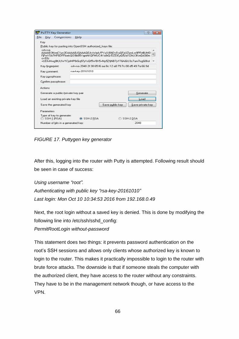
66
FIGURE 17. Puttygen key generator
After this, logging into the router with Putty is attempted. Following result should
be seen in case of success:
Using username “root”.
Authenticating with public key “rsa-key-20161010”
Last login: Mon Oct 10 10:34:53 2016 from 192.168.0.49
Next, the root login without a saved key is denied. This is done by modifying the
following line into /etc/ssh/sshd_config:
PermitRootLogin without-password
This statement does two things: it prevents password authentication on the
root’s SSH sessions and allows only clients whose authorized key is known to
login to the router. This makes it practically impossible to login to the router with
brute force attacks. The downside is that if someone steals the computer with
the authorized client, they have access to the router without any constraints.
They have to be in the management network though, or have access to the
VPN.
67
The setting affects after restarting the router or SSH service. This could be done
with commands reboot or systemctl restart sshd.
6.3.4 Configuring firewall
Configuring iptables is rather straight forward after the logic behind it is under-
stood. There are the different tables(filter, nat and mangle) and within them the
fixed chains INPUT, FORWARD, OUTPUT, PREROUTING, POSTROUTING.
Some rules will be added on the filter table and two outgoing rules to the nat
table. The final target is to have rules that allow inside and the visitor to talk out-
side, but not between each other. Also the voice VLAN needs to be isolated.
First a port address translation from LAN interfaces to outside will be done.
This is achieved using the nat table’s POSTROUTING chain. Everything going
out on the interface enp3s0 needs to be translated. First the visitor network is
translated to 217.116.163.201, and the rest will be translated to
217.116.163.200. For connections initiated from outside, everything that is not
return traffic for a connection initiated from the inside will be dropped. Therefore
a drop rule to the appropriate position in the filter table’s INPUT chain will be
added. The same applies to the FORWARD chain. Next, all traffic from visitor
and inside network to Internet is allowed. All necessary traffic from LAN net-
works to the INPUT chain is allowed. That traffic would be DHCP, DNS, SIP
and RTP for the voice VLAN, DHCP and DNS for the visitor VLAN as well as
inside VLAN. The management network will have full access. Finally, traffic be-
tween the local interfaces will be denied.
For ipv6 there will be no control traffic, therefore only traffic allowed is for the
inside interface to send traffic to the Internet. Also, the return traffic is allowed.
IPv6 will be disabled on other interfaces.
Adding the Suricata and VoIP services will cause some additional tweaks to the
firewall rules. The final commented rules can be found from the appendix 1.

68
6.3.5 Configuring DHCP
The DHCP server configuration file is /etc/dhcp/dhcpd.conf. The beginning of
the file has some default settings, which can be overridden by the subnet
statements. This device will be set authoritative on these networks. The gate-
way and DNS will be in this router. There is an option to assign a domain name,
too. This has the advantage that short names can be used for reaching hosts on
the same domain. The domain example.local will be set as the domain name for
inside and voip. Visitor addresses will not have the domain name set.
IP phones need TFTP server settings for provisioning info.
DNS will be configured in next chapter, but to update the local DNS files dynam-
ically, some settings related to it need to be put into the files.
The DHCP daemon configuration will now look like this:
LISTING 5: DHCP daemon config ---------------------------------------------------------------------------------------------------------------------------- #This directive makes the server superior to an non-authoritative server authoritative; #This statement sets the syslog facility for logging log-facility local7; #Lease times. Can be overruled in subnet statements default-lease-time 21600; max-lease-time 86400; #Checks the availability of the address with a ping on top of it's database ping-check true; #Dynamic DNS updates from client are ignored ignore client-updates; #Dynamic update key include "/var/named/chroot/etc/rndc.key"; #If a device has a reservation, it will still be updated into DNS update-static-leases on; #Update style. Check man dhcpd.conf for more details on it. ddns-update-style interim; #Updates will be done. ddns-updates on; #Domain zone to update ddns-domainname "example.local"; #Reverse zone to update ddns-rev-domainname "in-addr.arpa"; #here we define the zones and where to send updates to zone example.local { primary 127.0.0.1; key rndc-key; }

69
zone 0.30.172.in-addr.arpa { primary 127.0.0.1; key rndc-key; } zone 20.30.172.in-addr.arpa { primary 127.0.0.1; key rndc-key; } #Here are the actual DHCP settings. Network, mask, gateway and other options #Note that DHCP will only be run on interfaces matching the subnet statments subnet 172.30.0.0 netmask 255.255.255.0 { range 172.30.0.11 172.30.0.253; option subnet-mask 255.255.255.0; option routers 172.30.0.1; option domain-name "example.local"; option domain-name-servers 172.30.0.1; option ntp-servers 172.30.0.1; } subnet 172.30.10.0 netmask 255.255.255.0 { range 172.30.10.11 172.30.10.253; option subnet-mask 255.255.255.0; option routers 172.30.10.1; option domain-name-servers 172.30.10.1; option ntp-servers 172.30.10.1; } subnet 172.30.20.0 netmask 255.255.255.0 { range 172.30.20.11 172.30.20.253; option subnet-mask 255.255.255.0; option routers 172.30.20.1; option tftp-server-name "172.30.20.1"; option domain-name "example.local"; option domain-name-servers 172.30.20.1; option ntp-servers 172.30.20.1; } ----------------------------------------------------------------------------------------------------------------------------
After this the daemon needs to be started and also it needs to be run at startup.
It must be noted that startup might fail before configuring the DNS portion.
systemctl enable dhcpd
systemctl start dhcpd
6.3.6 Configuring DNS
Intranet forward and reverse DNS zones will be created for example.local. On
top of this, an authoritative record for example.com will exist. Also, the server
will take care of iterative DNS requests towards other servers. Visitor devices

70
will not have access to intranet zones. The Bind server will run in a chroot-jail,
meaning that even if compromised, it will not have access to other parts of the
system. Initial settings files will be generated with a script. The setup will be
started with the command /usr/libexec/setup-named-chroot.sh
/var/named/chroot on
The configuration files will be in /var/named/chroot/etc and zones in
/var/named/chroot/var/named. A baseline for settings was taken from Oracle
(7), which were then modified to suite our example network using hints from
Geekdudes website (8). The main configuration file, named.conf, can be found
from the etc –folder. The most important statements here are the zone defini-
tions, and that the recursion is limited to local networks. Open recursion will like-
ly cause the router to be an instrument for a DDoS attack. Views will be defined,
i.e. only the inside and voip networks have access to example.local record, and
everyone else have only access to the global one. To enable dynamic updates
of intranet DNS records, the rndc.key file generated by the system will be uti-
lized, the same as used for DHCP.
Finally zone files for all zones will be configured. Within these, the zone header
and actual records are defined. The dynamic zone files are populated by the
system as well, the static ones only manually.
Before the service can be started, some selinux settings have to be altered. Sel-
inux is a security utility designed by NSA, which restricts the process access to
files it is by default not needing. Here it is ensured that the named daemon can
write into zone files, as dynamic DNS is used. The command needed is set-
sebool -P named_write_master_zones true
This ensures that the named process can write into the zone files. –P is there to
make the changes persistent over reboots.
All DNS files are found in the appendix 3.

71
6.3.7 Configuring VPN
A VPN server will be used to allow remote workers to connect into the system.
For this purpose the OpenVPN –package is downloaded, along with OpenSSL
and Easy-RSA.
The first thing to do is to create the PKI infrastructure. The easiest way is to
create self-signed certificates. The /usr/share/easy-rsa/2.0 folder content is cop-
ied to the /etc/openvpn/PKI folder. Next the variables in the vars file are modi-
fied. To ease the certificate issuance, the location and company data can be
filled into the template. Also, the certificate destination can be somewhere else,
in this device /etc/openvpn/keys was used. When being happy with it, the fol-
lowing commands are given:
source ./vars This will take the defined variables into use
./clean-all This resets the system. It should be noted that this
WILL erase all existing certificates.
./build-ca This builds the certificate authority certificates for
Openvpn
./build-dh This builds the Diffie-Hellman key pair for the encryp-
tion key exchange
./build-key-server This builds the VPN server certificates, which will be
signed by the certificate authority. The server name is
given as an argument.
./build-key This is used to build client certificates. The username is
given as an argument.
There are several ways of doing the authentication. In this example system both
a client certificate and username/password authentication will be used. This
gives some level of 2-factor authentication, as the client needs to have both the
certificate and the username/password. If a user needs to be removed, the cer-
tificate can be revoked along with the username. The user can be given differ-
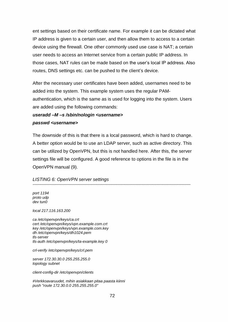
72
ent settings based on their certificate name. For example it can be dictated what
IP address is given to a certain user, and then allow them to access to a certain
device using the firewall. One other commonly used use case is NAT; a certain
user needs to access an Internet service from a certain public IP address. In
those cases, NAT rules can be made based on the user’s local IP address. Also
routes, DNS settings etc. can be pushed to the client’s device.
After the necessary user certificates have been added, usernames need to be
added into the system. This example system uses the regular PAM-
authentication, which is the same as is used for logging into the system. Users
are added using the following commands:
useradd –M –s /sbin/nologin <username>
passwd <username>
The downside of this is that there is a local password, which is hard to change.
A better option would be to use an LDAP server, such as active directory. This
can be utilized by OpenVPN, but this is not handled here. After this, the server
settings file will be configured. A good reference to options in the file is in the
OpenVPN manual (9).
LISTING 6: OpenVPN server settings ---------------------------------------------------------------------------------------------------------------------------- port 1194 proto udp dev tun0 local 217.116.163.200 ca /etc/openvpn/keys/ca.crt cert /etc/openvpn/keys/vpn.example.com.crt key /etc/openvpn/keys/vpn.example.com.key dh /etc/openvpn/keys/dh1024.pem tls-server tls-auth /etc/openvpn/keys/ta-example.key 0 crl-verify /etc/openvpn/keys/crl.pem server 172.30.30.0 255.255.255.0 topology subnet client-config-dir /etc/openvpn/clients #Verkkoavaruudet, mihin asiakkaan pitaa paasta kiinni push "route 172.30.0.0 255.255.255.0"

73
push "dhcp-option DNS 172.30.30.1" push "dhcp-option DOMAIN example.com" cipher BF-CBC #comp-lzo user nobody group nobody persist-key persist-tun keepalive 10 60 status openvpn-status.log daemon verb 4 plugin /usr/lib64/openvpn/plugins/openvpn-plugin-auth-pam.so login ----------------------------------------------------------------------------------------------------------------------------
First it is told which IP to bind to, and in this case it is the IP of the outside inter-
face. By default Openvpn works on the UDP port 1194, and it is left as default. It
is explicitly defined which tun interface is to be used. This can then be used for
firewall rules and client settings. After defining certificates and CRL, the network
for which the server provides addresses us defined. In this case it will be
172.30.30.0/24. The topology is defined as subnet, this allows for a more effi-
cient address usage. Routes and necessary DHCP options that will be pushed
to the client are defined. Service is started as user nobody, so hijackers will not
get root access. Keepalives are sent over the connections, and the tun interface
is made persistent (always up). The server is started in daemon mode, and the
PAM plugin is used for for authentication.
For iptables the following rule is needed:
iptables -A FORWARD -i tun0 -o vlan71 -m comment --comment "VPN traf-
fic to home network" -j ACCEPT
The server is enabled with command systemctl enable open-
vpn@servername
The server is then started with command systemctl start open-
vpn@servername
The servername is the name of the server configuration file.

74
When the server side is up, the client application needs to be installed on the
mobile worker’s PC or laptop. There is an OpenVPN client software available at
https://openvpn.net/. This software package is installed on the client, and the
public ca-cert file, public and private client cert files and the configuration file are
moved into the folder C:\Program Files\OpenVPN\config

75
LISTING 7: OpenVPN client settings ---------------------------------------------------------------------------------------------------------------------------- client dev tun proto udp remote 217.116.163.200 1194 resolv-retry infinite nobind cipher bf-cbc ca ca.crt cert user.crt key user.key tls-client tls-auth ta-example.key 1 tls-timeout 5 ns-cert-type server verb 2 auth-user-pass auth-nocache --------------------------------------------------------------------------------------------------------------------- -------
Client uses corresponding settings with the server file. First, the client statement
tells this is the client configuration. The connection is made to 217.116.163.200
udp port 1194, and in case of failure, connection is retried until the end of time.
Cipher needs to be the same in both the client and the server, default Blowfish
encryption is used. The Auth-nocache option tells that credentials should not be
stored.
With these settings in place, a VPN-tunnel can be established.
6.3.8 Configuring VoIP
The asterisk system is the one of the most popular open source VoIP systems
available. This system can be used for any kind of VoIP purposes. A small sys-
tem, that can make internal calls using two voip phones, will be set up. It is ra-
ther easy to add VoIP capabilities outside, too, using Skype or something simi-
lar. PRI or FXO cards can be added to have the POTS line connected to the
system. In this example two SIP subscribers are configured, which can call
themselves internally. External calls are going through an IAX trunk towards
Tele-entre OY’s PBX.

76
The installation of Asterisk on Centos7 is rather complex, as there is no reposi-
tory for Asterisk packages for this distro. So, it needs to be compiled from
scratch according to the instructions from Asterisk (10). The version 11 will be
used, as it is more than enough for this demo, and it is a long term support ver-
sion.
First the source code is downloaded from Asterisk website.
wget http://downloads.asterisk.org/pub/telephony/asterisk/asterisk-11-
current.tar.gz
Then the tar-ball is extracted
tar xzf asterisk-11-current.tar.gz
The extracted source directory is entered with cd –command and start the con-
figuration part. It should be noted that live systems with POTS components,
such as FXO/FXS/PRI ports need to have the appropriate drivers installed. The
DAHDI package is for POTS channels in general and LIBPRI is additional if
digital lines are used. Now, the prerequisites existence is checked:
contrib/scripts/install_prereq test
This command tests if all prerequisites are installed. If not, it gives a command
string for yum to install. After those have been sorted out, the initial configura-
tion can be made.
./configure –prefix=/usr/local --libdir=/usr/local/lib64 --sysconfdir=/etc
Next, options will be selected for our Asterisk build. Asterisk has a menuselect
configuration utility, where different options are selected for the installation. This
is invoked by make menuselect. This gives a lot of options, which can be
checked from the Asterisk website if needed. Other languages, database sup-
port and mp3 support can be selected among others. For this demo the defaults
were just enough.
Next, the compilation process is started. This happens with the command
make. Compiling takes some time, thus it is wise to perform it using the console
or using the screen command. This ensures that if the session is terminated for

77
any reason, the build does not stop. After this has been done successfully, the
compiled software can be installed with the command make install.
Now the executables exist. After this, template files can be generated by issuing
command make samples. In some occasions these are not wanted, as they
replace existing files. Also, if there are some previous settings files, which are
just being restored, this is an unnecessary step. Initialization scripts are created
with the command make config . This enables starting and termination of the
application using regular distro commands. Last but not least is make install-
logrotate. This one creates a logrotate configuration. Logrotate is a Linux fea-
ture, which archives logs at a certain interval, or at a certain size. This is very
useful if there are a lot of calls and/or small disk space, preventing the files from
not growing too big.
Now the application has been installed. Next the software must be configured.
Good examples are found online (14). All configuration files are in the
/etc/asterisk –folder. Configuration is started by defining the SIP settings. There
are some general settings, such as what address to bind to, and then the peer
configurations. These settings are in the sip.conf –file.
LISTING 8: SIP settings for Asterisk ---------------------------------------------------------------------------------------------------------------------------- [general] bindaddr=172.30.20.1 permit = 172.30.20.0/255.255.255.0
[1001] username = 1001 callerid = "User1"<1001> secret = abc123 type = friend host = dynamic context = from-internal qualify = yes [1002] username = 1002 callerid = "User2"<1002> secret = abc123 type = friend host = dynamic context = from-internal

78
qualify = yes ----------------------------------------------------------------------------------------------------------------------------
Here, all SIP messages are bound to IP address 172.30.20.1. This means that
the SIP registrar will not listen to other local addresses. Then there is the end
user registration data, which includes e.g. username and callerid.. The context
dictates into which context the call is put in when received (see dialplan below).
The type can be “peer”, “user” or “friend”. A peer is a device that conveys calls,
such as another Asterisk system. A user is an end user device, which registers
with asterisk. A friend can be of both types. The host can be either a static host
address, or it can be set as “dynamic” like here. If it is dynamic, the host is al-
lowed to register itself with any IP address.
The settings for the IAX protocol are configured next, as a connection to the
upstream PBX is needed. The file for these settings is iax.conf.
Listing 9: IAX settings for Asterisk ---------------------------------------------------------------------------------------------------------------------------- [general] port = 4569 bindaddr=217.116.163.200 register => thesislab:[email protected] [teleentre] type=friend disallow=all allow=alaw username=teleentre secret=topsecret123 context=from-external host=dynamic qualify=yes ---------------------------------------------------------------------------------------------------------------------------- The options are a lot similar to those in the sip.conf file. The biggest difference
is the register string, which is used to register with the peer on the other side.
Also there is the qualify –statement, which makes the Asterisk system to track
the peer. The Asterisk sends keepalives to the other side, and if it does not hear
back, it considers the system unreachable. This has mostly relevance if sys-
tems are behind NAT.

79
Last, the rules that make everything tick are introduced, i.e. the dialplan. This
file has the calling logic, explaining how different extensions and contexts are
handled. File for this is extensions.conf.
LISTING 10: Dialplan settings for Asterisk ---------------------------------------------------------------------------------------------------------------------------- [from-internal] exten => _100[12],1,Dial(SIP/${EXTEN},45,t) same => n,Hangup() exten => _0.,1,Dial(IAX2/thesislab@teleentre/${EXTEN:1}) same => n,Hangup() [from-external] exten => _100[12],1,Dial(SIP/${EXTEN},45,t) exten => n,Hangup
----------------------------------------------------------------------------------------------------------------------------
A context is defined here in the brackets. In each context, there are dialplan
rules. Here, the rules try to match the dialed extension, and if it matches, the
actions are executed. An underscore in the beginning means that there is a pat-
tern match, without the underscore there would be an explicit match. What is
missing here is the configuration from the other side of the IAX trunk. However,
the system there is GUI-based, so the trunk information cannot be extracted.
The logic is that anything internal stays within this system, and all external calls
go through the upstream PBX to the PSTN network. Likewise, if someone calls
certain numbers from the PSTN, they will be directed to this system and the
particular extensions.
When everything is in place, Asterisk can be enabled by command systemctl
enable asterisk and systemctl start asterisk. As the package is not made for
the new systemctl utility, it will redirect the necessary command to the old
chkconfig and service –utilities.

80
6.3.9 Configuring Suricata
The purpose is to use Suricata as an IPS system, meaning that it can drop
harmful traffic when seen. It will be configured to inspect the traffic coming in
from the Internet.
Suricata was installed according to the guidelines given by the Open Infor-
mation Security Foundation (3) and (4). The guide was followed step by step,
starting from the dependencies to a full installation:
sudo yum -y install gcc libpcap-devel pcre-devel libyaml-devel file-devel \ zlib-devel jansson-devel nss-devel libcap-ng-devel libnet-devel tar make \ libnetfilter_queue-devel lua-devel wget http://www.openinfosecfoundation.org/download/suricata-3.1.tar.gz tar -xvzf suricata-3.1.tar.gz cd suricata-3.1 ./configure --prefix=/usr --sysconfdir=/etc --localstatedir=/var --enable-nfqueue --enable- lua make make install-full ldconfig
The configuration was made automatically by the make install-full –command,
but the settings were tweaked just a bit:
HOME_NET: "[172.30.0.0/16,5240:0:8002::/64]"
Next, it is checked that everything works fine. The command suricata –c
/etc/suricata/suricata.yaml –i enp3s0 --init-errors-fatal is given. If everything
comes up fine, the packet statistics in file /var/log/suricata/stats.log should be
growing. The next step is to put suricata inline. This is done by feeding the in-
coming packets from the Internet to the Suricata engine by the iptables/netfilter
NFQUEUE –feature (5). With iptables, it is possible to select what traffic is in-
spected and what is not. The following settings will be added to iptables:
iptables –I FORWARD –i enp3s0 –m state –state ESTABLISHED,RELATED
–j NFQUEUE

81
This statement will cause the replies for established Internet connections to be
inspected. As it is in the forward-chain, only the established pass-through traffic
will be inspected.
After that, Suricata can be started with command /usr/bin/suricata –c /etc/suricata/suricata.yaml –q 0. To make the command boot persistent, an init-script is added into the /etc/init.d –folder, as shown in listing 11.
LISTING 11: Startup script for Suricata ---------------------------------------------------------------------------------------------------------------------------- #!/bin/sh # ### BEGIN INIT INFO # Provides: suricata # Required-Start: $time $network $local_fs $remote_fs # Required-Stop: $remote_fs # Default-Start: 2 3 4 5 # Default-Stop: 0 1 6 # Short-Description: Next Generation IDS/IPS # Description: Intrusion detection system that will # capture traffic from the network cards and will # match against a set of known attacks. ### END INIT INFO # Source function library. . /etc/rc.d/init.d/functions . /etc/sysconfig/suricata # We'll add up all the options above and use them NAME=suricata DAEMON=/usr/bin/$NAME check_nfqueue() { if [ ! -e /proc/net/netfilter/nfnetlink_queue ]; then logger -t suricata "NFQUEUE support not found !" logger -t "Please ensure the nfnetlink_queue module is loaded or built in kernel" exit 5 fi } case "$LISTENMODE" in nfqueue) IDMODE="IPS (nfqueue)" LISTEN_OPTIONS=" -q $NFQUEUE" check_nfqueue ;; pcap) IDMODE="IDS (pcap)" LISTEN_OPTIONS=" -i $IFACE" ;; af-packet) IDMODE="IDS (af-packet)" LISTEN_OPTIONS=" --af-packet"

82
;; *) echo "Unsupported listen mode $LISTENMODE, aborting" exit 1 ;; esac SURICATA_OPTIONS=" -c $SURCONF --pidfile $PIDFILE $LISTEN_OPTIONS -D" # See how we were called. case "$1" in start) if [ -f $PIDFILE ]; then PID1=`cat $PIDFILE` if kill -0 "$PID1" 2>/dev/null; then echo "$NAME is already running with PID $PID1" exit 0 fi fi echo -n "Starting suricata in $IDMODE mode..." $DAEMON $SURICATA_OPTIONS > /var/log/suricata/suricata-start.log 2>&1 & echo " done." ;; stop) echo -n "Stopping suricata: " if [ -f $PIDFILE ]; then PID2=`cat $PIDFILE` else echo " No PID file found; not running?" exit 0; fi killproc `basename $DAEMON` if [ -n "$PID2" ]; then kill "$PID2" ret=$? sleep 2 if kill -0 "$PID2" 2>/dev/null; then ret=$? echo -n "Waiting . " cnt=0 while kill -0 "$PID2" 2>/dev/null; do ret=$? cnt=`expr "$cnt" + 1` if [ "$cnt" -gt 10 ]; then kill -9 "$PID2" break fi sleep 2 echo -n ". " done fi fi if [ -e $PIDFILE ]; then rm $PIDFILE > /dev/null 2>&1 fi echo " done." ;; status) # Check if running... if [ -s $PIDFILE ]; then

83
PID3=`cat $PIDFILE` if kill -0 "$PID3" 2>/dev/null; then echo "$NAME is running with PID $PID3" exit 0 else echo "PID file $PIDFILE exists, but process not running!" fi else echo "$NAME not running!" fi ;; reload-rules) echo -n "Reloading rules: " if [ -f $PIDFILE ]; then PID4=`cat $PIDFILE` else echo " No PID file found; not running?" exit 1; fi kill -USR2 "$PID4" echo "Done." ;; restart) $0 stop $0 start ;; force-reload) $0 stop $0 start ;; *) echo "Usage: $0 {start|stop|reload-rules|restart|status}" exit 1 esac exit 0 ----------------------------------------------------------------------------------------------------------------------------
After putting the script in place, it is enabled at startup by first making it execut-
able with chmod 755 suricata (suricata is the file name) and by issuing com-
mand systemctl enable suricata.
Last, it is made sure that all suricata rules are updated on a scheduled basis.
The rules can be updated either manually, or by a program called oinkmaster.
On top of downloading the latest rules, Oinkmaster can modify the rulesets to
whatever if preferred. In this case the Emerging Threats rulesets are donloaded.
Then, some rulesets are modified to drop traffic. First, the Oinkmaster source is
downloaded from the website (12). This website has as well good documenta-
tion about the configuration itself. After having the source, the oinkmaster pearl

84
script is copied to /usr/local/bin –folder and the oinkmaster.conf –file is copied to
/etc –folder. The oinkmaster.conf is modified will be modified in the following
way:
#Emerging threats rules:
url = https://rules.emergingthreats.net/open/suricata-1.3/emerging.rules.tar.gz
modifysid * “^alert” | “drop”
The first rule defines the download path, the second one modifies all rules to
drop traffic. Now, in a real production environment the rules need to be checked
more carefully. If there are strict drop rules, it is really necessary to select only
the most critical rulesets for the environment. The rulesets in use are selected in
suricata.yaml –file. In this example environment, only rule files that have mal-
ware, viruses or other clearly harmful signatures in them are selected.
Finally a crontab rule is made to update the rulesets every day. This script is
inserted in /etc/cron.d.
LISTING 12: Suricata rule update script ---------------------------------------------------------------------------------------------------------------------------- 00 06 * * * root /usr/local/bin/oinkmaster.pl -o /etc/suricata/inlinerules 2>&1 | logger -t oinkmas-ter 00 07 * * * root /etc/init.d/suricata reload-rules 2>&1 | logger -t oinkmaster ----------------------------------------------------------------------------------------------------------------------------
Here updating the rule set is started at 6:00 every morning. Then it is given
some time to process, and the reload happens at 7:00am. The logger-command
makes syslog entries into the /var/log/messages –file.
6.3.10 Configuring QoS settings
The quality of service is meant for ensuring bandwidth for essential services. It
is most efficient when sending information, since it is the only direction where
there is full control of the data. But it can be used to some extent as well on re-
ceived information. The receiving direction is used in this case, meaning that
data coming in from the Internet will be categorized. This is the main direction
for traffic, because end user networks tend to be more hungry downstream than

85
upstream. Policing the received data relies on the TCP behavior. The TCP
throttling kicks in, when TCP packets are dropped. This throttling cuts the speed
of that particular TCP session, thus, releasing the bandwidth for the other ses-
sions..
The essential part is measuring the total bandwidth available. This can be done
with iperf or a similar bandwidth tool. It is also possible to just start a download
of some big file and check the bandwidth with iftop-application. The best mo-
ment to test this is when there is no other usage. Essential is that the total
bandwidth configured in QoS is a little less than the actual bandwidth. If miscon-
figured, the QoS will never step in. The downstream Internet trafficwill be limited
to 20Mbps in the test system.
The classification hierarchy is shown in the figure 18 below:
FIGURE 18. QoS incoming classes

86
All incoming traffic is put into an ingress software queue, using a linux module
called IFB (18). This is a trick that is needed due to the fact that there is no
managed incoming queue in Linux interfaces, thus, it is pretended that the in-
coming queue is an outgoing queue. On the root and leaf classes a HSFC
scheduling algorithm is put (17). This is a queuing discipline, which allows to
adjust both the bandwidth and delay for a class. Then classes are made for dif-
ferent traffic, and traffic is guided to different classes based on filter statements.
At the end SFQ scheduling is used for giving all users a fair proportion of the
bandwidth. Internal traffic is assigned 17Mbps, and guests can have the rest
3M. One thing to note is that the HSFC allows one single class to use all of the
root bandwidth if higher priority classes do not have any traffic. There is a very
extensive guide to traffic handling with Traffic Control (tc) available (11). Listing
13 has the applicable settings in a shell script format.
LISTING 13: QoS configuration script ---------------------------------------------------------------------------------------------------------------------------- #!/bin/sh #Loading kernel modules modprobe sch_hfsc #HFSC-alogrithm modprobe cls_u32 #u32 classifier modprobe sch_sfq #u32 classifier modprobe ifb #ifb0 interface (incoming traffic software queue) #Removing possibly existing QoS settings. tc qdisc del dev enp3s0 root 2>/dev/null tc qdisc del dev enp3s0 ingress 2>/dev/null tc qdisc del dev ifb0 root 2>/dev/null #Enable ifb0 interface ip link set ifb0 up #We make an ingress class into Internet interface tc qdisc add dev enp3s0 handle ffff: ingress #All incoming traffic from Internet is put into software interface tc filter add dev enp3s0 parent ffff: protocol ip prio 2 u32 match u32 0 0 flowid 1:1 action mirred egress redirect dev ifb0 #We define HFSC queueing discipline, default class 1:20 tc qdisc add dev ifb0 root handle 1: hfsc default 20 #Set limits for classes, both bw and delay can be used tc class add dev ifb0 parent 1: classid 1:1 hfsc sc rate 20Mbit ul rate 20Mbit tc class add dev ifb0 parent 1:1 classid 1:10 hfsc sc rate 17Mbit ul rate 20Mbit tc class add dev ifb0 parent 1:10 classid 1:11 hfsc sc umax 1500b dmax 53ms rate 1Mbit ul rate 20Mbit tc class add dev ifb0 parent 1:10 classid 1:12 hfsc sc umax 1500b dmax 200ms rate 16Mbit ul rate 20Mbit

87
tc class add dev ifb0 parent 1:1 classid 1:20 hfsc sc rate 3Mbit ul rate 20Mbit #Add SFQ discipline tc qdisc add dev ifb0 parent 1:11 handle 11: sfq perturb 10 tc qdisc add dev ifb0 parent 1:12 handle 12: sfq perturb 10 tc qdisc add dev ifb0 parent 1:20 handle 20: sfq perturb 10 #Assign traffic to classes based on IP tc filter add dev ifb0 parent 1:0 protocol ip prio 1 u32 match ip dst 217.116.163.200 flowid 1:10 tc filter add dev ifb0 parent 1:0 protocol ip prio 4 u32 match ip src 172.16.1.152/32 flowid 1:10 #Within class 1:10, we will move DSCP EF or CS5-marked packets to flowid 1:11 tc filter add dev ifb0 parent 1:10 protocol ip prio 10 u32 match ip tos 0xb8 0xfc flowid 1:11 tc filter add dev ifb0 parent 1:10 protocol ip prio 11 u32 match ip tos 0xa0 0xfc flowid 1:11 #Other internal traffic to 1:12 tc filter add dev ifb0 parent 1:10 protocol ip prio 12 u32 match ip dst 0.0.0.0/0 flowid 1:12 #Guest traffic will go to flow 1:20, as it is default ----------------------------------------------------------------------------------------------------------------------------

88
6.4 Testing the system
Now when our system is complete, a test plan is needed to ensure that the
system works as designed. First the basic network operations are tested: inter-
nal networks should get an ip address, but they should not be able to communi-
cate with each other. The inside network should get both IPv4 and IPv6 ad-
dresses. The inside and voice networks’ hosts should automatically be added
into the DNS system. And all traffic from the Internet to hosts should be in-
spected for malware.
Router hardening must be tested, i.e. the root access is only available from cer-
tain hosts and only from management network.
VoIP system needs to be tested so that it can create calls between hosts, and
to public land lines. Calls from a landline should alert the targeted VoIP phone.
The next step is remote access testing. The user certificate must exist to get a
connection. Revoked certificates should not work. Management access should
be possible using the VPN client, as well as access to the LAN networks.
Last but not least is the QoS testing. It is necessary to test that the classifying
works properly, and that the limitation really kicks in.
The test matrix can be seen in appendix 4.

89
7 CONCLUSIONS
As witnessed, a Linux router is very versatile in different operations; there are
very few tasks that it cannot perform at least at some level. It was made to per-
form routing, firewalling, security screening and additionally a VPN server and a
VoIP server were installed in it. These are just example services seen in these
kinds of devices; alternatively an email server, network monitoring service or a
webserver could have been installed. Pretty much any service can be installed
on a Linux access node, and only thing needed for it is the necessary hardware
resources and capable people to maintain it.
Also, it was seen that implementing different services needs a big amount of
configuration. The configuration itself is sometimes tricky, and there are several
possibilities for errors and incorrect settings. Along with the possibility to install
subpar hardware, these facts make the use of Linux devices as routers very
controversial. Purpose-built devices are faster in their routing efficiency, and
those can easily be backed up and restored. It is easy to find documentation
and people understanding their configurations. In case there are problems with
these devices, the vendors’ technical assistance is there to help. However, pur-
pose built devices are not even nearly as flexible as Open Source Linux - based
devices. As such, a Linux device will not be very suitable for extremely large
organizations; those need something that can be outsourced and easily docu-
mented and maintained. Additionally, the cost of equipment is usually not a big
concern for bigger companies. However for private persons with adequate
knowledge and small and even midsized companies this is a viable solution. If
IT is maintained internally by the company and there are some spare hours to
spend for configuration and support, adding this kind of a device into the infra-
structure will reduce costs and give flexibility to add customized services into
the network.

90
REFERENCES
1. Vinals, Ramon 2006. Cisco ASA 5500 FW and IPS in detail. Cisco.
http://www.cisco.com/c/dam/global/es_mx/assets/docs/pdf/Webinar_ASA.pd
f
2. Cisco 2014. Comparing traffic policing and traffic shaping for bandwidth lim-
iting. Cisco. Date of retrieval 15.4.2016
http://www.cisco.com/c/en/us/support/docs/quality-of-service-qos/qos-
policing/19645-policevsshape.html
3. Suricata Team. Suricata CentOS installation. Open Information Security
Foundation. Date of retrieval 15.9.2016
https://redmine.openinfosecfoundation.org/projects/suricata/wiki/CentOS_Ins
tallation
4. Suricata Team. Suricata basic setup. Open Information Security Foundation.
Date of retrieval 15.9.2016
https://redmine.openinfosecfoundation.org/projects/suricata/wiki/Basic_Setu
p
5. Suricata Team. Setting up IPS/inline for Linux. Open Information Security
Foundation Date of retrieval 15.9.2016
https://redmine.openinfosecfoundation.org/projects/suricata/wiki/Setting_up_
IPSinline_for_Linux
6. Andreasson, Oskar 2006. Iptables tutorial 1.2.2. Date of retrieval 13.10.2016
https://www.frozentux.net/iptables-tutorial/iptables-tutorial.html
7. Oracle 2010. Oracle Integrated Lights Out Manager (ILOM) 3.0 Concepts
Guide. Oracle. Date of retrieval 14.10.2016
https://docs.oracle.com/cd/E19469-01/820-6410-12/app_example_dns.html
8. Vucanovic, Dragan 2015. Installing,configuring DNS,DHCP and Dynamic
DNS on CENTOS 7. Geekdudes. Date of retrieval 9.10.2016

91
https://geekdudes.wordpress.com/2015/05/28/installingconfiguring-dnsdhcp-
and-dynamic-dns-on-centos-7/
9. OpenVPN Technologies Inc. 2013. OpenVPN howto. Date of retrieval
8.9.2016
https://openvpn.net/index.php/open-source/documentation/howto.html
10. Jordan, Matt and malcolmd. 2014. Installing Asterisk from source. Aster-
isk.org. Date of retrieval 11.9.2016
https://wiki.asterisk.org/wiki/display/AST/Installing+Asterisk+From+Source
11. Hubert, Bert. Linux advanced routing & traffic control howto. Lartc.org
http://lartc.org/howto/
12. Östling Andreas 2006, Oinkmaster documentation. Date of retrieval
12.10.2016
http://oinkmaster.sourceforge.net/docs.shtml
13. Putty Team. PuTTY: a free SSH and Telnet client. Date of retrieval
16.7.2016
http://www.chiark.greenend.org.uk/~sgtatham/putty/download.html
14. Voip-Info Forum, VoIP/Asterisk configuration guides Date of retrieval
13.10.2016
http://www.voip-info.org/wiki/
15. Graziani, Rick 2012. IPv6 Fundamentals: A Straightforward Approach to
Understanding IPv6. Cisco Press.
16. Keijser, Jan Just 2011. OpenVPN 2 Cookbook. PACKT publishing 2011
17. Rechert, Klaus 2005. HSFC scheduling in Linux. 26.9.2016
http://linux-ip.net/articles/hfsc.en/
18. Royston, Ron 2016. IFB module for iptables. Linux foundation wiki.
https://wiki.linuxfoundation.org/networking/ifb

92
19. RIPE-NCC, IPv4 CIDR chart
https://www.ripe.net/support/training/material/LIR-Training-Course/LIR-
Training-Handbook-Appendices/CIDR-Chart-IPv4.pdf
Date of retrieval 4.10.2015
20. RIPE-NCC, IPv6 subnetting chart.
https://www.ripe.net/manage-ips-and-asns/ipv6/ipv6-subnetting-card
Date of retrieval 4.10.2015
21. Microsoft Inc 2006. TCP/IP fundamentals for Microsoft Windows.
https://technet.microsoft.com/en-us/library/bb962069.aspx
Date of retrieval 18.10.2015
22. Cisco Inc 2008, Cisco Unified Communications Voice over Spoke-to-Spoke
DMVPN Test Results and Recommendations
http://www.cisco.com/c/en/us/td/docs/solutions/Enterprise/WAN_and_MAN/
VoSDMVPN.html
Date of retrieval 25.10.2015
23. Wikipedia 2014. Sampling and quantization of a signal (red) for 4-bit LPCM
https://commons.wikimedia.org/wiki/File:Pcm.svg
Date of retrieval 15.11.2015
24. Karapantazis, Pavlidou 2009. VoIP: A comprehensive survey on a promising
technology
http://www.sciencedirect.com/science/article/pii/S1389128609001200#
Date of retrieval 5.8.2016
25. IETF 2002. SIP: Session Initiation Protocol
https://www.ietf.org/rfc/rfc3261.txt
Date of retrieval 15.4.2016
26. NIST 2009. Guidelines on Firewall and Firewall Policy
http://nvlpubs.nist.gov/nistpubs/Legacy/SP/nistspecialpublication800-
41r1.pdf
Date of retrieval 15.10.2016

93
27. Scarfone, Karen 2015, Introduction to SIEM services and products
http://searchsecurity.techtarget.com/feature/Introduction-to-SIEM-services-
and-products
Date of retrieval 20.10.2016
28. PKI Forum 2002. PKI Basics – a Technical Perspective
http://www.oasis-pki.org/pdfs/PKI_Basics-A_technical_perspective.pdf
Date of retrieval 21.9.2016
29. Aldeid team 2016. Suricata vs Snort.
https://www.aldeid.com/wiki/Suricata-vs-snort
Date of retrieval 21.9.2016

94
APPENDICES
Appendix 1 Iptables settings
Appendix 2 Suricata settings
Appendix 3 Named settings
Appendix 4 Test matrix
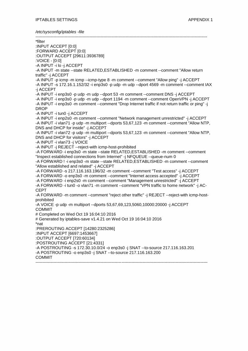
IPTABLES SETTINGS APPENDIX 1
/etc/sysconfig/iptables -file ---------------------------------------------------------------------------------------------------------------------------- *filter :INPUT ACCEPT [0:0] :FORWARD ACCEPT [0:0] :OUTPUT ACCEPT [29611:3936789] :VOICE - [0:0] -A INPUT -i lo -j ACCEPT -A INPUT -m state --state RELATED,ESTABLISHED -m comment --comment "Allow return traffic" -j ACCEPT -A INPUT -p icmp -m icmp --icmp-type 8 -m comment --comment "Allow ping" -j ACCEPT -A INPUT -s 172.16.1.152/32 -i enp3s0 -p udp -m udp --dport 4569 -m comment --comment IAX -j ACCEPT -A INPUT -i enp3s0 -p udp -m udp --dport 53 -m comment --comment DNS -j ACCEPT -A INPUT -i enp3s0 -p udp -m udp --dport 1194 -m comment --comment OpenVPN -j ACCEPT -A INPUT -i enp3s0 -m comment --comment "Drop Internet traffic if not return traffic or ping" -j DROP -A INPUT -i tun0 -j ACCEPT -A INPUT -i enp2s0 -m comment --comment "Network management unrestricted" -j ACCEPT -A INPUT -i vlan71 -p udp -m multiport --dports 53,67,123 -m comment --comment "Allow NTP, DNS and DHCP for inside" -j ACCEPT -A INPUT -i vlan72 -p udp -m multiport --dports 53,67,123 -m comment --comment "Allow NTP, DNS and DHCP for visitors" -j ACCEPT -A INPUT -i vlan73 -j VOICE -A INPUT -j REJECT --reject-with icmp-host-prohibited -A FORWARD -i enp3s0 -m state --state RELATED,ESTABLISHED -m comment --comment "Inspect established connections from Internet" -j NFQUEUE --queue-num 0 -A FORWARD ! -i enp3s0 -m state --state RELATED,ESTABLISHED -m comment --comment "Allow established and related" -j ACCEPT -A FORWARD -s 217.116.163.196/32 -m comment --comment "Test access" -j ACCEPT -A FORWARD -o enp3s0 -m comment --comment "Internet access accepted" -j ACCEPT -A FORWARD -i enp2s0 -m comment --comment "Management unrestricted" -j ACCEPT -A FORWARD -i tun0 -o vlan71 -m comment --comment "VPN traffic to home network" -j AC-CEPT -A FORWARD -m comment --comment "reject other traffic" -j REJECT --reject-with icmp-host-prohibited -A VOICE -p udp -m multiport --dports 53,67,69,123,5060,10000:20000 -j ACCEPT COMMIT # Completed on Wed Oct 19 16:04:10 2016 # Generated by iptables-save v1.4.21 on Wed Oct 19 16:04:10 2016 *nat :PREROUTING ACCEPT [14280:2325286] :INPUT ACCEPT [6697:1453667] :OUTPUT ACCEPT [720:60134] :POSTROUTING ACCEPT [21:4331] -A POSTROUTING -s 172.30.10.0/24 -o enp3s0 -j SNAT --to-source 217.116.163.201 -A POSTROUTING -o enp3s0 -j SNAT --to-source 217.116.163.200 COMMIT ----------------------------------------------------------------------------------------------------------------------------

SURICATA SETTINGS APPENDIX 2/1
/etc/suricata/suricata.yaml -file ---------------------------------------------------------------------------------------------------------------------------- %YAML 1.1 --- # Suricata configuration file. In addition to the comments describing all # options in this file, full documentation can be found at: # https://redmine.openinfosecfoundation.org/projects/suricata/wiki/Suricatayaml ## ## Step 1: inform Suricata about your network ## vars: # more specifc is better for alert accuracy and performance address-groups: #HOME_NET: "[192.168.0.0/16,10.0.0.0/8,172.16.0.0/12]" #HOME_NET: "[192.168.0.0/16]" #HOME_NET: "[10.0.0.0/8]" HOME_NET: "[172.30.0.0/16,2a00:5240:0:8002::/64]" #HOME_NET: "any" EXTERNAL_NET: "!$HOME_NET" #EXTERNAL_NET: "any" HTTP_SERVERS: "$HOME_NET" SMTP_SERVERS: "$HOME_NET" SQL_SERVERS: "$HOME_NET" DNS_SERVERS: "$HOME_NET" TELNET_SERVERS: "$HOME_NET" AIM_SERVERS: "$EXTERNAL_NET" DNP3_SERVER: "$HOME_NET" DNP3_CLIENT: "$HOME_NET" MODBUS_CLIENT: "$HOME_NET" MODBUS_SERVER: "$HOME_NET" ENIP_CLIENT: "$HOME_NET" ENIP_SERVER: "$HOME_NET" port-groups: HTTP_PORTS: "80" SHELLCODE_PORTS: "!80" ORACLE_PORTS: 1521 SSH_PORTS: 22 DNP3_PORTS: 20000 MODBUS_PORTS: 502 ## ## Step 2: select the rules to enable or disable ## default-rule-path: /etc/suricata/inlinerules rule-files: - botcc.rules # - ciarmy.rules - compromised.rules - drop.rules - dshield.rules # - emerging-activex.rules # - emerging-attack_response.rules

SURICATA SETTINGS APPENDIX 2/2
# - emerging-chat.rules # - emerging-current_events.rules # - emerging-dns.rules - emerging-dos.rules - emerging-exploit.rules # - emerging-ftp.rules # - emerging-games.rules # - emerging-icmp_info.rules # - emerging-icmp.rules # - emerging-imap.rules # - emerging-inappropriate.rules - emerging-malware.rules # - emerging-misc.rules # - emerging-mobile_malware.rules # - emerging-netbios.rules # - emerging-p2p.rules # - emerging-policy.rules # - emerging-pop3.rules # - emerging-rpc.rules # - emerging-scada.rules # - emerging-scan.rules # - emerging-shellcode.rules # - emerging-smtp.rules # - emerging-snmp.rules # - emerging-sql.rules # - emerging-telnet.rules # - emerging-tftp.rules - emerging-trojan.rules # - emerging-user_agents.rules # - emerging-voip.rules # - emerging-web_client.rules # - emerging-web_server.rules # - emerging-web_specific_apps.rules - emerging-worm.rules - tor.rules # - decoder-events.rules # available in suricata sources under rules dir # - stream-events.rules # available in suricata sources under rules dir # - http-events.rules # available in suricata sources under rules dir # - smtp-events.rules # available in suricata sources under rules dir # - dns-events.rules # available in suricata sources under rules dir # - tls-events.rules # available in suricata sources under rules dir # - modbus-events.rules # available in suricata sources under rules dir # - app-layer-events.rules # available in suricata sources under rules dir classification-file: /etc/suricata/classification.config reference-config-file: /etc/suricata/reference.config # threshold-file: /etc/suricata/threshold.config <rest of the file omitted>

NAMED SETTINGS APPENDIX 3/1
named.conf –file: ---------------------------------------------------------------------------------------------------------------------------- // // named.conf // // Provided by Red Hat bind package to configure the ISC BIND named(8) DNS // server as a caching only nameserver (as a localhost DNS resolver only). // // See /usr/share/doc/bind*/sample/ for example named configuration files. // options { listen-on port 53 { any; }; listen-on-v6 port 53 { any; }; directory "/var/named"; dump-file "/var/named/data/cache_dump.db"; statistics-file "/var/named/data/named_stats.txt"; memstatistics-file "/var/named/data/named_mem_stats.txt"; max-journal-size 50k; allow-query { any; }; allow-recursion { 127.0.0.1; 172.30.0.0/24; 172.30.10.0/24; 172.30.20.0/24; ::1; fe80::/64; 2a00:5240:0:8002::/64; }; /* Path to ISC DLV key */ bindkeys-file "/etc/named.iscdlv.key"; managed-keys-directory "/var/named/dynamic"; pid-file "/run/named/named.pid"; session-keyfile "/run/named/session.key"; check-names master warn; check-names slave warn; check-names response warn; }; controls { inet 127.0.0.1 allow {127.0.0.1;} keys {"rndc-key"; }; }; # include "/etc/named.root.key"; include "/etc/rndc.key"; view trusted { match-clients { 172.30.0.0/24; 172.30.20.0/24; 127.0.0.1; }; zone "." IN { type hint; file "named.ca"; }; zone "example.com" { type master;

NAMED SETTINGS APPENDIX 3/2
file "example.com"; }; zone "example.local" { type master; file "dynamic/example.local"; allow-update { key rndc-key; }; }; zone "0.30.172.in-addr.arpa" { type master; file "dynamic/0.30.172.in-addr.arpa"; allow-update { key rndc-key; }; }; zone "20.30.172.in-addr.arpa" { type master; file "dynamic/20.30.172.in-addr.arpa"; allow-update { key rndc-key; }; }; }; view guest { match-clients { any; }; zone "." IN { type hint; file "named.ca"; }; zone "example.com" { type master; file "example.com"; }; }; ----------------------------------------------------------------------------------------------------------------------------

NAMED SETTINGS APPENDIX 3/3
example.com zone file:
----------------------------------------------------------------------------------------------------------------------------
$ORIGIN . $TTL 86400 example.com IN SOA linux.example.com. root.example.com. ( 1 ; serial 21600 ; refresh after 6 hours 3600 ; retry after 1 hour 604800 ; expire after 1 week 86400 ) ; minimum TTL of 1 day ; IN NS linux.example.com. $ORIGIN example.com. linux IN A 217.116.163.200 ---------------------------------------------------------------------------------------------------------------------------- example.local zone file:
------------------------------------------------------------------------------------------------------- ---------------------
$ORIGIN . $TTL 43200 ; 12 hours example.local IN SOA localhost. root. ( 280 ; serial 21600 ; refresh (6 hours) 3600 ; retry (1 hour) 604800 ; expire (1 week) 86400 ; minimum (1 day) ) NS localhost. $ORIGIN example.local. $TTL 3600 ; 1 hour
0.30.172.in-addr.arpa zone file:
----------------------------------------------------------------------------------------------------------------------------
$ORIGIN . $TTL 43200 ; 12 hours 0.30.172.in-addr.arpa IN SOA localhost. root. ( 183 ; serial 28800 ; refresh (8 hours) 7200 ; retry (2 hours) 604800 ; expire (1 week) 86400 ; minimum (1 day) ) NS localhost. $ORIGIN 0.30.172.in-addr.arpa.
$TTL 3600 ; 1 hour

TEST MATRIX APPENDIX 4/1
Test case Descrip-
tion
Procedure Expected outcome
1 IP set-
tings and
connectiv-
ity
1.1 DHCP
IP address
assignme
nt
Clients get
IP ad-
dresses
when
connect-
ed. The
settings
are com-
plete, so
that gate-
way, DNS
server and
other set
options
are given.
Connect a host in each
VLAN. Enable DHCP
client. Check IP settings
and confirm IP settings.
All clients get IP address,
mask and DNS. Voip cli-
ents get TFTP server.
DNS
updates
DNS rec-
ords are
updated
dynami-
cally. Both
forward
and re-
verse
Connect a host in each
VLAN. Enable DHCP
client. Check DNS rec-
ords on router with dig -
tAXFR example.local,
0.30.172.in-addr.arpa
and 20.30.172.in-
addr.arpa
Hosts connected to the
inside and voip networks
are listed in records

TEST MATRIX APPENDIX 4/2
zones.
1.2 DNS
Recusive
lookups
Recursive
lookups
work from
the inside
networks.
Lookups
are
blocked
for outside
requests.
Ask for
www.google.com ad-
dress from inside client
using nslookup. Do the
same with an external
client, by setting server
to 217.116.163.200.
Outside recursive lookup
should fail. Inside clients
should be able to make
requests.
Zone
lookups
Check that
zone visi-
bility is
correct
Start nslookup. Point
server to be our linux
router. Ask for
linux.example.com and
client.example.local.
Local public zone exam-
ple.com can be queried
from everywhere. Private
zone example.local only
from inside and VoIP.
1.3
Connectivi
ty check
Check
network
access
using IPv4
Check that
Internet
can be
accessed
using IPv4
Open browser and
open page
http://217.116.160.50.
You should see your public
IPv4 address (router's pub-
lic IP).
Check
network
access
Check that
Internet
can be
Open address
http://[2a00:5240:0:202
4::50].
You should see your cli-
ent's IPv6 address.
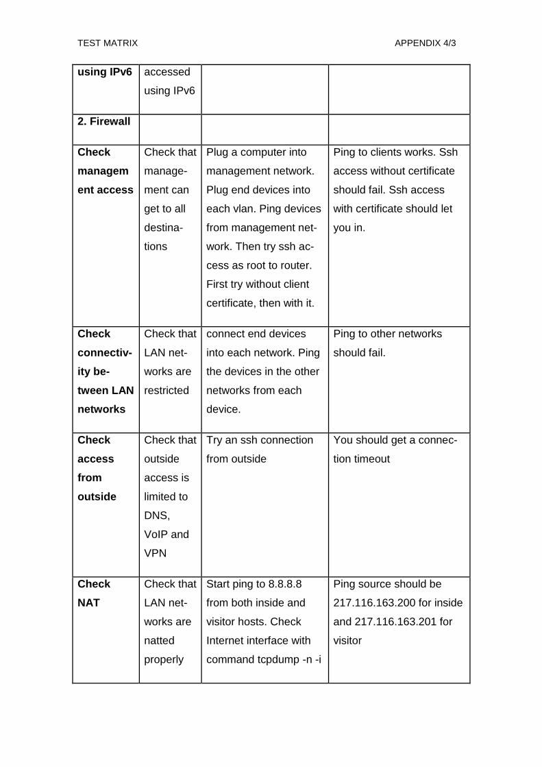
TEST MATRIX APPENDIX 4/3
using IPv6 accessed
using IPv6
2. Firewall
Check
managem
ent access
Check that
manage-
ment can
get to all
destina-
tions
Plug a computer into
management network.
Plug end devices into
each vlan. Ping devices
from management net-
work. Then try ssh ac-
cess as root to router.
First try without client
certificate, then with it.
Ping to clients works. Ssh
access without certificate
should fail. Ssh access
with certificate should let
you in.
Check
connectiv-
ity be-
tween LAN
networks
Check that
LAN net-
works are
restricted
connect end devices
into each network. Ping
the devices in the other
networks from each
device.
Ping to other networks
should fail.
Check
access
from
outside
Check that
outside
access is
limited to
DNS,
VoIP and
VPN
Try an ssh connection
from outside
You should get a connec-
tion timeout
Check
NAT
Check that
LAN net-
works are
natted
properly
Start ping to 8.8.8.8
from both inside and
visitor hosts. Check
Internet interface with
command tcpdump -n -i
Ping source should be
217.116.163.200 for inside
and 217.116.163.201 for
visitor
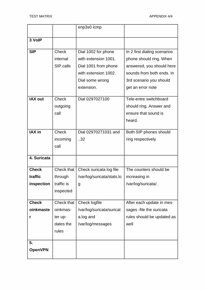
TEST MATRIX APPENDIX 4/4
enp3s0 icmp
3 VoIP
SIP Check
internal
SIP calls
Dial 1002 for phone
with extension 1001.
Dial 1001 from phone
with extension 1002.
Dial some wrong
extension.
In 2 first dialing scenarios
phone should ring. When
answered, you should here
sounds from both ends. In
3rd scenario you should
get an error note
IAX out Check
outgoing
call
Dial 0297027100 Tele-entre switchboard
should ring. Answer and
ensure that sound is
heard.
IAX in Check
incoming
call
Dial 02970271031 and
..32
Both SIP phones should
ring respectively
4. Suricata
Check
traffic
inspection
Check that
through
traffic is
inspected
Check suricata log file
/var/log/suricata/stats.lo
g
The counters should be
increasing in
/var/log/suricata/.
Check
oinkmaste
r
Check that
oinkmas-
ter up-
dates the
rules
Check logfile
/var/log/suricata/suricat
a.log and
/var/log/messages
After each update in mes-
sages -file the suricata
rules should be updated as
well
5.
OpenVPN

TEST MATRIX APPENDIX 4/5
Check
server
connectivi
ty
Check that
you can
access the
server
Download the client
files to your laptop or
computer. Connect to
the example-server.
Give bogus credentials.
Check the connection
log.
There should be a log en-
try: TLS: Initial packet from
[AF_INET]217.116.163.20
0:1194
Check
login
Check that
you can
login to
server
with valid
creden-
tials
Login to server. Use
valid credentials, both
the ones the certificate
is for and some other.
Login with any valid cre-
dentials will work. You can
see the user's certificate
name in log file
/etc/openvpn/openvpn-
status.log
Check
access
Check that
you can
access the
inside
networks
and the
router
Logon to the router.
Check that you can
reach the inside net-
work. Use putty and the
authrorized key to logon
to the router using the
openvpn address
172.30.30.1. Ping the
computer in the inside
network from your local
computer.
SSH to router should work.
Ping should succeed. You
can check traffic using
tcpdump -n -i tun0 on the
router.
6. QoS
Check rate
limits
Check that
proper
limits are
set on
Give command tc -s
class ls dev ifb0
Check that the limits on
classes are the same as
given in the script.
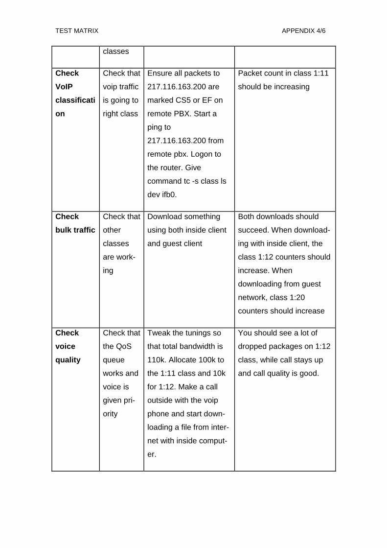
TEST MATRIX APPENDIX 4/6
classes
Check
VoIP
classificati
on
Check that
voip traffic
is going to
right class
Ensure all packets to
217.116.163.200 are
marked CS5 or EF on
remote PBX. Start a
ping to
217.116.163.200 from
remote pbx. Logon to
the router. Give
command tc -s class ls
dev ifb0.
Packet count in class 1:11
should be increasing
Check
bulk traffic
Check that
other
classes
are work-
ing
Download something
using both inside client
and guest client
Both downloads should
succeed. When download-
ing with inside client, the
class 1:12 counters should
increase. When
downloading from guest
network, class 1:20
counters should increase
Check
voice
quality
Check that
the QoS
queue
works and
voice is
given pri-
ority
Tweak the tunings so
that total bandwidth is
110k. Allocate 100k to
the 1:11 class and 10k
for 1:12. Make a call
outside with the voip
phone and start down-
loading a file from inter-
net with inside comput-
er.
You should see a lot of
dropped packages on 1:12
class, while call stays up
and call quality is good.