LAN CASE STUDY: UGANDA TECHNICAL COLLEGE
111
SETTING UP, DESIGN AND IMPLEMENTATION OF A LOCAL AREA NETWORK- LAN CASE STUDY: UGANDA TECHNICAL COLLEGE- KICHWAMBA. BY MWESIGWA JIMMY KIKOYO BCS/4756/31/DU. A GRADUATION PROECT REPORT SUBMITTED TO THE SCHOOL OF COMPUTER STUDIES FOR APPROVAL IN PARTIAL FULFILLMENT OF THE REQUIREMENTS OF THE AWARD OF A BACHELLOR'S DEGREE IN COMPUTER SCIENCE OF KAMPALA INTERNATIONAL UNIVERSITY. JUNE2009
-
Upload
khangminh22 -
Category
Documents
-
view
1 -
download
0
Transcript of LAN CASE STUDY: UGANDA TECHNICAL COLLEGE
SETTING UP, DESIGN AND IMPLEMENTATION OF
A LOCAL AREA NETWORK- LAN
CASE STUDY: UGANDA TECHNICAL COLLEGE- KICHWAMBA.
BY
MWESIGWA JIMMY KIKOYO
BCS/4756/31/DU.
A GRADUATION PROECT REPORT
SUBMITTED TO THE SCHOOL OF COMPUTER STUDIES FOR APPROVAL
IN PARTIAL FULFILLMENT OF THE REQUIREMENTS OF THE A WARD OF
A BACHELLOR'S DEGREE IN COMPUTER SCIENCE OF
KAMPALA INTERNATIONAL UNIVERSITY.
JUNE2009

DECLARATION: I Mwesigwa Jimmy Kikoyo do hereby declare to the best of my knowledge that this is my
original Graduation Project Report and has never been submitted to any University or Higher
Institution of learning for the same case. It is the original work done and submitted by me to the
School of Computer Studies of Kampala International University for the award of a Bachelor's
Degree in Computer Science as a requirement by Kampala International University.
The information from other peoples' works has been fully and dully referenced and
acknowledged in the text of this book for better notes and bibliography .
. ~ W £;5 (tf\Jf\ ~I'm '(Y'I 'f /)._j t_<Q""f 0 Name . .... .. ........ . ..................... . .. .
Regno: .. .. f?.~ . .!. .<-H-: ~ ~./.~ /./ ~ Signature: .... ·~· . .. .. . ..... .
Date: .. f.?~~ .. b: ~ .. ~ ... ~'QP .. '3
School of Computer Studies:
Supervisor:
~~ ·~ Name: .1 . :7: ~· · }~-,;..:_.· .... . ... . . .. .
Signature: .. ~ . . .. ... . .... . .
Date: . .. 4'(~(~.1 . . . .
Dean:
Name: . .. ............ . ... . . . .. . .. .. . .. . .
Signature: .... . ... . ......... . ........ . .. .. .
Date: ... . . . ......... . .. . ....... .. .. . .. . .. .. .
11

ACKNOWLEDGEMENT
First and foremost, I thank God for enabling and being with me in life of study since the
first year to the last year because it was not easy with out Him.
I am greatly thankful to my parents, Mr. and Mrs. Patrick Bujara, who have seen me
tlu·ough the school life, and worked tirelessly through their prayers as parents to ensure
that I become a responsible and well educated person.
I am also very thankful to the management of Madhvani and group of Companies for the
support they gave me to complete my studies when I had failed to raise my tuition for a
year and a semester.
Great thanks also go to the Administration and Management of different organizations
like the Ministry of Information and Communications Teclmology (MoiCT), Action on
Disability and Development (ADD), Kamwenge District Local Government and
Karnwenge District Union of the Disabled (KADUDI) for allowing me catTy out my
Internship training with them for various times.
Finally, I extend my thanks to various people who assisted me in one way or the other
without getting tired of me to ensure that I am successful in my studies which led me to
acquiring my Bachelor's Degree in Computer Science.
ll1

DEDICATION
This report is dedicated to my parents Mr. and Mrs. Patrick Bujara whom I have been
wishing to see me succeed in life. This also goes to my Wife Jackie, Brothers and Sisters
-Francis, Gad, Prudence, Medias, Justine (In - Law) and Christine.
Specially, this is also dedicated to my Children Joel, Job and Jordan whom I wish and
pray to God to have the same like me.
May the Good Lord Bless You All!
IV
LIST OF ABBREVEATIONS RegNo:
MoiCT:
ADD:
TCP:
IP:
IT:
LAN:
WAN:
NIC:
RJ:
CLNS
CONS
NSAPs
NETs:
UTC
NOS
FDDI
CAD
CAM
MRI
CAT
GoS
VPis
ATM
RAM
CPU NIC DRCN HTTP FPT
Registration Number.
Ministry oflnformation and Communications Technology
Action on Disability and Development.
Transmission Control Protocol
Internet Protocol
Inf01mation Technology
Local Area Network
Wide Area Network
Network Interface Card
Registered Jack
Connectionless Network Service
Connection-Oriented Network Service
Network Service Access Points
Network Entity Titles
Uganda Technical College
Network Operating System
Fiber Data Distributed Interface
Electronic mail
Computer Aided Design
Computer Aided Manufacturing
Magnetic Response Imaging
Computerized Axial Tomography
Grade of Service
Virtual Path Identifiers
Asynchronous Transfer Model
Random Access Memory
Central Processing Unit Network Interface Card Design of Reliable Communication Network Hypertext Transfer Protocol File Transfer Protocol
v
LIST OF FIGURES Fig. I.
Fig.2.
Fig.3.
Fig.4.
Fig.5.
Fig 6.
Fig. 7.
Fig. 8.
Fig 9.
Fig. 10.
Figure 11:
Figure 12:
Figure 13:
Figure 14:
Figure 31:
Figure 15:
Figure. 16: Figure. 17:
Figure. 18:
Figure. 19:
Figure. 20:
The Organizational Structure ofUTC Kichwamba
A typical bus topology.
Star Topology.
Typical Ring Topology
Mesh Topology
Star Bus Topology
Star-Ring topology
Department Relational diagram
Unshielded Twisted Pair (UTP)
RJ-45 connector
Kichwamba with Hubs or Switches
Kichwamba (Bridge) with Multiple Server Farms
Kichwamba (Bridge) with a Router and Server Clusters
Wiring the Network
Computer to be connected on the Network.
Computer and Wireless Router connection
Network Setup Wizard to run the network Network Setup Wizard to checklist for creating a network.
Network Setup Wizard to confirm use of shared connection.
Network Setup Wizard to select a network connection method
Network Setup Wizard for other Internet Connection methods.
VI
Figure. 21:
Figure. 22:
Figure. 23:
Figure. 24:
Figure. 25:
Figure. 26:
Figure. 27:
Network Setup Wizard to describe and name the computer.
Network Setup Wizard for naming the network.
Network Setup Wizard for Resource sharing
Network Setup Wizard to indicate whether the computer is ready to network
settings.
Network Setup Wizard for configuring the computer for home or small office
networking.
Network Setup Wizard to run the network setup wizard.
Network Setup Wizard for selecting the drive to use in creating a network setup
drive.
Figure. 28: Network Setup Wizard showing the drive selected.
Figure. 29: Network Setup Wizard for running the wizard with the network setup disk.
Figure. 30: Network Setup Wizard for completing the network setup wizard.
Figure. 31: Network Setup Wizard showing the user what to do for the new setup to take
effect.
Figure. 32: Network Setup Wizard showing how to run the computer on this wizard.
Figure. 33: Network Setup Wizard for Reviewing the checklist for creating the network.
Figure. 34: Network Setup Wizard for other shared connection.
Figure. 35: Network Setup Wizard for naming and describing computers in case of shared
connection.
Figure. 36: Network Setup Wizard for naming the network to specify the workgroup.
Vll
Figure. 37: Network Setup Wizard for applying network settings.
Figure. 38: Network Setup Wizard to run the network setup disk
Figure. 39: Network Setup Wizard completing the setup wizard in case of shared
Figure. 40: Shows which computers are available aud/or which files or folders have been
shared
Figure. 41:
Figure. 42:
Figure. 43:
Figure. 43:
Fig. 44:
Fig. 45:
Fig. 46:
Fig. 47:
Fig 48:
Fig 49:
Fig 50:
Fig 51:
Fig 52:
Fig 53:
Fig 54:
Showing how to add a new hardware using the wizard
Add new hardware Wizard to select the type of hardware to install.
Showing the network adapters that match with the hardware selected.
Adding the TCP/IP Protocol Stack
Configuring the TCP/IP Protocol
Server Installation
Managing Your Server
Steps taken to configure a server
To set up a server to perform one or more specific roles.
Summery of Selections
The Active Directory Installation Wizard
The Active Directory Installation Wizard showing the operating system
compatibility.
The Active Directory Installation Wizard showing the Domain controller type
The Active Directory Installation Wizard for creating new domain.
The Active Directory Installation Wizard showing the full DNS name for new
domain.
viii

Fig 55:
Fig 56:
Fig 57:
Fig 58:
Fig 59:
objects.
Fig 60:
Fig 61:
selections.
Fig 62:
Directory
Fig 63:
Fig 64:
Fig 65:
Fig 66:
Fig. 67
The Active Directory Installation Wizard showing Domain NetBios Name for the
new domain.
The Active Directory Installation Wizard showing Active Directory information
storage.
The Active Directory Installation Wizard showing shared system volume
The Active Directory Installation Wizard showing DNS Registration Diagnostics.
The Active Directory Installation Wizard showing pennissions for user and group
The Active Directory Installation Wizard to create a password used to start the
server in "Restore Mode" ..
The Active Directory Installation Wizard displaying a summary of your
The Active Directory Installation Wizard for creating and configuring Active
The Active Directory Installation Wizard configuring the components.
The Active Directory Installation Wizard is completed.
The Active Directory Installation Wizard for restarting the computer for the
installation to take effect
Dialog box titled Configure Your Server showing successful installation of Active
Directory.
Regional and Language Setup Options dialog box
IX
Table of Contents
DECLARATION: ............................................................................................................... ii
ACKNOWLEDGEMENT ................................................................................................. iii
DEDICATION ................................................................................................................... iv
LIST OF ABBREVEATIONS ............................................................................................ v
LIST OF FIGURES ........................................................................................................... vi
Table of Contents ................................................................................................................ x
DEFINITION OF TERMS: ............................................................................................. xiii
CHAPTER ONE .................................................................................................................. !
GENERAL INTRODUCTION: .......................................................................................... !
BACKGROUND TO THE STUDY: ................................................................................... !
DEPARMENTS AND COURSES: ..................................................................................... 2
PROBLEM STATEMENT: ................................................................................................ .3
AIMS AND OBJECTIVES OF THE STUDY: .................................................................. .3
General Objectives: .......................................................................................................... 3
Specific Objectives: ........................................................................................................ .3
Organizational Structure: ................................................................................................. 5
CHAPTER TWO: .................................................................................... 5 JUSTIFICATION: ............................................................................................................... 5
LITERATURE REVIEW .................................................................................................... 7
INTRODUCTION: .............................................................................................................. 7
INFORMATION TECHNOLOGY: .................................................................................... 7
Role of Information Technology Today .......................................................................... 8
Objectives of IT Architecture: ......................................................................................... 9
CHAPTER THREE: .......................................................................................................... ! 0
RESEARCH METHODOLOGY: ..................................................................................... 10
VARIOUS TYPES OF NETWORICS: .............................................................................. !!
Standard Network Topologies: ...................................................................................... !!
X
Reasons for Networking: ............................................................................................... 18
Advantages of setting up and Installing a College Network .......................................... l9
Disadvantages off setting up and Installing a College Network .................................... 20
CHAPTER FOUR: ............................................................................................................ 21
NETWORK PLANNING AND DESIGN ......................................................................... 21
Department Relational Diagram .................................................................................... 22
NETWORK PLANNING METHODOLOGY .................................................................. 22
NETWORK FORECASTING: .......................................................................................... 24
The role of forecasting ................................................................................................... 24
NETWORK DIMENSIONING ......................................................................................... 24
TRAFFIC ENGINEERING ............................................................................................... 25
NETWORK SURVIVABILITY ....................................................................................... 26
NETWORK SERVERS ..................................................................................................... 26
Server Requirements: ..................................................................................................... 26
NETWORK DESIGN ESSENTIALS: .............................................................................. 27
NETWORK MEDIA: ........................................................................................................ 27
DIFFERENT TYPES OF CABLES: ................................................................................. 27
TWISTED PAIR CABLE: ................................................................................................ 28
Advantages .................................................................................................................... .29
Disadvantages ............................................................................................................... .30
NETWORK MONITORING AND TROUBLESHOOTING: .......................................... 30
OSI MODEL: ................................................................................................................... 30
NETWORK OPERATIONS AND MANAGEMENT ..................................................... .32
CHAPTER FIVE: ............................................................................................................. .34
NETWORK IMPLEMENTATION ................................................................................... 34
NETWORK IMPLEMENTATION .................................................................................. .34
NETWORK SECURITY ................................................................................................... 36
ATTRIBUTES OF A SECURE NETWORK ............................................................... .36
SECURITY MANAGEMENT ......................................................................................... .37
GUIDES ............................................................................................................................. 38
Xl
Choosing IP Addresses for Network Machines ............................................................. 38
Configuring TCP/IP on Windows NT ........................................................................... 38
Configuring TCP/IP on Windows 95 ............................................................................. 39
Testing the TCP/IP Connection .................................................................................... .40
Wiring the Network ...................................................................................................... .40
Connecting and setting up a Wireless Network - LAN ................................................ .41
Network Setup on First Computer ................................................................................ .43
Network Setup on Additional Computers ...................................................................... 5 I
Viewing Network Connections ...................................................................................... 56
Setting up a Win9x Local Area Network ....................................................................... 57
Adding Your Network Adapter. ..................................................................................... 58
Adding the TCP/IP Protocol Stack ................................................................................ 59
Configuring the TCP/IP Protocol ................................................................................... 60
Server Installation Necessary Hardware and Software .................................................. 61
Installing the Server Operating System ......................................................................... 64
Software Installations - Workstation Operating Systems .............................................. 78
Performing a New Installation of Windows XP ............................................................ 79
NETWORK MANAGEMENT ......................................................................................... 90
NETWORK MANAGEMENT WITH WINDOWS SERVER 2003 ................................ 91
The Microsoft Management Console ............................................................................. 94
REFERENCES: ................................................................................................................. 97
Xll
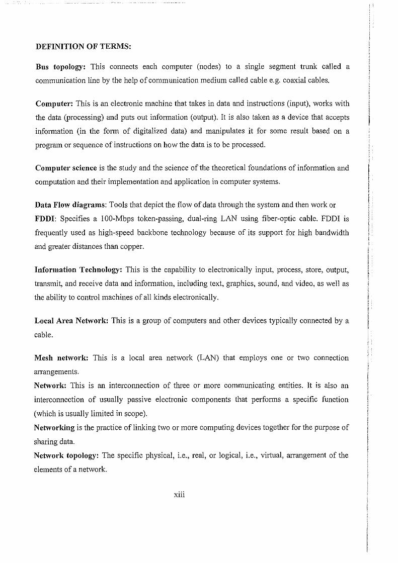
DEFINITION OF TERMS:
Bus topology: This connects each computer (nodes) to a single segment trunk called a
communication line by the help of communication medium called cable e.g. coaxial cables.
Computer: This is an electronic machine that takes in data and instructions (input), works with
the data (processing) and puts out information (output). It is also taken as a device that accepts
inf01mation (in the form of digitalized data) and manipulates it for some result based on a
program or sequence of instructions on how the data is to be processed.
Computet· science is the study and the science of the theoretical foundations of inf01mation and
computation and their implementation and application in computer systems.
Data Flow diagrams: Tools that depict the flow of data through the system and then work or
FDDI: Specifies a l 00-Mbps token-passing, dual-ring LAN using fiber-optic cable. FDDI is
frequently used as high-speed backbone technology because of its support for high bandwidth
and greater distances than copper.
Information Technology: This is the capability to electronically input, process, store, output,
transmit, and receive data and information, including text, graphics, sound, and video, as well as
the ability to control machines of all kinds electronically.
Local Area Network: This is a group of computers and other devices typically connected by a
cable.
Mesh network: This is a local area network (LAN) that employs one or two connection
arrangements.
Network: This is an interconnection of three or more communicating entities. It is also an
interconnection of usually passive electronic components that performs a specific function
(which is usually limited in scope).
Netwol'idng is the practice of linking two or more computing devices together for the purpose of
sharing data.
Network topology: The specific physical, i.e., real, or logical, i.e., virtual, arrangement of the
elements of a network.
xiii
Operating System: This is a computer software that manages the resources of the computer
system.
Personal Computer: Computers that can run easy to use programs like Ms Office.
Relationships: Representation of an event that links the entities or merely a logical affinity that
exists between the entities.
Ring network: This is a network topology in which each node connects to exactly two other
nodes, forming a circular pathway for signals.
Terminal: Any input I output device that uses a key board to input and a monitor to output.
processing by that system.
Workgroup: This is a group of computers connected with a networking hardware and software
that users can share resources e.g. files and databases
xiv
CHAPTER ONE
GENERAL INTRODUCTION: As the spectacular success UTC Kichwamba is likely to rely on a series of Information aud
Communication Technology services as they are widely known and acknowledged globally,
Success in particular shall be witnessed in deployment, Design aud Implementation of Local
Area Network- LAN that will globally expose the College resources and services leading to an
efficient and effective service delivery institution.
The project shall focus on setting up, designing aud implementing of a Local Area Network -
LAN for UTC Kichwamba in F01t P01tal where the survey was taken from following a study that
was made from the college by the designer with the help of various methods that are related to
data collection and analysis.
In the world of computers, aud according to Todd Lammle and Kevin Hales in their book of
CCNP Support, Study Guide; in particular, Networking is taken to be the practice of linking
two or more computing devices together for the purpose of sharing data. Networks are built with
a mix of computer hardware aud computer software. Also Williams Sawyer Hutchinson in his
book of Using Information Teclmology defines Networking as a sub-discipline of
telecommunications, Computer Science, information technology aud I or computer engineering.
Computet· science (or computing science) is the study aud the science of the theoretical
foundations of information and computation aud their implementation and application in
computer systems.
BACKGROUND TO THE STUDY: UTC - Kichwamba is a Govemment Aided Technical College found in Kabarole District. It is
located along Kabarole - Bundibudyo Road approximately 15 km from Fort Portal Town -
Kabarole District heading to Bundibudyo District. It was founded in 1979 as a Technical
Institute offering only Certificate Courses.
It lies at the foot hills of the Rwenzori Mountains at the borders of Kabarole and Bundibudyo
Districts along the Westem Rift valley. Since it was started, it had been headed by a number of
1

Principals and more than I 00,000 students have passed through the same college and are now
champions in exploring the world and doing some recommendable work out there.
Presently, it has over 700 students of which 5% are females and the rest are male students. The
college has both teaching and non teaching staff as the major beneficiaries.
DEPARMENTS AND COURSES: The College has various departments which house different courses which lead students getting
both ordinary and advanced diplomas and Certificates respectively at the end of their studies.
Department of Civil Engineering:
• Civil Engineering.
• Land Survey.
• Brick Laying and Concrete Practice.
• Carpentry and Joinery
Department of Electrical Engineering:
• Electrical Engineering
• Electrical Installation .
• Electronics
• Refrigeration
• Motor rewinding
Depa1·tment of Mechanical Engineering:
• Mechanical Engineering
• Agricultural Engineering.
• Motor Vehicle Technology.
• Agricultural Technology.
Computer Science and Information Technology
• Computer Engineering.
• Computer Science
• Software Engineering
• Computer Applications
2
So, the Networking aspect of the College shall help the administration of UTC in the purpose of
resource sharing in terms of information and peripherals. This will be done by connecting
different departments where each of the above mentioned courses lies for better service delivery.
PROBLEM STATEMENT: UTC Kichwamba like any other un networked enterprise most of the time used computers for
traditional activities like word processing of documents, traditional information storage which is
static in a sense that that data could only accessed at particular locations of storage. To access
ce1iain information, the college staff could move from office to office in search for the required
information which was time consuming; and in case that information was urgently needed, it
used to delay the services. This could have been reduced by peripheral/ device sharing but due
to lack of networking facilities, there was no peripheral I device sharing like printers, etc. This
led the college to spending much in buying various peripherals for different staffs in the same
location leading to financial crisis.
Therefore, the establishment of a LAN at the college to provide a Networked environment
helped a lot in curbing down most of the problems that are related to a non networked
environment.
AIMS AND OBJECTIVES OF THE STUDY:
General Objectives:
To have an efficient and effective management tool of the college's resources by establishing a
LAN for advanced related activities that shall be result oriented.
Specific Objectives:
• To Study the cun·ent Network connectivity of the college to find means of solving most
of the related problems:
The Researcher first studied the networking environment of the college under which the
activities of the college were being performed. Due to the fact that the college have no
networked environment, the college staff used to move from office to office in search for the
required information which was time consuming; and in case that information is urgently
3
needed, it used to delay the services, the researcher after finding out the problems related to
that, designed a network to solve such problems.
• To design a network that addresses the cun-ent connectivity related problems of the
college.
Under this, the researcher came out with plans and designs of how the environment of UTC
Kichwamba would look like after setting up the Local Area Network while solving problems
that are related to a non networked environment. These designs and plans were handed over
to the concerned staff for approval who later gave him a go ahead to implementing the plan.
This was done because it was one way to solve problems that related to data and information
sharing and storage in a non networked environment.
• To implement the designed network to ensure that it meets the users' needs.
The researcher implemented his designed network in phases by carrying out various activities
in relation to the set LAN. These activities included the following:
o Surveying of different sites, creating suitable Network designs, and Identifying and
setting up locations for network components. These covered the first phase took a
period of30 days.
o In the second Phase, the Researcher carried out other activities as pmi of
implementation to ensure that the LAN is in place. These included the following:
Installation of conduits I tunnels for ports, testing of all ports, replacement and repair
of faulty ports, and then repmiing about all the proceeding s in this phase. This took
3 7 days to reach to completion.
o The third phase consisted of activities like, Connection of all components together,
testing the connectivity of the components and then reporting on the proceedings of
the phase. This took 22 days before completion.
o In the last phase, the Resem·cher can·ied various activities and it took him 48 days to
complete. These activities includes: ISP Connection and testing, , LAN Testing, User
Training, Report on Phase Four, and then Launching the Network,
4
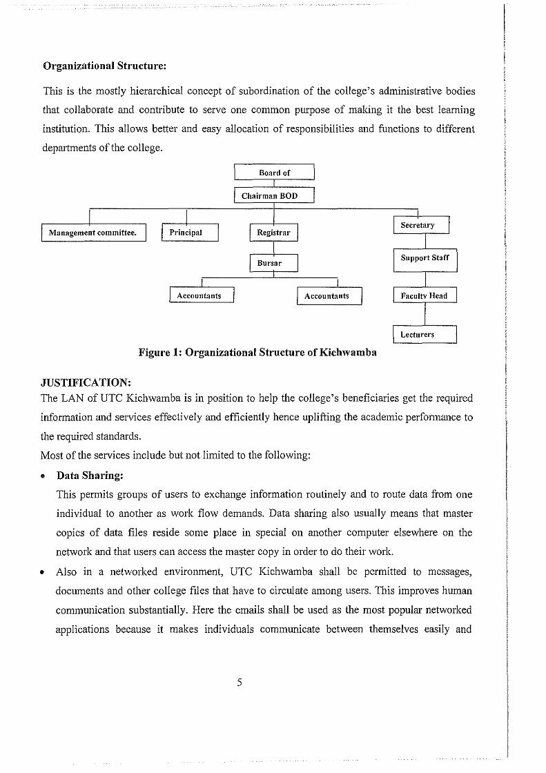
Organizational Structure:
This is the mostly hierarchical concept of subordination of the college's administrative bodies
that collaborate and contribute to serve one common purpose of making it the best learning
institution. This allows better and easy allocation of responsibilities and functions to different
depmtments of the college.
Board of
Chairman BOD
Accountants Accountants
Figure 1: Organizational Structure of Kichwamba
JUSTIFICATION: The LAN of UTC Kichwamba is in position to help the college's beneficiaries get the required
information and services effectively and efficiently hence uplifting the academic performance to
the required standards.
Most of the services include but not limited to the following:
• Data Sharing:
This permits groups of users to exchange information routinely and to route data from one
individual to another as work flow demands. Data sharing also usually means that master
copies of data files reside some place in special on another computer elsewhere on the
network and that users can access the master copy in order to do their work.
• Also in a networked environment, UTC Kichwamba shall be permitted to messages,
documents and other college files that have to circulate among users. This improves human
communication substantially. Here the emails shall be used as the most popular networked
applications because it makes individuals communicate between themselves easily and
5

effectively, which was a problem for the college before thinking of implementing a LAN for
the college.
• Peripheral I device sharing in the college shall let groups of users take the advantage of
peripherals e.g. printers, scanners, faxes etc attached to correctly to the network or generally
available.
• Proper and Secure filing systems for the college in that college files shall be kept and
backed up using the network.
6

CHAPTER TWO:
LITERATURE REVIEW
INTRODUCTION: This chapter focuses on the concept and magnitude of Local Area Networks as a component with
in the Information and Communications Technology Industry and computer science at large, the
structure and effects of Local Area Networks in relation to global and national perspective as it
addresses the challenges faced in designing a LAN in UTC - Kichwamba.
Therefore, Literature Review means becoming familiar with ones research topic. It gives an
insight by suggesting a research design for dealing with the research problem.
INFORMATION TECHNOLOGY: According to Williams Sawyer Hutchnison in his Using Information Technology; Information
Technology (IT) also known as Information and Communications Technology (ICT) is
concerned with the use of technology in managing and processing information, especially in
large organizations. In particular, IT deals with the use of electronic computers and computer
software to convert, store, protect, process, transmit, and retrieve information.
Information Technology is also taken as the study, design, development, implementation,
support or management of computer-based information systems, particularly software
applications and computer hardware (Jeffrey L. Whitten and Lonnie D. Bentley in Systems
Analysis and Design Methods).
Encompassing the computer and information systems industries, information technology is the
capability to electronically input, process, store, output, transmit, and receive data and
information, including text, graphics, sound, and video, as well as the ability to control machines
of all kinds electronically (defined by the Information Technology Association of America -
ITAA).
From the above definitions and statements therefore, Information Technology is taken to be the
means by which information is acquired, organized, stored, manipulated and transmitted
electronically.
7
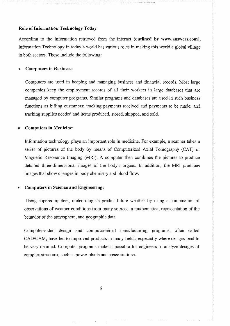
Role oflnformation Technology Today
According to the information retrieved from the internet (outlined by www.answers.com),
Infmmation Technology in today's world has various roles in making this world a global village
in both sectors. These include the following:
• Computers in Business:
Computers are used in keeping and managing business and financial records. Most large
companies keep the employment records of all their workers in large databases that are
managed by computer programs. Similar programs and databases are used in such business
functions as billing customers; tracking payments received and payments to be made; and
tracking supplies needed and items produced, stored, shipped, and sold.
• Computers in Medicine:
Infmmation technology plays an important role in medicine. For example, a scanner takes a
series of pictures of the body by means of Computerized Axial Tomography (CAT) or
Magnetic Resonance Imaging (MRI). A computer then combines the pictures to produce
detailed three-dimensional images of the body's organs. In addition, the MRI produces
images that show changes in body chemistly and blood flow.
• Computers in Science and Engineering:
Using supercomputers, meteorologists predict future weather by using a combination of
observations of weather conditions from many sources, a mathematical representation of the
behavior of the atmosphere, and geographic data.
Computer-aided design and computer-aided manufacturing programs, often called
CAD/CAM, have led to improved products in many fields, especially where designs tend to
be very detailed. Computer programs make it possible for engineers to analyze designs of
complex structures such as power plants and space stations.
8
• Integrated Information Systems:
With today's sophisticated hardware, software, and communications technologies, it is often
difficult to classify a system as belonging uniquely to one specific application program.
Organizations increasingly are consolidating their information needs into a single, integrated
information system.
• Information Technology Architecture:
The IT Architecture is an organized set of consensus decisions on policies & principles,
services & common solutions, standards & guidelines as well as specific vendor products
used by IT providers both inside and outside the organization trying to integrate the use of
Information Technology within its operations.
Objectives of IT Architecture:
The IT Architecture is guided by the following objectives, which help make decisions for
establishing individual standards:
• Architectural decisions should serve the Organization's mission.
• The architecture serves heterogeneous environments.
• The greater the consensus achieved for individual architectural decisions, the greater the
benefit.
• The architecture should identity areas of stability without impeding essential innovation.
• Architectural decisions should describe the tangible results of conformance and non
conformance with the architecture.
• Architectural decisions should provide sufficient documentation to assess the compliance of
a specific implementation.
9
CHAPTER THREE:
RESEARCH METHODOLOGY: These are the techniques or methods the designer used to collect data to facilitate the design and
implementation of the Local Area network for UTC- Kichwamba.
In this case, the designer collected all the necessary infmmation using methods like observing all
the activities done and consulting various documents of UTC - Kichwamba. Other methods
included Questionnaires designed by the researcher and distributed for filling to the College staff
and students to enable him get the required information to support his research.
Project Area:
The report reflects what took place at UTC - Kichwamba from where the Case Study was done.
The College is located in Kabarole District approximately 15 km along Bundibudyo Road at the
footsteps ofRwenzori Mountains.
Project Population:
The Project only targets College Administration, Tutors I Lecturers, Departmental Heads,
Teaching and Non- teaching Staffs and Students' Information.
Procedure:
Accessing the college for research, information was through the designer being given
introductory letter from the Executive Director Industrial Training and Research. Copies of the
letter were distributed to all the above said personnel to prepare for the exercise.
Documentary Evidence:
Extraction of results was facilitated through consultations made through different documents e.g.
files, records, college manuals, admission forms, financial statements, etc.
Observations:
The project designer spent much of the time watching individuals working out certain activities
from different college departments taking one at a time. This was aimed at generating new
information stmctures and improve on the existing procedures with in the college. The designer
then observed and identified the work flow patterns within the college e.g. how documents move
from one office I department to the other.
Mel"its
• Cheap method.
• No interruption of work I activities and schedules.
10
• Provides enough access to various key departments since the designer was acting like a staff
member allowed document view of various activities and procedures with in the college.
Demerits:
• The method was time consuming for substantiating results.
• Respondents were not comfortable being watched while working.
VARIOUS TYPES OF NETWORKS: During the research, the researcher took much concern and focus on different types of networks
that any networked environment may be having for it to support and solve certain problems that
are network related. In reference to various authors of different books and retrieved information
fro the Internet, the Researcher came out with various definitions of the following types of
networks as: (http://www.en.wikipedia.org/wiki/networks, Networking Complete, 2"ct Edition,
etc).
• Local Area Network- LAN is a group of computers and other devices typically connected by a cable. It is contained in a company or department and located in a single geographical area, usually a building.
• Wide area network (WAN) that is usually a larger network that covers a large geographic area.
• Wireless LANs and WANs (WLAN & WW AN) are the wireless equivalent of the LAN
and WAN.
The Researcher went ahead and found out that a variety of different kinds of media, including
twisted-pair copper wire cable, coaxial cable, optical fiber, and various wireless technologies are
used to interconnect various networks components to allow communication between them. The
components can be separated by a few meters (e.g. via Bluetooth for wireless) or nearly
unlimited distances (e.g. via the interconnections of the Internet).
Standard Network Topologies:
According to John Swartz and Todd Lammle in their Study Guide of Cisco Certified Internetwork Expert for Routing and Switching exam 350-001, a Network Topology is defined as a specific physical and virtual arrangement of network components I elements.
II
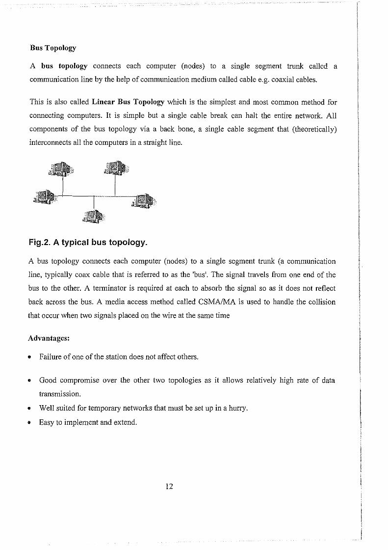
Bus Topology
A bus topology connects each computer (nodes) to a single segment trunk called a
communication line by the help of communication medium called cable e.g. coaxial cables.
This is also called Linear Bus Topology which is the simplest and most common method for
connecting computers. It is simple but a single cable break can halt the entire network. All
components of the bus topology via a back bone, a single cable segment that (theoretically)
interconnects all the computers in a straight line.
Fig.2. A typical bus topology.
A bus topology connects each computer (nodes) to a single segment trunk (a communication
line, typically coax cable that is referred to as the 'bus'. The signal travels from one end of the
bus to the other. A terminator is required at each to absorb the signal so as it does not reflect
back across the bus. A media access method called CSMAIMA is used to handle the collision
that occur when two signals placed on the wire at the same time
Advantages:
• Failure of one of the station does not affect others.
• Good compromise over the other two topologies as it allows relatively high rate of data
transmission.
• Well suited for temporary networks that must be set up in a hurry.
• Easy to implement and extend.
12
Disadvantage:
• Require a network to detect when two nodes are transmitting at the same time.
• Does not cope well with heavy traffic rates
• Difficult to administer/troubleshoot.
• Limited cable length and number of stations.
• A cable brake can disable the entire network; no redundancy.
• Maintenance cost may be higher in the long mn.
• Performance degrades as additional computers are added.
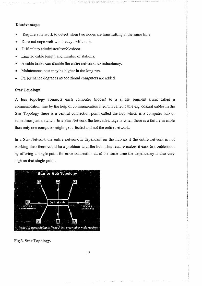
Star Topology
A bus topology connects each computer (nodes) to a single segment trunk called a
communication line by the help of communication medium called cable e.g. coaxial cables In the
Star Topology there is a central connection point called the hub which is a computer hub or
sometimes just a switch. In a Star Network the best advantage is when there is a failure in cable
then only one computer might get affected and not the entire network.
In a Star Network the entire network is dependant on the hub so if the entire network is not
working then there could be a problem with the hub. This feature makes it easy to troubleshoot
by offering a single point for error connection ad at the same time the dependency is also very
high on that single point.
Fig.3. Star Topology.
13
Advantages
• A Star Network Topology is very easy to manage because of its simplicity in functionality.
• The problems can be easily located logically in a Star Topology and therefore is easy to
troubleshoot also.
• The Star Topology is very simple in format so it is very easy to expand on the Star Topology.
Disadvantages
• The Star Topology is fully dependant on the hub and the entire working of the network depends
on the hub or the switch.
• If there are many nodes and the cable is long then the network may slow down.
Since all the computers on the network have independent control of their networks and only
dependant on the central hub computer, the failures in transmission and other possible problems
in this area are less likely. Also if the hub is safe then every computer in the network is safe. This
type of network also offers more privacy than any other network.
If one computer fails in the network it does not affect any other computer in the network and the
tasks of this computer can be easily switched very to the next computer easily using the hub
controls. In a Star Network Topology it is possible to have all the impmtant data back ups on the
hub in a private folder and this way if the computer fails you can still use your data using the
next computer in the network and accessing the backup files on the hub.
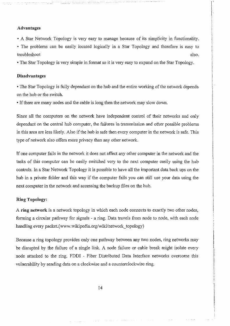
Ring Topology:
A ring network is a network topology in which each node connects to exactly two other nodes,
forming a circular pathway for signals - a ring. Data travels from node to node, with each node
handling every packet.( www. wikipedia.org/wiki/network _topology)
Because a ring topology provides only one pathway between any two nodes, ring networks may
be disrupted by the failure of a single link. A node failure or cable break might isolate every
node attached to the ring. FDDI - Fiber Distributed Data Interface networks overcome this
vulnerability by sending data on a clockwise and a counterclockwise ring.
14
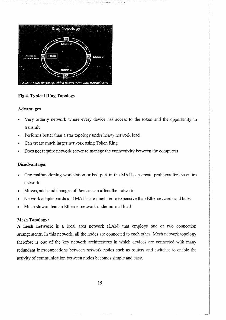
Fig.4. Typical Ring Topology
Advantages
• Very orderly network where every device has access to the token and the opportunity to
transmit
• Performs better than a star topology under heavy network load
• Can create much larger network using Token Ring
• Does not require network server to manage the connectivity between the computers
Disadvantages
• One malfi.mctioning workstation or bad port in the MAU can create problems for the entire
network
• Moves, adds and changes of devices can affect the network
• Network adapter cards and MAU's are much more expensive than Ethemet cards and hubs
• Much slower than an Ethemet network under normal load
Mesh Topology: A mesh network IS a local area network (LAN) that employs one or two connection
arrangements. In this network, all the nodes are connected to each other. Mesh network topology
therefore is one of the key network architectures in which devices are connected with many
redundant interconnections between network nodes such as routers and switches to enable the
activity of communication between nodes becomes simple and easy.
15
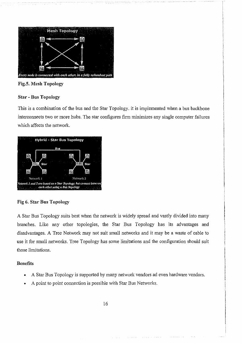
Fig.S. Mesh Topology
Star- Bus Topology
This is a combination of the bus and the Star Topology. it is implemented when a bus backbone
interconnects two or more hubs. The star configures firm minimizes any single computer failures
which affects the network.
Fig 6. Star Bus Topology
A Star Bus Topology suits best when the network is widely spread and vastly divided into many
branches. Like any other topologies, the Star Bus Topology has its advantages and
disadvantages. A Tree Network may not suit small networks and it may be a waste of cable to
use it for small networks. Tree Topology has some limitations and the configuration should suit
those limitations.
Benefits
• A Star Bus Topology is supported by many network vendors ad even hardware vendors.
• A point to point connection is possible with Star Bus Networks.
16
• All the computers have access to the larger and their immediate networks.
• Best topology for branched out networks.
Limitations
• In a Network Topology the length of the network depends on the type of cable that is
being used.
• The Star Bus Topology network is entirely dependant on the trunk which is the main
backbone of the network. If that has to fail then the entire network would fail.
• Since the Star Bus Topology network is big it is difficult to configure and can get
complicated after a certain point.
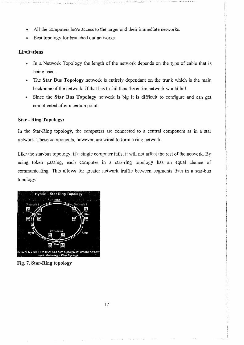
Star- Ring Topology:
In the Star-Ring topology, the computers are connected to a central component as in a star
network. These components, however, are wired to fmm a ring network.
Like the star-bus topology, if a single computer fails, it will not affect the rest of the network. By
using token passing, each computer in a star-ring topology has an equal chance of
communicating. This allows for greater network traffic between segments than in a star-bus
topology.
Fig. 7. Star-Ring topology
17
Reasons for Networking:
Basing on the need for networked environment, the setting, designing and implementation of a
LAN - Local Area Network at UTC Kichwamba uplift the standards of the college both
effectively and efficiently through having the following in place:
• Software Sharing:
The ability to share both a software application and the files it creates amongst all of your
computers is the primary reason for setting up a network. This does not only increase in
productivity, but an increase in the organization of their computer files as well. Opening files
on a computer across your office will be as simple if they were stored on your own machine.
• Printers and other peripheral sharing:
Sometimes the printer and other peripherals shall be connected together to increase the
capabilities of other devices in the networked environment. Instead of college staff moving
from office to office searching for certain peripherals, the networked environment shall make
this easy by sharing them. on a network.
• Internet Access.
Most of the employees in your office, including yourself, can increase their productivity with
access to the Internet. Using a technology such as Cable/DSL router combined with a
network allows multiple computers to share the same Internet account simultaneously.
Advantages of setting up and Installing a College Network
• Speed: Networks provide a very rapid method for sharing and transferring files. Without a
network, files are shared by copying them to floppy disks, then carrying or sending the disks
from one computer to another which is very time-consuming.
• Cost: Networkable versions of many popular software programs are available at considerable
savings when compared to buying individually licensed copies. Besides monetary savings,
sharing a program on a network allows for easier upgrading of the program.
• Security: Files and programs on a network can be designated as "copy inhibit," so that you
do not have to worry about illegal copying of programs. Also, passwords can be established
for specific directories to restrict access to authorized users.
18
• Centralized Software Management: One of the greatest benefits of installing a network at a
school I Institution like Kichwamba is the fact that all of the software can be loaded on one
computer (the file server). This eliminates that need to spend time and energy installing
updates and tracking files on independent computers throughout the building.
• Resource Sharing: Sharing resources is another area in which a network exceeds stand
alone computers. Most institutions can not afford peripherals like laser printers, fax
machines, modems, scanners, and CD-ROM players for each computer. However, if these or
similar peripherals are added to a network, they can be shal'ed by many users.
• Electronic Mail: The presence of a network provides the hardware necessary to install an e
mail system. E-mail aids in personal and professional communication for all school
personnel, and it facilitates the dissemination of general information to the entire school staff.
Electronic mail on a LAN can enable students to communicate with teachers and peers at
their own school. If the LAN is connected to the Internet, students can communicate with
others throughout the world.
• Flexible Access: School networks allow students to access their files from computers
throughout the college. Students can begin an assignment in their classroom, save part of it
on a public access area of the network, then go to the media center after school to finish their
work. Students can also work cooperatively through the network.
• Workgroup Computing: Workgroup software (such as Microsoft BackOffice) allows many
users to work on a document or project concurrently.
Disadvantages off setting up and Installing a College Network
• Expensive to Install. Although a network will generally save money over time, the initial
costs of installation can be prohibitive. Cables, network cards, and software are expensive,
and the installation may require the services of a technician.
• Requires Administrative Time. Proper maintenance of a network requires considerable
time and expertise. Many enterprises have installed a network, only to find that they did not
budget for the necessary administrative support.
19
• File Server May Fail. Although a file server is no more susceptible to failure than any other
computer, when the files server "goes down," the entire network may come to a halt. When
this happens, the entire college may lose access to necessary programs and files.
• Cables May Break. Some of the configurations are designed to minimize the inconvenience
of a broken cable; with other configurations, one broken cable can stop the entire network.
NETWORK OPERATING SYSTEM:
For any communication within a Network to happen, the Researcher decided to have an
Operating system to support such communication of computers over a network. A network
operating system (NOS) is a computer operating system that is designed primarily to support
workstation, personal computer, and, in some instances, older tetminal that are connected on a
local area network (LAN). A network operating system provides printer sharing, common file
system and database sharing, application sharing, and the ability to manage a network name
directory, security, and other housekeeping aspects of a network.
20
CHAPTER FOUR:
NETWORK PLANNING AND DESIGN The researcher used different applications and techniques in designing the network. Some of the applications used include Ms Access for drawing relational diagrams to show how different departments from different buildings at the college shall be connected to support an interactive environment, Ms Office Project for drawing a work plan to show the period the work was to be finished.
During planning of the Network and how different departments should be connected to facilitate communication, the researcher used Relational Diagrams to explain them.
Various departments included:
Department of Civil Engineering:
• Civil Engineering.
• Land Survey.
• Brick Laying and Concrete Practice.
• Carpentry and Joinery
Department of Electrical Engineering:
• Electrical Engineering
• Electrical Installation .
• Electronics
• Refrigeration
• Motor rewinding
Department of Mechanical Engineering:
• Mechanical Engineering
• Agricultural Engineering.
• Motor Vehicle Technology.
• Agricultural Technology.
Computer Science and Information Technology
• Computer Engineering.
• Computer Science
• Software Engineering
• Computer Applications
21
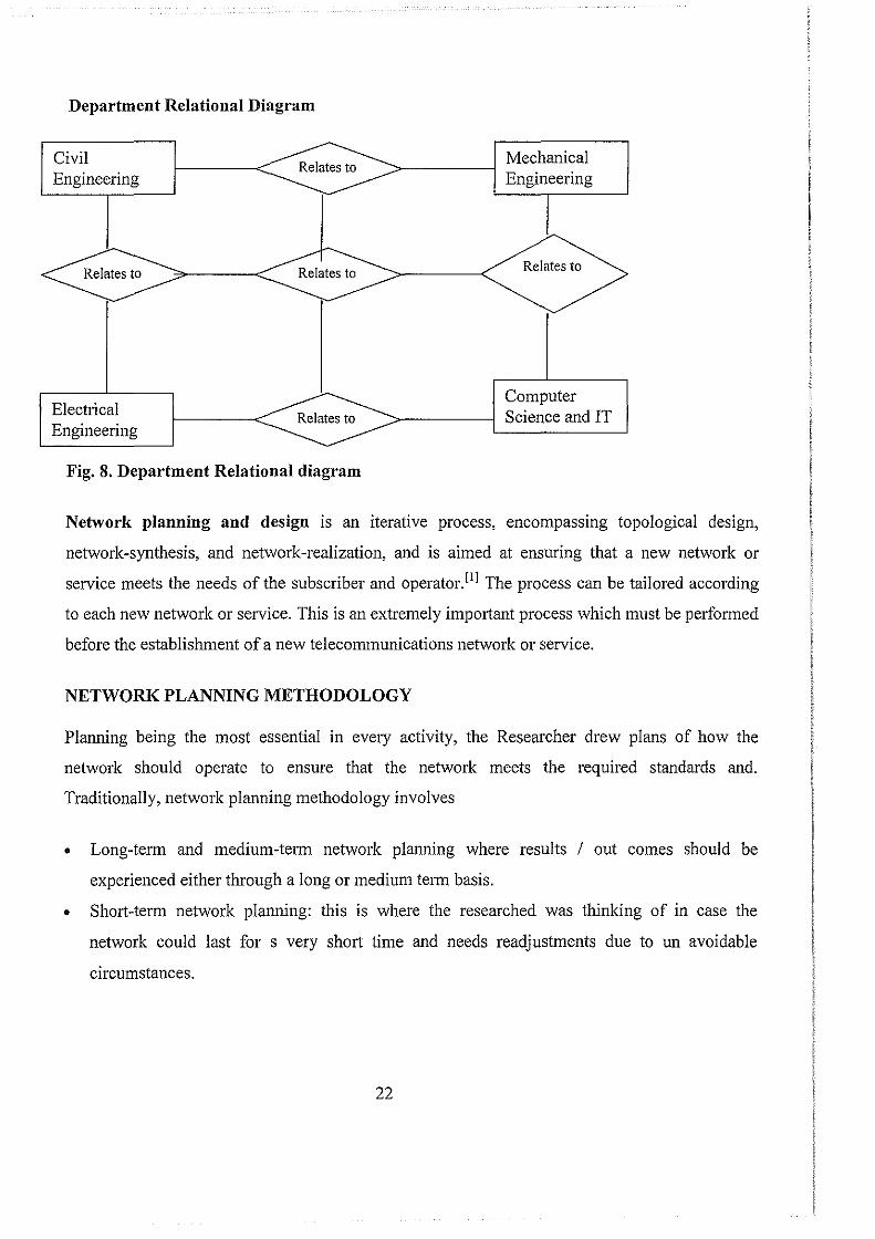
Department Relational Diagram
Civil Engineering
Electrical Engineering
Fig. 8. Department Relational diagram
Mechanical Engineering
Relates to
Computer Science and IT
Network planning and design is an iterative process, encompassing topological design,
network-synthesis, and network-realization, and is aimed at ensuring that a new network or
service meets the needs of the subscriber and operator. 111 The process can be tailored according
to each new network or service. This is an extremely important process which must be performed
before the establishment of a new telecommunications network or service.
NETWORK PLANNING METHODOLOGY
Planning being the most essential in every activity, the Researcher drew plans of how the
network should operate to ensure that the network meets the required standards and.
Traditionally, network planning methodology involves
• Long-term and medium-term network planning where results I out comes should be
experienced either tlu·ough a long or medium term basis.
• Short-term network planning: this is where the researched was thinking of in case the
network could last for s very short time and needs readjustments due to un avoidable
circumstances.
22
• Operations and maintenance: This is where the researcher focused on the full operation of the
network after fully trouble shoot and maintained. Here the end users are able to us the
network for information and peripheral sharing i.e. operation of the network on a daily basis.
The network planning process begins with the acquisition of external information. This includes:
• forecasts of how the new network/service will operate;
• the economic information concerning costs;
• The technical details of the network's capabilities.
It should be considered that planning a new network/service involves implementing the new
system across the first four layers of the OS! Reference Model. This means that even before the
network planning process begins, choices must be made, involving protocols and transmission
technologies.
Once the initial decisions have been made, the network planning process involves three main
steps:
• Topological design: This stage involves determining where to place the components and
how to connect them. The (topological) optimization methods that can be used in this stage
come from an area of mathematics called Graph Theory. These methods involve detetmining
the costs of transmission and the cost of switching, and thereby determining the optimum
connection matrix and location of switches and concentrators.
• Network-synthesis: This stage involves determining the size of the components used,
subject to performance criteria such as the Grade of Service (GoS). The method used is
known as "Nonlinear Optimization", and involves detetmining the topology, required GoS,
cost of transmission, etc., and using this information to calculate a routing plan, and the size
of the components.
• Network realization: This stage involves determining how to meet capacity requirements,
and ensure reliability within the network. The method used is known as "Multicommodity
23
Flow Optimization", and involves determining all information relating to demand, costs and
reliability, and then using this information to calculate an actual physical circuit plan.
These steps are inte!Telated and are therefore performed iteratively, and in parallel with one
another. The planning process is highly complex, meaning that at each iteration, an analyst must
increase his plarming horizons, and in so doing, he must generate plans for the various layers
outlined above.
NETWORK FORECASTING:
In order to eliminate Network Traffic, the Researcher also put into considerations the estimation
of the expected traffic intensity and thus the traffic load that the network must support. In case a
similar network exists, the researcher put up measures to take traffic measurements of such a
network and use that data to calculate the exact traffic load which is likely to happen in most
instances when a similar network is not found.
The role of forecasting
The forecasting process involves several steps as follows:
• Definition of problem;
• Data acquisition;
• Choice of forecasting method;
• Analysis I Forecasting;
• Documentation and analysis of results.
NETWORK DIMENSIONING
In addition to forecasting, the Researcher also focused on Network Dimensioning. The purpose
of dimensioning a new network I service is to determine the minimum capacity requirements that
will still allow the Teletraffic Grade of Service (GaS) requirements to be met. Here the
Researcher decided to plan for peak-hour traffic, i.e. that hour during the day during which
traffic intensity is at its peak so as to meet the users' needs.
24

The dimensioning process involves determining the network's topology, routing plan, traffic
matrix, and GoS requirements, and using this information to determine the maximum call
handling capacity of the switches, and the maximum number of channels required between the
switches. This process requires a complex model that simulates the behavior of the network
equipment and routing protocols.
A dimensioning rule is that the Researcher must ensure that the traffic load should never
approach a load of I 00 percent. To calculate the correct dimensioning to comply with the above
rule, the researcher must take on-going measurements of the network's traffic, and continuously
maintain and upgrade resources to meet the changing requirements. Another reason for "over
provisioning" is to make sure that traffic can be rerouted in case a failure occurs in the network.
TRAFFIC ENGINEERING
Comparing to network engineering which adds resource, such as link, router, switch into the
network, traffic engineering targets to change traffic path on the existing network to alleviate
traffic congestion or accommodate more traffic demand, the researcher also put into
consideration Traffic Engineering as a necessity while planning and implementation of a LAN of
UTC Kichwamba.
This technology is critical when the cost of expanding network expansion is prohibitively high
and network load is not optimally balanced. The available technologies for traffic engineering
include MPLS and ATM for current Internet backbone. For example, MPLS allows catTiers to
provision LSPs with dynamic or explicit routes. The dynamic route is controlled by CSPF while
the explicit routes are optimized in an offline tool or through a Path Computation Element which
is under study by IETF. End-to-end protection is an alternative resilient approach. It provides a
backup route for each primary route. Preplanning enough bandwidth for these backup routes is
one of the active topics for survivable network design.
25
NETWORK SURVIVABILITY
In addition to the above planning methodologies, the Researcher focused on how the planned
network should last longer and meet users' requirements. He termed this as Network
Survivability.
This is a situation where the network maintains maximum network connectivity and quality of
service under failure conditions. As one of the critical requirements in network planning and
design, It involves design requirements on topology, protocol, bandwidth allocation, etc ..
Topology requirement can be maintaining a minimum two-connected network against any failure
of a single link or node. Protocol requirements include using dynamic routing protocol to reroute
traffic against network dynamics during the transition of network dimensioning or equipment
failures. Bandwidth allocation requirements pro-actively allocate extra bandwidth to avoid traffic
loss under failure conditions.
NETWORK SERVERS. Fro any network to stand and operate under any condition, there has to be a communication
driver facilitating it. This the Researcher termed it as a Network Server.
A network server therefore is a computer designed to process requests and deliver data to other
computers I clients with a specialized operating system over a local network or the Internet.
Examples of network servers include Web servers, proxy servers, and FTP servers.
Set-ver Requirements:
Wherever a machine functions as a server on a server based or peer to peer network, handling
service requests across a network invariably adds to a machine's processing load. The higher the
load, the more important it is to purchase computers with additional power to handle demands
for network resources.
Considering the above Network Planning Methodologies to ensure hat the LAN in UTC
Kichwamba operates to the maximum and meets the users' requirements, it shall have the servers
with the following specifications as listed in the table below.
26
Item Windows NT Server Windows 2000 Server
RAM 16(128 +)MB 128(256+)MB
Disk type EIDE (SCSI) EIDE(SCSI)
Disk space 124 (2000) MB 1000 (3000)MB
CPU types 80486 + (Pentium +) Pentium (Pentium II +)
CPU Count 1(2or4) 1 (2 or 4)
NIC Type EISA (PCI) PCI
NETWORK DESIGN ESSENTIALS:
Network Based Design plays an integral part in its operation and performance. The topology of a
network dictates the media used the type of channel access and the speed at which the network
operates.
Network Topology: This is a physical layout of the network. It refers not only to the physical
layout of its computers, cables and other resources, but also how those components communicate
with each other. The network topology has significant effect on its perfmmance as well as
growth potential of a network.
NETWORK MEDIA: Network media is the actual path over which an electrical signal travels as it moves from one
component to another (Networking Essentials Plus; Academic Learning Series; 3'd Edition).
Most networks today use cables to interconnect various devices employing signaling techniques,
network cables transfer signals between computers, allowing them to communicate with each
other.
There are different kinds to be used to build networks each with its own distinguishing set of
signal - carrying characteristics.
Not all computers or networked devices attach to networks by cables; a growing portion of the
networking population uses wireless technologies, either because physical obstructions or
distance limitations make cable unsuitable or because users are mobile.
27
DIFFERENT TYPES OF CABLES: A Cable is the medium through which information usually moves from one network device to
another. There are several types of cable which are commonly used with LANs. In some cases, a
network will utilize only one type of cable, other networks will use a variety of cable types. The
type of cable chosen for a network is related to the network's topology, protocol, and size.
Understanding the characteristics of different types of cable and how they relate to other aspects
of a network is necessary for the development of a successful network.
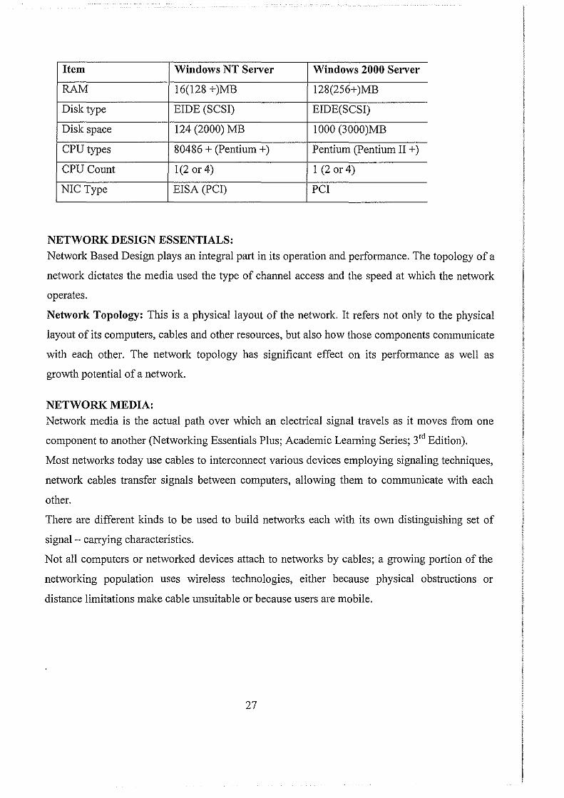
TWISTED PAIR CABLE: This is a form of wiring in which two conductors (two halves of a single circuit) are wound
together for the purposes of canceling out electromagnetic interference (EM!) from external
sources; for instance, electromagnetic radiation from unshielded twisted pair (UTP) cables,
and crosstalk between neighboring pairs.
Twisting wires decreases interference because the loop area between the wires (which
determines the magnetic coupling into the signal) is reduced. In balanced pair operation, the
two wires typically carry equal and opposite signals (differential mode) which are combined
by addition at the destination. The twist rate (also called pitch of the twist, usually defined in
twists per meter) makes up part of the specification for a given type of cable. Where pairs are
not twisted, one member of the pair may be closer to the source than the other, and thus
exposed to slightly different induced electromotive force (EMF).
In planning for the network, the researcher also considered the connectivity of the network
components to by use of twisted pair cables due to that fact that they have the following
advantages.
• Cancels out I prevents electromagnetic interference (EM!) from external sources
• Has less or no crosstalk experienced in the network during device communication.
28
Fig 9. Unshielded Twisted Pail· (UTP)
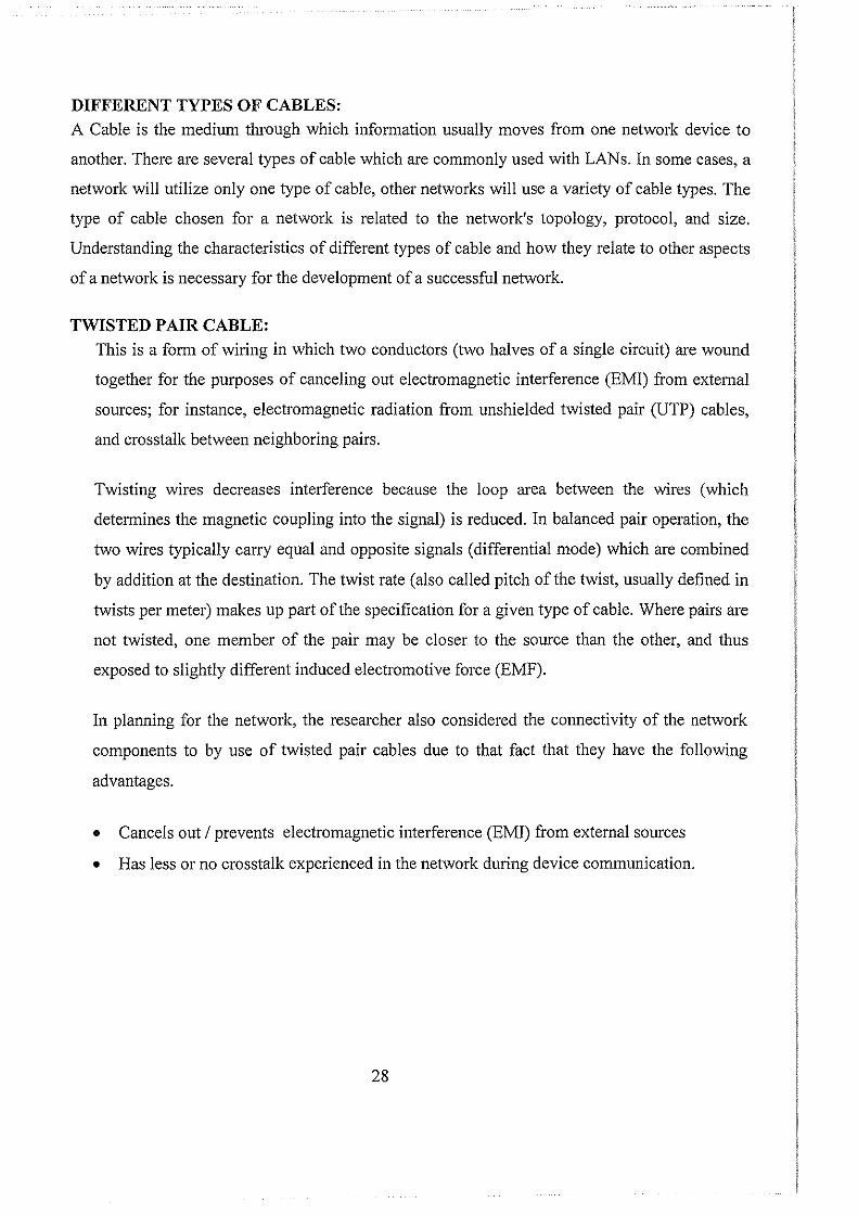
Unshielded Twisted Pair Connector
The standard connector for unshielded twisted pair cabling is an RJ-45 connector. This is a
plastic connector that looks like a large telephone-style connector. A slot allows the RJ-45 to be
inserted only one way. RJ stands for Registered Jack, implying that the connector follows a
standard borrowed from the telephone industry. This standard designates which wire goes with
each pin inside the connector.
Fig. 10. RJ-45 connector
STP cabling, also known as Screened Fully shielded Twisted Pair (S/FTP), is both individually
shielded (like STP cabling) and also has an outer metal shielding covering the entire group of
shielded copper pairs (like S/UTP). This type of cabling offers the best protection from
interference from external sources, and also eliminates alien crosstalk.
Advantages
• It is a thin, flexible cable that is easy to string between walls.
• Because UTP is small, it does not quickly fill up wiring ducts.
• UTP costs less per foot than any other type of LAN cable.
29
Disadvantages
• Twisted pair's susceptibility to electromagnetic interference greatly depends on the pair
twisting schemes (usually patented by the manufacturers) staying intact during the
installation. As a result, twisted pair cables usually have stringent requirements for
maximum pulling tension as well as minimum bend radius. This relative fragility of
twisted pair cables makes the installation practices an important part of ensuring the
cable's performance.
Therefore, the Researcher in setting up the LAN decided to use the UTP cable and RJ 45
Connectors because they are easy to use both in terms of cost and availability in the today's
market.
NETWORK MONITORING AND TROUBLESHOOTING:
For easy monitoring and troubleshooting of the network, the Researcher set up methods one
should use to ensure that the network is well monitored for proper operation and in case of any
problem, also measures were set to carryout a Troubleshooting exercise.
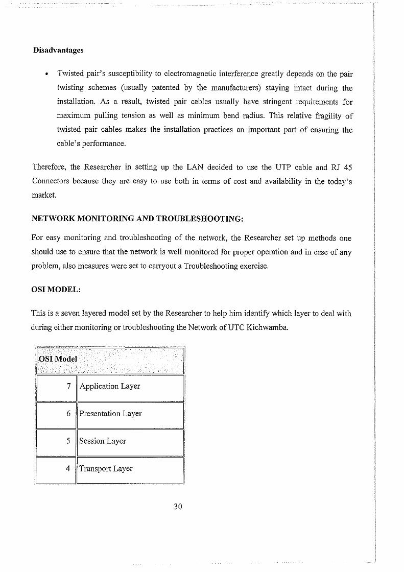
OSIMODEL:
This is a seven layered model set by the Researcher to help him identify which layer to deal with
during either monitoring or troubleshooting the Network ofUTC Kichwamba.
~o Application Layer
iD Presentation Layer
J[]l Session Layer
l[]ITransport Layer
30
II
I!
iC~JINetwork Layer I!
~=====2~~D==m=a=L=ink===L=ay=e=r========~l,
• •
LLC sub layer MAC sub layer
11
1 llf=P=h=y=si=ca=I=L=a=y=er=====,= ___ = __ =--==_ =ij 'I
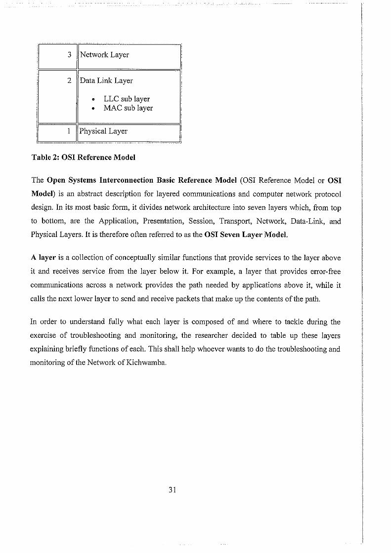
Table 2: OSI Reference Model
The Open Systems Interconnection Basic Reference Model (OSI Reference Model or OSI
Model) is an abstract description for layered communications and computer network protocol
design. In its most basic form, it divides network architecture into seven layers which, from top
to bottom, are the Application, Presentation, Session, Transport, Network, Data-Link, and
Physical Layers. It is therefore often refened to as the OSI Seven Layer Model.
A layer is a collection of conceptually similar functions that provide services to the layer above
it and receives service from the layer below it. For example, a layer that provides error-free
communications across a network provides the path needed by applications above it, while it
calls the next lower layer to send and receive packets that make up the contents of the path.
In order to understand fully what each layer is composed of and where to tackle during the
exercise of troubleshooting and monitoring, the researcher decided to table up these layers
explaining briefly functions of each. This shall help whoever wants to do the troubleshooting and
monitoring of the Network ofKichwamba.
31
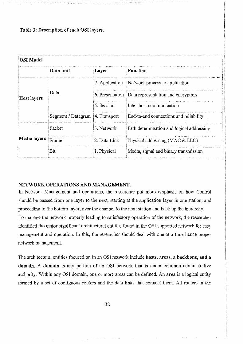
Table 3: Description of each OSI layers.
·osr Model
'Host layers
·Data unit
r- -~ -- -~H"·---~- ~
i Segment I Datagram ' I
!Packet
1 Media layers I Frame
Bit
,Layer Function
i 7. Application !Network process to application
6. Presentation Data representation and encryption i
· 5. Session 'Inter-host communication
End-to-end connections and reliability
:3. Network Path determination and logical addressing
2. Data Link Physical addressing (MAC & LLC)
, I. Physical , Media, signal and binary transmission
NETWORK OPERATIONS AND MANAGEMENT.
In Network Management and operations, the researcher put more emphasis on how Control
should be passed from one layer to the next, starting at the application layer in one station, and
proceeding to the bottom layer, over the channel to the next station and back up the hierarchy.
To manage the network properly leading to satisfactory operation of the network, the researcher
identified the major significant architectural entities found in the OSI supported network for easy
management and operation. In this, the researcher should deal with one at a time hence proper
network management.
The architectural entities focused on in an OSI network include hosts, areas, a backbone, and a
domain. A domain is any portion of an OSI network that is under common administrative
authority. Within any OSI domain, one or more areas can be defined. An area is a logical entity
formed by a set of contiguous routers and the data links that connect them. All routers in the
32

same area exchange information about all of the hosts that they can reach. The areas are
connected to form a backbone. All routers on the backbone know how to reach all areas. The
te1m end system (ES) refers to any non routing host or node; intermediate system (IS) refers to a
router.
Therefore, the above architectural entities were set to help the researcher which network
component and part of the network infrastructure to deal with while monitoring, troubleshooting
and even during management of the Kichwamba network.
33
CHAPTER FIVE:
NETWORK IMPLEMENTATION
This involves several of the configuration options that the researcher used to implement the UTC
Kichwamba LAN. The Implementation exercise focuses on each of the network components,
their connectivity and operations. This is done to prove whether there is direct communication
between them and the server.
In addition to connectivity, the researcher also focused on how the Kichwamba Bridge
communicates with various servers to enable packet movements through different network
components. In doing this the work of network implementation should be seen as to as simple as
possible.
NETWORK IMPLEMENTATION
UTC Kichwamba uses directed or dispatch mode to appear to the client as if they are
communicating directly with a real server. If the client and server are on the same network
segment, the response from the server bypasses Kichwamba Bridge, and the traffic will not be
load balanced. All traffic must pass through the Bridge and be directed to the real servers.
Kichwamba Bridge serves as a transparent leaming bridge to forward data packets between its
interfaces. Because of its bridge capability, the Bridge must not be installed on the network
parallel to another bridge. Only use Kichwamba Bridge to connect to servers allowing a single
way in or out to the network through Kichwamba Bridge.
The connectivity of the LAN Components the researcher used Hubs or Switches to connect two
or more components together for example in one department. These facilitate easy
communication of these components with in a network.
If there is another path from the network to your servers, a bridge loop is created and
Kichwamba Bridge does not work properly. Kichwamba Bridge automatically detects a bridge
loop and tries to recover. SYSLOG messages are generated to indicate there is a bridge loop, and
virtual and real servers have intermittent failures.
34
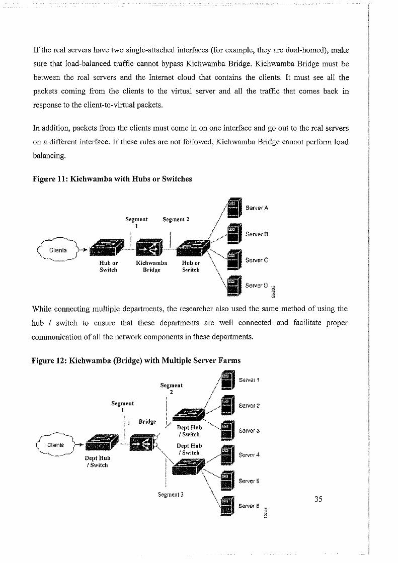
If the real servers have two single-attached interfaces (for example, they are dual-homed), make
sure that load-balanced traffic cannot bypass Kichwamba Bridge. Kichwamba Bridge must be
between the real servers and the Internet cloud that contains the clients. It must see all the
packets coming from the clients to the virtual server and all the traffic that comes back m
response to the client-to-virtual packets.
In addition, packets fi·om the clients must come in on one interface and go out to the real servers
on a different interface. If these rules are not followed, Kichwamba Bridge cannot perform load
balancing.
Figure 11: Kichwamba with Hubs or Switches
r,_,~~~----,"-.
( C:I>Brrts ~-·--~.,.,_ __ __.
Segment I
Bridge
Segment 2
While connecting multiple departments, the researcher also used the same method of using the
hub I switch to ensure that these departments are well connected and facilitate proper
communication of all the network components in these departments.
Figure 12: Kichwamba (Bridge) with Multiple Serve1· Farms
Segment I
Bridge
Segment 2
Segment 3
S'.!tver 2
S.arvnr 4
35
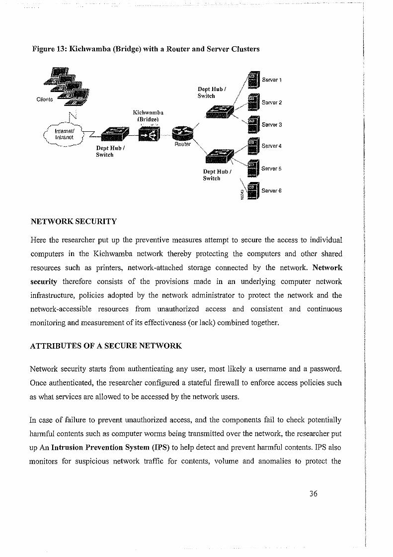
Figure 13: Kichwamba (Bridge) with a Router and Server Clusters
NETWORK SECURITY
Dept Hub I Switch
Dept Hub I Switch
Server 1
Server 2
Serter4
Sert.er S
Here the researcher put up the preventive measures attempt to secure the access to individual
computers in the Kichwamba network thereby protecting the computers and other shared
resources such as printers, network-attached storage connected by the network. Network
security therefore consists of the provisions made in an underlying computer network
infrastructure, policies adopted by the network administrator to protect the network and the
network -accessible resources from unauthorized access and consistent and continuous
monitoring and measurement of its effectiveness (or lack) combined together.
ATTRIBUTES OF A SECURE NETWORK
Network security stmis from authenticating any user, most likely a username and a password.
Once authenticated, the researcher configured a stateful firewall to enforce access policies such
as what services are allowed to be accessed by the network users.
In case of fail me to prevent unauthorized access, and the components fail to check potentially
harmful contents such as computer worms being transmitted over the network, the researcher put
up An Intrusion P1·evention System (IPS) to help detect and prevent harmful contents. IPS also
monitors for suspicious network traffic for contents, volume and anomalies to protect the
36

network of Kichwamba from attacks such as denial of service. Communication between two
hosts using the network could be encrypted to maintain privacy. Individual events occurring on
the network could be tracked for audit purposes and for a later high level analysis.
SECURITY MANAGEMENT
Security Management for networks is different for all kinds of situations. UTC Kichwamba for
this matter as requirement needed basic security for high maintenance and advanced software
and hardware to prevent malicious attacks from hacking and spamming. The following are the
requirements needed for the college to have a secure network.
• An adjustable firewall and proxy to allow authorized users access from the outside and
inside.
• Strong Antivirus software and Internet Security Software packages.
• Students' Internet Protection Act compliance.
• Supervision of network to guarantee updates and changes based on popular site usage.
• Constant supervision by College ICT Department and administrators to guarantee protection
against attacks by both internet and sneaker net sources.
To enhance effective implementation of the LAN at UTC Kichwamba, the researcher
decided to use the Networking Guides to help in the networking process as they play a big
role in the exercise.
The Networking guides indicate what the Researcher did while implementing the network
especially during installation and configuration of the network ofUTC Kichwamba.
The screen shots in the guides are some of the wizards followed since the procedures are easy
to use and follow in the sense that the computer tells the network administrator what to do.
Therefore, the guides with respect to networking helped the researcher a lot in setting up and
implementation of the Network as it is a click and play procedure.
37
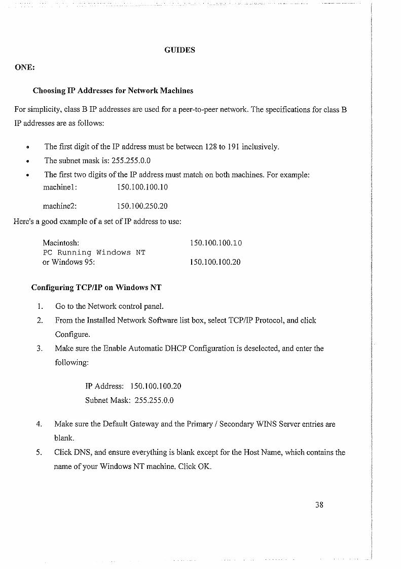
GUIDES
ONE:
Choosing IP Addresses for Network Machines
For simplicity, class B IP addresses are used for a peer-to-peer network. The specifications for class B
IP addresses are as follows:
• The first digit of the IP address must be between 128 to 191 inclusively.
• The subnet mask is: 255.255.0.0
• The first two digits of the IP address must match on both machines. For example:
machine!: 150.100.100.10
machine2: 150.100.250.20
Here's a good example of a set ofiP address to use:
Macintosh: PC Running Windows NT or Windows 95:
Configuring TCP/IP on Windows NT
1. Go to the Network control panel.
150.100.100.10
150.100.100.20
2. From the Installed Network Software list box, select TCP/IP Protocol, aud click
Configure.
3. Make sure the Enable Automatic DHCP Configuration is deselected, and enter the
following:
IP Address: 150.100.100.20
Subnet Mask: 255.255.0.0
4. Make sure the Default Gateway aud the Primary I Secondary WINS Server entries are
blank.
5. Click DNS, and ensure everything is blank except for the Host Name, which contains the
name of your Windows NT machine. Click OK.
38

6. Click Advanced, and ensure that Enable LMHOSTS Lookup is selected. Everything else
should be either blank or deselected. Click OK.
7. Close the Network control panel, and restart Windows NT.
8. Find the file name in the \Winnt\System32\Drivers directory. Make a copy and name it
Hosts, leaving it in the same directory.
9. Edit the Hosts file, and add the following line at the bottom:
150.100.100.10 as the IP Address.
10. From the File menu, choose Save. You are now ready to test the connection.
Configuring TCP/IP on Windows 95
I. From the Network control panel, select TCP/IP, and click Properties.
2. Go to WINS Configuration, and select Disable WINS resolution.
3. Go to the IP Address, select Specify an IP Address, and enter:
IP Address: 150.100.100.20
Subnet Mask: 255.255.0.0
4. Go to Gateway, and make sure it is empty.
5. Go to DNS configuration, and select Disable DNS.
6. Click OK, and close out the Network control panel. Restart Windows 95.
7. In the main Windows directory, usually C:\Windows, find the file name. Copy the file,
and Rename it. Place the file in the main Windows directory.
8. Edit the Hosts file, and add the following line at the bottom:
150.100.100.10 as its IP address.
9. From the File menu, choose Save. You are now ready to test the connection.
NOTE: If the MSN login dialog box appears when you are connecting, click Cancel to continue. To
disable this behavior, run the Internet applet from the control panel and clear the UseAutoDial option
in the AutoDial Tab.
39
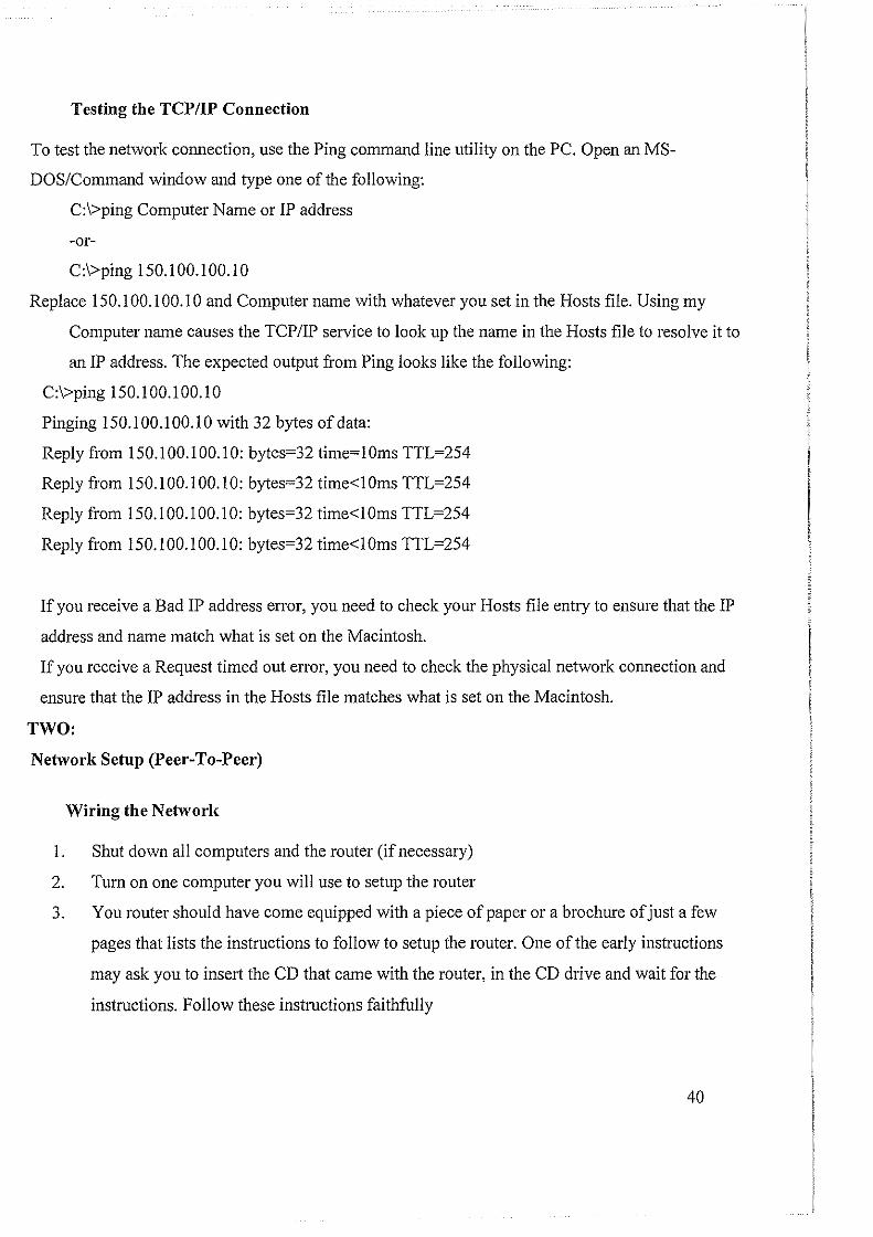
Testing the TCPIIP Connection
To test the network connection, use the Ping command line utility on the PC. Open an MS
DOS/Command window and type one of the following:
C:l>ping Computer Name or IP address
-or-
C:I>ping 150.100.100.10
Replace 150.100.100.10 and Computer name with whatever you set in the Hosts file. Using my
Computer name causes the TCP/IP service to look up the name in the Hosts file to resolve it to
an IP address. The expected output from Ping looks like the following:
C:\>ping 150.100.100.10
Pinging 150.100.100.10 with 32 bytes of data:
Reply from 150.100.100.10: bytes=32 time=lOms TTL=254
Reply from 150.100.100.10: bytes=32 time<! Oms TTL=254
Reply from 150.100.100.10: bytes=32 time<! Oms TTL=254
Reply from 150.100.100.10: bytes=32 time<! Oms TTL=254
If you receive a Bad IP address error, you need to check your Hosts file entry to ensure that the IP
address and name match what is set on the Macintosh.
If you receive a Request timed out enor, you need to check the physical network connection and
ensure that the IP address in the Hosts file matches what is set on the Macintosh.
TWO:
Network Setup (Peer-To-Peer)
Wiring the Network
1. Shut down all computers and the router (if necessary)
2. Tum on one computer you will use to setup the router
3. You router should have come equipped with a piece of paper or a brochure of just a few
pages that lists the instructions to follow to setup the router. One of the early instructions
may ask you to insert the CD that came with the router, in the CD drive and wait for the
instructions. Follow these instructions faithfully
40
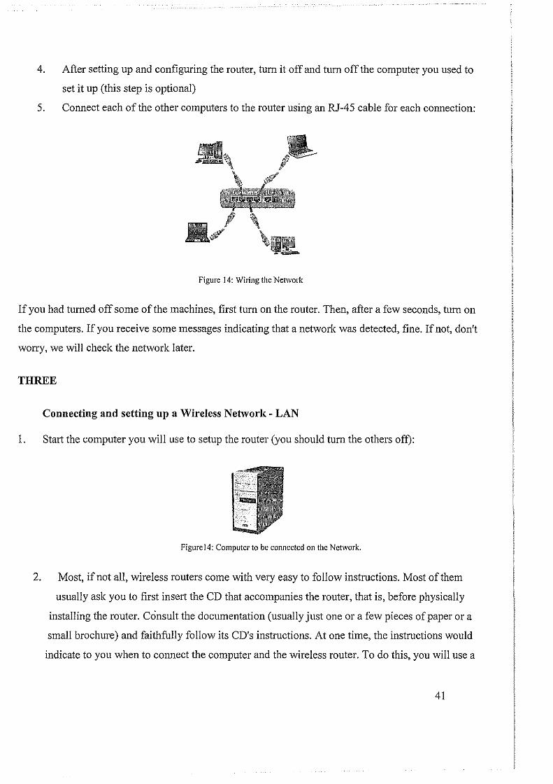
4. After setting up and configuring the router, tum it off and tum off the computer you used to
set it up (this step is optional)
5. Connect each of the other computers to the router using an RJ-45 cable for each connection:
Figure 14: Wiring the Network
If you had turned off some of the machines, first turn on the router. Then, after a few seconds, tum on
the computers. If you receive some messages indicating that a network was detected, fine. If not, don't
worry, we will check the network later.
THREE
Connecting and setting up a Wireless Network- LAN
1. Sta1i the computer you will use to setup the router (you should turn the others off):
Figurel4: Computer to be connected on the Network.
2. Most, if not all, wireless routers come with very easy to follow instructions. Most of them
usually ask you to first insert the CD that accompanies the router, that is, before physically
installing the router. Consult the documentation (usually just one or a few pieces of paper or a
small brochure) and faithfully follow its CD's instructions. At one time, the instructions would
indicate to you when to connect the computer and the wireless router. To do this, you will use a
41

cable (usually supplied to you) to connect one end to the computer and another end to the router:
Figure 15: Computer and Wireless Router connection
3. Because the steps to perform depend on the router (or the manufacturer), we will let you perform
as described by their documentation
4. After installing and setting up the wireless router, tum it off and tum the computer off
5. If you didn't yet, install the wireless network card(s) on the other computer(s).
For any computer that doesn't have a wireless network card but has a wired network card,
connect it to a port of the wireless router using an RJ-45 cable. The computers that have a
network card will not need a physical connection to the wireless router:
tJ~\ ====
6. Turn on the router. After a few seconds, turn on the computers one by one.
You may not need to check whether they work at this time or not.
42
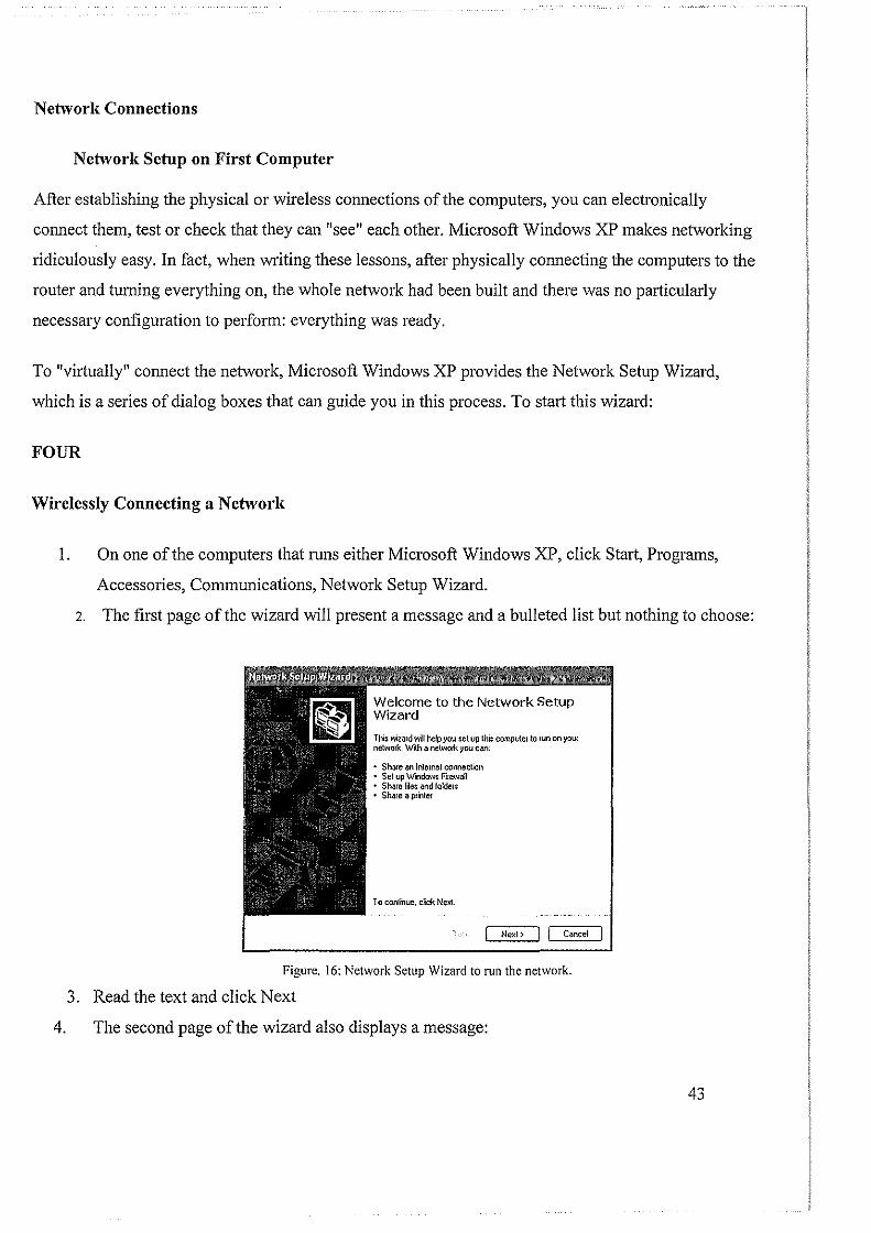
Network Connections
Netw01·k Setup on First Computer
After establishing the physical or wireless connections of the computers, you can electronically
connect them, test or check that they can "see" each other. Microsoft Windows XP makes networking
ridiculously easy. In fact, when writing these lessons, after physically connecting the computers to the
router and turning everything on, the whole network had been built and there was no pmiicularly
necessary configuration to perform: everything was ready.
To "virtually" connect the network, Microsoft Windows XP provides the Network Setup Wizard,
which is a series of dialog boxes that can guide you in this process. To stllii this wizard:
FOUR
Wirelessly Connecting a Network
I. On one of the computers that runs either Microsoft Windows XP, click Start, Progrllil1s,
Accessories, Communications, Network Setup Wizm·d.
2. The first page of the wizm·d will present a message and a bulleted list but nothing to choose:
Welcome to the Network Setup Wizard
This wizard rffl! help you set up thr~ computer to run onyoUI network With a nelV«llkyou can;
• Sha~e ""Internet connection • Set up Window~ Firewall • Shale f~e; and folders • Shale a Pfinler
To continue, clck Next
I Next> I I C.mcel
Figure. 16: Network Setup Wizard to run the network.
3. Read the text and click Next
4. The second page of the wizard also displays a message:
43
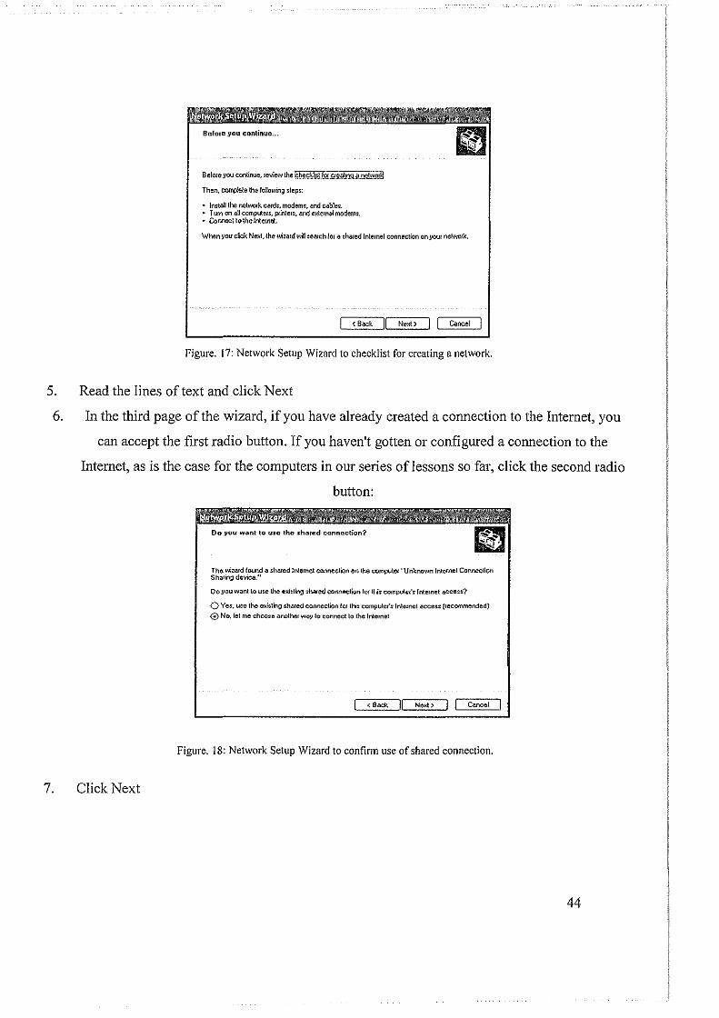
BefOlc you con!lnue, review the t&9.!ill~UU.!!!in.Q..It!l~~ill
Then, complete the following l!eps:
• ln~!all !he netwOlk cMd:, modems, .md cables. • Tum on all computer:, ptinlers, and eldemal modems. • Connect to the Internet
When you cick Next. the wizard wiU :eruch lor a ~hrued Internet connection on your netWOik.
< Back ]I Next> J I Cancel J
Figure. 17: Network Setup Wizard to checklist for creating a network.
5. Read the lines of text and click Next
6. In the third page of the wizard, if you have already created a connection to the Internet, you
can accept the first radio button. If you haven't gotten or configured a connection to the
Internet, as is the case for the computers in our series oflessons so far, click the second radio
button:
7. Click Next
The wizard found a shared lr11emet connection on the computer "Unknown Internet Connection Shar~ng device."
Do.vou want to use the cHiding shared connection IO!" this computar': Internet acceu?
0 Yes. Ute the e~l~ting :hmcd connection fOl thi$ computer':lnte:nct acceu {recommended)
0 No. let me choose .:mother way to connect to the Internet
< Sack NeJ<t > j J Cancel
Figure. 18: Network Setup Wizard to confirm use of shared connection.
44
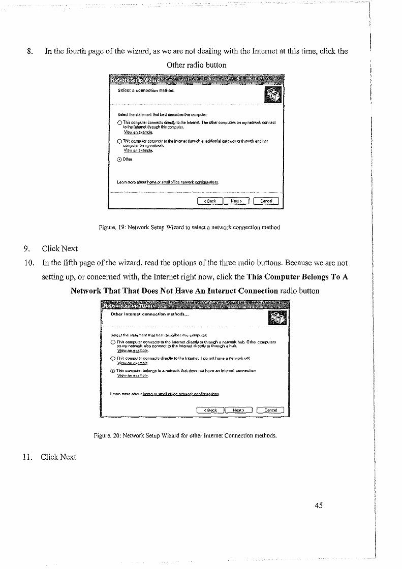
8. In the fourth page of the wizard, as we are not dealing with the Internet at this time, click the
9. Click Next
Other radio button
Select the statement that best describes this computer:
O This computer connects direclly to the lntemet The other compute!~ on Ill)' network connect to the Internet Uvough this compute1. View an eJ.:ample.
0 This COOlpUter connects to the Internet through a residential gateway or lhroogh another compute! on my netWQfk. View .-:m e~amp!e.
00thel
Learn more about home or email office network confiauratirms.
<Back Next>
Figure. 19: Network Setup Wizard to select a network connection method
10. In the fifth page of the wizard, read the options of the three radio buttons. Because we are not
setting up, or concerned with, the Internet right now, click the This Computer Belongs To A
Network That That Does Not Have An Internet Connection radio button
I I. Click Next
Select the :t<'l\ement that best describe~ this computer:
0 Thi: computer connect: to the Internet directly 01 through a network hub. Othet ccmputer: on MJ.1 netwOfk .:~!so connect to the Internet directly or through a hub. Vjew on J%!!'Dmp!e.
(.") This computer oonnech1: direcUy to the Internet. I do not have a network yet Yinw an mwmp!e.
0 This computer belongs to .a network th;:,t doe$ not have .an lntetnet connection. Yi..,w .:m eK.:!mpJ,..
learn mme about hqme m ;mall pffjce Of!!wprk confjqw<ltjqn;.
< Back NeHt > I J Cancel
Figure. 20: Network Setup Wizard for other Internet Connection methods.
45
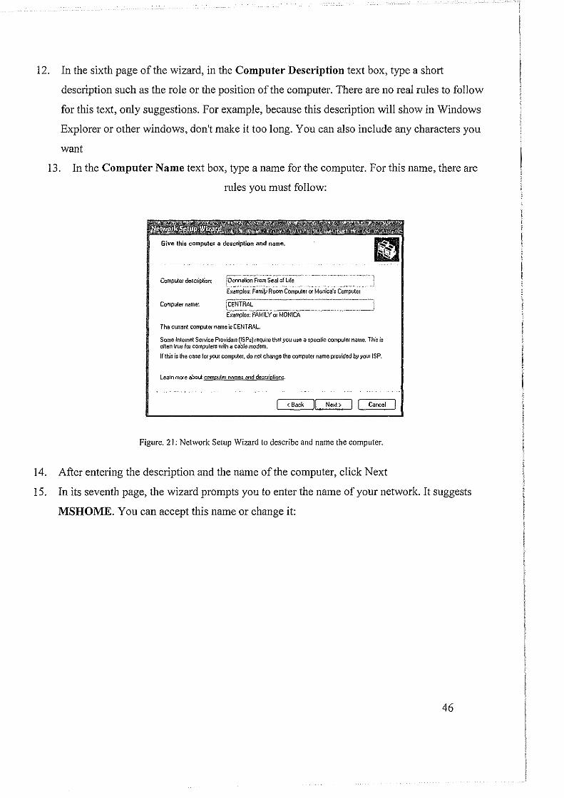
12. In the sixth page of the wizard, in the Computer Description text box, type a short
description such as the role or the position of the computer. There are no real rules to follow
for this text, only suggestions. For example, because this description will show in Windows
Explorer or other windows, don't make it too long. You can also include any characters you
want
13. In the Computer Name text box, type a name for the computer. For this name, there are
rules you must follow:
Computet desc;iption: !~~~~~~~!~~~:~~~~ ~.-~:~'"· "---·-· Examples: Family Room Computer or Monica's Computer
Computer name~ fCENffiAL---------·-------·~
E)(emptes: FAMilY or MONIC6.
The cunent complier name is CENTRAL.
Some Internet SerV!ce Providers (ISPs) require that .YOU use a specific computer name. This i$ often true fo1 computers with a cable modem.
If this is the case fDl' your computer, do not change the computer name provided by your ISP.
learn more about computer names and descrio!ions.
I < Back )[, Next> I / Cancel
Figure. 21: Network Setup Wizard to describe and name the computer.
14. After entering the description and the name of the computer, click Next
15. In its seventh page, the wizard prompts you to enter the name of your network. It suggests
MSHOME. You can accept this name or change it:
46

Name your ne{work by ;pedying a workgroup name below. All computer~ on yow network should have the same workgroup name.
Workgroup name: iFUNCTIONX L ~··-· -~ ·----·~. --Examples; HOME or OFFICE
< Back 1/ Next> J j Cancel
Figure. 22: Network Setup Wizard for naming the network.
16. After typing a name for the network (you can still change the name later), click Next
17. In the eighth page of the wizard, read the text:
, i ) Turning on lile and pnnter ;haling makes the Shared Documents folder avaUable to "V everyone on your nelWOik. It lll:o glve: everyone acces.: to a shared printm if one i$
available.
What do you want to do?
0 Twn on Jle and printer :hari-\g Windom Fuewa!l Wdl be configUred to allow J~e and printer sharing on your networl-...
0 Tum olllile and printer sharing Windows FirewaU will block flle and p!inter sharinQ on your netw01k. If you currently have ~hared filet 01 printers, they will no Ionge~ be m&ed
( < Back !( Ne~t > ! ( Cancel
Figure. 23: Network Setup Wizard for Resource sharing
For our project, accept the Turn On File And Printer Sharing radio button and click Next
47

18. In the ninth page of the wizard, read the text:
The wizard mJ apply the foiowing ~!ling;, This process may lake a few minutes to complete and e<~nnol be interrupled.
§~!!ing:; _____ _."' '''"''''' .-~~·~---i Internet cormection ;citing~
J Internet connection:
! Network sethng:;
Compu\ef de~criplion:
I Computer name: ,Workgroup name: L, __ .
To apply these :etlings, click Ne)({.
local Area Connection
Donnalion From Seal of L~e CENTRAL FUNCTJONX
Figure. 24: Network Setup Wizard to indicate whether the computer is ready to network settings.
Click Next
19. After clicking Next, the wizard will start creating the files used to setup a network, based
on your previous selections:
Please wait while the wi~ard configure; lhi$ computer/or home or smaU offiCe neliYOiking. This process lnll.Y take a few minute;.
Figure. 25: Network Setup Wizard for configuring the computer for home or small office networking.
When it has created the files, it would present a new page of the wizard.
In the tenth page of the wizard, read the text. Normally, you should create a setup disk:
48
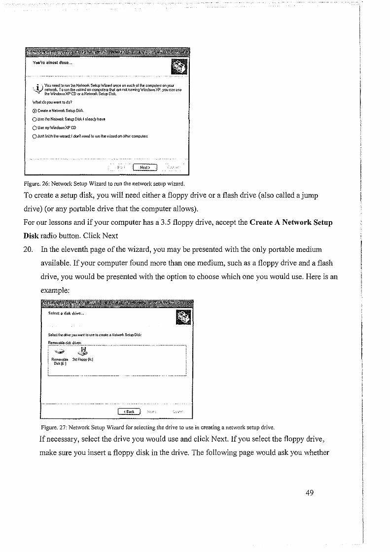
i ) You need to run the Network Setup Wizard once on each of the compute~s on your 'V netwwk. To run the wiuud on computers that are not running WindowsXP.you can use
the Window; XP CD Of a Network Setup Disk.
Whaldoyouwant to do?
0 Create a NeiWO!k Setup Disk
O Ure the Nehorork Setup Disk I alleady have
OU;e myW'mdow:XP CD
QJust flllhh the wizard; J donl need to run the wizard on othet computers
I Ne~t> J
Figure. 26: Network Setup Wizard to run the network setup wizard.
To create a setup disk, you will need either a floppy drive or a flash drive (also called a jump
drive) (or any potiable drive that the computer allows).
For our lessons and if your computer has a 3.5 floppy drive, accept the Create A Network Setup
Disk radio button. Click Next
20. In the eleventh page of the wizard, you may be presented with the only portable medium
available. If your computer found more than one medium, such as a floppy drive and a flash
drive, you would be presented with the option to choose which one you would use. Here is an
example:
Select the drlvcjiOU want to u:e to creille a Netw01k Selt.p Di~k:
Remov.Jb!e 31{ Floppy (A:) Dltk(E·J
Figure. 27: Network Setup Wizard for selecting the drive to use in creating a network setup drive.
If necessary, select the drive you would use and click Next. If you select the floppy drive,
make sure you insert a floppy disk in the drive. The following page would ask you whether
49
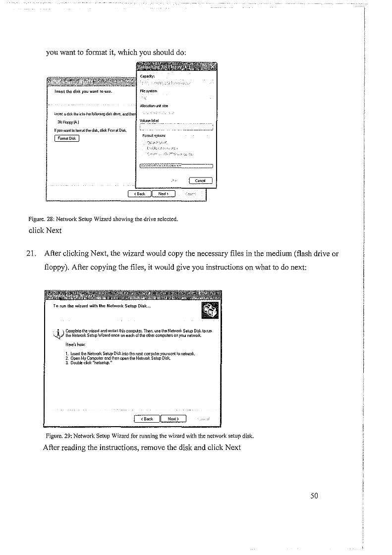
you want to format it, which you should do:
Intel! the did~ }IOU want to u:e.
!n~e1t a di~k the into the following di;k '"'"· ;md lh<1
311: Floppy (A:)
If you want to format the di~k. click F01m& Oi:k.
I Format Disk I
File system
Allocation IJ!1it size
Vo!umel*cl
ForiMt optoos
Figure. 28: Network Setup Wizard showing the drive selected.
click Next
Cancel
21. After clicking Next, the wizard would copy the necessary files in the medium (flash drive or
floppy). After copying the files, it would give you instructions on what to do next:
_ i ) Complete the wizard and restart !hi~ computet. Then, use lhe Network Setup Disk to run ~ the Network Setup Wizard once on each of the other computers on your net well< ..
He1e's how:
1. Insert the Network Setup Di$k into the neKt computer }'OU want to network. 2. Open MJ.i Computer and then open the Network Setup Di~k. 3. Double·ckk "netsetup."
j <Back Next>
Figure. 29: Network Setup Wizard for running the wizard with the network setup disk.
After reading the instructions, remove the disk and click Next
50
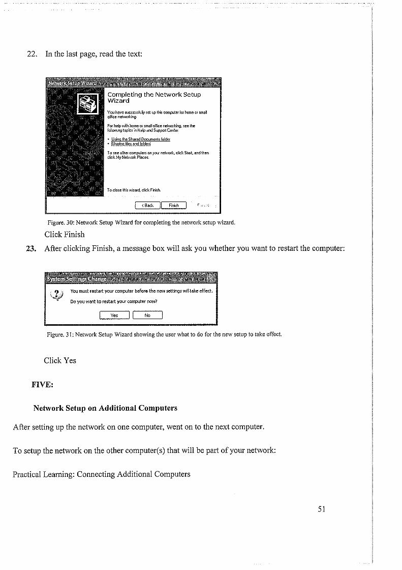
22. In the last page, read the text:
Completing the Network Setup Wizard
You have successlul!y ~et up this computer lm home or small olfice netw01king.
For help with home or small office netw01king. see the following topics in Help and Support Center:
• Usino the Shared Documents folder • t3J:t~~in!tm~.L~ruU.9!~~I~
To see other computers on your network. click Start and then cfick My Network Places.
To close this wizard, click Finish.
j < Back II Finish
Figure. 30: Network Setup Wizard for completing the network setup wizard.
Click Finish
23. After clicking Finish, a message box will ask you whether you want to restart the computer:
You must restart your computer before the new settings will tal'.e effect.
Do you want to restart your computer now?
Yes II No
Figure. 31: Network Setup Wizard showing the user what to do for the new setup to take effect.
Click Yes
FIVE:
Network Setup on Additional Computers
After setting up the network on one computer, went on to the next computer.
To setup the network on the other computer(s) that will be part of your network:
Practical Learning: Connecting Additional Computers
51
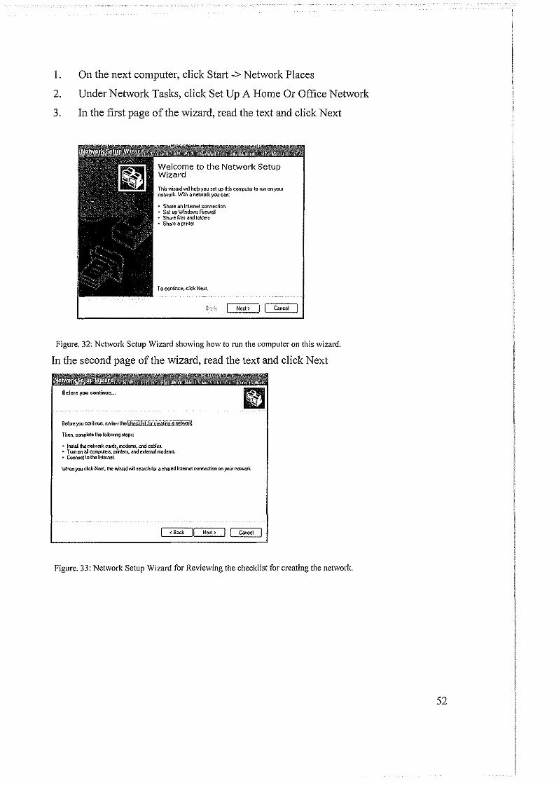
1. On the next computer, click Start ->Network Places
2. Under Network Tasks, click Set Up A Home Or Office Network
3. In the first page of the wizard, read the text and click Next
Welcome to the Network Setup Wizard
Thi; wizard will help you set up this compuler to run on your network. With a network you can:
• Share an Internet connechon • Set up Wind()W~ FilewaD • Sha!e file~ and /oldeu • Share a prltller
To conlinue, ctck Ne~l
il·r.~ Ne~t> ) I Cancel I
Figure. 32: Network Setup Wizard showing how to run the computer on this wizard.
In the second page of the wizard, read the text and click Next
Befoul you continue ...
Bel01e you conlinue. review the ~!IQ'l£te"i!iOO:~JY.tO!~
Then. COillflleiO the following step$:
• ln:tal the 1'\e\work card;,modom3, and cable:. • Turn on 6!1 cOI!liMen, printer: • .end exlemal modem;, • Connect to the hllemel
\>./hen you click NeKI, Uw wi~ad will $Calch f01 a :ffired hllemet connection on ~'CUI nelWOik
I <Back Next> ) I Cancel I
Figure. 33: Network Setup Wizard for Reviewing the checklist for creating the network.
52
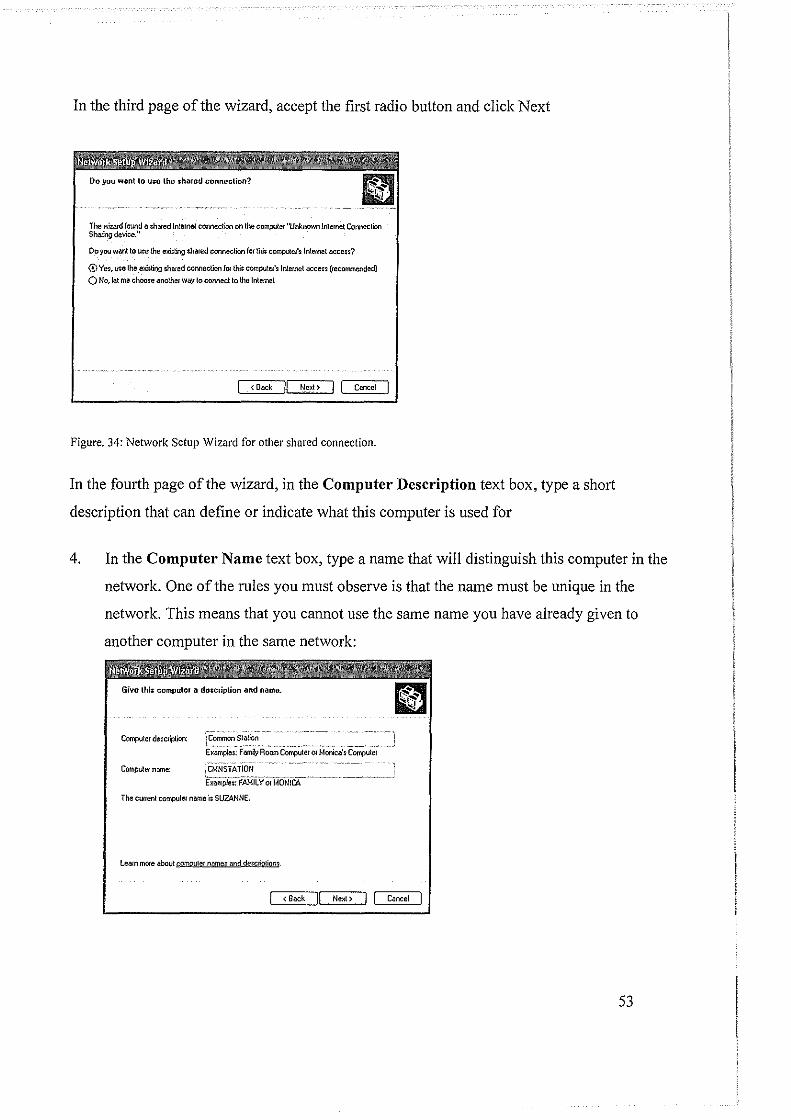
In the third page of the wizard, accept the first radio button and click Next
The wi:a~d found a :;Nred Internet connection on the coo.puter ''Unknown Internet Connection Sha~ing device."
Do you want to Ute the e!citling shared connection f01 thi$ compute!'slnternet acce;~?
0Yes, U$e the e!cisting sha~ed connection for thit computru's Internet accen (recorrvnendedl O No, Jet me choose another way to connect to lhe Internet
I < Back IJ Next> I Coocel I
Figure. 34: Network Setup Wizard for other shared connection.
In the fourth page of the wizard, in the Computer Description text box, type a short
description that can define or indicate what this computer is used for
4. In the Computer Name text box, type a name that will distinguish this computer in the
network. One of the rules you must observe is that the name must be unique in the
network. This means that you cannot use the same name you have already given to
another computer in the same network:
Computer descsiption: \C~~-:~~.~=-----~-~-~- -~ ----·~---~-~) E~: Fami,y Room Computer or Monica's Compuler
Computetname: iCt~NS.rAiiON ; ~::-FAM'ii.Y(;MoNi~----- .. ----~·-'
The current computer name is SUZANNE.
lea~n more about cgmputer name:: and descriotion-j.
I < Back I! Next> ! Cancel I
53
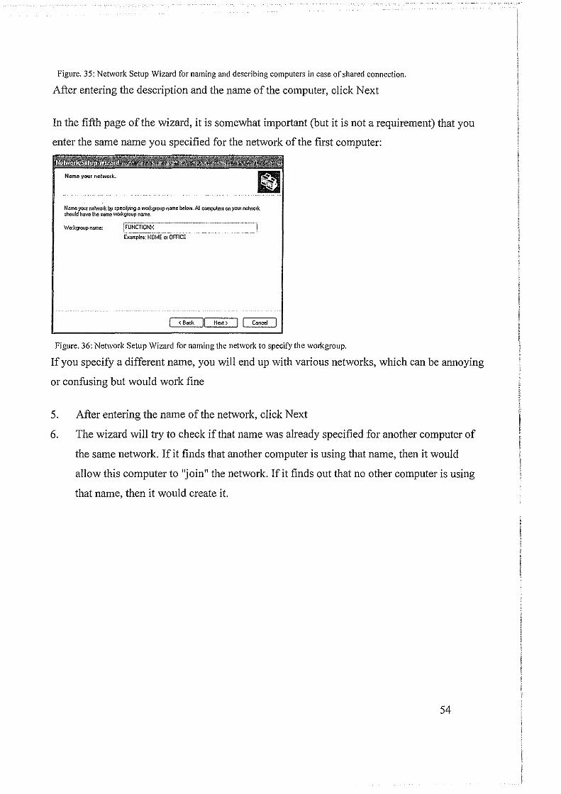
Figure. 35: Network Setup Wizard for naming and describing computers in case of shared connection.
After entering the description and the name of the computer, click Next
In the fifth page of the wizard, it is somewhat important (but it is not a requirement) that you
enter the same name you specified for the network of the first computer:
Name yout network by specifjling a w01kgroup name below. All computer: on your neiWO!k ;hou!d have the ;arne workg~oup tlllme.
W01kgroup name; jFuNcnciNX~~-~----~--~--------···-~···
E~a;;;j;J~:HOME·~-OFFt·cr-- --- - .. ·~·-
! <Back Jl NeMt> I I Wncel I
Figure. 36: Network Setup Wizard for naming the network to specify the workgroup.
If you specify a different name, you will end up with various networks, which can be annoying
or confusing but would work fine
5. After entering the name of the network, click Next
6. The wizard will try to check if that name was already specified for another computer of
the same network. If it finds that another computer is using that name, then it would
allow this computer to "join" the network. If it finds out that no other computer is using
that name, then it would create it.
54
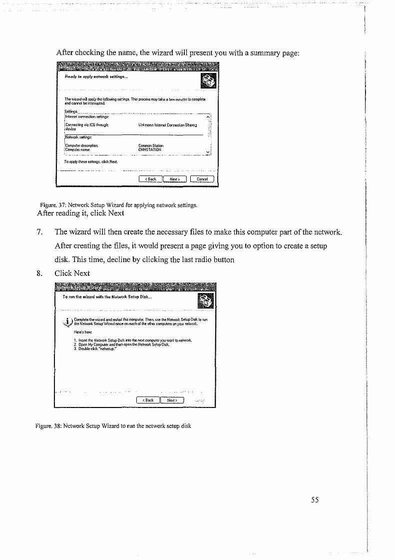
After checking the name, the wizard will present you with a summary page:
The Wizard will apply the following setting:. Thi: proce;: rna}' take a few minute~ to c~te and coonol be interrupted
?.e_tt~:;._ _____ ~~- ---------· ·- --1 lntemet connection $Citing::
l Coonecting via ICS through: !device
i Neli'/Oik setting~
i Compute!' de~cription: ! Compvter name:
To apply the:e :etting:, click Nexl
Unknown Jntemet Connection Sharing
Common Station CMNSTAT!ON
I <Back Ne~t > I J Cancel
Figure. 37: Network Setup Wizard for applying network settings. After reading it, click Next
7. The wizard will then create the necessary files to make this computer pru.i of the network.
After creating the files, it would present a page giving you to option to create a setup
disk. This time, decline by clicking the last radio button
8. Click Next
To run the wizard with the Netwmk Setup Disk ...
_ j ·) Complete the wiz~d and re:ta~t \hi: cotqlU!er. Then. use the Netw01k Setup Disk to run \'V the Network SetupWizrud once on eoch o/ the olhet computer: on}'OUI" ne\WOik
Here's how:
1. Insert the Network Set({! Or~k nto the next computer yoo want to nelWOJk.. 2. Open My Computer and then open the Netw01k Setup Oidt 3. Double-click ''nehetup."
I <Back Jl Next> I
Figure. 38: Network Setup Wizard to run the network setup disk
55
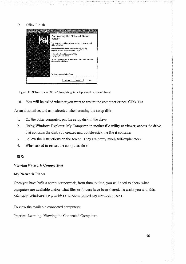
9. Click Finish
You h.lve ~\ICeenfut}l set up this compute! for home or~ ol!icu neli'IOiking.
for help with home or :mal olfice l'lclWOiking. Sell the /oUowing topiCS in Help Md Suppo<t Cenler
• Woo the Shnu:d 00f;vm•nl: ff!ld<or • §h!lf.'!)qli!~t_¥)Q'_/~~
To see olf'let compuler; on your netWOik. click Sta<t. and Uwn diCk MyNeti'IOik Ploce;.
To close lh; Wll:llld. click Fi'll~h.
I <Bock II flllish
Figure. 39: Network Setup Wizard completing the setup wizard in case of shared
I 0. You will be asked whether you want to restart the computer or not. Click Yes
As an alternative, and as instructed when creating the setup disk:
I. On the other computer, put the setup disk in the drive
2. Using Windows Explorer, My Computer or another file utility or viewer, access the drive
that contains the disk you created and double-click the file it contains
3. Follow the instructions on the screen. They are pretty much self-explanatory
4. When asked to restart the computer, do so
SIX:
Viewing Network Connections
My Network Places
Once you have built a computer network, from time to time, you will need to check what
computers are available and/or what files or folders have been shared. To assist you with this,
Microsoft Windows XP provides a window named My Network Places.
To view the available connected computers:
Practical Learning: Viewing the Connected Computers
56
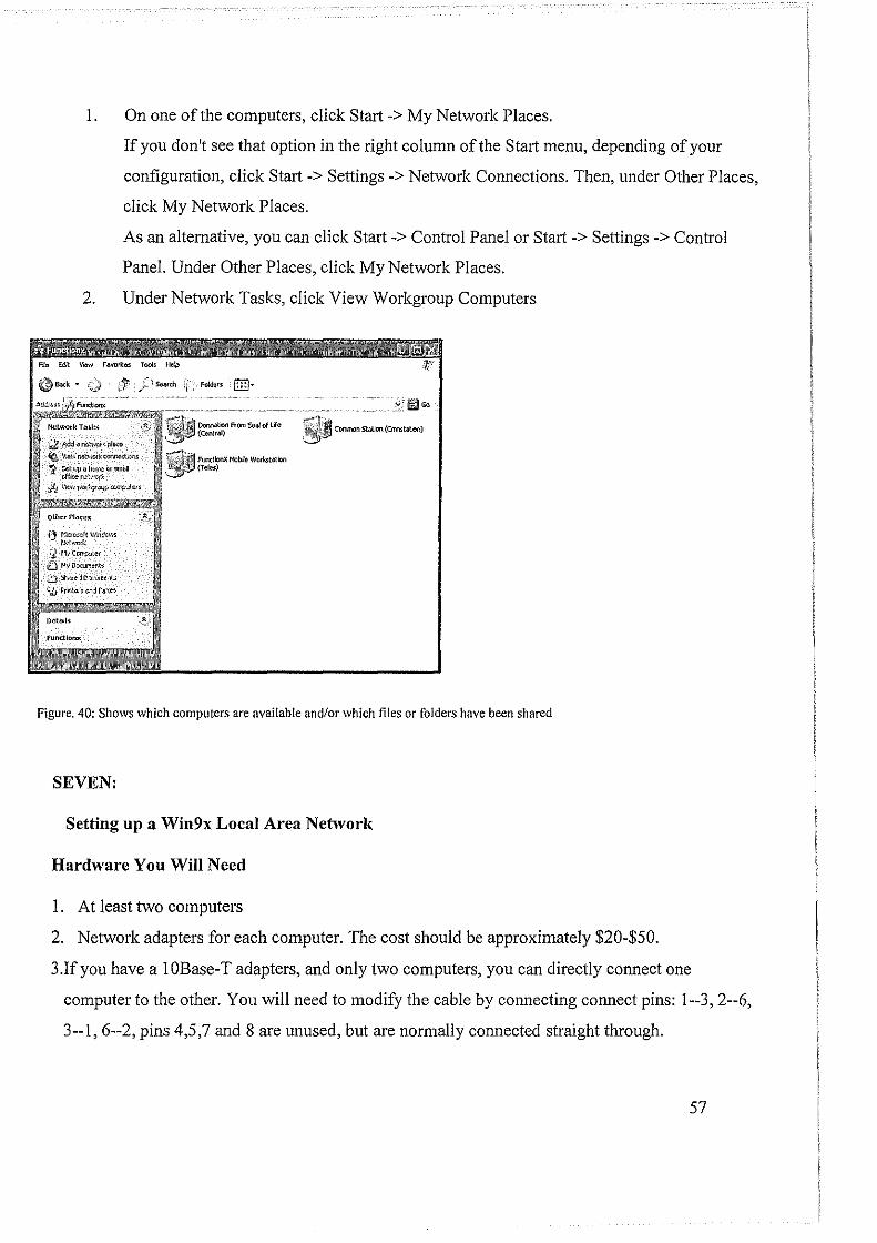
I. On one of the computers, click Start -> My Network Places.
If you don't see that option in the right column of the Stati menu, depending of your
configuration, click Stati -> Settings ->Network Connections. Then, under Other Places,
click My Network Places.
As an alternative, you can click Start-> Control Panel or Start -> Settings -> Control
Panel. Under Other Places, click My Network Places.
2. Under Network Tasks, click View Workgroup Computers
~ 1\ddiJ ~~pl~o
~\le\'<~cor.r.e.;l;lon;
~ ~opul>«<>eta,;,mJ rilkf1 v.t*"ft
i/1 ~kw•l~l~qoopwr;;..-<Jitr~
1:} ffiawr/t Wn:Wm !'><'hwrr,
,'3 111 CCITp.Jier
[) Mytlowmtl\t;
D sr..,~dJ}x~m'tl'l,h,
"Ji I'TO<\l!iHif'd F~~c;
,~2~Go
~ COIMlOfl statiOn {Orrntabon)
Figure. 40: Shows which computers are available and/or which files or folders have been shared
SEVEN:
Setting up a Win9x Local Area Network
Hardware You Will Need
I. At least two computers
2. Network adapters for each computer. The cost should be approximately $20-$50.
3.Ifyou have a IOBase-T adapters, and only two computers, you can directly connect one
computer to the other. You will need to modify the cable by connecting connect pins: 1--3,2--6,
3--1,6--2, pins 4,5,7 and 8 are unused, but are normally connected straight through.
57
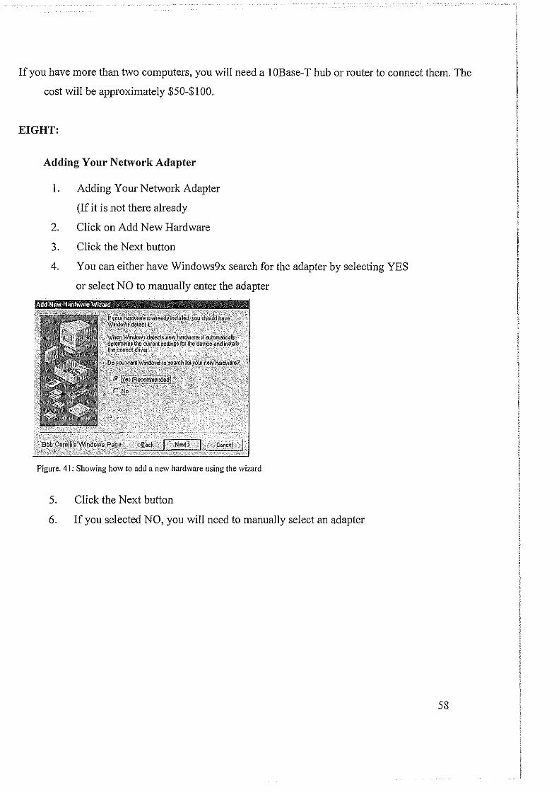
If you have more than two computers, you will need a I OBase-T hub or router to connect them. The
cost will be approximately $50-$100.
EIGHT:
Adding Your Network Adapter
I. Adding Your Network Adapter
(If it is not there already
2. Click on Add New Hardware
3. Click the Next button
4. You can either have Windows9x search for the adapter by selecting YES
or select NO to manually enter the adapter
Figure. 41: Showing how to add a new hardware using the wizard
5. Click the Next button
6. If you selected NO, you will need to manually select an adapter
58
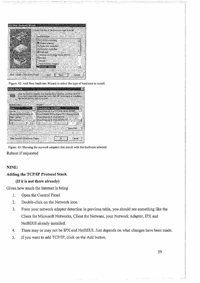
Figure. 42: Add New hardware Wizard to select the type of hardware to install.
Figure. 43: Showing the network adapters that match with the hardware selected.
Reboot if requested
NINE:
Adding the TCP/IP Protocol Stack
(If it is not there already)
Given how much the Internet is being
I. Open the Control Panel
2. Double-click on the Network icon
3. From your network adapter detection in previous table, you should see something like the
Client for Microsoft Networks, Client for Netware, your Network Adapter, IPX and
NetBEUI already installed.
4. There may or may not be IPX and NetBEUI. Just depends on what changes have been made.
5. If you want to add TCP/IP, click on the Add button.
59

6. Click on Protocol
7. Click on Microsoft
8. Click on TCPIIP
9. Then delete IPX and NetBEUI
10. Other than the adapter(s), it should look pretty much like the following screenshot.
Figure. 43: Adding the TCP/IP Protocol Stack
TEN:
Configuring the TCP/IP Protocol
IP Address
o Click on TCP/IP
o Select IP Address:
o If you have a DHCP serviced subnet, select Obtain an IP Address Automatically
If not, enter your IP address, Subnet Mask, DNS and Gateway IP address information.
60
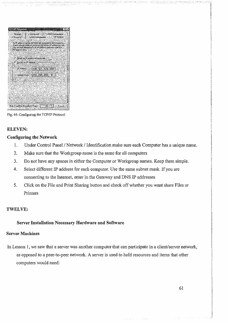
Fig. 44: Configuring the TCP/IP Protocol
ELEVEN:
Configuring the Network
1. Under Control Panel I Network I Identification make sure each Computer has a unique name.
2. Make sure that the Workgroup name is the same for all computers
3. Do not have any spaces in either the Computer or Workgroup names. Keep them simple.
4. Select different IP address for each computer. Use the same sub net mask. If you are
connecting to the Internet, enter in the Gateway and DNS IP addresses
5. Click on the File and Print Sharing button and check off whether you want share Files or
Printers
TWELVE:
Server Installation Necessary Hardware and Software
Server Machines
In Lesson 1, we saw that a server was another computer that can participate in a client/server network,
as opposed to a peer-to-peer network. A server is used to hold resources and items that other
computers would need:
61

Fax Computer
Fig. 45: Server Installation
A server is primarily a regular computer. For a small network, identify the computer that you will use
as the server. You can use an existing computer or purchase a new one. Before starting to acquire the
necessary hardware for your network, when planning a server, you may fit one or the following
descriptions:
• I will purchase a server from the Internet: If you haven't bought a server but are planning
to purchase a computer for it,.
o I already have the/a computer and it has an operating system: If you plan to use one of
your (existing) computers as the server, check its hardware and make sure it meets the
following requirements:
o A processor with 133-MHz or higher speed; 550-MHz recommended; up to eight processors
supported on one server
o 128MB of RAM minimum required; 256MB or more recommended; 32GB
maximum
o 1.25 to 2 GB of available hard disk space
o CD-ROM or DVD-ROM drive
o VGA or hardware that supports console redirection required; Super VGA supporting
800 x 600 or higher-resolution monitor recommended
If necessary, you can purchase additional items to meet these requirements.
• If you have a computer that doesn't have any operating system and you are
planning to use it as the server of your network, make sure it meets the
62
Monito1·
following requirements:
A processor with 133-MHz or higher speed; 550-MHz recommended; up to
eight processors supported on one server
• 128MB of RAM minimum required; 256MB or more recommended; 32GB
maximum
• 1.25 to 2 GB of available hard disk space
• CD-ROM or DVD-ROM drive
• VGA or hardware that supports console redirection required; Super VGA
supporting 800 x 600 or higher-resolution monitor recommended
You will also need a monitor attached to the server. If you will not work closely with the server, that
is, if you will not "watch" the server all day long, the type of monitor you connect to it may not
be imp01tant.
Server Operating System
As its name implies, the role of a server is to serve. To perform this job, it must be loaded with a
special operating system. On this site, we cover a network that deals with a Microsoft -based
network. The company publishes a server operating system named Microsoft Windows Server
2003.
Before acquiring the operating system, a brand new computer, to use as a server, can be
purchased from a manufacturer on the Internet.. When choosing the machine, make sure it meets
the following requirements:
• 133-MHz processor required; 550-MHz recommended; up to eight processors supp01ted on
one server
• 128MB of RAM minimum required; 256MB or more recommended; 32GB maximum
• 1.25 to 2 GB of available hard disk space
• CD-ROM or DVD-ROM drive
63
• VGA or hardware that supports console redirection required; Super VGA suppmiing 800
x 600 or higher-resolution monitor recommended
• Besides these requirements, if your budget permits, change or add the following items:
o Tape Backup and Tape Software: This can help to perform regular backup of files.
o Floppy Drive: This drive cannot be completely ruled out yet. Get it just in case (you
never know).
o DVD Drive: The web site or company may suggest a CD drive. In most cases this can be
enough. Still, tty to get a DVD drive instead of a simple CD drive
o Second Network Card: This can be valuable if you are building a small network and
plan to give access to your computers to the Internet. This second can help you with
Internet connection and security
o Extended WaJTanty: No matter what its price and what else, get it (even if you think
you will never need it).
Installations and Connections
New Installation
After acquiring a computer, you may have one that is ready but doesn't have an operating. You may
have a computer with an operating system but that OS cannot be upgraded into Microsoft Windows
Server 2003. In one of these cases, you would need to perform a new installation.
THIRTEEN:
Installing the Server Operating System
I. If the computer doesn't have an operating system but it meets all the requirements and it
can boot from the CD, stati the computer. You may receive a message stating operating
system missing or something like that. Open the CD drive, put the CD in the drive, and
close it. Restart the computer. You should receive a message stating Press Any Key To
Boot From CD (or something like that)
64
2. Press any key to start the installation.
If your computer already has an operating system, start it. Open the CD drive, put the CD
in it, and close its door. If the operating system cannot be upgraded, a message box and
display and let you know. Accept to perform a new installation and click Next
3. When the installation struis, it will display a blue screen with Windows Setup on top and
some messages on the status bar (bottom of screen).
After a while, the screen will change and display a new title based on the version of
operating system you are installing. For exrunple, if you are installing Microsoft
Windows Server 2003 Enterprise Edition, the title would display
Windows Server 2003, Enterprise Edition Setup
The body of the screen will present options to you. To continue the installation, press
Enter
4. The next screen will show the Windows Licensing Agreement. Read it. Since it is long,
to navigate up and down, you can press Page Up or Page Down. After reading it, if you
accept the terms of the license, press FS. If you don't like what it says, press ESC and
stop the installation.
5. The next screen asks you to select the pmiition you want to use to install the operating
system
• If you have only one partition and it looks small, such as less than 8 GB, simply select it
• If you have only one pmiition and that, regardless of its size, you want to use it wholly to
install the OS, select it
• If you have only one partition but it is Iru·ge and you want to create various partitions,
first make sure it is selected it. Then, press C to partition it. The next screen would ask
how much space you want to use for the new partition. By default, it will propose the
total space for it. To reduce it, first press Backspace a few times to delete the numbers,
then type the desired number of megabytes, and press Enter. Press the down arrow key to
select the Unpartitioned Space option and press C. Continue in the srune way until you
have created the desired partitions
If you have many partitions already, to specify which one will be used to hold the operating system,
65

use the up and down anow keys to select it
6. After selecting the partition you will use, press Enter to install the OS in it
7. The next screen will ask you to format the selected partition and specify the type of file
system you want to use. Select the Format The Partition Using The NTFS File System
option and press Enter
8. In the next screen, the partition will get formatted. This may take a few minutes.
Once the formatting is over, the installation will continue by copying files.
After a while, a wizard, titled Windows Setup, will come up. Its first page presents you
with two options.
The first choice consists of changing the Regional and Language Options. The default
options will be selected depending on your version of the CD. For example, if you bought
the OS intended for a US use, the US English would be selected. If you want to change
the language, click the Customize button. Another dialog box, titled Regional and
Language Options, would come up with English (United States) selected. You can then
click the arrow of its combo box to change the language. After making your selection,
you can click OK. If you don't intend to change anything, you can click Cancel.
The second option consists of making changes to the way the keyboard will interpret text.
Once again, if you are installing the OS intended for a US audience, the US English is
selected by default. If you want to change it, click Details. This would open the Text
Services and Input Languages dialog box. You can change the language by clicking the
arrow of the combo box. After making the change, you can click OK. To ignore any
change, you can click Cancel or press Esc.
After dealing with the Windows Setup dialog box, click Next
9. The next screen requests that you enter your name or the name of the primary person who
will be using the computer. You must type a name other than Administrator or Guest
10. The other text box, Organization, expects the name of the company. Make sure that you
provide this information
II. After entering the name and the organization, click Next or press Enter
12. The next page of the wizard requests the Product Key, which you must enter
13. After typing the product key, click Next
66

14. The next page of the wizard shows the options available for licensing. You should accept
the Per Server option and click Next
15. The next page of the wizard, expects you to type the computer name. It also suggests a
default, based on the company name you would have entered previously as the
Organization. You can accept the suggested name, which you can still change later on, or
you can type a new name
16. We haven't mentioned "user accounts" yet but during installation, a user object is created
and it is named Administrator. When setting up the operating system, you must give a
password to this account. Obviously the password should not be too easy. Fortunately
you can give it temporary password and change it later on as your network, skills, and
concerned improve. You must enter the password in the Administrator Password text box
and type it again in the Confirm Password text box. Make sure you remember this
password because you will need it just after the installation
17. After specifying the password, click Next
18. The next page of the wizard allows you to set the date, the time, and the time zone that
the server will use. Most of the time, the computer finds out the right date and the right
time and it selects them. On the other hand, you should adjust the time zone if the default
is not the right one. This page of the wizard also allows you the let the computer adjust its
clock when daylight time is switched during the year. The option to change this is
selected by default. If you don't want the computer to take care of that, you can remove
the check mark on the check box.
After changing the options or making sure that they are right, click Next
19. After clicking next, the wizard is closed and the installation continues copying files.
After a few minutes, a new wizard, titled Windows Setup, comes up. This time, it will
ask you to accept or change the network settings of the server. The first option allows you
to let the installation take care of networking details. The second option allows you to
manually set them.
Because we will review the details of this wizard in later lessons, accept the Typical
Settings option and click Next
20. The next page of the wizard allows you to actually make this computer into a server.
Accept the first option not to "join" a domain.
67
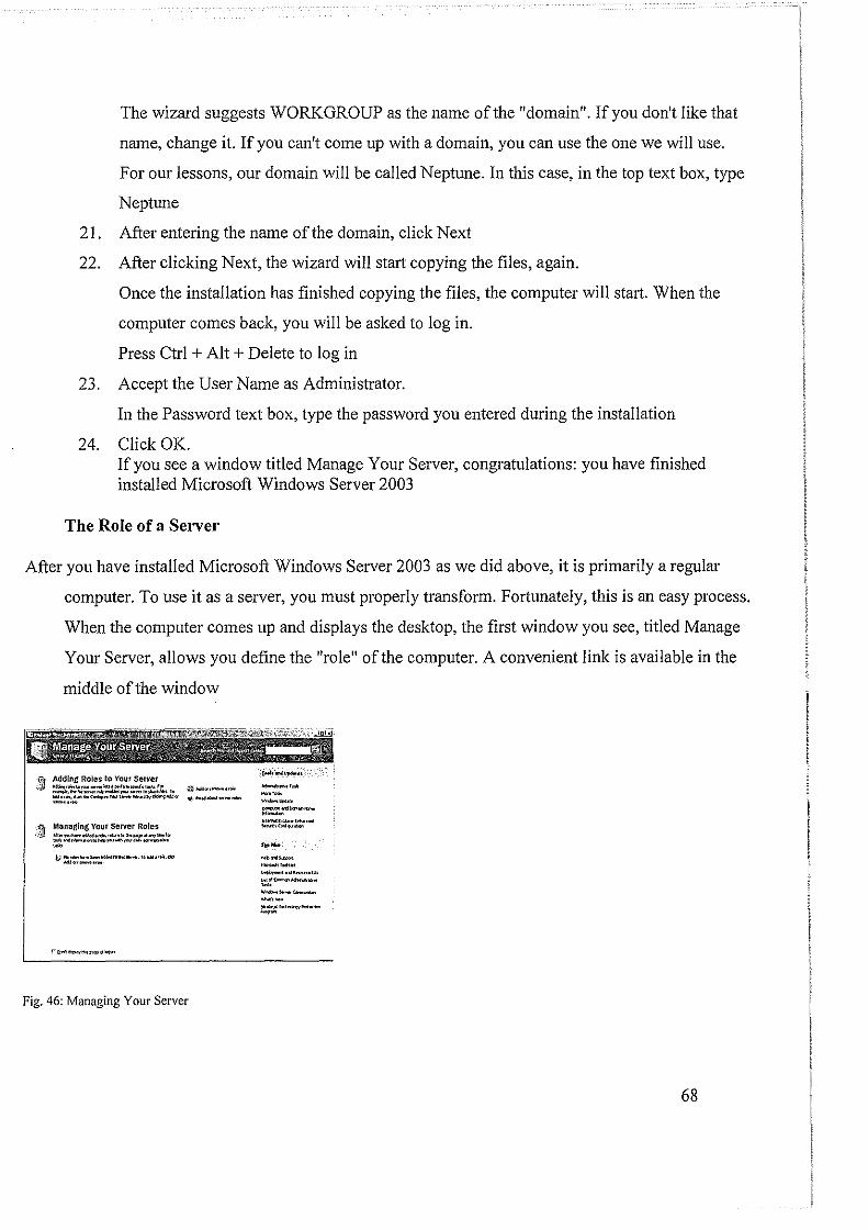
The wizard suggests WORKGROUP as the name of the "domain". If you don't like that
name, change it. If you can't come up with a domain, you can use the one we will use.
For our lessons, our domain will be called Neptune. In this case, in the top text box, type
Neptune
21. After entering the name of the domain, click Next
22. After clicking Next, the wizard will start copying the files, again.
Once the installation has finished copying the files, the computer will stmt. When the
computer comes back, you will be asked to log in.
Press Ctrl + Alt + Delete to log in
23. Accept the User Name as Administrator.
In the Password text box, type the password you entered during the installation
24. Click OK. If you see a window titled Manage Your Server, congratulations: you have finished installed Microsoft Windows Server 2003
The Role of a Server
After you have installed Microsoft Windows Server 2003 as we did above, it is primarily a regulm·
computer. To use it as a server, you must properly transform. Fortunately, this is an easy process.
When the computer comes up and displays the desktop, the first window you see, titled Manage
Your Server, allows you define the "role" of the computer. A convenient link is available in the
middle of the window
~ Man11ging Your Server Roles __ ,j! oil .. ,.., .... ....., ............... ._ .. ..., ..... .. ...,w,.,......., .. "'b,...-.,...;.., __ , .•.
u ... - ..... ....,...., ..... ,_, ... , .... -Ml"' ...... '""
,....!'>'>,_ ..... ., ........
Fig. 46: Managing Your Server
__ , .... """""' --· ,_...,. __ ·-, ...... ,_ .. ,_ -·<"'"'""" _ ......... ,. .... \::;;'< __ _
--~ -·-,.. .. ..,.,.......,.,. .... """" ··-
68
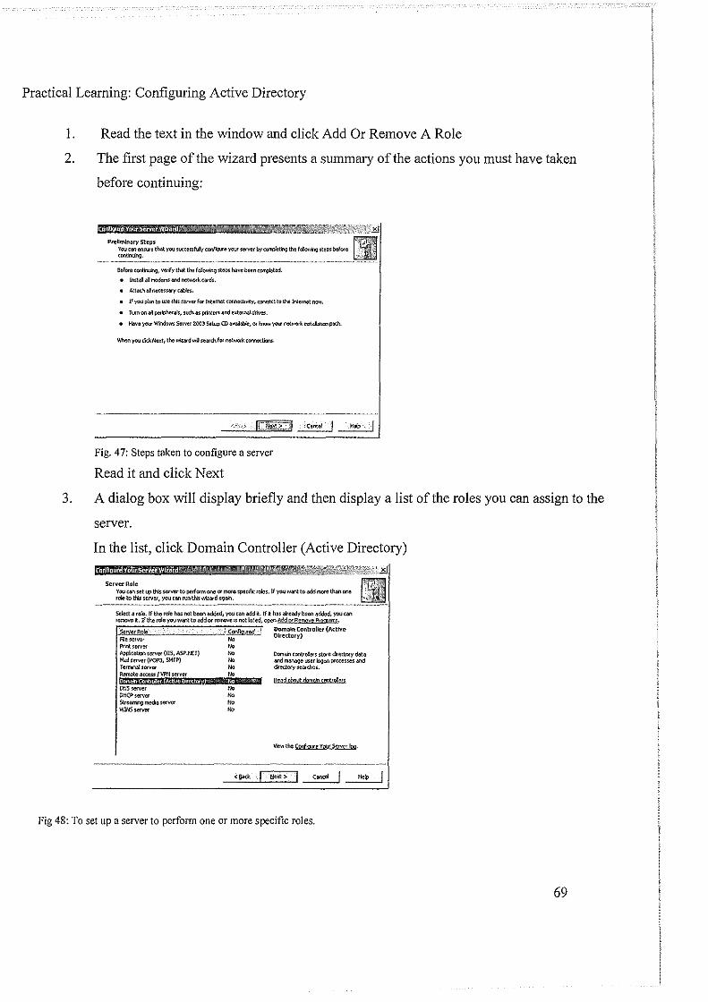
Practical Learning: Configuring Active Directory
!. Read the text in the window and click Add Or Remove A Role
2. The first page of the wizard presents a summary of the actions you must have taken
before continuing:
Preliminary steps You cao cnrure that you ~IICceufu!y ccrilO\lro:t Y<l"' se!'WII' by co~lr>!J the f~ stePs Wore CO/\t~.
neforo tontnuin<;l, ves-'fy that the fQIQwinc;l ~ej)S h<ave been c~tod.
llut41 a! rTIC®ms Md netWO<kca<els.
Att.W. eJ ncccsS6<)' c~ble$c.
If you pt..., to usc INs server fa Internet cor.n«bvity, CQN1el:t to the Internet MW.
T,_.n on all pe~lphe<~!s, sucll as printers and external drive$.
Hllv~ yoo.r W'r'ldom S<!<nt Z003 Setup CD a~M~, or fn<>w Y<)<a' oe\WO<k M~..ucn p$.
Fig. 47: Steps taken to configure a server
Read it and click Next
3. A dialog box will display briefly and then display a list of the roles you can assign to the
server.
In the list, click Domain Controller (Active Directory)
Server Role Vou can set l.4> this server to puform ono or more spccifo:: roles. If yoo w.v\1: to~ more than one role to this sCNer, you can runtht!; wizard aQ~~<n.
Seloct a ro!e.lf the role h3s not been added, youcan4dd it. If It h!ls ~~cady been added, yooCilll remove it. If the role you want ta add or remove !!: not bs\ed, ~"' Al1d pr Rt,'TJ<WQ Pr!XI(MM,
File server f>llntsorver Ap¢c.ili:)n Sef\/Cf (115, ASnJ::T) Mall server (POPJ, SMTP) Termiml!sorver Remote 4o:CI!!ss f Y?N server !!JIW4NII$tltif.!StMJl.lii!g® Dt/5server OHCPserver StrcMI'in9 rnedil 1om:r WINSsefver
lc~cd
,. '" "' "'
Domain C<mtroller (Active Directory)
DomiOn cQOtr~ers stO<e directory 00!:~ lll'ld ~user boon P<<Xesses lll'ld dfectory ~ear~.
Fig 48: To set up a server to perform one or more specific roles.
69

4. Click Next
Summlry of selection• \1\ew Md" !orlitm tho ~you have oelotto>d.
Fig 49: Summery of Selections
5. Click Next to Run The Active Directory Installation Wizard
6. Another wizard, titled Active Directory Installation Wizard, comes up. Read its text and
click Next
Welcome to the Active Directory Installation Wizard
Till: w.wd help; you imt41Aclive Olcclor~ !elw;e~ on lhi$ ~eiVw. mllkina the ;etver a dom401 cootro!et
If tit; i; the fntlime )'OU have imta!ed Aclive Oirecl01y. ~ i; r!X:OOllllended thai )'OU rrsl reed the ovlltl'lel'l in8cJw ~
Fig 50: The Active Directory Installation Wizard
70
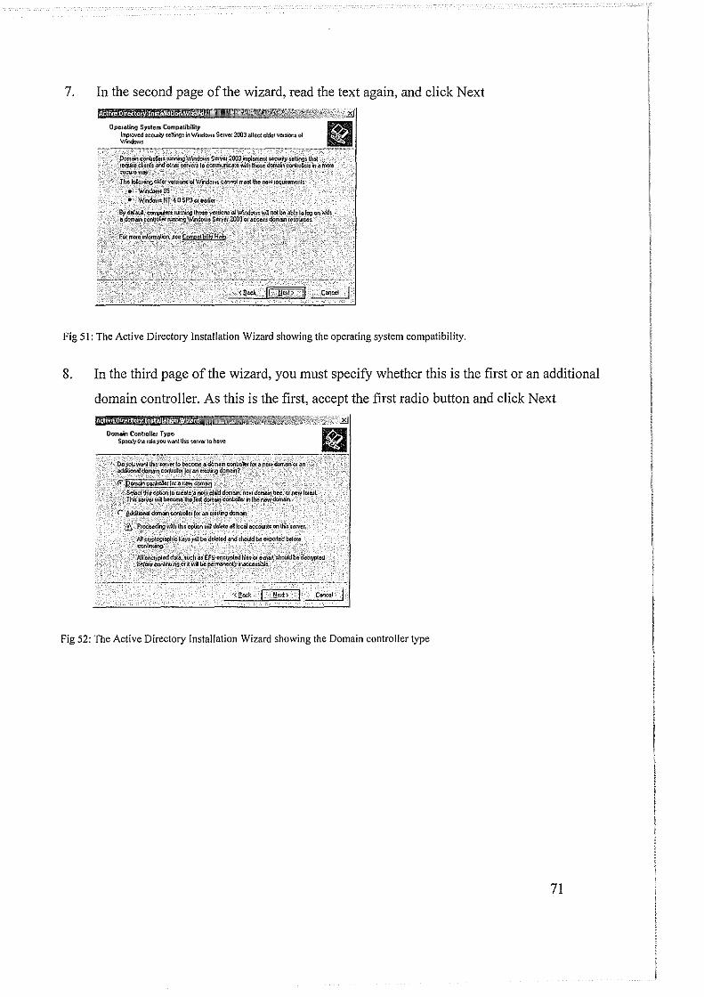
7. In the second page of the wizard, read the text again, and click Next
. ' , ! I i
Ope/cling System Compatibility lmp~oved secu~y ;elbngs in Wndow: Servet 2003 <)(led olde1 vetsion< of Wondow,.
Ooml~Ul cofiJale:: 1urr.ing \<fmOOVI: SCIVW 200Jinplcmer.t $¢¢\111}1 ~t'lting~ ~ teqke deoo .md oUiel ;e!'ler: to c0fl1lllt.ric~ IWh thote c!orn.m coriiukr; II'! II niole :ecue.way, TIJC I~ ok!et ver:lom cfWII"odoMc c4!)n01 n=t lrno flllW lequilcmenh'
•. W.ndoW:SS • Wrndaw:NT 4.0SP3orea.!iel
B;l del~· eomputer:,rumiog time VC!'cion: olWornhw:. ~ not be abJe to lo!:l.cn l'#h 11 ~ conttoller ~ Wndowt Seryet 2003 01 .IC(;II:f domain rcscu:cc:.
f~ !OO!Ciriorrria~~-:~.~-iblit_sikffi
Fig 51: The Active Directory Installation Wizard showing the operating system compatibility.
8. In the third page of the wizard, you must specify whether this is the first or an additional
domain controller. As this is the first, accept the first radio button and click Next
Domain Conlro!ICI Type Spec~y the role you wMllhi: ;erve~ to have.
·r ed&tiO~af~cOotrOia~f••"'''"'··""'""' lt/ i10ce0cring \11Th tM oPtion wa delete a~ md ooCount= oo tl'f: ~.
Alf Clyp!O!ll,cp!Jic key: WIJ bll dclelcd 4nd ;hou!d be expol!ed bef01c coo!irniog.
j.jj e~cd ®t~"Wcl1a: EFS•eoczypted filet Cf ~ ::hWid ~a·lk<:f)'pled Mtorc rorlll"'l4v.. or il: wa be per~ Ncccul*, ' '
Fig 52: The Active Directory Installation Wizard showing the Domain controller type
71

9. In the fourth page of the wizard, accept the first radio button and click Next
Croato Now Oom;:~in Select which lype ol domilin lo Cleale
_(4~e-'an6v(
<0:-'bomcininanew:§,!.!]:-,·:-:_<,,.,:<->_ , ___ : , Sek<:lthl: op!ioil il U'li~ 1: _!he_ll1t domWI_inYOUI otgari:afuntlf ij yw ~r.l thd·nw~
dotrillln ~o be iomp!eteylridipendent of VO\¥ cunenl l01e:t
Fig 53: The Active Directory Installation Wizard for creating new domain.
In the fifth page, you must enter the name of the domain. The name should be followed by an
Internet domain name (.com, .net, .org, .us, etc). If you have a domain in mind, type it. If you
don't have a domain in mind, for our lessons, type netconsulting.com
New Domain Name Specify a name lor U1e new domain.
;T~ihe'fuiiDNS)lameloclhtirww·dOfflaln L[\_~-~~-,1:1~adq~3ll~r:~:~~amplo.m!cfosofl_com). ful DNs:name 101 new'dOmcin:
:: Jnetconsulling.com
Fig 54: The Active Directory Installation Wizard showing the full DNS name for new domain.
10. Click Next
In the next page of the wizard, a suggested NetBIOS name displays, intended for earlier
versions of Windows":
72
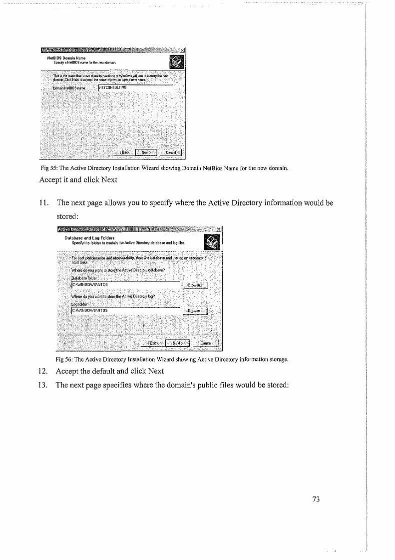
NclOIOS Domain Namo SpecJy a NetBIOS name for the new !loman
Q~NeiBIOSrtalllll: jNETCONSULTfNG
Fig 55: The Active Directory Installation Wizard showing Domain NetBios Name for the new domain.
Accept it and click Next
II. The next page allows you to specify where the Active Directory information would be
stored:
Databas-e and log Folden Spec~y the folders to contain the Active Dileclory database and log f~et.
for mnt peiiOr~e andie6o¥erdtl}l.1tore the datahaie _and the_IOg on :eparate· hrud dith, · ··
Where do you want to store the Active Dilectoty d~aba~e?
Qaiaba:e foldet
Jc:\WINOOWS\NTDS
\v'hme do you want to ~tore the Active D~ectory log?
.Leo Joldel: jc:\WINDOWS\NTDS
c..,~r I
Fig 56: The Active Directory Installation Wizard showing Active Directory information storage.
12. Accept the default and click Next
13. The next page specifies where the domain's public files would be stored:
73
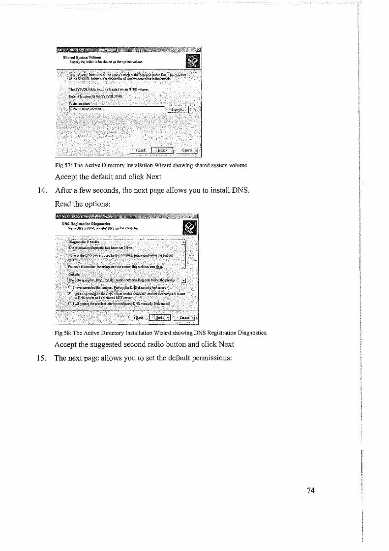
Shared Sy.tcm Volume Spec~;o the /older lc be ~hared a~ the ;yslem volume.
The SYSVOL fo!dol mwt be !oellled on M~NTFS WJ;'umc
Enter a~alion /01 thc-SYSVOLta!der.
fcldo!loc~ jc. \WINDOWS\SYSVOL
'"""' I Fig 57: The Active Directory Installation Wizard showing shared system volume
Accept the default and click Next
I 4. After a few seconds, the next page allows you to install DNS.
Read the options: i! '],;;.
DNS Rogi~tration Diagnostic: Verily ONS ~uppotl, 01 install DNS on lhi: compoJer.
i U tc:ta!lllh
lhi:COII'IpU!wlou:o
caoce1 I
Fig 58: The Active Directory Installation Wizard showing DNS Registration Diagnostics.
Accept the suggested second radio button and click Next
15. The next page allows you to set the default permissions:
74

Pemlinion: Select default permission~ for user and !Jiot!P objects.
'Some 's'cwer' 'piooram:, :uCh a; __ \ifr~d'iWf~ 'NT B~Ac~n' Sl!f';ice; Hi~-rl'Olmation' ;!orad oo domain coolloller;
r):~elfrlis$;00~_co_~ib!C with Pl,f:-Yf~s 2000 $eJ\>er oper.wng ~ems -: Scleci thJs oplion)t yourun SefYef PIOOfllmS on pte·W,,ows 2000 ~e!VCf oper/l!ioJ $114\Cfll$ or on_Wildow: 2000 01 WhdQW; Se~ve~ 2003 operalirg :ydenu IMl .a~e member .s-ol pte·Wmdows 2000 ~
& Aiwn:,omou: u~en can read idormalion on thi: domah
Co' ~;;:~COO.patitk ~ WXfi W!OdoWs 2001f0! Wandow: ScwCi 2003] at' J}!!llll!l~ · ·. · ' _j
seJect J!-il -~ II roo run ierver progHll!lS Ol1!;o ori WII1Ciow~ 2000 01 Wl!\dow; Setv~lr 2fl{}3 _qmoong sydem~ !hat rue !lll:!mbc!; of AcWe Dmtory domain;.' Only ~Wthenticatcid u:IU: can ,c,;d ~~ion on _UY: d:!fuah
<!!.ad:. C-' I
Fig 59: The Active Directory Installation Wizard showing permissions for user and group objects.
Accept the suggested second radio button and click Next
16. The next page prompts you to create a password used to start the server in "Restore
Mode". Enter a password in both text boxes:
Oiroclory Service: Ro:loro Modo Admini:lralor Pauword This password is used when you sllllllhe compute! !1'1 Oirec\O!J! Services Aest01e Mode.
T ypc _arid_confum tho pam\'()fd you want lo auignlo lhe Adr~Wlislralor accounl U$ed when lhl; truver 1$ $lat_tcd in Directory Services Restore Mode. The 11:stme modeAdminitlralm account is tfilferenl from the domainAdmOatratm account The pa11$Wotd; lm the accounh might be dilfcient, :o be :1.1e to tcmembor bo<h
RM!OIC MDdcfa:swO!d
ConfKrn pam'101d:
I········ I········
fo; more infwmMion about Directory Service$ Ae~toro Modo, :ceActive Dimclnry Hr:lp
C!II'ICc!
Fig 60: The Active Directory Installation Wizard to create a password used to start the server in 11Restore Mode11 ••
Click Next
17. The next page displays a summary of your selections:
75
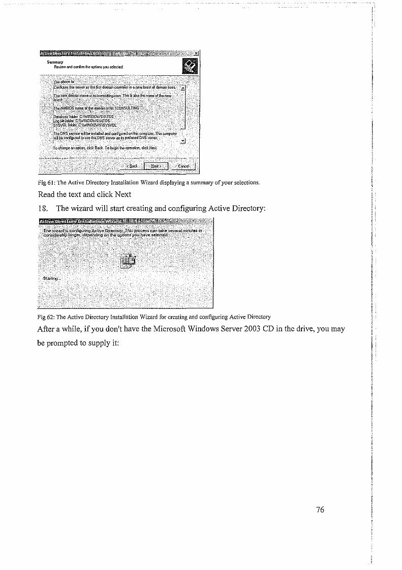
1l! · • A 1~ i '
Summary Review and coofum the option~ you sekcted
~,~!~~~w_,_,~,·---~~~~--··-~--•N-•~•---~~~~-
~;~'F=~~;~~.;:;:.:::·:;:::" . lrhe' Nei~!OS Mme. 01 the l:!o!Mln lt NETCONSUL TJNG 1-"·:·.:t;-_-.:·_·_-:< .. ::.--'>--;.:-.-:--: ·-· :-.' > -: jOataba:e folder C:\WINOOWS\NTDS J!:??.lileloldel: C;\WINOOWSIJHDS -~YSroL lokler._~:\W~_NQOWS\SYSVOL In~ ONS ~ewice wm be in~taled and conf~ed Oil thi: compuler:Thi: eompulet r be cori'Jgi.Ked !o U$e lhh: ONS servet a:~$ prelerred DNS ~eNer. ..:::J
To change ooop!lcn, click Back-To be!)i1 the opetatioo, cEck Nett.
Fig 61: The Active Directory Installation Wizard displaying a summary of your selections.
Read the text and click Next
18. The wizard will start creating and configuring Active Directory:
~'·i!l!l!l'!.lffl!l:·ll·ll!_'l!:#!!dt~:_i:!llHil_'ll __ Ml!! .. !l:· _!tn!Iifflfil·l!:iMtil!l· Z\IZ·IF!'l*!!d#ll·•ll•••••••n•~:ttx~r~z?>~4-l;-; The::wii_ard is C()IYigurfr:i9:~dive;[)lrect_o_r.Y;.:rJils p10Ce.Ss cantil~e-sever.!il minutes or cons[dera_bl.vlon9e:,·depe)1_ding_ Of1_ th.e_.optioM you have _;e!_ected,
Sti:utln~L.
l'lr~o ~·
Fig 62: The Active Directory Installation Wizard for creating and configuring Active Directory
After a while, if you don't have the Microsoft Windows Server 2003 CD in the drive, you may
be prompted to supply it:
76
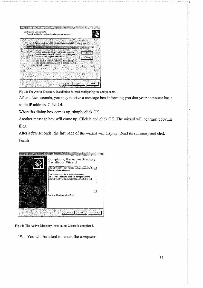
Configuring Componenb Setup i: making the conligur<tllon change: you requested
c...• I
Fig 63: The Active Directory Installation Wizard configuring the components.
After a few seconds, you may receive a message box informing you that your computer has a
static IP address. Click OK
When the dialog box comes up, simply click OK
Another message box will come up. Click it and click OK. The wizard will continue copying
files.
After a few seconds, the last page of the wizard will display. Read its summary and click
Finish
Completing the Active Directory Installation Wizat·d
~clive DirecTory i; now installed on thi; computer for the'::!] !domain netcomu!ling.corn
IT his domain controner is as;igned to the $ile iDefault·F~st·S~e·Name. S~es are managed with the r"" "'"'"' .. ., '"' '"""'"'"'"'""""tool.
I .:J To clo~e this wizard. cEck Finish.
Fllish
Fig 64: The Active Directory Installation Wizard is completed.
19. You will be asked to restart the computer:
77

!ijfuj!JH~j!§!ll·h2!Mi!J!§H!!!· l'l!ft!ll!!!!ffllll@:l!@!!l·" fmvi!Z@mi· •• ltZJiiizlii~fft -<~.1 ,· 'V/'u1d6:~~-m~::t b~--T-~at~r!e'd, bel Ole· ~he :Ch~r.ges made by the Ac~ve
Dire?lay ,Installation wizard take effect
Qon't Resta~t Now I
Fig 65: The Active Directory Installation Wizard for restarting the computer for the installation to take effect
If you have a CD in the CD drive, remove it and click Restart New
20. When the computer comes up, click the Options button and make sure that the name of
the domain is selected in the Log On To text box.
Make sure that Administrator is specified in the User Name text box.
Enter your administrator's password
21. Click OK
After the computer displays the desktop, a dialog box titled Configure Your Server will let you know
whether the installation of Active Directory was successful:
This Server is Now a Domain Controller
You hwe ruccMJfuly set ~ till:> S«Ver u 11 domain con\roler. To 6dd or remove lli\Other rola, nr1 the COI'ilQure Vl,lt$ :>etver Willlfd ~.
For 11 recOtd of YW' ch~s, see the Coof'9' 't YQ'Jr Servtr loo,
To OOso thiswilud, ckkFfflh.
Fig 66: Dialog box titled Configure Your Server showing successful installation of Active Directory.
Then Click Finish
FOURTEEN:
Software Installations- Workstation Operating Systems
Intt·oduction
When you are planning to use a computer as a workstation is a network, you should make sure that
computer meets the necessary requirements. In some cases, it may only meet the hardware
requirements without any software. In some cases, something could be missing
78
Acquiring Brand New Computers
The hardware requirements the computer must meet:
• A processor with 300 megahertz or higher processor clock speed recommended; 233
MHz minimum required (single or dual processor system); Intel Pentium/Celeron family,
or AMD K6/Athlon/Duron family, or compatible processor recommended
• 128 megabytes (MB) of RAM or higher recommended (64MB minimum supported; may
limit performance and some features)
• 1.5 gigabytes (GB) of available hard disk space
• Super VGA (800 x 600) or higher-resolution video adapter and monitor
• CD-ROM or DVD drive
• Keyboard
New Installation
A new installation of a operating system is suitable if:
• You have a new computer with no operating system at all
• You have a computer with an operating system but you want to overwrite, that is, you
want to install a new operating system on top of the old one and you don't mind loosing
(since you will loose, with a new installation) whatever files already exist in the computer
• You have a computer with an operating system but Microsoft Windows XP Professional
doesn't support an upgrade from that existing operating system
FIFTEEN:
Performing a New Installation of Windows XP
To perform a new installation:
1. Turn the computer on.
If you receive a message stating, "Diskette drive 0 seek failure", open the computer and
make sure the power cable that connects the floppy drive is connected.
79

In case you are using a computer without an operating system, and you receive a message
stating "Missing Operating System", or "Strike Fl to retry boot, F2 for setup utility", don't
worry about it at this time
2. Put the Microsoft Windows XP Professional CD in the CD drive and restart the computer
(you can press Ctrl + Alt + Delete to restatt)
o After a while, as soon as the computer statts, a message will notify you that the computer
will boot from the CD and install the operating system (the message may display "Press
any key to boot fi·om CD").
If a message of installing the operating system doesn't come up, you should restart the
computer. Then, as soon as the black screen of the computer restarting appears, press a key
such as F2 or F8 to access the BIOS. Access the Boot Sequence and check the list. If the
CD (or DVD) drive is not on top and if the instructions allow it, move the CD (or DVD)
drive to the top of the sequence. If you cannot move the CD (or DVD) drive to the top, then
disable the drives, such as floppy or hard drive, that come above it. In some cases, you can
select the drive and press the Space bar to remove the check mark from the selected item.
In this case, make sure that only the CD (or DVD) drive has a check mark next to it. After
making changes in the BIOS to make the computer boot from the CD drive, save and exit
the BIOS. Then restart the computer and follow the instructions on the screen to install the
operating system.
o If a message of installation still doesn't come up, make sure the CD drive is installed
appropriately. You could try to find out from somebody to get the Microsoft Windows 98
boot disk (it is a floppy disk that would first install the (driver for the) CD drive). (If you
have access to the Internet, you can also check the following site:
http://www.bootdisk.com/ for a boot disk). Put that disk in the floppy drive and restatt the
computer. After a while, a list of options will come up and ask you whether you want to
start the computer with or without the CD drive. Select the option that states "without" the
CD. After the CD drive has been installed, make sure you remember the drive letter
assigned to it. Switch to that drive by typing it followed by and press Enter. Then, at the
prompt, type setup.exe and press Enter. For example, if the CD drive is D, after typing D:
and pressing Enter, type D:\setup.exe and press Enter
80

*If the computer still doesn't boot from the CD and if you have access to the Internet, check
the following miicle from Microsoft: http://support.microsoft.com/?kbid=31 0994
As stated above, when the installation stmis, you may see a "Boot From CD" message. In
this case, press Enter.
After a while, you should see a blue screen titled Windows XP Professional Setup and
Welcome to Setup, To Set Up Windows XP Now, Press Enter. To continue, press Enter
3. The next screen will present to you the License Agreement. Read it. If you don't agree with
it, press Esc and stop the installation.
If you agree with the license agreement, press F8 (or the appropriate key)
4. The next screen asks you to select the pmiition you want to use to install the operating
system:
o If you have only one pmiition and it looks small, such as less than 5 GB, simply select it
o If you have only one partition and that, regardless of its size, you want to use it wholly to
install the OS, select it
o If you have only one partition but it is large and you want to create various pmiitions,
first make sure it is selected. Then, press C to partition it. The next screen would ask how
much space you want to use for the new pmiition. By default, it will propose the total
space for it. To reduce it, first press Backspace a few times to delete the numbers, then
type the desired number of megabytes, and press Enter. Press the down anow key to
select the Unpartitioned Space option and press C. Continue the smne way until you
have created the desired pmiitions.
A small pmiition of 8MB will be created by Windows. Don't touch and don't delete it
If you have many partitions already, to specify which one will be used to hold the operating
system, use the up and down anow keys to select it
5. After selecting the pmiition you will use, press Enter to install the OS in it
6. The next screen will ask you to format the selected pmiition and specify the type of file
system you want to use. Select the Format The Partition Using The NTFS File System
option and press Enter
81

7. In the next screen, the installation will start formatting the partition. This may take a few
minutes.
Once the formatting is over, the installation will sta1t loading files. This may take a few
minutes
A wizard, titled Windows XP Professional Setup, will come up. Its first page presents you
with two options.
The first choice consists of changing the Regional and Language Options. If you click
Customize, the Regional and Language Setup Options dialog box will come up:
lll®!!!·lllNi!!IMII!ml!!l·D•+m·''im'!ac®rm·!illl.ttJm· i1iJl!.l.!!l' •III•••·~~Jtt~ft, L.1J~ R~W:~~::'I'~~~-~e$Y~v~~df --· rstandards'andfor~ ' ' ' _: __ ·_·,' ' '' I: )his 'oi)ti~ at'i~_S ~_sOme PrOQi~~s fomiaf,ntrmb~rs, coo~-~ '1:::~~-s~---~--~~:< ,·, ,, ----·.•.~-ct:~ Jte.m to match 'its:'!iefOrenec's~ or' dick: ~u~omli:e tO 'choosC
your own' format~: i I !tlifllfflj@ij@ :::::J cwtomqc,, I ) ' . I s,.;., i ~erJ jt2"3,-l56,769,00
Currency: J $123,456,769,00 1
Time: Jt:55:56 PM j Short"'"'' l-;Jt"'OI30;;:,/::;:20;:-;01_..:.---,----,...--
11
,.
L~ ~-e: , _- J Sattiday,-_October,30, 2004 ... .
'''"'"'. Io help servkes provide you with local information, such as news and weather, seled your present location: ,
jUnil:ed States iJ
.
..
.
I OK Cancel
Fig. 67 Regional and Language Setup Options dialog box
8. The default options will be selected depending on your version of the CD. For example, if
you bought the OS intended for a US use, the US English would be selected. If you want to
change the language, click the Customize button. Another dialog box, titled Regional and
Language Options, would come up with English (United States) selected. You can then
click the anow of its combo box to change the language. After making your selection, you
can click OK. If you don't intend to change anything, you can click Cancel.
The bottom option consists of making changes to the way the keyboard will interpret text.
Once again, if you are installing the OS intended for a US audience, the US English is
selected by default. If you want to change it, click Details. This would open the Text
82

Services and Input Languages dialog box. You can change the language by clicking the
!UTOW of the combo box. After making the change, you can click OK. To ignore any
change, you can click Cancel or press Esc.
After dealing with the Windows Setup dialog box, click Next
9. The next screen requests that you enter your name or the name of the primary person who
will be using the computer. You must type a name other than Administrator or Guest
10. The other text box, Organization, expects the name of the company. Make sure that you
provide this information
11. After entering the name and the organization, click Next or press Enter
12. The next page of the wizard requests the Product Key, which you must enter
13. After typing the product key, click Next
14. The next page of the wizard, expects you to type the computer name. It also suggests a
default based on the organization you entered. You can accept the suggested name, which
you can still change later on, or you can type a new name
15. The dialog box also requests a password for the administrator. This password will be stored
locally, on the computer. Type a semi-difficult password in the Administrator Password
text box, such as P@s$w0rd8
16. Type the exact same password in the Confirm Password text box
17. Press Enter
18. The next page of the wizard allows you accept or change the cunent time, the date, and the
time zone of the computer. After making your selection, click Next
19. The installation will start/continue copying files.
After a while, a dialog box titled Windows XP Professional Setup will prompt you for
Network Settings. Accept Typical Settings and click Next
20. The next page of the wizard will prompt you to specify the name ofthe network or to join a
domain. Accept the default of WORKGROUP and press Enter.
The installation will continue copying the files
21. When the installation finishes copying the files, the computer will reboot. When it comes
up a Welcome to Microsoft Windows message will display. Click Next
22. In the next screen, accept the "Yes, this computer will connect through a local area network
or home network" radio button and click Next
83

23. In the next screen, click the "No, not at this time" radio button
24. Click Next
25. The next screen prompts you to enter at least one name. Enter a name that is neither
Administrator, nor Guest, nor the name of the computer
26. Click Next
27. The next screen displays Thank You and Congratulations ...
Click Finish
The computer will display Welcome for a few seconds and change to the desktop
Upgrade
If your computer already has an operating system installed, instead of performing a new installation,
you can upgrade the existing one. This would preserve the existing files and other items, such as
the computer name, the password, the name of the network, etc, and would only install the new
features and other improvements.
To perform an upgrade:
1. Start the computer as you usually do
2. Open the CD drive. Put the CD (or DVD) that contains Microsoft Windows XP
Professional in the drive and close its door. A window will display and present you some
options.
3. Click Install Windows XP.
Another window will come up with a dialog box on top of it. The dialog box will present
you the option of performing a new installation or upgrading. To choose, click the arrow
of the Installation Type combo box and select your desired option.
Keep in mind that if you perform a new installation, all existing files will be lost. When
in doubt, accept to upgrade
4. After making your selection in the dialog box, click Next
5. You will be presented with the License Agreement. Read it. If you agree with it, click the
I Accept This Agreement radio button and click Next. If you don't agree with it, click the
second radio button and click Next to stop the installation
84

6. If you agreed with the License Agreement and clicked the first radio button, click Next
7. The next screen will request the Product Key. Enter it
8. Click Next
9. In the next screen, if you (already) have an Internet connection, accept the first radio
button so the installation would check updates on the Microsoft web site. If you don't
have an Internet connection or you don't want to check the updates (since you can do this
later on anyway), click the second radio button
10. Click Next
II. Continue the installation. At one time, the computer will reboot (itself). Some time to
time, the computer will go blank for one second or half a second. Don't worry about that.
It will only be a good sign. Let it flow until it prompts you for something. Don't expect
this quiet (and perhaps boring) installation to take less than 3 0 minutes (in fact more than
that). Meanwhile, if you have nothing else to do, the installation will present (somewhat
advertising) messages that you can read or admire to keep yourself busy
12. When the installation is over and the computer has rebooted, a Welcome to Microsoft
Windows will display with Thank You For Purchasing Microsoft Windows XP. Let's
Spend A Few Minutes Setting Up Your Computer.
Click Next
13. The next screen will ask you whether you want to register online. Click the No, Not At
This Time radio button (unless you want to register at this time, in which case you would
click the first radio button)
14. Click Next
15. The next window, titled Let's get On The Internet, would prompt you to setup the Internet
at this time.
Click the Do Not Set Up An Internet Connection At This Time radio button
16. Click Next
17. A Thank You message will show Congratulations, You're Ready To Go!
Click Finish
You may be presented with a (blank) window with only one or two icons including
Recycle Bin. This would simply indicate that the installation was fine. Congratulations
85

The Computer Name
After perfmming an installation of the operating system, you can perform some routine
operations to check or change things.
To check the name of a computer, open Control Panel and double-click System. Alternatively, you can right-click My Computer and click Properties. In the System Properties dialog box, click the Computer Name tab.
Joining the Network
Joining a Domain
Creating a Computer Account
After creating a domain, you can add client computers to it. In our examples, we will add
workstations that run Microsoft Windows XP Professional. There are two actions to adding a
client to a Microsoft Windows Server 2003 domain but only one is required.
Before physically or electronically adding a client to a domain, you can first create a computer
account for it. To create a computer account, you have various alternatives:
• If using the Manage Your Server window, you can click Manage Users And Computers
In Active Directory
• You can also click Start-> Administrative Tools-> Active Directory Users And
Computers
• You can also click Start-> Control Panel-> Administrative Tools-> Active Directory
Users And Computers
Any of these actions would open the Active Directory Users and Computers window. In
the left frame, expand the name of the domain. Then you can right-click the name of the
domain-> New-> Computer. This would open the New Object - Computer dialog box.
In the Computer Name text box, enter the name of the computer. The operating systems
before Windows 2000 don't use very long names. Therefore, when naming a computer,
86
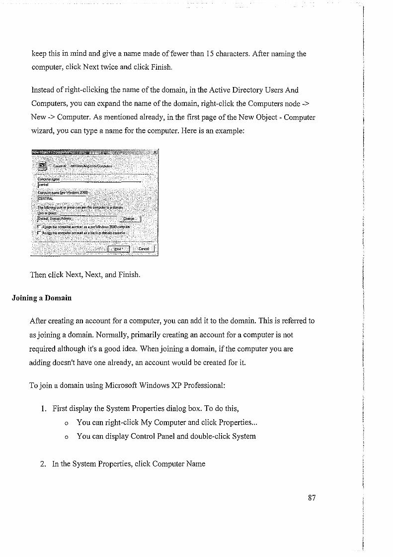
keep this in mind and give a name made of fewer than 15 characters. After naming the
computer, click Next twice and click Finish.
Instead of right-clicking the name of the domain, in the Active Directory Users And
Computers, you can expand the name of the domain, right -click the Computers node ->
New-> Computer. As mentioned already, in the first page of the New Object- Computer
wizard, you can type a name for the computer. Here is an example:
centre!
~I#MmcW;i:\'(.iido-M2000l jCENTRAL
JhC}O~~i~l!hnCr'or'~OOj)caiijolri_tN;_~to'a_~ U:eior!1~' jDcld D~Adtnn: .tl\anoe,,.
r .·.Aj~ l!if ccoiPu\ilt.~ IU a JliC•\Jfl)dow~ 2IXlQ eOII'Ipl.llel
r Anlmi IN; e~m ~ a; a backup &.wnaln· eontro!IW
Then click Next, Next, and Finish.
Joining a Domain
After creating an account for a computer, you can add it to the domain. This is referred to
as joining a domain. Normally, primarily creating an account for a computer is not
required although it's a good idea. When joining a domain, if the computer you are
adding doesn't have one already, an account would be created for it.
To join a domain using Microsoft Windows XP Professional:
I. First display the System Properties dialog box. To do this,
o You can right-click My Computer and click Properties ...
o You can display Control Panel and double-click System
2. In the System Properties, click Computer Name
87
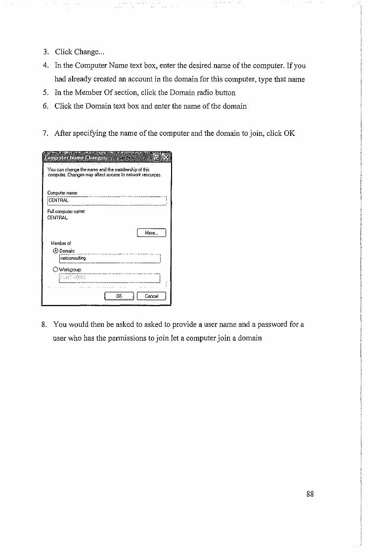
3. Click Change ...
4. In the Computer Name text box, enter the desired name of the computer. If you
had already created an account in the domain for this computer, type that name
5. In the Member Of section, click the Domain radio button
6. Click the Domain text box and enter the name of the domain
7. After specifying the name of the computer and the domain to join, click OK
You can change the name and the membership of this computer. Changes may affect access to network resources.
Computer name: ~"·-··---·-"·------------
! rcENTRAL _____ ... J
Full computer name: CENTRAL
Member ol
®Domain:
I More ...
E~~~~-~iti~; -··-··---···-----·- .. ~_-_· _·_-·-=~-· ·_·· _·--J 0 Workgroup:
OK [ I Cancel
8. You would then be asked to asked to provide a user name and a password for a
user who has the permissions to join let a computer join a domain
88

Mowher(l
@D~
rwlconiu\na
9. After entering a user and a password, click OK. If you have the right to add
computers to the domain, you would receive a Welcome message and click OK:
Full COmpulef rnll'!le;
cnnAAL.
Member of
0Workgroup:
Wekome to the netcon:rulting clorn&n.
OK
OK II c"""
OK II"""''' I ..... .
89
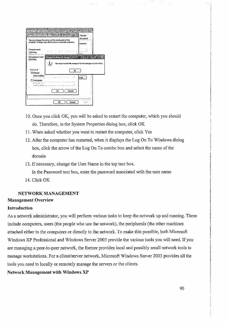
~ocrwno:
CEHTRAL
M<lfi"lhil<lll 0Domait
jnetcon:Utl'l£)
0Worl1!Joup:
I 0. Once you click OK, you will be asked to restart the computer, which you should
do. Therefore, in the System Properties dialog box, click OK
II. When asked whether you want to restmi the computer, click Yes
12. After the computer has restarted, when it displays the Log On To Windows dialog
box, click the aiTow of the Log On To combo box and select the name of the
domain
13. If necessary, change the User Name in the top text box.
In the Password text box, enter the password associated with the user name
14. Click OK
NETWORK MANAGEMENT
Management Overview
Introduction
As a network administrator, you will perform various tasks to keep the network up and mnning. These
include computers, users (the people who use the network), the peripherals (the other machines
attached either to the computers or directly to the network. To make this possible, both Microsoft
Windows XP Professional and Windows Server 2003 provide the various tools you will need. If you
are managing a peer-to-peer network, the former provides local and possibly small network tools to
manage workstations. For a client/server network, Microsoft Windows Server 2003 provides all the
tools you need to locally or remotely manage the servers or the clients.
Network Management with Windows XP
90
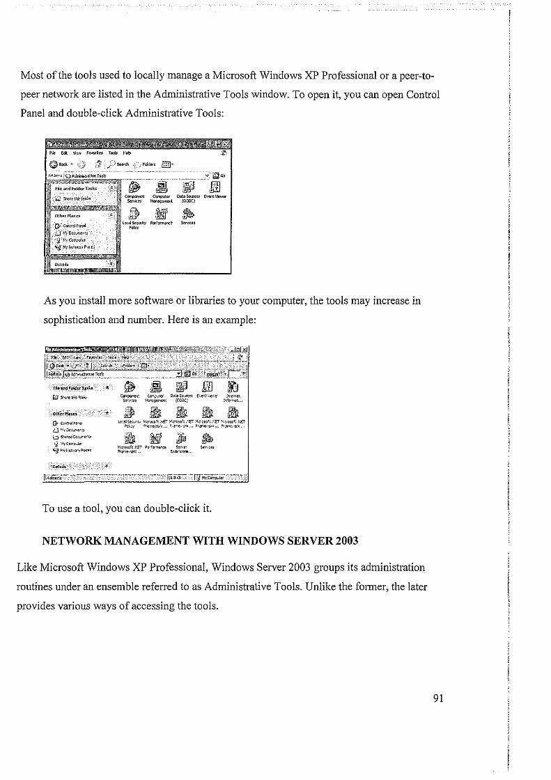
Most of the tools used to locally manage a Microsoft Windows XP Professional or a peer-to
peer network are listed in the Administrative Tools window. To open it, you can open Control
Panel and double-click Administrative Tools:
C<>'rlp\tor Dlltll Sou1:e~ E~Of\t Vlewor M~ment (006C)
As you install more software or libraries to your computer, the tools may increase in
sophistication and number. Here is an example:
OthuPluu
(} C:flUO!;>'~'"'
,;.) ~~>Oo:>.r.Mtl
L) S."¥ed ~~"""'"' ~ '~yCO<""'~ 'J !-'.1) .. ~.-.?t'<;>t>: ..
~ot c~_,ter D~:.Scvtel f>!<'t .. ewt• l~W<Itt
Se''t•:ts ~lv-~~e->e<\t (000.:) lo'r:<"'~~ ...
• ~ 3l1l 3l1l ~ 3l1l
'
l1>:oiS•~-"'-1' 1>!-P"<><~f: .~ET ~··:-os~ft .';E'r 1-',;,.oto!: ,•,r ''""'~f: .I C. ~l;y "'~·t'IOV"<-.. ~•!=-'=" ''"'~""''"· !'r'~?-i)C'<,.,
3l1l ~ ,jJiJ ~ y,:nloof:.riET ~ •• r"'""""' ~.,.'<'< Sff'.,:u l'<tn".ew<'•k... ~1!~,,.,,,,
To use a tool, you can double-click it.
NETWORK MANAGEMENT WITH WINDOWS SERVER 2003
Like Microsoft Windows XP Professional, Windows Server 2003 groups its administration
routines under an ensemble refetTed to as Administrative Tools. Unlike the former, the later
provides various ways of accessing the tools.
91
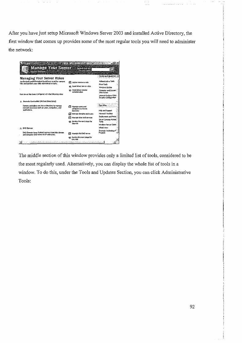
After you have just setup Microsoft Windows Server 2003 and installed Active Directory, the
first window that comes up provides some of the most regular tools you will need to administer
the network:
Managing Your Server Roles .Y.e the tool!: and riorTMtion fa<.nd We to .add,... r'lll'IOV(I "Oies and perform your doiy adrnlnlru&m t~*-:;.
;t Domllln Controller {Active rn ... ctory)
O<:ornm ccnlrol!t!rs uoe A<:tNe Dt'ectery to~~ netwotkrew.rces wch~st!UJ<'l, ~e<s, and aj>pkatlons.
0NS (DorMin NMM S)'$1.em) Slll"o'e<S ttonslete <lorn4n and con¢or otiS 1\M\e$ to IP ••1<h-:=.
tin) Add ot remove ~ "* ,_tl Rcod llb...t serv11< rcles
tli~~em::tc
QjMM~C~~·~ cOft'CUt«Si'IActiVe Olrectcry
~ M'IM')C domW aod truru
iU! MM1>90 s~cs and strnoos
t"l,i ij.~., the noxt st~ lor
~j MM"'lCt'*ONS
til Roviow the ooxt !to;>sl« thi;rol.l
~ttbtiveToolo
l<loreTQQI;
"""""''"''" Corr:cuter.mdOom~ !rlorm:.tioo
!rtcrnotE>qlloruErm S.N'I:yCor{i.pllt!On
... ... ,_... l<li<roml"tTed-tlcl
Otllloymcnl: ondReroo. Ul:t <J Colmoo Admfl!: T~W.!
Wlt"<loM Sctvct (Q<M"
The middle section of this window provides only a limited list of tools, considered to be
the most regularly used. Alternatively, you can display the whole list of tools in a
window. To do this, under the Tools and Updates Section, you can click Administrative
Tools:
92
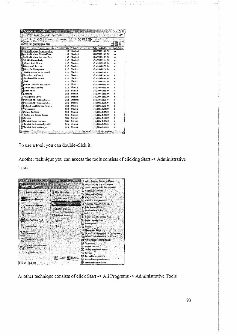
'1:23PM A
"' Sho!'tcut 1/14/2006 'l:lJ PN A
'"' ""''"" 1/1'1/2006 '1:23PM A
"' Shortrut 1/13/20069:1'\PM A
"' Shoftrut 1/13/2006 9:07PM A
"' ""''"" 1/13/2006 6:58PM A
"' Shortcut 1/16/2006 2:57 PI~ A
"' Shoftcut 1(13/2006 9:16PM A
"' ""''"" 1/16/2006 3:'17 PM A
"' st-.:lrtrut l/13/20069:16Pfll A
'"' Shoftcut 1(!'\{20061:53PN A I. "' ""''"" 1/1'1/20061:23 PM A
U:B Shortrut 1/14/2006 '1:23PM A
"' """'"" 1/16/20063:S6PM A 2KB Shol'tcut 1{13/2006 9:16PM A
"" ""''"" 1/15/2006 8:12AM A 2KD st-.:lrtrut 1/13/2006 8:59PM A 2KD sholtcut 1/13/2006fl:S9PM A
'"' Sholtrut 1(13/20066:06PM A
"' ShortCIJI: 1/16/2006 3:55PM A 2KD Shortcut 1/13/2006 8:57PM A
"' Shalt cut 1/13/2006 6:06PM A
"' Sholtcut l/13/20069:16PM A 2KD ""''"" 1/13/Z006 9:07PM A
"' ShortCIJI: 1/13/2006 8:57PM A
'" Shol'lcut 1/13/2006 8:57PM A
To use a tool, you can double-click it.
Another technique you can access the tools consists of clicking Start ->Administrative
Tools:
Tcrlrirla!Sltfvo:rlkeruli:19
'~,..--,;-:;--,.----"=--...::;:_ __ .~ T<~!rrirui~$Corl$.0r~
Another technique consists of click Start-> All Programs -> Administrative Tools
93
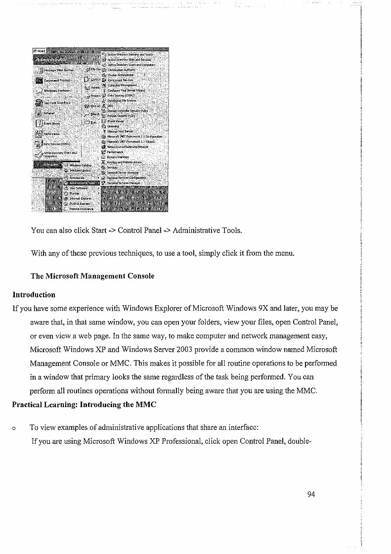
You can also click Start-> Control Panel -> Administrative Tools.
With any of these previous techniques, to use a tool, simply click it from the menu.
The Microsoft Management Console
Introduction
If you have some experience with Windows Explorer of Microsoft Windows 9X and later, you may be
aware that, in that same window, you can open your folders, view your files, open Control Panel,
or even view a web page. In the same way, to make computer and network management easy,
Microsoft Windows XP and Windows Server 2003 provide a common window named Microsoft
Management Console or MMC. This makes it possible for all routine operations to be performed
in a window that primary looks the same regardless of the task being performed. You can
perform all routines operations without formally being aware that you are using the MMC.
Practical Learning: Introducing the MMC
o To view examples of administrative applications that share an interface:
If you are using Microsoft Windows XP Professional, click open Control Panel, double-
94
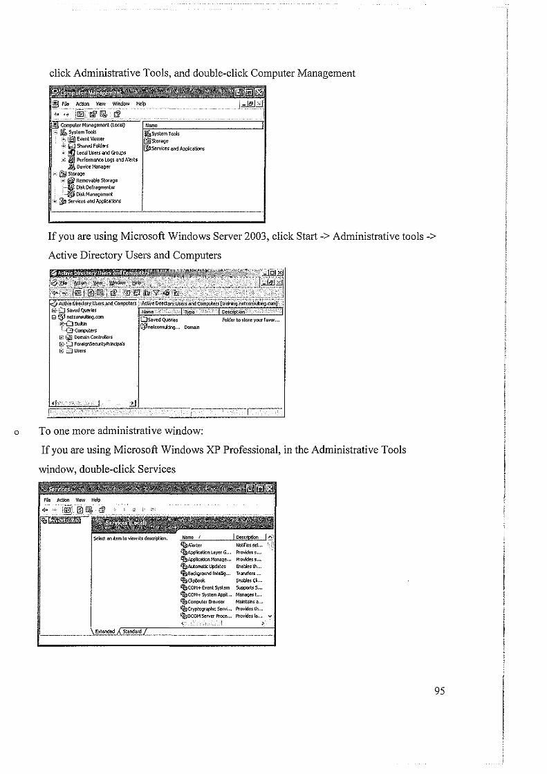
0
click Administrative Tools, and double-click Computer Management
If you are using Microsoft Windows Server 2003, click Start-> Administrative tools->
Active Directory Users and Computers
Folder to store your f11vor ...
Domllin
To one more administrative window:
If you are using Microsoft Windows XP Professional, in the Administrative Tools
window, double-click Services
~!~§[~t~~: Providess .. . Provides s .. . EMblesth .. .
''~"'" .. . Enatlesct..
liE~;,~, Supports s ... Manages t. .. Mailtalns ~ .. .
'"''··· ~~"" ~ .. . Proce... Provides~ .. , ..,
>
95
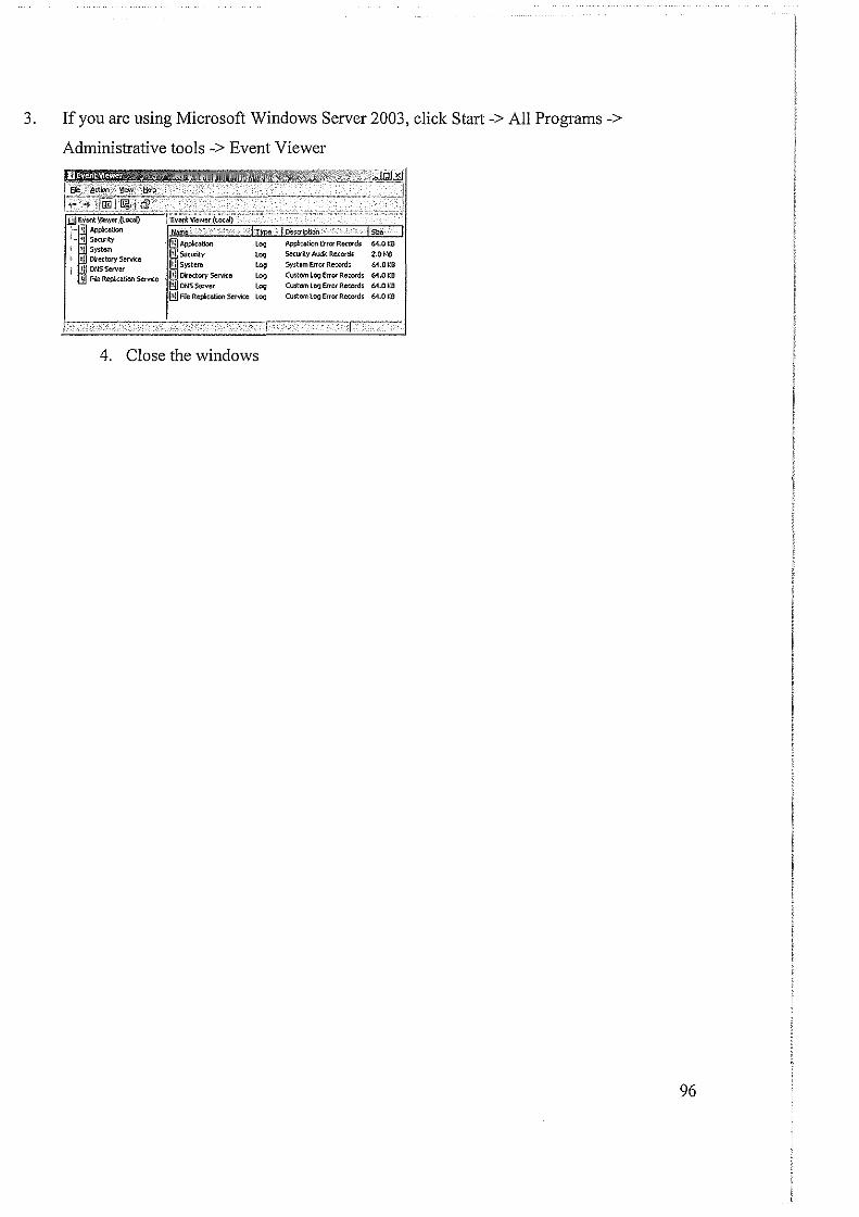
3. If you are using Microsoft Windows Server 2003, click Start -> All Programs ->
Administrative tools -> Event Viewer
_fnl'
"' """" . ,;. .... ,.. ->llffillilll>IB' .
l~ • 0~!0" ""' ! Security (illAfll'kation '"" Applkatioo Errcr Rccord5 64.0 ~0
System r .. , ,., Seturly Aud1: R~cord~ 2.01>1) Directory Service DNSServer '"'= "" Sy~tem Error Retordi 61.01:0
Mia Repkation Service Directory Service LOQ Custom LOQ Error Records 61.0KB
tlliDNSS&ver '"" Custom LD'J Error Reccrd> 6'1.0KD
till ne Repkation Service '"" Custom Log Error Reccrds 6-J.OKD
I
4. Close the windows
96
REFERENCES: I. Networking Essentials Plus. Academic Learning Series. 3'd Edition.
2. CCNP Support. Study Guide. By Todd Lammle and Kevin Hales.
3. Networking Lab Manual for Network+ Guide to Networks. 3'd Edition. By Michael Grice.
4. CCNA Self Study. CCNA Intro. Exam Certification Guide.
5. CCIE - Cisco Certified Intemetwork Expert. Study Guide; Routing and Switching Exam
350-001. By John Swartz and Todd Lammle.
6. Networking Complete. 2"d Edition.
7. Using Information technology. 3'd Edition. By Williams Sawyer Hutchinson.
8. Computers, Communications and information. User's Introduction. By Sarah E. Hutchinson
Stacey C. Sawyer.
9. http://www.google.com/
I 0. http://www.answers.com/
97