TTE Combo - LAN Communication Module
41
• Installation and Programming Manual • Operation Instruction • User Guide TTE Combo LAN Communication Module Rev. 4.1.x Release 01/2020 Attention: This manual contains information on limitations regarding product use and function and information on the limitations as to liability of the manufacturer. The entire manual should be carefully read. The information in this manual is a subject to change without notice!
-
Upload
khangminh22 -
Category
Documents
-
view
3 -
download
0
Transcript of TTE Combo - LAN Communication Module

• Installation and Programming Manual • Operation Instruction • User Guide
TTE Combo LAN Communication Module
Rev. 4.1.x Release 01/2020
Attention: This manual contains information on limitations regarding product use and function and information on the limitations as to liability of the manufacturer. The entire manual should be carefully read. The information in this manual is a subject to change without notice!

TTE Combo Communication Module – Installation and Programming Manual
2
Table of contents 1. INTRODUCTION ......................................................................................................................................... 4
1.1 General Information ...................................................................................................................... 4 1.1.1 Functional Features ................................................................................................................ 5 1.1.2 Technical Specifications.......................................................................................................... 5 1.1.3 Operation Block Diagrams ...................................................................................................... 6
Operation with a Burglary Alarm Control panel .......................................................................... 6 Operation as Stand-Alone Device................................................................................................ 7
1.2 Before you start ............................................................................................................................. 7
2. HARDWARE INSTALLATION ...................................................................................................................... 8 2.1 Connection to Burglary Alarm Control Panel ................................................................................ 8 2.2 Internal Structure of the Outputs.................................................................................................. 8 2.3 Basic Installation Steps .................................................................................................................. 9 2.4 TTE Combo Module LED Indication ............................................................................................. 10 2.5 Restore to Factory Settings ......................................................................................................... 11
3. PROGRAMMING WITH ProsTE ............................................................................................................... 12 3.1 Reading a Configuration .............................................................................................................. 12 3.2 General Settings Menu ................................................................................................................ 13 3.3 GPRS Settings Menu .................................................................................................................... 16 3.4 LAN Settings Menu ...................................................................................................................... 16 3.5 Receiver Settings Menu ............................................................................................................... 17 3.6 Saving a TDF File .......................................................................................................................... 18 3.7 Writing a Configuration ............................................................................................................... 18
4. AJAX WEB User Interface ....................................................................................................................... 19 4.1 Creating an Account .................................................................................................................... 19 4.2 Adding a System to Account ........................................................................................................ 20 4.3 Online Connection with AJAX SP Pro Server ............................................................................... 23 4.4 Operation with System ................................................................................................................ 23
5. TTE Combo – Installation Summary ...................................................................................................... 26
6. USER GUIDE ............................................................................................................................................. 27 6.1 AJAX WEB User Interface ............................................................................................................ 27
6.1.1 Remote Access ..................................................................................................................... 27 6.1.2 Main Menus.......................................................................................................................... 27 6.1.3 Communication Module ....................................................................................................... 28 6.1.4 Edit Parameters Menu.......................................................................................................... 28
6.2 Mobile TTE Smartphone Application........................................................................................... 29 6.2.1 Adding a System to Mobile TTE ............................................................................................ 29 6.2.2 Connection to a System ........................................................................................................ 30 6.2.3 Operation with outputs ........................................................................................................ 30 6.2.4 System Main Menu .............................................................................................................. 31
7. APPENDIX – SIA CODES ........................................................................................................................... 34

TTE Combo Communication Module – Installation and Programming Manual
3
DOCUMENTATION FEEDBACK If you have any comments or suggestions on our products’ manuals or installation instructions you can email us on: [email protected] Your feedback on product documentation will help us to improve the contents of our manuals and stickers and keep them up-to-date. Please, include in your feedback email the product name, the revision of the manual or instruction (8-digit number with Revision and date of issue) and the page number.

TTE Combo Communication Module – Installation and Programming Manual
4
1. INTRODUCTION 1.1 General Information TTE Combo is a universal communication module, that can be connected to any panel capable to transmit CID events, including Eclipse Series. The general application of the module is to transmit the incoming events from the panel (the events recorded into the panel’s memory log file) to AJAX SP Pro server and/or SIA-DC09 Receiver station via several reporting channels – LAN/GPRS/PSTN (communication media) – using alternative or parallel reporting type. TTE Combo is a module for emulation of a standard PSTN line or Receiver Station. The module receives the events from the connected alarm control panel and returns a confirmation for the successful receiving. TTE Combo is equipped with an internal loop buffer with capacity of 256 events. In case of overflow of the internal buffer, the module stops the confirming of successfully received events. In this way the untransmitted events will be kept into the log buffer of the alarm control panel and would not be lost. These events will be transmitted when the module’s buffer is unloaded during the next successful transmitting of events to AJAX SP Pro server or SIA-DC09 Receiver station. The received CID (Contact ID) events are converted internally into SIA code. Reporting via “SIA over IP” protocol is realised via standard GPRS and/or LAN channel. The user can use one or both reporting channels. When the both reporting channels are used, the user can set their priority of using – setting one for main and the other for a backup – alternative reporting type. There is also an option for using a parallel reporting type, as the events are transmitted via the both reporting channels. When the control panel is additionally equipped with a digital communicator, the standard PSTN telephone line can also be used for backup channel for transmitting of events, as the TTE Combo is connected directly to the digital communicator terminals of the panel. The hardware connection with the panel is monitored and in case of fault or trouble with the line the module will report to the monitoring station. In case of connection to Eclipse series control panel, TTE Combo is fully compatible and can operate in configuration with Eclipse VD (voice dialer) mounted on slot to the panel’s PCB. The user can use the full functionality of the Voice Management Mode and the monitoring via TTE Combo through the available PSTN line. The user also can remotely control the outputs of TTE Combo via AJAX WEB software application and MobileTTE smartphone application. According the application, TTE Combo can be powered up directly from the control panel (± AUX terminals, 9-30VDC) or from a stand-alone power supply unit. The module can be mounted directly into the panel’s box or into a separate small plastic box (SB-U) suitable for wall mounting according the application. TTE Combo is programmed via ProsTE software or remotely via AJAX Web User Interface.

TTE Combo Communication Module – Installation and Programming Manual
5
1.1.1 Functional Features • Compatible with control panels capable of sending Contact ID (CID) • Control panel communication supervision • AES 128 encryption • Supports 2G networks • Communication channels – PSTN, LAN and/or GPRS • Main and Back-up reporting channels • Connecting to AJAX SP PRO through IP or DNS address • Supports operation with SIA-DC09 IP protocol messages • LAN settings – Manual or Automatic (DHCP) • 1 input (TAMPER/NC to GND) • 2 outputs OC type • Internal buffer for 256 events • Micro USB input for direct PC connection • Jumper for restoring of the default factory settings • Reversed polarity protection
1.1.2 Technical Specifications • Main power supply: ...................................................... 9-30VDC (no tolerance) • Current consumption:
o Normal operation mode (standby): ........... 100mA o Maximal consumption: ............................... 200mA
• Time for filtration of signals incoming at I/O: ...............0.3 seconds • GPRS working frequencies: .......................................... 850/900/1800/1900 MHz • Antenna connector (internal mounted): ...................... SMA 50Ohm • Operating temperature: ............................................... -20°C ÷ +60°C • Dimensions (PCB): ......................................................... 73x108mm
Important note: The purpose of this manual is to give directions for programming the TTE Combo module and its operation with AJAX SP Pro server. You can refer to the installation manual of the module (applied into the packing box) for details about its elements and PCB hardware. Find out more materials also at www.teletek-electronics.com.

TTE Combo Communication Module – Installation and Programming Manual
6
1.1.3 Operation Block Diagrams
Operation with a Burglary Alarm Control panel
1. TTE Combo communication module and burglary alarm control panel. The control panel is compatible to transmit CID events – see item 2.1 Connection to Burglary Alarm Control Panel. 2. Program the TTE Combo module with ProsTE – see item 3. Programming with ProsTE. 3. Standard telephone line connected to PSTN Station. 4. Monitoring station for receiving of events via RS232 communication protocol. 5. SIA over IP communication protocol. 6. AJAX SP Pro Server. This is a computer with installed AJAX SP Pro Server administrative interface. Usually it is situated into a Monitoring station of a service security provider. 7. AJAX WEB. This is a User interface (web site) for management and control of panels and communication modules produced by Teletek Electronics JSC. After registration the User can review the status and to control (switch ON/OFF) the outputs of TTE Combo attached to his account. 8. Mobile TTE. This is a smartphone application for management and control of panels and communication modules produced by Teletek Electronics JSC, which are attached to a User account at AJAX WEB. The smartphone application is compatible with iOS and Android platforms. 9. SIA DC-09 Alarm Receiver and Monitoring Software. Monitoring station of a service security provider operating with SIA-DC09 IP reporting to monitoring software. 10. SURGARD MLR 2 communication protocol, providing message transfer via LAN or RS 232 between AJAX SP Pro server and Monitoring software.

TTE Combo Communication Module – Installation and Programming Manual
7
Operation as Stand-Alone Device This configuration is suitable for realizing of home automation applications where the User wants to control different electrical appliances via the outputs of the module. In this case, TTE Combo must be powered up from and external power supply unit providing 9-30VDC. The outputs can be switched ON/OFF remotely via AJAX WEB or MobileTTE.
1.2 Before you start Before starting you need the following equipment (full configuration): - ProsTE Programming Software installed on a local computer or laptop for reading, writing and saving the module’s configuration. - Standard USB-Micro USB data cable. - Valid SIM Card supporting 2G networks with disabled PIN protection code. - Router. - CAT-5 Ethernet cable, max. 90 m (not included into the kit). - Access to WAN/LAN available and enabled network. - Control panel with digital communicator (supporting CID protocol). - Access to PSTN available network. - Resistor 220k (included in the kit of the supplied equipment) for termination of the terminals of the digital communicator for phone device connection (in case the phone device is not used). And also, is helpful to have prepared: - A valid account registration in AJAX WEB User interface*. - An installed Mobile TTE application on your smartphone**. * For monitoring and management of burglary control panels Eclipse series and module’s outputs. Ask your local distributer or security provider how to access the AJAX WEB site and to register an account. ** You can download the application from Google Play or App Store according your smartphone model. You will be able to review all attached systems to your AJAX WEB account after adding them into the Mobile TTE application. The manufacturer also recommends: - Review the status of the burglary alarm panel to which the TTE Combo module is going to be connected. Check the programming and settings for operation with communication equipment. Set the phone numbers: one for communication with the Central Monitoring Station, and other for connection with TTE Combo module. Set CID protocol for transferring of events. - Check the subscription plan of the used SIM card and network coverage. The SIM card must support 2G network. To be able to connect to AJAX SP Pro Server and use the Mobile TTE application on your smartphone, your plan must include a mobile internet (at least 100MB data traffic per month). - In case the TTE Combo is going to be used as a stand-alone device, equip it with a suitable external power supply unit providing 9-30VDC. - Connect the “In1” terminal of the module to the TAMPER switch of the control panel (or to a TAMPER Zone type). - Equip your Router device for access to WAN/LAN network with an uninterruptable power supply (UPS) unit.
Important note: When only LAN communication media of TTE Combo module is going to be used for reporting of events in your burglary alarm system for security, it is obligatory to equip your Router device with a UPS unit. In this way, in case of a main power supply failure in the protected site, the router will stay powered on and will be able to send messages for “AC lost” and “Burglary Alarm” to the monitoring station and/or the end user.

TTE Combo Communication Module – Installation and Programming Manual
8
2. HARDWARE INSTALLATION TTE Combo is a universal communication module which provides the opportunity for connection to different types of control panels and reporting for events to a monitoring station and/or end User.
2.1 Connection to Burglary Alarm Control Panel TTE Combo is mounted into the panel’s installation box. The module can be powered on directly from the +/- AUX outputs (required 9-30VDC) of the control panel as observing the polarity; or from an external power supply unit.
Important note: If the terminals A1 and B1 (on the presented diagram) are not used for connection of a telephone device, the terminals must be terminated with a 220k resistance! If the A1 and B1 terminals are missing the resistance of 220k must be connected to A and B terminals!
2.2 Internal Structure of the Outputs TTE Combo has 2 outputs OC type that can be used for small home automation projects. The Internal structure of the output is presented on the following schematic diagram:
Digital communicator
TTE Combo Attention:
All electrical connections must be done ONLY when the mains and back-up power supplies of the module are switched off!
Burglary Alarm Control Panel
Connection of a Tamper switch (optional)

TTE Combo Communication Module – Installation and Programming Manual
9
2.3 Basic Installation Steps (for full configuration)
1. Turn off the main and backup power supply of the control panel. 2. Connect the power supply of the module (9-30VDC) – from the control panel or external power unit. 3. Run the CAT-5 Ethernet cable for LAN connection through any suitable cable opening of the box and connect it to the LAN connector of the module. 4. Switch off the PIN protection code of the SIM card and place it into the SIM interface holder of TTE Combo module. 5. Run the PSTN cable through any suitable cable opening of the box and connect it to the LINE connector of the module. 6. Connect the digital communicator of the control panel (A and B terminals) to ALARM PANEL terminals of TTE Combo. 7. Connect the phone device to A1 and B1 terminals of the control panel; in case the phone device is not used – terminate the A1 and B1 terminals with 220k resistor. 8. Connect t a TAMPER switch (or TAMPER zone) to IN1 terminals of TTE Combo. 9. Turn on the main and backup power supply of the panel. 10. Wait for the connection with the Main and/or Backup Receiver station - up to 90 sec the Main/Backup Receiver LEDs are blinking in red. The established connection is indicated with blinking in green. 11. Check the signal strength - 2 or 3 RSSI LEDs are lighting on in green. If the signal strength is poor, change the location of the module or use external antenna. 12. The module is in normal operation mode - the PSTN LED lights on in green, and Main/Backup Receiver LEDs are blinking in green (depends on the application). 13. Set the parameters of ТТЕ Combo module using ProsTE programming software – see also 3. Programming with ProsTE.

TTE Combo Communication Module – Installation and Programming Manual
10
2.4 TTE Combo Module LED Indication The LED indication of TTE Combo communication module has the following meaning during operation.
The LED Indication has the following meaning: LED Action Description
PSTN (green)
Lights OFF The PSTN line is missing or it is unavailable.
Lights ON The PSTN line is available.
RSSI Signal Strength
●○○ The signal strength is poor (from -111 to -91 dBm).
●●○ The signal strength is good (from -90 to -70 dBm).
●●● The signal strength is very good (from -69 to -51 dBm).
Main Receiver
Blinking Slow (1 sec)
Green Successful connection with the Main Receiver station via the Main IP address and the Main communication media (GPRS/LAN).
Red
No connection with the Main Receiver station. Possible problem with the used communication media GPRS or LAN. • Possible troubles with the SIM card (GPRS media): 1. The SIM card is missing. 2. The SIM card could not register to the available GSM/GPRS network. 3. Active PIN code for verification. • No signal/link. • Wrong configuration (Server type, IP, Port, Encr. Key, etc.)
Orange There is at least 1 transmitted and received (confirmed) event in a 3 sec. time interval.
Blinking Fast (0.25 sec)
Green-Orange
Successful connection with the Main Receiver station via the Main IP address and the Backup communication media (GPRS/LAN).
Backup Receiver
LED indication for the Backup Receiver station. The description is the same as the one for the Main Receiver.
RJ-45 (LAN connector indication)
LAN Status ①
LED LAN Action. The LED is blinking when there is activity on the link; otherwise, the LED is on.
② LED LAN Link. The LED is lit on when there is a link to an Ethernet device; otherwise the LED is off.
1. PSTN - LED for presence of PSTN telephone line.
2. RSSI – 3 LEDs for the signal strength of the available GSM/GPRS network.
3. Main/Backup Receiver - LED for Main/Backup Receiver status.
4. LAN LEDs – LEDs for LAN network status.

TTE Combo Communication Module – Installation and Programming Manual
11
2.5 Restore to Factory Settings This function is for restoring of the default parameters of the module set by the manufacturer.
The Reset Jumper is situated on the left side of the SIM card holder. To perform restoring of the factory settings:
1. Turn off the power supply of the module. 2. Place a jumper on Reset Jumper terminals. 3. Turn on the power supply of the module. 4. Wait for 10 seconds and remove the Reset Jumper. 5. Wait for the Main/Backup Receiver LED to start blinking in green – the initial startup can take up to 90 seconds. 6. Program the module with ProsTE software according the application.
Reset Jumper Terminals

TTE Combo Communication Module – Installation and Programming Manual
12
3. PROGRAMMING WITH ProsTE ProsTE is a specialized software for programming of panels and modules produced by Teletek Electronics JSC. The installer can quickly read the current configuration, to set new parameters and to write it back to the panel or module. Attention: Always use the latest version of ProsTE software downloaded from www.teletek-electronics.com or ask your local distributer for more information and details. To connect the TTE Combo to a local computer or laptop for programming, use a standard USB-Micro USB data cable.
Note: The TTE Combo module must be powered up during programming! After connecting to the computer, you may be asked to wait until the system is installing some USB drivers.
3.1 Reading a Configuration Run the ProsTE software and choose in sequence using the right mouse button: System – Add – TTE Combo.
The TTE Combo menus are loaded at the left side as a tree structure. Select the module and using the right mouse button again choose in sequence: TTE Combo – Read.
Read is a command for downloading the current module’s parameters and settings into ProsTE software.

TTE Combo Communication Module – Installation and Programming Manual
13
A new window with options for Reading is opened:
In Com Port field, select the number of USB port to which the module is physically connected. Press OK button to continue. Next you have to enter a Password code – “1234” by default.
If the downloading is successful a message “Download from hardware finished successfully!” will appear on the screen.
3.2 General Settings Menu Click on the “+” icon in front of TTE Combo module to expand the programming menus. Select General Settings menu. The possible settings are displayed on the right side on the screen:
Important Note. According the used way for monitoring, there are two general approaches for programming of the Account Number and System ID fields.
- For Monitoring stations. Enter into the fields the specific information for the site according the used software for monitoring. See the description of the fields below. - For AJAX SP Pro Server. Leave empty. The fields will be filled in automatically after the registration of the TTE Combo as standalone device to a User account at AJAX WEB.
TTE Combo Communication Module – Installation and Programming Manual
14
Description of the fields • “Ademco CID Panel Phone” – Enter a phone number for connection between the control
panel and TTE Combo. The phone number can be up to 16 digits long, as spaces, letters and special symbols are not allowed.
Note: You must set the same phone number to the control panel, in the digital communicator programming menus. The “Contact ID (CID)” communication protocol must be set for reporting in the digital communicator menus also.
Useful Tip: In case of connection to Eclipse control panel, enter into engineering programming menus “8. COMMUNICATION – 1. DIGITAL COMM – 5. PHONES – 1.PHONE – 1.PHONE NUMBER” and set the same phone number set in the “Ademco CID Panel Phone” field. Save and enter in the next submenu “2.PROTOCOL” to set “CID” type for the communication protocol.
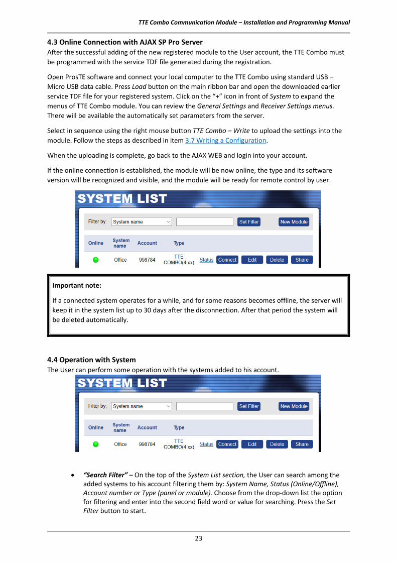
• “Panel Line Test Period” – Enter a time interval in minutes (from 2 to 10080) for periodic test of the connection between the control panel and TTE Combo module. The purpose of the test is to check the physical connection presence between terminals “A” and “B” on the digital communicator of the control panel and “ALARM PANEL” terminals of TTE Combo – see item 2.1 Connection to Burglary Alarm Control Panel.
In case of trouble with the connection (broken line, disconnection between panel and module, absence of 220k resistor), a trouble message “Service Required” (“YX” SIA code) will be sent to the monitoring station. When the connection is restored the monitoring station will receive a message “Service Completed” (“YZ” SIA code).
When TTE combo is used as standalone device or the testing of the connection with the control panel is not necessary, the periodic test can be disabled with setting “0” in the field.
Example: For periodic test at every hour, enter 60; for periodic test at 24 hours – enter 1440, etc.; to disable the periodic test – enter 0.
Useful Information: The used SIA codes and their description are presented in item 7. APPENDIX – SIA CODES.
• “Account number” - This is the number of the protected site (up to 6 digits), where the module TTE Combo is installed. In AJAX WEB, this is the number of the registered TTE Combo module.
• “Password” – User access code for reading/ writing parameters to the module via ProsTE. The default set code is 1234. To change it you must enter a new 4-digit code into the field. The code is used also when connecting to AJAX WEB and MobileTTE application.
• “System ID” –This is a unique name for identification (up to 15 symbols – digits, letters and special characters), between module and user in the monitoring software.
• “Reporting channels” – Use the drop-down menu to set the type and the way of reporting of used channels (also called media) for transmitting of events to Receiver Monitoring station/Server (AJAX SP Pro or SIA-DC09). The user can choose among several option according the application and needs.
o “LAN is main; GPRS is backup” – The both communication media are used for reporting. The Alternative reporting is applied for transmitting of events. LAN media is the Main media for reporting and GPRS is the Backup one.
o “GPRS is main; LAN is backup” – The both communication media are used for reporting. The Alternative reporting is applied for transmitting of events. GPRS media is the Main media for reporting and LAN is the Backup one.
o “Use only GPRS media” – Only the GPRS channel is used for reporting of events.

TTE Combo Communication Module – Installation and Programming Manual
15
o “Use only LAN media” – Only the LAN channel is used for reporting of events. o “Both GPRS and LAN media are main (Ver.<4.0)” – This option can be applied for
TTE combo with software version 4.0.0 and higher. The both communication media are used for reporting. The Parallel reporting is applied for transmitting of events. The both media are Main.
Note: According the set reporting channels it is obligatory to set properly also the submenus “GPRS Settings” and/or “LAN Settings”!
Definitions
• Alternative Reporting. In alternative reporting, to the available communication media are set priorities for using. One of the media is set with the highest priority for using – Main, and the other(s) are set with lower priority – Backup. In case of an event in the system, it is transmitted first through the Main media and if the transmitting is successful, the event is not transmitted further. If the transmitting through the Main media is failed, the event is transmitted through the Backup media. In alternative reporting is important the events to be successfully transmitted through only one of the set communication media, starting with the Main one. The User sets the priority of the used communication media.
• Parallel Reporting. In parallel reporting, the events are transmitted through all used communication media. All reporting channels are Main in priority and are used for transmitting. If the transmitting through one of the media is failed, the incoming events will be stored in the loop buffer of the module (TTE Combo). When the transmitting through the media is restored, all the stored events will be sent. In parallel reporting is obligatory the events to be successfully transmitted through all communication media.
Important: In case the option “LAN is main; GPRS is backup” or “GPRS is main; LAN is backup” is set, and the module uses Alternative reporting type for transmitting of events, is applied a special internal test for availability and presence of the used media. The test is performed on every hour and its purpose is to inform the Monitoring station for possible problems with both Main and Backup media. In case of a problem with any of the media, a message “Communication trouble” (“YC” SIA code) will be sent to the monitoring station, as the type of the media is presented with “1” for GPRS and “2” for LAN. For example, the SIA code “YC1” means that there is problem with the used GPRS media of TTE Combo. The restoring event is “Communication Restore” (“YK” SIA code).
• “Test message (minutes)” – Enter a time in minutes (from 3 to 10080) for a time period
for sending test message from the module to a monitoring station. You can disable the sending of test messages with setting “0” in the field. Example: For sending a test message every hour, enter 60; for sending a test message every 24 hours – enter 1440, etc.
• “Software version” – The current software revision of the TTE Combo module. The field is not accessible for changing.
Confirm with “Apply” button.

TTE Combo Communication Module – Installation and Programming Manual
16
3.3 GPRS Settings Menu Select the GPRS menu, click on “+” icon in front of it and expand the GPRS Settings submenu. In the fields must be set some specific information for the mobile service provider.
Important Note. There are two general approaches for programming of the GPRS Settings submenu.
- For Monitoring stations. Enter into the fields the specific information for the Net Settings of the mobile operator:
o “Net APN” – Enter the APN (Access Point Name) of the GPRS network. o “User Name” – Enter valid user name for access to the GPRS network. o “Password” – Enter valid password for access to the GPRS network.
- For AJAX SP Pro Server. Leave empty. The fields will be filled in automatically after the registration of TTE Combo module to a User account at AJAX WEB – the user sets the mobile service provider according the selected country.
3.4 LAN Settings Menu Select the LAN menu, click on “+” icon in front of it and expand the LAN Settings submenu. You can choose between Automatic and Manual settings of the network characteristics.
If you are not sure about your server type choose the option “Manual Settings” from the drop-down list and enter manually the parameters of the network – IP address, Subnet Mask and Gateway.
Confirm with “Apply” button.
The “Automatic Settings (DHCP)” option is set by default; it is recommended for a network using DHCP server. In this case the Combo module will take the network settings directly from the server.

TTE Combo Communication Module – Installation and Programming Manual
17
3.5 Receiver Settings Menu This is a menu for setting the options for connection with Monitoring station server (AJAX SP Pro and/or SIA-DC09). There are two sections: for Main Receiver and for Backup Receiver. Important Note. There are two general approaches for programming of the Main Receiver Settings fields.
- For Monitoring stations. Enter into the fields the specific information for the main receiver according the used equipment and network. See the description of the fields below. - For AJAX SP Pro Server. Leave the default settings. The fields for Main Receiver will be filled in automatically after the registration of TTE Combo module as a standalone device, to a User account at AJAX WEB.
Here is a short description of the fields
• “Keep Alive Message (seconds)” – This is а time period, in which the TTE Combo module sends its status to AJAX SP Pro server to keep the communication alive. The default set period between two messages is 170 seconds, but it can be changed according the system requirements – from 20 to 200 seconds.
• “Main Receiver” Section – These are the settings for the Main Receiver Server for monitoring.
o “Enable Main Receiver” – Enabling the communication with the Main Receiver server for monitoring.
o “Server 1 Type” – The type of the server for monitoring: AJAX SP Pro or SIA-DC09 Receiver*.
o “IP Address 1” – The IP address of the Main Receiver server for monitoring. o “Main Receiver Port” – The Port of the Main Receiver server for monitoring. o “Encryption Key 1” – A special security encrypted key for the connection. The
key is 32-symbols long and must be set one and the same at the TTE Combo and the server for monitoring for proper operation.
* For SIA09 Receiver the settings must be set manually. There is no option for automatic settings.
• “Backup Receiver” Section – These are the settings for the Backup Receiver Server for monitoring in case of the Main Receiver failure. The settings in this section have the same description as those for the Main Receiver.
Note: The settings for the Backup Receiver must be set manually just in case of using a second backup server for monitoring.

TTE Combo Communication Module – Installation and Programming Manual
18
Important Note An internal algorithm for the reporting of events is applied for operation, when both Main and Backup Receivers are used.
Server Type 1 Server Type 2 Reporting Type
AJAX Pro AJAX Pro Alternative AJAX Pro SIA-DC09 Parallel SIA-09 AJAX Pro Parallel SIA-DC09 SIA-DC09 Alternative
3.6 Saving a TDF File When you complete with all parameters setting of TTE Combo you have to save the module’s configuration as TDF file. TDF (Teletek Data File) is a file format for ProsTE software.
To save the current opened module configuration, press the “Save as” button on the ProsTE ribbon bar and browse a place on your local computer. It is recommended in one TDF file to save only one TTE Combo module configuration.
3.7 Writing a Configuration To upload the settings from ProsTE to the TTE Combo module you have to write them to the currently connected module. Select TTE Combo main menu and choose using the right mouse button: TTE Combo – Write.
In the Write window select the USB port number to which you are physically connected and press OK button. The software will ask for a password. The default password is 1234: Note: The “Password” is set at General Settings Menu - 3.2 General Settings Menu. A system message will inform if the writing of the new configuration in the TTE Combo module is successful.
Write is a command for uploading the current ProsTE settings to the device configuration.

TTE Combo Communication Module – Installation and Programming Manual
19
4. AJAX WEB User Interface AJAX WEB User Interface is a web service for monitoring of burglary alarm panels and communication modules produced by Teletek Electronics JSC. It is configured as a web application (web page) during the installation of AJAX SP Pro Cloud Server. Ask your security provider, the monitoring company or your local distributor, whether and how you can access AJAX WEB User Interface. You can also visit www.teletek-ajax.com for review and test*. * Note: All previewed examples and screens below are based on this web application.
4.1 Creating an Account To be able to control your TTE Combo communication module, first you must have a User account registered to AJAX WEB User Interface (hereafter referred to as AJAX WEB). On the home page of AJAX WEB, the User must login with his personal User Name and Password or to create a new account:
To create a new account, click on “I am new user” and fill in the registration form:

TTE Combo Communication Module – Installation and Programming Manual
20
Attention: It is important to enter a valid e-mail address, so to be able to complete the registration and to receive in the future the information for the registered systems to your account at AJAX WEB. When you complete the form, press the Register button. You will be returned to the main home page with the following information message:
Go to your personal e-mail box and confirm the received link. The Home page of AJAX WEB is loaded automatically and in case of successful registration you will see the following confirmation message over the login section:
Then you can login the AJAX WEB. Note: In case you receive a message for browser incompatibility, you have to proceed with registration pressing the option “Ignore and save this decision”. Then, return to your e-mail box and confirm the received link again.
4.2 Adding a System to Account After login, a system list for the User account is shown on. You will see your First and Last names from the registration form on the upper right corner of the screen. Next to it is the menu for editing your personal details.
For the new registered Users, the System List will be empty at the very beginning. To add a system for monitoring press New Module button on the right.
A new window “New Module Registration” with addition information for describing the security system is opened.

TTE Combo Communication Module – Installation and Programming Manual
21
In case of registering of a TTE Combo module you have to make the following settings: - “System Name” – Enter a name describing the protected site. The name can be edited or changed later. - “Panel” – Select Standalone type from the drop-down list. - “Type of connection” – You can choose between LAN and GPRS communication media. As a universal module TTE Combo supports operation via both of them but you can choose only one of them for access to the AJAX WEB. When the both media are enabled for operation of a TTE Combo module, it is recommended to use GPRS media for registration, because it is more versatile. Select GPRS type from the drop-down list. - “Country” – Select from the drop-down list the country of the mobile operator. - “Mobile operator” – According the selected country you must select the mobile service provider. - “Attach TDF File” – Click on Browse and select the preliminary saved TDF file of the TTE Combo module’s configuration.
* Important Note: If the used mobile operator is not present in the list, choose any other, just to complete the registration. Then after loading the service TDF file in ProsTE software, you must enter the exact settings in GPRS Settings menu and then write into the TTE Combo module.
Confirm with Register button.
TTE Combo can be registered only as a standalone device. It is recommended to use GPRS connection type. Note: When LAN media is used the fields for Country and Mobile Operator are canceled.
Select your country and mobile service provider*.

TTE Combo Communication Module – Installation and Programming Manual
22
In a new window is presented summary information about the new system registration:
Press “Get TDF” button and download the service TDF file containing the pre-programmed information for the module and the automatically set parameters for the connection with AJAX SP Pro server (in ProsTE “Receiver Settings” menu). Press Close button to exit the New Module Registration window. At this stage your TTE Combo is added to the System list but it is still offline, because the settings for the connection with AJAX SP Pro server are not set to the module yet.
Important note: Every new added system must be connected (to become online) to the AJAX SP Pro server in 24 hours after the registration. That means the TTE Combo module to be programmed with the received service TDF file and connected to an available network (Ethernet or GPRS, according the registration). If, 24 hours after the registration there is no online connection between the module and the server, the registration will be automatically deleted and the Account number will be free for other new registration.
This is a special QR code for directly adding the system information to MobileTTE smartphone application.
You can also directly download the service TDF file for the security system and save it to your local computer.
All this information is loaded in a service TDF file which is sent to your personal e-mail address (those you have been provided for the account registration). This is the service information for the Mobile Operator in GPRS Settings menu of ProsTE software. It is different and depends on the selected country and the mobile operator.
TTE Combo Communication Module – Installation and Programming Manual
23
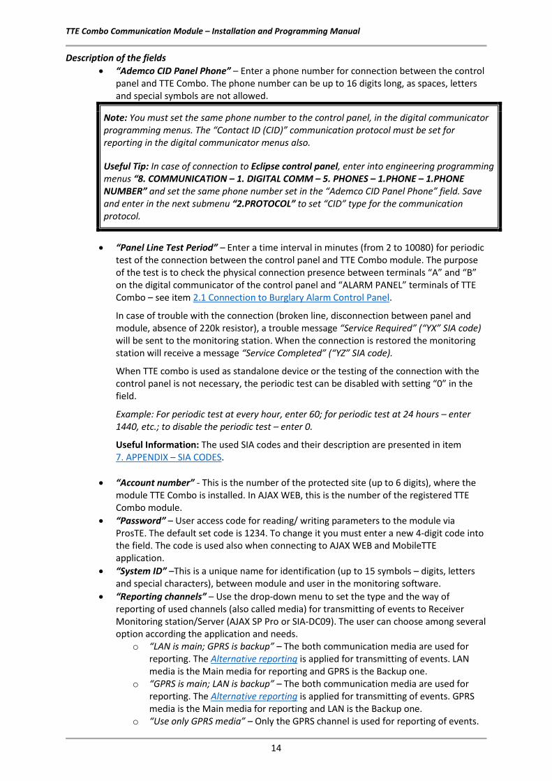
4.3 Online Connection with AJAX SP Pro Server After the successful adding of the new registered module to the User account, the TTE Combo must be programmed with the service TDF file generated during the registration.
Open ProsTE software and connect your local computer to the TTE Combo using standard USB – Micro USB data cable. Press Load button on the main ribbon bar and open the downloaded earlier service TDF file for your registered system. Click on the “+” icon in front of System to expand the menus of TTE Combo module. You can review the General Settings and Receiver Settings menus. There will be available the automatically set parameters from the server.
Select in sequence using the right mouse button TTE Combo – Write to upload the settings into the module. Follow the steps as described in item 3.7 Writing a Configuration.
When the uploading is complete, go back to the AJAX WEB and login into your account.
If the online connection is established, the module will be now online, the type and its software version will be recognized and visible, and the module will be ready for remote control by user.
Important note:
If a connected system operates for a while, and for some reasons becomes offline, the server will keep it in the system list up to 30 days after the disconnection. After that period the system will be deleted automatically.
4.4 Operation with System The User can perform some operation with the systems added to his account.
• “Search Filter” – On the top of the System List section, the User can search among the added systems to his account filtering them by: System Name, Status (Online/Offline), Account number or Type (panel or module). Choose from the drop-down list the option for filtering and enter into the second field word or value for searching. Press the Set Filter button to start.

TTE Combo Communication Module – Installation and Programming Manual
24
• “New Module” – Adding new system to the User account – see item 4.2 Adding a System to Account.
• “Status” – Click on the button to review some information about the connection between the system and the server – the system status. In the new window you will find details about the date of registration, last communication and the last user login for management and control.
• “Connect/Busy” – Remote control of the TTE Combo outputs. Attention: Every system can be shared for operation between different users, but only one of them can access it at a time. If the system is accessed from a User, the button becomes inactive with text “Busy”. That means the system is not accessible for control from other users at this time. The system is accessible when the button “Connect” is visible and active. To connect to a TTE Combo standalone module, press the button and enter the PC ID Number (1234 by default) – this is the password set with ProsTE – see also item 3.2 General Settings Menu.
• “Edit” – Editing the name of the system and setting the type of notification messages for events received via MobileTTE. Press the button to open the window for editing:
o “Red Dot Notifications” – A special mark (a red dot) alerts the User in case of occurring of an event (in the system list of MobileTTE). Check the boxes of those events for which you want to be alerted. See Red Dot Notifications in the User Guide.
o “Push Notifications” – Check the boxes for those events for which you want to receive a push notification messages on your smartphone. See Push Notifications in the User Guide.
Here you can change the name of the system.
You can use the QR code at any time for scanning and directly adding the system information to MobileTTE smartphone application.
These are special sections for setting the notification messages received via MobileTTE.

TTE Combo Communication Module – Installation and Programming Manual
25
• “Delete” – Deleting the system from the list and from AJAX WEB. The site will ask for confirmation. Note: Once deleted from the list and from the AJAX WEB, the system could not be restored again. If you delete it by mistake, you have to add the system again following the steps described in 4.2 Adding a System to Account.
• “Share” – Sharing the access to a system between two or more different users. To share the access, you have to know in advance the account Usernames of those Users to which you want to assign rights for operation. Press the “Share” button to open the “User Assignment” window.
The shared system is added automatically to the user account, but without the option for sharing (for account “user5120” from the example above):
Note: The right to share a system for operation with other users, can only the User who is performed the New Module Registration procedure (the initial registration of the system) to his own account.
Step-by-Step Example for sharing access to a system: 1. Enter in “User name” field a real account Username registered in AJAX WEB. 2. Press “<<Add” button. 3. The name of the User will be added to the list of the Assigned Users. 4. Press “OK” button. To remove a User from the List, select it and press “Remove>>” button. Then confirm with “OK”.

TTE Combo Communication Module – Installation and Programming Manual
26
5. TTE Combo – Installation Summary Here is a short list of the important steps necessary for successful connection of TTE Combo module to AJAX WEB.
• Disable the PIN protection code of the SIM card for the module and place it in the holder. • Power on TTE Combo – from the control panel or from external power unit 9-30VDC.
See also item 2.1 Connection to Burglary Alarm Control Panel. • Read the Factory setting of TTE Combo and pre-program the phone number for connection
with the panel (Ademco CID panel number), the Panel line test period and the type and the priority of used Reporting channels – see item 3.2 General Settings Menu. If you will use LAN as a communication media to AJAX WEB, it is recommended to leave “Automatic Settings (DHCP)” in LAN Settings menu.
• Save this configuration (FileName.TDF) on your local computer or laptop. You will need this file later during adding the system to AJAX WEB.
• Open AJAX WEB site and login. If you are a new user - make a registration. • In the system list of your account press “New module” button and register your TTE Combo
module as a standalone system. • Save the service TDF from the registration form on your local computer or laptop. • Open ProsTE software, connect to TTE Combo and write the service TDF file received from
AJAX WEB. • The established connection with AJAX WEB is indicated with blinking with green LED
“Main/Backup Receiver” of TTE Combo communication module. The Online status of the system will be indicated with an active online status (green) after login the AJAX WEB.

TTE Combo Communication Module – Installation and Programming Manual
27
6. USER GUIDE 6.1 AJAX WEB User Interface Using AJAX WEB interface, the user can remotely control the outputs of his TTE Combo module and to review the status of the Input (activated TAMPER). 6.1.1 Remote Access Login in your AJAX WEB User account and press “Connect” button.
The site will ask for a Password - PC ID Number (1234 by default):
Press “Connect” button and wait until the connection with the system is established. 6.1.2 Main Menus The online connection with the module provides the following activities for the User:
- Communication Module. Control of the TTE Combo Outputs and preview the status of the Input – see item 6.1.3 Communication Module. - Edit Parameters. Menu for setting the parameters of TTE Combo module.
The unavailable menus are presented into grey; the available – into blue; and the current selected – into black colour.
Not available
Available Menu
Selected menu
To exit from the system press “Disconnect” button.

TTE Combo Communication Module – Installation and Programming Manual
28
Out1
Out2
6.1.3 Communication Module In this menu the User can review the status of the input terminal (activated TAMPER) and to control (switch ON/OFF) the outputs of TTE Combo communication module. Description of TTE Combo Input and Outputs states:
Icon Terminal Description
Input The Input is not activated. The TAMPER switch (TAMPER zone type) is closed.
Output The output is turned OFF (deactivated) or it is not used.
Input
The Input is activated. The TAMPER switch (TAMPER zone type) is opened and TAMPER Alarm message is sent to Monitoring station and MobileTTE (notification).
Output The output is turned ON (activated). The current information for all 3 terminals (PGMs) of TTE Combo is displayed as the User can review their current status. The outputs are remotely controlled with Turn ON/OFF button. The User can set different names for every terminal according its functionality in the system – press Set Name button and enter a name to recognize. The terminals are displayed with numbers following their physical order on the PCB (left to right counting).
To activate the PGM output, press once the “Turn ON” button next to it. The status becomes “Active” and the button is changed to “Turn OFF”. To deactivate the PGM output, press once the “Turn OFF” button. The status becomes “Inactive” and the button is changed to “Turn ON”. 6.1.4 Edit Parameters Menu In this menu the User can perform programming of TTE Combo parameters same as the programming with ProsTE software. Click on Edit Parameters menu to enter into System Parameters settings. To expand the programming menus, click on the “►” icon on the tree structure on the left. Select the menu and review the available parameters on the right. All changes are saved with “UPLOAD” button. Attention: To avoid problems in operation, it is recommended the settings in this menu to be done only by a technician trained in installation of TTE Combo module!
In1
Terminals on the PCB:

TTE Combo Communication Module – Installation and Programming Manual
29
6.2 Mobile TTE Smartphone Application Mobile TTE is a smart phone application suitable for remote management of burglary control panels and modules produced by Teletek Electronics JSC. The application is compatible with Android and iOS platforms and can be downloaded directly from Google Play and App Store, or you can use the QR codes below:
6.2.1 Adding a System to Mobile TTE Run the Mobile TTE application and Press Menu – Add System.
Then you have to choose the way of adding the system. You can add the information manually or to scan the QR code received after registration of the system in AJAX WEB (recommended).
Mobile TTE

TTE Combo Communication Module – Installation and Programming Manual
30
The system will be added to the System List of MobileTTE. If the system is online and ready for operation that will be displayed with text in green. If there is a red dot in the upper left corner, that means there is a system event (the red dot notifications are set in AJAX WEB user account for every of the attached system and also edited in MobileTTE Settings Menu). 6.2.2 Connection to a System To connect with the system – TTE Combo module standalone device, press the button and wait until the connection is established. When you are connecting to a system for the first time, you will be asked to enter a User code – this is the Password code set with ProsTE – see item3.2 General Settings Menu .
6.2.3 Operation with outputs After entering the available outputs for management are loaded on the screen. The outputs are presented with their names set in AJAX WEB with an additional service name “Module”. The status of the output is changed with pressing ON/OFF button. Note: The Outputs are appeared with the numbers following their physical order on the PCB!
Out1 (on the PCB)
Press to connect with the system.
Choose the button to add the settings for system manually. You will be asked to enter:
- your account username and password in AJAX WEB; - a system attached to your AJAX WEB account; - UDL (PC ID) code (1234 by default).
Open the e-mail from the registration of the system and scan the received QR code after the registration.
Press to edit the system parameters and account settings or to delete the system from the list.
Press for more settings in MobileTTE application – language of the menus and reordering of the systems in the list.
Out2 (on the PCB)
Control buttons: - Output is switched ON. - Output is switched OFF.

TTE Combo Communication Module – Installation and Programming Manual
31
6.2.4 System Main Menu There are some important settings for the system. After connection press “Menu” button in the right upper corner of the screen. Then choose Settings.
The general functions of MobileTTE is to provide to the user remote control of the outputs of TTE Combo communication module, and to receive notification messages in case of alarm or trouble events and the arming status of the connected burglary alarm panel. The receiving of notification messages is disabled by default. The enabling of this function is in the Settings menu of the respective system.
The receiving of notification messages is enabled when the “Enabled” setting is visible in the section. In this menu the User can also set the type of the events for which to receive notifications. Select the Push Notification Groups and select those type of events for which you want to be informed.

TTE Combo Communication Module – Installation and Programming Manual
32
By default, all types of events are enabled (it depends also of the settings in AJAX WEB). The number of set notifications will be visible on the screen. Note, these are events for the status of the connected burglary control panel to TTE Combo module (via digital communicator). The notifications (for the status of the control panel) have the following description:
Event Description Sound type
ALARM Notification in case of burglary alarm in the system. Special alarm tone*
ARM Notification in case of arming (Full, Stay, Sleep) and disarming.
General notification tone
FIRE Notification in case of fire alarm in the system.
MEDICAL Notification in case of medical alarm in the system. (Activated medical type zone or panic button.)
PANIC Notification in case of panic alarm in the system. (Activated panic type zone or panic button.)
SPECIAL
Notification in case of other special events in the system like resetting of the system, time changed, test, etc. The special messages are programmed in the Eclipse panel engineering menus.
TAMPER Notification in case of open tamper in the system (panel or device).
TROUBLE Notification in case of trouble or fault event in the system, for example “220 AC Lost”, “Battery Lost”, etc.
*Note: Some smartphone models do not support the second alarm tone for notifications. In case the receiving of notifications in enabled, but you do not receive them, is necessary to check your smartphone settings and to enable also the notifications from installed applications programs.

TTE Combo Communication Module – Installation and Programming Manual
33
In Settings menu the user can also set the visualization of events via red dot in the system list. Select the Red Dot Notification and select those type of events for which you want to be informed.
You can find the description of the events in the table above.
It is recommended to leave the default settings for Refresh time and Last Events Count because they are optimal for the application. Move down to the bottom of Settings menu. There is an option to select different language of your MobileTTE smartphone application.
To exit from Settings menu, press Save button to confirm changes, or Back button to reject them. To exit from MobileTTE application press the Back button of your smartphone. The currently installed version of MobileTTE on your smartphone is reviewed with About button.
Change the language of the MobileTTE application menus. Note: This setting will not affect the set names of the PGMs in the system.

TTE Combo Communication Module – Installation and Programming Manual
34
7. APPENDIX – SIA CODES SIA
Code Event Code Description Address Field
AN Analog Restoral An analog fire sensor has been restored to normal operation. Zone or point
AR AC Restoral AC power of the control panel has been restored. Unused
AS Analog Service An analog fire sensor needs to be cleaned or calibrated. Zone or point AT AC Trouble AC power of the control panel has been failed. Unused BA Burglary Alarm Burglary zone has been violated while armed. Zone or point
BB Burglary Bypass Burglary zone has been bypassed. Zone or point BC Burglary Cancel Alarm has been cancelled by authorized user. User number
BD Swinger Trouble A non-fire zone has been violated after a Swinger Shutdown (short intermittent) on the zone. Zone or point
BE Swinger Trouble Restore A non-fire zone restores to normal from a Swinger (short intermittent) Trouble state. Zone or point
BH Burglary Alarm Restore Alarm condition eliminated. Zone or point BJ Burglary Trouble Restore Trouble condition eliminated. Zone or point
BM Burglary Alarm - Cross Point Burglary alarm w/cross point also in alarm - alarm verified. Zone or point
BR Burglary Restoral Alarm/trouble condition has been eliminated. Zone or point
BS Burglary Supervisory Unsafe intrusion detection system condition. Zone or point BT Burglary Trouble Burglary zone disabled by fault. Zone or point BU Burglary Unbypass Zone bypass has been removed. Zone or point
BV Burglary Verified A burglary alarm has occurred and been verified within programmed conditions (zone or point not sent). Area number
BX Burglary Test Burglary zone activated during testing. Zone or point CA Automatic Closing System armed automatically. Area number
CD Closing Delinquent The system has not been armed for a programmed amount of time. Area number
CE Closing Extend Extend closing time. User number CF Forced Closing System armed; some zones not ready. User number
CG Close Area System has been partially armed. Area number
CI Fail to Close An area has not been armed at the end of the closing window. Area number
CJ Late Close An area was armed after the closing window. User number CK Early Close An area was armed before the closing window. User number
CL Closing Report System armed, normal. User number CP Automatic Closing System armed automatically. User number CQ Remote Closing The system was armed from a remote location. User number
CR Recent Closing An alarm occurred within five minutes after the system was closed. User number
CS Closing Keyswitch Account has been armed by keyswitch. Zone or point CT Late to Open System was not disarmed on time. Area number
CW Was Force Armed Header for a force armed session, forced point msg. may follow. Area number
CZ Point Closing A point, as opposed to a whole area or account, has closed. Zone or point
DC Access Closed Access to all users prohibited. Door number DD Access Denied Access denied, unknown code. Door number

TTE Combo Communication Module – Installation and Programming Manual
35
SIA Code Event Code Description Address Field
DF Door Forced Door opened without access request. Door number DG Access Granted Door access granted. Door number DK Access Lockout Access denied, known code. Door number DO Access Open Access to authorized users allowed. Door number
DR Door Restoral Access alarm/trouble condition eliminated. Door number DS Door Station Identifies door for next report. Door number DT Access Trouble Access system trouble. Unused
DU Dealer ID Dealer ID number. Dealer ID
EA Exit Alarm An exit zone remained violated at the end of the exit delay period. Zone or point
EE Exit Error An exit zone remained violated at the end of the exit delay period. User number
EJ Expansion Tamper Restore Expansion device tamper restoral. Expansion device number
EM Expansion Device Missing Expansion device missing. Expansion device number
EN Expansion Missing Restore Expansion device communications re-established. Expansion device number
ER Expansion Restoral Expansion device trouble eliminated. Expander number
ES Expansion Device Tamper Expansion device enclosure tamper. Expansion device number
ET Expansion Trouble Expansion device trouble. Expander number
FA Fire Alarm Fire condition detected. Zone or point
FB Fire Bypass Zone has been bypassed. Zone or point FH Fire Alarm Restore Alarm condition eliminated. Zone or point FI Fire Test Begin The transmitter area's fire test has begun. Area number
FJ Fire Trouble Restore Trouble condition eliminated. Zone or point FK Fire Test End The transmitter area's fire test has ended. Area number
FQ Fire Supervisory Trouble Restore
A fire supervisory zone that was in trouble condition has now restored to normal. Zone or point
FR Fire Restoral Alarm/trouble condition has been eliminated. Zone or point FS Fire Supervisory Unsafe fire detection system condition. Zone or point FT Fire Trouble Zone disabled by fault. Zone or point
FU Fire Unbypass Bypass has been removed. Zone or point FX Fire Test Fire zone activated during test. Zone or point FY Missing Fire Trouble A fire point is now logically missing. Zone or point
GA Gas Alarm Gas alarm condition detected. Zone or point GB Gas Bypass Zone has been bypassed. Zone or point GH Gas Alarm Restore Alarm condition eliminated. Zone or point GJ Gas Trouble Restore Trouble condition eliminated. Zone or point
GR Gas Restoral Alarm/trouble condition has been eliminated. Zone or point GS Gas Supervisory Unsafe gas detection system condition. Zone or point GT Gas Trouble Zone disabled by fault. Zone or point
GU Gas Unbypass Bypass has been removed. Zone or point GX Gas Test Zone activated during test. Zone or point HA Holdup Alarm Silent alarm, user under duress. Zone or point

TTE Combo Communication Module – Installation and Programming Manual
36
SIA Code Event Code Description Address Field
HB Holdup Bypass Zone has been bypassed. Zone or point HH Holdup Alarm Restore Alarm condition eliminated. Zone or point HJ Holdup Trouble Restore Trouble condition eliminated. Zone or point HR Holdup Restoral Alarm/trouble condition has been eliminated. Zone or point
HS Holdup Supervisory Unsafe holdup system condition. Zone or point HT Holdup Trouble Zone disabled by fault. Zone or point HU Holdup Unbypass Bypass has been removed. Zone or point
JA User Code Tamper Too many unsuccessful attempts have been made to enter a user ID. Area number
JD Date Changed The date was changed in the transmitter/receiver. User number JH Holiday Changed The transmitter's holiday schedule has been changed. User number
JL Log Threshold The transmitter's log memory has reached its threshold level. Unused
JO Log Overflow The transmitter's log memory has overflowed. Unused JR Schedule Executed An automatic scheduled event was executed. Area number JS Schedule Changed An automatic schedule was changed. User number
JT Time Changed The time was changed in the transmitter/receiver. User number JV User Code Changed A user's code has been changed. User number JX User Code Deleted A user's code has been removed. User number
KA Heat Alarm High temperature detected on premise. Zone or point KB Heat Bypass Zone has been bypassed. Zone or point KH Heat Alarm Restore Alarm condition eliminated. Zone or point
KJ Heat Trouble Restore Trouble condition eliminated. Zone or point KR Heat Restoral Alarm/trouble condition has been eliminated. Zone or point KS Heat Supervisory Unsafe heat detection system condition. Zone or point KT Heat Trouble Zone disabled by fault. Zone or point
KU Heat Unbypass Bypass has been removed. Zone or point LB Local Program Begin local programming. Unused LD Local Program Denied Access code incorrect. Unused
LE Listen-in Ended The listen-in session has been terminated. Unused LF Listen-in Begin The listen-in session with the RECEIVER has begun. Unused LR Phone Line Restoral Phone line restored to service. Line number
LS Local Program Success Local programming successful. Unused LT Phone Line Trouble Phone line trouble report. Line number LU Local Program Fail Local programming unsuccessful. Unused
LX Local Programming Ended A local programming session has been terminated. Unused MA Medical Alarm Emergency assistance request. Zone or point MB Medical Bypass Zone has been bypassed. Zone or point MH Medical Alarm Restore Alarm condition eliminated. Zone or point
MJ Medical Trouble Restore Trouble condition eliminated. Zone or point MR Medical Restoral Alarm/trouble condition has been eliminated. Zone or point MS Medical Supervisory Unsafe system condition exists. Zone or point
MT Medical Trouble Zone disabled by fault. Zone or point MU Medical Unbypass Bypass has been removed. Zone or point

TTE Combo Communication Module – Installation and Programming Manual
37
SIA Code Event Code Description Address Field
NA No Activity There has been no zone activity for a programmed amount of time. Zone number
NF Forced Perimeter Arm Some zones/points not ready. Area number NL Perimeter Armed An area has been perimeter armed. Area number
OA Automatic Opening System has disarmed automatically Area number OC Cancel Report Untyped zone cancel. User number OG Open Area System has been partially disarmed. Area number
OI Fail to Open An area has not been armed at the end of the opening window. Area number
OJ Late Open An area was disarmed after the opening window. User number OK Early Open An area was disarmed before the opening window. User number OP Opening Report Account was disarmed. User number OQ Remote Opening The system was disarmed from a remote location. User number
OR Disarm From Alarm Account in alarm was reset/disarmed. User number OS Opening Keyswitch Account has been disarmed by keyswitch. Zone or point OT Late To Close System was not armed on time. User number
OZ Point Opening A point, rather than a full area or account, disarmed. Zone or point PA Panic Alarm Emergency assistance request, manually activated. Zone or point PB Panic Bypass Panic zone has been bypassed. Zone or point
PH Panic Alarm Restore Alarm condition eliminated. Zone or point PJ Panic Trouble Restore Trouble condition eliminated. Zone or point PR Panic Restoral Alarm/trouble condition has been eliminated. Zone or point
PS Panic Supervisory Unsafe system condition exists. Zone or point PT Panic Trouble Zone disabled by fault. Zone or point PU Panic Unbypass Panic zone bypass has been removed. Zone or point QA Emergency Alarm Emergency assistance request. Zone or point
QB Emergency Bypass Zone has been bypassed. Zone or point QH Emergency Alarm Restore Alarm condition has been eliminated. Zone or point QJ Emergency Trouble Restore Trouble condition has been eliminated. Zone or point
QR Emergency Restoral Alarm/trouble condition has been eliminated. Zone or point QS Emergency Supervisory Unsafe system condition exists. Zone or point QT Emergency Trouble Zone disabled by fault. Zone or point
QU Emergency Unbypass Bypass has been removed. Zone or point
RA Remote Programmer Call Failed
Transmitter failed to communicate with the remote programmer. Unused
RB Remote Program Begin Remote programming session initiated. Unused RC Relay Close A relay has energized. Relay number RD Remote Program Denied Access passcode incorrect. Unused
RN Remote Reset A TRANSMITTER was reset via a remote programmer. Unused RO Relay Open A relay has de-energized. Relay number RP Automatic Test Automatic communication test report. Unused RR Power Up System lost power, is now restored. Unused
RS Remote Program Success Remote programming successful. Unused RT Data Lost Dialer data lost, transmission error. Line number RU Remote Program Fail Remote programming unsuccessful. Unused

TTE Combo Communication Module – Installation and Programming Manual
38
SIA Code Event Code Description Address Field
RX Manual Test Manual communication test report. User number SA Sprinkler Alarm Sprinkler flow condition exists. Zone or point SB Sprinkler Bypass Sprinkler zone has been bypassed. Zone or point SH Sprinkler Alarm Restore Alarm condition eliminated. Zone or point
SJ Sprinkler Trouble Restore Trouble condition eliminated. Zone or point SR Sprinkler Restoral Alarm/trouble condition has been eliminated. Zone or point SS Sprinkler Supervisory Unsafe sprinkler system condition. Zone or point
ST Sprinkler Trouble Zone disabled by fault. Zone or point SU Sprinkler Unbypass Sprinkler zone bypass has been removed. Zone or point TA Tamper Alarm Opened TAMPER at TTE Combo module (IN1 Terminal). Zone or point
TB Tamper Bypass Tamper detection has been bypassed. Zone or point TE Test End Communicator restored to operation. Unused TH Tamper Alarm Restore TAMPER Restored at TTE Combo module (IN1 Terminal). Zone or point
TP Walk Test Point This point was tested during a Walk Test. Point number TR Tamper Restoral Alarm equipment enclosure has been closed. Zone or point TS Test Start Communicator taken out of operation. Unused TU Tamper Unbypass Tamper detection bypass has been removed. Zone or point
TX Test Report An unspecified (manual or automatic) communicator test. Unused
UA Untyped Zone Alarm Alarm condition from zone of unknown type. Zone or point UB Untyped Zone Bypass Zone of unknown type has been bypassed. Zone or point UH Untyped Alarm Restore Alarm condition eliminated. Zone or point
UJ Untyped Trouble Restore Trouble condition eliminated. Zone or point
UR Untyped Zone Restoral Alarm/trouble condition eliminated from zone of unknown type. Zone or point
US Untyped Zone Supervisory Unsafe condition from zone of unknown type. Zone or point UT Untyped Zone Trouble Trouble condition from zone of unknown type. Zone or point
UU Untyped Zone Unbypass Bypass on zone of unknown type has been removed. Zone or point UX Undefined An undefined alarm condition has occurred. Unused
UY Untyped Missing Trouble A point or device which was not armed is now logically missing. Zone or point
UZ Untyped Missing Alarm A point or device which was armed is now logically missing. Zone or point
VI Printer Paper In TRANSMITTER or RECEIVER paper in. Printer number
VO Printer Paper Out TRANSMITTER or RECEIVER paper out. Printer number VR Printer Restore TRANSMITTER or RECEIVER trouble restored. Printer number VT Printer Trouble TRANSMITTER or RECEIVER trouble. Printer number
VX Printer Test TRANSMITTER or RECEIVER test. Printer number VY Printer Online RECEIVER'S printer is now online. Unused VZ Printer Offline RECEIVER'S printer is now offline. Unused
WA Water Alarm Water detected at protected premises. Zone or point WB Water Bypass Water detection has been bypassed. Zone or point WH Water Alarm Restore Water alarm condition eliminated. Zone or point WJ Water Trouble Restore Water trouble condition eliminated. Zone or point
WR Water Restoral Water alarm/trouble condition has been eliminated. Zone or point

TTE Combo Communication Module – Installation and Programming Manual
39
SIA Code Event Code Description Address Field
WS Water Supervisory Water unsafe water detection system condition. Zone or point WT Water Trouble Water zone disabled by fault. Zone or point WU Water Unbypass Water detection bypass has been removed. Zone or point
XE Extra Point Panel has sensed an extra point not specified for this site. Point number
XF Extra RF Point Panel has sensed an extra RF point not specified for this site. Point number
XH RF Interference Restoral A radio device is no longer detecting RF Interference. Receiver number
XI Sensor Reset A user has reset a sensor. Zone or point
XQ RF Interference A radio device is detecting RF Interference. Receiver number
XR Transmitter Battery Restoral Low battery has been corrected. Zone or point XT Transmitter Battery Trouble Low battery in wireless transmitter. Zone or point
XW Forced Point A point was forced out of the system at arm time. Zone or point
YA Bell Fault A trouble condition has been detected on a Local Bell, Siren, or Annunciator. Unused
YB Busy Seconds Percent of time receiver's line card is on-line. Line card number
YC Communications Trouble
Problem with Main or Backup communication media. Example: “YC1”- Problem with GPRS media; “YC2”- Problem with LAN media. The type of the media and the priority of transmitting is set in General Settings menu.
1 - GPRS 2 - LAN
YD Receiver Line Card Trouble A line card identified by the passed address is in trouble. Line card number
YE Receiver Line Card Restored A line card identified by the passed address is restored. Line card number
YF Parameter Checksum Fail System data corrupted. Unused YG Parameter Changed A TRANSMITTER'S parameters have been changed. Unused
YH Bell Restored A trouble condition has been restored on a Local Bell, Siren, or Annunciator. Unused
YI Overcurrent Trouble An Expansion Device has detected an overcurrent condition. Unused
YJ Overcurrent Restore An Expansion Device has restored from an overcurrent condition. Unused
YK Communications Restore
The transmitting of messages via Main or Backup media is Restored. Example: “YK1”- GPRS communication media restored; “YK2”- LAN communication media restored.
1 - GPRS 2 - LAN
YM System Battery Missing TRANSMITTER/RECEIVER battery is missing. Unused YN Invalid Report TRANSMITTER has sent a packet with invalid data. Unused
YO Unknown Message Impossible translation of the received CID event Example: “YO1205” – the translation of CID 1205 is missing.
CID code
YP Power Supply Trouble TRANSMITTER/RECEIVER has a problem with the power supply. Unused
YQ Power Supply Restored TRANSMITTER'S/RECEIVER'S power supply has been restored. Unused
YR System Battery Restoral Low battery has been corrected. Unused
YS Communications Trouble RECEIVER and TRANSMITTER. Unused YT System Battery Trouble Low battery in control/communicator. Unused
TTE Combo Communication Module – Installation and Programming Manual
40
SIA Code Event Code Description Address Field
YW Watchdog Reset The TRANSMITTER created an internal reset. Unused
YX Service Required
Problem with the connection to the control panel – line is broken or the phone device terminals are not terminated with 220k resistor - 2.1 Connection to Burglary Alarm Control Panel.
Unused
YY Status Report This is a header for an account status report transmission. Unused
YZ Service Completed Connection with the control panel is restored. Unused
ZA Freeze Alarm Low temperature detected at premises. Zone or point ZB Freeze Bypass Low temperature detection has been bypassed. Zone or point ZH Freeze Alarm Restore Alarm condition eliminated. Zone or point
ZJ Freeze Trouble Restore Trouble condition eliminated. Zone or point ZR Freeze Restoral Alarm/trouble condition has been eliminated. Zone or point ZS Freeze Supervisory Unsafe freeze detection system condition. Zone or point
ZT Freeze Trouble Zone disabled by fault. Zone or point ZU Freeze Unbypass Low temperature detection bypass removed. Zone or point

TTE Combo Communication Module – Installation and Programming Manual
41
www.teletek-electronics.com
Address: Bulgaria, 1407 Sofia, 14А Srebarna Str. Tel.: +359 2 9694 800, Fax: +359 2 962 52 13 e-mail: [email protected]