LAMP SERIES REPORT
17
INTERNATIONAL ATOMIC ENERGY AGENCY UNITED NATIONS EDUCATIONAL, SCIENTIFIC AND CULTURAL ORGANIZATION LAM 1790/8 INTERNATIONAL CENTRE FOR THEORETICAL PHYSICS LAMP SERIES REPORT (Laser, Atomic and Molecular Physics) PRINCIPLES OF OPTICAL FIBRE COMMUNICATION TECHNIQUES: NONCOHERENT AND COHERENT V.K. Jain 1990 MIRAMARE - TRIESTE
-
Upload
khangminh22 -
Category
Documents
-
view
7 -
download
0
Transcript of LAMP SERIES REPORT
INTERNATIONAL ATOMIC ENERGY
AGENCY
UNITED NATIONS EDUCATIONAL,
SCIENTIFIC AND CULTURAL ORGANIZATION
LAM 1790/8
INTERNATIONAL CENTRE FOR THEORETICAL PHYSICS
LAMP SERIES REPORT
(Laser, Atomic and Molecular Physics)
PRINCIPLES OF OPTICAL FIBRE COMMUNICATION
TECHNIQUES: NONCOHERENT AND COHERENT
V.K. Jain
1990 MIRAMARE - TRIESTE
P r e f a c e
The I C T P - L A M P r e p o r t s consis t of m a n u s c r i p t s relevant to seminars and discussions held at ICTP in the field of Laser, Atomic and Molecular Physics (LAMP).
These repor t s aim at informing LAMP researchers on the activity carr ied out at ICTP in their field of interest , with the specific p u r p o s e of s t imula t ing scientif ic con tac t s and collaboration of physicists from Third World Countr ies .
If you a r c i n t e r e s t e d in r e c e i v i n g a d d i t i o n a l information on the Laser and Optical Fibre activities at ICTP, kindly contact Professor Gallieno Denardo, ICTP.
LAMP/90/X
International Atomic Energy Agency
and
United Nations Educational Scientific and Cultural (Mganization
INTERNATIONAL CENTRE IOR THEORETICAL PHYSICS
LAMP SERIES REPORT
(Laser, Atomic and Molecular Physics)
PRINCIPLES OF OPTICAL FIBRE COMMUNICATION TECHNIQUES:
NONCOHERENT AND COHERENT
V.K.Jain'
International Centre for Theoretical Physics, Trieste, Italy.
ABSTRACT
In this paper a brief historical description of optical fibre communication system (OFCS)
has been presented and the main characteristics ot the basic components used in it are summarized.
Introduction of noncoherent and coherent (homodync and heterodyne i system is given. In coherent
OFCS, source linewidth requirement, phase anil polarization — divcr-ity and combined phase and
polarization - diversity receivers are described.
M1RAMARI--TRIESTE
October 1990
Permanent address: Electrical Engineering Department, Indian Institute of Technology, llauzKhas.
New Delhi 110016, India.
1.INTRODUCTION:
The principal motives behind the design of a communication
systems are either to improve the tranamission fidelity, to
increase the data rate / bandwidth or to increase the spacing
between the repeater:! Since available bandwidth for information
tranumission is directly related to the carrier frequency, the
trend in the communication world is to use the higher and higher
carrier frequency Thia led to the birth of optical
communication system.
In early 196U:i, several communication experiments were
conducted using atmospheric optical channels . However , the
high installation cost and the limitations imposed on the
atmospheric channel by rain , fog , snow and dust etc. made
thedf systems unattractive from the practical point of view.
Concurrent with the work on atmospheric channels, investigations
were also carried out on guided propogation of optical signal
through the optical fibres. These were thought to provide more
reliable arid versatile communication channel than the atmosphere.
Initially the attenuation coefficient of the fibre was
nearly 1000 dB / km In 1966 , Kao and Hockam [1) showed that the
high attenuation of ihe fibres available at that time was not due
to rhe intrinsic |n opertie.i of the materials, but due to the
pres'-nce ot inipuri i i ea in t h e fibre material . Reduction of
Hurh impurities to v ry low levels (in some cases of the order of
one part per billion ) would allow attenuation coefficient to be
much lower than the ones usually (ound in copper cables. In
1970, Kapron, Keck and Maurer [2] of the Corning Glas.-i Uorks
fabricated a fibre having an attenuation coefficient of 20 dB/km.
Now-a-days fibres with an attenuation coefficient of as low as
0.2 dB/km are available [3].
In the decade that followed the above breakthrough ,
extensive investigations were conducted on the possible use of
optical fibre for telecommunication purposes. In the first half
of 1970s , ,i number of field trials were carried out on digital
transmission systems at various bit rates. These systems were
operating in the 800 - 900 nm wavelenwh region, commonly known aa
first window. In this region , fibres at that time had their
minimum attenuation and other key components i.e., sources and
detectors were available. In the second half of the 70s, with
the development of technology, other wavelength regions around
1300 nm and 1550 nm, often referred to aa second and third window
respectively became available. At th«:ie wavelengths , performance
of the fibre has been reported to be much better than in the
first window [3]. In early 80s, a number of optical fibre
communication systems .it 1J00 nm were put on trial and now
these are being put in service . Communication systems at lbSf)
nm range are still in an early stage of development [31_
This paper ia organized as follows : In section 2, main
characteristics of the ba:iic components used in OKC.i viz., fibre.
source and detector art discussed. In aection 3, a brief
introduction to the noncoherent OFCS is given . Section 4 diMla
with the coherent OFCS In this section, principles of operation
of homodyne and heterodyne receiver is presented. Laiier
lineuidth requirement and the impairment in the coherent receiver
performance due to laser phase noise and polarization mismatching
is discussed. Operation of phase and polarization - diversity and
the combined phase nad polarization - diversity receiver to
overcome the degradation in the performance has been discussed.
2.BASIC COMPONENTS:
There are three basic comonents in OFCS .These are: source,
fibre and detector. A brief description of these components 11 <>m
the telecommunication point of view is given below.
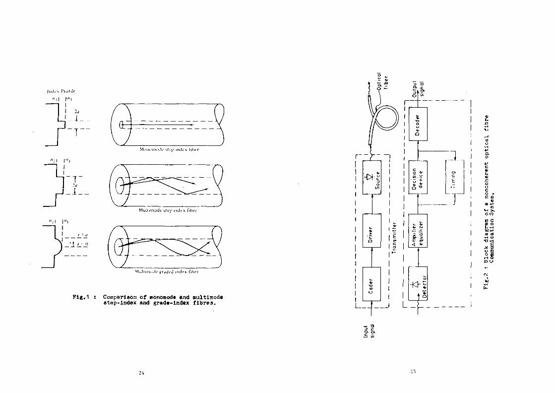
2.1 Optical Fibre:
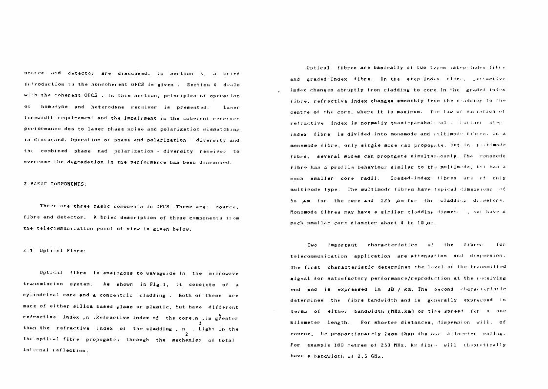
Optical fibre is analogous to waveguide in the microwave
transmission system. As shown in Fig.l, it consists of a
cylindrical core and a concentric cladding . Both of these are
made of either silica based tilass or plastic, but have different
refractive Index ,n .Refractive index of the core.n ,is greater 1
than the refractive index of the cladding , n . Light in the 2
the optical fibre propogate:; through the mechanism of total
Internal reflection.
Optical fibres are basically of two types :step index filne
and graded-index fibre. In the step-lnd<x (ibr» , reitactive
index changes abruptly fron cladding to core.In the graded-index
fibre, refractive index changes smoothly from the c;addiiu to tin-
centre of the core, where it is maximum. The law oi variation ol
refractive index is normally qu.io i -parabol i cal . lurthei step
index fibre is divided into monomode and mu 11 i mod» I iljr c::. In a
monomode fibre, only single mode can propoxate, but in iiniltinoile
fibre, several modes can propogate simultaneously. The iionomode
fibre has a profile behaviour similar to the multim do, but. has a
much smaller core radii. Graded-index fibres are of only
multimode type. The multlmode fibres have typical dimension:'; o(
5o /jm for the core and 125 /im for the claddii j.' diameter.4;.
Monomode fibres may have a similar claddin*.: diuniet' , but have a
much smaller core diameter about t to 10 /jm.
Two important characteristics of the fibre:! for
telecommunication application are attenuation and dispersion.
The first characteristic determines the level of the transmitted
signal for satisfactory performance/reproduction at the receiving
end and is expressed in dB / km. The second characteristic
determines the fibre bandwidth and is generally expressed in
terms of either bandwidth (MHz.km) or time spread for a one
kilometer length. For shorter distances, Jispeiioion will, of
course, be proportionately less than the one kilometer rating.
For example 100 metres of 250 MHz. km fibre will theoretically
have a bandwidth o( 2.5 GHz.
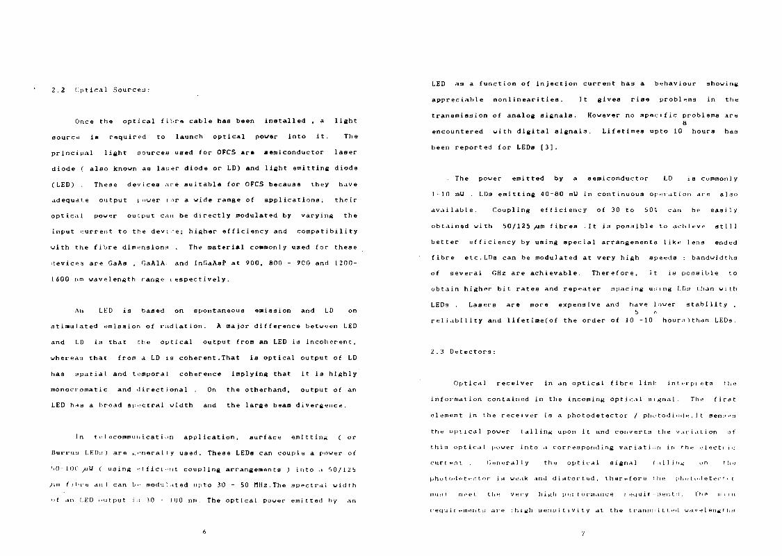
2.2 Optical Sources:
Once the optical fibre cable has been installed , a light
source is required to launch optical power into it. The
principal light sources used for OFCS are semiconductor laser
diode ( also known aa la;;er diode or LD) and light emitting diode
(LED) These devices ate suitable for OFCS because they have
adequate output power tor a wide range of applications; their
optical power output c<m be directly modulated by varying the
input current to the device; higher efficiency and compatibility
with the fibre dlmansions . The material commonly used for these
devices are GaAs , GaAlA: and InGaAaP at 900, 800 - 900 and 1200-
1600 nm wavelength range respectively.
An LKD is based on spontaneous emission and LD on
stimulated emission of radiation. A major difference between LED
and LD is that the optical output from an LED is incoherent,
whereas that from a LD ia coherent.That is optical output of LD
has spatial and temporal coherence implying that it is highly
monocromatic and directional On the otherhand, output of an
LED has a broad spectral width and the large beam divergence.
In telecommunication application, surface emitting ( or
Burrua I.EDu) are ^i-ntral ly used. These LEDs can couple a power of
SO-11)11 /ill ( using efficient coupling arrangements ) into a 50/125
/»•" fibre ami can b.- modulated upto 30 - 50 MHz.The spectral width
of an I.ED output i.i 30 - 10 0 nm. The optical power emitted by an
6
LED as a function of injection current has a behaviour showing
appreciable nonlinearities. It gives rise problems in the
transmission of analog signals. However no specific problems are S
encountered with digital signals. Lifetimes upto 10 hours has
been reported for LEDs [3].
The power emitted by a semiconductor LD ia commonly
1-10 mU LDs emitting 40-80 mU in continuous operation are also
available. Coupling efficiency of 30 to 50* can be easily
obtained with 50/125 /jm fibres .It is possible to achieve atlll
better efficiency by using special arrangements like lens ended
fibre etc.LDs can be modulated at very high speeds bandwidtha
of several GHz are achievable. Therefore, it ia possible to
obtain higher bit rates and repeater spacing using IDs than with
LEDs Lasers are more expensive and have lower stability .
5 t, reliability and 1ifetime(of the order of 10 -10 hours)than LEDs.
2.3 Detectors:
Optical receiver in an optical fibre link interptets the
information contained in the incoming optical signal. The first
element in the receiver is a photodetector / photodiode.It senses
the optical power tailing upon it and converts the variation of
this optical power into a corresponding variation in the electr i <;
current Generally the optical signal falling on rli.;
pho t o<l •• t t-'C t or is weak and distorted, therefore the pho t od e t ec T • < r
mu M r meet the v t:i- y h i ̂ h p IM I o r mam: e r t»q u i i •men t :i . The n> i i n
i ec|u i i einen t :i are :high sensitivity at the t ratunn i t t e>l wav e I eriu r ha
7
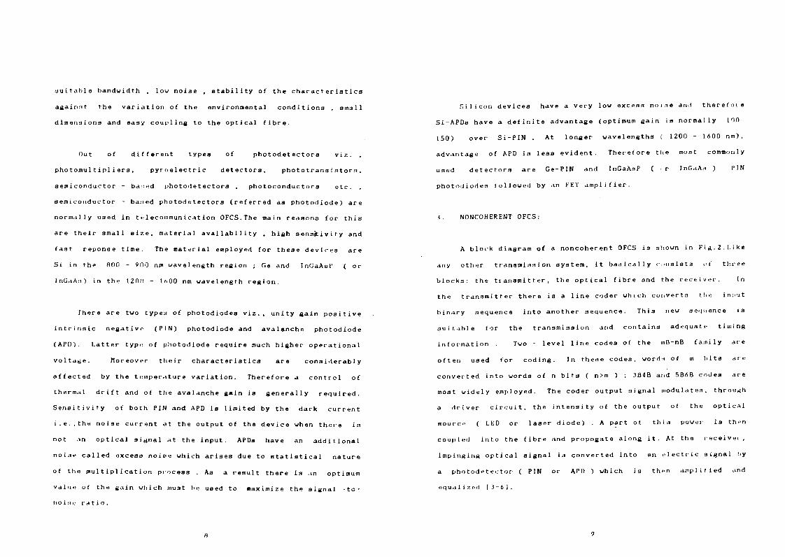
suitable bandwidth , low noise , stability of the characteristics
again.'it the variation of the environmental conditions , small
dimensions and easy coupling to the optical fibre.
Out of different types of photodetectors viz. ,
photomultipliera , pyroelectric detectors, phototransistors.
semiconductor - based photodetectors , photoconductors etc.
serai conductor - ba;:ed photodetectors (referred as photodiode) are
normally used in telecommunication OFCS.The main reasons for this
are their small size, material availability , high sensitivity and
fast reponse time. The material employed for these devices are
Si in the 800 - 900 nm wavelength region ; Ge and InGaAsP ( or
InGaAs) in the 1200 - 1600 nm wavelength region.
There are two typea of photodiodes viz., unity gain positive
intrinsic negative (PIN) photodiode and avalanche photodiode
(APD). Latter type of photodiode require much higher operational
voltage. Moreover their characteristics are considerably
affected by the temperature variation. Therefore a control of
thermal drift and of the avalanche gain is generally required.
Sensitivity of both PIN and APD is limited by the dark current
i.e.,the noise current at the output of the device when there is
not an optical signal at the input. APDa have an additional
noise called excess noise which arises due to statistical nature
of the multiplication process . As a result there is an optimum
value of the sain which must he used to maximize the signal -to-
noisu ratio.
H
Silicon devices have a very low excess noise and therefore
Si-APDa have a definite advantage (optimum gain is normally 100-
150) over Si-PIN . At longer wavelengths ( 1200 - 1600 nm).
advantage of APD is less evident. Therefore the moat commonly
used detectors are Ge-PIN and InGaAsP ( r InGaA.i ) PIN
photodiodes followed by an FET amplifier.
J. NONCOHERENT OFCS:
A block diagram of a noncoherent OFCS i3 shown in Fig.2.Like
any other transmission system, it basically consists of three
blocks: the transmitter, the optical fibre and the receiver. In
the transmitter there is a line coder which converts the input
binary sequence into another sequence. This new sequence is
suitable for the transmission and contains adequate timing
information . Two - level line codes of the mD-nB family are
often used for coding. In these codes, wordi of m hits ate
converted into words of n bits ( n>m ) ; 3B4B and 5B<5B codes are
most widely employed. The coder output signal modulates, through
a driver circuit, the intensity of the output of the optical
source ( LED or laser diode) . A part of this power is then
coupled into the fibre and propogate along it. At the receiver,
impinging optical signal is converted into an electric signal l>y
a photodet ec-tor ( PIN or API) ) which is then amplified and
oqua1i zed [ ^- 6] .
9
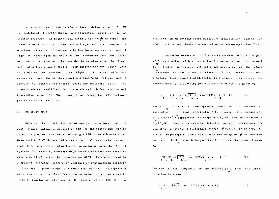
At a data rate of 140 Hbit/a or less , drive current of LED
is modulated directly through a differential amplifier or an
emitter follower. At higher data rates ( 565 rtbityte or more), the
laser source can be driven by a voltage amplifier through a
matching circuit. Of course, with the laser source. a control
loop to track both the drift of the threshold and modulation
efficiency is required. As regards the receivers, at the lower
bit rates like Z and 8 tlbit/s , PIN photodiodes are often used
to simplify the receiver. At higher bit rates, APDs are
generally used though they require a high biaa voltage and a
circuit to control the thermal drift and avalanche gain. The
transimpedence amplifier is the preferred choice for signal
bandwidths upto 1 *>n PIHz ; above this value, the FET voltage
preamplifier is used [ i - 6 \ .
4. COHERENT OFCS:
Despite the i-i;iid advances of optical technology over the
past decade, intensity modulation (IH) of the source and direct
detection (DD) of the receiver using a PIN or an APD have still
been used in OFCS.However,advances in optical components techno
logy have now offered significant advantages over the I tl - DD
systems .For example, coherent OFCS could offer receiver sensiti
vity S to 20 dB better than noncoherent OFCS. This would lead to
increased repeater spacing or increase In transmission capacity
or inn ease in power budget available for optical multiplexing
/demultiplexing. It also offers better selectivity. As a result
<hann.-l spacing of ..nly, nay 100 MHz in:itead of the 100 GHz let
10
required in an optical fibre multiplex transmission system. In
addition to these, there are several other advantages also [7-9].
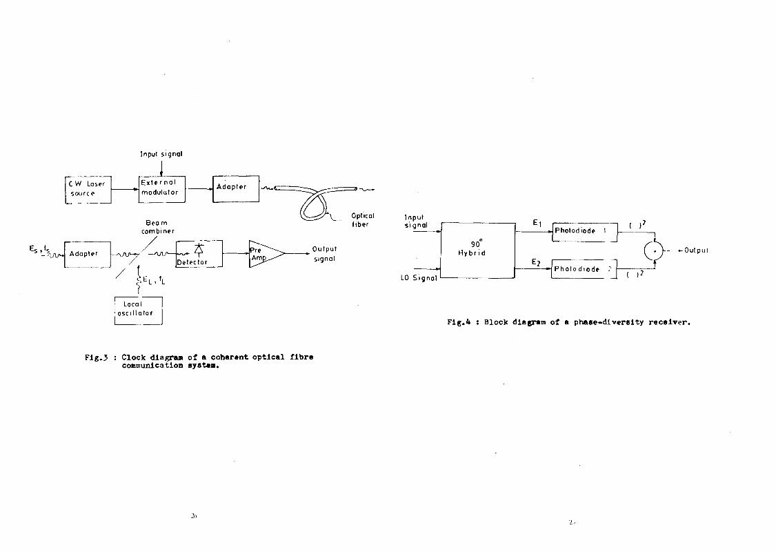
In coherent detect ion,the low level received optical signal
(E ) ia combined with a strong locally generated optical signal S
(E ) (refer to Fig. 3 ) . Let the phase angle, tp, is the phase L
difference between these two electric fields defined at some
arbitary time. Since photodetector is a square law device, the
photocurrent (i ) assuming perfect optical mixing is given by t
i = R (P +P +2 J~P P c o s [2TT(f - f ) t « 0 ] ) ( 1 ) t o S L S L L S
where P is the incident optical power in the absence of S
modulation ; P local oscillator ( L0 ) power The parameter, L
R ( = >1 q/hl) ) represents the reaponaivity of the pho t ode t ect or o "•
(iiA/xjU) Here Y] represents detector quantum efficiency ; h
Planck"s constant, q electronic charge ;^ optical frequency, f S
signal frequency; f local oscillator frequency and jp as defined
L earlier. As P Is much larger than P , (1) can be approximated
L S as
i *R (P *Z I P P cos ( 2 T T ( f - f ) t + ^ l ) (2) t o L S L L S
Desired signal component of the current (i ) from the above
equation is given by
i R (2 J P P c o s [ 2 T T ( f - f n + j t f n O ) s o S L L S
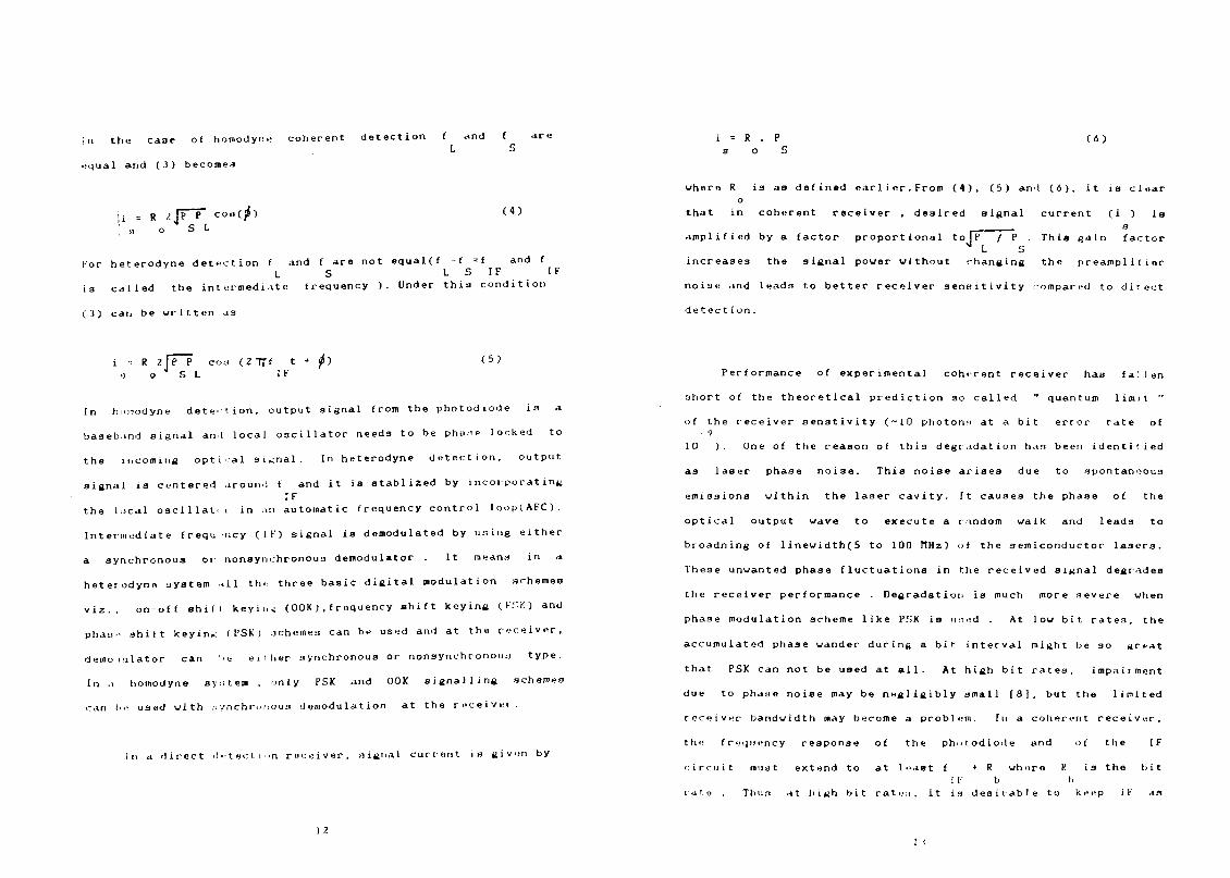
:n the case of homodyne coherent detection f and f are
L S
equal and (3) becomes
|i = R ,>JFT" coe(j<) ' « o S L
(«)
tor heterodyne detection f and f are not equal(f -f -f and f L S L S IF IF
ia called the intermediate frequency ). Under this condition
(3) can be written as
R 2\P P cod (27Tf t + jp) o g S L IF
(5)
In humodyne detection, output signal from the photodiode is a
baseband signal an.I local oscillator needs to be phaae locked to
the incoming optical signal. In heterodyne detection, output
signal is centered around f and it is atablized by incorporating IF
the local oscillator in an automatic frequency control loop(AFC).
Intermediate frequ ncy (IF) signal is demodulated by using either
a synchronous or nonsynchronous demodulator It means in a
heterodyne system all thu three basic digital modulation schemes
viz., on-off shift keying (00K).frequency shift keying (Fi;K) and
phase shift keying ( I'SK ) schemes can be used and at the receiver.
demodulator can 'e eiilier synchronous or nonsynchronouj type.
In a homodyne system , only PSK and OOK signalling schemes
can be used with :: ynchruuous demodulation at the receiver.
In a direct detection receiver, oignal current in given by
1 7.
i = R . P (6) s o S
where R is as defined earlier.From (4), (5) and (6), it is clear o
that in coherent receiver , desired signal current (1 ) is
.——— s
amplified by a factor proportional to IT / P • This gain factor 4 I S
increases the signal power without changing the preamplifier
noise and leads to better receiver sensitivity compared to direct
detect ion.
Performance of experimental coherent receiver has fallen
short of the theoretical prediction so called " quantum limit "
of the receiver senstivity (-10 photon.i at a bit error rate of
10 ). One of the reason of this degradation has been identitied
as laser phase noise. This noise arises due to spontaneous
emissions within the laser cavity. It causes the phase of the
optical output wave to execute a random walk and leads to
broadning of linewidth(5 to 100 H H Z ) of the semiconductor lasers.
These unwanted phase fluctuations in the received signal degrades
the receiver performance Degradation is much more severe when
phase modulation scheme like PSK is used . At low bit rates, the
accumulated phase wander during a bit interval might be so great
that PSK can not be used at all. At high bit rates. impairment
due to phase noise may be negligibly small (8], but the limited
receiver bandwidth may become a problem. In a coherent receiver,
the frequency response of the photodiode and of the IF
circuit must extend to at least f • R whore K is the bit
I F b I. rate . Thus at high bit rate.i, it is desirable to keep IF as
1 I
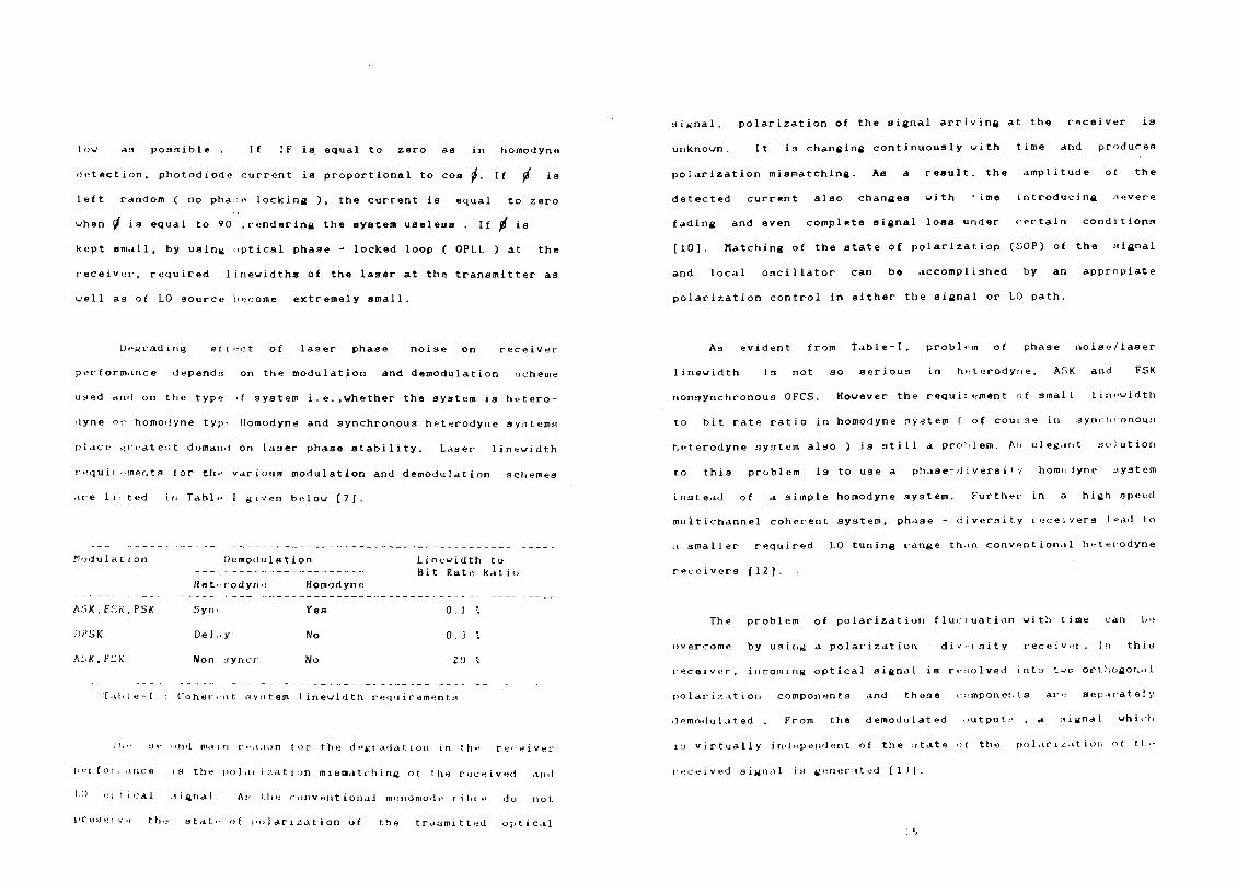
low as possible . If IF is equal to zero aa in homodyne
detection, photodiode current is proportional to cos 0. If fj ia
left random ( no phase locking ) , the current la equal to zero
when (J ia equal to 90 .rendering the system useless If p is
kept small, by using optical phase - locked loop ( OPLL ) at the
receiver, required linewidths of the laser at the transmitter as
well as of L0 source become extremely small.
Degrading eftect of laser phase noise on receiver
performance dependn on the modulation and demodulation acheie
used ami on the type >( system i.e.,whether the system is hetero
dyne or homoilyne t yp-'. Homodyne and synchronous heterodyne systems
place .:redttst demand on laser phase stability. Laser linewidth
requit ••mentfl lor the various modulation and demodulation schemes
are listed in Tabl- I given below [7].
Modular ion Demodulation Linewidth to Bit Rate katio
Heterodyne Homodyne
ASK,FSK.PSK Synr Yes 0 . ) \
DPSK D e l . . y No 0 . 3 \
AsK.FSK Non jyncr No 20 ".
Tahle-1 Coher-sit jiyMtem lineuidth requirements
l'i" ae, HII| main re.ison tor the degradation in the re'-eiver
li'M (or.i.ince is the polai ization mismatching or the received ami
LO Di.I ical signal. . A:: the conventional monomode tilne do not.
proaeiv.j the star.- of polarisation of the traumitted optical
signal, polarization of the signal arriving at the receiver is
unknown. It is changing continuously with time and produces
polarization mismatching. As a result, the amplitude of the
detected current also changes with i ime introducing aevere
fading and even complete signal loaa under certain conditions
[10]. Hatching of the state of polarization (SOP) of the signal
and local oscillator can be accomplished by an appropiate
polarization control in either the signal or LO path.
As evident from Table-I, problem of phase noise/laser
linewidth is not so serious in heterodyne, ASK and FSK
nonsynchronous OFCS. However the requirement of small linewidth
to bit rate ratio in homodyne system t of course in synclnonouu
heterodyne system also ) is still a problem. An elegant solution
to this problem is to use a phase-diversity horao.Jyne system
instead of a simple homodyne system. Further in a high speed
multichannel coherent system, phase - diversity receivers lead to
a smaller required LO tuning range thin conventional heterodyne
receivers [12].
The problem of polarization fluctuation with time can be
overcome by using a polarization - div.'isity receiver. I n thin
receiver, incoming optical signal is resolved into two orthogonal
polarization components and these components are separately
demodulated . From the demodulated outputs , a :>ignal which
in virtually independent of the state >I the polarisation ot the
received signal is generated [It).
Principles of phase and polarization - diversity receivers
are de.-jcribod below.
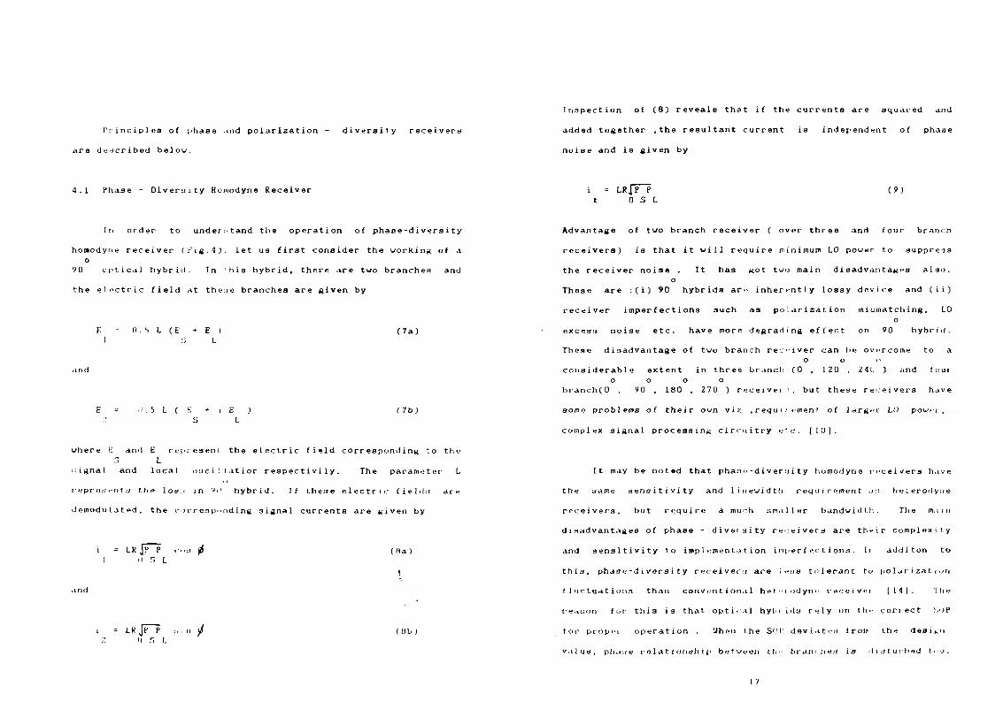
4.1 Phase - Diversity Homodyne Receiver
In order to understand the operation of phase-diversity
homodyne receiver (Fig.4). let us first consider the working of a o
90 optical hybrid. In 'his hybrid, there are two branches and
the electric field at theae branches are given by
0 . i L ( E (7a)
li . S L ( K + i E ) S L
(7b)
where K anil E represent the electric field corresponding to the 5 L
signal and local oaci ! latior respectivi1y. The parameter L
i epr e:.- i-n t s the loy:> in '»ii hybrid. If these electric fields ate
demodulated, the rorr esp'.nd i ng signal currents are given by
LR Jp P II S L
(Ha)
and
LRjP P I) 5 I.
(Ob)
Inspection of (8) reveals that if the currents are squared and
added together ,the resultant current is independent of phase
noise and is given by
i = LRjP P (9) t 0 S L
Advantage of two branch receiver ( over three and four branch
receivers) is that it will require minimum LO power to suppress
the receiver noise . It has got two main disadvantages also. o
These are :(i) 90 hybrids arc inherently lossy device and (ii)
receiver imperfections such as polarization mismatching, 1.0 o
excess noise etc. have more degrading effect on 90 hybrid.
These disadvantage of two branch receiver can hi; overcome to a o o o
considerable extent in three branch (0 , 120 , 24U ) and four o o o o
branch(0 , 90 , 180 , 270 ) receivers, but these receivers have
some problems of their own vi^.,requi;etnent of larger LO power,
complex signal processing circuitry etc. [10].
It may be noted that pha;n:-diver:jity homodyno receivers have
the same sensitivity and linewidtb requirement a:i heterodyne
receivers. but require a much smaller bandwidth. The main
disadvantages of phase - diveisity receivers are their complexity
and sensitivity to implementation imperfections. In additon to
this, phase-diversity receiver:! are I e<is tolerant to polarization
fluctuations than conventional he f -i odyri" receiver [11]. lh>;
t-e.iuon for this is that optical hyln ids rely on th- correct ;,i>P
tor proper operation . Uhen the SOI' deviates from the design
v.iluu, phane r o 1 a t i onsh i p between the branches is 'ILstutbed lno.
17
In order to simplify the practical implementation of the
phase -diversity receiver,aometimes the IF is taken to be several
megahertz or even half of the bit rate instead of zero. Such
receivers are called quasi-homodyne or intradyne receiver.
Intradyne-phase diversity receivers have the same sensitivity and
linewidth requirement as homodyne phase-diversity receivers, but
need a somewhat larger bandwidth [14].
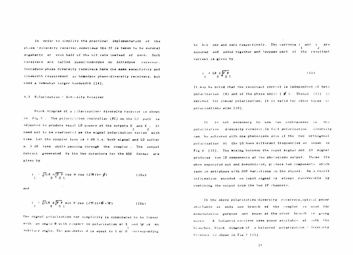
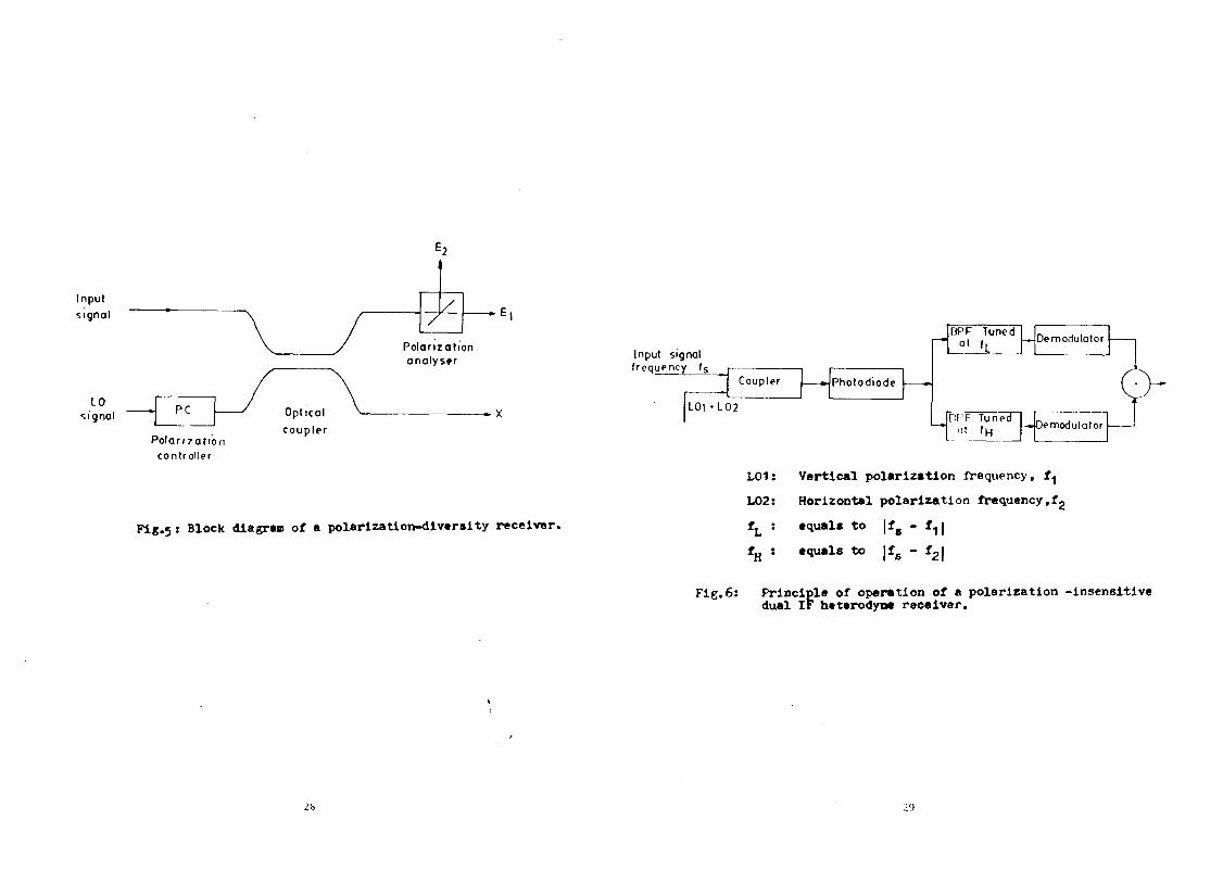
'i . Z Polarization - Div.ioity Receiver
Block diagram of a ;oiarization- diversity receiver is shown
111 f i»'> • The polar j .-..it ion controller (PC) on the 1.0 path in
adjusted to produce equal L0 powers at the outputs E and E . It
1 2 need not to be readjusted as the signal polarization varies with
time. Let the coupler loss is 3 dB i.e. both signal and L0 suffer
a 3 dB loss while passing through the coupler . The output
current generated by the two detectors for the ASK format are
given by
i = JTlR (1 ]P P cos 9 cos (2TTft + j/) (10a) 1 0 J S [.
and
i = JTlR d Jp P ain 9 cos (2 7T f t • <£ * ̂ ) (10b) t. 0 S L
The signal polarization for simplicity is considered to be linear
with an angle 9 with inspect to polarization of E and Vf is an 1
arbit.aiy angle. Tli •• parameter d is equal to 1 or 0 correspond in*
to bit one and zero respectively. The currents i and i are 1 2
squared and added together and lowpass part of the resultant.
current is given by
i = LR d IP P t 0 ^ S L
(11)
It .may be noted that the resultant current is independent of both
polarization (8) and of the phase noise ( jl ) . Though (11) i::
derived (or linear polarization, it is valid for other types oi
polarizations also [10].
[t is not necessary to use two piiototiiodes t u the
polarization - diversity receiver.In fa't polarization - diversity
can be achieved with one photodiode ah:o if the two orthogonal
polarization of the LO have different frequencies as :;hown in
Fig 6 [15]- The mixing between the input signal and LO signal
produces two IF components at t.he phorodiode output. These I Fs
when separated out and demodulated, produce two component;! which
fade in antiphase with SOP variations in the signal. As a result
information encoded on input signal is always recoverable by
combining the output from the two IF channels.
In the above po1arization-diversity recetvers,optical power
available at only one branch of the coupler is used tor
demodulation purpose and power at the othor branch is going
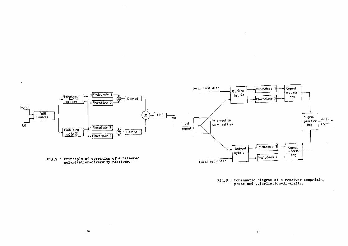
waste. A balanced receiver uses power available at both the
branches. Block diagram of a balanced polarization - diversity
r ece i v ei t s shown in F i M . 7 [ibj.
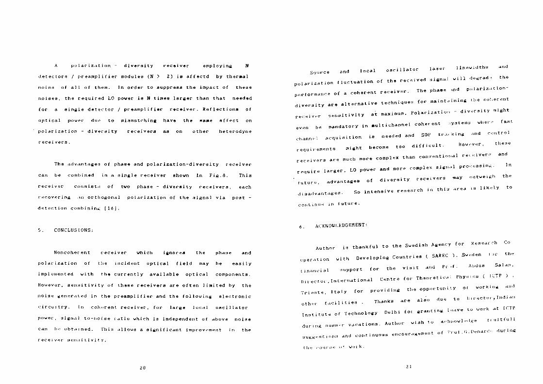
A polarization - diversity receiver employing N
detectors / preamplifier modules (N > 2) is affectd by thermal
noise of all of them. In order to suppress the impact of these
noiaea, the required LO power is N times larger than that needed
for a single detector / preamplifier receiver. Reflections of
optical power due to mismatching have the same affect on
polarization - diversity receivers as on other heterodyne
receivers.
The advantages of phase and polarization-diversity receiver
can be combined in a single receiver shown in Fig.8. This
receiver consists of two phase - diversity receivers, each
recovering .in orthogonal polarization of the signal via post -
detection combining [16].
5. CONCLUSIONS:
Noncoherent receiver which ignores the phase and
polarization of the incident optical field may be easily
implemented with the currently available optical components.
However, sensitivity of these receivers are often limited by the
noise generated in the preamplifier and the following electronic
circuitry. In coherent receiver, for large local oscillator
power, signal-to-noise ratio which is independent of above noise
can bo obtained. This allows a significant improvement in the
receiver sensitivity.
20
Source and local oscillator laser linewidths and
polarization fluctuation of the received signal will degrade the
performance of a coherent receiver. The phase and polarization-
diversity are alternative techniques for maintaining the coherent
receiver sensitivity at maximum. Polarization - diversity might
even be mandatory in multichannel coherent systems where fast,
channel acquisition is needed and SOT tracking and control
requirements might become too difficult. However, these
receivers are much more complex than conventional receiver:! and
require larger, LO power and more complex signal processing. In
future, advantages of diversity receivers may outweigh the
disadvantages. So intensive research in thi3 area is likely to
continue in future.
6. ACKNOWLEDGEMENT:
Author is thankful to the Swedish Agency for Research Co
operation with Developing Countries ( SAREC 1, .Sweden for the
financial support for the visit and Prof. Abdua Salam,
l)irue tor, International Centre for Theoretical Physics ( 1CTP ) .
Trieste, Italy for providing the opportunir.y ot working and
other facilities . Thanks are also due to I) irectoi ,Indian
Institute of Technology Delhi for granting leave to work at ICTP
during nuimiiMr vacations. Author wish to arlmowledge ftultfull
suggestion;! and continuous encouragement of Pi o t . G . Denarii" during
t he com s e o 1 work .
21
1. REFERENCES:
(1] K.C. Kao anil G.A. Hockman, "Dielectric fibre surface uaveguide for optical frequencies", Proc.IEE, vol.133, pp.1151-1158. July 1986.
[2) F.P.Kapron , I).B.Keck and R.D.Maurer ," Radiation losses in slaas optical vaveguidea",Appl. Phys.Lett., vol.17, pp.423-4 25, Nov.1970.
11] U.R.Rao, K.K.iuturlr.injan, K.R.Sridhara Hurthi and Surendra Pal, Perspectives in Communications,UorId 5cientific,1987.
[4] J.Gouar, Optical Communication Systems, Prentice-Hall, 1984.
| cj ] .1.Senior, Optical 1 iber Communications : Principles and
Practice, Prentice Hall 1985.
!*] G.Keiser, Optical Fiber Communications, HcGrau-Hall, 1983.
[/) T.G.Hodgkinsou. D.U Smith, R.Uyatt and D.J.Malyon. "Coherent optical fibre ti .nsmlasLon systems", British Telecom. Technology, Journal, vol.3 no.3,pp.101-113, July 1985.
[8] J.Salz. "Coherent lightwave communications" , AT 4 T Technical Journal, vol.64. no. 10, pp.2153-2209, 1985.
[9] L.G.Kazovsky. "Multichannel coherent optical commui.: ationa system", J. lightwave Technol., vol. LT-5, no.8,pp.1U95-1102, August 1987 .
[10] L.G.Kazovsky ."Phase and polarization - diversity coherent optical tec1 nique.'i " , J . Lightwave Technol., vol. LT-7, no.2, pp.279 291, Feb. 1989.
ill] I. G.Kazovsky . L.Curtis, U.C.Young and N.K.Cheung, "An all t ibre 90 degree hybrid for coherent commun i c<* t i oris" , Appl . Opt., vol.26, pp 41/-439. Feb.1,1987.
[12] A.U.Davis, n.J.P.M tott, J.P.King and S.Uright, "Phase-• liversity I ochni'ine for coherent optical receivers", J.Lightuave Techno 1 ..vo1.LT-5, no.4.pp.561 - 572. April,1987.
M M l\.Glance, " Polai nation independed cohermit optical receiver". J.Lightjave Techno 1. ,vo1.LT-5. no. 2,pp.274 -276,
[15] O.L.Abbas, V.U.S.Chan and T.K.Yee. "A dual detector optical heterodyne receiver for local o«ri1 J ,itui noise. suppression". J.Lightwave Technol., vol. I.T-3, no.5, pp.1110-1122, Oct.1985.
[16] T.Okoshi and Y.H. Cheng, "Four - port homodyne receiver for optical t ibre communications comprising pha.se and polarization - diversities". Elect. Lett., vo1 .2 J, no.8, pp.377-378, April 9, 1987.
FIGURE CAPTIONS:
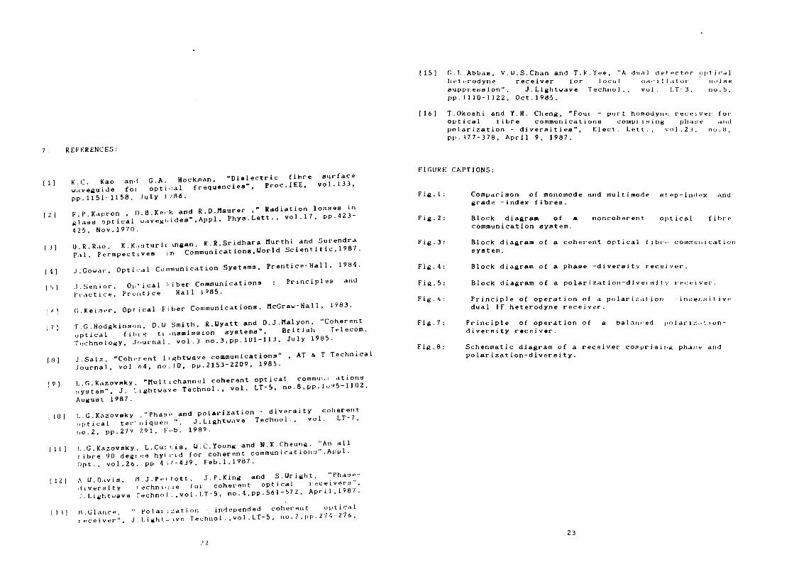
Fig.l: Comparison of monomode and multimode step-lndux and grade -index fibres.
Fig.2: Block diagram of a noncoherent optical fibre communication system.
Fig.3: Block diagram of a coherent optical fibre coinmun i cat i or system.
Fig.4: Block diagram of a phase -diversity receiver.
Fig.5: Block diagram of a polarization-diversity receiver.
Fig.6: Principle of operation of a polarisation -insensitive dual IF heterodyne receiver.
Fig.7: Principle of operation of a balanced polarisation-diversity receiver.
Fig.8: Schenmatic diagram of a receiver comprising pha::e and polarization-diversity.
23
_ ' l LrJ!
Flg .1
MiMuinuvK- sii-n-iiiji-v lidcr
Mulliinode sicp-inde* fib
MUI I IMKJ I ' |.*fddi'd-indrx fihtr
Comparison of monomoda and multlmoda s tep- index and grade-index f i b r e s . _.J
- 3 2 c
24
Input s igna l
CW Loser
source
E . A ' _ V l H Adapter
Exte r n a l
modu la to r A d a p t e r
B e a m combiner
Optical l iber
Output
s ignal
Fig.3 : Clock diagram of a coherent optical fibre communication system.
I npu t s i g n a l
Photod iode I
_ J . ) - O u t p u t
LO S i g n a l
Fig.h : Block diagram of a phase-diversity receiver.
Input
signal
LO signal
F
PC
'olari zatic controller
t i
\ /
Optical \ -coupler
1
/ /
Polarization analyser
Fig . 5 i Block diagram of a polarlzation-dlveraity receiver.
2h
Input signal frequency ls
Coupler Photodiode
LOl -L02
L01: Vertical polarization frequency, f1
L02i Horizontal polarization frequency,f2
f, : equals to | fg - f 11
fH : equals to |fB - f2|
Fig.6: Principle of operation of a polarization -insensitive dual IF heterodyne receiver.
2<)
Signal
3dB Coupler
J Polarizing —
1 splitter —I
Photodiode |
LO
HPhotod i'ode 3H Demod
, 1 M— Photodiode 3 — , Polarizing — ' I 1 M t
b e a m " , , @ - H spl i t ter 1—L^jphotodiode 11—F
Demod
LPF -'Output
Pig.7 : Principle of operation of a balanced polarization-diversity receiver.
3fi
Local o s c i l l a t o r
Input
s ignal
Op t i ca l hyb r id
Local o sc i l l a t o r
Optical hyb r id
Signal process
ing
Output
signal
JPhotodiod
Fig.8 : Schennatic diagram of a receiver comprising phase and polarization-diversity.
31