LambdaUnite MultiService Switch (MSS) Release 2.0 ...
308
LambdaUnite ™ MultiService Switch (MSS) Release 2.0 Applications and Planning Guide 365-374-053 CC109192385 Issue a January 2002
-
Upload
khangminh22 -
Category
Documents
-
view
1 -
download
0
Transcript of LambdaUnite MultiService Switch (MSS) Release 2.0 ...
LambdaUnite™ MultiService Switch(MSS)Release 2.0
Applications and Planning Guide
365-374-053CC109192385
Issue aJanuary 2002

Copyright © 2002 Lucent Technologies. All Rights Reserved.
This material is protected by the copyright laws of the United States and other countries. It may not be reproduced, distributed, or altered in anyfashion by any entity (either internal or external to Lucent Technologies), except in accordance with applicable agreements, contracts orlicensing, without the express written consent of Lucent Technologies and the business management owner of the material.
For permission to reproduce or distribute, please contact:
Lucent Learning +49 911 526 3315 or +49 911 526 2455
Notice
Every effort has been made to ensure that the information in this document was complete and accurate at the time of printing. However,information is subject to change.
Mandatory customer information
Trademarks
These trademarks are used in this manual:
Adobe, Acrobat and the Acrobat logo is a registered trademark of Adobe Systems Incorporated.
ANSI is a registered trademark of American National Standards Institute Incorporated.
CompactFlash is a trademark of SanDisk Corporation.
LambdaUnite is a trademark of Lucent Technologies.
Navis is a trademark of Lucent Technologies.
Pentium is a registered trademark of Intel Corporation.
WaveStar is a registered trademark of Lucent Technologies.
Windows, Windows NT and the Windows logo is a registered trademark of Microsoft Corporation.
Ordering information
The order number of this document is 365-374-053 (Issue a).
Support
Technical support
Please contact your Lucent Technologies Local Customer Support Team (LCS) for technical questions about the information in this document.
Information product support
On the following page, we provide a comment form for you to report errors or make suggestions about this document.
Lucent Technologies

LambdaUnite ™ MultiService Switch (MSS)Release 2.0Applications and Planning Guide365-374-053 Issue a January 2002
Lucent Technologies welcomes your comments on this information product. Your opinion is of great value and helps us toimprove.
1. Was the information product:Yes No Not
applicable
In the language of your choice?In the desired media (paper, CD-ROM, etc.)?Available when you needed it?
Please provide any additional comments:
________________________________________________________________________________________________
________________________________________________________________________________________________
2. Please rate the effectiveness of this information product:Excellent More than Satisfactory Less than Unsatisfactory Not
satisfactory satisfactory applicable
Ease of useLevel of detailReadability and clarity OrganizationCompletenessTechnical accuracyQuality of translationAppearance
If your response to any of the above questions is “Less than satisfactory” or “Unsatisfactory,” please explain your rating.
________________________________________________________________________________________________
________________________________________________________________________________________________
3. If you could change one thing about this information product, what would it be?
________________________________________________________________________________________________
________________________________________________________________________________________________
4. Please write any other comments about this information product:
________________________________________________________________________________________________
________________________________________________________________________________________________
Please complete the following if we may contact you for clarification or to address your concerns:
Name: ______________________________________________________ Date: ________________________________
Company/organization: ______________________________ Telephone number: ________________________________
Address: ____________________________________________________________________________________________
Email address: ______________________________ Job function: __________________________________________
Lucent Technologies values your comments!
If you choose to complete this form online, go to http://www.lucent-info.com/commentsOtherwise fax to 407 767 2760 (U.S.) or +1 407 767 2760 (outside the U.S.) or email comments to [email protected]

Contents
BOOKMARK1::About this information productAbout this information product
BOOKMARK2::PurposePurpose xi
BOOKMARK3::Reason for reissueReason for reissue xi
BOOKMARK4::Safety labelsSafety labels xi
BOOKMARK5::Intended audienceIntended audience xii
BOOKMARK6::How to use this information productHow to use this information product xii
BOOKMARK7::Conventions usedConventions used xiv
BOOKMARK8::Related documentationRelated documentation xiv
BOOKMARK9::Documented feature setDocumented feature set xvi
BOOKMARK10::How to commentHow to comment xvi
BOOKMARK11::How to orderHow to order xvi
.....................................................................................................................................................................................................................................
1 BOOKMARK12::1 IntroductionIntroduction
BOOKMARK13::OverviewOverview 1-1
BOOKMARK14:: LambdaUnite ™ MSS network solutionsLambdaUnite™ MSS network solutions 1-2
BOOKMARK15::The optical networking products familyThe optical networking products family 1-8
BOOKMARK16:: LambdaUnite ™ MSS descriptionLambdaUnite™ MSS description 1-10
....................................................................................................................................................................................................................................
365-374-053Issue a, January 2002
Lucent Technologies C O N T E N T Si i i
1-10
1-8
1-2
1-1
xvi
xvi
xvi
xiv
xiv
xii
xii
xi
xi
xi
.....................................................................................................................................................................................................................................
2 BOOKMARK17::2 FeaturesFeatures
BOOKMARK18::OverviewOverview 2-1
BOOKMARK19::Physical interfacesPhysical interfaces
BOOKMARK20::OverviewOverview 2-3
BOOKMARK21::Synchronous interfacesSynchronous interfaces 2-4
BOOKMARK22::Data interfacesData interfaces 2-5
BOOKMARK23::Timing interfacesTiming interfaces 2-6
BOOKMARK24::User byte and orderwire interfacesUser byte and orderwire interfaces 2-7
BOOKMARK25::Operations interfacesOperations interfaces 2-8
BOOKMARK26::Power interfaces and groundingPower interfaces and grounding 2-9
BOOKMARK27::Transmission featuresTransmission features
BOOKMARK28::OverviewOverview 2-10
BOOKMARK29::Cross-connection featuresCross-connection features 2-11
BOOKMARK30::Forward error correctionForward error correction 2-13
BOOKMARK31::Dual Node Ring InterworkingDual Node Ring Interworking 2-14
BOOKMARK32::Line protectionLine protection 2-15
BOOKMARK33::Path protectionPath protection 2-17
BOOKMARK34::Equipment featuresEquipment features
BOOKMARK35::OverviewOverview 2-21
BOOKMARK36::Equipment protectionEquipment protection 2-22
BOOKMARK37::Equipment reportsEquipment reports 2-23
BOOKMARK38::Synchronization and timingSynchronization and timing
BOOKMARK39::OverviewOverview 2-24
BOOKMARK40::Timing featuresTiming features 2-25
....................................................................................................................................................................................................................................
C O N T E N T Si v
Lucent Technologies 365-374-053Issue a, January 2002
2-25
2-24
2-23
2-22
2-21
2-17
2-15
2-14
2-13
2-11
2-10
2-9
2-8
2-7
2-6
2-5
2-4
2-3
2-1
BOOKMARK41::Timing protectionTiming protection 2-26
BOOKMARK42::Timing interface featuresTiming interface features 2-27
BOOKMARK43::Operations, Administration, Maintenance and ProvisioningOperations, Administration, Maintenance and Provisioning
BOOKMARK44::OverviewOverview 2-28
BOOKMARK45::InterfacesInterfaces 2-29
BOOKMARK46::Monitoring and diagnostics featuresMonitoring and diagnostics features 2-31
.....................................................................................................................................................................................................................................
3 BOOKMARK47::3 Network topologiesNetwork topologies
BOOKMARK48::OverviewOverview 3-1
BOOKMARK49::Backbone applicationsBackbone applications
BOOKMARK50::OverviewOverview 3-3
BOOKMARK51::Classical backbonesClassical backbones 3-4
BOOKMARK52::Transoceanic applicationsTransoceanic applications 3-7
BOOKMARK53::All Optical backbonesAll Optical backbones 3-8
BOOKMARK54::Metro core/regional applicationsMetro core/regional applications
BOOKMARK55::OverviewOverview 3-12
BOOKMARK56::Ring topologiesRing topologies 3-13
BOOKMARK57::Meshed topologiesMeshed topologies 3-15
BOOKMARK58::Synchronous Network Navigator (SNN)Synchronous Network Navigator (SNN) 3-17
BOOKMARK59::Traffic hubbingTraffic hubbing 3-18
BOOKMARK60::Access/metro applicationsAccess/metro applications
BOOKMARK61::OverviewOverview 3-20
BOOKMARK62::Tier 1 applicationsTier 1 applications 3-21
BOOKMARK63::Application detailsApplication details
BOOKMARK64::OverviewOverview 3-22
....................................................................................................................................................................................................................................
365-374-053Issue a, January 2002
Lucent Technologies C O N T E N T Sv
3-22
3-21
3-20
3-18
3-17
3-15
3-13
3-12
3-8
3-7
3-4
3-3
3-1
2-31
2-29
2-28
2-27
2-26

BOOKMARK65::Ethernet applicationsEthernet applications 3-23
BOOKMARK66::Broadband transportBroadband transport 3-28
BOOKMARK67::Remote hubbingRemote hubbing 3-29
BOOKMARK68::Ring topologiesRing topologies 3-31
BOOKMARK69::Interworking with WaveStar ® TDM 10G/2.5G and WaveStar ADM 16/1Interworking with WaveStar® TDM 10G/2.5G and WaveStar ADM16/1 3-35
BOOKMARK70::Interworking with WaveStar ® BandWidth ManagerInterworking with WaveStar® BandWidth Manager 3-37
BOOKMARK71::Interworking with Wavelength Division MultiplexingInterworking with Wavelength Division Multiplexing 3-38
BOOKMARK72::Interworking with LambdaRouter ™ AOSInterworking with LambdaRouter™ AOS 3-41
.....................................................................................................................................................................................................................................
4 BOOKMARK73::4 Product descriptionProduct description
BOOKMARK74::OverviewOverview 4-1
BOOKMARK75::Concise system descriptionConcise system description 4-3
BOOKMARK76::Transmission architectureTransmission architecture 4-5
BOOKMARK77::Switch functionSwitch function 4-6
BOOKMARK78::Shelf configurationsShelf configurations 4-7
BOOKMARK79::ShelfShelf 4-8
BOOKMARK80::Circuit packsCircuit packs 4-14
BOOKMARK81::SynchronizationSynchronization 4-19
BOOKMARK82::ControlControl 4-25
BOOKMARK83::PowerPower 4-29
BOOKMARK84::CoolingCooling 4-30
.....................................................................................................................................................................................................................................
5 BOOKMARK85::5 Operations, administration, maintenance, and provisioningOperations, administration, maintenance, and provisioning
BOOKMARK86::OverviewOverview 5-1
....................................................................................................................................................................................................................................
C O N T E N T Sv i
Lucent Technologies 365-374-053Issue a, January 2002
5-1
4-30
4-29
4-25
4-19
4-14
4-8
4-7
4-6
4-5
4-3
4-1
3-41
3-38
3-37
3-35
3-31
3-29
3-28
3-23
BOOKMARK87::OperationsOperations
BOOKMARK88::OverviewOverview 5-3
BOOKMARK89::Visible alarm indicatorsVisible alarm indicators 5-4
BOOKMARK90:: WaveStar ® CITWaveStar® CIT 5-8
BOOKMARK91::Operations interfacesOperations interfaces 5-10
BOOKMARK92::AdministrationAdministration
BOOKMARK93::OverviewOverview 5-12
BOOKMARK94::SecuritySecurity 5-13
BOOKMARK95::MaintenanceMaintenance
BOOKMARK96::OverviewOverview 5-15
BOOKMARK97::Maintenance signalsMaintenance signals 5-16
BOOKMARK98::Loopbacks and testsLoopbacks and tests 5-18
BOOKMARK99::Protection switchingProtection switching 5-19
BOOKMARK100::Performance monitoringPerformance monitoring 5-21
BOOKMARK101::ReportsReports 5-24
BOOKMARK102::Maintenance conditionMaintenance condition 5-26
BOOKMARK103::OrderwireOrderwire 5-27
BOOKMARK104::ProvisioningProvisioning
BOOKMARK105::OverviewOverview 5-28
BOOKMARK106::IntroductionIntroduction 5-29
.....................................................................................................................................................................................................................................
6 BOOKMARK107::6 System planning and engineeringSystem planning and engineering
BOOKMARK108::OverviewOverview 6-1
BOOKMARK109::General planning informationGeneral planning information 6-2
BOOKMARK110::Power planningPower planning 6-3
....................................................................................................................................................................................................................................
365-374-053Issue a, January 2002
Lucent Technologies C O N T E N T Sv i i
6-3
6-2
6-1
5-29
5-28
5-27
5-26
5-24
5-21
5-19
5-18
5-16
5-15
5-13
5-12
5-10
5-8
5-4
5-3

BOOKMARK111::Cooling equipmentCooling equipment 6-4
BOOKMARK112::Transmission capacityTransmission capacity 6-5
BOOKMARK113::Port location rulesPort location rules 6-6
BOOKMARK114::Floor plan layoutFloor plan layout 6-7
BOOKMARK115::Equipment interconnectionEquipment interconnection 6-11
.....................................................................................................................................................................................................................................
7 BOOKMARK116::7 OrderingOrdering
BOOKMARK117::OverviewOverview 7-1
BOOKMARK118::Ordering informationOrdering information 7-2
.....................................................................................................................................................................................................................................
8 BOOKMARK119::8 Product supportProduct support
BOOKMARK120::OverviewOverview 8-1
BOOKMARK121::Engineering and installation servicesEngineering and installation services 8-2
BOOKMARK122::Technical supportTechnical support 8-3
BOOKMARK123::Documentation supportDocumentation support 8-5
BOOKMARK124::TrainingTraining 8-6
BOOKMARK125::Training coursesTraining courses 8-7
.....................................................................................................................................................................................................................................
9 BOOKMARK126::9 Quality and reliabilityQuality and reliability
BOOKMARK127::OverviewOverview 9-1
BOOKMARK128::QualityQuality
BOOKMARK129::OverviewOverview 9-2
BOOKMARK130::Lucent’s commitment to quality and reliabilityLucent’s commitment to quality and reliability 9-3
BOOKMARK131::Ensuring qualityEnsuring quality 9-4
BOOKMARK132::Reliability specificationsReliability specifications
BOOKMARK133::OverviewOverview 9-5
....................................................................................................................................................................................................................................
C O N T E N T Sv i i i
Lucent Technologies 365-374-053Issue a, January 2002
9-5
9-4
9-3
9-2
9-1
8-7
8-6
8-5
8-3
8-2
8-1
7-2
7-1
6-11
6-7
6-6
6-5
6-4
BOOKMARK134::General specificationsGeneral specifications 9-6
.....................................................................................................................................................................................................................................
10 BOOKMARK135::10 Technical specificationsTechnical specifications
BOOKMARK136::OverviewOverview 10-1
BOOKMARK137::InterfacesInterfaces 10-2
BOOKMARK138::Optical parametersOptical parameters 10-4
BOOKMARK139::Bandwidth managementBandwidth management 10-12
BOOKMARK140::Performance requirementsPerformance requirements 10-13
BOOKMARK141::Supervision and alarmsSupervision and alarms 10-14
BOOKMARK142::Timing and synchronizationTiming and synchronization 10-15
BOOKMARK143::OAM and POAM and P 10-16
BOOKMARK144::Network managementNetwork management 10-17
BOOKMARK145::Physical designPhysical design 10-18
BOOKMARK146::Power consumptionPower consumption 10-19
BOOKMARK147::Environmental conditionsEnvironmental conditions 10-20.....................................................................................................................................................................................................................................
A BOOKMARK148::A An SDH overviewAn SDH overview A-1
BOOKMARK149::OverviewOverview A-1
BOOKMARK150::SDH signal hierarchySDH signal hierarchy A-4
BOOKMARK151::SDH path and line sectionsSDH path and line sections A-6
BOOKMARK152::SDH frame structureSDH frame structure A-9
BOOKMARK153::SDH digital multiplexingSDH digital multiplexing A-12
BOOKMARK154::SDH interfaceSDH interface A-14
BOOKMARK155::SDH multiplexing processSDH multiplexing process A-15
BOOKMARK156::SDH demultiplexing processSDH demultiplexing process A-16
....................................................................................................................................................................................................................................
365-374-053Issue a, January 2002
Lucent Technologies C O N T E N T Si x
A-16
A-15
A-14
A-12
A-9
A-6
A-4
A-1
A-1
10-20
10-19
10-18
10-17
10-16
10-15
10-14
10-13
10-12
10-4
10-2
10-1
9-6
BOOKMARK157::SDH transport ratesSDH transport rates A-17.....................................................................................................................................................................................................................................
B BOOKMARK158::B A SONET overviewA SONET overview B-1
BOOKMARK159::OverviewOverview B-1
BOOKMARK160::SONET signal hierarchySONET signal hierarchy B-3
BOOKMARK161::SONET layersSONET layers B-5
BOOKMARK162::SONET frame structureSONET frame structure B-8
BOOKMARK163::SONET digital multiplexingSONET digital multiplexing B-12
BOOKMARK164::SONET interfaceSONET interface B-15
BOOKMARK165::SONET multiplexing processSONET multiplexing process B-16
BOOKMARK166::SONET demultiplexing processSONET demultiplexing process B-18
BOOKMARK167::SONET transport ratesSONET transport rates B-21.....................................................................................................................................................................................................................................
GL BOOKMARK168::GlossaryGlossary GL-1.....................................................................................................................................................................................................................................
IN BOOKMARK169::IndexIndex IN-1
....................................................................................................................................................................................................................................
C O N T E N T Sx
Lucent Technologies 365-374-053Issue a, January 2002
B-21
B-18
B-16
B-15
B-12
B-8
B-5
B-3
B-1
B-1
A-17
About this information product
...............................................................................................................................................................................................................................................................
Purpose This Applications and Planning Guide (APG) provides the followinginformation about LambdaUnite™ MultiService Switch (MSS):
• Features
• Applications
• Product description
• Operations and maintenance
• System engineering
• Product support
• Technical and reliability specifications
Reason for reissue This is the initial version of this guide for LambdaUnite MSS Release2.0.
Safety labels Safety labels are not used in this guide.
....................................................................................................................................................................................................................................
365-374-053Issue a, January 2002,
Lucent Technologies x i

Intended audience The LambdaUnite MultiService Switch (MSS) Applications andPlanning Guide is primarily intended for network planners andengineers. In addition, others who need specific information about thefeatures, applications, operation, and engineering of LambdaUniteMSS may find the information in this manual useful.
How to use thisinformation product
Each chapter of this manual treats a specific aspect of the system andcan be regarded as an independent description. This ensures thatreaders can inform themselves according to their special needs. Thisalso means that the manual provides more information than needed bymany of the readers. Before you start reading the manual, it istherefore necessary to assess which aspects or chapters will cover theindividual area of interest.
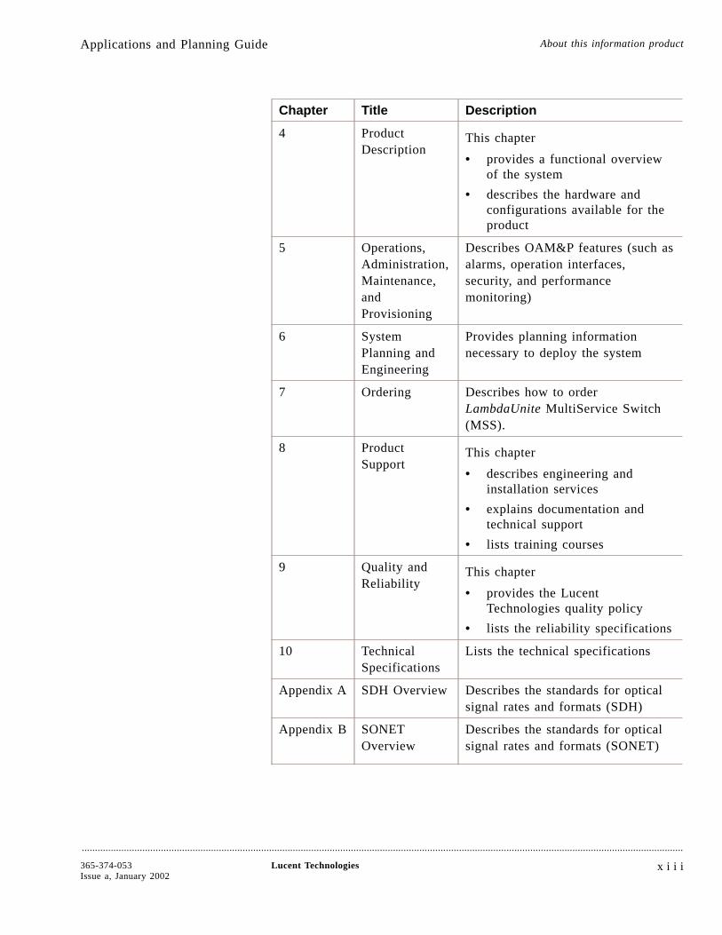
The following table briefly describes the type of information found ineach chapter.
Chapter Title Description
Preface About ThisDocument
This chapter
• describes the guide’s purpose,intended audience, andorganization
• lists related documentation
• explains how to comment onthis document
1 Introduction This chapter
• presents network applicationsolutions
• provides a high-level productoverview
• describes the product family
• lists features
2 Features Describes the features ofLambdaUnite MSS
3 NetworkTopologies
Describes some of the main networktopologies possible withLambdaUnite MSS
Applications and Planning Guide About this information product
....................................................................................................................................................................................................................................
x i i Lucent Technologies 365-374-053Issue a, January 2002
,
Chapter Title Description
4 ProductDescription
This chapter
• provides a functional overviewof the system
• describes the hardware andconfigurations available for theproduct
5 Operations,Administration,Maintenance,andProvisioning
Describes OAM&P features (such asalarms, operation interfaces,security, and performancemonitoring)
6 SystemPlanning andEngineering
Provides planning informationnecessary to deploy the system
7 Ordering Describes how to orderLambdaUnite MultiService Switch(MSS).
8 ProductSupport
This chapter
• describes engineering andinstallation services
• explains documentation andtechnical support
• lists training courses
9 Quality andReliability
This chapter
• provides the LucentTechnologies quality policy
• lists the reliability specifications
10 TechnicalSpecifications
Lists the technical specifications
Appendix A SDH Overview Describes the standards for opticalsignal rates and formats (SDH)
Appendix B SONETOverview
Describes the standards for opticalsignal rates and formats (SONET)
Applications and Planning Guide About this information product
....................................................................................................................................................................................................................................
365-374-053Issue a, January 2002,
Lucent Technologies x i i i

Chapter Title Description
Abbreviationsand Acronyms
Expands common telecommunica-tion abbreviations and acronyms
Glossary Defines telecommunication terms
Index Lists specific subjects and theircorresponding page numbers
Conventions used The following conventions are used throughout the manual:
Numbering
Each fascicle can be identified by its number (see above) and containsa chapter which is numbered accordingly (e.g. Chapter 2 is containedin Fascicle 2). The page numbering begins with “1” in every chapter.To be able to identify them easily, these numbers are prefixed with thefascicle number.
Related documentation This section briefly describes the documents that are included in theLambdaUnite MultiService Switch (MSS) documentation set.
• Installation GuideThe LambdaUnite MSS Installation Guide is a step-by-step guideto system installation and setup. It also includes informationneeded for pre-installation site planning and post-installationacceptance testing.
• Applications and Planning GuideThe LambdaUnite MSS Applications and Planning Guide (APG)is for use by network planners, analysts and managers. It is alsofor use by the Lucent Account Team. It presents a detailedoverview of the system, describes its applications, gives planningrequirements, engineering rules, ordering information, andtechnical specifications.
• User Operations GuideThe LambdaUnite MSS User Operations Guide providesstep-by-step information for use in daily system operations. Themanual demonstrates how to perform system provisioning,operations, and administrative tasks by use of WaveStar® CIT.
• Alarm Messages and Trouble Clearing Guide
Applications and Planning Guide About this information product
....................................................................................................................................................................................................................................
x i v Lucent Technologies 365-374-053Issue a, January 2002
,
The LambdaUnite MSS Alarm Messages and Trouble ClearingGuide gives detailed information on each possible alarmmessage. Furthermore, it provides procedures for routinemaintenance, troubleshooting, diagnostics, and componentreplacement.
• Operations System Engineering GuideThe LambdaUnite MSS Operations System Engineering Guideserves as a reference for all TL1 commands which can be used tooperate the network element. The manual gives an introduction tothe concept of the TL1 commands and instructs how to use them.
• Navis™ Optical EMS Provisioning Guide (ApplicationLambdaUnite MSS)The Navis Optical EMS Provisioning Guide (ApplicationLambdaUnite MSS) gives instructions on how to perform systemprovisioning, operations, and administrative tasks by use of NavisOptical EMS.
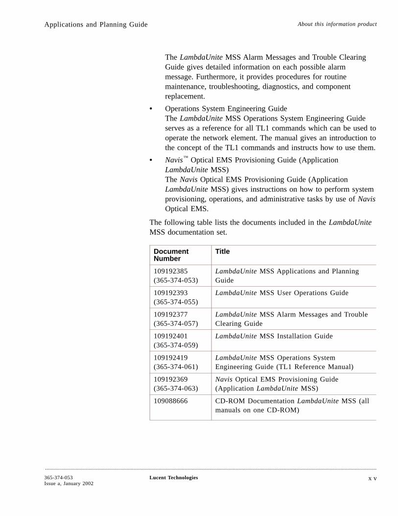
The following table lists the documents included in the LambdaUniteMSS documentation set.
DocumentNumber
Title
109192385(365-374-053)
LambdaUnite MSS Applications and PlanningGuide
109192393(365-374-055)
LambdaUnite MSS User Operations Guide
109192377(365-374-057)
LambdaUnite MSS Alarm Messages and TroubleClearing Guide
109192401(365-374-059)
LambdaUnite MSS Installation Guide
109192419(365-374-061)
LambdaUnite MSS Operations SystemEngineering Guide (TL1 Reference Manual)
109192369(365-374-063)
Navis Optical EMS Provisioning Guide(Application LambdaUnite MSS)
109088666 CD-ROM Documentation LambdaUnite MSS (allmanuals on one CD-ROM)
Applications and Planning Guide About this information product
....................................................................................................................................................................................................................................
365-374-053Issue a, January 2002,
Lucent Technologies x v

The following additional documents can be helpful for planning andordering:
• Ordering & Information Drawings
• Cable Ordering & Information Drawings
Documented feature set This manual describes LambdaUnite MSS release 2.0. For technicalreasons some of the documented features might not be available untillater software versions. For precise information about the availabilityof features, please consult the Software Release Description (SRD)that is distributed with the network element software. This providesdetails of the status at the time of software delivery.
How to comment As customer satisfaction is extremely important to LucentTechnologies, every attempt is made to encourage feedback fromcustomers about our information products.
Customer Comment Form
A customer comment form is located immediately after the title pageof this document. Please fill out the form and fax it to the numberprovided on the form.
How to order If the customer comment form is missing, send or fax commentsabout this document to
Lucent Technologies Network Systems GmbH
Lucent Learning WO
Thurn-und-Taxis-Str. 10
90411 Nuernberg, Germany
Fax: +49 911 526 3545
Applications and Planning Guide About this information product
....................................................................................................................................................................................................................................
x v i Lucent Technologies 365-374-053Issue a, January 2002
,
1 Introduction
Overview....................................................................................................................................................................................................................................
Purpose This chapter introduces the LambdaUnite™ MultiService Switch(MSS).
ContentsLambdaUnite MSS network solutions 1-2
The optical networking products family 1-8
LambdaUnite MSS description 1-10
....................................................................................................................................................................................................................................
365-374-053Issue a, January 2002
Lucent Technologies 1 - 1
1-10
1-8
1-2
LambdaUnite ™ MSS network solutions....................................................................................................................................................................................................................................
Overview LambdaUnite MultiService Switch (MSS) is a global platform designsupporting both the Synchronous Optical Network (SONET) standardsas well as the Synchronous Digital Hierarchy (SDH) standards.
Using the experience Lucent Technologies gained with 40-Gbit/s TDMproducts in more than one year of successful field trials, LambdaUniteMSSis the next generation of Lucent’s high speed TDM equipmentfor various 40-Gbit/s applications as well as 10-Gbit/s applicationsbuilt upon a cost optimized, high density and future proof platform.The feature set in this first release has common points with existingSDH and SONET transport products as well as an advanced set ofmarket-proven features. The feature set will grow continuously infuture releases. For planning reasons, major future features will alsobe mentioned within this Applications and Planning Guide.
Key features Key features of LambdaUnite MSS include:
• 10-Gbit/s and 2.5-Gbit/s optical synchronous interfaces(40-Gbit/s, further 10-Gbit/s and 2.5-Gbit/s, and 622/155-Mbit/sinterfaces in future release)
• Direct Gigabit Ethernet (IEEE 802.3) optical interface
• DWDM and passive WDM compatible optics, in future release
• 2-fiber BLSR/MS-SPRing on 10-Gbit/s interfaces; 4-fiber versionand transoceanic protocol for STM-64 interfaces in future release
• 2-fiber BLSR/MS-SPRing on 2.5-Gbit/s interfaces; 4-fiberversion in future release
• Unidirectional Path Switched Ring (UPSR) / SubnetworkConnection Protection (SNC/I and SNC/N) for all types of crossconnections and any mix of supported interfaces, also for the 1Gigabit Ethernet interface
• 1+1 linear APS / MSP for 2.5-Gbit/s and for 10-Gbit/s interfaces
• Dual Ring Interworking (DRI, SONET) / Dual NodeInterworking (DNI, SDH) between two BLSR / MS-SPRing /SNCP protected rings, also supports collapsed nodes, in futurerelease
Introduction
....................................................................................................................................................................................................................................
1 - 2 Lucent Technologies 365-374-053Issue a, January 2002

• Flexible, non-blocking STS-1/HO VC-3, STS-3c/VC-4,STS-12c/VC-4-4c, STS-48c/VC-4-16c and STS-192c/VC-4-64cgranularity cross connect
• Cross Connection capability: 320 Gbit/s in total: 6144 x 6144STS-1 / 2048 x 2048 VC-4, extension to 640 Gbit/s planned forfuture releases
• Multiple Ring Closure
• Flexible any card in any slot architecture
• Telcordia Management Support in future release
• TL1 operations interface
• Manageable by Navis™ Optical EMS element and subnetworkmanager and WaveStar® CIT Craft Interface Terminal.
Applications LambdaUnite MSS is designed to cover a variety of 10-Gbit/s and40-Gbit/s (next release) applications in the metro and backbonedomain, based on the same common hardware and software.LambdaUnite MSS can comprise one or more Terminal Multiplexer(TM) or Add/Drop Multiplexer (ADM) functions in a single node, butas well can also act as a fully non-blocking cross connect (XC). As acombination of the ADM function with the XC function, also multiring applications are supported to directly interconnect added/droppedtributaries between 40-Gbit/s (in future), 10-Gbit/s and 2.5-Gbit/srings. The ability to support and efficiently interconnect multiple ringsusing a single network element provides the basis for advancednetworking capabilities and potential cost savings to a large amount.
The complete LambdaUnite MSS network element requires only onesingle sub-rack. The design is in compliance with ETSI / NEBSspecifications.
LambdaUnite™ MSS network solutions Introduction
....................................................................................................................................................................................................................................
365-374-053Issue a, January 2002
Lucent Technologies 1 - 3
Differentiators The main differentiators of the product are:
• Minimized Number of Equipment Types
- Innovative high flexible architectural design
- Full configuration & application coverage with single shelf
- Easy, restriction-less configuration via simple I/O packplugging
• All configurations based on common HW/SW components
- Same shelf, same units, same SW
- Upgrade just means plugging of additional cards and newconfiguration
- Drastically reduced spare part, maintenance and trainingcosts for operators
• Minimized Floor Space and Equipment Cost
- Lowest foot print by ultra compact single shelf
- Outstanding architectural support for pay as you grow
- High interface density merging today’s multiplexer farmsinto a single shelf
- Multi Ring closure architecture prevents from back-to-backADM arrays
• Multi Service Support
- Global product design covering SONET, SDH andtransoceanic (future release) application
- Data transport with fixed Link Capacity Adjustment System(LCAS), flexible LCAS in future release, and direct low cost1 Gigabit Ethernet interfacing. Low cost VSR OC/STMoptics towards routers at full concatenation support
• Future proof investment
- 640 Gbit/s switch capacity upgrade improves return oninvestment
- Self aware services including fast provisioning andrestoration
LambdaUnite™ MSS network solutions Introduction
....................................................................................................................................................................................................................................
1 - 4 Lucent Technologies 365-374-053Issue a, January 2002
- Transparent Services
- Enables highest bandwidth for lowest cost/bit with 40-Gbit/sinterfaces: Upgrade to 40 Gbit/s from initial deploymentwith 10 Gbit/s
• Full integration into Lucent Technologies’ management solution
These features make the LambdaUnite MSS one of the mostcost-effective, future-proof and flexible network elements available onthe market today.
Comparison: central office A comparison of a traditional central office and the future centraloffice with LambdaUnite MSS impressively shows its advantages:
• significantly reduced floor space requirements
• lowering equipment cost
• reducing power requirements
• reducing cabling effort.
The following figure shows as an example a traditional central officeconsisting of 8 backbone feeder 10-Gbit/s ADMs, 4 metro 10-Gbit/sADMs, 16 metro 2.5-Gbit/s ADMs and one 4/4 Digital Cross Connect(DXC) with 160 Gigabit cross connection capacity on the left. On the
LambdaUnite™ MSS network solutions Introduction
....................................................................................................................................................................................................................................
365-374-053Issue a, January 2002
Lucent Technologies 1 - 5
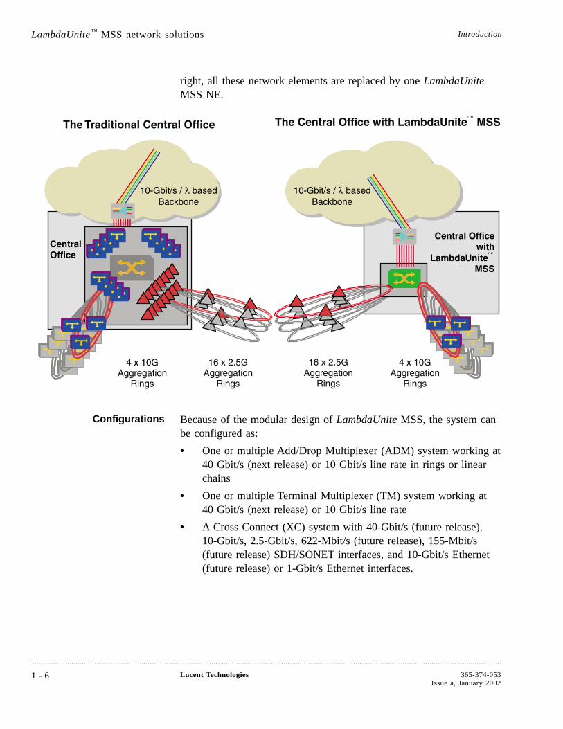
right, all these network elements are replaced by one LambdaUniteMSS NE.
Configurations Because of the modular design of LambdaUnite MSS, the system canbe configured as:
• One or multiple Add/Drop Multiplexer (ADM) system working at40 Gbit/s (next release) or 10 Gbit/s line rate in rings or linearchains
• One or multiple Terminal Multiplexer (TM) system working at40 Gbit/s (next release) or 10 Gbit/s line rate
• A Cross Connect (XC) system with 40-Gbit/s (future release),10-Gbit/s, 2.5-Gbit/s, 622-Mbit/s (future release), 155-Mbit/s(future release) SDH/SONET interfaces, and 10-Gbit/s Ethernet(future release) or 1-Gbit/s Ethernet interfaces.
LambdaUnite™ MSS network solutions Introduction
....................................................................................................................................................................................................................................
1 - 6 Lucent Technologies 365-374-053Issue a, January 2002
Management Like most of the network elements of the Lucent Technologies OpticalNetworking Group (ONG) product portfolio, LambdaUnite MSS ismanaged by Lucent Technologies Navis Optical EMS, a user-friendlysubnetwork and element level management system. On a networklevel, the network management system Navis Optical NMS can beused to manage, among others, the LambdaUnite MSS networkelements. A local craft terminal, the WaveStar Craft Interface Terminal(CIT), is available for on-site, but also for remote operations andmaintenance activities.
Interworking LambdaUnite MSS is a member of the suite of next generationtransport products which have the prefix “Lambda” in their name. Thesystem can be deployed together with other Lucent Technologiestransport products, for example WaveStar TDM 10G, WaveStarADM-16/1, WaveStar BandWidth Manager, Metropolis™ DMX,WaveStar OLS 1.6T, LambdaXtreme™ Transport and LambdaRouter™
All Optical Switch systems today and in the future. This makesLambdaUnite MSS one of the main building blocks of today’s andfuture transport networks.
If necessary, you can coordinate with Lucent Technologies whatproducts are able to interwork with LambdaUnite MSS.
LambdaUnite™ MSS network solutions Introduction
....................................................................................................................................................................................................................................
365-374-053Issue a, January 2002
Lucent Technologies 1 - 7
The optical networking products family....................................................................................................................................................................................................................................
Overview Lucent Technologies offers the industry’s widest range of high-qualitytransport systems and related services designed to provide totalnetwork solutions. Included in this offering is the optical networkingproduct family. The optical networking product family offerstelecommunications service providers advanced services andrevenue-generating capabilities.
Family members The optical networking products family includes products designed tobring your networks forward into the next century.
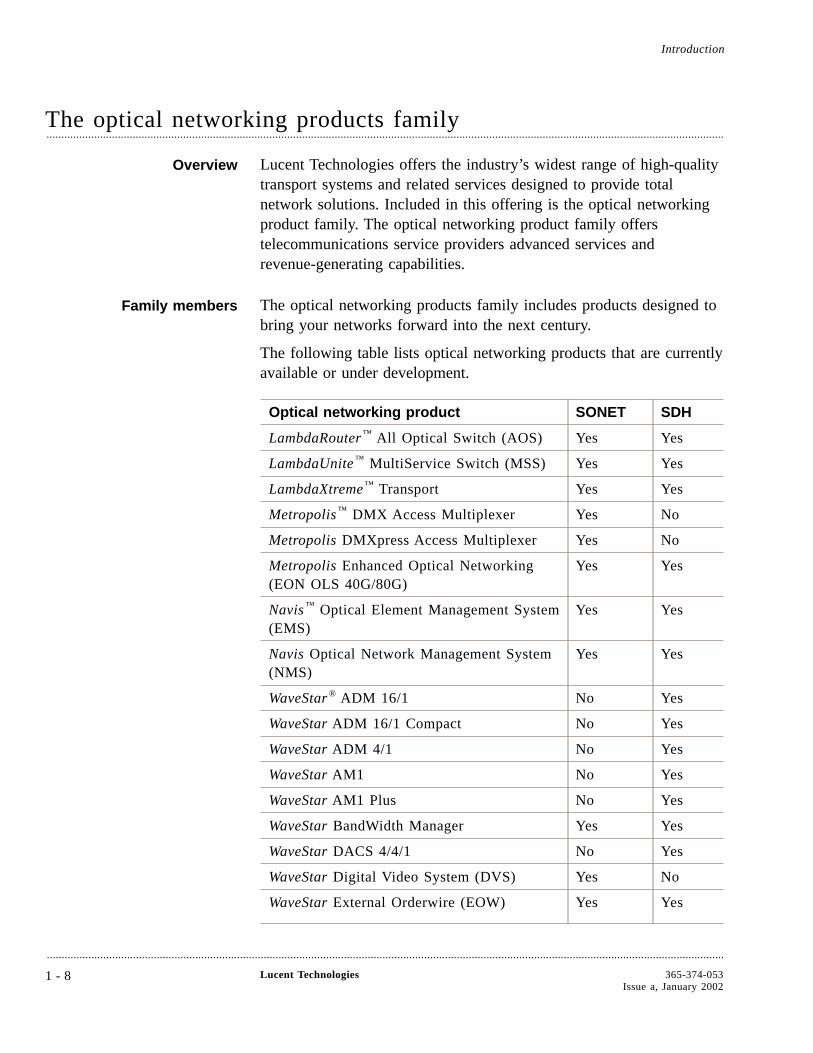
The following table lists optical networking products that are currentlyavailable or under development.
Optical networking product SONET SDH
LambdaRouter™ All Optical Switch (AOS) Yes Yes
LambdaUnite™ MultiService Switch (MSS) Yes Yes
LambdaXtreme™ Transport Yes Yes
Metropolis™ DMX Access Multiplexer Yes No
Metropolis DMXpress Access Multiplexer Yes No
Metropolis Enhanced Optical Networking(EON OLS 40G/80G)
Yes Yes
Navis™ Optical Element Management System(EMS)
Yes Yes
Navis Optical Network Management System(NMS)
Yes Yes
WaveStar® ADM 16/1 No Yes
WaveStar ADM 16/1 Compact No Yes
WaveStar ADM 4/1 No Yes
WaveStar AM1 No Yes
WaveStar AM1 Plus No Yes
WaveStar BandWidth Manager Yes Yes
WaveStar DACS 4/4/1 No Yes
WaveStar Digital Video System (DVS) Yes No
WaveStar External Orderwire (EOW) Yes Yes
Introduction
....................................................................................................................................................................................................................................
1 - 8 Lucent Technologies 365-374-053Issue a, January 2002
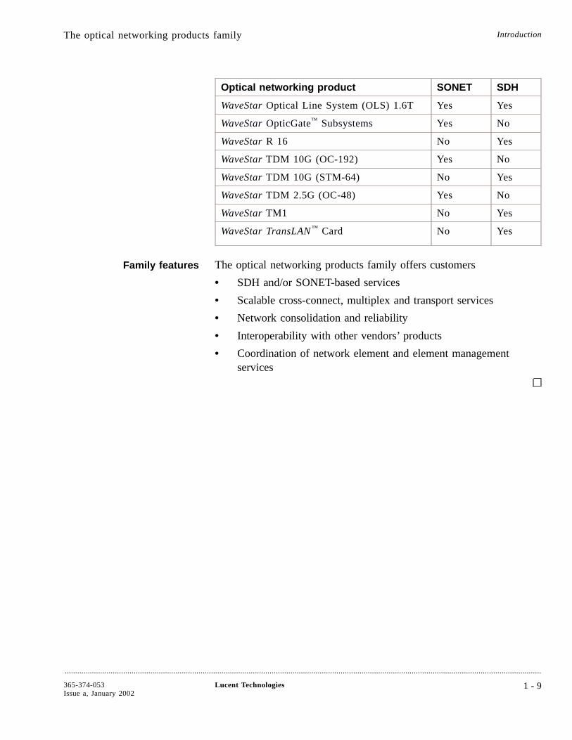
Optical networking product SONET SDH
WaveStar Optical Line System (OLS) 1.6T Yes Yes
WaveStar OpticGate™ Subsystems Yes No
WaveStar R 16 No Yes
WaveStar TDM 10G (OC-192) Yes No
WaveStar TDM 10G (STM-64) No Yes
WaveStar TDM 2.5G (OC-48) Yes No
WaveStar TM1 No Yes
WaveStar TransLAN™ Card No Yes
Family features The optical networking products family offers customers
• SDH and/or SONET-based services
• Scalable cross-connect, multiplex and transport services
• Network consolidation and reliability
• Interoperability with other vendors’ products
• Coordination of network element and element managementservices
The optical networking products family Introduction
....................................................................................................................................................................................................................................
365-374-053Issue a, January 2002
Lucent Technologies 1 - 9
LambdaUnite ™ MSS description....................................................................................................................................................................................................................................
Overview The LambdaUnite MSS system architecture is based on a 320 Gbit/sfull non-blocking switch matrix with AU-3 granularity. This equals6144 x 6144 STS-1s or 2048 x 2048 VC-4s. The switch can beupgraded to 640 Gbit/s capacity in a later release.
The system provides 32 universal slots, which can be flexiblyconfigured with 40-Gbit/s (future release), 10-Gbit/s, 2.5-Gbit/s,622-Mbit/s (future release), 155-Mbit/s (future release), 10-Gbit/sEthernet WANPHY and 1-Gbit/s Ethernet optical interface circuitpacks. Any one-slot wide interface circuit pack can be operated in anyslot position with no connectivity restrictions in all configurations.
The mix and the number of 40-Gbit/s, 10-Gbit/s, 2.5-Gbit/s2-fiber/4-fiber rings and linear links is only limited by the maximumnumber of slots. This makes LambdaUnite MSS a highly flexiblesystem and allows for a variety of different configurations.
One whole network element fits in a double row sub-rack. Thedimensions of the sub-rack are: 950 x 500 x 545 mm (37.4 x 19.7 x21.5 in) (H x W x D). Therefore, two complete network elements fitin one rack. The sub-racks are in accordance with Rec. ETS 300119-4 and Telcordia and can be mounted in ETSI racks (2200 mm(86.6 in) and 2600 mm (102.4 in) height) and Telcordia racks (2125mm (83.7 in) height).
Introduction
....................................................................................................................................................................................................................................
1 - 1 0 Lucent Technologies 365-374-053Issue a, January 2002
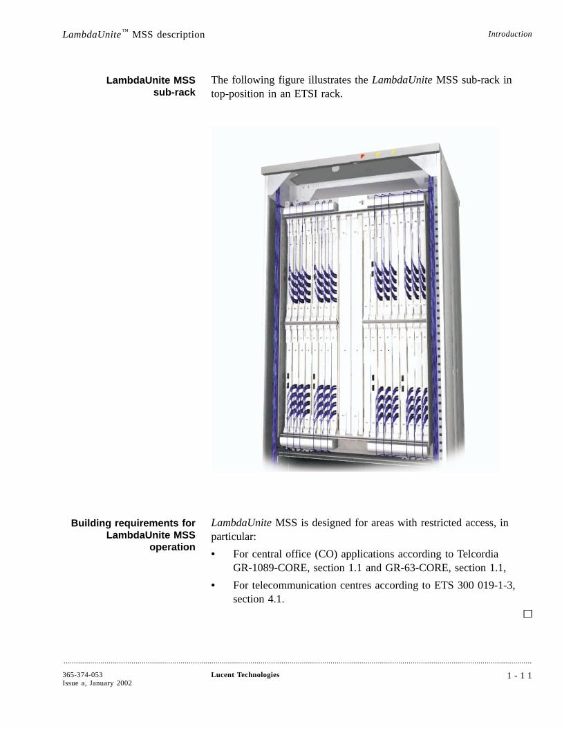
LambdaUnite MSSsub-rack
The following figure illustrates the LambdaUnite MSS sub-rack intop-position in an ETSI rack.
Building requirements forLambdaUnite MSS
operation
LambdaUnite MSS is designed for areas with restricted access, inparticular:
• For central office (CO) applications according to TelcordiaGR-1089-CORE, section 1.1 and GR-63-CORE, section 1.1,
• For telecommunication centres according to ETS 300 019-1-3,section 4.1.
LambdaUnite™ MSS description Introduction
....................................................................................................................................................................................................................................
365-374-053Issue a, January 2002
Lucent Technologies 1 - 1 1

2 Features
Overview....................................................................................................................................................................................................................................
Purpose This chapter briefly describes the features of LambdaUnite™
MultiService Switch (MSS).
For more information on the physical design features and theapplicable standards, please refer to Chapter 6 and Chapter 10.
Standards Compliance Lucent Technologies SONET and SDH products comply with therelevant ETSI, Telcordia and ITU-T standards. Important functionsdefined in SDH and SONET Standards such as the DataCommunications Channel (DCC), the associated 7-layer OSI protocolstack, the SONET and SDH multiplexing structure and the Operations,Administration, Maintenance, and Provisioning (OAM&P) functionsare implemented in Lucent Technologies product families.
Lucent Technologies is heavily involved in various study groups withITU-T, Telcordia and ETSI work creating and maintaining the latestworldwide SONET and SDH standards. LambdaUnite MSS complieswith all relevant and latest Telcordia, ETSI and ITU-T standards andsupports both, SONET and SDH protocols in a singlehardware-software configuration.
ContentsPhysical interfaces 2-3
Transmission features 2-10
....................................................................................................................................................................................................................................
365-374-053Issue a, January 2002
Lucent Technologies 2 - 1
2-10
2-3

Equipment features 2-21
Synchronization and timing 2-24
Operations, Administration, Maintenance andProvisioning
2-28
Overview Features
....................................................................................................................................................................................................................................
2 - 2 Lucent Technologies 365-374-053Issue a, January 2002
2-28
2-24
2-21
Physical interfaces
Overview....................................................................................................................................................................................................................................
Purpose This section provides information about all kinds of physical externalinterfaces of LambdaUnite™ MSS. For detailed technical data andoptical parameters of the interfaces please refer to Chapter 10,“Technical Specifications”.
The LambdaUnite MSS hardware (HW) and software (SW)architecture supports terminal multiplexer (TM), add-dropp-multiplexer (ADM) and cross connect (XC) configurations (multi-ringterminal, optical switch) on all line rates within the same sub-rack andwith a single common SW load. Any circuit pack, with exception ofthe 40-Gbit/s packs (future release), can be operated in any slotposition of the sub-rack without any restrictions in terms of unitnumber and types; each of the 32 slots supports up to 10 Gbit/straffic, handled by the switching matrix (up to 320 Gbit/s in thisrelease, up to 640 Gbit/s in future release).
Features
....................................................................................................................................................................................................................................
365-374-053Issue a, January 2002
Lucent Technologies 2 - 3
Synchronous interfaces....................................................................................................................................................................................................................................
SONET and SDH interfaces LambdaUnite™ MSS supports transmission rates of 10 Gbit/s and 2.5Gbit/s. In the next release, 40-Gbit/s interfaces, further 10-Gbit/s and2.5-Gbit/s interfaces, and 622-Mbit/s as well as 155-Mbit/s interfaceswill be available. All circuit packs support SDH and SONETformatted signals.
The following synchronous interfaces are available:
• 10-Gbit/s long reach interface (80 km), 1550 nm
• 10-Gbit/s intermediate reach / short haul interface (40 km), 1550nm
• 10-Gbit/s intra-office interface (600 m), 1310 nm
• 2.5-Gbit/s long reach interface (80 km), 1550 nm
• 2.5-Gbit/s long reach interface (40 km), 1310 nm
• 2.5-Gbit/s short reach / intra-office interface (2 km), 1310 nm.
In future will additionally be available:
• 40-Gbit/s long reach interface (80 km), 1550 nm, without-of-band FEC
• 40-Gbit/s intermediate reach interface (40 km), 1550 nm, without-of-band FEC
• 40-Gbit/s interface for direct LambdaXtreme™ Transportinterworking, 64 wavelengths
• 40-Gbit/s intra-office interface (14 km), 1310 nm
• 10-Gbit/s interface for direct LambdaXtreme Transportinterworking, 128 wavelengths
• 10-Gbit/s interface for direct WaveStar® OLS 1.6T (400G)interworking, 40 wavelengths
• 10-Gbit/s interface for direct WaveStar OLS 1.6T (800G)interworking, 80 wavelengths
• 2.5-Gbit/s intermediate reach / short haul interface (60 km), 1550nm, passive WDM compatible, 32 wavelengths
• 622-Mbit/s intermediate reach / short haul interface (15 km),1310 nm
• 155-Mbit/s intermediate reach / short haul interface (15 km),1310 nm.
Physical interfaces Features
....................................................................................................................................................................................................................................
2 - 4 Lucent Technologies 365-374-053Issue a, January 2002
Data interfaces....................................................................................................................................................................................................................................
Ethernet interface LambdaUnite™ MSS supports an optical 1-Gbit/s (1000BASE-SX)Ethernet interface in accordance with IEEE 802.3-2000 Clause 38.The Ethernet interface supports auto-negotiation, as defined in Section37 of IEEE 802.3. This feature, among others, enablesIEEE-802.3-compliant devices with different technologies tocommunicate their enhanced mode of operation in order tointer-operate and to take maximum advantage of their abilities, seealso “Ethernet data mapping (virtual concatenation)” (2-11) and“1-Gbit/s Ethernet” (10-9).
The 1 Gbit/s Ethernet circuit pack (GE1/SX4) supported byLambdaUnite MSS allows to transport Gigabit Ethernet signals overSDH or SONET networks by encapsulating Ethernet packets invirtually concatenated VC-4 or STS-1s. This GbE interface supportspoint-to-point connectivity.
Each GE1/SX4 circuit pack offers four bidirectional 1000BASE-SXEthernet LAN ports (LC connectors). Each external port can beconnected to seven virtually concatenated VC-4s, or in future also toflexibly configurable VC-4s or to STS-1s (the maximum amount ofSTS-1s per port is 21, in case of SDH operation it is 7 VC-4s).
10-Gbit/s Ethernet WANPHY: the 10-Gbit/s synchronous intermediatereach / short haul interface (40 km) supports 10-Gbit/s EthernetWANPHY transmission.
Physical interfaces Features
....................................................................................................................................................................................................................................
365-374-053Issue a, January 2002
Lucent Technologies 2 - 5
Timing interfaces....................................................................................................................................................................................................................................
Synchronization interfaces LambdaUnite™ MSS provides two physical timing inputs and twotiming outputs. For SONET applications, DS1 (B8ZS) Telcordiatiming signals (SF or ESF) are supported. In SDH networks, ITU-Tcompliant 2.048 kHz and 2 Mbit/s (framed or unframed) timingsignals can be used as inputs and outputs, see also “Timing features”(2-25).
Physical interfaces Features
....................................................................................................................................................................................................................................
2 - 6 Lucent Technologies 365-374-053Issue a, January 2002
User byte and orderwire interfaces....................................................................................................................................................................................................................................
User byte and orderwireinterfaces
LambdaUnite™ MSS provides six physical overhead access interfaceports. Four ports are configurable to operate in G.703 or in V.11mode. Two ports only support V.11 mode. In V.11 mode the interfacesupports frame clock and bit clock. The interfaces operate incontradirectional mode (timing provided by transport system). Theengineering orderwire interface (EOW) will be supported in future.
Physical interfaces Features
....................................................................................................................................................................................................................................
365-374-053Issue a, January 2002
Lucent Technologies 2 - 7
Operations interfaces....................................................................................................................................................................................................................................
Operations interfaces LambdaUnite™ MSS is equipped with the following operationsinterfaces:
• Station alarm interface which drives three rack top lamps(indicating critical/prompt, major/deferred and minor/informalalarms)
• LEDs on each controlled circuit pack (red fault LED, greenstatus LED)
• User panel with several LEDs to indicate alarms and status, analarm cut-off (ACO) button, an LED test button, and one LANinterface to WaveStar® Craft Interface Terminal (CIT) or Navis™
Optical Element Management System (EMS)
• Eight miscellaneous discrete inputs and eight miscellaneousdiscrete outputs (MDI/MDO) for control and supervisionpurposes (in a future release)
• Three LAN connectors on the rear, two of them for managementsystems (e.g. Navis Optical EMS), and one for LambdaXtreme™
Transport interworking in a future release.
Physical interfaces Features
....................................................................................................................................................................................................................................
2 - 8 Lucent Technologies 365-374-053Issue a, January 2002
Power interfaces and grounding....................................................................................................................................................................................................................................
Power supply Two redundant power supply inputs are available per shelf. Thesupply voltage is -48 V DC to -60 V DC nominal, and the maximumpower consumption supported in the present release is 2.700 W. Thesystem powering meets the ETSI requirements ETS 300132-2,Telcordia Technologies General Requirements GR-1089-CORE andGR-499-CORE. Operation range is -40 V DC to -72 V DC.
System grounding System grounding can be done according to
• ETSI requirements in ETS 300253 (mesh ground with the batteryreturn connected to ground),
• Telcordia GR-1089-CORE.
Physical interfaces Features
....................................................................................................................................................................................................................................
365-374-053Issue a, January 2002
Lucent Technologies 2 - 9

Transmission features
Overview....................................................................................................................................................................................................................................
Purpose This section gives an overview of the transmission related features ofthe LambdaUnite™ MultiService Switch (MSS). For more detailedinformation on the implementation of the switch function in the NEplease refer to Chapter 4, “Product Description”.
Features
....................................................................................................................................................................................................................................
2 - 1 0 Lucent Technologies 365-374-053Issue a, January 2002
Cross-connection features....................................................................................................................................................................................................................................
Cross-connection rates LambdaUnite™ MSS supports unidirectional and bidirectionalcross-connections for STS-1/HO VC-3, STS-3c/VC-4,STS-12c/VC-4-4c, STS-48c/VC-4-16c and STS-192c/VC-4-64cpayloads. The assignment of unidirectional cross-connection does notoccupy or restrict cross-connection capacity or cross-connection typesin the reverse direction.
Cross-connection capacity The cross-connection capacity of LambdaUnite MSS is 320 Gbit/s intotal (6144 x 6144 STS-1 / 2048 x 2048 VC-4). In a future release itcan be upgraded to 640 Gbit/s.
Bridged cross-connections(broadcast)
An existing cross-connection can be bridged by adding aunidirectional cross-connection from the existing input port to asecond output port, resulting in a 1:2 broadcast. LambdaUnite MSSsupports bridging for each of the supported cross-connection rateswithout impairing the existing signal. Conversely, either broadcast legcan be removed without impairing the remaining cross-connectedsignal.
Rolling cross-connections The system supports facility rolling for all allowed cross-connectionrates. Rolling means that for an existing cross-connection a newsource can easily be selected, i.e. the cross-connection can be “rolled”to this new source without traffic interruption.
Fully non-blockingcross-connections
The system is strictly non-blocking for all supported cross-connectionarrangements (point-to-point, multi-cast allowable port typeconnections, etc.) among all transmission interfaces within thecross-connection capacity of the system (320 Gbit/s in total: 6144 x6144 STS-1 / 2048 x 2048 VC-4). Thus, within the systemcross-connect capacity, a desired cross-connection can always beestablished, regardless of the state of other cross-connections. Newcross-connections and/or disconnections do not cause any bit errors onexisting cross-connections.
Ethernet data mapping(virtual concatenation)
Data which is intended to be transmitted via the 1-Gigabit Ethernet(GbE) interface can be mapped with the present release into sevenVC-4s (fixed Link Capacity Adjustment Scheme (LCAS)).
Transmission features Features
....................................................................................................................................................................................................................................
365-374-053Issue a, January 2002
Lucent Technologies 2 - 1 1
In future the following unidirectional and bidirectional virtualconcatenations will be supported:
• STS-1-Kv, where K = 1 up to 21 in steps of 1
• VC-4-Kv, where K = 1 up to 7 in steps of 1.
The mapping is compliant to the generic framing procedure acc. toT1X1.5/2000-147. Differential delays of up to 32 ms can becompensated. The flexible LCAS will then be supported which allowsmanual in-service dynamic sizing of bandwidth in anSTS-1-Kv/VC-4-Kv link.
SONET pipe modecross-connections
The system supports STS-3, STS-12, STS-48 and STS-192unidirectional and bidirectional pipe-mode cross-connections. TheSTS-3 pipe mode cross-connection allows STS-3c or multiple STS-1transport without extra provisioning. The STS-12 pipe-modecross-connection allows STS-12c or multiple STS-3c / STS-1 transportor any mix without extra provisioning. The STS-48 pipe modecross-connection allows STS-48c or multiple STS-12c / STS-3c /STS-1 transport or any mix without extra provisioning. The STS-192pipe mode cross-connection allows STS-192c or multiple STS-48c /STS-12c / STS-3c / STS-1 transport or any mix without extraprovisioning.
Pipe-mode processing can be configured at the port level. Apipe-mode cross-connection is created by provisioning across-connection with an input leg within a pipe-mode port. Path faultmanagement and performance monitoring are performed independentlyfor each of the path-level constituent signals within a pipe-mode port.
Inter-connection betweenSONET- and SDH-
structured ports
The LambdaUnite MSS switching matrix supports an inter-connectionbetween SONET and SDH structured ports: SONET signals can becross-connected to the relative SDH signals and vice versa.
Unequipped signalinsertion
In case an STS/VC is not cross-connected, an unequipped signal isinserted in downstream direction.
Transmission featuresCross-connection features
Features
....................................................................................................................................................................................................................................
2 - 1 2 Lucent Technologies 365-374-053Issue a, January 2002
Forward error correction....................................................................................................................................................................................................................................
Overview Forward error correction (FEC) makes it possible to improve theoptical signal-to-noise ratio (OSNR), and thus to lower the bit errorratio, of an optical line signal by adding redundant information. Thisredundant information can then be used to correct bit errors thatunavoidably occur when an optical line signal is transmitted overlonger distances over an optical fiber.
Out-of-band forward errorcorrection
LambdaUnite™ MSS supports “strong” Forward Error Correction:
• Out-of-band FEC (also referred to as “strong FEC”)The redundant information is appended to the original signalresulting in an optical signal with a modified framing structureand extended bit rate. The bit rate is increased by approx. 7%.The new signal format is referred to as “Optical Channel” at thecorresponding bit rate.
Transmission features Features
....................................................................................................................................................................................................................................
365-374-053Issue a, January 2002
Lucent Technologies 2 - 1 3
Dual Node Ring Interworking....................................................................................................................................................................................................................................
DRI/DNI LambdaUnite™ MSS will support dual node ring interworking forboth, SONET and SDH formatted signals in a future release:
• SONET: Dual Ring Interworking (DRI)
• SDH: Dual Node Interworking (DNI).
Transmission features Features
....................................................................................................................................................................................................................................
2 - 1 4 Lucent Technologies 365-374-053Issue a, January 2002

Line protection....................................................................................................................................................................................................................................
Overview LambdaUnite™ MSS supports linear protection features:
• SONET: 1+1 linear Automatic Protection Switching (line APS)
• SDH: 1+1 Multiplex Section Protection (MSP)
Linear APS / MSPprinciple
The principle of a linear APS is based on the duplication of thesignals to be transmitted and the selection of the best signal availableat the receiving port. The two (identical) signals are routed over twodifferent lines, one of which is defined as the working line, and theother as protection line. The same applies to the opposite direction(bidirectional linear APS). The system only switches to the standbyline if the main line is faulty.
It is possible to add/drop linear APS protected traffic from/to all portsin the NE. Linear APS protection switching can be configuredrevertive or non-revertive with WaveStar® CIT or Navis™ OpticalEMS.
Linear APS / MSP schemes Linear APS protection schemes can be configured with LambdaUniteMSS network elements for all synchronous interfaces. The SONET1+1 Linear APS scheme complies with the ANSI T 1.105.01 APSstandard. The SDH multiplex section protection (MSP) schemecomplies with the ITU-T Rec. G.841.
The following figure shows an 1+1 linear APS protection example:one physical main (working) connection between multiplexers isprotected by one physical stand-by (protection) connection.
Transmission features Features
....................................................................................................................................................................................................................................
365-374-053Issue a, January 2002
Lucent Technologies 2 - 1 5
The system supports multiple linear APS protections at the same timeup to the full transmission/slot capacity. There is no restriction due toother configuration or performance limitations.
Linear APS protection switching can be configured with WaveStarCIT or Navis Optical EMS in the following modes: unidirectional,bidirectional (each revertive or non-revertive), or optimized.
Transmission featuresLine protection
Features
....................................................................................................................................................................................................................................
2 - 1 6 Lucent Technologies 365-374-053Issue a, January 2002

Path protection....................................................................................................................................................................................................................................
Overview LambdaUnite™ MSS supports both, SONET and SDH path protectionfeatures:
• SONET: Unidirectional Path-Switched Ring (UPSR)
• SDH: Subnetwork Connection Protection (SNCP)
UPSR/SNCP benefits This feature allows you to provide additional end-to-end survivabilityfor selected circuits in a network.
UPSR/SNCP principle The principle of a UPSR/SNCP is based on the duplication of thesignals to be transmitted and the selection of the best signal availableat the path termination. The two (identical) signals are routed overtwo different path segments (uni-directional paths), one of which isdefined as the main path and the other as standby path. The sameapplies to the opposite direction (bidirectional UPSR/SNCP). Thesystem only switches to the standby path if the main path is faulty.
UPSR/SNCP withLambdaUnite MSS
UPSR/SNCP protection switching can be configured with WaveStar®
CIT or Navis™ Optical EMS in two modes: revertive or non-revertive.When revertive switching is configured, a Wait-To-Restore time(WTR) can be defined. Additionally a hold-off timer can beconfigured individually for each path selector to defer to otherprotection features in case of redundant protection.
UPSR/SNCP can be configured for all types of cross-connections (see“Cross-connection features” (2-11)). It is possible to add/dropUPSR/SNCP protected traffic from/to all ports in the NE. There areno restrictions regarding the types or mix of supported interfaces. Alsotraffic from 1 Gigabit Ethernet interfaces may be protected.UPSR/SNCP can be configured up to the total capacity of the systemon the lowest path (cross-connection) granularity. The protectionschemes comply with the Telcordia GR-1400-CORE, respectively ETS300417 and ITU-T Rec. G.783.
UPSR LambdaUnite MSS supports UPSR protection, also within logical ringapplications.
Transmission features Features
....................................................................................................................................................................................................................................
365-374-053Issue a, January 2002
Lucent Technologies 2 - 1 7

SNCP LambdaUnite MSS supports two types of SNCP:
• Inherently monitored subnetwork connection protection (SNC/I)
• Non-intrusively monitored subnetwork connection protection(SNC/N).
UPSR/SNCP configuration The WaveStar CIT cross-connection Wizard supports the creation ofUPSR/SNCP protected paths in single rings and in connected rings(ring-to-ring configuration, i.e., one NE connects to two rings). Pleasenote that in the ring-to-ring configuration the full UPSR/SNCP isavailable within each ring. The connection between the rings, thismeans the connection within the network element, is unprotected,because in this example there is just a single-homed ring connection(refer to “Dual-homed vs. single-homed” (3-32)), no dual node ringinterworking.
The following figure shows a single ring UPSR/SNCP application.Path 1 is the working (main) path, path 2 is the protection (standby)path in this example. The path termination is always outsideLambdaUnite MSS. For simplification, the UPSR/SNCP switch isonly shown for a unidirectional connection.
Transmission featuresPath protection
Features
....................................................................................................................................................................................................................................
2 - 1 8 Lucent Technologies 365-374-053Issue a, January 2002
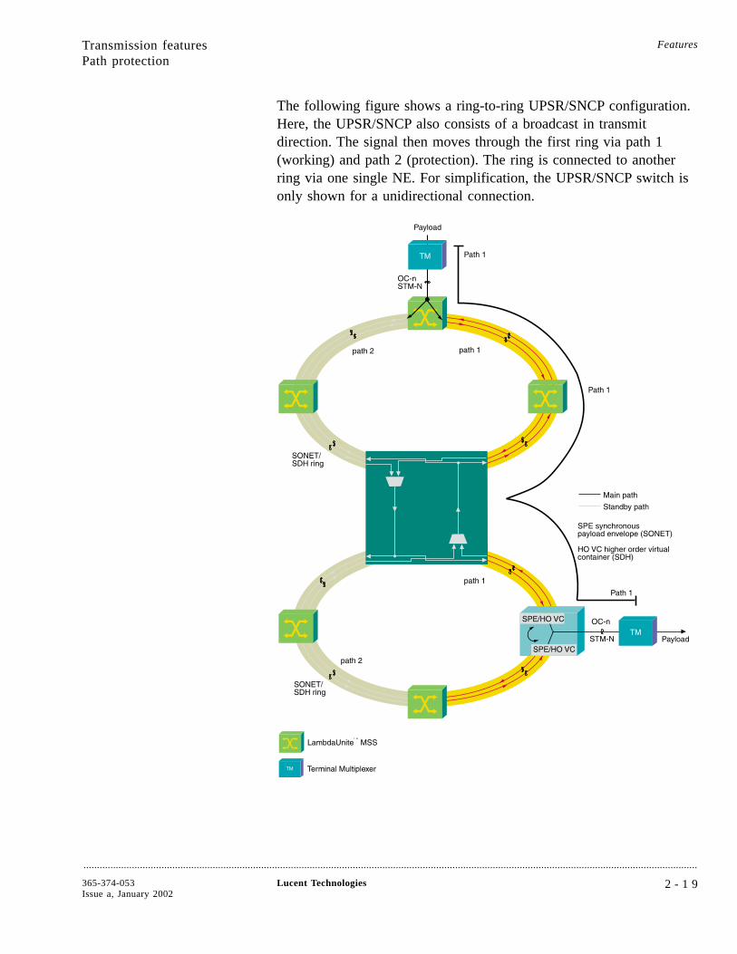
The following figure shows a ring-to-ring UPSR/SNCP configuration.Here, the UPSR/SNCP also consists of a broadcast in transmitdirection. The signal then moves through the first ring via path 1(working) and path 2 (protection). The ring is connected to anotherring via one single NE. For simplification, the UPSR/SNCP switch isonly shown for a unidirectional connection.
Transmission featuresPath protection
Features
....................................................................................................................................................................................................................................
365-374-053Issue a, January 2002
Lucent Technologies 2 - 1 9
Manual switch The following manual switching actions are possible with WaveStarCIT or Navis Optical EMS:
• Manual to working: switches the traffic to the main path if it isnot faulty
• Manual to protection: switches the traffic to the standby path if itis not faulty
• Forced to working: causes switchover to the main (working) path(even if this path is faulty)
• forced to protection: causes forced switchover to the standby(protection) path (even if this path is faulty)
• Clear: clears any active manual switch request; clear will alsorelease the wait-to-restore timer when provided for revertiveswitching.
Protection schemeindependence
Due to the LambdaUnite MSS architecture protection schemes ofdifferent layers do not interact from a resource or provisioningperspective. Especially LambdaUnite MSS supports the back-to-backconfiguration of protection schemes. In a back-to-back configurationthe selector of the first protection scheme is followed by the bridgefunction of the second protection scheme. Exceptions from that ruleare DRI/DNI configurations (not supported in the present release).
Transmission featuresPath protection
Features
....................................................................................................................................................................................................................................
2 - 2 0 Lucent Technologies 365-374-053Issue a, January 2002
Equipment features
Overview....................................................................................................................................................................................................................................
Purpose This section provides information about LambdaUnite™ MSS featuresconcerning hardware protection, inventory and failure reports.
Features
....................................................................................................................................................................................................................................
365-374-053Issue a, January 2002
Lucent Technologies 2 - 2 1

Equipment protection....................................................................................................................................................................................................................................
Circuit pack protection To enhance the reliability of the system, the switch and timingfunction (physically combined on one circuit pack) form a 1+1 nonrevertive equipment protection. Besides automatic switching, manual(forced) switching is supported to minimize operations interruptione.g. in maintenance scenarios (exchange of circuit packs).
Power supply The power feed is maintained duplicated throughout the system.
Equipment features Features
....................................................................................................................................................................................................................................
2 - 2 2 Lucent Technologies 365-374-053Issue a, January 2002
Equipment reports....................................................................................................................................................................................................................................
Equipment inventory LambdaUnite™ MSS automatically maintains an inventory of thefollowing information of each installed circuit pack:
• Serial number
• ECI code
• CLEI code
• Functional name
• Apparatus code
• Series number
• Functional qualifier
• Software release (of the NE)
You can obtain this information by an inventory request command.
Equipment failure reports Failure reports are generated for equipment faults and can beforwarded via the WaveStar® CIT and Navis™ Optical EMS interfaces.
Equipment features Features
....................................................................................................................................................................................................................................
365-374-053Issue a, January 2002
Lucent Technologies 2 - 2 3
Synchronization and timing
Overview....................................................................................................................................................................................................................................
Purpose This section provides information about synchronization features,timing protection and timing interfaces of LambdaUnite™ MSS.
Features
....................................................................................................................................................................................................................................
2 - 2 4 Lucent Technologies 365-374-053Issue a, January 2002

Timing features....................................................................................................................................................................................................................................
Synchronization modes Several synchronization configurations can be used. TheLambdaUnite™ MSS can be provisioned for:
• Locked mode, internal Station Equipment Clock (SIC/SEC)locked to either:
- One of two external synchronization inputs (each of themaccepts 2.048 kHz, 2 Mbit/s (framed or unframed) or DS1(B8ZS) signals (SF or ESF), or
- One of up to six OC-n / STM-N input signals (choice ofinput is provisionable).
Thus in the timing reference list up to eight timing references canbe configured. The timing reference for the external timingoutput can be provisioned independently from the timingreference for the system clock.
• Hold-over mode (in locked mode of operation, if no acceptablereferences are available, the internal clock will switch to thehold-over state)
• Forced hold-over mode (the user can select the internal oscillatorto use stored correction data of the last available used inputreference)
• Free-running.
Synchronizationprovisioning
It is possible to provision manual timing reference switching, to setpriorities for timing sources, to choose timing sources that are addedto the sources list, to lock out of individual timing sources, etc. usingthe WaveStar® CIT or the Navis™ Optical EMS.
Synchronization and timing Features
....................................................................................................................................................................................................................................
365-374-053Issue a, January 2002
Lucent Technologies 2 - 2 5
Timing protection....................................................................................................................................................................................................................................
Timing unit protection In LambdaUnite™ MSS the timing functionality is physically locatedon the switching circuit pack. Thus, 1+1 non-revertive protection ofthe timing functionality is provided (see “Equipment protection”(2-22)).
Timing reference selection Automatic timing reference switching is supported by LambdaUniteMSS on signal failure of the active timing reference. The timingreference selection is according to ETSI 300 417.1.1 / ITU-T Rec.G.781 for SDH timing and Telcordia GR-253 for SONET timing. Ifall provisioned timing references fail or become unacceptable, thesystem will automatically switch over to the hold-over mode.
Synchronization and timing Features
....................................................................................................................................................................................................................................
2 - 2 6 Lucent Technologies 365-374-053Issue a, January 2002
Timing interface features....................................................................................................................................................................................................................................
External timing outputs LambdaUnite™ MSS provides external timing output signals derivedfrom the system clock or from the incoming aggregate signals. Theseoutput ports support 2 MHz or 2 Mbit/s (framed or unframed) signalsas per ITU-T Rec. G.812 and G.703 or DS1 (B8ZS) signals (SF orESF).
An external timing output will automatically be squelched as soon asits associated Quality Level (QL) drops below a provisionablethreshold. Squelching is implemented by turning the timing outputsignal off.
Synchronization StatusMessage (SSM)
A Synchronization Status Message (SSM) can be used to indicate thesignal quality level throughout a network. This will guarantee that allnetwork elements will always be synchronized to the highest qualityclock available.
On the LambdaUnite MSS system, the SSM algorithm is implementedaccording to ETS 300 417-6 and GR-253-CORE. SSM is supportedon incoming and outgoing optical 2.5-Gbit/s and 10-Gbit/s interfaces,in future also 40-Gbit/s interfaces.
The user can assign a certain SSM value (overriding the receivedSSM, if any) to any synchronization reference signal that can be madeavailable to the SSM selection algorithm.
It is possible to force each individual outgoing SSM value (overridingthe SSM computed by the algorithm) to the value DNU/DUS (do notuse for synchronization).
Additionally LambdaUnite MSS supports insertion of an SSM valueinto an outgoing 2-Mbit/s framed signal (external timing output) andevaluation of the SSM of an incoming 2-Mbit/s framed signal(external timing input). This feature complies to the ITU-T Rec.G.704 and Bellcore TR-NWT-000499 respectively.
Synchronization and timing Features
....................................................................................................................................................................................................................................
365-374-053Issue a, January 2002
Lucent Technologies 2 - 2 7
Operations, Administration, Maintenance and Provisioning
Overview....................................................................................................................................................................................................................................
Purpose The following section provides information about interfaces forOperations, Administration, Maintenance, and Provisioning (OAM&P)activities and the monitoring and diagnostics features ofLambdaUnite™ MultiService Switch (MSS).
Features
....................................................................................................................................................................................................................................
2 - 2 8 Lucent Technologies 365-374-053Issue a, January 2002

Interfaces....................................................................................................................................................................................................................................
WaveStar® CIT and Navis™
Optical EMSOperations, Administration, Maintenance, and Provisioning (OAM&P)activities are performed using either the WaveStar Craft InterfaceTerminal (CIT) or Navis Optical Element Management System (EMS).The WaveStar CIT and the Navis Optical EMS is a customer-suppliedWindows NT PC running the WaveStar Graphical User Interface(GUI) software. You can plug it into the LambdaUnite™ MSS userpanel or use it at a remote location to access LambdaUnite MSS bymeans of a LAN or of Data Communications Channel (DCC). Youcan use the WaveStar CIT and the Navis Optical EMS to run a fullyfeatured GUI. The GUI provides access to the entire LambdaUniteMSS functionality and contains extensive menus and context-sensitivehelp.
Full TL1command/message set
LambdaUnite MSS supports the full TL1 command and message set.The WaveStar CIT and the Navis Optical EMS convert user inputs atthe GUI into the corresponding TL1 commands and convert TL1responses and messages into the GUI displays.
TL1 cut-through interface The LambdaUnite MSS system provides a TL1 cut-through interfacevia WaveStar CIT and Navis Optical EMS. Thus, you can interactwith the NE using the TL1 language directly. Navis Optical EMSprovides TL1 cut-through as a function within the GUI and alsosupports a special TL1 login. The TL1 cut-through is useful because itenables you to build custom macros of multiple TL1 commandscoupled with a broadcast capability to send the TL1 commands tomultiple NEs. Furthermore, TL1 cut-through is necessary for someinfrequently used commands that are not supported by the NavisOptical EMS GUI.
Security LambdaUnite MSS uses logins, passwords, authentication, and accesslevels to protect against unauthorized access. It also keeps the securitylog.
Local and remote softwaredownloads
With LambdaUnite MSS software can be downloaded from theWaveStar CIT, or from the Navis Optical EMS. Software downloadingdoes not affect transmission or operations. Activating the newlydownloaded software may affect operations but does not affecttransmission.
Operations, Administration, Maintenanceand Provisioning
Features
....................................................................................................................................................................................................................................
365-374-053Issue a, January 2002
Lucent Technologies 2 - 2 9
OSI LAN interface LambdaUnite MSS also communicates with remote logins, operationssystems and management systems by means of the standard 7-layerOSI protocol over a LAN.
TCP/IP tunnelling TCP/IP tunnelling via OSI will be supported by LambdaUnite MSS infuture.
DCC interfaces The LambdaUnite MSS system supports operations via the standard7-layer OSI protocol over Data Communications Channel (DCC).Section DCC (DCCR) and line DCC (DCCM) channels are available in2.5-Gbit/s, 10-Gbit/s, and in a future release in 155-Mbit/s, 622-Mbit/sand 40-Gbit/s signals. DCC channel protection switching is supportedin conjunction with protection switching of the respective opticalinterface.
NE level Detailed information and system control is obtained by using theWaveStar CIT (Craft Interface Terminal) which supports provisioning,maintenance, configuration on a local basis. A similar facility isremotely (via a Q-LAN connection or via the DCC channels)available on the WaveStar CIT, or on the Navis Optical EMS, whichprovides a centralized maintenance view and supports maintenanceactivities from a central location.
Orderwire and UserChannel
Orderwire and user channel interfaces are physically implemented onthe Control Interface Panel. E1, E2 and F1 byte access will besupported in a future release.
Operations, Administration, Maintenanceand ProvisioningInterfaces
Features
....................................................................................................................................................................................................................................
2 - 3 0 Lucent Technologies 365-374-053Issue a, January 2002
Monitoring and diagnostics features....................................................................................................................................................................................................................................
Performance monitoring LambdaUnite™ MSS monitors performance parameters on thetransmission interfaces, so monitoring can be full-time for each signalwithout requiring any additional cross-connect capacity.
Monitoring of opticalinterface parameters
The user can monitor the values of the laser bias current and thereceived and transmitted optical power of 40-Gbit/s (future release)and 10-Gbit/s interfaces.
Port monitoring modes Each physical interface can be in one of three different modes:automatic (AUTO), monitored (MON) or non-monitored (NMON). InNMON mode all alarms that originate in the physical sectiontermination function are suppressed, while in the MON mode they arereported. In the AUTO mode alarms are suppressed until an incomingsignal is detected, then the mode of the port switches automatically toMON.
Transmission maintenancesignals
Regenerator section, multiplex section, and higher order pathmaintenance signals are supported as per ITU-T Rec. G.783. Thesystem can generate and retrieve path trace messages on STS-1respectively higher order VC-3 and VC-4 level as well as section tracemessages respectively STM-N RSOH messages.
Path termination pointmonitoring modes
Each Path Termination Point can be in one of two different modes,monitored (MON) or non-monitored (NMON). In NMON mode allalarms that originate in the termination point are suppressed, while inthe MON mode they are reported .
Provisioned state record LambdaUnite MSS automatically maintains a record of theprovisioned state of each transmit and receive port on each circuitpack.
Loopbacks LambdaUnite MSS supports facility loopbacks for testing andmaintenance purposes. These loopbacks are available for eachsupported signal type. Facility loopbacks are established electricallyon port-level on a port unit. Two different types are available:
• Near-side loopback (in-loop)
• Far-side loopback (out-loop)
Operations, Administration, Maintenanceand Provisioning
Features
....................................................................................................................................................................................................................................
365-374-053Issue a, January 2002
Lucent Technologies 2 - 3 1

The loopbacks can be configured via WaveStar® CIT and Navis™
Optical EMS.
Local and remoteinventory
The LambdaUnite MSS system provides automatic version recognitionof the entire hardware and software installed in the system. Thisgreatly simplifies troubleshooting, dispatch decisions, and inventoryaudits. A list of detailed information, see “Equipment inventory”(2-23), is accessible via the local WaveStar CIT or via the NavisOptical EMS.
Self diagnostics(in-service)
The system runs audits and diagnostics to monitor its health. Theseself-diagnostics don’t have any effect on the performance of thesystem.
Auto-recovery after inputpower interrupt
The system can restore itself automatically after an interruption of thepower.
Recovery fromconfiguration failures
If the system detects that its configuration database is empty orcorrupted it will remain in the current configuration without impactingthe traffic, will raise an alarm and will request an configuration updatefrom the Navis Optical Network Management System (NMS).
Operations, Administration, Maintenanceand ProvisioningMonitoring and diagnostics features
Features
....................................................................................................................................................................................................................................
2 - 3 2 Lucent Technologies 365-374-053Issue a, January 2002
3 Network topologies
Overview....................................................................................................................................................................................................................................
Purpose This chapter describes the key applications of LambdaUnite™
MultiService Switch (MSS). It gives an overview of the variousnetwork applications and identifies the key functions associated withthese applications.
Network tiers Optical networks can be structured into three tiers in order to simplifytheir understanding, modelling and implementation:
• Backbone (tier 3)
• Metro core/regional (tier 2)
• Access (tier1)
Due to the flexibility of LambdaUnite MSS it is able to cover manydifferent applications especially in the backbone and metrocore/regional tier. The following sections will identify some of themain applications and configurations for which LambdaUnite MSS isoptimized.
ContentsBackbone applications 3-3
Classical backbones 3-4
Transoceanic applications 3-7
All Optical backbones 3-8
....................................................................................................................................................................................................................................
365-374-053Issue a, January 2002
Lucent Technologies 3 - 1
3-8
3-7
3-4
3-3
Metro core/regional applications 3-12
Ring topologies 3-13
Meshed topologies 3-15
Synchronous Network Navigator (SNN) 3-17
Traffic hubbing 3-18
Access/metro applications 3-20
Application details 3-22
Ethernet applications 3-23
Broadband transport 3-28
Remote hubbing 3-29
Ring topologies 3-31
Interworking with WaveStar® TDM 10G/2.5G andWaveStar ADM 16/1
3-35
Interworking with WaveStar BandWidth Manager 3-37
Interworking with Wavelength DivisionMultiplexing
3-38
Interworking with LambdaRouter™ AOS 3-41
Overview Network topologies
....................................................................................................................................................................................................................................
3 - 2 Lucent Technologies 365-374-053Issue a, January 2002
3-41
3-38
3-37
3-35
3-31
3-29
3-28
3-23
3-22
3-20
3-18
3-17
3-15
3-13
3-12
Backbone applications
Overview....................................................................................................................................................................................................................................
Purpose This section provides, after a brief introduction to the backbonetopology, information about backbone applications for LambdaUnite™
MSS.
Characterization of tier 3topologies
The backbone network tier typically shows the following features:
• Ring and meshed network topology
• Long and very long distance (several thousand kilometers)
• High capacity per fiber (multiple terabit/s)
• Efficient protection schemes (e.g. 4-fiber BLSR/MS-SPRing)
• Traffic patterns of big pipes (2.5 Gbit/s and beyond)
• Edge grooming (45-Mbit/s up to 10-Gbit/s services)
ContentsClassical backbones 3-4
Transoceanic applications 3-7
All Optical backbones 3-8
Network topologies
....................................................................................................................................................................................................................................
365-374-053Issue a, January 2002
Lucent Technologies 3 - 3
3-8
3-7
3-4

Classical backbones....................................................................................................................................................................................................................................
Overview This application shows the fit of LambdaUnite™ MSS in a backbonetransport network, which uses a combination of DWDM andSONET/SDH technology in a meshed topology.
Classical backboneexample
The given application is characterized by the use of DWDMequipment for cost optimized long distance point-to-point transport tolink the Points of Presence (PoP) in the network. Network ProtectionEquipment (NPE) based on SONET/SDH is used in the PoPs toprotect and redirect traffic, as well as to monitor transport quality andisolate faults. The service capacities handled in this network rangefrom STS-1 (50 Mbit/s) or VC-4 (155 Mbit/s) on the low end toconcatenated service signals with speeds up to 10 Gbit/s. For optimalreliability stacked BLSR/MS-SPRing rings are provisioned through theNPE in different PoPs. The selection of the network elements which
Backbone applications Network topologies
....................................................................................................................................................................................................................................
3 - 4 Lucent Technologies 365-374-053Issue a, January 2002
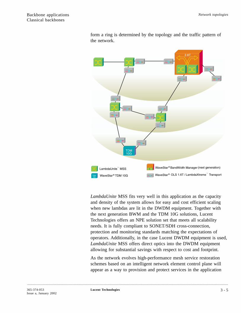
form a ring is determined by the topology and the traffic pattern ofthe network.
LambdaUnite MSS fits very well in this application as the capacityand density of the system allows for easy and cost efficient scalingwhen new lambdas are lit in the DWDM equipment. Together withthe next generation BWM and the TDM 10G solutions, LucentTechnologies offers an NPE solution set that meets all scalabilityneeds. It is fully compliant to SONET/SDH cross-connection,protection and monitoring standards matching the expectations ofoperators. Additionally, in the case Lucent DWDM equipment is used,LambdaUnite MSS offers direct optics into the DWDM equipmentallowing for substantial savings with respect to cost and footprint.
As the network evolves high-performance mesh service restorationschemes based on an intelligent network element control plane willappear as a way to provision and protect services in the application
Backbone applicationsClassical backbones
Network topologies
....................................................................................................................................................................................................................................
365-374-053Issue a, January 2002
Lucent Technologies 3 - 5
above. LambdaUnite MSS as well as the next generation BWM willsupport this functionality in a future release.
As transparent high capacity services become more importantLambdaUnite MSS will support overhead transparent services with acapacity of 2.5 Gbit/s and 10 Gbit/s in a future release. This waytransparent high capacity services and all lower speed transportservices can be served from a single layer high capacity network.Especially for applications with a substantial portion of the servicesbeing in the lower speed range, this is a powerful and flexiblesolution.
For further increase of transport capacity per fiber and furtherreduction of the cost per transported bit, LambdaUnite MSS willprovide 40-Gbit/s interfaces in a future release, including the veryinteresting option of using direct optics to the 40-Gbit/s DWDMsystem from Lucent Technologies. Deployment of 40-Gbit/s interfacesdoes not need any hardware change on the LambdaUnite MSS system– the interface pack can directly be plugged into free slots in thesystem.
Backbone applicationsClassical backbones
Network topologies
....................................................................................................................................................................................................................................
3 - 6 Lucent Technologies 365-374-053Issue a, January 2002

Transoceanic applications....................................................................................................................................................................................................................................
Overview This application shows the fit of LambdaUnite™ MSS in atransoceanic transport network.
Transoceanic network A transoceanic network is categorized by very long distancepoint-to-point DWDM transport links (several thousand kilometerlength through the ocean). In addition to these links, shorter DWDMtransport links in the terrestrial portion of the network are used tobackhaul the traffic from the landing point on the shore of the oceaninto the business centers located somewhere deeper in the country.Normally only a small portion of the lambdas available in theundersea and the backhaul links are utilized initially. More lambdasare lit as demand increases.
Network Protection Equipment (NPE) based on SONET/SDH is usedin the Points of Presence (PoPs) at the end points of the DWDM linksto protect and redirect traffic, as well as to monitor transport qualityand isolate faults. The service capacity ranges from VC-4 (155 Mbit/s)to concatenated service signals with speeds up to 10 Gbit/s. The rateper lambda is 10 Gbit/s today with 40 Gbit/s expected in the nextrelease.
LambdaUnite MSS intransoceanic topologies
LambdaUnite MSS fits ideally in the transoceanic application mainlybecause of the following reasons: The system supports the specialtransoceanic version of the MS-SPRing protocol in a future release,which is a mandatory requirement for the given application. Evenpreemptible protection access is supported. LambdaUnite MSS allowsfor easy and cost efficient scaling when new lambdas are lit in thetransoceanic and/or backhaul link. It’s capability to support bothSONET and SDH out of single node makes it a perfect vehicle fortransatlantic links. Finally, the system’s ability to not only support10-Gbit/s line rates but also 40-Gbit/s line rates makes it perfectlyprepared for future needs in this application space.
Backbone applications Network topologies
....................................................................................................................................................................................................................................
365-374-053Issue a, January 2002
Lucent Technologies 3 - 7

All Optical backbones....................................................................................................................................................................................................................................
Overview All-optical backbone applications are gaining importance as the needfor bandwidth increases and more high capacity services (lambdas) areto be handled. The all-optical backbone serves as an underlying layerbelow the existing backbone transport layers and this way allows forbest scalability at an optimized footprint and power level. Once highcapacity services with a data rate of 2.5 Gbit/s, 10 Gbit/s or abovebecome the predominant service types, an all-optical backbone layershows its advantages. LambdaUnite™ MSS plays an important role inall-optical backbone applications, where it is inter-working with a pureOOO (optical-optical-optical) crossconnect like the LambdaRouter™
All Optical Switch (AOS).
All-optical backboneexample
In the all-optical backbone layer, LambdaUnite MSS can be used tobridge the gap between lower speed services offered to customers andthe lambda as the smallest unit of capacity that is handled by theall-optical part of the network:
Here LambdaUnite MSS performs:
• Aggregation of lower speed services into lambdas (backbonefeeding)
• Grooming between different lambdas (sub-λ grooming)
All-optical backboneexample
In the picture below the left and middle part illustrates these twofunctions:
The leftmost LambdaUnite MSS element takes lower speed trafficfrom the regional network and aggregates this traffic into lambdasdirectly feeding DWDM gear. The lambdas in the network are thenredirected via LambdaRouter All Optical Switches (AOSs) as the oneon the top left of the picture.
The LambdaUnite MSS located in the middle of the picture illustratesthe grooming function: The system is connected to a LambdaRouterAOS, takes the lambdas and regroups the services within the lambdas.This way each lambda can be efficiently utilized.
The right part of the picture illustrates the next evolution step of theall-optical backbone layer: LambdaRouter AOS is now taking on thefunctionality of restoring lambdas and therefore must be used at everyPoint of Presence (PoP) where traffic is entering the all-opticalbackbone network. Therefore the right hand side LambdaUnite MSS is
Backbone applications Network topologies
....................................................................................................................................................................................................................................
3 - 8 Lucent Technologies 365-374-053Issue a, January 2002
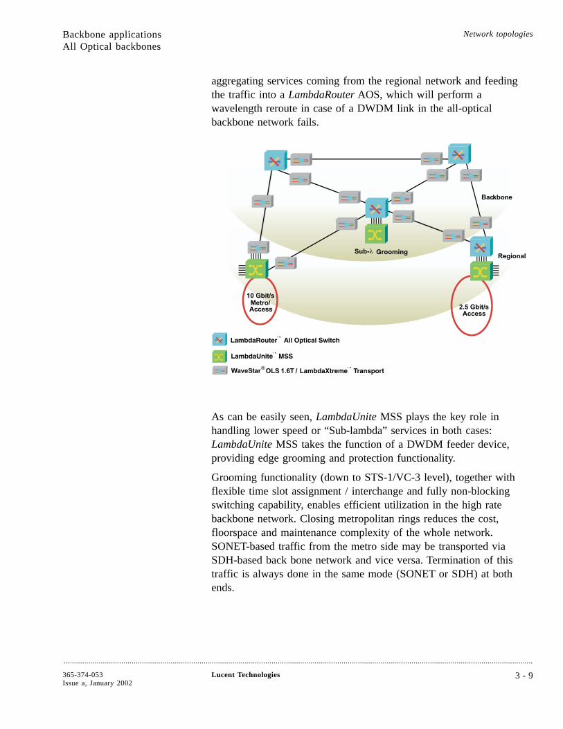
aggregating services coming from the regional network and feedingthe traffic into a LambdaRouter AOS, which will perform awavelength reroute in case of a DWDM link in the all-opticalbackbone network fails.
As can be easily seen, LambdaUnite MSS plays the key role inhandling lower speed or “Sub-lambda” services in both cases:LambdaUnite MSS takes the function of a DWDM feeder device,providing edge grooming and protection functionality.
Grooming functionality (down to STS-1/VC-3 level), together withflexible time slot assignment / interchange and fully non-blockingswitching capability, enables efficient utilization in the high ratebackbone network. Closing metropolitan rings reduces the cost,floorspace and maintenance complexity of the whole network.SONET-based traffic from the metro side may be transported viaSDH-based back bone network and vice versa. Termination of thistraffic is always done in the same mode (SONET or SDH) at bothends.
Backbone applicationsAll Optical backbones
Network topologies
....................................................................................................................................................................................................................................
365-374-053Issue a, January 2002
Lucent Technologies 3 - 9
All Optical SwitchLambdaRouter AOS
The central element of optical backbones are optical switches like theLambdaRouter All Optical Switch (AOS). This product is capable ofoperating at any optical layer bit rate, including 40 Gbit/s and beyond,ideal for an IP over wavelength network. This is a true optical crossconnect system, operating an optical - rather than electrical -switching fabric.
Because optical to electrical to optical conversions do not occurwithin the system, transmission interfaces are transparent. TheLambdaRouter AOS is also non-blocking, rate- and format-independent, large, and scalable - innovations that place it at thevanguard of optical technology.
Optical network platform As more and more service providers deploy optical products in theirnetworks, they need help provisioning bandwidth. Therefore LucentTechnologies recently unveiled an intelligent optical networkingplatform that will allow the customers to cost-effectively providebandwidth-on-demand and other new revenue-generating services. Theoptical-data networking platform is built around the all-optical switch- the LambdaRouter AOS - and two new, industry-leading softwareproducts from Bell Labs that enable carriers to control individualwavelengths of light carrying all forms of telecommunications traffic.
The new intelligent routing software also will let our all-opticalswitches communicate with one another, instantly discover newswitches and links as they are added to a network’s topology andautomatically redistribute wavelengths in response to fluctuatingtraffic demands and network resources. Using these products, serviceproviders will be able to offer their customers networks withunparalleled levels of flexibility, reliability, auto-recovery and qualityof service that can scale to multi-terabit capacities.
The Navis™ Optical Customer Service Manager (CSM), which BellLabs brought from research to market in just eight months, is aninnovative software platform that provides network operators withcapabilities like “point-and-click” bandwidth provisioning. UsingLucent’s Navis Optical CSM software, network operators canremotely direct a LambdaRouter AOS in Chicago, for example, toincrease the number of wavelengths it is sending to Seattle anddecrease the number it is sending to Denver as traffic between thosecities fluctuates. This will enable carriers to offer suchrevenue-generating services as bandwidth trading, optical virtual
Backbone applicationsAll Optical backbones
Network topologies
....................................................................................................................................................................................................................................
3 - 1 0 Lucent Technologies 365-374-053Issue a, January 2002

private networks and dynamic bandwidth control, as well as createtheir own custom services.
Backbone applicationsAll Optical backbones
Network topologies
....................................................................................................................................................................................................................................
365-374-053Issue a, January 2002
Lucent Technologies 3 - 1 1
Metro core/regional applications
Overview....................................................................................................................................................................................................................................
Purpose This section provides some information about the metro core/regionalnetwork tier and about regional/metro applications of LambdaUnite™
MSS.
Characterization of tier 2topologies
The metro core/regional network tier typically shows the followingfeatures:
• Dominated by ring network topology
• Mid range distance (up to ~ 200 km)
• Partially high capacity per fiber (terabit/s)
• Efficient protection schemes (e.g. 2-fiber/4-fiberBLSR/MS-SPRing)
• Mixed traffic patterns (from 45-Mbit/s up to 10-Gbit/s services)
• Grooming (45-Mbit/s up to 10-Gbit/s services)
• Synchronous and data interfaces
ContentsRing topologies 3-13
Meshed topologies 3-15
Synchronous Network Navigator (SNN) 3-17
Traffic hubbing 3-18
Network topologies
....................................................................................................................................................................................................................................
3 - 1 2 Lucent Technologies 365-374-053Issue a, January 2002
3-18
3-17
3-15
3-13
Ring topologies....................................................................................................................................................................................................................................
Overview For many metro core applications around the world a ring basednetwork topology with the associated ring protection schemes is used.This application example shows the benefits of using a LambdaUnite™
MSS system in these applications.
Ring based metrocore/regional application
In this ring based application LambdaUnite MSS plays the role of avery flexible and expandable multi-ring terminal. This and the datacapabilities of the system make it a representative of the new opticalswitches or optical edge devices (OEDs), which are brought to marketand are greatly replacing classical ADM products. The multi-ringcapability of the OED applies both to the aggregation of access ringsas well as grooming between neighboring metro core/regional rings,which come together at central PoPs.
As described in the network picture below, the multi-ring terminalsare aggregating traffic from the access rings, huge data nodes andbusiness parks. Grooming functionality (down to STS1/HO-VC-3 orVC-4 level) together with flexible time slot assignment or interchangeand fully non-blocking switching capability enables high utilization inthe high rate metro ring.
Taking into account the size of the metro ring (typically 5 to 10nodes), 155-Mbit/s (later release), 622-Mbit/s (later release), 2.5-Gbit/sand 10-Gbit/s tributary interfaces are supported to address anappropriate bandwidth ratio between access and metro rings. Thesupport of Gigabit Ethernet with flexible bandwidth assignment to theGbE service port is a key functionality to fit the operator’s needs forflexible data transport solutions as part of a single network.
Due to the wide range of protection features supported byLambdaUnite MSS, protection schemes can be chosen dependent ontraffic pattern (hubbed versus more neighboring traffic) and theprotection schemes supported by the nodes to interwork with on thesame ring. A combination with DWDM or “passive” WDM issupported for fiber constrained environments.
An important additional value proposition to use LambdaUnite MSSin these applications lies in the value that the system brings to thetable as a backbone feeder node (see previous applicationdescriptions). This way the very same LambdaUnite MSS system that
Metro core/regional applications Network topologies
....................................................................................................................................................................................................................................
365-374-053Issue a, January 2002
Lucent Technologies 3 - 1 3
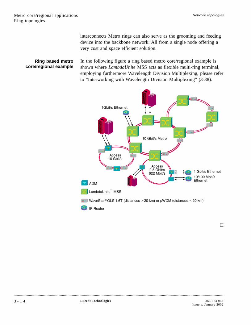
interconnects Metro rings can also serve as the grooming and feedingdevice into the backbone network: All from a single node offering avery cost and space efficient solution.
Ring based metrocore/regional example
In the following figure a ring based metro core/regional example isshown where LambdaUnite MSS acts as flexible multi-ring terminal,employing furthermore Wavelength Division Multiplexing, please referto “Interworking with Wavelength Division Multiplexing” (3-38).
Metro core/regional applicationsRing topologies
Network topologies
....................................................................................................................................................................................................................................
3 - 1 4 Lucent Technologies 365-374-053Issue a, January 2002

Meshed topologies....................................................................................................................................................................................................................................
Overview As new metro core networks are built, mesh based topologies arestarting to appear in fiber-rich metro environments. The benefits thatthese new topologies bring along are only possible with systemsdesigned like LambdaUnite™ MSS. The following applicationdescription explain these benefits enabled by LambdaUnite MSS.
Meshed metrocore/regional topology
Due to the flexible architecture of LambdaUnite MSS the creation andexpansion of a meshed metro core topology is very easy. This can becombined with the ring closure capability towards the access network(the access network is still dominated by ring topologies due to itshubbed traffic pattern). Taking these capabilities, the system plays therole of a flexible Optical Edge Device (OED) supporting a wide rangeof services and topologies.
As described in the picture below, the OEDs are aggregating thetraffic from the access nodes and are forwarding it into the metro coremeshed network. The protection schemes used in the metro corenetwork can be either BLSR/MS-SPRing or SNCP/UPSR, whichsupports meshed topologies more easily.
Service interfaces of the OEDs in the metro core network cover awide range from 155 Mbit/s to 10 Gbit/s as well as Gigabit Ethernet.The fact that LambdaUnite MSS can act as a flexible backbone feedernode makes it possible to combine the metro core and backbonefeeder node function into a single node, allowing for cost and floorspace optimization.
In addition to the protection schemes mentioned abovehigh-performance mesh service restoration schemes based on anintelligent network element control plane will appear as a way toprovision and protect services in the given application. LambdaUniteMSS will support this functionality in a future release. This way theinvestment into a metro core build with LambdaUnite MSS isprotected.
Metro core/regional applications Network topologies
....................................................................................................................................................................................................................................
365-374-053Issue a, January 2002
Lucent Technologies 3 - 1 5
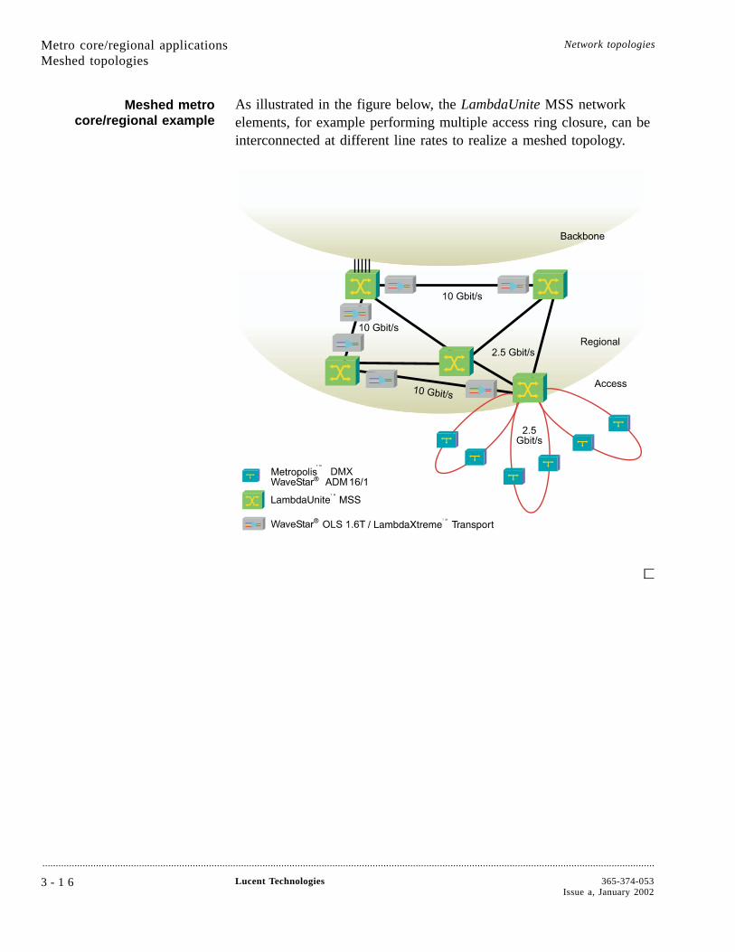
Meshed metrocore/regional example
As illustrated in the figure below, the LambdaUnite MSS networkelements, for example performing multiple access ring closure, can beinterconnected at different line rates to realize a meshed topology.
Metro core/regional applicationsMeshed topologies
Network topologies
....................................................................................................................................................................................................................................
3 - 1 6 Lucent Technologies 365-374-053Issue a, January 2002
Synchronous Network Navigator (SNN)....................................................................................................................................................................................................................................
SNN advantages The key drivers for the Synchronous Network Navigator (SNN) are:
• Fast, automatic service fulfillment
• Simplification of manual operations
• Elimination of connection design failure by using the network asthe topology database.
As a part of the intelligent network platform, SNN will comprise a setof capabilities that automates SONET/SDH connection set-up, fastrestoration, and the automatic discovery of the topology inSONET/SDH networks. In its initial releases, SNN will operate inconjunction with Lucent Technologies SONET or SDH products thatare capable of switching at the STS-1 or STM-1 level. Althoughconnections are supported without making use of the SNN, the SNNcan set-up connections faster, using automated circuit design.
SNN functionalities The SNN will provide route selection and connection set-up functions.It will discover available transport capacity, route, and provideconnection management for a network of Lucent TechnologiesSONET or SDH switches and ADMs. SNN will enable the intelligentnetwork elements to automatically set up end-to-end connectionsacross the network. New Lucent Technologies network elements (NE)will support the signaling necessary to actively participate in the SNN.Older NEs may be passive participants in the SNN, merelytransporting the channels switched by the newer NEs that support thesignaling and control architecture of the SNN.
The SNN will be supported in a future release of LambdaUnite™
MSS.
Metro core/regional applications Network topologies
....................................................................................................................................................................................................................................
365-374-053Issue a, January 2002
Lucent Technologies 3 - 1 7
Traffic hubbing....................................................................................................................................................................................................................................
Overview As mentioned before in this chapter, one of the key values of theflexible LambdaUnite™ MSS architecture lies in its ability toefficiently hub traffic from lower tiers of the network and feed thistraffic into the next higher tier. This section illustrates the specificsand the value of this hubbing function from the access layer into themetro core/regional layer as well as from the metro core/regional layerinto the backbone layer.
Metro core/regionalhubbing example
In the 10-Gbit/s metro regional hub application LambdaUnite MSSacts as multi-ring terminal, hubbing (see also “Remote hubbing”(3-29)) the traffic from several lower rate access rings (see also“Closing rings” (3-31)) and providing the interconnection to one ormore 10-Gbit/s metro/backbone networks. LambdaUnite MSS will betypically located in a central office where it provides numerous localinterconnections to several routers of the different IS-providers, voiceswitches, backbone multiplexers, and DWDM equipment of othernetwork operators.
Grooming functionality, together with flexible time slotassignment/interchange and fully non-blocking switching capability,enables high utilization in the 10-Gbit/s metro/backbone rings.LambdaUnite MSS can be efficiently coupled with anotherSONET/SDH multiplexer mounted in the same bay, in order toprovide access for electrical signals as well as grooming of someremaining lower order traffic.
Depending on the capacity needs, configurations of 2-fiber ring can besupported, in a future release also 4-fiber ring or combinations withDWDM or “passive” WDM; see also “Growing demand for extracapacity” (3-38).
Metro core/regional applications Network topologies
....................................................................................................................................................................................................................................
3 - 1 8 Lucent Technologies 365-374-053Issue a, January 2002
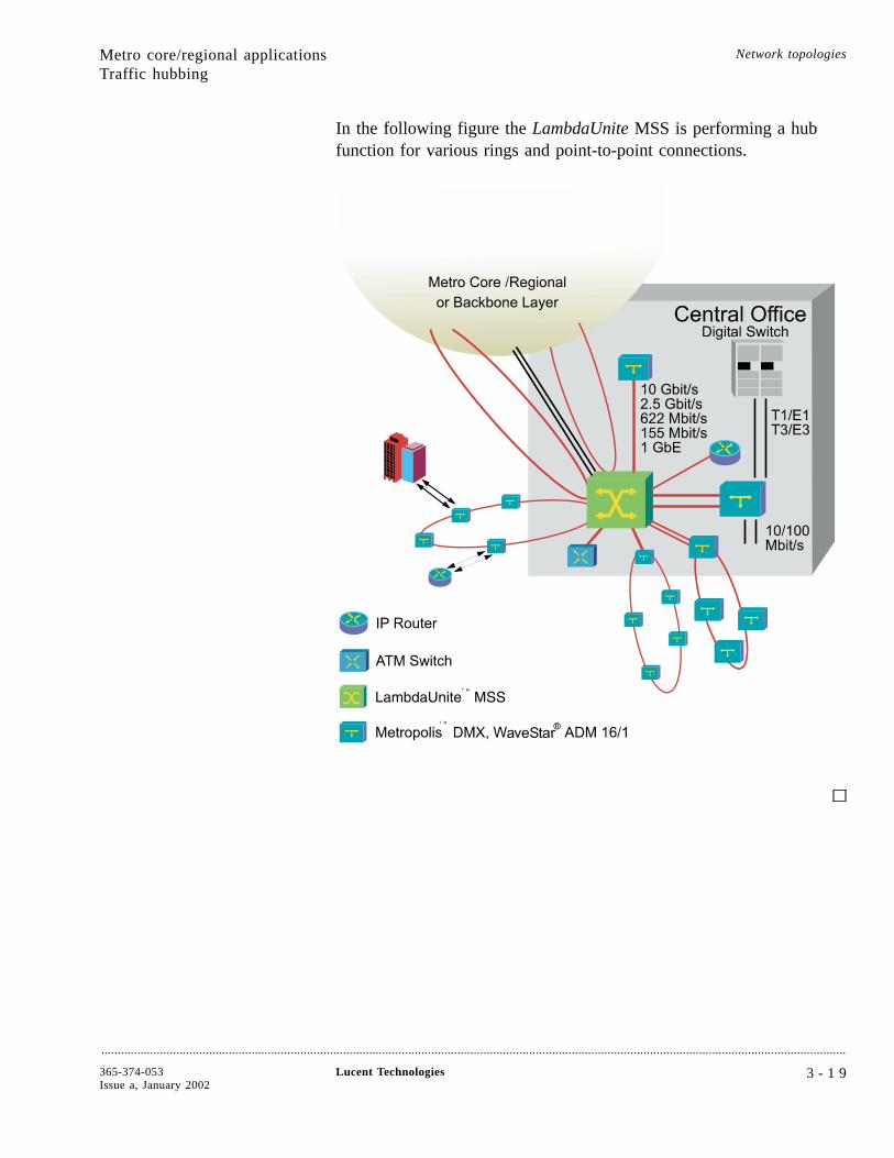
In the following figure the LambdaUnite MSS is performing a hubfunction for various rings and point-to-point connections.
Metro core/regional applicationsTraffic hubbing
Network topologies
....................................................................................................................................................................................................................................
365-374-053Issue a, January 2002
Lucent Technologies 3 - 1 9
Access/metro applications
Overview....................................................................................................................................................................................................................................
Purpose This section provides information about access/metro tiercharacteristics and access/metro applications for LambdaUnite™
MultiService Switch (MSS).
Characterization of tier 1topologies
The access/metro network tier typically shows the following features:
• Point to point and ring network topology
• Short distance (up to ~ 40 km)
• Low capacity per fiber (2.5 Gbit/s and lower)
• Mixed traffic patterns (from 2 Mbit/s up to 2.5 Gbit/s services)
• Edge concentration
• Circuit and data interfaces
Network topologies
....................................................................................................................................................................................................................................
3 - 2 0 Lucent Technologies 365-374-053Issue a, January 2002

Tier 1 applications....................................................................................................................................................................................................................................
Although LambdaUnite™ MultiService Switch (MSS) with its 320Gbit/s switching matrix is designed rather for network tier 3 and tier 2applications, it can be employed in topologies that initially performaccess/metro functions, providing remarkable and cost-efficient growthcapabilities.
Access/metro applications Network topologies
....................................................................................................................................................................................................................................
365-374-053Issue a, January 2002
Lucent Technologies 3 - 2 1

Application details
Overview....................................................................................................................................................................................................................................
Purpose This chapter gives an overview of LambdaUnite™ MSS applicationdetails in basic topologies.
ContentsEthernet applications 3-23
Broadband transport 3-28
Remote hubbing 3-29
Ring topologies 3-31
Interworking with WaveStar® TDM 10G/2.5G andWaveStar ADM 16/1
3-35
Interworking with WaveStar BandWidth Manager 3-37
Interworking with Wavelength DivisionMultiplexing
3-38
Interworking with LambdaRouter™ AOS 3-41
Network topologies
....................................................................................................................................................................................................................................
3 - 2 2 Lucent Technologies 365-374-053Issue a, January 2002
3-41
3-38
3-37
3-35
3-31
3-29
3-28
3-23

Ethernet applications....................................................................................................................................................................................................................................
Overview Data services based on IP are becoming more and more important.With Ethernet being the native LAN interface for IP traffic, offeringEthernet interface based WAN transport services becomes animportant element for competitive service offerings.
This section explains the Ethernet services and underlying applicationssupported by LambdaUnite™ MSS:
• Inter-PoP (Point-of-Presence) services
• Corporate LAN interconnections
• Virtual concatenation
Inter-PoP services Internet Service Providers (ISPs) and Application Service Providers(ASPs) need high but flexible bandwidth connections between their IProuters and their bandwidth wholesaler. An efficient solution for theseconnections are direct paths between the main routing locations(inter-PoP services) in the form of dedicated SONET/SDH and/orWDM signals, simply employing Ethernet interfaces in SONET/SDHadd-drop-multiplexers.
This Hybrid Transport based on SONET/SDH with LambdaUniteMSS systems can provide high speed and simply leased line Ethernet
Application details Network topologies
....................................................................................................................................................................................................................................
365-374-053Issue a, January 2002
Lucent Technologies 3 - 2 3
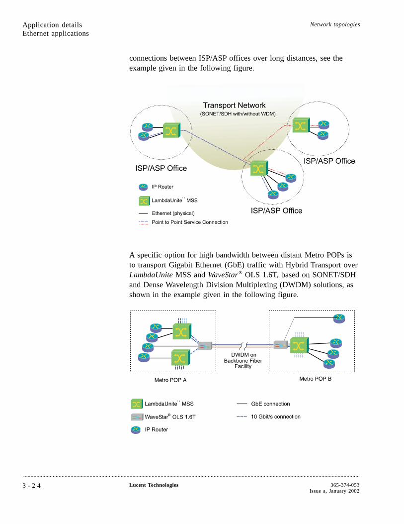
connections between ISP/ASP offices over long distances, see theexample given in the following figure.
A specific option for high bandwidth between distant Metro POPs isto transport Gigabit Ethernet (GbE) traffic with Hybrid Transport overLambdaUnite MSS and WaveStar® OLS 1.6T, based on SONET/SDHand Dense Wavelength Division Multiplexing (DWDM) solutions, asshown in the example given in the following figure.
Application detailsEthernet applications
Network topologies
....................................................................................................................................................................................................................................
3 - 2 4 Lucent Technologies 365-374-053Issue a, January 2002
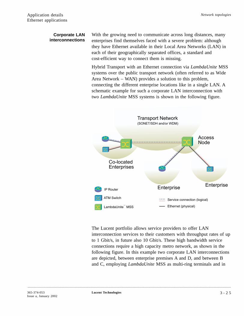
Corporate LANinterconnections
With the growing need to communicate across long distances, manyenterprises find themselves faced with a severe problem: althoughthey have Ethernet available in their Local Area Networks (LAN) ineach of their geographically separated offices, a standard andcost-efficient way to connect them is missing.
Hybrid Transport with an Ethernet connection via LambdaUnite MSSsystems over the public transport network (often referred to as WideArea Network – WAN) provides a solution to this problem,connecting the different enterprise locations like in a single LAN. Aschematic example for such a corporate LAN interconnection withtwo LambdaUnite MSS systems is shown in the following figure.
The Lucent portfolio allows service providers to offer LANinterconnection services to their customers with throughput rates of upto 1 Gbit/s, in future also 10 Gbit/s. These high bandwidth serviceconnections require a high capacity metro network, as shown in thefollowing figure. In this example two corporate LAN interconnectionsare depicted, between enterprise premises A and D, and between Band C, employing LambdaUnite MSS as multi-ring terminals and in
Application detailsEthernet applications
Network topologies
....................................................................................................................................................................................................................................
365-374-053Issue a, January 2002
Lucent Technologies 3 - 2 5
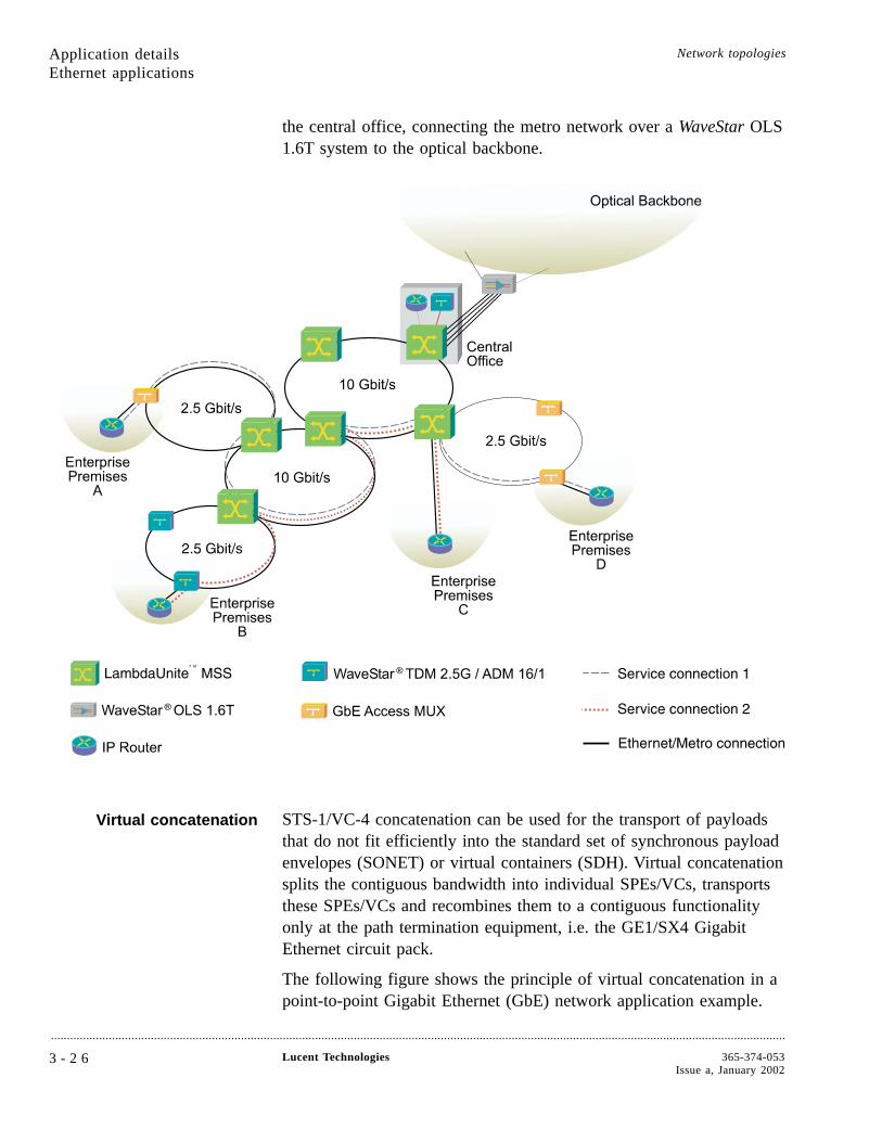
the central office, connecting the metro network over a WaveStar OLS1.6T system to the optical backbone.
Virtual concatenation STS-1/VC-4 concatenation can be used for the transport of payloadsthat do not fit efficiently into the standard set of synchronous payloadenvelopes (SONET) or virtual containers (SDH). Virtual concatenationsplits the contiguous bandwidth into individual SPEs/VCs, transportsthese SPEs/VCs and recombines them to a contiguous functionalityonly at the path termination equipment, i.e. the GE1/SX4 GigabitEthernet circuit pack.
The following figure shows the principle of virtual concatenation in apoint-to-point Gigabit Ethernet (GbE) network application example.
Application detailsEthernet applications
Network topologies
....................................................................................................................................................................................................................................
3 - 2 6 Lucent Technologies 365-374-053Issue a, January 2002

Protection of the VC-4-7c traffic, in future also STS-1-Kv/VC-4-kvtraffic is possible via UPSR/SNCP and in ring topologies viaBLSR/MS-SPRing protection schemes.
The H4 POH byte is used for the sequence and multi-frame indicationspecific for virtual concatenation.
Due to different propagation delay of the virtual containers adifferential delay will occur between the individual virtual containers.This differential delay has to be compensated and the individualvirtual containers have to be re-aligned for access to the contiguouspayload area. The LambdaUnite MSS re-alignment process covers atleast a differential delay of 32 ms.
Application detailsEthernet applications
Network topologies
....................................................................................................................................................................................................................................
365-374-053Issue a, January 2002
Lucent Technologies 3 - 2 7

Broadband transport....................................................................................................................................................................................................................................
Broadband Services Broadband services that can be handled with LambdaUnite™
MultiService Switch (MSS) include:
• LAN interconnection
• Video distribution from a video server
• Medical imaging
• ATM traffic
These services can be conveniently switched by LambdaUnite MSS asconcatenated payloads (STS-3c/VC-4, STS-12c/VC-4-4c,STS-48c/VC-4-16c or STS-192c/VC-4-64c) over all available lineinterfaces.
ATM transport example As an example, the figure below shows LambdaUnite MSStransporting ATM traffic between a central office and a customer’spremises.
Application details Network topologies
....................................................................................................................................................................................................................................
3 - 2 8 Lucent Technologies 365-374-053Issue a, January 2002
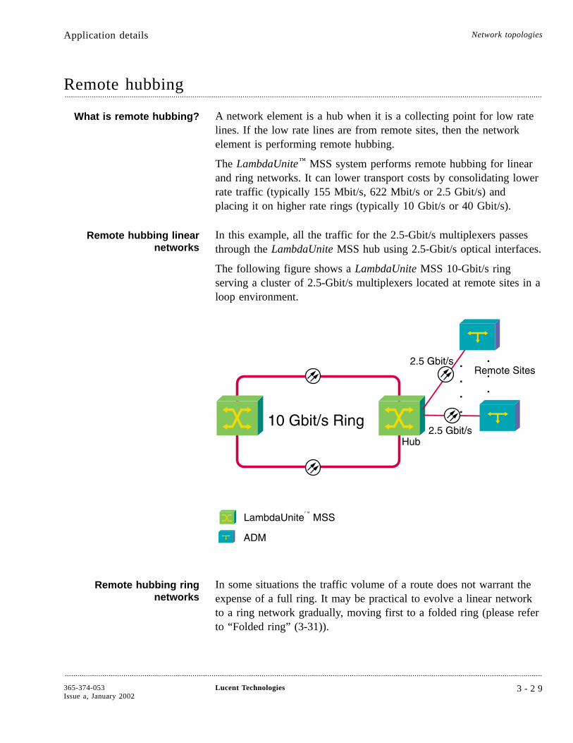
Remote hubbing....................................................................................................................................................................................................................................
What is remote hubbing? A network element is a hub when it is a collecting point for low ratelines. If the low rate lines are from remote sites, then the networkelement is performing remote hubbing.
The LambdaUnite™ MSS system performs remote hubbing for linearand ring networks. It can lower transport costs by consolidating lowerrate traffic (typically 155 Mbit/s, 622 Mbit/s or 2.5 Gbit/s) andplacing it on higher rate rings (typically 10 Gbit/s or 40 Gbit/s).
Remote hubbing linearnetworks
In this example, all the traffic for the 2.5-Gbit/s multiplexers passesthrough the LambdaUnite MSS hub using 2.5-Gbit/s optical interfaces.
The following figure shows a LambdaUnite MSS 10-Gbit/s ringserving a cluster of 2.5-Gbit/s multiplexers located at remote sites in aloop environment.
Remote hubbing ringnetworks
In some situations the traffic volume of a route does not warrant theexpense of a full ring. It may be practical to evolve a linear networkto a ring network gradually, moving first to a folded ring (please referto “Folded ring” (3-31)).
Application details Network topologies
....................................................................................................................................................................................................................................
365-374-053Issue a, January 2002
Lucent Technologies 3 - 2 9

However, you can still gain the benefit of a ring architecture on theroute by using two interfaces per ring in one LambdaUnite MSSnetwork element to close and link the rings. In this way LambdaUniteMSS acts as a hub for traffic from the lower rate ring that is to becarried on a 10-Gbit/s ring (in the next release also on a 40-Gbit/sring), see also “Ring topologies” (3-31).
Application detailsRemote hubbing
Network topologies
....................................................................................................................................................................................................................................
3 - 3 0 Lucent Technologies 365-374-053Issue a, January 2002
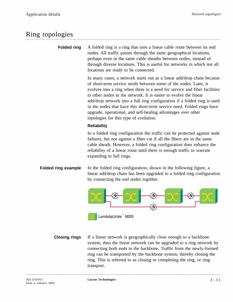
Ring topologies....................................................................................................................................................................................................................................
Folded ring A folded ring is a ring that uses a linear cable route between its endnodes. All traffic passes through the same geographical locations,perhaps even in the same cable sheaths between nodes, instead ofthrough diverse locations. This is useful for networks in which not alllocations are ready to be connected.
In many cases, a network starts out as a linear add/drop chain becauseof short-term service needs between some of the nodes. Later, itevolves into a ring when there is a need for service and fiber facilitiesto other nodes in the network. It is easier to evolve the linearadd/drop network into a full ring configuration if a folded ring is usedin the nodes that have this short-term service need. Folded rings haveupgrade, operational, and self-healing advantages over othertopologies for this type of evolution.
Reliability
In a folded ring configuration the traffic can be protected against nodefailures, but not against a fiber cut if all the fibers are in the samecable sheath. However, a folded ring configuration does enhance thereliability of a linear route until there is enough traffic to warrantexpanding to full rings.
Folded ring example In the folded ring configuration, shown in the following figure, alinear add/drop chain has been upgraded to a folded ring configurationby connecting the end nodes together.
Closing rings If a linear network is geographically close enough to a backbonesystem, then the linear network can be upgraded to a ring network byconnecting both ends to the backbone. Traffic from the newly-formedring can be transported by the backbone system, thereby closing thering. This is referred to as closing or completing the ring, or ringtransport.
Application details Network topologies
....................................................................................................................................................................................................................................
365-374-053Issue a, January 2002
Lucent Technologies 3 - 3 1
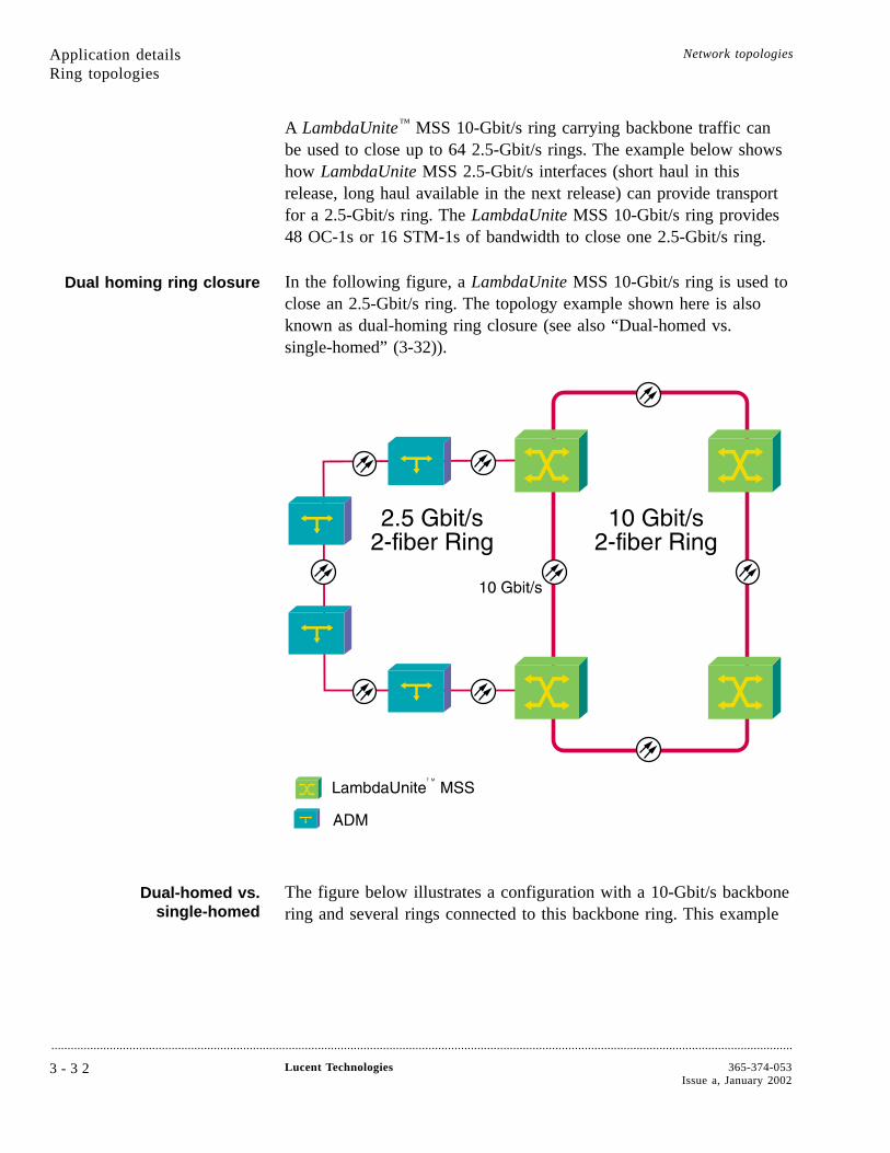
A LambdaUnite™ MSS 10-Gbit/s ring carrying backbone traffic canbe used to close up to 64 2.5-Gbit/s rings. The example below showshow LambdaUnite MSS 2.5-Gbit/s interfaces (short haul in thisrelease, long haul available in the next release) can provide transportfor a 2.5-Gbit/s ring. The LambdaUnite MSS 10-Gbit/s ring provides48 OC-1s or 16 STM-1s of bandwidth to close one 2.5-Gbit/s ring.
Dual homing ring closure In the following figure, a LambdaUnite MSS 10-Gbit/s ring is used toclose an 2.5-Gbit/s ring. The topology example shown here is alsoknown as dual-homing ring closure (see also “Dual-homed vs.single-homed” (3-32)).
Dual-homed vs.single-homed
The figure below illustrates a configuration with a 10-Gbit/s backbonering and several rings connected to this backbone ring. This example
Application detailsRing topologies
Network topologies
....................................................................................................................................................................................................................................
3 - 3 2 Lucent Technologies 365-374-053Issue a, January 2002
shows the following types of connections between a LambdaUniteMSS 10-Gbit/s ring and the 2.5-Gbit/s rings:
• Dual-homed ring connections to a LambdaUnite MSS ring atnodes A and E
• Single-homed ring connections (unprotected) to a LambdaUniteMSS ring at node B
• Single-homed ring connections (unprotected) to a LambdaUniteMSS ring at node C
In a dual-homed ring configuration, one ring connects to the other bytwo LambdaUnite MSS nodes, one 2.5-Gbit/s interface connectioneach.
In a single-homed ring configuration, one ring connects to the otherby a single LambdaUnite MSS node, with two 2.5-Gbit/s interfaceconnections.
Ring topology example
The following figure shows two single-homed (on the top and on theright hand side) and one dual-homed (left hand side) ringconfigurations in a 10-Gbit/s backbone ring.
Multiple ring closure LambdaUnite MultiService Switch (MSS) is an ideal ring closurenetwork element because its architecture, although extremely compact,allows the insertion of up to eight 40-Gbit/s interfaces (in the nextrelease), up to 32 10-Gbit/s interfaces, or up to 128 2.5-Gbit/s ports inone single shelf. Therefore up to four 40-Gbit/s rings, up to sixteen10-Gbit/s rings or up to 64 2.5-Gbit/s rings can be closed by oneLambdaUnite MultiService Switch (MSS). For all ringsBLSR/MS-SPRing protection can be configured.
In the following figure LambdaUnite MultiService Switch (MSS)performs ring closure and ring connection on different levels,interworking with WaveStar® BandWidth Manager, WaveStar TDM10G, WaveStar ADM 16/1, and Metropolis Trademark DMX.
Low rate grooming andprotection
Closing rings that carry traffic structured below the STS-1 or VC-3level, it may be required to perform
• grooming
• path protection
Application detailsRing topologies
Network topologies
....................................................................................................................................................................................................................................
365-374-053Issue a, January 2002
Lucent Technologies 3 - 3 3
on traffic below the STS-1 or VC-3 level between rings on low ratelevels. This can be done by connecting an additional low rate ADM tothe LambdaUnite MultiService Switch (MSS).
As an example, the following figure illustrates a multiple ring closure,in this case with WaveStar ADM 16/1 and Metropolis TrademarkDMX rings, with an additional WaveStar ADM 16/1 or MetropolisTrademark DMX connected to LambdaUnite MultiService Switch(MSS) in order to perform grooming / path protection below theSTS-1 or VC-3 level.
Application detailsRing topologies
Network topologies
....................................................................................................................................................................................................................................
3 - 3 4 Lucent Technologies 365-374-053Issue a, January 2002
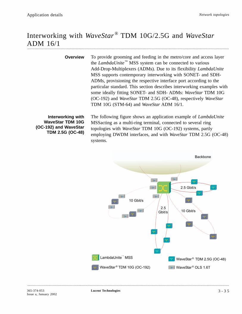
Interworking with WaveStar ® TDM 10G/2.5G and WaveStarADM 16/1....................................................................................................................................................................................................................................
Overview To provide grooming and feeding in the metro/core and access layerthe LambdaUnite™ MSS system can be connected to variousAdd-Drop-Multiplexers (ADMs). Due to its flexibility LambdaUniteMSS supports contemporary interworking with SONET- and SDH-ADMs, provisioning the respective interface port according to theparticular standard. This section describes interworking examples withsome ideally fitting SONET- and SDH- ADMs: WaveStar TDM 10G(OC-192) and WaveStar TDM 2.5G (OC-48), respectively WaveStarTDM 10G (STM-64) and WaveStar ADM 16/1.
Interworking withWaveStar TDM 10G
(OC-192) and WaveStarTDM 2.5G (OC-48)
The following figure shows an application example of LambdaUniteMSSacting as a multi-ring terminal, connected to several ringtopologies with WaveStar TDM 10G (OC-192) systems, partlyemploying DWDM interfaces, and with WaveStar TDM 2.5G (OC-48)systems.
Application details Network topologies
....................................................................................................................................................................................................................................
365-374-053Issue a, January 2002
Lucent Technologies 3 - 3 5
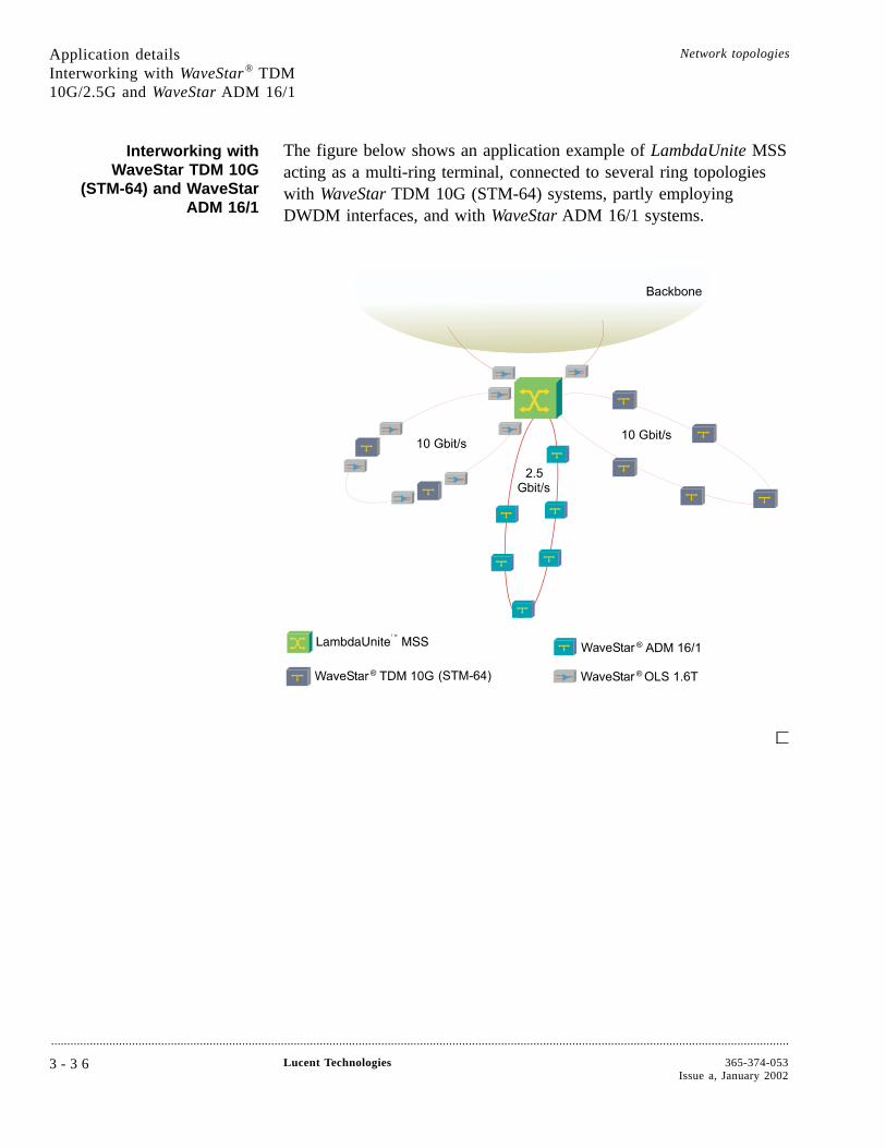
Interworking withWaveStar TDM 10G
(STM-64) and WaveStarADM 16/1
The figure below shows an application example of LambdaUnite MSSacting as a multi-ring terminal, connected to several ring topologieswith WaveStar TDM 10G (STM-64) systems, partly employingDWDM interfaces, and with WaveStar ADM 16/1 systems.
Application detailsInterworking with WaveStar® TDM10G/2.5G and WaveStar ADM 16/1
Network topologies
....................................................................................................................................................................................................................................
3 - 3 6 Lucent Technologies 365-374-053Issue a, January 2002
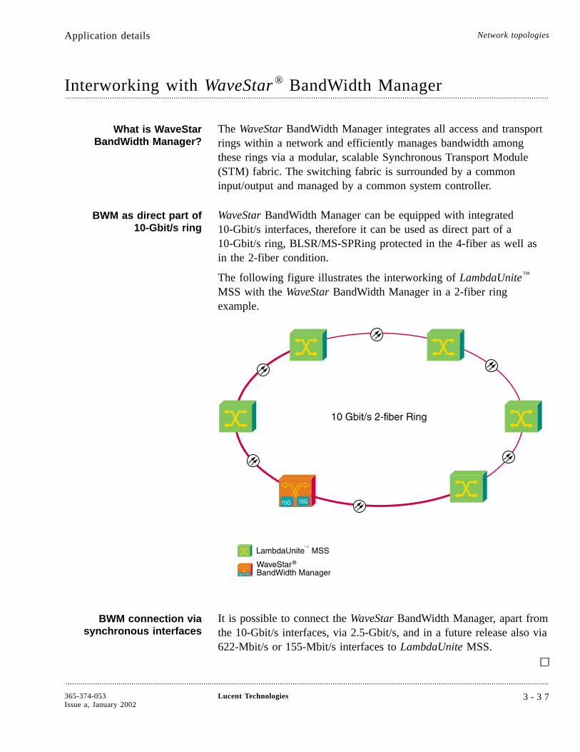
Interworking with WaveStar ® BandWidth Manager....................................................................................................................................................................................................................................
What is WaveStarBandWidth Manager?
The WaveStar BandWidth Manager integrates all access and transportrings within a network and efficiently manages bandwidth amongthese rings via a modular, scalable Synchronous Transport Module(STM) fabric. The switching fabric is surrounded by a commoninput/output and managed by a common system controller.
BWM as direct part of10-Gbit/s ring
WaveStar BandWidth Manager can be equipped with integrated10-Gbit/s interfaces, therefore it can be used as direct part of a10-Gbit/s ring, BLSR/MS-SPRing protected in the 4-fiber as well asin the 2-fiber condition.
The following figure illustrates the interworking of LambdaUnite™
MSS with the WaveStar BandWidth Manager in a 2-fiber ringexample.
BWM connection viasynchronous interfaces
It is possible to connect the WaveStar BandWidth Manager, apart fromthe 10-Gbit/s interfaces, via 2.5-Gbit/s, and in a future release also via622-Mbit/s or 155-Mbit/s interfaces to LambdaUnite MSS.
Application details Network topologies
....................................................................................................................................................................................................................................
365-374-053Issue a, January 2002
Lucent Technologies 3 - 3 7

Interworking with Wavelength Division Multiplexing....................................................................................................................................................................................................................................
Growing demand for extracapacity
A very efficient way to increase the capacity per fiber is to usedistinct wavelength channels. LambdaUnite™ MSS supports both,Passive Wavelength Division Multiplexing (PWDM) and DenseWavelength Division Multiplexing (DWDM).
Passive WDM A Passive Wavelength Division Multiplexing application ofLambdaUnite MSS is illustrated in the following figure. In the nextrelease up to 32 different 2.5-Gbit/s signals can be passivelymultiplexed into a single fiber and transported cost-efficiently overshort and intermediate distances this way.
The LambdaUnite MSS interface available in a future release forPWDM applications are:
• 2.5 Gbit/s intermediate reach / short haul interface (60 km), 1550nm, passive WDM compatible, 32 colors.
Dense WDM Dense Wavelength Division Multiplexing (DWDM) systems can beused both in a future release at the 10-Gbit/s and at the 40-Gbit/sinterfaces of LambdaUnite MSS for cost-efficient data transport overlong distances:
• WaveStar® Optical Line System (OLS) 1.6T (400G/800G) can beconnected directly to 10-Gbit/s interfaces
• LambdaXtreme™ Transport, connected directly to 10-Gbit/s or40-Gbit/s interfaces.
Application details Network topologies
....................................................................................................................................................................................................................................
3 - 3 8 Lucent Technologies 365-374-053Issue a, January 2002
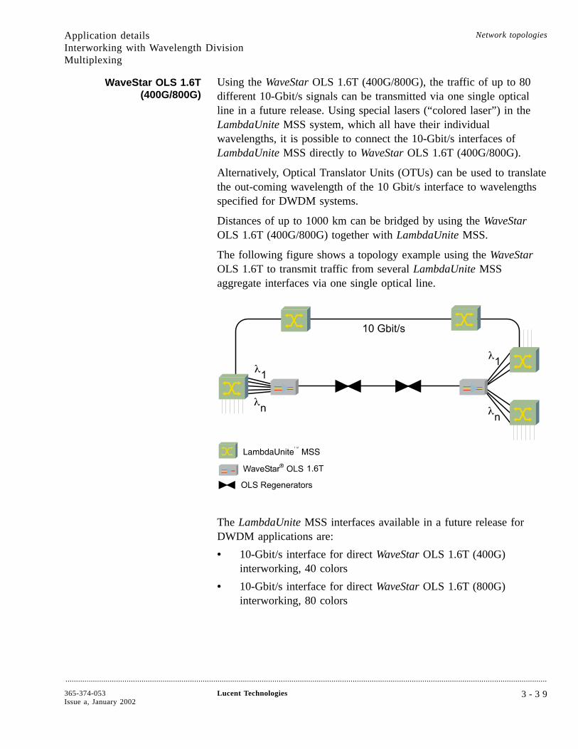
WaveStar OLS 1.6T(400G/800G)
Using the WaveStar OLS 1.6T (400G/800G), the traffic of up to 80different 10-Gbit/s signals can be transmitted via one single opticalline in a future release. Using special lasers (“colored laser”) in theLambdaUnite MSS system, which all have their individualwavelengths, it is possible to connect the 10-Gbit/s interfaces ofLambdaUnite MSS directly to WaveStar OLS 1.6T (400G/800G).
Alternatively, Optical Translator Units (OTUs) can be used to translatethe out-coming wavelength of the 10 Gbit/s interface to wavelengthsspecified for DWDM systems.
Distances of up to 1000 km can be bridged by using the WaveStarOLS 1.6T (400G/800G) together with LambdaUnite MSS.
The following figure shows a topology example using the WaveStarOLS 1.6T to transmit traffic from several LambdaUnite MSSaggregate interfaces via one single optical line.
The LambdaUnite MSS interfaces available in a future release forDWDM applications are:
• 10-Gbit/s interface for direct WaveStar OLS 1.6T (400G)interworking, 40 colors
• 10-Gbit/s interface for direct WaveStar OLS 1.6T (800G)interworking, 80 colors
Application detailsInterworking with Wavelength DivisionMultiplexing
Network topologies
....................................................................................................................................................................................................................................
365-374-053Issue a, January 2002
Lucent Technologies 3 - 3 9
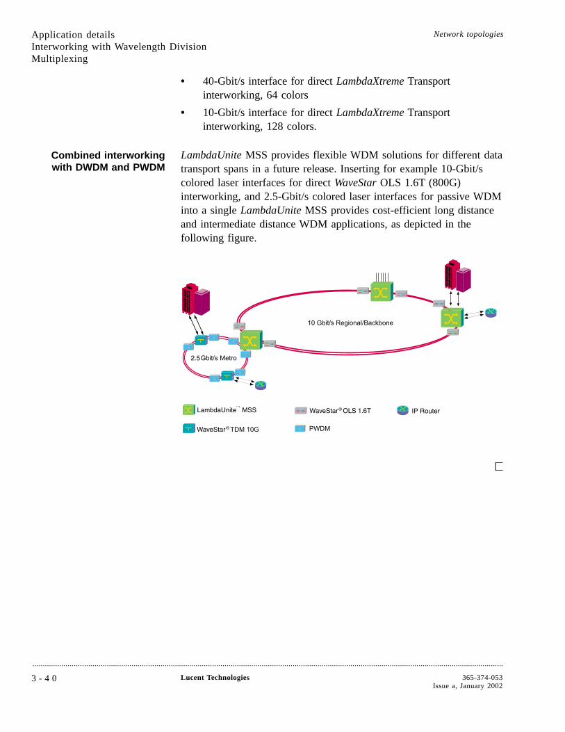
• 40-Gbit/s interface for direct LambdaXtreme Transportinterworking, 64 colors
• 10-Gbit/s interface for direct LambdaXtreme Transportinterworking, 128 colors.
Combined interworkingwith DWDM and PWDM
LambdaUnite MSS provides flexible WDM solutions for different datatransport spans in a future release. Inserting for example 10-Gbit/scolored laser interfaces for direct WaveStar OLS 1.6T (800G)interworking, and 2.5-Gbit/s colored laser interfaces for passive WDMinto a single LambdaUnite MSS provides cost-efficient long distanceand intermediate distance WDM applications, as depicted in thefollowing figure.
Application detailsInterworking with Wavelength DivisionMultiplexing
Network topologies
....................................................................................................................................................................................................................................
3 - 4 0 Lucent Technologies 365-374-053Issue a, January 2002
Interworking with LambdaRouter ™ AOS....................................................................................................................................................................................................................................
Interfaces toLambdaRouter AOS
LambdaUnite™ MSS is able to feed both, passive and active ports ofthe all-optical cross-connect LambdaRouter AOS. LambdaUnite MSSprovides several interfaces for this interworking feature:
• For active LambdaRouter AOS ports: 10-Gbit/s intra-officeinterface (1310 nm),
• For passive LambdaRouter AOS ports: 10-Gbit/s long haul andintermediate reach interfaces (1550 nm).
Application details Network topologies
....................................................................................................................................................................................................................................
365-374-053Issue a, January 2002
Lucent Technologies 3 - 4 1

4 Product description
Overview....................................................................................................................................................................................................................................
Purpose This chapter describes the LambdaUnite™ MultiService Switch (MSS)in terms of basic architecture, physical configuration and circuit packs.
Chapter structure After a concise system overview, the transmission architecture ispresented. A closer look is taken to the switch function.
The shelf configuration of the LambdaUnite MSS shelf is described,followed by a short description of the circuit packs contained.
Furthermore, this chapter deals with synchronization aspects withinthe network element and outlines the control architecture and thepower distribution concept.
ContentsConcise system description 4-3
Transmission architecture 4-5
Switch function 4-6
Shelf configurations 4-7
Shelf 4-8
Circuit packs 4-14
Synchronization 4-19
Control 4-25
....................................................................................................................................................................................................................................
365-374-053Issue a, January 2002
Lucent Technologies 4 - 1
4-25
4-19
4-14
4-8
4-7
4-6
4-5
4-3

Power 4-29
Cooling 4-30
Overview Product description
....................................................................................................................................................................................................................................
4 - 2 Lucent Technologies 365-374-053Issue a, January 2002
4-30
Concise system description....................................................................................................................................................................................................................................
Overview The LambdaUnite™ MSS system architecture is based on a 320 Gbit/sfull non-blocking switch matrix with STS-1/VC-4 granularity. Thisequals 6144 x 6144 STS-1s or 2048 x 2048 VC-4s. The switch can beupgraded to 640 Gbit/s capacity at a later release.
The system provides 32 universal slots, which can be flexibleconfigured with 40-Gbit/s (future release), 10-Gbit/s, 2.5-Gbit/s,622-Mbit/s (future release), 155-Mbit/s (future release), 10-Gbit/sEthernet (future release) and 1-Gbit/s Ethernet optical interface circuitpacks. Any available interface circuit pack can be operated in any slotposition with no connectivity restrictions in all configurations.
The mix and the number of 40-Gbit/s, 10-Gbit/s, 2.5-Gbit/s 2F/4Frings and linear links is only limited by the maximum number ofslots. This makes LambdaUnite MSS a highly flexible system andallows for a variety of different configurations.
Applications The system can be used as single or multiple Add/Drop Multiplexer(ADM), as single or multiple Terminal Multiplexer (TM) and as anOptical Switch (XC), using only one sub-rack. The system providesbuilt-in cross-connect facilities and flexible interface circuit packs.Local and remote management and control facilities are provided viathe TL1 interface and the Embedded Communication Channels (ECC).The cross-connect circuit packs are the core of the LambdaUnite MSSsystem.
Basic architecture The basic LambdaUnite MSS architecture covers the network elementas a whole and does not go into further detail on the required numberof the individual circuit packs. This will be discussed later in thischapter.
Product description
....................................................................................................................................................................................................................................
365-374-053Issue a, January 2002
Lucent Technologies 4 - 3
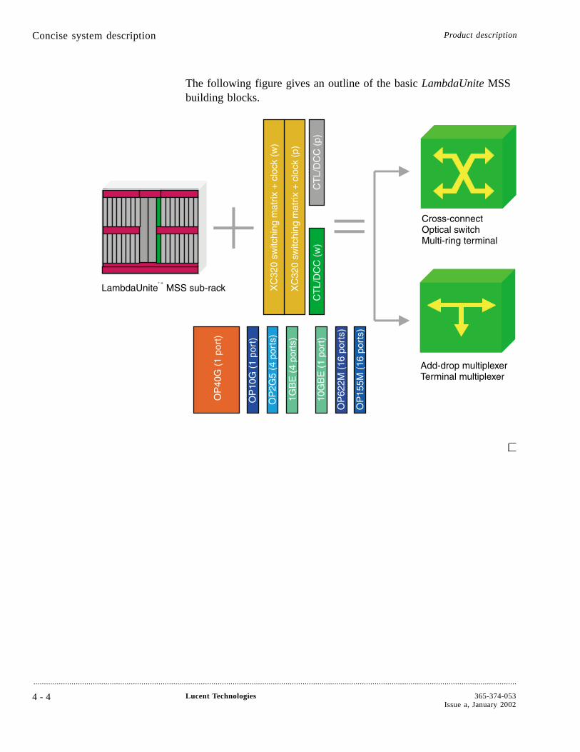
The following figure gives an outline of the basic LambdaUnite MSSbuilding blocks.
Concise system description Product description
....................................................................................................................................................................................................................................
4 - 4 Lucent Technologies 365-374-053Issue a, January 2002
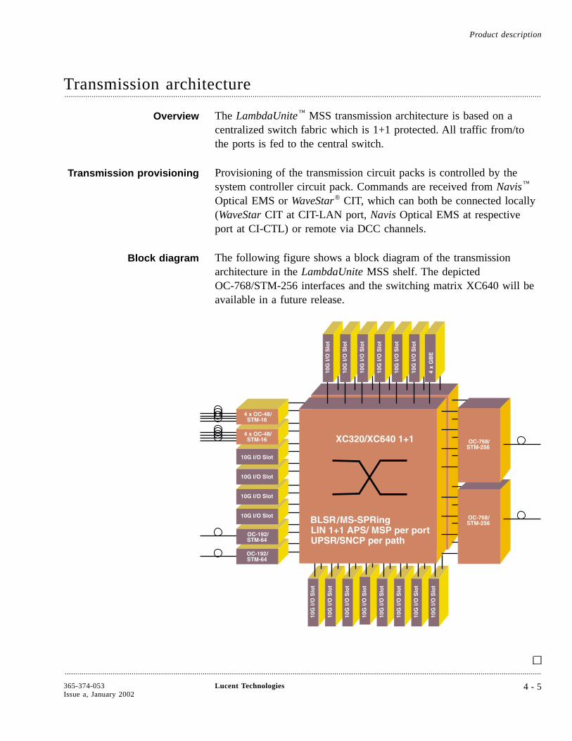
Transmission architecture....................................................................................................................................................................................................................................
Overview The LambdaUnite™ MSS transmission architecture is based on acentralized switch fabric which is 1+1 protected. All traffic from/tothe ports is fed to the central switch.
Transmission provisioning Provisioning of the transmission circuit packs is controlled by thesystem controller circuit pack. Commands are received from Navis™
Optical EMS or WaveStar® CIT, which can both be connected locally(WaveStar CIT at CIT-LAN port, Navis Optical EMS at respectiveport at CI-CTL) or remote via DCC channels.
Block diagram The following figure shows a block diagram of the transmissionarchitecture in the LambdaUnite MSS shelf. The depictedOC-768/STM-256 interfaces and the switching matrix XC640 will beavailable in a future release.
Product description
....................................................................................................................................................................................................................................
365-374-053Issue a, January 2002
Lucent Technologies 4 - 5
Switch function....................................................................................................................................................................................................................................
Overview All traffic from/to port units is fed from/to the central switch 1+1protected (c.f. “Block diagram” (4-5) on the previous pages).
Switching capabilities The total full none blocking switch capacity is 320 Gbit/s (= 6144STS-1 / 2048 VC-4s). Additionally to SPE/VC switch capabilities,also overhead information from SONET/SDH I/O ports may betransparently switched. The switch itself is based on a bit slicedarchitecture providing this very high capacity on a single pack. Slicing/ deslicing functions are part of the switch circuit pack.
Traffic protection Traffic protection switching (linear APS / MSP, BLSR/MS-SPRing,UPSR/SNCP) is performed centrally on the switch unit. All necessaryswitch information is transported via internal transmission lines (2.5Gbit/s TXI channels on the backplane) directly towards the switch,switch execution is done in Hardware. Therefore, no interaction withthe central control function (system controller) is needed to performtraffic protection switching which increases speed and reliability.
1+1 Protection To contribute to the overall system reliability and availability, theswitching circuit packs are 1+1 equipment protected.
Product description
....................................................................................................................................................................................................................................
4 - 6 Lucent Technologies 365-374-053Issue a, January 2002

Shelf configurations....................................................................................................................................................................................................................................
Overview The LambdaUnite™ MSS shelf is designed for application in 600 mm(23.6 in) deep ETSI rack frames and in Telcordia/NEBS compliantracks.
The shelf provides the facilities to house the LambdaUnite MSScircuit packs. It consists of the mechanics, a backplane, a user paneland interface panels for the connections to the customer’sinfrastructure.
Interface panels Access to station alarms, miscellaneous discretes, overhead channels,and Q-LAN is possible via the interface panels which are located atthe rear of the shelf. Additionally, there is a User Panel (UPL) on thefront of the shelf (see Chapter 2, “Features” ).
Optical interfaces The optical interfaces are located on the front side of the opticalcircuit packs. From there, the optical fibres are guided to the rackconnection panel.
Product description
....................................................................................................................................................................................................................................
365-374-053Issue a, January 2002
Lucent Technologies 4 - 7
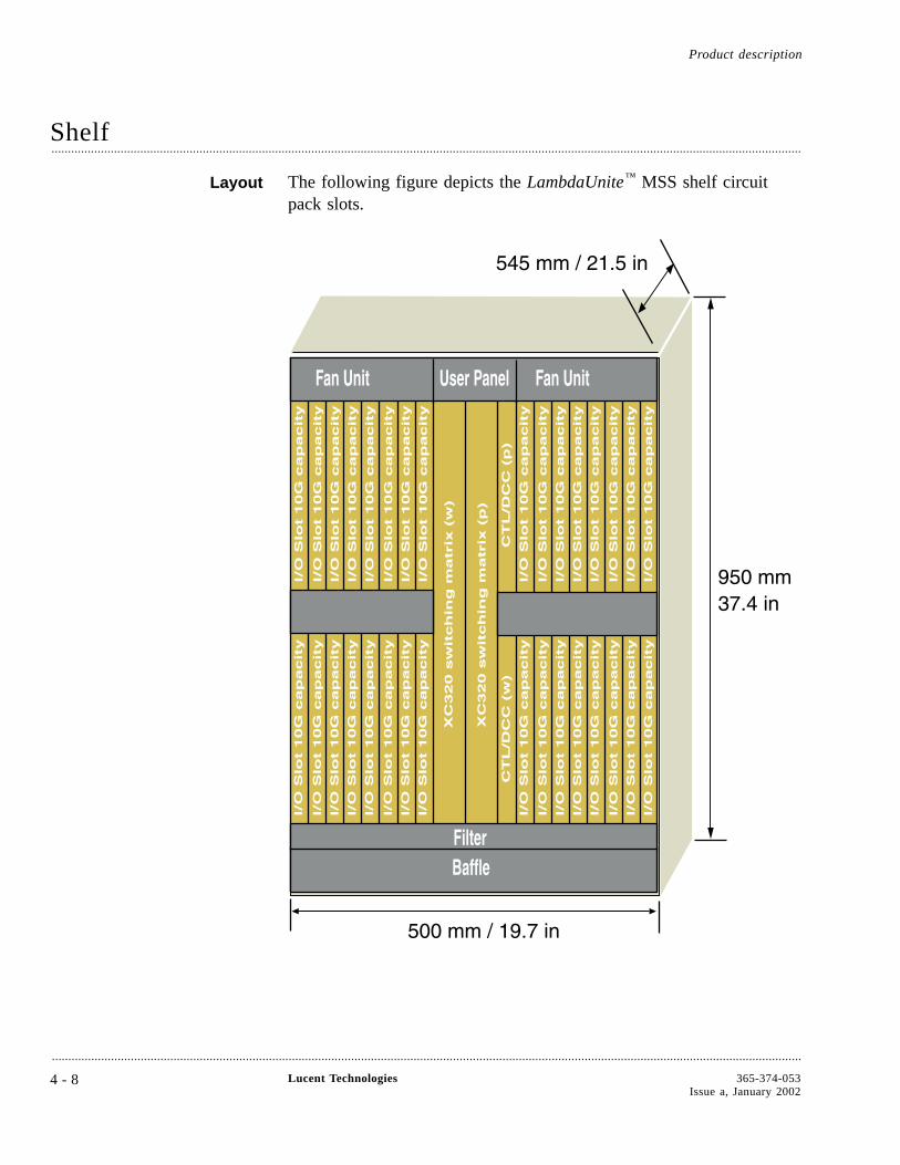
Shelf....................................................................................................................................................................................................................................
Layout The following figure depicts the LambdaUnite™ MSS shelf circuitpack slots.
Product description
....................................................................................................................................................................................................................................
4 - 8 Lucent Technologies 365-374-053Issue a, January 2002
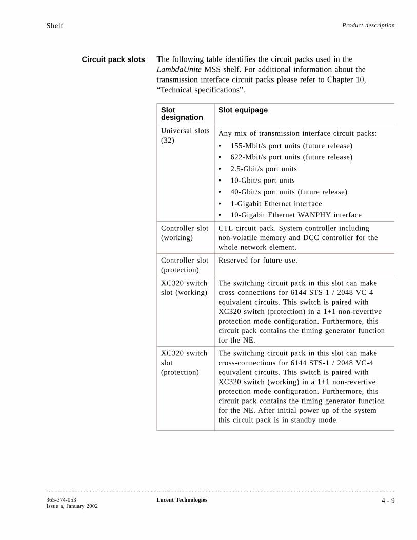
Circuit pack slots The following table identifies the circuit packs used in theLambdaUnite MSS shelf. For additional information about thetransmission interface circuit packs please refer to Chapter 10,“Technical specifications”.
Slotdesignation
Slot equipage
Universal slots(32)
Any mix of transmission interface circuit packs:
• 155-Mbit/s port units (future release)
• 622-Mbit/s port units (future release)
• 2.5-Gbit/s port units
• 10-Gbit/s port units
• 40-Gbit/s port units (future release)
• 1-Gigabit Ethernet interface
• 10-Gigabit Ethernet WANPHY interface
Controller slot(working)
CTL circuit pack. System controller includingnon-volatile memory and DCC controller for thewhole network element.
Controller slot(protection)
Reserved for future use.
XC320 switchslot (working)
The switching circuit pack in this slot can makecross-connections for 6144 STS-1 / 2048 VC-4equivalent circuits. This switch is paired withXC320 switch (protection) in a 1+1 non-revertiveprotection mode configuration. Furthermore, thiscircuit pack contains the timing generator functionfor the NE.
XC320 switchslot(protection)
The switching circuit pack in this slot can makecross-connections for 6144 STS-1 / 2048 VC-4equivalent circuits. This switch is paired withXC320 switch (working) in a 1+1 non-revertiveprotection mode configuration. Furthermore, thiscircuit pack contains the timing generator functionfor the NE. After initial power up of the systemthis circuit pack is in standby mode.
Shelf Product description
....................................................................................................................................................................................................................................
365-374-053Issue a, January 2002
Lucent Technologies 4 - 9
Minimum complement ofcircuit packs
The minimum complement of circuit packs required for an operationalLambdaUnite MSS shelf is
• Working XC320 switch circuit pack
• CTL circuit pack
• Any interface circuit packs in the universal slots
A shelf equipped with these circuit packs would be fully functional.Other essential parts of the system which always have to be installedin the shelf are the Power Interfaces (PI), the fan unit, the User Paneland a CI-CTL.
Front view of LambdaUniteMSS sub-rack
The following figure shows a front view of a LambdaUnite MSSsub-rack with two XC320 switching circuit-packs, one workercontroller circuit pack and one protection controller circuit pack
Shelf Product description
....................................................................................................................................................................................................................................
4 - 1 0 Lucent Technologies 365-374-053Issue a, January 2002
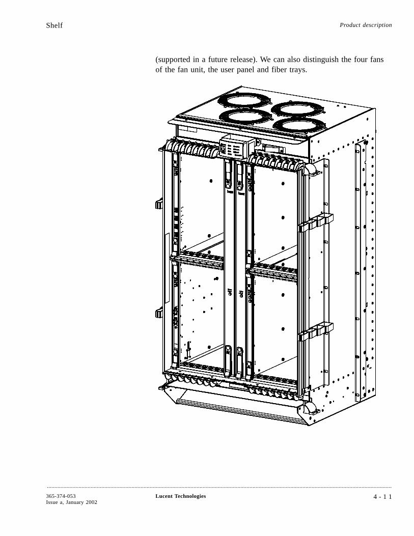
(supported in a future release). We can also distinguish the four fansof the fan unit, the user panel and fiber trays.
Shelf Product description
....................................................................................................................................................................................................................................
365-374-053Issue a, January 2002
Lucent Technologies 4 - 1 1
Interface panels A variety of Interface Panel boards exist to be connected in betweencustomer cabling and the backplane. All Interface Panel boards areinserted from the rear of the equipment.
Interface Panel boards available:
• Timing Interface (TI), provides external timing inputs/outputs
• Controller Interface (CI), provides the external LAN interface,station alarm interface, MDI/MDO interface (available in a futurerelease), user byte interface and interface for cables to User Paneland Fan Unit.
Shelf Product description
....................................................................................................................................................................................................................................
4 - 1 2 Lucent Technologies 365-374-053Issue a, January 2002
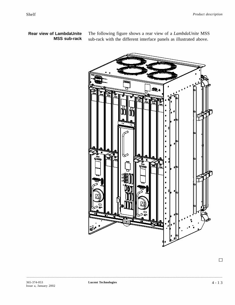
Rear view of LambdaUniteMSS sub-rack
The following figure shows a rear view of a LambdaUnite MSSsub-rack with the different interface panels as illustrated above.
Shelf Product description
....................................................................................................................................................................................................................................
365-374-053Issue a, January 2002
Lucent Technologies 4 - 1 3
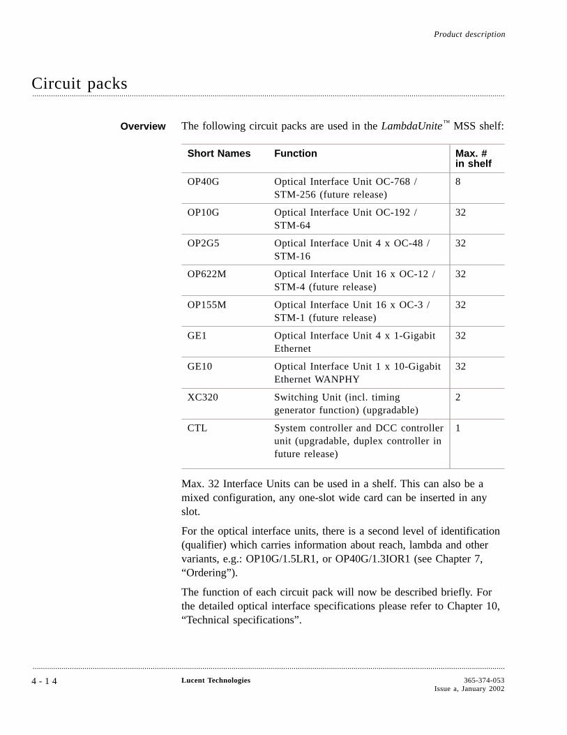
Circuit packs....................................................................................................................................................................................................................................
Overview The following circuit packs are used in the LambdaUnite™ MSS shelf:
Short Names Function Max. #in shelf
OP40G Optical Interface Unit OC-768 /STM-256 (future release)
8
OP10G Optical Interface Unit OC-192 /STM-64
32
OP2G5 Optical Interface Unit 4 x OC-48 /STM-16
32
OP622M Optical Interface Unit 16 x OC-12 /STM-4 (future release)
32
OP155M Optical Interface Unit 16 x OC-3 /STM-1 (future release)
32
GE1 Optical Interface Unit 4 x 1-GigabitEthernet
32
GE10 Optical Interface Unit 1 x 10-GigabitEthernet WANPHY
32
XC320 Switching Unit (incl. timinggenerator function) (upgradable)
2
CTL System controller and DCC controllerunit (upgradable, duplex controller infuture release)
1
Max. 32 Interface Units can be used in a shelf. This can also be amixed configuration, any one-slot wide card can be inserted in anyslot.
For the optical interface units, there is a second level of identification(qualifier) which carries information about reach, lambda and othervariants, e.g.: OP10G/1.5LR1, or OP40G/1.3IOR1 (see Chapter 7,“Ordering”).
The function of each circuit pack will now be described briefly. Forthe detailed optical interface specifications please refer to Chapter 10,“Technical specifications”.
Product description
....................................................................................................................................................................................................................................
4 - 1 4 Lucent Technologies 365-374-053Issue a, January 2002
Optical interface circuitpack OP10G
For interfacing to optical 10-Gbit/s signals, LambdaUnite MSS can beequipped with the OP10G circuit pack which is available in severalvariants:
• 10-Gbit/s long reach interface (80 km), 1550 nm
• 10-Gbit/s intermediate reach / short haul interface (40 km), 1550nm
• 10-Gbit/s intra-office interface (600 m), 1310 nm
• 10-Gbit/s interface for direct OLS 1.6T (400G/800G)interworking, 40 / 80 colors (future release)
• 10-Gbit/s interface for direct LambdaXtreme™ Transportinterworking, 128 colors (future release)
The electrical-to-optical and optical-to-electrical conversion isprovided by the optics module(s) of these circuit packs. Severaloptical modules are used dependent on the required optical interfacespecifications.
The optics modules interface to the receive byte processor and thetransmit byte processor by 16 times 622 Mbit/s (or 666 Mbit/s in caseof strong FEC) interfaces.
The receive byte processor and transmit byte processor interface to thepointer processor through 16 times 622-Mbit/s TXI interfaces. Thepointer processor itself provides the interface to the backplane with 4times 2.5-Gbit/s TXI interfaces. These 2.5-Gbit/s TXI are doubled atthe pointer processor, connecting to the working or the protectionswitch circuit pack (XC320) respectively.
The 155-MHz board clock which is fed to the byte processors and tothe pointer processor is generated out of the 6.48-MHz referenceclock provided via the backplane.
The circuit pack is equipped with an on-board function controllerwhich interfaces with the system controller circuit pack (CTL).
Optical interface circuitpack OP2G5
For interfacing to four optical 2.5-Gbit/s signals, LambdaUnite MSScan be equipped with the OP2G5 circuit pack which is available inthe current release in the following variant:
• 2.5-Gbit/s long reach interface (80 km), 1550 nm.
• 2.5-Gbit/s long reach interface (40 km), 1310 nm.
Circuit packs Product description
....................................................................................................................................................................................................................................
365-374-053Issue a, January 2002
Lucent Technologies 4 - 1 5
• 2.5-Gbit/s intra-office interface (2 km), 1310 nm.
• 2.5-Gbit/s intermediate reach pWDM interface, 32 colors (60km), 1550 nm (future release).
The electrical-to-optical and optical-to-electrical conversion isprovided by the four optical transceivers. Each transceiver interfacesto a MUX/DEMUX device.
The MUX/DEMUX devices interface to the byte and pointerprocessor device by 4 times 622-Mbit/s interfaces each.
The byte and pointer processor provides the interface to the backplanewith four 2.5-Gbit/s TXI interfaces. The 2.5-Gbit/s TXIs are doubledat the byte and pointer processor, connecting to the working or theprotection switch circuit pack (XC320) respectively.
The 155-MHz board clock which is fed to the byte and pointerprocessor is generated out of the 6.48-MHz reference clock providedvia the backplane.
The circuit pack is equipped with an on-board function controllerwhich interfaces with the system controller circuit pack (CTL).
Gigabit Ethernet interfacecircuit pack GE1/SX4
For interfacing to four optical 1-Gbit/s Ethernet signals, LambdaUniteMSS can be equipped with the GE1/SX4 circuit pack. Each portprovides a 1000Base-SX optical Ethernet interface.
Each Ethernet port has a LAN port and a WAN port. A Crossbardevice interconnects each LAN port with each WAN port. A functioncontroller is used for on-board control and supervision purposes.
The LAN port consists of an optical module, a 1.25-GbitSerialize/Deserialize (SerDes) device, and an Ethernet controller. TheWAN port consists of an Ethernet controller and a Gigabit EthernetOver SDH/SONET (GEOS) Flexible Programmable Gate Array(FPGA).
The interface to the backplane consists of two stages. The first stageis a backplane transceiver device which has an 8-bit parallel interfaceto the GEOS FPGA and a TXI622 interface to the second stage. Theseconds stage combines the TXI622 interfaces to the TXI2G5 CMLinterface that is used on the backplane.
The function controller is built around an MPC860 processor. Theasset uses 4 Mbyte of Flash memory and 16 Mbyte of SDRAM
Circuit packs Product description
....................................................................................................................................................................................................................................
4 - 1 6 Lucent Technologies 365-374-053Issue a, January 2002
memory. A PQIO device is used to provide the interface to the systemcontroller and to the ON (operations Network).
The timing function of the Gigabit Ethernet board is built around theclock sync distribution device (CSD2). Via this device a 77.76-MHzclock and a 8-kHz synchronization signal is distributed to the variousdevices on the circuit pack.
DC power is applied to the Gigabit Ethernet board via two -48-Vbattery feeds. On-board DC/DC converters generate 3.3 V, 2.5 V and1.8 V.
Cross-connect circuit pack The XC320 is connected with the interface circuit packs via thebackplane bus (TXI). The XC320 is a bit-sliced cross-connect for6144 STS-1 or 2048 VC-4 level signals. The bit-sliced data isgenerated in the data converter device, and will be desliced in the dataconverter after cross-connect. MS-SPRing/BLSR, 1+1 line APS / 1+1MSP and SNCP/UPSR switching is supported on the cross-connectcircuit pack.
The XC320 circuit pack receives the TXI2G5-signals unsliced (via thebackplane) on the data converter devices. After 12-to-8 staticpreselection and a slicing function this data is forwarded to the switchmatrix device. So, for each set of 12 incoming TXI2G5 links at thebackplane side of the data converter devices, only 8 are active (staticslot selection). The 8 active channels are 1-bit sliced and each bit sliceis transported over a TXI2G5 link to the switch matrix device. In theswitch matrix, the data is switched according to the defined schemespecified by using WaveStar® CIT or Navis™ Optical EMS. The1-bit-sliced data which egresses the switch matrix devices is collectedand desliced in the data converter devices before it leaves the XC320circuit pack.
LambdaUnite MSS provides 1+1 equipment protection for thecross-connect circuit pack.
Timing generator function The timing generator function in the LambdaUnite MSS networkelement is physically implemented on the cross-connect circuit pack(XC320). The external physical timing interfaces (inputs and outputs)are located on the Timing Interface (TI) panel.
The timing generator is designed as Stratum 3 version meeting therequirements of ITU-T Rec. G.813 (SDH) and Bellcore TR-1244(SONET).
Circuit packs Product description
....................................................................................................................................................................................................................................
365-374-053Issue a, January 2002
Lucent Technologies 4 - 1 7
Timing modes available are:
• Free running
• Hold-over (deviation from the last source max. 4.6 ppm in twoweeks)
• Locked with reference to:
- one of the external synchronization inputs
- one of all of the STM-N / OC-N input signals.
LambdaUnite MSS provides 1+1 equipment protection for thetiming function.
For more information on the timing architecture, please refer to“Synchronization” (4-19).
Power Interface The Power Interface (PI), which is integrated in the shelf performs thefiltering functions for the primary voltage to meet the ETSIrequirements. To maintain high availability this functionality isduplicated.
The actual DC/DC conversion is located on the individual circuitpacks. The power feeds remain duplicated between the PI and thecircuit packs.
Controller circuit pack CTL The controller circuit pack CTL provides the central control,supervision and security functions in the network element. For thispurpose, it communicates with the function controllers on theindividual interface circuit packs and the switch circuit packs.Furthermore it maintains system configuration data and systemsoftware on an exchangeable 256 MB CompactFlash™ card.
The second area of functionality is as an adjunct controller whichhandles the Data Communication Network (DCN), the LAN and otherexternal control interfaces. Thus, it acts as a network layer router,de-coupling the routing of DCN through traffic from system control.The CTL also provides data link protocol termination for DCC typeHDLC links and for 802.3 LAN type links.
A further description of the control architecture in the shelf can befound on “Control” (4-25).
Circuit packs Product description
....................................................................................................................................................................................................................................
4 - 1 8 Lucent Technologies 365-374-053Issue a, January 2002
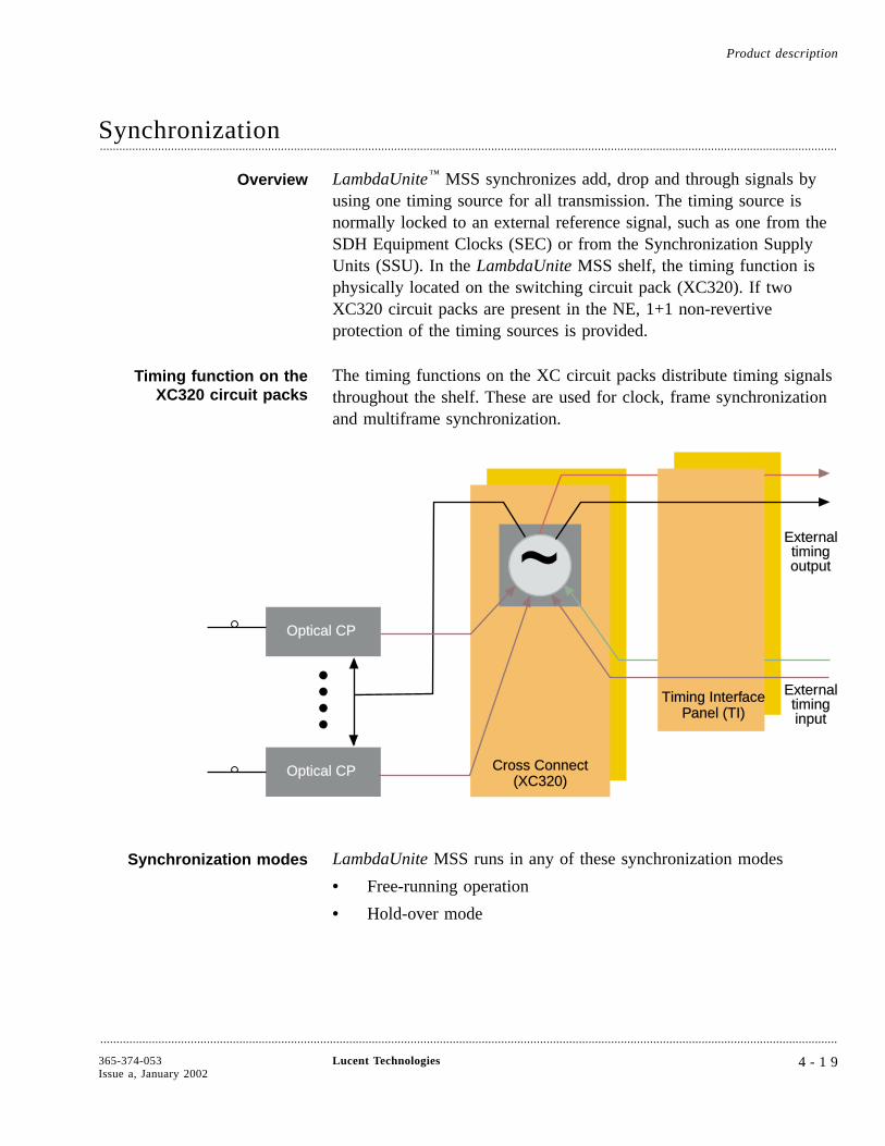
Synchronization....................................................................................................................................................................................................................................
Overview LambdaUnite™ MSS synchronizes add, drop and through signals byusing one timing source for all transmission. The timing source isnormally locked to an external reference signal, such as one from theSDH Equipment Clocks (SEC) or from the Synchronization SupplyUnits (SSU). In the LambdaUnite MSS shelf, the timing function isphysically located on the switching circuit pack (XC320). If twoXC320 circuit packs are present in the NE, 1+1 non-revertiveprotection of the timing sources is provided.
Timing function on theXC320 circuit packs
The timing functions on the XC circuit packs distribute timing signalsthroughout the shelf. These are used for clock, frame synchronizationand multiframe synchronization.
Synchronization modes LambdaUnite MSS runs in any of these synchronization modes
• Free-running operation
• Hold-over mode
Cross ConnectCross Connect(XC320)(XC320)
Timing InterfTiming InterfaceacePPanel (TI)anel (TI)
ExterExternalnaltimingtimingoutputoutput
ExterExternalnaltimingtiminginputinput
Optical CPOptical CP
Optical CPOptical CP
~~
Product description
....................................................................................................................................................................................................................................
365-374-053Issue a, January 2002
Lucent Technologies 4 - 1 9
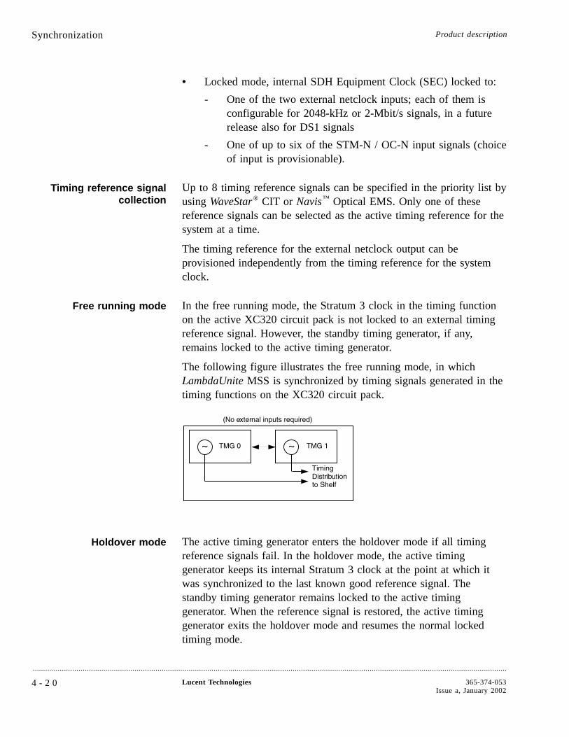
• Locked mode, internal SDH Equipment Clock (SEC) locked to:
- One of the two external netclock inputs; each of them isconfigurable for 2048-kHz or 2-Mbit/s signals, in a futurerelease also for DS1 signals
- One of up to six of the STM-N / OC-N input signals (choiceof input is provisionable).
Timing reference signalcollection
Up to 8 timing reference signals can be specified in the priority list byusing WaveStar® CIT or Navis™ Optical EMS. Only one of thesereference signals can be selected as the active timing reference for thesystem at a time.
The timing reference for the external netclock output can beprovisioned independently from the timing reference for the systemclock.
Free running mode In the free running mode, the Stratum 3 clock in the timing functionon the active XC320 circuit pack is not locked to an external timingreference signal. However, the standby timing generator, if any,remains locked to the active timing generator.
The following figure illustrates the free running mode, in whichLambdaUnite MSS is synchronized by timing signals generated in thetiming functions on the XC320 circuit pack.
Holdover mode The active timing generator enters the holdover mode if all timingreference signals fail. In the holdover mode, the active timinggenerator keeps its internal Stratum 3 clock at the point at which itwas synchronized to the last known good reference signal. Thestandby timing generator remains locked to the active timinggenerator. When the reference signal is restored, the active timinggenerator exits the holdover mode and resumes the normal lockedtiming mode.
Synchronization Product description
....................................................................................................................................................................................................................................
4 - 2 0 Lucent Technologies 365-374-053Issue a, January 2002

Holdover mode is automatically available when the system clock is inthe locked timing mode. The timing functions on the XC320 circuitpacks monitor the quality of reference signals they receive. If one ofthe reference signals fails, LambdaUnite MSS uses the next in thepriority list. If all reference signals fail, LambdaUnite MSS enters theholdover mode.
Furthermore the holdover mode can be entered intentionally by theoperator command “forced holdover”.
Optical line timing In the locked mode, the timing functions on the XC320 circuit packscan be provisioned to accept a timing reference signal from anincoming optical signal (10 Gbit/s or 2.5 Gbit/s, in future also 40Gbit/s, 622 Mbit/s, or 155 Mbit/s). The timing functions then employthe provisioned timing reference signal from he specified port unit tosynchronize the transmission port units.
The timing reference signal is continuously monitored for error-freeoperation. If the reference signal becomes corrupted or unavailable,the timing function selects the timing reference signal that is next inthe priority list. If all configured timing reference signals arecorrupted or unavailable, the timing function enters the holdovermode.
External netclock timingmode
In the external netclock timing mode, the timing function on theactive XC320 circuit pack receives a 2.048-MHz, 2-Mbit/s ITU-T or aDS1 Telcordia (B8ZS, SF and ESF format; if in ESF format SSM issupported) reference signal from the external netclock inputs. Thereference signals should be based on a Stratum 1 clock. The timingfunction on the active circuit pack synchronizes its internal Stratum 3clock to the reference signal. The timing function on the standbyXC320 circuit pack synchronizes its internal Stratum 3 clock to theactive circuit pack. Then the timing functions distribute the clocksignals to all circuit packs in the shelf.
Timing protection LambdaUnite MSS uses non-revertive 1+1 protection switching toprotect its timing function. If the active XC320 circuit pack fails andcauses a switch to the standby circuit pack, the standby circuit packbecomes the active circuit pack. It remains the active circuit pack,even when the failed circuit pack is replaced. The replacement circuitpack becomes the standby circuit pack. There is no automaticrevertive switching.
Synchronization Product description
....................................................................................................................................................................................................................................
365-374-053Issue a, January 2002
Lucent Technologies 4 - 2 1
If the active timing generator were to fail while in holdover mode,then the standby timing generator would become the active timinggenerator and would switch to holdover mode (before switching, itwas fed by the active timing generator) until the reference signal isrestored to an acceptable quality.
Timing provisioning The LambdaUnite MSS synchronization mode can be set to locked orfree running by using WaveStar CIT. Additionally, either timinggenerator circuit pack can be switched to be the active timinggenerator. However, when LambdaUnite MSS is provisioned for thelocked mode, the holdover mode is entered automatically upon loss ofall reference signals. The holdover mode can be entered intentionallyby the operator command “forced holdover”.
Control and status The behavior of the timing generators is controlled by switching themamong several defined states. As commands are issued or as failuresoccur and are cleared, the timing system switches from one state toanother. The status of the timing is retrievable for user observation.You can issue commands to obtain status reports or to manuallychange the synchronization state from one to another.
There are three categories of commands
• Modify – to provision operating parameters
• Retrieve – to obtain parameter values, states and statuses
• Operate – to lockout a switch, force a switch or holdover modeor clear a state
Synchronization switching Synchronization operations that can be user-controlled by commandsinclude
• Non-revertive synchronization equipment switching
• Synchronization reference switching
• Synchronization mode switching
Timing marker The timing quality of the 40-Gbit/s, 10-Gbit/s and 2.5-Gbit/s datasignals is coded in the timing marker (also known as synchronizationstatus message, SSM) as per ITU-T Rec. G.783 and G.707. Thetiming marker is located in the lower four bits of the S1 byte. The S1byte is located in the STM-N signal SOH (SDH) or in the first STS-1of a STS-N (SONET).
Synchronization Product description
....................................................................................................................................................................................................................................
4 - 2 2 Lucent Technologies 365-374-053Issue a, January 2002
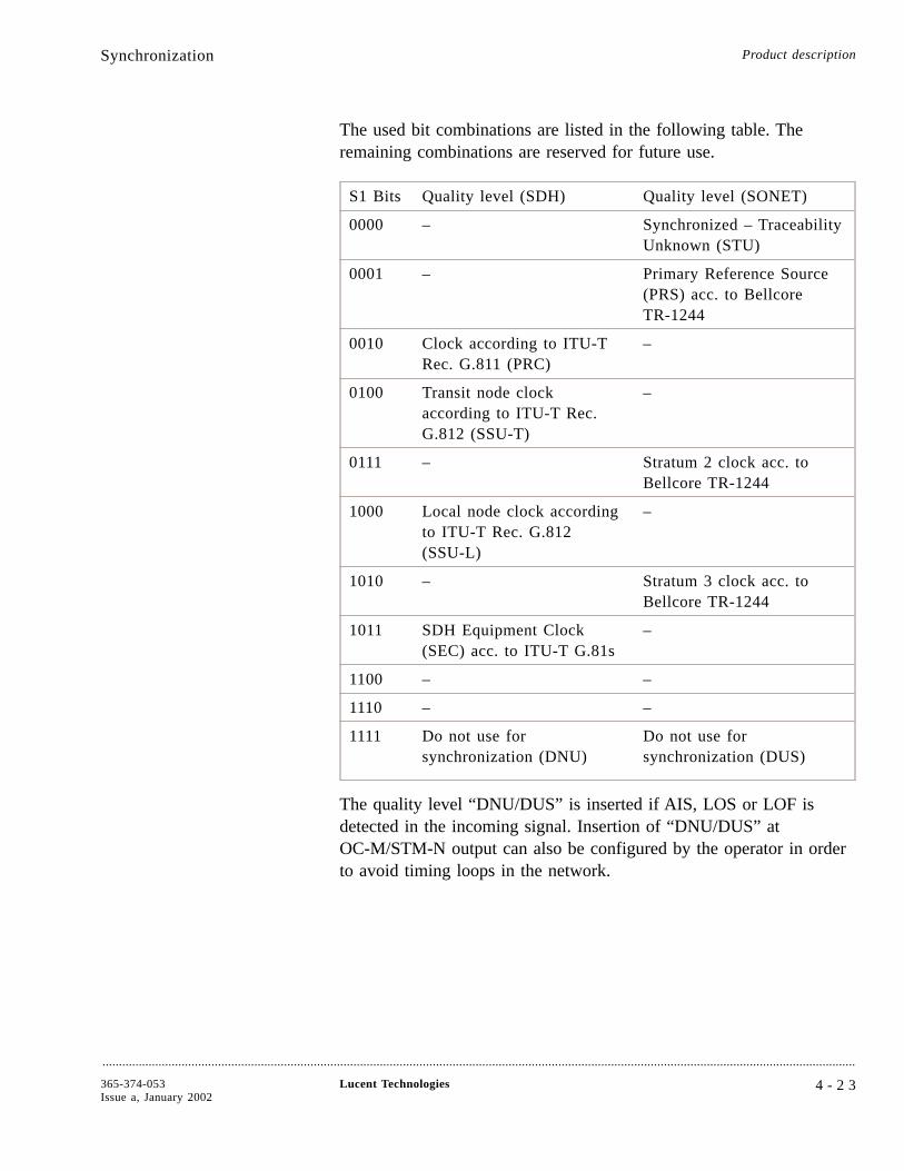
The used bit combinations are listed in the following table. Theremaining combinations are reserved for future use.
S1 Bits Quality level (SDH) Quality level (SONET)
0000 – Synchronized – TraceabilityUnknown (STU)
0001 – Primary Reference Source(PRS) acc. to BellcoreTR-1244
0010 Clock according to ITU-TRec. G.811 (PRC)
–
0100 Transit node clockaccording to ITU-T Rec.G.812 (SSU-T)
–
0111 – Stratum 2 clock acc. toBellcore TR-1244
1000 Local node clock accordingto ITU-T Rec. G.812(SSU-L)
–
1010 – Stratum 3 clock acc. toBellcore TR-1244
1011 SDH Equipment Clock(SEC) acc. to ITU-T G.81s
–
1100 – –
1110 – –
1111 Do not use forsynchronization (DNU)
Do not use forsynchronization (DUS)
The quality level “DNU/DUS” is inserted if AIS, LOS or LOF isdetected in the incoming signal. Insertion of “DNU/DUS” atOC-M/STM-N output can also be configured by the operator in orderto avoid timing loops in the network.
Synchronization Product description
....................................................................................................................................................................................................................................
365-374-053Issue a, January 2002
Lucent Technologies 4 - 2 3
External timing outputs The external timing output interfaces support 2048-kHz, 2-Mbit/s orTelcordia DS1 signals. For the external timing outputs, it is possibleeither to use the system timing reference (derived from internaloscillator) or a timing reference independent from the system timingreference (one out of available OC-M/STM-N signals). The externaltiming outputs will be squelched if the available timing quality dropsbelow a configurable threshold.
Synchronization Product description
....................................................................................................................................................................................................................................
4 - 2 4 Lucent Technologies 365-374-053Issue a, January 2002
Control....................................................................................................................................................................................................................................
Overview The functions in the LambdaUnite™ MSS network element arecontrolled by a system controller circuit pack (CTL) and by functioncontrollers on the other circuit packs in the shelf. Overall shelfoperation is controlled by signals received over the SDH DataCommunication Channel (DCC) or the intra-office LAN (IAO LAN).
Product description
....................................................................................................................................................................................................................................
365-374-053Issue a, January 2002
Lucent Technologies 4 - 2 5
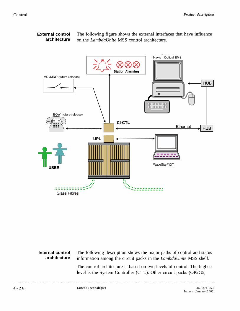
External controlarchitecture
The following figure shows the external interfaces that have influenceon the LambdaUnite MSS control architecture.
Internal controlarchitecture
The following description shows the major paths of control and statusinformation among the circuit packs in the LambdaUnite MSS shelf.
The control architecture is based on two levels of control. The highestlevel is the System Controller (CTL). Other circuit packs (OP2G5,
Control Product description
....................................................................................................................................................................................................................................
4 - 2 6 Lucent Technologies 365-374-053Issue a, January 2002
OP10G, GE1, XC320) contain a function controller. The functioncontroller performs the local unit control and is connected to thesystem controller via the Operations Network Interface (ONI). EachCTL has two control functions, the System Control Function (SCF)and the DCC Control Function (DCF). Both control functions runindependently from each other.
The Operations Network (ON) is the internal communications networkand is physically implemented in a star topology. An ON hub functionis placed on the SCF on the controller circuit pack (CTL).
The equipment management (EMP) control function is responsible forinventory data access, reset lines and equipment sensing (checkphysical availability of circuit packs).
In case of DCN messages addressing the network element the DCNtraffic is terminated on the DCC Control Function (DCF) on the CTLcircuit pack. Application messages are forwarded to the SystemControl Function (SCF) on the CTL. In case of messages for otherNEs the DCF decides on which of the channels listed below themessage will be forwarded. Thus all channels are to be considered asbidirectional links.
The data communication network control function comprises thetraffic
• from external interfaces and CIT at LAN ports forwarded via CIPto the DCF on CTL
• from the XC320 circuit pack where line DCC (DCCr) andsection DCC (DCCm) are terminated via OHI to the DCF onCTL
• from OP40G circuit pack (in future release) where the DCCmx isterminated via MxDCC to the DCF on CTL.
Furthermore, the CTL is involved in user byte processing. The userbytes (E1, E2, F1, supported in a future release) which are physicallymade available as 64-kbit/s channels at the Control Interface (CI) arefed to this interface via the XC320 and CTL circuit pack.
The CTL is also responsible for the control of equipment protectionswitching.
The Timing Interface Control (TIC) interaction ensures the isolation ofa timing function in case that the CTL detects misbehavior. Normallythe timing function on both XC320 can share the assigned
Control Product description
....................................................................................................................................................................................................................................
365-374-053Issue a, January 2002
Lucent Technologies 4 - 2 7

functionality. However in case of isolation one timing function cantake over all functionality. This is controlled by the TIC lines.
Additionally, the CTL supports the status indicators on the User Panel(UPL).
Control Product description
....................................................................................................................................................................................................................................
4 - 2 8 Lucent Technologies 365-374-053Issue a, January 2002
Power....................................................................................................................................................................................................................................
Overview LambdaUnite™ MSS uses a distributed powering system, rather thanbulk power supplies. It distributes -48V/-60V power throughout theshelf with an average fully loaded power consumption of 2.200 W,and each circuit pack uses its own on-board power converter to derivethe necessary operating voltages.
Dual power feeds, powerinterfaces (PI)
Office power feeders A and B are filtered and protected by circuitbreakers at the input to the shelf. This is done by the Power Interface(PI) units, one unit is assigned to each power feeder. After that, thesupplies are distributed separately to each circuit pack, where they arefiltered again and fused before being converted to the circuit packworking voltages.
The A and B power inputs are supervised individually by the systemcontroller circuit pack (CTL). A green LED on every Power Interface(PI) indicates that the input power is available which means that it isabove 39.0 VDC ± 1.0 VDC. As soon as the input voltage is below39.0 VDC ±1. 0 VDC, an alarm message will be send to the CTL.
Power indicator The green PWR ON indicator on the user panel remains lighted aslong as either -48 V / -60 V supply is received from the circuitbreakers.
Product description
....................................................................................................................................................................................................................................
365-374-053Issue a, January 2002
Lucent Technologies 4 - 2 9

Cooling....................................................................................................................................................................................................................................
Overview Cooling is provided by a plug-in fan unit placed on top of thesub-rack. Fans pull air through a filter below the circuit packs andforce it through the sub-rack from bottom to top. An air flow baffle isintegrated in the sub-rack to prevent the intake of exhaust air frombelow. The air filter should be replaced or cleaned every three monthsto ensure the proper cooling, as described in the UOG chapter“Periodic activities” or as part of a trouble clearing procedure asdescribed in the AMTCG.
Fan controller The fan unit includes four fans and a microcontroller that senses airflow, air temperature and fan faults. The microcontroller adjusts thespeed of the fans to compensate for the failure of a fan or to conservepower when full air flow is not needed. It also reports the status ofthe fan unit to the shelf controller.
Important! The fan unit must be installed and operating in a shelfbefore any circuit packs are installed.
Product description
....................................................................................................................................................................................................................................
4 - 3 0 Lucent Technologies 365-374-053Issue a, January 2002

5 Operations, administration,maintenance, and provisioning
Overview....................................................................................................................................................................................................................................
Purpose This chapter describes hardware and software interfaces used foradministration, maintenance, and provisioning activities, the systemmanagement function for the administration of the LambdaUnite™
MultiService Switch (MSS) and the maintenance and provisioningfeatures available in the LambdaUnite MSS.
ContentsOperations 5-3
Visible alarm indicators 5-4
WaveStar® CIT 5-8
Operations interfaces 5-10
Administration 5-12
Maintenance 5-15
Maintenance signals 5-16
Loopbacks and tests 5-18
Protection switching 5-19
Performance monitoring 5-21
Reports 5-24
Maintenance condition 5-26
....................................................................................................................................................................................................................................
365-374-053Issue a, January 2002
Lucent Technologies 5 - 1
5-26
5-24
5-21
5-19
5-18
5-16
5-15
5-12
5-10
5-8
5-4
5-3

Orderwire 5-27
Provisioning 5-28
Overview Operations, administration, maintenance, andprovisioning
....................................................................................................................................................................................................................................
5 - 2 Lucent Technologies 365-374-053Issue a, January 2002
5-28
Operations
Overview....................................................................................................................................................................................................................................
Purpose This section describes the hardware and software interfaces used foradministration, maintenance, and provisioning activities. These include
• Visible and audible indicators
• Graphical User Interface (GUI) on the WaveStar® CIT (CraftInterface Terminal)
• Operations interfaces
Please note that administration, maintenance, and provisioningactivities via Navis™ Optical EMS are described in the separate NavisOptical EMS documentation set.
Visible and audibleindicators
Visible and audible indicators notify you of maintenance conditionssuch as faults and alarms.
Graphical user interface The GUI on the WaveStar CIT retrieves detailed information aboutlocal and remote network elements. The GUI is also used to provisionlocal and remote LambdaUnite™ MSS circuit packs and the switchingmatrix.
Operations systeminterfaces
Operations interfaces include the DCC interfaces on theOC-M/STM-N port units and the IAO LAN (intra-office LAN)interface. Both the DCC interface and the IAO LAN interface canreceive commands from operations systems (network elementmanagement systems) or from a remote WaveStar CIT.
ContentsVisible alarm indicators 5-4
WaveStar CIT 5-8
Operations interfaces 5-10
Operations, administration, maintenance, andprovisioning
....................................................................................................................................................................................................................................
365-374-053Issue a, January 2002
Lucent Technologies 5 - 3
5-10
5-8
5-4
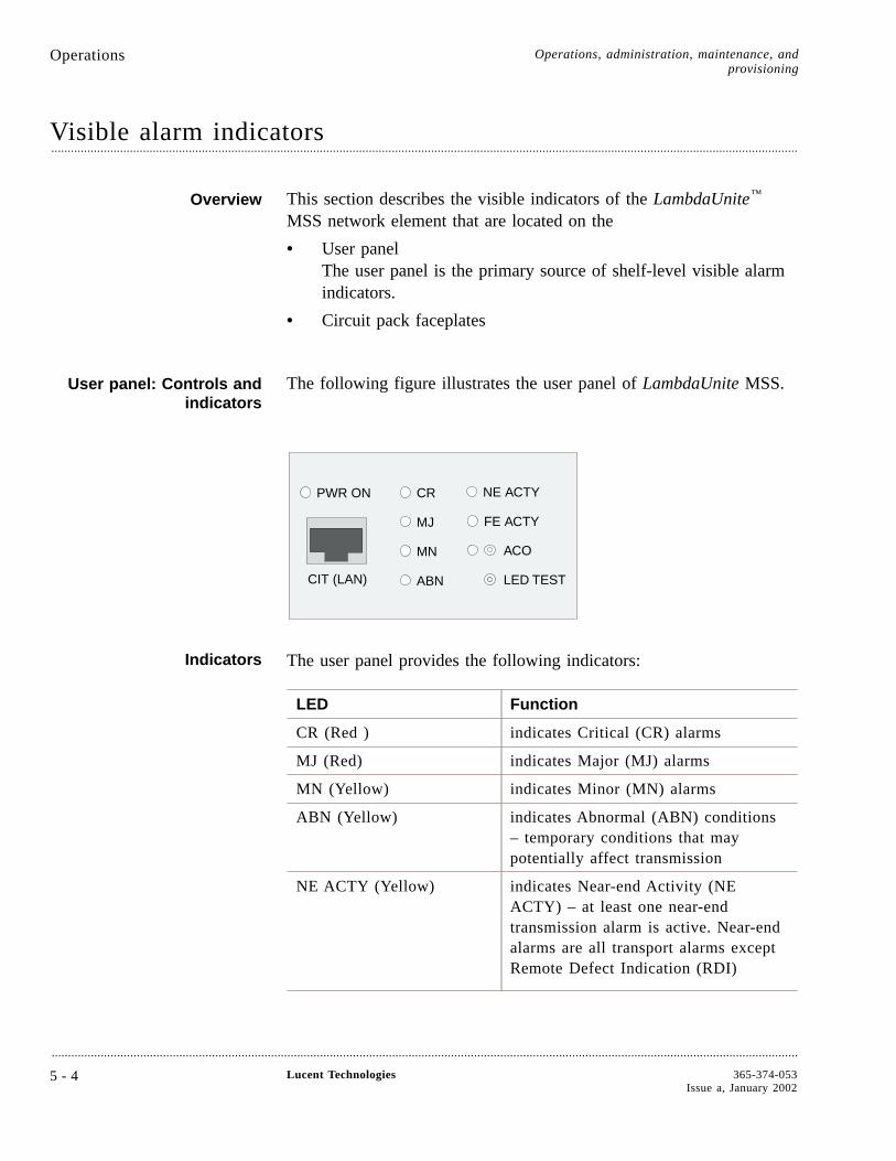
Visible alarm indicators....................................................................................................................................................................................................................................
Overview This section describes the visible indicators of the LambdaUnite™
MSS network element that are located on the
• User panelThe user panel is the primary source of shelf-level visible alarmindicators.
• Circuit pack faceplates
User panel: Controls andindicators
The following figure illustrates the user panel of LambdaUnite MSS.
Indicators The user panel provides the following indicators:
LED Function
CR (Red ) indicates Critical (CR) alarms
MJ (Red) indicates Major (MJ) alarms
MN (Yellow) indicates Minor (MN) alarms
ABN (Yellow) indicates Abnormal (ABN) conditions– temporary conditions that maypotentially affect transmission
NE ACTY (Yellow) indicates Near-end Activity (NEACTY) – at least one near-endtransmission alarm is active. Near-endalarms are all transport alarms exceptRemote Defect Indication (RDI)
NE ACTY
FE ACTY
ACO
LED TEST
CR
MJ
MN
ABN
PWR ON
CIT (LAN)
Operations Operations, administration, maintenance, andprovisioning
....................................................................................................................................................................................................................................
5 - 4 Lucent Technologies 365-374-053Issue a, January 2002

LED Function
FE ACTY (Yellow) indicates Far-end Activity (FE ACTY)– at least one far-end transmissionalarm is active
PWR ON (Green) indicates that power is supplied to theshelf.
Controls and connectors The user panel provides the following controls and connections:
Button/Connection Function
LED TEST Test button for testing all shelf LEDs(except PWR ON on the user paneland the fan unit LEDs)
ACO Test button and LED; LED lights upyellow when button is pressed tosilence audible office alarms
CIT (LAN) LAN socket (4-wire RJ-45 for crossedcable) to connect a WaveStar® CIT tothe system LAN.
OperationsVisible alarm indicators
Operations, administration, maintenance, andprovisioning
....................................................................................................................................................................................................................................
365-374-053Issue a, January 2002
Lucent Technologies 5 - 5
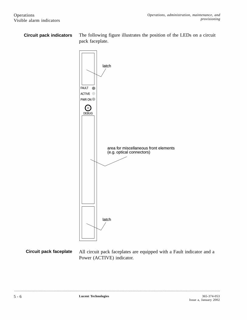
Circuit pack indicators The following figure illustrates the position of the LEDs on a circuitpack faceplate.
Circuit pack faceplate All circuit pack faceplates are equipped with a Fault indicator and aPower (ACTIVE) indicator.
latchlatch
latchlatch
area farea for miscellaneous front elementsor miscellaneous front elements(e(e.g..g. optical connectors)optical connectors)
FFAAULULTT
AACTIVECTIVE
PWR ONPWR ON
DEBDEBUGUG
OperationsVisible alarm indicators
Operations, administration, maintenance, andprovisioning
....................................................................................................................................................................................................................................
5 - 6 Lucent Technologies 365-374-053Issue a, January 2002
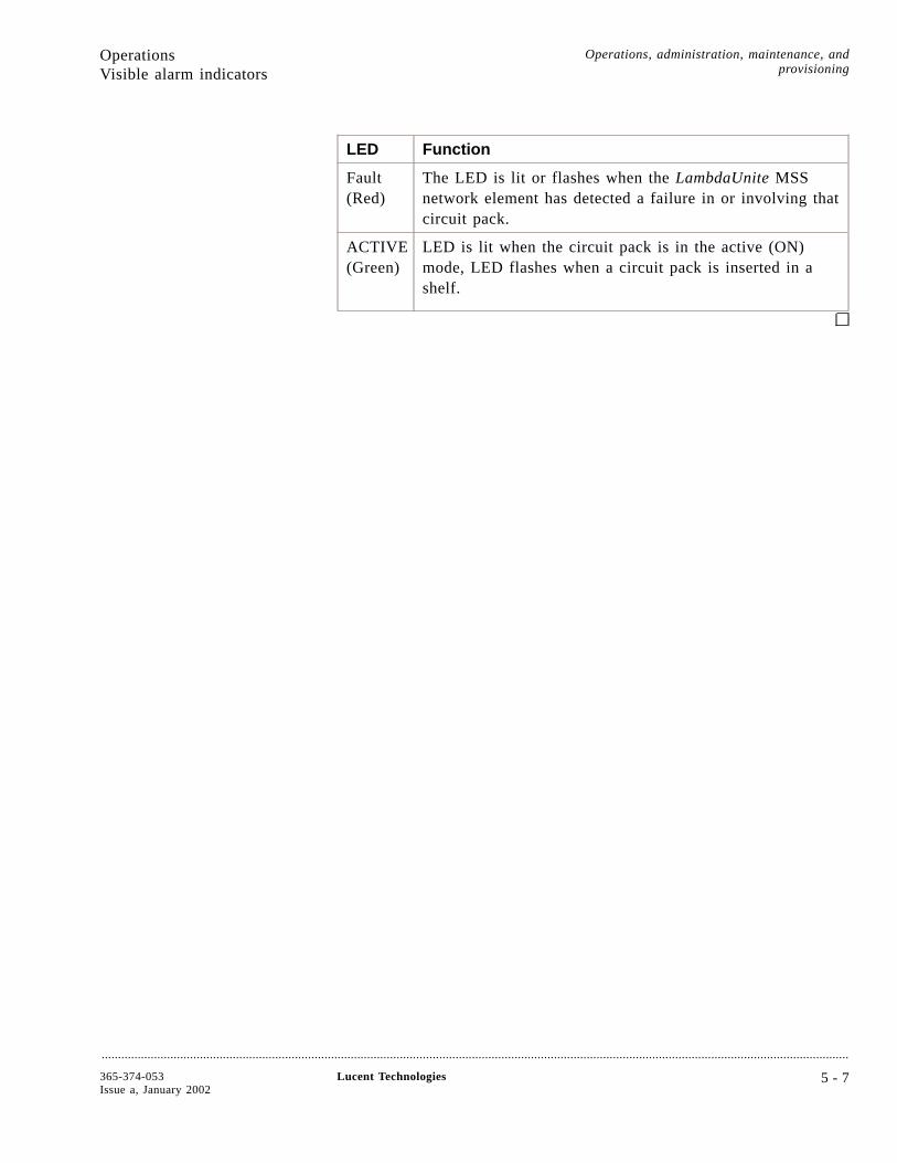
LED Function
Fault(Red)
The LED is lit or flashes when the LambdaUnite MSSnetwork element has detected a failure in or involving thatcircuit pack.
ACTIVE(Green)
LED is lit when the circuit pack is in the active (ON)mode, LED flashes when a circuit pack is inserted in ashelf.
OperationsVisible alarm indicators
Operations, administration, maintenance, andprovisioning
....................................................................................................................................................................................................................................
365-374-053Issue a, January 2002
Lucent Technologies 5 - 7
WaveStar ® CIT....................................................................................................................................................................................................................................
Overview LambdaUnite™ MSS is shipped with software for a MicrosoftWindows®-NT or Windows-2000® -based GUI that runs on acustomer-furnished desktop or laptop computer. The GUI provides
• Control of operations, administration, maintenance andprovisioning activities
• Security features to prevent unauthorized access
• Easy-to-use Transaction Language 1 (TL1) interface.
Definition WaveStar CIT is a PC-based GUI software handling the LambdaUniteMSS network elements one-by-one. It provides pull-down menus andextensive, context-sensitive on-line help. It offers a unified set offeatures for provisioning, testing, and reporting. The WaveStar CIT isnecessary to install and accept the system.
PC requirements These are the minimum PC requirements for running WaveStar CIT:
• Pentium® 266-MHz processor (Pentium III 500 MHzrecommended) with 128 MB RAM (256 MB recommended)
• Standard floppy drive for 1.44-MB 3.5” floppy disks
• 150 MB of free hard drive space (for the WaveStar CIT softwareonly; for the NE software generics and the online help files 120MB additional free hard drive space should be reserved)
• CD-ROM drive (16X)
• CompactFlash™ card
• SVGA monitor set with 800x600 resolution and 256 colors(1024x768, 16 million colors recommended)
• 100BaseT LAN interface, installed and working
• Microsoft® Windows NT® 4.0 or Windows® 2000 operatingsystem
• Adobe® Acrobat® Reader for Windows (version 3.01) to displaydocumentation in PDF format stored on the Installation CD
The performance of the user interface can be enhanced by using ahigher-performance personal computer.
An unshielded crossed Ethernet LAN cable (100BaseT) with 4-wireRJ-45 connectors is used for connecting the WaveStar CIT to the NE.
Operations Operations, administration, maintenance, andprovisioning
....................................................................................................................................................................................................................................
5 - 8 Lucent Technologies 365-374-053Issue a, January 2002
WaveStar CIT access LambdaUnite MSS supports local and remote access using a WaveStarCIT. Remote access uses the DCC (data communications channel) oran external WAN connected to a LambdaUnite MSS LAN port.
Security function LambdaUnite MSS provides a security function to protect againstunauthorized access to the WaveStar CIT system functions (such asprovisioning). Security is controlled through logins, passwords, andauthorization levels for the system functions.
TL1 interface You can use the GUI to manage all provisioning, testing, and reportgeneration easily and intuitively, with the GUI handling the TL1interface behind the scenes.
Maintenance andadministrative activities
The WaveStar CIT provides detailed information and system controlof the following specialized local/remote maintenance andadministrative activities:
• Provisioning
• Cross-connect assignments
• Protection switching
• Displaying performance-monitoring data
• Fault management (alarms lists, etc.)
• Polling inventory data of the NE
• Software download to the NE
• Loopback operation and testing
• Reporting.
OperationsWaveStar® CIT
Operations, administration, maintenance, andprovisioning
....................................................................................................................................................................................................................................
365-374-053Issue a, January 2002
Lucent Technologies 5 - 9
Operations interfaces....................................................................................................................................................................................................................................
Overview LambdaUnite™ MultiService Switch (MSS) supports the followingoperations interfaces
• Office alarms interface
• Miscellaneous discrete interfaces
• Operations system LAN interface
• Data communications channels (DCC).
Office alarms interface The office alarms interface is a set of discrete relays that controlaudible and visible office alarms. Separate relays handle the followingalarm levels: either critical, major, and minor or prompt, deferred andinfo.
Miscellaneous discreteinterfaces
The miscellaneous discrete interfaces, supported in a future release,allow an OS to control and monitor equipment co-located withLambdaUnite MSS through a set of input and output contact closures.There are 8 miscellaneous inputs that can monitor conditions such asopen doors or high temperature, and 8 miscellaneous discrete outputsto control equipment such as fans and generators. These can be set bythe user.
The status of the miscellaneous discrete inputs can be queried fromthe WaveStar® CIT. The LambdaUnite MSS network element collectsmiscellaneous discrete alarms and automatically sends them to the OS.
Message-based OSinterface
The LambdaUnite MSS supports a message-based OS interface thatuses the LAN to communicate with the OS. This interface supportsTransaction Language 1 (TL1) and standard operations messages. It iscompatible with Bellcore Network Monitoring and Analysis (NMA),Lucent Technologies Transvu II, and Lucent Technologies Navis™
Optical Element Management System (EMS). Navis Optical EMS is atype of OS element manager. It then collects and forwards theresponses and autonomous messages from the Network Elements toitself. The information it receives is used to perform fault correlationand diagnose problems in the network. The Navis Optical EMSconcentrates the data links to/from NEs into a single link back to anetwork management OS, thus reducing costs.
Operations Operations, administration, maintenance, andprovisioning
....................................................................................................................................................................................................................................
5 - 1 0 Lucent Technologies 365-374-053Issue a, January 2002
A message-based operations system can access the local LambdaUniteMSS (local access capability) and any remote network element in amaintenance subnetwork using the DCC capability.
Interface security function LambdaUnite MSS also provides a security function to protect againstunauthorized access to OS functions, such as provisioning. Security iscontrolled through logins, passwords, and authorization levels for thesystem functions.
Data communicationschannel (DCC)
The WaveStar CIT and operations interface features extend beyond thelocal LambdaUnite MSS to cover remote sites. This networkoperations capability uses the section DCC bytes in the OC-M/STM-Noverhead. WaveStar CIT dialogues and operations interface messagestravel in these DCC bytes.
OperationsOperations interfaces
Operations, administration, maintenance, andprovisioning
....................................................................................................................................................................................................................................
365-374-053Issue a, January 2002
Lucent Technologies 5 - 1 1
Administration
Overview....................................................................................................................................................................................................................................
Purpose The system management function for the administration ofLambdaUnite™ MultiService Switch (MSS) is operator administrated.
Security The WaveStar® LambdaUnite MSS provides for secure system accessby means of a two-tier security mechanism.
Operations, administration, maintenance, andprovisioning
....................................................................................................................................................................................................................................
5 - 1 2 Lucent Technologies 365-374-053Issue a, January 2002
Security....................................................................................................................................................................................................................................
Overview This section describes the various security features that theLambdaUnite™ MSS provides to monitor and control access to thesystem.
Two-tier security The two tiers of security that protect against unauthorized access tothe WaveStar® CIT and the network element functions are
• User login security (WaveStar CIT)
• Network element login security (“System View”)
User login security User login security controls access to the system on an individual userbasis by means of
• Login ID and password assignment
• Login and password aging
• Autonomous indications and history records
• User privilege codes.
Network element loginsecurity
NE login security controls access to the system through a lockoutmechanism to disable all but administrative logins.
Login and passwordassignment
To access the system, the user must enter a valid login ID andpassword. LambdaUnite MSS allows up to 500 login IDs andpasswords. Two of these login IDs are for the Superuser authorizationlevel. The others are for Privileged User, Maintenance, Reports Only,and General User authorization levels.
Login and password aging The following aging processes provide additional means of monitoringand controlling access to the system:
• Login aging deletes individual logins if unused for a pre-setnumber of days or on a particular date (for example, for a visitoror for temporary access during installation)
• Password aging requires that users change passwords periodically.
Autonomous indicationsand history records
The system provides autonomous indications and history log recordsof successful and unsuccessful logins, as well as intrusion attempts forsecurity audits.
Administration Operations, administration, maintenance, andprovisioning
....................................................................................................................................................................................................................................
365-374-053Issue a, January 2002
Lucent Technologies 5 - 1 3
User privilege codes When a user is added to the NE, a separate user privilege code, whichmay include an authorization level, is assigned to that user for each ofthe functional categories, based on the type of work the user is doing.The user privilege codes may be accompanied by an authorizationlevel represented by a number between 1 and 5, with 5 being thehighest level of access. It is permissible to grant access to anycombination of commands using a privilege code, except for fullprivileges, which are reserved for the two pre-installed superusers.
Functional categories
The functional categories for the user privilege codes may include
• Security (S)
• Maintenance (M)
• Performance monitoring (PM)
• Testing (T)
• Provisioning (P).
Authorization levels
Users can execute any commands at their functional categories’authorization level, as well as all commands at lower levels. Forexample, a user with authorization level 4 in the maintenance categorycan also execute commands listed in levels 3, 2, and 1 in themaintenance category.
AdministrationSecurity
Operations, administration, maintenance, andprovisioning
....................................................................................................................................................................................................................................
5 - 1 4 Lucent Technologies 365-374-053Issue a, January 2002
Maintenance
Overview....................................................................................................................................................................................................................................
Purpose This section introduces the maintenance features available in theLambdaUnite™ MultiService Switch (MSS).
Definition Maintenance is the system’s capability to continuously monitor itsequipment and the signals that it carries in order to notify the user ofany current or potential problems. This enables the user to takeappropriate proactive (preventive) or reactive (corrective) action.
ContentsMaintenance signals 5-16
Loopbacks and tests 5-18
Protection switching 5-19
Performance monitoring 5-21
Reports 5-24
Maintenance condition 5-26
Orderwire 5-27
Operations, administration, maintenance, andprovisioning
....................................................................................................................................................................................................................................
365-374-053Issue a, January 2002
Lucent Technologies 5 - 1 5
5-27
5-26
5-24
5-21
5-19
5-18
5-16

Maintenance signals....................................................................................................................................................................................................................................
Overview This section describes the maintenance signals available inLambdaUnite™ MultiService Switch (MSS).
Definition LambdaUnite MSS maintenance signals notify downstream equipmentthat a failure has been detected and alarmed by some upstreamequipment (Alarm Indication Signal) or the LambdaUnite MSS, andthey notify upstream equipment that a downstream failure has beendetected (yellow signals).
Standards compliant The fault monitoring and maintenance signals supported in theLambdaUnite MSS are compliant to ITU-T and Telcordia standards.
Monitoring failures LambdaUnite MSS continuously monitors its internal conditions andincoming signals. Read access to the path trace information isprovided for all signals.
Signal maintenance When defects are detected, the LambdaUnite MSS inserts anappropriate maintenance signal to downstream and/or upstreamequipment.
Path unequipped LambdaUnite MSS inserts the Path Unequipped identifier todownstream and/or upstream equipment if paths are intentionally notcarrying traffic.
Fault detection andreporting
When a fault is detected, LambdaUnite MSS employs automaticdiagnostics to isolate the failed component or signal. Failures arereported to local maintenance personnel and to the OS so that repairdecisions can be made. If desired, OS personnel and local personnelcan use the WaveStar® CIT to gain more detailed information about aspecific fault condition.
Fault history All alarmed fault conditions detected and isolated by WaveStarLambdaUnite MSS are stored and made available to be reported, ondemand, through the WaveStar CIT. In addition, a history of the 1024most recent alarm events, of the 500 most recent state change eventsand of the 1000 most recent database change events is maintained andavailable for on-demand reporting. Each event is date and timestamped.
Maintenance Operations, administration, maintenance, andprovisioning
....................................................................................................................................................................................................................................
5 - 1 6 Lucent Technologies 365-374-053Issue a, January 2002

Reports LambdaUnite MSS automatically and autonomously reports alldetected alarm and status conditions through the
• Office alarm relays
• User panel
• Equipment LEDs
• Message-based OS.
MaintenanceMaintenance signals
Operations, administration, maintenance, andprovisioning
....................................................................................................................................................................................................................................
365-374-053Issue a, January 2002
Lucent Technologies 5 - 1 7
Loopbacks and tests....................................................................................................................................................................................................................................
Overview This section describes the loopbacks and tests that the LambdaUnite™
MSS performs.
Loopback definition A loopback is a troubleshooting test in which a signal is transmittedthrough a port unit to a set destination and then returned to theoriginating port unit. The transmitted and received signals aremeasured and evaluated by the user to ensure that the received signalis accurate and complete when compared to the originating signal.
Software-initiatedloopbacks
LambdaUnite MSS can perform software-initiated facility loopbackswithin the port units (in-loopbacks and out-loopbacks). Activeloopbacks are indicated by the abnormal (ABN) LED on the userpanel.
Installation self-test Installation self test and diagnostics are executed automatically duringinstallation and after power up to verify correct system operation.Additional diagnostic tests are performed for fault isolation. Thesetests ensure that the system is capable of performing its requiredfunctions. If a defect is detected, the replaceable unit which should bereplaced to repair the defect is identified.
Circuit pack self-test LambdaUnite MSS supports a variety of self-tests designed to verifythe health of individual transmission circuit packs.
Maintenance Operations, administration, maintenance, andprovisioning
....................................................................................................................................................................................................................................
5 - 1 8 Lucent Technologies 365-374-053Issue a, January 2002
Protection switching....................................................................................................................................................................................................................................
Overview This section describes the protection switching and redundancymechanisms available in LambdaUnite™ MultiService Switch (MSS).
Definition The following types of protection and redundancy are available (seeChapter 2, “Features” ):
• 1+1 Linear APS on OC-192 and OC-48 level
• 1+1 Multiplex Section Protection (MSP)
• Bidirectional Line Switched Ring (BLSR)
• Multiplex Section Shared Protection Ring (MS-SPRing)
• Transoceanic Protocol (future release)
• Uni-directional Path Switched Ring (UPSR) on all supportedcross connection types
• Sub-Network Connection Protection (SNCP) on all supportedcross connection types
• Redundant Timing circuit packs: TMG protected with XC320
• Duplicated power feed throughout the system.
1+1 Line Protection(SONET), 1+1 MSP (SDH)
One physical working connection is protected by one physicalstand-by connection.
BLSR (SONET), MS-SPRing(SDH)
A bidirectional line switched ring (BLSR) / multiplex section sharedprotection ring (MS-SPRing) is a self-healing ring configuration inwhich traffic is bidirectional between each pair of adjacent nodes andis protected by redundant bandwidth on the bidirectional lines thatinter-connect the nodes in the ring.
UPSR (SONET), SNCP(SDH)
The principle of a UPSR/SNCP is based on the duplication of thesignals to be transmitted and the selection of the best signal availableat the subnetwork connection termination. The two (identical) signalsare routed over two different path segments, one of which is definedas the main path and the other as standby path. The same applies tothe opposite direction (bidirectional UPSR/SNCP). The system onlyswitches to the standby path if the main path is faulty.
Maintenance Operations, administration, maintenance, andprovisioning
....................................................................................................................................................................................................................................
365-374-053Issue a, January 2002
Lucent Technologies 5 - 1 9

Redundant timinggenerator
TMG is protected with the switching circuit pack XC320.
Duplicated power feed Power feed is duplicated throughout the system. Each circuit pack hasits own DC/DC converter (distributed powering).
MaintenanceProtection switching
Operations, administration, maintenance, andprovisioning
....................................................................................................................................................................................................................................
5 - 2 0 Lucent Technologies 365-374-053Issue a, January 2002

Performance monitoring....................................................................................................................................................................................................................................
Overview Performance Monitoring provides the user with the facility tosystematically track the quality of a particular transport entity. This isdone by means of continuous collection and analysis of the dataderived from defined measurement points.
Basic measurementparameters
The following performance parameters are available to estimate theerror performance of a section (SONET):
• SES (number of Severely Errored Seconds in the received signal)
• ES (number of Errored Seconds in the received signal)
• CV (number of Code Violations in the received signal)
• SEFS (number of seconds during which the Severely ErroredFraming defect was detected)
• LOSS (number of seconds during which the Loss of Signaldefect was detected)
The following performance parameters are available to estimate theerror performance of a line (SONET):
• SES (number of Severely Errored Seconds in the received signal)
• ES (number of Errored Seconds in the received signal)
• CV (number of Code Violations in the received signal)
• UAS (number of Unavailable Seconds in the received signal)
• FC (number of times the incoming signal failed (AIS detected orinserted))
• AISS (number of seconds during which the AIS defect wasdetected)
The following performance parameters are available to estimate theerror performance of an RS, MS (SDH):
• SES (number of Severely Errored Seconds in the received signal)
• ES (number of Errored Seconds in the received signal)
• BBE (number of Background Block Errors in the received signal)
• UAS (number of Unavailable Seconds in the received signal)
Maintenance Operations, administration, maintenance, andprovisioning
....................................................................................................................................................................................................................................
365-374-053Issue a, January 2002
Lucent Technologies 5 - 2 1

The following performance parameters are available to estimate theerror performance of a VC sub-network connection (SDH):
• SES (number of Severely Errored Seconds in the received signal)
• ES (number of Errored Seconds in the received signal)
• BBE (number of Background Block Errors in the received signal)
• UAS (number of Unavailable Seconds in the received signal)
Enabling performancemeasurement points
Performance measurement points can be enabled via the ElementManager Navis™ Optical EMS and via the WaveStar® CIT. Pleaserefer to the LambdaUnite™ MSS User Operations Guide.
Data storage All data is stored in the current bin. The managed NE has a currentdata register (current bin) for 15 minutes and 24 hours. Once atermination point for measurements has been configured, you are ableto get a snapshot view of the data gathered at any time (default).
Historic bins The network element keeps a store of the historic 15 minute and 24hour bins.
Interval Number of historic bins Total storage time
15 minute 16 4 hours
24 hours 1 1 day
Data retrieval Performance Data can be polled via the Navis Optical EMS and viathe WaveStar CIT.
Reports Via the Navis Optical EMS the user is able to create reports fromhistory data stored in the database of the network managementsystem.
Zero suppression Performance data sets with counter value zero, i.e. no errors occurred,will not be stored in the performance data log.
Performance alarms If the counter value of a performance parameter exceeds the threshold,in a future release an alarm can be generated and displayed on theNavis Optical EMS and WaveStar CIT.
MaintenancePerformance monitoring
Operations, administration, maintenance, andprovisioning
....................................................................................................................................................................................................................................
5 - 2 2 Lucent Technologies 365-374-053Issue a, January 2002

Fault localization Performance alarms only give a hint that the signal quality at a certainmeasurement point is degraded. They can be used as a help for faultlocalization. The severity of such an alarm is strongly dependent onthe application of your network. Often it can be helpful to define avery low threshold value (supported in a future release) in order torealize a signal degradation at a very early stage .
Clearing The clearing of the alarms is done automatically at the end of the firstcomplete interval during which no threshold crossing occurred.
MaintenancePerformance monitoring
Operations, administration, maintenance, andprovisioning
....................................................................................................................................................................................................................................
365-374-053Issue a, January 2002
Lucent Technologies 5 - 2 3
Reports....................................................................................................................................................................................................................................
Overview This topic contains information about the
• Active alarms and status reports
• Performance monitoring reports
• History reports
• Report on circuit pack, slot, port and switch states
• Version/equipment list
• Synchronization reports
Active alarms and statusreports
LambdaUnite™ MSS provides an on-demand report ( WaveStar® CITNE Alarm List) that shows all the active alarm and status conditions.LambdaUnite MSS automatically displays the local alarm and statusreport on the WaveStar CIT. The WaveStar CIT can be configured toshow the following alarm levels and alarm conditions: Either
• Critical (CR)
• Major (MJ)
• Minor (MN)
• Not Alarmed (status) (NA)
or
• Prompt
• Deferred
• Info
Among others, the alarm issue point and a description of each alarmcondition are included in the report along with the date and timedetected. The report also indicates whether or not the alarm isservice-affecting.
Performance monitoringreports
LambdaUnite MSS provides reports that contain the values of allperformance monitoring registers requested at the time of the report.The start time of each register’s recording period is also included. Thereports provide all performance monitoring data that was recorded in aseries of 15-minute and 24-hour storage registers.
Performance parameters report
LambdaUnite MSS provides another report that contains a summaryof all performance parameters that have crossed their provisioned
Maintenance Operations, administration, maintenance, andprovisioning
....................................................................................................................................................................................................................................
5 - 2 4 Lucent Technologies 365-374-053Issue a, January 2002
15-minute or 24-hour thresholds within the history of the 15-minuteand 24-hour registers.
A series of 32 previous and one current 15-minute registers areprovided for each parameter, allowing for up to 8 hours and 15minutes (495 minutes) of history in 15-minute registers. Also, onecurrent and one previous 24-hour registers are provided, allowing forup to 2 days (48 hours) of history in 24-hour registers.
History report
A history report displays the past 500 events. An event is any changein LambdaUnite MSS that may affect its performance (for example, afailure) or change its operation status (for example, loopback setup).This summary contains time stamps showing when each condition wasdetected and when it has cleared. The WaveStar CIT events contain atime stamp showing when the command was entered.
Report on pack, slot, portand switch states
This on-demand report displays
• Circuit pack, transmission port, and timing port state information
• Protection group switch states.
Version/equipment list The version/equipment list report is an on-demand report that lists all
• Provisioned or pre-provisioned circuit packs
• Circuit packs that are present.
Synchronization report The synchronization report is an on-demand report that lists thesystem synchronization status.
MaintenanceReports
Operations, administration, maintenance, andprovisioning
....................................................................................................................................................................................................................................
365-374-053Issue a, January 2002
Lucent Technologies 5 - 2 5
Maintenance condition....................................................................................................................................................................................................................................
Definition The system state of Maintenance Condition is a special state that thesystem is placed into for securing the integrity of the system’scross-connection maps and database in times of non-volatile memory(NVM) corruption, or when maintenance activities need to beperformed on the NVM for purposes of installing a new softwaregeneric on the system, or restoring the database from a previouslystored backup version. Any changes to NE-originated data during theMaintenance Condition is made only in the controller RAM of theprocessor that owns the data and is not made in the correspondingassociated object or NVM.
Maintenance Operations, administration, maintenance, andprovisioning
....................................................................................................................................................................................................................................
5 - 2 6 Lucent Technologies 365-374-053Issue a, January 2002
Orderwire....................................................................................................................................................................................................................................
Overview This section provides information about orderwire.
Description Engineering Orderwire (EOW) provides voice communications formaintenance personnel to perform facility maintenance.LambdaUnite™ MultiService Switch (MSS) provides two pairs of64-kbit/s (E1 and E2) orderwire (OW) interfaces per shelf (supportedin a future release).
Each pair includes
• Local Orderwire (SONET) / Regenerator Section Orderwire(SDH)
• Express Orderwire (SONET) / Multiplex Section Orderwire(SDH).
Maintenance Operations, administration, maintenance, andprovisioning
....................................................................................................................................................................................................................................
365-374-053Issue a, January 2002
Lucent Technologies 5 - 2 7
Provisioning
Overview....................................................................................................................................................................................................................................
Purpose This section contains information about the following features:
• Local or remote provisioning
• Preprovisioning circuit packs
• Circuit pack replacement provisioning
• Original value provisioning
Definition Provisioning refers to assigning values to parameters used for specificfunctions by network elements. The values of the provisionedparameters determine many operating characteristics of a networkelement.
References For more information about provisioning parameters and originalvalues using the WaveStar® CIT, refer to the LambdaUnite™ MSSUser Operations Guide.
Operations, administration, maintenance, andprovisioning
....................................................................................................................................................................................................................................
5 - 2 8 Lucent Technologies 365-374-053Issue a, January 2002
Introduction....................................................................................................................................................................................................................................
Local or remoteprovisioning
The LambdaUnite™ MSS software allows local and remoteprovisioning of all user-provisionable parameters. The provisionableparameters and values (current and original) are maintained in thenonvolatile memory of the controller circuit pack.
Preprovisioning circuitpacks
To simplify circuit pack installation, parameters can be provisionedbefore inserting the corresponding circuit pack. The appropriateparameters are automatically downloaded when the correspondingcircuit pack is installed. All system parameters and values (current andoriginal) are retrievable on demand regardless of the means used forprovisioning.
Circuit pack replacementprovisioning
Replacement of a failed circuit pack is simplified by the LambdaUniteMSS automatic provisioning of the original circuit pack values. Thecontroller circuit packs maintain a provisioning map of the currentprovisioning values. When a transmission and/or a timing circuit packis replaced, the controller automatically downloads the previousprovisioning parameters to the new circuit pack.
Original valueprovisioning
Installation provisioning is minimized with factory-preset values. Eachprovisionable parameter is assigned an original value at the factory.The provisionable parameters are automatically set to their originalvalues during installation.
There are two complete sets of data (parameters and their values)located in the nonvolatile memory of the controller circuit pack undernormal conditions:
• The first set contains the system parameters and their originalvalues (values assigned to a parameter at the factory).
• The second set contains the system parameters and their currentvalues (values currently being used by the system).
Please note that the original values assigned at the factory cannot bechanged. However, the current values can be overridden through localor remote provisioning.
Provisioning Operations, administration, maintenance, andprovisioning
....................................................................................................................................................................................................................................
365-374-053Issue a, January 2002
Lucent Technologies 5 - 2 9

6 System planning and engineering
Overview....................................................................................................................................................................................................................................
Purpose This chapter provides general System Planning and Engineeringinformation for LambdaUnite™ MultiService Switch (MSS).
ContentsGeneral planning information 6-2
Power planning 6-3
Cooling equipment 6-4
Transmission capacity 6-5
Port location rules 6-6
Floor plan layout 6-7
Equipment interconnection 6-11
....................................................................................................................................................................................................................................
365-374-053Issue a, January 2002
Lucent Technologies 6 - 1
6-11
6-7
6-6
6-5
6-4
6-3
6-2
General planning information....................................................................................................................................................................................................................................
Overview This section provides general planning information for LambdaUnite™
MSS.
Planning considerations When planning your network, you should consider the
• Power planning
• Cooling Equipment
• Transmission capacity
• Port location rules
• Synchronization
• Floor plan layout
• Equipment interconnection.
Engineering andinstallation services group
Lucent Technologies maintains an Engineering and InstallationServices group to assist you in planning and engineering a newsystem. The Engineering and Installation Services group is a highlyskilled force of support personnel dedicated to providing customerswith quality engineering and installation services. These specialists usestate-of-the-art technology, equipment, and procedures to providecustomers with highly competent, rapid response services.
For more information about the Engineering and Installation Servicesgroup, refer to Chapter 8, “Product support”.
System planning and engineering
....................................................................................................................................................................................................................................
6 - 2 Lucent Technologies 365-374-053Issue a, January 2002

Power planning....................................................................................................................................................................................................................................
Overview This section provides general power planning information forLambdaUnite™ MSS. The LambdaUnite MSS sub-rack uses adistributed powering system, rather than bulk power supplies. Itdistributes -48 V DC / -60 V DC power throughout the sub-rack up toa maximum power consumption of 2.200 W, and each circuit packuses its own onboard power converter to derive the necessaryoperating voltages.
Dual power feeds, powerinterfaces (PI)
Office power feeders A (working) and B (protection) are filtered andprotected by circuit breakers at the input to the sub-rack. This is doneby the PI units, one unit is assigned to each power feeder. Thesupplies are distributed separately to each circuit pack, where they arefiltered again and fused before being converted to the circuit packworking voltages. For the main over-current protection of the system acentralized 63-A circuit breaker located in the PI is used.
The A and B power inputs are supervised individually by the systemcontroller circuit pack (CTL). A green LED on every Power Interface(PI) indicates that the input power is available which means that it isabove 39.0 V ± 1.0 V. As soon as the input voltage is below 39.0 V±1. 0 V, an alarm message will be send to the CTL.
Power distribution The power supply of the rack is provided by the Power DistributionPanel (PDP) at the top of the rack. This PDP provides doubled powersupply to the sub-rack.
Grounding The grounding and earthing of the system covers the requirements forMESH-BN and MESH-IBN according to ETSI 300 253 or ITU K.27.With the PDP it is possible to connect or to disconnect the DC returnsto GRD. At this way, the system can be applied in a MESH-BN orMESH-IBN environment.
Power consumption For more information about power consumption of the whole sub-rackand of the individual circuit packs, refer to Chapter 10, “Technicalspecifications”.
For this release the system can be equipped up to a maximum powerconsumption of 2.700 W.
System planning and engineering
....................................................................................................................................................................................................................................
365-374-053Issue a, January 2002
Lucent Technologies 6 - 3
Cooling equipment....................................................................................................................................................................................................................................
Overview This section provides general cooling equipment information forLambdaUnite™ MSS.
Fan units Cooling is done by fans. Fans in a fan unit located above the upperrow of boards in the DUR sub-rack aspirate air through a filterlocated below the lower row of boards and force the air through thesub-rack from bottom to top.
Air flow baffle An air flow baffle is integrated in the sub-rack to prevent the fan unitfrom drawing in the exhaust air from the sub-rack below.
Mounting the sub-rack allow no gaps between the baffle mountedbelow the LambdaUnite MSS sub-rack and any equipment mounteddirectly below. Observing this rule avoids thermic stress due to hotexhaust air from the equipment below the sub-rack entering the airflow baffle.
References For more information about cooling, refer to Chapter 4, “Productdescription”.
System planning and engineering
....................................................................................................................................................................................................................................
6 - 4 Lucent Technologies 365-374-053Issue a, January 2002

Transmission capacity....................................................................................................................................................................................................................................
Overview This section provides general information about transmission capacityfor LambdaUnite™ MSS.
Capacity The LambdaUnite MSS Dual Unit Row sub-rack (DUR) provides2048 x STM-1 or 6144 x STS-1 capacity. This allows you to equipthe sub-rack with any mixture of 155-Mbit/s (future release),622-Mbit/s (future release), 2.5-Gbit/s, 10-Gbit/s, 40-Gbit/s (futurerelease), 1-Gigabit Ethernet and 10-Gigabit Ethernet (future release)port units.
Port unit capacities The following table lists the transmission capacity required for eachport unit.
Port unit max. STM-1Equivalents
max. STS-1Equivalents
155 Mbit/s (16 portsper unit) (futurerelease)
16 48
622 Mbit/s (16 portsper unit) (futurerelease)
64 192
2.5 Gbit/s (4 portsper unit) (in futurerelease 2 or 4 portsper unit)
64 192
10-Gbit/ssynchronous andWANPHY Ethernet(1 port per unit)
64 192
40 Gbit/s (1 port perunit) (future release)
256 768
1-Gigabit Ethernet (4ports per unit)
max. 28 max. 84
References For more information about transmission capacity, refer to Chapter 4,“Product description”.
System planning and engineering
....................................................................................................................................................................................................................................
365-374-053Issue a, January 2002
Lucent Technologies 6 - 5
Port location rules....................................................................................................................................................................................................................................
Overview This section provides recommendations about using port units andport unit circuit pack slots efficiently.
40-Gbit/s port units If 40-Gbit/s port units are planned to be used be aware that each ofthem requires four universal slots, either on the left or on the rightedge of a sub-rack quadrant.
Optical port unit protection In the case of optical port protection (1+1 Linear APS / 1+1 MSP) itis recommended to place the working port unit and the protection portunit side by side for ease of maintenance.
10-Gbit/s port units and1-Gbit/s Ethernet interface
It is recommended, to avoid thermic stress, not to place a 10-Gbit/sport unit directly above a GE1/SX4 port unit.
References For more information about port location rules and sub-rackconfiguration, refer to Chapter 4, “Product description”.
System planning and engineering
....................................................................................................................................................................................................................................
6 - 6 Lucent Technologies 365-374-053Issue a, January 2002
Floor plan layout....................................................................................................................................................................................................................................
Overview This section gives information about the space needed to mountLambdaUnite™ MSS sub-racks and racks.
Rack dimensions The racks require an area of 600 mm x 600 mm (23.6 in x 23.6 in)(width x depth) in accordance with ETSI 300 119 and with BellcoreGR-63. This area represents the absolute system limits which is notexceeded in the operating state by protruding elements such asswitches or plugs. The rack height can be chosen in accordance withthe local conditions. Standard height is 2.2 m (86.6). Heights 2.6 m(102.4 in), 2.125 m (83.66 in) and a seismic rack (2.0 m (78.7 in)height) are possible depending on customer requirements (not standarddelivery).
Rack equipping Depending on the desired configuration, the appropriate rack heightmust be chosen. The following figure gives an example of a 2.2 m
System planning and engineering
....................................................................................................................................................................................................................................
365-374-053Issue a, January 2002
Lucent Technologies 6 - 7

(86.6 in) rack (ETSI 300 119) equipped with two Dual Unit Row(DUR) shelves.
Sub-rack dimensions The size of the DUR sub-rack is 950 mm x 500 mm x 545 mm (37.4in x 19.7 in x 21.5 in) (height x width x depth). The air flow baffle
Floor plan layout System planning and engineering
....................................................................................................................................................................................................................................
6 - 8 Lucent Technologies 365-374-053Issue a, January 2002
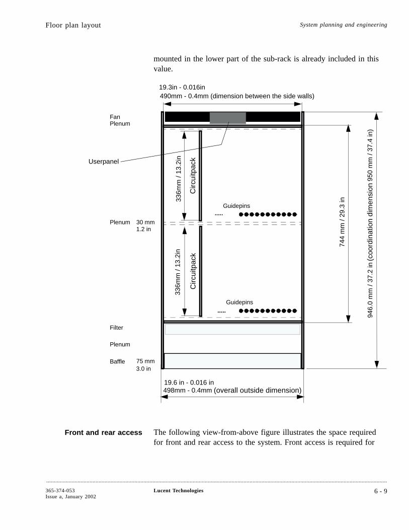
mounted in the lower part of the sub-rack is already included in thisvalue.
Front and rear access The following view-from-above figure illustrates the space requiredfor front and rear access to the system. Front access is required for
(coo
rdin
atio
ndi
men
sion
(overall outside dimension)
Circ
uitp
ack
Circ
uitp
ack
Filter
Plenum
Plenum
PlenumFan
Baffle 75 mm
30 mm
Userpanel
.....
.....
Guidepins
Guidepins
744
mm
/ 29
.3 in
490mm - 0.4mm (dimension between the side walls)19.3in - 0.016in
946.
0 m
m /
37.2
in95
0 m
m /
37.4
in)
336m
m /
13.2
in33
6mm
/ 13
.2in
1.2 in
3.0 in
498mm - 0.4mm19.6 in - 0.016 in
Floor plan layout System planning and engineering
....................................................................................................................................................................................................................................
365-374-053Issue a, January 2002
Lucent Technologies 6 - 9

operations activities and rearrangements of the optical port units. Rearaccess is required for upgrades that require cable rearrangements.
Circ
uitp
acks
Circ
uitp
acks
Fiber Cable Management
RE
AR
Cable Management
ETSI flangeETSI flange
600
mm
/ 23
.6 in
FR
ON
T
Floor plan layout System planning and engineering
....................................................................................................................................................................................................................................
6 - 1 0 Lucent Technologies 365-374-053Issue a, January 2002
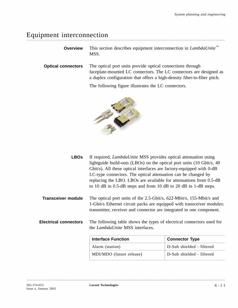
Equipment interconnection....................................................................................................................................................................................................................................
Overview This section describes equipment interconnection in LambdaUnite™
MSS.
Optical connectors The optical port units provide optical connections throughfaceplate-mounted LC connectors. The LC connectors are designed asa duplex configuration that offers a high-density fiber-to-fiber pitch.
The following figure illustrates the LC connectors.
LBOs If required, LambdaUnite MSS provides optical attenuation usinglightguide build-outs (LBOs) on the optical port units (10 Gbit/s, 40Gbit/s). All these optical interfaces are factory-equipped with 0-dBLC-type connectors. The optical attenuation can be changed byreplacing the LBO. LBOs are available for attenuations from 0.5-dBto 10 dB in 0.5-dB steps and from 10 dB to 20 dB in 1-dB steps.
Transceiver module The optical port units of the 2.5-Gbit/s, 622-Mbit/s, 155-Mbit/s and1-Gbit/s Ethernet circuit packs are equipped with transceiver modules:transmitter, receiver and connector are integrated in one component.
Electrical connectors The following table shows the types of electrical connectors used forthe LambdaUnite MSS interfaces.
Interface Function Connector Type
Alarm (station) D-Sub shielded - filtered
MDI/MDO (future release) D-Sub shielded - filtered
System planning and engineering
....................................................................................................................................................................................................................................
365-374-053Issue a, January 2002
Lucent Technologies 6 - 1 1

Interface Function Connector Type
LAN 1 (external LAN interface tolocal CIT)
RJ 45 crossed - shielded
LAN2, LAN3, LAN4 RJ 45 crossed - shielded
Racktop (alarm lamps) D-Sub shielded - filtered
FAN Signals (from fan controllerboard)
D-Sub shielded
UPL internal interface (from userpanel)
D-Sub shielded
G703 interface D-Sub shielded
V11 interface D-Sub shielded
Station clock interface 1.6 / 5.6 coax connector
Equipment interconnection System planning and engineering
....................................................................................................................................................................................................................................
6 - 1 2 Lucent Technologies 365-374-053Issue a, January 2002
7 Ordering
Overview....................................................................................................................................................................................................................................
Purpose This chapter provides an overview of ordering information forLambdaUnite™ MultiService Switch (MSS).
ContentsOrdering information 7-2
....................................................................................................................................................................................................................................
365-374-053Issue a, January 2002
Lucent Technologies 7 - 1
7-2
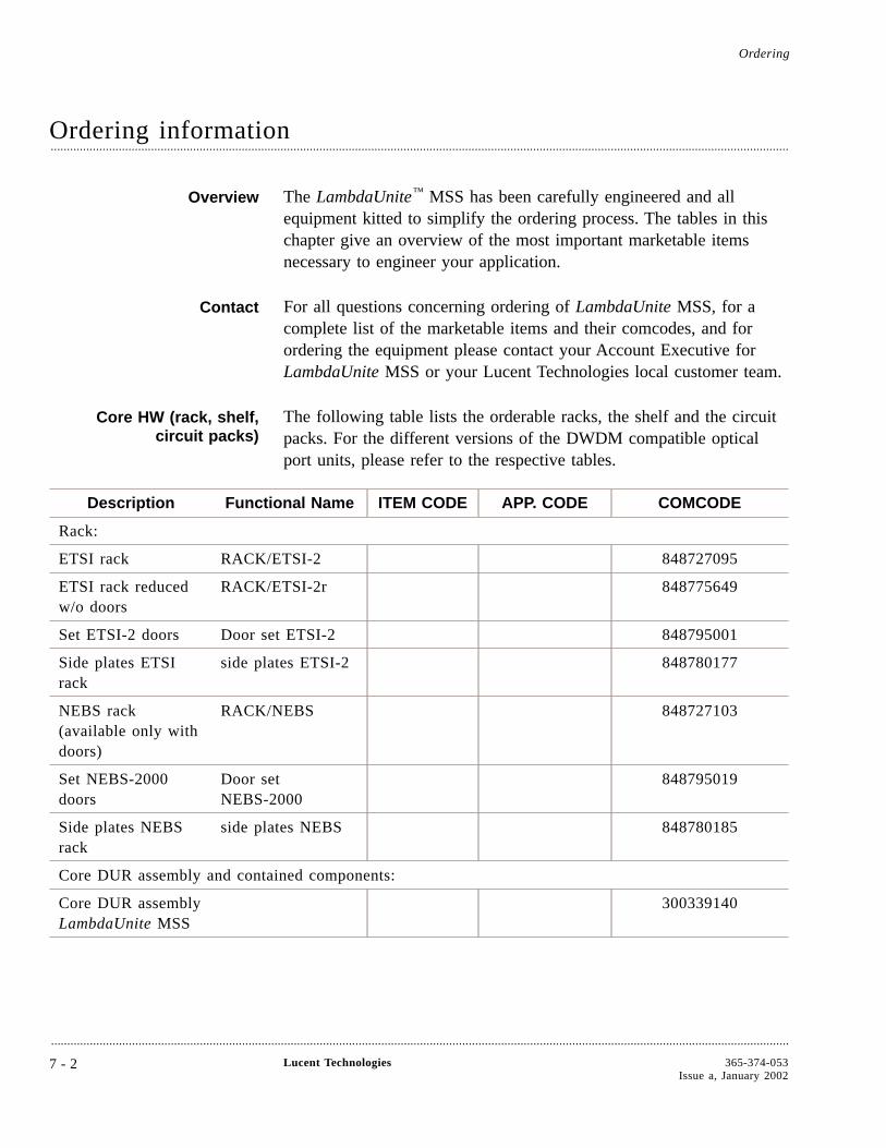
Ordering information....................................................................................................................................................................................................................................
Overview The LambdaUnite™ MSS has been carefully engineered and allequipment kitted to simplify the ordering process. The tables in thischapter give an overview of the most important marketable itemsnecessary to engineer your application.
Contact For all questions concerning ordering of LambdaUnite MSS, for acomplete list of the marketable items and their comcodes, and forordering the equipment please contact your Account Executive forLambdaUnite MSS or your Lucent Technologies local customer team.
Core HW (rack, shelf,circuit packs)
The following table lists the orderable racks, the shelf and the circuitpacks. For the different versions of the DWDM compatible opticalport units, please refer to the respective tables.
Description Functional Name ITEM CODE APP. CODE COMCODE
Rack:
ETSI rack RACK/ETSI-2 848727095
ETSI rack reducedw/o doors
RACK/ETSI-2r 848775649
Set ETSI-2 doors Door set ETSI-2 848795001
Side plates ETSIrack
side plates ETSI-2 848780177
NEBS rack(available only withdoors)
RACK/NEBS 848727103
Set NEBS-2000doors
Door setNEBS-2000
848795019
Side plates NEBSrack
side plates NEBS 848780185
Core DUR assembly and contained components:
Core DUR assemblyLambdaUnite MSS
300339140
Ordering
....................................................................................................................................................................................................................................
7 - 2 Lucent Technologies 365-374-053Issue a, January 2002
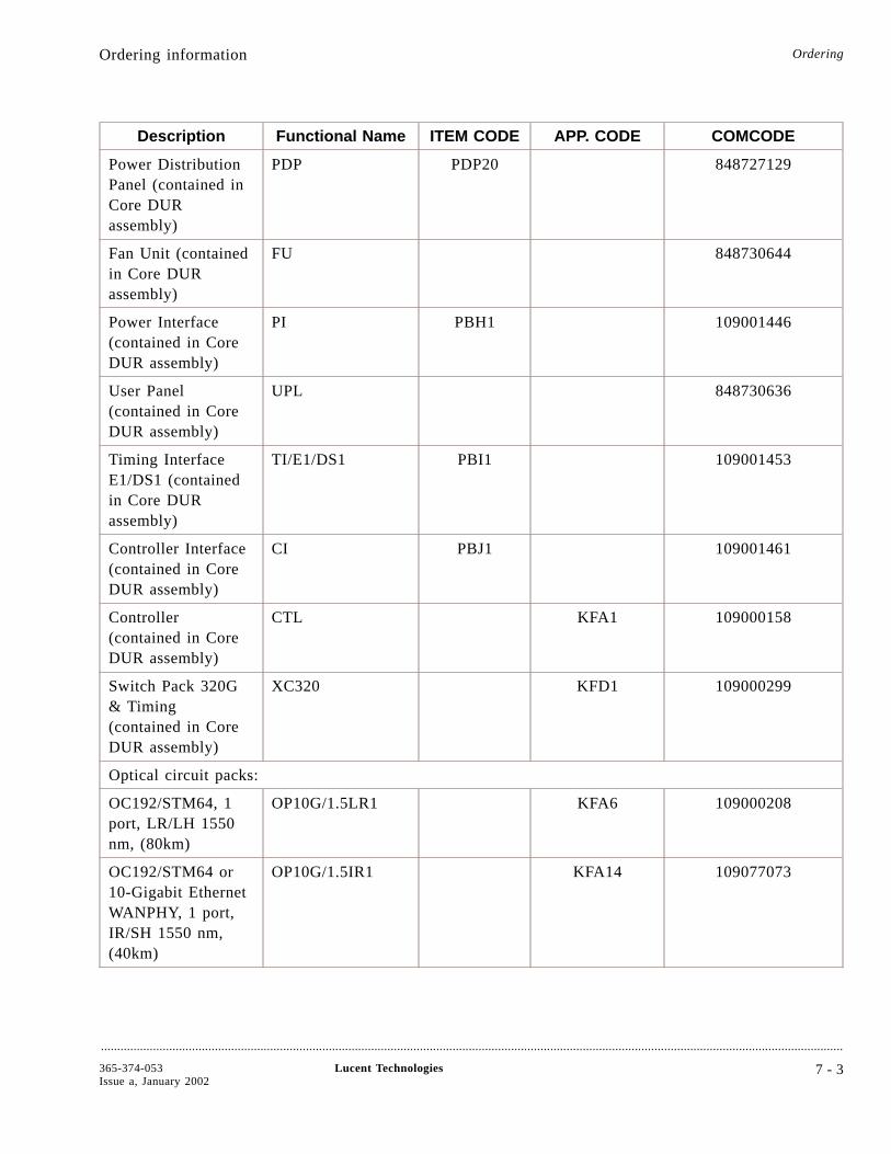
Description Functional Name ITEM CODE APP. CODE COMCODE
Power DistributionPanel (contained inCore DURassembly)
PDP PDP20 848727129
Fan Unit (containedin Core DURassembly)
FU 848730644
Power Interface(contained in CoreDUR assembly)
PI PBH1 109001446
User Panel(contained in CoreDUR assembly)
UPL 848730636
Timing InterfaceE1/DS1 (containedin Core DURassembly)
TI/E1/DS1 PBI1 109001453
Controller Interface(contained in CoreDUR assembly)
CI PBJ1 109001461
Controller(contained in CoreDUR assembly)
CTL KFA1 109000158
Switch Pack 320G& Timing(contained in CoreDUR assembly)
XC320 KFD1 109000299
Optical circuit packs:
OC192/STM64, 1port, LR/LH 1550nm, (80km)
OP10G/1.5LR1 KFA6 109000208
OC192/STM64 or10-Gigabit EthernetWANPHY, 1 port,IR/SH 1550 nm,(40km)
OP10G/1.5IR1 KFA14 109077073
Ordering information Ordering
....................................................................................................................................................................................................................................
365-374-053Issue a, January 2002
Lucent Technologies 7 - 3

Description Functional Name ITEM CODE APP. CODE COMCODE
OC192/STM64, 1port, Intra-Office1310 nm (600m)
OP10G/1.3IOR1 KFA7 109000216
OC48/STM16, 4ports, LR 1550 nm,80 km
OP2G5/1.5LR4 KFA204 109055665
OC48/STM16, 4ports, LR 1310 nm,40 km
OP2G5/1.3LR4 KFA203 109055657
OC48/STM16, 4ports, IR/SH 1310nm, 2 km
OP2G5/1.3SR4 KFA12 109000265
1000 Base SX(1-Gigabit) EthernetInterface, 4 ports
GE1/SX/4 KFA13 109000273
Software and licenses The following table lists the available software and licenses forLambdaUnite MSS.
Description Functional Name ITEM CODE APP.CODE
COMCODE
CD LambdaUnite MSS Rel2.0 NE SW & Licences
NE SW&Li R2 SCA113 109177873
Lightguide build-outs andcables
A complete list of the available lightguide build-outs and of thedifferent cables for LambdaUnite MSS with the relative comcodes youcan find in the LambdaUnite MSS Installation Guide in chapters threeand four. Some specific spare-unit recommendations are providedthere, too.
Required spare parts The following table indicates how many spare plug-in units or otherpieces of equipment are required for the customer’s spare stock(s).For further information please contact your Lucent Technologies localcustomer team.
Ordering information Ordering
....................................................................................................................................................................................................................................
7 - 4 Lucent Technologies 365-374-053Issue a, January 2002
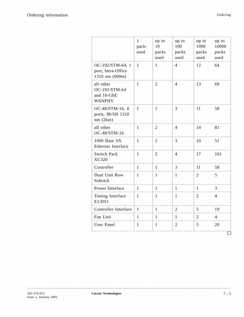
1pack-used
up to10packsused
up to100packsused
up to1000packsused
up to10000packsused
OC-192/STM-64, 1port, Intra-Office1310 nm (600m)
1 1 4 12 64
all otherOC-192/STM-64and 10-GbEWANPHY
1 2 4 13 69
OC-48/STM-16, 4ports, IR/SH 1310nm (2km)
1 1 3 11 58
all otherOC-48/STM-16
1 2 4 14 81
1000 Base SXEthernet Interface
1 1 3 10 51
Switch PackXC320
1 2 4 17 101
Controller 1 1 3 11 58
Dual Unit RowSubrack
1 1 1 2 5
Power Interface 1 1 1 1 3
Timing InterfaceE1/DS1
1 1 1 2 4
Controller Interface 1 1 2 5 19
Fan Unit 1 1 1 2 4
User Panel 1 1 2 5 20
Ordering information Ordering
....................................................................................................................................................................................................................................
365-374-053Issue a, January 2002
Lucent Technologies 7 - 5

8 Product support
Overview....................................................................................................................................................................................................................................
Purpose This chapter provides information about the support for theLambdaUnite™ MultiService Switch (MSS).
ContentsEngineering and installation services 8-2
Technical support 8-3
Documentation support 8-5
Training 8-6
Training courses 8-7
....................................................................................................................................................................................................................................
365-374-053Issue a, January 2002
Lucent Technologies 8 - 1
8-7
8-6
8-5
8-3
8-2

Engineering and installation services....................................................................................................................................................................................................................................
Overview This section describes the engineering and installation servicesavailable to support LambdaUnite™ MSS.
Engineering andinstallation services group
The engineering and installation services group has a highly skilledforce of support personnel dedicated to providing customers withquality engineering and installation services. These specialists usestate-of-the-art technology, equipment, and procedures to providecustomers with highly competent, rapid response services.
Services provided The services include
• Analyzing your equipment requests
• Preparing detailed specifications for manufacturing andinstallation
• Creating and maintaining job records
• Installing equipment
• Testing and turning over working systems
Tailored services When you purchase Lucent Technologies engineering and installationservices, your system order is integrated into a complete workingsystem tailored to your office conditions and preferences.
Providing for all yourneeds
The Engineering and Installation Services group provides for all yourneeds, including provisions for
• Cabling
• Lighting
• Power equipment
• Connections to local and/or remote alarms
Reference For more information about specialized engineering and installationservices, engineering consultations, and/or database preparation, pleasecontact your local Account Executive.
Product support
....................................................................................................................................................................................................................................
8 - 2 Lucent Technologies 365-374-053Issue a, January 2002

Technical support....................................................................................................................................................................................................................................
Overview This section describes the technical support available forLambdaUnite™ MSS.
Technical support groups Technical support is available through
• Local/Regional Customer Support (LCS/RCS)
• Customer Technical Support (CTS).
Contacting your LCS/RCS LCS/RCS personnel troubleshoot field problems 24 hours a day overthe phone and on site (if necessary) based on Lucent TechnologiesService Contracts.
For technical assistance, call your Local/Regional Customer SupportTeam. If the request cannot be solved by LCS/RCS, it will beescalated to the central Customer Technical Support (CTS) teams inMerrimack Valley, USA or Nuremberg, Germany.
Customer technicalsupport
Lucent Technologies Customer Technical Support (CTS) organizationis committed to providing customers with quality product supportservices. Each segment of the CTS organization regards the customeras its highest priority and understands your obligations to maintainquality services for your customers.
The CTS team maintains direct contact with Lucent Technologiesmanufacturing, Bell Laboratories development, and other organizationsto assure fast resolution of all assistance requests.
Services LambdaUnite MSS is complemented by a full range of servicesavailable to support planning, maintaining, and operating your system.Applications testing, network integration, and upgrade/conversionsupport is also available.
A technical supportplatform
A global online trouble tracking system is used by all support teamsto track customer assistance requests. The system communicatesdetails about product bulletins, troubleshooting procedures, and othercritical information to customers. All details of a request are enteredinto this database until closure. For online access to your troubletickets via the web please contact your local support team.
Product support
....................................................................................................................................................................................................................................
365-374-053Issue a, January 2002
Lucent Technologies 8 - 3
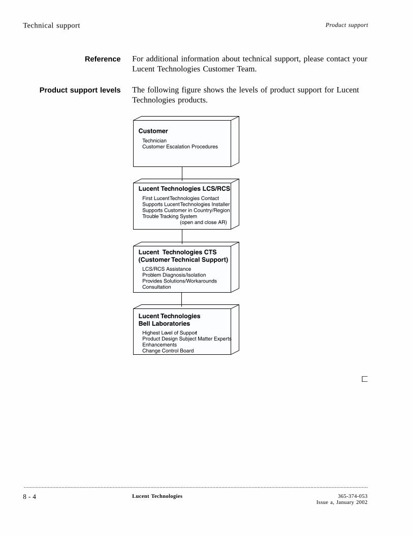
Reference For additional information about technical support, please contact yourLucent Technologies Customer Team.
Product support levels The following figure shows the levels of product support for LucentTechnologies products.
Technical support Product support
....................................................................................................................................................................................................................................
8 - 4 Lucent Technologies 365-374-053Issue a, January 2002
Documentation support....................................................................................................................................................................................................................................
Overview The Lucent Learning (former Customer Training and InformationProducts) organization provides comprehensive product documentationtailored to the needs of the different audiences. An overview of thedocumentation set can be found in the chapter “About ThisDocument”.
Customer comment form Lucent Learning (LL) provides a customer comment form in the frontof this guide. Please use the form to report errors or make suggestionsabout the document.
Is the form missing?
If the customer comment form is missing, please send or fax yourcomments to
Lucent Technologies Network Systems GmbH
Lucent Learning WO
Thurn-und-Taxis-Str. 10
90411 Nürnberg, Germany
Fax: +49 911 526 3545.
Product support
....................................................................................................................................................................................................................................
365-374-053Issue a, January 2002
Lucent Technologies 8 - 5

Training....................................................................................................................................................................................................................................
Overview The Lucent Learning organization offers a formal training package tocomplement your product needs.
On-site training On-site training is available for all LambdaUnite™ MSS trainingcourses.
Registering for a courseor arranging an on-site
training session
To enroll in a training class at one of the Lucent Technologiescorporate training centers or to arrange an on-site training session atyour facility, please contact
in Germany Dieter Kellermeier
voice: +49 911 526 6145
fax: +49 911 526 6145
e-mail: [email protected]
in the USA Carlos Sarabasa
voice: +1 407 767 4933
fax: +1 407 767 2760
e-mail: [email protected]
in Singapore Jenny Ong
voice: +65 240 8000
fax: +65 240 8017
e-mail: [email protected]
Product support
....................................................................................................................................................................................................................................
8 - 6 Lucent Technologies 365-374-053Issue a, January 2002
Training courses....................................................................................................................................................................................................................................
Overview This section describes the LambdaUnite™ MSS training courses.
SDH optical networkingproducts overview
This introductory course (TR9204) provides an operational overviewof Lucent Technologies SDH optical networking products. The courseexplains a variety of applications of these products and developsnetworking scenarios using these products. This course can becustomized to the needs of individual customers.
Audience
This course is designed for telecommunications professionals,engineers, project managers, account executives, and other salespersonnel who need to understand the basic functionality of LucentTechnologies Synchronous Digital Hierarchy (SDH) opticalnetworking products in a network.
Objectives
This course is designed to enable students to
• Get an overview of Lucent Technologies’ Synchronous DigitalHierarchy (SDH) optical networking products
• Understand all applications and features.
Prerequisites
Students should be familiar with basic SDH or SONET principles.
Media
A combination of instructor lectures and written exercises.
Duration
Approx. 3 days
Applications, Architecture,and Planning Course
(instructor led)
The LambdaUnite MSS Applications, Architecture, and PlanningCourse (TR6070) provides a detailed introduction to LambdaUniteMSS, covering equipment functions and requirements, systemcapabilities and network topology applications.
Audience
Network planners and engineers; Lucent Technologies sales andmarketing personnel, product managers, technical consultants andaccount representatives, generally anyone who needs a high-leveldescription of the LambdaUnite MSS equipment.
Product support
....................................................................................................................................................................................................................................
365-374-053Issue a, January 2002
Lucent Technologies 8 - 7
Course length
2 days
Applications, Architecture,and Planning (e-learning)
The LambdaUnite MSS Applications, Architecture, and PlanningCourse is also available as a comprehensive e-learning (TR6070M) onCD-ROM. The course provides a detailed introduction toLambdaUnite MSS, covering equipment functions and requirements,system capabilities and network topology applications.
Audience
Network planners and engineers; Lucent Technologies sales andmarketing personnel, product managers, technical consultants andaccount representatives, generally anyone who needs a high-leveldescription of the LambdaUnite MSS equipment.
Duration
Time needed to complete the CBT is approx. 3–4 hours.
Local Operations andMaintenance via
WaveStar® CIT Course(instructor led)
The LambdaUnite MSS Local Operations and Maintenance Course viaWaveStar CIT (TR6071) provides a detailed introduction toLambdaUnite MSS, covering equipment functions and requirements,system capabilities and network topology applications. It describes indetail the initial turn up and day-to-day operations and maintenancetasks, and it puts emphasis on developing skills using theLambdaUnite MSS User Operations Guide and the LambdaUnite MSSAlarm Messages and Trouble Clearing Guide. The course uses theGUI-based WaveStar CIT to provision the equipment, to createcross-connections, to perform administrative functions, to rundiagnostic tests, and to perform manual protection switching.
Audience
Technicians, installers, maintenance engineers, technical supportpersonnel, product evaluators, and anyone desiring operations andmaintenance information for LambdaUnite MSS.
Course length
5 days
Training courses Product support
....................................................................................................................................................................................................................................
8 - 8 Lucent Technologies 365-374-053Issue a, January 2002

Local Operations andMaintenance via WaveStar
CIT (e-learning)
The LambdaUnite MSS Local Operations and Maintenance viaWaveStar CIT Course is also available as comprehensive e-learning(TR6071M) on CD-ROM. It supplements and replenishes theApplications, Architecture, and Planning (e-learning), teaching theinitial turn up and day-to-day operations and maintenance tasks to beperformed with the GUI-based WaveStar CIT.
Audience
Technicians, installers, maintenance engineers, technical supportpersonnel, product evaluators, and anyone desiring operations andmaintenance information for LambdaUnite MSS.
Duration
Approx. 4 hours
Installation and TestCourse
The LambdaUnite MSS Installation and Test Course (TR6072)includes step-by step guidance to system installation and setup. It alsoincludes information needed for pre-installation site planning andpost-installation acceptance testing. The course is based on thecontents of the LambdaUnite MSS Installation Guide.
Audience
Installers, maintenance engineers, technical support personnel.
Course length
2 days
Operations andMaintenance via Navis™
Optical EMS Course
The LambdaUnite MSS Operations and Maintenance Course via NavisOptical EMS provides a detailed introduction to LambdaUnite MSS,covering equipment functions and requirements, system capabilitiesand network topology applications. It prepares students for operating,monitoring and maintaining the product on a subnetwork level usingNavis Optical EMS. The course is based on the LambdaUnite MSSApplications, Architecture, and Planning Course and on the contentsof the Navis Optical EMS Provisioning Guide for the applicationLambdaUnite MSS, it combines instructor lectures and hands-onexercises.
Audience
Persons that are responsible for operation and maintenance ofLambdaUnite MSS via Navis Optical EMS. It is also useful totechnical support personnel working with Navis Optical EMS.
Training courses Product support
....................................................................................................................................................................................................................................
365-374-053Issue a, January 2002
Lucent Technologies 8 - 9

Course Length
5 days
Training courses Product support
....................................................................................................................................................................................................................................
8 - 1 0 Lucent Technologies 365-374-053Issue a, January 2002
9 Quality and reliability
Overview....................................................................................................................................................................................................................................
Purpose This chapter provides information about the quality and reliability ofLambdaUnite™ MultiService Switch (MSS).
ContentsQuality 9-2
Lucent’s commitment to quality and reliability 9-3
Ensuring quality 9-4
Reliability specifications 9-5
General specifications 9-6
....................................................................................................................................................................................................................................
365-374-053Issue a, January 2002
Lucent Technologies 9 - 1
9-6
9-5
9-4
9-3
9-2
Quality
Overview....................................................................................................................................................................................................................................
Purpose This section describes Lucent’s Commitment to Quality andReliability and how quality is ensured.
ContentsLucent’s commitment to quality and reliability 9-3
Ensuring quality 9-4
Quality and reliability
....................................................................................................................................................................................................................................
9 - 2 Lucent Technologies 365-374-053Issue a, January 2002
9-4
9-3

Lucent’s commitment to quality and reliability....................................................................................................................................................................................................................................
Overview Lucent Technologies is extremely committed to providing ourcustomers with products of the highest level of quality and reliabilityin the industry. LambdaUnite™ MSS is a prime example of thiscommitment.
Quality policy Lucent Technologies is committed to achieving sustained businessexcellence by integrating quality principles and methods into all wedo at every level of our company to
• Anticipate and meet customer needs and exceed theirexpectations, every time
• Relentlessly improve how we work – to deliver the world’s bestand most innovative communications solutions – faster and morecost-effectively than our competitors
Reliability in the productlife-cycle
Each stage of the life cycle of LambdaUnite MSS relies on peopleand processes that contribute to the highest product quality andreliability possible. The reliability of a product begins at the earliestplanning stage and continues into
• Product architecture
• Design and simulation
• Documentation
• Prototype testing during development
• Design change control
• Manufacturing and product testing (including 100% screening)
• Product quality assurance
• Product field performance
• Product field return management
The R&D community of Lucent Technologies is certified by ISO9001.
Quality Quality and reliability
....................................................................................................................................................................................................................................
365-374-053Issue a, January 2002
Lucent Technologies 9 - 3
Ensuring quality....................................................................................................................................................................................................................................
Overview This section describes the critical elements that ensure product qualityand reliability within
• Product development
• Manufacturing
Critical elements ofproduct development
The product development group’s strict adherence to the followingcritical elements ensures the product’s reliability
• Design standards
• Design and test practices
• Comprehensive qualification programs
• System-level reliability integration
• Reliability audits and predictions
• Development of quality assurance standards for manufacturedproducts
Critical elements ofmanufacturing
Note: Independent Quality Representatives are also present atmanufacturing locations to ensure shipped product quality.
The manufacturing and field deployment groups’ strict adherence tothe following critical elements ensures the product’s reliability
• Pre-manufacturing
• Qualification
• Accelerated product testing
• Product screening
• Production quality tracking
• Failure mode analysis
• Feedback and corrective actions
Quality Quality and reliability
....................................................................................................................................................................................................................................
9 - 4 Lucent Technologies 365-374-053Issue a, January 2002

Reliability specifications
Overview....................................................................................................................................................................................................................................
Purpose This section describes how reliability is specified.
ContentsGeneral specifications 9-6
Quality and reliability
....................................................................................................................................................................................................................................
365-374-053Issue a, January 2002
Lucent Technologies 9 - 5
9-6
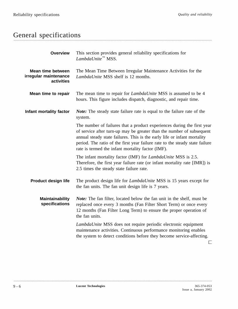
General specifications....................................................................................................................................................................................................................................
Overview This section provides general reliability specifications forLambdaUnite™ MSS.
Mean time betweenirregular maintenance
activities
The Mean Time Between Irregular Maintenance Activities for theLambdaUnite MSS shelf is 12 months.
Mean time to repair The mean time to repair for LambdaUnite MSS is assumed to be 4hours. This figure includes dispatch, diagnostic, and repair time.
Infant mortality factor Note: The steady state failure rate is equal to the failure rate of thesystem.
The number of failures that a product experiences during the first yearof service after turn-up may be greater than the number of subsequentannual steady state failures. This is the early life or infant mortalityperiod. The ratio of the first year failure rate to the steady state failurerate is termed the infant mortality factor (IMF).
The infant mortality factor (IMF) for LambdaUnite MSS is 2.5.Therefore, the first year failure rate (or infant mortality rate [IMR]) is2.5 times the steady state failure rate.
Product design life The product design life for LambdaUnite MSS is 15 years except forthe fan units. The fan unit design life is 7 years.
Maintainabilityspecifications
Note: The fan filter, located below the fan unit in the shelf, must bereplaced once every 3 months (Fan Filter Short Term) or once every12 months (Fan Filter Long Term) to ensure the proper operation ofthe fan units.
LambdaUnite MSS does not require periodic electronic equipmentmaintenance activities. Continuous performance monitoring enablesthe system to detect conditions before they become service-affecting.
Reliability specifications Quality and reliability
....................................................................................................................................................................................................................................
9 - 6 Lucent Technologies 365-374-053Issue a, January 2002
10 Technical specifications
Overview....................................................................................................................................................................................................................................
Purpose This chapter provides the technical specifications for LambdaUnite™
MultiService Switch (MSS). These data are necessary for planning theuse of a LambdaUnite MSS network element in an existing or newnetwork.
ContentsInterfaces 10-2
Optical parameters 10-4
Bandwidth management 10-12
Performance requirements 10-13
Supervision and alarms 10-14
Timing and synchronization 10-15
OAM and P 10-16
Network management 10-17
Physical design 10-18
Power consumption 10-19
Environmental conditions 10-20
....................................................................................................................................................................................................................................
365-374-053Issue a, January 2002
Lucent Technologies 1 0 - 1
10-20
10-19
10-18
10-17
10-16
10-15
10-14
10-13
10-12
10-4
10-2
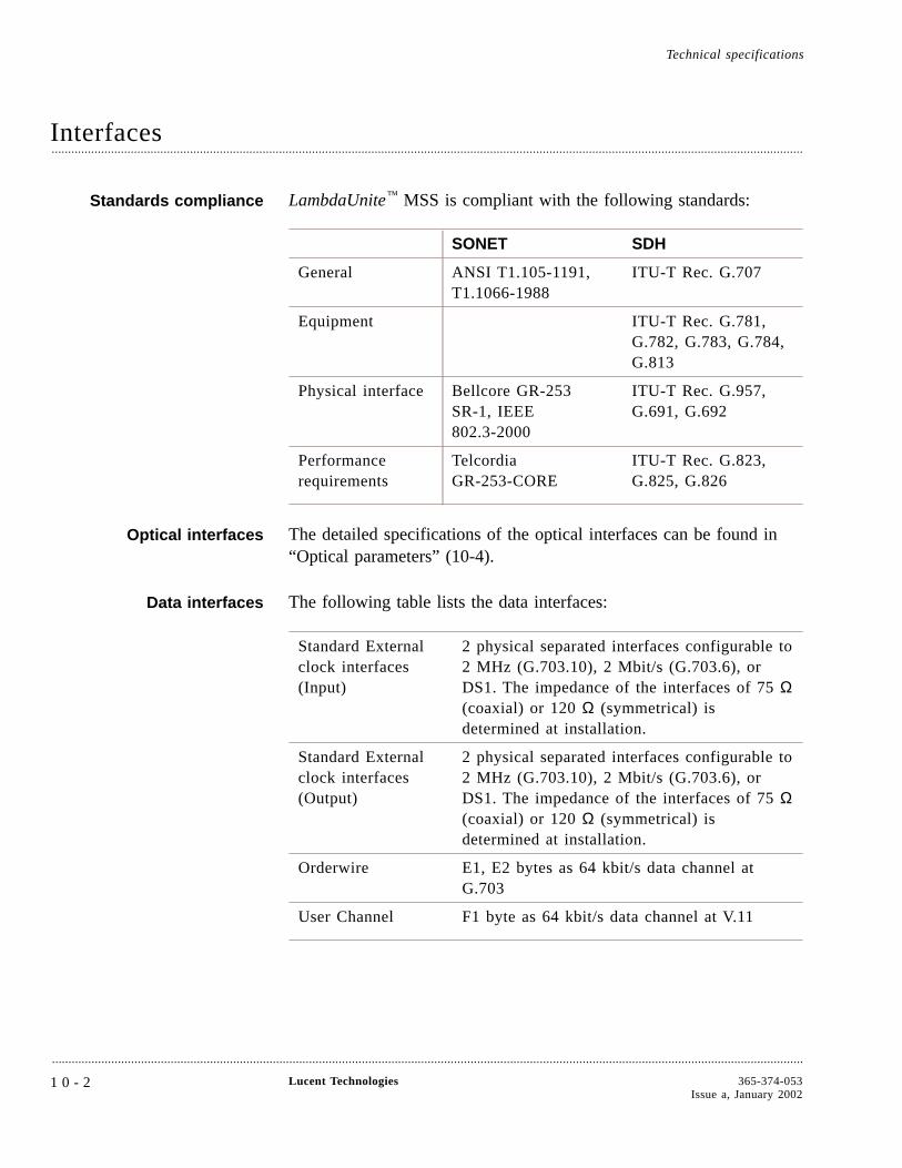
Interfaces....................................................................................................................................................................................................................................
Standards compliance LambdaUnite™ MSS is compliant with the following standards:
SONET SDH
General ANSI T1.105-1191,T1.1066-1988
ITU-T Rec. G.707
Equipment ITU-T Rec. G.781,G.782, G.783, G.784,G.813
Physical interface Bellcore GR-253SR-1, IEEE802.3-2000
ITU-T Rec. G.957,G.691, G.692
Performancerequirements
TelcordiaGR-253-CORE
ITU-T Rec. G.823,G.825, G.826
Optical interfaces The detailed specifications of the optical interfaces can be found in“Optical parameters” (10-4).
Data interfaces The following table lists the data interfaces:
Standard Externalclock interfaces(Input)
2 physical separated interfaces configurable to2 MHz (G.703.10), 2 Mbit/s (G.703.6), orDS1. The impedance of the interfaces of 75 Ω(coaxial) or 120 Ω (symmetrical) isdetermined at installation.
Standard Externalclock interfaces(Output)
2 physical separated interfaces configurable to2 MHz (G.703.10), 2 Mbit/s (G.703.6), orDS1. The impedance of the interfaces of 75 Ω(coaxial) or 120 Ω (symmetrical) isdetermined at installation.
Orderwire E1, E2 bytes as 64 kbit/s data channel atG.703
User Channel F1 byte as 64 kbit/s data channel at V.11
Technical specifications
....................................................................................................................................................................................................................................
1 0 - 2 Lucent Technologies 365-374-053Issue a, January 2002
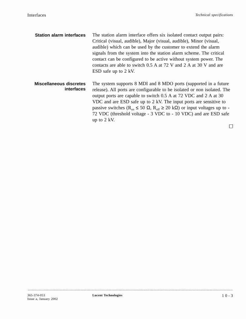
Station alarm interfaces The station alarm interface offers six isolated contact output pairs:Critical (visual, audible), Major (visual, audible), Minor (visual,audible) which can be used by the customer to extend the alarmsignals from the system into the station alarm scheme. The criticalcontact can be configured to be active without system power. Thecontacts are able to switch 0.5 A at 72 V and 2 A at 30 V and areESD safe up to 2 kV.
Miscellaneous discretesinterfaces
The system supports 8 MDI and 8 MDO ports (supported in a futurerelease). All ports are configurable to be isolated or non isolated. Theoutput ports are capable to switch 0.5 A at 72 VDC and 2 A at 30VDC and are ESD safe up to 2 kV. The input ports are sensitive topassive switches (Ron ≤ 50 Ω, Roff ≥ 20 kΩ) or input voltages up to -72 VDC (threshold voltage - 3 VDC to - 10 VDC) and are ESD safeup to 2 kV.
Interfaces Technical specifications
....................................................................................................................................................................................................................................
365-374-053Issue a, January 2002
Lucent Technologies 1 0 - 3
Optical parameters....................................................................................................................................................................................................................................
Planning data Data for planning a transmission route with the optical transmittersand receivers is listed in the following tables. With these data it ispossible to determine the maximum link distance between the networkelements.
Port unit designation The designation of the various types of optical port units reflects theirapplication and functional characteristics:
• SH stands for short-haul
• LH stands for long-haul
• VLH stands for very long-haul
• ULH stands for ultra long-haul
Application code The application code used in the tables is as follows:
application-[STM level.]suffix
Please note that in SONET applications the STM level is not part ofthe application code.
Application (SDH) In the applicable SDH standards, the following abbreviations areavailable for designating the application: I, S, L, V, U.
• I stands for intra-office
• S stands for short-haul
• L stands for long-haul
• V stands for very long-haul
• U stands for ultra long-haul
I, S, L, V and U are internationally standardized designations.
Application (SONET) In the applicable SONET standards, the following abbreviations areavailable for designating the application: SR, IR, LR, VR.
• SR stands for short range
• IR stands for intermediate range
• LR stands for long range
• VR stands for very long range
Technical specifications
....................................................................................................................................................................................................................................
1 0 - 4 Lucent Technologies 365-374-053Issue a, January 2002
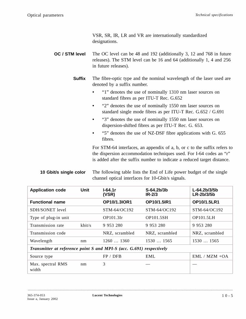
VSR, SR, IR, LR and VR are internationally standardizeddesignations.
OC / STM level The OC level can be 48 and 192 (additionally 3, 12 and 768 in futurereleases). The STM level can be 16 and 64 (additionally 1, 4 and 256in future releases).
Suffix The fibre-optic type and the nominal wavelength of the laser used aredenoted by a suffix number.
• “1” denotes the use of nominally 1310 nm laser sources onstandard fibres as per ITU-T Rec. G.652
• “2” denotes the use of nominally 1550 nm laser sources onstandard single mode fibres as per ITU-T Rec. G.652 / G.691
• “3” denotes the use of nominally 1550 nm laser sources ondispersion-shifted fibres as per ITU-T Rec. G. 653.
• “5” denotes the use of NZ-DSF fibre applications with G. 655fibres.
For STM-64 interfaces, an appendix of a, b, or c to the suffix refers tothe dispersion accommodation techniques used. For I-64 codes an “r”is added after the suffix number to indicate a reduced target distance.
10 Gbit/s single color The following table lists the End of Life power budget of the singlechannel optical interfaces for 10-Gbit/s signals.
Application code Unit I-64.1r(VSR)
S-64.2b/3bIR-2/3
L-64.2b/3/5bLR-2b/3/5b
Functional name OP10/1.3IOR1 OP10/1.5IR1 OP10/1.5LR1
SDH/SONET level STM-64/OC192 STM-64/OC192 STM-64/OC192
Type of plug-in unit OP101.3Ir OP101.5SH OP101.5LH
Transmission rate kbit/s 9 953 280 9 953 280 9 953 280
Transmission code NRZ, scrambled NRZ, scrambled NRZ, scrambled
Wavelength nm 1260 … 1360 1530 … 1565 1530 … 1565
Transmitter at reference point S and MPI-S (acc. G.691) respectively
Source type FP / DFB EML EML / MZM +OA
Max. spectral RMSwidth
nm 3 — —
Optical parameters Technical specifications
....................................................................................................................................................................................................................................
365-374-053Issue a, January 2002
Lucent Technologies 1 0 - 5
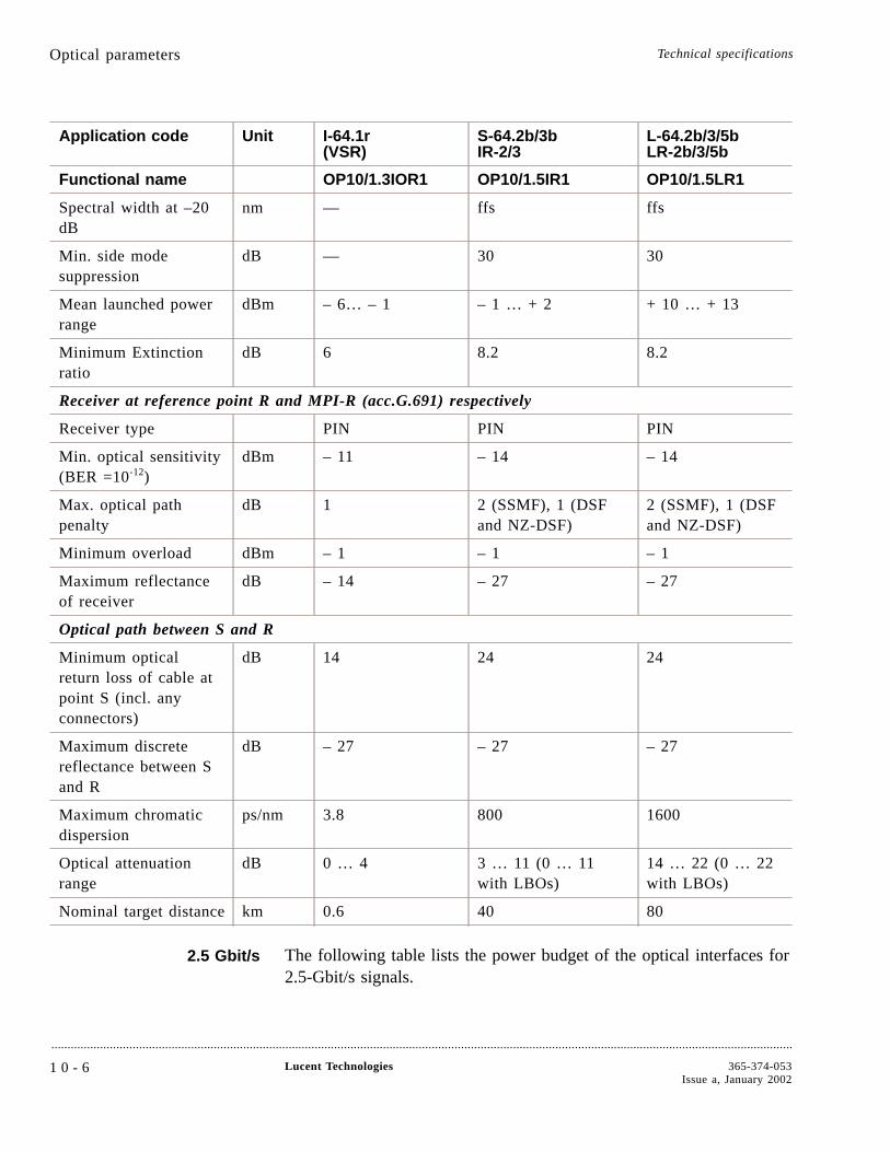
Application code Unit I-64.1r(VSR)
S-64.2b/3bIR-2/3
L-64.2b/3/5bLR-2b/3/5b
Functional name OP10/1.3IOR1 OP10/1.5IR1 OP10/1.5LR1
Spectral width at –20dB
nm — ffs ffs
Min. side modesuppression
dB — 30 30
Mean launched powerrange
dBm – 6… – 1 – 1 … + 2 + 10 … + 13
Minimum Extinctionratio
dB 6 8.2 8.2
Receiver at reference point R and MPI-R (acc.G.691) respectively
Receiver type PIN PIN PIN
Min. optical sensitivity(BER =10-12)
dBm – 11 – 14 – 14
Max. optical pathpenalty
dB 1 2 (SSMF), 1 (DSFand NZ-DSF)
2 (SSMF), 1 (DSFand NZ-DSF)
Minimum overload dBm – 1 – 1 – 1
Maximum reflectanceof receiver
dB – 14 – 27 – 27
Optical path between S and R
Minimum opticalreturn loss of cable atpoint S (incl. anyconnectors)
dB 14 24 24
Maximum discretereflectance between Sand R
dB – 27 – 27 – 27
Maximum chromaticdispersion
ps/nm 3.8 800 1600
Optical attenuationrange
dB 0 … 4 3 … 11 (0 … 11with LBOs)
14 … 22 (0 … 22with LBOs)
Nominal target distance km 0.6 40 80
2.5 Gbit/s The following table lists the power budget of the optical interfaces for2.5-Gbit/s signals.
Optical parameters Technical specifications
....................................................................................................................................................................................................................................
1 0 - 6 Lucent Technologies 365-374-053Issue a, January 2002
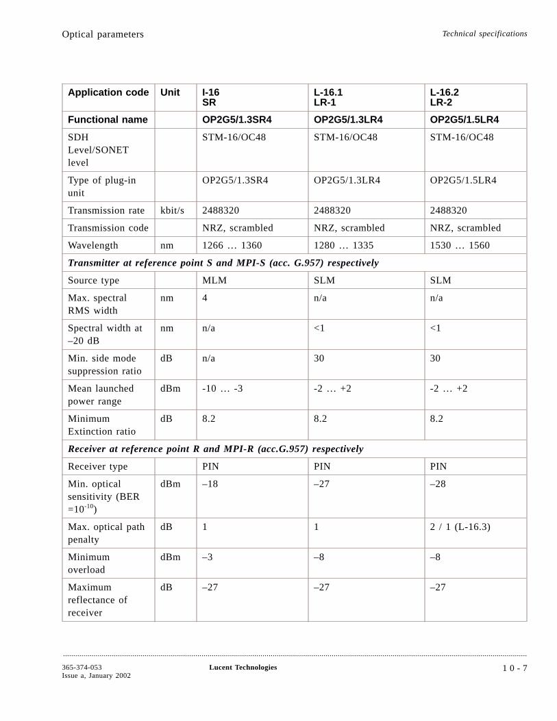
Application code Unit I-16SR
L-16.1LR-1
L-16.2LR-2
Functional name OP2G5/1.3SR4 OP2G5/1.3LR4 OP2G5/1.5LR4
SDHLevel/SONETlevel
STM-16/OC48 STM-16/OC48 STM-16/OC48
Type of plug-inunit
OP2G5/1.3SR4 OP2G5/1.3LR4 OP2G5/1.5LR4
Transmission rate kbit/s 2488320 2488320 2488320
Transmission code NRZ, scrambled NRZ, scrambled NRZ, scrambled
Wavelength nm 1266 … 1360 1280 … 1335 1530 … 1560
Transmitter at reference point S and MPI-S (acc. G.957) respectively
Source type MLM SLM SLM
Max. spectralRMS width
nm 4 n/a n/a
Spectral width at–20 dB
nm n/a <1 <1
Min. side modesuppression ratio
dB n/a 30 30
Mean launchedpower range
dBm -10 … -3 -2 … +2 -2 … +2
MinimumExtinction ratio
dB 8.2 8.2 8.2
Receiver at reference point R and MPI-R (acc.G.957) respectively
Receiver type PIN PIN PIN
Min. opticalsensitivity (BER=10-10)
dBm –18 –27 –28
Max. optical pathpenalty
dB 1 1 2 / 1 (L-16.3)
Minimumoverload
dBm –3 –8 –8
Maximumreflectance ofreceiver
dB –27 –27 –27
Optical parameters Technical specifications
....................................................................................................................................................................................................................................
365-374-053Issue a, January 2002
Lucent Technologies 1 0 - 7

Application code Unit I-16SR
L-16.1LR-1
L-16.2LR-2
Functional name OP2G5/1.3SR4 OP2G5/1.3LR4 OP2G5/1.5LR4
Optical path between S and R
Minimum opticalreturn loss ofcable at point S(incl. anyconnectors)
dB 24 24 24
Maximum discretereflectancebetween S and R
dB -27 -27 -27
Maximumchromaticdispersion
ps/nm 12 230 1600 / 600 (L-16.3)
Opticalattenuation range
dB 0 … 7 10 … 24 10 … 24 / 25(L-16.3)
Nominal targetdistance
km 2 40 80
1-Gbit/s Ethernet The GE1/SX4 port unit supports 4 fully independent bidirectionalports. Ethernet frames received from a GE1/SX4 port are mapped intoVC-4s, in future also into STS1s, using Virtual Concatenation. Thenumber of STS1s/VC-4s per virtual concatenated signal can be userprovisioned in a future release as ≤ 21 STS1s/7 VC-4s at singleSTS1/VC-4s intervals. This will offer an effective capacity usage overa network from 50/155 to 1000 Mbit/s in steps of 50/155 Mbit/s.
The GE1/SX4 port unit supports standard BLSR/MS-SPRing andUPSR/SNCP protection schemes on the individual STS1s/VC-4s thatare part of the Virtually Concatenated signal.
The GE1/SX4 port unit uses a Low Power Laser (laser class 1Maccording to IEC 60825).
The GE1/SX4 port unit complies with IEEE 802.3-2000 Clause 38.
The table below describes the various operating ranges for theGE1/SX4 port unit over each optical fiber type.
Optical parameters Technical specifications
....................................................................................................................................................................................................................................
1 0 - 8 Lucent Technologies 365-374-053Issue a, January 2002
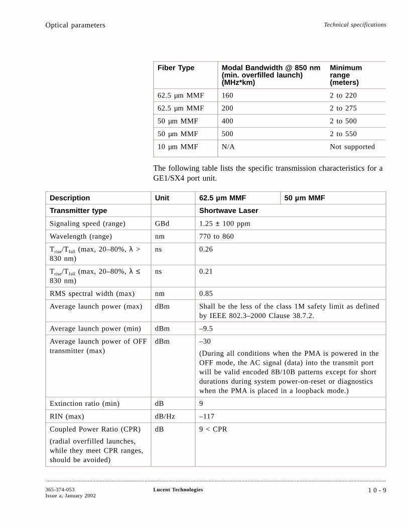
Fiber Type Modal Bandwidth @ 850 nm(min. overfilled launch)(MHz*km)
Minimumrange(meters)
62.5 µm MMF 160 2 to 220
62.5 µm MMF 200 2 to 275
50 µm MMF 400 2 to 500
50 µm MMF 500 2 to 550
10 µm MMF N/A Not supported
The following table lists the specific transmission characteristics for aGE1/SX4 port unit.
Description Unit 62.5 µm MMF 50 µm MMF
Transmitter type Shortwave Laser
Signaling speed (range) GBd 1.25 ± 100 ppm
Wavelength (range) nm 770 to 860
Trise/Tfall (max, 20–80%, λ >830 nm)
ns 0.26
Trise/Tfall (max, 20–80%, λ ≤830 nm)
ns 0.21
RMS spectral width (max) nm 0.85
Average launch power (max) dBm Shall be the less of the class 1M safety limit as definedby IEEE 802.3–2000 Clause 38.7.2.
Average launch power (min) dBm –9.5
Average launch power of OFFtransmitter (max)
dBm –30
(During all conditions when the PMA is powered in theOFF mode, the AC signal (data) into the transmit portwill be valid encoded 8B/10B patterns except for shortdurations during system power-on-reset or diagnosticswhen the PMA is placed in a loopback mode.)
Extinction ratio (min) dB 9
RIN (max) dB/Hz –117
Coupled Power Ratio (CPR)
(radial overfilled launches,while they meet CPR ranges,should be avoided)
dB 9 < CPR
Optical parameters Technical specifications
....................................................................................................................................................................................................................................
365-374-053Issue a, January 2002
Lucent Technologies 1 0 - 9

The following table lists the specific receive characteristics for aGE1/SX4 port unit.
Description Unit 62.5 µm MMF 50 µm MMF
Signaling speed (range) GBd 1.25 ± 100 ppm
Wavelength (range) nm 770 to 860
Average receive power(max)
dBm 0
Receive sensitivity dBm –17
Return loss (min) dB 12
Stressed receive sensitivity
(measured with conformancetest signal at TP3 for BER =10–12 at the eye center)
(measured with a transmitsignal having a 9 dBextinction ratio; if anotherextinction ratio is used, thestressed received sensitivityshould be corrected for theextinction ratio penalty)
dBm 12.5 13.5
Vertical eye-closure penalty
(is a test condition formeasuring stressed receivesensitivity, it is not arequired characteristic of thereceiver)
dB 2.60 2.20
Receive electrical 3 dBupper cutoff frequency(max)
MHz 1500
The following table lists the worst-case power budget and linkpenalties for a GE1/SX4 port unit. Link penalties are used for linkbudget calculations.
Description Unit 62.5 µm MMF 50 µm MMF
Modal bandwidth asmeasured at 850 nm(minimum, overfilled launch)
MHz*km 160 200 400 500
Low power budget dB 7.5 7.5 7.5 7.5
Optical parameters Technical specifications
....................................................................................................................................................................................................................................
1 0 - 1 0 Lucent Technologies 365-374-053Issue a, January 2002

Description Unit 62.5 µm MMF 50 µm MMF
Modal bandwidth asmeasured at 850 nm(minimum, overfilled launch)
MHz*km 160 200 400 500
Operating distance m 220 275 500 550
Channel insertion loss (awavelength of 830 nm is usedto calculate the values)
dB 2.38 2.60 3.37 3.56
Link power penalties (awavelength of 830 nm is usedto calculate the values)
dB 4.27 4.29 4.07 3.57
Unallocated margin in linkpower budget (a wavelength of830 nm is used to calculate thevalues)
dB 0.84 0.60 0.05 0.37
Optical parameters Technical specifications
....................................................................................................................................................................................................................................
365-374-053Issue a, January 2002
Lucent Technologies 1 0 - 1 1
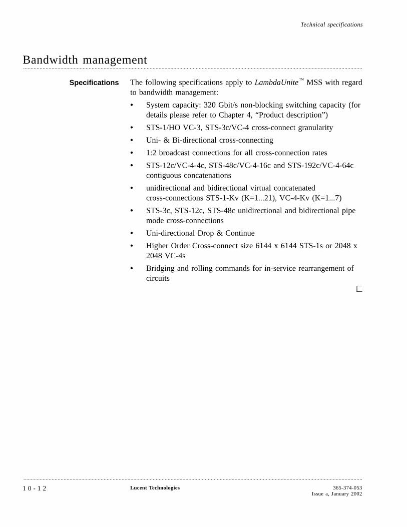
Bandwidth management....................................................................................................................................................................................................................................
Specifications The following specifications apply to LambdaUnite™ MSS with regardto bandwidth management:
• System capacity: 320 Gbit/s non-blocking switching capacity (fordetails please refer to Chapter 4, “Product description”)
• STS-1/HO VC-3, STS-3c/VC-4 cross-connect granularity
• Uni- & Bi-directional cross-connecting
• 1:2 broadcast connections for all cross-connection rates
• STS-12c/VC-4-4c, STS-48c/VC-4-16c and STS-192c/VC-4-64ccontiguous concatenations
• unidirectional and bidirectional virtual concatenatedcross-connections STS-1-Kv (K=1...21), VC-4-Kv (K=1...7)
• STS-3c, STS-12c, STS-48c unidirectional and bidirectional pipemode cross-connections
• Uni-directional Drop & Continue
• Higher Order Cross-connect size 6144 x 6144 STS-1s or 2048 x2048 VC-4s
• Bridging and rolling commands for in-service rearrangement ofcircuits
Technical specifications
....................................................................................................................................................................................................................................
1 0 - 1 2 Lucent Technologies 365-374-053Issue a, January 2002
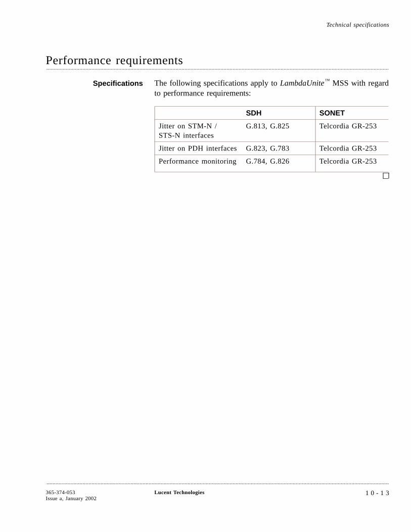
Performance requirements....................................................................................................................................................................................................................................
Specifications The following specifications apply to LambdaUnite™ MSS with regardto performance requirements:
SDH SONET
Jitter on STM-N /STS-N interfaces
G.813, G.825 Telcordia GR-253
Jitter on PDH interfaces G.823, G.783 Telcordia GR-253
Performance monitoring G.784, G.826 Telcordia GR-253
Technical specifications
....................................................................................................................................................................................................................................
365-374-053Issue a, January 2002
Lucent Technologies 1 0 - 1 3

Supervision and alarms....................................................................................................................................................................................................................................
Specifications The following specifications apply to LambdaUnite™ MSS with regardto supervision and alarms:
• Plug-in circuit pack indication: red fault and green service/activeLED per circuit pack
• System Controller indicators/buttons:
- User Panel LED indicators: Prompt, Deferred and Infoalarm, Abnormal, Near-End Activity, Far-End Activity,Power On, Alarm Cut-off (ACO)
- Push-buttons: ACO button to acknowledge office alarms,LED test button
• Station Alarm Interface: Offers six isolated contact output pairs:Critical (visual, audible), Major (visual, audible), Minor (visual,audible), which can be used to extend the alarm signals from thesystem into the station alarm scheme.
• Rack Top Alarm Lamps: Two red and one yellow lamp arepresent in top of the rack to signal a Critical, Major and Minoralarm, respectively.
• CIT connector for connecting the CIT to the system LAN
• Floating station alarm interface outputs
• Miscellaneous discretes (future release)
• Q-LAN interface to connect to EMS or other Network Elements
Technical specifications
....................................................................................................................................................................................................................................
1 0 - 1 4 Lucent Technologies 365-374-053Issue a, January 2002
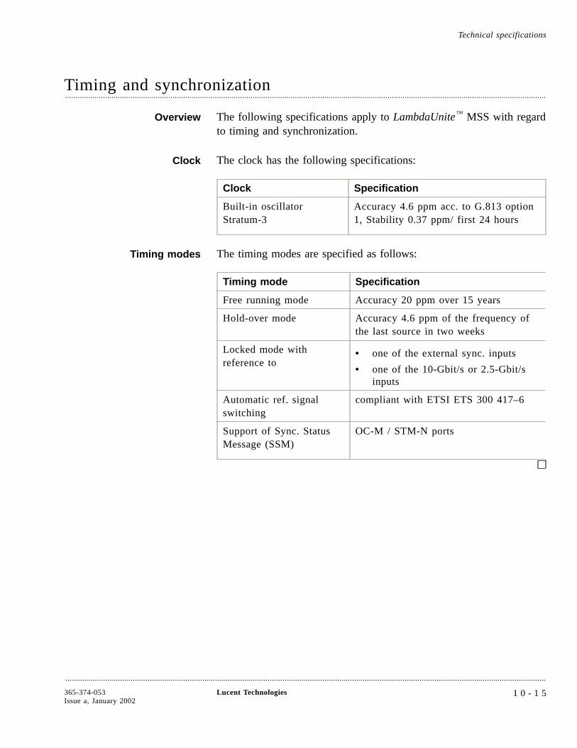
Timing and synchronization....................................................................................................................................................................................................................................
Overview The following specifications apply to LambdaUnite™ MSS with regardto timing and synchronization.
Clock The clock has the following specifications:
Clock Specification
Built-in oscillatorStratum-3
Accuracy 4.6 ppm acc. to G.813 option1, Stability 0.37 ppm/ first 24 hours
Timing modes The timing modes are specified as follows:
Timing mode Specification
Free running mode Accuracy 20 ppm over 15 years
Hold-over mode Accuracy 4.6 ppm of the frequency ofthe last source in two weeks
Locked mode withreference to
• one of the external sync. inputs
• one of the 10-Gbit/s or 2.5-Gbit/sinputs
Automatic ref. signalswitching
compliant with ETSI ETS 300 417–6
Support of Sync. StatusMessage (SSM)
OC-M / STM-N ports
Technical specifications
....................................................................................................................................................................................................................................
365-374-053Issue a, January 2002
Lucent Technologies 1 0 - 1 5
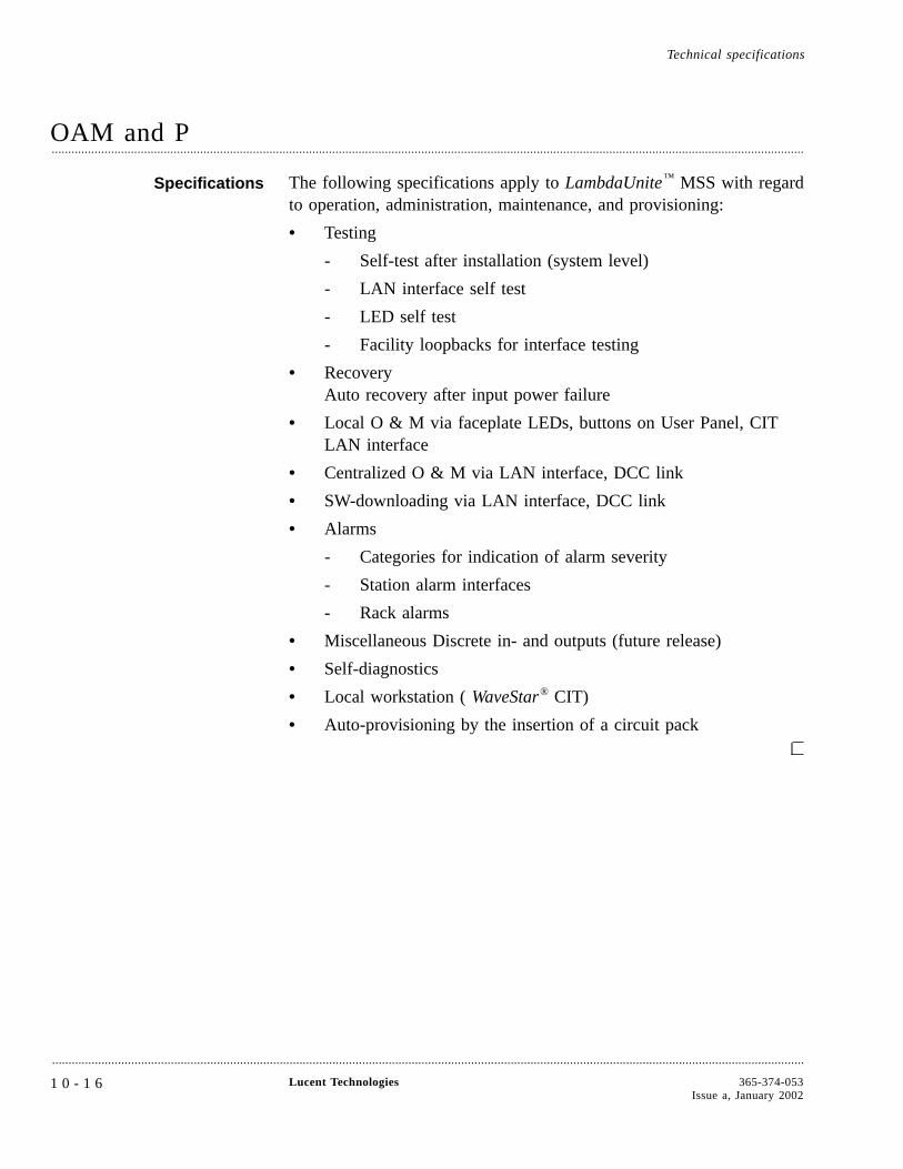
OAM and P....................................................................................................................................................................................................................................
Specifications The following specifications apply to LambdaUnite™ MSS with regardto operation, administration, maintenance, and provisioning:
• Testing
- Self-test after installation (system level)
- LAN interface self test
- LED self test
- Facility loopbacks for interface testing
• RecoveryAuto recovery after input power failure
• Local O & M via faceplate LEDs, buttons on User Panel, CITLAN interface
• Centralized O & M via LAN interface, DCC link
• SW-downloading via LAN interface, DCC link
• Alarms
- Categories for indication of alarm severity
- Station alarm interfaces
- Rack alarms
• Miscellaneous Discrete in- and outputs (future release)
• Self-diagnostics
• Local workstation ( WaveStar® CIT)
• Auto-provisioning by the insertion of a circuit pack
Technical specifications
....................................................................................................................................................................................................................................
1 0 - 1 6 Lucent Technologies 365-374-053Issue a, January 2002

Network management....................................................................................................................................................................................................................................
Specifications The following specifications apply to LambdaUnite™ MSS with regardto network management:
• Fully manageable by Navis™ Optical EMS
• Integration into path management Navis Optical NMS
• Access to Embedded Communication Channels
• Via in-station EMS interface: TL1 message protocol / 100BaseTinterface
• WaveStar® CIT for small network management: RJ-45 CITinterface / 100BaseT interface
Technical specifications
....................................................................................................................................................................................................................................
365-374-053Issue a, January 2002
Lucent Technologies 1 0 - 1 7

Physical design....................................................................................................................................................................................................................................
Specifications The following specifications apply to LambdaUnite™ MSS with regardto physical design:
Subrackdimensions
DUR Shelf: 950 x 498 x 438 mm (37.4 x 19.6 x17.2 in) (H x W x D) in accordance with ETSIStandard ETS 300 119-4
Weight DUR Shelf (without circuit packs): approx. 27kg
Rack types ETSI (D700) rack
Connectorsoptical
LC connectors on all optical interfaces
Connectorselectrical
SUB-D on Alarm, Timing, User Byte IF, 1.6/5.6on station clock IF, Western RJ45 on LANinterfaces
Station powerinput (battery)
-48 V / -60 VDC (Range: -40 ... -72 VDC)
Powerconsumption
2200 W for a typical configuration. For powerconsumption of the individual units, please referto “Power consumption” (10-19)
Transmission Fibers LambdaUnite MSS uses the following transmission fibers: [G.652,G.655]
• Standard single-mode fiber acc. to ITU-T Rec. G. 652
• Dispersion shifted fiber acc. to ITU-T Rec. G.653
• Non-zero dispersion shifted fiber acc. to ITU-T Rec. G.655
• Multimode fiber (MMF) for Gigabit Ethernet acc. to IEEE1802.3
Technical specifications
....................................................................................................................................................................................................................................
1 0 - 1 8 Lucent Technologies 365-374-053Issue a, January 2002
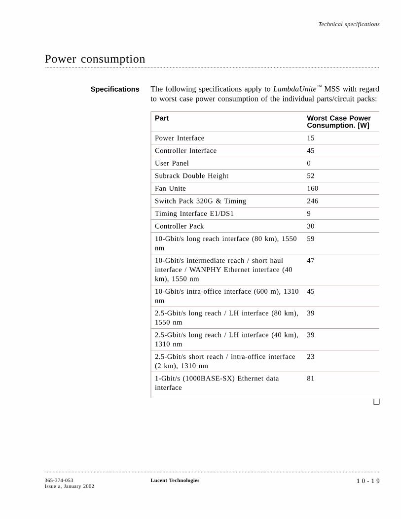
Power consumption....................................................................................................................................................................................................................................
Specifications The following specifications apply to LambdaUnite™ MSS with regardto worst case power consumption of the individual parts/circuit packs:
Part Worst Case PowerConsumption. [W]
Power Interface 15
Controller Interface 45
User Panel 0
Subrack Double Height 52
Fan Unite 160
Switch Pack 320G & Timing 246
Timing Interface E1/DS1 9
Controller Pack 30
10-Gbit/s long reach interface (80 km), 1550nm
59
10-Gbit/s intermediate reach / short haulinterface / WANPHY Ethernet interface (40km), 1550 nm
47
10-Gbit/s intra-office interface (600 m), 1310nm
45
2.5-Gbit/s long reach / LH interface (80 km),1550 nm
39
2.5-Gbit/s long reach / LH interface (40 km),1310 nm
39
2.5-Gbit/s short reach / intra-office interface(2 km), 1310 nm
23
1-Gbit/s (1000BASE-SX) Ethernet datainterface
81
Technical specifications
....................................................................................................................................................................................................................................
365-374-053Issue a, January 2002
Lucent Technologies 1 0 - 1 9

Environmental conditions....................................................................................................................................................................................................................................
Environment Compliant with EN300 019-1-3 for Class 3.1 Environment “Stationaryuse at weather protected locations” and Telcordia GR 63 (Bellcore):
Temperaturerange
Humidity
Normaloperation
+5°C to +40°C up to 85%
Short termoperation
-5°C to +50°C up to 90% (conditions last atmost 72 hours per year duringat most 15 days)
Storage -25°C to +55°C up to 100%
EMC LambdaUnite™ MSS meets the emissions requirement as per FCC 47CFR part 15 Subpart B for class A computing device.
LambdaUnite MSS is compliant with EN300 386-2: “EMCrequirements for Public Telecommunication Network Equipment”, IEC61000-4-x series (immunity) and Telcordia GR-1089-core (emissionand immunity).
Radiatedemission
EN 55 022 Class A GR-1089-core chapter 3
Conductedemission
DC-power, ETS 300 386-1, 20 kHz - 30 MHz(corresponds with EN 55022 class A) Telecom.Ports, CISPR 22 Amd, Class B GR-1089-core
Electro-staticdischarge
IEC 61000-4-2, tested at level 4 (contact discharge8 kV, air 15 kV; NEBS level 3 requirement)GR-1089-core chapter 2
Radiatedimmunity
IEC 61000-4-3, tested at level 3 GR-1089-core
Electrical fasttransients
DC Power, IEC 61000-4-4 (tested at level 1, 0.5kV) Telecom. Ports, IEC 61000-4-4 (tested at level1, 0.5 kV) There is no requirement regardingG-1089 but there are objectives in GR513 (O4-21)for power ports. GR-1089-core
Technical specifications
....................................................................................................................................................................................................................................
1 0 - 2 0 Lucent Technologies 365-374-053Issue a, January 2002

Surges IEC 61000-4-5, tested at level 1 (0.5 kV withperformance criterion B and additional 0.8 kV(series resistor 6 Ω) and 1.5 kV (series resistor 12Ω) the system shall not be damaged and shallcontinue to operate. Indoor Telecom. Ports, ETS300 386-1, Tested at 0.5 kV GR-1089-core ITUK.41
Continuouswave
IEC 61000-4-6 DC Power, IEC 61000-4-6 (tested atlevel 3) Telecom. Ports, IEC 61000-4-6 (tested atlevel 3) GR-1089-core
Compliantwith LVD
EN 60950
NEBS L3compliance
The subrack and all circuit packs comply withNEBS Level 3.
CECertification
CE compliant with European Directive 89/336/EEC
Environmental conditions Technical specifications
....................................................................................................................................................................................................................................
365-374-053Issue a, January 2002
Lucent Technologies 1 0 - 2 1

Appendix A: An SDH overview
Overview....................................................................................................................................................................................................................................
Purpose This chapter briefly describes the Synchronous Digital Hierarchy(SDH).
Synchronous DigitalHierarchy
In 1988, the ITU-T (formerly CCITT) came to an agreement on theSynchronous Digital Hierarchy (SDH). The corresponding ITU-TRecommendation G.707 forms the basis of a global, uniform opticaltransmission network. SDH can operate with plesiochronous networksand therefore allows the continuous evolution of existing digitaltransmission networks.
The major features and advantages of SDH are:
• Compatibility of transmission equipment and networks on aworldwide basis
• Uniform physical interfaces
• Easy cross connection of signals in the network nodes
• Possibility of transmitting PDH (Plesiochronous DigitalHierarchy) tributary signals at bit rates commonly used at present
• Simple adding and dropping of individual channels withoutspecial multiplexers (add/drop facility)
• Easy transition to higher transmission rates
....................................................................................................................................................................................................................................
365-374-053Issue a, January 2002
Lucent Technologies A - 1

• Due to the standardization of the network element functions SDHsupports a superordinate network management and newmonitoring functions and provides transport capacity andprotocols (Telecommunication Management Network, TMN) forthis purpose in the overheads of the multiplex signals.
• High flexibility and user-friendly monitoring possibilities, e.g.end-to-end monitoring of the bit error ratio.
Purpose of SDH The basic purpose of SDH is to provide a standard synchronousoptical hierarchy with sufficient flexibility to accommodate digitalsignals that currently exist in today’s network, as well as thoseplanned for the future.
SDH currently defines standard rates and formats and opticalinterfaces. Today, mid-span meet is possible at the optical transmissionlevel. These and other related issues continue to evolve through theITU-T committees.
ITU-T addressed issues The set of ITU-T Recommendations defines
• Optical parameters
• Multiplexing schemes to map existing digital signals (PDH) intoSDH payload signals
• Overhead channels to support standard operation, administration,maintenance, and provisioning (OAM&P) functions
• Criteria for optical line Automatic Protection Switch (APS)
References For more detailed information on SDH, refer to
• ITU-T Recommendation G.703, “Physical/electricalcharacteristics of hierarchical digital interfaces”, October 1996
• ITU-T Recommendation G.707, “Network Node Interface ForThe Synchronous Digital Hierarchy (SDH)”, March 1996
• ITU-T Recommendation G.780, “Vocabulary of terms forsynchronous digital hierarchy (SDH) networks and equipment“ ,November 1993
• ITU-T Recommendation G.783, “Characteristics of SynchronousDigital Hierarchy (SDH) Multiplexing Equipment FunctionalBlocks “, April 1997
• ITU-T Recommendation G.784, “Synchronous Digital Hierarchy(SDH) Management “, January 1994
Overview An SDH overview
....................................................................................................................................................................................................................................
A - 2 Lucent Technologies 365-374-053Issue a, January 2002
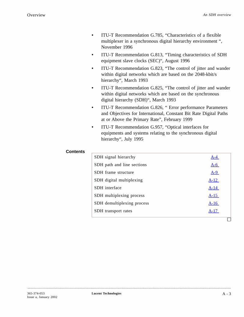
• ITU-T Recommendation G.785, “Characteristics of a flexiblemultiplexer in a synchronous digital hierarchy environment “,November 1996
• ITU-T Recommendation G.813, “Timing characteristics of SDHequipment slave clocks (SEC)“, August 1996
• ITU-T Recommendation G.823, “The control of jitter and wanderwithin digital networks which are based on the 2048-kbit/shierarchy“, March 1993
• ITU-T Recommendation G.825, “The control of jitter and wanderwithin digital networks which are based on the synchronousdigital hierarchy (SDH)“, March 1993
• ITU-T Recommendation G.826, “ Error performance Parametersand Objectives for International, Constant Bit Rate Digital Pathsat or Above the Primary Rate”, February 1999
• ITU-T Recommendation G.957, “Optical interfaces forequipments and systems relating to the synchronous digitalhierarchy“, July 1995
ContentsSDH signal hierarchy A-4
SDH path and line sections A-6
SDH frame structure A-9
SDH digital multiplexing A-12
SDH interface A-14
SDH multiplexing process A-15
SDH demultiplexing process A-16
SDH transport rates A-17
Overview An SDH overview
....................................................................................................................................................................................................................................
365-374-053Issue a, January 2002
Lucent Technologies A - 3
A-17
A-16
A-15
A-14
A-12
A-9
A-6
A-4
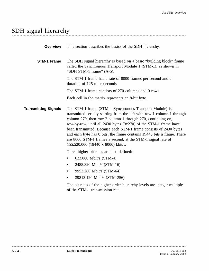
SDH signal hierarchy....................................................................................................................................................................................................................................
Overview This section describes the basics of the SDH hierarchy.
STM-1 Frame The SDH signal hierarchy is based on a basic “building block” framecalled the Synchronous Transport Module 1 (STM-1), as shown in“SDH STM-1 frame” (A-5).
The STM-1 frame has a rate of 8000 frames per second and aduration of 125 microseconds
The STM-1 frame consists of 270 columns and 9 rows.
Each cell in the matrix represents an 8-bit byte.
Transmitting Signals The STM-1 frame (STM = Synchronous Transport Module) istransmitted serially starting from the left with row 1 column 1 throughcolumn 270, then row 2 column 1 through 270, continuing on,row-by-row, until all 2430 bytes (9x270) of the STM-1 frame havebeen transmitted. Because each STM-1 frame consists of 2430 bytesand each byte has 8 bits, the frame contains 19440 bits a frame. Thereare 8000 STM-1 frames a second, at the STM-1 signal rate of155.520.000 (19440 x 8000) kbit/s.
Three higher bit rates are also defined:
• 622.080 Mbit/s (STM-4)
• 2488.320 Mbit/s (STM-16)
• 9953.280 Mbit/s (STM-64)
• 39813.120 Mbit/s (STM-256)
The bit rates of the higher order hierarchy levels are integer multiplesof the STM-1 transmission rate.
An SDH overview
....................................................................................................................................................................................................................................
A - 4 Lucent Technologies 365-374-053Issue a, January 2002
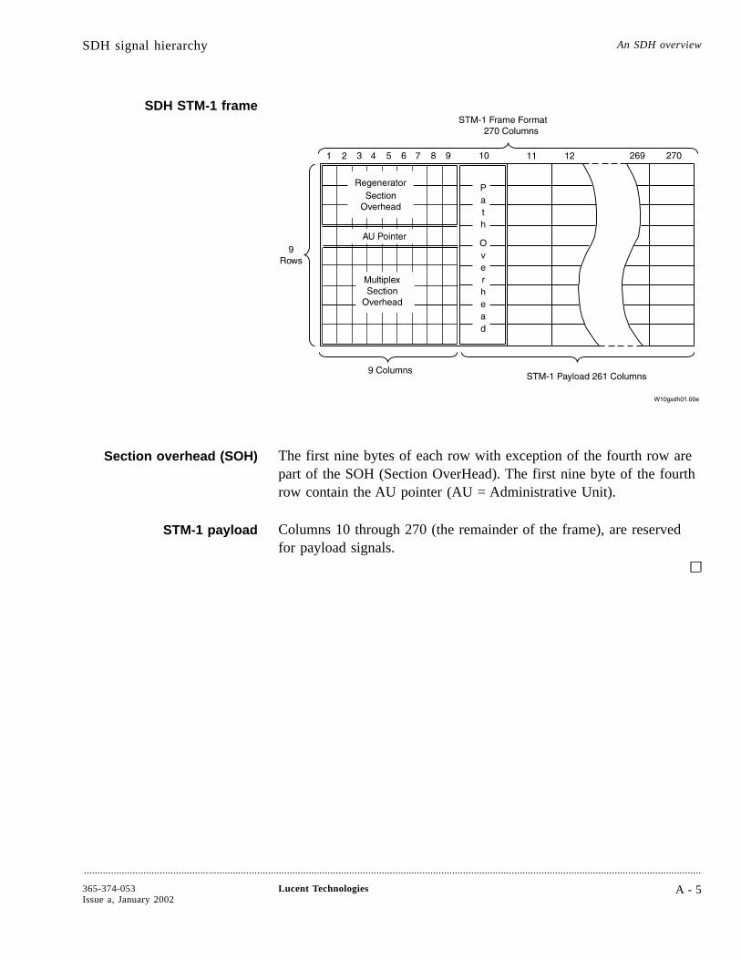
SDH STM-1 frame
Section overhead (SOH) The first nine bytes of each row with exception of the fourth row arepart of the SOH (Section OverHead). The first nine byte of the fourthrow contain the AU pointer (AU = Administrative Unit).
STM-1 payload Columns 10 through 270 (the remainder of the frame), are reservedfor payload signals.
SDH signal hierarchy An SDH overview
....................................................................................................................................................................................................................................
365-374-053Issue a, January 2002
Lucent Technologies A - 5
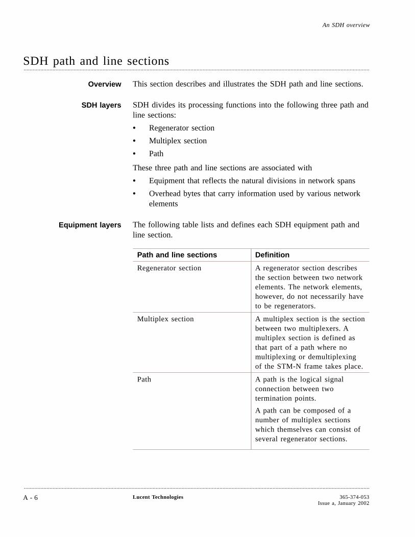
SDH path and line sections....................................................................................................................................................................................................................................
Overview This section describes and illustrates the SDH path and line sections.
SDH layers SDH divides its processing functions into the following three path andline sections:
• Regenerator section
• Multiplex section
• Path
These three path and line sections are associated with
• Equipment that reflects the natural divisions in network spans
• Overhead bytes that carry information used by various networkelements
Equipment layers The following table lists and defines each SDH equipment path andline section.
Path and line sections Definition
Regenerator section A regenerator section describesthe section between two networkelements. The network elements,however, do not necessarily haveto be regenerators.
Multiplex section A multiplex section is the sectionbetween two multiplexers. Amultiplex section is defined asthat part of a path where nomultiplexing or demultiplexingof the STM-N frame takes place.
Path A path is the logical signalconnection between twotermination points.
A path can be composed of anumber of multiplex sectionswhich themselves can consist ofseveral regenerator sections.
An SDH overview
....................................................................................................................................................................................................................................
A - 6 Lucent Technologies 365-374-053Issue a, January 2002
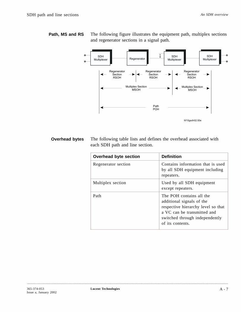
Path, MS and RS The following figure illustrates the equipment path, multiplex sectionsand regenerator sections in a signal path.
Overhead bytes The following table lists and defines the overhead associated witheach SDH path and line section.
Overhead byte section Definition
Regenerator section Contains information that is usedby all SDH equipment includingrepeaters.
Multiplex section Used by all SDH equipmentexcept repeaters.
Path The POH contains all theadditional signals of therespective hierarchy level so thata VC can be transmitted andswitched through independentlyof its contents.
SDH path and line sections An SDH overview
....................................................................................................................................................................................................................................
365-374-053Issue a, January 2002
Lucent Technologies A - 7
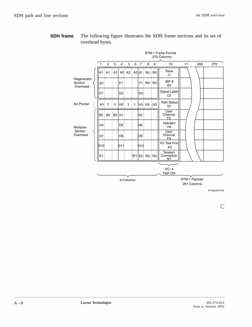
SDH frame The following figure illustrates the SDH frame sections and its set ofoverhead bytes.
SDH path and line sections An SDH overview
....................................................................................................................................................................................................................................
A - 8 Lucent Technologies 365-374-053Issue a, January 2002

SDH frame structure....................................................................................................................................................................................................................................
Overview This section provides detailed information on the locations andfunctions of various overhead bytes for each of the following SDHpath and line sections:
• Regenerator Section
• Multiplex Section
• Path
Section overhead The following table identifies the location and function of eachregenerator section overhead byte.
Bytes Function
A1, A2 Frame alignment A1 = 1111 0110 ; A2 = 00101000 ; These fixed-value bytes are used forsynchronization.
B1 BIP-8 parity test
Regenerator section error monitoring; BIP-8 :
Computed over all bits of the previous frameafter scrambling; B1 is placed into the SOHbefore scrambling;
BIP-X: (Bit Interleaved Parity X bits) Evenparity, X-bit code;
first bit of code = even parity over first bit ofall X-bit sequences;
B2 Multiplex section error monitoring; BIP-24 :
B2 is computed over all bits of the previousSTM-1 frame except for row 1 to 3 of the SOH(RSOH); B2 is computed after and placedbefore scrambling;
Z0 Spare bytes
D1 - D3 (=DCCR) D4 - D12(= DCCM)
Data Communication Channel (networkmanagement information exchange)
E1 Orderwire channel
E2 Orderwire channel
F1 User channel
An SDH overview
....................................................................................................................................................................................................................................
365-374-053Issue a, January 2002
Lucent Technologies A - 9

Bytes Function
K1, K2 Automatic protection switch
K2 MS-AIS/RDI indicator
S1 Synchronization Status Message
M1 REI (Remote Error Indication) byte
NU National Usage
Path overhead The Path Overhead (POH) is generated for all plesiochronous tributarysignals in accordance with ITU-T Rec. G.709. The POH provides forintegrity of communication between the point of assembly of a VirtualContainer VC and its point of disassembly. The following table showsthe POH bytes and their functions.
Byte Location and Function
J1 Path Trace Identifier byte
B3 Path Bit Interleaved Parity (BIP-8)
Provides each path performancemonitoring. This byte is calculatedover all bits of the previous payloadbefore scrambling.
C2 Signal Label
All ″0″ means unequipped; other and″00000001″ means equipped
G1 Path Status
Conveys the STM-1 path terminatingstatus, performance, and remote defectindication (RDI) signal conditionsback to an originating path terminatingequipment.
F2, F3 User Data Channel
Reserved for user communication.
H4 Multiframe Indicator
Provides a general multiframeindicator for VC-structured payloads.
K3 VC Trail protection.
SDH frame structure An SDH overview
....................................................................................................................................................................................................................................
A - 1 0 Lucent Technologies 365-374-053Issue a, January 2002
Byte Location and Function
N1 Tandem connection OH
AU pointer The AU pointer together with the last 261 columns of the STM-1frame forms an AUG (Administrative Unit Group). An AUG maycontain one AU-4 or three byte-multiplexed AU-3s (an AU-3 isexactly one third of the size of an AU-4). AU-3s are also compatiblewith the SONET standard (Synchronous Optical NETwork) which isthe predecessor of SDH (and still the prevailing technology within theUSA). Three byte-multiplexed STS frames (SONET frame), eachcontaining one AU-3 can be mapped into one STM-1.
SDH frame structure An SDH overview
....................................................................................................................................................................................................................................
365-374-053Issue a, January 2002
Lucent Technologies A - 1 1

SDH digital multiplexing....................................................................................................................................................................................................................................
Overview Digital multiplexing is SDH’s method of byte mapping tributarysignals to a higher signal rate, which permits economical extraction ofa single tributary signal without the need to demultiplex the entireSTM-1 payload. In addition, SDH provides overhead channels for useby OAM&P groups.
SDH digital multiplexing The following figure illustrates the SDH technique of mappingtributary signals into an STM-1 frame.
Transporting SDHpayloads
Tributary signals are mapped into a digital signal called a virtualcontainer (VC). The VC is a structure designed for the transport andswitching of sub-STM-1 payloads. There are five sizes of VCs:VC-11, VC-12, VC-2, VC-3, and VC-4.
Table The following table provides the digital signals that can be transportedas SDH payloads.
An SDH overview
....................................................................................................................................................................................................................................
A - 1 2 Lucent Technologies 365-374-053Issue a, January 2002
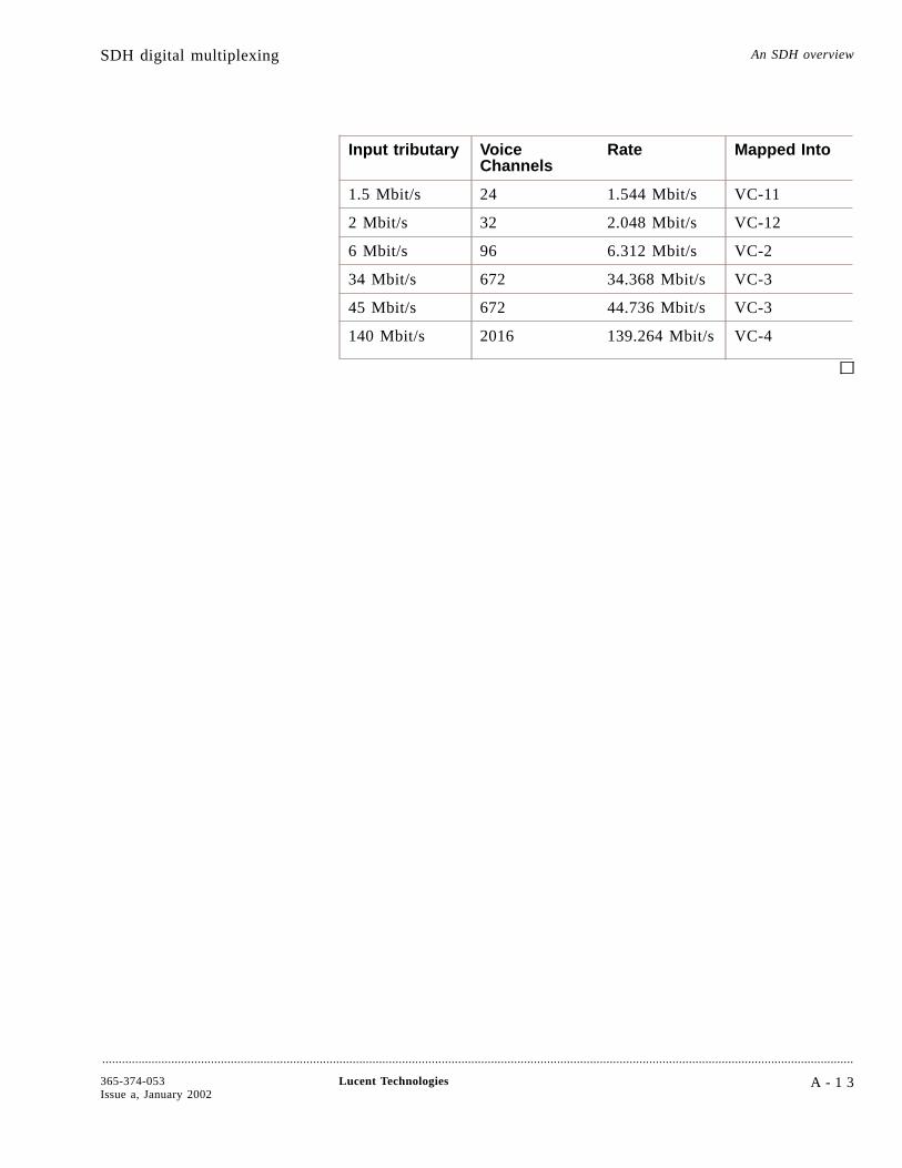
Input tributary VoiceChannels
Rate Mapped Into
1.5 Mbit/s 24 1.544 Mbit/s VC-11
2 Mbit/s 32 2.048 Mbit/s VC-12
6 Mbit/s 96 6.312 Mbit/s VC-2
34 Mbit/s 672 34.368 Mbit/s VC-3
45 Mbit/s 672 44.736 Mbit/s VC-3
140 Mbit/s 2016 139.264 Mbit/s VC-4
SDH digital multiplexing An SDH overview
....................................................................................................................................................................................................................................
365-374-053Issue a, January 2002
Lucent Technologies A - 1 3
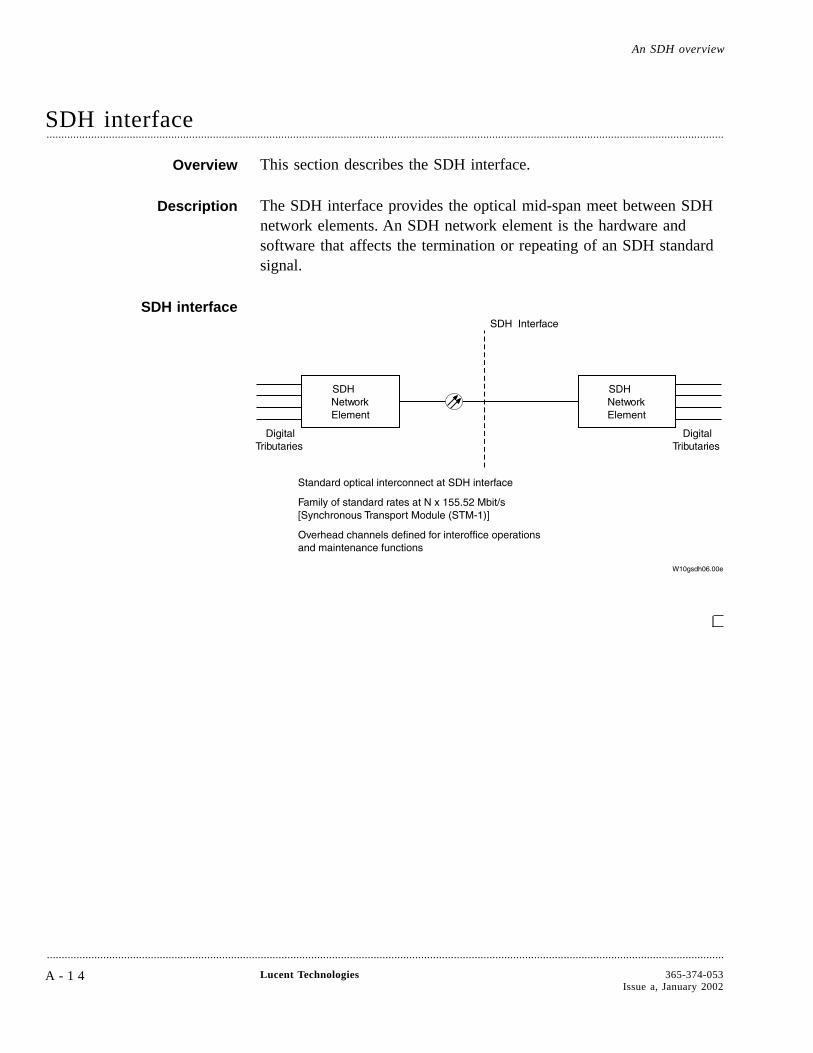
SDH interface....................................................................................................................................................................................................................................
Overview This section describes the SDH interface.
Description The SDH interface provides the optical mid-span meet between SDHnetwork elements. An SDH network element is the hardware andsoftware that affects the termination or repeating of an SDH standardsignal.
SDH interface
An SDH overview
....................................................................................................................................................................................................................................
A - 1 4 Lucent Technologies 365-374-053Issue a, January 2002
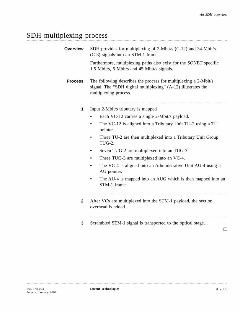
SDH multiplexing process....................................................................................................................................................................................................................................
Overview SDH provides for multiplexing of 2-Mbit/s (C-12) and 34-Mbit/s(C-3) signals into an STM-1 frame.
Furthermore, multiplexing paths also exist for the SONET specific1.5-Mbit/s, 6-Mbit/s and 45-Mbit/s signals.
Process The following describes the process for multiplexing a 2-Mbit/ssignal. The “SDH digital multiplexing” (A-12) illustrates themultiplexing process.
............................................................................................................................................................
1 Input 2-Mbit/s tributary is mapped
• Each VC-12 carries a single 2-Mbit/s payload.
• The VC-12 is aligned into a Tributary Unit TU-2 using a TUpointer.
• Three TU-2 are then multiplexed into a Tributary Unit GroupTUG-2.
• Seven TUG-2 are multiplexed into an TUG-3.
• Three TUG-3 are multiplexed into an VC-4.
• The VC-4 is aligned into an Administrative Unit AU-4 using aAU pointer.
• The AU-4 is mapped into an AUG which is then mapped into anSTM-1 frame.
............................................................................................................................................................
2 After VCs are multiplexed into the STM-1 payload, the sectionoverhead is added.
............................................................................................................................................................
3 Scrambled STM-1 signal is transported to the optical stage.
An SDH overview
....................................................................................................................................................................................................................................
365-374-053Issue a, January 2002
Lucent Technologies A - 1 5

SDH demultiplexing process....................................................................................................................................................................................................................................
Overview Demultiplexing is the inverse of multiplexing. This topic describeshow to demultiplex a signal.
Process The following describes the process for demultiplexing an STM-1signal to a 2 Mbit/s signal. The “SDH digital multiplexing” (A-12)illustrates the demultiplexing process.
............................................................................................................................................................
1 The unscrambled STM-1 signal from the optical conversion stages isprocessed to extract the path overhead and accurately locate thepayload.
............................................................................................................................................................
2 The STM-1 path overhead is processed to locate the VCs. Theindividual VCs are then processed to extract VC overhead and, via theVC pointer, accurately locate the 2-Mbit/s signal.
............................................................................................................................................................
3 The 2-Mbit/s signal is desynchronized, providing a standard 2-Mbit/ssignal to the asynchronous network.
Key points SDH STM pointers are used to locate the payload relative to thetransport overhead.
Remember the following key points about signal demultiplexing:
• The SDH frame is a fixed time (125 µs) and no bit-stuffing isused.
• The synchronous payload can float within the frame. This is topermit compensation for small variations in frequency betweenthe clocks of the two systems that may occur if the systems areindependently timed (plesiochronous timing).
An SDH overview
....................................................................................................................................................................................................................................
A - 1 6 Lucent Technologies 365-374-053Issue a, January 2002

SDH transport rates....................................................................................................................................................................................................................................
Overview Higher rate STM-N frames are built through byte-multiplexing of NSTM-1 signals.
Creating higher ratesignals
A STM-N signal can only be multiplexed out of N STM-1 frameswith their first A1 byte at the same position (i.e. the first A1 bytearriving at the same time).
STM-N frames are built through byte-multiplexing of N STM-1signals. Not all bytes of the multiplexed SOH (size = N x SOH ofSTM-1) are relevant in an STM-4/16.
For example there is only one B1 byte in an STM-4/16 frame whichis computed the same way as for an STM-1. Generally the SOH ofthe first STM-1 inside the STM-N is used for SOH bytes that areneeded only once. The valid bytes are given in ITU-T G.707.
SDH transport ratesDesignation Line rate (Mbit/s) Capacity
STM-1 155.520 1 AU-4 or 3 AU-3
STM-4 622.080 4 AU-4 or 12 AU-3
STM-16 2488.320 16 AU-4 or 48 AU-3
STM-64 9953.280 64 AU-4 or 192AU-3
STM-256 39813.120 256 AU-4 or 768AU-3
An SDH overview
....................................................................................................................................................................................................................................
365-374-053Issue a, January 2002
Lucent Technologies A - 1 7

Appendix B: A SONET overview
Overview....................................................................................................................................................................................................................................
Purpose This chapter briefly describes the Synchronous Optical Network(SONET).
History of the SONETname
The American National Standards Institute (ANSI) recognized theneed for an optical signal standard for future broadband transmission,and a committee began working on optical signal and interfacestandards in 1984.
In 1985, Bellcore proposed a network approach to fiber systemstandardization to T1X1. In the proposal, Bellcore suggested thefollowing:
• Hierarchical family of signals whose rates would be integermultiples of a basic modular signal
• Synchronous multiplexing technique, leading to the coining ofthe term Synchronous Optical Network (SONET)
CCITT interest in SONET The International Telegraph and Telephone Consultative Committee(CCITT) was interested in SONET and held conferences in 1987 and1988 which resulted in coordinated specifications and approval ofboth the American National Standard (SONET) and theCCITT-International Standard, Synchronous Digital Hierarchy (SDH)in 1988.
....................................................................................................................................................................................................................................
365-374-053Issue a, January 2002
Lucent Technologies B - 1
Important! The CCITT is now named InternationalTelecommunication Union, Telecommunication Standardization Sector(ITU-T). For more information refer to the “Standards: Their GlobalImpact” in the IEEE Communications Magazine, Vol. 32, No. 1,January 1994.
Purpose The basic purpose of SONET is to provide a standard synchronousoptical hierarchy with sufficient flexibility to accommodate digitalsignals that currently exist in the networks of today, as well as thoseplanned for the future.
SONET currently defines standard rates and formats and opticalinterfaces. Today, mid-span meet is possible at the optical transmissionlevel. These and other related issues continue to evolve through theANSI committees.
ANSI addressed issues The set of American National Standards defines:
• Optical parameters
• Multiplexing schemes to map existing digital signals (that is,DS1 and DS3) into SONET payload signals
• Overhead channels to support standard operation, administration,maintenance, and provisioning (OAM&P) functions
• Criteria for optical line automatic protection switch (APS)
References For more detailed information on SONET, refer to:
• ANSI T1.105 – 1995 American National Standard forTelecommunications, Synchronous Optical Network (SONET)
• ANSI T1.106-1988 American National Standard forTelecommunications – Digital Hierarchy Optical InterfaceSpecifications, Single Mode
• ITU Recommendations G.707, G.708, G.709
• R. Ballart and Y. C. Ching, SONET: Now It’s the StandardOptical Network, IEEE Communications Magazine, Vol. 27, No.3 (March 1989): 8-15
Overview A SONET overview
....................................................................................................................................................................................................................................
B - 2 Lucent Technologies 365-374-053Issue a, January 2002
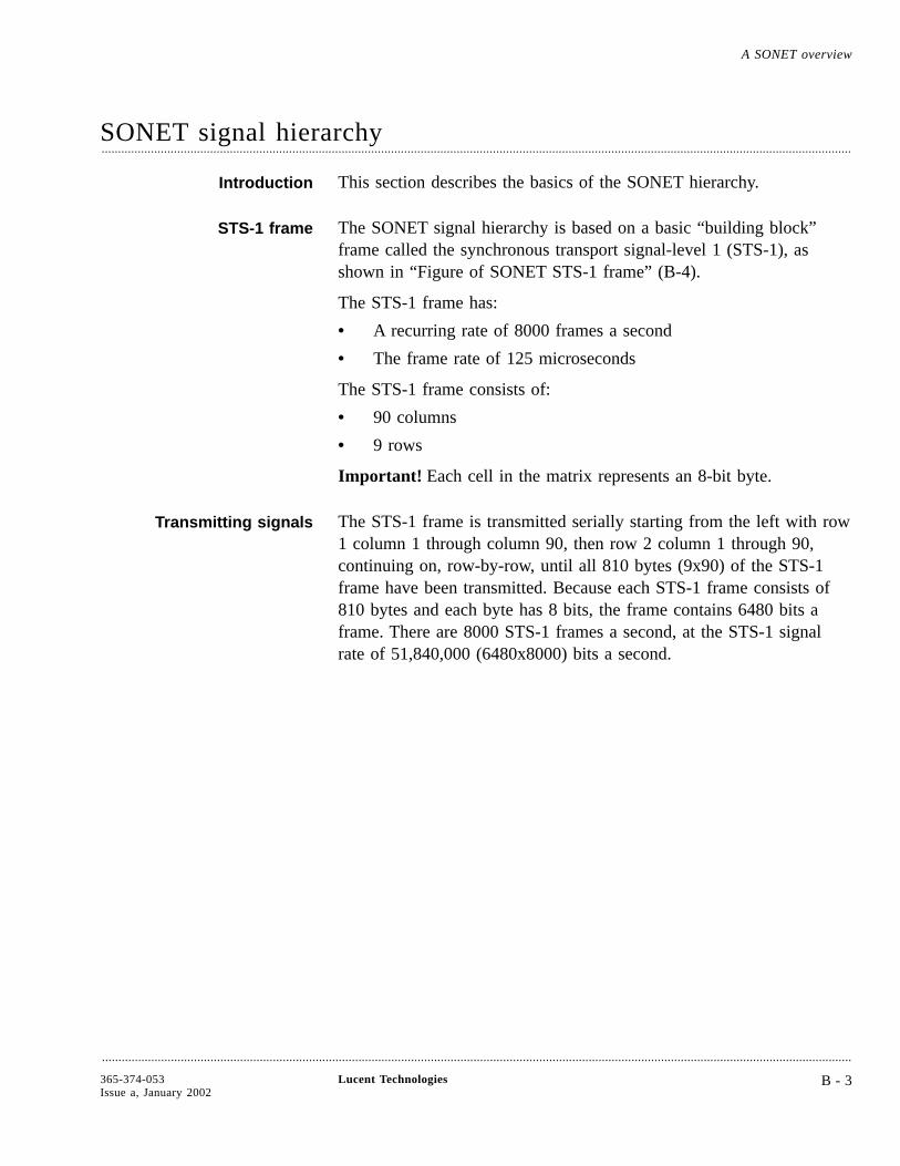
SONET signal hierarchy....................................................................................................................................................................................................................................
Introduction This section describes the basics of the SONET hierarchy.
STS-1 frame The SONET signal hierarchy is based on a basic “building block”frame called the synchronous transport signal-level 1 (STS-1), asshown in “Figure of SONET STS-1 frame” (B-4).
The STS-1 frame has:
• A recurring rate of 8000 frames a second
• The frame rate of 125 microseconds
The STS-1 frame consists of:
• 90 columns
• 9 rows
Important! Each cell in the matrix represents an 8-bit byte.
Transmitting signals The STS-1 frame is transmitted serially starting from the left with row1 column 1 through column 90, then row 2 column 1 through 90,continuing on, row-by-row, until all 810 bytes (9x90) of the STS-1frame have been transmitted. Because each STS-1 frame consists of810 bytes and each byte has 8 bits, the frame contains 6480 bits aframe. There are 8000 STS-1 frames a second, at the STS-1 signalrate of 51,840,000 (6480x8000) bits a second.
A SONET overview
....................................................................................................................................................................................................................................
365-374-053Issue a, January 2002
Lucent Technologies B - 3
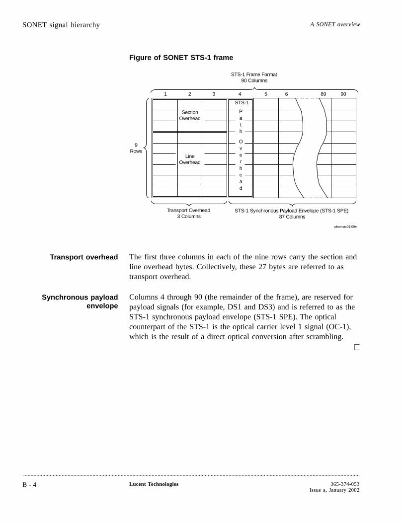
Figure of SONET STS-1 frame
Transport overhead The first three columns in each of the nine rows carry the section andline overhead bytes. Collectively, these 27 bytes are referred to astransport overhead.
Synchronous payloadenvelope
Columns 4 through 90 (the remainder of the frame), are reserved forpayload signals (for example, DS1 and DS3) and is referred to as theSTS-1 synchronous payload envelope (STS-1 SPE). The opticalcounterpart of the STS-1 is the optical carrier level 1 signal (OC-1),which is the result of a direct optical conversion after scrambling.
STS-1
Path
Over
ead
Section
Line
1 2 3 4 5 6 89 90
Transport Overhead3 Columns
STS-1 Synchronous Payload Envelope (STS-1 SPE)87 Columns
STS-1 Frame Format90 Columns
9
Overhead
Overhead
h
Rows
wbwmax01.00e
SONET signal hierarchy A SONET overview
....................................................................................................................................................................................................................................
B - 4 Lucent Technologies 365-374-053Issue a, January 2002
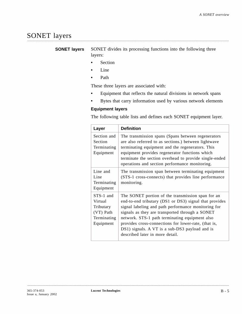
SONET layers....................................................................................................................................................................................................................................
SONET layers SONET divides its processing functions into the following threelayers:
• Section
• Line
• Path
These three layers are associated with:
• Equipment that reflects the natural divisions in network spans
• Bytes that carry information used by various network elements
Equipment layers
The following table lists and defines each SONET equipment layer.
Layer Definition
Section andSectionTerminatingEquipment
The transmission spans (Spans between regeneratorsare also referred to as sections.) between lightwaveterminating equipment and the regenerators. Thisequipment provides regenerator functions whichterminate the section overhead to provide single-endedoperations and section performance monitoring.
Line andLineTerminatingEquipment
The transmission span between terminating equipment(STS-1 cross-connects) that provides line performancemonitoring.
STS-1 andVirtualTributary(VT) PathTerminatingEquipment
The SONET portion of the transmission span for anend-to-end tributary (DS1 or DS3) signal that providessignal labeling and path performance monitoring forsignals as they are transported through a SONETnetwork. STS-1 path terminating equipment alsoprovides cross-connections for lower-rate, (that is,DS1) signals. A VT is a sub-DS3 payload and isdescribed later in more detail.
A SONET overview
....................................................................................................................................................................................................................................
365-374-053Issue a, January 2002
Lucent Technologies B - 5

The following figure illustrates the equipment layers (section, line,and path) in a signal path.
Overhead byte layers
Table B-2 “Overhead Byte Layers” lists and defines the overheadassociated with each SONET layer.
OverheadByteLayer
Definition
Section Contains information that is used by all SONETequipment including repeaters.
Line Used by all SONET equipment except repeaters.
Path Carried within the payload envelope across theend-to-end path with:
• STS-1 remaining with the STS-1 SPE until itspayload is demultiplexed
• VTN (N= 1.5, 2, 3, or 6) remaining with the VTNuntil it is demultiplexed to its asynchronous signal
DS1s
DS3Digital
Multiplexer
LightwaveTerminatingEquipment
Sections
Line
Path
DS1s
DS3Digital
Multiplexer
LightwaveTerminatingEquipment
Lightwave Repeaters
wbwmax02.00e
SONET layers A SONET overview
....................................................................................................................................................................................................................................
B - 6 Lucent Technologies 365-374-053Issue a, January 2002

Figure of SONET Frame Format
The following figure illustrates each SONET layer and its set ofoverhead bytes.
Data ComD9
Data ComD6
APSK2
D3
IndicatorH4
User
F2Channel
Signal LabelC2
Data Com
Path StatusG1
Data Com
OrderwireE2
Data Com Data ComD12
Data Com
Pointer
Orderwire UserF1
Data Com
BIP-8B3
PointerAction
H3
STS-1
D11
APS
Framing TraceJ1
GrowthS1/Z1
Data ComD10
Data ComD7 D8
Data ComD4 D5
BIP-8B2 K1
PointerH1 H2
FramingA1 A2
BIP-8B1 E1
Data ComD1 D2
1 2 3 4 5
SectionOverhead
LineOverhead
Path OH
wbwmax03.01e
Transport Overhead3 Columns
STS-1 Synchronous Payload Envelope (STS-1 SPE)87 Columns
STS-1 Frame Format90 Columns
9089
GrowthZ4
GrowthZ3
TandemConnection
Z5
FEBE/Growth
M0 or M1/Z2
Trace/Growth(STS-ID)
J0/Z0
Sync. Status/
SONET layers A SONET overview
....................................................................................................................................................................................................................................
365-374-053Issue a, January 2002
Lucent Technologies B - 7
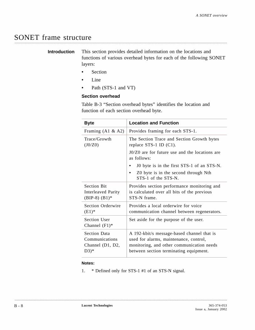
SONET frame structure....................................................................................................................................................................................................................................
Introduction This section provides detailed information on the locations andfunctions of various overhead bytes for each of the following SONETlayers:
• Section
• Line
• Path (STS-1 and VT)
Section overhead
Table B-3 “Section overhead bytes” identifies the location andfunction of each section overhead byte.
Byte Location and Function
Framing (A1 & A2) Provides framing for each STS-1.
Trace/Growth(J0/Z0)
The Section Trace and Section Growth bytesreplace STS-1 ID (C1).
J0/Z0 are for future use and the locations areas follows:
• J0 byte is in the first STS-1 of an STS-N.
• Z0 byte is in the second through NthSTS-1 of the STS-N.
Section BitInterleaved Parity(BIP-8) (B1)*
Provides section performance monitoring andis calculated over all bits of the previousSTS-N frame.
Section Orderwire(E1)*
Provides a local orderwire for voicecommunication channel between regenerators.
Section UserChannel (F1)*
Set aside for the purpose of the user.
Section DataCommunicationsChannel (D1, D2,D3)*
A 192-kbit/s message-based channel that isused for alarms, maintenance, control,monitoring, and other communication needsbetween section terminating equipment.
Notes:
1. * Defined only for STS-1 #1 of an STS-N signal.
A SONET overview
....................................................................................................................................................................................................................................
B - 8 Lucent Technologies 365-374-053Issue a, January 2002

Line overhead
Table B-4 “Line Overhead Bytes” identifies the location and functionof each line overhead byte.
Byte Location and Function
Pointer (H1, H2) Two bytes indicating the offset in bytesbetween the pointer action byte (H3) and thefirst byte (J1) of the STS-1 synchronouspayload envelope (SPE).
Pointer Action(H3)
Allocated for frequency justification.
Line BitInterleaved Parity(BIP-8) (B2)
Provided for line performance monitoring in allSTS-1 signals within an STS-N signal.
AutomaticProtectionSwitching (APS)(K1, K2)*
Two bytes used for APS signaling between linelevel entities. In addition, bits 6, 7, and 8 ofK2 are used for line alarm indication signal(AIS) and line far-end receive failure (FERF).
Line DataCommunicationsChannel (D4 -D12)
This is a 576-kbit/s message-based channel.
SynchronizationStatus (S1)
• Located in the first STS-1 of an STS-N.
• Conveys the synchronization status of theNetwork Element.
Growth (Z1) • Located in the second through Nth STS-1of an STS-N.
• Reserved for future growth.
Line Orderwire(E2)*
Allocated to be used as an express orderwirebetween line entities.
Notes:
1. * Defined only for STS-1 #1 of an STS-N signal.
STS-1 path overhead
The STS-1 path overhead is assigned to and remains with the STS-1SPE until the payload is demultiplexed and is used for functions thatare necessary to transport all synchronous payload envelopes.
SONET frame structure A SONET overview
....................................................................................................................................................................................................................................
365-374-053Issue a, January 2002
Lucent Technologies B - 9
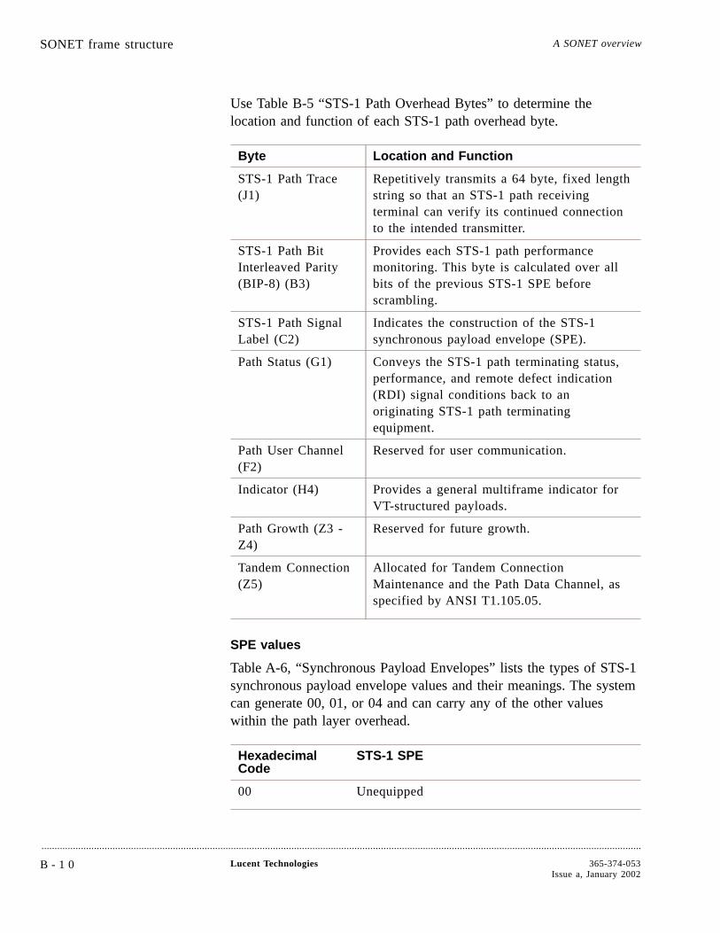
Use Table B-5 “STS-1 Path Overhead Bytes” to determine thelocation and function of each STS-1 path overhead byte.
Byte Location and Function
STS-1 Path Trace(J1)
Repetitively transmits a 64 byte, fixed lengthstring so that an STS-1 path receivingterminal can verify its continued connectionto the intended transmitter.
STS-1 Path BitInterleaved Parity(BIP-8) (B3)
Provides each STS-1 path performancemonitoring. This byte is calculated over allbits of the previous STS-1 SPE beforescrambling.
STS-1 Path SignalLabel (C2)
Indicates the construction of the STS-1synchronous payload envelope (SPE).
Path Status (G1) Conveys the STS-1 path terminating status,performance, and remote defect indication(RDI) signal conditions back to anoriginating STS-1 path terminatingequipment.
Path User Channel(F2)
Reserved for user communication.
Indicator (H4) Provides a general multiframe indicator forVT-structured payloads.
Path Growth (Z3 -Z4)
Reserved for future growth.
Tandem Connection(Z5)
Allocated for Tandem ConnectionMaintenance and the Path Data Channel, asspecified by ANSI T1.105.05.
SPE values
Table A-6, “Synchronous Payload Envelopes” lists the types of STS-1synchronous payload envelope values and their meanings. The systemcan generate 00, 01, or 04 and can carry any of the other valueswithin the path layer overhead.
HexadecimalCode
STS-1 SPE
00 Unequipped
SONET frame structure A SONET overview
....................................................................................................................................................................................................................................
B - 1 0 Lucent Technologies 365-374-053Issue a, January 2002
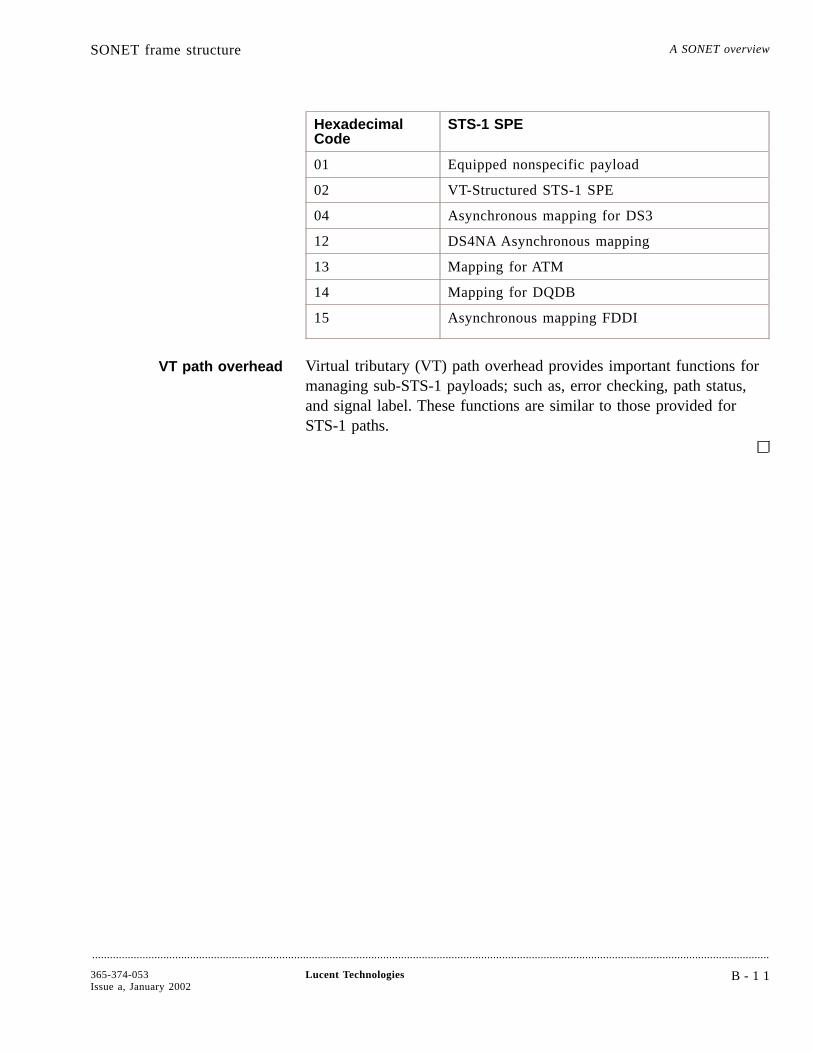
HexadecimalCode
STS-1 SPE
01 Equipped nonspecific payload
02 VT-Structured STS-1 SPE
04 Asynchronous mapping for DS3
12 DS4NA Asynchronous mapping
13 Mapping for ATM
14 Mapping for DQDB
15 Asynchronous mapping FDDI
VT path overhead Virtual tributary (VT) path overhead provides important functions formanaging sub-STS-1 payloads; such as, error checking, path status,and signal label. These functions are similar to those provided forSTS-1 paths.
SONET frame structure A SONET overview
....................................................................................................................................................................................................................................
365-374-053Issue a, January 2002
Lucent Technologies B - 1 1
SONET digital multiplexing....................................................................................................................................................................................................................................
Introduction SONET provides the following two multiplexing schemes:
• Asynchronous
• Synchronous
Asynchronousmultiplexing
When fiber optic facilities are used to carry DS3 signals, the signalconsists of a combination of the following payload signals:
• 28 DS1s
• 14 DS1s
• 7 DS2s
M23 format Typically, 28 DS1 signals are multiplexed into a DS3 signal, using theM23 format. The M23 format involves bit interleaving of four DS1signals into a DS2 signal and then bit interleaving of seven DS2signals into a DS3. In addition, the DS3 rate is not a direct multipleof the DS1 or the DS2 rates due to the bit-stuffing synchronizationtechnique used in asynchronous multiplexing.
Disadvantages of M23format
When using an M23 format, identification of DS0s contained in anyDS-N signal is complex, and DS0s cannot be directly extracted. Anasynchronous DS3 signal must be demultiplexed down to the DS1level to access and cross-connect DS0 and DS1 signals. In addition,the M23 format does not provide an end-to-end overhead channel foruse by OAM&P groups.
Synchronous multiplexing Synchronous multiplexing is the SONET method of byte interleavingDS1s to a higher signal rate, which permits economical extraction of asingle DS1 without the need to demultiplex the entire STS-1 SPE. Inaddition, SONET provides overhead channels for use by OAM&Pgroups.
A SONET overview
....................................................................................................................................................................................................................................
B - 1 2 Lucent Technologies 365-374-053Issue a, January 2002

Figure of synchronousmultiplexing
The following figure illustrates the SONET technique of mapping asingle asynchronous DS1 signal into an STS-1 SPE.
Transporting SONETpayloads
Sub-DS3 asynchronous signals (DS1, DS1C, DS2, and E1) are byteinterleaved into a digital signal called a virtual tributary (VT). TheVT is a structure designed for the transport and switching of sub-DS3payloads. There are four sizes of VTs: 1.5, 2, 3, and 6.
Table Digital signals DS1 and DS3 are the most important asynchronoussignals in the current network. Broadband payloads, such as ATM, arealso of great importance.
InputTributary
VoiceChannels(DS0s)
Rate SONETSignal
Rate
DS1 24 DS0s 1.544 Mbit/s VT1.5 1.728 Mbit/s
E1(CEPT)
32 DS0s 2.048 Mbit/s VT2 2.304 Mbit/s
DS1C 48 DS0s 3.152 Mbit/s VT3 3.456 Mbit/s
DS2 96 DS0s 6.312 Mbit/s VT6 6.912 Mbit/s
DS3 672 DS0s 44.736 Mbit/s STS-1 51.840 Mbit/s
1 VF Circuit = 1 DSO
Byte Interleaving above DS1
DS1 Observable above DS1
Standard End-To-End Overhead Channel
4 VT1.5s = VT-G 7 VT-Gs+ STS-1 Path OH+ STS-1 Line OH+ STS-1 Section OH1 STS-1
wbwmax05.00e
24 DS0s = 1 DS1
24 DS0s+ 1 DS0 (stuffing bit)+ 1 DS0 (VT Path OH)+ 1 DS0 (VT pointer)1 VT1.5
STS-1 X N = OC-N
SONET digital multiplexing A SONET overview
....................................................................................................................................................................................................................................
365-374-053Issue a, January 2002
Lucent Technologies B - 1 3

InputTributary
VoiceChannels(DS0s)
Rate SONETSignal
Rate
DS4NA 2016DS0s
139.264Mbit/s
STS-3c 155.520Mbit/s
ATM 2016DS0s
149.760Mbit/s
STS-3c 155.520Mbit/s
FDDI 2016DS0s
125.000Mbit/s
STS-3c 155.520Mbit/s
SONET digital multiplexing A SONET overview
....................................................................................................................................................................................................................................
B - 1 4 Lucent Technologies 365-374-053Issue a, January 2002
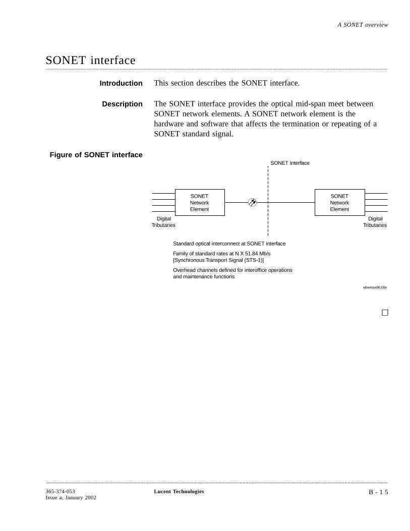
SONET interface....................................................................................................................................................................................................................................
Introduction This section describes the SONET interface.
Description The SONET interface provides the optical mid-span meet betweenSONET network elements. A SONET network element is thehardware and software that affects the termination or repeating of aSONET standard signal.
Figure of SONET interface
SONETNetworkElement
DigitalTributaries
SONET Interface
Standard optical interconnect at SONET interface
Family of standard rates at N X 51.84 Mb/s[Synchronous Transport Signal (STS-1)]
Overhead channels defined for interoffice operationsand maintenance functions
SONETNetworkElement
DigitalTributaries
wbwmax06.00e
A SONET overview
....................................................................................................................................................................................................................................
365-374-053Issue a, January 2002
Lucent Technologies B - 1 5
SONET multiplexing process....................................................................................................................................................................................................................................
Introduction SONET provides for multiplexing of asynchronous DS1s, synchronousDS1s, and asynchronous DS3s.
Multiplexing process The following describes the process for multiplexing a signal.
............................................................................................................................................................
1 Input DS1 or DS3 tributary is mapped.
In the case of DS1 inputs, three time slots (DS0s) are added to theincoming signal, becoming a VT1.5.
An asynchronous DS1 that fully meets the specified rate is mappedinto the VT1.5 SPE as clear channel input since no framing is needed.
• Each VT1.5 carries a single DS1 payload.
• Four VT1.5s are bundled into a VT group (VT-G).
• Seven VT-Gs are byte interleaved into an STS-1 frame.
Important! The VT-G to-STS-1 multiplex is a simple byteinterleaving process, so individual VT signals are easily observablewithin the STS-1. Thus, cross-connections and add/drop can beaccomplished without the back-to-back mux/demux steps required byasynchronous signal formats.
............................................................................................................................................................
2 After VTs are multiplexed into the STS-1 SPE, the path, line, andsection overhead is added.
............................................................................................................................................................
3 Scrambled STS-N signal is transported to the optical stage.
A SONET overview
....................................................................................................................................................................................................................................
B - 1 6 Lucent Technologies 365-374-053Issue a, January 2002

Figure of SONETmultiplexing process
Byte-Interleaves3 STS-1s intoan STS-3
Writes Sectionand LineOH Bytesof STS-1#1
Converts STS-3into OC-3
AddsVT-Path OH
(3 Time Slots)
DS1 to VTG Multiplexer
#1#2#3#4
#1
VT1.5to
VTGByte
Interleaver
DS1DS1DS1DS1
#7
DS3 to STS-1Multiplexer
DS3 to STS-1Multiplexer
VTG to STS-1Multiplexer
Maps 7 VTGsinto STS-1 SPE
Maps 1 DS3into STS-1 SPE
Maps 1 DS3into STS-1 SPE
Adds STS-1Path OH(Nine Time Slots)
Adds STS-1Path OH(Nine Time Slots)
Adds STS-1Path OH(Nine Time Slots)
Builds STS-1Frame
Builds STS-1Frame
Builds STS-1Frame
STS-1 #3
STS-1 to OC-3Multiplexer
STS-1 #1
STS-1 #2
DS1 to VTG Multiplexer
#7
#1
VTG
VTGOC-3
DS3
DS3
wbwmax07.00e
SONET multiplexing process A SONET overview
....................................................................................................................................................................................................................................
365-374-053Issue a, January 2002
Lucent Technologies B - 1 7
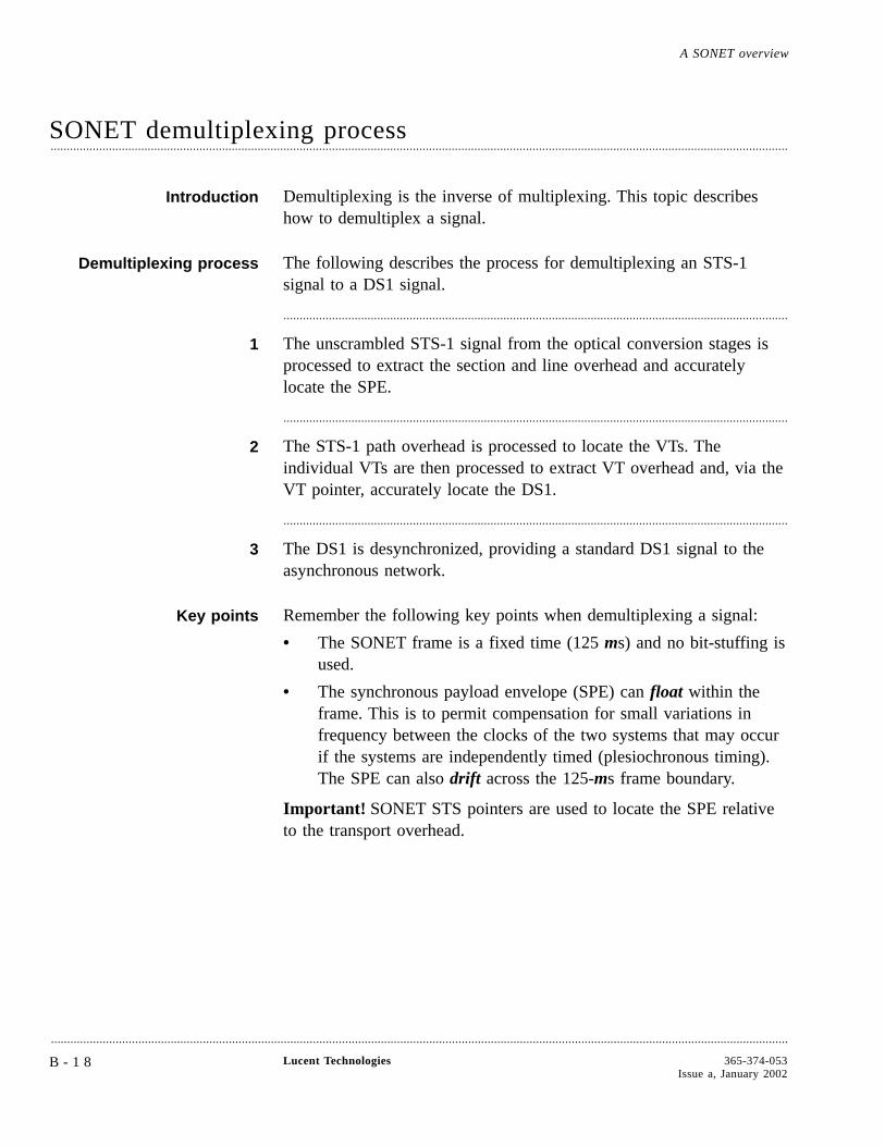
SONET demultiplexing process....................................................................................................................................................................................................................................
Introduction Demultiplexing is the inverse of multiplexing. This topic describeshow to demultiplex a signal.
Demultiplexing process The following describes the process for demultiplexing an STS-1signal to a DS1 signal.
............................................................................................................................................................
1 The unscrambled STS-1 signal from the optical conversion stages isprocessed to extract the section and line overhead and accuratelylocate the SPE.
............................................................................................................................................................
2 The STS-1 path overhead is processed to locate the VTs. Theindividual VTs are then processed to extract VT overhead and, via theVT pointer, accurately locate the DS1.
............................................................................................................................................................
3 The DS1 is desynchronized, providing a standard DS1 signal to theasynchronous network.
Key points Remember the following key points when demultiplexing a signal:
• The SONET frame is a fixed time (125 ms) and no bit-stuffing isused.
• The synchronous payload envelope (SPE) can float within theframe. This is to permit compensation for small variations infrequency between the clocks of the two systems that may occurif the systems are independently timed (plesiochronous timing).The SPE can also drift across the 125-ms frame boundary.
Important! SONET STS pointers are used to locate the SPE relativeto the transport overhead.
A SONET overview
....................................................................................................................................................................................................................................
B - 1 8 Lucent Technologies 365-374-053Issue a, January 2002
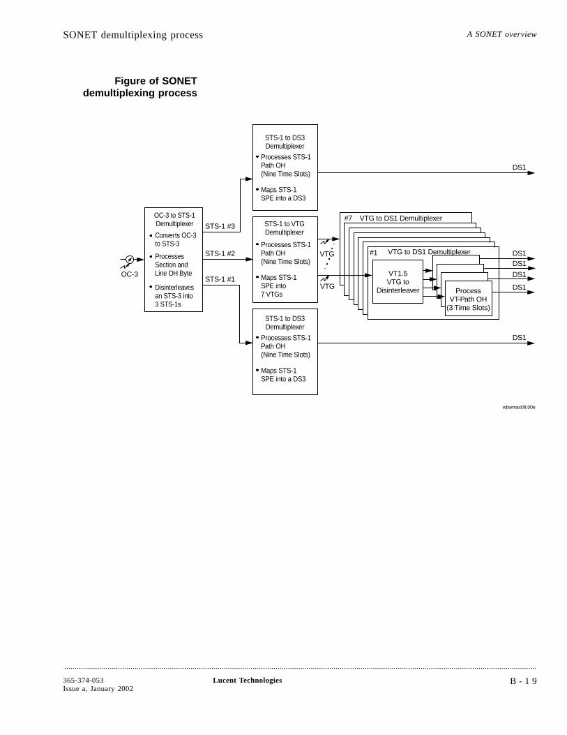
Figure of SONETdemultiplexing process
VT1.5VTG to
Disinterleaver
VTG to DS1 Demultiplexer
ProcessOH
(3 Time Slots)VT-Path
DS1
DS1DS1
DS1
DS1
DS1
#1
#7 VTG to DS1 Demultiplexer
Maps STS-1SPE into7 VTGs
Maps STS-1SPE into a DS3
Maps STS-1SPE into a DS3
OC-3 to STS-1Demultiplexer
Converts OC-3to STS-3
ProcessesSection andLine OH Byte
Processes STS-1Path OH(Nine Time Slots)
Processes STS-1Path OH(Nine Time Slots)
Processes STS-1Path OH(Nine Time Slots)
STS-1 to DS3Demultiplexer
STS-1 to DS3Demultiplexer
STS-1 to VTGDemultiplexer
Disinterleavesan STS-3 into3 STS-1s
wbwmax08.00e
STS-1 #3
STS-1 #1
STS-1 #2 VTG
VTG
OC-3
SONET demultiplexing process A SONET overview
....................................................................................................................................................................................................................................
365-374-053Issue a, January 2002
Lucent Technologies B - 1 9
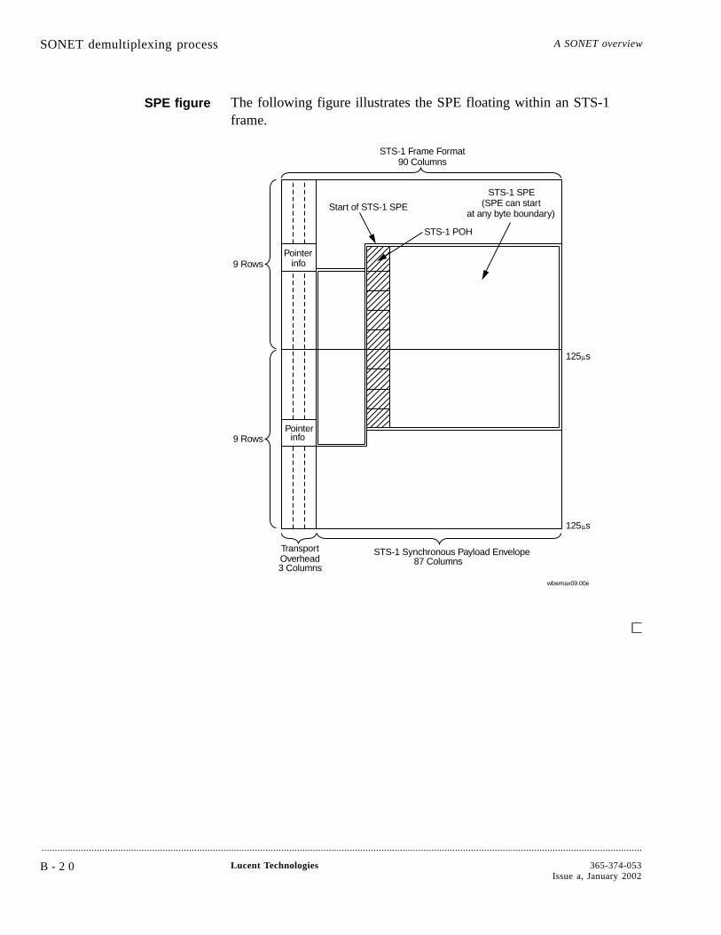
SPE figure The following figure illustrates the SPE floating within an STS-1frame.
STS-1 Synchronous Payload Envelope
125
125
s
s
Pointerinfo
TransportOverhead
STS-1 POH
Pointerinfo
Start of STS-1 SPE
STS-1 Frame Format
(SPE can startat any byte boundary)
STS-1 SPE
87 Columns3 Columns
9 Rows
9 Rows
90 Columns
wbwmax09.00e
SONET demultiplexing process A SONET overview
....................................................................................................................................................................................................................................
B - 2 0 Lucent Technologies 365-374-053Issue a, January 2002
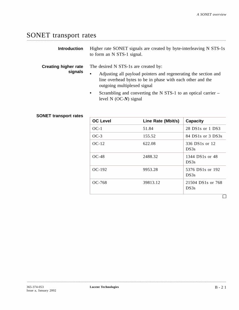
SONET transport rates....................................................................................................................................................................................................................................
Introduction Higher rate SONET signals are created by byte-interleaving N STS-1sto form an N STS-1 signal.
Creating higher ratesignals
The desired N STS-1s are created by:
• Adjusting all payload pointers and regenerating the section andline overhead bytes to be in phase with each other and theoutgoing multiplexed signal
• Scrambling and converting the N STS-1 to an optical carrier –level N (OC-N) signal
SONET transport ratesOC Level Line Rate (Mbit/s) Capacity
OC-1 51.84 28 DS1s or 1 DS3
OC-3 155.52 84 DS1s or 3 DS3s
OC-12 622.08 336 DS1s or 12DS3s
OC-48 2488.32 1344 DS1s or 48DS3s
OC-192 9953.28 5376 DS1s or 192DS3s
OC-768 39813.12 21504 DS1s or 768DS3s
A SONET overview
....................................................................................................................................................................................................................................
365-374-053Issue a, January 2002
Lucent Technologies B - 2 1

Glossary
µMicrons
NUMERICS0x1 Line Operation0x1 means unprotected operation. The connection between network elements has onebidirectional line (no protection line).
1+1 Line ProtectionA protection architecture in which the transmitting equipment transmits a valid signal on boththe working and protection lines. The receiving equipment monitors both lines. Based onperformance criteria and OS control, the receiving equipment chooses one line as the active lineand designates the other as the standby line.
1xN Equipment Protection1xN protection pertains to N number of circuit pack/port units protected by one circuit pack orport unit. When a protection switch occurs, the working signals are routed from the failed packto the protection pack. When the fault clears, the signals revert to the working port unit.
12NC (12-digit Numerical Code)Used to uniquely identify an item or product. The first ten digits uniquely identify an item. Theeleventh digit is used to specify the particular variant of an item. The twelfth digit is used forthe revision issue. Items with the first eleven digits the same, are functionally equal and may beexchanged.
....................................................................................................................................................................................................................................
A ABNAbnormal (condition)
ABS (Absent)Used to indicate that a given circuit pack is not installed.
....................................................................................................................................................................................................................................
365-374-053Issue a, January 2002
Lucent Technologies G L O S S A R YG L - 1
ACAlternating Current
ACO (Alarm Cut-Off)A button on the user panel used to silence audible alarms.
ACT (Active)Used to indicate that a circuit pack or module is in-service and currently providing servicefunctions.
Adaptive-rate tributary operation of a port (Pipe mode)Mode of operation of a port in which tributaries are not explicitly provisioned for the expectedsignal rates. The signal rates are automatically identified.
ADM (Add/Drop Multiplexer)The term for a synchronous network element capable of combining signals of different rates andhaving those signals added to or dropped from the stream.
AELAccessible Emission Limits
AgentPerforms operations on managed objects and issues events on behalf of these managed objects.All SDH managed objects will support at least an agent. Control of distant agents is possiblevia local “Managers”.
AGNEAlarm Gateway Network Element
AID (Access Identifier)A technical specification for explicitly naming entities (both physical and logical) of an NEusing a grammar comprised of ASCII text, keywords, and grammar rules.
AIS (Alarm Indication Signal)A code transmitted downstream in a digital network that indicates that an upstream failure hasbeen detected and alarmed if the upstream alarm has not been suppressed.
AITSAcknowledged Information Transfer Service: Confirmed mode of operation of the LAPDprotocol.
AlarmVisible or audible signal indicating that an equipment failure or significant event/condition hasoccurred.
....................................................................................................................................................................................................................................
G L O S S A R YG L - 2
Lucent Technologies 365-374-053Issue a, January 2002

Alarm CorrelationThe search for a directly-reported alarm that can account for a given symptomatic condition.
Alarm SeverityAn attribute defining the priority of the alarm message. The way alarms are processed dependson the severity.
Alarm SuppressionSelective removal of alarm messages from being forwarded to the GUI or to networkmanagement layer OSs.
Alarm ThrottlingA feature that automatically or manually suppresses autonomous messages that are not priorityalarms.
AligningIndicating the head of a virtual container by means of a pointer, for example, creating anAdministrative Unit (AU) or a Tributary Unit (TU).
AMI (Alternate Mark Inversion)A line code that employs a ternary signal to convert binary digits, in which successive binaryones are represented by signal elements that are normally of alternative positive and negativepolarity but equal in amplitude and in which binary zeros are represented by signal elementsthat have zero amplitude.
AnomalyA difference between the actual and desired operation of a function.
ANSIAmerican National Standards Institute
APDAvalanche Photo Diode
APS (Automatic Protection Switch)A protection switch that occurs automatically in response to an automatically detected faultcondition.
ASCII (American Standard Code for Information Interchange)A standard 7-bit code that represents letters, numbers, punctuation marks, and special charactersin the interchange of data among computing and communications equipment.
ASN.1Abstract Syntax Notation 1
....................................................................................................................................................................................................................................
365-374-053Issue a, January 2002
Lucent Technologies G L O S S A R YG L - 3
AssemblyGathering together of payload data with overhead and pointer information (an indication of thedirection of the signal).
AssociationA logical connection between manager and agent through which management information can beexchanged.
AsynchronousThe essential characteristic of time-scales or signals such that their corresponding significantinstants do not necessarily occur at the same average rate.
ATM (Asynchronous Transfer Mode)A high-speed transmission technology characterized by high bandwidth and low delay. It utilizesa packet switching and multiplexing technique which allocates bandwidth on demand.
AttributeAlarm indication level: critical, major, minor, or no alarm.
AU (Administrative Unit)Carrier for TUs.
AU PTR (Administrative Unit Pointer)Indicates the phase alignment of the VC-N with respect to the STM-N frame. The pointerposition is fixed with respect to the STM-N frame.
AUGAdministrative Unit Group
AUTO (Automatic)One possible state of a port or slot. When a port is in the AUTO state and a good signal isdetected, the port automatically enters the IS (in-service) state. When a slot is in the AUTOstate and a circuit pack is detected, the slot automatically enters the EQ (equipped) state.
AutolockAction taken by the system in the event of circuit pack failure/trouble. System switches toprotection and prevents a return to the working circuit pack even if the trouble clears. Multipleprotection switches on a circuit pack during a short period of time cause the system to autolockthe pack.
Autonomous MessageA message transmitted from the controlled Network Element to the Navis™ Optical EMS whichwas not a response to an Navis Optical EMS originated command.
AVAILAvailable
....................................................................................................................................................................................................................................
G L O S S A R YG L - 4
Lucent Technologies 365-374-053Issue a, January 2002

....................................................................................................................................................................................................................................
B BandwidthThe difference in Hz between the highest and lowest frequencies in a transmission channel. Thedata rate that can be carried by a given communications circuit.
Baud RateTransmission rate of data (bits per second) on a network link.
BER (Bit Error Rate )The ratio of error bits received to the total number of bits transmitted.
Bidirectional LineA transmission path consisting of two fibers that handle traffic in both the transmit and receivedirections.
Bidirectional RingA ring in which both directions of traffic between any two nodes travel through the samenetwork elements (although in opposite directions).
Bidirectional SwitchProtection switching performed in both the transmit and receive directions.
BIP-N (Bit Interleaved Parity-N)A method of error monitoring over a specified number of bits (BIP-3 or BIP-8).
BitThe smallest unit of information in a computer, with a value of either 0 or 1.
Bit Error Rate ThresholdThe point at which an alarm is issued for bit errors.
BLD OUT LGBuild-Out Lightguide
Bridge Cross-ConnectionThe setting up of a cross-connection leg with the same input tributary as that of an existingcross-connection leg. Thus, forming a 1:2 bridge from an input tributary to two outputtributaries.
Broadband CommunicationsVoice, data, and/or video communications at greater than 2 Mbit/s rates.
Broadband Service TransportSTM-1 concatenation transport over the LambdaUnite™ MSS for ATM applications.
....................................................................................................................................................................................................................................
365-374-053Issue a, January 2002
Lucent Technologies G L O S S A R YG L - 5
ByteRefers to a group of eight consecutive binary digits.
....................................................................................................................................................................................................................................
C CContainer
CC (Clear Channel)A digital circuit where no framing or control bits are required, thus making the full bandwidthavailable for communications.
CC (Cross-Connection)Path-level connections between input and output tributaries or specific ports within a single NE.Cross-connections are made in a consistent way even though there are various types of portsand various types of port protection. Cross-Connections are re-configurable interconnectionsbetween tributaries of transmission interfaces.
Cell RelayFixed-length cells. For example, ATM with 53 octets.
CEPTConférence Européenne des Administrations des Postes et des Télécommunications
ChannelA sub-unit of transmission capacity within a defined higher level of transmission capacity.
CircuitA set of transmission channels through one or more network elements that provides transmissionof signals between two points, to support a single communications path.
CIT or WaveStar® CIT (Craft Interface Terminal)The user interface terminal used by craft personnel to communicate with a network element.
CLClear
CLEICommon Language Equipment Identifier
ClientComputer in a computer network that generally offers a user interface to a server.
CLLICommon Language Location Identifier
....................................................................................................................................................................................................................................
G L O S S A R YG L - 6
Lucent Technologies 365-374-053Issue a, January 2002
Closed Ring NetworkA network formed of a ring-shaped configuration of network elements. Each network elementconnects to two others, one on each side.
CM (Configuration Management)Subsystem that configures the network and processes messages from the network.
CMICoded Mark Inversion
CMIPCommon Management Information Protocol. OSI standard protocol for OAM&P informationexchange.
CMISECommon Management Information Service Element
CO (Central Office)A building where common carriers terminate customer circuits.
Co-ResidentA hardware configuration where two applications can be active at the same time independentlyon the same hardware and software platform without interfering with each others functioning.
CollocatedSystem elements that are located in the same location.
Command GroupAn administrator-defined group that defines commands to which a user has access.
ConcatenationA procedure whereby multiple virtual containers are associated one with each other resulting ina combined capacity that can be used as a single container across which bit sequence integrityis maintained.
CorrelationA process where related hard failure alarms are identified.
CPCircuit Pack
CPECustomer Premises Equipment
....................................................................................................................................................................................................................................
365-374-053Issue a, January 2002
Lucent Technologies G L O S S A R YG L - 7
CPUCentral Processing Unit
CR (Critical (alarm))Alarm that indicates a severe, service-affecting condition.
CRCCyclical Redundancy Check
Cross-Connect MapConnection map for an SDH Network Element; contains information about how signals areconnected between high speed time slots and low speed tributaries.
CrosstalkAn unwanted signal introduced into one transmission line from another.
CSMA/CDCarrier Sense Multiple Access with Collision Detection
CTIPCustomer Training and Information Products
CTSCustomer Technical Support within Lucent Technologies
Current ValueThe value currently assigned to a provisionable parameter.
....................................................................................................................................................................................................................................
D DACS/DCSDigital Access Cross-Connect System
DataA collection of system parameters and their associated values.
Database AdministratorA user who administers the database of the application.
dBDecibels
DCDirect Current
DCC (Data Communications Channel)
....................................................................................................................................................................................................................................
G L O S S A R YG L - 8
Lucent Technologies 365-374-053Issue a, January 2002
The embedded overhead communications channel in the synchronous line, used for end-to-endcommunications and maintenance. The DCC carries alarm, control, and status informationbetween network elements in a synchronous network.
DCE (Data Communications Equipment)The equipment that provides signal conversion and coding between the data terminatingequipment (DTE) and the line. The DCE may be separate equipment or an integral part of theDTE or of intermediate equipment. A DCE may perform other functions usually performed atthe network end of the line.
DCFData Communications Function; Dispersion Compensation Fiber
DCM (Dispersion Compensation Module)A device used to compensate the dispersion, the pulse spreading properties of an optical fiber.DCMs are necessary for very-long-haul applications and high bit rates.
DCNData Communications Network
DefaultAn operation or value that the system or application assumes, unless a user makes an explicitchoice.
Default ProvisioningThe parameter values that are pre-programmed as shipped from the factory.
DefectA limited interruption of the ability of an item to perform a required function. It may or maynot lead to maintenance action depending on the results of additional analysis.
DemultiplexingA process applied to a multiplexed signal for recovering signals combined within it and forrestoring the distinct individual channels of these signals.
DEMUX (Demultiplexer)A device that splits a combined signal into individual signals at the receiver end oftransmission.
DeprovisioningThe inverse order of provisioning. To manually remove/delete a parameter that has (orparameters that have) previously been provisioned.
Digital LinkA transmission span such as a point-to-point 2 Mbit/s, 34 Mbit/s, 140 Mbit/s, VC12, VC3 orVC4 link between controlled network elements.
....................................................................................................................................................................................................................................
365-374-053Issue a, January 2002
Lucent Technologies G L O S S A R YG L - 9

Digital MultiplexerEquipment that combines by time-division multiplexing several digital signals into a singlecomposite digital signal.
Digital SectionA transmission span such as an STM-N signal. A digital section may contain multiple digitalchannels.
DisassemblySplitting up a signal into its constituents as payload data and overhead (an indication of thedirection of a signal).
DispersionTime-broadening of a transmitted light pulse.
Dispersion Shifted Optical Fiber1330/1550 nm minimum dispersion wavelength.
DivergenceWhen there is unequal amplification of incoming wavelengths, the result is a power divergencebetween wavelengths.
DNI (Dual Node Ring Interworking)A topology in which two rings are interconnected at two nodes on each ring and operate so thatinter-ring traffic is not lost in the event of a node or link failure at an interconnecting point.
DopingThe addition of impurities to a substance in order to attain desired properties.
DownstreamAt or towards the destination of the considered transmission stream, for example, looking in thesame direction of transmission.
DPLLDigital Phase Locked Loop
DRAMDynamic Random Access Memory
Drop and ContinueA circuit configuration that provides redundant signal appearances at the outputs of two networkelements in a ring. Can be used for Dual Node Ring Interworking (DNI) and for videodistribution applications.
....................................................................................................................................................................................................................................
G L O S S A R YG L - 1 0
Lucent Technologies 365-374-053Issue a, January 2002
Drop-Down MenuA menu that is displayed from a menu bar.
DSNE (Directory Service Network Element)A designated Network Element that is responsible for administering a database that mapsNetwork Elements names (node names) to addresses (node Id). There can be one DSNE per(sub)network.
DTE (Data Terminating Equipment)The equipment that originates data for transmission and accepts transmitted data.
DTMFDual Tone Multifrequency
DURDual Unit Row (subrack)
DUSDo not Use for Synchronization
DWDM (Dense Wavelength Division Multiplexing)Transmitting two or more signals of different wavelengths simultaneously over a single fiber.
....................................................................................................................................................................................................................................
E EBER (Excessive Bit Error Rate)The calculated average bit error rate over a data stream.
ECCEmbedded Control Channel
EEPROMElectrically Erasable and Programmable Read-Only Memory
EIA (Electronic Industries Association)A trade association of the electronic industry that establishes electrical and functional standards.
EM (Event Management)Subsystem of Navis Optical EMS that processes and logs event reports of the network.
EMC (Electromagnetic Compatibility)A measure of equipment tolerance to external electromagnetic fields.
EMI (Electromagnetic Interference)High-energy, electrically induced magnetic fields that cause data corruption in cables passingthrough the fields.
....................................................................................................................................................................................................................................
365-374-053Issue a, January 2002
Lucent Technologies G L O S S A R YG L - 1 1
EMSElement Management System
EntityA specific piece of hardware (usually a circuit pack, slot, or module) that has been assigned aname recognized by the system.
Entity IdentifierThe name used by the system to refer to a circuit pack, memory device, or communicationslink.
EPROMErasable Programmable Read-Only Memory
EQ (Equipped)Status of a circuit pack or interface module that is in the system database and physically in theframe, but not yet provisioned.
ES (Errored Seconds)A performance monitoring parameter. ES “type A” is a second with exactly one error; ES “typeB” is a second with more than one and less than the number of errors in a severely erroredsecond for the given signal. ES by itself means the sum of the type A and type B ESs.
ESDElectrostatic Discharge
ESPElectrostatic Protection
EstablishA user initiated command, at the WaveStar CIT, to create an entity and its associated attributesin the absence of certain hardware.
ETSIEuropean Telecommunications Standards Institute
EventA significant change. Events in controlled Network Elements include signal failures, equipmentfailures, signals exceeding thresholds, and protection switch activity. When an event occurs in acontrolled Network Element, the controlled Network Element will generate an alarm or statusmessage and send it to the management system.
Event DrivenA required characteristic of network element software system: NEs are reactive systems,primarily viewed as systems that wait for and then handle events. Events are provided by theexternal interface packages, the hardware resource packages, and also by the software itself.
....................................................................................................................................................................................................................................
G L O S S A R YG L - 1 2
Lucent Technologies 365-374-053Issue a, January 2002
Externally TimedAn operating condition of a clock in which it is locked to an external reference and is usingtime constants that are altered to quickly bring the local oscillator’s frequency into approximateagreement with the synchronization reference frequency.
Extra trafficUnprotected traffic that is carried over protection channels when their capacity is not used forthe protection of working traffic.
....................................................................................................................................................................................................................................
F FaultTerm used when a circuit pack has a hard (not temporary) fault and cannot perform its normalfunction.
Fault ManagementCollecting, processing, and forwarding of autonomous messages from network elements.
FCCFederal Communications Commission
FDA/CDRHThe Food and Drug Administration′s Center for Devices and Radiological Health.
FDDI (Fiber Distributed Data Interface)Fiber interface that connects computers and distributes data among them.
FE (Far End )Any other network element in a maintenance subnetwork other than the one the user is at orworking on. Also called remote.
FEBE (Far-End Block Error)An indication returned to the transmitting node that an errored block has been detected at thereceiving node. A block is a specified grouping of bits.
FEC (Forward Error Correction)An error correction technique in which redundant bits are added to the payload signal enablingthe receiving station to detect and correct bit errors that unavoidably occur when an optical linesignal is transmitted over longer distances over an optical fiber. FEC is used to increase thetransmission span length.
FEPROM (Flash EPROM)A technology that combines the non-volatility of EPROM with the in-circuit re-programmabilityof EEPROM.
FERF (Far-End Receive Failure)An indication returned to a transmitting Network Element that the receiving Network Element
....................................................................................................................................................................................................................................
365-374-053Issue a, January 2002
Lucent Technologies G L O S S A R YG L - 1 3
has detected an incoming section failure. Also known as RDI.
FIT (Failures in Time)Circuit pack failure rates per 109 hours as calculated using the method described in ReliabilityPrediction Procedure for Electronic Equipment, BellCore Method I, Issue 6, December 1997.
Fixed-rate tributary operation of a portMode of operation of a port in which tributaries are provisioned for the expected signal rates.This provisioning information is used for cross-connection rate validation and for alarmhandling (for example “Loss of Pointer”).
Folded RingsFolded (collapsed) rings are rings without fiber diversity. The terminology derives from theimage of folding a ring into a linear segment.
ForcedTerm used when a circuit pack (either working or protection) has been locked into aservice-providing state by user command.
FR (Frame Relay)A form of packet switching that relies on high-quality phone lines to minimize errors. It is verygood at handling high-speed, bursty data over wide area networks. The frames are variablelengths and error checking is done at the end points.
FrameThe smallest block of digital data being transmitted.
FrameworkAn assembly of equipment units capable of housing shelves, such as a bay framework.
Free RunningAn operating condition of a clock in which its local oscillator is not locked to an internalsynchronization reference and is using no storage techniques to sustain its accuracy.
....................................................................................................................................................................................................................................
G GBGigabytes
Gbit/sGigabits per second
GHzGigahertz
....................................................................................................................................................................................................................................
G L O S S A R YG L - 1 4
Lucent Technologies 365-374-053Issue a, January 2002

Global Wait to Restore TimeCorresponds to the time to wait before switching back to the timing reference. It occurs after atiming link failure has cleared. This time applies for all timing sources in a system hence thename global. This can be between 0 and 60 minutes, in increments of one minute.
GNE (Gateway Network Element)A network element that passes information between other network elements and managementsystems through a data communication network.
GroomingIn telecommunications, the process of separating and segregating channels, as by combing, suchthat the broadest channel possible can be assembled and sent across the longest practical link.The aim is to minimize de-multiplexing traffic and reshuffling it electrically.
....................................................................................................................................................................................................................................
H Hard FailureAn unrecoverable non-symptomatic (primary) failure that causes signal impairment or interfereswith critical network functions, such as DCC operation.
HDB3 (High Density Bipolar 3 Code)Line code for 2 Mbit/s transmission systems.
HDLC (High Level Data Link Control)OSI reference model datalink layer protocol.
HMIHuman Machine Interface
HML (Human Machine Language)A standard language developed by the ITU for describing the interaction between humans anddumb terminals.
HOHigh Order
HoldoverAn operating condition of a clock in which its local oscillator is not locked to an externalreference but is using storage techniques to maintain its accuracy with respect to the last knownfrequency comparison with a synchronization reference.
Hot StandbyA circuit pack ready for fast, automatic placement into operation to replace an active circuitpack. It has the same signal as the service going through it, so that choice is all that is required.
HPA (Higher Order Path Adaptation)Function that adapts a lower order Virtual Container to a higher order Virtual Container by
....................................................................................................................................................................................................................................
365-374-053Issue a, January 2002
Lucent Technologies G L O S S A R YG L - 1 5

processing the Tributary Unit pointer which indicates the phase of the lower order VirtualContainer Path Overhead relative to the higher order Virtual Container Path Overhead andassembling/disassembling the complete higher order Virtual Container.
HPC (Higher Order Path Connection)Function that provides for flexible assignment of higher order Virtual Containers within anSTM-N signal.
HPT (Higher Order Path Termination)Function that terminates a higher order path by generating and adding the appropriate VirtualContainer Path Overhead to the relevant container at the path source and removing the VirtualContainer Path Overhead and reading it at the path sink.
HSHigh Speed
HWHardware
HzHertz
....................................................................................................................................................................................................................................
I I/OInput/Output
IAO LANIntraoffice Local Area Network
IDIdentifier
IECInternational Electro-Technical Commission
IEEEInstitute of Electrical and Electronics Engineers
IMFInfant Mortality Factor
InsertTo physically insert a circuit pack into a slot, thus causing a system initiated restore of an entityinto service and/or creation of an entity and associated attributes.
....................................................................................................................................................................................................................................
G L O S S A R YG L - 1 6
Lucent Technologies 365-374-053Issue a, January 2002
Interface CapacityThe total number of STM-1 equivalents (bidirectional) tributaries in all transmission interfaceswith which a given transmission interface shelf can be equipped at one time. The interfacecapacity varies with equipage.
IS (Intermediate System)A system which routes/relays management information. A Network Element may be a combinedintermediate and end system.
IS (In-Service)A memory administrative state for ports. IS refers to a port that is fully monitored and alarmed.
IS-IS RoutingThe Network Elements in a management network route packets (data) between each other, usingan IS-IS level protocol. The size of a network running IS-IS Level 1 is limited, and thereforecertain mechanisms are employed to facilitate the management of larger networks.For STATIC ROUTING, the capability exists for disabling the protocol over the LANconnections, effectively causing the management network to be partitioned into separate IS-ISLevel 1 areas. In order for the network management system to communicate with a specificNetwork Element in one of these areas, the network management system must identify throughwhich so-called Gateway Network Element this specific Network Element is connected to theLAN. All packets to this specific Network Element are routed directly to the Gateway NetworkElement by the network management system, before being re-routed (if necessary) within theLevel 1 area.For DYNAMIC ROUTING an IS-IS Level 2 routing protocol is used allowing a number ofLevel 1 areas to interwork. The Network Elements which connect an IS-IS area to another areaare set to run the IS-IS Level 2 protocol within the Network Element and on the connectionbetween other Network Elements. Packets can now be routed between IS-IS areas and thenetwork management system does not have to identify the Gateway Network Elements.
ISDNIntegrated Services Digital Network
ITMIntegrated Transport Management
ITM-NMIntegrated Transport Management Network Module
ITUInternational Telecommunications Union
ITU-TInternational Telecommunications Union — Telecommunication standardization sector. Formerlyknown as CCITT: Comité Consultatif International Télégraphique & Téléphonique; InternationalTelegraph and Telephone Consultative Committee.
....................................................................................................................................................................................................................................
365-374-053Issue a, January 2002
Lucent Technologies G L O S S A R YG L - 1 7
....................................................................................................................................................................................................................................
J JitterShort term variations of amplitude and frequency components of a digital signal from their idealposition in time.
....................................................................................................................................................................................................................................
K kbit/sKilobits per second
....................................................................................................................................................................................................................................
L LAN (Local Area Network)A communications network that covers a limited geographic area, is privately owned and useradministered, is mostly used for internal transfer of information within a business, is normallycontained within a single building or adjacent group of buildings, and transmits data at a veryrapid speed.
LAPD (Link Access Procedure D-bytes)Protocol used on Data Link Layer (OSI layer two) according to ITU-T Q.921.
LBCLaser Bias Current
LBFCLaser Backface Currents
LBO (Lightguide Build-Out )An attenuating (signal-reducing) element used to keep an optical output signal strength withindesired limits.
LCNLocal Communications Network
LCSLocal Customer Support
LEDLight-Emitting Diode
LHLong Haul
LineA transmission medium, together with the associated equipment, required to provide the meansof transporting information between two consecutive network elements. One network elementoriginates the line signal; the other terminates it.
....................................................................................................................................................................................................................................
G L O S S A R YG L - 1 8
Lucent Technologies 365-374-053Issue a, January 2002

Line ProtectionThe optical interfaces can be protected by line protection. Line protection switching protectsagainst failures of line facilities, including the interfaces at both ends of a line, the opticalfibers, and any equipment between the two ends. Line protection includes protection ofequipment failures.
Line TimingRefers to a network element that derives its timing from an incoming STM-N signal.
LinkThe mapping between in-ports and out-ports. It specifies how components are connected to oneanother.
LLLucent Learning (former CTIP)
LOLow Order
LocationAn identifier for a specific circuit pack, interface module, interface port, or communicationslink.
Lockout of ProtectionThe WaveStar CIT command that prevents the system from switching traffic to the protectionline from a working line. If the protection line is active when a “Lockout of Protection” isentered – this command causes the working line to be selected. The protection line is thenlocked from any Automatic, Manual, or Forced protection switches.
Lockout StateThe Lockout State shall be defined for each working or protection circuit pack. The twopermitted states are: None – meaning no lockout is set for the circuit pack, set meaning thecircuit pack has been locked out. The values (None & Set) shall be taken independently foreach working or protection circuit pack.
LOF (Loss of Frame)A failure to synchronize an incoming signal.
LOMLoss Of Multiframe
Loop TimingA special case of line timing. It applies to network elements that have only one OC-N/STM-Ninterface. For example, terminating nodes in a linear network are loop timed.
....................................................................................................................................................................................................................................
365-374-053Issue a, January 2002
Lucent Technologies G L O S S A R YG L - 1 9
LoopbackType of diagnostic test used to compare an original transmitted signal with the resultingreceived signal. A loopback is established when the received optical or electrical externaltransmission signal is sent from a port or tributary input directly back toward the output.
LOP (Loss of Pointer )A failure to extract good data from a signal payload.
LOS (Loss of Signal)The complete absence of an incoming signal.
Loss BudgetLoss (in dB) of optical power due to the span transmission medium (includes fiber loss andsplice losses).
LPA (Lower order Path Adaptation)Function that adapts a PDH signal to a synchronous network by mapping the signal into orde-mapping the signal out of a synchronous container.
LPC (Lower Order Path Connection )Function that provides for flexible assignment of lower order VCs in a higher order VC.
LPT (Lower Order Path Termination)Function that terminates a lower order path by generating and adding the appropriate VC POHto the relevant container at the path source and removing the VC POH and reading it at the pathsink.
LSLow Speed
LTELine Terminating Equipment
....................................................................................................................................................................................................................................
M µmMicrometer
MAFManagement Application Function
Maintenance ConditionAn equipment state in which some normal service functions are suspended, either because of aproblem or to perform special functions (copy memory) that can not be performed while normalservice is being provided.
....................................................................................................................................................................................................................................
G L O S S A R YG L - 2 0
Lucent Technologies 365-374-053Issue a, January 2002
Management ConnectionIdentifies the type of routing used (STATIC or DYNAMIC), and if STATIC is selected allowsthe gateway network element to be identified.
ManagerCapable of issuing network management operations and receiving events. The managercommunicates with the agent in the controlled network element.
Manual Switch StateA protection group shall enter the Manual Switch State upon the initiation and successfulcompletion of the Manual Switch command. The protection group leaves the Manual Switchstate by means of the Clear or Forced Switch commands. While in the Manual Switch state thesystem may switch the active unit automatically if required for protection switching.
MappingThe logical association of one set of values, such as addresses on one network, with quantitiesor values of another set, such as devices or addresses on another network.
MBMegabytes
Mbit/sMegabits per second
MCF (Message Communications Function)Function that provides facilities for the transport and routing of TelecommunicationsManagement Network messages to and from the Network Manager.
MD (Mediation Device)Allows for exchange of management information between Operations System and NetworkElements.
MDIMiscellaneous Discrete Input
MDOMiscellaneous Discrete Output
MEC (Manufacturer Executable Code)Network Element system software in binary format that after being downloaded to one of thestores can be executed by the system controller of the network element.
MEMMemory
....................................................................................................................................................................................................................................
365-374-053Issue a, January 2002
Lucent Technologies G L O S S A R YG L - 2 1

Mid-Span MeetThe capability to interface between two lightwave network elements of different vendors. Thisapplies to high-speed optical interfaces.
MIPSMillions of Instructions Per Second
Miscellaneous Discrete InterfaceAllows an operations system to control and monitor equipment collocated within a set of inputand output contact closures.
MJ (Major (alarm))Indicates a service-affecting failure, main or unit controller failure, or power supply failure.
MMFMulti-Mode Fiber
MMIMan-Machine Interface
MMLHuman-Machine Language
MN (Minor (alarm))Indicates a non-service-affecting failure of equipment or facility.
MOManaged Object
MSMultiplexer Section
msMillisecond
MS-SPRING (Multiplexer Section Shared Protection Ring)A protection method used in Add-Drop Multiplexer Network Elements.
MSOH (Multiplexer Section OverHead)Part of the Section Overhead. Is accessible only at line terminals and multiplexers.
MSP (Multiplexer Section Protection)Provides capability for switching a signal from a working to a protection section.
MST (Multiplexer Section Termination)Function that generates the Multiplexer Section OverHead in the transmit direction and
....................................................................................................................................................................................................................................
G L O S S A R YG L - 2 2
Lucent Technologies 365-374-053Issue a, January 2002

terminates the part of the Multiplexer Section overhead that is acceptable in the receivedirection.
MTBFMean Time Between Failures
MTBMAMean Time Between Maintenance Activities
MTIEMaximum Time Interval Error
MTPIMultiplexer Timing Physical Interface
MTS (Multiplexer Timing Source)Function that provides timing reference to the relevant component parts of the multiplexequipment and represents the SDH Network Element clock.
MTTRMean Time To Repair
MultiplexerA device (circuit pack) that combines two or more transmission signals into a combined signalon a shared medium.
MultiplexingA procedure by which multiple lower order path layer signals are adapted into a higher orderpath, or the multiple higher order path layer signals are adapted into a multiplex section.
....................................................................................................................................................................................................................................
N NANot Applicable
Navis Optical NMSOptical Network Management System
NE (Network Element)A node in a telecommunication network that supports network transport services and is directlymanageable by a management system.
NEBSNetwork Equipment-Building System
....................................................................................................................................................................................................................................
365-374-053Issue a, January 2002
Lucent Technologies G L O S S A R YG L - 2 3

nmNanometer (10–9 meters)
NMON (Not Monitored )A provisioning state for equipment that is not monitored or alarmed.
No Request StateThis is the routine-operation quiet state in which no external command activities are occurring.
NodeA network element in a ring or, more generally, in any type of network. In a network elementsupporting interfaces to more than one ring, node refers to an interface that is in a particularring. Node is also defined as all equipment that is controlled by one system controller. A nodeis not always directly manageable by a management system.
Non-Revertive SwitchingIn non-revertive switching, an active and stand-by line exist on the network. When a protectionswitch occurs, the standby line is selected to support traffic, thereby becoming the active line.The original active line then becomes the stand-by line. This status remains in effect even whenthe fault clears. That is, there is no automatic switch back to the original status.
Non-SynchronousThe essential characteristic of time-scales or signals such that their corresponding significantinstants do not necessarily occur at the same average rate.
NORMNormal
NPINull Pointer Indication
NPPA (Non-Preemptible Protection Access)Non-preemptible protection access increases the available span capacity for traffic which doesnot require protection by a ring, but which cannot be preempted.
NRZNonreturn to Zero
NSANon-Service Affecting
NSAP Address (Network Service Access Point Address)Network Service Access Point Address (used in the OSI network layer 3). An automaticallyassigned number that uniquely identifies a Network Element for the purposes of routing DCCmessages.
....................................................................................................................................................................................................................................
G L O S S A R YG L - 2 4
Lucent Technologies 365-374-053Issue a, January 2002

NVM (Non-Volatile Memory )Memory that retains its stored data after power has been removed. An example of NVM wouldbe a hard disk.
....................................................................................................................................................................................................................................
O O&MOperation and Maintenance
OAOptical Amplifier
OAM&POperations, Administration, Maintenance, and Provisioning
OC, OC-nOptical Carrier
OC-12Optical Carrier, Level 12 Signal (622.08 Mbit/s)
OC-192Optical Carrier, Level 192 (9953.28 Mbit/s) (10 Gbit/s)
OC-3Optical Carrier, Level 3 Signal (155 Mbit/s)
OC-48Optical Carrier, Level 48 (2488.32 Mbit/s) (2.5 Gbit/s)
OC-768Optical Carrier, Level 768 (39813.12 Mbit/s) (40 Gbit/s)
OI (Operations Interworking)The capability to access, operate, provision, and administer remote systems through craftinterface access from any site in an SDH network or from a centralized operations system.
OLSOptical Line System
OOFOut-of-Frame
OOS (Out-of-Service)The circuit pack is not providing its normal service function (removed from either the workingor protection state) either because of a system problem or because the pack has been removed
....................................................................................................................................................................................................................................
365-374-053Issue a, January 2002
Lucent Technologies G L O S S A R YG L - 2 5
from service.
Open Ring NetworkA network formed of a linear chain-shaped configuration of network elements. Each networkelement connects to two others, one on each side, except for two network elements at the endswhich are connected on only one side. A closed ring can be formed by adding a connectionbetween the two end nodes.
Operations InterfaceAny interface providing you with information on the system behavior or control. These includethe equipment LEDs, user panel,WaveStar CIT, office alarms, and all telemetry interfaces.
OperatorA user of the system with operator-level user privileges.
Optical ChannelA STM-N wavelength within an optical line signal. Multiple channels, differing by 1.5 µm inwavelength, are multiplexed into one signal.
Optical Line SignalA multiplexed optical signal containing multiple wavelengths or channels.
Original Value ProvisioningPreprogramming of a system’s original values at the factory. These values can be overriddenusing local or remote provisioning.
OS (Operations System)A central computer-based system used to provide operations, administration, and maintenancefunctions.
OSFOpen Software Foundation; Operations System Function
OSI (Open Systems Interconnection)Referring to the OSI reference model, a logical structure for network operations standardized bythe International Standards Organization (ISO).
OutageA disruption of service that lasts for more than 1 second.
OW (Orderwire)A dedicated voice-grade line for communications between maintenance and repair personnel.
....................................................................................................................................................................................................................................
G L O S S A R YG L - 2 6
Lucent Technologies 365-374-053Issue a, January 2002

....................................................................................................................................................................................................................................
P ParameterA variable that is given a value for a specified application. A constant, variable, or expressionthat is used to pass values between components.
Parity CheckTests whether the number of ones (or zeros) in an array of binary bits is odd or even; used todetermine that the received signal is the same as the transmitted signal.
Pass-ThroughPaths that are cross-connected directly across an intermediate node in a network.
PathA logical connection between the point at which a standard frame format for the signal at thegiven rate is assembled, and the point at which the standard frame format for the signal isdisassembled.
Path Terminating EquipmentNetwork elements in which the path overhead is terminated.
PCBPrinted Circuit Board
PCMPulse Code Modulation
PDHPlesiochronous Digital Hierarchy
PIPhysical Interface
Pipe mode (Adaptive-rate tributary operation of a port)Mode of operation of a port in which tributaries are not explicitly provisioned for the expectedsignal rates. The signal rates are automatically identified.
PlatformA family of equipment and software configurations designed to support a particular application.
Plesiochronous NetworkA network that contains multiple subnetworks, each internally synchronous and all operating atthe same nominal frequency, but whose timing may be slightly different at any particularinstant.
PM (Performance Monitoring)
....................................................................................................................................................................................................................................
365-374-053Issue a, January 2002
Lucent Technologies G L O S S A R YG L - 2 7

Measures the quality of service and identifies degrading or marginally operating systems (beforean alarm would be generated).
PMD (Polarization Mode Dispersion)Output pulse broadening due to random coupling of the two polarization modes in an opticalfiber.
POH (Path Overhead)Informational bytes assigned to, and transported with the payload until the payload isde-multiplexed. It provides for integrity of communication between the point of assembly of avirtual container and its point of disassembly.
PointerAn indicator whose value defines the frame offset of a virtual container with respect to theframe reference of the transport entity on which it is supported.
POPPoint of Presence
Port (also called Line)The physical interface, consisting of both an input and output, where an electrical or opticaltransmission interface is connected to the system and may be used to carry traffic betweennetwork elements. The words “port” and “line” may often be used synonymously. “Port”emphasizes the physical interface, and “line” emphasizes the interconnection. Either may beused to identify the signal being carried.
Port State ProvisioningA feature that allows a user to suppress alarm reporting and performance monitoring duringprovisioning by supporting multiple states (automatic, in-service, and not monitored) forlow-speed ports.
POTSPlain Old Telephone Service
PPPointer Processing
PRC (Primary Reference Clock)The main timing clock reference in SDH equipment.
PreprovisioningThe process by which the user specifies parameter values for an entity in advance of some ofthe equipment being present. These parameters are maintained only in NVM. Thesemodifications are initiated locally or remotely by either WaveStar CIT or Navis Optical EMS.Preprovisioning provides for the decoupling of manual intervention tasks (for example, installcircuit packs) from those tasks associated with configuring the node to provide services (for
....................................................................................................................................................................................................................................
G L O S S A R YG L - 2 8
Lucent Technologies 365-374-053Issue a, January 2002
example, specifying the entities to be cross-connected).
PRIPrimary
Proactive MaintenanceRefers to the process of detecting degrading conditions not severe enough to initiate protectionswitching or alarming, but indicative of an impending signal fail or signal degrade defect.
Protection AccessTo provision traffic to be carried by protection tributaries when the port tributaries are not beingused to carry the protected working traffic.
Protection Group ConfigurationThe members of a group and their roles, for example, working protection, line number, etc.
Protection PathOne of two signals entering a path selector used for path protection switching or dual ringinterworking. The other is the working path. The designations working and protection areprovisioned by the user, whereas the terms active path and standby path indicate the currentprotection state.
Protection StateWhen the working unit is currently considered active by the system and that it is carryingtraffic. The “active unit state” specifically refers to the receive direction of operation — sinceprotection switching is unidirectional.
PROTN (Protection)Extra capacity (channels, circuit packs) in transmission equipment that is not intended to beused for service, but rather to serve as backup against equipment failures.
PROV (Provisioned)Indicating that a circuit pack is ready to perform its intended function. A provisioned circuitpack can be active (ACT), in-service (IS), standby (STBY), provisioned out-of-service (POS), orout-of-service (OOS).
PSDNPublic Switched Data Network
PSTNPublic Switched Telephone Network
PTEPath Terminating Equipment
....................................................................................................................................................................................................................................
365-374-053Issue a, January 2002
Lucent Technologies G L O S S A R YG L - 2 9
PTRPointer
PWRPower
PWR ONPower On
....................................................................................................................................................................................................................................
Q Q-LANThin Ethernet LAN which connects the manager to Gateway Network Elements so thatmanagement information between Network Elements and management systems can beexchanged.
QL (Quality Level)The quality of the timing signal(s) provided to synchronize a Network Element. In case ofoptical line timing the level can be provided by the Synchronization Status Message (S-1 byte).If the System and Output Timing Quality Level mode is “Enabled”, and if the signal selectedfor the Station Clock Output has a quality level below the Acceptance Quality Level, theNetwork Element “squelches” the Station Clock Output Signal, which means that no signal isforwarded at all.
QOSQuality of Service
....................................................................................................................................................................................................................................
R RAMRandom Access Memory
RDI (Remote Defect Indication)An indication returned to a transmitting terminal that the receiving terminal has detected anincoming section failure. [Previously called far-end-receive failure (FERF).]
Reactive MaintenanceRefers to detecting defects/failures and clearing them.
Receive-DirectionThe direction towards the Network Element.
RegenerationThe process of reconstructing a digital signal to eliminate the effects of noise and distortion.
....................................................................................................................................................................................................................................
G L O S S A R YG L - 3 0
Lucent Technologies 365-374-053Issue a, January 2002
Regenerator LoopLoop in a Network Element between the Station Clock Output(s) and one or both Station ClockInputs, which can be used to de-jitterize the selected timing reference in network applications.
Regenerator Section Termination (RST)Function that generates the Regenerator Section Overhead (RSOH) in the transmit direction andterminates the RSOH in the receive direction.
ReliabilityThe ability of a software system performing its required functions under stated conditions for astated period of time. The probability for an equipment to fulfill its function. Some of the waysin which reliability is measured are: MTBF (Mean Time Between Failures) expressed in hours;Availability = (MTBF)/(MTBF+MTTR)(%) [where MTTR = mean time to restore]; outage inminutes per year; failures per hour; percentage of failures per 1,000 hours.
Remote Network ElementAny Network Element that is connected to the referenced Network Element through either anelectrical or optical link. It may be the adjacent node on a ring, or N nodes away from thereference. It also may be at the same physical location but is usually at another (remote) site.
Restore TimerCounts down the time (in minutes) during which the switch waits to let the worker line recoverbefore switching back to it. This option can be set to prevent the protection switch continuallyswitching if a line has a continual transient fault.
RevertiveA protection switching mode in which, after a protection switch occurs, the equipment returns tothe nominal configuration (that is, the working equipment is active, and the protectionequipment is standby) after any failure conditions that caused a protection switch to occur,clear, or after any external switch commands are reset. (See “Non-Revertive”.)
Revertive SwitchingIn revertive switching, there is a working and protection high-speed line, circuit pack, etc.When a protection switch occurs, the protection line, circuit pack, etc. is selected. When thefault clears, service “reverts” to the working line.
RingA configuration of nodes comprised of network elements connected in a circular fashion. Undernormal conditions, each node is interconnected with its neighbor and includes capacity fortransmission in either direction between adjacent nodes. Path switched rings use a head-endbridge and tail-end switch. Line switched rings actively reroute traffic over the protectioncapacity.
RouteA series of contiguous digital sections.
....................................................................................................................................................................................................................................
365-374-053Issue a, January 2002
Lucent Technologies G L O S S A R YG L - 3 1

RouterAn interface between two networks. While routers are like bridges, they work differently.Routers provide more functionality than bridges. For example, they can find the best routebetween any two networks, even if there are several different networks in between. Routers alsoprovide network management capabilities such as load balancing, partitioning of the network,and trouble-shooting.
RSOHRegenerator Section OverHead; part of SOH
RSTRegenerator Section Termination
RTRemote Terminal
RTRVRetrieve
RZ (Return to Zero)A code form having two information states (termed zero and one) and having a third state or anat-rest condition to which the signal returns during each period.
....................................................................................................................................................................................................................................
S SAService Affecting
SASection Adaptation
SDSignal Degrade
SDH (Synchronous Digital Hierarchy)A hierarchical set of digital transport structures, standardized for the transport of suitableadapted payloads over transmission networks.
SDSStandard Directory Service based on ANSI recommendation T1.245
SECSecondary
SECSDH Equipment Clock
....................................................................................................................................................................................................................................
G L O S S A R YG L - 3 2
Lucent Technologies 365-374-053Issue a, January 2002
SectionThe portion of a transmission facility, including terminating points, between a terminal networkelement and a line-terminating network element, or two line-terminating network elements.
Section AdaptationFunction that processes the AU-pointer to indicate the phase of the VC-3/4 POH relative to theSTM-N SOH and assembles/disassembles the complete STM-N frame.
Self-HealingA network’s ability to automatically recover from the failure of one or more of its components.
SEMF (Synchronous Equipment Management Function)Function that converts performance data and implementation specific hardware alarms intoobject-oriented messages for transmission over the DCC and/or Q-interface. It also convertsobject-oriented messages related to other management functions for passing across the Sreference points.
ServerComputer in a computer network that performs dedicated main tasks which generally requiresufficient performance.
ServiceThe operational mode of a physical entity that indicates that the entity is providing service. Thisdesignation will change with each switch action.
SES (Severely Errored Seconds)This performance monitoring parameter is a second in which a signal failure occurs, or morethan a preset amount of coding violations (dependent on the type of signal) occurs.
SHShort Haul
Single-Ended OperationsProvides operations support from a single location to remote Network Elements in the sameSDH subnetwork. With this capability you can perform operations, administration, maintenance,and provisioning on a centralized basis. The remote Network Elements can be those that arespecified for the current release.
Site AddressThe unique address for a Network Element.
SlotA physical position in a shelf designed for holding a circuit pack and connecting it to thebackplane. This term is also used loosely to refer to the collection of ports or tributariesconnected to a physical circuit pack placed in a slot.
....................................................................................................................................................................................................................................
365-374-053Issue a, January 2002
Lucent Technologies G L O S S A R YG L - 3 3
SM or SMF (Single-Mode Fiber)A low-loss, long-span optical fiber typically operating at either 1310 nm, 1550 nm, or both.
SMNSDH Management Network
SNC/ISubNetwork Connection (protection) / Inherent monitoring
SNC/NSubNetwork Connection (protection) / Non-Intrusive Monitoring
SNR (Signal-to-Noise Ratio)The relative strength of signal compared to noise.
Software BackupThe process of saving an image of the current network element’s databases, which are containedin its NVM, to a remote location. The remote location could be theWaveStar CIT or NavisOptical EMS.
Software DownloadThe process of transferring a generic (full or partial) or provisioned database from a remoteentity to the target network element’s memory. The remote entity may be theWaveStar CIT orNavis Optical EMS. The download procedure uses bulk transfer to move an un-interpretedbinary file into the network element.
Software IDNumber that provides the software version information for the system.
SOH (Section Overhead)Capacity added to either an AU-4 or assembly of AU-3s to create an STM-1. Contains alwaysSTM-1 framing and optionally maintenance and operational functions. SOH can be subdividedin MSOH (multiplex section overhead) and RSOH (regenerator section overhead).
SONET (Synchronous Optical Network)The North American standard for the rates and formats that defines optical signals and theirconstituents.
SpanAn uninterrupted bidirectional fiber section between two network elements.
Span GrowthA type of growth in which one wavelength is added to all lines before the next wavelength isadded.
....................................................................................................................................................................................................................................
G L O S S A R YG L - 3 4
Lucent Technologies 365-374-053Issue a, January 2002
SPESynchronous Payload Envelope
SPF (Single point of failure)A single failure in the OSI-network (DCC, LAN or node), that causes isolation of more thanone node in the OSI-network. The use of IS-IS areas, without obeying all rules & guidelines,increases the risk of a single point of failure in the network.
SPISDH Physical Interface
Squelch MapThis map contains information for each cross-connection in a ring and indicates the source anddestination nodes for the low-speed circuit that is part of the cross-connection. This informationis used to prevent traffic misconnection in rings with isolated nodes or segments.
SSMSynchronization Status Marker
SSU_LSynchronization Supply Unit — Local
SSU_TSynchronization Supply Unit — Transit
Standby PathOne of two signals entering a constituent path selector, the standby path is the path notcurrently being selected.
StateThe state of a circuit pack indicates whether it is defective or normal (ready for normal use).
Station Clock InputAn external clock may be connected to a Station Clock Input.
StatusThe indication of a short-term change in the system.
STBY (Standby)The circuit pack is in service but is not providing service functions. It is ready to be used toreplace a similar circuit pack either by protection or by duplex switching.
STMSynchronous Transport Module (SDH)
STM-N (Synchronous Transport Module, Level N)....................................................................................................................................................................................................................................
365-374-053Issue a, January 2002
Lucent Technologies G L O S S A R YG L - 3 5
A building block information structure that supports SDH section layer connections, where Nrepresents a multiple of 155.52 Mbit/s. Normally N = 1, 4, 16, 64 or 256.
Stream (Line; aggregate)A synchronous high rate connection between multiplexers, typically 10 or 40 Gbit/s.
STSSynchronous Transport Signal (SONET)
SubnetworkA group of interconnected/interrelated Network Elements. The most common connotation is asynchronous network in which the Network Elements have data communications channel (DCC)connectivity.
SupervisorA user of the application with supervisor user privileges.
SuppressionA process where service-affecting alarms that have been identified as an “effect” are notdisplayed to a user.
SYNCSynchronizer
Synchronization MessagingSynchronization messaging is used to communicate the quality of network timing, internaltiming status, and timing states throughout a subnetwork.
SynchronousThe essential characteristic of time scales or signals such that their corresponding significantinstances occur at precisely the same average rate, generally traceable to a single Stratum 1source.
Synchronous NetworkThe synchronization of transmission systems with synchronous payloads to a master (network)clock that can be traced to a reference clock.
Synchronous PayloadPayloads that can be derived from a network transmission signal by removing integral numbersof bits from every frame. Therefore, no variable bit-stuffing rate adjustments are required to fitthe payload in the transmission signal.
SYSCTLSystem Controller circuit pack
....................................................................................................................................................................................................................................
G L O S S A R YG L - 3 6
Lucent Technologies 365-374-053Issue a, January 2002

System AdministratorA user of the computer system on which the system’s OS software application can be installed.
....................................................................................................................................................................................................................................
T TARPTarget Identifiers Address Resolution Protocol
TBDTo Be Determined
TCA (Threshold-Crossing Alert)A message type sent from a Network Element that indicates that a certain performancemonitoring parameter has exceeded a specified threshold.
TDM (Time Division Multiplexing)A technique for transmitting a number of separate data, voice, and/or video signalssimultaneously over one communications medium by interleaving a portion of each signal oneafter another.
TENTelecommunications Management Network
Through (or Continue) Cross-ConnectionA cross-connection within a ring, where the input and output tributaries have the same tributarynumber but are in lines opposite each other.
Through TimingRefers to a network element that derives its transmit timing in the east direction from a receivedline signal in the east direction and its transmit timing in the west direction from a received linesignal in the west direction.
THzTerahertz (1012 Hz)
TID (Target Identifier)A provisionable parameter that is used to identify a particular Network Element within anetwork. It is a character string of up 20 characters where the characters are letters, digits, orhyphens (-).
TL1 (Transaction Language One)A subset of ITU’s human-machine language.
TM (Terminal Multiplexer)An Add/Drop Multiplexer with only one stream interface.
....................................................................................................................................................................................................................................
365-374-053Issue a, January 2002
Lucent Technologies G L O S S A R YG L - 3 7
Transmit-DirectionThe direction outwards from the Network Element.
TributaryA signal of a specific rate (2 Mbit/s, 34 Mbit/s, 140 Mbit/s, VC12, VC3, VC4, STM-1 orSTM-4) that may be added to or dropped from a line signal.
TributaryA path-level unit of bandwidth within a port, or the constituent signal(s) being carried in thisunit of bandwidth, for example, an STM-1 tributary within an STM-N port.
Tributary Unit PointerIndicates the phase alignment of the VC with respect to the TU in which it resides. The pointerposition is fixed with respect to the TU frame.
True Wave™ Optical FiberLucent Technologies’ fiber generally called non-zero dispersion-shift fiber, with a controlledamount of chromatic dispersion designed for amplified systems in the 1550/1310 nm range.
TRYTechnical Requirement
TSA (Time Slot Assignment)A capability that allows any tributary in a ring to be cross-connected to any tributary in anylower-rate, non-ring interface or to the same-numbered tributary in the opposite side of the ring.
TSI (Time Slot Interchange)The ability of the user to assign cross-connections between any tributaries of any lines within aNetwork Element. Three types of TSI can be defined: Hairpin TSI, Interring TSI (betweenrings), and intra-ring TSI (within rings).
TSOTechnical Support Organization
TTPTrail Termination Point
TU (Tributary Unit)An information structure which provides adaptation between the lower order path layer and thehigher path layer. Consists of a VC-n plus a tributary unit pointer (TU PTR).
TUGTributary Unit Group
....................................................................................................................................................................................................................................
G L O S S A R YG L - 3 8
Lucent Technologies 365-374-053Issue a, January 2002
Two-Way Point-to-Point Cross-ConnectionA two-legged interconnection, that supports two-way transmission, between two and only twotributaries.
Two-Way RollThe operation which moves a two-way cross-connection between tributary i and tributary j to atwo-way cross-connection between the same tributary i and a new tributary k with a single usercommand.
....................................................................................................................................................................................................................................
U UAS (Unavailable Seconds )In performance monitoring, the count of seconds in which a signal is declared failed or inwhich 10 consecutively severely errored seconds (SES) occurred, until the time when 10consecutive non-SES occur.
UITS (Unacknowledged Information Transfer Service)Unconfirmed mode of LAPD operation.
UNEQPath Unequipped
UpstreamAt or towards the source of the considered transmission stream, for example, looking in theopposite direction of transmission.
User PrivilegePermissions a user must perform on the computer system on which the system software runs.
UTC (Universal Time Coordinated )A time-zone independent indication of an event. The local time can be calculated from theUniversal Coordinated Time.
....................................................................................................................................................................................................................................
V VVolts
VACVolts Alternating Current
ValueA number, text string, or other menu selection associated with a parameter.
VariableAn item of data named by an identifier. Each variable has a type, such as int or Object, and ascope.
....................................................................................................................................................................................................................................
365-374-053Issue a, January 2002
Lucent Technologies G L O S S A R YG L - 3 9
VC (Virtual Container)Container with path overhead.
VDCVolts Direct Current
VFVoice frequency
VirtualRefers to artificial objects created by a computer to help the system control shared resources.
Virtual CircuitA logical connection through a data communication (for example, X.25) network.
Voice Frequency (VF) CircuitA 64 kilobit per second digitized signal.
Volatile MemoryType of memory that is lost if electrical power is interrupted.
....................................................................................................................................................................................................................................
W WADWavelength Add/Drop
WAN (Wide Area Network )A communication network that uses common-carrier provided lines and covers an extendedgeographical area.
WanderLong term variations of amplitude frequency components (below 10 Hz) of a digital signal fromtheir ideal position in time possibly resulting in buffer problems at a receiver.
Wavelength InterchangeThe ability to change the wavelength associated with an STM-N signal into another wavelength.
WaveStar OLS 1.6T (400G/800G)WaveStar Optical Line System 1.6 Terabit/s (400Gbit/s/800Gbit/s)
WDCSWideband Digital Cross-Connect System
WDM (Wavelength Division Multiplexing)A means of increasing the information-carrying capacity of an optical fiber by simultaneouslytransmitting signals at different wavelengths.
....................................................................................................................................................................................................................................
G L O S S A R YG L - 4 0
Lucent Technologies 365-374-053Issue a, January 2002
Wideband CommunicationsVoice, data, and/or video communication at digital rates from 64 kbit/s to 2 Mbit/s.
WorkingLabel attached to a physical entity. In case of revertive switching the working line or unit is theentity that is carrying service under normal operation. In case of nonrevertive switching thelabel has no particular meaning.
Working StateThe working unit is currently considered active by the system and that it is carrying traffic.
WRT (Wait to Restore Time)Corresponds to the time to wait before switching back after a failure has cleared, in a revertiveprotection scheme. This can be between 0 and 15 minutes, in increments of one minute.
WSWork Station
WTR (Wait to Restore)Applies to revertive switching operation. The protection group enters the WTR state when allEquipment Fail (EF) conditions are cleared, but the system has not yet reverted back to itsworking line. The protection group remains in the WTR state until the Wait-to-Restore timercompletes the WTR time interval.
....................................................................................................................................................................................................................................
X X.25An ITU standard defining the connection between a terminal and a public packet-switchednetwork
X.25 Interface/ProtocolThe ITU packet-switched interface standard for terminal access that specifies three protocollayers: physical, link, and packet for connection to a packet-switched data network.
XCCross Connect
....................................................................................................................................................................................................................................
Z Zero Code SuppressionA technique used to reduce the number of consecutive zeros in a line-coded signal (B3ZS,B8ZS).
....................................................................................................................................................................................................................................
365-374-053Issue a, January 2002
Lucent Technologies G L O S S A R YG L - 4 1

Index
A abnormal conditions, 5-4
Add/Drop, A-1
administration
CIT, 5-9
features, 5-12
alarms
active, 5-24
office, 5-10
All Optical Switch
LambdaRouter, 3-10
APOG, xi
Applications, Architecture,and Planning Course, 8-7,8-8
ATM transport, 3-28
AU Pointer, A-11
authorization levels, 5-14........................................................
B Broadband, 3-28........................................................
C cable storage
floor plan layout figure,6-9
cabling
self-test, 5-19
chapter descriptions, xii
circuit packs, 4-9
faceplates, 5-6
self-test, 5-18
CIT
requirements, 5-8
Classical backbone, 3-4
connectors
electrical, 6-11
optical, 6-11
control architecture, 4-26
cooling, 4-30
course
descriptions, 8-7
registration, 8-6
suitcase, arranging, 8-6
course; listing, 8-7
critical alarms, 5-4, 5-24
cross-connections, 2-11
CTIP, 8-5
CTS, 8-3
customer comment form,xvi, 8-5, 8-5
Customer TechnicalSupport. See CTS., 8-3
........................................................
D DCC, 2-30
network operations,5-11
Dense Wavelength DivisionMultiplexing
DWDM, 3-38
Dimensions
Rack, 6-7
documentation
numbers, xiv
set; manuals, xiv
support, 8-5
Dual-homed, 3-32........................................................
E electrical
connectors, 6-11
element manager, 5-10
engineering services;installation
services, 6-2, 8-2
environmental conditions,10-20
equipment, 2-23
interconnection, 6-11
inventory, 5-15
.....................................................................................................................................................................................................................................
365-374-053Issue a, January 2002
Lucent Technologies I N D E XI N - 1
xii 5-15
5-19 6-11
8-3 2-23
6-9 10-20xvi 8-5 8-5
6-2 8-28-3
8-53-28
2-11 5-10
5-4 5-24 6-115-14
8-7A-11
8-63-28
8-6 3-328-8
8-7 8-58-7
xiv
xi 4-30 xiv
3-10 4-26
6-11 6-7
5-10 6-11
5-24 3-38
3-4
5-12 5-8
5-115-9
5-182-30
A-1 5-6
5-4 4-9
list, 5-25
Equipment protection, 2-22
ethernet interface, 2-5........................................................
F faceplate
circuit pack, 5-6
LEDs, 5-6
fan unit, 4-30
fault
detection, 5-16
LED, 5-6
FBBE
Far-End BackgroundBlock Errors, 5-21
FECSee: Forward Error
Correction
FES
Far-End ErroredSeconds, 5-21
flashing fault LED, 5-6
floor plan layout, 6-7
Folded rings, 3-31
Forced switch, 2-20
Forward Error Correction(FEC), 2-13
free running mode, 4-20
FSES
Far-End SeverelyErrored Seconds, 5-21
FUAS
Far-End UnavailableSeconds, 5-21
........................................................
G general planninginformation, 6-2
Gigabit Ethernet
GE1/SX4, 3-23
Grooming, 3-33
grounding, 2-9........................................................
H history
report, 5-24
history records, 5-13
holdover mode, 4-20........................................................
I
In-band FEC, 2-13
infant mortality factor, 9-6
installation
self-test, 5-18
Intelligent network, 3-17
interface
ethernet, 2-5
operations, 2-8
orderwire, 2-7
power, 2-9
timing, 2-6
transmission, 2-4
user byte, 2-7
interfaces
message-based, 5-10
office alarms, 5-10
operations, 5-10
internal timing, 4-20
inventory, 2-23
ITU-T, A-1........................................................
L LBOs, 6-11
LCS/RCS, 8-3
LEDs
circuit pack, 5-6
user panel, 5-4
lightguide build-outs. SeeLBOs., 6-11
Linear APS, 2-15
LL, 8-5
local
provisioning, 5-29
Local/Regional CustomerSupport. See LCS/RCS.,8-3
loopbacks, 5-18
Low rate grooming, 3-33
Lucent Learning, 8-5, 8-6........................................................
M maintainabilityspecifications, 9-6
maintenance
signals, 5-16, 5-16
specifications, 9-6
types of, 5-15
using WaveStar CIT, 5-9
major alarms, 5-4, 5-24
Manual switch, 2-20
mean time
between maintenanceactivities, 9-6
to repair, 9-6
.....................................................................................................................................................................................................................................
I N D E XI N - 2
Lucent Technologies 365-374-053Issue a, January 2002
2-23
4-209-6
5-105-21
9-65-10
5-10
5-212-20
2-75-4 5-24
2-45-9
4-20 2-65-15
2-13 2-99-6
2-75-16 5-162-20
2-83-31
2-59-66-7
5-63-17
5-215-18 8-5 8-6
3-33
9-6 5-18
2-13 8-3
5-21
5-294-20
5-135-68-5
5-245-162-15
6-114-30
5-6 2-9 5-4
5-6 3-33 5-6
3-23
8-3
6-2 6-112-5
2-22
A-1

Meshed network
Mesh, 3-15
message-based interface,5-10
minor alarms, 5-4, 5-24
MSP, 2-15
Multibit FEC, 2-13........................................................
N Navis™ Optical EMS, 5-10
NBBE
Near-End BackgroundBlock Errors, 5-21
NE login security, 5-13
NES
Near-End ErroredSeconds, 5-21
Network tiers, 3-1
not-alarmed status, 5-24
NSES
Near-End SeverelyErrored Seconds, 5-21
NUAS
Near-End UnavailableSeconds, 5-21
........................................................
O office
alarms, 5-10
operations
interfaces, 5-10
Operations andMaintenance Course, 8-8,8-9
operations interface, 2-8
Operations SystemInterfaces, 5-3
optical
connectors, 6-11
Optical backbone
All-optical backbone,3-8
Optical Channel, 2-13
Optical network, 3-10
optical networking productsfamily, 1-8
Optical signal-to-noiseratio (OSNR), 2-13
orderwire, 5-27, 5-27
orderwire interface, 2-7
original value provisioning,5-29
OS, 5-11
OSI LAN, 2-30
OSM
ONN, 3-10
OSNRSee: Optical
signal-to-noise ratio
Out-of-band FEC, 2-13........................................................
P Passive WavelengthDivision Multiplexing
PWDM, 3-38
password assignment, 5-13
path overhead, A-10
Performance Monitoring,5-21
performance monitoring,5-24
pipe mode, 2-12
planning
considerations, 6-2
Planning data, 10-4, 10-5,10-6, 10-8
Plesiochronous DigitalHierarchy (PDH), A-1
port units, 4-9, 4-16
power, 4-29
LED, 5-4, 5-6
power consumption, 10-19
power interface, 2-9
privilege codes, 5-14
product
design life, 9-6
development, 9-4
family, 1-8
product family, 1-9
protection, timing, 4-21
provisioning, 5-28, 5-28
definition, 5-28
provisioning, timing, 4-22........................................................
Q quality policy, 9-3........................................................
R Rack
Dimensions, 6-7
record, circuit provisioning,2-31
reference signals, 4-21
reliability
product, 9-3
specifications, 9-5
Remote hubbing, 3-29
reports, 5-17
history, 5-24
.....................................................................................................................................................................................................................................
365-374-053Issue a, January 2002
Lucent Technologies I N D E XI N - 3
6-25-3
5-24
2-12 5-172-85-24 3-298-9
8-8 9-55-21
9-35-10
A-104-21
5-135-10
2-313-38
6-7
5-21
2-139-3
5-21
4-223-10
5-285-24
5-28 5-283-12-30
4-215-215-11
1-95-29
1-8
5-13 9-42-7
5-21 9-65-27 5-27
2-135-14
5-102-91-8
10-192-13 3-10
5-4 5-62-15 2-13
4-295-4 5-24 3-8
4-9 4-165-10
A-1
3-15 6-1110-6 10-8
10-4 10-5
Ring closure
Closing a ring, 3-31
Ring-to-ring SNCP, 2-19........................................................
S SDH, A-1
section overhead, A-9, B-8
Security, 2-29
security, 5-9, 5-13
OS, 5-11
self-tests, 5-18, 5-19
shelf layout, 4-8
Single-homed, 3-32
Single-ring SNCP, 2-18
SNCP, 2-17
SNN, 3-17
Software download, 2-29
Software ReleaseDescription, xvi
specifications
maintenance, 9-6
reliability, 9-5
SRD, xvi
SSM, 2-27
STM-1 frame, A-4
Strong FEC, 2-13
STS-1 frame, B-3
sub-λ grooming, 3-8
Sub-Network ConnectionProtection
SNCP, 2-15, 2-17
support
documentation, 8-5
Synchronization, 2-25
synchronization
reports, 5-25
synchronization modes,4-19
Synchronous DigitalHierarchy (SDH), A-1
Synchronous TransportModule 1 (STM-1), A-4
........................................................
T TCP/IP, 2-30
technical support; support
technical, 8-3
Tiers, 3-1
time stamp, 5-24
timing, 4-22
timing interface, 2-6
Timing Marker, 2-27
TL1 interface, 5-9, 5-10
Transaction Language SeeTL1., 5-10
transceiver module, 6-11
transmission
fibers, 10-18
transmission interface, 2-4
Transoceanic application,3-7
Transoceanic network, 3-7,3-7
........................................................
U UPSR, 2-17
user byte interface, 2-7
user panel
buttons, 5-4
connectors, 5-4
figure, 5-4
LEDs, 5-4
user privilege codes, 5-14........................................................
V virtual concatenation, 2-11
visible alarms, 5-3, 5-4........................................................
W Wavelength DivisionMultiplexing
WDM, 3-38
WaveStar® CIT access, 5-9
.....................................................................................................................................................................................................................................
I N D E XI N - 4
Lucent Technologies 365-374-053Issue a, January 2002
3-83-7
B-3 3-7
2-13 3-7
A-4
2-42-27
10-18xvi
9-5
6-119-6
5-10
xvi5-9 5-10
2-272-29
2-63-17
4-222-17
5-242-18
3-13-32
8-34-8
5-18 5-19 5-92-305-11 3-38
5-9 5-13
2-29 A-4
A-9 B-8A-1
A-1 5-3 5-4
2-114-19
2-19
3-31 5-145-25
5-4
5-4
2-25 5-4
8-5 5-4
2-15 2-17 2-7
2-17