
Khalil: Digital Hardware Implementation of Artificial Neurons ...
13
Khalil: Digital Hardware Implementation of Artificial Neurons Models Using FPGA 12 Digital Hardware Implementation of Artificial Neurons Models Using FPGA Rafid Ahmed Khalil Sa'ad Ahmed Al-Kazzaz [email protected] [email protected] Department of Electrical Engineering, University of Mosul, Mosul, Iraq Abstract This paper present the digital implementation of multiply-accumulate (MAC) circuit of artificial neuron using FPGA (Field Programmable Gate Array) including three types of nonlinear activation functions: hardlims, satlins and tansig. A VHDL hardware description Language codes are used to implement the neuron using XC3S500E-FG320 Xilinx FPGA device. The simulation results obtained with Xilinx Foundation 8.2i software are presented. The results are analyzed in terms of usage percentage of chip resources and maximum working frequency. œƒƄƀš ŗŞƆŧŕƆƃŒ ŘœŕŒƍŕƃŒ ŗżƍŽŮƆ ƅŒťŤřŪœŕ ŗƒŵœƈűŮŒ ŗƒŕŮŵ œƒƚŤ ŜŦœƆƈƃ ƑƆſŧƃŒ ƐťœƆƃŒ ƇœƒƂƃŒ ŦƒŽƈř ŨŒŨƀƃŒ ťƆšŊ ťŶŪ ¾ƒƄŤ ťƆšŒ ťżŒŧ ŗƒőœŕŧƌƂƃŒ ŗŪťƈƌƃŒ ƅŪſ , ¾ŮƍƆƃŒ ŗŶƆœŞ ŗŮƚŤƃŒ řƂƔũų ŜţŗƅŔ ŔŨƍ ƇŧƂƔ Ļŕ»ƔƆƂţ řŠƈũŗƈƅŔ ŚŕŗŔƏŗƅŔ řžƏſŰƈ ƑƆŷ ƓƊŗƈƅŔ ƓƈƁũƅŔ ƒŧŕƈƅŔ ƉŕƔƄƅŔ ŨƔſƊśƅ ) FPGA ( ŖũŲ ŘũœŔŧƅ - ŶƔƈŠś ) MAC ( řƔŷŕƊųŰŔ řƔŗŰŷ řƔƆŦƅ ƅƏ Ɖƈ řſƆśŦƈ ŵŔƏƊŌ řŝƜŝ ƅŔ ¿ŔƏŧ ¿ƔŸſśƅŔ řƔųŦ ũƔżƅŔ : - ( hardlims , satlins , tansig ) . ś Ƈś ŜƔţ Əų Ɣ ŸƅŔ ŕƔƜŦƅŔ ŨƔſƊśƅ ŚŕƔŠƈũŗ ũ řţƔũŮ ƑƆŷ řƔŷŕƊųŰƛŔ řƔŗŰ FPGA ) ( ŵƏƊ XC3S500E-FG320 řƄũŮ ŞŕśƊŏ Xilinx . ƉŔ ŞŔũ»ŦƙŔƏ ¿ŕ»ŦŧƙŔ ŚŔũŕ»Ůƙ ŚŕƄŕţƈƅŔ şœŕśƊ řžŕƄ ř»ƔŠƈũŗƅŔ ¿»ƈŸƅŔ řœƔŗ ƇŔŧŦśŬŕŗ ŕƎƔƆŷ ¿ƏŰţƅŔ Ƈś ŜţŗƅŔ ŔŨƍ Ɠž ŚŲũŷ ƓśƅŔ řſƆśŦƈƅŔ Xilinx Foundation 8.2i Ə ţƔũŮŗ řŰŕŦƅŔ ř (FPGA) Ŕ ƈŧŦśŬƈƅ ř . ŧƁƏ řƔƏœƈƅŔ ŖŬƊƅŔ ƑƆŷ ŧŕƈśŷƛŕŗ ƒŧŕƈƅŔ ŨƔſƊśƅŔ şœŕśƊ řžŕƄ ¿ƔƆţś Ƈś řţƔũŮƅ řƔŧŕƈƅŔ ŧũŔƏƈƅŔ ƃƜƎśŬƛ ) FPGA ( ŨſƊƈ ŞŨƏƈƊ ¿Ƅƅ ¿ŕżśŮƛŔ ŧŧũśƅ ƑƈŴŸƅŔ řƈƔƂƅŔ ƃƅŨƄƏ . Received 10 Dec. 2007 Accepted 16 May 2008
-
Upload
khangminh22 -
Category
Documents
-
view
2 -
download
0
Transcript of Khalil: Digital Hardware Implementation of Artificial Neurons ...
Khalil: Digital Hardware Implementation of Artificial Neurons Models Using FPGA
12
Digital Hardware Implementation of Artificial Neurons Models Using FPGA
Rafid Ahmed Khalil Sa'ad Ahmed [email protected] [email protected]
Department of Electrical Engineering, University of Mosul, Mosul, Iraq
Abstract
This paper present the digital implementation of multiply-accumulate (MAC) circuit ofartificial neuron using FPGA (Field Programmable Gate Array) including three types ofnonlinear activation functions: hardlims, satlins and tansig. A VHDL hardware descriptionLanguage codes are used to implement the neuron using XC3S500E-FG320 Xilinx FPGAdevice. The simulation results obtained with Xilinx Foundation 8.2i software are presented.The results are analyzed in terms of usage percentage of chip resources and maximumworking frequency.
,
)FPGA (-)MAC (:-(
hardlims , satlins , tansig ) .FPGA )( XC3S500E-FG320 Xilinx .
Xilinx Foundation8.2i(FPGA).
)FPGA (.
Received 10 Dec. 2007 Accepted 16 May 2008
Al-Rafidain Engineering Vol.17 No.2 April 2009
13
1. Introduction
Artificial neural networks (ANNs) have been used successfully in solving patternclassification and recognition problems, function approximation and predictions. Theirprocessing capabilities are based on their highly, parallel and interconnected architecture.Such characteristics make their implementation enormous challenging, and also very costly,due to the large amount of hardware required [ 1].
Digital implementation of ANNs may be performed using different tools such ascustom design, digital signal processor (DSP), programmable logic …etc. Among them,programmable logic offers low cost, powerful software development tools and true parallelimplementation [ 2].
Field Programmable Gate Array (FPGA) are a family of programmable device basedon an array of configurable logic blocks (CLBs), which gives a great flexibility inprototyping, designing and development of complex hardware real time systems . Thestructure of a FPGA can be described as an "array of blocks" connected togerther viaprogrammable interconnections. The main advantage of FPGA is the flexibility that theyafford [ 3]. Xilinx Inc. introduced the world's first FPGA, the XC2064 in 1985. TheXC2064 contained approximately 1000 logic gate. Since then, the gate density of XilinxFPGAs has increased thousands times [4]. Recently there is a lot of interest in the FPGArealization of neural networks which is reported by many researchers [ 1, 5-8].
In the present work, we introduced the design of an artificial neuron models based ona XC3S500E Xilinx FPGA device. The XC3S500E Xilinx FPGA device has high gate densityi.e. 500,000 logic gate and many features, as illustrated below [ 9], which are necessary forneural implementation:- Fast logic enable the design of compact and fast arithmetic functions (i.e., multiplication
and addition ).- Look up tables can be used as RAMs and ROMs.
- Combinational functions have up to ten inputs within configurable logic blocks (CLBs),and delays are very small and almost independent on the number of variable.
- Very high routing capabilities allows successful implementation of critical path delays,even for complex neural network [1].
The Very high speed integrated circuit Hardware Description Language (VHDL) isheavily used by large corporations, majority of companies as well as universities for FPGAprogramming.VHDL was first adopted as language standard in 1987, with a major revisionoccurring in 1993, 2001 [10 ]. VHDL is very powerful (HDL) but very complex syntaxlanguage. VHDL simplifies the development of complex system such as ANNS, because it ispossible to model and simulate a digital system from a high level of abstraction withimportant facilities for modular design [2 ].
The purpose of this work is to design an artificial neuron model. The model consist oftwo stages .The first is the MAC stage for multiplication and accumulation of parallel inputsand weights values . And the second is the nonlinear activation function for the output signal.Three types of activation functions were considered : symmetrical hard limiter, symmetricsaturating linear, and hyperbolic tangent sigmoid (referred to as hardlims, satlins, and tansigin Matlab software package receptivity ).
Khalil: Digital Hardware Implementation of Artificial Neurons Models Using FPGA
14
2. Mathematical model of an artificial neuron
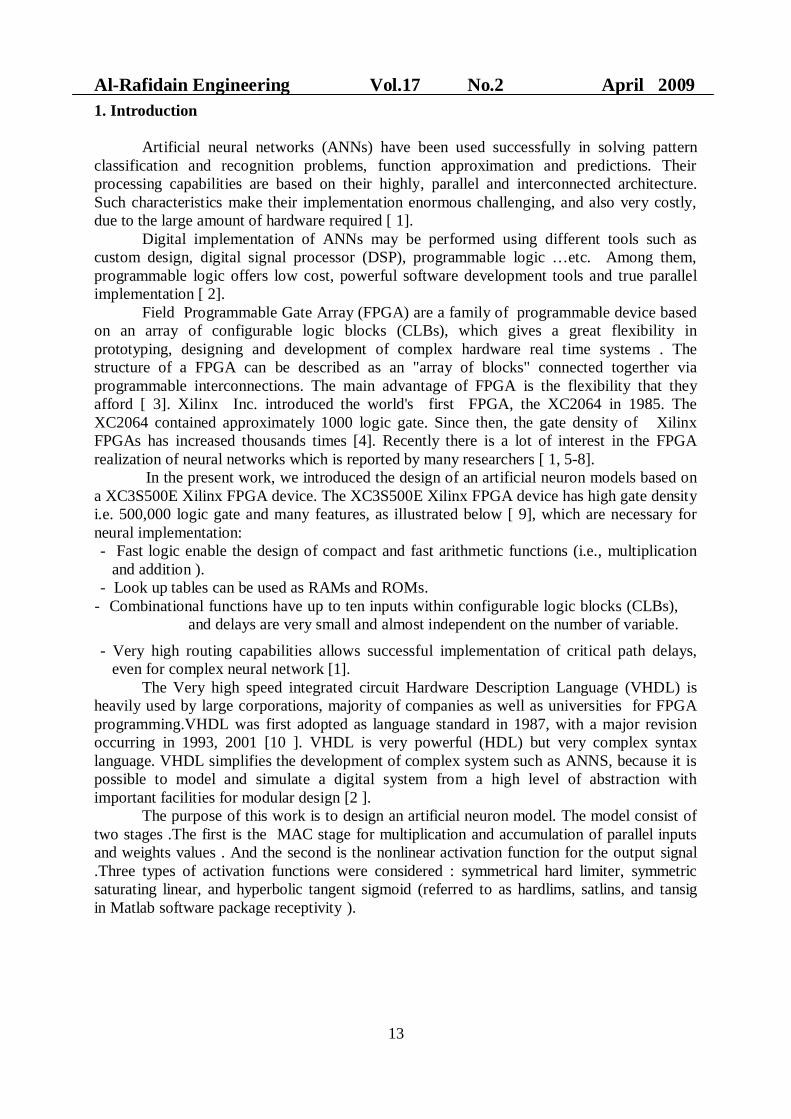
The common Mathematical model of an artificial neuron is shown in Fig.(1) [ 11] .
Fig.( 1) mathematical model of artificial neuron .
The neuron output can be written as :
1
( )R
j jj
a f w p ……………..…. ( 1 )
where jp is the input value and jw is the corresponding weight value , a is the output of
the neuron, and f is a nonlinear activation function. Typically the activation function ischosen by the designer for specific training algorithm , and then the weights will be adjustedby some learning rule so that the neuron input / output relationship meet some specific goal.
3. VHDL design of the neuron
It is important to design the neuron without activation function as common part in designinga complete neuron with any activation function based on FPGA The design affect theutilization ratio of the chips area and the processing speed directly. The structure of theneuron can be realized in many ways , mainly considering the degree of the parallelcomputation needed .
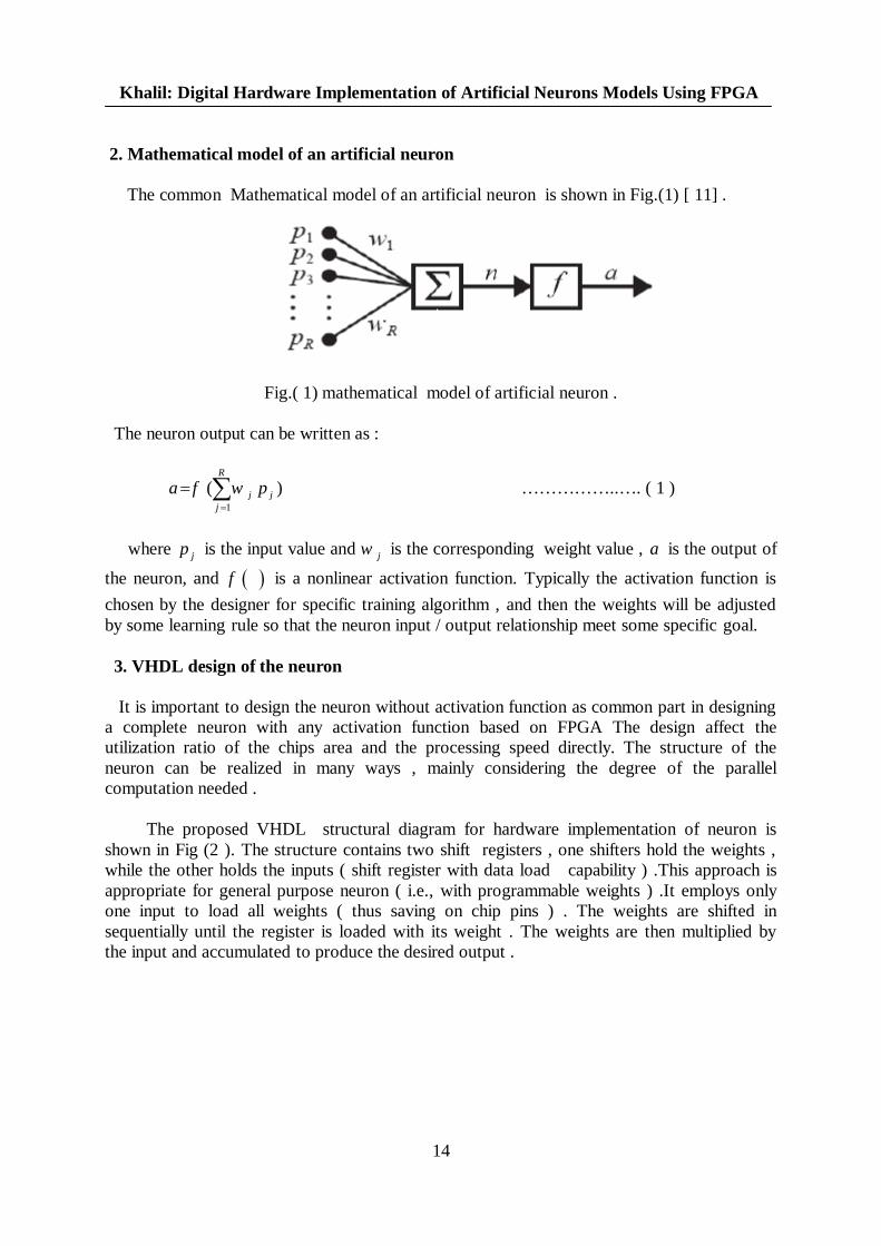
The proposed VHDL structural diagram for hardware implementation of neuron isshown in Fig (2 ). The structure contains two shift registers , one shifters hold the weights ,while the other holds the inputs ( shift register with data load capability ) .This approach isappropriate for general purpose neuron ( i.e., with programmable weights ) .It employs onlyone input to load all weights ( thus saving on chip pins ) . The weights are shifted insequentially until the register is loaded with its weight . The weights are then multiplied bythe input and accumulated to produce the desired output .
Al-Rafidain Engineering Vol.17 No.2 April 2009
15
Fig.( 2 ) VHDL structural diagram for neuron implementation.
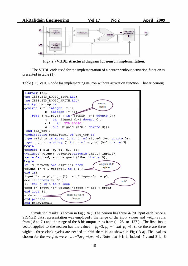
The VHDL code used for the implementation of a neuron without activation function ispresented in table (1).
Table ( 1 ) VHDL code for implementing neuron without activation function (linear neuron).
Simulation results is shown in Fig.( 3a ) .The neuron has three 4- bit input each .since aSIGNED data representation was employed , the range of the input values and weights runsfrom (-8 to 7 ) and the range of the 8-bit output runs from ( -128 to 127 ) . The first inputvector applied to the neuron has the values 1 2 33, 4, 5p p and p , since there are threewights , three clock cycles are needed to shift them in ,as shown in Fig ( 3 a) .The valueschosen for the weights were 3 2 17, 8, 9w w w . Note that 9 is in indeed -7 , and 8 is -8
Khalil: Digital Hardware Implementation of Artificial Neurons Models Using FPGA
16
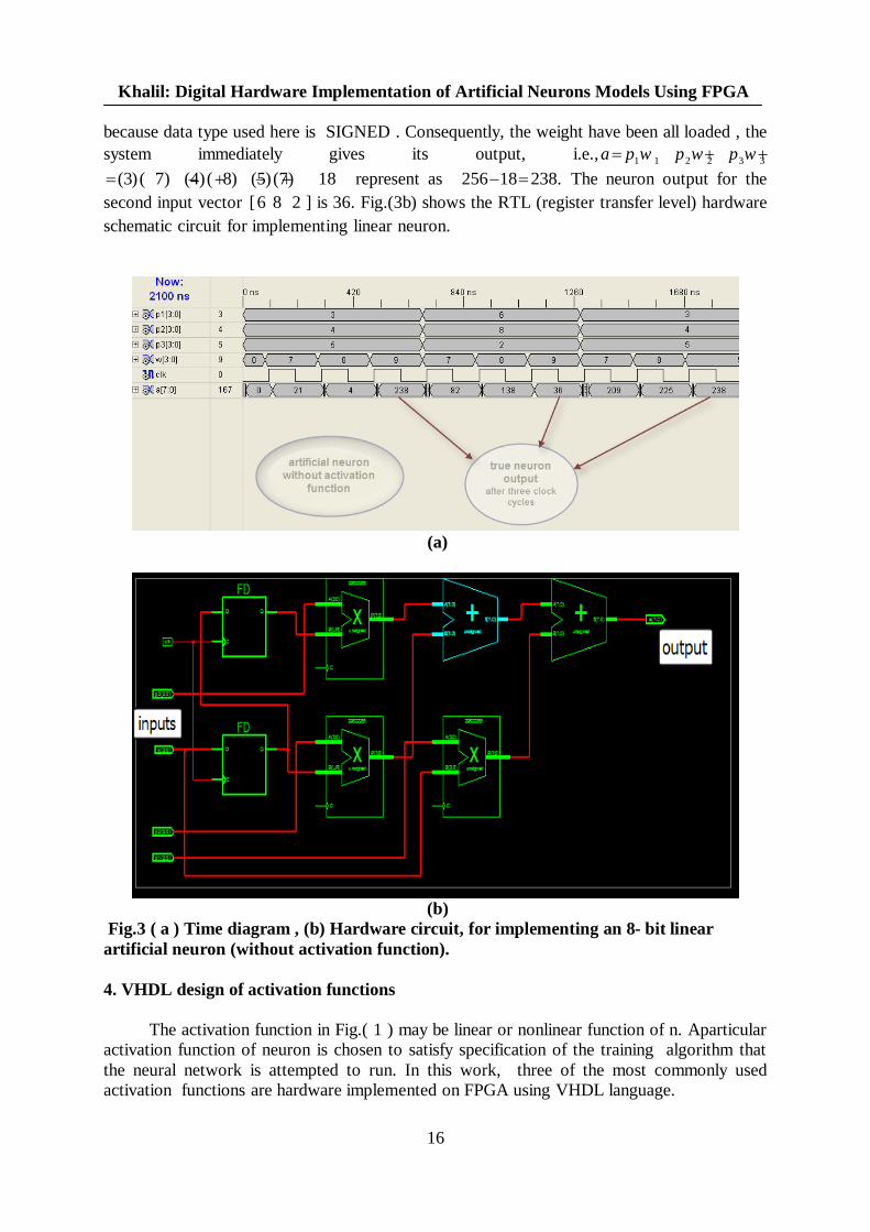
because data type used here is SIGNED . Consequently, the weight have been all loaded , thesystem immediately gives its output, i.e., 1 1 2 2 3 3a p w p w p w
(3)( 7) (4)( 8) (5)(7) 18 represent as 256 18 238. The neuron output for thesecond input vector [6 8 2 ] is 36. Fig.(3b) shows the RTL (register transfer level) hardwareschematic circuit for implementing linear neuron.
(a)
(b) Fig.3 ( a ) Time diagram , (b) Hardware circuit, for implementing an 8- bit linearartificial neuron (without activation function).
4. VHDL design of activation functions
The activation function in Fig.( 1 ) may be linear or nonlinear function of n. Aparticularactivation function of neuron is chosen to satisfy specification of the training algorithm thatthe neural network is attempted to run. In this work, three of the most commonly usedactivation functions are hardware implemented on FPGA using VHDL language.
Al-Rafidain Engineering Vol.17 No.2 April 2009
17
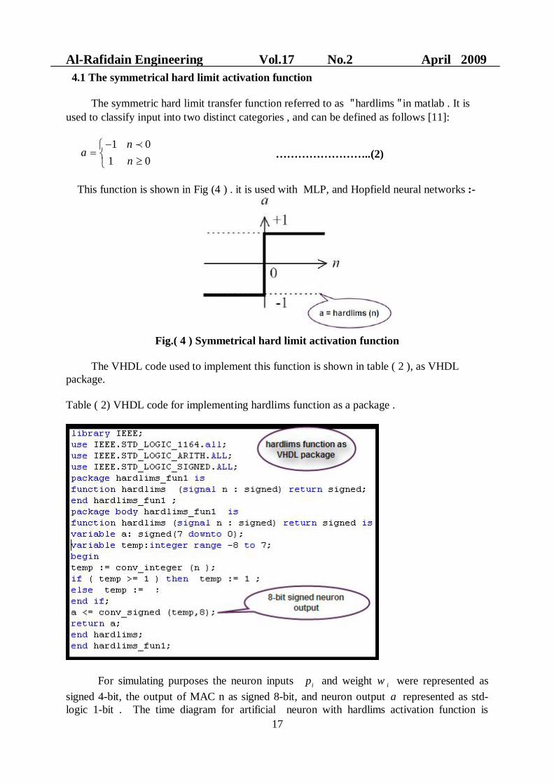
4.1 The symmetrical hard limit activation function
The symmetric hard limit transfer function referred to as " hardlims " in matlab . It isused to classify input into two distinct categories , and can be defined as follows [11]:
1 01 0
na
n ……………………..(2)
This function is shown in Fig (4 ) . it is used with MLP, and Hopfield neural networks :-
Fig.( 4 ) Symmetrical hard limit activation function
The VHDL code used to implement this function is shown in table ( 2 ), as VHDLpackage.
Table ( 2) VHDL code for implementing hardlims function as a package .
For simulating purposes the neuron inputs ip and weight iw were represented assigned 4-bit, the output of MAC n as signed 8-bit, and neuron output a represented as std-logic 1-bit . The time diagram for artificial neuron with hardlims activation function is
Khalil: Digital Hardware Implementation of Artificial Neurons Models Using FPGA
18
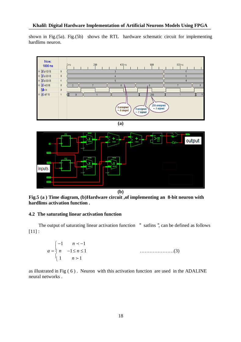
shown in Fig.(5a). Fig.(5b) shows the RTL hardware schematic circuit for implementinghardlims neuron.
(a)
(b)Fig.5 (a ) Time diagram, (b)Hardware circuit ,of implementing an 8-bit neuron withhardlims activation function .
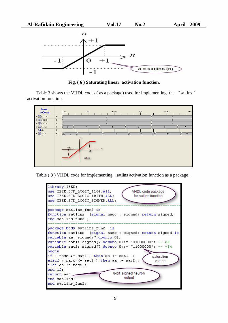
4.2 The saturating linear activation function
The output of saturating linear activation function " satlins ", can be defined as follows[11] :
1 11 1
1 1
na n n
n …………………(3)
as illustrated in Fig ( 6 ) . Neuron with this activation function are used in the ADALINEneural networks .
Al-Rafidain Engineering Vol.17 No.2 April 2009
19
Fig. ( 6 ) Saturating linear activation function.
Table 3 shows the VHDL codes ( as a package) used for implementing the " saltins "activation function.
Table ( 3 ) VHDL code for implementing satlins activation function as a package .
Khalil: Digital Hardware Implementation of Artificial Neurons Models Using FPGA
20
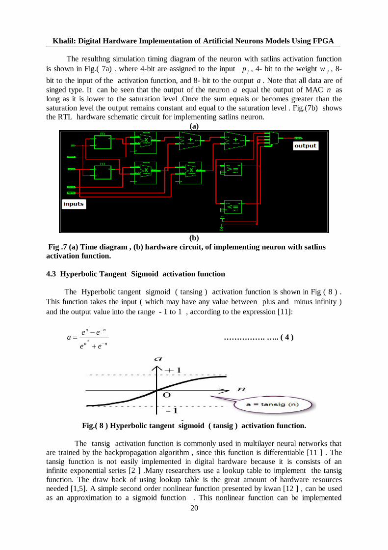
The resulthng simulation timing diagram of the neuron with satlins activation functionis shown in Fig.( 7a) . where 4-bit are assigned to the input jp , 4- bit to the weight jw , 8-bit to the input of the activation function, and 8- bit to the output a . Note that all data are ofsinged type. It can be seen that the output of the neuron a equal the output of MAC n aslong as it is lower to the saturation level .Once the sum equals or becomes greater than thesaturation level the output remains constant and equal to the saturation level . Fig.(7b) showsthe RTL hardware schematic circuit for implementing satlins neuron.
(a)
(b)Fig .7 (a) Time diagram , (b) hardware circuit, of implementing neuron with satlins
activation function.
4.3 Hyperbolic Tangent Sigmoid activation function
The Hyperbolic tangent sigmoid ( tansing ) activation function is shown in Fig ( 8 ) .This function takes the input ( which may have any value between plus and minus infinity )and the output value into the range - 1 to 1 , according to the expression [11]:
nn
nn
ee
eea e ……………. ….. ( 4 )
Fig.( 8 ) Hyperbolic tangent sigmoid ( tansig ) activation function.
The tansig activation function is commonly used in multilayer neural networks thatare trained by the backpropagation algorithm , since this function is differentiable [11 ] . Thetansig function is not easily implemented in digital hardware because it is consists of aninfinite exponential series [2 ] .Many researchers use a lookup table to implement the tansigfunction. The draw back of using lookup table is the great amount of hardware resourcesneeded [1,5]. A simple second order nonlinear function presented by kwan [12 ] , can be usedas an approximation to a sigmoid function . This nonlinear function can be implemented
Al-Rafidain Engineering Vol.17 No.2 April 2009
21
directly using digital techniques . The following equation is a second order nonlinear functionwhich has a tansig transition between the upper and lower saturation regions:
( . ) 0( )
( . )n B g n for n L
f nn B g n for L n L
……………………(4)
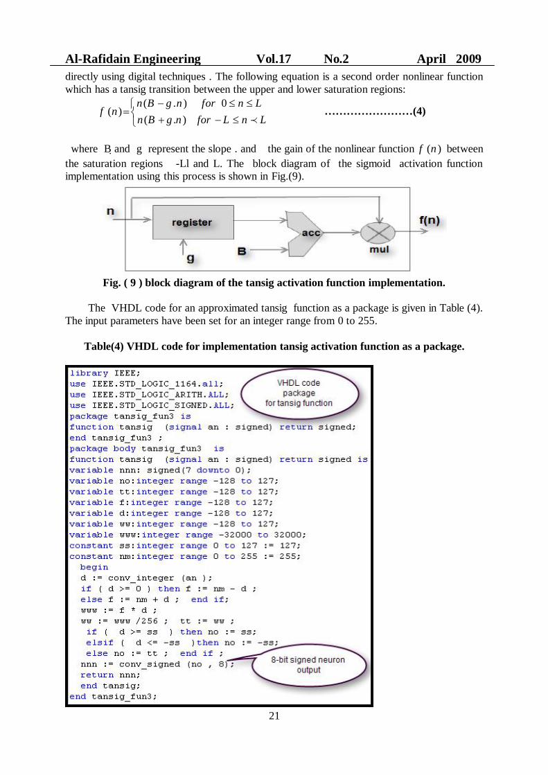
where B and g represent the slope . and the gain of the nonlinear function ( )f n betweenthe saturation regions -Ll and L. The block diagram of the sigmoid activation functionimplementation using this process is shown in Fig.(9).
Fig. ( 9 ) block diagram of the tansig activation function implementation.
The VHDL code for an approximated tansig function as a package is given in Table (4).The input parameters have been set for an integer range from 0 to 255.
Table(4) VHDL code for implementation tansig activation function as a package.
Khalil: Digital Hardware Implementation of Artificial Neurons Models Using FPGA
22
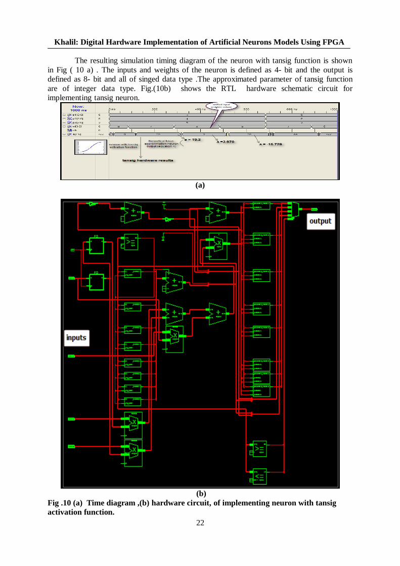
The resulting simulation timing diagram of the neuron with tansig function is shownin Fig ( 10 a) . The inputs and weights of the neuron is defined as 4- bit and the output isdefined as 8- bit and all of singed data type .The approximated parameter of tansig functionare of integer data type. Fig.(10b) shows the RTL hardware schematic circuit forimplementing tansig neuron.
(a)
(b)Fig .10 (a) Time diagram ,(b) hardware circuit, of implementing neuron with tansigactivation function.
Al-Rafidain Engineering Vol.17 No.2 April 2009
23
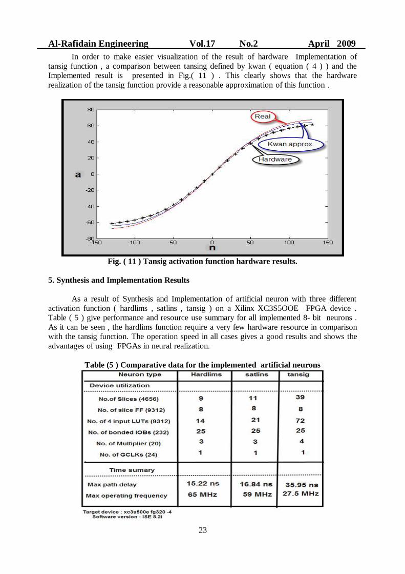
In order to make easier visualization of the result of hardware Implementation oftansig function , a comparison between tansing defined by kwan ( equation ( 4 ) ) and theImplemented result is presented in Fig.( 11 ) . This clearly shows that the hardwarerealization of the tansig function provide a reasonable approximation of this function .
Fig. ( 11 ) Tansig activation function hardware results.
5. Synthesis and Implementation Results
As a result of Synthesis and Implementation of artificial neuron with three differentactivation function ( hardlims , satlins , tansig ) on a Xilinx XC3S5OOE FPGA device .Table ( 5 ) give performance and resource use summary for all implemented 8- bit neurons .As it can be seen , the hardlims function require a very few hardware resource in comparisonwith the tansig function. The operation speed in all cases gives a good results and shows theadvantages of using FPGAs in neural realization.
Table (5 ) Comparative data for the implemented artificial neurons
Khalil: Digital Hardware Implementation of Artificial Neurons Models Using FPGA
24
6. Conclusions
The results of this work successfully demonstrate the hardware implementationof artificial neuron with three different activation functions using Xilinx FPGAS . Thisallows comparisons to be made between the hardware realization of these neurons , which areregarded as basic building block of artificial neural networks .
The tansig function approximation problem has been employed and demonstrate thevalidity of hardware implementation. The timing diagrams show the accuracy of the resultsand to enable comparisons with actual result . The operation frequency in all cases is verygood and it gives a clear idea of the advantages of using FPGAs, since multiple modules canbe working in parallel with a minimum reduction in performance due to the increased numberof interconnections.
Finally , it can be say that FPGAs technology and their low cost , and reprogrammabilitymake this approach a very powerful option for implementing ANNS as an alternative to thedevelopment of custom hardware.
References
1. Parasovic A., latinovic I . , "A Neural Network FPGA Implementation" . IEEE. 5thseminar on Neural Network Application in Electrical Engineering , September 2000 ,PP117 – 120.
2. R. Omondi, C. Rajapakse," FPGA Implementation of Neural Networks", Springer U.S.,2006, ISBN 10-0-387-28485-0.
3. Xilinx , XST User Guide , Xilinx Inc . 2003.4. S. Brown , J . Rose , "FPGA and CPDL Architectures , A Tutorial ", IEEE Design and
Test of Computer , No. 4 , June 1996 , pp.42 – 57.5. Pavlitov K., Mancler O., " FPGA Implementation of Artificial Neurons" , Electronics,
No.9 September , 2004 , pp . 22-24 .6. J. Blake , L. McDaid , " Using Xilinx FPGAs to Implement Neural Networks and
Fuzzy Systems" , Faculty of Eng . , University . of Ulster , Magel college , Northland Rd. Derry , 2005.
7. O. Maischberger ,V. Salapura , " A Fast FPGA Implementation of a General PurposeNeuron ", Technical University , Institute of in formatik , Austria , 2006.
8. Sarich , Moussa , " The Impact of Arithmetic Representation on Implementing MLP –BP on FPGAs : A study " , IEEE Transaction on Neural Network , Vol18 , No.1 ,JANNARY 2007 . PP240 – 255.
9. Xilinx , Spartan – 3E starter Kit Board user guide.10. D. L. Berry, "VHDL programming by examples", McGraw-Hill, fourth edition, 2002.11. M.Hagan , H . Demuth , M. Beele , " Neural Network Design" , University of Colorado
Bookstore, 2002, ISBN : 0- 9717321- 0-8.12. Kwan , H.K. , " simple sigmoid . like activation function suitable for digital hardware
implementation" , Electronic Letters , V.28 , July , 1992 , pp. 1379 – 1380 .
The work was carried out at the college of Engg. University of Mosul