KFE and KFVE recloser time-current curves - Eaton
24
February 1989 • Supersedes 4/86 1 Reclosers Electrical Apparatus KFE10001-E Electronically Controlled Types KFE and KFVE; Three-Phase Figure 1. Cooper Power System’s Type KFVE recloser combines interruption with hydraulic counting and electronic sensing and trippping. DESCRIPTlON The Cooper Power Systems three-phase Types KFE and KFVE hydraulic/electronic- vacuum reclosers (Figure 1 ) provide mini- mum maintenance, long operating life, reli- able and compact construction, proven and versatile solid-state electronics, and ground-fault tripping as low as five amps, and a maximum continuous current rating of 400 amps. The Type KFE provides 6000 amps symmetrical interrupting at 2.4-14.4 Kv and the Type KFVE provides 6000 amps symmetrical interrupting at 2.4-27 Kv. COOPER POWER SYSTEMS COMPANY HISTORY Fifty years ago, Kyle Corporation produced its first automatic circuit recloser. In 1947, Kyle became the distribution switchgear division of Line Material Industries, which then became part of McGraw-Electric Company in 1949. In 1957 the McGraw Electric Company merged with Thomas A. Edison Industries to become McGraw- Edison Company. In 1985 McGraw-Edison became a subsidiary of Cooper Industries. Through all of these growing stages, Kyle reclosers have been refined and improved to their present reliable, basically mainte- nance-free state. In addition, Kyle became a leader in technology with the introduction of the solid-state electronically controlled recloser in the early 60s. Since then, the electronic control has added simplicity, accuracy, and flexibility to power distribution protection schemes. In keeping with the tradition of McGraw- Edison’s progressive development, the Type KF vacuum recloser was redesigned to include the time-proven technology of elec- tronic control. The Types KFE and KFVE reclosers combine the self-contained durability and simplicity of hydraulic control with the accu- racy, reliability, and flexibility of solid-state electronics. These reclosers use long-life, mainte- nance-free vacuum interruption, in combi- nation with the latest solid-state electronic technology for current sensing and tripping. This combined technology produces a more compact (21% less volume), lighter (24% less weight) unit which requires 42% less oil. The results are lower shipping costs, lower maintenance costs, and reduced han- dling and warehousing costs. FEATURES Both the Type KFE and KFVE are com- pletely self-contained—no external power source or battery are required to operate the electronics. Power is obtained from the primary sources by means of bushing current transformers. A minimum of 5 amps primary-current flow is sufficient to power the electronics. ■ Compactly designed in size and weight to conveniently mount to pole or substation structure. ■ Plug-in trip resistors and trip-timing curves increase application flexibility. Plug-in components are easily installed into the electronic control— no longer a need to lower the recloser tank to change tripping and timing val- ues. ■ Ground-tripping as low as 5 amps is provided as a standard feature of the control. Ground-trip timing is available in both inverse and definite time curves. ■ Long-life, maintenance-free, sealed vacuum interrupters provide safe, quiet current interruption without the oil contamination and contact wear associated with other interrupting media. ■ Operating mechanism is designed to maximize recloser durability while simultaneously simplifying mainte- nance procedures. ■ All external tank and head hardware is stainless steel, ensuring easy main- tenance and durability. ■ Electronic control circuitry is central- ized on a single printed circuit board which is easily field replaceable. An easy-to-use electronic control tester is available. ■ Electronic control design expands and simplifies the addition of accessories. Instantaneous phase- and ground- tripping and fault-indicating acces- sories now available add to applica- tion flexibility. 88982KM-A
-
Upload
khangminh22 -
Category
Documents
-
view
0 -
download
0
Transcript of KFE and KFVE recloser time-current curves - Eaton

February 1989 • Supersedes 4/86 1
ReclosersElectrical Apparatus
KFE10001-EElectronically ControlledTypes KFE and KFVE; Three-Phase
Figure 1.Cooper Power System’s Type KFVE recloser combines interruption withhydraulic counting and electronic sensing and trippping.
DESCRIPTlONThe Cooper Power Systems three-phaseTypes KFE and KFVE hydraulic/electronic-vacuum reclosers (Figure 1 ) provide mini-mum maintenance, long operating life, reli-able and compact construction, proven andversatile solid-state electronics, andground-fault tripping as low as five amps,and a maximum continuous current ratingof 400 amps. The Type KFE provides 6000amps symmetrical interrupting at 2.4-14.4Kv and the Type KFVE provides 6000amps symmetrical interrupting at 2.4-27 Kv.
COOPER POWERSYSTEMS COMPANY HISTORYFifty years ago, Kyle Corporation producedits first automatic circuit recloser. In 1947,Kyle became the distribution switchgeardivision of Line Material Industries, whichthen became part of McGraw-ElectricCompany in 1949. In 1957 the McGrawElectric Company merged with Thomas A.Edison Industries to become McGraw-Edison Company. In 1985 McGraw-Edisonbecame a subsidiary of Cooper Industries.
Through all of these growing stages, Kylereclosers have been refined and improvedto their present reliable, basically mainte-nance-free state. In addition, Kyle became aleader in technology with the introduction ofthe solid-state electronically controlledrecloser in the early 60s. Since then, theelectronic control has added simplicity,accuracy, and flexibility to power distributionprotection schemes.
In keeping with the tradition of McGraw-Edison’s progressive development, the TypeKF vacuum recloser was redesigned toinclude the time-proven technology of elec-tronic control.
The Types KFE and KFVE recloserscombine the self-contained durability andsimplicity of hydraulic control with the accu-racy, reliability, and flexibility of solid-stateelectronics.
These reclosers use long-life, mainte-nance-free vacuum interruption, in combi-nation with the latest solid-state electronictechnology for current sensing and tripping.This combined technology produces amore compact (21% less volume), lighter(24% less weight) unit which requires 42%less oil.
The results are lower shipping costs,lower maintenance costs, and reduced han-dling and warehousing costs.
FEATURESBoth the Type KFE and KFVE are com-pletely self-contained—no externalpower source or battery are required tooperate the electronics. Power isobtained from the primary sources bymeans of bushing current transformers.A minimum of 5 amps primary-currentflow is sufficient to power the electronics.■ Compactly designed in size and
weight to conveniently mount to poleor substation structure.
■ Plug-in trip resistors and trip-timingcurves increase application flexibility.Plug-in components are easilyinstalled into the electronic control—no longer a need to lower the reclosertank to change tripping and timing val-ues.
■ Ground-tripping as low as 5 amps isprovided as a standard feature of thecontrol. Ground-trip timing is availablein both inverse and definite timecurves.
■ Long-life, maintenance-free, sealedvacuum interrupters provide safe,quiet current interruption without theoil contamination and contact wearassociated with other interruptingmedia.
■ Operating mechanism is designed tomaximize recloser durability whilesimultaneously simplifying mainte-nance procedures.
■ All external tank and head hardwareis stainless steel, ensuring easy main-tenance and durability.
■ Electronic control circuitry is central-ized on a single printed circuit boardwhich is easily field replaceable. Aneasy-to-use electronic control tester isavailable.
■ Electronic control design expands andsimplifies the addition of accessories.Instantaneous phase- and ground-tripping and fault-indicating acces-sories now available add to applica-tion flexibility.
88982KM-A
2
Types KFE and KFVE
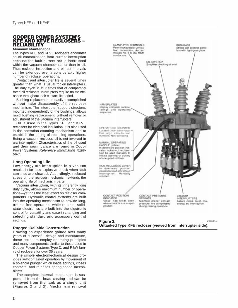
Figure 2.Untanked Type KFE recloser (viewed from interrupter side).
82057KM-A
COOPER POWER SYSTEM’SKFE AND KFVE RECLOSERS = RELIABILITYMinimum MaintenanceThe Types KFE and KFVE reclosers encounterno oil contamination from current interruptionbecause the fault-current arc is interruptedwithin the vacuum chamber rather than in oil.Thus recloser inspection and oil-test intervalscan be extended over a considerably highernumber of recloser operations.
Contact and interrupter life is several timesgreater than what is usual for oil interrupters.The duty cycle is four times that of comparablyrated oil reclosers. Interrupters require no mainte-nance throughout their contact-life period.
Bushing replacement is easily accomplishedwithout major disassembly of the reclosermechanism. The interrupter-support structure,mounted independently of the bushings, allowsrapid bushing replacement, without removal oradjustment of the vacuum interrupters.
Oil is used in the Types KFE and KFVEreclosers for electrical insulation. It is also usedin the operation-counting mechanism and toestablish the timing of reclosing operations.Being a vacuum recloser, oil is not involved inarc interruption. Characteristics of the oil usedand their significance are found in CooprPower Systems Reference Information R280-90-1.
Long Operating LifeLow-energy arc interruption in a vacuumresults in far less explosive shock when faultcurrents are cleared. Accordingly, reducedstress on the recloser mechanism extends theoperating life of mechanism parts.
Vacuum interruption, with its inherently longduty cycle, allows maximum number of opera-tions—yet has the least effect on recloser com-ponents. Hydraulic control systems are builtinto the operating mechanism to provide long,trouble-free operation, while reliable, solid-state electronics are built into the electroniccontrol for versatility and ease in changing andselecting standard and accessory control settings.
Rugged, Reliable Construction Drawing on experience gained over manyyears of successful design and manufacture,these reclosers employ operating principlesand many components similar to those used inCooper Power Systems Type D, and R&W fam-ily of reclosers for over 35 years.
The simple electromechanical design pro-vides self-contained operation by movement ofa solenoid plunger which loads springs, closescontacts, and releases springloaded mecha-nisms.
The complete internal mechanism is sus-pended from the head casting and can beremoved from the tank as a single unit(Figures 2 and 3). Mechanism removal

3
KFE10001-E
Figure 3.Untanked Type KFE recloser (viewed from contactor side).
82056KM-A82068KM-A
Figure 3.Head mechanism for Type KFE recloser (head removed).
88983KM-A
requires merely loosening and pivotingsix captive bolts on the head flange. Sixhead flange clamping locations assureeven and proper gasket compression. Anoil-tight, weatherproof seal betweenhead and tank is obtained by a nitrilegasket confined in a controlled compres-sion clamping arrangement. The mecha-nism itself is secured to the head withfour large bolts, easily removed in theevent that work is required on mecha-nism parts (Figure 4).
External construction involves arugged cast-aluminum head, sturdy well-anchored bushings, and a steel tank fin-ished with a corrosion-resistant polyesterbase paint. Both finish and bushing glazecolor is light gray, Munsell 5BG7.0/0.4.
Where additional operating and ser-vice flexibility is required, KFE and KFVEreclosers can be supplied with factory-installed accessories. Metering or relay-ing can be accomplished with integralbushing-current transformers. Remote-Trip, Remote-Close, and Remote-Lockout accessories permit remote oper-ation. Recloser contact or mechanismposition can be monitored with Auxiliaryor Lockout-lndicating Switches. Theseand other accessories permit KFE andKFVE reclosers to fit even the most com-plex of system applications.
4
Types KFE and KFVE
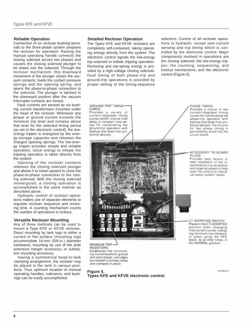
Figure 5.Types KFE and KFVE electronic control.
85708KM-A
Reliable OperationConnection of six recloser bushing termi-nals to the three-phase system preparesthe recloser for operation. Raising themanual operating handle connects theclosing solenoid across two phases andcauses the closing solenoid plunger tobe drawn into the solenoid. Through therecloser mechanism, this downwardmovement of the plunger closes the vac-uum contacts, loads the contact pressuresprings and the opening spring, andopens the phase-to-phase connection tothe solenoid. The plunger is latched inthe downward position after the vacuuminterrupter contacts are closed.
Fault currents are sensed by six bush-ing current transformers mounted underthe head of the recloser. Whenever anyphase or ground current exceeds theminimum trip level and remains abovethat level for the selected timing period(as set in the electronic control), the low-energy tripper is energized by the ener-gy-storage capacitor and releases thecharged opening springs. The low-ener-gy tripper provides simple and reliableoperation, since energy to initiate thetripping operation is taken directly fromthe system.
Opening of the recloser contactsreleases the closing solenoid plungerand allows it to travel upward to close thephase-to-phase connection to the clos-ing solenoid. With the closing solenoidreenergized, a closing operation isaccomplished in the same manner asdescribed above.
Hydraulic control of recloser opera-tions makes use of separate elements toregulate recloser sequence and reclos-ing time. A counting mechanism countsthe number of operations to lockout.
Versatile Recloser MountingAny of three methods can be used tomount a Type KFE or KFVE recloser.Direct mounting by tank lugs to either acurved or flat surface (mounting lugsaccommodate 16-mm (5/8-in.) diameterhardware); mounting by use of the poleextension hanger accessory; or substa-tion mounting accessory.
Having a symmetrical head-to-tankclamping arrangement, the recloser maybe placed in the tank in various posi-tions. Thus optimum location of manualoperating handles, indicators, and bush-ings can be easily accomplished.
Detailed Recloser OperationThe Types KFE and KFVE reclosers arecompletely self-contained, taking operat-ing energy directly from the system. Theelectronic control signals the low-energytrip solenoid to initiate tripping operation.Reclosing and trip-spring energy is pro-vided by a high-voltage closing solenoid.Dual timing of both phase-tr ip andground-trip operations is provided byproper setting of the timing-sequence
selectors. Control of all recloser opera-tions is hydraulic, except over-currentsensing and trip timing which is con-trolled by the electronic control. Majorcomponents involved in operations arethe closing solenoid; the low-energy trip-per ; the counting, sequencing, and lockout mechanisms; and the electroniccontrol (Figure 5).

5
KFE10001-E
Figure 6.Simplified diagram of recloser’s major electrical and mechanical components.
CLOSING SOLENOlDEnergy that operates the recloser mech-anism to close the vacuum interruptercontacts, compress the contact pressuresprings, and charge the opening springis obtained from the system through ahigh-voltage closing solenoid. As shownin Figure 6, this solenoid is connectedphase-to-phase on the recloser’s sourceside through a high-voltage contactor(switch). Selection of the closing solenoidvoltage rating is based on the phase-to-phase voltage of the system on whichthe recloser is to be used. Low-voltagepower can be employed for closing if theproper solenoid and a Low-VoltageClosing accessory are specified whenthe recloser is ordered.
The closing operation is best under-stood by considering the recloser to beconnected to the line out but locked out(yellow manual operating handle in
downward position). To close from lock-out, the manual operating handle israised to the closed position. This allowsthe closing solenoid contactor to closethe phase-to-phase connection, therebyenergizing the closing solenoid andimparting a downward acceleration to thesolenoid plunger. Downward movementof the plunger causes the recloser oper-ating mechanism to do the following:
■ Contact-operating rods move down-ward to close vacuum interrupter con-tacts and compress contact-pressuresprings.
■ Closing-solenoid contactor opens.■ Opening spring is charged and reclos-
er mechanism is set up for a trippingoperation.
■ Plunger is latched in its downwardposition, charging plunger-returnsprings.
While the recloser contacts are closed,the solenoid plunger remains latched inits downward position. Release of therecloser-opening spring (as in a tripoperation) releases the plunger latch andallows the plunger to be drawn upwardunder action of the plunger-returnsprings. Oil flow into the chamber beingvacated by upward movement of theplunger is regulated by a timing orifice inits base. This retards the plunger’supward movement to accomplish therecloser’s two-second reclosing time (afour-second reclosing time is also avail-able as an accessory). As the plungerreaches the top of its stroke, the closingsolenoid contactor again closes, momen-tarily actuating the closing solenoid, anddrawing the plunger back down to repeatthe closing operation.

6
Types KFE and KFVE
Figure 7.Low-energy tripper.
Figure 8.Simplified diagram of counting mechanism.
82076KM-A
LOW-ENERGY TRIPPERThe low-energy tripping mechanism,operated from the electronic control, initi-ates the overcurrent tripping operation.The mechanism consists of a permanentmagnet and an armature and coil assem-bly which operate a trip lever (Figure 7).
During the closing operation, an elec-tromagnetic charging coil instantaneous-ly charges the trip capacitors — in theelectronic-trip control—assuring that therecloser is armed and ready for animmediate trip operation if necessary.When the recloser is closed, the tripper-armature plunger is held in by the mag-netic force of the permanent magnet. Inthis position, the armature spring is com-pressed and energized—ready to with-draw the armature when magneticallyreleased.
During a trip operation, the storedenergy in the trip capacitors energizesthe solenoid coil in the low-energy trip-per. This creates a counter-magneticfield which momentarily neutralizes thefield of the permanent magnet—thusallowing the spring-driven armature toinstantaneously operate the trip leverwhich in turn opens the recloser con-tacts. As the recloser contacts open, theprecharged reset spring is released andreturns the solenoid plunger to its de-energized position. This low-energy tripassembly is thus re-cocked and able toperform another trip operation as soonas a closing operation is completed.
COUNTING AND SEQUENCINGMECHANISMSEach recloser operation is counted —phase and ground—by a ratchet-rod-andpiston assembly mounted on the reclosermechanism. The counting mechanism inturn actuates the recloser’s sequencemechanism and lockout mechanism.
COUNTING OPERATIONAfter each tripping operation, during thereclosing interval, a spring-biased pawlis moved upward by the pivoting mecha-nism linkage as shown by arrows inFigure 8. Being spring biased, the pawlengages the ratchet rod at the bottom ofits stroke, raising the rod approximately7,9-mm (5/16-in.). At the top of its stroke,the pawl disengages from the ratchetrod, returning to its starting position asthe recloser closes.
The count is registered by a piston thatis attached to the lower end of the ratch-et rod and moves in an oil-filled housing.The piston is drawn upward with theratchet rod and held there by oil trappedby a ball check valve; as the piston isdrawn upward the valve opens, permit-ting the piston unimpeded upward travel,but downward movement only at a cali-brated resetting rate. Each subsequentrecloser operation further elevates theratchet rod and piston.
7
KFE10001-E
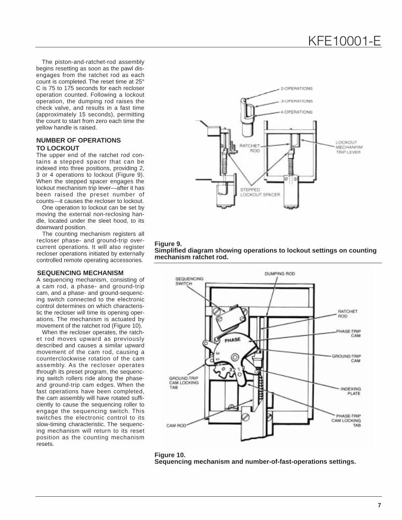
Figure 9.Simplified diagram showing operations to lockout settings on countingmechanism ratchet rod.
Figure 10.Sequencing mechanism and number-of-fast-operations settings.
The piston-and-ratchet-rod assemblybegins resetting as soon as the pawl dis-engages from the ratchet rod as eachcount is completed. The reset time at 25°C is 75 to 175 seconds for each recloseroperation counted. Following a lockoutoperation, the dumping rod raises thecheck valve, and results in a fast time(approximately 15 seconds), permittingthe count to start from zero each time theyellow handle is raised.
NUMBER OF OPERATIONS TO LOCKOUTThe upper end of the ratchet rod con-tains a stepped spacer that can beindexed into three positions, providing 2,3 or 4 operations to lockout (Figure 9).When the stepped spacer engages thelockout mechanism trip lever—after it hasbeen raised the preset number ofcounts—it causes the recloser to lockout.
One operation to lockout can be set bymoving the external non-reclosing han-dle, located under the sleet hood, to itsdownward position.
The counting mechanism registers allrecloser phase- and ground-trip over-current operations. It will also registerrecloser operations initiated by externallycontrolled remote operating accessories.
SEQUENCING MECHANISMA sequencing mechanism, consisting ofa cam rod, a phase- and ground-tripcam, and a phase- and ground-sequenc-ing switch connected to the electroniccontrol determines on which characteris-tic the recloser will time its opening oper-ations. The mechanism is actuated bymovement of the ratchet rod (Figure 10).
When the recloser operates, the ratch-et rod moves upward as previouslydescribed and causes a similar upwardmovement of the cam rod, causing acounterclockwise rotation of the camassembly. As the recloser operatesthrough its preset program, the sequenc-ing switch rollers ride along the phase-and ground-trip cam edges. When thefast operations have been completed,the cam assembly will have rotated suffi-ciently to cause the sequencing roller toengage the sequencing switch. Thisswitches the electronic control to itsslow-timing characteristic. The sequenc-ing mechanism will return to its resetposition as the counting mechanismresets.

8
Types KFE and KFVE
Figure 11.Types KFE and KFVE recloser electronic control.
Figure 12.Functional block diagram of electronic control.
85708KM-A
NUMBER OF FAST OPERATIONSThe phase- and ground-trip cams areused to program the number of fast tripoperations required in the recloser’soperating sequence. As shown in Figure10, the cam plates contain indexing num-bers (0, 1, 2, 3) for both phase andground. The operating sequence is setby simply lifting the locking tab on eitherthe phase- or ground-trip cam and rotat-ing it until it aligns with the desired num-ber of operations on the fast curve. Thenumber of slow operations will be auto-matically established—it will be the differ-ence between the number of fast opera-tions and the number of operations tolockout. In all cases, the total number ofoperations on both phase and groundmust be the same. If four fast operationsare desired, consult the factory.
ELECTRONIC CONTROLThe electronic control (Figures 11 and12) utilizes solid-state circuitry and pro-vides the intelligence for current sensingand trip timing. All the control electronicsand electronic accessories are located inan external cabinet connected to therecloser with a 1,8-m (6-ft) long cable.The separate control cabinet is intendedto be mounted to the recloser tank,although it can be mounted to the pole orother mounting structure at a distanceequal to the cable length. The controlcable is hard wired to the recloser andconnected to the control with a threadedweatherproof connector.
CURRENT SENSINGKFE and KFVE reclosers have six1000:1-ratio current-sensing transform-ers mounted on the bushings under thehead—providing both phase- andground- (zero-sequence) current sens-ing. The CTs are connected to the elec-tronic control cabinet by the 1,8-m (6-ft)cable.
MINIMUM-TRIP SELECTIONThe minimum-trip ratings, both phase(10-800 amps) and ground (5-400 amps)are established by plug-in resistor car-tridges. The cartridges are labeled withtheir minimum-trip current values. Theminimum-trip setting of the recloser canbe changed by merely changing the tripresistors. A 1-amp ground minimum-triprating is also available by connecting ajumper between Tabs X and Y on themain circuit board and installing a 5-ampground minimum-trip resistor.

9
KFE10001-E
Figure 13.Typical set of time-current curves for phase-trip operations.
PHASE- AND GROUND-TRIP TIMINGA variety of time-current characteristiccurves allow the KFE and KFVE to fitspecific power distribution systems. Alltiming starts at initiation of a fault, orwhen closing into a fault.
An A (fast), and B and C (delayed)phase-trip timing curves are available.For ground-trip timing, inverse curves 1(fast) and 2 and 3 (delayed) and 9 con-stant time curves of from 0.1 to 15 sec-onds are available.
The A curve for phase timing is per-manently wired on the control circuitboard. The delayed phase-trip curvesand all ground-trip curves are circuitcards which plug into the main controlboard. Phase and ground TCC circuitcards are not interchangeable. A typicalset of curves is illustrated in Figure 13.For detailed coordination planning,complete sets of curves can beordered; specify Cooper PowerSystems bulletin KFE10004-E.
CONTROL POWERThe KFE and KFVE reclosers are com-pletely self-contained; no external powersource or battery is required to operatethe electronics. The electronic circuitry ispowered from the line by bushing-cur-rent transformers mounted under thehead. A minimum of 5-amps primarycurrent flow is sufficient to power theelectronics and charge the trip capaci-tors which actuate the low-energy trip-per. In addition, a pickup coil, wound onone leg of the closing solenoid frame,provides additional charge to the tripcapacitors during each reclosing opera-tion to insure that sufficient trippingpower is available immediately followinga closing operation, thus eliminating thenecessity of a time delay to charge tripcapacitors from load or fault current.Tabs are provided on Terminal Strip TB2within the control cabinet for connectinga 15-18 Vdc voltage supply to chargethe capacitors for test purposes.
VACUUM INTERRUPTlONVacuum has proven to be an efficientmedium for fault- and load-current inter-ruption. It offers many advantages overother interrupting media:■ Deterioration of the medium is virtually
non existent.■ Its extremely rapid dielectric recovery
makes the interrupter insensitive tothe recovery-voltage rise rates usuallyencountered.
■ Interrupter contact wear is minimal;consequently, contact life is consider-ably extended.
■ Shorter contact travel significantlyreduces mechanism shock whichresults in less parts wear and longeroperating life.
■ Shorter contact travel results in fasteropening time and fault clearing.
■ The medium itself requires no servicethroughout the life of the interrupter.
Since the early twenties, designers ofcircuit interrupters have recognized theadvantages of vacuum as an interruptingmedium. But only during the last 35years have two major technologicaladvances enabled vacuum interruptersto become a commercial reality. Theseare developments in metallurgy growingout of the semiconductor industry anddevelopments in modern vacuum techniques.
It was during this period that CooperPower Systems, in conjunction with otherresearch organizations, developed itsfirst vacuum interrupter. Culminating overten years of research, testing, and devel-opment, Cooper Power Systems (thenLine Material Industries) announced in1966 the Type VSA vacuum recloser,forerunner of what today is the industry’sbroadest line of vacuum reclosers.
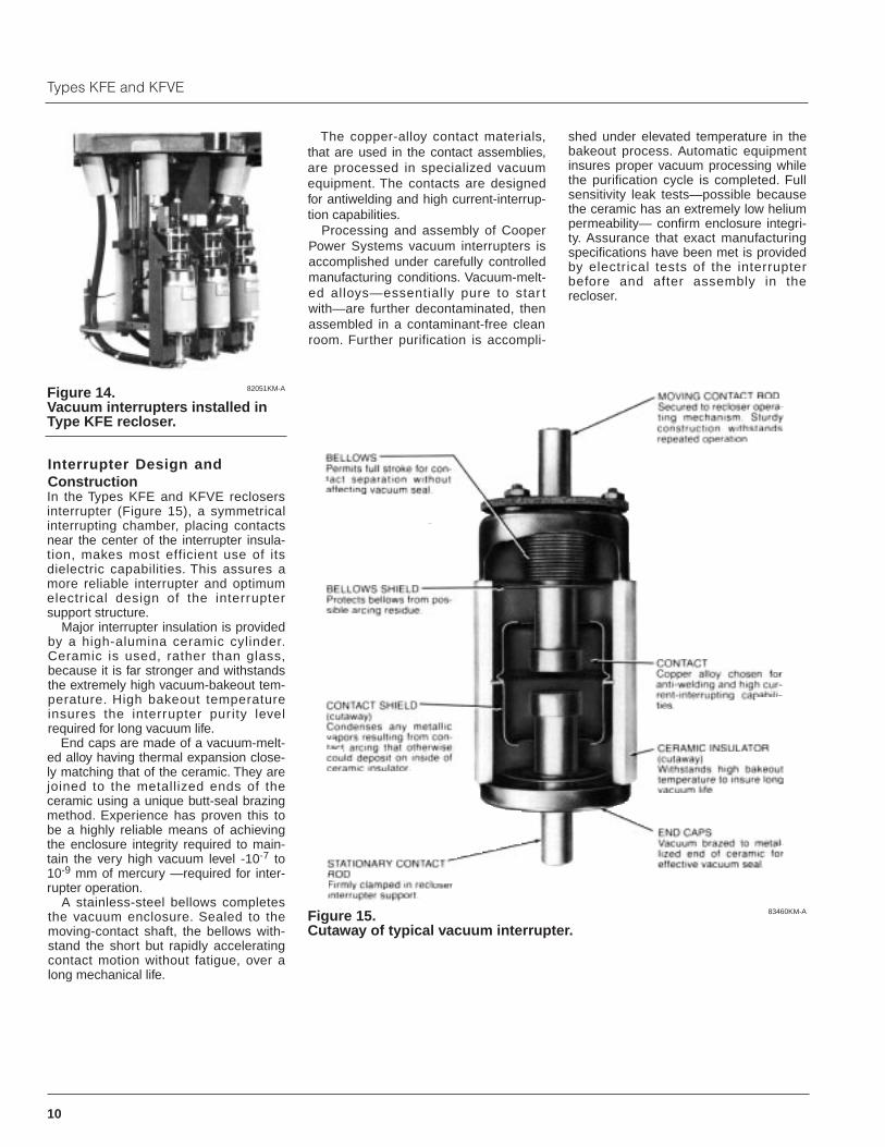
Manufactured at its Kyle ProductsPlant, Cooper Power Systems vacuuminterrupters have established a superbfield record for long life and high reliabili-ty. This stems from superior design,materials, and processing, plus thoroughtesting to confirm that high-quality stan-dards have been met. The interruptersused in the Types KFE and KFVEreclosers (Figure 14) employ the samematerials and are similarly processedand tested.
10
Types KFE and KFVE
Figure 15.Cutaway of typical vacuum interrupter.
Figure 14.Vacuum interrupters installed inType KFE recloser.
83460KM-A
82051KM-A
Interrupter Design andConstructionIn the Types KFE and KFVE reclosersinterrupter (Figure 15), a symmetricalinterrupting chamber, placing contactsnear the center of the interrupter insula-tion, makes most efficient use of itsdielectric capabilities. This assures amore reliable interrupter and optimumelectr ical design of the interrupter support structure.
Major interrupter insulation is providedby a high-alumina ceramic cylinder.Ceramic is used, rather than glass,because it is far stronger and withstandsthe extremely high vacuum-bakeout tem-perature. High bakeout temperatureinsures the interrupter purity levelrequired for long vacuum life.
End caps are made of a vacuum-melt-ed alloy having thermal expansion close-ly matching that of the ceramic. They arejoined to the metallized ends of theceramic using a unique butt-seal brazingmethod. Experience has proven this tobe a highly reliable means of achievingthe enclosure integrity required to main-tain the very high vacuum level -10-7 to10-9 mm of mercury —required for inter-rupter operation.
A stainless-steel bellows completesthe vacuum enclosure. Sealed to themoving-contact shaft, the bellows with-stand the short but rapidly acceleratingcontact motion without fatigue, over along mechanical life.
The copper-alloy contact materials,that are used in the contact assemblies,are processed in specialized vacuumequipment. The contacts are designedfor antiwelding and high current-interrup-tion capabilities.
Processing and assembly of CooperPower Systems vacuum interrupters isaccomplished under carefully controlledmanufacturing conditions. Vacuum-melt-ed alloys—essentially pure to star twith—are further decontaminated, thenassembled in a contaminant-free cleanroom. Further purification is accompli-
shed under elevated temperature in thebakeout process. Automatic equipmentinsures proper vacuum processing whilethe purification cycle is completed. Fullsensitivity leak tests—possible becausethe ceramic has an extremely low heliumpermeability— confirm enclosure integri-ty. Assurance that exact manufacturingspecifications have been met is providedby electrical tests of the interrupterbefore and after assembly in the recloser.
11
KFE10001-E
TABLE 1Voltage Ratings
TABLE 2Current Rating
TABLE 3Interrupting Rating
TABLE 4Operating Times
TABLE 5Duty Cycle
TABLE 6Mechanical Specifications
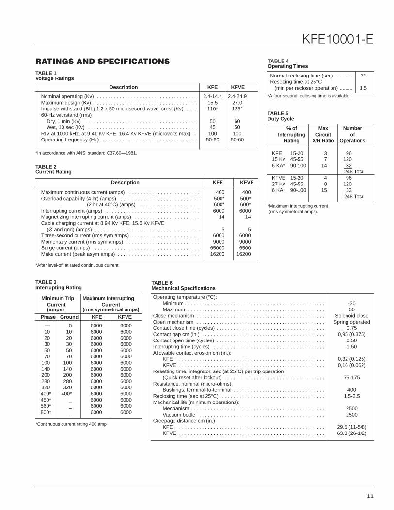
RATINGS AND SPECIFICATIONS
Description KFE KFVE
Nominal operating (Kv) . . . . . . . . . . . . . . . . . . . . . . . . . . . . . . . . . . . 2.4-14.4 2.4-24.9Maximum design (Kv) . . . . . . . . . . . . . . . . . . . . . . . . . . . . . . . . . . . . 15.5 27.0Impulse withstand (BIL) 1.2 x 50 microsecond wave, crest (Kv) . . . 110* 125*60-Hz withstand (rms)
Dry, 1 min (Kv) . . . . . . . . . . . . . . . . . . . . . . . . . . . . . . . . . . . . . . . 50 60Wet, 10 sec (Kv) . . . . . . . . . . . . . . . . . . . . . . . . . . . . . . . . . . . . . . 45 50
RIV at 1000 kHz, at 9.41 Kv KFE, 16.4 Kv KFVE (microvolts max) . 100 100Operating frequency (Hz) . . . . . . . . . . . . . . . . . . . . . . . . . . . . . . . . . 50-60 50-60
Description KFE KFVE
Maximum continuous current (amps) . . . . . . . . . . . . . . . . . . . . . . . . . 400 400Overload capability (4 hr) (amps) . . . . . . . . . . . . . . . . . . . . . . . . . . . . 500* 500*
(2 hr at 40°C) (amps) . . . . . . . . . . . . . . . . . . . . . 600* 600*Interrupting current (amps) . . . . . . . . . . . . . . . . . . . . . . . . . . . . . . . . . 6000 6000Magnetizing interrupting current (amps) . . . . . . . . . . . . . . . . . . . . . . . 14 14Cable charging current at 8.94 Kv KFE, 15.5 Kv KFVE
(Ø and gnd) (amps) . . . . . . . . . . . . . . . . . . . . . . . . . . . . . . . . . . . . . 5 5Three-second current (rms sym amps) . . . . . . . . . . . . . . . . . . . . . . . . 6000 6000Momentary current (rms sym amps) . . . . . . . . . . . . . . . . . . . . . . . . . . 9000 9000Surge current (amps) . . . . . . . . . . . . . . . . . . . . . . . . . . . . . . . . . . . . . 65000 6500Make current (peak asym amps) . . . . . . . . . . . . . . . . . . . . . . . . . . . . . 16200 16200
Minimum Trip Maximum InterruptingCurrent Current(amps) (rms symmetrical amps)
Phase Ground KFE KFVE
— 5 6000 600010 10 6000 600020 20 6000 600030 30 6000 600050 50 6000 600070 70 6000 6000
100 100 6000 6000140 140 6000 6000200 200 6000 6000280 280 6000 6000320 320 6000 6000400* 400* 6000 6000450* _ 6000 6000560* _ 6000 6000800* _ 6000 6000
Normal reclosing time (sec) ............ 2*Resetting time at 25°C
(min per recloser operation) ......... 1.5
% of Max NumberInterrupting Circuit of
Rating X/R Ratio Operations
KFE 15-20 3 9615 Kv 45-55 7 1206 KA* 90-100 14 32
248 TotalKFVE 15-20 4 9627 Kv 45-55 8 1206 KA* 90-100 15 32
248 Total
Operating temperature (°C):Minimum . . . . . . . . . . . . . . . . . . . . . . . . . . . . . . . . . . . . . . . . . . . . . . . . . -30Maximum . . . . . . . . . . . . . . . . . . . . . . . . . . . . . . . . . . . . . . . . . . . . . . . . 50
Close mechanism . . . . . . . . . . . . . . . . . . . . . . . . . . . . . . . . . . . . . . . . . . . . . Solenoid closeOpen mechanism . . . . . . . . . . . . . . . . . . . . . . . . . . . . . . . . . . . . . . . . . . . . . Spring operatedContact close time (cycles) . . . . . . . . . . . . . . . . . . . . . . . . . . . . . . . . . . . . . . 0.75Contact gap cm (in.) . . . . . . . . . . . . . . . . . . . . . . . . . . . . . . . . . . . . . . . . . . . 0,95 (0.375)Contact open time (cycles) . . . . . . . . . . . . . . . . . . . . . . . . . . . . . . . . . . . . . . 0.50Interrupting time (cycles) . . . . . . . . . . . . . . . . . . . . . . . . . . . . . . . . . . . . . . . 1.50Allowable contact erosion cm (in.):
KFE . . . . . . . . . . . . . . . . . . . . . . . . . . . . . . . . . . . . . . . . . . . . . . . . . . . . 0,32 (0.125)KFVE . . . . . . . . . . . . . . . . . . . . . . . . . . . . . . . . . . . . . . . . . . . . . . . . . . . 0,16 (0.062)
Resetting time, integrator, sec (at 25°C) per trip operation(Quick reset after lockout) . . . . . . . . . . . . . . . . . . . . . . . . . . . . . . . . . . . 75-175
Resistance, nominal (micro-ohms):Bushings, terminal-to-terminal . . . . . . . . . . . . . . . . . . . . . . . . . . . . . . . . 400
Reclosing time (sec at 25°C) . . . . . . . . . . . . . . . . . . . . . . . . . . . . . . . . . . . . 1.5-2.5Mechanical life (minimum operations):
Mechanism . . . . . . . . . . . . . . . . . . . . . . . . . . . . . . . . . . . . . . . . . . . . . . . 2500Vacuum bottle . . . . . . . . . . . . . . . . . . . . . . . . . . . . . . . . . . . . . . . . . . . . 2500
Creepage distance cm (in.)KFE . . . . . . . . . . . . . . . . . . . . . . . . . . . . . . . . . . . . . . . . . . . . . . . . . . . . 29.5 (11-5/8)KFVE. . . . . . . . . . . . . . . . . . . . . . . . . . . . . . . . . . . . . . . . . . . . . . . . . . . . 63.3 (26-1/2)
*In accordance with ANSI standard C37.60—1981.
*After level-off at rated continuous current
*Continuous current rating 400 amp
*A four-second reclosing time is available.
*Maximum interrupting current(rms symmetrical amps).

12
Types KFE and KFVE
Figure 16.Types KFE recloser top and front view dimensions.
DIMENSIONS, WEIGHTS, OIL CAPACITY
13
KFE10001-E
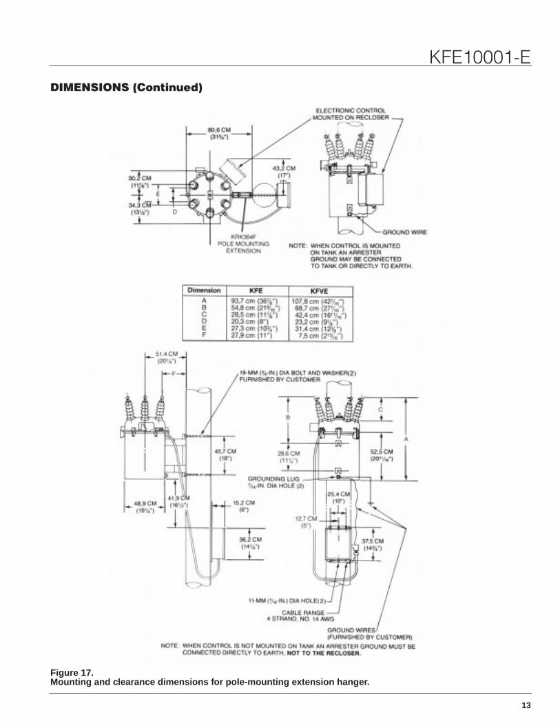
Figure 17.Mounting and clearance dimensions for pole-mounting extension hanger.
DIMENSIONS (Continued)

14
Types KFE and KFVE
Figure 18.Mounting and clearance dimensions for substation elevating structure.
15
KFE10001-E
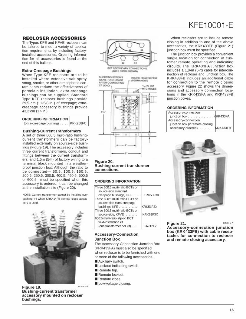
Figure 19.Bushing-current transformeraccessory mounted on recloserbushings.
Figure 20.Bushing-current transformer connections.
Figure 21.Accessory-connection junctionbox (KRK433FB) with cable recep-tacles for connection to recloserand remote-closing accessory.
83459KM-A
82083KM-A
RECLOSER ACCESSORIESThe Types KFE and KFVE reclosers canbe tailored to meet a variety of applica-tion requirements by including factory-installed accessories. Ordering informa-tion for all accessories is found at theend of this bulletin.
Extra-Creepage BushingsWhen Type KFE reclosers are to beinstalled where extensive salt spray,smog, smoke, or other atmospheric con-taminants reduce the effectiveness ofporcelain insulation, extra-creepagebushings can be supplied. StandardType KFE recloser bushings provide29,5 cm (11-5/8-in ) of creepage; extra-creepage accessory bushings provide43,2 cm (17-in.).
ORDERING INFORMATlONExtra-creepage bushings . . . . . KRK288FC
Bushing-Current TransformersA set of three 600:5 multi-ratio bushing-current transformers can be factory-installed externally on source-side bush-ings (Figure 19). The accessory includesthree current transformers, conduit andfittings between the current transform-ers, and 1,5m (5-ft) of factory wiring to aterminal block mounted in a weather-proof junction box. Although the ratio tobe connected— 50:5, 100:5, 150:5,200:5, 250:5, 300:5, 400:5, 450:5, 500:5or 600:5—must be specified when thisaccessory is ordered, it can be changedat the installation site (Figure 20).
NOTE: Current transformer cannot be installed overbushing #4 when KRK414FB remote close acces-sory is used.
Three 600:5 multi-ratio BCTs onsource-side standardcreepage bushings, KFE . . . . . KRK50F3X
Three 600:5 multi-ratio BCTs onsource-side extra-creepagebushings, KFE . . . . . . . . . . . . . KRK51F3X
Three 600:5 multi-ratio BCTs onsource-side, KFVE . . . . . . . . . KRK63F3X
600:5 multi-ratio slip-on BCTfield-installation kit(one transformer per kit). . . . . KA712L2
ORDERING INFORMATlON
ORDERING INFORMATlON
Accessory-Connection Junction Box The Accessory-Connection Junction Box(KRK433FA) must also be specifiedwhen recloser is to be furnished with oneor more of the following accessories.■ Auxiliary switch.■ Lockout-indicating switch.■ Remote trip.■ Remote lockout.■ Remote close.■ Low-voltage closing.
When reclosers are to include remoteclosing in addition to one of the aboveaccessories, the KRK433FB (Figure 21)junction box must be specified.
The junction box provides a convenientsingle location for connection of cus-tomer remote operating and indicatingcircuits. The KRK433FA junction boxincludes a 1,8-m (6-ft) cable for intercon-nection of recloser and junction box. TheKRK433FB includes an additional cablefor connection to the remote closingaccessory. Figure 22 shows the dimen-sions and accessory connection loca-tions in the KRK433FA and KRK433FBjunction boxes.
Accessory-connectionjunction box . . . . . . . . . . . . . . . KRK433FA
Accessory-connectionjunction box (if remote-closingaccessory ordered) . . . . . . . . KRK433FB

16
Types KFE and KFVE
Figure 22.Dimensions and accessory-con-nection locations in the KRK433FAand KRK433FB accessory junctionboxes.
Figure 23.Auxiliary switch mounted on sideof recloser mechanism frame.
Figure 24.Lockout-indicating switch mount-ed on side of recloser mechanism.
82253KM-A 82253KM-A
VoltsCurrent(amps)
120 ac 15240 ac 1524 dc 248 dc 0.75
125 dc 0.5250 dc 0.25
Auxiliary SwitchRemote indication of recloser contactposition can be accomplished with theAuxiliary Switch accessory (Figure 23).The contacts of the auxiliary switch alsocan be used to switch other circuits inaccordance with the opening and closingof the recloser contacts. Table 7 showsthe interrupter ratings of the auxiliaryswitch.
TABLE 7Interrupting Ratings of Auxiliary Switch
TABLE 8Interrupting Ratings of Lockout-Indicating Switch
A two-stage switch is provided; eachstage contains one single-pole doublethrowisolated set of contacts—a and b. When therecloser contacts are open, the a contactsare also open and the b contacts areclosed. How auxiliary switch and reclosercontacts are related is tabulated below. Thecontacts cannot be changed.
When recloser contacts are closed:Auxiliary switch contacts a are closed;auxiliary switch contacts b are open.
When recloser contacts are open:Auxiliary switch contacts a are open;auxiliary switch contacts b are closed.
Customer connections to auxiliaryswitch contacts are made in the accesso-ry-connection junction box (Figure 22).One stage (Terminals 8, 9, and 10 inFigure 22) is employed in the switchingof the remote-trip accessory; however,the second stage of the auxiliary switch(Terminals 5, 6, and 7 in Figure 22) isavailable for customer use.
The accessory-connection junctionbox must be ordered separately unlessthe remote-trip accessory is specified; inthis case, the auxiliary switch is automat-ically included, and need not be specifiedseparately.
ORDERING INFORMATlON
ORDERING INFORMATlON
Accessory auxiliary switch(2 normally open/normallyclosed contacts). . . . . . . . . . . . . KRK411FA*
* Requires accessory junction box KRK433FA. Ifremote-trip accessory is ordered, auxiliary switchaccessory need not be ordered separately.
Lockout-lndicating SwitchA Lockout-lndicating Switch accessory(Figure 24) can be included on reclosers toprovide a facility for remote indication ofrecloser lock out. This accessory is particu-larly useful in load-transfer schemes orother applications where lockout of onerecloser may initiate the closing of another.Table 8 shows the interrupting ratings of thelockout-indicating switch.
VoltsCurrent(amps)
120 ac 15240 ac 1524 dc 248 dc 0.75
125 dc 0.5250 dc 0.25
A two-stage switch is provided; eachstage contains one single-pole, double-throw isolated set of contacts—aa andbb. When the recloser is locked out, thebb contacts are closed and aa contactsopen. See tabulation below for relation-ship of recloser and indicating switchcontacts. The contacts cannot bechanged.
When recloser is locked notout locked out
Indicating switch aacontacts are ........ open closed
Indicating switch bbcontacts are ........ closed open
Customer connections to lockout-indi-cating switch contacts are made in theaccessory-connection junction box asshown in Figure 22. One stage(Terminals 14, 15, and 16 in Figure 22) isemployed in the switching of the remote-lockout accessory; however, the secondstage of the lockout-indicating switch(Terminals 11, 12, and 13 in Figure 22) isavailable for customer use.
The accessory-connection junction boxmust be ordered separately unless theremote-lockout accessory is specified; inthis case, the lockout-indicating switch isautomatically included, and need not bespecified separately.
Accessory lockout-indicatingswitch . . . . . . . . . . . . . . . . KRK412FA*
* Requires accessory junction box KRK433FA. Ifremote-lockout accessory is ordered lockout-indi-cating switch need not be ordered separately.
17
KFE10001-E
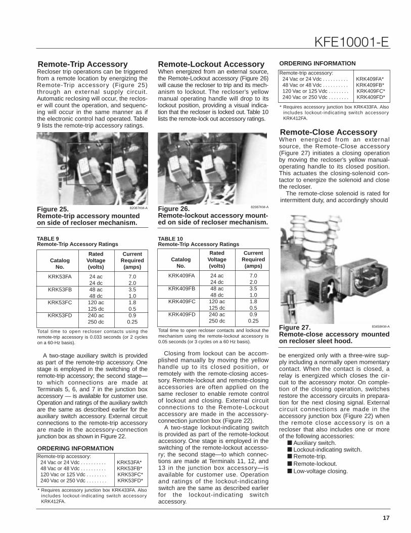
Figure 25.Remote-trip accessory mountedon side of recloser mechanism.
Figure 26.Remote-lockout accessory mount-ed on side of recloser mechanism.
Figure 27.Remote-close accessory mountedon recloser sleet hood.
83458KM-A
82087KM-A 82087KM-A
ORDERING INFORMATlON
ORDERING INFORMATlONRemote-Trip AccessoryRecloser trip operations can be triggeredfrom a remote location by energizing theRemote-Trip accessory (Figure 25)through an external supply circuit.Automatic reclosing will occur, the reclos-er will count the operation, and sequenc-ing will occur in the same manner as ifthe electronic control had operated. Table9 lists the remote-trip accessory ratings.
TABLE 9Remote-Trip Accessory Ratings
TABLE 10Remote-Trip Accessory Ratings
Rated CurrentCatalog Voltage Required
No. (volts) (amps)
KRK53FA 24 ac 7.024 dc 2.0
KRK53FB 48 ac 3.548 dc 1.0
KRK53FC 120 ac 1.8125 dc 0.5
KRK53FD 240 ac 0.9250 dc 0.25
Total time to open recloser contacts using theremote-trip accessory is 0.033 seconds (or 2 cycleson a 60-Hz basis).
Rated CurrentCatalog Voltage Required
No. (volts) (amps)
KRK409FA 24 ac 7.024 dc 2.0
KRK409FB 48 ac 3.548 dc 1.0
KRK409FC 120 ac 1.8125 dc 0.5
KRK409FD 240 ac 0.9250 dc 0.25
Total time to open recloser contacts and lockout themechanism using the remote-lockout accessory is0.05 seconds (or 3 cycles on a 60 Hz basis).
A two-stage auxiliary switch is providedas part of the remote-trip accessory. Onestage is employed in the switching of theremote-trip accessory; the second stage—to which connections are made atTerminals 5, 6, and 7 in the junction boxaccessory — is available for customer use.Operation and ratings of the auxiliary switchare the same as described earlier for theauxiliary switch accessory. External circuitconnections to the remote-trip accessoryare made in the accessory-connectionjunction box as shown in Figure 22.
Remote-trip accessory:24 Vac or 24 Vdc . . . . . . . . . . KRK53FA*48 Vac or 48 Vdc . . . . . . . . . . KRK53FB*120 Vac or 125 Vdc . . . . . . . . KRK53FC*240 Vac or 250 Vdc . . . . . . . . KRK53FD*
* Requires accessory junction box KRK433FA. Alsoincludes lockout-indicating switch accessoryKRK412FA.
Remote-trip accessory:24 Vac or 24 Vdc . . . . . . . . . . KRK409FA*48 Vac or 48 Vdc . . . . . . . . . . KRK409FB*120 Vac or 125 Vdc . . . . . . . . KRK409FC*240 Vac or 250 Vdc . . . . . . . . KRK409FD*
* Requires accessory junction box KRK433FA. Alsoincludes lockout-indicating switch accessoryKRK412FA.
Remote-Lockout AccessoryWhen energized from an external source,the Remote-Lockout accessory (Figure 26)will cause the recloser to trip and its mech-anism to lockout. The recloser’s yellowmanual operating handle will drop to itslockout position, providing a visual indica-tion that the recloser is locked out. Table 10lists the remote-lock out accessory ratings.
Closing from lockout can be accom-plished manually by moving the yellowhandle up to its closed position, orremotely with the remote-closing acces-sory. Remote-lockout and remote-closingaccessories are often applied on thesame recloser to enable remote controlof lockout and closing. External circuitconnections to the Remote-Lockoutaccessory are made in the accessory-connection junction box (Figure 22).
A two-stage lockout-indicating switchis provided as part of the remote-lockoutaccessory. One stage is employed in theswitching of the remote-lockout accesso-ry; the second stage—to which connec-tions are made at Terminals 11, 12, and13 in the junction box accessory—isavailable for customer use. Operationand ratings of the lockout-indicatingswitch are the same as described earlierfor the lockout-indicating switch accessory.
Remote-Close AccessoryWhen energized from an externalsource, the Remote-Close accessory(Figure 27) initiates a closing operationby moving the recloser’s yellow manual-operating handle to its closed position.This actuates the closing-solenoid con-tactor to energize the solenoid and closethe recloser.
The remote-close solenoid is rated forintermittent duty, and accordingly should
be energized only with a three-wire sup-ply including a normally open momentarycontact. When the contact is closed, arelay is energized which closes the cir-cuit to the accessory motor. On comple-tion of the closing operation, switchesrestore the accessory circuits in prepara-tion for the next closing signal. Externalcircuit connections are made in theaccessory junction box (Figure 22) whenthe remote close accessory is on arecloser that also includes one or moreof the following accessories:
■ Auxiliary switch.■ Lockout-indicating switch.■ Remote-trip.■ Remote-lockout.■ Low-voltage closing.
18
Types KFE and KFVE
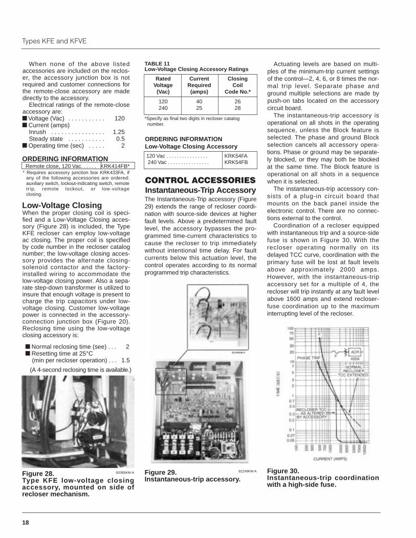
Figure 28.Type KFE low-voltage closingaccessory, mounted on side ofrecloser mechanism.
Figure 29.Instantaneous-trip accessory.
Figure 30.Instantaneous-trip coordinationwith a high-side fuse.
82085KM-A 82249KM-A
TABLE 11Low-Voltage Closing Accessory Ratings
ORDERING INFORMATlONLow-Voltage Closing Accessory
When none of the above listedaccessories are included on the reclos-er, the accessory junction box is notrequired and customer connections forthe remote-close accessory are madedirectly to the accessory.
Electrical ratings of the remote-closeaccessory are:■ Voltage (Vac) . . . . . . . . . . . 120■ Current (amps)
Inrush . . . . . . . . . . . . . . . . 1.25Steady state . . . . . . . . . . . 0.5
■ Operating time (sec) . . . . . 2
ORDERING INFORMATlONRemote close, 120 Vac. . . . . . KRK414FB*
* Requires accessory junction box KRK433FA, ifany of the following accessories are ordered:auxiliary switch, lockout-indicating switch, remotetr ip, remote lockout, or low-voltage closing.
Low-Voltage ClosingWhen the proper closing coil is speci-fied and a Low-Voltage Closing acces-sory (Figure 28) is included, the TypeKFE recloser can employ low-voltageac closing. The proper coil is specifiedby code number in the recloser catalognumber; the low-voltage closing acces-sory provides the alternate closing-solenoid contactor and the factory-installed wiring to accommodate thelow-voltage closing power. Also a sepa-rate step-down transformer is utilized toinsure that enough voltage is present tocharge the trip capacitors under low-voltage closing. Customer low-voltagepower is connected in the accessory-connection junction box (Figure 20).Reclosing time using the low-voltageclosing accessory is:
■ Normal reclosing time (see) . . . 2■ Resetting time at 25°C
(min per recloser operation) . . . 1.5
(A 4-second reclosing time is available.)
120 Vac . . . . . . . . . . . . . . . . KRK54FA240 Vac . . . . . . . . . . . . . . . . KRK54FB
Rated Current ClosingVoltage Required Coil
(Vac) (amps) Code No.*
120 40 26240 25 28
*Specify as final two digits in recloser catalog number.
CONTROL ACCESSORIESInstantaneous-Trip AccessoryThe Instantaneous-Trip accessory (Figure29) extends the range of recloser coordi-nation with source-side devices at higherfault levels. Above a predetermined faultlevel, the accessory bypasses the pro-grammed time-current characteristics tocause the recloser to trip immediatelywithout intentional time delay. For faultcurrents below this actuation level, thecontrol operates according to its normalprogrammed trip characteristics.
Actuating levels are based on multi-ples of the minimum-trip current settingsof the control—2, 4, 6, or 8 times the nor-mal tr ip level. Separate phase andground multiple selections are made bypush-on tabs located on the accessorycircuit board.
The instantaneous-trip accessory isoperational on all shots in the operatingsequence, unless the Block feature isselected. The phase and ground Blockselection cancels all accessory opera-tions. Phase or ground may be separate-ly blocked, or they may both be blockedat the same time. The Block feature isoperational on all shots in a sequencewhen it is selected.
The instantaneous-trip accessory con-sists of a plug-in circuit board thatmounts on the back panel inside theelectronic control. There are no connec-tions external to the control.
Coordination of a recloser equippedwith instantaneous trip and a source-sidefuse is shown in Figure 30. With therecloser operating normally on itsdelayed TCC curve, coordination with theprimary fuse will be lost at fault levelsabove approximately 2000 amps.However, with the instantaneous-tripaccessory set for a multiple of 4, therecloser will trip instantly at any fault levelabove 1600 amps and extend recloser-fuse coordination up to the maximuminterrupting level of the recloser.
19
KFE10001-E
Figure 31.On a load-side fault, instanta-neous tripping occurs at high-cur-rent fault (F1) with normal coordi-nation at F2 to allow the fuse tosectionalize.
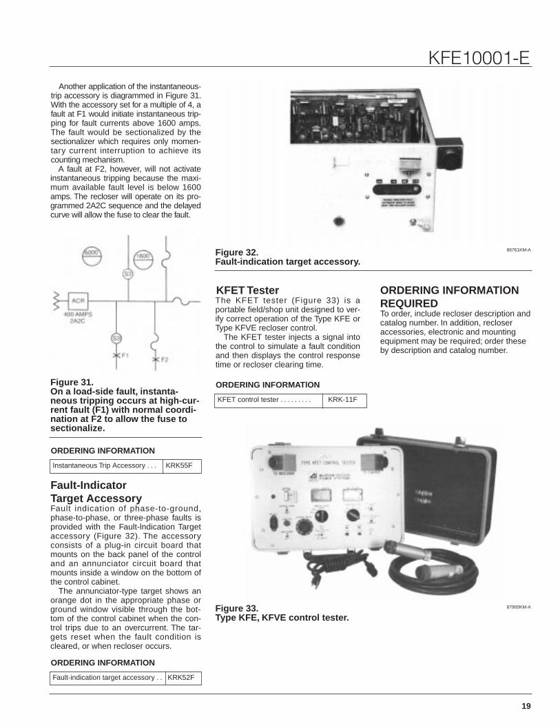
Figure 32.Fault-indication target accessory.
86761KM-A
87900KM-A
ORDERING INFORMATlON
Figure 33.Type KFE, KFVE control tester.
Another application of the instantaneous-trip accessory is diagrammed in Figure 31.With the accessory set for a multiple of 4, afault at F1 would initiate instantaneous trip-ping for fault currents above 1600 amps.The fault would be sectionalized by thesectionalizer which requires only momen-tary current interruption to achieve itscounting mechanism.
A fault at F2, however, will not activateinstantaneous tripping because the maxi-mum available fault level is below 1600amps. The recloser will operate on its pro-grammed 2A2C sequence and the delayedcurve will allow the fuse to clear the fault.
Instantaneous Trip Accessory . . . KRK55F
Fault-IndicatorTarget AccessoryFault indication of phase-to-ground,phase-to-phase, or three-phase faults isprovided with the Fault-lndication Targetaccessory (Figure 32). The accessoryconsists of a plug-in circuit board thatmounts on the back panel of the controland an annunciator circuit board thatmounts inside a window on the bottom ofthe control cabinet.
The annunciator-type target shows anorange dot in the appropriate phase orground window visible through the bot-tom of the control cabinet when the con-trol trips due to an overcurrent. The tar-gets reset when the fault condition iscleared, or when recloser occurs.
ORDERING INFORMATlON
Fault-indication target accessory . . KRK52F
ORDERING INFORMATlON
KFET control tester . . . . . . . . . KRK-11F
KFET TesterThe KFET tester (Figure 33) is aportable field/shop unit designed to ver-ify correct operation of the Type KFE orType KFVE recloser control.
The KFET tester injects a signal intothe control to simulate a fault conditionand then displays the control responsetime or recloser clearing time.
ORDERING INFORMATlONREQUIRED To order, include recloser description andcatalog number. In addition, recloseraccessories, electronic and mountingequipment may be required; order theseby description and catalog number.

20
Types KFE and KFVE
TABLE 12Closing Coil Voltage Code Numbers
TABLE 13Plug-In Operating Settings
Construction of Basic Catalog Number1. Use the chart below and Table 12 to construct a catalog number that describes the
basic recloser.2. From Table 13, specify the catalog numbers that describe the plug-in operating set-
tings.3. From Tables 14 and 15, specify the catalog numbers that describe the desired
accessories.4. From Table16,specify the catalog numbers that describe the mounting equipment
(if required).
Example:To order a basic 11 -Kv Type KFE recloser with 2 fast, 2 delayed on-phase trip and 1fast, 3 delayed on-ground trip operations for service on a 50-Hz system, the catalognumber would be constructed like this:KKFE Basic letters for a Type KFE recloser
Basic letters for a type KFVE recloser: KKFVE
4 Number of operations to be lockout: 2, 3, or 4.
2 Number of fast phase-trip operations: 0, 1, 2, or 3.*
1 Number of fast ground-trip operations: 0, 1, 2, or 3.*
52 Closing coil voltage code numbers: select from Table 12.
KKFE 4 2 1 52 *Remaining operations to lock out willbe on delayed curve.
KKFE42152 is the catalog number for a basic Type KFE recloser with 2 fast, 2delayed on-phase trip and 1 fast, 3 delayed on-ground trip operations; for service onan 11 Kv, 50-Hz system.
Phase-to-Phase Closing CoilOperating Voltage ±15% Code
5-Hz Coils (Kv) No.6.0 51
11.0 5213.2 5314.4 5420.0 55**22.0-24.9 56**
6-Hz Coils (Kv)2.4 214.16-4.8 226.0 31
12.0-13.2 3014.4 2720.0 29**22.0-24.9 33**
Low-Voltage Coils* (Vac)120 26240 28
* Require low-voltage closing accessory (KRK54F)to operate. Order separately.
** KFVE reclosers only.
Description Catalog No.Minimum-trip current
Phase minimum-trip resistors _amps (set of 3) . . . . . . . . . . . . . . . . . . . . KRK597F_(Select from 10, 20,30,50,70, 100,140, 200, 280, 320, 400, 450, 560,or 800 amps)
Ground minimum-trip resistor _amps . . . . . . . . . . . . . . . . . . . . . . . . . . . KRK596F_(Select from 5, 10, 20, 30, 50, 70, 100, 140, 200, 280, 320, or 400 amps)*
Trip timing characteristicsPhase-trip timing plug _ . . . . . . . . . . . . . . . . . . . . . . . . . . . . . . . . . . . . . KRK592F_
(Select phase-trip curve B or C)Ground-trip inverse time delay
Ground-trip timing plug____ in first socket** . . . . . . . . . . . . . . . . . . . . . . KRK590F_-1Ground-trip timing plug____ in second socket** . . . . . . . . . . . . . . . . . . . KRK590F_-2
(Select from curves 1, 2, or 3***)or
Ground-trip constant time delayGround-trip timing plug____ in first socket** . . . . . . . . . . . . . . . . . . . . . . KRK673F_-1Ground-trip timing plug____ in second socket** . . . . . . . . . . . . . . . . . . . KRK673F_-2
(Select from curves 1, 2, 3, 4, 5, 6, 7, 8, 9***)
* One amp ground minimum-trip is available by connecting a jumper between Tabs X and Y on the main circuit board and installing a 5-amp ground minimum-trip resistor.
* * If single timing of ground-trip is desired, order basic recloser with 0 number of fast ground-trip operationsand specify 0 in catalog number for ground-trip timing plug in first socket.
* * * Apply faster curves (smaller number plug) to first ground socket.

21
KFE10001-ETABLE 14Recloser Accessories
TABLE 15Electronic Trip Control Accessories
TABLE 16Mounting Equipment
Description Catalog No.
Three 600:5 multi-ratio bushing-current transformers on standardcreepage source-side bushings, KFE only . . . . . . . . . . . . . . . . . . . . . . . KRK50F3X*
Three 600:5 multi-ratio bushing current transformers onextra-creepage source-side bushings(Includes the extra-creepage bushings), KFE only . . . . . . . . . . . . . . . . . KRK51F3X*
Three 600:5 multi-ratio bushing current transformers onsource-side bushings, KFVE only . . . . . . . . . . . . . . . . . . . . . . . . . . . . . . KRK63F3X*
600:5 multi-ratio slip-on bushing-current transformer fieldinstallation kit (one transformer per kit) . . . . . . . . . . . . . . . . . . . . . . . . . KA712L2
Auxiliary switch (2 no-nc contacts)** . . . . . . . . . . . . . . . . . . . . . . . . . . . . . . KRK411FA***Lockout indicating switch . . . . . . . . . . . . . . . . . . . . . . . . . . . . . . . . . . . . . . . KRK412FA***Remote trip (includes auxiliary switch accessory)
24 Vac or 24 Vdc . . . . . . . . . . . . . . . . . . . . . . . . . . . . . . . . . . . . . . . . . . . KRK53FA***48 Vac or 48 Vdc . . . . . . . . . . . . . . . . . . . . . . . . . . . . . . . . . . . . . . . . . . . KRK53FB***120 Vac or 125 Vdc . . . . . . . . . . . . . . . . . . . . . . . . . . . . . . . . . . . . . . . . . KRK53FC**240 Vac or 250 Vdc . . . . . . . . . . . . . . . . . . . . . . . . . . . . . . . . . . . . . . . . . KRK53FD***
Remote lockout (includes lockout-indicating switch accessory)24 Vac or 24 Vdc . . . . . . . . . . . . . . . . . . . . . . . . . . . . . . . . . . . . . . . . . . . KRK409FA***48 Vac or 48 Vdc . . . . . . . . . . . . . . . . . . . . . . . . . . . . . . . . . . . . . . . . . . . KRK409FB***120 Vac or 125 Vdc . . . . . . . . . . . . . . . . . . . . . . . . . . . . . . . . . . . . . . . . . KRK409FC***240 Vac or 250 Vdc . . . . . . . . . . . . . . . . . . . . . . . . . . . . . . . . . . . . . . . . . KRK409FD***
Remote close, 120 Vac . . . . . . . . . . . . . . . . . . . . . . . . . . . . . . . . . . . . . . . . KRK414FBLow-voltage closing, KFE only
120 Vac . . . . . . . . . . . . . . . . . . . . . . . . . . . . . . . . . . . . . . . . . . . . . . . . . . KRK54FA***240 Vac . . . . . . . . . . . . . . . . . . . . . . . . . . . . . . . . . . . . . . . . . . . . . . . . . . KRK54FB***
Accessory junction boxFor one or more of the triple asterisk (*** accessories . . . . . . . . . . . . . . KRK433FAFor remote close accessory, and in combination with
(X) accessories . . . . . . . . . . . . . . . . . . . . . . . . . . . . . . . . . . . . . . . . . KRK433FBExtra-creepage distance bushings, KFE only . . . . . . . . . . . . . . . . . . . . . . . KRK288FCOil-sampling-and-drain valve . . . . . . . . . . . . . . . . . . . . . . . . . . . . . . . . . . . . KA809RBushing terminals for 1/0 to 500 mcm cable, KFE only . . . . . . . . . . . . . . . . KRK525F
* Replace X in catalog number with ratio to be connected: 600, 500, 450, 400, 300, 250, 200, 150, 100, 50.
* * If remote trip is also being specified, auxiliary switch need not be ordered separately.
* * * Requires accessory junction box KRK433FA; order separately.
If remote lockout is also being specified, lockout indicating switch need not be ordered separately.
Requires accessory junction box KRK433FB if the auxiliary switch, lockout-indicating switch, remote trip,remote lockout, or low-voltage closing accessories are ordered; order separately.
Recloser must be ordered with Code 26 (120 Vac) or Code 28 (240 Vac) closing coil; see constructing a catalog number for basic recloser.
Description Catalog No.
Instantaneous trip . . . . . . . . . . . . . . . . . . . . . . . . . . . . . . . . . . . . . . . . . . . KRK55FFault-indicator target . . . . . . . . . . . . . . . . . . . . . . . . . . . . . . . . . . . . . . . . . KRK52F
Description Catalog No.
Pole-mounting extension hanger . . . . . . . . . . . . . . . . . . . . . . . . . . . . . . . . KRK364FSubstation-mounting structure . . . . . . . . . . . . . . . . . . . . . . . . . . . . . . . . . . KRK942F3Windlass accessory, for use with substation—mounting structure . . . . . . KRK942F5Control and junction box mounting accessory, for use with
substation - mounting structure . . . . . . . . . . . . . . . . . . . . . . . . . . . . . . KRK942F4Auxiliary junction box mounting accessory, for use with substation—
mounting structure . . . . . . . . . . . . . . . . . . . . . . . . . . . . . . . . . . . . . . . . KRK942F2Meter-trough mounting for substation structure . . . . . . . . . . . . . . . . . . . . . KRK398FA

22
Types KFE and KFVE

23
KFE10001-E

P.O. Box 1640Waukesha, WI 53187
© 1995 Cooper Industries, Inc.Kyle® is a registered trademark of Cooper Industries, Inc.
Printed on Recycled Paper KML12/95