
Durant® - Eaton
51
Durant® INSTALLATION AND OPERATION MANUAL Number 58860-900-06 PRESIDENT SERIES Model 5886-1400 THREE PRESET 6 DIGIT ELECTRONIC CONTROL TABLE OF CONTENTS 1 General Description 2 Specifications 4 Description of Operating Modes 8 Installation Instructions 14 Installation Instructions/Wiring 21 Operation 28 Scale Factors 36 Serial Communications 40 Troubleshooting 45 Transducers, Accessories and Replacement Parts List
-
Upload
khangminh22 -
Category
Documents
-
view
1 -
download
0
Transcript of Durant® - Eaton

Durant® INSTALLATION AND OPERATIONMANUAL Number 58860-900-06
PRESIDENT SERIES Model 5886-1400THREE PRESET 6 DIGIT ELECTRONIC CONTROL
TABLE OF CONTENTS
1 General Description2 Specifications4 Description of Operating Modes8 Installation Instructions
14 Installation Instructions/Wiring21 Operation28 Scale Factors36 Serial Communications40 Troubleshooting45 Transducers, Accessories and Replacement Parts List

ii
WARRANTY
WARRANTY: Cutler Hammer-Eaton Corporation warrants all products against defects in material and work-manship for a period of one (1) year from date of shipment to Buyer. This is a limited warranty limited to itsterms. This warranty is void if the product has been altered, misused, taken apart or otherwise abused. ALLOTHER WARRANTIES, EXPRESS OR IMPLIED, ARE EXCLUDED, INCLUDING BUT NOT LIMITED TOTHE IMPLIED WARRANTIES OF MERCHANTABILITY AND FITNESS FOR PURPOSE.
BUYERS REMEDIES: Cutler Hammer-Eaton Corporation’s obligations and liabilities under the foregoingwarranty are limited to repair or replacement of the product without charge, provided it is mailed prepaid toCutler Hammer-Eaton Corporation, Durant Instruments, 901 South 12th Street, Watertown, Wisconsin,53094. A charge is made for repairing after the expiration of the warranty. IN NO EVENT SHALL CUTLERHAMMER-EATON CORPORATION BE LIABLE FOR CLAIMS BASED UPON BREACH OF EXPRESS ORIMPLIED WARRANTY OR NEGLIGENCE OR ANY OTHER DAMAGES WHETHER DIRECT, IMMEDIATE,FORESEEABLE, CONSEQUENTIAL OR SPECIAL OR FOR ANY EXPENSES INCURRED BY REASON OFTHE USE OR MISUSE, SALE OR FABRICATION OF PRODUCTS WHICH DO OR DO NOT CONFORM TOTHE TERMS AND CONDITIONS OF THIS CONTRACT.
INDEMNIFICATION: Buyer agrees to hold Cutler Hammer-Eaton Corporation harmless from, defend andindemnify Cutler Hammer-Eaton Corporation against damages, claims and expenses arising out of subse-quent sales of Durant products or products containing components manufactured by Cutler Hammer-EatonCorporation and based upon personal injuries, deaths, property damage, lost profits and other matters forwhich Buyer its employees or sub-contractors are or may be to any extent liable, including without limitationpenalties imposed by the Consumer Product Safety Act (P.L.92-573) and liability imposed upon any personpursuant to the Mansion-Moss Warranty Act (P.L.93-637), as now in effect or amended hereafter. The war-ranties and remedies provided for herein are available to Buyer and shall not extend to any other person.
COMPLIANCE WITH OSHA: Cutler Hammer-Eaton Corporation offers no warranty and makes no repre-sentation that its products comply with the provisions or standards of the Occupational Safety and Health Actof 1970, or any regulations issued thereunder. In no event shall Cutler Hammer-Eaton Corporation be liablefor any loss, damages, fines, penalty or expense arising under said Act.
This manual constitutes proprietary information of Cutler Hammer-Eaton Corporation, and is furnished for thecustomer’s use in operating the Series 5886 Count Control. Reproduction of this material for purposes otherthan the support of the 5886 Control or related products is prohibited without the prior written consent of Cut-ler Hammer-Eaton Corporation.
In the construction of the Control described herein, the full intent of the specifications will be met. Cutler Ham-mer-Eaton Corporation, however reserves the right to make, from time to time and without prior writtennotice, such departures from the detail specifications as may be required to permit improvements in thedesign of the product.
The information included herein is believed to be accurate and reliable, however, no responsibility is assumeto Cutler Hammer-Eaton Corporation for its use; nor for any infringements of patents or other rights of thirdparties which may result from its use.
WARNING: This equipment generates, uses and can radiate radio frequency energy and if not installedand used in accordance with the instructions manual, may cause interference to radio communications. It hasbeen tested and found to comply with the limits for a Class A computing device pursuant to Subpart J of Part15 of FCC Rules, which are designed to provide reasonable protection against such interference when oper-ated in a commercial environment. Operation of this equipment in a residential area is likely to cause interfer-ence in which case the user at his own expense will be required to take whatever measures may be requiredto correct the interference.

GENERAL DESCRIPTION
1
The Durant Model 5886 is a versatile six-digit,three-preset, bi-directional count control. The con-trol has three sets of transistor outputs (one foreach preset), and two relay outputs. The tworelays may each be operated by any of the threetransistor outputs. The three transistor outputsmay be programmed to occur sequentially or inde-pendently with the count. Output 1 and/or Output 2may also be programmed to function as floatingprewarn outputs. The control may be programmedto reset to zero or reset to the preset 3 value.
The 5886-1400 Model also features the ability toscale incoming counts. This means that for eachpulse received on the count inputs, a fraction ormultiple of that pulse is counted. The scale factorcan be a number from 0.0001 to 9.9999. Thisnumber becomes a factor by which incomingcount pulses are multiplied.
A non-volatile memory insures that the setupinstructions will not be lost if power is interrupted.Count values will also be retained if a power lossinterrupts a process or machine cycle.
The front panel of the control, Figure 1, is framedby a bezel that seals the panel to the mountingsurface. A large, six-digit high visibility red LEDdisplay with a programmable decimal point posi-tion is located in the upper left portion of the panel.The keyboard has a Mylar front face and consistsof ten data keys (0 through 9), “COUNT” key,
“RESET” key, “FUNCTION” key and “ENTER” key.The “1” key also serves as the “PRESET 1” key,the “2” key also serves as the “PRESET 2” keyand the “3” key also serves as the “PRESET 3”key. The upper right portion of the front panel con-tains 4 yellow LED indicators for Count, Preset 1,Preset 2, and Preset 3.
The rear panel, Figure 2, contains screw terminalsfor use with stripped wire, either solid or stranded,from 28 to 14 gauge. The rear panel also containstwo plug-in type replaceable relays with “form-C”contacts.
The counter provides two-way serial communi-cation with remote devices using standard ASCIIcode and three selectable Baud rates. Count andpreset data can be sent and preset data and aprint request command can be received by thecontrol via two 20-milliampere current loops. OnModel 5886-1400 the Scale Factor may also betransmitted and received. Optional accessoriesare available to convert the communication loop toRS232, parallel BCD and multiplexed BCD for-mats.
The relay and transistor outputs can be timed from0.01 to 99.99 seconds inclusive, latched until resetcomplete, unlatched at reset, remain latched untilan unlatch input occurs or unlatch when thecounter reaches an alternate preset. Outputs canalso be operated in the Reverse mode.
Figure 1. 5886 Dual Preset 6-Digit Electronic Control

SPECIFICATIONS
2
Figure 2. 5886 Rear Panel
The count input circuit provides the user with sev-eral options:
1. Separate add and subtract inputs.
2. Count input with up/down control input.
3. Quadrature input.
4. Count doubling in any of the three above con-figurations.
5. Count up input with count inhibit input.
6. High or low speed operation. Low speed oper-ation provides maximum immunity to contactbounce and noise.
The control is equipped with self-diagnostics whichtest the internal memories for faults. Should a faultbe detected, an indication given on the display.Displays and indicators are turned on in a pat-terned sequence for visual examination.

SPECIFICATIONS
3
POWER REQUIREMENTS:
AC Operation:115/230 VAC (+10%, -20%) 47 - 63 Hz.
DC Operation:11 - 28 VDC
Power:18 Watts
DC POWER OUTPUT:
15 VDC (+1, -2).150 mA if powered from AC or less than 24
VDC.100 mA if powered from 24 VDC or greater.
NOTE: DC power output is only regulated ifunit is powered by AC or greater than 18.5VDC.
ENVIRONMENT:
Operating Temperature:32 to 130° F (0 to 55° C)
Storage Temperature:-40 to 160° F (-40 to 70° C)
Operating Humidity:85% non-condensing relative
PHYSICAL:
Case Dimensions:5.38″ W × 2.62″ H × 5.91″ D
(136.7mm W x 66.5mm H x 150.1mm D)
Bezel Dimensions:5.80″ W × 3.04″ H × 0.17″ 0
(147.3mm W × 77.2mm H × 4.3mm D)
LIP:0.2″ (5.0mm)
Panel Cut-out Dimensions:5.43″ W x 2.68″ H
(138mm W x 68mm H, DIN)
Mounting Panel Thickness:0.58″ (14.7mm) maximum
(without optional spacer provided) .077″ (1.96mm) maximum
(with optional spacer provided)
Front panel will provide watertight seal with gasket provided.
Case Material:Cadon FRX plastic case with Mylar front face
overlay
Weight:2.2 lbs. (1.0 Kg)
Display Size:6 digits, 0.56″ (14.2mm) H
(with programmable decimal point location)
Memory Types:PROM, RAM, Non-volatile NVRAM
COUNTER:
Count Range:6 digits (0 to 999,999) with rollover
Preset Range:6 digits (0 to 999,999) (3 presets)
Count Modes:Count with Add and Subtract inputs Count with Up/Down direction input
(Hardware doubling for above modes is provided.)
Count with Count Inhibit inputQuadratureDoubled Quadrature
Count Speed (Model 5886-0400):0 to 7,500 CPS minimum for sensors with
open collector transistor output.0 to 5,000 CPS when hardware doubling IS
implemented.0 to 150 CPS when Low Frequency jumpers
are installed.Count Speeds for Model 5886-1400 are shown
on page 28.

DESCRIPTION OF OPERATING MODES
4
COUNT INPUT RATINGS:
The count inputs are designed to work with current sinking sensors (open-collector NPN transistor output with or without passive pull-up resistor) or contact closures to DC Common.
Input Voltage:High state (Logical “1”, sensor off or contact
open):
10.5 to 24.5 VDC when control is powered by AC line
7.0 to 24.5 VDC when control is powered by 11 VDC
11.0 to 24.5 VDC when control is powered by 16 VDC
Low state (Logical “0”, sensor on or contact closed):
0 to 4.5 VDC when control is powered by AC line
0 to 3.0 VDC when control is powered by DC supply
Input Impedance:6800 ohms to 15 VDC when control is
powered by AC line6800 ohms to 10 VDC when control is
powered by DC supply
Input Current:20 mA peak, 3 mA steady state
Input Response:High State (Logical “1”, sensor off or contact
open)High Speed (Low Speed jumpers not
connected):110 µsec minimum at 15 VDC (6,800 ohms to
+DC)160 µsec minimum at 13.5 VDC (50,000 ohms
to +DC)High State (Logical “1”, sensor off or contact
open)Low Speed (Low Speed jumpers connected):5.5 msec minimum at 15 VDC (6,800 ohms to
+DC)
7.5 msec minimum at 13.5 VDC (50,000 ohms to +DC)
Low State (Logical “0”, sensor on or contact closed)
High Speed (Low Speed jumpers not connected):
20 µsec minimum at 0.1 VDC (0 ohms to DC Common)
45 µsec minimum at 1.5 VDC (500 ohms to DC Common)
Low State (Logical “0”, sensor on or contact closed)
Low Speed (Low Speed jumpers connected):1.0 msec minimum at 0.1 VDC (0 ohms to DC
Common)2.0 msec minimum at 1.5 VDC (500 ohms to
DC Common)
CONTROL INPUTS:
Impedance:4.75K ohms to +5 VDC.
Threshold:High +3.5 to +22 VDC.Low +0.0 to +1.0 VDC.
Response Time:Min. High 5.3 mS.Min. Low 3.9 mS.
NOTE: The reset and unlatch signals will bothoccur in less than 200 microseconds after theinput signal is detected. The start of the print willoccur within 2 milliseconds after the input isdetected if the unit is not counting.
OUTPUT RATINGS:
Relay Contacts
Type: Form C (SPDT) U.L./C.S.A. Contact Ratings:
10 amps, resistive, @ 24 VDC or 230 VAC1/3 HP @ 115 VAC or 230 VAC150 VDC maximum switched voltage
Mechanical Life: 5,000,000 operationsElectrical Life: 100,000 operations at resistive
rating

DESCRIPTION OF OPERATING MODES
5
Transistor Outputs
Type: Open collector NPN transistor with Zener diode transient surge protection.
Load Voltage: 30 VDC maximumLoad Current: 300 milliamps maximum per
transistor. 480 milliamps total for all transistors.
Rev. 50-59:
Use 90 milliamps per relay coil when calculating total transistor current.
Rev. 60 - up:
Use 5 milliamps per relay coil when calculating total transistor current.
OUTPUT OPERATING MODES:
Actuation:IndependentPrewarn (Outputs 1 and 2 only)Sequential
Unlatch:After timeoutWith external signalWhen Reset EnergizedWhen Reset De-energizedAt Alternate Output
Reverse:Reversed operation of any transistor outputs
COUNTER OPERATING MODES:
Reset to ZeroReset to PresetAuto RecycleMaintained ResetMomentary
DIAGNOSTIC MODES:
ROM ChecksumRAM Bit TestNVRAM Read/Write TestNVRAM Store TestNVRAM ChecksumWatchdog TimerDisplay and Led Indicator Test
COMMUNICATIONS:
Interface Type:Dual port 20 milliamp current loop
Speed:110, 300 and 1200 Baud, user selectable
Data Type:Standard ASCII code
Format:Start bit, 7 ASCII data bits, Parity bit, one or
two Stop bits(Even parity for Serial Data Output, no parity for Serial Data Input)
Information Transmitted:Count valuePreset 1 valuePreset 2 valuePreset 3 valueScale Factor (Model 5886-1400 only)
Information Received:Print requestPreset 1 valuePreset 2 valuePreset 3 valueScale Factor (Model 5886-1400 only)
SCALE FACTOR:
Range:5 digits (0.0001 to 9.9999)

DESCRIPTION OF OPERATING MODES
6
COUNT MODES
The control has five count modes, which are:Count with separate add and subtract inputs,Count with direction control input, Count up withinhibit control input, Quadrature, and DoubledQuadrature.
Add and Subtract Inputs
The add and subtract mode allows separate sig-nals to simultaneously add and subtract counts. Itcan be used to indicate material stretch, subtractdefective parts from total parts produced, etc.
Count with Directional Control
Count with direction control mode uses one inputfor incoming count pulses and the other to informthe control whether the pulses should be used toadd or subtract counts. Count with direction maybe used when an item must be measured or posi-tioned. Many types of sensors or control systemsutilize count signals of this nature.
In both of the above count modes, the counter willnormally increment or decrement on the fallingedge of the incoming count pulse. (The fallingedge is defined as the moment in time when thepulse changes state from +DC to DC Commonpotential.) Doubling allows the counter to incre-ment or decrement on both the falling and the ris-ing edges of the pulse. (The rising edge is definedas the moment when the pulse changes state fromDC Common to +DC potential.)
Count with Inhibit Control
The count up with inhibit control mode provides aninput which increments the control and an inputwhich causes incoming count pulses to beignored. This mode can be used when defectivematerial must be ignored or when inspection sam-ples are taken without incrementing the counter.The count up with inhibit control mode may not bedoubled.
Quadrature Inputs
Quadrature counting makes use of two count sig-nals which are phase shifted by 90 degrees. Thedetection of which signal is rising first allows thecounter to know in what direction the shaft is turn-ing. When Quadrature count sources are being
used, the Double Input must always be connectedto DC Common to allow the quadrature signals tobe decoded.
Quadrature Input Doubled
Doubled Quadrature is implemented by program-ming. This mode allows the counter to count onboth the rising and falling edges of the incomingcount pulses. The number of pulses per revolutionof the shaft encoder is effectively doubled,increasing the resolution without any loss of accu-racy.
COUNT SCALING
When the 5886-1400 receives a count pulse in anycount mode, the count is increased by the scalefactor for count-up pulses and decreased by thescale factor for count-down pulses. The countshows the accumulated total in whole increments.Accumulated Total = Total Number of Pulses ×Scale Factor.
DECIMAL POINT LOCATION
The location of the decimal point on the display isprogrammed and may be located between any twodigits on the display, or omitted. When a printer isconnected to the serial communication output, thedecimal point is printed.
The decimal point remains on the display when-ever the actual value of the counter or the presetvalue is being displayed. It is not lit when functioncodes or other function entries are being dis-played. The timeout function automatically dis-plays the decimal point to indicate 0.01 secondincrements.
COUNTER OPERATING MODES
Reset Mode
Reset mode is used when the counter should startat zero and count up to the preset values. Resetmode implies that when the “RESET” key ispressed or the Reset input in energized, thecounter is reset to zero.
Preset Mode
Preset mode is used when the control must start ata preset value and count down to zero. Preset
DESCRIPTION OF OPERATING MODES
7
mode implies that when the “RESET” key ispressed or the Reset input is energized, the con-trol is reset to preset 3; that is, forced to have avalue equal to the preset 3 value. When the con-trol is in the Preset mode, transistor output 3 turnson when the counter reaches zero.
Automatic Recycle Operation
It may be desirable to have the control automati-cally reset itself for repeated cycles. Auto Recyclecan be programmed to occur when any one, anyof two or any of the three transistor outputs turnon. When in the Reset mode and any of theselected outputs turn on, the counter is automati-cally reset to zero. When in the Preset mode andany of the selected outputs turn on, the counter isautomatically reset to the Preset 3 value.
OUTPUT AND RELAY OPERATION
The outputs of the control consist of five transis-tors and two relays. The output associated withPreset 1 and the output associated with Preset 2each provide a pair of transistors. The two transis-tors in each pair operate in parallel; that is, whenone of the transistors is turned on, the other isturned on as well. The fifth transistor is associatedwith Preset 3. The collectors of each of these tran-sistors is brought out to individual screw terminals.
The relays are uncommitted and may be assignedby the user to any of the 5 transistor outputs. Thisis done by connecting a single wire for each relayto the desired transistor output screw terminal.When shipped from the factory, relay K1 is
prewired to Output 1 (terminal 8) and relay K2 isprewired to Output 2 (terminal 9).
Turning Outputs On
There are three programmable modes which affectwhen the transistor outputs turn on (conduct to DCCommon.) These modes are:
Independent ModePrewarn ModeSequential Mode
In addition, the reset and preset modes affectwhen transistor output 3 turns on.
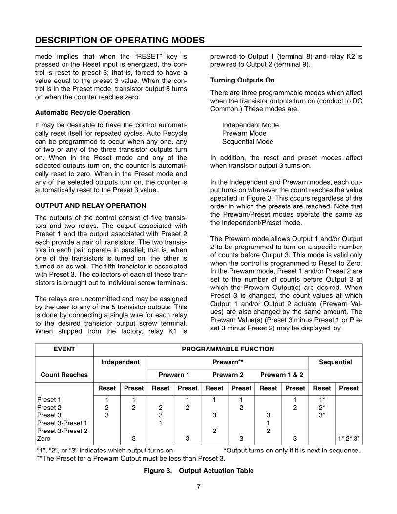
In the Independent and Prewarn modes, each out-put turns on whenever the count reaches the valuespecified in Figure 3. This occurs regardless of theorder in which the presets are reached. Note thatthe Prewarn/Preset modes operate the same asthe Independent/Preset mode.
The Prewarn mode allows Output 1 and/or Output2 to be programmed to turn on a specific numberof counts before Output 3. This mode is valid onlywhen the control is programmed to Reset to Zero.In the Prewarn mode, Preset 1 and/or Preset 2 areset to the number of counts before Output 3 atwhich the Prewarn Output(s) are desired. WhenPreset 3 is changed, the count values at whichOutput 1 and/or Output 2 actuate (Prewarn Val-ues) are also changed by the same amount. ThePrewarn Value(s) (Preset 3 minus Preset 1 or Pre-set 3 minus Preset 2) may be displayed by
EVENT PROGRAMMABLE FUNCTION
Count Reaches
Independent Prewarn** Sequential
Prewarn 1 Prewarn 2 Prewarn 1 & 2
Reset Preset Reset Preset Reset Preset Reset Preset Reset Preset
Preset 1Preset 2Preset 3Preset 3-Preset 1Preset 3-Preset 2Zero
123
12
3
231
12
3
1
3
2
12
3
312
12
3
1*2*3*
1*,2*,3*
“1”, “2”, or “3” indicates which output turns on. *Output turns on only if it is next in sequence.**The Preset for a Prewarn Output must be less than Preset 3.
Figure 3. Output Actuation Table

INSTALLATION INSTRUCTIONS
8
selecting the appropriate Function Code (see Fig-ure 22).
In the Sequential mode, each output turns on asspecified in Figure 3, only if that output is next insequence (see Figure 4). The counter automati-cally resets and advances the sequence after thefirst and second events shown in Figure 4. In theReset mode the counter is automatically reset tozero, in the Preset mode the counter is automati-cally reset to Preset 2 after the first event and Pre-set 1 after the second event shown in Figure 4.The counter does not automatically reset after thethird event unless automatic recycle is pro-grammed to occur at that output. An automaticrecycle at any event resets both the counter andthe sequence. In the count mode, the PresetLED’s light to show which Output is next insequence.
In the Sequential mode, the reset input or resetkey may be used at any time to reset both thecounter and the sequence. A separate program-mable input (terminal 16) may be used at any timeto reset the counter without resetting thesequence.
Turning Outputs Off
Once a transistor output is turned on, it remains onuntil it is unlatched. There are five ways to unlatcheach output:
1. TimeoutEach output has a separate timeout function.The timeout function causes an output tounlatch after a specified “on” time. The allow-able time range is from 0.01 to 99.99 seconds.A value of 0 inhibits the timeout function forthat output. In this case, the output remains onuntil unlatched by one of the following meth-ods.
2. Unlatch at Reset (UAR)Each output may be programmed to unlatchwhen the reset key is pushed or the reset inputis energized (goes low).
3. Latch Until Reset Complete (LURC)Each output may be programmed to unlatch
when the reset key is released or the resetinput is de-energized (goes high).
4. Unlatch at Alternate OutputEach output may be programmed to unlatchwhen one or either of the remaining two out-puts turns on.
5. Unlatch InputsTwo programmable unlatch inputs may beused to unlatch any two of the three outputs.When an unlatch input is energized, theselected output unlatches.
Figure 4. Output Sequence Table
Reverse Outputs
Each transistor output may be programmed tooperate in reverse. A reversed output is normallyon (conducts to DC Common) and turns off whenFigure 3 shows that it should turn on. Likewise, areversed output turns on when it is timed out orunlatched.
When power is interrupted, all outputs turn off andwill remain off when power is reapplied. It is there-fore necessary to “enable” all reversed outputsafter a power interruption. This is usually done byenergizing the appropriate unlatch input(s) or byprogramming the reversed outputs to latch untilreset complete and then resetting the control.
���� WARNING
A POWER OUTAGE CAUSES THE OUT-PUTS AND RELAYS TO TURN OFFREGARDLESS OF THE OPERATINGMODE SELECTED. BE SURE THATTHIS EFFECT IS NOT HAZARDOUS TOTHE OPERATOR.
Event Sequential Mode
Reset Preset
FirstSecondThird
Output 1Output 2Output 3
Output 3Output 2Output 1

INSTALLATION INSTRUCTIONS
9
GENERAL
When mounting, the location selected must pro-vide for adequate air circulation space aroundthe unit. Avoid locating the unit near instruments
and/or equipment that generate excessive heat.Figure 5 shows recommended cutout and productdetails as well as mounting details.

INSTALLATION INSTRUCTIONS
10
WIRING - GENERAL
1. Disconnect all power before wiring terminals.
2. Do not use machine power service for 115/230VAC input power to the control. A dedicated orlighting circuit is recommended.
3. Keep all signal lines as short as possible.
4. Do not bundle or route signal line(s) withpower carrying lines.
5. Tools required are a wire stripper and a smallcommon screwdriver.
6. Refer to the setup chart Figure 6 for terminaldesignations.
7. Use 18 ga. Minimum (1mm2, 600V) and 14 ga.
Maximum (2.1mm2, 600V) wire for AC powerwiring.
8. See Figure 8 for correct fuse to be used in thepower input wiring.
Figure 6. Terminal Designations

INSTALLATION INSTRUCTIONS
11
TERMINAL ASSIGNMENTS AND FUNCTIONS
#1 - BYPASS PRESET 1 INPUT
Connecting this terminal to DC Common causesthe counter to ignore Preset 1. When the counterreaches Preset 1, Transistor Output 1 remains offand any other functions (such as auto recycle atOutput 1) will not occur.
NOTE:
In the sequential mode, this input must beenergized before the counter starts count-ing to or from preset 1 for bypass to occur.
#2 AND 3 - TRANSISTOR OUTPUT UNLATCH INPUTS
These two terminals are programmable inputswhich may be used to unlatch any two of the threetransistor outputs. Function code 49 is used toselect which output is unlatched by each input(see Figure 21). When an Unlatch input is ener-gized, the selected output turns off. If the output isalready off, the Unlatch input has no effect. If theoutput has been reversed the Unlatch input turnsthe output on.
#4 - BYPASS PRESET 2 INPUT
This input operates the same as #1 above exceptit applies to Preset 2 and Transistor Output 2.
#5 AND 8 - TRANSISTOR OUTPUT 1
These outputs are open collector NPN transistorswith built-in transient overvoltage protection in theform of zener diode clamping. Each transistor israted at 30 Vdc maximum and can sink up to 300milliamps. Both transistors turn on as shown inFigure 3 for Output 1.
#6 AND 9 - TRANSISTOR OUTPUT 2
These outputs have the same configuration as #5and 8 above except that they turn on as shown inFigure 3 for Output 2.
#8, 9, 12 AND 21 - DC COMMON
These terminals are internally connected to thenegative side of the DC power supply.
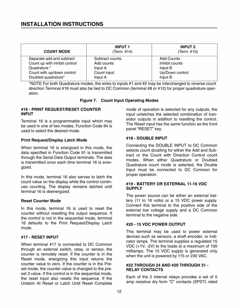
#10 AND 14 - COUNT INPUTS
These two count inputs are used to increment ordecrement the counter. Terminal #14 is labeled“COUNT INPUT 1” and terminal #10 is “COUNTINPUT 2.” The table shown in Figure 7 lists theoperation of the two count inputs as related to thecount function, and indicates how each inputcauses the counter to operate when a DC Com-mon signal is applied.
#11 AND 13 - LOW FREQUENCY SELECT INPUTS
When contact closures are used for countsources, it must be remembered that the contactswill bounce slightly each time they close. Thisslight bounce can cause extra counts to beentered into the counter. This effect can be elimi-nated by limiting the allowable frequency responseat the count inputs. The low frequency select ter-minals reduce the count input frequency responsefrom 7500 PPS to 150 PPS when they are con-nected to DC Common. Terminal #13 is LOWFREQUENCY SELECT for COUNT INPUT 1 (ter-minal #14) and terminal #11 is LOW FREQUENCYSELECT for COUNT INPUT 2 (terminal #10). Lowfrequency is selected by placing a jumper betweenterminal #11 and/or terminal #13 and DC Com-mon. Use the Low Frequency inputs wheneverpossible to guard against electrical noise andinterference.
#15 - PROGRAM INHIBIT INPUT
The PROGRAM INHIBIT terminal, when con-nected to DC Common through the use of ajumper, prevents all of the programming functionsfrom being changed. Modification of the Presetvalues can also be prevented with this jumper ifFunction Code 41, Preset Lock, is set to a valueother than “0.”
INSTALLATION INSTRUCTIONS
12
Figure 7. Count Input Operating Modes
#16 - PRINT REQUEST/RESET COUNTER INPUT
Terminal 16 is a programmable input which maybe used in one of two modes. Function Code 84 isused to select the desired mode.
Print Request/Display Latch Mode
When terminal 16 is energized in this mode, thedata specified in Function Code 91 is transmittedthrough the Serial Data Output terminals. The datais transmitted once each time terminal 16 is ener-gized.
In this mode, terminal 16 also serves to latch thecount value on the display while the control contin-ues counting. The display remains latched untilterminal 16 is deenergized.
Reset Counter Mode
In this mode, terminal 16 is used to reset thecounter without resetting the output sequence. Ifthe control is not in the sequential mode, terminal16 defaults to the Print Request/Display Latchmode.
#17 - RESET INPUT
When terminal #17 is connected to DC Commonthrough an external switch, relay, or sensor, thecounter is remotely reset. If the counter is in theReset mode, energizing this input returns thecounter value to zero. If the counter is in the Pre-set mode, the counter value is changed to the pre-set 3 value. If the control is in the sequential mode,the reset input also resets the sequence. If theUnlatch At Reset or Latch Until Reset Complete
mode of operation is selected for any outputs, theinput unlatches the selected combination of tran-sistor outputs in addition to resetting the control.The Reset input has the same function as the frontpanel “RESET” key.
#18 - DOUBLE INPUT
Connecting the DOUBLE INPUT to DC Commonselects count doubling for either the Add and Sub-tract or the Count with Direction Control countmodes. When either Quadrature or DoubledQuadrature count mode is selected, the DoubleInput must be connected to DC Common forproper operation.
#19 - BATTERY OR EXTERNAL 11-16 VDC SUPPLY
The power source can be either an external bat-tery (11 to 16 volts) or a 15 VDC power supply.Connect this terminal to the positive side of theexternal low voltage supply and a DC Commonterminal to the negative side.
#20 - 15 VDC POWER OUTPUT
This terminal may be used to power externaldevices such as sensors, a shaft encoder, or indi-cator lamps. The terminal supplies a regulated 15VDC (+1V, -2V) to the loads at a maximum of 100milliamps. The 15 VDC supply is generated onlywhen the unit is powered by 115 or 230 VAC.
#22 THROUGH 24 AND #29 THROUGH 31 - RELAY CONTACTS
Each of the 2 internal relays provides a set of 5amp resistive dry form “C” contacts (SPDT) rated
COUNT MODEINPUT 1
(Term. #14)INPUT 2
(Term. #10)
Separate add and subtractCount up with inhibit controlQuadrature *Count with up/down controlDoubled quadrature*
Subtract countsAdd countsInput ACount inputInput A
Add CountsInhibit countsInput BUp/Down controlInput B
*NOTE For both Quadrature modes, the wires to inputs #1 and #2 may be interchanged to reverse countdirection Terminal #18 must also be tied to DC Common (terminal #8 or #12) for proper quadrature oper-ation.

INSTALLATION INSTRUCTIONS
13
at 115 or 230 VAC. For K1 terminal #23 is commonto terminal #22(NC) and terminal #24(NO). For K2terminal #30 is common to terminal #29(NC) andterminal #31(NO).
#25 THROUGH 28 - AC POWER INPUT
For 115 VAC operation, jumper terminal #25 to#28, and #26 to #27. Connect the AC line power to#25 and #26.
For 230 VAC operation, jumper #26 to #28. Con-nect the AC line power to #25 and #27.
#32 - CHASSIS GROUND
This terminal must be connected to earth groundto provide proper noise immunity. When shieldedcable is used for sensors or communications wir-ing, connect the shields to this terminal.
When the unit is being used in a mobile, batterypowered application, this terminal MUST be con-nected to CHASSIS GROUND.
A factory installed green wire connects this termi-nal to DC Common. This is done to provide addedimmunity to static discharge and electrical interfer-ence. In control systems incorporating severalelectronic devices, it is accepted practice to pro-vide one SYSTEM grounding point. In this case,the green wire as provided may be removed andSEPARATE green wires attached to both ChassisGround and DC Common for connection to thecommon system grounding point.
For applications which require isolated DC Com-mon and Chassis Ground, the green jumper maybe removed entirely. However, extra care must betaken to route current carrying wires away from thecounter as much as possible. Shields in trans-ducer cables should be connected to ChassisGround wherever possible.
#33 AND 34 - SERIAL DATA INPUT
The serial communications inputs are used toreceive new preset values and print requests. Theinterface utilized is a standard 20 milliamp currentloop with a user selectable Baud rate.
Terminal #33 is the negative side of the currentloop and #34 is the positive side. When connectingserial communications between the unit and anyother device, note that SERIAL DATA OUT PLUS(SDO+) from the transmitting device is wired to theSERIAL DATA IN MINUS (SDI-) of the counter.Likewise, SDO- from the transmitting device iswired to SDI+ of the counter.
#35 AND 36-SERIAL DATA OUTPUT
The counter has serial communications outputwhich may be used to transmit the current countvalue, the preset 1 value, the preset 2 value, thepreset 3 value, or any combination. The Baud rateof the 20 milliamp current loop is user selectable.However, the Baud rate selected is the same forserial input and serial output communications.
Terminal #36 is the negative side of the output cur-rent loop and terminal #35 is the positive side.When connecting serial communications betweenthe counter and any other device, note thatSERIAL DATA OUT PLUS (SDO+) from thecounter is wired to the SERIAL DATA IN MINUS(SDI-) of the device receiving the data. Likewise,SDO- from the counter is wired to SDI+ of thereceiving device.
RELAY COIL LEADS
The gray lead is internally connected to the K1relay coil and the white/yellow lead is internallyconnected to the K2 relay coil. As shipped fromthe factory, the gray lead (K1) is connected to Out-put 1 (terminal 8) and the white/yellow lead (K2) isconnected to Output 2 (terminal 9). These termi-nals conduct to DC common when energized. Theopposite side of each relay coil is internally con-nected to +12 Vdc.
INTERCONNECTION
After determining the desired operating mode,select the appropriate Figure 8 through 21 for con-nection diagrams for the application.

INSTALLATION INSTRUCTIONS/WIRING
14
PANEL MOUNTING
The panel mounting kit includes: (1) mounting gas-ket, (2) mounting clips and (2) screws. Refer to thedimension diagram in Figure 5 for a drawing of thecorrect installation of these parts.
The mounting gasket is coated on one side with acontact adhesive and a paper backing. Careshould be taken during the gasket installation thatthe gasket be correctly positioned on the panel atthe first attempt. Attempting to re-position the gas-ket once the adhesive has come in contact withthe panel is likely to deform or tear the gasket.This may result in an improper seal. For bestresults, follow these directions:
1. Stand the counter on a desk or table with itsdisplay down, screw terminals up.
2. Remove and discard the center square of thegasket at the scribe marks in the gasket andpaper backing. Do not remove the backingfrom the remaining outer rim.
3. Slide the gasket down the unit until it is in posi-tion at the rear of the unit’s front bezel. Thepaper backing side should be up.
4. Insert the tip of a knife between the paper andthe gasket and, while holding the gasket downto the unit with the knife, peel off the paperbacking.
5. Slide the unit through the panel cutout until thegasket firmly adheres to the panel.
6. Install the mounting clips and screws asshown in the diagram above. Do not overtighten the mounting screws. The screwsshould be tight enough to firmly hold the unit inplace, but not so tight as to squeeze the gas-ket out from behind the front bezel.
7. A switch shall be included in the buildinginstallation:
• It shall be in close proximity to the equip-ment and within easy reach of the opera-tor.
• It shall be marked as the disconnecting device for the equipment.
• Switches and circuit breakers in Europe must comply with IEC 947.
Figure 8. 115 VAC 47/63 Hz Power Connection

INSTALLATION INSTRUCTIONS/WIRING
15
Figure 9. 230 VAC 47/63 Hz Power Connection
Figure 10. 12 VDC Power Connection

INSTALLATION INSTRUCTIONS/WIRING
16
Figure 11. Count Input Wiring
Figure 12. Quadrature Encoder Count Input Wiring

INSTALLATION INSTRUCTIONS/WIRING
17
Figure 13. Encoder with Directional Control Count Input Wiring
Figure 14. Add and Subtract Count Input Wiring

INSTALLATION INSTRUCTIONS/WIRING
18
Figure 15. Remote Reset Wiring
Figure 16. Latch Until Contact Closure Wiring

INSTALLATION INSTRUCTIONS/WIRING
19
Figure 17. Bypass Preset I Input Wiring
Figure 18. Using Transistor Outputs to Drive Loads

INSTALLATION INSTRUCTIONS/WIRING
20
Figure 19. Program Inhibit Wiring
Figure 20. Serial Communications to Durant Communications Convertor

OPERATION
21
DISPLAY
The six-digit numeric display normally indicatesthe counter value. When presets or functions arebeing programmed, the display indicates either thefunction code or the data being programmed.When power is applied to the counter, the displayflashes at 1/2 second intervals for 4 seconds. Thecounter will accept counts during this period.
INDICATORS
Four yellow LED indicators in the form of “light-bars” are located to the right of the display. Theselightbars indicate what is being displayed, thecount value, preset 1 value, preset 2 value or pre-set 3 value. All four are off when functions arebeing interrogated or modified. When the count isdisplayed in the sequential mode, the Preset LEDsindicate which preset is currently being used.
KEYBOARD
Data Entry Keys (0 through 9)
The data entry keys are used to enter preset val-ues, function codes and parameters.
“PRESET 1” Key (1)
The “1” key also serves as the “PRESET 1” key.The “PRESET 1” key is used to select the Preset 1value for interrogation or modification.
“PRESET 2” Key (2)
The “2” key also serves as the “PRESET 2” key.The “PRESET 2” key is used to select the Preset 2value for interrogation or modification.
“PRESET 3” Key (3)
The “3” key also serves as the “PRESET 3” key.The “PRESET 3” key is also used to select thePreset 3 value for interrogation or modification.
“COUNT” Key
The use of this key after an interrogation or modifi-cation of an operating function will cause the countto display.
“FUNCTION” Key
The “FUNCTION” key is used to change the pro-grammable functions. When this key is pressed
and followed by 2 digit code, the function to beinterrogated or modified is selected.
The “FUNCTION” key permits the programming ofall functions except preset values.
“RESET” Key
The “RESET” key is used to reset the counter. Ifthe “Unlatch At Reset” or the “Latch Until ResetComplete” function is programmed, the “RESET”key may be used to unlatch any of the transistoroutputs. If the control is in the sequential mode,the “RESET” key also resets the sequence.
“ENTER” Key
When the “FUNCTION” key is pressed and a codeis specified, the “ENTER” key is used to terminateand enter the code. The “ENTER” key is also usedto terminate and enter a programmed value or apreset value.
FUNCTION CODES
The control has many different programmableoperating modes and selectable options. The usermust select which of these functions will be usedand how they should operate by specifying aFunction Code on the keyboard and entering thecorrect value choice to select the desired mode.The functions may be reprogrammed at any time ifthe Program Inhibit terminal (terminal #15) is notconnected to the DC Common.
While the user is programming the various func-tions and their entry choices, the counter contin-ues to operate normally, even though the displaydoes not indicate the current value of the counter.This allows the operating parameters to bechanged while the process being controlled is run-ning. See Figure 22 for a complete table of thefunctions and their allowable entry choices.
���� WARNING
CHANGING FUNCTION CODE VALUESWHILE THE PROCESS IS OPERATINGMAY BE HAZARDOUS TO THE OPERA-TOR AND/OR THE MACHINERY. USEEXTREME CAUTION. IT IS RECOM-MENDED THAT THE PROCESS BE

OPERATION
22
STOPPED BEFORE FUNCTION CODEVALUES ARE MODIFIED WHENEVERPOSSIBLE.
If an invalid Function Code is specified, the controlignores the selection and displays the currentcount value. An invalid Function Code is any codenot listed in Figure 21.
If an invalid value is entered in a Function Code,the control may ignore or modify the entry. Ifignored, the previous setting is retained. An invalidvalue is any value other than those allowable val-ues listed in Figure 21.
When shipped from the factory, the control is pro-grammed with the Function Codes set as indicatedin Figure 21 with asterisks (*). When the userchanges the values for any or all of the functions,the new values are stored in the nonvolatile mem-ory of the counter. This means that the new valuesare permanently stored until reprogrammed, evenif power fails.
If it is desired to return the control to the factory setvalues after being reprogrammed, enter a value of“1” in function 43.
FUNCTIONFUNCTION
CODEENTRY
CHOICESDESCRIPTION
CURRENT COUNT VALUE COUNT KEY NONE Shows current count value.
PRESET 1 PRESET 1 KEY
(“1” KEY)
*0 to 999,999
Defines Preset 1 value.(Factory set value is zero.)
PRESET 2 PRESET 2 KEY
(“2” KEY)
*0 to 999,999
Defines Preset 2 value.(Factory set value is zero.)
PRESET 3 PRESET 3 KEY
(“3” KEY)
*0 to 999,999
Defines Preset 3 value.(Factory set value is zero.)
SCALE FACTOR(Model 5883-1400 only)
5 0.0001 to 9.9999
*1.0000
Defines scale factor value.
(Factory set value is 1.0000)
COUNT MODE 60 *0
1
1
2
3
Count with separate add (Input 2) and subtract (Input 1)
Count up (Input 1) with Inhibit control (Input 2) NOTE: This mode cannot be doubled with double input.
QuadratureNOTE: Double input MUST be connected to DC Common.
Count (Input 1) with up/down control (Input 2)
Double QuadratureNOTE: Double input MUST be connected to DC Common.
NOTE: Choices shown with asterisks are the factory set values
Figure 21. Function Code Programming Table

OPERATION
23
DECIMAL POINT LOCATION 62 012345
No decimal points are displayed00000.00000.00000.00000.00000.00000
TRANSISTOR OUTPUT 1TIMEOUT
30 .00
0.01 to 99.99
10.00
No timeout. Transistor output remains on until unlatched.
Seconds of delay before transistor output unlatches.
Factory set value.
TRANSISTOR OUTPUT 2TIMEOUT
31 .00
0.01 to 99.99
10.00
No timeout. Transistor output remains on until unlatched.
Seconds of delay before transistor output unlatches.
Factory set value.
TRANSISTOR OUTPUT 3TIMEOUT
32 .00
0.01 to 99.99
10.00
No timeout. Transistor output remains on until unlatched.
Seconds of delay before transistor output unlatches.
Factory set value.
TRANSISTOR OUTPUTOPERATION
33 01234567
Normal Outputs.Reverse Output 1.Reverse Output 2.Reverse Output 1 and Output 2.Reverse Output 3.Reverse Output 1 and Output 3.Reverse Output 2 and Output 3.Reverse All Outputs.
UNLATCH AT ALTERNATE OUTPUTS
Proper selection of three digits, “XYZ,” determines when each output will unlatch. “000” causes no latch at alternate outputs, “333” causes each output to unlatch when another output turns on.
35“X” Value
0
123
OUTPUT 3Output 3 does not unlatch at an alternate Output.Unlatch Output 3 at Output 1.Unlatch Output 3 at Output 2.Unlatch Output 3 at either Output 1 or Output 2.
FUNCTIONFUNCTION
CODEENTRY
CHOICESDESCRIPTION
NOTE: Choices shown with asterisks are the factory set values
Figure 21. Function Code Programming Table (Continued)

OPERATION
24
UNLATCH AT ALTERNATE OUTPUTS (Continued)
“Y” Value0
123
“Z” Value0
123
OUTPUT 2Output 2 does not unlatch at an alternate Output.Unlatch Output 2 at Output 1.Unlatch Output 2 at Output 3.Unlatch Output 2 at either Output 3 or Output 1.
OUTPUT 1Output 1 does not unlatch at an alternate Output.Unlatch Output 1 at Output 2.Unlatch Output 1 at Output 3.Unlatch Output 1 at either Output 2 or Output 3.
LATCH UNTIL RESET COMPLETE
36 01234567
No LURC.LURC Output 1.LURC Output 2.LURC Output 1 and Output 2.LURC Output 3.LURC Output 1 and Output 3.LURC Output 2 and Output 3.LURC All Outputs
UNLATCH AT RESET 39 01234567
No UAR.UAR Output 1.UAR Output 2.UAR Output 1 and Output 2.UAR Output 3.UAR Output 1 and Output 3.UAR Output 2 and Output 3.UAR All Outputs
PRESET LOCK(Functional only when the Program Inhibit terminal is connected to DC Common.)
41 01234567
All Presets Unlocked.Preset 1 Locked.Preset 2 Locked.Preset 1 and Preset 2 Locked.Preset 3 Locked.Preset 1 and Preset 3 Locked.Preset 2 and Preset 3 Locked.All Presets Locked.
OUTPUT UNLATCH OPERATION(Terminals 2 and 3)
49 0
1
2
A Unlatches Output 1.B Unlatches Output 2.A Unlatches Output 1.B Unlatches Output 3.A Unlatches Output 2.B Unlatches Output 3.
FUNCTIONFUNCTION
CODEENTRY
CHOICESDESCRIPTION
NOTE: Choices shown with asterisks are the factory set values
Figure 21. Function Code Programming Table (Continued)

OPERATION
25
RESET/PRESET MODE 80 0
1
Reset mode. Counter is reset to zero when the “RESET” key is pressed or the reset input (terminal # 17) is energized.Preset mode. Counter is reset to the Preset 3 number when the “RESET” key is pressed or the reset input (terminal #17) is energized.
AUTO RECYCLE 81 01234567
No Auto RecycleAuto Recycle at Output 1.Auto Recycle at Output 2.Auto Recycle at either Output 1 or Output 2.Auto Recycle at Output 3.Auto Recycle at either Output 1 or Output 3.Auto Recycle at either Output 2 or Output 3.Auto Recycle at Output 1, Output 2 or Output 3.
RESET INPUT MODE 82 0
1
Maintained. Counter remains reset until the Reset input is deenergized or the “RESET” key is released.Momentary. Instantaneously reset when input is energized or when “RESET” key is pressed. Then allows counter to operate normally regardless of whether reset input is held energized or “RESET” key is continuously being pressed.
SCALER RESET
(Model 5886-1400 only)
83 0
1
Reset Scaler when “Reset” key is pressed or when Reset Input is energized.Reset Scaler as above or when counter performs Auto Recycle.
PRINT REQUEST/RESET COUNTER INPUT OPERATION (Terminal 16)
84 01
Print Request/Display Latch.Reset Counter (Functional only in sequential mode, Function code 85=“4”)
OUTPUT OPERATION(See Figure 3)
85 01234
IndependentPrewarn Output 1.Prewarn Output 2.Prewarn both Output 1 and Output 2.Sequential.
COMMUNICATIONS SPEED 90 0
12
100 Baud (Send and receive data at 110 bits per second.)300 Baud1200 Baud
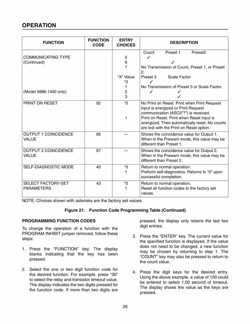
COMMUNICATING TYPEProper selection of two digits, “XY,” determines the combination of values which are transmitted. “17” transmits no values.
91“Y” Value
*01234
Count Preset 1 Preset 2✓ ✓ ✓✓ ✓
✓ ✓✓
✓ ✓
FUNCTIONFUNCTION
CODEENTRY
CHOICESDESCRIPTION
NOTE: Choices shown with asterisks are the factory set values
Figure 21. Function Code Programming Table (Continued)
OPERATION
26
PROGRAMMING FUNCTION CODES
To change the operation of a function with thePROGRAM INHIBIT jumper removed, follow thesesteps:
1. Press the “FUNCTION” key. The displayblanks indicating that the key has beenpressed.
2. Select the one or two digit function code forthe desired function. For example, press “30”to select the relay and transistor timeout value.The display indicates the two digits pressed forthe function code. If more than two digits are
pressed, the display only retains the last twodigit entries.
3. Press the “ENTER” key. The current value forthe specified function is displayed. If the valuedoes not need to be changed, a new functionmay be chosen by returning to step 1. The“COUNT” key may also be pressed to return tothe count value.
4. Press the digit keys for the desired entry.Using the above example, a value of 100 couldbe entered to select 1.00 second of timeout.The display shows the value as the keys arepressed.
COMMUNICATING TYPE(Continued)
(Model 5886-1400 only)
567
“X” Value*0123
Count Preset 1 Preset2✓
✓No Transmission of Count, Preset 1, or Preset 2.Preset 3 Scale Factor
✓No Transmission of Preset 3 or Scale Factor.
✓ ✓✓
PRINT ON RESET 92 *0
1
No Print on Reset. Print when Print Request input is energized or Print Request communication (ASCII”?”) is received. Print on Reset. Print when Reset input is energized. Then automatically reset. No counts are lost with the Print on Reset option.
OUTPUT 1 COINCIDENCE VALUE
96 — Shows the coincidence value for Output 1. When in the Prewarn mode, this value may be different than Preset 1.
OUTPUT 2 COINCIDENCE VALUE
97 — Shows the coincidence value for Output 2. When in the Prewarn mode, this value may be different than Preset 2.
SELF-DIAGNOSTIC MODE 40 *01
Return to normal operation.Preform self-diagnostics. Returns to “0” upon successful completion.
SELECT FACTORY-SET PARAMETERS
43 *01
Return to normal operation.Reset all function codes to the factory set values.
FUNCTIONFUNCTION
CODEENTRY
CHOICESDESCRIPTION
NOTE: Choices shown with asterisks are the factory set values
Figure 21. Function Code Programming Table (Continued)

OPERATION
27
5. Press the “ENTER” key to store the new data.The display blanks temporarily as the controlstores the information. If the entry is out ofrange for the selected function, the controlmay change the entry to a value in range.
6. The next function to be interrogated or modi-fied may be specified. If no additional functionsneed to be selected, the control can bereturned to displaying the current count valueby pressing the “COUNT” key.
CHANGING THE PRESET VALUES
To change the value of Preset 1, Preset 2 or Pre-set 3, follow these steps:
1. Press the “PRESET 1,” “PRESET 2,” or “PRE-SET 3” key. The display will show the currentvalue for that preset. If the value displayed isthe same as the desired value, proceed to step4.
2. Key in the new preset value. Upon pressingthe first key, the current preset value disap-pears and the digit which was pressedappears. Each successive digit displays as it ispressed.
3. Press the “ENTER” key. The display blanks fora moment and then redisplays the new preset.This confirms that the new value has beenentered.
4. Press the “COUNT” key. The display returns toshowing the current count value.
5. If other presets must be entered, return to step1.
PREVENTING PRESET MODIFICATION
To avoid accidental change to the preset values, itis recommended that the ability to change the Pre-sets is inhibited whenever possible.
Function code 41, Preset Lock, allows any combi-nation of Presets to be inhibited (see Figure 21).
Any Presets selected in Function code 41 cannotbe changed when the Program Inhibit Input isenergized (see “Inhibiting Programming Modifica-tions” below).
DISABLING THE FRONT PANEL RESET KEY
Select the Momentary Reset mode (enter “1” infunction 82) and install a jumper from the resetinput (terminal #17) to DC Common. This disablesthe Front Panel Reset key and prevents the opera-tor from accidentally resetting the counter.
The jumper may be replaced by a normally closedcontact. In this case the counter is reset externallyby opening and closing this contact.
If power is interrupted, the counter is not resetwhen power is reapplied.
INHIBITING PROGRAMMING MODIFICATIONS
The function codes and their values may beaccessed and modified whenever the control haspower applied, including times when the processbeing controlled is running.
���� WARNING
CHANGING FUNCTION CODE VALUESWHILE THE PROCESS IS OPERATINGMAY BE HAZARDOUS TO THE OPERA-TOR AND/OR THE MACHINERY. USEEXTREME CAUTION. WHENEVER POS-SIBLE, STOP THE PROCESS BEFOREATTEMPTING TO MODIFY FUNCTIONCODE VALUES.
To avoid accidental change to the function codevalues, it is recommended that the ability tochange them be removed by installing a jumperbetween the PROGRAM INHIBIT terminal and DCCommon on the rear of the control. Wheninstalled, all of the functions may be interrogatedbut not modified.

SCALE FACTORS
28
The Model 5886-1400 Control includes the abilityto scale incoming counts. This means that for eachpulse received on the count inputs, a fraction ormultiple of that pulse is counted. Scaling can beused to compensate for wear on measuringwheels, consistent material slippage or material
stretch, to make conversions between differentunits of measure (inches to centimeters, for exam-ple) or to totalize parts produced from multiple partmanufacturing processes (such as 6 parts pro-duced for each operation of a press).
Figure 22. Table of Scale Factors versus Count Speed
The scale factor can be a number from 0.0001 to9.9999. This number becomes a factor by whichincoming count pulses are multiplied. The sum ofthe scaled count pulses is shown on the frontpanel display.
ENTERING A SCALE FACTOR
Function 5 selects the Scale Factor. Note that anyjumper connected to the Program Inhibit terminalon the rear panel of the counter must first be dis-connected before the Scale Factor may be modi-fied. To change the Scale Factor, follow thesesteps:
1. Press the “FUNCTION” key. The displayblanks to indicate that the key has beenpressed.
2. Press the “5” key. The display indicates thisdigit.
3. Press the “ENTER” key. The current value forthe Scale Factor is displayed. If the value doesnot need to be changed, proceed on to step 6below.
4. Press the digit keys for the desired entry. Notethat for a Scale Factor of 1 the entry of 10000
SCALE FACTOR COUNT SPEED (PULSES PER SECOND)
Normal Count
Quadrature and/orDoubled Count
0.0001 to 0.9999 5,000 2,500
1.0000 7,500 3,750
1.0001 to 1.9999 4,000 2,000
2.0000 6,000 3,000
2.0001 to 2.9999 3,500 1,750
3.0000 5,000 2,500
3.0001 to 3.9999 3,000 1,500
4.0000 4,000 2,000
4.0001 to 4.9999 2,750 1,375
5.0000 3,500 1,750
5.0001 to 5.9999 2,500 1,250
6.0000 3,000 1,500
6.0001 to 6.9999 2,250 1,125
7.0000 2,500 1,250
7.0001 to 7.9999 2,000 1,000
8.0000 2,250 1,125
8.0001 to 8.9999 1,750 875
9.0000 2,000 1,000
9.0001 to 9.9999 1,500 750

SCALE FACTORS
29
must be made since the scale factor is dis-played in the X.XXXX format. The displayshows the value as each key is pressed.
5. Press the “ENTER” key to store the new data.The display blanks momentarily as the controlstores the information. If a zero is entered asthe Scale Factor, the counter defaults to thevalue of 1.0000.
6. The next function to be interrogated or modi-fied may be specified. If no additional functionsneed to be selected, the counter may bereturned to displaying the current count valueby pressing the “COUNT” key.
COUNT SPEED VERSUS SCALE FACTOR
The scale factor entered into the counter has adirect effect on the maximum rate at which thecounter can receive count pulses. Generally, thelarger the scale factor the slower the counter canreceive pulses. A table indicating count speed ver-sus scale factor values is given in Figure 23.
In this table, the Normal Count columns representthe speed at which the counter can receive pulseswhen it is operating in the Add/Subtract, Countwith Direction Control or Count Up with InhibitControl modes. The Quadrature and DoubledCount columns indicate speed whenever the hard-ware doubling (jumper installed between the Dou-ble Input and DC Common) is utilized.
OPERATION OF THE SCALER
When the counter receives a count pulse, thescaler recognizes that fact and multiplies the 1pulse by the scale factor. The scaled value, whichwill be a number from 0.0001 to 9.9999 since thisis the range of the scale factor, is added to aresultant total. This resultant is shown on the dis-play. However, the result can have up to four deci-mal places of value. The display only shows wholeincrements of counts.
For example, a scale factor of 1.2000 is enteredinto the counter. For each pulse received 1.200 isadded to the result. But since the display only indi-cates whole numbers, after the first pulse it shows“1”. After 5 pulses it shows “6”. This is shown inFigure 23.
The scaler stores any remaining partial count andadds that to the next scaled pulse value when it isreceived. This allows accumulation of scaled par-tial counts.
When a Preset is established on a control withscaling, the control activates the related output asshown in Figure 3. But when scaling is used, thecount value is not necessarily a whole number.The partial count remainder can affect when theoutput(s) change state.
With the example of Figure 23, a Preset of 11 isentered into the control. After the first pulse thedisplay shows 1 and after the ninth pulse it shows10. But, the next pulse changes the display toshow 12, bypassing the preset of 11. The counter,during the process of adding the scaled result tothe total, actually counts from 10 through 11 to 12.This occurs so swiftly that the value of 11 cannotbe seen on the display. However, the counter doesrecognize coincidence at the value of 11 andchanges the state of the output.
As a second example, a Scale Factor of 0.5000 isentered into the control. Figure 24 gives a table ofpulses received versus displayed value for thisexample.
A Preset of 5 is entered when the control is in theindependent output mode. From Figure 24, it isevident that the output will turn on when the 10th
PULSES RECEIVED
RESULT CALCULATED
DISPLAY VALUE
012345678910
0.00001.20002.40003.60004.80006.00007.20008.40009.6000
10.800012.0000
0123467891012
Figure 23. Pulses Received versus Dis-played Value Using Scale Factor of 1.2000

SCALE FACTORS
30
pulse is received on the count input. It is when the10th pulse is received that the display changesfrom 4 to 5. However, if the counter is used in theReset to Preset mode, the display shows 5 whenthe Reset key is pressed. The first pulse receivedchanges the display to show 4, and the ninth pulsechanges the display to 0. But, it is the TENTHpulse that causes the output to change state. Thisis because after the ninth pulse, there is a remain-der of 0.5000 counts in the counter and, therefore,the value in the counter is not actually zero untilafter the next pulse.
HOW SCALE FACTORS AFFECT PROCESSES
When the use of Scale Factors results in partialcount remainders, those remainders can affect themanner in which the process being controlled willfunction. For example, if a Scale Factor of 1.3000is entered into a control and a Preset of 15 is usedin the independent mode, a table as shown in Fig-ure 25 results.
The control is used in the Reset mode. Whenreset, the counter starts at zero and counts to thePreset value. If the Auto Recycle mode is imple-mented, the counter recycles when the Presetvalue is reached. But, with a Preset of 15, thecounter has actually accumulated 15.6000 counts.
Thus, when it recycles, a value of 0.6000 countsremains. When the next pulse is received, 1.3000counts is added and the count value is 1.9000.The “Second Cycle Display” column shows thedisplayed value for the second cycle.
It is obvious from the last column that slightly morecounts are accumulated for the second part thanwere accumulated for the first. If this table werecarried out for the third part, we would find that thethird part is cut off one pulse too early. Clearly, thecarryover of the remaining partial count causesproblems in these types of applications.
As a solution, a function code has been providedwhich allows the choice of whether the remainingpartial count is carried over into the next cycle ornot. Function 83, Scaler Reset on Recycle, allowsselection of this option. If function 83 has a valueof “0” entered, the scaler is not reset when an AutoRecycle occurs. If a value of “1” is entered, thescaler is reset each time an Auto Recycle occurs.This forces any remaining partial count to be resetto zero, eliminating the problem described above.The unit is shipped from the factory with the ScalerReset on Recycle Mode enabled (Function 83 hasa value of “1”).
It should be noted that the remaining partial countis typically an extremely small part of the totallength of the part being produced (typically lessthan 1%). In those applications where the mea-surement system may be chosen, the rule ofthumb is that the measurement device shouldhave a minimum of twice the resolution (generateat least twice as many pulses per unit of measure)as the desired part accuracy.
For example, if a 10.00 inch part is to be made andthe tolerance of the part may be plus or minus 0.02inches, the measurement system should generateat least one pulse for each 0.01 inches of materialbeing measured. Thus, after the display shows10.00 inches (1000 counts), there may be aremaining partial count of 0.400 due to the use ofa Scale Factor. The percentage of error is calcu-lated by 0.400/1000. This yields 0.04% error.
Even though the error is so small, compensationshould still be made for the extra partial count atthe end of a part by entering a “1” in Function 83.This is because the error is cumulative; that is,
PULSES RECEIVED
RESULT CALCULATED
DISPLAY VALUE
012345678910111213141516
0.00000.50001.00001.50002.00002.50003.00003.50004.00004.50005.00005.50006.00006.50007.00007.50008.0000
00112233445566778
Figure 24. Pulses Received versus Display Value Using Scale Factor of 0.5000

SCALE FACTORS
31
each successive part grows longer by 0.004inches. Eventually, this cumulative error will causethe part to be out of tolerance.
Typically, those applications which require Func-tion 83 to have a value of “1” are cut-to-lengthapplications. When the application is performing arepetitive process such as punching equallyspaced holes in a single part, the scaler shouldretain partial counts for the next measurement. Inthese cases, Function 83 should be set to “0”.Whenever the Reset key is pressed or the ResetInput is energized, the scaler is always reset, elim-inating any remaining partial counts. This isregardless of the value entered in Function 83.
CALCULATING THE SCALE FACTOR
There are four general categories of applicationswhich require scaling. The method of calculatingthe scale factor differs for each. The categoriesare:
1. Allowances for wear of measurement devicesand material stretch applications.
2. Unit conversions (typically when the measure-ment system is set up for measuring one unitand the part must be made in another; i.e.,inches versus millimeters.)
3. Scaling of pulses received from flowmeters orother sensors which produce a non-standardnumber of pulses per unit of measure.
4. Allowing multiple parts to be made for eachoperation of a machine.
A discussion of the means of calculating the scalefactor for each category and special problemsinvolved follows.
Allowances for Wear or Stretch
Over a period of time a measuring wheel will beginto wear. The wheel allows accurate measurementonly when its circumference is a known, fixedvalue. Thus, as the wheel wears, the error in themeasurement increases because the circumfer-ence of the wheel becomes less and less. Scalingprovides a means to compensate for the decreas-ing wheel circumference. This allows the useful lifeof the measuring wheel to be extended, decreas-ing cost.
In applications where the material stretches orshrinks by a fixed amount, scaling allows compen-sation for gained or lost material. These applica-tions required that the amount of stretch orshrinkage be known, measurable or calculableand that it be consistent from machine cycle tomachine cycle.
In either case, the scale factor is calculated byusing the formula:
Measured or Calculated DistanceScale Factor = Theoretical Distance
PULSESRECEIVED
RESULTCALCULATED
DISPLAYVALUE
SECOND CYCLERESULT
SECOND CYCLE DISPLAY
123456789
101112
1.30002.60003.90005.20006.50007.80009.100010.400011.700013.000014.300015.6000
12356791011131415
1.90003.20004.50005.80007.10008.40009.700011.000012.300013.600014.900016.2000
13457891112131416
Figure 25. Pulses Received versus Display Value Using Scale Factor of 1.3000

SCALE FACTORS
32
In the above formula, the Theoretical Distance isthe distance that would be measured if the mea-suring wheel were new or within design toleranceof new. For stretch or shrinkage applications, it isthe amount of material fed into the process beforethe stretching or shrinkage occurs. The Measuredor Calculated Distance is the length which resultsupon completion of the part or process. For exam-ple, if the counter is intended to produce 12.00inch parts but the parts come out of the machineonly 11.93 inches long, the Measure distance is11.93 inches. (The Theoretical Distance in thisexample is 12.00 inches.) Figure 26 shows graphi-cally what takes place in this application.
The shaft encoder in Figure 26 produces 600pulses per revolution. Doubling is used in thecounter to result in 1200 pulses per revolution. Themeasurement wheel is intended to have a 12.00inch circumference. This should result in 1 pulseper 0.01 inches. Since a 12.00 inch is desired, aPreset of 1200 is entered into the counter with ascale factor of 1.0000.
However, when the process is run, the parts con-sistently come out of the machine only 11.93
inches long. The counter is counting 1200 pulsesand the output of the counter is energized at thattime. Obviously, the wheel is not the 12.00 inch cir-cumference which it should be. Rather thanreplacing the measurement wheel, a scale factorcan be entered to compensate for the discrepancy.Using the formula on the previous page, the scalefactor is calculated by:
11.93″ (Measured)Scale Factor = 12.00″ (Theoretical) = 0.9942
With this scale factor entered, the display stillshows 12.00 counts for each part, but each pulsereceived is worth only 0.9942 counts. Thus, morethan 1200 pulses are received by the counter foreach part being produced and the part is made tothe correct length.
For applications where the material is stretched orshrunk, the measurement device may be locatedon the front end of the process where the unaf-fected material is fed in. Yet the counter can havea scale factor entered which allows it to measurethe finished parts. Figure 27 shows a typical pro-cess which results in material stretch.
Figure 26. Wheel Wear Correction Application

SCALE FACTORS
33
Figure 27. Material Stretch Application
Again, a 12.00 inch part is desired. A Preset of12.00 is entered into the control with a scale factorof 1.0000 and a sample part is produced. When itis measured, it is found to be 12.37 inches long.The scale factor needed to produce a 12.00 inchpart is calculated by plugging these values into theformula:
12.37″ (Measured)Scale Factor = 12.00″ (Desired) = 1.0308
When the scale factor of 1.0308 is entered into thecontrol, parts are produced at 12.00 inches asdesired. Since the material is stretched in the pro-cess, each pulse received by the counter is worth1.0308 counts. Thus, less than 1200 pulses needto be received to produce each 12.00 inch finishedpart and display 1200 counts.
MEASUREMENT SYSTEM MEASURES IN:
DISPLAY MUST SHOW QUANTITY IN:
SCALE FACTOR TO BE USED:
InchesCentimetersFeetYardsFeetYardsMetersMeters
Gallons (US)Gallons (Imp.)LitersLitersQuarts (US)Liters
CentimetersInchesYardsFeetMetersMetersFeetYards
LitersLitersGallons (US)Gallons (Imp.)LitersQuarts (US)
2.54000.39370.33333.00000.30480.91443.28081.0936
3.78544.54280.26420.22010.94631.0567
Figure 28. Unit Conversion Scale Factors

SCALE FACTORS
34
Unit Conversions
In some cases, the measurement system is set upto measure in one engineering unit but the partsmade are produced in a different engineering unit.This may be the difference between ounces andgallons, inches and feet, feet and yards, inchesand millimeters, quarts and liters or any other com-bination. In these applications, the scale factormay be chosen from the table given in Figure 28 orcalculated using any standard conversion factorcarried out to four decimal places.
Scaling Pulses Received From Flowmeters or Other Sensors
Typically, flowmeters generate large numbers ofpulses for each unit of measure. Additionally, thenumber of pulses per unit is usually not easilydivisible or massaged to allow a standard counterto increment in a common engineering unit.
The scale factor to be entered into the counter iseasily calculated by using the formula:
1 (Unit of Measure)Scale Factor = Pulses Produced
per Unit of Measure
For example, a flowmeter might produce 146pulses per gallon of flow. If the counter is to countgallons of flow, the incoming pulses must bedivided by 146. If the display should indicate wholegallons of flow accumulated, the scale factor isdetermined by:
Scale Factor = 1 / 146 = 0.0068
If the display should rather show gallons andtenths of gallons, the scale factor may be multi-plied by 10 to yield 0.0685. (Note that in this casethe decimal point on the counter should be placedbetween the first and second digits for proper indi-cation of units.)
When the output from other sensors must bescaled, the same formula can be used to calculatethe scale factor. It is sometimes easier to changethe definition of the terms in order to find the scale
factor, however. For example, a quadrature shaftencoder which produces 600 pulses per revolutionis used to indicate rotation of a shaft. Usually, rota-tion is given in degrees with 360 degrees per revo-lution. If the doubled Quadrature count mode isused, 1200 pulses per revolution are received bythe counter. This results in 3.3333 pulses perdegree of rotation.
Given this information, finding the scale factor nec-essary for proper operation can be confusing. Butif the terms of the formula are changed as:
Desired Display ValueScale Factor = Actual Pulses Received
Filling in the terms the scale factor is found by:
360(Counts Per Revolution)Scale Factor=1200(Pulses Per Revolution)=0.3000
With the Scale Factor of 0.3000, the display willindicate 360 degrees per revolution from a 1200PPR encoder.
Allowing Multiple Parts per Machine Operation
If a single machine operation causes one pulse tobe received by the counter and that singlemachine operation produces several parts simulta-neously, the scale factor is simply the number ofparts produced per pulse. For example, if six partsare produced per cycle of the machine, a scalefactor of 6.0000 should be entered into the control.
In this example, if one of the six cavities requiresrepair and is not producing parts, the scale factormay be reduced from 6.0000 to 5.0000. Thisadjustment can be made without resetting thecounter. The machine must be stopped, the Pro-gram Inhibit jumper removed if installed, and theScale Factor changed. Then the Program Inhibitjumper may be reinstalled and the process startedup again. This allows in-process service andadjustment of machine malfunctions without losingtrack of how many parts have been produced sofar.

SCALE FACTORS
35
It may be desirable in this type of application tohave the Program Inhibit terminal wired to a key-lock switch, allowing easier adjustment whenneeded.
An additional consideration in this application isthat even if the Preset is set as a multiple of six
and only five parts are made per cycle, the Presetdoes not need to be adjusted. This is true becausethe counter checks the preset for each of the fiveincrements per cycle individually and will energizethe output when coincidence is established. How-ever, in this example, up to four extra parts may beproduced when the output is energized.
SERIAL COMMUNICATIONS
36
Several types of information may be transmitted orreceived by the control. The serial communi-cations capability allows any combination of countand preset values to be printed, remotely dis-played, or sent to a host computer or other periph-eral device for processing. The characteristics ofthe communication are controlled by functioncodes.
COMMUNICATION FORMAT
The control uses a 20 milliamp current loop typeof electrical interface for serial communications.The control has a separate 20 milliamp currentloop for incoming communications and anotherloop for outgoing communications.
Since serial communication (either in or out) isdone through only two wires, each character trans-mitted or received must be generated by a seriesof on and off states called bits. Each character hasits own unique code or sequence of bits thatallows the receiving device to understand whatcharacter it is receiving. The character “5”, forexample, has a series of bits which are differentfrom the series of bits for the character “6”. In fact,eight individual bits are needed to express a singlecharacter. Seven bits identify the character itselfand the eighth is used for error checking to allowthe receiving device to make sure that the previ-ous seven are correct when they are received.This eighth bit is called the parity bit and shows“even parity” to the receiving device when trans-mitting data. When the counter receives serialdata, it ignores the parity bit.
There are several different standard rates at whichserial communications occur. Each is a function ofthe number of bits transmitted per second. Theterm which defines transmission rate is “Baud”which is understood to mean “bits per second.”
The standard transmission rates the control canbe set up to use are 110 Baud, 300 Baud, and1200 Baud.
While each character requires eight individual bitsto be uniquely expressed, a few additional bitsmust be sent between characters. These arecalled “start” and “stop” bits. The “start” bit signi-fies that this is the beginning of the character andthe next eight bits are the character itself. After the
character is transmitted, either one or two “stop”bits are sent to indicate that the character hasbeen completely transmitted. When the control isoperating at 110 Baud, two “stop” bits are sent andat 300 or 1200 Baud one is sent. Thus, at 300Baud, for example, each character requires tenbits to be transmitted: one “start” bit, eight data bitsand one “stop” bit. If information is being communi-cated at 300 Baud, 30 characters per second arecommunicated since a total of ten bits per charac-ter are required.
The standard set of codes used by the control forcommunicating information serially is called theASCII character table. ASCII stands for AmericanStandard Code for Information Interchange. Thecontrol uses ASCII codes for all its communica-tions.
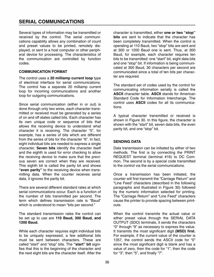
A typical character transmitted or received isshown in Figure 30. In this figure, the character isshown with the “start” bit, seven data bits, the evenparity bit, and one “stop” bit.
SENDING DATA
Data transmission can be initiated by either of twomethods. The first is by connecting the PRINTREQUEST terminal (terminal #16) to DC Com-mon. The second is by a special code transmittedto the control via the serial communications.
Once a transmission has been initiated, thecounter will first transmit the “Carriage Return” and“Line Feed” characters (described in the followingparagraphs and illustrated in Figure 30) followedby the numeric information selected for printing.The “Carriage Return” and “Line Feed” characterscause the printer to provide spacing between print-outs.
When the control transmits the actual value oreither preset value through the SERIAL DATAOUTPUT (SDO) terminals, it sends the characters“0” through “9” as necessary to express the value.It transmits the most significant digit (MSD) first.For example, if the current value of the counter is1357, the control sends the ASCII code for “0”since the most significant digit is blank and has avalue of zero, then the code for “1”, then the codefor “3”, then “5”, and finally “7”.

SERIAL COMMUNICATIONS
37
Figure 29. Organization of Typical Serially Transmitted Character
Figure 30. Serial Transmission of a Complete Value, Including “CNT” Label, Value, “CR” and “LF”
After the entire value has been transmitted, thecontrol sends two more characters. These arecalled “Carriage Return” (CR) and “Line Feed”(LF). A printer, host computer or other peripheraluses these characters to identify when a transmis-sion is complete. In the case of the printer, the“CR” instructs it to return the printing carriage and
the “LF” tells it to advance the paper one line. The“CR” and “LF” are transmitted after each valuethe control sends.
By selecting the associated value for the Commu-nications Type function (Function 91) the controlcan transmit the counter value or any combination

SERIAL COMMUNICATIONS
38
of preset values. Before the value(s) are sent, thecontrol sends an identifier which indicates whatinformation is to follow. When the control is con-nected to a printer, these identifiers are alsoprinted. The label “CNT” is printed before the valueof the counter, “PS1” is printed before the Preset 1value, “PS2” is printed before the Preset 2 valueand “PS3” is printed before the Preset 3 value. If adecimal point has been specified by programmingFunction 62, the decimal point is inserted into theprintout at the appropriate place.
Figure 30 shows graphically how a typical value istransmitted. Each block shown consists of the bitorganization as indicated in Figure 29.
Figure 31 shows a sample printout when the con-trol has been set up to print both the counter andpreset values with a decimal point before the sec-ond digit.
If the count value and both preset values are to betransmitted, the count value is always transmittedfirst, Preset 1 second, Preset 2 third, and Preset 3last.
The control can be programmed to automaticallytransmit its values when reset. This mode isselected by entering a “1” in Function 92. Uponpressing the “RESET” key or having the Resetinput energized, the control internally stores thecount value, then resets the counter. Once thecontrol is reset, the stored count value is transmit-ted. This allows the count value to be recordedwhile the process is running without losing anycounts.
Figure 31. Typical Printout of Transmitted Values
Figure 32. Typical Preset Change Serially Communicated
When the Print on Reset mode is selected, thePrint Request input may be energized or the ASCII“?” received through serial communication tocause a printout without resetting the counter.
RECEIVING DATA
The control can receive a command through theserial communications input which instructs it toautomatically transmit the information of thecounter or presets (depending on Function 91).
This command has the same effect as energizingthe Print Request input. The ASCII character “?”asks the control to send its data.
In addition, the preset values can be changedthrough the serial communication input when anew value is received from a remote preset periph-eral, a host computer or another compatibleperipheral. The new Preset 1 value must be pre-ceded by the ASCII character “A” which informs
CNT 1234.56PS1 5000.00PS2 9738.15PS3 0050.00

SERIAL COMMUNICATIONS
39
the control that a new Preset 1 value is forthcom-ing. The ASCII character “B” must precede thenew Preset 2 value. The ASCII character “C” mustprecede the new Preset 3 value. After the 1 to 6digits for the new preset are received, the ASCIIcharacter “*” must be received to tell the controlthat the end of the preset value has been received.When the “*” is received, the new preset is auto-matically entered.
Sample commands to change both Preset 1 andPreset 2 via serial communications is shown inFigure 33. Note that each block shown containsthe bit organization as indicated in Figure 31. Aminimum of 100 milliseconds must be allowedbetween transmissions for proper operation.
The Baud rate of the incoming serial communica-tions is the same rate as set for the outgoing com-munications. Any serial data the control receives isignored if it is not either preceded by an “A”, “B” ora “?”. The control ignores any decimal pointswhich are received during a transmission of a newpreset, but inserts the decimal point automaticallyafter the new preset has been entered uponreceipt of the “*”.
TRANSMITTING SCALE FACTORS
For Model 5886-1400, the Scale Factor can be
transmitted with the other values (see Figure 22).When the Scale Factor is transmitted, the value ispreceded by the identifying label “SCA”, indicatingScale Factor. A sample printout of all values froma model 5886-1400 control is given in Figure 33.
Figure 33. Sample Printout of Values from a 5886-1400
RECEIVING SCALE FACTORS
For Model 5886-1400 the Scale Factor can bereceived with the other values. In this case, theScale Factor must be preceded by an ASCII “S”.The sale factor itself can be up to five digits long inASCII characters and followed by an ASCII “*” Forexample, a scale factor of 5.0000 is transmitted as“S50000*”.
PRINT ON RESET
The control may be programmed to print whenreset. Function code 92 is used to select thismode. Print on reset does not occur when the con-trol auto-recycles.
CNT 001567 (Count Value)PS1 010000 (Preset 1 Value)PS2 025000 (Preset 2 Value)PS3 000000 (Preset 3 Value)SCA 1.0000 (Scale Factor)
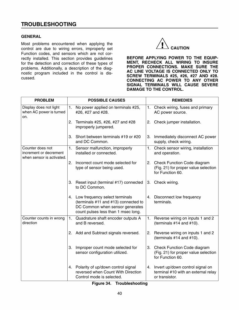
TROUBLESHOOTING
40
GENERAL
Most problems encountered when applying thecontrol are due to wiring errors, improperly setFunction codes, and sensors which are not cor-rectly installed. This section provides guidelinesfor the detection and correction of these types ofproblems. Additionally, a description of the diag-nostic program included in the control is dis-cussed.
���� CAUTION
BEFORE APPLYING POWER TO THE EQUIP-MENT, RECHECK ALL WIRING TO INSUREPROPER CONNECTIONS. MAKE SURE THEAC LINE VOLTAGE IS CONNECTED ONLY TOSCREW TERMINALS #25, #26, #27 AND #28.CONNECTING AC POWER TO ANY OTHERSIGNAL TERMINALS WILL CAUSE SEVEREDAMAGE TO THE CONTROL.
PROBLEM POSSIBLE CAUSES REMEDIES
Display does not light when AC power is turned on.
1. No power applied on terminals #25, #26, #27 and #28.
2. Terminals #25, #26, #27 and #28 improperly jumpered.
3. Short between terminals #19 or #20 and DC Common.
1. Check wiring, fuses and primary AC power source.
2. Check jumper installation.
3. Immediately disconnect AC power supply, check wiring.
Counter does not increment or decrement when sensor is activated.
1. Sensor malfunction, improperly installed or connected.
2. Incorrect count mode selected for type of sensor being used.
3. Reset input (terminal #17) connected to DC Common.
4. Low frequency select terminals (terminals #11 and #13) connected to DC Common when sensor generates count pulses less than 1 msec long.
1. Check sensor wiring, installation and operation.
2. Check Function Code diagram (Fig. 21) for proper value selection for Function 60.
3. Check wiring.
4. Disconnect low frequency terminals.
Counter counts in wrong direction
1. Quadrature shaft encoder outputs A and B reversed.
2. Add and Subtract signals reversed.
3. Improper count mode selected for sensor configuration utilized.
4. Polarity of up/down control signal reversed when Count With Direction Control mode is selected.
1. Reverse wiring on inputs 1 and 2 (terminals #14 and #10).
2. Reverse wiring on inputs 1 and 2 (terminals #14 and #10).
3. Check Function Code diagram (Fig. 21) for proper value selection for Function 60.
4. Invert up/down control signal on terminal #10 with an external relay or transistor.
Figure 34. Troubleshooting
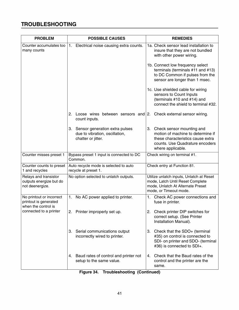
TROUBLESHOOTING
41
Counter accumulates too many counts
1. Electrical noise causing extra counts.
2. Loose wires between sensors andcount inputs.
3. Sensor generation extra pulses due to vibration, oscillation, chatter or jitter.
1a. Check sensor lead installation to insure that they are not bundled with other power wiring.
1b. Connect low frequency select terminals (terminals #11 and #13) to DC Common if pulses from the sensor are longer than 1 msec.
1c. Use shielded cable for wiring sensors to Count Inputs (terminals #10 and #14) and connect the shield to terminal #32.
2. Check external sensor wiring.
3. Check sensor mounting and motion of machine to determine if these characteristics cause extra counts. Use Quadrature encoders where applicable.
Counter misses preset 1 Bypass preset 1 input is connected to DC Common.
Check wiring on terminal #1.
Counter counts to preset 1 and recycles
Auto recycle mode is selected to auto recycle at preset 1.
Check entry at Function 81.
Relays and transistor outputs energize but do not deenergize.
No option selected to unlatch outputs. Utilize unlatch inputs, Unlatch at Reset mode, Latch Until Reset Complete mode, Unlatch At Alternate Preset mode, or Timeout mode.
No printout or incorrect printout is generated when the control is connected to a printer
1. No AC power applied to printer.
2. Printer improperly set up.
3. Serial communications output incorrectly wired to printer.
4. Baud rates of control and printer not setup to the same value.
1. Check AC power connections and fuse in printer.
2. Check printer DIP switches for correct setup. (See Printer Installation Manual).
3. Check that the SDO+ (terminal #35) on control is connected to SDI- on printer and SDO- (terminal #36) is connected to SDI+.
4. Check that the Baud rates of the control and the printer are the same.
PROBLEM POSSIBLE CAUSES REMEDIES
Figure 34. Troubleshooting (Continued)

TROUBLESHOOTING
42
CHECK-OUT PROCEDURE
If the control does not perform satisfactorily, checkall connections, proceed through the trouble-shooting chart on the previous pages, and checkall function codes for proper set-up according tothe table given in Figure 21. If these tests proceedcorrectly and the control is still not properly func-tioning, remove ALL wiring from the back of thecounter and proceed through the following steps. Ifthe control fails to function in any of the steps,return it to Durant Products, Attn: Repair Depart-ment, 901 South 12th Street, Watertown, WI53094. Enclose a letter describing the malfunction.
Power Input
Connect 115 VAC between terminals #25 and #26.Jumper terminal #25 to terminal #28 and jumperterminal #26 to terminal #27. The display shouldflash for a short period of time and then remain lit.Place electrical tape over terminals #25 through#28 to prevent electrical shock during the nexttests.
Keyboard
Press the “FUNCTION” key, the display shouldblank. Press “43” which the display should indi-cate. Press ENTER, the display should show “0”.Press “1” which the display should indicate. Press“ENTER”, the display should flash “0” and the“COUNT” indicator for a short period of time thenremain lit.
Count Up
Make a momentary connection between terminals#10 and #12. The display should increment sev-eral counts. Make a connection with a short pieceof wire between terminals #11 and #12 and repeatthe count test between terminals #10 and #12.Retain the connection between terminals #11 and#12.
Count Down
Make a momentary connection between terminals#14 and #12. The display should decrement sev-eral counts. Make a connection with a short pieceof wire between terminals #13 and #12 and repeatthe count test between terminals #14 and #12.
Retain the connection between terminals #13 and#12. Decrement the counter until the display indi-cates less than #5”.
Preset
Press the “PRESET 1” key and the display shouldshow “0”. Press the “5” key, which the displayshould indicate. Press the “ENTER” key. The dis-play should blank for one half second then remainlit. Press the “COUNT” key, the display should indi-cate the previous count value. Make a momentaryconnection between terminals #10 and #12 atleast five times. You should hear the output relayactuate.
Relay Timeout
Ten seconds after relay K1 actuates, you shouldhear it release.
Reset
Press the “RESET” key. The display should show“0”.
Unlatch
Again make a momentary connection between ter-minals #10 and #12 at least five times. Before theten second timeout elapses, make a momentaryconnection between terminals #2 and #8. Youshould hear output relay K1 release. Press the“RESET” key again.
Latch Until Reset Complete
Press the “FUNCTION” key, press “36”, then press“ENTER”. The display should indicate “0”. Pressthe “1” key, then “ENTER”. The display shouldshow “1”, blank for one half second then remain lit.Press the “FUNCTION” key, press 30, then press“ENTER”. The display should show “10.00”. Pressthe “0” key, then “ENTER”. The display shouldshow “0.00”, blank for one half second then remainlit. Press the “COUNT” key, the display should indi-cate “0” and the COUNT indicator lit. Make amomentary connection between terminals #10 and#12 at least five times. You should hear the outputrelay activate. Press the “RESET” key. The displayshould display “0” and you should hear the relayrelease.

TROUBLESHOOTING
43
Auto Recycle
Press the “FUNCTION” key, press “81”, then press“ENTER”. The display should indicate “0”. Pressthe “1” key, then “ENTER”. The display shouldshow “1”, blank for one half second, then remainlit. Press the “COUNT” key, the display should indi-cate “0” and the COUNT indicator lit. Make amomentary connection between terminals #10 and#12 five times. You should hear output relay K1activate and the display should show “0”.
Power Outage
Disconnect the AC power. You should hear relayK1 release.
INTERNAL DIAGNOSTICS
The control has several internal diagnostic rou-tines which allow it to self-test various operationalcharacteristics. When power is applied, the controltests its memory to determine if it has retained allof the values and function code parameters previ-ously entered. It also tests to insure that all of theinternal memory is functional. During these self-tests, the display is blanked. Since the tests areperformed very quickly, the user usually does notnotice the short delay on power-up.
The user also has the ability to initiate the controlself-test diagnostics at any time. Function code 40is used to initiate the diagnostics. If the control failsany of the diagnostic routines, either on power-upor upon manual command, the display will flash anumber indicating which of the six self-tests failed.If no failures are found, the control returns auto-matically to normal operation.
NOTE
The self-diagnostics should not be per-formed while the process being controlledis running. The control responds to countpulses but ignores any incoming controlsignals while the diagnostics are operat-ing.
Description of the Diagnostics
The diagnostics which are included and theirrelated test numbers are as follows:
#1 - ROM (Read Only Memory) 16 Bit Checksum #2 - Internal RAM (Random Access Memory)
Bit Test#3 - Non-Volatile RAM Read/Write Bit Test#4 - Non-Volatile RAM Store Test#5 - Non-Volatile RAM 8 Bit Checksum#6 - Watch Dog Timer (1.3 Seconds) Timeout
ROM (Read Only Memory) 16 Bit Checksum - Test #1
This test determines if the permanent memorywhich controls how the control operates is good.
Internal RAM (Random Access Memory) Bit Test - Test #2
This routine tests the temporary workspace mem-ory used for normal operation and communication.If a failure occurs, the counter may change or losevalues or operating characteristics unexpectedly.
Non-Volatile RAM Read/Write Bit Test - Test #3
This test checks the memory which permanentlystores the operating characteristics and valueswhen a power outage occurs.
Non-Volatile RAM Store Test - Test #4
This test insures that the non-volatile memoryaccurately stores and retrieves the programmedoperating characteristics and values upon a poweroutage. If a failure of this type occurs, the counterwill operate correctly but could change its valuesor operating characteristics upon a power failureor power drop-out.
���� CAUTION
TO INSURE PROPER OPERATION, CHECK ALLFUNCTION CODE VALUES BEFORE STARTINGTHE PROCESS. NOTE THAT A TEMPORARYPOWER INTERRUPTION MAY CHANGE THEVALUES OF FUNCTION CODES DURING THEPROCESS IF TEST #4 HAS FAILED.
Non-Volatile RAM 8 Bit Checksum Test -Test #5
A checksum test is performed on the non-volatilememory to insure that none of the informationstored was changed while the control was unpow-ered. If this test fails, check all function code val-ues and the values of the counter and preset toinsure they are correct. Then disconnect andreconnect power to perform this test again. If the

TROUBLESHOOTING
44
test fails the second time, return the counter forrepair.
Watch Dog Timer (1.3 Seconds) - Test #6
While the control is operating, an internal WatchDog Timer is incremented every millisecond.Under normal operation, the control automaticallyresets the Watch Dog Timer at least once per sec-ond. If the control would malfunction during opera-tion, the Watch Dog Timer may time out(depending on the type of malfunction) and anerror code of “6” flashes on the display. If this typeof failure occurs, run the diagnostics using Func-tion 40. Excessive electrical interference maycause this type of failure without damage to thecontrol or the operating characteristics. If the diag-nostics find no other fault, it is reasonable toassume that the control is fully operational, unlessthis failure is recurring.
OPERATION OF DIAGNOSTICS
When power is applied, the control begins by per-forming tests #1, #2, #3 and #5. If all of thesepass, the counter is ready to operate as indicatedby flashing the count value on the display at onehalf second intervals for four seconds, thenremaining lit.
To select the self-diagnostic mode, specify Func-tion code 40 and enter a value of “1”. The controlimmediately turns on all display segments andLED indicators for 2 seconds. Then the displaysblank and the control steps through all five tests. Ifall five pass, the control begins a display and LEDtest routine. This routine sequences through flash-ing the numbers “0” through “9” on the displays,alternates the Preset 1, Preset 2 and Count LEDindicators and moving the decimal point from digitto digit. When the display sequence is finished, thecontrol shows the count value and the Count indi-cator is lit.
NOTE
The self-diagnostics should not be per-formed while the process being controlled
is running. The control responds to countpulses but ignores any incoming controlsignals while the diagnostics areoperating.
Performing the diagnostic routines does not affectthe Function code parameters. Thus, when thediagnostics are finished, the control retains all ofthe operational characteristics previously pro-grammed.
WHAT TO DO IF THE CONTROL FAILS A DIAGNOSTIC TEST
If the control flashes a single digit number continu-ously on power-up or when the self-diagnosticsare performed, it indicates which one of the testshas failed. When the number displayed is “4”, “5”,or “6”, the control can be allowed to operate bypressing the FUNCTION key to clear the display.
���� WARNING
RUNNING THE COUNTER AFTER AFAILURE HAS BEEN DETECTED CRE-ATES A SERIOUS RISK TO THE OPER-ATOR AND/OR MACHINERY.
As a minimum safety precaution, the Functioncode Default mode (Function 43) should beselected (enter a value of “1”) and the Functioncodes reprogrammed. This will insure that the fail-ure has not altered any of the operating character-istics of the counter. Selecting the defaultparameters with Function 43 also performs thepower-up self test, which could give another failureindication (for tests #1, #2 or #3). If this occurs,return the control for repair immediately.
Address units to be repaired to:
Cutler Hammer-Eaton CorporationDurant Instruments901 South 12th StreetWatertown, WI 53094ATTENTION: REPAIR DEPARTMENT

TRANSDUCERS, ACCESSORIES AND REPLACEMENT PARTS LIST
45
TRANSDUCERS
Medium Duty Shaft EncoderSingle Channel - 38150-XXXQuadrature - 38151-XXX
Heavy Duty Shaft EncoderSingle Channel - 48370-XXXQuadrature - 48371-XXX
60, 100, 120 and 600 PPR are stocked ratios for encodersAny number from 001 to 600 is available.Substitute the desired PPR for “XXX” in the part numbers.
12″″″″ Measuring Wheels with 3/8″″″″ BoreAluminum Rimmed
20156-301Rubber Rimmed
20154-301Urethane Rimmed
20144-301
Connector for Encoder
29729-300
Connector with 10 Foot Cable
29665-300
Rotary & Lineal Contactor
ES-9513-RS
Mounting Bracket for ES-9513-RS
40460-400Shown with ES-9513-RS and 12″ measuring wheel

TRANSDUCERS, ACCESSORIES AND REPLACEMENT PARTS LIST
46
ACCESSORIES
Serial to Parallel BCD Communications Convertor 58801-410The Serial to Parallel BCD Communications Convertor (SPCC) is aserial to parallel BCD adapter which provides a means of interfacinga Durant counter to a ladder logic based Programmable Control. TheSPCC converts the serial data from the counter’s 20ma current loopto eight digits of binary coded decimal data for use by theProgrammable Control. The BCD output is connected to the I/Ostructure of the PC. Several options, conveniently selected by a fourposition DIP switch eliminates the need for a special configurationfor each different application. The SPCC has a self contained powersupply which requires 115VAC power.
Parallel BCD To Serial Communications Convertor 58801-411The Parallel BCD to Serial Communications Convertor (PSCC) is aparallel BCD to serial Adaptor which provides a means of interfacinga Durant counter with a ladder logic based Programmable Control.The SPCC converts eight digits of binary coded decimal data from aPC to serial data to be input to the Durant counter through thecounter’s 20ma current loop. The BCD input is connected from theI/O structure of the PC. Several options, conveniently selected by afour position DIP switch, eliminates the need for a specialconfiguration for each different application. The SPCC has a selfcontained power supply which requires 115VAC power.
Simultaneous Input ProcessorThe Simultaneous Input Processor (SIP) is used as an accessorywith Durant counters to insure that all counts are recorded whenmultiple sources of count signal are required (counts can occursimultaneously).
8 input 49990-40816 input 49990-416

TRANSDUCERS, ACCESSORIES AND REPLACEMENT PARTS LIST
47
Timer Module 48160-440The Durant Timer Module, 48160-440, provides a series of timedoutput pulses at a rate selectable by the user. The selection is madeby setting a DIP switch located on the side of the module. A varietyof pulse rates, from 1,000 pulses per second to 10 pulses perminute, can be set on the switch. The timer module will convert anyDurant electronic counter or count control with a high speed (5000Hertz) input into a timer.
Input Signal Conditioner 48160-400The Model 48160-400 Signal Conditioner converts a wide range ofinput signals to a level that is compatible with Durant Electronic Con-trols. It will accept differential inputs from 50 millivolts to 400 voltsand ground referenced inputs from 2.4 volts to 100 volts.
Relay ModuleThis unit has two relays that may be operated by transistors that arerated to carry at least .075A in a 12-volt circuit. Each relay has DPDTcontacts for controlling external loads. The relays are plug-in type foreasy replacement. The 12-volt power for the relays is provided fromthe AC input.
115 VAC input power 51611-400230 VAC input power 51611-401
Desk Mounting KitsThese attractive mounting kits fit the Durant Series 5880 count controlsfor installation on any flat surface. The convenient two piece “snaptogether” design requires no tools for assembly. Four non-skid rubberfeet prevent the control from sliding on the mounting surface. Standardconduit knockouts are provided on the rear of the kit for wiring to theprocess. The 58802-410 kit fits the 5881-0400 Totalizer. The 58802-420kits fits all other 5880 series count controls.
58802-41058802-420

TRANSDUCERS, ACCESSORIES AND REPLACEMENT PARTS LIST
48
REPLACEMENT PARTS
Replacement RelayEaton No: 38133-202Aromat No:
JW1FEN-B-DC5V
Mounting clip48433-200
Screw29801-187
Front Panel GasketsAll Controls28720-216
Totalizer (5881-0400)28720-215
Front Panel SpacerAdapter to JIC enclosuresAll Controls3882-0400Totalizer (5881-0400)3881-0400

Printed in U.S.A. Cutler-Hammer901 South 12th StreetWatertown, WI 53094920-261-4070 . 800-540-9242 . FAX 920-261-9097