KDU PENANG @ BATU KAWAN Table of Contents Division ...
723
KDU PENANG @ BATU KAWAN Table of Contents Division Section Title BH YEW ARCHITECTS 0 - 1/3 PROCUREMENT AND CONTRACTING DOCUMENTS GROUP DIVISION 00 - PROCUREMENT AND CONTRACTING REQUIREMENTS 0 0 0 SPECIFICATIONS GROUP General Requirements Subgroup DIVISION 01 - GENERAL REQUIREMENTS 014000 QUALITY REQUIREMENTS 014200 REFERENCES 016000 PRODUCT REQUIREMENTS Facility Construction Subgroup DIVISION 03 - CONCRETE 033000 033300 CAST IN PLACE CONCRETE ARCHITECTURAL CONCRETE DIVISION 04 - MASONRY 042113 BRICK MASONRY 28050 ARCHITECTURAL ACOUSTICS DIVISION 05 - METALS 057100 METAL STAIRS 057300 METAL RAILINGS 057313 GLAZED METAL RAILINGS DIVISION 06 - WOOD 061000 ROUGH CARPENTRY 061600 064800 SHEATHING WOOD FRAME, DOOR FRAME DIVISION 07 - THERMAL AND MOISTURE PROTECTION 07600 METAL ROOFING 071416 COLD FLUID-APPLIED WATERPROOFING 072100 THERMAL INSULATION_ROCKWOOL 074113.16 STANDING SEAM METAL ROOF PANELS 079200 JOIN SEALANTS 079219 ACOUSTICAL JOIN SEALANTS
-
Upload
khangminh22 -
Category
Documents
-
view
4 -
download
0
Transcript of KDU PENANG @ BATU KAWAN Table of Contents Division ...

KDU PENANG @ BATU KAWAN
Table of Contents
Division Section Title
BH YEW ARCHITECTS 0 - 1/3
PROCUREMENT AND CONTRACTING DOCUMENTS GROUP
DIVISION 00 - PROCUREMENT AND CONTRACTING REQUIREMENTS
0 0 0
SPECIFICATIONS GROUP
General Requirements Subgroup
DIVISION 01 - GENERAL REQUIREMENTS
014000 QUALITY REQUIREMENTS 014200 REFERENCES 016000 PRODUCT REQUIREMENTS
Facility Construction Subgroup
DIVISION 03 - CONCRETE
033000 033300
CAST IN PLACE CONCRETE ARCHITECTURAL CONCRETE
DIVISION 04 - MASONRY
042113 BRICK MASONRY 28050 ARCHITECTURAL ACOUSTICS
DIVISION 05 - METALS
057100 METAL STAIRS 057300 METAL RAILINGS 057313 GLAZED METAL RAILINGS
DIVISION 06 - WOOD
061000 ROUGH CARPENTRY 061600 064800
SHEATHING WOOD FRAME, DOOR FRAME
DIVISION 07 - THERMAL AND MOISTURE PROTECTION
07600 METAL ROOFING 071416 COLD FLUID-APPLIED WATERPROOFING 072100 THERMAL INSULATION_ROCKWOOL 074113.16 STANDING SEAM METAL ROOF PANELS 079200 JOIN SEALANTS 079219 ACOUSTICAL JOIN SEALANTS

KDU PENANG @ BATU KAWAN
Table of Contents
Division Section Title
BH YEW ARCHITECTS 0 - 2/3
079500 EXPANSION CONTROL
DIVISION 08 - OPENINGS
08305 ACCESS DOORS AND PANELS 08700 IRONMONGERIES 081113 HOLLOW METAL DOORS AND FRAMES 081119 STEEL DOORS AND FRAMES 081173 SLIDING METAL DOORS 081213 HOLLOW METAL FRAMES 081216 ALUMINUM FRAMES 081416 FLUSH WOOD DOORS_INTERNAL DOOR 083213 SLIDING ALUMINUM-FRAMED GLASS DOORS 083473.16 WOOD SOUND CONTROL DOOR ASSEMBLIES _DOOR SEALS 085113 ALUMINUM WINDOWS 086300 METAL-FRAMED SKYLIGHTS 087100 DOOR HARDWARE 088000 GLAZING 088300 MIRRORS 089119 FIXED LOUVERS
DIVISION 09 - FINISHES
09500 CEILING SYSTEM 09510 ACOUSTICAL METAL PAN CEILINGS 09610 SURFACE HARDENER 092400 PORTLAND CEMENT PLASTERING 093013 TILING 096466 WOOD ATHLETIC FLOORING 096516 RESILIENT SHEET FLOORING 096813 TILE CARPETING 098433 SOUND-ABSORBING WALL UNITS 098436 SOUND-ABSORBING CEILING UNITS 099113 EXTERIOR PAINTING 099123 INTERIOR PAINTING
DIVISION 10 - SPECIALTIES
10160 TOILET PARTITION 10170 MIRRORS 10270 ACCESS FLOORING 10400 SIGNAGE AND WAY FINDING - DWI ELEMENT 10800 WASHROOM ACCESSORIES 10815 SANITARY APPLIANCES 10816 SANITARY FITTINGS 102600 WALL AND DOOR PROTECTION 107516 GROUND-SET FLAGPOLES

KDU PENANG @ BATU KAWAN
Table of Contents
Division Section Title
BH YEW ARCHITECTS 0 - 3/3
DIVISION 11 - EQUIPMENT
111313 LOADING DOCK BUMPERS 111319 STATIONARY LOADING DOCK EQUIPMENT
Facility Services Subgroup
DIVISION 22 - PLUMBING
28000 PLUMBING FIXTURES 15415 ROOF DRAINAGE SYSTEM
Site and Infrastructure Subgroup
DIVISION 31 - EARTHWORK
311000 SITE CLEARING 313116 ANTI TERMITE TREATMENT
DIVISION 32 - EXTERIOR IMPROVEMENTS
321316 DECORATIVE CONCRETE PAVING_CONCRETE IMPRINT 321400 UNIT PAVING_INTERLOCKING 321713 PARKING BUMPERS 321723 PAVEMENT MARKINGS 321726 TACTILE WARNING SURFACING
END OF TABLE OF CONTENTS

QUALITY REQUIREMENT (DRAFT)
Technical Specification Page 1 of 10
DIVISION 1 Quality Requirements Rev. 00
014000 March 2016
SECTION 014000 - QUALITY REQUIREMENTS
PART 1 - GENERAL
1.1 RELATED DOCUMENTS
A. Drawings and general provisions of the Contract, including General and Supplementary Conditions and other Division 01 Specification Sections, apply to this Section.
1.2 SUMMARY
A. Section includes administrative and procedural requirements for quality assurance and quality control.
B. Testing and inspecting services are required to verify compliance with requirements specified or indicated. These services do not relieve Contractor of responsibility for compliance with the Contract Document requirements. 1. Specific quality-assurance and -control requirements for individual construction
activities are specified in the Sections that specify those activities. Requirements in those Sections may also cover production of standard products.
2. Specified tests, inspections, and related actions do not limit Contractor's other quality-assurance and -control procedures that facilitate compliance with the Contract Document requirements.
3. Requirements for Contractor to provide quality-assurance and -control services required by Architect, Owner, or authorities having jurisdiction are not limited by provisions of this Section.
4. Specific test and inspection requirements are not specified in this Section.
C. Related Requirements: 1. To all Sections
1.3 DEFINITIONS
A. Quality-Assurance Services: Activities, actions, and procedures performed before and during execution of the Work to guard against defects and deficiencies and substantiate that proposed construction will comply with requirements.
B. Quality-Control Services: Tests, inspections, procedures, and related actions during and after execution of the Work to evaluate that actual products incorporated into the Work and completed construction comply with requirements. Services do not include contract enforcement activities performed by Architect.

QUALITY REQUIREMENT (DRAFT)
Technical Specification Page 2 of 10
DIVISION 1 Quality Requirements Rev. 00
014000 March 2016
C. Mockups: Full-size physical assemblies that are constructed on-site. Mockups are constructed to verify selections made under Sample submittals; to demonstrate aesthetic effects and, where indicated, qualities of materials and execution; to review coordination, testing, or operation; to show interface between dissimilar materials; and to demonstrate compliance with specified installation tolerances. Mockups are not Samples. Unless otherwise indicated, approved mockups establish the standard by which the Work will be judged.
D. Preconstruction Testing: Tests and inspections performed specifically for Project before products and materials are incorporated into the Work, to verify performance or compliance with specified criteria.
E. Product Testing: Tests and inspections that are performed by SIRIM Malaysia, or a testing agency qualified to conduct product testing and acceptable to authorities having jurisdiction, to establish product performance and compliance with specified requirements.
F. Source Quality-Control Testing: Tests and inspections that are performed at the source, e.g., plant, mill, factory, or shop.
G. Field Quality-Control Testing: Tests and inspections that are performed on-site for installation of the Work and for completed Work.
H. Testing Agency: An entity engaged to perform specific tests, inspections, or both. Testing laboratory shall mean the same as testing agency.
I. Installer/Applicator/Erector: Contractor or another entity engaged by Contractor as an employee, Subcontractor, or Sub-subcontractor, to perform a particular construction operation, including installation, erection, application, and similar operations. 1. Use of trade-specific terminology in referring to a trade or entity does not require
that certain construction activities be performed by accredited or unionized individuals, or that requirements specified apply exclusively to specific trade(s).
1.4 CONFLICTING REQUIREMENTS
A. Referenced Standards: If compliance with two or more standards is specified and the standards establish different or conflicting requirements for minimum quantities or quality levels, comply with the most stringent requirement. Refer conflicting requirements that are different, but apparently equal, to Architect for a decision before proceeding.
B. Minimum Quantity or Quality Levels: The quantity or quality level shown or specified shall be the minimum provided or performed. The actual installation may comply exactly with the minimum quantity or quality specified, or it may exceed the minimum within reasonable limits. To comply with these requirements, indicated numeric values are minimum or maximum, as appropriate, for the context of requirements. Refer uncertainties to Architect for a decision before proceeding.

QUALITY REQUIREMENT (DRAFT)
Technical Specification Page 3 of 10
DIVISION 1 Quality Requirements Rev. 00
014000 March 2016
1.5 ACTION SUBMITTALS
A. Shop Drawings: For mockups, provide plans, sections, and elevations, indicating materials and size of mockup construction. 1. Indicate manufacturer and model number of individual components. 2. Provide axonometric drawings for conditions difficult to illustrate in two
dimensions.
1.6 INFORMATIONAL SUBMITTALS
A. Contractor's Quality-Control Plan: For quality-assurance and quality-control activities and responsibilities.
B. Qualification Data : For Contractor's quality-control personnel.
C. Contractor's Statement of Responsibility: When required by authorities having jurisdiction, submit copy of written statement of responsibility sent to authorities having jurisdiction before starting work on the following systems:
D. Testing Agency Qualifications: For testing agencies specified in "Quality Assurance" Article to demonstrate their capabilities and experience. Include proof of qualifications in the form of a recent report on the inspection of the testing agency by a recognized authority.
E. Schedule of Tests and Inspections: Prepare in tabular form and include the following: 1. Specification Section number and title. 2. Entity responsible for performing tests and inspections. 3. Description of test and inspection. 4. Identification of applicable standards. 5. Identification of test and inspection methods. 6. Number of tests and inspections required. 7. Time schedule or time span for tests and inspections. 8. Requirements for obtaining samples. 9. Unique characteristics of each quality-control service.
1.7 CONTRACTOR'S QUALITY-CONTROL PLAN
A. Quality-Control Plan, General: Submit quality-control plan within 10 days of Notice to Proceed, and not less than five days prior to preconstruction conference. Submit in format acceptable to Architect. Identify personnel, procedures, controls, instructions, tests, records, and forms to be used to carry out Contractor's quality-assurance and quality-control responsibilities. Coordinate with Contractor's construction schedule.
B. Quality-Control Personnel Qualifications: Engage qualified full-time personnel trained and experienced in managing and executing quality-assurance and quality-control procedures similar in nature and extent to those required for Project. 1. Project quality-control manager may also serve as Project superintendent.

QUALITY REQUIREMENT (DRAFT)
Technical Specification Page 4 of 10
DIVISION 1 Quality Requirements Rev. 00
014000 March 2016
C. Submittal Procedure: Describe procedures for ensuring compliance with requirements through review and management of submittal process. Indicate qualifications of personnel responsible for submittal review.
D. Testing and Inspection: In quality-control plan, include a comprehensive schedule of Work requiring testing or inspection, including the following: 1. Contractor-performed tests and inspections including subcontractor-performed
tests and inspections. Include required tests and inspections and Contractor-elected tests and inspections.
2. Special inspections required by authorities having jurisdiction and indicated on the "Statement of Special Inspections."
3. Owner-performed tests and inspections indicated in the Contract Documents.
E. Continuous Inspection of Workmanship: Describe process for continuous inspection during construction to identify and correct deficiencies in workmanship in addition to testing and inspection specified. Indicate types of corrective actions to be required to bring work into compliance with standards of workmanship established by Contract requirements and approved mockups.
F. Monitoring and Documentation: Maintain testing and inspection reports including log of approved and rejected results. Include work Architect has indicated as nonconforming or defective. Indicate corrective actions taken to bring nonconforming work into compliance with requirements. Comply with requirements of authorities having jurisdiction.
1.8 REPORTS AND DOCUMENTS
A. Test and Inspection Reports: Prepare and submit certified written reports specified in other Sections. Include the following: 1. Date of issue. 2. Project title and number. 3. Name, address, and telephone number of testing agency. 4. Dates and locations of samples and tests or inspections. 5. Names of individuals making tests and inspections. 6. Description of the Work and test and inspection method. 7. Identification of product and Specification Section. 8. Complete test or inspection data. 9. Test and inspection results and an interpretation of test results. 10. Record of temperature and weather conditions at time of sample taking and
testing and inspecting. 11. Comments or professional opinion on whether tested or inspected Work complies
with the Contract Document requirements. 12. Name and signature of laboratory inspector. 13. Recommendations on retesting and reinspecting.

QUALITY REQUIREMENT (DRAFT)
Technical Specification Page 5 of 10
DIVISION 1 Quality Requirements Rev. 00
014000 March 2016
B. Manufacturer's Technical Representative's Field Reports: Prepare written information documenting manufacturer's technical representative's tests and inspections specified in other Sections. Include the following: 1. Name, address, and telephone number of technical representative making report. 2. Statement on condition of substrates and their acceptability for installation of
product. 3. Statement that products at Project site comply with requirements. 4. Summary of installation procedures being followed, whether they comply with
requirements and, if not, what corrective action was taken. 5. Results of operational and other tests and a statement of whether observed
performance complies with requirements. 6. Statement whether conditions, products, and installation will affect warranty. 7. Other required items indicated in individual Specification Sections.
C. Factory-Authorized Service Representative's Reports: Prepare written information documenting manufacturer's factory-authorized service representative's tests and inspections specified in other Sections. Include the following: 1. Name, address, and telephone number of factory-authorized service
representative making report. 2. Statement that equipment complies with requirements. 3. Results of operational and other tests and a statement of whether observed
performance complies with requirements. 4. Statement whether conditions, products, and installation will affect warranty. 5. Other required items indicated in individual Specification Sections.
D. Permits, Licenses, and Certificates: For Owner's records, submit copies of permits, licenses, certifications, inspection reports, releases, jurisdictional settlements, notices, receipts for fee payments, judgments, correspondence, records, and similar documents, established for compliance with standards and regulations bearing on performance of the Work.
1.9 QUALITY ASSURANCE
A. General: Qualifications paragraphs in this article establish the minimum qualification levels required; individual Specification Sections specify additional requirements.
B. Manufacturer Qualifications: A firm experienced in manufacturing products or systems similar to those indicated for this Project and with a record of successful in-service performance, as well as sufficient production capacity to produce required units.
C. Fabricator Qualifications: A firm experienced in producing products similar to those indicated for this Project and with a record of successful in-service performance, as well as sufficient production capacity to produce required units.
D. Installer Qualifications: A firm or individual experienced in installing, erecting, or assembling work similar in material, design, and extent to that indicated for this Project,

QUALITY REQUIREMENT (DRAFT)
Technical Specification Page 6 of 10
DIVISION 1 Quality Requirements Rev. 00
014000 March 2016
whose work has resulted in construction with a record of successful in-service performance.
E. Specialists: Certain Specification Sections require that specific construction activities shall be performed by entities who are recognized experts in those operations. Specialists shall satisfy qualification requirements indicated and shall be engaged for the activities indicated.
F. Testing Agency Qualifications: An independent agency with the experience and capability to conduct testing and inspecting indicated, as documented according to ASTM E 329 or British Standard, Malaysia Standard; and with additional qualifications specified in individual Sections; and, where required by authorities having jurisdiction, that is acceptable to authorities.
G. Manufacturer's Technical Representative Qualifications: An authorized representative of manufacturer who is trained and approved by manufacturer to observe and inspect installation of manufacturer's products that are similar in material, design, and extent to those indicated for this Project.
H. Factory-Authorized Service Representative Qualifications: An authorized representative of manufacturer who is trained and approved by manufacturer to inspect installation of manufacturer's products that are similar in material, design, and extent to those indicated for this Project. 1. Testing Agency Responsibilities: Submit a certified written report of each test,
inspection, and similar quality-assurance service to Architect, with copy to Contractor. Interpret tests and inspections and state in each report whether tested and inspected work complies with or deviates from the Contract Documents.
I. Mockups: Before installing portions of the Work requiring mockups, build mockups for each form of construction and finish required to comply with the following requirements, using materials indicated for the completed Work: 1. Build mockups in location and of size indicated or, if not indicated, as directed by
Architect. 2. Notify Architect seven days in advance of dates and times when mockups will be
constructed. 3. Employ supervisory personnel who will oversee mockup construction. Employ
workers that will be employed during the construction at Project. 4. Demonstrate the proposed range of aesthetic effects and workmanship. 5. Obtain Architect's approval of mockups before starting work, fabrication, or
construction. a. Allow seven days for initial review and each re-review of each mockup.
6. Maintain mockups during construction in an undisturbed condition as a standard for judging the completed Work.
7. Demolish and remove mockups when directed unless otherwise indicated.
J. Room Mockups: Construct room mockups incorporating required materials and assemblies, finished according to requirements. Provide required lighting and

QUALITY REQUIREMENT (DRAFT)
Technical Specification Page 7 of 10
DIVISION 1 Quality Requirements Rev. 00
014000 March 2016
additional lighting where required to enable Architect to evaluate quality of the Work. Provide room mockups of the room to be confirmed by Owner.
1.10 QUALITY CONTROL
A. Contractor Responsibilities: Tests and inspections not explicitly assigned to Owner are Contractor's responsibility. Perform additional quality-control activities required to verify that the Work complies with requirements, whether specified or not. 1. Unless otherwise indicated, provide quality-control services specified and those
required by authorities having jurisdiction. Perform quality-control services required of Contractor by authorities having jurisdiction, whether specified or not.
2. Where services are indicated as Contractor's responsibility, engage a qualified testing agency to perform these quality-control services.
3. Notify testing agencies at least 24 hours in advance of time when Work that requires testing or inspecting will be performed.
4. Where quality-control services are indicated as Contractor's responsibility, submit a certified written report, in duplicate, of each quality-control service.
5. Testing and inspecting requested by Contractor and not required by the Contract Documents are Contractor's responsibility.
6. Submit additional copies of each written report directly to authorities having jurisdiction, when they so direct.
B. Manufacturer's Field Services: Where indicated, engage a factory-authorized service representative to inspect field-assembled components and equipment installation, including service connections. Report results in writing as specified in Section 013300 "Submittal Procedures."
C. Manufacturer's Technical Services: Where indicated, engage a manufacturer's technical representative to observe and inspect the Work. Manufacturer's technical representative's services include participation in preinstallation conferences, examination of substrates and conditions, verification of materials, observation of Installer activities, inspection of completed portions of the Work, and submittal of written reports.
D. Retesting/Reinspecting: Regardless of whether original tests or inspections were Contractor's responsibility, provide quality-control services, including retesting and reinspecting, for construction that replaced Work that failed to comply with the Contract Documents.
E. Testing Agency Responsibilities: Cooperate with Architect and Contractor in performance of duties. Provide qualified personnel to perform required tests and inspections. 1. Notify Architect and Contractor promptly of irregularities or deficiencies observed
in the Work during performance of its services. 2. Determine the location from which test samples will be taken and in which in-situ
tests are conducted.

QUALITY REQUIREMENT (DRAFT)
Technical Specification Page 8 of 10
DIVISION 1 Quality Requirements Rev. 00
014000 March 2016
3. Conduct and interpret tests and inspections and state in each report whether tested and inspected work complies with or deviates from requirements.
4. Submit a certified written report, in duplicate, of each test, inspection, and similar quality-control service through Contractor.
5. Do not release, revoke, alter, or increase the Contract Document requirements or approve or accept any portion of the Work.
6. Do not perform any duties of Contractor.
F. Coordination: Coordinate sequence of activities to accommodate required quality-assurance and control services with a minimum of delay and to avoid necessity of removing and replacing construction to accommodate testing and inspecting.
G. Schedule of Tests and Inspections: Prepare a schedule of tests, inspections, and similar quality-control services required by the Contract Documents as a component of Contractor's quality-control plan. Coordinate and submit concurrently with Contractor's construction schedule. Update as the Work progresses. 1. Distribution: Distribute schedule to Owner, Architect, testing agencies, and each
party involved in performance of portions of the Work where tests and inspections are required.
1.11 SPECIAL TESTS AND INSPECTIONS
A. Special Tests and Inspections: Conducted by a qualified testing agency as required by authorities having jurisdiction, as indicated in individual Specification Sections and in Statement of Special Inspections attached to this Section, and as follows: 1. Verifying that manufacturer maintains detailed fabrication and quality-control
procedures and reviews the completeness and adequacy of those procedures to perform the Work.
2. Notifying Architect and Contractor promptly of irregularities and deficiencies observed in the Work during performance of its services.
3. Submitting a certified written report of each test, inspection, and similar quality-control service to Architect with copy to Contractor and to authorities having jurisdiction.
4. Submitting a final report of special tests and inspections at Substantial Completion, which includes a list of unresolved deficiencies.
5. Interpreting tests and inspections and stating in each report whether tested and inspected work complies with or deviates from the Contract Documents.
6. Retesting and reinspecting corrected work.
PART 2 - PRODUCTS (Not Used)
PART 3 - EXECUTION
A. Erection Drawings

QUALITY REQUIREMENT (DRAFT)
Technical Specification Page 9 of 10
DIVISION 1 Quality Requirements Rev. 00
014000 March 2016
a) The Contractor shall, where deemed necessary by the Architect, produce Erection Drawings showing the dimensional layout of the structure from which Contractor’s Drawings shall be produced. b) Erection Drawings shall be produced to a relevant and agreed scale.
B. As-built Drawings and Manuals
a) In respect of trades for which the Contractor has responsibility for completing the Detailed Design or for trades carried out by nominated sub-contractors the Contractor shall, upon completion of the Works and when deemed necessary by the Architect, provide As-built Drawings in a computer format, agreed with the Architect, showing the Works finally fabricated and erected in accordance with the Category “A” status Con-tractor’s Drawings. b) The Contractor’s Drawings referred to above shall be updated to reflect any Site va-riances or installation adjustments or variations and any actual Site or setting-out di-mensional modifications as installed. c) As-built Drawings shall be produced to a relevant and agreed scale and shall be used to complement
C. the Maintenance Manual for the specific purpose of locating the elements within the overall structure.
3.2 ACCEPTABLE TESTING AGENCIES
A. SIRIM Berhad Malaysia
B. TUV Rheinland Malaysia
C. Other qualified testing agency acceptable by Architect.
3.3 TEST AND INSPECTION LOG
A. Test and Inspection Log: Prepare a record of tests and inspections. Include the following: 1. Date test or inspection was conducted. 2. Description of the Work tested or inspected. 3. Date test or inspection results were transmitted to Architect. 4. Identification of testing agency or special inspector conducting test or inspection.
B. Maintain log at Project site. Post changes and revisions as they occur. Provide access to test and inspection log for Architect's reference during normal working hours.

QUALITY REQUIREMENT (DRAFT)
Technical Specification Page 10 of 10
DIVISION 1 Quality Requirements Rev. 00
014000 March 2016
3.4 REPAIR AND PROTECTION
A. General: On completion of testing, inspecting, sample taking, and similar services, repair damaged construction and restore substrates and finishes. 1. Provide materials and comply with installation requirements specified in other
Specification Sections or matching existing substrates and finishes. Restore patched areas and extend restoration into adjoining areas with durable seams that are as invisible as possible. Comply with the Contract Document requirements for cutting and patching.
B. Protect construction exposed by or for quality-control service activities.
C. Repair and protection are Contractor's responsibility, regardless of the assignment of responsibility for quality-control services.
END OF SECTION 014000

REFERENCES (DRAFT)
Technical Specification Page 1 of 3
DIVISION 1 References Rev. 00
014200 March 2016
SECTION 014200 - REFERENCES
PART 1 - GENERAL
1.1 RELATED DOCUMENTS
A. Drawings and general provisions of the Contract, including General and Supplementary Conditions and other Division 01 Specification Sections, apply to this Section.
1.2 DEFINITIONS
A. General: Basic Contract definitions are included in the Conditions of the Contract.
B. "Approved": When used to convey Architect's action on Contractor's submittals, applications, and requests, "approved" is limited to Architect's duties and responsibilities as stated in the Conditions of the Contract.
C. "Directed": A command or instruction by Architect. Other terms including "requested," "authorized," "selected," "required," and "permitted" have the same meaning as "directed."
D. "Indicated": Requirements expressed by graphic representations or in written form on Drawings, in Specifications, and in other Contract Documents. Other terms including "shown," "noted," "scheduled," and "specified" have the same meaning as "indicated."
E. "Regulations": Laws, ordinances, statutes, and lawful orders issued by authorities having jurisdiction, and rules, conventions, and agreements within the construction industry that control performance of the Work.
F. "Furnish": Supply and deliver to Project site, ready for unloading, unpacking, assembly, installation, and similar operations.
G. "Install": Unload, temporarily store, unpack, assemble, erect, place, anchor, apply, work to dimension, finish, cure, protect, clean, and similar operations at Project site.
H. "Provide": Furnish and install, complete and ready for the intended use.
I. "Project Site": Space available for performing construction activities. The extent of Project site is shown on Drawings and may or may not be identical with the description of the land on which Project is to be built.

REFERENCES (DRAFT)
Technical Specification Page 2 of 3
DIVISION 1 References Rev. 00
014200 March 2016
1.3 INDUSTRY STANDARDS
A. Applicability of Standards: Unless the Contract Documents include more stringent requirements, applicable construction industry standards have the same force and effect as if bound or copied directly into the Contract Documents to the extent referenced. Such standards are made a part of the Contract Documents by reference.
B. Publication Dates: Comply with standards in effect as of date of the Contract Documents unless otherwise indicated.
C. Copies of Standards: Each entity engaged in construction on Project should be familiar with industry standards applicable to its construction activity. Copies of applicable standards are not bound with the Contract Documents. 1. Where copies of standards are needed to perform a required construction
activity, obtain copies directly from publication source.
1.4 ABBREVIATIONS AND ACRONYMS
A. Industry Organizations: Where abbreviations and acronyms are used in Specifications or other Contract Documents, they shall mean the recognized name of the entities in the following list. This information is subject to change and is believed to be accurate as of the date of the Contract Documents. 1. ASTM - ASTM International; (American Society for Testing and Materials
International); www.astm.org. 2. BS – British Standards 3. MS – Malaysia Standards 4. SIRIM Berhad 5. CIDB-Construction Indistry Development Board Malaysia 6. ISO - International Organization for Standardization; www.iso.org. 7. NFPA - NFPA; (National Fire Protection Association); www.nfpa.org. 8. NFPA - NFPA International; (See NFPA). 9. UL - Underwriters Laboratories Inc.; www.ul.com.
B. Standards and Regulations: Where abbreviations and acronyms are used in Specifications or other Contract Documents, they shall mean the recognized name of the standards and regulations in the following list. This information is subject to change and is believed to be accurate as of the date of the Contract Documents. 1. UBBL – Uniform Building By laws 1984 2. BOMBA– Jabatan Bomba dan Penyelamat Malaysia 3. DBKL – Dewan Bandaraya Kuala Lumpur

REFERENCES (DRAFT)
Technical Specification Page 3 of 3
DIVISION 1 References Rev. 00
014200 March 2016
PART 2 - PRODUCTS (Not Used)
PART 3 - EXECUTION (Not Used)
END OF SECTION 014200

PRODUCT REQUIREMENTS (DRAFT)
Technical Specification Page 1 of 5
DIVISION 3 Product Requirements Rev. 00
016000 March 2016
SECTION 016000 - PRODUCT REQUIREMENTS
PART 1 - GENERAL
1.1 RELATED DOCUMENTS
A. Drawings and general provisions of the Contract, including General and Supplementary Conditions and other Division 01 Specification Sections, apply to this Section.
1.2 SUMMARY
A. Section includes administrative and procedural requirements for selection of products for use in Project; product delivery, storage, and handling; manufacturers' standard warranties on products; special warranties; and comparable products.
B. Related Requirements:
1. Section 014200 "References" for applicable industry standards for products specified
2. Section 014000 Quality Requirements. 3. To all Sections
1.3 DEFINITIONS
A. Products: Items obtained for incorporating into the Work, whether purchased for Project or taken from previously purchased stock. The term "product" includes the terms "material," "equipment," "system," and terms of similar intent.
1. Named Products: Items identified by manufacturer's product name, including make or model number or other designation shown or listed in manufacturer's published product literature that is current as of date of the Contract Documents.
2. New Products: Items that have not previously been incorporated into another project or facility. Products salvaged or recycled from other projects are not considered new products.
3. Comparable Product: Product that is demonstrated and approved through submittal process to have the indicated qualities related to type, function, dimension, in-service performance, physical properties, appearance, and other characteristics that equal or exceed those of specified product.
B. Basis-of-Design Product Specification: A specification in which a specific manufacturer's product is named and accompanied by the words "basis-of-design product," including make or model number or other designation, to establish the significant qualities related to type, function, dimension, in-service performance,

PRODUCT REQUIREMENTS (DRAFT)
Technical Specification Page 2 of 5
DIVISION 3 Product Requirements Rev. 00
016000 March 2016
physical properties, appearance, and other characteristics for purposes of evaluating comparable products of additional manufacturers named in the specification.
C. Action Submittals: Written and graphic information and physical samples that require Architect's responsive action. Action submittals are those submittals indicated in individual Specification Sections as "action submittals." Sample for verification is sample to be approved by Architect.
D. Informational Submittals: Written and graphic information and physical samples that do not require Architect's responsive action. Submittals may be rejected for not complying with requirements. Informational submittals are those submittals indicated in individual Specification Sections as "informational submittals."
1.4 ACTION SUBMITTALS
A. Comparable Product Requests: Submit request for consideration of each comparable product. Identify product or fabrication or installation method to be replaced. Include Specification Section number and title and Drawing numbers and titles.
1. Include data to indicate compliance with the requirements specified in "Comparable Products" Article.
2. Architect's Action: If necessary, Architect will request additional information or documentation for evaluation within one week of receipt of a comparable product request. Architect will notify Contractor of approval or rejection of proposed comparable product request within 15 days of receipt of request, or seven days of receipt of additional information or documentation, whichever is later.
a. Form of Approval: Provide standard submittal form for Architect approval b. Use product specified if Architect does not issue a decision on use of a
comparable product request within time allocated.
B. Basis-of-Design Product Specification Submittal: Comply with requirements indicated in individual section." Show compliance with requirements.
1.5 QUALITY ASSURANCE
A. Compatibility of Options: If Contractor is given option of selecting between two or more products for use on Project, select product compatible with products previously selected, even if previously selected products were also options.
1. Each contractor is responsible for providing products and construction methods compatible with products and construction methods of other contractors.
2. If a dispute arises between contractors over concurrently selectable but incompatible products, Architect will determine which products shall be used.
B. All Specification to refer to References standard specified.

PRODUCT REQUIREMENTS (DRAFT)
Technical Specification Page 3 of 5
DIVISION 3 Product Requirements Rev. 00
016000 March 2016
1.6 PRODUCT DELIVERY, STORAGE, AND HANDLING
A. Deliver, store, and handle products using means and methods that will prevent damage, deterioration, and loss, including theft and vandalism. Comply with manufacturer's written instructions.
B. Delivery and Handling:
1. Schedule delivery to minimize long-term storage at Project site and to prevent overcrowding of construction spaces.
2. Coordinate delivery with installation time to ensure minimum holding time for items that are flammable, hazardous, easily damaged, or sensitive to deterioration, theft, and other losses.
3. Deliver products to Project site in an undamaged condition in manufacturer's original sealed container or other packaging system, complete with labels and instructions for handling, storing, unpacking, protecting, and installing.
4. Inspect products on delivery to determine compliance with the Contract Documents and to determine that products are undamaged and properly protected.
C. Storage:
1. Store products to allow for inspection and measurement of quantity or counting of units.
2. Store materials in a manner that will not endanger Project structure. 3. Store products that are subject to damage by the elements, under cover in a
weather-tight enclosure above ground, with ventilation adequate to prevent condensation.
4. Protect foam plastic from exposure to sunlight, except to extent necessary for period of installation and concealment.
5. Comply with product manufacturer's written instructions for temperature, humidity, ventilation, and weather-protection requirements for storage.
6. Protect stored products from damage and liquids from freezing.
1.7 PRODUCT WARRANTIES
A. Warranties specified in other Sections shall be in addition to, and run concurrent with, other warranties required by the Contract Documents. Manufacturer's disclaimers and limitations on product warranties do not relieve Contractor of obligations under requirements of the Contract Documents.
1. Manufacturer's Warranty: Written warranty furnished by individual manufacturer for a particular product and specifically endorsed by manufacturer to Owner.
2. Special Warranty: Written warranty required by the Contract Documents to provide specific rights for Owner.
B. Special Warranties: Prepare a written document that contains appropriate terms and identification, ready for execution.

PRODUCT REQUIREMENTS (DRAFT)
Technical Specification Page 4 of 5
DIVISION 3 Product Requirements Rev. 00
016000 March 2016
1. Manufacturer's Standard Form: Modified to include Project-specific information and properly executed.
2. Specified Form: When specified forms are included with the Specifications, prepare a written document using indicated form properly executed.
3. See other Sections for specific content requirements and particular requirements for submitting special warranties.
C. Submittal Time: Comply with requirements.
PART 2 - PRODUCTS
2.1 PRODUCT SELECTION PROCEDURES
A. General Product Requirements: Provide products that comply with the Contract Documents, are undamaged and, unless otherwise indicated, are new at time of installation.
1. Provide products complete with accessories, trim, finish, fasteners, and other items needed for a complete installation and indicated use and effect.
2. Standard Products: If available, and unless custom products or nonstandard options are specified, provide standard products of types that have been produced and used successfully in similar situations on other projects.
3. Owner reserves the right to limit selection to products with warranties not in conflict with requirements of the Contract Documents.
4. Where products are accompanied by the term "as selected," Architect will make selection.
5. Descriptive, performance, and reference standard requirements in the Specifications establish salient characteristics of products.
B. Product Selection Procedures:
1. Product: Where Specifications name a single manufacturer and product, provide the named product that complies with requirements. Comparable products or substitutions for Contractor's convenience will not be considered.
2. Manufacturer/Source: Where Specifications name a single manufacturer or source, provide a product by the named manufacturer or source that complies with requirements. Comparable products or substitutions for Contractor's convenience will not be considered.
3. Products:
a. Restricted List: Where Specifications include a list of names of both manufacturers and products, provide one of the products listed that complies with requirements. Comparable unnamed products or substitutions for Contractor's convenience will not be considered unless otherwise indicated.
4. Manufacturers:

PRODUCT REQUIREMENTS (DRAFT)
Technical Specification Page 5 of 5
DIVISION 3 Product Requirements Rev. 00
016000 March 2016
a. Restricted List: Where Specifications include a list of manufacturers' names, provide a product by one of the manufacturers listed that complies with requirements. Comparable unnamed manufacturers and products or substitutions for Contractor's convenience will not be considered unless otherwise indicated.
5. Basis-of-Design Product: Where Specifications name a product, or refer to a product indicated on Drawings, and include a list of manufacturers, provide the specified or indicated product or a comparable product by one of the other named manufacturers. Drawings and Specifications indicate sizes, profiles, dimensions, and other characteristics that are based on the product named. Comparable products or substitutions for Contractor's convenience will not be considered.
C. Visual Selection Specification: Where Specifications include the phrase "as selected by Architect from manufacturer's full range" or similar phrase, select a product that complies with requirements. Architect will select color, gloss, pattern, density, or texture from manufacturer's product line that includes both standard and premium items.
2.2 COMPARABLE PRODUCTS
A. Conditions for Consideration: Architect will consider Contractor's request for comparable product when the following conditions are satisfied. If the following conditions are not satisfied, Architect may return requests without action, except to record noncompliance with these requirements:
1. Evidence that the proposed product does not require revisions to the Contract Documents that it is consistent with the Contract Documents and will produce the indicated results, and that it is compatible with other portions of the Work.
2. Detailed comparison of significant qualities of proposed product with those named in the Specifications. Significant qualities include attributes such as performance, weight, size, durability, visual effect, and specific features and requirements indicated.
3. Evidence that proposed product provides specified warranty. 4. List of similar installations for completed projects with project names and
addresses and names and addresses of architects and owners, if requested. 5. Samples, if requested.
PART 3 - EXECUTION (Not Used)
END OF SECTION 016000

CAST-IN-PLACE CONCRETE (DRAFT)
Technical Specification Page 1 of 34
DIVISION 3 Architectural Works Rev. 00
033000 Cast in Place Concrete March 2016
SECTION 033000 - CAST-IN-PLACE CONCRETE
PART 1 - GENERAL
1.1 RELATED DOCUMENTS
A. Drawings and general provisions of the Contract, including General and Supplementary Conditions and Division 01 Specification Sections, apply to this Section.
1.2 SUMMARY
A. Section includes cast-in-place concrete, including formwork, reinforcement, concrete materials, mixture design, placement procedures, and finishes, for the following:
1. Footings. 2. Foundation walls. 3. Slabs-on-grade. 4. Suspended slabs. 5. Concrete toppings. 6. Building frame members. 7. Building walls.
B. Related Sections:
1. Section 033300 "Architectural Concrete" for general building applications of especially finished formed concrete.
1.3 DEFINITIONS
A. Cementitious Materials: Portland cement alone or in combination with one or more of the following: blended hydraulic cement, fly ash and other pozzolans, ground granulated blast-furnace slag, and silica fume; subject to compliance with requirements.
1.4 ACTION SUBMITTALS
A. Product Data: For each type of product indicated.
1. content. Include statement indicating cost for each product having recycled content.
2. Product Data for Credit IEQ 4.3: For liquid floor treatments and curing and
sealing compounds, documentation including printed statement of VOC content.

CAST-IN-PLACE CONCRETE (DRAFT)
Technical Specification Page 2 of 34
DIVISION 3 Architectural Works Rev. 00
033000 Cast in Place Concrete March 2016
3. Design Mixtures for Credit ID 1.1: For each concrete mixture containing fly ash as a replacement for portland cement or other portland cement replacements, and for equivalent concrete mixtures that do not contain portland cement replacements.
B. Design Mixtures: For each concrete mixture. Submit alternate design mixtures when characteristics of materials, Project conditions, weather, test results, or other circumstances warrant adjustments.
1. Indicate amounts of mixing water to be withheld for later addition at Project site.
C. Steel Reinforcement Shop Drawings: Placing drawings that detail fabrication, bending, and placement. Include bar sizes, lengths, material, and grade, bar schedules, stirrup spacing, bent bar diagrams, bar arrangement, splices and laps, mechanical connections, tie spacing, hoop spacing, and supports for concrete reinforcement.
D. Formwork Shop Drawings: Prepared by or under the supervision of a qualified professional engineer detailing fabrication, assembly, and support of formwork.
1. Shoring and Reshoring: Indicate proposed schedule and sequence of stripping formwork, shoring removal, and reshoring installation and removal.
E. Construction Joint Layout: Indicate proposed construction joints required to construct the structure.
1. Location of construction joints is subject to approval of the Architect.
F. Samples: For [waterstops] or [vapor retarder].
1.5 INFORMATIONAL SUBMITTALS
A. Qualification Data: For Installer, manufacturer and testing agency.
B. Welding certificates.
C. Material Certificates: For each of the following, signed by manufacturers:
1. Cementations materials. 2. Admixtures. 3. Form materials and form-release agents. 4. Steel reinforcement and accessories. 5. Fiber reinforcement. 6. Water-stops. 7. Curing compounds. 8. Floor and slab treatments. 9. Bonding agents. 10. Adhesives. 11. Vapor retarders. 12. Semi-rigid joint filler.

CAST-IN-PLACE CONCRETE (DRAFT)
Technical Specification Page 3 of 34
DIVISION 3 Architectural Works Rev. 00
033000 Cast in Place Concrete March 2016
13. Joint-filler strips. 14. Repair materials.
D. Material Test Reports: For the following, from a qualified testing agency, indicating compliance with requirements:
1. Aggregates. Include service record data indicating absence of deleterious expansion of concrete due to alkali aggregate reactivity.
E. Floor surface flatness and levelness measurements indicating compliance with specified tolerances.
F. Field quality-control reports.
G. Minutes of pre-installation conference.
1.6 QUALITY ASSURANCE
A. Installer Qualifications: A qualified installer who employs on Project personnel qualified as ACI-certified Flatwork Technician and Finisher and a supervisor who is an ACI-certified Concrete Flatwork Technician.
B. Manufacturer Qualifications: A firm experienced in manufacturing ready-mixed concrete products and that complies with ASTM C 94/C 94M requirements for production facilities and equipment.
1. Manufacturer certified according to NRMCA's "Certification of Ready Mixed Concrete Production Facilities."
C. Testing Agency Qualifications: An independent agency, acceptable to authorities having jurisdiction, qualified according to ASTM C 1077 and ASTM E 329 for testing indicated.
1. Personnel conducting field tests shall be qualified as ACI Concrete Field Testing Technician, Grade 1, according to ACI CP-1 or an equivalent certification program.
2. Personnel performing laboratory tests shall be ACI-certified Concrete Strength Testing Technician and Concrete Laboratory Testing Technician - Grade I. Testing Agency laboratory supervisor shall be an ACI-certified Concrete Laboratory Testing Technician - Grade II.
D. Source Limitations: Obtain each type or class of cementitious material of the same brand from the same manufacturer's plant, obtain aggregate from single source, and obtain admixtures from single source from single manufacturer.
E. Welding Qualifications: Qualify procedures and personnel according to AWS D1.4/D 1.4M, "Structural Welding Code - Reinforcing Steel."

CAST-IN-PLACE CONCRETE (DRAFT)
Technical Specification Page 4 of 34
DIVISION 3 Architectural Works Rev. 00
033000 Cast in Place Concrete March 2016
F. Concrete Testing Service: Engage a qualified independent testing agency to perform material evaluation tests and to design concrete mixtures.
G. Mockups: Cast concrete slab-on-grade and formed-surface panels to demonstrate typical joints, surface finish, texture, tolerances, floor treatments, and standard of workmanship.
1. Build panel approximately18.6 sq. m for slab-on-grade and 9.3 sq. m for formed surface in the location indicated or, if not indicated, as directed by Architect.
2. Approved mockups may become part of the completed Work if undisturbed at time of Substantial Completion.
H. Pre-installation Conference: Conduct conference at Project site.
1. Before submitting design mixtures, review concrete design mixture and examine procedures for ensuring quality of concrete materials. Require representatives of each entity directly concerned with cast-in-place concrete to attend, including the following:
a. Contractor's superintendent. b. Independent testing agency responsible for concrete design mixtures. c. Ready-mix concrete manufacturer. d. Concrete subcontractor. e. Special concrete finish subcontractor.
2. Review : a. special inspection and testing and inspecting agency procedures for field
quality control, concrete finishes and finishing, b. hot-weather concreting procedures, c. curing procedures, d. Construction contraction and isolation joints, and joint-filler strips, e. semi rigid joint fillers, f. forms and form removal limitations, g. shoring and reshoring procedures, h. vapor-retarder installation, i. anchor rod and anchorage device installation tolerances j. steel reinforcement installation, k. floor and slab flatness and levelness measurement, l. concrete repair procedures, and concrete protection.
1.7 DELIVERY, STORAGE, AND HANDLING
A. Steel Reinforcement: Deliver, store, and handle steel reinforcement to prevent bending and damage. Avoid damaging coatings on steel reinforcement.
B. Waterstops: Store waterstops under cover to protect from moisture, sunlight, dirt, oil, and other contaminants.

CAST-IN-PLACE CONCRETE (DRAFT)
Technical Specification Page 5 of 34
DIVISION 3 Architectural Works Rev. 00
033000 Cast in Place Concrete March 2016
PART 2 - PRODUCTS
2.1 FORM-FACING MATERIALS
A. Smooth-Formed Finished Concrete: Form-facing panels that will provide continuous, true, and smooth concrete surfaces. Furnish in largest practicable sizes to minimize number of joints.
1. Plywood, metal, or other approved panel materials. 2. Exterior-grade plywood panels, suitable for concrete forms, complying with
DOC PS 1, and as follows:
a. High-density overlay, Class 1 or better. b. Medium-density overlay, Class 1 or better; mill-release agent treated and
edge sealed. c. Structural 1, B-B or better; mill oiled and edge sealed. d. B-B (Concrete Form), Class 1 or better; mill oiled and edge sealed.
B. Rough-Formed Finished Concrete: Plywood, lumber, metal, or another approved material. Provide lumber dressed on at least two edges and one side for tight fit.
C. Forms for Cylindrical Columns, Pedestals, and Supports: Metal, glass-fiber-reinforced plastic, paper, or fiber tubes that will produce surfaces with gradual or abrupt irregularities not exceeding specified formwork surface class. Provide units with sufficient wall thickness to resist plastic concrete loads without detrimental deformation.
D. Pan-Type Forms: Glass-fiber-reinforced plastic or formed steel, stiffened to resist plastic concrete loads without detrimental deformation.
E. Void Forms: Biodegradable paper surface, treated for moisture resistance, structurally sufficient to support weight of plastic concrete and other superimposed loads.
F. Chamfer Strips: Wood, metal, PVC, or rubber strips, 19 by 19 mm, minimum.
G. Rustication Strips: Wood, metal, PVC, or rubber strips, kerfed for ease of form removal.
H. Form-Release Agent: Commercially formulated form-release agent that will not bond with, stain, or adversely affect concrete surfaces and will not impair subsequent treatments of concrete surfaces.
1. Formulate form-release agent with rust inhibitor for steel form-facing materials.
I. Form Ties: Factory-fabricated, removable or snap-off metal or glass-fiber-reinforced plastic form ties designed to resist lateral pressure of fresh concrete on forms and to prevent spalling of concrete on removal.
1. Furnish units that will leave no corrodible metal closer than 25 mm to the plane of exposed concrete surface.

CAST-IN-PLACE CONCRETE (DRAFT)
Technical Specification Page 6 of 34
DIVISION 3 Architectural Works Rev. 00
033000 Cast in Place Concrete March 2016
2. Furnish ties that, when removed, will leave holes no larger than 25 mm in diameter in concrete surface.
3. Furnish ties with integral water-barrier plates to walls indicated to receive dampproofing or waterproofing.
2.2 STEEL REINFORCEMENT
A. Recycled Content of Steel Products: Postconsumer recycled content plus one-half of preconsumer recycled content not less than [25] or [60] percent.
B. Reinforcing Bars: ASTM A 615/A 615M, Grade 420, deformed.
C. Low-Alloy-Steel Reinforcing Bars: ASTM A 706/A 706M, deformed.
D. Galvanized Reinforcing Bars: [ASTM A 615/A 615M, Grade 420] [ASTM A 706/A 706M], deformed bars, ASTM A 767/A 767M, [Class I] [Class II] zinc coated after fabrication and bending.
E. Epoxy-Coated Reinforcing Bars: [ASTM A 615/A 615M, Grade 420] [ASTM A 706/A 706M], deformed bars, [ASTM A 775/A 775M] [or] [ASTM A 934/A 934M], epoxy coated, with less than 2 percent damaged coating in each 300-mm bar length.
F. Stainless-Steel Reinforcing Bars: ASTM A 955/A 955M, Grade 420, [Type 304] [Type 316L], deformed.
G. Steel Bar Mats: ASTM A 184/A 184M, fabricated from [ASTM A 615/A 615M,
Grade 420] [ASTM A 706/A 706M], deformed bars, assembled with clips.
H. Plain-Steel Wire: ASTM A 82/A 82M, [as drawn] or [galvanized].
I. Deformed-Steel Wire: ASTM A 496/A 496M.
J. Epoxy-Coated Wire: ASTM A 884/A 884M, Class A, Type 1 coated, [as-drawn, plain] [deformed]-steel wire, with less than 2 percent damaged coating in each 300-mm wire length.
K. Plain-Steel Welded Wire Reinforcement: ASTM A 185/A 185M, plain, fabricated from as-drawn steel wire into flat sheets.
L. Deformed-Steel Welded Wire Reinforcement: ASTM A 497/A 497M, flat sheet.
M. Galvanized-Steel Welded Wire Reinforcement: ASTM A 185/A 185M, plain, fabricated from galvanized-steel wire into flat sheets.
N. Epoxy-Coated Welded Wire Reinforcement: ASTM A 884/A 884M, Class A coated, Type 1, [plain] or [deformed] steel.

CAST-IN-PLACE CONCRETE (DRAFT)
Technical Specification Page 7 of 34
DIVISION 3 Architectural Works Rev. 00
033000 Cast in Place Concrete March 2016
2.3 REINFORCEMENT ACCESSORIES
A. Joint Dowel Bars: ASTM A 615/A 615M, Grade 420, plain-steel bars, cut true to length with ends square and free of burrs.
B. Epoxy-Coated Joint Dowel Bars: ASTM A 615/A 615M, Grade 420, plain-steel bars, ASTM A 775/A 775M epoxy coated.
C. Epoxy Repair Coating: Liquid, two-part, epoxy repair coating; compatible with epoxy coating on reinforcement and complying with ASTM A 775/A 775M.
D. Zinc Repair Material: ASTM A 780, zinc-based solder, paint containing zinc dust, or sprayed zinc.
E. Bar Supports: Bolsters, chairs, spacers, and other devices for spacing, supporting, and fastening reinforcing bars and welded wire reinforcement in place. Manufacture bar supports from steel wire, plastic, or precast concrete according to CRSI's "Manual of Standard Practice," of greater compressive strength than concrete and as follows:
1. For concrete surfaces exposed to view where legs of wire bar supports contact forms, use CRSI Class 1 plastic-protected steel wire or CRSI Class 2 stainless-steel bar supports.
2. For epoxy-coated reinforcement, use epoxy-coated or other dielectric-polymer-coated wire bar supports.
3. For zinc-coated reinforcement, use galvanized wire or dielectric-polymer-coated wire bar supports.
2.4 CONCRETE MATERIALS
A. Cementitious Material: Use the following cementitious materials, of the same type, brand, and source, throughout Project:
1. Portland Cement: ASTM C 150, [Type I] /[Type II]/ [Type I/II] /[Type III]/ [Type V],/ [gray]/ [white]./[ Supplement with the following:]
a. Fly Ash: ASTM C 618, [Class F] [Class F or C]. b. Ground Granulated Blast-Furnace Slag: ASTM C 989, Grade 100 or 120.
2. Blended Hydraulic Cement: ASTM C 595, [Type IS, portland blast-furnace
slag]/ [Type IP, portland-pozzolan]/ [Type I (PM), pozzolan-modified
portland]/ [Type I (SM), slag-modified portland] cement.
B. Silica Fume: ASTM C 1240, amorphous silica.
C. Normal-Weight Aggregates: ASTM C 33, [Class 3S] or [Class 3M] or [Class 1N] coarse aggregate or better, graded. Provide aggregates from a single source with documented service record data of at least 10 years' satisfactory service in similar applications and service conditions using similar aggregates and cementitious materials.

CAST-IN-PLACE CONCRETE (DRAFT)
Technical Specification Page 8 of 34
DIVISION 3 Architectural Works Rev. 00
033000 Cast in Place Concrete March 2016
1. Maximum Coarse-Aggregate Size: [38 mm] or [25 mm] or [19 mm] nominal. 2. Fine Aggregate: Free of materials with deleterious reactivity to alkali in cement.
D. Lightweight Aggregate: ASTM C 330, [25-mm] or [19-mm] or [13-mm] or [10-mm] nominal maximum aggregate size.
E. Water: ASTM C 94/C 94M[ and potable.
2.5 ADMIXTURES
A. Air-Entraining Admixture: ASTM C 260.
B. Chemical Admixtures: Provide admixtures certified by manufacturer to be compatible with other admixtures and that will not contribute water-soluble chloride ions exceeding those permitted in hardened concrete. Do not use calcium chloride or admixtures containing calcium chloride.
1. Water-Reducing Admixture: ASTM C 494/C 494M, Type A. 2. Retarding Admixture: ASTM C 494/C 494M, Type B. 3. Water-Reducing and Retarding Admixture: ASTM C 494/C 494M, Type D. 4. High-Range, Water-Reducing Admixture: ASTM C 494/C 494M, Type F. 5. High-Range, Water-Reducing and Retarding Admixture: ASTM C 494/C 494M,
Type G. 6. Plasticizing and Retarding Admixture: ASTM C 1017/C 1017M, Type II.
C. Set-Accelerating Corrosion-Inhibiting Admixture: Commercially formulated, anodic inhibitor or mixed cathodic and anodic inhibitor; capable of forming a protective barrier and minimizing chloride reactions with steel reinforcement in concrete and complying with ASTM C 494/C 494M, Type C.
1. Products: Subject to compliance with requirements, available products that may be incorporated into the Work include, but are not limited to, the following: a. Sika Corporation; Sika CNI. b. or equivalence to the above.
D. Non-Set-Accelerating Corrosion-Inhibiting Admixture: Commercially formulated, non-set-accelerating, anodic inhibitor or mixed cathodic and anodic inhibitor; capable of forming a protective barrier and minimizing chloride reactions with steel reinforcement in concrete.
1. Products: Subject to compliance with requirements available products that may be incorporated into the Work include, but are not limited to, the following: a. Sika Corporation; Ferro Gard 901. b. or equivalence to the above.
E. Color Pigment: ASTM C 979, synthetic mineral-oxide pigments or colored water-reducing admixtures; color stable, free of carbon black, nonfading, and resistant to lime and other alkalis.

CAST-IN-PLACE CONCRETE (DRAFT)
Technical Specification Page 9 of 34
DIVISION 3 Architectural Works Rev. 00
033000 Cast in Place Concrete March 2016
1. Color : Match Architect's sample or as selected by Architect from
manufacturer's full range.
2.6 FIBER REINFORCEMENT
A. Carbon-Steel Fiber: ASTM A 820/A 820M, deformed, minimum of [38 mm] or [50 mm] or [60 mm] long, and aspect ratio of [35 to 40] or [45 to 50] or [60 to 65].
1. Products: Subject to compliance with requirements, available products that
may be incorporated into the Work include, but are not limited to, the
following:
a. Fiber: Type 1, Cold-Drawn Wire: 1) Sika Corporation; Sika Fiber SH. 2) or equivalence to the above.
b. Fiber: Type 2, Cut Sheet:
B. Synthetic Micro-Fiber: [Monofilament] [or] [fibrillated] polypropylene micro-fibers engineered and designed for use in concrete, complying with ASTM C 1116/C 1116M, Type III, [13 to 38 mm] or [25 to 57 mm] long.
1. Products: Subject to compliance with requirements, available products that
may be incorporated into the Work include, but are not limited to, the
following: 1) Sika Corporation; Sika Fiber PPM. 2) or equivalence to the above.
b. Fibrillated Micro-Fibers: 1) Sika Corporation; Sika Fiber PPF. 2) or equivalence to the above.
C. Synthetic Macro-Fiber: Polyolefin macro-fibers engineered and designed for use in concrete, complying with ASTM C 1116/C 1116M, Type III, [25 to 57 mm] long.
1. Products: Subject to compliance with requirements, available products that
may be incorporated into the Work include, but are not limited to, the
following: a. Sika Corporation; Sika Fiber b. or equivalence to the above.
2.7 WATERSTOPS
A. Flexible Rubber Waterstops: CE CRD-C 513,[ with factory-installed metal eyelets,] for embedding in concrete to prevent passage of fluids through joints. Factory fabricate corners, intersections, and directional changes.

CAST-IN-PLACE CONCRETE (DRAFT)
Technical Specification Page 10 of 34
DIVISION 3 Architectural Works Rev. 00
033000 Cast in Place Concrete March 2016
1. Manufacturers: Subject to compliance with requirements
2. Profile: [As indicated] 3. Dimensions: [100 mm by 4.75 mm thick] [150 mm by 10 mm thick] [225 mm by
10 mm thick] .nontapered.
B. Chemically Resistant Flexible Waterstops: Thermoplastic elastomer rubber waterstops[ with factory-installed metal eyelets], for embedding in concrete to prevent passage of fluids through joints; resistant to oils, solvents, and chemicals. Factory fabricate corners, intersections, and directional changes.
1. Products: Subject to compliance with requirements,
2. ] [As indicated] 3. Dimensions: [100 mm by 4.75 mm thick] or [150 mm by 4.75 mm thick] or [150
mm by 10 mm thick] or [225 mm by 4.75 mm thick] or [225 mm by 10 mm thick]; nontapered.
C. Flexible PVC Waterstops: CE CRD-C 572, with factory-installed metal eyelets, for embedding in concrete to prevent passage of fluids through joints. Factory fabricate corners, intersections, and directional changes.
1. Manufacturers: Subject to compliance with requirements,
2. Profile: [As indicated]. 3. Dimensions: [100 mm by 4.75 mm thick] [150 mm by 10 mm thick] [225 mm by
10 mm thick]; nontapered.
D. Self-Expanding Butyl Strip Waterstops: Manufactured rectangular or trapezoidal strip, butyl rubber with sodium bentonite or other hydrophilic polymers, for adhesive bonding to concrete, 19 by 25 mm.
1. Products: Subject to compliance with requirements
E. Self-Expanding Rubber Strip Waterstops: Manufactured rectangular or trapezoidal strip, bentonite-free hydrophilic polymer modified chloroprene rubber, for adhesive bonding to concrete, 10 by 19 mm.
1. Products: Subject to compliance with requirements
2.8 VAPOR RETARDERS
A. Sheet Vapor Retarder: ASTM E 1745, Class A Include manufacturer's recommended adhesive or pressure-sensitive tape.
1. Products: Subject to compliance with requirements,

CAST-IN-PLACE CONCRETE (DRAFT)
Technical Specification Page 11 of 34
DIVISION 3 Architectural Works Rev. 00
033000 Cast in Place Concrete March 2016
B. Sheet Vapor Retarder: ASTM E 1745, Class B Include manufacturer's recommended adhesive or pressure-sensitive tape.
1. Products: Subject to compliance with requirements,
C. Sheet Vapor Retarder: ASTM E 1745, Class C. Include manufacturer's recommended adhesive or pressure-sensitive joint tape.
1. Products: Subject to compliance with requirements
D. Sheet Vapor Retarder: Polyethylene sheet, ASTM D 4397, not less than 0.25 mm thick.
E. Bituminous Vapor Retarder: 2.8-mm- thick, semi-flexible, 7-ply sheet membrane consisting of reinforced core and carrier sheet with fortified asphalt layers, protective weather-coating, and removable plastic release liner. Furnish manufacturer's accessories including bonding asphalt, pointing mastics, and self-adhering joint tape.
1. Products: Subject to compliance with requirements
2. Water-Vapor Permeance: 0.00 ng/Pa x s x sq. m; ASTM E 154. 3. Tensile Strength: 24.5 kN/m; ASTM E 154. 4. Puncture Resistance: 400N; ASTM E 154.
F. Granular Fill: Clean mixture of crushed stone or crushed or uncrushed gravel; ASTM D 448, Size 57, with 100 percent passing a 37.5-mm sieve and 0 to 5 percent passing a 2.36-mm sieve.
G. Fine-Graded Granular Material: Clean mixture of crushed stone, crushed gravel, and manufactured or natural sand; ASTM D 448, Size 10, with 100 percent passing a 9.5-mm sieve, 10 to 30 percent passing a 0.15-mm sieve, and at least 5 percent passing 0.075-mm sieve; complying with deleterious substance limits of ASTM C 33 for fine aggregates.
2.9 FLOOR AND SLAB TREATMENTS
A. Slip-Resistive Emery Aggregate Finish: Factory-graded, packaged, rustproof, nonglazing, abrasive, crushed emery aggregate containing not less than 50 percent aluminum oxide and not less than 20 percent ferric oxide; unaffected by freezing, moisture, and cleaning materials with 100 percent passing [9.5-mm] or [4.75-mm] or [2.36-mm] sieve.
1. Products: Subject to compliance with requirements
B. Slip-Resistive Aluminum Granule Finish: Factory-graded, packaged, rustproof, nonglazing, abrasive aggregate of not less than 95 percent fused aluminum-oxide granules.
1. Products: Subject to compliance with requirements,

CAST-IN-PLACE CONCRETE (DRAFT)
Technical Specification Page 12 of 34
DIVISION 3 Architectural Works Rev. 00
033000 Cast in Place Concrete March 2016
C. Emery Dry-Shake Floor Hardener: [Pigmented] or [Unpigmented], factory-packaged, dry combination of portland cement, graded emery aggregate, and plasticizing admixture; with emery aggregate consisting of no less than 60 percent of total aggregate content.
1. Color: Match Architect's sample or As selected by Architect from
manufacturer's full range.
D. Metallic Dry-Shake Floor Hardener: [Pigmented] or [Unpigmented], factory-packaged, dry combination of portland cement, graded metallic aggregate, rust inhibitors, and plasticizing admixture; with metallic aggregate consisting of no less than 65 percent of total aggregate content.
1. Color: Match Architect's sample or As selected by Architect from
manufacturer's full range.
E. Unpigmented Mineral Dry-Shake Floor Hardener: Factory-packaged dry combination of portland cement, graded quartz aggregate, and plasticizing admixture.
1. Products: Subject to compliance with requirements
F. Pigmented Mineral Dry-Shake Floor Hardener: Factory-packaged, dry combination of portland cement, graded quartz aggregate, color pigments, and plasticizing admixture. Use color pigments that are finely ground, nonfading mineral oxides inter-ground with cement.
1. Products: Subject to compliance with requirements
2. Color: Match Architect's sample or As selected by Architect from
manufacturer's full range.
2.10 LIQUID FLOOR TREATMENTS
A. VOC Content: Liquid floor treatments shall have a VOC content of 200 g/L or less when calculated according to 40 CFR 59, Subpart D (EPA Method 24).
B. Penetrating Liquid Floor Treatment: Clear, chemically reactive, waterborne solution of inorganic silicate or siliconate materials and proprietary components; odorless; that penetrates, hardens, and densifies concrete surfaces.
1. Products: Subject to compliance with requirements,
C. Penetrating Liquid Floor Treatments for Polished Concrete Finish: Clear, waterborne solution of inorganic silicate or siliconate materials and proprietary components; odorless; that penetrates, hardens, and is suitable for polished concrete surfaces.
1. Products: Subject to compliance with requirements,

CAST-IN-PLACE CONCRETE (DRAFT)
Technical Specification Page 13 of 34
DIVISION 3 Architectural Works Rev. 00
033000 Cast in Place Concrete March 2016
2.11 CURING MATERIALS
A. Evaporation Retarder: Waterborne, monomolecular film forming, manufactured for application to fresh concrete.
1. Products: Subject to compliance with requirements,
B. Absorptive Cover: AASHTO M 182, Class 2, burlap cloth made from jute or kenaf, weighing approximately 305 g/sq. m when dry.
C. Moisture-Retaining Cover: ASTM C 171, polyethylene film or white burlap-polyethylene sheet.
D. Water: Potable.
E. Clear, Waterborne, Membrane-Forming Curing Compound: ASTM C 309, Type 1, Class B, dissipating.
1. Products: Subject to compliance with requirements
F. Clear, Waterborne, Membrane-Forming Curing Compound: ASTM C 309, Type 1, Class B, nondissipating, certified by curing compound manufacturer to not
interfere with bonding of floor covering.
1. Products: Subject to compliance with requirements
G. Clear, Waterborne, Membrane-Forming Curing Compound: ASTM C 309, Type 1, Class B, 18 to 25 percent solids, nondissipating, certified by curing compound
manufacturer to not interfere with bonding of floor covering].
1. Products: Subject to compliance with requirements
H. Clear, Solvent-Borne, Membrane-Forming Curing and Sealing Compound: ASTM C 1315, Type 1, Class A.
1. Products: Subject to compliance with requirements,
2. VOC Content: Curing and sealing compounds shall have a VOC content of 200 g/L or less when calculated according to 40 CFR 59, Subpart D (EPA Method 24).
I. Clear, Waterborne, Membrane-Forming Curing and Sealing Compound: ASTM C 1315, Type 1, Class A.
1. Products: Subject to compliance with requirements,
2. VOC Content: Curing and sealing compounds shall have a VOC content of 200 g/L or less when calculated according to 40 CFR 59, Subpart D (EPA Method 24).

CAST-IN-PLACE CONCRETE (DRAFT)
Technical Specification Page 14 of 34
DIVISION 3 Architectural Works Rev. 00
033000 Cast in Place Concrete March 2016
2.12 RELATED MATERIALS
A. Expansion- and Isolation-Joint-Filler Strips: ASTM D 1751, asphalt-saturated
cellulosic fiber or ASTM D 1752, cork or self-expanding cork.
B. Semirigid Joint Filler: Two-component, semirigid, 100 percent solids, [epoxy resin
with a Type A shore durometer hardness of 80] or [aromatic polyurea with a
Type A shore durometer hardness range of 90 to 95] per ASTM D 2240.
C. Bonding Agent: ASTM C 1059/C 1059M, Type II, non-redispersible, acrylic emulsion or styrene butadiene.
D. Epoxy Bonding Adhesive: ASTM C 881, two-component epoxy resin, capable of humid curing and bonding to damp surfaces, of class suitable for application temperature and of grade to suit requirements, and as follows:
1. [Types I and II, non-load bearing] and [Types IV and V, load bearing], for bonding hardened or freshly mixed concrete to hardened concrete.
E. Reglets: Fabricate reglets of not less than 0.55-mm- thick, galvanized-steel sheet. Temporarily fill or cover face opening of reglet to prevent intrusion of concrete or debris.
F. Dovetail Anchor Slots: Hot-dip galvanized-steel sheet, not less than 0.85 mm thick, with bent tab anchors. Temporarily fill or cover face opening of slots to prevent intrusion of concrete or debris.
2.13 REPAIR MATERIALS
A. Repair Underlayment: Cement-based, polymer-modified, self-leveling product that can be applied in thicknesses from 3.2 mm and that can be feathered at edges to match adjacent floor elevations.
1. Cement Binder: ASTM C 150, portland cement or hydraulic or blended hydraulic cement as defined in ASTM C 219.
2. Primer: Product of underlayment manufacturer recommended for substrate, conditions, and application.
3. Aggregate: Well-graded, washed gravel, 3.2 to 6 mm or coarse sand as recommended by underlayment manufacturer.
4. Compressive Strength: Not less than [29 MPa] at 28 days when tested according to ASTM C 109/C 109M.
B. Repair Overlayment: Cement-based, polymer-modified, self-leveling product that can be applied in thicknesses from 6.4 mm and that can be filled in over a scarified surface to match adjacent floor elevations.
1. Cement Binder: ASTM C 150, portland cement or hydraulic or blended hydraulic cement as defined in ASTM C 219.

CAST-IN-PLACE CONCRETE (DRAFT)
Technical Specification Page 15 of 34
DIVISION 3 Architectural Works Rev. 00
033000 Cast in Place Concrete March 2016
2. Primer: Product of topping manufacturer recommended for substrate, conditions, and application.
3. Aggregate: Well-graded, washed gravel, 3.2 to 6 mm or coarse sand as recommended by topping manufacturer.
4. Compressive Strength: Not less than [34.5 MPa] at 28 days when tested according to ASTM C 109/C 109M.
2.14 CONCRETE MIXTURES, GENERAL
A. Prepare design mixtures for each type and strength of concrete, proportioned on the basis of laboratory trial mixture or field test data, or both, according to ACI 301.
1. Use a qualified independent testing agency for preparing and reporting proposed mixture designs based on laboratory trial mixtures.
B. Cementitious Materials:[ Use fly ash, pozzolan, ground granulated blast-furnace
slag, and silica fume as needed to reduce the total amount of portland cement,
which would otherwise be used, by not less than 40 percent.] or [ Limit
percentage, by weight, of cementitious materials other than portland cement in
concrete as follows:]
1. Fly Ash: 25 percent. 2. Combined Fly Ash and Pozzolan: 25 percent. 3. Ground Granulated Blast-Furnace Slag: 50 percent. 4. Combined Fly Ash or Pozzolan and Ground Granulated Blast-Furnace Slag: 50
percent portland cement minimum, with fly ash or pozzolan not exceeding 25 percent.
5. Silica Fume: 10 percent. 6. Combined Fly Ash, Pozzolans, and Silica Fume: 35 percent with fly ash or
pozzolans not exceeding 25 percent and silica fume not exceeding 10 percent. 7. Combined Fly Ash or Pozzolans, Ground Granulated Blast-Furnace Slag, and
Silica Fume: 50 percent with fly ash or pozzolans not exceeding 25 percent and silica fume not exceeding 10 percent.
C. Limit water-soluble, chloride-ion content in hardened concrete to [0.06] or [0.15] or [0.30] or [1.00] percent by weight of cement.
D. Admixtures: Use admixtures according to manufacturer's written instructions.
1. Use [water-reducing] or [high-range water-reducing] [or] [plasticizing] admixture in concrete, as required, for placement and workability.
2. Use water-reducing and retarding admixture when required by high temperatures, low humidity, or other adverse placement conditions.
3. Use water-reducing admixture in pumped concrete, concrete for heavy-use industrial slabs and parking structure slabs, concrete required to be watertight, and concrete with a water-cementitious materials ratio below 0.50.
4. Use corrosion-inhibiting admixture in concrete mixtures where indicated.

CAST-IN-PLACE CONCRETE (DRAFT)
Technical Specification Page 16 of 34
DIVISION 3 Architectural Works Rev. 00
033000 Cast in Place Concrete March 2016
E. Color Pigment: Add color pigment to concrete mixture according to manufacturer's written instructions and to result in hardened concrete color consistent with approved mockup.
2.15 CONCRETE MIXTURES FOR BUILDING ELEMENTS
A. Footings: Proportion normal-weight concrete mixture as follows:
1. Minimum Compressive Strength: [34.5 MPa]/ [31 MPa] /[27.6 MPa]/ [24.1 MPa]/ [20.7 MPa] at 28 days.
2. Maximum Water-Cementitious Materials Ratio: [0.50]/ [0.45]/ [0.40] . 3. Slump Limit: [100 mm] /[125 mm] /[200 mm] for concrete with verified slump
of 50 to 100 mm before adding high-range water-reducing admixture or
plasticizing admixture plus or minus 25 mm. 4. Air Content: [5.5] percent, plus or minus 1.5 percent at point of delivery for 38-
mm nominal maximum aggregate size. 5. Air Content: [6] percent, plus or minus 1.5 percent at point of delivery for [25-mm]
[19-mm] nominal maximum aggregate size.
B. Foundation Walls: Proportion normal-weight concrete mixture as follows:
1. Minimum Compressive Strength: [34.5 MPa]/ [31 MPa] /[27.6 MPa] /[24.1 MPa] /[20.7 MPaat 28 days.
2. Maximum Water-Cementitious Materials Ratio: [0.50]/ [0.45]/ [0.40] . 3. Slump Limit: [100 mm] /[125 mm]/ [200 mm for concrete with verified slump of
50 to 100 mm before adding high-range water-reducing admixture or
plasticizing admixture], plus or minus 25 mm. 4. Air Content: [5.5] percent, plus or minus 1.5 percent at point of delivery for 38-
mm nominal maximum aggregate size. 5. Air Content: [6] percent, plus or minus 1.5 percent at point of delivery for [25-mm]
or [19-mm] nominal maximum aggregate size.
C. Slabs-on-Grade: Proportion normal-weight concrete mixture as follows:
1. Minimum Compressive Strength: [34.5 MPa] / [31 MPa] / [27.6 MPa] / [24.1 MPa] /[20.7 MPa] at 28 days.
2. Minimum Cementitious Materials Content: [279 kg/cu. m]/ [309 kg/cu. m]/ [320 kg/cu. m].
3. Slump Limit: [100 mm] / [125 mm], plus or minus 25 mm. 4. Air Content: [5.5] percent, plus or minus 1.5 percent at point of delivery for 38-
mm nominal maximum aggregate size. 5. Air Content: [6] percent, plus or minus 1.5 percent at point of delivery for [25-
mm]/ [19-mm] nominal maximum aggregate size. 6. Air Content: Do not allow air content of trowel-finished floors to exceed 3 percent. 7. Steel-Fiber Reinforcement: Add to concrete mixture, according to manufacturer's
written instructions, at a rate of [29.7 kg/cu. m] 8. Synthetic Micro-Fiber: Uniformly disperse in concrete mixture at manufacturer's
recommended rate, but not less than [0.60 kg/cu. m] /[0.90 kg/cu. m].

CAST-IN-PLACE CONCRETE (DRAFT)
Technical Specification Page 17 of 34
DIVISION 3 Architectural Works Rev. 00
033000 Cast in Place Concrete March 2016
9. Synthetic Macro-Fiber: Uniformly disperse in concrete mixture at manufacturer's recommended rate, but not less than [2.4 kg/cu. m]/ [3 kg/cu. m].
D. Suspended Slabs: Proportion normal-weight concrete mixture as follows:
1. Minimum Compressive Strength: [34.5 MPa] [31 MPa] [27.6 MPa] [24.1 MPa] [20.7 MPa] at 28 days.
2. Minimum Cementitious Materials Content: [279 kg/cu. m] [309 kg/cu. m] [320 kg/cu. m].
3. Slump Limit: [100 mm] / [125 mm], plus or minus 25 mm. 4. Air Content: [5.5] percent, plus or minus 1.5 percent at point of delivery for 38-
mm nominal maximum aggregate size. 5. Air Content: [6] percent, plus or minus 1.5 percent at point of delivery for [25-
mm]/ [19-mm] nominal maximum aggregate size. 6. Air Content: Do not allow air content of trowel-finished floors to exceed 3 percent. 7. Steel-Fiber Reinforcement: Add to concrete mixture, according to manufacturer's
written instructions, at a rate of [29.7 kg/cu. m]. 8. Synthetic Micro-Fiber: Uniformly disperse in concrete mixture at manufacturer's
recommended rate, but not less than [0.60 kg/cu. m]/ [0.90 kg/cu. m]. 9. Synthetic Macro-Fiber: Uniformly disperse in concrete mixture at manufacturer's
recommended rate, but not less than [2.4 kg/cu. m]/ [3 kg/cu. m].
E. Suspended Slabs: Proportion structural lightweight concrete mixture as follows:
1. Minimum Compressive Strength: [34.5 MPa]/ [31 MPa]/ [27.6 MPa]/ [24.1 MPa] /[20.7 MPa] at 28 days.
2. Calculated Equilibrium Unit Weight: [1842 kg/cu. m]/ [1762 kg/cu. m]/ [1682 kg/cu. m], plus or minus 48.1 kg/cu. m as determined by ASTM C 567.
3. Slump Limit: [100 mm]/ [125 mm], plus or minus 25 mm. 4. Air Content: 6 percent, plus or minus 2 percent at point of delivery for nominal
maximum aggregate size greater than 10 mm. 5. Air Content: 7 percent, plus or minus 2 percent at point of delivery for nominal
maximum aggregate size 10 mm or less. 6. Air Content: Do not allow air content of trowel-finished floors to exceed 3 percent. 7. Steel-Fiber Reinforcement: Add to concrete mixture, according to manufacturer's
written instructions, at a rate of [29.7 kg/cu.m 8. Synthetic Micro-Fiber: Uniformly disperse in concrete mixture at manufacturer's
recommended rate, but not less than [0.60 kg/cu. m]/ [0.90 kg/cu. m] 9. Synthetic Macro-Fiber: Uniformly disperse in concrete mixture at manufacturer's
recommended rate, but not less than [2.4 kg/cu. m]/ [3 kg/cu. m]
F. Concrete Toppings: Proportion normal-weight concrete mixture as follows:
1. Minimum Compressive Strength: [34.5 MPa]/ [31 MPa] /[27.6 MPa] /[24.1 MPa]/ [20.7 MPa] at 28 days.
2. Minimum Cementitious Materials Content: [279 kg/cu. m] [309 kg/cu. m] [320 kg/cu. m].
3. Slump Limit: [100 mm] [125 mm], plus or minus 25 mm.

CAST-IN-PLACE CONCRETE (DRAFT)
Technical Specification Page 18 of 34
DIVISION 3 Architectural Works Rev. 00
033000 Cast in Place Concrete March 2016
4. Air Content: [5.5] percent, plus or minus 1.5 percent at point of delivery for 38-mm nominal maximum aggregate size.
5. Air Content: [6] percent, plus or minus 1.5 percent at point of delivery for [25-mm]/ [19-mm] nominal maximum aggregate size.
6. Air Content: Do not allow air content of trowel-finished toppings to exceed 3 percent.
7. Steel-Fiber Reinforcement: Add to concrete mixture, according to manufacturer's written instructions, at a rate of [29.7 kg/cu. m].
8. Synthetic Micro-Fiber: Uniformly disperse in concrete mixture at manufacturer's recommended rate, but not less than [0.60 kg/cu. m]/ [0.90 kg/cu. m].
9. Synthetic Macro-Fiber: Uniformly disperse in concrete mixture at manufacturer's recommended rate, but not less than [2.4 kg/cu. m]/ [3 kg/cu. m].
G. Building Frame Members: Proportion normal-weight concrete mixture as follows:
1. Minimum Compressive Strength: [34.5 MPa]/ [31 MPa]/ [27.6 MPa]/ [24.1 MPa] /[20.7 MPa] at 28 days.
2. Maximum Water-Cementitious Materials Ratio: [0.50] /[0.45] /[0.40] 3. Slump Limit: [100 mm] /[125 mm]/ [200 mm for concrete with verified slump of
50 to 100 mm before adding high-range water-reducing admixture or
plasticizing admixture] plus or minus 25 mm. 4. Air Content: [5.5] percent, plus or minus 1.5 percent at point of delivery for 38-
mm nominal maximum aggregate size. 5. Air Content: [6] percent, plus or minus 1.5 percent at point of delivery for [25-
mm]/ [19-mm] nominal maximum aggregate size.
H. Building Walls: Proportion normal-weight concrete mixture as follows:
1. Minimum Compressive Strength: [34.5 MPa]/ [31 MPa]/ [27.6 MPa] /[24.1 MPa]/ [20.7 MPa] at 28 days.
2. Maximum Water-Cementitious Materials Ratio: [0.50]/ [0.45] /[0.40]. 3. Slump Limit: [100 mm] /[125 mm] /[200 mm for concrete with verified slump of
50 to 100 mm before adding high-range water-reducing admixture or
plasticizing admixture] plus or minus 25 mm. 4. Air Content: [5.5] percent, plus or minus 1.5 percent at point of delivery for 38-
mm nominal maximum aggregate size. 5. Air Content: [6] percent, plus or minus 1.5 percent at point of delivery for [25-mm]
/[19-mm] nominal maximum aggregate size.
2.16 FABRICATING REINFORCEMENT
A. Fabricate steel reinforcement according to CRSI's "Manual of Standard Practice."
2.17 CONCRETE MIXING
A. Ready-Mixed Concrete: Measure, batch, mix, and deliver concrete according to ASTM C 94/C 94M [and ASTM C 1116/C 1116M], and furnish batch ticket information.

CAST-IN-PLACE CONCRETE (DRAFT)
Technical Specification Page 19 of 34
DIVISION 3 Architectural Works Rev. 00
033000 Cast in Place Concrete March 2016
1. When air temperature is between 30 and 32 deg C, reduce mixing and delivery time from 1-1/2 hours to 75 minutes; when air temperature is above 32 deg C, reduce mixing and delivery time to 60 minutes.
B. Project-Site Mixing: Measure, batch, and mix concrete materials and concrete according to ASTM C 94/C 94M. Mix concrete materials in appropriate drum-type batch machine mixer.
1. For mixer capacity of 0.76 cu. m or smaller, continue mixing at least 1-1/2 minutes, but not more than 5 minutes after ingredients are in mixer, before any part of batch is released.
2. For mixer capacity larger than 0.76 cu. m, increase mixing time by 15 seconds for each additional 0.76 cu. m.
3. Provide batch ticket for each batch discharged and used in the Work, indicating Project identification name and number, date, mixture type, mixture time, quantity, and amount of water added. Record approximate location of final deposit in structure.
PART 3 - EXECUTION
3.1 FORMWORK
A. Design, erect, shore, brace, and maintain formwork, according to ACI 301, to support vertical, lateral, static, and dynamic loads, and construction loads that might be applied, until structure can support such loads.
B. Construct formwork so concrete members and structures are of size, shape, alignment, elevation, and position indicated, within tolerance limits of ACI 117.
C. Limit concrete surface irregularities, designated by ACI 347 as abrupt or gradual, as follows:
1. [Class A, 3.2 mm] for smooth-formed finished surfaces. 2. [Class B, 6 mm] /[Class C, 13 mm] /[Class D, 25 mm] for rough-formed finished
surfaces.
D. Construct forms tight enough to prevent loss of concrete mortar.
E. Fabricate forms for easy removal without hammering or prying against concrete surfaces. Provide crush or wrecking plates where stripping may damage cast concrete surfaces. Provide top forms for inclined surfaces steeper than 1.5 horizontal to 1 vertical.
1. Install keyways, reglets, recesses, and the like, for easy removal. 2. Do not use rust-stained steel form-facing material.

CAST-IN-PLACE CONCRETE (DRAFT)
Technical Specification Page 20 of 34
DIVISION 3 Architectural Works Rev. 00
033000 Cast in Place Concrete March 2016
F. Set edge forms, bulkheads, and intermediate screed strips for slabs to achieve required elevations and slopes in finished concrete surfaces. Provide and secure units to support screed strips; use strike-off templates or compacting-type screeds.
G. Provide temporary openings for cleanouts and inspection ports where interior area of formwork is inaccessible. Close openings with panels tightly fitted to forms and securely braced to prevent loss of concrete mortar. Locate temporary openings in forms at inconspicuous locations.
H. Do not chamfer exterior corners and edges of permanently exposed concrete.
I. Form openings, chases, offsets, sinkages, keyways, reglets, blocking, screeds, and bulkheads required in the Work. Determine sizes and locations from trades providing such items.
J. Clean forms and adjacent surfaces to receive concrete. Remove chips, wood, sawdust, dirt, and other debris just before placing concrete.
K. Retighten forms and bracing before placing concrete, as required, to prevent mortar leaks and maintain proper alignment.
L. Coat contact surfaces of forms with form-release agent, according to manufacturer's written instructions, before placing reinforcement.
3.2 EMBEDDED ITEMS
A. Place and secure anchorage devices and other embedded items required for adjoining work that is attached to or supported by cast-in-place concrete. Use setting drawings, templates, diagrams, instructions, and directions furnished with items to be embedded.
1. Install anchor rods, accurately located, to elevations required and complying with tolerances in Section 7.5 of AISC's "Code of Standard Practice for Steel Buildings and Bridges."
2. Install reglets to receive waterproofing and to receive through-wall flashings in outer face of concrete frame at exterior walls, where flashing is shown at lintels, shelf angles, and other conditions.
3. Install dovetail anchor slots in concrete structures as indicated.
3.3 REMOVING AND REUSING FORMS
A. General: Formwork for sides of beams, walls, columns, and similar parts of the Work that does not support weight of concrete may be removed after cumulatively curing at not less than 10 deg C for [24] hours after placing concrete. Concrete has to be hard enough to not be damaged by form-removal operations and curing and protection operations need to be maintained.

CAST-IN-PLACE CONCRETE (DRAFT)
Technical Specification Page 21 of 34
DIVISION 3 Architectural Works Rev. 00
033000 Cast in Place Concrete March 2016
1. Leave formwork for beam soffits, joists, slabs, and other structural elements that supports weight of concrete in place until concrete has achieved [at least 70
percent of] its 28-day design compressive strength. 2. Remove forms only if shores have been arranged to permit removal of forms
without loosening or disturbing shores.
B. Clean and repair surfaces of forms to be reused in the Work. Split, frayed, delaminated, or otherwise damaged form-facing material will not be acceptable for exposed surfaces. Apply new form-release agent.
C. When forms are reused, clean surfaces, remove fins and laitance, and tighten to close joints. Align and secure joints to avoid offsets. Do not use patched forms for exposed concrete surfaces unless approved by Architect.
3.4 SHORES AND RESHORES
A. Comply with ACI 318M and ACI 301 for design, installation, and removal of shoring and reshoring.
1. Do not remove shoring or reshoring until measurement of slab tolerances is complete.
B. In multistory construction, extend shoring or reshoring over a sufficient number of stories to distribute loads in such a manner that no floor or member will be excessively loaded or will induce tensile stress in concrete members without sufficient steel reinforcement.
C. Plan sequence of removal of shores and reshore to avoid damage to concrete. Locate and provide adequate reshoring to support construction without excessive stress or deflection.
3.5 VAPOR RETARDERS
A. Sheet Vapor Retarders: Place, protect, and repair sheet vapor retarder according to ASTM E 1643 and manufacturer's written instructions.
1. Lap joints 150 mm and seal with manufacturer’s recommended tape.
B. Bituminous Vapor Retarders: Place, protect, and repair bituminous vapor retarder according to manufacturer's written instructions.
C. Granular Course: Cover vapor retarder with [granular fill] or [fine-graded granular
material], moisten, and compact with mechanical equipment to elevation tolerances of plus 0 mm or minus 19 mm.
1. Place and compact a 13-mm- thick layer of fine-graded granular material over granular fill.

CAST-IN-PLACE CONCRETE (DRAFT)
Technical Specification Page 22 of 34
DIVISION 3 Architectural Works Rev. 00
033000 Cast in Place Concrete March 2016
3.6 STEEL REINFORCEMENT
A. General: Comply with CRSI's "Manual of Standard Practice" for placing reinforcement.
1. Do not cut or puncture vapor retarder. Repair damage and reseal vapor retarder before placing concrete.
B. Clean reinforcement of loose rust and mill scale, earth, ice, and other foreign materials that would reduce bond to concrete.
C. Accurately position, support, and secure reinforcement against displacement. Locate and support reinforcement with bar supports to maintain minimum concrete cover. Do not tack weld crossing reinforcing bars.
1. Weld reinforcing bars according to AWS D1.4/D 1.4M, where indicated.
D. Set wire ties with ends directed into concrete, not toward exposed concrete surfaces.
E. Install welded wire reinforcement in longest practicable lengths on bar supports spaced to minimize sagging. Lap edges and ends of adjoining sheets at least one mesh spacing. Offset laps of adjoining sheet widths to prevent continuous laps in either direction. Lace overlaps with wire.
F. Epoxy-Coated Reinforcement: Repair cut and damaged epoxy coatings with epoxy repair coating according to ASTM D 3963/D 3963M. Use epoxy-coated steel wire ties to fasten epoxy-coated steel reinforcement.
G. Zinc-Coated Reinforcement: Repair cut and damaged zinc coatings with zinc repair material according to ASTM A 780. Use galvanized steel wire ties to fasten zinc-coated steel reinforcement.
3.7 JOINTS
A. General: Construct joints true to line with faces perpendicular to surface plane of concrete.
B. Construction Joints: Install so strength and appearance of concrete are not impaired, at locations indicated or as approved by Architect.
1. Place joints perpendicular to main reinforcement. Continue reinforcement across construction joints unless otherwise indicated. Do not continue reinforcement through sides of strip placements of floors and slabs.
2. Form keyed joints as indicated. Embed keys at least 38 mm into concrete. 3. Locate joints for beams, slabs, joists, and girders in the middle third of spans.
Offset joints in girders a minimum distance of twice the beam width from a beam-girder intersection.
4. Locate horizontal joints in walls and columns at underside of floors, slabs, beams, and girders and at the top of footings or floor slabs.

CAST-IN-PLACE CONCRETE (DRAFT)
Technical Specification Page 23 of 34
DIVISION 3 Architectural Works Rev. 00
033000 Cast in Place Concrete March 2016
5. Space vertical joints in walls [as indicated. Locate joints beside piers integral with walls, near corners, and in concealed locations where possible.
6. Use a bonding agent at locations where fresh concrete is placed against hardened or partially hardened concrete surfaces.
7. Use epoxy-bonding adhesive at locations where fresh concrete is placed against hardened or partially hardened concrete surfaces.
C. Contraction Joints in Slabs-on-Grade: Form weakened-plane contraction joints, sectioning concrete into areas as indicated. Construct contraction joints for a depth equal to at least [one-fourth] of concrete thickness as follows:
1. Grooved Joints: Form contraction joints after initial floating by grooving and finishing each edge of joint to a radius of 3.2 mm. Repeat grooving of contraction joints after applying surface finishes. Eliminate groover tool marks on concrete surfaces.
2. Sawed Joints: Form contraction joints with power saws equipped with shatterproof abrasive or diamond-rimmed blades. Cut 3.2-mm- wide joints into concrete when cutting action will not tear, abrade, or otherwise damage surface and before concrete develops random contraction cracks.
D. Isolation Joints in Slabs-on-Grade: After removing formwork, install joint-filler strips at slab junctions with vertical surfaces, such as column pedestals, foundation walls, grade beams, and other locations, as indicated.
1. Extend joint-filler strips full width and depth of joint, terminating flush with finished concrete surface unless otherwise indicated.
2. Terminate full-width joint-filler strips not less than 13 mm or more than 25 mm below finished concrete surface where joint sealants, specified in Section 079200 "Joint Sealants," are indicated.
3. Install joint-filler strips in lengths as long as practicable. Where more than one length is required, lace or clip sections together.
E. Doweled Joints: Install dowel bars and support assemblies at joints where indicated. Lubricate or asphalt coat one-half of dowel length to prevent concrete bonding to one side of joint.
3.8 WATERSTOPS
A. Flexible Waterstops: Install in construction joints and at other joints indicated to form a continuous diaphragm. Install in longest lengths practicable. Support and protect exposed waterstops during progress of the Work. Field fabricate joints in waterstops according to manufacturer's written instructions.
B. Self-Expanding Strip Waterstops: Install in construction joints and at other locations indicated, according to manufacturer's written instructions, adhesive bonding, mechanically fastening, and firmly pressing into place. Install in longest lengths practicable.

CAST-IN-PLACE CONCRETE (DRAFT)
Technical Specification Page 24 of 34
DIVISION 3 Architectural Works Rev. 00
033000 Cast in Place Concrete March 2016
3.9 CONCRETE PLACEMENT
A. Before placing concrete, verify that installation of formwork, reinforcement, and embedded items is complete and that required inspections have been performed.
B. Do not add water to concrete during delivery, at Project site, or during placement unless approved by Architect.
C. Before test sampling and placing concrete, water may be added at Project site, subject to limitations of ACI 301.
1. Do not add water to concrete after adding high-range water-reducing admixtures to mixture.
D. Deposit concrete continuously in one layer or in horizontal layers of such thickness that no new concrete will be placed on concrete that has hardened enough to cause seams or planes of weakness. If a section cannot be placed continuously, provide construction joints as indicated. Deposit concrete to avoid segregation.
1. Deposit concrete in horizontal layers of depth to not exceed formwork design pressures and in a manner to avoid inclined construction joints.
2. Consolidate placed concrete with mechanical vibrating equipment according to ACI 301.
3. Do not use vibrators to transport concrete inside forms. Insert and withdraw vibrators vertically at uniformly spaced locations to rapidly penetrate placed layer and at least 150 mm into preceding layer. Do not insert vibrators into lower layers of concrete that have begun to lose plasticity. At each insertion, limit duration of vibration to time necessary to consolidate concrete and complete embedment of reinforcement and other embedded items without causing mixture constituents to segregate.
E. Deposit and consolidate concrete for floors and slabs in a continuous operation, within limits of construction joints, until placement of a panel or section is complete.
1. Consolidate concrete during placement operations so concrete is thoroughly worked around reinforcement and other embedded items and into corners.
2. Maintain reinforcement in position on chairs during concrete placement. 3. Screed slab surfaces with a straightedge and strike off to correct elevations. 4. Slope surfaces uniformly to drains where required. 5. Begin initial floating using bull floats or darbies to form a uniform and open-
textured surface plane, before excess bleed-water appears on the surface. Do not further disturb slab surfaces before starting finishing operations.
F. Cold-Weather Placement: Comply with ACI 306.1 and as follows. Protect concrete work from physical damage or reduced strength that could be caused by frost, freezing actions, or low temperatures.
1. When average high and low temperature is expected to fall below 4.4 deg C for three successive days, maintain delivered concrete mixture temperature within the temperature range required by ACI 301.

CAST-IN-PLACE CONCRETE (DRAFT)
Technical Specification Page 25 of 34
DIVISION 3 Architectural Works Rev. 00
033000 Cast in Place Concrete March 2016
2. Do not use frozen materials or materials containing ice or snow. Do not place concrete on frozen subgrade or on subgrade containing frozen materials.
3. Do not use calcium chloride, salt, or other materials containing antifreeze agents or chemical accelerators unless otherwise specified and approved in mixture designs.
G. Hot-Weather Placement: Comply with ACI 301 and as follows:
1. Maintain concrete temperature below 32 deg C at time of placement. Chilled mixing water or chopped ice may be used to control temperature, provided water equivalent of ice is calculated to total amount of mixing water. Using liquid nitrogen to cool concrete is Contractor's option.
2. Fog-spray forms, steel reinforcement, and subgrade just before placing concrete. Keep subgrade uniformly moist without standing water, soft spots, or dry areas.
3.10 FINISHING FORMED SURFACES
A. Rough-Formed Finish: As-cast concrete texture imparted by form-facing material with tie holes and defects repaired and patched. Remove fins and other projections that exceed specified limits on formed-surface irregularities.
1. Apply to concrete surfaces [not exposed to public view].
B. Smooth-Formed Finish: As-cast concrete texture imparted by form-facing material, arranged in an orderly and symmetrical manner with a minimum of seams. Repair and patch tie holes and defects. Remove fins and other projections that exceed specified limits on formed-surface irregularities.
1. Apply to concrete surfaces [exposed to public view,] or [to receive a rubbed
finish,] or [to be covered with a coating or covering material applied directly
to concrete] Retain rubbed finish in first paragraph below with smooth-formed finish in paragraph above.
C. Rubbed Finish: Apply the following to smooth-formed finished as-cast concrete where indicated:
1. Smooth-Rubbed Finish: Not later than one day after form removal, moisten concrete surfaces and rub with carborundum brick or another abrasive until producing a uniform color and texture. Do not apply cement grout other than that created by the rubbing process.
2. Grout-Cleaned Finish: Wet concrete surfaces and apply grout of a consistency of thick paint to coat surfaces and fill small holes. Mix one part portland cement to one and one-half parts fine sand with a 1:1 mixture of bonding admixture and water. Add white portland cement in amounts determined by trial patches so color of dry grout will match adjacent surfaces. Scrub grout into voids and remove excess grout. When grout whitens, rub surface with clean burlap and keep surface damp by fog spray for at least 36 hours.
3. Cork-Floated Finish: Wet concrete surfaces and apply a stiff grout. Mix one part portland cement and one part fine sand with a 1:1 mixture of bonding agent and

CAST-IN-PLACE CONCRETE (DRAFT)
Technical Specification Page 26 of 34
DIVISION 3 Architectural Works Rev. 00
033000 Cast in Place Concrete March 2016
water. Add white portland cement in amounts determined by trial patches so color of dry grout will match adjacent surfaces. Compress grout into voids by grinding surface. In a swirling motion, finish surface with a cork float.
D. Related Unformed Surfaces: At tops of walls, horizontal offsets, and similar unformed surfaces adjacent to formed surfaces, strike off smooth and finish with a texture matching adjacent formed surfaces. Continue final surface treatment of formed surfaces uniformly across adjacent unformed surfaces unless otherwise indicated.
3.11 FINISHING FLOORS AND SLABS
A. General: Comply with ACI 302.1R recommendations for screeding, restraightening, and finishing operations for concrete surfaces. Do not wet concrete surfaces.
B. Scratch Finish: While still plastic, texture concrete surface that has been screeded and bull-floated or darbied. Use stiff brushes, brooms, or rakes to produce a profile amplitude of 6 mm in one direction.
1. Apply scratch finish to surfaces [indicated] [and] [to receive concrete floor
toppings] or [to receive mortar setting beds for bonded cementitious floor
finishes]
C. Float Finish: Consolidate surface with power-driven floats or by hand floating if area is small or inaccessible to power driven floats. Restraighten, cut down high spots, and fill low spots. Repeat float passes and restraightening until surface is left with a uniform, smooth, granular texture.
1. Apply float finish to surfaces [indicated] or [to receive trowel finish] [and] [to
be covered with fluid-applied or sheet waterproofing, built-up or membrane
roofing, or sand-bed terrazzo].
D. Trowel Finish: After applying float finish, apply first troweling and consolidate concrete by hand or power-driven trowel. Continue troweling passes and restraighten until surface is free of trowel marks and uniform in texture and appearance. Grind smooth any surface defects that would telegraph through applied coatings or floor coverings.
1. Apply a trowel finish to surfaces [indicated] or [exposed to view] [or] [to be
covered with resilient flooring, carpet, ceramic or quarry tile set over a
cleavage membrane, paint, or another thin-film-finish coating system]. 2. Finish surfaces to the following tolerances, according to ASTM E 1155M, for a
randomly trafficked floor surface:
a. Specified overall values of flatness, F(F) 25; and of levelness, F(L) 20; with minimum local values of flatness, F(F) 17; and of levelness, F(L) 15.
b. Specified overall values of flatness, F(F) 35; and of levelness, F(L) 25; with minimum local values of flatness, F(F) 24; and of levelness, F(L) 17; for slabs-on-grade.

CAST-IN-PLACE CONCRETE (DRAFT)
Technical Specification Page 27 of 34
DIVISION 3 Architectural Works Rev. 00
033000 Cast in Place Concrete March 2016
c. Specified overall values of flatness, F(F) 30; and of levelness, F(L) 20; with minimum local values of flatness, F(F) 24; and of levelness, F(L) 15; for suspended slabs.
d. Specified overall values of flatness, F(F) 45; and of levelness, F(L) 35; with minimum local values of flatness, F(F) 30; and of levelness, F(L) 24.
3. Finish and measure surface so gap at any point between concrete surface and an unleveled, freestanding, 3.05-m- long straightedge resting on two high spots and placed anywhere on the surface does not exceed [6 mm]/ [4.8 mm] /[3.2 mm].
E. Trowel and Fine-Broom Finish: Apply a first trowel finish to surfaces [indicated] or [where ceramic or quarry tile is to be installed by either thickset or thin-set
method]. While concrete is still plastic, slightly scarify surface with a fine broom.
1. Comply with flatness and levelness tolerances for trowel-finished floor surfaces.
F. Broom Finish: Apply a broom finish to exterior concrete platforms, steps, ramps, and elsewhere as indicated.
1. Immediately after float finishing, slightly roughen trafficked surface by brooming with fiber-bristle broom perpendicular to main traffic route. Coordinate required final finish with Architect before application.
G. Slip-Resistive Finish: Before final floating, apply slip-resistive [aggregate] or [aluminum granule] finish where indicated and to concrete stair treads, platforms, and ramps. Apply according to manufacturer's written instructions and as follows:
1. Uniformly spread [12 kg/10 sq. m] of dampened slip-resistive [aggregate] [aluminum granules] over surface in one or two applications. Tamp aggregate flush with surface, but do not force below surface.
2. After broadcasting and tamping, apply float finish. 3. After curing, lightly work surface with a steel wire brush or an abrasive stone and
water to expose slip-resistive [aggregate] or [aluminum granules].
H. Dry-Shake Floor Hardener Finish: After initial floating, apply dry-shake floor hardener to surfaces according to manufacturer's written instructions and as follows:
1. Uniformly apply dry-shake floor hardener at a rate of [49 kg/10 sq. m] unless greater amount is recommended by manufacturer.
2. Uniformly distribute approximately two-thirds of dry-shake floor hardener over surface by hand or with mechanical spreader, and embed by power floating. Follow power floating with a second dry-shake floor hardener application, uniformly distributing remainder of material, and embed by power floating.
3. After final floating, apply a trowel finish. Cure concrete with curing compound recommended by dry-shake floor hardener manufacturer and apply immediately after final finishing.

CAST-IN-PLACE CONCRETE (DRAFT)
Technical Specification Page 28 of 34
DIVISION 3 Architectural Works Rev. 00
033000 Cast in Place Concrete March 2016
3.12 MISCELLANEOUS CONCRETE ITEMS
A. Filling In: Fill in holes and openings left in concrete structures after work of other trades is in place unless otherwise indicated. Mix, place, and cure concrete, as specified, to blend with in-place construction. Provide other miscellaneous concrete filling indicated or required to complete the Work.
B. Curbs: Provide monolithic finish to interior curbs by stripping forms while concrete is still green and by steel-troweling surfaces to a hard, dense finish with corners, intersections, and terminations slightly rounded.
C. Equipment Bases and Foundations:
1. Coordinate sizes and locations of concrete bases with actual equipment provided.
2. Construct concrete bases [100 mm] / [150 mm] / [200 mm] high unless otherwise indicated; and extend base not less than 150 mm in each direction beyond the maximum dimensions of supported equipment unless otherwise indicated or unless required for seismic anchor support.
3. Minimum Compressive Strength: [34.5 MPa]/ [31 MPa]/ [27.6 MPa]/ [24.1 MPa]/ [20.7 MPa] at 28 days.
4. Install dowel rods to connect concrete base to concrete floor. Unless otherwise indicated, install dowel rods on 450-mm centers around the full perimeter of concrete base.
5. For supported equipment, install epoxy-coated anchor bolts that extend through concrete base, and anchor into structural concrete substrate.
6. Prior to pouring concrete, place and secure anchorage devices. Use setting drawings, templates, diagrams, instructions, and directions furnished with items to be embedded.
7. Cast anchor-bolt insert into bases. Install anchor bolts to elevations required for proper attachment to supported equipment.
D. Steel Pan Stairs: Provide concrete fill for steel pan stair treads, landings, and associated items. Cast-in inserts and accessories as shown on Drawings. Screed, tamp, and trowel finish concrete surfaces.
3.13 CONCRETE PROTECTING AND CURING
A. General: Protect freshly placed concrete from premature drying and excessive cold or hot temperatures. Comply with ACI 306.1 for cold-weather protection and ACI 301 for hot-weather protection during curing.
B. Evaporation Retarder: Apply evaporation retarder to unformed concrete surfaces if hot, dry, or windy conditions cause moisture loss approaching 1 kg/sq. m x h before and during finishing operations. Apply according to manufacturer's written instructions after placing, screeding, and bull floating or darbying concrete, but before float finishing.
C. Formed Surfaces: Cure formed concrete surfaces, including underside of beams, supported slabs, and other similar surfaces. If forms remain during curing period, moist

CAST-IN-PLACE CONCRETE (DRAFT)
Technical Specification Page 29 of 34
DIVISION 3 Architectural Works Rev. 00
033000 Cast in Place Concrete March 2016
cure after loosening forms. If removing forms before end of curing period, continue curing for the remainder of the curing period.
D. Unformed Surfaces: Begin curing immediately after finishing concrete. Cure unformed surfaces, including floors and slabs, concrete floor toppings, and other surfaces.
E. Cure concrete according to ACI 308.1, by one or a combination of the following methods:
1. Moisture Curing: Keep surfaces continuously moist for not less than seven days with the following materials:
a. Water. b. Continuous water-fog spray. c. Absorptive cover, water saturated, and kept continuously wet. Cover
concrete surfaces and edges with 300-mm lap over adjacent absorptive covers.
2. Moisture-Retaining-Cover Curing: Cover concrete surfaces with moisture-retaining cover for curing concrete, placed in widest practicable width, with sides and ends lapped at least 300 mm, and sealed by waterproof tape or adhesive. Cure for not less than seven days. Immediately repair any holes or tears during curing period using cover material and waterproof tape.
a. Moisture cure or use moisture-retaining covers to cure concrete surfaces to receive floor coverings.
b. Moisture cure or use moisture-retaining covers to cure concrete surfaces to receive penetrating liquid floor treatments.
c. Cure concrete surfaces to receive floor coverings with either a moisture-retaining cover or a curing compound that the manufacturer certifies will not interfere with bonding of floor covering used on Project.
3. Curing Compound: Apply uniformly in continuous operation by power spray or roller according to manufacturer's written instructions. Recoat areas subjected to heavy rainfall within three hours after initial application. Maintain continuity of coating and repair damage during curing period.
a. Removal: After curing period has elapsed, remove curing compound without damaging concrete surfaces by method recommended by curing compound manufacturer[ unless manufacturer certifies curing
compound will not interfere with bonding of floor covering used on
Project].
4. Curing and Sealing Compound: Apply uniformly to floors and slabs indicated in a continuous operation by power spray or roller according to manufacturer's written instructions. Recoat areas subjected to heavy rainfall within three hours after initial application. Repeat process 24 hours later and apply a second coat. Maintain continuity of coating and repair damage during curing period.

CAST-IN-PLACE CONCRETE (DRAFT)
Technical Specification Page 30 of 34
DIVISION 3 Architectural Works Rev. 00
033000 Cast in Place Concrete March 2016
3.14 LIQUID FLOOR TREATMENTS
A. Penetrating Liquid Floor Treatment: Prepare, apply, and finish penetrating liquid floor treatment according to manufacturer's written instructions.
1. Remove curing compounds, sealers, oil, dirt, laitance, and other contaminants and complete surface repairs.
2. Do not apply to concrete that is less than [three] / [seven] / [14] / [28] days' old. 3. Apply liquid until surface is saturated, scrubbing into surface until a gel forms;
rewet; and repeat brooming or scrubbing. Rinse with water; remove excess material until surface is dry. Apply a second coat in a similar manner if surface is rough or porous.
B. Polished Concrete Floor Treatment: Apply polished concrete finish system to cured and prepared slabs to match accepted mockup.
1. Machine grind floor surfaces to receive polished finishes level and smooth [and
to depth required to reveal aggregate to match approved mockup]. 2. Apply penetrating liquid floor treatment for polished concrete in polishing
sequence and according to manufacturer's written instructions, allowing recommended drying time between successive coats.
3. Continue polishing with progressively finer grit diamond polishing pads to gloss level to match approved mockup.
4. Control and dispose of waste products produced by grinding and polishing operations.
5. Neutralize and clean polished floor surfaces.
C. Sealing Coat: Uniformly apply a continuous sealing coat of curing and sealing compound to hardened concrete by power spray or roller according to manufacturer's written instructions.
3.15 JOINT FILLING
A. Prepare, clean, and install joint filler according to manufacturer's written instructions.
1. Defer joint filling until concrete has aged at least [one] / [six] month(s). Do not fill joints until construction traffic has permanently ceased.
B. Remove dirt, debris, saw cuttings, curing compounds, and sealers from joints; leave contact faces of joint clean and dry.
C. Install semirigid joint filler full depth in saw-cut joints and at least 50 mm deep in formed joints. Overfill joint and trim joint filler flush with top of joint after hardening.

CAST-IN-PLACE CONCRETE (DRAFT)
Technical Specification Page 31 of 34
DIVISION 3 Architectural Works Rev. 00
033000 Cast in Place Concrete March 2016
3.16 CONCRETE SURFACE REPAIRS
A. Defective Concrete: Repair and patch defective areas when approved by Architect. Remove and replace concrete that cannot be repaired and patched to Architect's approval.
B. Patching Mortar: Mix dry-pack patching mortar, consisting of one part portland cement to two and one-half parts fine aggregate passing a 1.18-mm sieve, using only enough water for handling and placing.
C. Repairing Formed Surfaces: Surface defects include color and texture irregularities, cracks, spalls, air bubbles, honeycombs, rock pockets, fins and other projections on the surface, and stains and other discolorations that cannot be removed by cleaning.
1. Immediately after form removal, cut out honeycombs, rock pockets, and voids more than 13 mm in any dimension to solid concrete. Limit cut depth to 19 mm. Make edges of cuts perpendicular to concrete surface. Clean, dampen with water, and brush-coat holes and voids with bonding agent. Fill and compact with patching mortar before bonding agent has dried. Fill form-tie voids with patching mortar or cone plugs secured in place with bonding agent.
2. Repair defects on surfaces exposed to view by blending white portland cement and standard portland cement so that, when dry, patching mortar will match surrounding color. Patch a test area at inconspicuous locations to verify mixture and color match before proceeding with patching. Compact mortar in place and strike off slightly higher than surrounding surface.
3. Repair defects on concealed formed surfaces that affect concrete's durability and structural performance as determined by Architect.
D. Repairing Unformed Surfaces: Test unformed surfaces, such as floors and slabs, for finish and verify surface tolerances specified for each surface. Correct low and high areas. Test surfaces sloped to drain for trueness of slope and smoothness; use a sloped template.
1. Repair finished surfaces containing defects. Surface defects include spalls, popouts, honeycombs, rock pockets, crazing and cracks in excess of 0.25 mm wide or that penetrate to reinforcement or completely through unreinforced sections regardless of width, and other objectionable conditions.
2. After concrete has cured at least 14 days, correct high areas by grinding. 3. Correct localized low areas during or immediately after completing surface
finishing operations by cutting out low areas and replacing with patching mortar. Finish repaired areas to blend into adjacent concrete.
4. Correct other low areas scheduled to receive floor coverings with a repair underlayment. Prepare, mix, and apply repair underlayment and primer according to manufacturer's written instructions to produce a smooth, uniform, plane, and level surface. Feather edges to match adjacent floor elevations.
5. Correct other low areas scheduled to remain exposed with a repair topping. Cut out low areas to ensure a minimum repair topping depth of 6 mm to match adjacent floor elevations. Prepare, mix, and apply repair topping and primer

CAST-IN-PLACE CONCRETE (DRAFT)
Technical Specification Page 32 of 34
DIVISION 3 Architectural Works Rev. 00
033000 Cast in Place Concrete March 2016
according to manufacturer's written instructions to produce a smooth, uniform, plane, and level surface.
6. Repair defective areas, except random cracks and single holes 25 mm or less in diameter, by cutting out and replacing with fresh concrete. Remove defective areas with clean, square cuts and expose steel reinforcement with at least a 19-mm clearance all around. Dampen concrete surfaces in contact with patching concrete and apply bonding agent. Mix patching concrete of same materials and mixture as original concrete except without coarse aggregate. Place, compact, and finish to blend with adjacent finished concrete. Cure in same manner as adjacent concrete.
7. Repair random cracks and single holes 25 mm or less in diameter with patching mortar. Groove top of cracks and cut out holes to sound concrete and clean off dust, dirt, and loose particles. Dampen cleaned concrete surfaces and apply bonding agent. Place patching mortar before bonding agent has dried. Compact patching mortar and finish to match adjacent concrete. Keep patched area continuously moist for at least 72 hours.
E. Perform structural repairs of concrete, subject to Architect's approval, using epoxy adhesive and patching mortar.
F. Repair materials and installation not specified above may be used, subject to Architect's approval.
3.17 FIELD QUALITY CONTROL
A. Testing and Inspecting: Owner will engage a [special inspector] [and] [qualified
testing and inspecting agency] to perform field tests and inspections and prepare test reports.
B. Testing and Inspecting: Engage a qualified testing and inspecting agency to perform tests and inspections and to submit reports.
C. Inspections:
1. Steel reinforcement placement. 2. Steel reinforcement welding. 3. Headed bolts and studs. 4. Verification of use of required design mixture. 5. Concrete placement, including conveying and depositing. 6. Curing procedures and maintenance of curing temperature. 7. Verification of concrete strength before removal of shores and forms from beams
and slabs.
D. Concrete Tests: Testing of composite samples of fresh concrete obtained according to ASTM C 172 shall be performed according to the following requirements:
1. Testing Frequency: Obtain one composite sample for each day's pour of each concrete mixture exceeding 4 cu. m, but less than 19 cu. m, plus one set for each additional 38 cu. m or fraction thereof.

CAST-IN-PLACE CONCRETE (DRAFT)
Technical Specification Page 33 of 34
DIVISION 3 Architectural Works Rev. 00
033000 Cast in Place Concrete March 2016
2. Testing Frequency: Obtain at least one composite sample for each 76 cu. m or fraction thereof of each concrete mixture placed each day.
a. When frequency of testing will provide fewer than five compressive-strength tests for each concrete mixture, testing shall be conducted from at least five randomly selected batches or from each batch if fewer than five are used.
3. Slump: ASTM C 143/C 143M; one test at point of placement for each composite sample, but not less than one test for each day's pour of each concrete mixture. Perform additional tests when concrete consistency appears to change.
4. Air Content: ASTM C 231, pressure method, for normal-weight concrete; [ASTM C 173/C 173M, volumetric method, for structural lightweight
concrete; ]one test for each composite sample, but not less than one test for each day's pour of each concrete mixture.
5. Concrete Temperature: ASTM C 1064/C 1064M; one test hourly when air temperature is 4.4 deg C and below and when 27 deg C and above, and one test for each composite sample.
6. Unit Weight: ASTM C 567, fresh unit weight of structural lightweight concrete; one test for each composite sample, but not less than one test for each day's pour of each concrete mixture.
7. Compression Test Specimens: ASTM C 31/C 31M.
a. Cast and laboratory cure two sets of two standard cylinder specimens for each composite sample.
b. Cast and field cure [two] sets of two standard cylinder specimens for each composite sample.
8. Compressive-Strength Tests: ASTM C 39/C 39M; test one set of two laboratory-cured specimens at 7 days and one set of two specimens at 28 days.
a. Test one set of two field-cured specimens at 7 days and one set of two specimens at 28 days.
b. A compressive-strength test shall be the average compressive strength from a set of two specimens obtained from same composite sample and tested at age indicated.
9. When strength of field-cured cylinders is less than 85 percent of companion laboratory-cured cylinders, Contractor shall evaluate operations and provide corrective procedures for protecting and curing in-place concrete.
10. Strength of each concrete mixture will be satisfactory if every average of any three consecutive compressive-strength tests equals or exceeds specified compressive strength and no compressive-strength test value falls below specified compressive strength by more than 3.4 MPa.
11. Test results shall be reported in writing to Architect, concrete manufacturer, and Contractor within 48 hours of testing. Reports of compressive-strength tests shall contain Project identification name and number, date of concrete placement, name of concrete testing and inspecting agency, location of concrete batch in Work, design compressive strength at 28 days, concrete mixture proportions and

CAST-IN-PLACE CONCRETE (DRAFT)
Technical Specification Page 34 of 34
DIVISION 3 Architectural Works Rev. 00
033000 Cast in Place Concrete March 2016
materials, compressive breaking strength, and type of break for both 7- and 28-day tests.
12. Nondestructive Testing: Impact hammer, sonoscope, or other nondestructive device may be permitted by Architect but will not be used as sole basis for approval or rejection of concrete.
13. Additional Tests: Testing and inspecting agency shall make additional tests of concrete when test results indicate that slump, air entrainment, compressive strengths, or other requirements have not been met, as directed by Architect. Testing and inspecting agency may conduct tests to determine adequacy of concrete by cored cylinders complying with ASTM C 42/C 42M or by other methods as directed by Architect.
14. Additional testing and inspecting, at Contractor's expense, will be performed to determine compliance of replaced or additional work with specified requirements.
15. Correct deficiencies in the Work that test reports and inspections indicate do not comply with the Contract Documents.
E. Measure floor and slab flatness and levelness according to ASTM E 1155M within [24] or [48] hours of finishing.
3.18 PROTECTION OF LIQUID FLOOR TREATMENTS
A. Protect liquid floor treatment from damage and wear during the remainder of construction period. Use protective methods and materials, including temporary covering, recommended in writing by liquid floor treatments installer.
END OF SECTION 033000

ARCHITECTURAL CONCRETE (DRAFT)
Technical Specification Page 1 of 18
DIVISION 3 Architectural Works Rev. 00
033300 Architectural Concrete March 2016
SECTION 033300 - ARCHITECTURAL CONCRETE
PART 1 - GENERAL
1.1 RELATED DOCUMENTS
A. Drawings and general provisions of the Contract, including General and Supplementary Conditions and Division 01 Specification Sections, apply to this Section.
B. This Section specifies requirements for architectural finishes for in situ and precast concrete.
C. Concrete shall generally be in accordance with the Structural Engineer’s specification. This Section shall be read in conjunction with the Structural Engineer’s specification. All materials and methods selected by the Contractor shall be made so as to ensure the specified finishes.
1.2 SUMMARY
A. Section includes cast-in-place architectural concrete including form facings, reinforcement accessories, concrete materials, concrete mixture design, placement procedures, and finishes.
B. Related Requirements:
1. Section 079200 "Joint Sealants" for elastomeric joint sealants in contraction and other joints in cast-in-place architectural concrete.
2. Section 321313 "Concrete Paving" for concrete pavement and flatwork finishes.
1.3 DEFINITIONS
A. Cast-in-Place Architectural Concrete: Formed concrete that is exposed to view on surfaces of completed structure or building and that requires special concrete materials, formwork, placement, or finishes to obtain specified architectural appearance.
B. Cementitious Materials: Portland cement alone or in combination with one or more of the following: blended hydraulic cement, fly ash and other pozzolans, ground granulated blast-furnace slag, and silica fume; subject to compliance with requirements.
C. Design Reference Sample: Sample designated by Architect in the Contract Documents that reflects acceptable surface quality and appearance of cast-in-place architectural concrete.

ARCHITECTURAL CONCRETE (DRAFT)
Technical Specification Page 2 of 18
DIVISION 3 Architectural Works Rev. 00
033300 Architectural Concrete March 2016
D. Reveal: Projection of coarse aggregate from matrix or mortar after completion of exposure operations.
E.
1.4 PREINSTALLATION MEETINGS
A. Pre-installation Conference: Conduct conference at Project site.
1. Before submitting design mixtures, review concrete design mixture and examine procedures for ensuring quality of concrete materials. Require representatives of each entity directly concerned with cast-in-place architectural concrete to attend, including the following:
a. Contractor's superintendent. b. Independent testing agency responsible for concrete design mixtures. c. Ready-mix concrete manufacturer. d. Cast-in-place architectural concrete subcontractor.
2. Review concrete finishes and finishing, cold- and hot-weather concreting procedures, curing procedures, construction joints, forms and form-removal limitations, reinforcement accessory installation, concrete repair procedures, and protection of cast-in-place architectural concrete.
1.5 ACTION SUBMITTALS
A. Product Data: For each type of product.
B. Except as otherwise indicated or specified herein, all works shall comply with the relevant Malaysian Codes and all authorities having jurisdiction.
C. Where requirements indicated on the drawings or specified herein differ from the Malaysian Codes or authorities having jurisdiction, the more stringent shall govern.
D. Design Mixtures: For each concrete mixture. Submit alternate design mixtures when characteristics of materials, Project conditions, weather, test results, or other circumstances warrant adjustments.
1. Indicate amounts of mixing water to be withheld for later addition at Project site.
E. Formwork Shop Drawings: Show formwork construction including form-facing joints, rustications, construction and contraction joints, form joint-sealant details, form tie locations and patterns, inserts and embedments, cutouts, cleanout panels, and other items that visually affect cast-in-place architectural concrete.
F. Placement Schedule: Submit concrete placement schedule before start of placement operations. Include locations of all joints including construction joints.

ARCHITECTURAL CONCRETE (DRAFT)
Technical Specification Page 3 of 18
DIVISION 3 Architectural Works Rev. 00
033300 Architectural Concrete March 2016
G. Samples: For each of the following materials:
1. Form-facing panel. 2. Form ties. 3. Form liners. 4. Coarse- and fine-aggregate gradations. 5. Chamfers and rustications.
H. Samples for Verification: Architectural concrete Samples, cast vertically, approximately 450 by 450 by 50 mm, of finishes, colors, and textures to match design reference sample. Include Sample sets showing the full range of variations expected in these characteristics.
1.6 INFORMATIONAL SUBMITTALS
A. Qualification Data: For manufacturer / testing agency.
B. Material Certificates: For each of the following:
1. Cementitious materials. 2. Admixtures. 3. Form materials and form-release agents. 4. Repair materials.
C. Material Test Reports: For the following, by a qualified testing agency:
1. Aggregates. Include service record data indicating absence of deleterious expansion of concrete due to alkali-aggregate reactivity.
D. The Contractor shall comply with the requirements for samples, mock-ups, benchmarks etc., as specified for the proposed finishes and co-ordinate his work accordingly.
1.7 QUALITY ASSURANCE
A. Manufacturer Qualifications: A firm experienced in manufacturing ready-mixed concrete products and that complies with ASTM C 94/C 94M requirements for production facilities and equipment.
1. Manufacturer certified according to NRMCA's "NRMCA Quality Control Manual - Section 3, Certification of Ready Mixed Concrete Production Facilities."
B. Testing Agency Qualifications: Qualified according to ASTM C 1077 and ASTM E 329 for testing indicated.

ARCHITECTURAL CONCRETE (DRAFT)
Technical Specification Page 4 of 18
DIVISION 3 Architectural Works Rev. 00
033300 Architectural Concrete March 2016
1. Personnel conducting field tests shall be qualified as ACI Concrete Field Testing Technician, Grade 1, according to ACI CP-01 or an equivalent certification program.
2. Personnel performing laboratory tests shall be an ACI-certified Concrete Strength Testing Technician and Concrete Laboratory Testing Technician - Grade I. Testing Agency laboratory supervisor shall be an ACI-certified Concrete Laboratory Testing Technician - Grade II.
C. Source Limitations for Cast-in-Place Architectural Concrete: Obtain each color, size, type, and variety of concrete material and concrete mixture from single manufacturer with resources to provide cast-in-place architectural concrete of consistent quality in appearance and physical properties.
D. ACI Publications: Comply with the following unless modified by requirements in the Contract Documents:
1. ACI 301, "Specification for Structural Concrete,"[ Sections 1 through 5.] or [ Sections 1 through 5 and Section 6, "Architectural Concrete."]
2. ACI 303.1, "Specification for Cast-in-Place Architectural Concrete."
E. Concrete Testing Service: Engage a qualified independent testing agency to perform material evaluation tests and to design concrete mixtures.
F. Field Sample Panels: After approval of verification sample and before casting architectural concrete, produce field sample panels to demonstrate the approved range of selections made under Sample submittals. Produce a minimum of three sets of full-scale panels, cast vertically, approximately 1200 by 1200 by 150 mm minimum, to demonstrate the expected range of finish, color, and texture variations.
1. Locate panels as indicated or, if not indicated, as directed by Architect. 2. Demonstrate methods of curing, aggregate exposure, sealers, and coatings, as
applicable. 3. In presence of Architect, damage part of an exposed-face surface for each finish,
color, and texture, and demonstrate materials and techniques proposed for repair of tie holes and surface blemishes to match adjacent undamaged surfaces.
4. Maintain field sample panels during construction in an undisturbed condition as a standard for judging the completed Work.
5. Demolish and remove field sample panels when directed.
G. Mockups: Before casting architectural concrete, build mockups to verify selections made under Sample submittals and to demonstrate typical joints, surface finish, texture, tolerances, and standard of workmanship. Build mockups to comply with the following requirements, using materials indicated for the completed Work:
1. Build mockups in the location and of the size indicated or, if not indicated, as directed by Architect.
2. Build mockups of typical exterior wall of cast-in-place architectural concrete as shown on Drawings.

ARCHITECTURAL CONCRETE (DRAFT)
Technical Specification Page 5 of 18
DIVISION 3 Architectural Works Rev. 00
033300 Architectural Concrete March 2016
3. Demonstrate curing, cleaning, and protecting of cast-in-place architectural concrete, finishes, and contraction joints, as applicable.
4. In presence of Architect, damage part of the exposed-face surface for each finish, color, and texture, and demonstrate materials and techniques proposed for repair of tie holes and surface blemishes to match adjacent undamaged surfaces.
5. Obtain Architect's approval of mockups before casting architectural concrete. 6. Subject to compliance with requirements, approved mockups may become part
of the completed Work if undisturbed at time of Substantial Completion.
PART 2 - PRODUCTS
2.1 FORM-FACING MATERIALS
A. General: Comply with Section 033000 "Cast-in-Place Concrete" for formwork and other form-facing material requirements.
B. Form-Facing Panels for [As-Cast] or [Exposed-Aggregate] Finishes: Steel, glass-fiber-reinforced plastic, or other approved nonabsorptive panel materials that will provide continuous, true, and smooth architectural concrete surfaces. Furnish in largest practicable sizes to minimize number of joints.
C. Form-Facing Panels for [As-Cast] or [Exposed-Aggregate] Finishes: Exterior-grade plywood panels, nonabsorptive, that will provide continuous, true, and smooth architectural concrete surfaces, [high-density overlay, Class 1, or better] [medium-
density overlay, Class 1, or better, mill-applied release agent and edge sealed], complying with DOC PS 1[, or Finnish phenolic overlaid birch plywood].
D. Forms for Cylindrical Columns, Pedestals, and Supports: Metal, glass-fiber-reinforced plastic, paper, or fiber tubes that will provide surfaces with gradual or abrupt irregularities not exceeding specified formwork surface class. Provide units with sufficient wall thickness to resist plastic concrete loads without detrimental deformation.
E. Pan-Type Forms: Glass-fiber-reinforced plastic or formed steel, stiffened to resist plastic concrete loads without detrimental deformation.
F. Form Liners: Units of face design, texture, arrangement, and configuration indicated/to match design reference sample. Furnish with manufacturer's recommended liquid-release agent that will not bond with, stain, or adversely affect concrete surfaces and will not impair subsequent surface treatments of concrete.
G. Rustication Strips: Metal, rigid plastic, or dressed wood with sides beveled and back kerfed; nonstaining; in longest practicable lengths.
H. Chamfer Strips: Metal, rigid plastic, elastomeric rubber, or dressed wood, 19 by 19 mm, minimum; nonstaining; in longest practicable lengths.

ARCHITECTURAL CONCRETE (DRAFT)
Technical Specification Page 6 of 18
DIVISION 3 Architectural Works Rev. 00
033300 Architectural Concrete March 2016
I. Form Joint Tape: Compressible foam tape; pressure sensitive; AAMA 800, "Specification 810.1, Expanded Cellular Glazing Tape"; minimum 6 mm thick.
J. Form Joint Sealant: Elastomeric sealant complying with ASTM C 920, Type M or Type S, Grade NS, that adheres to form joint substrates.
K. Sealer: Penetrating, clear, polyurethane wood form sealer formulated to reduce absorption of bleed water and prevent migration of set-retarding chemicals from wood.
L. Form-Release Agent: Commercially formulated, colorless form-release agent that will not bond with, stain, or adversely affect architectural concrete surfaces and will not impair subsequent treatments of those surfaces.
1. Formulate form-release agent with rust inhibitor for steel form-facing materials.
M. Surface Retarder: Chemical liquid set retarder, for application on form-facing materials, capable of temporarily delaying final hardening of newly placed concrete surface to depth of reveal specified.
N. Form Ties: Factory-fabricated, [glass-fiber-reinforced plastic] [internally
disconnecting] [or] [removable] ties designed to resist lateral pressure of fresh concrete on forms and to prevent spalling of concrete on removal.
1. Furnish ties[ with tapered tie cone spreaders] that, when removed, will leave holes [19 mm]or [25 mm]or [32 mm] or[38 mm] in diameter on concrete surface.
2. Furnish internally disconnecting ties that will leave no metal closer than 38 mm[, after exposing aggregate,] from the architectural concrete surface.
3. Furnish glass-fiber-reinforced plastic ties, not less than 13 mm in diameter, of color to match Architect's sample or selected by Architect from
manufacturer's full range. 4. Furnish ties with integral water-barrier plates to walls indicated to receive
dampproofing or waterproofing.
2.2 STEEL REINFORCEMENT AND ACCESSORIES
A. General: Comply with Section 033000 "Cast-in-Place Concrete" for steel reinforcement and other requirements for reinforcement accessories.
B. Recycled Content of Steel Products: Postconsumer recycled content plus one-half of preconsumer recycled content not less than [25] or [60] percent.
C. Bar Supports: Bolsters, chairs, spacers, and other devices for spacing, supporting, and fastening reinforcing bars and welded-wire fabric in place; manufacture according to CRSI's "Manual of Standard Practice."
1. Where legs of wire bar supports contact forms, use [gray, all-plastic] [CRSI
Class 1, gray, plastic-protected] [or] [CRSI Class 2, stainless-steel] bar supports.

ARCHITECTURAL CONCRETE (DRAFT)
Technical Specification Page 7 of 18
DIVISION 3 Architectural Works Rev. 00
033300 Architectural Concrete March 2016
2.3 CONCRETE MATERIALS
A. Cementitious Material: Use the following cementitious materials, of the same type, brand, and source, throughout Project:
1. Portland Cement: ASTM C 150, [Type I] [Type II] [Type I/II] [Type III], [gray] [white].[ Supplement with the following:]
a. Fly Ash: ASTM C 618, [Class C] [Class F]. b. Ground Granulated Blast-Furnace Slag: ASTM C 989, Grade 100 or
Grade 120. c. Silica Fume: ASTM C 1240, amorphous silica.
2. Blended Hydraulic Cement: ASTM C 595, [Type IS, portland blast-furnace
slag] [Type IP, portland-pozzolan] [Type I (PM), pozzolan-modified portland] [Type I (SM), slag-modified portland] cement.
B. Normal-Weight Aggregates: ASTM C 33, [Class 5S] [Class 5M] [Class 1N] <Insert
class> coarse aggregate or better, graded. Provide aggregates from single source[ with documented service record data of at least 10 years' satisfactory
service in similar applications and service conditions using similar aggregates
and cementitious materials].
1. Maximum Coarse-Aggregate Size: [25 mm] or [19 mm] or [13 mm] or [10 mm]. 2. Gradation: Uniformly graded.
C. Normal-Weight Fine Aggregate: [ASTM C 33] [or] [ASTM C 144], manufactured or natural sand, from same source for entire Project.
D. Water: Potable, complying with ASTM C 94/C 94M except free of wash water from mixer washout operations.
2.4 ADMIXTURES
A. Air-Entraining Admixture: ASTM C 260.
B. Chemical Admixtures: Provide admixtures certified by manufacturer to be compatible with other admixtures and that will not contribute water-soluble chloride ions exceeding those permitted in hardened concrete. Do not use calcium chloride or admixtures containing calcium chloride.
1. Water-Reducing Admixture: ASTM C 494/C 494M, Type A. 2. Retarding Admixture: ASTM C 494/C 494M, Type B. 3. Water-Reducing and Retarding Admixture: ASTM C 494/C 494M, Type D. 4. High-Range, Water-Reducing Admixture: ASTM C 494/C 494M, Type F. 5. High-Range, Water-Reducing and Retarding Admixture: ASTM C 494/C 494M,
Type G.

ARCHITECTURAL CONCRETE (DRAFT)
Technical Specification Page 8 of 18
DIVISION 3 Architectural Works Rev. 00
033300 Architectural Concrete March 2016
6. Plasticizing and Retarding Admixture: ASTM C 1017/C 1017M, Type II.
C. Color Pigment: ASTM C 979, synthetic mineral-oxide pigments or colored water-reducing admixtures; color stable,[ free of carbon black,] nonfading, and resistant to lime and other alkalis.
1. Color: Match Architect's sample or As selected by Architect from
manufacturer's full range.
2.5 CURING MATERIALS
A. Absorptive Cover: AASHTO M 182, Class 2, burlap cloth made from jute or kenaf, weighing approximately 305 g/sq. m when dry.
B. Moisture-Retaining Cover: ASTM C 171, polyethylene film or white burlap-polyethylene sheet.
C. Waterborne, Membrane-Forming Curing Compound: ASTM C 309, Type 1, Class B.
1. For integrally colored concrete, curing compound shall be pigmented type approved by color pigment manufacturer.
2. For concrete indicated to be sealed, curing compound shall be compatible with sealer.
2.6 REPAIR MATERIALS
A. Bonding Agent: ASTM C 1059/C 1059M, Type II, nonredispersible, acrylic emulsion or styrene butadiene.
B. Epoxy Bonding Adhesive: ASTM C 881/C 881M, two-component epoxy resin, capable of humid curing and bonding to damp surfaces, of class suitable for application temperature and of grade to suit requirements.
1. Types I and II, non-load bearing and Types IV and V, load bearing, for bonding hardened or freshly mixed concrete to hardened concrete.
2.7 CONCRETE MIXTURES, GENERAL
A. Prepare design mixtures for each type and strength of cast-in-place architectural concrete proportioned on basis of laboratory trial mixture or field test data, or both, according to ACI 301.
1. Use a qualified independent testing agency for preparing and reporting proposed design mixtures based on laboratory trial mixtures.
B. Proportion concrete mixtures as follows:

ARCHITECTURAL CONCRETE (DRAFT)
Technical Specification Page 9 of 18
DIVISION 3 Architectural Works Rev. 00
033300 Architectural Concrete March 2016
1. Compressive Strength (28 Days): [34.5 MPa] or [31 MPa] or [27.6 MPa] or [24.1
MPa] [20.7 MPa]. 2. Maximum Water-Cementitious Materials Ratio: 0.46. 3. Slump Limit: 75 mm or 100 mm or 200 mm for concrete with verified slump of
50 to 100 mm before adding high-range water-reducing admixture or
plasticizing admixture, plus or minus 25 mm. 4. Air Content: 5-1/2 percent, plus or minus 1.5 percent at point of delivery for 38-
mm nominal maximum aggregate size. 5. Air Content: [6] percent, plus or minus 1.5 percent at point of delivery for 25-mm
or 19-mm nominal maximum aggregate size.
C. Cementitious Materials: For cast-in-place architectural concrete exposed to deicers, limit percentage, by weight, of cementitious materials other than portland cement according to ACI 301 requirements.Use fly ash, pozzolan, ground granulated blast-
furnace slag, and silica fume as needed to reduce the total amount of portland
cement, which would otherwise be used, by not less than 40 percent.
D. Limit water-soluble, chloride-ion content in hardened concrete to [0.06] [0.15] [0.30] [1.00] percent by weight of cement.
E. Admixtures: Use admixtures according to manufacturer's written instructions.
F. Color Pigment: Add color pigment to concrete mixture according to manufacturer's written instructions and to result in hardened concrete color consistent with approved mockup.
2.8 CONCRETE MIXING
A. Ready-Mixed OR Site-Mixed Architectural Concrete: Measure, batch, mix, and deliver concrete according to ASTM C 94/C 94M and furnish batch ticket information.
1. Clean equipment used to mix and deliver cast-in-place architectural concrete to prevent contamination from other concrete.
2. When air temperature is between 30 and 32 deg C, reduce mixing and delivery time from 1-1/2 hours to 75 minutes; when air temperature is above 32 deg C, reduce mixing and delivery time to 60 minutes.
PART 3 - EXECUTION
3.1 FORMWORK
A. General: Comply with Section 033000 "Cast-in-Place Concrete" for formwork, embedded items, and shoring and reshoring.
B. Limit deflection of form-facing panels to not exceed ACI 303.1 requirements.

ARCHITECTURAL CONCRETE (DRAFT)
Technical Specification Page 10 of 18
DIVISION 3 Architectural Works Rev. 00
033300 Architectural Concrete March 2016
C. In addition to ACI 303.1 limits on form-facing panel deflection, limit cast-in-place architectural concrete surface irregularities, designated by ACI 347 as abrupt or gradual, as follows:
1. Class A, 3.2 mm OR Class B, 6 mm OR Class C, 13 mm.
D. Fabricate forms to result in cast-in-place architectural concrete that complies with ACI 117, "Specifications for Tolerances for Concrete Construction and Materials."
1. In addition to ACI 117, comply with the following tolerances:
E. Fabricate forms for easy removal without hammering or prying against concrete surfaces. Provide crush or wrecking plates where stripping may damage cast-in-place surfaces. Provide top forms for inclined surfaces steeper than 1.5 horizontal to 1 vertical. Kerf wood rustications, keyways, reglets, recesses, and the like, for easy removal.
1. Seal form joints and penetrations at form ties with form joint tape or form joint sealant to prevent cement paste leakage.
2. Do not use rust-stained steel form-facing material.
F. Provide temporary openings for cleanouts and inspection ports where interior area of formwork is inaccessible. Close openings with panels tightly fitted to forms and securely braced to prevent loss of concrete mortar. Locate temporary openings in forms at inconspicuous locations.
G. Do not chamfer exterior corners and edges of cast-in-place architectural concrete.
H. Coat contact surfaces of wood rustications and chamfer strips with sealer before placing reinforcement, anchoring devices, and embedded items.
I. Form openings, chases, offsets, sinkages, keyways, reglets, blocking, screeds, and bulkheads required in the Work. Determine sizes and locations from trades providing such items.
J. Clean forms and adjacent surfaces to receive concrete. Remove chips, wood, sawdust, dirt, and other debris just before placing concrete.
K. Retighten forms and bracing before placing concrete, as required, to prevent mortar leaks and maintain proper alignment.
L. Coat contact surfaces of forms with form-release agent, according to manufacturer's written instructions, before placing reinforcement.
M. Coat contact surfaces of forms with surface retarder, according to manufacturer's written instructions, before placing reinforcement.
N. Place form liners accurately to provide finished surface texture indicated. Provide solid backing and attach securely to prevent deflection and maintain stability of liners during

ARCHITECTURAL CONCRETE (DRAFT)
Technical Specification Page 11 of 18
DIVISION 3 Architectural Works Rev. 00
033300 Architectural Concrete March 2016
concreting. Prevent form liners from sagging and stretching in hot weather. Seal joints of form liners and form liner accessories to prevent mortar leaks. Coat form liner with form-release agent.
3.2 REINFORCEMENT AND INSERTS
A. General: Comply with Section 033000 "Cast-in-Place Concrete" for fabricating and installing steel reinforcement. Securely fasten steel reinforcement and wire ties against shifting during concrete placement.
B. Set wire ties with ends directed into concrete, not toward exposed concrete surfaces.
3.3 REMOVING AND REUSING FORMS
A. Formwork for sides of beams, walls, columns, and similar parts of the Work that does not support weight of concrete may be removed after cumulatively curing at not less than 10 deg C for 24 hours after placing concrete if concrete is hard enough to not be damaged by form-removal operations and curing and protection operations are maintained.
1. Schedule form removal to maintain surface appearance that matches approved field sample panels OR mockups.
2. Cut off and grind glass-fiber-reinforced plastic form ties flush with surface of concrete.
B. Leave formwork for beam soffits, joists, slabs, and other structural elements that support weight of concrete in place until concrete has achieved 28-day design
compressive strength OR at least 70 percent of 28-day design compressive
strength. Remove forms only if shores have been arranged to permit removal of forms without loosening or disturbing shores.
C. Clean and repair surfaces of forms to be reused in the Work. Do not use split, frayed, delaminated, or otherwise damaged form-facing material. Apply new form-release agent.
D. When forms are reused, clean surfaces, remove fins and laitance, and tighten to close joints. Align and secure joints to avoid offsets. Do not use patched forms for cast-in-place architectural concrete surfaces.
3.4 JOINTS
A. Construction Joints: Install construction joints true to line with faces perpendicular to surface plane of cast-in-place architectural concrete so strength and appearance of concrete are not impaired, at locations indicated or as approved by Architect.
1. Place joints perpendicular to main reinforcement. Continue reinforcement across construction joints unless otherwise indicated.

ARCHITECTURAL CONCRETE (DRAFT)
Technical Specification Page 12 of 18
DIVISION 3 Architectural Works Rev. 00
033300 Architectural Concrete March 2016
2. Form keyed joints as indicated. Embed keys at least 38 mm into concrete. Align construction joint within rustications attached to form-facing material.
3. Locate joints for beams, slabs, joists, and girders in the middle third of spans. Offset joints in girders a minimum distance of twice the beam width from a beam-girder intersection.
4. Locate horizontal joints in walls and columns at underside of floors, slabs, beams, and girders and at the top of footings or floor slabs.
5. Space vertical joints in walls as indicated. Locate joints beside piers integral with walls, near corners, and in concealed locations where possible.
6. Use bonding agent OR epoxy-bonding adhesive at locations where fresh concrete is placed against hardened or partially hardened concrete surfaces.
B. Contraction Joints: Form weakened-plane contraction joints true to line with faces perpendicular to surface plane of cast-in-place architectural concrete so strength and appearance of concrete are not impaired, at locations indicated or as approved by Architect.
3.5 CONCRETE PLACEMENT
A. Before placing concrete, verify that installation of formwork, form-release agent, reinforcement, and embedded items is complete and that required inspections have been performed.
B. Do not add water to concrete during delivery, at Project site, or during placement unless approved by Architect.
C. Before test sampling and placing concrete, water may be added at Project site, subject to limitations of ACI 301.
1. Do not add water to concrete after adding high-range water-reducing admixtures to mixture.
D. Deposit concrete continuously between construction joints. Deposit concrete to avoid segregation.
1. Deposit concrete in horizontal layers of depth to not exceed formwork design pressures and in a manner to avoid inclined construction joints.
2. Consolidate placed concrete with mechanical vibrating equipment according to ACI 303.1.
3. Do not use vibrators to transport concrete inside forms. Insert and withdraw vibrators vertically at uniformly spaced locations to rapidly penetrate placed layer and at least 150 mm into preceding layer. Do not insert vibrators into lower layers of concrete that have begun to lose plasticity. Do not permit vibrators to contact forms.
E. Cold-Weather Placement: Comply with ACI 306.1 and as follows. Protect concrete work from physical damage or reduced strength that could be caused by frost, freezing actions, or low temperatures.

ARCHITECTURAL CONCRETE (DRAFT)
Technical Specification Page 13 of 18
DIVISION 3 Architectural Works Rev. 00
033300 Architectural Concrete March 2016
1. When average high and low temperature is expected to fall below 4.4 deg C for three successive days, maintain delivered concrete mixture temperature within the temperature range required by ACI 301.
2. Do not use frozen materials or materials containing ice or snow. Do not place concrete on frozen subgrade or on subgrade containing frozen materials.
3. Do not use calcium chloride, salt, or other materials containing antifreeze agents. 4. Do not use chemical accelerators unless otherwise specified and approved in
design mixtures.
F. Hot-Weather Placement: Comply with ACI 301 and as follows:
1. Maintain concrete temperature below 32 deg C at time of placement. Chilled mixing water or chopped ice may be used to control temperature, provided water equivalent of ice is calculated to total amount of mixing water. Using liquid nitrogen to cool concrete is Contractor's option.
2. Fog-spray forms, steel reinforcement, and subgrade just before placing concrete. Keep subgrade uniformly moist without standing water, soft spots, or dry areas.
3.6 FINISHES, GENERAL
A. All exposed in situ concrete surfaces shall have the following finishes as indicated on the Design Drawings unless indicated/noted otherwise:
a) BS 8110 Part 1, with the following additional requirements:
i) Produce a smooth, even finish with an impervious sheet material (e.g. high quality resin film faced plywood), arranged in an accepted regular pattern as a feature of the surface. This shall coincide with the architectural features as indicated on the Design Drawings. Do not replace parts of formwork panels where this may cause a change in colour in the concrete. The layout of features on the Design Drawings may determine the number of uses of shuttering.
ii) Abrupt irregularities shall be not greater than 1mm. Gradual irregularities, expressed as maximum permissible deviation from a 1m straight edge, shall be not greater than 3mm.
iii) The surface shall be free from discolouration caused by contamination from release agent, grout leakage or other sources.
iv) Cover spacers: No cover spacers will be visible, nor rust marks.
v) Generally, surfaces shall be free from voids, honeycombing, segregation and other defects.Voids shall be kept to an absolute minimum whilst ensuring compliance with other requirements of the Specification. The following criteria shall be observed :
• No blowholes larger than 3mm in diameter will be permitted. There shall be no more than 3 such holes in any square metre of surface area. The

ARCHITECTURAL CONCRETE (DRAFT)
Technical Specification Page 14 of 18
DIVISION 3 Architectural Works Rev. 00
033300 Architectural Concrete March 2016
surface shall be free from voids, honeycombing, segregation and other defects.
• The concrete shall have a consistent, uniform, matt, light coloured face.
• The concrete shall be free of surface blemishes visible to the eye at 3 metres distance.
• No repairs are permitted to formwork without acceptance. Damaged panels shall be replaced with material of the same performance and shall be grout washed to blend in with existing panels.
• No water or grout loss will be permitted. Marks no larger than 50mm in any dimension will be acceptable.
• Making good: Apart from the making good allowed for in the Structural Engineer’s specification, making good must be minimal and consistent to an accepted sample. As far as possible the finished surface shall be achieved without making good. The improvement of the surface finish by the Contractor (e.g. filling noticeable surface blemishes) shall be agreed with the Employer, prior to any work being carried out. Blowholes will be filled and all irregularities stoned off. After at least three weeks curing, the visible facework shall be rubbed down to produce a smooth, even surface. Continuity of personnel for making good, where required, shall be provided by the Contractor, to the complete satisfaction of the Employer.
vi) Arrises to be as detailed on the Design Drawings.
vii) Formwork tie holes shall be in an accepted regular pattern, or as indicated on the Design Drawings, filled with exact matching prepared cement/fine aggregate paste to an accepted sample as specified. Nail spacing shall be to an agreed regular layout co-ordinated with tie hole centres.
viii) Where rebates or features are shown these shall also be the panel joints. No other joints are permissible. The design of panel joints, rebates, striking pieces and other elements are the responsibility of the Contractor but shall be subject to the acceptance of the Employer.Features shall be bedded on mastic, but no mastic is permitted on the finished facework.
B. BS 8110 Part 1, with the following additional requirements:
i) The formwork face material may leave a wood grain imprint on the concrete, but this is not specifically part of the finish. The Contractor is free to use a different type of face material, to required finish.
ii) Abrupt irregularities shall permitted up to 3mm, but up to 5mm at construction or movement joints, as measured on the normal surface of the finished face. This irregularity is independent of any tolerance allowed in the construction and is meant to encompass formwork face irregularities.

ARCHITECTURAL CONCRETE (DRAFT)
Technical Specification Page 15 of 18
DIVISION 3 Architectural Works Rev. 00
033300 Architectural Concrete March 2016
iii) Cover spacers: No spacers will be visible, nor rust marks.
iv) Generally, surfaces shall be free from voids, honeycombing, segregation and other defects. Voids shall be kept to an absolute minimum whilst ensuring compliance with other requirements of the Particular Specification. The following shall be observed :
• Blowholes:
(1) Permitted up to 20mm diameter measured on the surface.
(2) Permitted up to 10mm deep measured from the surface.
• No repairs are permitted to formwork without approval. Damaged panels shall be replaced with material of the same performance and shall be grout washed to blend in with existing panels.
• No water or grout loss will be permitted. Marks no larger than 50mm in any dimension will be acceptable.
• Making good: Making good must be minimal and consistent to an approved sample. As far as possible the finished surface shall be achieved without making good. The improvement of the surface finish by the Contractor (e.g. filling noticeable surface blemishes) shall be agreed with the Employer, prior to any work being carried out. Continuity of personnel for making good, where required, shall be provided by the Contractor, to the complete satisfaction of the Employer.
v) Formwork tie holes shall be in-filled with matching prepared cement/fine aggregate paste to an approved sample as specified.
vi) Where rebates or features are shown these shall also be the panel joints. No other joints are permissible. The design of panel joints, rebates, striking pieces and other elements are the responsibility of the Contractor but shall be subject to the approval of the Employer. Features shall be bedded on mastic, but no mastic is permitted on the finished facework.
3.7 AS-CAST FORMED FINISHES
A. Rough-Formed Finish: As-cast concrete texture imparted by form-facing material with tie holes and defects repaired and patched. Remove fins and other projections exceeding specified limits on formed-surface irregularities.
B. Smooth-Formed Finish: As-cast concrete texture imparted by form-facing material, arranged in an orderly and symmetrical manner with a minimum of seams. Remove fins and other projections exceeding specified limits on formed-surface irregularities. [Repair] [Do not repair] and patch tie holes and defects.
C. Rubbed Finish: Apply the following to smooth-form-finished as-cast concrete where indicated:

ARCHITECTURAL CONCRETE (DRAFT)
Technical Specification Page 16 of 18
DIVISION 3 Architectural Works Rev. 00
033300 Architectural Concrete March 2016
1. Smooth-Rubbed Finish: Not later than one day after form removal, moisten concrete surfaces and rub with carborundum brick or another abrasive until producing a uniform color and texture. Do not apply cement grout other than that created by the rubbing process.
2. Grout-Cleaned Finish: Wet concrete surfaces and apply grout of a consistency of thick paint to coat surfaces and fill small holes. Mix one part portland cement to one and one-half parts fine sand with a 1:1 mixture of bonding admixture and water. Add white portland cement in amounts determined by trial patches so color of dry grout will match surrounding concrete. Scrub grout into voids and remove excess grout. When grout whitens, rub surface with clean burlap and keep surface damp by fog spray for at least 36 hours.
3. Cork-Floated Finish: Wet concrete surfaces and apply a stiff grout. Mix one part portland cement and one part fine sand with a 1:1 mixture of bonding agent and water. Add white portland cement in amounts determined by trial patches so color of dry grout will match surrounding concrete. Compress grout into voids by grinding surface. In a swirling motion, finish surface with a cork float.
D. Form-Liner Finish: Produce a textured surface free of pockets, streaks, and honeycombs, and of uniform appearance, color, and texture.
3.8 EXPOSED-AGGREGATE FINISHES
A. Scrubbed Finish: After concrete has achieved a compressive strength of from 6.9 to 10.3 MPa, apply scrubbed finish. Wet concrete surfaces thoroughly and scrub with stiff fiber or wire brushes, using water freely, until top mortar surface is removed and aggregate is uniformly exposed. Rinse scrubbed surfaces with clean water. Maintain continuity of finish on each surface or area of Work. Remove only enough concrete mortar from surfaces to match design reference sample or mockup.
B. High-Pressure Water-Jet Finish: Perform high-pressure water jetting on concrete that has achieved a minimum compressive strength of 31 MPa. Coordinate with formwork removal to ensure that surfaces to be high-pressure water-jet finished are treated at same age for uniform results.
1. Surface Continuity: Perform high-pressure water-jet finishing in as continuous an operation as possible, maintaining continuity of finish on each surface or area of Work. Maintain required patterns or variances in reveal projection to match design reference sample or mockup.
C. Abrasive-Blast Finish: Perform abrasive blasting after compressive strength of concrete exceeds 13.8 MPa. Coordinate with formwork removal to ensure that surfaces to be abrasive blasted are treated at same age for uniform results.
1. Surface Continuity: Perform abrasive-blast finishing in as continuous an operation as possible, maintaining continuity of finish on each surface or area of Work. Maintain required patterns or variances in depths of blast to match design reference sample or mockup.

ARCHITECTURAL CONCRETE (DRAFT)
Technical Specification Page 17 of 18
DIVISION 3 Architectural Works Rev. 00
033300 Architectural Concrete March 2016
2. Abrasive Blasting: Abrasive blast corners and edges of patterns carefully, using backup boards, to maintain uniform corner or edge line. Determine type of nozzle, nozzle pressure, and blasting techniques required to match design reference sample or mockup.
3. Depth of Cut: Use an abrasive grit of proper type and gradation to expose aggregate and surrounding matrix surfaces to match design reference sample or mockup, as follows:
a. Brush: Remove cement matrix to dull surface sheen and expose face of fine aggregate; with no significant reveal.
b. Light: Expose fine aggregate with occasional exposure of coarse aggregate and uniform color; with maximum reveal of 1.5 mm.
c. Medium: Generally expose coarse aggregate; with slight reveal, a maximum of 6 mm.
d. Heavy: Expose and reveal coarse aggregate to a maximum projection of one-third its diameter; with reveal range of 6 to 13 mm.
D. Bushhammer Finish: Allow concrete to cure at least 14 days before starting bushhammer surface finish operations.
1. Surface Continuity: Perform bushhammer finishing in as continuous an operation as possible, maintaining continuity of finish on each surface or area of Work. Maintain required patterns or variances of cut as shown on Drawings or to match design reference sample or mockup.
2. Surface Cut: Maintain required depth of cut and general aggregate exposure. Use power tool with hammer attachments for large, flat surfaces, and use hand hammers for small areas, at corners and edges, and for restricted locations where power tools cannot reach.
3. Remove impressions of formwork and form facings with exception of tie holes.
3.9 CONCRETE PROTECTING AND CURING
A. General: Protect freshly placed concrete from premature drying and excessive cold or hot temperatures. Comply with ACI 306.1 for cold-weather protection and with ACI 301 for hot-weather protection during curing.
B. Begin curing cast-in-place architectural concrete immediately after removing forms from to concrete. Cure according to ACI 308.1, by one or a combination of the following methods that will not mottle, discolor, or stain concrete:
1. Moisture Curing: Keep exposed surfaces of cast-in-place architectural concrete continuously moist for no fewer than seven days with the following materials:
a. Water. b. Continuous water-fog spray. c. Absorptive cover, water saturated and kept continuously wet. Cover
concrete surfaces and edges with 300-mm lap over adjacent absorptive covers.

ARCHITECTURAL CONCRETE (DRAFT)
Technical Specification Page 18 of 18
DIVISION 3 Architectural Works Rev. 00
033300 Architectural Concrete March 2016
2. Moisture-Retaining-Cover Curing: Cover concrete surfaces with moisture-retaining cover for curing concrete, placed in widest practicable width, with sides and ends lapped at least 300 mm, and sealed by waterproof tape or adhesive. Cure for no fewer than seven days. Immediately repair any holes or tears during curing period; use cover material and waterproof tape.
3. Curing Compound: Mist concrete surfaces with water. Apply curing compound uniformly in continuous operation by power spray or roller according to manufacturer's written instructions. Recoat areas subjected to heavy rainfall within three hours after initial application. Maintain continuity of coating and repair damage during curing period.
3.10 FIELD QUALITY CONTROL
A. General: Comply with field quality-control requirements in Section 033000 "Cast-in-Place Concrete."
3.11 REPAIRS, PROTECTION, AND CLEANING
A. Repair and cure damaged finished surfaces of cast-in-place architectural concrete when approved by Architect. Match repairs to color, texture, and uniformity of surrounding surfaces and to repairs on approved mockups.
1. Remove and replace cast-in-place architectural concrete that cannot be repaired and cured to Architect's approval.
B. Protect corners, edges, and surfaces of cast-in-place architectural concrete from damage; use guards and barricades.
C. Protect cast-in-place architectural concrete from staining, laitance, and contamination during remainder of construction period.
D. Clean cast-in-place architectural concrete surfaces after finish treatment to remove stains, markings, dust, and debris.
E. Wash and rinse surfaces according to concrete finish applicator's written instructions. Protect other Work from staining or damage due to cleaning operations.
1. Do not use cleaning materials or processes that could change the appearance of cast-in-place architectural concrete finishes.
END OF SECTION 033300

BRICK MASONRY (DRAFT)
VOLUME Technical Specification Page 1 of 20
DIVISION 4 Architectural Works Rev. 00
042113 Brick Masonry March 2016
BRICK MASONRY
GENERAL
1.1 RELATED DOCUMENTS
A. Drawings and general provisions of the Contract, including General and Supplementary Conditions and Division 01 Specification Sections, apply to this Section.
B. Refer herein, but not limited to the following :
1. Schedules, product and descriptions 2. Drawings for location and extent of works
C. - Structural Documentation
1.2 SUMMARY
A. Section Includes: 1. Common brick (Clay brick/ cement brick) 2. Mortar and grout 3. Ties and anchors 4. Embedded flashing 5. Miscellaneous masonry accessories (eg. Corner beat)
B. Related Sections:
1. Cross references with structural framing and stiffeners specification by others 2. Cross references with mechanical related works co-ordination on service
penetrations. 3. Section 092900 Gypsum Board 4. Section 078413 Penetration Fire stopping 5. Section 092400 Portland Cement Plastering
C. References
1. British Standards: BS 4482:1985 Specification for cold reduced steel wire for
the reinforcement of concrete. BS 729: 1971 (1986) Specification for hot dip galvanised coatings
on iron and steel articles. BS 1449:1983 Specification for stainless and heat Part 2 resisting steel plate, sheet and strip. BS 2870: 1980 Specification for rolled copper and copper al-
loys: sheet strip and foil.

KDU PENANG
BRICK MASONRY (DRAFT)
BS 882:1992 Specification for aggregates from natural sources for concrete.
BS 812:1975 to 1990 Testing of aggregates. Parts 1 to 24 BS 3921:1975 Specification for clay bricks BS 6649:1985 Specification for clay and calcium silicate
modular bricks. BS 4255 Rubber used in preformed gaskets for
weather exclusion from buildings. BS 6073:1981 Specification and methods for precast Parts
1 and 2 concrete masonry units. BS12:1991 Specification for Portland cement. BS 6213:1992 Guide to selection of constructional sealants. BS 4721:1981 (1986) Specification for ready-mixed building mor-
tars. BS 890:1972 Specification for building limes. BS 3797:1990 Specification for lightweight aggregates for
masonry units and structural concrete. BS 187:1978 Specification for calcium silicate (sandlime
and flintlime) bricks. BS 1014:1995 (1992) Specification for pigments for Portland ce-
ment and Portland cement products. BS 4551:1980 Methods of testing mortars, screeds and
plasters. BS 146:1991 Specification for Portland blast furnace ce-
ment. BS 493:1970 Specification for air bricks and gratings for
wall ventilation. BS 743:1970 Specification for materials for damp-proof
courses. BS 1047:1983 Specification for air cooled blast furnace slag
aggregate for use in construction. BS 1178:1982 Specification for milled lead sheet for building
purposes. BS 1181:1989 Specification for clay flue linings and flue
terminals. BS 1199: and Specification for building sands from BS 1200:1976 natural sources. BS 1243:1978 Specification for metal ties for cavity wall
construction. BS 4027:1991 Specification for sulphate resisting Portland
cement. BS 4248:1974 Specification for supersulphated cement. BS 4729:1971 Specification for shapes and dimensions or
special bricks. BS 4887 Mortar admixtures. BS 5080 Methods of tests for structural fixings in con-
crete and masonry. BS 5224 Specification for masonry cement. BS 5628:1985 to 1992 Code of practice for use of masonry. Parts 1
and 2

KDU PENANG
BRICK MASONRY (DRAFT)
BS 6457:1984 Specification for reconstruction stone maso-nry units.
PD 6472:1974 Guide to specifying the quality of building mortars.
BS 6093:1993 Code of practice for design of joints and joint-ing in building construction.
BS 1047:1983 Specification for air-cooled blast furnace slag aggregate for use in construction.
BS 5328 Concrete. BS 3892 Pulverised-fuel ash. Part 1:1993 Specification for pulverised-fuel ash for use
with Portland cement. Part 2:1984 Specification for pulverised-fuel ash for use
in grouts and for miscellaneous uses in con-crete.
BS 4449:1988 Specification for carbon steel bars for the reinforcement of concrete.
BS 1052:1980 (1986) Specification for mild steel wire for general engineering purposes.
BS 1554:1990 Specification for stainless and heat-resisting steel round wire.
BS 8000:Part 3:1989 Code of practice for masonry. BS 5606:1990 Guide to accuracy in building. BS 443:1982 (1990) Specification for testing zinc coatings on
steel wire and for quality requirements. BS 6744:1986 Specification for austenitic stainless steel
bars for the reinforcement of concrete.
2. Malaysian Standards: MS 76 : 1972 Specification For Bricks And Blocks Of Fired Brickearth, Clay Or Shale Part 2 : Metric Units MS 1064: Part 8:2001 (Confirmed:2009) Guide To Modular Coordination In Buildings: Part 8 : Coordinating Sizes And Preferred Sizes For Masonry Bricks And Blocks MS 1569 : 2003 Specification For Putty Lime MS 2280:2010 Aggregates For Mortar - Specification MS 2281:2010 Clay And Calcium Silicate Bricks Of Special Shapes And Sizes - Recommendations MS 2421-3:2011 Code Of Practice For The Use of Masonry- Part 3: Materials And Components, Design And Workmanship 3. Advisory Organisations:
Brick Development Association. Aggregate Concrete Block Association Building Research Establishment.
1.3 ACTION SUBMITTALS
A. Product Data: For each type of product indicated.
B. Shop Drawings: For the following:

KDU PENANG
BRICK MASONRY (DRAFT)
1. Masonry Units: Show sizes, profiles, coursing, and locations of special shapes. 2. Anchoring details for masonry wall intersections, masonry to concrete columns or
wall conditions, and masonry to steel. 3. Expansion joints control joints and all details related to same including schedule
showing sizes, locations, materials, etc
C. Samples for Verification: For each type and color of the following:
1. Concrete facing brick, in the form of small-scale units. 2. Common brick, in the form of straps of two or more bricks 3. Weep holes/vents, piping/ ducting/ trucking opening and others if applicable 4. Accessories
1.4 INFORMATIONAL SUBMITTALS
A. List of Materials Used in Constructing Mockups: List generic product names together with manufacturers, manufacturers' product names, model numbers, lot numbers, batch numbers, source of supply, and other information as required to identify materials used. Include mix proportions for mortar and grout and source of aggregates.
1. Submittal is for information only. Neither receipt of list nor approval of mockup constitutes approval of deviations4 from the Contract Documents unless such deviations are specifically brought to the attention of Architect and approved in writing.
B. Material Certificates: For each type and size of the following:
1. Masonry units.
a. Include data on material properties; material test reports and data calculation establishing average net-area compressive strength of units substantiating compliance with requirements. For brick, include size-variation data verifying that actual range of sizes falls within specified tolerances.
b. Certification approval from SIRIM and Bomba compliance with requirement c. For exposed block wall, include test report for efflorescence according to
ASTM C 67.
2. Cementitious materials. Include brand, type, warranty and name of manufacturer. 3. Preblended, dry mortar mixes. Include description of type and proportions of
ingredients. 4. Grout mixes. Include description of type and proportions of ingredients. 5. Anchors, ties, and metal accessories.
C. Mix Designs: For each type of mortar and grout. Include description of type and proportions of ingredients.
1. Include test reports for mortar mixes required to comply with property specification. Test according to SIRIM with reference to ASTM C 109/C 109M for compressive strength, ASTM C 1506 for water retention, and ASTM C 91/C 91M for air content.

KDU PENANG
BRICK MASONRY (DRAFT)
2. Include test reports, according to SIRIM with reference to ASTM C 1019, for grout mixes required to comply with compressive strength requirement.
D. Statement of Compressive Strength of Masonry: For each combination of masonry unit type and mortar type, provide statement of average net-area compressive strength of masonry units, mortar type, and resulting net-area compressive strength of masonry determined according to SIRIM with reference to TMS 602/ACI 530.1/ASCE 6.
E. Hot-Weather Procedures: Detailed description of methods, materials, and equipment to be used to comply with requirements.
1.5 QUALITY ASSURANCE
A. Source Limitations for Masonry Units: Obtain exposed masonry units of a uniform texture and color, or a uniform blend within the ranges accepted for these characteristics, from single source from single manufacturer for each product required.
B. Source Limitations for Mortar Materials: Obtain mortar ingredients of a uniform quality, including color for exposed masonry, from single manufacturer for each cementitious component and from single source or producer for each aggregate.
C. Masonry Standard: Comply with SIRIM and reference to ACI 530.1/ASCE 6/TMS 602 unless modified by requirements in the Contract Documents.
D. Mockups: Build mockups to verify selections made under sample submittals and to demonstrate aesthetic effects and set quality standards for materials and execution.
1. Build mockup of typical wall area to be confirmed by Architect 2. Build mockups for each type of exposed or internal unit masonry construction in
sizes approximately 2400mm long by 4000mm high by full thickness, including accessories.
a. Include a sealant-filled joint at least 400mm long in mockup. b. Include lower corner of door opening at internal or exposed wall mockup.
Make opening approximately 300 mm wide by 400 mm high. c. Include through-wall flashing installed for a 600-mm length in corner of
exterior wall mockup approximately 400mm down from top of mockup, with a 300-mm length of flashing left exposed to view (omit masonry above half of flashing).
d. Include metal studs, sheathing, sheathing joint-and-penetration treatment, veneer anchors, flashing, and weep holes in mockup.
3. Protect accepted mockups from the elements with weather-resistant membrane. 4. Approval of mockups is for color, texture, and blending of masonry units;
relationship of mortar and sealant colors to masonry unit colors; tooling of joints; and aesthetic qualities of workmanship.
a. Approval of mockups does not constitute approval of deviations from the Contract Documents contained in mockups unless such deviations are specifically approved by Architect in writing.

KDU PENANG
BRICK MASONRY (DRAFT)
5. Approved mockups may become part of the completed Work if undisturbed at time of Substantial Completion.
1.6 DELIVERY, STORAGE, AND HANDLING
A. Store masonry units on elevated platforms in a dry location. If units are not stored in an enclosed location, cover tops and sides of stacks with waterproof sheeting, securely tied. If units become wet, do not install until they are dry.
B. Store cementitious materials on elevated platforms, under cover, and in a dry location. Do not use cementitious materials that have become damp.
C. Store aggregates where grading and other required characteristics can be maintained and contamination avoided.
D. Deliver preblended, dry mortar mix in moisture-resistant containers designed for use with dispensing silos. Store pre-blended, dry mortar mix in delivery containers on elevated platforms, under cover, and in a dry location or in covered weatherproof dispensing silos.
E. Store masonry accessories, including metal items, to prevent corrosion and accumulation of dirt and oil.
1.7 PROJECT CONDITIONS
A. Protection of Masonry: During construction, cover tops of walls, projections, and sills with waterproof sheeting at end of each day's work. Cover partially completed masonry when construction is not in progress.
1. Extend cover a minimum of 600mm down both sides of walls and hold cover securely in place.
2. Where one wythe of multiwythe masonry walls is completed in advance of other wythes, secure cover a minimum of 600mm down face next to unconstructed wythe and hold cover in place.
B. Stain Prevention: Prevent grout, mortar, and soil from staining the face of masonry to be left exposed or painted. Immediately remove grout, mortar, and soil that come in contact with such masonry.
1. Protect base of walls from rain-splashed mud and from mortar splatter by spreading coverings on ground and over wall surface.
2. Protect sills, ledges, and projections from mortar droppings. 3. Protect surfaces of window and door frames, as well as similar products with
painted and integral finishes, from mortar droppings. 4. Turn scaffold boards near the wall on edge at the end of each day to prevent rain
from splashing mortar and dirt onto completed masonry.
C. Hot-Weather Requirements: Comply with hot-weather construction requirements contained in SACI 530.1/ASCE 6/TMS 602.

KDU PENANG
BRICK MASONRY (DRAFT)
PRODUCTS
1.8 MASONRY UNITS, GENERAL
A. Defective Units: Referenced masonry unit standards may allow a certain percentage of units to contain chips, cracks, or other defects exceeding limits stated in the standard. Do not use units where such defects will be exposed in the completed Work.
B. Fire-Resistance Ratings: Where indicated, provide units that comply with requirements for fire-resistance ratings indicated as determined by testing agency according to SIRIM and reference to ASTM E 119, by equivalent masonry thickness, or by other means, comply with Bomba fire rating requirement.
1.9 CONCRETE BRICK
A. Regional Materials: Concrete brick shall be local manufactured from aggregates and cement that have been extracted, harvested, or recovered, as well as manufactured locally
B. Concrete Masonry Units Bricks – BS 6073: Part 1 & 2: 1981 & MS 27: 1971. Minimum compressive strength shall be not less than 7N/mm2
1.10 COMMON BRICK
A. Regional Materials: Concrete brick shall be local manufactured from aggregates and cement that have been extracted, harvested, or recovered, as well as manufactured locally
B. General: Clay bricks to MS 76 and BS 3921 type.
C. Brick Sizes: 215 x 102.5 x 65 mm (work size), 225 x 112.5 x 75 mm (coordinating size).
1.11 MORTAR MATERIALS
A. Regional Materials: Aggregate for mortar, cement, and lime shall be extracted, harvested, or recovered, as well as local manufactured.
B. Portland Cement: To MS 522 Part 1.
C. Fine aggregate: To M 701. Washed, clean, sharp, hard, durable, granular, natural sand with particles passing through a 1.6mm sieve and free from deleterious substances including soluble salts or other contaminants liable to cause efflorescence.
D. Water: Potable conforming to MS 28 and free from impurities substances which may be harmful to the work, including reinforcement and embedment.
E. Sand: Conforming in all respects to BS 1200, Table 1.

KDU PENANG
BRICK MASONRY (DRAFT)
F. Plasticiser: Conforming in all respects to BS 4887.
G. Hydrated Lime: Hydrated for masonry purposes conforming to MS 850
H. Calcium Chloride: Not permitted.
I. Colour Pigments: BS 1014
J. Type of the brick wall :
(1) 150mm clay brick wall.

KDU PENANG
BRICK MASONRY (DRAFT)
(2) Cavity brick wall
(3) 230mm clay brick wall

KDU PENANG
BRICK MASONRY (DRAFT)
1.12 REINFORCEMENT
A. For Interior Applications – truss type, two 3.8mm side rods with 3.8mm diagonal rods, galvanized in accordance with ASTM A 641, class 1.
B. For Exterior Applications – truss type, two 3.8mm side rods with 3.8mm diagonal rods, galvanized in accordance with ASTM A 153, class B-3.
C. Rods set flush and welded at all intersections
D. Side rods spaced for the wall thickness, less 50 mm
1.13 JOINT REINFORCEMENT
A. Provide "Exmet" hot dip galvanised steel mesh reinforcement for brickwork as manufactured or other approved equal. The reinforcement shall be of appropriate width for the thickness of wall in which it is to be installed. Joints shall be at every 4th course for brickwork. The joint reinforcement for concrete block work shall be at every third course
1.14 TIES AND ANCHORS
A. Wall Ties – BS 1243: Type 1: Butterfly in 200mm lengths, galvanised to BS 729 at the rate of 940g/m2 minimum. 50mm mortar embedments at ends.
B. Pr-estressed Precast Concrete Lintels – Designed in accordance with BS 5977: Part 1 and supplied by an approved specialist manufacturer to suit the spans and loadings which apply.
C. Steels Lintels – Pressed steel galvanized lintels designed in accordance with BS 5977: Part 1.
D. Masonry Reinforcement
1. For interior applications – truss type, two 3.8mm side rods with 3.8mm diagonal rods, galvanized in accordance with ASTM A 641, class 1.
2. For exterior applications – truss type, two 3.8mm side rods with 3.8mm diagonal rods, galvanized in accordance with ASTM A 641, class B-3.
3. Rods set flush and welded at all intersections. 4. Side rods spaced for the wall thickness, less 50mm.
E. Reinforcing Bars – Deformed steel bars, BS 4449.
1.15 STIFFENER
A. Provide reinforced concrete stiffeners to brickwork spaced at not more than 4.00m horizontally and 3.00m vertically. For single skin brickwork, size of stiffeners generally to be 102.5mm x 300mm, for double skin brickwork 215mm x 300mm

KDU PENANG
BRICK MASONRY (DRAFT)
B. Stiffeners shall be stopped short of structural soffits as appropriate to the anticipated deflection and suitably fire-stopped as necessary
C. Lateral stability shall be provided to vertical stiffeners by 2 no. 100mm x 100mm x 3mm x 300mm length galvanised angles to be bolted either side of stiffener to the soffit by 2 M6 galvanised expanding bolts for each length or welded in the case of steel soffits. Galvanised angles to be fire rated by spray on fireproofing material as specified
1.16 EMBEDDED FLASHING MATERIALS
A. Metal Flashing: Stainless steel, fully annealed, BS 1449: Part 2, Type 304.
B. Cold rolled copper, 0.5mm roofing temper, BS 2870, soft temper, 454 grams minimum weight.
C. Lead clad 4,880g/m2 copper, with coating on two sides, ASTM B 101, type 1, class A standard.
D. Use any one of the above materials at Contractor's option; use the same material throughout.
1.17 SOLDER AND FLUX
A. For Copper, Terne, And Stainless Steel – 50% virgin pig lead and 50% block tin
B. For Lead And Lead Clad Copper – 40% virgin pig lead and 60% block tin
C. Non-acid type flux for copper, lead, and terne.
D. Acid type flux for stainless steel.
1.18 MISCELLANEOUS MASONRY ACCESSORIES
A. Compressible Filler: Premolded filler strips complying with ASTM D 1056 Grade 2A1 or ASTM D 1752, Type 1; compressible with recovery rate of 95% of original thickness; formulated from neoprene and to provide filler of varying thickness to compress and completely fill joints.
1.19 MORTAR MIXES
A. General: Do not use admixtures, including pigments, air-entraining agents, accelerators, retarders, water-repellent agents, antifreeze compounds, or other admixtures unless otherwise indicated.
1. Do not use calcium chloride in mortar. 2. Use portland cement-lime masonry cement or mortar cement mortar unless
otherwise indicated.
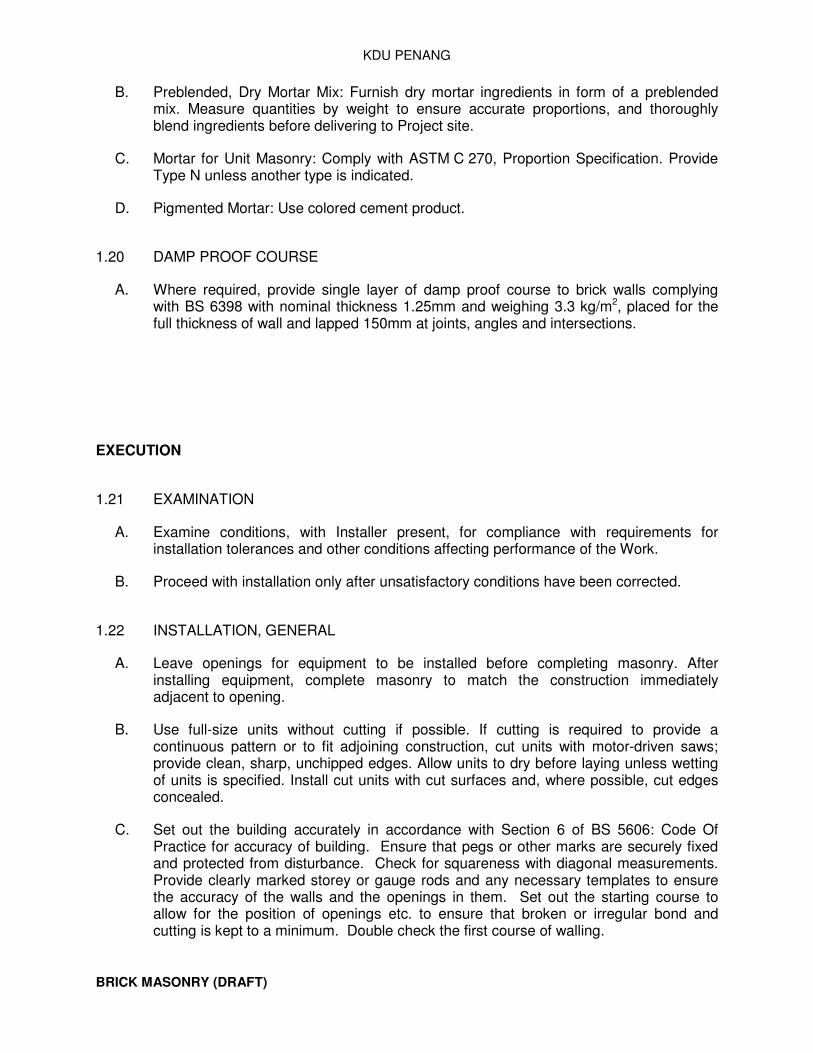
KDU PENANG
BRICK MASONRY (DRAFT)
B. Preblended, Dry Mortar Mix: Furnish dry mortar ingredients in form of a preblended mix. Measure quantities by weight to ensure accurate proportions, and thoroughly blend ingredients before delivering to Project site.
C. Mortar for Unit Masonry: Comply with ASTM C 270, Proportion Specification. Provide Type N unless another type is indicated.
D. Pigmented Mortar: Use colored cement product.
1.20 DAMP PROOF COURSE
A. Where required, provide single layer of damp proof course to brick walls complying with BS 6398 with nominal thickness 1.25mm and weighing 3.3 kg/m2, placed for the full thickness of wall and lapped 150mm at joints, angles and intersections.
EXECUTION
1.21 EXAMINATION
A. Examine conditions, with Installer present, for compliance with requirements for installation tolerances and other conditions affecting performance of the Work.
B. Proceed with installation only after unsatisfactory conditions have been corrected.
1.22 INSTALLATION, GENERAL
A. Leave openings for equipment to be installed before completing masonry. After installing equipment, complete masonry to match the construction immediately adjacent to opening.
B. Use full-size units without cutting if possible. If cutting is required to provide a continuous pattern or to fit adjoining construction, cut units with motor-driven saws; provide clean, sharp, unchipped edges. Allow units to dry before laying unless wetting of units is specified. Install cut units with cut surfaces and, where possible, cut edges concealed.
C. Set out the building accurately in accordance with Section 6 of BS 5606: Code Of Practice for accuracy of building. Ensure that pegs or other marks are securely fixed and protected from disturbance. Check for squareness with diagonal measurements. Provide clearly marked storey or gauge rods and any necessary templates to ensure the accuracy of the walls and the openings in them. Set out the starting course to allow for the position of openings etc. to ensure that broken or irregular bond and cutting is kept to a minimum. Double check the first course of walling.

KDU PENANG
BRICK MASONRY (DRAFT)
1.23 MORTAR TYPES AND MIXING
A. Mix Proportions: Use mortars that comply with the following table. Use only one type for any one type of work. Adjust proportions within the permitted limits to suit the sand and weather conditions. Mixes are designated in nominal volume proportions of cement and dry hydrated lime to dry sand. For sulphate-resisting mixes, substitute sulphate-resisting cement for ordinary cement
B. Refer to BS 4721 using nominal volume proportions and BS 5628: Part 1 for Specific locations.
C. Proportions of mortar mixes
Type
General brick-work
Facing Brick-wall
Below ground: exposed positions
Cement:lime:sand Masonry cement:sand Cement:sand:plasticiser
1:1:5-6 1:4-5 1:5-6
1:1/4:3 - -
1:1/4:3 ..... .....
D. Generally: Mix site-proportioned mortars by machine, subject to clause 3.03 A. Stated mixing times are for guidance; mix materials sufficiently to obtain a uniform colour and consistency. Clean the mixer at least once a day and also when a different mix is used
E. Batching By Volume: Measure sand, cement and lime (or cement and coarse stuff if applicable) each into a separate gauge box made to suit the proportions specified. Completely fill and empty boxes at each batching and keep the cement gauging boxes dry at all times. Crude gauging by the shovel is strictly forbidden.
F. Assessing Volume Proportions : Calculate proportions of materials on the following basis
1. Cement: 1440 kg/m3 2. Lime (dry hydrated): 75 kg/m3 3. Sand (dry): 1520 kg/m3
Note: When gauging cement with ready-mixed coarse stuff, calculate cement addition based on the suppliers' quoted weight of coarse stuff per delivery.
G. Batching By Weight: Measure sand, cement and lime (or cement and coarse stuff if applicable) each separately in weight-batching plant in proportions specified.
H. Control of Mixer: Use an approved type of machine suited to mortar mixing. Carefully control the mixing in order that the materials are properly mixed to produce consistent batches of mortar. When all materials added, mix for 3 to 5 minutes according to the type of mortar. Do not exceed recommended mixing times for plasticised / air entrained / masonry mortars
I. Measuring and Adding Water: Measure into a suitable container and do not add more to the mix than necessary to produce mortar of desired workability.

KDU PENANG
BRICK MASONRY (DRAFT)
J. Site Preparation of Coarse Stuff: Mix dry hydrated lime with sand, first dry and then with water. Keep resultant coarse stuff at least 16 hours, protected as in clause 2.03 E.
K. Cement: Sand Mixes: Add approx. 3/4 of water and sand to mixer: gradually add cement and thoroughly mix: add remainder of sand. Add more of measured water if necessary to attain required workability. Mix for at least 3 to 5 minutes.
L. Cement: Dry Hydrated Lime:Sand Mixes : Add approximately 3/4 of water and sand to mixer: gradually add cement and lime and mix thoroughly. Add remainder of sand. Add more of the measured water if necessary to attain desired workability. Mix for at least five minutes.
M. Plasticised Cement: Sand Mixes: Mix correct dosage of plasticiser with the water. Add approx. 3/4 of sand and adequate proportion of solution to mixer (taking care not to add too much solution at the start). Gradually add the cement and mix until incorporated, then add remainder of sand. Add more of the measure solution of necessary to attain the required workability. Cease mixing immediately the correct workability is attained.
N. Masonry Cement:Sand Mixes : Add approx. 3/4 of sand and an adequate proportion of the water to the mixes (taking care not to add too much water at the start). Gradually add cement and mix until incorporated: then add remainder of sand. Add more of the measured solution if necessary to attain the required workability. Cease mixing immediately the correct workability is attained.
O. Cement: Coarse Stuff Mixes: Add approx. 3/4 of the water and coarse stuff to the mixer: gradually add cement and mix until incorporated and forming a thin lump-free paste; then add remainder of coarse stuff. Add more of the measured water if necessary to attain the required workability. Mix for at least 5 mins.
1.24 MEASURING AND MIXING MORTAR BY HAND
A. Small Quantities Of Mortar : Use hand mixing for small quantities only or when machine mixing impracticable. Measure materials into gauge boxes as stated in clause 3.02 C and thoroughly mix on a clean smooth non-absorbent surface. Add 25 per cent more cement to the specified mix proportions, and up to 50 per cent more dry hydrated lime (if used). Do not add water until materials are thoroughly mixed dry to an even colour.
1.25 READY-MIXED COARSE MORTAR
A. Generally : No lime-gauged mortars shall be mixed on site except in respect of small quantities when it is impracticable to obtain ready-mixed mortar
B. Source Of Supply: Obtain ready-mixed lime:sand from a reputable supplier who will undertake to supply in accordance with BS 4721 Ready-mixed building mortars. Obtain dated certificates from the supplier verifying that the lime:sand mix complies with BS 4721.

KDU PENANG
BRICK MASONRY (DRAFT)
C. Site Delivery: Provide a clean impervious surface for the tipping vehicle: cover the coarse stuff with waterproof sheeting.
D. Cement Addition: Guidance : For the cemnt:lime mixes specified in clause 3.02 A, the approx., weight of cement to be added per tonne of coarse stuff is as the table below
E. Weight of cement for coarse stuff (clause 375)
Nominal Proportion cement / lime / sand Cement in kg
1:1/4:3 1:1:5-6 1:2:8-9
250 125-135 90-95
F. Method Of Adding Cement : Add water and cement to the mixer as stated in clause 3.02 N.
G. 3.6 READY-MIXED RETARDED MORTAR
H. Generally : No mortar shall be mixed on site except in respect of small quantities when it is impracticable to obtain ready-mixed mortar.
I. Source Of Supply : Obtain ready-mixed retarded mortar from a reputable supplier who will undertake to supply in accordance with BS 4721 Ready-mixed building mortars. Agree the retardation time with the specifier, selecting a time that is as short as possible in relation to site needs. Obtain dated certificates from the supplier stating the retardation time and verifying that the mortar complies with BS 4721
J. Site Delivery : Provide a clean impervious surface for the tipping vehicle and cover the mortar with waterproof sheeting. Alternatively arrange for delivery in suitable containers that will protect the mortar
K. Do Not Re-Mix : Remixing of retarded mortars or the addition of any further material is forbidden.
L. PRE-PACKED MORTARS
M. Limitations Of Use : Pre-packed mortars may be used for small isolated portions of the work, subject to compliance with specification and BS 5838: Part 2 Pre-packed mortar mixes.
N. 3.8 ALL MORTARS
O. Cleanliness : Keep mixing and handling equipment clean. Remove traces of one type of mortar before another is mixed and used; this is particularly important with coloured mortars.
P. Setting Time : Use normal setting mortars within two hours of the addition of the cement to the mix. Use retarded mortars within the agreed setting time. Discard any mortar kept beyond these time limits
Q. Prevent Moisture Loss : Dampen mortar boards and other absorbent surfaces; cover mortar not in use during drying conditions.

KDU PENANG
BRICK MASONRY (DRAFT)
R. Retempering : Excluding retarded and / or coloured mortars, a little water may be added if necessary to retemper mortar but only within two hours of mixing.
S. 3.9 LAYING
T. Scaffolding : Use free-standing scaffolding where scaffolding is necessary for facework. The building of putlogs or other restraints into the faced walls is not permitted
U. Wetting Bricks : Except in cold weather, wet dry clay bricks sufficiently to prevent undue suction. Do not wet calcium silicate, concrete or dense engineering bricks except sparingly in very hot or dry conditions. Avoid excessive wetting and do not wet brick stacks
V. Bedding And Jointing : Lay bricks in true and regular courses on a full, fairly smooth and leveled bed of mortar and fill all joints, and cross joints, and frogs solid (except cellular bricks). Press joints back with the trowel and strike off flush. Walls built against other structures to be filled solid at the back with mortar or grout. Keep mortar off the face of the work. In very dry conditions lay the mortar beds in short lengths to limit water loss before the bricks are laid
W. Joint Thickness : Keep joints to a consistent average thickness of 10mm nominal. Subject to approval, the specified joint thickness may be evenly modified to suit adjacent work. (e.g. a thicker joint will be necessary for dpc's). Check overall panel sizes in order to establish the correct joint thickness before commencing the work
X. Bonding : Where any bonding is unspecified, use a minimum bond of quarter unit and select a bond that will reduce cutting to a minimum and avoid irregular or broken bond
Y. Perpends And Quoins : Keep perpends and quoins plumb, the perpends in line with the horizontal joints
Z. Walls To Rise Evenly : Carry up work evenly. No part of the wall to rise more than 1.5m above any other part and all variations in level to be evenly stepped
AA. Stability Of Walls : Do not lay bricks at such a pace that lower courses are disturbed. Temporarily brace large unsupported areas of wall if disturbance by winds or other influences could occur
BB. Filling In : Additional material for making up to other work (e.g. steelwork) and making up courses etc. shall be in special or cut bricks and the mortar used for the walling. Material of different characteristics shall not be used
CC. Generally
1. Apply mortar to obtain full vertical perpendicular joints. 2. Slushing of perpendicular joints or furrowing of bed joints is not acceptable. 3. Fully bond intersections, external corners and internal corners, unless indicated
otherwise on the drawings. 4. Do not shift or tap masonry units after mortar has taken initial set. Where
adjustment has to be made, remove mortar and replace. 5. Remove excess mortar as the work progresses.

KDU PENANG
BRICK MASONRY (DRAFT)
6. Ensure that site cutting is with proper tools in order to maintain straight unclipped edges.
7. After mortar has set dry brush faces to remove excess mortar, smears and stains prior to end of each work day.
8. Test cleaning materials at site sample panel or other location as directed. 9. Clean stained surfaces with non-acidic solution of type which will not harm
masonry or adjacent materials. Follow manufacturer's instructions. Consult masonry manufacturer for acceptable cleaners.
10. Do not allow cleaning solution to etch mortar joints, masonry, foundations, or windows
11. Cleaning Tools – Non-metallic 12. Clean-up-debris and refuse created by masonry work and remove from site
DD. BLOCKWORK
EE. General: 1. Prevent mortar from staining exposed brick and concrete masonry units faces. 2. Protect sills, ledges, and projections from mortar droppings or other damage dur-
ing construction 3. Maintain protective boards at exposed external corners, sills, ledges, and projec-
tions to avoid damage by construction activities.
FF. Wall Covers : 1. Cover partially completed walls with impervious sheets when work is not in
progress. 2. Extend cover down 600mm minimum on both sides of wall and secure in-place to
prevent moisture infiltration and protect from weather.
GG. Protect wall at scaffold work platform. Turn-up inside scaffold boards at end of day to reduce mortar stains on walls during wet weather
HH. After completion of masonry work protect top of walls until wall coping and flashing are in place
II. Bonding : Build blockwork in stretcher bond
JJ. Bonding To Other Walls : Tie the ends of walls with expanded metal or specially made metal ties
KK. Fairfaced Work : Ensure that mortar is not smeared into the exposed face of the blocks. Brush away any accidental smears after the mortar has taken its first set
1.26 ANCILLARY WORK
A. General Labours : Subject to any specified requirements, form all chases and fixings and so on as the work proceeds. Fully bed and solidly flush up lintels and other components built in. Ensure that the ends of lintels bear on whole units. Temporarily support or brace built-in items liable to distortion (such as frames). Perform all ancillary work in the mortar used for the surrounding brickwork except where strong mortars specified for weatherings and pointing and so on

KDU PENANG
BRICK MASONRY (DRAFT)
B. Cutting Into Masonry : Cutting into masonry is subject to the following conditions
1. Delay cutting until the mortar has hardened 2. Obtain approval to cut into load-bearing walls or walls of hollow units 3. Obtain approval to cut holes greater than 300mm square 4. Perform cuttings in a manner that involves minimal vibration to the wall 5. Do not chase any walls less than 75mm thick 6. In solid walls do not chase deeper than one-sixth wall thickness at any point
when horizontal or one-third at any appoint when vertical. 7. Do not allow chases to be located back to back in any wall
C. Lintels : Solidly build in with 100mm minimum end bearing (150mm for steel lintels and boot lintels). Prop heavy lintels and all prestressed lintels until mortar has set. Ensure concrete lintels are built in the correct way up. Provide continuous support under reinforced brick or block lintels. See relevant structural specification section in respect of concrete lintels cast in place
D. Relieving Arches: Bearing Bars : Bridge (by approved methods) over non-loadbearing ducts, services and other components which pass through walls and which exceed the length of two single wall units
E. Centering : Provide temporary centering for arches and other work requiring support during construction
F. Mechanical Key : Where keying is specified, rake out brick joints 10-15mm deep. Do not rake out the joints of loadbearing walls or blockwork without approval
G. Grooves for Weatherings Etc.: Rake out joints or cut grooves for the turn-in of flashings, and so on. Enlarge raked-out joints to 25 x 25mm with a rough splayed bottom edge for asphalt
H. Movement Joints : Form specified joints as the work proceeds, and in such a manner that the full width is maintained at every point and the space is kept free of mortar or debris
I. Tops Of Partitions : Unless otherwise specified, finish partitions below soffits as follows
1. Loadbearing – Pin up to the soffit with dry mix mortar well wedged and rammed into position
2. Non-Loadbearing – Fill solid at top with mortar.
J. Grouting : Mix grout in accordance with the specification for mortar, adding only enough water to make a pourable mix suited to its application in the Works
K. Pointing Flashings, And So On : Point flashings and weatherings (such as flexible materials; asphalt) turned into grooves or joints in a strong mortar
L. Ventilation Ducts, And So On : Construct small ducts required through external walls with a slight fall to the outer face
M. Toothings : Weather any external toothings left for future extensions to a wall in a weak mortar

KDU PENANG
BRICK MASONRY (DRAFT)
N. Corbelling : Unless otherwise specified, do not project any one corbel further than one quarter of the wall thickness; ensure the total corbelled projection does not exceed one half of the wall thickness
O. Reinforcement : Totally embed expanded metal reinforcement in the mortar joints and keep back 15mm from inner face and 20mm from outer face. Lap 250mm in the length and the full width of angles
P. Fire Stopping : Ensure that all gaps are sealed with mortar to prevent the passage of fire
Q. Damp Proof Courses: Where required, provide single layer of damp proof course to brick walls complying with BS 6398, Type B (Felt Fibre Base), weighing 3.3 kg/m2, placed for the full thickness of wall and lapped 150 mm at joints, angles and intersections.
R. Mastic Sealants : Apply as follows:-
1. Clean and prepare joint surfaces 2. Apply any specified primer and allow it to dry 3. Insert specified back-up material (normally plastic foam strips) to ensure sealant
is forced against joint faces 4. Apply specified bond-breaker tape where adhesion is to be avoided 5. Use correct size nozzle on applicator 6. Use two-part sealants as soon as mixed and within setting period 7. Apply sealant steadily and firmly to ensure joint is filled 8. Neatly finish the sealant with wetted spatula or by other suitable method to form
a convex face; feather-edged and concave seals shall be cut out and re-formed
1.27 3.12 WEATHER PRECAUTIONS
A. Generally : Take precautions to prevent damage due to unfavourable weather of any description as stated in Section 2. Take particular precautions as stated hereunder. Note that the term bricklaying includes block laying, rendering and other work involving mortar
B. High Winds : Cease bricklaying in exposed positions
C. Rain : Cease exposed bricklaying in all except very light rain or showers
1.28 FIELD QUALITY CONTROL
A. Testing and Inspecting: Owner will engage special inspectors to perform tests and inspections and prepare reports. Allow inspectors access to scaffolding and work areas as needed to perform tests and inspections. Retesting of materials that fail to comply with specified requirements shall be done at Contractor's expense.

KDU PENANG
BRICK MASONRY (DRAFT)
1.29 3.14 REPAIRING, POINTING, AND CLEANING
A. Remove and replace masonry units that are loose, chipped, broken, stained, or otherwise damaged or that do not match adjoining units. Install new units to match adjoining units; install in fresh mortar, pointed to eliminate evidence of replacement.
B. Pointing: During the tooling of joints, enlarge voids and holes, except weep holes, and completely fill with mortar. Point up joints, including corners, openings, and adjacent construction, to provide a neat, uniform appearance. Prepare joints for sealant application, where indicated.
C. In-Progress Cleaning: Clean unit masonry as work progresses by dry brushing to remove mortar fins and smears before tooling joints.
D. Final Cleaning: After mortar is thoroughly set and cured, clean exposed masonry as follows:
1. Remove large mortar particles by hand with wooden paddles and nonmetallic scrape hoes or chisels.
2. Test cleaning methods on sample wall panel; leave one-half of panel uncleaned for comparison purposes. Obtain Architect's approval of sample cleaning before proceeding with cleaning of masonry.
1.30 3.15 MASONRY WASTE DISPOSAL
A. Salvageable Materials: Unless otherwise indicated, excess masonry materials are Contractor's property. At completion of unit masonry work, remove from Project site.
B. Waste Disposal as Fill Material: Dispose of clean masonry waste, including excess or soil-contaminated sand, waste mortar, and broken masonry units, by crushing and mixing with fill material as fill is placed.
END OF SECTION 042113

DECORATIVE METAL STAIRS (DRAFT)
VOLUME Technical Specification Page 1 of 8
DIVISION 5 Architectural Works Rev. 00
057100 Metal Stairs March 2016
SECTION 057100 - METAL STAIRS
PART 1 - GENERAL
1.1 RELATED DOCUMENTS
A. Drawings and general provisions of the Contract, including General and Supplementary Conditions and Division 01 Specification Sections, apply to this Section.
1.2 SUMMARY
A. Section includes steel-framed metal stairs.
B. Related Requirements: 1. Section 093013 " Tiling" for -tile treads and landings[ for metal stairs].
1.3 COORDINATION
A. Coordinate selection of shop primers with topcoats to be applied over them. Comply with paint and coating manufacturers' written recommendations to ensure that shop primers and topcoats are compatible with one another.
B. Coordinate installation of anchorages for metal stairs. Furnish setting drawings, templates, and directions for installing anchorages, including sleeves, concrete inserts, anchor bolts, and items with integral anchors, that are to be embedded in concrete or masonry. Deliver such items to Project site in time for installation.
1.4 ACTION SUBMITTALS
A. Product Data: For metal stairs and the following:
1. Paint products. 2. Grout.
B. Shop Drawings: Include plans, elevations, sections, details, and attachments to other work.
1.5 INFORMATIONAL SUBMITTALS
A. Welding certificates.

DECORATIVE METAL STAIRS (DRAFT)
VOLUME Technical Specification Page 2 of 8
DIVISION 5 Architectural Works Rev. 00
057100 Metal Stairs March 2016
B. Paint Compatibility Certificates: From manufacturers of topcoats applied over shop primers certifying that shop primers are compatible with topcoats.
1.6 QUALITY ASSURANCE
A. Installer Qualifications: Fabricator of products.
B. Welding Qualifications: Qualify procedures and personnel according to AWS D1.1/D1.1M, "Structural Welding Code - Steel."
PART 2 - PRODUCTS
2.1 METAL STAIRS, GENERAL
A. NAAMM Stair Standard: Comply with "Recommended Voluntary Minimum Standards for Fixed Metal Stairs" in NAAMM AMP 510, "Metal Stairs Manual," Architectural class, unless more stringent requirements are indicated.
2.2 METALS
A. Metal Surfaces, General: Provide materials with smooth, flat surfaces unless otherwise indicated. For components exposed to view in the completed Work, provide materials without seam marks, roller marks, rolled trade names, or blemishes.
B. Recycled Content of Steel Products: Postconsumer recycled content plus one-half of preconsumer recycled content not less than [25] percent.
C. Steel Plates, Shapes, and Bars: ASTM A 36/A 36M.
D. Steel Tubing: [ASTM A 500 (cold formed)] [or] [ASTM A 513].
E. Cast Iron: Either gray iron, ASTM A 48/A 48M, or malleable iron, ASTM A 47/A 47M, unless otherwise indicated.
F. Uncoated, Cold-Rolled Steel Sheet: ASTM A 1008/A 1008M,[ either commercial steel, Type B, or] structural steel, Grade 170, unless another grade is required by design loads; exposed.
G. Aluminum Extrusions: ASTM B 221M, Alloy 6063-T6.
H. Aluminum Castings: ASTM B 26/B 26M, Alloy 443.0-F.
I. Bronze Extrusions: ASTM B 455, Alloy UNS No. C38500 (extruded architectural bronze).

DECORATIVE METAL STAIRS (DRAFT)
VOLUME Technical Specification Page 3 of 8
DIVISION 5 Architectural Works Rev. 00
057100 Metal Stairs March 2016
J. Bronze Castings: ASTM B 584, Alloy UNS No. C83600 (leaded red brass) or No. C84400 (leaded semired brass).
K. Nickel Silver Castings: ASTM B 584, Alloy UNS No. C97600 (20 percent leaded nickel bronze).
2.3 ABRASIVE NOSINGS
A. Cast-Metal Units: Cast [iron] or [aluminum]or [bronze]or [nickel silver], with an integral abrasive, as-cast finish consisting of aluminum oxide, silicon carbide, or a combination of both. Fabricate units in lengths necessary to accurately fit openings or conditions.
1. Configuration: Cross-hatched units, [75 mm]or[100 mm] wide without lip. a. >.
2. Provide ribbed units, with abrasive filler strips projecting 1.5 mm above aluminum extrusion.
3. Provide solid-abrasive-type units without ribs. 4. Nosings: Square-back units, [48 mm] [75 mm] [100 mm] wide, without lip.
2.4 FASTENERS
A. General: Provide zinc-plated fasteners with coating complying with ASTM B 633 or ASTM F 1941M, Class Fe/Zn 12 for exterior use, and Class Fe/Zn 5 where built into exterior walls. Select fasteners for type, grade, and class required.
B. Bolts and Nuts: Regular hexagon-head bolts, ASTM F 568M, Property Class 4.6; with hex nuts, ASTM A 563M; and, where indicated, flat washers.
C. Anchor Bolts: ASTM F 1554, Grade 36, of dimensions indicated; with nuts, ASTM A 563M; and, where indicated, flat washers.
1. Provide mechanically deposited or hot-dip, zinc-coated anchor bolts for exterior stairs, stairs indicated to be galvanized, stairs indicated to be shop primed with zinc-rich primer.
D. Post-Installed Anchors: [Torque-controlled expansion anchors] [or] [chemical anchors] capable of sustaining, without failure, a load equal to six times the load imposed when installed in unit masonry and four times the load imposed when installed in concrete, as determined by testing according to ASTM E 488/E 488M, conducted by a qualified independent testing agency.
1. Material for Interior Locations: Carbon-steel components zinc plated to comply with ASTM B 633 or ASTM F 1941M, Class Fe/Zn 5, unless otherwise indicated.

DECORATIVE METAL STAIRS (DRAFT)
VOLUME Technical Specification Page 4 of 8
DIVISION 5 Architectural Works Rev. 00
057100 Metal Stairs March 2016
2. Material for Exterior Locations and Where Stainless Steel Is Indicated: Alloy [Group A1] [Group A4] stainless-steel bolts, ASTM F 738M, and nuts, ASTM F 836M.
2.5 MISCELLANEOUS MATERIALS
A. Low-Emitting Materials: Paints and coatings shall comply with the testing and product requirements of the California Department of Public Health's (formerly, the California Department of Health Services') "Standard Method for the Testing and Evaluation of Volatile Organic Chemical Emissions from Indoor Sources Using Environmental Chambers."
B. Shop Primers: Provide primers that comply with [Section 099113 "Exterior Painting"
and Section 099123 "Interior Painting."] [Section 099600 "High-Performance
Coatings."] [Section 099113 "Exterior Painting," Section 099123 "Interior
Painting," and Section 099600 "High-Performance Coatings."]
C. Universal Shop Primer: Fast-curing, lead- and chromate-free, universal modified-alkyd primer complying with MPI#79 and compatible with topcoat.
1. Use primer containing pigments that make it easily distinguishable from zinc-rich primer.
D. Epoxy Zinc-Rich Primer: Complying with MPI#20 and compatible with topcoat.
1. Manufacturers: Subject to compliance with requirements.
E. Shop Primer for Galvanized Steel: Primer formulated for exterior use over zinc-coated metal and compatible with finish paint systems indicated.
F. Galvanizing Repair Paint: High-zinc-dust-content paint complying with SSPC-Paint 20 and compatible with paints specified to be used over it.
G. Bituminous Paint: Cold-applied asphalt emulsion complying with ASTM D 1187/D 1187M.
H. Nonshrink, Nonmetallic Grout: Factory-packaged, nonstaining, noncorrosive, nongaseous grout complying with ASTM C 1107/C 1107M. Provide grout specifically recommended by manufacturer for interior and exterior applications.
2.6 PRECAST CONCRETE TREADS
A. Concrete Materials and Properties: Comply with requirements in Section 033000 "Cast-in-Place Concrete" for normal-weight, ready-mixed concrete with a minimum 28-day compressive strength of 35 MPa and a total air content of not less than 4 percent or more than 6 percent.

DECORATIVE METAL STAIRS (DRAFT)
VOLUME Technical Specification Page 5 of 8
DIVISION 5 Architectural Works Rev. 00
057100 Metal Stairs March 2016
B. Reinforcement: Galvanized, welded wire reinforcement, 50 by 50 mm by 1.6-mm- diameter wire; comply with ASTM A 185/A 185M and ASTM A 82/A 82M, except for minimum wire size.
2.7 FABRICATION, GENERAL
A. Provide complete stair assemblies, including metal framing, hangers, struts, clips, brackets, bearing plates, and other components necessary to support and anchor stairs and platforms on supporting structure.
1. Join components by welding unless otherwise indicated. 2. Use connections that maintain structural value of joined pieces.
B. Cut, drill, and punch metals cleanly and accurately. Remove burrs and ease edges to a radius of approximately 1 mm unless otherwise indicated. Remove sharp or rough areas on exposed surfaces.
C. Form bent-metal corners to smallest radius possible without causing grain separation or otherwise impairing work.
D. Form exposed work with accurate angles and surfaces and straight edges.
E. Weld connections to comply with the following:
1. Use materials and methods that minimize distortion and develop strength and corrosion resistance of base metals.
2. Obtain fusion without undercut or overlap. 3. Remove welding flux immediately. 4. Weld exposed corners and seams continuously unless otherwise indicated. 5. At exposed connections, finish exposed welds to comply with NOMMA's
"Voluntary Joint Finish Standards" for Type 1 welds: no evidence of a welded joint.
F. Form exposed connections with hairline joints, flush and smooth, using concealed fasteners where possible. Where exposed fasteners are required, use Phillips flat-head (countersunk) screws or bolts unless otherwise indicated. Locate joints where least conspicuous.
2.8 STEEL-FRAMED STAIRS
A. Stair Framing:
1. Fabricate stringers of steel [plates]or [channels]or [plates or channels]or [tubes].
a. Provide closures for exposed ends of [channel] or[tube] stringers.

DECORATIVE METAL STAIRS (DRAFT)
VOLUME Technical Specification Page 6 of 8
DIVISION 5 Architectural Works Rev. 00
057100 Metal Stairs March 2016
2. Construct platforms of steel [plate] or[channel]or [plate or channel]or [tube] headers and miscellaneous framing members as indicated.
3. Weld stringers to headers; weld framing members to stringers and headers.[ If using bolts, fabricate and join so bolts are not exposed on finished
surfaces.]
B. Subtreads, Risers, and Subplatforms:
1. Fabricate subtreads and subplatforms of steel [plates] or[shapes indicated]. 2. Form subtreads, risers, and subplatforms to configurations indicated from cold-
rolled steel sheet [.9 mm thick] or [of thickness indicated]. 3. Weld substreads to stringers. Locate welds on top of subtreads where they will
be concealed by finished treads. 4. Provide subplatforms of configuration indicated or, if not indicated, the same as
subtreads. Weld subplatforms to platform framing.
a. Smooth Soffit Construction: Construct subplatforms with flat metal under surfaces to produce smooth soffits.
2.9 STAIR RAILINGS
A. Comply with applicable requirements in Section 057300 "Decorative Metal Railings."
1. Connect posts to stair framing by direct welding unless otherwise indicated.
2.10 FINISHES
A. Finish metal stairs after assembly.
B. Galvanizing: Hot-dip galvanize items as indicated to comply with ASTM A 153/A 153M for steel and iron hardware and with ASTM A 123/A 123M for other steel and iron products.
1. Do not quench or apply post galvanizing treatments that might interfere with paint adhesion.
2. Fill vent and drain holes that are exposed in finished Work, unless indicated to remain as weep holes, by plugging with zinc solder and filing off smooth.
C. Preparation for Shop Priming: Prepare uncoated ferrous-metal surfaces to comply with [SSPC-SP 6/NACE No. 3, "Commercial Blast Cleaning."] [SSPC-SP 3, "Power Tool
Cleaning."]
D. Apply shop primer to uncoated surfaces of metal stair components, except those with galvanized finishes and those to be embedded in concrete or masonry unless otherwise indicated. Comply with SSPC-PA 1, "Shop, Field, and Maintenance Painting of Steel," for shop painting.

DECORATIVE METAL STAIRS (DRAFT)
VOLUME Technical Specification Page 7 of 8
DIVISION 5 Architectural Works Rev. 00
057100 Metal Stairs March 2016
1. Stripe paint corners, crevices, bolts, welds, and sharp edges.
PART 3 - EXECUTION
3.1 INSTALLATION, GENERAL
A. Fastening to In-Place Construction: Provide anchorage devices and fasteners where necessary for securing metal stairs to in-place construction. Include threaded fasteners for concrete and masonry inserts, through-bolts, lag bolts, and other connectors.
B. Cutting, Fitting, and Placement: Perform cutting, drilling, and fitting required for installing metal stairs. Set units accurately in location, alignment, and elevation, measured from established lines and levels and free of rack.
C. Install metal stairs by welding stair framing to steel structure or to weld plates cast into concrete unless otherwise indicated.
D. Provide temporary bracing or anchors in formwork for items that are to be built into concrete or masonry.
E. Fit exposed connections accurately together to form hairline joints. Weld connections that are not to be left as exposed joints but cannot be shop welded because of shipping size limitations. Do not weld, cut, or abrade surfaces of exterior units that have been hot-dip galvanized after fabrication and are for bolted or screwed field connections.
F. Field Welding: Comply with requirements for welding in "Fabrication, General" Article.
G. Install precast concrete treads with adhesive supplied by manufacturer.
3.2 INSTALLING METAL STAIRS WITH GROUTED BASEPLATES
A. Clean concrete and masonry bearing surfaces of bond-reducing materials, and roughen to improve bond to surfaces. Clean bottom surface of baseplates.
B. Set steel stair baseplates on wedges, shims, or leveling nuts. After stairs have been positioned and aligned, tighten anchor bolts. Do not remove wedges or shims but, if protruding, cut off flush with edge of bearing plate before packing with grout.
1. Use nonmetallic, nonshrink grout unless otherwise indicated. 2. Pack grout solidly between bearing surfaces and plates to ensure that no voids
remain.

DECORATIVE METAL STAIRS (DRAFT)
VOLUME Technical Specification Page 8 of 8
DIVISION 5 Architectural Works Rev. 00
057100 Metal Stairs March 2016
3.3 ADJUSTING AND CLEANING
A. Touchup Painting: Immediately after erection, clean field welds, bolted connections, and abraded areas of shop paint, and paint exposed areas with same material as used for shop painting to comply with SSPC-PA 1 for touching up shop-painted surfaces.
1. Apply by brush or spray to provide a minimum 0.05-mm dry film thickness.
B. Touchup Painting: Cleaning and touchup painting of field welds, bolted connections, and abraded areas of shop paint are specified in [Section 099113 "Exterior Painting" and Section 099123 "Interior Painting [Section 099113 "Exterior Painting," Section 099123 "Interior Painting," and Section 099600 "High-Performance Coatings."]
C. Galvanized Surfaces: Clean field welds, bolted connections, and abraded areas, and repair galvanizing to comply with ASTM A 780/A 780M.
END OF SECTION 057100

VOLUME Technical Specification Page 1 of 16
DIVISION 5 Architectural Works Rev. 00
057300 Metal Railings March 2016
SECTION 057300 - METAL RAILINGS
PART 1 - GENERAL
1.1 RELATED DOCUMENTS
A. Drawings and general provisions of the Contract, including General and Supplementary Conditions and Division 01 Specification Sections, apply to this Section.
1.2 SUMMARY
A. Section Includes:
1. Mild steel railings. 2. Galvanised -steel railings
B. Related Requirements:
1. [Section 061000 "Rough Carpentry"] [Section 061053 "Miscellaneous Rough Carpentry"] for wood blocking for anchoring railings.
2. Section 092216 "Non-Structural Metal Framing" for metal backing for anchoring railings.
1.3 DEFINITIONS
A. Railings: Guards, handrails, and similar devices used for protection of occupants at open-sided floor areas and for pedestrian guidance and support, visual separation, or wall protection.
1.4 COORDINATION AND SCHEDULING
A. Coordinate selection of shop primers with topcoats to be applied over them. Comply with paint and coating manufacturers' written instructions to ensure that shop primers and topcoats are compatible.
B. Coordinate installation of anchorages for railings. Furnish setting drawings, templates, and directions for installing anchorages, including sleeves, concrete inserts, anchor bolts, and items with integral anchors, that are to be embedded in concrete or masonry. Deliver items to Project site in time for installation.

VOLUME Technical Specification Page 2 of 16
DIVISION 5 Architectural Works Rev. 00
057300 Metal Railings March 2016
C. Schedule installation so wall attachments are made only to completed walls. Do not support railings temporarily by any means that do not meet structural performance requirements.
1.5 PREINSTALLATION MEETINGS
A. Pre-installation Conference: Conduct conference at Project site
1.6 ACTION SUBMITTALS
A. Product Data: For the following:
1. Manufacturer's product lines of railings assembled from standard components. 2. Grout, anchoring cement, and paint products.
B. Shop Drawings: Include plans, elevations, sections, and attachment details.
C. Samples for Initial Selection: For products involving selection of color, texture, or design.
D. Samples for Verification: For each type of exposed finish required.
1. Sections of each distinctly different linear railing member, including handrails, top rails, posts, and balusters.
2. Fittings and brackets. 3. Welded connections. 4. Brazed connections. 5. Assembled Samples of railing systems, made from full-size components,
including top rail, post, handrail, and infill. Show method of finishing members at intersections. Samples need not be full height.
E. Delegated-Design Submittal: For installed products indicated to comply with performance requirements and design criteria, including analysis data signed and sealed by the qualified professional engineer responsible for their preparation.
1.7 INFORMATIONAL SUBMITTALS
A. Qualification Data: For [professional engineer] or [testing agency].
B. Mill Certificates: Signed by manufacturers of stainless-steel products certifying that products furnished comply with requirements.
C. Welding certificates.

VOLUME Technical Specification Page 3 of 16
DIVISION 5 Architectural Works Rev. 00
057300 Metal Railings March 2016
D. Product Test Reports: Based on evaluation of comprehensive tests performed by a qualified testing agency, according to ASTM E 894 and ASTM E 935.
E. Preconstruction test reports.
F. Evaluation Reports: For post-installed anchors, from ICC-ES.
1.8 QUALITY ASSURANCE
A. Welding Qualifications: Qualify procedures and personnel according to the following:
1. AWS D1.1/D1.1M, "Structural Welding Code - Steel." 2. AWS D1.2/D1.2M, "Structural Welding Code - Aluminum." 3. AWS D1.6/D1.6M, "Structural Welding Code - Stainless Steel."
B. Mockups: Build mockups to verify selections made under Sample submittals, to demonstrate aesthetic effects, and to set quality standards for fabrication and installation.
1. Build mockups as shown on Drawings. 2. Build mockups for each form and finish of railing consisting of two posts, top rail,
infill area, and anchorage system components that are full height and are not less than 600 mm in length.
3. Subject to compliance with requirements, approved mockups may become part of the completed Work if undisturbed at time of Substantial Completion.
1.9 PRECONSTRUCTION TESTING
A. Preconstruction Testing Service: [Engage] a qualified testing agency to perform preconstruction testing on laboratory mockups. Payment for these services will be made [by Owner] or [from the testing and inspecting allowance, as authorized by Change Orders] or [by Contractor]. Retesting of products that fail to meet specified requirements shall be done at Contractor's expense.
1. Build laboratory mockups at testing agency facility; use personnel, materials, and methods of construction that will be used at Project site.
2. Test railings according to ASTM E 894 and ASTM E 935. 3. Notify Architect [seven] days in advance of the dates and times when laboratory
mockups will be tested.

VOLUME Technical Specification Page 4 of 16
DIVISION 5 Architectural Works Rev. 00
057300 Metal Railings March 2016
1.10 FIELD CONDITIONS
A. Field Measurements: Verify actual locations of walls and other construction contiguous with railings by field measurements before fabrication and indicate measurements on Shop Drawings.
PART 2 - PRODUCTS
2.1 MANUFACTURERS
A. Galvanized Railings:
1. Manufacturers: Subject to compliance with requirements, 2. Please refer to railing detail drawings (561-01)
B. Steel & Iron (Mild steel) Railings:
1. Manufacturers: Subject to compliance with requirements. 2. Please refer to railing detail drawings (528-10)
C. Source Limitations: Obtain each type of railing from single source from single manufacturer.
D. Product Options: Information on Drawings and in Specifications establishes requirements for system's aesthetic effects and performance characteristics. Aesthetic effects are indicated by dimensions, arrangements, alignment, and profiles of components and assemblies as they relate to sightlines, to one another, and to adjoining construction. Performance characteristics are indicated by criteria subject to verification by one or more methods, including structural analysis, preconstruction testing, field testing, and in-service performance.
1. Do not modify intended aesthetic effects, as judged solely by Architect, except with Architect's approval. If modifications are proposed, submit comprehensive explanatory data to Architect for review.
E. Product Options: Drawings indicate size, profiles, and dimensional requirements of railings and are based on the specific system indicated. See Section 016000 "Product Requirements."
1. Do not modify intended aesthetic effects, as judged solely by Architect, except with Architect's approval. If modifications are proposed, submit comprehensive explanatory data to Architect for review.

VOLUME Technical Specification Page 5 of 16
DIVISION 5 Architectural Works Rev. 00
057300 Metal Railings March 2016
2.2 PERFORMANCE REQUIREMENTS
A. Delegated Design: Engage a qualified professional engineer, as defined in Section 014000 "Quality Requirements," to design railings, including attachment to building construction.
B. General: In engineering railings to withstand structural loads indicated, determine allowable design working stresses of railing materials based on the following:
1. Aluminum: The lesser of minimum yield strength divided by 1.65 or minimum ultimate tensile strength divided by 1.95.
2. Copper Alloys: 60 percent of minimum yield strength. 3. Stainless Steel: 60 percent of minimum yield strength. 4. Steel: 72 percent of minimum yield strength.
C. Structural Performance: Railings, including attachment to building construction, shall withstand the effects of gravity loads and the following loads and stresses within limits and under conditions indicated:
1. Handrails and Top Rails of Guards:
a. Uniform load of 0.73 kN/m applied in any direction. b. Concentrated load of 0.89 kN applied in any direction. c. Uniform and concentrated loads need not be assumed to act concurrently.
2. Infill of Guards:
a. Concentrated load of 0.22 kN applied horizontally on an area 0.093 sq. m. b. Infill load and other loads need not be assumed to act concurrently.
D. Thermal Movements: Allow for thermal movements from ambient and surface temperature changes acting on exterior railings by preventing buckling, opening of joints, overstressing of components, failure of connections, and other detrimental effects.
1. Temperature Change:67 deg C, ambient; 100 deg C, material surfaces.
2.3 METALS, GENERAL
A. Metal Surfaces, General: Provide materials with smooth surfaces, without seam marks, roller marks, rolled trade names, stains, discolorations, or blemishes.
B. Brackets, Flanges, and Anchors: Same metal and finish as supported rails unless otherwise indicated.

VOLUME Technical Specification Page 6 of 16
DIVISION 5 Architectural Works Rev. 00
057300 Metal Railings March 2016
1. Provide cast-metal brackets with flange tapped for concealed anchorage to threaded hanger bolt.
2. Provide either formed- or cast-metal brackets with predrilled hole for exposed bolt anchorage.
3. Provide formed-steel brackets with predrilled hole for bolted anchorage and with snap-on cover that matches rail finish and conceals bracket base and bolt head.
4. Provide extruded-aluminum brackets with interlocking pieces that conceal anchorage. Locate set screws on bottom of bracket.
2.4 STEEL AND IRON (Mild Steel)
A. Recycled Content of Steel Products: Postconsumer recycled content plus one-half of preconsumer recycled content not less than [25] percent.
B. Tubing: [ASTM A 500/A 500M (cold formed)] [or] [ASTM A 513].
C. Bars: Hot-rolled, carbon steel complying with ASTM A 29/A 29M, Grade 1010.
D. Plates, Shapes, and Bars: ASTM A 36/A 36M.
E. Cast Iron: Either gray iron, ASTM A 48/A 48M, or malleable iron, ASTM A 47/A 47M, unless otherwise indicated.
2.5 FASTENERS
A. Fastener Materials: Unless otherwise indicated, provide the following:
1. Aluminum Components: [Type 304] or [Type 316] stainless-steel fasteners. 2. Copper-Alloy (Bronze) Components: Silicon bronze (Alloy 651 or Alloy 655)
fasteners[ where concealed; muntz metal (Alloy 280) fasteners where exposed]. 3. Copper-Alloy (Brass) Components: Silicon bronze (Alloy 651 or Alloy 655)
fasteners[ where concealed; brass (Alloy 260 or Alloy 360) fasteners where exposed].
4. Stainless-Steel Components: [Type 304] or [Type 316] stainless-steel fasteners. 5. Uncoated Steel Components: Plated-steel fasteners complying with
ASTM B 633, Class Fe/Zn 25 for electrodeposited zinc coating where concealed; Type 304 stainless-steel fasteners where exposed.
6. Galvanized-Steel Components: Plated-steel fasteners complying with ASTM B 633, Class Fe/Zn 25 for electrodeposited zinc coating.
7. Dissimilar Metals: [Type 304] or [Type 316] stainless-steel fasteners.
B. Fasteners for Anchoring to Other Construction: Select fasteners of type, grade, and class required to produce connections suitable for anchoring railings to other types of construction indicated[ and capable of withstanding design loads].

VOLUME Technical Specification Page 7 of 16
DIVISION 5 Architectural Works Rev. 00
057300 Metal Railings March 2016
C. Provide concealed fasteners for interconnecting railing components and for attaching railings to other work unless [otherwise indicated] or [exposed fasteners are unavoidable] or [exposed fasteners are the standard fastening method for railings indicated].
1. Provide [Phillips] or [tamper-resistant] or [square or hex socket] flat-head machine screws for exposed fasteners unless otherwise indicated.
D. Post-Installed Anchors: Fastener systems with working capacity greater than or equal to the design load, according to an evaluation report acceptable to authorities having jurisdiction, based on ICC-ES AC193[ or ICC-ES AC308].
1. Material for Interior Locations: Carbon-steel components zinc plated to comply with ASTM B 633 or ASTM F 1941M, Class Fe/Zn 5, unless otherwise indicated.
2. Material for Exterior Locations and Where Stainless Steel Is Indicated: Alloy [Group A1] [Group A4] stainless-steel bolts ASTM F 738M, and nuts, ASTM F 836M.
2.6 MISCELLANEOUS MATERIALS
A. Heavy Duty Plastic Bumper: Thermoplastic rail covering, color as indicated or, if not indicated, as selected by Architect from manufacturer's standard colors.
B. Floor guard: 65mm diameter Stainless steel kicker bar with hairline finish.
C. Low-Emitting Paints and Coatings: Paints and coatings applied to interior decorative metal railings shall comply with the testing and product requirements of the California Department of Public Health's (formerly, the California Department of Health Services') "Standard Method for the Testing and Evaluation of Volatile Organic Chemical Emissions from Indoor Sources Using Environmental Chambers."
D. Etching Cleaner for Galvanized Metal: Complying with MPI#25.
E. Galvanizing Repair Paint: High-zinc-dust-content paint complying with SSPC-Paint 20 and compatible with paints specified to be used over it.
F. Shop Primers: Provide primers that comply with [Section 099113 "Exterior Painting."] or [Section 099123 "Interior Painting."] or [Section 099600 "High-Performance Coatings."]
G. Universal Shop Primer: Fast-curing, lead- and chromate-free, universal modified-alkyd primer complying with MPI#79 and compatible with topcoat.
1. Use primer containing pigments that make it easily distinguishable from zinc-rich primer.
H. Epoxy Zinc-Rich Primer: Complying with MPI#20 and compatible with topcoat.

VOLUME Technical Specification Page 8 of 16
DIVISION 5 Architectural Works Rev. 00
057300 Metal Railings March 2016
I. Shop Primer for Galvanized Steel: [Cementitious galvanized metal primer complying with MPI#26] or [Vinyl wash primer complying with MPI#80] or [Water-based galvanized metal primer complying with MPI#134].
J. Intermediate Coats and Topcoats: Provide products that comply with [Section 099113 "Exterior Painting."] or [Section 099123 "Interior Painting."] or [Section 099600 "High-Performance Coatings."]
K. Epoxy Intermediate Coat: Complying with MPI#77 and compatible with primer and topcoat.
L. Polyurethane Topcoat: Complying with MPI#72 and compatible with undercoat.
M. Bituminous Paint: Cold-applied asphalt emulsion complying with ASTM D 1187/D 1187M.
N. Non-shrink, Nonmetallic Grout: Factory-packaged, nonstaining, noncorrosive, nongaseous grout complying with ASTM C 1107/C 1107M. Provide grout specifically recommended by manufacturer for interior and exterior applications.
O. Anchoring Cement: Factory-packaged, nonshrink, nonstaining, hydraulic-controlled expansion cement formulation for mixing with water at Project site to create pourable anchoring, patching, and grouting compound.
1. Water-Resistant Product: [At exterior locations] [and] [where indicated] provide formulation that is resistant to erosion from water exposure without needing protection by a sealer or waterproof coating and that is recommended by manufacturer for exterior use.
2.7 FABRICATION
A. General: Fabricate railings to comply with requirements indicated for design, dimensions, member sizes and spacing, details, finish, and anchorage, but not less than that required to support structural loads.
B. Assemble railings in the shop to greatest extent possible to minimize field splicing and assembly. Disassemble units only as necessary for shipping and handling limitations. Clearly mark units for reassembly and coordinated installation. Use connections that maintain structural value of joined pieces.
C. Make up wire-rope assemblies in the shop to field-measured dimensions with fittings machine swaged. Minimize amount of turnbuckle take-up used for dimensional adjustment so maximum amount is available for tensioning wire ropes. Tag wire-rope assemblies and fittings to identify installation locations and orientations for coordinated installation.

VOLUME Technical Specification Page 9 of 16
DIVISION 5 Architectural Works Rev. 00
057300 Metal Railings March 2016
D. Cut, drill, and punch metals cleanly and accurately. Remove burrs and ease edges to a radius of approximately 1 mm unless otherwise indicated. Remove sharp or rough areas on exposed surfaces.
E. Form work true to line and level with accurate angles and surfaces.
F. Fabricate connections that will be exposed to weather in a manner to exclude water. Provide weep holes where water may accumulate. Locate weep holes in inconspicuous locations.
G. Cut, reinforce, drill, and tap as indicated to receive finish hardware, screws, and similar items.
H. Connections: Fabricate railings with [welded] [or] [nonwelded] connections unless otherwise indicated.
I. Welded Connections: Cope components at connections to provide close fit, or use fittings designed for this purpose. Weld all around at connections, including at fittings.
1. Use materials and methods that minimize distortion and develop strength and corrosion resistance of base metals.
2. Obtain fusion without undercut or overlap. 3. Remove flux immediately. 4. At exposed connections, finish exposed welds to comply with NOMMA's
"Voluntary Joint Finish Standards" for Type 1 welds; no evidence of a welded joint.
J. Welded Connections for Aluminum Pipe: Fabricate railings to interconnect members with concealed internal welds that eliminate surface grinding, using manufacturer's standard system of sleeve and socket fittings.
K. Brazed Connections: Connect copper-alloy railings by brazing. Cope components at connections to provide close fit, or use fittings designed for this purpose. Braze corners and seams continuously.
1. Use materials and methods that match color of base metal, minimize distortion, and develop maximum strength and corrosion resistance.
2. Remove flux immediately. 3. At exposed connections, finish exposed surfaces smooth and blended so no
roughness shows after finishing and brazed surface matches contours of adjoining surfaces.
L. Mechanical Connections: Connect members with concealed mechanical fasteners and fittings. Fabricate members and fittings to produce flush, smooth, rigid, hairline joints.
1. Fabricate splice joints for field connection using an epoxy structural adhesive if this is manufacturer's standard splicing method.

VOLUME Technical Specification Page 10 of 16
DIVISION 5 Architectural Works Rev. 00
057300 Metal Railings March 2016
M. Form changes in direction as follows:
1. As detailed. 2. [By bending] [or] [by inserting prefabricated elbow fittings]. 3. [By flush bends] [or] [by inserting prefabricated flush-elbow fittings]. 4. [By radius bends of radius indicated] [or] [by inserting prefabricated elbow fittings
of radius indicated]. 5. By bending to smallest radius that will not result in distortion of railing member.
N. Close exposed ends of hollow railing members with prefabricated end fittings.
O. Provide wall returns at ends of wall-mounted handrails unless otherwise indicated. Close ends of returns, unless clearance between end of rail and wall is 6 mm or less.
P. Brackets, Flanges, Fittings, and Anchors: Provide wall brackets, flanges, miscellaneous fittings, and anchors to interconnect railing members to other work unless otherwise indicated.
1. At brackets and fittings fastened to plaster or gypsum board partitions, provide crush-resistant fillers, or other means to transfer loads through wall finishes to structural supports and to prevent bracket or fitting rotation and crushing of substrate.
Q. Provide inserts and other anchorage devices for connecting railings to concrete or masonry work. Fabricate anchorage devices capable of withstanding loads imposed by railings. Coordinate anchorage devices with supporting structure.
R. For railing posts set in concrete, provide [steel] or [stainless-steel] sleeves not less than 150 mm long with inside dimensions not less than 13 mm greater than outside dimensions of post, with metal plate forming bottom closure.
2.8 GENERAL FINISH REQUIREMENTS
A. Comply with NAAMM's "Metal Finishes Manual for Architectural and Metal Products" recommendations for applying and designating finishes.
B. Protect mechanical finishes on exposed surfaces from damage by applying a strippable, temporary protective covering before shipment.
C. Appearance of Finished Work: Noticeable variations in same piece are not acceptable. Variations in appearance of abutting or adjacent pieces are acceptable if they are within one-half of the range of approved Samples. Variations in appearance of other components are acceptable if they are within the range of approved Samples and are assembled or installed to minimize contrast.

VOLUME Technical Specification Page 11 of 16
DIVISION 5 Architectural Works Rev. 00
057300 Metal Railings March 2016
D. Provide exposed fasteners with finish matching appearance, including color and texture, of railings.
2.9 STEEL AND IRON FINISHES.
A. Galvanized Railings:
1. Hot-dip galvanize [exterior] steel and iron railings, including hardware, after fabrication.
2. Hot-dip galvanize indicated steel and iron railings, including hardware, after fabrication.
3. Comply with ASTM A 123/A 123M for hot-dip galvanized railings. 4. Comply with ASTM A 153/A 153M for hot-dip galvanized hardware. 5. Do not quench or apply post-galvanizing treatments that might interfere with paint
adhesion. 6. Fill vent and drain holes that are exposed in the finished Work, unless indicated
to remain as weep holes, by plugging with zinc solder and filing off smooth.
B. For galvanized railings, provide hot-dip galvanized fittings, brackets, fasteners, sleeves, and other ferrous components.
C. Preparing Galvanized Railings for Shop Priming: After galvanizing, thoroughly clean railings of grease, dirt, oil, flux, and other foreign matter, and treat with etching cleaner.
D. Primer Application: Apply shop primer to prepared surfaces of railings unless otherwise indicated. Comply with requirements in SSPC-PA 1, "Paint Application Specification No. 1: Shop, Field, and Maintenance Painting of Steel," for shop painting. Primer need not be applied to surfaces to be embedded in concrete or masonry.
1. Shop prime uncoated railings with [universal shop primer] or [primers specified in Section 099113 "Exterior Painting"] or [primers specified in Section 099123 "Interior Painting"] unless [zinc-rich primer is] or [primers specified in Section 099600 "High-Performance Coatings" are] indicated.
2. Do not apply primer to galvanized surfaces.
E. Shop-Painted Finish: Comply with [Section 099113 "Exterior Painting."] and [Section 099600 "High-Performance Coatings."]
1. Color: [As selected by Architect from manufacturer's full range].
F. High-Performance Coating: Apply epoxy intermediate and polyurethane topcoats to prime-coated surfaces. Comply with coating manufacturer's written instructions and with requirements in SSPC-PA 1, "Paint Application Specification No. 1: Shop, Field, and Maintenance Painting of Steel," for shop painting. Apply at spreading rates recommended by coating manufacturer.

VOLUME Technical Specification Page 12 of 16
DIVISION 5 Architectural Works Rev. 00
057300 Metal Railings March 2016
1. Color: [As selected by Architect from manufacturer's full range].
G. Powder-Coat Finish: Prepare, treat, and coat nongalvanized ferrous metal to comply with resin manufacturer's written instructions and as follows:
1. Prepare uncoated ferrous-metal surfaces to comply with SSPC-SP 6/NACE No. 3, "Commercial Blast Cleaning."
2. Treat prepared metal with iron-phosphate pretreatment, rinse, and seal surfaces. 3. Apply thermosetting polyester or acrylic urethane powder coating with cured-film
thickness not less than 0.04 mm. 4. Color: [As selected by Architect from manufacturer's full range].
H. Powder-Coat Finish: Prepare, treat, and coat galvanized metal to comply with resin manufacturer's written instructions and as follows:
1. Prepare galvanized metal by thoroughly removing grease, dirt, oil, flux, and other foreign matter.
2. Treat prepared metal with zinc-phosphate pretreatment, rinse, and seal surfaces. 3. Apply thermosetting polyester or acrylic urethane powder coating with cured-film
thickness not less than 0.04 mm. 4. Color: [As selected by Architect from manufacturer's full range].
PART 3 - EXECUTION
3.1 EXAMINATION
A. Examine plaster and gypsum board assemblies, where reinforced to receive anchors, to verify that locations of concealed reinforcements have been clearly marked for Installer. Locate reinforcements and mark locations if not already done.
3.2 INSTALLATION, GENERAL
A. Fit exposed connections together to form tight, hairline joints.
B. Perform cutting, drilling, and fitting required for installing railings. Set railings accurately in location, alignment, and elevation; measured from established lines and levels and free of rack.
1. Do not weld, cut, or abrade surfaces of railing components that have been coated or finished after fabrication and that are intended for field connection by mechanical or other means without further cutting or fitting.
2. Set posts plumb within a tolerance of 2 mm in 1 m.

VOLUME Technical Specification Page 13 of 16
DIVISION 5 Architectural Works Rev. 00
057300 Metal Railings March 2016
3. Align rails so variations from level for horizontal members and variations from parallel with rake of steps and ramps for sloping members do not exceed 5 mm in 3 m.
C. Control of Corrosion: Prevent galvanic action and other forms of corrosion by insulating metals and other materials from direct contact with incompatible materials.
1. Coat concealed surfaces of [aluminum] [and] [copper alloys] that will be in contact with grout, concrete, masonry, wood, or dissimilar metals, with a heavy coat of bituminous paint.
D. Adjust railings before anchoring to ensure matching alignment at abutting joints.
E. Fastening to In-Place Construction: Use anchorage devices and fasteners where necessary for securing railings and for properly transferring loads to in-place construction.
3.3 RAILING CONNECTIONS
A. Non-welded Connections: Use mechanical or adhesive joints for permanently connecting railing components. Use wood blocks and padding to prevent damage to railing members and fittings. Seal recessed holes of exposed locking screws using plastic cement filler colored to match finish of railings.
B. Welded Connections: Use fully welded joints for permanently connecting railing components. Comply with requirements for welded connections in "Fabrication" Article whether welding is performed in the shop or in the field.
C. Expansion Joints: Install expansion joints at locations indicated but not farther apart than required to accommodate thermal movement. Provide slip-joint internal sleeve extending 50 mm beyond joint on either side, fasten internal sleeve securely to one side, and locate joint within 150 mm of post.
3.4 ANCHORING POSTS
A. Use steel pipe sleeves preset and anchored into concrete for installing posts. After posts have been inserted into sleeves, fill annular space between post and sleeve with [nonshrink, nonmetallic grout] [or] [anchoring cement], mixed and placed to comply with anchoring material manufacturer's written instructions.
B. Form or core-drill holes not less than 125 mm deep and 20 mm larger than OD of post for installing posts in concrete. Clean holes of loose material, insert posts, and fill annular space between post and concrete with [nonshrink, nonmetallic grout] [or] [anchoring cement], mixed and placed to comply with anchoring material manufacturer's written instructions.

VOLUME Technical Specification Page 14 of 16
DIVISION 5 Architectural Works Rev. 00
057300 Metal Railings March 2016
C. Cover anchorage joint with flange of same metal as post, [welded to post after placing anchoring material] [attached to post with set screws].
D. Leave anchorage joint exposed with [3-mm buildup, sloped away from post] [anchoring material flush with adjacent surface].
E. Anchor posts to metal surfaces with flanges, angle type, or floor type as required by conditions, connected to posts and to metal supporting members as follows:
1. For aluminum railings, attach posts as indicated using fittings designed and engineered for this purpose.
2. For copper-alloy railings, attach posts as indicated using fittings designed and engineered for this purpose.
3. For stainless-steel railings, weld flanges to posts and bolt to metal-supporting surfaces.
4. For steel railings, weld flanges to posts and bolt to metal-supporting surfaces.
F. Install removable railing sections, where indicated, in slip-fit metal sockets cast in concrete.
3.5 ATTACHING RAILINGS
A. Anchor railing ends to concrete and masonry with [sleeves concealed within] [flanges connected to] [brackets on underside of rails connected to] railing ends and anchored to wall construction with anchors and bolts.
B. Anchor railing ends to metal surfaces with flanges bolted to metal surfaces and [welded to railing ends] [or] [connected to railing ends using nonwelded connections].
C. Attach handrails to walls with wall brackets[ except where end flanges are used]. Provide brackets with 38-mm clearance from inside face of handrail and finished wall surface. Locate brackets as indicated or, if not indicated, at spacing required to support structural loads.
1. Use type of bracket with [flange tapped for concealed anchorage to threaded hanger bolt] [predrilled hole for exposed bolt anchorage].
2. Locate brackets as indicated or, if not indicated, at spacing required to support structural loads.
D. Secure wall brackets[ and railing end flanges] to building construction as follows:
1. For concrete and solid masonry anchorage, use drilled-in expansion shields and hanger or lag bolts.
2. For hollow masonry anchorage, use toggle bolts. 3. For wood stud partitions, use hanger or lag bolts set into wood backing between
studs. Coordinate with carpentry work to locate backing members.

VOLUME Technical Specification Page 15 of 16
DIVISION 5 Architectural Works Rev. 00
057300 Metal Railings March 2016
4. For steel-framed partitions, use hanger or lag bolts set into[ fire-retardant-treated] wood backing between studs. Coordinate with stud installation to locate backing members.
5. For steel-framed partitions, fasten brackets directly to steel framing or concealed steel reinforcements using self-tapping screws of size and type required to support structural loads.
6. For steel-framed partitions, fasten brackets with toggle bolts installed through flanges of steel framing or through concealed steel reinforcements.
3.6 INSTALLING HEAVY DUTY PLASTIC HANDRAIL BUMPER & KICKER BAR
A. Apply heavy duty plastic bumper to low rails and handrails, where indicated, complying with manufacturer's written instructions for cutting, mounting, forming, welding, cleaning, applying end caps, and finishing. (Please refer to detail 901-01).
B. Apply stainless steel kicker bar, where indicated, complying with manufacturer's written instructions for cutting, mounting, forming, welding, cleaning, applying end caps, and finishing. (Please refer to detail 901-01).
3.7 FIELD QUALITY CONTROL
A. Testing Agency: Owner will engage a qualified testing agency to perform tests and inspections and to prepare test reports. Payment for these services will be made [by Owner] [from the testing and inspecting allowance, as authorized by Change Orders].
B. Extent and Testing Methodology: Testing agency will randomly select completed railing assemblies for testing that are representative of different railing designs and conditions in the completed Work. Test railings according to ASTM E 894 and ASTM E 935 for compliance with performance requirements.
C. Remove and replace railings where test results indicate that they do not comply with specified requirements unless they can be repaired in a manner satisfactory to Architect and comply with specified requirements.
D. Perform additional testing and inspecting, at Contractor's expense, to determine compliance of replaced or additional work with specified requirements.
3.8 CLEANING
A. Clean aluminum and stainless steel by washing thoroughly with clean water and soap, rinsing with clean water, and wiping dry.
B. Clean copper alloys according to metal finisher's written instructions in a manner that leaves an undamaged and uniform finish matching approved Sample.

VOLUME Technical Specification Page 16 of 16
DIVISION 5 Architectural Works Rev. 00
057300 Metal Railings March 2016
C. Clean and polish [glass] [and] [plastic glazing] as recommended in writing by manufacturer. Wash both exposed surfaces in each area of Project not more than four days before date scheduled for inspections that establish date of Substantial Completion.
D. Clean [wood rails] [and] [plastic handrail caps] by wiping with a damp cloth and then wiping dry.
E. Touchup Painting: Immediately after erection, clean field welds, bolted connections, and abraded areas of shop paint, and paint exposed areas with the same material used for shop painting to comply with SSPC-PA 1 for touching up shop-painted surfaces.
1. Apply by brush or spray to provide a minimum 0.05-mm dry film thickness.
F. Touchup Painting: Cleaning and touchup painting of field welds, bolted connections, and abraded areas of shop paint are specified in [Section 099113 "Exterior Painting" and Section 099123 "Interior Painting."] or [Section 099600 "High-Performance Coatings."] or [Section 099113 "Exterior Painting," Section 099123 "Interior Painting," and Section 099600 "High-Performance Coatings."]
G. Galvanized Surfaces: Clean field welds, bolted connections, and abraded areas and repair galvanizing to comply with ASTM A 780/A 780M.
3.9 PROTECTION
A. Protect finishes of railings from damage during construction period with temporary protective coverings approved by railing manufacturer. Remove protective coverings at time of Substantial Completion.
B. Restore finishes damaged during installation and construction period so no evidence remains of correction work. Return items that cannot be refinished in the field to the shop; make required alterations and refinish entire unit, or provide new units.
END OF SECTION 057300

GLAZED DECORATIVE METAL RAILINGS (DRAFT) 057313 - 1
VOLUME Technical Specification Page 1 of 13
DIVISION 5 Architectural Works Rev. 00
057313 Glazed Metal Railings March 2016
SECTION 057313 - GLAZED METAL RAILINGS
PART 1 - GENERAL
1.1 RELATED DOCUMENTS
A. Drawings and general provisions of the Contract, including General and Supplementary Conditions and Division 01 Specification Sections, apply to this Section.
1.2 SUMMARY
A. Section Includes:
1. Glass -supported railings. 2.
B. Related Requirements:
1. Section 061000 Rough Carpentry for wood blocking for anchoring railings. 2. Section 092216 "Non-Structural Metal Framing" for metal backing for anchoring
railings. 3. Section 088000 “Glazing”.
1.3 DEFINITIONS
A. Railings: Guards, handrails, and similar devices used for protection of occupants at open-sided floor areas and for pedestrian guidance and support, visual separation, or wall protection.
1.4 COORDINATION AND SCHEDULING
A. Coordinate selection of shop primers with topcoats to be applied over them. Comply with paint and coating manufacturers' written instructions to ensure that shop primers and topcoats are compatible.
B. Coordinate installation of anchorages for railings. Furnish setting drawings, templates, and directions for installing anchorages, including sleeves, concrete inserts, anchor bolts, and items with integral anchors, that are to be embedded in concrete or masonry. Deliver items to Project site in time for installation.

GLAZED DECORATIVE METAL RAILINGS (DRAFT) 057313 - 2
VOLUME Technical Specification Page 2 of 13
DIVISION 5 Architectural Works Rev. 00
057313 Glazed Metal Railings March 2016
1.5 PREINSTALLATION MEETINGS
A. Preinstallation Conference: Conduct conference at Project site.
1.6 ACTION SUBMITTALS
A. Product Data: For the following:
1. Manufacturer's product lines of railings assembled from standard components. 2. Grout, anchoring cement, and paint products.
B. Shop Drawings: Include plans, elevations, sections, and attachment details.
C. Samples for Initial Selection: For products involving selection of color, texture, or design.
D. Samples for Verification: For each type of exposed finish required.
1. Sections of each distinctly different linear railing member, including handrails, top rails, posts, and balusters.
2. Each type of glass required. 3. Fittings and brackets. 4. Assembled Samples of railing systems, made from full-size components,
including top rail, post, handrail, and infill. Show method of finishing members at intersections. Samples need not be full height.
E. Delegated-Design Submittal: For installed products indicated to comply with performance requirements and design criteria, including analysis data signed and sealed by the qualified professional engineer responsible for their preparation.
1.7 INFORMATIONAL SUBMITTALS
A. Qualification Data: For [professional engineer] or [testing agency].
B. Mill Certificates or equivalent: Signed by manufacturers of stainless-steel products certifying that products furnished comply with requirements.
C. Product Test Reports: Based on evaluation of comprehensive tests performed by a qualified testing agency, according to ASTM E 894 and ASTM E 935.
D. Preconstruction test reports.
E. Evaluation Reports: For post-installed anchors, from ICC-ES.

GLAZED DECORATIVE METAL RAILINGS (DRAFT) 057313 - 3
VOLUME Technical Specification Page 3 of 13
DIVISION 5 Architectural Works Rev. 00
057313 Glazed Metal Railings March 2016
1.8 QUALITY ASSURANCE
A. Mockups: Build mockups to verify selections made under Sample submittals, to demonstrate aesthetic effects, and to set quality standards for fabrication and installation.
1. Build mockups as shown on Drawings. 2. Build mockups for each form and finish of railing consisting of two posts, top rail,
infill area, and anchorage system components that are full height and are not less than 600 mm in length.
3. Subject to compliance with requirements, approved mockups may become part of the completed Work if undisturbed at time of Substantial Completion.
1.9 PRECONSTRUCTION TESTING
A. Preconstruction Testing Service: Engage a qualified testing agency to perform preconstruction testing on laboratory mockups. Payment for these services will be made by Contractor. Retesting of products that fail to meet specified requirements shall be done at Contractor's expense.
1. Build laboratory mockups at testing agency facility; use personnel, materials, and methods of construction that will be used at Project site.
2. Test railings according to ASTM E 894 and ASTM E 935. 3. Notify Architect seven days in advance of the dates and times when laboratory
mockups will be tested.
1.10 FIELD CONDITIONS
A. Field Measurements: Verify actual locations of walls and other construction contiguous with railings by field measurements before fabrication and indicate measurements on Shop Drawings.
PART 2 - PRODUCTS
2.1 MANUFACTURERS
A. Manufacturers: Subject to compliance with requirements,
B. Source Limitations: Obtain each type of railing from single source from single manufacturer.

GLAZED DECORATIVE METAL RAILINGS (DRAFT) 057313 - 4
VOLUME Technical Specification Page 4 of 13
DIVISION 5 Architectural Works Rev. 00
057313 Glazed Metal Railings March 2016
C. Product Options: Information on Drawings and in Specifications establishes requirements for system's aesthetic effects and performance characteristics. Aesthetic effects are indicated by dimensions, arrangements, alignment, and profiles of components and assemblies as they relate to sightlines, to one another, and to adjoining construction. Performance characteristics are indicated by criteria subject to verification by one or more methods, including structural analysis, preconstruction testing, field testing, and in-service performance.
1. Do not modify intended aesthetic effects, as judged solely by Architect, except with Architect's approval. If modifications are proposed, submit comprehensive explanatory data to Architect for review.
D. Product Options: Drawings indicate size, profiles, and dimensional requirements of railings and are based on the specific system indicated. See Section 016000 "Product Requirements."
1. Do not modify intended aesthetic effects, as judged solely by Architect, except with Architect's approval. If modifications are proposed, submit comprehensive explanatory data to Architect for review.
2.2 PERFORMANCE REQUIREMENTS
A. Delegated Design: Engage a qualified professional engineer, as defined in Section 014000 "Quality Requirements," to design railings, including attachment to building construction.
B. General: In engineering railings to withstand structural loads indicated, determine allowable design working stresses of railing materials based on the following:
1. Aluminum: The lesser of minimum yield strength divided by 1.65 or minimum ultimate tensile strength divided by 1.95.
2. Glass: 25 percent of mean modulus of rupture (50 percent probability of breakage), as listed in "Mechanical Properties" in AAMA's Aluminum Curtain Wall Series No. 12, "Structural Properties of Glass."
C. Structural Performance: Railings, including attachment to building construction, shall withstand the effects of gravity loads and the following loads and stresses within limits and under conditions indicated:
1. Handrails and Top Rails of Guards:
a. Uniform load of 0.73 kN/m applied in any direction. b. Concentrated load of 0.89 kN applied in any direction. c. Uniform and concentrated loads need not be assumed to act concurrently.

GLAZED DECORATIVE METAL RAILINGS (DRAFT) 057313 - 5
VOLUME Technical Specification Page 5 of 13
DIVISION 5 Architectural Works Rev. 00
057313 Glazed Metal Railings March 2016
2. Infill of Guards:
a. Concentrated load of 0.22 kN applied horizontally on an area of 0.093 sq. m.
b. Infill load and other loads need not be assumed to act concurrently.
3. Glass-Supported Railings: Support each section of top rail by a minimum of three glass panels or by other means so top rail will remain in place if any one panel fails.
D. Thermal Movements: Allow for thermal movements from ambient and surface temperature changes acting on exterior railings by preventing buckling, opening of joints, overstressing of components, failure of connections, and other detrimental effects.
1. Temperature Change: 67 deg C, ambient; 100 deg C, material surfaces.
2.3 METALS, GENERAL
A. Metal Surfaces, General: Provide materials with smooth surfaces, without seam marks, roller marks, rolled trade names, stains, discolorations, or blemishes.
B. Brackets, Flanges, and Anchors: Same metal and finish as supported rails unless otherwise indicated.
C. STEEL AND IRON (Mild Steel)
1. Recycled Content of Steel Products: Postconsumer recycled content plus one-half of preconsumer recycled content not less than [25] percent.
2. Usually allow fabricator to use either type of tubing in "Tubing" Paragraph below unless structural engineer of record has designed railings.
3. Tubing: [ASTM A 500/A 500M (cold formed)] [or] [ASTM A 513].
4. Bars: Hot-rolled, carbon steel complying with ASTM A 29/A 29M, Grade 1010.
5. Plates, Shapes, and Bars: ASTM A 36/A 36M.
6. Cast Iron: Either gray iron, ASTM A 48/A 48M, or malleable iron, ASTM A 47/A 47M, unless otherwise indicated.
2.4 GLASS AND GLAZING MATERIALS
A. Safety Glazing: Glazing shall comply with 16 CFR 1201, Category II.
B. Tempered Glass: ASTM C 1048, Kind FT (fully tempered), and Condition A (uncoated), Type 1 (transparent flat glass), Quality-Q3. Provide products that have been tested for

GLAZED DECORATIVE METAL RAILINGS (DRAFT) 057313 - 6
VOLUME Technical Specification Page 6 of 13
DIVISION 5 Architectural Works Rev. 00
057313 Glazed Metal Railings March 2016
surface and edge compression according to ASTM C 1048 and for impact strength according to 16 CFR 1201 for Category II materials.
1. Glass Color: [Clear] 2. Thickness for Glass : 12.0mm to 15 mm.
C. Laminated Glass: ASTM C 1172, Condition A (uncoated), Type I (transparent flat glass), Quality-Q3 with two plies of glass and polyvinyl butyral interlayer not less than 1.52 mm thick.
1. Basis-of-Design Product: Subject to compliance with requirements, provide Ajiya Berhad or comparable product by one of the following:
a. TopLine Safety Glass (Malaysia) Sdn. Bhd.
2. Kind: [ [LHS (laminated heat strengthened)] or [LT (laminated tempered)] 3. Glass Color: [Clear] [Interlayer Color: [ClearRetain "Interlayer Color and Pattern"
Subparagraph below for interlayer with printed decorative pattern. 4. Interlayer Color and Pattern: [As selected by Architect from manufacturer's full
range].
D. Safety Glazing Labeling: Permanently mark glass with certification label of [the SGCC] [the SGCC or another certification agency acceptable to authorities having jurisdiction] [or] [manufacturer]. Label shall indicate manufacturer's name, type of glass, thickness, and safety glazing standard with which glass complies.
2.5 FASTENERS
A. Fastener Materials: Unless otherwise indicated, provide the following:
1. Aluminum Components: [Type 304] or [Type 316] stainless-steel fasteners. 2. Stainless-Steel Components: [Type 304] or [Type 316] stainless-steel fasteners. 3. Dissimilar Metals: [Type 304] or [Type 316] stainless-steel fasteners.
B. Fasteners for Anchoring to Other Construction: Select fasteners of type, grade, and class required to produce connections suitable for anchoring railings to other types of construction indicated[ and capable of withstanding design loads].
C. Provide concealed fasteners for interconnecting railing components and for attaching railings to other work unless [otherwise indicated] or [exposed fasteners are unavoidable] or [exposed fasteners are the standard fastening method for railings indicated].
1. Provide [Phillips] or [tamper-resistant] or [square or hex socket] flat-head machine screws for exposed fasteners unless otherwise indicated.

GLAZED DECORATIVE METAL RAILINGS (DRAFT) 057313 - 7
VOLUME Technical Specification Page 7 of 13
DIVISION 5 Architectural Works Rev. 00
057313 Glazed Metal Railings March 2016
D. Post-Installed Anchors: Fastener systems with working capacity greater than or equal to the design load, according to an evaluation report acceptable to authorities having jurisdiction, based on ICC-ES AC193[ or ICC-ES AC308].
1. Material for Interior Locations: Carbon-steel components zinc plated to comply with ASTM B 633 or ASTM F 1941M, Class Fe/Zn 5, unless otherwise indicated.
2. Material for Exterior Locations and Where Stainless Steel Is Indicated: Alloy [Group A1] [Group A4] stainless-steel bolts, ASTM F 738M, and nuts, ASTM F 836M.
2.6 MISCELLANEOUS MATERIALS
A. Low-Emitting Paints and Coatings: Paints and coatings applied to interior metal railings shall comply with the testing and product requirements of the California Department of Public Health's (formerly, the California Department of Health Services')
B. Universal Shop Primer: Fast-curing, lead- and chromate-free, universal modified-alkyd primer complying with MPI#79.
C. Bituminous Paint: Cold-applied asphalt emulsion complying with ASTM D 1187/D 1187M.
D. Non-shrink, Nonmetallic Grout: Factory-packaged, non-staining, noncorrosive, nongaseous grout complying with ASTM C 1107/C 1107M. Provide grout specifically recommended by manufacturer for interior and exterior applications.
E. Anchoring Cement: Factory-packaged, non-shrink, non-staining, hydraulic-controlled expansion cement formulation for mixing with water at Project site to create pourable anchoring, patching, and grouting compound.
1. Water-Resistant Product: [At exterior locations] [and] [where indicated] provide formulation that is resistant to erosion from water exposure without needing protection by a sealer or waterproof coating and that is recommended by manufacturer for exterior use.
2.7 FABRICATION
A. General: Fabricate railings to comply with requirements indicated for design, dimensions, member sizes and spacing, details, finish, and anchorage[, but not less than that required to support structural loads].
B. Assemble railings in the shop to greatest extent possible to minimize field splicing and assembly. Disassemble units only as necessary for shipping and handling limitations.

GLAZED DECORATIVE METAL RAILINGS (DRAFT) 057313 - 8
VOLUME Technical Specification Page 8 of 13
DIVISION 5 Architectural Works Rev. 00
057313 Glazed Metal Railings March 2016
Clearly mark units for reassembly and coordinated installation. Use connections that maintain structural value of joined pieces.
C. Cut, drill, and punch metals cleanly and accurately. Remove burrs and ease edges to a radius of approximately 1 mm unless otherwise indicated. Remove sharp or rough areas on exposed surfaces.
D. Form work true to line and level with accurate angles and surfaces.
E. Fabricate connections that will be exposed to weather in a manner to exclude water. Provide weep holes where water may accumulate. Locate weep holes in inconspicuous locations.
F. Cut, reinforce, drill, and tap as indicated to receive finish hardware, screws, and similar items.
G. Mechanical Connections: Connect members with concealed mechanical fasteners and fittings. Fabricate members and fittings to produce flush, smooth, rigid, hairline joints.
1. Fabricate splice joints for field connection using an epoxy structural adhesive if this is manufacturer's standard splicing method.
H. Bend members in jigs to produce uniform curvature for each configuration required; maintain cross section of member throughout entire bend without buckling, twisting, cracking, or otherwise deforming exposed surfaces of components.
I. Close exposed ends of hollow railing members with prefabricated end fittings.
J. Brackets, Flanges, Fittings, and Anchors: Provide wall brackets, flanges, miscellaneous fittings, and anchors to interconnect railing members to other work where indicated.
1. At brackets and fittings fastened to plaster or gypsum board partitions, provide crush-resistant fillers, or other means to transfer loads through wall finishes to structural supports and to prevent bracket or fitting rotation and crushing of substrate.
K. Provide inserts and other anchorage devices for connecting railings to concrete or masonry work. Fabricate anchorage devices capable of withstanding loads imposed by railings. Coordinate anchorage devices with supporting structure.
L. For railing posts set in concrete, provide steel sleeves not less than 150 mm long with inside dimensions not less than 13 mm greater than outside dimensions of post, with metal plate forming bottom closure.

GLAZED DECORATIVE METAL RAILINGS (DRAFT) 057313 - 9
VOLUME Technical Specification Page 9 of 13
DIVISION 5 Architectural Works Rev. 00
057313 Glazed Metal Railings March 2016
2.8 GLAZING PANEL FABRICATION
A. General: Fabricate to sizes and shapes required; provide for proper edge clearance and bite on glazing panels.
1. Clean-cut or flat-grind edges at butt-glazed sealant joints to produce square edges with slight chamfers at junctions of edges and faces.
2. Grind smooth exposed edges, including those at open joints, to produce square edges with slight chamfers at junctions of edges and faces.
B. Structural Balusters: Provide thermoformed, curved, plastic glazing panels for curved sections and [tempered] or [laminated, heat-strengthened] or [laminated, tempered] glass panels for straight sections.
C. Infill Panels: Provide [tempered] or [laminated, annealed] or [laminated, heat-strengthened] or [laminated, tempered] glass panels.
2.9 GENERAL FINISH REQUIREMENTS
A. Protect mechanical finishes on exposed surfaces from damage by applying a strippable, temporary protective covering before shipment.
B. Appearance of Finished Work: Noticeable variations in same piece are not acceptable. Variations in appearance of abutting or adjacent pieces are acceptable if they are within one-half of the range of approved Samples. Variations in appearance of other components are acceptable if they are within the range of approved Samples and are assembled or installed to minimize contrast.
C. Provide exposed fasteners with finish matching appearance, including color and texture, of railings.
2.10 ALUMINUM FINISHES
A. Baked-Enamel or Powder-Coat Finish: AAMA 2603 except with a minimum dry film thickness of 0.04 mm. Comply with coating manufacturer's written instructions for cleaning, conversion coating, and applying and baking finish.
1. Color and Gloss: As selected by Architect from manufacturer's full range.

GLAZED DECORATIVE METAL RAILINGS (DRAFT) 057313 - 10
VOLUME Technical Specification Page 10 of 13
DIVISION 5 Architectural Works Rev. 00
057313 Glazed Metal Railings March 2016
PART 3 - EXECUTION
3.1 INSTALLATION, GENERAL
A. Fit exposed connections together to form tight, hairline joints.
B. Perform cutting, drilling, and fitting required for installing railings. Set railings accurately in location, alignment, and elevation; measured from established lines and levels and free of rack.
1. Do not weld, cut, or abrade surfaces of railing components that have been coated or finished after fabrication and that are intended for field connection by mechanical or other means without further cutting or fitting.
2. Set posts plumb within a tolerance of 2 mm in 1 m. 3. Align rails so variations from level for horizontal members and variations from
parallel with rake of steps and ramps for sloping members do not exceed 5 mm in 3 m.
C. Control of Corrosion: Prevent galvanic action and other forms of corrosion by insulating metals and other materials from direct contact with incompatible materials.
1. Coat concealed surfaces of [aluminum] that will be in contact with grout, concrete, masonry, wood, or dissimilar metals, with a heavy coat of bituminous paint.
D. Adjust railings before anchoring to ensure matching alignment at abutting joints.
E. Fastening to In-Place Construction: Use anchorage devices and fasteners where necessary for securing railings and for properly transferring loads to in-place construction.
3.2 RAILING CONNECTIONS
A. Non-welded Connections: Use mechanical or adhesive joints for permanently connecting railing components. Use wood blocks and padding to prevent damage to railing members and fittings. Seal recessed holes of exposed locking screws using plastic cement filler colored to match finish of railings.
B. Expansion Joints: Install expansion joints at locations indicated but not farther apart than required to accommodate thermal movement. Provide slip-joint internal sleeve extending 50 mm beyond joint on either side, fasten internal sleeve securely to one side, and locate joint within 150 mm of post.

GLAZED DECORATIVE METAL RAILINGS (DRAFT) 057313 - 11
VOLUME Technical Specification Page 11 of 13
DIVISION 5 Architectural Works Rev. 00
057313 Glazed Metal Railings March 2016
3.3 ANCHORING POSTS
A. Use steel pipe sleeves preset and anchored into concrete for installing posts. After posts have been inserted into sleeves, fill annular space between post and sleeve with [nonshrink, nonmetallic grout] [or] [anchoring cement], mixed and placed to comply with anchoring material manufacturer's written instructions.
B. Form or core-drill holes not less than 125 mm deep and 20 mm larger than OD of post for installing posts in concrete. Clean holes of loose material, insert posts, and fill annular space between post and concrete with [non-shrink, nonmetallic grout] [or] [anchoring cement], mixed and placed to comply with anchoring material manufacturer's written instructions.
C. Cover anchorage joint with flange of same metal as post, [welded to post after placing anchoring material] or [attached to post with set screws].
D. Leave anchorage joint exposed with [3-mm buildup, sloped away from post] or [anchoring material flush with adjacent surface].
E. Anchor posts to metal surfaces with flanges, angle type, or floor type as required by conditions, connected to posts and to metal supporting members as follows:
1. For aluminum railings, attach posts as indicated using fittings designed and engineered for this purpose.
2. For copper-alloy railings, attach posts as indicated using fittings designed and engineered for this purpose.
3. For stainless-steel railings, weld flanges to posts and bolt to metal-supporting surfaces.
F. Install removable railing sections, where indicated, in slip-fit metal sockets cast in concrete.
3.4 INSTALLING GLASS PANELS
A. Glass-Supported Railings: Install assembly to comply with railing manufacturer's written instructions.
1. Attach base channel to building structure, then insert and connect factory-fabricated and -assembled glass panels[ if glass was bonded to base and top-rail channels in factory].
2. Attach base channel to building structure, then insert glass into base channel and bond with glazing cement[ unless glass was bonded to base and top-rail channels in factory].

GLAZED DECORATIVE METAL RAILINGS (DRAFT) 057313 - 12
VOLUME Technical Specification Page 12 of 13
DIVISION 5 Architectural Works Rev. 00
057313 Glazed Metal Railings March 2016
a. Support glass panels in base channel at quarter points with channel-shaped setting blocks that also act as shims to maintain uniform space for glazing cement. Fill remaining space in base channel with glazing cement for uniform support of glass.
3. Adjust spacing of glass panels so gaps between panels are equal before securing in position.
4. Erect glass railings under direct supervision of manufacturer's authorized technical personnel.
B. Post-Supported Glass Railings: Install assembly to comply with railing manufacturer's written instructions and with requirements in other Part 3 articles. Erect posts and other metal railing components, then set factory-cut glass panels. Do not cut, drill, or alter glass panels in field. Protect edges from damage.
3.5 FIELD QUALITY CONTROL
A. Testing Agency: Owner will engage a qualified testing agency to perform tests and inspections and to prepare test reports. Payment for these services will be made from the testing and inspecting allowance, as authorized by Change Orders].
B. Extent and Testing Methodology: Testing agency will randomly select completed railing assemblies for testing that are representative of different railing designs and conditions in the completed Work. Test railings according to ASTM E 894 and ASTM E 935 for compliance with performance requirements.
C. Remove and replace railings where test results indicate that they do not comply with specified requirements unless they can be repaired in a manner satisfactory to Architect and comply with specified requirements.
D. Perform additional testing and inspecting, at Contractor's expense, to determine compliance of replaced or additional work with specified requirements.
3.6 CLEANING
A. Clean aluminum and stainless steel by washing thoroughly with water and soap, rinsing with clean water, and wiping dry.
B. Clean copper alloys according to metal finisher's written instructions in a manner that leaves an undamaged and uniform finish matching approved Sample.
C. Clean and polish glass as recommended in writing by manufacturer. Wash both exposed surfaces in each area of Project not more than four days before date scheduled for inspections that establish date of Substantial Completion.

GLAZED DECORATIVE METAL RAILINGS (DRAFT) 057313 - 13
VOLUME Technical Specification Page 13 of 13
DIVISION 5 Architectural Works Rev. 00
057313 Glazed Metal Railings March 2016
D. Clean wood rails by wiping with a damp cloth and then wiping dry.
3.7 PROTECTION
A. Protect finishes of railings from damage during construction period with temporary protective coverings approved by railing manufacturer. Remove protective coverings at time of Substantial Completion.
B. Restore finishes damaged during installation and construction period so no evidence remains of correction work. Return items that cannot be refinished in the field to the shop; make required alterations and refinish entire unit, or provide new units.
END OF SECTION 057313

ROUGH CARPENTRY (DRAFT)
VOLUME Technical Specification Page 1 of 15
DIVISION 06 Architectural Works Rev. 00
061000 Rough Carpentry March 2016
SECTION 061000 - ROUGH CARPENTRY
PART 1 - GENERAL
1.1 RELATED DOCUMENTS
A. Drawings and general provisions of the Contract, including General and Supplementary Conditions and Division 01 Specification Sections, apply to this Section.
B. Refer herein, but not limited to the following:-
1. Schedules, product and description 2. Drawings for location and extent of works
1.2 SUMMARY
A. Section Includes:
1. Framing with dimension lumber. 2. Framing with timber. 3. Framing with engineered wood products. 4. Shear wall panels. 5. Rooftop equipment bases and support curbs. 6. Wood blocking, cants, and nailers. 7. Wood furring and grounds. 8. Wood sleepers. 9. Utility shelving. 10. Plywood backing panels.
B. Related Requirements:
1. Section 081416 Flush Wood Doors
C. References:
1. British Standards: CP 151 Doors and windows including frames and linings BS 144 Wood Preservatives BS 459 Doors BS 476 Fire tests on building materials and structures BS 1186 Timber for and workmanship in joinery BS 1202 Nails BS 1203 Synthetic resin adhesives for plywood BS 1204 Synthetic resin adhesives for wood BS 1210 Wood screws BS 1494 Fixing accessories for building purposes

ROUGH CARPENTRY (DRAFT)
VOLUME Technical Specification Page 2 of 15
DIVISION 06 Architectural Works Rev. 00
061000 Rough Carpentry March 2016
BS 1567 Wood door frames and linings BS 4787 Internal and external wood doorsets, door leaves and frames BS 5277 Doors: Measurement of defects of general flatnessof door leaves BS 5278 Doors: Measurement of dimensions and defects of squareness
of door leaves BS 5369 Methods of testing doors BS 5450 Specification for sizes of hardwoods and methods of measurement BS 5588 Fire precautions in the design and construction of buildings BS 6566 Parts: 1-8 Plywood
2. Malaysian Standards: MS 738 Timber MS 471 Glossary MS 229 Nomenclature MS 837 Moisture measurement, Dean & Stark test method MS 821 }
MS 833 } Preservatives treated, Chemical analysis
MS 1043} MS 834 Preservatives treated, Copper naphtheate, Chemical Analysis MS 544 Structural use, Code of practice MS 360 Timber preservation: Copper/chrome/arsenic composition MS 734 Timber preservation: Pressure creosoting MS 697 Timber preservatives: Application & use, Guide MS 835 Timber preservatives: Bis(tri-n-butylin) oxide, chemical analysis MS 995 Timber preservatives: Boron MS 696 Timber preservatives: Coal tarcreosote MS 878 Timber preservatives: Copper naphtenate MS 733 Timber preservatives: Copper/Chrome/arsenic MS 1030 Timber preservatives: Glossary MS836 Timber preservatives: Tributyline oxide MS 1401:1996 Specifications For Dressed Timber, Door Jambs
And General Mouldings MS 1506 : 2000 Specification For Wooden Door MS 1508:2000 Specification For Wooden Door Frame
MS 1073Pt 2:1996 Specification For Fire Resistant Doorsets Part 2: Methods For Determination Of The Fire Resistance – General Principles
MS 1073Pt3:1996 Specification For Fire Resistance Doorsets Part 3: Me-thods For Determination Of The Fire Resistance - Type Of Doorsets
MS 228 : 1991 Specification For Plywood.
3. American Standards:

ROUGH CARPENTRY (DRAFT)
VOLUME Technical Specification Page 3 of 15
DIVISION 06 Architectural Works Rev. 00
061000 Rough Carpentry March 2016
ANSI A208.1 - 1993 : Particle Board, Mat-Formed Wood ANSI A208.2 - 1994 : Medium Density Fiber board for Interior Use ASTM E84-94 : Test Methods for Surface Burning Characteristics of Building Materials American Plywood Association Product Standards American Wood Preserves Association (AWPA) Standards:
4. Others Standards: SIRIM Berhad
Malaysia Timber Council (MTC) The Timber Exporters Association of Malaysia
Malaysian Fire Protection Association (MFPA)
Malaysian Timber Industry Board (MTIB):
1.3 DEFINITIONS
A. Exposed Framing: Framing not concealed by other construction.
B. Dimension Lumber: Lumber of 38 mm actual or greater but less than 114 mm actual in least dimension.
C. Timber: Lumber of 114 mm actual or greater in least dimension.
D. Lumber grading agencies, and the abbreviations used to reference them, include the following:
1. CTAG: Certification & Timber Grading (UK). 2. MTIB: The Certification Body of Malaysian Timber Industry Board
1.4 ACTION SUBMITTALS
A. Product Data: For each type of process and factory-fabricated product. Indicate component materials and dimensions and include construction and application details.
1. Include data for wood-preservative treatment from chemical treatment manufacturer and certification by treating plant that treated materials comply with requirements. Indicate type of preservative used and net amount of preservative retained.
2. Include data for fire-retardant treatment from chemical treatment manufacturer and certification by treating plant that treated materials comply with requirements. Include physical properties of treated materials based on testing by a qualified independent testing agency.
3. For fire-retardant treatments, include physical properties of treated lumber both before and after exposure to elevated temperatures, based on testing by a qualified independent testing agency according to ASTM D 5664.

ROUGH CARPENTRY (DRAFT)
VOLUME Technical Specification Page 4 of 15
DIVISION 06 Architectural Works Rev. 00
061000 Rough Carpentry March 2016
4. For products receiving a waterborne treatment, include statement that moisture content of treated materials was reduced to levels specified before shipment to Project site.
5. Include copies of warranties from chemical treatment manufacturers for each type of treatment.
B. Fastener Patterns: Full-size templates for fasteners in exposed framing.
1.5 INFORMATIONAL SUBMITTALS
A. Material Certificates: For dimension lumber specified to comply with minimum allowable unit stresses. Indicate species and grade selected for each use and design values approved by the ALSC Board of Review.
B. Evaluation Reports: For the following, from ICC-ES:
1. Wood-preservative-treated wood. 2. Fire-retardant-treated wood. 3. Engineered wood products. 4. Shear panels. 5. Power-driven fasteners. 6. Powder-actuated fasteners. 7. Expansion anchors. 8. Metal framing anchors.
1.6 QUALITY ASSURANCE
A. Timber, and wood board products from Malaysia meeting the Malaysian Timber Industry Board (MTIB) Grading Rules and the specified grades herein shall be used as first preference.
B. Testing Agency Qualifications: For testing agency providing classification marking for fire-retardant treated material, an inspection agency acceptable to authorities having jurisdiction that periodically performs inspections to verify that the material bearing the classification marking is representative of the material tested.
C. Timber Quality Requirements:
1. Timber generally to be BS 1186 : Pt. 1 and to be of mature growth, properly seasoned and sawn square. Timber to be free from decay, insect damage, wood wasp holes, large loose or dead knots, splits, ring shakes, or other defects that will reduce its strength. Pin holes and worm holes may be permitted to a slight extent in a small number of pieces subject to the acceptance of the Architect provided that there is no active infestation of the materials, that the strength of the member is not impaired and that they do not appear on stained or the finished faces of any exposed joinery work. All timber and wood veneers shall be MTIB graded “Select and Prime”.
2. Soft-plith in wood surfaces are not permitted where they are to receive final decoration

ROUGH CARPENTRY (DRAFT)
VOLUME Technical Specification Page 5 of 15
DIVISION 06 Architectural Works Rev. 00
061000 Rough Carpentry March 2016
3. All hardwood shall conform to BS 5756 : 1980(1985) and shall be of HS grade. Density of hardwood at 15% moisture content shall be 720 kg/m3 minimum.
4. All timber, and wood board products specified in this Section shall be flame-retardant, vacuum pressure impregnating treated to achieve Class 1 & O ratings when tested to BS 476 Part 6 & 7. Flame-retardant treatment chemicals shall be non- hygroscopic (i.e. non-moisture absorbent).
5. Verify that timber and wood board products containing tannin, thuyaplicins or other acids will not stain or discolour fnished joinery work or adjacent/adjoining material. In addition, check to ensure that fasteners, metal flashing and framing hardwares will not be corroded by any timber acids. Install suitable isolator between dissimilar materials and metals.
6. “Clear” grades of softwood or hardwood with Class CSH and Class 1 grading shall be used for all high-quality, specialized and exposed joinery work per BS 1186 : Part 1
D. Moisture Content Requirements:
1. Calculate moisture content at the time of fabrication of timber, plywood and particle board shall be determined by the following formula:
Wet (or supplied) Mass - Dry Mass
------------------------------------------- x 100 = Moisture Content (percentage) Dry Mass
2. The dry mass shall be determined by drying in an oven at a temperature of 103oC+2oC until the weight is constant per BS 6566 : Part 5 : 1985 (1991) for plywood, and BS 1186 : Part : 1991 for timber
3. The maximum permissible moisture content in timbers, and wood board products, to be incorporated into the Work are as follows:
a. Internal timber for use in air conditioned space : 12 % b. Internal timber generally : 16% c. Timbers with one face to the exterior of the building and one face to the
interior (e.g. window frames, external doors, etc.) = 18% d. External timbers (e.g. fencing, external trims, etc.) = 20% e. Verify moisture content of internal timber with an electrical resistance
moisture meter with insulated electrodes and calibrated for species of wood to be measure. The moisture meter shall be capable of making individual measurement with an error of not more than 2% (m/m) for MC between 7% and 28% (m/m). Make at least three measurements in each measuring area 10mm to 15mm apart to avoid any accidential error due to electrodes penetrating an inner invisible defect in the wood. MC is given by the mean of the averages of three measurements on each face of the wood. Penetrating depth of measuring electrodes shall strictly conform with BS 4072 : Part 2 : 1987
f. Verify specific moisture content requirements for timber, plywood and particle board to be fire-retardant or preservative treated per BS 5589 : 1989 , BS 6566 : Part 7 : 1985 (1991), BS 5669 : Part 5 : 1993, and BS 11088 & 4076 : 1966 (1980)

ROUGH CARPENTRY (DRAFT)
VOLUME Technical Specification Page 6 of 15
DIVISION 06 Architectural Works Rev. 00
061000 Rough Carpentry March 2016
1.7 DELIVERY, STORAGE, AND HANDLING
A. Stack lumber flat with spacers beneath and between each bundle to provide air circulation. Protect lumber from weather by covering with waterproof sheeting, securely anchored. Provide for air circulation around stacks and under coverings.
PART 2 - PRODUCTS
2.1 WOOD PRODUCTS, GENERAL
A. Certified Wood: Materials shall be produced from wood obtained from forests certified by an FSC-accredited certification body to comply with FSC STD-01-001, "FSC Principles and Criteria for Forest Stewardship," for the following:
1. Dimension lumber framing. 2. Timber. 3. Laminated-veneer lumber. 4. Parallel-strand lumber. 5. Prefabricated wood I-joists. 6. Rim boards. 7. Miscellaneous lumber.
B. Lumber: DOC PS 20 and applicable rules of grading agencies indicated. If no grading agency is indicated, provide lumber that complies with the applicable rules of any rules-writing agency certified by the ALSC Board of Review. Provide lumber graded by an agency certified by the ALSC Board of Review to inspect and grade lumber under the rules indicated.
1. Factory mark each piece of lumber with grade stamp of grading agency. 2. For exposed lumber indicated to receive a stained or natural finish, mark grade
stamp on end or back of each piece or provide certificates of grade compliance issued by grading agency.
3. Where nominal sizes are indicated, provide actual sizes required by DOC PS 20 for moisture content specified. Where actual sizes are indicated, they are minimum dressed sizes for dry lumber.
4. Provide dressed lumber, S4S, unless otherwise indicated.
C. Maximum Moisture Content of Lumber: 15 percent for 38-mm actual thickness or less, 19 percent for more than 38-mm actual thickness unless otherwise indicated.
D. Engineered Wood Products: Provide engineered wood products acceptable to authorities having jurisdiction and for which current model code research or evaluation reports exist that show compliance with building code in effect for Project.
1. Allowable Design Stresses: Provide engineered wood products with allowable design stresses, as published by manufacturer, that meet or exceed those indicated. Manufacturer's published values shall be determined from empirical

ROUGH CARPENTRY (DRAFT)
VOLUME Technical Specification Page 7 of 15
DIVISION 06 Architectural Works Rev. 00
061000 Rough Carpentry March 2016
data or by rational engineering analysis and demonstrated by comprehensive testing performed by a qualified independent testing agency.
2.2 WOOD-PRESERVATIVE-TREATED LUMBER
A. Preservative Treatment by Pressure Process: AWPA U1; Use Category UC2.
1. Preservative Chemicals: Acceptable to authorities having jurisdiction and containing no arsenic or chromium. Do not use inorganic boron (SBX) for sill plates.]
2. For exposed items indicated to receive a stained or natural finish, use chemical formulations that do not require incising, contain colorants, bleed through, or otherwise adversely affect finishes.
B. Kiln-dry lumber after treatment to a maximum moisture content of 19 percent. Do not use material that is warped or that does not comply with requirements for untreated material.
C. Mark lumber with treatment quality mark of an inspection agency approved by the ALSC Board of Review.
1. For exposed lumber indicated to receive a stained or natural finish, mark end or back of each piece or omit marking and provide certificates of treatment compliance issued by inspection agency.
D. Application: Treat all rough carpentry unless otherwise indicated.
1. Wood cants, nailers, curbs, equipment support bases, blocking, stripping, and similar members in connection with roofing, flashing, vapor barriers, and waterproofing.
2. Wood sills, sleepers, blocking, furring, stripping, and similar concealed members in contact with masonry or concrete.
3. Wood framing and furring attached directly to the interior of below-grade exterior masonry or concrete walls.
4. Wood framing members that are less than 460 mm above the ground in crawlspaces or unexcavated areas.
5. Wood floor plates that are installed over concrete slabs-on-grade.
2.3 FIRE-RETARDANT-TREATED MATERIALS
A. General: Where fire-retardant-treated materials are indicated, use materials complying with requirements in this article, that are acceptable to authorities having jurisdiction, and with fire-test-response characteristics specified as determined by testing identical products per test method indicated by a qualified testing agency.
B. Fire-Retardant-Treated Lumber and Plywood by Pressure Process: Products with a flame spread index of 25 or less when tested according to ASTM E 84, and with no evidence of significant progressive combustion when the test is extended an additional

ROUGH CARPENTRY (DRAFT)
VOLUME Technical Specification Page 8 of 15
DIVISION 06 Architectural Works Rev. 00
061000 Rough Carpentry March 2016
20 minutes, and with the flame front not extending more than 3.2 m beyond the centerline of the burners at any time during the test.
1. Use treatment that does not promote corrosion of metal fasteners. 2. Exterior Type: Treated materials shall comply with requirements specified above
for fire-retardant-treated lumber and plywood by pressure process after being subjected to accelerated weathering according to ASTM D 2898. Use for exterior locations and where indicated.
3. Interior Type A: Treated materials shall have a moisture content of 28 percent or less when tested according to ASTM D 3201 at 92 percent relative humidity. Use where exterior type is not indicated.
4. Design Value Adjustment Factors: Treated lumber shall be tested according ASTM D 5664 and design value adjustment factors shall be calculated according to ASTM D 6841.
C. Kiln-dry lumber after treatment to a maximum moisture content of 19 percent. Kiln-dry plywood after treatment to a maximum moisture content of 15 percent.
D. Identify fire-retardant-treated wood with appropriate classification marking of qualified testing agency.
1. For exposed lumber indicated to receive a stained or natural finish, mark end or back of each piece or omit marking and provide certificates of treatment compliance issued by testing agency.
E. For exposed items indicated to receive a stained or natural finish, use chemical formulations that do not bleed through, contain colorants, or otherwise adversely affect finishes.
F. Application: Treat all rough carpentry unless otherwise indicated.
1. Framing for raised platforms. 2. Framing for stages. 3. Concealed blocking. 4. Plywood backing panels.
2.4 DIMENSION LUMBER FRAMING
A. For available Species locally: To refer to the latest edition of Malaysian Standard (M.S.) 544, and not limited to the following :
1. Species:
a. Meranti. b. Nyatoh. c. Rubberwood d. Merbau e. Resak f. Ramin g. Sengkuang

ROUGH CARPENTRY (DRAFT)
VOLUME Technical Specification Page 9 of 15
DIVISION 06 Architectural Works Rev. 00
061000 Rough Carpentry March 2016
h. Chengal i. Balau j. Kempas k. Kapur
B. Other Framing Not Listed Above: Any species and grade with a modulus of elasticity of at least 7590 MPa and an extreme fiber stress in bending of at least 5.86 MPa for 38-mm actual thickness and 286-mm actual width for single-member use.
C. Exposed Framing: Provide material hand-selected for uniformity of appearance and freedom from characteristics, on exposed surfaces and edges, that would impair finish appearance, including decay, honeycomb, knot-holes, shake, splits, torn grain, and wane.
1. Species and Grade: As indicated above for load-bearing construction of same type.
2.5 TIMBER FRAMING
A. Provide timber framing complying with the following requirements, according to grading rules of grading agency indicated:
1. Maximum Moisture Content: 19 percent. 2. Additional Restriction: Free of heart centers.
2.6 ENGINEERED WOOD PRODUCTS
A. Engineered Wood Products, General: Products shall contain no urea formaldehyde.
B. Source Limitations: Obtain each type of engineered wood product from single source from a single manufacturer.
C. Laminated-Veneer Lumber: Structural composite lumber made from wood veneers with grain primarily parallel to member lengths, evaluated and monitored according to ASTM D 5456 and manufactured with an exterior-type adhesive complying with ASTM D 2559.
1. Extreme Fiber Stress in Bending, Edgewise: 20.0 MPa for 286-mm actual-depth members.
2. Modulus of Elasticity, Edgewise: 15 100 MPa.
D. Parallel-Strand Lumber: Structural composite lumber made from wood strand elements with grain primarily parallel to member lengths, evaluated and monitored according to ASTM D 5456 and manufactured with an exterior-type adhesive complying with ASTM D 2559.
1. Extreme Fiber Stress in Bending, Edgewise: 20 MPa for 286-mm actual-depth members.
2. Modulus of Elasticity, Edgewise: 15 100 MPa.

ROUGH CARPENTRY (DRAFT)
VOLUME Technical Specification Page 10 of 15
DIVISION 06 Architectural Works Rev. 00
061000 Rough Carpentry March 2016
E. Wood I-Joists: Prefabricated units, I-shaped in cross section, made with solid or structural composite lumber flanges and wood-based structural panel webs, let into and bonded to flanges. Provide units complying with material requirements of and with structural capacities established and monitored according to ASTM D 5055.
1. Web Material: Either oriented strand board or plywood, complying with DOC PS 1 or DOC PS 2, Exposure 1.
2. Structural Properties: Provide units with depths and design values not less than those indicated.
3. Provide units complying with APA PRI-400, factory marked with APA trademark indicating nominal joist depth, joist class, span ratings, mill identification, and compliance with APA standard.
F. Rim Boards: Product designed to be used as a load-bearing member and to brace wood I-joists at bearing ends, complying with research/evaluation report for I-joists.
1. Manufacturer: Provide products by same manufacturer as I-joists. 2. Material: All-veneer product glued-laminated wood or product made from any
combination solid lumber, wood strands, and veneers. 3. Thickness: 25 mm 28 mm 32 mm.
2.7 SHEAR WALL PANELS
A. Wood-Framed Shear Wall Panels: Prefabricated assembly consisting of wood perimeter framing, tie downs, and Exposure I, Structural I plywood or OSB sheathing.
1. Products shall contain no urea formaldehyde.
B. Steel-Framed Shear Wall Panels: Prefabricated assembly consisting of cold-formed galvanized steel panel, steel top and bottom plates, and wood studs.
C. Allowable Design Loads: Provide products with allowable design loads, as published by manufacturer, that meet or exceed those of basis-of-design products. Manufacturer's published values shall be determined from empirical data or by rational engineering analysis and demonstrated by comprehensive testing performed by a qualified independent testing agency.
2.8 MISCELLANEOUS LUMBER
A. General: Provide miscellaneous lumber indicated and lumber for support or attachment of other construction, including the following:
1. Blocking. 2. Nailers. 3. Cants. 4. Utility shelving.
B. For items of dimension lumber size, provide grade lumber of any species.

ROUGH CARPENTRY (DRAFT)
VOLUME Technical Specification Page 11 of 15
DIVISION 06 Architectural Works Rev. 00
061000 Rough Carpentry March 2016
C. For utility shelving and concealed boards, provide lumber with 19 percent maximum moisture content and any of the any species and with SG 5
D. For blocking not used for attachment of other construction, Utility, Stud, or No. 3 grade lumber of any species may be used provided that it is cut and selected to eliminate defects that will interfere with its attachment and purpose.
E. For blocking and nailers used for attachment of other construction, select and cut lumber to eliminate knots and other defects that will interfere with attachment of other work.
F. For furring strips for installing plywood or hardboard paneling, select boards with no knots capable of producing bent-over nails and damage to paneling.
2.9 PLYWOOD BACKING PANELS
A. Equipment Backing Panels: DOC PS 1, Exterior, AC Exterior, C-C Plugged Exposure 1, C-D Plugged, fire-retardant treated, in thickness indicated or, if not indicated, not less than 19-mm nominal thickness.
1. Plywood shall comply with the testing and product requirements of the California Department of Health Services' "Standard Practice for the Testing of Volatile Organic Emissions from Various Sources Using Small-Scale Environmental Chambers."
2.10 FASTENERS
A. General: Provide fasteners of size and type indicated that comply with requirements specified in this article for material and manufacture.
1. Where rough carpentry is exposed to weather, in ground contact, pressure-preservative treated, or in area of high relative humidity, provide fasteners with hot-dip zinc coating complying with ASTM A 153/A 153M.
B. Nails, Brads, and Staples: ASTM F 1667.
C. Power-Driven Fasteners: NES NER-272.
D. Wood Screws: ASME B18.6.1.
E. Lag Bolts: ASME B18.2.3.8M.
F. Bolts: Steel bolts complying with ASTM F 568M, Property Class 4.6; with ASTM A 563M hex nuts and, where indicated, flat washers.
G. Expansion Anchors: Anchor bolt and sleeve assembly of material indicated below with capability to sustain, without failure, a load equal to six times the load imposed when installed in unit masonry assemblies and equal to four times the load imposed when

ROUGH CARPENTRY (DRAFT)
VOLUME Technical Specification Page 12 of 15
DIVISION 06 Architectural Works Rev. 00
061000 Rough Carpentry March 2016
installed in concrete as determined by testing per ASTM E 488 conducted by a qualified independent testing and inspecting agency.
1. Material: Carbon-steel components, zinc plated to comply with ASTM B 633, Class Fe/Zn 5.
2. Material: Stainless steel with bolts and nuts complying with ASTM F 738M and ASTM F 836M, Grade A1 or A4.
2.11 METAL FRAMING ANCHORS
A. Allowable Design Loads: Provide products with allowable design loads, as published by manufacturer, that meet or exceed those of products of manufacturers listed. Manufacturer's published values shall be determined from empirical data or by rational engineering analysis and demonstrated by comprehensive testing performed by a qualified independent testing agency.
2.12 MISCELLANEOUS MATERIALS
A. Sill-Sealer Gaskets: Glass-fiber-resilient insulation, fabricated in strip form, for use as a sill sealer; 25-mm nominal thickness, compressible to 0.8 mm; selected from manufacturer's standard widths to suit width of sill members indicated.
B. Sill-Sealer Gaskets: Closed-cell neoprene foam, 6.4 mm thick, selected from manufacturer's standard widths to suit width of sill members indicated.
C. Flexible Flashing: Composite, self-adhesive, flashing product consisting of a pliable, butyl rubber or rubberized-asphalt compound, bonded to a high-density polyethylene film, aluminum foil, or spunbonded polyolefin to produce an overall thickness of not less than 0.6 mm.
D. Adhesives for Gluing Furring and Sleepers to Concrete or Masonry: Formulation complying with ASTM D 3498 that is approved for use indicated by adhesive manufacturer.
1. Adhesives shall have a VOC content of 70 g/L or less when calculated according to 40 CFR 59, Subpart D (EPA Method 24).
2. Adhesives shall comply with the testing and product requirements of the California Department of Health Services' "Standard Practice for the Testing of Volatile Organic Emissions from Various Sources Using Small-Scale Environmental Chambers."
E. Water-Repellent Preservative: NWWDA-tested and -accepted formulation containing 3-iodo-2-propynyl butyl carbamate, combined with an insecticide containing chloropyrifos as its active ingredient.

ROUGH CARPENTRY (DRAFT)
VOLUME Technical Specification Page 13 of 15
DIVISION 06 Architectural Works Rev. 00
061000 Rough Carpentry March 2016
PART 3 - EXECUTION
3.1 EXAMINATION
A. Examine areas to receive rough carpentry Work and Verify the following:
1. That installation of building components to receive rough carpentry work is complete.
2. That surfaces are satisfactory to receive Work. 3. That spacing, direction and details of supports are correct to accommodate
installation of blocking, backing, stripping, furring and nailing strips.
3.2 INSTALLATION, GENERAL
A. Set rough carpentry to required levels and lines, with members plumb, true to line, cut, and fitted. Fit rough carpentry to other construction; scribe and cope as needed for accurate fit. Locate furring, nailers, blocking, grounds, and similar supports to comply with requirements for attaching other construction.
B. Framing Standard: Comply with AF&PA's WCD 1, "Details for Conventional Wood Frame Construction," unless otherwise indicated.
C. Framing with Engineered Wood Products: Install engineered wood products to comply with manufacturer's written instructions.
D. Install plywood backing panels by fastening to studs; coordinate locations with utilities requiring backing panels. Install fire-retardant treated plywood backing panels with classification marking of testing agency exposed to view.
E. Shear Wall Panels: Install shear wall panels to comply with manufacturer's written instructions.
F. Metal Framing Anchors: Install metal framing anchors to comply with manufacturer's written instructions. Install fasteners through each fastener hole.
G. Install sill sealer gasket to form continuous seal between sill plates and foundation walls.
H. Do not splice structural members between supports unless otherwise indicated.
I. Provide blocking and framing as indicated and as required to support facing materials, fixtures, specialty items, and trim.
1. Provide metal clips for fastening gypsum board or lath at corners and intersections where framing or blocking does not provide a surface for fastening edges of panels. Space clips not more than 406 mm o.c.

ROUGH CARPENTRY (DRAFT)
VOLUME Technical Specification Page 14 of 15
DIVISION 06 Architectural Works Rev. 00
061000 Rough Carpentry March 2016
J. Provide fire blocking in furred spaces, stud spaces, and other concealed cavities as indicated and as follows:
1. Fire block furred spaces of walls, at each floor level, at ceiling, and at not more than 2438 mm o.c. with solid wood blocking or noncombustible materials accurately fitted to close furred spaces.
2. Fire block concealed spaces of wood-framed walls and partitions at each floor level, at ceiling line of top story, and at not more than 2438 mm o.c. Where fire blocking is not inherent in framing system used, provide closely fitted solid wood blocks of same width as framing members and 38-mm actual-thickness.
3. Fire block concealed spaces between floor sleepers with same material as sleepers to limit concealed spaces to not more than 9.3 sq. m and to solidly fill space below partitions.
4. Fire block concealed spaces behind combustible cornices and exterior trim at not more than 6 m o.c.
K. Sort and select lumber so that natural characteristics will not interfere with installation or with fastening other materials to lumber. Do not use materials with defects that interfere with function of member or pieces that are too small to use with minimum number of joints or optimum joint arrangement.
L. Comply with AWPA M4 for applying field treatment to cut surfaces of preservative-treated lumber.
1. Use inorganic boron for items that are continuously protected from liquid water. 2. Use copper naphthenate for items not continuously protected from liquid water.
M. Securely attach rough carpentry work to substrate by anchoring and fastening as indicated, complying with the following:
1. NES NER-272 for power-driven fasteners. 2. Table 2304.9.1, "Fastening Schedule," in ICC's International Building Code. 3. Table R602.3(1), "Fastener Schedule for Structural Members," and
Table R602.3(2), "Alternate Attachments," in ICC's International Residential Code for One- and Two-Family Dwellings.
N. Use steel common nails unless otherwise indicated. Select fasteners of size that will not fully penetrate members where opposite side will be exposed to view or will receive finish materials. Make tight connections between members. Install fasteners without splitting wood. Drive nails snug but do not countersink nail heads unless otherwise indicated.
O. For exposed work, arrange fasteners in straight rows parallel with edges of members, with fasteners evenly spaced, and with adjacent rows staggered.
1. Comply with approved fastener patterns where applicable. Before fastening, mark fastener locations, using a template made of sheet metal, plastic, or cardboard.
2. Use finishing nails unless otherwise indicated. Countersink nail heads and fill holes with wood filler.

ROUGH CARPENTRY (DRAFT)
VOLUME Technical Specification Page 15 of 15
DIVISION 06 Architectural Works Rev. 00
061000 Rough Carpentry March 2016
3. Use common nails unless otherwise indicated. Drive nails snug but do not countersink nail heads.
3.3 WOOD BLOCKING, AND NAILER INSTALLATION
A. Install where indicated and where required for screeding or attaching other work. Form to shapes indicated and cut as required for true line and level of attached work. Coordinate locations with other work involved.
B. Attach items to substrates to support applied loading. Recess bolts and nuts flush with surfaces unless otherwise indicated.
C. Where wood-preservative-treated lumber is installed adjacent to metal decking, install continuous flexible flashing separator between wood and metal decking.
D. Provide permanent grounds of dressed, pressure-preservative-treated, key-beveled lumber not less than 38 mm wide and of thickness required to bring face of ground to exact thickness of finish material. Remove temporary grounds when no longer required.
3.4 PROTECTION
A. Protect wood that has been treated with inorganic boron (SBX) from weather. If, despite protection, inorganic boron-treated wood becomes wet, apply EPA-registered borate treatment. Apply borate solution by spraying to comply with EPA-registered label.
B. Protect rough carpentry from weather. If, despite protection, rough carpentry becomes wet or sufficiently wet that moisture content exceeds that specified, apply EPA-registered borate treatment. Apply borate solution by spraying to comply with EPA-registered label.
END OF SECTION 061000

SHEATHING (DRAFT) 1
VOLUME Technical Specification Page 1 of 12
DIVISION 04 Architectural Works Rev. 00
061600 Sheathing March 2016
SECTION 061600 - SHEATHING
PART 1 - GENERAL
1.1 RELATED DOCUMENTS
A. Drawings and general provisions of the Contract, including General and Supplementary Conditions and Division 01 Specification Sections, apply to this Section.
1.2 SUMMARY
A. Section Includes:
1. Wall sheathing. 2. Roof sheathing. 3. Composite nail base insulated roof sheathing. 4. Subflooring. 5. Underlayment. 6. Sheathing joint and penetration treatment.
B. Related Requirements:
1. [Section 061000 "Rough Carpentry"for plywood backing panels.
1.3 ACTION SUBMITTALS
A. Product Data: For each type of process and factory-fabricated product. Indicate component materials and dimensions and include construction and application details.
1. Include data for wood-preservative treatment from chemical treatment manufacturer and certification by treating plant that treated plywood complies with requirements. Indicate type of preservative used and net amount of preservative retained.
2. Include data for fire-retardant treatment from chemical treatment manufacturer and certification by treating plant that treated plywood complies with requirements. Include physical properties of treated materials.
3. For fire-retardant treatments, include physical properties of treated plywood both before and after exposure to elevated temperatures, based on testing by a qualified independent testing agency according to ASTM D 5516.
4. For products receiving a waterborne treatment, include statement that moisture content of treated materials was reduced to levels specified before shipment to Project site.
5. Include copies of warranties from chemical treatment manufacturers for each type of treatment.

SHEATHING (DRAFT) 2
VOLUME Technical Specification Page 2 of 12
DIVISION 04 Architectural Works Rev. 00
061600 Sheathing March 2016
1.4 INFORMATIONAL SUBMITTALS
A. Evaluation Reports: For following products, from ICC-ES:
1. Preservative-treated plywood. 2. Fire-retardant-treated plywood. 3. Foam-plastic sheathing.
1.5 QUALITY ASSURANCE
A. Testing Agency Qualifications: For testing agency providing classification marking for fire-retardant-treated material, an inspection agency acceptable to authorities having jurisdiction that periodically performs inspections to verify that the material bearing the classification marking is representative of the material tested.
1.6 DELIVERY, STORAGE, AND HANDLING
A. Stack panels flat with spacers beneath and between each bundle to provide air circulation. Protect sheathing from weather by covering with waterproof sheeting, securely anchored. Provide for air circulation around stacks and under coverings.
PART 2 - PRODUCTS
2.1 PERFORMANCE REQUIREMENTS
A. Fire-Test-Response Characteristics: For assemblies with fire-resistance ratings, provide materials and construction identical to those of assemblies tested for fire resistance per ASTM E 119 by a testing and inspecting agency acceptable to authorities having jurisdiction.
1. Fire-Resistance Ratings: Indicated by design designations UBBL (BOMBA Malaysia).
2.2 WOOD PANEL PRODUCTS
A. Emissions: Products shall meet the testing and product requirements of the Related Malaysian authority’s approval.
B. Certified Wood: For the following wood products, provide materials produced from wood obtained from forests certified :
1. Plywood. 2. Oriented strand board. 3. Fiberboard wall sheathing.

SHEATHING (DRAFT) 3
VOLUME Technical Specification Page 3 of 12
DIVISION 04 Architectural Works Rev. 00
061600 Sheathing March 2016
4. Particleboard underlayment. 5. Hardboard underlayment.
C. Thickness: As needed to comply with requirements specified, but not less than thickness indicated.
D. Factory mark panels to indicate compliance with applicable standard.
2.3 PRESERVATIVE-TREATED PLYWOOD
A. Preservative Treatment by Pressure Process: AWPA U1; Use Category UC2[ for interior construction not in contact with the ground, Use Category UC3b for exterior construction not in contact with the ground, and Use Category UC4a for items in contact with the ground].
1. Preservative Chemicals: Acceptable to authorities having jurisdiction and containing no arsenic or chromium.
B. Mark plywood with appropriate classification marking of an inspection agency acceptable to authorities having jurisdiction.
C. Application: [Treat all plywood unless otherwise indicated].
2.4 FIRE-RETARDANT-TREATED PLYWOOD
A. General: Where fire-retardant-treated materials are indicated, use materials complying with requirements in this article that are acceptable to authorities having jurisdiction and with fire-test-response characteristics specified as determined by testing identical products per test method indicated by a qualified testing agency.
B. Fire-Retardant-Treated Plywood by Pressure Process: Products with a flame-spread index of 25 or less when tested according to ASTM E 84, and with no evidence of significant progressive combustion when the test is extended an additional 20 minutes, and with the flame front not extending more than 3.2 m beyond the centerline of the burners at any time during the test.
1. Use treatment that does not promote corrosion of metal fasteners. 2. Exterior Type: Treated materials shall comply with requirements specified above
for fire-retardant-treated plywood by pressure process after being subjected to accelerated weathering according to ASTM D 2898. Use for exterior locations and where indicated.
3. Interior Type A: Treated materials shall have a moisture content of 28 percent or less when tested according to ASTM D 3201 at 92 percent relative humidity. Use where exterior type is not indicated.
4. Design Value Adjustment Factors: Treated lumber plywood shall be tested according ASTM D 5516 and design value adjustment factors shall be calculated according to ASTM D 6305. Span ratings after treatment shall be not less than span ratings specified.[ For roof sheathing and where high-temperature fire-

SHEATHING (DRAFT) 4
VOLUME Technical Specification Page 4 of 12
DIVISION 04 Architectural Works Rev. 00
061600 Sheathing March 2016
retardant treatment is indicated, span ratings for temperatures up to 76 deg C shall be not less than span ratings specified.]
C. Kiln-dry material after treatment to a maximum moisture content of 15 percent. Do not use material that is warped or does not comply with requirements for untreated material.
D. Identify fire-retardant-treated plywood with appropriate classification marking of qualified testing agency.
E. Application: Treat all plywood unless otherwise indicated.
2.5 WALL SHEATHING
A. Plywood Wall Sheathing: [Exterior, Structural I] [Exterior] [Exposure 1, Structural I] [Exposure 1] sheathing.
1. Span Rating: Not less than [16/0] [20/0] [24/0] [32/16]. 2. Nominal Thickness: Not less than [8.7 mm] [9.5 mm] [13 mm].
B. Oriented-Strand-Board Wall Sheathing: [Exposure 1, Structural I] [Exposure 1] sheathing.
1. Span Rating: Not less than [16/0] [20/0] [24/0] [24/16] [32/16]. 2. Nominal Thickness: Not less than [7.9 mm] [9.5 mm] [13 mm].
C. Paper-Surfaced Gypsum Wall Sheathing: ASTM C 1396/C 1396M, gypsum sheathing; with water-resistant-treated core and with water-repellent paper bonded to core's face, back, and long edges.
1. Manufacturers: Subject to compliance with requirements,
2. Type and Thickness: [Regular, 13 mm] [Type X, 15.9 mm] thick. 3. Edge and End Configuration: [V-shaped, tongue-and-groove long edges; square
ends] [Square]. 4. Size: [610 by 2438 mm for horizontal] [1219 by 2438 mm for vertical] [1219 by
2743 mm for vertical] [600 by 2400 mm for horizontal] [1200 by 2400 mm for vertical] [1200 by 2750 mm for vertical] installation.
D. Glass-Mat Gypsum Wall Sheathing: ASTM C 1177/1177M.
1. Products: Subject to compliance with requirements,
2. Type and Thickness: [Regular, 13 mm] [Type X, 15.9 mm] thick. 3. Size: [1219 by 2438 mm] [1219 by 2743 mm] [1219 by 3048 mm] [1200 by 2400
mm] [1200 by 2750 mm] [1200 by 3050 mm] for vertical installation.
E. Cellulose Fiber-Reinforced Gypsum Sheathing: ASTM C 1278/C 1278M, gypsum sheathing.

SHEATHING (DRAFT) 5
VOLUME Technical Specification Page 5 of 12
DIVISION 04 Architectural Works Rev. 00
061600 Sheathing March 2016
1. Product: Subject to compliance with requirements, provide "Fiberock Sheathing with Aqua-Tough" by United States Gypsum Co.
2. Type and Thickness: [Regular, 13 mm] [Type X, 15.9 mm] thick. 3. Size: [1219 by 2438 mm] [1219 by 2743 mm] [1219 by 3048 mm] [1200 by 2400
mm] [1200 by 2750 mm] [1200 by 3050 mm].
F. Cementitious Backer Units: ASTM C 1325, Type A.
1. Products: Subject to compliance with requirements.
2. Thickness: [12.7 mm] [15.9 mm] [As indicated].
G. Fiberboard Wall Sheathing: ASTM C 208, Type IV, [Grade 1 (Regular)] [Grade 2 (Structural)] cellulosic fiberboard sheathing with square edges, [13 mm] [20 mm] thick.
H. Extruded-Polystyrene-Foam Wall Sheathing: ASTM C 578, Type IV, in manufacturer's standard lengths and widths with tongue-and-groove or shiplap long edges as standard with manufacturer.
1. Manufacturers: Subject to compliance with requirements
2. Thickness: [19 mm] [25 mm] [As indicated].
I. Foil-Faced, Polyisocyanurate-Foam Wall Sheathing: ASTM C 1289, Type I or Type II, Class 2, rigid, cellular, polyisocyanurate thermal insulation. Foam-plastic core and facings shall have a flame-spread index of 25 or less when tested individually.
1. Manufacturers: Subject to compliance with requirements,
2. Thickness: [11.1 mm] [13 mm] [15.9 mm] [19 mm] [25 mm] [As indicated].
2.6 ROOF SHEATHING
A. Plywood Roof Sheathing: [Exterior, Structural I] [Exterior] [Exposure 1, Structural I] [Exposure 1] sheathing.
1. Span Rating: Not less than [16/0] [20/0] [24/0] [32/16] [40/20] [48/24]. 2. Nominal Thickness: Not less than [11.9 mm] [13 mm].
B. Oriented-Strand-Board Roof Sheathing: [Exposure 1, Structural I] [Exposure 1] sheathing.
1. Span Rating: Not less than [16/0] [20/0] [24/0] [24/16] [32/16] [40/20] [48/24]. 2. Nominal Thickness: Not less than [11.1 mm] [11.9 mm] [13 mm] [16 mm] [19
mm].

SHEATHING (DRAFT) 6
VOLUME Technical Specification Page 6 of 12
DIVISION 04 Architectural Works Rev. 00
061600 Sheathing March 2016
2.7 COMPOSITE NAIL BASE INSULATED ROOF SHEATHING
A. Oriented-Strand-Board-Surfaced, Polyisocyanurate-Foam Sheathing: Rigid, cellular, polyisocyanurate thermal insulation with oriented strand board laminated to one face complying with ASTM C 1289, Type V.
1. Manufacturers: Subject to compliance with requirements,
2. Polyisocyanurate-Foam Thickness: [25 mm] [38 mm] [50 mm] [64 mm] [76 mm] [89 mm] [102 mm].
3. Oriented-Strand-Board Nominal Thickness: [11.1 mm] [15.9 mm].
B. Vented, Oriented-Strand-Board-Surfaced, Polyisocyanurate-Foam Sheathing: Rigid, cellular, polyisocyanurate thermal insulation complying with ASTM C 1289, Type II, Class 1, with oriented strand board adhered to spacers on one face.
1. Manufacturers: Subject to compliance with requirements
2. Polyisocyanurate-Foam Thickness: [25 mm] [38 mm] [50 mm] [64 mm] [76 mm] [89 mm] [102 mm].
3. Oriented-Strand-Board Nominal Thickness: [11.1 mm] [15.9 mm]. 4. Spacers: Wood furring strips or blocks not less than 19 mm thick and spaced not
more than [300 mm] [400 mm] [600 mm] o.c.
2.8 SUBFLOORING AND UNDERLAYMENT
A. Plywood Combination Subfloor-Underlayment: DOC PS 1, [Exterior, Structural I, C-C Plugged] [Exterior, C-C Plugged] [Exposure 1, Structural I, Underlayment] [Exposure 1, Underlayment] single-floor panels.
1. Span Rating: Not less than [16] [20] [24] [32] [48] o.c. 2. Nominal Thickness: Not less than [18.3 mm] [22.2 mm] [25 mm]. 3. Edge Detail: Square. 4. Edge Detail: Tongue and groove. 5. Surface Finish: Fully sanded face.
B. Oriented-Stand-Board Combination Subfloor-Underlayment: Exposure 1 single-floor panels.
1. Span Rating: Not less than [16] [20] [24] [32] [48] o.c. 2. Nominal Thickness: Not less than [18.3 mm] [22.2 mm] [25 mm]. 3. Edge Detail: Square. 4. Edge Detail: Tongue and groove. 5. Surface Finish: [Fully sanded] [Resin-impregnated overlay] face.
C. Plywood Subflooring: [Exterior, Structural I] [Exterior] [Exposure 1, Structural I] [Exposure 1] single-floor panels or sheathing.

SHEATHING (DRAFT) 7
VOLUME Technical Specification Page 7 of 12
DIVISION 04 Architectural Works Rev. 00
061600 Sheathing March 2016
1. Span Rating: Not less than [16] [20] [24] [32] [48] o.c. [or] [32/16] [40/20] [48/24]. 2. Nominal Thickness: Not less than [18.3 mm] [22.2 mm] [25 mm].
D. Oriented-Strand-Board Subflooring: Exposure 1[, Structural I sheathing] [single-floor panels or sheathing].
1. Span Rating: Not less than [16] [20] [24] [32] [48] o.c. [or] [32/16] [40/20] [48/24] [60/32].
2. Nominal Thickness: Not less than [18.3 mm] [22.2 mm] [25 mm].
E. Underlayment, General: Provide underlayment in nominal thicknesses indicated or, if not indicated, not less than 6.4 mm over smooth subfloors and not less than 9.5 mm over board or uneven subfloors.
F. Plywood Underlayment for Resilient Flooring: DOC PS 1, [Exterior A-C] [Exterior B-C] [Exterior, C-C Plugged] [Exposure 1 Underlayment] with fully sanded face.
G. Plywood Underlayment for Ceramic Tile: DOC PS 1, Exterior, C-C Plugged, not less than 15.9-mm nominal thickness, for ceramic tile set in [organic adhesive] [epoxy adhesive] [EGP (exterior glue plywood) latex-portland cement mortar].
H. Plywood Underlayment for Carpet: DOC PS 1, [Exterior, C-C Plugged] [Exposure 1, Underlayment] [Interior, Underlayment].
I. Particleboard Underlayment: ANSI A208.1, [Grade PBU] [Grade M-2, made with binder containing no urea formaldehyde].
J. Hardboard Underlayment: ANSI A135.4, Class 4 (Service), Surface S1S; with back side sanded.
2.9 FASTENERS
A. General: Provide fasteners of size and type indicated that comply with requirements specified in this article for material and manufacture.
1. For roof[ and wall] sheathing, provide fasteners [with hot-dip zinc coating complying with ASTM A 153/A 153M] [of Type 304 stainless steel].
B. Nails, Brads, and Staples: ASTM F 1667.
C. Power-Driven Fasteners: NES NER-272.
D. Wood Screws: ASME B18.6.1.
E. Screws for Fastening Wood Structural Panels to Cold-Formed Metal Framing: ASTM C 954, except with wafer heads and reamer wings, length as recommended by screw manufacturer for material being fastened.

SHEATHING (DRAFT) 8
VOLUME Technical Specification Page 8 of 12
DIVISION 04 Architectural Works Rev. 00
061600 Sheathing March 2016
1. For wall and roof sheathing panels, provide screws with organic-polymer or other corrosion-protective coating having a salt-spray resistance of more than 800 hours according to ASTM B 117.
F. Screws for Fastening Gypsum Sheathing to Cold-Formed Metal Framing: Steel drill screws, in length recommended by sheathing manufacturer for thickness of sheathing to be attached, with organic-polymer or other corrosion-protective coating having a salt-spray resistance of more than 800 hours according to ASTM B 117.
1. For steel framing less than 0.835 mm thick, use screws that comply with ASTM C 1002.
2. For steel framing from 0.84 to 2.84 mm thick, use screws that comply with ASTM C 954.
G. Screws for Fastening Oriented-Strand-Board-Surfaced, Polyisocyanurate-Foam Sheathing to Metal Roof Deck: Steel drill screws, in type and length recommended by sheathing manufacturer for thickness of sheathing to be attached, with organic-polymer or other corrosion-protective coating having a salt-spray resistance of more than 800 hours according to ASTM B 117. Provide washers or plates if recommended by sheathing manufacturer.
2.10 SHEATHING JOINT-AND-PENETRATION TREATMENT MATERIALS
A. Sealant for [Paper-Surfaced] [Glass-Mat] Gypsum Sheathing: Elastomeric, medium-modulus, neutral-curing silicone joint sealant compatible with joint substrates formed by gypsum sheathing and other materials, recommended by sheathing manufacturer for application indicated and complying with requirements for elastomeric sealants specified in Section 079200 "Joint Sealants."
B. Sealant for Glass-Mat Gypsum Sheathing: Silicone emulsion sealant complying with ASTM C 834, compatible with sheathing tape and sheathing and recommended by tape and sheathing manufacturers for use with glass-fiber sheathing tape and for covering exposed fasteners.
1. Sheathing Tape: Self-adhering glass-fiber tape, minimum 50 mm wide, 390 by 390 or 390 by 780 threads/m, of type recommended by sheathing and tape manufacturers for use with silicone emulsion sealant in sealing joints in glass-mat gypsum sheathing and with a history of successful in-service use.
C. Sheathing Tape for Foam-Plastic Sheathing: Pressure-sensitive plastic tape recommended by sheathing manufacturer for sealing joints and penetrations in sheathing.
2.11 MISCELLANEOUS MATERIALS
A. Adhesives for Field Gluing Panels to Framing: Formulation complying with [APA AFG-01] [ASTM D 3498] that is approved for use with type of construction panel indicated by manufacturers of both adhesives and panels.

SHEATHING (DRAFT) 9
VOLUME Technical Specification Page 9 of 12
DIVISION 04 Architectural Works Rev. 00
061600 Sheathing March 2016
1. Adhesives shall have a VOC content of [50] or [70] g/L or less when calculated according to 40 CFR 59, Subpart D (EPA Method 24).
2. Adhesives shall comply with the testing and product requirements of the California Department of Health Services' "Standard Practice for the Testing of Volatile Organic Emissions from Various Sources Using Small-Scale Environmental Chambers."
PART 3 - EXECUTION
3.1 INSTALLATION, GENERAL
A. Do not use materials with defects that impair quality of sheathing or pieces that are too small to use with minimum number of joints or optimum joint arrangement. Arrange joints so that pieces do not span between fewer than three support members.
B. Cut panels at penetrations, edges, and other obstructions of work; fit tightly against abutting construction unless otherwise indicated.
C. Securely attach to substrate by fastening as indicated, complying with the following:
1. NES NER-272 for power-driven fasteners. 2. Table 2304.9.1, "Fastening Schedule," in ICC's "International Building Code." 3. Table R602.3(1), "Fastener Schedule for Structural Members," and
Table R602.3(2), "Alternate Attachments," in ICC's "International Residential Code for One- and Two-Family Dwellings."
D. Use common wire nails unless otherwise indicated. Select fasteners of size that will not fully penetrate members where opposite side will be exposed to view or will receive finish materials. Make tight connections. Install fasteners without splitting wood.
E. Coordinate wall and roof sheathing installation with flashing and joint-sealant installation so these materials are installed in sequence and manner that prevent exterior moisture from passing through completed assembly.
F. Do not bridge building expansion joints; cut and space edges of panels to match spacing of structural support elements.
G. Coordinate sheathing installation with installation of materials installed over sheathing so sheathing is not exposed to precipitation or left exposed at end of the workday when rain is forecast.
3.2 WOOD STRUCTURAL PANEL INSTALLATION
A. General: Comply with applicable recommendations in APA Form No. E30, "Engineered Wood Construction Guide," for types of structural-use panels and applications indicated.

SHEATHING (DRAFT) 10
VOLUME Technical Specification Page 10 of 12
DIVISION 04 Architectural Works Rev. 00
061600 Sheathing March 2016
B. Fastening Methods: Fasten panels as indicated below:
1. Combination Subfloor-Underlayment:
a. Glue and nail to wood framing. b. Screw to cold-formed metal framing. c. Space panels 3 mm apart at edges and ends.
2. Subflooring:
a. [Glue and nail] [Nail] [Nail or staple] to wood framing. b. Screw to cold-formed metal framing. c. Space panels 3 mm apart at edges and ends.
3. Wall and Roof Sheathing:
a. [Nail] [Nail or staple] to wood framing.[ Apply a continuous bead of glue to framing members at edges of wall sheathing panels.]
b. Screw to cold-formed metal framing. c. Space panels 3 mm apart at edges and ends.
4. Underlayment:
a. [Nail] [Nail or staple] to subflooring. b. Space panels 0.8 mm apart at edges and ends. c. Fill and sand edge joints of underlayment receiving resilient flooring
immediately before installing flooring.
3.3 GYPSUM SHEATHING INSTALLATION
A. Comply with GA-253 and with manufacturer's written instructions.
1. Fasten gypsum sheathing to wood framing with [nails] [or] [screws]. 2. Fasten gypsum sheathing to cold-formed metal framing with screws. 3. Install boards with a 9.5-mm gap where non-load-bearing construction abuts
structural elements. 4. Install boards with a 6.4-mm gap where they abut masonry or similar materials
that might retain moisture, to prevent wicking.
B. Apply fasteners so heads bear tightly against face of sheathing, but do not cut into facing.
C. Horizontal Installation: Install sheathing with V-grooved edge down and tongue edge up. Interlock tongue with groove to bring long edges in contact with edges of adjacent boards without forcing. Abut ends of boards over centers of studs, and stagger end joints of adjacent boards not less than one stud spacing. Attach boards at perimeter and within field of board to each steel stud.

SHEATHING (DRAFT) 11
VOLUME Technical Specification Page 11 of 12
DIVISION 04 Architectural Works Rev. 00
061600 Sheathing March 2016
1. Space fasteners approximately 200 mm o.c. and set back a minimum of 9.5 mm from edges and ends of boards.
2. For sheathing under stucco cladding, boards may be initially tacked in place with screws if overlying self-furring metal lath is screw-attached through sheathing to studs immediately after sheathing is installed.
D. Vertical Installation: Install board vertical edges centered over studs. Abut ends and edges of each board with those of adjacent boards. Attach boards at perimeter and within field of board to each stud.
1. Space fasteners approximately 200 mm o.c. and set back a minimum of 9.5 mm from edges and ends of boards.
2. For sheathing under stucco cladding, boards may be initially tacked in place with screws if overlying self-furring metal lath is screw-attached through sheathing to studs immediately after sheathing is installed.
E. Seal sheathing joints according to sheathing manufacturer's written instructions.
1. Apply elastomeric sealant to joints and fasteners and trowel flat. Apply sufficient amount of sealant to completely cover joints and fasteners after troweling. Seal other penetrations and openings.
2. Apply glass-fiber sheathing tape to glass-mat gypsum sheathing joints and apply and trowel silicone emulsion sealant to embed entire face of tape in sealant. Apply sealant to exposed fasteners with a trowel so fasteners are completely covered. Seal other penetrations and openings.
3.4 CEMENTITIOUS BACKER UNIT INSTALLATION
A. Install panels and treat joints according to ANSI A108.11 and manufacturer's written instructions for type of application indicated.
3.5 FIBERBOARD SHEATHING INSTALLATION
A. Comply with ASTM C 846 and with manufacturer's written instructions.
B. Fasten fiberboard sheathing panels to intermediate supports and then at edges and ends. Use galvanized roofing nails[ or galvanized staples]; comply with manufacturer's recommended spacing and referenced fastening schedule. Drive fasteners flush with surface of sheathing and locate perimeter fasteners at least 9.5 mm from edges and ends.
C. Install sheathing vertically with long edges parallel to, and centered over, studs. Install solid wood blocking where end joints do not occur over framing. Allow 3-mm open space between edges and ends of adjacent units. Stagger horizontal joints if any.
D. Cover sheathing as soon as practical after installation to prevent deterioration from wetting.

SHEATHING (DRAFT) 12
VOLUME Technical Specification Page 12 of 12
DIVISION 04 Architectural Works Rev. 00
061600 Sheathing March 2016
3.6 FOAM-PLASTIC SHEATHING INSTALLATION
A. Comply with manufacturer's written instructions.
B. Foam-Plastic Wall Sheathing: Install vapor-relief strips or equivalent for permitting escape of moisture vapor that otherwise would be trapped in stud cavity behind sheathing.
C. Apply sheathing tape to joints between foam-plastic sheathing panels and at items penetrating sheathing. Apply at upstanding flashing to overlap both flashing and sheathing.
3.7 PARTICLEBOARD UNDERLAYMENT INSTALLATION
A. Comply with CPA's recommendations for type of subfloor indicated. Fill and sand gouges, gaps, and chipped edges. Sand uneven joints flush.
1. Fastening Method: [Glue and nail] [Nail] [Nail or staple] underlayment to subflooring.
3.8 HARDBOARD UNDERLAYMENT INSTALLATION
A. Comply with CPA's recommendations and hardboard manufacturer's written instructions for preparing and applying hardboard underlayment.
1. Fastening Method: [Nail] [Nail or staple] underlayment to subflooring.
END OF SECTION 061600

WOOD FRAMES (DRAFT)
VOLUME Technical Specification Page 1 of 11
DIVISION 06 Architectural Works Rev. 00
064800 Wood Frames (Door Frames) March 2016
SECTION 064800 - WOOD FRAMES
PART 1 - GENERAL
1.1 RELATED DOCUMENTS
A. Drawings and general provisions of the Contract, including General and Supplementary Conditions and Division 01 Specification Sections, apply to this Section.
B. Refer herein, but not limited to the following:-
1. Schedules, product and description 2. Drawings for location and extent of works
1.2 SUMMARY
A. Section Includes:
1. Exterior frames and jambs. 2. Interior frames and jambs. 3. Shop priming wood frames and jambs. 4. Shop finishing wood frames and jambs.
B. Related Requirements:
1. Section 081416 Flush Wood Doors 2. Section 083473.16 "Wood Sound Control Door Assemblies" 3. Section 087100 "Door Hardware" 4. Section 099123 Interior Painting
C. References:
1. British Standards: CP 151 Doors and windows including frames and linings BS 144 Wood Preservatives BS 459 Doors BS 476 Fire tests on building materials and structures BS 1186 Timber for and workmanship in joinery BS 1202 Nails BS 1203 Synthetic resin adhesives for plywood BS 1204 Synthetic resin adhesives for wood BS 1210 Wood screws BS 1494 Fixing accessories for building purposes BS 1567 Wood door frames and linings BS 4787 Internal and external wood doorsets, door leaves and frames

WOOD FRAMES (DRAFT)
VOLUME Technical Specification Page 2 of 11
DIVISION 06 Architectural Works Rev. 00
064800 Wood Frames (Door Frames) March 2016
BS 5277 Doors: Measurement of defects of general flatnessof door leaves BS 5278 Doors: Measurement of dimensions and defects of squareness
of door leaves BS 5369 Methods of testing doors BS 5450 Specification for sizes of hardwoods and methods of measurement BS 5588 Fire precautions in the design and construction of buildings BS 6566 Parts: 1-8 Plywood
2. Malaysian Standards: MS 738 Timber MS 471 Glossary MS 229 Nomenclature MS 837 Moisture measurement, Dean & Stark test method MS 821 }
MS 833 } Preservatives treated, Chemical analysis
MS 1043} MS 834 Preservatives treated, Copper naphtheate, Chemical Analysis MS 544 Structural use, Code of practice MS 360 Timber preservation: Copper/chrome/arsenic composition MS 734 Timber preservation: Pressure creosoting MS 697 Timber preservatives: Application & use, Guide MS 835 Timber preservatives: Bis(tri-n-butylin) oxide, chemical analysis MS 995 Timber preservatives: Boron MS 696 Timber preservatives: Coal tarcreosote MS 878 Timber preservatives: Copper naphtenate MS 733 Timber preservatives: Copper/Chrome/arsenic MS 1030 Timber preservatives: Glossary MS836 Timber preservatives: Tributyline oxide MS 1401:1996 Specifications For Dressed Timber, Door Jambs
And General Mouldings MS 1506 : 2000 Specification For Wooden Door MS 1508:2000 Specification For Wooden Door Frame
MS 1073Pt 2:1996 Specification For Fire Resistant Doorsets Part 2: Methods For Determination Of The Fire Resistance – General Principles
MS 1073Pt3:1996 Specification For Fire Resistance Doorsets Part 3: Me-thods For Determination Of The Fire Resistance - Type Of Doorsets
MS 228 : 1991 Specification For Plywood.
3. Others Standards: SIRIM Berhad

WOOD FRAMES (DRAFT)
VOLUME Technical Specification Page 3 of 11
DIVISION 06 Architectural Works Rev. 00
064800 Wood Frames (Door Frames) March 2016
Malaysia Timber Council (MTC) The Timber Exporters Association of Malaysia
Malaysian Fire Protection Association (MFPA)
Malaysian Timber Industry Board (MTIB):
1.3 ACTION SUBMITTALS
A. Product Data: For each type of product, including fire-retardant-treated materials and finishing materials and processes.
1. Include data for fire-retardant treatment from chemical-treatment manufacturer and certification by treating plant that treated materials comply with requirements.
B. Shop Drawings: Show location of each item, dimensioned plans and elevations, large-scale details, attachment devices, and other components.
1. Show details full size. 2. Show locations and sizes of concealed blocking and reinforcement specified in
other Sections.
C. Samples for Verification: Prepare Samples to demonstrate compliance with requirements for quality of materials and construction. Show profile, corner joint, floor and wall anchors, and silencers.
1. Lumber for transparent finish, not less than 125 mm wide by 600 mm long, for each species and cut, finished on one side and one edge.
1.4 INFORMATIONAL SUBMITTALS
A. Qualification Data: For Manufacturer.
B. Sample Warranty: For special warranty.
C. Test Reports: For each type of frame assembly, for fire tests performed by a qualified testing agency acceptable by Bomba.
D. Oversize Construction Certification: For assemblies required to be fire rated and exceeding limitations of labeled assemblies.
E. Product Certificates: For each type of product include evidence on preservative treatment.1
F. Evaluation Reports: For fire-retardant-treated materials, to comply with Jabatan Bomba’s requirements
G. Special details, design and conditions shall be separately detailed and clearly brought to the attention of the Architect for review prior to fabrication

WOOD FRAMES (DRAFT)
VOLUME Technical Specification Page 4 of 11
DIVISION 06 Architectural Works Rev. 00
064800 Wood Frames (Door Frames) March 2016
1.5 QUALITY ASSURANCE
A. Testing Agency Qualifications: For testing agency providing classification marking for fire-retardant treated material, an inspection agency acceptable to authorities having jurisdiction that periodically performs inspections to verify that the material bearing the classification marking is representative of the material tested acceptable by Bomba.
B. Manufacturer Qualifications: A qualified manufacturer that has no less than 5 years’ experience in production of specified product and a successful record in service performance.
C. All materials upon receipt shall be inspected for damage, and the shipper and supplier notified if damage is found.
D. Where specified, all products shall be marked door opening number/tag on all doors, frames, misc. parts and cartons
1.6 DELIVERY, STORAGE, AND HANDLING
A. Do not deliver wood frames until operations that could damage wood frames have been completed in installation areas. If wood frames must be stored in other than installation areas, store only in areas where environmental conditions comply with requirements specified in Manufacturer’s written instruction.
1.7 FIELD CONDITIONS
A. Weather Limitations for Exterior Work: Proceed with installation of exterior wood frames only when existing and forecasted weather conditions permit work to be performed and at least one coat of specified finish to be applied without exposure to rain, or dampness.
B. Environmental Limitations for Interior Work: Do not deliver or install interior wood frames until building is enclosed, wet work is complete, and HVAC system is operating and maintaining temperature and relative humidity at occupancy levels during the remainder of the construction period.
C. Field Measurements: Where wood frames are indicated to fit to other construction, verify dimensions of other construction by field measurements before fabrication, and indicate measurements on Shop Drawings. Coordinate fabrication schedule with construction progress to avoid delaying the Work.
1. Locate concealed framing, blocking, and reinforcements that support wood frames by field measurements before being enclosed, and indicate measurements on Shop Drawings.
D. Established Dimensions: Where wood frames are indicated to fit to other construction, establish dimensions for areas where wood frames are to fit. Coordinate construction

WOOD FRAMES (DRAFT)
VOLUME Technical Specification Page 5 of 11
DIVISION 06 Architectural Works Rev. 00
064800 Wood Frames (Door Frames) March 2016
to ensure that actual dimensions correspond to established dimensions as indicated in door schedules.
1.8 COORDINATION
A. Coordinate sizes and locations of framing, opening, blocking, furring, reinforcements, and other related units of Work specified in other Sections to ensure that wood frames can be supported and installed as indicated.
1.9 WARRANTY
A. Special Warranty: Manufacturer agrees to repair or replace components of Hollow metal frame that fail in materials or workmanship within specified warranty period.
1. Warranty Period: Five years from date of Practical Completion
PART 2 - PRODUCTS
2.1 WOOD FRAME FABRICATORS
A. Manufacturers: Subject to compliance with requirements, provide products by one of the following available manufacturers offering products that may be incorporated into the Work include, but are not limited to, the following:
B. Basis of Design product: Subject to compliance with requirements, provide product indicated on schedule of finishes or comparable product by one of the following:
1. Woodlandor Wood Products Sdn Bhd 2. Jurusanwa Enterprise Sdn Bhd (Sandor) 3. Fitters Diversified Berhad (Pyrodoor) 4. Or equivalent to the above
C. Source Limitations: Obtain Wood Doors and timber frame from single manufacturer.
2.2 WOOD FRAMES, GENERAL
A. Quality Standard: In addition to requirements specified, Manufacturers shall be subject to approval and doors shall be approved for use at the place of the Work, by the Local Authorities having jurisdiction over same.
1. Provide labels and certificates from manufacturer standard certification program indicating that woodwork, including installation, complies with requirements of grades specified.
B. Regional Materials: Doors shall be local manufactured.

WOOD FRAMES (DRAFT)
VOLUME Technical Specification Page 6 of 11
DIVISION 06 Architectural Works Rev. 00
064800 Wood Frames (Door Frames) March 2016
C. Grade: Premium.
D. Species: Keranji Timber with average density of 975 kg/m3
E. Profile:
1. Refer to drawings to Architect Approval 2. For frames or jambs wider than available lumber, use veneered construction. Do
not glue for width. 3. Run in single lengths, machined from solid stock. Do not use planted stops.
F. Fire-Rated Interior Frames and Jambs: Products fabricated from fire-retardant particleboard or fire-retardant medium-density fiberboard with veneered exposed surfaces and listed and labeled by a testing and inspecting agency acceptable to authorities having jurisdiction, for fire ratings indicated, based on testing according to SIRIM with reference to NFPA 252.
1. Fire Rating: As indicated in drawings and door schedules
2.3 EXTERIOR FRAMES AND JAMBS FOR TRANSPARENT FINISH
2.4 EXTERIOR FRAMES AND JAMBS FOR OPAQUE FINISH
2.5 INTERIOR FRAMES AND JAMBS FOR TRANSPARENT FINISH
2.6 INTERIOR FRAMES AND JAMBS FOR OPAQUE FINISH
2.7 WOOD MATERIALS
A. Wood Products: Provide materials that comply with requirements of referenced quality standard for each type of wood frame and quality grade specified unless otherwise indicated.
1. Do not use plain-sawn softwood lumber with exposed, flat surfaces more than 75 mm wide.
2. Wood Moisture Content for Exterior Materials: 10 to 15 percent. 3. Wood Moisture Content for Interior Materials: 8 to 13 percent.
B. Water-Repellent Preservative Treated Materials: Comply with AWPA N1 (dip, spray, flood, or vacuum-pressure treatment) for exterior wood frames indicated to receive water-repellent preservative treatment.
1. Preservative Chemicals: 3-iodo-2-propynyl butyl carbamate (IPBC), combined with an insecticide containing chloropyrifos (CPF).

WOOD FRAMES (DRAFT)
VOLUME Technical Specification Page 7 of 11
DIVISION 06 Architectural Works Rev. 00
064800 Wood Frames (Door Frames) March 2016
2. Use chemical formulations that do not bleed through or otherwise adversely affect finishes. Do not use colorants in solution to distinguish treated material from untreated material.
3. Extent of Water-Repellent Preservative Treatment: Treat all exterior wood frames unless otherwise indicated.
2.8 FIRE-RETARDANT-TREATED MATERIALS
A. Fire-Retardant-Treated Materials, General: Where fire-retardant-treated materials are indicated, use materials complying with requirements in this article that are acceptable to authorities having jurisdiction and with fire-test-response characteristics specified as determined by testing identical products per test method indicated by a qualified testing agency.
1. Identify fire-retardant-treated materials with appropriate classification marking of qualified testing agency in the form of removable paper label or imprint on surfaces that will be concealed from view after installation.
B. Fire-Retardant-Treated Lumber: Products with a flame-spread index of 25 or less when tested according to ASTM E 84, with no evidence of significant progressive combustion when the test is extended an additional 20 minutes, and with the flame front not extending more than 3.2 m beyond the centerline of the burners at any time during the test.
1. Kiln dry lumber after treatment to a maximum moisture content of 19 percent.
C. Fire-Retardant Particleboard: Panels complying with the following requirements, made from softwood particles and fire-retardant chemicals mixed together at time of panel manufacture to achieve flame-spread index of 25 or less and smoke-developed index of 25 or less per ASTM E 84.
1. For panels 19 mm thick and less, comply with ANSI A208.1 for Grade M-2 except for the following minimum properties: modulus of rupture, 11 MPa; modulus of elasticity, 2070 MPa; internal bond, 550 kPa; and screw-holding capacity on face and edge, 1100 and 1000 N, respectively.
D. Fire-Retardant Fiberboard: Medium-density fiberboard panels complying with ANSI A208.2, made from softwood fibers, synthetic resins, and fire-retardant chemicals mixed together at time of panel manufacture to achieve flame-spread index of 25 or less and smoke-developed index of 200 or less per ASTM E 84.
2.9 MISCELLANEOUS MATERIALS
A. Exterior Blocking, Shims, and Nailers: Softwood or hardwood lumber, pressure-preservative treated , fire-retardant treated, kiln dried to less than 15 percent moisture content.
B. Interior Blocking, Shims, and Nailers: Softwood or hardwood lumber Fire-retardant-treated softwood lumber, kiln dried to less than 15 percent moisture content.

WOOD FRAMES (DRAFT)
VOLUME Technical Specification Page 8 of 11
DIVISION 06 Architectural Works Rev. 00
064800 Wood Frames (Door Frames) March 2016
C. Nails for Exterior Use: hot-dip galvanized or stainless steel.
D. Screws for Exterior Use: hot-dip galvanized or stainless steel.
E. Provide self-drilling screws for metal-framing supports, as recommended by metal-framing manufacturer.
F. Anchors: Select material, type, size, and finish required for each substrate for secure anchorage. Provide metal expansion sleeves or expansion bolts for post-installed anchors. Use nonferrous-metal or hot-dip galvanized anchors and inserts at inside face of exterior walls and at floors.
G. Adhesives: Do not use adhesives that contain urea formaldehyde.
H. Adhesives: Use adhesives that meet the testing and product requirements of the California Department of Health Services' "Standard Practice for the Testing of Volatile Organic Emissions from Various Sources Using Small-Scale Environmental Chambers."
2.10 FABRICATION
A. Fabricate wood frames to dimensions, profiles, and details indicated. Ease edges to radius indicated for the following:
1. Edges of Solid-Wood (Lumber) Members: 1.5 mm unless otherwise indicated. 2. Fabricate frames off site as complete units with joints pinned
2.11 SHOP PRIMING
A. Exterior Wood Frames for Opaque Finish: Shop prime with one coat of wood primer specified in Section 099113 "Exterior Painting."
B. Exterior Wood Frames for Transparent Finish: Shop seal with stain (if required), other required pretreatments, and first coat of finish as specified in Section 099300 "Staining and Transparent Finishing."
C. Interior Wood Frames for Opaque Finish: Shop prime with one coat of wood primer specified in Section 099123 "Interior Painting."
D. Interior Wood Frames for Transparent Finish: Shop seal with stain (if required), other required pretreatments, and first coat of finish as specified in Section 099300 "Staining and Transparent Finishing."
E. Preparations for Finishing: Comply with referenced quality standard for sanding, filling countersunk fasteners, sealing concealed surfaces, and similar preparations for finishing wood frames, as applicable to each unit of work.

WOOD FRAMES (DRAFT)
VOLUME Technical Specification Page 9 of 11
DIVISION 06 Architectural Works Rev. 00
064800 Wood Frames (Door Frames) March 2016
1. Backpriming: Apply one coat of sealer or primer, compatible with finish coats, to concealed surfaces of wood trim. Apply two coats to surfaces installed in contact with concrete or masonry and to end-grain surfaces.
2.12 SHOP FINISHING
A. General: Finish wood frames at fabrication shop as specified in this Section. Defer only final touchup, cleaning, and polishing until after installation.
B. General: Shop finish transparent-finished wood frames at fabrication shop as specified in this Section. Refer to Section 099113 "Exterior Painting" and Section 099123 "Interior Painting" for field finishing opaque-finished wood frames.
C. General: Drawings indicate items that are required to be shop finished. Finish such items at fabrication shop as specified in this Section. Refer to Section 099113 "Exterior Painting" Section 099123 "Interior Painting" for field finishing wood frames not indicated to be shop finished.
D. Finish Materials: Use finish materials that meet the testing and product requirements of the California Department of Health Services' "Standard Practice for the Testing of Volatile Organic Emissions from Various Sources Using Small-Scale Environmental Chambers."
E. Preparation for Finishing: Comply with referenced quality standard for sanding, filling countersunk fasteners, sealing concealed surfaces, and similar preparations for finishing wood frames, as applicable to each unit of work.
1. Backpriming: Apply one coat of sealer or primer, compatible with finish coats, to concealed surfaces of wood frames. Apply two coats to end-grain surfaces.
F. Transparent Finish for Exterior Frames: Comply with Section 099300 "Staining and Transparent Finishing."
G. Opaque Finish for Exterior Frames: Comply with Section 099113 "Exterior Painting."
H. Final Finish for Interior Door Frames: Comply with Section 099123 "Interior Painting."
1. Color: As selected by Architect from manufacturer's full range. 2. Open Finish for Open-Grain Woods: Do not apply filler to open-grain woods. 3. Filled Finish for Open-Grain Woods: Apply paste wood filler and wipe off excess.
Tint filler to match stained wood.
I. Opaque Finish for Interior Frames:

WOOD FRAMES (DRAFT)
VOLUME Technical Specification Page 10 of 11
DIVISION 06 Architectural Works Rev. 00
064800 Wood Frames (Door Frames) March 2016
PART 3 - EXECUTION
3.1 PREPARATION
A. Before installation, condition wood frames to average prevailing humidity conditions in installation areas.
B. Before installing wood frames, examine shop-fabricated work for completion and complete work as required, including removal of packing and backpriming.
3.2 INSTALLATION
A. Grade: Install wood frames to comply with same grade as item to be installed.
B. Assemble wood frames and complete fabrication at Project site to the extent that it was not completed in the shop.
C. Install wood frames level, plumb, true, and straight. Shim as required with concealed shims. Install level and plumb to a tolerance of 3 mm in 2400 mm.
D. Scribe and cut wood frames to fit adjoining work, refinish cut surfaces, and repair damaged finish at cuts.
E. Fire-Retardant-Treated Wood: Handle, store, and install fire-retardant-treated wood to comply with chemical treatment manufacturer's written instructions, including those for adhesives used to install woodwork.
F. Anchor wood frames to anchors or blocking built in or directly attached to substrates. Secure with countersunk, concealed fasteners and blind nailing. Use fine finishing nails or finishing screws for exposed fastening, countersunk and filled flush with woodwork.
1. For shop-finished items, use filler matching finish of items being installed.
G. Touch up finishing work specified in this Section after installation of wood frames. Fill nail holes with matching filler where exposed.
1. Apply specified finish coats, including stains and paste fillers if any, to exposed surfaces where only sealer/prime coats are applied in shop.
H. Refer to Section 099123 "Interior Painting" for final finishing of installed wood frames.

WOOD FRAMES (DRAFT)
VOLUME Technical Specification Page 11 of 11
DIVISION 06 Architectural Works Rev. 00
064800 Wood Frames (Door Frames) March 2016
3.3 ADJUSTING AND CLEANING
A. Repair damaged and defective wood frames, where possible, to eliminate functional and visual defects; where not possible to repair, replace wood frames. Adjust joinery for uniform appearance.
B. Clean wood frames on exposed and semiexposed surfaces. Touch up shop-applied finishes to restore damaged or soiled areas.
C. Touchup Painting: Cleaning and touchup painting of abraded areas of paint are specified in painting Sections.
END OF SECTION 064800

COLD FLUID APPLIED WATERPROOFING (DRAFT)
VOLUME Technical Specification Page 1 of 17
DIVISION 07 Architectural Works Rev. 00
071416 Cold-Fluid Applied Waterproofing March 2016
SECTION 07141
COLD FLUID-APPLIED WATERPROOFING
PART 1 - GENERAL
1.1 RELATED DOCUMENTS
A. Drawings and general provisions of the Contract, including General and Supplementary Conditions and Division 01 Specification Sections, apply to this Section.
B. Refer herein, but not limited to the following:-
1. Schedules, product and description 2. Drawings for location and extent of works
1.2 SUMMARY
A. Section Includes:
1. Polyurethane-based membrane waterproofing.
B. Related Requirements:
1. Section 071800 "Traffic Coatings" for exposed, fluid-applied membrane with an integral wearing surface.
2. Section 079500 "Expansion Control" for plaza or foundation-wall expansion-joint assemblies that interface with waterproofing.
3. Section 093013 "Tiling" for fluid-applied waterproof membranes beneath ceramic tiles.
4. Coordinate waterproofing with works others trade. 5. Cross references with structural works, penetration opening and specification by
others
C. References:
1. British Standards: CP 102: Code of Practice for protection of buildings against water
from the ground. BS 743:1970 Specification for materials for damp-proof courses. BS 747: 1977 Specification for roofing felts. BS 874:1973 (1980) Methods of determining thermal insulating properties. BS 2000 Methods of test for petroleum and its materials.

KDU PENANG
Part 49:1993 Penetration of bituminous material. Part 58:1993 Softening point of bitumen. Part 72:1993 Viscosity of cut back bitumen. BS 3690 Bitumens for building and civil engineering. Part 2:1989 Specification for bitumens for Industrial purposes. BS 4370:1988 to 1993 Methods of test for rigid cellular materials. Part 1 to 4. BS 6398:1983 Specification for bitumen damp-proof courses for maso-
nry. BS 8102:1990 Codes of Practice for protection of structures against wa-
ter from the ground. BS 8000: Workmanship on building sites Part 4: 1989 Code of
Practice for waterproofing BS 3837 Expanded polystyrene boards. BS 2782 Methods of testing plastics. BS 6906 Methods of tests for geotextiles. Part 3:1989 Determination of water flow normal to the plane of the
geotextile under a constant head. BS 874:1980 Methods of determining thermal insulating properties. BS 2832:1957 Specification for hot applied damp resisting coatings for
solums. BS 1142:1989 Specification for fibre building boards BS 2000 Methods of test for petroleum and its materials. BS 6367:1983 Code of Practice for drainage of roofs and paved areas. BS 5212 Cold applied joint sealant systems for concrete pave-
ments. BS 2499 Hot applied joint sealant systems for concrete pave-
ments. BS 476: Part 3 (Ext F.AA) – External Fire Exposure Roof Test BS 3177 BS 2782: Part 3
2. American Standards: C272-91 Water absorption of Core Materials for Structural
Sandwich Constructions. C836-89a High Solids Content, Cold Liquid-Applied Elas-
tomeric Waterproof Membrane for use with Sepa-rate Wearing Course. (included those referred to in the specification)
3. Other Standards: JIS A6021: 1995 EN 10204 – Physiologically harmless in cured condition, no noxious substances pemitted. DIN 53504, DIN 53515, DIN 53505, DIN 53516, DIN 1048, DIN 4062
1.3 PREINSTALLATION MEETINGS
A. Pre-installation Conference: Conduct conference at Project site. 1. Review waterproofing requirements including, but not limited to, the following:

KDU PENANG
a. Surface preparation specified in other Sections. b. Minimum curing period. c. Forecasted weather conditions. d. Special details and sheet flashings. e. Repairs.
1.4 ACTION SUBMITTALS
A. Product Data: For each type of product.
1. Include product literature, construction details, material descriptions, and tested physical and performance properties of waterproofing.
2. Include manufacturer's written instructions for evaluating, preparing, and treating substrate.
B. Shop Drawings:
1. Show locations and extent of waterproofing. 2. Include details for substrate joints and cracks, sheet flashings, penetrations,
inside and outside corners, tie-ins with adjoining waterproofing, and other termination conditions.
3. If applied, include setting drawings showing layout, sizes, sections, profiles, and joint details of pedestal-supported concrete pavers.
C. Samples for Verification: For each exposed product and for each color and texture specified, including the following products:
1. Flashing sheet, 200 by 200 mm. 2. Membrane-reinforcing fabric, 200 by 200 mm. 3. Insulation, 200 by 200 mm. 4. Drainage panel, 100 by 100 mm. 5. Plaza-deck paver, full sized in each color and texture required. 6. Paver pedestal assembly.
1.5 INFORMATIONAL SUBMITTALS
A. Qualification Data: For Applicator and Manufacturer.
B. Product Certificates: For each type of waterproofing, patching, and plugging material signed by the manufacturer.
C. Product Test Reports: For each product formulation, from independent testing lab demonstrating the waterproofing system complies with the requirement of this section.
D. Field quality-control reports: Manufacturer’s inspection report of completed installation
E. Sample Warranties: For manufacturer's special warranties.

KDU PENANG
1.6 QUALITY ASSURANCE
A. Applicator Qualifications: A qualified firm that is approved, authorized, or licensed by waterproofing system manufacturer to install manufacturer's product and that is eligible to receive manufacturer's special warranty.
B. Manufacturers Qualifications:
1. ISO 9001: 2000certified. 2. Having at least 25 years’ experience in the manufacture of fluid applied
waterproofing materials
C. Mockups: Build mockups to verify selections made under Sample submittals, to demonstrate aesthetic effects, and to set quality standards for materials and execution.
1. Build mockup for each typical waterproofing installation including pavers and accessories to demonstrate surface preparation, crack and joint treatments, inside and outside corner treatments, and protection.
a. Size: 9.3 sq. m in area. b. Description: Each type of wall deck and plaza with waterproofing
installation.
2. Approval of mockups does not constitute approval of deviations from the Contract Documents contained in mockups unless Architect specifically approves such deviations in writing.
3. Subject to compliance with requirements, approved mockups may become part of the completed Work if undisturbed at time of Practical Completion.
1.7 FIELD CONDITIONS
A. Environmental Limitations: Apply waterproofing within the range of ambient and substrate temperatures recommended in writing by waterproofing manufacturer.
1. Do not apply waterproofing to a damp or wet substrate, when relative humidity exceeds 85 percent, or when temperatures are less than 3 deg C above dew point.
2. Do not apply waterproofing in snow, rain, fog or mist, or when such weather conditions are imminent during application and curing period.
B. Maintain adequate ventilation during application and curing of waterproofing materials.
1.8 WARRANTY
A. Manufacturer's Special Warranty: Manufacturer standard form in which manufacturer agrees to repair or replace waterproofing that fails in materials or workmanship within specified warranty period.
1. Failures include, but are not limited to the following:

KDU PENANG
a. Failure to maintain watertight conditions within specified warranty period.
2. Warranty Period: 10 years from date of Practical Completion.
B. Applicator’s Special Warranty: Specified form, signed by Applicator approved under manufacturer, covering Work of this Section, for warranty period of two years.
1. Warranty includes removing and reinstalling protection board, drainage panels, insulation, pedestals, and pavers on plaza decks.
1.9 DELIVERY, STORAGE, AND HANDLING
A. Delivery: All materials delivered to the site shall be in sealed containers or in rolls with paper wrappings, bearing the manufacturer's name
B. Store: The waterproofing material shall be store in its original packaging in a dry storage area to avoid contact with moisture
C. Handling: use all means necessary to protect the waterproofing material before and during dosing into the concrete mix.
PART 2 - PRODUCTS
2.1 MATERIALS, GENERAL
A. Manufacturers: Subject to compliance with requirements, provide products by Penetron Sdn Bhd Or equivalent offering products incorporated into the Work.
B. Source Limitations for Waterproofing System: Obtain waterproofing materials, protection course, and molded-sheet drainage panels from single source from single manufacturer.
2.2 BASE MATERIAL The material is a liquid-applied, highly permanent elastic, cold applied and cold curing, high sol-id, one component, 100% polyurethane-based membrane used for long-lasting waterproofing. It is consists of flexible, high solid polyurethane resins formula, without the addition of inferior acryl resins and bitumen. When the material is applied, it forms a hydrophobic, 100% water-proofing, seamless, polyurethane membrane without joints or leak possibilities, that protect old and new structures efficient and on a long term basis.
1. Subject to compliance with requirement, provide the specified product by Pentens Holdings Sdn Bhd, or a comparable product by one of the others manufacturers listed:- - Penetron Malaysia
2. Basis of Design product: Subject to compliance with requirement provide Penetron Topseal HG260 Waterproofing System or equivalents.

KDU PENANG
3. Location: Refer to ARCh drawings Water proofing Schedule; Area include, but are not limited to the following:
Item no.
Location
Description
Unit
Specification
Product
1.
Lift Pit
i. To supply and install Penetron Ad-
mix crystalline waterproofing admix-
ture used at the rate of 0.8% by
weight of cementitious content at the
time of batching. All done as accor-
dance with manufacturer’s instruction
� To lift pit slab and wall
ii. To supply and apply 2 coats of Top-
seal HG260 liquid applied pure po-
lyurethane waterproofing membrane
with 100% solid content, All done as
accordance with manufacturer’s In-
struction
� To lit pit external wall surface
iii. To supply and install 25mm thick po-
lystyrene foam as protection before
backfills
m3
m2
m2
Crystalline concrete wa-terproofing admixture Liquid ap-plied pure polyurethane membrane
Penetron Admix Topseal HG260
2.
Fire Water tank room/ Domestic Water Trans-fer tank/ Hot water plant room
GROUND FLOOR
To apply 2 coats of Sealcoat Elastic flex-ible cementitious waterproofing slurry at 1kg/coat/m2. All done as accordance with manufacturer’s instruction
� To concrete slab surface
� Upturn 300mm height
� Treatment to outlet
m2
m no.
Flexible ce-mentitious waterproofing slurry
Sealcoat Elastic

KDU PENANG
3.
Waste Bin Centre
To apply 2 coats of Sealcoat Elastic flex-ible cementitious waterproofing slurry at 1kg/coat/m2. All done as accordance with manufacturer’s instruction
� To concrete slab surface
� Upturn 300mm height
� Treatment to outlet
m2
m no.
Flexible ce-mentitious waterproofing slurry
Sealcoat Elastic
Item no.
Location
Description
Unit
Specification
Product
4. 5.
RC Water tank Planter box
i. To supply and install Penetron Admix
crystalline waterproofing admixture used
at the rate of 0.8% by weight of cementi-
tious content at the time of batching. All
done as accordance with manufacturer’s
instruction
� To slab concrete
� To wall concrete
ii. To supply and apply two coats of Pene-
tron crystalline cementitious capillary wa-
terproofing slurry used at the rate of
0.7kg/coat/m² onto concrete surface. All
done as accordance with the manufactur-
er’s instruction
� To internal slab
� To internal wall
� Treatment to outlet
m3
m3
m2
m2
no.
Crystalline concrete wa-terproofing admixture Crystalline cementitious waterproofing slurry
Penetron Admix Penetron
i. To supply and apply 2 coats of Topseal
HG260 liquid applied pure polyurethane
waterproofing membrane with 100% solid
content. All done as accordance with
manufacturer’s
� To slab
� Upturn full height to planter wall
� Treatment to outlet
ii. 50mm thick protective screed to archi-
tect’s details
m2
m2
no. m2
Liquid applied pure polyure-thane mem-brane
Topseal HG260 By others

KDU PENANG
6.
Toilet
To apply 2 coats of Sealcoat Elastic flex-ible cementitious waterproofing slurry at 1kg/coat/m2. All done as accordance with manufacturer’s instruction
� To concrete slab surface
� Upturn 300mm height
� Treatment to outlet
m2
m no.
Flexible ce-mentitious waterproofing slurry
Sealcoat Elastic
Item no.
Location
Description
Unit
Specification
Product
7. 8.
Sunken Am-phitheatre AHU Room
i. To supply and install Penetron Admix
crystalline waterproofing admixture used
at the rate of 0.8% by weight of cementi-
tious content at the time of batching. All
done as accordance with manufacturer’s
instruction
� To slab concrete
� To wall concrete
m3
m3
Crystalline concrete wa-terproofing admixture
Penetron Admix
To apply 2 coats of Sealcoat Elastic flex-ible cementitious waterproofing slurry at 1kg/coat/m2. All done as accordance with manufacturer’s instruction
� To concrete slab surface
� Upturn 300mm height
� Treatment to outlet
m2
m no.
Flexible ce-mentitious waterproofing slurry
Sealcoat Elastic

KDU PENANG
9.
Water feature
i. To supply and install Penetron Admix
crystalline waterproofing admixture used
at the rate of 0.8% by weight of cementi-
tious content at the time of batching. All
done as accordance with manufacturer’s
instruction
� To concrete slab
� To concrete wall
ii. To apply 2 coats of Sealcoat Elastic flex-
ible cementitious waterproofing slurry at
1kg/coat/m2. All done as accordance
with manufacturer’s instruction
� To slab surface
� To wall surface
� Treatment to outlet
iii. Other finishes to architect’s details
m3
m3
m2
m2
no.
Crystalline concrete wa-terproofing admixture Flexible ce-mentitious waterproofing slurry
Penetron Admix Sealcoat Elastic
10.
Toilet/ AHU Room
1st FLOOR To apply 2 coats of Sealcoat Elastic flex-ible cementitious waterproofing slurry at 1kg/coat/m2. All done as accordance with manufacturer’s instruction
� To concrete slab surface
� Upturn 300mm height
� Treatment to outlet
m2
m no.
Flexible ce-mentitious waterproofing slurry
Sealcoat Elastic
Item no.
Location
Description
Unit
Specification
Product
11.
Butchery/ Culinary Stu-dio/ Garde Manger/ Mix-ology Lab/ Molecular training/ Pan-try/ Kitchen Bakery/ Bar Bistro/Wet Areas
To apply 2 coats of Sealcoat Elastic flex-ible cementitious waterproofing slurry at 1kg/coat/m2. All done as accordance with manufacturer’s instruction
� To concrete slab surface
� Upturn 300mm height
� Treatment to outlet
m2
m no.
Flexible ce-mentitious waterproofing slurry
Sealcoat Elastic

KDU PENANG
12.
Ice Carving Room
To apply 2 coats of Sealcoat Elastic flex-ible cementitious waterproofing slurry at 1kg/coat/m2. All done as accordance with manufacturer’s instruction
� To concrete slab surface
� Full Height to wall surface
� Treatment to outlet
m2
m2
no.
Flexible ce-mentitious waterproofing slurry
Sealcoat Elastic
13.
RC Flat Roof/ Cooling Tower/ Piaz-za/ Collabor-ative space
2nd – 5th FLOOR i. Concrete cast to fall to received water-
proofing
ii. To supply and apply 2 coats of Topseal
HG260 liquid applied pure polyurethane
waterproofing membrane with 100% solid
content, reinforce with non-woven po-
lyester fabric. All done as accordance
with manufacturer’s
� To slab
� Upturn 600mm height
� Treatment to outlet
iii. 50mm thick protective screed reinforced
with fibre mesh cast in panel size at 1.5m
X 1.5m with crack control joint at 15mm
X 18mm and seal with sealant.
m2
m no. m2
Liquid applied pure polyure-thane mem-brane
Topseal HG260 By Others
Item no.
Location
Description
Unit
Specification
Product
14.
Toilet/ Changing Room/ AHU Room/ park Window
To apply 2 coats of Sealcoat Elastic flex-ible cementitious waterproofing slurry at 1kg/coat/m2. All done as accordance with manufacturer’s instruction
� To concrete slab surface
� Upturn 300mm height
� Treatment to outlet
m2
m no.
Flexible ce-mentitious waterproofing slurry
Sealcoat Elastic

KDU PENANG
15.
Planter box
i. To supply and apply 2 coats of Top-
seal HG260 liquid applied pure po-
lyurethane waterproofing membrane
with 100% solid content. All done as
accordance with manufacturer’s
� To slab
� Upturn full height to planter wall
� Treatment to outlet
ii. 50mm thick protective screed to arc-
hitect’s details
m2
m2
no. m2
Liquid applied pure polyure-thane mem-brane
Topseal HG260 By others
16.
RC Flat Roof
ROOF PLAN
i. Concrete cast to fall to received wa-
terproofing
ii. To supply and apply 2 coats of Top-
seal HG260 liquid applied pure po-
lyurethane waterproofing membrane
with 100% solid content, reinforce
with non-woven polyester fabric. All
done as accordance with manufactur-
er’s
� To slab
� Upturn 600mm height
� Treatment to outlet
iii. 50mm thick protective screed rein-
forced with fibre mesh cast in panel
size at 1.5m X 1.5m with crack con-
trol joint at 15mm X 18mm and seal
with sealant.
m2
m no. m2
Liquid applied pure polyure-thane mem-brane
Topseal HG260 By others
Item no.
Location
Description
Unit
Specification
Product
17.
Construction joint
To supply and install Penebar SW 55
swellable waterstop at size 19mm X 25mm
m.r
Hydrophilic rubber wa-terstop
Penebar SW55

KDU PENANG
18. 19.
RC Flat Roof fully covered with metal deck Refer to ARCh draw-ings Water proofing Schedule
To apply 2 coats of Sealcoat Elastic flex-ible cementitious waterproofing slurry at 1kg/coat/m2. All done as accordance with manufacturer’s instruction
� To slab
� Upturn 300mm height
� Treatment to outlet
i. 50mm thick protective screed to archi-
tect’s details
ii. Metal decking
m2 m no.
Flexible ce-mentitious waterproofing slurry
Penetron Deckrpoof By others By others
2.3 AUXILIARY MATERIALS
A. General: Provide auxiliary materials recommended in writing by waterproofing manufacturer for intended use and compatible with one another and with waterproofing.
1. Furnish liquid-type auxiliary materials that comply with VOC limits of authorities having jurisdiction.
B. Primer: Manufacturer's standard primer, sealer, or surface conditioner; factory-formulated acrylic latex, polyurethane, or epoxy.
C. Sheet Flashing: 1.3-mm-minimum, non-staining, uncured sheet neoprene.
1. Adhesive: Manufacturer's recommended contact adhesive.
D. Membrane-Reinforcing Fabric: Manufacturer's recommended fiberglass mesh or polyester fabric, Non-Woven Polyester Fabric manufacturer's standard weight as indicate in drawings
E. Joint Reinforcing Strip: Manufacturer's recommended fiberglass mesh or polyester fabric.

KDU PENANG
F. Joint Sealant: Multicomponent polyurethane sealant, compatible with waterproofing; as specified in Section 079200 "Joint Sealants"; and as recommended by manufacturer for substrate and joint conditions.
1. Backer Rod: Closed-cell polyethylene foam.
2.4 PROTECTION COURSE
A. Protection Course: Extruded-polystyrene board insulation with continuous surface skins on both faces intact, unfaced; ASTM C 578, 50 mm thick
1. Subject to compliance with requirements, available products that may be incorporated into the Work include, but are not limited to, the following:
a. Basis of design: Roofmate SL board by Dow Building Solutions or equivalent
2. Location: Lift Pit below Ground only
2.5 MOLDED-SHEET DRAINAGE PANELS
A. Molded-Sheet Drainage Panel: Comply with manufacture written requirement
2.6 INSULATION
A. Insulation, General: Comply with Section 072100 "Thermal Insulation."
B. Board Insulation: Extruded-polystyrene board insulation according to ASTM C 578, square edged.
1. Manufacturers: Subject to compliance with requirements provide products by one of the following: a. Penetron Malaysia Sdn Bhd
2. Type IV, 25-psi (173-kPa) minimum compressive strength. 3. Type VI, 40-psi (276-kPa) minimum compressive strength. 4. Type VII, 60-psi (414-kPa) minimum compressive strength. 5. Type V, 100-psi (690-kPa) minimum compressive strength.
2.7 INSULATION DRAINAGE PANELS
A. Geotextile-Faced, Plaza-Deck, Insulation Drainage Panels: Extruded-polystyrene board insulation according to ASTM C 578, Type VI, 40-psi (276-kPa) minimum compressive strength; fabricated with tongue-and-groove edges, with one side having grooved drainage channels, and faced with manufacturer's standard, nonwoven-geotextile filter fabric.

KDU PENANG
1. Products: Subject to compliance with requirements, provide the following: a. Penetron Sdn Bhd Or equivalent
PART 3 - EXECUTION
3.1 EXAMINATION A. Acceptable substrates are cast-in-place concrete, precast concrete, gypsum deck sheathing and plywood. Metal pan decks to which concrete is poured must be venting type. Lightweight concrete is not an acceptable substrate. B. Verify that surfaces and conditions are ready to accept the work of this section. Com-mencement of the work or any parts thereof shall mean acceptance of the substrate. 3.2 PREPARATION A. All surfaces must be sound, dry, clean and free of oil, grease, dirt, excess mortar, frost or other contaminants. Fill spalled areas in substrate to provide an even plane and remove scaling or laitant concrete. Remove curing compounds or any foreign matter detrimental to the adhesion of the primary waterproofing membrane or membrane flashings. B. New concrete should be cured for a minimum of 3 days and must be dry before waterproof-ing membranes are applied. Concrete in vented metal pan decks must be cured a minimum of seven days. C. Concrete shall have a wood float finish. Decks with a steel float finish must be sandblasted or equivalent prior to the application of the waterproofing system. D. Expansion joint assemblies should be in place prior to the application of the primary water-proofing assembly. E. Substrate Preparation For Gypsum Sheathing and Plywood 1. Mechanically fasten sheathing with self-tapping, non-corroding screws and 3 inches diameter metal plates spaced a maximum of 24 inches in either direction and to only the top flanges of the metal deck or as per sheathing board manufacturers written instructions. 2. Lay sheathing with tightly butted joints at right angles to flute direction. Joints occurring along the widths of the sheathing to be continuously supported on a top flange of the metal deck. 3. Check tightness of joints and flatness of wood decking prior to proceeding with application of membrane. Ensure sheathing is continuously supported on framing. 4. The joints between boards of plywood decks shall be treated with elas-tomeric crack treatment membrane prior to the application of protection sheet. Loose lay mop grade protection sheet over plywood sheathing and back nail, provide 6 inches end laps and 2 1/2 inches side laps. Stager end laps. 5. Before application of primary waterproofing membrane, the substrate shall be clean and dry, free from surface water, ice, snow or frost, dust, dirt, oil, grease, of any other foreign matter detrimental to the adhesion of the elastomeric waterproofing membrane. 6. The contractor shall review all surfaces to receive the membrane and report any discrepancies prior to installing the waterproofing system. 3.3. INSTALLATION OF CRACK TREATEMENT AND FLASHINGS A. Joint Treatment For Precast Concrete Deck: 1. Reinforce joints along length of concrete deck units with a minimum 12 inch wide strip of fa-bric reinforcement embedded into an 18 inch wide by 55 mil thick coating of the primary mem-brane.

KDU PENANG
2. At joints occurring along the width of the precast units reinforce with a minimum 12 inch wide strip of elastomeric crack treatment membrane embedded into an 18 inch wide by 55 mil thick coating of the primary membrane. B. Deck to Vertical Junctures: 1. Apply a 55 mil thick coating of the primary waterproofing membrane extending 4 inches onto horizontal and vertical faces. 2. Embed elastomeric flashing sheet flat into wet membrane extending a minimum of 3 inches out onto the horizontal and vertical surfaces, avoid wrinkles or fish mouths. 3. When height of elastomeric flashing sheet exceeds 12 inches mechanically attach the flash-ing sheet to vertical surface with metal termination bar. Lap flashing sheets a minimum of 3 inches on end laps and bond with 5.5 mils thick coating of primary membrane. C. Crack Treatment: 1. Seal cracks and joints up to 1/8 inch in width with a 12 inch wide by 55 mil thick coating of the primary membrane and a 6 inch wide strip of fabric reinforcement centered over the joint. 2. Seal cracks and joints up to 1/4 inch in width with a 12 inch wide by 55 mil thick coating of the primary membrane and a 6 inch wide strip of elastomeric crack treatment membrane cen-tered over joint. D. Membrane Flashing At Drains: 1. Coat areas around the drains with a 5.5 mil thick coating of primary membrane. Place elastomeric flashing sheet over the coated drain flange and extending a minimum 6 inch-es around the flange. 3. Apply a second coat of 5.5 mil thick elastomeric membrane over the flashing sheet. 4. Apply clamping ring exerting sufficient pressure to affect a seal between clamping ring and membrane. Temporarily block all drains during the application of ballast, or other materials that might block the drains. Remove blocking when work is not in progress and upon comple-tion. E. Membrane Flashing At Protrusions: 1. At mechanical vent protrusions and pipe penetrations provide elastomeric lashing sheet set into a 55 mil thick coating of primary membrane. Overcoat and seal with membrane. Install clamps as required. 2. At pitch pockets, place the pan on top of a 55 mil thick coating of primary membrane and attach into roof deck. Set flashing sheet into 55 mil thick coating of primary membrane over top of flange. Fill pitch pocket primary waterproofing membrane in order to shed water. F. Expansion Joints: Elastomeric sheet membrane can be applied in a bed of primary waterproofing membrane. Place elastomeric sheet membrane into primary liquid membrane as recommended by manu-facturers’ written instructions. Loop elastomeric sheet membrane down into expansion joint, embedded into a 55 mil thick layer of primary waterproofing membrane. Ensure that the depth of loop is a minimum 1-1/2”. Extend elastomeric sheet membrane minimum of 3” on each side of joint. Seal end joints a min-imum of 6” and seal with a 55 mil thick coat of membrane. Fill loop with membrane as required. Secure top of expansion joint membrane with continuous fixing bar at vertical wall locations. 3.5 HIGH BUILD COLD APPLIED ELASTOMERIC MEMBRANE APPLICATION A. Application of Base Coat Layer: 1. Ensure substrates are ready to receive primary roof waterproofing mem-brane. 2. Apply membrane by squeegee, roller or trowel ensuring full bond of mem-brane to substrate.

KDU PENANG
3. Apply base coat layer of primary membrane evenly to a minimum thickness of 55 mils to form a continuous monolithic coating over horizontal and vertical surfaces including previously reinforced areas. 4. Embed fabric reinforcement into primary membrane ensuring no wrinkles or fish mouths are created and allow to set up. Firmly press into base coat layer of primary mem-brane. Overlap fabric reinforcement no more than 1/4 inch ensuring waterproofing membrane is applied between the overlapping plies so that no dry mat-to-mat overlap exists. B. Application of Top Coat Layer: 1. Allow base coat layer to firm up and cure prior to application of subsequent layers. 2. Apply top coat layer of primary membrane over the fabric to a minimum thick-ness of 110 mils on horizontal surfaces providing a total thickness of 165 mils and 55 mils on vertical surfaces providing a total thickness of 110 mils. 3.5 INSTALLATION OF PROTECTION COURSE/SEPARATION SHEET (Horizontal)
A. Place specified protection course/separation sheet onto top coat layer of primary membrane while it is still wet and has not skinned over.
B. Lap protection course 2 inches on side laps and 6 inches on end laps. C. Start at the low points or drains, lay the protection course membrane in full continuous sheets in a shingle pattern. Stager all end laps. 3.6 CURING AND PROTECTION
A. Allow membrane to dry thoroughly. Protect from rain until fully cured. Allow membrane to fully cure prior to installing drainage composite, covering material or backfilling. Patch or repair damaged areas using same material as original coating.
B. Protect cured membrane from damage caused by backfilling with drain boards prior to commencing backfill.
3.7 FIELD QUALITY CONTROL
A. Manufacturer's Field Service: Engage a Manufacturer or factory-authorized service representative to test and inspect completed application of waterproofing.
B. Inspection: Notify the Architect, Engineer, and manufacturer representative to examine each completed waterproofing works for any defects. Concrete with admixture shall be examined for structural defects such as faulty in construction joints, cold joint and crack. Manufacturer representative to provide written inspection report.
C. Flood Testing for suspended slabs.
1. Perform flood test on completed waterproofing installation before placement of other construction
2. Plug or dam drains and fill area with water to a depth of two inched (50mm) or to within 0.5inch (12.5mm) of top of waterproofing treatment not more than any floor drop. Water fill depth at pool should be in full height unless otherwise indicated.
3. Let water stand for 48 hours 4. If leaks are discovered, make repairs and repeat test until no leaks are observed 5. Prepare test and inspection written reports that application complies with
manufacturer's written instructions.

KDU PENANG
D. If flood tested fails, replace, rectify or rework all waterproofing works to bring them into compliance at Contractor's expense.
1. Additional testing and inspecting at Contractor's expense will be performed to determine if replaced or additional work complies with specified requirements.
3.8 PROTECTION AND CLEANING
A. Remove excess materials, debris, masking and coverings used to protect adjacent surfaces resulting from work of this section.
B. Check area drains to ensure cleanliness and proper function, and remove debris, equipment and excess material from the site.
C. Protect applied waterproofing from rapid drying, severe exposure, traffic and water accumulation. Maintain completed work in mist condition for not less than 48 hours by procedure recommended in writing by waterproofing manufacture.
D. Protect applied waterproofing and finishes surfaces from damage for at least 1 week after application.
END OF SECTION 07141

THERMAL INSULATION (DRAFT)
VOLUME Technical Specification Page 1 of 6
DIVISION 07 Architectural Works Rev. 00
072100 Thermal insulation March 2016
SECTION 072100 - THERMAL INSULATION
PART 1 - GENERAL
1.1 RELATED DOCUMENTS
A. Drawings and general provisions of the Contract, including General and Supplementary Conditions and Division 01 Specification Sections, apply to this Section.
B. Refer herein, but not limited to the following:-
1. Schedules, product and description 2. Drawings for location and extent of works
1.2 SUMMARY
A. Section Includes:
1. Mineral-wool board insulation. 2. Mineral-wool blanket insulation. 3. Impact Flooring Mat Insulation
B. Related Sections:
1. Section 075552 "Modified Bituminous Protected Membrane Roofing" Section 075556 "Fluid-Applied Protected Membrane Roofing"" " for insulation specified as part of roofing construction..
2. Section 092116.23 "Gypsum Board Shaft Wall Assemblies" Section 092400 "Cement Plastering" for installation in wood- and metal-framed assemblies of insulation specified by referencing this Section.
C. References:
1. British Standards Institution (BSI) - BS EN 13162:2001 Thermal Insulation Products for buildings - BS EN 3958: Part 5: 1986 Specification for boded man made mineral fi-
bre slabs. - BS EN 13162: 2001. Thermal insulation products for buildings – factory
made mineral wool (MW) products – specification - BS 5422 Method for specifying thermal insulating materials for pipes,
tanks, vessels ductwork and equipment. - BS EN 29052-1: 1992: Acoustics. Method for the determination of dynamic
stiffness. Materials used under floating floors in dwellings

THERMAL INSULATION (DRAFT)
VOLUME Technical Specification Page 2 of 6
DIVISION 07 Architectural Works Rev. 00
072100 Thermal insulation March 2016
1.3 ACTION SUBMITTALS
A. Product Data: For each type of product indicated.
1.4 INFORMATIONAL SUBMITTALS
A. Product Test Reports: Based on evaluation of comprehensive tests performed by a qualified testing agency, for each product.
B. Qualification: Submit manufacturer and installer data.
C. Material Certification: Compliance to Jabatan Keselamatan dan Penyelamat (BOMBA)
1.5 QUALITY ASSURANCE
A. Surface-Burning Characteristics: As determined by testing identical products according to ASTM E 84 by a qualified testing agency. Identify products with appropriate markings of applicable testing agency.
1.6 DELIVERY, STORAGE, AND HANDLING
A. Protect insulation materials from physical damage and from deterioration due to moisture, soiling, and other sources. Store inside and in a dry location. Comply with manufacturer's written instructions for handling, storing, and protecting during installation.
PART 2 - PRODUCTS
2.1 MINERAL-WOOL BOARD INSULATION
A. Manufacturer: Subject to compliance with requirement, provide the specified product made by Rockwool Malaysia Sdn Bhd, or a comparable product by others manufacturers.
B. Unfaced, Mineral-Wool Board Insulation: ASTM C 612; with maximum flame-spread and smoke-developed indexes of 15 and zero, respectively, per ASTM E 84; passing ASTM E 136 for combustion characteristics, ATSM C518 for Thermal Conductivity, ASTM C1104/C1104M for water vapor absorption.
1. Basis of Design Product: ThermalRock S as follows, but not limited to following:-
a. Nominal density: as indicated in drawings and schedule b. Thickness: as indicated in drawings and schedule c. Location: For frame construction and cavity wall as indicated in
drawings and schedule

THERMAL INSULATION (DRAFT)
VOLUME Technical Specification Page 3 of 6
DIVISION 07 Architectural Works Rev. 00
072100 Thermal insulation March 2016
2.2 MINERAL-WOOL BLANKET INSULATION
A. Manufacturer: Subject to compliance with requirement, provide the specified product made by Rockwool Malaysia Sdn Bhd, or a comparable product by others manufacturers.
B. Unfaced, Mineral-Wool Blanket Insulation: ASTM C 665, Type I (blankets without membrane facing); consisting of fibers; with maximum flame-spread and smoke-developed indexes of 25 and 50, respectively, per ASTM E 84; passing ASTM E 136 for combustion characteristics, ATSM C518 for Thermal Conductivity, ASTM C1104/C1104M for water vapor absorption.
1. Basis of Design Product: ThermalRock B as follows, but not limited to following:-
a. Nominal density: as indicated in drawings and schedule b. Thickness: as indicated in drawings and schedule
Location: For ceiling as indicated in drawings and schedule
2.3 INSULATION FASTENERS
A. Adhesively Attached, Spindle-Type Anchors: Plate welded to projecting spindle; capable of holding insulation of specified thickness securely in position indicated with self-locking washer in place.
1. Plate: Perforated, galvanized carbon-steel sheet, 0.762 mm thick by 50 mm square.
2. Spindle: Copper-coated, low-carbon steel; fully annealed; 2.67 mm in diameter; length to suit depth of insulation indicated.
B. Adhesively Attached, Angle-Shaped, Spindle-Type Anchors: Angle welded to projecting spindle; capable of holding insulation of specified thickness securely in position indicated with self-locking washer in place.
1. Angle: Formed from 0.762-mm-thick, perforated, galvanized carbon-steel sheet with each leg 50 mm square.
2. Spindle: Copper-coated, low-carbon steel; fully annealed; 2.67 mm in diameter; length to suit depth of insulation indicated.
C. Insulation-Retaining Washers: Self-locking washers formed from 0.41-mm-thick galvanized-steel sheet, with beveled edge for increased stiffness, sized as required to hold insulation securely in place, but not less than 38 mm square or in diameter.
1. Protect ends with capped self-locking washers incorporating a spring steel insert to ensure permanent retention of cap in the following locations:
a. Crawl spaces. b. Ceiling plenums. c. Attic spaces.

THERMAL INSULATION (DRAFT)
VOLUME Technical Specification Page 4 of 6
DIVISION 07 Architectural Works Rev. 00
072100 Thermal insulation March 2016
d. Where indicated.
D. Insulation Standoff: Spacer fabricated from galvanized mild-steel sheet for fitting over spindle of insulation anchor to maintain air space of minimum 25 mm between face of insulation and substrate to which anchor is attached.
E. Anchor Adhesive: Product with demonstrated capability to bond insulation anchors securely to substrates indicated without damaging insulation, fasteners, and substrates.
2.4 IMPACT FLOORING MAT INSULATION
A. Manufacturer: Subject to compliance with requirement, provide the specified product made by Wilhams Insulation Far East Sdn Bhd, or a comparable product by one of the following:-.
1. Pertac Resources Sdn Bhd
B. Material: Basis of Design Product: Wil-Mat 70, a resin bonded rubber sheeting
a. Thickness: 6mm
PART 3 - EXECUTION
3.1 PREPARATION
A. Clean substrates of substances that are harmful to insulation or vapor retarders, including removing projections capable of puncturing vapor retarders, or that interfere with insulation attachment.
3.2 INSTALLATION, GENERAL
A. Comply with insulation manufacturer's written instructions applicable to products and applications indicated.
B. Install insulation that is undamaged, dry, and unsoiled and that has not been left exposed to ice, rain, or snow at any time.
C. Extend insulation to envelop entire area to be insulated. Cut and fit tightly around obstructions and fill voids with insulation. Remove projections that interfere with placement.
D. Provide sizes to fit applications indicated and selected from manufacturer's standard thicknesses, widths, and lengths. Apply single layer of insulation units to produce thickness indicated unless multiple layers are otherwise shown or required to make up total thickness.

THERMAL INSULATION (DRAFT)
VOLUME Technical Specification Page 5 of 6
DIVISION 07 Architectural Works Rev. 00
072100 Thermal insulation March 2016
3.3 INSTALLATION OF INSULATION FOR FRAMED AND CAVITY WALL CONSTRUCTION
A. Apply insulation units to substrates by method indicated, complying with manufacturer's written instructions. If no specific method is indicated, bond units to substrate with adhesive or use mechanical anchorage to provide permanent placement and support of units.
B. Glass-Fiber or Mineral-Wool Blanket Insulation: Install in cavities formed by framing members according to the following requirements:
1. Use insulation widths and lengths that fill the cavities formed by framing members. If more than one length is required to fill the cavities, provide lengths that will produce a snug fit between ends.
2. Place insulation in cavities formed by framing members to produce a friction fit between edges of insulation and adjoining framing members.
3. Maintain 76-mm clearance of insulation around recessed lighting fixtures not rated for or protected from contact with insulation.
4. For metal-framed wall cavities where cavity heights exceed 2438 mm, support unfaced blankets mechanically and support faced blankets by taping flanges of insulation to flanges of metal studs.
a. With faced blankets having stapling flanges, lap blanket flange over flange of adjacent blanket to maintain continuity of vapor retarder once finish material is installed over it.
3.4 INSTALLATION OF INSULATION IN CEILINGS FOR SOUND ATTENUATION
A. Where glass-fiber blankets are indicated for sound attenuation above ceilings, install blanket insulation over entire ceiling area in thicknesses indicated. Extend insulation 1219 mm up either side of partitions.
3.5 INSTALLATION OF INSULATION FOR CONCRETE SUBSTRATES
A. Install board insulation on concrete substrates by adhesively attached, spindle-type insulation anchors as follows:
1. Fasten insulation anchors to concrete substrates with insulation anchor adhesive according to anchor manufacturer's written instructions. Space anchors according to insulation manufacturer's written instructions for insulation type, thickness, and application indicated.
2. Apply insulation standoffs to each spindle to create cavity width indicated between concrete substrate and insulation.
3. After adhesive has dried, install board insulation by pressing insulation into position over spindles and securing it tightly in place with insulation-retaining washers, taking care not to compress insulation below indicated thickness.

THERMAL INSULATION (DRAFT)
VOLUME Technical Specification Page 6 of 6
DIVISION 07 Architectural Works Rev. 00
072100 Thermal insulation March 2016
4. Where insulation will not be covered by other building materials, apply capped washers to tips of spindles.
3.6 INSTALLATION OF INSULATION FOR IMPACT FLOORING MAT
A. Install board insulation on concrete substrates by adhesively attached, as follows:
1. Before installing the Wilhams WIL-MAT 70, ensure the concrete floor is dry, clean and free of dust. Minor variations of 1-2mm in the concrete surfacing will not be detrimental to the performance of the Wilhams WIL-MAT 70.
2. Prior to cutting, unroll the WIL-MAT 70 and leave it to settle for two to three hours. This allows any tensions in the roll from the production process to dissipate.
3. After adhesive has dried, install board insulation by pressing insulation into position over spindles and securing it tightly in place with insulation-retaining washers, taking care not Apply contact adhesive to both the structural concrete slab and the Wilhams WIL-MAT 70
4. Apply the WIL-MAT 70 ensuring all edges are tightly butted leaving no gaps. 5. To prevent flanking, the WIL-MAT 70 must be turned up and laminated at the
wall edges to a height of 5mm above the installed laminate flooring level 6. Once the WIL-MAT 70 is laid, it can be immediately covered with the screed and
marble finish in accordance with the manufacturer’s instructions.
3.7 PROTECTION
A. Protect installed insulation from damage due to harmful weather exposures, physical abuse, and other causes. Provide temporary coverings or enclosures where insulation is subject to abuse and cannot be concealed and protected by permanent construction immediately after installation.
END OF SECTION 072100

STANDING-SEAM METAL ROOF PANELS (DRAFT)
VOLUME Technical Specification Page 1 of 17
DIVISION 04 Architectural Works Rev. 00
074113.16 Standing Seam Metal Roof Panel March 2016
SECTION 074113.16 - STANDING-SEAM METAL ROOF PANELS
PART 1 - GENERAL
1.1 RELATED DOCUMENTS
A. Drawings and general provisions of the Contract, including General and Supplementary Conditions and Division 01 Specification Sections, apply to this Section.
1.2 SUMMARY
A. Section includes standing-seam metal roof panels.
B. Related Sections:
1. Section 07600 Metal Roofing
2. Section 074113 Insulated Metal Roofing
1.3 PREINSTALLATION MEETINGS
A. Pre-installation Conference: Conduct conference at Project site:
1. Meet with Owner, Architect, Owner's insurer if applicable, metal panel Installer, metal panel manufacturer's representative, structural-support Installer, and installers whose work interfaces with or affects metal panels, including installers of roof accessories and roof-mounted equipment.
2. Review and finalize construction schedule and verify availability of materials, Installer's personnel, equipment, and facilities needed to make progress and avoid delays.
3. Review methods and procedures related to metal panel installation, including manufacturer's written instructions.
4. Examine support conditions for compliance with requirements, including alignment between and attachment to structural members.
5. Review structural loading limitations of deck, purlins and rafters during and after roofing.
6. Review flashings, special details, drainage, penetrations, equipment curbs, and condition of other construction that affect metal panels.
7. Review governing regulations and requirements for insurance, certificates, and tests and inspections if applicable.
8. Review temporary protection requirements for metal panel systems during and after installation.
9. Review procedures for repair of metal panels damaged after installation.

STANDING-SEAM METAL ROOF PANELS (DRAFT)
VOLUME Technical Specification Page 2 of 17
DIVISION 04 Architectural Works Rev. 00
074113.16 Standing Seam Metal Roof Panel March 2016
10. Document proceedings, including corrective measures and actions required, and furnish copy of record to each participant.
1.4 ACTION SUBMITTALS
A. Product Data: For each type of product.
1. Include construction details, material descriptions, dimensions of individual components and profiles, and finishes for each type of panel and accessory.
B. Shop Drawings:
1. Include fabrication and installation layouts of metal panels; details of edge conditions, joints, panel profiles, corners, anchorages, attachment system, trim, flashings, closures, and accessories; and special details.
2. Accessories: Include details of the flashing, trim, and anchorage systems, at a scale of not less than 1:10.
C. Samples for Initial Selection: For each type of metal panel indicated with factory-applied color finishes.
1. Include similar Samples of trim and accessories involving color selection.
D. Samples for Verification: For each type of exposed finish required, prepared on Samples of size indicated below.
1. Metal Panels: 305 mm long by actual panel width. Include clips, fasteners, closures, and other metal panel accessories.
1.5 INFORMATIONAL SUBMITTALS
A. Qualification Data: For Installer.
B. Product Test Reports: For each product, for tests performed by a qualified testing agency.
C. Field quality-control reports.
D. Sample Warranties: For special warranties.
1.6 CLOSEOUT SUBMITTALS
A. Maintenance Data: For metal panels to include in maintenance manuals.

STANDING-SEAM METAL ROOF PANELS (DRAFT)
VOLUME Technical Specification Page 3 of 17
DIVISION 04 Architectural Works Rev. 00
074113.16 Standing Seam Metal Roof Panel March 2016
1.7 QUALITY ASSURANCE
A. Installer Qualifications: An entity that employs installers and supervisors who are trained and approved by manufacturer.
B. UL-Certified, Portable Roll-Forming Equipment: UL-certified, portable roll-forming equipment capable of producing metal panels warranted by manufacturer to be the same as factory-formed products. Maintain UL certification of portable roll-forming equipment for duration of work.
C. Mockups: Build mockups to verify selections made under Sample submittals and to demonstrate aesthetic effects and set quality standards for fabrication and installation.
1. Build mockup of typical roof area and eave (including fascia and soffit) as shown on Drawings; approximately 3.5 m square by full thickness, including attachments, underlayment and accessories.
2. Build mockups for typical roof area only, including accessories.
a. Size:5 m long by 1.75 m b. Each type of exposed seam and seam termination
3. Approval of mockups does not constitute approval of deviations from the Contract Documents contained in mockups unless Architect specifically approves such deviations in writing.
4. Approved mockups may become part of the completed Work if undisturbed at time of Substantial Completion.
1.8 DELIVERY, STORAGE, AND HANDLING
A. Deliver components, metal panels, and other manufactured items so as not to be damaged or deformed. Package metal panels for protection during transportation and handling.
B. Unload, store, and erect metal panels in a manner to prevent bending, warping, twisting, and surface damage.
C. Stack metal panels horizontally on platforms or pallets, covered with suitable weather-tight and ventilated covering. Store metal panels to ensure dryness, with positive slope for drainage of water. Do not store metal panels in contact with other materials that might cause staining, denting, or other surface damage.
D. Retain strippable protective covering on metal panels during installation.
E. Copper Panels: Wear gloves when handling to prevent fingerprints and soiling of surface.

STANDING-SEAM METAL ROOF PANELS (DRAFT)
VOLUME Technical Specification Page 4 of 17
DIVISION 04 Architectural Works Rev. 00
074113.16 Standing Seam Metal Roof Panel March 2016
1.9 FIELD CONDITIONS
A. Weather Limitations: Proceed with installation only when existing and forecasted weather conditions permit assembly of metal panels to be performed according to manufacturers' written instructions and warranty requirements.
1.10 COORDINATION
A. Coordinate sizes and locations of roof curbs, equipment supports, and roof penetrations with actual equipment provided.
B. Coordinate metal panel installation with rain drainage work, flashing, trim, construction of soffits, and other adjoining work to provide a leak-proof, secure, and noncorrosive installation.
1.11 WARRANTY
A. Special Warranty: Manufacturer's standard form in which installer agrees to repair or replace components of metal panel systems that fail in materials or workmanship within specified warranty period.
1. Failures include, but are not limited to, the following:
a. Structural failures including rupturing, cracking, or puncturing. b. Deterioration of metals and other materials beyond normal weathering.
2. Warranty Period: 2 years from date of Substantial Completion.
B. Under comply with the below condition, the supplier hereby makes guarantee that 15 years against paint delamination, fading, chalking and cracking. The above guarantee must adhesive with the below condition.
1. Request that to be used under without condition polluted and oxidation.
2. Coating thickness must be based on the national standard, not less than 25mm-28mm with metallic series, which alkaline resistance character can only comply with national standard.
3. The guarantee covers the normal condition, not including result be damaged from chiemical material.
4. To inform the supplier immediately if there are special conditions happen.

STANDING-SEAM METAL ROOF PANELS (DRAFT)
VOLUME Technical Specification Page 5 of 17
DIVISION 04 Architectural Works Rev. 00
074113.16 Standing Seam Metal Roof Panel March 2016
PART 2 - PRODUCTS
2.1 PERFORMANCE REQUIREMENTS
A. Recycled Content of Steel Products: Postconsumer recycled content plus one-half of pre-consumer recycled content not less than 25 percent.
B. Solar Reflectance Index: Not less than [78] or [29] when calculated according to ASTM E 1980.
C. Energy Performance: Provide roof panels that are listed on the EPA/DOE's ENERGY STAR "Roof Product List" for low or steep-slope roof products.
D. Energy Performance: Provide roof panels according to one of the following when tested according to CRRC-1:
1. Three-year, aged solar reflectance of not less than 0.55 and emissivity of not less than 0.75.
2. Three-year, aged Solar Reflectance Index of not less than 64 when calculated according to ASTM E 1980.
E. Structural Performance: Provide metal panel systems capable of withstanding the effects of the following loads, based on testing according to ASTM E 1592:
1. Wind Loads: As indicated on approved manufacturer’s test report 2. Other Design Loads: As indicated on Drawings. 3. Deflection Limits: For wind loads, no greater than [1/180] or [1/240] of the span.
F. Air Infiltration: Air leakage of not more than 0.3 L/s per sq. m when tested according to ASTM E 1680[ or ASTM E 283] at the following test-pressure difference:
1. Test-Pressure Difference: [75 Pa] or [300 Pa].
G. Water Penetration under Static Pressure: No water penetration when tested according to ASTM E 1646[ or ASTM E 331] at the following test-pressure difference:
1. Test-Pressure Difference: [137 Pa] or [300 Pa].
H. Hydrostatic-Head Resistance: No water penetration when tested according to ASTM E 2140.
I. Wind-Uplift Resistance: Provide metal roof panel assemblies that comply with UL 580 for wind-uplift-resistance class indicated.
1. Uplift Rating: [UL 30]/ [UL 60] / [UL 90].

STANDING-SEAM METAL ROOF PANELS (DRAFT)
VOLUME Technical Specification Page 6 of 17
DIVISION 04 Architectural Works Rev. 00
074113.16 Standing Seam Metal Roof Panel March 2016
J. Thermal Movements: Allow for thermal movements from ambient and surface temperature changes by preventing buckling, opening of joints, overstressing of components, failure of joint sealants, failure of connections, and other detrimental effects. Base calculations on surface temperatures of materials due to both solar heat gain and nighttime-sky heat loss.
1. Temperature Change (Range): 67 deg C, ambient; 100 deg C, material surfaces.
2.2 STANDING-SEAM METAL ROOF PANELS
A. General: Provide factory-formed metal roof panels designed to be installed by lapping and interconnecting raised side edges of adjacent panels with joint type indicated and mechanically attaching panels to supports using concealed clips in side laps. Include clips, cleats, pressure plates, and accessories required for weather-tight installation.
1. Steel Panel Systems: Unless more stringent requirements are indicated, comply with ASTM E 1514.
2. Aluminum Panel Systems: Unless more stringent requirements are indicated, comply with ASTM E 1637.
B. Vertical-Rib, Snap-Joint, Standing-Seam Metal Roof Panels: Formed with vertical ribs at panel edges and intermediate stiffening ribs symmetrically spaced,a flat pan between ribs; designed for sequential installation by mechanically attaching panels to supports using concealed clips located under one side of panels, engaging opposite edge of adjacent panels, and snapping panels together.
1. Manufacturers: Subject to compliance with requirements, available
manufacturers offering products that may be incorporated into the Work
include, but are not limited to, the following:
2. .Basis-of-Design Product: Subject to compliance with requirements, provide KAWA Sdn. Bhd. NS 500 Non-structural Standing Seam or comparable product.
3. System : KAWA R700 Height H=25mm, Profile Width: Effective – 700mm Double Skin Roofing & Wall Cladding Unless otherwise specified, all aluminium roofing where shown on the drawings shall be as described above or any other approved equivalent in a continuous length without any end lap joint, fixed to steel purlins in strict accordance with the manufacturer’s instructions.
4. Allow for all necessary On-Site Roll Forming cost to achieve one continuous length of roofing sheet from eave to ridge. The roof shall be completed with all flashing, capping and other accessories as required to prevent water ingress and as required by the site condition.
5. Profile : Single span non-puncturing boltless metal roofing system.
a. Base Metal : Aluminium –Alloy 3004, 0.8mm thick : AS1397

STANDING-SEAM METAL ROOF PANELS (DRAFT)
VOLUME Technical Specification Page 7 of 17
DIVISION 04 Architectural Works Rev. 00
074113.16 Standing Seam Metal Roof Panel March 2016
b. Subtrate : None c. Paint Coating: 2 coat & 2-baked process d. AS2728 Category 3 e. Exterior : 5um Primer & 20um PVDF finish f. Colour : Metallic Silver g. Reverse Coat : 10um custom formulated Grey h. Flashing for double skin roofing shall be as indicated in the article 1-1-1,
material for double skin roofing sheets. i. Fixing accessories such as Screws : Self-drilling self tapping Wafer, Class
3 screws and Fixing Clip : Stainless Steel Fixing Clip j. Thickness range: 0.7mm, 0.8mm, and 0.9mm (Thickness) k. (Kawa NS Series available in width of 250mm to 500mm and various
Tapered Shape).
2.3 UNDERLAYMENT MATERIALS
A. Self-Adhering, High-Temperature Underlayment: Provide self-adhering, cold-applied, sheet underlayment, a minimum of 0.76 mm thick, consisting of slip-resistant, polyethylene-film top surface laminated to a layer of butyl or SBS-modified asphalt adhesive, with release-paper backing. Provide primer when recommended by underlayment manufacturer.
1. Thermal Stability: Stable after testing at 116 deg C; ASTM D 1970. 2. Low-Temperature Flexibility: Passes after testing at minus 29 deg C;
ASTM D 1970. 3. Products: Subject to compliance with requirements
B. Felt Underlayment: ASTM D 226/D 22M, Type II (No. 30), asphalt-saturated organic felts.
C. Slip Sheet: Manufacturer's recommended slip sheet, of type required for application.
2.4 MISCELLANEOUS MATERIALS
A. Miscellaneous Metal Sub-framing and Furring: ASTM C 645; cold-formed, metallic-coated steel sheet, ASTM A 653/A 653M, Z275 hot-dip galvanized coating designation or ASTM A 792/A 792M, Class AZM150 coating designation unless otherwise indicated. Provide manufacturer's standard sections as required for support and alignment of metal panel system.
B. Panel Accessories: Provide components required for a complete, weather-tight panel system including trim, copings, fasciae, mullions, sills, corner units, clips, flashings, sealants, gaskets, fillers, closure strips, and similar items. Match material and finish of metal panels unless otherwise indicated.

STANDING-SEAM METAL ROOF PANELS (DRAFT)
VOLUME Technical Specification Page 8 of 17
DIVISION 04 Architectural Works Rev. 00
074113.16 Standing Seam Metal Roof Panel March 2016
1. Closures: Provide closures at eaves and ridges, fabricated of same metal as metal panels.
2. Backing Plates: Provide metal backing plates at panel end splices, fabricated from material recommended by manufacturer.
3. Closure Strips: Closed-cell, expanded, cellular, rubber or cross linked, polyolefin-foam or closed-cell laminated polyethylene; minimum 25-mm- thick, flexible closure strips; cut or pre-molded to match metal panel profile. Provide closure strips where indicated or necessary to ensure weather-tight construction.
C. Flashing and Trim: Provide flashing and trim formed from same material as metal panels as required to seal against weather and to provide finished appearance. Locations include, but are not limited to, eaves, rakes, corners, bases, framed openings, ridges, fasciae, and fillers. Finish flashing and trim with same finish system as adjacent metal panels.
D. Gutters: Formed from same material as roof panels, complete with end pieces, outlet tubes, and other special pieces as required. Fabricate in minimum 2400-mm- long sections, of size and metal thickness according to SMACNA's "Architectural Sheet Metal Manual." Furnish gutter supports spaced a maximum of 914 mm o.c., fabricated from same metal as gutters. Provide wire ball strainers of compatible metal at outlets. Finish gutters to match metal roof panels or roof fascia and rake trim.
E. Downspouts: Formed from same material as roof panels. Fabricate in 3-m- long sections, complete with formed elbows and offsets, of size and metal thickness according to SMACNA's "Architectural Sheet Metal Manual." Finish downspouts to match gutters.
F. Roof Curbs: Fabricated from same material as roof panels, [1.2-mm] nominal thickness; with bottom of skirt profiled to match roof panel profiles and with welded top box and integral full-length cricket. Fabricate curb sub-framing of 1.52-mm- nominal thickness, angle-, C-, or Z-shaped steel sheet. Fabricate curb and sub-framing to withstand indicated loads of size and height indicated. Finish roof curbs to match metal roof panels.
1. Insulate roof curb with 25-mm- thick, rigid insulation.
G. Panel Fasteners: Self-tapping screws designed to withstand design loads.
H. Panel Sealants: Provide sealant type recommended by manufacturer that are compatible with panel materials, are non-staining, and do not damage panel finish.
1. Sealant Tape: Pressure-sensitive, 100 percent solids, gray polyisobutylene compound sealant tape with release-paper backing. Provide permanently elastic, nonsag, nontoxic, non-staining tape 13 mm wide and 3 mm thick.
2. Joint Sealant: ASTM C 920; elastomeric polyurethane or silicone sealant; of type, grade, class, and use classifications required to seal joints in metal panels and remain weathertight; and as recommended in writing by metal panel manufacturer.
3. Butyl-Rubber-Based, Solvent-Release Sealant: ASTM C 1311.

STANDING-SEAM METAL ROOF PANELS (DRAFT)
VOLUME Technical Specification Page 9 of 17
DIVISION 04 Architectural Works Rev. 00
074113.16 Standing Seam Metal Roof Panel March 2016
2.5 EXAMINATION
a. Examine substrates, areas, and conditions, with Installer present, for compliance with requirements for installation tolerances, metal panel supports, and other conditions affecting performance of the Work.
b. Examine primary and secondary roof framing to verify that rafters, purlins, angles, channels, and other structural panel support members and anchorages have been installed within alignment tolerances required by metal roof panel manufacturer.
c. Examine solid roof sheathing to verify that sheathing joints are supported by framing or blocking and that installation is within flatness tolerances required by metal roof panel manufacturer.
d. Verify that air- or water-resistive barriers have been installed over sheathing or backing substrate to prevent air infiltration or water penetration.
e. Examine roughing-in for components and systems penetrating metal panels to verify actual locations of penetrations relative to seam locations of metal panels before installation.
f. Proceed with installation only after unsatisfactory conditions have been corrected.
2.6 FABRICATION
A. Factory Work :
1. KAWA NS500 Standing Seam & KAWA R700 rollforming machines.
2. Overhead Crane.
3. Spreader Bar. B. Site Work :
1. Power Tools.
2. KAWA NS Standing Seam Robotic Seamer Machine.
3. Power Generator (supplied by other).
4. Mobile cranes of various tonnages.
5. Scaffoldings (supplied by other).
C. Main building contractor (mbc) to provide: -
1. All structures required for the support (eg: purlins etc.) of the steel deck roofing sys-tems.
2. All members required for the support of equipments or services penetrating the clad-ding systems.
3. Temporary access to all roofs working level.

STANDING-SEAM METAL ROOF PANELS (DRAFT)
VOLUME Technical Specification Page 10 of 17
DIVISION 04 Architectural Works Rev. 00
074113.16 Standing Seam Metal Roof Panel March 2016
4. Power supply and distribution boards at 50m intervals around the perimeter of the building work.
5. Protection of completed work physically accepted and handed over.
6. General safety requirement on site as per mbc safety plan.
2.7 PROFILED STEEL DECK ROOFING SHEETS
The following describes procedures at the manufacturing facility, packaging and deli-very of products. materials for the profiled deck roofing sheets shall be referred to as steel coils:
2.6.1 Material manufacturing, packaging, loading and delivery :
a. Metal coils are inserted into an un-coiler and the leading edge of the sheet is fed into the entrance of the roll-forming machine.
b. The metal deck roofing sheets are profiled by gradually passing the metal coils through the rollforming machine. The metal decking is cut at pre-set intervals using a profile cutter as it exits the rollforming machine.
c. The metal deck roofing sheets shall then be manually transferred to the packing area.
d. The metal deck roofing sheets are bundled together using timber battens and steel straps not exceeding 3,000 mm centres. Each bundle shall be approximately one (1) metric tonne.
e. QA/QC inspections are made at the point of exit of the rollforming ma-chine (1.1.2) and again before loading onto the lorry.
f. A spreader bar and/or fabric slings (3 metric tonne capacity) shall be used for loading the finished goods onto the lorry using an overhead crane. Al-ternatively, a forklift can be used for shorter length roofing sheets.
g. A final pre-delivery inspection check shall be conducted based on the De-livery Order to ensure that the correct items are loaded onto the lorry.
h. The lorry driver shall sign for the consignment on the Delivery Order and the goods are officially released for delivery.
i. Each lorry, generally, has a capacity to carry approximately ten (10) me-tric tonnes. Heavier tonnages shall be advised by the transporters accor-dingly.
j. Safety requirements refer to Safety & Health Plan
2.6.2 Unloading at site
a. Upon arrival of the metal deck roofing sheets at the job site, the consignment shall be verified by the MBC site supervisor and UNISON

STANDING-SEAM METAL ROOF PANELS (DRAFT)
VOLUME Technical Specification Page 11 of 17
DIVISION 04 Architectural Works Rev. 00
074113.16 Standing Seam Metal Roof Panel March 2016
foreman for compliance to the Delivery Order accompanying the consignment
b. Pre-lifting checks shall be performed to ensure that roof trusses are completed, fully secured and officially released for roof covering. This shall form part of the Pre-installation Checklist. Refer 1.3.
c. The roofing sheets shall be unloaded immediately onto the roof working level. Each bundle of roofing sheets shall be positioned on the center line of column/trusses or other positions approved by the MBC site supervisor. Bundles of roofing sheets shall not be stacked on localized position on the roof trusses and purlins. They shall be placed so as to not exceed the design load of the roof structure. As such, the MBC Site Supervisor shall approve clearance on limits of loads that can be placed on the roof structure prior to loading.
d. The roofing sheets shall be unloaded immediately onto the roof working level. Each bundle of roofing sheets shall be positioned on the center line of column/trusses or other positions approved by the MBC site supervisor. Bundles of roofing sheets shall not be stacked on localized position on the roof trusses and purlins. They shall be placed so as to not exceed the design load of the roof structure. As such, the MBC Site Supervisor shall approve clearance on limits of loads that can be placed on the roof structure prior to loading.
e. To avoid double handling, do not unload to the ground level. This can only be achieved with the roof structures fully completed and ready for roof installation at the time of delivery. The MBC Construction Manager and/or his representative shall be responsible to ensure that the items indicated in the Pre-installation Checklist are carried out. However, should the bundle of metal deck roofing sheets be unloaded at ground level, ensure storage area to be flat, hard, dry, free from any debris, sloped using timber sleepers to facilitate water run off and protected from the elements. (Refer Appendix 2B)
f. Bundles of roofing sheets shall be fastened to roof trusses using nylon / wire ropes of sufficient strength and tautness that would not cause them being blown off the roof during windy conditions.
g. Inspection of such storing methods shall form part of the daily inspection checklist carried out by both UNISON and MBC.
h. Crane positions and lay down areas shall be flat, hard, dry and if needed, reinforced for crane stability.
i. Safety requirements refer to Safety & Health Plan.
2.6.3 Pre-installation checklist

STANDING-SEAM METAL ROOF PANELS (DRAFT)
VOLUME Technical Specification Page 12 of 17
DIVISION 04 Architectural Works Rev. 00
074113.16 Standing Seam Metal Roof Panel March 2016
a. The objective of this checklist is to pre-empt incomplete structural steel works, R.C. works and architectural wet trades that would unnecessarily blemish roof covering in the event that they are done after roofing works.
b. On official hand over of area to be covered, the following items shall be checked prior to installation.
c. R.C. works up to roof beams and brickwork stiffeners/lintols shall be com-pleted.
d. Primary and secondary members of the structural steelwork shall be aligned, bolts fastened, members painted and accepted.
e. All purlin spacing shall be checked to ensure compliance to specification and are suited for the type of roofing system used.
f. All purlins shall be certified as secured, aligned and painted. This visual in-spection is not to ensure the soundness of the structure but rather to en-sure that the roofing sheets to be installed will not be defective due to the loose and uneven structures.
g. All necessary steel support members at the hip or valley areas shall be in-stalled for the diagonal support of roofing sheets.
h. All masonry brick wall adjacent to metal roofing shall be plastered com-pletely.
i. If any of the above conditions are not met to ensure good roofing installa-tion, a Notice Of Non-conformance shall be issued to the MBC. Work shall only commence upon confirmation of the MBC with instructions to proceed either after or before rectification of items listed.
j. If works proceed with instruction before rectification, all problems arising from such Non-Conformance shall be the responsibility of the MBC.
2.6.4 Metal roofing installation.
a. On completion of Pre-installation Checklist, place first metal roofing steel inner liner on the purlin. Align to ensure that the installation direction of the Inner Liner opposes that of prevailing winds.
b. Place 1mm thick galvanized steel strips on top of steel inner liner. These strips are at 1200mm centres. At this position, self drilling self tapping screws are drilled and fastened into the purlin below.
c. Stainless steel fixing clips are fixed onto the galvanized steel strips using self drilling self tapping screws. It is important that the first row of clips is correctly set out.
d. Ensure that the direction of the Standing Seam 0.8mm thick Aluminium PVDF based paint system roof sheets opposes that of prevailing winds. Place the first piece of NS sheet over the first row of clips. Temporarily se-

STANDING-SEAM METAL ROOF PANELS (DRAFT)
VOLUME Technical Specification Page 13 of 17
DIVISION 04 Architectural Works Rev. 00
074113.16 Standing Seam Metal Roof Panel March 2016
cure the sheet by clipping on to the clips. Place the female rib of the second piece of the sheet over the male rib of the first sheet.
e. A hand clamp is then used to close the seam of the female rib tightly over the male rib at the end of the roof / wall cladding sheets. This is done in or-der for the roller of the robotic seamer to seamlessly slot into the sheet ribs.
f. The roof sheets are then fastened onto the clips as the side lap is locked and seamed under constant tension by the robotic seamer. The robotic seamer is then left to run on its own without any guidance of an operator until it reaches the other end of the roof eave. As installation work progresses, it is important to check that installed sheets are in alignment and that the inter-locking ribs are fully engaged.
g. Repeat Steps (a) through to (f) from the other end of the roof an wall clad-ding on the next row of standing seam ribs until the roof and wall cladding is fully covered. Finish wall cladding installation with necessary flashing and capping.
h. To prevent water from entering the building through the flashing and capping, the roof sheets undergoes the stop ending process. This process is done using a turn-up tool, whereby the trays between the crests at the end of the sheets are turned up
2.6..5 Miscellaneous Supports: Install sub-framing, furring, and other miscellaneous panel support members and anchorages according to ASTM C 754 and metal panel manufacturer's written recommendations.
2.7 FINISHES
a. Protect mechanical and painted finishes on exposed surfaces from damage by applying a strippable, temporary protective covering before shipping.
b. Appearance of Finished Work: Variations in appearance of abutting or adjacent pieces are acceptable if they are within one-half of the range of approved Samples. Noticeable variations in same piece are unacceptable. Variations in appearance of other components are acceptable if they are within the range of approved Samples and are assembled or installed to minimize contrast.
2.8 UNDERLAYMENT INSTALLATION
a. Self-Adhering Sheet Underlayment: Apply primer if required by manufacturer. Comply with temperature restrictions of underlayment manufacturer for installation. Apply at locations indicated on Drawings, wrinkle free, in shingle fashion to shed

STANDING-SEAM METAL ROOF PANELS (DRAFT)
VOLUME Technical Specification Page 14 of 17
DIVISION 04 Architectural Works Rev. 00
074113.16 Standing Seam Metal Roof Panel March 2016
water, and with end laps of not less than 152 mm staggered 610 mm between courses. Overlap side edges not less than 90 mm.Extend underlayment into
gutter trough. Roll laps with roller. Cover underlayment within 14 days.Apply over the entire roof surface.
b. Felt Underlayment: Apply at locations indicated [below] [on Drawings], in shingle fashion to shed water, and with lapped joints of not less than 50 mm. Apply over the entire roof surface. Apply on roof not covered by self-adhering sheet underlayment. Lap over edges of self-adhering sheet underlayment not less than 75 mm, in shingle fashion to shed water.
c. Slip Sheet: Apply slip sheet over underlayment before installing metal roof panels.
d. Flashings: Install flashings to cover underlayment to comply with requirements specified in Section 076200 "Sheet Metal Flashing and Trim."
1. General: Install metal panels according to manufacturer's written instructions in orientation, sizes, and locations indicated. Install panels perpendicular to supports unless otherwise indicated. Anchor metal panels and other components of the Work securely in place, with provisions for thermal and structural movement.
2. Shim or otherwise plumb substrates receiving metal panels.
3. Flash and seal metal panels at perimeter of all openings. Fasten with self-tapping screws. Do not begin installation until air- or water-resistive barriers and flashings that will be concealed by metal panels are installed.
4. Install screw fasteners in predrilled holes. a. Locate and space fastenings in uniform vertical and horizontal
alignment. b. Install flashing and trim as metal panel work proceeds. c. Locate panel splices over, but not attached to, structural supports.
Stagger panel splices and end laps to avoid a four-panel lap splice condition.
d. Align bottoms of metal panels and fasten with blind rivets, bolts, or self-tapping screws. Fasten flashings and trim around openings and similar elements with self-tapping screws.
e. Provide weather-tight escutcheons for pipe- and conduit-penetrating panels.
5. Fasteners:
a. Steel Panels: Use stainless-steel fasteners for surfaces exposed to the exterior; use galvanized-steel fasteners for surfaces exposed to the interior.

STANDING-SEAM METAL ROOF PANELS (DRAFT)
VOLUME Technical Specification Page 15 of 17
DIVISION 04 Architectural Works Rev. 00
074113.16 Standing Seam Metal Roof Panel March 2016
b. Aluminum Panels: Use aluminum or stainless-steel fasteners for surfaces exposed to the exterior; use aluminum or galvanized-steel fasteners for surfaces exposed to the interior.
c. Copper Panels: Use copper, stainless-steel, or hardware-bronze fasteners.
d. Stainless-Steel Panels: Use stainless-steel fasteners.
6. Anchor Clips: Anchor metal roof panels and other components of the Work securely in place, using manufacturer's approved fasteners according to manufacturers' written instructions.
7. Metal Protection: Where dissimilar metals contact each other or corrosive substrates, protect against galvanic action as recommended in writing by metal panel manufacturer.
8. Standing-Seam Metal Roof Panel Installation: Fasten metal roof panels to supports with concealed clips at each standing-seam joint at location, spacing, and with fasteners recommended in writing by manufacturer.
i. Install clips to supports with self-tapping fasteners. ii. Install pressure plates at locations indicated in manufacturer's
written installation instructions. i. Snap Joint: Nest standing seams and fasten together by
interlocking and completely engaging factory-applied sealant. ii. Seamed Joint: Crimp standing seams with manufacturer-approved,
motorized seamer tool so clip, metal roof panel, and factory-applied sealant are completely engaged.
i. Watertight Installation:
a. Apply a continuous ribbon of sealant or tape to seal joints of metal panels, using sealant or tape as recommend in writing by manufacturer as needed to make panels watertight.
b. Provide sealant or tape between panels and protruding equipment, vents, and accessories.
c. At panel splices, nest panels with minimum 152-mm end lap, sealed with sealant and fastened together by interlocking clamping plates.
9. Clipless Metal Panel Installation: Fasten metal panels to supports with screw fasteners at each lapped joint at location and spacing recommended by manufacturer.
10. Accessory Installation: Install accessories with positive anchorage to building and weathertight mounting, and provide for thermal expansion. Coordinate installation with flashings and other components.
Install components required for a complete metal panel system including trim, copings, corners, seam covers, flashings, sealants, gaskets, fillers, closure

STANDING-SEAM METAL ROOF PANELS (DRAFT)
VOLUME Technical Specification Page 16 of 17
DIVISION 04 Architectural Works Rev. 00
074113.16 Standing Seam Metal Roof Panel March 2016
strips, and similar items. Provide types indicated by metal roof panel manufacturers; or, if not indicated, types recommended by metal roof panel manufacturer.
11. Flashing and Trim: Comply with performance requirements, manufacturer's written installation instructions, and SMACNA's "Architectural Sheet Metal Manual." Provide concealed fasteners where possible, and set units true to line and level as indicated. Install work with laps, joints, and seams that will be permanently watertight and weather resistant.
i. Install exposed flashing and trim that is without buckling and tool marks, and that is true to line and levels indicated, with exposed edges folded back to form hems. Install sheet metal flashing and trim to fit substrates and achieve waterproof and weather-resistant performance.
ii. Expansion Provisions: Provide for thermal expansion of exposed flashing and trim. Space movement joints at a maximum of 3 m with no joints allowed within 610 mm of corner or intersection. Where lapped expansion provisions cannot be used or would not be sufficiently weather resistant and waterproof, form expansion joints of intermeshing hooked flanges, not less than 25 mm deep, filled with mastic sealant (concealed within joints).
12. Gutters: Join sections with riveted and soldered or lapped and sealed joints. Attach gutters to eave with gutter hangers spaced not more than 914 mm o.c. using manufacturer's standard fasteners. Provide end closures and seal watertight with sealant. Provide for thermal expansion.
13. Downspouts: Join sections with telescoping joints. Provide fasteners designed to hold downspouts securely 25 mm away from walls; locate fasteners at top and bottom and at approximately 1524 mm o.c. in between.
i. Provide elbows at base of downspouts to direct water away from building. ii. Connect downspouts to underground drainage system indicated.
14. Roof Curbs: Install flashing around bases where they meet metal roof panels.
15. Pipe Flashing: Form flashing around pipe penetration and metal roof panels. Fasten and seal to metal roof panels as recommended by manufacturer.
2.9 ERECTION TOLERANCES
Installation Tolerances: Shim and align metal panel units within installed tolerance of 6 mm in 6 m on slope and location lines as indicated and within 3-mm offset of adjoining faces and of alignment of matching profiles.

STANDING-SEAM METAL ROOF PANELS (DRAFT)
VOLUME Technical Specification Page 17 of 17
DIVISION 04 Architectural Works Rev. 00
074113.16 Standing Seam Metal Roof Panel March 2016
2.10 FIELD QUALITY CONTROL
a. Manufacturer's Field Service: Engage a factory-authorized service representative to test and inspect metal roof panel installation, including accessories. Report results in writing.
b. Remove and replace applications of metal roof panels where tests and inspections indicate that they do not comply with specified requirements.
c. Additional tests and inspections, at Contractor's expense, are performed to determine compliance of replaced or additional work with specified requirements.
d. Prepare test and inspection reports.
2.11 CLEANING AND PROTECTION
a. Remove temporary protective coverings and strippable films, if any, as metal panels are installed, unless otherwise indicated in manufacturer's written installation instructions. On completion of metal panel installation, clean finished surfaces as recommended by metal panel manufacturer. Maintain in a clean condition during construction.
b. Replace metal panels that have been damaged or have deteriorated beyond successful repair by finish touchup or similar minor repair procedures.
END OF SECTION 074113.16

METAL ROOFING 7600 (DRAFT)
VOLUME Technical Specification Page 1 of 8
DIVISION 07 Architectural Works Rev. 00
07600 Metal Roofing March 2016
1.0 GENERAL
1.1 GENERAL INSTRUCTION
.1 Work of this section shall conform to the requirements of the Contract Documents.
1.2 RELATED WORK SPECIFIED ELSEWHERE
.1 Structural Steel Section 05110 .2 Rough Carpentry Section 06100 .3 Metal Fabrications Section 05510 .4 Protected membrane Roofing Section 07552
.5 Skylights Section 86300 1.3 WORK INCLUDED
.1 The work shall include but not necessary limited to the following:- .1 Installation of double sided sisalation aluminium foil .2 Metal purlins. .3 Roofing sheets. .4 Matching components and accessories. .5 Valley gutter. .6 Wall flashing. .7 GRC gutter. 1.4 QUALITY ASSURANCE
.1 Execute this work by a firm who had adequate plant, equipment and skilled
workers to perform it expeditiously and is known to have been responsible for satisfactory installation of similar to that specified for a period of the immediate past five (5) years.
.2 Except as otherwise indicated or specified herein, all work shall comply with
the relevant Malaysian Codes and all authorities having jurisdiction. .3 Where requirements indicated on the drawings or specified herein differ from
the Malaysian Codes or authorities having jurisdiction, the more stringent shall govern.
1.5 SUBMITTALS .1 Submit for review shop drawings completely dimensioned indicating batten
size and spacing, flashing type, lapping and thickness, adjacent materials for coordination, construction and installation guide and details.
.2 Submit for review and approval the followings: a) Roofing sheets
b) All accessory
Comment [ED1]: Pls clarify whether metal
roofing should come under part 7 or part 5 (metal). It
depends whether you refer to roofing as a system or
purely by trade (rc oof, waterproofing, metal frame +
roofing)

METAL ROOFING 7600 (DRAFT)
VOLUME Technical Specification Page 2 of 8
DIVISION 07 Architectural Works Rev. 00
07600 Metal Roofing March 2016
d) Insulation and sisalation foil
1.6 STORAGE, DELIVERY AND HANDLING
.1 Deliver materials in original manufacturer’s pallets or container indicating manufacturer’s name, batch series and other identifying information.
.2 Protect and store materials in dry, cool area. Replace all materials which have become damaged, broken, chipped, torn etc. or otherwise unfit for use during delivery or storage at the expense of this trade.
.3 Transport material to site on day of installation and extra materials shall be kept at site for installation on following days.
.4 Sheeting elements to be supplied in a cover width of 400 mm, profile height of 65 mm and a material thickness of 1.5 mm. All sheeting to be supplied in single length without any horizontal overlaps or fixing clips complete with hollow polyamide thermal barrier pads and fixed with s.s. self tapping screws.
1.7 COORDINATION
.1 Coordinate with other Division as necessary for proper execution to complete roof tile coverage upon installation of double-sided sisalation.
2.0 PRODUCT
2.1 MATERIALS
a) Types of Metal roofing sheet :
1. General roof : KAWA R760 Height H=25mm , Profile Width :
Effective 760mm. Screw Fixing 0.42mm BST Clean Color Bond™ Thermatech ‘Ivory grey’ metal roofing sheet or comparable product.
a. Unless otherwise specified, all metal roofing where shown on the drawings shall be as described above or any other approved equivalent in a continuous length without any end lap joint, fixed to steel purlins in strict accordance with the manufacturer’s instructions. The roof shall be completed with all flashing, capping and other accessories as required to prevent water ingress and as required by the site condition

METAL ROOFING 7600 (DRAFT)
VOLUME Technical Specification Page 3 of 8
DIVISION 07 Architectural Works Rev. 00
07600 Metal Roofing March 2016
b. Base Metal : Steel Sheet G550, 0.42mm (BST) thick : AS1397 Substrate : AZ100: 100gm/m2 nominal Zinc-Aluminium Alloy (55% Aluminium, 43.5% Zinc & 1.5% Silicon) to both side.
c. Paint Coating : Primamaju-R™ 2-Coat & 2-Baked process. AS2728 Category 3.
d. Exterior : 3um Primer & 14um Polyester finish
e. Finish Colour : Ivory Grey (Solar Reflective Index 79)
f. Reverse Coat : 5um custom formulated Prima Backer
g. Flashing for single skin roofing shall be as indicated in the article 1-1-1, material for single skin roofing sheets.
h. Fixing accessories : Screws : Self-drilling self tapping Hexagonal Head, Class 3 screws
i. Fixing Clip : Not required
j. Thickness range: 0.42mm and 0.48mm (Base Steel Thickness)
2. Roofing for double skin : KAWA R700 Height H=25mm, Profile
Width: Effective – 700mm . Single Span Profile metal roofing system or comparable product.
a. Unless otherwise specified, the metal roofing described above or any other approved equivalent in a continuous length without any end lap joint, fixed to steel purlins in strict accordance with the manufacturer’s instructions. The roof shall be completed with all flashing, capping and other accessories as required to prevent water ingress and as required by the site condition
b. Base Metal: Steel Sheet G550, 0.42mm (BST) thick: AS1397. Substrate: Zincalume® AZ150: 150gm/m2 nominal Zinc-Aluminium Alloy (55% Aluminium, 43.5% Zinc. & 1.5% Silicon) to both sides.
c. Flashing for single skin roofing shall be as indicated in the article 1-1-1, material for double skin roofing sheets.
d. Fixing accessories :Screws : Self-drilling self-tapping Hexagonal Head, Class 3 screws
e. Fixing Clip : Not required
f. Thickness range: 0.42mm and 0.48mm (Base Steel Thickness)

METAL ROOFING 7600 (DRAFT)
VOLUME Technical Specification Page 4 of 8
DIVISION 07 Architectural Works Rev. 00
07600 Metal Roofing March 2016
2.2 INSTALLATION
Below is for General roofing system only. (For KaWa R700 Double roofing, please refer to to section 074113.16 Standing seam metal roof panel).
1. Unison main plant and equipment.
a. Factory Work
a. Roll forming Machine.
b. Site Work a. Power Tools.
b. Power Generator (supplied by other).
c. Mobile cranes of various tonnage (supplied by other).
d. Scaffoldings.
2. Main building contractor to provide: -
a. All structures required for the support (eg: purlins etc.) of the steel deck roofing systems.
b. All members required for the support of equipment or services penetrating the cladding systems.
c. Temporary access to all roofs working level.
d. Power supply and distribution boards at 50m intervals around the perimeter of the building work.
e. Protection of completed work physically accepted and handed over.
f. General safety requirement on site as per Safety Plan.
3. Profiled steel deck roofing sheet .The following describes procedures at the manufacturing facility, packaging and delivery of products:
a. Material, Manufacturing, packaging, loading and delivery. Steel coils are inserted into a un-coiler and the leading edge of the sheet is fed into the entrance of the roll-forming machine.
b. The steel deck roofing sheets are profiled by gradually passing the steel coils through the roll-forming machine. The steel metal decking is cut at pre-set lengths using a profile cutter as it exits the roll-forming machine.
c. The steel deck roofing sheets shall then be manually transferred to the packing area.

METAL ROOFING 7600 (DRAFT)
VOLUME Technical Specification Page 5 of 8
DIVISION 07 Architectural Works Rev. 00
07600 Metal Roofing March 2016
d. The steel deck roofing sheets are bundled together using timber battens and steel straps not exceeding 3000 mm centers. Each bundle shall be approximately one (1) metric ton.
e. QA/QC inspections are made at the point of exit of the roll-forming machine (1.1.2) and again before loading onto the lorry.
f. A spreader bar and/or fabric slings (3 metric tonne capacity) are used for loading the goods onto the lorry using an overhead crane. Alternatively, a forklift can be used for shorter length roofing sheets.
g. A final pre-delivery inspection check is made based on the Delivery Order to ensure that the correct items are loaded onto the lorry.
h. The lorry driver shall sign for the consignment on the Delivery Order and the goods are officially released for delivery.
i. Each lorry, generally, has a capacity to carry approximately ten (10) metric tonnes. Heavier tonnage to be advised by the transporters accordingly.
j. Safety requirements refer to Safety Plan (Attachment 02).
k. The steel deck roofing sheets shall then be manually transferred to the packing area.
l. The steel deck roofing sheets are bundled together using timber battens and steel straps not exceeding 3000 mm centers. Each bundle shall be approximately one (1) metric ton.
m. QA/QC inspections are made at the point of exit of the roll-forming machine (1.1.2) and again before loading onto the lorry.
n. A spreader bar and/or fabric slings (3 metric tonne capacity) are used for loading the goods onto the lorry using an overhead crane. Alternatively, a forklift can be used for shorter length roofing sheets.
o. A final pre-delivery inspection check is made based on the Delivery Order to ensure that the correct items are loaded onto the lorry.
p. The lorry driver shall sign for the consignment on the Delivery Order and the goods are officially released for delivery.
q. Each lorry, generally, has a capacity to carry approximately ten (10) metric tonnes. Heavier tonnage to be advised by the transporters accordingly.
r. Safety requirements refer to Safety Plan.
4. Unloading at site
a. Upon arrival of the steel deck roofing sheets at the job site, the consignment shall be verified by the main contractor site supervisor and UNISON foreman for compliance to the Delivery Order accompanying the consignment.
b. Pre-lifting checks are performed to ensure that roof trusses are completed, fully secured and officially released for roof covering. This shall form part of the Pre-installation Checklist.Refer item 5.
c. The steel deck roofing sheets shall be unloaded immediately onto the roof working level. Position each bundle of roofing sheets on the centre line of

METAL ROOFING 7600 (DRAFT)
VOLUME Technical Specification Page 6 of 8
DIVISION 07 Architectural Works Rev. 00
07600 Metal Roofing March 2016
column/trusses or other positions approved by the site supervisor. Bundles of roofing sheets shall not be stacked on localised position on the roof trusses and purlins. They shall be placed so as to not exceed the design load of the roof structure. As such, the Site Supervisor prior to loading shall approve clearance on limits of loads that can be placed on the roof structure.
d. To avoid double handling do not unload to the ground level. This can only be achieved with the roof structures fully completed and ready for roof installation at the time of delivery. The contractor Construction Manager and/or his representative shall be responsible to ensure that the items indicated in the Pre-installation Checklist are carried out. However, should the bundle of steel deck
e. roofing sheets be unloaded at ground level, ensure storage area to be flat, hard, dry, free from any debris and sloped using timber sleepers to facilitate water run-off.
f. roofing sheets be unloaded at ground level, ensure storage area to be flat, hard, dry, free from any debris and sloped using timber sleepers to facilitate water run-off.
g. Bundles of roofing sheets shall be fastened to roof trusses using nylon / wire ropes of sufficient strength and tautness that would not cause them being blown off the roof during windy conditions.
h. Inspection of such storing methods shall form part of the daily inspection checklist carried out by both UNISON and contractor
i. Crane position and lay down area shall be flat, hard, and dry and if needed, reinforced for crane stability.
5. Pre-installation checklist
a. The objective of this checklist is to pre-empt incomplete structural steel-works, r.c. Works and architectural wet trades that would unnecessarily blemish roof covering in the event that they are done after roofing works.
b. On official hand over of area to be covered, the following items will have to be checked prior to installation.
c. R.C. works up to roof beams and brickwork stiffeners/lintols are complete.
d. Primary and secondary members of the structural steelwork have been aligned, bolts fastened, members painted and accepted.
e. Check all purlin spacing is to specification and are suited for the type of roofing system used.
f. Check all purlins are secured, aligned and painted. This visual inspection is not to ensure the soundness of the structure but rather to ensure that the roofing sheets to be installed will not be defective due to the loose and uneven structure.
g. Check that all necessary steel support members at the hip or valley areas are installed for the diagonal support of roofing sheets.

METAL ROOFING 7600 (DRAFT)
VOLUME Technical Specification Page 7 of 8
DIVISION 07 Architectural Works Rev. 00
07600 Metal Roofing March 2016
h. Check all fascia trusses are secured, aligned and painted.
i. Check that all masonary brick wall adjacent to metal roofing has been plastered completely.
j. If any of the above conditions are not met to ensure good roofing installation, a Notice Of Non-conformance shall be issued to the Main Building Contractor. Work shall only commence upon confirmation of the Main Building Contractor with instructions to proceed either after or before rectification of items listed.
k. If works proceed with instruction before rectification, all problems arising from such Non-Conformance shall be the responsibility of the Main Building Contractor.
6. Installation of kawa R760 (or equivalent) roofing system :
a. The KaWa R760 roof sheet (or equivalent) is fastened onto the zed-spacers on its crests using self-drilling self-tapping DX 645 HM Hexagonal Head screws with pre-assembled bonded steel washers. The screws are fastened on every alternate crest. Pull and secure an alignment line along the eave end of the roof, ensuring that the line is parallel to the eave purlin.
b. The next roof sheet is placed over the previous sheet with the female rib of the sheet resting on the male rib of the previous sheet. Adjust the second roof sheet as close as possible to the alignment line and fasten the sheet with self-drilling self-tapping DX 645 HM Hexagonal Head screws with pre-assembled neoprene bonded steel washers on every alternate crest
c. Repeat the process until the roof is fully covered.
d. Finish roof installation with necessary flashing and capping.
e. At completion of each day of work, contractor shall ensure all swarfs generated from the drilling of fastening holes are brushed away from the roof truss and the roofing sheets. This is to prevent possible rust forming on the roof truss and the roofing sheet.
f. Allow a minimum of 230 mm end laps on all end laps joints for a 5� roof pitch and below, and a minimum 150 mm end lap for a roof pitch exceeding 5�.
g. To prevent water from entering the building through the flashing and capping, the roof sheets undergoes the stop ending process. This process is done using a turn-up tool, whereby the trays between the crests at the end of the sheets are turned up.
h. To prevent water from being driven into the building by wind or capillary action, the roof sheets undergoes the lapping process. This process is carried out using a turn–down tool, whereby the trays between the crests at the end of the sheets are turned down.

METAL ROOFING 7600 (DRAFT)
VOLUME Technical Specification Page 8 of 8
DIVISION 07 Architectural Works Rev. 00
07600 Metal Roofing March 2016
3.0 EXECUTION .1 Sheets shall be joined laterally with an electrically operated closure machine
as the work proceeds. .2 The first layer of cement board is laid on 0.42 mm zincalume corrugated
decking on top of roof purlins with staggered laps to provide effective sealing of sound transmission.
.3 The decking acts as weather protection and working platform. .4 Two layers of 1.2 mm thick cemboard are laid. .5 50 mm rockwool insulation is laid in layers with staggered laps across the
surface of the cement board and surmounted with a layer of strong, double sided fire retardant reflective aluminium foil with penetrations made at the ST clips.
.6 The aluminium sheets are laid and supported on the ST clips at every rib and
are zipped mechanically. .7 Capping and flashing are formed from the same material, thickness, finish
and colour as the aluminium sheets. All flashing laps and critical intersections are sealed and fastened with aluminium rivets.
4.0 WARRANTY .1 Provide written warranty against roof leakage under installation for 2 years. .2 Provide written warranty against corrosion for 25 years. 5.0 CLEANING
4.1 Clean and make good to the Architect’s approval, surfaces soiled or
otherwise damaged in connection with this work. 4.2 Upon completion, remove from the roof top all debris, equipment and excess
materials resulting from this work or on the ground.
END OF SECTION 07600

JOINT SEALANT (DRAFT)
VOLUME Technical Specification Page 1 of 9
DIVISION 07 Architectural Works Rev. 00
079200 Joint Sealant March 2016
SECTION 079200 - JOINT SEALANTS
PART 1 - GENERAL
1.1 RELATED DOCUMENTS
A. Drawings and general provisions of the Contract, including General and Supplementary Conditions and Division 01 Specification Sections, apply to this Section.
B. Refer herein, but not limited to the following:- 1. Schedules, product and description 2. Drawings for location and extent of works
1.2 SUMMARY
A. Section Includes: 1. Polyurethane Sealant 2. Silicone Sealant 3. Submersible type sealant 4. Immersible joint sealants. 5. UV resistance sealant
B. Related Requirements: 1. Section 079219 "Acoustical Joint Sealants" for sealing joints in sound-rated
construction.
C. Related Requirements: 1. British Standards
a. BS 2499 Specification for hot applied joint sealants for concrete pavements
b. BS 3712: Building and construction sealants c. BS 4254 Specification for two-part polysulphide-based sealants for the
building industry d. BS 4643 Glossary of terms relating to joints and jointing in building e. BS 5212 Specification for cold poured joint sealants for concrete
pavements f. BS 5215 Specification for one-part gun grade polysulphide-based
sealants g. BS 5385 Wall and floor tiling h. BS 5889 Specification for silicone based building sealants i. BS 6093 Code of practice for design of joints and jointing in building
construction

JOINT SEALANT (DRAFT)
VOLUME Technical Specification Page 2 of 9
DIVISION 07 Architectural Works Rev. 00
079200 Joint Sealant March 2016
j. BS 6213 Guide to selection of constructional sealants and AMD 5466 2. Advisory Organisations 3. British Adhesive and Sealants Association 4. The Sealant Manufacturer’s Conference/Construction Industry Research and 5. Information Association 1976. Manual of Good Practice in Sealant Application
1.3 ACTION SUBMITTALS
A. Product Data: For each joint-sealant product.
B. Samples for Initial Selection: Manufacturer's color charts consisting of strips of cured sealants showing the full range of colors available for each product exposed to view.
C. Samples for Verification: For each kind and color of joint sealant required, provide Samples with joint sealants in 13-mm-wide joints formed between two 150-mm-long strips of material matching the appearance of exposed surfaces adjacent to joint sealants.
D. Joint-Sealant Schedule: Include the following information: 1. Joint-sealant application, joint location, and designation. 2. Joint-sealant manufacturer and product name. 3. Joint-sealant formulation. 4. Joint-sealant color.
1.4 INFORMATIONAL SUBMITTALS
A. Qualification Data: For qualified testing agency.
B. Product Test Reports: For each kind of joint sealant, for tests performed by a qualified testing agency.
C. Preconstruction Laboratory Test Schedule: Include the following information for each joint sealant and substrate material to be tested: 1. Joint-sealant location and designation. 2. Manufacturer and product name. 3. Type of substrate material. 4. Proposed test. 5. Number of samples required.
D. Preconstruction Laboratory Test Reports: From sealant manufacturer, indicating the following: 1. Materials forming joint substrates and joint-sealant backings have been tested for
compatibility and adhesion with joint sealants. 2. Interpretation of test results and written recommendations for primers and
substrate preparation are needed for adhesion.

JOINT SEALANT (DRAFT)
VOLUME Technical Specification Page 3 of 9
DIVISION 07 Architectural Works Rev. 00
079200 Joint Sealant March 2016
E. Preconstruction Field-Adhesion-Test Reports: Indicate which sealants and joint preparation methods resulted in optimum adhesion to joint substrates based on testing specified in "Preconstruction Testing" Article.
F. Field-Adhesion-Test Reports: For each sealant application tested.
G. Sample Warranties: For special warranties.
1.5 QUALITY ASSURANCE
A. Installer Qualifications: An authorized representative who is trained and approved by manufacturer.
B. Product Testing: Test joint sealants using a qualified testing agency. 1. Testing Agency Qualifications: Qualified according to ASTM C 1021 to conduct
the testing indicated.
C. Mockups: Install sealant in mockups of assemblies specified in other Sections that are indicated to receive joint sealants specified in this Section. Use materials and installation methods specified in this Section.
D. Joint sealants are required to establish and maintain airtight and waterproof continuous seals on a permanent basis, within recognised limitations of wear and aging for each application. Failures of installed sealers to comply with this requirement will be recognised as failure of materials and workmanship
E. Source Limitations: Obtain Joint Sealant material from single source from single manufacturer for each product indicated.
1.6 FIELD CONDITIONS
A. Do not proceed with installation of joint sealants under the following conditions: 1. When ambient and substrate temperature conditions are outside limits permitted
by joint-sealant manufacturer or are below 5 deg C. 2. When joint substrates are wet. 3. Where joint widths are less than those allowed by joint-sealant manufacturer for
applications indicated. 4. Where contaminants capable of interfering with adhesion have not yet been
removed from joint substrates.

JOINT SEALANT (DRAFT)
VOLUME Technical Specification Page 4 of 9
DIVISION 07 Architectural Works Rev. 00
079200 Joint Sealant March 2016
1.7 WARRANTY
A. Special Installer's Warranty: Installer agrees to repair or replace joint sealants that do not comply with performance and other requirements specified in this Section within specified warranty period. 1. Warranty Period: Two years from date of Practical Completion.
B. Special Manufacturer's Warranty: Manufacturer agrees to furnish joint sealants to repair or replace those joint sealants that do not comply with performance and other requirements specified in this Section within specified warranty period. 1. Warranty Period: Five years from date of Practical Completion.
C. Special warranties specified in this article exclude deterioration or failure of joint sealants from the following: 1. Movement of the structure caused by stresses on the sealant exceeding sealant
manufacturer's written specifications for sealant elongation and compression. 2. Disintegration of joint substrates from causes exceeding design specifications. 3. Mechanical damage caused by individuals, tools, or other outside agents. 4. Changes in sealant appearance caused by accumulation of dirt or other
atmospheric contaminants.
PART 2 - PRODUCTS
2.1 JOINT SEALANTS, GENERAL
A. Compatibility: Provide joint sealants, backings, and other related materials that are compatible with one another and with joint substrates under conditions of service and application, as demonstrated by joint-sealant manufacturer, based on testing and field experience.
B. Bond-Breaker Tape: Polyethylene tape or other plastic tape recommended by sealant manufacturer for preventing sealant from adhering to rigid, inflexible joint-filler materials or joint surfaces at back of joint. Provide self-adhesive tape where applicable.
C. Manufacturers: Subject to compliance with requirements, provide products by one of the following available manufacturers offering products that may be incorporated into the Work include, but are not limited to, the following: 1. Basis of Design product: Subject to compliance with requirements, provide
product indicated on schedule of finishes or comparable product by one of the a. Penetron (Penebar SW55)
D. All sealants shall be custom coloured, unless otherwise approved. Silicone based sealant shall not be used where sealant is in contact with mirror or porous stone 1. Types (for all vertical and horizontal joints, as noted below). Provide the following
sealant:-
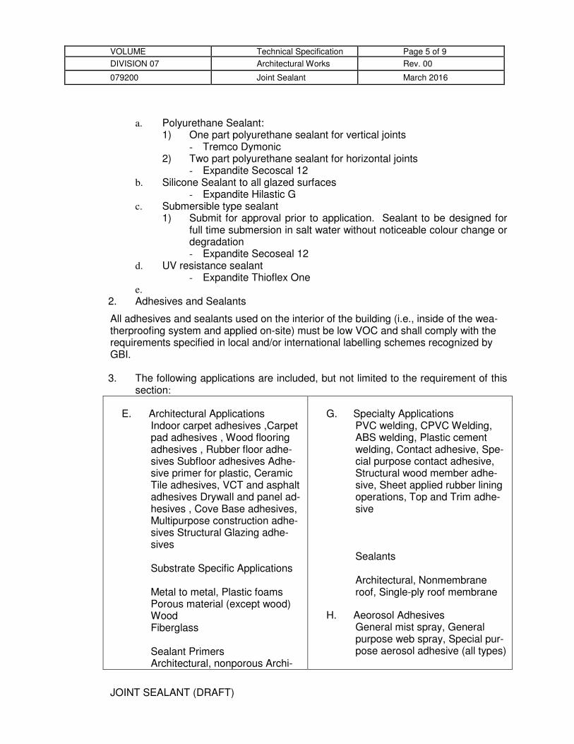
JOINT SEALANT (DRAFT)
VOLUME Technical Specification Page 5 of 9
DIVISION 07 Architectural Works Rev. 00
079200 Joint Sealant March 2016
a. Polyurethane Sealant: 1) One part polyurethane sealant for vertical joints
- Tremco Dymonic 2) Two part polyurethane sealant for horizontal joints
- Expandite Secoscal 12 b. Silicone Sealant to all glazed surfaces
- Expandite Hilastic G c. Submersible type sealant
1) Submit for approval prior to application. Sealant to be designed for full time submersion in salt water without noticeable colour change or degradation - Expandite Secoseal 12
d. UV resistance sealant - Expandite Thioflex One
e. 2. Adhesives and Sealants
All adhesives and sealants used on the interior of the building (i.e., inside of the wea-therproofing system and applied on-site) must be low VOC and shall comply with the requirements specified in local and/or international labelling schemes recognized by GBI. 3. The following applications are included, but not limited to the requirement of this
section:
E. Architectural Applications Indoor carpet adhesives ,Carpet pad adhesives , Wood flooring adhesives , Rubber floor adhe-sives Subfloor adhesives Adhe-sive primer for plastic, Ceramic Tile adhesives, VCT and asphalt adhesives Drywall and panel ad-hesives , Cove Base adhesives, Multipurpose construction adhe-sives Structural Glazing adhe-sives Substrate Specific Applications Metal to metal, Plastic foams Porous material (except wood) Wood Fiberglass Sealant Primers Architectural, nonporous Archi-
G. Specialty Applications PVC welding, CPVC Welding, ABS welding, Plastic cement welding, Contact adhesive, Spe-cial purpose contact adhesive, Structural wood member adhe-sive, Sheet applied rubber lining operations, Top and Trim adhe-sive Sealants Architectural, Nonmembrane roof, Single-ply roof membrane
H. Aeorosol Adhesives General mist spray, General purpose web spray, Special pur-pose aerosol adhesive (all types)

JOINT SEALANT (DRAFT)
VOLUME Technical Specification Page 6 of 9
DIVISION 07 Architectural Works Rev. 00
079200 Joint Sealant March 2016
tectural, porous
F. I.
J.
2.2 MISCELLANEOUS MATERIALS
A. Primer: Material recommended by joint-sealant manufacturer where required for adhesion of sealant to joint substrates indicated, as determined from preconstruction joint-sealant-substrate tests and field tests.
B. Cleaners for Nonporous Surfaces: Chemical cleaners acceptable to manufacturers of sealants and sealant backing materials, free of oily residues or other substances capable of staining or harming joint substrates and adjacent nonporous surfaces in any way, and formulated to promote optimum adhesion of sealants to joint substrates.
C. Masking Tape: Nonstaining, nonabsorbent material compatible with joint sealants and surfaces adjacent to joints.
PART 3 - EXECUTION
3.1 EXAMINATION
A. Examine joints indicated to receive joint sealants, with Installer present, for compliance with requirements for joint configuration, installation tolerances, and other conditions affecting performance of the Work.
B. Proceed with installation only after unsatisfactory conditions have been corrected.
3.2 PREPARATION
A. Surface Cleaning of Joints: Clean out joints immediately before installing joint sealants to comply with joint-sealant manufacturer's written instructions and the following requirements: 1. Remove all foreign material from joint substrates that could interfere with
adhesion of joint sealant, including dust, paints (except for permanent, protective coatings tested and approved for sealant adhesion and compatibility by sealant manufacturer), old joint sealants, oil, grease, waterproofing, water repellents, water, surface dirt, and frost.
2. Clean porous joint substrate surfaces by brushing, grinding, mechanical abrading, or a combination of these methods to produce a clean, sound substrate capable of developing optimum bond with joint sealants. Remove loose particles

JOINT SEALANT (DRAFT)
VOLUME Technical Specification Page 7 of 9
DIVISION 07 Architectural Works Rev. 00
079200 Joint Sealant March 2016
remaining after cleaning operations above by vacuuming or blowing out joints with oil-free compressed air. Porous joint substrates include the following: a. Concrete. b. Masonry. c. Unglazed surfaces of tile. d. Exterior insulation and finish systems.
3. Remove laitance and form-release agents from concrete. 4. Clean nonporous joint substrate surfaces with chemical cleaners or other means
that do not stain, harm substrates, or leave residues capable of interfering with adhesion of joint sealants. Nonporous joint substrates include the following: a. Metal. b. Glass. c. Porcelain enamel. d. Glazed surfaces of ceramic tile.
B. Joint Priming: Prime joint substrates where recommended by joint-sealant manufacturer or as indicated by preconstruction joint-sealant-substrate tests or prior experience. Apply primer to comply with joint-sealant manufacturer's written instructions. Confine primers to areas of joint-sealant bond; do not allow spillage or migration onto adjoining surfaces.
C. Masking Tape: Use masking tape where required to prevent contact of sealant or primer with adjoining surfaces that otherwise would be permanently stained or damaged by such contact or by cleaning methods required to remove sealant smears. Remove tape immediately after tooling without disturbing joint seal.
3.3 INSTALLATION OF JOINT SEALANTS
A. General: Comply with joint-sealant manufacturer's written installation instructions for products and applications indicated, unless more stringent requirements apply.
B. Sealant Installation Standard: Comply with recommendations in ASTM C 1193 for use of joint sealants as applicable to materials, applications, and conditions indicated.
C. Install sealant backings of kind indicated to support sealants during application and at position required to produce cross-sectional shapes and depths of installed sealants relative to joint widths that allow optimum sealant movement capability. 1. Do not leave gaps between ends of sealant backings. 2. Do not stretch, twist, puncture, or tear sealant backings. 3. Remove absorbent sealant backings that have become wet before sealant
application, and replace them with dry materials.
D. Install bond-breaker tape behind sealants where sealant backings are not used between sealants and backs of joints.

JOINT SEALANT (DRAFT)
VOLUME Technical Specification Page 8 of 9
DIVISION 07 Architectural Works Rev. 00
079200 Joint Sealant March 2016
E. Install sealants using proven techniques that comply with the following and at the same time backings are installed: 1. Place sealants so they directly contact and fully wet joint substrates. 2. Completely fill recesses in each joint configuration. 3. Produce uniform, cross-sectional shapes and depths relative to joint widths that
allow optimum sealant movement capability.
F. Tooling of Nonsag Sealants: Immediately after sealant application and before skinning or curing begins, tool sealants according to requirements specified in subparagraphs below to form smooth, uniform beads of configuration indicated; to eliminate air pockets; and to ensure contact and adhesion of sealant with sides of joint. 1. Remove excess sealant from surfaces adjacent to joints. 2. Use tooling agents that are approved in writing by sealant manufacturer and that
do not discolor sealants or adjacent surfaces.
3.4 FIELD QUALITY CONTROL
A. Field-Adhesion Testing: Field test joint-sealant adhesion to joint substrates as follows: 1. Extent of Testing: Test completed and cured sealant joints as follows:
a. Perform 10 tests for the first 300 m of joint length for each kind of sealant and joint substrate.
2. Inspect tested joints and report on the following: a. Whether sealants filled joint cavities and are free of voids. b. Whether sealant dimensions and configurations comply with specified
requirements. c. Whether sealants in joints connected to pulled-out portion failed to adhere
to joint substrates or tore cohesively. Include data on pull distance used to test each kind of product and joint substrate. Compare these results to determine if adhesion complies with sealant manufacturer's field-adhesion hand-pull test criteria.
3. Record test results in a field-adhesion-test log. Include dates when sealants were installed, names of persons who installed sealants, test dates, test locations, whether joints were primed, adhesion results and percent elongations, sealant material, sealant configuration, and sealant dimensions.
4. Repair sealants pulled from test area by applying new sealants following same procedures used originally to seal joints. Ensure that original sealant surfaces are clean and that new sealant contacts original sealant.
B. Evaluation of Field-Adhesion-Test Results: Sealants not evidencing adhesive failure from testing or noncompliance with other indicated requirements will be considered satisfactory. Remove sealants that fail to adhere to joint substrates during testing or to comply with other requirements. Retest failed applications until test results prove sealants comply with indicated requirements.

JOINT SEALANT (DRAFT)
VOLUME Technical Specification Page 9 of 9
DIVISION 07 Architectural Works Rev. 00
079200 Joint Sealant March 2016
3.5 CLEANING
A. Clean off excess sealant or sealant smears adjacent to joints as the Work progresses by methods and with cleaning materials approved in writing by manufacturers of joint sealants and of products in which joints occur.
3.6 PROTECTION
A. Protect joint sealants during and after curing period from contact with contaminating substances and from damage resulting from construction operations or other causes so sealants are without deterioration or damage at time of Practical Completion. If, despite such protection, damage or deterioration occurs, cut out, remove, and repair damaged or deteriorated joint sealants immediately so installations with repaired areas are indistinguishable from original work.
END OF SECTION 079200

ACOUSTICAL JOINT SEALANTS (DRAFT)
VOLUME Technical Specification Page 1 of 5
DIVISION 07 Architectural Works Rev. 00
079219 Acoustical Joint Sealant March 2016
SECTION 079219 - ACOUSTICAL JOINT SEALANTS
PART 1 - GENERAL
1.1 RELATED DOCUMENTS
A. Drawings and general provisions of the Contract, including General and Supplementary Conditions and Division 01 Specification Sections, apply to this Section.
B. Refer herein, but not limited to the following:-
1. Schedules, product and description 2. Drawings for location and extent of works
1.2 SUMMARY
A. Section includes acoustical joint sealants.
B. Related Requirements:
1. Section 042200 Concrete Unit Masonry 2. Section 092900 "Gypsum Board 3. Section 079200 "Joint Sealants" for elastomeric, latex, and butyl-rubber-based
joint sealants for non-acoustical applications.
C. Reference:
1. BS 476 Part 20: 1987 Fire test on building materials and structures. 2. BS EN 13501 - 1: 2002 Non combustibility 3. prEN 1366 Part 3: 1998 Penetration seals 4. prEN 1366 Part 4: 2000 Linear joint seals
1.3 ACTION SUBMITTALS
A. Product Data: For each acoustical joint sealant.
B. Samples for Initial Selection: Manufacturer's color charts consisting of strips of cured sealants showing the full range of colors available for each product exposed to view.
C. Samples for Verification: For each kind and color of acoustical joint sealant required, provide Samples with joint sealants in 13-mm-wide joints formed between two 150-

ACOUSTICAL JOINT SEALANTS (DRAFT)
VOLUME Technical Specification Page 2 of 5
DIVISION 07 Architectural Works Rev. 00
079219 Acoustical Joint Sealant March 2016
mm-long strips of material matching the appearance of exposed surfaces adjacent to joint sealants.
D. Acoustical-Joint-Sealant Schedule: Include the following information:
1. Joint-sealant application, joint location, and designation. 2. Joint-sealant manufacturer and product name. 3. Joint-sealant formulation. 4. Joint-sealant color.
E. Shop Drawings: Show locations and installation of acoustic joints sealant.
1.4 INFORMATIONAL SUBMITTALS
A. Product Test Reports: For each kind of acoustical joint sealant, for tests performed by a qualified testing agency under acoustic and fire rated.
B. Qualification: Submit manufacturer and installer data.
C. Material Certification: Compliance to BOMBA
D. Sample Warranties: For special warranties.
1.5 QUALITY ASSURANCE
A. Manufacturer Qualification: No less than 10 years’ experience in production of specified product and a record of successful in service performance
B. Installer Qualification:
1. Engage an installer who has no less than 3 years’ experience in installation of system similar in complexity to those required for this project
2. Designate one individual as project foreman who shall be on site at all times during installation.
1.6 DELIVERY, STORAGE, AND HANDLING
A. Accept materials on site in manufacturers unopened original packaging. Inspect for damage
B. Store primers and sealants in cool dry location with ambient temperature range of 60-80°F (15-27°C)

ACOUSTICAL JOINT SEALANTS (DRAFT)
VOLUME Technical Specification Page 3 of 5
DIVISION 07 Architectural Works Rev. 00
079219 Acoustical Joint Sealant March 2016
1.7 WARRANTY
A. Special Installer's Warranty: Installer agrees to repair or replace acoustical joint sealants that do not comply with performance and other requirements specified in this Section within specified warranty period.
1. Warranty Period: Two years from date of Practical Completion.
B. Special Manufacturer's Warranty: Manufacturer agrees to furnish acoustical joint sealants to repair or replace those joint sealants that do not comply with performance and other requirements specified in this Section within specified warranty period.
1. Warranty Period: Five years from date of Practical Completion.
PART 2 - PRODUCTS
2.1 PERFORMANCE REQUIREMENTS
A. Provide acoustical joint-sealant products that effectively reduce airborne sound transmission through perimeter joints and openings in building construction, as demonstrated by testing representative assemblies according to ASTM E 90.
B. Fire-Resistance-Rated Assemblies: For fire-resistance-rated and smoke seal joint sealant, provide materials and construction identical to those tested in assembly indicated according to by an independent testing agency
2.2 ACOUSTICAL JOINT SEALANTS
A. Fire and Acoustical Sealant for Concealed Joints: Manufacturer's standard nonsag, nondrying, nonhardening, nonskinning, nonstaining, gunnable, synthetic-rubber acoustical sealant.
1. Basic of Design Product: Subject to compliance with requirement, provide Rockwoool FirePro® Acoustic Intumescent Sealant or comparable product by one of the following:-
a. BORAL Plasterboard (Malaysia) Sdn Bhd
2. Colors of Exposed Acoustical Joint Sealants: As indicated by manufacturer's designations.

ACOUSTICAL JOINT SEALANTS (DRAFT)
VOLUME Technical Specification Page 4 of 5
DIVISION 07 Architectural Works Rev. 00
079219 Acoustical Joint Sealant March 2016
2.3 MISCELLANEOUS MATERIALS
A. Primer: Material recommended by acoustical-joint-sealant manufacturer where required for adhesion of sealant to joint substrates.
B. Cleaners for Nonporous Surfaces: Chemical cleaners acceptable to manufacturers of sealants and sealant backing materials, free of oily residues or other substances capable of staining or harming joint substrates and adjacent nonporous surfaces in any way, and formulated to promote optimum adhesion of sealants to joint substrates.
C. Masking Tape: Nonstaining, nonabsorbent material compatible with joint sealants and surfaces adjacent to joints.
PART 3 - EXECUTION
3.1 EXAMINATION
A. Examine joints indicated to receive acoustical joint sealants, with Installer present, for compliance with requirements for joint configuration, installation tolerances, and other conditions affecting performance of the Work.
B. Proceed with installation only after unsatisfactory conditions have been corrected.
3.2 PREPARATION
A. Surface Cleaning of Joints: Clean out joints immediately before installing acoustical joint sealants to comply with joint-sealant manufacturer's written instructions.
B. Joint Priming: Prime joint substrates where recommended by acoustical-joint-sealant manufacturer. Apply primer to comply with joint-sealant manufacturer's written instructions. Confine primers to areas of joint-sealant bond; do not allow spillage or migration onto adjoining surfaces.
C. Masking Tape: Use masking tape where required to prevent contact of sealant or primer with adjoining surfaces that otherwise would be permanently stained or damaged by such contact or by cleaning methods required to remove sealant smears. Remove tape immediately after tooling without disturbing joint seal.
3.3 INSTALLATION OF ACOUSTICAL JOINT SEALANTS
A. Comply with acoustical joint-sealant manufacturer's written installation instructions unless more stringent requirements apply.

ACOUSTICAL JOINT SEALANTS (DRAFT)
VOLUME Technical Specification Page 5 of 5
DIVISION 07 Architectural Works Rev. 00
079219 Acoustical Joint Sealant March 2016
B. STC-Rated Assemblies: Seal construction at perimeters, behind control joints, and at openings and penetrations with a continuous bead of acoustical joint sealant. Install acoustical joint sealants at both faces of partitions, at perimeters, and through penetrations. Comply with ASTM C 919, ASTM C 1193, and manufacturer's written recommendations for closing off sound-flanking paths around or through assemblies, including sealing partitions to underside of floor slabs above acoustical ceilings.
C. Acoustical Ceiling Areas: Apply acoustical joint sealant at perimeter edge moldings of acoustical ceiling areas in a continuous ribbon concealed on back of vertical legs of moldings before they are installed.
3.4 CLEANING
A. Clean off excess sealant or sealant smears adjacent to joints as the Work progresses by methods and with cleaning materials approved in writing by manufacturers of acoustical joint sealants and of products in which joints occur.
3.5 PROTECTION
A. Protect acoustical joint sealants during and after curing period from contact with contaminating substances and from damage resulting from construction operations or other causes so sealants are without deterioration or damage at time of Substantial Completion. If, despite such protection, damage or deterioration occurs, cut out, remove, and repair damaged or deteriorated acoustical joint sealants immediately so installations with repaired areas are indistinguishable from original work.
END OF SECTION 079219

EXPANSION CONTROL (DRAFT)
VOLUME Technical Specification Page 1 of 9
DIVISION 07 Architectural Works Rev. 00
079500 Expansion Control March 2016
SECTION 079500 - EXPANSION CONTROL
PART 1 - GENERAL
1.1 RELATED DOCUMENTS
A. Drawings and general provisions of the Contract, including General and Supplementary Conditions and Division 01 Specification Sections, apply to this Section.
B. Refer herein, but not limited to the following:- 1. Schedules, product and description 2. Drawings for location and extent of works
1.2 SUMMARY
A. Section Includes: 1. Interior expansion control systems. 2. Exterior wall expansion control systems. 3. Movement Joint 4. Open-air structure expansion control systems.
B. Related Requirements: 1. Section 078446 "Fire-Resistive Joint Systems" for liquid-applied joint sealants in
fire-resistive building joints. 2. Section 079200 "Joint Sealants" for liquid-applied joint sealants and for
elastomeric sealants without metal frames.
1.3 ACTION SUBMITTALS
A. Shop Drawings: For each expansion control system specified. Include plans, elevations, sections, details, splices, blockout requirement, attachments to other work, and line diagrams showing entire route of each expansion control system. Where expansion control systems change planes, provide isometric or clearly detailed drawing depicting how components interconnect.
B. Samples: For each exposed expansion control system and for each color and texture specified, full width by 150 mm long in size.
C. Samples for Initial Selection: For each type of expansion control system indicated.

EXPANSION CONTROL (DRAFT)
VOLUME Technical Specification Page 2 of 9
DIVISION 07 Architectural Works Rev. 00
079500 Expansion Control March 2016
1. Include manufacturer's color charts showing the full range of colors and finishes available for each exposed metal and elastomeric seal material.
D. Samples for Verification: For each type of expansion control system indicated, full width by 150 mm long in size.
E. Product Schedule: Prepared by or under the supervision of the supplier. Include the following information in tabular form: 1. Manufacturer and model number for each expansion control system. 2. Expansion control system location cross-referenced to Drawings. 3. Nominal joint width. 4. Movement capability. 5. Materials, colors, and finishes. 6. Product options. 7. Fire-resistance ratings.
1.4 INFORMATIONAL SUBMITTALS
A. Product Test Reports: For each fire barrier provided as part of an expansion control system, for tests performed by a qualified testing agency.
B. Product Certification: Material Test Report from qualified testing laboratory indicating and interpreting test results relative to compliance of fire rated expansion joint assemblies with requirement indicated.
C. Sample Warranties: For special warranties.
1.5 QUALITY ASSURANCE
A. Installer Qualifications: A firm experienced in installing expansion joint systems similar in material, design, and extent to that indicated for this Project, whose work has resulted in construction with a record of successful performance. Qualifications include having the necessary experience, staff, and training to install manufacturer's products per specified requirements.
B. Source Limitations: Obtain expansion control systems from single source from single manufacturer.
1.6 PERFORMANCE REQUIREMENTS
A. Fire-Resistance Ratings: Where indicated, provide expansion control systems with fire barriers identical to those of systems tested for fire resistance per SIRIM with reference

EXPANSION CONTROL (DRAFT)
VOLUME Technical Specification Page 3 of 9
DIVISION 07 Architectural Works Rev. 00
079500 Expansion Control March 2016
to UL 2079 or ASTM E 1966 by a testing and inspecting agency acceptable to authorities having jurisdiction. 1. Fire-Resistance Rating: Provide expansion control system and fire-barrier
assembly with a rating not less than that of adjacent construction.
B. Loading Characteristic: Standard loading withstanding up to 500lb. point loads. Heavy duty loading withstanding up to 2000lb points load
1.7 WARRANTY
A. Special Warranty: Installer agrees to repair or replace expansion control systems not comply with performance and other requirements specified in this Section within specified warranty period. 1. Warranty Period: Two years from date of Practical Completion.
B. Special Manufacturer's Warranty: Manufacturer agrees to furnish expansion control system to repair or replace those that do not comply with performance and other requirements specified in this Section within specified warranty period. 1. Warranty Period: Five years from date of Practical Completion.
1.8 COORDINATION
A. Coordinate construction of joints to ensure that fire-resistive joint systems are installed according to specified requirements.
B. Coordinate sizing of joints to accommodate fire-resistive joint systems.
C. Coordination installation assemblies of any transition of all joint are watertight.
PART 2 - PRODUCTS
2.1 SYSTEM DESCRIPTION
A. General: Provide expansion control systems of design, basic profile, materials, and operation indicated. Provide units with capability to accommodate variations in adjacent surfaces. 1. Furnish units in longest practicable lengths to minimize field splicing. Install with
hairline mitered corners where expansion control systems change direction or abut other materials.

EXPANSION CONTROL (DRAFT)
VOLUME Technical Specification Page 4 of 9
DIVISION 07 Architectural Works Rev. 00
079500 Expansion Control March 2016
2. Include factory-fabricated closure materials and transition pieces, T-joints, corners, curbs, cross-connections, and other accessories as required to provide continuous expansion control systems.
3. Design Characteristic: a. Nominal Joint Width; The width of the linear opening specified in practice
and in which the joint system is installed.
2.2 INTERIOR EXPANSION CONTROL SYSTEMS
A. Manufacturer: Subject to compliance with requirement, provide by Construction Specialties (Malaysia) Sdn Bhd, or a comparable product by one of the following:- 1. TSI Engineering Sdn Bhd 2. Hilti (Malaysia) Sdn Bhd
B. Floor-to-Floor 1. Basis-of-Design Product: CS Flush Thinline Floor Covers GFT Series: 2. Type: Elastomeric Seal 3. Exposed Metal: Aluminum
a. Finish: Class II, Clear Anodic 4. Seal Material: CS Thermoplastic Rubber (TPR)
a. Color: As selected by Architect from Manufacturer’s Standard Range b. Gasket to be dual durometer and have a flat profile that is free of
ridges/reveals c. that collect dirt
5. Attachment Method: Mechanical Anchors 6. Load Capacity: Standard Duty 7. Location: Podium Retail
C. Floor-to-Wall 1. Basis-of-Design Product: CS Flush Thinline Floor Covers GFTW Series: 2. Type: Elastomeric Seal 3. Exposed Metal: Aluminum
a. Finish: Class II, Clear Anodic 4. Seal Material: CS Thermoplastic Rubber (TPR)
a. Color: As selected by Architect from Manufacturer’s Standard Range b. Gasket to be dual durometer and have a flat profile that is free of
ridges/reveals c. that collect dirt
5. Attachment Method: Mechanical Anchors 6. Load Capacity: Standard Duty 7. Location: Between Tower and Podium

EXPANSION CONTROL (DRAFT)
VOLUME Technical Specification Page 5 of 9
DIVISION 07 Architectural Works Rev. 00
079500 Expansion Control March 2016
2.3 MOVEMENT JOINTS
A. Manufacturer: Subject to compliance with requirement provide one of the followings, or a comparable product by one of the following:- 1. TSI Engineering Sdn Bhd 2. U Win Trading & Supply Sdn Bhd 3. Basis-of-Design Product: Screed Expansion Joints 4. Type: Soft Coextruded PVC 5. Attached method: Embedded in in screed/plaster 6. Location: Movement joint in bricks, screed and render
2.4 OPEN-AIR STRUCTURE EXPANSION CONTROL
A. Manufacturer: Subject to compliance with requirement provide by Construction Specialties (Malaysia) Sdn Bhd, or a comparable product by one of the following:- 1. TSI Engineering Sdn Bhd 2. U Win Trading & Supply Sdn Bhd
B. Slab-to-Slab: 1. Basis-of-Design Product: Construction Specialties-Model PDA 2. Type: Metal Plate 3. Exposed Metal: Aluminum
a. Finish: Mill 4. Seal Material: Santoprene
a. Color: Black b. Wing Seal Material: PVC Black
5. Attachment Method: Mechanical Anchors 6. Load Capacity: Heavy Duty 7. Location: Vehicular Traffic/Deck
2.5 ACCESSORIES
A. Moisture Barriers: Manufacturer's standard moisture barrier consisting of a continuous, waterproof membrane within joint and attached to substrate on sides of joint below the primary cover. 1. Drain-Tube Assemblies: Equip moisture barrier with drain tubes and seals to
direct collected moisture to drain.
2.6 MATERIALS
A. Aluminum: ASTM B 221M, Alloy 6063-T5 for extrusions; ASTM B 209M, Alloy 6061-T6 for sheet and plate.

EXPANSION CONTROL (DRAFT)
VOLUME Technical Specification Page 6 of 9
DIVISION 07 Architectural Works Rev. 00
079500 Expansion Control March 2016
1. Apply manufacturer's standard protective coating on aluminum surfaces to be placed in contact with cementitious materials.
B. Stainless Steel: ASTM A 240/A 240M or ASTM A 666, Type 304 for plates, sheet, and strips. 1. Remove tool and die marks and stretch lines or blend into finish.
C. Elastomeric Seals: ASTM E 1783; preformed elastomeric membranes or extrusions to be installed in metal frames.
D. Compression Seals: ASTM E 1612; preformed elastomeric extrusions having an internal baffle system and designed to function under compression.
E. Cellular Foam Seals: Extruded, compressible foam designed to function under compression.
F. Elastomeric Concrete: Modified epoxy or polyurethane extended into a prepackaged aggregate blend, specifically designed for bonding to concrete substrates.
G. Fire Barriers: Any material or material combination, when fire tested after cycling, designated to resist the passage of flame and hot gases through a movement joint and to meet performance criteria for required fire-resistance rating.
H. Moisture Barrier: Flexible elastomeric material,
I. Nonmetallic, Shrinkage-Resistant Grout: ASTM C 1107/C 1107M, factory-packaged, nonmetallic aggregate grout, noncorrosive, nonstaining, mixed with water to consistency suitable for application and a 30-minute working time.
J. Accessories: Manufacturer's standard anchors, clips, fasteners, set screws, spacers, and other accessories compatible with material in contact, as indicated or required for complete installations.
2.7 GENERAL FINISH REQUIREMENTS
A. Comply with NAAMM's "Metal Finishes Manual for Architectural and Metal Products" for recommendations for applying and designating finishes.
B. Protect mechanical finishes on exposed surfaces from damage by applying a strippable, temporary protective covering before shipping.
C. Appearance of Finished Work: Noticeable variations in same piece are not acceptable. Variations in appearance of adjoining components are acceptable if they are within the range of approved Samples and are assembled or installed to minimize contrast.

EXPANSION CONTROL (DRAFT)
VOLUME Technical Specification Page 7 of 9
DIVISION 07 Architectural Works Rev. 00
079500 Expansion Control March 2016
2.8 ALUMINUM FINISHES
A. Clear Anodic Finish: AAMA 611 as per Manufacturer's standard.
B. Mill finish as per Manufacturer's standard.
2.9 STAINLESS-STEEL FINISHES
A. Surface Preparation: Remove tool and die marks and stretch lines, or blend into finish.
B. Polished Finishes: Grind and polish surfaces to produce uniform finish, free of cross scratches. 1. Run grain of directional finishes with long dimension of each piece. 2. When polishing is completed, passivate and rinse surfaces. Remove embedded
foreign matter and leave surfaces chemically clean. 3. Directional Satin Finish: No. 4.
C. Bright, Cold-Rolled, Unpolished Finish: No. 2B.
PART 3 - EXECUTION
3.1 EXAMINATION
A. Examine surfaces where expansion control systems will be installed for installation tolerances and other conditions affecting performance of work. 1. Proceed with installation only after unsatisfactory conditions have been
corrected.
3.2 PREPARATION
A. Prepare substrates according to expansion control system manufacturer's written instructions.
B. Coordinate and furnish anchorages, setting drawings, and instructions for installing expansion control systems. Provide fasteners of metal, type, and size to suit type of construction indicated and to provide for secure attachment of expansion control systems.
C. Cast-In Frames: Coordinate and furnish frames to be cast into concrete.

EXPANSION CONTROL (DRAFT)
VOLUME Technical Specification Page 8 of 9
DIVISION 07 Architectural Works Rev. 00
079500 Expansion Control March 2016
3.3 INSTALLATION
A. Comply with manufacturer's written instructions for storing, handling, and installing expansion control systems and materials unless more stringent requirements are indicated.
B. Metal Frames: Perform cutting, drilling, and fitting required to install expansion control systems. 1. Install in true alignment and proper relationship to joints and adjoining finished
surfaces measured from established lines and levels. 2. Adjust for differences between actual structural gap and nominal design gap due
to ambient temperature at time of installation. Notify Architect where discrepancies occur that will affect proper expansion control system installation and performance.
3. Cut and fit ends to accommodate thermal expansion and contraction of metal without buckling of frames.
4. Repair or grout blockout as required for continuous frame support using nonmetallic, shrinkage-resistant grout.
5. Install frames in continuous contact with adjacent surfaces. a. Shimming is not permitted.
6. Locate anchors at interval recommended by manufacturer, but not less than 75 mm from each end and not more than 600 mm o.c.
C. Seals in Metal Frames: Install elastomeric seals and membranes in frames to comply with manufacturer's written instructions. Install with minimum number of end joints. 1. Provide in continuous lengths for straight sections. 2. Seal transitions according to manufacturer's written instructions. Vulcanize or
heat-weld field-spliced joints as recommended by manufacturer. 3. Installation: Mechanically lock seals into frames or adhere to frames with
adhesive or pressure-sensitive tape as recommended by manufacturer.
D. Compression Seals: Apply adhesive or lubricant adhesive as recommended by manufacturer to both frame interfaces sides of slabs before installing compression seals.
E. Fire-Resistance-Rated Assemblies: Coordinate installation of expansion control system materials and associated work so complete assemblies comply with assembly performance requirements. 1. Fire Barriers: Install fire barriers to provide continuous, uninterrupted fire
resistance throughout length of joint, including transitions and field splices.
F. Water Barrier: Provide Water barrier at exterior joints and where called for on drawings. Provide Drainage fitting where required.

EXPANSION CONTROL (DRAFT)
VOLUME Technical Specification Page 9 of 9
DIVISION 07 Architectural Works Rev. 00
079500 Expansion Control March 2016
3.4 PROTECTION
A. Do not remove protective covering until finish work in adjacent areas is complete. When protective covering is removed, clean exposed metal surfaces to comply with manufacturer's written instructions.
B. Protect the installation from damage by work of other Sections. Where necessary due to heavy construction traffic, remove and properly store cover plates or seals and install temporary protection over expansion control systems. Reinstall cover plates or seals prior to Substantial Completion of the Work.
END OF SECTION 079500

HOLLOW METAL DOORS & FRAMES (DRAFT)
VOLUME Technical Specification Page 1 of 12
DIVISION 08 Architectural Works Rev. 00
081113 Hollow Metal Doors & Frames March 2016
SECTION 081113 - HOLLOW METAL DOORS AND FRAMES
PART 1 - GENERAL
1.1 RELATED DOCUMENTS
A. Drawings and general provisions of the Contract, including General and Supplementary Conditions and Division 01 Specification Sections, apply to this Section.
B. Refer herein, but not limited to the following:- 1. Schedules, product and description 2. Drawings for location and extent of works
1.2 SUMMARY
A. Section includes hollow-metal work.
B. Related Requirements: 1. Section 083473.13 "Metal Sound Control Door Assemblies" for packaged,
acoustical hollow-metal door and frame assemblies with STC ratings of 35 or more.
2. Section 087100 "Door Hardware" for door hardware for hollow-metal doors.
1.3 DEFINITIONS
A. Minimum Thickness: Minimum thickness of base metal without coatings according to NAAMM-HMMA 803 or SDI A250.8.
1.4 COORDINATION
A. Coordinate anchorage installation for hollow-metal frames. Furnish setting drawings, templates, and directions for installing anchorages, including sleeves, concrete inserts, anchor bolts, and items with integral anchors. Deliver such items to Project site in time for installation.
1.5 PREINSTALLATION MEETINGS
A. Preinstallation Conference: Conduct conference at Project site

HOLLOW METAL DOORS & FRAMES (DRAFT)
VOLUME Technical Specification Page 2 of 12
DIVISION 08 Architectural Works Rev. 00
081113 Hollow Metal Doors & Frames March 2016
1.6 ACTION SUBMITTALS
A. Product Data: For each type of product. 1. Include construction details, material descriptions, core descriptions, fire-
resistance ratings and finishes.
B. Shop Drawings: Include the following: 1. Elevations of each door type. 2. Details of doors, including vertical- and horizontal-edge details and metal
thicknesses. 3. Frame details for each frame type, including dimensioned profiles and metal
thicknesses. 4. Locations of reinforcement and preparations for hardware. 5. Details of each different wall opening condition. 6. Details of anchorages, joints, field splices, and connections. 7. Details of accessories. 8. Details of moldings, removable stops, and glazing. 9. Details of conduit and preparations for power, signal, and control systems.
C. Samples for Initial Selection: For units with factory-applied color finishes.
D. Samples for Verification: 1. For each type of exposed finish required, prepared on Samples of not less than
75 by 127 mm. 2. For "Doors" and "Frames" subparagraphs below, prepare Samples approximately
305 by 305 mm to demonstrate compliance with requirements for quality of materials and construction: a. Doors: Show vertical-edge, top, and bottom construction; core construction;
and hinge and other applied hardware reinforcement. Include separate section showing glazing if applicable.
b. Frames: Show profile, corner joint, floor and wall anchors, and silencers. Include separate section showing fixed hollow-metal panels and glazing if applicable.
E. Schedule: Provide a schedule of hollow-metal work prepared by or under the supervision of supplier, using same reference numbers for details and openings as those on Drawings. Coordinate with final Door Hardware Schedule.
1.7 INFORMATIONAL SUBMITTALS
A. Product Test Reports: For each type of hollow-metal door and frame assembly, for tests performed by a qualified testing agency.
B. Oversize Construction Certification: For assemblies required to be fire rated and exceeding limitations of labeled assemblies.

HOLLOW METAL DOORS & FRAMES (DRAFT)
VOLUME Technical Specification Page 3 of 12
DIVISION 08 Architectural Works Rev. 00
081113 Hollow Metal Doors & Frames March 2016
1.8 DELIVERY, STORAGE, AND HANDLING
A. Deliver hollow-metal work palletized, packaged, or crated to provide protection during transit and Project-site storage. Do not use non-vented plastic. 1. Provide additional protection to prevent damage to factory-finished units.
B. Deliver welded frames with two removable spreader bars across bottom of frames, tack welded to jambs and mullions.
C. Store hollow-metal work vertically under cover at Project site with head up. Place on minimum 102-mm-high wood blocking. Provide minimum 6-mm space between each stacked door to permit air circulation.
PART 2 - PRODUCTS
A. Source Limitations: Obtain hollow-metal work from single source from single manufacturer.
B. Manufacturers: Subject to compliance with requirements, provide products by one of the following available manufacturers offering products that may be incorporated into the Work include, but are not limited to, the following:
C. Basis of Design product: Subject to compliance with requirements, provide product indicated on drawings or comparable product by one of the following:
1. EconFrame Sdn Bhd 2. SKB Shutter Sdn Bhd 3. MetaFrame Sdn Bhd
2.2 REGULATORY REQUIREMENTS
A. Fire-Rated Assemblies: Complying with NFPA 80 or Bomba Malaysia and listed and labeled by a qualified testing agency acceptable to authorities having jurisdiction for fire-protection ratings indicated, based on testing at positive pressure according to NFPA 252 or UL 10C. 1. Smoke- and Draft-Control Assemblies: Provide an assembly with gaskets listed
and labeled for smoke and draft control by a qualified testing agency acceptable to authorities having jurisdiction, based on testing according to UL 1784 and installed in compliance with NFPA 105.
B. Fire-Rated, Borrowed-Light Assemblies: Complying with NFPA 80 or Bomba Malaysia and listed and labeled by a testing and inspecting agency acceptable to authorities having jurisdiction for fire-protection ratings indicated, based on testing according to NFPA 257 or UL 9.

HOLLOW METAL DOORS & FRAMES (DRAFT)
VOLUME Technical Specification Page 4 of 12
DIVISION 08 Architectural Works Rev. 00
081113 Hollow Metal Doors & Frames March 2016
2.3 INTERIOR/EXTERIOR DOORS AND FRAMES
A. Construct interior/exterior doors and frames to comply with the standards indicated for materials, fabrication, hardware locations, hardware reinforcement, tolerances, and clearances, and as specified.
B. Standard-Duty Doors and Frames: SDI A250.8, Level 1. At locations indicated in the Door and Window Schedule 1. Physical Performance: Level C according to SDI A250.4. 2. Doors:
a. Type: As indicated in the Door and Frame Schedule. b. Thickness: 44.5 mm c. Face: Uncoated, cold-rolled steel sheet, minimum thickness of 0.8 mm. d. Edge Construction: Model 2, Seamless. e. Core: Manufacturer's standard kraft-paper honeycomb, polystyrene,
polyurethane, polyisocyanurate, mineral-board, or vertical steel-stiffener core at manufacturer's discretion.
3. Frames: a. Materials: Uncoated cold-rolled steel sheet, minimum thickness of 1.0 mm. b. Construction: Full profile welded.
4. Exposed Finish: Prime
C. Heavy-Duty Doors and Frames: SDI A250.8, Level 2. At locations indicated in the Door and Window Schedule . 1. Physical Performance: Level B according to SDI A250.4. 2. Doors:
a. Type: As indicated in the Door and Frame Schedule. b. Thickness: 44.5 mm. c. Face: Uncoated cold-rolled steel sheet, minimum thickness of 1.0 mm. d. Edge Construction: Model 2, Seamless. e. Core: Manufacturer's standard kraft-paper honeycomb, polystyrene,
polyurethane, polyisocyanurate, mineral-board, or vertical steel-stiffener core at manufacturer's discretion.
3. Frames: a. Materials: Uncoated steel sheet, minimum thickness of 1.3 mm. b. Construction: Full profile welded.
4. Exposed Finish: Prime.
D. Extra-Heavy-Duty Doors and Frames: SDI A250.8, Level 3. At locations indicated in the Door and Frame Schedule. 1. Physical Performance: Level A according to SDI A250.4. 2. Doors:
a. Type: As indicated in the Door and Frame Schedule. b. Thickness: 44.5 mm. c. Face: Uncoated,cold-rolled steel sheet, minimum thickness of 1.3 mm. d. Edge Construction:Model 2, Seamless. e. Core: Manufacturer's standard kraft-paper honeycomb, polystyrene,
polyurethane, polyisocyanurate, mineral-board, or vertical steel-stiffener core at manufacturer's discretion.

HOLLOW METAL DOORS & FRAMES (DRAFT)
VOLUME Technical Specification Page 5 of 12
DIVISION 08 Architectural Works Rev. 00
081113 Hollow Metal Doors & Frames March 2016
3. Frames: a. Materials: Uncoated, steel sheet, minimum thickness of 1.3 mm. b. Construction: Full profile welded.
4. Exposed Finish: Prime.
E. Maximum-Duty Doors and Frames: SDI A250.8, Level 4. [At locations indicated in the Door and Frame Schedule] . 1. Physical Performance: Level A according to SDI A250.4. 2. Doors:
a. Type: As indicated in the Door and Frame Schedule. b. Thickness: 44.5 mm. c. Face: Uncoated, cold-rolled steel sheet, minimum thickness of 1.7 mm. d. Edge Construction:Model 2, Seamless. e. Core: Manufacturer's standard kraft-paper honeycomb, polystyrene,
polyurethane, polyisocyanurate, mineral-board, or vertical steel-stiffener core at manufacturer's discretion.
3. Frames: a. Materials: Uncoated steel sheet, minimum thickness of 1.7 mm. b. Construction: Full profile welded.
4. Exposed Finish: Prime
F. Hollow-Metal Doors and Frames: NAAMM-HMMA 860. At locations indicated in the Door and Frame Schedule . 1. Physical Performance: Level A according to SDI A250.4. 2. Doors:
a. Type: As indicated in the Door and Frame Schedule. b. Thickness: 1-3/4 inches (44.5 mm.) c. Face: Uncoated, cold-rolled steel sheet, minimum thickness of 0.032 inch
(0.8 mm). d. Edge Construction:Continuously welded with no visible seam. e. Core: Steel stiffened.
3. Frames: a. Materials: Uncoated steel sheet, minimum thickness of 0.053 inch (1.3 mm)
for frames that receive hollow-metal doors; minimum thickness of 0.042 inch (1.0 mm)for frames that receive hollow-core wood doors.
b. Materials: Uncoated steel sheet, minimum thickness of 0.042 inch (1.0 mm) c. Construction: Full profile welded.
4. Exposed Finish: Prime.
2.4 HOLLOW-METAL PANELS
A. Provide hollow-metal panels of same materials, construction, and finish as adjacent door assemblies.
2.5 FRAME ANCHORS
A. Jamb Anchors:

HOLLOW METAL DOORS & FRAMES (DRAFT)
VOLUME Technical Specification Page 6 of 12
DIVISION 08 Architectural Works Rev. 00
081113 Hollow Metal Doors & Frames March 2016
1. Masonry Type: Adjustable strap-and-stirrup or T-shaped anchors to suit frame size, not less than 0.042 inch (1.0 mm) thick, with corrugated or perforated straps not less than 2 inches (51 mm) wide by 10 inches (254 mm) long; or wire anchors not less than 0.177 inch (4.5 mm) thick.
2. Stud-Wall Type: Designed to engage stud, welded to back of frames; not less than 0.042 inch (1.0 mm) thick.
3. Compression Type for Drywall Slip-on Frames: Adjustable compression anchors. 4. Post-installed Expansion Type for In-Place Concrete or Masonry: Minimum 3/8-
inch- (9.5-mm-) diameter bolts with expansion shields or inserts. Provide pipe spacer from frame to wall, with throat reinforcement plate, welded to frame at each anchor location.
B. Floor Anchors: Formed from same material as frames, minimum thickness of 0.042 inch (1.0 mm), and as follows: 1. Monolithic Concrete Slabs: Clip-type anchors, with two holes to receive
fasteners. 2. Separate Topping Concrete Slabs: Adjustable-type anchors with extension clips,
allowing not less than 2-inch (51-mm) height adjustment. Terminate bottom of frames at finish floor surface.
2.6 MATERIALS
A. Recycled Content of Steel Products: Postconsumer recycled content plus one-half of preconsumer recycled content not less than 25 Insert number percent.
B. Cold-Rolled Steel Sheet: ASTM A 1008/A 1008M, Commercial Steel (CS), Type B; suitable for exposed applications.
C. Hot-Rolled Steel Sheet: ASTM A 1011/A 1011M, Commercial Steel (CS), Type B; free of scale, pitting, or surface defects; pickled and oiled.
D. Metallic-Coated Steel Sheet: ASTM A 653/A 653M, Commercial Steel (CS), Type B.
E. Frame Anchors: ASTM A 879/A 879M, Commercial Steel (CS), 04Z (12G) coating designation; mill phosphatized. 1. For anchors built into exterior walls, steel sheet complying with
ASTM A 1008/A 1008M or ASTM A 1011/A 1011M, hot-dip galvanized according to ASTM A 153/A 153M, Class B.
F. Inserts, Bolts, and Fasteners: Hot-dip galvanized according to ASTM A 153/A 153M.
G. Power-Actuated Fasteners in Concrete: Fastener system of type suitable for application indicated, fabricated from corrosion-resistant materials, with clips or other accessory devices for attaching hollow-metal frames of type indicated.
H. Grout: ASTM C 476, except with a maximum slump of 4 inches (102 mm), as measured according to ASTM C 143/C 143M.

HOLLOW METAL DOORS & FRAMES (DRAFT)
VOLUME Technical Specification Page 7 of 12
DIVISION 08 Architectural Works Rev. 00
081113 Hollow Metal Doors & Frames March 2016
I. Mineral-Fiber Insulation: ASTM C 665, Type I (blankets without membrane facing); consisting of fibers manufactured from slag or rock wool; with maximum flame-spread and smoke-developed indexes of 25 and 50, respectively; passing ASTM E 136 for combustion characteristics.
J. Glazing: Comply with requirements in Section 088000 "Glazing."
K. Bituminous Coating: Cold-applied asphalt mastic, compounded for 15-mil (0.4-mm) dry film thickness per coat. Provide inert-type noncorrosive compound free of asbestos fibers, sulfur components, and other deleterious impurities.
2.7 FABRICATION
A. Fabricate hollow-metal work to be rigid and free of defects, warp, or buckle. Accurately form metal to required sizes and profiles, with minimum radius for metal thickness. Where practical, fit and assemble units in manufacturer's plant. To ensure proper assembly at Project site, clearly identify work that cannot be permanently factory assembled before shipment.
B. Hollow-Metal Doors: 1. Steel-Stiffened Door Cores: Provide minimum thickness 0.026 inch (0.66 mm),
steel vertical stiffeners of same material as face sheets extending full-door height, with vertical webs spaced not more than 6 inches (152 mm) apart. Spot weld to face sheets no more than 5 inches (127 mm) o.c. Fill spaces between stiffeners with glass- or mineral-fiber insulation.
2. Fire Door Cores: As required to provide fire-protection and temperature-rise ratings indicated.
3. Vertical Edges for Single-Acting Doors: Provide square edges at manufacturer's specification.
4. Top Edge Closures: Close top edges of doors with inverted closures, except provide flush closures at exterior doors of same material as face sheets.
5. Bottom Edge Closures: Close bottom edges of doors where required for attachment of weather stripping with end closures or channels of same material as face sheets.
6. Exterior Doors: Provide weep-hole openings in bottoms of exterior doors to permit moisture to escape. Seal joints in top edges of doors against water penetration.
7. Astragals: Provide overlapping astragal on one leaf of pairs of doors where required by NFPA 80 for fire-performance rating or where indicated. Extend minimum 3/4 inch (19 mm) beyond edge of door on which astragal is mounted or as required to comply with published listing of qualified testing agency.
C. Hollow-Metal Frames: Where frames are fabricated in sections due to shipping or handling limitations, provide alignment plates or angles at each joint, fabricated of same thickness metal as frames. 1. Sidelight and Transom Bar Frames: Provide closed tubular members with no
visible face seams or joints, fabricated from same material as door frame. Fasten members at crossings and to jambs by butt welding.

HOLLOW METAL DOORS & FRAMES (DRAFT)
VOLUME Technical Specification Page 8 of 12
DIVISION 08 Architectural Works Rev. 00
081113 Hollow Metal Doors & Frames March 2016
2. Provide countersunk, flat- or oval-head exposed screws and bolts for exposed fasteners unless otherwise indicated.
3. Grout Guards: Weld guards to frame at back of hardware mortises in frames to be grouted.
4. Floor Anchors: Weld anchors to bottoms of jambs with at least four spot welds per anchor; however, for slip-on drywall frames, provide anchor clips or countersunk holes at bottoms of jambs.
5. Jamb Anchors: Provide number and spacing of anchors as follows: a. Masonry Type: Locate anchors not more than 16 inches (406 mm) from top
and bottom of frame. Space anchors not more than 32 inches (813 mm) o.c., to match coursing, and as follows: 1) Two anchors per jamb up to 60 inches (1524 mm) high. 2) Three anchors per jamb from 60 to 90 inches (1524 to 2286 mm)
high. 3) Four anchors per jamb from 90 to 120 inches (2286 to 3048 mm)
high. 4) Four anchors per jamb plus one additional anchor per jamb for each
24 inches (610 mm) or fraction thereof above 120 inches (3048 mm) high.
b. Stud-Wall Type: Locate anchors not more than 18 inches (457 mm) from top and bottom of frame. Space anchors not more than 32 inches (813 mm) o.c. and as follows: 1) Three anchors per jamb up to 60 inches (1524 mm) high. 2) Four anchors per jamb from 60 to 90 inches (1524 to 2286 mm) high. 3) Five anchors per jamb from 90 to 96 inches (2286 to 2438 mm) high. 4) Five anchors per jamb plus one additional anchor per jamb for each
24 inches (610 mm) or fraction thereof above 96 inches (2438 mm) high.
c. Compression Type: Not less than two anchors in each frame. d. Post installed Expansion Type: Locate anchors not more than 6 inches
(152 mm) from top and bottom of frame. Space anchors not more than 26 inches (660 mm) o.c.
6. Head Anchors: Two anchors per head for frames more than 42 inches (1067 mm) wide and mounted in metal-stud partitions.
7. Door Silencers: Except on weather-stripped frames, drill stops to receive door silencers as follows. Keep holes clear during construction. a. Single-Door Frames: Drill stop in strike jamb to receive three door
silencers. b. Double-Door Frames: Drill stop in head jamb to receive two door silencers.
8. Terminated Stops: Terminate stops 6 inches (152 mm) above finish floor with a 45 or 90-degree angle cut to architect approval, and close open end of stop with steel sheet closure. Cover opening in extension of frame with welded-steel filler plate, with welds ground smooth and flush with frame.
D. Fabricate concealed stiffeners and edge channels from either cold- or hot-rolled steel sheet.

HOLLOW METAL DOORS & FRAMES (DRAFT)
VOLUME Technical Specification Page 9 of 12
DIVISION 08 Architectural Works Rev. 00
081113 Hollow Metal Doors & Frames March 2016
E. Hardware Preparation: Factory prepare hollow-metal work to receive templated mortised hardware; include cutouts, reinforcement, mortising, drilling, and tapping according to SDI A250.6, the Door Hardware Schedule, and templates. 1. Reinforce doors and frames to receive non-templated, mortised, and surface-
mounted door hardware. 2. Comply with applicable requirements in SDI A250.6 and BHMA A156.115 for
preparation of hollow-metal work for hardware.
F. Stops and Moldings: Provide stops and moldings around glazed lites and louvers where indicated. Form corners of stops and moldings with mitered hairline joints. 1. Single Glazed Lites: Provide fixed stops and moldings welded on secure side of
hollow-metal work. 2. Multiple Glazed Lites: Provide fixed and removable stops and moldings so that
each glazed lite is capable of being removed independently. 3. Provide fixed frame moldings on outside of exterior and on secure side of interior
doors and frames. 4. Provide loose stops and moldings on inside of hollow-metal work. 5. Coordinate rabbet width between fixed and removable stops with glazing and
installation types indicated.
2.8 STEEL FINISHES
A. Prime Finish: Clean, pretreat, and apply manufacturer's standard primer. 1. Shop Primer: Manufacturer's standard, fast-curing, lead- and chromate-free
primer complying with SDI A250.10; recommended by primer manufacturer for substrate; compatible with substrate and field-applied coatings despite prolonged exposure.
B. Factory Finish: Clean, pretreat, and apply manufacturer's standard two-coat, baked-on finish consisting of prime coat and thermosetting topcoat, complying with SDI A250.3. 1. Color and Gloss: As selected by Architect from manufacturer's full range.
2.9 ACCESSORIES
A. Louvers: Provide louvers for interior doors, where indicated, which comply with SDI 111C, with blades or baffles formed of 0.020-inch- (0.5-mm-) thick, cold-rolled steel sheet set into 0.032-inch- (0.8-mm-) thick steel frame. 1. Sight-proof Louver: Stationary louvers constructed with inverted-V or inverted-Y
blades. 2. Lightproof Louver: Stationary louvers constructed with baffles to prevent light
from passing from one side to the other. 3. Fire-Rated Automatic Louvers: Louvers constructed with movable blades closed
by actuating fusible link, and listed and labeled for use in fire-rated door assemblies of type and fire-resistance rating indicated by same qualified testing and inspecting agency that established fire-resistance rating of door assembly.

HOLLOW METAL DOORS & FRAMES (DRAFT)
VOLUME Technical Specification Page 10 of 12
DIVISION 08 Architectural Works Rev. 00
081113 Hollow Metal Doors & Frames March 2016
B. Mullions and Transom Bars: Join to adjacent members by welding or rigid mechanical anchors.
C. Grout Guards: Formed from same material as frames, not less than 0.016 inch (0.4 mm) thick.
PART 3 - EXECUTION
3.1 EXAMINATION
A. Examine substrates, areas, and conditions, with Installer present, for compliance with requirements for installation tolerances and other conditions affecting performance of the Work.
B. Examine roughing-in for embedded and built-in anchors to verify actual locations before frame installation.
C. Prepare written report, endorsed by Installer, listing conditions detrimental to performance of the Work.
D. Proceed with installation only after unsatisfactory conditions have been corrected.
3.2 PREPARATION
A. Remove welded-in shipping spreaders installed at factory. Restore exposed finish by grinding, filling, and dressing, as required to make repaired area smooth, flush, and invisible on exposed faces.
B. Drill and tap doors and frames to receive non-templated, mortised, and surface-mounted door hardware.
3.3 INSTALLATION
A. General: Install hollow-metal work plumb, rigid, properly aligned, and securely fastened in place. Comply with Drawings and manufacturer's written instructions.
B. Hollow-Metal Frames: Install hollow-metal frames of size and profile indicated. Comply with SDI A250.11 or NAAMM-HMMA 840 as required by standards specified. 1. Set frames accurately in position; plumbed, aligned, and braced securely until
permanent anchors are set. After wall construction is complete, remove temporary braces, leaving surfaces smooth and undamaged. a. At fire-rated openings, install frames according to NFPA 80. b. Where frames are fabricated in sections because of shipping or handling
limitations, field splice at approved locations by welding face joint

HOLLOW METAL DOORS & FRAMES (DRAFT)
VOLUME Technical Specification Page 11 of 12
DIVISION 08 Architectural Works Rev. 00
081113 Hollow Metal Doors & Frames March 2016
continuously; grind, fill, dress, and make splice smooth, flush, and invisible on exposed faces.
c. Install frames with removable stops located on secure side of opening. d. Install door silencers in frames before grouting. e. Remove temporary braces necessary for installation only after frames have
been properly set and secured. f. Check plumb, square, and twist of frames as walls are constructed. Shim
as necessary to comply with installation tolerances. g. Field apply bituminous coating to backs of frames that will be filled with
grout containing anti-freezing agents. 2. Floor Anchors: Provide floor anchors for each jamb and mullion that extends to
floor, and secure with post-installed expansion anchors. a. Floor anchors may be set with power-actuated fasteners instead of post-
installed expansion anchors if so indicated and approved on Shop Drawings.
3. Metal-Stud Partitions: Solidly pack mineral-fiber insulation inside frames. 4. Masonry Walls: Coordinate installation of frames to allow for solidly filling space
between frames and masonry with grout. 5. Concrete Walls: Solidly fill space between frames and concrete with mineral-fiber
insulation. 6. In-Place Concrete or Masonry Construction: Secure frames in place with post-
installed expansion anchors. Countersink anchors, and fill and make smooth, flush, and invisible on exposed faces.
7. In-Place Metal or Wood-Stud Partitions: Secure slip-on drywall frames in place according to manufacturer's written instructions.
8. Installation Tolerances: Adjust hollow-metal door frames for squareness, alignment, twist, and plumb to the following tolerances: a. Squareness: Plus or minus 1/16 inch (1.6 mm), measured at door rabbet
on a line 90 degrees from jamb perpendicular to frame head. b. Alignment: Plus or minus 1/16 inch (1.6 mm), measured at jambs on a
horizontal line parallel to plane of wall. c. Twist: Plus or minus 1/16 inch (1.6 mm), measured at opposite face
corners of jambs on parallel lines, and perpendicular to plane of wall. d. Plumbness: Plus or minus 1/16 inch (1.6 mm), measured at jambs at floor.
C. Hollow-Metal Doors: Fit hollow-metal doors accurately in frames, within clearances specified below. Shim as necessary. 1. Non-Fire-Rated Steel Doors:
a. Between Door and Frame Jambs and Head: 1/8 inch (3.2 mm) plus or minus 1/32 inch (0.8 mm).
b. Between Edges of Pairs of Doors: 1/8 inch (3.2 mm) to 1/4 inch (6.3 mm) plus or minus 1/32 inch (0.8 mm).
c. At Bottom of Door: [3/4 inch (19.1 mm)] [5/8 inch (15.8 mm)] plus or minus 1/32 inch (0.8 mm).
d. Between Door Face and Stop: 1/16 inch (1.6 mm) to 1/8 inch (3.2 mm) plus or minus 1/32 inch (0.8 mm).
2. Fire-Rated Doors: Install doors with clearances according to NFPA 80 or Bomba. 3. Smoke-Control Doors: Install doors and gaskets according to NFPA 105 or
Bomba

HOLLOW METAL DOORS & FRAMES (DRAFT)
VOLUME Technical Specification Page 12 of 12
DIVISION 08 Architectural Works Rev. 00
081113 Hollow Metal Doors & Frames March 2016
D. Glazing: Comply with installation requirements in Section 088000 "Glazing" and with hollow-metal manufacturer's written instructions. 1. Secure stops with countersunk flat- or oval-head machine screws spaced
uniformly not more than 9 inches (230 mm) o.c. and not more than 2 inches (51 mm) o.c. from each corner.
3.4 ADJUSTING AND CLEANING
A. Final Adjustments: Check and readjust operating hardware items immediately before final inspection. Leave work in complete and proper operating condition. Remove and replace defective work, including hollow-metal work that is warped, bowed, or otherwise unacceptable.
B. Remove grout and other bonding material from hollow-metal work immediately after installation.
C. Prime-Coat Touchup: Immediately after erection, sand smooth rusted or damaged areas of prime coat and apply touchup of compatible air-drying, rust-inhibitive primer.
D. Metallic-Coated Surface Touchup: Clean abraded areas and repair with galvanizing repair paint according to manufacturer's written instructions.
E. Factory-Finish Touchup: Clean abraded areas and repair with same material used for factory finish according to manufacturer's written instructions.
F. Touchup Painting: Cleaning and touchup painting of abraded areas of paint are specified in painting Sections.
END OF SECTION 081113

STAINLESS-STEEL DOORS AND FRAMES 081119 - 1
VOLUME Technical Specification Page 1 of 9
DIVISION 08 Architectural Works Rev. 00
081119 Steel Doors & Frames March 2016
PART 1 - GENERAL
1.1 RELATED DOCUMENTS
A. Drawings and general provisions of the Contract, including General and Supplementary Conditions and Division 01 Specification Sections, apply to this Section.
1.2 SUMMARY
A. Section Includes:
1. Steel, hollow-metal doors. 2. Steel, hollow-metal frames.
B. Related Sections:
1. Section 042000 "Unit Masonry" for building anchors into and grouting stainless-steel frames in masonry construction.
2. Section 099113 "Exterior Painting" for field painting of factory-primed, stainless-steel doors and frames.
3. Section 099123 "Interior Painting" for field painting of factory-primed, stainless-steel doors and frames.
1.3 ACTION SUBMITTALS
A. Product Data: For each type of product indicated. Include construction details, material descriptions, core descriptions, [fire-resistance rating,] [temperature-rise ratings,] and finishes.
B. Shop Drawings: Include the following:
1. Elevations of each door design. 2. Details of doors, including vertical and horizontal edge details and metal
thicknesses. 3. Frame details for each frame type, including dimensioned profiles and metal
thicknesses. 4. Locations of reinforcement and preparations for hardware. 5. Details of each different wall opening condition. 6. Details of anchorages, joints, field splices, and connections. 7. Details of accessories. 8. Details of moldings, removable stops, and glazing. 9. Details of conduit and preparations for power, signal, and control systems.

STAINLESS-STEEL DOORS AND FRAMES 081119 - 2
VOLUME Technical Specification Page 2 of 9
DIVISION 08 Architectural Works Rev. 00
081119 Steel Doors & Frames March 2016
C. Samples for Verification:
1. Finishes: For each type of exposed finish required, prepared on Samples of not less than 75 by 125 mm.
2. Doors: Include section of vertical-edge, top, and bottom construction; core construction; and hinge and other applied hardware reinforcement.
3. Frames: Show profile, corner joint, floor and wall anchors, and silencers. Include separate section showing fixed hollow-metal panels and glazing if applicable.
D. Schedule: Provide a schedule of stainless-steel, hollow-metal work prepared by or under the supervision of supplier, using same reference numbers for details and openings as those on Drawings. Coordinate with a door hardware schedule.
1.4 INFORMATIONAL SUBMITTALS
A. Oversize Construction Certification: For assemblies required to be fire rated and exceeding limitations of labeled assemblies.
B. Product Test Reports: Based on evaluation of comprehensive tests performed by a qualified testing agency, for each type of stainless-steel, hollow-metal door and frame assembly.
1.5 QUALITY ASSURANCE
A. Source Limitations: Obtain stainless-steel, hollow-metal work from single source from single manufacturer.
B. Fire-Rated Door Assemblies: Assemblies complying with NFPA 80 that are listed and labeled by a qualified testing agency, for fire-protection ratings indicated, based on testing at positive pressure according to NFPA 252 or UL 10C.
C. Smoke- and Draft-Control Door Assemblies: [Where indicated] provide assemblies tested according to UL 1784 and installed in compliance with NFPA 105.
D. Fire-Rated, Borrowed-Light Frame Assemblies: Assemblies that are listed and labeled, by a testing agency acceptable to authorities having jurisdiction, for fire-protection ratings indicated, based on testing according to NFPA 257 or UL 9. Label each individual glazed lite. Install in compliance with NFPA 80.
E. Preinstallation Conference: Conduct conference at Project site.
1.6 DELIVERY, STORAGE, AND HANDLING
A. Deliver doors and frames palletized, wrapped, or crated to provide protection during transit and Project-site storage. Do not use non-vented plastic.

STAINLESS-STEEL DOORS AND FRAMES 081119 - 3
VOLUME Technical Specification Page 3 of 9
DIVISION 08 Architectural Works Rev. 00
081119 Steel Doors & Frames March 2016
B. Shipping Spreaders: Deliver welded frames with two removable spreader bars across bottom of frames, tack welded or mechanically attached to jambs and mullions.
C. Store doors and frames under cover at Project site. Place units in a vertical position with heads up, spaced by blocking, on minimum 100-mm- high wood blocking. Avoid using nonvented plastic or canvas shelters that could create a humidity chamber.
1. If wrappers on doors become wet, remove cartons immediately. Provide minimum 6-mm space between each stacked door to permit air circulation.
1.7 PROJECT CONDITIONS
A. Field Measurements: Verify actual dimensions of openings by field measurements before fabrication.
1.8 COORDINATION
A. Coordinate installation of anchorages for steel frames. Furnish setting drawings, templates, and directions for installing anchorages, including sleeves, inserts, anchor bolts, and items with integral anchors. Deliver such items to Project site in time for installation.
PART 2 - PRODUCTS
2.1 STEEL DOORS AND FRAMES
A. Manufacturers: Subject to compliance with requirements available manufacturers offering products that may be incorporated into the Work include, but are not limited to, the following:
i) SKB Shutters Corporation Berhad.
ii) Econframe Sdn. Bhd.
B. Steel Frame – 2 Hours fire rated with insulation fabricated from galvanised steel of 1.5mm thickness with reinforced backplates and protection cover for hinges, closers and lockset’s strikers. Single coat of anti-rust primer as standard finishing.
C. Door panel – made of galvanised steel of 0.8mm thickness with solid calcium silicate core. Fire-resistant strips installed with expansion pins for increased fire safety. Each door panel comes with approved and tested door closer and branded European quality mortised level handle lockset with interchangeable key cylinder with panic functions safety and thumb turn for easy handling.
D. Steel doors are tested to minimum of 100,000 operating cycle test by SIRIM.

STAINLESS-STEEL DOORS AND FRAMES 081119 - 4
VOLUME Technical Specification Page 4 of 9
DIVISION 08 Architectural Works Rev. 00
081119 Steel Doors & Frames March 2016
E. Flat Type Hinge – Fabricated with 4.0mm thick 304 stainless steel with stainless steel screws. Door panel comes with 3 pieces of hinges as minimum standard.
F. Automatic Stainless Steel Flush Bolt for double panel doors – Imported UL US listed automatic flush bolts shall keep door panels intact with steel frame when fire door is shut.
G. Automatic door selector for double panel doors – Aluminium encased surface mounted flush to the upper frame for automatic selection of sequence of door panel closing mode
H. Finishing – steel frame and door panel are applied with single coat of anti-rust primer as minimum standard
2.2 STEEL FRAMES
A. Description: Fabricate stainless-steel frames of construction indicated, with faces of corners mitered and contact edges closed tight.
2.3 ACCESSORIES
A. Grout: Comply with ASTM C 476, with a slump of not more than 102 mm as measured according to ASTM C 143/C 143M.
B. Corrosion-Resistant Coating: Cold-applied asphalt mastic, compounded for 0.4-mm dry film thickness per coat. Provide inert-type noncorrosive compound free of asbestos fibers, sulfur components, and other deleterious impurities.
C. Mineral Fiber Insulation: Insulation composed of rock-wool fibers, slag-wool fibers, or glass fibers.
2.4 FABRICATION
A. Steel Door Fabrication: steel doors to be rigid and free of defects, warp, or buckle. Accurately form metal to required sizes and profiles, with minimum radius for thickness of metal.
1. Seamed Edge Construction: Both vertical door edges joined by visible, continuous interlocking seam (lock seam) full height of door.
2. Seamed Edge Construction: Both vertical door edges joined by visible seam that is projection, spot, or tack welded on inside edges of door at minimum 152 mm o.c.
3. Seamless Edge Construction: Door face sheets joined at vertical edges by continuous weld extending full height of door; with edges ground and polished, providing smooth, flush surfaces with no visible seams.

STAINLESS-STEEL DOORS AND FRAMES 081119 - 5
VOLUME Technical Specification Page 5 of 9
DIVISION 08 Architectural Works Rev. 00
081119 Steel Doors & Frames March 2016
4. Exterior Doors: Close top edges flush and seal joints against water penetration. Provide weep-hole openings in bottom of exterior doors to permit moisture to escape.
5. Stops and Moldings: Factory cut openings in doors. Provide stops and moldings around glazed lites. Form corners of stops and moldings with butted or mitered hairline joints.
a. Glazed Lites: Provide fixed stops and moldings welded on secure side of door.
b. Coordinate rabbet width between fixed and removable stops with type of glazing and type of installation indicated.
6. Hardware Preparation: Factory prepare stainless-steel doors to receive templated mortised hardware; include cutouts, reinforcement, mortising, drilling, and tapping, according to the Door Hardware Schedule and templates furnished as specified in [Section 087100 "Door Hardware."]
a. Reinforce doors to receive nontemplated mortised and surface-mounted door hardware.
7. Locate hardware as indicated, or if not indicated, according to HMMA 831, "Recommended Hardware Locations for Custom Hollow Metal Doors and Frames."
8. Tolerances: Fabricate doors to tolerances indicated in ANSI/NAAMM-HMMA 866.
B. Steel Frame Fabrication: Fabricate stainless-steel frames to be rigid and free of defects, warp, or buckle. Accurately form metal to required sizes and profiles, with minimum radius for thickness of metal. Where practical, fit and assemble units in manufacturer's plant. To ensure proper assembly at Project site, clearly identify work that cannot be permanently factory assembled before shipment.
1. Weld flush face joints continuously; grind, fill, dress, and make smooth, flush, and invisible. Where frames are fabricated in sections due to shipping or handling limitations, provide alignment plates or angles at each joint, fabricated from same thickness metal as frames.
2. [Mullions] [Rails] [and] [Transom Bars]: Provide closed tubular members with no visible face seams or joints. Fasten members at crossings and to jambs by butt welding according to joint designs in HMMA 820.
a. Provide false head member to receive lower ceiling where frames extend to finish ceilings of different heights.
3. Provide countersunk, flat-, or oval-head exposed screws and bolts for exposed fasteners unless otherwise indicated.
4. Floor Anchors: Weld anchors to bottom of jambs and mullions with at least four spot welds per anchor.
5. Jamb Anchors: Provide number and spacing of anchors as follows:

STAINLESS-STEEL DOORS AND FRAMES 081119 - 6
VOLUME Technical Specification Page 6 of 9
DIVISION 08 Architectural Works Rev. 00
081119 Steel Doors & Frames March 2016
a. Masonry Type: Locate anchors not more than 457 mm from top and bottom of frame. Space anchors not more than 813 mm o.c. and as follows:
1) Two anchors per jamb up to 1524 mm in height. 2) Three anchors per jamb from 1524 to 2286 mm in height. 3) Four anchors per jamb from 2286 to 2438 mm in height. 4) Four anchors per jamb plus one additional anchor per jamb for each
610 mm or fraction thereof more than 2438 mm in height.
b. Stud-Wall Type: Locate anchors not more than 457 mm from top and bottom of frame. Space anchors not more than 813 mm o.c. and as follows:
1) Three anchors per jamb up to 1524 mm in height. 2) Four anchors per jamb from 1524 to 2286 mm in height. 3) Five anchors per jamb from 2286 to 2438 mm in height. 4) Five anchors per jamb plus one additional anchor per jamb for each
610 mm or fraction thereof more than 2438 mm in height. 5) Two anchors per head for frames more than 1066 mm wide and
mounted in metal-stud partitions.
c. Compression Type: Not less than two anchors in each jamb. d. Postinstalled Expansion Type: Locate anchors not more than 152 mm from
top and bottom of frame. Space anchors not more than 660 mm o.c.
6. Head Reinforcement: For frames more than 1219 mm wide, provide continuous head reinforcement for full width of opening, welded to back of frame at head.
7. Door Silencers: Except on weather-stripped frames, drill stops to receive door silencers as follows. Provide plastic plugs to keep holes clear during construction.
a. Single-Door Frames: Drill stop in strike jamb to receive three door silencers.
b. Double-Door Frames: Drill stop in head jamb to receive two door silencers.
8. Stops and Moldings: Provide stops and moldings around [glazed lites] [and] [solid panels] where indicated. Form corners of stops and moldings with butted or mitered hairline joints.
a. Single Glazed Lites: Provide fixed stops and moldings welded on secure side of door or frame.
b. Multiple Glazed Lites: Provide fixed and removable stops and moldings such that each lite is capable of being removed independently.
c. Coordinate rabbet width between fixed and removable stops with type of glazing[ or panel] and type of installation indicated.
d. Terminated Stops: Where indicated for interior door frames, terminate stops 152 mm above finish floor with a [45] [90]-degree angle cut, and close open end of stop with stainless-steel sheet closure. Cover opening in extension of frame with welded-stainless-steel filler plate, with welds ground smooth and flush with frame.

STAINLESS-STEEL DOORS AND FRAMES 081119 - 7
VOLUME Technical Specification Page 7 of 9
DIVISION 08 Architectural Works Rev. 00
081119 Steel Doors & Frames March 2016
9. Hardware Preparation: Factory prepare stainless-steel frames to receive templated mortised hardware; include cutouts, reinforcement, mortising, drilling, and tapping, according to the Door Hardware Schedule and templates furnished as specified in [Section 087100 "Door Hardware."] [Section 087111 "Door
Hardware (Descriptive Specification)."]
a. Reinforce frames to receive nontemplated mortised and surface-mounted door hardware.
b. Locate hardware as indicated, or if not indicated, according to HMMA 831, "Recommended Hardware Locations for Custom Hollow Metal Doors and Frames."
10. Plaster Guards: Weld guards to frame at back of hardware mortises and mounting holes in frames to be grouted.
11. Tolerances: Fabricate frames to tolerances indicated in ANSI/NAAMM-HMMA 866.
PART 3 - EXECUTION
3.1 EXAMINATION
A. Examine substrates, areas, and conditions, with Installer present, for compliance with requirements for installation tolerances and other conditions affecting performance of stainless-steel doors and frames.
B. Examine roughing-in for embedded and built-in anchors to verify actual locations of -steel, door-frame connections before frame installation.
C. Proceed with installation only after unsatisfactory conditions have been corrected.
3.2 PREPARATION
A. Remove welded-in shipping spreaders installed at factory. Restore exposed finish by grinding, filling, and dressing, as required to make repaired area smooth, flush, and invisible on exposed faces.
B. Prior to installation and with installation spreaders in place, adjust and securely brace stainless-steel door frames for squareness, alignment, twist, and plumb to the following tolerances:
1. Squareness: Plus or minus 1.6 mm, measured at door rabbet on a line 90 degrees from jamb perpendicular to frame head.
2. Alignment: Plus or minus 1.6 mm, measured at jambs on a horizontal line parallel to plane of wall.
3. Twist: Plus or minus 1.6 mm, measured at opposite face corners of jambs on parallel lines, and perpendicular to plane of wall.

STAINLESS-STEEL DOORS AND FRAMES 081119 - 8
VOLUME Technical Specification Page 8 of 9
DIVISION 08 Architectural Works Rev. 00
081119 Steel Doors & Frames March 2016
4. Plumbness: Plus or minus 1.6 mm, measured at jambs on a perpendicular line from head to floor.
C. Drill and tap doors and frames to receive nontemplated mortised and surface-mounted door hardware.
3.3 INSTALLATION
A. General: Install stainless-steel doors and frames plumb, rigid, properly aligned, and securely fastened in place; comply with ANSI/NAAMM-HMMA 866 and manufacturer's written instructions.
B. Steel Frames: Install -steel frames of size and profile indicated.
1. Set frames accurately in position; plumbed, aligned, and braced securely until permanent anchors are set. After wall construction is complete, remove temporary braces, leaving surfaces smooth and undamaged.
a. At fire-protection-rated openings, install frames according to NFPA 80. b. Where frames are fabricated in sections due to shipping or handling
limitations, field splice at approved locations by welding face joint continuously; grind, fill, dress, and make splice smooth, flush, and invisible on exposed faces.
c. Install frames with removable glazing stops located on secure side of opening.
d. Install door silencers in frames before grouting. e. Remove temporary braces necessary for installation only after frames have
been properly set and secured. f. Check plumb, squareness, and twist of frames as walls are constructed.
Shim as necessary to comply with installation tolerances. g. Apply corrosion-resistant coating to backs of grout-filled frames.
2. Floor Anchors: Provide floor anchors for each jamb and mullion that extends to floor and secure with postinstalled expansion anchors.
a. Floor anchors may be set with powder-actuated fasteners instead of postinstalled expansion anchors, if so indicated and approved on Shop Drawings.
3. Metal-Stud Partitions: Solidly pack mineral-fiber insulation behind frames. 4. In-Place Concrete or Masonry Construction: Secure frames in place with
postinstalled expansion anchors. Countersink anchors, and fill and make smooth, flush, and invisible on exposed faces.
5. In-Place Gypsum Board Partitions: Secure frames in place with postinstalled expansion anchors through floor anchors at each jamb. Countersink anchors, and fill and make smooth, flush, and invisible on exposed faces.
6. Ceiling Struts: Extend struts vertically from top of frame at each jamb to supporting construction above, unless frame is anchored to masonry or to other

STAINLESS-STEEL DOORS AND FRAMES 081119 - 9
VOLUME Technical Specification Page 9 of 9
DIVISION 08 Architectural Works Rev. 00
081119 Steel Doors & Frames March 2016
structural support at each jamb. Bend top of struts to provide flush contact for securing to supporting construction above. Provide adjustable wedged or bolted anchorage to frame jamb members.
7. Grouted Frames: Solidly fill space between frames and substrate with grout. Take precautions, including bracing frames, to ensure that frames are not deformed or damaged by grout forces.
8. Installation Tolerances: Adjust stainless-steel frames for squareness, alignment, twist, and plumb to the following tolerances:
a. Squareness: Plus or minus 1.6 mm, measured at door rabbet on a line 90 degrees from jamb perpendicular to frame head.
b. Alignment: Plus or minus 1.6 mm, measured at jambs on a horizontal line parallel to plane of wall.
c. Twist: Plus or minus 1.6 mm, measured at opposite face corners of jambs on parallel lines, and perpendicular to plane of wall.
d. Plumbness: Plus or minus 1.6 mm, measured at jambs at floor.
9. Fire-Rated Doors: Install doors with clearances according to NFPA 80. 10. Smoke-Control Doors: Install doors according to NFPA 105.
3.4 ADJUSTING AND CLEANING
A. Final Adjustments: Check and readjust operating hardware items immediately before final inspection. Leave work in complete and proper operating condition. Remove and replace defective work including stainless-steel doors or frames that are warped, bowed, or otherwise unacceptable.
B. Clean grout and other bonding material off stainless-steel doors and frames immediately after installation.
C. Stainless-Steel Touchup: Immediately after erection, smooth any abraded areas of stainless steel and polish to match undamaged finish.
END OF SECTION 081119

SLIDING METAL DOORS (DRAFT) 1
VOLUME Technical Specification Page 1 of 7
DIVISION 08 Architectural Works Rev. 00
081173 Sliding Metal Doors March 2016
SECTION 081173 - SLIDING METAL DOORS
PART 1 - GENERAL
1.1 RELATED DOCUMENTS
A. Drawings and general provisions of the Contract, including General and Supplementary Conditions and Division 01 Specification Sections, apply to this Section.
1.2 SUMMARY
A. Section Includes:
1. Single-leaf, [power-operated] and [manually operated] sliding door [with pass door].
2. Biparting, [power-operated] and [manually operated] sliding door[ with pass door].
B. Related Requirements:
1. Section 099113 "Exterior Painting" for field painting of doors. 2. Section 099123 "Interior Painting" for field painting of doors.
1.3 ACTION SUBMITTALS
A. Product Data: For each type of product.
1. Summary of forces and loads imposed on walls by sliding doors.
B. Shop Drawings:
1. Include plans, elevations, sections, details, operational clearances, and attachments to other work.
2. Include diagrams for power, signal, and control wiring.
1.4 INFORMATIONAL SUBMITTALS
A. Qualification Data: For Installer and testing agency.
B. Product Certificates: For sliding metal doors.

SLIDING METAL DOORS (DRAFT) 2
VOLUME Technical Specification Page 2 of 7
DIVISION 08 Architectural Works Rev. 00
081173 Sliding Metal Doors March 2016
C. Field quality-control reports.
1.5 CLOSEOUT SUBMITTALS
A. Operation and Maintenance Data: For sliding metal doors to include in emergency, operation, and maintenance manuals.
1.6 QUALITY ASSURANCE
A. Installer Qualifications: An entity that employs installers and supervisors who are trained and approved by manufacturer.
1.7 FIELD CONDITIONS
A. Field Measurements: Indicate measurements on Shop Drawings.
PART 2 - PRODUCTS
2.1 MANUFACTURERS
A. Manufacturers: Subject to compliance with requirements available manufacturers offering products that may be incorporated into the Work include, but are not limited to, the following:
B. Basis-of-Design Product: Subject to compliance with requirements, provide or comparable product by one of the following:
1. EconFrame Sdn Bhd 2. SKB Shutter Sdn Bhd 3. MetaFrame Sdn Bhd
C. Source Limitations: Obtain sliding metal fire doors from single source from single manufacturer.
2.2 PERFORMANCE REQUIREMENTS
A. Electrical Components, Devices, and Accessories: Listed and labeled as defined in NFPA 70, by a qualified testing agency, and marked for intended location and application.

SLIDING METAL DOORS (DRAFT) 3
VOLUME Technical Specification Page 3 of 7
DIVISION 08 Architectural Works Rev. 00
081173 Sliding Metal Doors March 2016
2.3 MATERIALS
A. Steel Plate, Shapes, and Bars: ASTM A 36/A 36M.
B. Steel Sheets: ASTM A 1008/A 1008M, Commercial Steel (CS), or Drawing Steel (DS), Type B, cold rolled; exposed, matte finish.
C. Metallic-Coated Steel Sheet: ASTM A 653/A 653M, Commercial Steel (CS), Type B, with [ZF180] or [ZF275] zinc-iron-alloy (galvannealed) coating or [Z275] or [Z180] zinc coating; restricted flatness.
D. Stainless-Steel Sheets: ASTM A 240/A 240M, [Type 304] or [Type 316]; stretcher-leveled standard of flatness; No. [4] or [6] finish.
Hardware and Fasteners: Manufacturer's standard.
SLIDING METAL DOORS.
A. Type of Door 1. Concealed metal sliding door with timber frame painted finish (Double leaf)-DD5,
Location-Multipurpose Hall. 2. Metal Sliding door (Single leaf)
Location-kitchen, cafeteria, container store. 3. Metal (Manual push button) Sliding door Metal frame powder coated finishes,no
locked required (Single leaf) Location-Production kitchen
4. Metal (Manual push button) Sliding door Metal frame powder coated finishes,no locked required with vision panel. (Double leaf) Location-Training, Restaurant 1 & 2, preparation kitchen.
B. Retain one option in "Door Type" Paragraph below. Verify door construction with manufacturers. Current UL-listed products are all overhead supported.
C. Door Type: Overhead supported with wall-mounted overhead track. Reinforce frame structure with minimum 1.1-mm- thick steel shapes. Reinforce mounting and hardware attachment locations. Attach armor edges and astragals to doors.
1. Composite-Type Doors: Fabricate in modular flush panels. Bond face materials to both sides of core. Internally reinforce perimeter with steel channels. Back joints in face sheets with a continuous steel H column covered with a steel, surface-applied faceplate or otherwise reinforce panels at connecting joints to provide a solid one-piece panel. Encase panel edges with minimum 1.7-mm- thick, steel channel.
2. Hollow-Metal Doors: Bond face materials to both sides of core. Internally reinforce perimeter with steel channels. Back joints in face sheets with a continuous steel H column covered with a steel, surface-applied faceplate or otherwise reinforce panels at connecting joints to provide a solid one-piece panel. Weld and fill joints and grind exposed welds smooth.

SLIDING METAL DOORS (DRAFT) 4
VOLUME Technical Specification Page 4 of 7
DIVISION 08 Architectural Works Rev. 00
081173 Sliding Metal Doors March 2016
3. Tubular-Frame Doors: Fabricate perimeter frame and internal stiffeners of steel tubes. Miter corner joints in frame and weld frame and stiffener joints. Locate joints in face sheets over stiffeners. Reinforce mounting and hardware attachment locations. Weld and fill joints and grind exposed welds smooth.
4. Doors: Manufacturer's standard type and construction.
D. Panel Facing:
1. Steel Sheet: [0.8-mm] / [1.1-mm] / [1.35-mm] / [1.7-mm] minimum thickness. 2. Metallic-Coated Steel Sheet: [1.0-mm] / [1.3-mm / [1.6-mm] / [2.0-mm] nominal
thickness. 3. Stainless-Steel Sheet: [0.96-mm] / [1.3-mm] / [1.57-mm] / [1.98-mm] nominal
thickness.
E. Core Construction: Manufacturer's standard.
F. Operating Hardware: Manufacturer's standard, labeled, automatic-closing-type, sliding fire door assemblies complete with track, roller assemblies, adjustable roller guides, binders, floor stops, cables, [pulleys and counterweights,] [reel,] and fusible links. Furnish necessary hangers, fittings, and fasteners required for attaching hardware to door and for door sliding operation, including latch or handle for manual operation.
G. Weight Boxes: 1.6-mm- thick, metallic-coated steel sheet counterweight boxes or guards; size as required for counterweights and clearance.
H. Crush Plates: 4.8-mm-thick by 150-mm-wide, continuous steel plates on hollow concrete masonry walls.
I. Track Hood: Formed, [metallic-coated steel] or [stainless-steel] sheet; size as required for clearance and to protect tracks.
J. Weather Stripping: UL-classified, [neoprene]or [nylon filament brush-style] weather stripping with attachments for mounting at head, jambs, and bottom surface of door.
K. Motorized Operator: UL-approved, high-starting-torque, reversing motor and adjustable speed operator with thermal-overload protection. Include fusible-link release to disengage operator and to allow door to close automatically.
1. Design operator for current characteristics of electrical service supplied. Provide UL-listed, 1/2-hp, [208- to 230-V ac, single-phase] [208-V ac, three-phase] [220-V ac, three-phase] [480-V ac, three-phase], 60-cycle motor with NEMA 250, [Type 1] <Insert type> enclosure and 24-V ac, secondary control voltage.
2. Equip door for completely automatic operation with clutch, speed reducer, brake, limit switches, electric reverse edge, brackets, bolts, and release for manual operation. Control equipment includes [two pull cords] [two three-button control stations with push buttons labeled "OPEN," "CLOSE," and "STOP"] [two motion detectors] [two loop detectors] [two photoelectric obstruction detectors] [time delay for closing] [and] [electric interlock for pass door].

SLIDING METAL DOORS (DRAFT) 5
VOLUME Technical Specification Page 5 of 7
DIVISION 08 Architectural Works Rev. 00
081173 Sliding Metal Doors March 2016
L. Interconnecting Device: Device for connecting fusible links for doors on both sides of wall.
M. Pass Door: UL-listed swing door and frame assembly.
1. Pass Door Hardware: Factory installed with one and one-half pairs of mortise [spring hinges] [butt hinges and closer] and [mortise latchset] [mortise lock] [exit device] [panic device].
a. Comply with Section 087111 "Door Hardware (Descriptive Specification)."
N. Vision Panels: Factory fabricated in door with integral removable glass stops. Provide glazing product tested and listed by a qualified testing agency as a component for fire-protection-rated sliding fire door assembly and acceptable to authorities having jurisdiction; do not exceed area allowed for door rating.
2.4 FABRICATION
A. Fabricate sliding metal door assemblies rigid, neat in appearance, and free of defects, warp, or buckle. Where practical, fit and assemble units in manufacturer's plant. To ensure proper assembly at Project site, clearly identify work that cannot be permanently factory assembled before shipment.
B. Factory prepare sliding metal fire door assemblies and frames to receive hardware and accessories including cutouts, reinforcements, mortising, drilling, and tapping.
2.5 METALLIC-COATED STEEL SHEET FINISHES
A. Surface Preparation: Clean surfaces with nonpetroleum solvent so surfaces are free of oil and other contaminants. After cleaning, apply a conversion coating compatible with the organic coating to be applied over it. Clean welds, mechanical connections, and abraded areas and apply galvanizing repair paint, complying with SSPC-Paint 20, to comply with ASTM A 780.
B. Factory Prime Finish: Immediately after cleaning and pretreating, apply an air-dried primer compatible with the organic coating to be applied over it.
C. Baked-Enamel or Powder-Coat Finish: Immediately after cleaning and pretreating, apply manufacturer's standard two-coat, baked-on finish consisting of prime coat and thermosetting topcoat to a minimum dry film thickness of 0.05 mm.
1. Color and Gloss: As selected by Architect from manufacturer's full range.

SLIDING METAL DOORS (DRAFT) 6
VOLUME Technical Specification Page 6 of 7
DIVISION 08 Architectural Works Rev. 00
081173 Sliding Metal Doors March 2016
2.6 STEEL FINISHES
A. Surface Preparation: Remove mill scale and rust, if present, from uncoated steel, complying with SSPC-SP 6/NACE No. 3, "Commercial Blast Cleaning" or SSPC-SP 7/NACE No. 4, "Brush-off Blast Cleaning". After cleaning, apply a conversion coating compatible with the organic coating to be applied over it.
B. Factory Prime Finish: Immediately after surface preparation and pretreatment, apply manufacturer's standard, fast-curing, lead- and chromate-free, universal primer.
C. Baked-Enamel or Powder-Coat Finish: Immediately after cleaning and pretreating, apply manufacturer's standard two-coat, baked-on finish consisting of prime coat and thermosetting topcoat to a minimum dry film thickness of 0.05 mm.
1. Color and Gloss: As selected by Architect from manufacturer's full range.
PART 3 - EXECUTION
3.1 EXAMINATION
A. Examine substrates and conditions, with Installer present, for compliance with requirements for installation tolerances and other conditions affecting performance of the Work.
1. Examine floor under door to confirm that floor is level for the full travel of door. 2. Examine wall where track assembly mounts and area behind door to confirm that
wall is smooth and in same plane for the full travel of door.
B. Proceed with installation only after unsatisfactory conditions have been corrected.
3.2 INSTALLATION
A. Install sliding metal doors according to NFPA 80 and manufacturer's written instructions for type of door operation indicated.
B. Drill necessary holes cleanly, with no broken areas or spalls, for installation of fasteners in concrete or masonry. Remove and replace damaged masonry as directed.
3.3 FIELD QUALITY CONTROL
A. Testing Agency: Engage a qualified testing agency to perform tests and inspections.
B. Perform the following tests and inspections:

SLIDING METAL DOORS (DRAFT) 7
VOLUME Technical Specification Page 7 of 7
DIVISION 08 Architectural Works Rev. 00
081173 Sliding Metal Doors March 2016
1. Test door closing when activated by detector or alarm-connected, fire-release system. Reset door-closing mechanism after successful test.
2. Operational Test: After electrical circuitry has been energized, start units to confirm proper motor rotation and unit operation.
3. Test and adjust controls and safeties. Replace damaged and malfunctioning controls and equipment.
C. Sliding metal door will be considered defective if it does not pass tests and inspections.
D. Prepare test and inspection reports.
3.4 ADJUSTING
A. Adjust hardware to function smoothly, and lubricate as recommended by manufacturer.
3.5 CLEANING
A. Clean surfaces and refinish abraded or damaged surfaces to match factory finish.
END OF SECTION 081173

HOLLOW METAL FRAME (DRAFT)
VOLUME Technical Specification Page 1 of 13
DIVISION 08 Architectural Works Rev. 00
081213 Hollow Metal Frames March 2016
SECTION 081213 - HOLLOW METAL FRAMES
PART 1 - GENERAL
1.1 RELATED DOCUMENTS
A. Drawings and general provisions of the Contract, including General and Supplementary Conditions and Division 01 Specification Sections, apply to this Section.
1.2 SUMMARY
A. Section includes hollow-metal frames.
B. Related Requirements:
1. Section 081416 "Flush Wood Doors" for wood doors installed in hollow-metal frames.
2. Section 083473.13 "Metal Sound Control Door Assemblies" 3. Section 087100 "Door Hardware"
C. References:
1. British Standards: BS 1245: Specification for metal door frames (steel). BS 4315: Part 2 Methods of test for resistance to air and water
penetration. BS 5277: Doors: Measurement of affects of general flat-
ness of door leaves. BS 5278: Doors: Measurement of dimensions and affects of
squareness of door leaves. BS 5588: Fire precautions in the design and construction of
buildings. BS 5588:Part 9 Code of practice for shopping complexes. BS 5725:Part 1 Emergency exit devices. BS 6206 Specification for impact performances require-
ments for flat safety glass and safety plastics for use in buildings.
BS 6497 Specification for powder organic coatings for ap-plication and stoving to hot-dip galvanised hot rolled steel sections and preformed steel sheet for windows and associated external architectural purposes, and for finish on galvanised steel sec-

HOLLOW METAL FRAME (DRAFT)
VOLUME Technical Specification Page 2 of 13
DIVISION 08 Architectural Works Rev. 00
081213 Hollow Metal Frames March 2016
tions and preformed sheet coated with powder organic coatings.
BS 6510 Specification for steel windows, sills, window boards and doors.
BS 7352 Specification for strength and durability perfor-mance of metal hinges for side hanging applica-tions and dimensional requirements for template drilled hinges.
BS 476 Fire tests for building materials and structures. BS 3621 Specification for thief-resistant locks. BS 3827 Glossary of terms relating to builder’s hardware. BS 4951 Specification for builders hardware, locks, and
latches furniture (doors). BS 6450:Part 1 Door closers. BS EN 10143 Specification for continuously hot-dip zinc coated
and iron-zinc alloy coated steel flat products: to-lerances on dimensions and shapes.
BS 1706 Electroplated coatings of cadmium and zinc on iron and steel.
BS 3698 Calcium plumbate priming paints. BS 4921 Sheradized coatings on iron and steel articles.
CP 2008 Protection of iron and steel structures from corrosion 2. American Standards:
ASTM A1008-2003 Standard Specification for Steel Sheet, Cold-Rolled, Carbon, Structural, High-Strength Low-Alloy and High-Strength Low-Alloy with Improved Formability
ASTM A568-2003 Standard Specification for Steel Sheet, Carbon, and High-Strength, Low-Alloy, Hot-Rolled and Cold-Rolled, General Requirements for
ASTM A1011-2001 Standard Specification for Steel Sheet and Strip, Hot-Rolled, Carbon, Structural, High-Strength Low-Alloy and High-Strength Low-Alloy with Improved Formability
ASTM A591-1998 Standard Specification for Steel Sheet, Electrolytic Zinc-Coated, for Light Coating Weight [Mass] Applications
ASTM A653-2002 Standard Specification for Steel Sheet, Zinc-Coated (Galvanized) or Zinc-Iron Alloy-Coated (Galvannealed) by the Hot-Dip Process
ASTM A924-1999 Standard Specification for General Requirements for Steel Sheet, Metallic-Coated by the Hot-Dip Process
3. ANSI Standards: ANSI/UL 10B-1997 Fire Tests of Door Assemblies

HOLLOW METAL FRAME (DRAFT)
VOLUME Technical Specification Page 3 of 13
DIVISION 08 Architectural Works Rev. 00
081213 Hollow Metal Frames March 2016
ANSI/UL 10C-1998 Positive Pressure Fire Tests of Door Assemblies ANSI/UL 1784-2001 Air Leakage Test of Door Assemblies ANSI/NFPA 80-1999 Fire Doors and Fire Windows ANSI/NFPA 252-1999 Fire Tests of Door Assemblies ANSI/SDI A250.3-1999 Test Procedure and Acceptance Criteria for Fac-
tory Applied Finish Painted Steel Surfaces for Steel Doors and Frames
ANSI/SDI A250.4-2001 Test Procedure and Acceptance Criteria for Phys-ical En
durance for Steel Doors, Frames, Frame Anchors and Hardware Reinforcings
ANSI/SDI A250.6-1997 Recommended Practice for Hardware Reinforcing on
Standard Steel Doors and Frames ANSI/SDI A250.7-1997 Nomenclature for Standard Steel Doors and Steel
Frames ANSI/SDI A250.10-1998 Test Procedure and Acceptance Criteria for Prime
Painted Steel Surfaces for Steel Doors and Frames ANSI/SDI A250.11-2001 Recommended Erection Instructions for Steel
Frames A115 Hardware Preparation in Steel Doors and Steel
Frames A115. IG Installation Guide for Doors and Hardware
4. SDI Standards SDI-108 Recommended Selection and Usage Guide for
Standard Steel Doors
SDI-111 Recommended Details and Guidelines for
Standard Steel Doors, Frames, and Accessories
SDI-112 Zinc-Coated (Galvanized/Galvannealed) Standard
Steel Doors and Frames
SDI-117 Manufacturing Tolerances for Standard Steel
Doors and Frames
SDI-118 Basic Fire Door Requirements
SDI-124 Maintenance of Standard Steel Doors and Frames
1.3 DEFINITIONS
A. Minimum Thickness: Minimum thickness of base metal without coatings according to NAAMM-HMMA 803 or SDI A250.8.

HOLLOW METAL FRAME (DRAFT)
VOLUME Technical Specification Page 4 of 13
DIVISION 08 Architectural Works Rev. 00
081213 Hollow Metal Frames March 2016
1.4 COORDINATION
A. Coordinate anchorage installation for hollow-metal frames. Furnish setting drawings, templates, and directions for installing anchorages, including sleeves, concrete inserts, anchor bolts, and items with integral anchors. Deliver such items to Project site in time for installation.
1.5 PREINSTALLATION MEETINGS
A. Preinstallation Conference: Conduct conference at Project site.
1.6 ACTION SUBMITTALS
A. Product Data: For each type of product.
1. Include product literature, construction details, material descriptions, fire-resistance ratings, temperature-rise ratings, and finishes.
B. Shop Drawings: Include the following:
1. Frame details for each frame type, including dimensioned profiles and metal thicknesses.
2. Locations of reinforcement and preparations for hardware. 3. Details of each different wall opening condition. 4. Details of anchorages, joints, field splices, and connections. 5. Details of moldings, removable stops, and glazing. 6. Details of conduit and preparations for power, signal, and control systems.
C. Samples for Initial Selection: For units with factory-applied color finishes and profiles selection.
D. Samples for Verification: Prepare Samples to demonstrate compliance with requirements for quality of materials and construction. Show profile, corner joint, floor and wall anchors, and silencers. Include separate section showing fixed hollow-metal panels and glazing if applicable.
E. Schedule: Provide a schedule of hollow-metal work prepared by or under the supervision of supplier, using same reference numbers for details and openings as those on Drawings. Coordinate with final Door Hardware Schedule.
1.7 INFORMATIONAL SUBMITTALS
A. Product Test Reports: For each type of frame assembly, for tests performed by a qualified testing agency.

HOLLOW METAL FRAME (DRAFT)
VOLUME Technical Specification Page 5 of 13
DIVISION 08 Architectural Works Rev. 00
081213 Hollow Metal Frames March 2016
B. Oversize Construction Certification: For assemblies required to be fire rated and exceeding limitations of labeled assemblies.
1.8 QUALITY ASSURANCE
A. Installer Qualifications: An entity that employs installers and supervisors who are trained and approved by manufacturer if applicable.
B. All materials upon receipt shall be inspected for damage, and the shipper and supplier notified if damage is found.
C. Where specified, all products shall be marked door opening number/tag on all doors, frames, misc. parts and cartons
1.9 DELIVERY, STORAGE, AND HANDLING
A. Deliver hollow-metal work palletized, packaged, or crated to provide protection during transit and Project-site storage. Do not use non-vented plastic.
1. Provide additional protection to prevent damage to factory-finished units.
B. Deliver welded frames with two removable spreader bars across bottom of frames, tack welded to jambs and mullions.
C. Store hollow-metal work vertically under cover at Project site with head up. Place on minimum 102-mm-high wood blocking. Provide minimum 6-mm space between each unit to permit air circulation.
1.10 FIELD CONDITIONS
A. Field Measurements: Where metal frames are indicated to fit to other construction and allowed opening, verify dimensions of other construction by field measurements before fabrication, and indicate measurements on Shop Drawings. Coordinate fabrication schedule with construction progress to avoid delaying the Work. Coordinate construction to ensure that actual dimensions correspond to established dimensions as indicated in door schedules.
1.11 COORDINATION
A. Coordinate sizes and locations of framing, opening, blocking, furring, reinforcements, and other related units of Work specified in other Sections to ensure that metal frames can be supported and installed as indicated.
HOLLOW METAL FRAME (DRAFT)
VOLUME Technical Specification Page 6 of 13
DIVISION 08 Architectural Works Rev. 00
081213 Hollow Metal Frames March 2016
1.12 WARRANTY
A. Special Warranty: Manufacturer agrees to repair or replace components of Hollow metal frame that fail in materials or workmanship within specified warranty period.
1. Failures include, but are not limited to, the following:
a. Failure to meet structural integrity requirements. b. Deterioration of metals, metal finishes, and other materials beyond normal
use or weathering.
1. Warranty Period: Ten years from date of Practical Completion.
PART 2 - PRODUCTS
2.1 MANUFACTURERS
A. Manufacturers: Subject to compliance with requirements, provide products by one of the following available manufacturers offering products that may be incorporated into the Work include, but are not limited to, the following:
1. EconFrame Sdn Bhd 2. SKB Shutter Sdn Bhd 3. MetaFrame Sdn Bhd
B. Source Limitations: Obtain hollow-metal work from single source from single manufacturer.
2.2 REGULATORY REQUIREMENTS
A. Fire-Rated Assemblies: Complying with NFPA 80 and listed and labeled by a qualified testing agency acceptable to authorities having jurisdiction for fire-protection ratings and temperature-rise limits indicated, based on testing at positive pressure according to Bomba with reference to NFPA 252 or UL 10C.
1. Smoke- and Draft-Control Assemblies: Provide an assembly with gaskets listed and labeled for smoke and draft control by a qualified testing agency acceptable to authorities having jurisdiction, based on testing according to SIRIM and UL 1784 and installed in compliance with Bomba reference to NFPA 105.
B. Fire-Rated, Borrowed-Light Assemblies: Complying with Bomba reference to NFPA 80 and listed and labeled by a testing and inspecting agency acceptable to authorities having jurisdiction for fire-protection ratings indicated, based on testing according to SIRIM with reference to NFPA 257 or UL 9.

HOLLOW METAL FRAME (DRAFT)
VOLUME Technical Specification Page 7 of 13
DIVISION 08 Architectural Works Rev. 00
081213 Hollow Metal Frames March 2016
2.3 FRAMES
A. Construct interior frames to comply with the standards indicated for materials, fabrication, hardware locations, hardware reinforcement, tolerances, and clearances, and as specified.
B. Standard-Duty Frames:
1. Materials: Zincalume, minimum thickness of 1.0 mm 2. Construction: To be selected from manufacturer full profile range. 3. Frame size: As indicated in drawings 4. Exposed Finish: Prime or factory finish as per manufacturer standard. 5. Location: Service Riser Door and non-fire rated door. Refer to Door schedules.
C. Medium-Duty Frames:
1. Materials: Galvanised, thickness of 1.2 mm 2. Construction: To be selected from manufacturer full profile range. 3. Frame size: As indicated in drawings 4. Exposed Finish: Prime or factory finish as per manufacturer standard. 5. Location: 1 Hour Fire Rated Door and normal solid doors.
D. Heavy-Duty Frames:
1. Materials: Galvanised, thickness not less than 1.5 mm 2. Construction: To be selected from manufacturer full profile range. 3. Frame size: As indicated in drawings 4. Exposed Finish: Prime or factory finish as per manufacturer standard. 5. Location: 2 Hour Fire Rated Door above and Fire Acoustic doors (if applicable).
Refer to Door schedules. Unless otherwise indicated.
E. Jamb Anchors:
1. Masonry Type: Adjustable strap-and-stirrup or T-shaped anchors to suit frame size, not less than 1.0 mm thick, with corrugated or perforated straps not less than 51 mm wide by 254 mm long; or wire anchors not less than 4.5 mm thick.
2. Stud-Wall Type: Designed to engage stud, welded to back of frames; not less than 1.0 mm thick.
3. Compression Type for Drywall Slip-on Frames: Adjustable compression anchors. 4. Postinstalled Expansion Type for In-Place Concrete or Masonry: Minimum 9.5-
mm-diameter bolts with expansion shields or inserts. Provide pipe spacer from frame to wall, with throat reinforcement plate, welded to frame at each anchor location.
F. Floor Anchors: Formed from same material as frames, minimum thickness of 1.0 mm, and as follows:

HOLLOW METAL FRAME (DRAFT)
VOLUME Technical Specification Page 8 of 13
DIVISION 08 Architectural Works Rev. 00
081213 Hollow Metal Frames March 2016
1. Monolithic Concrete Slabs: Clip-type anchors, with two holes to receive fasteners.
2. Separate Topping Concrete Slabs: Adjustable-type anchors with extension clips, allowing not less than 51-mm height adjustment. Terminate bottom of frames at finish floor surface.
2.4 MATERIALS
A. Cold-Rolled Steel Sheet: ASTM A 1008/A 1008M, Commercial Steel (CS), Type B; suitable for exposed applications.
B. Hot-Rolled Steel Sheet: ASTM A 1011/A 1011M, Commercial Steel (CS), Type B; free of scale, pitting, or surface defects; pickled and oiled.
C. Metallic-Coated Steel Sheet: ASTM A 653/A 653M, Commercial Steel (CS), Type B.
D. Frame Anchors: ASTM A 879/A 879M, Commercial Steel (CS), 12G coating designation; mill phosphatized.
1. For anchors built into exterior walls, steel sheet complying with ASTM A 1008/A 1008M or ASTM A 1011/A 1011M, hot-dip galvanized according to ASTM A 153/A 153M, Class B.
E. Inserts, Bolts, and Fasteners: Hot-dip galvanized according to ASTM A 153/A 153M.
F. Power-Actuated Fasteners in Concrete: Fastener system of type suitable for application indicated, fabricated from corrosion-resistant materials, with clips or other accessory devices for attaching hollow-metal frames of type indicated.
G. Grout: ASTM C 476, except with a maximum slump of 102 mm, as measured according to ASTM C 143/C 143M.
H. Mineral-Fiber Insulation: ASTM C 665, Type I (blankets without membrane facing); consisting of fibers manufactured from slag or rock wool with 96- to 192-kg/cu. m density; with maximum flame-spread and smoke-developed indexes of 25 and 50, respectively; passing ASTM E 136 for combustion characteristics.
I. Glazing: Comply with requirements in Section 088000 "Glazing."
2.5 FABRICATION
A. Fabricate hollow-metal work to be rigid and free of defects, warp, or buckle. Accurately form metal to required sizes and profiles, with minimum radius for metal thickness. Where practical, fit and assemble units in manufacturer's plant. To ensure proper assembly at Project site, clearly identify work that cannot be permanently factory assembled before shipment.

HOLLOW METAL FRAME (DRAFT)
VOLUME Technical Specification Page 9 of 13
DIVISION 08 Architectural Works Rev. 00
081213 Hollow Metal Frames March 2016
B. Hollow-Metal Frames: Where frames are fabricated in sections due to shipping or handling limitations, provide alignment plates or angles at each joint, fabricated of same thickness metal as frames.
1. Provide countersunk, flat- or oval-head exposed screws and bolts for exposed fasteners unless otherwise indicated.
2. Grout Guards: Weld guards to frame at back of hardware mortises in frames to be grouted.
3. Floor Anchors: Weld anchors to bottoms of jambs with at least four spot welds per anchor; however, for slip-on drywall frames, provide anchor clips or countersunk holes at bottoms of jambs.
4. Jamb Anchors: Provide number and spacing of anchors as follows:
a. Masonry Type: Locate anchors not more than 406 mm from top and bottom of frame. Space anchors not more than 813 mm o.c., to match coursing, and as follows:
1) Two anchors per jamb up to 1524 mm high. 2) Three anchors per jamb from 1524 to 2286 mm high. 3) Four anchors per jamb from 2286 to 3048 mm high. 4) Four anchors per jamb plus one additional anchor per jamb for each
610 mm or fraction thereof above 3048 mm high.
b. Stud-Wall Type: Locate anchors not more than 457 mm from top and bottom of frame. Space anchors not more than 813 mm o.c. and as follows:
1) Three anchors per jamb up to 1524 mm high. 2) Four anchors per jamb from 1524 to 2286 mm high. 3) Five anchors per jamb from 2286 to 2438 mm high. 4) Five anchors per jamb plus one additional anchor per jamb for each
610 mm or fraction thereof above 2438 mm high.
c. Compression Type: Not less than two anchors in each frame. d. Postinstalled Expansion Type: Locate anchors not more than 152 mm from
top and bottom of frame. Space anchors not more than 660 mm o.c.
5. Head Anchors: Two anchors per head for frames more than 1067 mm wide and mounted in metal-stud partitions if recommended by manufacturer.
6. Door Silencers only applicable for acoustic steel door: Except on weather-stripped frames, drill stops to receive door silencers as follows. Keep holes clear during construction.
a. Single-Door Frames: Drill stop in strike jamb to receive three door silencers.
b. Double-Door Frames: Drill stop in head jamb to receive two door silencers.

HOLLOW METAL FRAME (DRAFT)
VOLUME Technical Specification Page 10 of 13
DIVISION 08 Architectural Works Rev. 00
081213 Hollow Metal Frames March 2016
C. Hardware Preparation: Factory prepare hollow-metal work to receive templated mortised hardware; include cutouts, reinforcement, mortising, drilling, and tapping according to manufacturer written standard with reference to Door Hardware Schedule.
1. Reinforce frames to receive nontemplated, mortised, and surface-mounted hardware.
2. Comply with applicable requirements in Manufacturer recommendation reference to SDI A250.6 and BHMA A156.115 for preparation of hollow-metal work for hardware.
D. Stops and Moldings: Provide stops and moldings around glazed lites and louvers where indicated. Form corners of stops and moldings with mitered hairline joints.
1. Single Glazed Lites: Provide fixed stops and moldings welded on secure side of hollow-metal work.
2. Multiple Glazed Lites: Provide fixed and removable stops and moldings so that each glazed lite is capable of being removed independently.
3. Provide fixed frame moldings on outside of exterior and on secure side of interior frames.
4. Provide loose stops and moldings on inside of hollow-metal work. 5. Coordinate rabbet width between fixed and removable stops with glazing and
installation types indicated.
2.6 STEEL FINISHES
A. Prime Finish: Clean, pretreat, and apply manufacturer's standard primer.
1. Shop Primer: Manufacturer's standard, fast-curing, lead- and chromate-free primer complying with SDI A250.10; recommended by primer manufacturer for substrate; compatible with substrate and field-applied coatings despite prolonged exposure.
B. Factory Finish: Clean, pretreat, and apply manufacturer's standard two-coat, baked-on finish consisting of prime coat and thermosetting topcoat, complying with SDI A250.3.
1. Color and Gloss: As selected by Architect from manufacturer's full range.
2.7 ACCESSORIES
A. Mullions and Transom Bars: Join to adjacent members by welding or rigid mechanical anchors.
B. Grout Guards: Formed from same material as frames, not less than 0.4 mm thick.

HOLLOW METAL FRAME (DRAFT)
VOLUME Technical Specification Page 11 of 13
DIVISION 08 Architectural Works Rev. 00
081213 Hollow Metal Frames March 2016
PART 3 - EXECUTION
3.1 EXAMINATION
A. Examine substrates, areas, and conditions, with Installer present, for compliance with requirements for installation tolerances and other conditions affecting performance of the Work.
B. Examine roughing-in for embedded and built-in anchors to verify actual locations before frame installation.
C. Prepare written report, endorsed by Installer, listing conditions detrimental to performance of the Work.
D. Proceed with installation only after unsatisfactory conditions have been corrected.
3.2 PREPARATION
A. Remove welded-in shipping spreaders installed at factory. Restore exposed finish by grinding, filling, and dressing, as required to make repaired area smooth, flush, and invisible on exposed faces.
B. Drill and tap frames to receive nontemplated, mortised, and surface-mounted hardware.
3.3 INSTALLATION
A. General: Install hollow-metal work plumb, rigid, properly aligned, and securely fastened in place. Comply with Drawings and manufacturer's written instructions.
B. Hollow-Metal Frames: Install hollow-metal frames of size and profile indicated. Comply with manufacturer’s written standard with reference to SDI A250.11 or NAAMM-HMMA 840 as required by standards specified.
1. Set frames accurately in position; plumbed, aligned, and braced securely until permanent anchors are set. After wall construction is complete, remove temporary braces, leaving surfaces smooth and undamaged.
a. At fire-rated openings, install frames according to Bomba with reference to NFPA 80.
b. Where frames are fabricated in sections because of shipping or handling limitations, field splice at approved locations by welding face joint continuously; grind, fill, dress, and make splice smooth, flush, and invisible on exposed faces.
c. Install frames with removable stops located on secure side of opening.

HOLLOW METAL FRAME (DRAFT)
VOLUME Technical Specification Page 12 of 13
DIVISION 08 Architectural Works Rev. 00
081213 Hollow Metal Frames March 2016
d. Install door silencers in frames before grouting for Acoustic Door Assemblies.
e. Remove temporary braces necessary for installation only after frames have been properly set and secured.
f. Check plumb, square, and twist of frames as walls are constructed. Shim as necessary to comply with installation tolerances.
g. Field apply bituminous coating to backs of frames that will be filled with grout containing antifreezing agents.
2. Floor Anchors: Provide floor anchors for each jamb and mullion that extends to floor, and secure with postinstalled expansion anchors if require..
a. Floor anchors may be set with power-actuated fasteners instead of postinstalled expansion anchors if so indicated and approved on Shop Drawings.
3. Metal-Stud Partitions: Solidly pack mineral-fiber insulation inside frames. 4. Masonry Walls: Coordinate installation of frames to allow for solidly filling space
between frames and masonry with grout. 5. Concrete Walls: Solidly fill space between frames and concrete with mineral-fiber
insulation. 6. In-Place Concrete or Masonry Construction: Secure frames in place with
postinstalled expansion anchors. Countersink anchors, and fill and make smooth, flush, and invisible on exposed faces.
7. In-Place Metal or Wood-Stud Partitions: Secure slip-on drywall frames in place according to manufacturer's written instructions.
8. Installation Tolerances: Adjust hollow-metal door frames for squareness, alignment, twist, and plumb to the following tolerances:
a. Squareness: Plus or minus 1.6 mm, measured at door rabbet on a line 90 degrees from jamb perpendicular to frame head.
b. Alignment: Plus or minus 1.6 mm, measured at jambs on a horizontal line parallel to plane of wall.
c. Twist: Plus or minus 1.6 mm, measured at opposite face corners of jambs on parallel lines, and perpendicular to plane of wall.
d. Plumbness: Plus or minus 1.6 mm, measured at jambs at floor.
C. Glazing: Comply with installation requirements in Section 088000 "Glazing" and with hollow-metal manufacturer's written instructions if available.
1. Secure stops with countersunk flat- or oval-head machine screws spaced uniformly not more than 230 mm o.c. and not more than 51 mm o.c. from each corner.

HOLLOW METAL FRAME (DRAFT)
VOLUME Technical Specification Page 13 of 13
DIVISION 08 Architectural Works Rev. 00
081213 Hollow Metal Frames March 2016
3.4 ADJUSTING AND CLEANING
A. Final Adjustments: Remove and replace defective work, including hollow-metal work that is warped, bowed, or otherwise unacceptable.
B. Remove grout and other bonding material from hollow-metal work immediately after installation.
C. Prime-Coat Touchup: Immediately after erection, sand smooth rusted or damaged areas of prime coat and apply touchup of compatible air-drying, rust-inhibitive primer.
D. Metallic-Coated Surface Touchup: Clean abraded areas and repair with galvanizing repair paint according to manufacturer's written instructions.
E. Factory-Finish Touchup: Clean abraded areas and repair with same material used for factory finish according to manufacturer's written instructions.
F. Touchup Painting: Cleaning and touchup painting of abraded areas of paint are specified in painting Sections.
END OF SECTION 081213

ALUMINIUM FRAMES (DRAFT)
VOLUME Technical Specification Page 1 of 9
DIVISION 08 Architectural Works Rev. 00
081216 Aluminum Frames March 2016
SECTION 081216 - ALUMINUM FRAMES
PART 1 - GENERAL
1.1 RELATED DOCUMENTS
A. Drawings and general provisions of the Contract, including General and Supplementary Conditions and Division 01 Specification Sections, apply to this Section.
B. Refer herein, but not limited to the following:-
1. Schedules, product and description 2. Drawings for location and extent of works
1.2 SUMMARY
A. Section includes interior aluminum frames for doors and glazing installed in gypsum board partitions.
B. Related Sections:
1. Section 081416 "Flush Wood Doors" for wood doors installed in interior aluminum frames.
1.3 ACTION SUBMITTALS
A. Product Data: For each type of product indicated. Include construction details, material descriptions, dimensions of individual components and profiles, fire-resistance rating, and finishes.
B. Shop Drawings: Include the following:
1. Frame details for each frame type, including dimensioned profiles and metal thicknesses.
2. Locations of reinforcements and preparations for hardware. 3. Details of each different wall-opening condition. 4. Details of anchorages, joints, field splices, and connections. 5. Details of accessories. 6. Details of moldings, removable stops, and glazing. 7. Details of conduits and preparations for power, signal, and control systems.
C. Samples for Initial Selection: For units with factory-applied finishes.

ALUMINIUM FRAMES (DRAFT)
VOLUME Technical Specification Page 2 of 9
DIVISION 08 Architectural Works Rev. 00
081216 Aluminum Frames March 2016
1. Include similar Samples of seals, gaskets, and accessories involving color selection.
D. Samples for Verification: For interior aluminum frames, prepared on Samples of size indicated below:
1. Framing Member: 300 mm long. 2. Corner Fabrication: 300-by-300-mm-long, full-size window corner, including full-
size sections of extrusions with factory-applied color finish.
E. Schedule: For interior aluminum frames. Use same designations indicated on Drawings. Coordinate with door hardware schedule and glazing.
1.4 INFORMATIONAL SUBMITTALS
A. Product Test Reports: Based on evaluation of comprehensive tests performed by a qualified testing agency, for each type of interior aluminum frame.
1.5 CLOSEOUT SUBMITTALS
A. Maintenance Data: For interior aluminum frames to include in maintenance manuals.
1.6 QUALITY ASSURANCE
A. Source Limitations: Obtain interior aluminum frames from single source from single manufacturer.
B. Fire-Rated Assemblies: Assemblies complying with NFPA 80 that are listed and labeled by a qualified testing agency, for fire-protection ratings indicated, based on testing at positive pressure according to NFPA 252 or UL 10C.
C. Smoke- and Draft-Control Assemblies: Where indicated At corridors, smoke barriers, and smoke partitions, provide assemblies tested according to UL 1784 and installed in compliance with NFPA 105.
1. Air Leakage Rate: Maximum air leakage of3 cu. m per minute/sq. m at the tested pressure differential of 75 Pa of water.
D. Mockups: Build mockups to verify selections made under sample submittals and to demonstrate aesthetic effects and set quality standards for fabrication and installation.
1. Build mockup of typical wall area as shown on Drawings. 2. Approved mockups may become part of the completed Work if undisturbed at
time of Substantial Completion.
E. Preinstallation Conference: Conduct conference at Project site.

ALUMINIUM FRAMES (DRAFT)
VOLUME Technical Specification Page 3 of 9
DIVISION 08 Architectural Works Rev. 00
081216 Aluminum Frames March 2016
1.7 DELIVERY, STORAGE, AND HANDLING
A. Deliver interior aluminum frames palletized, wrapped, or crated to provide protection during transit and Project-site storage. Do not use non vented plastic. Store interior aluminum frames under cover at Project site.
PART 2 - PRODUCTS
2.1 MANUFACTURERS
A. Manufacturers: Subject to compliance with requirements, provide products by one of the following available manufacturers offering products that may be incorporated into the Work include. but are not limited to, the following:
i. LB Aluminum Berhad. ii. Sentech aluminium & glass engineering iii. Ip aluminium engineering sdn bhd iv. Tycotech aluminium sdn bhd
2.2 COMPONENTS
A. Aluminum Framing: ASTM B 221M, Alloy 6063-T5 or alloy and temper required to suit structural and finish requirements, not less than 1.6 mm thick.
B. Door Frames: Extruded aluminum, reinforced for hinges, strikes, and closers.
1. 90-Minute Fire-Protection Rating: Fabricate aluminum frame assemblies with a cold-formed, primed, interior steel liner.
C. Glazing Frames: Extruded aluminum, for glazing thickness indicated.
D. Ceiling Tracks: Extruded aluminum.
E. Trim: Extruded aluminum, not less than 1.6 mm thick, with removable snap-in casing trim glazing stops and door stops without exposed fasteners.
F. Sub-Frame for Installation purpose.
G. Type for aluminum frame
Type Description
1. Aluminum Frame Shopfront/ Fixed Glass Panel (2400mm
height)
Supply and install nominal thickness of 1.50mm LB shopfront SF06a,8646 series by LB Aluminium Berhad or equivalent. Completed with all associated sub-frame and necessary hardware, to manufacturer’s detail and architect’s approval (Glass &

ALUMINIUM FRAMES (DRAFT)
VOLUME Technical Specification Page 4 of 9
DIVISION 08 Architectural Works Rev. 00
081216 Aluminum Frames March 2016
silicone by others). Finish: 'Albecoat' Powder Coating (average 60 microns)
2. Aluminium Frame Curtainwall/ Fixed Glass Panel (3900mm height).
Supply and install nominal thickness of 2.00mm-3.00mm Albexwall Performance curtainwall-stickwall ctw/st02 18865 series by LB Aluminium Berhad or equivalent. Completed with all associated sub-frame and necessary hardware, to manufacturer’s detail and architect’s approval (Glass & silicone by others).
Finish: 'Albecoat' Powder Coating (average 60 microns)
3. Aluminium Frame Curtainwall/ Fixed Glass Panel (3300mm height)
Supply and install nominal thickness of 2.00mm-3.00mm Albexwall Performance curtainwall-stickwall ctw/st02 18866 series by LB Aluminium Berhad or equivalent. Completed with all associated sub-frame and necessary hardware, to manufacturer’s detail and architect’s approval (Glass & silicone by others).
Finish: 'Albecoat' Powder Coating (average 60 microns).
4. Aluminium Frame Fixed Glass Panel with tophung window (2800mm height)
Supply and install nominal thickness of 1.40mm Domal R4 casement window series by LB Aluminium Berhad or equivalent. Completed with D402411 Extruded aluminum corner joint,D40415 zamak pair of terminal , D401002 slip-off hinges, D502123 nylon alignment corner joint on fin,D503450 reversible cremone bolt for external opening, D404130push channel for external opening, DA4306NN Nylon striker with roller for terminal, DA2157TN circular cover hole plug dia.12mm, DG013BRN perimeter weather strip, DG0127EN internal weather strip on glass 2mm, DG0140RN External weather strip on glass 3mm all associated sub-frame and necessary hardware, to manufacturer’s detail and architect’s approval (Glass & silicone by others).
Finish: 'Albecoat' Powder Coating (average 60 microns).

ALUMINIUM FRAMES (DRAFT)
VOLUME Technical Specification Page 5 of 9
DIVISION 08 Architectural Works Rev. 00
081216 Aluminum Frames March 2016
5. Aluminium Frame Top Hung Window (650mm height)
Supply and install nominal thickness of 1.40mm Domal R4 casement window series by LB Aluminium Berhad or equivalent. Completed with D402411 Extruded aluminum corner joint,D40415 zamak pair of terminal , D401002 slip-off hinges, D502123 nylon alignment corner joint on fin,D503450 reversible cremone bolt for external opening, D404130push channel for external opening, DA4306NN Nylon striker with roller for terminal, DA2157TN circular cover hole plug dia.12mm, DG013BRN perimeter weather strip, DG0127EN internal weather strip on glass 2mm, DG0140RN External weather strip on glass 3mm all associated sub-frame and necessary hardware, to manufacturer’s detail and architect’s approval (Glass & silicone by others).
Finish: 'Albecoat' Powder Coating (average 60 microns).
6. Aluminum Frame Sliding Window (1200mm height)
Supply and install nominal thickness of 1.30mm Albesash Performance sliding window PSW02 7038 series by LB Aluminium Berhad or equivalent. Completed with DC370 crescent lock, W002PR euro sliding roller,W003SG euro slide top,W004TG Euro Top guide, W007 corner bracket (Inner frame),MP90 corner bracket (Outer frame),001 Weep Hole Cover, Woolpole, all associated sub-frame and necessary hardware, to manufacturer’s detail and architect’s approval (Glass & silicone by others).
Finish: 'Albecoat' Powder Coating (average 60 microns).
7. Aluminium Frame Swing Door (2800mm height)
Supply and install nominal thickness of 1.50mm LB swing door SWD02,7801 series by LB Aluminum Berhad or equivalent, completed with floor door closer with handle, top centre, top pivot & bottom strap, A141 top fixed pivot, inner corner bracket, wool pile all associated sub-frames frame and necessary hardware, to manufacturer’s detail and architect’s approval (Glass & silicone by

ALUMINIUM FRAMES (DRAFT)
VOLUME Technical Specification Page 6 of 9
DIVISION 08 Architectural Works Rev. 00
081216 Aluminum Frames March 2016
others.)
Finish: 'Albecoat' Powder Coating (average 60 microns).
8. Aluminium Frame Fixed Glass Louvre (2200mm height) Supply and install Breezway Altair Fixed
Glass Louvre by LB Aluminum Berhad or equivalent, completed with Breezway Altair Adjustable Louvre gallery, all associated sub-frames and necessary hardware, to manufacturer’s details and architect’s approval (Glass and silicone by others).
Finish: Albecoat Powder coating (average 60 microns).
9. Aluminium Frame Fixed 'Z - Type' Louvre @ Cafeteria Supply and install nominal thickness of
1.00mm LB fixed louvre (Z type), 9960 series (32.80mm depth X 53.00mm width) by LB aluminum berhad or equivalent,completed with all associated sub-frame and necessary hardware, to manufacturer’s detail and architect’s approval (Glass & silicone by others).
Finish: Albecoat Powder coating (average 60 microns).
10. Aluminium Frame Fixed 'Z - Type' Louvre @ Staircase
Supply and install nominal thickness of 1.30mm LB fixed louvre (Z type), 9277 series (77.72mm depth X 126.37mm width) by LB aluminum berhad or equivalent,completed with all associated sub-frame and necessary hardware, to manufacturer’s detail and architect’s approval (Glass & silicone by others.
Finish: Albecoat Powder coating (average 60 microns).
11. Aluminium Frame Fixed 'Storm' Louvre @ Block B
Supply and install nominal thickness of 1.50mm LB fixed storm louvre,15131 series (93.11mm depth X 61.79mm width) by LB aluminum berhad or equivalent,completed with all associated sub-frame and necessary hardware, to manufacturer’s detail and architect’s approval (Glass & silicone by others.

ALUMINIUM FRAMES (DRAFT)
VOLUME Technical Specification Page 7 of 9
DIVISION 08 Architectural Works Rev. 00
081216 Aluminum Frames March 2016
Finish: Albecoat Powder coating (average 60 microns
2.3 ACCESSORIES
A. Fasteners: Aluminum, nonmagnetic, stainless-steel or other noncorrosive metal fasteners compatible with frames, stops, panels, reinforcement plates, hardware, anchors, and other items being fastened.
B. Door Silencers: Manufacturer's standard continuous mohair, wool pile, or vinyl seals<; samples to be submitted for approval by Architect
C. Smoke Seals: Intumescent strip or fire-rated gaskets<; samples to be submitted for approval by Architect>.
D. Glazing Gaskets: Manufacturer's standard extruded or molded plastic, to accommodate glazing thickness indicated<; samples to be submitted for approval by Architect
E. Glazing: Comply with requirements in Section 088000 "Glazing." Section 088113 "Decorative Glass Glazing."
F. Hardware: Comply with requirements in Section 087100 "Door Hardware" and Section 087111 "Door Hardware (Descriptive Specification)."
2.4 FABRICATION
A. Provide concealed corner reinforcements and alignment clips for accurately fitted hairline joints at butted or mitered connections.
B. Factory prepare interior aluminum frames to receive templated mortised hardware; include cutouts, reinforcements, mortising, drilling, and tapping, according to the Door Hardware Schedule and templates furnished as specified in Section 087100 "Door Hardware." Section 087111 "Door Hardware (Descriptive Specification)."
1. Locate hardware as required by fire-rated label for assembly.
C. Fabricate frames for glazing with removable stops to allow glazing replacement without dismantling frame.
1. Locate removable stops on the inside of spaces accessed by keyed doors.
D. Fabricate components to allow secure installation without exposed fasteners.

ALUMINIUM FRAMES (DRAFT)
VOLUME Technical Specification Page 8 of 9
DIVISION 08 Architectural Works Rev. 00
081216 Aluminum Frames March 2016
2.5 GENERAL FINISH REQUIREMENTS
A. Comply with NAAMM's "Metal Finishes Manual for Architectural and Metal Products" for recommendations for applying and designating finishes.
B. Appearance of Finished Work: Noticeable variations in same piece are not acceptable. Variations in appearance of adjoining components are acceptable if they are within the range of approved Samples and are assembled or installed to minimize contrast.
2.6 ALUMINUM FINISHES
A. Clear Anodic Finish: AAMA 611, AA-M12C22A31, Class II, 0.010 mm or thicker.
B. Color Anodic Finish: AAMA 611, AA-M12C22A32/A34, Class II, 0.010 mm or thicker.
1. Color: As selected by Architect from full range of industry colors and color densities.
C. Baked-Enamel or Powder-Coat Finish: AAMA 2603 except with a minimum dry-film thickness of 0.025 mm. Comply with coating manufacturer's written instructions for cleaning, conversion coating, and applying and baking finish.
1. Color and Gloss: As selected by Architect from manufacturer's full range.
D. High-Performance Organic Finish: Two-coat fluoropolymer finish complying with AAMA 2604 and containing not less than 50 percent PVDF resin by weight in color coat. Prepare, pretreat, and apply coating to exposed metal surfaces to comply with coating and resin manufacturers' written instructions.
1. Color and Gloss: As selected by Architect from manufacturer's full range.
PART 3 - EXECUTION
3.1 EXAMINATION
A. Examine walls, floors, and ceilings, with Installer present, for conditions affecting performance of the Work.
B. Verify that wall thickness does not exceed standard tolerances allowed by throat size indicated.
C. Proceed with installation only after unsatisfactory conditions have been corrected.

ALUMINIUM FRAMES (DRAFT)
VOLUME Technical Specification Page 9 of 9
DIVISION 08 Architectural Works Rev. 00
081216 Aluminum Frames March 2016
3.2 INSTALLATION
A. General: Install interior aluminum frames plumb, rigid, properly aligned, and securely fastened in place; comply with manufacturer's written instructions.
B. Set frames accurately in position and plumbed, aligned, and securely anchored to substrates.
1. At fire-protection-rated openings, install interior aluminum frames according to NFPA 80 and NFPA 105.
C. Install frame components in the longest possible lengths; components up to 2450 mm long must be one piece.
1. Fasten to suspended ceiling grid on maximum centers, using sheet metal screws or other fasteners approved by frame manufacturer.
2. Use concealed installation clips to produce tightly fitted and aligned splices and connections.
3. Secure clips to extruded main-frame components and not to snap-in or trim members.
4. Do not leave screws or other fasteners exposed to view when installation is complete.
3.3 CLEANING
A. Clean exposed frame surfaces promptly after installation, using cleaning methods recommended by frame manufacturer with reference to AAMA 609 & 610.
B. Touch up marred frame surfaces so touchup is not visible from a distance of 1220 mm. Remove and replace frames with damaged finish that cannot be satisfactorily repaired.
END OF SECTION 081216

FLUSH WOOD DOOR (DRAFT)
VOLUME Technical Specification Page 1 of 13
DIVISION 08 Architectural Works Rev. 00
081416 Flush Wood Doors (Internal) March 2016
SECTION 081416 - FLUSH WOOD DOORS
1.1 RELATED DOCUMENTS
A. Drawings and general provisions of the Contract, including General and Supplementary Conditions and Division 01 Specification Sections, apply to this Section.
B. Refer herein, but not limited to the following:-
1. Schedules, product and description 2. Drawings for location and extent of works
1.2 SUMMARY
A. Section Includes:
1. Fire Rated doors with accessories with wood-veneer or painted finish. 2. Solid-core doors with wood-veneer or painted finish. 3. Hollow-core flush doors with wood-veneer or painted finish. 4. Shop priming Factory finishing flush wood doors. 5. Shop priming Factory finishing flush wood doors. 6. Factory fitting flush wood doors to frames and factory machining for hardware.
B. Related Requirements:
1. Section 064800 "Wood Frames" for wood door frames including fire-rated wood door Section 083473.16 "Wood Sound Control Door Assemblies" for acoustic flush wood doors.
2. Section 088000 "Glazing" for glass view panels in flush wood doors. 3. Section 099113 "Exterior Painting" Section 099123 "Interior Painting" 4. Section 087100 "Door Hardware
C. References:
1. British Standards: CP 151 Doors and windows including frames and linings BS 144 Wood Preservatives BS 459 Doors BS 476 Fire tests on building materials and structures BS 1186 Timber for and workmanship in joinery BS 1202 Nails BS 1203 Synthetic resin adhesives for plywood BS 1204 Synthetic resin adhesives for wood BS 1210 Wood screws BS 1494 Fixing accessories for building purposes

FLUSH WOOD DOOR (DRAFT)
VOLUME Technical Specification Page 2 of 13
DIVISION 08 Architectural Works Rev. 00
081416 Flush Wood Doors (Internal) March 2016
BS 1567 Wood door frames and linings BS 4787 Internal and external wood doorsets, door leaves and frames BS 5277 Doors: Measurement of defects of general flatnessof door leaves BS 5278 Doors: Measurement of dimensions and defects of squareness
of door leaves BS 5369 Methods of testing doors BS 5450 Specification for sizes of hardwoods and methods of measurement BS 5588 Fire precautions in the design and construction of buildings BS 6566 Parts: 1-8 Plywood
2. Malaysian Standards: MS 738 Timber MS 471 Glossary MS 229 Nomenclature MS 837 Moisture measurement, Dean & Stark test method MS 821 }
MS 833 } Preservatives treated, Chemical analysis
MS 1043} MS 834 Preservatives treated, Copper naphtheate, Chemical Analysis MS 544 Structural use, Code of practice MS 360 Timber preservation: Copper/chrome/arsenic composition MS 734 Timber preservation: Pressure creosoting MS 697 Timber preservatives: Application & use, Guide MS 835 Timber preservatives: Bis(tri-n-butylin) oxide, chemical analysis MS 995 Timber preservatives: Boron MS 696 Timber preservatives: Coal tarcreosote MS 878 Timber preservatives: Copper naphtenate MS 733 Timber preservatives: Copper/Chrome/arsenic MS 1030 Timber preservatives: Glossary MS836 Timber preservatives: Tributyline oxide MS 1401:1996 Specifications For Dressed Timber, Door Jambs
And General Mouldings MS 1506 : 2000 Specification For Wooden Door MS 1508:2000 Specification For Wooden Door Frame
MS 1073Pt 2:1996 Specification For Fire Resistant Doorsets Part 2: Methods For Determination Of The Fire Resistance – General Principles
MS 1073Pt3:1996 Specification For Fire Resistance Doorsets Part 3: Me-thods For Determination Of The Fire Resistance - Type Of Doorsets
MS 228 : 1991 Specification For Plywood

FLUSH WOOD DOOR (DRAFT)
VOLUME Technical Specification Page 3 of 13
DIVISION 08 Architectural Works Rev. 00
081416 Flush Wood Doors (Internal) March 2016
3. Others Standards: SIRIM Berhad
Malaysia Timber Council (MTC) The Timber Exporters Association of Malaysia
Malaysian Fire Protection Association (MFPA)
1.3 ACTION SUBMITTALS
A. Product Data: For each type of door. Include product literature, details of core and edge construction, louvers, and trim for openings. Include factory-finishing specifications.
B. Shop Drawings: Indicate location, size, and hand of each door; elevation of each kind of door; construction details not covered in Product Data; and the following:
1. Dimensions and locations of blocking. 2. Dimensions and locations of mortises and holes for hardware. 3. Dimensions and locations of cutouts. 4. Undercuts. 5. Requirements for veneer matching. 6. Doors to be factory finished and finish requirements. 7. Fire-protection ratings for fire-rated doors.
C. Samples for Initial Selection: For veneer door faces, plastic laminated and factory-finished doors.
D. Samples for Verification:
1. Factory finishes applied to actual door face materials, approximately 8 by 10 inches (200 by 250 mm), for each material and finish. For each wood species and transparent finish, provide set of three Samples showing typical range of color and grain to be expected in finished Work.
2. Plastic laminate, 6 inches (150 mm) square, for each color, texture, and pattern selected.
3. Corner sections of doors, approximately 8 by 10 inches (200 by 250 mm), with door faces and edges representing actual materials to be used.
a. Provide Samples for each species of veneer and solid lumber required. b. Provide Samples for each color, texture, and pattern of plastic laminate
required. c. Finish veneer-faced door Samples with same materials proposed for
factory-finished doors.
E. Schedule: Provide a schedule of sound control door assemblies prepared using same reference numbers for details and openings as those on Drawings. Coordinate with the Door Hardware Schedule.

FLUSH WOOD DOOR (DRAFT)
VOLUME Technical Specification Page 4 of 13
DIVISION 08 Architectural Works Rev. 00
081416 Flush Wood Doors (Internal) March 2016
1.4 INFORMATIONAL SUBMITTALS
A. Qualification Data: For Manufacturer.
B. Sample Warranty: For special warranty.
C. Quality Standard Compliance Certificates.
D. Test Reports: For each type of frame assembly, for fire tests performed by a qualified testing agency acceptable by Bomba.
E. Product Certificates: For each type of product include evidence on preservative treatment.
F. Special details, design and conditions shall be separately detailed and clearly brought to the attention of the Architect for review prior to fabrication
1.5 QUALITY ASSURANCE
A. Testing Agency Qualifications: For testing agency providing classification marking for fire-retardant treated material, an inspection agency acceptable to authorities having jurisdiction that periodically performs inspections to verify that the material bearing the classification marking is representative of the material tested acceptable by Bomba.
B. Manufacturer Qualifications: A qualified manufacturer that has no less than 5 years’ experience in production of specified product and a successful record in service performance.
C. Vendor Qualifications: A vendor that is certified for chain of custody by an FSC-accredited certification body.
D. All materials upon receipt shall be inspected for damage, and the shipper and supplier notified if damage is found.
E. Where specified, all products shall be marked door opening number/tag on all doors, frames, misc. parts and cartons
1.6 DELIVERY, STORAGE, AND HANDLING
A. Comply with requirements of referenced standard and manufacturer's written instructions.
B. Package doors individually in plastic bags or cardboard cartons.
C. Door units shall be delivered, stored, handled and installed so as not to be damaged or deformed. Abraded, chipped, marred surfaces on doors will not be acceptable and shall be replaced.

FLUSH WOOD DOOR (DRAFT)
VOLUME Technical Specification Page 5 of 13
DIVISION 08 Architectural Works Rev. 00
081416 Flush Wood Doors (Internal) March 2016
D. Provide space between the doors to promote air circulation. If the wrapper on the door becomes wet, it must be removed immediately
1.7 FIELD CONDITIONS
A. Environmental Limitations: Do not deliver or install doors until spaces are enclosed and weather-tight, wet work in spaces is complete and dry, and HVAC system is operating and maintaining ambient temperature and humidity conditions at occupancy levels during remainder of construction period.
B. Field Measurements: Where wood door are indicated to fit constructed door frame and allowed opening, verify dimensions of other construction by field measurements before fabrication, and indicate measurements on Shop Drawings. Coordinate fabrication schedule with construction progress to avoid delaying the Work. Coordinate construction to ensure that actual dimensions correspond to established dimensions indicated in door schedules.
1.8 WARRANTY
A. Special Warranty: Manufacturer agrees to repair or replace doors that fail in materials or workmanship within specified warranty period.
1. Failures include, but are not limited to, the following:
a. Warping (bow, cup, or twist) more than 6.4 mm in a 1067-by-2134-mm section of a 44.5mm thick door leaf.
b. Telegraphing of core construction in face veneers exceeding 0.25 mm in a 76.2-mm span.
2. Warranty shall also include installation and finishing that may be required due to repair or replacement of defective doors.
3. Warranty Period for Doors: Minimum Five years from date of Practical Completion.
4. Warranty Period for Solid-Core Interior Doors: Life of installation. 5. Warranty Period for Hollow-Core Interior Doors: Two year(s) from date of
Practical Completion.
PART 2 - PRODUCTS
2.1 MANUFACTURERS
A. Manufacturers: Subject to compliance with requirements, provide products by one of the following available manufacturers offering products that may be incorporated into the Work include, but are not limited to, the following:

FLUSH WOOD DOOR (DRAFT)
VOLUME Technical Specification Page 6 of 13
DIVISION 08 Architectural Works Rev. 00
081416 Flush Wood Doors (Internal) March 2016
B. Basis of Design product: Subject to compliance with requirements, provide product indicated on drawings or comparable product by one of the following:
1. Woodlandor Wood Products Sdn Bhd 2. Jurusanwa Enterprise Sdn Bhd (Sandor) 3. Fitters Diversified Berhad (Pyrodoor)
C. Source Limitations: Obtain Wood Doors and timber frame from single manufacturer.
2.2 FLUSH WOOD DOORS, GENERAL
A. Quality Standard: In addition to requirements specified, Manufacturers shall be subject to approval and doors shall be approved for use at the place of the Work, by the Local Authorities having jurisdiction over same.
B. Regional Materials: Doors shall be local manufactured.
C. Fire-Rated Wood Doors: Doors complying with Bomba with reference to NFPA 80 that are listed and labeled by a qualified testing agency, for fire-protection ratings indicated, based on testing at positive pressure according to SIRIM with reference to NFPA 252.
1. Oversize Fire-Rated Door Assemblies: For units exceeding sizes of tested assemblies, provide certification by a qualified testing agency that doors comply with standard construction requirements for tested and labeled fire-rated door assemblies except for size.
2. Fire rated Door Assemblies shall include door leaf, door frame, hardware, electronic /electrical security device and others accessories for the fire test compliance.
3. Fire rating: As indicated in drawings and door schedules as require. 4. Temperature-Rise Limit: At vertical exit enclosures and exit passageways,
provide doors that have a maximum transmitted temperature end point of not more than 450 deg F (250 deg C) above ambient after 30 minutes of standard fire-test exposure.
5. Cores: Provide core specified or mineral core as needed to provide fire-protection rating indicated.
6. Edge Construction: Provide edge construction with intumescent seals concealed by outer stile. Comply with specified requirements for exposed edges.
7. Pairs: Provide fire-retardant stiles that are listed and labeled for applications indicated without formed-steel edges and astragals. Provide stiles with concealed intumescent seals. Comply with specified requirements for exposed edges.
8. Pairs: Provide formed-steel edges and astragals with intumescent seals.
a. Finish steel edges and astragals with baked enamel same color as doors. b. Finish steel edges and astragals to match door hardware (locksets or exit
devices).

FLUSH WOOD DOOR (DRAFT)
VOLUME Technical Specification Page 7 of 13
DIVISION 08 Architectural Works Rev. 00
081416 Flush Wood Doors (Internal) March 2016
D. Smoke- and Draft-Control Door Assemblies: Listed and labeled for smoke and draft control, based on testing according to SIRIM reference to UL 1784.
E. Fire Rated Door Labels: Metal plate with emboss printed labeled manufacturer door detail and fire certification compliance.
F. Hardwood: All timber for doors shall be hardwood equal to types specified in BS 1186, designated "S", for interior work. Quality of all timber for doors shall be class one (1). Hardwood shall be approved equivalent hardwood timber selected for highest quality paint finish
G. Plywood: Plywood veneer for rated and/or non-rated doors shall be provided in accordance with BS 459, and BS 1186, for paint finish. Hardwood will not be accepted in lieu of plywood. Minimum acceptable thickness of veneer shall be 3mm
H. Door leaf thickness: Minimum 38mm thick unless otherwise indicated in drawings and door schedules.
I. Fire rated leaf doors thickness: Not less than 45mm thick to comply with Bomba requirement, unless otherwise indicated in drawings and door scheduled.
J. Final Finish: Generally paint finishes, unless otherwise indicated in drawings and door schedules.
K. Veneer Finish (Hardwood): Thicknes snot less than 3mm, Nyatoh or Meranti at both sides for non-painted finish door, unless otherwise indicated in drawings and door schedules.
L. Particleboard-Core Doors (If applicable):
1. Particleboard: ANSI A208.1, Grade LD-2, made with binder containing no urea-formaldehyde].
2. Particleboard: Straw-based particleboard complying with ANSI A208.1, Grade LD-2 or M-2, except for density.
3. Blocking: Provide wood blocking in particleboard-core doors as needed to eliminate through-bolting hardware as per manufacturer standard
4. Provide doors with glued-wood-stave or structural-composite-lumber cores instead of particleboard cores for doors indicated to receive exit devices.
M. Structural-Composite-Lumber-Core Doors (If applicable)::
1. Structural Composite Lumber: WDMA I.S.10.
a. Screw Withdrawal, Face: 3100 N. b. Screw Withdrawal, Edge: 1780 N.
N. Mineral-Core Doors (If applicable)::

FLUSH WOOD DOOR (DRAFT)
VOLUME Technical Specification Page 8 of 13
DIVISION 08 Architectural Works Rev. 00
081416 Flush Wood Doors (Internal) March 2016
1. Core: Noncombustible mineral product complying with requirements of referenced quality standard and testing and inspecting agency for fire-protection rating indicated.
2. Blocking: Provide composite blocking with improved screw-holding capability approved for use in doors of fire-protection ratings indicated as needed to eliminate through-bolting hardware as per manufacturer standard.
a. 125-mm midrail blocking, in doors indicated to have exit devices.
3. Edge Construction: At hinge stiles, provide laminated-edge construction with improved screw-holding capability and split resistance. Comply with specified requirements for exposed edges.
a. Screw-Holding Capability: 2440 N per WDMA T.M.-10.
O. Wood Door Types: 1. 1 hour rated Fire Door (Metal frame) painted finish-Double leaf 2. 2 hour rated Fire Door Metal frame) painted finish-Double Leaf 3. 1 hour rated Fire Door (Metal frame) painted finish-Single leaf 4. Plywood flush door (Metal frame & HW timber architrave) painted finish 5. Plywood flush door with vision panel c/w timber beading to spec.(Metal frame &
HW timber architrave) painted finish 6. Plywood flush door with polyethylene protection with vision panel c/w timber
beading to spec.(Metal frame & HW timber architrave) painted finish 7. Timber door in laminate finish (Timber frame & HW timber architrave) stained to
match laminate 8. Timber door in laminate finish (Timber frame & HW timber architrave) stained to
match laminate 9. Timber door in laminate finish with fixed glass panel (Timber frame & HW timber
architrave) stained to match laminate 10. Timber door in laminate finish c/w visionary glass panel c/w timber beading
(Timber frame & HW timber architrave) stained to match laminate 11. Acoustic solid door to spec 12. Plywood flush door with aluminum louvers (Metal frame)painted finish 13. Timber sliding door laminated finish c/w viewing panel (Ironmongery-manual with
hw lock at side jamb) 14. Timber sliding door laminated finish (Ironmongery-manual with hw lock at side
jamb)
P. Types of Fire Door
1. Fire-rated doors with or without vision panel: All fire-rated doors with or without vision panel shall be flush timber doors supplied by an approved company, having the fire resistance rating as required, constructed in strict compliance with standards specified in this section and provided with or approved equivalent intumescent smoke seals.

FLUSH WOOD DOOR (DRAFT)
VOLUME Technical Specification Page 9 of 13
DIVISION 08 Architectural Works Rev. 00
081416 Flush Wood Doors (Internal) March 2016
a. Single leaf and double leaf panels consist basically of fire resistance material, faced on both sides with first grade plywood of HMR (high moisture resistance) quality, single and double doors shall have internal grade "A" timber edge strips fitted to both stiles. Door leaf shall be of thickness to provide the fire rating specified.
b. Group "A" timber door frames must be installed true and plumb into door openings and grouted solid with cement mortar (1:3) to ensure compliance with fire rating regulations
c. Ensure the veneers on any pair of doors match: provide a paired sample for approval before general purchase or fabrication is put in hand. Approved samples may be used in the works.
2. Vision panel doors: Internal framing shall be of solid hardwood for stiles, top,
bottom and intermediate rails. Framing for glazing shall be of solid rebated hardwood with timber glazing bead. Doors to be finished with 6mm selected veneered plywood to receive paint or clear finish
3. Hollow core doors: Internal framing shall be of solid hardwood for stiles, top, bottom and intermediate rails. Face veneers to be paint or clear finish as selected by the Architect.
4. Solid core doors: Solid timber core, tongued and grooved, with side edges not less than 37mm thick, top and bottom not less than 37mm thick after trimming. Face veneers to be paint or clear finish grade as selected by the Architect
2.3 VENEER-FACED DOORS FOR TRANSPARENT FINISH
2.4 DOORS FOR OPAQUE FINISH
2.5 PLASTIC-LAMINATE-FACED DOORS
2.6 LIGHT FRAMES AND LOUVERS
2.7 FABRICATION
A. Factory fit doors to suit frame-opening sizes indicated. Comply with clearance requirements of referenced quality standard for fitting unless otherwise indicated.
1. Comply with Bomba with reference to NFPA 80 requirements for fire-rated doors.
B. Factory machine doors for hardware that is not surface applied. Locate hardware to comply with DHI-WDHS-3. Comply with door schedules drawings, final hardware schedules, door frame Shop Drawings, BHMA-156.115-W, and hardware templates.

FLUSH WOOD DOOR (DRAFT)
VOLUME Technical Specification Page 10 of 13
DIVISION 08 Architectural Works Rev. 00
081416 Flush Wood Doors (Internal) March 2016
1. Coordinate with hardware mortises in metal frames to verify dimensions and alignment before factory machining.
2. Metal Astragals: Factory machine astragals and formed-steel edges for hardware for pairs of fire-rated doors.
C. Transom and Side Panels: Fabricate matching panels with same construction, exposed surfaces, and finish as specified for associated doors. Finish bottom edges of transoms and top edges of rabbeted doors same as door stiles.
1. Fabricate door and transom panels with full-width, solid-lumber, rabbeted, meeting rails. Provide factory-installed spring bolts for concealed attachment into jambs of metal door frames.
D. Openings: Factory cut and trim openings through doors.
1. Light Openings: Trim openings with moldings of material and profile indicated. 2. Glazing: Factory install glazing in doors indicated to be factory finished. Comply
with applicable requirements in Section 088000 "Glazing." 3. Louvers: Factory install louvers in prepared openings if applicable.
E. Exterior Doors: Factory treat exterior doors with water repellent after fabrication has been completed but before factory finishing.
1. Flash top of out swinging doors with manufacturer's standard metal flashing.
2.8 SHOP PRIMING
A. Doors for Opaque Finish: Shop prime faces, all four edges, edges of cutouts, and mortises with one coat of wood primer specified in Section 099113 "Exterior Painting." Section 099123" Interior Painting."
B. Doors for Transparent Finish: Shop prime faces and all four edges with stain (if required), other required pretreatments, and first coat of finish as specified in Section 099300 "Staining and Transparent Finishing." Seal edges of cutouts and mortises with first coat of finish.
2.9 FACTORY FINISHING
A. General: Comply with referenced quality standard for factory finishing. Complete fabrication, including fitting doors for openings and machining for hardware that is not surface applied, before finishing.
1. Finish faces, all four edges, edges of cutouts, and mortises. Stains and fillers may be omitted on top and bottom edges, edges of cutouts, and mortises.
B. Factory finish doors.

FLUSH WOOD DOOR (DRAFT)
VOLUME Technical Specification Page 11 of 13
DIVISION 08 Architectural Works Rev. 00
081416 Flush Wood Doors (Internal) March 2016
C. Factory finish doors that are indicated to receive transparent finish.
D. Factory finish doors where indicated in schedules or on Drawings as factory finished.
E. Use only paints and coatings that comply with the testing and product requirements of the California Department of Health Services' "Standard Practice for the Testing of Volatile Organic Emissions from Various Sources Using Small-Scale Environmental Chambers."
F. Transparent Finish:
1. Grade: Premium. 1. Finish: As selected by Architect from manufacturer's full range. 2. Staining: As selected by Architect from manufacturer's full range. 3. Effect: Semifilled finish, produced by applying an additional finish coat to partially
fill the wood pores. 4. Sheen: Satin.
G. Opaque Finish:
1. Grade: Premium. 2. Finish: As selected by Architect from manufacturer's full range. 3. Color: As selected by Architect from manufacturer's full range. 4. Sheen: Satin.
PART 3 - EXECUTION
3.1 EXAMINATION
A. Examine doors and installed door frames, with Installer present, before hanging doors.
1. Verify that installed frames comply with indicated requirements for type, size, location, and swing characteristics and have been installed with level heads and plumb jambs. Any deficiencies must be corrected prior to door installation.
2. Reject doors with defects.
B. Proceed with installation only after unsatisfactory conditions have been corrected.
3.2 INSTALLATION
A. Hardware: For installation, see Section 087100 "Door Hardware."
B. Protect adjacent work during installation. Use protective coverings where required
C. Installation Instructions: Install doors to comply with manufacturer's written instructions and referenced quality standard, and as indicated.

FLUSH WOOD DOOR (DRAFT)
VOLUME Technical Specification Page 12 of 13
DIVISION 08 Architectural Works Rev. 00
081416 Flush Wood Doors (Internal) March 2016
.
1. Install fire-rated doors according to Bomba with reference to NFPA 80. 2. Install intumescent smoke- and draft-control doors according to Bomba with
reference to NFPA 105
D. Job-Fitted Doors: Align and fit doors in frames with uniform clearances and bevels as indicated below; do not trim stiles and rails in excess of limits set by manufacturer or permitted for fire-rated doors. Machine doors for hardware. Seal edges of doors, edges of cutouts, and mortises after fitting and machining.
1. Clearances: Provide 3.2 mm at heads, jambs, and between pairs of doors. Provide 3.2 mm from bottom of door to top of decorative floor finish or covering unless otherwise indicated. Where threshold is shown or scheduled, provide6.4 mm from bottom of door to top of threshold unless otherwise indicated.
a. Comply with Bomba with reference to NFPA 80 for fire-rated doors. b. Bevel non-fire-rated doors 3-1/2 degrees at lock and hinge edges.
2. Bevel fire-rated doors 3 degrees at lock and hingesedges, trim stiles and rails only to extent permitted by labeling agency.
E. Factory-Fitted Doors: Align in frames for uniform clearance at each edge.
F. Factory-Finished Doors: Restore finish before installation if fitting or machining is required at Project site.
G. Painted finishes Doors: Primed surfaces including top and bottom edges. Refer section 099123 Interior Painting.
H. Repair damage to adjacent work caused during installation
3.3 ADJUSTING
A. Operation: Rehang or replace doors that do not swing or operate freely.
B. Finished Doors: Replace doors that are damaged or that do not comply with requirements. Doors may be repaired or refinished if Work complies with requirements and shows no evidence of repair or refinishing.
3.4 FIELD QUALITY CONTROL
A. Fire Certificates: Submit certification of compliance for each fire rated doors upon installation complete.
B. Fire Rated Door Labels: Fit fire rated doors with identification compliance tag/plates in accordance with the requirements of the relevant authorities, verifying compliance of

FLUSH WOOD DOOR (DRAFT)
VOLUME Technical Specification Page 13 of 13
DIVISION 08 Architectural Works Rev. 00
081416 Flush Wood Doors (Internal) March 2016
manufacture and installation, and stating fire-resistance rating. Install plates on the hinge edge of doors, in a position concealed when the door is closed and clearly visible when the door is open, unless otherwise indicate.
3.5 CLEANING AND PROTECTION
A. Remove all surplus grout and point between frame and wall construction
B. Clean all surfaces of doors and frames for the application of finish painting
C. Provide final protection and maintain conditions that ensure that door is without damage or deterioration at time of Practical Completion.
END OF SECTION 081416

ACCESS DOORS & PANELS (DRAFT)
VOLUME Technical Specification Page 1 of 4
DIVISION 08 Architectural Works Rev. 00
08305 Access Doors & panels March 2016
SECTION 08305 – ACCESS DOORS AND FRAMES
1.0 GENERAL
1.1 Description of Work
1. Works Included
a. Provide access doors as indicated on the drawings. Provide access doors
not indicated on the drawings but required by Codes or needed by the
work. Provide access doors for all concealed work including Plumbing,
Electrical and Mechanical requiring periodic servicing or inspection.
b. All access doors shall be provided by one manufacturer for entire project.
Cylinder locks keys or screw driver latches and door stoppers shall be the
same for all access doors.
2. Work of Other Sections
i. Masonry Section 04200
ii. Gypsum Board Section 09250
iii. Valves, switches, transformers and other concealed mechanical, electrical
or plumbing items requiring access.
1.2 QUALITY ASSURANCE
1. Provide steel access panels as a single integral unit with frame, anchors, hard-
ware, accessory, accessory parts, fittings and fastenings. Units are to be the
standard products or modifications if required.
2. Size Variations - Obtain Employer’s Representative E.R. acceptance of manufac-
turer’s standard size units which may vary slightly from sizes shown.
3. Fire-Resistance Ratings - Wherever a fire-resistance rating is shown for construc-
tion into which access panels are to be installed, provide an access panel as-
sembly of type and manufacturer listed by SIRIM, “Classified Building Materials
Index”. Provide ‘SIRIM’ label on each fire-resistance rated access panel assem-
bly.
4. Inserts and Anchorages - Furnish inserts and anchoring devices to applicable
trades, which must be built into other work for the installation of access panels.
Coordinate delivery with other work to avoid delay.

ACCESS DOORS & PANELS (DRAFT)
VOLUME Technical Specification Page 2 of 4
DIVISION 08 Architectural Works Rev. 00
08305 Access Doors & panels March 2016
1.3 SUBMITTALS
1. Manufacturer’s Data
a. Submit copies of manufacturer’s technical data and installation instruc-
tions for each type of access panel assembly. Transmit copies of each in-
struction to the Approved Installer of the manufacturer.
b. Provide setting drawings, templates, instructions and directions for instal-
lation of anchorage devices.
2.0 PRODUCT
2.1 MATERIALS AND FABRICATION
1. General
a. Furnish access panel assemblies manufactured as in integral unit, com-
plete with all parts and ready for installation.
b. Fabricate units of continuous welded steel construction. Grind welds
smooth and flush with adjacent surfaces. Furnish attachment devices and
fasteners of the type required to secure access panels to the types of
support shown.
2. Manufacturer
Provide access panels as manufacturer or E.R. approved equal.
3. Flush panels – Masonry / Tile
Frame shall be 16 ga. (1.6mm) steel with a nominal 25mm exposed frame
flange. Panel shall be 14 ga. (1.9mm) steel, fitted flush with frame flange.
Provide a concealed spring hinges permitted 175 degree opening, galvanised
steel masonry anchors and flush key operated cylinder locks in sufficient
number for the size of panel. All mild steel shall be factory prime painted.
4. Flush Panel – Drywall
Frame shall be 16 ga. (1.6mm) steel with an integral galvanised steel drywall
bead, Panel shall be 14 ga. (1.9mm) steel, fitted flush with integral bead. Pro-
vide concealed spring hinges permitting 175 degree opening and flush key
operated cylinder in sufficient number of the size panel. All mild steel shall be
factory prime painted.

ACCESS DOORS & PANELS (DRAFT)
VOLUME Technical Specification Page 3 of 4
DIVISION 08 Architectural Works Rev. 00
08305 Access Doors & panels March 2016
5. Flush Panels – Plaster
Frame shall be 16 ga. (1.6mm) steel with 20mm integral 11 ga. (0.7mm) gal-
vanised steel plaster casing bead and galvanised expanded metal lath peri-
meter wings. Panel shall be 14 ga. (1.9mm) steel, fitted flush with the integral
casing bead. Provide concealed spring hinges permitting 175 degree opening
and flush key operated cylinder locks in sufficient number for the site of panel.
All mild steel shall be factory prime painted.
6. Recessed Panel – Plaster Ceiling
Frame shall be 16 ga. (1.6mm) galvanized steel with 20mm integral 22 ga.
(0.76mm) galvanized steel plaster casing bead and galvanized expanded
metal lath perimeter wings. Panels shall be 18 ga. (1.2mm) galvanized steel
with 12mm integral galvanized steel casing bead and expanded metal lath
facing. Reinforce panel as required to prevent sagging. Provide continuous
steel piano type hinge for the length of the panel and sleeved and grommeted
screw driver operated cam locks in sufficient number for the size of panel, in-
cluding one key operated cylinder lock per panel. All surfaces not galvanized
shall be factory prime painted.
7. Recessed Panels – Acoustic Tile or Drywall Ceiling
2.1.7.1 Frame shall be 16 ga. (1.6mm) steel without flange. Panel shall be 18 ga.
(1.2mm) steel recessed 25 mm to receive tile. Reinforce panel as required
to prevent sagging. Provide continuous steel piano type hinge for the
length of the panel screw driver operated cam locks in sufficient number
for the size of panel, including one key operated cylinder lock per panel.
Include a supply of grommets for insertion in tile cam lock hole. All mild
steel shall be factory prime painted.
8. Fire-Rated Panels
a. Where shown or required construct panels and frames to comply with the
requirements of SIRIM for 1½ hour, “B” Label, 120°C rating. Install SIRIM
label on each panel.
b. Frame shall be 16 ga. (1.6mm) steel with a nominal 25mm frame flange
and integral masonry anchors. Panel shall be 20 ga. (0.9mm) steel,

ACCESS DOORS & PANELS (DRAFT)
VOLUME Technical Specification Page 4 of 4
DIVISION 08 Architectural Works Rev. 00
08305 Access Doors & panels March 2016
sandwich construction, with a non-combustible insulation core. Provide
continuous steel piano type hinge for the length of the panel and a latch-
ing device with flush cylinder lock and interior latch release. Provide an
automatic panel closer for panels over 300mm x 300mm. All mild steel
shall be factory prime painted.
9. Locking Devices
All cylinder locks furnished with 3 keys per lock. Key all locks alike, unless
specified in schedule.
3.0 EXECUTION
3.1 INSPECTION
1. Examine substrate and adjoining construction, and the conditions under which
the Work is to be installed. Do not proceed with the Work until unsatisfactory
conditions detrimental to the proper and timely completion of the work have
been corrected.
3.2 INSTALLATION
1. Comply with manufacturer’s instruction for installation of access panels.
2. Coordinate installations with work of other trades.
3. Set frames accurately in position and securely attach to supports with face panels
plumb or level in relation to adjacent finish surfaces.
4. Adjust hardware and panels after installation for proper operation and to E.R’s
approval.
5. Remove and replace panels or frames which are warped, bowed or otherwise
damaged.
END OF SECTION 08305

SLIDING ALUMINUM-FRAMED GLASS DOORS (DRAFT) 1
VOLUME Technical Specification Page 1 of 12
DIVISION 08 Architectural Works Rev. 00
083213 Sliding Aluminum Framed Glass Door
March 2016
SECTION 083213 - SLIDING ALUMINUM-FRAMED GLASS DOORS
PART 1 - GENERAL
1.1 RELATED DOCUMENTS
A. Drawings and general provisions of the Contract, including General and Supplementary Conditions and Division 01 Specification Sections, apply to this Section.
1.2 SUMMARY
A. Section includes sliding aluminum-framed glass doors for exterior locations.
B. Related Sections: 1. Section 085113 "Aluminum Windows" for related aluminum-framed transom and
sidelite windows and mullions and for coordinating finish among aluminum fenestration units on the building exterior.
2. Section 087100 "Door Hardware" for hardware not specified in this Section.
1.3 PERFORMANCE REQUIREMENTS
A. General: Provide sliding aluminum-framed glass doors capable of complying with performance requirements indicated, based on testing manufacturer's sliding doors that are representative of those specified, and that are of minimum test size indicated below: 1. Size indicated on Drawings.
B. Structural Performance: Provide sliding aluminum-framed glass doors capable of withstanding the effects of the following loads, based on testing units representative of those indicated for Project that pass AAMA/WDMA/CSA 101/I.S.2/A440, Uniform Load Structural Test:
1. Design Wind Loads: Determine design wind loads under conditions indicated according to [ASCE/SEI 7]
2. Deflection Limits: Design glass framing system to limit lateral deflections of glass edges to less than 1/175 of glass-edge length or 19 mm, whichever is less, at design pressure based on testing performed according to AAMA/WDMA/CSA 101/I.S.2/A440, Uniform Load Deflection Test, or structural computations.

SLIDING ALUMINUM-FRAMED GLASS DOORS (DRAFT) 2
VOLUME Technical Specification Page 2 of 12
DIVISION 08 Architectural Works Rev. 00
083213 Sliding Aluminum Framed Glass Door
March 2016
C. Thermal Movements: Allow for thermal movements from ambient and surface temperature changes. Base calculations on surface temperatures of materials due to both solar heat gain and nighttime-sky heat loss.
1. Temperature Change (Range): [67 deg C, ambient; 100 deg C] material surfaces.
1.4 ACTION SUBMITTALS
A. Product Data: For each type of product indicated. Include construction details, material descriptions, fabrication methods, dimensions of individual components and profiles, hardware, finishes, and operating instructions.
B. Shop Drawings: For sliding aluminum-framed glass doors. Include plans, elevations, sections, details, hardware, attachments to other work, operational clearances, and the following:
1. Mullion details for fenestration combinations including reinforcement and stiffeners.
2. Joinery details. 3. Expansion provisions. 4. Flashing and drainage details. 5. Weather-stripping details. 6. Thermal-break details. 7. Glazing details. 8. Accessories.
C. Samples for Initial Selection: For each type of sliding aluminum-framed glass door indicated.
1. Include similar Samples of hardware and accessories involving color selection.
D. Samples for Verification: For sliding aluminum-framed glass doors and components required, prepared on Samples of size indicated below:
1. Main Framing Member: 300-mm- long section with glazing bead and factory-applied color finish.
2. Hardware: Full-size units with factory-applied finish.
E. Delegated-Design Submittal: For sliding aluminum-framed glass doors indicated to comply with performance requirements and design criteria, including analysis data signed and sealed by the qualified professional engineer responsible for their preparation and used to determine the following:
1. Structural test pressures and design pressures from wind loads indicated. 2. Deflection limitations of glass framing systems.

SLIDING ALUMINUM-FRAMED GLASS DOORS (DRAFT) 3
VOLUME Technical Specification Page 3 of 12
DIVISION 08 Architectural Works Rev. 00
083213 Sliding Aluminum Framed Glass Door
March 2016
1.5 INFORMATIONAL SUBMITTALS
A. Qualification Data: For qualified Installer, manufacturer, professional engineer and testing agency.
B. Product Test Reports: Based on evaluation of comprehensive tests performed [within the last four years] by a qualified testing agency, for each class, grade, and size of sliding aluminum-framed glass door. Retain first paragraph below if Contractor is responsible for field quality-control testing and inspecting.
C. Field quality-control reports.
D. Warranty: Sample of special warranty.
1.6 CLOSEOUT SUBMITTALS
A. Maintenance Data: For finishes, weather stripping, operable panels, and operating hardware to include in maintenance manuals.
1.7 QUALITY ASSURANCE
A. Manufacturer Qualifications: A manufacturer capable of fabricating sliding aluminum-framed glass doors that meet or exceed performance requirements indicated and of documenting this performance by inclusion in lists and by labels, test reports, and calculations.
B. Installer Qualifications: An installer acceptable to sliding door manufacturer for installation of units required for this Project.
1. Installer's responsibilities include providing professional engineering services needed to assume engineering responsibility including preparation of data for sliding aluminum-framed glass doors, including Shop Drawings and Designated-Design Submittal, based on testing and engineering analysis of manufacturer's standard units in assemblies similar to those indicated for this Project.
C. Source Limitations: Obtain sliding aluminum-framed glass doors from single source from single manufacturer.
D. Product Options: Information on Drawings and in Specifications establishes requirements for aesthetic effects and performance characteristics of sliding aluminum-framed glass doors. Aesthetic effects are indicated by dimensions, arrangements, alignment, and profiles of components and assemblies as they relate to sightlines, to one another, and to adjoining construction. Performance characteristics are indicated by criteria subject to verification by one or more methods including preconstruction testing, field testing, and in-service performance.

SLIDING ALUMINUM-FRAMED GLASS DOORS (DRAFT) 4
VOLUME Technical Specification Page 4 of 12
DIVISION 08 Architectural Works Rev. 00
083213 Sliding Aluminum Framed Glass Door
March 2016
E. Product Options: Drawings indicate size, profiles, and dimensional requirements of sliding aluminum-framed glass doors and are based on the specific system indicated. Refer to Section 016000 "Product Requirements." Do not modify size and dimensional requirements.
1. Do not modify intended aesthetic effects, as judged solely by Architect, except with Architect's approval. If modifications are proposed, submit comprehensive explanatory data to Architect for review.
F. Safety Glass: Category II materials complying with testing requirements in 16 CFR 1201.
1. Subject to compliance with requirements, permanently mark safety glass with certification label of the SGCC or another certification agency acceptable to authorities having jurisdiction.
G. Glazing Publications: Comply with published recommendations of glass manufacturers and with GANA's "Glazing Manual" unless more stringent requirements are indicated.
H. Mockups: Build mockups to verify selections made under sample submittals and to demonstrate aesthetic effects and set quality standards for materials and execution.
1. Build mockup for type(s) of sliding aluminum-framed glass door(s) indicated, in location(s) shown on Drawings.
I. Pre-installation Conference: Conduct conference at Project site
1.8 PROJECT CONDITIONS
A. Field Measurements: Verify actual dimensions of sliding aluminum-framed glass door openings by field measurements before fabrication.
1.9 WARRANTY
A. Special Warranty: Manufacturer's standard form in which manufacturer agrees to repair or replace components of sliding aluminum-framed glass doors that fail in materials or workmanship within specified warranty period.
1. Failures include, but are not limited to, the following:
a. Failure to meet performance requirements. b. Structural failures including excessive deflection. c. Water leakage or air infiltration. d. Faulty operation of movable sash and hardware. e. Deterioration of metals, metal finishes, and other materials beyond normal
weathering.

SLIDING ALUMINUM-FRAMED GLASS DOORS (DRAFT) 5
VOLUME Technical Specification Page 5 of 12
DIVISION 08 Architectural Works Rev. 00
083213 Sliding Aluminum Framed Glass Door
March 2016
f. Deterioration of insulating glass [and laminated glass] as defined in Section 088000 "Glazing."
2. Warranty Period:
a. Sliding Door: Five years from date of Substantial Completion. b. Glazing: 20 years from date of Substantial Completion. c. Metal Finish: 15 years from date of Substantial Completion.
PART 2 - PRODUCTS
2.1 MANUFACTURERS
A. Manufacturers: Subject to compliance with requirements available manufacturers offering products that may be incorporated into the Work include, but are not limited to, the following:
B. Basis-of-Design Product: Subject to compliance with requirements, provide the product indicated on Drawings or a comparable product by one of the following:
1. LB Aluminum Berhad
2.2 MATERIALS
A. Aluminum Extrusions: Provide alloy and temper recommended by sliding aluminum-framed glass door manufacturer for strength, corrosion resistance, and application of required finish. Comply with AAMA/WDMA/CSA 101/I.S.2/A440.
B. Fasteners: Provide fasteners of aluminum, nonmagnetic stainless steel, or other materials warranted by manufacturer to be noncorrosive for SC 3 severe service conditions and compatible with members, trim, hardware, anchors, and other components of sliding aluminum-framed glass doors. Comply with AAMA/WDMA/CSA 101/I.S.2/A440.
1. Exposed Fasteners: Unless unavoidable for applying hardware, do not use exposed fasteners. For application of hardware, use fasteners that match finish of member or hardware being fastened, as appropriate.
C. Anchors, Clips, and Accessories: Provide anchors, clips, and accessories of aluminum, nonmagnetic stainless steel, or zinc-coated steel or iron for sliding aluminum-framed glass doors, complying with ASTM B 456 or ASTM B 633 for SC 3 severe service conditions; provide sufficient strength to withstand design pressure indicated.

SLIDING ALUMINUM-FRAMED GLASS DOORS (DRAFT) 6
VOLUME Technical Specification Page 6 of 12
DIVISION 08 Architectural Works Rev. 00
083213 Sliding Aluminum Framed Glass Door
March 2016
D. Reinforcing Members: Provide aluminum, nonmagnetic stainless steel, or nickel/chrome-plated steel reinforcing members that are noncorrosive for SC 3 severe service conditions and that comply with AAMA/WDMA/CSA 101/I.S.2/A440; provide sufficient strength to withstand design pressure indicated.
E. Compression-Type Weather Stripping: Provide compressible weather stripping designed for permanently resilient sealing under bumper or wiper action, and completely concealed when sliding aluminum-framed glass door is closed.
1. Weather-Stripping Material: Closed-cell elastomeric, preformed gaskets complying with ASTM C 509.
2. Weather-Stripping Material: Dense elastomeric gaskets complying with ASTM C 864.
3. Weather-Stripping Material: Manufacturer's standard system and materials complying with AAMA/WDMA/CSA 101/I.S.2/A440.
F. Sliding-Type Weather Stripping: Provide woven-pile weather stripping of wool, polypropylene, or nylon pile and resin-impregnated backing fabric. Comply with AAMA 701.
1. Weather Seals: Provide weather stripping with integral barrier fin or fins of semirigid, polypropylene sheet or polypropylene-coated material. Comply with AAMA 702.
G. Sealant: For sealants required within fabricated sliding doors, provide sliding aluminum-framed glass door manufacturer's standard, permanently elastic, nonshrinking, and nonmigrating type recommended by sealant manufacturer for joint size and movement.
2.3 SLIDING DOOR
A. AAMA/WDMA/CSA Performance Requirements: Provide sliding aluminum-framed glass doors of performance indicated that comply with AAMA/WDMA/CSA 101/I.S.2/A440
B. Condensation Resistance: Provide sliding aluminum-framed glass doors with a minimum CRF when tested according to AAMA 1503.
C. Thermal Transmittance: Provide sliding aluminum-framed determined according to ASTM E 1423.
D. Solar Heat-Gain Coefficient (SHGC): Provide sliding aluminum-framed glass doors with a whole-fenestration product SHGC maximum of [0.40] or [0.55, determined according to NFRC 200.

SLIDING ALUMINUM-FRAMED GLASS DOORS (DRAFT) 7
VOLUME Technical Specification Page 7 of 12
DIVISION 08 Architectural Works Rev. 00
083213 Sliding Aluminum Framed Glass Door
March 2016
E. Acoustical Performance: Provide sliding aluminum-framed glass doors with an [STC] [OITC] rating of [29] or [34] when tested according to and determined by [ASTM E 90 and ASTM E 413] [ASTM E 1425 and ASTM E 1332], respectively.
F. Air Leakage Resistance: Maximum rate not more than indicated when tested according to AAMA/WDMA/CSA 101/I.S.2/A440, Air Leakage Resistance Test.
G. Water Penetration Resistance: No water leakage as defined in the AAMA/WDMA/CSA referenced test methods at a water test pressure equaling that indicated, when tested according to AAMA/WDMA/CSA 101/I.S.2/A440, Water Penetration Resistance Test.
H. Forced-Entry Resistance: Comply with Performance Grade 10 requirements when tested according to ASTM F 842.
I. Life-Cycle Testing: Tested according to and complying with AAMA/WDMA/CSA 101/I.S.2/A440.
J. Operating Force and Auxiliary (Durability) Tests: Tested according to and complying with AAMA/WDMA/CSA 101/I.S.2/A440.
2.4 GLAZING
A. Glass and Glazing System: Comply with Section 088000 "Glazing" for safety glass, insulating-glass units, laminated glass, and glazing requirements applicable to glazed sliding aluminum-framed glass doors.
B. Glass: Comply with Section 088000 "Glazing" for requirements applicable to safety glazing, insulating-glass units, and laminated glass units.
C. Glazing System: Manufacturer's standard factory-glazing system as indicated in Section 088000 "Glazing."
2.5 HARDWARE
A. General: Provide manufacturer's standard hardware, fabricated from a corrosion-resistant material compatible with aluminum complying with AAMA 907 and designed to smoothly operate, tightly close, and securely lock sliding aluminum-framed glass doors. Do not use aluminum in frictional contact with other metals.
1. Hardware Finish: Manufacturer's standard
B. Roller Assemblies: Provide movable panels with adjustable-height roller assemblies, complying with AAMA 906, consisting of self-lubricating, dual tandem manufacturer's standard nylon or steel ball-bearing rollers; with two roller assemblies per panel.

SLIDING ALUMINUM-FRAMED GLASS DOORS (DRAFT) 8
VOLUME Technical Specification Page 8 of 12
DIVISION 08 Architectural Works Rev. 00
083213 Sliding Aluminum Framed Glass Door
March 2016
C. Threshold and Sill Cap/Track: Provide extruded-aluminum threshold and track of thickness, dimensions, and profile indicated; designed to comply with performance requirements indicated and to drain to the exterior; with manufacturer's standard finish.
1. Low-Profile Floor Track: ADA-ABA compliant.
D. Door Pulls: Provide manufacturer's standard extruded-aluminum pull grips.
E. Lock: Install manufacturer's keyed cylinder lock and multipoint locking device on each movable panel, lockable from the inside only and outside. Adjust locking device to allow unobstructed movement of the panel across adjacent panel in the direction indicated.
1. Keying System Keyed to match other building entrances.
2.6 FABRICATION
A. Fabricate sliding aluminum-framed glass doors in sizes indicated. Include a complete system for assembling components and anchoring doors.
B. Fabricate sliding aluminum-framed glass doors that are reglazable without dismantling panel framing.
C. Thermally Improved Construction: Fabricate sliding aluminum-framed glass doors with an integral, concealed, low-conductance thermal barrier; locate between exterior materials and door members exposed on interior side, and in a manner that eliminates direct metal-to-metal contact.
1. Provide thermal-break construction that has been in use for not less than three years and has been tested to demonstrate resistance to thermal conductance and condensation and to show adequate strength and security of glass retention.
2. Provide thermal barriers tested according to AAMA 505; determine the allowable design shear flow per the appendix in AAMA 505.
3. Provide hardware with low conductivity, or provide nonmetallic material for hardware bridging thermal breaks at frame.
D. Weather Stripping: Provide operable panels with a double row of sliding weather stripping in horizontal rails and single or double row weather stripping in meeting or jamb stiles. Provide compression-type weather stripping at the perimeter of each movable panel where sliding-type weather stripping is not appropriate.
1. Provide weather stripping locked into extruded grooves in door panels or frames.
E. Weep Holes: Provide weep holes and internal drainage passages to conduct infiltrating water to exterior.

SLIDING ALUMINUM-FRAMED GLASS DOORS (DRAFT) 9
VOLUME Technical Specification Page 9 of 12
DIVISION 08 Architectural Works Rev. 00
083213 Sliding Aluminum Framed Glass Door
March 2016
F. Factory-Glazed Fabrication: Glaze sliding aluminum-framed glass doors in the factory where practical and possible for applications indicated. Comply with requirements in Section 088000 "Glazing" and with AAMA/WDMA/CSA 101/I.S.2/A440.
G. Glazing Stops: Provide snap-on glazing stops coordinated with Section 088000 "Glazing" and with glazing system indicated. Provide glazing stops to match panel frames.
2.7 GENERAL FINISH REQUIREMENTS
A. Comply with NAAMM's "Metal Finishes Manual for Architectural and Metal Products" for recommendations for applying and designating finishes.
B. Protect mechanical finishes on exposed surfaces from damage by applying a strippable, temporary protective covering before shipping.
C. Appearance of Finished Work: Noticeable variations in same piece are not acceptable. Variations in appearance of adjoining components are acceptable if they are within the range of approved Samples and are assembled or installed to minimize contrast.
2.8 ALUMINUM FINISHES
A. Clear Anodic Finish: AAMA 611, [AA-M12C22A41, Class I, 0.018 mm] [AA-M12C22A31, Class II, 0.010 mm] or thicker.
B. Color Anodic Finish: AAMA 611, [AA-M12C22A42/A44, Class I, 0.018 mm] [AA-M12C22A32/A34, Class II, 0.010 mm] or thicker.
1. Color: As selected by Architect from full range of industry colors and color densities.
C. Baked-Enamel or Powder-Coat Finish: AAMA 2603 except with a minimum dry film thickness of 0.04 mm. Comply with coating manufacturer's written instructions for cleaning, conversion coating, and applying and baking finish.
1. Color and Gloss As selected by Architect from manufacturer's full range.
D. High-Performance Organic Finish: Two-coat fluoropolymer finish complying with [AAMA 2604] [AAMA 2605] and containing not less than 50 percent PVDF resin by weight in color coat. Prepare, pretreat, and apply coating to exposed metal surfaces to comply with coating and resin manufacturers' written instructions.
1. Color and Gloss: As selected by Architect from manufacturer's full range.

SLIDING ALUMINUM-FRAMED GLASS DOORS (DRAFT) 10
VOLUME Technical Specification Page 10 of 12
DIVISION 08 Architectural Works Rev. 00
083213 Sliding Aluminum Framed Glass Door
March 2016
PART 3 - EXECUTION
3.1 EXAMINATION
A. Examine openings, substrates, structural support, anchorage, and conditions, with Installer present, for compliance with requirements for installation tolerances and other conditions affecting performance of work.
1. Masonry Surfaces: Visibly dry and free of excess mortar, sand, and other construction debris.
2. Wood Frame Walls: Dry, clean, sound, well nailed, free of voids, and without offsets at joints. Ensure that nail heads are driven flush with surfaces in opening and within 76 mm of opening.
3. Metal Surfaces: Dry; clean; free of grease, oil, dirt, rust, corrosion, and welding slag; without sharp edges or offsets at joints.
B. Verify rough opening dimensions, levelness of threshold substrate, and operational clearances.
C. Examine wall flashings, vapor retarders, water and weather barriers, and other built-in components to ensure a coordinated, weathe-tight sliding aluminum-framed glass door installation.
D. Proceed with installation only after unsatisfactory conditions have been corrected.
3.2 INSTALLATION
A. Comply with Drawings, Shop Drawings, and manufacturer's written instructions for installing doors, hardware, accessories, and other components.
B. Install sliding aluminum-framed glass doors level, plumb, square, true to line, without distortion, warp or rack of frames and panels, or impeding thermal movement, anchored securely in place to structural support, and in proper relation to wall flashing, vapor retarders, air barriers, water/weather barriers, and other adjacent construction.
C. Set sill members in bed of sealant or with gaskets, as indicated, to provide weather-tight construction.
D. Install sliding aluminum-framed glass doors and components to drain condensation, water penetrating joints, and moisture migrating within doors to the exterior.
E. Separate aluminum and other corrodible surfaces from sources of corrosion or electrolytic action at points of contact with other materials according to ASTM E 2112, Section 5.12 "Dissimilar Materials."

SLIDING ALUMINUM-FRAMED GLASS DOORS (DRAFT) 11
VOLUME Technical Specification Page 11 of 12
DIVISION 08 Architectural Works Rev. 00
083213 Sliding Aluminum Framed Glass Door
March 2016
3.3 FIELD QUALITY CONTROL
A. Testing Agency: Engage a qualified testing agency to perform tests and inspections.
B. Tests and Inspections:
1. Testing Methodology: Testing of sliding aluminum-framed glass doors for air penetration resistance and water resistance will be performed according to AAMA 502 by applying same test pressures required to determine compliance with AAMA/WDMA/CSA 101/I.S.2/A440.
2. Testing Extent: Three mockup sliding aluminum-framed glass doors as selected by Architect and a qualified independent testing and inspecting agency. Sliding doors shall be tested immediately after installation.
C. Sliding aluminum-framed glass door will be considered defective if it does not pass tests and inspections.
D. Prepare test and inspection reports according to AAMA 502. Testing agency will interpret test results and state in each report whether tested work complies with or deviates from requirements.
3.4 ADJUSTING, CLEANING, AND PROTECTION
A. Lubricate hardware and moving parts.
B. Adjust operating panels and screens to provide a tight fit at contact points and weather stripping for smooth operation, without binding, and a weathertight closure.
C. Adjust hardware for proper alignment, smooth operation, and proper latching without unnecessary force or excessive clearance.
D. Clean aluminum surfaces immediately after installing sliding doors. Comply with manufacturer's written recommendations for final cleaning and maintenance. Avoid damaging protective coatings and finishes. Remove nonpermanent labels, and clean surfaces.
E. Clean glass immediately after installing sliding aluminum-framed glass doors. Comply with manufacturer's written recommendations for final cleaning and maintenance. Remove nonpermanent labels and clean surfaces.
F. Remove and replace glass that has been broken, chipped, cracked, abraded, or damaged during construction period.
G. Protect sliding door surfaces from contact with contaminating substances resulting from construction operations. During construction, monitor sliding door surfaces adjacent to and below exterior concrete and masonry surfaces for presence of dirt, scum, alkaline deposits, stains, or other contaminants. If contaminating substances do

SLIDING ALUMINUM-FRAMED GLASS DOORS (DRAFT) 12
VOLUME Technical Specification Page 12 of 12
DIVISION 08 Architectural Works Rev. 00
083213 Sliding Aluminum Framed Glass Door
March 2016
contact sliding door surfaces, remove contaminants immediately according to manufacturer's written instructions.
H. Refinish or replace sliding aluminum-framed glass doors with damaged finishes.
I. Replace damaged components.
END OF SECTION 083213

1 METAL SOUND CONTROL DOOR ASSEMBLIES
VOLUME Technical Specification Page 1 of 13
DIVISION 08 Architectural Works Rev. 00
083473.13 Metal Sound Control Door Assemblies March 2016
SECTION 083473.13 - METAL SOUND CONTROL DOOR ASSEMBLIES
PART 1 - GENERAL
1.1 RELATED DOCUMENTS
A. Drawings and general provisions of the Contract, including General and Supplementary Conditions and Division 01 Specification Sections, apply to this Section.
B. Refer herein, but not limited to the following:- 1. Schedules, product and description 2. Drawings for location and extent of works
1.2 SUMMARY
A. Section includes metal sound control door assemblies.
B. Related Requirements: 1. Section 042200 Concrete Unit Masonry 2. Section 08473.16 "Wood Sound Control Door Assemblies" for sound control 3. assemblies with wood doors and steel frames. 4. Section 087100 Door Hardware (Ironmongery) 5. Section 099123 Interior Painting
C. References: 1. Malaysian Standards: 2. UBBL Building by Law 1984
1.3 COORDINATION
A. Coordinate installation of anchorages for sound control door assemblies. Furnish setting drawings, templates, and directions for installing anchorages. Deliver sleeves, inserts, anchor bolts, and items with integral anchors to Project site in time for installation.
1.4 PREINSTALLATION MEETINGS
A. Preinstallation Conference: Conduct conference at Project site. 1. Review procedures for coordinating frame and anchor installation with wall
construction. 2. Review required field quality-control procedures.

2 METAL SOUND CONTROL DOOR ASSEMBLIES
VOLUME Technical Specification Page 2 of 13
DIVISION 08 Architectural Works Rev. 00
083473.13 Metal Sound Control Door Assemblies March 2016
1.5 ACTION SUBMITTALS
A. Product Data: For each type of product. Include sound ratings, construction details, material descriptions, core descriptions, fire-resistance rating, temperature-rise ratings and finishes.
B. Shop Drawings: For sound control door assemblies. 1. Include elevations of each door design. 2. Include details of sound control seals, door bottoms, and thresholds. 3. Include details of doors, including vertical- and horizontal-edge details and metal
thicknesses. 4. Include frame details for each frame type, including dimensioned profiles and
metal thickness. 5. Include locations of reinforcements and preparations for hardware. 6. Include details of each different wall opening condition. 7. Include details of anchorages, joints, field splices, and connections. 8. Include details of accessories. 9. Include details of moldings, removable stops, and glazing. 10. Include details of conduits and preparations for power, signal, and control
systems.
C. Samples for Initial Selection: For units with factory-applied finishes.
D. Samples for Verification: For each type of exposed finish not less than 3 by 5 inches (76 by 127 mm.) 1. Doors and Frames: Samples approximately 12 by 12 inches (305 by 305 mm).
a. Doors: Include section of vertical-edge, top, and bottom construction; automatic door bottom or gasket; core construction; glazing if any and hinge and other applied hardware reinforcement.
b. Frames: Include profile, corner joint, floor and wall anchors, and seals.
E. Schedule: Provide a schedule of sound control door assemblies prepared using same reference numbers for details and openings as those on Drawings. Coordinate with the Door Hardware Schedule.
1.6 INFORMATIONAL SUBMITTALS
A. Qualification Data: For Installer, manufacturer & acoustical testing agency.
B. Product Certificates: For each type of sound control door assembly.
C. Product Test Reports: For each sound control door assembly, for tests performed by a qualified testing agency.
D. Product Certification: Material Test Report from qualified testing laboratory indicating and interpreting test results relative to compliance of fire rated door complete assemblies with hardware in accordance to Bomba and SIRIM with reference to NFPA 80.

3 METAL SOUND CONTROL DOOR ASSEMBLIES
VOLUME Technical Specification Page 3 of 13
DIVISION 08 Architectural Works Rev. 00
083473.13 Metal Sound Control Door Assemblies March 2016
E. Oversize Construction Certification: For assemblies required to be fire rated and exceeding limitations of labeled assemblies.
F. Field quality-control reports.
G. Sample Warranty: For manufacturer's special warranties.
1.7 CLOSEOUT SUBMITTALS
A. Maintenance Data: For sound control door assemblies to include in maintenance manuals.
1.8 QUALITY ASSURANCE
A. Installer Qualifications: An entity that employs installers and supervisors who are trained and approved by manufacturer.
B. Acoustical Testing Agency Qualifications: An independent agency accredited as an acoustical laboratory according qualified testing agency.
C. All materials upon receipt shall be inspected for damage, and the shipper and supplier notified if damage is found.
D. Where specified, all products shall be marked with door opening number/tag on all doors, frames, misc. parts and cartons
1.9 DELIVERY, STORAGE, AND HANDLING
A. Deliver doors and frames palletized, wrapped, or crated to provide protection during transit and Project-site storage. Avoid the use of no vented plastic. 1. Provide additional protection to prevent damage to factory-finished units.
B. Deliver welded frames with two removable spreader bars across bottom of frames, tack welded to jambs and mullions.
C. Store doors and frames vertically under cover at Project site with head up. Place on minimum 4-inch- (102-mm-) high wood blocking. Provide minimum 1/4-inch (6-mm) space between each stacked door to permit air circulation.
D. Provide space between the doors to promote air circulation. If the wrapper on the door becomes wet, it must be removed immediately
1.10 FIELD CONDITIONS
A. Field Measurements: Where door are indicated to fit constructed door frame and allowed opening, verify dimensions of other construction by field measurements before fabrication, and indicate measurements on Shop Drawings. Coordinate fabrication schedule with construction progress to avoid delaying the Work. Coordinate

4 METAL SOUND CONTROL DOOR ASSEMBLIES
VOLUME Technical Specification Page 4 of 13
DIVISION 08 Architectural Works Rev. 00
083473.13 Metal Sound Control Door Assemblies March 2016
construction to ensure that actual dimensions correspond to established dimensions indicated in door schedules.
1.11 WARRANTY
A. Special Warranty: Manufacturer agrees to repair or replace components of sound control door assemblies that fail in materials or workmanship within specified warranty period. 1. Failures include, but are not limited to, the following:
a. Failure to meet sound rating requirements. b. Faulty operation of sound seals. c. Deterioration of metals, metal finishes, and other materials beyond normal
use or weathering. 1. Warranty Period: Five years from date of Practical Completion.
PART 2 - PRODUCTS
2.1 PERFORMANCE REQUIREMENTS
A. Sound Rating: Provide sound control door assemblies identical to those of assemblies tested as sound-retardant units by an acoustical testing agency, and have the following minimum rating: 1. STC Rating: As indicated on Drawings & Door Schedule as calculated by
ASTM E 413 when tested in an operable condition according to ASTM E 90 or as required by the Acoustic Consultant or as required by the Owner Acoustic Consultant
B. Fire-Rated Assemblies: Complying with Bomba with reference to NFPA 80 and listed and labeled by a qualified testing agency acceptable to authorities having jurisdiction for fire-protection ratings and temperature-rise limits indicated, based on testing at positive pressure according to SIRIM reference to NFPA 252 or UL 10C.
2.2 STEEL SOUND CONTROL DOORS
A. Type of Door : Acoustic Solid Door with metal frame.
B. Location: Acoustic podcast /Acoustic radio room
C. Manufacturers: Subject to compliance with requirements, provide products by INC Acoustic Sdn Bhd, offering products incorporated into the Work.
D. Source Limitations: Obtain steel sound control door assemblies, including doors, frame, sound control seals, hinges, thresholds, and other items essential for sound control, from single source from single manufacturer.
E. Doors: Flush-design sound control doors, thickness as required to provide STC rating, of seamless construction; with manufacturer's standard sound-retardant core as required to provide STC and fire rating indicated. Construct doors with smooth, flush

5 METAL SOUND CONTROL DOOR ASSEMBLIES
VOLUME Technical Specification Page 5 of 13
DIVISION 08 Architectural Works Rev. 00
083473.13 Metal Sound Control Door Assemblies March 2016
surfaces without visible joints or seams on exposed faces or stile edges. Fabricate according to manufacturer’s standard and reference to NAAMM-HMMA 865. 1. Exterior Doors: Fabricate from metallic-coated steel sheet 0.052-inch (1.32-mm)
nominal thickness or thicker as required to provide STC rating indicated. 2. Interior Doors: Fabricate from cold-rolled steel sheet unless otherwise indicated,
0.048-inch (1.21-mm) nominal thickness or thicker as required to achieve STC rating indicated.
3. Core: Manufacturer's standard sound control core. 4. Loose Stops for Glazed Lites in Doors: Same material as face sheets. 5. Top and Bottom Channels: Closed with continuous channels of same material as
face sheets, spot welded to face sheets not more than 6 inches (152 mm) o.c. 6. Hardware Reinforcement: Same material as face sheets.
F. Materials: 1. Cold-Rolled Steel Sheet: ASTM A 1008/A 1008M, Commercial Steel (CS),
Type B, suitable for exposed applications. 2. Hot-Rolled Steel Sheet: ASTM A 1011/A 1011M, Commercial Steel (CS),
Type B; free of scale, pitting, or surface defects; pickled and oiled. 3. Metallic-Coated Steel Sheet: ASTM A 653/A 653M, Commercial Steel (CS),
Type B, with G60 (Z180) zinc (galvanized) or A40 (ZF120) zinc-iron-alloy (galvannealed) coating designation.
4. Glazing: As required by sound control door assembly manufacturer to comply with sound control and fire-rated-door labeling requirements.
G. Finishes: 1. Factory-Applied Paint Finish: Manufacturer's standard primer and finish coats,
complying with performance and acceptance criteria. a. Color and Gloss: As selected by Architect from manufacturer's full range.
2. Finishes refer to door schedules subject to Interior Designer selection as labeled.
H. Fire Rated Door Labels: Metal plate with emboss printed labeled manufacturer door detail and fire certification compliance.
2.3 SOUND CONTROL FRAMES
A. Frames: Fabricate sound control door frames with corners mitered, reinforced, and continuously welded the full depth and width of frame. Fabricate according to manufacturer’s recommendation standard and reference to NAAMM-HMMA 865. 1. Weld frames according to manufacturer’s standard and reference to NAAMM-
HMMA 820. 2. Exterior Frames: Fabricate from metallic-coated steel sheet 0.079-inch (2.01-
mm) nominal thickness or thicker as required to provide STC rating indicated. 3. Interior Frames: Fabricate from cold-rolled steel sheet unless otherwise
indicated, 0.075-inch (1.90-mm) nominal thickness or thicker as required to provide STC rating indicated.
4. Hardware Reinforcement: Fabricate according to manufacturer’s standard and reference to NAAMM-HMMA 865 of same material as face sheets.

6 METAL SOUND CONTROL DOOR ASSEMBLIES
VOLUME Technical Specification Page 6 of 13
DIVISION 08 Architectural Works Rev. 00
083473.13 Metal Sound Control Door Assemblies March 2016
5. Head Reinforcement: Metallic-coated steel channel or angle stiffener, 0.108-inch (2.74-mm) nominal thickness.
6. Jamb Anchors: a. Masonry Type: Adjustable strap-and-stirrup or T-shaped anchors to suit
frame size, not less than 0.064-inch (1.63-mm) nominal-thickness metallic-coated steel with corrugated or perforated straps not less than 2 inches (51 mm) wide by 10 inches (254 mm) long; or wire anchors not less than 0.156 inch (3.9 mm) thick.
b. Stud-Wall Type: Designed to engage stud, welded to back of frames; not less than 0.048-inch (1.21-mm) nominal-thickness uncoated steel unless otherwise indicated.
c. Postinstalled Expansion Type for In-Place Concrete or Masonry: Minimum 3/8-inch- (9.5-mm-) diameter, metallic-coated steel bolts with expansion shields or inserts. Provide pipe spacer from frame to wall, with throat reinforcement plate, welded to frame at each anchor location.
7. Floor Anchors: Not less than 0.079-inch (2.01-mm) nominal-thickness metallic-coated steel, and as follows: a. Monolithic Concrete Slabs: Clip-type anchors, with two holes to receive
fasteners. b. Separate Topping Concrete Slabs: Adjustable-type anchors with extension
clips, allowing not less than 2-inch (51-mm) height adjustment. Terminate bottom of frames at finish floor surface.
8. Ceiling Struts: Minimum 3/8-inch-thick by 2-inch- (9.5-mm-thick by 51-mm-) wide uncoated steel unless otherwise indicated.
9. Plaster Guards: Metallic-coated steel sheet, not less than 0.026 inch (0.6 mm) thick.
B. Materials: 1. Cold-Rolled Steel Sheet: ASTM A 1008/A 1008M, Commercial Steel (CS),
Type B, suitable for exposed applications. 2. Hot-Rolled Steel Sheet: ASTM A 1011/A 1011M, Commercial Steel (CS),
Type B; free of scale, pitting, or surface defects; pickled and oiled. 3. Metallic-Coated Steel Sheet: ASTM A 653/A 653M, Commercial Steel (CS),
Type B, with G60 (Z180) zinc (galvanized) or A40 (ZF120) zinc-iron-alloy (galvannealed) coating designation.
4. Supports and Anchors: After fabricating, galvanize units to be built into exterior walls according to ASTM A 153/A 153M, Class B.
5. Inserts, Bolts, and Fasteners: Provide items to be built into exterior walls, hot-dip galvanized according to ASTM A 153/A 153M or ASTM F 2329.
6. Powder-Actuated Fasteners in Concrete: Fastener system of type suitable for application indicated, fabricated from corrosion-resistant materials, with clips or other accessory devices for attaching sound control door frames of type indicated.
7. Mineral-Fiber Insulation: Insulation composed of rock-wool fibers, slag-wool fibers, or glass fibers.
C. Finishes:

7 METAL SOUND CONTROL DOOR ASSEMBLIES
VOLUME Technical Specification Page 7 of 13
DIVISION 08 Architectural Works Rev. 00
083473.13 Metal Sound Control Door Assemblies March 2016
1. Factory-Applied Paint Finish: Manufacturer's standard primer and finish coats, complying with SDI A250.3 for performance and acceptance criteria. a. Color and Gloss: As selected by Architect from manufacturer's full range.
2. Finishes refer to door schedules subject to Interior Designer selection as labeled.
2.4 HARDWARE
A. Sound Control Door Hardware: Manufacturer's standard sound control system, including head and jamb seals, door bottoms, cam-lift hinges, and thresholds, as required by testing to achieve STC and fire rating indicated. 1. Head and Jamb Seals:
a. Magnetic Seals: One-piece units consisting of closed-cell sponge neoprene seal and resiliently mounted magnet held in place by metal retainer, with retainer cover of same material as door frame; attached to door frame with concealed screws.
2. Automatic Door Bottoms: Neoprene or silicone gasket, held in place by metal housing, that automatically drops to form seal when door is closed; mounted to bottom edge of door with screws. a. Mounting: Mortised or semi mortised into bottom of door as required by
testing to achieve STC rating indicated. 3. Door Bottoms: Neoprene or silicone gasket held in place by metal housing;
mortised into bottom edge of door. 4. Cam-Lift Hinges: Full-mortise template type that raises door 1/2 inch (13 mm)
when door is fully open; with hardened pin; fabricated from stainless steel. 5. Thresholds: Flat, smooth, unfluted type as recommended by manufacturer;
fabricated from Stainless Steel a. Finish: Clear anodic finish.
B. Other Hardware: Comply with requirements in Section 087100 "Door Hardware”
2.5 SOUND CONTROL ACCESSORIES
A. Glazing: Manufacturers' standard factory-installed glazing.
B. Grout: Comply with ASTM C 476, with a slump of not more than 4 inches (102 mm) as measured according to ASTM C 143/C 143M.
C. Corrosion-Resistant Coating: Cold-applied asphalt mastic, compounded for 15-mil (0.4-mm) dry film thickness per coat. Provide inert-type noncorrosive compound free of asbestos fibers, sulfur components, and other deleterious impurities.
2.6 FABRICATION
A. Steel Sound Control Door Fabrication: Sound control doors to be rigid and free of defects, warp, or buckle. Accurately form metal to required sizes and profiles, with minimum radius for thickness of metal. 1. Comply with requirements in Bomba with reference to NFPA 80 for fire-rated and
smoke control doors.

8 METAL SOUND CONTROL DOOR ASSEMBLIES
VOLUME Technical Specification Page 8 of 13
DIVISION 08 Architectural Works Rev. 00
083473.13 Metal Sound Control Door Assemblies March 2016
2. Seamless Edge Construction: Fabricate doors with faces joined at vertical edges by welding; welds shall be ground, filled, and dressed to make them invisible and to provide a smooth, flush surface.
3. Exterior Doors: Close top edges flush and seal joints against water penetration. Provide weep-hole openings in bottom of exterior doors to permit moisture to escape.
4. Hardware Preparation: Factory prepare sound control doors to receive template mortised hardware; include cutouts, reinforcement, mortising, drilling, and tapping. a. Reinforce doors to receive non template mortised and surface-mounted
door hardware. 5. Tolerances: Fabricate doors to tolerances indicated in manufacturer’s standard
B. Sound Control Frame Fabrication: Fabricate sound control frames to be rigid and free of defects, warp, or buckle. Accurately form metal to required sizes and profiles, with minimum radius for thickness of metal. Where practical, fit and assemble units in manufacturer's plant. To ensure proper assembly at Project site, clearly identify work that cannot be permanently factory assembled before shipment. 1. Weld flush face joints continuously; grind, fill, dress, and make smooth, flush, and
invisible. Where frames are fabricated in sections due to shipping or handling limitations, provide alignment plates or angles at each joint, fabricated from same thickness metal as frames.
2. Provide countersunk, flat- or oval-head exposed screws and bolts for exposed fasteners unless otherwise indicated.
3. Floor Anchors: Weld anchors to bottom of jambs and mullions with at least four spot welds per anchor.
4. Jamb Anchors: Provide number and spacing of anchors as follows: a. Masonry Type: Locate anchors not more than 18 inches (457 mm) from top
and bottom of frame. Space anchors not more than 32 inches (813 mm) o.c. and as follows: 1) Two anchors per jamb up to 60 inches (1524 mm) in height. 2) Three anchors per jamb from 60 to 90 inches (1524 to 2286 mm) in
height. 3) Four anchors per jamb from 90 to 96 inches (2286 to 2438 mm) in
height. 4) Four anchors per jamb plus one additional anchor per jamb for each
24 inches (610 mm), or fraction thereof, more than 96 inches (2438 mm) in height.
b. Stud-Wall Type: Locate anchors not more than 18 inches (457 mm) from top and bottom of frame. Space anchors not more than 32 inches (813 mm) o.c. and as follows: 1) Three anchors per jamb up to 60 inches (1524 mm) in height. 2) Four anchors per jamb from 60 to 90 inches (1524 to 2286 mm) in
height. 3) Five anchors per jamb from 90 to 96 inches (2286 to 2438 mm) in
height.

9 METAL SOUND CONTROL DOOR ASSEMBLIES
VOLUME Technical Specification Page 9 of 13
DIVISION 08 Architectural Works Rev. 00
083473.13 Metal Sound Control Door Assemblies March 2016
4) Five anchors per jamb plus one additional anchor per jamb for each 24 inches (610 mm), or fraction thereof, more than 96 inches (2438 mm) in height.
5) Two anchors per head for frames more than 42 inches (1066 mm) wide and mounted in metal-stud partitions.
c. Postinstalled Expansion Type: Locate anchors not more than 6 inches (152 mm) from top and bottom of frame. Space anchors not more than 26 inches (660 mm) o.c.
5. Head Reinforcement: For grouted frames more than 48 inches (1219 mm) wide, weld continuous head reinforcement to back of frame at head full width of opening
6. Hardware Preparation: Factory prepare sound control frames to receive templated mortised hardware; include cutouts, reinforcement, mortising, drilling, and tapping. a. Reinforce frames to receive nontemplated mortised and surface-mounted
door hardware. b. Locate hardware as indicated, or if not indicated, according to NAAMM-
HMMA 831, "Recommended Hardware Locations for Custom Hollow Metal Doors and Frames."
7. Plaster Guards: Weld guards to frame at back of hardware cutouts and glazing-stop screw and sound control seal preparations to close off interior of openings in frames to be grouted.
8. Tolerances: Fabricate frames to tolerances indicated in NAAMM-HMMA 865.
PART 3 - EXECUTION
3.1 EXAMINATION
A. Examine substrates, areas, and conditions, with Installer present, for compliance with requirements and other conditions affecting performance of the Work.
B. Examine roughing-in for embedded and built-in anchors to verify actual locations of sound control door frame connections before frame installation.
C. Proceed with installation only after unsatisfactory conditions have been corrected.
3.2 PREPARATION
A. Remove welded-in shipping spreaders installed at factory. Restore exposed finish by grinding, filling, and dressing, as required to make repaired area smooth, flush, and invisible on exposed faces.
B. Prior to installation, adjust and securely brace sound control door frames to the following tolerances: 1. Squareness: Plus or minus 1/16 inch (1.6 mm), measured at door rabbet on a
line 90 degrees from jamb perpendicular to frame head. 2. Alignment: Plus or minus 1/16 inch (1.6 mm), measured at jambs on a horizontal
line parallel to plane of wall.

10 METAL SOUND CONTROL DOOR ASSEMBLIES
VOLUME Technical Specification Page 10 of 13
DIVISION 08 Architectural Works Rev. 00
083473.13 Metal Sound Control Door Assemblies March 2016
3. Twist: Plus or minus 1/16 inch (1.6 mm), measured at opposite face corners of jambs on parallel lines, and perpendicular to plane of wall.
4. Plumbness: Plus or minus 1/16 inch (1.6 mm), measured at jambs on a perpendicular line from head to floor.
C. Drill and tap doors and frames to receive nontemplated mortised and surface-mounted door hardware.
3.3 INSTALLATION
A. General: Install sound control door assemblies plumb, rigid, properly aligned, and securely fastened in place; comply with manufacturer's written instructions.
B. Frames: Install sound control door frames in sizes and profiles indicated. 1. Set frames accurately in position; plumbed, aligned, and braced securely until
permanent anchors are set. After wall construction is complete, remove temporary braces, leaving surfaces smooth and undamaged. a. At fire-rated openings, install frames according to NFPA 80 or Bomba
Malaysia. b. At openings requiring smoke and draft control, install frames according to
NFPA 105. c. Where frames are fabricated in sections due to shipping or handling
limitations, field splice at approved locations by welding face joint continuously; grind, fill, and dress; make splice smooth, flush, and invisible on exposed faces.
d. Install sound control frames with removable glazing stops located on secure side of opening.
e. Remove temporary braces only after frames or bucks have been properly set and secured.
f. Check squareness, twist, and plumbness of frames as walls are constructed. Shim as necessary to comply with installation tolerances.
g. Apply corrosion-resistant coating to backs of frames to be filled with mortar, grout, and plaster containing antifreezing agents.
2. Floor Anchors: Provide floor anchors for each jamb and mullion that extends to floor, and secure with postinstalled expansion anchors. a. Floor anchors may be set with powder-actuated fasteners instead of
postinstalled expansion anchors if so indicated and approved on Shop Drawings.
3. Metal-Stud Partitions: Fully fill frames with mineral-fiber insulation. 4. In-Place Concrete or Masonry Construction: Secure frames in place with
postinstalled expansion anchors. Countersink anchors, and fill and make smooth, flush, and invisible on exposed faces.
5. In-Place Gypsum Board Partitions: Secure frames in place with postinstalled expansion anchors through floor anchors at each jamb. Countersink anchors, and fill and make smooth, flush, and invisible on exposed faces.
6. Ceiling Struts: Extend struts vertically from top of frame at each jamb to supporting construction above unless frame is anchored to masonry or to other structural support at each jamb. Bend top of struts to provide flush contact for

11 METAL SOUND CONTROL DOOR ASSEMBLIES
VOLUME Technical Specification Page 11 of 13
DIVISION 08 Architectural Works Rev. 00
083473.13 Metal Sound Control Door Assemblies March 2016
securing to supporting construction above. Provide adjustable wedged or bolted anchorage to frame jamb members.
7. Grouted Frames: Solidly fill space between frames and substrate with grout. Take precautions, including bracing frames, to ensure that frames are not deformed or damaged by grout forces.
8. Installation Tolerances: Adjust sound control door frames for squareness, alignment, twist, and plumbness to the following tolerances: a. Squareness: Plus or minus 1/16 inch (1.6 mm), measured at door rabbet
on a line 90 degrees from jamb perpendicular to frame head. b. Alignment: Plus or minus 1/16 inch (1.6 mm), measured at jambs on a
horizontal line parallel to plane of wall. c. Twist: Plus or minus 1/16 inch (1.6 mm), measured at opposite face
corners of jambs on parallel lines, and perpendicular to plane of wall. d. Plumbness: Plus or minus 1/16 inch (1.6 mm), measured at jambs on a
perpendicular line from head to floor.
C. Doors: Fit sound control doors accurately in frames, within clearances indicated below. Shim as necessary. 1. Non-Fire-Rated Doors: Fit non-fire-rated doors accurately in frames with the
following clearances: a. Jambs: 1/8 inch (3 mm). b. Head with Butt Hinges: 1/8 inch (3 mm). c. Head with Cam-Lift Hinges: As required by manufacturer, but not more
than 3/8 inch (9.5 mm). d. Sill: Manufacturer's standard. e. Between Edges of Pairs of Doors: 1/8 inch (3 mm).
2. Fire-Rated Doors: Install fire-rated doors with clearances according to Bomba with treference to NFPA 80
D. Sound Control Seals: Where seals have been factory prefit and preinstalled and subsequently removed for shipping, reinstall seals and adjust according to manufacturer's written instructions.
E. Cam-Lift Hinges: Install hinges according to manufacturer's written instructions.
F. Thresholds: Set thresholds in full bed of sealant complying with requirements in Section 079200 "Joint Sealants."
G. Glazing: Comply with installation requirements in Section 088000 "Glazing" and with sound control door assembly manufacturer's written instructions. 1. Secure stops with countersunk flat- or oval-head machine screws spaced
uniformly not more than 9 inches (230 mm) o.c. and not more than 2 inches (51 mm) o.c. from each corner.
3.4 FIELD QUALITY CONTROL
A. Testing Agency: Engage a qualified testing agency to perform tests and inspections.

12 METAL SOUND CONTROL DOOR ASSEMBLIES
VOLUME Technical Specification Page 12 of 13
DIVISION 08 Architectural Works Rev. 00
083473.13 Metal Sound Control Door Assemblies March 2016
B. Testing Services: Perform testing for verification that assembly complies with STC rating requirements. 1. Acoustical testing and inspecting agency shall select one sound control door(s)
for each type at random from sound control door assemblies that are completely installed for testing.
2. Field Tests shall be conducted according to Acoustic’s Consultant and manufacturer recommendation with compliance to SIRIM and ASTM E 336, with results calculated according to ASTM E 413. Acceptable field NIC values shall be within 5 dB of laboratory STC values.
3. Field Test shall be tested in a mock up room sample with complete assemblies of wall, floor, ceiling configuration, glass façade and acoustic door with complete accessories installed.
4. Inspection Report: Acoustical testing agency shall submit report in writing to Architect Acoustic Consultant and Contractor within 24 hours after testing.
5. If tested door fails, replace or rework all sound control door assemblies to bring them into compliance at Contractor's expense. a. Additional testing and inspecting at Contractor's expense will be performed
to determine if replaced or additional work complies with specified requirements.
C. Fire Rated Door Labels: Fit fire rated doors with identification compliance tag/plates in accordance with the requirements of the relevant authorities, verifying compliance of manufacture and installation, and stating fire-resistance rating. Install plates on the hinge edge of doors, in a position concealed when the door is closed and clearly visible when the door is open, unless otherwise indicate.
D. Prepare test and inspection reports.
3.5 ADJUSTING AND CLEANING
A. Final Adjustments: Check and adjust seals, door bottoms, and other sound control hardware items right before final inspection. Leave work in complete and proper operating condition.
B. Remove and replace defective work, including defective or damaged sound seals and doors and frames that are warped, bowed, or otherwise unacceptable. 1. Adjust gaskets, gasket retainers, and retainer covers to provide contact required
to achieve STC rating.
C. Grouted Frames: Clean grout off sound control door frames immediately after installation.
D. Prime-Coat Touchup: Immediately after erection, sand smooth rusted or damaged areas of prime coat and apply touchup of compatible, rust-inhibitive, air-drying primer.
E. Metallic-Coated Surfaces: Clean abraded areas of doors and repair with galvanizing repair paint according to manufacturer's written instructions.

13 METAL SOUND CONTROL DOOR ASSEMBLIES
VOLUME Technical Specification Page 13 of 13
DIVISION 08 Architectural Works Rev. 00
083473.13 Metal Sound Control Door Assemblies March 2016
END OF SECTION 083473.13

1 WOOD SOUND CONTROL DOOR ASSEMBLIES (DRAFT)
VOLUME Technical Specification Page 1 of 11
DIVISION 08 Architectural Works Rev. 00
083473.16 Wood Sound Control Door Assemblies March 2016
SECTION 083473.16 - WOOD SOUND CONTROL DOOR ASSEMBLIES
PART 1 - GENERAL
1.1 RELATED DOCUMENTS
A. Drawings and general provisions of the Contract, including General and Supplementary Conditions and Division 01 Specification Sections, apply to this Section.
B. Refer herein, but not limited to the following:- 1. Schedules, product and description 2. Drawings for location and extent of works
1.2 SUMMARY
A. Section includes wood sound control door assemblies.
B. Related Requirements: 1. Section 042200 Concrete Unit Masonry 2. Section 092900 "Gypsum Board 3. Section 08473.13 "Metal Sound Control Door Assemblies" for sound control
assemblies with steel doors and steel frames. 4. Section 087100 - Door Hardware (Ironmongery) 5. Section 099123 Interior Painting
C. References: 1. Malaysian Standards: 2. UBBL Building by Law 1984 3. Others Standards: 4. SIRIM Berhad
1.3 COORDINATION
A. Coordinate installation of anchorages for sound control door assemblies. Furnish setting drawings, templates, and directions for installing anchorages. Deliver sleeves, inserts, anchor bolts, and items with integral anchors to Project site in time for installation.
1.4 PREINSTALLATION MEETINGS
A. Preinstallation Conference: Conduct conference at Project site. 1. Review procedures for coordinating frame and anchor installation with wall
construction. 2. Review required field quality-control procedures.

2 WOOD SOUND CONTROL DOOR ASSEMBLIES (DRAFT)
VOLUME Technical Specification Page 2 of 11
DIVISION 08 Architectural Works Rev. 00
083473.16 Wood Sound Control Door Assemblies March 2016
1.5 ACTION SUBMITTALS
A. Product Data: For each type of product. Include sound ratings, construction details, material descriptions, core descriptions, fire-resistance rating, and finishes.
B. Shop Drawings: For sound control door assemblies. 1. Include elevations of each door design. 2. Include details of sound control seals, door bottoms, and thresholds. 3. Include details of doors, including vertical- and horizontal-edge details and metal
thicknesses. 4. Include frame details for each frame type, including dimensioned profiles and
metal thicknesses. 5. Include locations of reinforcements and preparations for hardware. 6. Include details of each different wall opening condition. 7. Include details of anchorages, joints, field splices, and connections. 8. Include details of accessories. 9. Include details of moldings, removable stops, and glazing. 10. Include details of conduits and preparations for power, signal, and control
systems.
C. Samples for Initial Selection: For units with factory-applied finishes.
D. Samples for Verification: For each type of exposed finish not less than 3 by 5 inches (76 by 127 mm). 1. Doors and Frames: Samples approximately 12 by 12 inches (305 by 305 mm).
a. Doors: Include section of vertical-edge, top, and bottom construction; automatic door bottom or gasket; core construction; glazing, if any; and hinge and other applied hardware reinforcement.
b. Frames: Include profile, corner joint, floor and wall anchors, and seals.
E. Schedule: Provide a schedule of sound control door assemblies prepared using same reference numbers for details and openings as those on Drawings. Coordinate with the Door Hardware Schedule.
1.6 INFORMATIONAL SUBMITTALS
A. Qualification Data: For Installer, manufacturer & acoustical testing agency.
B. Product Certificates: For each type of sound control door assembly.
C. Product Test Reports: For each sound control door assembly, for tests performed by a qualified testing agency.
D. Product Certification: Material Test Report from qualified testing laboratory indicating and interpreting test results relative to compliance of fire rated door complete assemblies with hardware in accordance to Bomba and SIRIM with reference to NFPA 80.

3 WOOD SOUND CONTROL DOOR ASSEMBLIES (DRAFT)
VOLUME Technical Specification Page 3 of 11
DIVISION 08 Architectural Works Rev. 00
083473.16 Wood Sound Control Door Assemblies March 2016
E. Oversize Construction Certification: For assemblies required to be fire rated and exceeding limitations of labeled assemblies.
F. Field quality-control reports.
G. Sample Warranty: For manufacturer's special warranties.
1.7 CLOSEOUT SUBMITTALS
A. Maintenance Data: For sound control door assemblies to include in maintenance manuals.
1.8 QUALITY ASSURANCE
A. Installer Qualifications: An entity that employs installers and supervisors who are trained and approved by manufacturer.
A. Acoustical Testing Agency Qualifications: An independent agency accredited as an acoustical laboratory according qualified testing agency.
B. All materials upon receipt shall be inspected for damage, and the shipper and supplier notified if damage is found.
C. Where specified, all products shall be marked with door opening number/tag on all doors, frames, misc. parts and cartons
1.9 DELIVERY, STORAGE, AND HANDLING
A. Deliver doors and frames palletized, wrapped, or crated to provide protection during transit and Project-site storage. Avoid the use of non-vented plastic. 1. Provide additional protection to prevent damage to factory-finished units.
B. Deliver welded frames with two removable spreader bars across bottom of frames, tack welded to jambs and mullions.
C. Store doors and frames vertically under cover at Project site with head up. Place on minimum 4-inch- (102-mm-) high wood blocking. Provide minimum 1/4-inch (6-mm) space between each stacked door to permit air circulation.
D. Provide space between the doors to promote air circulation. If the wrapper on the door becomes wet, it must be removed immediately
1.10 FIELD CONDITIONS
A. Environmental Limitations: Do not deliver or install wood sound control doors until spaces are enclosed and weatherproof, wet work in spaces is complete and dry, and ambient temperature and humidity conditions are maintained at the levels indicated for Project when occupied for its intended use.

4 WOOD SOUND CONTROL DOOR ASSEMBLIES (DRAFT)
VOLUME Technical Specification Page 4 of 11
DIVISION 08 Architectural Works Rev. 00
083473.16 Wood Sound Control Door Assemblies March 2016
B. Field Measurements: Where door are indicated to fit constructed door frame and allowed opening, verify dimensions of other construction by field measurements before fabrication, and indicate measurements on Shop Drawings. Coordinate fabrication schedule with construction progress to avoid delaying the Work. Coordinate construction to ensure that actual dimensions correspond to established dimensions indicated in door schedules.
1.11 WARRANTY
A. Special Warranty: Manufacturer agrees to repair or replace components of sound control door assemblies that fail in materials or workmanship within specified warranty period. 1. Failures include, but are not limited to, the following:
a. Failure to meet sound rating requirements. b. Faulty operation of sound seals. c. Deterioration of metal frames, metal finishes, and other materials beyond
normal use or weathering. d. Wood doors that are warped (bow, cup, or twist) more than 1/4 inch (6 mm)
in a 42-by-84-inch (1067-by-2134-mm) section, or show telegraphing of core construction in face veneers exceeding 0.01 inch in a 3-inch (0.25 mm in a 75-mm) span.
2. Warranty Period: Five years from date of Practical Completion.
PART 2 - PRODUCTS
2.1 PERFORMANCE REQUIREMENTS
A. Type of Door : Acoustic Solid Door with metal frame (Single & Double Leaves)
B. Location: Acoustic podcast /Acoustic radio room & Multi purpose hall.
C. Sound Rating: Provide sound control door assemblies identical to those of assemblies tested as sound-retardant units by an acoustical testing agency, and have the following minimum rating: 1. STC Rating: As indicated on Drawings & Door Schedule as calculated by
ASTM E 413 when tested in an operable condition according to ASTM E 90 or as required by the Owner Acoustic Consultant
D. Fire-Rated Assemblies: Complying with Bomba reference to NFPA 80 listed and labeled by a qualified testing agency acceptable to authorities having jurisdiction for fire-protection ratings and temperature-rise limits indicated, based on testing at positive pressure according to Bomba reference to NFPA 252 or UL 10C.
2.2 WOOD SOUND CONTROL DOORS
A. Manufacturers: Subject to compliance with requirements, provide products by INC Acoustic Sdn Bhd, offering products incorporated into the Work.

5 WOOD SOUND CONTROL DOOR ASSEMBLIES (DRAFT)
VOLUME Technical Specification Page 5 of 11
DIVISION 08 Architectural Works Rev. 00
083473.16 Wood Sound Control Door Assemblies March 2016
B. Source Limitations: Obtain steel sound control door assemblies, including doors, frame, sound control seals, hinges, thresholds, and other items essential for sound control, from single source from single manufacturer.
C. Materials: Comply with Section 081416 "Flush Wood Doors" for grade, faces, veneer matching, fabrication, finishing, and other requirements unless otherwise indicated. 1. Glazing: As required by sound control door assembly manufacturer to comply
with sound control and fire-rated-door labeling requirements.
D. Finishes: 1. Factory finish sound control wood doors to match doors specified in
Section 081416 "Flush Wood Doors”.
E. Fire Rated Door Labels: Metal plate with emboss printed labeled manufacturer door detail and fire certification compliance.
2.3 SOUND CONTROL FRAMES
A. Frames: Fabricate sound control door frames with corners mitered, reinforced, and continuously welded the full depth and width of frame. Fabricate according to manufacturer’s standard and reference to NAAMM-HMMA 865. 1. Weld frames according to manufacturer’s standard and reference to NAAMM-
HMMA 820. 2. Exterior Frames: Fabricate from metallic-coated steel sheet 0.079-inch (2.01-
mm) nominal thickness or thicker as required to provide STC rating indicated. 3. Interior Frames: Fabricate from cold-rolled steel sheet unless otherwise
indicated, 0.075-inch (1.90-mm) nominal thickness or thicker as required to provide STC rating indicated.
4. Hardware Reinforcement: Fabricate according to manufacturer’s standard and reference to NAAMM-HMMA 865 of same material as face sheets.
5. Head Reinforcement: Metallic-coated steel channel or angle stiffener, 0.108-inch (2.74-mm) nominal thickness.
6. Jamb Anchors: a. Masonry Type: Adjustable strap-and-stirrup or T-shaped anchors to suit
frame size, not less than 0.064-inch (1.63-mm) nominal-thickness metallic-coated steel with corrugated or perforated straps not less than 2 inches (51 mm) wide by 10 inches (254 mm) long; or wire anchors not less than 0.156 inch (3.9 mm) thick.
b. Stud-Wall Type: Designed to engage stud, welded to back of frames; not less than 0.048-inch (1.21-mm) nominal-thickness uncoated steel unless otherwise indicated.
c. Postinstalled Expansion Type for In-Place Concrete or Masonry: Minimum 3/8-inch- (9.5-mm-) diameter, metallic-coated steel bolts with expansion shields or inserts. Provide pipe spacer from frame to wall, with throat reinforcement plate, welded to frame at each anchor location.
7. Floor Anchors: Not less than 0.079-inch (2.01-mm) nominal-thickness metallic-coated steel, and as follows:

6 WOOD SOUND CONTROL DOOR ASSEMBLIES (DRAFT)
VOLUME Technical Specification Page 6 of 11
DIVISION 08 Architectural Works Rev. 00
083473.16 Wood Sound Control Door Assemblies March 2016
a. Monolithic Concrete Slabs: Clip-type anchors, with two holes to receive fasteners.
b. Separate Topping Concrete Slabs: Adjustable-type anchors with extension clips, allowing not less than 2-inch (51-mm) height adjustment. Terminate bottom of frames at finish floor surface.
8. Ceiling Struts: Minimum 3/8-inch-thick by 2-inch- (9.5-mm-thick by 50-mm-) wide uncoated steel unless otherwise indicated.
9. Plaster Guards: Metallic-coated steel sheet, not less than 0.026 inch (0.6 mm) thick.
B. Finishes: 1. Factory-Applied Paint Finish: Manufacturer's standard primer and finish coats,
complying for performance and acceptance criteria. a. Color and Gloss: As selected by Architect from manufacturer's full range.
2. Finishes refer to door schedules subject to Interior Designer selection as labeled.
2.4 HARDWARE
A. Sound Control Door Hardware: Manufacturer's standard sound control system, including head and jamb seals, door bottoms, cam-lift hinges, and thresholds, as required by testing to achieve STC and fire rating indicated. 1. Head and Jamb Seals:
a. Magnetic Seals: One-piece units consisting of closed-cell sponge neoprene seal and resiliently mounted magnet held in place by metal retainer, with retainer cover of same material as door frame; attached to door frame with concealed screws.
b. Seals Sample To be approved by Architects 2. Automatic Door Bottoms: Neoprene or silicone gasket, held in place by metal
housing, that automatically drops to form seal when door is closed; mounted to bottom edge of door with screws. a. Mounting: Mortised or semi mortised into bottom of door as required by
testing to achieve STC rating indicated. 3. Door Bottoms: Neoprene or silicone gasket held in place by metal housing;
mortised into bottom edge of door. 4. Cam-Lift Hinges: Full-mortise template type that raises door 1/2 inch (13 mm)
when door is fully open; with hardened pin; fabricated from stainless steel. 5. Thresholds: Flat, smooth, unfluted type as recommended by manufacturer;
fabricated from stainless steel a. Finish: Clear anodic finish.
A. Other Hardware: Comply with requirements in Section 087100 "Door Hardware”.
2.5 SOUND CONTROL ACCESSORIES
A. Corrosion-Resistant Coating: Cold-applied asphalt mastic, compounded for 15-mil (0.4-mm) dry film thickness per coat. Provide inert-type noncorrosive compound free of asbestos fibers, sulfur components, and other deleterious impurities.

7 WOOD SOUND CONTROL DOOR ASSEMBLIES (DRAFT)
VOLUME Technical Specification Page 7 of 11
DIVISION 08 Architectural Works Rev. 00
083473.16 Wood Sound Control Door Assemblies March 2016
2.6 FABRICATION
A. Wood Sound Control Door Fabrication: Factory fit doors to suit frame-opening sizes indicated, with uniform clearances and bevels according to manufacturer’s standard unless otherwise indicated. Comply with final door hardware schedules and hardware templates. 1. Comply with requirements in Bomba reference to NFPA 80 for fire-rated and
smoke control doors. a. Coordinate measurements of hardware mortises in steel frames to verify
dimensions and alignment before factory machining.
B. Sound Control Frame Fabrication: Fabricate sound control frames to be rigid and free of defects, warp, or buckle. Accurately form metal to required sizes and profiles, with minimum radius for thickness of metal. Where practical, fit and assemble units in manufacturer's plant. To ensure proper assembly at Project site, clearly identify work that cannot be permanently factory assembled before shipment. 1. Weld flush face joints continuously; grind, fill, dress, and make smooth, flush, and
invisible. Where frames are fabricated in sections due to shipping or handling limitations, provide alignment plates or angles at each joint, fabricated from same thickness metal as frames.
2. Provide countersunk, flat- or oval-head exposed screws and bolts for exposed fasteners unless otherwise indicated.
3. Floor Anchors: Weld anchors to bottom of jambs and mullions with at least four spot welds per anchor.
4. Jamb Anchors: Provide number and spacing of anchors as follows: a. Masonry Type: Locate anchors not more than 18 inches (457 mm) from top
and bottom of frame. Space anchors not more than 32 inches (813 mm) o.c. and as follows: 1) Two anchors per jamb up to 60 inches (1524 mm) in height. 2) Three anchors per jamb from 60 to 90 inches (1524 to 2286 mm) in
height. 3) Four anchors per jamb from 90 to 96 inches (2286 to 2438 mm) in
height. 4) Four anchors per jamb plus one additional anchor per jamb for each
24 inches (610 mm), or fraction thereof, more than 96 inches (2438 mm) in height.
b. Stud-Wall Type: Locate anchors not more than 18 inches (457 mm) from top and bottom of frame. Space anchors not more than 32 inches (813 mm) o.c. and as follows: 1) Three anchors per jamb up to 60 inches (1524 mm) in height. 2) Four anchors per jamb from 60 to 90 inches (1524 to 2286 mm) in
height. 3) Five anchors per jamb from 90 to 96 inches (2286 to 2438 mm) in
height. 4) Five anchors per jamb plus one additional anchor per jamb for each
24 inches (610 mm), or fraction thereof, more than 96 inches (2438 mm) in height.

8 WOOD SOUND CONTROL DOOR ASSEMBLIES (DRAFT)
VOLUME Technical Specification Page 8 of 11
DIVISION 08 Architectural Works Rev. 00
083473.16 Wood Sound Control Door Assemblies March 2016
5) Two anchors per head for frames more than 42 inches (1066 mm) wide and mounted in metal-stud partitions.
c. Post-installed Expansion Type: Locate anchors not more than 6 inches (152 mm) from top and bottom of frame. Space anchors not more than 26 inches (660 mm) o.c.
5. Hardware Preparation: Factory prepare sound control frames to receive templated mortised hardware; include cutouts, reinforcement, mortising, drilling, and tapping. a. Reinforce frames to receive non-templated mortised and surface-mounted
door hardware. 6. Plaster Guards: Weld guards to frame at back of hardware cutouts and glazing-
stop screw and sound control seal preparations to close off interior of openings in frames to be grouted.
7. Tolerances: Fabricate frames to tolerances indicated in manufacturer’s standard reference to NAAMM-HMMA 865.
PART 3 - EXECUTION
3.1 EXAMINATION
A. Examine substrates, areas, and conditions, with Installer present, for compliance with requirements and other conditions affecting performance of the Work.
B. Examine roughing-in for embedded and built-in anchors to verify actual locations of sound control door frame connections before frame installation.
C. Proceed with installation only after unsatisfactory conditions have been corrected.
3.2 PREPARATION
A. Remove welded-in shipping spreaders installed at factory. Restore exposed finish by grinding, filling, and dressing, as required to make repaired area smooth, flush, and invisible on exposed faces.
B. Prior to installation, adjust and securely brace sound control door frames to the following tolerances: 1. Squareness: Plus or minus 1/16 inch (1.6 mm), measured at door rabbet on a
line 90 degrees from jamb perpendicular to frame head. 2. Alignment: Plus or minus 1/16 inch (1.6 mm), measured at jambs on a horizontal
line parallel to plane of wall. 3. Twist: Plus or minus 1/16 inch (1.6 mm), measured at opposite face corners of
jambs on parallel lines, and perpendicular to plane of wall. 4. Plumbness: Plus or minus 1/16 inch (1.6 mm), measured at jambs on a
perpendicular line from head to floor.
C. Drill and tap doors and frames to receive non-templated mortised and surface-mounted door hardware.

9 WOOD SOUND CONTROL DOOR ASSEMBLIES (DRAFT)
VOLUME Technical Specification Page 9 of 11
DIVISION 08 Architectural Works Rev. 00
083473.16 Wood Sound Control Door Assemblies March 2016
3.3 INSTALLATION
A. General: Install sound control door assemblies plumb, rigid, properly aligned, and securely fastened in place; comply with manufacturer's written instructions.
B. Frames: Install sound control door frames in sizes and profiles indicated. 1. Set frames accurately in position; plumbed, aligned, and braced securely until
permanent anchors are set. After wall construction is complete, remove temporary braces, leaving surfaces smooth and undamaged. a. At fire-rated openings, install frames according to Bomba and NFPA 80 b. At openings requiring smoke and draft control, install frames according to
NFPA 105 or JBPM c. Where frames are fabricated in sections due to shipping or handling
limitations, field splice at approved locations by welding face joint continuously; grind, fill, and dress; make splice smooth, flush, and invisible on exposed faces.
d. Install sound control frames with removable glazing stops located on secure side of opening.
e. Remove temporary braces only after frames or bucks have been properly set and secured.
f. Check squareness, twist, and plumbness of frames as walls are constructed. Shim as necessary to comply with installation tolerances.
g. Apply corrosion-resistant coating to backs of frames to be filled with mortar, grout, and plaster containing antifreezing agents.
2. Floor Anchors: Provide floor anchors for each jamb and mullion that extends to floor, and secure with postinstalled expansion anchors. a. Floor anchors may be set with powder-actuated fasteners instead of
postinstalled expansion anchors if so indicated and approved on Shop Drawings.
3. Metal-Stud Partitions: Fully fill frames with mineral-fiber insulation. 4. In-Place Concrete or Masonry Construction: Secure frames in place with
postinstalled expansion anchors. Countersink anchors, and fill and make smooth, flush, and invisible on exposed faces.
5. In-Place Gypsum Board Partitions: Secure frames in place with postinstalled expansion anchors through floor anchors at each jamb. Countersink anchors, and fill and make smooth, flush, and invisible on exposed faces.
6. Ceiling Struts: Extend struts vertically from top of frame at each jamb to supporting construction above unless frame is anchored to masonry or to other structural support at each jamb. Bend top of struts to provide flush contact for securing to supporting construction above. Provide adjustable wedged or bolted anchorage to frame jamb members.
7. Installation Tolerances: Adjust sound control door frames for squareness, alignment, twist, and plumbness to the following tolerances: a. Squareness: Plus or minus 1/16 inch (1.6 mm), measured at door rabbet
on a line 90 degrees from jamb perpendicular to frame head. b. Alignment: Plus or minus 1/16 inch (1.6 mm), measured at jambs on a
horizontal line parallel to plane of wall.

10 WOOD SOUND CONTROL DOOR ASSEMBLIES (DRAFT)
VOLUME Technical Specification Page 10 of 11
DIVISION 08 Architectural Works Rev. 00
083473.16 Wood Sound Control Door Assemblies March 2016
c. Twist: Plus or minus 1/16 inch (1.6 mm), measured at opposite face corners of jambs on parallel lines, and perpendicular to plane of wall.
d. Plumbness: Plus or minus 1/16 inch (1.6 mm), measured at jambs on a perpendicular line from head to floor.
C. Doors: Fit sound control doors accurately in frames, within clearances indicated below. Shim as necessary. 1. Non-Fire-Rated Doors: Fit non-fire-rated doors accurately in frames with the
following clearances: a. Jambs: 1/8 inch (3 mm). b. Head with Butt Hinges: 1/8 inch (3 mm). c. Head with Cam-Lift Hinges: As required by manufacturer, but not more
than 3/8 inch (9.5 mm). d. Sill: Manufacturer's standard. e. Between Edges of Pairs of Doors: 1/8 inch (3 mm).
2. Fire-Rated Doors: Install fire-rated doors with clearances according to NFPA 80 or Bomba Malaysia
D. Sound Control Seals: Where seals have been factory prefit and preinstalled and subsequently removed for shipping, reinstall seals and adjust according to manufacturer's written instructions.
E. Cam-Lift Hinges: Install hinges according to manufacturer's written instructions.
F. Thresholds: Set thresholds in full bed of sealant complying with requirements in Section 079200 "Joint Sealants."
G. Glazing: Comply with installation requirements in Section 088000 "Glazing" and with sound control door assembly manufacturer's written instructions. 1. Secure stops with countersunk flat- or oval-head machine screws spaced
uniformly not more than 9 inches (230 mm) o.c. and not more than 2 inches (51 mm) o.c. from each corner.
3.4 FIELD QUALITY CONTROL
A. Testing Agency: Engage a qualified testing agency to perform tests and inspections.
B. Testing Services: Perform testing for verification that assembly complies with STC rating requirements. 1. Acoustical testing and inspecting agency shall select one sound control door(s)
for each types at random from sound control door assemblies that are completely installed for testing.
2. Field Tests shall be conducted according to Acoustic’s Consultant and manufacturer recommendation with compliance to SIRIM and ASTM E 336, with results calculated according to ASTM E 413. Acceptable field NIC values shall be within 5 dB of laboratory STC values.

11 WOOD SOUND CONTROL DOOR ASSEMBLIES (DRAFT)
VOLUME Technical Specification Page 11 of 11
DIVISION 08 Architectural Works Rev. 00
083473.16 Wood Sound Control Door Assemblies March 2016
3. Field Test shall be tested in a mock up room sample with complete assemblies of wall, floor, ceiling configuration, glass façade and acoustic door with complete accessories installed.
4. Inspection Report: Acoustical testing agency shall submit report in writing to Architect and Contractor within 24 hours after testing.
5. If tested door fails, replace or rework all sound control door assemblies to bring them into compliance at Contractor's expense. a. Additional testing and inspecting at Contractor's expense will be performed
to determine if replaced or additional work complies with specified requirements.
C. Fire Rated Door Labels: Fit fire rated doors with identification compliance tag/plates in accordance with the requirements of the relevant authorities, verifying compliance of manufacture and installation, and stating fire-resistance rating. Install plates on the hinge edge of doors, in a position concealed when the door is closed and clearly visible when the door is open, unless otherwise indicate.
D. Prepare test and inspection reports.
3.5 ADJUSTING AND CLEANING
A. Final Adjustments: Check and adjust seals, door bottoms, and other sound control hardware items right before final inspection. Leave work in complete and proper operating condition.
B. Remove and replace defective work, including defective or damaged sound seals and doors and frames that are warped, bowed, or otherwise unacceptable. 1. Adjust gaskets, gasket retainers, and retainer covers to provide contact required
to achieve STC rating.
C. Grouted Frames: Clean grout off sound control door frames immediately after installation.
D. Prime-Coat Touchup: Immediately after erection of frames, sand smooth rusted or damaged areas of prime coat and apply touchup of compatible, rust-inhibitive, air-drying primer.
E. Metallic-Coated Surfaces: Clean abraded areas of frames and repair with galvanizing repair paint according to manufacturer's written instructions.
END OF SECTION 083473.16

DRAFT
ALUMINUM WINDOWS (DRAFT)
VOLUME Technical Specification Page 1 of 11
DIVISION 08 Architectural Works Rev. 00
085113 Aluminum Windows March 2016
SECTION 085113 - ALUMINUM WINDOWS
PART 1 - GENERAL
1.1 RELATED DOCUMENTS
A. Drawings and general provisions of the Contract, including General and Supplementary Conditions and Division 01 Specification Sections, apply to this Section.
B. Refer herein, but not limited to the following:-
1. Schedules, product and description 2. Drawings for location and extent of works
1.2 SUMMARY
A. Section includes aluminum windows for exterior locations.
1.3 PREINSTALLATION MEETINGS
A. Pre-installation Conference: Conduct conference at Project site.
1. Review and finalize construction schedule and verify availability of materials, Installer's personnel, equipment, and facilities needed to make progress and avoid delays.
2. Review and discuss the finishing of aluminum windows that is required to be coordinated with the finishing of other aluminum work for color and finish matching.
3. Review, discuss, and coordinate the interrelationship of aluminum windows with other exterior wall components. Include provisions for anchorage, flashing, sealing perimeters, and protecting finishes.
4. Review and discuss the sequence of work required to construct a watertight and weathertight exterior building envelope.
5. Inspect and discuss the condition of substrate and other preparatory work performed by other trades.
1.4 ACTION SUBMITTALS
A. Product Data: For each type of product.

DRAFT
ALUMINUM WINDOWS (DRAFT)
VOLUME Technical Specification Page 2 of 11
DIVISION 08 Architectural Works Rev. 00
085113 Aluminum Windows March 2016
1. Include construction details, material descriptions, glazing and fabrication methods, dimensions of individual components and profiles, hardware, and finishes for aluminum windows.
B. Shop Drawings: Include plans, elevations, sections, hardware, accessories, insect screens, operational clearances, and details of installation, including anchor, flashing, and sealant installation.
C. Samples: For each exposed product and for each color specified, 50 by 100 mm in size.
D. Samples for Initial Selection: For units with factory-applied color finishes.
1. Include similar Samples of hardware and accessories involving color selection.
E. Samples for Verification: For aluminum windows and components required, showing full range of color variations for finishes, and prepared on Samples of size indicated below:
1. Exposed Finishes: 50 by 100 mm 2. Exposed Hardware: Full-size units.
F. Product Schedule: For aluminum windows. Use same designations indicated on Drawings.
1.5 INFORMATIONAL SUBMITTALS
A. Qualification Data: For manufacturer and Installer.
B. Product Test Reports: For each type of aluminum window, for tests performed by a qualified testing agency.
C. Field quality-control reports.
D. Sample Warranties: For manufacturer's warranties.
1.6 QUALITY ASSURANCE
A. Manufacturer Qualifications: A manufacturer capable of fabricating aluminum windows that meet or exceed performance requirements indicated and of documenting this performance by test reports, and calculations.
B. Installer Qualifications: An installer acceptable to aluminum window manufacturer for installation of units required for this Project.

DRAFT
ALUMINUM WINDOWS (DRAFT)
VOLUME Technical Specification Page 3 of 11
DIVISION 08 Architectural Works Rev. 00
085113 Aluminum Windows March 2016
C. Mockups: Build mockups to verify selections made under Sample submittals and to demonstrate aesthetic effects and set quality standards for materials and execution.
1. Build mockup of typical wall area as shown on Drawings. 2. Approval of mockups does not constitute approval of deviations from the
Contract Documents contained in mockups unless Architect specifically approves such deviations in writing.
1.7 WARRANTY
A. Manufacturer's Warranty: Manufacturer agrees to repair or replace aluminum windows that fail in materials or workmanship within specified warranty period.
1. Failures include, but are not limited to, the following:
a. Failure to meet performance requirements. b. Structural failures including excessive deflection, water leakage,
condensation, and air infiltration. c. Faulty operation of movable sash and hardware. d. Deterioration of materials and finishes beyond normal weathering. e. Failure of insulating glass.
2. Warranty Period:
a. Window: 10 years from date of Practical Completion. b. Glazing Units: 10 years from date of Practical Completion. c. Aluminum Finish: 10 years from date of Practical Completion.
PART 2 - PRODUCTS
2.1 MANUFACTURERS
A. Source Limitations: Obtain aluminum windows from single source from single manufacturer.
B. Manufacturers: Subject to compliance with requirements, provide products by one of the following available manufacturers offering products that may be incorporated into the Work include. but are not limited to, the following:
i. LB Aluminum Berhad. ii. Sentech aluminium & glass engineering iii. Ip aluminium engineering sdn bhd iv. Tycotech aluminium sdn bhd

DRAFT
ALUMINUM WINDOWS (DRAFT)
VOLUME Technical Specification Page 4 of 11
DIVISION 08 Architectural Works Rev. 00
085113 Aluminum Windows March 2016
2.2 WINDOW PERFORMANCE REQUIREMENTS
A. Product Standard: Comply with AAMA/WDMA/CSA 101/I.S.2/A440 for definitions and minimum standards of performance, materials, components, accessories, and fabrication unless more stringent requirements are indicated.
1. Window Certification: AMMA certified with label attached to each window.
B. Performance Class and Grade: AAMA/WDMA/CSA 101/I.S.2/A440
2.3 ALUMINUM WINDOWS
A. Operating Types: Provide the following operating types in locations indicated on Drawings:
1. Casement: Project out. 2. Awning: Project out. 3. Hopper: Project in. 4. Single hung. 5. Double hung. 6. Horizontal sliding. 7. Fixed.
B. Frames and Sashes: Aluminum extrusions complying with AAMA/WDMA/CSA 101/I.S.2/A440.
1. Thermally Improved Construction: Fabricate frames, sashes, and muntins with an integral, concealed, low-conductance thermal barrier located between exterior materials and window members exposed on interior side in a manner that eliminates direct metal-to-metal contact.
C. Glass: Clear annealed glass, ASTM C 1036
1. Kind: Fully tempered
D. Insulating-Glass Units: ASTM E 2190, certified through IGCC as complying with requirements of IGCC.
1. Glass: ASTM C 1036
a. Tint: Green or Blue Green to be approved by Architect. b. Kind: Fully tempered
2. Lites: Single 3. Low-E Coating:

DRAFT
ALUMINUM WINDOWS (DRAFT)
VOLUME Technical Specification Page 5 of 11
DIVISION 08 Architectural Works Rev. 00
085113 Aluminum Windows March 2016
E. Glazing System: Manufacturer's standard factory-glazing system that produces weathertight seal
F. Hardware, General: Provide manufacturer's standard hardware fabricated from aluminum, stainless steel, carbon steel complying with AAMA 907, or other corrosion-resistant material compatible with adjacent materials; designed to smoothly operate, tightly close, and securely lock windows, and sized to accommodate sash weight and dimensions.
1. Exposed Hardware Color and Finish: As selected by Architect from manufacturer's full range.
G. Projected Window Hardware:
1. Gear-Type Rotary Operators: Complying with AAMA 901 when tested according to ASTM E 405, Method A. Provide operators that function without requiring the removal of interior screens or using screen wickets.
a. Type and Style: As selected by Architect from manufacturer's full range of types and styles. Non-friction type, not less than two per sash
2. Lock: Lever handle and cam-action lock with keeper 3. Pole Operators: Tubular-shaped anodized aluminum; with rubber-capped lower
end and standard push-pull hook at top to match hardware design; of sufficient length to operate window without reaching more than 1500 mm above floor; one pole operator and pole hanger per room that has operable windows more than 1800 mm above floor.
H. Hung Window Hardware:
1. Counterbalancing Mechanism: Complying with AAMA 902, concealed, of size and capacity to hold sash stationary at any open position.
2. Locks and Latches: Allow unobstructed movement of the sash across adjacent sash in direction indicated and operated from the inside only. Provide custodial locks.
3. Tilt Latch: Releasing latch allows sash to pivot about horizontal axis to facilitate cleaning exterior surfaces from the interior.
I. Horizontal-Sliding Window Hardware:
1. Sill Cap/Track: Extruded-aluminum track with powder coated finish of dimensions and profile indicated; designed to comply with performance requirements indicated and to drain to the exterior.
2. Locks and Latches: Allow unobstructed movement of the sash across adjacent sash in direction indicated and operated from the inside only. Provide custodial locks.
3. Roller Assemblies: Low-friction design.

DRAFT
ALUMINUM WINDOWS (DRAFT)
VOLUME Technical Specification Page 6 of 11
DIVISION 08 Architectural Works Rev. 00
085113 Aluminum Windows March 2016
J. Weather Stripping: Provide full-perimeter weather stripping for each operable sash unless otherwise indicated.
K. Fasteners: Noncorrosive and compatible with window members, trim, hardware, anchors, and other components.
1. Exposed Fasteners: Do not use exposed fasteners to the greatest extent possible. For application of hardware, use fasteners that match finish hardware being fastened.
L. Types of Aluminum windows frames
1. Aluminium Frame Fixed Glass Panel with tophung window (2800mm height)
Supply and install nominal thickness of 1.40mm Domal R4 casement window series by LB Aluminium Berhad or equivalent. Completed with D402411 Extruded aluminum corner joint,D40415 zamak pair of terminal , D401002 slip-off hinges, D502123 nylon alignment corner joint on fin,D503450 reversible cremone bolt for external opening, D404130push channel for external opening, DA4306NN Nylon striker with roller for terminal, DA2157TN circular cover hole plug dia.12mm, DG013BRN perimeter weather strip, DG0127EN internal weather strip on glass 2mm, DG0140RN External weather strip on glass 3mm all associated sub-frame and necessary hardware, to manufacturer’s detail and architect’s approval (Glass & silicone by others).
Finish: 'Albecoat' Powder Coating (average 60 microns).
2. Aluminium Frame Top Hung Window (650mm height)
Supply and install nominal thickness of 1.40mm Domal R4 casement window series by LB Aluminium Berhad or equivalent. Completed with D402411 Extruded aluminum corner joint,D40415 zamak pair of terminal , D401002 slip-off hinges, D502123 nylon alignment corner joint on fin,D503450 reversible cremone bolt for external opening, D404130push channel for external opening, DA4306NN Nylon striker with roller for terminal, DA2157TN circular cover hole plug dia.12mm, DG013BRN perimeter weather strip, DG0127EN internal weather strip on

DRAFT
ALUMINUM WINDOWS (DRAFT)
VOLUME Technical Specification Page 7 of 11
DIVISION 08 Architectural Works Rev. 00
085113 Aluminum Windows March 2016
glass 2mm, DG0140RN External weather strip on glass 3mm all associated sub-frame and necessary hardware, to manufacturer’s detail and architect’s approval (Glass & silicone by others).
Finish: 'Albecoat' Powder Coating (average 60 microns).
3. Aluminum Frame Sliding Window (1200mm height)
Supply and install nominal thickness of 1.30mm Albesash Performance sliding window PSW02 7038 series by LB Aluminium Berhad or equivalent. Completed with DC370 crescent lock, W002PR euro sliding roller,W003SG euro slide top,W004TG Euro Top guide, W007 corner bracket (Inner frame),MP90 corner bracket (Outer frame),001 Weep Hole Cover, Woolpole, all associated sub-frame and necessary hardware, to manufacturer’s detail and architect’s approval (Glass & silicone by others).
Finish: 'Albecoat' Powder Coating (average 60 microns).
2.4 ACCESSORIES
A. Integral Ventilating System/Device: Where indicated, provide weather-stripped, adjustable, horizontal fresh-air vent, with a free airflow slot, full width of window sash by approximately 25 mm when open, complying with AAMA/WDMA/CSA 101/I.S.2/A440. Equip vent bar with an integral insect screen, removable for cleaning.
B. Dividers (False Muntins): Provide extruded-aluminum divider grilles in designs indicated for each sash lite.
1. Type: Permanently located at exterior lite 2. Pattern: As indicated on Drawings . 3. Profile: As selected by Architect from manufacturer's full range.
C. Horizontal Louver Blinds: Provide manufacturer's standard, removable, horizontal louver blinds with aluminum slats and polyester fiber cords that are operated by hardware located on inside face of sash.

DRAFT
ALUMINUM WINDOWS (DRAFT)
VOLUME Technical Specification Page 8 of 11
DIVISION 08 Architectural Works Rev. 00
085113 Aluminum Windows March 2016
1. Operation: Tilt only. 2. Color: As selected by Architect from manufacturer's full range
D. Subsills: Nonthermal, extruded-aluminum subsills in configurations indicated on Drawings.
E. Column Covers: Extruded-aluminum profiles in sizes and configurations indicated on Drawings.
F. Interior Trim: Extruded-aluminum profiles in sizes and configurations indicated on Drawings.
G. Panning Trim: Extruded-aluminum profiles in sizes and configurations indicated on Drawings.
H. Receptor System: Two-piece, snap-together, thermally broken, extruded-aluminum receptor system that anchors windows in place.
I. Sub-Frame for Installation purpose.
2.5 FABRICATION
A. Fabricate aluminum windows in sizes indicated. Include a complete system for assembling components and anchoring windows.
B. Glaze aluminum windows in the factory.
C. Weather strip each operable sash to provide weathertight installation.
D. Weep Holes: Provide weep holes and internal passages to conduct infiltrating water to exterior.
E. Provide water-shed members above side-hinged sashes and similar lines of natural water penetration.
F. Mullions: Provide mullions and cover plates, matching window units, complete with anchors for support to structure and installation of window units. Allow for erection tolerances and provide for movement of window units due to thermal expansion and building deflections, as indicated. Provide mullions and cover plates capable of withstanding design wind loads of window units.
G. Complete fabrication, assembly, finishing, hardware application, and other work in the factory to greatest extent possible. Disassemble components only as necessary for shipment and installation.

DRAFT
ALUMINUM WINDOWS (DRAFT)
VOLUME Technical Specification Page 9 of 11
DIVISION 08 Architectural Works Rev. 00
085113 Aluminum Windows March 2016
2.6 GENERAL FINISH REQUIREMENTS
A. Comply with NAAMM's "Metal Finishes Manual" for recommendations for applying and designating finishes.
B. Protect mechanical finishes on exposed surfaces from damage by applying a strippable, temporary protective covering before shipping.
C. Appearance of Finished Work: Variations in appearance of abutting or adjacent pieces are acceptable if they are within one-half of the range of approved Samples. Noticeable variations in the same piece are not acceptable. Variations in appearance of other components are acceptable if they are within the range of approved Samples and are assembled or installed to minimize contrast.
PART 3 - EXECUTION
3.1 EXAMINATION
A. Examine openings, substrates, structural support, anchorage, and conditions, with Installer present, for compliance with requirements for installation tolerances and other conditions affecting performance of the Work.
B. Verify rough opening dimensions, levelness of sill plate, and operational clearances.
C. Examine wall flashings, vapor retarders, water and weather barriers, and other built-in components to ensure weather-tight window installation.
D. Proceed with installation only after unsatisfactory conditions have been corrected.
3.2 INSTALLATION
A. Comply with manufacturer's written instructions for installing windows, hardware, accessories, and other components. For installation procedures and requirements not addressed in manufacturer's written instructions, comply with installation requirements in ASTM E 2112.
B. Install windows level, plumb, square, true to line, without distortion or impeding thermal movement, anchored securely in place to structural support, and in proper relation to wall flashing and other adjacent construction to produce weathertight construction.
C. Install windows and components to drain condensation, water penetrating joints, and moisture migrating within windows to the exterior.

DRAFT
ALUMINUM WINDOWS (DRAFT)
VOLUME Technical Specification Page 10 of 11
DIVISION 08 Architectural Works Rev. 00
085113 Aluminum Windows March 2016
D. Separate aluminum and other corrodible surfaces from sources of corrosion or electrolytic action at points of contact with other materials.
3.3 FIELD QUALITY CONTROL
A. Testing Agency: Engage a qualified testing agency when required to perform tests and inspections.
1. Testing and inspecting agency will interpret tests and state in each report whether tested work complies with or deviates from requirements.
B. Testing Services: Testing and inspecting of installed windows shall take place as follows:
1. Testing Methodology: Testing of windows for air infiltration and water resistance shall be performed according to AAMA 502.
2. Air-Infiltration Testing:
a. Test Pressure: That required to determine compliance with AAMA/WDMA/CSA 101/I.S.2/A440 performance class indicated.
b. Allowable Air-Leakage Rate: 1.5 times the applicable AAMA/WDMA/CSA 101/I.S.2/A440 rate for product type and performance class rounded down to one decimal place.
3. Water-Resistance Testing:
a. Test Pressure: Two-thirds times test pressure required to determine compliance with AAMA/WDMA/CSA 101/I.S.2/A440 performance grade indicated.
b. Allowable Water Infiltration: No water penetration.
4. Testing Extent: One mockup windows of each type as selected by Architect and a qualified independent testing and inspecting agency. Windows shall be tested after perimeter sealants have cured.
5. Test Reports: Prepared according to AAMA 502.
C. Remove and replace noncomplying windows and retest as specified above.
D. Additional testing and inspecting, at Contractor's expense, will be performed to determine compliance of replaced or additional work with specified requirements.
E. Prepare test and inspection reports.

DRAFT
ALUMINUM WINDOWS (DRAFT)
VOLUME Technical Specification Page 11 of 11
DIVISION 08 Architectural Works Rev. 00
085113 Aluminum Windows March 2016
3.4 ADJUSTING, CLEANING, AND PROTECTION
A. Adjust operating sashes and hardware for a tight fit at contact points and weather stripping for smooth operation and weathertight closure.
B. Clean exposed surfaces immediately after installing windows. Avoid damaging protective coatings and finishes. Remove excess sealants, glazing materials, dirt, and other substances.
1. Keep protective films and coverings in place until final cleaning.
C. Remove and replace glass that has been broken, chipped, cracked, abraded, or damaged during construction period.
D. Protect window surfaces from contact with contaminating substances resulting from construction operations. If contaminating substances do contact window surfaces, remove contaminants immediately according to manufacturer's written instructions.
END OF SECTION 085113

METAL-FRAMED SKYLIGHTS (DRAFT) 086300 - 1
VOLUME Technical Specification Page 1 of 13
DIVISION 08 Architectural Works Rev. 00
086300 Metal Framed Skylights March 2016
SECTION 086300 - METAL-FRAMED SKYLIGHTS
PART 1 - GENERAL
1.1 RELATED DOCUMENTS
A. Drawings and general provisions of the Contract, including General and Supplementary Conditions and Division 01 Specification Sections, apply to this Section.
1.2 SUMMARY
A. Section includes skylights with metal framing.
B. Related Sections: 1. Section 051200 Structural Steel Frame 2. Section 074113 Standing Seam Metal Roof Panel 3. Section 07600 Metal Roofing
1.3 ACTION SUBMITTALS
A. Product Data: For each type of product indicated. Include construction details, material descriptions, dimensions of individual components and profiles, and finishes for metal-framed skylights.
B. Shop Drawings: For metal-framed skylights. Include plans, elevations, sections, details, and attachments to other work.
1. Include details of provisions for assembly expansion and contraction and for draining moisture within the assembly to the exterior.
2. Include full-size isometric details of each vertical-to-horizontal intersection of assembly, showing the following:
a. Joinery including concealed welds. b. Anchorage. c. Expansion provisions. d. Glazing. e. Flashing and drainage.
3. Include laboratory mockup Shop Drawings, prepared by a qualified preconstruction testing agency, showing details of laboratory mockup.

METAL-FRAMED SKYLIGHTS (DRAFT) 086300 - 2
VOLUME Technical Specification Page 2 of 13
DIVISION 08 Architectural Works Rev. 00
086300 Metal Framed Skylights March 2016
a. Resubmit Shop Drawings with changes made to details of mockup to successfully complete preconstruction testing.
C. Samples for Initial Selection: For units with factory-applied color finishes.
D. Samples for Verification: For each type of exposed finish required, in manufacturer's standard sizes.
E. Fabrication Sample: Of each framing intersection of assemblies, made from 305-mm lengths of full-size components and showing details of the following:
1. Joinery including concealed welds. 2. Anchorage. 3. Expansion provisions. 4. Glazing. 5. Flashing and drainage.
F. Delegated-Design Submittal: For metal-framed skylights indicated to comply with performance requirements and design criteria, including analysis data signed and sealed by the qualified professional engineer responsible for their preparation.
1.4 INFORMATIONAL SUBMITTALS
A. Qualification Data: For qualified [Installer] or [testing agency].
B. Welding certificates.
C. Preconstruction Test Reports: Prepared by a qualified preconstruction testing agency.
D. Compatibility and Adhesion Test Reports: For structural-sealant-glazed skylights, test reports from sealant manufacturer indicating that joint sealants have been tested for each material that will come in contact with sealants.
E. Product Test Reports: Based on evaluation of comprehensive tests performed by a qualified testing agency, for metal-framed skylights.
F. Field quality-control reports.
G. Warranties: Sample of special warranties.
1.5 QUALITY ASSURANCE
Installer Qualifications: Manufacturer's authorized representative who is trained and approved for installation of metal-framed skylights required for this Project. Execute this work by a firm who has adequate plant, equipment and skilled workers to perform work expeditiously and is

METAL-FRAMED SKYLIGHTS (DRAFT) 086300 - 3
VOLUME Technical Specification Page 3 of 13
DIVISION 08 Architectural Works Rev. 00
086300 Metal Framed Skylights March 2016
known to have been responsible for installations similar to that specified during the immediate past five (5) years.
A. Except as otherwise indicated or specified herein, all works shall comply with the relevant Malaysian Codes and all authorities having jurisdiction.
B. Where requirements indicated on the drawings or specified herein differ from the Malaysian Codes or authorities having jurisdiction, the more stringent shall govern.
C. Testing Agency Qualifications: Qualified according to ASTM E 699 for testing indicated.
D. Product Options: Information on Drawings and in Specifications establishes requirements for skylights' aesthetic effects and performance characteristics. Aesthetic effects are indicated by dimensions, arrangements, alignment, and profiles of components and assemblies as they relate to sightlines, to one another, and to adjoining construction. Performance characteristics are indicated by criteria subject to verification by one or more methods including testing conducted by an independent testing agency and in-service performance.
1. Do not modify intended aesthetic effects, as judged solely by Architect, except with Architect's approval. If modifications are proposed, submit comprehensive explanatory data to Architect for review.
E. Welding Qualifications: Qualify procedures and personnel according to AWS D1.2/D1.2M, "Structural Welding Code - Aluminum."
F. Structural-Sealant Glazing: Comply with recommendations in ASTM C 1401, "Guide for Structural Sealant Glazing," for joint design and quality-control procedures.
1. Joint designs are reviewed and approved by structural-sealant manufacturer. 2. Quality-control program development and reporting comply with ASTM C 1401
recommendations for material qualification procedures, preconstruction sealant-testing program, and procedures and intervals for fabrication and installation reviews and checks.
3. Perform manufacturer's standard tests for compatibility and adhesion of sealants with each material that will come in contact with sealants.
G. Provide metal-framed skylights that comply with test-performance requirements indicated, as evidenced by reports [of tests performed on manufacturer's standard
assemblies] or [based on Project-specific preconstruction testing] by a qualified independent testing agency.
1. Preconstruction Testing: [Engage] a qualified testing agency to perform preconstruction testing on laboratory mockups of assemblies.
2. Build laboratory mockups at testing agency facility using personnel, materials, and methods of construction that will be used at Project site.

METAL-FRAMED SKYLIGHTS (DRAFT) 086300 - 4
VOLUME Technical Specification Page 4 of 13
DIVISION 08 Architectural Works Rev. 00
086300 Metal Framed Skylights March 2016
3. Before performing testing on structural-sealant-glazed assemblies, remove at least one of every type of glazing lite from each laboratory mockup and replace them using re-glazing procedures required for in-use skylight assembly.
4. Notify Architect seven days in advance of the dates and times when laboratory mockups will be constructed.
5. Preconstruction Testing Sequence: Test laboratory mockups according to AAMA 501, using the following sequence of tests:
a. Structural-performance preloading at one-half of the specified maximum test load (ASTM E 330).
b. Air infiltration (ASTM E 283). c. Water penetration under static pressure (ASTM E 331). d. Water penetration under dynamic pressure (AAMA 501.1). e. Structural performance at design load (ASTM E 330). f. Repeat air filtration (ASTM E 283). g. Repeat water penetration under static pressure (ASTM E 331). h. Structural performance at specified maximum test load (ASTM E 330).
H. Mockups: Build mockups to verify selections made under sample submittals and to demonstrate aesthetic effects and set quality standards for fabrication and installation.
1. Build mockup of typical metal-framed skylights as shown on Drawings. 2. Approval of mockups does not constitute approval of deviations from the
Contract Documents contained in mockups unless Architect specifically approves such deviations in writing.
3. Approved mockups may become part of the completed Work if undisturbed at time of Substantial Completion.
I. Preinstallation Conference: Conduct conference at Project site
1.6 WARRANTY
A. Special Warranty: Manufacturer's standard form in which manufacturer agrees to repair or replace components of metal-framed skylights that fail in materials or workmanship within specified warranty period.
1. Failures include, but are not limited to, the following:
a. Structural failures including, but not limited to, excessive deflection. b. Noise or vibration caused by thermal movements. c. Deterioration of metals metal finishes, and other materials beyond normal
weathering. d. Adhesive or cohesive sealant failures. e. Water leakage.
2. Warranty Period: [Five] or [Ten] years from date of Substantial Completion.

METAL-FRAMED SKYLIGHTS (DRAFT) 086300 - 5
VOLUME Technical Specification Page 5 of 13
DIVISION 08 Architectural Works Rev. 00
086300 Metal Framed Skylights March 2016
B. Special Finish Warranty: Manufacturer's standard form in which manufacturer agrees to repair or replace components on which finishes fail within specified warranty period. Warranty does not include normal weathering.
1. Failures include, but are not limited to, checking, crazing, peeling, chalking, and fading of finishes.
2. Warranty Period: [Five] or [10] or [20] years from date of Substantial Completion.
PART 2 - PRODUCTS
2.1 MANUFACTURERS
A. Manufacturers: Subject to compliance with requirements, available manufacturers offering products that may be incorporated into the Work include, but are not limited to, the following:
B. Basis-of-Design Product for Glass: Subject to compliance with requirements, provide Ajiya berhad or comparable product by one of the following:
Topline Safety Glass (Malaysia) Sdn. Bhd.
C. Basis-of-Design Product for Frame: Subject to compliance with requirements, provide comparable product by one of the following:
I. Sentech aluminium & glass engineering II. Ip aluminium engineering sdn bhd
III. Tycotech aluminium sdn bhd
2.2 PERFORMANCE REQUIREMENTS
A. General: Where there is in existence a relevant Malaysian Standard, British Codes of Practice applicable to the design, execution or performance of the skylights glass and glazing, finishes, tolerances, fixing to structure, sealants and application, then the recommendations and requirements of such document shall be considered a minimum standard for the work described and must be complied with.
B. Should any of the Standard conflict, the Contractor shall draw attention to this and state the option chosen.
C. Metal-framed skylights shall withstand the effects of the following without failure due to defective manufacture, fabrication, installation, or other defects in construction:

METAL-FRAMED SKYLIGHTS (DRAFT) 086300 - 6
VOLUME Technical Specification Page 6 of 13
DIVISION 08 Architectural Works Rev. 00
086300 Metal Framed Skylights March 2016
1. Structural loads. 2. Thermal movements. 3. Movements of supporting structure. 4. Dimensional tolerances of support system and other adjacent construction. 5. Failure includes, but is not limited to, the following:
a. Deflection exceeding specified limits. b. Thermal stresses transferring to building structure. c. Framing members transferring stresses, including those caused by thermal
and structural movements to glazing. d. Glazing-to-glazing contact. e. Noise or vibration created by wind and by thermal and structural
movements. f. Loosening or weakening of fasteners, attachments, and other components. g. Sealant failure.
D. Delegated Design: Design metal-framed skylights, including comprehensive engineering analysis by a qualified professional engineer, using performance requirements and design criteria indicated.
E. Structural Loads:
1. Wind Loads
a. Basic Wind Speed b. Importance Factor c. Exposure Category
2. Seismic Loads
F. Lateral Bracing of Framing Members: Compression flanges of flexural members are laterally braced by cross members with minimum depth equal to 50 percent of flexural member that is braced. Glazing does not provide lateral support.
G. Structural-Test Performance: Provide metal-framed skylights tested according to ASTM E 330, as follows:
1. When tested at positive and negative wind-load design pressures, assemblies do not evidence deflection exceeding specified limits.
2. When tested at [150] percent of positive and negative wind-load design pressures, assemblies, including anchorage, do not evidence material failures, structural distress, and permanent deformation of main framing members exceeding [0.2] percent of span.
3. Test Durations: As required by design wind velocity, but not less than [10] seconds.

METAL-FRAMED SKYLIGHTS (DRAFT) 086300 - 7
VOLUME Technical Specification Page 7 of 13
DIVISION 08 Architectural Works Rev. 00
086300 Metal Framed Skylights March 2016
H. Air Infiltration: Provide metal-framed skylights with maximum air leakage through fixed glazing and framing areas of 0.03 L/s per sq. m] of fixed wall area when tested according to ASTM E 283 at a minimum static-air-pressure difference of75 Pa 300 Pa]
I. Water Penetration under Static Pressure: Provide metal-framed skylights that do not evidence water penetration through fixed glazing and framing areas when tested according to ASTM E 331 at a minimum static-air-pressure difference of 20 percent of positive wind-load design pressure, but not less than300 Pa]
J. Water Penetration under Dynamic Pressure: Provide metal-framed skylights that do not evidence water leakage through fixed glazing and framing areas when tested according to AAMA 501.1 under dynamic pressure equal to 20 percent of positive wind-load design pressure, but not less than [300 Pa] .
1. Maximum Water Leakage: [According to AAMA 501.1] [No uncontrolled water penetrating aluminum-framed systems or water appearing on systems' normally exposed interior surfaces from sources other than condensation]. Water leakage does not include water controlled by flashing and gutters that is drained to exterior and water that cannot damage adjacent materials or finishes.
K. Thermal Movements: Provide metal-framed skylights that allow for thermal movements resulting from the following maximum change (range) in ambient and surface temperatures. Base engineering calculations on surface temperatures of materials due to both solar heat gain and nighttime-sky heat loss.
1. Temperature Change (Range): 67 deg C, ambient; 100 deg C, material surfaces.
L. Condensation Resistance: Provide metal-framed skylights with fixed glazing and framing areas having condensation-resistance factor (CRF) of not less than [45] or [53] when tested according to AAMA 1503.
M. Structural Sealant: Capable of withstanding tensile and shear stresses imposed without failing adhesively or cohesively. When tested for preconstruction adhesion and compatibility, cohesive failure of sealant shall occur before adhesive failure.
N. Energy Performance: Provide metal-framed skylights with performance properties specified, as indicated in manufacturer's published test data, based on procedures indicated below[ and certified and labeled according to NFRC]:
1. Thermal Transmittance (U-Factor): Fixed glazing and framing areas shall have U-factor of not more than [4.54 W/sq. m x K] 3.69 W/sq. m x K] as determined according to NFRC 100.
2. Solar Heat Gain Coefficient: Fixed glazing and framing areas shall have a solar heat gain coefficient of no greater than [0.6] [0.7] as determined according to NFRC 200.

METAL-FRAMED SKYLIGHTS (DRAFT) 086300 - 8
VOLUME Technical Specification Page 8 of 13
DIVISION 08 Architectural Works Rev. 00
086300 Metal Framed Skylights March 2016
2.3 FRAMING SYSTEMS
A. Aluminum: Alloy and temper recommended in writing by manufacturer for type of use and finish indicated.
1. Sheet and Plate ASTM B 209M. 2. Extruded Bars, Rods, Profiles, and Tubes: ASTM B 221M. 3. Extruded Structural Pipe and Tubes: ASTM B 429/B 429M. 4. Structural Profiles: ASTM B 308/B 308M. 5. Welding Rods and Bare Electrodes: AWS A5.10/A5.10M.
B. Pressure Caps: Manufacturer's standard aluminum components that mechanically retain glazing.
1. Include snap-on aluminum trim that conceals fasteners.
C. Brackets and Reinforcements: Manufacturer's standard high-strength aluminum with nonstaining, nonferrous shims for aligning skylight components.
D. Fasteners and Accessories: Manufacturer's standard, corrosion-resistant, nonstaining, nonbleeding fasteners and accessories compatible with adjacent materials.
1. At pressure caps, use ASTM A 193/A 193M stainless-steel screws. 2. Use self-locking devices where fasteners are subject to loosening or turning out
from thermal and structural movements, wind loads, or vibration. 3. Reinforce members as required to receive fastener threads. 4. Use exposed fasteners with countersunk Phillips screw heads.
E. Concrete and Masonry Inserts: Hot-dip galvanized cast-iron, malleable-iron, or steel inserts complying with ASTM A 123/A 123M or ASTM A 153/A 153M requirements.
F. Anchor Bolts: ASTM F 568M, Property Class 4.6, galvanized steel.
G. Concealed Flashing: [Manufacturer's standard, corrosion-resistant, non-staining, nonbleeding flashing compatible with adjacent materials] [Dead-soft, 0.457-mm- thick stainless steel, ASTM A 240/A 240M of type recommended in writing by manufacturer].
H. Exposed Flashing and Closures: Manufacturer's standard aluminum components not less than [0.762 mm] or [1.016 mm] or [1.524 mm] thick.
I. Framing Gaskets: [Manufacturer's standard]
J. Framing Sealants: As recommended in writing by manufacturer.
1. Sealants used inside the weatherproofing system shall have a VOC content of [250] g/L or less when calculated according to 40 CFR 59, Subpart D (EPA Method 24).

METAL-FRAMED SKYLIGHTS (DRAFT) 086300 - 9
VOLUME Technical Specification Page 9 of 13
DIVISION 08 Architectural Works Rev. 00
086300 Metal Framed Skylights March 2016
2. Sealants used inside the weatherproofing system shall comply with the testing and product requirements of the California Department of Health Services' "Standard Practice for the Testing of Volatile Organic Emissions from Various Sources Using Small-Scale Environmental Chambers."
K. Corrosion-Resistant Coating: Cold-applied asphalt mastic, compounded for 0.4-mm dry film thickness per coat. Provide inert-type noncorrosive compound free of asbestos fibers, sulfur components, and other deleterious impurities.
2.4 GLAZING
A. Glazing: As specified in Section 088000 "Glazing. Perform glazing in accordance with material manufacturer’s directions. Comply with FGMA (Flat Galss Marketing Association) glazing manual. Orient heat strengthened and tempered glass so that roller marks are horizontal.
a. Description : 13.52mm Clear Tempered Heat Soaked Test (HST) Laminated with Clear PVB
b. Combination : 6mm Clear Tempered HST + 1.52mm Clear PVB + 6mm Clear Tempered HST
B. Spacers, Setting Blocks, and Gaskets: [Manufacturer's standard elastomeric types.] [As specified in Section 088000 "Glazing."]
C. Bond-Breaker Tape: [Manufacturer's standard tetrafluoroethylene-fluorocarbon or polyethylene material to which sealants will not develop adhesion]
D. Glazing Sealants: As recommended in writing by manufacturer (1.78mm Clear SGP Interlayer).
1. Sealants used inside the weatherproofing system shall have a VOC content as indicated when calculated according to 40 CFR 59, Subpart D (EPA Method 24).
2. Sealants used inside the weatherproofing system shall comply with the testing and product requirements of the California Department of Health Services' "Standard Practice for the Testing of Volatile Organic Emissions from Various Sources Using Small-Scale Environmental Chambers."
3. Structural Sealant: ASTM C 1184, neutral-curing silicone formulation compatible with system components with which it comes in contact, specifically formulated and tested for use as structural sealant, and approved by structural-sealant manufacturer for use in metal-framed skylights indicated.
a. VOC Content: [100] g/L or less. b. Color: As selected by Architect from manufacturer's full range.
4. Weather-seal Sealant: ASTM C 920 for Type S, Grade NS, Class 25, Uses NT, G, A, and O; neutral-curing silicone formulation compatible with structural sealant and other components with which it comes in contact; and recommended in
METAL-FRAMED SKYLIGHTS (DRAFT) 086300 - 10
VOLUME Technical Specification Page 10 of 13
DIVISION 08 Architectural Works Rev. 00
086300 Metal Framed Skylights March 2016
writing by structural- and weatherseal-sealant and metal-framed skylight manufacturers for this use.
a. VOC Content: [250] g/L or less. b. Color: Matching structural sealant.
2.5 FABRICATION
A. Where practical, fit and assemble metal-framed skylights in manufacturer's plant. To ensure proper assembly at Project site, clearly identify work that cannot be permanently factory assembled before shipment.
B. Fabricate aluminum components before finishing.
C. Fabricate aluminum components that, when assembled, have the following characteristics:
1. Profiles that are sharp, straight, and free of defects or deformations. 2. Accurately fitted joints with ends coped or mitered. 3. Internal guttering systems or other means to drain water passing joints,
condensation occurring within framing members, and moisture migrating within skylight to exterior.
4. Physical and thermal isolation of glazing from framing members. 5. Accommodations for thermal and mechanical movements of glazing and framing
to maintain required glazing edge clearances.
D. Fabricate aluminum sill closures with weep holes and for installation as continuous component.
E. Reinforce aluminum components as required to receive fastener threads.
F. Weld aluminum components in concealed locations to greatest extent possible to minimize distortion or discoloration of finish. Remove weld spatter and welding oxides from exposed surfaces by descaling or grinding.
G. Factory-Glazed, Metal-Framed Skylights:
1. Factory install glazing to comply with requirements in [Section 088000 "Glazing."] 2. Prepare surfaces that will contact structural sealant according to structural-
sealant manufacturer's written instructions to ensure compatibility and adhesion. Preparation includes, but is not limited to, cleaning and priming surfaces.
H. After fabrication, clearly mark components to identify their locations in Project according to Shop Drawings.

METAL-FRAMED SKYLIGHTS (DRAFT) 086300 - 11
VOLUME Technical Specification Page 11 of 13
DIVISION 08 Architectural Works Rev. 00
086300 Metal Framed Skylights March 2016
2.6 ALUMINUM FINISHES
A. Clear Anodic Finish: AAMA 611, [AA-M12C22A41, Class I, 0.018 mm] or [AA-M12C22A31, Class II, 0.010 mm] or thicker.
B. Color Anodic Finish: AAMA 611, [AA-M12C22A42/A44, Class I, 0.018 mm] or [AA-M12C22A32/A34, Class II, 0.010 mm] or thicker.
1. Color: As selected by Architect from full range of industry colors and color densities.
C. Baked-Enamel or Powder-Coat Finish: AAMA 2603 except with a minimum dry film thickness of 0.04 mm. Comply with coating manufacturer's written instructions for cleaning, conversion coating, and applying and baking finish.
2.7 SOURCE QUALITY CONTROL
A. Structural-Sealant Glazing: Perform quality-control procedures complying with ASTM C 1401 recommendations including, but not limited to, material qualification procedures, sealant testing, and fabrication reviews and checks.
PART 3 - EXECUTION
3.1 EXAMINATION
A. Examine areas and conditions, with Installer present, for compliance with requirements for installation tolerances and other conditions affecting performance of the Work.
B. Proceed with installation only after unsatisfactory conditions have been corrected.
3.2 INSTALLATION
A. General:
1. Comply with manufacturer's written instructions. 2. Do not install damaged components. 3. Fit joints between aluminum components to produce hairline joints free of burrs
and distortion. 4. Rigidly secure non-movement joints. 5. Install anchors with separators and isolators to prevent metal corrosion and
electrolytic deterioration and to prevent impeding movement of moving joints. 6. Weld components in concealed locations to minimize distortion or discoloration of
finish. Protect glazing surfaces from welding. 7. Seal joints watertight unless otherwise indicated.

METAL-FRAMED SKYLIGHTS (DRAFT) 086300 - 12
VOLUME Technical Specification Page 12 of 13
DIVISION 08 Architectural Works Rev. 00
086300 Metal Framed Skylights March 2016
B. Metal Protection: Where aluminum will contact dissimilar materials, protect against galvanic action by painting contact surfaces with protective coating or by installing nonconductive spacers as recommended in writing by manufacturer for this purpose.
C. Install continuous aluminum sill closure with weatherproof expansion joints and locked and sealed or welded corners. Locate weep holes at rafters.
D. Install components to drain water passing joints, condensation occurring within framing members, and moisture migrating within skylight to exterior.
E. Install components plumb and true in alignment with established lines and elevations.
F. Install glazing as specified in [Section 088000 "Glazing."]
1. Structural-Sealant Glazing:
a. Prepare surfaces that will contact structural sealant according to structural-sealant manufacturer's written instructions to ensure compatibility and adhesion. Preparation includes, but is not limited to, cleaning and priming surfaces.
b. Install weatherseal sealant according to Section 079200 "Joint Sealants" and according to weatherseal-sealant manufacturer's written instructions to produce weatherproof joints. Install joint filler behind weatherseal sealant as recommended in writing by weatherseal-sealant manufacturer.
G. Erection Tolerances: Install metal-framed skylights to comply with the following maximum tolerances:
1. Alignment: Limit offset from true alignment to 0.8 mm where surfaces abut in line, edge to edge, at corners, or where a reveal or protruding element separates aligned surfaces by less than 76 mm; otherwise, limit offset to 3.2 mm.
2. Location and Plane: Limit variation from true location and plane to 3.2 mm in 3.7 m but no greater than 13 mm over total length.
3.3 FIELD QUALITY CONTROL
A. Testing Agency: [Engage] a qualified testing agency to perform tests and inspections.
1. Water-Spray Test: Before installation of interior finishes has begun, skylights shall be tested according to AAMA 501.2 and shall not evidence water penetration.
2. Water Penetration under Static Pressure: Before installation of interior finishes has begun, areas shall be tested according to ASTM E 1105.
a. Test Procedures: Test under [uniform] [and] [cyclic] static-air pressure. b. Static-Air-Pressure Difference: c. Water Penetration: None.

METAL-FRAMED SKYLIGHTS (DRAFT) 086300 - 13
VOLUME Technical Specification Page 13 of 13
DIVISION 08 Architectural Works Rev. 00
086300 Metal Framed Skylights March 2016
3. Structural-Sealant Compatibility and Adhesion: Structural sealant shall be tested according to recommendations in ASTM C 1401.
a. Destructive test method, Method A, Hand Pull Tab (Destructive) in ASTM C 1401, Appendix X2, shall be used.
1) A minimum of [one] or [two] area(s) on each skylight face shall be tested.
2) Repair installation areas damaged by testing.
4. Structural-Sealant Glazing Inspection: After installation of metal-framed skylights is complete, structural-sealant glazing shall be inspected and evaluated according to ASTM C 1401 recommendations for quality-control procedures.
B. Repair or remove work where test results and inspections indicate that it does not comply with specified requirements.
C. Additional testing and inspecting, at Contractor's expense, will be performed to determine compliance of replaced or additional work with specified requirements.
D. Prepare test and inspection reports.
END OF SECTION 086300

IRONMONGERIES (DRAFT)
VOLUME Technical Specification Page 1 of 21
DIVISION 08 Architectural Works Rev. 00
08700 Ironmongeries March 2016
SECTION 08700 IRONMONGERY
1.0 GENERAL
The work of this Section shall conform to the requirements of the Contract Documents.
1.1 RELATED DOCUMENTS
Drawings and general provisions of the Contract, including General and Supplementary
Conditions and Division 01 Specification Sections, apply to this Section.
1.2 SUMMARY
1. Section includes: Mechanical door hardware for the following:
i. Swinging doors.
ii. Sliding doors.
iii. Folding doors.
iv. Cylinders for door hardware specified in other Sections.
v. Electrified door hardware.
2. Related Sections:
i. Door Schedule
ii. Ironmongery Schedule
3. References:
i. Malaysia Standards
MS 1060 : 1986 Specification For Mortice Locks For Use In Buildings
MS 1601-1:2009 Specification For Fire Resistant Doorsets - Part 1: Design
Requirements And Variation From The Tested Specimen
MS 1601-3:2009 Specification For Fire Resistant Doorsets - Part 3: Code Of
Practice For Installation Of Fire Resistant Doorsets
Ms 1601-4:2009 Specification For Fire Resistant Doorsets - Part 4:
Requirements And Method Of Determining The Performance
of Mortice Locksets Specification for Fire Resistant Doorsets –
Part 6: Requirements and method of Determining The
Performance of Controlled Door Closing Devices. Performance
Of Mortice Locksets
MS 1601: Part 6:2007 Specification For Fire Resistant Doorsets -Part 6:

2
IRONMONGERIES (DRAFT)
Requirements And Method Of Determining The Performance
Of Controlled Door Closing Devices
MS 1601: Part 9:2007 Specification For Fire Resistant Doorsets - Part 9:
Requirements And Method Of Determining The Performance
Of Door Coordinator Devices
MS 1062 : 1986 Specification For Bored Locks And Latches For Buildings
MS 1064: Part 4:2001 (Confirmed:2009) Guide To Modular Coordination In
Buildings : Part 4: Coordinating Sizes And Preferred Sizes For
Doorsets (First Revision)
MS 1073: Part 2:1996 Specification For Fire Resistant Doorsets Part 2: Methods For
Determination Of The Fire Resistance – General Principles
MS 1073: Part 3:1996 Specification For Fire Resistance Doorsets Part 3: Methods
For Determination Of The Fire Resistance - Type Of Doorsets
1.3 DESCRIPTION OF WORK
1. Work Included :The required types of finish hardware to be furnished and installed in
accordance to the drawings include (but not necessarily limited to) the following:-
i Butt Hinges
ii Pivots
iii Spring Hinges
iv Lock Cylinders and Keys
v Lock and Latch Sets
vi Deadlocks
vii Flush Bolts
viii Panic Exit Devices
ix Push / Pull Units
x Closers
xi Door Control Devices
xii Door Trim Units Including Kick Plates
xiii Thresholds, Weather and Sound Seals
xiv Door Silencers
xv Master Key and Sub master Keys as required
xvi Window Levers
xvii Guide Tracks for Folding Doors (Centro Products or equivalent
1.4 RELATED WORK SPECIFIED ELSEWHERE
i. Rough Carpentry Section 06100

3
IRONMONGERIES (DRAFT)
ii. Timber Doors and Frames Section 08210
iii. Access Doors and Panels Section 08305
1.5 QUALITY ASSURANCE
1. Provide and install finish hardware complying with the applicable requirements of
the following publications:-
i. NFPA Standard 80
ii. Other equivalent standards by Authorities of as approved by Employer
Representative (E.R) .
2. Coordinate the application of hardware items with door frame details and with
methods of fastening specified.
3. Where the type of hardware specified is not adaptable to the finished size of
members requiring hardware, submit an item having a similar operation and
quality for review and approval by the E.R.
4. Make finish hardware to templates, with wood / or machine screws as applicable
to door and frame details. Furnish templates and schedules to door frame
manufacturers and other trades so that doors and frames can be cut, reinforced
and prepared in the shop to receive hardware.
5. No names, designs or labels will be permitted on the following items : Face of
cylinder, turn pieces or operating trim of lock sets or latch sets, push bars, pull
handles, plates, case covers or surface applied closing devices and underside of
door holder arms.
6. Where several manufacturers are specified for one type of hardware, use only the
products of one manufacturer. Execute this work by a firm who has been
responsible for satisfactory installation similar to that specified during the
immediate past five [5] years.
i. Hardware at Labeled Openings - Furnish hardware in accordance with NFPA
Standard No. 80 for openings specified, shown or scheduled for a fire rated
opening or to receive a UL label of Fire Department of Malaysia. In case of
conflict between type of hardware specified and type required for fire
protection, furnish type required by NFPA or UL or Fire Department of
Malaysia and to submit written certification of compliance to Code
requirements for each of ironmongery prior to delivery.
Furnish hardware of type listed by UL for usage with the types and sizes of
fire doors and frames required. Unless otherwise shown or specified, arrange
doors at fire rated openings to remain the normally closed position by

4
IRONMONGERIES (DRAFT)
furnishing each unit with an automatic closing device. Furnish active latch
bolts of UL approved throw that cannot be held in the retracted position.
Wherever panic hardware is required on doors at fire rated openings, comply
with UL, Standard of Safety. “305 Panic Hardware”. Furnish hardware to door
manufacturer for installation at his factory. Provide a supplementary label,
“Fire Exit Hardware”, on each exit device to certify that hardware has been
panic and load tested with door.
iii. Application Assurance
The Contractor assumes overall responsibility for the work of this Section i.e.
to ensure that all assemblies, components and parts shown or required,
comply with the Contract Documents.
The Contractor also assures that all components, specified or required to
satisfactorily complete the installation are compatible with each other, with
adjoining substrates, materials and work by other trades and with the
condition of installation and expected use.
Ironmongery companies tendering for this project shall be required to make a
detailed review of the schedule of ironmongery and the architectural drawings
in order to satisfy themselves as to its completeness.
1.6 SUBMITTALS
1. Manufacturer’s Data - Submit 6 copies of manufacturer’s specifications,
maintenance and keying manuals and installation instructions (templates to suit
each particular installation), for each item of finish hardware. Include
photographs, catalogue, cuts marked templates and other data as may be
required to show compliance with these specifications. Indicate by transmittal that
copy of each applicable instruction has been distributed to the Installer.
2. Samples, Finish and Color : Submit, prior to the submission of finish hardware
item samples and schedules, samples of each type of finish required in minimum
100mm x 150mm plate size.
3. Samples, Items : In conjunction with the submission of the finish hardware
schedule, submit samples of each typical item of exposed hardware. After final
review, deliver samples to job site for comparison with hardware delivered for
installation. Unblemished samples may be used in the work.
4. Shop Drawings, Finish Hardware Schedule : Submit 6 copies of finish hardware
schedule covering complete identification of all items required for the project.

5
IRONMONGERIES (DRAFT)
Include manufacturer’s names and identification of finishes. Include a separate
schedule of key and master key system with final submittal of schedule. Review
of schedules shall neither be construed as a complete check nor shall it relieve
the Contractor of responsibility for errors, deviations or omission from
requirements to provide complete hardware for project.
1.7 DELIVERY, STORAGE AND HANDLING
Package and label each item of hardware separately for each opening. Tag each
item in accordance with the final hardware schedule. Each package shall contain
appropriate and complete set of fastenings, instructions and installation templates.
Wrap and protect all items from loss or damage in shipment. Upon arrival on site, the
Contractor to check stock of each against sample submitted for comparability.
Contractor will be responsible for any difference to sample approved prior and after
installation.
1.8 PRE – INSTALLATION CONFERENCE
1. After delivery of hardware and prior to its installation, meet the E.R., Installer and
manufacturer’s representative. Compare final with actual hardware delivered to
assure acceptability. Review catalogues, brochures, for all installation procedures
and workmanship with special emphasis on special instructions, so as to ensure
correct technique of installation.
2. Finish and color of each hardware item are to match sample furnished to the E.R.
for review.
2.0 PRODUCTS
2.1 Refer to DOOR HARDWARE SCHEDULE for application of individual hardware
items as referred to each opening or function.
1. Hardware Finishes:
i. Produce finishes to exact match with E.R. approved sample(s). Reduce
variance the hue in the colour of each finish, as much as possible, whether
the base metal is cast, forged or stamped, or when plating is applied over
steel, brass or bronze. Finishes of the same designation that comes from 2 or
more sources shall match when the items are viewed at arm’s length and
approximately 600mm apart. Unless otherwise specified, match the finish of
each item of hardware with the finish selected for lock sets and latches.
ii. Type of finish for each hardware item shall be indicated in the hardware
schedule and to be subjected to E.R. approval.

6
IRONMONGERIES (DRAFT)
2. Hardware Mounting Heights: The following mounting heights shall apply
throughout the work, unless otherwise shown or specified.
i. Lock Sets and Latches: 950mm to centre of knob or lever from floor.
ii. Butt Hinges: 250mm to bottom of lower hinge from floor; 125mm to top of
upper hinge from top of door; space other hinges equally between lower and
upper hinges.
iii. Door Pulls: 1.12m finish floor to centre of pull; centre line in 125m from edge
of flush doors and centered on stile of narrow stile glass doors.
iv. Deadlock: Centre line of cylinder to align with centre line of cylinder for lock
sets. Lock to centre line from finish floor unless shown otherwise.
v. Cross-Bars of Exist Device: 1.05 finish floor to centre of cross-bar.
vi. Push Bar : 1.05m finish floor to centre of push door.
vii. Push Plat : 1.12m finish floor to centre of plate mounted to pulls.
viii. Flush Bolt Operating Mechanism : Top bolt 1.65m above finished floor,
bottom bolt 300mm above finished floor.
3. Fasteners
i. Provide concealed fastenings wherever possible. The use of self-tapping or
sheet metal screws is prohibited except for the application of flush mounted
push and kick plates.
ii. Concealed Fasteners : Furnish hardware items appropriate type and length of
screws or other fastenings suitable to ensure permanent anchorage.
iii. Exposed Fasteners : Furnish hardware with countersunk Philips oval head
type screws where concealed fastening is not possible. The finish or colour of
these screws is to match that of the hardware item being fastened.
4. Butt Hinges
i. General : Pack all hinges with machine or wood screws as required by door
and frame construction. Where door jamb or trim projects to such an
extent that the width of leaf specified will not allow the door to clear such
frame or trim, furnish hinges with leaves of sufficient width to clear.
Furnish template hinges in accordance with door and frame material
requirements.
ii. Butt Hinge Quantities Per Door Leaf
Height of Door Number. of Hinges
1.5m or less 2
1.5m to 2.25m 3
2.26m to 3.0m 4

7
IRONMONGERIES (DRAFT)
iii. Hinge Base Metal
a. Exterior: Stainless Steel SUS316 Grade
b. Interior: Stainless Steel SUS304 Grade
iv. Butt Hinge Characteristics. The following apply throughout the work:
a. Ball Bearing: Bearings contained within or flush with barrels.
b. Plain Bearing: Five knuckle flush barrel, minimum metal gauge
3.5mm.
c. Pins: All interior hinges are to have non-rising pins. All exterior hinges
are to have non-removable pins.
d. Tips: Button
e. Application: Full mortise
v. Standard : EN1935,1634-1 or EN1935:2002 Grade 13
vi. Manufacturers: Subject to compliance with requirements, provide products by
one of the following and as equivalent and approved by E.R.
a. Dorma Malaysia
b. Assa Abloy Malaysia
c. Hafele (Malaysia) Sdn Bhd
5. Spring Hinges
i. General : Pack all spring hinges with wood or machine screws as required by
door and frame construction. Furnish templates to suit door and frame
material requirements. Spring hinges to feature adjustable tensioning.
ii. Spring Pivots Characteristics
a. Size and Quantity: As recommended by the manufacturer for door
weight and widths.
b. Base Metal: Stainless Steel SUS304 Grade
c. Application: Full Mortise
iii. Standards: EN1154
iv. Manufacturers: Subject to compliance with requirements, provide products by
one of the following and as equivalent and approved by E.R.
a. Dorma Malaysia
b. Assa Abloy Malaysia
c. Hafele (Malaysia) Sdn Bhd
6. Pivot Hinges

8
IRONMONGERIES (DRAFT)
i. General : Pack all pivots with wood or machine as required by door and frame
construction, floor mounted pivots to include appropriate expansion shields.
Furnish template hinges in accordance with door and frame requirements.
Consult the manufacturer for pivot application in conjunction with detail shown
and specified.
ii. Hinge Base Metal
a. Stainless Steel SUS304 Grade
iii. Special Details : Custom fabricated recessed cover plates to accept floor
covering materials (marble, ceramic tiles, etc.); furnish in conjunction with
floor pivots where scheduled.
iv. Type
a. Offset Hung Single Acting Pivots
b. Offset Intermediate Pivots Full Mortise
c. Centre Hung Double Acting Pivots
vii. Manufacturers: Subject to compliance with requirements, provide products by
one of the following and as equivalent and approved by E.R.
a. Dorma Malaysia
b. Assa Abloy Malaysia
c. Hafele (Malaysia) Sdn Bhd
7. Mortise Locks, Latches and Deadlocks
i. General :
a. Furnish mortise type lock sets and latch sets with anti-friction
deadlocking latch bolts and deadlocks as scheduled. All lock sets,
latch sets or deadlocks to be furnish complete with trim. Armour fronts
and 6 pin cylinders. Conceal fastenings, washers and bushings.
Provide wrought box strikes for each lock set, latch set or deadlock
with curved lips of sufficient length to protect frames.
b. Provide a minimum 20mm thrown on lock sets and latch sets.
ii. Deadlocks : Furnish deadlocks from the same manufacturer as lock sets and
latch sets, with the same turn-pieces and cylinder trim as furnished for
lock sets and latch sets. Provide units with 25mm throw bolts.
iii. Forend Base Metal
a. Stainless Steel SUS304 Grade
iv. Standards
a. Mortice : DIN EN 12209:2004-03
b. Lever Handle : BSEN1906:2002

9
IRONMONGERIES (DRAFT)
v. Manufacturers: Subject to compliance with requirements, provide products by
one of the following and as equivalent and approved by E.R.
a. Dorma Malaysia
b. Assa Abloy Malaysia
c. Hafele (Malaysia) Sdn Bhd
8. Cylinders
i. General : Standard threaded, 6 pin cylinders keyed into building system, with
cams to suit look functions and furnish with square shouldered blocking
rings.
ii. Base Metal : Brass
iii. Standards : EN1303:2005
iv. Manufacturers: Subject to compliance with requirements, provide products by
one of the following and as equivalent and approved by E.R.
a. Dorma Malaysia
b. Assa Abloy Malaysia
c. Hafele (Malaysia) Sdn Bhd
9. Narrow Stile Door Locks
i. Locks to be furnished less cylinders. Where key cylinder is scheduled, furnish
cylinder type as specified for mortise locks fitted with proper cams.
ii. Forend Base Metal : Stainless Steel SUS304 Grade
iii. Manufacturers: Subject to compliance with requirements, provide products by
one of the following and as equivalent and approved by E.R.
a. Dorma Malaysia
b. Assa Abloy Malaysia
c. Hafele (Malaysia) Sdn Bhd
10. Panic Devices
i. General : Furnish panic devices where schedules, subject to the following:-
a. Mounting: Devices shall be furnished with provision for concealed
mounting, through bolts will not be accepted.
b. Keying: Keyed devices shall be furnished less cylinders. Cylinders
shall be as herein before specified, keyed to building system.
c. Bolts Retracted, feature to be provided for all concealed vertical rod
devices provided at centre hung doors.
d. Outside Trims: Custom application as scheduled and as follows.
e. Knob and Rose: Device to be furnished with trim modification to omit
escutcheon and to fit knob and rose matching lock and latch trims.
f. Pulls: Custom types as scheduled and specified.

10
IRONMONGERIES (DRAFT)
ii. Manufacturers: Subject to compliance with requirements, provide products by
one of the following and as equivalent and approved by E.R.
a. Dorma Malaysia
b. Assa Abloy Malaysia
c. Hafele (Malaysia) Sdn Bhd
11. Overhead Surface Closer
i. General: Closer sizes shall be as recommended by the manufacturer
unless larger sizes are scheduled. Closers shall have the following
features: cam action; and adjustable closing speed and latch regulating
valves; and adjustable back-check. Additional features shall be provided
as specified. Closers are to be furnished for 180 degrees door opening
where partition construction will permit. Schedule indicates regular or
parallel arms; hold open fusible link.
ii. Single Size, Heavy Duty Reversible : Additional features shall include:
reversible (non-handed) application permitting regular or parallel arm
placement and adjustable power spring (sizing) to suit door and
installation requirements.
iii. Standards : EN1154, EN1155, EN1634-1
iv. Manufacturers: Subject to compliance with requirements, provide products
by one of the following and as equivalent and approved by E.R.
a. Dorma Malaysia
b. Assa Abloy Malaysia
c. Hafele (Malaysia) Sdn Bhd
12. Floor Closers
i. General : Closer sizes shall be as recommended by the manufacturer for
size of door and application in consideration of the details shown and
specified with special details as follows:
ii. Recessed Dress Plates : Furnish metal pan, recessed dress plate
specially constructed and design to be installed below and to support
removable sections of finished flooring; furnish extended spindles with
modified closer design required to support and operate the floor.
iii. Extended Spindles : Furnish extended spindles and modified closer
mechanism for support of doors at carpet areas, or for use with recessed
dress plates, or where thresholds are scheduled.

11
IRONMONGERIES (DRAFT)
iv. Thresholds : Furnish closer manufacturer’s thresholds, modify to suit
details where shown or scheduled in conjunction with floor closers.
v. Centre Hung Arm, Less Exposed Alignment Screws : Furnish special
arms for all centre hung floor closers as engineered by the manufacturer
to eliminate exposed arm alignment screws.
vi. Modified Top Pivots : Bearing type: in which walking beam portion of
standard top pivot is inverted and set in door with spindle to bearing
applications will require delivery of bearing to metal frame fabricator for
location for locating and pressing into permanent position.
vii. Types
a. Offset Hung, Heavy Duty
b. Offset Hung, Single Acting, Heavy Duty
c. Offset Hung, Double Acting, Heavy Duty
viii. Manufacturers: Subject to compliance with requirements, provide products
by one of the following and as equivalent and approved by E.R.
a. Dorma Malaysia
b. Assa Abloy Malaysia
c. Hafele (Malaysia) Sdn Bhd
13. Coordinator
i. Provide coordinator on pairs of doors with closers and an astragal to
insure doors will automatically close in proper sequence to fully latch.
Provide for pairs of A and B labeled doors.
ii. Standards : ANSI/BHMA A156.3-2008
iii. Manufacturers: Subject to compliance with requirements, provide products
by one of the following and as equivalent and approved by E.R.
a. Dorma Malaysia
b. Assa Abloy Malaysia
c. Hafele (Malaysia) Sdn Bhd
14. Flush Bolts :
i. All flush bolts are to be furnished in pairs (top and bottom of door).
Furnish minimum length of 300mm for all rods, except where any door is
higher than 2.1m; furnish the top bolt in a length sufficient to locate the
flush bolt operator no more than 1.8m above the finished door. Furnish
standard strikes with wrought boxes for top bolts. Furnish “Dust-Proof
Strikes” for bottom bolts.
ii. Manufacturers: Subject to compliance with requirements, provide products
by one of the following and as equivalent and approved by E.R.

12
IRONMONGERIES (DRAFT)
a. Dorma Malaysia
b. Assa Abloy Malaysia
c. Hafele (Malaysia) Sdn Bhd
15. Dustproof Strikes
i. Floor Manufacturers: Subject to compliance with requirements, provide
products by one of the following and as equivalent and approved by E.R.
a. Dorma Malaysia
b. Assa Abloy Malaysia
c. Hafele (Malaysia) Sdn Bhd
16. Automatic Flush Bolts
i. Automatic Release : Top and bottom self-latching devices (top and
bottom), unlatched when active door leaf is opened.
ii. Manufacturers: Subject to compliance with requirements, provide products
by one of the following and as equivalent and approved by E.R.
a. Dorma Malaysia
b. Assa Abloy Malaysia
c. Hafele (Malaysia) Sdn Bhd
17. Overhead Stay
i. Manufacturers: Subject to compliance with requirements, provide products
by one of the following and as equivalent and approved by E.R.
a. Dorma Malaysia
b. Assa Abloy Malaysia
c. Hafele (Malaysia) Sdn Bhd
18. Door Stop
i. General : Cast half dome design with inset rubber bumper.
ii. Type of Thresholds, Carpet and / or Undercoat Doors
a. Manufacturers: Dori or equivalent and approved by E.R.
iii. Type for Standard 3/8 Inch Door Clearance
a. Dori or equivalent and approved by E.R.
iv. Base Metal : Stainless Steel SUS304 Grade
19. Wall Bumpers
i. General : Wrought disc type with convex rubber bumper and concealed
attachments suited to the substrate.
ii. For Attachment to Masonry and Drywall : Manufacturers: Subject to
compliance with requirements, provide products by one of the following
and as equivalent and approved by E.R.

13
IRONMONGERIES (DRAFT)
a. Dorma Malaysia
b. Assa Abloy Malaysia
c. Hafele (Malaysia) Sdn Bhd
20. Kick and Armour Plates
i. General : Kick plates shall be surface mounted, beveled three sides,
1.5mm minimum thickness stainless steel and mounted with oval head
Philips fasteners. Size: 200mm high for kick plates and 900mm high for
armour plates x door width less 25mm for dingle door or door leaf less
20mm for pairs.
ii. Manufacturers: Subject to compliance with requirements, provide products
by one of the following and as equivalent and approved by E.R.
a. Dorma Malaysia
b. Assa Abloy Malaysia
c. Hafele (Malaysia) Sdn Bhd
21. Door Silencers
i. General : Furnish for hollow metal frames, 3 door mutes for each single
door and 4 door mutes for each pair of doors.
ii. Manufacturers : As approved by E.R.
22. Seals and Thresholds
i. Required application of stripping, seals and thresholds include the
following:-
a. Weather stripping, including thresholds on exterior doors weather-
stripped.
b. Sound stripping on all doors in soundproof walls including
mechanical and machine rooms.
c. Automatic drop seals (door bottoms) at weather or sound stripped
doors without thresholds.
d. Astragals or meeting seals on pairs of doors.
e. Door bottoms on exterior doors with thresholds where thresholds
are furnished.
ii. Fire-Rated and Emergency Exit Opening : Regardless of the typical types
or details specified or shown. Provide only units which do not interfere
with the rating or proper operation of doors at fire-rated openings and at
emergency exit openings.
iii. Continuity of Stripping : Stripping of each opening shall be continuous and
without unnecessary interruptions at door corners and hardware.

14
IRONMONGERIES (DRAFT)
iv. Replaceable Seal Strips : It is required that the resilient or flexible seal
strip of every unit be easily replaceable and readily available from stock
maintained by the manufacturer for distribution during the lift of the
building.
v. Manufacturer: To the greatest extent possible (wherever available),
provide stripping, seals and thresholds and locally available.
vi. Weather-stripping : Provide bumper-type weather-stripping at jambs and
head, including a resilient insert retainer strip, surface-applied unless
shown as mortised or semi-mortised of the following metal, finish and
resilient bumper material:
a. Extruded aluminium: 1.575mm minimum thickness of main walls
and flanges.
b. Closed cell sponge insert, 6mm x 20mm.
vii. Sound Stripping : Provide adjustable, bumper-type sound-stripping at
jambs and head, with resilient insert retained in adjustable metal strip by
captive adjustment screws, and metal housing forming a combination door
stop and seal; metal, finish and resilient insert as follows:
a. Extruded aluminium: 1.575mm minimum thickness of main walls
and flanges.
b. Closed-cell, extruded sponge neoprene insert with ribbed face of
16mm contact width.
viii. Door-Bottom : Provide threshold contact-type weather-stripping at door
bottom, including resilient insert and metal housing of the design and size
shown; of the following metal, finish and resilient seal strip:
a. Extruded aluminium: 1.575mm minimum thickness of main walls
and flanges.
b. Solid neoprene wiper or sweep seal strip.
ix. Automatic Drop-Seal Sound-Stripping : Provide door bottom unit of
manufacturer’s standard design. With operating seal bar of the following
material retained in an extruded metal bar and capable of operating to
close a ¾ in. (19.05mm) gap (from door bottom to floor or threshold).
House mechanism and operating bar in the following metal housing for
mounting on doors as follows:
a. Seal: Closed-cell sponge neoprene.
b. Housing: Extruded aluminium, 1.575mm thick.
c. Mounting: Mortised at centre of doors except as otherwise
indicated.

15
IRONMONGERIES (DRAFT)
d. Strike Plate: Wherever units are indicated to be used with wood or
aluminium door frames, provide metal strike plates for plunger
operations.
e. Carpet Application: Wherever unit is shown to drop onto pile-type
carpeted floor finish, provide pointed edge (45 degrees bevel from
both sides) on bottom of seal contact strip.
x. Meeting Stiles : Provide meeting seals for solid core wood doors only, with
metal housing strip (door centre) for pairs of doors with both leaves active,
with adjustable insert plunger strips retained in the housing with captive
screws. Provide units of the following type, metal, placement and seal
materials.
a. Mounting: Mortised, except as otherwise indicated.
b. Metal: Extruded aluminium, 1.575mm thick.
c. Seal: Pile insert of wool, polypropylene or nylon woven pile with
aluminium strip backing, complying with AAMA 701.1. For double
units, provide one unit metal-faced and other unit with pile insert.
d. Provide meeting seal for pairs of hollowing metal doors with both
leaves active, with metal strips retaining flexible stripping seals as
follows:
e. Extruded aluminium stripping, 1.575mm thick.
f. Seal of wool or polypropylene pile wiper or sweep. Provide seal
strips on both door leaves.
xi. Thresholds
a. Metal: Extruded aluminium, smooth commercial finish.
b. Surface Pattern: Grooved tread, manufacturer’s standard.
c. Width: As indicated, not less than 125mm if not other otherwise
indicated.
xii. Profile : Provide manufacturer’s standard unit which conforms to the
minimum size and profile requirements as shown or otherwise indicated.
xiii. Finish : All door stripping and seals shall have metal parts natural mill
finish, anodised, colour anodised or spray lacquered in colour selected by
the E.R.
23. Keys and Keying
i. General : The HARDWARE SET SCHEDULE in conjunction with Set
Numbers and / or applications shows the extent of locks; provide keys
accordingly. The specific keying requirements are to be determined in

16
IRONMONGERIES (DRAFT)
consultation with the E.R. Review the specific keying requirements with
the E.R. prior to purchasing locks and cylinders, to ensure proper security
of the completed work. All locksets to be construction master keyed.
ii. Levels of Control in Master keying : Furnish lock sets and cylinders with
levels of controls as follows. Grand masterly and master key lock sets
and cylinders in accordance with E.R. instructions.
iii. Keys : Furnish all keys and blanks in “Z4” bow.
iv. Material : Nickel silver.
v. Quantities : Set of keys are required comprising of:
a. Great Grand Master
b. Grand Masters
c. Masters
d. Each set to comprise 6 nos. keys or subjected to E.R requirement.
In additional 1 no. set (6 nos. keys) of control keys is required for
removing cores. Please note that these keys are separate from the
construction master key system which requires 12 no. keys.
vi. Extra Blanks : Furnish the following quantities of blanks for the E.R. use in
making additional keys. Two blanks for each cylinder; four blanks for
double cylinder locksets.
vii. Key Control : Furnish a complete two tag key control system of the type
specified. Furnish complete accessories including key gathering
envelopes, labels, reserve-pattern key tags with self-locking key clips, key
receipt forms, 3-way visible and card index, temporary key markers and
permanent key markers for total quantity of cylinders plus 20% extra.
viii. Installation of Cylinders :
a. Do not install permanent key cylinders in locks until the time of
preliminary acceptance by the E.R. At the time of preliminary
acceptance, and in the presence of the E.R., permanent key all
lock cylinders. Record and file all keys in the keys control system
specified, and return system to E.R. for sole Possession and
control.
b. Provide “Construction Keyed” cylinders in locks during
construction.
c. All “Construction Keyed” cylinders shall be a single master key.
ix. Key Cabinets : Provide fully equipped mild steel key cabinet with security
locking for each master key system.

17
IRONMONGERIES (DRAFT)
24. Strikes :
i. Provide manufacturer’s standard wrought box strike for each latch of bolt,
with curved lip extended to protect frame, finished to match hardware set.
Curved lip is not required where all metal mechanical anti-friction latches
are furnished.
ii. Provide dust-proof strikes for foot bolts, except where special threshold
construction provides non-recessed strike for bolt.
2.2 HARDWARE SET SCHEDULE
1. General :
i. Hardware Set Schedule contained herein refers principally to doors
and drawers of timber construction.
ii. Windows and doors are to be supplied complete with approved locks,
hooks, stays or hinges and other necessary fittings for the proper and
safe operation of the window and door and in accordance with
manufacturers requirements and recommendations and in compliance
with the relevant sections and subsections of these specifications.
iii. Aluminium windows and doors shall have approved quality hardware
and fixtures installed and finishes shall match closely with the
aluminium extrusion finishes. Necessary fittings shall be supplied for
the proper and safe operation of the window and in compliance with
the relevant sections and subsections of these specifications.
iv. Hardware for Safety Glass Doors shall be as per Subsection 5.6
“Safety Glass Doors”.
v. Hardware for Rolling Overhead Door shall be as per Subsection 5.5
“Rolling Overhead Doors”.
2. Single Leaf Doors
i. 4 no of 4” x 3” x 3mm Concealed Bearing stainless steel SUS304
Grade butt hinges.
ii. 1 no. mortice lockset with E.R’s approved satin stainless steel lever
handle furniture of approved manufacturer with 3 nos. chrome plated
keys of different serial number for each building.
iii. 1 no. surface mounted door closer
iv. 1 no. door stop.
3. Double Leaf Doors

18
IRONMONGERIES (DRAFT)
i. 8nos. of 4” x 3” x 3mm Concealed Bearing stainless steel SUS304
Grade butt hinges.
ii. 1 no. mortise lockset with satin stainless steel lever handle furniture of
approved manufacturer with 3 nos. chrome plated keys of different
serial number for each building.
iii. 1 no. 200mm stainless steel SUS304 Grade flush bolt.
iv. 1 no. 300mm stainless steel SUS304 Grade flush bolt.
v. 2 nos. surface mounted door closer
vi. 2 nos. door stop.
4. Internal Doors to Toilet
i. 4 nos. of 4” x 3” x 3mm Concealed Bearing stainless steel SUS304
Grade butt hinges.
ii. 1 no. deadlock mortice lockset c/w escutcheon with 3 nos. chrome
plated keys of different serial number for each building.
iii. 1 no. stainless steel pull handle and push plate
iv. 1 no. surface mounted door closer
v. 1 no. door stopper
5. Single Leaf Fire-rated Doors (1 hr.)
i. 4 nos. of 4” x 3.5” x 3mm 2BB stainless steel SUS304 Grade butt
hinges.
ii. 1 no. mortice lockset with satin stainless steel lever handle furniture of
approved manufacturer with 3 nos. chrome plated keys of different
serial number for each building.
iii. 1 no. surface mounted door closer.
iv. 1 no. door stop.
6. Double Leaf Fire-rated Doors (1 hour)
i. 8 nos. of 4” x 3.5” x 3mm 2BB stainless steel SUS304 Grade butt
hinges.
ii. 1 no. mortice lockset with satin stainless steel lever handle furniture of
approved manufacturer with 3 nos. chrome plated keys of different
serial number for each building.
iii. 2 nos. surface mounted door closer
iv. 1 no. Door coordinator
v. 1 pair. Automatic flush bolt
vi. 2 no. door stop.
7. Single Leaf Fire Escape Doors (1 hour)

19
IRONMONGERIES (DRAFT)
i. 4 nos. of 4” x 3.5” x 3mm 2BB stainless steel SUS304 Grade butt
hinges.
ii. 1 complete set of approved make panic bar.
iii. 1 surface mounted door closer
8. Double Leaf Fire Escape Doors (1 hr.)
i. 8 nos. of 4” x 3.5” x 3mm 2BB stainless steel SUS304 Grade butt
hinges
ii. 1 complete set of approved make panic bar.
iii. 2 surface mounted door closer
9. Cupboard and Cabinet Doors
i. Galvanised steel [120 micron minimum] continuous piano butt hinges.
ii. 1 no. 100mm aluminium D handle.
iii. 1 no. bales catch.
iv. 1 no. galvanised steel [120 micron minimum] cupboard lock in satin
chrome finish.
10. Wardrobes / Full Height Cupboards
i. 3 nos. of 75 brass butt hinges.
ii. 2 nos. 100mm anodised aluminium barrel bolt (for double doors).
iii. 1 nos. 100mm aluminium D handle
iv. Chromium plated steel clothes hanger rail (for wardrobe only).
v. Steel cylinder cupboard lock in satin chrome finish.
11. Drawers
i. 1 no. steel cylinder drawer lock in satin chrome finish.
ii. 1 no. 100mm aluminium D handle.
12. Sliding and Folding Door Partitions
i. Top or bottom running set including and folding door gear, complete
with stainless steel tracks, channels, brackets, roller guides, hangers
and all necessary butt hinges, flush bolts and flush door pulls etc. as
recommended by the manufacturer
ii. 1 no. mortice lockset for sliding and folding door with satin stainless
steel flush pull handle furniture with 3 nos. keys of different serial
number for each building.
13. Straight Sliding Door
i. Top or bottom running set including and folding door gear, complete
with tracks, channels, brackets, roller guides, hangers and all

20
IRONMONGERIES (DRAFT)
necessary butt hinges, flush bolts and flush door pulls etc. as
recommended by the manufacturer.
ii. 1 no. mortice lockset for sliding and folding door with satin stainless
steel flush pull handle furniture with 3 nos. keys of different serial
number for each building.
3.0 EXECUTION
3.1 INSPECTION
1. Examine substrates and adjoining construction and conditions under which the work is to
be installed. Do not proceed with work until unsatisfactory conditions detrimental to the
proper and timely completion of the work have been corrected.
2. Before finishing finished hardware, check drawings for finished hardware requirements,
verify door swings, check shop drawings, frame and door schedules and advice in writing
of any revisions are required.
3.2 INSTALLATION
1. General :
Receive hardware for doors as shown and scheduled and as specified in the applicable
hardware portions of these Specifications. Store in a locked space to prevent loss. Apply
to doors as recommended by hardware manufacturer and as required. Fit locks and latch
sets in their respective doors and remove before painting. Reinstall after painting of
doors is completed. Upon completion adjust and lubricate hardware for proper operation.
Instruct E.R’s personnel in the proper adjustment and maintenance of hardware.
2. Stripping and Seals
i. Provide metal fasteners if the type which will not work loose as a result of
normal door use, and which are compatible with the metal of the stripping and
door (if metal). Provide only smooth exposed fasteners heads which do not
constitute a snagging exposed hazard to clothing of the building occupants.
ii. Finish on exposed fasteners shall match stripping.Set units plumb and level,
accurately centered at the optimum location for maintaining a permanent
seal.Adjust doors, frames and hardware, if necessary, to achieve proper
operation of seals and stripping.
3. Threshold
i. On concrete, masonry and similar substrate, install lead-shield anchors,
accurately placed to receive machine screw anchors at locations pre-drilled
and evenly spaced in threshold units (spaced not more than 300mm o.c.).

21
IRONMONGERIES (DRAFT)
ii. Screw thresholds to substrate with No.10 or larger screws, of the proper type
for permanent anchorage. On heavy-duty cast metal thresholds, provide not
less than 10mm diameter screw anchors.
iii. At exterior doors, and elsewhere as indicated, set thresholds in a bed of
either butyl rubber sealant or polyisobutylene mastic sealant to completely fill
concealed voids and exclude moisture from every source. Do not plug
drainage holes of block weeps. Remove excess sealant.
iv. Set thresholds units level and accurately aligned with the frames and doors
and at the proper elevations for door operation. Shim, if necessary, for full
continuous support of threshold at each edge and intermediate legs, if any.
Use non-corrosive shim of metal or plastic, set in adhesive or otherwise
anchored against dislocation from impact forces of traffic upon the threshold.
4. Final Adjustments and Checking
i. The hardware supplier shall assist the Installer in adjusting and checking the
installation of finish hardware. Furnish proper lubricant, graphite or special oil
to the Installer. Check, test and adjust moving parts to ensure free and
smooth operation. Furnish to the E.R. the special tools required to adjust and
maintain hardware.
ii. After the building is completed and in use, assist the Installer with the
adjustment of hardware to compensate for air movement and other
conditions, so that all items will operate properly.
iii. Hardware shall be inspected after installation by the ironmongeries supplier’s
representative, who shall certify in writing that all hardware has been supplied
and installed in accordance with the specifications and hardware
manufacturer’s recommendations and is functioning properly.
iv. A factory representative of the lock and latch manufacturer shall examine all
hardware furnished, with the E.R., 6 months after preliminary acceptance by
the E.R. Adjust the hardware for proper operation.
4.0 SCHEDULE OF FINISH HARDWARE
To refer to the Ironmongery Schedule.
5.0 WARRANTY
Warrant ironmongery five (5) years generally against defects of material and workmanship.
END OF SECTION 08700

DOOR HARDWARE (DRAFT)
VOLUME Technical Specification Page 1 of 15
DIVISION 08 Architectural Works Rev. 00
087100 Door Hardware March 2016
SECTION 08700
DOOR HARDWARE (IRONMONGERY)
PART 1 - GENERAL
1.1 RELATED DOCUMENTS
A. Drawings and general provisions of the Contract, including General and
Supplementary Conditions and Division 01 Specification Sections, apply to this
Section.
B. Refer herein, but not limited to the following:-
1. Schedules, product and description
2. Drawings for location and extent of works
1.2 SUMMARY
A. Section includes:
1. Mechanical door hardware for the following
a. Swinging doors.
b. Sliding doors.
c. Folding doors.
2. Cylinders for door hardware specified in other Sections.
3. Electrified door hardware.
4. Except for labeled door by interior designer or façade in Door Hardware
schedules
B. Related Sections:
1. Section 081113 "Hollow Metal Doors and Frames

DOOR HARDWARE (DRAFT)
VOLUME Technical Specification Page 2 of 15
DIVISION 08 Architectural Works Rev. 00
087100 Door Hardware March 2016
2. Section 081216 "Aluminum Frames" for door silencers provided as part of
aluminum frames.
3. Section 081416 "Flush Wood Doors
4. Section 081433 "Stile and Rail Wood Doors
5. Section 083113 "Access Doors and Frames" for access door hardware, except
including cylinders.
6. Section 083323 "Overhead Coiling Doors" for door hardware provided as part of
overhead door assemblies.
7. Section 083326 "Overhead Coiling Grilles" for door hardware provided as part of
overhead grille assemblies.
8. Section 083463 "Detention Doors and Frames" for door silencers provided as
part of detention frames.
9. Section 083473.13 "Metal Sound Control Door Assemblies" and
Section 083473.16 "Wood Sound Control Door Assemblies" for hinges and
gasketing provided as part of sound-rated door assemblies.
10. Section 102600 "Wall and Door Protection" for plastic door protection units that
match wall protection units.
11. Section 281300 "Access Control" for access control devices installed at door
openings and provided as part of a security system.
C. References:
1. Malaysian Standards:
MS 1060 : 1986 Specification For Mortice Locks For Use In Buildings
MS 1601-1:2009 Specification For Fire Resistant Doorsets - Part 1: Design
Requirements And Variation From The Tested Specimen
MS 1601-3:2009 Specification For Fire Resistant Doorsets - Part 3: Code Of
Practice For Installation Of Fire Resistant Doorsets
Ms 1601-4:2009 Specification For Fire Resistant Doorsets - Part 4:
Requirements And Method Of Determining The
Performance Of Mortice Locksets
MS 1601: Part 6:2007 Specification For Fire Resistant Doorsets -Part 6:
Requirements And Method Of Determining The
Performance Of Controlled Door Closing Devices

DOOR HARDWARE (DRAFT)
VOLUME Technical Specification Page 3 of 15
DIVISION 08 Architectural Works Rev. 00
087100 Door Hardware March 2016
MS 1601: Part 9:2007 Specification For Fire Resistant Doorsets - Part 9:
Requirements And Method Of Determining The
Performance Of Door Coordinator Devices
MS 1062 : 1986 Specification For Bored Locks And Latches For Buildings
MS 1064: Part 4:2001 (Confirmed:2009) Guide To Modular Coordination In
Buildings : Part 4: Coordinating Sizes And Preferred Sizes
For Doorsets (First Revision)
MS 1073: Part 2:1996 Specification For Fire Resistant Doorsets Part 2:
Methods For Determination Of The Fire Resistance –
General Principles
MS 1073: Part 3:1996 Specification For Fire Resistance Doorsets Part 3: Me-
thods For Determination Of The Fire Resistance - Type Of
Doorsets
1.3 ACTION SUBMITTALS
A. Product Data: For each type of product indicated. Include construction and installation
details, material descriptions, dimensions of individual components and profiles, and
finishes.
B. Shop Drawings: Details of electrified door hardware, indicating the following:
1. Wiring Diagrams: For power, signal, and control wiring and including the
following:
a. Details of interface of electrified door hardware and building safety and
security systems.
b. Schematic diagram of systems that interface with electrified door hardware.
c. Point-to-point wiring.
d. Risers.
e. Elevations doors controlled by electrified door hardware.
2. Operation Narrative: Describe the operation of doors controlled by electrified
door hardware.

DOOR HARDWARE (DRAFT)
VOLUME Technical Specification Page 4 of 15
DIVISION 08 Architectural Works Rev. 00
087100 Door Hardware March 2016
C. Samples for Initial Selection: For plastic protective trim units in each finish, color, and
texture required for each type of trim unit indicated.
D. Samples for Verification: For exposed door hardware of each type required, in each
finish specified, prepared on Samples of size indicated below. Tag Samples with full
description for coordination with the door hardware schedule. Submit Samples before,
or concurrent with, submission of door hardware schedule.
1. Sample Size: Full-size units or minimum 51-by-102-mm Samples for sheet and
102-mm long Samples for other products.
a. Full-size Samples will be returned to Contractor. Units that are acceptable
and remain undamaged through submittal, review, and field comparison
process may, after final check of operation, be incorporated into the Work,
within limitations of keying requirements.
E. Other Action Submittals:
1. Door Hardware Schedule: Prepared by or under the supervision of Installer,
detailing fabrication and assembly of door hardware, as well as installation
procedures and diagrams. Coordinate final door hardware schedule with doors,
frames, and related work to ensure proper size, thickness, hand, function, and
finish of door hardware.
a. Submittal Sequence: Submit door hardware schedule concurrent with
submissions of Product Data, Samples, and Shop Drawings. Coordinate
submission of door hardware schedule with scheduling requirements of
other work to facilitate the fabrication of other work that is critical in Project
construction schedule.
b. Format: Use same scheduling sequence and format and use same door
numbers as in the Contract Documents.
c. Content: Include the following information:
1) Identification number, location, hand, fire rating, size, and material of
each door and frame.

DOOR HARDWARE (DRAFT)
VOLUME Technical Specification Page 5 of 15
DIVISION 08 Architectural Works Rev. 00
087100 Door Hardware March 2016
2) Locations of each door hardware set, cross-referenced to Drawings
on floor plans and to door and frame schedule.
3) Complete designations, including name and manufacturer, type,
style, function, size, quantity, function, and finish of each door
hardware product.
4) Description of electrified door hardware sequences of operation and
interfaces with other building control systems.
5) Fastenings and other pertinent information.
6) Explanation of abbreviations, symbols, and codes contained in
schedule.
7) Mounting locations for door hardware.
8) List of related door devices specified in other Sections for each door
and frame.
2. Keying Schedule: Prepared by or under the supervision of Installer, detailing
Owner's final keying instructions for locks. Include schematic keying diagram and
index each key set to unique door designations that are coordinated with the
Contract Documents.
a. General - The HARDWARE SET SCHEDULE in conjunction with Set
Numbers and / or applications shows the extent of locks; provide keys
accordingly. The specific keying requirements are to be determined in
consultation with the S.O. Review the specific keying requirements with the
S.O. prior to purchasing locks and cylinders, to ensure proper security of
the completed work. All locksets to be construction master keyed.
b. Levels of Control in Master Keying - Furnish lock sets and cylinders with
levels of controls as follows. Grand masterly and master key lock sets and
cylinders in accordance with S.O. instructions.
c. Keys - Furnish all keys and blanks in “Z4” bow.
d. Material - Nickel silver.
e. Quantities :
i. Great Grand Master
ii. Grand Master
iii. Masters

DOOR HARDWARE (DRAFT)
VOLUME Technical Specification Page 6 of 15
DIVISION 08 Architectural Works Rev. 00
087100 Door Hardware March 2016
iv. Each set to comprise 6 nos. keys. In additional 1 no. set (6 nos. keys)
of control keys is required for removing cores. Please note that
these keys are separate from the construction master key system
which requires 12 no. keys.
f. Extra Blanks - Furnish the following quantities of blanks for the S.O. use in
making additional keys. Two blanks for each cylinder; four blanks for
double cylinder locksets.
g. Key Control - Furnish a complete two tag key control system of the type
specified. Furnish complete accessories including key gathering
envelopes, labels, reserve-pattern key tags with self-locking key clips, key
receipt forms, 3-way visible and card index, temporary key markers and
permanent key markers for total quantity of cylinders plus 20% extra.
h. Installation of Cylinders - Do not install permanent key cylinders in locks
until the time of preliminary acceptance by the S.O. At the time of
preliminary acceptance, and in the presence of the S.O., permanent key all
lock cylinders. Record and file all keys in the keys control system specified,
and return system to S.O. for sole Possession and control. Provide
“Construction Keyed” cylinders in locks during construction. All
“Construction Keyed” cylinders shall be a single master key.
i. Key Cabinets - Provide fully equipped mild steel key cabinet with security
locking for each master key system.
1.4 INFORMATIONAL SUBMITTALS
A. Qualification Data: For Installer and Architectural Hardware Consultant.
B. Product Certificates: For electrified door hardware, from the manufacturer.
1. Certification that door hardware tested and approved for use on types and sizes
of labeled fire-rated doors complies with listed fire-rated door assemblies in
accordance to Bomba and SIRIM.

DOOR HARDWARE (DRAFT)
VOLUME Technical Specification Page 7 of 15
DIVISION 08 Architectural Works Rev. 00
087100 Door Hardware March 2016
C. Product Test Reports: For compliance with accessibility requirements, based on
evaluation of comprehensive tests performed by manufacturer and witnessed by a
qualified testing agency, for door hardware on doors located in accessible routes.
D. Warranty: Special warranty specified in this Section.
1.5 CLOSEOUT SUBMITTALS
A. Maintenance Data: For each type of door hardware to include in maintenance manuals.
Include final hardware and keying schedule.
1.6 MAINTENANCE MATERIAL SUBMITTALS
A. Furnish extra materials that match products installed and that are packaged with
protective covering for storage and identified with labels describing contents.
1. Door Hardware:
2. Electrical Parts:
1.7 QUALITY ASSURANCE
A. Installer Qualifications: Supplier of products and an employer of workers trained and
approved by product manufacturers who is available during the course of the Work to
consult with Contractor, Architect, and Owner about door hardware and keying.
1. Warehousing Facilities: In Project's vicinity.
2. Scheduling Responsibility: Preparation of door hardware and keying schedules.
3. Engineering Responsibility: Preparation of data for electrified door hardware,
including Shop Drawings, based on testing and engineering analysis of
manufacturer's standard units in assemblies similar to those indicated for this
Project.
B. Source Limitations: Obtain each type of door hardware from a single manufacturer.

DOOR HARDWARE (DRAFT)
VOLUME Technical Specification Page 8 of 15
DIVISION 08 Architectural Works Rev. 00
087100 Door Hardware March 2016
1. Provide electrified door hardware from same manufacturer as mechanical door
hardware, unless otherwise indicated. Manufacturers that perform electrical
modifications and that are listed by a testing and inspecting agency acceptable to
authorities having jurisdiction are acceptable.
C. Fire-Rated Door Assemblies: Where fire-rated door assemblies are indicated, provide
door hardware rated for use in assemblies complying with Bomba Malaysia that are
listed and labeled by a qualified testing agency, for fire-protection ratings indicated,
based on testing at positive pressure according to SIRIM Malaysia, unless otherwise
indicated.
D. Electrified Door Hardware: Listed and labeled as defined in SIRIM and NFPA 70,
Article 100, by a testing agency acceptable to authorities having jurisdiction.
E. Means of Egress Doors: Latches do not require more than 67 N to release the latch.
Locks do not require use of a key, tool, or special knowledge for operation.
F. Keying Conference: Conduct conference at Project site to comply with requirements in
contract document." In addition to Owner, Construction Manager, Contractor, and
Architect, conference participants shall also include Installer's Architectural Hardware
Supplier and Owner's security consultant. Incorporate keying conference decisions into
final keying schedule after reviewing door hardware keying system including, but not
limited to, the following:
1. Function of building, flow of traffic, purpose of each area, degree of security
required, and plans for future expansion.
2. Preliminary key system schematic diagram.
3. Requirements for key control system.
4. Requirements for access control.
5. Address for delivery of keys.
G. Pre-installation Conference:.
1. Review and finalize construction schedule and verify availability of materials,
Installer's personnel, equipment, and facilities needed to make progress and
avoid delays.

DOOR HARDWARE (DRAFT)
VOLUME Technical Specification Page 9 of 15
DIVISION 08 Architectural Works Rev. 00
087100 Door Hardware March 2016
2. Inspect and discuss preparatory work performed by other trades.
3. Inspect and discuss electrical roughing-in for electrified door hardware.
4. Review sequence of operation for each type of electrified door hardware.
5. Review required testing, inspecting, and certifying procedures.
6. Finish and colour of each hardware items are to match sample furnished to the
S.O for review.
1.8 DELIVERY, STORAGE, AND HANDLING
A. Inventory door hardware on receipt and provide secure lock-up for door hardware
delivered to Project site.
B. Tag each item or package separately with identification coordinated with the final door
hardware schedule, and include installation instructions, templates, and necessary
fasteners with each item or package.
C. Deliver keys to manufacturer of key control system for subsequent delivery to Owner.
D. Deliver keys and permanent cores to Owner by registered mail or overnight package
service.
1.9 COORDINATION
A. Coordinate layout and installation of floor-recessed door hardware with floor
construction. Cast anchoring inserts into concrete. Concrete, reinforcement, and
formwork requirements are specified elsewhere.
B. Installation Templates: Distribute for doors, frames, and other work specified to be
factory prepared. Check Shop Drawings of other work to confirm that adequate
provisions are made for locating and installing door hardware to comply with indicated
requirements.
C. Security: Coordinate installation of door hardware, keying, and access control with
Owner's security consultant.

DOOR HARDWARE (DRAFT)
VOLUME Technical Specification Page 10 of 15
DIVISION 08 Architectural Works Rev. 00
087100 Door Hardware March 2016
D. Electrical System Roughing-In: Coordinate layout and installation of electrified door
hardware with connections to power supplies and building safety and security systems.
1.10 WARRANTY
A. Special Warranty: Manufacturer's standard form in which manufacturer agrees to repair
or replace components of door hardware that fails in materials or workmanship within
specified warranty period.
1. Failures include, but are not limited to, the following:
a. Structural failures including excessive deflection, cracking, or breakage.
b. Faulty operation of doors and door hardware.
c. Deterioration of metals, metal finishes, and other materials beyond normal
weathering and use.
2. Warranty Period: Five years from date of Practical Completion, unless otherwise
indicated.
1.11 MAINTENANCE SERVICE
A. Maintenance Tools and Instructions: Furnish a complete set of specialized tools and
maintenance instructions for Owner's continued adjustment, maintenance, and removal
and replacement of door hardware.
B. Maintenance Service: Beginning at Practical Completion, provide six months' full
maintenance by skilled employees of door hardware Installer. Include quarterly
preventive maintenance, repair or replacement of worn or defective components,
lubrication, cleaning, and adjusting as required for proper door and door hardware
operation. Provide parts and supplies that are the same as those used in the
manufacture and installation of original products.

DOOR HARDWARE (DRAFT)
VOLUME Technical Specification Page 11 of 15
DIVISION 08 Architectural Works Rev. 00
087100 Door Hardware March 2016
PART 2 - PRODUCTS
2.1 Refer to Door Hardware Schedule for application of individual hardware items as referred to each opening or function.
2.2 SCHEDULED DOOR HARDWARE
A. Provide door hardware for each door as scheduled on Architectural Drawings to
comply with requirements in this Section.
1. Door Hardware Sets: Provide quantity, item, size, finish or color indicated.
2. Sequence of Operation: Provide electrified door hardware function, sequence of
operation, and interface with other building control systems indicated.
B. Designations: Requirements for design, grade, function, finish, size, and other
distinctive qualities of each type of door hardware are indicated in Architectural
Drawings.
C. Manufacturers: Subject to compliance with requirements and Owner standard, provide
products supply by acceptable manufacturer or equivalent offering products that may
be incorporated into the Work, as following
1. Dorma
2. Assa Abloy
3. Hafele
2.3 FINISHES
A. Provide finishes complying with Manufacturer’s standard as indicated in ironmongery
schedule.
B. Protect mechanical finishes on exposed surfaces from damage by applying a
strippable, temporary protective covering before shipping.
C. Appearance of Finished Work: Variations in appearance of abutting or adjacent pieces
are acceptable if they are within one-half of the range of approved Samples. Noticeable

DOOR HARDWARE (DRAFT)
VOLUME Technical Specification Page 12 of 15
DIVISION 08 Architectural Works Rev. 00
087100 Door Hardware March 2016
variations in the same piece are not acceptable. Variations in appearance of other
components are acceptable if they are within the range of approved Samples and are
assembled or installed to minimize contrast.
D. Type of finish for each hardware item shall be indicated in the hardware schedule and
to be subjected to S.O approval.
PART 3 - EXECUTION
3.1 EXAMINATION
A. Examine substrates and adjoining construction and conditions under which the work is
to be installed. Do not proceed with work until unsatisfactory conditions detrimental to
the proper and timely completion of the work have been corrected.
B. Before finishing finished hardware, check drawings for finished hardware requirements,
verify door swings, check shop drawings, frame and door schedules and advice in
writing of any revisions are required.
C. Examine doors and frames, with Installer present, for compliance with requirements for
installation tolerances, labeled fire-rated door assembly construction, wall and floor
construction, and other conditions affecting performance.
D. Examine roughing-in for electrical power systems to verify actual locations of wiring
connections before electrified door hardware installation.
E. Proceed with installation only after unsatisfactory conditions have been corrected.
3.2 PREPARATION
A. Steel Doors and Frames: For surface applied door hardware, drill and tap doors and
frames according to Manufacturer’s written recommendation.

DOOR HARDWARE (DRAFT)
VOLUME Technical Specification Page 13 of 15
DIVISION 08 Architectural Works Rev. 00
087100 Door Hardware March 2016
B. Wood Doors: Comply with Manufacturer’s written recommendation DHI WDHS.5
"Recommended Hardware Reinforcement Locations for Mineral Core Wood Flush
Doors."
3.3 INSTALLATION
A. Mounting Heights: Mount door hardware units at heights indicated on Drawings unless
otherwise indicated or required to comply with governing regulations.
B. Install each door hardware item to comply with manufacturer's written instructions.
Where cutting and fitting are required to install door hardware onto or into surfaces that
are later to be painted or finished in another way, coordinate removal, storage, and
reinstallation of surface protective trim units with finishing work. Do not install surface-
mounted items until finishes have been completed on substrates involved.
1. Set units level, plumb, and true to line and location. Adjust and reinforce
attachment substrates as necessary for proper installation and operation.
2. Drill and countersink units that are not factory prepared for anchorage fasteners.
Space fasteners and anchors according to industry standards.
C. Hinges: Install types and in quantities indicated in door hardware schedule but not
fewer than the number recommended by manufacturer for application indicated or one
hinge for every 750 mm of door height, whichever is more stringent, unless other
equivalent means of support for door, such as spring hinges or pivots, are provided.
Strictly in accordance to Manufacturer’s written recommendation.
D. Intermediate Offset Pivots: Where offset pivots are indicated, provide intermediate
offset pivots in quantities indicated in door hardware schedule but not fewer than one
intermediate offset pivot per door and one additional intermediate offset pivot for every
750 mm of door height greater than 2286 mm.
E. Lock Cylinders: Install construction cores to secure building and areas during
construction period.
F. Key Control System: Tag keys and place them on markers and hooks in key control
system cabinet, as determined by final keying schedule.

DOOR HARDWARE (DRAFT)
VOLUME Technical Specification Page 14 of 15
DIVISION 08 Architectural Works Rev. 00
087100 Door Hardware March 2016
G. Boxed Power Supplies: Locate power supplies as indicated or, if not indicated, in
equipment room. Verify location with Architect.
1. Configuration: Provide one power supply for each door opening with electrified
door hardware.
H. Thresholds: Set thresholds for exterior doors and other doors indicated in full bed of
sealant complying with requirements specified in Section 079200 "Joint Sealants."
I. Stops: Provide floor stops for doors unless wall or other type stops are indicated in
door hardware schedule. Do not mount floor stops where they will impede traffic.
J. Perimeter Gasketing: Apply to head and jamb, forming seal between door and frame.
K. Meeting Stile Gasketing: Fasten to meeting stiles, forming seal when doors are closed.
L. Door Bottoms: Apply to bottom of door, forming seal with threshold when door is
closed.
M. Stripping and Seals : Provide metal fasteners if the type which will not work loose as a
result of normal door use, and which are compatible with the metal of the stripping and
door (if metal). Provide only smooth exposed fasteners heads which do not constitute a
snagging exposed hazard to clothing of the building occupants. Finish on exposed
fasteners shall match stripping. Set units plumb and level, accurately centered at the
optimum location for maintaining a permanent seal. Adjust doors, frames and
hardware, if necessary, to achieve proper operation of seals and stripping.
3.4 FIELD QUALITY CONTROL
A. Engage Hardware Manufacturer representative to perform inspections and to prepare
inspection reports.
1. Inspect door hardware and state in each report whether installed work complies
with or deviates from requirements, including whether door hardware is properly
installed and adjusted.

DOOR HARDWARE (DRAFT)
VOLUME Technical Specification Page 15 of 15
DIVISION 08 Architectural Works Rev. 00
087100 Door Hardware March 2016
3.5 ADJUSTING
A. Initial Adjustment: Adjust and check each operating item of door hardware and each
door to ensure proper operation or function of every unit. Replace units that cannot be
adjusted to operate as intended. Adjust door control devices to compensate for final
operation of heating and ventilating equipment and to comply with referenced
accessibility requirements.
1. Spring Hinges: Adjust to achieve positive latching when door is allowed to close
freely from an open position of 30 degrees.
2. Electric Strikes: Adjust horizontal and vertical alignment of keeper to properly
engage lock bolt.
3. Door Closers: Adjust sweep period to comply with accessibility requirements and
requirements of authorities having jurisdiction.
3.6 CLEANING AND PROTECTION
A. Clean adjacent surfaces soiled by door hardware installation.
B. Clean operating items as necessary to restore proper function and finish.
C. Provide final protection and maintain conditions that ensure that door hardware is
without damage or deterioration at time of Practical Completion.
3.7 DEMONSTRATION
A. Engage a factory-authorized service representative to train Owner's maintenance
personnel to adjust, operate, and maintain door hardware and door hardware finishes.
END OF SECTION 087100

GLAZING (DRAFT)
VOLUME Technical Specification Page 1 of 13
DIVISION 08 Architectural Works Rev. 00
088000 Glazing March 2016
SECTION 088000 - GLAZING
PART 1 - GENERAL
1.1 RELATED DOCUMENTS
A. Drawings and general provisions of the Contract, including General and Supplementary Conditions and Division 01 Specification Sections, apply to this Section.
B. Refer herein, but not limited to the following:-
1. Schedules, product and description 2. Drawings for location and extent of works
1.2 SUMMARY
A. Section includes:
1. Glass for windows. 2. Glazing sealants and accessories. 3. Glass for vision panel on the door.
B. Related Requirements:
1.3 DEFINITIONS
A. Glass Manufacturers: Firms that produce primary glass, fabricated glass, or both, as defined in referenced glazing publications.
B. Glass Thicknesses: Indicated by thickness designations in millimeters according to ASTM C 1036.
C. IBC: International Building Code.
D. Interspace: Space between lites of an insulating-glass unit.
1.4 COORDINATION
A. Coordinate glazing channel dimensions to provide necessary bite on glass, minimum edge and face clearances, and adequate sealant thicknesses, with reasonable tolerances.

GLAZING (DRAFT)
VOLUME Technical Specification Page 2 of 13
DIVISION 08 Architectural Works Rev. 00
088000 Glazing March 2016
1.5 PREINSTALLATION MEETINGS
A. Pre-installation Conference: Conduct conference at Project site.
1. Review and finalize construction schedule and verify availability of materials, Installer’s personnel, equipment, and facilities needed to make progress and avoid delays.
2. Review temporary protection requirements for glazing during and after installation.
1.6 ACTION SUBMITTALS
A. Product Data: For each type of product.
B. Glass Samples: For each type of the following products; 300 mm square.
1. Tinted glass. 2. Coated glass. 3. Laminated glass. 4. Insulating glass.
C. Glazing Accessory Samples: For sealants and colored spacers, in 300-mm lengths. Install sealant Samples between two strips of material representative in color of the adjoining framing system.
D. Glazing Schedule: List glass types and thicknesses for each size opening and location. Use same designations indicated on Drawings.
E. Delegated-Design Submittal: For glass indicated to comply with performance requirements and design criteria, including analysis data signed and sealed by the qualified professional engineer responsible for their preparation.
1.7 INFORMATIONAL SUBMITTALS
A. Qualification Data: For Installer, manufacturers of insulating-glass units with sputter-coated, low-E coatings, glass testing agency and sealant testing agency.
B. Product Certificates: For glass.
C. Product Test Reports: For tinted glass, coated glass, insulating glass and glazing sealants], for tests performed by a qualified testing agency.
D. Preconstruction adhesion and compatibility test report.
E. Sample Warranties: For special warranties.

GLAZING (DRAFT)
VOLUME Technical Specification Page 3 of 13
DIVISION 08 Architectural Works Rev. 00
088000 Glazing March 2016
1.8 QUALITY ASSURANCE
A. Manufacturer Qualifications for Insulating-Glass Units with Sputter-Coated, Low-E Coatings: A qualified insulating-glass manufacturer who is approved and certified by coated-glass manufacturer.
B. Installer Qualifications: A qualified installer who employs glass installers for this Project who are certified under the National Glass Association’s Certified Glass Installer Program.
C. Glass Testing Agency Qualifications: A qualified independent testing agency accredited according to the NFRC CAP 1 Certification Agency Program.
D. Sealant Testing Agency Qualifications: An independent testing agency qualified according to ASTM C 1021 to conduct the testing indicated.
E. Mockups: Build mockups to demonstrate aesthetic effects and to set quality standards for materials and execution.
1. Install glazing in mockups specified in Section 085113 “Aluminum Windows” to match glazing systems required for Project, including glazing methods.
2. Subject to compliance with requirements, approved mockups may become part of the completed Work if undisturbed at time of Substantial Completion.
1.9 PRECONSTRUCTION TESTING
A. Preconstruction Adhesion and Compatibility Testing: Test each glass product, tape sealant, gasket, glazing accessory, and glass-framing member for adhesion to and compatibility with elastomeric glazing sealants.
1. Testing is not required if data are submitted based on previous testing of current sealant products and glazing materials matching those submitted.
2. Use ASTM C 1087 to determine whether priming and other specific joint-preparation techniques are required to obtain rapid, optimum adhesion of glazing sealants to glass, tape sealants, gaskets, and glazing channel substrates.
3. Test no fewer than eight Samples of each type of material, including joint substrates, shims, sealant backings, secondary seals, and miscellaneous materials.
4. Schedule enough time for testing and analyzing results to prevent delaying the Work.
5. For materials failing tests, submit sealant manufacturer’s written instructions for corrective measures including the use of specially formulated primers.
1.10 DELIVERY, STORAGE, AND HANDLING
A. Protect glazing materials according to manufacturer’s written instructions. Prevent damage to glass and glazing materials from condensation, temperature changes, direct exposure to sun, or other causes.

GLAZING (DRAFT)
VOLUME Technical Specification Page 4 of 13
DIVISION 08 Architectural Works Rev. 00
088000 Glazing March 2016
B. Comply with insulating-glass manufacturer’s written instructions for venting and sealing units to avoid hermetic seal ruptures due to altitude change.
1.11 FIELD CONDITIONS
A. Environmental Limitations: Do not proceed with glazing when ambient and substrate temperature conditions are outside limits permitted by glazing material manufacturers and when glazing channel substrates are wet from rain, frost, condensation, or other causes.
1. Do not install glazing sealants when ambient and substrate temperature conditions are outside limits permitted by sealant manufacturer or are below 4.4 deg C.
1.12 WARRANTY
A. Manufacturer’s Special Warranty for Laminated /float/tempered Glass: Manufacturer agrees to replace laminated-glass units that deteriorate within specified warranty period. Deterioration of laminated glass is defined as defects developed from normal use that are not attributed to glass breakage or to maintaining and cleaning laminated glass contrary to manufacturer’s written instructions. Defects include edge separation, delamination materially obstructing vision through glass, and blemishes exceeding those allowed by referenced laminated-glass standard.
1. Warranty Period: 5 years from date of Substantial Completion.
2. Warranty Period: 10 years from date of Substantial Completion for heat-socked tempered glass.
PART 2 - PRODUCTS
2.1 MANUFACTURERS
A. Source Limitations for Glass: Obtain from single source from single manufacturer for each glass type.
B. Source Limitations for Glazing Accessories: Obtain from single source from single manufacturer for each product and installation method.
C. Manufacturers: Subject to compliance with requirements, available manufacturers
offering products that may be incorporated into the Work include, but are not
limited to, the following:
D. Basis-of-Design Product: Subject to compliance with requirements, provide Ajiya Sdn. Bhd. Or comparable product by one of the following:

GLAZING (DRAFT)
VOLUME Technical Specification Page 5 of 13
DIVISION 08 Architectural Works Rev. 00
088000 Glazing March 2016
E. Topline Safety Glass (Malaysia) Sdn. Bhd.
2.2 PERFORMANCE REQUIREMENTS
A. General: Installed glazing systems shall withstand normal thermal movement and wind and impact loads without failure, including loss or glass breakage attributable to the following: defective manufacture, fabrication, or installation; failure of sealants or gaskets to remain watertight and airtight; deterioration of glazing materials; or other defects in construction.
B. Structural Performance: Glazing shall withstand the following design loads within limits and under conditions indicated determined according to the IBC and ASTM E 1300.
1. Design Wind Pressures: Determine design wind pressures applicable to Project according to ASCE/SEI 7, based on heights above grade indicated on Drawings.
a. Wind Design Data: As indicated on Drawings. b. Basic Wind Speed: [38 m/s] c. Importance Factor: [1.2] d. Exposure Category: Moderate
2. Thickness of Patterned Glass: Base design of patterned glass on thickness at thinnest part of the glass.
3. Probability of Breakage for Sloped Glazing: For glass surfaces sloped more than 15 degrees from vertical, design glass for a probability of breakage not greater than 0.001.
4. Maximum Lateral Deflection: For glass supported on all four edges, limit center-of-glass deflection at design wind pressure to not more than 1/50 times the short-side length or 25 mm, whichever is less.
5. Differential Shading: Design glass to resist thermal stresses induced by differential shading within individual glass lites.
C. Safety Glazing: Where safety glazing is indicated, provide glazing that complies with 16 CFR 1201, Category II.
D. Thermal and Optical Performance Properties: Provide glass with performance properties specified, as indicated in manufacturer’s published test data, based on procedures indicated below:
1. For monolithic-glass lites, properties are based on units with lites of thickness indicated.
2. For laminated-glass lites, properties are based on products of construction indicated.
3. For insulating-glass units, properties are based on units of thickness indicated for overall unit and for each lite.
4. U-Factors: Center-of-glazing values, according to NFRC 100 and based on LBL’s WINDOW 5.2 computer program, expressed as W/sq. m x K.
5. Solar Heat-Gain Coefficient and Visible Transmittance: Center-of-glazing values, according to NFRC 200 and based on LBL’s WINDOW 5.2 computer program.

GLAZING (DRAFT)
VOLUME Technical Specification Page 6 of 13
DIVISION 08 Architectural Works Rev. 00
088000 Glazing March 2016
6. Visible Reflectance: Center-of-glazing values, according to NFRC 300.
2.3 GLASS PRODUCTS, GENERAL
A. Glazing Publications: Comply with published recommendations of glass product manufacturers and organizations below unless more stringent requirements are indicated. See these publications for glazing terms not otherwise defined in this Section or in referenced standards.
1. GANA Publications: “Laminated Glazing Reference Manual” and “Glazing Manual.”
2. AAMA Publications: AAMA GDSG-1, “Glass Design for Sloped Glazing,” and AAMA TIR A7, “Sloped Glazing Guidelines.”
3. IGMA Publication for Sloped Glazing: IGMA TB-3001, “Guidelines for Sloped Glazing.”
4. IGMA Publication for Insulating Glass: SIGMA TM-3000, “North American Glazing Guidelines for Sealed Insulating Glass Units for Commercial and Residential Use.”
B. Safety Glazing Labeling: Where safety glazing is indicated, permanently mark glazing with certification label of the SGCC or another certification agency acceptable to authorities having jurisdiction or manufacturer. Label shall indicate manufacturer’s name, type of glass, thickness, and safety glazing standard with which glass complies.
C. Insulating-Glass Certification Program: Permanently marked either on spacers or on at least one component lite of units with appropriate certification label of IGCC.
D. Thickness: Where glass thickness is indicated, it is a minimum. Provide glass that complies with performance requirements and is not less than the thickness indicated.
Louvers 6mm Clear Tempered Heat Louvers
Window 8mm Blue Tinted Tempered Heat Soaked Test
Shopfront 12mm Clear Tempered Heat Soaked Test
Railing 13.52mm Clear Tempered Heat Soaked Test (HST) Laminated with Clear PVB (Combination of 6mm Clear Tempered HST + 1.52mm Clear PVB + 6mm Clear Tempered HST).
Skylight Option 1: 13.52mm Clear Tempered Heat Soaked Test (HST) Laminated with Clear PVB (6mm Clear Tempered HST + 1.52mm Clear PVB + 6mm Clear Tempered HST)
Option 2: 13.78mm Clear Tempered Heat Soaked Test (HST) Laminated with Clear SGP Interlayer (6mm Clear Tempered HST + 1.78mm Clear SGP Interlayer + 6mm Clear Tempered HST)
Vision panel 6mm Clear Tempered Heat soaked glass

GLAZING (DRAFT)
VOLUME Technical Specification Page 7 of 13
DIVISION 08 Architectural Works Rev. 00
088000 Glazing March 2016
E.
F. Strength: Where annealed float glass is indicated, provide annealed float glass, heat-strengthened float glass, or fully tempered float glass[ as needed to comply with "Performance Requirements" Article]. Where heat-strengthened float glass is indicated, provide heat-strengthened float glass or fully tempered float glass[ as needed to comply with "Performance Requirements" Article]. Where fully tempered float glass is indicated, provide fully tempered float glass.
2.4 GLASS PRODUCTS
A. Clear Annealed Float Glass: ASTM C 1036, Type I, Class 1 (clear), Quality-Q3.
B. Ultraclear Float Glass: ASTM C 1036, Type I, Class I (clear), Quality-Q3; and with visible light transmission of not less than 91 percent.
C. Tinted Annealed Float Glass: ASTM C 1036, Type I, Class 2 (tinted), Quality-Q3.
D. Fully Tempered Float Glass: ASTM C 1048, Kind FT (fully tempered), Condition A (uncoated) unless otherwise indicated, Type I, Class 1 (clear) or Class 2 (tinted) as indicated, Quality-Q3.
1. Fabrication Process: By horizontal (roller-hearth) process with roll-wave distortion parallel to bottom edge of glass as installed unless otherwise indicated.
E. Heat-Strengthened Float Glass: ASTM C 1048, Kind HS (heat strengthened), Type I, Condition A (uncoated) unless otherwise indicated, Type I, Class 1 (clear) or Class 2 (tinted) as indicated, Quality-Q3.
1. Fabrication Process: By horizontal (roller-hearth) process with roll-wave distortion parallel to bottom edge of glass as installed unless otherwise indicated.
F. Pyrolytic-Coated, Low-Maintenance Glass: Clear float glass with a coating on first surface having both photocatalytic and hydrophilic properties that act to loosen dirt and to cause water to sheet evenly over the glass instead of beading.
G. Ceramic-Coated Vision Glass: ASTM C 1048, Condition C, Type I, Class 1 (clear) or Class 2 (tinted) as indicated, Quality-Q3; and complying with Specification No. 95-1-31 in GANA's "Engineering Standards Manual."
H. Reflective-Coated Vision Glass: ASTM C 1376.
I. Ceramic-Coated Spandrel Glass: ASTM C 1048, Type I, Condition B, Quality-Q3.
J. Silicone-Coated Spandrel Glass: ASTM C 1048, Type I, Condition C, Quality-Q3.
K. Reflective-Coated Spandrel Glass: ASTM C 1376, Kind CS.

GLAZING (DRAFT)
VOLUME Technical Specification Page 8 of 13
DIVISION 08 Architectural Works Rev. 00
088000 Glazing March 2016
2.5 LAMINATED GLASS
A. Laminated Glass: ASTM C 1172. Use materials that have a proven record of no tendency to bubble, discolor, or lose physical and mechanical properties after fabrication and installation.
1. Construction: Laminate glass with polyvinyl butyral interlayer or ionomeric polymer interlayer or cast-in-place and cured-transparent-resin interlayer] to comply with interlayer manufacturer's written instructions.
2. Interlayer Thickness: Provide thickness not less than that indicated and as needed to comply with requirements.
3. Interlayer Color: Clear unless otherwise indicated.
B. Windborne-Debris-Impact-Resistant Laminated Glass: Comply with requirements specified above for laminated glass except laminate glass with one of the following to comply with interlayer manufacturer's written instructions:
1. Polyvinyl butyral interlayer. 2. Polyvinyl butyral interlayers reinforced with polyethylene terephthalate film. 3. Ionomeric polymer interlayer. 4. Cast-in-place and cured-transparent-resin interlayer. 5. Cast-in-place and cured-transparent-resin interlayer reinforced with polyethylene
terephthalate film.
2.6 GLAZING SEALANTS
A. General:
1. Compatibility: Compatible with one another and with other materials they contact, including glass products, seals of insulating-glass units, and glazing channel substrates, under conditions of service and application, as demonstrated by sealant manufacturer based on testing and field experience.
2. Suitability: Comply with sealant and glass manufacturers' written instructions for selecting glazing sealants suitable for applications indicated and for conditions existing at time of installation.
B. Glazing Sealant: Neutral-curing silicone glazing sealant complying with ASTM C 920, Type S, Grade NS, Class 100/50, Use NT.
1. Applications: When glass in contact with aluminium both at interior and at exterior.
2.7 GLAZING TAPES
A. Back-Bedding Mastic Glazing Tapes: Preformed, butyl-based, 100 percent solids elastomeric tape; non-staining and non-migrating in contact with nonporous surfaces; with or without spacer rod as recommended in writing by tape and glass manufacturers

GLAZING (DRAFT)
VOLUME Technical Specification Page 9 of 13
DIVISION 08 Architectural Works Rev. 00
088000 Glazing March 2016
for application indicated; and complying with ASTM C 1281 and AAMA 800 for products indicated below:
1. AAMA 807.3 tape, for glazing applications in which tape is not subject to continuous pressure.
B. Expanded Cellular Glazing Tapes: Closed-cell, PVC foam tapes; factory coated with adhesive on both surfaces; and complying with AAMA 800 for the following types:
1. AAMA 810.1, Type 1, for glazing applications in which tape acts as the primary sealant.
2. AAMA 810.1, Type 2, for glazing applications in which tape is used in combination with a full bead of liquid sealant.
2.8 MISCELLANEOUS GLAZING MATERIALS
A. General: Provide products of material, size, and shape complying with referenced glazing standard, with requirements of manufacturers of glass and other glazing materials for application indicated, and with a proven record of compatibility with surfaces contacted in installation.
B. Cleaners, Primers, and Sealers: Types recommended by sealant or gasket manufacturer.
C. Setting Blocks: Elastomeric material with a Shore, Type A durometer hardness of 85, plus or minus 5.
D. Spacers: Elastomeric blocks or continuous extrusions of hardness required by glass manufacturer to maintain glass lites in place for installation indicated.
E. Edge Blocks: Elastomeric material of hardness needed to limit glass lateral movement (side walking).
F. Cylindrical Glazing Sealant Backing: ASTM C 1330, Type O (open-cell material), of size and density to control glazing sealant depth and otherwise produce optimum glazing sealant performance.
2.9 FABRICATION OF GLAZING UNITS
A. Fabricate glazing units in sizes required to fit openings indicated for Project, with edge and face clearances, edge and surface conditions, and bite complying with written instructions of product manufacturer and referenced glazing publications, to comply with system performance requirements.
1. Allow for thermal movements from ambient and surface temperature changes acting on glass framing members and glazing components.
a. Temperature Change: 67 deg C, ambient; 100 deg C, material surfaces

GLAZING (DRAFT)
VOLUME Technical Specification Page 10 of 13
DIVISION 08 Architectural Works Rev. 00
088000 Glazing March 2016
B. Clean-cut or flat-grind vertical edges of butt-glazed monolithic lites to produce square edges with slight chamfers at junctions of edges and faces.
C. Grind smooth and polish exposed glass edges and corners.
PART 3 - EXECUTION
3.1 EXAMINATION
A. Examine framing, glazing channels, and stops, with Installer present, for compliance with the following:
1. Manufacturing and installation tolerances, including those for size, squareness, and offsets at corners.
2. Presence and functioning of weep systems. 3. Minimum required face and edge clearances. 4. Effective sealing between joints of glass-framing members.
B. Proceed with installation only after unsatisfactory conditions have been corrected.
3.2 PREPARATION
A. Clean glazing channels and other framing members receiving glass immediately before glazing. Remove coatings not firmly bonded to substrates.
B. Examine glazing units to locate exterior and interior surfaces. Label or mark units as needed so that exterior and interior surfaces are readily identifiable. Do not use materials that leave visible marks in the completed Work.
3.3 GLAZING, GENERAL
A. Comply with combined written instructions of manufacturers of glass, sealants, gaskets, and other glazing materials, unless more stringent requirements are indicated, including those in referenced glazing publications.
B. Protect glass edges from damage during handling and installation. Remove damaged glass from Project site and legally dispose of off Project site. Damaged glass includes glass with edge damage or other imperfections that, when installed, could weaken glass, impair performance, or impair appearance.
C. Apply primers to joint surfaces where required for adhesion of sealants, as determined by preconstruction testing.
D. Install setting blocks in sill rabbets, sized and located to comply with referenced glazing publications, unless otherwise required by glass manufacturer. Set blocks in thin course of compatible sealant suitable for heel bead.

GLAZING (DRAFT)
VOLUME Technical Specification Page 11 of 13
DIVISION 08 Architectural Works Rev. 00
088000 Glazing March 2016
E. Do not exceed edge pressures stipulated by glass manufacturers for installing glass lites.
F. Provide spacers for glass lites where length plus width is larger than 1270 mm.
1. Locate spacers directly opposite each other on both inside and outside faces of glass. Install correct size and spacing to preserve required face clearances, unless gaskets and glazing tapes are used that have demonstrated ability to maintain required face clearances and to comply with system performance requirements.
2. Provide 3-mm minimum bite of spacers on glass and use thickness equal to sealant width. With glazing tape, use thickness slightly less than final compressed thickness of tape.
G. Provide edge blocking where indicated or needed to prevent glass lites from moving sideways in glazing channel, as recommended in writing by glass manufacturer and according to requirements in referenced glazing publications.
H. Set glass lites in each series with uniform pattern, draw, bow, and similar characteristics.
I. Set glass lites with proper orientation so that coatings face exterior or interior as specified.
J. Where wedge-shaped gaskets are driven into one side of channel to pressurize sealant or gasket on opposite side, provide adequate anchorage so gasket cannot walk out when installation is subjected to movement.
K. Square cut wedge-shaped gaskets at corners and install gaskets in a manner recommended by gasket manufacturer to prevent corners from pulling away; seal corner joints and butt joints with sealant recommended by gasket manufacturer.
3.4 TAPE GLAZING
A. Position tapes on fixed stops so that, when compressed by glass, their exposed edges are flush with or protrude slightly above sightline of stops.
B. Install tapes continuously, but not necessarily in one continuous length. Do not stretch tapes to make them fit opening.
C. Cover vertical framing joints by applying tapes to heads and sills first, then to jambs. Cover horizontal framing joints by applying tapes to jambs, then to heads and sills.
D. Place joints in tapes at corners of opening with adjoining lengths butted together, not lapped. Seal joints in tapes with compatible sealant approved by tape manufacturer.
E. Do not remove release paper from tape until right before each glazing unit is installed.
F. Apply heel bead of elastomeric sealant where indicated.

GLAZING (DRAFT)
VOLUME Technical Specification Page 12 of 13
DIVISION 08 Architectural Works Rev. 00
088000 Glazing March 2016
G. Center glass lites in openings on setting blocks, and press firmly against tape by inserting dense compression gaskets formed and installed to lock in place against faces of removable stops. Start gasket applications at corners and work toward centers of openings.
H. Apply cap bead of elastomeric sealant over exposed edge of tape.
3.5 GASKET GLAZING (DRY)
A. Cut compression gaskets to lengths recommended by gasket manufacturer to fit openings exactly, with allowance for stretch during installation.
B. Insert soft compression gasket between glass and frame or fixed stop so it is securely in place with joints miter cut and bonded together at corners.
C. Installation with Drive-in Wedge Gaskets: Center glass lites in openings on setting blocks, and press firmly against soft compression gasket by inserting dense compression gaskets formed and installed to lock in place against faces of removable stops. Start gasket applications at corners and work toward centers of openings. Compress gaskets to produce a weather-tight seal without developing bending stresses in glass. Seal gasket joints with sealant recommended by gasket manufacturer.
D. Installation with Pressure-Glazing Stops: Center glass lites in openings on setting blocks, and press firmly against soft compression gasket. Install dense compression gaskets and pressure-glazing stops, applying pressure uniformly to compression gaskets. Compress gaskets to produce a weather-tight seal without developing bending stresses in glass. Seal gasket joints with sealant recommended by gasket manufacturer.
E. Install gaskets so they protrude past face of glazing stops.
3.6 SEALANT GLAZING (WET)
A. Install continuous spacers, or spacers combined with cylindrical sealant backing, between glass lites and glazing stops to maintain glass face clearances and to prevent sealant from extruding into glass channel and blocking weep systems until sealants cure. Secure spacers or spacers and backings in place and in position to control depth of installed sealant relative to edge clearance for optimum sealant performance.
B. Force sealants into glazing channels to eliminate voids and to ensure complete wetting or bond of sealant to glass and channel surfaces.
C. Tool exposed surfaces of sealants to provide a substantial wash away from glass.
GLAZING (DRAFT)
VOLUME Technical Specification Page 13 of 13
DIVISION 08 Architectural Works Rev. 00
088000 Glazing March 2016
3.7 CLEANING AND PROTECTION
A. Immediately after installation remove nonpermanent labels and clean surfaces.
B. Protect glass from contact with contaminating substances resulting from construction operations. Examine glass surfaces adjacent to or below exterior concrete and other masonry surfaces at frequent intervals during construction, but not less than once a month, for buildup of dirt, scum, alkaline deposits, or stains.
1. If, despite such protection, contaminating substances do come into contact with glass, remove substances immediately as recommended in writing by glass manufacturer. Remove and replace glass that cannot be cleaned without damage to coatings.
C. Remove and replace glass that is damaged during construction period.
D. Wash glass on both exposed surfaces not more than four days before date scheduled for inspections that establish date of Substantial Completion. Wash glass as recommended in writing by glass manufacturer.
END OF SECTION 088000

MIRRORS (DRAFT)
VOLUME Technical Specification Page 1 of 7
DIVISION 08 Architectural Works Rev. 00
088300 Mirrors March 2016
SECTION 088300 - MIRRORS
PART 1 - GENERAL
1.1 RELATED DOCUMENTS
A. Drawings and general provisions of the Contract, including General and Supplementary Conditions and Division 01 Specification Sections, apply to this Section.
1.2 SUMMARY
A. Section includes the following types of silvered flat glass mirrors:
1. Annealed monolithic glass mirrors. 2. [Film-backed] OR [Laminated] OR [Tempered] glass mirrors qualifying as safety
glazing.
B. Related Requirements:
1. Section 088000 "Glazing" for glass with reflective coatings used for vision and spandrel lites.
2. Section 102800 "Toilet, Bath, and Laundry Accessories" for metal-framed mirrors.
1.3 ACTION SUBMITTALS
A. Product Data: For each type of product.
1. Mirrors. Include description of materials and process used to produce each type of silvered flat glass mirror specified that indicates sources of glass, glass coating components, edge sealer, and quality-control provisions.
B. Shop Drawings: Include mirror elevations, edge details, mirror hardware, and attachment details.
C. Samples: For each type of the following:
1. Mirrors: 300 mm square, including edge treatment on two adjoining edges. 2. Mirror Clips: Full size. 3. Mirror Trim: 300 mm long.

MIRRORS (DRAFT)
VOLUME Technical Specification Page 2 of 7
DIVISION 08 Architectural Works Rev. 00
088300 Mirrors March 2016
1.4 INFORMATIONAL SUBMITTALS
A. Qualification Data: For Installer.
B. Product Certificates: For each type of mirror and mirror mastic.
C. Preconstruction Test Reports: From mirror manufacturer indicating that mirror mastic was tested for compatibility and adhesion with mirror backing and substrates on which mirrors are installed.
D. Sample Warranty: For special warranty.
1.5 CLOSEOUT SUBMITTALS
A. Maintenance Data: For mirrors to include in maintenance manuals.
1.6 QUALITY ASSURANCE
A. Installer Qualifications: A qualified installer who employs glass installers for this Project who are certified under the National Glass Association's Certified Glass Installer Program.
1.7 PRECONSTRUCTION TESTING
A. Preconstruction Mirror Mastic Compatibility Test: Submit mirror mastic products to mirror manufacturer for testing to determine compatibility of mastic with mirror backing.
1. Testing is not required if data are submitted based on previous testing of mirror mastic products and mirror backing matching those submitted.
1.8 DELIVERY, STORAGE, AND HANDLING
A. Protect mirrors according to mirror manufacturer's written instructions and as needed to prevent damage to mirrors from moisture, condensation, temperature changes, direct exposure to sun, or other causes.
B. Comply with mirror manufacturer's written instructions for shipping, storing, and handling mirrors as needed to prevent deterioration of silvering, damage to edges, and abrasion of glass surfaces and applied coatings. Store indoors.
1.9 FIELD CONDITIONS
A. Environmental Limitations: Do not install mirrors until ambient temperature and humidity conditions are maintained at levels indicated for final occupancy.

MIRRORS (DRAFT)
VOLUME Technical Specification Page 3 of 7
DIVISION 08 Architectural Works Rev. 00
088300 Mirrors March 2016
1.10 WARRANTY
A. Special Warranty: Manufacturer agrees to replace mirrors that deteriorate within specified warranty period. Deterioration of mirrors is defined as defects developed from normal use that are not attributed to mirror breakage or to maintaining and cleaning mirrors contrary to manufacturer's written instructions. Defects include discoloration, black spots, and clouding of the silver film.
1. Warranty Period: Five years from date of practical Completion manufacture.
PART 2 - PRODUCTS
2.1 MANUFACTURERS
A. Manufacturers: Subject to compliance with requirements
B. Source Limitations for Mirrors: Obtain mirrors from single source from single manufacturer.
C. Source Limitations for Mirror Accessories: Obtain mirror glazing accessories from single source.
2.2 SILVERED FLAT GLASS MIRRORS
A. Mirrors, General: ASTM C 1503[; manufactured using copper-free, low-lead mirror coating process].
B. Annealed Monolithic Glass Mirrors: Mirror [Glazing] Quality, [clear] See ASTM C 1503 for intended use recommendations based on thickness.
1. Nominal Thickness: 6.0 mm 2. Tint Color: As selected by architect
C. Tempered Glass Mirrors: Mirror Glazing Quality for blemish requirements and complying with ASTM C 1048 for Kind FT, Condition A, tempered float glass before silver coating is applied; [clear] [tinted].
1. Nominal Thickness: 6.0 mm 2. Tint Color: As selected by architect.
D. Laminated Mirrors: ASTM C 1172, Type II.
1. Nominal Thickness: 6.0 mm 2. Tint Color: As selected by architect

MIRRORS (DRAFT)
VOLUME Technical Specification Page 4 of 7
DIVISION 08 Architectural Works Rev. 00
088300 Mirrors March 2016
E. Safety Glazing Products: For [film-backed] or [laminated] or [tempered] mirrors, provide products that comply with 16 CFR 1201, Category II.
2.3 MISCELLANEOUS MATERIALS
A. Setting Blocks: Elastomeric material with a Shore, Type A durometer hardness of 85, plus or minus 5.
B. Edge Sealer: Coating compatible with glass coating and approved by mirror manufacturer for use in protecting against silver deterioration at mirrored glass edges.
C. Mirror Mastic: An adhesive setting compound, asbestos-free, produced specifically for setting mirrors and certified by both mirror and mastic manufacturer as compatible with glass coating and substrates on which mirrors will be installed.
1. Manufacturers: Subject to compliance with requirements,
2. Adhesive shall have a VOC content of [70] g/L or less. 3. Adhesive shall comply with the testing and product requirements of the California
Department of Public Health's (formerly, the California Department of Health Services') "Standard Method for the Testing and Evaluation of Volatile Organic Chemical Emissions from Indoor Sources Using Environmental Chambers."
D. Film Backing for Safety Mirrors: Film backing and pressure-sensitive adhesive; both compatible with mirror backing paint as certified by mirror manufacturer.
2.4 MIRROR HARDWARE
A. Aluminum J-Channels: Aluminum extrusions with a return deep enough to produce a glazing channel to accommodate mirrors of thickness indicated and in lengths required to cover edges of mirrors in a single piece.
1. Bottom and Side Trim: J-channels formed with front leg and back leg not less than 9.5 and 22 mm in height, respectively, and a thickness of not less than 1.0 mm.
a. Manufacturers: Subject to compliance with requirements,
2. Top Trim: J-channels formed with front leg and back leg not less than 16 and 25 mm in height, respectively, and a thickness of not less than 1.0 mm.
a. Manufacturers: Subject to compliance with requirements
3. Finish: [Clear] bright anodized.

MIRRORS (DRAFT)
VOLUME Technical Specification Page 5 of 7
DIVISION 08 Architectural Works Rev. 00
088300 Mirrors March 2016
B. Aluminum J-Channels and Cleat: Aluminum extrusions with a return deep enough to produce a glazing channel to accommodate mirrors of thickness indicated and in lengths required to cover edges of mirrors in a single piece.
1. Bottom and Side Trim: J-channels formed with front leg and back leg not less than 7.9 and 19 mm in height, respectively.
a. Manufacturers: Subject to compliance with requirements.
2. Top Trim: Formed with front leg with a height matching bottom trim and back leg designed to fit into the pocket created by wall-mounted aluminum cleat.
a. Manufacturers: Subject to compliance with requirements
3. Finish: [Clear] bright anodized.
C. Mirror Bottom Clips: [Manufacturer’s standard].
D. Mirror Top Clips: [Manufacturer’s standard].
E. Plated Steel Hardware: Formed-steel shapes with plated finish indicated.
1. Profile: As indicated. 2. Finish: [Manufacturer’s standard].
F. Fasteners: Fabricated of same basic metal and alloy as fastened metal and matching it in finished color and texture where fasteners are exposed.
G. Anchors and Inserts: Provide devices as required for mirror hardware installation. Provide toothed or lead-shield, expansion-bolt devices for drilled-in-place anchors. Provide galvanized anchors and inserts for applications on inside face of exterior walls and where indicated.
2.5 FABRICATION
A. Fabricate mirrors in the shop to greatest extent possible.
B. Fabricate cutouts for notches and holes in mirrors without marring visible surfaces. Locate and size cutouts so they fit closely around penetrations in mirrors.
C. Mirror Edge Treatment: [Flat polished] [Rounded polished] [Flat high-polished] [Rounded high-polished] [Beveled polished edge of width shown].
1. Seal edges of mirrors with edge sealer after edge treatment to prevent chemical or atmospheric penetration of glass coating.
2. Require mirror manufacturer to perform edge treatment and sealing in factory immediately after cutting to final sizes.

MIRRORS (DRAFT)
VOLUME Technical Specification Page 6 of 7
DIVISION 08 Architectural Works Rev. 00
088300 Mirrors March 2016
D. Film-Backed Safety Mirrors: Apply film backing with adhesive coating over mirror backing paint, as recommended in writing by film-backing manufacturer, to produce a surface free of bubbles, blisters, and other imperfections.
PART 3 - EXECUTION
3.1 EXAMINATION
A. Examine substrates, over which mirrors are to be mounted, with Installer present, for compliance with installation tolerances, substrate preparation, and other conditions affecting performance of the Work.
B. Verify compatibility with and suitability of substrates, including compatibility of existing finishes or primers with mirror mastic.
C. Proceed with installation only after unsatisfactory conditions have been corrected and surfaces are dry.
3.2 PREPARATION
A. Comply with mastic manufacturer's written installation instructions for preparation of substrates, including coating substrates with mastic manufacturer's special bond coating where applicable.
3.3 INSTALLATION
A. General: Install mirrors to comply with mirror manufacturer's written instructions and with referenced GANA publications. Mount mirrors accurately in place in a manner that avoids distorting reflected images.
1. GANA Publications: ["Laminated Glazing Reference Manual," ]"Glazing Manual" and "Mirrors, Handle with Extreme Care: Tips for the Professional on the Care and Handling of Mirrors."
B. Provide a minimum airspace of 3 mm between back of mirrors and mounting surface for air circulation between back of mirrors and face of mounting surface.
C. Install mirrors with [mastic and ]mirror hardware. Attach mirror hardware securely to mounting surfaces with mechanical fasteners installed with anchors or inserts as applicable. Install fasteners so heads do not impose point loads on backs of mirrors.
1. Aluminum J-Channels: Provide setting blocks 3 mm thick by 100 mm long at quarter points. To prevent trapping water, provide, between setting blocks, two slotted weeps not less than 6.4 mm wide by 9.5 mm long at bottom channel.

MIRRORS (DRAFT)
VOLUME Technical Specification Page 7 of 7
DIVISION 08 Architectural Works Rev. 00
088300 Mirrors March 2016
2. Aluminum J-Channels and Cleat: Fasten J-channel directly to wall and attach top trim to continuous cleat fastened directly to wall.
3. Mirror Clips: Place a felt or plastic pad between mirror and each clip to prevent spalling of mirror edges. Locate clips [where indicated] [so they are symmetrically placed and evenly spaced].
4. Install mastic as follows:
a. Apply barrier coat to mirror backing where approved in writing by manufacturers of mirrors and backing material.
b. Apply mastic to comply with mastic manufacturer's written instructions for coverage and to allow air circulation between back of mirrors and face of mounting surface.
c. After mastic is applied, align mirrors and press into place while maintaining a minimum airspace of 3 mm between back of mirrors and mounting surface.
3.4 CLEANING AND PROTECTION
A. Protect mirrors from breakage and contaminating substances resulting from construction operations.
B. Do not permit edges of mirrors to be exposed to standing water.
C. Maintain environmental conditions that prevent mirrors from being exposed to moisture from condensation or other sources for continuous periods of time.
D. Clean exposed surface of mirrors not more than four days before date scheduled for inspections that establish date of Substantial Completion. Clean mirrors as recommended in writing by mirror manufacturer.
END OF SECTION 088300

VOLUME Technical Specification Page 1 of 7
DIVISION 08 Architectural Works Rev. 00
089119 Louvers March 2016
SECTION 089119 - FIXED LOUVERS
PART 1 - GENERAL
1.1 RELATED DOCUMENTS
A. Drawings and general provisions of the Contract, including General and Supplementary Conditions and Division 01 Specification Sections, apply to this Section.
1.2 SUMMARY
A. Section Includes:
1. Fixed aluminum louvers.
2. Storm louvers
B. Related Requirements:
1. Section 081113 "Hollow Metal Doors and Frames" for louvers in hollow-metal doors.
2. Section 099113 "Exterior Painting" for field painting louvers.
1.3 DEFINITIONS
A. Louver Terminology: Definitions of terms for metal louvers contained in AMCA 501 apply to this Section unless otherwise defined in this Section or in referenced standards.
B. Horizontal Louver: Louver with horizontal blades (i.e., the axes of the blades are horizontal).
C. Wind-Driven-Rain-Resistant Louver: Louver that provides specified wind-driven rain performance, as determined by testing according to AMCA 500-L.
1.4 ACTION SUBMITTALS
A. Product Data: For each type of product.

VOLUME Technical Specification Page 2 of 7
DIVISION 08 Architectural Works Rev. 00
089119 Louvers March 2016
B. Shop Drawings: For louvers and accessories. Include plans, elevations, sections, details, and attachments to other work. Show frame profiles and blade profiles, angles, and spacing.
1. Show weep paths, gaskets, flashing, sealant, and other means of preventing water intrusion.
2. Show mullion profiles and locations.
C. Samples: For each type of metal finish required.
D. Delegated-Design Submittal: For louvers indicated to comply with structural performance requirements, including analysis data signed and sealed by the qualified professional engineer responsible for their preparation.
1.5 INFORMATIONAL SUBMITTALS
A. Product Test Reports: by a qualified testing agency or by manufacturer and witnessed by a qualified testing agency, for each type of louver and showing compliance with performance requirements specified.
1.6 QUALITY ASSURANCE
A. Welding Qualifications: Qualify procedures and personnel according to the following:
1. AWS D1.2/D1.2M, "Structural Welding Code - Aluminum." 2. AWS D1.3/D1.3M, "Structural Welding Code - Sheet Steel." 3. AWS D1.6/D1.6M, "Structural Welding Code - Stainless Steel."
1.7 FIELD CONDITIONS
A. Field Measurements: Verify actual dimensions of openings by field measurements before fabrication.
PART 2 - PRODUCTS
2.1 MANUFACTURERS
A. Source Limitations: Obtain louvers from single source from a single manufacturer where indicated to be of same type, design, or factory-applied color finish.

VOLUME Technical Specification Page 3 of 7
DIVISION 08 Architectural Works Rev. 00
089119 Louvers March 2016
2.2 PERFORMANCE REQUIREMENTS
A. Delegated Design: Design louvers, including comprehensive engineering analysis by a qualified professional engineer, using structural performance requirements and design criteria indicated.
B. Structural Performance: Louvers shall withstand the effects of gravity loads and the following loads and stresses within limits and under conditions indicated without permanent deformation of louver components, noise or metal fatigue caused by louver-blade rattle or flutter, or permanent damage to fasteners and anchors. Wind pressures shall be considered to act normal to the face of the building.
1. Wind Loads: Determine loads based on pressures as indicated on Drawings.
C. Louver Performance Ratings: Provide louvers complying with requirements specified, as demonstrated by testing manufacturer's stock units identical to those provided.
D. Thermal Movements: Allow for thermal movements from ambient and surface temperature changes.
E. SMACNA Standard: Comply with recommendations in SMACNA's "Architectural Sheet Metal Manual" for fabrication, construction details, and installation procedures.
2.3 FIXED, EXTRUDED-ALUMINUM LOUVERS
A. Horizontal, Drainable-Blade Louver:
1. Manufacturers: Subject to compliance with requirements: available manufacturers offering products that may be incorporated into the Work include, but are not limited to, the following:
Basis-of-Design Product: Subject to compliance with requirements, provide Air louvers (Louvres LV3575) or comparable product by one of the following:
a. LB Aluminium Berhad. b. SYS Holdings Sdn. Bhd.
The louvers shall be conform to BS EN 13030:2001 with CLASS 4 for Coefficient of Discharge or Entry i.e.minimum 19% of wind ventilation flow.
The louvers shall be conform to BS EN 13030:2001 with CLASS C/D for Effectiveness of Rain Water Penetration through louvre opening i.e. minimum *80% (maximum *94.99%) of preventing water penetration through open hole of louvre.
[* subject to rate of wind velocity]

VOLUME Technical Specification Page 4 of 7
DIVISION 08 Architectural Works Rev. 00
089119 Louvers March 2016
2.4 MATERIALS
A. Types of Aluminum Louvres Aluminium Frame Fixed Glass Louvre (2200mm height) Supply and install Breezway Altair Fixed
Glass Louvre by LB Aluminum Berhad or equivalent, completed with Breezway Altair Adjustable Louvre gallery, all associated sub-frames and necessary hardware, to manufacturer’s details and architect’s approval (Glass and silicone by others).
Finish: Albecoat Powder coating (average 60 microns).
Aluminium Frame Fixed 'Z - Type' Louvre @ Cafeteria Supply and install nominal thickness of 1.00mm
LB fixed louvre (Z type), 9960 series (32.80mm
depth X 53.00mm width) by LB aluminum
berhad or equivalent,completed with all
associated sub-frame and necessary hardware, to
manufacturer’s detail and architect’s approval
(Glass & silicone by others).
Finish: Albecoat Powder coating (average 60
microns).
Aluminium Frame Fixed 'Z - Type' Louvre @ Staircase
Supply and install nominal thickness of 1.30mm LB fixed louvre (Z type), 9277 series (77.72mm depth X 126.37mm width) by LB aluminum berhad or equivalent,completed with all associated sub-frame and necessary hardware, to manufacturer’s detail and architect’s approval (Glass & silicone by others.
Finish: Albecoat Powder coating (average 60 microns).
Aluminium Frame Fixed 'Storm' Louvre @ Block B
Supply and install nominal thickness of 1.50mm LB fixed storm louvre,15131 series (93.11mm depth X 61.79mm width) by LB aluminum berhad or equivalent,completed with all associated sub-frame and necessary hardware, to manufacturer’s detail and architect’s approval (Glass & silicone by others.

VOLUME Technical Specification Page 5 of 7
DIVISION 08 Architectural Works Rev. 00
089119 Louvers March 2016
Finish: Albecoat Powder coating (average 60 microns
2.5 FABRICATION
A. Factory assemble louvers to minimize field splicing and assembly. Disassemble units as necessary for shipping and handling limitations. Clearly mark units for reassembly and coordinated installation.
B. Maintain equal louver blade spacing including separation between blades and frames at head and sill to produce uniform appearance.
C. Fabricate frames, including integral sills, to fit in openings of sizes indicated, with allowances made for fabrication and installation tolerances, adjoining material tolerances, and perimeter sealant joints.
1. Frame Type: [Channel] or [Exterior flange] or [Interior flange] unless otherwise indicated.
D. Include supports, anchorages, and accessories required for complete assembly.
E. Provide vertical mullions of type and at spacing indicated, but not more than is recommended by manufacturer, or 1830 mm o.c., whichever is less.
1. Fully Recessed Mullions: Where indicated, provide mullions fully recessed behind louver blades. Where length of louver exceeds fabrication and handling limitations, fabricate with close-fitting blade splices designed to permit expansion and contraction.
2. Semi-recessed Mullions: Where indicated, provide mullions partly recessed behind louver blades so louver blades appear continuous. Where length of louver exceeds fabrication and handling limitations, fabricate with interlocking split mullions and close-fitting blade splices designed to permit expansion and contraction.
3. Exposed Mullions: Where indicated, provide units with exposed mullions of same width and depth as louver frame. Where length of louver exceeds fabrication and handling limitations, provide interlocking split mullions designed to permit expansion and contraction.
4. Exterior Corners: Prefabricated corner units with mitered [and welded blades]or [blades with concealed close-fitting splices] and with [fully recessed] or [semi-recessed] mullions at corners.
F. Provide [subsills made of same material as louvers] [or] [extended sills] for recessed louvers.

VOLUME Technical Specification Page 6 of 7
DIVISION 08 Architectural Works Rev. 00
089119 Louvers March 2016
G. Join frame members to each other and to fixed louver blades with fillet welds [concealed from view] or [, threaded fasteners, or both, as standard with louver manufacturer] unless otherwise indicated or size of louver assembly makes bolted connections between frame members necessary.
PART 3 - EXECUTION
3.1 EXAMINATION
A. Examine substrates and openings, with Installer present, for compliance with requirements for installation tolerances and other conditions affecting performance of the Work.
B. Proceed with installation only after unsatisfactory conditions have been corrected.
3.2 PREPARATION
A. Coordinate setting drawings, diagrams, templates, instructions, and directions for installation of anchorages that are to be embedded in concrete or masonry construction. Coordinate delivery of such items to Project site.
3.3 INSTALLATION
A. Locate and place louvers level, plumb, and at indicated alignment with adjacent work.
B. Use concealed anchorages where possible. Provide brass or lead washers fitted to screws where required to protect metal surfaces and to make a weather-tight connection.
C. Form closely fitted joints with exposed connections accurately located and secured.
D. Provide perimeter reveals and openings of uniform width for sealants and joint fillers, as indicated.
E. Protect unpainted galvanized and nonferrous-metal surfaces that are in contact with concrete, masonry, or dissimilar metals from corrosion and galvanic action by applying a heavy coating of bituminous paint or by separating surfaces with waterproof gaskets or nonmetallic flashing.
F. Install concealed gaskets, flashings, joint fillers, and insulation as louver installation progresses, where weathertight louver joints are required. Comply with Section 079200 "Joint Sealants" for sealants applied during louver installation.

VOLUME Technical Specification Page 7 of 7
DIVISION 08 Architectural Works Rev. 00
089119 Louvers March 2016
3.4 ADJUSTING AND CLEANING
A. Clean exposed louver surfaces that are not protected by temporary covering, to remove fingerprints and soil during construction period. Do not let soil accumulate during construction period.
B. Before final inspection, clean exposed surfaces with water and a mild soap or detergent not harmful to finishes. Thoroughly rinse surfaces and dry.
C. Restore louvers damaged during installation and construction so no evidence remains of corrective work. If results of restoration are unsuccessful, as determined by Architect, remove damaged units and replace with new units.
1. Touch up minor abrasions in finishes with air-dried coating that matches color and gloss of, and is compatible with, factory-applied finish coating.
END OF SECTION 089119

PORTLAND CEMENT PLASTERING (DRAFT)
VOLUME Technical Specification Page 1 of 11
DIVISION 09 Architectural Works Rev. 00
092400 Portland Cement Plastering March 2016
SECTION 092400 - CEMENT PLASTERING
PART 1 - GENERAL
1.1 RELATED DOCUMENTS
A. Drawings and general provisions of the Contract, including General and Supplementary Conditions and Division 01 Specification Sections, apply to this Section.
B. Refer herein, but not limited to the following:-
1. Schedules, product and description 2. Drawings for location and extent of works
1.2 SUMMARY
A. Section Includes: 1. Interior vertical plasterwork. 2. Interior horizontal and non-vertical plasterwork.
B. References:
1. British Standards: BS 5492: 1990 Code of practice for internal plastering, BS 5262: 1991 Code of practice for external renderings. BS 1369 Steel lathing for internal plastering and ex-
ternal rendering. Part 1: 1987 (1994) Specification for expanded metal and
ribbed lathing. BS 476 Fire tests on building materials and struc-
tures. Part 20: 1987 Method of determination of the fire resis-
tance of elements of construction (general principles).
BS 8000: Part 10: 1989 Code of practice for plastering and render-ing.
BS 1191 Specification for gypsum building plaster. Part 812 Testing aggregates. Part 101: 1984 Guide to sampling and testing aggregates. Part 102: 1989 Methods for samples. BS 890: 1972 Specification for building limes. BS 1199 and 1200: 1976 Specification for building sands from natu-
ral resources. BS 1485: 1983 (1989) Specification for zinc coated hexagonal
steel wire netting.

PORTLAND CEMENT PLASTERING (DRAFT)
VOLUME Technical Specification Page 2 of 11
DIVISION 09 Architectural Works Rev. 00
092400 Portland Cement Plastering March 2016
BS 8212: 1995 Code of practice for dry lining and parti-tioning using gypsum plasterboard.
BS 1521: 1972 (1994) Specification for waterproof building pa-per.
BS 6452 Boards for internal plastering and dry lin-ing.
BS 729 Specification for hot dip galvanised coat-ings on iron and steel articles.
BS 1449: Part 2 Stainless steel plate, sheet and strip
2. Other Standards: British Gypsum Ltd. (‘The White Book’ publication). Building Research Establishment: Digest 213. National Federation of Plastering.
1.3 PREINSTALLATION MEETINGS
A. Preinstallation Conference: Conduct conference at Project site.
1.4 ACTION SUBMITTALS
A. Product Data: For each type of product.
B. Shop Drawings: Show locations and installation of control and expansion joints, including plans, elevations, sections, details of components, and attachments to other work.
C. Samples: For each type of factory-prepared finish coat and for each color and texture specified.
D. Samples for Initial Selection: For each type of factory-prepared finish coat and for each color and texture specified.
E. Samples for Verification: For each type of factory-prepared finish coat and for each color and texture specified, 305 by 305 mm, and prepared on rigid backing include all accessories and corner bead.
1.5 INFORMATION SUBMITTALS
A. Installer Qualifications: A firm experienced in plastering similar in material, design, and extent to that indicated for this Project, whose work has resulted in construction with a record of successful performance. Qualifications include having the necessary experience, staff, and training to install manufacturer's products per specified requirements.

PORTLAND CEMENT PLASTERING (DRAFT)
VOLUME Technical Specification Page 3 of 11
DIVISION 09 Architectural Works Rev. 00
092400 Portland Cement Plastering March 2016
1.6 QUALITY ASSURANCE
A. Mockups: Build mockups to verify selections made under Sample submittals, to demonstrate aesthetic effects, and to set quality standards for materials and execution.
1. Build mockups for each substrate and finish texture indicated for cement plastering, including accessories.
a. Size: 2.4m X 4m (high) in surface area.
2. For interior plasterwork, simulate finished lighting conditions for review of mockups.
3. Approval of mockups does not constitute approval of deviations from the Contract Documents contained in mockups unless Architect specifically approves such deviations in writing.
4. Subject to compliance with requirements, approved mockups may become part of the completed Work if undisturbed at time of Substantial Completion.
1.7 DELIVERY, STORAGE, AND HANDLING
A. Store materials inside under cover, and keep them dry and protected against damage from weather, moisture, direct sunlight, surface contamination, corrosion, construction traffic, and other causes.
1.8 FIELD CONDITIONS
A. Comply with ASTM C 926 requirements.
B. Exterior Plasterwork:
1. Apply and cure plaster to prevent plaster drying out during curing period. Use procedures required by climatic conditions, including moist curing, providing coverings, and providing barriers to deflect sunlight and wind.
2. Apply plaster when ambient temperature is greater than 4.4 deg C. 3. Protect plaster coats from freezing for not less than 48 hours after set of plaster
coat has occurred.
C. Interior Plasterwork: Maintain room temperatures at greater than 4.4 deg C for at least 48 hours before plaster application, and continuously during and after application.
1. Avoid conditions that result in plaster drying out during curing period. Distribute heat evenly; prevent concentrated or uneven heat on plaster.
2. Ventilate building spaces as required to remove water in excess of that required for hydrating plaster in a manner that prevents drafts of air from contacting surfaces during plaster application and until plaster is dry.

PORTLAND CEMENT PLASTERING (DRAFT)
VOLUME Technical Specification Page 4 of 11
DIVISION 09 Architectural Works Rev. 00
092400 Portland Cement Plastering March 2016
D. Factory-Prepared Finishes: Comply with manufacturer's written recommendations for environmental conditions for applying finishes.
PART 2 - PRODUCTS
2.1 PERFORMANCE REQUIREMENTS
A. Fire-Resistance Ratings:
1. Where assemblies with fire ratings are indicated, provide materials and installations which are identical with those or applicable assemblies tested in accordance with BS 476: Part 20 by testing laboratories acceptable to authorities having jurisdiction
2. Construct assemblies identical to those indicated by design designations listed by Fire Safety Strategy Report or to the local Fire Officer’s requirements
B. Structural Requirement:
1. Exterior Soffits: Plaster soffits shall withstand a minimum positive and negative wind pressure of 0.96 kN/m2 and maintain a deflection of not more than 1/360 of distance between supports.
2. Interior Suspended Ceilings And Soffits: Suspended plaster ceilings and soffits shall maintain a deflection of not more than 1/360 of distance between supports.
2.2 METAL LATH
A. Manufacturers: Subject to compliance with requirements, provide products available manufacturers offering products that may be incorporated into the Work to be approved by Architect.
B. Fittings
1. Metal lath of mild steel, galvanised for both internal and external use.
a. Lath shall be self-furring diamond mesh, standard diamond mesh, flat rib, or 10mm rib as required and specified herein for the specific applications
b. Lath weight: 1.61 Kg minimum per square meter.
C. Corner Lath:
1. Lath shall be bent to form two 75mm wide wings. 2. Lath Weight: 1.9 Kg minimum per square meter
D. Rib Lath:
1. Rib lath shall be in integrally ribbed galvanised steel expanded metal lath with 10 mm deep ribs

PORTLAND CEMENT PLASTERING (DRAFT)
VOLUME Technical Specification Page 5 of 11
DIVISION 09 Architectural Works Rev. 00
092400 Portland Cement Plastering March 2016
2. Lath Weight: 1.33 Kg minimum per square meter
2.3 ACCESSORIES
A. Manufacturers: Subject to compliance with requirements, provide products available manufacturers offering products that may be incorporated into the Work to be approved by Architect.
B. Wires and Clips
1. Tie Wires: Galvanised soft-annealed steel; 1.2 mm thick for attaching metal lath to supports and for lacing of metal lath. Use 1.6 mm thick for attaching metal furring to main runners
2. Wire Clips: Galvanised copper bearing steel, 4mm thick hairpin clip for attaching metal lath to supports
C. Beads
1. Galvanised steel for internal work, zinc for external work (subject to manufacturer's recommendations). Nominal sizes to provide 5mm bead with 62mm minimum expanded metal wings (subject to manufacturer's recommendations)
2. Casing Beads
a. Galvanised steel for interior work, zinc for exterior work (subject to manufacturer's recommendations). Nominal sizes to be 5mm return square-edged bead with 75mm wide expanded metal wing, depth to suit plaster thickness. Materials, gauges and size to be subject to manufacturer's recommendations
3. Control Beads
a. For plaster to plaster surfaces, use two casing beads back-to-back of same type and manufacturer as specified for casing beads. For joints between plaster and dissimilar material use a single casing bead
4. Expansion Joint Beads
a. Galvanised steel for interior work, zinc for exterior work with adjustable opening (subject to manufacturer's recommendations). Metal gauge and size to manufacturer's recommendations, where shown on Drawings.
5. Special Beads and Accessories
a. Metal, corner trim, rola-bead, metal reinforcement, gypsum plasterboard joint and type.
D. Plastic Accessories: Manufactured from high-impact PVC.
1. Cornerbeads: With perforated flanges.

PORTLAND CEMENT PLASTERING (DRAFT)
VOLUME Technical Specification Page 6 of 11
DIVISION 09 Architectural Works Rev. 00
092400 Portland Cement Plastering March 2016
a. Small-nose cornerbead; use unless otherwise indicated. b. Bullnose cornerbead, radius 19-mm minimum; use at locations indicated on
Drawings.
2. Casing Beads: With perforated flanges in depth required to suit plaster bases indicated and flange length required to suit applications indicated.
a. Square-edge style; use unless otherwise indicated. b. Bullnose style, radius 19-mm minimum; use at locations indicated on
Drawings.
3. Control Joints: One-piece-type, folded pair of unperforated screeds in M-shaped configuration; with perforated flanges and removable protective tape on plaster face of control joint.
4. Expansion Joints: Two-piece type, formed to produce slip-joint and square-edged 13-mm-wide reveal; with perforated concealed flanges.
E. Protective Coatings
1. Mild Steel
a. To be hot dipped galvanized b. Cut sections of lathing to be touched up with rust-inhibitive paint c. Damaged sections of lathing to be cut and replaced at the Contractor's
expense
2.4 PLASTER MATERIALS
A. Manufacturers: Subject to compliance with requirements, provide products by one of the following available manufacturers offering products that may be incorporated into the Work include, but are not limited to, the following:
a. Larsen Building Product b. Lafarge DryMix Sdn Bhd c. Saint Gobain AAC Malaysia (Henner) d. ParexDavco Malaysia
B. Basis of Design product: Subject to compliance with requirements, provide product indicated on schedule of finishes or comparable product by one of the following:
C. Portland Cement: ASTM C 150/C 150M, Grey or white to BS 12. Coloured cement for integral coloured plaster shall have colouring additive to BS 1014 not exceeding 5% of the cement by weight incorporated. Colours shall be as selected by Architect.
D. Lime: ASTM C 206, Type S; or ASTM C 207, Type S.
E. Sand: ASTM C 897.Sand shall be naturally occurring material. It shall be hard, clean and free from adherent coatings and shall not contain any appreciable amount of clay balls or pellets. It shall be free from deleterious matter likely to affect adversely the

PORTLAND CEMENT PLASTERING (DRAFT)
VOLUME Technical Specification Page 7 of 11
DIVISION 09 Architectural Works Rev. 00
092400 Portland Cement Plastering March 2016
hardening, strength, durability or appearance of the plaster or any subsequently applied decoration, or to cause corrosion. Sand shall be as light colour as possible. Its grading shall conform with the requirements of BS 1199 and 1200 - Building Sands from Natural Sources
F. Bonding Agent: External and internal.
G. Water: Clean, fresh and suitable for drinking, free from mineral and organic substances that would adversely affect the installation or set of the plaster
H. Prepared Plaster Mixes: Acceptable manufacturers, prepared plaster mixes designed to provide plaster systems as described herein will be given consideration, subject to review, and where approved for use in Malaysia
I. Binder: Fibreglass fibre, 12mm to 50mm long, free of grease, oil, dirt, and other impurities
J. Skim Coat Plaster: Cement/sand plaster or "Vetonit", or approved equal
2.5 PLASTER MIXES
A. Mixing: Machine mix all plaster. Measure plastering materials with accurate and approved measuring devices
1. Shovel" measurements and hand mixing not permitted 2. Add minimum quantity of water to produce sufficient workability 3. Clean mixer and remove all set or hardened materials prior to loading mixer with
each new batch of materials. Mix each batch separately. Partially set materials shall not be retempered or used
4. Caked or lumpy material shall not be used 5. Carefully measure and thoroughly incorporate specified additives and pigments
etc into the mix where integral coloured plaster is required. Do not use mixtures or additives without approval
B. Portland Cement Plaster
1. Scratch Coat (on metal lath): One part Portland cement to three parts damp, loose sand, by volume, plus 0.05 kg of binder to each sack (50 kg) of Portland cement
2. Scratch Coat (on masonry or concrete) and Brown Coat: 3. Same as Scratch Coat (on metal lath) for "Portland Cement Plaster" mixes, but
no binder 4. Finish Coat: One part Portland cement, three parts damp, loose sand, by volume
C. Portland Cement Scratch Coat for Ceramic Tile
1. One part Portland Cement to three parts damp, loose sand, by volume
D. Plaster Skim Coat

PORTLAND CEMENT PLASTERING (DRAFT)
VOLUME Technical Specification Page 8 of 11
DIVISION 09 Architectural Works Rev. 00
092400 Portland Cement Plastering March 2016
1. One part Portland Cement to three parts damp loose fine sand
PART 3 - EXECUTION
3.1 EXAMINATION
A. Examine substrates and conditions, with Installer present, for compliance with requirements for installation tolerances and other conditions affecting performance of the Work.
B. Proceed with installation only after unsatisfactory conditions have been corrected.
3.2 PREPARATION
A. Protect adjacent work from soiling, spattering, moisture deterioration, and other harmful effects caused by plastering.
B. Prepare smooth, solid substrates for plaster according to ASTM C 926.
3.3 INSTALLATION, GENERAL
A. Fire-Resistance-Rated Assemblies: Install components according to requirements for design designations from listing organization and publication indicated on Drawings.
B. Sound-Attenuation Blankets: Where required, install blankets before installing lath unless blankets are readily installed after lath has been installed on one side.
3.4 INSTALLING METAL LATH
A. Metal Lath: Install according to ASTM C 1063.
1. Partition Framing and Vertical Furring: Install metal lath. 2. Flat-Ceiling and Horizontal Framing: Install metal lath. 3. On Solid Surfaces, Not Otherwise Furred: Install self-furring, metal lath.
3.5 INSTALLING ACCESSORIES
A. Install according to ASTM C 1063 and at locations indicated on Drawings.
B. Reinforcement for External (Outside) Corners:
1. Install lath-type, external-corner reinforcement cornerbead at exterior locations. 2. Install cornerbead at interior locations.
C. Control Joints: Locate as approved by Architect for visual effect and as follows:

PORTLAND CEMENT PLASTERING (DRAFT)
VOLUME Technical Specification Page 9 of 11
DIVISION 09 Architectural Works Rev. 00
092400 Portland Cement Plastering March 2016
1. As required to delineate plasterwork into areas (panels) of the following maximum sizes:
a. Vertical Surfaces: 13.4 sq. m. b. Horizontal and Other Nonvertical Surfaces: 9.3 sq. m.
2. At distances between control joints of not greater than 5.5 m o.c. 3. As required to delineate plasterwork into areas (panels) with length-to-width
ratios of not greater than 2-1/2:1. 4. Where control joints occur in surface of construction directly behind plaster. 5. Where plasterwork areas change dimensions, to delineate rectangular-shaped
areas (panels) and to relieve the stress that occurs at the corner formed by the dimension change.
3.6 INSTALLING FIBREGLASS MESH
A. Fiberglass mesh install according to Manufacturer installation Manual
B. Install fiberglass mesh to all CMU’s area:
1. High stress areas. Eg door and window opening 2. Wall to column interface(flush) 3. Wall and beam interface (flush) 4. Chasing area
3.7 PLASTER APPLICATION
A. General: Comply with ASTM C 926.
1. Do not deviate more than plus or minus 6 mm in 3 m from a true plane in finished plaster surfaces when measured by a 3-m straightedge placed on surface.
2. Finish plaster flush with metal frames and other built-in metal items or accessories that act as a plaster ground unless otherwise indicated. Where casing bead does not terminate plaster at metal frame, cut base coat free from metal frame before plaster sets and groove finish coat at junctures with metal.
3. Provide plaster surfaces that are ready to receive field-applied finishes indicated.
B. Bonding Compound: Apply on unit masonry and concrete substrates for direct application of plaster.
C. Coats: Unless indicated otherwise on drawings or in specifications total number coat shall be:
1. On Metal Lath: 3 coats-Scratch, brown and finish coats 2. On Masonry and Concrete: 2 coats-Combined and finish coats 3. Plaster Skim coat on concrete surfaces: 1 finish coats

PORTLAND CEMENT PLASTERING (DRAFT)
VOLUME Technical Specification Page 10 of 11
DIVISION 09 Architectural Works Rev. 00
092400 Portland Cement Plastering March 2016
D. Thickness: Unless indicated otherwise on drawings or in specifications total plaster thickness shall be nominal:
1. With Metal Lath:
a. Over Metal Lath: For scratch, brown coat and finish coat, for three-coat plasterwork with 20-mm nominal total thickness
2. Wihout Metal Lath :
a. Over Masonry blockwork and Concrete: For scratch and finish coat, for two coat plasterwork with 20-mm nominal total thickness
b. Over Concrete Masonry Unit (CMU’s) external use: For scratch and finish coat, for two coat plasterwork with 20-mm nominal total thickness
c. Over Concrete Masonry Unit (CMU’s) internal use: For scratch and finish coat, for two coat plasterwork with 6-mm nominal total thickness
d. Over Concrete Soffit; Base-Coat Mix: For base (scratch) coat and brown coat, for
two-coat plasterwork and having 6-mm nominal thickness
3. Additional Note: a. Plasterwork to columns may, in certain locations, be required to be dubbed out to 35mm and 50mm thicknesses. Use expanded metal as reinforcement in such instances, and provide Shop Drawings.
E. Plaster Finish Coats:
1. All plaster finish Coats shall be plumb, level, and true, accurately finished to planes or profiles indicated, without trowel marks or defects of any kind
2. Angles, intersections, and corners shall be clean sharp, crisp and accurately formed
3. Flat surfaces shall be level and true within 3mm in 3 metres, checked with a metal straight edge. Curved, radial, splayed and irregular plaster surfaces shall be true to profile and shall be formed and verified by means of accurate metal forms and templates
F. Acrylic-Based Finish Coatings: Apply coating system, including primers, finish coats, and sealing topcoats, according to manufacturer's written instructions.
G. Concealed Exterior Plasterwork:
1. Where plaster application is used as a base for adhered finishes, omit finish coat. 2. Where plaster application with metal lath for reinforcement, 3 coats are required.
H. Concealed Interior Plasterwork:
1. Where plaster application is concealed behind built-in cabinets, similar furnishings, and equipment, apply finish coat.
2. Where plaster application is concealed above suspended ceilings and in similar locations, omit finish coat.

PORTLAND CEMENT PLASTERING (DRAFT)
VOLUME Technical Specification Page 11 of 11
DIVISION 09 Architectural Works Rev. 00
092400 Portland Cement Plastering March 2016
3. Where plaster application is used as a base for adhesive application of tile and similar finishes, omit finish coat.
3.8 PLASTER REPAIRS
A. Repair or replace work to eliminate cracks, dents, blisters, buckles, crazing and check cracking, dry outs, efflorescence, sweat outs, and similar defects and where bond to substrate has failed.
3.9 CLEANING AND PROTECTION
A. Remove temporary protection and enclosure of other work after plastering is complete. Promptly remove plaster from door frames, windows, and other surfaces not indicated to be plastered. Repair floors, walls, and other surfaces stained, marred, or otherwise damaged during plastering.
END OF SECTION 092400

TILING (DRAFT)
VOLUME Technical Specification Page 1 of 13
DIVISION 09 Architectural Works Rev. 00
093013 Tilings March 2016
SECTION 093013 - TILING
PART 1 - GENERAL
1.1 RELATED DOCUMENTS
A. Drawings and general provisions of the Contract, including General and Supplementary Conditions and Division 01 Specification Sections, apply to this Section.
B. Refer herein, but not limited to the following:-
1. Schedules, product and description 2. Drawings for location and extent of works
1.2 SUMMARY
A. Section Includes:
1. Ceramic tile. 2. Porcelain tile. 3. Non-Slip porcelain tiles 4. Heavy duty porcelain tiles 5. Glazed wall tile. 6. Crack isolation membrane. 7. Metal strips.
B. Related Requirements:
042113 Brick Masonry Section 079200 "Joint Sealants" for sealing of expansion, contraction, control, and isolation joints in tile surfaces. Section 71000 Series Waterproofing Section 092400 "Cement Plastering" for scratch coat for thickset mortar setting-bed installations. Section 092900 Gypsum Board
C. References:
1. British Standards: BS 1485:1983 (1989) Specification for steel zinc coated hex-
agonal steel netting. BS 812:1975 to 1988 Testing Aggregates. Parts 1 to 124 BS 1199 and 1200:1976 Specification for building sands from natu-
ral sources.

TILING (DRAFT)
VOLUME Technical Specification Page 2 of 13
DIVISION 09 Architectural Works Rev. 00
093013 Tilings March 2016
BS 12:1978 Specification for ordinary and rapid har-dening Portland cement.
BS 6431:1983 to 1986 Ceramic floor and wall tiles. Parts 1 to 23 BS 5385:1990 to 1991 Wall and floor tiles. Parts 1 to 4 BS 5980:1980 (1991) Specification for adhesives for use with
ceramic tiles and mosaics. CP 202: 1972 Code of practice for tile flooring and slab
flooring. BS 8204:Part 1 Code of practice for screeds bases and
insitu flooring. BS 8298:1994 Code of practice for design and installa-
tion of natural stone cladding and lining. BS 476:1970 to 1991 Fire tests on building materials and Parts 3 to 31 structures. BS 8000:1990:Part 11 Code of practice for wall and floor tiling
2. Malaysia Standards: MS 1294: 1993 Wall and Floor Tiling MS 1064: 2007 Guide To Modular Coordination In Buildings
Ms ISO 13006:2014 Ceramic Tiles - Definitions, Classification, Characteristics And Marking MS ISO 13007-4:06/05 Ceramic Tiles - Grouts And Adhesives MS ISO 10545-14:06/08 Determination-Part 1-16 MS 1091 : Part 4 : 1987 Methods Of Test For Ceramic Tiles MS ISO 13007 (1-4:2006) Ceramic Tiles - Grouts And Adhesives –
Definition, Specification and Test
3. American Society for Testing Materials (ASTM) C 1028.89 Evaluating the static coefficient of friction of ceramic tile, and other surfaces by the
horizontal dynamometer pull metre method
4. Others Standards: SIRIM Berhad
British Ceramic Research Ltd. British Ceramic Tile Council. National Master Tile Fixers.
1.3 DEFINITIONS
A. General: Definitions in the ANSI A108 series of tile installation standards and in ANSI A137.1 apply to Work of this Section unless otherwise specified.
B. ANSI A108 Series: ANSI A108.01, ANSI A108.02, ANSI A108.1A, ANSI A108.1B, ANSI A108.1C, ANSI A108.4, ANSI A108.5, ANSI A108.6, ANSI A108.8, ANSI A108.9, ANSI A108.10, ANSI A108.11, ANSI A108.12, ANSI A108.13, ANSI A108.14,

TILING (DRAFT)
VOLUME Technical Specification Page 3 of 13
DIVISION 09 Architectural Works Rev. 00
093013 Tilings March 2016
ANSI A108.15, ANSI A108.16, and ANSI A108.17, which are contained in its "Specifications for Installation of Ceramic Tile." or comparable to SIRIM Malaysia
C. Module Size: Actual tile size plus joint width indicated.
D. Face Size: Actual tile size, excluding spacer lugs.
1.4 PREINSTALLATION MEETINGS
A. Pre-installation Conference: Conduct conference at Project site.
1.5 ACTION SUBMITTALS
A. Product Data: For each type of product.
1. Include manufacturer's written data on physical characteristics, durability, fade resistance, and slip resistance, shading, and pattern.
2. Include all installation accessories recommendation by manufacturer’s
B. Shop Drawings: Show locations of each type of tile and tile pattern. Show tile code, widths, thickness, slip resistant, technical details, and locations of expansion, contraction, control, and isolation joints in tile substrates and finished tile surfaces.
C. Samples for Initial Selection: For each type of product, grout, and accessories involving color selection. For Architect confirmation and selection.
D. Samples for Verification:
1. Full-size units of each type and composition of tile and for each color and finish required. For ceramic mosaic tile in color blend patterns, provide full sheets of each color blend.
2. Assembled samples mounted on a rigid panel, with grouted joints, for each type and composition of tile and for each color and finish required. Make samples at least 300 mm square, 600 mm square, 1200 mm square, but not fewer than four tiles. Use grout of type and in color or colors approved for completed Work.
3. Full-size units of each type of trim and accessory for each color and finish required.
4. Metal edge strips in 150-mm lengths.
E. Product Schedule: For Tiles.
1.6 INFORMATIONAL SUBMITTALS
A. Qualification Data: For Installer.
B. Master Grade Certificates: For each shipment, type, and composition of tile, signed by tile manufacturer and Installer.

TILING (DRAFT)
VOLUME Technical Specification Page 4 of 13
DIVISION 09 Architectural Works Rev. 00
093013 Tilings March 2016
C. Product Certificates: For each type of product.
D. Product Test Reports: For ach types of product, tile-setting and -grouting products and certified porcelain tile performed by a qualified testing agency, SIRIM.
1.7 MAINTENANCE MATERIAL SUBMITTALS
A. Furnish extra materials that match and are from same production runs as products installed and that are packaged with protective covering for storage and identified with labels describing contents.
1. Tile and Trim Units: Furnish quantity of full-size units equal to 2 percent of amount installed for each type, composition, color, pattern, and size indicated.
2. Grout: Furnish quantity of grout equal to 3 percent of amount installed for each type, composition, and color indicated.
1.8 QUALITY ASSURANCE
A. Installer Qualifications: A firm experienced in installing similar in material, design, and extent to that indicated for this Project, whose work has resulted in construction with a record of successful performance. Qualifications include having the necessary experience, staff, and training to install manufacturer's products per specified requirements.
B. Mockups: Build mockups to verify selections made under Sample submittals and to demonstrate aesthetic effects and set quality standards for materials and execution.
1. Build mockup of each type of floor tile installation. 2. Build mockup of each type of wall tile installation. 3. Subject to compliance with requirements, approved mockups may become part
of the completed Work if undisturbed at time of Substantial Completion.
1.9 DELIVERY, STORAGE, AND HANDLING
A. Deliver and store packaged materials in original containers with seals unbroken and labels intact until time of use. Comply with requirements in manufacturer for labeling tile packages.
B. Store tile and cementations materials on elevated platforms, under cover, and in a dry location.
C. Store aggregates where grading and other required characteristics can be maintained and contamination can be avoided.
D. Store liquid materials in unopened containers and protected from freezing.

TILING (DRAFT)
VOLUME Technical Specification Page 5 of 13
DIVISION 09 Architectural Works Rev. 00
093013 Tilings March 2016
1.10 WARRANTY
A. Manufacturer's Special Warranty: Manufacturer standard form in which manufacturer agrees to repair or replace tiles that fails in materials or workmanship within specified warranty period.
1. Failures include, but are not limited to the following:
a. cracking and/or chipping of tile b. separation of tiles from the bedding c. separation of bedding from the substrate d. cracking, peeling, delaminating of caulking and/or sealants e. crazing or discoloration of tiles f. movement in divider strips g. leaching from the tiling materials
2. Warranty Period: Five years from date of Practical Completion
1.11 FIELD CONDITIONS
A. Environmental Limitations: Do not install tile until construction in spaces is complete and ambient temperature and humidity conditions are maintained at the levels indicated in referenced standards and manufacturer's written instructions.
PART 2 - PRODUCTS
2.1 MANUFACTURERS
A. Source Limitations for Tile: Obtain tiles of each color or finish from single source Manufacturer unless otherwise stated.
1. Obtain tile of each type and color or finish from same production run and of consistent quality in appearance and physical properties for each contiguous area.
B. Source Limitations for Setting and Grouting Materials: Obtain ingredients of a uniform quality for each mortar, adhesive, and grout component from single manufacturer and each aggregate from single source or producer.
1. Obtain setting and grouting materials, except for unmodified Portland cement and aggregate, from single manufacturer.
2. Obtain waterproof membrane and crack isolation membrane, except for sheet products, from manufacturer of setting and grouting materials.

TILING (DRAFT)
VOLUME Technical Specification Page 6 of 13
DIVISION 09 Architectural Works Rev. 00
093013 Tilings March 2016
C. Manufacturers: Subject to compliance with requirements, provide products by one of the following available manufacturers offering products that may be incorporated into the Work include, but are not limited to, the following:
D. 1. White Horse Sdn. Bhd. Or approved equivalent.
E. Basis of Design product: Subject to compliance with requirements, provide product indicated on schedule of finishes or comparable product by one of the following:
2.2 TILES, GENERAL
A. Tile Standard: Provide tile that comply with SIRIM for types, compositions, and other characteristics indicated.
1. Provide tile complying with Standard grade requirements unless otherwise indicated.
2. Dimensional Tolerances: Dimensions and their tolerances shall be as follows:-
a. Length : 150mm/300mm nominal ± 0.3% tolerance
b. Width : 150mm/300mm nominal ± 0.3% tolerance c. Thickness: 9mm/12mm minimum, the average thickness of each
specimen shall
Not deviate more than ± 5% from the average thickness of 10 test specimens
3. Straightness of Sides:
a. The maximum deviation from straightness, referred to the length of the
side, shall not exceed ± 0.35% of the nominal dimension
4. Rectangularity
a. The maximum deviation from rectangularity of each specimen shall not
exceed ± 0.30% of the nominal dimension
5. Flatness of Surface
a. Centre curvature and warpage of the surface shall not exceed 0.3% of the length of the corresponding diagonal calculated from the nominal dimension. The maximum edge curvature of each specimen shall not exceed 0.30% of the nominal dimension
6. Water Absorption
a. The average water absorption shall be < 0.1%.
7. Allowable Tolerances for Setting Tile

TILING (DRAFT)
VOLUME Technical Specification Page 7 of 13
DIVISION 09 Architectural Works Rev. 00
093013 Tilings March 2016
a. Plumb, level and true to line within +/- 6mm in an undivided space and +/- 1mm maximum in 300mm.
B. Provide materials complying with Manufacturer standards referenced in other Part 2 articles, Manufacturer’s standard installation methods specified in tile installation schedules, and other requirements specified.
C. Factory Blending: For tile exhibiting color variations within ranges, blend tile in factory and package so tile units taken from one package show same range in colors as those taken from other packages and match approved Samples.
D. Mounting: For factory-mounted tile, provide back- or edge-mounted tile assemblies as standard with manufacturer unless otherwise indicated.
1. Where tile is indicated for installation in swimming pools on exteriors or in wet areas, do not use back- or edge-mounted tile assemblies unless tile manufacturer specifies in writing that this type of mounting is suitable for installation indicated and has a record of successful in-service performance.
2.3 TILE PRODUCTS
A. General Requirement: 1. Certification: Porcelain tile certified by the Porcelain Tile Certification Agency. 2. Module Size: 300mm x 300mm and 600mm x 600mm as nominal. 3. Thickness: 9.5 mm 4. Dynamic Coefficient of Friction: Not less than 0.42. 5. Finish: As selected by Architect from manufacturer's full range. 6. Dynamic Coefficient of Friction: Not less than 0.42. 7. Tile Color, Glaze, and Pattern: As selected by Architect from manufacturer's full
range. 8. Grout Color: As selected by Architect from manufacturer's full range. 9. Trim Units: Coordinated with sizes and coursing of adjoining flat tile where
applicable and matching characteristics of adjoining flat tile as indicated in drawing.
10. 100mm height tiles skirting.
B. Impervious, fully vitrified bright glazed, cushion edge homogenous tile –
1. Face dimension 600 x 600mm x 8mm thk. 2. Face dimension 300 x 600mm x 8mm thk. 3. Conform to requirements of MS 1088: 1987, for materials. 4. Furnish cove, self-bullnose and other trim pieces for all combina-
tions of uses. 5. By White Horse, or approved equivalent.

TILING (DRAFT)
VOLUME Technical Specification Page 8 of 13
DIVISION 09 Architectural Works Rev. 00
093013 Tilings March 2016
2.4 THRESHOLDS
A. General: Fabricate to sizes and profiles indicated or required to provide transition between adjacent floor finishes.
1. Bevel edges at 1:2 slope, with lower edge of bevel aligned with or up to 1.5 mm above adjacent floor surface. Finish bevel to match top surface of threshold. Limit height of threshold to 12.7 mm or less above adjacent floor surface, unless otherwise indicated.
2.5 MORTAR
A. General: Manufacturer's standard product that complies with ANSI A118.10 and is recommended by the manufacturer for the application indicated. Include reinforcement and accessories recommended by manufacturer.
B. Latex-Portland Cement Waterproof Mortar: Flexible, waterproof mortar consisting of cement-based mix and latex additive.
1. Manufacturers: Subject to compliance with requirements, provide products by one of the following available manufacturers offering products that may be incorporated into the Work include, but are not limited to, the following:
a. Larsen Building Product b. Weber Saint Gobain Malaysia c. ParexDavco Malaysia
2. Basis of Design product: Subject to compliance with requirements, Davcogrout Cement Sand Mortar 123 mixed with Davco RL 4516 Mortar Admix.
2.6 ADHESIVE
A. Latex-Portland Cement Mortar: ANSI A118
1. Manufacturers: Subject to compliance with requirements, provide products by one of the following available manufacturers offering products that may be incorporated into the Work include, but are not limited to, the following:
2. Larsen Building Product 3. Weber Saint Gobain Malaysia 4. ParexDavco Malaysia
B. Basis of Design product: Subject to compliance with requirements, Davcogrout Davco TTB 98 mixed with Davco Davelastic 98 latex additive.
1. Provide prepackaged, dry-mortar mix containing dry, redispersible, vinyl acetate or acrylic additive to which only water must be added at Project site.

TILING (DRAFT)
VOLUME Technical Specification Page 9 of 13
DIVISION 09 Architectural Works Rev. 00
093013 Tilings March 2016
2. Provide prepackaged, dry-mortar mix combined with liquid-latex additive at Project site.
3. Latex Additive: Manufacturer's standard water emulsion, serving as replacement for part or all of gaging water, of type specifically recommended by latex-additive manufacturer for use with field-mixed portland cement and aggregate mortar bed. Latex additive apply for larger porcelain and homegenoues tiles application
4. For wall applications, provide mortar that complies with requirements for nonsagging mortar in addition to the other requirements in ANSI A118.4.
2.7 GROUT MATERIALS
A. Sand-Portland Cement Grout: ANSI A108.10, consisting of white or gray cement and white or colored aggregate as required to produce color indicated.
B. Manufacturers: Subject to compliance with requirements, provide products by one of the following available manufacturers offering products that may be incorporated into the Work include, but are not limited to, the following:
1. Larsen Building Product 2. Weber Saint Gobain Malaysia 3. ParexDavco Malaysia
C. Basis of Design product: Subject to compliance with requirements, Davcogrout Floor & Wall Joint Filler mixed with Davco Grout Admix Plus RL100.
1. Provide product capable of withstanding continuous and intermittent exposure to temperatures of up to 60 and 100 deg C, respectively, and certified by manufacturer for intended use.
2.8 MISCELLANEOUS MATERIALS
A. Trowelable Underlayments and Patching Compounds: Latex-modified, portland cement-based formulation provided or approved by manufacturer of tile-setting materials for installations indicated.
B. Metal Edge Strips: Angle or L-shaped, height to match tile and setting-bed thickness, metallic or combination of metal and PVC or neoprene base, designed specifically for flooring applications; stainless-steel, ASTM A 666, 300 Series exposed-edge material. Not less than 5mm thick.
C. Tile Cleaner: A neutral cleaner capable of removing soil and residue without harming tile and grout surfaces, specifically approved for materials and installations indicated by tile and grout manufacturers.
D. Grout Sealer: Manufacturer's standard product for sealing grout joints and that does not change color or appearance of grout.

TILING (DRAFT)
VOLUME Technical Specification Page 10 of 13
DIVISION 09 Architectural Works Rev. 00
093013 Tilings March 2016
2.9 MIXING MORTARS AND GROUT
A. Mix mortars and grouts to comply with referenced standards and mortar and grout manufacturers' written instructions.
B. Add materials, water, and additives in accurate proportions.
C. Obtain and use type of mixing equipment, mixer speeds, mixing containers, mixing time, and other procedures to produce mortars and grouts of uniform quality with optimum performance characteristics for installations indicated.
PART 3 - EXECUTION
3.1 EXAMINATION
A. Examine substrates, areas, and conditions where tile will be installed, with Installer present, for compliance with requirements for installation tolerances and other conditions affecting performance of the Work.
1. Verify that substrates for setting tile are firm; dry; clean; free of coatings that are incompatible with tile-setting materials, including curing compounds and other substances that contain soap, wax, oil, or silicone; and comply with flatness tolerances required by manufacturer for installations indicated.
2. Verify that concrete substrates for tile floors installed with adhesives bonded mortar bed or thinset mortar comply with surface finish requirements in manufacturer for installations indicated.
a. Verify that surfaces that received a steel trowel finish have been mechanically scarified.
b. Verify that protrusions, bumps, and ridges have been removed by sanding or grinding.
3. Verify that installation of grounds, anchors, recessed frame2s, electrical and mechanical units of work, and similar items located in or behind tile has been completed.
4. Verify that joints and cracks in tile substrates are coordinated with tile joint locations; if not coordinated, adjust joint locations in consultation with Architect.
B. Proceed with installation only after unsatisfactory conditions have been corrected.
3.2 PREPARATION
A. Fill cracks, holes, and depressions in concrete substrates for tile floors installed with adhesives or thinset mortar with trowelable leveling and patching compound specifically recommended by tile-setting material manufacturer.

TILING (DRAFT)
VOLUME Technical Specification Page 11 of 13
DIVISION 09 Architectural Works Rev. 00
093013 Tilings March 2016
B. Where indicated, prepare substrates to receive waterproofing by applying a reinforced mortar bed that complies with manufacturer's written instructions and is sloped 1:50 toward drains.
C. Blending: For tile exhibiting color variations, verify that tile has been factory blended and packaged so tile units taken from one package show same range of colors as those taken from other packages and match approved Samples. If not factory blended, either return to manufacturer or blend tiles at Project site before installing.
3.3 TILE INSTALLATION
A. Comply with manufacturer written standard installation methods, specified selected tiles and apply to types of setting and grouting materials used.
1. For the following installations, follow procedures in the manufacturer's written instructions series of tile installation standards for providing 95 percent mortar coverage:
a. Exterior tile floors. b. Tile floors in wet areas. c. Tile pond decks. d. Tile floors in kitchen. e. Tile floors consisting of tiles 300 by 300 mm or larger. f. Tile floors consisting of rib-backed tiles.
B. Extend tile work into recesses and under or behind equipment and fixtures to form complete covering without interruptions unless otherwise indicated. Terminate work neatly at obstructions, edges, and corners without disrupting pattern or joint alignments.
C. Accurately form intersections and returns. Perform cutting and drilling of tile without marring visible surfaces. Carefully grind cut edges of tile abutting trim, finish, or built-in items for straight aligned joints. Fit tile closely to electrical outlets, piping, fixtures, and other penetrations so plates, collars, or covers overlap tile.
D. Provide manufacturer's standard trim shapes where necessary to eliminate exposed tile edges.
E. Jointing Pattern: Lay tile in grid pattern unless otherwise indicated. Lay out tile work and center tile fields in both directions in each space or on each wall area. Lay out tile work to minimize the use of pieces that are less than half of a tile. Provide uniform joint widths unless otherwise indicated.
1. For tile mounted in sheets, make joints between tile sheets same width as joints within tile sheets so joints between sheets are not apparent in finished work.
2. Where adjoining tiles on floor, base, walls, or trim are specified or indicated to be same size, align joints.
3. Where tiles are specified or indicated to be whole integer multiples of adjoining tiles on floor, base, walls, or trim, align joints unless otherwise indicated.

TILING (DRAFT)
VOLUME Technical Specification Page 12 of 13
DIVISION 09 Architectural Works Rev. 00
093013 Tilings March 2016
F. Joint Widths: Unless otherwise indicated, install tile with the following joint widths:
1. Ceramic Floor Tile: 3.2 mm. 2. Porcelain Floor Tile: 3.2 mm. 3. Ceramic Glazed/Porcelain Wall Tile: 1.6 mm 4. Homogeneous Tile: 3.2 mm.
G. Lay out tile wainscots to dimensions indicated or to next full tile beyond dimensions indicated otherwise indicates in the drawing.
H. Expansion Joints: Provide expansion joints and other sealant-filled joints, including control, contraction, and isolation joints, where indicated. Form joints during installation of setting materials, mortar beds, and tile. Do not saw-cut joints after installing tiles.
1. Where joints occur in concrete substrates, locate joints in tile surfaces directly above them.
I. Metal Edge Strips: Install at locations indicated, where exposed edge of tile flooring meets carpet, wood, or other flooring that finishes flush with top of tile, where exposed edge of tile flooring meets carpet, wood, or other flooring that finishes flush with or below top of tile and no threshold is indicated.
J. Grout Sealer: Apply grout sealer to cementitious grout joints in tile floors according to grout-sealer manufacturer's written instructions. As soon as grout sealer has penetrated grout joints, remove excess sealer and sealer from tile faces by wiping with soft cloth.
3.4 TILE BACKING PANEL INSTALLATION
A. Install panels and treat joints according to manufacturer's written instructions for type of application indicated. Use latex-portland cement mortar for bonding material unless otherwise directed in manufacturer's written instructions.
3.5 WATERPROOFING INSTALLATION
A. Install waterproofing to comply with manufacturer's written instructions to produce waterproof membrane of uniform thickness that is bonded securely to substrate. Refer Section 071613 Polymer Modified Cement Waterproofing and Section 075556 Fluid-Applied Protected Membrane Roofing.
B. Allow waterproofing to cure and verify by testing that it is watertight before installing tile or setting materials over it.

TILING (DRAFT)
VOLUME Technical Specification Page 13 of 13
DIVISION 09 Architectural Works Rev. 00
093013 Tilings March 2016
3.6 CRACK ISOLATION MEMBRANE INSTALLATION
3.7 ADJUSTING AND CLEANING
A. Remove and replace tile that is damaged or that does not match adjoining tile. Provide new matching units, installed as specified and in a manner to eliminate evidence of replacement.
B. Cleaning: On completion of placement and grouting, clean all ceramic tile surfaces so they are free of foreign matter.
1. Remove grout residue from tile as soon as possible. 2. Clean grout smears and hazes from tile according to tile and grout
manufacturer's written instructions but no sooner than 10 days after installation. Use only cleaners recommended by tile and grout manufacturers and only after determining that cleaners are safe to use by testing on samples of tile and other surfaces to be cleaned. Protect metal surfaces and plumbing fixtures from effects of cleaning. Flush surfaces with clean water before and after cleaning.
3.8 PROTECTION
A. Protect installed tile work with Kraft paper or other heavy covering during construction period to prevent staining, damage, and wear. If recommended by tile manufacturer, apply coat of neutral protective cleaner to completed tile walls and floors.
B. Prohibit foot and wheel traffic from tiled floors for at least seven days after grouting is completed.
C. Before final inspection, remove protective coverings and rinse neutral protective cleaner from tile surfaces.
END OF SECTION 093013

TECHNICAL SPECIFICATION PAGE 1 OF 8
DIVISION 9 ARCHITECTURAL WORKS REV. 01
SECTION 09500 ACOUSTIC MINERAL FIBRE CEILING SYSTEM MARCH 2016
ACOUSTICAL MINERAL FIBRE CEILING SYSTEM (DRAFT)
1.0 GENERAL
1.1 GENERAL INSTRUCTIONS
1.1.1 Work of this Section shall conform to the requirements of the Contract
Documents.
1.2 RELATED WORK SPECIFIED ELSEWHERE
1.2.1 Mineral Fibre Board Section 09250
1.2.2 Painting Section 09900
1.3 EXPERIENCE
1.3.1 Execute this work by a firm who has adequate plant, equipment and
skilled workers to perform work expeditiously and is known to have been
responsible for installation similar to that specified during the immediate
past eight (8) years.
1.4 SCOPE OF WORK
1.4.1 The Contractor shall provide all labour, materials and equipment required
to supply and install fibrous plaster ceiling and mouldings with metal
suspension system as shown on Drawings.
1.4.2 To provide shop drawings to Employer’s Representative [E.R.] for review
And approval.
1.5 MOCK-UP
1.5.1 To erect one complete sample of shaped element including finishing for
approval by E.R.
1.5.2 Approved mock-up shall remain in place to serve as standard of
acceptance.

VOLUME 3 TECHNICAL SPECIFICATION PAGE 2 OF 9
DIVISION 9 ARCHITECTURAL WORKS REV. 01
SECTION 09500 ACOUSTIC MINERAL FIBRE CEILING SYSTEM MARCH 2016
1.6 SITE CONDITIONS
Install work only in areas closed and protected against weather
and maintained in the range of 32⁰C, provide adequate ventilation and
dehumification to eliminate excessive moisture in the areas of work to ensure
proper drying, setting or curing of the compounds.
Do not install work in any area unless satisfied that work in place has dried
out and that no further installation of damp materials is contemplated
2.0
MATERIALS
1) Ceiling Legend - G (Gypsum Plasterboard Ceiling - 9.5mm thick)
Boral Unispan 9.5mm thick gypsum plasterboard (Size: 1220mm x 2440m) with staggered joints screw fixed onto RONDO zincalume coated Keylock steel ceiling system(Top Cross Rail (P/N: 125) at 1200mm c/c, Furring Channel (P/N: 129) at 600mm c/c ; Adjustable suspension clip(P/N: 2534) and RONDO suspension angle bracket(P/N: 247) fixed to soffit of slab using M6 Mechanical anchor) suspended by 5mm hanger rods. Perimeter of zincalume suspension to finished with RONDO Furring Track (P/N: 140). Boards surface to be flushed using 50mm Boral Perforated paper tape and Boral Premium Premix jointing compound. Location: All common corridor
2) Ceiling Legend- G1 (Sound Absorption Gypsum Perforated Plasterboard
Ceiling 1 layer - 12mm thick Boral Echostop c/w 1 layer of 50mm thick
BORAL Sound Block Insulation)
Boral acoustic sound absorption suspended ceiling system comprising of 1 layer 12mm thick Boral Echostop Plasterboard with staggered joints as center core and BORAL Std. Core 12.5mm thick as borders screw fixed onto RONDO zincalume coated Keylock steel ceiling system(Top Cross Rail (P/N: 128) at 1200mm c/c, Furring Channel (P/N: 129) at 600mm c/c ; Adjustable suspension clip(P/N: 2534) and RONDO suspension angle bracket(P/N: 274) fasten to roof purlin using metal teks screws) or RONDO suspension angle bracket (P/N: 247) fixed to soffit of slab using M6 Mechanical anchor) suspended 5mm hanger rods. Perimeter of zincalume suspension to finished with RONDO Furring Track (P/N: 140). 1 layers of 50mm thick BORAL Sound Block Insulation glasswool (Density: 14kg/m3) lay on top of plasterboard. Boards surface to be flushed finish using 50mm Boral Perforated paper tape and Boral Premium Premix jointing compound. Location: Auditorium

VOLUME 3 TECHNICAL SPECIFICATION PAGE 3 OF 9
DIVISION 9 ARCHITECTURAL WORKS REV. 01
SECTION 09500 ACOUSTIC MINERAL FIBRE CEILING SYSTEM MARCH 2016
3) Ceiling Legend- G2 (Sound Insulation Gypsum Plasterboard Ceiling 2
layers – 12.5mm thick Boral Standard Core gypsum plasterboard c/w 1
layer of 50mm thick BORAL Sound Block Insulation)
Boral acoustic sound insulation suspended ceiling system comprising of 2 layers of 12.5mm thick Boral Standard Core Plasterboard with staggered joints as center core screw fixed onto RONDO zincalume coated Keylock steel ceiling system(Top Cross Rail (P/N: 128) at 1200mm c/c, Furring Channel (P/N: 129) at 600mm c/c ; Adjustable suspension clip(P/N: 2534) and RONDO suspension angle bracket(P/N: 274) fasten to roof purlin using metal teks screws) or RONDO suspension angle bracket (P/N: 247) fixed to soffit of slab using M6 Mechanical anchor) suspended 5mm hanger rods. Perimeter of zincalume suspension to finished with RONDO Furring Track (P/N: 140). 1 layers of 50mm thick BORAL Sound Block Insulation glasswool (Density: 14kg/m3) lay on top of plasterboard. Boards surface to be flushed finish using 50mm Boral Perforated paper tape and Boral Premium Premix jointing compound. Location: Lecture Hall
4) Ceiling Type AG (600mm x 1200mm Mineral Fibre Ceiling Panel - 16mm
thick)
Boral acoustic exposed grid suspended ceiling system comprising of 600mm x 1200mm x 16mm thick USG Boral Mineral Fibre (Pattern: Pin Perf/Radar/Impression) ceiling panel with square edges and including USG Donn DX1 main tees, cross tees, suspended by 3mm diameter BORAL hanger rod with BORAL Adjustable suspension clips and perimeter finished with wall angle.
5) Ceiling Type AG1 (600mm x 1200mm Mineral Fibre Ceiling Panel -
16mm thick)
Boral acoustic exposed grid suspended ceiling system comprising of 600mm x 1200mm x 16mm thick USG Boral Mineral Fibre (Pattern: Pin Perf/Radar/Impression) ceiling panel with fineline bevel edges and including USG Donn DXM main tees, cross tees, suspended by 3mm diameter BORAL hanger rod with BORAL Adjustable suspension clips and perimeter finished with wall angle.
6) Ceiling Type C (Gypsum Moisture Resistant Plasterboard Ceiling -
9.5mm thick)
Boral Wetstop 9.5mm thick Plasterboard with staggered joints screw fixed onto RONDO zincalume coated Keylock steel ceiling system(Top Cross Rail (P/N: 125) at 1200mm c/c, Furring Channel (P/N: 129) at 600mm c/c ; Adjustable suspension clip(P/N: 2534) and RONDO suspension angle bracket(P/N: 247) fixed to soffit of slab using M6 Masonary anchor)

VOLUME 3 TECHNICAL SPECIFICATION PAGE 4 OF 9
DIVISION 9 ARCHITECTURAL WORKS REV. 01
SECTION 09500 ACOUSTIC MINERAL FIBRE CEILING SYSTEM MARCH 2016
suspended by 5mm hanger rods. Perimeter of zincalume suspension to finished with RONDO Furring Track (P/N: 140). Boards surface to be flushed using 50mm Boral Perforated paper tape and Boral Premium Premix jointing compound. Location: All common toilet rooms
7) Ceiling Type C 2 (600mm x 1200mm Vinyl Laminated Gypsum Ceiling
Panel - 9.5mm thick)
Boral exposed grid suspended ceiling system comprising of 600mm x 1200mm x 9.5mm thick Boral Vinyl Laminated (Pattern: Capricorn/Scorpio/Libra/Taurus/Aquarius) ceiling panel and including Boral main tees, cross tees, suspended by 3mm hanger rod and perimeter finished with wall angle. Location: Kitchen/ Cafetaria Kitchen (Ground Floor)
8) Ceiling Type C3 (Gypsum Moisture Resistant Plasterboard Ceiling -
9.5mm thick to withstand wind load)
Boral semi - external suspended ceiling system comprising of 9.5mm thick Boral Wetstop Plasterboard with staggered joints (Size: 1220mm x 2440mm) screw fixed onto RONDO 28mm height zincalume coated steel furring channel (P/N: 129) at 400mm c/c with RONDO Furring Channel Joiner (P/N: 224) fixing to RONDO Zincalume Lipped-Studs (Size: 51mm x 0.75mm Base Metal Thickness (B.M.T.) spacing at 900mm c/c as horizontal members with 2 nos of 12g- 14 x25mm Hex head drill point screws. The metal studs fits snugly to RONDO Wall Track (Size: 51mm x 0.75mm (B.M.T) as perimeter track around the concrete beam or wall. A RONDO L-Angle suspension(Size: 50mm x 50mm x 1.2mm thickness) as additional vertical support structure spacing at 1200mm c /c c/w RONDO L-Bracket (Size: 50mm x 50mm x 3mm thick) to with stand wind pressure that fasten to the horizontal RONDO Zincalume C-Studs members with 4 nos of 12g- 14 x 25mm Hex Head Drill Point Screws at one end and the end of L-Bracket fastened to the concrete slab using 1 No HLC M8(By others) anchor. RONDO Wall Track (Size: 51mm x 0.75mm BMT) at 2400mm c/c as lateral bracing member to the horizontal studs. Boards surface to be flushed using 50mm Boral Perforated paper tape and Boral Premium Premix jointing compound, all fixed in accordance to manufacturer's instruction and recommendation. Location: Lift Lobby / Corridor(Ground Floor)
9) Ceiling Legend- FR ( Boral 2 hour fire rated ceiling system)
Boral 2 hour fire rated suspended ceiling system comprising of 2 layers of 16mm thick Boral Fire Stop Plasterboard with staggered joints as center core screw fixed onto RONDO zincalume coated Keylock steel ceiling system(Top Cross Rail (P/N: 128) at 900mm c/c, Furring Channel (P/N: 129) at 600mm c/c ; Adjustable suspension clip(P/N: 2534) and RONDO suspension angle bracket(P/N: 274) fasten to roof purlin using metal teks screws) or RONDO and also suspended by 5mm hanger rods. Perimeter of zincalume suspension to finished with RONDO Furring Track (P/N: 140). Boards surface to be flushed using 50mm Boral Perforated paper tape and Boral Premium Premix

VOLUME 3 TECHNICAL SPECIFICATION PAGE 5 OF 9
DIVISION 9 ARCHITECTURAL WORKS REV. 01
SECTION 09500 ACOUSTIC MINERAL FIBRE CEILING SYSTEM MARCH 2016
jointing compound, with perimeter of the board abut to masonary wall with BORAL Fire Sealant, all fixed according to manufacturer’s detail. Location: Consumer 11kV VCB Room/Consumer MSB Room/ Genset
Room – Ground Floor
Location: Refer to ARCh drawings ceiling demarcation schedule; Area include, but
are not limited to the above.
2.1 Ceiling Panels: USG CLIMAPLUS (NRC 0.60 / Pattern: Radar/Pin Perf/
Impression with Square or Fineline Bevel [FLB] edge) (Size: 600mm x
600mm or 600mm x 1200mm or approved equal in accordance with the
following:-
Surface spread of flame Class A per ASTM E 1264 Flame spread 25 or
under, UL labeled
Light reflectance
Noise reduction Co-efficient
Sound Attenuation
Humidity Resistance:
VOC Emissions
Deflections Limits
LR 1 [min.75]
0.60 [min]
33-34db [ 16mm thickness ]
up to 95% RH
Meets the emission test criteria as low –emitting
prescribed by the Malaysia GBI
L/360
2.2 Suspension System:
The suspension system shall be of Donn Fineline DXM Omega or Donn DX 1
Accessible Ceiling Tile System or approved equivalent. The ceiling tile
suspended by means of accessible suspension system. Suspension system

VOLUME 3 TECHNICAL SPECIFICATION PAGE 6 OF 9
DIVISION 9 ARCHITECTURAL WORKS REV. 01
SECTION 09500 ACOUSTIC MINERAL FIBRE CEILING SYSTEM MARCH 2016
must fulfill the uniform loads in kg/lm based on simple span test in
accordance with ASTM C635 deflection limit on L/360.
1) Main Members:
For Donn Fineline DXM Omega Grid System:
It shall be Galvanised Iron Main Tees :
(Dimension; Length - 3000mm, Height - 32mm, Width - 14mm, G. I.
thickness: 0.27mm c/w capping thickness: 0.23mm).
For Donn DX1 Grid System:
It shall be Galvanised Iron Main Tees:
(Dimension; Length – 3600 or 3000mm, Height - 32mm, Width –
24mm, G. I. thickness: 0.30mm c/w capping thickness: 0.23mm).
2) Cross Members:
For Donn Fineline DXM Omega Grid System:
It shall be Galvanised Iron Steel Cross Tee:
(Dimension: Length- 1200mm, Height – 32mm, Width – 14mm, G. I.
thickness: 0.27mm c/w capping thickness: 0.23mm /Length- 600mm,
Height – 32mm, Width: 14mm , G. I. thickness: 0.23mm c/w capping
thickness: 0.23mm.
For Donn DX1 Grid System:
It shall be Galvanised Iron Steel Cross Tee:
(Dimension: Length- 1200mm, Height – 32mm,Width: 24mm, G. I.
thickness: 0.27mm c/w capping thickness: 0.23mm /Length- 600mm,
Height – 25mm, Width: 24mm, G. I. thickness: 0.23mm c/w capping
thickness: 0.23mm.
3) Wall Angle:
For Donn Fineline DXM Omega Grid System:

VOLUME 3 TECHNICAL SPECIFICATION PAGE 7 OF 9
DIVISION 9 ARCHITECTURAL WORKS REV. 01
SECTION 09500 ACOUSTIC MINERAL FIBRE CEILING SYSTEM MARCH 2016
It shall be Galvanised Iron Steel with either “W” or “L” angle.
L - Angle : (Dimension: Length- 3000mm , Height – 22mm, Width
14mm, G.I. Thickness: 0.40mm) and finished an exposed surface with
powder coated white.
W- Angle : (Dimension: Length- 3000mm , Height – 15mm x 10mm x
11mm, Width 14mm, G.I. Thickness: 0.40mm) and finished an
exposed surface with powder coated white.
For Donn DX1 Grid System:
It shall be Galvanised Iron Steel with either “W” or “L” angle.
L - Angle : (Dimension: Length- 3000mm , Height – 22mm, Width
24mm, G.I. Thickness: 0.40mm) and finished an exposed surface with
powder coated white.
4) Suspension Rods: Shall be 3mm diameter BORAL soft galvanised
suspension
5) Adjustable butterfly clip: Shall be BORAL adjustable suspension
butterfly clips.
6) Suspension Rod Bracket (for fixing to soffit of slab - P/N: 247)
manufactured from 1.20 mm Zincalume/Galvanized steel
7) Suspension Rod Bracket for fixing to steel/timber roof structure –P/N:
274) manufactured from 1.20 mm Zincalume/Galvanized steel .
3.0 EXECUTION
3.1 Preparation
1. Ensure work above ceiling is complete, inspected and approved by
E.R. before commencing installation.
2. Coordinate the work with trades installing equipment above or in the
suspended ceiling areas so as to produce a layout of hangers,

VOLUME 3 TECHNICAL SPECIFICATION PAGE 8 OF 9
DIVISION 9 ARCHITECTURAL WORKS REV. 01
SECTION 09500 ACOUSTIC MINERAL FIBRE CEILING SYSTEM MARCH 2016
carrying channels and furring channels suitable to accommodate
fixtures, units of equipment and other appurtenances in a proper
manner. Failure to follow this procedure will require that the hangers
and channels be revised to suit to site conditions as necessary,
without cost to the Employer.
3. Install suspension system according ASTM C 636, “Recommended
Practice for installation of Metal Ceiling Suspension System for
Acoustical tile and Lay-in panel Ceilings”.
4. The relative humidity of the area to be installed should not exceed
75% and installation should not be carried out until doors and glazed
windows have been fitted all plastering completed.

VOLUME 3 TECHNICAL SPECIFICATION PAGE 9 OF 9
DIVISION 9 ARCHITECTURAL WORKS REV. 01
SECTION 09500 ACOUSTIC MINERAL FIBRE CEILING SYSTEM MARCH 2016
3.2 Installation.
.1 Workmanship
Install ceilings by mechanics skilled in this trade and in accordance with the
engineering design and system manufacturer’s printed directions to produce a finished
ceiling level, in true plane, free from warped, soiled or damaged tile and grid.
.2 Lay-out
.1 Lay-out work in accordance with reflected ceiling plans. Allowable tolerance of
finished acoustical ceiling system: 3mm in 3660mm and 0.3mm between
adjacent metal members. Tolerances shall not be cumulative.
.2 Hangers should be plumb, free of kinds and not pressed against ducts, pipes or
conduits. Splayed hangers are not acceptable. Arrange hangers to cause as little
interference as possible to ducts and piping, provide additional supports,
hangers and trapeze framing for hangers required under ducts. Hangers shall
not under any circumstances be secured to pipes, ducts or electrical or
mechanical work.
.3
.4
.5 .6
Perform leveling with the supporting hangers taut to prevent subsequent to
prevent subsequent downward movement of the carrying channels
when the ceiling and lighting fixture loads are imposed.
Kinks or bends shall not be made in hangers as a means of leveling carrying
channels.
Form hangers tightly and sharply around carrying channels to prevent movement
or rotation of the channel with the loop. Securely saddle tie channel to hanger
and return loop leg of hanger to the hanger with not less than two strands of tie
wire in each case for permanent securement.
Grid system shall consist of main tees installed with two re-locatable tees set at
one third points to accommodate 50mm wide fixture and acoustic panels. The
grid shall be accurately spaced, square and true in line at correct elevations.
Lay-out grid square with walls and as per the reflected ceiling plans.

VOLUME 3 TECHNICAL SPECIFICATION PAGE 10 OF 9
DIVISION 9 ARCHITECTURAL WORKS REV. 01
SECTION 09500 ACOUSTIC MINERAL FIBRE CEILING SYSTEM MARCH 2016
.7 Install main grid tees by means of hangers secured to underside of concrete
slabs. Join abutting sections by means of suitable connections such as splices,
interlocking ends, tabs locks, or pin locks to provide a uniform aligned
undersurface of tees within 0.33mm of each other. Main tees shall be leveled
and aligned so that there is no apparent angular displacement of the longitudinal
axis of one to represent the others.
.8 Install re-locatable tees and lock into main grid tees. Cross grid tees shall be
leveled and aligned so that the undersurface of the cross grid tee and the
undersurface of the main grid tee are within 0.30mm of each other.
.9 Lighting fixtures and return air are to be supported from the acoustic grid system
fixtures should be maintained before installing ceiling tie. Coordinate the work
with Divisions 15 and 16 to accommodate the units, and see Electrical
specifications for exact number of fixtures being supplied. Recessed troffers
shall have hanger wires at each corner.
.3 Hangers and anchors
.1
.2 .3
Provide anchors of the self-drilling type specified herein. Submit
recommendations from the anchor manufacturer with all data pertinent to the
anchor. The static load for anchors shall not exceed 25% of the ultimate capacity
of the anchors.
Load test of anchors inserts shall be conducted at the job site using DPG 100
electronic load cell to permit applying a measured amount of pull-out load to the
anchor. At commencement of the work, a minimum of 2 tests [per each type of
anchor] will be required and at the option of the additional test may be required
at any time to confirm the anchor loading capability.
At perimeter of suspended ceiling areas, provide hangers located within 150mm
of walls or other vertical projections.

VOLUME 3 TECHNICAL SPECIFICATION PAGE 11 OF 9
DIVISION 9 ARCHITECTURAL WORKS REV. 01
SECTION 09500 ACOUSTIC MINERAL FIBRE CEILING SYSTEM MARCH 2016
.4 Hangers shall be looped through the screw-in eyebolt in the insert and the return
loop leg shall securely wire-tied to the shank of the hanger in each case with two
strands of tie wire for permanent securement.
.5 Hanger for suspended ceiling shall support the ceiling grillage independent of
walls, columns, pipes, ducts and conduits.
.6 At locations where ducts and other equipment interfere, provide cross channel
furring to accommodate the hangers at correct locations.
.7 Hanger shall be plumb and not in contact with ducts, pipes or conduits. Splayed
hangers are not acceptable. Arrange hangers to cause as little interference as
possible to ducts and piping.
.8 Form hangers tightly and sharply around main runner channels to prevent
movement or rotation of the channel within the loop. Securely saddle-tie channel
to hanger and return loop leg of hanger to the main hanger with two strands of
tie wire in each case.
.9 Kink or bends shall not be made in hangers as a means of leveling main runner
channels.
.10 Space hangers at maximum 1200mm c.c along the main carrying channels and
not more than 150mm from ends of the carrying channels.
.11 Under no circumstances will the use of powder actuated fasteners be permitted.

VOLUME 3 TECHNICAL SPECIFICATION PAGE 12 OF 9
DIVISION 9 ARCHITECTURAL WORKS REV. 01
SECTION 09500 ACOUSTIC MINERAL FIBRE CEILING SYSTEM MARCH 2016
.4 Ceiling Framing
1. Construct suspension systems for finished mineral fibre ceiling at heights called
for on schedules.
2. Main runner channels shall be spaced at 1200mm c.c and not more than 150mm
from walls which are parallel to them or form other ceiling interruptions. Overlap
ends of adjacent lengths not less than 300mm interlock flanges and tie securely
50mm from each end of overlap with 2 strands of tie wire. The ends of runner
channels shall not be let into or come into contact with abutting walls.
3. Install main runner channels so that they are level to within 3mm in 3000mm.
perform leveling with supporting hangers taut to prevent subsequent downward
movement of the main runner channels when the ceiling loads are imposed.
4. Space furring channels at right angles to main runners at 300mm c.c. attach to
main runners with clips or two strands of tie wire. Overlap ends of adjacent
lengths not less than 150mm interlock flanges and tie securely 25mm from each
end of overlap with two strands of tie wire. The ends of cross furring shall not be
let into or come into contact with abutting walls.
5. Frame around light fixtures and other openings. Ensure that the framing
members are not supporting the fixture and that the suspension is independently
provided by Division 16.
6. Install access doors to electrical and mechanical fixtures specified in respective
sections. Rigidly secure frames to furring or framing systems.
3.3 Cleaning.
1. Make good surfaces soiled or otherwise damaged in connection with this trade.
2. Upon completion of the work, remove all debris, equipment and excess material
resulting from this work from the site.
END OF SECTION 09510

VOLUME 3 Technical Specification Page 1 of 13
DIVISION 9 Architectural Works Rev. 00
09510 Acoustical Metal Pan Ceilings March 2016
SECTION 09510 - ACOUSTICAL METAL PAN CEILINGS
PART 1 - GENERAL
1.1 RELATED DOCUMENTS
1. Drawings and general provisions of the Contract, including General and
Supplementary Conditions and Division 01 Specification Sections, apply to this
Section.
2. Refer herein, but not limited to the following:-
i. Schedules, product and description
ii. Drawings for location and extent of works
1.2 SUMMARY
1. Section includes acoustical metal pans and associated suspension system for interior ceilings.
2. Products furnished, but not installed, under this Section include anchors, clips, and
other ceiling attachment devices to be cast in concrete.
3. Reference:
i. British Standards:
BS 8290: 1991 Suspended ceilings.
Parts 1, 2 and 3
BS 443: 1982 (1990) Specification for testing zinc coatings on steel
wire and for quality requirement.
BS 1052: 1980 (1986) Specification for mild steel wire for general
engineering purposes.
BS 476 Fire tests on building materials and struc-
tures.

VOLUME 3 Technical Specification Page 2 of 13
DIVISION 9 Architectural Works Rev. 00
09510 Acoustical Metal Pan Ceilings March 2016
ii. Advisory Organisations :
a. Suspended Ceiling Association Guides –
Guide 1 : Good practice for the installation of sus-
pended ceilings 1982.
Guide 2 : Recommendations for suspended ceiling
grid systems 1982.
Guide 3 : Recommendations for the selection of sus-
pended ceiling materials 1984.
1.3 ACTION SUBMITTALS
1. Product Data: For each type of product.
2. Samples: For each exposed product and for each color and texture specified, in full
size.
3. Samples for Initial Selection: For units with factory-applied finishes.
4. Samples for Verification: For each component indicated and for each exposed finish
required, prepared on Samples of size indicated below:
i. Metal Pans: Set of full size. Samples of each type, finish, color, pattern, and
texture. Show pan edge profile.
ii. Exposed Suspension-System Members, Moldings, and Trim: Set of 150-mm-
long Samples of each type, finish, and color.
iii. Sound Absorber: Sample of each type matching size of Sample metal pan.
1.4 INFORMATIONAL SUBMITTALS
1. Coordination Drawings: Reflected ceiling plans, drawn to scale, on which the
following items are shown and coordinated with each other, using input from
installers of the items involved:
i. Suspended ceiling components. ii. Structural members to which suspension systems will be attached.
iii. Size and location of access modules for acoustical panels.
iv. Items penetrating finished ceiling including the following:
a. Lighting fixtures.

VOLUME 3 Technical Specification Page 3 of 13
DIVISION 9 Architectural Works Rev. 00
09510 Acoustical Metal Pan Ceilings March 2016
b. Air outlets and inlets.
c. Speakers.
d. Sprinklers.
e. Access panels.
v. Perimeter moldings.
2. Qualification Data: For testing agency.
3. Product Test Reports: For each acoustical metal pan ceiling, for tests performed by
a qualified testing agency.
4. Evaluation Reports: For each acoustical metal pan ceiling suspension system and
anchor and fastener type.
1.5 CLOSEOUT SUBMITTALS
1. Maintenance Data: For finishes to include in maintenance manuals.
1.6 MAINTENANCE MATERIAL SUBMITTALS
1. Furnish extra materials that match products installed and that are packaged with
protective covering for storage and identified with labels describing contents.
i. Acoustical Metal Pans: Full-size units equal to 2 percent of quantity installed.
1.7 QUALITY ASSURANCE
1. Testing Agency Qualifications: Qualified according to SIRIM for testing indicated.
1.8 DELIVERY, STORAGE, AND HANDLING
1. Deliver acoustical metal pans, suspension-system components, and accessories to
Project site in original, unopened packages and store them in a fully enclosed,
conditioned space where they are protected against damage from moisture,
humidity, temperature extremes, direct sunlight, surface contamination, and other
causes.

VOLUME 3 Technical Specification Page 4 of 13
DIVISION 9 Architectural Works Rev. 00
09510 Acoustical Metal Pan Ceilings March 2016
2. Handle acoustical metal pans, suspension-system components, and accessories
carefully to avoid damaging units and finishes in any way.
1.9 WARRANTY
1. Special Warranty: Manufacturer agrees to repair or replace components of acoustic
ceiling panel and suspension system that fail in materials or workmanship within
specified warranty period.
i. Failures include, but are not limited to, the following:
a. Structural integrity associated with visible sagging, warping & rust
b. Correct selection of fire-resistant, acoustic-rated and moisture-resistant
systems
c. Dislodgement or displacement due to air pressure up-lift within the
design load range
d. Staining or discoloration.
ii. Warranty Period: Ten years from date of Practical Completion.
1.10 FIELD CONDITIONS
1. Environmental Limitations: Do not install acoustical panel ceilings until spaces are
enclosed and weatherproof, wet work in spaces is complete and dry, work above
ceilings is complete, and ambient temperature and humidity conditions are
maintained at the levels indicated for Project when occupied for its intended use.
PART 2 - PRODUCTS
2.1 PERFORMANCE REQUIREMENTS
1. Surface-Burning Characteristics: Comply with Bomba and ASTM E 84 ; testing by a
qualified testing agency. Identify products with appropriate markings of applicable
testing agency.
i. Flame-Spread Index: Comply with ASTM E 1264 for Class A materials.
ii. Smoke-Developed Index: 50 or less.

VOLUME 3 Technical Specification Page 5 of 13
DIVISION 9 Architectural Works Rev. 00
09510 Acoustical Metal Pan Ceilings March 2016
2.2 ACOUSTICAL METAL PANS, GENERAL
1. Source Limitations: Obtain each type of acoustical metal ceiling pan and supporting
suspension system from single source from single manufacturer.
2. Acoustical Panel Standard: Provide manufacturer's standard pans of configuration
indicated that comply with ASTM E 1264 classifications as designated by types,
patterns, acoustical ratings, and light reflectances unless otherwise indicated.
3. Sheet Metal Characteristics: For metal components exposed to view in the
completed Work, provide materials with smooth, flat surfaces without blemishes. Do
not use materials with exposed pitting, seam marks, roller marks, roughness,
stains, or discolorations.
i. Aluminum Sheet: Rolled aluminum sheet, complying with ASTM B 209M;
alloy and temper recommended by aluminum producer and finisher for type of
use and finish indicated.
2.3 ALUMINUM PANS FOR ACOUSTICAL METAL PAN CEILING
1. Manufacturers: Subject to compliance with requirements, provide products by
Armstrong Ceiling (Malaysia) one of the following available manufacturers offering
products that may be incorporated into the Work include, but are not limited to, the
following:
i. Basis of Design product: Subject to compliance with requirements, provide
Armstrong Lay in Metal Ceiling System or equivalent, indicated on drawings
or comparable product one of the following:
a. USG Ceiling
2. Classification: Units complying with ASTM E 1264 for unperforated steel facing pan
units
i. Pattern: Non Perforated (0% open area)

VOLUME 3 Technical Specification Page 6 of 13
DIVISION 9 Architectural Works Rev. 00
09510 Acoustical Metal Pan Ceilings March 2016
3. Pan Fabrication: Manufacturer's standard units of size, profile, and edge treatment
indicated, formed from metal indicated and finished to comply with requirements
indicated.
i. Lay-in Pans: Formed to set in exposed suspension grid.
4. Pan Thickness: Not less than 0.6 mm.
5. Pan Edge Detail: Tegular edge refer to manufacturer's standard edge detail.
6. Pan Joint Detail: Flush narrow reveal, not greater than 15 mm wide
7. Pan Size: 610 by 610 mm.
8. Scoring: Score pans at intervals to appear as ceiling units.
9. Pan Face Finish: Electrostatic Powder coating/pre-coated selected from
manufacturer's full range
10. LR: Not less than 0.75.
11. NRC: Not less than 0.75.
12. CAC: Not less than 40.
2.4 ALUMINUM STRIP CEILING
1. Manufacturers: Subject to compliance with requirements, provide products by or
one of the following available manufacturers offering products that may be
incorporated into the Work include, but are not limited to, the following:
Basis of Design product: Subject to compliance with requirements, provide Qube
Aluminum Strip Ceiling solutions System, indicated on drawings or comparable
product one of the following:
DML Products Sdn. Bhd. Or equivalent
2. Supply and install Qube Strip Ceiling Aluminium Strip ceiling ,comprising of panel 100mm effective width c/c and 0.55mm thickness , ceiling trim to perimeter of wall and other standard accessories and all fixed accordance to manufacturer’s instruc-tion.

VOLUME 3 Technical Specification Page 7 of 13
DIVISION 9 Architectural Works Rev. 00
09510 Acoustical Metal Pan Ceilings March 2016
2.5 METAL SUSPENSION SYSTEMS, GENERAL
13. Metal Suspension System Standard: Provide manufacturer's standard metal
suspension systems of types, structural classifications, and finishes indicated that
comply with applicable ASTM C 635/C 635M requirements.
14. Suspension Systems: Provide systems complete with carriers, runners, splice
sections, connector clips, alignment clips, leveling clips, hangers, molding, trim,
retention clips, load-resisting struts, and other suspension components required to
support ceiling units and other ceiling-supported construction.
15. Attachment Devices: Size for 5 times the design load indicated in
ASTM C 635/C 635M, Table 1, Direct Hung, unless otherwise indicated to
manufacturer’s recommendation
i. Anchors in Concrete: Anchors of type and material indicated below, with
holes or loops for attaching hangers of type indicated and with capability to
sustain, without failure, a load equal to 5 times that imposed by ceiling
construction, as determined by testing according to SIRIM and ASTM E 488
or ASTM E 1512 as applicable, conducted by a qualified testing and
inspecting agency.
a. Type: Cast in Place or Post installed expansion or Post installed
bonded anchors verify suitability method with structural engineer and
manufacturer’s recommendation.
b. Corrosion Protection: Carbon-steel components zinc plated to comply
with ASTM B 633, Class Fe/Zn 5 (0.005 mm) for Class SC 1 service
condition.
ii. Power-Actuated Fasteners in Concrete: Fastener system of type suitable for
application indicated, fabricated from corrosion-resistant materials, with clips
or other accessory devices for attaching hangers of type indicated, and with
capability to sustain, without failure, a load equal to 10 times that imposed by
ceiling construction, as determined by testing according to SIRIM and
ASTM E 1190, conducted by a qualified testing and inspecting agency.

VOLUME 3 Technical Specification Page 8 of 13
DIVISION 9 Architectural Works Rev. 00
09510 Acoustical Metal Pan Ceilings March 2016
16. Wire Hangers, Braces, and Ties: Provide wires complying with the following
requirements:
i. Zinc-Coated, Carbon-Steel Wire: ASTM A 641/A 641M, Class 1 zinc coating,
soft temper.
17. Hanger Rods: Galvanized, Mild steel, zinc coated or protected with rust-inhibitive
paint.
18. Angle Hangers: Angles with legs not less than 22 mm wide; formed with 1.0-mm-
thick, galvanized-steel sheet complying with ASTM A 653/A 653M, Z275 coating
designation; with bolted connections and 8-mm-diameter bolts.
19. Hold-Down Clips: Manufacturer's standard hold-down clips spaced to secure
acoustical metal pans in place at each pan.
20. Exposed Metal Edge Moldings and Trim: Provide exposed members as indicated or
as required to comply with seismic requirements of authorities having jurisdiction, to
conceal edges of and penetrations through ceiling, to conceal edges of pans and
runners, for fixture trim and adapters, for fasciae at changes in ceiling height, and
for other conditions; of metal and finish matching acoustical metal pan ceiling units
unless otherwise indicated.
2.6 DIRECT-HUNG, STANDARD-GRID, METAL SUSPENSION SYSTEM FOR
ACOUSTICAL METAL PAN CEILING
21. Manufacturers: Subject to compliance with requirements, provide products by
Armstrong Ceiling (Malaysia) one of the following available manufacturers offering
products that may be incorporated into the Work include, but are not limited to, the
following:
i. Basis of Design product: Subject to compliance with requirements, provide
Armstrong Peakform Suprafine 600 x 600mm Grid Suspension Metal Ceiling
System, indicated on drawings or comparable product one of the following:
a. USG Ceiling
22. Suspension System: For lay-in pans.

VOLUME 3 Technical Specification Page 9 of 13
DIVISION 9 Architectural Works Rev. 00
09510 Acoustical Metal Pan Ceilings March 2016
23. Narrow-Face, Uncapped, Double-Web, Steel Suspension System: Main and cross
runners roll formed from cold-rolled steel sheet, pre-painted, electrolytic zinc-coated
or hot-dip galvanized, to produce structural members with 15-mm-wide faces.
i. Structural Classification: Intermediate-duty system.
ii. Face Design: With 3.2-mm-wide, slotted, box-shaped flange.
iii. Face Finish: Painted to match color of metal pan.
24. Suspension System for Torsion-Spring-Hinged Metal Pans: Provide runners with
factory-cut slots fabricated to accept torsion-spring-hinged attachment.
2.4 ACOUSTICAL SEALANT
i. General: Provide sealant, primer, backer rods and other sealant accessories
that comply with the applicable requirement in section 079200 ‘’Joint Sealant’’
2.5 GENERAL FINISH REQUIREMENTS
1. Protect mechanical finishes on exposed surfaces from damage by applying a
strippable, temporary protective covering before shipping.
2. Appearance of Finished Work: Noticeable variations in same piece are not
acceptable. Variations in appearance of adjoining components are acceptable if
they are within the range of approved Samples and are assembled or installed to
minimize contrast.
3. High-Humidity Finish: Comply with ASTM C 635/C 635M requirements for "Coating
Classification for Severe Environment Performance" where high-humidity finishes
are indicated.
2.6 ALUMINUM FINISHES
1. Color-Coated Finish: Manufacturer's standard powder-coat baked paint complying
with coating manufacturer's written instructions for surface preparation,
pretreatment, application, baking, and minimum dry film thickness to E.R approval.

VOLUME 3 Technical Specification Page 10 of 13
DIVISION 9 Architectural Works Rev. 00
09510 Acoustical Metal Pan Ceilings March 2016
2.7 METALLIC-COATED STEEL SHEET FINISHES (if applicable)
1. Color-Coated Finish: Manufacturer's standard powder-coat baked paint complying
with coating manufacturer's written instructions for surface preparation,
pretreatment, application, baking, and minimum dry film thickness.
PART 3 - EXECUTION
3.1 EXAMINATION
1. Examine substrates, areas, and conditions, including structural framing to which
acoustical metal pan ceilings attach or abut, with Installer present, for compliance
with requirements specified in this and other Sections that affect ceiling installation
and anchorage and with requirements for installation tolerances and other
conditions affecting performance of acoustical metal pan ceilings.
2. Proceed with installation only after unsatisfactory conditions have been corrected.
3.2 PREPARATION
1. Measure each ceiling area and establish layout of acoustical metal pans to balance
border widths at opposite edges of each ceiling. Avoid using less-than-half-width
pans at borders, and comply with layout shown on reflected ceiling plans and
coordination drawings.
3.3 INSTALLATION
1. General: Install acoustical metal pan ceilings to comply with ASTM C 636/C 636M
according to manufacturer's written instructions.
2. Suspend ceiling hangers from building's structural members and as follows:
i. Install hangers plumb and free from contact with insulation or other objects
within ceiling plenum that are not part of supporting structure or of ceiling
suspension system.

VOLUME 3 Technical Specification Page 11 of 13
DIVISION 9 Architectural Works Rev. 00
09510 Acoustical Metal Pan Ceilings March 2016
ii. Splay hangers only where required to miss obstructions; offset resulting
horizontal forces by bracing, counter splaying, or other equally effective
means.
iii. Where width of ducts and other construction within ceiling plenum produces
hanger spacings that interfere with location of hangers at spacing required to
support standard suspension-system members, install supplemental
suspension members and hangers in form of trapezes or equivalent devices.
iv. Secure wire hangers to ceiling suspension members and to supports above
with a minimum of three tight turns. Connect hangers directly either to
structures or to inserts, eye screws, or other devices that are secure and
appropriate for substrate and that do not deteriorate or otherwise fail due to
age, corrosion, or elevated temperatures.
v. Secure flat, angle, channel, and rod hangers to structure, including
intermediate framing members, by attaching to inserts, eye screws, or other
devices that are secure and appropriate for both structure to which hangers
are attached and hanger type involved. Install hangers in a manner that does
not cause them to deteriorate or fail due to age, corrosion, or elevated
temperatures.
vi. Do not support ceilings directly from permanent metal forms or floor deck.
Fasten hangers to cast-in-place hanger inserts, post installed mechanical or
adhesive anchors, or power-actuated fasteners that extend through forms into
concrete.
vii. When steel framing does not permit installation of hanger wires at spacing
required, install carrying channels or other supplemental support for
attachment of hanger wires.
viii. Do not attach hangers to steel deck tabs.
ix. Do not attach hangers to steel roof deck. Attach hangers to structural
members.
x. Space hangers not more than 1200 mm o.c. along each member supported
directly from hangers unless otherwise indicated; provide hangers not more
than 200 mm from ends of each member.
xi. Size supplemental suspension members and hangers to support ceiling loads
within performance limits established by referenced standards and
publications.
3. Secure bracing wires to ceiling suspension members and to supports with a
minimum of four tight turns. Suspend bracing from building's structural members as

VOLUME 3 Technical Specification Page 12 of 13
DIVISION 9 Architectural Works Rev. 00
09510 Acoustical Metal Pan Ceilings March 2016
required for hangers, without attaching to permanent metal forms, steel deck, or
steel deck tabs. Fasten bracing wires into concrete with cast-in-place or post-
installed anchors.
4. Install edge moldings and trim of type indicated at perimeter of acoustical ceiling
area and where necessary to conceal edges of acoustical metal pans.
i. Apply acoustical sealant in a continuous ribbon concealed on back of vertical
legs of moldings before they are installed.
ii. Screw attach moldings to substrate at intervals not more than 400 mm o.c.
and not more than 75 mm from ends, leveling with ceiling suspension system
to a tolerance of 3.2 mm in 3.6 m. Miter corners accurately and connect
securely.
iii. Do not use exposed fasteners, including pop rivets, on moldings and trim.
5. Install suspension-system runners so they are square and securely interlocked with
one another. Remove and replace dented, bent, or kinked members.
6. Cut acoustical metal pan units for accurate fit at borders and at interruptions and
penetrations by other work through ceilings. Stiffen edges of cut units as required to
eliminate evidence of buckling or variations in flatness exceeding referenced
standards for stretcher-leveled metal sheet.
7. Install acoustical metal pans in coordination with suspension system and exposed
moldings and trim. Comply with installation tolerances according manufacturer’s
written instructions.
8. Install sound attenuation panels in areas indicated by reflected ceiling plans or
room finish schedules. Lay panels directly on ceiling system and close major
openings to form complete coverage in required areas. Lay second sound-
absorbent pads on sound attenuation panels.
9. Install hold-down clips where indicated.
3.4 CLEANING
1. Clean exposed surfaces of acoustical metal pan ceilings, including trim and edge
moldings, after removing strippable, temporary protective covering, if any. Comply
with manufacturer's written instructions for stripping of temporary protective

VOLUME 3 Technical Specification Page 13 of 13
DIVISION 9 Architectural Works Rev. 00
09510 Acoustical Metal Pan Ceilings March 2016
covering, cleaning, and touchup of minor finish damage. Remove and replace
ceiling components that cannot be successfully cleaned and repaired to
permanently eliminate evidence of damage, including dented and bent units.
END OF SECTION 09510

VOLUME Technical Specification Page 1 of 5
DIVISION 09 Architectural Works Rev. 00
09610 Surface Hardener March 2016
PART 1 GENERAL
1.01 GENERAL REQUIREMENT
A. Perform the work in accordance with the requirements of the General Conditions. B. References :
British Standard Institution (BSI) BS 476 Fire tests on building material and structures 1.02 SUBMITTALS
A. Procedure: Prepare & make submission listed.
B. Submit 3 samples of coatings:
i) Exposed coatings, 300 x 300mm applied on hardboard for color and surface texture.
ii) Treatment of cracks and construction joints; include details. iii) Expansion joint waterproofing methods; include details. iv) Application methods and total coating thickness. v) Manufacturer’s maintenance recommendations for exposed coatings
PART 2 PRODUCTS 2.01 Materials
A. Non Metallic Floor Hardener:
i) The floor hardener material shall be of a well graded quartz aggregate free from impurities such as oil and grease.
ii) Compressive strength of over 87.5N/mm2 at 28 days. iii) Flexural strength 7N/mm2 at 28 days iv) Abrasion resistant of 4 times over ordinary concrete (Laboratory test method
using Abrasion Taber Model 504). v) Hardness or resistant to abrasion of 7 measured on the Moh’s scale of
Hardness. vi) The resultant floor shall be abrasion and impact resistant, non dusting, non slip,
low absorption surface and maintenance free. vii) Product - Proconnon metallic floor hardener, NitoflorMetaltop NF from Fosroc,
Sealolite HG from Sealocrete or approved equivalent.
B. Power Float with Floor Hardener:
i) Location: General areas as shown in Design Drawings.

VOLUME Technical Specification Page 2 of 5
DIVISION 09 Architectural Works Rev. 00
09610 Surface Hardener March 2016
ii) Float concrete to an even surface with no ridges or steps, then immediately commence curing as specified in the Structural Engineer’s specification. When the concrete is suitably stiff, power trowel to give a uniform, smooth but not polished surface, free from trowel marks and other blemishes and suitable to receive the specified flooring material (by others).
iii) Floor finish shall have a non-slip finish.
iv) Type: Sikafloor-3 Quartz Top dry-shake non-metallic, natural colour floor hardener incompliance with ASTM D4060
v) Physical Properties:
• Compressive Strength:
• MOH’S Hardness, MOH’s Scale: 7 – 8
vi) Trowel surfaces to obtain flatness tolerance of 5mm (max) difference for every 3m length (SR-2.)
vii) Preparation: The concrete surface shall be sound, dry and free from oil, grease, dust and loose material. It shall be at least 21 days old before a finish is applied.
viii) Mixing and Application: Broadcast at the rate of 4.0 kg /m2 power floated finish on fresh yet stiff concrete with optional Antisol A, curing compound to prevent rapid water loss from the concrete slab all in accordance to the manufacturer’s (Sika Kimia SdnBhd) specification and recommendation. The manufacturer must comply with approved International Quality System
ISO 9000 series and approved Environmental Management System ISO 14000 series.
ix) Colour: Natural colour.
PART 3 EXECUTIONS
3.01 SITE CONTROL
1) Quality Control/Monitoring Requirements.
a) The Contractor shall submit his proposals for ongoing monitoring and quality control of the concrete with his Tender submission.
b) As soon as possible after any concrete has been deemed as unacceptable within the requirements of the Particular Specification, the Contractor shall submit proposals to the

VOLUME Technical Specification Page 3 of 5
DIVISION 09 Architectural Works Rev. 00
09610 Surface Hardener March 2016
Employer for the removal and re-construction of that section of the Works. All such work to be at the Contractor’s expense.
This requirement applies to all elements of the Works. The Contractor shall allow for all such remedial and reconstruction work in his overall frame programme. 2) Batching, Mixing and Transport
a) Extreme care must be taken to ensure that accurate and consistent batching and mixing is carried out to achieve the specified quality of finish, e.g. added water must allow for the moisture content of the aggregate to achieve a similar slump for each mix.
b) Proposals shall be submitted with the Tender, together with a demonstration of the proposed methods of practice by constructing the full size quality-control prototype.
c) Consideration must be given to the use of a dedicated main mixing and batching plant to avoidcontamination of the mix. A standby back-up plant shall also be available that is capable of providingequivalent mix and batching facilities. The use or otherwise of such a plant shall be stated in the Tender documentation.
3) Storage
The Contractor shall ensure that all materials are suitably stored on Site, clear of the ground with protection from inclement weather, contamination by other materials and are kept dry. Precast Concrete Units shall be stored so as to prevent soiling, chipping and any mechanical damage, contamination by salts and other deleterious substances. 4) Contractor’s Drawings a) All formwork layouts including joints and rebates shall be constructed as shown on the Design Drawings. The Contractor shall provide Contractor’s Drawings showing all formwork and temporary Works details for compliance. Details of all fittings, features, associated formwork and temporary Works for installation shall be included. Typical details will not be accepted. b) The Contractor must show all interfaces on the Contractor’s Drawings, particularly in respect to corner junctions, services and interfaces with other Trades. c) For all critical finishes, the 3-dimensional geometry, setting out and relationship to the next panels must be clearly conveyed for comment by the Employer. 3.02 SAMPLES, MOCK-UPS, PROTOTYPES, QUALITY BENCHMARKS
1. Tender Samples Provide examples of finished Works on similar projects which can be viewed by the Employer to demonstrate acceptable quality and ability to conform to the Specification.

VOLUME Technical Specification Page 4 of 5
DIVISION 09 Architectural Works Rev. 00
09610 Surface Hardener March 2016
2. Control Samples Two sets of each finished type 1000mm x 1000mm.
3. Prototypes One structural bay of each concrete finish specified.
4. Quality Benchmarks General Requirements
a) The Contractor shall construct sections of the concrete elements, to the satisfaction of the Employer. These shall be used as a Quality Benchmark for the remainder of the Works until Practical Completion. b) The Contractor shall not commence construction in other areas of that particular finish type until the Employer has examined and accepted the Quality Benchmark.
c) Upon receipt of the Employer’s acceptance, the Contractor shall immediately fully protect the Quality Benchmark. It shall be used, from time to time, to check and monitor quality of materials and workmanship incorporated in the remaining areas of the concrete work, or where specifically stated for the purpose of further testing. The Contractor shall remove and replace all protection when requested by the Employer for such purposes.
3.03 WORKMANSHIP
A. GENERAL :
1) Install the materials over properly prepared, sound underlying work. 2) Produce completed surfaces which are level and true.
B. PREPARATION OF DECK:
1) Perform work required for bonding and adhesion of the floor hardener in
conformance with instructions of the supplying manufacturer. 2) Loose or blistered finished surface will not be accepted. 3) Patching of the finished surface will not be accepted.
C. PLACING OF CONCRETE : 1) The concrete shall be placed, compacted and strike off to the finished level. 2) Immediately after the strike off operation, the concrete shall be further levelled and
consolidated with a wooden bull float. 3) The concrete adjacent to forms, columns and walls shall be floated first. 4) Surface bleed water shall be removed prior to application of the surface hardener. 5) The concrete shall be cast in panels and size of panels to be determined by the
Employer Representative.

VOLUME Technical Specification Page 5 of 5
DIVISION 09 Architectural Works Rev. 00
09610 Surface Hardener March 2016
6) All construction joint shall be butt joint.
D) APPLICATION OF HARDENER :
1) The hardener shall be applied over freshly placed levelled concrete in to operations after surface is free from bleed water.
2) The first shake shall consist of 2/3 of the total quantity specified. Float the shake on concrete adjacent to walls, forms and columns as soon as possible.
3) Follow similarly to the overal areas. 4) Immediately after the floating of the first shake, apply the final 1/3 quantity and spead the
materials evenly. 5) Float and compact the surface with a mechanical trowelling machine to the desired
finish texture.
E) CURING :
1) Apply one coat of curing compound as per manufacturer’s specification
Completed Work :The Work is to be of uniform color in each area, unmarred and free form dirt and staining at time of issuance of Certificate of Practical Completion and acceptance of work.
END OF SECTION 09610

WOOD ATHLETIC FLOORING (DRAFT) 096466 - 1
VOLUME Technical Specification Page 1 of 9
DIVISION 09 Architectural Works Rev. 00
096466 Wood Athletic Flooring March 2016
SECTION 096466 - WOOD ATHLETIC FLOORING
PART 1 - GENERAL
1.1 RELATED DOCUMENTS
A. Drawings and general provisions of the Contract, including General and Supplementary Conditions and Division 01 Specification Sections, apply to this Section.
1.2 SUMMARY
A. This Section includes wood athletic flooring.
1.3 ACTION SUBMITTALS
A. Product Data: For each type of product indicated. Include construction details, material descriptions, dimensions of individual components and profiles, and finishes for wood athletic flooring.
B. Shop Drawings: For each type of floor assembly and accessory. Include plans, elevations, sections, details, and attachments to other work. Include the following:
1. Expansion provisions and trim details. 2. Layout, colors, widths, and dimensions of game lines and markers. 3. Locations of floor inserts for athletic equipment installed through flooring
assembly.
C. Samples for Initial Selection: Manufacturer's color charts showing colors and glosses available for the following:
1. Floor finish. 2. Game-line and marker paint.
D. Samples for Verification: For each type of wood athletic flooring and accessory required; approximately 300 mm long and of same thickness and material indicated for the Work.
1. Include sample sets showing the full range of normal color and texture variations expected in wood flooring.
2. Include Sample sets showing finishes and game-line and marker paint colors applied to wood flooring.

WOOD ATHLETIC FLOORING (DRAFT) 096466 - 2
VOLUME Technical Specification Page 2 of 9
DIVISION 09 Architectural Works Rev. 00
096466 Wood Athletic Flooring March 2016
1.4 INFORMATIONAL SUBMITTALS
A. Qualification Data: For qualified Installer & manufacturer.
B. Product Test Reports: Based on evaluation of comprehensive tests performed by a qualified testing agency, for wood athletic flooring system.
1.5 CLOSEOUT SUBMITTALS
A. Maintenance Data: For wood athletic flooring and finish systems to include in maintenance manuals.
1.6 QUALITY ASSURANCE
A. Manufacturer Qualifications: A qualified manufacturer that is certified for chain-of-custody certification by an FSC-accredited certification body.
B. Installer Qualifications: A firm or individual that has been approved by MFMA as an accredited Installer according to the MFMA Accreditation Program.
C. Installer Qualifications: An experienced Installer who has completed wood athletic flooring installations similar in material, design, and extent to that indicated for this Project and whose work has resulted in installations with a record of successful in-service performance.
1. Installer responsibilities include installation and field finishing of wood athletic flooring components and accessories, and application of game lines and markers.
D. Flooring: Comply with MFMA grading rules for species, grade, and cut.
1. Certification: Provide flooring that carries MFMA mark on each bundle or piece.
E. Mockups: Build mockups to verify selections made under Sample submittals and to demonstrate aesthetic effects and set quality standards for fabrication and installation.
1. To set quality standards for installation, install mockup of floor area as shown on Drawings.
2. Prepare finished mockup of floor area as shown on Drawings to set quality standards for sanding and application of field finishes and game lines and markers.
3. Approval of mockups does not constitute approval of deviations from the Contract Documents contained in mockups unless Architect specifically approves such deviations in writing.
4. Approved mockups may become part of the completed Work if undisturbed at time of Substantial Completion.

WOOD ATHLETIC FLOORING (DRAFT) 096466 - 3
VOLUME Technical Specification Page 3 of 9
DIVISION 09 Architectural Works Rev. 00
096466 Wood Athletic Flooring March 2016
1.7 DELIVERY, STORAGE, AND HANDLING
A. Deliver assembly materials in unopened cartons or bundles.
B. Protect wood from exposure to moisture. Do not deliver wood components until after concrete, masonry, plaster, ceramic tile, and similar wet work is complete and dry.
C. Store wood components in a dry, warm, well-ventilated, weather-tight location and in a horizontal position.
1.8 FIELD CONDITIONS
A. Conditioning period begins not less than seven days before wood athletic flooring installation, is continuous through installation, and continues not less than seven days after installation.
1. Environmental Conditioning: Maintain an ambient temperature between 18 and 24 deg C and relative humidity planned for building occupants, but not less than 35 percent or more than 50 percent, in spaces to receive wood athletic flooring during the conditioning period.
2. Wood Conditioning: Move wood components into spaces where they will be installed, no later than beginning of the conditioning period.
a. Do not install wood athletic flooring until wood components adjust to relative humidity of, and are at same temperature as, spaces where they are to be installed.
b. Open sealed packages to allow wood components to acclimatize immediately on moving wood components into spaces in which they will be installed.
B. After conditioning period, maintain relative humidity and ambient temperature planned for building occupants.
C. Install wood athletic flooring after other finishing operations, including painting, have been completed.
1.9 COORDINATION
A. Coordinate layout and installation of wood athletic flooring systems with floor inserts for gymnasium equipment.

WOOD ATHLETIC FLOORING (DRAFT) 096466 - 4
VOLUME Technical Specification Page 4 of 9
DIVISION 09 Architectural Works Rev. 00
096466 Wood Athletic Flooring March 2016
PART 2 - PRODUCTS
2.1 MANUFACTURERS
A. Manufacturers: Subject to compliance with requirements, available manufacturers
offering products that may be incorporated into the Work include, but are not
limited to, the following:
B. Basis-of-Design Product: Subject to compliance with requirements, provide Hevea Wooden Sports Floor or comparable product by one of the following:
a. Syspor (M) Sdn. Bhd.
2.2 DESCRIPTION
A. System Type: Batten or Double Plywood construction.
B. Area : Multi purpose Hall.
C. Overall dimension: a. Thickness: 15 mm – 22 mm b. Width:29 mm c. Length: 1820 mm d. Tolerances: +_ 0.2 mm
D. Skirting: 100mm X 15mm thk timber strip.
2.3 PERFORMANCE REQUIREMENTS
A. Provide wood athletic flooring systems tested by a qualified testing agency according to DIN V 18032-2 and shown to meet the requirements.
B. FloorScore Compliance: Wood athletic flooring shall comply with requirements of FloorScore Standard.
C. Low-Emitting Materials: Wood athletic flooring systems shall comply with the testing and product requirements of the Malaysia’s Department of Health.
D. The wood flooring shall offers maximum level of shock absorption that is consistent throughout the floor. The rubber damper pads act as a shock absorbers and its resilience together with the body of air cushion beneath the floor produces an instant response to any dynamic activity on the floor surface.

WOOD ATHLETIC FLOORING (DRAFT) 096466 - 5
VOLUME Technical Specification Page 5 of 9
DIVISION 09 Architectural Works Rev. 00
096466 Wood Athletic Flooring March 2016
2.4 FLOORING MATERIALS
A. Certified Wood: Provide wood flooring produced from wood obtained from forests certified by an FSC-accredited certification body to comply with FSC STD-01-001, "FSC Principles and Criteria for Forest Stewardship."
B. The top layer finishing can be installed with Kempas, ramin, teak, merbau, maple or oak timber strips, T&G or parquet to suit the user’s specific needs and requirement.
C. Timber properties: a. Timber species : rubberwood (hevea brasiliensis) b. Mosture content: 8-10% c. Hardness: Medium 28-30 N/mm2 d. Shrinkage: low Max 6% in tangential direction from the green to ovendry. e. Colour: Light yellowish f. Density : Medium 580-630kg/m3 (Ovendry).
D. Materials: a. Surface Coating: 7 layers of UV-cured acrylic lacquer. b. Gluie: PVAc Glue c. Chemical treatment; Vacuum/pressure impregnated with boron.
E. Constructions: a. Edge Gluing: Each board consist of 2 strips b. Finger-jointing : each strips consists of pieces with a random lentgs of 200-
500mm, which are finger-jointed into 1820 mm long strips c. Profiling: d. Tongued and grooved on all 4 sides. With square edges. e. Sanding: Grit # 240 f. Finising: UV-lacquered.
F. Characteristic: a. Resistance to stains b. Resistance to scratch c. Resistance to burn mark d. Easy cleaning.
2.5 SUBFLOOR MATERIALS
A. Resilient rubber element
B. Wooden batten.
2.6 ACCESSORIES
A. Vapor Retarder: ASTM D 4397, polyethylene sheet not less than 0.15 mm thick. (Polyethylene film vapor barrier).

WOOD ATHLETIC FLOORING (DRAFT) 096466 - 6
VOLUME Technical Specification Page 6 of 9
DIVISION 09 Architectural Works Rev. 00
096466 Wood Athletic Flooring March 2016
B. Resilient Wall Base: Molded, vented, rubber or vinyl cove base; 100 by 75 by 1200 mm; with premolded outside corners.
1. Color: [Black] or [Brown].
C. Thresholds: [As specified in Section 087100 "Door Hardware."]
D. Fasteners: Type and size recommended by manufacturer, but not less than those recommended by MFMA for application indicated.
E. Trowelable Leveling and Patching Compound: Latex-modified, hydraulic-cement-based formulation approved by wood athletic flooring manufacturer.
F. Adhesives: Manufacturer's standard for application indicated that has a VOC content of [100 g/L or less when calculated according to 40 CFR 59, Subpart D (EPA Method 24).
G. Adhesives: Manufacturer's standard for application indicated that comply with the testing and product requirements of the California Department of Health Services' "Standard Practice for the Testing of Volatile Organic Emissions from Various Sources Using Small-Scale Environmental Chambers."
PART 3 - EXECUTION
3.1 EXAMINATION
A. Examine substrates, areas, and conditions, with Installer present, for compliance with requirements for maximum moisture content, installation tolerances, and other conditions affecting performance of wood athletic flooring.
B. Proceed with installation only after unsatisfactory conditions have been corrected.
C. Concrete Slabs: Verify that concrete substrates are dry and moisture-vapor emissions are within acceptable levels according to manufacturer's written instructions.
1. Moisture Testing: Perform tests so that each test area does not exceed [18.6 sq. m] and perform no fewer than two tests in each installation area and with test areas evenly spaced in installation areas.
a. Perform anhydrous calcium chloride test per ASTM F 1869, as follows:
1) Proceed with installation only after substrates have maximum moisture-vapor-emission rate of [1.36 kg of water/92.9 sq. m] or [2.04 kg of water/92.9 sq. m] in 24 hours.
b. Perform plastic sheet test, ASTM D 4263. Proceed with installation only after testing indicates absence of moisture in substrates.

WOOD ATHLETIC FLOORING (DRAFT) 096466 - 7
VOLUME Technical Specification Page 7 of 9
DIVISION 09 Architectural Works Rev. 00
096466 Wood Athletic Flooring March 2016
1) Proceed with installation only if there is no evidence of condensation or clouding in 24 hours.
c. Perform tests recommended by manufacturer. Proceed with installation only after substrates pass testing.
3.2 PREPARATION
A. Grind high spots and fill low spots on concrete substrates to produce a maximum 3-mm deviation in any direction when checked with a 3-m straight edge.
1. Use trowelable leveling and patching compounds, according to manufacturer's written instructions, to fill cracks, holes, and depressions in substrates.
B. Remove coatings including curing compounds and other substances on substrates that are incompatible with installation adhesives and that contain soap, wax, oil, or silicone; use mechanical methods recommended by manufacturer. Do not use solvents.
C. Broom and vacuum clean substrates to be covered immediately before product installation. After cleaning, examine substrates for moisture, alkaline salts, carbonation, or dust. Proceed with installation only after unsatisfactory conditions have been corrected.
3.3 INSTALLATION
A. General: Comply with wood athletic flooring manufacturer's written instructions, but not less than written recommendations of MFMA applicable to flooring type indicated.
B. Pattern: Lay flooring parallel with long dimension of space to be floored unless otherwise indicated.
C. Expansion Spaces: Provide as indicated, but not less than that required by manufacturer's written instructions and MFMA's written recommendations at walls and other obstructions, and at interruptions and terminations of flooring.
1. Cover expansion spaces with base molding, trim, and saddles, as indicated on Drawings.
D. Vapor Retarder: Cover entire slab area beneath wood flooring. Install with joints lapped a minimum of 150 mm and sealed.
E. Underlayment: Install perpendicular to direction of flooring, staggering end joints in adjacent rows.
F. Sleepers:
1. Prime entire slab beneath wood floor area with asphalt primer at coverage rate recommended by manufacturer.

WOOD ATHLETIC FLOORING (DRAFT) 096466 - 8
VOLUME Technical Specification Page 8 of 9
DIVISION 09 Architectural Works Rev. 00
096466 Wood Athletic Flooring March 2016
2. Install sleepers perpendicular to direction of flooring, staggering end joints a minimum of [610 mm]
3. Space [at spacing recommended by manufacturer for system components indicated]
4. Shim and level sleepers and install anchors at spacing recommended by manufacturer, but not less than 760 mm o.c.
5. Pour asphalt mastic to 3 mm above the level of shims. 6. Anchor predrilled sleepers through resilient pads.
G. Channels: Anchor channels to substrate according to manufacturer's written instructions.
1. Install wood strip flooring across channels. 2. Insert steel clip at each intersection of a flooring strip with a channel.
H. Strip Flooring: Mechanically fasten perpendicular to supports.
I. Parquet Flooring: Adhere to substrates according to manufacturer's written instructions.
J. Installation Tolerances: 3 mm in 3 m of variance from level.
3.4 SANDING AND FINISHING
A. Allow installed flooring to acclimate to ambient conditions before sanding.
B. Follow applicable recommendations in MFMA's "Industry Recommendations for Sanding, Sealing, Court Lining, Finishing, and Resurfacing of Maple Gym Floors."
C. Machine sand with coarse, medium, and fine grades of sandpaper to achieve a level, smooth, uniform surface without ridges or cups. Remove sanding dust by tack or vacuum.
D. Finish: Apply seal and finish coats of finish system according to finish manufacturer's written instructions. Provide no fewer than [four] coats total and no fewer than [two] finish coats.
1. Water-Based Finishes: Use finishing methods recommended by finish manufacturer to reduce grain raise and side-bonding effect.
2. Game-Line and Marker Paint: Apply game-line and marker paint between final seal coat and first finish coat according to paint manufacturer's written instructions.
a. Mask flooring at game lines and markers, and apply paint to produce lines and markers with sharp edges.
b. Where game lines cross, break minor game line at intersection; do not overlap lines.
c. Apply game lines and markers in widths and colors according to [requirements indicated on Drawings].
d. Apply finish coats after game-line and marker paint is fully cured.

WOOD ATHLETIC FLOORING (DRAFT) 096466 - 9
VOLUME Technical Specification Page 9 of 9
DIVISION 09 Architectural Works Rev. 00
096466 Wood Athletic Flooring March 2016
3.5 PROTECTION
A. Protect wood athletic flooring during remainder of construction period to allow finish to cure and to ensure that flooring and finish are without damage or deterioration at time of Substantial Completion.
1. Do not cover flooring after finishing until finish reaches full cure and not before seven days after applying last finish coat.
2. Do not move heavy and sharp objects directly over flooring. Protect fully cured floor finishes and surfaces with plywood or hardboard panels to prevent damage from storing or moving objects over flooring.
END OF SECTION 096466

RESILIENT SHEET FLOORING (DRAFT) 1
VOLUME Technical Specification Page 1 of 9
DIVISION 09 Architectural Works Rev. 00
096516 Resilient Sheet Flooring March 2016
SECTION 096516 - RESILIENT SHEET FLOORING
PART 1 - GENERAL
1.1 RELATED DOCUMENTS
A. Drawings and general provisions of the Contract, including General and Supplementary Conditions and Division 01 Specification Sections, apply to this Section.
B. Refer herein, but not limited to the following:-
1. Schedules, product and description 2. Drawings for location and extent of works
C. Reference:-
1. Malaysia Standards: MS 408 (1976) Code of practice for laying of resilient tile and sheet flooring MS ISO 24341:2008 Resilient and Textile Floor Coverings MS IEC 61000-4-2:2007 Electromagnetic Compatibility
2. ISO Standards: ISO 9001-2008 Quality management systems -- Requirements
3. British Standard: BS EN 685 Resilient, textile and laminate floor coverings. Classification BS 8203 Code of practice for installation of resilient floor coverings BS 6263-2 Care and maintenance of floor surfaces. Code of practice for resilient sheet and tile flooring. BS EN ISO 10582:2012 Heterogeneous poly (vinyl chloride) floor coverings. BS EN 12199 Resilient floor coverings - Specifications for homogeneous and heterogeneous relief rubber floor coverings BS ISO 16581 Resilient Floor Covering - Determination of the effect of simulated movement of a furniture leg BS EN 660-2:1999 Resilient floor coverings.Determination of wear resistance BS EN 649:2011 Resilient floor coverings. Homogenous and heterogeneous polyvinyl chloride floor coverings. BS EN 433:1994 Determination of residual indentation after static loading BS EN 13845:2005 Resilient floor coverings. Polyvinyl chloride floor coverings with particle based enhanced slip resistance. Specification BS EN 1081 Resilient floor coverings-Determination of electrical resistance BS EN ISO 9239 Reaction to fire test for flooring

RESILIENT SHEET FLOORING (DRAFT) 2
VOLUME Technical Specification Page 2 of 9
DIVISION 09 Architectural Works Rev. 00
096516 Resilient Sheet Flooring March 2016
4. American Standards: ASTM F141 Standard Terminology, relating to Resilient Floor Coverings ASTM F1303 Specification for Sheet Vinyl floor covering with Backing ASTM F710-11 Standard practice for preparing concrete floors to received resilient flooring.
1.2 SUMMARY
A. Section includes vinyl sheet flooring.
1.3 ACTION SUBMITTALS
A. Product Data: For each type of product.
1. Include manufacturer's written data on physical characteristics, durability, and fade resistance.
2. Include installation recommendations for each type of substrate. 3. Include all installation accessories recommendation by manufacturer’s
B. Shop Drawings: For each type of static-control resilient flooring confirm selection by Architect. Include floor-covering layouts, edges, columns, doorways, enclosing partitions, built-in furniture, cabinets, and cutouts.
1. Show details of special patterns.
C. Samples: For each exposed product and for each color and texture specified in manufacturer's standard size, but not less than 600-by-600-mm sections.
1. For heat-welding bead, manufacturer's standard-size Samples, but not less than 230 mm] Insert dimension long, of each color required.
D. Samples for Initial Selection: For Architect confirmation and selection.
E. Samples for Verification: In manufacturer's standard size, but not less than 150-by-230-mm sections of each different color and patterns of resilient sheet flooring required.
1. For heat-welding bead, manufacturer's standard-size Samples, but not less than 150mm by 230 mm, of each color required.
F. Welded-Seam Samples: For seamless-installation technique indicated and for each resilient sheet flooring product, color, and pattern required; with seam running lengthwise and in center of 150-by-230-mm Sample applied to a rigid backing and prepared by Installer for this Project.
G. Product Schedule: For floor tile.

RESILIENT SHEET FLOORING (DRAFT) 3
VOLUME Technical Specification Page 3 of 9
DIVISION 09 Architectural Works Rev. 00
096516 Resilient Sheet Flooring March 2016
1.4 INFORMATIONAL SUBMITTALS
A. Qualification Data: For Installer.
B. Product Test Reports: For carpet, for tests performed by a qualified testing agency. Test results report shall not be more than two years old at date of submission.
C. Sample Warranties: For special warranties.
1.5 CLOSEOUT SUBMITTALS
A. Maintenance Data: For each type of resilient sheet flooring to include in maintenance manuals.
1.6 MAINTENANCE MATERIAL SUBMITTALS
A. Furnish extra materials that match products installed and that are packaged with protective covering for storage and identified with labels describing contents.
1. Resilient Sheet Flooring: Furnish not less than 3 linear m for every 150 linear m or fraction thereof, in roll form and in full roll width for each type, color, and pattern of flooring installed.
1.7 QUALITY ASSURANCE
A. Installer Qualifications: A qualified installer who employs workers for this Project who are competent in techniques required by manufacturer for resilient sheet flooring installation and seaming method indicated.
1. Engage an installer who employs workers for this Project who are trained or certified by resilient sheet flooring manufacturer for installation techniques required.
B. Mockups: Build mockups to verify selections made under Sample submittals and to demonstrate aesthetic effects and set quality standards for materials and execution.
1. Build mockups for resilient sheet flooring including resilient base and accessories.
a. Size: Minimum 9.3 sq. m for each type, color and pattern in locations directed by Architect.
2. Approval of mockups does not constitute approval of deviations from the Contract Documents contained in mockups unless Architect specifically approves such deviations in writing.

RESILIENT SHEET FLOORING (DRAFT) 4
VOLUME Technical Specification Page 4 of 9
DIVISION 09 Architectural Works Rev. 00
096516 Resilient Sheet Flooring March 2016
3. Subject to compliance with requirements, approved mockups may become part of the completed Work if undisturbed at time of Practical Completion.
1.8 DELIVERY, STORAGE, AND HANDLING
A. Store resilient sheet flooring and installation materials in dry spaces protected from the weather, with ambient temperatures maintained within range recommended by manufacturer, but not less than 10 deg C or more than 35 deg C. Store rolls upright.
B. Adhesives in unidentified container will be rejected
1.9 WARRANTY
A. Special Warranty: Manufacturer agrees to repair or replace components of specified products that fail in materials or workmanship within specified warranty period.
1. Failures include, but are not limited to, the following:
a. Excessive wearing and reduced slip resistance b. Preparation of Substrates c. Bedding, base coats or adhesive system d. Joint and edges e. Dimensional stability f. Accessories and trims, including corrosion g. Discoloration and fading h. Delamination, loss of bond to substrate, reeling, flaking, loose or drummy
work. i. Cracking, cupping, bulking, erosion, chipping, crazing, blistering,
perforation j. Contamination or staining due to adhesives or others causes k. Splitting or opening of joints
2. Warranty Period: Ten years from date of Practical Completion.
1.10 FIELD CONDITIONS
A. Maintain ambient temperatures within range recommended by manufacturer, but not less than 21 deg C or more than 29 deg C, in spaces to receive resilient sheet flooring during the following time periods:
1. 48 hours before installation. 2. During installation. 3. 24 hours after installation.
B. After installation and until Practical Completion, maintain ambient temperatures within range recommended by manufacturer.
C. Close spaces to traffic during resilient sheet flooring installation.

RESILIENT SHEET FLOORING (DRAFT) 5
VOLUME Technical Specification Page 5 of 9
DIVISION 09 Architectural Works Rev. 00
096516 Resilient Sheet Flooring March 2016
D. Restrict heavy traffic for 48 hours after installation, lift foot traffic is permissible after 24 hours.
E. Install resilient sheet flooring after other finishing operations, including painting, dry wall, etc have been completed.
PART 2 - PRODUCTS
2.1 PERFORMANCE REQUIREMENTS
A. Fire-Test-Response Characteristics: For resilient sheet flooring, as determined by testing identical products according to Bomba and reference to ASTM E 648 or NFPA 253 by a qualified testing agency.
1. Flammability/Radiant test: Class 1 per ASTM E-648 or Bomba approved equivalent and BS EN ISO 9239
2. Smoke Density: Less than 450 per ASTM E-662
B. Static-Dissipative Properties: Provide static-control resilient flooring with static-control properties indicated as determined by testing identical products per test method indicated by an independent testing and inspecting agency
C. Conductive Properties: Provide static-control resilient flooring with static-control properties indicated as determined by testing identical products per test method indicated by an independent testing and inspecting agency.
2.2 VINYL SHEET FLOORING WITH BACKING
A. Manufacturers: Subject to compliance with requirements, provide products by one of the following :
1. Forbo Flooring System (Malaysia) 2. Amstrong (Malaysia) Sdn Bhd 3. Gerflor Flooring Group 4. Or equivalent to the above.
B. Basis of Design product: Subject to compliance with requirements, provide PUR coated Heterogeneous Vinyl Sheet.
C. Location: Refer to floor finishes schedules as indicated in drawings.
D. Product Standard: ASTM F 1303.
1. Type (Binder Content): Type I, minimum binder content of 90 percent. 2. Wear-Layer Thickness: Grade 1. Not less than 0.7mm 3. Overall Thickness: Not less than 2.0mm 4. Interlayer Material: Fibre-glass

RESILIENT SHEET FLOORING (DRAFT) 6
VOLUME Technical Specification Page 6 of 9
DIVISION 09 Architectural Works Rev. 00
096516 Resilient Sheet Flooring March 2016
5. Resistance Level: Not less than R10 6. Backing Class: Plasticized filled PVC weighing 2.8kg/m2
E. Wearing Surface: Embossed or Embossed with embedded abrasives to be selected by Architect from manufacturer's full range
F. Sheet Width: As standard with manufacturer
G. Seamless-Installation Method: Heat welded with adhesive bonding
H. Colors and Patterns: As selected by Architect from manufacturer's full range
I. Skirting : 100mm high homog. Vinyl sheet skirting.
2.3 INSTALLATION MATERIALS
A. Trowelable Cementititious Self Leveling and Patching Compounds: Latex-modified, portland cement based or blended hydraulic-cement-based formulation provided or approved by resilient sheet flooring manufacturer for applications indicated.
B. Static-Control Adhesive: Provided or approved by manufacturer; type that maintains electrical continuity of floor-covering system to ground connection
C. Adhesives: Water-resistant type recommended by flooring and adhesive manufacturers to suit resilient sheet flooring and substrate conditions indicated.
1. Adhesives shall have a low VOC content.
D. Seamless-Installation Accessories:
1. Heat-Welding Bead: Manufacturer's solid-strand product for heat welding seams.
a. Color: As selected by Architect from manufacturer's full range to contrast with flooring.
2. Bonding Compound: Manufacturer's product for chemically bonding seams adhesive.
a. Bonding compound shall have a VOC content of 0.05 g/L or less.
E. Integral-Flash-Cove-Base Accessories:
1. Cove Fillet/Strip: 25-mm radius provided or approved by resilient sheet flooring manufacturer.
2. Cap Strip: Square metal, vinyl, or rubber cap Insert requirements provided or approved by resilient sheet flooring manufacturer.
3. Corners: Metal inside and outside corners and end stops provided or approved by resilient sheet flooring manufacturer.

RESILIENT SHEET FLOORING (DRAFT) 7
VOLUME Technical Specification Page 7 of 9
DIVISION 09 Architectural Works Rev. 00
096516 Resilient Sheet Flooring March 2016
F. Floor Polish: Provide protective, liquid floor-polish products recommended by resilient sheet flooring manufacturer.
PART 3 - EXECUTION
3.1 EXAMINATION
A. Examine substrates, with Installer present, for compliance with requirements for maximum moisture content and other conditions affecting performance of the Work.
1. Verify that finishes of substrates comply with tolerances and other requirements specified in other Sections and that substrates are free of cracks, ridges, depressions, scale, and foreign deposits that might interfere with adhesion of resilient sheet flooring.
B. Proceed with installation only after unsatisfactory conditions have been corrected.
3.2 PREPARATION
A. Prepare substrates according to resilient sheet flooring manufacturer's written instructions to ensure adhesion of resilient sheet flooring.
B. Concrete Substrates: Prepare according to ASTM F 710.
1. Verify that substrates are dry and free of curing compounds, sealers, and hardeners.
2. Remove substrate coatings and other substances that are incompatible with adhesives and that contain soap, wax, oil, or silicone, using mechanical methods recommended by resilient sheet flooring manufacturer. Do not use solvents.
3. Alkalinity and Adhesion Testing: Perform tests recommended by resilient sheet flooring manufacturer. Proceed with installation only after substrate alkalinity falls within range on pH scale recommended by manufacturer in writing, but not less than 5 or more than 9 pH.
4. Moisture Testing: Proceed with installation only after substrates pass testing according to resilient sheet flooring manufacturer's written recommendations, but not less stringent than the following:
a. Perform anhydrous calcium chloride test according to ASTM F 1869. Proceed with installation only after substrates have maximum moisture-vapor-emission rate of 1.36 kg of water/92.9 sq. m in 24 hours.
b. Perform relative humidity test using in situ probes according to ASTM F 2170. Proceed with installation only after substrates have a maximum 75 percent relative humidity level.
C. Fill cracks, holes, and depressions in substrates with trowelable cementitious leveling and patching compound; remove bumps and ridges to produce a uniform and smooth substrate.

RESILIENT SHEET FLOORING (DRAFT) 8
VOLUME Technical Specification Page 8 of 9
DIVISION 09 Architectural Works Rev. 00
096516 Resilient Sheet Flooring March 2016
D. Do not install resilient sheet flooring until it is the same temperature as the space where it is to be installed.
1. At least 24 hours in advance of installation, move flooring and installation materials into spaces where they will be installed.
E. Immediately before installation, sweep and vacuum clean substrates to be covered by resilient sheet flooring.
3.3 RESILIENT SHEET FLOORING INSTALLATION
A. Comply with manufacturer's written instructions for installing resilient sheet flooring.
B. Unroll resilient sheet flooring and allow it to stabilize before cutting and fitting.
C. Lay out resilient sheet flooring as follows:
1. Maintain uniformity of flooring direction. 2. Minimize number of seams; place seams in inconspicuous and low-traffic areas,
at least 152 mm away from parallel joints in flooring substrates. 3. Match edges of flooring for color shading at seams. 4. Minimise cross seams.
D. Scribe and cut resilient sheet flooring to butt neatly and tightly to vertical surfaces, permanent fixtures, and built-in furniture including cabinets, pipes, outlets, and door frames.
E. Extend resilient sheet flooring into toe spaces, door reveals, closets, and similar openings.
F. Maintain reference markers, holes, and openings that are in place or marked for future cutting by repeating on resilient sheet flooring as marked on substrates. Use chalk or other nonpermanent marking device.
G. Install resilient sheet flooring on covers for telephone and electrical ducts and similar items in installation areas. Maintain overall continuity of color and pattern between pieces of flooring installed on covers and adjoining flooring. Tightly adhere flooring edges to substrates that abut covers and to cover perimeters.
H. Adhere resilient sheet flooring to substrates using a full spread of adhesive applied to substrate to produce a completed installation without open cracks, voids, raising and puckering at joints, telegraphing of adhesive spreader marks, and other surface imperfections.
I. Seamless Installation (whichever preference:
1. Heat-Welded Seams: Comply with ASTM F 1516. Rout joints and heat weld with welding bead to permanently fuse sections into a seamless flooring. Prepare, weld, and finish seams to produce surfaces flush with adjoining flooring surfaces.

RESILIENT SHEET FLOORING (DRAFT) 9
VOLUME Technical Specification Page 9 of 9
DIVISION 09 Architectural Works Rev. 00
096516 Resilient Sheet Flooring March 2016
2. Chemically Bonded Seams: Bond seams with adhesive compound to permanently fuse sections into a seamless flooring. Prepare seams and apply compound to produce tightly fitted seams without gaps, overlays, or excess bonding compound on flooring surfaces.
J. Integral-Flash-Cove Base: Cove resilient sheet flooring 152 mm up vertical surfaces. Support flooring at horizontal and vertical junction with cove strip. Butt at top against cap strip.
1. Install metal corners at inside and outside corners.
3.4 CLEANING AND PROTECTION
A. Comply with manufacturer's written instructions for cleaning and protecting resilient sheet flooring.
B. Perform the following operations immediately after completing resilient sheet flooring installation:
1. Remove adhesive and other blemishes from surfaces. 2. Sweep and vacuum surfaces thoroughly. 3. Damp-mop surfaces to remove marks and soil.
C. Protect resilient sheet flooring from mars, marks, indentations, and other damage from construction operations and placement of equipment and fixtures during remainder of construction period.
D. Floor Polish: Remove soil, adhesive, and blemishes from flooring surfaces and clean with a neutral PH floor cleaner before applying liquid floor polish.
1. Verify with manufacturer’s written instruction for compatible floor polish require. 2. Apply minimum one to two coat(s) prior before practical completion
E. Cover floor tile until Practical Completion if foot traffic is required immediately.
END OF SECTION 096516

TILE CARPETING (DRAFT)
VOLUME Technical Specification Page 1 of 8
DIVISION 09 Architectural Works Rev. 00
096813 Tile carpeting March 2016
SECTION 096813 - TILE CARPETING
PART 1 - GENERAL
1.1 RELATED DOCUMENTS
A. Drawings and general provisions of the Contract, including General and Supplementary Conditions and Division 01 Specification Sections, apply to this Section.
1.2 SUMMARY
A. Section includes modular, fusion-bonded tufted carpet tile.
B. References:
1. British Standard: BS 5287 Specification for assement and labeling of textile floor coverings tested to BS 4790 BS 5325 Installation of textile floor coverings-Code of practice BS EN 1307:2008 Textile floor coverings. Classification of pile carpets BS 5325:2001 Installation of textile floor coverings BS 5808:1991 Specification for underlays for textile BS ISO 11860 Textile floor coverings. Jute carpet backing fabric. Specification. BS 4790:1987 Method for determination of the effects of a small source of ignition on textile floor coverings
ISO 11654:1997 Acoustics - Sound absorbers for use in buildings -- Rating of sound absorption
ISO 354:2003 Acoustics - Measurement of sound absorption in a reverberation Room
BS EN ISO 9001 Quality management systems-requirements BS EN ISO 9239 Reaction to fire tests for flooring
2. Malaysia Standard: MS ISO 3018:2007 Textile Floor Covering MS ISO 1763:2007 Textile Floor Coverings – Jute Carpet Backing Fabric – Specification MS ISO 105-J02 : 2003 Textiles: Test For Color Fastness
MS ISO 6356:2007 Textile Floor Coverings - Assessment Of Static Electrical Propensity - Walking Test MS IEC 61000-4-2:2007 Electromagnetic Compatibility
3. ISO Standards: ISO 9001-2008 Quality management systems --Requirements

TILE CARPETING (DRAFT)
VOLUME Technical Specification Page 2 of 8
DIVISION 09 Architectural Works Rev. 00
096813 Tile carpeting March 2016
1.3 PREINSTALLATION MEETINGS
A. Preinstallation Conference: Conduct conference at Project site.
1. Review methods and procedures related to carpet tile installation including, but not limited to, the following:
a. Review delivery, storage, and handling procedures. b. Review ambient conditions and ventilation procedures. c. Review subfloor preparation procedures.
1.4 ACTION SUBMITTALS
A. Product Data: For each type of product.
1. Include manufacturer's written data on physical characteristics, durability, and fade resistance.
2. Include installation recommendations for each type of substrate. 3. Include all installation accessories recommendation by manufacturer’s
B. Shop Drawings: Show the following:
1. Columns, doorways, enclosing walls or partitions, built-in cabinets, and locations where cutouts are required in carpet tiles.
2. Carpet tile type, color, and dye lot. 3. Type of subfloor. 4. Type of installation. 5. Pattern of installation. 6. Pattern type, location, and direction. 7. Pile direction. 8. Type, color, and location of insets and borders. 9. Type, color, and location of edge, transition, and other accessory strips. 10. Transition details to other flooring materials.
C. Samples: For each of the following products and for each color and texture confirm selection by Architect. Label each Sample with manufacturer's name, material description, color, pattern, and designation indicated on Drawings and in schedules.
1. Carpet Tile: Full-size Sample. 2. Exposed Edge, Transition, and Other Accessory Stripping: 300-mm-long
Samples.
D. Samples for Initial Selection: For Architect confirmation and selection.
E. Product Schedule: For carpet tile. Use same designations indicated on Drawings.

TILE CARPETING (DRAFT)
VOLUME Technical Specification Page 3 of 8
DIVISION 09 Architectural Works Rev. 00
096813 Tile carpeting March 2016
1.5 INFORMATIONAL SUBMITTALS
A. Qualification Data: For Installer.
B. Product Test Reports: For carpet tile, for tests performed by a qualified testing agency. Test results report shall not be more than two years old at date of submission.
C. Sample Warranty: For special warranty.
1.6 CLOSEOUT SUBMITTALS
A. Maintenance Data: For carpet tiles to include in maintenance manuals. Include the following:
1. Methods for maintaining carpet tile, including cleaning and stain-removal products and procedures and manufacturer's recommended maintenance schedule.
2. Precautions for cleaning materials and methods that could be detrimental to carpet tile.
1.7 MAINTENANCE MATERIAL SUBMITTALS
A. Furnish extra materials, from the same product run, that match products installed and that are packaged with protective covering for storage and identified with labels describing contents.
1. Carpet Tile: Full-size units equal to 5 percent of amount installed for each type indicated, but not less than 8.3 sq. m.
1.8 QUALITY ASSURANCE
A. Manufacturer Qualifications: Having at least 10 years’ experience in the manufacturing commercial carpet.
B. Installer Qualifications: An experienced Installer who is specializing in commercial carpet installation approved and skilled trained by manufacturer.
C. Fire-Test-Response Ratings: Where indicated, provide carpet tile identical to those of assemblies tested for fire response according to Bomba and reference to NFPA 253 by a qualified testing agency.
D. For carpet, documentation indicating compliance with testing and product requirements of CRI's "Green Label Plus" program or approved equivalent
E. For installation adhesive, including printed statement of VOC content

TILE CARPETING (DRAFT)
VOLUME Technical Specification Page 4 of 8
DIVISION 09 Architectural Works Rev. 00
096813 Tile carpeting March 2016
1.9 DELIVERY, STORAGE, AND HANDLING
A. Comply with manufacturer handling recommendation.
B. Delivered on project site in original mill wrapping with each roll or tiles box having its register number properly attached, clearly marked as to size, dye lot and materials
C. Material shall be stored in an enclosed and dry area protected from damage and soiling
1.10 FIELD CONDITIONS
A. Comply with manufacturer procedure for temperature, humidity, and ventilation limitations.
B. Environmental Limitations: Do not deliver or install carpet until spaces are enclosed and weathertight, wet work in spaces is complete and dry, and ambient temperature and humidity conditions are maintained at occupancy levels during the remainder of the construction period.
C. Do not install carpet tiles over concrete slabs until slabs have cured and are sufficiently dry to bond with adhesive and concrete slabs have pH range recommended by carpet tile manufacturer.
D. Where demountable partitions or other items are indicated for installation on top of carpet tiles, install carpet tiles before installing these items.
1.11 WARRANTY
A. Special Warranty for Carpet Tiles: Manufacturer agrees to repair or replace components of carpet tile installation that fail in materials or workmanship within specified warranty period.
1. Warranty does not include deterioration or failure of carpet tile due to unusual traffic, failure of substrate, vandalism, or abuse.
2. Failures include, but are not limited to, more than 10 percent edge raveling, snags, runs, dimensional stability, excess static discharge, loss of tuft bind strength, loss of face fiber, and delamination.
3. Warranty Period: 10 years from date of Substantial Completion.

TILE CARPETING (DRAFT)
VOLUME Technical Specification Page 5 of 8
DIVISION 09 Architectural Works Rev. 00
096813 Tile carpeting March 2016
PART 2 - PRODUCTS
2.1 CARPET TILE
A. Manufacturers: Subject to compliance with requirements, provide products by one of the following available manufacturers offering products that may be incorporated into the Work include, but are not limited to, the following:
1. WSA Group (Carpet International Malaysia) 2. Paragon Union Berhad
B. Color: As selected by Architect from manufacturer's full range.
C. Pattern: As selected by Architect from manufacturer's full range.
D. Fiber Content: 100 percent nylon 6
E. Face Construction: Tufted
F. Pile Characteristic: textured/Pattern loop pile
G. Dye Method: 100% solution dyed
H. Pile Height: Not less than 4.0mm
I. Pile Total Height: Not less than 6.0mm.
J. Gage: not less than 1/12’’
K. Pile Weight: Not less than 900 g/sq.m32 ozs psy)
L. Primary Backing: Manufacturer's standard composite materials
M. Secondary Backing: Manufacturer's standard material.
N. Size: 500 by 500 mm.
O. Applied Soil-Resistance Treatment: Manufacturer's standard material.
P. Antimicrobial Treatment: Manufacturer's standard material.
Q. Performance Characteristics: As follows:
1. Appearance Retention Rating: Appearance Retention Rating: Moderate traffic, 2.5 minimum according to ASTM D 7330
2. Tuft Bind: Not less than 45 N according to ASTM D 1335. 1. Delamination: Not less than 15 N/mm according to ASTM D 3936.

TILE CARPETING (DRAFT)
VOLUME Technical Specification Page 6 of 8
DIVISION 09 Architectural Works Rev. 00
096813 Tile carpeting March 2016
2. Dimensional Tolerance: Within 0.8 mm of specified size dimensions, as determined by physical measurement.
3. Dimensional Stability: 0.2 percent or less according to ISO 2551 (Aachen Test). 4. Colorfastness to Crocking: Not less than 4, wet and dry, according to
AATCC 165. 5. Colorfastness to Light: Not less than 4 after 60 AFU (AATCC fading units)
according to AATCC 16, Option E. 6. Emissions: Provide carpet tile that complies with testing and product
requirements of CRI's "Green Label Plus" program. 7. Electrostatic Propensity: Less than 2.0 kV according to AATCC 134. 8. Flammability/Radiant test: Class 1 per ASTM E-648 or Bomba approved
equivalent 9. Smoke Density: Less than 450 per ASTM E-662
R. Flatness of Carpet: Tolerance for flatness of finishes surfaces shall not exceed +/- 5mm under a 3 meter straight edge in any direction.
S. Location: As indicated in drawings and schedule.
T. Skirting : 100mm X 15mm thick timber strip
2.2 INSTALLATION ACCESSORIES
A. Trowelable Leveling and Patching Compounds: Latex-modified, hydraulic-cement-based formulation provided or recommended by carpet tile manufacturer.
B. Adhesives: Water-resistant, mildew-resistant, nonstaining, pressure-sensitive type to suit products and subfloor conditions indicated, that complies with flammability requirements for installed carpet tile and is recommended by carpet tile manufacturer for releasable installation.
C. Metal Edge/Transition Strips: Extruded aluminum with mill finish of profile and width shown, of height required to protect exposed edge of carpet, and of maximum lengths to minimize running joints.
PART 3 - EXECUTION
3.1 EXAMINATION
A. Examine substrates, areas, and conditions, with Installer present, for compliance with requirements for maximum moisture content, alkalinity range, installation tolerances, and other conditions affecting carpet tile performance. Examine carpet tile for type, color, pattern, and potential defects.
B. Concrete Subfloors: Verify that concrete slabs comply with ASTM F 710 and the following:

TILE CARPETING (DRAFT)
VOLUME Technical Specification Page 7 of 8
DIVISION 09 Architectural Works Rev. 00
096813 Tile carpeting March 2016
1. Slab substrates are dry and free of curing compounds, sealers, hardeners, and other materials that may interfere with adhesive bond. Determine adhesion and dryness characteristics by performing bond and moisture tests recommended by carpet tile manufacturer.
2. Subfloors are free of cracks, ridges, depressions, scale, and foreign deposits.
C. For raised access flooring systems, verify the following if applicable:
1. Access floor substrate is compatible with carpet tile and adhesive if any. 2. Underlayment surface is flat, smooth, evenly planed, tightly jointed, and free of
irregularities, gaps greater than 3 mm, protrusions more than 0.8 mm, and substances that may interfere with adhesive bond or show through surface.
D. Proceed with installation only after unsatisfactory conditions have been corrected.
3.2 PREPARATION
A. General: Comply Site Conditions; Floor Preparation, and with carpet tile manufacturer's written installation instructions for preparing substrates indicated to receive carpet tile installation.
B. Use trowelable leveling and patching compounds, according to manufacturer's written instructions, to fill cracks, holes, depressions, and protrusions in substrates. Fill or level cracks, holes and depressions 3 mm wide or wider and protrusions more than 0.8 mm unless more stringent requirements are required by manufacturer's written instructions.
C. Remove coatings, including curing compounds, and other substances that are incompatible with adhesives and that contain soap, wax, oil, or silicone, without using solvents. Use mechanical methods recommended in writing by carpet tile manufacturer.
3.3 INSTALLATION
A. Comply shall be installed in strict accordance with carpet manufacturer's written installation instructions and recommendation.
B. Installation Method: As recommended in writing by carpet tile manufacturer.
C. Maintain dye lot integrity. Do not mix dye lots in same area.
D. Cut and fit carpet tile to butt tightly to vertical surfaces, permanent fixtures, and built-in furniture including cabinets, pipes, outlets, edgings, thresholds, and nosings. Bind or seal cut edges as recommended by carpet tile manufacturer.
E. Extend carpet tile into toe spaces, door reveals, closets, open-bottomed obstructions, removable flanges, alcoves, and similar openings.

TILE CARPETING (DRAFT)
VOLUME Technical Specification Page 8 of 8
DIVISION 09 Architectural Works Rev. 00
096813 Tile carpeting March 2016
F. Maintain reference markers, holes, and openings that are in place or marked for future cutting by repeating on finish flooring as marked on subfloor. Use nonpermanent, nonstaining marking device.
G. Install pattern parallel to walls and borders.
H. Stagger joints of carpet tiles so carpet tile grid is offset from access flooring panel grid. Do not fill seams of access flooring panels with carpet adhesive; keep seams free of adhesive. For raised access flooring only if applicable
3.4 CLEANING AND PROTECTION
A. Perform the following operations immediately after installing carpet tile:
1. Remove excess adhesive, seam sealer, and other surface blemishes using cleaner recommended by carpet tile manufacturer.
2. Remove yarns that protrude from carpet tile surface. 3. Vacuum carpet tile using commercial machine with face-beater element.
B. Protect installed carpet tile to comply with manufacturer's written recommendations.
C. Protect carpet tile against damage from construction operations and placement of equipment and fixtures during the remainder of construction period. Use protection methods indicated or recommended in writing by carpet tile manufacturer.
END OF SECTION 096813

SOUND-ABSORBING WALL UNITS (DRAFT) 1
VOLUME Technical Specification Page 1 of 9
DIVISION 09 Architectural Works Rev. 00
098433 Sound Absorbing Wall Units March 2016
SECTION 098433 - SOUND-ABSORBING WALL UNITS
PART 1 - GENERAL
1.1 RELATED DOCUMENTS
A. Drawings and general provisions of the Contract, including General and Supplementary Conditions and Division 01 Specification Sections, apply to this Section.
1.2 SUMMARY
A. Section includes shop-fabricated, fabric-wrapped panel units tested for acoustical performance, including:
1. Sound-absorbing wall panels. 2. Sound-diffusing wall panels. 3. Sound-reflecting wall panels.
1.3 DEFINITIONS
A. NRC: Noise Reduction Coefficient.
B. SAA: Sound Absorption Average.
1.4 ACTION SUBMITTALS
A. Product Data: For each type of fabric facing panel edge, core material, and mounting indicated.
B. Shop Drawings: For sound-absorbing wall units. Include mounting devices and details; details at panel head, base, joints, and corners; and details at ceiling, floor base, and wall intersections. Indicate panel edge and core materials.
1. Include elevations showing panel sizes and direction of fabric weave and pattern matching.
C. Samples for Initial Selection: For each type of fabric facing from sound-absorbing wall unit manufacturer's full range.
D. Samples for Verification: For the following products, prepared on Samples of size indicated below:

SOUND-ABSORBING WALL UNITS (DRAFT) 2
VOLUME Technical Specification Page 2 of 9
DIVISION 09 Architectural Works Rev. 00
098433 Sound Absorbing Wall Units March 2016
1. Fabric: Full-width by approximately [900-mm-] long Sample, but not smaller than required to show complete pattern repeat, from dye lot to be used for the Work, and with specified treatments applied. Mark top and face of fabric.
2. Panel Edge: 300-mm- long Sample(s) showing each edge profile, corner, and finish.
3. Core Material: 300-mm- square Sample at corner. 4. Mounting Devices: Full-size Samples. 5. Assembled Panels: Approximately 900 by 900 mm, including joints and mounting
methods.
1.5 INFORMATIONAL SUBMITTALS
A. Coordination Drawings: Elevations and other details, drawn to scale, on which the following items are shown and coordinated with each other, using input from installers of the items involved:
1. Electrical outlets, switches, and thermostats. 2. Items penetrating or covered by sound-absorbing wall units including the
following:
a. Lighting fixtures. b. Air outlets and inlets. c. Speakers. d. Alarms. e. Sprinklers. f. Access panels.
3. Show operation of hinged and sliding components covered by or adjacent to sound-absorbing wall units.
B. Product Certificates: For each type of sound-absorbing wall unit, from manufacturer.
C. Warranty: Sample of special warranty.
1.6 CLOSEOUT SUBMITTALS
A. Maintenance Data: For sound-absorbing wall units to include in maintenance manuals. Include fabric manufacturers' written cleaning and stain-removal recommendations.
1.7 MAINTENANCE MATERIAL SUBMITTALS
A. Furnish extra materials from same production run that match products installed and that are packaged with protective covering for storage and identified with labels describing contents.

SOUND-ABSORBING WALL UNITS (DRAFT) 3
VOLUME Technical Specification Page 3 of 9
DIVISION 09 Architectural Works Rev. 00
098433 Sound Absorbing Wall Units March 2016
1. Fabric: For each fabric, color, and pattern installed, provide length equal to 10 percent of amount installed, but no fewer than 9m.
2. Mounting Devices: Full-size units equal to 5 percent of amount installed, but no fewer than 5 devices, including unopened adhesives.
1.8 QUALITY ASSURANCE
A. Source Limitations: Obtain sound-absorbing wall units from single source from single manufacturer.
B. Fire-Test-Response Characteristics: Provide sound-absorbing wall units meeting the following as determined by testing identical products by UL or another testing and inspecting agency acceptable to authorities having jurisdiction:
1. Surface-Burning Characteristics: As determined by testing per ASTM E 84.
a. Flame-Spread Index: [25] or less. b. Smoke-Developed Index: [450] or less.
2. Fire Growth Contribution: Meeting acceptance criteria of local code and authorities having jurisdiction when tested according to [NFPA 265] or [NFPA 286].
C. Mockups: Build mockups to verify selections made under Sample submittals and to demonstrate aesthetic effects and set quality standards for materials, fabrication, and installation.
1. Build mockup of typical wall area [as shown on Drawings] or [ as directed by Architect] Include intersection of wall and ceiling, corners, and perimeters.
2. Approval of mockups does not constitute approval of deviations from the Contract Documents contained in mockups unless Architect specifically approves such deviations in writing.
D. Pre-installation Conference: Conduct conference at Project site.
1.9 DELIVERY, STORAGE, AND HANDLING
A. Comply with fabric and sound-absorbing wall unit manufacturers' written instructions for minimum and maximum temperature and humidity requirements for shipment, storage, and handling.
B. Deliver materials and units in unopened bundles and store in a temperature-controlled dry place with adequate air circulation.

SOUND-ABSORBING WALL UNITS (DRAFT) 4
VOLUME Technical Specification Page 4 of 9
DIVISION 09 Architectural Works Rev. 00
098433 Sound Absorbing Wall Units March 2016
1.10 PROJECT CONDITIONS
A. Environmental Limitations: Do not install sound-absorbing wall units until spaces are enclosed and weather-tight, wet work in spaces is complete and dry, work at and above ceilings is complete, and ambient temperature and humidity conditions are maintained at the levels indicated for Project when occupied for its intended use.
B. Lighting: Do not install sound-absorbing wall units until [a permanent level of lighting] is provided on surfaces to receive the units.
C. Air-Quality Limitations: Protect sound-absorbing wall units from exposure to airborne odors, such as tobacco smoke, and install units under conditions free from odor contamination of ambient air.
D. Field Measurements: Verify locations of sound-absorbing wall units and actual dimensions of openings and penetrations by field measurements before fabrication.
1.11 WARRANTY
A. Special Warranty: Manufacturer's standard form in which manufacturer agrees to repair or replace components of sound-absorbing wall units that fail in materials or workmanship within specified warranty period.
1. Failures include, but are not limited to the following:
a. Acoustical performance. b. Fabric sagging, distorting, or releasing from panel edge. c. Warping of core.
2. Warranty Period: Two years from date of Substantial Completion.
PART 2 - PRODUCTS
2.1 SOUND-ABSORBING WALL UNITS
A. Manufacturers: Subject to compliance with requirements, available manufacturers offering products that may be incorporated into the Work include, but are not limited to, the following:
B. Basis-of-Design Product: Subject to compliance with requirements.
C. General Requirements for Sound-Absorbing Wall Units: Units shall comply with the testing and product requirements of the California Department of Health Services' "Standard Practice for the Testing of Volatile Organic Emissions from Various Sources Using Small-Scale Environmental Chambers."

SOUND-ABSORBING WALL UNITS (DRAFT) 5
VOLUME Technical Specification Page 5 of 9
DIVISION 09 Architectural Works Rev. 00
098433 Sound Absorbing Wall Units March 2016
D. Sound-Absorbing Wall Panel Manufacturer's standard panel construction consisting of facing material [laminated to front face, edges, and back edge border of core] [stretched over front face of edge-framed core and bonded or attached to edges and back of frame] <Insert description>.
1. Basis-of-Design Product. 2. Mounting: Edge mounted with splines secured to substrate.
a. Finish Color at Exposed Edges: As selected by Architect from manufacturer's full range.
3. Mounting: Back mounted with manufacturer's standard [adhesive] [adhesive tape strips] [hook-and-loop strips] [impaling clips] [magnetic devices] [metal clips or bar hangers], secured to substrate.
4. Core: [Manufacturer's standard].
5. Edge Construction: Manufacturer's standard 6. Edge Profile: [Long edges kerfed and rabbeted to receive splines] [Chamfered
(beveled)] [Eased (small radius)] [Mitered (beveled to a point)] [Radiused (bullnosed)] [Square] [Custom profile as indicated on Drawings]
7. Corner Detail in Elevation: [Square] [Round, radius as indicated on Drawings] [Custom as indicated on Drawings] with continuous edge profile indicated.
8. Reveals between Panels: reveals as selected by Architect from manufacturer's full range.
9. Facing Material: Owner-furnished material. 10. Acoustical Performance: Sound absorption [NRC] [or] [SAA] of [0.50 to 0.90]
[0.60 to 0.70] [0.65 to 0.75] [not less than 0.65] according to ASTM C 423 for [Type A] mounting according to ASTM E 795.
11. Nominal [Core] [Overall Panel] Thickness: [19 mm] [25 mm] [38 mm] [51 mm] [As indicated on Drawings]
12. Panel Width: [610 mm] [762 mm] [1220 mm] 13. Panel Height: [1829 mm] [2438 mm] [2743 mm] [3048 mm]
E. Sound-[Diffusing] or [Reflecting] Wall Panel: Manufacturer's standard panel construction consisting of facing material laminated to front face, edges, and back edge border of core.
1. Basis-of-Design Product:. 2. Panel Shape: [Barrel] [Pyramidal] [Radially curved flat panel]. 3. Mounting: Back mounted with manufacturer's standard [adhesive] [adhesive tape
strips] [hook-and-loop strips] [impaling clips] [magnetic devices] [metal clips or bar hangers], secured to substrate.
4. Core: [Manufacturer's standard] [glass-fiber board with a reflective component] [mineral-fiber board with a reflective component] [cementitious-fiber board with a reflective component] [fire-retardant formed plastic] [medium-density fiberboard] [or] [particleboard], prepared for required acoustical performance.
5. Edge Construction: Manufacturer's standard chemically hardened core with no frame.

SOUND-ABSORBING WALL UNITS (DRAFT) 6
VOLUME Technical Specification Page 6 of 9
DIVISION 09 Architectural Works Rev. 00
098433 Sound Absorbing Wall Units March 2016
6. Reveals between Panels: Recessed, Flush, Projecting reveals as selected by Architect from manufacturer's full range.
7. Facing Material: [Owner-furnished material]. 8. Acoustical Performance: Sound absorption [NRC] [or] [SAA] of [0.05 to 0.10]
[0.15 to 0.25] [0.30 to 0.40] [not more than 0.35] according to ASTM C 423 for [Type A] mounting according to ASTM E 795.
9. Panel Width: [610 mm] [762 mm] [1220 mm]. 10. Panel Height: [1829 mm] [2438 mm] [2743 mm] [3048 mm].
2.2 MATERIALS
A. General:
1. Minimum Recycled Content: Postconsumer recycled content plus one-half of preconsumer recycled content.
2. Regional Materials: Sound-absorbing wall units shall be manufactured within 800 km of Project site.
3. Certified Wood: Fabricate products with wood-based components produced from wood obtained from forests certified by an FSC-accredited certification body to comply with FSC STD-01-001, "FSC Principles and Criteria for Forest Stewardship."
B. Core Materials:[ Manufacturer's standard.]
1. Glass-Fiber Board: ASTM C 612, Type standard with manufacturer; nominal density of [96 to 112 kg/cu. m], unfaced, and dimensionally stable, molded rigid board; and with maximum flame-spread and smoke-developed indexes of 25 and 50, respectively.
2. Mineral-Fiber Board: Maximum flame-spread and smoke-developed indexes of 25 and 10, respectively; minimum density of [208 kg/cu. m] [320 kg/cu. m], and with perforated surface.
3. Cementitious-Fiber Board: Density of not less than [320 kg/cu. m]. 4. Fire-Retardant Formed Plastic: Manufacturer's standard formed plastic with
flame-spread index of 25 or less and smoke-developed index of 25 or less according to ASTM E 84.
5. Medium-Density Fiberboard: Panels complying with ANSI A208.2, Grade M-2.
a. Made with binder containing no urea formaldehyde. b. Panels shall comply with the testing and product requirements of the
California Department of Health Services' "Standard Practice for the Testing of Volatile Organic Emissions from Various Sources Using Small-Scale Environmental Chambers."
c. Fire-retardant panels made from softwood fibers, synthetic resins, and fire-retardant chemicals mixed together at time of panel manufacture to achieve flame-spread index of 25 or less and smoke-developed index of 200 or less per ASTM E 84.

SOUND-ABSORBING WALL UNITS (DRAFT) 7
VOLUME Technical Specification Page 7 of 9
DIVISION 09 Architectural Works Rev. 00
098433 Sound Absorbing Wall Units March 2016
6. Particleboard: Panels complying with ANSI A208.1, Grade M-2.
a. Made with binder containing no urea formaldehyde. b. Panels shall comply with the testing and product requirements of the
California Department of Health Services' "Standard Practice for the Testing of Volatile Organic Emissions from Various Sources Using Small-Scale Environmental Chambers."
c. Fire-retardant panels made from softwood particles and fire-retardant chemicals mixed together at time of panel manufacture to achieve flame-spread index of 25 or less and smoke-developed index of 25 or less per ASTM E 84.
7. Tackable, Impact-Resistant, High-Density Board for Face Layer: 3.2-mm- thick layer of compressed molded glass-fiber board with a nominal density of 256 to 288 kg/cu. m laminated to face of core.
8. Impact-Resistant, Acoustically Transparent, Copolymer Sheet for Face Layer: 1.6- to 3.2-mm- thick layer of perforated, noncombustible, copolymer sheet laminated to face of core.
9. Wood and Plywood: Manufacturer's standard plywood or clear, vertical grain, straight, kiln-dried hardwood.
a. Plywood shall comply with the testing and product requirements of the California Department of Health Services' "Standard Practice for the Testing of Volatile Organic Emissions from Various Sources Using Small-Scale Environmental Chambers."
b. Fire-retardant treated by pressure process with a flame-spread index of 25 or less when tested according to ASTM E 84, and with no evidence of significant progressive combustion when the test is extended an additional 20 minutes, and with the flame front not extending more than 3.2 m beyond the centerline of the burners at any time during the test.
1) Treated material shall have a moisture content of 28 percent or less when tested according to ASTM D 3201 at 92 percent relative humidity.
2) Kiln-dry material after treatment to 7 to 13 percent or less for lumber and 15 percent or less for plywood.
C. Facing Material: Fabric from same dye lot; color and pattern as selected by Architect from manufacturer's full range.
D. Mounting Devices: Concealed on back of unit, recommended by manufacturer to support weight of unit, and as follows:
1. Splines: Manufacturer's standard concealed metal or plastic splines that engage the kerfed edges of the unit, with other moldings and trim for interior corners, exterior corners, and exposed edges, with factory-applied finish on exposed items.

SOUND-ABSORBING WALL UNITS (DRAFT) 8
VOLUME Technical Specification Page 8 of 9
DIVISION 09 Architectural Works Rev. 00
098433 Sound Absorbing Wall Units March 2016
2. Adhesives: As recommended by sound-absorbing wall unit manufacturer and with a VOC content of 70 g/L or less when calculated according to 40 CFR 59, Subpart D (EPA Method 24).
3. Adhesives: As recommended by sound-absorbing wall unit manufacturer and that comply with the testing and product requirements of the California Department of Health Services' "Standard Practice for the Testing of Volatile Organic Emissions from Various Sources Using Small-Scale Environmental Chambers."
4. Adhesive Tape Strips: Manufacturer's standard 1.6-mm- thick, double-sided foam tape.
5. Hook-and-Loop Strips: [Manufacturer's standard] 6. Impaling Clips: [Manufacturer's standard]. 7. Magnetic Strip or Devices: [Manufacturer's standard]. 8. Metal Clips or Bar Hangers: Manufacturer's standard two-part metal "Z" clips,
with one part of each clip mechanically attached to back of unit and the other part to substrate, designed to permit unit removal.
2.3 FABRICATION
A. General: Use manufacturer's standard construction except as otherwise indicated; with facing material applied to face, edges, and back border of dimensionally stable core; and with rigid edges to reinforce panel perimeter against warpage and damage.
1. [Glass-Fiber Board] [and] [Mineral-Fiber Board] Cores: Chemically harden core edges and areas of core where mounting devices are attached.
B. Core-Face Layer: Evenly stretched over core face and edges and securely attached to core; free from puckers, ripples, wrinkles, or sags.
C. Facing Material: Apply fabric facing fully covering visible surfaces of unit; with material stretched straight, on the grain, tight, square, and free from puckers, ripples, wrinkles, sags, blisters, seams, adhesive, or other visible distortions or foreign matter.
1. Square Corners: Tailor corners.[ Heat seal vinyl fabric seams at corners.] 2. Radius and Other Nonsquare Corners: Attach facing material so there are no
seams or gathering of material. 3. Fabrics with Directional or Repeating Patterns or Directional Weave: Mark fabric
top and attach fabric in same direction so pattern or weave matches in adjacent units.
D. Dimensional Tolerances of Finished Units: Plus or minus 1.6 mm for the following:
1. Thickness. 2. Edge straightness. 3. Overall length and width. 4. Squareness from corner to corner. 5. Chords, radii, and diameters.

SOUND-ABSORBING WALL UNITS (DRAFT) 9
VOLUME Technical Specification Page 9 of 9
DIVISION 09 Architectural Works Rev. 00
098433 Sound Absorbing Wall Units March 2016
PART 3 - EXECUTION
3.1 EXAMINATION
A. Examine fabric, fabricated units, substrates, areas, and conditions, for compliance with requirements, installation tolerances, and other conditions affecting performance of sound-absorbing wall units.
B. Proceed with installation only after unsatisfactory conditions have been corrected.
3.2 INSTALLATION
A. Install sound-absorbing wall units in locations indicated with vertical surfaces and edges plumb, top edges level and in alignment with other units, faces flush, and scribed to fit adjoining work accurately at borders and at penetrations.
B. Comply with sound-absorbing wall unit manufacturer's written instructions for installation of units using type of mounting devices indicated. Mount units securely to supporting substrate.
C. Align and level fabric pattern and grain among adjacent units.
3.3 INSTALLATION TOLERANCES
A. Variation from Plumb and Level: Plus or minus [1.6 mm].
B. Variation of Panel Joints from Hairline: Not more than [1.6 mm] [0.79 mm] wide.
3.4 CLEANING
A. Clip loose threads; remove pills and extraneous materials.
B. Clean panels on completion of installation to remove dust and other foreign materials according to manufacturer's written instructions.
END OF SECTION 098433

SOUND-ABSORBING CEILING UNITS (DRAFT) 1
VOLUME Technical Specification Page 1 of 8
DIVISION 09 Architectural Works Rev. 00
098436 Sound Absorbing Ceiling Units March 2016
SECTION 098436 - SOUND-ABSORBING CEILING UNITS
PART 1 - GENERAL
1.1 RELATED DOCUMENTS
A. Drawings and general provisions of the Contract, including General and Supplementary Conditions and Division 01 Specification Sections, apply to this Section.
1.2 SUMMARY
A. Section includes shop-fabricated, fabric-wrapped panel units tested for acoustical performance, including:
1. Sound-absorbing panels. 2. Sound-diffusing panels. 3. Sound-reflecting panels. 4. Sound-absorbing baffle panels.
B. Related Requirements:
1. Section 098433 "Sound-Absorbing Wall Units" for shop-fabricated fabric-wrapped
wall panels tested for acoustical performance and for coordinated requirements for fabric.
1.3 DEFINITIONS
A. NRC: Noise reduction coefficient.
B. SAA: Sound absorption average.
1.4 PREINSTALLATION MEETINGS
A. Pre-installation Conference: Conduct conference at Project site.
1.5 ACTION SUBMITTALS
A. Product Data: For each type of product.

SOUND-ABSORBING CEILING UNITS (DRAFT) 2
VOLUME Technical Specification Page 2 of 8
DIVISION 09 Architectural Works Rev. 00
098436 Sound Absorbing Ceiling Units March 2016
1. Include construction details, mounting, material descriptions, dimensions of individual components and profiles, and finishes for sound-absorbing ceiling units.
2. Include furnished specialties and accessories.
B. Shop Drawings: For sound-absorbing ceiling units.
1. Include plans, elevations, sections, and mounting devices and details. 2. Include details at joints and corners; and details at ceiling intersections and
intersections with walls. Indicate panel edge and core materials. 3. Include reflected ceiling plans showing panel sizes and direction of fabric weave
and pattern matching.
C. Samples for Initial Selection: For each type of fabric facing from sound-absorbing ceiling unit manufacturer's full range.
D. Samples for Verification: For the following products:
1. Fabric: Full-width by approximately [900-mm- long Sample, but not smaller than required to show complete pattern repeat, from dye lot to be used for the Work, and with specified treatments applied. Mark top and face of fabric.
2. Panel Edge: 300-mm- long Sample(s) showing each edge profile, corner, and finish.
3. Core Material: 300-mm- square Sample at corner. 4. Mounting Devices: Full-size Samples. 5. Assembled Panels: Approximately 900 by 900 mm, including joints and mounting
methods.
1.6 INFORMATIONAL SUBMITTALS
A. Coordination Drawings: Reflected ceiling plans and other details, drawn to scale, on which the following items are shown and coordinated with each other, using input from installers of the items involved:
1. Electrical outlets, switches, and thermostats. 2. Suspended ceiling components above sound-absorbing ceiling units. 3. Structural members to which suspension devices will be attached. 4. Items penetrating or covered by sound-absorbing ceiling units including the
following:
a. Lighting fixtures. b. Air outlets and inlets. c. Speakers. d. Alarms. e. Sprinklers. f. Access panels.

SOUND-ABSORBING CEILING UNITS (DRAFT) 3
VOLUME Technical Specification Page 3 of 8
DIVISION 09 Architectural Works Rev. 00
098436 Sound Absorbing Ceiling Units March 2016
5. Show operation of hinged and sliding components covered by or adjacent to sound-absorbing ceiling units.
B. Product Certificates: For each type of sound-absorbing ceiling unit.
C. Sample Warranty: For special warranty.
1.7 CLOSEOUT SUBMITTALS
A. Maintenance Data: For sound-absorbing ceiling units to include in maintenance manuals. Include fabric manufacturer's written cleaning and stain-removal recommendations.
1.8 MAINTENANCE MATERIAL SUBMITTALS
A. Furnish extra materials, from the same product run, that match products installed and that are packaged with protective covering for storage and identified with labels describing contents.
1. Fabric: For each fabric, color, and pattern installed, furnish length equal to 10 percent of amount installed, but no fewer than 9m.
2. Mounting Devices: Full-size units equal to 5 percent of amount installed, but no fewer than five devices.
1.9 QUALITY ASSURANCE
A. Mockups: Build mockups to verify selections made under Sample submittals and to demonstrate aesthetic effects and set quality standards for materials, fabrication, and installation.
1. Build mockup of typical ceiling area as shown on Drawings or as directed by Architect Include intersection of wall and ceiling, corners, and perimeters.
2. Approval of mockups does not constitute approval of deviations from the Contract Documents contained in mockups unless Architect specifically approves such deviations in writing.
1.10 DELIVERY, STORAGE, AND HANDLING
A. Comply with fabric and sound-absorbing ceiling unit manufacturers' written instructions for minimum and maximum temperature and humidity requirements for shipment, storage, and handling.
B. Deliver materials and units in unopened bundles and store in a temperature-controlled dry place with adequate air circulation.

SOUND-ABSORBING CEILING UNITS (DRAFT) 4
VOLUME Technical Specification Page 4 of 8
DIVISION 09 Architectural Works Rev. 00
098436 Sound Absorbing Ceiling Units March 2016
1.11 FIELD CONDITIONS
A. Environmental Limitations: Do not install sound-absorbing ceiling units until spaces are enclosed and weathertight, wet work in spaces is complete and dry, work at and above ceilings is complete, and ambient temperature and humidity conditions are maintained at the levels indicated for Project when occupied for its intended use.
B. Lighting: Do not install sound-absorbing ceiling units until a permanent level of lighting is provided on surfaces to receive the units.
C. Air-Quality Limitations: Protect sound-absorbing ceiling units from exposure to airborne odors, such as tobacco smoke, and install units under conditions free from odor contamination of ambient air.
D. Field Measurements: Verify locations of sound-absorbing ceiling units and actual dimensions of openings and penetrations by field measurements before fabrication.
1.12 WARRANTY
A. Special Warranty: Manufacturer agrees to repair or replace components of sound-absorbing ceiling units that fail in materials or workmanship within specified warranty period.
1. Failures include, but are not limited to, the following:
a. Acoustical performance. b. Fabric sagging, distorting, or releasing from panel edge. c. Warping of core.
2. Warranty Period: Two years from date of Substantial Completion.
PART 2 - PRODUCTS
2.1 MANUFACTURERS
A. Manufacturers: Subject to compliance with requirements, [available manufacturers offering products that may be incorporated into the Work include, but are not limited to, the following:
B. Basis-of-Design Product: Subject to compliance with requirements
C. Source Limitations: Obtain sound-absorbing ceiling units from single source from single manufacturer.

SOUND-ABSORBING CEILING UNITS (DRAFT) 5
VOLUME Technical Specification Page 5 of 8
DIVISION 09 Architectural Works Rev. 00
098436 Sound Absorbing Ceiling Units March 2016
2.2 PERFORMANCE REQUIREMENTS
A. General Requirements for Sound-Absorbing Ceiling Units: Provide [sound-absorbing] [sound-diffusing] [sound-reflecting] [and] [sound-absorbing baffle] panels that comply with the testing and product requirements of the Malaysia’s Health department."
B. Fire-Test-Response Characteristics: Provide sound-absorbing ceiling units meeting the following requirements as determined by testing identical products by UL or another testing and inspecting agency acceptable to authorities having jurisdiction:
1. Surface-Burning Characteristics: Comply with ASTM E 84; testing by a qualified testing agency. Identify products with appropriate markings of applicable testing agency.
a. Flame-Spread Index: [25] or less. b. Smoke-Developed Index: [450] or less.
2. Fire Growth Contribution: Comply with acceptance criteria of local code and authorities having jurisdiction when tested according to [NFPA 265] [NFPA 286].
2.3 SOUND-ABSORBING CEILING UNITS
A. Sound-Absorbing Ceiling: Manufacturer's standard panel construction consisting of facing material.
B. Sound-[Diffusing] [Reflecting] Ceiling Panel: Manufacturer's standard panel construction consisting of facing material [laminated to front face, edges, and back edge border of core]
C. Sound-Absorbing Baffle Panel: Manufacturer's standard panel construction consisting of facing material [laminated to front face, edges, and back edge border of core] [stretched over front face of edge-framed core and bonded or attached to edges and back of frame]
2.4 MATERIALS
A. General:
1. Recycled Content of Sound-Absorbing Ceiling Units: Postconsumer recycled content plus one-half of pre-consumer recycled content.
2. Regional Materials: Sound-absorbing ceiling units shall be manufactured within 800 km of Project site.
3. Certified Wood: Sound-absorbing ceiling units fabricated with wood obtained from forests certified by an FSC-accredited certification body to comply with FSC STD-01-001, "FSC Principles and Criteria for Forest Stewardship."
B. Core Materials: [Manufacturer's standard.]

SOUND-ABSORBING CEILING UNITS (DRAFT) 6
VOLUME Technical Specification Page 6 of 8
DIVISION 09 Architectural Works Rev. 00
098436 Sound Absorbing Ceiling Units March 2016
1. Glass-Fiber Board: ASTM C 612, Type standard with manufacturer; nominal density of [96 to 112 kg/cu. m], unfaced, and dimensionally stable, molded rigid board; and with maximum flame-spread and smoke-developed indexes of 25 and 50, respectively.
2. Glass-Fiber Blanket: ASTM C 612, ASTM C 553, or ASTM C 665; Type standard with manufacturer; nominal density of [48 to 64 kg/cu. m]; flexible; and with maximum flame-spread and smoke-developed indexes of 25 and 50, respectively.
3. Mineral-Fiber Board: Maximum flame-spread and smoke-developed indexes of 25 and 10, respectively; minimum density of [208 kg/cu. m] [320 kg/cu. m], and with perforated surface.
4. Cementitious-Fiber Board: Density of not less than [320 kg/cu. m]. 5. Fire-Retardant Formed Plastic: Manufacturer's standard formed plastic with
flame-spread index of 25 or less and smoke-developed index of 25 or less according to ASTM E 84.
6. Medium-Density Fiberboard: Panels complying with ANSI A208.2, Grade M-2.
a. Made with binder containing no urea formaldehyde. b. Use panels that meet the testing and product requirements of the Malaysia
related Health Department'. c. Fire-retardant panels made from softwood fibers, synthetic resins, and fire-
retardant chemicals mixed together at time of panel manufacture to achieve flame-spread index of 25 or less and smoke-developed index of 200 or less when tested according to ASTM E 84.
7. Particleboard: Panels complying with ANSI A208.1, Grade M-2.
a. Made with binder containing no urea formaldehyde. b. Use panels that meet the testing and product requirements of the Malaysia
related Health Department'. c. Fire-retardant panels made from softwood particles and fire-retardant
chemicals mixed together at time of panel manufacture to achieve flame-spread index of 25 or less and smoke-developed index of 25 or less when tested according to ASTM E 84.
8. Wood and Plywood: Manufacturer's standard plywood or clear, vertical grain, straight, kiln-dried hardwood. a. Use plywood that meet the testing and product requirements of the
Malaysia related Health Department'. b. Fire-retardant treated by pressure process with a flame spread index of 25
or less when tested according to ASTM E 84, and with no evidence of significant progressive combustion when the test is extended an additional 20 minutes, and with the flame front not extending more than 3.2 m beyond the centerline of the burners at any time during the test.
1) Treated material shall have a moisture content of 28 percent or less when tested according to ASTM D 3201 at 92 percent relative humidity.

SOUND-ABSORBING CEILING UNITS (DRAFT) 7
VOLUME Technical Specification Page 7 of 8
DIVISION 09 Architectural Works Rev. 00
098436 Sound Absorbing Ceiling Units March 2016
2) Kiln-dry material after treatment to 7 to 13 percent or less for lumber and 15 percent or less for plywood.
C. Facing Material: Fabric from same dye lot; color and pattern as selected by Architect from manufacturer's full range:
1. Manufacturer: 2. Product Line/Pattern: 3. Pattern Repeat: 4. Style Number: 5. Color: 6. Fiber Content: [100] percent [woven polyester] [nonwoven polyester] [polyolefin]
[acoustically transparent vinyl] 7. Width: [1371 mm] or [1676 mm] 8. Source: 9. Applied Treatments: Stain resistance 10. Light Reflectance: Average value not less than [0.75] when tested according to
ASTM E 1477.
D. Mounting Devices: Concealed on back of unit, recommended by manufacturer to support weight of unit.
2.5 FABRICATION
A. General: Use manufacturer's standard construction except as otherwise indicated, with facing material applied to face, edges, and back border of dimensionally stable core and with rigid edges to reinforce panel perimeter against warpage and damage.
B. Measure each area and establish layout of panels and joints of uniform size with balanced borders at opposite edges within a given area.
C. Mineral-Fiber Board Cores: Chemically harden core edges and areas of core where mounting devices are attached.
D. Facing Material: Apply fabric facing fully covering visible surfaces of unit; with material stretched straight, on the grain, tight, square, and free from puckers, ripples, wrinkles, sags, blisters, seams, adhesive, or other visible distortions or foreign matter.
1. Square Corners: Tailor corners. Heat seal vinyl fabric seams at corners. 2. Radius and Other Nonsquare Corners: Attach facing material so there are no
seams or gathering of material. 3. Fabrics with Directional or Repeating Patterns or Directional Weave: Mark fabric
top and attach fabric in same direction so pattern or weave matches adjacent units.
E. Dimensional Tolerances of Finished Units: Plus or minus 1.6 mm for the following:

SOUND-ABSORBING CEILING UNITS (DRAFT) 8
VOLUME Technical Specification Page 8 of 8
DIVISION 09 Architectural Works Rev. 00
098436 Sound Absorbing Ceiling Units March 2016
1. Thickness. 2. Edge straightness. 3. Overall length and width. 4. Squareness from corner to corner. 5. Chords, radii, and diameters.
PART 3 - EXECUTION
3.1 EXAMINATION
A. Examine fabric, fabricated units, substrates, areas, and conditions for compliance with requirements, installation tolerances, and other conditions affecting performance of sound-absorbing ceiling units.
B. Proceed with installation only after unsatisfactory conditions have been corrected.
3.2 INSTALLATION
A. Install sound-absorbing ceiling units in locations indicated with edges in alignment with walls and other units, faces flush, and scribed to fit adjoining work accurately at borders and at penetrations.
B. Comply with sound-absorbing ceiling unit manufacturer's written instructions for installation of units using type of mounting devices indicated. Mount units securely to supporting substrate.
C. Align fabric pattern and grain with adjacent units.
3.3 INSTALLATION TOLERANCES
A. Variation from Alignment with Surfaces: Plus or minus [1.6 mm].
B. Variation from Level or Slope: Plus or minus [1.6 mm] [3.2 mm].
C. Variation of Panel Joints from Hairline: Not more than [1.6 mm] or [0.79 mm] wide.
3.4 CLEANING
A. Clip loose threads; remove pills and extraneous materials.
B. Clean panels on completion of installation to remove dust and other foreign materials according to manufacturer's written instructions.
END OF SECTION 098436

EXTERIOR PAINTING (RAFT)
VOLUME Technical Specification Page 1 of 15
DIVISION 09 Architectural Works Rev. 00
099113 Exterior Painting March 2016
SECTION 099113 - EXTERIOR PAINTING
PART 1 - GENERAL
1.1 RELATED DOCUMENTS
A. Drawings and general provisions of the Contract, including General and Supplementary Conditions and Division 01 Specification Sections, apply to this Section.
B. Refer herein, but not limited to the following:-
1. Schedules, product and description 2. Drawings for location and extent of works
1.2 SUMMARY
A. Section includes surface preparation and the application of paint systems on exterior substrates.
1. Concrete. 2. Clay masonry. 3. Concrete masonry units (CMU). 4. Steel. 5. Galvanized metal. 6. Aluminum (not anodized or otherwise coated). 7. Wood. 8. Plastic trim fabrications. 9. Exterior portland cement plaster (stucco). 10. Exterior gypsum board.
B. Related Requirements:
1. Section 051200 "Structural Steel Framing" for shop priming of metal substrates with primers specified in this Section.
2. Section 099123 "Interior Painting" for surface preparation and the application of paint systems on interior substrates.
C. References:
1. Malaysia Standards MS 11, 12 Paints MS 125:1995 Specification For Gloss Enamel Paint (Second Revision) MS 132 : 1993 Specification For Under Coating Paint For Use Under Gloss Enamel (First Revision) MS 133 Test Methods For Paints And Varnishes

EXTERIOR PAINTING (RAFT)
VOLUME Technical Specification Page 2 of 15
DIVISION 09 Architectural Works Rev. 00
099113 Exterior Painting March 2016
MS 133:Pt B4 Determination Of Contents – Lead MS 133:Pt H1 Degradation Of Paint Coatings, Rating Schemes MS 133:Pt H1 Degradation Of Paint Coatings, Rating Schemes MS 133 : Part F9 : 1986 Methods Of Test For Paints : Part F9 : Washability MS 134:2007 Latex Emulsion Paint For Exterior and Interior Use – Specification MS 163 : 1973 Specification For Water Paint / Distemper, Washable Oil Bound MS 164 : 2007 Road marking paint: Specification MS 288:1975 Specification For Paint, Dry, Cementitious (Cement Paint) MS 289 : 1987 Specification For Aluminium Finishing Paint Ms 291 : 1984 Specification For Paint, Varnish And Lacquer Remover, Solvent Type, Non-Flammable MS 904:2010 Paints And Varnishes - Terms And Definitions
2. British Standards: BS 476:Part 7:1987 Fire tests on building materials and structures
method for classification of the surface spread of flame of materials.
BS 245:1976 (1987) Specification for mineral solvents (white spirit and related hydrocarbon solvents) for paints and other purposes.
BS 2015:1965 (1985) Glossary of paint terms. BS 2469 Specification for sprayed metal coatings. Part 1: 1964 (1988) Protection of iron and steel by aluminium and
zinc against atmospheric corrosion. BS 3416:1988 Specification for bitumen-based coatings for
cold application, suitable for use in contact with potable water.
BS 3483 Methods for testing pigments for paints. BS 3698:1964 (1979) Specification for calcium plumbate priming
paints. BS 3761:1986 Specification for solvent-based paint remover. BS 3900 Methods of test for paints. Part A9:1986 (1991) Determination of flashpoint (closed cup equi-
librium method). Part B2:1970 (1991) Determination of volatile matter and non-
volatile matter. Part D5:1995 Measurement of specular gloss of non-
metallic paint films of 20°, 60° and 85°. Part E3:1973 (1991) Impact (falling weight) resistance. Part F2:1973 (1989) Determination of resistance to humidity (cyc-
lic condensation). BS 4147:1980 (1987) Specification for bitumen-based hot-applied
coating materials for protecting iron and steel, including suitable primers where required.

EXTERIOR PAINTING (RAFT)
VOLUME Technical Specification Page 3 of 15
DIVISION 09 Architectural Works Rev. 00
099113 Exterior Painting March 2016
BS 4652:1971 (1979) Specification for metallic zinc-rich priming paint (organic media).
BS 4756:1971 (1983) Specification for ready mixed aluminium prim-ing paints for woodwork.
BS 4764:1986 Specification for powder cement paints. BS 4842:1984 Specification for liquid organic coatings for
application to aluminium alloy extrusions, sheet and performed sections or external architectural purposes, and for the finish on aluminium alloy-extrusions, sheet and pre-formed sections coated with liquid organic coatings.
BS 4900:1976 (1988) Specification for vitreous enamel colour for building purposes.
BS 5082:1986 Specification for water-borne priming paints for woodwork.
BS 5358:1986 Specification for solvent-borne priming paints for woodwork.
BS 5493:1977 Code of practice for protective coating of iron and steel structures against corrosion.
BS 5589:1989 Code of practice for preservation of timber. BS 5707 Solutions of wood preservatives in organic
solvents. BS 6150:1982 Code of practice for painting of buildings. BS 6496:1984 Specification for powder organic coatings for
application and stoving to aluminium alloy ex-trusions, sheet and preformed sections for external architectural purposes, and for the finish on aluminium alloy extrusions, sheet and preformed sections coated with powder organic coatings.
BS 6497:1984 Specification for powder organic coatings for application and stoving to hot-dip galvanised hot-rolled steel and preformed steel sheet for windows and associated external architectur-al purposes, and for the finish on galvanised steel sections and preformed sheet coated with powder organic coatings.
BS 6900:1987 Specification for raw, refined and boiled lin-seed oils for paint and varnishes.
BS 6952:1988 Exterior wood coating systems. BS 7664:1993 Specification for undercoat and finishing
paints. BS 8000:Part 12:1989 Code of practice for decorative wall coverings
and painting. BS 7773:1995 Code of practice for cleaning and preparation
of metal surfaces. BS 7079 Preparation of steel substrates before appli-
cation of paints and related materials.

EXTERIOR PAINTING (RAFT)
VOLUME Technical Specification Page 4 of 15
DIVISION 09 Architectural Works Rev. 00
099113 Exterior Painting March 2016
BS 812:Part 109:1990 Testing aggregates; methods for determina-tion of moisture content.
3. American Standards: B117-94 Salt Spray (Fog) Testing. D2832 - 83(91) Practices for Determining Non-volatile Content of Paint and Paint Materials. D3363 92a Film Hardness by Pencil Test. D4442-92 Direct Moisture Content Measurement of
Wood and Wood-Base Materials. D4060-90 Test method for Abrasion Resistance of or-
ganic coatings by the Taber Abraser. D3359-93 Test methods for measuring adhesion by
tape test.
4. Others Standards: National Federation of Painting and Decorating Contractors. Paint Research Association (PRA). Paintmakers Association of Great Britian Ltd. (PA).
5. Legislation Environmental Protection Act (1990)
1.3 ACTION SUBMITTALS
A. Product Data: For each type of product. Include preparation requirements and application instructions.
B. Samples for Initial Selection: For each type of topcoat product.
C. Samples for Verification: For each type of paint system and each color and gloss of topcoat.
1. Submit Samples on rigid backing, 8 inches square. 2. Label each Sample for project, architect, general contractor, painting contractor,
paint color name and number, paint brand name, “P” number if applicable, and applicable area
D. Product List: For each product indicated, include the following:
1. Cross-reference to paint system and locations of application areas. Use same designations indicated on Drawings and in schedules.
E. Schedule: Provide paint finishes schedules for each types paint systems on different substrates stated in contract document.

EXTERIOR PAINTING (RAFT)
VOLUME Technical Specification Page 5 of 15
DIVISION 09 Architectural Works Rev. 00
099113 Exterior Painting March 2016
1.4 CLOSEOUT SUBMITTALS
A. Coating Maintenance Manual: Provide coating maintenance manual including area of summary with finish schedule, area designating location where each product/color/finish was used, product data pages, material safety data sheet, care and cleaning instruction, touch up procedures, and color samples of each color and finish used.
1.5 MAINTENANCE MATERIAL SUBMITTALS
A. Furnish extra materials that match products installed and that are packaged with protective covering for storage and identified with labels describing contents.
1. Paint: 5 (five) gallon, of each material and color applied in public, guestroom and back of house as specify
1.6 QUALITY ASSURANCE
A. All materials and workmanship provided under this Section shall meet or exceed the following:
1. Durability: Provide only paints of durable and washable quality. Do not use paint materials that will not withstand normal washing as required to remove pencil marks, ink, ordinary soil, and similar materials without showing discoloration, loss of gloss, staining, and other damage.
2. Colours and Glosses: Colours selection by Architect to be used in the various locations and types of applications and will be the sole judge of acceptability of the various glosses obtained from the materials proposed to be used in the Work.
3. All primers, paints, solvents and other accessory materials shall be lead free and low in volatile organic compounds (VOC) in strict conformance to BS7557, BS6782 : Part 1, and ASTM D3960
4. All materials, paints, paint products and accessories shall be new, unused and not expired
B. Mockups: Apply mockups of each paint system indicated and each color and finish selected to verify preliminary selections made under Sample submittals and to demonstrate aesthetic effects and set quality standards for materials and execution.
1. Architect will select one surface to represent surfaces and conditions for application of each paint system specified in Part 3.
a. Vertical and Horizontal Surfaces: Provide samples of at least 100 sq. ft.. b. Other Items: Architect will designate items or areas required.
2. Final approval of color selections will be based on mockups.
a. If preliminary color selections are not approved, apply additional mockups of additional colors selected by Architect at no added cost to Owner.

EXTERIOR PAINTING (RAFT)
VOLUME Technical Specification Page 6 of 15
DIVISION 09 Architectural Works Rev. 00
099113 Exterior Painting March 2016
3. Approval of mockups does not constitute approval of deviations from the Contract Documents contained in mockups unless Architect specifically approves such deviations in writing.
4. Subject to compliance with requirements, approved mockups may become part of the completed Work if undisturbed at time of Practical Completion.
1.7 DELIVERY, STORAGE, AND HANDLING
A. Deliver material to site in manufacturer’s sealed and labeled containers; inspect to verify compliance with specified requirements.
B. Store. Label containers to indicate manufacturers name, material name and type of coating, brand code or stock number, date of manufacture, coverage, surface preparation, drying time, clean-up, colour designation and instructions for mixing and reducing.
C. Store materials not in use in tightly covered containers in well-ventilated areas with ambient temperatures continuously maintained at not less than 45 deg Fand 32°C maximum.
1. Maintain containers in clean condition, free of foreign materials and residue. 2. Remove rags and waste from storage areas daily.
D. Close containers and remove flammable materials from the premises at end of day's work. Leave no materials open
E. Flammable and volatile materials should be stored in well-ventilated areas. Prominent warning signs should be displayed in the area. The Contractor shall take all precautions required to prevent fire
1.8 WARRANTY
A. Provide a written warranty in accordance with the General Conditions that
B. 1. Warrants the paint systems against failure due to material failure or poor workmanship including but not limited to the following
- incorrect substrate preparation - peeling or cracking of the paint coatings - fungus growth exceeding 15% of the area
- In the event of a failure the provider of the warranty shall remove the failed prod-uct and replace it to the original specified condition including the substrate and surround-ing surfaces at no cost to the Owner - Include all manufacturers’ product warranties.
2. Warranty Period: 10 years from date of Practical Completion

EXTERIOR PAINTING (RAFT)
VOLUME Technical Specification Page 7 of 15
DIVISION 09 Architectural Works Rev. 00
099113 Exterior Painting March 2016
1.9 FIELD CONDITIONS
A. Apply paints only when temperature of surfaces to be painted and ambient air temperatures are between 10 and 50 deg F. Minimum for varnish and transparent finishes is 18 degrees C (65oF).
B. Do not apply paints in rain, fog, or mist; when relative humidity exceeds 85 percent; at temperatures less than 5 deg F above the dew point; or to damp or wet surfaces.
C. Painting contractor should follow proper painting practices and exercise judgment based on his or her experience and project specific conditions as to when to proceed
PART 2 - PRODUCT
2.1 MANUFACTURERS
A. Source Limitations: Obtain paint materials from single source from single listed manufacturer unless otherwise stated
B. Manufacturers: Subject to compliance with requirements, provide products by one of the following or a comparable product by one of the following:
1. SKK paint (Malaysia) Sdn Bhd 2. AkzoNobel Paint (Malaysia)
C. Basis of Design product: Subject to compliance with requirement, provide products listed from AkzoNobel Paint (Malaysia) Sdn Bhd (previously known as ICI Dulux).
D. Manufacturers designation listed on a separate color schedule are for color references only and do not indicate prior approval
2.2 PAINT, GENERAL
A. Material Compatibility:
1. Provide materials for use within each paint system that are compatible with one another and substrates indicated, under conditions of service and application as demonstrated by manufacturer, based on testing and field experience.
2. For each coat in a paint system, provide products recommended in writing by manufacturers of topcoat for use in paint system and on substrate indicated.
B. Colors: As selected by Architect from manufacturer's full range.

EXTERIOR PAINTING (RAFT)
VOLUME Technical Specification Page 8 of 15
DIVISION 09 Architectural Works Rev. 00
099113 Exterior Painting March 2016
2.3 BLOCK FILLERS
A. Block Filler, Latex, Interior/Exterior: ICI Polycell Multi Purpose Polyfill
2.4 PAINTS
A. Concrete Substrates
1. Primer/Sealer : Dulux Alkali Resisting Wall Sealer A931-18177 (1 coat) 2. Finish Coat : Dulux Weathersheild Keep Cool A910(2 coat)
B. Masonry Substrates
1. Primer/Sealer : Dulux Alkali Resisting Wall Sealer A931-18177 (1 coat) 2. Finish Coat : Dulux Weathersheild Keep Cool A910(2 coat)
C. Plaster Substrates (Wet Surfaces)
1. Primer/Sealer : Dulux Alkali Resisting Wall Sealer A931-18177 (1 coat) 2. Finish Coat : Dulux Weathersheild Keep Cool A910(2 coat)
D. Exposed Steel Substrates
1. Primer/Sealer : Dulux Grey Green Zinc Phosphates Primer A500-388(1 coat) 2. Finish Coat : Dulux Micaceous Iron oxide.(2 coat)
E. Metal Non-Galvanised Substrates
1. Primer/Sealer : Dulux Grey Green Zinc Phosphates Primer A500-388 (1 coat) 2. Finish Coat : Dulux Gloss Finish A365-line.(2 coat)
F. Metal Galvanised Substrates
1. Primer/Sealer : Dulux Galvprime A931-10420 (1 coat) 2. Undercoat : Dulux Speed Undercoat A545-101 (1 coat) 3. Finish Coat : Dulux Gloss Finish A365-line.(2 coat)
G. Alum Substrates
1. Primer/Sealer : Dulux Grey Green Zinc Phosphates Primer A500-38 (1 coat) 2. Finish Coat : Dulux Easy Clean A990 Line (2 coat)
H. Wood Substrates
1. Primer/Sealer : ICI Maxilite Plus Undercoat A543-15308 (1 coat) 2. Finish Coat : Dulux Waterbased Gloss Finish A908-line (2 coat)
I. Exposed Pipe, Equipment or Ducts Substrates

EXTERIOR PAINTING (RAFT)
VOLUME Technical Specification Page 9 of 15
DIVISION 09 Architectural Works Rev. 00
099113 Exterior Painting March 2016
1. Primer/Sealer : Dulux Alkali Resisting Wall Sealer A931-18177(1 coat) 2. Finish Coat : Dulux Weathersheild Keep Cool A910(2 coat)
J. Traffic Substrates:
1. Subject to compliance with requirements, available manufacturers offering products that may be incorporated into the Work include, but are not limited to, the following:
a. SeaMaster Paint Group b. Kova Paint Group (Malaysia)
2. Primer/Sealer : Hot Melt Primer (1 coat) 3. Finish Coat : Hot Melt Thermoplastic Traffic Paint (2 coat)
K. Spray Tile for Building exterior
a) Location: Façade of building as shown on Design Drawings.
b) Manufacturer: SKK or approved equivalent.
c) Type: SK Kaken “CT- Tile’ Pressed Finish Biofine Matt spray tile texture coating sys-tem or approved equivalent. The system shall comprise of:
i. One coat of Biofine Sealer - acrylic water based anti fungus and alkaline undercoat, applied using wool roller,
ii. One coat of CT Tile Texture- inorganic polymer composite based com-pound, applied using a Texture Spray Gun, and
iii. Two coats of Biofine Matt, chemical cross linking acrylic water based paint, to be applied using spray/ brush/ wool roller.
d) Texturer & Colour: To be approved by the Architect.
e) Preparation & Application: As per manufacturer’s published data and applied strictly according to manufacturer’s specification and instruction.
f) Paint system shall be provided with a warranty of at least 7 (seven) years from the date of Practical Completion.
2.5 SOURCE QUALITY CONTROL
A. Testing of Paint Materials: Owner reserves the right to invoke the following procedure:
1. Owner may engage the services of a qualified testing agency to sample paint materials. Contractor will be notified in advance and may be present when samples are taken. If paint materials have already been delivered to Project site, samples may be taken at Project site. Samples will be identified, sealed, and certified by testing agency.
2. Owner may direct Contractor to stop applying paints if test results show materials being used do not comply with product requirements. Contractor shall remove noncomplying paint materials from Project site, pay for testing, and repaint

EXTERIOR PAINTING (RAFT)
VOLUME Technical Specification Page 10 of 15
DIVISION 09 Architectural Works Rev. 00
099113 Exterior Painting March 2016
surfaces painted with rejected materials. Contractor will comply with requirements to use compatible products and systems as described. Contractor will be required to remove rejected materials from previously painted surfaces if, on repainting with complying materials, the two paints are incompatible.
PART 3 - EXECUTION
3.1 EXAMINATION
A. Examine substrates and conditions, with Applicator present, for compliance with requirements for maximum moisture content and other conditions affecting performance of the Work.
B. Starting Work constitutes acceptance of the existing conditions and the Painting Sub-Contractor shall, at his own expense, be responsible for correcting all unsatisfactory and defective Work encountered
C. Maximum Moisture Content of Substrates: When measured with an electronic moisture meter as follows:
1. Concrete: 12 percent. 2. Masonry (Clay and CMU): 12 percent. 3. Wood: 15 percent. 4. Portland Cement Plaster: 12 percent. 5. Gypsum Board: 12 percent.
D. Portland Cement Plaster Substrates: Verify that plaster is fully cured.
E. Exterior Gypsum Board Substrates: Verify that finishing compound is sanded smooth.
F. Verify suitability of substrates, including surface conditions and compatibility with existing finishes and primers.
G. Proceed with coating application only after unsatisfactory conditions have been corrected.
1. Application of coating indicates acceptance of surfaces and conditions.
3.2 PREPARATION
A. Comply with manufacturer's written instructions and recommendations applicable to each substrates and paint systems indicated.
B. General: Unless specifically stated to the contrary, the descriptions of “Painting” Work shall be understood to include all preparatory work, and priming, required and necessary

EXTERIOR PAINTING (RAFT)
VOLUME Technical Specification Page 11 of 15
DIVISION 09 Architectural Works Rev. 00
099113 Exterior Painting March 2016
to produce a first class finish, free from all blemishes, brush marks, blisters and weeping.
C. Remove hardware, covers, plates, and similar items already in place that are removable and are not to be painted. If removal is impractical or impossible because of size or weight of item, provide surface-applied protection before surface preparation and painting.
1. After completing painting operations, use workers skilled in the trades involved to reinstall items that were removed. Remove surface-applied protection.
D. Clean substrates of substances that could impair bond of paints, including dust, dirt, oil, grease, and incompatible paints and encapsulates.
1. Remove incompatible primers and reprime substrate with compatible primers or apply tie coat as required to produce paint systems indicated.
E. Concrete Substrates: Remove release agents, curing compounds, efflorescence, and chalk. Do not paint surfaces if moisture content or alkalinity of surfaces to be painted exceeds that permitted in manufacturer's written instructions, , including PH testing to determine that alkalinity is within limits established by the manufacturer
F. Masonry Substrates: Remove efflorescence and chalk. Do not paint surfaces if moisture content or alkalinity of surfaces or mortar joints exceeds that permitted in manufacturer's written instructions.
G. Steel Substrates: Remove rust, loose mill scale, and shop primer if any. Clean using methods recommended in writing by paint manufacturer.
H. Galvanized-Metal Substrates: Remove grease and oil residue from galvanized sheet metal by mechanical methods to produce clean, lightly etched surfaces that promote adhesion of subsequently applied paints.
I. Wood Substrates:
1. Scrape and clean knots. Before applying primer, apply coat of knot sealer recommended in writing by topcoat manufacturer for exterior use in paint system indicated.
2. Sand surfaces that will be exposed to view, and dust off. 3. Prime edges, ends, faces, undersides, and backsides of wood. 4. After priming, fill holes and imperfections in the finish surfaces with putty or plastic
wood filler. Sand smooth when dried.
J. Plastic Trim Fabrication Substrates: Remove dust, dirt, and other foreign material that might impair bond of paints to substrates.

EXTERIOR PAINTING (RAFT)
VOLUME Technical Specification Page 12 of 15
DIVISION 09 Architectural Works Rev. 00
099113 Exterior Painting March 2016
3.3 APPLICATION
A. Apply paints according to manufacturer's written instructions and recommendations
1. Use applicators and techniques suited for paint and substrate indicated. 2. The number of coats scheduled is the minimum number of coats required.
Additional coat(s) shall be applied at no additional cost to the Owner, to completely hide base material, provide uniform color, and to produce satisfactory finish results.
3. Apply coatings without thinning except as specifically required by label directions, or required by these specifications. In such cases, thinning shall be the minimum reduction permitted.
4. Paint surfaces behind movable items same as similar exposed surfaces. Before final installation, paint surfaces behind permanently fixed items with prime coat only.
5. Paint both sides and edges of exterior doors and entire exposed surface of exterior door frames.
6. Do not paint over labels of independent testing agencies or equipment name, identification, performance rating, or nomenclature plates.
7. Do not paint over dirt, rust, scale, grease, moisture, scuffed surfaces, and conditions otherwise detrimental to formation of a durable paint film
B. Each coat of paint is to be slightly darker than preceding coat unless otherwise approved by the Architect. Sand lightly between coats if necessary to achieve required finish.
C. The Paint Schedule provides for a minimum three-coat application, The intent of these Specifications is to provide 100% protective coverage for all exposed surfaces scheduled for painting.
1. Additional coat may be required by Architect to give complete coverage and uniform appearance.
2. Primer may be omitted for items shop primed. 3. Paint inside surfaces of sheet metal items and assemblies.
D. Apply additional coats when undercoats, stains, or other conditions show through final coat of paint until paint film is of uniform finish, color, and appearance. Give special attention to ensure that surfaces, including edges, corners, crevices, welds, and exposed fasteners, receive a dry film thickness equivalent to that of flat surfaces
E. Minimum Coating Thickness: Apply materials at not less than the Manufacturer’s recommended spreading rate. Providing a total dry film thickness (DFT) of the entire system as recommended by the Manufacturer, or as specified herein for stricter DFT
F. Prime Coats: Before application of finish coats, apply a prime coat of material as recommended by the Manufacturer to material that is required to be painted or finished and has not been prime coated by others. Recoat primed and sealed surfaces where evidence of suction spots or unsealed areas in first coat appears, to assure a finish coat with no burn through or other defects due to insufficient sealing.

EXTERIOR PAINTING (RAFT)
VOLUME Technical Specification Page 13 of 15
DIVISION 09 Architectural Works Rev. 00
099113 Exterior Painting March 2016
G. Pigmented (Opaque) Finishes: Completely cover to provide an opaque, smooth surface of uniform finish, color, appearance, and coverage. Cloudiness, spotting, laps, brush marks, runs, sats, or other surface imperfections will not be acceptable.
H. Transparent (Clear) Finishes: Use multiple coats to produce a glass-smooth surface film of even luster. Provide a finish free of laps, cloudiness, color irregularity, brush marks, runs, sags, orange peel, nail holes or other surface imperfections
I. Provide adequate fresh air, exhausting and other measures to ensure that specified indoor air quality during and after Work of this Section is met. All Volatile Organic Compounds, air pollutants and other toxins released during Work of this Section shall be purged in strict accordance with the Consulting Mechanical Engineer’s Contract Documents.
J. Block Filler: Provide Block filler for CMU
K. Painting Fire Suppression, Plumbing, HVAC, Electrical, Communication, and Electronic Safety and Security Work:
1. Paint the following work where exposed to view, but not limited to, the following items:
a. Equipment, including panelboards b. Uninsulated metal piping. c. Uninsulated plastic piping. d. Pipe hangers and supports. e. Metal conduit. f. Plastic conduit. g. Tanks that do not have factory-applied final finishes. h. Steel door frames (where not pre-finished). i. Metal flashing, and coping (where not pre-finished). j. Pipe bollards and handrails k. Exterior Painted Signage l. Coiling doors and fire shutters.(where not pre-finished). m. Steel tubes and miscellaneous exterior metals. Access ladders n. Exposed roof mechanical equipments, ducts, etc. o. External road pavement marking p. Other items and surfaces noted on the Drawings.
L. Completed Work: Match approved samples for color, texture, and coverage. Remove, refinish, or repaint all work not in compliance with specified requirements.
3.4 FIELD QUALITY CONTROL
A. Dry Film Thickness Testing: Owner may engage the services of a qualified testing and inspecting agency to inspect and test paint for dry film thickness.
1. Contractor shall touch up and restore painted surfaces damaged by testing.

EXTERIOR PAINTING (RAFT)
VOLUME Technical Specification Page 14 of 15
DIVISION 09 Architectural Works Rev. 00
099113 Exterior Painting March 2016
2. If test results show that dry film thickness of applied paint does not comply with paint manufacturer's written recommendations, Contractor shall pay for testing and apply additional coats as needed to provide dry film thickness that complies with paint manufacturer's written recommendations.
3.5 CLEANING AND PROTECTION
A. At end of each workday, remove rubbish, empty cans, rags, and other discarded materials from Project site.
B. After completing paint application, clean spattered surfaces. Remove spattered paints by washing, scraping, or other methods. Do not scratch or damage adjacent finished surfaces.
C. Protect work of other trades against damage from paint application. Correct damage to work of other trades by cleaning, repairing, replacing, and refinishing, as approved by Architect, and leave in an undamaged condition.
D. Install “Wet Paint. Do not touch.” signs in English and barrier tapes around painted areas and items.
E. At completion of construction activities of other trades, touch up and restore damaged or defaced painted surfaces.
3.6 INSPECTION
A. Final Inspection :
B. Undertake a thorough visual inspection with the Architect/Owner/Project Manager of the completed decorations. The general quality will be judged as follows:
1. Satisfactory stopping and filling. 2. Uniformity of gloss, sheen or texture. 3. Uniformity of colour and obscuration of the substrate. 4. Freedom from film defects such as runs, sags, wrinkling, bulking or thinning at
edges, entrained dust, dirt or paint. 5. Accuracy of cutting-in. 6. General cleanliness and an overall appearance of the work.
C. Sampling And Testing : Should any of the coating materials appear to be defective, arrange for tests in accordance with 47.3 of BS 6150 by an approved testing laboratory. In any event periodically test film thickness of each wet coat with wet film gauge to ensure coatings are being applied to proper thicknesses. Each applied coat shall be reviewed by the Architect prior to application of successive coats
END OF SECTION 099113

EXTERIOR PAINTING (RAFT)
VOLUME Technical Specification Page 15 of 15
DIVISION 09 Architectural Works Rev. 00
099113 Exterior Painting March 2016

INTERIOR PAINTING (DRAFT)
VOLUME Technical Specification Page 1 of 18
DIVISION 09 Architectural Works Rev. 00
099123 Interior Painting March 2016
SECTION 099123 - INTERIOR PAINTING
PART 1 - GENERAL
1.1 RELATED DOCUMENTS
A. Drawings and general provisions of the Contract, including General and Supplementary Conditions and Division 01 Specification Sections, apply to this Section.
B. Refer herein, but not limited to the following:-
1. Schedules, product and description 2. Drawings for location and extent of works
1.2 SUMMARY
A. Section includes surface preparation and the application of paint systems on interior substrates.
1. Concrete. 2. Clay masonry. 3. Steel. 4. Cast iron. 5. Galvanized metal. 6. Aluminum (not anodized or otherwise coated). 7. Wood. 8. Gypsum board. 9. Plaster.
B. Related Requirements:
1. Section 051200 "Structural Steel Framing" for shop priming of metal substrates with primers specified in this Section.
2. Section 099113 "Exterior Painting" for surface preparation and the application of paint systems on exterior substrates.
C. References:
1. Malaysia Standards: MS 11, 12 Paints MS 125:1995 Specification For Gloss Enamel Paint (Second Revision) MS 132 : 1993 Specification For Under Coating Paint For Use Under Gloss Enamel (First Revision)

INTERIOR PAINTING (DRAFT)
VOLUME Technical Specification Page 2 of 18
DIVISION 09 Architectural Works Rev. 00
099123 Interior Painting March 2016
MS 133 Test Methods For Paints And Varnishes MS 133:Pt B4 Determination Of Contents – Lead MS 133:Pt H1 Degradation Of Paint Coatings, Rating Schemes MS 133:Pt H1 Degradation Of Paint Coatings, Rating Schemes
MS 133 : Part F9 : 1986 Methods Of Test For Paints : Part F9 : Washability
MS 134:2007 Latex Emulsion Paint For Exterior and Interior Use –
Specification
MS 163 : 1973 Specification For Water Paint / Distemper, Washable Oil Bound
MS 164 : 2007 Road marking paint: Specification
MS 288:1975 Specification For Paint, Dry, Cementitious (Cement Paint)
MS 289 : 1987 Specification For Aluminium Finishing Paint
Ms 291 : 1984 Specification For Paint, Varnish And Lacquer
Remover, Solvent Type, Non-Flammable
MS 903 : 1984 Specification For Latex Emulsion Paint For Interior Use
MS 904:2010 Paints And Varnishes - Terms And Definitions
2. British Standards: BS 476:Part 7:1987 Fire tests on building materials and structures
method for classification of the surface spread of flame of materials.
BS 245:1976 (1987) Specification for mineral solvents (white spirit and related hydrocarbon solvents) for paints and other purposes.
BS 2015:1965 (1985) Glossary of paint terms. BS 2469 Specification for sprayed metal coatings. Part 1: 1964 (1988) Protection of iron and steel by aluminium and
zinc against atmospheric corrosion. BS 3416:1988 Specification for bitumen-based coatings for
cold application, suitable for use in contact with potable water.
BS 3483 Methods for testing pigments for paints. BS 3698:1964 (1979) Specification for calcium plumbate priming
paints. BS 3761:1986 Specification for solvent-based paint remover. BS 3900 Methods of test for paints.

INTERIOR PAINTING (DRAFT)
VOLUME Technical Specification Page 3 of 18
DIVISION 09 Architectural Works Rev. 00
099123 Interior Painting March 2016
Part A9:1986 (1991) Determination of flashpoint (closed cup equi-librium method).
Part B2:1970 (1991) Determination of volatile matter and non-volatile matter.
Part D5:1995 Measurement of specular gloss of non-metallic paint films of 20°, 60° and 85°.
Part E3:1973 (1991) Impact (falling weight) resistance. Part F2:1973 (1989) Determination of resistance to humidity (cyc-
lic condensation). BS 4147:1980 (1987) Specification for bitumen-based hot-applied
coating materials for protecting iron and steel, including suitable primers where required.
BS 4652:1971 (1979) Specification for metallic zinc-rich priming paint (organic media).
BS 4756:1971 (1983) Specification for ready mixed aluminium prim-ing paints for woodwork.
BS 4764:1986 Specification for powder cement paints. BS 4842:1984 Specification for liquid organic coatings for
application to aluminium alloy extrusions, sheet and performed sections or external architectural purposes, and for the finish on aluminium alloy-extrusions, sheet and pre-formed sections coated with liquid organic coatings.
BS 4900:1976 (1988) Specification for vitreous enamel colour for building purposes.
BS 5082:1986 Specification for water-borne priming paints for woodwork.
BS 5358:1986 Specification for solvent-borne priming paints for woodwork.
BS 5493:1977 Code of practice for protective coating of iron and steel structures against corrosion.
BS 5589:1989 Code of practice for preservation of timber. BS 5707 Solutions of wood preservatives in organic
solvents. BS 6150:1982 Code of practice for painting of buildings. BS 6496:1984 Specification for powder organic coatings for
application and stoving to aluminium alloy ex-trusions, sheet and preformed sections for external architectural purposes, and for the finish on aluminium alloy extrusions, sheet and preformed sections coated with powder organic coatings.
BS 6497:1984 Specification for powder organic coatings for application and stoving to hot-dip galvanised hot-rolled steel and preformed steel sheet for windows and associated external architectur-

INTERIOR PAINTING (DRAFT)
VOLUME Technical Specification Page 4 of 18
DIVISION 09 Architectural Works Rev. 00
099123 Interior Painting March 2016
al purposes, and for the finish on galvanised steel sections and preformed sheet coated with powder organic coatings.
BS 6900:1987 Specification for raw, refined and boiled lin-seed oils for paint and varnishes.
BS 6952:1988 Exterior wood coating systems. BS 7664:1993 Specification for undercoat and finishing
paints. BS 8000:Part 12:1989 Code of practice for decorative wall coverings
and painting. BS 7773:1995 Code of practice for cleaning and preparation
of metal surfaces. BS 7079 Preparation of steel substrates before appli-
cation of paints and related materials. BS 812:Part 109:1990 Testing aggregates; methods for determina-
tion of moisture content.
3. American Standards: B117-94 Salt Spray (Fog) Testing. D2832 - 83(91) Practices for Determining Non-volatile Content of Paint and Paint Materials. D3363 92a Film Hardness by Pencil Test. D4442-92 Direct Moisture Content Measurement of
Wood and Wood-Base Materials. D4060-90 Test method for Abrasion Resistance of or-
ganic coatings by the Taber Abraser. D3359-93 Test methods for measuring adhesion by
tape test.
4. Other Standards: National Federation of Painting and Decorating Contractors. Paint Research Association (PRA). Paintmakers Association of Great Britian Ltd. (PA).
5. Legislation Environmental Protection Act (1990).
1.3 ACTION SUBMITTALS
A. Product Data: For each type of product. Include preparation requirements and application instructions.
B. Samples for Initial Selection: For each type of topcoat product.
C. Samples for Verification: For each type of paint system and in each color and gloss of topcoat.

INTERIOR PAINTING (DRAFT)
VOLUME Technical Specification Page 5 of 18
DIVISION 09 Architectural Works Rev. 00
099123 Interior Painting March 2016
1. Submit Samples on rigid backing, 8 inches square. 2. Label each Sample for project, architect, general contractor, painting contractor,
paint color name and number, paint brand name, “P”number if applicable, and applicable area
D. Product List: For each product indicated, include the following:
1. Cross-reference to paint system and locations of application areas. Use same designations indicated on Drawings and in schedules.
E. Schedule: Provide paint finishes schedules for each types paint systems on different substrates stated in contract document.
1.4 CLOSEOUT SUBMITTALS
A. Coating Maintenance Manual: Provide coating maintenance manual including area of summary with finish schedule, area designating location where each product/color/finish was used, product data pages, material safety data sheet, care and cleaning instruction, touch up procedures, and color samples of each color and finish used.
1.5 MAINTENANCE MATERIAL SUBMITTALS
A. Furnish extra materials that match products installed and that are packaged with protective covering for storage and identified with labels describing contents.
1.6 QUALITY ASSURANCE
A. All materials and workmanship provided under this Section shall meet or exceed the following:
1. Durability: Provide only paints of durable and washable quality. Do not use paint materials that will not withstand normal washing as required to remove pencil marks, ink, ordinary soil, and similar materials without showing discoloration, loss of gloss, staining, and other damage.
2. Colours and Glosses: Colours selection by Architect to be used in the various locations and types of applications and will be the sole judge of acceptability of the various glosses obtained from the materials proposed to be used in the Work.
3. All primers, paints, solvents and other accessory materials shall be lead free and low in volatile organic compounds (VOC) in strict conformance to BS7557, BS6782 : Part 1, and ASTM D3960.
4. All materials, paints, paint products and accessories shall be new, unused and not expired

INTERIOR PAINTING (DRAFT)
VOLUME Technical Specification Page 6 of 18
DIVISION 09 Architectural Works Rev. 00
099123 Interior Painting March 2016
B. Mockups: Apply mockups of each paint system indicated and each color and finish selected to verify preliminary selections made under Sample submittals and to demonstrate aesthetic effects and set quality standards for materials and execution.
1. Architect will select one surface to represent surfaces and conditions for application of each paint system specified in Part 3.
a. Vertical and Horizontal Surfaces: Provide samples of at least 100 sq. ft.. b. Other Items: Architect will designate items or areas required.
2. Final approval of color selections will be based on mockups.
a. If preliminary color selections are not approved, apply additional mockups of additional colors selected by Architect at no added cost to Owner.
3. Approval of mockups does not constitute approval of deviations from the Contract Documents contained in mockups unless Architect specifically approves such deviations in writing.
4. Subject to compliance with requirements, approved mockups may become part of the completed Work if undisturbed at time of Practical Completion.
1.7 DELIVERY, STORAGE, AND HANDLING
A. Deliver material to site in manufacturer’s sealed and labeled containers; inspect to verify compliance with specified requirements.
B. Store. Label containers to indicate manufacturer’s name, material name and type of coating, brand code or stock number, date of manufacture, coverage, surface preparation, drying time, clean-up, colour designation and instructions for mixing and reducing.
C. Store materials not in use in tightly covered containers in well-ventilated areas with ambient temperatures continuously maintained at not less than 45 deg F and 32°C maximum.
1. Maintain containers in clean condition, free of foreign materials and residue. 2. Remove rags and waste from storage areas daily.
D. Close containers and remove flammable materials from the premises at end of day's work. Leave no materials open
E. Flammable and volatile materials should be stored in well-ventilated areas. Prominent warning signs should be displayed in the area. The Contractor shall take all precautions required to prevent fire

INTERIOR PAINTING (DRAFT)
VOLUME Technical Specification Page 7 of 18
DIVISION 09 Architectural Works Rev. 00
099123 Interior Painting March 2016
1.8 WARRANTY
A. Provide a written warranty in accordance with the General Conditions that
B. 1. Warrants the paint systems against failure due to material failure or poor workmanship including but not limited to the following
- incorrect substrate preparation - peeling or cracking of the paint coatings - fungus growth exceeding 15% of the area
- In the event of a failure the provider of the warranty shall remove the failed prod-uct and replace it to the original specified condition including the substrate and surround-ing surfaces at no cost to the Owner - Include all manufacturers’ product warranties.
2. Warranty Period: 10 years from date of Practical Completion
1.9 FIELD CONDITIONS
A. Apply paints only when temperature of surfaces to be painted and ambient air temperatures are between 10 and 50 deg F. Minimum for varnish and transparent finishes is 18 degrees C (65oF).
B. Do not apply paints when relative humidity exceeds 85 percent; at temperatures less than 5 deg F above the dew point; or to damp or wet surfaces.
C. Painting contractor should follow proper painting practices and exercise judgment based on his or her experience and project specific conditions as to when to proceed.
D. Indoor Air Quality Control: The Painting Contractor and the Main Contractor are cautioned that the Work of this Section will result in the release of volatile organic compounds (VOC) and other toxins from paints, solvents and other painting products which may be attributable to the “Sick Building Syndrome (SBD)
1.10 PRODUCTS PERFORMANCE REQUIREMENTS
General
Visual Requirements
a) The definitions contained in BS EN ISO 4618 ‘Glossary of Paint and Related Terms’ shall be used to define adhesion, excess fading, non-uniformity of colour, cracking, peeling, pitting or other visual defects. None of the defects shall be acceptable.
b) Visual requirements shall be based upon samples submitted and agreed.
c) For the purpose of conforming with visual requirements, the work shall be viewed with normal eyesight from a distance of 2m for colour consistency and excessive fading and 1m for cracking, pitting and other defects. M60.2.1.2 Deleterious Materials Paint shall be

INTERIOR PAINTING (DRAFT)
VOLUME Technical Specification Page 8 of 18
DIVISION 09 Architectural Works Rev. 00
099123 Interior Painting March 2016
lead free. M60.2.1.3 Gloss Levels Specular gloss levels specified shall be measured in accordance with BS 3900: Part D5 “Measurement of specular gloss of non-metallic paint
films at 20o, 60o and 85o
”. Scratch Resistance Paints used shall comply with the
minimum requirements of BS 3900: Part E2 “Scratch test
d) Life Expectancy Life expectancy to first maintenance for paint finishes shall be a minimum of 4-5 years. The paint manufacturer shall provide a written specification at the time of tender for recoating (by others) at the end of the life expectancy period.
1.10 MANUFACTURERS
A. Source of Materials
a) Coating materials shall be obtained from one source and the Employer shall be notified of the selected manufacturer before the Painting/Clear Finishing work commences.
b) All materials used shall be as recommended for the intended application and a warranty shall be provided from the manufacturer for the particular surface and the conditions of exposure. They shall be compatible with each other.
B. Manufacturers: Subject to compliance with requirements, provide products by one of the following or a comparable product by one of the following:
1. ICI Dulux 2. SKK paint (Malaysia) Sdn Bhd 3. Jotun
C. Basis of Design product: Subject to compliance with requirement, provide products listed from AkzoNobel Paint (Malaysia) Sdn Bhd (previously known as ICI Dulux).
D. Manufacturers designation listed on a separate color schedule are for color references only and do not indicate prior approval
1.11 PAINT, GENERAL
A. Material Compatibility:
1. Provide materials for use within each paint system that are compatible with one another and substrates indicated, under conditions of service and application as demonstrated by manufacturer, based on testing and field experience.
2. For each coat in a paint system, provide products recommended in writing by manufacturers of topcoat for use in paint system and on substrate indicated.

INTERIOR PAINTING (DRAFT)
VOLUME Technical Specification Page 9 of 18
DIVISION 09 Architectural Works Rev. 00
099123 Interior Painting March 2016
3. Provide minimum three-coat application. Third coat may be required as directed to provide complete coverage and uniform appearance. Omit primer for items shop primed, unless primed surfaces show signs of poor adhesion and cohesion, defects and other detrimental conditions. Re-prepare and re-prime such surfaces as part of the Work.
B. Colors: As selected by Architect from manufacturer's full range.
1.12 BLOCK FILLERS
A. Block Filler, Latex, Interior/Exterior: ICI Polycell Multi Purpose Polyfill
1.13 PAINT
A. Concrete Substrates
1. Primer/Sealer : Dulux Interior Basecoat Sealer A931-15443(1 coat) 2. Finish Coat : Dulux Pentalite A921 Line(2 coat)
B. Masonry Substrates
1. Primer/Sealer : Dulux Interior Basecoat Sealer A931-15443 (1 coat) 2. Finish Coat : Dulux Easy Clean A990 Line (2 coat)
C. Plaster Substrates (Dry Area)
1. Primer/Sealer : Dulux Interior Basecoat Sealer A931-15443 (1 coat) 2. Finish Coat : Dulux Pentalite A921 Line (2 coat)
D. Plaster Substrates (Wet Area)
1. Primer/Sealer : Dulux Alkali Resisting Wall Sealer A931-18177(1 coat) 2. Finish Coat : Dulux Weathershield A910(2 coat)
E. Gypsum Board Substrates (Dry Area)
1. Primer/Sealer : Dulux Interior Basecoat Sealer A931-15443 (1 coat) 2. Finish Coat : Dulux Easy Clean A990 Line (2 coat)
F. Gypsum Board Substrates (Wet Area)
1. Primer/Sealer : Dulux Alkali Resisting Wall Sealer A931-18177(1 coat) 2. Finish Coat : Dulux Weathershield A910(2 coat)
G. Metal Non-Galvanised Substrates

INTERIOR PAINTING (DRAFT)
VOLUME Technical Specification Page 10 of 18
DIVISION 09 Architectural Works Rev. 00
099123 Interior Painting March 2016
1. Primer/Sealer : Dulux Grey Green Zinc Phosphates Primer A500-38 (1 coat) 2. Finish Coat : Dulux SatinWood A345-line.(2 coat)
H. Metal Galvanised Substrates
1. Primer/Sealer : Dulux Galvprime A931-10420 (1 coat) 2. Undercoat : Dulux Speed Undercoat A545-101 (1 coat) 3. Finish Coat : Dulux SatinWood A345-line.(2 coat)
I. Alum Substrates
1. Primer/Sealer : Dulux Grey Green Zinc Phosphates Primer A500-38 (1 coat)) 2. Finish Coat : Dulux SatinWood A345-line.(2 coat)
J. Wood Substrates
1. Primer/Sealer : ICI Maxilite Plus Undercoat A543-15308 (1 coat) 2. Finish Coat : Dulux SatinWood A345-line.(2 coat)
K. Exposed Pipe, Equipment or Ducts Substrates
1. Primer/Sealer : Dulux Interior Basecoat Sealer A931-15443 (1 coat) 2. Finish Coat : Dulux Easy Clean A990 Line (2 coat)
1.14 SOURCE QUALITY CONTROL
A. Testing of Paint Materials: Owner reserves the right to invoke the following procedure:
1. Owner may engage the services of a qualified testing agency to sample paint materials. Contractor will be notified in advance and may be present when samples are taken. If paint materials have already been delivered to Project site, samples may be taken at Project site. Samples will be identified, sealed, and certified by testing agency.
2. Testing agency will perform tests for compliance with product requirements. 3. Owner may direct Contractor to stop applying coatings if test results show
materials being used do not comply with product requirements. Contractor shall remove noncomplying paint materials from Project site, pay for testing, and repaint surfaces painted with rejected materials. Contractor will comply with requirement to use compatible products and systems as described. Contractor will be required to remove rejected materials from previously painted surfaces if, on repainting with complying materials, the two paints are incompatible.

INTERIOR PAINTING (DRAFT)
VOLUME Technical Specification Page 11 of 18
DIVISION 09 Architectural Works Rev. 00
099123 Interior Painting March 2016
PART 2 - EXECUTION
2.1 EXAMINATION
A. Where surfaces have been treated with preservatives or fire retardants, the layer coating materials shall be compatible with the treatment and shall not inhibit its performance.
B. The Employer shall be informed of any discrepancy in the specification of coatings. Instructions shall be obtained before proceeding with the application.
C. All steelwork shall have received corrosion protection treatment and the finishing coats shall be compatible and maintain the integrity of the protective system.
D. The concrete structure may have inherent cracks measuring up to 0.3mm in width, due to the loading of the structure. Decoration and preparation of the concrete surfaces shall therefore not take place until the structure and roof are complete. The cracks within the structure shall be filled
E. Examine substrates and conditions, with Applicator present, for compliance with requirements for maximum moisture content and other conditions affecting performance of the Work.
F. Work constitutes acceptance of the existing conditions and the Painting Sub-Contractor shall, at his own expense, be responsible for correcting all unsatisfactory and defective Work encountered.
G. Maximum Moisture Content of Substrates: When measured with an electronic moisture meter as follows:
1. Concrete: 12 percent. 2. Masonry (Clay and CMU): 12 percent. 3. Wood: 15 percent. 4. Gypsum Board: 12 percent. 5. Plaster: 12 percent.
H. Gypsum Board Substrates: Verify that finishing compound is sanded smooth.
I. Plaster Substrates: Verify that plaster is fully cured, including PH testing to determine that alkalinity is within limits established by the manufacturer
J. Verify suitability of substrates, including surface conditions and compatibility with existing finishes and primers.
K. Proceed with coating application only after unsatisfactory conditions have been corrected.

INTERIOR PAINTING (DRAFT)
VOLUME Technical Specification Page 12 of 18
DIVISION 09 Architectural Works Rev. 00
099123 Interior Painting March 2016
1. Application of coating indicates acceptance of surfaces and conditions.
2.2 PREPARATION
A. Comply with manufacturer's written instructions and recommendations applicable to substrates indicated.
B. Work shall comply with BS 8000: Part 12, Section 2 and any additional requirements of the General Specification.
C. General: Unless specifically stated to the contrary, the descriptions of “Painting” Work shall be understood to include all preparatory work, and priming, required and necessary to produce a first class finish, free from all blemishes, brush marks, blisters and weeping
D. General: Remove hardware, covers, plates, and similar items already in place that are removable and are not to be painted. If removal is impractical or impossible because of size or weight of item, provide surface-applied protection before surface preparation and painting.
1. After completing painting operations, use workers skilled in the trades involved to reinstall items that were removed. Remove surface-applied protection if any.
E. General: Clean substrates of substances that could impair bond of paints, including dust, dirt, oil, grease, and incompatible paints and encapsulants.
1. Remove incompatible primers and reprime substrate with compatible primers or apply tie coat as required to produce paint systems indicated.
F. Concrete Substrates:
1. Remove release agents, curing compounds, efflorescence, and chalk. Do not paint surfaces if moisture content or alkalinity of surfaces to be painted exceeds that permitted in manufacturer's written instructions, , including PH testing to determine that alkalinity is within limits established by the manufacturer
2. Patch concrete surfaces to be painted with a Portland Cement grout, or approved spackling compound, filling all cracks, depressions, and similar voids in order to provide smooth surfaces for painting.
3. Concrete shall be allowed to cure for a minimum of 60 days prior to application of paint or coating. Concrete surfaces indicated to receive a "special" coating system shall be allowed to cure for a time greater than the minimum based upon determination at the site of concrete thickness, environmental conditions and recommendations of the paint system manufacturer
G. Masonry Substrates: Remove efflorescence and chalk. Do not paint surfaces if moisture content or alkalinity of surfaces or mortar joints exceed that permitted in manufacturer's

INTERIOR PAINTING (DRAFT)
VOLUME Technical Specification Page 13 of 18
DIVISION 09 Architectural Works Rev. 00
099123 Interior Painting March 2016
written instructions. Fill cracks, holes or voids, not filled under "Masonry" Section, with Portland cement grout or spackle, and bag wipe surface so that it has approximately the same texture as the adjacent masonry surface.
H. Plaster Substrates:
1. Test plaster surfaces with a moisture meter and do not proceed with painting until the moisture content satisfies the recommendation of the respective paint manufacturer
2. Remove grit and loose particles and repair surface irregularities before paint is applied. Repair cracks and holes with patching plaster, properly keyed to the existing plaster, and sandpaper smooth.
3. Prime plaster surfaces with an approved alkali-resistant primer. Speckle imperfections in the plaster that become visible after the prime coat is applied. Make flush with adjoining surface, and spot prime with the prime coat material. If the prime coat does not dry to a uniform sheen over the entire surface, the areas that indicate suction shall also be spot primed before applying succeeding coats.
I. Gypsum Board Substrates: Repair minor cracks and holes with finishing compounds including taped and spackled joints and sand smooth after drying.
J. Steel Substrates: Remove rust, loose mill scale, and shop primer, if any. Clean using methods recommended in writing by paint manufacturer.
K. Shop-Primed Steel Substrates: Clean field welds, bolted connections, and abraded areas of shop paint, and paint exposed areas with the same material as used for shop priming to comply with manufacturer’s standard for touching up shop-primed surfaces.
L. Galvanized-Metal Substrates: Remove grease and oil residue from galvanized sheet metal fabricated from coil stock to produce clean, lightly etched surfaces that promote adhesion of subsequently applied paints.
M. Aluminum Substrates: Remove loose surface oxidation.
N. Wood Substrates:
1. Scrape and clean knots, and apply coat of knot sealer before applying primer. 2. Sand surfaces that will be exposed to view, and dust off. 3. Prime edges, ends, faces, undersides, and backsides of wood. 4. After priming, fill holes and imperfections in the finish surfaces with putty or plastic
wood filler. Sand smooth when dried.
O. Insulated Pipe, Equipment or Ducts Substrates: Remove dust, clean and apply 1 coat of size, prior to painting on all insulated pipe equipment and ducts which will remain exposed in the finished work, outside of mechanical equipment rooms
P. Touch-Up: Prime paint patched portions in addition to other specified coats as required.
INTERIOR PAINTING (DRAFT)
VOLUME Technical Specification Page 14 of 18
DIVISION 09 Architectural Works Rev. 00
099123 Interior Painting March 2016
2.3 APPLICATION
A. Apply paints according to manufacturer's written instructions and to recommendations.
1. Use applicators and techniques suited for paint and substrate indicated. 2. Paint surfaces behind movable equipment and furniture same as similar exposed
surfaces. Before final installation, paint surfaces behind permanently fixed equipment or furniture with prime coat only.
3. Paint front and backsides of access panels, removable or hinged covers, and similar hinged items to match exposed surfaces.
4. Do not paint over labels of independent testing agencies or equipment name, identification, performance rating, or nomenclature plates.
5. Do not paint over dirt, rust, scale, grease, moisture, scuffed surfaces, and conditions otherwise detrimental to formation of a durable paint film.
6. Primers specified in painting schedules may be omitted on items that are factory primed or factory finished if acceptable to topcoat manufacturers.
B. Each coat of paint is to be slightly darker than preceding coat unless otherwise approved by the Architect. Sand lightly between coats if necessary to achieve required finish.
C. The Paint Schedule provides for a minimum three-coat application, The intent of these Specifications is to provide 100% protective coverage for all exposed surfaces scheduled for painting.
1. Additional coat may be required by Architect to give complete coverage and uniform appearance.
2. Primer may be omitted for items shop primed. 3. Paint inside surfaces of sheet metal items and assemblies
D. Apply additional coats when undercoats, stains, or other conditions show through final coat of paint until paint film is of uniform finish, color, and appearance. Give special attention to ensure that surfaces, including edges, corners, crevices, welds, and exposed fasteners, receive a dry film thickness equivalent to that of flat surfaces.
E. Minimum Coating Thickness: Apply materials at not less than the Manufacturer’s recommended spreading rate. Providing a total dry film thickness (DFT) of the entire system as recommended by the Manufacturer, or as specified herein for stricter DFT
F. Prime Coats: Before application of finish coats, apply a prime coat of material as recommended by the Manufacturer to material that is required to be painted or finished and has not been prime coated by others. Recoat primed and sealed surfaces where evidence of suction spots or unsealed areas in first coat appears, to assure a finish coat with no burn through or other defects due to insufficient sealing.

INTERIOR PAINTING (DRAFT)
VOLUME Technical Specification Page 15 of 18
DIVISION 09 Architectural Works Rev. 00
099123 Interior Painting March 2016
G. Pigmented (Opaque) Finishes: Completely cover to provide an opaque, smooth surface of uniform finish, color, appearance, and coverage. Cloudiness, spotting, laps, brush marks, runs, sats, or other surface imperfections will not be acceptable.
H. Transparent (Clear) Finishes: Use multiple coats to produce a glass-smooth surface film of even luster. Provide a finish free of laps, cloudiness, color irregularity, brush marks, runs, sags, orange peel, nail holes or other surface imperfections
I. Provide adequate fresh air, exhausting and other measures to ensure that specified indoor air quality during and after Work of this Section is met. All Volatile Organic Compounds, air pollutants and other toxins released during Work of this Section shall be purged in strict accordance with the Consulting Mechanical Engineer’s Contract Documents
J. Paint the following work where exposed to view, but not limited to, the following items:
a. Steel door frames. b. Gypsum board and plaster render surfaces c. Fire shutters and coiling doors. d. Metal pipe bollards, stair railings and handrails e. Exposed plywood surfaces as indicated. f. Exposed mechanical ductwork. g. Miscellaneous interior metals, as indicated. h. Internal wood joinery and trims as indicated. i. Ceiling trims and blank-out panels j. Parking traffic symbols, directional signs and graphic works on the wall k. Decorative steel work. l. Stairwell wall skirting. m. Other items and surfaces noted on the Drawings
K. Painting Fire Suppression, Plumbing, HVAC, Electrical, Communication, and Electronic Safety and Security Work:
1. Paint the following work where exposed in equipment rooms:
a. Equipment, including panelboards b. Uninsulated metal piping. c. Uninsulated plastic piping. d. Pipe hangers and supports. e. Metal conduit. f. Plastic conduit. g. Tanks that do not have factory-applied final finishes. h. Duct, equipment, and pipe insulation having cotton or canvas insulation
covering or other paintable jacket material.
2. Paint the following work where exposed in occupied spaces:

INTERIOR PAINTING (DRAFT)
VOLUME Technical Specification Page 16 of 18
DIVISION 09 Architectural Works Rev. 00
099123 Interior Painting March 2016
a. Equipment, including panelboards. b. Uninsulated metal piping. c. Uninsulated plastic piping. d. Pipe hangers and supports. e. Metal conduit. f. Plastic conduit. g. Duct, equipment, and pipe insulation having cotton or canvas insulation
covering or other paintable jacket material. h. Other items as directed by Architect.
3. Paint portions of internal surfaces of metal ducts, without liner, behind air inlets and outlets that are visible from occupied spaces.
L. Non Painted Item:
a. Aluminum, brass, bronze, stainless steel, and chrome plated steel. b. Pre-finished items, such as toilet compartments, metal panels and trims
decorative wood veneer panel materials c. UL, FM, and other fire certificate labels. d. Equipment identification, performance rating, and name plates. e. Finish ironmongery and hardware f. Carpark pavement paint and marking. Refer to section Section 321723
Pavement Markings and Section 071800 Traffic Coatings
M. Completed Work: Match approved samples for color, texture, and coverage. Remove, refinish, or repaint all work not in compliance with specified requirements.
N. Once applied the finish shall not in any way slump, flow, crack, flake, split, sag, pit, bubble, blister, float, effloresce, craze, shrink, break, wrinkle, crinkle, yellow, chalk, fade, discolour, powder, stain, bleed or loose its finish or gloss in any way. Full account of the extremes of all atmospheric and environmental conditions shall be taken.
O. All surface finishes shall be dry to handle.
P. Paint sealant shall not, unless otherwise specified, be over thinned so as to change in any way its surface colour, gloss, opacity or finish and nothing shall be added to paint to change in any way its consistency or constitution.
Q. There shall be no variation of final surface finish.
R. All paints shall be anti-mould and stable in humid conditions and suitable to hot climate exposure.
S. Spray Tile for internal building
1. Location : Building interior as shown on Design Drawings.
INTERIOR PAINTING (DRAFT)
VOLUME Technical Specification Page 17 of 18
DIVISION 09 Architectural Works Rev. 00
099123 Interior Painting March 2016
2. Manufacturer: SKK or approved equivalent.
3. Type: SK Kaken Small Mount Finish Finish spray tile texture coating system or approved equivalent.
4. The system shall comprise of: i. One coat of Biofine Sealer - acrylic water based anti fungus and alkaline under coat, applied using wool roller, ii. One coat of CT Tile Texture- Small Mount Finish inorganic polymer composite based compound, applied using a Texture Spray Gun, and iii. Two coats of Biofine Matt, chemical cross linking acrylic water based paint, to be applied using spray/ brush/ wool roller. d) Texturer & Colour: To be approved by the Architect. e) Preparation & Application: As per manufacturer’s published data and applied strictly according to manufacturer’s specification and instruction. f) Paint system shall be provided with a warranty of at least 7 (seven) years from the date of Practical Completion.
2.4 FIELD QUALITY CONTROL
A. Dry Film Thickness Testing: Owner may engage the services of a qualified testing and inspecting agency to inspect and test paint for dry film thickness.
1. Contractor shall touch up and restore painted surfaces damaged by testing. 2. If test results show that dry film thickness of applied paint does not comply with
paint manufacturer's written recommendations, Contractor shall pay for testing and apply additional coats as needed to provide dry film thickness that complies with paint manufacturer's written recommendations.
2.5 CLEANING AND PROTECTION
A. At end of each workday, remove rubbish, empty cans, rags, and other discarded materials from Project site.
B. After completing paint application, clean spattered surfaces. Remove spattered paints by washing, scraping, or other methods. Do not scratch or damage adjacent finished surfaces.
C. Protect work of other trades against damage from paint application. Correct damage to work of other trades by cleaning, repairing, replacing, and refinishing, as approved by Architect, and leave in an undamaged condition.
D. Install “Wet Paint. Do not touch.” signs in English and barrier tapes around painted areas and items.

INTERIOR PAINTING (DRAFT)
VOLUME Technical Specification Page 18 of 18
DIVISION 09 Architectural Works Rev. 00
099123 Interior Painting March 2016
E. At completion of construction activities of other trades, touch up and restore damaged or defaced painted surfaces.
F. The Mechanical Sub-Contractor shall clean or replace all air filters in air inlets and outlets after purging of Project Building as part of the Work. Refer to Consulting Mechanical Engineer’s Contract Documents
2.6 INSPECTION
A. Final Inspection :
B. Undertake a thorough visual inspection with the Architect/Owner/Project Manager of the completed decorations. The general quality will be judged as follows:
1. Satisfactory stopping and filling. 2. Uniformity of gloss, sheen or texture. 3. Uniformity of colour and obscuration of the substrate. 4. Freedom from film defects such as runs, sags, wrinkling, bulking or thinning at
edges, entrained dust, dirt or paint. 5. Accuracy of cutting-in. 6. General cleanliness and an overall appearance of the work.
C. Sampling And Testing : Should any of the coating materials appear to be defective, arrange for tests in accordance with 47.3 of BS 6150 by an approved testing laboratory. In any event periodically test film thickness of each wet coat with wet film gauge to ensure coatings are being applied to proper thicknesses. Each applied coat shall be reviewed by the Architect prior to application of successive coats
END OF SECTION 099123

TECHNICAL SPECIFICATION PAGE 1 OF 8
DIVISION 10 ARCHITECTURAL WORKS REV. 01
SECTION 10160 TOILET PARTITION MARCH 2016
1
1.1 GENERAL INSTRUCTION
1. Work of this section shall conform to the requirements of the Contract
Documents.
2. Make thorough examination of the drawings, the specifications and
the site, to determine the intent, extent, materials, conditions of
interfacing with other work to be fully cognizant of requirements.
1.2 RELATED WORK SPECIFIED ELSEWHERE
1. Brickwork Section 042113
2. Joint Sealants Section 79200
3. Tiling Section 93013
4. Washroom Accessories Section 10800
5. Mirrors Section 10811
6. Plumbing Fixtures Section 15400
7. Toilet Drawings &Details
1.3 QUALITY ASSURANCE
1. Execute this work by a firm who has adequate plant, equipment and
skilled workers to perform work expeditiously and is known to have
been responsible for installations similar to that specified during the
immediate past five (5) years.
2. Design, fabricate, erect and warrant a complete system of floor
mounted toilet partitions.
3. Shop-fabricate units to field dimensions by a manufacturer fully
equipped and specializing in high quality plastic laminate toilet
compartments.
4. Ensure proper use to proprietary materials in accordance with
manufacturer’s direction.
5. No trademarks or labels on exposed surfaces will be accepted.
1.4 STANDARDS
Comment [ED1]: Pls indicate for section 10160
Comment [A2]:
Comment [ED3]: 42113
Comment [ED4]: 79200
Comment [ED5]: Pls omit if this is not relevant
Comment [ED6]: Pls omit if this is not relevant
Comment [ED7]: Pls omit if this is not relevant
Comment [ED8]: Pls omit if this is not relevant

TECHNICAL SPECIFICATION PAGE 2 OF 8
DIVISION 10 ARCHITECTURAL WORKS REV. 01
SECTION 10160 TOILET PARTITION MARCH 2016
2
1. All work shall conform to the following standards and codes of
practice:-
BS 4965: 1999 Decorative laminated plastics sheet veneered
boards and panels
BS 7364: 1990 Specification for galvanized steel studs and
channels for stud and sheet partitions and lining
using screw-fixed gypsum wallboards
BS EN 317: 1993 Particle boards & fibreboards. Determination of
swelling in thickness after immersion in water
BS EN 319: 1993 Particle boards & fibreboards. Determination of
tensile strength perpendicular to the plane of
the board
BS EN 321: 2002 Wood based panels. Determination of moisture
resistance under cyclic test conditions
BS EN 324-2: 1993 Wood based panels. Determination of
dimensions of boards. Determination of
squareness and edge straightness
BS EN 438-7: 2005 High pressure decorative laminates (HPL)
sheets based on thermosetting resins. Compact
laminate and HPL composite panels for internal
and external wall and ceiling finishes
BS EN 622-3: 2004 Fiberboards. Specifications for medium boards
BS EN 622-5: 2009 Fiberboards. Specifications. Requirements for
dry process boards (MDF)
BS EN 12150-1: 2000 Glass in building. Thermally toughened soda
lime silicate safety glass. Definition and
description
BS EN ISO 13894-1:2015 High pressure decorative laminates.
Composite elements. Test methods
BS EN ISO 13894-2:2015 High pressure decorative laminates.
Composite elements. Specifications for
composite elements with wood based
substrates for interior use
ASTM D5582-14 Standard test method for determining

TECHNICAL SPECIFICATION PAGE 3 OF 8
DIVISION 10 ARCHITECTURAL WORKS REV. 01
SECTION 10160 TOILET PARTITION MARCH 2016
3
formaldehyde levels from wood products using
a desiccators
AS/NZS 4266-16 Reconstituted wood based panels. Methods of
test. Formaldehyde emission. Desiccator
method
ASTM D6330-98 Standard practice for determination of volatile
organic compounds (excluding formaldehyde)
emissions from wood based panels using small
environmental chambers under defined test
conditions
ANSI/NEMA LD3-2005 High-pressure decorative laminates (HPDL)
ANSI A208.2-2009 Medium Density Fiberboards (MDF) for interior
applications
1.5 SUBMITTALS
1. Shop drawings: Submit for review, shop drawings clearly indicating
compartment dimensions, door swing, elevations, edge details,
interfacing details, the material and finish being supplied and all
connections, attachments, reinforcing, anchorage, hardware, built in
reinforcement in steel stud partitions and locations of exposed
fastenings.
2. Technical Data: Submit manufacturer’s technical data & product
literature of panel laminate & core material and recommended
installation instructions.
3. Templates: Submit necessary templates and instruction where
supports or anchors have to be built in by trades.
4. Samples: Submit samples of partition types showing finish on both
sides, finished edges, corners, core construction, hardware and
accessories for approval.
5. Mock-Up: Install a full scale mock-up of toilet cubicle system in toilets
at location to be designated, for approval prior to commencement of
actual installation work.
6. Maintenance & Operation Manual: Submit manual describing
maintenance of finishes recommended by finish manufacturers.

TECHNICAL SPECIFICATION PAGE 4 OF 8
DIVISION 10 ARCHITECTURAL WORKS REV. 01
SECTION 10160 TOILET PARTITION MARCH 2016
4
1.6 DELIVERY, HANDLING AND STORAGE
1. Adequately protect and crate all components against damage and
wracking.
2. Coordinate deliveries to comply with Construction Schedule and
arrange for off-the-ground, under cover storage locations.
3. Adequately protect and crate all components against damage and
wracking.
4. Coordinate deliveries to comply with Construction Schedule and
arrange for off-the-ground, under cover storage locations.
1.7 SITE CONDITIONS
1. Protection
2. Protect the work of other trades in the area from damage. Make good
all damages.
3. Protect this work and on completion of the work, replace defective
work and repair damage to exposed finished surfaces.
1.8 WARRANTY
1. Provide manufacturer’s ten year warranty against workmanship,
delamination, corrosion, warpage and any moisture related damages
to doors and panels from the date of practical completion.
2.0 PRODUCTS
2.1 SYSTEM DESCRIPTION
1. The toilet partition system shall consist of laminated partition wall and
door panels complete with hardware, accessories, trims and frames
as shown in the Architectural Drawings and Details.
2.2 MATERIALS
1. Laminate:

TECHNICAL SPECIFICATION PAGE 5 OF 8
DIVISION 10 ARCHITECTURAL WORKS REV. 01
SECTION 10160 TOILET PARTITION MARCH 2016
5
a. The laminate shall be 0.7mm thick high pressure decorative
laminate by LAMITAK (Finish: Pine Oregon Teak WY4217X
SGLS) or comparable product by one of the following:
Asuwaris Sdn. Bhd.
b. The laminate shall be bonded to core material under high
pressure using thermosetting resins as binders in compliance
with ANSI/NEMA LD3 standard or approved equivalent and
meet the following GREENGUARD requirements or approved
equivalent:-
Individual VOC’s ≤0.1 TLV
Formaldehyde ≤0.025 ppm
4-Phenylcyclohexane ≤0.0033 mg/m3
Total VOC’s ≤0.25 mg/m3
Total Aldehydes ≤0.05 ppm
c. Edge-banding with high-pressure laminate to match the color
of face shall be carried out prior to face lamination to ensure
optimum water runoff and durability.
2. Core Material:
a. The core material of panels shall be of structural grade
Moisture Resistant Medium Density Fiberboard with E0 rating
for formaldehyde emission (MR E0 MDF) in compliance with
AS/NZS 1859-2 requirements or approved equivalent. The
mean and maximum formaldehyde emission shall not exceed
0.5 mg/L and 0.7 mg/L respectively when tested to AS/NZS
4266-16 standard or approved equivalent.
3. Dividing & End Walls:
a. The intermediate dividers and end walls shall be constructed of
62mm / 74mm width galvanized steel C-studs (BMT=0.5mm)
as shown in the Drawings & Details, complete with galvanized
steel U-track and fixings by GYPROC or approved equivalent.
High-pressure laminated panels of 25mm nominal thickness

TECHNICAL SPECIFICATION PAGE 6 OF 8
DIVISION 10 ARCHITECTURAL WORKS REV. 01
SECTION 10160 TOILET PARTITION MARCH 2016
6
with MR E0 MDF core shall be laid and fixed to both sides of
framing with concealed fixing method.
4. Rear Wall Panels:
a. High-pressure laminated panels of 25mm nominal thickness
with MR E0 MDF core shall be laid and installed with
concealed fixing method over 50mm width galvanized steel
furring channels (BMT=0.5mm) fixed to substrate. The
paneling shall be complete with 2mm thick Type 316 stainless
steel edge trims in fine brushed finish (No.6) on 4 sides of
panels.
b. The access panel as indicated in Drawings & Details shall be
fitted with stainless steel hinges and keyed lock.
5. Doors & Pilasters:
a. High-pressure laminated doors and front pilasters shall be of
44mm nominal thickness. The door shall sit flush with the
pilaster panels and the vertical edges of the door and pilasters
shall be rebated and fitted with 2mm thick Type 316 stainless
steel profiled edge trims in fine brushed finish (No.6).
6. Hardware:
a. No door hardware or mounting brackets shall be exposed on
exterior of toilet cubicles. The toilet partition doors shall be
fitted with engaged/vacant indicator lock, door stop and heavy
duty stainless steel gravity hinges. Stainless steel coat hooks
shall be provided as per Schedule of Sanitary Fittings &
Wares.
b. Fasteners shall be vandal-proof through bolt type employing
toggles and expansion sleeves where applicable.
7. Wall Skirting:
a. 1mm thick x 100mm nominal height Type 316 stainless steel in
fine brushed finish (No.6) with tamper proof installation
method.
8. Concealed Fasteners:
a. Stainless steel.
9. Exposed Fasteners:

TECHNICAL SPECIFICATION PAGE 7 OF 8
DIVISION 10 ARCHITECTURAL WORKS REV. 01
SECTION 10160 TOILET PARTITION MARCH 2016
7
a. Stainless steel, tamper-resistant type.
10. Urinal Privacy Screens:
a. Provide privacy screens in between urinals per locations and
dimensions as indicated on Drawings & Details. The screens
shall be of 13.52mm (6+1.52+6mm) thick laminated glass
consisting of 2 layers of 6mm thick back-painted Opti-White
low iron tempered glass with heat soak and a 1.52mm thick
clear PVB interlayer by PILKINGTON or approved equivalent.
The tempered glass shall meet BS EN 12150 requirements or
approved equivalent.
b. Color of back-painted glass: RAL 1015, Light Ivory. The paint
shall be of non-leaded moisture resistant type.
c. Provide stainless steel trims and brackets Type 316 in fine
brushed finish (No.6) as per Drawings & Details.
d. Sealants shall be compatible with back-painted glass.
e. The handling, processing and installation of glass panels shall
be as per manufacturer’s guidelines and instructions.
2.3 FABRICATION
1. Shop-fabricate the partitions for their particular location as indicated
on the drawings. Verify all site measurements and fabricate to suit site
conditions. Partitions components shall be true to dimensions shown
on drawings.
2. Fabricate finished work free from distortion and defects detrimental to
appearance and performance.
3. Provide properly sized and located cut-outs in partition panels as
required to incorporate hardware and compartment mounted toilet
accessories.
3.0 EXECUTION
3.1 INSTALLATION
1. Erect partitions secure, plumb, true and square, with the bottoms of
doors and panels level and in line. Secure components together in
accordance with the manufacturer’s directions and written instructions.

TECHNICAL SPECIFICATION PAGE 8 OF 8
DIVISION 10 ARCHITECTURAL WORKS REV. 01
SECTION 10160 TOILET PARTITION MARCH 2016
8
2. Anchor panels and screens securely to wall and intersection partitions,
and provide all anchorage devices and attachments as required.
3. Secure pilasters to floor with pilaster supports anchored to structural
concrete floor.
4. Equip each door with hinges, indicator lock, door stop and coat hook.
Adjust and align hardware for easy and proper function.
5. Hang and adjust hinges of doors to operate properly and to hold doors
open at a uniform 30 degree angle when not in use for in-swinging
doors.
3.2 FINAL CLEANING
1. Upon completion of the work or when directed, remove all traces of
protective coating, clean, polish all surfaces and make good any
damage.
2. Field touch-up of scratches or defaced finish will be subject to the
approval of the E.R. Otherwise defective materials shall be rejected
and replaced with new materials.
END OF SECTION 10160

VOLUME Technical Specification Page 1 of 3
DIVISION 10 Architectural Works Rev. 00
10170 Mirrors March 2016
PART 1 - GENERAL
1.0 GENERAL REQUIREMENTS
A. Perform the work in accordance with the requirements of the Contract
Documents.
B. Refer to related work in other specification sections as follows :
1) Sealants Section 79200
2) Tiling Section 093013
3) Washroom Accessories Section 10800
C. References :
1) British Standards Institution (BSI) –
BS 7449:1991 Specification for inclusion of glass in the
construction of furniture, other than tables or
trolleys, including cabinets, shelving systems and
wall hung or free standing mirrors.
BS 3447:1962 (1991) Glossary of terms used in the glass industry.
2) Advisory Organisations –
British Glass Manufacturers Confederation.
Flat Glass Manufacturers Association.
Glass and Glazing Federation.
1.2 QUALITY ASSURANCE
A. Execute this work by a firm who has adequate plant, equipment and skilled
workers to perform work expeditiously and is known to have been responsible
for installations similar to that specified during the immediate past five (5) years.
Comment [ED1]: What about masonry works and tiling? Mirrors are surfaced mounted
Comment [ED2]: 79200
Comment [ED3]: Pls omit if this is not relevant

2
1.3 SUBMITTALS
A. Submit for review, shop drawings showing full scale glazing details for each type
of frame or other element to be glazed under this Section. Show frame profiles
and fastening devices.
B. Submit for approval duplicate 300mm x 300mm samples of mirror and frame
representing the physical properties of the materials to be supplied.
C. Manufacturer ’ Instructions: Submit manufacturer’s printed installation
instructions.
1.4 DELIVERY, HANDLING AND STORAGE
A. Handle and store materials according to manufacturer's recommendations.
Prevent damage.
B. Deliver and store packaged materials in original, undamaged containers with
manufacturer's labels and seals intact.
1.5 WARRANTY
A. Submit a written warranty against defects in the workmanship and materials of
mirrors and, more specifically, against silver deterioration for a period of two (2)
years from the end of the Defects Liability Period.
PART 2 PRODUCTS
2.0 MATERIALS
A. Mirrors: Polished plate glass, silvering quality with polished bevelled edges.
Coat mirror backs with epoxy paint and allow to cure before delivery to the site.
1) Thickness – 6mm minimum, unless otherwise shown.
B. Mirror Fasteners: Continuous stainless steel sliding channel clip and
stationary bottom stainless steel channel clip as approved by Architect.
C. Mirror Adhesive: Two-sided adhesive tape should be used together with
mirror mastic as recommended by mirror manufacturer.
1) Mirror Mastic Glue – The glue contact surface mush be more than
500cm2 per 1m2.
Thickness Of Glue: 3 – 5mm (Apply 10mm thick of mirror mastic and press
down to 3 – 5mm).
2) Two Sided Adhesive Tape – 5 pieces of 10cm x 10cm of tape for 1m2.
Thickness Of Tape: 3 – 5mm.
3) Sealant Material – Silicone sealant of non-acetic type.

3
D. Mirror Backing: 13mm thick water resistant plywood with a flatness variation
of ± 1mm.
PART 3 EXECUTION
3.1 PREPARATION
A. Ensure that surfaces to receive mirror are sealed. Commencement of the work
of this Section shall be deemed acceptance of the work of other Sections and
site conditions upon which it depends.
B. Size of mirrors in washrooms and handicapped washrooms shall be as
indicated on drawings.
C. Job measure before fabrication. Cut mirrors to size required and as shown. All
mirrors to be one piece.
3.2 INSTALLATION
A. Apply a layer of primer on the plywood before using the double-sided adhesive
tape in combination with mirror mastic.
B. Do not use silicone sealants as adhesive bonding material.
C. When appropriate insert adequate cushioning to prevent the back coated
surface from contact with hard objects. (e.g. metallic hangers, screws, etc.).
D. The gap between the mirror and the plywood backboard shall be 3-5mm.
E. Install surface mounted mirrors in the locations indicated.
F. Mount mirrors plumb and in true planes.
G. Provide continuous formed stainless steel J-channel around mirrors (12mm
maximum exterior face) to receive and secure mirrors in position.
H. Pack behind mirrors as required using closed cell foam tape for alignment and
rigidity.
3.3 CLEANING
A. Wash and polish face of mirrors.
B. Remove slight stains of etch using hand polishing with a slurry of cerium oxide.
Do not use power tool for polishing.
END OF SECTION 10811

TECHNICAL SPECIFICATION PAGE 1 OF 8
DIVISION 10 ARCHITECTURAL WORKS REV. 01
SECTION 102600 WALL & DOOR PROTECTION MARCH 2016
WALL AND DOOR PROTECTION (DRAFT)
SECTION 102600 - WALL AND DOOR PROTECTION
PART 1 - GENERAL
1.1 RELATED DOCUMENTS
A. Drawings and general provisions of the Contract, including General and Supplementary Conditions and Division 01 Specification Sections, apply to this Section.
B. Refer herein, but not limited to the following:-
1. Schedules, product and description 2. Drawings for location and extent of works
1.2 SUMMARY
A. Section Includes:
1. Wall guards. 2. Corner guards. 3. Door protection systems.
B. Related Sections:
1. Section 055000 "Metal Fabrications" for metal angle corner guards pipe guards wheel guards.
2. Section 087100 "Door Hardware" for metal armor, kick, mop, and push plates.
1.3 PERFORMANCE REQUIREMENTS
A. Structural Performance: Provide handrails capable of withstanding the effects of gravity loads and the following loads and stresses within limits and under conditions indicated:
1. Concentrated load of 0.89 kN applied in any direction. 2. Uniform and concentrated loads need not be assumed to act concurrently.
1.4 ACTION SUBMITTALS
A. Product Data: Include construction details, material descriptions, impact strength, fire-test-response characteristics, dimensions of individual components and profiles, and finishes for each impact-resistant wall protection unit.
B. Shop Drawings: For each impact-resistant wall protection unit showing locations and extent. Include sections, details, and attachments to other work.

TECHNICAL SPECIFICATION PAGE 2 OF 8
DIVISION 10 ARCHITECTURAL WORKS REV. 01
SECTION 102600 WALL & DOOR PROTECTION MARCH 2016
WALL AND DOOR PROTECTION (DRAFT)
C. Samples for Initial Selection: For each type of impact-resistant wall protection unit indicated.
1. Include similar Samples of accent strips and accessories involving color selection.
D. Samples for Verification: For each type of exposed finish required, prepared on Samples of size indicated below. Include Samples of accent strips to verify color selected.
1. Wall Guards 2. Corner Guards 3. Door-Surface Protection
1.5 INFORMATIONAL SUBMITTALS
A. Qualification: Submit manufacturer and installer data.
B. Material Certificates: For each impact-resistant plastic material, from manufacturer.
C. Material Test Reports: For each impact-resistant plastic material.
1.6 CLOSEOUT SUBMITTALS
A. Maintenance Data: For each impact-resistant wall protection unit to include in maintenance manuals.
1. Include recommended methods and frequency of maintenance for maintaining optimum condition of plastic covers under anticipated traffic and use conditions. Include precautions against using cleaning materials and methods that may be detrimental to plastic finishes and performance.
1.7 MAINTENANCE MATERIAL SUBMITTALS
A. Furnish extra materials that match products installed and that are packaged with protective covering for storage and identified with labels describing contents.
1. Wall-Guard Covers: Full-size plastic covers of maximum length equal to 2 percent of each type, color, and texture of units installed, but no fewer than two, 2.4-m-long units.
2. Corner-Guard Covers: Full-size plastic covers of maximum length equal to 2 percent of each type, color, and texture of units installed, but no fewer than two, 1.2-m-long units.
B. Include mounting and accessory components. Replacement materials shall be from same production run as installed units.

TECHNICAL SPECIFICATION PAGE 3 OF 8
DIVISION 10 ARCHITECTURAL WORKS REV. 01
SECTION 102600 WALL & DOOR PROTECTION MARCH 2016
WALL AND DOOR PROTECTION (DRAFT)
1.8 QUALITY ASSURANCE
A. Manufacturer Qualification: No less than 5 years’ experience in production of specified product and a record of successful in service performance.
B. Installer Qualification:
1. Engage an installer who has no less than 3 years’ experience in installation of system similar in complexity to those required for this project
2. Designate one individual as project foreman who shall be on site at all times during installation.
C. Source Limitations: Obtain impact-resistant wall protection units from single source from single manufacturer.
D. Product Options: Drawings indicate size, profiles, and dimensional requirements of impact-resistant wall protection units and are based on the specific system indicated. Refer to Section 014000 "Quality Requirements."
E. Revise subparagraph below to suit Project.
1. Do not modify intended aesthetic effects, as judged solely by Architect, except with Architect's approval. If modifications are proposed, submit comprehensive explanatory data to Architect for review.
1.9 DELIVERY, STORAGE, AND HANDLING
A. Store impact-resistant wall protection units in original undamaged packages and containers inside well-ventilated area protected from weather, moisture, soiling, extreme temperatures, and humidity.
1. Maintain room temperature within storage area at not less than 21 deg C during the period plastic materials are stored.
2. Keep plastic sheet material out of direct sunlight. 3. Store plastic wall protection components for a minimum of 72 hours, or until
plastic material attains a minimum room temperature of 21 deg C.
a. Store corner-guard covers in a vertical position. b. Store wall-guard bed-locator and handrail covers in a horizontal position.
1.10 WARRANTY
A. Special Warranty: Manufacturer agrees to repair or replace components of specified products that fail in materials or workmanship within specified warranty period.
1. Warranty Period: Two years from date of Practical Completion.

TECHNICAL SPECIFICATION PAGE 4 OF 8
DIVISION 10 ARCHITECTURAL WORKS REV. 01
SECTION 102600 WALL & DOOR PROTECTION MARCH 2016
WALL AND DOOR PROTECTION (DRAFT)
1.11 PROJECT CONDITIONS
A. Environmental Limitations: Do not deliver or install impact-resistant wall protection units until building is enclosed and weatherproof, wet work is complete and dry, and HVAC system is operating and maintaining temperature at 21 deg C for not less than 72 hours before beginning installation and for the remainder of the construction period.
PART 2 - PRODUCTS
2.1 MATERIALS
A. PVC Plastic: ASTM D 1784, Class 1, textured, chemical- and stain-resistant, high-impact-resistant PVC or acrylic-modified vinyl plastic with integral color throughout; extruded material, thickness as indicated.
B. Aluminum Extrusions: Alloy and temper recommended by manufacturer for type of use and finish indicated, but with not less than strength and durability properties specified in ASTM B 221M for Alloy 6063-T5.
C. Stainless-Steel Sheet: ASTM A 240/A 240M.
D. Fasteners: Aluminum, nonmagnetic stainless-steel, or other noncorrosive metal screws, bolts, and other fasteners compatible with items being fastened. Use security-type fasteners where exposed to view.
E. Adhesive: As recommended by impact-resistant plastic wall protection manufacturer and with a VOC content of 70 g/L or less Retain "Adhesive" Paragraph below if required for LEED for Schools Credit IEQ 4.
F. Adhesive: As recommended by impact-resistant plastic wall protection manufacturer and that complies with the testing and product requirements.
2.2 WALL GUARDS
A. Bumper Rail: Assembly consisting of continuous snap-on plastic cover installed over concealed, continuous retainer; designed to withstand impacts.
1. Manufacturer: Subject to compliance with requirement, provide by Construction Specialties (Malaysia) Sdn Bhd , or a comparable product by one of the following:-
a. TSI Engineering Sdn Bhd b. U Win Trading & Supply Sdn Bhd
2. Basis-of-Design Product: Acrovyn Bumper Rail SCR-48N 3. Cover: Extruded rigid plastic, minimum 2.5-mm wall thickness; as follows:

TECHNICAL SPECIFICATION PAGE 5 OF 8
DIVISION 10 ARCHITECTURAL WORKS REV. 01
SECTION 102600 WALL & DOOR PROTECTION MARCH 2016
WALL AND DOOR PROTECTION (DRAFT)
a. Profile: Flat
1) Dimensions: Nominal 150 mm high by 32 mm deep. 2) Surface: Uniform.
b. Color and Texture: As selected by Architect from manufacturer's full range.
4. Continuous Retainer: Minimum 2.0-mm-thick, one-piece, extruded aluminum. 5. Retainer Clips: Manufacturer's standard impact-absorbing clips designed for
heavy-duty performance. 6. Bumper: Continuous rubber or vinyl bumper cushion(s). 7. End Caps and Corners: Prefabricated, injection-molded plastic; matching color
cover; field adjustable for close alignment with snap-on cover. 8. Accessories: Concealed splices and mounting hardware. 9. Mounting: In accordance with the manufacturer 10. Location: as indicated in Drawings
B. Rub Rail: Assembly consisting of continuous snap-on cover installed over concealed, continuous retainer.
1. Manufacturer: Subject to compliance with requirement provide by Construction Specialties (Malaysia) Sdn Bhd , or a comparable product by one of the following:- a. TSI Engineering Sdn Bhd b. U Win Trading & Supply Sdn Bhd
2. Basis-of-Design Product: Acrovyn Rubbing Rail BG-30N 3. Cover: Extruded rigid plastic, minimum 2.0-mm wall thickness; as follows:
a. Profile: Half-round profile, nominal 70 mm high by 35 mm deep. b. Color and Texture: As selected by Architect from manufacturer's full range.
4. Retainer: Minimum 1.6-mm-thick, one-piece, extruded aluminum. 5. End Caps and Corners: Prefabricated, injection-molded plastic; color matching
cover; field adjustable for close alignment with snap-on cover. 6. Accessories: Concealed splices and mounting hardware. 7. Mounting: In accordance with the manufacturer 8. Location: as indicated in Drawings
2.3 CORNER GUARDS
A. Surface-Mounted, Metal Corner Guards: Fabricated from one-piece, formed or extruded metal with formed edges; with 90- or 135-degree turn to match wall condition.
1. Manufacturers: Subject to compliance with requirements, available manufacturers offering products that may be incorporated into the Work include, but are not limited to, the following: a. TSI Engineering Sdn Bhd b. U Win Trading & Supply Sdn Bhd

TECHNICAL SPECIFICATION PAGE 6 OF 8
DIVISION 10 ARCHITECTURAL WORKS REV. 01
SECTION 102600 WALL & DOOR PROTECTION MARCH 2016
WALL AND DOOR PROTECTION (DRAFT)
B. 2. Material: Mild Steel
a. Thickness: Minimum 6.0 mm b. Finish: Reflective paint yellow and white strip as approved by Architect c. Height: 1000mm d. Wing Size: Nominal 75 by 75 mm. e. Corner Radius: 3 mm. g. Mounting: Flat-head, countersunk screws through factory-drilled mounting h. Location: Loading Bay and as indicated in drawings.
C. Surface-Mounted, Metal, End-Wall Guards: Fabricated from one-piece, formed or extruded metal that covers entire end of wall; with formed edges.
1. Manufacturer: Subject to compliance with requirement, provide by Construction Specialties (Malaysia) Sdn Bhd , or a comparable product by one of the following:- a. TSI Engineering Sdn Bhd b. U Win Trading & Supply Sdn Bhd
2. Basis-of-Design Product: Acrovyn Corner Guard LG Series
a. Thickness: Minimum 3.0 mm b. Finish: Chrome plated c. Height: 1000mm d. Wing Size: Nominal 76 by 76 mm. e. Corner Radius: 3 mm. f. Mounting: Flat-head, countersunk screws through factory-drilled mounting
3. Location: As indicated in drawings
D. Flush-Mounted, Resilient, Plastic End-Wall Guard:
1. Manufacturers: Subject to compliance with requirements, available manufacturers offering products that may be incorporated into the Work include, but are not limited to, the following: a. TSI Engineering Sdn Bhd b. U Win Trading & Supply Sdn Bhd
2. Material: Extruded rigid plastic, minimum 2.0-mm wall thickness; as follows:
a. Profile: As selected by Architect from manufacturer's full range. b. Height: As tiles finishes height c. Color and Texture: As selected by Architect from manufacturer's full range. d. Mounting: Adhesive to Architect approval e. Location: Tiles angle corner
E.

TECHNICAL SPECIFICATION PAGE 7 OF 8
DIVISION 10 ARCHITECTURAL WORKS REV. 01
SECTION 102600 WALL & DOOR PROTECTION MARCH 2016
WALL AND DOOR PROTECTION (DRAFT)
2.4 DOOR PROTECTION SYSTEMS
A. General: Comply with Bomba.
1. For fire-rated doors, provide door protection systems that are Bomba listed and labeled.
2. Protection Plates: Stainless steel, of thickness indicated. 3. Manufacturer: Subject to compliance with requirement, provide by Construction
Specialties (Malaysia) Sdn Bhd, or a comparable product by one of the following:- a. TSI Engineering Sdn Bhd b. U Win Trading & Supply Sdn Bhd
B. Kick Plates: Minimum 1.0-mm thick; beveled four sides at door edge.
1. Size: 1000 mm high by door width, with allowance for frame stops. 2. Color and Texture: As selected by Architect from manufacturer's full range. 3. Mounting: Countersunk screws through factory-drilled mounting holes. 4. Location : As indicated in door schedules and drawings
C. Mop Plates: Minimum 1.0-mm thick; beveled four sides at door edge.
1. Size: 152 mm high by 25 mm less than door width. 2. Color and Texture: As selected by Architect from manufacturer's full range. 3. Mounting: Countersunk screws through factory-drilled mounting holes. 4. Location : As indicated in door schedules and drawings
D. Push Plates: Minimum 1.0-mm thick; beveled four sides at door edge.
1. Size: 300 mm high by 152 mm wide 2. Color and Texture: As selected by Architect from manufacturer's full range. 3. Mounting: Countersunk screws through factory-drilled mounting holes. 4. Location : As indicated in door schedules and drawings
2.5 FABRICATION
A. Fabricate impact-resistant wall protection units to comply with requirements indicated for design, dimensions, and member sizes, including thicknesses of components.
B. Assemble components in factory to greatest extent possible to minimize field assembly. Disassemble only as necessary for shipping and handling.
C. Fabricate components with tight seams and joints with exposed edges rolled. Provide surfaces free of wrinkles, chips, dents, uneven coloration, and other imperfections. Fabricate members and fittings to produce flush, smooth, and rigid hairline joints.
D. Miter corners and ends of wood handrails for returns.

TECHNICAL SPECIFICATION PAGE 8 OF 8
DIVISION 10 ARCHITECTURAL WORKS REV. 01
SECTION 102600 WALL & DOOR PROTECTION MARCH 2016
WALL AND DOOR PROTECTION (DRAFT)
2.6 METAL FINISHES
A. Comply with NAAMM's "Metal Finishes Manual for Architectural and Metal Products" for recommendations for applying and designating finishes.
1. Remove tool and die marks and stretch lines, or blend into finish. 2. Grind and polish surfaces to produce uniform finish, free of cross scratches. 3. Run grain of directional finishes with long dimension of each piece. 4. When polishing is completed, passivate and rinse surfaces. Remove embedded
foreign matter and leave surfaces chemically clean.
B. Protect finishes on exposed surfaces from damage by applying a strippable, temporary protective covering before shipping.
PART 3 - EXECUTION
3.1 EXAMINATION
A. Examine substrates and wall areas, with Installer present, for compliance with requirements for installation tolerances, fire rating, and other conditions affecting performance of work.
B. Examine walls to which impact-resistant wall protection will be attached for blocking, grounds, and other solid backing that have been installed in the locations required for secure attachment of support fasteners.
1. For impact-resistant wall protection units attached with adhesive or foam tape, verify compatibility with and suitability of substrates, including compatibility with existing finishes or primers.
C. Proceed with installation only after unsatisfactory conditions have been corrected.
3.2 PREPARATION
A. Complete finishing operations, including painting, before installing impact-resistant wall protection system components.
B. Before installation, clean substrate to remove dust, debris, and loose particles.
3.3 INSTALLATION
A. General: Install impact-resistant wall protection units level, plumb, and true to line without distortions. Do not use materials with chips, cracks, voids, stains, or other defects that might be visible in the finished Work.

TECHNICAL SPECIFICATION PAGE 9 OF 8
DIVISION 10 ARCHITECTURAL WORKS REV. 01
SECTION 102600 WALL & DOOR PROTECTION MARCH 2016
WALL AND DOOR PROTECTION (DRAFT)
1. Install impact-resistant wall protection/corner guard units in locations and at mounting heights indicated on Drawings or, if not indicated, at heights indicated below:
a. Bumper Rails: 890mm above finished floor. b. Rub Rails: 200mm above finished floor. c. Corner guard: 200mm above finished floor.
2. Provide splices, mounting hardware, anchors, and other accessories required for a complete installation.
a. Provide anchoring devices to withstand imposed loads. b. Where splices occur in horizontal runs of more than 6.1 m, splice aluminum
retainers and plastic covers at different locations along the run, but no closer than 305 mm.
c. Adjust end and top caps as required to ensure tight seams.
B. Impact-Resistant Wall Covering: Install top and edge moldings, corners, and divider bars as required for a complete installation.
3.4 INSTALLING HEAVY DUTY PLASTIC HANDRAIL BUMPER & KICKER BAR
A. Apply heavy duty plastic bumper to low rails and handrails, where indicated, complying with manufacturer's written instructions for cutting, mounting, forming, welding, cleaning, applying end caps, and finishing. (Please refer to detail 901-01).
B. Apply stainless steel kicker bar, where indicated, complying with manufacturer's written instructions for cutting, mounting, forming, welding, cleaning, applying end caps, and finishing. (Please refer to detail 901-01).
3.5 CLEANING
A. Immediately after completion of installation, clean plastic covers and accessories using a standard, ammonia-based, household cleaning agent.
B. Remove excess adhesive using methods and materials recommended in writing by manufacturer.
3.6 PROTECTION
A. Protect installed materials to prevent damage by others trades. Use material that may be easily removed without leaving residue or permanent stains
END OF SECTION 102600

TECHNICAL SPECIFICATION PAGE 10 OF 8
DIVISION 10 ARCHITECTURAL WORKS REV. 01
SECTION 102600 WALL & DOOR PROTECTION MARCH 2016
WALL AND DOOR PROTECTION (DRAFT)

TECHNICAL SPECIFICATION PAGE 1 OF 8
DIVISION 10 ARCHITECTURAL WORKS REV. 01
SECTION 10270 ACCESS FLOORING MARCH 2016
ACCESS FLOORING (DRAFT)
SECTION 10270 - ACCESS FLOORING (RAISED FLOOR SYSTEM)
PART 1 - GENERAL
1.1 RELATED DOCUMENTS
A. Drawings and general provisions of the Contract, including General and
Supplementary Conditions and Division 01 Specification Sections, apply to this
Section.
1.2 SUMMARY
A. Section Includes:
1. Access-flooring panels.
2. Understructure.
3. Floor panel coverings.
B. References:
1. All works shall conform to the following standards and codes of practice:-
ATM E84 Test method for surface burning characteristics of
building materials
NEMA LD3 Static generation test
BS 476 Fire tests on building materials and structures.
BS 1449 Steel plate, sheet and strip.
BS 729 : 1971 (1994) Specification for hot dip galvanized coatings on iron
and steel articles.
BS 4255 Rubber used in performed gaskets for weather
exclusion from buildings.
BS 5588-11:1997 Fire precautions in the design, construction & use of
buildings; Code of practice for shops. Offices,
industrial, storage & other similar buildings.
BS 6266:2002 Code of practice for fire protection for electronic
equipment installations
BS EN 12825:2001 Raised access floors

TECHNICAL SPECIFICATION PAGE 2 OF 8
DIVISION 10 ARCHITECTURAL WORKS REV. 01
SECTION 10270 ACCESS FLOORING MARCH 2016
ACCESS FLOORING (DRAFT)
“MOB PF 2 PS/SPU, March 1992” Platform Floor (Raised Access Floors)
Performance Specification.
CISCA (ceilings & Interior System Construction Association) –
“Recommended Test Procedures for Access
Floors” shall be used as guideline when
presenting load performance product
information.
The access floor system shall comply with Malaysia SIRIM all loading test
JBPM KELAS “O”
Green Label Certified product.
2. Details on drawings are intended to serve as a guide. Manufacturer’s
published standard details shall be referred to in each separate instances
where applicable.
3. If there is any discrepancy between various standards, the more stringent one
shall take precedent.
1.3 ALLOWANCES
A. Cutouts: Fabricate floor panels with cutouts for cables at locations shown. Trim and
close cutouts with plastic edging and foam rubber pad for sealing and protection of
cables. Reinforce panel units if required to satisfy performance requirements.
B. Service outlets are to be confirmed by E.R.
1.4 COORDINATION
A. Coordinate location of mechanical and electrical work in underfloor cavity to prevent
interference with access-flooring pedestals.
B. Mark pedestal locations on subfloor using a grid to enable mechanical and electrical
work to proceed without interfering with access-flooring pedestals.

TECHNICAL SPECIFICATION PAGE 3 OF 8
DIVISION 10 ARCHITECTURAL WORKS REV. 01
SECTION 10270 ACCESS FLOORING MARCH 2016
ACCESS FLOORING (DRAFT)
1.5 PREINSTALLATION MEETINGS
A. Pre-installation Conference: Conduct conference at Project site.
1. Review connection with mechanical and electrical systems.
2. Review requirements related to sealing the plenum.
3. Review procedures for keeping underfloor space clean.
1.6 ACTION SUBMITTALS
A. Product Data and Technical Data: For each type of product.
B. Shop Drawings: Include layout of access-flooring system and relationship to
adjoining Work based on field-verified dimensions.
1. Details and sections with descriptive notes indicating materials, finishes,
fasteners, typical and special edge conditions, accessories, and
understructures.
C. Samples:
1. Floor Covering: Full-size units for each color and texture specified.
2. Exposed Metal Accessories: Approximately 250 mm in length.
3. One complete full-size floor panel, pedestal, and understructure unit for each
type of access-flooring system required.
D. Samples for Initial Selection: For each type of product and exposed finish.
E. Samples for Verification: For the following products:
1. Floor Covering: Full-size units.
2. Exposed Metal Accessories: Approximately 250 mm in length.
3. One complete full-size floor panel, pedestal, and understructure unit for each
type of access-flooring system required.
F. Manufacturer’s installation instructions and guidelines: submit for review, the
manufacturer’s installation instructions and guidelines for the access floor systems
prior to the commencement of work.

TECHNICAL SPECIFICATION PAGE 4 OF 8
DIVISION 10 ARCHITECTURAL WORKS REV. 01
SECTION 10270 ACCESS FLOORING MARCH 2016
ACCESS FLOORING (DRAFT)
G. Maintenance manual and as-built drawings: submit for review and acceptance,
manufacturer’s owner manual outlining recommended care and maintenance
procedures and as-built drawings upon completion of the work.
1.7 INFORMATIONAL SUBMITTALS
A. Qualification Data: For Installer.
B. Product Certificates: For each type of access-flooring system.
C. Product Test Reports: For each type of flooring material and exposed finish, for
tests performed by a qualified testing agency.
D. Preconstruction Test Reports: For preconstruction adhesive field test.
1.8 MAINTENANCE MATERIAL SUBMITTALS
A. Furnish extra materials that match products installed and that are packaged with
protective covering for storage and identified with labels describing contents.
1. Flooring Panels: 4 extra solid panels.
2. Pedestals: per 100m²
3. Stringers: per 100m².
4. Manufacturer’s recommended cleaning methods and materials.
5. Furnish one panel lifting device for each room, or one each for every 100m² of
access flooring, whichever is smaller in area.
1.9 QUALITY ASSURANCE
A. Installer Qualifications: An entity that employs installers and supervisors who are
trained and approved by manufacturer.
B. Mockups: Build mockups to verify selections made under Sample submittals to
demonstrate aesthetic effects and to set quality standards for materials and
execution.
1. Build mockup of typical access-flooring assembly as shown on Drawings.
Erect one full size access floor assemblies measuring 4 modules by 4

TECHNICAL SPECIFICATION PAGE 5 OF 8
DIVISION 10 ARCHITECTURAL WORKS REV. 01
SECTION 10270 ACCESS FLOORING MARCH 2016
ACCESS FLOORING (DRAFT)
modules at site as mock-up for approval prior to proceeding with the work.
The exact location of the mock-up shall be specified by the E.R.
2. Approval of mockups does not constitute approval of deviations from the
Contract Documents contained in mockups unless E.R specifically approves
such deviations in writing.
3. Subject to compliance with requirements, approved mockups may become
part of the completed Work if undisturbed at time of Substantial Completion.
1.10 PRECONSTRUCTION TESTING
A. Preconstruction Testing Service: Engage a qualified testing agency to perform
preconstruction testing on field mockups.
1. Sizes and configurations of assemblies to be confirmed by E.R and supplier.
2. Use personnel, materials, and methods of construction that will be used at
Project site.
3. Notify E.R seven days in advance of the dates and times when laboratory
mockups will be tested.
B. Preconstruction Adhesive Field Test: Before installing pedestals, field test their
adhesion to subfloor surfaces by doing the following:
1. In areas representative of each subfloor surface, set typical pedestal
assemblies in same adhesive and use methods required for the completed
Work.
2. Allow test installation to cure for manufacturer's recommended cure time, with
a pressure of 111 N applied vertically to pedestals during this period.
3. After curing, apply lateral load against a straight steel bar inserted 51 mm into
pedestal stems. Measure the force needed to cause adhesive failure of
pedestal base.
4. Remove and discard failed pedestals, and clean pedestals of adhered
residue.
5. Proceed with installation only after tests show compliance with performance
requirement specified for pedestals' capability to resist overturning moment.

TECHNICAL SPECIFICATION PAGE 6 OF 8
DIVISION 10 ARCHITECTURAL WORKS REV. 01
SECTION 10270 ACCESS FLOORING MARCH 2016
ACCESS FLOORING (DRAFT)
1.11 FIELD CONDITIONS
A. Environmental Limitations: Do not install access flooring until spaces are enclosed,
subfloor has been sealed, ambient temperature is between 10 and 32 deg C, and
relative humidity is not less than 20 and not more than 70 percent.
B. Do not install work in any area unless satisfied that work in place has dried out, and
that no further installation of damp materials is contemplated.
C. This trade will be responsible for coordination between and interfacing with all
trades associated with this work once this works is commenced.
D. Carry out field measurements prior to shop drawing preparation; check actual
location of walls and other construction to which access flooring must abut. Show
recorded dimensions on shop drawings.
PART 2 - PRODUCTS
2.1 PERFORMANCE REQUIREMENTS
A. Structural Performance: Provide access-flooring systems capable of complying with
the following performance requirements according to testing procedures in CISCA's
"Recommended Test Procedures for Access Floors":
1. Uniform Load: The system shall be capable of accepting a uniform load of not
less than 12 000PA over 25mm x 25mm area with maximum deflection of
1.5mm
2. Concentrated Loads: 1000lb with the following deflection and permanent set:
a. Top-Surface Deflection: 2.4 mm
b. Permanent Set: 0.25 mm.
3. Ultimate Loads: the system must accept a 9000N (medium Gradeaa) or 13
500 N (Heavy Grade) of point load 25mm x 25mm area without collapse.
4. Stringer Load Test: 5600N center of span with a permanent set not to exceed
0.25 mm.
5. Pedestal Axial Load Test: shall be able to accept 18 000 N axial loads and
minimum 13 500N load directly over one quadrant of the pedestal head.

TECHNICAL SPECIFICATION PAGE 7 OF 8
DIVISION 10 ARCHITECTURAL WORKS REV. 01
SECTION 10270 ACCESS FLOORING MARCH 2016
ACCESS FLOORING (DRAFT)
6. Uniform Load Test: 13.0 kPa with a maximum top-surface deflection not to
exceed 1.02 mm and a permanent set not to exceed 0.25 mm.
7. Drop Impact Load Test: the system shall be able to withstand an impact load
of dropping over 50kg mass from a height of 900mm over 25mm x 25mm
square indentor without structural failure. .
8. Recycled Content: panel and understructure system shall be required to have
a minimum pre-consumer recycled content of 20% post-consumer recycled
content of 18% and a minimum total recycled content of 49%.
B. Fire Performance:
1. Surface-Burning Characteristics: Comply with ASTM E 84; testing by a
qualified testing agency. Identify products with appropriate markings of
applicable testing agency.
a. Flame-Spread Index: 25 or less.
b. Smoke-Developed Index: 50 or less.
2. Combustion Characteristics: ASTM E 136.
C. Low-Emitting Materials: Flooring system shall comply with the testing and product
requirements of the "Standard Practice for the Testing of Volatile Organic
Emissions from Various Sources Using Small-Scale Environmental Chambers."
2.2 MANUFACTURERS
A. Source Limitations: Obtain access-flooring system from single source from single
manufacturer.
2.3 FLOOR PANELS
A. Floor Panels, General: Provide modular panels interchangeable with other field
panels without disturbing adjacent panels or understructure.
1. Size: Nominal 600mm x 600mm.
2. Attachment to Understructure: Bolted/rigid grid with stringer
3. One-to-One Carpet Tile: Fabricate panels to accept one-to-one carpet tile.
B. Cementitious-Core Steel Panels: Fabricated from cold-rolled steel sheet, with the
die-cut flat top sheet and die-formed and stiffened bottom pan welded together, and

TECHNICAL SPECIFICATION PAGE 8 OF 8
DIVISION 10 ARCHITECTURAL WORKS REV. 01
SECTION 10270 ACCESS FLOORING MARCH 2016
ACCESS FLOORING (DRAFT)
with metal surfaces protected against corrosion by manufacturer's standard factory-
applied finish. Fully grout internal spaces of completed units with manufacturer's
standard cementitious fill.
1. Manufacturers: Subject to compliance with requirements, provide products by
one of the following.
2. Basis-of-Design Product: Subject to compliance with requirements, provide
Pentens Raised Floor System or comparable product by one of the following:
a. Tate Access Floors, Inc.
b. Tako Raised Floor System
3. Solid Panels: Flat, solid top surface.
4. Perforated Panels: Perforated top surface with holes of number, spacing, and
size standard with manufacturer to produce a nominal open area of 20
percent. Provide mechanical dampers with each panel unit.
a. Quantity: As shown on Drawings
b. Finish: Manufacturer's standard – smooth, anti-static and high pressure
laminate
5. Epoxy Finish: Conductive epoxy powder coating with a minimum average
thickness of 0.064 mm and in color selected from manufacturer's full range.
6.
2.4 UNDERSTRUCTURE
A. Pedestals: Assembly consisting of base, column with provisions for height
adjustment, and head (cap); made of steel or aluminium.
1. Provide pedestals designed for use in seismic applications.
2. Base: Square or circular base with not less than 100mm x 100mm of bearing
area.
3. Column: Of height required to bring finished floor to elevations indicated.
Weld to base plate.
4. Provide vibration-proof leveling mechanism for making and holding fine
adjustments in height over a range of not less than 51 mmand for locking at a
selected height, so deliberate action is required to change height setting and
prevent vibratory displacement.
5. Head: Designed to support the panel system indicated.

TECHNICAL SPECIFICATION PAGE 9 OF 8
DIVISION 10 ARCHITECTURAL WORKS REV. 01
SECTION 10270 ACCESS FLOORING MARCH 2016
ACCESS FLOORING (DRAFT)
a. Provide sound-deadening pads or gaskets at contact points between
heads and panels.
b. Bolted Assemblies: Provide head with four holes aligned with holes in
floor panels for bolting of panels to pedestals.
B. Stringer Systems: Modular galvanized steel stringer systems designed to bolt to
pedestal heads and form a grid pattern. Protect steel components with
manufacturer's standard galvanized or corrosion-resistant paint finish.
1. Continuous Gaskets: At contact surfaces between panel and stringers to
deaden sound, seal off the underfloor cavity from above, and maintain panel
alignment and position.
2.5 FLOOR PANEL COVERINGS
A. Floor Score Compliance: Floor panel coverings shall comply with requirements of
Floor Score Standard.
B. High-Pressure Plastic Laminate: Factory applied, NEMA LD 3, High-Wear type,
Grade HDH fabricated in one piece to cover each panel face with integral trim.
1. Manufacturers: Subject to compliance with requirements, provide products by
one of the following:
2. Basis-of-Design Product: Subject to compliance with requirements, provide
Pentens Green Raised Floor or comparable product by one of the following:
a. Tate Access Floors, Inc.
b. Tako Raised Floor System
3. Electrical Resistance: Average no less than 1 megohm and no more than
20,000 megohms when installed floor coverings are surface-to-ground tested
according to NFPA 99.
4. Colors, Textures, and Patterns: As selected by E.R from manufacturer's full
range.
C. Conductive High-Pressure Plastic Laminate: Factory applied, NEMA LD 3, High-
Wear type, Grade HDH fabricated in one piece to cover each panel face with
integral trim edging.
1. Manufacturers: Subject to compliance with requirements, provide products by
one of the following:

TECHNICAL SPECIFICATION PAGE 10 OF 8
DIVISION 10 ARCHITECTURAL WORKS REV. 01
SECTION 10270 ACCESS FLOORING MARCH 2016
ACCESS FLOORING (DRAFT)
2. Basis-of-Design Product: Subject to compliance with requirements, provide
Pentens Green Access Floor or comparable product by one of the following:
a. Tate Access Floors, Inc.
b. Tako Raised Floor System
3. Electrical Resistance: Average no less than 25,000 ohms and no more than
1 megohm when installed floor coverings are surface-to-ground tested
according to ASTM F 150 with 100-V applied voltage.
4. Colors, Textures, and Patterns: As selected by E.R from manufacturer's full
range.
D. Static-Dissipative Vinyl Tile: Factory applied, ASTM F 1700, Class I (Monolithic
Vinyl Tile), Type A (Smooth Surface), fabricated in one piece to cover panel face
with monolithic edging.
1. Manufacturers: Subject to compliance with requirements, provide products by
one of the following:
2. Retain "Basis-of-Design Product" Subparagraph and list of manufacturers
below to identify a specific product or a comparable product from
manufacturers listed. Retain option and delete insert note if manufacturer's
name and model number are indicated on Drawings.
3. Basis-of-Design Product: Subject to compliance with requirements, provide
Pentens Green Access Floor or comparable product by one of the following:
a. Tate Access Floors, Inc.
b. Tako Raised Floor System
4. Electrical Resistance: Average no less than 1 megohm and no more than
1000 megohms when installed floor coverings are surface-to-ground tested
according to ASTM F 150 with 100-V applied voltage.
5. Colors, Textures, and Patterns: As selected by E.R from manufacturer's full
range.
E. Conductive Vinyl Tile: Factory applied, ASTM F 1700, Class I (Monolithic Vinyl
Tile), Type A (Smooth Surface), fabricated in one piece to cover panel face with
applied perimeter plastic edging.
1. Manufacturers: Subject to compliance with requirements, available
manufacturers offering products that may be incorporated into the Work
include, but are not limited to, the following:

TECHNICAL SPECIFICATION PAGE 11 OF 8
DIVISION 10 ARCHITECTURAL WORKS REV. 01
SECTION 10270 ACCESS FLOORING MARCH 2016
ACCESS FLOORING (DRAFT)
2. Basis-of-Design Product: Subject to compliance with requirements, provide
Pentens Green Access Floor or comparable product by one of the following:
a. Tate Access Floors
b. Tako Raised Floor System.
3. Electrical Resistance: Average no less than 25,000 ohms and no more than
1 megohm when installed floor coverings are surface-to-ground tested
according to ASTM F 150 with 100-V applied voltage.
4. Colors, Textures, and Patterns: As selected by E.R from manufacturer's full
range.
2.6 FABRICATION
A. Fabrication Tolerances:
1. Size: Plus or minus 0.50 mm of required size.
2. Square-ness: Plus or minus 0.38 mm between diagonal measurements
across top of panel.
3. Flatness: Plus or minus 0.89 mm, measured on a diagonal on top of panel.
B. Panel Markings: Clearly and permanently mark floor panels on their underside with
panel type and concentrated-load rating.
C. Bolted Panels: Provide panels with holes drilled in corners to align precisely with
threaded holes in pedestal heads and to accept countersunk screws with heads
flush with top of panel.
1. Captive Fasteners: Provide fasteners held captive to panels.
D. Cutouts: Fabricate cutouts in floor panels for cable penetrations and service outlets.
Provide reinforcement or additional support, if needed, to make panels with cutouts
comply with structural performance requirements.
1. Number, Size, Shape, and Location: As indicated.
2. Grommets: Where indicated, fit cutouts with manufacturer's standard
grommets; or, if size of cutouts exceeds maximum grommet size available,
trim edge of cutouts with manufacturer's standard plastic molding with tapered
top flange. Furnish removable covers for grommets.
3. Provide foam-rubber pads for sealing annular space formed in cutouts by
cables.

TECHNICAL SPECIFICATION PAGE 12 OF 8
DIVISION 10 ARCHITECTURAL WORKS REV. 01
SECTION 10270 ACCESS FLOORING MARCH 2016
ACCESS FLOORING (DRAFT)
2.7 ACCESSORIES
A. Adhesives: Manufacturer's standard adhesive for bonding pedestal bases to
subfloor.
1. Adhesive shall All adhesives shall be low VOC and comply with limits in
Section 27000.
2. Adhesive shall comply with the testing and product requirements of the
California Department of Health Services' "Standard Practice for the Testing
of Volatile Organic Emissions from Various Sources Using Small-Scale
Environmental Chambers."
B. Post-Installed Anchors: For anchoring pedestal bases to subfloor, provide four post-
installed expansion anchors made from carbon-steel components, zinc plated to
comply with ASTM B 633, Class Fe/Zn 5 (5 microns) for Class SC 1 (Mild), with the
capability to sustain, without failure, a load equal to 1.5 times the loads imposed by
pedestal overturning moment on fasteners, as determined by testing according to
ASTM E 488, conducted by a qualified independent testing agency.
C. Service Outlets: Standard UL-listed and -labeled assemblies, for recessed
mounting flush with top of floor panels; for power, communication, and signal
services; and complying with the following requirements:
1. Structural Performance: Cover capable of supporting a 4448-N concentrated
load.
2. Cover and Box Type: Hinged polycarbonate cover with opening for passage
of cables when cover is closed and including frame and steel box or formed-
steel plate for mounting electrical receptacles.
3. Location: In center of panel quadrant unless otherwise indicated.
4. Receptacles and Wiring: Electrical receptacles and wiring for service outlets
are specified elsewhere.
5. Receptacles and Wiring: Equip each service outlet with power receptacles to
comply with the following requirements:
a. Type of Receptacle: Heavy-duty duplex, two-pole, three-wire grounding,
20 A, 125 V, NEMA WD 6, Configuration 5-20R unless otherwise
indicated.
b. Number of Receptacles for Outlet: As indicated in the drawing.
c. Retain one of two "Wiring Method" subparagraphs below.

TECHNICAL SPECIFICATION PAGE 13 OF 8
DIVISION 10 ARCHITECTURAL WORKS REV. 01
SECTION 10270 ACCESS FLOORING MARCH 2016
ACCESS FLOORING (DRAFT)
d. Wiring Method: Factory wired for hardwiring in field with armored cable,
containing three insulated No. 12 AWG solid-copper conductors,
terminated with a 152-mm long pigtail.
e. Wiring Method: Power-in connectors, built into outlet housing, of type to
fit power-in and power-out connectors of branch-circuit cables supplied
with building electrical system.
D. Occupant Adjustable Diffusers: Manufacturer's standard round diffusers, 102 mm or
203 mm in diameter, formed from aluminum to produce a removable one-piece
unit complete with diffuser, manually adjustable flow regulator, dirt and dust
receptacle, trim ring, and underfloor compression mounting ring; precisely fitted in
factory-prepared openings of standard field panels and complying with the following
requirements:
1. Air-Distribution Characteristics: 47 L/s at 24-Pa static pressure and a
maximum noise criterion rating of 15
2. Structural Performance: Capable of supporting a 5000-N concentrated load.
3. Fire-Test-Response Characteristics: Classified 94V-0 according to UL 94.
E. Floor Grilles: Standard load-bearing grilles formed from aluminum to produce
removable one-piece unit precisely fitted in factory-prepared openings of standard
field panels, with adjustable/removable dampers and complying with the following
requirements:
1. Air-Distribution Characteristics: 221 L/s at 25-Pa static pressure.
2. Structural Performance: Capable of supporting a 4448-N concentrated load.
3. Fire-Test-Response Characteristics: Classified 94V-0 according to UL 94.
F. Plenum-Wall Brush Grommets: Self-sealing cable brush grommet with 102-by-330-
mm rectangular, usable area for passage of power and signal cables through
plenum walls. Frame of ABS plastic or aluminum with passageway consists of
intermediate layer of flexible EPDM rubber and interwoven nylon filaments. Provide
units with plastic cable tray for support of cables and protection of wallboard.
G. Cavity Dividers: Provide manufacturer's standard metal dividers located where
indicated to divide under floor cavities.

TECHNICAL SPECIFICATION PAGE 14 OF 8
DIVISION 10 ARCHITECTURAL WORKS REV. 01
SECTION 10270 ACCESS FLOORING MARCH 2016
ACCESS FLOORING (DRAFT)
H. Closures: Where under floor cavity is not enclosed by abutting walls or other
construction, provide metal-closure plates with manufacturer's standard finish.
I. Ramps: Manufacturer's standard ramp construction of width and slope indicated,
but not steeper than 1:10, with raised-disc or textured rubber or vinyl-tile floor
coverings, and of same materials, performance, and construction requirements as
access flooring.
J. Steps: Provide steps of size and arrangement indicated with floor coverings to
match access flooring. Apply nonslip aluminum nosings to treads unless otherwise
indicated.
K. Railings: Standard extruded-aluminum railings at ramps and open-sided perimeter
of access flooring where indicated. Include handrail, intermediate rails, posts,
brackets, end caps, wall returns, wall and floor flanges, plates, and anchorages
where required.
1. Provide railings that comply with structural performance requirements
specified in section 05510 Steel Stairs and Railings.
L. Panel Lifting Device: Panel manufacturer's standard portable lifting device for each
type of panel required for each computer room.
M. Perimeter Support: Where indicated, provide manufacturer's standard method for
supporting panel edge and forming transition between access flooring and adjoining
floor coverings at same level as access flooring.
PART 3 - EXECUTION
3.1 EXAMINATION
A. Examine substrates, with Installer and manufacturer's representative present, for
compliance with requirements for installation tolerances and other conditions
affecting performance of the Work.
1. Verify that substrates comply with tolerances and other requirements
specified in other Sections and that substrates are free of cracks, ridges,

TECHNICAL SPECIFICATION PAGE 15 OF 8
DIVISION 10 ARCHITECTURAL WORKS REV. 01
SECTION 10270 ACCESS FLOORING MARCH 2016
ACCESS FLOORING (DRAFT)
depressions, scale, foreign deposits, and debris that might interfere with
attachment of pedestals.
2. Verify that concrete floor sealer and finish have been applied and cured.
B. Proceed with installation only after unsatisfactory conditions have been corrected.
3.2 PREPARATION
A. Lay out floor panel installation to keep the number of cut panels at floor perimeter to
a minimum. Avoid using panels cut to less than 152 mm.
B. Locate each pedestal, complete any necessary subfloor preparation, and vacuum
subfloor to remove dust, dirt, and construction debris before beginning installation.
3.3 INSTALLATION
A. Install access-flooring system and accessories under supervision of access-flooring
manufacturer's authorized representative to produce a rigid, firm installation that
complies with performance requirements and is free of instability, rocking, rattles,
and squeaks.
B. Adhesive Attachment of Pedestals: Set pedestals in adhesive, according to access-
flooring manufacturer's written instructions, to provide full bearing of pedestal base
on subfloor.
C. Mechanical Attachment of Pedestals: Attach pedestals to subfloor with post-
installed mechanical anchors.
D. Adjust pedestals to permit top of installed panels to be set flat, level, and to proper
height.
E. Stringer Systems: Secure stringers to pedestal heads according to access-flooring
manufacturer's written instructions.
F. Install flooring panels securely in place, properly seated with panel edges flush. Do
not force panels into place.

TECHNICAL SPECIFICATION PAGE 16 OF 8
DIVISION 10 ARCHITECTURAL WORKS REV. 01
SECTION 10270 ACCESS FLOORING MARCH 2016
ACCESS FLOORING (DRAFT)
G. Scribe perimeter panels to provide a close fit with adjoining construction with no
voids greater than 3 mm where panels abut vertical surfaces.
1. To prevent dusting, seal cut edges of steel-encapsulated, wood-core panels
with sealer recommended in writing by panel manufacturer.
H. Cut and trim access flooring and perform other dirt-or-debris-producing activities at
a remote location or as required to prevent contamination of subfloor under already-
installed access flooring.
I. Grounded Flooring Access Panel Systems: Ground flooring system as
recommended by manufacturer and as needed to comply with performance
requirements for electrical resistance of floor coverings.
1. Panel-to-Understructure Resistance: Not more than 10 ohms as measured
without floor coverings.
J. Underfloor Dividers: Scribe and install underfloor-cavity dividers to closely fit
against subfloor surfaces, and seal with mastic.
K. Closures: Scribe closures to closely fit against subfloor and adjacent finished-floor
surfaces. Set in mastic and seal to maintain plenum effect within underfloor cavity.
L. Clean dust, dirt, and construction debris caused by floor installation, and vacuum
subfloor area as installation of floor panels proceeds.
M. Seal underfloor air cavities at construction seams, penetrations, and perimeter to
control air leakage, according to manufacturer's written instructions.
N. Install access flooring without change in elevation between adjacent panels and
within the following tolerances:
1. Plus or minus 1.5 mm in any 3-m distance.
2. Plus or minus 3 mm from a level plane over entire access-flooring area.
3.4 PROTECTION
A. Protect areas with 12mm thick plywood from light trades working in the same
space.

TECHNICAL SPECIFICATION PAGE 17 OF 8
DIVISION 10 ARCHITECTURAL WORKS REV. 01
SECTION 10270 ACCESS FLOORING MARCH 2016
ACCESS FLOORING (DRAFT)
B. Protect surface with 25mm thick plywood before any equipment is moved across
the access floor.
C. Prohibit traffic on access flooring for 24 hours and removal of floor panels for 72
hours after installation to allow pedestal adhesive to set.
D. After completing installation, vacuum access flooring and cover with continuous
sheets of reinforced paper or plastic. Maintain protective covering until time of
Practical Completion.
E. Replace damaged products. No repair of damaged product is allowed. .
END OF SECTION 10270

TECHNICAL SPECIFICATION PAGE 1 OF 8
DIVISION 10 ARCHITECTURAL WORKS REV. 01
SECTION 10400 SIGNAGE AND WAYFINDING MARCH 2016
SIGNAGE & WAYFINDING (DRAFT)
SECTION 10400 – SIGNAGE AND WAYFINDING
1.0 GENERAL
1.1 GENERAL INSTRUCTIONS
i. Work of this section shall conform to the requirements of the Contract
Documents.
ii. Make thorough examination of the drawings, the specifications and
the site; determine the intent, extent, materials, and conditions of
interfacing with other work to be fully cognizant of requirements.
1.2 RELATED WORK SPECIFIED ELSEWHERE
i. Architectural Floor Plans
ii. Traffic Flow Plans
iii. Landscape Plans
1.3 WORKS INCLUDED IN THE SCOPE
The scope of works would include:
i. New wayfinding signage to be fabricated and installed
ii. All internal identification signage for institutional building
iii. All external directional and wayfinding signage
iv. Place markers and identity signage
v. All statutory signage
vi. All general authority signage
vii. Car park signage including wall painting, column painting directional
signage
2.0 SIGNS
2.1 The scope of work shall include the production of signage as per the sign details
to be provided and to be installed at the locations identified with the message
schedule as provided in the drawings.
2.2 All signs generally are single sided signs as will be indicated in the drawings.
Directional signs can be double sided depending on the location within the retail
areas. There are also wall-mounted signs, door mounted signs, vinyl sticker at
the escalators and floor-mounted signs at escalators leading to the different
levels.
2.3 There will be interactive directories as per the locations specified.

KDU PENANG
SIGNAGE & WAYFINDING (DRAFT)
i. The contractor is to do the provision of cables for power to locations
of the interactive directories
ii. Which the interactive directory supplier would need.
iii. The Sign Fabricator shall be required to provide construction
drawings (Shop Drawings) for each the sign types.
iv. No fabrication shall proceed without the approval of The shop
drawings by the E.R.
3.0 SAMPLES
3.1 The Sign Fabricator shall submit samples of each type of sign
3.2 All samples submitted shall be in strict accordance with the requirements of the
General Provisions, Special Conditions, Technical Specifications and approved
Shop Drawings and shall establish a standard of workmanship, construction and
finish
3.3 The approved samples shall be used as a standard for determining the
acceptability of the work to be installed. Approved samples shall remain with the
E.R.
3.4 Contractor must submit samples of each finish for E.R approval prior to
fabrication
3.5 Contractor must obtain E.R approval for the first completed example of each
sign type prior to fabrication of the remaining signs
3.6 The signage fabricator is to ensure that they understand the task at each
location and what is necessary to make good after the installation of the sign.
3.7 The Sign Fabricator shall provide all work including all equipment, appliances,
labor, materials, related electrical work, transportation and all operations
required for complete fabrication and installation of all signage and graphic items
detailed on drawings.
3.8 All typographic and graphic images for signage shall be computer generated. All
such images, whether fabricated metal characters, routed, laser cut or acrylic
characters, shall be completely smooth and uniform in appearance, with even
opaque colors, and sharp, clear and unbroken edges, curves and angles.

KDU PENANG
SIGNAGE & WAYFINDING (DRAFT)
4.0 ACCEPTABLE MANUFACTURERS
4.1 General
Subject to compliance with the requirements specified and to provide
standardization of materials and systems, the Sign Fabricator shall provide
products of the following:
5.0 MATERIALS
5.1 General
i. To establish a standard of quality, design and function desired,
portions of the drawings and specifications have been based on the
products of manufacturers mentioned hereafter.
ii. All materials shown on the drawings shall be the best quality
products available.
iii. All additional parts necessary to complete fabrication and
installation shall be furnished by the Sign Fabricator.
iv. Should conflicts occur in or between drawings, sign schedules,
written specifications and on-site conditions, the Sign Fabricator is
deemed to have included under the contract sum the more
expensive items or method of construction.
v. The Sign Fabricator shall strictly adhere to the fabrication and
application specifications of all applied materials of manufacturer to
insure the full five (5) year contractual warranty and the full five (5)
year manufacturer warranty.
5.2 Polyurethane Paints
i. The Sign Fabricator shall use 2K PU paint (DuPont or equivalent).
All paints shall be UV resistant. The Sign Fabricator shall verify all
paint types with manufacturer and the E.R with specific regard to
substrate in order to achieve the greatest durability and
performance.
ii. Sign Fabricator to submit paint warranty. All metal sign
components shall be painted with a catalyst hardened acrylic
polyurethane paint that is UV resistant. The Sign Fabricator shall
strictly adhere to the application specifications of all accessory paint

KDU PENANG
SIGNAGE & WAYFINDING (DRAFT)
and ink components of the manufacturers including but not limited
to solvent wipes, metal pretreatments, metal activators, paint
reducers and paint catalysts.
iii. Fabricator is to provide a colour sample plate of the the 2K paint to
be used
5.3 Acrylic
The Sign Fabricator to use Mitsubishi or equivalent sign grade acrylic
5.4 Stainless steel
Stainless steel is 316 grade.
5.5 Aluminum
i. Aluminum plates, extrusions and supports shall conform to the
requirements of the sign details, ASTM standards and as submitted
and approved on the shop drawings.
ii. All screws, bolts and fasteners ware stainless steel, unless
otherwise specified.
iii. All flat-headed screws used to hold signage in place shall be
countersunk with the head painted to match the adjacent panel
surface color.
5.6 LED
i. The LED to be used is decoflex base by Osram or equivalent,
generally a Type 3 Chip with Very High Intensity and Reliability,
Should be a White Flash type LED
ii. Color Temperature: 6500°K (Pure White range)
iii. Interval of LED bulbs are 16.66mm (24 LED per 500mm)
iv. Rated Voltage: D.C. 24Volts (Typical)
v. Power consumption: 12 watts / one meter of LED strip
vi. Connecting wire: 20AWG, electric wire for interconnecting of both
LED strips
vii. Fabricator is to provide a sample board of the LED strip lighting for
E.R approval.
5.7 Metals
i. General all the signage would use either 3mm aluminum or

KDU PENANG
SIGNAGE & WAYFINDING (DRAFT)
ii. mm stainless steel as the base element and with hairline finish
iii. All metal surfaces shall be cleaned, prepared, degreased and
treated in strict accordance with the recommendations of the
manufacturer of the surfacing material to be applied thereon. All
work shall be subject to the approval of and performed to the
satisfaction of the E.R.
iv. All metals shall be smooth and free of nicks, scars, marks or burrs.
Fluorocarbon and silicon finishes are not suitable finishes for
refinishing.
v. All stainless steel is 316 grade.
vi. Aluminum plates, extrusions and supports shall conform to the
requirements of the sign details, ASTM standards and as submitted
and approved on the shop drawings.
vii. All screws, bolts and fasteners ware stainless steel, unless
otherwise specified.
viii. All flat-headed screws used to hold signage in place shall be
countersunk with the head painted to match the adjacent panel
surface color.
ix. All miscellaneous steel shall conform to the requirements of the
sign details and ASTM standards and shall be as submitted and
approved in the Shop Drawings.
x. All steel items shall be thoroughly cleaned and hot dipped
galvanized after fabrication.
xi. All welding of aluminum or steel shall conform to AWS Standards
and shall be performed by certified welders licensed to perform
such work.
xii. All fastenings shall be as indicated on the drawings shall be
compatible to the materials fastened.
xiii. Isolation materials shall be provided between unlike metals (i.e.,
aluminum and steel) to eliminate “electrolysis”.
5.8 PAINTS
A. Application
i. All paints and inks shall be of type specially formulated and
manufactured for application of the surface material upon which it is
to be applied and recommended for such use by the manufacturer
of the paint and ink.

KDU PENANG
SIGNAGE & WAYFINDING (DRAFT)
ii. Priming, surface preparation and application of all materials shall
be in strict accordance with manufacturer's written product data and
description, and as otherwise necessary to produce a finish free of
blistering, bleeding, fading and other imperfections.
iii. Mix paint for each color shall be ordered in sufficient quantity to
assure consistent signage application.
iv. All paint colors and samples shall match specified manufacturer's
color number as approved by the E.R during Shop Drawings
review.
v. All paint colors shall be consistent in Chroma and value and shall
maintain proper opacity or translucency as indicated.
vi. For this program a color code (pantone will be specified) is to be
used
vii. All sign pieces to be painted with self-etching primer and two coats
of paint to achieve a minimum of 2mil thickness.
viii. All paint shall be of the finest quality of heat, moisture and fade
proof pigments. For each color specified, the paint shall be mixed in
sufficient quantity to accommodate every sign application of the
specified color.
ix. The Sign Fabricator shall allow paint surfaces to air dry forty-eight
(48) hours prior to the application of masking film which shall be
applied to protect all sign surfaces during shipping and erection.
x. All screws used to hold signage in place shall be painted to match
the adjacent panel surface color.
B. Painting
i. Properly clean surfaces to be coated as per manufacturer's
instructions.
ii. All paint colors shall match specified samples and/or
manufacturers' color numbers.
iii. Final painting shall be free of blistering, bleeding, fading and other
imperfections.
iv. Color breaks that occur on the sign face are to be sharp and even,
with no serration or color bleed.

KDU PENANG
SIGNAGE & WAYFINDING (DRAFT)
v. The Designer shall specify any and all paint colors and finishes not
specifically specified herein with a manufacturers number and
finish type.
6.0 SIGNAGE INSTALLATION
6.1 The fabricator is to coordinate with the architectural plans and fixing details
as specified at the locations as indicated in the signage plans and review
and allow for brackets to be fixed directly to the concrete slab through the
plaster ceiling or by mobilizing the fixing prior to ceiling being finished. The
shop drawings should indicate all brackets and fixing methods for the signs
to the slab or column.
6.2 The signage fabricator has to make good the area where the sign is located
to the satisfaction of the E.R.
6.3 All signage is to be clean and free of all glue, tape and other extraneous
materials.
6.4 All signage is to be free of fabricator's logo or identification.
6.5 All debris relating to signage installation must be removed from the areas of
the completion of the installation phase.
6.6 No screws or fasteners shall be permitted to interrupt and/or interfere with
signage typography or graphics.
6.7 All signs that are cantilevered or mounted from the ceiling are to have
professional engineering certification to ensure the integrity of the fixing and
mounting.
7.0 ELECTRICAL WORKS
7.1 All drawings and locations are to be reviewed to ensure the power
requirements are provided for and are adequate for the lighting of the
signage. The fabricator is to provide the power to all the signs that are
illuminated.
7.2 All electrical works required for the illumination of the signage are to be
included in the scope,
END OF SECTION 10400

TECHNICAL SPECIFICATION PAGE 1 OF 8
DIVISION 10 ARCHITECTURAL WORKS REV. 01
SECTION 107516 GROUND-SET FLAGPOLES MARCH 2016
GROUND-SET FLAGPOLES (DRAFT)
SECTION 107516 - GROUND-SET FLAGPOLES
PART 1 - GENERAL
1.1 RELATED DOCUMENTS
A. Drawings and general provisions of the Contract, including General and Supplementary Conditions and Division 01 Specification Sections, apply to this Section.
1.2 SUMMARY
A. Section includes ground-set flagpoles made from stainless steel.
B. Owner-Furnished Material: Flags.
1.3 ACTION SUBMITTALS
A. Product Data: For each type of product.
1. Include construction details, material descriptions, dimensions of individual components and profiles, operating characteristics, fittings, accessories, and finishes for flagpoles.
B. Shop Drawings: For flagpoles.
1. Include plans, elevations, and attachment details. Show general arrangement, jointing, fittings, accessories, grounding, anchoring, and support.
2. Include section, and details of foundation system.
C. Samples for Verification: For each type of exposed finish, in manufacturer's standard sizes.
D. Delegated-Design Submittal: For flagpoles.
1.4 CLOSEOUT SUBMITTALS
A. Operation and Maintenance Data: For flagpoles to include in operation and maintenance manuals.

TECHNICAL SPECIFICATION PAGE 2 OF 8
DIVISION 10 ARCHITECTURAL WORKS REV. 01
SECTION 107516 GROUND-SET FLAGPOLES MARCH 2016
GROUND-SET FLAGPOLES (DRAFT)
1.5 DELIVERY, STORAGE, AND HANDLING
A. Spiral wrap flagpoles with heavy paper and enclose in a hard fiber tube or other protective container.
PART 2 - PRODUCTS
2.1 MANUFACTURERS
A. Source Limitations: Obtain flagpoles as complete units, including fittings, accessories, bases, and anchorage devices, from single source from single manufacturer.
2.2 PERFORMANCE REQUIREMENTS
A. Delegated Design: Engage a qualified professional engineer, as defined in Section 014000 "Quality Requirements," to design flagpole assemblies.
B. Structural Performance: Flagpole assemblies, including anchorages and supports, shall withstand design loads indicated within limits and under conditions indicated.
1. Wind Loads: Determine according to NAAMM FP 1001. Basic wind speed for Project location is <Insert wind speed>.
2. Base flagpole design on polyester or nylon or cotton flags of maximum standard size suitable for use with flagpole or flag size indicated, whichever is more stringent.
2.3 STAINLESS-STEEL FLAGPOLES
A. Stainless-Steel Flagpoles: Cone Entasis-tapered flagpoles fabricated from pipe, tube, or plate complying with ASTM A 312/A 312M, ASTM A 269, or ASTM A 666, [Type 304] or [Type 316L].
1. Manufacturers: Subject to compliance with requirements, available manufacturers offering products that may be incorporated into the Work include, but are not limited to, the following:
Basis-of-Design Product: Subject to compliance with requirements,
Exposed Height: 6m S/s pole anchor-bolted to 2550mm height concrete base foundation.
B. Construct flagpoles in one piece if possible. If more than one piece is necessary, comply with the following:

TECHNICAL SPECIFICATION PAGE 3 OF 8
DIVISION 10 ARCHITECTURAL WORKS REV. 01
SECTION 107516 GROUND-SET FLAGPOLES MARCH 2016
GROUND-SET FLAGPOLES (DRAFT)
1. Fabricate shop and field joints without using fasteners, screw collars, or lead calking.
2. Provide flush hairline joints using self-aligning, snug-fitting, internal sleeves.
C. Metal Foundation Tube: Manufacturer's standard corrugated-steel foundation tube, 1.52-mm wall thickness with 4.8-mm steel bottom plate and support plate; 19-mm- diameter, steel ground spike; and steel centering wedges welded together. Galvanize foundation tube after assembly. Furnish loose hardwood wedges at top of foundation tube for plumbing pole.
1. Flashing Collar: Same material and finish as flagpole.
2.4 FITTINGS
A. Stainless steel capping : sized as indicated or, if not indicated, to match flagpole-butt diameter.
1. 75-mm diameter s/s cap : finished to match flagpole 2.
B. External Halyard: Ball-bearing, non-fouling, revolving truck assembly of cast metal with continuous [8-mm- diameter, braided polypropylene halyard] <Insert type> and 228-mm cast-metal cleats with fasteners. Finish exposed metal surfaces to match flagpole.
1. Halyards and Cleats: [One] [Two] at each flagpole. 2. Cleat Covers: Cast metal, finished to match flagpole, secured with cylinder locks. 3. Halyard Covers: 50-mm channel, 1500 mm long, finished to match flagpole. 4. Halyard Flag Snaps: [Chromium-plated bronze] [Stainless-steel] [Bronze] [Nylon]
swivel snap hooks[ with neoprene or vinyl covers]. Furnish two per halyard.
2.5 MISCELLANEOUS MATERIALS
A. Nonshrink, Nonmetallic Grout: Factory-packaged, nonstaining, noncorrosive, nongaseous grout complying with ASTM C 1107/C 1107M.
B. Drainage Material: Crushed stone, or crushed or uncrushed gravel; coarse aggregate.
C. Sand: ASTM C 33/C 33M, fine aggregate.
D. Elastomeric Joint Sealant: [Multicomponent nonsag urethane] or [Single-component nonsag urethane] or [Single-component neutral-curing silicone] joint sealant complying with requirements in Section 079200 "Joint Sealants."
E. Bituminous Paint: Cold-applied asphalt emulsion complying with ASTM D 1187/D 1187M.

TECHNICAL SPECIFICATION PAGE 4 OF 8
DIVISION 10 ARCHITECTURAL WORKS REV. 01
SECTION 107516 GROUND-SET FLAGPOLES MARCH 2016
GROUND-SET FLAGPOLES (DRAFT)
2.6 STAINLESS-STEEL FINISHES
A. Surface Preparation: Remove tool and die marks and stretch lines, or blend into finish.
B. Polished Finishes: Grind and polish surfaces to produce uniform finish, free of cross scratches.
1. When polishing is completed, passivate and rinse surfaces. Remove embedded foreign matter and leave surfaces chemically clean.
2. Directional Satin Finish: No. 4.
PART 3 - EXECUTION
3.1 PREPARATION
A. Prepare uncoated metal flagpoles that are set in foundation tubes by painting below-grade portions with a heavy coat of bituminous paint.
B. Foundation Excavation: Excavate to neat clean lines in undisturbed soil. Remove loose soil and foreign matter from excavation and moisten earth before placing concrete. Place and compact drainage material at excavation bottom.
C. Provide forms where required due to unstable soil conditions and for perimeter of flagpole base at grade. Secure and brace forms to prevent displacement during concreting.
D. Foundation Tube: Place foundation tube, center, and brace to prevent displacement during concreting. Place concrete. Plumb and level foundation tube and allow concrete to cure.
E. Sleeves: Locate and secure sleeves in forms by bracing to reinforcement and forms.
F. Anchor Bolts: Locate and secure anchor bolts in forms with templates and by tying to reinforcement.
G. Place concrete, as specified in [Section 033000 "Cast-in-Place Concrete."] [Section 033053 "Miscellaneous Cast-in-Place Concrete."] Compact concrete in place by using vibrators. Moist-cure exposed concrete for no fewer than seven days or use nonstaining curing compound.
H. Trowel exposed concrete surfaces to a smooth, dense finish, free of trowel marks, and uniform in texture and appearance. Provide positive slope for water runoff to perimeter of concrete base.

TECHNICAL SPECIFICATION PAGE 5 OF 8
DIVISION 10 ARCHITECTURAL WORKS REV. 01
SECTION 107516 GROUND-SET FLAGPOLES MARCH 2016
GROUND-SET FLAGPOLES (DRAFT)
3.2 FLAGPOLE INSTALLATION
A. General: Install flagpoles where indicated and according to Shop Drawings and manufacturer's written instructions.
B. Foundation Tube: Place flagpole in tube, seated on bottom plate between steel centering wedges, and install hardwood wedges to secure flagpole in place. Place and compact sand in foundation tube and remove hardwood wedges. Seal top of foundation tube with a 50-mm layer of elastomeric joint sealant and cover with flashing collar.
C. Baseplate: Cast anchor bolts in concrete foundation. Install baseplate on washers placed over leveling nuts on anchor bolts and adjust until flagpole is plumb. After flagpole is plumb, tighten retaining nuts and fill space under baseplate solidly with nonshrink, nonmetallic grout. Finish exposed grout surfaces smooth and slope 45 degrees away from edges of baseplate.
END OF SECTION 107516

TECHNICAL SPECIFICATION PAGE 1 OF 8
DIVISION 10 ARCHITECTURAL WORKS REV. 01
SECTION 10800 WASHROOM ACCESSORIES MARCH 2016
WASHROOM ACCESSORIES (DRAFT)
1.0 GENERAL
1.1 GENERAL INSTRUCTION
.1 Work of this section all conform to the requirements of the Contract Documents.
.2 Products listed herein may or may not require installation by supplier. Allocate
installation of items not normally installed by supplier.
1.2 RELATED WORK SPECIFIED ELSEWHERE
.1 Tiling Section 93013
.2 Laminated Toilet Partitions Section 10160
.4 Plumbing Section 28000
1.3 SUBMITTALS
.1 Coordinate and arrange with other division on submission for review, shop
drawings and catalogue cuts of accessories before submitting samples. Show
details, joints, fastenings, surface finish inside and out, hardware and locks,
description, of roughed-in-frame, building in details of anchors for grab bars and
radii of curvature.
.2 Submit for approval, samples of each accessory specified. Modify and resubmit as
necessary, until approved by the Employer’s Representative [ER]. Approved
samples shall remain on site to serve as standard of work. Accessories shall match
approved samples.

TECHNICAL SPECIFICATION PAGE 2 OF 8
DIVISION 10 ARCHITECTURAL WORKS REV. 01
SECTION 10800 WASHROOM ACCESSORIES MARCH 2016
WASHROOM ACCESSORIES (DRAFT)
2.0 PRODUCTS
2.1 MATERIALS
.1 Stainless Steel: to BS 4825: Part 2: 1983, ASTM A484/A484M-85, ASTM
A482/A480M-85, Type 304, No. 4 finish.
.2 Sheet Steel: commercial quality to BS 1449: Part 1, ASTM A366/A366M-85: 1983,
G90 unless specified otherwise. Surface preparation and metal pretreatment as
required for applied finishes.
.3 Stainless Steel Tubing: type 304, commercial grade, seamless welded, 1.2mm wall
thickness.
.4 Steel for Plating: cold rolled carbon steel, commercial quality.
.5 Galvanized Steel: commercial quality to BS 2989: 1989, ASTM A153-82, ASTM
A525-86, wiped coat.
.6 Paint: on galvanized sheet steel, epoxy type to 0.03 mm minimum dry thickness.
.7 Galvanized Steel Mounting Devices: to BS 729 ASTM A525M-86 hot dipped
galvanized after fabrication.
.8 Fasteners: screws, bolts and other devices of same material as accessory unit or of
galvanized steel where concealed.
.9 Keys: provide universal keys for access to units requiring internal access for
servicing, re-supply etc.
.10 Finishes:

TECHNICAL SPECIFICATION PAGE 3 OF 8
DIVISION 10 ARCHITECTURAL WORKS REV. 01
SECTION 10800 WASHROOM ACCESSORIES MARCH 2016
WASHROOM ACCESSORIES (DRAFT)
.11 Chrome Plating: BS4641: 1986, ASTM 265-84
.12 Baked Enamel: condition metal by applying one coat of metal conditioner, apply one
coat of primer and bake, apply 2 coats enamel and bake to hard, durable finish.
Sand between final coats. Colour to be Gloss White.
2.2 FABRICATION AND MANUFACTURE
.1 Toilet Tissue Dispensers
i. Provide for each water closet one double roll (1) self-surface mounted toilet
tissue dispenser Bobrick (B2840.60) with theft resistant spindle or approved
equal.
ii. Bracket: heavy duty aluminium casting with satin finish.
iii. Spindles: shall be moulded and extruded ABS.
iv Provide concealed locking device to prevent removal of roll until paper is
depleted.
.2 Paper Towel Dispenser/Waste Receptacle
i. Provide for each washroom one fully recessed combination unit, paper towel
dispenser and waste receptacle.
ii. Cabinet shall be fabricated from type 304, 22 gauge stainless steel all exposed
surfaces shall be No. 4 finish.
iii. Door shall be fabricated from type 304 18 ga stainless steel 13mm return,
concealed full length SS piano hinge and 2 tumbler locks keyed like other
units.

TECHNICAL SPECIFICATION PAGE 4 OF 8
DIVISION 10 ARCHITECTURAL WORKS REV. 01
SECTION 10800 WASHROOM ACCESSORIES MARCH 2016
WASHROOM ACCESSORIES (DRAFT)
.3 Grab Bars
i. Provide at each handicapped water closet L-shaped grab bar for handicap B-
68137.99 (Bobrick Spec.) or approved equal grab bars in accordance with the
MS 1184.
ii. Grab bars shall be Type 304, polished stainless steel, 1.2mm thick with a
pended finish and concealed mounting. Flanges shall be 3mm thick.
iii. Supply for installation by other trades all reinforcement necessary for grab
bars.
iv. Installed grab bars shall be capable of supporting 225kg.
.4 Soap Dispensers
i. Provide for each wash basin spout soap dispenser.
.5 Soap Dispensers for the Handicapped
i. Provide in each handicapped washroom or lavatory one (1) soap dispenser for
handicap surface mounted.
ii. Body: type 304 stainless steel, satin finish, one piece seamless construction.
iii. Back: 0.8mm stainless steel with 0.9mm stainless steel mounting bracket
attached.
iv. Refill window: polycarbonate.
v. Capacity: 1.18 litres

TECHNICAL SPECIFICATION PAGE 5 OF 8
DIVISION 10 ARCHITECTURAL WORKS REV. 01
SECTION 10800 WASHROOM ACCESSORIES MARCH 2016
WASHROOM ACCESSORIES (DRAFT)
.6 Valve: corrosion resistant mechanism with Oring seals.
.7 Push Button and Spout: stainless steel.
.8 Recessed Feminine Napkin Disposal
i. Provide in each female washroom one fully recessed sanitary napkin disposal
unit “Sanistrel ST 500S by IMC or approved equal.
ii. Cabinet: Type 304 stainless steel, satin finish. All welded construction.
iii. Door: Type 304 stainless steel, 1.2mm stainless steel with 22 mm return edges
for maximum rigidity. Secured to cabinet with a concealed, full length stainless
steel piano hinge and international graphic symbol identifying napkin disposal.
iv. Motor : 0.55kw (075 HP)
v. Water consumption : 6-9 litres
vi. Per 90 second cycle.
2.3 OTHERS
.1 Water Closets (to follow sanitary where schedule for final selection)
i. Elongated back or top inlet siphonic pedestal pan with concealed P- or S-trap,
self covering bidet nozzle, pressure reducing valve, flow control tap system and
open front seat and cover.
ii. Sensor flush valve concealed duct-type, AC operated complete with electrical

TECHNICAL SPECIFICATION PAGE 6 OF 8
DIVISION 10 ARCHITECTURAL WORKS REV. 01
SECTION 10800 WASHROOM ACCESSORIES MARCH 2016
WASHROOM ACCESSORIES (DRAFT)
over-riding and all necessary fittings and accessories or approved equal.
.2 Squatting Water Closets
i. Squatting pan with integral foot rest and concealed P- or S-trap, self-covering
bidet nozzle, pressure reducing valve and flow control tap system or approved
equal.
ii. Sensor flush valve concealed duct-type, AC operated complete with electrical
over-riding and all necessary fittings and accessories or approved equal.
.3 Handicapped Water Closets
i. Elongated back or top inlet siphonic pedestal pan with concealed P- or S-trap,
self covering bidet nozzle, pressure reducing valve, flow control tap system and
open front seat and cover or approved equal.
ii. Sensor flush valve concealed box-type, AC operated complete with electrical
over-riding and all necessary fittings and accessories or approved equal.
.4 Urinal
i. Wall hung urinal (standard colour) complete with hanger, flange and spud,
Muslim bidet nozzle or approved equal.
ii. Urinal sensor flush valve concealed box-type, AC operated complete with
electrical over-riding and all necessary fittings and accessories for urinal
partition or approved equal.
iii. 380mm wide, 19mm thick “Solid Phenolic Partition” complete with all necessary
stainless steel fittings and accessories.

TECHNICAL SPECIFICATION PAGE 7 OF 8
DIVISION 10 ARCHITECTURAL WORKS REV. 01
SECTION 10800 WASHROOM ACCESSORIES MARCH 2016
WASHROOM ACCESSORIES (DRAFT)
.5 Wash basin & tap
i. Under counter elliptical shaped vanity basin incorporating soap dispenser hole
with fixing clip complete with back hanger, PVC bottle trap and basin waste,
plug and chain and all necessary fittings and accessories or approved equal.
ii. Flexible hose and angle stop cock and all necessary fittings and accessories.
iii. Single lever cold water pillar tap complete with anti-splash aerator outlet with
Pelangi chrome plated metal handle and all accessories or approved equal.
.6 Handicapped Wash basin & tap
i. Handicap wall hung basin complete with bracket, PVC bottle trap and basin
waste, plug and chain and all necessary fittings and accessories or approved
equal.
ii. Handicap wall hung basin complete with bracket, PVC bottle trap and basin
waste, plug and chain and all necessary fittings and accessories or approved
equal.
iii. Flexible hose and angle stop cock and all necessary fittings and accessories.
iv. Elbowline pillar tap complete with chrome plated metal handle and all
necessary fittings and accessories.
3.0 FINAL ADJUSTMENT AND CLEANING
3.1 Adjust all accessories for proper operation and verify that mechanical function

TECHNICAL SPECIFICATION PAGE 8 OF 8
DIVISION 10 ARCHITECTURAL WORKS REV. 01
SECTION 10800 WASHROOM ACCESSORIES MARCH 2016
WASHROOM ACCESSORIES (DRAFT)
smoothly. Replace damaged or defective items.
3.2 Clean and polish all exposed surfaces in strict accordance with manufacturer’s
recommendations after removing temporary labels and protective coatings.
END OF SECTION 10800

TECHNICAL SPECIFICATION PAGE 1 OF 8
DIVISION 10 ARCHITECTURAL WORKS REV. 01
SECTION 10815 SANITARY APPLIANCES MARCH 2016
1.0 GENERAL
1.1 GENERAL INSTRUCTIONS
.1 The work of this Section shall conform to the requirements of the Contract
Document.
1.2 DESCRIPTION
.1 Work Included
Provide and install sanitary appliances where indicated on the Drawings and
specified herein.
1.3 RELATED WORK SPECIFIED ELSEWHERE
.1 Unit Masonry Section 04200
.2 Natural Stone Installation Section 04410
.3 Joint Sealants Section 07920
.4 Portland Cement Plaster Section 09220
.5 Gypsum Board Section 09250
.6 Ceramic Tiles Section 09310
.7 Sanitary Fittings Section 10816
1.4 QUALITY ASSURANCE
.1 Approved Manufacturers
Provide and install sanitary appliances in accordance to the requirements of the
manufacturer, or equal and equivalent to Employers’ Representative [ER]

TECHNICAL SPECIFICATION PAGE 2 OF 8
DIVISION 10 ARCHITECTURAL WORKS REV. 01
SECTION 10815 SANITARY APPLIANCES MARCH 2016
2
SANITARY APPLIANCES (DRAFT)
approval.
.2 Governing Standards
MS 147: 1973 Specification for Quality of Vitreous China Sanitary
Appliances.
MS 1018: 1986 Specification for Vitreous China Pedestal Washdown W.C.
Pans.
MS 1019: 1986 Specification for Vitreous China Squatting Washdown W.C.
Pans.
MS 1172.1: 1993 Water Closets of 6/3 Litre Part 1: Pans.
1.5 SUBMITTALS
.1 Manufacturer’s Literature
Submit copies of manufacturer’s specifications, dimension diagrams and
installation instructions for products to be evaluated approved and subsequently
installed. Include instructions for handling, storage, finishing and protection.
Submit documentation confirming compliance of products with the Malaysian
Standards as referred.
.2 Accessories Samples
Submit for approval samples of each accessory specified. Modify and resubmit
as necessary, until approved by ER. Approved samples shall remain on site to
serve as standard for work. Accessories shall match approved samples.
.3 Installation and Procedures

TECHNICAL SPECIFICATION PAGE 3 OF 8
DIVISION 10 ARCHITECTURAL WORKS REV. 01
SECTION 10815 SANITARY APPLIANCES MARCH 2016
3
SANITARY APPLIANCES (DRAFT)
Submit full description of builder’s work, special provisions and requirements and
attendance required of other trades.
Submit proposals for protection of all sanitary appliances and fittings during
installation and until completion of the Contract works.
.4 Shop Drawings
Contractor must complete the design and detailing of the work, based on the
Drawings Schedule and Specifications. Shop drawings of all installations to be
submitted to ER for endorsement. Shop drawings to be made available to all
other trades working with related building elements and services.
.5 Maintenance Manuals
Provide information for ER detailing all method of cleaning, maintenance and
repair of sanitary appliances / fittings.
.6 Warranty
Submit warranty for the sanitary appliances and fittings against defects in the
workmanship and materials for a period of two [2] years from the date of practical
completion [CPC].
TECHNICAL SPECIFICATION PAGE 4 OF 8
DIVISION 10 ARCHITECTURAL WORKS REV. 01
SECTION 10815 SANITARY APPLIANCES MARCH 2016
4
SANITARY APPLIANCES (DRAFT)
1.6 PRODUCT HANDLING
.1 Deliver specified items to the project site in manufacturers unopened containers
or coverings. Clearly indicate the manufacturers name, brand, type, size, colour
and other identifying information.
.2 Store items in a dry location off the ground and in a manner to prevent damage
and deterioration. Items which have been damaged or are otherwise unfit for use
shall be replaced as directed.
2.0 PRODUCTS
2.1 SANITARY APPLIANCES
To refer to Architect’s / I.D. Schedule of Sanitary Wares and Fittings.
3.0 EXECUTION
3.1 WORKMANSHIP
.1 Installation, General
i. Assemble and fix appliances and fittings so that surfaces design to fall, drain
as intended.
ii. Use stainless steel or non-ferrous fastenings unless specified otherwise.
iii. When not specified otherwise, use jointing and bedding compounds
recommended by the manufacturers of the appliances fittings and pipes
being jointed and bedded.
iv. Prevent use of appliances and fittings for any purpose whatsoever until
completion of Contract Work.

TECHNICAL SPECIFICATION PAGE 5 OF 8
DIVISION 10 ARCHITECTURAL WORKS REV. 01
SECTION 10815 SANITARY APPLIANCES MARCH 2016
5
SANITARY APPLIANCES (DRAFT)
.2 Noggings / Bearers
Ensure that noggings, bearers etc. required to support sanitary appliances and
fittings are accurately positioned and securely fixed.
.3 Tiled Backgrounds (Other Than Splashbacks)
Ensure that:
i. Tiling is complete and ready before fixing appliances, vanity units, taps etc.
ii. Fixings do not overstress tiles.
.4 WC Pans
Ensure that seat is stable when raised and the flush system operates smoothly
and in accordance with operation requirements
.5 Taps
Fix securely, making a watertight seal with the appliance. Position taps as shown
on drawings.
.6 Wastes / Overflows
Bed in waterproof jointing compound and fix with resilient washer between
appliance and back nut.
.7 Sealant Pointing
Sealant: BS 5889 Type A or FS TT-S001 543A Class A. Containers shall bear
manufacturers name and product designation. Colour to ER approval

TECHNICAL SPECIFICATION PAGE 6 OF 8
DIVISION 10 ARCHITECTURAL WORKS REV. 01
SECTION 10815 SANITARY APPLIANCES MARCH 2016
6
SANITARY APPLIANCES (DRAFT)
3.2 COMPLETION
.1 Testing and Adjustment
Test and adjust all sanitary appliances and fittings as required by the ER and
local authorities for proper operation and verify that mechanisms function
smoothly.
.2 Inspection
Inspect all sanitary appliances and fittings and replace damaged or defective
items.
.3 Cleaning
Clean and polish all exposed surfaces in strict accordance with manufacturer’s
recommendations after removing temporary labels and protective coatings.
END OF SECTION 10815

TECHNICAL SPECIFICATION PAGE 1 OF 8
DIVISION 10 ARCHITECTURAL WORKS REV. 01
SECTION 10816 SANITARY FITTINGS MARCH 2016
1
1.0 GENERAL
1.1 GENERAL INSTRUCTIONS
.1 The work of this Section shall conform to the requirements of the Contract
Documents
.2 Products listed herein may or may not require installation by manufacturer
(supplier).
Allocate installation of items not normally installed by the Contractor.
1.2 RELATED WORK SPECIFIED ELSEWHERE
.1 Unit Masonry Section 04200
.2 Natural Stone Installation Section 04410
.3 Joint Sealants Section 07920
.4 Portland Cement Plaster Section 09220
.5 Gypsum Board Section 09250
.6 Ceramic Tiles Section 09310
.7 Sanitary Appliances Section 10815
1.3 QUALITY ASSURANCE
.1 Inserts and Anchorages
i. Furnish inserts and anchoring devices which must be set in concrete or
built into masonry for the installation of toilet accessories. Coordinate delivery
with other work to avoid delay.
ii See concrete and masonry sections of these specifications for installation of
inserts and anchorage devices.

KDU PENANG
2 SANITARY FITTINGS (DRAFT)
.2 Products
i. Provide products of the same manufacturer for each type of accessory unit
and for units exposed in the same areas, unless otherwise acceptable to
the Employer’s Representative [ER].
ii. Stamped names or labels on exposed faces of units will not be permitted,
except where otherwise indicated.
iii. Provide locks where shown, with the same keying for each type of accessory
units in the project wherever possible. Furnish two keys for each lock.
.3 Application Assurance
i. The Contractor assumes overall possibility for the work of this section, to
assure that all components and parts shown or required, comply with the
Contract Documents.
ii. The Contractor also assures that all components, specified or required
to satisfactorily complete the installation are compatible with each other,
with adjoining substrates, material and work by other trades and with the
conditions of installation and expected use.
1.5 SUBMITTALS
.1 Manufacturer’s Data
Submit manufacturer’s technical data and installation instructions for each toilet
accessory. Transmit copies of installation instructions to the Installer.
.2 Samples
Submit for approval full-size samples of each unit specified. Modify and resubmit
as necessary, until approved by the ER. Approved samples shall remain on site
to serve as standard for work. Accessories shall match approved samples.
.3 Setting Drawings

KDU PENANG
3 SANITARY FITTINGS (DRAFT)
Provide setting drawings, templates, instructions and directions for installation of
anchorage devices in other work.
2.0 PRODUCTS
2.1 MATERIALS
.1 Stainless Steel
All stainless steel to type 304 (18-8), unless otherwise indicated. Architectural
satin finish for exposed surfaces, as scheduled or equivalent and approved by the
ER.
.2 Brass
Cast or forged quality alloy, FS WW-P-541 or equivalent.
.3 Sheet Steel
Cold rolled, commercial quality (to B.S 1449; Part 7), ASTM a366 / a366m – 85:
1983, G90 unless specified otherwise. Surface preparation and metal pre-
treatment as required for applied finish.
.4 Galvanised Steel Sheet
ASTM A 527, G60 or equivalent.
.5 Chrome Plating
Nickel and chromium electro-deposited on metal, ASTM B 456, Type SC 2 or
equivalent.
.6 Galvanised Steel Mounting Devices
ASTM A 386, Hot-dip galvanised after fabrication or equivalent.
.7 Keys

KDU PENANG
4 SANITARY FITTINGS (DRAFT)
Provide universal keys for access to units requiring internal access for servicing,
re-supply etc.
3.0 EXECUTION
3.1 INSPECTION
.1 Examine the substrates and adjoining construction and the conditions under
which the work is to be installed. Do not proceed with the work until
unsatisfactory conditions detrimental to the proper and timely completion of the
work have been corrected.
3.2 INSTALLATION
.1 Use concealed fastenings wherever possible.
.2 Provide anchors, bolts and other necessary anchorage and attach accessories
securely to walls and partitions in locations as shown or directed.
.3 Install concealed mounting devices and fasteners fabricated of the same material
as the accessories or of galvanised steel as recommended by manufacturer.
.4 Provide anchors, bolts and other necessary anchorage and attach accessories
securely to walls and partitions in locations as shown or directed.
.5 Install exposed mounting devices and fasteners finished to match the accessories.
.6 Provide theft-resistant fasteners for all accessory mountings.
.7 Secure toilet room accessories in accordance with the manufacturer’s instructions
For each item and each type of substrate construction.
4.0 SCHEDULES
4.1 The following items are based on Architect’s Schedules of Sanitary Wares and Fittings
and products manufactured unless noted otherwise. All products to be vandal proof and
of ‘institutional’ standard able to withstand heavy-duty usage. All mounting screws,

KDU PENANG
5 SANITARY FITTINGS (DRAFT)
brackets, angles etc. to be purpose made for particular specified product, or in absence
of such, strictly as per manufacturer’s instruction.
.1 Covered Waste Receptacle
Recessed mounted receptacle with hinged cover.
Receptacle to be fabricated from type 304 (18-8) 22 gauge stainless steel with
seamless exposed surfaces in architectural satin finish.
All welded construction with rounded front corners.
Hinged cover fixed with heavy duty stainless steel piano hinges.
Heavy duty vinyl liner with brass grommets.
Secured to wall according to manufacturers instructions.
.2 Grab Bar
Heavy duty 32mm 18-gauge 316 stainless steel tubing in satin finish with welded
11-gauge 304 stainless steel concealed mounting flanges. Able to withstand
loading of 250kg.

KDU PENANG
6 SANITARY FITTINGS (DRAFT)
.3 Hand Dryer
Heavy duty cast iron hand dryer with exposed surfaces in enamel finish and
automatic infra-red sensor operation.
Provide one [1] year warranty against faulty materials and workmanship.
.4 Toilet Tissue Dispenser (Surface Mounted)
Surface mounted toilet tissue dispenser shall be polished chrome plated die
cast zinc capable of holding one standard core toilet tissue rolls.
Dispenser to be fitted with tension spring controlled delivery operation.
Locking operation for installation of toilet tissue roll.
.5 Toilet Tissue Dispenser (Recessed)
Recessed dual roll tissue dispenser shall be heavy gauge satin finish stainless
steel.
Flanged, Cabinet and Door fabricated from type 316 (18-8) 22 gauge stainless
steel with exposed surfaces in architectural satin finish.
Flange of one piece seamless construction. Flange width 25mm with 6mm return.
Cabinet of welded construction with burr-free edges.
Door provide with full length piano hinge and tumbler lock keyed.
Spindles of moulded polyethylene.
.6 Sanitary Napkin Macerator
Double sided and single sided sanitary napkin macerators as per manufacturer’s

KDU PENANG
7 SANITARY FITTINGS (DRAFT)
standard range. Stainless steel or baked enamel mild steel casing.
Unit shall be wall mounted with automatic flushing lid plus pump action designed
to avoid blockages.
The shredding unit shall be totally enclosed and shall comprise a stainless steel
impeller driven with a toothed cutter ring of hardened nickel steel. The mechanical
assembly is to be resiliently anchored to wall mounting frame.
4.2 Approved Manufacturers
Contractor may nominate alternate supplier or manufacturer to ER’s approval.
Presence of manufacturers name on list does not necessarily imply that products from
such manufacturer are in accordance with the specifications.
4.3 Final Adjustment and Cleaning
.1 Adjust all accessories for proper operation and verify that mechanisms function
smoothly. Replace damaged or defective item.
.2 Clean and polish all exposed surfaces on strict accordance with manufacturer’s
recommendations after removing temporary labels and protective coatings.
END OF SECTION 10816

TECHNICAL SPECIFICATION PAGE 1 OF 8
DIVISION 11 ARCHITECTURAL WORKS REV. 01
SECTION 111313 LOADING DOCK BUMPERS MARCH 2016
LOADING DOCK BUMPERS (DRAFT)
SECTION 111313 - LOADING DOCK BUMPERS
PART 1 - GENERAL
1.1 RELATED DOCUMENTS
A. Drawings and general provisions of the Contract, including General and Supplementary Conditions and Division 01 Specification Sections, apply to this Section.
B. Refer herein, but not limited to the following:-
1. Schedules, product and description 2. Drawings for location and extent of works
1.2 SUMMARY
A. Section includes loading dock bumpers.
1.3 ACTION SUBMITTALS
A. Product Data: For each type of loading dock bumper.
B. Shop Drawings: For dock bumpers. Include plans, elevations, sections, details, and attachments to other work.
C. Contractor to submit manufacturer and product data for architect approval
PART 2 - PRODUCTS
2.1 DOCK BUMPERS
A. General: Surface-mounted bumpers; of type, size, and construction indicated; designed to absorb kinetic energy and minimize damage to loading dock structure.
B. Molded-Rubber Dock Bumpers: Fabricated from molded-rubber compound reinforced with nylon, rayon, or polyester cord; with Type A Shore durometer hardness of 80, plus or minus 5, when tested according to ASTM D 2240; of size and configuration indicated. Fabricate units with not less than two predrilled anchor holes.

TECHNICAL SPECIFICATION PAGE 2 OF 8
DIVISION 11 ARCHITECTURAL WORKS REV. 01
SECTION 111313 LOADING DOCK BUMPERS MARCH 2016
LOADING DOCK BUMPERS (DRAFT)
1. Configuration: Rectangular. 2. Thickness: 102 mm. 3. 250 mm wide by 18 inches (450mm) high
C. Anchorage Devices: Galvanized-steel anchor bolts, nuts, washers, bolts, sleeves, cast-in-place plates, and other anchorage devices as required to fasten bumpers securely in place and to suit installation type indicated. Hot-dip galvanized according to ASTM A 153/A 153M or ASTM F 2329.
PART 3 - EXECUTION
3.1 EXAMINATION
A. Examine areas and conditions, with Installer present, for compliance with requirements for installation tolerances and other conditions affecting performance of the Work.
B. Proceed with installation only after unsatisfactory conditions have been corrected.
3.2 INSTALLATION
A. Dock Bumpers: Attach dock bumpers to face of loading dock in a manner that complies with requirements indicated for spacing, arrangement, and position relative to top of platform and anchorage.
1. Welded Attachment: Plug-weld anchor holes in contact with steel inserts and fillet weld at other locations.
2. Bolted Attachment: Attach dock bumpers to preset anchor bolts embedded in concrete or to cast-in-place inserts or threaded studs welded to embedded-steel plates or angles. If preset anchor bolts, cast-in-place inserts, or threaded studs welded to embedded-steel plates or angles are not provided, attach dock bumpers by drilling and anchoring with expansion anchors and bolts.
3. Screw Attachment: Attach dock bumpers to wood construction with lag bolts as indicated.
3.3 ADJUSTING
A. After completing installation of exposed, factory-finished dock bumpers, inspect exposed finishes and repair damaged finishes.
END OF SECTION 111313

TECHNICAL SPECIFICATION PAGE 1 OF 8
DIVISION 15 ARCHITECTURAL WORKS REV. 01
SECTION 15415 ROOF DRAINAGE SYSTEM MARCH 2016
1.0 GENERAL
1.1 General Instruction .1 Work of this Section shall conform to the requirement of the Contract Documents.
1.2 Related Work Specified Elsewhere
.1 Cast in place concrete
.2 Masonry Section 04200
.3 Mechanical
2.0 PRODUCTS
2.1 Material
.1 Rainwater Goods
(i) UPVC Rainwater Downpipe
Provide UPVC integrated piping system that is complete with all fittings i.e. from “BESSTEM” piping system or approved equivalent to manufacturer’s specification. The system shall be safe, leak proof, durable, is resistant to the external weather and ultra-violet rays. UPVC pipes for rainwater drainage shall confirm to BS EN 12200-Part 1: 2000 [BS 4576].
Rainwater piping casted in RC columns or buried underground shall be BS EN 1200 Heavy Duty type. (The pipe wall thickness shall comply to BS 3505 class ‘D’ pipe and ISO4422 SDR21 with a minimum working pressure of 12 BAR and 12.5 BAR respectively).
(ii) UPVC Accessories
UPVC rainwater downpipe system shall be an integrated system processing all the required fitting complete for the installation.
(iii) Pipe Sleeves
All UPVC piping works running through concrete floor slab be carried out with

TECHNICAL SPECIFICATION PAGE 2 OF 8
DIVISION 15 ARCHITECTURAL WORKS REV. 01
SECTION 15415 ROOF DRAINAGE SYSTEM MARCH 2016
proprietary pipe sleeves connecting floor to prevent water seepage along the external smooth surface of the UPVC pipes. Proprietary pipe sleeves shall be of the type from “BESSTEM” piping system or approved equivalent suitable for the whole rainwater piping works.
(iv) Access Doors
Rainwater piping systems are to be provided with approved proprietary removable openings for cleaning after every pipe bend below the floor slab.
(v) Pipe Bends
All pipes run below the concrete slab are to be installed close to the concrete soffit as not obstruct the installation of MEP services and false ceiling works by using approved proprietary 91˚ bends or approved equivalent.
(vi) Access Pipes
Provide approved proprietary removable openings access doors to all piping running at the top of the ground slab before connection into the ground. The access doors size shall be the same as the downpipe diameter.
(vii) Offset Bend
All down droppers shall be run close to the walls and where obstructions are encountered proper approved proprietary 91° or 112° offset bends or swanneck are to be provided.
(viii) Balcony Outlet Gratings
All connecting down pipes to all balconies below are to come fitted with drainage outlet system that comes with the down pipes or other approved equivalent.
(ix) Domed Roof Outlet Grating with Flange
All gutter outlets to the concrete roof and / or metal roof are to be fitted with approved proprietary removable UPVC high domed grating to prevent blockage. The domed grating shall be strong enough to withstand normal foot traffic.

TECHNICAL SPECIFICATION PAGE 3 OF 8
DIVISION 15 ARCHITECTURAL WORKS REV. 01
SECTION 15415 ROOF DRAINAGE SYSTEM MARCH 2016
(x) Pipe installation
All pipeworks used shall comply with and be installed in accordance with the regulations of the Local Authority.
All pipes and fittings shall be thoroughly cleaned before erection. All stains and obstructions shall be removed prior to installation. Piping shall be carefully arranged to give true alignment with minimum number of crossovers. Cut piping shall be reamed to remove all burrs. Plan pipe works in such manner that does not entail making joints in restricted locations.
Run all piping as close to ceiling and away from other construction as possible, free of unnecessary traps or bends.
Where pipes passed through the concrete floor slab and roof slab, approved proprietary pipe sleeves shall be provided. The Contractor shall be required to provide a watertight dressing to floor at the pipe upstand area.
Use the fitting and jointing methods recommended by the manufacturer of each type of plastic pipe.
Use the recommended adaptors when jointing to pipes of different materials or to appliances.
UPVC solvent weld systems shall include provision for expansion joints by means of ring joint sockets to accommodate thermal movement. Push the pipe fully into the rubber ring push-fit joint and slightly withdraw about 5-10mm.
Obtain approval before making any joint or using any fittings not included in the manufacturer’s range.
2.2 Solvent Comments Joints
.1 Connections of UPVC Pipes by Solvent Cement
A square cut shall be made on the pipe using a mitre box and fine-toothed panel saw.
Remove all burrs and swarf. Slightly chamfer the external pipe edge. Clean the pipe and matching sockets, using primer fluid. Keep the cleaned surfaces free of dirt and grease.
Apply an even coat of approved UPVC solvent cement to the outside of the spigot pipe and the inside of the sockets.

TECHNICAL SPECIFICATION PAGE 4 OF 8
DIVISION 15 ARCHITECTURAL WORKS REV. 01
SECTION 15415 ROOF DRAINAGE SYSTEM MARCH 2016
While the surface is still wet, push the spigot home into the socket with a slight twisting motion.
Hold for 30 seconds without movement.
Remove excess cement with a soft cloth. The pipe may be handled, but not unduly strained for 1 hour. Wait 24 hours before putting to use.
.2 Hangers and Brackets
Provide sufficient hangers, clamps, clips, insets, mounting devices & etc to support all piping installed to prevent sagging.
Install all hangers straight and true and in perfect alignment.
The fitting brackets shall be mounted at the recess provided on the UPVC fittings to hold firm the piping in the position.
Where piping runs along walls provide suitable wall type and gang type hangers.
Hanger rods shall be threaded and fabricated from hot rolled steel, galvanized and shall be of the following minimum sizes :-
NOMINAL PIPE
Size 65mm –
80mm 100mm 150mm 200mm
Diameter of Hanger Rod 65mm –
80mm 16mm 25mm 32mm
Max spacing of hanger :-
A) Horizontal 0.9mm 0.9mm 1.2mm 1.0mm
B) Vertical 1.8mm 1.8mm 1.8mm 1.8mm
Estimated Coverage of Solvent Cement Required for Jointing
NOMINAL PIPE SIZE AV. NO. OF JOINT
PER 500 GRAM CAN
OF CEMENT
NOMINAL PIPE SIZE AV. NO. OF JOINT
PER 500 GRAM CAN
CEMENT
15mm 300 80mm 30
20mm 175 100mm 120
25mm 120 155mm 72

TECHNICAL SPECIFICATION PAGE 5 OF 8
DIVISION 15 ARCHITECTURAL WORKS REV. 01
SECTION 15415 ROOF DRAINAGE SYSTEM MARCH 2016
32mm 85 200mm 48
40mm 70 250mm 4
50mm 37 300mm 2
65mm 32
.3 Use of Concrete
Contact with concrete is not detrimental as such to PVC but unless the engineering requirement of the installations so require it, surrounding UPVC with concrete is wasteful since it converts a flexible pipeline into a rigid beam which may fracture underground movement.
When pipes are to be set in concrete, ensure that they do not float when the concrete is poured. Filing the pipes with water will generally provide sufficient ballast, but additional side restraint may be required to maintain alignment.
Where pipes are set in concrete, rubber ring joints should be wrapped to prevent the ingress of cement. Wrapping should be with polyethylene sheet or any adhesive tape material.
.4 “BESSTEM” uPVC BS EN 1220 – Part 1:2000 [BS 4576] Rainwater Downpipe System – White Colour
Specifications for Pipes
(i) ‘Normal Duty’ To BS4576 – Part 1 : 1970 For Exposed Installation Only.
Nominal Size Code No.
Mean Outside
Diameter Min. Wall
Thickness
for pipes
& fittings
Average
Pipe
Weight
Min Max
Area of Circle For
Pipe’s ID
50* (2”) 2R086 55.75 56.05 2.0 0.6 kg/m 3.804 sq. in.
82** (3”) 3R086 82.4 82.8 3.2 1.3kg/m 7.069 sq. in.
110** (4”) 4R086 110.0 110.4 3.2 1.6kg/m 13.142 sq. in
160** (6”) 6R086 160.0 160.6 3.2 3.0kg/m 28.163 sq. in
200+ (8”) 8R086 200.0 200.6 4.9** 4.6kg/m 44.179 sq. in

TECHNICAL SPECIFICATION PAGE 6 OF 8
DIVISION 15 ARCHITECTURAL WORKS REV. 01
SECTION 15415 ROOF DRAINAGE SYSTEM MARCH 2016
** These Wall Thickness are made complied to “ISO 3663:1991(E) PVC- U Pipes & Fittings for soil and waste discharge.
(ii) ‘HEAVY DUTY’ To BS4576 – Part 1 : 1970
For Casting in The R.C. Column/Buried Underground
Nominal
Size Code No.
Mean Outside
Diameter
Minimum Wall
Thickness for
Pipes
Average
Pipe Area of Circle for
Pipe’s I/D Min Max Weight
82 (3”) 3R096HD 82.4 82.8 4.6* 1.8 kg/m 6.56 sq. inches
110 (4”) 4R096HD-
ISO 110.0 110.4 5.3**
2.7 kg/m 12.08 sq. inches
160 (6”) 6R096HD-
ISO 160.0 160.6 7.7**
5.6 kg/m 25.54 sq. inches
200 (8”) 8R096HD-
ISO 200.0 200.6 9.6**
8.4 kg/m 39.324 sq. inches
* This Wall Thickness is made to comply to BS3505 : 1975 Class ‘D’ uPVC Pressure Pipes for Water Services with a Working Pressure of 12 Bar
** These Wall Thickness is made to comply to ISO 4422-2 : 1996(E) SDR21PN12.5 PVC-U Pipes & Fittings for water Supply with a Working Pressure of 12.5 Bar.
END OF SECTION 15415

TECHNICAL SPECIFICATION PAGE 1 OF 8
DIVISION 11 ARCHITECTURAL WORKS REV. 01
SECTION 111319 STATIONARY LOADING DOCK EQUIPMENT MARCH 2016
STATIONARY LOADING DOCK EQUIPMENT (DRAFT)
SECTION 111319 - STATIONARY LOADING DOCK EQUIPMENT
PART 1 - GENERAL
1.1 RELATED DOCUMENTS
A. Drawings and general provisions of the Contract, including General and Supplementary Conditions and Division 01 Specification Sections, apply to this Section.
B. Refer herein, but not limited to the following:-
1. Schedules, product and description 2. Drawings for location and extent of works
1.2 SUMMARY
A. Section Includes:
1. Recessed dock levelers.
B. Related Requirements:
1. Section 055000 "Metal Fabrications" for loading dock platform edge channels. 2. Section 111313 "Loading Dock Bumpers" for loading dock bumpers.
C. References:
1. British Standard: BS OHSAA 18001 Occupational Health and Safety Management
D. BS EN1398: 2009: Dock levellers. Safety requirements
E. BS 7671: Requirements for electrical installations. IEE Wiring
F. Regulations. 17 edition
1. ISO Standards: ISO 9001-2008 Quality management systems -- Requirements
2. Others Standards: Occupational Health and Safety Act 1994 – Act 514, Regulations and Orders Factory and Machinery Act 1967 – Act 139 and Regulations

TECHNICAL SPECIFICATION PAGE 2 OF 8
DIVISION 11 ARCHITECTURAL WORKS REV. 01
SECTION 111319 STATIONARY LOADING DOCK EQUIPMENT MARCH 2016
STATIONARY LOADING DOCK EQUIPMENT (DRAFT)
Electricity Supply Act 1990 IEEE Standard : The Institute of Electrical and Electronics Engineers
Standards
Association (UK) IEC Standard : International Electrotechnical Commission
G. ANSI/ASME MH 14.1: Loading Dock Levelers and Dockboards.
H. Commercial Standard (CS) 202 ; Industrial Lifts and Hinged Loading Ramps
1.3 PREINSTALLATION MEETINGS
A. Preinstallation Conference: Conduct conference at project site
1. Inspect and discuss electrical roughing-in, equipment bases, and other preparatory work specified elsewhere.
2. Review sequence of operation for each type of loading dock equipment. 3. Review coordination of interlocked equipment specified in this Section and
elsewhere. 4. Review required testing, inspecting, and certifying procedures.
1.4 DEFINITIONS
A. Operating Range: Maximum amount of travel above and below the loading dock level.
B. Working Range: Recommended amount of travel above and below the loading dock level for which loading and unloading operations can take place.
1.5 ACTION SUBMITTALS
A. Product Data: For each type of product.
1. Include construction details, material descriptions, dimensions of individual components and profiles, and finishes for stationary loading dock equipment.
2. Include rated capacities, operating characteristics, electrical characteristics, and furnished specialties and accessories.
B. Shop Drawings: For stationary loading dock equipment.
1. Include plans, elevations, sections, details, and attachments to other work. 2. Include details of equipment assemblies. Indicate dimensions, weights, loads,
required clearances, method of field assembly, components, and location and size of anchors and field connection.

TECHNICAL SPECIFICATION PAGE 3 OF 8
DIVISION 11 ARCHITECTURAL WORKS REV. 01
SECTION 111319 STATIONARY LOADING DOCK EQUIPMENT MARCH 2016
STATIONARY LOADING DOCK EQUIPMENT (DRAFT)
3. Include diagrams for power, signal, and control wiring.
1.6 INFORMATIONAL SUBMITTALS
A. Qualification Data: For Installer.
B. Welding certificates.
C. Product Test Reports: For each dock leveler, for tests performed by manufacturer and witnessed by a qualified testing agency.
1. Indicate compliance of dock levelers with requirements in MH 30.1 for determining rated capacity, which is based on comprehensive testing within last two years of current products.
2. Submittal Form:
D. Sample Warranty: For manufacturer's special warranty.
1.7 CLOSEOUT SUBMITTALS
A. Operation and Maintenance Data: For stationary loading dock equipment to include in operation and maintenance manuals.
1.8 QUALITY ASSURANCE
A. Installer Qualifications: An authorized representative who is trained and approved by manufacturer.
1. Maintenance Proximity: Not more than two hours' normal travel time from Installer's place of business to Project site.
B. Welding & Wiremen Qualifications: Qualify procedures and manufacturer authorized personal with at least 10 years’ experience in welding for commercial building or having similar project experience holding a recognize welding & wiring certificate and a record of successful in service performance.
1.9 FIELD CONDITIONS
A. Field Measurements: Verify actual dimensions of construction contiguous with stationary loading dock equipment, including recessed pit dimensions and heights of loading docks, by field measurements before fabrication.

TECHNICAL SPECIFICATION PAGE 4 OF 8
DIVISION 11 ARCHITECTURAL WORKS REV. 01
SECTION 111319 STATIONARY LOADING DOCK EQUIPMENT MARCH 2016
STATIONARY LOADING DOCK EQUIPMENT (DRAFT)
1.10 WARRANTY
A. Manufacturer's Special Warranty: Manufacturer agrees to repair or replace dock levelers that fail in materials or workmanship within specified warranty period.
1. Failures include, but are not limited to, the following:
a. Structural failures including cracked or broken structural support members, load-bearing welds, and front and rear hinges.
b. Faulty operation of operators, control system, or hardware. c. Deck plate failures including cracked plate or permanent deformation in
excess of 6 mm between deck supports. d. Hydraulic system failures including failure of hydraulic seals and cylinders.
2. Warranty Period for Hydraulic System: Five years from date of Practical Completion.
3. Warranty shall be for unlimited usage of leveler for the specified rated capacity over the term of the warranty.
PART 2 - PRODUCTS
2.1 GENERALLY
A. Products of any of the following manufacturers shall be a complete approved proprietary system installed in accordance to manufacture product data and requirement to relevant approved standard
B. Proprietary products from manufacture which may be approved include:
1. Mhe-Demag Malaysia Sdn Bhd 2. Fluid Energy Sdn Bhd
2.2 PERFORMANCE REQUIREMENTS
A. Electrical Components, Devices, and Accessories: Listed and labeled as defined in NFPA 70, by a qualified testing agency, and marked for intended location and application.
2.3 RECESSED DOCK LEVELERS
A. General: Recessed, hinged-lip-type dock levelers designed for permanent installation in concrete pits preformed in the edge of loading platform; of type, function, operation,

TECHNICAL SPECIFICATION PAGE 5 OF 8
DIVISION 11 ARCHITECTURAL WORKS REV. 01
SECTION 111319 STATIONARY LOADING DOCK EQUIPMENT MARCH 2016
STATIONARY LOADING DOCK EQUIPMENT (DRAFT)
capacity, size, and construction indicated; and complete with controls, safety devices, and accessories required.
B. Standard: Comply with MH 30.1, except for structural testing to establish rated capacity.
C. Rated Capacity: Capable of supporting total gross load of 30,000 lbs without permanent deflection or distortion.
D. Platform: Not less than 6-mm-thick, nonskid steel plate.
1. Platform Size: 72 inches (1880mm) wide by 60 inches (1550mm) length 2. Frame: Manufacturer's standard. 3. Toe Guards: Equip open sides of dock leveler over range indicated with metal
toe guards.
E. Hinged Lip: Not less than 13-mm-thick, nonskid steel plate.
1. Hinge: Full-width, piano-type hinge with heavy-wall hinge tube and grease fittings, with gussets on lip and ramp for support.
2. Safety Barrier Lip: Designed to protect material-handling equipment from an accidental fall from loading platform edge of the dock leveler when the leveler is not in use.
F. Function: Dock levelers shall compensate for differences in height between truck bed and loading platform.
1. Vertical Travel: Operating range above platform level of sufficient height to enable lip to extend and clear truck bed before contact with the following minimum working range:
a. Above Adjoining Platform: 305 mm. b. Below Adjoining Platform: 305 mm.
2. Automatic Vertical Compensation: Floating travel of ramp with lip extended and resting on truck bed shall compensate automatically for upward or downward movement of truck bed during loading and unloading.
3. Automatic Lateral Compensation: Tilting of ramp with lip extended and resting on truck bed shall compensate automatically for canted truck beds of up to 102 mm over width of ramp.
4. Lip Operation: Manufacturer's standard mechanism, which automatically extends and supports hinged lip on ramp edge with lip resting on truck bed over dock leveler's working range, allows lip to yield under impact of incoming truck and automatically retracts lip when truck departs.
a. Length of Lip Extension: 406 mm.

TECHNICAL SPECIFICATION PAGE 6 OF 8
DIVISION 11 ARCHITECTURAL WORKS REV. 01
SECTION 111319 STATIONARY LOADING DOCK EQUIPMENT MARCH 2016
STATIONARY LOADING DOCK EQUIPMENT (DRAFT)
5. Automatic Ramp Return: Automatic return of unloaded ramp, from raised or lowered positions to stored position, level with platform, as truck departs.
6. Interlock: Leveler does not operate while overhead door is in closed position.
G. Hydraulic Operating System: Electric control from a remote-control station; fully hydraulic operation. Electric-powered hydraulic raising and hydraulic lowering of ramp. Equip leveler with a packaged unit including a unitized, totally enclosed, nonventilated electric motor, pump, manifold reservoir, and valve assembly of proper size, type, and operation for capacity of leveler indicated. Include means for lowering ramp below platform level with lip retracted behind dock bumpers. Provide a hydraulic velocity fuse connected to main hydraulic cylinder to limit loaded ramp's free fall to not more than 76 mm.
1. Remote-Control Station with Emergency Stop: Weatherproof multibutton control station with an UP button of the constant-pressure type and an emergency STOP button of the momentary-contact type, enclosed in box. Ramp raises by depressing and holding UP button; ramp lowers at a controlled rate by releasing UP button. All ramp movement stops, regardless of position of ramp or lip, by depressing STOP button. Normal operation resumes by engaging a manual reset button or by pulling out STOP button.
a. Dual-Panel Control Station: Remote-control station for operating side-by-side dock levelers.
2. Independent Lip Operation: Electric-powered hydraulic raising and hydraulic lowering of lip, controlled independent of raising and lowering of ramp.
H. Electric Operating System: Electric control from a remote-control station; motorized operation. Electric activation for raising of ramp and automatic extending of lip. Equip leveler with a packaged unit including a unitized electric motor and shaft assembly of proper size, type, and operation for capacity of leveler indicated. Include means for lowering ramp below platform level with lip retracted behind dock bumpers.
1. Remote-Control Station with Emergency Stop: Weatherproof multibutton control station with an UP button of the constant-pressure type and an emergency STOP button of the momentary-contact type, enclosed in NEMA ICS 6, box. Ramp raises by depressing and holding UP button; ramp lowers at a controlled rate by releasing UP button. All ramp movement stops, regardless of position of ramp or lip, by depressing STOP button. Normal operation resumes by engaging a manual reset button or by pulling out STOP button.
I. Construction: Fabricate dock-leveler frame, platform supports, and lip supports from structural- or formed-steel shapes. Weld platform and hinged lip to supports. Fabricate entire assembly to withstand deformation during both operating and stored phases of service. Chamfer lip edge to minimize obstructing wheels of material-handling vehicles.

TECHNICAL SPECIFICATION PAGE 7 OF 8
DIVISION 11 ARCHITECTURAL WORKS REV. 01
SECTION 111319 STATIONARY LOADING DOCK EQUIPMENT MARCH 2016
STATIONARY LOADING DOCK EQUIPMENT (DRAFT)
1. Cross-Traffic Support: Manufacturer's standard method of supporting ramp at platform level in stored position with lip retracted. Provide a means to release supports to allow ramp to descend below platform level.
2. Maintenance Strut: Integral strut to positively support ramp in up position during maintenance of dock leveler.
J. Integral Molded-Rubber Dock Bumpers: Fabricated from 102-mm-thick, heavy molded-rubber compound reinforced with nylon, rayon, or polyester cord; with Type A Shore durometer hardness of 80, plus or minus 5, when tested according to ASTM D 2240. Provide two dock bumpers for each recessed dock leveler, attached to face of loading dock with expansion bolts.
K. Materials:
1. Steel Plates, Shapes, and Bars: ASTM 36/A 36M. 2. Rolled-Steel Floor Plate: ASTM A 786/A 786M, rolled from steel plate complying
with ASTM A 572/A 572M, Grade 380. 3. Steel Tubing: ASTM A 500/A 500M, cold formed. 4. Welding Rods and Bare Electrodes: Select according to AWS specifications for
metal alloy welded.
L. Dock-Leveler Finish: Manufacturer's standard finish.
1. Toe Guards: Paint toe guards to comply with ANSI Z535.1.
M. Accessories:
1. Curb Angles: 76-by-76-by-6-mm galvanized-steel curb angles for edge of recessed leveler pit, with 13-mm-diameter by 152-mm-long concrete anchors welded to angle at 152 mm o.c.
2. Self-Forming Pan: Manufacturer's standard prefabricated, self-forming steel form system for poured-in-place construction of concrete pit.
3. Night Locks: Manufacturer's standard means to prevent extending lip and lowering ramp when overhead doors are locked.
4. Side and rear weatherseals. 5. Foam insulation under dock-leveler platform. 6. Abrasive skid-resistant surface.
2.4 LIGHT-COMMUNICATION SYSTEMS
A. General: Communication system consisting of signal-light sets, caution signs, alarms, and controls for each location indicated.
B. Caution Signs: Surface mounted; designed to inform both dock attendant and truck driver; with sign copy as follows:

TECHNICAL SPECIFICATION PAGE 8 OF 8
DIVISION 11 ARCHITECTURAL WORKS REV. 01
SECTION 111319 STATIONARY LOADING DOCK EQUIPMENT MARCH 2016
STATIONARY LOADING DOCK EQUIPMENT (DRAFT)
1. Exterior Sign Copy in Forward and Reverse Text: Manufacturer's standard text permitting truck movement with green light.
2. Interior Sign Copy: Manufacturer's standard text permitting truck movement with green light.
C. Signal-Light Sets: Red and green illuminated signal-light sets, with lens approximately 102 mm in diameter, designed to indicate status to both dock attendant and truck driver. Equip system with steel control panel that includes illuminated lights indicating status of exterior signal lights; locate control panel at interior of dock. Provide signal-light set and control panel at each location indicated for light-communication system. Enclose signal lights in steel or plastic housing, with exterior signal-light sets equipped with sunshade.
1. Manual Operation: Lights are activated by push button or switch located on interior signal-light enclosure.
2. Automatic Operation: Lights are activated automatically by limit switch mounted on overhead door track. Provide on-off switch located on control panel.
D. Materials:
1. Steel Plates, Shapes, and Bars: ASTM 36/A 36M. 2. Rolled-Steel Floor Plate: ASTM A 786/A 786M, rolled from steel plate complying
with ASTM A 572/A 572M, Grade 380. 3. Steel Tubing: ASTM A 500/A 500M, cold formed. 4. Welding Rods and Bare Electrodes: Select according to AWS specifications for
metal alloy welded.
2.5 FINISH REQUIREMENTS
A. Finish loading dock equipment after assembly and testing.
B. Galvanizing: Hot-dip galvanize components to comply with the following:
1. ASTM A 123/A 123M for iron and steel loading dock equipment. 2. ASTM A 153/A 153M or ASTM F 2329 for iron and steel hardware for loading
dock equipment.
C. Finish: Immediately after cleaning and pretreating, apply manufacturer's standard two-coat, baked-on finish consisting of prime coat and thermosetting topcoat in manufacturer's standard color.

TECHNICAL SPECIFICATION PAGE 9 OF 8
DIVISION 11 ARCHITECTURAL WORKS REV. 01
SECTION 111319 STATIONARY LOADING DOCK EQUIPMENT MARCH 2016
STATIONARY LOADING DOCK EQUIPMENT (DRAFT)
PART 3 - EXECUTION
3.1 EXAMINATION
A. Examine areas and conditions, with Installer present, for compliance with requirements for installation tolerances and other conditions affecting performance of the Work.
B. Examine roughing-in for electrical systems for loading dock equipment to verify actual locations of connections before equipment installation.
C. Examine walls and floors of pits for suitable conditions where recessed loading dock equipment is to be installed. Pits shall be plumb and square and properly sloped for drainage from back to front of loading dock.
D. Proceed with installation only after unsatisfactory conditions have been corrected.
3.2 PREPARATION
A. Coordinate size and location of loading dock equipment indicated to be attached to or recessed into concrete or masonry, and furnish anchoring devices with templates, diagrams, and instructions for their installation.
B. Set curb angles in concrete edges of dock-leveler recessed pits with tops flush with loading platform. Fit exposed connections together to form hairline joints.
C. Clean recessed pits of debris.
3.3 INSTALLATION
A. General: Install loading dock equipment as required for a complete installation.
1. Rough-in electrical connections.
B. Recessed Dock Levelers: Attach dock levelers securely to loading dock platform, flush with adjacent loading dock surfaces and square to recessed pit.
3.4 ADJUSTING
A. Adjust loading dock equipment to function smoothly and safely, and lubricate as recommended by manufacturer.
B. Test dock levelers for vertical travel within operating range indicated.

TECHNICAL SPECIFICATION PAGE 10 OF 8
DIVISION 11 ARCHITECTURAL WORKS REV. 01
SECTION 111319 STATIONARY LOADING DOCK EQUIPMENT MARCH 2016
STATIONARY LOADING DOCK EQUIPMENT (DRAFT)
C. After completing installation of exposed, factory-finished loading dock equipment, inspect exposed finishes and repair damaged finishes.
3.5 MAINTENANCE SERVICE
A. Maintenance Service: Shall be effective from Certificate of Completion and Compliance (CCC) to include 12 months' full maintenance by skilled employees of loading dock equipment Installer. Include quarterly preventive maintenance, repair or replacement of worn or defective components, lubrication, cleaning, and adjusting as required for proper loading dock equipment operation at rated speed and capacity. Parts and supplies shall be manufacturer's authorized replacement parts and supplies.
3.6 DEMONSTRATION
A. Engage a factory-authorized service representative to train owner's maintenance personnel to adjust, operate, and maintain loading dock equipment.
END OF SECTION 111319

TECHNICAL SPECIFICATION PAGE 1 OF 8
DIVISION 28 ARCHITECTURAL WORKS REV. 01
SECTION 28000 PLUMBING FIXTURES MARCH 2016
28000 PLUMBING FIXTURES (DRAFT)
SECTION 28000 – PLUMBING FIXTURES
1.0 GENERAL
1.1 GENERAL INSTRUCTIONS
1. Work of this Section shall conform to the requirements of the Contract
Documents.
2. Make thorough examination of the drawings, the specifications and the site, to
determine the intent, extent, materials and conditions of interfacing with other
work to be fully cognizant of requirements.
1.2 RELATED WORK SPECIFIED ELSEWHERE
1. Crystalline Waterproofing Section 07161
2. Polymer Modified Cement Waterproofing Section 07171
3. Gypsum Board Section 09250
4. Partitions Section 10165
5. Washroom Accessories Section 10800
6. Sanitary Appliances Section 10815
7. Sanitary Fittings Section 10816
8. Schedule of Sanitary Fittings & Wares
1.3 STANDARDS
1. All works shall conform to the following standards & codes of practice:-
BS EN 12056-2: 2000 Gravity drainage systems inside buildings.
Sanitary pipework, layout and calculation
BS EN 997: 2012+A1: 2015 WC pans & WC suites with integral trap
BS EN 33: 2011 WC pans & WC suites. Connecting dimensions
BS EN 35: 2014 Pedestal & wall hung bidets with over-rim
supply. Connecting dimensions.
BS EN 31: 2011+A1: 2014 Wash basins. Connecting dimensions
BS 1254: 1981 Specification for WC seats (plastics)
MS 147: 2001 Specification for quality of vitreous china
sanitary appliances (1st revision)
MS 795-1: 2011 WC flushing cisterns. Part 1: Specification (2nd
Rev.)
MS 795-2: 2011 WC flushing cisterns. Part 2: Inlet valves (2nd

TECHNICAL SPECIFICATION PAGE 2 OF 8
DIVISION 28 ARCHITECTURAL WORKS REV. 01
SECTION 28000 PLUMBING FIXTURES MARCH 2016
28000 PLUMBING FIXTURES (DRAFT)
Rev.)
MS 795-3: 2011 WC flushing cisterns. Part 3: Flushing device
(2nd Rev.)
MS 924: 1984 Specification for Metal Sinks for Domestic
Purposes
MS 1184: 2014 Universal design and accessibility in the built
environment. Code of Practice (2nd Rev.)
MS 1402: 2006 Code of practice for sanitary system in buildings
(Part 1-4)
MS 1522: 2011 Vitreous china water closet pans- Specification
(3rd revision)
MS 1799: 2008 Urinals- Specification
AMD.1: 2010
MS 2545: 2014 Flush Valves- Specification
PUB WELS Requirement
(Singapore) Flow rate / flush capacity requirement for fittings
1.4 SUBMITTALS
1. Product Catalogues: Prior to purchase, submit manufacturer’s catalogue
& data including illustrations, operating characteristics, descriptive
literature on installation methods & procedures and details of construction
for all plumbing fixtures and trim.
2. Water Efficiency Data: To provide specifications of fixtures indicating that
water efficient labeled products are used (flow rate reports, cut sheets) or
approved equivalent recognized by GBI certification body for all plumbing
fixtures for approval prior to ordering; indicate water consumption rates in
litres per minute for basin taps, mixers, faucets, bib/sink taps and flush
capacity in litres per full / reduced flush for water closets.
3. Shop drawings: Provide detail drawing for each accessory and
information on reinforcement and cutouts required in walls and
compartments to accommodate the accessories.

TECHNICAL SPECIFICATION PAGE 3 OF 8
DIVISION 28 ARCHITECTURAL WORKS REV. 01
SECTION 28000 PLUMBING FIXTURES MARCH 2016
28000 PLUMBING FIXTURES (DRAFT)
4. Operation & Maintenance Manual: Submit operation & maintenance
manual consisting of manufacturer’s operation and maintenance
instructions for the accessories.
1.5 MOCK-UP
1. Install plumbing fixtures selected in conjunction with Section 10810-
Bathroom Accessories in toilets designated as mock-up units and at
specified position and height, complete with other finishing works in the
toilets for viewing and approval prior to proceed with the actual installation
work.
2. Fixtures’ fixing height shall be as specified in the drawings provided.
1.6 QUALITY ASSURANCE
1. Fixtures shall be free from imperfections true as to line, angles curves and
color. Fixtures shall be smooth and watertight.
2. If products of alternate manufacturers are selected, the alternate products
shall have clearances, waterways, water use characteristics and
assembly equal to that of the products specified.
3. Except as otherwise indicated or specified herein, all work shall comply
with the Malaysian Codes or regulations of authorities having jurisdiction.
4. Where requirements indicated on the drawings or specified herein differ
from the Malaysian Codes and regulations of authorities having
jurisdiction, the more stringent ones shall take precedence.
a. PRODUCTS
b. MATERIALS
1. Manufacturers: Subject to compliance with requirements, provide products
by one of the followingsubject to the approval of Employer’s
Representative (E.R):
a. Johnson Suisse SdnBhd

TECHNICAL SPECIFICATION PAGE 4 OF 8
DIVISION 28 ARCHITECTURAL WORKS REV. 01
SECTION 28000 PLUMBING FIXTURES MARCH 2016
28000 PLUMBING FIXTURES (DRAFT)
2. Basis of Design product: Subject to compliance with requirements,
provide Johnson Suisse Sanitary fittings as indicated in the sanitary
fittings and as per E.R approval.
3. Water Management: Provide low flow fixtures and automatic sensor
operated faucets and flush valve where applicable as per the following
flow rate and flush capacity unless otherwise noted:-
a. Sensor Operated Basin Taps ≤ 4litres/minute
b. Wash Basin Taps (Handicapped Toilets): ≤ 4litres/minute
c. Sensor Operated Water Closets: ≤ 4 litres per flush
d. Urinals: 0.5 – 1litre per flush
e. WC Built-in Bidets: 3-4 litres/minute
f. Ablution Taps: ≤4litres/minutes
g. Shower Heads: 5-7 litres/minutes
4. Vitreous China Ware: Fired vitreous china ware of the best quality, non-
absorbent and burned so that the whole mass is thoroughly fused and
vitrified producing a material, which when fractured will show a
homogeneous mass, close-grained and free from pores. Glaze and finish
shall be thoroughly fused and united to the body, without discoloration
chips or flaws and shall be free from cracks. Warped or otherwise
imperfect fixtures will not be accepted.
5. Exposed Trim: Including all fittings, escutcheons, faucets, traps, exposed
piping, etc. shall be brass, chrome plated over nickel plate with polished
finish. any hanger nuts that are visible shall likewise be chrome plated
over nickel plate.
6. Provide supply stop valves with renewable seats for each plumbing
fixtures.
7. Locations of Accessories: Accessories are to be furnished as per
Hydraulic Fixtures Code Summary and installed at locations as indicated
in the drawings.
8. Wall Hung Water Closet With Sensor Operated Flush Valve :Provide wall
hung vitreous china water closets inclusive fixings, accessories by
Johnson Suisse (Model RD Monaco) or approved equivalent with built in

TECHNICAL SPECIFICATION PAGE 5 OF 8
DIVISION 28 ARCHITECTURAL WORKS REV. 01
SECTION 28000 PLUMBING FIXTURES MARCH 2016
28000 PLUMBING FIXTURES (DRAFT)
bidet cleansing nozzle and soft closing open front seat. The sensor flush
valve shall be of wall mounted dual power mode 240VAC/6VDC powered
sensor with matt chrome vandal resistant front panel and with manual
override button by Viega 654 504 (Model Style 13)or approved equivalent
to E.R approval.
9. Wall Hung Urinal With Sensor Operated Flush Valve: Provide wall hung
vitreous china urinal inclusive of fixings, accessories by Johnson Suisse
(Model: Tavenna Bi Urinal Cleansing Set) or approved equivalent with
integrated built-in sensor flush valve, built-in nozzle bidet and override
button by Johnson Suisse (Model WBFT400927CP) or approved
equivalent to E.R approval.
10. Under Counter Wash Basins for Back of House and CMO Office Toilets:
Provide under counter vitreous china wash basins inclusive of fixings and
accessories by Johnson Suisse (Model: Monaco) or approved equivalent.
The tap fittings by Johnson Suisse (Model Como) Wall hung basin set,
Anello (Model AC70 and ANPW901) or approved equivalent to E.R
approval.
11. Wall Hung Wash Basins for Normal and Handicapped Toilets to be
referred to sanitary fittings schedule and as per E.R approval.
12. Housekeeping sanitary fittings to be referred to sanitary schedule and as
per E.R approval.
13. Loading/unloading sanitary fittings to be referred to sanitary schedule and
as per E.R approval.
14. Pantry sanitary fittings to be referred to sanitary schedule and as per E.R
approval.
15. Ablution set: Provide wall-mounted ablution taps in chrome finish or
approved equivalent to E.R approval.
16. CMO Office Pantry: As indicated in sanitary fittings schedule and as per
E.R approval.
17. All other sanitary fittings to be referred to sanitary schedule and as per
E.R approval.

TECHNICAL SPECIFICATION PAGE 6 OF 8
DIVISION 28 ARCHITECTURAL WORKS REV. 01
SECTION 28000 PLUMBING FIXTURES MARCH 2016
28000 PLUMBING FIXTURES (DRAFT)
3.0 EXECUTION
3.1 Installation shall generally conform to CP 305 where applicable, unless
provide for by other By-Laws.
3.2 Provide all hangers, support, brackets, etc. for the installation of the
lavatories, sinks, etc requiring support.
3.3 Such supports shall be in accordance with the recommendations of the
manufacturers of the fixtures and if built into partitions or walls shall be set as
the wall construction progresses.
3.4 Before roughing work is stated, submit to the Employer’s Representative
complete with figured drawings and cuts of all plumbing fixtures, fittings,
trimmings, etc. for review before proceeding with the installation of any work.
These drawings shall accurately indicate the installation locations.
3.5 Set all fixtures level and flush with finished floors and partitions.
3.6 Fixture mounting heights shall be as detailed on the drawings provided.
3.7 Provide trim silicon caulking for water closets and urinals.
3.8 Protect fixtures from damage before and after installation.
3.9 Clean and adjust all fixtures and trim before acceptance.
3.10 Bolt all floor mounted water closets of floor with Philips insert and galvanized
bolts and washers. Cover bolt with caps supplied with water closet.
END OF SECTION 28000

VOLUME Technical Specification Page 1 of 13
DIVISION 04 Architectural Works Rev. 00
28050 Architectural & Acoustics Wall March 2016
SECTION 28050 – ARCHITECTURAL ACOUSTICS WALL
1.1
1.0 RELATED DOCUMENTS
1.1 Drawings and general provisions of the Contract, including General and
Supplementary Conditions and Division 01 Specification Sections, apply to this Section.
1.2 Refer herein, but not limited to the following:-
1.2.1 Schedules, product and description
1.2.2 Drawings for location and extent of works
2.0 SUMMARY
2.1 Section Includes:
2.1.1 Wall systems
2.2 Related Requirements:
2.2.1 Cast-in-place Concrete Section 03300 2.2.2 Brickwork Section 04300 2.2.3 Acoustical Joint Sealants Section 07921 2.2.4 Timber door and Steel Frames Section 08210 2.2.5 Access Doors & Panels Section 08305
2.2.6 Folding Panel Partitions (Moveable Doors) Section 08310 2.2.7 Gypsum Plaster Board Section 09200 2.2.8 Gypsum Board Section
09250 i. 3.0 INTRODUCTION
3.1 The acoustic treatment for the various categories shall be minimally ap-
plied to the following and by no meant exhaustive with due considera-tion must be taken in interpreting them;
3.1.1 Architectural Acoustics – To include Walls.
3.1.2 Interior Acoustics – To include finishes of Walls
3.1.3 Sound Reinforcement System or Electro-acoustic – To in-
clude Potential Acoustics Gain, Equivalent Acoustic Dis-tant, Needed Acoustics Gain, Rapid Speech Transmission Index with relation to RT60
3.1.4 Environmental Noise – Compliance to internal noise levels

2
ARCHITECTURAL & ACOUSTIC WALL (DRAFT)
VOLUME Technical Specification Page 2 of 13
DIVISION 28 Architectural Works Rev. 00
28050 Architectural & Acoustics Wall March 2016
4.0 STANDARDS
4.1 Acoustics design is based on Standards established by International
bodies such as:
4.1.1 A.S.A - Acoustical Standards of Australia
4.1.2 B.S.I. - British Standards International
4.1.3 I.S.O. - Organization for International Standardization
4.1.4 ASHRAE - American Society of Heating, Refrigerating and Air Conditioning Engineers
4.1.5 INCE - Institute of Noise Control Engineering
5.0 CONCEPT
5.1 Material proposed where appropriate shall exhibit the following features:
5.1.1 Locally sourced
5.1.2 Flexible
5.1.3 Non-proprietary products
5.1.4 Aesthetically blended into Architectural/Interior finishes
5.1.5 Weather, insect & fungus resistant
5.1.6 Ease of installation

3
ARCHITECTURAL & ACOUSTIC WALL (DRAFT)
VOLUME Technical Specification Page 3 of 13
DIVISION 28 Architectural Works Rev. 00
28050 Architectural & Acoustics Wall March 2016
6.0 DESIGN CRITERIA
6.1 Type of Cavity Wall
1. Brick Wall Description
BW 3
1) Cavity wall 2 layers of min 115mm thk solid brick-wall separated with minimum air cavity space of 50mm infilled with 50mm thk rockwool. 2) Externally 20mm thk cement plaster and paint on both sides. Overall thickness :310mm
1) Cavity wall 2 layers of minimum 100mm thk con-crete blockwall separated with minimum air cavity space of 50mm infilled with 50mm thk rockwool. 2) Externally 7.5mm thk cement plaster and paint on both sides. 3) Overall thickness : 265mm 4) Location : AHU rooms
BW 4
2. Dry Wall Description
PT1
1) 1 layer of 12.5 mm thk boral standard-core board supported by 1 row of rondo 76mm X 0.75 bmt nog-gin track at mid span & rondo 76mm X 0.75 BMT wall stud at 610mm CTCS, infilled with Boral Sound Block glasswool insulation of 14kg/CUM density. 2) Supported by 1 row of rondo 76mm X 0.75 BMT nogging track at mid span & rondo 76mm X 0.75 BMT wall stud at 610mm CTCS and Rondo 76mm X 0.75mm BMT deflection head track (part no. 498) fasten on ceiling. 3) Overall thickness : 101mm *refer wall type drawing for detail section.

4
ARCHITECTURAL & ACOUSTIC WALL (DRAFT)
VOLUME Technical Specification Page 4 of 13
DIVISION 28 Architectural Works Rev. 00
28050 Architectural & Acoustics Wall March 2016
6.2 Type of acoustic Wall
1. Acoustic Wall
Description
AC-A (observation window detail)
1) minimum air cavity space of 150mm. 2) supported by steel frame 3) min. 38mm rock-wool absorption 60kg/m3 all around reveals (3 sides) 4) silicon to seal airtight 5) closed cell polyurethane rod to seal cavity silica gel to cloth bag perforated reveal min. 0.8mm 25% net free 6) top & bottom track fixed with 1 no m6 anchor to slab at every 600mm centers 7) mounted by rondo 76 mm x 0.75 bmt wall track (part no. 494) 8) sealant finish between boral board and floor. *refer wall type drawing for detail section.
AC-B (for internal partition)
1) 2 layer of 12.5 mm thk. boral standardcore board with staggered joints, taped with 50 mm width boral perforated paper tape and boral jointing compound 2) mounted by rondo 92 mm x 0.75 bmt wall stud @ 610 mm ctcs (part no. 495) , rondo 92 mm x 0.75 bmt wall stud @ 406 mm ctcs (part no. 495) and Rondo 92 mm x 0.75 bmt deflection head track (part no. 499) 3) infilled with 50mm thk. boral sound block glass-wool insulation of 14kg/cu.m. density 4) 2 rows of rondo 92 mm x 0.75 bmt nogging track 100 mm below dht 1 row @ mid span (part no. 506) 5) top & bottom track fixed with 1 no m6 anchor to slab at every 600mm centres, mounted by 1 row of rondo 92 mm x 0.75 bmt nogging track @ mid span (part no. 506) , and 1 row of rondo92 mm x 0.75 bmt nogging track @ mid span (part no. 506) 6) Overall thickness : 284mm *refer wall type drawing for detail section.

5
ARCHITECTURAL & ACOUSTIC WALL (DRAFT)
VOLUME Technical Specification Page 5 of 13
DIVISION 28 Architectural Works Rev. 00
28050 Architectural & Acoustics Wall March 2016
1. Acoustic Wall
Description
AC-C (Exterior Wall with windows)
1) minimum air cavity space of 150mm. 2) mounted by rondo 92 mm x 0.75 bmt deflection head track (part no. 499) , rondo 92 mm x 0.75 bmt deflection head track (part no. 499) , rondo 92 mm x 0.75 bmt deflection head track (part no. 499) , rondo 92 mm x 0.75 bmt wall stud @ 610 mm ctcs (part no. 495), rondo 92 mm x 0.75 bmt wall stud @ 406 mm ctcs (part no. 495), 1 row of rondo 92 mm x 0.75 bmt nogging track @ mid span (part no. 506), 2 rows of rondo 92 mm x 0.75 bmt nogging track 100 mm be-low dht 1 row @ mid span (part no. 506), rondo 92 mm x 0.75 bmt wall track (part no. 496) 10) top & bottom track fixed with 1 no m6 anchor to slab at every 600mm centres 11) sealant finish between boral board and floor. 12) Overall thickness : 234mm *refer wall type drawing for detail section.
AC-D (perimeter wall detail)
1) rondo stdc resilient mount with 4 of 10g-16x16mm wafer head drill screw to stud & 1 no m6 anchor to wall @ 2000mm span 2) 1 layer 12.5mm thick boral standard core board on inner side 3) mounted to the ceiling with rondo 64mm x 0.75bmt deflection head track (part no.497) 4) 1 layer 19mm thick boral impactstop board on outer side 5) sealant finish between board and soffit of slab 6) block wall-bw1, stc 41 7) mounted by rondo 64mm x 0.50bmt single studs @ 610mm ctcs (part no.112) 8) infilled with 50mm x 14 kg/m3 boral glasswool in-sulationmid span (part no. 506) 9) mounted to the top & bottom track fixed with 1 no m6 anchor to slab at every 600mm centresrondo 64mm x 0.50bmt wall track (part no.111) overall thickness: 234mm *refer wall type drawing for detail section.

6
ARCHITECTURAL & ACOUSTIC WALL (DRAFT)
VOLUME Technical Specification Page 6 of 13
DIVISION 28 Architectural Works Rev. 00
28050 Architectural & Acoustics Wall March 2016
Detail section for cavity and acoustical wall.

7
ARCHITECTURAL & ACOUSTIC WALL (DRAFT)
VOLUME Technical Specification Page 7 of 13
DIVISION 28 Architectural Works Rev. 00
28050 Architectural & Acoustics Wall March 2016
Detail section for cavity and acoustical wall.
6.1 Finishes – Reverberation Time
6.1.1 Student activities hub / amphitheatre / Piazza
6.1.1.1 This area is large in volume and has high ceilings. Such spaces are notoriously difficult to control with regard to reverberation time. Although a busy vibrant environment is desired in this space, in order to ensure people’s com-fort absorptive treatment is required. In order to control the reverberation time it is recommend treating an area equivalent to 100% of ceiling area on each floor with one or a combination of the following materials;
a. Perforated Acoustic Plasterboard b. Acoustic Ceiling Tiles c. Acoustic Panels (Suspended /fixed to the wall) i.e fa-
bric, timber.
6.1.1.2 The treated areas shall be distributed evenly to the ceil-ing and where possible the walls. The treated areas shall achieve the minimum Sound Absorption Coefficients given in xx.
6.1.2 Open Plan Dining
6.1.2.1 Open eating areas as food courts can become noisy and
uncomfortable when fully populated. Again it is recom-mended that an area equivalent to 100% of ceiling / foot-print area to be treated. The treated areas shall achieve

8
ARCHITECTURAL & ACOUSTIC WALL (DRAFT)
VOLUME Technical Specification Page 8 of 13
DIVISION 28 Architectural Works Rev. 00
28050 Architectural & Acoustics Wall March 2016
the minimum Sound Absorption Coefficients given in 5.4.2.2.
6.1.2.2 The acoustic treatment shall achieve the following sound absorption coefficients;
Sound Absorption Coefficient (�) 125 250 500 1000 2000 4000 0.25 0.70 0.85 0.55 0.40 0.30
6.1.3 Lobbies and Circulation Areas
6.1.3.1 Lobby areas are required to meet an RT of 1.5 seconds.
Typically lobby spaces are finished with hard walls and floors. In order to reduce the reverberation time allow-ance shall be made for acoustic absorbent finishes. For spaces with typical floor height of 3m this can be achieved by installing an acoustic ceiling comprising per-forated plasterboard with a mineral wool backing or ceil-ing tile arrangement. For large volumes spaces or spaces with ceiling heights in excess of 3m allowance for an ab-sorbent ceiling and wall panels shall be made.
6.1.4 Food and Beverage Spaces
6.1.4.1 Lobby areas are required to meet an RT of 1.2 seconds.
Typically this can be achieved by installing an absorbent ceiling. For spaces with a typical floor height in excess of 3m or have large volumes such as All Day Dining a com-bination of an absorbent ceiling and wall panels is re-quired.
6.1.5 Pre Function Spaces
6.1.5.1 Within the Pre Function Spaces an RT between 0.6 and
0.8 seconds is required. Due to the high ceilings and vol-umes allowance for wall, ceiling and floor treatment shall be made.
6.1.6 Multi purpose Hall
6.1.6.1 With regards to Ballroom, allowance shall be made for
absorbent ceilings, floors and walls. Due to the nature of these spaces rectangular boxes and an uneven surface on the walls are acoustically advantages where practica-ble.
6.1.7 Meeting Rooms, Classrooms and administration offices.
6.1.7.1 Meeting Rooms are required to meet an RT between 0.6
and 0.8 seconds. This can be achieved with carpeted floors and acoustic absorbent ceilings.

9
ARCHITECTURAL & ACOUSTIC WALL (DRAFT)
VOLUME Technical Specification Page 9 of 13
DIVISION 28 Architectural Works Rev. 00
28050 Architectural & Acoustics Wall March 2016
7.0 EXTERNAL FACADE – SOUND INSULATION
7.1 Facade Sound Insulation
7.1.1 In order to control the transfer noise (60dB) into the build-
ing all glazing elements including frames and seals shall meet the following sound reduction indices;
Minimum Sound Reduction Indices SRI (dB) at Oc-tave Band Centre Frequencies (Hz)
Rw / STC 63 125 250 500 1000
2000
4000
8000
21 25 25 31 34 34 36 37 36
7.1.2 Fairmont Design and Construction Standards state that the performance shall be designed to an OITC (Outdoor-Indoor Transmission Class). This is an overall value such as the Rw/STC but weighted for low frequency noise such as traffic. In order to ensure compliance to the internal noise levels given in Para 4.1.1 it is recommended that the facade manufacturer uses the minimum SRI value given at each octave band centre frequency as these values have been determined by the noise levels measured on site and not by a theoretical correction.
7.1.3 The external walls to the plant rooms shall achieve the fol-
lowing sound reduction indices;
Minimum Sound Reduction Indices SRI (dB) at Oc-tave Band Centre Frequencies (Hz)
Rw / STC 63 125 250 500 1000
2000
4000
8000
12 15 19 24 27 24 40 40 26
7.1.4 Where acoustic louvers are given the following insertion losses shall be achieved;
Description Minimum Insertion Losses dB at Octave Band Cen-tre Frequency
63 125 250 500 1000 2000 4000 8000
Acoustic Louver (305mm deep)
5 7 11 12 13 14 12 9

10
ARCHITECTURAL & ACOUSTIC WALL (DRAFT)
VOLUME Technical Specification Page 10 of 13
DIVISION 28 Architectural Works Rev. 00
28050 Architectural & Acoustics Wall March 2016
8.0 MATERIALS, EQUIPMENT AND WORKMANSHIP
8.1 All works shall comply with the requirements, rules and regulations of
local authorities such as Jabatan Bomba Malaysia, Jabatan Kesihatan dan Keselamatan Pekerja Am (DOSH), Jabatan Alam Sekitar and other supply companies or utility companies having jurisdiction over the works.
8.2 All materials and equipment shall be new and good quality and reputa-
ble make with regards to design, manufacture and performance, meet-ing the approval of the relevant authorities. Preference to the use of materials produced and assembled in Malaysia is required. Use of ma-terial from elsewhere will be considered of the contractor demonstrated to the Project Manager that the use of comparable domestic material is impractical due to unreasonable increase in cost or insufficient in quan-tity.
8.3 Special intention shall be taken in the design and selection of the mate-
rials to be used in order to minimize the effects of the corrosive envi-ronment.
8.4 All works performed and executed shall conform to good engineering
practice and good workmanship. They shall be carried out and super-vised by qualified, competent and skilled personnel.
8.5 Any other materials, equipments and works which is not specifically
mentioned in this section, but is mentioned in any other section of the Technical Specification or is required for the proper and satisfactory op-eration of all buildings and facilities for this project, shall deem to be in-cluded in the contract.

11
ARCHITECTURAL & ACOUSTIC WALL (DRAFT)
VOLUME Technical Specification Page 11 of 13
DIVISION 28 Architectural Works Rev. 00
28050 Architectural & Acoustics Wall March 2016
9.0 SCHEDULE OF WORKS, DRAWINGS AND TECHNICAL DETAILS
9.1 Submission of Shop Drawings, Detail design, samples of product, per-
formance data and other details shall comply with the specifications as mentioned.
9.2 The drawings shall accompany but not limited to detail calculations,
technical data, samples and catalogues. The contractor shall also sub-mit shop drawings to the Employer Representative(s) for comment pe-riod to fabrication and installation. Method of statement on installation of equipment shall be submitted before constructing/installing any equipment.
9.3 Design amendments and alterations if any during construction process
shall be approved, signed and supported by design calculations and to be approved by the Employer Representative(s).
9.4 Within three (3) weeks of acceptance of tender or such shorter period
as may be required by the Employer Representative(s), the Contractor shall submit four (4) sets of dimensioned working drawings showing all details of the plant and other necessary work required in the connection with the installation. The drawings submitted shall be modified as nec-essary and if requested by the Employer Representative(s) resubmitted for final approval.
9.5 However, the approval of the drawings will not exonerate the Contractor
from any responsibility in connection with the work.
9.6 Within three (3) months after the award of the Contract, the Contractor shall submit to the Employer Representative(s) the following :-
9.6.1 Four (4) sets of detail design drawings.
9.6.2 Four (4) sets of detail design calculation for each scope of
work..
9.6.3 Four (4) sets of technical data
9.6.4 Four (4) sets of catalogues
9.6.5 All drawings and calculations shall be duly certified and signed by registered consulting engineers.
9.7 The Contractor shall also submit shop drawings and construction draw-
ings to the Employer Representative(s) for comment prior to fabrication and installation. Installation manuals shall be submitted before installing any equipment.

12
ARCHITECTURAL & ACOUSTIC WALL (DRAFT)
VOLUME Technical Specification Page 12 of 13
DIVISION 28 Architectural Works Rev. 00
28050 Architectural & Acoustics Wall March 2016
9.8 Within three (3) months after the completion and handing over of the
project, the Contractor shall submit to the Employer Representative(s) following :-
9.8.1 One (1) set of drawing in CD ROM.
9.8.2 One (1) set of tracing/original drawings.
9.8.3 Four (4) sets of prints as built drawings.
9.8.4 Four (4) sets of technical information, catalogues, opera-
tion maintenance manuals, spare parts lists, servicing schedule etc.
9.8.5 Four (4) sets of testing and commissioning results.
9.8.6 These documents shall be properly bound with hard cov-
ers. 9.9 If the Employer Representative(s) is not satisfied with the submissions,
the Contractor shall make the necessary alterations and amendments and resubmit the document within three (3) weeks after the comment is made.
10.0 TESTING & COMMISIONING
10.1 Laboratory measurements and field test report shall be obtained from
manufacturer on a similar installation of the product being proposed. The contractor shall also conduct acoustic mock-up and post installation tests of the system. The expenses of the testing will be entirely borne by the Contractor.
10.2 All materials/equipments after installation shall be properly tested and commissioned. The contractor shall carry out test on all individual rooms/halls/spaces, of each acoustic treatment or system to prove that the individual capacities specified for all areas can be produced and maintained. The contractor shall also carry out on each room/hall/space as a whole to prove that the installation of acoustic treatment or system has been constructed/installed to produce the required guaranteed per-formance as offered.
10.3 The contractor shall arrange for the whole construction/installation to be
tested and certified completed and safe to use, according to the rules and regulations and requirements of the authorities having jurisdiction in the construction/installation works. Qualified and competent personnel shall carry out the test.

13
ARCHITECTURAL & ACOUSTIC WALL (DRAFT)
VOLUME Technical Specification Page 13 of 13
DIVISION 28 Architectural Works Rev. 00
28050 Architectural & Acoustics Wall March 2016
10.4 The testing shall conform to the following standards;
10.4.1 AS 2253 Methods of Field Measurement of the Reduction
of Airborne Sound Transmission in Buildings.
10.4.2 AS 2460 Acoustics – Measurement of Reverberation Time in Enclosures.
10.4.3 BS EN ISO 140-4 Part 4 : Field Measurement of Airborne
Sound Insulation Between Rooms.
10.4.4 ASTM E336 – Standard Test Method For Measurement Of Airborne Sound Insulation In Buildings.
10.5 When the above tests have been completed to the satisfaction of the contractor, the contractor shall arrange with the Employer Representa-tive(s) for a joint inspection so that the Project Manager may be present to witness the testing and commissioning.
10.6 The contractor shall also submit commissioning manual/procedures to
the Employer Representative(s) before the commencement of testing and commissioning. Brief lectures on the testing and commissioning procedures shall be conducted for the Employer Representative(s) be-fore the testing and commissioning.
10.7 Complete records of the tests and result of such tests (whether suc-
cessful or otherwise) shall be kept up-to-date by the contractor. At the conclusion of the entire test, these records shall be collected, bounded and submitted to Employer Representative(s).
10.8 Should the whole part of the construction/installation fail to produce the
required performance as offered, the contractor shall be required to carry out the necessary modifications/corrective actions or replace the same at his own cost with an alternative to be agreed by the Employer Representative(s).
10.9 All energy, electricity, etc. consumed during the testing and commis-
sioning shall be borne by the contractor and included in the tender pric-ing by the contract. The contractor shall be responsible for providing all necessary test equipment to ensure the smooth running of testing and commissioning.
END OF SECTION 28050
i.

SITE CLEARING (DRAFT)
VOLUME Technical Specification Page 1 of 5
DIVISION 31 Architectural Works Rev. 00
311000 Site Clearing March 2016
SECTION 311000 - SITE CLEARING
PART 1 - GENERAL
1.1 RELATED DOCUMENTS
A. Drawings and general provisions of the Contract, including General and Supplementary Conditions and Division 01 Specification Sections, apply to this Section.
1.2 SUMMARY
A. Section Includes:
1. Protecting existing vegetation to remain. 2. Removing existing vegetation. 3. Clearing and grubbing. 4. Stripping and stockpiling topsoil. 5. Removing above- and below-grade site improvements. 6. Disconnecting, capping or sealing, and removing site utilities abandoning site
utilities in place. 7. Temporary erosion and sedimentation control.
1.3 DEFINITIONS
A. Subsoil: Soil beneath the level of subgrade; soil beneath the topsoil layers of a naturally occurring soil profile, typified by less than 1 percent organic matter and few soil organisms.
B. Surface Soil: Soil that is present at the top layer of the existing soil profile. In undisturbed areas, surface soil is typically called "topsoil," but in disturbed areas such as urban environments, the surface soil can be subsoil.
C. Topsoil: Top layer of the soil profile consisting of existing native surface topsoil or existing in-place surface soil; the zone where plant roots grow. Its appearance is generally friable, pervious, and black or a darker shade of brown, gray, or red than underlying subsoil; reasonably free of subsoil, clay lumps, gravel, and other objects larger than 50 mm in diameter; and free of weeds, roots, toxic materials, or other nonsoil materials.
D. Tree-Protection Zone: Area surrounding individual trees or groups of trees to be protected during construction as required.

SITE CLEARING (DRAFT)
VOLUME Technical Specification Page 2 of 5
DIVISION 31 Architectural Works Rev. 00
311000 Site Clearing March 2016
1.4 PREINSTALLATION MEETINGS
1.5 MATERIAL OWNERSHIP
A. Except for materials indicated to be stockpiled or otherwise remain Owner's property, cleared materials shall become Contractor's property and shall be removed from Project site.
1.6 INFORMATIONAL SUBMITTALS
A. Existing Conditions: Documentation of existing trees and plantings, adjoining construction, and site improvements that establishes preconstruction conditions that might be misconstrued as damage caused by site clearing.
1. Use sufficiently detailed photographs or video recordings. 2. Include plans and notations to indicate specific wounds and damage conditions
of each tree or other plant designated to remain.
B. Topsoil stripping and stockpiling program.
C. Record Drawings: Identifying and accurately showing locations of capped utilities and other subsurface structural, electrical, and mechanical conditions.
1.7 QUALITY ASSURANCE
A. Topsoil Stripping and Stockpiling Program: Prepare a written program to systematically demonstrate the ability of personnel to properly follow procedures and handle materials and equipment during the Work. Include dimensioned diagrams for placement and protection of stockpiles.
B. Rock Stockpiling Program: Prepare a written program to systematically demonstrate the ability of personnel to properly follow procedures and handle materials and equipment during the Work. Include dimensioned diagrams for placement and protection of stockpiles.
1.8 FIELD CONDITIONS
A. Traffic: Minimize interference with adjoining roads, streets, walks, and other adjacent occupied or used facilities during site-clearing operations.
1. Do not close or obstruct streets, walks, or other adjacent occupied or used facilities without permission from Owner and authorities having jurisdiction.
2. Provide alternate routes around closed or obstructed trafficways if required by Owner or authorities having jurisdiction.

SITE CLEARING (DRAFT)
VOLUME Technical Specification Page 3 of 5
DIVISION 31 Architectural Works Rev. 00
311000 Site Clearing March 2016
B. Improvements on Adjoining Property: Authority for performing site clearing indicated on property adjoining Owner's property will be obtained by Owner before award of Contract.
1. Do not proceed with work on adjoining property until directed by Architect.
PART 2 - PRODUCTS
PART 3 - EXECUTION
3.1 PREPARATION
A. Protect and maintain benchmarks and survey control points from disturbance during construction.
B. Protect existing site improvements to remain from damage during construction.
1. Restore damaged improvements to their original condition, as acceptable to Owner.
3.2 TEMPORARY EROSION AND SEDIMENTATION CONTROL
A. Provide temporary erosion- and sedimentation-control measures to prevent soil erosion and discharge of soil-bearing water runoff or airborne dust to adjacent properties and walkways, according to erosion- and sedimentation-control Drawings and requirements of authorities having jurisdiction.
B. Inspect, maintain, and repair erosion- and sedimentation-control measures during construction until permanent vegetation has been established.
C. Remove erosion and sedimentation controls, and restore and stabilize areas disturbed during removal.
3.3 EXISTING UTILITIES
A. Owner will arrange for disconnecting and sealing indicated utilities that serve existing structures before site clearing, when requested by Contractor.
1. Verify that utilities have been disconnected and capped before proceeding with site clearing.
B. Locate, identify, disconnect, and seal or cap utilities indicated to be removed or abandoned in place.
C. Locate, identify, and disconnect utilities indicated to be abandoned in place.

SITE CLEARING (DRAFT)
VOLUME Technical Specification Page 4 of 5
DIVISION 31 Architectural Works Rev. 00
311000 Site Clearing March 2016
D. Interrupting Existing Utilities: Do not interrupt utilities serving facilities occupied by Owner or others, unless permitted under the following conditions and then only after arranging to provide temporary utility services according to requirements indicated:
1. Notify Architect not less than two days in advance of proposed utility interruptions.
2. Do not proceed with utility interruptions without Architect's written permission.
E. Excavate for and remove underground utilities indicated to be removed.
F. Removal of underground utilities is included in earthwork sections; in applicable fire suppression, plumbing, HVAC, electrical, communications, electronic safety and security, and utilities sections; and in Section 024116 "Structure Demolition" and Section 024119 "Selective Demolition."
3.4 CLEARING AND GRUBBING
A. Remove obstructions, trees, shrubs, and other vegetation to permit installation of new construction.
1. Do not remove trees, shrubs, and other vegetation indicated to remain or to be relocated.
2. Grind down stumps and remove roots larger than 50 mm in diameter, obstructions, and debris to a depth of 450 mm below exposed subgrade.
3. Use only hand methods or air spade for grubbing within protection zones. 4. Chip removed tree branches and dispose of off-site.
3.5 TOPSOIL STRIPPING
A. Strip topsoil to depth of 150 mm in a manner to prevent intermingling with underlying subsoil or other waste materials.
1. Remove subsoil and nonsoil materials from topsoil, including clay lumps, gravel, and other objects larger than 50 mm in diameter; trash, debris, weeds, roots, and other waste materials.
3.6 SITE IMPROVEMENTS
A. Remove existing above- and below-grade improvements as indicated and necessary to facilitate new construction.
B. Remove slabs, paving, curbs, gutters, and aggregate base as indicated.
1. Unless existing full-depth joints coincide with line of demolition, neatly saw-cut along line of existing pavement to remain before removing adjacent existing pavement. Saw-cut faces vertically.

SITE CLEARING (DRAFT)
VOLUME Technical Specification Page 5 of 5
DIVISION 31 Architectural Works Rev. 00
311000 Site Clearing March 2016
2. Paint cut ends of steel reinforcement in concrete to remain with two coats of antirust coating, following coating manufacturer's written instructions. Keep paint off surfaces that will remain exposed.
3.7 DISPOSAL OF SURPLUS AND WASTE MATERIALS
A. Remove surplus soil material, unsuitable topsoil, obstructions, demolished materials, and waste materials including trash and debris, and legally dispose of them off Owner's property.
B. Separate recyclable materials produced during site clearing from other nonrecyclable materials. Store or stockpile without intermixing with other materials, and transport them to recycling facilities. Do not interfere with other Project work.
END OF SECTION 311000

VOLUME Technical Specification Page 1 of 11
DIVISION 31 Architectural Works Rev. 00
0313116 Anti Termite Treatment March 2016
1.0 ANTI-TERMITE TREATMENT
1.1 GENERAL INSTRUCTIONS Work of this section shall conform to the requirements of the Contract Documents.
1.2 RELATED WORK SPECIFIED ELSEWHERE NIL
1.3 EXPERIENCE
.3.1 Execute this work by a firm who has adequate plant, equipment and skilled workers to perform work expeditiously and is known to have been responsible for similar work to that specified during the immediate past 5 years.
.3.2 Execute this work by workmen trained and experienced in this type of work. Have a full time senior qualified representative at the site to direct the work at all time.
1.4 STANDARDS / OVER-RIDING CLAUSE
.4.1 The Subterranean Termite Control for concrete substructure is specified by performance. The Contractor shall:
a) Be responsible for the Detailed Design, survey and report, supply and application of the Subterranean Termite Control for the Concrete Substructures based upon the Design Drawings and the requirements of the General Specification.
b) Be responsible for the final selection of materials, sizes, thicknesses and types all in accordance with specified standards detailed herein. Submit samples for review by the Employer prior to ordering.
1.5 SUBMITTALS
.5.1 Submit sample of material to be use in the work, together with name of manufacturer and pertinent literature to the ER prior to purchase.
.5.2 Submit test report conforming with the specification. Technical literature and specifications reflecting the proposed materials/systems etc. ii) A Method Statement for the works. iii) A list of potential suppliers. iv) Details of warranties offered.
1.6 SCOPE OF WORKS
The Contractor shall chemically pre-treat the soil for the protection of buildings against subterranean termites. The areas to be chemically treated shall include:-

VOLUME Technical Specification Page 2 of 11
DIVISION 02 Architectural Works Rev. 00
02285 Anti Termite Treatment March 2016
.6.1 The entire ground floor slab area prior to the laying of the concrete floor slab.
.6.2 The area surrounding all sides of column stumps extending to one meter below the soil surface or to the top of pile caps.
.6.3 Two meters all around the building perimeter prior to concreting of the apron area.
The Contractor shall comply with all ENV's requirements pertaining to such soil treatment works, and such compliance shall form part of the Scope of Work.
1.7 SUSTAINABILITY: GREEN BUILDING INDEX [GBI]/LEEDS REQUIREMENTS.
For corporate social responsibility reasons, the Clients intends to develop a sustainable building model by incorporating energy efficient and environment friendly initiatives into the building design and construction. The project team is targeting to a achieve Sustainability Rating in compliance with Non-Residential Non Construction [NRNC] Version 1.0, Green Building Index by Green Building Index Sdn. Bhd./LEEDS. The Green Building Index for NRNC Version 1.0 is included in this document.
When complete, the building is expected to be one of GBI/LEEDS certified building in Malaysia. All potential contractors and subcontractors involved in the project are required to familarise themselves with the current sustainable initiatives with regards to the built environment as well as with the requirements to the NRNC version 1.0. Whenever requested by the project team [such as GBI/LEEDS Facilitator], the Contractor shall submit related documentation of evidences in complying the GBI/LEEDS requirements.
The Contractor is required amongst others, to comply with the following:
1. Enhanced Commissioning of Building Energy System Requirements
Liase with the appointed Commissioning Specialist [CxS] regarding the Commissioning of energy related equipment. To hold meetings whenever requested by client or CxS and to invite related parties such as Sub-Contractors if required. To submit documents and/or drawings to CxS that related to commissioning stage. To follow instructions from CxS in order to follow the standard of commissioning imposed by GBI/LEEDS. To provide necessary training during the commissioning stage to the appointed maintenance team.
2. Mold Prevention. Requirements:
To control moisture during construction by using normal practices in industry. To liaise and discuss with appointed GBI/LEEDS facilitator and consultants regarding techniques and/or methods of mold prevention during construction.

VOLUME Technical Specification Page 3 of 11
DIVISION 02 Architectural Works Rev. 00
02285 Anti Termite Treatment March 2016
3. Building User Manual Requirements:
The Contractor shall submit the Operation and Maintenance manual for all GBI/LEEDS items to the Project Team. The Contractor shall liaise with Sub-Contractor and/or supplier in getting the related documentations.
4. Formaldehyde Minimisation
Reduce the exposure of occupants to formaldehyde and promote good indoor air quality in the living space. Products with no added urea formaldehyde are to be used. All the Low Formaldehyde materials specifications shall be endorsed by GBI/LEEDS facilitator before submitting to Client for approval.
5. Recycle Content Material Requirements:
The Contractor shall use materials with recycled content such that the sum of post-
consumer recycled plus one-half of the pre-consumer content constitutes at least 30% [based on cost] of the total value of the materials in the project. Mechanical, electrical and plumbing components shall not be included. Only include materials permanently installed in the project. Recycled content shall be defined in accordance with the International Organisation of Standards Document. The Contractor shall work with subcontractors and suppliers to verify the availability of materials. The Contractor shall propose the materials that have recycle content and to provide evidence from to project team.
6. Regional Materials. Requirements:
The Contractor shall use building materials or products that have been extracted,
harvested or recovered, as well as manufactured, within 500km of the project site for a minimum of 30% [based on cost] of the total material value. The Contractor shall work with subcontractors and suppliers to verify the availability of materials which are extracted/harvested/recovered and manufactured locally. Mechanical, electrical and plumbing components shall not be included. Only include materials permanently installed in the project.
7. Construction Waste Management. Requirements:
The Contractor shall recycle and/or salvage at least 75% of all non-hazardous
construction debris. The Contractor to develop and implement a construction waste management plan that, at a minimum identifies the materials to be diverted from disposal and whether the materials will be sorted on site or co-mingled. The Contractor shall liaise with subcontractors/supplier regarding handling and recording the construction waste. The Contractor shall record and provide evidence regarding the construction waste and all records shall be endorsed by Site Engineer. Quantify by measuring total tonnage of waste.

VOLUME Technical Specification Page 4 of 11
DIVISION 02 Architectural Works Rev. 00
02285 Anti Termite Treatment March 2016
8. Storage & Collection of Recyclables Requirements:
During construction, Contractor shall provide a dedicated area where on-site sorted
waste materials can be stored in separate skips for collection to recycling facilities. The separate bin shall include metal, wood, crushed concrete and mixed waste. Only non-hazardous construction waste to be included. Hazardous waste, domestic waste, excavation soils and land clearing debris shall have their own designated bins.
2.0 PRODUCTS
.1 Chemical to be used and Rate of Application The chemical to be used for the pre-treatment of the soil shall be the following:-
Chemical Dilution For Works which are
Chlorpyrifos or equivalent
An aqueous emulsion at a concentration of one percent (1%)
Within water catchment areas
Or Chlordane or equivalent
An aqueous emulsion at a concentration of one percent (1%)
Outside water catchment areas
The chemical shall be applied uniformly over the area to be treated at a rate of not less than five [5] liters per square meter of soil surface.
The total volume of flow in liters shall be measured by a meter. .2 MATERIALS
Termite Solution a) Type: Anti-Termite System. b) Supplier: Rentokil (M) Sdn. Bhd or approved equivalent. c) Chemical: Imidacloprid – Premise 200 SC Termiticide or approved equivalent. d) Chemical shall not be a banned material e.g. chlorpyrifos or chlorodane. e) Warranty: Minimum period of 5 years. f)Termite Control (white ants) soil poisoning shall only be carried out by recognised termite control organisations or companies approved by the Employer. The Employer shall be notified of the selected manufacturer before the work commences g) The Subterranean Termite Control Contractor shall work in conjunction with the Substructure works at all times.The Contractor shall ensure that all areas to be treated are notified to the Substructure Works h) Contractor to ensure concrete is poured not more than 12 hours after chemical application. Treatment Areas
a) The building area plus 1000mm on all sides is required. b) All loose timber, wood shavings and other cellulose containing materials shall be removed prior to treatment. c) The periphery of the building is to be treated prior to the laying of the building apron.The Contractor shall allow dosage requirements to meet the performance requirements generally in accordance with the following: i) All surface areas shall be treated at the rate of 4.546 litres to 0.93m2 with a 1%

VOLUME Technical Specification Page 5 of 11
DIVISION 02 Architectural Works Rev. 00
02285 Anti Termite Treatment March 2016
finished chemical. ii) The periphery of the building is to be treated at the rate of 9.092 litres per 1.524 m run with a 10% finished chemical. b) The finished chemical strength and dosage rates for the various locations should be determined by the Contractor and the responsibility for achieving the performance requirements shall remain the Contractor’s responsibility.
3.0 EXECUTION
.1 CHEMICAL PREPARATION
Preparation of the chemical shall be carried out within a kerbed area under a roof with no outlet to the open drains or public sewers. Washing of hands, chemical containers, spraying equipment etc., shall be carried out in a wash area connected to a public sewer. At sites where the wash areas are not connected to a sewer, the washing wastewater shall be collected in containers for re-use or transported to a premise for discharge into the sewer. The waster-water containing the chemical shall not be discharged into a septic tank or open drain. .2 TIME OF APPLICATION Treatment shall be carried out immediately before the lean concreting of the floor slabs and aprons areas. Soil treatment shall not be carried out when the soil is saturated, e.g. during or immediately after rainfall. The application is to be carried by approved applicator of the manufacturer. The Contractor shall verify the ground water table before soil treatment. For this purpose, the Contractor shall at his own cost and expense excavate trial holes of more than 0.5m deep measured from the level of the soil to be treated. As required by ENV, soil treatment shall not be carried out if the ground water table is 0.5m or less below the level of the soil to be treated, and in such event the Employer is entitled to recover from the Contractor the value of work so omitted by way of variation order. The variation order shall be priced based on the applicable or analogous or pro-rated rates in the Schedule of Rates times the untreated area measured flat on plan. Notwithstanding such cost recovery, the Contractor is deemed to have allowed in his tender sum for the provision of 2-year warranty from the date of practical completion for the Works and the cost recovery shall not absolve the Contractor from his responsibilities to rectify future occurrence of defects in respect of the Works under the warranty. The restriction to soil treatment by virtue of compliance with ENV's requirements shall not in any way affect or diminish the Contractor's responsibilities under the warranty. Provided always that in-the event chemical pre-treatment of the soil for the protection of buildings against subterranean termites is omitted altogether from the Scope of Work for the building block either on account of ENV's requirements or by reason of an Authorization order, then the provision of a 2-year warranty for the chemical pre-treatment of the soil for that building block shall be deemed to be waived by the Employer.

VOLUME Technical Specification Page 6 of 11
DIVISION 02 Architectural Works Rev. 00
02285 Anti Termite Treatment March 2016 .3
APPLICATION PROCEDURE When it rains during the course of soil treatment, all treated soil shall be covered immediately with black polythene sheet. The coverage shall extend one meter into the untreated areas. The polythene sheets, especially their overlapping parts, shall be properly secured by heavy objects to ensure that all rain water runs into the surrounding temporary drains. Immediately after the soil treatment is completed, the treated soil shall be securely covered with black polythene sheet. The layer of lean concreting shall be cast on top of the polythene sheet. .4 ALLOCATION EQUIPMENT All equipment used in soil treatment shall be in good working order and in serviceable condition.
.5 PROVISION OF TEMPORARY DRAINAGE
Temporary drainage of adequate capacity shall be provided around the whole area to be treated with an outlet connected to a sump.
.6 EXAMINATION / QUALITY CONTROL SAMPLING
To verify the concentration of the chemical used, one sample of the chemical shall be taken randomly on each day of application as directed by the ER and send for testing at an approved laboratory. Unless otherwise stipulated in the Contract, the costs arising from such tests shall be borne by the Contractor. The Contractor is to provide at his own costs and expense a container of 1 liter capacity for the collection of the sample.
.7 FAILURE OF TEST ON CHEMICAL CONCENTRATION
The Contractor will be directed to re-treat the part of the Works represented by the sample that has failed all at the Contractor's cost and expense.
.8 APPROVED PEST CONTROL OPERATORS
The Contractor shall engage a Pest Control Operator who is registered with CIDB under the work head for Pest Control to execute the pre-treatment of soil. The Pest Control Operator shall be a holder of a Poisons Permit issued by ENV. In this respect, the Contractor shall submit the name of the Pest Control Operator, proof of CIDB registration, proof of Poisons Permit issued by ENV and the type of details of chemicals to be used (including the rate of application) to the Employer for approval prior to commencement of the treatment. The Employer reserves the right to disapprove the use of the type of chemical and/or the Pest Control Operator so selected by the Contractor. The Contractor shall not be entitled to any claim arising from such decision by the Employer.
.9 WARRANTY The Contractor and his Specialist shall warrant the works on the terms and conditions as stipulated in the Deed of Warranty for Pre-treatment of soil for Protection of Buildings against Subterranean Termites. In this respect, the Contractor and his specialist shall submit such Deed of Warranty to the Employer or to such other party as the ER may at his sole discretion decide. The duly executed Warranty shall be submitted immediately upon request by the ER and if no such

VOLUME Technical Specification Page 7 of 11
DIVISION 02 Architectural Works Rev. 00
02285 Anti Termite Treatment March 2016
request is made, then not later than the commencement of such works. In the event the Contractor and his Specialist shall fail to execute and submit the Deed of Warranty within the time specified, the ER may at his discretion withhold payment of any sums due to the Contractor in relation to the execution of such works. However, such sums if withheld shall be released to the Contractor upon submission by him of the duly executed Deed of Warranty. The treatment shall have a warranty by the Contractor for a minimum period of 3 years. .10 RE-TREATMENT DURING WARRANTY PERIOD If subterranean termite infestation should occur in the treated buildings within the warranty period, the Contractor shall provide Powder or Dust Treatment to exterminate the infestation at his own costs and expense. Should the Powder or Dust Treatment fail to exterminate the infestation, the Contractor shall re-treat the soil using the Post-Construction Soil Treatment method at his own costs and expense. Drilled holes shall be patched and walls and / or floors re-finished. In addition, in the event of additions or extensions to the buildings during the warranty period, the Pest Control Operator and the Contractor shall be informed and shall also execute soil treatment to extend the chemical barrier to cover such additions of extensions. The costs of such extensions of soil treatment shall, however, be borne by the Employer. .11 DELIVERY, STORAGE, HANDLING The Contractor shall exercise safety precautions during all treatment processes. Personnel engaged in the soil treatment shall wear protective clothing e.g. goggles, long sleeve shirt and long legged trousers or an overall garment, impervious footwear and gloves. Spray drifts beyond the area to be treated shall be avoided. Every precaution shall be taken to prevent accidental spillage of the chemical. All spillage shall be mopped up with soil or other absorbent materials as approved by the ER. The affected soil shall be added to the treated area or kept in plastic bags for disposal at the ENV's dumping ground. Signs in the areas of application shall be posted to warn workers and the public that the area has been treated with poisonous chemicals. Unwanted chemicals and containers shall be disposed off safely at the ENV's dumping grounds. .12 POST-SUBMITTAL -THE DETAILED DESIGN The Contractor shall provide Contractor’s Drawings to show the full extent of subterranean termite control application.

VOLUME Technical Specification Page 8 of 11
DIVISION 02 Architectural Works Rev. 00
02285 Anti Termite Treatment March 2016
.12 CHOICE OF CHEMICAL FOR PRE-TREATMENT OF SOIL FOR PROTECTION OF BUILDINGS AGAINST SUBTERRANEAN TERMITES
For the purpose of selection of chemical for pre-treatment of soil for protection of buildings against subterranean termites, please take note of the following:-
Site is located Soil Treatment Chemical to be used
* Within water catchment area Chlorpyrifos
* Outside water catchment area Chlordane
(* Architect-in-charge to delete where appropriate)
.13
MEASUREMENT AMPLIFICATION AND PRICING FACTORS
.13.1 Where an item of work or part thereof is described in both the Standard and Supplementary Schedules of Rates, the rate in the Supplementary Schedule of Rates shall prevail.
.13.2 The description given of each item, unless otherwise stated, shall be held to include the use of materials, labour, equipment, tools and vehicles including maintenance, supply of fuel and all idle time, conveyance, delivery, unloading, storing, hoisting, all labour setting, fitting, scaffolding and fixing in position, all cutting and waste, return of packing, establishment charges, overheads, profits and all forms of claim for loss and expense.
.13.3 No deduction shall be made in the measurement of pre-treatment of soil for protection of building against subterranean termites for plan areas occupied by the column stumps.
.13.4 The rates provided in this Schedule shall be inclusive of the provision of 2-year warranty and shall affect the provisions of Building Specifications on Pre-Treatment of Soil for Protection of Building against Subterranean Termites which provisions remain applicable in every respect in relation to all situations where these rates are applied.
END OF SECTION 02285

VOLUME Technical Specification Page 9 of 11
DIVISION 02 Architectural Works Rev. 00
02285 Anti Termite Treatment March 2016

VOLUME Technical Specification Page 10 of 11
DIVISION 02 Architectural Works Rev. 00
02285 Anti Termite Treatment March 2016

VOLUME Technical Specification Page 11 of 11
DIVISION 02 Architectural Works Rev. 00
02285 Anti Termite Treatment March 2016

DECORATIVE CONCRETE PAVING (DRAFT) 321316 - 1
VOLUME Technical Specification Page 1 of 12
DIVISION 32 Architectural Works Rev. 00
321316 Concrete Imprint March 2016
SECTION 321316 - DECORATIVE CONCRETE PAVING
PART 1 - GENERAL
1.1 RELATED DOCUMENTS
A. Drawings and general provisions of the Contract, including General and Supplementary Conditions and Division 01 Specification Sections, apply to this Section.
1.2 SUMMARY
A. Section includes colored, stamped, stenciled, and stained concrete paving.
B. Related Sections:
1. Section 033000 "Cast-in-Place Concrete for general building applications of concrete.
2. Section 033300 "Architectural Concrete" for general building applications of especially finished formed concrete.
1.3 DEFINITIONS
A. Cementitious Materials: Portland cement alone or in combination with one or more of blended hydraulic cement, fly ash and other pozzolans, and ground granulated blast-furnace slag.
1.4 ACTION SUBMITTALS
A. Product Data: For each type of product indicated.
B. Samples for Initial Selection: For each type of product, ingredient, or admixture requiring color, pattern, or texture selection.
C. Samples for Verification: For each type of exposed color, pattern, or texture indicated.
D. Other Action Submittals:
1. Design Mixtures: For each decorative concrete paving mixture. Include alternate design mixtures when characteristics of materials, Project conditions, weather, test results, or other circumstances warrant adjustments.

DECORATIVE CONCRETE PAVING (DRAFT) 321316 - 2
VOLUME Technical Specification Page 2 of 12
DIVISION 32 Architectural Works Rev. 00
321316 Concrete Imprint March 2016
1.5 INFORMATIONAL SUBMITTALS
A. Qualification Data: For qualified Installer, ready-mix concrete manufacturer and testing agency.
B. Material Certificates: For the following, from manufacturer:
1. Cementitious materials. 2. Steel reinforcement and reinforcement accessories. 3. Fiber reinforcement. 4. Admixtures. 5. Curing compounds. 6. Applied finish materials. 7. Bonding agent or epoxy adhesive. 8. Joint fillers.
C. Material Test Reports: For each of the following:
1. Aggregates. (Include service-record data indicating absence of deleterious expansion of concrete due to alkali-aggregate reactivity).
D. Field quality-control reports.
1.6 QUALITY ASSURANCE
A. Installer Qualifications: An employer of workers trained and approved by manufacturer of decorative concrete paving systems.
B. Ready-Mix-Concrete Manufacturer Qualifications: A firm experienced in manufacturing ready-mixed concrete products and that complies with ASTM C 94/C 94M requirements for production facilities and equipment.
1. Manufacturer certified according to NRMCA's "Certification of Ready Mixed Concrete Production Facilities" (Quality Control Manual - Section 3, "Plant Certification Checklist").
C. Testing Agency Qualifications: Qualified according to ASTM C 1077 and ASTM E 329 for testing indicated.
1. Personnel conducting field tests shall be qualified as ACI Concrete Field Testing Technician, Grade 1, according to ACI CP-1 or an equivalent certification program.
D. Source Limitations: Obtain decorative concrete paving products and each type or class of cementitious material of the same brand from same manufacturer's plant, and obtain each aggregate from single source.

DECORATIVE CONCRETE PAVING (DRAFT) 321316 - 3
VOLUME Technical Specification Page 3 of 12
DIVISION 32 Architectural Works Rev. 00
321316 Concrete Imprint March 2016
E. Concrete Testing Service: Engage a qualified testing agency to perform material evaluation tests and to design concrete mixtures.
F. ACI Publications: Comply with ACI 301Munless otherwise indicated.
G. Mockups: Build mockups to verify selections made under sample submittals and to demonstrate aesthetic effects and set quality standards for materials and execution.
1. Build mockups of full-thickness sections of decorative concrete paving to demonstrate typical joints; surface color, pattern, and texture; curing; and standard of workmanship.
2. Build mockups of decorative concrete paving in the location and of the size indicated or, if not indicated, build mockups where directed by Architect and not less than [2400 mm by 2400 mm].
3. Approval of mockups does not constitute approval of deviations from the Contract Documents contained in mockups unless Architect specifically approves such deviations in writing.
4. Approved mockups may become part of the completed Work if undisturbed at time of Substantial Completion.
H. Preinstallation Conference: Conduct conference at Project site.
1. Review methods and procedures related to decorative concrete paving, including but not limited to, the following:
a. Concrete mixture design. b. Quality control of concrete materials and decorative concrete paving
construction practices.
2. Require representatives of each entity directly concerned with decorative concrete paving to attend, including the following:
a. Contractor's superintendent. b. Independent testing agency responsible for concrete design mixtures. c. Ready-mix concrete manufacturer. d. Decorative concrete paving Installer. e. Manufacturer's representative of decorative concrete paving system.
1.7 PROJECT CONDITIONS
A. Traffic Control: Maintain access for vehicular and pedestrian traffic as required for other construction activities.

DECORATIVE CONCRETE PAVING (DRAFT) 321316 - 4
VOLUME Technical Specification Page 4 of 12
DIVISION 32 Architectural Works Rev. 00
321316 Concrete Imprint March 2016
PART 2 - PRODUCTS
2.1 MANUFACTURERS
A. Manufacturers: Subject to compliance with requirements, available manufacturers
offering products that may be incorporated into the Work include, but are not
limited to, the following:
B. Basis-of-Design Product: Subject to compliance with requirements, provide Mtex Concrete Imprint or comparable product by one of the following:
a. Multi Link Resources Sdn. Bhd. b. Sunden Paving Sdn. Bhd.
2.2 FORMS
A. Form Materials: Plywood, metal, metal-framed plywood, or other approved panel-type materials to provide full-depth, continuous, straight, and smooth exposed surfaces.
1. Use flexible or uniformly curved forms for curves of a radius of 30.5 m or less. Do not use notched and bent forms.
B. Forms for Textured Finish Concrete: Units of face design, size, arrangement, and configuration indicated. Provide solid backing and form supports to ensure stability of textured form liners.
C. Form-Release Agent: Commercially formulated form-release agent that will not bond with, stain, or adversely affect concrete surfaces and that will not impair subsequent treatments of concrete surfaces.
2.3 STEEL REINFORCEMENT
A. Recycled Content: Postconsumer recycled content plus one-half of preconsumer recycled content not less than 25 percent.
B. Plain-Steel Welded Wire Reinforcement: ASTM A 185/A 185M, fabricated from as-drawn steel wire into flat sheets.
C. Reinforcing Bars: ASTM A 615/A 615M, Grade 420; deformed.
D. Steel Bar Mats: ASTM A 184/A 184M; with ASTM A 615/A 615M, Grade 420, deformed bars; assembled with clips.
E. Plain-Steel Wire: ASTM A 82/A 82M, as drawn.
F. Joint Dowel Bars: ASTM A 615/A 615M, Grade 420 plain-steel bars. Cut bars true to length with ends square and free of burrs.

DECORATIVE CONCRETE PAVING (DRAFT) 321316 - 5
VOLUME Technical Specification Page 5 of 12
DIVISION 32 Architectural Works Rev. 00
321316 Concrete Imprint March 2016
G. Bar Supports: Bolsters, chairs, spacers, and other devices for spacing, supporting, and fastening reinforcing bars, welded wire reinforcement, and dowels in place. Manufacture bar supports according to CRSI's "Manual of Standard Practice" from steel wire, plastic, or precast concrete of greater compressive strength than concrete specified, and as follows:
1. Equip wire bar supports with sand plates or horizontal runners where base material will not support chair legs.
2.4 CONCRETE MATERIALS
A. Cementitious Material: Use the following cementitious materials, of the same type, brand, and source, throughout Project:
1. Portland Cement: ASTM C 150, Supplement with the following:
a. Fly Ash: ASTM C 618, Class C or F. b. Ground Granulated Blast-Furnace Slag: ASTM C 989, Grade 100 or 120.
2. Blended Hydraulic Cement: ASTM C 595,
B. Normal-Weight Aggregates: ASTM C 33, uniformly graded. Provide aggregates from a single source.
C. Water: Potable and complying with ASTM C 94/C 94M.
D. Air-Entraining Admixture: ASTM C 260.
E. Chemical Admixtures: Admixtures certified by manufacturer to be compatible with other admixtures and to contain not more than 0.1 percent water-soluble chloride ions by mass of cementitious material.
1. Water-Reducing Admixture: ASTM C 494/C 494M, Type A 2. Water-Reducing and Retarding Admixture: ASTM C 494/C 494M, Type D 3. Water-Reducing and Accelerating Admixture: ASTM C 494/C 494M, Type E.
F. Color Pigment: ASTM C 979, synthetic mineral-oxide pigments or colored water-reducing admixtures; color stable,free of carbon black, nonfading, and resistant to lime and other alkalis.
2.5 FIBER REINFORCEMENT
A. Synthetic Fiber: Monofilament or fibrillated polypropylene fibers engineered and designed for use in decorative concrete paving, complying with ASTM C 1116/C 1116M, Type III, 13 to 38 mm long.
1. Products: Subject to compliance with requirements.

DECORATIVE CONCRETE PAVING (DRAFT) 321316 - 6
VOLUME Technical Specification Page 6 of 12
DIVISION 32 Architectural Works Rev. 00
321316 Concrete Imprint March 2016
2.6 SURFACE COLORING MATERIALS
A. Pigmented Mineral Dry-Shake Hardener: Factory-packaged, dry combination of portland cement, graded quartz aggregate, color pigments, and plasticizing admixture. Use color pigments that are finely ground, nonfading mineral oxides interground with cement.
B. Pigmented Powder Release Agent: Factory-packaged, dry combination of surface-conditioning and dispersing agents interground with color pigments that facilitates release of stamp mats. Use color pigments that are finely ground, nonfading mineral oxides interground with cement.
C. Liquid Release Agent: Manufacturer's standard, clear, evaporating formulation that facilitates release of stamp mats and texture rollers.
2.7 STAMPING DEVICES
A. Stamp Mats: Semirigid polyurethane mats with projecting textured and ridged underside capable of imprinting texture and joint patterns on plastic concrete.
B. Stamp Tools: Open-grid, aluminum or rigid-plastic stamp tool capable of imprinting joint patterns on plastic concrete.
C. Rollers: Manually controlled, water-filled aluminum rollers with projecting ridges on drum capable of imprinting texture and joint patterns on plastic concrete.
D. Texture Rollers: Manually controlled, abrasion-resistant polyurethane rollers capable of imprinting texture on plastic concrete.
2.8 STENCIL MATERIALS
A. Stencils: Manufacturer's standard, moisture-resistant paper or reusable plastic stencils, designed for use on plastic concrete.
2.9 STAIN MATERIALS
A. Reactive Stain: Acidic-based stain with wetting agents and high-grade, UV-stable metallic salts that react with calcium hydroxide in cured concrete to produce permanent, variegated, or translucent color effects.
B. Penetrating Stain: Water-based, acrylic latex, penetrating stain with colorfast pigments.
2.10 CURING AND SEALING MATERIALS
A. Curing Paper: Nonstaining, waterproof paper, consisting of two layers of kraft paper cemented together and reinforced with fiber, and complying with ASTM C 171.

DECORATIVE CONCRETE PAVING (DRAFT) 321316 - 7
VOLUME Technical Specification Page 7 of 12
DIVISION 32 Architectural Works Rev. 00
321316 Concrete Imprint March 2016
B. Evaporation Retarder: Waterborne, monomolecular, film forming, manufactured for application to fresh concrete.
C. Waterborne, Membrane-Forming Curing Compound: ASTM C 309, Type I, Class B, manufactured for colored concrete.
1. For integrally colored concrete, curing compound shall be pigmented type approved by coloring admixture manufacturer.
2. For concrete indicated to be sealed, curing compound shall be compatible with sealer.
D. Clear, Solvent-Borne, Membrane-Forming Curing and Sealing Compound: ASTM C 1315, Type I, Class A, manufactured for use with colored concrete.
E. Clear, Waterborne, Membrane-Forming Curing and Sealing Compound: ASTM C 1315, Type I, Class A, manufactured for use with colored concrete.
F. Clear Acrylic Sealer: Manufacturer's standard, waterborne, nonyellowing and UV-resistant, membrane-forming, medium-gloss, acrylic copolymer emulsion solution, manufactured for colored concrete, containing not less than 15 percent solids by volume.
G. Slip-Resistance-Enhancing Additive: Manufacturer's standard finely graded aggregate or polymer additive, designed to be added to clear acrylic sealer to enhance slip resistance of sealed paving surface.
2.11 RELATED MATERIALS
A. Joint Fillers: [ASTM D 1751, asphalt-saturated cellulosic fiber] [or] [ASTM D 1752, cork or self-expanding cork] in preformed strips.
B. Bonding Agent: ASTM C 1059, Type II, non-redispersible, acrylic emulsion or styrene butadiene.
C. Epoxy Bonding Adhesive: ASTM C 881/C 881M, two-component epoxy resin capable of humid curing and bonding to damp surfaces; of class suitable for application temperature, of grade complying with requirements, and of the following types:
1. [Types I and II, non-load bearing] [Types IV and V, load bearing], for bonding hardened or freshly mixed concrete to hardened concrete.
D. Polyethylene Film: ASTM D 4397, 0.025 mm thick, clear.

DECORATIVE CONCRETE PAVING (DRAFT) 321316 - 8
VOLUME Technical Specification Page 8 of 12
DIVISION 32 Architectural Works Rev. 00
321316 Concrete Imprint March 2016
PART 3 - EXECUTION
3.1 EXAMINATION
A. Examine exposed subgrades and subbase surfaces for compliance with requirements for dimensional, grading, and elevation tolerances.
B. Proof-roll prepared subbase surface below decorative concrete paving to identify soft pockets and areas of excess yielding.
1. Completely proof-roll subbase in one direction and repeat in perpendicular direction. Limit vehicle speed to 5 km/h.
2. Proof-roll with a pneumatic-tired and loaded, 10-wheel, tandem-axle dump truck weighing not less than 13.6 tonnes.
3. Correct subbase with soft spots and areas of pumping or rutting exceeding depth of [13 mm] according to requirements in Section 312000 "Earth Moving."
C. Proceed with installation only after unsatisfactory conditions have been corrected.
D. Location: Drop off area.
3.2 PREPARATION
A. Remove loose material from compacted subbase surface immediately before placing concrete.
B. Protect adjacent construction from discoloration and spillage during application of color hardeners, release agents, stains, curing compounds, and sealers.
3.3 PAVING TOLERANCES
A. Comply with tolerances in ACI 117 and as follows:
1. Elevation: 19 mm. 2. Thickness: Plus 10 mm, minus 6 mm. 3. Surface: Gap below 3-m- long, unleveled straightedge not to exceed 13 mm. 4. Lateral Alignment and Spacing of Dowels: 25 mm. 5. Vertical Alignment of Dowels: 6 mm. 6. Alignment of Dowel-Bar End Relative to Line Perpendicular to Paving Edge: 6
mm per 300 mm of dowel. 7. Joint Spacing: 75 mm. 8. Contraction Joint Depth: Plus 6 mm, no minus. 9. Joint Width: Plus 3 mm, no minus.

DECORATIVE CONCRETE PAVING (DRAFT) 321316 - 9
VOLUME Technical Specification Page 9 of 12
DIVISION 32 Architectural Works Rev. 00
321316 Concrete Imprint March 2016
3.4 FIELD QUALITY CONTROL
A. Testing Agency: Engage a qualified testing agency to perform tests and inspections.
B. Testing Services: Testing of composite samples of fresh concrete obtained according to ASTM C 172 shall be performed according to the following requirements:
1. Testing Frequency: Obtain at least one composite sample for each 465 sq. m or fraction thereof of each concrete mixture placed each day.
a. When frequency of testing will provide fewer than five compressive-strength tests for each concrete mixture, testing shall be conducted from at least five randomly selected batches or from each batch if fewer than five are used.
2. Slump: ASTM C 143/C 143M; one test at point of placement for each composite sample, but not less than one test for each day's pour of each concrete mixture. Perform additional tests when concrete consistency appears to change.
3. Air Content: ASTM C 231, pressure method; one test for each composite sample, but not less than one test for each day's pour of each concrete mixture.
4. Concrete Temperature: ASTM C 1064/C 1064M; one test hourly when air temperature is 4.4 deg C and below and when it is 27 deg C and above, and one test for each composite sample.
5. Compression Test Specimens: ASTM C 31/C 31M; cast and laboratory cure one set of three standard cylinder specimens for each composite sample.
6. Compressive-Strength Tests: ASTM C 39/C 39M; test one specimen at seven days and two specimens at 28 days.
a. A compressive-strength test shall be the average compressive strength from two specimens obtained from same composite sample and tested at 28 days.
C. Strength of each concrete mixture will be satisfactory if average of any three consecutive compressive-strength tests equals or exceeds specified compressive strength and no compressive-strength test value falls below specified compressive strength by more than 3.4 MPa.
D. Test results shall be reported in writing to Architect, concrete manufacturer, and Contractor within 48 hours of testing. Reports of compressive-strength tests shall contain Project identification name and number, date of concrete placement, name of concrete testing and inspecting agency, location of concrete batch in Work, design compressive strength at 28 days, concrete mixture proportions and materials, compressive breaking strength, and type of break for both 7- and 28-day tests.
E. Nondestructive Testing: Impact hammer, sonoscope, or other nondestructive device may be permitted by Architect but will not be used as sole basis for approval or rejection of concrete.

DECORATIVE CONCRETE PAVING (DRAFT) 321316 - 10
VOLUME Technical Specification Page 10 of 12
DIVISION 32 Architectural Works Rev. 00
321316 Concrete Imprint March 2016
F. Additional Tests: Testing and inspecting agency shall make additional tests of concrete when test results indicate that slump, air entrainment, compressive strengths, or other requirements have not been met, as directed by Architect.
G. Decorative concrete paving will be considered defective if it does not pass tests and inspections.
H. Additional testing and inspecting, at Contractor's expense, will be performed to determine compliance of replaced or additional work with specified requirements.
I. Prepare test and inspection reports.
3.5 EXECUTION
A. INSTALLATION PROCEDURES
1. Subgrade Preparation : Excavation of the driveway shall be 4” (100mm) if a suitable sub-base is exposed 2” (50mm) Hardcore shall be Type 1 Road Stone which is ag-gregate 40mm to dust, compacted at a depth of 4” (100mm)
2. Testing The Mix (Optional) : It is important to test the mix of the concrete at each site. This will help ensure the mix reaches the required specification. The slump test measures the place ability of the concrete mix, but is not a measure of the quality. Variations in the slump usually happened because of changes in the aggregate pro-portioning, the water content or because of an error in the addition of an admixture. A faulty slump may well affect the performance of the slab. Adding more water (i.e. a higher slump) will result in less strength unless the cement ratio is also increased. To test the mix the slump cone is placed on a flat surface and the bottom secured as it is filled. Filling takes place in three stages with adequate striking taking place to compact the sample. Any excess is struck off and the top of the cone smoothened. The cone is then raised off the sample steadily and placed alongside. The slump is difference be-tween the cone and the concrete’s level.
3. Prevention of Cracks in Concrete: Cracks will always be the most common source of complaint, often resulting in the need to repair or to dig up the slab. It is therefore sound economic sense to reduce the chances of cracks in concrete, by prior planning and placing of the construction/expansion joints.
Construction joints are sited where the placement of the concrete is interrupted - for example, at the end of each day - and should take the form of an isolation joint with jointing materials separating the pours.
4. Reinforcement: Steel Reinforcement does not add significance to the load bearing ca-pacity of the slab. If the joint spacing are those recommended for plain concrete, steel reinforcement need not be used. If it is desired to have greater space between joints, reinforcing mesh serves to reduce shrinkage movement and will prevent cracks from opening even if they do occur. If the reinforcement is to serve its purpose of reinforc-

DECORATIVE CONCRETE PAVING (DRAFT) 321316 - 11
VOLUME Technical Specification Page 11 of 12
DIVISION 32 Architectural Works Rev. 00
321316 Concrete Imprint March 2016
ing the slab, it must be placed at the upper part of the slab at least 2” below the sur-face.
5. MTEX Concrete Imprint Specification or comparable product :
a. To supply and lay 50-100mm thick ready mix concrete grade 25 with one (1) layer of BRC A6 wire reinforcement.
b. To supply and lay MTEX colour hardener using a dry shake method at 3kg/m2, work the material into the surface, integrate the colour with the concrete.
c. Application : After the concrete has been screed, consolidated and further le-veled by bull float and any free water has evaporated or been removed, the surface should be again floated by hand or bull float.
d. Immediately following this floating operation, shake the MTEX Colour Harden-er evenly by hand over the surface. The first application of the MTEX Colour Hardener should be about 2/3 of the total amount needed.
e. The dry shake material will absorb some moisture from the freshly prepared concrete and should then be thoroughly floated into the surface, preferably by a bull float.
f. The remainder of the specified amount of the MTEX Colour Hardener should be distributed evenly over the surface at right angle to the previous application. This should be thoroughly floated until a uniform colour is obtained. Final towe-ling is best done by hand.
g. To apply MTEX release agent or comparable product on the surface after con-crete has been thoroughly toweled. As soon as the application of MTEX co-lour hardener is completed and ready to print, final trowel the surface of the color hardener for smoother finish. Dry shake the MTEX Release Agent and apply the required tools to form the pattern surface.
h. One or two days after imprint, wash excess releaser off job with water and sweep dry. After 5-7 days the surface shall be cleaned with a high pressure cleaner. Rough surfaces shall be grinded-down and touched-up if needed. Af-ter washing and the surface is completely dry, apply one to two coats of MTEX Sealer. Allow the first coat to dry before application of second coat.
a. Tap in mats of selected pattern.
b. Pressure wash excess release agent.
c. To supply and apply one (1) layer of MTEX Sealer or comparable product. Be-fore application, the concrete surface must be clean of all dirt, oil and grease. Coatings and curing membranes, other than previously applied Sealer, must be stripped. Failure to remove all contaminants and coatings will cause ap-pearance defects, adhesion loss, peeling and reduced durability.
d. All washed or wet areas should be allowed to dry thoroughly before application of Sealer. The coating must be applied thinly and uniformly. Immediately prior to use, the liquid material should be thoroughly mixed. Application of two coats is recommended.

DECORATIVE CONCRETE PAVING (DRAFT) 321316 - 12
VOLUME Technical Specification Page 12 of 12
DIVISION 32 Architectural Works Rev. 00
321316 Concrete Imprint March 2016
e. The second coat should be applied after the first coat is completely dry, a min-imum of 4 hours. Sealer must be allowed to dry completely, normally a mini-mum of 12 hours after application of the second coat. Finished surfaces should be protected from damage by other trades.
6. Cracks can often be the results of poor construction practices, inadequate subgrade compaction, poor forming, poor mixing, placing and curing. A well compacted sub-grade is vital in order to provide proper load bearing uniformity. Correct curing of the concrete slab is very important. Rapid curing (during High Temperatures) will accele-rate drying and could cause further shrinkage cracking. Spraying the surface with a water base curing membrane as early as possible will slow down dehydration
7. The finished surface is usually pressure washed to remove the antique release powd-er to expose pattern and its colour and any minor flaws or abnormalities such as hair-line splits and chips, so that minor touch-up can be carried out prior to sealing.
3.5 REPAIRS AND PROTECTION
A. Remove and replace decorative concrete paving that is broken or damaged or does not comply with requirements in this Section. Remove work in complete sections from joint to joint unless otherwise approved by Architect.
B. Detailing: Grind concrete "squeeze" left from tool placement. Color ground areas with slurry of color hardener mixed with water and bonding agent. Remove excess release agent with high-velocity blower.
C. Protect decorative concrete paving from damage. Exclude traffic from paving for at least 14 days after placement. When construction traffic is permitted, maintain paving as clean as possible by removing surface stains and spillage of materials as they occur.
D. Maintain decorative concrete paving free of stains, discoloration, dirt, and other foreign material. Sweep paving not more than two days before date scheduled for Substantial Completion inspections.
E. Vehicles may only drive through the completed pavement minimum 3 days after concreting, and minimum 2 days after sealing works.
F. Any electricity cable to be installed shall be placed below the hardcore level in protective tubing.
END OF SECTION 321316

UNIT PAVING 321400 - 1
VOLUME Technical Specification Page 1 of 13
DIVISION 32 Architectural Works Rev. 00
321400 Interlocking Paving March 2016
SECTION 321400 - UNIT PAVING
PART 1 - GENERAL
1.1 RELATED DOCUMENTS
A. Drawings and general provisions of the Contract, including General and Supplementary Conditions and Division 01 Specification Sections, apply to this Section.
1.2 SUMMARY
A. Related Sections:
1. [Section 071416 "Cold Fluid-Applied Waterproofing"] for waterproofing and protection board under plaza deck pavers.
1.3 PRECONSTRUCTION TESTING
A. Preconstruction Adhesion and Compatibility Testing: Submit to latex-additive manufacturer, for testing as indicated below, samples of paving materials that will contact or affect mortar and grout that contain latex additives.
1. Use manufacturer's standard test methods to determine whether mortar and grout materials will obtain optimum adhesion with, and will be nonstaining to, installed pavers and other materials constituting paver installation.
1.4 ACTION SUBMITTALS
A. Product Data: For materials other than water and aggregates.
B. Product Data: For the following:
1. Pavers. 2. Bituminous setting materials. 3. Mortar and grout materials. 4. Edge restraints. 5. Precast concrete curbs. 6. Stone curbs.
C. Adhesion and Compatibility Test Reports: From latex-additive manufacturer for mortar and grout containing latex additives.

UNIT PAVING 321400 - 2
VOLUME Technical Specification Page 2 of 13
DIVISION 32 Architectural Works Rev. 00
321400 Interlocking Paving March 2016
D. Sieve Analyses: For aggregate setting-bed materials, according to ASTM C 136.
E. Samples for Initial Selection: For the following:
1. Each type of unit paver indicated. 2. Joint materials involving color selection. 3. Exposed edge restraints involving color selection.
F. Samples for Verification:
1. Full-size units of each type of unit paver indicated. [Assemble no fewer than five Samples of each type of unit on suitable backing and grout joints.]
2. Joint materials. 3. Exposed edge restraints. 4. Precast concrete curbs. 5. Stone curbs.
1.5 QUALITY ASSURANCE
A. Source Limitations: Obtain each type of unit paver, joint material, and setting material from single source with resources to provide materials and products of consistent quality in appearance and physical properties.
B. Mockups: Build mockups to verify selections made under Sample submittals and to demonstrate aesthetic effects and set quality standards for materials and execution.
1. Approved mockups may become part of the completed Work if undisturbed at time of Substantial Completion.
C. Pre-installation Conference: Conduct conference at Project site
1.6 DELIVERY, STORAGE, AND HANDLING
A. Store pavers on elevated platforms in a dry location. If units are not stored in an enclosed location, cover tops and sides of stacks with waterproof sheeting, securely tied.
B. Store cementitious materials on elevated platforms, under cover, and in a dry location. Do not use cementitious materials that have become damp.
C. Store aggregates where grading and other required characteristics can be maintained and contamination avoided.
D. Store liquids in tightly closed containers protected from freezing.
E. Store asphalt cement and other bituminous materials in tightly closed containers.

UNIT PAVING 321400 - 3
VOLUME Technical Specification Page 3 of 13
DIVISION 32 Architectural Works Rev. 00
321400 Interlocking Paving March 2016
1.7 PROJECT CONDITIONS
A. Weather Limitations for Bituminous Setting Bed:
1. Install bituminous setting bed only when ambient temperature is above 4 deg C and when base is dry.
2. Apply asphalt adhesive only when ambient temperature is above 10 deg C.Do not apply when setting bed is wet or contains excess moisture.
B. Weather Limitations for Mortar and Grout: 1. Hot-Weather Requirements: Comply with hot-weather construction requirements
contained in ACI 530.1/ASCE 6/TMS 602. Provide artificial shade and windbreaks and use cooled materials as required. Do not apply mortar to substrates with temperatures of 38 deg C and higher.
a. When ambient temperature exceeds 38 deg C, or when wind velocity exceeds 13 km/h and ambient temperature exceeds 32 deg C, set pavers within 1 minute of spreading setting-bed mortar.
PART 2 - PRODUCTS
2.1 BRICK PAVERS
A. Regional Materials: Provide brick pavers that have been manufactured within 800 km of Project site from materials that have been extracted, harvested, or recovered, as well as manufactured, within 800 km of Project site.
A. Brick Pavers: Heavy vehicular paving brick; ASTM C 1272, [Type F, Application PX] In first subparagraph below, 2-1/4 inches (57 mm) is minimum thickness for Type R; 2-5/8 inches (67 mm) is minimum for Type F.
1. Manufacturers: Subject to compliance with requirements, available manufacturers offering products that may be incorporated into the Work include, but are not limited to, the following:
a. MTEX Interlocking paver.
2. Thickness: Manufacturer’s standard 3. Face Size: Manufacturer’s standard. 4. Color: As selected by Architect from manufacturer's full range] <Insert color.
B. Efflorescence: Brick shall be rated "not effloresced" when tested according to ASTM C 67.
C. Temporary Protective Coating: Pre-coat exposed surfaces of brick pavers with a continuous film of a temporary protective coating that is compatible with brick, mortar,

UNIT PAVING 321400 - 4
VOLUME Technical Specification Page 4 of 13
DIVISION 32 Architectural Works Rev. 00
321400 Interlocking Paving March 2016
and grout products and can be removed without damaging grout or brick. Do not coat unexposed brick surfaces; handle brick to prevent coated surfaces from contacting backs or edges of other units. If, despite these precautions, coating does contact bonding surfaces of brick, remove coating from bonding surfaces before setting brick.
2.2 STONE PAVERS
2.3 CURBS AND EDGE RESTRAINTS
A. Plastic Edge Restraints: Manufacturer's standard triangular PVC extrusions [45 mm high by 89 mm wide] or [79 mm high by 241 mm wide] designed to serve as edge restraints for unit pavers; rigid type for straight edges and flexible type for curved edges, with pipe connectors and 9.5-mm diameter by 300-mm- long steel spikes.
B. Steel Edge Restraints: Manufacturer's standard painted steel edging [4.8 mm thick by 100 mm high] or [6.4 mm thick by 125 mm high] with loops pressed from or welded to face to receive stakes at 900 mm o.c., and steel stakes 380 mm long for each loop.
1. Color: [As selected by Architect from manufacturer's full range.
C. Aluminum Edge Restraints: Manufacturer's standard [straight, 3.2-mm- thick by 100-mm- high] [straight, 4.8-mm- thick by 100-mm- high] or [L-shaped, 3.2-mm- thick by 35-mm- high] or [L-shaped, 4.8-mm- thick by 57-mm- high] extruded-aluminum edging with loops pressed from face to receive stakes at 300 mm o.c., and aluminum stakes 300 mm long for each loop.
D. Job-Built Concrete Edge Restraints: Comply with requirements in Section 033000 "Cast-in-Place Concrete" for normal-weight, air-entrained, ready-mixed concrete with minimum 28-day compressive strength of 20 MPa.
E. Precast Concrete Curbs: Made from normal-weight concrete with a compressive strength not less than [34 MPa] or [41 MPa] and water absorption not more than 5 percent, in shapes and sizes indicated.
1. Color and TextureAs selected by Architect from manufacturer's full range.
F. Stone Curbs: Granite curbing, with face battered 1:12, produced in random lengths not less than 900 mm from granite complying with ASTM C 615.
2.4 ACCESSORIES
A. Cork Joint Filler: Preformed strips complying with ASTM D 1752, Type II.
B. Compressible Foam Filler: Preformed strips complying with ASTM D 1056, Grade 2A1.

UNIT PAVING 321400 - 5
VOLUME Technical Specification Page 5 of 13
DIVISION 32 Architectural Works Rev. 00
321400 Interlocking Paving March 2016
2.5 AGGREGATE SETTING-BED MATERIALS
A. Graded Aggregate for Subbase: Sound, crushed stone or gravel complying with [ASTM D 448 for Size No. 57] or [ASTM D 2940, subbase material]
B. Graded Aggregate for Base: Sound, crushed stone or gravel complying with [ASTM D 448 for Size No. 8] or [ASTM D 2940, base material] Revise first paragraph below to ASTM C 144 for leveling course less than 1 inch (25 mm) thick.
C. Sand for Leveling Course: Sound, sharp, washed, natural sand or crushed stone complying with gradation requirements in ASTM C 33 for fine aggregate.
D. Stone Screenings for Leveling Course: Sound stone screenings complying with ASTM D 448 for Size No. 10.
E. Sand for Joints: Fine, sharp, washed, natural sand or crushed stone with 100 percent passing 1.18-mm sieve and no more than 10 percent passing 0.075-mm sieve.
1. Provide sand of color needed to produce required joint color.
F. Separation Geotextile: Woven geotextile fabric, manufactured for separation applications; made from polyolefins or polyesters, with elongation less than 50 percent; complying with AASHTO M 288 and the following, measured per test methods referenced:
1. Survivability: Class 2, AASHTO M 288. 2. Apparent Opening Size: 0.250-mm sieve, maximum; ASTM D 4751. 3. Permittivity: 0.02 per second, minimum; ASTM D 4491. 4. UV Stability: 50 percent after 500 hours' exposure, ASTM D 4355.
G. Drainage Geotextile: Nonwoven needle-punched geotextile fabric, manufactured for subsurface drainage applications, made from polyolefins or polyesters; with elongation greater than 50 percent; complying with AASHTO M 288 and the following, measured per test methods referenced:
1. Survivability: Class 2, AASHTO M 288. 2. Apparent Opening Size: 0.425-mm sieve, maximum; ASTM D 4751. 3. Permittivity: 0.5 per second, minimum; ASTM D 4491. 4. UV Stability: 50 percent after 500 hours' exposure, ASTM D 4355.
H. Herbicide: Commercial chemical for weed control, registered with the EPA. Provide in granular, liquid, or wettable powder form.
2.6 BITUMINOUS SETTING-BED MATERIALS
A. Primer for Base: ASTM D 2028, cutback asphalt, grade as recommended by unit paver manufacturer.

UNIT PAVING 321400 - 6
VOLUME Technical Specification Page 6 of 13
DIVISION 32 Architectural Works Rev. 00
321400 Interlocking Paving March 2016
B. Fine Aggregate for Setting Bed: ASTM D 1073, No. 2 or No. 3.
C. Asphalt Cement: ASTM D 3381, Viscosity Grade AC-10 or Grade AC-20.
D. Neoprene-Modified Asphalt Adhesive: Paving manufacturer's standard adhesive consisting of oxidized asphalt combined with 2 percent neoprene and 10 percent long-fibered mineral fibers containing no asbestos.
E. Sand for Joints: Fine, sharp, washed, natural sand or crushed stone with 100 percent passing 1.18-mm sieve and no more than 10 percent passing 0.075-mm sieve.
1. Provide sand of color needed to produce required joint color.
2.7 MORTAR SETTING-BED MATERIALS
A. Regional Materials: Provide aggregate [ cement, and lime] for mortar that has been extracted, harvested, or recovered, as well as manufactured, within 800 km of Project site.
B. Portland Cement: ASTM C 150, Type I or Type II.
C. Hydrated Lime: ASTM C 207, Type S.
D. Sand: ASTM C 144.
E. Latex Additive: [Manufacturer's standard] water emulsion, serving as replacement for part or all of gaging water, of type specifically recommended by latex-additive manufacturer for use with field-mixed portland cement and aggregate mortar bed, and not containing a retarder.
F. Thinset Mortar: Latex-modified portland cement mortar complying with ANSI A118.4.
1. Provide prepackaged, dry-mortar mix containing dry, redispersible, vinyl acetate or acrylic additive to which only water must be added at Project site.
2. Provide prepackaged, dry-mortar mix combined with [acrylic resin] [or] [styrene-butadiene-rubber] liquid-latex additive at Project site.
G. Water: Potable.
H. Reinforcing Wire Fabric: Galvanized, welded wire fabric, 50.8 by 50.8 mm by 1.57 mm in diameter; comply with ASTM A 185/A 185M and ASTM A 82/A 82M except for minimum wire size.

UNIT PAVING 321400 - 7
VOLUME Technical Specification Page 7 of 13
DIVISION 32 Architectural Works Rev. 00
321400 Interlocking Paving March 2016
2.8 GROUT MATERIALS
A. Regional Materials: Provide aggregate and cement for grout that has been extracted, harvested, or recovered, as well as manufactured, within 800 km of Project site.
B. Sand-Portland Cement Grout: ANSI A108.10, composed of white or gray cement and white or colored aggregate as required to produce color indicated.
1. Colored Mortar Pigments for Grout: Natural and synthetic iron and chromium oxides, compounded for use in mortar and grout mixes. Use only pigments that have proved, through testing and experience, to be satisfactory for use in portland cement grout.
C. Standard Cement Grout: ANSI A118.6, sanded.
D. Polymer-Modified Tile Grout: ANSI A118.7, sanded.
1. Polymer Type: Ethylene-vinyl acetate or acrylic additive in dry, redispersible form; prepackaged with other dry ingredients.
2. Polymer Type: [Acrylic resin] [or] [styrene-butadiene rubber] in liquid-latex form for addition to prepackaged dry-grout mix.
E. Grout Colors: As selected by Architect from manufacturer's full range.
2.9 BITUMINOUS SETTING-BED MIX
A. Mix bituminous setting-bed materials at an asphalt plant in approximate proportion, by weight, of 7 percent asphalt cement to 93 percent fine aggregate unless otherwise indicated. Heat mixture to 149 deg C.
2.10 MORTAR AND GROUT MIXES
A. General: Comply with referenced standards and with manufacturers' written instructions for mix proportions, mixing equipment, mixer speeds, mixing containers, mixing times, and other procedures needed to produce setting-bed and joint materials of uniform quality and with optimum performance characteristics. Discard mortars and grout if they have reached their initial set before being used.
B. Mortar-Bed Bond Coat: Mix neat cement and [latex additive] [water] to a creamy consistency.
C. Portland Cement-Lime Setting-Bed Mortar: Type M complying with ASTM C 270, Proportion Specification.
D. Latex-Modified, Portland Cement Setting-Bed Mortar: Proportion and mix portland cement, sand, and latex additive for setting bed to comply with written instructions of

UNIT PAVING 321400 - 8
VOLUME Technical Specification Page 8 of 13
DIVISION 32 Architectural Works Rev. 00
321400 Interlocking Paving March 2016
latex-additive manufacturer and as necessary to produce stiff mixture with a moist surface when bed is ready to receive pavers.
E. Latex-Modified, Portland Cement Bond Coat: Proportion and mix portland cement, aggregate, and liquid latex for bond coat to comply with written instructions of liquid-latex manufacturer.
F. Thinset Mortar Bond Coat: Proportion and mix thinset mortar ingredients according to manufacturer's written instructions.
G. Job-Mixed Portland Cement Grout: Proportion and mix job-mixed portland cement and aggregate grout to match setting-bed mortar except omit hydrated lime and use enough water to produce a pourable mixture.
1. Pigmented Grout: Select and proportion pigments with other ingredients to produce color required. Do not exceed pigment-to-cement ratio of 1 to 10, by weight.
2. Colored-Aggregate Grout: Produce color required by combining colored aggregates with portland cement of selected color.
H. Packaged Grout Mix: Proportion and mix grout ingredients according to grout manufacturer's written instructions.
PART 3 - EXECUTION
3.1 EXAMINATION
A. Examine areas indicated to receive paving, with Installer present, for compliance with requirements for installation tolerances and other conditions affecting performance.
B. Proceed with installation only after unsatisfactory conditions have been corrected
3.2 PREPARATION
A. Remove substances from concrete substrates that could impair mortar bond, including curing and sealing compounds, form oil, and laitance.
B. Sweep concrete substrates to remove dirt, dust, debris, and loose particles.
C. Proceed with unit paver installation only after deficient subgrades have been corrected and are ready to receive [subbase and base] course for unit pavers.

UNIT PAVING 321400 - 9
VOLUME Technical Specification Page 9 of 13
DIVISION 32 Architectural Works Rev. 00
321400 Interlocking Paving March 2016
3.3 INSTALLATION, GENERAL
A. Do not use unit pavers with chips, cracks, voids, discolorations, or other defects that might be visible or cause staining in finished work.
B. Mix pavers from several pallets or cubes, as they are placed, to produce uniform blend of colors and textures.
C. Cut unit pavers with motor-driven masonry saw equipment to provide clean, sharp, unchipped edges. Cut units to provide pattern indicated and to fit adjoining work neatly. Use full units without cutting where possible. Hammer cutting is not acceptable.
D. Handle protective-coated brick pavers to prevent coated surfaces from contacting backs or edges of other units. If, despite these precautions, coating does contact bonding surfaces of brick, remove coating from bonding surfaces before setting brick.
E. Joint Pattern: Match and continue existing unit paver joint pattern.
F. Tolerances: Do not exceed 0.8-mm unit-to-unit offset from flush (lippage) nor 3 mm in 3 m from level, or indicated slope, for finished surface of paving.
G. Tolerances: Do not exceed[ 1.6-mm unit-to-unit offset from flush (lippage) nor 3 mm in 600 mm and] 6 mm in 3 m from level, or indicated slope, for finished surface of paving.
H. Expansion and Control Joints: Provide for sealant-filled joints at locations and of widths indicated. Provide compressible foam filler as backing for sealant-filled joints[ unless otherwise indicated; where unfilled joints are indicated, provide temporary filler until paver installation is complete]. Install joint filler before setting pavers. Sealant materials and installation are specified in Section 079200 "Joint Sealants."
I. Expansion and Control Joints: Provide cork joint filler at locations and of widths indicated. Install joint filler before setting pavers. Make top of joint filler flush with top of pavers.
J. Provide edge restraints as indicated. Install edge restraints before placing unit pavers.
1. Install edge restraints to comply with manufacturer's written instructions. Install stakes at intervals required to hold edge restraints in place during and after unit paver installation.
2. For metal edge restraints with top edge exposed, drive stakes at least 25 mm below top edge.
3. Install job-built concrete edge restraints to comply with requirements in Section 033000 "Cast-in-Place Concrete."
4. Where pavers set in mortar bed are indicated as edge restraints for pavers set in aggregate setting bed, install pavers set in mortar and allow mortar to cure before placing aggregate setting bed and remainder of pavers. Cut off mortar bed at a steep angle so it will not interfere with aggregate setting bed.

UNIT PAVING 321400 - 10
VOLUME Technical Specification Page 10 of 13
DIVISION 32 Architectural Works Rev. 00
321400 Interlocking Paving March 2016
5. Where pavers embedded in concrete are indicated as edge restraints for pavers set in aggregate setting bed, install pavers embedded in concrete and allow concrete to cure before placing aggregate setting bed and remainder of pavers. Hold top of concrete below aggregate setting bed.
K. Provide steps made of pavers as indicated. Install paver steps before installing adjacent pavers.
1. Where pavers set in mortar bed are indicated for steps constructed adjacent to pavers set in aggregate setting bed, install steps and allow mortar to cure before placing aggregate setting bed and remainder of pavers. Cut off mortar bed at a steep angle so it will not interfere with aggregate setting bed.
3.4 AGGREGATE SETTING-BED APPLICATIONS
A. Compact soil subgrade uniformly to at least [95] percent of [ASTM D 698] [ASTM D 1557] laboratory density.
B. Proof-roll prepared subgrade to identify soft pockets and areas of excess yielding. Excavate soft spots, unsatisfactory soils, and areas of excessive pumping or rutting, as determined by Architect, and replace with compacted backfill or fill as directed.
C. Place separation geotextile over prepared subgrade, overlapping ends and edges at least 300 mm.
D. Place aggregate [subbase and] base, compact by tamping with plate vibrator, and screed to depth indicated.
E. Place aggregate [subbase and] base, compact to 100 percent of ASTM D 1557 maximum laboratory density, and screed to depth indicated.
F. Place drainage geotextile over compacted base course, overlapping ends and edges at least 300 mm.
G. Place leveling course and screed to a thickness of 25 to 38 mm, taking care that moisture content remains constant and density is loose and uniform until pavers are set and compacted.
H. Treat leveling course with herbicide to inhibit growth of grass and weeds.
I. Set pavers with a minimum joint width of 1.5 mm and a maximum of 3 mm, being careful not to disturb leveling base. If pavers have spacer bars, place pavers hand tight against spacer bars. Use string lines to keep straight lines. Fill gaps between units that exceed [10 mm] with pieces cut to fit from full-size unit pavers.
1. When installation is performed with mechanical equipment, use only unit pavers with spacer bars on sides of each unit.

UNIT PAVING 321400 - 11
VOLUME Technical Specification Page 11 of 13
DIVISION 32 Architectural Works Rev. 00
321400 Interlocking Paving March 2016
J. Vibrate pavers into leveling course with a low-amplitude plate vibrator capable of a 16- to 22-kN compaction force at 80 to 90 Hz. Use vibrator with neoprene mat on face of plate or other means as needed to prevent cracking and chipping of pavers. Perform at least three passes across paving with vibrator.
1. Compact pavers when there is sufficient surface to accommodate operation of vibrator, leaving at least 900 mm of uncompacted pavers adjacent to temporary edges.
2. Before ending each day's work, compact installed concrete pavers except for 900 mm width of uncompacted pavers adjacent to temporary edges (laying faces).
3. As work progresses to perimeter of installation, compact installed pavers that are adjacent to permanent edges unless they are within 90 mm of laying face.
4. Before ending each day's work and when rain interrupts work, cover pavers that have not been compacted and cover leveling course on which pavers have not been placed with non-staining plastic sheets to protect them from rain.
K. Spread dry sand and fill joints immediately after vibrating pavers into leveling course. Vibrate pavers and add sand until joints are completely filled, then remove excess sand. Leave a slight surplus of sand on the surface for joint filling.
L. Do not allow traffic on installed pavers until sand has been vibrated into joints.
M. Repeat joint-filling process 30 days later.
3.5 BITUMINOUS SETTING-BED APPLICATIONS
A. Apply primer to concrete slab or binder course immediately before placing setting bed.
B. Prepare for setting-bed placement by locating 19-mm- deep control bars approximately 3.3 m apart and parallel to one another, to serve as guides for striking board. Adjust bars to subgrades required for accurate setting of paving units to finished grades indicated.
C. Place bituminous setting bed where indicated, in panels, by spreading bituminous material between control bars. Spread mix at a minimum temperature of 121 deg C. Strike setting bed smooth, firm, even, and not less than 19 mm thick. Add fresh bituminous material to low, porous spots after each pass of striking board. After each panel is completed, advance first control bar to next position in readiness for striking adjacent panels. Carefully fill depressions that remain after removing depth-control bars.
1. Roll setting bed with power roller to a nominal depth of 19 mm. Adjust thickness as necessary to allow accurate setting of unit pavers to finished grades indicated. Complete rolling before mix temperature cools to 85 deg C.

UNIT PAVING 321400 - 12
VOLUME Technical Specification Page 12 of 13
DIVISION 32 Architectural Works Rev. 00
321400 Interlocking Paving March 2016
D. Apply neoprene-modified asphalt adhesive to cold setting bed by squeegeeing or troweling to a uniform thickness of 1.6 mm. Proceed with setting of paving units only after adhesive is tacky and surface is dry to touch.
E. Place pavers carefully by hand in straight courses, maintaining accurate alignment and uniform top surface. Protect newly laid pavers with plywood panels on which workers can stand. Advance protective panels as work progresses, but maintain protection in areas subject to continued movement of materials and equipment to avoid creating depressions or disrupting alignment of pavers. If additional leveling of paving is required, and before treating joints, roll paving with power roller after sufficient heat has built up in the surface from several days of hot weather.
F. Joint Treatment: Place unit pavers with hand-tight joints. Fill joints by sweeping sand over paved surface until joints are filled. Remove excess sand after joints are filled.
3.6 MORTAR SETTING-BED APPLICATIONS
A. Saturate concrete subbase with clean water several hours before placing setting bed. Remove surface water about one hour before placing setting bed.
B. Apply mortar-bed bond coat over surface of concrete subbase about 15 minutes before placing mortar bed. Limit area of bond coat to avoid its drying out before placing setting bed. Do not exceed 1.6-mm thickness for bond coat.
C. Apply mortar bed over bond coat; spread and screed mortar bed to uniform thickness at subgrade elevations required for accurate setting of pavers to finished grades indicated.
D. Place reinforcing wire over concrete subbase, lapped at joints by at least one full mesh and supported so mesh becomes embedded in the middle of mortar bed. Hold edges back from vertical surfaces approximately 13 mm.
E. Place mortar bed with reinforcing wire fully embedded in middle of mortar bed. Spread and screed mortar bed to uniform thickness at subgrade elevations required for accurate setting of pavers to finished grades indicated.
F. Mix and place only that amount of mortar bed that can be covered with pavers before initial set. Before placing pavers, cut back, bevel edge, and remove and discard setting-bed material that has reached initial set.
G. Wet brick pavers before laying if the initial rate of absorption exceeds 30 g/194 sq. cm per minute when tested according to ASTM C 67. Allow units to absorb water so they are damp but not wet at time of laying.
H. Place pavers before initial set of cement occurs. Immediately before placing pavers on mortar bed, apply uniform 1.5-mm- thick bond coat to mortar bed or to back of each paver with a flat trowel.

UNIT PAVING 321400 - 13
VOLUME Technical Specification Page 13 of 13
DIVISION 32 Architectural Works Rev. 00
321400 Interlocking Paving March 2016
I. Tamp or beat pavers with a wooden block or rubber mallet to obtain full contact with setting bed and to bring finished surfaces within indicated tolerances. Set each paver in a single operation before initial set of mortar; do not return to areas already set or disturb pavers for purposes of realigning finished surfaces or adjusting joints.
J. Spaced Joint Widths: Provide [10-mm] [13-mm] [19-mm] nominal joint width with variations not exceeding plus or minus [1.5 mm] [3 mm] [4.5 mm].
K. Grouted Joints: Grout paver joints complying with ANSI A108.10.
L. Grout joints as soon as possible after initial set of setting bed.
1. Force grout into joints, taking care not to smear grout on adjoining surfaces. 2. Clean pavers as grouting progresses by dry brushing or rubbing with dry burlap
to remove smears before tooling joints. 3. Tool exposed joints slightly concave when thumbprint hard, using a jointer larger
than joint thickness unless otherwise indicated. 4. If tooling squeezes grout from joints, remove excess grout and smears by dry
brushing or rubbing with dry burlap and tool joints again to produce a uniform appearance.
M. Cure grout by maintaining in a damp condition for seven days unless otherwise recommended by grout or liquid-latex manufacturer.
3.7 REPAIRING, POINTING, AND CLEANING
A. Remove and replace unit pavers that are loose, chipped, broken, stained, or otherwise damaged or that do not match adjoining units. Provide new units to match adjoining units and install in same manner as original units, with same joint treatment and with no evidence of replacement.
B. Pointing: During tooling of joints, enlarge voids or holes and completely fill with grout. Point joints at sealant joints to provide a neat, uniform appearance, properly prepared for sealant application.
C. Cleaning: Remove excess grout from exposed paver surfaces; wash and scrub clean.
1. Remove temporary protective coating as recommended by coating manufacturer and as acceptable to paver and grout manufacturers.
2. Do not allow protective coating to enter floor drains. Trap, collect, and remove coating material.
END OF SECTION 321400

PARKING BUMPERS (DRAFT) 321713 - 1
VOLUME Technical Specification Page 1 of 2
DIVISION 32 Architectural Works Rev. 00
321713 Parking Bumpers March 2016
SECTION 321713 - PARKING BUMPERS
PART 1 - GENERAL
1.1 RELATED DOCUMENTS
A. Drawings and general provisions of the Contract, including General and Supplementary Conditions and Division 01 Specification Sections, apply to this Section.
1.2 SUMMARY
A. Section includes wheel stops.
1.3 ACTION SUBMITTALS
A. Product Data: For each type of product.
B. Samples for Initial Selection: For each type of exposed finish requiring color selection.
C. Samples for Verification: For wheel stops, 150 mm long showing color and cross section; with fasteners.
PART 2 - PRODUCTS
2.1 PARKING BUMPERS
A. Concrete Wheel Stops: Precast, steel-reinforced, air-entrained concrete, [27.6-MPa] minimum compressive strength, [115 mm high by 225 mm wide by 1800 mm long] Provide chamfered corners, transverse drainage slots on underside, and a minimum of [two] or [three] factory-formed or -drilled vertical holes through wheel stop for anchoring to substrate.
1. Surface Appearance: Free of pockets, sand streaks, honeycombs, and other obvious defects. Corners shall be uniform, straight, and sharp.
2. Mounting Hardware: Galvanized-steel [spike or dowel, 13-mm diameter, 254-mm minimum length] [lag screw, shield, and washers; 13-mm diameter, 203-mm minimum length] [hardware as standard with wheel-stop manufacturer].
B. Resilient Wheel Stops: Solid, integrally colored, 96 percent postconsumer or commingled postconsumer and pre-consumer recycled [rubber] [or] [plastic]; UV stabilized; [100 mm high by 150 mm wide by 1800 mm long].

PARKING BUMPERS (DRAFT) 321713 - 2
VOLUME Technical Specification Page 2 of 2
DIVISION 32 Architectural Works Rev. 00
321713 Parking Bumpers March 2016
C. Provide chamfered corners and a minimum of [two] factory-formed or -drilled vertical holes through wheel stop for anchoring to substrate.
1. Manufacturers: Subject to compliance with requirements available manufacturers offering products that may be incorporated into the Work include, but are not limited to, the following:
2. Basis-of-Design Product: Subject to compliance with requirements,
3. Adhesive: As recommended by wheel-stop manufacturer for adhesion to pavement.
PART 3 - EXECUTION
3.1 EXAMINATION
A. Verify that pavement is in suitable condition to begin installation according to manufacturer's written instructions.
B. Proceed with installation only after unsatisfactory conditions have been corrected.
3.2 INSTALLATION
A. General: Install wheel stops according to manufacturer's written instructions unless otherwise indicated.
B. Install wheel stops in bed of adhesive before anchoring.
C. Securely anchor wheel stops to pavement with hardware in each preformed vertical hole in wheel stop as recommended in writing by manufacturer. Recess head of hardware beneath top of wheel stop.
END OF SECTION 321713

PAVEMENT MARKINGS (DRAFT) 321723 - 1
VOLUME Technical Specification Page 1 of 3
DIVISION 32 Architectural Works Rev. 00
321723 Pavement marking March 2016
SECTION 321723 - PAVEMENT MARKINGS
PART 1 - GENERAL
1.1 RELATED DOCUMENTS
A. Drawings and general provisions of the Contract, including General and Supplementary Conditions and Division 01 Specification Sections, apply to this Section.
1.2 SUMMARY
A. Section includes painted markings applied to [asphalt] [and] [concrete] pavement.
B. Related Requirements:
1. Section 099113 "Exterior Painting" for painting exterior concrete surfaces other than pavement.
2. Section 099123 "Interior Painting" for painting interior concrete surfaces other than pavement.
1.3 PREINSTALLATION MEETINGS
A. Preinstallation Conference: Conduct conference at [Project site].
1. Review methods and procedures related to marking pavement including, but not limited to, the following:
a. Pavement aging period before application of pavement markings. b. Review requirements for protecting pavement markings, including
restriction of traffic during installation period.
1.4 ACTION SUBMITTALS
A. Product Data: For each type of product.
1. Include technical data and tested physical and performance properties.
B. Samples: For each exposed product and for each color and texture specified; on rigid backing, 200 mm square.

PAVEMENT MARKINGS (DRAFT) 321723 - 2
VOLUME Technical Specification Page 2 of 3
DIVISION 32 Architectural Works Rev. 00
321723 Pavement marking March 2016
1.5 QUALITY ASSURANCE
A. Regulatory Requirements: Comply with materials, workmanship, and other applicable requirements for pavement-marking work.
1. Measurement and payment provisions and safety program submittals included in standard specifications do not apply to this Section.
1.6 FIELD CONDITIONS
A. Environmental Limitations: Proceed with pavement marking only on clean, dry surfaces and at a minimum ambient or surface temperature of [4.4 deg C for alkyd materials] [12.8 deg C for water-based materials], and not exceeding 35 deg C.
PART 2 - PRODUCTS
2.1 MANUFACTURERS
A. Manufacturers: Subject to compliance with requirements, available manufacturers offering products that may be incorporated into the Work include, but are not limited to, the following:
B. Basis-of-Design Product: Subject to compliance with requirements.
2.2 PAVEMENT-MARKING PAINT
A. Pavement-Marking Paint: Alkyd-resin type, lead and chromate free, ready mixed, complying with AASHTO M 248, colors complying with FS TT-P-1952.
1. Color: As selected by Architect
B. Pavement-Marking Paint: MPI #32, alkyd traffic-marking paint.
1. Color: As selected by Architect
C. Pavement-Marking Paint: Latex, waterborne emulsion, lead and chromate free, ready mixed, complying with FS TT-P-1952, Type II, with drying time of less than [three] [45] minutes.
1. Color: As selected by Architect
D. Pavement-Marking Paint: MPI #97, latex traffic-marking paint.
1. Color: As selected by Architect
E. Glass Beads: AASHTO M 247, Type 1 made of 100 percent recycled glass.

PAVEMENT MARKINGS (DRAFT) 321723 - 3
VOLUME Technical Specification Page 3 of 3
DIVISION 32 Architectural Works Rev. 00
321723 Pavement marking March 2016
1. Roundness: Minimum [75] [80] percent true spheres by weight.
F. VOC Content: Pavement markings used on building interior shall have a VOC content of 150 g/L or less.
PART 3 - EXECUTION
3.1 EXAMINATION
A. Verify that pavement is dry and in suitable condition to begin pavement marking according to manufacturer's written instructions.
B. Proceed with pavement marking only after unsatisfactory conditions have been corrected.
3.2 PAVEMENT MARKING
A. Do not apply pavement-marking paint until layout, colors, and placement have been verified with Architect.
B. Allow paving to age for a minimum of [30] to [90] days before starting pavement marking.
C. Sweep and clean surface to eliminate loose material and dust.
D. Apply paint with mechanical equipment to produce pavement markings, of dimensions indicated, with uniform, straight edges. Apply at manufacturer's recommended rates to provide a minimum wet film thickness of [0.4 mm].
1. Apply graphic symbols and lettering with paint-resistant, die-cut stencils, firmly secured to pavement. Mask an extended area beyond edges of each stencil to prevent paint application beyond the stencil. Apply paint so that it cannot run beneath the stencil.
2. Broadcast glass beads uniformly into wet markings at a rate of 0.72 kg/L.
3.3 PROTECTING AND CLEANING
A. Protect pavement markings from damage and wear during remainder of construction period.
B. Clean spillage and soiling from adjacent construction using cleaning agents and procedures recommended by manufacturer of affected construction.
END OF SECTION 321723

TACTILE WARNING SURFACING (DRAFT)
VOLUME Technical Specification Page 1 of 10
DIVISION 32 Architectural Works Rev. 00
321726 Tactile warning surface March 2016
SECTION 321726 - TACTILE WARNING SURFACING
PART 1 - GENERAL
1.1 RELATED DOCUMENTS
A. Drawings and general provisions of the Contract, including General and Supplementary Conditions and Division 01 Specification Sections, apply to this Section.
1.2 SUMMARY
A. Section Includes:
1. Cast-in-place detectable warning tiles. 2. Surface-applied detectable warning tiles. 3. Detectable warning mats. 4. Detectable warning unit pavers.
B. Related Requirements:
1. Section 321313 "Concrete Paving" for concrete walkways serving as substrates for tactile warning surfacing.
2. Section 321400 "Unit Paving" for unit paving installations incorporating detectable warning unit pavers specified in this Section.
1.3 ACTION SUBMITTALS
A. Product Data: For each type of product.
B. Samples for Initial Selection: For each type of exposed finish requiring color selection.
C. Samples for Verification: For each type of tactile warning surface, in manufacturer's standard sizes unless otherwise indicated, showing edge condition, truncated-dome pattern, texture, color, and cross section; with fasteners and anchors.
1.4 CLOSEOUT SUBMITTALS
A. Maintenance Data: For tactile warning surfacing, to include in maintenance manuals.

TACTILE WARNING SURFACING (DRAFT)
VOLUME Technical Specification Page 2 of 10
DIVISION 32 Architectural Works Rev. 00
321726 Tactile warning surface March 2016
1.5 QUALITY ASSURANCE
A. Mockups: Build mockups to verify selections made under Sample submittals, to demonstrate aesthetic effects, and to set quality standards for materials and execution.
1. Subject to compliance with requirements, approved mockups may become part of the completed Work if undisturbed at time of Substantial Completion.
1.6 PREINSTALLATION MEETINGS
A. Preinstallation Conference: Conduct conference at Project site.
1.7 PROJECT CONDITIONS
A. Cold-Weather Protection: Do not use frozen materials or materials mixed or coated with ice or frost. Do not build on frozen subgrade or setting beds. Remove and replace unit paver work damaged by frost or freezing.
B. Weather Limitations for Adhesive Application:
1. Apply adhesive only when ambient temperature is above 10 deg C and when temperature has not been below 2 deg C for 12 hours immediately before application. Do not apply when substrate is wet or contains excess moisture.
C. Weather Limitations for Mortar and Grout:
1. Cold-Weather Requirements: Comply with cold-weather construction requirements contained in ACI 530.1/ASCE 6/TMS 602.
2. Hot-Weather Requirements: Comply with hot-weather construction requirements contained in ACI 530.1/ASCE 6/TMS 602. Provide artificial shade and windbreaks, and use cooled materials as required. Do not apply mortar to substrates with temperatures of 38 deg C and higher.
a. When ambient temperature exceeds 38 deg C, or when wind velocity exceeds 13 km/h and ambient temperature exceeds 32 deg C, set unit pavers within 1 minute of spreading setting-bed mortar.
1.8 WARRANTY
A. Special Warranty: Manufacturer agrees to repair or replace components of tactile warning surfaces that fail in materials or workmanship within specified warranty period.
1. Failures include, but are not limited to, the following:
a. Deterioration of finishes beyond normal weathering and wear.

TACTILE WARNING SURFACING (DRAFT)
VOLUME Technical Specification Page 3 of 10
DIVISION 32 Architectural Works Rev. 00
321726 Tactile warning surface March 2016
b. Separation or delamination of materials and components.
2. Warranty Period: Five years from date of Substantial Completion.
PART 2 - PRODUCTS
2.1 TACTILE WARNING SURFACING, GENERAL
A. Accessibility Requirements: Comply with applicable provisions in [the U.S.
Architectural & Transportation Barriers Compliance Board's ADA-ABA
Accessibility Guidelines for Buildings and Facilities] [and] [ICC A117.1] for tactile warning surfaces.
1. For tactile warning surfaces composed of multiple units, provide units that when installed provide consistent side-to-side and end-to-end dome spacing that complies with requirements.
B. Recycled Content of Detectable Warning [Tiles] or [Mats] or [Unit Pavers]: Postconsumer recycled content plus one-half of preconsumer recycled content not less than [25] percent.
C. Regional Materials: Detectable warning [tiles] or [mats] or [unit pavers] shall be manufactured within 800 km of Project site from materials that have been extracted, harvested, or recovered, as well as manufactured, within 800 km of Project site.
D. Source Limitations: Obtain each type of tactile warning surfacing, joint material , setting material, anchor, and fastener from single source with resources to provide materials and products of consistent quality in appearance and physical properties.
2.2 DETECTABLE WARNING TILES
A. Cast-in-Place Detectable Warning Tiles: Accessible truncated-dome detectable warning tiles with replaceable surface configured for setting flush in new concrete walkway surfaces, with slip-resistant surface treatment on domes and field of tile.
1. Manufacturers: Subject to compliance with requirements, available manufacturers offering products that may be incorporated into the Work include, but are not limited to, the following:
Terracotta Tiles Centre Sdn. Bhd.
2. Material: [Cast-fiber-reinforced polymer concrete tile] or [Molded glass- and carbon-fiber-reinforced polyester].
3. Color: [As selected by Architect from manufacturer's full line. 4. Shapes and Sizes:

TACTILE WARNING SURFACING (DRAFT)
VOLUME Technical Specification Page 4 of 10
DIVISION 32 Architectural Works Rev. 00
321726 Tactile warning surface March 2016
a. Rectangular panel, 305 by 305 mm / 610 by 610 mm / 610 by 914 mm b. Radius panel, nominal 610 mm deep by 1829-mm2438-mm] 3048-mm]
3658-mm] 4572-mm]
5. Dome Spacing and Configuration: 42.4-mm 59.7-mm Manufacturer's standard compliant spacing in [square] or [diamond] or [manufacturer's standard] pattern.
6. Mounting:
a. Permanently embedded detectable warning tile wet-set into freshly poured concrete.
b. Detectable warning tile set into formed recess in concrete and adhered with [mortar] or [adhesive].
c. Replaceable detectable warning tile wet-set into freshly poured concrete and surface-fastened to permanently embedded anchors.
B. Surface-Applied Detectable Warning Tiles: Accessible truncated-dome detectable warning concrete tiles configured for surface application on existing concrete walkway surfaces, with slip-resistant surface treatment on domes, field of tile, and beveled outside edges.
1. Manufacturers: Subject to compliance with requirements, available manufacturers offering products that may be incorporated into the Work include, but are not limited to, the following:
2. Material: [Cast-fiber-reinforced polymer concrete tile] or [Molded glass- and carbon-fiber-reinforced polyester].
3. Color: As selected by Architect from manufacturer's full line. 4. Shapes and Sizes:
a. Rectangular panel, [305 by 305 mm] [610 by 610 mm] [610 by 914 mm] [ b. Radius panel, nominal 610 mm deep by [1829-mm] [2438-mm] [3048-mm]
[3658-mm] [4572-mm] <Insert dimension> outside radius.
5. Dome Spacing and Configuration: [42.4-mm spacing] [59.7-mm spacing] [Manufacturer's standard compliant spacing, in [square] [diamond] [manufacturer's standard] pattern.
6. Mounting: Adhered[ and fastened] to existing concrete walkway.
2.3 DETECTABLE WARNING UNIT PAVERS
A. Detectable Warning Concrete Unit Pavers: Solid paving units, made from normal-weight concrete with a compressive strength of not less than 34 MPa water absorption of not more than 5 percent according to ASTM C 140, and no breakage and not more than 1 percent mass loss when tested for freeze-thaw resistance according to

TACTILE WARNING SURFACING (DRAFT)
VOLUME Technical Specification Page 5 of 10
DIVISION 32 Architectural Works Rev. 00
321726 Tactile warning surface March 2016
ASTM C 67, with accessible detectable warning truncated domes on exposed surface of units.
1. Manufacturers: Subject to compliance with requirements, available manufacturers offering products that may be incorporated into the Work include, but are not limited to, the following:
2. Basis-of-Design Product: Subject to compliance with requirements
3. Shapes and Sizes:
a. Thickness: [51 mm] [63 mm] at field of tile. b. Face Size: Nominal [305 by 305 mm] [610 by 610 mm] Some
manufacturers offer options listed in "Dome Spacing and Configuration" Subparagraph below; verify availability with manufacturers. Revise if different spacing and configurations are required by local jurisdictions.
4. Dome Spacing and Configuration: [42.4-mm spacing] [59.7-mm spacing] [Manufacturer's standard compliant spacing] in [manufacturer's standard] pattern.
5. Color: As selected by Architect from manufacturer's full
B. Setting Bed: Comply with requirements in Section 321400 "Unit Paving."
C. Aggregate Setting Bed:
1. Graded Aggregate for Base: Sound, crushed stone or gravel complying with ASTM D 448 for Size No. 8.
2. Sand for Leveling Course: Sound, sharp, washed, natural sand or crushed stone complying with gradation requirements in ASTM C 33/C 33M for fine aggregate.
3. Sand for Joints: Fine, sharp, washed, natural sand or crushed stone with 100 percent passing 1.18-mm sieve and no more than 10 percent passing 0.075-mm sieve.
D. Mortar Setting Bed:
1. Portland Cement: ASTM C 150/C 150M, Type I or Type II. 2. Sand: ASTM C 33/C 33M. 3. Latex Additive: Manufacturer's standard water emulsion, serving as replacement
for part or all of gaging water, of type specifically recommended by latex-additive manufacturer for use with field-mixed portland cement and aggregate mortar bed, and not containing a retarder.
4. Thinset Mortar: Latex-modified portland cement mortar complying with ANSI A118.4.
5. Water: Potable.

TACTILE WARNING SURFACING (DRAFT)
VOLUME Technical Specification Page 6 of 10
DIVISION 32 Architectural Works Rev. 00
321726 Tactile warning surface March 2016
2.4 ACCESSORIES
A. Fasteners and Anchors: Manufacturer's standard as required for secure anchorage of tactile warning surfaces, noncorrosive and compatible with each material joined, and complying with the following:
1. Furnish [Type 304] or [Type 316] stainless-steel fasteners for exterior use. 2. Fastener Heads: For nonstructural connections, use flathead or oval countersunk
screws and bolts with tamper-resistant heads, colored to match tile.
B. Adhesive: As recommended by manufacturer for adhering tactile warning surfacing unit to pavement.
C. Sealant: As recommended by manufacturer for sealing perimeter of tactile warning surfacing unit.
PART 3 - EXECUTION
3.1 EXAMINATION
A. Verify that pavement is in suitable condition to begin installation according to manufacturer's written instructions. Verify that installation of tactile warning surfacing will comply with accessibility requirements upon completion.
B. Proceed with installation only after unsatisfactory conditions have been corrected.
3.2 INSTALLATION OF TACTILE WARNING SURFACING
A. General: Prepare substrate and install tactile warning surfacing according to manufacturer's written instructions unless otherwise indicated.
B. Place tactile warning surfacing units in dimensions and orientation indicated. Comply with location requirements of AASHTO MP 12.
3.3 INSTALLATION OF DETECTABLE WARNING TILES
A. Cast-in-Place Detectable Warning Tiles:
1. Concrete Paving Installation: Comply with installation requirements in Section 321313 "Concrete Paving." Mix, place, and finish concrete to conditions complying with detectable warning tile manufacturer's written requirements for satisfactory embedment of tile.

TACTILE WARNING SURFACING (DRAFT)
VOLUME Technical Specification Page 7 of 10
DIVISION 32 Architectural Works Rev. 00
321726 Tactile warning surface March 2016
2. Set each detectable warning tile accurately and firmly in place and completely seat tile back and embedments in wet concrete by tamping or vibrating. If necessary, temporarily apply weight to tiles to ensure full contact with concrete.
3. Set surface of tile flush with surrounding concrete and adjacent tiles, with variations between tiles and between concrete and tiles not exceeding plus or minus 3 mm from flush.
4. Protect exposed surfaces of installed tiles from contact with wet concrete. Complete finishing of concrete paving surrounding tiles. Remove concrete from tile surfaces.
5. Clean tiles using methods recommended in writing by manufacturer.
B. Removable Cast-in-Place Detectable Warning Tiles:
1. Concrete Paving Installation: Comply with installation requirements in Section 321313 "Concrete Paving." Mix, place, and finish concrete to conditions complying with detectable warning tile manufacturer's written requirements for satisfactory embedment of removable tile.
2. Set each detectable warning tile accurately and firmly in place with embedding anchors and fasteners attached, and firmly seat tile back in wet concrete by tamping or vibrating. If necessary, temporarily apply weight to tiles to ensure full contact with concrete.
3. Set surface of tile flush with surrounding concrete and adjacent tiles, with variations between tiles and between concrete and tiles not exceeding plus or minus 3 mm from flush.
4. Protect exposed surfaces of installed tiles from contact with wet concrete. Complete finishing of concrete paving surrounding tiles. Remove concrete from tile surfaces.
5. Clean tiles using methods recommended in writing by manufacturer.
C. Surface-Applied Detectable Warning Tiles:
1. Lay out detectable warning tiles as indicated and mark concrete pavement. 2. Prepare existing paving surface by grinding and cleaning as recommended by
manufacturer.
a. Cut perimeter kerf in existing concrete pavement to receive metal tile flange.
3. Apply adhesive to back of tiles in amounts and pattern recommended by manufacturer, and set tiles in place. Firmly seat tiles in adhesive bed, eliminating air pockets and establishing full adhesion to pavement. If necessary, temporarily apply weight to tiles to ensure full contact with concrete.
4. Install anchor devices through face of tiles and into pavement using anchors located as recommended by manufacturer. Set heads of anchors flush with top surface of mat.
5. Mask perimeter of tiles and adjacent concrete, and apply sealant in continuous bead around perimeter of tile installation.

TACTILE WARNING SURFACING (DRAFT)
VOLUME Technical Specification Page 8 of 10
DIVISION 32 Architectural Works Rev. 00
321726 Tactile warning surface March 2016
6. Remove masking, adhesive, excess sealant, and soil from exposed surfaces of detectable warning tiles and surrounding concrete pavement using cleaning agents recommended in writing by manufacturer.
7. Protect installed tiles from traffic until adhesive has set.
3.4 INSTALLATION OF DETECTABLE WARNING MATS
A. Lay out detectable warning mats as indicated and mark concrete pavement at edges of mats.
B. Prepare existing paving surface by grinding and cleaning as recommended by manufacturer.
C. Apply adhesive to back of mat in amounts and pattern recommended by manufacturer, and set mat in place. Firmly seat mat in adhesive bed, eliminating air pockets and establishing full adhesion to pavement. If necessary, temporarily apply weight to mat to ensure full contact with adhesive.
D. Install anchor devices through face of mat and into pavement using anchors located as recommended by manufacturer. Set heads of anchors flush with mat surface.
E. Mask mat perimeter and adjacent concrete, and apply sealant in continuous bead around perimeter of mat.
F. Remove masking, adhesive, excess sealant, and soil from exposed surfaces of detectable warning mat and surrounding concrete pavement using cleaning agents recommended in writing by manufacturer.
G. Protect installed mat from traffic until adhesive has set.
3.5 INSTALLATION OF DETECTABLE WARNING UNIT PAVERS
A. Unit Paver Installation, General:
1. Setting-Bed and Unit Paver Installation: Comply with installation requirements in Section 321400 "Unit Paving."
2. Mix unit pavers from several pallets or cubes, as they are placed, to produce uniform blend of colors and textures.
3. Cut unit pavers with motor-driven masonry saw equipment to provide pattern indicated and to fit adjoining work neatly. Use full units without cutting where possible.
4. Tolerances: Do not exceed 6 mm in 3 m from level, or indicated slope, for finished surface of paving.
B. Aggregate Setting-Bed Applications:

TACTILE WARNING SURFACING (DRAFT)
VOLUME Technical Specification Page 9 of 10
DIVISION 32 Architectural Works Rev. 00
321726 Tactile warning surface March 2016
1. Place aggregate base, compact by tamping with plate vibrator, and screed to depth indicated.
2. Place leveling course and screed to a thickness of 25 to 38 mm, taking care that moisture content remains constant and density is loose and uniform until unit pavers are set and compacted.
3. Treat leveling course with herbicide to inhibit growth of grass and weeds. 4. Set unit pavers with a minimum joint width of 1.5 mm and a maximum of 3 mm,
being careful not to disturb leveling base. If pavers have spacer bars, place pavers hand tight against spacer bars. Use string lines to keep straight lines.
5. Vibrate pavers into leveling course with a low-amplitude plate vibrator capable of a 16- to 22-kN compaction force at 80 to 90 Hz.
6. Spread dry sand and fill joints immediately after vibrating pavers into leveling course. Vibrate pavers and add sand until joints are completely filled, then remove excess sand. Leave a slight surplus of sand on the surface for joint filling.
C. Mortar Setting-Bed Applications:
1. Saturate concrete subbase with clean water several hours before placing setting bed. Remove surface water about one hour before placing setting bed.
2. Apply mortar-bed bond coat over surface of concrete subbase about 15 minutes before placing mortar bed. Limit area of bond coat to avoid its drying out before placing setting bed. Do not exceed 1.6-mm thickness for bond coat.
3. Apply mortar bed over bond coat; spread and screed mortar bed to uniform thickness at subgrade elevations required for accurate setting of pavers to finished grades indicated.
4. Mix and place only that amount of mortar bed that can be covered with pavers before initial set. Before placing pavers, cut back, bevel edge, and remove and discard setting-bed material that has reached initial set.
5. Place pavers before initial set of cement occurs. Immediately before placing pavers on mortar bed, apply uniform 1.5-mm- thick bond coat to mortar bed or to back of each paver with a flat trowel.
6. Tamp or beat pavers with a wooden block or rubber mallet to obtain full contact with setting bed and to bring finished surfaces within indicated tolerances. Set each paver in a single operation before initial set of mortar; do not return to areas already set or disturb pavers for purposes of realigning finished surfaces or adjusting joints.
7. Spaced Joint Widths: Provide [10-mm] [13-mm] nominal joint width with variations not exceeding plus or minus [1.5 mm] [3 mm].
8. Grouted Joints: Grout paver joints complying with ANSI A108.10. Grout joints as soon as possible after initial set of setting bed.
a. Force grout into joints, taking care not to smear grout on adjoining surfaces.
b. Tool exposed joints slightly concave when thumbprint hard. c. Cure grout by maintaining in a damp condition for seven days unless
otherwise recommended by grout or liquid-latex manufacturer.
9. Remove excess grout from exposed paver surfaces; wash and scrub clean.

TACTILE WARNING SURFACING (DRAFT)
VOLUME Technical Specification Page 10 of 10
DIVISION 32 Architectural Works Rev. 00
321726 Tactile warning surface March 2016
10. Protect installation from traffic until grout has set.
3.6 CLEANING AND PROTECTION
A. Remove and replace tactile warning surfacing that is broken or damaged or does not comply with requirements in this Section. Remove in complete sections from joint to joint unless otherwise approved by Architect. Replace using tactile warning surfacing installation methods acceptable to Architect.
B. Protect tactile warning surfacing from damage and maintain free of stains, discoloration, dirt, and other foreign material.
END OF SECTION 321726


![RKL-RPL [Kajian Pertambangan Galian C (Pasir dan Batu)]](https://static.fdokumen.com/doc/165x107/631c3ccca906b217b906daf5/rkl-rpl-kajian-pertambangan-galian-c-pasir-dan-batu.jpg)