Karstic morphologies identified with geophysics around Saulges caves (Mayenne, France)
10
Karstic Morphologies Identified with Geophysics around Saulges Caves (Mayenne, France) RE ¤ MI VALOIS 1 * , LUCIA BERMEJO 2 , ROGER GUE ¤ RIN 1 , STE ¤ PHAN HINGUANT 3 , ROMAIN PIGEAUD 4 AND JOE « L RODET 5 1 UMR 7619 Sisyphe, University Pierre et Marie Curie-Paris 6, case 105, 4 place Jussieu, 75252 Paris cedex 05, France 2 IPHES (Institut de Paleoecologia Humana i Evolucio¤ Social), A ' rea de Prehistoria, Universitat Rovira i Virgili, Avda. Catalunya 35, 43005 Tarragona, Spain 3 INRAP et UMR 6566 CNRS, Centre de Recherche en Arche¤ ologie Arche¤ osciences Histoire, Universite¤ de Rennes 1, campus de Beaulieu, 35042 Rennes cedex, France 4 USM 103 ^ UMR 7194, De¤ partement de Pre¤ histoire du Muse¤ um national d’Histoire naturelle, Institut de Pale¤ ontologie Humaine, 75013 Paris, France 5 UMR 6143 CNRS, Continental & Coastal Morphodynamics, Laboratory of Geology, University of Rouen, 76821Mont Saint Aignan, France ABSTRACT Geophysical measurements were carried out around Saulges caves that sought to highlight the local karstic morphologies and the impact on preservation of archaeological material within the caves.Electrical resistivity tomogra- phies (ERTs) and apparent conductivity mapping detected a soil cover on the plateaus that ends abruptly over fractured limestone or over a bowl-shaped structure filled with clay soil. Moreover, there is at least one zone of soil accumulation with a basin form with almost no soil cover around this structure. The ERTand seismic refraction tomography (SRT) detected an important anomaly in the valley. Many clues indicate that this anomaly is a karstic conduit filled with water or clay.Therefore, some karstic dissolution zoneshave been found and onlygeophysicalmethods are able to detect such features. Detection of preferential pathways could help to protect prehistoric art within the caves and new karstic morphologies help to better understand this karstic system. Copyright # 2010 John Wiley & Sons, Ltd. Key words: karst; seismic refraction tomography; electrical resistivity tomography; Saulges; electromagnetic survey; geomorphology Introduction The Saulges site is in a residual carbonate massif of the Armorican Massif that the River Erve crosses from north to south. The river has cut a narrow (about 200 m) and deeply (about 30 m) embanked valley over 1.5 km – called the ‘canyon’ – through a structured and complex endokarstic system that spreads over the two sides of the valley (Figure 1). Study of the subterranean conduits penetrable by man has enabled the identifi- cation of three karstic base levels, illustrated by three collectors linked by vertical or oblique conduits, often located at tectonic irregularities. Some of cavities of the second level contain prehistoric art and archaeological strata (Pigeaud, 2004; Pigeaud et al., 2006, 2010; Hinguant et al., in press). The 20 cavities currently listed contain Quaternary fillings with or without human occupation evidence. The most ancient remains are from the Middle Pleistocene (Hinguant et al., 2005), but the site is known especially for the Late Pleistocene and particularly for the Upper Palaeolithic cultures. There- fore, cave walls should be protected from water percolating into the caves which could deteriorate prehistoric paintings and engravings. Archaeological Prospection Archaeol. Prospect. 17, 151–160 (2010) Published online in Wiley Online Library (wileyonlinelibrary.com) DOI: 10.1002/arp.385 * Correspondence to: R. Valois, UMR 7619 Sisyphe, University Pierre et Marie Curie-Paris 6, case 105, 4 place Jussieu, 75252 Paris cedex 05, France. E-mail: [email protected] Copyright # 2010 John Wiley & Sons, Ltd. Received 15 March 2010 Accepted 2 July 2010
-
Upload
independent -
Category
Documents
-
view
1 -
download
0
Transcript of Karstic morphologies identified with geophysics around Saulges caves (Mayenne, France)

Archaeological ProspectionArchaeol. Prospect. 17, 151–160 (2010)Published online in Wiley Online Library(wileyonlinelibrary.com) DOI: 10.1002/arp.385
* Correspondence to: R. Vaet Marie Curie-Paris 6, caseFrance. E-mail: remi.valois
Copyright # 2010 John
KarsticMorphologies IdentifiedwithGeophysicsaround Saulges Caves(Mayenne,France)
RE¤ MI VALOIS1*, LUCIABERMEJO2,ROGERGUE¤ RIN1, STE¤ PHANHINGUANT3,ROMAINPIGEAUD4 AND JOE« LRODET5
1 UMR 7619 Sisyphe, UniversityPierre etMarie Curie-Paris 6, case105, 4 place Jussieu, 75252 Paris cedex05, France2 IPHES (Institut de Paleoecologia Humana i Evolucio¤ Social), A' rea de Prehistoria, Universitat Rovira iVirgili, Avda. Catalunya 35, 43005 Tarragona, Spain3 INRAPetUMR6566CNRS, Centre deRecherche enArche¤ ologieArche¤ osciencesHistoire, Universite¤ deRennes 1, campus de Beaulieu, 35042 Rennes cedex, France4 USM103 ^ UMR 7194, De¤ partement de Pre¤ histoire duMuse¤ umnational d’Histoire naturelle, Institut dePale¤ ontologie Humaine, 75013 Paris, France5 UMR 6143 CNRS, Continental & CoastalMorphodynamics, Laboratory of Geology, University of Rouen,76821Mont Saint Aignan, France
ABSTRACT Geophysical measurements were carried out around Saulges caves that sought to highlight the local karsticmorphologiesandtheimpactonpreservationofarchaeologicalmaterialwithinthecaves.Electricalresistivity tomogra-phies (ERTs) andapparent conductivitymappingdetectedasoil coverontheplateausthatendsabruptlyover fracturedlimestone orovera bowl-shapedstructure filledwith clay soil.Moreover, there is at least onezone of soil accumulationwith a basin form with almost no soil cover around this structure. The ERTand seismic refraction tomography (SRT)detected an important anomaly in the valley.Many clues indicate that this anomaly is a karstic conduit filledwithwaterorclay.Therefore, somekarsticdissolutionzoneshavebeenfoundandonlygeophysicalmethodsareabletodetectsuchfeatures. Detection of preferential pathways could help to protect prehistoric art within the caves and new karsticmorphologies help to better understand this karstic system.Copyright# 2010 JohnWiley & Sons,Ltd.
Keywords: karst; seismic refraction tomography; electrical resistivity tomography; Saulges; electromagneticsurvey; geomorphology
Introduction
The Saulges site is in a residual carbonate massif of theArmorican Massif that the River Erve crosses fromnorth to south. The river has cut a narrow (about200 m) and deeply (about 30 m) embanked valley over1.5 km – called the ‘canyon’ – through a structured andcomplex endokarstic system that spreads over the twosides of the valley (Figure 1). Study of the subterraneanconduits penetrable by man has enabled the identifi-
lois, UMR 7619 Sisyphe, University Pierre105, 4 place Jussieu, 75252 Paris cedex 05,@upmc.fr
Wiley & Sons, Ltd.
cation of three karstic base levels, illustrated by threecollectors linked by vertical or oblique conduits, oftenlocated at tectonic irregularities.
Some of cavities of the second level containprehistoric art and archaeological strata (Pigeaud,2004; Pigeaud et al., 2006, 2010; Hinguant et al.,in press). The 20 cavities currently listed containQuaternary fillings with or without human occupationevidence. The most ancient remains are from theMiddle Pleistocene (Hinguant et al., 2005), but the siteis known especially for the Late Pleistocene andparticularly for the Upper Palaeolithic cultures. There-fore, cave walls should be protected from waterpercolating into the caves which could deteriorateprehistoric paintings and engravings.
Received 15 March 2010Accepted 2 July 2010
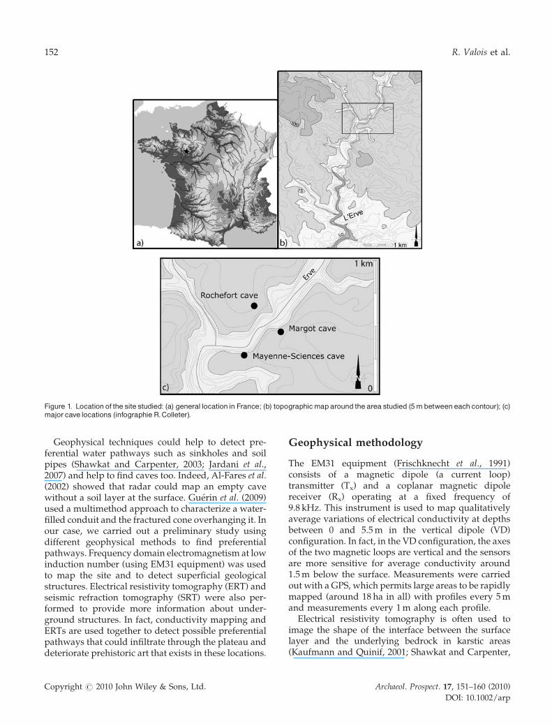
Figure 1. Location of the site studied: (a) general location in France; (b) topographicmaparound the area studied (5mbetweeneach contour); (c)major cave locations (infographie R.Colleter).
152 R. Valois et al.
Geophysical techniques could help to detect pre-ferential water pathways such as sinkholes and soilpipes (Shawkat and Carpenter, 2003; Jardani et al.,2007) and help to find caves too. Indeed, Al-Fares et al.(2002) showed that radar could map an empty cavewithout a soil layer at the surface. Guerin et al. (2009)used a multimethod approach to characterize a water-filled conduit and the fractured cone overhanging it. Inour case, we carried out a preliminary study usingdifferent geophysical methods to find preferentialpathways. Frequency domain electromagnetism at lowinduction number (using EM31 equipment) was usedto map the site and to detect superficial geologicalstructures. Electrical resistivity tomography (ERT) andseismic refraction tomography (SRT) were also per-formed to provide more information about under-ground structures. In fact, conductivity mapping andERTs are used together to detect possible preferentialpathways that could infiltrate through the plateau anddeteriorate prehistoric art that exists in these locations.
Copyright # 2010 John Wiley & Sons, Ltd.
Geophysical methodology
The EM31 equipment (Frischknecht et al., 1991)consists of a magnetic dipole (a current loop)transmitter (Tx) and a coplanar magnetic dipolereceiver (Rx) operating at a fixed frequency of9.8 kHz. This instrument is used to map qualitativelyaverage variations of electrical conductivity at depthsbetween 0 and 5.5 m in the vertical dipole (VD)configuration. In fact, in the VD configuration, the axesof the two magnetic loops are vertical and the sensorsare more sensitive for average conductivity around1.5 m below the surface. Measurements were carriedout with a GPS, which permits large areas to be rapidlymapped (around 18 ha in all) with profiles every 5 mand measurements every 1 m along each profile.
Electrical resistivity tomography is often used toimage the shape of the interface between the surfacelayer and the underlying bedrock in karstic areas(Kaufmann and Quinif, 2001; Shawkat and Carpenter,
Archaeol. Prospect. 17, 151–160 (2010)
DOI: 10.1002/arp

Geological structures around Saulges caves 153
2003). The ERT system (Dahlin, 2001) is a multi-electrode resistivity meter (Syscal Pro, Iris Instruments).It consists of an electrode array, control unit, dataacquisition and process unit, image reconstruction andanalysis unit. The sensor of the ERT system is anelectrode array, with 48 to 72 metal electrodesequidistantly located along a profile. A current isinjected between two electrodes and two other electro-des measure the electrical potential difference. An ERThelps determine horizontal and vertical electricalresistivity contrasts, and thus is able to providegeological information such as the fracturing level.Different arrays and spacing were carried out: Wenner–Schlumberger (WS) and dipole–dipole (DD) withinterelectrode distance of 2 and 3 m. Each array hasits own characteristics; a comparison can be found inDahlin and Zhou (2004). The data were processed withthe Res2dinv software (Geotomo Software) using thesmoothness-constrained least-squares method inver-sion technique to produce a two-dimensional model ofthe subsurface from the apparent electrical resistivitydata (Loke and Barker, 1996). Topography adjustmentshave been carried out during the inversion on ERTs,except for ERTs on flat areas. Nevertheless, thesensitivity of the calculated model decreases a lot froma few meters below surface. Finally, a quantitative two-dimensional model of interpreted resistivity is calcu-lated to explain a data set as best as possible and thecriterion used to evaluate the model is the root meansquare (RMS), difference between measured andcalculated apparent electrical resistivities.
Seismic methods are often used for the study ofkarstic areas (Sumanovac and Weisser, 2001;Kuniansky, 2005; Debeglia et al., 2006; Guerin et al.,2009) as they often have great penetration depth.Fractured zones and caves can be detected (by adelay in the first arrivals) although the wavelength ofthe source is too large to map exactly the shape ofthe target. The equipment used for this project was theGeometrics’ StrataVisor. The seismic line was recordedusing a hammer source along a profile. Forty-eight geophones were used with unit spacing of3 m and shots were made between each geophones.The inversion of refraction data with Rayfractsoftware (Intelligent Resources Inc.) provides a two-dimensional cross-section of P wave velocity linked tothe mechanical behaviour of materials. The depth ofinvestigation is about 25 m, similar to ERT (WS withthe same length, i.e. 142 m); but with the ray coveragecorresponding to the chosen shots scheme, theresolution at depth is higher than ERT.
Therefore, the aim of this two-dimensional surveywas to detect karstic features on the plateau, such as
Copyright # 2010 John Wiley & Sons, Ltd.
sinkholes or fractured zones, that could be connectedwith the underground network. New caves orextensions of known galleries could be expected too,but two-dimensional measurements do not allow us toconfirm the exact location of such morphologies. Anelectrical three-dimensional survey is required foraccurate detection and complete mapping of subsur-face voids (Chambers et al., 2002; Papadopoulos et al.,2006).
Results
The general apparent conductivity map of the studiedarea with respect to cave location is presented inFigure 2. Results show a large conductive area in thevalley (10–20 mS m�1) and some resistive zones (3–10 mS m�1) with conductive anomalies on the plateaus(10–20 mS m�1). The small anomalies (numbered 1, 2and 3) seem circular or subcircular (number 2 is closeto a wire fence). Anomaly number 1 was investigatedfurther with ERT. Large conductive anomalies (A, Band C) are located at higher altitudes. It is possible thatanomalies B and C are linked but crops within farmedfields do not allow us to prospect the area between Band C. Three ERTs were performed around anomaliesA and C.
The area around anomaly C, located on the southernplateau, was studied with more attention (Figure 3).The aerial photography reveals several zones of lightcolour and two of them correspond to pronouncedconductive zones whereas the others seem to corre-spond to weak conductive zones. It is possible thatthe differences of quality or quantity of the soilproduce vegetation differences in these highlightedzones. Section IJ reveals a conductive surface layer(<1000 V.m) over a resistive medium (>1000 V.m).This layer is very thin at the southwest of the profileand reaches its maximum (12 m) at the middle ofthe profile. Further north, the interface between theresistive and conductive medium is not regular andvaries between 3 and 8 m towards the northeast of thesection. Some very conductive structures were alsodetected (<100 V.m): the most impressive appears atthe middle of the section and some small structures arelocated to the northeast.
Subsequently the focus turned on the oppositeplateau around another large anomaly (A) and twoERTs were carried out (Figure 4). On the map,conductivity increases with altitude towards thenorthwest, except for the zone at the middle of sectionEF. This section shows that the very conductive surfacelayer (<100 V.m) stops abruptly around the abscissa55 m. The conductive layer (100 to 1500 V.m) is
Archaeol. Prospect. 17, 151–160 (2010)
DOI: 10.1002/arp

Figure 2. Apparent conductivitymap ofall areas studied.
154 R. Valois et al.
subhorizontal at the northeast of the section and seemsto dive into the resistive medium (>1500 V.m) aroundthe abscissa 50 m. The data along section GH werecollected to investigate further this probable conduc-
Copyright # 2010 John Wiley & Sons, Ltd.
tive structure and this electrical model reveals twoconductive structures (1000 to 1500 V.m): a vertical oneat the middle of the section and a possible smaller oneat the beginning of the line.
Archaeol. Prospect. 17, 151–160 (2010)
DOI: 10.1002/arp

Figure 3. (Upper left) Aerial photograph, (upper-right) apparent conductivity map and (bottom) ERT near zone C. The section is a Wenner^Schlumbergerarray (48 electrodeswith interelectrode distance of 3m), andwasobtainedby inversionwith an RMS errorof 3.6%.
Geological structures around Saulges caves 155
After the investigation of two large anomalies, asmall one is presented in Figure 5 with the apparentconductivity map in perspective and an ERT nearanomalies numbered 1 and 2. The first anomaly iscircular and the second one has produced an elongatedshape on the map. The ERT provides a cross-section(EF) of the first anomaly and detects a thin conductivesurface layer (<1000 V.m) which increases from 4 to8 m in thickness around the anomaly. The conductivestructure in the southwest (between x coordinates 18and 50 m and between z coordinates 8 and 18 m) couldbe a three-dimensional effect of anomaly number 2.The vertical conductive structure at the centre of thesection has to be interpreted with caution, because itcould be an artefact of the inversion.
Copyright # 2010 John Wiley & Sons, Ltd.
The last survey area is in the valley (Figure 6), a fewmeters below Mayenne-Sciences cave. In fact, theEM31 detected a weak conductive anomaly in front ofthe cave, and therefore SRT and ERT were performedalong profiles subparallel to the river. Both electricaland seismic models indicate pronounced anomalies(Figure 7). Indeed, there is a strong horizontalresistivity contrast between a high resistive medium(1000 to 10000 V.m) and a very conductive one (30 to300 V.m) in the middle of section CD. Moreover, thelocalization of this deep conductive structure corre-sponds with the velocity anomaly (<4000 m s�1) at theabscissa 40 m in section AB. However, the deepconductive structure in the eastern part of the ERTdoes not correspond to the velocity anomaly between
Archaeol. Prospect. 17, 151–160 (2010)
DOI: 10.1002/arp

Figure 4. ApparentconductivitymapinperspectivewithtwoERTsnearzoneA.SectionsEFandGHareWenner^Schlumbergerarrays(48electrodeswith interelectrode distance of 2 and 3mrespectively), andwere obtained by inversionwith an RMSerrorof 5.4 and 3.4% respectively.
156 R. Valois et al.
abscissas 80 and 100 m; it could be an effect of thedifferent orientations of the profiles or because the twoprofiles have been done in an area that does not respectthe two-dimensional assumptions, e.g. presence of thecliffs to the south and of the river to the north of thesection.
Discussion
Geological observations around Saulges show severalkinds of materials: clay soil, healthy limestone from theCarboniferous and fractured or karstic limestone,
Copyright # 2010 John Wiley & Sons, Ltd.
whose voids could contain air, water or clay sedi-ments. Water or clay sediments are characterized bytheir low electrical resistivity, while high resistivitiesare clues for limestone identification. Indeed, electricalproperties provide a good contrast between soil andlimestone, and the sensitivity of ERT is very good in aconductive medium at the surface. Therefore, theconductive surface layer in ERTs could be interpretedwith confidence as the clay soil layer.
Results show that measured apparent conductivitiescollected using the EM31 increase when ERTs alsodetect a significant soil thickness. Therefore, ERTs andconductivity mapping are in good correlation, and
Archaeol. Prospect. 17, 151–160 (2010)
DOI: 10.1002/arp
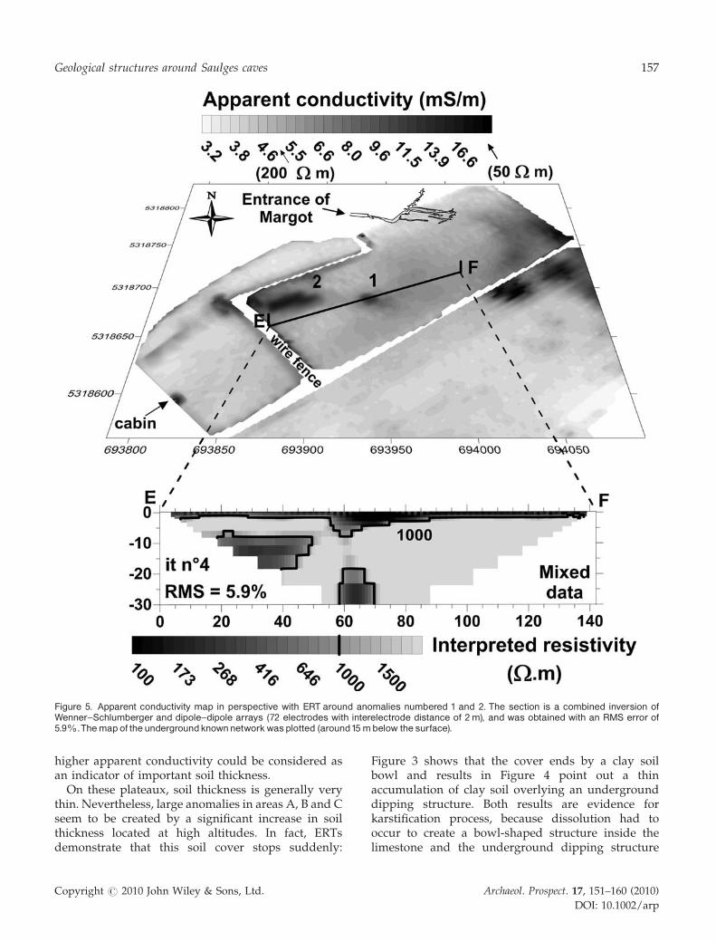
Figure 5. Apparent conductivity map in perspective with ERT around anomalies numbered 1 and 2. The section is a combined inversion ofWenner^Schlumberger and dipole^dipole arrays (72 electrodes with interelectrode distance of 2m), and was obtained with an RMS error of5.9%.Themapof the undergroundknownnetworkwasplotted (around15mbelow the surface).
Geological structures around Saulges caves 157
higher apparent conductivity could be considered asan indicator of important soil thickness.
On these plateaux, soil thickness is generally verythin. Nevertheless, large anomalies in areas A, B and Cseem to be created by a significant increase in soilthickness located at high altitudes. In fact, ERTsdemonstrate that this soil cover stops suddenly:
Copyright # 2010 John Wiley & Sons, Ltd.
Figure 3 shows that the cover ends by a clay soilbowl and results in Figure 4 point out a thinaccumulation of clay soil overlying an undergrounddipping structure. Both results are evidence forkarstification process, because dissolution had tooccur to create a bowl-shaped structure inside thelimestone and the underground dipping structure
Archaeol. Prospect. 17, 151–160 (2010)
DOI: 10.1002/arp
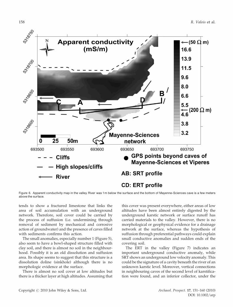
Figure 6. Apparent conductivity map in the valley. River was 1m below the surface and the bottom of Mayenne-Sciences cave is a few metersabove the surface.
158 R. Valois et al.
tends to show a fractured limestone that links thearea of soil accumulation with an undergroundnetwork. Therefore, soil cover could be carried bythe process of suffusion (i.e. undermining throughremoval of sediment by mechanical and corrosiveaction of groundwater) and the presence of caves filledwith sediments confirms this action.
The small anomalies, especially number 1 (Figure 5),also seem to have a bowl-shaped structure filled withclay soil, and there is almost no soil in the neighbour-hood. Possibly it is an old dissolution and suffusionarea. Its shape seems to suggest that this structure is adissolution doline (sinkhole) although there is nomorphologic evidence at the surface.
There is almost no soil cover at low altitudes butthere is a thicker layer at high altitudes. Assuming that
Copyright # 2010 John Wiley & Sons, Ltd.
this cover was present everywhere, either areas of lowaltitudes have been almost entirely digested by theunderground karstic network or surface runoff hascarried materials to the valley. However, there is nomorphological or geophysical evidence for a drainagenetwork at the surface, whereas the hypothesis ofsuffusion through preferential pathways could explainsmall conductive anomalies and sudden ends of thecovering soil.
The ERT in the valley (Figure 7) indicates animportant underground conductive anomaly, whileSRT shows an underground low velocity anomaly. Thiscould be the signature of a cavity beneath the river of anunknown karstic level. Moreover, vertical connectionsin neighbouring caves of the second level of karstifica-tion were found, and an inferior collector, under the
Archaeol. Prospect. 17, 151–160 (2010)
DOI: 10.1002/arp

Figure 7. The ERTand SRT in the front of Mayenne-Sciences cave (72 electrodes with interelectrode distance of 2m and 48 geophones withintergeophonedistanceof 3m).TheelectricalmodelisacombinedinversionofWenner^Schlumbergeranddipole^dipolearrays, andwasobtainedwith an RMS errorof 7%.The seismicvelocitymodelwasobtainedby inversionwith a RMS errorof 0.5 ms.
Geological structures around Saulges caves 159
river level, was predicted by the karst study (Rodetet al., 2001). This pseudocavity may contain water orclay, because this anomaly has a low resistivity andpoor mechanical properties. Moreover, results suggestthat the medium surrounding this anomaly is fracturedand filled with conductive materials.
The absence of visible drainage networks directedtowards dissolution zones on the plateaus suggeststhese zones are fossil morphologies or slightly active.In the valley, karstification might be more importantbecause of the proximity to the aquifer and to thedrainage network.
Conclusion
Apparent conductivity mapping and ERTs show thatthe soil cover thickness increases with altitude on theplateaus. This cover ends abruptly in a bowl form on
Copyright # 2010 John Wiley & Sons, Ltd.
the southern plateau, while the northern cover seemsto stop over a fractured area in the limestone.Moreover, in areas with no soil cover, there is at leastone bowl of clay soil, which resembles the geophysicalsignature of a doline (sinkhole). These karstic dissol-ution zones could be found only with geophysicsbecause there is no discernible morphological shape atthe surface. These results are evidence for karstifica-tion process on the plateaus, but no karsticmorphologies were detected over known prehistoriccaves. The ERT and SRT in the valley indicate animportant anomaly, which is interpreted as an under-ground karstic cave filled with clay or water.
Some karstic structures have been detected but moregeophysical investigations (for example three-dimen-sional survey), excavations and sedimentologicalstudies are needed to confirm these results and allowa better understanding of the karstic system aroundSaulges caves. Connections between superficial struc-
Archaeol. Prospect. 17, 151–160 (2010)
DOI: 10.1002/arp
160 R. Valois et al.
tures and cavities have to be studied with moreattention to protect prehistoric art from percolationwater.
Acknowledgements
The authors wish to thank Jean-Pierre Betton, LucieGarnier and Carole Ridel who participated in the fieldsurvey. This study is a part of the program: ‘Occu-pations paleolithiques de la vallee de l’Erve’ from theUMR 6566 of CNRS ‘CReAAH’, coordinated by Jean-Laurent Monnier.
References
Al-Fares W, Bakalowicz M, Guerin R, Dukhan M. 2002.Analysis of the karst aquifer structure of the Lamalouarea (Herault, France) with ground penetrating radar.Journal of Applied Geophysics 51: 97–106.
Chambers JE, Ogilvy RD, Kuras O, Cripps JC, MeldrumPI. 2002. 3D electrical imaging of known targets at acontrolled environmental test site. EnvironmentalGeology 41: 690–704.
Dahlin T. 2001. The development of electrical imagingtechniques. Computers and Geosciences 27: 1019–1029.
Dahlin T, Zhou B. 2004. A numerical comparison of 2Dresistivity imaging with 10 electrode arrays. GeophysicalProspecting 52: 379–398.
Debeglia N, Bitri A, Thierry P. 2006. Karst investigationsusing microgravity and MASW; application to Orleans,France. Near Surface Geophysics 4: 215–225.
Frischknecht FC, Labson VF, Spies BR, Anderson WL.1991. Profiling methods using small sources. In Electro-magnetic methods in applied geophysics 2: Applications,Nabighian MN editor. Society of Exploration Geophy-sicists: Tulsa, Oklahoma; 105–270.
Guerin R, Baltassat JM, Boucher M, Chalikakis K, GalibertPY, Girard JF, Plagnes V, Valois R. 2009. Geophysicalcharacterisation of karstic networks – Application to theOuysse system (Poumeyssen, France). Comptes RendusGeoscience 341(10–11): 810–817.
Hinguant S, Moulle PE, Arellano A. 2005. Premiersindices de la presence d’une faune du Pleistocenemoyen dans la vallee de l’Erve (Mayenne, France).Bulletin du Musee d’Anthropologie prehistorique de Monaco45: 25–30.
Hinguant S, Biard M, Moulle PE, Pigeaud R. In press. Lavallee de l’Erve (Mayene): presence solutreenne aunord de la Loire. In SERAP Vallee de la Claise
Copyright # 2010 John Wiley & Sons, Ltd.
coord. Actes du colloque Le Solutreen 40 ans apresSmith’66, Almeida M, Aubry T, Wakter B (eds).Preuilly-sur-Loire, 28 octobre–31 novembre 2007.
Jardani A, Revil A, Santos F, Fauchard C, Dupont JP. 2007.Detection of preferential infiltration pathways in sink-holes using joint inversion of self-potential and EM-34conductivity data. Geophysical Prospecting 55: 749–760.
Kaufmann O, Quinif Y. 2001. An application of conepenetration tests and combined array 2D electricalresistivity tomography to delineate cover-collapse sink-hole prone areas. In Geotechnical and EnvironmentalApplications of Karst Geology and Hydrology. Beck BF,Herring JG (eds). Balkema: Lisse; 359–364.
Kuniansky EL. 2005. US Geological Survey Karst InterestGroup, Proceedings. USGS Scientific InvestigationsReport, 2005-5160, 296 pp.
Loke MH, Barker RD. 1996. Rapid least-square inversionof apparent resistivity pseudo-sections by a quasi-newton method. Geophysical Prospecting 44: 131–152.
Papadopoulos NG, Tsourlos P, Tsoskas GN, Sarris A.2006. Two-dimensional and three-dimensional resis-tivity imaging in archaeological site investigation.Archaeological Prospection 13: 163–181.
Pigeaud R. (avec la collaboration de M. Bouchard etd’E. Laval). 2004. La grotte ornee Mayenne-Sciences(Thorigne-en-Charnie, Mayenne) : un exemple d’artparietal d’epoque gravettienne en France septentrio-nale. Gallia Prehistoire 46: 1–154.
Pigeaud R, Rodet J, Deviese T, Dufayet C, Trelohan-Chauve E, Betton JP, Bonic P. 2006. Palaeolithic caveart in West France: an exceptional discovery: theMargot Cave (Mayenne). Antiquity 80: (309). [http://antiquity.ac.uk/ProjGall/pigeaud/index.html]
Pigeaud R, Hinguant S, Rodet J, Betton JP, Bonic P. 2010.Something new in the West: the cave habitat of Roche-fort and the decorated cave of Margot (Mayenne).International Newsletter on Rock Art 56: 1–12.
Rodet J, Renault G, Bonic P. 2001. Contexte karstologiquede la grotte « Mayenne-Sciences » (Thorigne enCharnie, Mayenne) - etat au 30 novembre 2001. InLes occupations paleolithiques de la vallee de l’Erve, PigeaudR. (director), Programme UMR 6566, UMR 6569et MNHN, ‘Etude des representations de la grotteMayenne-Sciences Thorigne en Charnie, Mayenne’;44-50.
Shawkat A, Carpenter P. 2003. Geophysical response offilled sinkholes, soil pipes and associated bedrock frac-tures in thinly mantled karst, east-central Illinois.Environmental Geology 44: 705–716.
Sumanovac F, Weisser M. 2001. Evaluation of resistivityand seismic methods for hydrogeological mapping inkarst terrains. Journal of Applied Geophysics 47: 13–28.
Archaeol. Prospect. 17, 151–160 (2010)
DOI: 10.1002/arp