
The herbicide safener cloquintocet-mexyl reduces rye-grass ...
Upload
khangminh22Category
view
0download
0
KAM-XM-SERIESKAM-XM-UDC/UPC/UNC/DNC MODULES
Instruction Manual
SOFTWARE VERSION 1.4.4
071833003DECEMBER 2005

2 KAM-XM-SERIES Instruction Manual
Contacting Grass Valley
Copyright © Grass Valley. All rights reserved.
Grass Valley Web Site The www.thomsongrassvalley.com web site offers the following:
Online User Documentation — Current versions of product catalogs, brochures, data sheets, ordering guides, planning guides, manuals, and release notes in .pdf format can be downloaded.
FAQ Database — Solutions to problems and troubleshooting efforts can be found by searching our Frequently Asked Questions (FAQ) database.
Software Downloads — Software updates, drivers, and patches can be down-loaded.
Region Voice Fax Address Web Site
North America (800) 547-8949Support: 530-478-4148
Sales: (530) 478-3347Support: (530) 478-3181
Grass ValleyP.O. Box 599000Nevada City, CA 95959-7900 USA
www.thomsongrassvalley.com
Pacific Operations +852-2585-6688Support: 852-2585-6579
+852-2802-2996
U.K., Asia, Middle East +44 1753 218 777 +44 1753 218 757
France +33 1 45 29 73 00
Germany, Europe +49 6150 104 782 +49 6150 104 223

Preface
About This ManualThis manual describes the features of a specific KAM-XM module in the Kameleon Media Processing System. As part of this module family, it is subject to Safety and Regulatory Compliance described in the 2000 Series frame and power supply documentation (see the Kameleon 2000 Series Frames Instruction Manual).
KAM-XM-SERIES Instruction Manual 3

Preface
4 KAM-XM-SERIES Instruction Manual
ContentsPreface. . . . . . . . . . . . . . . . . . . . . . . . . . . . . . . . . . . . . . . . . . . . . . . . . . . . . . . . . . . . . . . . . . . . . 3
About This Manual . . . . . . . . . . . . . . . . . . . . . . . . . . . . . . . . . . . . . . . . . . . . . . . . . . . . . 3
KAM-XM SeriesUp/Down Conversion Modules . . . . . . . . . . . . . . . . . . . . . . . . . . . . . . . . . . . . . . . . . . . 7
Introduction . . . . . . . . . . . . . . . . . . . . . . . . . . . . . . . . . . . . . . . . . . . . . . . . . . . . . . . . . . . 7Module Descriptions . . . . . . . . . . . . . . . . . . . . . . . . . . . . . . . . . . . . . . . . . . . . . . . . . . . 8
Supported Up/Down Conversion Rates . . . . . . . . . . . . . . . . . . . . . . . . . . . . . . . . . 9System Requirements . . . . . . . . . . . . . . . . . . . . . . . . . . . . . . . . . . . . . . . . . . . . . . . . . . 10Quick Start Guide . . . . . . . . . . . . . . . . . . . . . . . . . . . . . . . . . . . . . . . . . . . . . . . . . . . . . 11Installation . . . . . . . . . . . . . . . . . . . . . . . . . . . . . . . . . . . . . . . . . . . . . . . . . . . . . . . . . . . 12
Module Placement in the 2000 Frame. . . . . . . . . . . . . . . . . . . . . . . . . . . . . . . . . . . 12Cabling . . . . . . . . . . . . . . . . . . . . . . . . . . . . . . . . . . . . . . . . . . . . . . . . . . . . . . . . . . . . 16
KAM-XM-R Rear Module Connections . . . . . . . . . . . . . . . . . . . . . . . . . . . . . . . 16GPI0 Connections for GPI Control . . . . . . . . . . . . . . . . . . . . . . . . . . . . . . . . . . . 18
Power Up and Module Status . . . . . . . . . . . . . . . . . . . . . . . . . . . . . . . . . . . . . . . . . . . 19Configuration and Adjustments . . . . . . . . . . . . . . . . . . . . . . . . . . . . . . . . . . . . . . . . . 21
Configuration Summary. . . . . . . . . . . . . . . . . . . . . . . . . . . . . . . . . . . . . . . . . . . . . . 21Up and Down Conversion . . . . . . . . . . . . . . . . . . . . . . . . . . . . . . . . . . . . . . . . . . 21Format Conversion . . . . . . . . . . . . . . . . . . . . . . . . . . . . . . . . . . . . . . . . . . . . . . . . 22Aspect Ratio Modes. . . . . . . . . . . . . . . . . . . . . . . . . . . . . . . . . . . . . . . . . . . . . . . . 23Proc Amp Controls . . . . . . . . . . . . . . . . . . . . . . . . . . . . . . . . . . . . . . . . . . . . . . . . 25Detail Enhance Controls . . . . . . . . . . . . . . . . . . . . . . . . . . . . . . . . . . . . . . . . . . . . 25
Noise Reduction. . . . . . . . . . . . . . . . . . . . . . . . . . . . . . . . . . . . . . . . . . . . . . . . . . . . . 26Spike Filtering. . . . . . . . . . . . . . . . . . . . . . . . . . . . . . . . . . . . . . . . . . . . . . . . . . . . . 26Brickwall Filtering . . . . . . . . . . . . . . . . . . . . . . . . . . . . . . . . . . . . . . . . . . . . . . . . . 26Temporal Recursive Filtering. . . . . . . . . . . . . . . . . . . . . . . . . . . . . . . . . . . . . . . . 27
Color Legalizer. . . . . . . . . . . . . . . . . . . . . . . . . . . . . . . . . . . . . . . . . . . . . . . . . . . . . . 29GPI and E-MEM Controls . . . . . . . . . . . . . . . . . . . . . . . . . . . . . . . . . . . . . . . . . . . . 29Configuration Summary Table . . . . . . . . . . . . . . . . . . . . . . . . . . . . . . . . . . . . . . . . 30Newton Control Panel Configuration . . . . . . . . . . . . . . . . . . . . . . . . . . . . . . . . . . 33Web Browser Interface . . . . . . . . . . . . . . . . . . . . . . . . . . . . . . . . . . . . . . . . . . . . . . . 34Web Page Operations and Functional Elements. . . . . . . . . . . . . . . . . . . . . . . . . . 36Links and Web Pages . . . . . . . . . . . . . . . . . . . . . . . . . . . . . . . . . . . . . . . . . . . . . . . . 38
Status Web Page . . . . . . . . . . . . . . . . . . . . . . . . . . . . . . . . . . . . . . . . . . . . . . . . . . . 39License Web Page. . . . . . . . . . . . . . . . . . . . . . . . . . . . . . . . . . . . . . . . . . . . . . . . . . 41Setup Web Page . . . . . . . . . . . . . . . . . . . . . . . . . . . . . . . . . . . . . . . . . . . . . . . . . . . 42Format Web Page . . . . . . . . . . . . . . . . . . . . . . . . . . . . . . . . . . . . . . . . . . . . . . . . . . 44Aspect Web Page . . . . . . . . . . . . . . . . . . . . . . . . . . . . . . . . . . . . . . . . . . . . . . . . . . 46Proc Amp Web Page . . . . . . . . . . . . . . . . . . . . . . . . . . . . . . . . . . . . . . . . . . . . . . . 48Detail Enhance Web Page . . . . . . . . . . . . . . . . . . . . . . . . . . . . . . . . . . . . . . . . . . . 49Spike Web Page . . . . . . . . . . . . . . . . . . . . . . . . . . . . . . . . . . . . . . . . . . . . . . . . . . . 50Brickwall Web Page. . . . . . . . . . . . . . . . . . . . . . . . . . . . . . . . . . . . . . . . . . . . . . . . 51Temporal Recursive Web Page . . . . . . . . . . . . . . . . . . . . . . . . . . . . . . . . . . . . . . 52
KAM-XM-SERIES Instruction Manual 5

Contents
Mosquito Web Page . . . . . . . . . . . . . . . . . . . . . . . . . . . . . . . . . . . . . . . . . . . . . . . 55Advanced Aperture Web Page . . . . . . . . . . . . . . . . . . . . . . . . . . . . . . . . . . . . . . 55Color Legalizer Web Page . . . . . . . . . . . . . . . . . . . . . . . . . . . . . . . . . . . . . . . . . . 56Grain Insertion Web Page . . . . . . . . . . . . . . . . . . . . . . . . . . . . . . . . . . . . . . . . . . 57GPI Web Page . . . . . . . . . . . . . . . . . . . . . . . . . . . . . . . . . . . . . . . . . . . . . . . . . . . . 58E-MEM Web Page . . . . . . . . . . . . . . . . . . . . . . . . . . . . . . . . . . . . . . . . . . . . . . . . . 59Slot Config Web Page . . . . . . . . . . . . . . . . . . . . . . . . . . . . . . . . . . . . . . . . . . . . . . 65
Software Updating . . . . . . . . . . . . . . . . . . . . . . . . . . . . . . . . . . . . . . . . . . . . . . . . . . 68Acquiring NetConfig Software . . . . . . . . . . . . . . . . . . . . . . . . . . . . . . . . . . . . . . 68Acquiring the Latest KAM-XM Software . . . . . . . . . . . . . . . . . . . . . . . . . . . . . 68Software Updating With NetConfig. . . . . . . . . . . . . . . . . . . . . . . . . . . . . . . . . . 69
Specifications. . . . . . . . . . . . . . . . . . . . . . . . . . . . . . . . . . . . . . . . . . . . . . . . . . . . . . . . . 73Service . . . . . . . . . . . . . . . . . . . . . . . . . . . . . . . . . . . . . . . . . . . . . . . . . . . . . . . . . . . . . . 75
Power-up Diagnostics Failure. . . . . . . . . . . . . . . . . . . . . . . . . . . . . . . . . . . . . . . . . 75Troubleshooting . . . . . . . . . . . . . . . . . . . . . . . . . . . . . . . . . . . . . . . . . . . . . . . . . . . . 75Module Repair. . . . . . . . . . . . . . . . . . . . . . . . . . . . . . . . . . . . . . . . . . . . . . . . . . . . . . 75
Index . . . . . . . . . . . . . . . . . . . . . . . . . . . . . . . . . . . . . . . . . . . . . . . . . . . . . . . . . . . . . . . . . . . . . . 77
6 KAM-XM-SERIES Instruction Manual

KAM-XM SeriesUp/Down Conversion Modules
IntroductionThis manual covers installation, configuration and operation of the fol-lowing Kameleon KAM-XM Series modules:
• KAM-XM-UDC – HDTV Up/Down Converter
• KAM-XM-UPC – HDTV High Quality Up Converter
• KAM-XM-UNC – HDTV Up Converter with Advanced SDTV Noise Reduction
• KAM-XM-DNC – HDTV Down Converter
Module functionality is summarized in Table 1.
Table 1. KAM-XM Up and Down Converter Module Summary
Function KM-XM-UDC KM-XM-UPC KM-XM-UNC KM-XM-DNC
Aspect Ratio Control X X X X
Proc Amp Adjustments (for video processing) X X X X
Color Space Conversion X X X X
Detail Enhancement X X X X
Spike Filter (Adaptive Median filtering) X
Brickwall Filter X
Temporal Recursive Filter (Auto or Manual mode) X
GPI Control (3 external GPI inputs controlling E-MEMs) X X X X
Color Legalizer Control X X X X
First 2 audio groups of HD video are re-embedded into SDI stream X X
First 2 audio groups of SDTV video re-embedded into HD output stream with compensating delay. X X X
Re-insertion of Closed Caption data into HD output stream X X X
2- or 4-frame processing delay X X X X
KAM-XM-SERIES Instruction Manual 7
Module Descriptions
The KAM-XM Up/Down conversion series modules also feature:
• Proprietary Teranex™ PixelMotion™ De-interlacing,
• Support of SD and HD video with embedded audio, including Dolby-E,
• Hot-swap capability,
• Operates in the same frame with other 2000 and Kameleon modules,
• Three external GPI inputs to trigger selectable Preset 1-10 registers,
• Network control with the Newton Control Panel or Kameleon web con-trol, and
• Support of NetConfig™ configuration tool and NetCentral™ SNMP-based monitoring system.
Module DescriptionsEach KAM-XM module uses the same circuit board with the application software enabled for the particular module type. The module type is iden-tified by a sticker on the circuit board and the Model name is identified in the web page header. For up/down conversion rates supported, refer to Table 2 on page 9.
The modules described in this manual include the following:
• KAM-XM-UDC – supports broadcast quality up and down conversion of SD and HD video with embedded audio with the standard conver-sion controls. This application utilizes de-interlacing on a pixel-by-pixel basis for preserving fine detail from the original image. Down conversion offers an anti-aliasing filter.
• KAM-XM-UNC – supports broadcast quality HD up conversion for SDI video with or without embedded audio with the standard conver-sion controls. In addition, this module also offers advanced noise reduction with adaptive median spike, brickwall, and temporal recur-sive filter controls. This application utilizes de-interlacing on a pixel-by-pixel basis for preserving fine detail from the original image.
• KAM-XM-UPC – supports broadcast quality HD up conversion for SDI video with or without embedded audio with the standard conversion controls. This application utilizes de-interlacing on a pixel-by-pixel basis for preserving fine detail from the original image.
• KAM-XM-DNC – this broadcast quality down converter application also utilizes de-interlacing on a pixel-by-pixel basis. Once the image has been de-interlaced and down converted, detail enhancement can be applied to the image to further shape the output. The first two groups of audio from the HD video are re-embedded into the standard defini-tion SDI video signal.
8 KAM-XM-SERIES Instruction Manual

Module Descriptions
Supported Up/Down Conversion RatesThe modules support the conversion rates summarized in Table 2.
Table 2. Format Conversion Input/Output Combinations
KAM-XM-
Input Format Output Format UNC UPC DNC UDC
480i59.94 480i59.94 X X X
480i59.94 720p59.94 X X X
480i59.94 1080i59.94 X X X
576i50 576i50 X X X
576i50 720p50 X X X
576i50 1080i50 X X X
720p50 576i50 X X
720p59.94 480i59.94 X X
1080i50 576i50 X X
1080i59.94 480i59.94 X X
KAM-XM-SERIES Instruction Manual 9
System Requirements
System RequirementsOperation of the KAM-XM modules in 2000 Series frames has the following hardware and software requirements:
• Modules must be installed in a 2000T1DNG or 2000T3DNG Kameleon 2000 Series frame containing a a 2000GEN module.
• The frame must have a 2000NET module with assembly number 671-5231-01 or later running software version 3.2.2 or later.
Note These requirements are necessary for proper cooling support and interface to the Newton Control Panel configuration, NetConfig and GUI control, and SNMP monitoring.
Existing Kameleon frames can be upgraded with the necessary modules and software for proper operation. Contact your sales repre-sentative for more information.
All KAM-XM module sets require two vertical module slots of frame space. Frame density for the 1 RU frame is two module sets and six module sets for a fully stuffed 3 RU frame. Both dual and single height Kameleon and 2000 modules can be mixed in the frames.
10 KAM-XM-SERIES Instruction Manual
Quick Start Guide
Quick Start GuideThis Quick Start Guide is provided for an overview of installing the KAM-XM modules. Each step gives you a link to a more detailed descrip-tion of each process.
1. Install the KAM-XM modules in the 2000 Kameleon frame. Install the XM-IO-1 Rear module first, then install the front module in the corresponding front slot (Module Placement in the 2000 Frame on page 12).
2. Connect the 2000 frame to the network and navigate the web browser to the frame. This process is described in detail in the 2000NET Instruction Manual available on-line.
3. Navigate to the module you would like to configure and click on the appropriate slot to access the module links (Links and Web Pages on page 38).
4. Click on the Slot Config link on the left side of the page (Slot Config Web Page on page 65). This page allows you to assign a name to this module. Assigning easily recognizable names will help later in the configuration process.
5. Cable the rear module signal connections (Cabling on page 16).
6. Configure the input and output formats on the Format web page (Format Web Page on page 44).
7. Configure the Reference source on the Setup web page (Setup Web Page on page 42). Select the type of reference from either the input signal or an external reference (2000GEN module installed in the 2000 frame).
8. Continue with module configuration depending on the module type.
KAM-XM-SERIES Instruction Manual 11
Installation
InstallationInstallation of a KAM-XM module set is a process of:
• Placing the KAM-XM rear module in a frame slot,
• Placing the front media module in the corresponding front slot, and
• Cabling signal ports.
Module Placement in the 2000 FrameThere are twelve slot locations in both the front and rear of a Kameleon 3 RU frame to accommodate KAM-XM modules. A KAM-XM module set consists of a front media module and a dual height rear module that requires two module slots.
Each KAM-XM front media module plugs into the front of the 2000 frame mid-plane. The rear module plugs into the corresponding rear slot to provide the input and output interface connectors.
A 3 RU 2000T3 frame fully stuffed with KAM-XM front and rear modules will accommodate up to six module sets. A 1 RU 2000T1 frame will accom-modate up to 2 module sets.
The KAM-XM front and rear module can be plugged in and removed from a Kameleon 2000 Series frame with power on. When power is applied to the module, LED indicators reflect the initialization process (see Power Up and Module Status on page 19).
To install a KAM-XM module set in a frame:
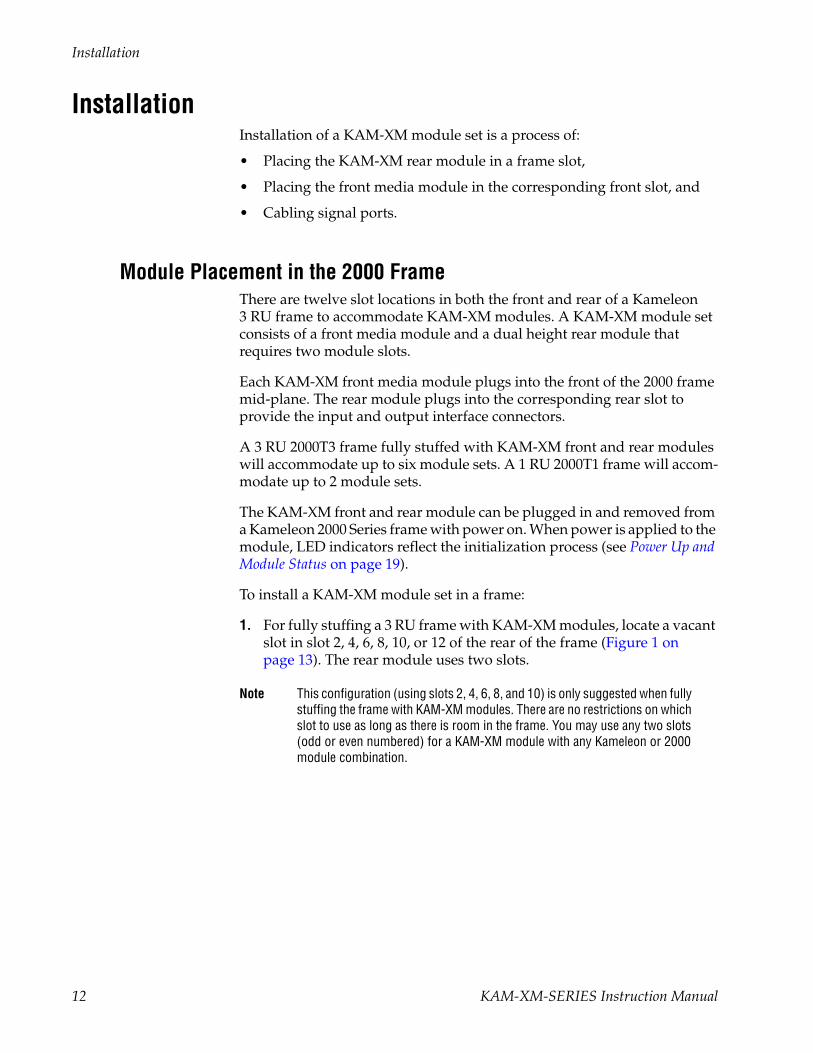
1. For fully stuffing a 3 RU frame with KAM-XM modules, locate a vacant slot in slot 2, 4, 6, 8, 10, or 12 of the rear of the frame (Figure 1 on page 13). The rear module uses two slots.
Note This configuration (using slots 2, 4, 6, 8, and 10) is only suggested when fully stuffing the frame with KAM-XM modules. There are no restrictions on which slot to use as long as there is room in the frame. You may use any two slots (odd or even numbered) for a KAM-XM module with any Kameleon or 2000 module combination.
12 KAM-XM-SERIES Instruction Manual
Installation
Figure 1. 2000T3NG Frame, Rear View
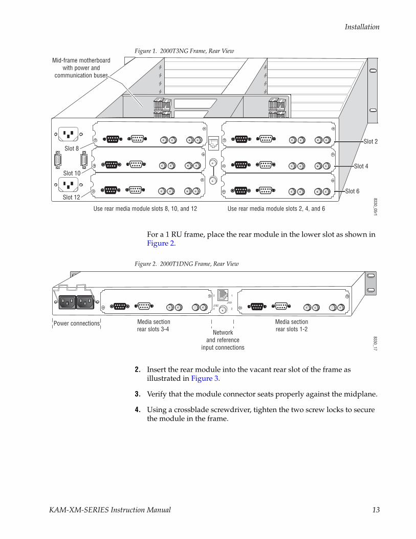
For a 1 RU frame, place the rear module in the lower slot as shown in Figure 2.
Figure 2. 2000T1DNG Frame, Rear View
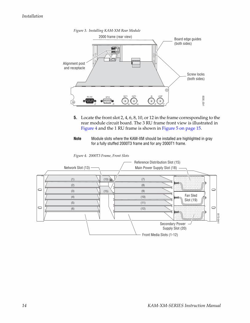
2. Insert the rear module into the vacant rear slot of the frame as illustrated in Figure 3.
3. Verify that the module connector seats properly against the midplane.
4. Using a crossblade screwdriver, tighten the two screw locks to secure the module in the frame.
Mid-frame motherboardwith power and
communication buses
Use rear media module slots 2, 4, and 6Use rear media module slots 8, 10, and 12
8330_05r1
Slot 6
Slot 4
Slot 2Slot 8
Slot 10
Slot 12
8330_17
Media sectionrear slots 1-2
J101
1
2
3
4J102
Media sectionrear slots 3-4 Network
and referenceinput connections
Power connections
KAM-XM-SERIES Instruction Manual 13
Installation
Figure 3. Installing KAM-XM Rear Module
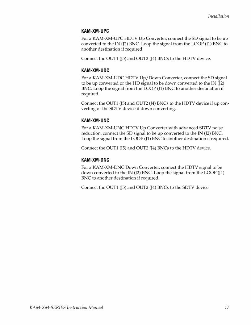
5. Locate the front slot 2, 4, 6, 8, 10, or 12 in the frame corresponding to the rear module circuit board. The 3 RU frame front view is illustrated in Figure 4 and the 1 RU frame is shown in Figure 5 on page 15.
Note Module slots where the KAM-XM should be installed are highlighted in gray for a fully stuffed 2000T3 frame and for any 2000T1 frame.
Figure 4. 2000T3 Frame, Front Slots
Alignment postand receptacle
Screw locks(both sides)
8330_03r1
2000 frame (rear view)Board edge guides(both sides)
J1
LOOPINOUT2OUT1RS-232 GP10
J2J4J5J5J7
(2)
(3)
(4)
(5)
(6)
(7)
(8)
(9)
(10)
(11)
(12)
(15)
(13)(1)
8173-04r1
Network Slot (13) Reference Distribution Slot (15)Main Power Supply Slot (18)
Secondary Power Supply Slot (20)
Front Media Slots (1-12)
Fan SledSlot (19)
14 KAM-XM-SERIES Instruction Manual

Installation
Figure 5. 2000T1 Frame, Front Slots
6. With the component side up, insert the front media module in the corresponding front slot (see Figure 6).
7. Verify that the module connector seats properly against the midplane and rear module connector.
8. Press firmly on both ejector tabs to seat the module.
Figure 6. Installing Front Media Module
(2)
(3)
(4)
(5)
(6)
(1)
8039-21
Network Slot (5) Power Supply Slot (7)
Front Media Slots (1-4)
Reference Distribution Slot (6)
KAM-XM
Alignment post and receptacle
8330-10
2000 Frame (front view)
Board edge guides
Board edge guides
KAM-XM-SERIES Instruction Manual 15

Installation
CablingAll cabling to the KAM-XM module set is done on the corresponding Dual Height KAM-XM-R rear module (XM-IO-1) at the back of the 2000 frame.
KAM-XM-R Rear Module ConnectionsRefer to Figure 7 for an illustration of the KAM-XM rear module.
The KAM-XM rear module provides the following input and output and control connections.
• IN (BNC)– a serial digital input that may be either standard definition (SD) or high definition (HD) video depending on the front module type.
• LOOP (BNC)– provides an output for the input signal to be looped to another destination.
• OUT1 (BNC)– this serial digital output connection can be either SD or HD depending on the front module type and the output format selected.
• OUT2 (BNC)– this serial digital output connection can be either SD or HD depending on the front module type and the output format selected.
• RS-232 Port (DB-9, Male) – this serial port allows a direct interface to the module for testing and configuration purposes. This port is not nor-mally used.
• GPI0 Port (DB-9, Female) – this port allows connection of external GPI (General Purpose Interface) signals to the module as described in GPI0 Connections for GPI Control on page 18.
Figure 7. KAM-XM Rear Module Input/Output Connectors
J1
LOOPINOUT2OUT1RS-232
XM-IO-1
GPI0
J2J4J5J6J7
8330
_02
16 KAM-XM-SERIES Instruction Manual
Installation
KAM-XM-UPCFor a KAM-XM-UPC HDTV Up Converter, connect the SD signal to be up converted to the IN (J2) BNC. Loop the signal from the LOOP (J1) BNC to another destination if required.
Connect the OUT1 (J5) and OUT2 (J4) BNCs to the HDTV device.
KAM-XM-UDCFor a KAM-XM-UDC HDTV Up/Down Converter, connect the SD signal to be up converted or the HD signal to be down converted to the IN (J2) BNC. Loop the signal from the LOOP (J1) BNC to another destination if required.
Connect the OUT1 (J5) and OUT2 (J4) BNCs to the HDTV device if up con-verting or the SDTV device if down converting.
KAM-XM-UNCFor a KAM-XM-UNC HDTV Up Converter with advanced SDTV noise reduction, connect the SD signal to be up converted to the IN (J2) BNC. Loop the signal from the LOOP (J1) BNC to another destination if required.
Connect the OUT1 (J5) and OUT2 (J4) BNCs to the HDTV device.
KAM-XM-DNCFor a KAM-XM-DNC Down Converter, connect the HDTV signal to be down converted to the IN (J2) BNC. Loop the signal from the LOOP (J1) BNC to another destination if required.
Connect the OUT1 (J5) and OUT2 (J4) BNCs to the SDTV device.
KAM-XM-SERIES Instruction Manual 17

Installation
GPI0 Connections for GPI ControlThe KAM-XM modules can receive up to three General Purpose Interface (GPI) external triggers to automatically activate specific user preset E-MEM registers configured on the GPI (page 58) and E-MEM web pages (page 59). Customer-supplied external GPI triggers are wired through connector J6 (GPIO) on the rear module.
Inputs to the GPI are held high and expect a contact closure to ground to activate the programmed presets. There is a 100 mA maximum sink to ground.
Table 3 provides pinouts for the GPI I/O control port, connector J6.
Table 3. Connector GP10 Wiring for GPI Control
GPIO Control Pin Connector J6
1 GPI Input 1
2 GPI Input 2
3 GPI Input 3
4 Reserved
5 System Ground
6 System Ground
7 Not Connected
8 Reserved
9 Reserved
Pin 1
Pin 6
Pin 5
Pin 9
D-9 Female
8330
_12
18 KAM-XM-SERIES Instruction Manual

Power Up and Module Status
Power Up and Module StatusThe front LED indicators are illustrated in Figure 8.
Upon power-up, the green PWR LED should light.
Note The KAM-XM module will take approximately 25 seconds to boot up.
Refer to Table 4 on page 20 to see a complete list of possible operating con-ditions and the resulting indicator status.
Figure 8. Front Edge LEDs Indicators
8269_07
FAULT
COMM
CONF
GND
PWR+3.3
SEQACT
TCPRSNT
AUDPRSNT
FRMLOCK
FBREFERR
UCREFERR
OFFERRIFF
ERRVOLTTRIPCH2STAT
CH1STAT
RESET
SEQ ACT (green)
TC PRSNT (green)
AUD PRSNT (green)
FRM LOCK (green)
FBREF ERR (red)
UCREF ERR (red)
OFF ERR (red)
IFF ERR (red)
VOLT TRIP (red)
CH1 STAT (yellow)
RESET (green)
FAULT (red)
COMM (yellow)
CONF (yellow)
PWR +3.3 (green)
KAM-XM-SERIES Instruction Manual 19

Power Up and Module Status
A red FAULT LED indicates an error situation and, when noted with the other indicator LEDs, can indicate a specific problem area. Table 4 describes signal output and LED indications for the various input combinations and user settings.
Table 4. Indicator LEDs and Conditions Indicated
LED Indication Condition
FAULT (red)
Off Normal operation.
On continuously Module has detected an Optic 1 or Optic 2 internal fault from the submodule or a write failure has occurred on the front module.
Long flash No input is detected for the input or the input does not match the format selected manually, no rear mod-ule is present, or the wrong rear module is present.
COMM(yellow)
Off No activity on frame communication bus.
3 Short Flashes Location Command received by the module from a remote control system.
Short flash Activity present on the frame communication bus.
CONF(yellow)
On Module is initializing, changing operating modes, or updating firmware.
Off Module is in normal operating mode.
PWR +3.3(green)
Off No power to module, fuse blown, or module’s DC/DC converter failed.
On continuously Normal operation, module is powered.
SEQ ACT(green)
Off Input video not detected or PLL unlocked.
Blinking Normal operation, Sequencer Active LED should be blinking to Indicate good video input and PLLs locked.
TC PRSNT(green)
Off No timecode or bad timecode.
On Good timecode is detected.
AUD PRSNT(green)
Off No embedded audio detected.
On Embedded audio detected.
FRM LOCK(green)
Off Input to output frame rates are not locked.
On Normal operation, input to output frame rates are locked.
FBREF ERR(yellow)
Off No FrameBuilder refresh error detected.
On FrameBuffer refresh error detected, output could be corrupted such as bad output image.
UCREF ERR(yellow)
Off No Microcode refresh error detected.
On Microcode refresh error detected, Microcode memory could be corrupted.
OFF ERR(yellow)
Off Normal operation, no Output FIFO underflow/overflow error detected.
On Output FIFO underflow/overflow error condition detected.
IFF ERR(yellow)
Off Normal operation, no input FIFO underflow/overflow error condition detected.
On Input FIFO is detecting underflow/overflow error condition.
VOLT TRIP(yellow)
Off Normal state, no under voltage trip detected.
On Under voltage trip detected, one or more supply voltages is below specification.
CH1 STAT(green)
Off No input detected or bad input.
On Normal operation, good input detected.
RESET(red)
Off Normal operation, board is not in Reset mode.
On Module is in reset mode, including FPGA configuration sequence.
20 KAM-XM-SERIES Instruction Manual
Configuration and Adjustments
Configuration and AdjustmentsThe KAM-XM modules are configured remotely using the 2000NET network interface GUI and/or a networked Newton Control Panel.
Refer to the following sections for configuration instructions:
• Configuration Summary (page 21)
• Newton Control Panel Configuration (page 33)
• Web Browser Interface (page 34)
Operation of these control types is explained in detail in their respective sections of this manual.
Note Before configuration, verify that system requirements have been met as described in System Requirements on page 10.
Configuration SummaryThis section provides a summary of all available filters and controls that can be adjusted on the KAM-XM module. Use this section for a summary of what adjustments can be made. Table 5 on page 30 provides a summary in table format of all controls and their ranges, default values, and remote and control panel function names and locations for setting each value.
Up and Down ConversionUp and down conversion in today’s facilities is required for interconnec-tion between video formats that have different numbers of pixels/line, lines/field, and in some cases, a different number of fields or frames/second. This interconnection requires the use of up and down format conversion devices.
Up conversion involves a three dimensional process for dealing with con-version of a moving image. Moving images exist in three dimensions. The horizontal dimension is made up of individual pixels. The vertical dimen-sion is made up of lines contained in the field or frame. These exist in what is referred to as the spatial domain. The number of fields or frames per second is known as the temporal domain.
Generally, the process of up conversion deals with changing the number of pixels and lines in a format (spatial domain). This process is a form of sample rate conversion. One main issue with this process is that of resolu-tion. Resolution cannot be created so the resolution of the original input signal must be carefully recovered and passed to the up converted output.
KAM-XM-SERIES Instruction Manual 21

Configuration and Adjustments
This is done by a process of de-interlacing the input signal so that the full vertical detail of the input is retained. On the KAM-XM modules this is basically accomplished by using an enhanced version of motion compen-sated de-interlacing which generates a motion vector for every pixel in the image.
In the process of up conversion, several factors must be addressed and the following controls are provided on the modules for these considerations.
Format ConversionThe video input to the module and the video output from the module can be selected as desired. On the Format web page (Figure 22 on page 45), the currently detected input is reported, the desired format pulldown is avail-able and the status of the desired conversion format is reported as avail-able. The available input/output format combinations are summarized in Table 2 on page 9.
Additional controls are included for format conversion as described below:
• App Configuration – this control provides a choice between 2 or 4 frames of processing delay in down or up conversion applications. In up conversion applications, you may also choose 2 Frame Common or 4 Frame Common which sets the aspect ratio to Common Sides.
When using the shorter delay of 2 frames, the following functionality will be affected due to the shorter signal path through the module:
• The module cannot be externally referenced.
• The 2 Frame mode utilizes a different de-interlace technique, causing the resultant down conversion to somewhat different.
• In up conversion mode, no noise reduction filters are available.
• Source Material – this control is provided to further distinguish the type of input signal to the module. Two choices are available, Auto or Video.
• When set to Auto, the module will determine if the input material orig-inated as video or film and adjust the filtering accordingly. In some sit-uations, such as broadcast applications, where the input material cannot be as easily interpreted by the module, the user can force the mode to Video to prevent artifacts from occurring.
• Deinterlace Type – two types of de-interlacing are provided, PixelMo-tion and Vert Interpolation.
• PixelMotion is a combination of motion-adaptive de-interlacing and diagonal filtering. When using this technique, the image is analyzed to determine if there is any motion. This information is used to determine the filter characteristics used to de-interlace.
• Vert Interpolation de-interlacing combines the two fields of video to create a progressive frame regardless of the amount of motion content in the image.
22 KAM-XM-SERIES Instruction Manual
Configuration and Adjustments
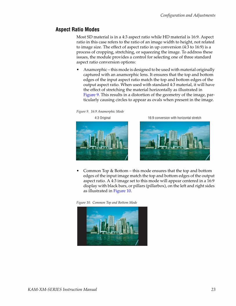
Aspect Ratio ModesMost SD material is in a 4:3 aspect ratio while HD material is 16:9. Aspect ratio in this case refers to the ratio of an image width to height, not related to image size. The effect of aspect ratio in up conversion (4:3 to 16:9) is a process of cropping, stretching, or squeezing the image. To address these issues, the module provides a control for selecting one of three standard aspect ratio conversion options:
• Anamorphic – this mode is designed to be used with material originally captured with an anamorphic lens. It ensures that the top and bottom edges of the input aspect ratio match the top and bottom edges of the output aspect ratio. When used with standard 4:3 material, it will have the effect of stretching the material horizontally as illustrated in Figure 9. This results in a distortion of the geometry of the image, par-ticularly causing circles to appear as ovals when present in the image.
Figure 9. 16:9 Anamorphic Mode
• Common Top & Bottom – this mode ensures that the top and bottom edges of the input image match the top and bottom edges of the output aspect ratio. A 4:3 image set to this mode will appear centered in a 16:9 display with black bars, or pillars (pillarbox), on the left and right sides as illustrated in Figure 10.
Figure 10. Common Top and Bottom Mode
16:9 conversion with horizontal stretch4:3 Original
KAM-XM-SERIES Instruction Manual 23

Configuration and Adjustments
• Common Side (Common Left & Right) – this mode ensures that the left and right edges of the input image match the left and right edge of the output aspect ratio. As illustrated in the Anamorphic example (Figure 9 on page 23), for a 4:3 image, the left and right edges are stretched to match the left and right edges of the output.
In order to maintain correct geometry of the image, in Common Side mode the input image is stretched vertically as well, creating a zoom effect (Figure 11). This method results in correct geometry of the image but also results in overall loss of approximately 33% of the input infor-mation in the vertical domain. This loss of information means less ver-tical information is available to the interpolation process resulting in lowering the overall resolution of the output image.
Figure 11. Common Sides Mode
• FlexView – (currently only available in 480i/59.94 to 1080i/59.94 up conversion) is a non-linear anamorphic aspect ratio designed for use when converting 4:3 material to 16:9 without the traditional distortion of a normal anamorphic stretch. FlexView leaves the center portion of the image untouched and then applies increasing amounts of stretch closer to the edges of the image, giving a more realistic conversion.
Other aspect ratio controls include the following:
• Zoom Crop – when turned on, will zoom the image by 3 pixels and then crop the image by 3 pixels. This corrects issues that arise on the top or bottom edge or on the left or right side of an image.
• Edge Trim – this control adjust the amount of border cropping in the X and Y directions. It is adjustable from 0-50 or 0-20 pixels, depending on the conversion currently in use.
• Fill Shade – this control is used when input the aspect ratio is smaller than the output aspect ratio and there are areas in the output display that are filled with black. The Fill Shade control adjusts the luminance level (Y) and color (Cb and Cr) of these areas from 64 (digital black) to 940 (digital white).
Stretched vertically
24 KAM-XM-SERIES Instruction Manual

Configuration and Adjustments
Proc Amp ControlsProc Amp controls are provided for making adjustments to the output video signal. Each Proc Amp function must be enabled before adjustments can be made.
The following Proc Amp controls are available:
• Video Gain – sets the overall amplitude with a range of ± 6 dB.
• Black Level – adjusts the black level with a range of ± 30 IRE.
• Hue – adjusts the phase with a range of ± 9 degrees.
• Saturation – adjusts the chroma saturation with a range of ± 6 dB.
• RP 177 checkbox – check this box when using video converted from film production as specified by SMPTE Recommended Practice RP 177.
Detail Enhance ControlsOnce the image has been de-interlaced and up converted, detail enhance-ment can be applied to the image to further sharpen the output detail. This process utilizes an industry standard film compositing technique called unsharp masking. The filtering process adds an additional level of image detail by detecting the edges of objects and adjusting the contrast ratio around these objects to help separate them from the background. This edge sharpening filter allows for both positive and negative aperture correction.
The following user adjustable controls are available in Detail Enhance:
• Horizontal – enabling the horizontal control allows the user to soften or sharpen the horizontal detail in the image. The range of this control is ± 7.0 dB.
• Vertical – enabling the vertical control allows the user to soften or sharpen the vertical detail in the image. The range of this control is ± 7.0 dB.
• Anti-Alias Filter – in down conversion modes only, an anti-alias filter can be enabled in the down conversion process to smooth edges such as graphics.
KAM-XM-SERIES Instruction Manual 25

Configuration and Adjustments
Noise ReductionTwo of the modules covered in this manual (KAM-XM-UNC – Up Con-verter with Noise Reduction and KAM-XM-UDC– Up/Down Converter) provide the additional noise filtering and reduction controls described below.
Spike FilteringThis is an adaptive median filter that works well in removing random impulse noise. This type of filtering performs spatial processing to deter-mine which pixels in an image have been affected by impulse noise. The adaptive median filter classifies pixels as noise by comparing each pixel in the image to its surrounding neighbor pixels. The size of the neighborhood is adjustable, as well as the threshold for the comparison.
A pixel that is different from a majority of its neighbors, as well as being not structurally aligned with those pixels to which it is similar, is labeled as impulse noise. These noise pixels are then replaced by the median pixel value of the pixels in the neighborhood that have passed the noise labeling test. This results in a prime benefit of not eroding edges or other small structures in the image with repeated application of the adaptive median filter.
This type of filtering provides controls for setting the adaptive threshold of the luminance and the chroma channels. The filter must be enabled to allow processing.
Brickwall FilteringThis is a low pass filter with a sharp cutoff. This type of high-order low pass filter attenuates high frequencies (image detail) while leaving low fre-quency information unaffected. Impulse and Gaussian noise contain high frequency components and will be diminished with this filter is on.
This filter is primarily intended for pre-compression processing, to atten-uate high frequency information that will normally be quantized away in the compression process. When used for pre-compression, it can improve the efficiency and quality of the compression process. By controlling the manner in which the detail is removed, compression artifacts can be mini-mized. A boost can be applied after the brickwall filter to accentuate the remaining edges in the filtered image.
One of the benefits of removing high frequency noise before compression is that there are more bits to spend when generating the compressed stream since there is less information to compress. In addition, the potential for loss of desirable information due to the compression of small details is decreased, resulting in a more consistent output.
26 KAM-XM-SERIES Instruction Manual

Configuration and Adjustments
Controls for this filter type include the following:
• Enable – the filter must be enabled.
• Boost – sets the amount of amplitude prior to the cutoff frequency. This boosting of the amplitudes gives the appearance of sharpening in the image to help compensate for blurring that occurs when filtering out high frequency information.
• Cutoff – sets the cutoff frequency so that information greater than this value will be filtered. Information less than the cutoff value will be left alone.
• Direction Control – allows setting the filter to affect both the horizontal and vertical axes or just the horizontal or vertical axis.
Temporal Recursive FilteringThis noise reducer is a motion adaptive temporal recursive filter that works well in removing random and Gaussian noise. Each pixel in the filter process is labeled as motion, no motion, or noise.
Each of these classes of pixels is treated differently in the noise reduction process as follows:
• For pixels in which there is no motion, low Gaussian noise may be reduced via temporal processing by a weighted averaging over succes-sive frames.
• For pixels labeled as random noise, spatial processing replaces these pixels.
• Pixels labeled as being in motion are left as is to avoid artifacts that may be introduced through temporal processing.
Controls for temporal filtering include the following:
• Enable – the filter must be enabled.
• Red Overlay – when turned on, the filter superimposes a red overlay onto areas in the input image where the temporal recursive filter iden-tifies motion. This red overlay will display what area is not being fil-tered.
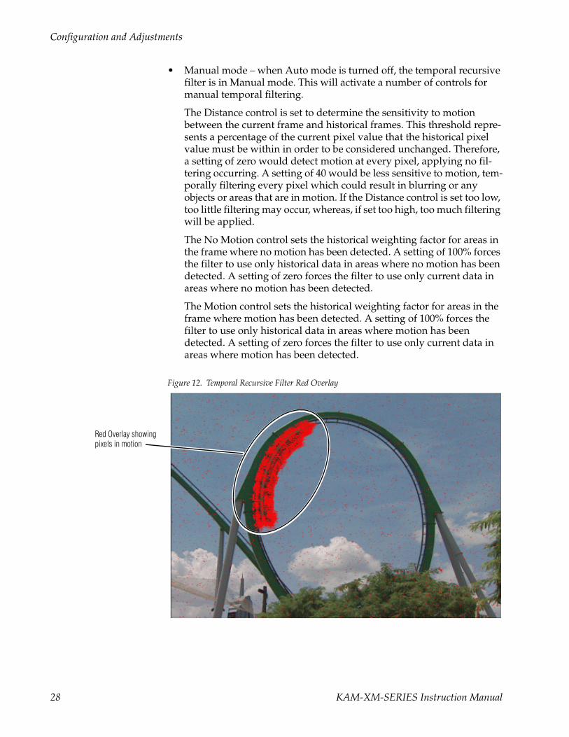
• Auto – when Auto mode is turned on, a feedback controller is engaged that dynamically sets the distance, no motion, and motion slider con-trols based on noise and motion measurements. The pixels determined to be in motion will be shown in red as shown in Figure 12 on page 28. These pixels will not have any noise reduction applied to them.
The Bias control in Auto mode adjusts the noise set point in the tem-poral recursive controller. The higher the bias, the more aggressive the controller is towards the noise in the scene. The lower the bias setting, the more sensitive the controller is towards motion in the scene.
KAM-XM-SERIES Instruction Manual 27
Configuration and Adjustments
• Manual mode – when Auto mode is turned off, the temporal recursive filter is in Manual mode. This will activate a number of controls for manual temporal filtering.
The Distance control is set to determine the sensitivity to motion between the current frame and historical frames. This threshold repre-sents a percentage of the current pixel value that the historical pixel value must be within in order to be considered unchanged. Therefore, a setting of zero would detect motion at every pixel, applying no fil-tering occurring. A setting of 40 would be less sensitive to motion, tem-porally filtering every pixel which could result in blurring or any objects or areas that are in motion. If the Distance control is set too low, too little filtering may occur, whereas, if set too high, too much filtering will be applied.
The No Motion control sets the historical weighting factor for areas in the frame where no motion has been detected. A setting of 100% forces the filter to use only historical data in areas where no motion has been detected. A setting of zero forces the filter to use only current data in areas where no motion has been detected.
The Motion control sets the historical weighting factor for areas in the frame where motion has been detected. A setting of 100% forces the filter to use only historical data in areas where motion has been detected. A setting of zero forces the filter to use only current data in areas where motion has been detected.
Figure 12. Temporal Recursive Filter Red Overlay
Red Overlay showingpixels in motion
28 KAM-XM-SERIES Instruction Manual

Configuration and Adjustments
Color LegalizerColor legalizer controls are provided to set the upper and lower limits for luma and chroma values to be within legal limits for broadcasting and downstream equipment.
Each luma and chroma value is a 10-bit value making the minimum limit 0 and the maximum limit 1019. High and low luma and chroma limit controls are provided for setting the upper and lower limits that the module will output. By default, these controls will cut off values outside of the legal range.
GPI and E-MEM ControlsConfiguration is provided for setting up GPI triggers from external devices. Up to ten different module preset configurations can be defined then assigned to the three external GPIs or recalled on the E-MEM web page.
KAM-XM-SERIES Instruction Manual 29

Configuration and Adjustments
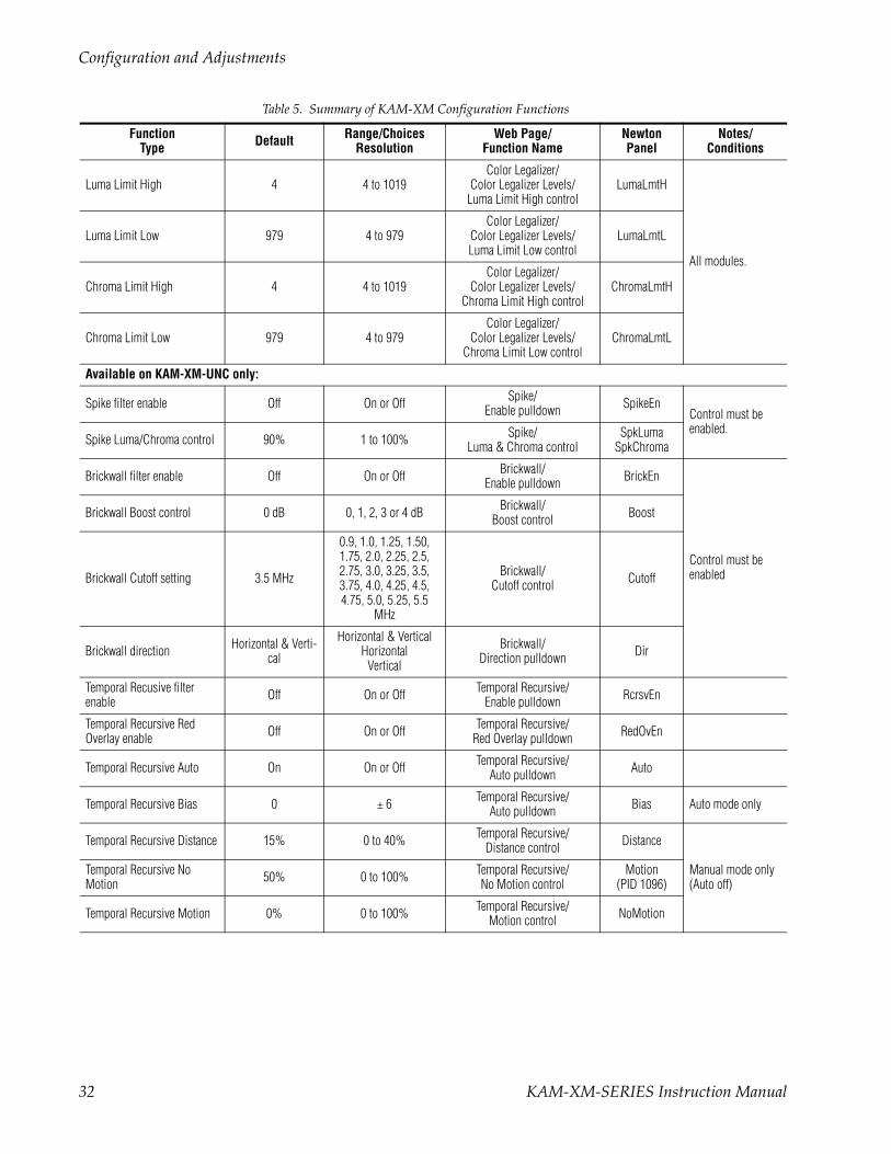
Configuration Summary TableTable 5 provides a complete summary of the KAM-XM functions and a comparison of the functionality available with each control type along with the ranges and default values for each parameter.
Table 5. Summary of KAM-XM Configuration Functions
FunctionType Default Range/Choices
ResolutionWeb Page/
Function NameNewtonPanel
Notes/Conditions
Reference input selection Input Input or External Setup/Reference pulldown Ref All modules.
Adjust Genlock Offset when external reference selected 0 µs ± 2000 µs Setup/
Genlock Offset (microseconds) –
Closed Caption Line select Line 9 Line 9 to 19 Setup/Closed Caption Line CCLine Up conversion
modes.
Ignore bad video control Don’t Ignore Ignore or Don’t Ignore
Setup/Bad Video Ignore checkbox – All modules
Blank VBI lines(525 line rate only) Not Blanked Blank or Not Blanked
Setup/Blank Line checkboxes
(525: Line 20, 21, 22, 23, 283, 284, 285, 286)
Blank20Blank283Blank21Blank284Blank22Blank285Blank23Blank286
Up conversion modes.
Format Conversion Input selection
Up Converter:480i59.94
Down Converter:720p50
480i59.94576i50720p50
720p59.941080i50
1080i59.94
Format/Input pulldown InDesired All modules.
Current Input Format 480i59.94 See list above Format/Current read-only column InCurrent
All modules. Changing formats in some cases will cause application to reload. Wait for module to reload.
Input Available – Yes or No Format Conversion/Available read-only column InAvailable
Format Conversion Output
Up Converter:480i59.94
Down Converter:576i50
See list above Format/Output pulldown OutDesired
Current Output Format 480i59.94 See list above Format/Current read-only column OutCurrent
Output Available – Yes or No Format/Available read-only column Available
Apply format control _ _ Format/Apply button ApplyFmt
App Configuration 4 Frame Delay
4 Frame Delay4 Frame Delay Common2 Frame Delay Common
2 Frame Delay (Common mode in up
conversion only)
Format/App Configuration pulldown _
See Format Conver-sion on page 22 for information on using this control.
30 KAM-XM-SERIES Instruction Manual

Configuration and Adjustments
Source Material selection Video Video or Auto Format/Source Material pulldown –
Up conversion modes.
Deinterlace Type selection PixelMotion PixelMotion orVert Interpolation
Format/Deinterlace Type pulldown –
Current Aspect selection Anamorphic
Anamorphic,Common Top,
Common Side, orFlexView (480i/59.94 to
1080i/59.94 only)
Aspect/Current Aspect pulldown Aspect
All modulesZoom Crop enable Off On or Off Aspect/Zoom Crop On checkbox Crop
Edge Trim – X or Y Trim 0 pixels 0 to 50 pixels0 to 20 pixels
Aspect/Edge Trim X or Y Trim control
XTrimYTrim
Fill Shade – Y/Cb/Cr Chan-nels 64 64-940 Aspect/
Fill Shade Y, Cb or Cr control
FillYFillCbFillCr
Video Gain Enable Off On or Off ProcAmp/Video Gain Enabled checkbox GainEn
All modules.Each control must be enabled,
Video Gain adjustment 0 dB ± 6.0 dB ProcAmp/Video Gain control Gain
Black Level Enable Off On or Off ProcAmp/Black Level Enabled checkbox BlackEn
Black Level adjustment 0 IRE ± 30 IRE ProcAmp/Black Level control Black
Hue Enable Off On or Off ProcAmp/Hue Enabled checkbox HueEn
Hue adjustment 0 degrees ± 9.0 degrees ProcAmp/Hue control Hue
Saturation Enable Off On or Off ProcAmp/Saturation Enabled checkbox SaturEn
Saturation adjustment 0 dB ± 6 dB ProcAmp/Saturation control Satur
RP 177 enable Off On or Off ProcAmp/RP 177 On checkbox _
Horizontal Detail Enhance Enable Off On or Off Detail Enhance/
Horizontal Enable checkbox EnhHorEn
All modules.Each control must be enabled
Horizontal Detail Enhance 0 dB ± 7 dB Detail Enhance/Horizontal (dB) control EnhHorDB
Vertical Detail Enhance Enable Off On or Off Detail Enhance/
Vertical Enable checkbox EnhVerEn
Vertical Detail Enhance 0 dB ± 7 dB Detail Enhance/Vertical control EnhVerDB
Anti-aliasing filter enable Off On or Off Detail Enhance/Anti-Alias Filter checkbox AntiAlias Down conversion
modes only
Table 5. Summary of KAM-XM Configuration Functions
FunctionType Default Range/Choices
ResolutionWeb Page/
Function NameNewtonPanel
Notes/Conditions
KAM-XM-SERIES Instruction Manual 31
Configuration and Adjustments
Luma Limit High 4 4 to 1019Color Legalizer/
Color Legalizer Levels/Luma Limit High control
LumaLmtH
All modules.
Luma Limit Low 979 4 to 979Color Legalizer/
Color Legalizer Levels/Luma Limit Low control
LumaLmtL
Chroma Limit High 4 4 to 1019Color Legalizer/
Color Legalizer Levels/Chroma Limit High control
ChromaLmtH
Chroma Limit Low 979 4 to 979Color Legalizer/
Color Legalizer Levels/Chroma Limit Low control
ChromaLmtL
Available on KAM-XM-UNC only:
Spike filter enable Off On or Off Spike/Enable pulldown SpikeEn
Control must be enabled.
Spike Luma/Chroma control 90% 1 to 100% Spike/Luma & Chroma control
SpkLumaSpkChroma
Brickwall filter enable Off On or Off Brickwall/Enable pulldown BrickEn
Control must be enabled
Brickwall Boost control 0 dB 0, 1, 2, 3 or 4 dB Brickwall/Boost control Boost
Brickwall Cutoff setting 3.5 MHz
0.9, 1.0, 1.25, 1.50, 1.75, 2.0, 2.25, 2.5, 2.75, 3.0, 3.25, 3.5, 3.75, 4.0, 4.25, 4.5, 4.75, 5.0, 5.25, 5.5
MHz
Brickwall/Cutoff control Cutoff
Brickwall direction Horizontal & Verti-cal
Horizontal & VerticalHorizontal
Vertical
Brickwall/Direction pulldown Dir
Temporal Recusive filter enable Off On or Off Temporal Recursive/
Enable pulldown RcrsvEn
Temporal Recursive Red Overlay enable Off On or Off Temporal Recursive/
Red Overlay pulldown RedOvEn
Temporal Recursive Auto On On or Off Temporal Recursive/Auto pulldown Auto
Temporal Recursive Bias 0 ± 6 Temporal Recursive/Auto pulldown Bias Auto mode only
Temporal Recursive Distance 15% 0 to 40% Temporal Recursive/Distance control Distance
Manual mode only (Auto off)
Temporal Recursive No Motion 50% 0 to 100% Temporal Recursive/
No Motion controlMotion
(PID 1096)
Temporal Recursive Motion 0% 0 to 100% Temporal Recursive/Motion control NoMotion
Table 5. Summary of KAM-XM Configuration Functions
FunctionType Default Range/Choices
ResolutionWeb Page/
Function NameNewtonPanel
Notes/Conditions
32 KAM-XM-SERIES Instruction Manual
Configuration and Adjustments
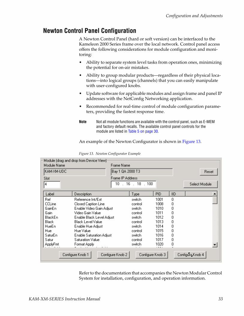
Newton Control Panel ConfigurationA Newton Control Panel (hard or soft version) can be interfaced to the Kameleon 2000 Series frame over the local network. Control panel access offers the following considerations for module configuration and moni-toring:
• Ability to separate system level tasks from operation ones, minimizing the potential for on-air mistakes.
• Ability to group modular products—regardless of their physical loca-tions—into logical groups (channels) that you can easily manipulate with user-configured knobs.
• Update software for applicable modules and assign frame and panel IP addresses with the NetConfig Networking application.
• Recommended for real-time control of module configuration parame-ters, providing the fastest response time.
Note Not all module functions are available with the control panel, such as E-MEM and factory default recalls. The available control panel controls for the module are listed in Table 5 on page 30.
An example of the Newton Configurator is shown in Figure 13.
Figure 13. Newton Configurator Example
Refer to the documentation that accompanies the Newton Modular Control System for installation, configuration, and operation information.
KAM-XM-SERIES Instruction Manual 33

Configuration and Adjustments
Web Browser InterfaceThe web browser interface provides a graphical representation of module configuration and monitoring.
Use of the web interface offers the following considerations:
• Provides complete access to all module status and configuration func-tions, including naming of inputs and outputs, factory parameter and name default recalls, E-MEM functions, slot configuration, and SNMP monitoring controls.
• Web access will require some normal network time delays for pro-cessing of information.
• Configuration parameter changes may require pressing the Apply button or Enter, upload processing time, and a manual screen refresh to become effective.
• Web interface recommended for setting up module signal and slot names, E-MEMS, and reporting status for SNMP and monitoring.
Refer to the Frame Status page shown in Figure 14 on page 35. The Kame-leon and 2000 modules can be addressed by clicking either on a specific module icon in the frame status display or on a module name or slot number in the link list on the left.
Note The physical appearance of the menu displays on the web pages shown in this manual represent the use of a particular platform, browser and version of 2000NET module software. They are provided for reference only. Displays will differ depending on the type of platform and browser you are using and the version of the 2000NET software installed in your system. This manual reflects 2000NET software version 4.0.0.
34 KAM-XM-SERIES Instruction Manual

Configuration and Adjustments
Figure 14. 2000NET GUI8330_11r2
The Links section lists the frame and its current modules. The selected link's Status page is first displayed and the sub-list of links for the selection is opened. The sub-list allows you to select a particular information page for the selected device.
Content display section displays the information page for the selected frame or module (frame slot icons are alsoactive links).
Refresh button for manual update of page
KAM-XM-SERIES Instruction Manual 35
Configuration and Adjustments
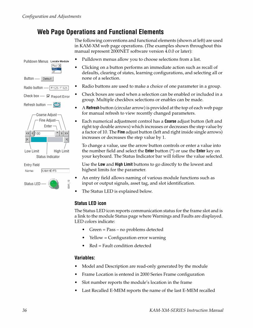
Web Page Operations and Functional ElementsThe following conventions and functional elements (shown at left) are used in KAM-XM web page operations. (The examples shown throughout this manual represent 2000NET software version 4.0.0 or later):
• Pulldown menus allow you to choose selections from a list.
• Clicking on a button performs an immediate action such as recall of defaults, clearing of states, learning configurations, and selecting all or none of a selection.
• Radio buttons are used to make a choice of one parameter in a group.
• Check boxes are used when a selection can be enabled or included in a group. Multiple checkbox selections or enables can be made.
• A Refresh button (circular arrow) is provided at the top of each web page for manual refresh to view recently changed parameters.
• Each numerical adjustment control has a Coarse adjust button (left and right top double arrows) which increases or decreases the step value by a factor of 10. The Fine adjust button (left and right inside single arrows) increases or decreases the step value by 1.
To change a value, use the arrow button controls or enter a value into the number field and select the Enter button (*) or use the Enter key on your keyboard. The Status Indicator bar will follow the value selected.
Use the Low and High Limit buttons to go directly to the lowest and highest limits for the parameter.
• An entry field allows naming of various module functions such as input or output signals, asset tag, and slot identification.
• The Status LED is explained below.
Status LED iconThe Status LED icon reports communication status for the frame slot and is a link to the module Status page where Warnings and Faults are displayed. LED colors indicate:
• Green = Pass – no problems detected
• Yellow = Configuration error warning
• Red = Fault condition detected
Variables:
• Model and Description are read-only generated by the module
• Frame Location is entered in 2000 Series Frame configuration
• Slot number reports the module’s location in the frame
• Last Recalled E-MEM reports the name of the last E-MEM recalled
Pulldown Menus
Check box
Refresh button
Coarse Adjust Fine Adjust
Enter
Status LED
Entry Field
High Limit Status Indicator
Low Limit
Radio button
8341
_13
Button
36 KAM-XM-SERIES Instruction Manual
Configuration and Adjustments
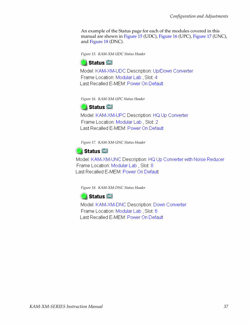
An example of the Status page for each of the modules covered in this manual are shown in Figure 15 (UDC), Figure 16 (UPC), Figure 17 (UNC), and Figure 18 (DNC).
Figure 15. KAM-XM-UDC Status Header
Figure 16. KAM-XM-UPC Status Header
Figure 17. KAM-XM-UNC Status Header
Figure 18. KAM-XM-DNC Status Header
KAM-XM-SERIES Instruction Manual 37
Configuration and Adjustments
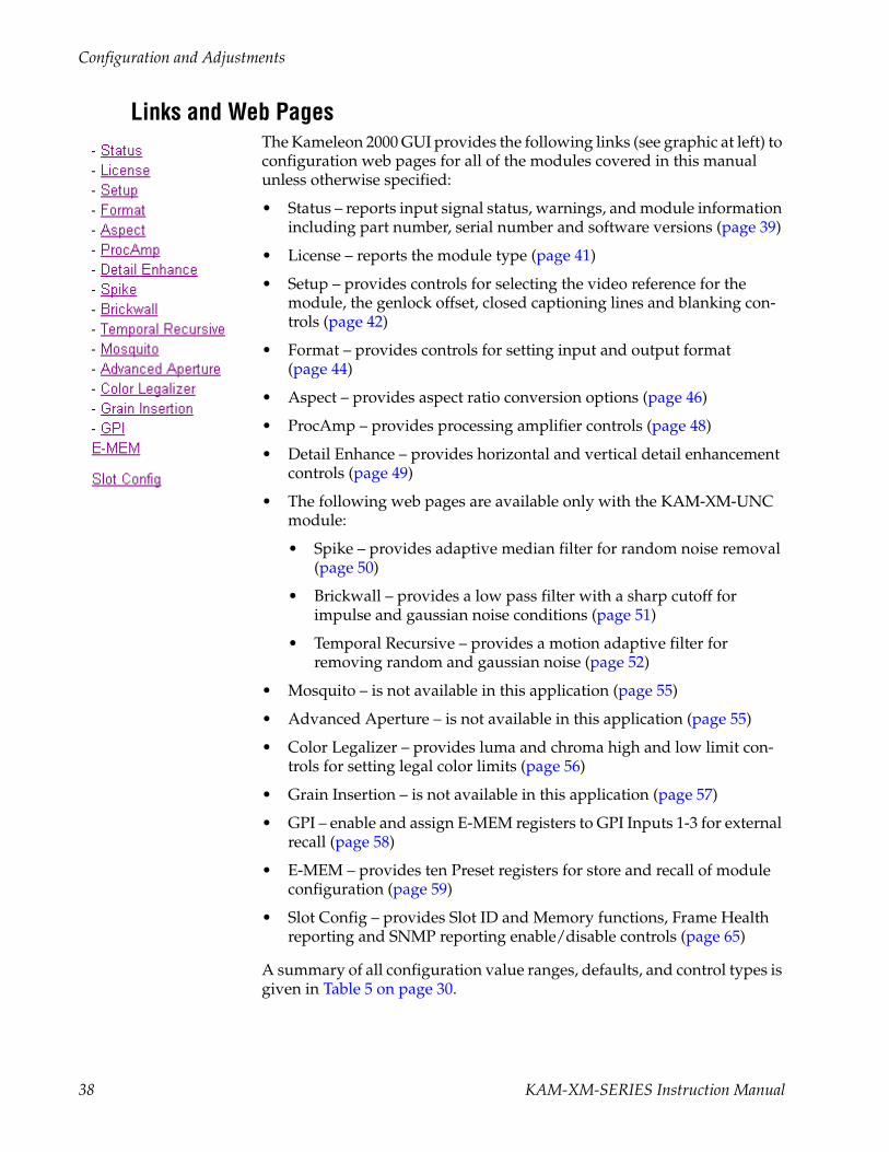
Links and Web PagesThe Kameleon 2000 GUI provides the following links (see graphic at left) to configuration web pages for all of the modules covered in this manual unless otherwise specified:
• Status – reports input signal status, warnings, and module information including part number, serial number and software versions (page 39)
• License – reports the module type (page 41)
• Setup – provides controls for selecting the video reference for the module, the genlock offset, closed captioning lines and blanking con-trols (page 42)
• Format – provides controls for setting input and output format (page 44)
• Aspect – provides aspect ratio conversion options (page 46)
• ProcAmp – provides processing amplifier controls (page 48)
• Detail Enhance – provides horizontal and vertical detail enhancement controls (page 49)
• The following web pages are available only with the KAM-XM-UNC module:
• Spike – provides adaptive median filter for random noise removal (page 50)
• Brickwall – provides a low pass filter with a sharp cutoff for impulse and gaussian noise conditions (page 51)
• Temporal Recursive – provides a motion adaptive filter for removing random and gaussian noise (page 52)
• Mosquito – is not available in this application (page 55)
• Advanced Aperture – is not available in this application (page 55)
• Color Legalizer – provides luma and chroma high and low limit con-trols for setting legal color limits (page 56)
• Grain Insertion – is not available in this application (page 57)
• GPI – enable and assign E-MEM registers to GPI Inputs 1-3 for external recall (page 58)
• E-MEM – provides ten Preset registers for store and recall of module configuration (page 59)
• Slot Config – provides Slot ID and Memory functions, Frame Health reporting and SNMP reporting enable/disable controls (page 65)
A summary of all configuration value ranges, defaults, and control types is given in Table 5 on page 30.
38 KAM-XM-SERIES Instruction Manual

Configuration and Adjustments
Status Web PageThe Status web page (Figure 19 on page 40) provides an overall indication of the health of the system in the following sections:
• Status Header – the same on all KAM-XM configuration pages (see Web Page Operations and Functional Elements on page 36),
• Color-coded communication status for each component and path,
• Summary of all fault/warning conditions, and
• Identification, Version and Download Status reporting.
Color-coded Status Indicators and LinksEach box on the Status page represents a KAM-XM module. Arrows repre-sent signal paths that may or may not be monitored. These elements act as links when their function is active (indicated by underlined function name).
Color code:
• Green = Pass – operating as expected.
• Yellow = Warning – signal is absent, has errors, or is misconfigured.
• Red = Fault – a component has failed.
• Grey = Not monitored.
IdentificationThe Identification section lists the following information about the module:
• Part Number
• Serial Number
• Hardware Version
• License Tag
VersionThe Version section lists currently loaded Program, Software, and Video and Audio firmware.
Download StatusThe current software version is listed in the Download Status area for all download components. The version for each of these components should be the same.
Usethislink
KAM-XM-SERIES Instruction Manual 39

Configuration and Adjustments
Figure 19. KAM-XM Status Web Page
Warning/Fault reporting area
40 KAM-XM-SERIES Instruction Manual
Configuration and Adjustments
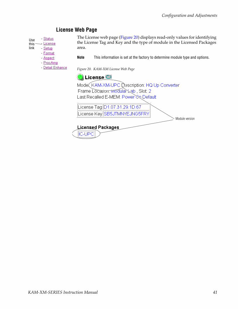
License Web PageThe License web page (Figure 20) displays read-only values for identifying the License Tag and Key and the type of module in the Licensed Packages area.
Note This information is set at the factory to determine module type and options.
Figure 20. KAM-XM License Web Page
Usethislink
Module version
KAM-XM-SERIES Instruction Manual 41

Configuration and Adjustments
Setup Web PageThe Setup web page (Figure 21 on page 43) provides the following controls for the module:
• Reference – set the module reference to either Input (from the currently selected video input) or External (from the 2000GEN module in the frame).
When External is selected, the Genlock Offset control will be available. Set the amount of offset in microseconds as needed to match the external reference.
• Closed Caption Line – select the line on which to place closed captioning.
• Bad Video Input – when the Ignore checkbox is selected, the module will not perform an application restart and will only lose the output for 2 frames. Under normal circumstances if a video switch/error occurs in the input SDI signal, the module will perform an application restart to recover, resulting in a 3 second loss of video output.
Note This mode requires that the source and frame be synchronized via an external reference.
• Blank Line – Select the On checkbox to blank the corresponding line in the vertical interval.
Usethislink
42 KAM-XM-SERIES Instruction Manual

Configuration and Adjustments
Figure 21. KAM-XM Setup Web Page.
KAM-XM-SERIES Instruction Manual 43

Configuration and Adjustments
Format Web PageThe Format web page (Figure 22 on page 45) provides the following con-trols for the module:
• Format Conversion – in the Format Conversion display, the Current input and output format are displayed. To change the input, use the Input Desired pulldown and select the format. If it is available a Yes will appear in the Available column. Possible input and output formats, as well as the defaults for an up and down converter are summarized in Table 2 on page 9.
Note Changing the input or output format will cause the module to reload the appli-cation. This will take approximately 60 seconds and a reloading message will appear during this time. Select the Refresh button at the top of the page to see the new settings after this time has elapsed.
Select the Apply button to set the values.
Note All possible input and output values will be listed and can be selected in the pulldowns. If the value does not apply to the application it will be reported as not available.
• App Configuration – this control sets the amount of processing delay through the module. Selecting 2 Frame Delay offers a shorter delay time but bypasses some functions available with the default 4 frame delay as described in Format Conversion on page 22.
For applications using down conversion, select either 2 Frame or 4 Frame Delay. For applications using up conversion, select from 4 Frame Delay, 4 Frame Delay Common (sets the Aspect Ratio to Common Sides), 2 Frame Delay Common (sets the Aspect Ratio to Common Sides), 2 Frames Delay.
• Source Material – select the type of source material being fed to the module (Video or Auto). When set to Auto, the module will determine if the input material is video or film originated and adjust the filtering accordingly. In some situations, such as broadcast applications, where the input material cannot be as easily interpreted by the module, the user can force the mode to Video to prevent artifacts from occurring.
• Deinterlace Type – select the type of deinterlacing for the module (PixelMo-tion or Vert Interpolation). Select PixelMotion for material that has motion or Vert Interpolation for images where motion is not a concern. Refer to Format Conversion on page 22 for more explanation on using a partic-ular de-interlace type.
Usethislink
44 KAM-XM-SERIES Instruction Manual

Configuration and Adjustments
Figure 22. KAM-XM Format Web Page.
KAM-XM-SERIES Instruction Manual 45

Configuration and Adjustments
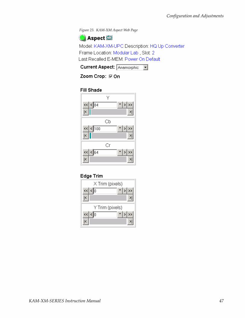
Aspect Web PageThe Aspect web page (Figure 23 on page 47) provides the following con-trols for selecting and adjusting the aspect ratio mode for the module:
• Current Aspect – Set the desired Aspect mode to one of the following:
• Anamorphic
• Common Side (Common Left & Right)
• Common Top & Bottom
Refer toAspect Ratio Modes on page 23 for an overview for setting the aspect ratio mode.
Note Changing the aspect from Common Sides or to Common Sides will cause the module to reload the application. This will take approximately 60 seconds and the module will display a message stating that the application is reloading. Select the Refresh button to see the new settings after this time has elapsed.
• Zoom Crop – when enabled by checking the On checkbox, zooms the image by 3 pixels and then crops the image by 3 pixels. This allows cor-rection of issues that occur on the top and bottom or left and right edges of an image.
• Fill Shade – when the input aspect ratio is smaller than the output aspect ratio there are areas in the output display filled with black. The Fill Shade controls adjust the luminance (Y) and color (Cb and Cr) of the black display areas.
• Edge Trim – use the X Trim and Y Trim controls to adjust the amount of border cropping in pixels in the X and Y directions performed on the image.
Usethislink
46 KAM-XM-SERIES Instruction Manual
Configuration and Adjustments
Figure 23. KAM-XM Aspect Web Page
KAM-XM-SERIES Instruction Manual 47

Configuration and Adjustments
Proc Amp Web PageThe Proc Amp web page (Figure 24) provides the controls for adjusting the video processing parameters for the output of the module. Ranges and default values are summarized in Table 5 on page 30.
Each control must be enabled by checking the Enabled checkbox.
Use the Proc Amp controls to set the following parameters:
• Video Gain – sets the overall amplitude of the output video signal from ± 6 dB.
• Black Level – adjusts the black level of the video output signal ±30 IRE.
• Hue – adjusts the phase of the output video signal ± 9 degrees.
• Saturation – adjusts the chroma saturation of the output video signal ± 6 dB.
Check the RP 177 On checkbox when using video converted from film pro-duction as required by SMPTE Recommended Practice RP 177.
Figure 24. KAM-XM ProcAmp Web Page
Usethislink
48 KAM-XM-SERIES Instruction Manual

Configuration and Adjustments
Detail Enhance Web PageThe Detail Enhance web page (Figure 25) provides the controls for deter-mining the amount of detail enhancement applied to the signal.
Each control must be enabled by checking the corresponding Enable checkbox.
Use the following controls to perform detail enhancement:
• Horizontal – this control is used to soften or sharpen the horizontal detail in the image (± 6 dB).
• Vertical – this control is used to soften or sharpen the vertical detail in the image (± 6 dB).
• Anti-Alias Filter – (active in modules with down conversion capability only) turn anti-aliasing On or Off with the pulldown.
Figure 25. KAM-XM Detail Enhance Web Page
Usethislink
KAM-XM-SERIES Instruction Manual 49

Configuration and Adjustments
Spike Web PageThe Spike web page (Figure 26) is active only on the KAM-XM-UNC module.
This web page provides noise reduction with an adaptive median filter that works well in reducing random impulse noise. Refer to Spike Filtering on page 26 for a discussion of the Spike filter.
• Enable – enable or disable the Spike control with the Enable pulldown.
• Luma & Chroma – sets the adaptive threshold of the filter in the luminance and chrominance channels. This threshold represents a percentage of the central pixel value that surrounding neighbors must be within in order to be considered similar.
Setting the filter to 100 (maximum) forces the filter on for every pixel, resulting in a standard median filter being applied to the entire lumi-nance and chrominance channels.
Figure 26. KAM-XM Spike Web Page
Usethislink
50 KAM-XM-SERIES Instruction Manual

Configuration and Adjustments
Brickwall Web PageThe Brickwall web page (Figure 27) is active only on the KAM-XM-UNC module.
This web page provides noise reduction by using a low pass filter with a sharp cutoff to attenuate high frequencies. This type of filter is best for diminishing Gaussian and impulse noise. Refer to Brickwall Filtering on page 26 for a discussion on using the Brickwall filter.
Enable the control by selecting On in the Enable pulldown then use the fol-lowing controls for the Brickwall filter:
• Boost – sets the amount of boosting in dB of amplitudes prior to the cutoff frequency. This gives the appearance of sharpening the image to help compensate for blurring that occurs when filtering out high fre-quency information.
• Cutoff – sets the cutoff frequency in MHz above which information will be filtered while information below the cutoff will be left untouched.
• Direction – this control allows the user to set the direction in which the filters above will affect the picture.
• Vertical applies the filters to the vertical axis only.
• Horizontal applies the filters to the horizontal axis only.
• Horizontal & Vertical applies the filters to the both axes.
Figure 27. KAM-XM Brickwall Web Page
Usethislink
KAM-XM-SERIES Instruction Manual 51

Configuration and Adjustments
Temporal Recursive Web PageThe Temporal Recursive web page is active only on the KAM-XM-UNC module.
This is a motion adaptive temporal recursive filter that works well in removing random and Gaussian noise. Refer to Temporal Recursive Filtering on page 27 for a discussion on using this filter.
Enable the Temporal Recursive control by selecting On in the Enable pull-down.This filter can operate in either Auto or Manual mode.
Auto ModeUse the following controls for removing noise:
• Red Overlay – when enabled (On), a red overlay is superimposed onto areas in the input image where the temporal recursive filter identifies motion.
• Auto – enabling this mode (Figure 28) engages a feedback controller that dynamically sets the Distance, No Motion and Motion control setting avail-able in Manual mode based on noise and motion measurement extracted from the scene.
• Bias – is active only in Auto mode. This control adjusts the noise set point in the temporal recursive controller. The higher the bias the more aggressive the controller is towards noise in the scene. The lower the bias setting the more sensitive the controller is towards motion.
Figure 28. KAM-XM Temporal Recursive – Auto Mode
Usethislink
52 KAM-XM-SERIES Instruction Manual

Configuration and Adjustments
Manual ModeEnable Manual control by turning Auto off. The web page will appear as shown in Figure 29.
Use the controls below in Manual Mode:
• Red Overlay – when enabled (On), a red overlay is superimposed onto areas in the input image where the temporal recursive filter identifies motion.
• Auto – disabling Auto (Off) puts the Temporal Recursive filter in Manual mode.
Figure 29. KAM-XM Temporal Recursive – Manual Mode
KAM-XM-SERIES Instruction Manual 53
Configuration and Adjustments
• Distance – sets the distance threshold to determine the sensitivity to motion between the current frame and historical frames. The range of this control is from 0 – 40, with the nominal value for the distance threshold at 15. A setting of 0 will detect motion at every pixel, causing no filtering to occur. A setting of 40 will be less sensitive to motion, tem-porally filtering every pixel, which may result in blurring of any objects/areas in motion.
In summary, if the distance is set too low, the module detects everything as moving and applies no filtering. If set too high, no motion is detected, and everything is filtered.
• No Motion – sets the historical weighting factor for areas in the frame where no motion has been detected. A high setting forces the filter to use only historical data in areas where no motion as been detected. A low setting forces the filter to use only current data in areas where no motion has been detected.
• Motion – sets the historical weighting factor for areas in the frame where motion has been detected. A low setting forces the filter to use only current data in areas where motion has been detected.
54 KAM-XM-SERIES Instruction Manual

Configuration and Adjustments
Mosquito Web PageThe Mosquito web page (Figure 30) indicates it is not available on these module types.
Figure 30. KAM-XM Mosquito Web Page
Advanced Aperture Web PageThe Advance Aperture web page (Figure 31) indicates it is not available on these module types.
Figure 31. KAM-XM Advanced Aperture Web Page
Usethislink
Usethislink
KAM-XM-SERIES Instruction Manual 55

Configuration and Adjustments
Color Legalizer Web PageThe Color Legalizer web page (Figure 32) provides the controls for setting the high and low legal limits for the luma and chroma values as described in Color Legalizer on page 29.
Use the following controls to set High and Low limits for Luma and Chroma:
• Luma – set the legal limits for the Luma signal with the High and Low controls.
• Chroma – set the legal limits for the Chroma signal with the High and Low controls.
Figure 32. KAM-XM Color Legalizer Web Page
Usethislink
56 KAM-XM-SERIES Instruction Manual

Configuration and Adjustments
Grain Insertion Web PageThe Grain Insertion web page (Figure 33) indicates it is not available on these module types.
Figure 33. KAM-XM Grain Insertion Web Page
Usethislink
KAM-XM-SERIES Instruction Manual 57

Configuration and Adjustments
GPI Web PageThe GPI web page (Figure 34) allows enabling and selection of E-MEM reg-isters to be recalled by three external GPI inputs (Input 1-3). The E-MEM presets are defined on the E-MEM web page (E-MEM Web Page on page 59).
• Select the desired E-MEM register to be recalled from the pulldown list for each GPI input.
• Check the Enabled check box to enable the GPI input.
External GPI connection is explained in GPI0 Connections for GPI Control on page 18.
Figure 34. KAM-XM GPI Web Page
Usethislink
58 KAM-XM-SERIES Instruction Manual
Configuration and Adjustments
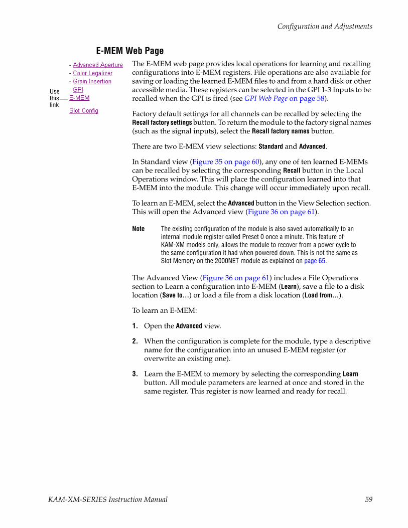
E-MEM Web PageThe E-MEM web page provides local operations for learning and recalling configurations into E-MEM registers. File operations are also available for saving or loading the learned E-MEM files to and from a hard disk or other accessible media. These registers can be selected in the GPI 1-3 Inputs to be recalled when the GPI is fired (see GPI Web Page on page 58).
Factory default settings for all channels can be recalled by selecting the Recall factory settings button. To return the module to the factory signal names (such as the signal inputs), select the Recall factory names button.
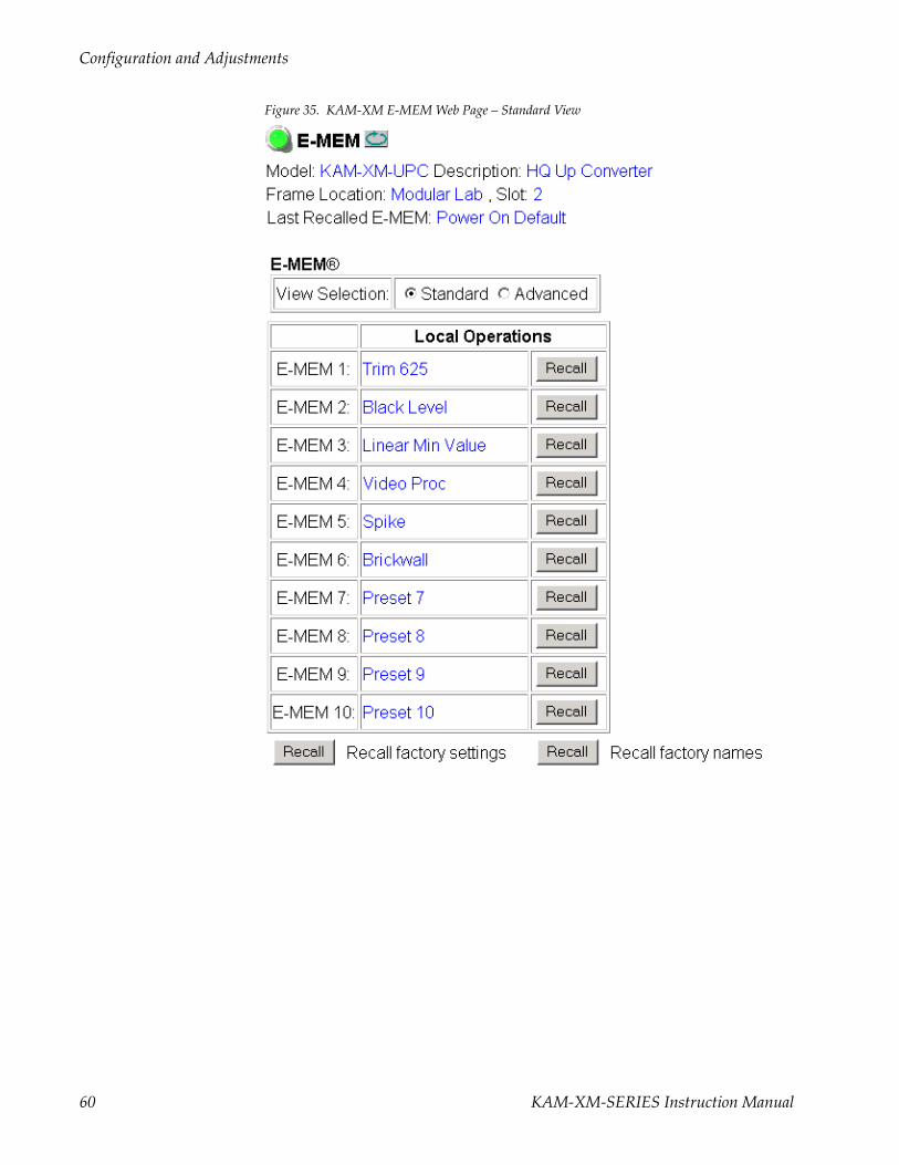
There are two E-MEM view selections: Standard and Advanced.
In Standard view (Figure 35 on page 60), any one of ten learned E-MEMs can be recalled by selecting the corresponding Recall button in the Local Operations window. This will place the configuration learned into that E-MEM into the module. This change will occur immediately upon recall.
To learn an E-MEM, select the Advanced button in the View Selection section. This will open the Advanced view (Figure 36 on page 61).
Note The existing configuration of the module is also saved automatically to an internal module register called Preset 0 once a minute. This feature of KAM-XM models only, allows the module to recover from a power cycle to the same configuration it had when powered down. This is not the same as Slot Memory on the 2000NET module as explained on page 65.
The Advanced View (Figure 36 on page 61) includes a File Operations section to Learn a configuration into E-MEM (Learn), save a file to a disk location (Save to...) or load a file from a disk location (Load from...).
To learn an E-MEM:
1. Open the Advanced view.
2. When the configuration is complete for the module, type a descriptive name for the configuration into an unused E-MEM register (or overwrite an existing one).
3. Learn the E-MEM to memory by selecting the corresponding Learn button. All module parameters are learned at once and stored in the same register. This register is now learned and ready for recall.
Usethislink
KAM-XM-SERIES Instruction Manual 59
Configuration and Adjustments
Figure 35. KAM-XM E-MEM Web Page – Standard View
60 KAM-XM-SERIES Instruction Manual

Configuration and Adjustments
Figure 36. KAM-XM E-MEM Web Page – Advanced View
KAM-XM-SERIES Instruction Manual 61
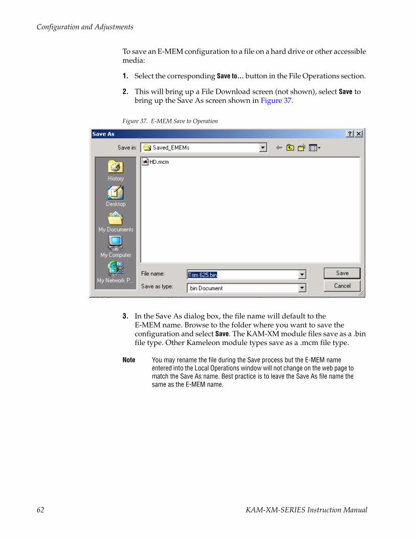
Configuration and Adjustments
To save an E-MEM configuration to a file on a hard drive or other accessible media:
1. Select the corresponding Save to... button in the File Operations section.
2. This will bring up a File Download screen (not shown), select Save to bring up the Save As screen shown in Figure 37.
Figure 37. E-MEM Save to Operation
3. In the Save As dialog box, the file name will default to the E-MEM name. Browse to the folder where you want to save the configuration and select Save. The KAM-XM module files save as a .bin file type. Other Kameleon module types save as a .mcm file type.
Note You may rename the file during the Save process but the E-MEM name entered into the Local Operations window will not change on the web page to match the Save As name. Best practice is to leave the Save As file name the same as the E-MEM name.
62 KAM-XM-SERIES Instruction Manual
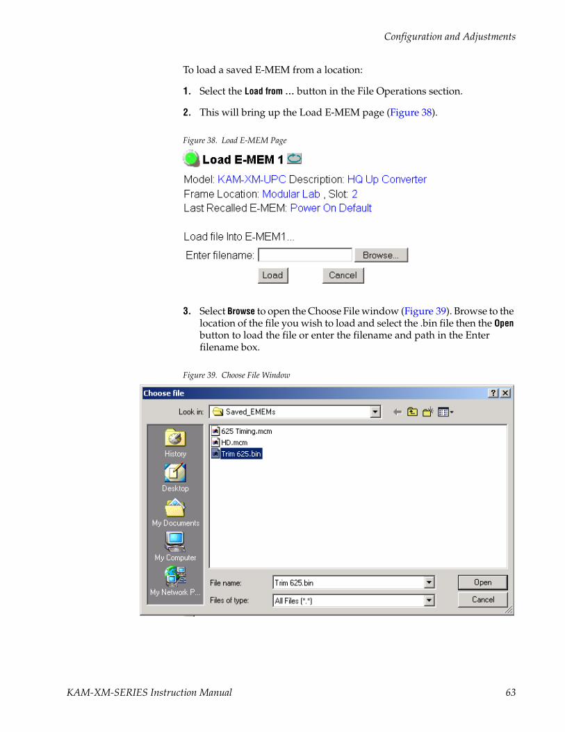
Configuration and Adjustments
To load a saved E-MEM from a location:
1. Select the Load from ... button in the File Operations section.
2. This will bring up the Load E-MEM page (Figure 38).
Figure 38. Load E-MEM Page
3. Select Browse to open the Choose File window (Figure 39). Browse to the location of the file you wish to load and select the .bin file then the Open button to load the file or enter the filename and path in the Enter filename box.
Figure 39. Choose File Window
KAM-XM-SERIES Instruction Manual 63

Configuration and Adjustments
4. Once the correct path and filename is loaded, select the Load button on the Load E-MEM page.
5. This should place the recalled E-MEM file into the corresponding E-MEM window.
6. Select the corresponding Recall button to invoke this configuration.
Note After a power cycle (module is removed and replaced), E-MEM will default to Power On Default regardless of the last E-MEM recalled.
64 KAM-XM-SERIES Instruction Manual

Configuration and Adjustments
Slot Config Web PageUse the Slot Config web page (Figure 40) to perform the following func-tions on the module:
• Slot Identification – You may identify the module by typing a specific name in the Name field. The assigned name is stored on the 2000NET module and travels with the 2000NET module if it is moved to another frame. Select Default to enter the factory default module name.
• Locate Module – selecting Flash from the Locate Module pulldown flashes the yellow COMM and CONF LEDs on the front of the module so it can be located in the frame.
Figure 40. Slot Config Web Page
• Slot Memory – the slot configuration for each media module is automati-cally saved periodically (once an hour) to the 2000NET module in that frame. You may also select the Learn Module Config button at any time to save the current configuration for this slot. The configuration is saved on the 2000NET module. If the 2000NET module is removed or powered down, the stored configurations are not saved.
Usethislink
KAM-XM-SERIES Instruction Manual 65
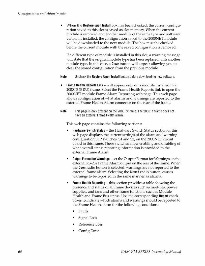
Configuration and Adjustments
• When the Restore upon Install box has been checked, the current configu-ration saved to this slot is saved as slot memory. When the current module is removed and another module of the same type and software version is installed, the configuration saved to the 2000NET module will be downloaded to the new module. The box must be checked before the current module with the saved configuration is removed.
If a different type of module is installed in this slot, a warning message will state that the original module type has been replaced with another module type. In this case, a Clear button will appear allowing you to clear the stored configuration from the previous module.
Note Uncheck the Restore Upon Install button before downloading new software.
• Frame Health Reports Link – will appear only on a module installed in a 2000T3 (3 RU) frame. Select the Frame Health Reports link to open the 2000NET module Frame Alarm Reporting web page. This web page allows configuration of what alarms and warnings are reported to the external Frame Health Alarm connector on the rear of the frame.
Note This page is only present on the 2000T3 frame. The 2000T1 frame does not have an external Frame Health alarm.
This web page contains the following sections:
• Hardware Switch Status – the Hardware Switch Status section of this web page displays the current settings of the alarm and warning configuration DIP switches, S1 and S2, on the 2000NET circuit board in this frame. These switches allow enabling and disabling of what overall status reporting information is provided to the external Frame Alarm.
• Output Format for Warnings – set the Output Format for Warnings on the external RS-232 Frame Alarm output on the rear of the frame. When the Open radio button is selected, warnings are not reported to the external frame alarm. Selecting the Closed radio button, causes warnings to be reported in the same manner as alarms.
• Frame Health Reporting – this section provides a table showing the presence and status of all frame devices such as modules, power supplies, and fans and other frame functions such as Module Health and Frame Bus status. Use the corresponding Report check-boxes to indicate which alarms and warnings should be reported to the Frame Health alarm for the following conditions:
• Faults
• Signal Loss
• Reference Loss
• Config Error
66 KAM-XM-SERIES Instruction Manual

Configuration and Adjustments
• SNMP Trap Reports Link – select the SNMP Trap Reports link to open the 2000NET SNMP Reporting web page. This link will only be present when SNMP Agent software has been installed on the 2000NET module. This web page allows configuration of what alarms and warn-ings are reported to the SNMP management software.
• Hardware Switch Status – the Hardware Switch Status section of this web page displays the current settings of the alarm and warning configuration DIP switches, S1 and S2, on the 2000NET circuit board in this frame. These switches allow enabling and disabling of what overall status reporting information is provided to the SNMP traps.
Note Slot SNMP traps can be enabled only when the hardware switches for Module Fault reporting and Asynchronous Status reporting are in enabled on the 2000NET module (dipswitch S1 segment 7 and dipswitch S2 segment 1).
• SNMP Trap Reporting – this section provides a table showing the pres-ence and/or status of all frame devices such as modules, power supplies, power and fan sleds and other frame functions such as fan and Frame Bus status.
Use the corresponding Report checkboxes to indicate what trap warnings and alarms should be reported to the SNMP manager for the following conditions:
• Faults
• Devices removed
• Signal Loss
• Reference Loss
• Config Error
The enabled SNMP traps will be reported to any SNMP manager that is identified as an SNMP Report Destination in 2000NET con-figuration. Trap severity is read-only hard-coded information that is interpreted and responded to by the SNMP Manager software configuration.
Refer to the 2000NET Instruction Manual for complete details on using the 2000NET web pages.
KAM-XM-SERIES Instruction Manual 67

Configuration and Adjustments
Software UpdatingSoftware updating for the KAM-XM modules is done using the NetConfig Networking application available from the Thomson Grass Valley ftp site or Customer Service data base as described in this section. It is recom-mended to use the latest available version of NetConfig for software updating.
Note Kameleon 2000 frames with a 2000NET module running version 4.0.0 and later will no longer provide a Software Update web page.
Acquiring NetConfig SoftwareIf you do not have NetConfig or the latest version, you can download it from the Thomson Grass Valley ftp site at this URL:
ftp://ftp.thomsongrassvalley.com/pub/router/NetConfig/Version 2.0.6/
1. Right-click on the latest NetConfig link to download the zipped file to the C:\temp folder or other convenient location on your PC.
2. Extract the zipped files onto your local drive:
3. Double-click on the NetConfig.EXE file to install NetConfig.
Note Installing NetConfig into the default location given in the install script (C:\Programs\Grass Valley Group) is recommended for future NetConfig and module software updates.
Acquiring the Latest KAM-XM Software To acquire the latest Kameleon software, connect to the Grass Valley Cus-tomer Service FAQ database from the following URL:
http://gvg.custhelp.com
This will take you to the Grass Valley Customer Service FAQ data base. The information provided here is the most up-to-date. You may also subscribe to software updates through the FAQ site. This is recommended so that when new versions of software are released, you are notified by email.
If you cannot find the software you need here, go directly to the Grass Valley Customer FTP site at the following URL:
ftp://ftp.thomsongrassvalley.com/pub/modular
To download the latest Kameleon HD software from either the Customer Service database or the ftp site, do the following:
1. Navigate to the Customer Service FAQ site and click on the first FAQ, DOWNLOAD THE LATEST SOFTWARE?
68 KAM-XM-SERIES Instruction Manual
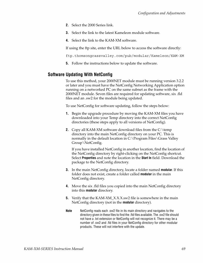
Configuration and Adjustments
2. Select the 2000 Series link.
3. Select the link to the latest Kameleon module software.
4. Select the link to the KAM-XM software.
If using the ftp site, enter the URL below to access the software directly:
ftp.thomsongrassvalley.com/pub/modular/Kameleon/KAM-XM
5. Follow the instructions below to update the software.
Software Updating With NetConfigTo use this method, your 2000NET module must be running version 3.2.2 or later and you must have the NetConfig Networking Application option running on a networked PC on the same subnet as the frame with the 2000NET module. Seven files are required for updating software, six .fld files and an .sw2 for the module being updated.
To use NetConfig for software updating, follow the steps below:
1. Begin the upgrade procedure by moving the KAM-XM files you have downloaded into your Temp directory into the correct NetConfig directories (these steps apply to all versions of NetConfig).
2. Copy all KAM-XM software download files from the C:\temp directory into the main NetConfig directory on your PC. This is normally in the default location in C:\Program Files\Grass Valley Group\NetConfig.
If you have installed NetConfig in another location, find the location of the NetConfig directory by right-clicking on the NetConfig shortcut. Select Properties and note the location in the Start In field. Download the package to the NetConfig directory.
3. In the main NetConfig directory, locate a folder named modular. If this folder does not exist, create a folder called modular in the main NetConfig directory.
4. Move the six .fld files you copied into the main NetConfig directory into this modular directory.
5. Verify that the KAM-XM_X.X.X.sw2 file is somewhere in the main NetConfig directory (not in the modular directory).
Note NetConfig reads each .sw2 file in its main directory and navigates to the directory given in these files to find the .fld files available. The .sw2 file should not have a .txt extension or NetConfig will not recognize it. There may be a number of .sw2 and .fld files in your NetConfig directory for other modular products. These will not interfere with the update.
KAM-XM-SERIES Instruction Manual 69

Configuration and Adjustments
CAUTION During the download, the module will have no video output, so be sure the module is off-air before upgrading.
6. Open NetConfig.
Note If you have not used NetConfig before, refer to the NetConfig Instruction Manual included during installation in the main NetConfig directory in pdf format (NetConfig.pdf).
7. Click on the Load SW button on the top of the NetConfig toolbar.
8. This will bring up the Load Software screen (Figure 41). This screen shows the latest version as of NetConfig currently available, version 2.0.6. If you are using an earlier version of NetConfig, the file structure is slightly different, but the files versions are the same.
Figure 41. NetConfig Load Software Screen – First .fld Download
9. Open the KAM-XM directory.
The following files should appear in the KAM-XM directory, all reporting the same software version represented here by X.X.X:
• apps (X.X.X)
• firmware (X.X.X)
• ucode1 (X.X.X)
• ucode2 (X.X.X)
• ucode3 (X.X.X)
• uvc (X.X.X)
Select apps and a KAM-XM Client Name.
70 KAM-XM-SERIES Instruction Manual

Configuration and Adjustments
Note Previous software updates may also be present in the modular folder and may appear in the KAM-XM directory
10. Highlight the apps Device Type. All KAM-XM modules accessible on this subnet will be displayed in the window on the right with their current software version and frame IP Address.
11. Find the KAM-XM module you are updating in the Client Name list. Check the corresponding checkbox in the window on the right to indicate you wish to update this device.
Note You may upgrade all modules at once with this application by checking all of the Client Name checkboxes. We recommend upgrading one module first to understand the process before attempting to upgrade all of the modules at once.
12. Check the Re-Boot when complete checkbox in the lower left corner of the screen.
13. Click on the Load button to begin the update.
14. If the load has been successful, a popup will appear as shown in Figure 42. Click the OK button.
Figure 42. Load Successful Popup
15. Allow the reboot to complete.
16. Bring up NetConfig again and click on the Discover button in the top menu bar. Then click on the Load SW button.
17. Select the firmware Device Type on the left (Figure 41 on page 70).
18. Select the same Client Name as the first download.
19. Check the Re-Boot when complete checkbox in the lower left corner of the screen.
20. Press the Load button to download the firmware to the KAM-XM module selected.
21. If the load has been successful, a popup will appear as shown in Figure 42 on page 71. Click the OK button.
KAM-XM-SERIES Instruction Manual 71
Configuration and Adjustments
22. Allow the reboot to complete.
23. Bring up NetConfig again and click on the Discover button in the top menu bar. Then click on the Load SW button.
24. Select the ucode1 Device Type on the left.
25. Select the same Client Name as the first download.
26. Complete the same steps for the rest of the .fld files listed, allowing the reboot to complete each time.
27. Verify that all downloads were successful by checking the Download Status table on the Status web page (Figure 19 on page 40).
For more information on using NetConfig, refer to the NetConfig Net-working Application Instruction Manual which is included with the option, available on the Thomson Grass Valley web site, and may also be present in the NetConfig directory during some NetConfig installations (Newton Control Panel installation is one example).
72 KAM-XM-SERIES Instruction Manual

Specifications
SpecificationsTable 6. KAM-XM Series Specifications
Parameter Value
SD/HD Video Input
Standard
KAM-XM-UNC KAM-XM-UPC SMPTE 259-C (270 Mb/s)
KAM-XM-UDC SMPTE 259-C (270 Mb/s), SMPTE 292M (1.5 Gb/s), SMPTE 274M, SMPTE 296M, SMPTE 349M
KAM-XM-DNC SMPTE 292M (1.5 Gb/s), SMPTE 274M, SMPTE 296M, SMPTE 349M
Number of inputs 1 with active loop-through
Connector BNC per IEC 60169-8 Amendment 2
Equalization
KAM-XM-UNC KAM-XM-UPC Automatic to 300 m @ 270 Mb/s with Belden 1694 or equivalent cable
KAM-XM-UDC Automatic to 100 m @ 1.5 Gb/s/300 m @ 270 Mb/s with Belden 1694 or equivalent
KAM-XM-DNC Automatic to 100 m @ 1.5 Gb/s with Belden 1694 or equivalent cable
Return Loss > 15 dB @ 270 Mb/s (and 1.5 Gb/s)
Active Input Loop-through Output
Standard
KAM-XM-UNC KAM-XM-UPC SMPTE 259-C (270 Mb/s)
KAM-XM-UDC SMPTE 259-C (270 Mb/s), SMPTE 292M (1.5 Gb/s), SMPTE 274M, SMPTE 296M, SMPTE 349M
KAM-XM-DNC SMPTE 292M (1.5 Gb/s), SMPTE 274M, SMPTE 296M, SMPTE 349M
Number of outputs 1
Connector BNC per IEC 60169-8 Amendment 2
DC offset 0 V ± 0.5 V
Rise and fall time 750 ps nominal for SD
Overshoot < 10% of amplitude
Return loss > 9 dB @ 1.5 Gb/s
Wideband jitter < 0.2 UI
Up/Down Converted Serial Video Output
Standard
KAM-XM-UNC KAM-XM-UPC KAM-XM-DNC
SMPTE 292M (1.5 Gb/s)
KAM-XM-UDC SMPTE 259-C (270 Mb/s) or SMPTE 292M (1.5 Gb/s)
Number of outputs 2
Connector BNC per IEC 60169-8 Amendment 2
DC offset 0 V ± 0.5 V
Rise and fall time 750 ps nominal for SD
Overshoot < 10% of amplitude
Return loss > 15 dB @ 270 Mb/s, > 9 dB @ 1.5 Gb/s
Wideband jitter < 0.2 UI
KAM-XM-SERIES Instruction Manual 73
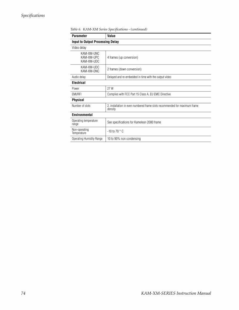
Specifications
Input to Output Processing Delay
Video delay
KAM-XM-UNC KAM-XM-UPC KAM-XM-UDC
4 frames (up conversion)
KAM-XM-UDCKAM-XM-DNC 2 frames (down conversion)
Audio delay Delayed and re-embedded in time with the output video
Electrical
Power 27 W
EMI/RFI Complies with FCC Part 15 Class A, EU EMC Directive
Physical
Number of slots 2, installation in even numbered frame slots recommended for maximum frame density
Environmental
Operating temperature range See specifications for Kameleon 2000 frame
Non-operating Temperature -10 to 70 ° C
Operating Humidity Range 10 to 90% non condensing
Table 6. KAM-XM Series Specifications - (continued)
Parameter Value
74 KAM-XM-SERIES Instruction Manual

Service
ServiceThe KAM-XM modules make extensive use of surface-mount technology and programmed parts to achieve compact size and adherence to demanding technical specifications. Circuit modules should not be ser-viced in the field unless as directed by Grass Valley Customer Service.
Power-up Diagnostics FailureIf the module has not passed self-diagnostics, do not attempt to trouble-shoot. Return the unit to Grass Valley (see Module Repair).
TroubleshootingIf your module is not operating correctly, proceed as follows:
• If module power is not present, check fuse F1 (see Figure 43).
• Check for presence and quality of input signals.
• Verify that source equipment is operating correctly.
• Check cable connections.
Figure 43. KAM-XM Voltage Testpoints and Fuse Location
Module RepairIf the module is still not operating correctly, replace it with a known good spare and return the faulty module to a designated Grass Valley repair depot. Call your Grass Valley representative for depot location. Refer to Contacting Grass Valley at the front of this document for the Grass Valley Customer Service Information number.
GRASS VALLEY KAM-XM-DNC115-0079-02 B
F1
Fuse: 2.5 A FAST, 125 V
Module Type Label
8330
_08
KAM-XM-SERIES Instruction Manual 75

Service
76 KAM-XM-SERIES Instruction Manual
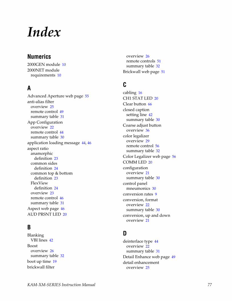
Index
Numerics2000GEN module 102000NET module
requirements 10
AAdvanced Aperture web page 55anti-alias filter
overview 25remote control 49summary table 31
App Configurationoverview 22remote control 44summary table 30
application loading message 44, 46aspect ratio
anamorphicdefinition 23
common sidesdefinition 24
common top & bottomdefinition 23
FlexViewdefinition 24
overview 23remote control 46summary table 31
Aspect web page 46AUD PRSNT LED 20
BBlanking
VBI lines 42Boost
overview 26summary table 32
boot up time 19brickwall filter
overview 26remote controls 51summary table 32
Brickwall web page 51
Ccabling 16CH1 STAT LED 20Clear button 66closed caption
setting line 42summary table 30
Coarse adjust buttonoverview 36
color legalizeroverview 29remote control 56summary table 32
Color Legalizer web page 56COMM LED 20configuration
overview 21summary table 30
control panelmneumonics 30
conversion rates 9conversion, format
overview 22summary table 30
conversion, up and downoverview 21
Ddeinterlace type 44
overview 22summary table 31
Detail Enhance web page 49detail enhancement
overview 25
KAM-XM-SERIES Instruction Manual 77

Index
remote controls 49summary table 31
documentation online 2
EE-MEM
advanced view 59description 59load from file 63save to file 62standard view 59web page 59
environmental 74
Ffactory defaults
recall factory defaults 59recall factory names 59summary table 30
FAQ database 2FAULT LED 20fault table 20FBREF ERR LED 20Fine adjust button
overview 36FlexView
aspect ratio, overview 24format conversion 44Format web page 44Frame Health Reporting 66frame, 1 RU 13frame, 3RU 12frequently asked questions 2FRM LOCK LED 20front module
installation 15front panel LEDs 19fuse
location and type 75
GGenlock Offset
remote control 42
summary table 30GPI (General Purpose Interface)
configuring inputs 58Connector J5 wiring 18overview 29
GPI web page 58Grain Insertion web page 57Grass Valley web site 2GUI 38
IIFF ERR LED 20input
cabling 16installation 12
KKAM-XM module
descriptions 8functionality summary 7
KAM-XM-DNCcabling 17description 8
KAM-XM-UDCcabling 17description 8
KAM-XM-UNCcabling 17description 8
KAM-XM-UPCcabling 17description 8
LLEDs
meanings 20License web page 41locate module 65
Mmedia module 12midplane 15
78 KAM-XM-SERIES Instruction Manual
Index
Mosquito web page 55
NNewton Control Panel
overview 33
OOFF ERR LED 20online documentation 2operational modes 20outputs
cabling 16
Ppassive rear module 12
installation 12PixelMotion
deinterlace type 31, 44Preset 0 59presets
overview 29proc amp
overview 25remote control 48summary table 31
ProcAmp web page 48PWR LED 20
QQuick Start guide 11
Rrear module
cabling 16red overlay
overview 27remote control 52
referenceselecting 42
Refresh button 36repair depot 75
RESET LED 20RP 177
overview 25proc amp control 48summary table 31
SSEQ ACT LED 20Setup web page 42Slot Config web page 65slot identification 65slot memory 66SNMP reporting
enabling 67software download from web 2software version 39source material
input selection 44summary table 31
spike filteroverview 26remote control 50summary table 32
Spike web page 50status indicators
color codes 39meanings 39
Status LEDsmeaning 36
Status web page 39system requirements 10
TTC PRSNT LED 20Temporal Recursive filter
auto mode 52Manual mode 53overview 27summary table 32
Temporal Recursive web page 52testpoints 75troubleshooting 75
KAM-XM-SERIES Instruction Manual 79

Index
UUCREF ERR LED 20
VVBI blanking
selecting lines 42summary table 30
Vert Interpolationdeinterlace type 31, 44
VOLT TRIP LED 20
Wweb browser overview 34web site documentation 2web site FAQ database 2web site Grass Valley 2web site software download 2
80 KAM-XM-SERIES Instruction Manual
Copyright © 2022 FDOKUMEN