K. Rathnam - Phenomny Books
389
K. Rathnam A First Course in Engineering Drawing
-
Upload
khangminh22 -
Category
Documents
-
view
10 -
download
0
Transcript of K. Rathnam - Phenomny Books

K. Rathnam
A First Course in Engineering Drawing

A First Course in Engineering Drawing

K. Rathnam
A First Course in EngineeringDrawing

K. RathnamAnnamalai UniversityCuddalore, Tamil NaduIndia
ISBN 978-981-10-5357-3 ISBN 978-981-10-5358-0 (eBook)DOI 10.1007/978-981-10-5358-0
Library of Congress Control Number: 2017946711
© Springer Nature Singapore Pte Ltd. 2018This work is subject to copyright. All rights are reserved by the Publisher, whether the whole or part ofthe material is concerned, specifically the rights of translation, reprinting, reuse of illustrations,recitation, broadcasting, reproduction on microfilms or in any other physical way, and transmissionor information storage and retrieval, electronic adaptation, computer software, or by similar ordissimilar methodology now known or hereafter developed.The use of general descriptive names, registered names, trademarks, service marks, etc. in thispublication does not imply, even in the absence of a specific statement, that such names are exemptfrom the relevant protective laws and regulations and therefore free for general use.The publisher, the authors and the editors are safe to assume that the advice and information in thisbook are believed to be true and accurate at the date of publication. Neither the publisher nor theauthors or the editors give a warranty, express or implied, with respect to the material containedherein or for any errors or omissions that may have been made. The publisher remains neutral withregard to jurisdictional claims in published maps and institutional affiliations.
Printed on acid-free paper
This Springer imprint is published by Springer NatureThe registered company is Springer Nature Singapore Pte Ltd.The registered company address is: 152 Beach Road, #21-01/04 Gateway East, Singapore 189721,Singapore

Dedicated to The Divine Mother

Preface
The primary object of the book is to provide an easy approach to the basic principles
of Engineering Drawing which is one of the core subjects for undergraduate
students of all branches in engineering. Years of experience in teaching this subject
convinced the author to prepare an exercise book for this course. This booklet
underwent several revisions with the help of his colleagues. This book is an attempt
to present methods of solutions for the exercise book from the students’ point ofview and with the sole object of keeping a book of reasonable size.
Emphasis is placed on the precise and logical presentation of the concepts and
principles which are essential for understanding the subject. The methods presented
help students to grasp the fundamentals more easily. The book offers comprehen-
sive coverage of topics required for a first course in this subject. Illustrations are
original drawings reduced in size for conceptual clarity. The problem-solving
strategies detailed in certain chapters will induce independent learning skills in
individuals.
The Introduction chapter begins with a mention of various instruments required
for drawing works, sizes of drawing sheets, methods of dimensioning and lettering
exercise. Geometrical constructions which are needed in the succeeding chapters
are explained in Chap. 2. The constructions of plain, diagonal and vernier scales are
presented in Chap. 3. Chapter 4 deals with the construction of curves used in
engineering practice. Mastering the methods of construction of curves in general
and conic curves in particular develops analytical skill which will be useful later in
the professional career of the learners. Orthographic projection which lies at the
heart of engineering drawing is presented in Chap. 5. Chapter 6 discusses the
projections of points located in any of the four quadrants. The importance of profile
plane is also stressed to complete the projections of a point. Projections of lines are
covered under three categories in Chap. 7. In the first type, the projection of one
view is easily obtained. In the second type, projections of a line are given and its
true length, inclination to co-ordinate planes and traces are obtained following the
vii

trapezium method. In the third category, the method of obtaining the projections of
line inclined to both the co-ordinate planes is explained. Students who spend more
time concentrating on the solution techniques detailed in this chapter will find it
easy to understand other topics in the succeeding chapters. Chapter 8 presents the
methods of projections of plane figures inclined to both the co-ordinate planes.
Projections of solids are detailed in Chap. 9, and grouping has been based upon the
type of solids. Chapter 10 discusses auxiliary projections of solids using auxiliary
planes. Chapter 11 addresses the importance of sectioning of solids and explains the
procedure of obtaining the true shape of section formed. The methods of obtaining
intersecting curves or lines based on the type of intersecting surfaces are discussed
in Chap. 12. Chapter 13 presents the methods of development of solid surfaces. The
principle of isometric projection is explained in Chap. 14. The advantage of
showing the forms of cubical objects in their isometric projections more clearly
than the corresponding orthographic projections is brought to light in a few
problems in this chapter. Chapter 15 is devoted to the perspective projection.
Chapter 16 provides 100 objective type questions with keys.
Cuddalore, India K. Rathnam
viii Preface

Acknowledgment
I express my sincere thanks to my teacher Professor K.S. Venkatasubban for his
inspiring lectures with elegant blackboard drawings in general and the drawing of
helical spring of square in cross section in particular. I wish to record my sincere
thanks to my former colleague (Late) Professor V. Saravanaperumal from whom I
generously received help and guidance during the formative years of my teaching
career. I thank my children Mrs. Tharani Sabarigirisan and Mr. R. Vigneshwaran
for their help. I also thank my wife Mrs R. Savithiri for her patience during the
course of this undertaking. Last but not the least, I thank the editorial team at
Springer Nature for their timely help approving the manuscript for publication.
ix

Contents
1 Introduction . . . . . . . . . . . . . . . . . . . . . . . . . . . . . . . . . . . . . . . . . . 1
Drawing Sheets . . . . . . . . . . . . . . . . . . . . . . . . . . . . . . . . . . . . . . . . 2
Pencils . . . . . . . . . . . . . . . . . . . . . . . . . . . . . . . . . . . . . . . . . . . . . . . 3
Lines . . . . . . . . . . . . . . . . . . . . . . . . . . . . . . . . . . . . . . . . . . . . . . . . 3
Leader Lines . . . . . . . . . . . . . . . . . . . . . . . . . . . . . . . . . . . . . . . . . . 4
Dimensioning . . . . . . . . . . . . . . . . . . . . . . . . . . . . . . . . . . . . . . . . . . 4
Methods of Dimensioning . . . . . . . . . . . . . . . . . . . . . . . . . . . . . . . . . 5
Lettering . . . . . . . . . . . . . . . . . . . . . . . . . . . . . . . . . . . . . . . . . . . . . 6
Single-Stroke Vertical Capitals . . . . . . . . . . . . . . . . . . . . . . . . . . . . . 6
Lettering Exercise . . . . . . . . . . . . . . . . . . . . . . . . . . . . . . . . . . . . . . . 8
Drawing Exercises . . . . . . . . . . . . . . . . . . . . . . . . . . . . . . . . . . . . . . 8
2 Geometrical Construction . . . . . . . . . . . . . . . . . . . . . . . . . . . . . . . . 13
Practice Problems . . . . . . . . . . . . . . . . . . . . . . . . . . . . . . . . . . . . . . . 24
3 Scales . . . . . . . . . . . . . . . . . . . . . . . . . . . . . . . . . . . . . . . . . . . . . . . 25
Representative Fraction . . . . . . . . . . . . . . . . . . . . . . . . . . . . . . . . . . . 25
Plain Scales . . . . . . . . . . . . . . . . . . . . . . . . . . . . . . . . . . . . . . . . . . . 26
Solved Problems . . . . . . . . . . . . . . . . . . . . . . . . . . . . . . . . . . . . . . 27
Diagonal Scales . . . . . . . . . . . . . . . . . . . . . . . . . . . . . . . . . . . . . . . . 29
Solved Problems . . . . . . . . . . . . . . . . . . . . . . . . . . . . . . . . . . . . . . 29
Vernier Scale . . . . . . . . . . . . . . . . . . . . . . . . . . . . . . . . . . . . . . . . . . 33
Practice Problems . . . . . . . . . . . . . . . . . . . . . . . . . . . . . . . . . . . . . . . 34
4 Curves Used in Engineering Practice . . . . . . . . . . . . . . . . . . . . . . . 37
Conic Curves . . . . . . . . . . . . . . . . . . . . . . . . . . . . . . . . . . . . . . . . . . 37
Solved Problems . . . . . . . . . . . . . . . . . . . . . . . . . . . . . . . . . . . . . . 39
Cycloidal Curves . . . . . . . . . . . . . . . . . . . . . . . . . . . . . . . . . . . . . . . 58
Solved Problems . . . . . . . . . . . . . . . . . . . . . . . . . . . . . . . . . . . . . . 59
Involute . . . . . . . . . . . . . . . . . . . . . . . . . . . . . . . . . . . . . . . . . . . . . . 63
Solved Problems . . . . . . . . . . . . . . . . . . . . . . . . . . . . . . . . . . . . . . 63
xi

Spiral Curves . . . . . . . . . . . . . . . . . . . . . . . . . . . . . . . . . . . . . . . . . . 66
Archimedean Spiral . . . . . . . . . . . . . . . . . . . . . . . . . . . . . . . . . . . . 66
Logarithmic Spiral . . . . . . . . . . . . . . . . . . . . . . . . . . . . . . . . . . . . 68
Applications . . . . . . . . . . . . . . . . . . . . . . . . . . . . . . . . . . . . . . . . . . . 70
Practice Problems . . . . . . . . . . . . . . . . . . . . . . . . . . . . . . . . . . . . . . . 70
5 Orthographic Projections . . . . . . . . . . . . . . . . . . . . . . . . . . . . . . . . 73
Orthographic Projection . . . . . . . . . . . . . . . . . . . . . . . . . . . . . . . . . . 73
Planes of Reference . . . . . . . . . . . . . . . . . . . . . . . . . . . . . . . . . . . . . 74
First Quadrant Projection . . . . . . . . . . . . . . . . . . . . . . . . . . . . . . . . . 76
Third Quadrant Projection . . . . . . . . . . . . . . . . . . . . . . . . . . . . . . . . . 78
Hidden Lines . . . . . . . . . . . . . . . . . . . . . . . . . . . . . . . . . . . . . . . . . . 82
Solved Problems . . . . . . . . . . . . . . . . . . . . . . . . . . . . . . . . . . . . . . . . 84
Practice Problems . . . . . . . . . . . . . . . . . . . . . . . . . . . . . . . . . . . . . . . 99
6 Projections of Points . . . . . . . . . . . . . . . . . . . . . . . . . . . . . . . . . . . . 103
Projections of a Point . . . . . . . . . . . . . . . . . . . . . . . . . . . . . . . . . . . . 103
Notation in Projections . . . . . . . . . . . . . . . . . . . . . . . . . . . . . . . . . . . 104
Solved Problems . . . . . . . . . . . . . . . . . . . . . . . . . . . . . . . . . . . . . . . . 108
Practice Problems . . . . . . . . . . . . . . . . . . . . . . . . . . . . . . . . . . . . . . . 114
7 Projections of Lines . . . . . . . . . . . . . . . . . . . . . . . . . . . . . . . . . . . . 117
Solved Problems . . . . . . . . . . . . . . . . . . . . . . . . . . . . . . . . . . . . . . . . 118
Trapezium Method . . . . . . . . . . . . . . . . . . . . . . . . . . . . . . . . . . . . . . 123
Projections of a Line Inclined to Both the Planes . . . . . . . . . . . . . . . . 134
Determination of True Length and Inclinations with the Reference
Planes of a Straight Line from Its Projections
(Rotating Line Method) . . . . . . . . . . . . . . . . . . . . . . . . . . . . . . . . . . . 138
Traces of a Straight Line . . . . . . . . . . . . . . . . . . . . . . . . . . . . . . . . . . 138
Practice Problems . . . . . . . . . . . . . . . . . . . . . . . . . . . . . . . . . . . . . . . 151
8 Projections of Plane Figures . . . . . . . . . . . . . . . . . . . . . . . . . . . . . . 155
Projections of Plane Figure . . . . . . . . . . . . . . . . . . . . . . . . . . . . . . . . 155
Position of Plane Figure with Respect to the Reference Planes . . . . . . 156
Solved Problems . . . . . . . . . . . . . . . . . . . . . . . . . . . . . . . . . . . . . . . . 156
Practice Problems . . . . . . . . . . . . . . . . . . . . . . . . . . . . . . . . . . . . . . . 169
9 Projections of Solids . . . . . . . . . . . . . . . . . . . . . . . . . . . . . . . . . . . . 171
Classification of Solids . . . . . . . . . . . . . . . . . . . . . . . . . . . . . . . . . . . 171
Polyhedron . . . . . . . . . . . . . . . . . . . . . . . . . . . . . . . . . . . . . . . . . . . . 171
Regular Polyhedra . . . . . . . . . . . . . . . . . . . . . . . . . . . . . . . . . . . . . 172
Prism . . . . . . . . . . . . . . . . . . . . . . . . . . . . . . . . . . . . . . . . . . . . . . . . 172
Pyramid . . . . . . . . . . . . . . . . . . . . . . . . . . . . . . . . . . . . . . . . . . . . . . 172
Solids of Revolution . . . . . . . . . . . . . . . . . . . . . . . . . . . . . . . . . . . . . 174
Cylinder . . . . . . . . . . . . . . . . . . . . . . . . . . . . . . . . . . . . . . . . . . . . 174
Cone . . . . . . . . . . . . . . . . . . . . . . . . . . . . . . . . . . . . . . . . . . . . . . 174
Sphere . . . . . . . . . . . . . . . . . . . . . . . . . . . . . . . . . . . . . . . . . . . . . 174
Position of a Solid to Get Its Projections . . . . . . . . . . . . . . . . . . . . . . 175
xii Contents

Projections of a Prism . . . . . . . . . . . . . . . . . . . . . . . . . . . . . . . . . . . . 176
Solved Problems . . . . . . . . . . . . . . . . . . . . . . . . . . . . . . . . . . . . . . 178
Projections of a Pyramid . . . . . . . . . . . . . . . . . . . . . . . . . . . . . . . . . . 182
Projections of Solids of Revolution . . . . . . . . . . . . . . . . . . . . . . . . . . 188
Practice Problems . . . . . . . . . . . . . . . . . . . . . . . . . . . . . . . . . . . . . . . 197
10 Auxiliary Projections . . . . . . . . . . . . . . . . . . . . . . . . . . . . . . . . . . . . 199
Projections of a Point on an Auxiliary Vertical Plane . . . . . . . . . . . . . . 200
Projections of a Point on an Auxiliary Inclined Plane . . . . . . . . . . . . . . 201
Projections of a Line on an Auxiliary Plane . . . . . . . . . . . . . . . . . . . . . 202
Solved Problems . . . . . . . . . . . . . . . . . . . . . . . . . . . . . . . . . . . . . . . . . 202
Practice Problems . . . . . . . . . . . . . . . . . . . . . . . . . . . . . . . . . . . . . . . . 228
11 Sections of Solids . . . . . . . . . . . . . . . . . . . . . . . . . . . . . . . . . . . . . . . 231
Solved Problems . . . . . . . . . . . . . . . . . . . . . . . . . . . . . . . . . . . . . . . . . 234
Practice Problems . . . . . . . . . . . . . . . . . . . . . . . . . . . . . . . . . . . . . . . . 265
12 Intersection of Surfaces . . . . . . . . . . . . . . . . . . . . . . . . . . . . . . . . . . 267
Solved Problems . . . . . . . . . . . . . . . . . . . . . . . . . . . . . . . . . . . . . . . . . 268
Practice Problems . . . . . . . . . . . . . . . . . . . . . . . . . . . . . . . . . . . . . . . . 288
13 Development of Surfaces . . . . . . . . . . . . . . . . . . . . . . . . . . . . . . . . . . 289
Classification of Developments . . . . . . . . . . . . . . . . . . . . . . . . . . . . . . 289
Solved Problems . . . . . . . . . . . . . . . . . . . . . . . . . . . . . . . . . . . . . . . . . 290
Practice Problems . . . . . . . . . . . . . . . . . . . . . . . . . . . . . . . . . . . . . . . . 318
14 Isometric Projections . . . . . . . . . . . . . . . . . . . . . . . . . . . . . . . . . . . . 321
Isometric Projection and Isometric View . . . . . . . . . . . . . . . . . . . . . . . 324
Solved Problems . . . . . . . . . . . . . . . . . . . . . . . . . . . . . . . . . . . . . . . . . 324
Practice Problems . . . . . . . . . . . . . . . . . . . . . . . . . . . . . . . . . . . . . . . . 349
15 Perspective Projections . . . . . . . . . . . . . . . . . . . . . . . . . . . . . . . . . . . 351
Nomenclature of Perspective . . . . . . . . . . . . . . . . . . . . . . . . . . . . . . . . 351
Solved Problems . . . . . . . . . . . . . . . . . . . . . . . . . . . . . . . . . . . . . . . . . 354
Practice Problems . . . . . . . . . . . . . . . . . . . . . . . . . . . . . . . . . . . . . . . . 370
16 Objective Type Questions . . . . . . . . . . . . . . . . . . . . . . . . . . . . . . . . . 373
Bibliography . . . . . . . . . . . . . . . . . . . . . . . . . . . . . . . . . . . . . . . . . . . . . 387
Contents xiii

Chapter 1
Introduction
The successful teaching of any engineering subject rests 49% with the students and
51% with the teacher. This is true in subjects like ‘Engineering Drawing’ whereinthe student is learning the skill to communicate his ideas through drawings since the
beginning of the class. It is our universal language even today when some our
drawings are prepared by computers and plotters. Hence, we need not
overemphasize the fact that engineering student must be proficient in ‘EngineeringDrawing’ for a full and complete exchange of ideas with colleagues.
We begin the course with the introduction and uses of the instruments needed for
drawing works. Lettering the alphabets and numerals shall form the first exercise
together with printing of a few sentences/anecdotes like ‘Small things make
perfection, but perfection is no small thing’. Drawing of geometrical figure is
introduced with the object of making the student to think and draw and also learn
the art of using pencils. It is worthwhile to recollect that child begins to draw curves
rather than straight lines.
The principle of orthographic projections is introduced and a lot of time should
be spent on mastering orthographic drawings. The value of pictorial drawing should
also be emphasized to supplement multi-view drawing, for, even today, the chief
executive conveys his ideas only through pictorial sketches. To speed up the work
we can introduce the graph papers/sheets for solving problems on projections of
points and straight lines.
For the preparation of a neat and correct drawings, good drawing instruments are
to be used. A list of drawing instruments and materials required is given below:
1. Drawing board
2. Mini-drafter
3. Instrument box
4. Engineer’s scale set/Scale5. Protractor
6. Drawing sheets
7. Eraser (good quality)
© Springer Nature Singapore Pte Ltd. 2018
K. Rathnam, A First Course in Engineering Drawing,DOI 10.1007/978-981-10-5358-0_1
1

8. Sand paper
9. Drawing pencils (HB, H and 2H)
10. Pocket knife/Blade
11. Drawing clips
12. Padding sheet
Drawing Sheets
Drawing sheets of different sizes are available in the market. A good quality
drawing is always made on a tough, strong and glossy sheet with perfect white
colour. The most common size of the sheet is imperial one (760 mm � 560 mm).
However, sheets are also available in standard sizes ranging from A0 through A3;
see Fig. 1.1.
The drawing sheets should be gently rolled while handling them. During
sketching, pencils should be used with light handed pressure so that the pencil tip
impression is not made on the drawing sheet (the use of padding sheet is
recommended in this regard). The use of eraser should, as far as possible, be
avoided.
Fig. 1.1 Different sizes of
drawing sheets
2 1 Introduction

Pencils
Drawings make sense when they are made with correct types of lines drawn using
the correct grades of pencils. Although an equal grade of pencils manufactured by
any brand possesses same softness, it is advisable to purchase pencils of different
grades of the same brand. The pencils must be peeled off with a knife/blade, so that
a length of 10 mm lead is left projected out of wood. The projecting lead should be
grounded with a sand paper to get proper tips. The line thickness is controlled by the
conical tip which is recommended for pencils. However, the chisel-type tip is
recommended for the lead in the compass.
Lines
For general engineering drawings, various types of lines are recommended. Each
line has a specific meaning and function. The types of lines required are shown in
Fig. 1.2.
Type A—used to represent visible outlines, visible edges
Type B—used to represent projectors, dimension lines, hatching lines, locus lines
Type C—used to represent hidden lines, hidden edges
Type D—used to represent imaginary lines
Type E—used to represent centre line, axis of solids
Type F—used to represent cutting planes
Fig. 1.2 Types of lines
Lines 3

Leader Lines
These are used to connect a note representing a special feature (Object, outline,
dimensions, etc.) on the drawings. These are drawn at an angle not less than 30�
with the horizontal. A leader line is terminated in a horizontal bar with a note at one
end. The other end is terminated with a dot if it ends within the outline of the object;
see Fig. 1.3(i). An arrow head is used to terminate its end if the end is on the outline
of the object; see Fig. 1.3(ii). The end is terminated without a dot or an arrow head if
it ends on a dimension line; see Fig. 1.3(iii).
Dimensioning
Drawing describes the shape of an object. For manufacturing of the object, size
description is required. Dimensions are shown on the drawings. The same unit of
measurement (i.e. millimetres) is adopted for all dimensioning but without showing
the unit symbol. Unit symbol on a drawing is shown in a note [ALL DIMENSIONS
ARE IN mm].
Elements of dimensioning
1. Projection line
2. Dimension line
3. Leader line
4. Termination of dimension line
5. Dimensions
Projection lines and dimension lines are shown in Fig. 1.4.
Leader lines are drawn as continuous thin lines with termination of leader by an
arrow head. An arrow head leader line applied to an arc should be in line with arc
centre; see Fig. 1.5.
Termination of dimension lines are indicated by arrow heads (closed and filled
or open, >) or oblique strokes 45�; see Fig. 1.6.Dimension is a numerical value expressed in appropriate unit of measurement.
Fig. 1.3 Leader lines
4 1 Introduction

Methods of Dimensioning
Method I Aligned system: Dimensional values are placed parallel to the dimension
lines. Dimensional values are placed above the dimension lines as shown in
Fig. 1.7. Dimensional values should not touch dimension line.
Method II Unidirectional system: Dimensions are placed in such a way that they
can be read from the bottom. Dimensional values are placed at the middle of
horizontal dimension line. For non-horizontal (vertical and oblique) dimension
line, the dimensional value is placed at the middle by interrupting the dimension
line as shown in Fig. 1.8.
Fig. 1.5 Arrow head leader
Fig. 1.6 Termination of
dimension lines
Fig. 1.4 Projection and
dimension lines
Methods of Dimensioning 5

Lettering
The description of an object or machine component requires the use of graphic
language to show the shape and of the written language to explain sizes and other
information. The written language used on drawings is in the form of lettering.
Freehand lettering, perfectly legible and quickly made, is an important part of
engineering drawings.
The ability to letter well and rapidly can be gained by constant and careful
practice. The forms and preparations of each of the letters must be mastered by
study and practice. Particular attention should be given to numerals as they form a
very important part of every working drawing.
Single-Stroke Vertical Capitals
An alphabet of vertical capitals and the vertical numerals are shown in Fig. 1.9.
Each letter is shown in a square so that the ratios of its width to height may be easily
learned. Letters A, O, Q, T, X and Z fill the square. Letters M and W are wider than
their height. Other letters E, H, L, N, etc. are narrower.
The first step is to study the shapes and proportions of the individual letters and
the order in which the strokes are made. Guidelines drawn lightly with a sharp
pencil should always be drawn for both the top and bottom of each line of letters.
The semi-arrows and numbers give the order and direction of the strokes. Vertical
Fig. 1.7 Aligned system
Fig. 1.8 Unidirectional
system
6 1 Introduction

strokes are always made from top to bottom. Horizontal strokes are made from left
to right. Numerals require special attention and practice. Uniform height is obtained
by having each letter meet the top and bottom guidelines. Uniform weight is
obtained by making all strokes of same thickness. Single stroke does not imply
that the letter should be made in one stroke without lifting the pencil.
All letters should be written/printed in capitals. In spacing words, the clear
distance between them should not be more than the height of the letters. Lower
case letters are used for abbreviations. For example, we can use mm for millimetre.
Fig. 1.9 Single-stroke vertical capitals and numerals
Single-Stroke Vertical Capitals 7

The sizes of letters and numerals are designated by their heights. The height of
the capital letter is taken as the base dimension. The height of numerals in
dimensioning is equal to the height of the capital letters. The range of standard
height h for lettering is given below:
2.5, 3.5, 5, 7, 10, 14 and 20 mm.
Lettering Exercise
1. Print the following using single-stroke vertical capital letters of height 10 mm:
(a) ENGINEERING GRAPHICS
(b) LETTERS AND NUMERALS
(c) CAPITAL LETTERS
(d) PLAN
(e) ELEVATION
2. Print the following sentences using 7 mm height guidelines.
(a) ENGINEERING DRAWING IS THE LANGUAGE OF ENGINEERS.
(b) LETTERING SHOULD BE DONE PROPERLY IN FREEHAND CLEAR,
LEGIBLE AND UNIFORM STYLE.
(c) THE LETTERS SHOULD BE SO SPACED THAT THEY DO NOT
APPEAR TOO CLOSE TOGETHER OR TOO MUCH APART.
(d) UNIFORMITY IN HEIGHT, INCLINATION AND STRENGTH OF LINE
IS ESSENTIAL FOR GOOD LETTERING.
(e) WHEN THE TOP AND BOTTOM OF EACH LETTER TOUCHES THE
GUIDE LINE, LETTERING LOOKS FINE.
(f) NO DECORATIONS ARE USED ON ENGINEERING LETTERS
WHERE PRECISION AND EASE OF READING ARE IMPORTANT.
(g) LETTERING BECOMES A REAL PLEASURE WHEN THE LETTERS
BEGIN TO LOOK WELL FORMED.
(h) LETTERING IS A SKILL THAT YOU LEARN SLOWLY AND ONLY
BY LONG AND STEADY PRACTICE.
(i) SMALL THINGS MAKE PERFECTION, BUT PERFECTION IS NO
SMALL THING.
( j) ONLY A DISCIPLINED PERSON WITH LOFTY IDEALS AND REGU-
LAR HABITS CAN BECOME A SUCCESSFUL ENGINEER.
Drawing Exercises
1. In a square of 50 mm sides, draw thick horizontal lines with 10 mm spacing as
shown in Fig. 1.10.
2. In a square of 50 mm sides, draw thick vertical lines with 10 mm spacing as
shown in Fig. 1.11.
8 1 Introduction

3. Draw Fig. 1.12
4. Draw Fig. 1.13
5. Copy Fig. 1.14
6. Copy Fig. 1.15
Fig. 1.10 ■
Fig. 1.11 ■
Fig. 1.12 ■
Drawing Exercises 9

Fig. 1.13 ■
Fig. 1.14 ■
10 1 Introduction

Fig. 1.15 ■
Drawing Exercises 11

Chapter 2
Geometrical Construction
1. Divide a line AB 100 mm long into nine equal parts.
Draw a horizontal line AB of 100 mm long as shown in Fig. 2.1. From A draw
AP at any convenient angle. Along AP mark off with divider or scale nine equal
distances and mark the ninth division point as C. Join CB and from the points
division on AC draw straight lines parallel to CB to meet AB. The line AB is
now divided into nine equal parts.
2. A point P is 15 mm from a line AB of 60 mm length. Draw an arc of radius
25 mm passing through this point and tangential to the line AB.
Draw a horizontal line AB of 60 mm in length and locate a point P 15 mm
above it as shown in Fig. 2.2. Draw a line CD parallel to AB at a distance of
25 mm above the line. The centre of the arc lies on this line. Since the arc passes
through the point P, an arc of radius 25 mm is drawn from P to cut the line CD at
O. An arc ST of radius 25 mm is drawn with centre O. This arc ST passes
through P and touches the line AB.
3. A line OA, 30 mm long, is a radius of a circle whose centre is O. AB is a line
60 mm long making an angle of 120� with OA. Draw a circle which touches the
given circle at A and passes through B.
Draw a horizontal line OX and draw the circle of radius 30 mm with centre O
as shown in Fig. 2.3. Mark point A and draw the line AB, 60 mm long, making an
angle of 120� with OA as shown in the figure. Since the circle to be drawn passes
through B and touches the circle already drawn at A, AB will be the chord of the
circle to be drawn and circle centre will be on the extension of the line OA. The
centre P is located by drawing a perpendicular bisector of the chord AB. The
centre can also be located by drawing a line from B making an angle of ∠ABP
¼ ∠XAB. The circle of radius PA or PB drawn with centre P touches the circle
of radius 30 mm and passes through the point B.
4. In a circle of 80 mm in diameter inscribe a triangle whose angles are to one
another as
© Springer Nature Singapore Pte Ltd. 2018
K. Rathnam, A First Course in Engineering Drawing,DOI 10.1007/978-981-10-5358-0_2
13

2: 3: 4.
Draw a circle of diameter 80 mmwith centre O as shown in Fig. 2.4. Since the
angles are 2: 3: 4, the individual angles are respectively 40�, 60� and 80�. Drawthree radial lines from O keeping the angles of 80�, 120� and 160� (twice the
individual angles of triangle) between them to meet the circle at A, B and C as
shown in the figure. Join the points A, B and C. Then ABC is the required
triangle with angles of 40�, 60� and 80�, respectively, at A, B and C.
Fig. 2.1 Dividing line AB in equal parts
Fig. 2.2 Construction of an arc touching a line and passing through a point
Fig. 2.3 Construction of a circle touching another circle and passing through a point
14 2 Geometrical Construction

5. On the base AB construct the polygon ABCDEF to the dimensions and angles
given. AB ¼ 100 mm; BC ¼ 75 mm; CD ¼ 55 mm; DE ¼ 50 mm and
EF ¼ 63 mm. Then measure the side AF and the angle θ and φ.Draw a horizontal line and locate points A and B keeping the distance of
100 mm between them as shown in Fig. 2.5. At B set an angle of 75� and draw a
line to locate point C at a distance of 75 mm from B. Set an angle of 85� at C and
draw a line to the left of C as shown in the figure. Mark point D at a distance of
55 mm from C. At point D set an angle of 75� and draw a line from D. The point
E is located on this line at a distance of 50 mm from D. From the point E draw a
line inclined to ED at an angle of 72� to the left of E as shown in the figure. On
this line point, F is located at a distance of 63 mm from E. Join FA and its length
is measured. The angles θ and φ are also measured.
Answers: AF ¼ 67 mm; θ ¼ 71�; and φ ¼ 86�.6. Draw an equilateral triangle of 80 mm side and in it place three equal circles,
each one touching the other two circles and one side of the triangle.
Draw an equilateral triangle of side 80 mm as shown in Fig. 2.6. Draw the
angular bisector from A, B and C to meet the opposite sides at L, M and N. The
Fig. 2.4 Construction of
triangle in a circle
Fig. 2.5 Construction of
polygon for the given data
2 Geometrical Construction 15

angular bisectors also intersect at O, the centre of the triangle. Since the circles to
be constructed touch one side of the triangle and the other circles to be drawn,
their centres should lie on OL, OM and ON. Draw the bisector ∠LBO to
intersect the line AL at L1. Similarly, points M1 and N1 are located as shown
in the figure. A circle is drawn with centre L1 and radius L1L. This circle will
touch side BC at L and lines BM and CN will be the tangents to it. Two circles
are drawn with centres M1 and N1 and radius L1L. Each circle touches one side
of the triangle and the other two circles.
7. Draw a triangle ABC. AB ¼ 75 mm. BC ¼ 63 mm. CA ¼ 50 mm. Draw a circle
of radius 25 mm to touch the side AB and pass through the point C.
The triangle is drawn taking the side AB along a horizontal line as shown in
Fig. 2.7. Draw a line parallel to AB at a distance 25 mm from and above it. The
centre of the circle should lie on this line drawn parallel to AB. The centre O is
located on this line by an arc of radius 25 mm drawn from C. A circle of radius
25 mm is now drawn with centre O.
This circle touches the line AB and passes through the point C.
8. Draw two circles having their centres 80 mm apart. The diameter of one circle
(A) is to be 50 mm and the diameter of the other (B) to be 80 mm. Draw a circle
(C), 100 mm in diameter, to touch the circles A and B so that A is inside and B
outside C.
Draw a horizontal line and locate the centres O1 and O2 of the circles A and B
keeping a distance of 80 mm between them as shown in Fig. 2.8. Draw the two
circles A and B. The centre of circle C, which touches both the circles A and B, is
located from O1 and O2. Since the circle A lies inside the circle C, the centre O3
of circle C is 25 mm (i.e. rc � ra) from O1. As the circle B lies outside the
circle C, the centre O3 is 90 mm (i.e. rc + rb) from O2. Since the distance of O3
Fig. 2.6 Construction of
three equal circles
16 2 Geometrical Construction

from O1 is 25 mm which is the radius of circle A in this case, the centre O3 lies
on the circumference of the circle A. An arc of radius 90 mm is drawn from O2,
the centre of the circle B, to cut the circle A giving the centre O3 of the circle
C. The circle C is drawn with a radius of 50 mm from centre O3. This circle C
touches both the circles A and B as shown in the figure.
9. Construct a regular pentagon of 30 mm side.
A regular polygon is one in which all the sides and all the interior angles are
equal. Consider a pentagon shown in Fig. 2.9. The five isosceles triangles with
the sides of the pentagon as bases and vertices at O are all equal and the angles at
the centre are equal. The sum of the angles at the centre is 360�. This is true forall regular polygons.
Fig. 2.7 Circle touching a side of triangle and passing through opposite point
Fig. 2.8 Circle C touching circle A internally and circle B externally
2 Geometrical Construction 17

For the pentagon, ∠AOB ¼ 15360
�� � ¼ 72�, ∠OAB ¼ ∠OBA
¼ 180� � 72
�
2
� �¼ 54
�, Hence, ∠ABC ¼ 54
� þ 54� ¼ 108
�
Draw a horizontal line and locate point A and B 30 mm apart. At B construct a
line BQ at an interior angle 108� as shown in Fig. 2.10. Along BQ mark off
BC¼AB. BC is the side of the pentagon. The same procedure is repeated at C to
get side CD. Similarly, point E is obtained to complete the pentagon ABCDE.
Alternately, the centre of the circumscribing circle can be located by drawing the
perpendicular bisectors of the two sides AB and BC. The circumscribing circle is
drawn and the remaining angular points of the pentagon are located on the
circumference of the circle.
10. Construct a regular hexagon of 30 mm side.
A regular hexagon has six sides and each side subtends an angle of 60� at thevertex of the equilateral triangle (for a regular polygon an isosceles triangle).
A circle of 30 mm radius is drawn and two points A and D are located along
the horizontal diameter as shown in Fig. 2.11. Four more points B, C, E and F
Fig. 2.9 Construction of pentagon
Fig. 2.10 Construction of pentagon
18 2 Geometrical Construction

are located on the circumference of the circle using the radius of the circle.
These points are joined to show the hexagon ABCDEF.
Draw a horizontal line and locate points A and B 30 mm apart representing
one side of the hexagon as shown in Fig. 2.12. At B construct an interior angle
∠ABQ¼ 120�(This can be done easily by a 30� set square). Along BQ mark
off BC ¼ AB. BC is another side of the hexagon. The same procedure is
extended to obtain subsequent points to complete the construction of the
hexagon.
11. ABC is a triangle. AB ¼ 40 mm, BC ¼ 35 mm and CA ¼ 25 mm. C is the
centre of the circle of 50 mm radius. Draw two circles to touch this circle and
pass through the points A and B.
Draw the triangle ABC and draw the circle of radius 50 mm with centre C as
shown in Fig. 2.13. Draw a line from C perpendicular to AC to meet the circle
at D. Draw a perpendicular bisector of the chord AD to meet DC at E. A circle
of radius ED or EA with centre E is drawn which touches the larger circle at D
and passes through the point A. Draw a line from C perpendicular to BC to
meet the larger circle at F. Draw a perpendicular bisector of the chord BF to
meet CF at G. A circle of radius GF or GB with centre G is drawn which
touches the larger circle at F and passes through the point B.
12. AB (Fig. 2.14) is an arc of circle of 50 mm radius. BC is an arc of 40 mm radius.
The centres of these circles are 30 mm apart. ADC is an arc of circle of 15 mm
radius which touches the arcs AB and BC. Draw the figure ABCD.
Let the centres of the arc of the circles AB, BC and ADC be designated as a,
c and d. The distance between c and a is 30 mm. The distance between d and a
Fig. 2.11 Construction of
hexagon
Fig. 2.12 Construction of
hexagon
2 Geometrical Construction 19

will be 35 mm (ra� rd) and the distance between d and c will be 55 mm (rc + rd).
The triangle acd is drawn knowing the sides ac, da and dc, respectively, 30 mm,
35 mm and 55 mm as shown in Fig. 2.15. The line ad is extended. With centre a,
draw an arc of radius 50 mm starting from the point A on the extension of the
line ad. With centre c, draw an arc of radius 40 mm to intersect the previous arc
at B and the line cd at C. With centre d draw an arc of radius 15 mm to meet the
points A and C. The figure ABCD is obtained as shown in Fig. 2.15.
13. Two pulleys of diameter 70 mm and 40 mm, respectively, with their centres
80 mm apart are connected by a flat belt in (i) open and (ii) crossed systems.
Draw the line diagram of the drive in both cases, assuming pulleys and belt are
of line thickness.
Fig. 2.13 Construction of
two circles for the given
data
Fig. 2.14 Aerofoil section
Fig. 2.15 Construction of
circular arcs
20 2 Geometrical Construction

The two pulleys are drawn for both the cases on horizontal lines as shown in
Fig. 2.16. Two semi-circles are drawn passing through the centres of the
pulleys as shown in the figure. In the case of open belt, an arc of radius equal
to the difference in the radii of the pulleys is drawn with its centre at the larger
pulley to cut the semi-circle already drawn. A radial line is drawn from the
centre of the larger pulley through the intersecting point to cut the larger circle.
Another line is drawn parallel to this radial line from the centre of smaller
pulley to cut the smaller circle. The meeting points of these radial lines with
circles are joined to show the common external tangent. The other common
external tangent is drawn as shown in the figure. This completes the line
diagram of the open system. In the case of crossed system, an arc of radius
equal to the sum of the radii of the pulleys is drawn from the centre of the larger
pulley to cut the semi-circle already drawn. The intersecting point is connected
to the centre of the larger pulley. The radial line cuts the larger circle to locate
the meeting point of the common internal tangent. A line parallel to this radial
line is drawn from the centre of smaller pulley to cut the smaller circle in the
opposite direction as shown in the figure. The two common internal tangents
are drawn to show the line diagram of the crossed system.
Fig. 2.16 Construction of external and internal tangents to two circles
2 Geometrical Construction 21

14. Two straight lines include an angle of 60�. Draw a circle 80 mm in diameter,
cutting one of the lines at points 44 mm apart and then the other at points
58 mm apart.
On a horizontal line, an isosceles triangle COD, base 58 mm and equal sides
40 mm, is drawn as shown in Fig. 2.17. Another isosceles triangle AOB, base
44 mm and equal sides 40 mm, is drawn and its altitude OS is measured. Draw
the circle with centre O and radius 40 mm passing through the points C and
D. Draw the radial OY inclined at 60� to the vertical diameter of the circle.
Locate a point S on this radial line at a distance equal to the altitude of the
isosceles triangle AOB from the centre of the circle. Draw a line perpendicular
to OS, and this line cuts the circle at points A and B which are 44 mm apart. The
line AB is extended to cut the horizontal line already drawn. The angle between
these lines is 60�, and the horizontal line cuts the circle at points 58 mm apart.
15. In a circle of 120 mm in diameter draw six equal circles, each one to touch the
original circle and two of the others.
Draw a circle of radius 60 mm and six radial lines OA, OB, OC, OD, OE and
OF as shown in Fig. 2.18. The centres of the six equal circles lie on these radial
lines. Draw angular bisectors OH1 and OB1 on both sides of the radial line OA
as shown in the figure. From A draw a line perpendicular to OH1 to meet it at
H2. Draw the bisector of the angle OAH2 to meet OH1 at H3. Draw a line
perpendicular to OH1 from H3 to meet the radial line OA at A2. With A2 as
centre and radius AA2, draw a circle which touches the original circle and the
two radial lines OH1 and OB1. On the radial line OB, locate a point B2 such that
AA2 ¼ BB2. A circle is drawn using the same radius with centre B2. This
procedure is repeated for other radial lines and the remaining four circles are
drawn. Each one of the six circles touches the original circle and two adjacent
circles.
Fig. 2.17 Construction of a circle passing through four points on two lines
22 2 Geometrical Construction

The radius of the six equal circles can also be obtained from the following
equation:
r/(R� r)¼ Sin (θ/2)where R is the radius of the given circle, r is the radius of the circle to be drawn
and θ is angle subtended by each circle at the centre of the original circle. The
centres of the circles can be located on the radial lines and circles are drawn
using the radius r.
16. Determine graphically the circumference of a circle of diameter D.
Draw a circle of diameter D with centre at O and also the diameter AB as
shown in Fig. 2.19. A tangent is drawn at B. Mark point G on the tangent such
that the distance of G from B is equal to three times the diameter (BG ¼ 3 D).
Draw a radial line OE at 30� to AB. Draw EF perpendicular to AB from E
intersecting AB at F. Join FG. The length FG gives a close approximation to the
circumference of the circle, π D.
Fig. 2.18 Construction of six equal circles inside a given circle
Fig. 2.19 Approximate length of the circumference of a circle of diameter D
2 Geometrical Construction 23

Practice Problems
1. Divide a line AB 120 mm long into seven equal parts.
2. A line AB is inclined to another line AC, angle BAC ¼ 60�. Draw an arc of
radius 30 mm tangential to the lines AB and AC.
3. Draw tangents to a circle of diameter 40 mm from a point 70 mm from the centre
of the circle.
4. Draw a common internal tangent to two circles of equal radii 40 mm and having
their centres 100 mm apart.
5. Construct a regular octagon of 35 mm side.
6. Draw a sector of a circle of radius 60 mm and angle of sector 60�. In this sector
inscribe a circle.
7. ABC is a triangle. AC ¼ 50 mm. BC ¼ 25 mm. Angle C ¼ 90�. Draw a circle
which touches AC and passes through B.
8. Draw an arc of radius 50 mm tangential externally to two circles having their
centres 80 mm apart and radii 30 mm and 15 mm.
9. Draw an arc of radius 100 mm tangential internally to two circles having their
centres 80 mm apart and radii 30 mm and 15 mm.
10. In a circle of 140 mm in diameter draw eight equal circles, each one to touch the
original circle and two of the other.
24 2 Geometrical Construction

Chapter 3
Scales
Drawings of buildings/machines are prepared adopting a scale, and the scale
adopted is to be mentioned below the drawing. If a drawing is made of the same
size as the object, the view obtained will have the same size as the object. The
drawing thus obtained is called a full size drawing and the scale used is called full
size scale. If the object is larger in size, its drawing cannot be accommodated in the
standard size drawing sheets. Hence, the drawing is made smaller in size. The scale
used for this type is called a reduced scale. Objects of smaller sizes require
drawings of larger in size. The scale used for drawing such components is called
an enlarged scale. A scale is used to prepare a reduced or an enlarged size drawing.
Standard draftsman scales are available in sets of 8 scales or 12 scales. The scale
used for the drawing should be mentioned in the appropriate place of the title block.
If more than one scale is used in a drawing sheet, the scale is to be printed under
each drawing, and the actual dimensions of the object should be marked on the
drawings.
Representative Fraction
The ratio of size of a component of an object in the drawing to its actual size is
called representative fraction (or RF). A scale is designated by its RF. The RF of a
full size drawing is 1:1, RF of a reducing scale is less than one and that of an
enlarging scale is greater than one.
RF¼ (Length of the object in the drawing)/(Length of the object)
For example, if a 5 m distance is represented on a drawing by a line of 50 mm,
then the RF of the scale on which the drawing is made will be
(50 mm) � (5000 mm) ¼ 1 � 100 (a reducing scale), i.e. RF ¼ 1:100. If a 5 mm
distance is represented on a drawing by a line of 50 mm, then the RF of the scale
will be (50 mm) � (5 mm) ¼ 10 � 1 (an enlarging scale), i.e. RF ¼ 10:1.
© Springer Nature Singapore Pte Ltd. 2018
K. Rathnam, A First Course in Engineering Drawing,DOI 10.1007/978-981-10-5358-0_3
25

The standard recommended scales are given below:
Full size
1:1
Reducing scales (drawings smaller than full size)
1 : 2 1 : 5 1 : 10 1 : 20 1 : 50 1 : 100 1 : 200 1 : 500 1 : 1000
Enlarging scales (drawings larger than full size)
2 : 1 5 : 1 10 : 1 20 : 1 50 : 1
The distances and dimensions are always measured in standard units. The
relationship between some of the measurement units is given in Table 3.1.
When a scale other than the standard one is required for the preparation of a
drawing, such scale is to be constructed. The information required for the construc-
tion of a scale are
(i) The RF of the scale
(ii) The maximum length the scale is supposed to measure
(iii) A close examination of the units (two or three units) required for measurement
The construction of Plain, Diagonal and Vernier scales are explained with
examples.
Plain Scales
A plain scale is the simplest scale in which a line is used to represent dimensions.
The line is divided into a suitable number of equal parts or units, and the first
division is subdivided into equal number of smaller parts or units. A plain scale
represents either two units or a unit and its subdivisions.
Table 3.1 Measuring units Unit Equivalent value in destination unit
1 centimetre 10 millimetre
1 decimetre 10 centimetre
1 metre 10 decimetre
1 decametre 10 metre
1 hectometre 10 decametre
1 kilometre 10 hectometre
1 inch 2.54 centimetre
1 foot 12 inches
1 yard 3 feet
1 chain 22 yards
1 furlong 10 chains
1 mile 8 furlongs
1 mile 1.609 kilometre
26 3 Scales

Solved Problems
1. Construct a plain scale of RF ¼ 1:60 to show metres and decimetres and long
enough to measure up to 6 m. Mark on the scale a dimension representing 5.7 m.
Length of the scale¼ (1/60)� (6000)¼ 100 mm
Draw a line PQ of length 100 mm and divide it into six equal parts as shown in
Fig. 3.1. Each main division represents 1 m. Subdivide the first left-most division
into 10 equal number of parts. Each subdivision represents 1 decimetre. In this
scale, 0 (zero) is marked at the end of the first left-most main division. The
subdivisions are numbered to the left starting from 0 as shown in the figure. The
main units are numbered to the right starting from 0. The scale is shown in the form
of a rectangle PQRS of convenient width (say 10 mm). To distinguish the divisions,
draw thick horizontal lines in the alternate divisions representing both metres and
decimetres. The RF is indicated at the centre of the scale preferably at the bottom.
The units of the main divisions and subdivisions are indicated in capitals at the right
and left ends respectively. The length measuring 5.7 m is marked by dimension line
as shown in the figure.
2. The distance between the centres of two drilled holes which are 0.8 m apart is
shown by a line of 2 cm on the drawing. Construct a scale to read up to 5 m.
Show on the scale a length of 2.3 m.
RF of the scale¼ (20)/(0.8� 1000)¼ 1/40 ; Length of the scale¼ (1/40)�(5000)¼ 125 mm
Draw a line PQ of length 125 mm and divide it into five equal parts as shown
in Fig. 3.2. Each main division represents 1 m. Subdivide the first left-most main
division into 10 equal parts. Each subdivision represents 1 decimetre. In this
scale 0 (zero) is marked at the end of first left-most main division. The sub-
divisions are numbered to the left starting from 0. The main divisions are
numbered to the right starting from 0. The scale is shown in the form of a
Fig. 3.1 Plain scale
Fig. 3.2 Plain scale
Plain Scales 27

rectangle PQRS of convenient width (say 10 mm). To distinguish the divisions,
draw thick horizontal lines in the alternate divisions representing both metres
and decimetres. The RF is indicated at the centre of the scale preferably at the
bottom. The units of the main divisions and subdivisions are indicated in capitals
at the right and left ends respectively. The length measuring 2.3 m is marked by
dimension line as shown in the figure.
3. An actual distance of 6 miles is represented on a map by 120 mm long line.
Construct a plain scale to read miles and furlongs and long enough to measure
8 miles. Mark on the scale a distance of 5 miles and 4 furlongs.
RF of the scale¼ 120ð Þ= 6� 1:6� 1000� 1000ð Þ ¼ 1=80,000 1mile¼ 1:6 kmð ÞLength of the scale¼ 1=80;000ð Þ� 8� 1:6� 1000� 1000ð Þ ¼ 160mm
Draw a line PQ of length 160 mm and divide it into eight equal number of parts
as shown in Fig. 3.3. Each main division represents 1 mile. Subdivide the first left-
most main division into eight equal number of parts. Each subdivision represents
1 furlong. In this scale 0 (zero) is marked at the end of first left-most main division.
The subdivisions are numbered to the left starting from 0. The main divisions are
numbered to the right starting from 0. The scale is shown in the form of rectangle
PQRS of convenient width (say 10 mm). To distinguish the divisions, draw thick
horizontal lines in the alternate divisions representing both miles and furlongs. The
RF is indicated at the centre of the scale preferably at the bottom. The units of the
main divisions and subdivisions are indicated in capitals at the right and left ends. A
distance of 5 miles and 4 furlongs is furnished by dimension line as shown in the
figure.
4. A field of 125 ha is shown on a map by a quadrilateral. One of the diagonals of
the quadrilateral is 8 cm long and the perpendiculars on the diagonal from the
other two corners are 2 cm and 3 cm in length. Construct a plain scale to show
kilometre and hectometre. Show on the scale a length of 3 km and 6 hm. What is
the RF of the scale?
1 hectare¼ 10 , 000 m2 ; Area of the quadrilateral¼ (1/2)� (2þ 3)� (8)¼20 cm2
RF of the scale ¼ Square root of area of the quadrilateral=area of the fieldð Þ¼ Sq:rt 20� 100ð Þ= 125� 10; 000� 1000� 1000ð Þf g¼ 1=25, 000 or 1 : 25, 000
Length of the scale¼ (1/25, 000)� (4� 1000� 1000)¼ 160mm
Fig. 3.3 Plain scale
28 3 Scales

Draw a line PQ ¼ 160 mm long and divide it into four equal parts as shown in
Fig. 3.4. Each main division represents 1 km. Subdivide the first left-most main
division into 10 equal parts. Each subdivision represents 1 hm. In this scale, 0 (zero)
is marked at the end of the first left-most main division. The subdivisions are
numbered to the left starting from 0 as shown in the figure. The main divisions
are numbered to the right starting from 0. The scale is shown in the form of a
rectangle PQRS. A length measuring 3 km and 6 hm is marked by the dimension
line as shown in the figure.
Diagonal Scales
Diagonal scales are used to represent three successive units such as metre,
decimetre and centimetre or to the accuracy correct to two decimal places i.e. to
measure a length of 5.83 m. In a diagonal scale, a line is divided into suitable
number of equal parts or units and the first division is subdivided into smaller parts
or units diagonally.
Solved Problems
5. Construct a diagonal scale to read up to (1/100)th of a metre and long enough to
measure up to 6 m. Take RF ¼ 1:50 and mark on the scale a distance of 4.58 m.
Length of the scale¼ (1/50)� (6000)¼ 120mm
Draw a line PQ of length 120 mm and divide it into six equal parts as shown in
Fig. 3.5. Each part or main division represents 1 m. Subdivide the first left-most part
into 10 equal parts. Each subdivision represents (1/10)th of a metre. In this scale,
0 (zero) is marked at E, the end of the first left-most main division. Draw perpen-
diculars PS and QR of convenient length (say 50 mm) at points P and Q. Complete
the rectangle PQRS. Divide PS into 10 equal parts and number the division points
from P. Draw horizontal lines through these points to meet the line QR. Divide PE
into 10 equal parts and transfer these points from PE to SF. Join ninth subdivision
on PE with S and draw lines parallel to the line S-9 through subdivision points
Fig. 3.4 Plain scale
Diagonal Scales 29

eighth, seventh, sixth, fifth, etc. on line PE as shown in the figure. These parallel
lines are called diagonal lines. GF represents 1 dm and the diagonal GE of the right
angled triangle GEF is divided into 10 equal parts by horizontal lines already
drawn. The length of the horizontal intercepts within the triangle progressively
increases from 0 at E to 1 dm at GF. The increase of length of successive horizontal
lines is by 0.1 dm ¼ 1 cm. To mark a distance of 4.58 m move to the fifth
subdivision point to the left of 0 and then move up on the diagonal through the
fifth subdivision point to intersect the eighth horizontal line to locate point M on the
scale. Move along horizontal line through this point towards right to the fourth main
division and mark this point N. The distance between the points M and N is 4.58 m
as shown by the dimension line in the figure.
6. Distance between Delhi and Chennai is 1800 km. On a railway map, it is
represented by 36 cm length. Calculate the RF. Construct a diagonal scale to
read up to a single kilometre. Mark on it the following distances: (1) 76 km;
(2) 593 km.
RF of the scale ¼ ð360Þ=ð1800� 1000� 1000Þ ¼ 1 : 5, 000, 000Length of the scale ¼ ð1=5, 000, 000Þ � ð600� 1000� 1000Þ ¼ 120 mm
Draw a line PQ of length 120 mm and divide it into six equal parts as shown in
Fig. 3.6. Each part or main division represents 100 km. Subdivide the first left-most
part into 10 equal parts. Each subdivision represents (1/10)th of 100 km or 10 km. In
this scale, 0 (zero) is marked at E, the end of the first left-most main division. Draw
perpendiculars PS and QR of convenient length (say 50 mm) at points P and
Q. Complete the rectangle PQRS. Divide PS into 10 equal parts and number the
division points from P. Draw horizontal lines through these points to meet the line
QR. Transfer the subdivision points from PE to the line SF. Join ninth subdivision
on PE with S and draw lines parallel to the line S-90 through subdivision points
eighth, seventh, sixth, etc. on the line PE. These parallel lines are called diagonal
lines. GF represents 10 km and the diagonal GE of the right angled triangle GEF is
divided into 10 equal parts by horizontal lines already drawn. The length of the
horizontal intercepts within the triangle increases progressively from 0 at E to
10 km at GF. The increase in length of each horizontal intercept is given by
Fig. 3.5 Diagonal scale
30 3 Scales

0.1� (10)¼ 1 km. Points M, N, K and H are marked following the method detailed
in the previous problem. The distance between the marked points M and N is 76 km
and that of points K and H is 593 km.
7. Distance between IIT Chennai and Guindy is 2.5 km. On a road map, this is
represented by a distance of 10 cm. Draw a diagonal scale to read a smallest
distance of 5 m and long enough to measure 4 km. Show on this scale a distance
of 3.375 km.
RF of the scale ¼ 10� 10ð Þ= 2:5� 1000� 1000ð Þ ¼ 1=25, 000 or 1 : 25, 000Length of the scale ¼ 1=25; 000ð Þ � 4� 1000� 1000ð Þ ¼ 160mm
Draw a line PQ ¼ 160 mm long and divide it into four equal parts as shown in
Fig. 3.7. Each main division represents 1 km. Subdivide the first left-most main
division into 10 equal parts. Each subdivision represents 1 hm. In this scale, 0 (zero)
is marked at E, the end of the first left-most main division. Draw perpendiculars PS
and QR of convenient length (say 100 mm) at points P and Q. Complete the
rectangle PQRS. Divide PS into 20 equal parts and number the alternate division
points as 1, 2, 3, etc. so that each division represents 0.5 dm or 5 m. Draw horizontal
lines through these points to meet the line QR. Transfer subdivisions from PE to
SF. Join ninth subdivision on PE with S and draw lines parallel to the line S-9
through subdivision points eighth, seventh, sixth, etc. on PE. These parallel lines
are called diagonal lines. GF represents 1 hm, and the diagonal GE of the right
angled triangle GEF is divided into 20 equal parts by horizontal lines already
drawn. The length of the horizontal intercept within the triangle increases progres-
sively from 0 at E to 1 hm at GF. The increase of length of the successive horizontal
intercept is given by 0.05 hm (0.5 dm or 5 m). The dimension line MN shown in the
figure furnishes the required distance of 3.375 km (3 km, 3 hm, 7.5 dm).
8. Construct a diagonal scale of RF ¼ 1/24 capable of reading 4 yards and showing
yards, feet and inches. Show on the scale a length of 3 yards, 2 ft and 10 in.
Length of the scale¼ (1/24)� (4� 3� 12)¼ 6 in.
Fig. 3.6 Diagonal scale
Diagonal Scales 31

Draw a line PQ ¼ 6 in. long and divide it into four equal parts as shown in
Fig. 3.8. Each part of main division represents 1 yard. Subdivide the first left-most
main part into three equal parts. Each subdivision represents 1 ft. In the scale,
0 (zero) is marked at E, the end of the first left-most main division. Draw perpen-
diculars PS and QR of convenient length (say 200) at points P and Q. Complete the
rectangle PQRS. Divide PS into 12 equal parts and number the alternate division
Fig. 3.7 Diagonal scale
Fig. 3.8 Diagonal scale
32 3 Scales

points as 2, 4, 6, etc. from P. Draw horizontal lines through these division points on
PS to meet the line QR. Transfer the subdivision points from PE to SF. Join second
subdivision on PE with S and draw lines parallel to the line S-2 through points 1 and
0 on PE as shown in the figure. These parallel lines are called as diagonal lines. GF
represents 1 ft, and the diagonal GE of the right angled triangle GEF is divided into
12 equal parts by horizontal lines already drawn. The increase of length of succes-
sivehorizontal interceptwithin the triangleGEF isgivenby (1/12)� (1 ft�12)¼1 in.
The required length of 3 yards, 2 ft and 10 in. is marked by the dimension line MN
as shown in the figure.
Vernier Scale
Vernier scale is a modified form of diagonal scale. It is used to measure very small
units with great accuracy over a small area. A vernier scale consists of a primary
scale similar to a plain scale and a secondary scale called vernier. A line is divided
into suitable number of equal parts or units, and the first division is subdivided into
smaller n equal parts or units. For constructing a vernier scale, a length of (n þ 1)
smaller subdivisions on the main scale is taken as the length of vernier scale and this
length is divided into n equal parts.
9. Construct a vernier scale to read up to (1/100)th of a metre and long enough to
measure up to 3 m. Take RF ¼ 1:20 and mark on it a distance of 2.58 m.
Length of the scale¼ (1/20)� (3� 1000)¼ 150 mm
Draw a line PQ ¼ 150 mm long and divide it into three equal parts as shown in
Fig. 3.9. Each main division represents 1 m. Subdivide the first left-most part and
each main part into 10 equal parts. Each subdivision represents (1/10)th of a metre
or 1 dm. In this scale, 0 (zero) is marked at the end of the first left-most main
division. The subdivisions are numbered to the left starting from 0 and the main
divisions are numbered to the right starting from 0. The scale is shown in the form
of a rectangle PQRS. Draw a line AB equal to a length of 11 subdivisions and divide
it into 10 equal parts. This scale is the vernier scale and is shown in the form of a
rectangle ABCD. Each of this subdivision on the vernier scale represents (11/10) of
Fig. 3.9 Vernier scale
Vernier Scale 33

each subdivision on the main scale, i.e. 1.1 dm or 11 cm.To mark the required
distance MN ¼ 2.58 m, split it as (0.88 þ 0.7 þ 1.0) m. Take one main division
representing 1 m, seven subdivisions beyond one main division on the main scale
representing 7 dm and eight divisions on the vernier scale representing 8.8 dm or
88 cm.
Distance between MN¼ 1 mþ 7 dmþ 8.8 dm¼ 2.58 m
10. Construct a vernier scale of RF ¼ (1/2.5) to show decimetre, centimetre and
millimetre. The scale should be long enough to measure 5 dm. Mark on it a
distance of 4.25 dm.
Length of the scale¼ (1/2.5)� (5� 100)¼ 200 mm
Draw a line PQ ¼ 200 mm long and divide it into five equal parts as shown in
Fig. 3.10. Each part or main division represents 1 dm. Subdivide the first left-lost
part and each main part into 10 equal parts. In this scale, 0 (zero) is marked at the
end of first left-most main division. The subdivisions are numbered to the left
starting from 0 in the first main part, and the main divisions are numbered to the
right starting from 0. The scale is shown in the form a rectangle PQRS. Draw a line
AB equal to a length of 11 subdivisions and divide it into 10 equal parts. This is the
Vernier scale and is shown in the form of a rectangle ABCD. Each of the subdivi-
sion on the Vernier scale represents (11/10) of each subdivision on the main scale,
i.e. 1.1 cm.To mark the required distance MN ¼ 4.25 dm, split it as (0.55 dm þ0.7 dm þ 3.0 dm). Take three main division on the main scale representing 3 dm,
seven subdivisions beyond the three main division representing 0.7 dm and five
divisions on the Vernier representing 0.55 dm.
Distance between MN¼ 3.0þ 0.7þ 0.55¼ 4.25 dm
Practice Problems
1. Draw a scale of RF 1:400 to show metre. Show 57 m on the scale.
2. On a survey map, the distance between two places 1 km apart is 2.5 cm.
Construct a scale to read 1.8 km. What is the RF of the scale?
Fig. 3.10 Vernier scale
34 3 Scales

3. Draw a diagonal scale to read kilometre, hectometre and decametre given that
1 km is represented by 5 cm on the drawing. Mark on the scale a distance of
1.54 km. What is the RF of the scale?
4. Draw a diagonal scale of RF ¼ 1/20,000 to show kilometre and decimals of
kilometre. Mark on the scale the distances 1.64 km and 2.37 km.
5. An area of 144 cm2 on a map represents an area of 36 km2 on the field. Find the
RF of the scale for the map. Draw a diagonal scale to show kilometre,
hectometre and decametre and to measure up to 10 km. Indicate on the scale a
distance of 7 km, 5 hm and 6 dm.
Practice Problems 35

Chapter 4
Curves Used in Engineering Practice
Conic Curves
Conic curves are obtained cutting a right circular double cone by different section
planes as shown in Fig. 4.1. Straight lines connecting the base points of the cone
with the apex are called generators or elements of cone. Conic curves are plane
curves.
When the cutting plane 1-1 is perpendicular to the axis of the cone, the curve
obtained is a circle as shown in Fig. 4.2(i).
If the cutting plane 2-2 makes a greater angle with the axis than the generators or
elements of the cone, the curve obtained is an ellipse as shown in Fig. 4.2(ii).
If the cutting plane 3-3 makes the same angle with the axis as generators or
elements of the cone, the resulting curve is a parabola as shown in Fig. 4.2(iii).
Finally, if the cutting plane makes a smaller angle with the axis than do the
generators or elements of the cone or is parallel to the axis of the cone, the plane
cuts both the parts of cone. The curves obtained are hyperbolae as shown in Fig. 4.2
(iv).
The conic curves may also be defined with reference to their properties as plane
curves. Let us assume F a fixed point and AB a fixed straight line as shown in
Fig. 4.3. A point P moves in a plane containing F and AB in such a manner that the
distance FP always bears the same ratio to the perpendicular PM to the fixed line
AB. The curve traced out by the point P is called a conic curve or conic. The fixed
point F is called the focus and the fixed straight line AB is called the directrix of the
conic. A straight line through the focus perpendicular to the directrix is called the
axis. The point V where the axis cuts the curve is called the vertex of the conic. The
constant ratio of FP to PM is called the eccentricity, e, of the conic.
When FP is less than PM, the conic is an ellipse.
When FP is equal to PM, the conic is a parabola.
When FP is greater than PM, the conic is a hyperbola.
© Springer Nature Singapore Pte Ltd. 2018
K. Rathnam, A First Course in Engineering Drawing,DOI 10.1007/978-981-10-5358-0_4
37

A straight line joining two points on a conic is called a chord. If the chord passes
through the focus, it is called a focal chord. The mid-points of parallel chords which
lie in a straight line is called a diameter. A perpendicular from a point on the conic
to the axis is called an ordinate and if produced to meet the conic again it is called a
double ordinate. The double ordinate through the focus is called the latus rectum.
To draw tangent and normal at a point on the conic curve
The conic curve is drawn with the directrix AB, axis OX, focus F and eccen-
tricity e as shown in Fig. 4.4. Let P be the point on the curve at which the tangent
and normal are to be constructed. Join PF and draw a line perpendicular to PF at
F. This line intersects the directrix at T. Join PT and produce it. The line PT is the
tangent to the conic curve at P. The normal PN is drawn perpendicular to PT as
shown in Fig. 4.4.
Fig. 4.1 Right circular
double cone
38 4 Curves Used in Engineering Practice

Solved Problems
1. Taking a focus 50 mm from the directrix construct (a) an ellipse, eccentricity,
e ¼ 2/3, (b) a parabola, eccentricity, e ¼ 1 and (c) one branch of hyperbola,
eccentricity, e ¼ 3/2.
(a) Draw the directrix AB and the axis OX perpendicular to AB as shown in
Fig. 4.5. The focus is located on the axis 50 mm from O. Since the eccentricity
Fig. 4.2 Types of conic
sections
Fig. 4.3 Conic curve
Conic Curves 39

is 2/3, the distance OF is divided into five equal parts. The vertex V is located
on OF such that (VF)/(VO) ¼ 2/3. Draw VE perpendicular to the axis such that
VE ¼ VF. Join OE and extend it. Draw a line inclined at 45� to the axis at F to
cut the extension of OE at G as shown in the figure. Draw a line perpendicular
to the axis from G to locate the other vertex V1 of the ellipse. Mark points 1, 2,
3, 4, 5 and 6 between V and V1 along the axis. Draw perpendiculars through
these points above and below the axis. The perpendiculars intersect the line
OEG at 10, 20, 30, 40, 50 and 60. With centre F and radius 110, draw arcs to cut the
perpendicular drawn through 1 at P1 above and P10 below the axis. Similarly,
points P2, P20, P3, P30, P4, P40, P5, P50, P6 and P60 are obtained following the
same procedure. Draw a smooth curve passing through the points V, P1, P2, P3,
P4, P5, P6, V1, P60, P50, P40, P30, P20, P10 and V to obtain the curve ellipse.
(b) Draw the directrix AB and the axis OX perpendicular to AB as shown in
Fig. 4.6. The focus is located on the axis 50 mm from O. Locate the vertex,
25 mm from O (mid-point of OF). Mark six points 1, 2, 3, 4, 5 and 6 on VX and
draw perpendiculars through these points. With centre F and O1 as radius, draw
arcs to cut the perpendicular through point 1 at P1 above and P10 below the axis
as shown in the figure. Similarly, obtain points P2, P20, P3, P30, P4, P40, P5, P50,P6 and P60 following the same procedure. Draw a smooth curve passing
through points P6, P5, P4, P3, P2, P1, V, P10, P20, P30, P40, P50 and P60 toobtain the curve parabola.
(c) Draw the directrix AB and the axis OX perpendicular to AB as shown in
Fig. 4.7. The focus is located on the axis 50 mm from O. Since the eccentricity
Fig. 4.4 Tangent and
normal to conic curve
40 4 Curves Used in Engineering Practice

is 3/2, the distance OF is divided into five equal parts. The vertex V is located
on OF such that (VF)/(VO) ¼ 3/2. Draw VE perpendicular to the axis such that
VE ¼ VF. Join OE and extend it up to G. Mark four points 1, 2, 3 and 4 along
the axis between V and X and draw perpendiculars through these points. The
perpendiculars intersect the line OEG at 10, 20, 30 and 40. With centre F and
radius 110, draw arcs to cut the perpendicular drawn through point 1 at P1 above
and P10 below the axis. Similarly, points P2, P20, P3, P30, P4 and P40 areobtained following the same procedure. Draw a smooth curve passing through
P4, P3, P2, P1, V, P10, P20, P30 and P40 to obtain the curve hyperbola.
2. A point moves such that the sum of its distances from two fixed points is always
equal to 100 mm. The distance between the fixed points is 70 mm. Draw the
curve using the intersecting arcs method. Draw tangent and normal to the curve
at any point on it.
The ellipse is a plane curve generated by a point moving in space such that
the sum of its distances from two fixed points is a constant (equal to the major
axis). Draw the major axis AB of length 100 mm and locate the foci F and G
15 mm from the ends of the major axis as shown in Fig. 4.8. Draw a line
Fig. 4.5 Ellipse (eccentricity method)
Conic Curves 41

perpendicular to the major axis through O, the centre of the ellipse. With centre
F and radius OA (one half of the major axis), draw arcs to cut the perpendicular
drawn through O at C and D. The minor axis is CD. Four points are chosen
between F and O as shown in the figure. With F and G as centres and the
distances A1 and B1 as radii, draw intersecting arcs to locate points J on the
curve ellipse. Radii A2 and B2 are used to locate points K. Points L and M are
also located following the same procedure. A smooth curve is drawn passing
through these intersecting points. Point Q is chosen on the curve. Join QF and
QG and draw the bisector of the angle FQG. The bisector QN is the required
normal, and the line QT drawn perpendicular to QN is the tangent to the curve
ellipse at point Q.
3. The major axis of an ellipse is 100 mm long and the minor axis is 60 mm long.
Draw the ellipse by concentric circles or auxiliary circles method. Draw a
tangent at any point on the ellipse using auxiliary circles.
Draw two concentric circles having the major and minor axes as diameters
using the centre of ellipse O as shown in Fig. 4.9. The major and minor axes
are, respectively, AB and CD. Draw a radial line through O cutting the
auxiliary circles at P and Q. Draw a line parallel to CD through Q and another
line parallel to AB through P. These lines which are parallel, respectively, to
the minor and major axes intersect at point R. The point R lies on the ellipse.
Fig. 4.6 Parabola
(eccentricity method)
42 4 Curves Used in Engineering Practice

The same procedure is repeated to locate a few more points in each quadrant. A
smooth curve is drawn passing through these points.
A point S is chosen on the ellipse as shown in Fig. 4.9. Points E and F are
located on the concentric circles by drawing lines parallel to CD and AB from
S. Draw the radial line OFE. Draw tangent ET at E to meet the major axis
Fig. 4.7 Hyperbola
(eccentricity method)
Fig. 4.8 Construction of
ellipse (intersecting arcs
method)
Conic Curves 43

extension at T. Another tangent FU at F is drawn to meet the minor axis
extension at U. Join TSU which is the required tangent to the ellipse.
4. Draw an ellipse whose major axis is 120 mm and minor axis is 80 mm using
oblong/rectangle method.
Construct a rectangle EFGH using the given major axis and minor axis as its
sides as shown in Fig. 4.10. Join the mid-points on the opposite sides of the
rectangle to show the major axis AB and the minor axis CD of the ellipse. The
centre of the ellipse is designated as O. Divide AO and AE into the same
number of equal parts (four in this case) and number the division points from
A. Draw a line from C through point 1 on the line AE and draw another line
from D through point 1 on the line AO. The point of intersection of these lines
is a point on the ellipse. Similarly, the intersections of lines from C and D
through points 2 and 3 will also be on the ellipse. Points are located in the other
Fig. 4.9 Construction of
ellipse (auxiliary circles
method)
Fig. 4.10 Construction of
ellipse (oblong/rectangle
method)
44 4 Curves Used in Engineering Practice

three quadrants following the same procedure. A smooth curve is drawn
passing through these points to get the required ellipse.
5. The lengths of the conjugate axes or diameters of an ellipse are 100 mm and
80 mm and the included angle is 60�. Draw the ellipse. Determine the principal
axes and the angle which the major axis makes with the longer conjugate axis
or diameter.
A parallelogram EFGH is drawn of sides 100 mm and 80 mm with the
included angle of 60� as shown in Fig. 4.11. The mid-points of the opposite
sides are joined to show the conjugate axes PQ and RS and also the centre of the
ellipse O. Divide PO and PE into the same number of equal parts (four in this
case) and number the division points from P. Join R to point 1 along PE and
draw a line from S through point 1 along PO. The point of intersection lies on
the ellipse. Similarly, points are located at the intersections of lines from R and
S through points 2 and 3. These points lie on the ellipse. Points are also located
on the other three parts of the parallelogram following the same procedure. A
smooth curve is drawn passing through these points besides the extremities of
the conjugate axes.
A semi-circle is drawn on RS as diameter intersecting the ellipse at U. A line
is drawn parallel to UR through O, centre of the ellipse. This line intersects the
ellipse at C and D. The line CD is the minor axis of the ellipse. Another line is
drawn parallel to SU through O. This line intersects the ellipse at A and B. The
line AB is the major axis of the ellipse. The inclination ϴ of the major axis with
the longer conjugate axis, angle ∠QOB, is 18�.6. The major axis of an ellipse is 120 mm long and the minor axis is 70 mm long.
Draw the ellipse by the ‘Four entre method’.The major axis AB and the minor axis CD with centre of ellipse O are drawn
as shown in Fig. 4.12. Draw line AC. With O as centre and radius OA, draw an
arc AE as shown in the figure. With C as centre and radius EC, draw an arc
EF. Draw the perpendicular bisector of AF to cut the major axis at G and also
CD (extended) at H. Points K and L are located on AB and CD (extended) such
that KB¼AG and OL¼OH.With H and L as centres and radius CH, draw two
Fig. 4.11 Construction of
ellipse (parallelogram
method)
Conic Curves 45

arcs PCQ and RDS as shown in the figure. With G and K as centres and radius
GA, draw two arcs PAR and QBS. The points G, H, K and L are four centres
that are used to draw the arcs to complete the construction of the ellipse.
7. Draw an ellipse whose minor axis is 70 mm and the major axis is 120 mm.
Draw a pair of tangents from a point P 40 mm above the major axis and 70 mm
to the left of the minor axis.
Draw the major axis AB and the minor axis CD as shown in Fig. 4.13. The
foci F and G are located on the major axis. The curve ellipse is drawn following
the intersecting arc method. The point P is located 70 mm from the minor axis
and 40 mm from the major axis. With centre P and radius PF (distance of
nearest focus from P), draw an arc. With centre G and radius AB, draw an arc to
intersect the previously drawn arc at H and K. Join HG and KG intersecting the
ellipse at Q and T. Join PQ and extend it. Join PT and extend it. The lines PQ
and PT are the tangents to the ellipse from the point P.
8. A line AB represents the major axis and measures 120 mm. A point P is 90 mm
from A and 50 mm from B. Draw the elliptical curve through the points P, A
and B.
Draw a circle taking the major axis as diameter and locate the centre of the
ellipse O as shown in Fig. 4.14. AB is the major axis of the ellipse. With centre
A and radius 90 mm, draw an arc. With centre B and radius 50 mm, draw an arc
to intersect the previously drawn arc to locate the point P. A line is drawn
perpendicular to AB through the point P to cut the major circle at E. Join the
radial line OE. Draw a line parallel to AB through the point P to intersect the
radial line at F. With centre O and radius OF, draw the concentric circle. This
Fig. 4.12 Construction of
ellipse (four centre method)
46 4 Curves Used in Engineering Practice

Fig. 4.13 Construction of a pair of tangents to the ellipse
Fig. 4.14 Construction of an ellipse through three points
Conic Curves 47

circle is the minor circle. Other points on the ellipse can be located following
the auxiliary circles method detailed in problem 3.
9. The double ordinate through the focus F of an ellipse is 60 mm. If the
eccentricity of the curve is 2/3, find the location of the directrix and the lengths
of major and minor axes.
Draw the axis of the ellipse and locate the focus F on it as shown in Fig. 4.15.
Draw a line perpendicular to the axis at F and represent the double ordinate PQ
such that PF ¼ FQ. A right angled triangle RST is constructed on the axis such
that (ST)/(RS) is 2/3. Draw a line parallel to RT through Q to intersect the axis
at U. Draw a line perpendicular to the axis through U. This line is the directrix
of the ellipse. Draw two lines from F inclined at 45� to the axis of the ellipse tointersect the line UQ and its extension at E and G. Draw lines perpendicular to
the axis through E and G to locate the vertices A and B of the ellipse. The line
AB is the major axis of the ellipse. The centre of the ellipse O is located at the
mid-point of AB. A line perpendicular to the axis of the ellipse is drawn
through O. With centre F and radius AO, an arc is drawn to cut the perpendic-
ular line drawn through O at C and D. The line CD is the minor axis of the
ellipse. The lengths of the major axis AB and the minor axis CD are, respec-
tively, 102 mm and 72 mm.
10. Determine the length of the minor axis of an ellipse whose distance between the
directrices is 120 mm and that of the vertices is 90 mm.
Draw the axis of the ellipse and locate the directrices EGH and JKL 120 mm
apart as shown in Fig. 4.16. The centre of the ellipse O is located mid-way
between the directrices along the axis. The vertices are located on the axis such
Fig. 4.15 Determination of principal axes of an ellipse
48 4 Curves Used in Engineering Practice

that AO ¼ BO ¼ 45 mm. A line is drawn perpendicular to the axis through O,
and point Q is located on it such that OQ ¼ AO. Join GQ and extend it. Two
lines are drawn perpendicular to the axis through points A and B. The inter-
sections of the lines with the line through GQ locate points R and S. The focus F
is located on the axis from A such that AF¼ AR. With centre F and radius AO,
draw an arc to cut the perpendicular through O at C and D. The line CD is the
minor axis of the ellipse and its length is 60 mm.
11. A stone thrown from the ground level reaches a maximum height of 20 m and
falls on the ground at a distance of 35 m from the point of projection. Trace the
path of the stone. Determine the angle of projection.
The trajectory of the stone is a parabola. Adopt a scale 1:250. With this
scale, a length of 80 mm in the drawing represents the maximum height 20 m
reached by stone, and a length of 140 mm in the drawing represents the
horizontal range 35 m covered by the stone. A rectangle ABCD is drawn as
shown in Fig. 4.17. The mid-point of BC is vertex V of the parabola, and a
vertical line through V represents axis of the parabola, VO. Divide AO and AB
into the same number of equal parts (four in the present case) and number the
division points from A. Draw a line from V through point 1 on line AB and
draw a line parallel to VO through point 1 on line AO. The point of intersection
lies on the parabola. Draw lines from V through points 2 and 3 on line
AB. Draw lines parallel to VO through points 2 and 3 on line AO. The
intersections of lines locate two more points on the curve. The same procedure
is repeated to locate points on the other part of the rectangle. A smooth curve is
Fig. 4.16 Determination of
length of minor axis
Conic Curves 49

drawn passing through these points. The angle of projection is obtained by
drawing tangent to the parabola at the initial point A of the projection. Extend
the line OV and locate point T on it such that TV ¼ VO. Join AT. AT is the
required tangent. Measure the angle ∠TAO, and the angle of projection ϴ is
found to be 67�.12. Draw a parabola with the axis vertical, for a rise of 80 mm and a span of 80 mm.
Locate the focus and the directrix.
Draw a rectangle ABCD as shown in Fig. 4.18. The mid-point of BC is the
vertex of the parabola, and a vertical line through V represents the axis of the
parabola. Divide AO and AB into the same number of parts (four in the present
case) and number the division points from A. Draw a line from V through point
1 on line AB and draw a line parallel to VO through point 1 on line AO. The
point of intersection lies on the parabola. Draw lines from V through points
2 and 3 on line AB. Draw lines parallel to VO through points 2 and 3 on line
AO. The intersections of lines locate two more points on the curve. The same
procedure is repeated to locate points on the other part of the rectangle. A
smooth curve is drawn passing through these points.
Extend OV upwards and locate point T on it such that TV ¼ VO. Join AT
and measure the angle∠BAT. Draw a line AG such that the angle∠TAG¼ the
angle ∠BAT. The line intersects the axis VO and locates the focus F. Locate
point H on VT such that VH ¼ VF. A line perpendicular to the axis of the
parabola through H represents the directrix XY of the parabola.
Fig. 4.17 Construction of
parabola (rectangle method)
50 4 Curves Used in Engineering Practice

13. Inscribe a parabola in a parallelogram whose sides are 120 mm and 60 mmwith
an included angle of 60�. Locate the focus and draw a tangent to the curve at
any point on it.
A parallelogram PQRS is drawn with sides 120 mm and 60 mm and included
angle 60� as shown in Fig. 4.19. Mark the point U, the mid-point of QR, and
also point O, the mid-point of PS. Join UO. Divide PO and PQ into the same
number of equal parts (four in the present case) and number the division points
from P. Draw a line from U through point 1 on line PQ and draw a line parallel
to UO through point 1 on line PO. The point of intersection is on the curve
parabola. Draw lines from U through points 2 and 3 on line PQ. Draw lines
parallel to UO through points 2 and 3 on line PO. The intersections of lines
locate two more points on the curve. The same procedure is repeated to locate
points on the other part of the parallelogram. A smooth curve is drawn passing
through these points on the parabola.
The parabola is redrawn in Fig. 4.20 to locate the focus.
Draw two parallel chords AB and CD to the parabola. Mark the mid-points
G and H of the chords AB and CD. Draw a line through G and H. At any point
K on this line GH, draw MN perpendicular to the line GH. Draw the perpen-
dicular bisector of MN through O, and this bisector is the axis of the parabola.
The intersection of the axis with the curve locates the vertex V of the parabola.
Extend OV and point T is located such that TV ¼ OV. Join MT and this is the
Fig. 4.18 Construction of
parabola (rectangle method)
Conic Curves 51

tangent to the parabola at point M. Draw a line MP parallel to the axis
OV. Measure the angle ∠TMP. A line MQ is drawn such that the angle
∠TMQ ¼ angle ∠TMP. This line MQ intersects the axis and locates the
focus F.
14. A stone is thrown up from a building of 10 m high. The initial direction of
velocity makes an angle of 50� with the horizontal. The maximum height
reached by the stone is 25 m above the ground. Trace the path of the stone.
Find the distance from the building at which the stone will reach the ground.
Adopt a scale of 1:250. Then, a length of 40 mm in the drawing represents
the height of the building, and a length of 60 mm in the drawing represents the
maximum height reached by the stone above the building. Draw a vertical line
HA representing the height of the building as shown in Fig. 4.21. The line HA is
extended upwards and a point S is located on it such that AS ¼ 2 � 15 m ¼30 m (120 mm in the drawing). The tangent to the parabola is drawn at A
making an angle of 50� to the horizontal. A horizontal line is drawn through
point S to intersect the tangent at T. A vertical line is drawn through T to
intersect the horizontal line through A at O. The mid-point of OT locates the
vertex V of the parabola. A rectangle ABCD is constructed as shown in the
figure. Divide AO and AB into the same number of equal parts (four in the
present case) and number the division points from A. Draw a line from V
through point 1 on line AB and draw a line parallel to VO through 4 on line
AO. The point of intersection is on the parabola. Draw lines from V through
2 and 3 on line AB. Draw lines parallel to VO through 5 and 6 on line AO. The
Fig. 4.19 Construction of
parabola (parallelogram
method)
Fig. 4.20 Drawing of
tangent to parabola and
location of its focus
52 4 Curves Used in Engineering Practice

intersections of lines locate two more points on the parabola. The same
procedure is repeated to locate points in the other part of the rectangle. The
parabola is to be extended beyond the point D. Extend the line AD up to E and
also the line CD up to F. Point 7 is marked on DE such that D7 ¼ A4 on line
AO. Point 8 is marked on DF such that D8 ¼ A1 on line AB. A line is drawn
from V through point 8. A line is drawn parallel to VO through 7. The point of
intersection lies on the parabola. Since the point of intersection is above the
ground, the parabola is to be extended further. Point 9 is marked on DE such
that D9 ¼ 1.5 times A4. Point 10 is marked on DF such that D10 ¼ 1.5 times
A1. A line is drawn from V through point 10. A line is drawn parallel to VO
through point 9. The point of intersection lies on the parabola. The parabola is
extended through these two points. The horizontal line through H intersects the
parabola at G. The horizontal line HG represents range of the stone on the
ground, and the distance of G from the building is 58.5 m.
15. The tangents PT and QT of a parabola are, respectively, 120 mm and 60 mm
long. P and Q are points of tangency. The distance between P and Q is 100 mm.
Draw the parabola.
Draw a horizontal line PQ 100 mm long as shown in Fig. 4.22. With centre P
and radius 120 mm, draw an arc. With centre Q and radius 60 mm, draw an arc
to intersect the former arc at T. Join PT and QT. PT and QT are tangents to the
parabola passing through points P and Q. Divide PT and TQ into the same
number of equal parts (six in the present case) and number the division points,
respectively, from P and T as shown in the figure. Join the points 1 and 1, 2 and
Fig. 4.21 Trajectory of the stone
Conic Curves 53

2, 3 and 3, etc. Develop a curve tangential to these lines. This curve is the
required parabola.
16. A point moves such that the difference of its distances from two fixed points
100 mm apart is always a constant and equal to 50 mm. Draw the locus of the
point and name the curve. Draw a tangent to the curve at any point on it.
The locus of the point describes the curve hyperbola. The difference of the
distance is its transverse axis and the fixed points are the foci of the curve.
Draw AB equal to the transverse axis and extend it on both sides as shown in
Fig. 4.23. Locate the centre of the curve at O. Mark F and G equal to the
distance between the foci such that FO ¼ GO. On BF produced, mark points
1, 2, 3, 4, etc. arbitrarily. With centres F and G and radius equal to B1, describe
arcs of circles. With centres F and G and radius A1, describe arcs of circles to
cut the former arcs at four points P1, Q1, R1 and S1. These four points are on
Fig. 4.22 Construction of
parabola (tangent method)
Fig. 4.23 Construction of
hyperbola (intersecting arcs
method)
54 4 Curves Used in Engineering Practice

the curve. The same procedure is repeated for other points 2, 3 and 4. There will
be 16 points of intersections. These points are joined to obtain both the
branches of hyperbola. Point M is chosen on the curve as shown in the figure.
Join MF and MG. The bisector MT of the angle ∠FMG between the focal radii
MF and MG is drawn. MT is the required tangent.
17. Trace the curve represented by the equation
X2� �
= 2500ð Þ � Y2� �
= 2500ð Þ ¼ 1
The above equation represents the curve hyperbola. Table 4.1 furnishes
co-ordinates for drawing the curve, and the hyperbolae are drawn as shown in
Fig. 4.24.
18. A hyperbola has a transverse diameter of 100 mm, a rise of 50 mm and a span of
180 mm. Draw one branch of the hyperbola. Locate its asymptotes and the
focus.
Draw AB equal to the transverse diameter, BC equal to the rise and RQ
equal to the span with the given data as shown in Fig. 4.25. Complete the
rectangle PQRS as shown in the figure. Divide QC and QP into the same
Table 4.1 Co-ordinates of hyperbolae
X �50.00 �60.00 �70.00 �80.00 �90.00 �100.00
Y 0 �33.17 �48.99 �62.45 �74.83 �86.60
Fig. 4.24 Construction of hyperbolae from co-ordinate points
Conic Curves 55

number of equal parts (four in the present case) and number the division points
from Q. Draw a line from A through point 1 on line QC. Draw a line from B
through point 1 on line QP. The point of intersection lies on the curve
hyperbola. Draw lines from A through points 2 and 3 on line QC. Draw lines
from B through points 2 and 3 on line QP. The intersections of lines locate two
more points on the curve. Similarly, points are located in the other part of
rectangle BCRS. The centre of the conic O is located at the mid-point of
AB. Mark point J on BS such that BJ ¼ BO. With centre O and radius OJ,
draw an arc to cut the axis at K. Draw a line perpendicular to the axis through
point K to cut the hyperbola at L. Draw a line parallel to the axis through L to
cut BS at N. Join ON and extend it. The line ON represents one asymptote, and
draw OM the other asymptote such that ∠COM ¼ ∠CON. With centre O and
radius ON, draw an arc to cut the axis at F. Point F is the focus of the hyperbola.
Fig. 4.25 Construction of hyperbola (rectangle method)
56 4 Curves Used in Engineering Practice

19. The angle between the asymptotes of a hyperbola is 60�, and a point P on it is
10 mm from one asymptote and 20 mm from the other. Draw the hyperbola and
find its focus.
Draw a horizontal line ON and a line OM inclined at 60� to ON to represent
the asymptotes of the hyperbola as shown in Fig. 4.26. The point P is located
such that its perpendicular distances from ON and OM are, respectively, 10 mm
and 20 mm. Draw lines AB and CD, respectively, parallel to the asymptotes ON
and OM through point P. Draw a radial line through O to cut PA at point 1 and
PD at point 10. Draw a line parallel to OM through point 1 and another line
parallel to ON through point 10. The point of intersection lies on the hyperbola.Similarly, obtain points of intersections by drawing radial lines through O and
lines parallel to the asymptotes. A smooth curve is drawn through these points
and also the given point P as shown in the figure. Draw the bisector of the angle
∠MON to locate the axis OX. The intersection of the axis with the hyperbola
locates the vertex V. Draw a line perpendicular to the axis at V to cut the
asymptotes at K and L. With centre O and radius OK, draw an arc to cut the axis
at F. Point F is the focus of the hyperbola.
20. A gas is compressed from a volume of 3 m3 and a pressure of 1 bar to a volume
of 0.2 m3 according to the Boyle’s law, pV ¼ constant. Draw the curve of
compression and find the final pressure.
The Boyle’s law, pV ¼ constant, represents a hyperbolic curve or more
correctly a rectangular hyperbola. The asymptotes of a rectangular hyperbola
are mutually perpendicular. The pressure, p, is represented along the Y axis
with a scale 10 mm ¼ 2 bar and the volume, V, is represented along the X axis
with a scale 10 mm ¼ 0.25 m3. Let OX and OY be the asymptotes with the
included angle 90�.Draw the asymptotes OX and OY representing, respectively, the volume and
pressure of the gas as shown in Fig. 4.27. The initial point P is located for a
Fig. 4.26 Construction of
hyperbola from its
asymptotes
Conic Curves 57

pressure of 1 bar and a volume of 3 m3. Draw lines AB and CD, respectively,
parallel to the asymptotes OX and OY. Draw a radial line through O to cut line
PA at point 1 and line PD at point 10. Draw a line parallel to OY through point
1 and another line parallel to OX through point 10. The point of intersection lieson the curve hyperbola. Similarly, obtain points of intersections by drawing
radial lines through O and lines parallel to the asymptotes. A smooth curve is
drawn passing through the points of intersections. The rectangular hyperbola
represents the curve of compression. The final pressure is obtained by drawing
a line parallel to the asymptote OY through the volume line 0.2 m3 to cut the
hyperbola at R. The final pressure is 15 bar.
Cycloidal Curves
Cycloidal curves are generated by points on the circumference of a rolling circle
when the circle rolls along a straight line or on another circle. The rolling circle is
called a generating circle. The straight line on which the circle rolls is called the
directing or base line. The circle on which the generating circle rolls is called the
directing or base circle. When the circle rolls on a straight line the curve obtained is
a cycloid. An epicycloid is the curve generated by a point on the circumference of a
circle when the circle rolls in a plane on the outside of another circle. A hypocycloid
is the curve generated by a point on the circumference of a circle that rolls in a plane
on the inside of another circle.
Fig. 4.27 Construction of
rectangular hyperbola
58 4 Curves Used in Engineering Practice

Solved Problems
21. A circle of 50 mm diameter rolls along a straight line without slipping. Draw
the curve generated by a point P on the circumference of a circle for one
complete revolution. Draw also a tangent to the curve at any point on it.
Draw a circle of diameter 50 mm as shown in Fig. 4.28. Draw the base line
AB tangential to the circle and equal in length to its circumference. Let P be the
generating point on the rolling circle and O centre of the circle in the initial
position. Draw OQ parallel to AB and equal to it in length. Divide OQ and the
circle into eight equal parts and mark the division points as shown in the figure.
Draw horizontal lines through the points 1, 2, 3, etc. With C1 as centre and
25 mm as radius, describe an arc to intersect the horizontal line through point
1 on the circle. The point of intersection lies on the curve cycloid. The same
procedure is repeated with centres C2, C3, C4, etc. and 25 mm as radius to get
other points on the curve. A smooth curve is drawn passing through these points
of intersections to get the required curve cycloid. Point R is chosen on the curve
to draw the tangent to the curve. With centre R and 25 mm as radius, draw an
arc to intersect the line OQ at C. Draw a line perpendicular to AB through
C. This line intersects AB at N. Join RN and draw a line RT perpendicular to
RN. RT is the tangent and RN is the normal to the cycloid at point R.
22. A circle of 40mm diameter rolls over a straight line without slipping. In the initial
position, the diameter RS of the circle is parallel to the line on which the circle
rolls. Draw the locus of points R and S for one complete revolution of the circle.
Draw a circle of diameter 40 mm as shown in Fig. 4.29. Draw the base line
AB tangential to the circle and equal in length to its circumference. Let O be the
centre of the circle in the initial position. Draw OQ parallel to AB and equal to
its length. Divide OQ and the circle into eight equal parts and mark the division
points as shown in the figure. RS represents the initial position of the diameter
parallel to AB. Point R coincides with point 2 and point S coincides with point
6. Draw horizontal lines through the points 1, 2, 3, 4, etc. With centre C1 and
radius 20 mm, draw an arc to intersect the horizontal line through point 3. The
intersecting point locates the position of R when the circle centre occupies the
Fig. 4.28 Construction of cycloid
Cycloidal Curves 59

position C1. With the same centre C1 and radius 20 mm, draw an arc to
intersect the horizontal line through point 7 locating the position of S. The
same procedure is repeated with centres C2, C3, C4, etc. to locate the positions
of points R and S. Two smooth curves are drawn passing through the two sets of
the points of intersections. The curves obtained are cycloids.
23. A circle of 40 mm diameter rolls on another circle of 120 mm diameter. Draw
an epicycloid and also a tangent and normal at any point on the curve.
For one complete revolution of generating circle of radius r, the arc length
travelled by the generating circle on the base circle of radius R would be equal
to the circumference of the generating circle. The angle subtended by an arc of
base circle at its centre is given by
θ ¼ 2Π rð Þ � 360ð Þ= 2ΠRð Þ ¼ 360� rð Þ=RFor r ¼ 20 mm and R ¼ 60 mm, θ ¼ 360� 20ð Þ= 60ð Þ ¼ 120
�
Draw an arc AB of base circle of radius (R) 60 mm such that the angle∠AOB is
120� (ϴ) as shown in Fig. 4.30. Produce OA to C such that AC is equal to the
Fig. 4.29 Construction of cycloids
Fig. 4.30 Construction of an epicycloid
60 4 Curves Used in Engineering Practice

radius (r) of the rolling circle, 20 mm. Draw the rolling circle with centre C. With
centre O and radius OC, draw an arc CD specifying the locus of centre of the
rolling circle. Point P lies initially at A. Divide the rolling circle and arc CD into
eight equal parts. Mark the division points as shown in the figure. With centre O
describe concentric arcs through points 1, 2, 3, etc. With centre C1 and radius
20 mm (r), draw an arc to cut the concentric arc through point 1. The point of
intersection lies on the curve epicycloid described by the locus of point P. The
same procedure is followed to get the remaining points of intersections. A
smooth curve is drawn passing through these points. Point M is chosen on the
curve. With centre M and radius 20 mm (r), draw an arc to intersect the arc CD at
S. Join S to O. This cuts the base line AB at N. Join M to N and draw line MT
perpendicular to MN at M. MT is the tangent and MN is the normal to the
epicycloid at point M.
24. Draw a hypocycloid whose diameter of rolling circle is 60 mm and the diameter
of the base circle is 180 mm. Draw a tangent and normal at any point on the
curve.
For one complete revolution of the rolling circle of radius r, the arc length
travelled by the rolling circle on the base circle of radius R would be equal to
the circumference of the rolling circle. The angle subtended by the arc of the
base circle at its centre is given by
θ ¼ 2Π rð Þ � 360ð Þ= 2ΠRð Þ ¼ 360� rð Þ=RFor r ¼ 30 mm and R ¼ 90 mm, θ ¼ 360� 30ð Þ= 90ð Þ ¼ 120
�
Draw an arc AB of base circle of radius 90 mm such that the angle ∠AOB is
equal to 120� as shown in Fig. 4.31. Locate point C on OA such that AC is equal
to the radius of rolling circle, 30 mm. Draw the rolling circle with centre C. With
centre O and radius OC, draw an arc CD specifying the locus of centre of the
Fig. 4.31 Construction of a hypocycloid
Cycloidal Curves 61

rolling circle. Point P lies initially at A. The rolling circle rolls in counter-
clockwise direction. Divide the rolling circle and the arc CD into eight equal
parts and mark the division points as shown in the figure. With centre O, describe
concentric arcs through points 1, 2, 3, etc. With centre C1 and radius 30 mm (r),
describe an arc cutting the concentric arc through point 1. The point of intersec-
tion lies on the curve hypocycloid described by the locus of the point P. The
same procedure is repeated to get the remaining points of intersections. A
smooth curve is drawn passing through these points. With centre M and radius
30 mm (r), draw an arc to intersect the arc CD at S. Join O to S and produce it to
cut the base line AB at N. Join M to N and draw line MT perpendicular to MN at
M. MT is the tangent and MN is the normal to the hypocycloid at point M.
25. Draw the hypocycloid when the diameter of the directing circle is twice the
diameter of the rolling circle. Take the diameter of the rolling circle as 70 mm.
The angle subtended by the arc of the directing circle at its centre for one
revolution of the rolling circle is given by
θ ¼ rð Þ � 360=Rð ÞWhen r ¼ 35 mm and R ¼ 2� 35 ¼ 70 mm, θ ¼ 35ð Þ � 360=70ð Þ ¼ 180
�
Draw a semi-circle AB of radius 70 mm as shown in Fig. 4.32. Locate point C on
OA such that AC is equal to 35 mm. Draw the rolling circle with centre C. With
centre O and radius OC, draw an arc CD specifying the locus of the centre of the
rolling circle. Point P lies initially at A. The rolling circle rolls in counter-
clockwise direction. Divide the rolling circle and the arc CD into eight equal
parts and mark the division points as shown in the figure. With centre O, describe
concentric arcs through points 1, 2, 3, etc. With centre C1 and radius 35 mm (r),
describe an arc cutting the concentric arc through point 1. The point of intersec-
tion lies on the curve hypocycloid described by the locus of the point P. The
Fig. 4.32 Construction of a
hypocycloid
62 4 Curves Used in Engineering Practice

same procedure is repeated to get the remaining points of intersections. All
points lie on the diameter of the directing circle. The hypocycloid is a straight
line when the diameter of the directing circle is twice the diameter of the rolling
circle.
Involute
The spiral curve traced by a point on a thread as it unwinds from around a polygon
or a circle keeping the thread always taut is an involute curve. The involute of a
polygon is obtained by extending the sides and drawing arcs using the corners as
centres. The circle may be considered to be a polygon having an infinite number of
sides.
Solved Problems
26. Draw one turn of an involute of an equilateral triangle of side 20 mm.
Draw the equilateral triangle ABC of side 20 mm and extend its sides as
shown in Fig. 4.33. With centre A and radius AB, draw an arc to intersect CA
produced at 1. With centre C and radius C1, draw an arc to intersect BC
produced at 2. With centre B and radius B2, draw an arc to intersect AB
produced at 3. The curve B-1-2-3 consisting of arcs is the required involute
of the equilateral triangle.
27. Draw an involute of a square of side 20 mm.
Draw a square ABCD of side 20 mm and extend its sides as shown in
Fig. 4.34. With centre A and radius AB, draw an arc to intersect DA produced
at point 1. With centre D and radius D1, draw an arc to intersect CD produced at
point 2. With centre C and radius C2, draw an arc to intersect BC produced at
Fig. 4.33 Involute of an
equilateral triangle
Involute 63

point 3. With centre B and radius B3, draw an arc to intersect AB produced at
point 4. The curve B-1-2-3-4 is the involute of a square.
28. Draw an involute of a circle 50 mm diameter and also tangent and normal to
this involute at a point on the curve 100 mm from the centre of the circle.
The length of the circumference of the circle of diameter 50 mm is found
graphically as given in Fig. 2.19. Draw the circle, centre O and the base line AB
Fig. 4.34 Involute of a square
Fig. 4.35 Involute of a circle
64 4 Curves Used in Engineering Practice

tangential to the circle and equal in length to its circumference as shown in
Fig. 4.35. Divide the line AB into eight equal parts. Divide the circumference
of the circle into eight equal parts and mark the points 1, 2, 3, etc. and at
these points draw tangents to the circle. Mark along the tangent drawn at
point 1 a length equal to A1 (one-eighth of the length AB) giving point
P1. Mark along the tangent drawn at point 2 a length A2 (two-eighth of
AB) giving point P2. The same procedure is followed to get the remaining
points P3, P4, P5, P6, P7 and P8. A smooth curve is drawn passing through
these points. This curve is the involute of the circle. Mark point M on the curve
100 mm from O, the centre of the circle. Join MO and mark the mid-point
of MO at C. With centre C and radius MC, describe a semi-circle which cuts
the circle at N as shown in the figure. Join MN and draw a line MT perpendic-
ular to MN. MT is the tangent and MN is the normal to the involute at point M.
29. AB the diameter of a circle is 80 mm. A piece of string is tied tightly round the
circumference of the semi-circle, starting from A and finishing at B. The string
is unwound from B until it lies along the tangent at A. Trace the path of the
moving end of the string.
The length of half the circumference of the circle of diameter 80 mm is
found graphically as given in Fig. 2.19. Draw the semicircle, centre O and the
vertical tangential line AB at A equal to half the circumference of the semi-
circle as shown in Fig. 4.36. Divide the line AB into four equal parts. Divide the
circumference of the semi-circle into four equal parts and mark the points 1, 2
and 3. Draw tangents at these points. Mark along the tangent drawn at point 1 a
length equal to B1 giving the point P1. Mark along the tangent drawn at point
Fig. 4.36 Involute of a
semi-circle
Involute 65

2 a length equal to B2 giving the point P2. Mark along the tangent drawn at
point 3 a length equal to B3 giving the point P3. A smooth curve is drawn
passing through the points B-P1-P2-P3-B giving the path of the moving end
B. The curve obtained is the involute of the semi-circle.
Spiral Curves
Assume a line rotates about one of its ends and a point moves continuously in one
direction along the line. The locus of the moving point is a spiral. The point about
which the line rotates is called the pole or axis. The part of the line between the
moving point and the pole is called the radius vector, and the angle between the line
and its initial position is called the vectorial angle. The moving point traces one
convolution for each complete revolution of the line.
Archimedean Spiral
It is the locus of a moving point along a line while the line rotates at uniform
angular velocity in such a way that equal increases in the angular displacement
accompany equal movements of the point towards or away from the fixed point
called pole.
30. Draw one convolution of an Archimedean spiral, least radius 20 mm and the
greatest radius 80 mm. Draw the tangent and normal at a point on the curve
60 mm from the pole.
The initial radius OP (least radius, 20 mm) and the final radius OQ (greatest
radius, 80 mm) are drawn as shown in Fig. 4.37. The line PQ is divided into
12 equal parts. Draw 12 equidistant radial lines OA, OB, OC, etc. through O
starting from OP. With centre O and radius O1, draw an arc to cut the radial line
OA at point P1. With centre O and radius O2, draw an arc to cut the radial line
OB at point P2. The same procedure is followed to obtain other points P3, P4,
P5, P6, - - - P12. A smooth curve is drawn passing through the points P, P1, P2,
P3, - - - P12 (Q). The curve represents one convolution of an Archimedean
spiral.
The polar equation of the curve is given by
r ¼ aþ c θ ð4:1Þ
where r is the radius vector, a is the initial radius vector or the least radius and c
is a constant. When θ ¼ 2Π, r ¼ 80, a ¼ 20, the constant c is obtained from
equation (4.1)
66 4 Curves Used in Engineering Practice

c ¼ 80� 20ð Þ= 2Πð Þ ¼ 9:5mm
Point M is chosen 60 mm from O. Points M and P8 coincide in this case. Draw a
perpendicular to the radial line OH at O and locate point N, 9.5 mm from O as
shown in the figure. Join MN and draw MT perpendicular to MN. MT is the
tangent and MN is the normal to the curve.
31. A circular disc of diameter AB ¼ 120 mm rotates about its centre with uniform
angular velocity. During one complete revolution, a point P moves along the
diameter AB from A to B. Draw the path traced by the point P.
Draw the circular disc of diameter 120 mm and locate its diameter AB as
shown in Fig. 4.38. The point P is initially at A and moves towards B along the
diameter AB and reaches B during one revolution of the disc. Divide the
diameter AB into 12 equal parts and number the division points from
A. Draw 12 equidistant radial lines A1, A2, A3, etc. as shown in the figure.
Locate point P1 along the radial line A1 such that the distance of P1 from A1 is
equal to the distance of point 1 from A. The same procedure is followed to
locate points P2, P3, P4, etc. A smooth curve is drawn passing through the
points P, P1, P2, - - - P12 to show the locus of the point P which is the required
curve Archimedean spiral. It is to be noted that the point P moves towards the
pole (centre of the circular disc) during the first half of the revolution and
moves away from the pole during the second half of the revolution.
Fig. 4.37 Construction of an Archimedean spiral
Spiral Curves 67

Logarithmic Spiral
Logarithmic spiral is the curve traced by a point moving along a line such that for
equal angular displacements of the line the ratio of the lengths of consecutive radius
vectors is constant.
32. The shortest radius vector in a logarithmic spiral is 15 mm. The lengths of
adjacent radius vectors enclosing an angle of 40� are in the ratio 5:4. Constructone convolution of the curve and determine α, the angle tangent makes with the
radius vector at any point on the curve.
A logarithmic scale is constructed to determine the lengths of successive
radius vectors. Draw two lines AB and AC enclosing an angle of 40� as shownin Fig. 4.39. Along AB locate point 0 at radius r0 (15 mm) and along AC locate
point 10 at radius r1 ((15 � 5)/4 ¼ 19 mm). Join point 0 to 10. Transfer point 10
to point 1 on AB by circular arc with centre A. At point 1 draw a line parallel to
010 and locate point 20 on AC. Transfer point 20 to point 2 on AB by circular arc
with centre A. Points 3, 4, 5, 6, 7, 8 and 9 are located on AB following the same
procedure. Points 0, 1, 2, 3, 4, 5, etc. will be at distances of r0 (shortest radius),
r1, r2, r3, r4, etc. from A.
Draw OA equal to the shortest radius vector (r0) as shown in Fig. 4.40
for the construction of one convolution of the logarithmic spiral. Draw
nine equidistant radial lines OC, OD, OE, OF, OG, OH, OI, OJ and OK
through O. With centre O and radius r1, draw an arc to cut the radial line OC
at point P1. With centre O and radius r2, draw an arc to cut the radial line OD
at P2. The same procedure is followed to locate other points P3, P4, P5, etc.
Fig. 4.38 Locus of Point P
(Archimedean spiral)
68 4 Curves Used in Engineering Practice

A smooth curve is drawn passing through these points. This curve represents one
convolution of logarithmic spiral. The angle α which the tangent makes with the
radius vector at any point is constant. Hence, the logarithmic spiral is also called
equiangular spiral. The value of tan (α) is given by the ratio log10(e)� log10(a),
where e¼ 2.718 and log10(a)¼ {(180)/(∏� 40)} log10(5/4).
Hence, the angle α¼ 72�
Note: The construction of helical curves and helical springs are explained in
Chap. 13.
Fig. 4.39 Logarithmic scale
Fig. 4.40 Logarithmic spiral
Spiral Curves 69
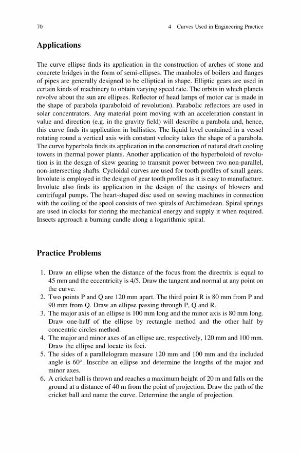
Applications
The curve ellipse finds its application in the construction of arches of stone and
concrete bridges in the form of semi-ellipses. The manholes of boilers and flanges
of pipes are generally designed to be elliptical in shape. Elliptic gears are used in
certain kinds of machinery to obtain varying speed rate. The orbits in which planets
revolve about the sun are ellipses. Reflector of head lamps of motor car is made in
the shape of parabola (paraboloid of revolution). Parabolic reflectors are used in
solar concentrators. Any material point moving with an acceleration constant in
value and direction (e.g. in the gravity field) will describe a parabola and, hence,
this curve finds its application in ballistics. The liquid level contained in a vessel
rotating round a vertical axis with constant velocity takes the shape of a parabola.
The curve hyperbola finds its application in the construction of natural draft cooling
towers in thermal power plants. Another application of the hyperboloid of revolu-
tion is in the design of skew gearing to transmit power between two non-parallel,
non-intersecting shafts. Cycloidal curves are used for tooth profiles of small gears.
Involute is employed in the design of gear tooth profiles as it is easy to manufacture.
Involute also finds its application in the design of the casings of blowers and
centrifugal pumps. The heart-shaped disc used on sewing machines in connection
with the coiling of the spool consists of two spirals of Archimedean. Spiral springs
are used in clocks for storing the mechanical energy and supply it when required.
Insects approach a burning candle along a logarithmic spiral.
Practice Problems
1. Draw an ellipse when the distance of the focus from the directrix is equal to
45 mm and the eccentricity is 4/5. Draw the tangent and normal at any point on
the curve.
2. Two points P and Q are 120 mm apart. The third point R is 80 mm from P and
90 mm from Q. Draw an ellipse passing through P, Q and R.
3. The major axis of an ellipse is 100 mm long and the minor axis is 80 mm long.
Draw one-half of the ellipse by rectangle method and the other half by
concentric circles method.
4. The major and minor axes of an ellipse are, respectively, 120 mm and 100 mm.
Draw the ellipse and locate its foci.
5. The sides of a parallelogram measure 120 mm and 100 mm and the included
angle is 60�. Inscribe an ellipse and determine the lengths of the major and
minor axes.
6. A cricket ball is thrown and reaches a maximum height of 20 m and falls on the
ground at a distance of 40 m from the point of projection. Draw the path of the
cricket ball and name the curve. Determine the angle of projection.
70 4 Curves Used in Engineering Practice

7. The sides of a rectangle are 100 mm and 80 mm. Inscribe two parabolas with
axes perpendicular to each other.
8. A suspension bridge has a total span of 20 m. The dip at the centre is 2 m. Draw
the profile of the bridge and also tangents to the curve at the two ends. Adopt a
scale 1:100
9. Draw the curve given by the equation Y2¼ 16X. Draw the tangent to this curve
at any point on it and also locate its focus.
10. Draw the curve representing the shape of the principal section of the parabolic
motor car head lamp reflector having an aperture of 140 mm and a depth of
70 mm.
11. The focus and the corresponding vertex of a hyperbola are 30 mm and 10 mm
distant from the directrix. Draw the curve and also the tangent and normal at
any point on the curve.
12. Draw both branches of a hyperbola, given eccentricity ¼ 3/2 and focus 40 mm
from the directrix. Mark the second directrix and focus. Draw the asymptotes
and measure the angle between them.
13. Draw a rectangular hyperbola, given that a point on the curve is 20 mm from
one asymptote and 30 mm from the other.
14. The asymptotes of a hyperbola intersect at 70� and at a distance of 40 mm from
the vertices of both branches of hyperbola. Draw one branch of the hyperbola
and locate its focus.
15. Draw a cycloid, given rolling circle diameter 60 mm. Draw the tangent and
normal for a point 40 mm from the base line and on the descending side of the
curve.
16. A circle of 40 mm diameter rolls for the first half of a revolution on a horizontal
line and the second half of the revolution on a vertical line. Draw the curve
traced out by the point P which is initially at the point of contact of the
horizontal line and the circle.
17. A circle of 50 mm diameter rolls on another circle of 50 mm diameter. Draw the
epicycloid.
18. A circus man rides a motor-cycle inside a globe of 4 m diameter. The motor-
cycle wheel diameter is 0.8 m. Draw the locus of a point spot on the circum-
ference of the motor-cycle wheel for its one complete turn. Adopt a suitable
scale.
19. Draw an involute of a hexagon of side 20 mm.
20. Trace the paths of the ends of a straight line AP 100 mm long when it rolls
without slipping on a semi-circle of 80 mm diameter. Assume the line AP to be
the tangent to the semi-circle in the starting position.
21. Draw two convolutions of an Archimedean spiral, least radius 10 mm and
greatest radius 58 mm. Also draw the tangent and normal at a point on the curve
40 mm from the pole.
22. The shortest radius vector in a logarithmic spiral is 10 mm. The lengths of
adjacent radius vectors enclosing 30� are in the ratio 10:9. Draw one convolu-
tion of the curve.
Practice Problems 71

23. Draw a series of triangles of base 100 mm and perimeter 240 mm and plot the
curve passing through the vertices. [Hint: The curve passing through the
vertices of the triangle is an ellipse. The base points of the triangle are the
foci of the ellipse and the length of the major axis of the ellipse is 140 mm].
24. AP, a chord of a parabola, is 50 mm long and is inclined at 50� to the axis. A is
the vertex of the parabola. Draw the curve parabola.
25. PNP, a double ordinate of a parabola, is 90 mm long. A is the vertex of the
parabola. The area bounded by the curve PAP and the double ordinate PNP is
12,000 mm2. Draw the curve. [Hint: Area bounded by the parabola PAP and the
double ordinate PNP is given by the formula, Area ¼ (2/3) X (axis or abscissa)
X (double ordinate)].
26. A toy rocket thrown up in the air reaches a maximum horizontal range of 50 m.
Trace the path of the rocket choosing a suitable scale. [Hint: The path of the
rocket in the air is a parabola. The angle of projection for maximum horizontal
range is 45� to the ground. The tangent to the curve at the point of projection
makes an angle of 45� to the ground.]
27. The transverse and conjugate axes of a hyperbola are 80 mm and 60 mm,
respectively. Draw the hyperbola and locate its focus.
28. For a perfect gas, the relation between the pressure p and volume V in an
isothermal expansion is given by pV ¼ constant. Draw the curve of isothermal
expansion of an enclosed volume of gas if the pressure of 0.2 m3 of gas is
40 bar. Determine the final volume of the gas for a pressure of 2 bar.
29. ABC is an equilateral triangle of side 60 mm. Trace the loci of the vertices A, B
and C when the circle circumscribing circle rolls without slipping along a fixed
straight line for one complete revolution.
30. Trace the simultaneous locus of the two extremities of initially vertical diam-
eter of a circle of diameter 50 mm, which rolls on a straight line without
slipping.
31. A circle of 60 mm diameter rolls without slipping on the outside of another
circle of diameter 240 mm. Show the path of a point on the periphery of the
rolling circle diametrically opposite to the initial point of contact between the
circles.
32. Draw a hypocycloid developed by a rolling circle of diameter 40 mm on a base
circle of diameter 240 mm Draw also a tangent and normal at any point on the
curve.
33. A rod 240 mm long rolls without slipping on the periphery of a disc of diameter
70 mm. Trace the locus of the two ends of the rod.
34. A spider is sitting at the centre of second’s hand of a wall clock. Trace and
name the curve followed by the spider if it moves radially out such that it
travels 60 mm during 1 min time.
72 4 Curves Used in Engineering Practice

Chapter 5
Orthographic Projections
An engineer must be able to visualize in his mind how an object looks like without
actually having the object. He must also be able to describe the object so that others
could build it from the information provided on his drawing. The description of an
object with lines requires a thorough knowledge of the principles of orthographic
projections.
The problem of representing a three-dimensional solid object on a sheet of paper
to show the exact shape is done by drawing views of the object as seen from
different positions and arranging these views in a systematic manner.
A rectangular prism is viewed in three directions as shown in Fig. 5.1. Views in
each of these directions are shown and named as in Fig. 5.2.
A cylinder is viewed in three directions as shown in Fig. 5.3. Views of the
cylinder are shown and named as in Fig. 5.4. The plan shows the circular shape of
the cylinder. The elevation and side elevation appear as rectangles and are of the
same size.
The cylinder is placed on the prism, and these parts are viewed as shown in
Fig. 5.5. Complete views composed of views of separate parts are shown in Fig. 5.6.
Orthographic Projection
The use of different views to describe an object, as seen previously, is based upon
the principles of orthographic projection. Ortho- means ‘straight or right angles’and -graphic means ‘written or drawn’. Projection comes from two Latin words,
‘pro’ meaning ‘forward’ and ‘jacere’ meaning ‘to through’. Thus, orthographicprojection means ‘through forward, drawn at right angles’. The following definitionhas been given: Orthographic projection is the method of representing the exact
form of an object in two or more views on planes generally at right angles to each
other, by dropping perpendiculars from the object to the planes.
© Springer Nature Singapore Pte Ltd. 2018
K. Rathnam, A First Course in Engineering Drawing,DOI 10.1007/978-981-10-5358-0_5
73

Planes of Reference
Two principal planes are used in orthographic projection, one horizontal and the
other vertical, intersecting and dividing space into four quadrants numbered as in
Fig. 5.7. These planes are denoted as the horizontal plane (HP) and the vertical
plane (VP). The line of intersection of the planes of projection is called as the
reference line xy. The object is supposed to be situated in one of the quadrants. It is
represented by its orthographic projection on the HP and VP, the views giving,
respectively, its plan and elevation. To show these views on a plane surface, the HP
Fig. 5.1 Rectangular prism
Fig. 5.2 Views of the
prism
Fig. 5.3 Cylinder
74 5 Orthographic Projections

is rotated about xy line until it coincides with the VP. The convention is that the first
quadrant is always opened out. For projection in the second, third and fourth
quadrants, the planes are assumed to be transparent and the projections are drawn
looking from the first quadrant. For practical purposes, the first and third quadrants
only are used for the projection; in the second and fourth quadrants, the views
overlap and cause confusion. An auxiliary vertical plane perpendicular to both the
horizontal plane and vertical plane is also used to get a third view of the object. The
third view can also be obtained from the two views by applying the principles of
auxiliary projections. This topic will be covered later in Chap. 9.
Fig. 5.4 Views of the
cylinder
Fig. 5.5 Combination of
solids
Planes of Reference 75

First Quadrant Projection (Figs. 5.8 and 5.9)
The projection on the HP is obtained by projectors drawn perpendicular to the HP
from the corners of the object as shown in Fig. 5.8. This will give the horizontal
projection or the plan or the top view of the object. This view will also show the
depth (D) and width (W) of the object. The projection on the VP is obtained by
drawing projectors perpendicular to the VP from the corners of the object as shown
in Fig. 5.8. This will give the vertical projection or the elevation or the front view of
the object with its height (H) and width (W). The projection on the auxiliary vertical
plane (AVP) is obtained by projectors drawn perpendicular to the AVP from the
Fig. 5.6 Views of the
solids
Fig. 5.7 Pictorial views of
the principal planes of
projection
76 5 Orthographic Projections

corners of the object. This will give the side elevation or the side view of the object
with its height (H) and depth (D).
When the first quadrant is opened out until the HP and AVP coincide with the
VP, the projections take the position as shown in Fig. 5.9. The plan is placed
beneath the elevation and the side elevation looking from the left is placed on the
right. The elevation shows the width (W) and the height (H) of the object. The plan
shows the width (W) and depth (D) of the object. The side elevation shows the
depth (D) and height (H) of the object.
Fig. 5.8 Pictorial view
Fig. 5.9 Orthographic
projection
First Quadrant Projection (Figs. 5.8 and 5.9) 77

Third Quadrant Projection (Figs. 5.10 and 5.11)
The principal planes which are transparent lie between the observer and the object
as shown in Fig. 5.10. The projections are viewed through the planes and are
obtained on them as shown in Fig. 5.10. The projection on the VP is named as
the front view, the projection on the HP is named as the top view and the projection
on the auxiliary vertical plane (AVP) is named as the end view of the object. The
HP and AVP are opened out until they coincide with the VP. The projections or
views of the object take the positions as shown in Fig. 5.11. The front view is
beneath the top view and the end view is adjacent to the end of the object that it
Fig. 5.10 Pictorial view
Fig. 5.11 Orthographic
views
78 5 Orthographic Projections

describes.The front view shows the height (H) and width (W), the top view shows
the width (W) and depth (D) and the end view shows the height (H) and depth (D) of
the object.
The views in Figs. 5.9 and 5.11 describe the object completely. The first angle
projection is used in this book. The first and third angle projections are identifiable
by their relative arrangement of views. The system of projection used in a drawing
is indicated by standard symbol. Figure 5.12 illustrates standard symbol for the first
angle projection. Figure 5.13 illustrates standard symbol for the third angle projec-
tion. The method of projection used should be indicated in the space provided for
this purpose in the title block of the drawing sheet.
The pictorial sketches and projections of certain objects are furnished in the
following figures to understand the theory of projection.
The pictorial sketch of an object is shown in Fig. 5.14. The orthographic pro-
jections of the object are shown in Fig. 5.15. Each projection represents a single
surface. A normal surface is a plane surface which is parallel to a plane of
projection. A normal surface will appear true size in one view and as a vertical or
horizontal line in each of the other two views. All surfaces are normal in this case.
Figure 5.16 shows the pictorial sketch of an object with surfaces at different
levels. The orthographic projections of the object are given in Fig. 5.17. The plan
Fig. 5.12 First angle
projection symbol
Fig. 5.13 Third angle
projection symbol
Fig. 5.14 Pictorial sketch
Third Quadrant Projection (Figs. 5.10 and 5.11) 79

Fig. 5.15 Orthographic
projections
Fig. 5.16 Pictorial sketch
Fig. 5.17 Orthographic
projections
80 5 Orthographic Projections

shows two surfaces A and B at different levels and surface A is above surface B as
shown by the elevation. In side elevation surfaces C and D are shown, but it is
certain from the elevation the surface C is closer to the AVP, which is behind the
object.
Figure 5.18 shows the pictorial sketch of an object with an inclined surface. The
orthographic projections of the object are given in Fig. 5.19.
The surface B is shown slightly shortened in the plan and very much shortened in
the side elevation. To obtain the true size of surface B, the distance de must be taken
from the elevation and the distance ef must be taken from the side elevation. The
inclined surface B appears as a line in the elevation (surface is perpendicular to the
VP).
Figure 5.20 shows the pictorial sketch of an object with a surface inclined to all
three planes (oblique surface). The orthographic projections of the object are as in
Fig. 5.21.
Fig. 5.18 Pictorial sketch
Fig. 5.19 Orthographic
projections
Third Quadrant Projection (Figs. 5.10 and 5.11) 81

The surface B is inclined to all three planes and appears in all three projections.
The true size of surface can be obtained knowing distances 12 from elevation,
23 from the side elevation and 31 from the plan.
Hidden Lines
Parts which cannot be seen in the views are represented by hidden lines composed
of short dashes or dotted. Figure 5.22 shows the pictorial sketch of an object. The
orthographic projections of the object are shown in Fig. 5.23. The surface A is
shown as an edge view in the elevation. Since the edge view is invisible in the
Fig. 5.20 Pictorial sketch
Fig. 5.21 Orthographic
projections
82 5 Orthographic Projections

elevation, it is shown as hidden line. The first dash of a hidden line touches the line
at which it starts.
Figure 5.24 shows the pictorial sketch of an object. Its orthographic projections
are shown in Fig. 5.25. The surface A is shown as an edge view in the elevation. A
portion of this edge view is invisible in the elevation. In this case, the invisible
Fig. 5.22 Pictorial sketch
Fig. 5.23 Orthographic
projections
Fig. 5.24 Pictorial sketch
Hidden Lines 83

portion of the hidden line is continuation of the visible full line. Hence, a space is
left between the full line and the first dash of the hidden line.
Solved Problems
1. Sketch freehand the orthographic projections of the object shown in Fig. 5.26
following the first angle projection. Identify the surfaces on the projections by
marking the corresponding alphabets.
The elevation, plan and left side elevation of the object are shown in
Fig. 5.27.
Fig. 5.25 Orthographic
projections
Fig. 5.26 Object
84 5 Orthographic Projections

2. Sketch freehand the orthographic projections of the object shown in Fig. 5.28
following the first angle projection. Identify the surfaces on the projections by
marking the corresponding alphabets.
The elevation, plan and left side elevation of the object are shown in
Fig. 5.29.
3. Sketch freehand the orthographic projections of the object shown in Fig. 5.30
following the first angle projection. Identify the surfaces on the projections by
marking the corresponding alphabets.
The elevation, plan and left side elevation of the object are shown in
Fig. 5.31.
Fig. 5.27 Projections of the
object
Fig. 5.28 Object
Solved Problems 85

4. Sketch freehand the orthographic views of the object shown pictorially in
Fig. 5.32 following the third angle projection. Identify the surfaces on the
projection by marking the corresponding alphabets.
The front view, top view and left end view of the object are shown in
Fig. 5.33.
5. The orthographic projections of an object are shown in Fig. 5.34. Visualize the
shape of the object and sketch its pictorial view.
Solution: Fig. 5.35 shows the pictorial view of the object.
6. The orthographic projections of an object are shown in Fig. 5.36. Sketch its
pictorial view.
Solution: Fig. 5.37 shows the pictorial view of the object
7. The orthographic projections of an object are shown in Fig. 5.38. Sketch its
pictorial view.
Solution: Fig. 5.39 shows the pictorial view of the object
Fig. 5.29 Projections of the
object
Fig. 5.30 Object
86 5 Orthographic Projections
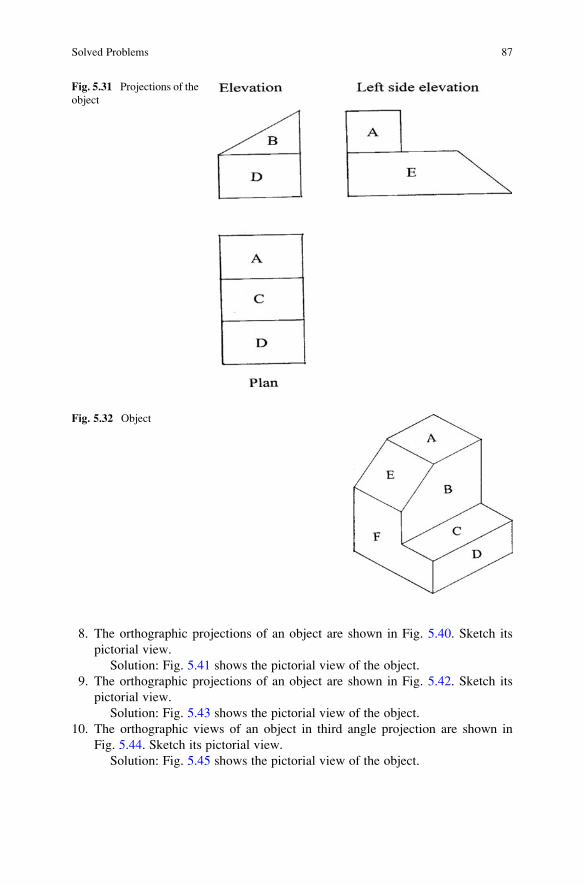
8. The orthographic projections of an object are shown in Fig. 5.40. Sketch its
pictorial view.
Solution: Fig. 5.41 shows the pictorial view of the object.
9. The orthographic projections of an object are shown in Fig. 5.42. Sketch its
pictorial view.
Solution: Fig. 5.43 shows the pictorial view of the object.
10. The orthographic views of an object in third angle projection are shown in
Fig. 5.44. Sketch its pictorial view.
Solution: Fig. 5.45 shows the pictorial view of the object.
Fig. 5.31 Projections of the
object
Fig. 5.32 Object
Solved Problems 87

Fig. 5.33 Orthographic
views
Fig. 5.34 Orthographic
projections of an object
Fig. 5.35 Pictorial view of
the object
88 5 Orthographic Projections

Fig. 5.36 Orthographic
projection of an object
Fig. 5.37 Pictorial view of
the object
Fig. 5.38 Orthographic
projections of an object
Solved Problems 89

Fig. 5.39 Pictorial view of
the object
Fig. 5.40 Orthographic
projections of an object
Fig. 5.41 Pictorial view of
the object
90 5 Orthographic Projections

11. A line is missing in one of the projections of the object whose projections are
shown in Fig. 5.46. Identify the projection and sketch it with the missing line.
Solution: Fig. 5.47 shows the plan of the object with the missing line
inserted in the appropriate place.
12. A line is missing in one of the projections of the object whose projections are
shown in Fig. 5.48. Identify the projection and sketch it with the missing line.
Solution: Fig. 5.49 shows the elevation of the object with the missing line
inserted in the appropriate place.
Fig. 5.42 Orthographic
projections of an object
Fig. 5.43 Pictorial view of
the object
Solved Problems 91

13. A line is missing in one of the projections of the object whose projections are
shown in Fig. 5.50. Identify the projection and sketch it with the missing line.
Solution: Fig. 5.51 shows the left side elevation of the object with the
missing line inserted in the appropriate place.
14. A line is missing in one of the projections of the object whose projections are
shown in Fig. 5.52. Identify the projection and sketch it with the missing line.
Solution: Fig. 5.53 shows the left side elevation of the object with the
missing line inserted in the appropriate place.
Fig. 5.44 Orthographic
views of an object
Fig. 5.45 Pictorial view of
the object
92 5 Orthographic Projections

Fig. 5.46 Projections of the
object
Fig. 5.47 Projection of the
object
Fig. 5.48 Projections of the
object
Fig. 5.49 Projection of the
object
Solved Problems 93

Fig. 5.50 Projections of the
object
Fig. 5.51 Projection of the
object
Fig. 5.52 Projections of the
object
94 5 Orthographic Projections

15. A line is missing in one of the projections of the object whose projections are
shown in Fig. 5.54. Identify the projection and sketch it with the missing line.
Solution: Fig. 5.55 shows the plan of the object with the missing line
inserted in the appropriate place.
Note: The following five problems are intended primarily for supplementary
practice in visualizing projections.
Fig. 5.53 Projection of the
object
Fig. 5.54 Projections of the
object
Fig. 5.55 Projection of the
object
Solved Problems 95

16. Complete the orthographic projections of the object as assigned in Fig. 5.56
supplying the missing projection.
Solution: The missing left side elevation is shown in Fig. 5.57.
17. Complete the orthographic projections of the object as assigned in Fig. 5.58
supplying the missing projection.
Solution: The missing elevation is shown in Fig. 5.59.
18. Complete the orthographic projections of the object as assigned in Fig. 5.60
supplying the missing projection.
Solution: The missing left side elevation is shown in Fig. 5.61.
19. Complete the orthographic projections of the object as assigned in Fig. 5.62
supplying the missing projection.
Solution: The missing plan is shown in Fig. 5.63
20. Complete the orthographic projections of the object as assigned in Fig. 5.64
supplying the missing projection.
Solution: The missing plan is shown in Fig. 5.65.
Fig. 5.56 Orthographic
projections of the object
Fig. 5.57 Orthographic
projection of the object
96 5 Orthographic Projections

Fig. 5.58 Orthographic
projections of the object
Fig. 5.59 Orthographic
projection of the object
Fig. 5.60 Orthographic
projections of the object
Solved Problems 97

Fig. 5.62 Orthographic
projections of the object
Fig. 5.61 Orthographic
projection of the object
Fig. 5.63 Orthographic
projection of the object
Fig. 5.64 Orthographic
projections of the object
Fig. 5.65 Orthographic
projection
98 5 Orthographic Projections

Practice Problems
1. Sketch freehand the orthographic projections of the objects shown in Figs. 5.66,
5.67, 5.68 and 5.69 following the first angle projections.
2. Complete the orthographic projections of the objects as assigned in Figs. 5.70,
5.71, 5.72, 5.73, 5.74 and 5.75 supplying the missing projection.
Fig. 5.66 ■
Fig. 5.67 ■
Fig. 5.68 ■
Practice Problems 99

Fig. 5.69 ■
Fig. 5.70 ■
Fig. 5.71 ■
Fig. 5.72 ■
100 5 Orthographic Projections

Fig. 5.74 ■
Fig. 5.73 ■
Fig. 5.75 ■
Practice Problems 101

Chapter 6
Projections of Points
In orthographic projection, an exact view of an object is obtained on a plane by
projectors drawn from the end points of the object to meet the plane of projection at
right angles. The view obtained in general consists of line representing edge of the
object and lines representing surfaces of the object. A line on the view is obtained
by the projections of two end points of the edge. Hence, the projection of points
shall be the starting point to understand the theory of projection of lines and
surfaces of the object. As the point has no dimension, its location is specified
with reference to the co-ordinate planes. The point can be located in any of the
four quadrants.
Projections of a Point
Refer to Fig. 6.1 showing the pictorial representation of a point A and the
co-ordinate planes VP and HP. The point A is above the HP and in front of the
VP and is situated in the First quadrant. A horizontal projector is drawn from A to
meet the VP giving the elevation a0 of the point. The height of the point A above the
HP shall be the distance of a0 from XY, the reference line/ground line. A vertical
projector is drawn from A to meet the HP giving the plan a of the point. The
distance of the point A from the VP shall be the distance of a from XY. To show the
projections of the point on a plane surface, the HP is rotated as indicated about XY
line until it coincides with the VP. The convention followed is that the first quadrant
is always opened out. The projections a0 and a lie in one plane and appear as shownin Fig. 6.2.
© Springer Nature Singapore Pte Ltd. 2018
K. Rathnam, A First Course in Engineering Drawing,DOI 10.1007/978-981-10-5358-0_6
103

Notation in Projections
In the text space point / end point of a line / a point in solid is denoted by an upper
case alphabet, its plan by its lower case, its elevation by its lower case with a dash
over it and its side elevation by its lower case with double dash over it. In the figures
space point / end point of a line / a point in solid is denoted by an upper case
alphabet, its plan by its lower case, its elevation by its lower case with an apos-
trophe over it and its side elevation by its lower case with an end quotation mark
over it.
Fig. 6.1 Pictorial
representation
Fig. 6.2 Projections of
point A
104 6 Projections of Points

Figure 6.3 shows the pictorial representation of a point B which is above the
HP and behind the VP and is situated in the Second quadrant. The corresponding
projections b0 and b are shown in Fig. 6.4.
Figure 6.5 shows the pictorial representation of a point C which is below the
HP and behind the VP and is situated in the Third quadrant. The corresponding
projections c0 and c are shown in Fig. 6.6.
Figure 6.7 shows the pictorial representation of a point D which is below the
HP and in front of the VP and is situated in the Fourth quadrant. The corresponding
projections d0 and d are shown in Fig. 6.8.
Fig. 6.3 Pictorial
representation
Fig. 6.4 Projections of
point B
Notation in Projections 105

Fig. 6.5 Pictorial
representation
Fig. 6.6 Projections of
point C
106 6 Projections of Points

The following points are to be noted from Figs. 6.2, 6.4, 6.6 and 6.8:
1. The line joining the elevation and plan of a point or its extension in Figs. 6.4 and
6.8 is called a projector and is perpendicular to the reference line xy.
2. The elevation of a point is above or below xy according as the point is above or
below the horizontal plane (HP) of projection.
3. The plan of a point is below or above xy according as the point is in front of or
behind the vertical plane (VP) of projection.
4. The distance of the elevation of a point from xy is equal to the distance of the
point from the horizontal plane (HP) of projection.
5. The distance of the plan of a point from xy is equal to the distance of the point
from the vertical plane (VP) of projection.
6. The elevation and plan of a point lie on the same projector. Hence, the plan can
be projected from its elevation or the elevation can be projected from its plan.
Fig. 6.7 Pictorial
representation
Fig. 6.8 Projections of
point D
Notation in Projections 107

Solved Problems
(Hint: Graph sheets can be used for showing the projections of the points)
1. Draw the projections of the following points on the same reference line keeping
the projectors 20 mm apart.
A: 40 mm above the HP and 25 mm in front of the VP.
B: 15 mm above the HP and 50 mm behind the VP.
C: 25 mm below the HP and 25 mm behind the VP.
D: 40 mm below the HP and 25 mm in front of the VP.
E: In the HP and 20 mm behind the VP.
F: 40 mm above the HP and in the VP.
G: In both the HP and the VP.
Draw the reference line xy long enough to accommodate the projections of all
points keeping a distance of 20 mm between the projectors as shown in Fig. 6.9.
Capital letters are marked at the top of the projectors to show the corresponding
projections. The projections of the points are as follows:
A: The elevation a0 is 40 mm above xy and the plan a is 25 mm below xy.
B: The elevation b0 is 15 mm above xy and the plan b is 50 mm above xy.
C: The elevation c0 is 25 mm below xy and the plan c is 25 mm above xy.
D: The elevation d0 is 40 mm below xy and the plan d is 25 mm below xy.
E: The elevation e0 is on xy and the plan e is 20 mm above xy.
F: The elevation f0 is 40 mm above xy and the plan f is on xy.
G: The elevation g0 and the plan g are both on xy.
Fig. 6.9 Projections of points A, B, C, D, E, F and G
108 6 Projections of Points

The projections of the points are shown in the figure.
2. A point P is 50 mm from the HP and 30 mm from the VP. Draw its projections in
all possible positions.
Let P1, P2, P3 and P4 be the four points in the four quadrants with the given
distances from the co-ordinate planes. The point P1 is 50 mm above the HP and
30 mm in front of the VP. Its elevation p10 is 50 mm above xy and plan p1 is
30 mm below xy. Similarly, the projections of other three points P2, P3 and P4
are obtained with their positions from xy. The projections of the four points are
shown in Fig. 6.10 keeping a distance of 20 mm between their projectors.
3. State the quadrants in which the following points are situated:
(i) A point R; its plan is 40 mm above xy line; the elevation is 20 mm below
the plan.
(ii) A point S; its projections coincide and lie 40 mm below xy line.
The projections of the points are shown in Fig. 6.11 on the same reference line xy.
Point R: The elevation r0 is 20 mm above xy and the point R is 20 mm above the
HP. The plan r is 40 mm above xy and the point R is 40 mm behind the VP. So,
the point R is situated in the second quadrant.
Point S: The elevation s0 is 40 mm below xy and the point is 40 mm below the
HP. The plan s is 40 mm below xy and the point is 40 mm in front of the VP. So,
the point S is situated in the fourth quadrant.
4. State the exact positions of the points whose projections are given in Fig. 6.12
with reference to the planes of projections giving the distances in mm.
The following are the positions of the points whose projections are shown in
Fig. 6.12:
Fig. 6.10 Projections of
points P1, P2, P3 and P4
Solved Problems 109

A: 50 mm below the HP and 20 mm in front of the VP.
B: 40 mm below the HP and in the VP.
C: 20 mm above the HP and 30 mm in front of the VP.
D: In the HP and 30 mm behind the VP.
E: 15 mm above the HP and 40 mm behind the VP.
5. A point 40 mm above xy line is the plan of three points A, B and C. The point A
is 20 mm above, the point B is 30 mm below and the point C is on the
HP. Determine the projections of A, B and C.
The plans of the given points are located 40 mm above the reference line xy as
shown in Fig. 6.13. The elevations of these points lie on the projector drawn
from the plan of the points. The elevation a0 is 20 mm above xy. The elevation b0
is 30 mm below xy. The elevation c0 lies on xy. The projections of the points areshown in the same figure.
Fig. 6.11 Projections of points R and S
Fig. 6.12 Projections of points A, B, C, D and E
110 6 Projections of Points

6. A point P is 15 mm above the HP and 20 mm in front of the VP. Another point Q
is 40 mm below the HP and 25 mm behind the VP. Draw the projections of P and
Q keeping the distance between their projectors equal to 90 mm. Draw straight
lines joining (i) their plans and (ii) their elevations.
Draw the reference line xy as shown in Fig. 6.14. The elevation p0 is locatedon the projector drawn perpendicular to xy and 15 mm above xy. The plan p is
located on the same projector 20 mm below xy. The elevation q0 is 40 mm below
xy and the plan q is 25 mm above xy. Another projector at a distance of 90 mm
from the projector P is drawn, and the points q0 and q are located on this
projector. A line is drawn connecting p and q. Another line is drawn connecting
p0 and q0. The elevation p0q0 and the plan pq of the line PQ are shown in the
same figure.
Fig. 6.13 Projections of points A, B and C
Fig. 6.14 Projections of points P and Q
Solved Problems 111

7. Show the projections of the points A, B, C, D and E using the same reference line
xy for all projections and making the projectors 20 mm apart.
(i) The plan of A is 30 mm below xy and the point A is 40 mm above the HP.
(ii) The plan of B is 35 mm above the xy and the point B is 35 mm above
the HP.
(iii) The elevation of C is on xy and the point C is 45 mm behind the VP.
(iv) The plan d is on xy and the point D is on the HP.
(v) The point E is 30 mm below the HP and e is 20 mm above xy.
The reference line xy is drawn, and the projectors are fixed on xy at intervals of
20 mm as shown in Fig. 6.15. The projections of the points are as follows:
A: The plan a is 30 mm below xy and the elevation a0 is 40 mm above xy.
B: The plan b is 35 mm above xy and the elevation b0 is 35 mm above xy.
C: The plan c is 45 mm above xy and the elevation c0 is on xy.
D: The plan d is on xy and the elevation d0 is also on xy.
E: The plan e is 20 mm above xy and the elevation e0 is 30 mm below xy.
The projections of the points are shown in Fig. 6.15.
8. A point touches all the three principal planes of projections. Draw its
projections.
The vertical plane, the horizontal plane and the profile plane are shown
pictorially in Fig. 6.16; the intersection of the VP and the HP is shown by the
reference line XY and the intersection of the VP, and the profile plane is shown
by the reference line X1Y1. The HP is rotated about the line XY until it
coincides with the VP. The profile plane is also rotated about X1Y1 until it
coincides with the VP. The three planes are shown in the figure after rotation
with the reference lines. The intersection of xy and x1y1 gives a point common
to the three planes and hence this point P represents its projection.
9. Two points A and B are in the HP. The point A is 30 mm in front of the VP
while B is behind the VP. The distance between their projectors is 75 mm, and
Fig. 6.15 Projections of
points A, B, C, D and E
112 6 Projections of Points

the line joining their plans makes an angle of 45� with xy. Find the distance of
the point B from the VP.
Draw the reference line xy as shown in Fig. 6.17. Two projectors are drawn
keeping a distance of 75 mm between them and the elevations a0 and b0 arelocated on xy as shown in the figure. The plan a is located 30 mm below xy
from a0. Since the point B is behind the VP, its plan will be above xy on the
projector drawn from b0. As the plan makes an angle of 45� with xy, a line is
drawn from a making an angle of 45� as shown in the figure. The intersection ofthis line with the projector B fixes the plan b. The distance of b from xy
measures the distance of B from the VP. The point B is 45 mm behind the VP.
10. Draw the projection of a point 30 mm above the HP and in the first quadrant, if
its shortest distance from the line of intersection of reference planes is 50 mm.
Also find the distance of the point from the VP.
Fig. 6.16 Projections of P
touching VP, HP and PP
Fig. 6.17 Projections of
points A and B
Solved Problems 113

Draw the reference line xy and locate the elevation a0 of the point above xyas shown in Fig. 6.18. Assume that the projection of this point is to be obtained
on the profile plane with reference to the new reference line x1 y1, the
intersection of the vertical plane and the profile plane as shown in the figure.
A projector is drawn from a0 perpendicular to x1 y1, and the elevation a10 on theprofile plane should lie along this line from x1 y1. The intersection of reference
line xy with x1y1 is designated as O. An arc of radius 50 mm is drawn with
centre O to intersect the projector drawn from a0. The intersecting point gives
the projection of this point on the profile plane. The distance of a10 from x1 y1
gives the distance of the point from the VP. The plan a is located on the
projector drawn perpendicular to xy from a0 as shown in the figure. The plan
a is 40 mm from xy. Hence, the point is 40 mm in front of the VP.
Practice Problems
1. Draw the projections of the following points using the same reference line xy for
all projections and keeping the projectors 20 mm apart.
A, 50 mm above the HP and 60 mm in front of the VP
B, 50 mm above the HP and 60 mm behind the VP
C, 40 mm below the HP and 30 mm behind the VP
D, 30 mm below the HP and 40 mm in front of the VP
E, 35 mm above the HP and in the VP
F, on the HP and 40 mm in front of the VP.
Fig. 6.18 Projections of
point A
114 6 Projections of Points

2. A point 30 mm above xy is the elevation of two points A and B. The plan of A is
40 mm behind the VP and the plan of B is 40 mm in front of the VP. Draw the
projections of the two points and state their positions with reference to the
co-ordinate planes and the quadrants in which they are situated.
3. Draw the projections of the points in Table 6.1 at 20 mm intervals along the
xy line.
4. State the position of each of the points in Table 6.2 with reference to the HP and
the VP and also the quadrant in which the point is situated:
5. Draw the projections of a point lying 25 mm in front of the VP and in the
first quadrant if its shortest distance from the line of intersection of the HP and
the VP is 65 mm. Also find the distance of the point from the HP.
6. The plan of the point P lies 40 mm above the reference line xy and its elevation
50 mm above the reference line xy. Mention the quadrant in which the point is
situated. Draw its projections and find the shortest distance of the point from the
intersection of the HP and VP.
7. A point Q is situated in a plane inclined 30� to the HP and passing through the
intersection of the HP and VP. Draw the projections of the point if the distance of
Q is 30 mm above the HP.
8. A point R is situated in a plane inclined 40� to the VP and passing through the
intersection of the HP and VP. Draw the projections of R if the distance of R is
50 mm in front of the VP.
9. A triangle ABC is in the first quadrant. A is in the VP and 50 mm above the
HP. B and C are in the HP. The plan of line ab makes 45� with the reference linexy and the plan of the triangle abc is an equilateral triangle of 50 mm side.
Draw the plan and elevation of the triangle.
Table 6.2 Projections of
pointsPoint Elevation Plan
A 50 mm above xy 20 mm below xy
B 10 mm below xy 30 mm above xy
C 40 mm above xy 20 mm above xy
D 30 mm below xy 40 mm below xy
Table 6.1 Positions of points
Point A B C D E F G
Distance from the HP (mm) 40 20 10 20 �10 �20 0
Distance from the VP (mm) 20 10 0 �10 �20 30 10
Practice Problems 115

Chapter 7
Projections of Lines
The projections of a straight line in various positions in the first quadrant are
grouped based on its orientation with reference to the vertical and horizontal planes.
They are:
1. Parallel to both the planes
2. Perpendicular to one plane
3. Parallel to one plane and inclined to the other plane
4. Lying in one plane
5. Lying in the reference line xy (intersection of the VP and the HP)
6. Inclined to both the planes
7. Inclined to both the planes with an end in the reference line xy
8. Inclined to both the planes with ends in both the planes
9. Perpendicular to the reference line xy
The methods of obtaining the projections are classified under three categories.
Type I
The straight line and its projection on a plane have the same length when the line is
parallel to that plane. Hence, it is straight-forward to obtain one of the projections.
When the straight line is parallel to both the planes, the projections have the same
length. After marking the projections of one end of the line, the projections of the
line are completed. There are six problems (nos. 1–6) that belong to this category.
Type II
The projections of a straight line inclined to both the planes will be given or stated.
The true length, inclinations to the planes of projection and the meeting points of
extension of the line with the planes (traces) are obtained by constructing trapeziums
on the projections of the line itself. Following this method, the solutions to
nine problems (nos. 7–15) are obtained.
© Springer Nature Singapore Pte Ltd. 2018
K. Rathnam, A First Course in Engineering Drawing,DOI 10.1007/978-981-10-5358-0_7
117

Type III
The method of obtaining the projections of a straight line inclined to both the planes
is explained. This method is reversed to get the true length and inclinations to the
reference planes from the projections of the line inclined to both the planes. An easy
method of locating the traces alone from the projections of the line is also given
with a caution that this simple procedure poses a problem when the projections of
the line are perpendicular to the reference line xy. The remaining problems in
this chapter are solved by following the method detailed in this type or by some
combinations.
Solved Problems
1. Draw the projections of a line 40 mm long when it is parallel to both the HP and
the VP. The line is 20 mm from both the planes.
Consider the pictorial representation of the line AB in the first quadrant as
shown in Fig. 7.1. The line is 20 mm above the HP and 20 mm in front of the
VP. Horizontal projectors are drawn from A and B to meet the vertical plane at a0
and b0. Since the line is parallel to the VP, a0b0 will be parallel to AB. The
elevation a0b0 will be equal to the true length of the line AB (i.e. a0b0 ¼ 40 mm).
Vertical projectors are drawn from A and B to meet the horizontal plane at a and
b. Since the line is parallel to the HP, the plan ab will be equal to the true length
Fig. 7.1 Pictorial
representation
118 7 Projections of Lines

of the line (i.e. ab ¼ 40 mm). The horizontal plane is rotated about XY to fall on
the vertical plane. The projections of the line AB obtained on the VP and the
HP are shown in Fig. 7.2.
2. A vertical line AB 40 mm long is 20 mm in front of the VP, the lower end B
being in the HP. Draw its projections.
The pictorial representation of the line is shown in Fig. 7.3. Horizontal
projectors are drawn from A and B to meet the VP at a0 and b0. Since the line
is vertical, the elevation a0b0 will be equal to the true length AB. The point B is
on the HP and its projection on the VP lies on the reference line xy. As the line is
vertical and 20 mm in front of the VP, its projection on the HP will be a point and
20 mm below the reference line xy. The projections of the line a0b0 and ab are
shown in Fig. 7.4.
Fig. 7.3 Pictorial
representation
Fig. 7.2 Projections of
line AB
Solved Problems 119

Note: The pictorial representation is given for guidance only and is not
required to be drawn. The projections of the line are to be drawn as the solution
to the problem.
3. A line 40 mm long is parallel to the VP and inclined at 30� to the HP. The end
nearer to the HP is 15 mm above the HP and 15 mm in front of the VP. Draw its
projections.
The pictorial representation of the line AB is shown in Fig. 7.5. Since the line
is parallel to the VP, its elevation a0b0 will be equal to the true length and the planab will be parallel to the reference line xy. The elevation a0b0 is inclined at 30� tothe HP. The elevation b0 of the point B which is nearer to the HP is 15 mm above
xy and the plan b is 15 mm below xy. The projections of B are located on a
projector drawn perpendicular to the reference line xy as shown in Fig. 7.6. A
horizontal line is drawn at b0 and a line b0d0 inclined at 30� to the horizontal is
drawn. The elevation a0 is located on b0d0 40 mm from b0. A projector is drawn
from a0 to locate the plan a at the intersection of the projector with the line drawn
Fig. 7.4 Projections of
line AB
Fig. 7.5 Pictorial
representation
120 7 Projections of Lines

parallel to xy from b. The projections a0b0 and ab of the line AB are shown in
Fig. 7.6.
4. Draw the projections of a line AB 60 mm long lying in the VP and inclined to the
HP at 30�. The end which is nearer to the HP is 10 mm above it.
The elevation a0b0 will be 60mm since the line is lying on the VP. Also, the plan
ab will be on the reference line xy. The elevation b0 of the end B, which is nearer tothe HP, is 10 mm above xy. Draw the reference line xy and locate the plan b on the
reference line xy as shown in Fig. 7.7. A projector is drawn fromb and the elevation
b0 is located 10 mm above xy. A line b0d0 inclined at 30� to xy is drawn from b0 asshown in the figure. The point a0 is located on b0d0 60 mm from b0. A projector is
drawn from a0 to meet the reference line xy at a. This completes the projections.
5. The plan ab of a line makes an angle of 30� with xy, ab being 45 mm long. The
point B is in the HP and the point A is in the VP and 40 mm above the HP. Draw
the projections of the line AB.
The elevation a0 of the line is 40 mm above xy and the elevation b0 of the lineis on xy. The plan a of the line is on xy. Draw the reference line xy and locate the
plan a as shown in Fig. 7.8. Draw a line ae inclined at 30� with xy as shown in thefigure and locate b along this line 45 mm from a. Draw projectors from a and
b. The elevation a0 is located 40 mm above xy and b0 is on xy. The elevation
points a0 and b0 are connected to complete the projections.
Fig. 7.7 Projections of
line AB
Fig. 7.6 Projections of
line AB
Solved Problems 121

6. The elevation a0b0 of a line is inclined at 45� to xy, a0b0 being 60 mm long, a0 is20 mm above xy and b0 is also above xy. The end A is 10 mm behind VP and the
end B is 40 mm in front of the VP. Draw the projections of the line.
The plan a of the point A is 10 mm above xy and the elevation a0 is 20 mm
above xy. Draw the reference line xy and locate the elevation a0 and the plan a
along a projector drawn perpendicular to xy as shown in Fig. 7.9. Since the
Fig. 7.8 Projections of
line AB
Fig. 7.9 Projections of
line AB
122 7 Projections of Lines

elevation b0 is also above xy, a line a0e0 is drawn inclined at 45� with xy from a0
as shown in the figure. The point b0 is located 60 mm from a0 on this line. A
projector is drawn from b0 to locate the plan b 40 mm below the reference line xy
and the points a and b are joined. This completes the projections of the line
AB. It is to be noted that the end A of the line lies in the second quadrant and the
end B lies in the first quadrant.
Trapezium Method
The determination of true length and inclinations to the reference planes are
obtained from the projections of a line inclined to both the planes by following
the trapezium method. The pictorial representation of a straight line AB and its
projections on the reference plane appear in Fig. 7.10. It is obvious from Fig. 7.10
that the line AB, its plan ab and vertical projectors Aa and Bb form a trapezium.
Also Aa is equal to the distance of a0 from xy, Bb is equal to the distance of b0 fromxy and the angles Aab and Bba are right angles. The trapezium aABb is rotated
about the plan ab to fall on the HP as shown in Fig. 7.10. The corresponding
projections appear in Fig. 7.11. A line is drawn perpendicular to ab at a. Point A is
located on this line taking the distance of a0 from xy as shown in Fig. 7.11. Another
line is drawn perpendicular to ab at b. Point B is located on this line taking the
distance of b0 from xy (Note: If the points A and B are on opposite sides of the HP,
the elevations a0 and b0 appear on opposite sides of the reference line xy. The
Fig. 7.10 Pictorial
representation
Trapezium Method 123

perpendiculars aA and Bb must be drawn on opposite sides of the plan ab). Join the
points A and B and extend it to meet the extension of the plan ab at h (H in
Fig. 7.10). The meeting point is called the horizontal trace of the line, and the angle
between ab and AB is the inclination of the line to the horizontal plane. The
construction given for finding the true length on the plan of the line also serves
for finding its inclination to the horizontal plane and the horizontal trace, h. It is
evident that the elevation h0 of the horizontal trace should lie on xy. The inclinationof the line to the horizontal plane is denoted by the symbol θ (θ is the alphabet O
with a horizontal line through it, i.e. θ).Refer to the pictorial representation in Fig. 7.10 once again. The line AB, its
elevation a0b0 and horizontal projectors Aa0 and Bb0 form a trapezium. Also Aa0 isequal to the distance of a from xy, Bb0 is equal to the distance of b from xy and the
angles Aa0b0 andBb0b are right angles. The trapezium is rotated about the elevation a0b0
to fall on theVP as shown in Fig. 7.10. Refer to the projections of the line in Fig. 7.11. A
line is drawn at a0 perpendicular to a0b0 and on this line the point A is located taking the
distance of a from xy. Another line is drawn at b0 perpendicular to a0b0 and on this linethe point B is located taking the distance of b0 from xy (If the points A and B are on
opposite sides of the VP, the plans a and bwill appear on opposite sides of the reference
line xy. The perpendiculars a0A and b0B must be drawn on opposite sides of the
elevation a0b0). Join the points A and B and extend it to meet the extension of the
elevation a0b0 at v0 (V in Fig. 7.10). The meeting point is the vertical trace of the line,
and the angle between a0b0 andAB is the inclination of the lineAB to the vertical plane.
The construction given for finding the true length AB from its elevation serves for
finding its inclination to the vertical plane and the vertical trace, v0. The inclination of
Fig. 7.11 Projections of
line AB
124 7 Projections of Lines

the line to the vertical plane is denoted by the symbol φ (φ is the alphabet O with a
vertical line through it, i.e. φ). The plan v of the vertical trace lies on xy.
7. The elevations a0 and c0 of two points A and C in the VP are shown in Fig. 7.12.
The plan b of another point B in the HP is also shown in Fig. 7.12. Determine the
distances between A&B, B&C and C&A.
The projections of the points are redrawn in Fig. 7.13. Since the points A and
C are in the VP, the plans a and c lie on xy as shown in Fig. 7.13. The elevation b0
of the point B is also located on xy. Join the points a, b and c in pairs and also the
points a0, b0 and c0 in pairs. Since the points A and C lie on the VP, the elevation
a0 and c0 include the space points A and C also. As the point B is on the HP, its
plan b includes the space point B also. A line is drawn perpendicular to ab at
Fig. 7.13 Projections of
lines AB, BC and CA
Fig. 7.12 Projections of
points
Trapezium Method 125

a. The point A is located on this line taking the distance of a0 from xy. Join the
points A and B and measure the true length of AB. Draw a line perpendicular to
b0c0 at b0. The point B is located on this line taking the distance of b from xy as
shown in Fig. 7.13. Join the point B and C and measure the true length of
BC. The points C and A coincide with the elevation c0a0 and give directly the truelength of CA. Answers: AB ¼ 66 mm; BC ¼ 63 mm; CA ¼ 72 mm.
8. A line AB is shown by its projections a0b0 and ab in Fig. 7.14. Find the length ofAB and its inclinations to the HP and the VP.
The projections of the line AB are redrawn as shown in Fig. 7.15. A line is
drawn perpendicular to ab at a, and point A is located on this line taking the
distance of a0 from xy. A line is drawn perpendicular to ab at b, and point B is
located on this line taking the distance of b0 from xy. Join the points A and B and
extend it to meet the extension of ab as shown in Fig. 7.15. The distance between
A and B measures its true length, and the angle between AB and ab gives the
Fig. 7.15 Projections of
line AB
Fig. 7.14 Projections of
points
126 7 Projections of Lines

inclination of the line to the HP, θ. Two lines are drawn perpendicular to a0b0 at a0and b0. The points A and B are located on these lines taking, respectively, the
distances of a and b from the reference line xy. Join the points A and B and
extend it to meet the extension of a0b0 as shown in Fig. 7.15. The angle between
AB and a0b0 gives the inclination of the line AB to the VP, φ.Answers: AB ¼ 61 mm; θ ¼ 19�; φ ¼ 29�.
9. The plan of a line 60 mm long is shown in Fig. 7.16. The elevation of one end is
at b0. Complete the elevation and measure the inclinations of the line to the
HP and the VP.
The given projections of the line AB are drawn as shown in Fig. 7.17. Two
lines are drawn at a and b perpendicular to ab. The point B is located on the line
drawn from b taking the distance of b0 from xy. With B as centre, an arc of radius
equal to 60 mm is drawn to intersect the line drawn from a as shown in Fig. 7.17.
The intersecting point is A. Join the points A and B. The line AB is extended to
meet the extension of ab at h. The angle between AB and ab gives the inclination
of the line to the HP. The projector of a is extended above xy, and point a0 islocated on it taking the distance of A from a. Join a0 and b0 to show the elevation
a0b0 of the line AB. Lines are drawn perpendicular to a0b0 at a0 and b0. Point A and
B are located on these lines taking the distances of a and b from xy. Join the
points A and B and extend it to meet the extension of a0b0 at v0. The angle
between AB and a0b0 gives the inclination of the line to the VP.
Answers: θ ¼ 42�; φ ¼ 20�.10. A point P is 20 mm above the HP and 20 mm in front of the VP. Another point
Q is 15 mm below the HP and 45 mm behind the VP. The distance between the
projectors measured along xy is 70 mm. Draw the projections of the line and
determine the true length, traces and inclinations of the line to the co-ordinate
points.
The elevation p0 is 20 mm above xy and the plan p is 20 mm below xy. The
elevation q0 is 15 mm below xy and the plan q is 45 mm above xy. The distance
between the projectors is 70 mm. The projections of the line PQ are shown in
Fig. 7.18. Two lines are drawn perpendicular to pq on both sides of the plan as
the elevations lie on opposite sides of xy. Points P and Q are located on the
Fig. 7.16 Projections of
points
Trapezium Method 127

Fig. 7.17 Projections of
line AB
Fig. 7.18 Projections of
line PQ
128 7 Projections of Lines

respective lines taking the distances of p0 and q0 from xy as shown in the
figure. Join P and Q and measure its length. Since the line PQ intersects
the plan pq at h, the angle between the intersecting lines measures the
inclination of the line to the HP. The intersecting point locates the
horizontal trace of the line. Two lines are drawn perpendicular to p0q0 at
p0 and q0 on both sides of the elevation as the plans p and q are on
opposite sides of xy. Points P and Q are located on the respective lines
taking the distances of p and q from xy. Join P and Q and check with the
true length already obtained. Since the line PQ intersects its elevation p0q0
at v0, the angle between the intersecting lines measures the inclination of
the line to the VP. The intersecting point locates the vertical trace of
the line.
Answers: PQ ¼ 101 mm; θ ¼ 20�; φ ¼ 40�.11. The plan of a line is 60 mm long and is inclined to xy at 30�. One end is 20 mm
above the HP and 10 mm in front of the VP. The other end is 40 mm above the
HP and is in front of the VP. Determine the true length of the line and its
inclinations to the HP and the VP. Locate its traces also.
Let the line be designated as AB. The plan ab is 60 mm long and is inclined
to xy at 30�. The elevation a0 is 20 mm above xy and the plan a is 10 mm below
xy. Draw the reference line xy and locate a0 and a on the projector A as shown
in Fig. 7.19. A line ae is drawn from a inclined at 30� to xy as shown in the
Fig. 7.19 Projections of
line AB
Trapezium Method 129

figure. The point b is located on this line 60 mm from a, and the projector B is
drawn through b. The elevation b0 is located 40 mm above xy. Complete the
elevation a0b0 by joining the points a0 and b0. A trapezium abBA is constructed
on the base ab as shown in the figure to determine the true length of the line AB
and the inclination of the line to the HP. The horizontal trace is also located by
extending the lines ba and BA as shown in the figure. Similarly another
trapezium a0b0BA is drawn on the base a0b0 to determine the true length and
the inclination of the line to the VP. The vertical trace is also located by
extending the lines BA and b0a0.Answers: AB ¼ 63 mm; θ ¼ 19�; φ ¼ 28�.
12. AB is a straight line 60 mm long. The end A is 10 mm above the HP and 20 mm
in front of the VP. The plan measures 50 mm. The end B is above the HP and
30 mm in front of the VP. Draw the projections of the line AB and find its
inclinations to the HP and the VP.
The elevation a0 is 10 mm above xy and the plan a is 20 mm below xy. The
elevation b0 is above xy and the plan b is 30 mm below xy. Draw the reference
line xy and locate a0 and a as shown in Fig. 7.20. Draw a line 30 mm below xy
and parallel to it. This line represents the locus of b (the plan of point B). With
Fig. 7.20 Projections of
line AB
130 7 Projections of Lines

centre a and the given plan length ab 50 mm as radius, draw an arc to cut the
locus line b drawn below xy at b. Join the points a and b. Two lines are drawn
perpendicular to ab at a and b. The point A is located along the line passing
through a taking the distance of a0 from xy (10 mm in this case). With centre A
and the true length as radius draw an arc to cut the line passing through b to
locate the point B. The distance Bb will be equal to the distance of b0 from xy or
the distance of B above the HP. The elevation b0 is located on the projector
passing through b. Join the points a0 and b0. The trapezium a0b0BA is now
constructed on the base a0b0 taking, respectively, the distances of a and b from
xy. Draw a line parallel to a0b0 at A. The angle between this line and the line ABgives the inclination of the line to the VP. A line is drawn parallel to ab at A in
the trapezium abBA to find the inclination of the line to the HP.
Answers: θ ¼ 34�; φ ¼ 9�.13. The plan of a line is 50 mm long and it makes 35� with xy, the elevation makes
45� with xy and the line intersects xy. Draw its projections and find its true
length and inclinations to the planes of projections.
Draw a reference line xy and mark a0 and a as the point of intersection of theline AB on xy as shown in Fig. 7.21. At a and a0 draw lines ae and a0e0 inclined,respectively, 35� and 45� with xy. The point b is located on ae 50 mm from a. A
projector is drawn perpendicular to xy through b to intersect the line a0e0 at b0. A
Fig. 7.21 Projections of
line AB
Trapezium Method 131

line is drawn at b perpendicular to ab, and point B is located taking the distance
of b0 from xy. The point of intersection of the line with xy locates the point A
also. Join A and B and measure its length AB. The angle between AB and ab
gives the inclination of AB to the HP. A line is drawn at b0 perpendicular to a0b0,and point B is located taking distance of b from xy. Join A and B. The angle
between AB and a0b0 gives the inclination of AB to the VP. Answers: θ ¼ 39�;φ ¼ 26�; AB ¼ 64 mm.
14. Line AB is in the first quadrant. Its ends A and B are, respectively, 20 mm and
50 mm in front of the VP. The distance between the end projectors is 45 mm.
The line is inclined at 30� to the HP, and its horizontal trace is 10 mm below the
xy line. Draw the projections and determine its true length. Locate the vertical
trace also.
The plan a, the plan b and the horizontal trace h are, respectively, 20 mm,
50 mm and 10 mm below xy. Draw the reference line xy, and the projections a
and b are marked on the projectors 45 mm apart as shown in Fig. 7.22. Join a
and b. Draw a horizontal line 10 mm below xy to indicate the locus of the
Fig. 7.22 Projections of
line AB
132 7 Projections of Lines

horizontal trace h. Extend plan ba to intersect the horizontal line to locate the
horizontal trace at h. Draw lines perpendicular to ab at a and b. Draw a line hd
inclined at 30� to the extension of the plan ab at h and locate points A and B on
the respective perpendicular lines as shown in the figure. The line AB measures
its true length. The distance of A from a measures the distance of a0 from xy or
the distance of A above the HP. The elevation a0 is marked on the projector
A. Similarly, the elevation b0 is also marked on the projector B to complete the
elevation a0b0. The trapezium a0b0BA is now constructed on the base a0b0 takingthe distances of a and b from xy. The lines BA and b0a0 are extended to meet at
the vertical trace v0 of the line.Answers: AB ¼ 62 mm.
15. The projections of a line AB are perpendicular to xy. The end A is 20 mm
above the HP and 20 mm in front of the VP and the end B is 60 mm above the
HP and 70 mm in front of the VP. Draw its projections and determine its true
length and inclinations with the reference planes. [Answers: AB ¼ 64 mm;
θ ¼ 39�; φ ¼ 51�. Note: θ + φ ¼ 90�]The elevation a0 is 20 mm above xy and the plan a is 20 mm below xy. The
elevation b0 is 60 mm above xy and the plan b is 70 mm below xy. Draw the
reference line xy and the projector which contains projections of the line,
i.e. a0, b0, a and b as shown in Fig. 7.23. The points a0 and b0 are located abovexy. The points a and b are located below xy on the same projector. The
Fig. 7.23 Projections of
line AB
Trapezium Method 133

elevation a0b0 and the plan ab are perpendicular to xy. The trapezium abBA is
drawn on the base ab taking the distances of a0 and b0 from xy. AB measures
the true length, and the angle between AB and ab gives the inclination of the
line to HP. The trapezium a0b0BA is constructed on a0b0 taking the distances ofa and b from xy. The angle between AB and a0b0 gives the inclination of the
line to the VP.
Projections of a Line Inclined to Both the Planes
Let a line AB of length TL be inclined at an angle θ to the horizontal plane and at φto the vertical plane. The position of one end of the line is specified with reference
to the planes of projections. The solution for this problem is explained in three
steps.
Draw a reference line xy long enough to show three sets of projections of the line
AB and also three sets of projections of the point A as shown in Fig. 7.24.
Fig. 7.24 Projections of line AB inclined to both the planes
134 7 Projections of Lines

Step I
Assume the line AB is parallel to the VP and inclined at an angle θ to the HP. The
projections of the line are shown in Fig. 7.24(i). The projections of point B are
enclosed in parentheses. If the line is made to move about the point A to a new
position keeping its inclination θ to the HP the same, the projections of the line a0b10
and ab1 appear as shown in Fig. 7.24(i). The elevation b10 moves along a line
parallel to xy. The plan b1 moves along a circular path. In this position, the line is
inclined at an angle φ1 (0 < φ1 < φmax) to the VP. The line is moved further till the
projections a0b20 and ab2 are perpendicular to xy. Let the inclination of the line to
the VP be φ2. It is to be noted that the sum of the inclinations of the line to the
reference planes is 90� when the projections of the line are perpendicular to
xy. Hence, the inclination φ2 will be equal to φmax or φmax ¼ (90 � θ)�.
Step II
Assume the line AB is parallel to the HP and inclined at an angle φ to the VP. The
projections shall appear as shown in Fig. 7.24(ii). If the line is moved about the
point A to a new position keeping its inclination to the VP the same, the projections
of the line a0b30 and ab3 appear as shown in Fig. 7.24(ii). The elevation b30 moves
along a circular path. The plan b3 moves along a line parallel to xy. In this position
the line is inclined to the HP at an angle θ3 (0 < θ3 < θmax). The line is moved
further till the projections a0b40 and ab4 are perpendicular to xy. The inclination θ4will be equal to θmax or θmax ¼ (90 � φ)�.
Step III
Assume the line AB is inclined at an angle θ to the HP and at an angle φ to the
VP. The projections of point A are already shown in Fig. 7.24(iii). The locus of (b0)when the line is inclined at θ to the HP is extended further (indicated by an arrow) as
shown in Fig. 7.24(iii). The locus of (b) when the line is inclined at φ to the VP is
also extended as shown in Fig. 7.24(iii). With centre a0 and radius a0b0 [obtainedfrom Fig. 7.24(ii)], draw an arc to cut the locus line (b0) at b0. With centre a and
radius ab [obtained from Fig. 7.24(i)], draw an arc to cut the locus line (b) at b. It
can be shown the projections b0 and b lie on the projector B perpendicular to xy. The
lines a0b0 and ab represent the projections of AB inclined to both the planes. The
elevation a0b0 makes an angle α (α> θ) with xy and the plan ab makes an angle β (β> φ) with xy. The angles α and β are called apparent inclinations of elevation and
plan of a straight line with the reference line xy.
16. A line PQ measuring 50 mm is inclined to the HP at 30� and to the VP at 45�
with the end P 20 mm above the HP and 15 mm in front of the VP. Draw its
projections.
Draw a reference line xy long enough to show three sets of projections of the
line AB and also three sets of projections of the point P as shown in Fig. 7.25.
Assume the line PQ is parallel to the VP and inclined at 30� to the HP with
the end P as projected in Fig. 7.25(i). Draw a line inclined at 30� to xy at p0 andlocate the point (q0) on this line 50 mm from p0. The plan will be parallel to
xy. Draw a projector through (q0) to locate the plan (q). The distance between p
Projections of a Line Inclined to Both the Planes 135

and (q) measures the plan length pq. The locus of elevation of Q is drawn
parallel to xy through (q0).Assume the line PQ is parallel to the HP and inclined at 45� to the VP with
the end P as projected in Fig. 7.25(ii). Draw a line inclined at 45� to xy at p andmark on this line (q) 50 mm from p. The line is parallel to the HP. Hence, the
elevation p0(q0) will be parallel to xy. Draw a projector through (q) to locate (q0)on the line drawn parallel to xy from p0. The distance between p0 and (q0)measures the elevation length p0q0.
The locus line (q0) when the line is inclined to the HP at 30� is extended as
shown in Fig. 7.25(iii). The locus line (q) when the line is inclined at 45� to theVP is extended as shown in Fig. 7.25(iii). With centre p0 and radius p0q0
[obtained from Fig. 7.25(ii)], draw an arc to cut the locus line (q0) at q0. With
centre p and radius pq [obtained from Fig. 7.25(i)], draw an arc to cut the locus
line (q) at q. The lines p0q0 and pq are the required projections of the line PQ
inclined to both the planes.
17. Draw the projections of a straight line AB 80 mm long inclined at 45� to the HPand 30� to the VP with the end A in the HP and the end B in the VP.
The elevation a0 of the end A will be on xy. The plan b of the end B will be
on xy. Draw a reference line xy as shown in Fig. 7.26. The elevation a0 islocated on xy as shown in Fig. 7.26(i). The line is made parallel to the VP and
inclined at 45� to the HP. The projections are obtained as shown in Fig. 7.26(i).The locus of (b0) and the plan length ab are obtained.
The plan b is located on xy. The projections of the line are now obtained
keeping it parallel to the HP and inclined at 30� to the VP as shown in Fig. 7.26
(ii). The locus of (a) and the elevation length a0b0 are obtained.The elevation a0 is marked on xy. The Locus lines (b0) and (a) are extended
as shown in Fig. 7.26(iii). With centre a0 and radius a0b0, draw an arc to cut the
Fig. 7.25 Projections of line PQ
136 7 Projections of Lines

locus line passing through (b0). This point locates the elevation of B, i.e. b0.Draw a projector through a0 to intersect the locus line (a). The intersecting pointlocates the plan of A, i.e. a. Another projector is drawn from b0 to locate the
plan b on xy. Join points a0b0 and ab to represent the elevation and plan of the
line AB. The plan length ab can be checked with the plan length obtained in
Fig. 7.26(i).
18. Draw the projections of a line 70 m long having one of its ends lying both in the
HP and the VP. The other end is 40 mm above the HP and 35 mm in front of the
VP. Find the inclinations of the line with the HP and the VP.
Draw a reference line xy as shown in Fig. 7.27. The elevation and plan of the
end A of line AB lie on xy itself in this case as shown in three sets of
Fig. 7.27 Projections of line AB
Fig. 7.26 Projections of line AB
Projections of a Line Inclined to Both the Planes 137

projections. Draw a line parallel to xy and 40 mm above it as shown in the
figure. This line represents locus b0 of the point B 40 mm above the HP. Draw
another line 35 mm below xy. This line represents the locus b of the point B
35 mm in front of the VP. With centre a0 and radius 70 mm (true length), draw
an arc to cut the locus of (b0) at (b0) as shown in Fig. 7.27(i). The angle betweena0(b0) and xy measures the inclination of AB to the HP (θ). Draw a projector
from (b0) to meet the reference line xy at (b). The plan length ab is obtained
on xy.
With centre a and radius 70 mm (true length), draw an arc to cut the locus
line (b) at (b) as shown in Fig. 7.27(ii). The angle between a(b) and xy gives the
inclination of AB to the VP (φ). Draw a projector from (b) to meet xy at (b0).The elevation length a0b0 is obtained on xy.
With centre a0 and radius a0b0 [obtained from Fig. 7.27(ii)], draw an arc to
cut the locus line (b0) at b0 as shown in Fig. 7.27(iii). Join the points a0 and b0. Aprojector is drawn through b0 to meet the locus line (b) at b. Connect the points
a and b. The plan length ab can be checked with the plan length obtained in
Fig. 7.27(i). The projections of the line AB are shown in Fig. 7.27(iii).
Answers: θ ¼ 35�; φ ¼ 30�.
Determination of True Length and Inclinations
with the Reference Planes of a Straight Line from Its
Projections (Rotating Line Method)
Let the plan ab and elevation a0b0 of a line AB inclined to both the planes be given as
shown in Fig. 7.28. Draw the locus line parallel to xy through b0. The plan ab is
rotated and made parallel to xy as shown in the figure. A projector is drawn from b1to meet the locus line (b0) at B. The line a0B gives the true length AB, and the angle
between a0B and xy measures the inclination θ of AB with the HP.
Draw the locus line parallel to xy through b. The elevation a0b0 is rotated and
made parallel to xy as shown in the figure. Draw a projector from b20 to meet the
locus line (b) at B. The line aB gives the true length, and the angle between aB and
xy measures the inclination φ of AB with the VP.
Traces of a Straight Line
Let the plan ab and elevation a0b0 of a line AB inclined to both the planes be
given as shown in Fig. 7.29. The traces can easily be located from the pro-
jections of the line.
138 7 Projections of Lines

Produce the elevation a0b0 to meet xy at h0. The point h0 is the elevation of the
horizontal trace. A line perpendicular to xy is drawn from h0 to meet the plan ab
produced at h. The point h is the horizontal trace of the line AB. Similarly produce
the plan ab to meet xy at v, the plan of the vertical trace. Draw a line perpendicular
to xy from v to meet the elevation a0b0 produced at v0. The point v0 is the vertical
trace of the line AB. This construction may not locate the traces when the pro-
jections of the line are perpendicular to xy. The trapezium method explained
previously will apply in this case also provided the plan and elevation of the line
are given.
Fig. 7.29 Traces of
line AB
Fig. 7.28 Determination of
true length and inclinations
of line AB
Traces of a Straight Line 139

19. The plan and elevation lengths of a line AB 100 mm long are 75 mm and
80 mm, respectively. End A is on the HP and 20 mm in front of the VP. Draw
the projections of the line and determine its inclinations with the HP and VP
and traces.
Draw reference line xy and mark the projections a0 and a as shown in
Fig. 7.30. Mark the plan length ab (75 mm) along a line parallel to xy and
from a. Draw a projector at the extremity of the plan ab. With centre a0 and100 mm (true length) as radius, draw an arc to cut the projector drawn above xy
at (b0). A line drawn parallel to xy through (b0) represents the locus of elevationof point B. The angle between a0(b0) and xy gives the inclination of AB with the
HP. With centre a0 and 80 mm (a0b0) as radius, draw an arc to cut the locus line
(b0) at b0. Join points a0 and b0. Draw a projector from b0. With centre a and
75 mm (ab) as radius, draw an arc to cut the projector at b. Join the points a and
b. Since the point A is on HP, the elevation of the horizontal trace coincides
with a0. The horizontal trace h coincides with the plan a as shown in the figure.
Fig. 7.30 Projections of the
line AB
140 7 Projections of Lines

The plan ab is extended to meet xy at v. A projector is drawn from v to meet the
extension of a0b0 at v0 as shown in the figure. The point v0 locates the verticaltrace of the line AB. The angle between a(b) and xy measures the inclination of
AB with the VP.
Answers: θ ¼ 41�; φ ¼ 37�.20. One end of a line PQ is at a distance of 25 mm from the VP and 20 mm from the
HP. The plan of the line measures 70 mm. The distance between the end
projectors when measured parallel to the line of intersection of HP and VP is
50 mm, and the vertical trace is 10 mm above the line of intersection of HP and
VP. Draw the projections of the line PQ. Find the true length of PQ and true
angles the line makes with HP and VP. Also locate its horizontal trace.
Let the end P of the line PQ be 25 mm in front of the VP and 20 mm above
the HP. Draw the reference line xy and also a projector for the point P as shown
in Fig. 7.31. The elevation p0 and plan p are marked on the projector P,
respectively, 20 mm above xy and 25 mm below xy. Another projector is
drawn 50 mm from the projector P as shown in the figure. With p as centre
and 70 mm radius, draw an arc to cut the projector Q. The intersecting point
locates plan q of the point Q. Extend qp to meet the reference line xy at v, the
plan of the vertical trace. A point v0 10 mm above xy on the projector drawn
from v locates the vertical trace. Join v0p0 and extend the line to locate q0 on theprojector Q already drawn. Draw the locus line q0. Rotate the plan pq about p tomake it parallel to xy. A projector is drawn from the extremity q of the plan pq
to locate Q on the locus line q0. The distance p0Q gives the true length PQ, and
the angle between p0Q and xy measures the inclination of PQ with the
Fig. 7.31 Projections of
line PQ
Traces of a Straight Line 141

HP. Draw the locus line q. Rotate the elevation p0q0 about p0 to make it parallel
to xy. A projector is drawn from the extremity q0 of the elevation p0q0 to locate
Q on the locus line q. The distance pQ gives the true length, and the angle
between pQ and xy measures the inclination of PQ with the VP. Extend the
elevation q0p0 to meet the reference line xy at h0. A projector is drawn from h0 tomeet the extension of the plan qp at h as shown in the figure. The point h locates
the horizontal trace of the line PQ.
Answers: PQ ¼ 72 mm; θ ¼ 16�; φ ¼ 42�.21. The projectors drawn from the HT and VT of a straight line AB are 80 mm
apart while those drawn from its ends are 50 mm apart. The HT is 35 mm in
front of the VP, the VT is 55 mm above the HP and the end A is 10 mm above
the HP. Draw the projections of the line AB. Determine the true length of AB
and the inclinations of the line AB with the reference plane.
The vertical trace v0 is 55 mm above xy, the horizontal trace h is 35 mm
below xy and the distance between their projectors is 80 mm. The elevation a0 is10 mm above xy. Draw the reference line xy and mark the traces keeping a
distance of 80 mm between their projectors as shown in Fig. 7.32. Join points
v0h0 and also vh. The elevation a0b0 and plan ab will lie, respectively, on the
lines v0h0 and vh. Draw a line 10 mm above and parallel to xy. The intersecting
point on v0h0 locates the elevation a0. A projector drawn through a0 intersects vhand locates the plan a at the intersecting point as shown in the figure. Draw a
projector B 50 mm from the projector A and locate the projections b0 and b,
respectively, on v0h0 and vh. The projections a0b0 and ab are thus obtained. A
trapezium a0b0BA is constructed on the base a0b0 taking the distances of a and bfrom xy. The line AB gives the true length. The line AB is extended to meet the
elevation at v0. The angle between AB and a0b0 gives the inclination of the line
AB with the VP. Another trapezium abBA is constructed on the base ab taking
the distances of a0 and b0 from xy. The line AB is extended to meet the plan
Fig. 7.32 Projections of
line AB
142 7 Projections of Lines

h. The angle between AB and ab measures the inclination of the line AB with
the HP.
Answers: AB ¼ 65 mm; θ ¼ 32�; φ ¼ 20�.22. A line MN 100 mm long is inclined at 45� to the VP and 30� to the HP. Its end
M is in the second quadrant and the end N is in the fourth quadrant. A point P on
MN, 70 mm from M, lies on both the HP and the VP. Draw the projections of
the line MN and locate its traces.
The elevation p0 and plan p lie on xy as the point P is on both the HP and the
VP. The elevation m0 and plan m lie above xy and the elevation n0 and plan n liebelow xy.
Draw a reference line long enough to show three sets of the projections of
line MN as shown in Fig. 7.33. The projections p0 and p are marked on xy at
three places as shown in the figure.
The line PM is made parallel to the VP and inclined at 30� to the HP. Its
projections are shown in Fig. 7.33(i). The locus line (m0) is drawn parallel to xythrough (m0). The plan length mp is obtained on xy. The other portion of the
line PN is also projected in the same figure. The locus line (n0) is drawn parallelto xy through (n0). The plan length pn is obtained on xy.
The line PM is now made parallel to the HP and inclined at 45� to the VP. Itsprojections are shown in Fig. 7.33(ii). The locus line (m) is drawn parallel to xy
through (m). The elevation length m0p0 is obtained on xy. The other portion of
the line PN is also projected in the same figure. The locus line (n) is drawn
parallel to xy through (n). The elevation length p0n0 is obtained on xy.
The locus lines (m0), (m), (n0) and (n) are extended as shown in Fig. 7.33(iii).With centre p0 and radius p0m0, draw an arc to locate the elevation m0 on the
locus line (m0). Join m0p0 and extend it to cut the locus line (n0) at n0. With
centre p and radius pm, draw an arc to locate the plan m on the locus line (m).
Join mp and extend it to cut the locus line (n) at n. A projector is drawn from m
Fig. 7.33 Projections of line MN
Traces of a Straight Line 143

to meet xy. Another projector is drawn from n to meet xy. The elevations m0
and n0 will lie on the respective projectors. Since the point P lies on both the
HP and the VP, its projections contain both the traces.
23. A straight line is 60 mm long. One end is in the horizontal plane and the other
end is in the vertical plane. The line is inclined at 30� to the horizontal plane,
and its plan makes an angle of 45� with xy. Draw the projections of the line.
Let the end A be on the HP and the end B be on the VP. Hence, the elevation
a0 and the plan b will lie on xy.
Draw the reference line xy and mark a0 and b on xy as shown in Fig. 7.34.
Assume the line is made parallel to the VP and inclined at 30� to the HP. The
elevation of the line is drawn as shown in the figure to get the locus line (b0) andthe plan length ab on xy. A projector is drawn through b to locate b0 on the locusline (b0). A line inclined at 45� to xy is drawn at b as shown in the figure. Point ais located on this line taking the distance of plan length ab already obtained. A
projector is drawn through a to meet xy at a0. The points a0 and b0 are joined.
The lines a0b0 and ab represent the projections of the line AB.
24. The distance between the ends projectors of a straight line AB when measured
parallel to the line of intersection of HP and VP is 50 mm. The end B is 40 mm
above HP and 50 mm in front of VP. The end A is 10 mm below HP. The line is
inclined at 30� to HP. Complete the plan and determine the inclination of the
line with VP. Find the true length of AB.
The elevation a0 is 10 mm below xy. The elevation b0 is 40 mm above xy
and the plan b is 50 mm below xy. The distance between the projectors A
and B is 50 mm. Draw the reference line xy and locate the projections a0, b0
and b as shown in Fig. 7.35. Join a0b0. The locus line (b0) is drawn parallel
to xy. Draw a line a0e0 inclined at 30� to xy. The line a0e0 intersects the
locus line (b0) and locates B. The horizontal projection of a0B gives the plan
length ab. With centre b and radius ab, draw an arc to intersect the projector
A at a as shown in the figure. The point above xy is chosen for conve-
nience. It is to be noted that the position of vertical trace alone will change
if the point a is chosen below xy. The plan a and b are opposite sides of
Fig. 7.34 Projections of
line AB
144 7 Projections of Lines

xy. Hence, two lines are drawn perpendicular to a0b0 at a0 and b0 on opposite
sides as shown in the figure. Points A and B are located on the lines taking
the distances of a and b from xy. Join AB. The intersecting point of AB and
a0b0 locates the vertical trace v0, and the angle between Bv0 and b0v0 givesthe inclination of AB with the VP.
Answer: AB ¼ 100 mm; φ ¼ 45�.25. The plan ab of a straight line is 45 mm long and makes an angle of 30� with xy
line. The end A is in the VP and 30 mm from the HP. The end B is 50 mm from
the HP. The whole line lies in the first quadrant. Draw the projections of the line
AB and determine the length of the elevation, true length, traces and inclina-
tions with the reference planes.
The whole line lies in the first quadrant. The plan a is on xy and the elevation
a0 is 30 mm above xy. The elevation b0 is 50 mm above xy. The plan length ab is
45 mm.
Draw the reference line xy and mark the projections of A as shown in
Fig. 7.36. Draw the locus line (b0) 50 mm above xy. Draw a line inclined 30�
to xy at a. Locate point b along this line 45 mm from a. Draw a projector
through b to intersect the locus line (b0) at b0. Join a0b0. The trapezium abBA is
drawn on the base ab taking the distances of a0 and b0 from xy. Extend the lines
BA and ba to meet at h, the horizontal trace of the line. The angle between BA
and ba gives the inclination of the line with the HP. Draw a line perpendicular
to a0b0 at b0. Locate point B on this line taking the distance of b from xy. Since
Fig. 7.35 Projections of the
line AB
Traces of a Straight Line 145

the point A lies on the VP, the space point A coincides with the elevation a0.Join AB and find its true length. The angle between AB and a0b0 measures the
inclination of the line with the VP. The vertical trace coincides with the
elevation a0 in this case.
Answers: a0b0 ¼ 44 mm; AB ¼ 49 mm; θ ¼ 24�; φ ¼ 27�.26. The end A of a straight line AB is in front of the VP and 30 mm above the
HP. The end B is 20 mm in front of the VP and above the HP. The line is 70 mm
long and is inclined at 45� to the HP and 30� to the VP. Draw the projections of
the line.
The elevation a0 is 30 mm above xy and the plan a is below xy. The elevation
b0 is above xy and the plan b is 20 mm below xy.
Draw the reference line xy as shown in Fig. 7.37. The projections a0 and b
are marked leaving sufficient space between their projectors to show the final
projections in the mid-portion of the figure.
The line AB is made parallel to the VP and inclined at 45� to the HP. The
projections are shown with reference to the elevation a0. This gives the locus
line (b0) and the plan length ab.
The line is made parallel to the HP and inclined at 30� to the VP. The
projections are shown with reference to the plan b. This gives the locus line
(a) and the elevation length a0b0.
Fig. 7.36 Projections of
line AB
146 7 Projections of Lines

Draw the projector B and mark b on it as shown in the figure and also locate
b0 at the intersection the projector with locus line (b0). With centre b0 and radiusa0b0, draw an arc to cut the locus line (a0). The intersecting point locates the
elevation a0. Join a0b0. Draw the projector passing through a0. With centre b and
radius ab, draw an arc to cut the projector at a. Join ab. The lines a0b0 and ab
represent the projections of the line AB.
27. The plan of certain triangle is an equilateral one abc of side 40 mm, one side ab
coinciding with xy. The corners A, B and C of the triangle are, respectively,
20 mm, 30 mm and 45 mm above the HP. Draw the projections of the triangle
ABC and determine the true lengths of its sides.
An equilateral triangle abc of side 40 mm with side ab on xy represents the
plan of certain triangle. The elevation a0 is 20 mm above xy. The elevation b0 is30 mm above xy. The elevation c0 is 45 mm above xy. Draw the reference line
xy and locate the plans a, b and c as shown in Fig. 7.38. Draw projectors
through a, b and c. The elevations of the corners of the triangle are marked on
the respective projectors. Since the plans a and b lie on xy, the corners A and B
lie on the VP. The elevations a0 and b0 represent the space points A and B. The
elevation length gives directly the true length of side AB. The trapezium acCA
is constructed on the base ac taking the distances of a0 and c0 from xy. The line
AC gives the true length of the side AC. The trapezium bcCB is constructed on
the base bc taking the distances of b0 and c0 from xy. The line BC measures the
true length of the side BC.
Answers: AB ¼ 41 mm; BC ¼ 43 mm; CA ¼ 47 mm.
28. Three vertical poles AB, CD and EF are, respectively, 2.5 m, 3 m and 4 m long.
Their ends B, D and F are on the ground and form the corners of an equilateral
triangle of 4 m sides. Determine graphically the distances between the top ends
Fig. 7.37 Projections of line AB
Traces of a Straight Line 147

of the pole, namely AC, CE and AE and the inclinations of these with the
ground.
The vertical poles form an equilateral triangle on the ground (horizontal
plane). In the scale specified 50 units on the actual size are represented as 1 unit
on the drawing. The equilateral triangle of side 80 mm (4 m) represents the
poles in the plan. The top ends of the poles are, respectively, 50 mm (2.5 m),
60 mm (3 m) and 80 mm (4 m) above the horizontal plane (ground). The
elevations a0, c0 and e0 are, respectively, 50 mm, 60 mm and 80 mm above xy.
Draw the reference line xy as shown in Fig. 7.39. The equilateral triangle is
drawn with one side parallel to xy, and the corner points are marked in the plan.
Projectors are drawn from the corner points in the plan. The elevations a0, b0, c0,d0, e0 and f0 are also marked on the respective projectors. As the ends B, D and F
are on the ground, the elevations b0, d0 and f0 lie on xy. Join the points a0, c0 ande0 in pairs. The plan ac is parallel to xy and the elevation a0c0 gives the true
length AC. The angle between a0c0 and xy gives the inclination θ1 of the top
ends AC with the ground. The trapezium aeEA is drawn on the base ae taking
the distances of a0 and e0 from xy. The line AE gives the distance between A and
E. The angle between AE and ae measures the inclination θ2 of the top ends A
and E with the ground. Another trapezium ceEC is drawn on the base ce taking
the distances of c0 and e0 from xy. The line CE gives the distance between C and
E. The angle between CE and ce measures the inclination θ3 of the top ends C
and E with the ground.
Answers: AC ¼ 4.03 m; θ1 ¼ 7�; AE ¼ 4.25 m; θ2 ¼ 20�; CE ¼ 4.1 m;
θ3 ¼ 13�.29. A room is 5 m long, 3 m wide and 4 m high. Determine graphically the distance
between the top corner and the bottom corner diagonally opposite to it.
The pictorial representation of the room is shown in Fig. 7.40. Choose the
line connecting the points AG whose true length is required graphically. The
vertical plane is chosen passing through the inner surface ABFE of the room.
Fig. 7.38 Projections of
triangle ABC
148 7 Projections of Lines

The horizontal plane contains the floor of the room. The positions of the points
A and G are stated with reference to the VP and the HP. The point A is in the
VP and 4 m above the HP. The point G is in the HP and 3 m in front of the
VP. Adopt a scale 1:50 for this problem. The elevation a0 is 80 mm (4 m) above
xy and the plan a is on xy. The elevation g0 is on xy and the plan g is 60 mm
(3 m) below xy. The distance between the projectors A and G is 100 mm (5 m).
Draw the reference line xy and mark the projections of AG as shown in
Fig. 7.41. Draw a line perpendicular to a0g0 at g0. Locate point G on this line taking
the distance of g from xy. Since the plan a is on xy, the space point A coincides
with the elevation a0. The line AG measures the true length of the diagonal.
Answer: AG ¼ 7.05 m.
Fig. 7.39 Projections of
poles
Fig. 7.40 Pictorial view of
the Room
Traces of a Straight Line 149

30. Two mangoes on a tree are, respectively, 5 m and 3 m above the ground and
1.5 m and 2.5 m from the wall surface, but on opposite sides of the wall. The
wall thickness is 0.3 m. The distance of mangoes measured along the ground
and parallel to the wall is 5 m. Determine the true distance between the
mangoes and the angles of inclinations of the line joining the mangoes
(i) with the ground and (ii) with the wall.
A scale of 1:50 is adopted for this problem. Let A and B be designated as the
two mangoes on the tree. The vertical plane is oriented on one face of the wall.
The ground is chosen as the horizontal plane. The positions of the mangoes are
stated with reference to the planes of projections. The point A is 30 mm (1.5 m
from the wall) in front of the VP and 100 mm (5 m above the ground) above the
HP. The point B is 56 mm (2.5 m + 0.3 m from the wall including its thickness)
behind the VP and 60 mm (3 m above the ground) above the HP. The elevation
a0 is 100 mm above xy and the plan a is 30 mm below xy. The elevation b0 is60 mm above xy and the plan b is 56 mm above xy. The distance between the
projectors A and B is 100 mm (5 m).
Draw the reference line xy and mark the projections a0, a, b0 and b on the
projectors A and B, 100 mm apart, as shown in Fig. 7.42. The trapezium abBA
is constructed on the base ab taking the distances of a0 and b0 from xy. The line
AB gives the distance between the mangoes, and the angle between AB and ab
measures the inclination of the line joining the mangoes with the ground (ϴ).The plans a and b are on opposite sides of xy. Hence, two lines perpendicular to
a0b0 are drawn at a0 and b0 on opposite sides of a0b0 as shown in the figure. Points
Fig. 7.41 Projections of
line AG
150 7 Projections of Lines

A and B are located on the respective lines taking the distances of a and b from
xy. The angle between the intersecting lines AB and a0b0 measures the inclina-
tion of the line joining the mangoes with the wall (Φ).
Answers: AB ¼ 6.9 m; ϴ ¼ 18�; Φ ¼ 39�.
Practice Problems
1. Draw the projections of the following lines:
(a) AB, 50 mm long, parallel to XY, 20 mm above the HP and 30 mm in front
of the VP.
(b) CD, 60 mm long, parallel to the HP, inclined at 30� to the VP, the end C to
be in the VP and 30 mm above the HP.
(c) EF, 40 mm long, perpendicular to the HP, the end E to be 15 mm above the
HP and 25 mm in front of the VP.
(d) GH, 50 mm long, perpendicular to the VP, 20 mm above the HP and the end
G to be 15 mm in front of the VP.
2. A line PQ 90 mm long is parallel to the HP and inclined 30� to the VP. End P is
30mmabove theHP and 20mm in front of theVP.Draw the projections of the line.
Fig. 7.42 Projections of
line AB (mangoes A and B)
Practice Problems 151

3. A line MN 70 mm long has its end M 30 mm above the HP and end N 20 mm
below the HP. If the line is 30 mm in front of and parallel to the VP, draw its
projections and measure its inclination to the HP.
4. A line GH 90 mm long is parallel to and 30 mm above the HP. Its ends G and H
are, respectively, 30 mm and 40 mm in front of the VP. Find its inclination with
the VP.
5. The elevation of a line inclined at 30� to the VP is 65 mm long. Draw the
projections of the line when it is parallel to and 30 mm above the HP, its one
end being 30 mm in front of the VP.
6. a0b0, 60 mm long, is the elevation of a straight line which is parallel to the
VP. The end A is in the HP and 20 mm in front of the VP. The end B is 30 mm
above the HP. Draw the plan and elevation of AB.
7. The projections of a line AB are perpendicular to xy. The end A is in the HP and
50 mm in front of the VP and the end B is in the VP and 40 mm above the
HP. Draw its projections, determine its true length and the inclinations with the
reference planes.
8. The plan and elevation of a line are inclined at 35� and 50� to the xy line. One
end of the line is touching both the HP and the VP. The other end is 50 mm
above the HP and in front of the VP. Find its true length and inclinations of the
line with HP and VP.
9. The distance between the end projectors passing through the end points of line
AB is 40 mm. The end A is 15 mm above the HP and 10 mm in front of the
VP. The line AB appears as 55 mm long in the elevation and the end B is
20 mm in front of the VP. Complete the projections. Find the true length of the
line and its inclinations with the HP and VP. Locate the traces also.
10. A line AB, 65 mm long, has its end A in the HP and 15 mm behind the VP. The
end B is in the first quadrant. The line is inclined at 30� to the HP and 60� to theVP. Draw its projections.
11. The plan of line PQ is 70 mm long while its elevation is 60 mm long. Q is
nearer to the HP and the VP than P. The distance between the end projectors of
the line when measured parallel to the line of intersection of the HP and the VP
is 50 mm. Determine the true length PQ, traces of PQ and the inclinations of PQ
with the reference planes.
12. The elevation of line AB is 100 mm long and makes 40� with the reference linexy. Its mid-point is 50 mm in front of the VP and 50 mm above the HP. The
point A is 40 mm in front of the VP. Draw the projections of the line and
determine its true length.
13. The middle point of a straight line 100 mm long is 20 mm above the HP and
30 mm in front of the VP. The line is inclined at 30� to the HP and 40� to the
VP. Draw the projections of the line.
14. A straight line inclined at 50� to the HP has one end 50 mm above the HP and
15 mm in front of the VP. The other end is on the HP and 50 mm in front of the
VP. Draw the projections of the line.
15. Figure 7.43 shows the plan cd of a straight line whose true length is 80 mm. The
end C is 10 mm below the HP and the end D is above the HP. Draw the
elevation of the line.
152 7 Projections of Lines

16. Figure 7.44 shows the elevation a0b0 of a straight line. B is in the VP. The line is
inclined at 35� to the HP. Draw the plan of the line.
17. A straight line AB is 140 mm long. Its elevation a0b0 measures 90 mm and plan
ab measures 100 mm. Its end B and the mid-point M are in the first quadrant.
The mid-point M is 30 mm from both the planes. Draw the projections of line
AB and find inclinations of the line with the HP and the VP.
18. A chimney of boiler is 20 m high and 1 m in diameter. This chimney is
supported by three guy wires which appear in plan at 120� to each other. The
ends of the wires are pegged to the ground at distance 3 m, 4 m and 5 m from
the centre of the chimney. The other ends of the wires are connected to the top
of the chimney. Find the length of the three guy wires.
19. A pipe is to be fixed on a vertical wall. One end of the pipe is touching on the
floor and the other end is at a height of 3 m. If the distance between the ends of
the pipe measured along the floor is 7 m, find graphically the length of the pipe
and its inclination to the floor. Adopt a scale 1:100.
20. Three sticks AB, AC and AD of equal length are joined at A, the lower ends B,
C and D resting on the ground. The lower ends occupy the corners of an
equilateral triangle of side 80 mm. The common end point A is 80 mm above
the ground. Find the length of the sticks.
Fig. 7.44 Elevation a0b0 ofa line
Fig. 7.43 Plan cd of a line
Practice Problems 153

Chapter 8
Projections of Plane Figures
A plane surface enclosed or bounded by straight lines or a curved line is called a
plane figure. The least number of straight lines which can enclose a space is three.
When three straight lines intersect, the plane surface enclosed is a triangle. With
four straight lines, the figure obtained is a quadrilateral. The most common plane
figures are set squares (30�–60� and 45�). Other common plane figures include
square, rectangle, pentagon, hexagon, octagon, circle, ellipse, etc.
Projections of Plane Figure
If a plane figure is perpendicular to the HP and parallel to the VP, its plan will be a
straight line parallel to xy. The elevation will have the exact size and shape of the
plane figure. If a plane figure is perpendicular to the VP and parallel to the HP, its
elevation will be a straight line parallel to xy. The plan will have the exact size and
shape of the plane figure. If the plane figure is perpendicular to both the reference
planes, its projections on both the reference planes will be straight lines and
perpendicular to xy. The projection on the profile plane will have the exact size
and shape of the plane figure. The plane figure on extension will intersect the two
reference planes (HP and VP) at two different lines. These lines of intersections are
called traces of the plane figure. The line of intersection of plane figure with
horizontal plane is called horizontal trace (HT). The line of intersection of plane
figure with vertical plane is called vertical trace (VT). If the plane figure is parallel
to one of the reference plane, it has no trace on that reference plane.
© Springer Nature Singapore Pte Ltd. 2018
K. Rathnam, A First Course in Engineering Drawing,DOI 10.1007/978-981-10-5358-0_8
155

Position of Plane Figure with Respect to the ReferencePlanes
The position of plane figures can be classified as follows:
(i) Parallel to one of the reference plane and perpendicular to the other plane.
(ii) Inclined to one of the reference plane and perpendicular to the other plane.
(iii) Perpendicular to both the reference planes.
(iv) Inclined to both the reference planes.
Solved Problems
1. A 45� set square has its hypotenuse 100 mm long and is kept on the HP in such
a way that its hypotenuse is touching the HP and perpendicular to the VP. Draw
the projections of the set square if it is inclined at 40� to the HP.
When a 45� set square is kept on the HP, its plan will be an isosceles triangleand the elevation will be a straight line on the reference line. The angle opposite
to hypotenuse is 90�. The hypotenuse is to be kept perpendicular to xy.
Draw the reference line xy and the plan abc of the set square lying on the HP
with its hypotenuse perpendicular to the reference line as shown in Fig. 8.1.
The elevation of the set square is a straight line on the reference line. The
elevation a0b0c0 is projected from the plan abc. The elevation is rotated about
a0b0 at an angle of 40� to xy, and the elevation a10b10c10 is redrawn as shown in
the figure. The corner point C of the set square moves parallel to the VP during
the rotation. Hence, the distance of the corner point C from the VP remains the
Fig. 8.1 Projections of 45�
set square
156 8 Projections of Plane Figures

same. Projectors are drawn from a10, b10 and c10. Locus lines are drawn from a, b
and c parallel to xy. The intersections of the points with the corresponding
projectors drawn from a10, b10 and c10 locate the plan a1, b1 and c1 of the corner
points of the set square. Join the points in the plan to complete the projections
a10b10c10 and a1b1c1 of the set square.
2. The plan of a 45� set square ABC with the side BC on the HP and the side AB in
the VP is a triangle abc. The side bc is 100 mm and perpendicular to xy. The
angle bca is 35�. Draw the plan and elevation of the set square and measure the
inclination of the set square with the HP.
The side BC of the set square is on the HP and the side AB is in the
VP. Hence, the side AC will be hypotenuse of the set square. The set square
is kept on the HP with the side AB touching the VP. The plan abc will be an
isosceles and the elevation a0b0c0 will be a straight line on the reference line.
The equal sides of the set square are 100 mm long.
Draw the reference line xy and the projections of the set square as shown in
Fig. 8.2. The set square is rotated about the side BC so that the point A moves
on the VP. The side BC stays on the HP. The plan b1c1 is drawn as shown in the
figure. Draw a line inclined at 35� to b1c1 at c1. This line intersects xy to locatethe plan a1. Draw a projector through a1. With centre b1
0 and radius a0b0
(i.e. a10b10), draw an arc to cut the projector at a1
0. Join the point a10 with b1
0
to complete the elevation of the set square. The angle between a10b10 and xy
measures the inclination of the set square with the HP.
Answer: θ ¼ 46�.3. A 30�–60� set square of hypotenuse 100 mm long is placed such that its
hypotenuse is in the VP and inclined at 30� to the HP. The surface of the set
square is perpendicular to the VP. Draw its projections.
Let ABC represent the 30�–60� set square with the side BC opposite to 30�
angle and side AC the hypotenuse. Since the hypotenuse is 100 mm, the side
BC will be 50 mm. The set square is kept initially on the HP with the
Fig. 8.2 Projections of 45�
set square
Solved Problems 157

hypotenuse AC touching the VP. In this position, the plan will be the exact size
of the set square and the elevation will be a straight line on xy.
Draw the reference line xy and also the projections abc and a0b0c0 of the setsquare as shown in Fig. 8.3. The set square is moved over the VP such that side
AC (hypotenuse) makes an angle of 30� with xy and the set square is perpen-
dicular to the VP. Draw a line inclined at 30� to xy and redraw the elevation
a10b10c10 on it as shown in the figure. Since the point B moves parallel to the VP,
the distance of b1 from xy remains the same as the distance of b from
xy. Projectors are drawn from a10 and c1
0. Since the points A and C lie on the
VP, the plans a1 and c1 will lie on xy. A projector is drawn through b10. Locus
line is drawn parallel to xy from b as shown in the figure. The intersecting point
of the projector with the locus line locates the plan b1. Join the points of the
plan a1, b1 and c1 to complete the projections of the set square.
4. A thin triangular lamina having sides 40 mm, 60 mm and 80 mm is held in such
a way that the smallest side is parallel to the HP and perpendicular to the
VP. The plane of the lamina is inclined at 60� to the HP. Draw the projections
of the lamina.
Let ABC be the triangular lamina with the sides AB, BC and CA of 40 mm,
60 mm and 80 mm, respectively. The smallest side AB is parallel to the HP and
perpendicular to the VP. The lamina ABC is kept initially on the HP with the
side AB perpendicular to the VP. The plan abc will be the triangle with the
sides 40 mm, 60 mm and 80 mm. The elevation a0b0c0 will be a straight line
on xy.
Draw the reference line xy and the projections of the lamina ABC as shown
in Fig. 8.4. The lamina is rotated about the side AB such that it is inclined at 60�
to the HP. The elevation of the lamina is rotated about a0b0 such that the
elevation a0b0c0 makes an angle of 60� with xy as shown in the figure. The
point C moves parallel to the VP and the distance of c1 from xy is unaltered.
The points A and B stay as such. Hence, locus lines are drawn parallel to xy
from a, b and c. Projectors are drawn from a10, b10 and c1
0. The intersecting
points of the corresponding projectors locate the plan a1, b1 and c1. Join the
points a1, b1 and c1 to complete the projections of the lamina.
5. Draw the projections of a square 40 mm side. Its centre is 30 mm above the HP
with its surface parallel to the VP and 20 mm in front of it.
Fig. 8.3 Projections of
30�–60� set square
158 8 Projections of Plane Figures

Let the square be designated as ABCD. The square is parallel to the
VP. Hence, the projections of ABCD on the VP will be a square of 40 mm
side. The centre of the square is 30 mm above xy. Draw a square of side 40 mm
as the elevation a0b0c0d0 of the square and locate its centre O0 as shown in
Fig. 8.5. Draw the reference line xy 30 mm below O0. The square is parallel tothe VP and 20 mm in front of it. The plan will be a straight line parallel to xy
and 20 mm below xy. The plan abcd of the square is drawn as shown in the
figure to complete the projections of the square.
6. A rectangular lamina of 40 mm � 60 mm rests on the HP on one of its longer
edges. The lamina is tilted about the edge on which it rests till the plane of the
lamina is inclined at 40� to the HP. The edge on which it rests is perpendicular
to the VP. Draw the projections of the lamina.
Let the lamina be designated as ABCD with longer sides as AB and CD. The
lamina is kept initially on the HP with the edge AB perpendicular to the VP.
Draw the reference line xy and the plan abcd of size 60 mm � 40 mm as
shown in Fig. 8.6.
Fig. 8.4 Projections of
triangular lamina
Fig. 8.5 Projections of
square
Solved Problems 159

The elevation a0b0c0d0 is obtained on the reference line xy. The lamina is
tilted about a0b0 till the elevation a0b0c0d0 makes an angle of 40� to xy. The newelevation is marked as a1
0b10c10d10. The points C and D move parallel to the VP
during tilting. Hence, the distances of c and d from xy remain the same. Locus
lines are drawn parallel to xy from a, b, c and d. Projectors are drawn through
a10, b10, c10 and d1
0. The intersections of the projectors with locus lines of the
corresponding points locate the plans a1, b1, c1 and d1. Join the points to
complete the plan a1b1c1d1 of the lamina.
7. A rectangular lamina ABCD of 80 mm � 50 mm has its plane perpendicular to
the VP and inclined at 45� to the HP. The longer edge AB is 20 mm above the
HP and the corner B is 15 mm in front of the VP. Draw the projections of the
lamina and locate its traces.
The lamina is kept initially parallel to the HP and 20 mm above it. The
longer edge AB is perpendicular to the VP with the corner B 15 mm in front of
the VP.
Draw the reference line xy, and the projections of the lamina in the initial
position are also drawn as shown in Fig. 8.7. The elevation is rotated about the
longer edge a0b0 such that the elevation is inclined at 45� to xy. The elevation
a10b10c10d10 is drawn as shown in the figure. The points C and D move parallel to
the VP during the rotation of the plane. Locus lines are drawn parallel to xy
from a, b, c and d. Projectors are drawn through a10, b10, c10 and d1
0. Theintersections of the projectors with the locus lines of the corresponding points
locate the plan a1, b1, c1 and d1. Join the points to complete the plan a1b1c1d1 of
the lamina. Since the lamina is perpendicular to the VP, the elevation
a10b10c10d10 is the vertical trace (VT) of the lamina. Extend the elevation to
cut the reference line xy at h0. Draw a projector through h0 to get the horizontaltrace (HT) of the lamina as shown in the figure.
Fig. 8.6 Projections of
rectangular lamina
160 8 Projections of Plane Figures

8. A circular lamina of 50 mm diameter has its plane vertical and inclined at 30� tothe VP. Its centre is 40 mm above the HP and 40 mm in front of the VP. Draw
its projections.
The circular lamina is kept parallel to the VP initially. Its centre is 40 mm
above the HP and 40 mm in front of the VP.
Draw the reference line xy as shown in Fig. 8.8. Locate the elevation of
circle centre 40 mm above xy and the plan of circle centre 40 mm below
xy. The elevation of the lamina is a circle of 50 mm in diameter and the plan is a
straight line. With centre O0 and radius 25 mm, draw a circle which represents
the elevation of the lamina. The plan is projected from the extremities of the
circle. Eight points are chosen equidistant on the circumference of the circle as
shown in the figure. The points in the plan are projected from the elevation. The
lamina is tilted about the diameter 1–5 so that the plane of the lamina is inclined
at 30� to the reference line xy. The plan is redrawn and numbered as 11, 21,
31,. . .etc. Since the points other than 1 and 5 move parallel to the HP, the
heights of points 1, 2, 3, 4, 5, etc. above the HP remain the same. Draw locus
lines parallel to xy from 10, 20, 30, 40, 50, etc. Projectors are drawn through 11, 21,31, 41, 51, etc. The intersections of the projectors with the locus lines of the
corresponding points locate the elevation 110, 210, 310, 410, 510, 610, 710 and 81
0,and a smooth curve is drawn through these points to complete the elevation of
the circular lamina.
9. Draw the projections of a regular pentagon of 30 mm side, having its surface
inclined at 50� to the HP and a side perpendicular to the VP. Show the traces.
Let the pentagon be designated as ABCDE. The pentagon is kept initially
parallel to the HP with side AB perpendicular to the VP. The plan of the
pentagon will be a regular pentagon of side 30 mm, and the elevation a0b0c0d0e0
Fig. 8.7 Projections of
rectangular lamina
Solved Problems 161

will be a straight line. Draw the reference line xy and the plan of the pentagon
abcde as shown in Fig. 8.9. The elevation is projected from the plan. The
pentagon is tilted about AB till it makes an angle of 50� with the HP. The
elevation is rotated about a0b0 till the elevation makes an angle of 50� with
Fig. 8.8 Projections of circular lamina
Fig. 8.9 Projections of pentagon
162 8 Projections of Plane Figures

xy. The elevation a10b10c10d10e10 is redrawn making an angle of 50� with xy. The
angular points C, D and Emove parallel to the VP during tilting. Locus lines are
drawn parallel to xy from a, b, c, d and e. Projectors are drawn from a10, b10, c10,
d10and e1
0 to intersect the locus lines. The intersecting points are marked as a1,b1, c1, d1 and e1. Join the points to complete the plan a1b1c1d1e1. Since the
pentagon is perpendicular to the VP, the elevation a10b10c10d10e10 is the vertical
trace (VT) of the pentagon. Extend the elevation to cut the reference line xy at
h0. Draw a projector through h0 to get the horizontal trace (HT) of the pentagonas shown in the figure.
10. A regular hexagonal lamina of 30 mm side has one side on the VP. If the lamina
is inclined at 40� to the VP and perpendicular to the HP, draw its projections.
Also show its traces.
Let the hexagonal lamina be designated as ABCDEF. It is kept initially on
the VP with side AB perpendicular to the HP. The elevation will be a regular
hexagon. The plan will be a straight line on xy.
Draw the reference line xy and the elevation a0b0c0d0e0f0 and the plan abcdef
of the hexagonal lamina as shown in Fig. 8.10. The lamina is tilted at an angle
of 40� to the VP about the side AB. The plan abcdef is rotated about ab such
that it makes an angle 40� with xy. The new plan a1b1c1d1e1f1 is drawn as
shown in the figure. The angular points C, D, E and F move parallel to the HP
during tilting. Locus lines are drawn parallel to xy from a0, b0, c0, d0, e0 and f0.Projectors are drawn through a1, b1, c1, d1, e1 and f1 to intersect the locus lines.
The intersecting points are marked as a10, b1
0, c10, d10, e10 and f10. Join the pointsto complete the elevation a1
0b10c10d10e10f10. Since the hexagon is perpendicular
to the HP, the plan a1b1c1d1e1f1 is the horizontal trace (HT) of the hexagon.
Extend the plan to cut the reference line xy at v. Draw a projector through v to
get the vertical trace (VT) of the hexagon as shown in the figure.
Fig. 8.10 Projections of
hexagon
Solved Problems 163

11. An isosceles triangular plate has its base 50 mm and altitude 70 mm. It is so
placed that in the elevation it is seen as an equilateral triangle of 50 mm sides
and one side is inclined at 45� to the reference line xy. Draw its projections.
Draw the reference line xy and the elevation a0b0c0 of the isosceles trianglelying on the VP with its base perpendicular to the HP as shown in Fig. 8.11. The
plan abc is a straight line on xy. The plate is tilted parallel to the HP about the
side ab such that the projection on the VP will be an equilateral triangle of sides
50 mm. The elevation is stated as an equilateral triangle. This triangle is drawn
and a projector is drawn from c10. With a as centre and ac as radius, draw an arc
to cut the projector at c1. The plan of the plate is abc1 and the elevation is a0b0c10
(an equilateral triangle). The plate is moved parallel to the VP so that the side
a0b0 is inclined at 45� to xy. The elevation is redrawn with the side a20b20
inclined at 45� to xy as shown in the figure. Projectors are drawn from a20,
b20 and c2
0. Locus lines are drawn from a, b and c1. The intersections of points
with the corresponding projectors locate the plans a2, b2 and c2. These points
are joined to show the required plan of the plate.
12. An equilateral triangular plate of 60 mm edge lies with one of its edges on the
HP, and the surface of the plate is inclined at 40� to the HP. The edge on whichit rests is inclined to the VP at 50�. Draw its projections.
Draw the reference line xy and the equilateral triangle abc, the plan of the
plate lying on the HP with edge ab perpendicular to xy as shown in Fig. 8.12.
The elevation a0b0c0 is a straight line on xy. The elevation is tilted parallel to theVP such that its surface is inclined at 40� to the HP. The elevation a1
0b10c10 isredrawn as shown in the figure. As the point C moves parallel to the VP, its
distance from the VP remains the same. Projectors are drawn from a10, b10 and
c10. Locus lines are drawn from a, b and c. The intersections of the points with
the corresponding projectors locate the plans a1, b1 and c1. Join the points to get
the plan of the plate. The plate is moved parallel to the HP with the edge a1b1
Fig. 8.11 Projections of isosceles triangle
164 8 Projections of Plane Figures

making an angle of 50� with xy. The plan is redrawn with the edge a2b2 making
an angle of 50� with xy. Projectors are drawn from a2, b2 and c2. Locus lines are
drawn from a10, b1
0 and c10. The intersections of the points with the
corresponding projectors locate the elevations a20, b20 and c2
0. These points
are joined to complete the required elevation of the plate.
13. A 30�–60� set square of 120 mm longest side is so kept that the longest side is
in the HP making an angle of 60� with the VP. The set square itself is inclined at45� to the HP. Draw the projections of the set square.
Draw the reference line xy and the plan abc of the set square on the HP with
the longest side bc perpendicular to xy as shown in Fig. 8.13. The elevation
Fig. 8.12 Projections of equilateral triangle
Fig. 8.13 Projections of 30�–60� set square
Solved Problems 165

a0b0c0 is a straight line on xy. The elevation is rotated about b0c0 such that the setsquare is inclined at 45� to the HP. The point A moves parallel to the VP. The
elevation a10b10c10 is redrawn as shown in the figure. Projectors are drawn from
a10, b10 and c1
0. Locus lines are drawn from a, b and c. The intersections of the
points with the corresponding projectors locate the plans a1, b1 and c1. These
points are joined to get the plan of the set square. The set square is moved
parallel to the HP such that the edge b1c1 makes an angle of 60� with the
VP. The plan a2b2c2 is redrawn with the side b2c2 making an angle of 60� withxy. Projectors are drawn from a2, b2 and c2. Locus lines are drawn from a1
0, b10
and c10. The intersections of the points with the corresponding projectors locate
the elevations a20, b20 and c20. Join the points to complete the elevation of the set
square.
14. A square plate of 40 mm side rests on the HP such that one of the diagonals is
inclined at 30� to the HP and 45� to the VP. Draw its projections.
Draw the reference line xy and the plan abcd of the square plate with its
sides equally inclined to xy as shown in Fig. 8.14. The diagonal ac is parallel to
both the HP and the VP. The elevation a0b0c0d0 lies on xy. The plate is tilted
parallel to the VP about the corner a0 such that the diagonal a0c0 makes an angle
of 30� with the HP. The elevation is redrawn with the diagonal making an angle
of 30� with xy. Projectors are drawn from a10, b10, c10 and d1
0. Locus lines aredrawn from a, b, c and d. The intersections of the points with the corresponding
projectors locate the plans a1, b1, c1 and d1. These points are joined to show the
plan of the plate. The length a1c1 provides the plan length of the diagonal. The
apparent angle of inclination of the plan of the diagonal is to be found out when
the diagonal is inclined at 45� to the VP. A line x1y1 is drawn parallel to
xy. Locate point a on the line x1y1 as shown in the figure. A line inclined at 45�
with x1y1 is drawn from a. A point c0 is marked on this line such that the length
Fig. 8.14 Projections of square plate
166 8 Projections of Plane Figures

of ac0 is equal to the diagonal length of the square plate. Draw locus line
parallel to xy through c0. With centre a and the plan length of the diagonal a1c1as radius, draw an arc to cut the locus line at c1. The inclination of ac1 furnishes
the apparent angle (β) of inclination of the plan of the diagonal with xy. The
square plate is moved parallel to the HP such that the plan of the diagonal
makes an angle of β with xy. The plan is redrawn such that the plan of the
diagonal a2c2 makes an angle of β with xy. Projectors are drawn from a2, b2, c2and d2. Locus lines are drawn from a1
0, b10, c10 and d10. The intersections of thepoints with the corresponding projectors locate the elevations a2
0, b20, c20 andd2
0. These points are joined to get the required elevation of the plate.
15. Draw the projections of an octagonal lamina of sides 30 mm when the lamina
rests on one of its sides, the side on which it rests being parallel to the VP and
the surface of the lamina inclined to the HP at an angle of 50�.Draw the reference line xy and the plan of the octagonal lamina lying on the
HP with one side perpendicular to the VP as shown in Fig. 8.15. The elevation
is a straight line on xy. The lamina is tilted parallel to the VP about the edge ab
such that the lamina surface makes an angle of 50� with the HP. The elevation
is redrawn as shown in the figure. Projectors are drawn from a10, b10, c10, d10, e10,
f10, g10 and h1
0. Locus lines are drawn from a, b, c, d, e, f, g and h. The
intersections of the points with the corresponding projectors locate the plans
a1, b1, c1, d1, e1, f1, g1 and h1. These points are joined to get the plan of the
lamina. The lamina is moved parallel to the HP such that the edge a1b1 is
parallel to the VP. The plan is redrawn with a2b2 being parallel to xy as shown
in the figure. Projectors are drawn from a2, b2, c2, d2, e2, f2, g2 and h2. Locus
lines are drawn from a10, b10, c10, d10, e10, f10, g10 and h1
0. The intersections of
Fig. 8.15 Projections of octagonal lamina
Solved Problems 167

points with the corresponding projectors locate the elevations a20, b20, c20, d20,
e20, f20, g20 and h20. These points are joined to show the sides of the lamina in the
elevation.
16. Draw the projections of a square lamina of side 40 mm when its centre is
40 mm from the HP and VP and one of its diagonals makes an angle of 30� tothe HP and the other 45� to the VP.
Let the square lamina be designated as ABCD. The square lamina is kept
parallel to the HP with its centre 40 mm in front of the VP and 40 mm above the
HP. The plan is drawn with its diagonal ac parallel to the VP as shown in
Fig. 8.16. The elevation is projected from the plan. The lamina is tilted about
the diagonal bd till the diagonal ac makes an angle of 30� to the HP. The
elevation a10b10c10d10 is redrawn as shown in the figure. The plan a1b1c1d1 is to
be projected from the elevation a10b10c10d10. Locus lines are drawn parallel to xy
from a, b, c and d. Projectors are drawn from a10, b10, c10 and d10 to intersect the
locus lines. The intersecting points are marked as a1, b1, c1 and d1. Join the
points to complete the plan a1b1c1d1. It should be noted that the centre of
lamina is 40 mm above xy and 40 mm below xy. The lamina in this position is
moved parallel to the HP such that the diagonal b1d1 makes 45� to the VP. Theplan a2b2c2d2 is redrawn such that the centre of the lamina is 40 mm below xy
and the diagonal b2d2 makes an angle of 45� to xy. Locus lines are drawn
parallel to xy from a10, b10, c10 and d1
0. Projectors are drawn from a2, b2, c2 and
d2 to intersect the locus lines. The intersecting points are marked a20, b20, c20 and
d20. Join the points to complete the final elevation a2
0b20c20d20.
Fig. 8.16 Projections of square lamina
168 8 Projections of Plane Figures

Practice Problems
1. A thin triangular lamina having sides 50 mm, 70 m and 100 mm is held in such a
way that the largest side is vertical and perpendicular to the HP. The plane of the
lamina is inclined at 40� to the VP. Draw the projections of the lamina.
2. The elevation of a rectangular lamina of sides 80 mm � 60 mm is a square of
60 mm side. Draw the plan and elevation of the lamina. Determine the inclina-
tion of the surface of the lamina with the HP and the VP.
3. A square lamina of 25 mm side rests on one of its sides on the VP. The lamina
makes an angle of 60� to the VP. Draw its projections.
4. A regular pentagonal plate with edge 30 mm length is held on the VP on one of
its edges. This edge is perpendicular to the HP and the plate surface makes 30� tothe VP. Draw its projections.
5. Draw the projections of a regular hexagon of 40 mm side standing vertically on
the HP on one edge with its plane inclined at 40� to the VP, and one angular point30 mm from the VP. Show its traces.
6. A circular plate of 60 mm diameter has its plane perpendicular to the VP and
inclined 45� to the HP. The centre of the plate is 40 mm in front of the VP and
35 mm above the HP. Show the projections of the plate. Also mark the traces.
7. A regular pentagon of 30 mm edges has an edge on the HP and perpendicular to
the VP. The corner opposite to the edge on the HP is 30 mm above the HP. Show
the projections of the pentagon. Determine the inclination of the surface with
the HP.
Practice Problems 169

Chapter 9
Projections of Solids
Classification of Solids
A solid may be defined as an object having dimensions like length, breadth and
thickness. Solids generally used in the study of Engineering Drawing may be
classified as:
1. Polyhedra
2. Solids of revolution.
Solids may also be classified as:
1. Right solids
2. Oblique solids.
If the axis of a solid is perpendicular to its base or end faces, that solid is called a
right solid. If all the edges of the base or of the end faces of a right solid are of equal
lengths and they form a plane figure, that right solid is called a right regular solid.
If the axis of a solid is inclined to its base or end faces, that solid is called an
oblique solid. If all the edges of the base or of the end faces of an oblique solid are
of equal lengths and they form a plane figure, that oblique solid is called an oblique
regular solid.
Polyhedron
A polyhedron is defined as a solid bounded by planes called faces. Regular
polyhedra, prisms and pyramids are some of the solids coming under this group.
© Springer Nature Singapore Pte Ltd. 2018
K. Rathnam, A First Course in Engineering Drawing,DOI 10.1007/978-981-10-5358-0_9
171

Regular Polyhedra
A regular polyhedron is defined as a solid bounded by regular planes called faces
whose edges are equal in length. The three regular polyhedra encountered in our
course are shown in Fig. 9.1.
Prism
A prism is a polyhedron having two equal and similar end faces parallel to each
other and joined by side faces which are either rectangles or parallelograms. Prisms
are named according to the shape of the end faces such as triangular, square,
pentagonal, hexagonal, etc. Some common types of prisms are shown in Fig. 9.2.
The axis of a prism is an imaginary line joining the centre of the end faces. In a
right prism, its axis is perpendicular to its base; but in an oblique prism, its axis is
inclined to its base. Figure 9.3 shows the nomenclature of a square prism.
Pyramid
A pyramid is a polyhedron having a polygon as base and a number of equal
isosceles triangular faces equal to the number of sides of the polygon, meeting at
a point called apex or vertex. Pyramids are named according to the shape of its base
such as triangular, square, pentagonal, hexagonal, etc. Some important types of
pyramids are shown in Fig. 9.4. Axis of pyramid is an imaginary line joining the
apex to the centre of its base. The perpendicular distance between the apex and the
base of the pyramid is called altitude or height of the pyramid. In a right pyramid,
the axis is perpendicular to its base, but in an oblique pyramid, the axis is inclined to
its base. Figure 9.5 shows the nomenclature of a square pyramid. In the figure
shown, the distance OP represents the height of the pyramid.
Fig. 9.1 Regular polyhedra
172 9 Projections of Solids

Fig. 9.2 Prisms
Fig. 9.3 Nomenclature of a square prism
Fig. 9.4 Pyramids
Pyramid 173

Solids of Revolution
A solid of revolution is defined as a solid generated by the revolution of a plane
figure about a line called axis. Cylinder, cone and sphere are some of the solids
coming under this group and are shown in Fig. 9.6.
Cylinder
A solid generated by the revolution of a rectangle about one of its sides which
remains stationary is called a right circular cylinder. The right circular cylinder is
generated by the revolution of the rectangle ABPO about OP as shown in Fig. 9.6(i).
Cone
A solid generated by the revolution of a right angled triangle about one of its sides
which remains stationary and containing the right angle is called right circular cone.
The right circular cone as shown in Fig. 9.6(ii) is generated by the revolution of the
right angled triangle OPA about OP.
Sphere
A solid generated by the revolution of a semi-circle about its diameter which
remains stationary is called a sphere. The sphere shown in Fig. 9.6(iii) is generated
by the revolution of the semi-circle about AB.
Fig. 9.5 Nomenclature of
square pyramid
174 9 Projections of Solids

Position of a Solid to Get Its Projections
The solid is generally placed in any one of the following ways, based on the
inclination of its axis with the reference planes:
1. Axis perpendicular to one of the reference planes (simple position)
2. Axis parallel to both the reference planes (simple position)
3. Axis parallel to one of the reference planes and inclined to the other plane.
The position of a solid with reference to the reference planes can also be grouped
as under:
1. Solid resting on its base (simple position in general except the solid Octahedron)
2. Solid resting on any one of its faces/an edge of face/an edge of base/a generator/a
slant edge.
3. Solid suspended freely from one of its corners, etc.
Axis perpendicular to one of the reference planesWhen the axis is perpendicular to one of the reference planes, its projection on this
plane is obtained first. After drawing this projection, the projection on the other
plane is obtained easily.
Axis parallel to both the reference planesIf the axis of a solid is parallel to both the VP and HP, its projections (elevation and
plan) can be easily obtained by drawing one of its end views first. End view of the
solid is the projection of the solid on a plane perpendicular to both the VP and
HP. This perpendicular plane is called profile plane and is abbreviated by PP (not to
be confused with the picture plane). These three mutually perpendicular planes HP,
VP and PP are shown in Fig. 9.7. The projection obtained on the profile plane kept
on the right hand side is called end view, side view or profile view from the left (left
Fig. 9.6 Solids of revolution
Position of a Solid to Get Its Projections 175

side elevation to be drawn on the right side). The lines of intersection of HP with
VP, VP with PP and HP with PP are marked by OX, OY and OZ, respectively. To
show the projections of the solid on a sheet of paper, the planes HP and PP are
rotated through 90� and are represented as shown in Fig. 9.8.
Axis parallel to one of the reference planes and inclined to the otherIn the preparation of the orthographic projections of a solid whose axis is parallel to
one of the reference planes and inclined to the other plane, the method adopted is as
follows. Assume the axis is initially perpendicular to the plane to which its
inclination is given in the problem. The projections of the solid are obtained.
Based upon to which plane the solid is inclined, one of the above views is rotated
to obtain the required view.
In this chapter, the projections of solids in simple position are given. Accord-
ingly, the projections of a prism is taken up first and explained with the help of the
pictorial representations.
Projections of a Prism
The projections of a prism are simple when the prism is placed such that its ends are
parallel to one of the reference planes. If the prism is a right prism with its ends
parallel to one of the planes, its projection on that plane will show its true form.
Also the projections of its ends will coincide on the plane of projection. The
projections of the ends on the other plane of projection will be straight lines parallel
to the reference line xy.
The projections of a square prism are illustrated in Figs. 9.9 and 9.10. Figure 9.9
shows the pictorial representation of the prism and the planes of projection.
Figure 9.10 shows the plan and elevation of a square prism when its ends are
horizontal. The plan abcd of the top end is drawn first; its position with reference to
xy will be specified in the problem. The plan of the lower end efgh coincides with
the top end. The elevation is projected from the plan as shown in Fig. 9.10. The
Fig. 9.7 Pictorial
representation of three
reference planes
176 9 Projections of Solids

height of the elevation of lower end above xy will be specified. The distance
between the horizontal lines a0b0c0d0 and e0f0g0h0 is equal to the altitude/axis of the
prism. It will be noticed in Fig. 9.10 that the elevation c0g0 of the edge CG is shown
as a dotted line. This edge is hidden by the solid when viewed/projected from the
front. Horizontal edges b0c0, c0d0, f0g0 and g0h0 are also invisible in the elevation.
When an invisible edge coincides fully with the visible edge in any projection, the
visible edge alone is shown by full line ignoring the invisible edge. When a part of
Fig. 9.8 Orthographic
views of an object (axis
parallel to both the planes)
Fig. 9.9 Pictorial view of
planes and prism
Projections of a Prism 177

the invisible edge is distinct in any projection, that part of invisible portion is shown
by a dotted line.
Solved Problems
1. Draw the projections of a cube of 40 mm side when resting on the HP on one of
its faces with a vertical face inclined at 30� to the VP.
When the cube rests on the HP, its projection on the HP is a square of 40 mm
side. The four sides of the square represent four vertical faces of the cube. The
projections of the top face and the bottom face coincide. The plan of the cube is
drawn first with a side of square inclined at 30� to the VP. The elevation is
projected from the plan.
Draw the reference line xy and the plan of the cube with one side inclined 30�
to xy as shown in Fig. 9.11. The plan of the bottom face efgh coincides with the
top face abcd. Draw projectors through a, b, c, d, e, f, g and h. The bottom face
EFGH lies on the HP. Hence, the elevation of the bottom face lies on xy. The
intersecting points of the projectors with reference line locate the elevation
e0f0g0h0 of the bottom face. The elevation of the top face will be 40 mm above
the bottom face. Draw a horizontal line 40 mm above xy. The intersecting points
of the projectors with this horizontal line locate the elevation a0b0c0d0 of the topface of the cube. Join the points a0e0, b0f0, c0g0 and d0h0 to complete the elevation
of the cube. The edge BF is hidden by the solid when viewed from the front.
Hence, the elevation b0f0 is shown by dotted line.
Fig. 9.10 Projections of
prism
178 9 Projections of Solids

2. A triangular prism 40 mm side of base and 60 mm long rests on the HP on one of
its ends with an edge of the base inclined at 30� to the VP. Draw its projections.
When the triangular prism rests on the HP on its end, its projection on the HP
is an equilateral triangle of side 40 mm. The plans of its ends coincide. The plan
of the prism is drawn first with a side of the triangle inclined at 30� to the
VP. The elevation is projected from the plan.
Draw the reference line xy and the plan of the prism keeping one of its sides
inclined at 30� to xy as shown in Fig. 9.12. The plan of the bottom face def
coincides with the top face abc. Draw projectors through a, b, c, d, e and f. The
bottom face DEF lies on the HP. Hence, the elevation of the bottom face lies on
xy. The intersecting points of the projectors with xy locate the elevation d0e0f0 onxy. The elevation of the top face will be 60 mm above the bottom face. Draw a
horizontal line 60 mm above xy. The intersecting points of the projectors with
the horizontal line locate the elevation a0b0c0. Join a0d0, b0e0 and c0f0 to complete
the elevation of the prism. The invisible edge b0e0 coincides with the visible edgea0d0.
3. Draw the projections of a pentagonal prism 30 mm side of base and axis 50 mm
long resting on the HP on one of its ends such that two of its rectangular faces are
equally inclined to the VP.
When the pentagonal prism rests on the HP, its projection on the HP is a
pentagon of side 30 mm. The plans of its ends coincide. The pentagon is drawn
keeping one side either parallel to xy or perpendicular to xy. In both cases, two of
its rectangular faces are equally inclined to the VP. The elevation is projected
from the plan.
Fig. 9.11 Projections of
a cube
Projections of a Prism 179

Draw the reference line xy and the plan of the pentagonal prism keeping one
of its sides parallel to xy as shown in Fig. 9.13. In this position, two faces AELF
and DELK are equally inclined to the VP. The plan of the bottom end coincides
Fig. 9.12 Projections of
triangular prism
Fig. 9.13 Projections of
pentagonal prism
180 9 Projections of Solids

with the plan of the top end. Draw projectors through a, b, c, d, e, f, g, h, k and
l. The elevation of the bottom end lies on xy. The intersecting points of the
projectors with xy locate the elevation f0g0h0k0l0 of the bottom end. The elevation
of the top end will be 50 mm above xy. Draw a horizontal line 50 mm above
xy. The intersecting points of the projectors with this horizontal line locate the
elevation a0b0c0d0e0 of the top end of prism.
The vertical edges are joined to complete the elevation of the prism. The
edges b0g0 and c0h0 are hidden by the solid when viewed from the front. Hence,
these two edges are shown by dotted lines.
4. A hexagonal prism, base 30 mm side and axis 70 mm long, is placed with its base
on the VP such that one of its base edges is parallel to and 20 mm above the
HP. Draw its projections.
When the hexagonal prism has its base on the VP, its projection on the VP is a
hexagon with a base edge parallel to and 20 mm above xy. The elevations of its
ends coincide. The plan is projected from the elevation. The plan of base of the
prism is a straight line on xy. The plan of top of the prism is also a straight line
70 mm below xy.
Draw the reference xy and the elevation of the hexagonal prism with a side
parallel to and 20 mm above xy as shown in Fig. 9.14. The elevation g0h0k0l0m0n0
of the base of the prism coincides with the elevation a0b0c0d0e0f0 of the top of the
prism. Projectors are drawn through a0, b0, c0, etc. The base of the prism rests on
the VP. Hence, the plan ghklmn of the prism lies on xy. The plan of the front/top
end of the prism will be 70 mm below xy. Draw a horizontal line 70 mm below
xy. The intersecting points of the projectors with this horizontal line locate the
Fig. 9.14 Projections of
hexagonal prism
Projections of a Prism 181

plan of the front end abcdef. The horizontal edges of the prism are joined to
complete the plan. The invisible edges em and fn coincide with the visible edges
ck and bh in the plan.
Projections of a Pyramid
The projections of a pyramid are simple when the base of the pyramid is parallel to
one of the reference planes. When the base of the pyramid is parallel to one of the
reference planes, its projection of the base on that plane will show its true form.
This projection is drawn first. For a right pyramid, the projection of its vertex will
be at the centre of the base. The projection of the base on the other plane will be
straight line.
The projections of a square pyramid are illustrated in Figs. 9.15 and 9.16.
Figure 9.15 shows the pictorial representation of the pyramid and the planes of
projection. Figure 9.16 shows the plan and elevation of a square pyramid when its
base is parallel to the horizontal plane. The plan is a square abcd with its diagonals
representing the slant edges. The intersection of the diagonals locates the plan v of
the vertex/apex of the pyramid. The elevation is projected from the plan as shown in
Fig. 9.16. The elevation of base of the pyramid will be a straight line parallel to the
reference line xy. Its position will be specified in the problem. The elevation v0 ofthe vertex is located on the projector drawn through v. The distance of v0 from the
elevation of base of the pyramid is the height/altitude of the pyramid. The invisible
slant edge v0c0 is shown by dotted line.
5. A square pyramid of 40 mm side of base and 60 mm height rests on the HP on its
base with a base edge inclined at 40� to the VP. Draw its projections.
Fig. 9.15 Pictorial view of
planes and pyramid
182 9 Projections of Solids

The square pyramid rests on the HP. The projection of the pyramid on the HP
will be a square with its diagonals representing the slant edges. The diagonals
intersect at v, the plan of the vertex/apex of the pyramid. The plan is drawn first.
The elevation is projected from the plan.
Draw the reference xy and the plan of the pyramid as shown in Fig. 9.17. The
side ad of the base is inclined at 40� to xy. The diagonals of the square intersect
at v and locate the plan of the vertex/apex of the pyramid. The elevation is
projected from the plan. The base of the pyramid rests on the HP. Hence, the
elevations of base points lie on xy. Projectors are drawn through a, b, c and d.
The intersecting points of projectors with xy locate the elevation a0b0c0d0. Theelevation v0 of the vertex lies on the projector drawn through v. The distance of
v0 from the elevation of the base is the height/altitude of the pyramid. Hence, v0 is60 mm from the elevation of base of the pyramid. The slant edges are joined. The
slant edge VB is hidden by the pyramid when viewed from the front. The
elevation of edge v0b0 is shown as dotted line. The axis of the pyramid is also
shown in the elevation.
6. Draw the projections of a pentagonal pyramid, side of base 30 mm and height
60 mm, resting with its base on the VP such that one of the corners of the base is
on the HP and the adjacent corner is 15 mm above the HP.
The hexagonal pyramid rests with its base on the VP. The projection on the
VP will be a pentagon. The elevation of an angular point lies on xy, and the
elevation of the adjacent angular point will be 15 mm above xy. The centre of the
pentagon represents the vertex and is joined to the angular points to show the
elevations of slant edges of the pyramid. The elevation is drawn first. The plan of
Fig. 9.16 Projections of
pyramid
Projections of a Pyramid 183

base of the pyramid lies on xy. The plan of the vertex/apex will be 60 mm from
the plan of the base of the pyramid.
Draw the reference line xy as shown in Fig. 9.18. The elevation a0 of anangular point is located on xy, and locus line of the adjacent angular point is
drawn 15 mm above xy. With centre a0 and radius 30 mm, draw an arc cutting the
Fig. 9.17 Projections of
square pyramid
Fig. 9.18 Projections of
pentagonal pyramid
184 9 Projections of Solids

locus line at e0. Join a0e0 and construct the pentagon a0b0c0d0e0 as shown in the
figure. Locate the elevation of the vertex at the centre of the pentagon. The
vertex is connected to the angular points to show the elevations of slant edges.
Projectors are drawn through a0, b0, c0, d0 and e0 to intersect the reference line xyto locate the plan of base points of the pyramid. A projector is drawn through v0.The plan v is located on this projector 60 mm from the plan of base of the
pyramid. The slant edges are connected. The invisible edge av is shown as a
dotted line.
7. A hexagonal pyramid, side of base 30 mm and height 70 mm, rests on the HP
with a base edge inclined at 45� to the VP. Draw its projections and also its end
elevation.
The hexagonal pyramid rests on the HP. The plan of the pyramid will be a
hexagon with a side of the base inclined at 45� to xy. The elevation is projected
from the plan. The end elevation (left side elevation) is projected from the plan
and elevation of the pyramid.
Draw the reference line xy and the plan of the pyramid as shown in Fig. 9.19.
The side af of the hexagon is inclined at 45� to xy. The diagonals of the hexagonrepresent the slant edges of the pyramid. The intersecting point of the diagonals
locates v, the vertex of the pyramid in the plan. Projectors are drawn through a, b,
c, d, e and f. The base of the pyramid rests on the HP. Hence, the intersecting
points of the projectors with the reference line xy locate the elevations of the
base points a0, b0, c0, d0, e0 and f0. A projector is drawn through v in the plan. The
Fig. 9.19 Projections of hexagonal pyramid
Projections of a Pyramid 185

elevation v0 is located on this line 70 mm from the elevation of the pyramid
a0b0c0d0e0f0. The elevations of the slant edges are connected. The invisible edgesare shown as dotted lines. The side elevation can be projected by drawing locus
lines through the angular points in the plan and elevation of the pyramid. The
locus lines drawn through the angular points in the plan are terminated at
OZ. The locus lines are turned through 90� by drawing circular arcs with centre
O so that the distances of the angular points and the vertex from the VP remain
the same. The base points are on the HP and the side elevations of the base points
lie on OZ1, the intersection of the HP with the PP (profile plane). These are
designated as a00, b00, c00, d00, e00 and f00. The locus line through v in the plan is
drawn and turned through 90�, and a projector is drawn upwards as shown in thefigure. The locus line through v0 intersects this projector and locates the vertex v00
in the side elevation. The slant edges are connected in the side elevation. The
hidden edges v00d00 and v00e00 when viewed from the left are shown as dotted lines.
The side elevation is obtained following the first angle projection (left side
elevation drawn on the right side).
8. Draw the projections of a tetrahedron of 40 mm edge resting on the HP on one of
its faces such that an edge of that face is parallel to and 20 mm in front of the VP.
The tetrahedron stands on the HP. All four faces of the tetrahedron are
equilateral triangles. The plan of the tetrahedron will be an equilateral triangle
with an edge parallel to and 20 mm below xy. The elevation is projected from
the plan.
Draw the reference line xy and the plan of the tetrahedron abc as shown in
Fig. 9.20. The plan d of the top angular point is at the centre of triangle. The
projections of slant edges ad, bd and cd are shown in the figure. Projectors are
drawn through a, b and c. The base of the tetrahedron is on the HP. Hence, the
intersecting points of the projectors with the reference line xy locate the eleva-
tions of base points a0, b0 and c0. The height of point D from the base ABC of the
tetrahedron is found as follows. The true length of the edge will be equal to
ac. Draw a line perpendicular to ad at d. With a as centre and ac as radius, draw
Fig. 9.20 Projections of
tetrahedron
186 9 Projections of Solids

an arc to cut the perpendicular line at d0. The distance d0d provides the height
(or altitude of the tetrahedron) of D from the base ABC. A projector is drawn
through d, and point d0 is located on this projector taking the height of point D
from ABC. The slant edges are connected to complete the elevation a0b0d0c0 ofthe tetrahedron.
9. An octahedron of 40 mm edges rests on the HP on one of its corners such that the
solid diagonal through that corner is perpendicular to the HP. Draw the pro-
jections when one of its horizontal edges is parallel to the VP.
An octahedron has 8 faces, 6 angular points (6 corners) and 12 edges. The
lines joining opposite angular points are its solid diagonals equal in length and
bisecting one another at right angles at the centre of the solid. When the
octahedron is placed with a solid diagonal perpendicular to the HP, the projec-
tion on the HP will be a square with its two diagonals representing its slant
edges. The plan is drawn first and the elevation is projected from the plan.
Draw the reference line xy and the plan of the octahedron as shown in
Fig. 9.21. The square abcd represents the outline of the plan with side bc parallel
to xy. The two diagonals ac and bd represent the projections of eight slant edges.
The four visible edges ae, be, ce and de have the common topmost point e. The
four invisible edges af, bf, cf and df coincide with the four visible edges and have
the common bottommost point f. The bottommost point f lies on the HP. A
projector is drawn through f to locate the elevation f0 on xy. The elevation e0f0 ofthe solid diagonal is perpendicular to xy and has length equal to ac or bd. The
elevation e0 of the topmost point is located on the projector drawn through e and
f. Projectors are drawn through a, b, c and d. Draw a line parallel to xy and
bisecting e0f0. The intersecting points of the projectors with the bisecting line
locate the elevations a0, b0, c0 and d0. The points are joined with e0 and f0 tocomplete the elevation of the octahedron. The solid diagonal e0f0 lies inside thesolid. The other two solid diagonals a0c0 and b0d0 coincide with visible horizontaledge ad of the solid.
Fig. 9.21 Projections of
octahedron
Projections of a Pyramid 187

Projections of Solids of Revolution
Cylinder, cone and sphere are some of the solids coming under this group.
When the axis of the cylinder is perpendicular to one of the planes of projection,
the projection of the cylinder on that plane will be a circle of diameter equal to the
diameter of the cylinder. The projection on the other plane will be a rectangle.
When the axis of the cone is perpendicular to one of the planes of projection, the
projection of the cone on that plane will be a circle having a diameter equal to the
diameter of the base of cone. The projection on the other plane will be an isosceles
triangle.
All the projections of a sphere are circles having diameter equal to that of the
sphere.
10. Draw the plan and elevation of a right circular cylinder of base 40 mm diameter
and axis 50 mm long lying on the HP on one of its generators such that one of
its ends is parallel to and 20 mm in front of the VP.
Draw a circle of diameter 40 mm with o0 as centre that represents the axis ofthe cylinder as shown in Fig. 9.22. Draw a tangent at the bottom of the circle.
This tangent is the reference line xy. Draw a projector through o0. Projectors arealso drawn through the extremities of the circle as shown in the figure. A line is
drawn parallel to and 20 mm below xy. The intersections of projectors with this
line drawn parallel to xy locate the plan of the rear end of the cylinder. Another
line is drawn parallel to and 70 mm (50 + 20) below xy. The intersections of the
projectors with this line locate the plan of the front end of the cylinder. The
rectangle represents the plan of the cylinder.
11. A cone of base 60 mm diameter and height 80 mm is resting on the HP on its
base such that the apex is 40 mm in front of the VP. Draw its projections.
Fig. 9.22 Projections of
cylinder
188 9 Projections of Solids

Draw a circle of diameter 60 mm, plan of the cone, as shown in Fig. 9.23.
The plan a of apex of the cone coincides with the centre of circle. Draw a
horizontal line 40 mm above a. This represents the reference line xy. Draw
projectors at the extremities of circle as shown in the figure. The base of the
cone is on the HP. Hence, the intersection of the projectors with xy locates the
elevation of base of the cone. The elevation a0 is located at 80 mm from xy on
the projector drawn through the plan a of apex of the cone. The isosceles
triangle is completed to represent the elevation of the cone.
12. Draw the plan and elevation of a sphere of 60 mm diameter lying on the
HP. The centre of sphere is 40 mm in front of the VP.
Draw the plan of sphere as a circle of 60 mm diameter as shown in Fig. 9.24.
Locate the plan of centre of the sphere at o. The reference line xy is 40 mm
from o. The plan b of base point of the sphere coincides with the plan o of the
centre of sphere. Draw a projector through b. Locate the elevation b0 at theintersection of the projector with xy. The elevation o0 of the centre of sphere islocated 30 mm above the elevation b0. With centre o0 and radius 30 mm, draw a
circle to represent the elevation of the sphere.
13. A triangular prism, side of base 35 mm and axis 70 mm long, lies on the HP on
one of its longer edges such that its axis is parallel to the VP. Draw its
projections.
The axis of the prism is parallel to the VP. One of its longer edges is on the
HP. Hence, the axis of the prism is parallel to both the VP and HP. The side
elevation of the prism is an equilateral triangle with a corner of the triangle on
Fig. 9.23 Projections
of cone
Projections of Solids of Revolution 189

the intersection of the profile plane and the horizontal plane. The plan and
elevation are projected from the side elevation. The triangular ends of the prism
are perpendicular to the VP and HP.
The reference lines xy, OZ, OZ1 and OY are drawn as shown in Fig. 9.25.
The side elevation is drawn first on OZ1. Locus lines are drawn parallel to xy
from the angular points a00, b00 and c00. Projectors are drawn through a00, b00 and
Fig. 9.24 Projections of sphere
Fig. 9.25 Projections of triangular prism
190 9 Projections of Solids

c00 to meet OZ1 as shown in the figure. These projectors are turned through 90�
by drawing arcs with centre O. These arcs intersect OZ as indicated. Locus
lines are drawn through the intersecting points. The ends of the prism are
perpendicular to the HP and VP. Hence, the projections of the ends are
perpendicular to xy. Draw the elevation d0e0f0 and plan def by drawing straight
lines perpendicular to xy as shown in the figure. The elevation and plan of the
other end will be 70 mm to the left of the end DEF. The invisible edge fc is
shown by dotted line in the plan.
14. A pentagonal prism, side of base 30 mm and axis 60 mm long, lies with one of
its rectangular faces on the HP such that its axis is parallel to the VP. Draw its
projections.
The prism lies on the HP on one of its rectangular faces. The axis of the
prism is parallel to the VP. The ends of the prism will be perpendicular to the
VP and HP. The side elevation will be a pentagon of side 30 mm with one side
coinciding on the intersection of the profile plane with the horizontal plane. The
side elevation is drawn first. The elevation and plan are projected from the side
elevation by drawing locus lines from the angular points of side elevation.
Draw the reference lines xy, OY, OZ and OZ1 as shown in Fig. 9.26. The
pentagon is drawn with side c00d00 on OZ1 (the rectangular face CDKH lies on
the HP). Locus lines are drawn parallel to xy to locate elevations of angular
points from the angular points of side elevation. Projectors are drawn through
a00, b00, c00, d00 and e00 to meet OZ1. These projectors are turned through 90� bydrawing circular arcs with centre O as shown in the figure. Locus lines are
drawn below xy to locate plans of the angular points. The plan and elevation of
Fig. 9.26 Projections of pentagonal prism
Projections of Solids of Revolution 191

the ends of the prism will be straight lines perpendicular to xy. A straight line is
drawn perpendicular to xy to show the elevation and plan of the right end of the
prism. Another line is drawn perpendicular to xy 60 mm in the left to show the
elevation and plan of the other end of the prism. The angular points are also
named in the elevation and plan of the prism. The invisible edges ch and dk that
are distinct in the plan are shown by dotted lines.
15. Draw the plan and elevation of a tetrahedron whose edges are 50 mm long
when one face is in the VP and an edge of that face is inclined at 20� to the HP.The tetrahedron has one face on the VP with an edge of that face inclined at
20� to xy. The elevation is drawn first. The plan is projected from the elevation.
Draw the reference line xy and the elevation a0b0c0 of the face ABC of the
tetrahedron with side b0c0 on a line inclined at 20� to xy as shown in Fig. 9.27.
The centre of the equilateral triangle represents the elevation d0 of the angularpoint D. The elevations of the edges a0d0, b0d0 and c0d0 are joined. Projectors aredrawn through a0, b0 and c0 to intersect the line xy at a, b and c giving the plan
abc of the face in the VP. The distance of point D from the face ABC is found as
follows. a0d0 is the elevation of slant edge AD and the true length of the edge
will be equal to a0b0 or b0c0 or c0a0. Draw a line perpendicular to a0d0 at d0. With
a0 as centre and a0b0 as radius, draw an arc to cut the perpendicular line at d. The
distance dd0 provides the height (or altitude) of the tetrahedron. A projector is
drawn through d0, and point d is located keeping the height of the tetrahedron
from the plan abc as shown in the figure. The slant edges da, db and dc in the
plan are connected to complete the plan of the tetrahedron.
16. Draw the plan and elevation of an octahedron whose edges are 40 mm long
when one axis (solid diagonal) is perpendicular to the VP and the elevation of
another axis (solid diagonal) is inclined at 60� to xy.
The elevation of octahedron is a square when an axis (solid diagonal) is
perpendicular to the VP. The other two axes (solid diagonals) are parallel to the
Fig. 9.27 Projections of
tetrahedron
192 9 Projections of Solids

VP. When an axis which is parallel to the VP is inclined at 60� to the xy, the
inclination of one side of the square (elevation of the octahedron) will be 15�
(60� � 45�) to xy.
Draw the reference line xy and the elevation of octahedron a0b0c0d0 with sided0c0 inclined at 15� to xy as shown in Fig. 9.28. The sides of the square representelevations of four edges and the diagonals of the square represent eight
remaining edges. The solid diagonal EF is perpendicular to the VP (parallel
to the HP) and the solid diagonal BD is inclined at 60� to the xy. The length of
solid diagonal is a0c0 or b0d0. Draw a projector through e0. The plan of points e
and f are located on this projector keeping the distance between them equal to
a0c0 or b0d0. A horizontal line is drawn through the middle point of ef. Projectors
are drawn through a0, b0, c0 and d0. The intersecting points of the projectors withthe horizontal line locate points a, b, c and d in the plan. The edges are
connected to complete the plan of the octahedron. The invisible edges ed and
fd are shown as dotted lines.
17. Lateral faces of a pentagonal pyramid are isosceles triangles of base 40 mm and
equal sides 70 mm. The pyramid rests on the HP. Draw its projections.
The base of the pyramid is a pentagon of 40 mm sides and the slant edges are
70 mm. The plan of the pyramid is drawn keeping one of its sides perpendicular
to the reference line. The elevation is projected from the plan.
Draw the reference line xy and the plan abcde of the pyramid with side ab
perpendicular to xy as shown in Fig. 9.29. The centre of the pentagon represents
plan of the vertex/apex of the pyramid and is joined to the angular points to
Fig. 9.28 Projections of
octahedron
Projections of Solids of Revolution 193

show the plan of the slant edges. Projectors are drawn through a, b, c, d, and e to
intersect the reference line to locate the elevation of base points a0, b0, c0, d0 ande0. A projector is drawn through v. The equal side of the isosceles triangle
provides the slant edge length of the pyramid. The plan vd of the slant edge is
parallel to xy. With d0 as centre, draw an arc of radius 70 mm. This arc
intersects the projector and locates v0, elevation of the vertex/apex of the
pyramid. The vertex is joined to the base points a0, b0, c0, d0 and e0 to complete
the elevation of the pyramid.
18. A square pyramid is placed over a cube of edge 50 mm such that the base
corners of pyramid touch the middle points of top end of the cube. The axis of
pyramid is 60 mm. Draw the projections of the solids.
Draw the reference line xy and a square of 50 mm side as shown in Fig. 9.30.
The square represents the plan of the cube. The middle points of its sides are
located. A square is drawn connecting the middle points. This square represents
the plan of base of the square pyramid. The diagonals the smaller square
represent the plan of slant edges of the pyramid. The intersecting point of the
diagonals locates the plan v of vertex/apex of the pyramid. The elevation is
projected from the plan. A square of 50 mm side on xy represents the elevation
of the cube. The base points of pyramid are located on the top end of the cube.
A projector is drawn through v to locate the elevation v0 of the pyramid 60 mm
from the base of pyramid. The slant edges are connected as shown in the figure
to complete the projections of the solids.
Fig. 9.29 Projections of
pentagonal pyramid
194 9 Projections of Solids

19. A sphere is placed centrally over a vertical hexagonal prism of edge of base
40 mm and height 60 mm such that the plan of the sphere touches the sides of
the hexagon. Draw the projections of the solids.
Draw the reference line xy and a hexagon of 40 mm side as shown in
Fig. 9.31. The hexagon represents the plan of the prism. A circle which touches
all the sides of the hexagon is to be drawn. The centre of the hexagon is located
by drawing perpendicular bisectors of the sides. The length op of any one of
these perpendiculars from the centre of the hexagon to one of the mid-points of
its sides gives the radius of the circle. With centre o and radius op, draw a circle
which touches all sides of the hexagon. This inscribed circle is the plan of the
sphere resting centrally over the prism. The elevation of the prism is projected
first. A projector is drawn through o. The elevation of the centre of the sphere is
located on this projector at o0 as shown in the figure using the radius of the
circle op. Draw a circle of radius op to show the elevation of the sphere.
20. The semicircle a0b0c0 (Fig. 9.32) is the elevation of the half of a right circular
cone, the base being in the VP. The semicircle a0d0c0 is the elevation of the halfof a right circular cylinder, one end being in the VP. The altitude of the cone is
the same as that of the cylinder, 70 mm. Draw the given elevation and from it
project the plan.
Fig. 9.30 Projections of
solids
Projections of Solids of Revolution 195

The elevation of the half of the cylinder is drawn as shown in Fig. 9.33(i).
The plan is projected from the elevation.
The elevation of the half of the cone is drawn as shown in Fig. 9.33(ii). The
plan is projected from the elevation.
Fig. 9.31 Projections of
solids
Fig. 9.32 Elevations of
cylinder and cone
196 9 Projections of Solids

Figure 9.33(iii) shows the given elevation and the plan projected from the
elevation.
Practice Problems
1. Draw the projections of a cube 40 mm side when resting on the HP on one of its
faces with its vertical faces equally inclined to the VP.
2. A square prism of 40 mm � 40 mm � 70 mm is on the HP with one of its
rectangular faces parallel to and 20 mm in front of the VP. Draw its projections.
3. A rectangular prism 30 mm � 40 mm � 70 mm is on the HP on one of its
largest faces with its axis parallel to the VP. Draw its projections.
4. A right pentagonal prism of base edge 40 mm and axis 70 mm long rests with
its base in the VP and axis parallel to the HP. Draw its projections when one of
the base edges of the prism is parallel to and 20 mm above the HP.
5. A triangular pyramid of base edges 40 mm and axis 60 mm long has its base in
the VP with an edge of base perpendicular to the HP. Draw its projections.
6. A square pyramid of base edges 40 mm and axis 60 mm long has its base on the
HP with the base edges equally inclined to the VP. Draw its projections.
7. A right hexagonal pyramid of base edges 30 mm and axis 60 mm long rests on
its base in the HP with an edge of base parallel to and 20 mm in front of the
VP. Draw its projections.
8. A tetrahedron of 40 mm edge rests on one of its faces in the HP such that an
edge is perpendicular to the VP. Draw its projections.
Fig. 9.33 Projections of half-cylinder and half-cone
Practice Problems 197

9. An octahedron of 40 mm edge stands on the HP on one of its corners such that
the solid diagonal through that corner is perpendicular to the HP. Draw its
projections when the horizontal edges are equally inclined to the VP.
10. A square pyramid of 40 mm side of base and 60 mm slant length rests on the HP
on its base with an edge of base inclined at 30� to the VP. Draw its projections
and also its end elevation.
198 9 Projections of Solids

Chapter 10
Auxiliary Projections
The projections of an object when its base is inclined to one of the principal planes
(HP/VP) are difficult to obtain in one step. Hence, the object is kept initially in
simple position to get its projections. Thereafter, the position of the object is
changed to satisfy the given condition with reference to one of the principal planes
(VP or HP) to which its base/axis is inclined. In this method, the angular points of
the object move parallel to the other principal plane (HP or VP). One of the
principal views (plan or elevation) will be common to the other two views. The
common view and the latest view obtained complete the projections of the object.
This method of projection is called change of position method. In the other method,
an auxiliary plane is chosen to satisfy the given condition instead of changing the
position of the object. The projection on the auxiliary plane furnishes the solution of
the problem.
Auxiliary planes are of two types, perpendicular or oblique. Perpendicular
planes are perpendicular to one or both of the principal planes. These are called
auxiliary vertical planes (AVP) perpendicular to the horizontal plane or auxiliary
inclined planes (AIP) perpendicular to the vertical plane. Oblique planes are
inclined to both the principal planes. The auxiliary vertical plane and the auxiliary
inclined plane are represented by lines in which they meet the principal planes.
These lines are called its traces. The line in which the plane meets the HP is called
the horizontal trace, HT, and the line in which the plane meets the VP is called the
vertical trace, VT. A feature common to all perpendicular planes is that one trace
represents an edge view of the plane.
An auxiliary vertical plane is shown in Fig. 10.1. The position of the auxiliary
vertical plane with reference to the principal planes is shown in the left side of the
figure. The principal planes and the auxiliary vertical plane are shown after rotation
about the reference line xy and the horizontal trace in the middle of the figure. The
conventional representation of the principal planes and the auxiliary vertical plane
are shown in the right side of the figure. An auxiliary elevation is a projection on
any auxiliary vertical plane (AVP) not parallel to the VP.
© Springer Nature Singapore Pte Ltd. 2018
K. Rathnam, A First Course in Engineering Drawing,DOI 10.1007/978-981-10-5358-0_10
199

An auxiliary inclined plane is shown in Fig. 10.2. The position of the auxiliary
inclined plane with reference to the principal planes is shown in the left side of the
figure. The principal planes and the auxiliary inclined plane are shown after rotation
about the reference line xy and the vertical trace in the middle of the figure. The
conventional representation of the principal planes and the auxiliary inclined plane
are shown in the right side of the figure. An auxiliary plan is a projection on any
auxiliary inclined plane (AIP).
Projections of a Point on an Auxiliary Vertical Plane
Refer to Fig. 10.3. The point P, the plane inclined to the VP, AVP and the trace of
AVP on the HP, X1Y1 are shown in the left side of the figure. The projections of the
point on the horizontal plane and the vertical plane are given by p and p0. Theprojection on the auxiliary vertical plane is given by p1
0. The rotation of the
Fig. 10.1 Representation of an auxiliary vertical plane
Fig. 10.2 Representation of an auxiliary inclined plane
200 10 Auxiliary Projections
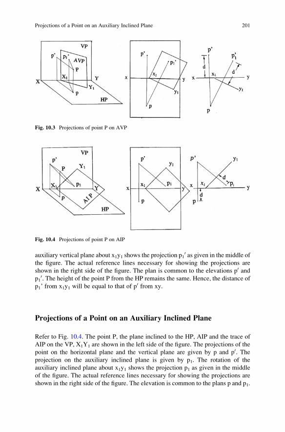
auxiliary vertical plane about x1y1 shows the projection p10 as given in the middle of
the figure. The actual reference lines necessary for showing the projections are
shown in the right side of the figure. The plan is common to the elevations p0 andp1
0. The height of the point P from the HP remains the same. Hence, the distance of
p1’ from x1y1 will be equal to that of p0 from xy.
Projections of a Point on an Auxiliary Inclined Plane
Refer to Fig. 10.4. The point P, the plane inclined to the HP, AIP and the trace of
AIP on the VP, X1Y1 are shown in the left side of the figure. The projections of the
point on the horizontal plane and the vertical plane are given by p and p0. Theprojection on the auxiliary inclined plane is given by p1. The rotation of the
auxiliary inclined plane about x1y1 shows the projection p1 as given in the middle
of the figure. The actual reference lines necessary for showing the projections are
shown in the right side of the figure. The elevation is common to the plans p and p1.
Fig. 10.3 Projections of point P on AVP
Fig. 10.4 Projections of point P on AIP
Projections of a Point on an Auxiliary Inclined Plane 201

The distance of the point P from the VP remains the same. Hence, the distance of p1from x1y1 will be equal to that of p from xy.
Projections of a Line on an Auxiliary Plane
The elevation a0b0 and plan ab of a straight line are shown in Fig. 10.5. An auxiliaryinclined plane (AIP) parallel to a0b0 is chosen at x1y1. Projectors are drawn perpen-
dicular to x1y1 from a0 and b0. An auxiliary plan on x1y1 is given by a1b1 as shown inthe figure. The distance of a1 from x1y1 will be equal to the distance of a from
xy. The distance of b1 from x1y1 will be equal to the distance of b from xy. The
projection a1b1 gives the true length of the line, and the angle between a1b1 and x1y1gives the inclination of the line with the vertical plane.
Solved Problems
1. The projections of a line a0b0, ab are given in Fig. 10.6. Determine auxiliary plans
on x1y1 and x3y3 and auxiliary elevations on x2y2 and x4y4. Find the length of
each projection. x1y1 is parallel to a0b0 and x3y3 is perpendicular to a0b0. x2y2 isparallel to ab and x4y4 is perpendicular to ab.
(i) The projections of the line are drawn as shown in Fig. 10.7. The auxiliary
inclined planes are chosen at x1y1 and x3y3, the distances of x1y1 and x3y3from a0b0 being arbitrary. Projectors are drawn perpendicular to x1y1 from a0
and b0. The auxiliary plans a1 and b1 are obtained using the distances of a
and b from xy. Projectors are drawn perpendicular to x3y3 from a0 and b0.The auxiliary plans a3 and b3 are obtained using the distances of a and b
from xy.
Answers: a1b1 ¼ 45 mm;
a3b3 ¼ 15 mm.
Fig. 10.5 Projections of
line AB on an auxiliary
plane
202 10 Auxiliary Projections

(ii) The projections of the line are drawn as shown in Fig. 10.8. The auxiliary
vertical planes are chosen at x2y2 and x4y4, the distances of x2y2 and x4y4from ab being arbitrary. Projectors are drawn perpendicular to x2y2 from a
and b. The auxiliary elevations a20 and b20 are obtained using the distances of
a0 and b0 from xy. Projectors are drawn perpendicular to x4y4 from a0 and b0.The auxiliary elevations a4
0 and b40 are obtained using the distances of a0 andb0 from xy.
Answers; a20b20 ¼ 45 mm;
a40b40 ¼ 15 mm.
Fig. 10.6 Projections of
line AB
Fig. 10.7 Auxiliary plans
of line AB
Solved Problems 203

2. Determine the true shape of the triangle whose projections are given in Fig. 10.9.
Measure the sides of the triangle.
The elevation a0b0c0 and plan abc of the triangle are drawn as shown in
Fig. 10.10. A horizontal line c0d0 lying in the elevation is drawn as shown in
the figure. The plan cd of the line is also drawn. The line cd is produced. An
auxiliary vertical plane perpendicular to cd is chosen with its reference line x1y1.
Projectors are drawn perpendicular to x1y1 from a, b and c. Project an auxiliary
elevation a10b10c10 from the plan abc. The distance of a1
0 from x1y1 is equal to the
distance of a0 from xy. The auxiliary projection of the triangle a10b10c10 is now a
straight line. Choose a reference line x2y2 parallel to a10b10c10 and project an
auxiliary plan a2b2c2. The distance of a2 from x2y2 is equal to the distance of a
Fig. 10.8 Auxiliary
elevations of line AB
Fig. 10.9 Projections of
triangle ABC
204 10 Auxiliary Projections

from x1y1. The final auxiliary plan a2b2c2 gives the true shape of the triangle.
The sides of Δ are AB ¼ 41 mm, BC ¼ 33 mm and CA ¼ 51 mm.
3. A triangular prism of edge of base 40 mm and axis 70 mm long rests with one of
its faces on the HP, and axis is inclined at 30� to the VP. Draw its projections.
(i) Auxiliary plane method
The axis of the prism is kept perpendicular to the VP initially. The elevation
is drawn with a side of triangle on xy. The plan is projected from the elevation.
An auxiliary vertical plane (perpendicular to the HP) inclined 30� to the axis ofthe prism is chosen. The projection on this plane is obtained from the plan of
the prism. The auxiliary elevation and the plan furnish the solution of the
problem.
Draw the reference line xy and the elevation of the prism with a side on xy
as shown in Fig. 10.11. The plan is projected from the elevation. An auxiliary
vertical plane is chosen at convenient distance from the plan of the prism such
that its inclination with the axis of the prism is 30�. The reference line x1y1represents the position of the auxiliary vertical plane. Projectors are drawn
perpendicular to x1y1 from the angular points of the prism in the plan to get the
auxiliary elevations of the angular points of the prism. The auxiliary elevation
b10 is located on the projector drawn from b. The distance of b1
0 from x1y1 is
equal to the distance of b0 from xy since the plan is common to the elevation
and the auxiliary elevation of the prism. The elevations of the remaining
angular points are located following the same procedure. The auxiliary eleva-
tion is completed with the invisible edge b10c10 shown as a dotted line.
Fig. 10.10 Auxiliary
projections of triangle ABC
Solved Problems 205

(ii) Change of position method
The prism is kept initially in simple position with the axis perpendicular to
the VP. The elevation and plan of the prism are dawn as shown in Fig. 10.12.
The prism is moved over the HP such that its axis is inclined at 30� to the VP. Inthis process, all the angular points of the prism move parallel to the HP. The
plan of the prism is redrawn as shown in the figure. A projector is drawn from
b1. Since the angular point moves parallel to the HP, locus line is drawn
parallel to xy from b0. The intersection of the projector with the locus line
locates the auxiliary elevation b10. The same procedure is repeated to get the
auxiliary elevations of the remaining points. The auxiliary elevation of the
prism is completed with the distinct invisible edge b10c10 shown as a dotted line.
Note: The change of position method does not require an auxiliary plane.
The drawing of projectors perpendicular to the new reference line x1y1 and
Fig. 10.11 Auxiliary
projections of Δ prism
Fig. 10.12 Auxiliary
projections of Δ prism
206 10 Auxiliary Projections

transferring the distances of projections of points become cumbersome in an
auxiliary plane method. It will be easy to redraw one view from its projections
in simple position in the change of position method. The drawing of locus lines
parallel to the reference line from the other view will eliminate the measure-
ment of the distances of the points from the reference line. Hence, the change
of position method is recommended for the problems in auxiliary projections.
If the given conditions require two stages in the projections, the change of
position is adopted in the first stage. An auxiliary plane (AVP/AIP) is used in
the second stage.
4. A pentagonal prism of edge of base 30 mm and axis 70 mm long rests with one of
its rectangular faces on the HP and the ends inclined at 30� to the VP. Draw its
projections.
The prism is kept initially in simple position with the axis perpendicular to the
VP. The elevation and plan of the prism are drawn as shown in Fig. 10.13. The
prism is moved over the HP such that its end is inclined at 30� to the VP. In this
process, all the angular points of the prism move parallel to the HP. The plan of
the prism is redrawn as shown in the figure. A projector is drawn perpendicular
to xy from b1. Since the angular point moves parallel to the HP, locus line is
drawn parallel to xy from b0. The intersection of the projector with the locus linelocates the auxiliary elevation b1
0. Projectors are drawn perpendicular to xy fromthe remaining angular points in the plan of the prism redrawn. Locus lines are
drawn parallel to xy from the corresponding points in the elevation of the prism.
The intersections of the projectors with the corresponding locus lines locate the
auxiliary elevations of the remaining angular points, and the auxiliary elevation
Fig. 10.13 Auxiliary projections of pentagonal prism
Solved Problems 207

of the prism is completed with the distinct invisible edges c10k10, h10k10 and k10n10
shown as dotted lines.
5. Draw the projections of a square prism of edge of base 40 mm and axis 70 mm
long when one of its solid diagonals is vertical.
There are four solid diagonals connecting the angular points of the base with
the opposite angular points of the top of a square prism. The square prism is kept
on the HP with its base edges equally inclined to the VP. Two of its solid
diagonals will be parallel to the VP. The prism is tilted parallel to the VP
about the right extreme base point so that the solid diagonal passing through
this base point will be perpendicular to the HP. The elevation is redrawn, and the
plan is projected from the elevation.
Draw the reference line xy and the plan of the square prism with its base
edges equally inclined to xy as shown in Fig. 10.14. The elevation is projected
from the plan. The solid diagonals a0h0 and c0e0 are parallel to the VP. The prismis tilted parallel to the VP about the base point H. The elevation is redrawn such
that the solid diagonal a0h0 is perpendicular to xy. The plan is to be projected
from the elevation. A projector is drawn perpendicular to xy from a10. The locus
line is drawn parallel to xy from a. The intersection of the projector with the
locus line locates the plan a1. The same procedure is repeated to get the plans of
the remaining angular points. These points are connected to show the edges of
the prism in the plan. The distinct invisible edges c1h1, f1h1 and n1h1 are shown
as dotted lines. The redrawn elevation and projection of the plan from it
complete the solution of the problem.
6. Draw the projections of a hexagonal prism of edge of base 30 mm and axis
80 mm long resting on a corner of its base with the base inclined at 45� to the HP.The prism is kept on the HP with a side of base parallel to the VP. The prism
can be tilted parallel to the VP about the right extreme corner such that its base is
Fig. 10.14 Auxiliary
projections of square prism
208 10 Auxiliary Projections

inclined at 45� to the HP. The elevation is redrawn and the plan is projected fromthe elevation.
Draw the reference line xy and the plan of the hexagonal prism with a side of
base parallel to xy as shown in Fig. 10.15. The elevation is projected from the
plan. The prism is tilted parallel to the VP about the right extreme corner N such
that the base is inclined at 45� to the HP. The elevation is redrawn so that prism
base is inclined at 45� with xy. The plan is to be projected from the elevation. A
projector is drawn perpendicular to xy from a10. The locus line is drawn parallel
to xy from a. The intersection of the projector with the locus line locates the plan
a1. The same procedure is repeated to get the plans of the remaining points.
These points are connected to show the edges of the prism in the plan. The
distinct invisible edges m1n1 and n1p1 and a portion of the invisible edge d1n1 are
shown as dotted lines. The redrawn elevation and projection of the plan from it
complete the solution of the problem.
7. A hexagonal pyramid edge of base 30 mm and axis 70 mm stands with a corner
of its base on the HP. Draw the projections of the pyramid when the slanting
edge containing that corner is vertical.
The hexagonal pyramid is kept on the HP with a base edge parallel to the
VP. Two of its slanting edges containing the two extreme corners are parallel to
the VP in this position. The pyramid is tilted parallel to the VP about one
extreme corner so that the slanting edge containing that corner is made perpen-
dicular to the HP. In this process, all the points of the prism move parallel to the
VP. The elevation is redrawn with the slanting edge perpendicular to the HP. The
plan is projected from the elevation.
Fig. 10.15 Auxiliary projections of hexagonal prism
Solved Problems 209

Draw the reference line xy and the plan of the hexagonal pyramid with a side
of base parallel to xy as shown in Fig. 10.16. The elevation is projected from the
plan. The pyramid is tilted parallel to the VP about the right extreme corner E
such that the slant edge EA is perpendicular to the HP. The elevation is redrawn
so that the slant edge e10a10 is perpendicular to the xy. The plan is to be projected
from the elevation. A projector is drawn perpendicular to xy from b10. The locus
line is drawn parallel to xy from b. The intersection of the projector with the
locus line locates the plan b1. The same procedure is repeated to get the plans of
the remaining points. These points are connected to show the edges of the prism
in the plan. The redrawn elevation and projection of the plan from it complete
the solution of the problem.
8. Draw the projections of an octahedron of edge 40 mm when it rests on the HP on
one of its faces.
The solid diagonal of the octahedron is kept perpendicular to the HP with the
end point of the solid diagonal on it to get its projection in its simple position. An
edge of the octahedron is kept parallel to the VP. The outline of the plan will be a
square and the outline of the elevation will be a rhombus. The octahedron is
tilted parallel to the VP about the end point till one of its faces rests on the
HP. The elevation is redrawn, and the plan is projected from it.
Draw the reference line xy and the plan of the octahedron with an edge
parallel to xy and a solid diagonal perpendicular to the HP as shown in
Fig. 10.17. The elevation is projected from the plan. The octahedron is tilted
Fig. 10.16 Auxiliary projections of hexagonal pyramid
210 10 Auxiliary Projections

parallel to the VP about the end point F of the diagonal till the face FCD rests on
the HP. The elevation is redrawn with the face f10c10d10 on the xy. The plan is to
be projected from the elevation. A projector is drawn perpendicular to xy from
b10. The locus line is drawn parallel to xy from b. The intersection of the
projector with the locus line locates the plan b1. The same procedure is repeated
to get the plans of the remaining points. These points are connected to show the
edges of the octahedron in the plan. The invisible edges f1c1, c1d1 and d1f1 are
shown as dotted lines. The redrawn elevation and projection of the plan from it
complete the solution of the problem.
9. A rectangular prism 50 mm � 30 mm � 70 mm stands on its shorter edge of its
base such that this edge is inclined at 40� to the VP, and the face containing thatedge is inclined at 60� to the HP. Draw its projections.
This problem needs two conditions to be satisfied. The prism is kept on the
HP on its base with a shorter edge perpendicular to the VP. The prism is tilted
parallel to the VP about this shorter edge such that the face containing this edge
is inclined at 60� to the HP. The elevation is redrawn and the plan is projected
from it. The outline of the plan will be a rectangle. The prism is moved parallel
to the HP to satisfy the other condition. The new plan is redrawn with the shorter
edge inclined at 40� to the VP. The final elevation is obtained from this new plan.
Draw the reference line xy and the plan of the rectangular prism resting on its
base on the HP with a shorter edge perpendicular to the reference line xy as shown
in Fig. 10.18. The elevation is projected from the plan. The prism is tilted parallel
to the VP about the shorter edge NH such that the face NDCH is inclined at 60� tothe HP. The elevation is redrawn with the face n0d0c0h0 inclined at 60� to xy as
shown in the figure. The plan is to be projected from the elevation. A projector is
drawn perpendicular to xy from a10. The locus line is drawn parallel to xy from a in
the plan. The intersection of the projector with the locus line locates the plan a1.
The same procedure is repeated to get the plans of the remaining points. The plan
is completed with the distinct invisible edge h1n1 shown by a dotted line. Since the
Fig. 10.17 Auxiliary
projections of octahedron
Solved Problems 211

outline of the plan c1d1e1f1 is a rectangle, the prism can be moved parallel to the
HP with its shorter edge inclined at 40� to the VP. The plan is redrawn with its
shorter edge inclined at 40� to xy as shown in the figure. The elevation is to be
projected from the plan. A projector is drawn perpendicular to xy from a2. The
locus line is drawn parallel to xy from a10. The intersection of the projector with
the locus line locates the elevation a20. The same procedure is repeated to get the
elevations of the remaining points. These points are connected to show the
elevation of the edges of the prism. The invisible edges b20f20, e20f20 and h2
0f20
are shown by dotted lines. The outline of elevation a20b20c20h20n20e20 and the
outline of plan c2d2e2f2 furnish the solution of the problem.
10. Draw the projections of a cube of edge 40 mm standing on one of its corners
with its solid diagonal perpendicular to the VP.
The cube is kept on the HP with its base edges equally inclined to the
VP. In this position two of its solid diagonals will be parallel to the VP. The
cube is tilted parallel to the VP about one of its extreme base corners till the
solid diagonal passing through the other extreme corner is parallel to the
HP. The elevation is redrawn with a corner touching the HP. The plan is
projected from the elevation. An auxiliary vertical plane is chosen at conve-
nient distance from the plan such that the plane is perpendicular to solid
diagonal parallel to the HP. An auxiliary elevation completes the solution.
Draw the reference line xy and the plan of the cube with its base edges
equally inclined to the VP as shown in Fig. 10.19. The elevation is projected
from the plan. The solid diagonals a0h0 and c0e0 are parallel to the VP. The
Fig. 10.18 Auxiliary projections of rectangular prism
212 10 Auxiliary Projections

elevation is tilted about the corner e0 so that the solid diagonal a0h0 is parallelto xy. The elevation is redrawn as shown in the figure. The plan is to be
projected from the elevation. A projector is drawn perpendicular to xy from
a10. The locus line is drawn parallel to xy from a. The intersection of the
projector with the locus line locates the plan a1. The same procedure is
followed to get the plans of the remaining points. These points are joined to
show the plans of the edges of the cube. The invisible edges a1e1, f1e1 and n1e1are shown by dotted lines. An auxiliary vertical plane is chosen perpendicular
to a1h1 at x2y2 as shown in the figure. The auxiliary elevation is to be projected
from the plan. A projector is drawn perpendicular to x2y2 from c1. Since the
plan c1 is common, the distance of c10 from xy will be equal to the distance of
c20 from x2y2. The distance of c1
0 from xy is measured and making use of this
distance the point c20 is located on the projector drawn through c1. The same
procedure is followed to get the elevations of other points. These points are
joined to show the elevations of the edges of the cube. The invisible edges
c20h20, f20h20 and n2
0h20 are shown by dotted lines.
11. Draw the projections of a tetrahedron of edge 40 mm resting on one of its
angular points with the axis inclined at 60� to the HP.
A face of the tetrahedron is kept parallel to the HP, and the angular point
opposite to this face is on the HP. The solid is tilted parallel to the VP about
the base angular point such that the axis passing through the base point is
inclined at 60� to the HP. The elevation is redrawn and the plan is projected
from the elevation.
Draw the reference line xy and the equilateral triangle abc representing the
outline of the plan of the inverted tetrahedron as shown in Fig. 10.20. The
invisible edges ad, bd and cd are shown by dotted lines. The elevation is
Fig. 10.19 Auxiliary projections of cube
Solved Problems 213

projected from the plan. The elevation of the angular point d0 lies on xy, and
the axis passing through d0 is also shown in the elevation. The tetrahedron is
tilted parallel to the VP about d10 such that the axis makes an angle of 60� with
the HP. As the angular points move parallel to the VP, the elevation is redrawn
with the axis inclined at 60� to xy as shown in the figure. The plan is to be
projected from the elevation. A projector is drawn perpendicular to xy from
a10. The locus line is drawn parallel to xy from a. The intersection of the
projector with the locus line locates the plan a1. The same procedure is
followed to get b1, c1 and d1. These points are joined to get the plan of the
tetrahedron. The invisible edge c1d1 is shown as a dotted line.
12. Draw the projections of a tetrahedron of edge 40 mm resting on an edge
inclined at 30� to the VP and a face contained the edge is inclined at 40� tothe HP.
The tetrahedron is kept with a face on the HP, and an edge of this face is
perpendicular to the VP. The projections are obtained. The tetrahedron is
tilted parallel to the VP about the base edge perpendicular to the VP such that
one face containing the edge is inclined at 40� to the HP. The elevation is
redrawn and the plan is obtained from the elevation. An auxiliary vertical
plane inclined at 30� to the base edge is chosen and the elevation is obtained
on this plane.
Draw the reference line xy and the plan of the tetrahedron as shown in
Fig. 10.21 with the edge ac perpendicular to xy. The elevation is projected
Fig. 10.20 Auxiliary
projections of tetrahedron
Fig. 10.21 Auxiliary
projections of tetrahedron
214 10 Auxiliary Projections

from the plan. The tetrahedron is tilted about the edge AC till the face ABC is
inclined at 40� to the HP. As the angular points move parallel to the VP, the
elevation is redrawn with the edge a10c10 on xy and the face a10b10c10 is inclined
at 40� to xy. The plan is to be projected from the elevation. A projector is
drawn perpendicular to xy from a10. The locus line is drawn parallel to xy from
a. The intersection of the projector with the locus line locates the plan a1. The
same procedure is followed to get b1, c1 and d1. These points are joined to
show the edges of the tetrahedron in the plan. The invisible edge a1c1 is shown
as a dotted line. An auxiliary vertical plane inclined at 30� to the base edge
a1c1 is chosen at x2y2 as shown in the figure. The elevation is to be projected
on this plane. Since the plan is common, the heights of the angular points of
the tetrahedron from the HP remain the same. A projector is drawn perpen-
dicular to x2y2 from d1. The point d20 is located on this projector such that the
distance of d20 from x2y2 is equal to the distance of d1
0 from xy. The same
procedure is followed to get the points a20, b20 and c20. These points are joined
to show the edges of tetrahedron in the elevation. The invisible edge b20c20 is
shown as a dotted line.
13. Draw the projections of an octahedron of edge 40 mm when it rests on the HP
on one of its faces, such that an edge of that face is inclined at 40� to the VP.
The octahedron is kept on the HP on an angular point in such a way that its
plan is a square with an edge parallel to the VP. In this position, four faces of
the solid are perpendicular to the VP. The octahedron is tilted parallel to the
VP about the base angular point till one of the four faces lies on the HP and the
projections are obtained. An auxiliary vertical plane inclined at 40� to the baseedge is chosen to get the elevation.
Draw the reference line xy and the plan of the octahedron as shown in
Fig. 10.22. The elevation is projected from the plan. The octahedron is tilted
parallel to the VP about the angular point F till one of the adjacent faces lies
Fig. 10.22 Auxiliary projections of octahedron
Solved Problems 215

on the HP. The elevation is redrawn with the face c10d10f10 on xy. The plan is to
be projected from the elevation. A projector is drawn perpendicular to xy from
a10. The locus line is drawn parallel to xy from a. The intersection of the
projector with the locus line locates plan a1. The same procedure is followed
to get b1, c1, d1, e1 and f1. These points are joined to show the plan of the
octahedron. The invisible edges c1d1, d1f1 and f1c1 are shown by dotted lines.
An auxiliary vertical plane inclined at 40� to c1d1 is chosen at x2y2. The
elevation is to be obtained on this plane. A projector is drawn perpendicular to
x2y2 from a1. The elevation a20 is marked on this projector such that the
distance of a20 from x2y2 is equal to the distance of a1
0 from xy. The same
procedure is followed to get the remaining points b20, c20, d20, e20 and f20. These
points are joined to complete the required elevation. The invisible edges b20c20
and c20e20 are shown by dotted lines.
14. A pentagonal pyramid of side of base 40 mm and axis 70 mm has one face on
the VP with the base edge of this face inclined at 70� to the HP. Draw its
projections.
The pentagonal pyramid base is kept on the VP with an edge of base
perpendicular to the HP. The projections are obtained. The pyramid is tilted
parallel to the HP about the base edge till the face containing the base edge lies
on the VP. The plan is redrawn and the elevation is projected from the plan.
An auxiliary plane inclined at 70� to the base edge is chosen at x2y2. The planis projected on this plane.
Draw the reference line xy and the elevation of the pyramid with an edge of
base perpendicular to xy as shown in Fig. 10.23. The plan is projected from
the elevation. The pyramid is tilted parallel to the HP about bc till the face abc
coincides with the reference line xy. The plan is redrawn with the face a1b1c1
Fig. 10.23 Auxiliary projections of pentagonal pyramid
216 10 Auxiliary Projections

on xy as shown in the figure. The elevation is to be projected from the plan. A
projector is drawn perpendicular to xy from e1. The locus line is drawn
parallel to xy from e0. The intersection of the projector with the locus line
locates e10. The same procedure is followed to get a1
0, b10, c10, d10 and f10.
These points are joined to get the elevation of the pyramid. The invisible
edges a10b10 and a10c10 are shown as dotted lines. An auxiliary plane inclined at
70� to b10c10 is chosen at x2y2. The plan is to be projected from the elevation. A
projector is drawn perpendicular to x2y2 from e10. The point e2 is marked on
this projector such that the distance of e2 from x2y2 is equal to the distance of
e1 from xy. The same procedure is followed to get a2, b2, c2, d2 and f2. These
points are joined to complete the plan of the pyramid. The invisible edges b2f2,
a2f2 and e2f2 are shown as dotted lines.
15. An octahedron of 40 mm edge rests with an edge on the HP such that the two
faces containing that edge make equal inclinations with the HP. The edge on
which it rests should be inclined at 30� to the VP. Draw its projections.
The octahedron is kept initially on an angular point on the HP such that the
solid diagonal passing through this angular point and another solid diagonal
are parallel to the VP. The projections are obtained. The octahedron is tilted
parallel to the VP about the base point till the edge passing through the base
point lies on the HP. In this position, the two faces containing the base edge
are equally inclined to the HP. The plan is projected from the elevation. An
auxiliary vertical plane inclined at 30� to the plan of base edge of the
octahedron is chosen. The elevation is projected on this plane.
Draw the reference line xy and the plan and elevation of the octahedron
resting on an angular point on the HP as shown in Fig. 10.24. The solid
diagonals ef and ac are parallel to the VP. The octahedron is tilted parallel to
the VP about the base point F till the edge FC lies on the HP. The angular
Fig. 10.24 Auxiliary projections of octahedron
Solved Problems 217

points move parallel to the VP. The elevation is redrawn with the edge f10c10
on xy. The faces f10b10 c10 and f10d10c10 are equally inclined to the HP. The plan
is to be projected from the elevation. A projector is drawn perpendicular to xy
from e10. The locus line is drawn parallel to xy from e. The intersection of the
projector with the locus line locates the point e1 in the plan. The same
procedure is followed to get a1, b1, c1, d1 and f1. These points are joined to
complete the plan of octahedron. An auxiliary vertical plane inclined at 30� tothe base edge f1c1 in the plan is chosen at x2y2. The elevation is to be obtained
on this plane. A projector is drawn perpendicular to x2y2 from e1. The point e20
is marked on this projector such that the distance of e20 from x2y2 is equal to
the distance of e10 from xy. The same procedure is followed to get a2
0, b20, c20,d2
0 and f20. These points are joined to show the elevation of the octahedron.
The invisible edges b20a20, b20e20, b20c20 and b2
0f20 are shown by dotted lines.
(Note: All 12 edges of octahedron are distinct in the final elevation and
8 edges are visible.)
16. A regular octagon abcdefgh of 20 mm side is the plan of a plane figure. The
heights of A, B, C, D, E, F, G and H are, respectively, 10 mm, 10 mm, 20 mm,
30 mm, 40 mm, 40 mm, 30 mm and 20 mm. Determine the true form of the
figure.
The plan of the octagon is drawn with a side parallel to the VP as shown in
Fig. 10.25. The left extreme points are designated as a and b. The elevations of
Fig. 10.25 Auxiliary projections of octagon
218 10 Auxiliary Projections

the points are shown on the respective projectors. It is to be noted that the
elevations of the lines a0b0, c0h0, d0g0 and e0f0 are points and are parallel to the
HP. Hence, ab, ch, dg and ef give the respective true lengths. Elevations a0h0,b0c0, d0e0 and g0f0 are parallel. An auxiliary plane is chosen parallel to the
elevations of these lines at x1y1. The projections h1a1b1c1 and g1f1e1d1 on this
auxiliary plane give true forms of the two portions of the octagon. The two
portions are identical. Another auxiliary plane is chosen parallel to c0d0 atx2y2. The projection c2d2g2h2 on this plane gives the true form of the middle
portion of the octagon. The two portions h1a1b1c1 and g1f1e1d1 are attached to
the middle portion using the angle θ and the true lengths of the sides.
ABCDEFGH represents the true form of the octagon.
17. A right square pyramid, edge of base 30 mm and height 60 mm, is suspended
freely from a corner of its base. Draw its projections.
The centre of gravity of a pyramid/cone lies on the axis at a distance equal
to ¼ axis from the base. The line connecting the corner of suspension with the
centre of gravity will be vertical when suspended freely. The base of the
square pyramid is kept parallel to the HP and above the apex/vertex with the
base edges equally inclined to the VP. The projections are obtained. The
pyramid is suspended from one of its extreme corners. The pyramid moves
parallel to the VP so that the line joining the extreme corner and the centre of
gravity is perpendicular to the HP. The plan is projected from the elevation.
Draw the reference line xy and the plan of the square pyramid with its base
above the apex and parallel to the HP as shown in Fig. 10.26. The base edges
are equally inclined to the VP so that the square pyramid can be suspended
from one of its extreme corner. The elevation is projected from the plan. The
centre of gravity g0 is located on the axis 15 mm from the base in the elevation.
Fig. 10.26 Auxiliary
projections of square
pyramid
Solved Problems 219

The plan of centre of gravity g coincides with the axis of the pyramid. The
pyramid is suspended from b0 so that the line passing through b0 and g0 isperpendicular to xy. The pyramid moves parallel to the VP. The elevation is
redrawn as shown in the figure. The plan is to be projected from the elevation.
A projector is drawn perpendicular to xy from d10. The locus line is drawn
parallel to xy from d. The intersection of the projector with the locus line
locates d1. The same procedure is followed to get a1, b1, c1 and e1. These
points are joined to show the edges of the pyramid in the plan with a part of
invisible edge a1d1 shown as dotted.
18. A tetrahedron of edge 50 mm stands on one of its edges on the HP such that
the vertical plane containing that edge and the centre of gravity of the solid
makes 30� with the VP. Draw its projections.
The tetrahedron is kept on the HP on one of its faces with a side of that face
perpendicular to the VP. The solid is tilted parallel to the VP about the
extreme angular point such that the edge containing the extreme angular
point is on the HP. The centre of gravity lies on the vertical plane containing
the edge on which the solid stands on the HP. An auxiliary vertical plane
inclined at 30� to the base edge is chosen, and the projection on this plane is
obtained.
Draw the reference line xy and the plan of the tetrahedron resting on the HP
on one of its faces with an edge of that face perpendicular to the VP as shown
in Fig. 10.27. The elevation is projected from the plan. The centre of gravity g
coincides with the point d in the plan. It is to be noted that the centre of gravity
g0 is one-fourth the height of d0 from the face a0b0c0. The tetrahedron is tilted
parallel to the VP about the extreme point c0 so that the edge c0d0 lies on
xy. The elevation is redrawn such that the edge c10d10 lies on xy. All points
move parallel to the VP. The plan is to be projected from the elevation. A
Fig. 10.27 Auxiliary projections of tetrahedron
220 10 Auxiliary Projections

projector is drawn perpendicular to xy from a10. The locus line is drawn
parallel to xy from a. The intersection of the projector with the locus line
locates the plan a1. The same procedure is followed to get b1, c1, g1 and d1. It is
to be noted that the centre of gravity lies on the plane containing the edge c1d1.
An auxiliary vertical plane inclined at 30� to the base edge c1d1 is chosen at
x2y2 as shown in the figure. The elevation is to be projected from the plan. A
projector is drawn perpendicular to x2y2 from a1. The elevation a20 is marked
on this projector such that the distance of a20 from x2y2 is equal to the distance
of a10 from xy. The same procedure is followed to get b2
0, c20, d20 and g20. Theangular points are joined to complete the elevation. The invisible edge b2
0d20
is shown by a dotted line.
19. A pentagonal pyramid, side of base 30 mm and axis 60 mm long, stands on the
HP with an edge of its base parallel to and 20 mm in front of the VP such that
the apex touches the VP. Draw its projections.
The projections of the pentagonal pyramid are obtained keeping its base on
the HP with a side of base perpendicular to the VP. An auxiliary vertical plane
is chosen at x2y2. The vertical trace of the auxiliary plane is also drawn. The
pyramid is moved parallel to the VP till the perpendicular base edge is 20 mm
from the vertical trace and then tilted about this base edge such that the apex
touches the auxiliary plane. The elevation is redrawn and the plan is projected
from the elevation. The projection on the auxiliary plane kept at x2y2 furnishes
the required elevation.
Draw the reference line xy and the projections of the pentagonal pyramid
resting on the HP on its base with a side of base perpendicular to the VP as
shown in Fig. 10.28. The side ed is perpendicular to xy. An auxiliary vertical
plane is chosen at x2y2 and its vertical trace is drawn above xy. The pyramid is
moved parallel to the VP initially till the edge e0d0 is 20 mm from the vertical
Fig. 10.28 Auxiliary projections of pentagonal pyramid
Solved Problems 221

trace. Thereafter, the pyramid is tilted parallel to the VP about the edge e0d0 tillthe apex touches the auxiliary plane. The elevation is redrawn with the edge
e10d10 on xy and the apex a1
0 touching the vertical trace as shown in the figure.
The plan is to be projected from the elevation. A projector is drawn perpen-
dicular to xy from b10. The locus line is drawn parallel to xy from b. The
intersection of the projector with the locus line locates the plan b1. The same
procedure is followed to get a1, c1, d1, e1 and f1. These points are joined to
complete the required plan of the pyramid. The elevation is to be projected on
the auxiliary plane at x2y2 from the plan. A projector is drawn perpendicular to
x2y2 from b1. The point b20 is marked on this projector such that the distance of
b20 from x2y2 is equal to the distance of b1
0 from xy. The same procedure is
followed to get a20, c20, d20, e20 and f2
0. These points are joined to complete the
required elevation of the pyramid. The invisible edges a20d20 and a2
0e20 areshown by dotted lines.
20. A hexagonal pyramid, edge of base 30 mm and axis 50 mm long, stands on an
edge of base in the HP and inclined at 45� to the VP and the face containing the
base edge inclined at 50� to the HP. Draw its projections.
The hexagonal pyramid is kept on the HP on its base with a base edge
perpendicular to the VP. The pyramid is tilted parallel to the VP about the edge
perpendicular to the VP till the face containing this edge makes an angle of 50�
with the HP. An auxiliary vertical plane inclined at 45� to the base edge is
chosen at x2y2. The projection on this plane provides the elevation of the
pyramid.
Draw the reference line xy and the plan of the pyramid with a base edge
perpendicular to xy as shown in Fig. 10.29. The elevation is projected from the
Fig. 10.29 Auxiliary projections of hexagonal pyramid
222 10 Auxiliary Projections

plan. The pyramid is tilted parallel to the VP about the base edge e0f0 till theface a0e0f0 is inclined at 50� to the HP. The elevation is redrawn such that the
face a10e10f10 is inclined at 50� to xy. The plan is to be projected from the
elevation. A projector is drawn perpendicular to xy from a10. The locus line is
drawn parallel to xy from a. The intersection of the projector with the locus line
locates the plan a1. The same procedure is followed to get b1, c1, d1, e1, f1 and
n1. These points are joined to complete the required plan of the pyramid. The
invisible edges a1e1, a1f1, e1f1, d1e1 and f1n1 are shown by dotted lines. An
auxiliary vertical plane inclined at 45� to the base edge is chosen at x2y2 as
shown in the figure. The elevation is to be projected from the plan. A projector
is drawn perpendicular to x2y2 from a1. The point a20 is marked on this projector
such that the distance of a20 from x2y2 is equal to the distance of a1
0 fromxy. The same procedure is followed to get b2
0, c20, d20, e20, f20 and n20. These
points are joined to get the required elevation of the pyramid. The invisible
edges a20c20, a20d20 and a2
0e20 are shown by dotted lines.
21. A square pyramid, side of base 40 mm and axis 60 mm long, lies with one of the
base diagonals inclined to the HP at 60� and the other diagonal parallel to the
HP. Draw its projections.
The square pyramid is kept on the HP on its base with base edges equally
inclined to the VP. The pyramid is tilted parallel to the VP such that one of the
base diagonals is inclined at 60� to the HP. The other base diagonal is parallel tothe HP. The elevation is redrawn and the plan is projected from the elevation.
Draw the reference line xy and plan of the square pyramid with its base
edges equally inclined to xy as shown in Fig. 10.30. The elevation is projected
from the plan. The pyramid is tilted parallel to the VP about the base diagonal
c0e0 such that the other base diagonal b0d0 is inclined at 60� to the HP. The
elevation is redrawn with the base diagonal b20d20 inclined at 60� to xy and the
Fig. 10.30 Auxiliary projections of square pyramid
Solved Problems 223

base diagonal c20e20 parallel to the HP as shown in the figure. The plan is to be
projected from the elevation. A projector is drawn perpendicular to xy from a20.
The locus line is drawn parallel to xy from a. The intersection of the projector
with the locus line locates the plan a2. The same procedure is followed to get b2,
c2, d2, and e2. These points are joined to complete the required plan with a
portion of the invisible edge a2d2 shown as dotted.
22. Draw the projections of a cylinder of diameter of base 50 mm and axis 70 mm
long when the base is inclined at 60� to the HP and the plan of the axis is
inclined at 45� to xy.
The cylinder is kept on the HP on its base and the projections are obtained.
The cylinder is tilted parallel to the VP about one of its extreme base point so
that the base is inclined at 60� to the HP. The elevation is redrawn and the planis projected from the elevation. An auxiliary vertical plane inclined at 45� to theplan of the axis is chosen at x2y2. The elevation is obtained on this plane.
Draw the reference line xy and the plan of the cylinder with its base on the
HP as shown in Fig. 10.31. The alternate generators on the lateral surface of the
cylinder are designated as ab, cd, ef and hn in the plan. The elevation is
projected from the plan. The cylinder is tilted parallel to the VP about the
base point f0 such that the base of the cylinder is inclined at 60� to the HP. The
elevation is redrawn with f10 on xy and the base b1
0d10f10n10 inclined at 60� toxy. The plan is to be projected from the elevation. A projector is drawn
perpendicular to xy from a10. The locus line is drawn parallel to xy from
a. The intersection of the projector with the locus line locates the plan a1.
The same procedure is followed to get remaining points in the plan. These
points are joined by smooth curves to show the plans of top and bottom ends of
Fig. 10.31 Auxiliary projections of cylinder
224 10 Auxiliary Projections
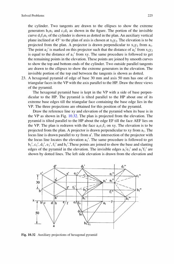
the cylinder. Two tangents are drawn to the ellipses to show the extreme
generators h1n1 and c1d1 as shown in the figure. The portion of the invisible
curve d1f1n1 of the cylinder is shown as dotted in the plan. An auxiliary vertical
plane inclined at 45� to the plan of axis is chosen at x2y2. The elevation is to beprojected from the plan. A projector is drawn perpendicular to x2y2 from a1.
The point a20 is marked on this projector such that the distance of a2
0 from x2y2is equal to the distance of a1
0 from xy. The same procedure is followed to get
the remaining points in the elevation. These points are joined by smooth curves
to show the top and bottom ends of the cylinder. Two outside parallel tangents
are drawn to the ellipses to show the extreme generators in the elevation. The
invisible portion of the top end between the tangents is shown as dotted.
23. A hexagonal pyramid of edge of base 30 mm and axis 50 mm has one of its
triangular faces in the VP with the axis parallel to the HP. Draw the three views
of the pyramid.
The hexagonal pyramid base is kept in the VP with a side of base perpen-
dicular to the HP. The pyramid is tilted parallel to the HP about one of its
extreme base edges till the triangular face containing the base edge lies in the
VP. The three projections are obtained for this position of the pyramid.
Draw the reference line xy and elevation of the pyramid when its base is in
the VP as shown in Fig. 10.32. The plan is projected from the elevation. The
pyramid is tilted parallel to the HP about the edge EF till the face AEF lies on
the VP. The plan is redrawn with the face a1e1f1 on xy. The elevation is to be
projected from the plan. A projector is drawn perpendicular to xy from a1. The
locus line is drawn parallel to xy from a0. The intersection of the projector withthe locus line locates the elevation a1
0. The same procedure is followed to get
b10, c10, d10, e10, f10 and h10.These points are joined to show the base and slanting
edges of the pyramid in the elevation. The invisible edges a10e10 and a1
0f10 areshown by dotted lines. The left side elevation is drawn from the elevation and
Fig. 10.32 Auxiliary projections of hexagonal pyramid
Solved Problems 225

plan of the pyramid following the principle of projection by drawing locus lines
and projectors as shown in the figure. The invisible slanting edges a1”d1”,
a1”c1”, a1”b1” and a1”h1” are shown by dotted lines in the side elevation.
24. The diameter of base of a cone is 50 mm and the height is 70 mm. Draw its
projections when it is resting on the HP on one of its generators with the axis
inclined at 35� to the VP.
The cone is kept on the HP on its base and the projections are drawn. The
cone is tilted parallel to the VP about one of its extreme base point till the
generator connecting the base point with the apex lies on the HP. The elevation
is redrawn and the plan is projected from the elevation. The next task will be to
find out the apparent angle of inclination (β) of the plan axis of the cone with
xy. An auxiliary vertical plane inclined at β to the plan axis of the cone is
chosen, and the required elevation is obtained on this plane.
Draw the reference line xy and the plan of cone with alternate generators
designated as ab, ac, ad and ae as shown in Fig. 10.33. The elevation is
projected with the generators from the plan. The cone is tilted parallel to the
VP about the base point D till the generator AD lies on the HP. The elevation is
redrawn with a10d10 on xy. The plan is to be projected from the elevation. A
projector is drawn perpendicular to xy from b10. The locus line is drawn parallel
to xy from b. The intersection of the projector with the locus line locates the
plan b1. The same procedure is followed to get the plans of base points and the
apex. The base points are joined by a smooth curve. Two tangents are drawn
from the apex a1 to the ellipse to show the extreme generators of the cone. To
find the apparent angle of inclination, a line x1y1 is drawn parallel to xy. The
point a1 is located on x1y1 and another line is drawn from a1 inclined at 35�. Apoint n0 is located on the inclined line taking its distance from a1 equal to the
Fig. 10.33 Auxiliary Projections of cone
226 10 Auxiliary Projections

axis of the cone. Draw the locus line passing through n0. With centre a1 and the
plan axis length a1n1 as radius draw an arc to cut the locus line at n1. The
inclination of the line a1n1 with x1y1 gives the apparent angle β. An auxiliary
vertical plane inclined at β to xy is chosen at x2y2. The projection on this planegives the elevation of the cone. A projector is drawn perpendicular to x2y2 from
b1. The point b20 is marked on this projector such that the distance of b2
0 fromx2y2 is equal to the distance of b1
0 from xy. The same procedure is followed to
get the elevations of the remaining points. The base points are joined by a
smooth curve. A tangent is drawn from the apex to the base curve to represent
the upper extreme generator of the cone in elevation.
25. The diameter of base of a cone is 50 mm and the height is 60 mm. Draw its
projections when it is suspended freely from a point on the circumference of its
base. Assume that the axis is parallel to the VP.
The cone base is kept parallel to the HP and above the apex. The projections
are drawn. The centre of gravity is located along the axis in the elevation. The
line joining the extreme base point and the centre of gravity will be vertical
when suspended freely from the extreme base point. The cone moves parallel to
the VP during the suspension. The elevation is redrawn keeping the line joining
the base point and the centre of gravity vertical and the plan is projected from
the elevation.
Draw the reference line xy and the projections of the cone as shown in
Fig. 10.34. The centre of gravity g0 is located 15 mm from the base of the cone
in the elevation. The centre of gravity g coincides with the apex of the cone in
the plan. When the cone is suspended freely from b0, the line joining b0 and g0
will be vertical. The cone moves parallel to the VP. The elevation is redrawn as
shown in the figure. The plan is to be projected from the elevation. A projector
is drawn perpendicular to xy from a10. The locus line is drawn parallel to xy
from a. The intersection of the projector with the locus line locates the plan a1.
Fig. 10.34 Auxiliary
projections of cone
Solved Problems 227

The same procedure is followed to get the plans of other points. The base points
of the cone are joined by a smooth curve. Two tangents are drawn from a1 to the
base curve of the cone in the plan.
Practice Problems
1. A square prism, edge of base 40 mm and axis 60 mm long, stands on the HP
with a face inclined 30� to the VP. Draw its projections.
2. A hexagonal prism, edge of base 30 mm and axis 70 mm long, rests with one of
its rectangular faces on the HP and the ends inclined at 40� to the VP. Draw its
projections.
3. A pentagonal prism, edge of base 30 mm and axis 60 mm long, rests with one of
its longer edges on the HP. The two rectangular faces containing the longer
edge on which it rests make equal inclination with the HP, and the longer edges
are inclined at 50� to the VP. Draw its projections.
4. A square pyramid, edge of base 30 mm and axis 60 mm long, stands on the HP
on one of its base edges. Draw its projections when the face containing that
base edge is perpendicular to the HP.
5. A pentagonal pyramid, edge of base 40 mm and axis 60 mm long, stands with a
corner of its base on the HP. Draw the projections of the pyramid when the
slanting edge containing that corner is vertical.
6. Draw the projections of a tetrahedron of edge 40 mm when suspended freely
from one of its angular points.
7. An octahedron of 50 mm edge rests on one of its angular points on the HP. Draw
its projections when one of its solid diagonals is parallel to both the HP and VP.
8. A square pyramid, edge of base 40 mm and axis 60 mm long, has one face on
the VP with the base edge of this face inclined at 50� to the HP. Draw its
projections.
9. Draw the projections of a hexagonal pyramid, side of base 30 mm and axis
70 mm long, when it is resting on one of its base edges with the axis making an
angle of 40� with the HP and its plan axis making an angle of 30� with the
reference line xy.
10. An octahedron of edge 40 mm has one of its faces in the VP and an edge of that
face is making 30� with the HP. Draw its projections.
11. A tetrahedron of edge 50 mm has one of its edges parallel to the HP and
inclined at 40� to the VP while one of the faces containing that edge is vertical.
Draw its projections.
12. A cone, base 50 mm diameter and axis 70 mm long, has one of its generators in
the HP and perpendicular to the VP. Draw its projections keeping the base
nearer to the VP than the apex.
13. A pentagonal pyramid, side of base 30 mm and axis 60 mm long, rests with one
of its base edges in the HP, the axis parallel to the VP and the base making an
angle of 40� to the HP. Draw the plan, elevation and the left side elevation of
the pyramid.
228 10 Auxiliary Projections

14. Draw the projections of a cylinder of diameter of base 50 mm and axis 70 mm
long when the base is inclined to the HP such that the plans of the top and
bottom ends touch each other.
15. An octagonal pyramid, base 20 mm side and axis 60 mm long, has one of its
triangular faces on the HP. A vertical plane containing the axis is inclined at
30� to the VP. Draw the projections of the pyramid if the base is nearer to the
VP than the apex.
16. A rectangular prism of base 50 mm � 20 mm and height 60 mm rests with one
of its longer base edges on the HP. The axis of the prism is inclined to the HP at
30� and the plan of the axis is inclined at 40� to the VP. Draw its projections.
17. A pentagonal prism of 30 mm side of base and height 50 mm rests with its base
on the HP such that one of its rectangular faces is inclined at 30� to the VP to
the left. Draw the plan, elevation and left side elevation of the prism.
18. A hexagonal prism side of base of 30 mm and axis 50 mm long rests on one of
its largest edges on the HP and the axis is inclined at 40� to the VP. One of the
rectangular faces containing the longer edge on which the prism rests is
inclined at 30� to the HP. Draw the projections of the prism.
19. Draw the projections of a right circular cone of 60 mm base diameter and
80 mm height when a generator lies in the VP making an angle of 30� to the HP.20. A rectangular pyramid of 30 mm � 40 mm sides of base and 70 m high rests
with one of its shorter edges of the base on the HP such that the axis is inclined
at 30� to the HP and 40� to the VP. Draw its projections.
Practice Problems 229

Chapter 11
Sections of Solids
The working parts of a machine are generally made of a number of geometric
shapes assembled to produce the desired form. The details of such parts are hidden
in an outside view of the machine. The machine is assumed to be cut through by a
section plane. Sectional views are obtained to show the true forms of hidden or
internal parts. In solid geometry, the solid is cut through by a section plane. The
portion of the solid between the section plane and the observer is removed. If the
portion of solid between the section plane and the plane of projection is projected,
as well as the section, the projection is called a sectional plan or sectional elevation.
The true shape of the section is obtained in sectional plan if the section plane is
parallel to the horizontal plane. The sectional elevation shows the true shape of the
section if the section plane is parallel to the vertical plane. If the section plane is not
parallel to any one of the principal planes, an auxiliary projection is necessary on a
plane parallel to the section plane to show the true shape of section. The projection
of section is distinguished by drawing evenly spaced thin lines, called section lines,
drawn at 45� to the horizontal or the reference line xy.
The section planes are classified as under:
(a) Section plane parallel to the HP and perpendicular to the VP
(b) Section plane inclined to the HP and perpendicular to the VP
(c) Section plane perpendicular to the HP and parallel to the VP
(d) Section plane perpendicular to the HP and inclined to the VP
(e) Section plane perpendicular to both the HP and VP
(f) Section plane inclined to both the HP and VP
(a) Section plane parallel to the HP and perpendicular to the VP
The section plane is shown pictorially in Fig. 11.1. The projection of the
section plane on the VP will be a line coinciding with its vertical trace. The
orthographic projection of the section plane is shown in Fig. 11.2. The inter-
sections of vertical trace with the edges of the solid locate the section points in
the elevation of the solid. These points are then projected in the plan of the
solid.
© Springer Nature Singapore Pte Ltd. 2018
K. Rathnam, A First Course in Engineering Drawing,DOI 10.1007/978-981-10-5358-0_11
231

(b) Section plane inclined to the HP and perpendicular to the VP
The section plane inclined at θ to the HP is shown pictorially in Fig. 11.3.
The orthographic projection of the section plane is shown in Fig. 11.4. The
vertical trace is inclined at θ to the reference line xy as shown in Fig. 11.4. Theintersections of the vertical trace with edges of the solid locate the section
points in the elevation of the solid. These points are then projected in the plan of
the solid.
(c) Section plane perpendicular to the HP and parallel to the VP
The section plane is shown pictorially in Fig. 11.5. The orthographic pro-
jection of the section plane is shown in Fig. 11.6. The intersections of the
horizontal trace with the edges of the solid locate the section points in the plan
of the solid. These points are then projected in the elevation of the solid.
(d) Section plane perpendicular to the HP and inclined to the VP
The section plane is shown pictorially in Fig. 11.7. The section plane is
inclined at Φ to the VP. The orthographic projection is shown in Fig. 11.8. The
horizontal trace is inclined at Φ to the reference line xy as shown in Fig. 11.8.
The intersections of the horizontal trace with the plan of the solid locate the
section points in the plan of the solid. These points are then projected in the
elevation of the solid.
(e) Section plane perpendicular to both the HP and VP
The section plane is shown pictorially in Fig. 11.9. The orthographic pro-
jection of the section plane is shown in Fig. 11.10. The vertical trace and the
horizontal trace will be perpendicular to the reference line xy. The traces
intersect the edges of the solid, and the side elevation shows the true shape of
the section.
(f) Section plane inclined to both the HP and VP
Section planes inclined to both the principal planes are called oblique planes
and are beyond the scope of this book.
Fig. 11.1 Pictorial
representation
Fig. 11.2 Orthographic
projection
232 11 Sections of Solids

Fig. 11.3 Pictorial
representation
Fig. 11.4 Orthographic
projection
Fig. 11.5 Pictorial
representation
Fig. 11.6 Orthographic
projection
Fig. 11.7 Pictorial
representation
11 Sections of Solids 233

Solved Problems
1. A triangular prism edge of base 30 mm and axis 60 mm long is lying on the HP
on one of its rectangular faces with its axis inclined at 30� to the VP. It is cut bya section plane parallel to the VP passing through the mid-point of the axis.
Draw its projections and the true shape of the section.
The plan of the triangular prism will be a rectangle of sides 30 mm� 60 mm
when it rests on its face on the HP. The axis is inclined at 30� to the VP. The
plan is drawn with the longer sides of the rectangle inclined at 30� to xy as
shown in Fig. 11.11. The line connecting the mid-points of the short edges
represents the top edge of the prism. The height of this edge above xy is
obtained from the equilateral triangle of sides 30 mm. The section plane,
which is parallel to the VP, is drawn passing through the mid-point of the
axis or the edge be in the plan. The section plane cuts the three longer edges of
Fig. 11.9 Pictorial
representation
Fig. 11.10 Orthographic
projection
Fig. 11.8 Orthographic
projection
234 11 Sections of Solids

the prism. The intersection points are marked as 1, 2 and 3. These points are
then projected in the elevation to get 10, 20 and 30 on the respective edges. The
front portion of the solid is removed. The sectioned surface is got by connecting
the points 10-20-30-10. The enclosing area of the sectioned surface is hatched by
drawing evenly spaced thin lines inclined at 45� to xy as shown in the figure.
Since the section plane is parallel to the VP, the hatched area itself shows the
true shape of the section in the elevation.
2. A cube of edge 40 mm stands on the HP with one of its faces inclined at 30� tothe VP. It is cut by a section plane parallel to the VP and 10 mm in front of the
axis. Draw its projections and the true shape of the section.
The plan of the cube will be a square when it stands on the HP. Since one of
the faces is inclined at 30� to the VP, the plan is drawn with a side of square
inclined at 30� to xy as shown in Fig. 11.12. The elevation is projected from the
plan. The section plane, which is parallel to the VP, is drawn 10 mm in front of
the vertical axis of the cube. The section plane cuts the top end and bottom end
of the cube. Hence, there will be four intersection points on the cube edges.
Point 2 lies on the edge ad, point 3 lies on the edge cd, point 4 lies on the edge
gh and point 1 lies on the edge eh. These points are then projected in the
elevation to get 20, 30, 40 and 10 on the respective edges. The front portion of thecube is removed. The sectioned surface is obtained by connecting the points
10-20-30-40-10. The sectioned surface is hatched by drawing evenly spaced thin
lines inclined at 45� to the reference line xy. Since the section plane is parallel
to the VP, the hatched area itself gives the true shape of the section.
3. A cube of edge 40 mm stands on the HP with one of its faces inclined at 30� tothe VP. It is cut by a section plane inclined at 60� to the HP and perpendicular to
the VP passing through a point on the axis 5 mm below the top end. Draw its
projections and the true shape of the section.
The plan of the cube will be a square when it stands on the HP. Since one of
the faces is inclined at 30� to the VP, the plan is drawn with a side of square
inclined at 30� to xy as shown in Fig. 11.13. The elevation is projected from the
plan. The section plane is shown by its vertical trace. The vertical trace is
Fig. 11.11 Sectional
projections of a triangular
prism
Solved Problems 235

inclined at 60� to the reference line xy and passing through a point on the axis
5 mm below the top end. The section plane cuts the top end and bottom end
besides the vertical edge b0f0. There are five intersection points on the cube.
Point 1 lies on the edge b0f0, point 20 lies on the edge b0c0, point 30 lies on the
edge d0a0, point 40 lies on the edge e0h0 and point 50 lies on the edge e0f0. Thesepoints are then projected to get 1, 2, 3, 4 and 5 on the respective edges in the
plan. The top portion of the cube is removed. The sectioned surface is obtained
by connecting the points 1-2-3-4-5-1. The sectioned surface is hatched by
drawing thin lines inclined at 45� to xy. An auxiliary plane parallel to the
section plane is chosen at x1y1. Projectors are drawn from 10, 20, 30, 40 and 50.Point 11 is located on the projector drawn from 10 such that the distance of 11from x1y1 is equal to the distance of 1 from xy. The same procedure is followed
to get the points 21, 31, 41 and 51. These points are then joined to show the true
Fig. 11.12 Sectional
projections of a cube
Fig. 11.13 Sectional
projections of a cube
236 11 Sections of Solids

shape of the section. The sectioned surface is hatched by drawing thin lines
inclined at 45� to the reference line xy.
4. A square prism 45 mm edge of base and 90 mm high rests with its base on the
HP and a face inclined at 30� to the VP. A section plane perpendicular to the VP
and inclined at 60� to the HP passes through a point 65 mm above the HP along
the axis. Draw its sectional plan and true shape of the section.
The plan of the square prism is a square of 45 mm side with a side of base
inclined at 30� to the VP. The plan is drawn with side bc inclined at 30� to xy asshown in Fig. 11.14. The elevation is projected from the plan. The section plane
is represented by its vertical trace. The vertical trace is inclined at 60� to xy andpasses through a point 65 mm above the base of the prism along the axis. The
section plane cuts three vertical edges a0e0, b0f0 and d0h0 and passes through the
top end of the prism. Hence, there will be three points on the vertical edges of
the prism and two points on the top end of the prism. The intersection points are
marked as 10, 20, 30, 40 and 50 in the elevation. Points 30 and 40 lie on the top
edges b0c0 and c0d0. These points are then projected to get points 1, 2, 3, 4 and
5 on the respective edges in the plan. The top portion of the prism is removed.
The sectioned surface is got by connecting the points 1-2-3-4-5-1 in the plan.
The enclosing area of the sectioned surface is hatched by drawing thin lines
Fig. 11.14 Sectional projections of a square prism
Solved Problems 237

inclined at 45� to xy. The elevation of the sectioned surface is kept horizontal
by moving the section points parallel to the VP. The elevation
110-210-310-410-510-110 is redrawn as shown in the figure. A projector is drawn
perpendicular to xy from 110. The locus line is drawn parallel to xy from 1. The
intersection of the projector with the locus line locates the point 11. The same
procedure is followed to get the remaining points 21, 31, 41 and 51. These points
are joined to get the true shape of the section 11-21-31-41-51-11 as shown in the
figure. The true shape of the section is hatched by drawing thin lines inclined at
45� to xy.
5. A pentagonal prism, edge of base 40 mm and axis 70 mm long, lies with one
face on the HP and the axis perpendicular to the VP. It is cut into two halves by
a vertical section plane inclined at 60� to the axis. Draw the true shape of the
section and a sectional elevation on a plane parallel to the cutting plane.
The elevation of the prism will be a pentagon with a side on the reference
line xy. The elevation is drawn as shown in Fig. 11.15. The plan is projected
Fig. 11.15 Sectional projections of a pentagonal prism
238 11 Sections of Solids

from the elevation. The section plane is represented by its horizontal trace. The
horizontal trace is inclined at 60� to the axis of the prism and passes through the
mid-point of the axis. The section plane cuts the five horizontal edges as shown
in the figure. The intersection points are marked as 1, 2, 3, 4 and 5 in the plan.
These points are then projected to get 10, 20, 30 40 and 50 on the respective edgesof the prism in the elevation. The front portion of the prism is removed. The
apparent sectioned surface is obtained by joining the points 10-20-30-40-50-10.The sectioned surface is hatched by drawing thin lines inclined at 45� to xy. Anauxiliary plane parallel to the section plane is chosen at x1y1 as shown in the
figure. A projector is drawn perpendicular to x1y1 from point 1. The point 110 is
located on this projector such that the distance of 110 from x1y1 is equal to the
distance of 10 from xy. Similarly, points 210, 310, 410, 510, a10, b10, c10, d10 and e10
are located following the same procedure. The sectioned surface is obtained by
connecting the points 110-210-310-410-510-110. The sectioned surface is hatched by
drawing thin lines inclined at 45� to xy. The end edges and the horizontal edgesare joined to complete the auxiliary projection of the prism. The invisible edges
are shown by dotted lines avoiding the sectioned surface as shown in the figure.
6. A pentagonal prism, edge of base 30 mm and axis 60 mm long, rests with one of
its longer edges on the HP. The two rectangular faces containing the longer
edge on which it rests make equal inclinations with the HP, and the longer
edges are inclined at 50� to the VP. The horizontal trace of the section plane
parallel to the VP passes through the mid-point of the axis. Draw the sectional
view of the prism and the true shape of the section.
The elevation and the plan of the prism are drawn keeping the axis perpen-
dicular to the VP with a longer edge on the HP and the two rectangular faces
containing this edge equally inclined to the HP as shown in Fig. 11.16. The plan
is redrawn keeping the longer edges inclined at 50� to xy. The elevation is
projected from the plan. The mid-point of the edge en is located, and the section
plane parallel to the VP passes through this mid-point. The horizontal trace is
drawn parallel to xy and passing through the mid-point of the edge en. The
section plane cuts five longer edges. The section points are marked as 1, 2, 3, 4
and 5 in the plan. These points are then projected to get 10, 20, 30, 40 and 50 on therespective edges in the elevation. The front portion of the prism is removed.
The sectioned surface is obtained by connecting the points 10-20-30-40-50-10 andis hatched by drawing thin lines inclined at 45� to xy. Since the section plane isparallel to the VP, the sectioned surface in the elevation itself gives the true
shape of the section.
7. A hexagonal prism, edge of base 25 mm and axis 65 mm long, has a face on the
HP and the axis parallel to the VP. It is cut by a section plane whose horizontal
trace makes an angle of 45� with xy and passes through a point 20 mm along the
axis from one of its ends. Draw its sectional elevation and true shape of the
section.
The axis of the prism is parallel to the VP with a face on the HP. Hence, its
left side elevation is drawn first as shown in Fig. 11.17. The elevation and the
plan are projected from the side elevation. The section plane is represented by
Solved Problems 239
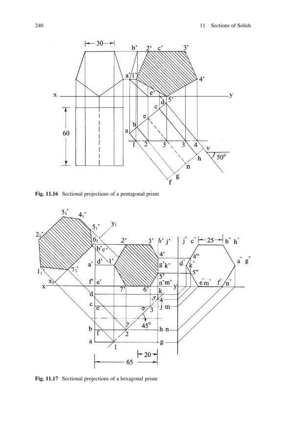
Fig. 11.16 Sectional projections of a pentagonal prism
Fig. 11.17 Sectional projections of a hexagonal prism
240 11 Sections of Solids

its horizontal trace which makes an angle of 45� with xy and passes through a
point 20 mm from its right end on its axis as shown in the figure. The section
plane cuts five horizontal longer edges and two shorter edges on the right end of
the prism. The intersection points are marked as 1, 2, 3, 4, 5, 6 and 7 in the plan.
Points 4 and 5 lie on the edges jk and km. The points 10, 20, 30, 60 and 70 arelocated directly on the respective longer edges of the prism in the elevation.
Since the plan of the edges jk and km are perpendicular to xy, points 40 and 50
cannot be projected directly from the plan. These points are projected on the
side elevation and are marked as 400 and 500. Locus lines are drawn parallel to xyfrom 400 and 500. These lines intersect the edges j0k0 and k0m0 and locate the
points 40 and 50 in the elevation of the prism. The portion of the prism lying in
front of the section plane is removed so that the sectioned surface will be visible
in the elevation of the prism. The sectioned surface is obtained by connecting
the points 10-20-30-40-50-60-70-10. The enclosing area is hatched by drawing thin
lines inclined at 45� to xy. An auxiliary plane parallel to the section plane is
chosen at x1y1 as shown in the figure. A projector is drawn perpendicular to
x1y1 from point 1. Point 110 is located on this projector such that the distance of
110 from x1y1 is equal to the distance of 10 from xy. The remaining points 21
0,31
0, 410, 510, 610 and 710 are located following the same procedure. These points
are connected to show the true shape of the section formed. The sectioned
surface is hatched by drawing thin lines inclined at 45� to xy.
8. A tetrahedron of edge 60 mm is placed on the HP with one of its edges parallel
to the VP. It is cut by a vertical section plane whose horizontal trace is inclined
at 60� to xy and 10 mm from the axis. Draw its projections and true shape of the
section.
The plan of the tetrahedron is drawn as shown in Fig. 11.18. The elevation is
projected from the plan. An arc of radius 10 mm is drawn with centre d. The
horizontal trace of the section plane inclined at 60� to xy is drawn tangential tothe arc as shown in the figure. The section plane cuts four edges of the
tetrahedron. The intersection points are marked as 1, 2, 3 and 4 in the plan.
Points 10, 20 and 40 are projected on the respective edges in the elevation. Point
3 lies on the edge dc which is perpendicular to xy. With centre d and radius d3,
an arc is drawn to cut the edge db at e as shown in the figure. A projector is
drawn perpendicular to xy from e, and the intersection of the projector with d0b0
locates e0 in the elevation. A horizontal line is drawn from e0 to locate 30 on theedge d0c0. The portion of the solid in front of the section plane is removed. The
sectioned surface is obtained by connecting the points 10-20-30-40-10 in the
elevation. The sectioned surface is hatched by drawing thin lines inclined at
45� to xy. An auxiliary plane parallel to the section plane is chosen at x1y1. A
projector is drawn perpendicular to x1y1 from point 2. Point 210 is located on
this projector such that the distance of 210 from x1y1 is equal to the distance of 2
0
from xy. The remaining points 110, 310 and 41
0 are located following the same
procedure. These points are connected to show the true shape of the section
formed. The sectioned surface is hatched by drawing thin lines inclined at 45�
to xy.
Solved Problems 241

9. An octahedron of edge 40 mm rests with one of its faces on the HP. It is cut by a
section plane parallel to the HP passing through the mid-point of its solid
diagonal/axis. Draw the sectional plan and true shape of the section.
The plan of the octahedron will be a square if one of its axis or solid diagonal
is vertical. Since the octahedron is to rest on one of its faces, the plan is drawn
with a side of square parallel to xy as shown in Fig. 11.19. The elevation is
projected from the plan. The elevation is redrawn such that the face c0d0f0 lieson xy. The plan is projected from the elevation. The horizontal section plane
passes through the mid-point of the axis or the solid diagonal. The vertical trace
of the section plane, which passes through the mid-point of e0f0, is drawn. Thesection plane cuts six edges of the octahedron as shown in the figure. These
Fig. 11.18 Sectional
projections of a tetrahedron
Fig. 11.19 Sectional
projections of an
octahedron
242 11 Sections of Solids

points are marked as 10, 20, 30, 40, 50 and 60 (10 lies on a0f0, 20 on bf0, etc.) in the
elevation. These points are then projected to locate 1, 2, 3, 4, 5 and 6 on the
respective edges in the plan. The top portion of the solid is removed. The
sectioned surface is obtained by connecting the points 1-2-3-4-5-6-1. The
sectioned surface is hatched by drawing thin lines inclined at 45� to xy. Since
the section plane is horizontal, the sectioned surface in the plan itself shows the
true shape of the section formed.
10. A square pyramid base 40 mm side and axis 60 mm long has its base on the HP
and base edges equally inclined to the VP. It is cut by a section plane inclined at
30� to the HP and bisecting the axis. Draw its sectional plan, sectional end
elevation and true shape of the section.
The plan of the square pyramid resting on the HP with its base is a square
and is drawn with the base edges equally inclined to xy (inclined at 45� to xy) asshown in Fig. 11.20. The elevation is projected from the plan. The side
elevation is drawn from the plan and elevation of the pyramid by drawing
locus lines parallel to xy and the 45� inclined lines as shown in the figure. The
section plane is represented by its vertical trace. The vertical trace is inclined at
30� to xy and passes through the mid-point of the axis in the elevation. The
section plane cuts the four slant edges. The intersection points are marked as 10,20, 30 and 40 in the elevation. Points 10 and 30 are projected to get points 1 and
3 on the respective edges in the plan. Points 20 and 40 lie on the slant edges
whose projections are perpendicular to xy. A horizontal line is drawn from 20
and 40 to intersect the slant edge e0c0 at g0. A projector is drawn perpendicular to
Fig. 11.20 Sectional projections of square pyramid
Solved Problems 243

xy from g0 to intersect the edge ec at g. With centre e and eg as radius, draw an
arc to cut the edges eb and ed to locate the points 2 and 4 as shown in the figure.
The top portion of the pyramid is removed. The sectioned surface is obtained
by connecting the points 1-2-3-4-1 in the plan. The sectioned surface is hatched
by drawing thin lines inclined at 45� to xy. The section points are projected in
the side elevation by drawing locus lines as shown in the figure. The sectioned
surface in the side elevation is obtained by connecting the points
100-200-300-400-100. The sectioned surface in the side elevation is hatched by
drawing thin lines inclined at 45� to xy. An auxiliary plane parallel to the
section plane is chosen at x1y1. A projector is drawn perpendicular to x1y1 from
10. Point 11 is located on this projector such that the distance of 11 from x1y1 is
equal to the distance of 1 from xy. The remaining points 21, 31 and 41 are
obtained following the same procedure. These points are joined to show the
true shape of the section. The sectioned surface is hatched by drawing thin lines
inclined at 45� to xy.
11. A right square pyramid, side of base 40 mm and axis 80 mm long, is resting on
the HP on one of its longer edges such that the sides of the base are equally
inclined to the HP and the axis is parallel to the VP. It is cut by a vertical section
plane parallel to the axis and at a distance of 10 mm in front of it. Draw the plan
and sectional elevation.
The square pyramid is kept initially on the HP on its base with the base
edges equally inclined to the VP. Then the pyramid is tilted about the right
extreme corner of its base such that the slant longer edge containing this corner
lies on the HP. In this position, the base edges are equally inclined to the HP
and the axis of the pyramid is parallel to the VP.
The plan of the square pyramid is drawn in its simple position with the base
edges equally inclined to xy as shown in Fig. 11.21. The elevation is projected
from the plan. The pyramid is tilted about the right extreme base corner so that
the longer edge containing this corner touches the HP. All the points move
parallel to the VP. The elevation is redrawn such that the edge b0v0 coincideswith the reference line xy. The plan is projected from the elevation. The
horizontal trace of the vertical section plane is drawn 10 mm in front of the
axis of the pyramid. The section plane cuts two base edges and one longer slant
edge of the pyramid. The intersection points are marked as 1, 2 and 3 as shown
in the figure. These points are projected to get 10, 20 and 30 on the respective
edges in the elevation. The portion of the pyramid in front of the section plane
is removed. The sectioned surface is obtained by connecting the points
10-20-30-10. The sectioned surface is hatched by drawing thin lines inclined at
45� to xy. A portion of the invisible edge c0v0, which lies inside the sectioned
surface, is not shown as dotted.
12. A pyramid has for its base a square of 50 mm side which is on the horizontal
plane. The altitude of the pyramid is 70 mm and the plan of the vertex is at the
middle point of one side of the plan of the base. This pyramid is cut into two
portions by a horizontal section plane which is 25 mm above the base. Draw the
plan of the lower portion.
244 11 Sections of Solids
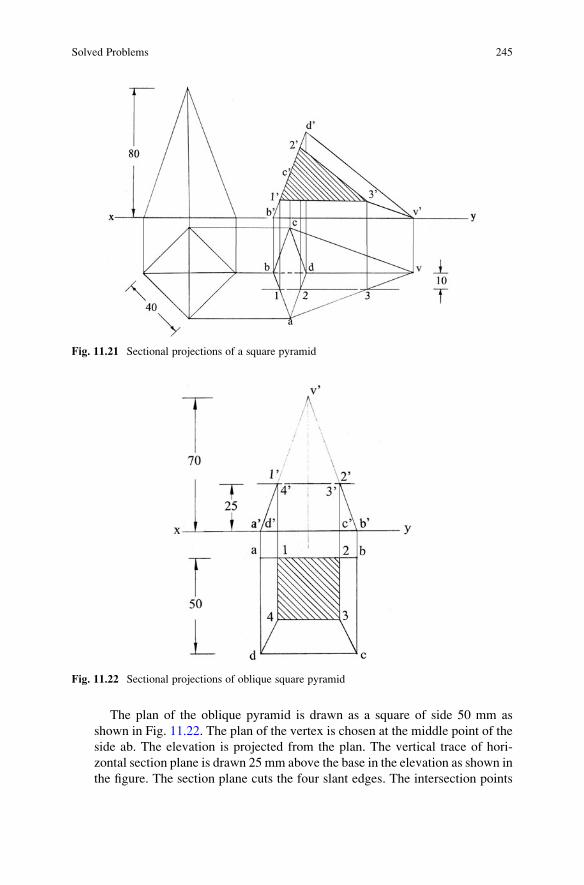
The plan of the oblique pyramid is drawn as a square of side 50 mm as
shown in Fig. 11.22. The plan of the vertex is chosen at the middle point of the
side ab. The elevation is projected from the plan. The vertical trace of hori-
zontal section plane is drawn 25 mm above the base in the elevation as shown in
the figure. The section plane cuts the four slant edges. The intersection points
Fig. 11.22 Sectional projections of oblique square pyramid
Fig. 11.21 Sectional projections of a square pyramid
Solved Problems 245

are marked as 10, 20, 30 and 40 in the elevation. These points are projected to get1, 2, 3 and 4 on the respective edges in the plan. The top portion of the pyramid
is removed. The sectioned surface is obtained by connecting the points 1-2-3-4-
1 in the plan. The sectioned surface is hatched by drawing thin lines inclined at
45� to xy.
13. A pentagonal pyramid edge of base 30 mm and axis 60 mm stands on the HP
with an edge of base parallel to the VP. It is cut by a section plane inclined at
45� to the HP passing through one of the extreme angular points of the base of
pyramid. Draw the sectional plan and also the plan of the truncated pyramid on
an auxiliary plane parallel to the section plane.
The plan of the pentagonal pyramid is drawn with a side of base parallel to
xy as shown in Fig. 11.23. The elevation is projected from the plan. The vertical
trace of the section plane is drawn inclined at 45� to xy and passing through theleft extreme corner a0. The section plane cuts four slant edges and passes
through the angular point a0. The intersection points are marked as 10, 20, 30,40 and 50 in the elevation. These points are projected to get 1, 2, 3, 4 and 5 on therespective edges in the plan (construction is shown for point 5). The top portion
of the pyramid is removed. The sectioned surface is obtained by connecting the
points 1-2-3-4-5-1 in the plan. The sectioned surface is hatched by drawing thin
lines inclined at 45� to xy. An auxiliary plane parallel to the section plane is
chosen at x1y1. A projector is drawn perpendicular to x1y1 from 10. Point 11 islocated on this projector such that the distance of 11 from x1y1 is equal to the
distance of 1 from xy. Points 21, 31, 41, 51, b1, c1, d1 and e1 are located on the
Fig. 11.23 Sectional
projections of a pentagonal
pyramid
246 11 Sections of Solids

respective projectors following the same procedure. The sectioned surface is
obtained by connecting the points 11-21-31-41-51-11. The sectioned surface is
hatched by drawing thin lines inclined at 45� to xy. The remaining edges of the
truncated pyramid are also joined. The invisible edges c1d1 and d1e1 are shown
as dotted avoiding the sectioned surface.
14. A hexagonal pyramid edge of base 30 mm and axis 50 mm rests with a
triangular face on the HP and the axis is parallel to the VP. It is cut by a section
plane parallel to the HP and passing through the centre of base of the pyramid.
Draw the sectional plan.
The plan of the hexagonal pyramid resting on the HP on its base is drawn
keeping a side of base perpendicular to xy as shown in Fig. 11.24. The elevation
is projected from the plan. The pyramid is tilted about the right extreme base
edge such that the triangular face containing this edge lies on xy. All points
move parallel to the VP. The elevation is redrawn as shown in the figure. The
plan is projected from the elevation. The vertical trace of the horizontal section
plane is drawn passing through the centre of the base of the pyramid. The
section plane cuts two slant edges a0v0 and b0v0 and passes through the angular
points c0 and f0. The intersection points are marked as 10, 20, 30 and 40 in the
elevation. These points are projected to get 1, 2, 3 and 4 on the respective edges
and the angular points in the plan as shown in the figure. The top portion of the
pyramid is removed. The sectioned surface is obtained by connecting the points
1-2-3-4-1 in the plan. The sectioned surface is hatched by drawing thin lines
inclined at 45� to xy. The invisible edges dv and ev are shown as dotted
avoiding the sectioned surface.
15. A regular hexagonal pyramid, edge of base 40 mm and axis 70 mm, is standing
on a base edge on the HP with the triangular face containing that edge
Fig. 11.24 Sectional projections of a hexagonal pyramid
Solved Problems 247
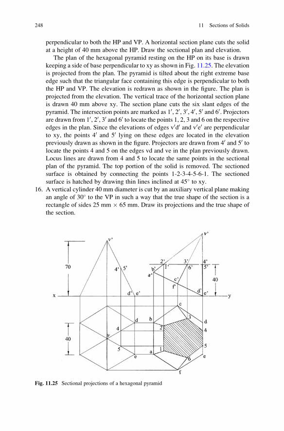
perpendicular to both the HP and VP. A horizontal section plane cuts the solid
at a height of 40 mm above the HP. Draw the sectional plan and elevation.
The plan of the hexagonal pyramid resting on the HP on its base is drawn
keeping a side of base perpendicular to xy as shown in Fig. 11.25. The elevation
is projected from the plan. The pyramid is tilted about the right extreme base
edge such that the triangular face containing this edge is perpendicular to both
the HP and VP. The elevation is redrawn as shown in the figure. The plan is
projected from the elevation. The vertical trace of the horizontal section plane
is drawn 40 mm above xy. The section plane cuts the six slant edges of the
pyramid. The intersection points are marked as 10, 20, 30, 40, 50 and 60. Projectorsare drawn from 10, 20, 30 and 60 to locate the points 1, 2, 3 and 6 on the respectiveedges in the plan. Since the elevations of edges v0d0 and v0e0 are perpendicularto xy, the points 40 and 50 lying on these edges are located in the elevation
previously drawn as shown in the figure. Projectors are drawn from 40 and 50 tolocate the points 4 and 5 on the edges vd and ve in the plan previously drawn.
Locus lines are drawn from 4 and 5 to locate the same points in the sectional
plan of the pyramid. The top portion of the solid is removed. The sectioned
surface is obtained by connecting the points 1-2-3-4-5-6-1. The sectioned
surface is hatched by drawing thin lines inclined at 45� to xy.
16. A vertical cylinder 40 mm diameter is cut by an auxiliary vertical plane making
an angle of 30� to the VP in such a way that the true shape of the section is a
rectangle of sides 25 mm � 65 mm. Draw its projections and the true shape of
the section.
Fig. 11.25 Sectional projections of a hexagonal pyramid
248 11 Sections of Solids

When a vertical cylinder is cut by an auxiliary vertical plane parallel to the
axis of the cylinder, the true shape of the section obtained will always be a
rectangle. The diameter of the cylinder is 40 mm. The given dimensions of the
rectangle are 25 mm � 65 mm. Hence, the height of the cylinder is 65 mm.
Draw a line inclined at 30� to xy and locate the chord of the circle 25 mm long
as shown in Fig. 11.26. Draw the perpendicular bisector of the chord and locate
the centre of the circle of diameter 40 mm. The plan of the cylinder is a circle of
diameter 40 mm. The plan is drawn knowing the circle centre. The elevation is
projected from the plan. The inclined line represents the horizontal trace of the
section plane. The section plane cuts the top and bottom ends of the cylinder.
Hence, there are two points on the circumference of top end and two points on
the bottom end of the cylinder. These points are marked as 1, 2, 3 and 4. Pro-
jectors are drawn from the points 1, 2, 3 and 4. The intersections of the
projectors with top and bottom ends of the cylinder locate the points 10, 20, 30
and 40 in the elevation. The portion of the cylinder lying in front of the section
plane is removed. The sectioned surface is obtained by connecting the points
10-20-30-40-10 in the elevation. The sectioned surface is hatched by drawing thin
lines inclined at 45� to xy. An auxiliary plane parallel to the section plane is
chosen at x1y1. A projector perpendicular to x1y1 is drawn from point 2. Point
210 is located on this projector such that the distance of 210 from x1y1 is equal to
the distance of 20 from xy. The remaining points are located following the same
procedure. The sectioned true shape is obtained by connecting the points
Fig. 11.26 Sectional
projections of a cylinder
Solved Problems 249

110-210-310-410-110. The sectioned surface is hatched by drawing thin lines
inclined at 45� to xy.
17. A cylinder, base 50 mm diameter and axis 80 mm long, has a square hole of
25 mm side cut through it so that the axis of the hole coincides with the axis of
the cylinder. The cylinder is lying on the HP with the axis perpendicular to the
VP and the faces of the hole equally inclined to the HP. The cylinder is cut in
halves by a vertical plane which is inclined at 30� to the VP. Draw the elevation
of the cylinder on an auxiliary plane parallel to the section plane.
The elevation of the cylinder is drawn on xy with the sides of square hole
equally inclined to the HP as shown in Fig. 11.27. The plan is projected from
the elevation. Eight generators are shown on the lateral surface of the cylinder
by dividing the circle into eight equal parts in the elevation and projecting them
in the plan (only the extreme two generators alone are shown in the diagram).
The horizontal trace of the vertical section plane inclined at 30� to xy is drawn
passing through the mid-point of the cylinder. The section plane cuts eight
generators on the surface of the cylinder and four longer edges of the hole. The
12 points are marked in the plan as shown in the figure. The intersection points
1, 2, 3 and 4 lie on the edges of square hole, and the remaining points lie on the
outer surface of the cylinder. These points are projected to get 10, 20, 30, etc. onthe respective edges/generators in the elevation. The portion of the solid lying
in front of the section plane is removed. The area lying between the surfaces
10-20-30-40-10 and 50-60-70-80-90-100-110-120-50 is the required sectioned surface.
An auxiliary projection of the cut cylinder is required on a plane parallel to
vertical section plane. The cut cylinder is moved parallel to the HP such the
sectioned surface is parallel to the VP instead of choosing an auxiliary plane
parallel to the section plane. The sectional plan of the cut cylinder is redrawn
keeping the sectioned surface parallel to xy as shown in the figure. Projectors
are drawn (perpendicular to xy) from the intersection points and also the end
Fig. 11.27 Sectional projections of a cylinder with a square hole
250 11 Sections of Solids

points of the cylinder in the plan redrawn. Locus lines are drawn parallel to xy
from the intersection points and the end points of the cylinder in the elevation.
The intersections of the projectors with the locus lines locate the points 110, 210,
310, 410, 510, etc. The intersection points are joined in the new elevation, and the
sectioned surface lying in between the surfaces 10-20-30-40-10 and 50-60-70-80-90-100-110-120-50 is hatched by drawing thin lines inclined at 45� to xy. The end
points are also joined in the elevation, and the invisible portion of the curve and
edges of the hole are shown as dotted avoiding the sectioned surface.
18. A right circular cone of 40 mm diameter of the base and 60 mm altitude stands
on the HP. A plane normal to the HP and inclined at 45� to the VP cuts the cone
at a distance of 10 mm from its axis. Draw the sectional elevation and true
shape of the section.
The plan and the elevation of the cone resting on the HP on its base are
drawn as shown in Fig. 11.28. The horizontal trace of section plane inclined at
45� to xy and perpendicular to the HP is drawn at a distance of 10 mm from the
axis of the cone. Five generators fa, fb, fc, fd and fe are chosen on the surface of
cone as shown in its plan. The generator fc is kept perpendicular to the
horizontal trace of the section plane. The elevations of the generators f0a0,f0b0, f0c0, f0d0 and f0e0 are projected from the plan. The section plane cuts these
generators as shown in the plan. The intersection points 1, 2, 3, 4 and 5 are
marked in the plan. These points are projected to get 10, 20, 30, 40 and 50 on the
respective generators in the elevation. The portion of the cone lying in front of
the section plane is removed. The sectioned surface is obtained by connecting
the points 10-20-30-40-50-10 in the elevation. The sectioned surface is hatched by
drawing thin lines inclined at 45� to xy. An auxiliary plane parallel to the
section plane is chosen at x1y1. A projector is drawn perpendicular to x1y1 from
the point 2 in the plan. Point 210 is located on this projector such that the
Fig. 11.28 Sectional
projections of a cone
Solved Problems 251

distance of 210 from x1y1 is equal to the distance of 20 from xy. Points 11
0, 310,41
0 and 510 are located following the same procedure. These points are
connected to show the true shape of the section. The sectioned surface is
hatched by drawing thin lines inclined at 45� to xy.
19. A right circular cone, 60 mm of base diameter and 80 mm in altitude, is resting
with its base on the HP. It is cut by a plane parallel to one of the generators of
the cone bisecting the axis. Draw the sectional plan and true shape of the
section.
The plan and elevation of the cone resting on the HP on its base are drawn as
shown in Fig. 11.29. Eight generators at equal intervals are shown in the plan
naming alternate generators as fa, fb, fc and fd. These generators are then
projected in the elevation. The vertical trace of the section plane parallel to the
left extreme generator f0a0 is drawn passing through the mid-point of the axis.
The section plane cuts five generators and passes through the base of the cone.
There are seven intersection points on the cone. The intersection points are
marked as 10, 20, 30, 40, 50, 60 and 70 in the elevation. These points are to be
projected in the plan. Projectors are drawn from 10 and 70 to intersect the base ofthe cone at points 1 and 7 in the plan. Projectors are drawn from 30, 40 and 50 tointersect the corresponding generators at 3, 4 and 5 in the plan. Since the points
20 and 60 lie on the generators f0b0 and f0d0, whose projections are perpendicularto the reference line xy, horizontal lines are drawn from these two points to
intersect the right extreme generator f0c0 at v0. A projector is drawn from v0 to
Fig. 11.29 Sectional projections of a cone
252 11 Sections of Solids

intersect the projector fc at v in the plan. With centre f and fv as radius, an arc is
drawn to intersect the generators fb and fd at 2 and 6 as shown in the figure. The
top portion of the cone is removed. The sectioned surface is obtained by
connecting the points 1-2-3-4-5-6-7-1 in the plan. The sectioned surface is
hatched by drawing thin lines inclined at 45� to xy. An auxiliary plane parallel
to the section plane is chosen at x1y1. A projector perpendicular to x1y1 is
drawn from point 10. Point 11 is located on this projector such that the distance
of 11 from x1y1 is equal to the distance of 1 from xy. Points 21, 31, 41, 51, 61 and
71 are located following the same procedure. The true shape of the section is
obtained by connecting points 11-21-31-41-51-61-71-11. The sectioned surface is
hatched by drawing thin lines inclined at 45� to xy.
20. A plastic bucket of height 4000 mm, bottom and top diameters of 2000 mm and
3000 mm, respectively, contains certain quantity of water. When the bucket is
tilted about the base rim through an angle of 45�, the liquid is about to ooze outfrom the bucket. Draw the projections of the bucket in this inclined position and
also the outline of water surface. Adopt a scale 1:50.
The plan of the bucket is drawn adopting a scale of 1:50 as shown in
Fig. 11.30. Eight generators are chosen by dividing the circumference of the
outer circle which represents the top edge of the bucket into eight equal parts.
The eight lines connecting the outer circle with the inner circle represent the
eight generators on the lateral conical surface of the bucket. The elevation of
the bucket is projected from the plan with the eight generators. The bucket is
Fig. 11.30 Projections of a bucket
Solved Problems 253

tilted about the right extreme base point such that the base is inclined at 45� tothe horizontal. All the points move parallel to the VP. The elevation is redrawn
with the base inclined at 45� to xy, and the alternate generators are named as
a0e0, b0f0, c0g0 and d0h0. The points a0, b0, c0 and d0 lie on the top edge of the
bucket. The points e0, f0, g0 and h0 lie on the bottom edge of the bucket.
Projectors are drawn perpendicular to xy from the generator ends on the top
of the bucket. Locus lines are drawn parallel to xy from the plan of generator
ends on the outer circle. The intersection points locate the points on the top rim
of the bucket. The ellipse is drawn passing through the intersection points. The
projection of the base of the bucket is obtained following the same procedure.
The eight generating lines are drawn connecting the respective points on the top
and bottom ends of the bucket. The alternate generating lines are identified as
a-e, b-f, c-g and d-h in the plan. A horizontal line passing through the point c0 isdrawn in the elevation. This line represents the water surface on the point of
oozing out from the bucket. The horizontal line cuts the eight generators. The
intersection points are marked as 10, 20, 30, 40, 50, 60, 70 and 80. Point 10 lies on thegenerator a0e0, point 30 lies on the generator b0f0, point 50 lies on the generator
c0g0 and point 70 lies on the generator d0h0. A projector is drawn from 10 tointersect the generator ae in the plan and locates point 1. Points 2, 3, 4, 5, 6, 7
and 8 are located on the respective generators following the same procedure.
The outline of water surface is obtained by connecting the points 1-2-3-4-5-6-
7-8-1 in the plan. The invisible portion of the ellipse representing the outline of
the water surface is shown as dotted.
21. A cone diameter of base 60 mm and axis 70 mm long is resting on its base on
the HP. It is cut by an auxiliary plane inclined such that the true shape of section
is an isosceles triangle of 50 mm base. Draw the sectional plan and elevation of
the cone. Also show the true shape of the section.
The plan and elevation of the cone resting on the HP on its base are drawn as
shown in Fig. 11.31. When the cone is cut by a section plane passing through its
apex, the true shape of the section formed shall always be an isosceles triangle.
Fig. 11.31 Sectional
projections of a cone
254 11 Sections of Solids

A chord of length 50 mm is drawn for the circle as shown in the figure. This
chord is projected in the elevation as a point, and the vertical trace of the
section plane passes through this point and the apex of the cone. The section
plane cuts the base of the cone and passes through its apex. There are three
points on the sectioned surface. The intersection points are marked as 10, 20 and30 in the elevation. These points are then projected to get 1, 2 and 3 in the plan.The left portion of the cone is removed. The sectioned surface is obtained by
connecting the points 1-2-3-1 in the plan. The sectioned surface is hatched by
drawing thin lines inclined at 45� to xy. An auxiliary plane parallel to the
section plane is chosen at x1y1. A projector perpendicular to x1y1 is drawn from
point 20 in the elevation. Point 21 is located on this projector such that the
distance of 21 from x1y1 is equal to the distance of 2 from xy. Points 11 and 31are also located following the same procedure. The isosceles triangle
representing the true shape of the section is obtained by connecting the points
11-21-31-11 as shown in the figure. The true shape of the section is hatched by
drawing thin lines inclined at 45� to xy.
22. A sphere of 50 mm diameter is on the HP. A vertical section plane inclined at
45� to the VP cuts the sphere. If the cutting plane is 10 mm from the centre of
the sphere, draw the sectional front elevation of the sphere.
The plan and elevation of the sphere are drawn as shown in Fig. 11.32. The
horizontal trace of the section plane inclined at 45� to xy is drawn 10 mm in
front of the centre of sphere (i.e. the centre of the circle) in the plan. The true
shape of sections obtained on a sphere will always be circles by any plane. An
Fig. 11.32 Sectional projections of a sphere
Solved Problems 255

auxiliary plane parallel to the section plane is chosen at x1y1. A projector is
drawn perpendicular to x1y1 from the centre of sphere in the plan. The centre of
sphere is located on this projector. A circle of diameter equal to the chord made
by the section plane in the plan is drawn as shown in the figure. This circle is the
true shape of the section obtained. The circle is divided into eight equal parts,
and eight points are located on the circumference of the circle. The points are
marked as 110, 210, 310, 410, 510, 610, 710 and 81
0. Projectors are drawn from these
points to intersect the horizontal trace of the section plane at 1, 2, 3, 4, 5, 6,
7 and 8 in the plan. A projector is drawn perpendicular to xy from point 1. Point
10 is located on this projector such that the distance of 10 from xy is equal to the
distance of 110 from x1y1. Points 2
0, 30, 40, 50, 60, 70 and 80 are located on the
respective projectors following the same procedure. A line is drawn parallel to
xy from the centre of the sphere in the plan. This line intersects the horizontal
trace of the section plane. There will be two points lying on the surface of the
sphere and also the sectioned surface. These points are marked as b and a in the
plan. These points are then projected to get b0 and a0 in the elevation of the
sphere. The portion of the sphere lying in front of the section plane is removed.
The sectioned surface is obtained by drawing an ellipse connecting the 10-20-a0-30-40-50-60-70-b0-80-10. The circle of the sphere connecting the points a0 and b0
is drawn thick to show the projection of the cut-sphere in the elevation. The
sectioned surface is hatched by drawing thin lines inclined at 45� to xy.
23. A tetrahedron of edge 60 mm is lying on the HP with one of its edges
perpendicular to the VP. It is cut by a section plane perpendicular to the VP
and inclined to the HP such that the true shape of section is an isosceles triangle
of base 50 mm and altitude 40 mm. Find the inclination of the section plane
with the HP and draw the sectional plan and the true shape of the section.
The plan and elevation of the tetrahedron lying on the HP with an edge
perpendicular to the VP are drawn as shown in Fig. 11.33. The points 1 and
Fig. 11.33 Sectional
projections of a tetrahedron
256 11 Sections of Solids

2 are chosen on the edges ad and bd such that the distance between them is
50 mm and the line joining them is perpendicular to xy. These two points are
projected to get 10 and 20 on the edges a0d0 and b0d0 in the elevation. With 10 ascentre and radius 40 mm, an arc is drawn to cut the edge c0d0 at 30 as shown in
the figure. The section plane passes through the points 10, 20 and 30. The verticaltrace of the section plane is extended and the angle θ, inclination of the sectionplane with the HP, is measured. A projector is drawn perpendicular to xy from
30 to locate the point 3 on the edge cd in the plan. The portion of the tetrahedronlying to the left of the section plane is removed. The sectioned surface is
obtained by connecting the points 1-2-3-1 in the plan. The sectioned surface
is hatched by drawing thin lines inclined at 45� to xy. An auxiliary plane
parallel to the section plane is chosen at x1y1. A projector is drawn perpendic-
ular to x1y1 from the point 30. Point 31 is located on this projector such that the
distance of 31 from x1y1 is equal to the distance of 3 from xy. Points 11 and 21are located on the respective projectors following the same procedure. The true
shape of the section is obtained by connecting the points 11-21-31-11. The
isosceles triangle is hatched by drawing thin lines inclined at 45� to xy. The
inclination of the section plane with the HP, ϴ, is 65�.24. A tetrahedron of edge 60 mm is resting on one of its faces on the HP with an
edge of that face perpendicular to the HP. It is cut by a section plane perpen-
dicular to the VP so that the true shape of the section is a square. Draw the
elevation, the sectional plan and the true shape of the section.
The plan and elevation of the tetrahedron resting on the HP on a face with an
edge of that face perpendicular to the VP are drawn as shown in Fig. 11.34. The
mid-points of the edges a0b0 and d0b0 are located in the elevation. These points
are marked as 10 and 20 in the elevation. The mid-points of the edges d0c0 anda0c0 coincide with the mid-points of the edges d0b0 and a0b0 already located.
These points are marked as 30 and 40 in the elevation. If a section plane passes
through these four points, the true shape of the section will be a square. The
Fig. 11.34 Sectional
projections of a tetrahedron
Solved Problems 257

vertical trace of the section plane is drawn passing through the points 10, 20, 30
and 40. Projectors are drawn from these four points to locate points 1, 2, 3 and
4 on the respective edges in the plan. The portion of the solid lying to the left of
the section plane is removed. The sectioned surface is obtained by connecting
the points 1-2-3-4-1 in the plan. The sectioned surface is hatched by drawing
thin lines inclined at 45� to xy. An auxiliary plane parallel to the section plane
is chosen at x1y1. A projector is drawn perpendicular to x1y1 from the point 20 inthe elevation. Point 21 is located on this projector such that the distance of 21from x1y1 is equal to the distance of 2 from xy. Points 31, 41 and 11 are located
on the respective projectors following the same procedure. The true shape of
the section is obtained by connecting the points 11-21-31-41-11. The true shape
is a square of side 30 mm (half the edge of the tetrahedron). The sectioned
surface is hatched by drawing thin lines inclined at 45� to xy.
25. A cube having an edge of 40 mm is cut by a section plane in such a way that the
true shape of the section made is a rhombus having side of maximum length
possible. Draw the projections of the sectioned cube showing the true shape of
section made.
The cube is kept on the HP with the vertical faces equally inclined to the
VP. The plan of the cube is drawn with sides of square equally inclined to xy as
shown in Fig. 11.35. The elevation of the cube is projected from the plan. If the
cube is cut by section planes perpendicular to the VP and passing through the
centre of cube and cutting the four vertical edges, the true shape of the sections
made will always be rhombuses of different sizes. When the section plane
passes through the extreme corners c0 and e0 of the vertical edges c0g0 and a0e0, arhombus of maximum size is obtained as the true shape of the section. The
vertical trace of the section plane is drawn passing through the corner points c0
Fig. 11.35 Sectional
projections of a cube
258 11 Sections of Solids

and e0 as shown in the figure. The section plane cuts two vertical edges b0f0 andd0h0 and passes through the points c0 and e0 in the elevation. The intersection
points are marked as 10, 20, 30 and 40. These points are projected to get 1, 2,
3 and 4 in the plan. The sectioned surface is obtained by connecting the points
1-2-3-4-1 in the plan. The sectioned surface is hatched by drawing thin lines
inclined at 45� to xy. An auxiliary plane parallel to the section plane is chosen
at x1y1. A projector is drawn perpendicular to x1y1 from point 10. Point 11 islocated on this projector such that the distance of 11 from x1y1 is equal to the
distance of 1 from xy. Points 21, 31 and 41 are located on the corresponding
projectors following the same procedure. The rhombus of maximum size is
obtained by connecting the points 11-21-31-41-11. The true shape of the section
is hatched by drawing thin lines inclined at 45� to xy.
26. A cube of 40 mm edge stands on the HP and is cut by a section plane such that
the true shape of the section is a regular hexagon. Draw the projections of the
cube and determine the angle of inclination of the section plane with the
HP. Also show the true shape of the section.
The cube is kept on the HP with the vertical faces equally inclined to the
VP. The plan of the cube is drawn with sides of square equally inclined to xy as
shown in Fig. 11.36. The elevation of the cube is projected from the plan.
Section planes perpendicular to the VP and passing through the centre of the
cube cut the top and bottom ends of the cube and give hexagons as true shapes
of sections. If the section plane passes through the mid-points of sides b0c0 andd0c0 at the top end and the mid-points of sides f0e0 and h0e0 in the bottom ends,
the true shape of the section will be a regular hexagon. The vertical trace of
section plane is drawn as shown in the figure. The inclination of the section
plane with the HP, ϴ, is found to be 54�. The section plane cuts the edges e0f0,b0f0, b0c0, c0d0, d0h0 and h0e0 at points 10, 20, 30, 40, 50 and 60 in the elevation. Thesepoints are projected to get points 1, 2, 3, 4, 5 and 6 on the respective edges in the
Fig. 11.36 Sectional
projections of a cube
Solved Problems 259

plan. The top portion of the cube is removed. The sectioned surface is obtained
by connecting the points 1-2-3-4-5-6-1 in the plan. The sectioned surface is
hatched by drawing thin lines inclined at 45� to xy. An auxiliary plane parallel
to the section plane is chosen at x1y1. A projector is drawn perpendicular to
x1y1 from point 10 in the elevation. Point 11 is located on this projector such thatthe distance of 11 from x1y1 is equal to the distance of 1 from xy. Points 21, 31,
41, 51 and 61 are located on the respective projectors following the same
procedure. The sectioned surface is obtained by connecting the points 11-21-
31-41-51-61-11. The regular hexagon representing the true shape of section is
hatched by drawing thin lines inclined at 45� to xy.
27. A cube of 50 mm edge is cut by a section plane perpendicular to the VP so that
the true shape of section is an equilateral triangle of maximum side. Draw the
sectional plan and the true shape of the section. Find also the inclination of the
section plane with the HP.
The cube is kept on the HP with the vertical faces equally inclined to the
VP. The plan of the cube is drawn with sides of square equally inclined to xy as
shown in Fig. 11.37. The elevation is projected from the plan. A section plane is
chosen passing through the points b0, d0 and e0. This plane cuts the cube, and thetrue shape of the section will be an equilateral triangle of maximum side equal
to diagonal of face of the cube. The vertical trace of the section plane is drawn
passing through the points b0, d0 and e0. The section points are marked as 10, 20
and 30 in the elevation. These points are projected to get 1, 2 and 3 in the plan.
The left portion of the cube is removed. The sectioned surface is obtained by
connecting the points 1-2-3-1 in the plan. The sectioned surface is hatched by
drawing thin lines inclined at 45� to xy. An auxiliary plane parallel to the
section plane is chosen at x1y1. A projector is drawn perpendicular to x1y1 from
the point 10. Point 11 is located on this projector such that the distance of 11
Fig. 11.37 Sectional
projections of a cube
260 11 Sections of Solids

from x1y1 is equal to the distance of 1 from xy. Points 21 and 31 are located on
the respective projectors following the same procedure. The sectioned surface
is obtained by connecting the points 11-21-31-11. The equilateral triangle
representing the true shape of section of maximum size is hatched by drawing
thin lines inclined at 45� to xy. The inclination of the section plane with the HP,ϴ, is 55�.
28. A right square prism, side of base 30 mm and altitude 80 mm, is cut into two
equal parts by a section plane. The true form of the section is a rhombus of
40 mm side. Draw a sectional plan of one part of the prism on a plane parallel to
the section plane.
The square prism is kept on the HP on its base with the vertical faces equally
inclined to the VP. The plan of the prism is drawn with the sides of square
equally inclined to xy as shown in Fig. 11.38. The elevation is projected from
the plan. The centre of the prism is located at the mid-point of vertical edge
d0h0. A section plane perpendicular to the VP, inclined to the HP and passing
through this point gives rhombus as true shape of the section. Locus lines are
drawn parallel to xy from the points a, b and d in the plan. The length of the
shorter diagonal of the rhombus is equal to the length of diagonal of the square
in the plan. The rhombus of side 40 mm is constructed on the locus lines as
shown in the figure. The length of the larger diagonal of the rhombus is
measured. An arc of radius equal to half the larger diagonal is drawn from
the centre of the prism to cut the vertical edges a0e0 and c0g0 at points 10 and 30 inthe elevation. The section plane passes through the points 10 and 30 and cuts theedges b0f0 and d0h0 at 20 and 40. These are projected to get points 1, 2, 3 and 4 in
Fig. 11.38 Sectional projections of a square prism
Solved Problems 261

the plan. The top portion of the prism is removed. The sectioned surface is
obtained by connecting the points 1-2-3-4-1 in the plan. The sectioned surface
is hatched by drawing thin lines inclined at 45� to xy. An auxiliary plane
parallel to the section plane is chosen at x1y1. A projector is drawn perpendic-
ular to x1y1 from point 10. Point 11 is located on this projector such that the
distance of 11 from x1y1 is equal to the distance of 1 from xy. Section points 21,
31 and 41 are located on the respective projectors following the same procedure.
Base points a1, b1, c1 and d1 are also located on the respective projectors
following the same procedure. The sectioned surface is obtained by connecting
the points 11-21-31-41-11. The sectioned surface is hatched by drawing thin
lines inclined at 45� to xy. The projections of the base of the prism and the
edges connecting the section points with the base points are completed. The
invisible edges are shown as dotted avoiding the sectioned surface.
29. A cylinder is cut to the shape of a wedge as shown in Fig. 11.39. Draw the
sectional side view and the true shape of the section for one side.
The cylinder is kept on the HP on its base. The plan, elevation and left side
elevation are drawn as shown in Fig. 11.40. Twelve generators are chosen on
the lateral surface of the cylinder at equidistant, and these generators are shown
in the plan, elevation and side elevation. Two section planes are used in the
elevation to cut the cylinder to the shape of a wedge as shown in Fig. 11.40. The
section plane cuts seven generators of the cylinder on the left side. The
intersection points are marked as 10, 20, 30, 40, 50, 60 and 70 in the elevation.
These points are projected to get points 1, 2, 3, 4, 5, 6 and 7 in the plan. Locus
lines are drawn parallel to xy from points 10, 20, 30, 40, 50, 60 and 70 to intersect
Fig. 11.39 Cut cylinder
262 11 Sections of Solids

the corresponding generators in the side elevation. The intersection points are
marked as 100, 200, 300, 400, 500, 600 and 700 in the side elevation. The sectioned
surface in the side elevation is obtained by drawing a smooth curve passing
through the points 100-200-300-400-500-600-700 and joining the points 100 and 700 by a
straight line. The sectioned surface is hatched by drawing thin lines inclined at
45� to xy. An auxiliary plane parallel to the section plane on the left side is
chosen at x1y1. A projector is drawn perpendicular to x1y1 from the point 10.Point 11 is located on this projector such that the distance of 11 from x1y1 is
equal to the distance of 1 from xy. Points 21, 31, 41, 51, 61 and 71 are located on
the respective projectors following the same procedure. The true shape of the
sectioned surface is obtained by drawing a smooth curve passing through the
points 11-21-31-41-51-61-71 and joining the points 11 and 71 by a straight line.
The sectioned surface is hatched by drawing thin lines inclined at 45� to xy.
30. A hexagonal pyramid, side of base 30 mm and axis 60 mm, is in the first
quadrant. A thread is tied to one corner of its base, and the pyramid is
suspended freely so that the vertex of the pyramid is above the HP and the
axis is parallel to the VP. A vertical section plane making an angle of 20� withthe VP and passing through the vertex of the pyramid cuts it completely. Draw
the projections of the larger portion of the pyramid and show the true shape of
the section made.
The pyramid base is kept parallel to HP with a side of hexagon parallel to the
VP and the vertex below the base. The plan of the pyramid is drawn as shown in
Fig. 11.41. The elevation is projected from the plan. The centre of gravity is
Fig. 11.40 Sectional projections of cut cylinder
Solved Problems 263

one-fourth the axis from the base of the pyramid and is located at g0 in the
elevation. The left extreme base point b0 is connected to the centre of gravity g0.The thread is tied to the point b0 and is freely hung from it. All the points move
parallel to the VP. The elevation is redrawn such that the line connecting the
points b0 and g0 is perpendicular to xy. Projectors are drawn perpendicular to xyfrom the angular points and vertex of the pyramid in the elevation. Locus lines
are drawn parallel to xy from the angular points and the vertex in the plan. The
intersections of the projectors with the locus lines locate the angular points and
the vertex in the new plan. The new plan is completed showing the visible and
invisible edges of the pyramid. The horizontal trace of the section plane is
drawn inclined at 20� to xy and passing through the vertex in the plan. The
section plane cuts two base edges ab and ef and passes through the vertex v in
the plan. The intersection points are marked as 1, 2 and 3 in the plan. These
points are projected to get 10, 20 and 30 on the respective edges in the elevation.The portion of the pyramid in front of the section plane is removed to retain the
larger portion of the pyramid. The sectioned surface is obtained by connecting
the points 10-20-30-10 in the elevation. The sectioned surface is hatched by
drawing thin lines inclined at 45� to xy. The sectioned surface in the plan is
kept parallel to the VP by moving the section points horizontally. The section
points move parallel to the HP. The new plan of the sectioned surface is
represented as 11-21-31. Projectors are drawn perpendicular to xy from the
points 11, 21 and 31. Locus lines are drawn parallel to xy from 10, 20 and 30 in theelevation. The intersection points are marked as 11
0, 210 and 310. The true shapeof section is obtained by connecting the points 11
0-210-310-110 and is hatched by
drawing thin lines inclined at 45� to xy.
Fig. 11.41 Sectional projections of a hexagonal pyramid
264 11 Sections of Solids

Practice Problems
1. A triangular prism, edge of base 30 mm and axis 50 mm long, is lying on the HP
on one of its rectangular faces with its axis inclined at 45� to the VP. It is cut bya section plane parallel to the HP and 10 mm above the HP. Draw its elevation
and sectional plan.
2. A pentagonal prism, edge of base 30 mm and axis 80 mm long, lies with one
face on the HP and the axis parallel to the VP. The solid is cut by an auxiliary
plane inclined at 40� to the HP and passing through the mid-point of the axis.
Draw the apparent and true shape of the section.
3. The base of a hollow prism is a regular hexagon of 40 mm side with another
concentric hexagon of 20 mm side, the sides of the latter being parallel to those
of the former. The prism is 60 mm high and stands on the HP on its base with a
face perpendicular to the VP. It is cut by a section plane inclined at 30� to the
HP and passing through the mid-point of its axis. Draw the true shape of the
section.
4. A cylinder, diameter of base 50 mm and axis 70 mm long, stands on the HP. A
section plane perpendicular to the VP and inclined at 60� to the HP bisects the
axis. Draw the sectional plan and true shape of the section.
5. A cylinder, diameter of base 60 mm and axis 80 mm long, has a square hole of
side 30 mm. The cylinder is resting on its base on the HP. The vertical faces of
the square hole are equally inclined to the VP. The axis of the hole coincides
with the axis of the cylinder. The cylinder is cut by a section plane perpendic-
ular to the VP. The section plane cuts at a point 10 mm from the top surface of
the cylinder and makes an angle of 30� with the HP. Draw the elevation,
sectional plan and the true shape of the section.
6. Draw the plan and elevation of a cylinder cut by a section plane in such a
manner that the true shape of section is an ellipse of 60 mm and 120 mm as its
minor and major axes, respectively. Find the slope of the section plane with the
axis of the cylinder. Take the smallest generator length to be 40 mm.
7. A triangular prism, side of base 40 mm and axis 80 mm long, is resting on the
HP on its base. It is cut by an auxiliary inclined plane which cuts the vertical
edges at heights of 20 mm, 40 mm and 60 mm above the base of the prism. Find
the inclination of this plane with the HP. Draw the sectional plan and true shape
of the section.
8. A triangular pyramid, edge of base 40 mm and axis 60 mm long, stands on the
HP on its base with an edge of base parallel to the VP and nearer to it. A section
plane inclined at 60� to the HP and perpendicular to the VP bisects the axis of
the pyramid. Draw the elevation, sectional plan and true shape of the section.
9. A square pyramid edge of base 50 mm and altitude 70 mm stands on the HP and
is cut by a vertical plane passing through one point half way down one slant
edge and another point one quarter way down an adjacent slant edge. Draw its
projections and true shape of the section.
10. A regular hexagonal pyramid, base 40 mm side and axis 80 mm long, is resting
on its base on the HP with two opposite slant edges parallel to the VP. It is cut
Practice Problems 265

by a section plane perpendicular to the VP and inclined at 45� to the HP. The
section plane passes through the axis at a point 30 mm above the base. Draw its
elevation, sectional plan and true shape of the section.
11. A right hexagonal pyramid, side of base 30 mm and altitude 60 mm, is cut by a
section plane which contains one edge of the base and is perpendicular to the
opposite face. Determine the true shape of the section.
12. A cone of 50 mm diameter of base and 70 mm height resting on the HP is cut by
a section plane inclined at 40� to the HP and perpendicular to the VP. The
section plane passes through a point 30 mm below the apex. Draw the true
shape of the section made and name the curve.
13. A frustum of a cone, top diameter 60 mm, base diameter 80 mm and height
80 mm has a coaxial through hole of 40 mm diameter and stands with its base
on the HP. It is cut by a section plane whose vertical trace inclined at 40� to
reference line xy passes through the mid-point of the axis of the frustum. Draw
the sectional plan and true shape of the section.
14. A cone of base 60 mm diameter and height 80 mm resting on its base on the HP
is cut by a section plane perpendicular to both the HP and VP at a distance
10 mm from the axis. Draw the sectional side elevation of the cone.
15. A square pyramid, side of base 50 mm and axis 80 mm, is lying on one of its
triangular faces on the HP with the axis parallel to the VP. It is cut by a
horizontal section plane which bisects the axis. Draw the elevation and the
sectional plan of the pyramid.
16. An equilateral triangular prism of 50 mm side of base and height 70 mm is cut
by a section plane in such a way that the true shape of the section is a trapezium
of parallel sides of 50 mm and 10 mm. Draw the projections of cut prism and
the true shape of the section.
17. A hollow square prism, base 50 mm side outside, height 75 mm and thickness
10 mm, is resting on its base on the HP with one of its vertical faces inclined at
30� to the VP. A section plane inclined at 30� to the HP and perpendicular to the
VP and passing through the axis 20 mm from its top end cuts the prism. Draw
the sectional plan and the true shape of the section.
18. A pentagonal prism, base 35 mm side and axis 90 mm long, is resting on a base
edge on the HP with a rectangular face containing that edge being perpendic-
ular to the VP and inclined to the HP at 60�. It is cut by a horizontal section
plane whose vertical trace (VT) passes through the mid-point of the axis. Draw
the projections of the cut prism.
19. A cylinder of 60 mm diameter of base and axis 90 mm long has its axis inclined
at 30� to the VP and parallel to the HP. It is cut by a section plane perpendicular
to the HP so that the true shape of the section is an ellipse of major axis 75 mm.
Draw the projections of the cut cylinder and the true shape of the section.
20. A triangular prism, side of base 40 mm and height 80 mm, rests with one of its
base edges on HP such that the axis is parallel to VP and inclined at 30� to
HP. A horizontal section plane passes through the lowest triangular edge of the
top end of the prism. Draw the sectional plan showing the true shape of the
section.
266 11 Sections of Solids

Chapter 12
Intersection of Surfaces
The need to determine the lines or curves of intersections between two surfaces of
similar or different geometric shapes occurs in the fabrication of ducts, boiler
mountings, pipe fittings, aircraft and automobile bodies. If two geometric shapes
with curved surfaces meet or penetrate each other, the lines of intersection is a
curve. The curve of intersection is determined by plotting the projections of points
which are common to both surfaces. This is done by choosing section planes which
cut the surfaces in lines or circles. The intersections of these lines give points on the
required curve.
Classification of intersecting surfaces
(a) Intersection of two curved surfaces
The intersection of curved surfaces is a curve. Cylinder and cylinder,
cylinder and cone or cone (penetrating surface) and cylinder belong to this
category.
(b) Intersection of two plane surfaces
The intersection of plane surfaces is a straight line. Prism and prism, prism
and pyramid or pyramid and pyramid belong to this category.
Methods used to draw the line or curve of intersection
The following two methods are used to draw the line of intersection.
1. Cutting plane method
In this method, a number of section planes are chosen and cut the intersecting
surfaces in lines or circles. The intersections of these lines give points common
to both the surfaces. This method is used for cylinder penetrating another
cylinder or cone.
2. Line method or piercing point method
In this method, a number of straight lines are chosen on the penetrating
surface, and points of intersection which are common to both surfaces are
obtained. This method is used for cone penetrating cylinder and prism penetrat-
ing another prism.
© Springer Nature Singapore Pte Ltd. 2018
K. Rathnam, A First Course in Engineering Drawing,DOI 10.1007/978-981-10-5358-0_12
267

Solved Problems
1. A horizontal cylinder of 50 mm diameter penetrates the vertical cylinder of
80 mm diameter resting on the HP. The axes of the cylinders are coplanar. The
axis of the horizontal cylinder is 50 mm above the HP. Draw the projections of
the cylinders showing the curves of intersections of the two cylinders.
The plan, elevation and left side elevation of the outline of intersecting
cylinders with axes coplanar are drawn as shown in Fig. 12.1. It is evident that
the horizontal cylinder penetrates the vertical cylinder, and the curves of
intersection lie entirely on the surface of the horizontal cylinder. The circum-
ference of the horizontal cylinder in the side elevation is divided into eight
equal parts, and the division points are numbered in the three views as shown in
the figure. A horizontal section plane is chosen passing through point 100. Thissection plane cuts the surface of horizontal cylinder in its topmost generator
and the surface of the vertical cylinder in a circle. The plan of the generator
passing through point 1 in the plan intersects the circle in points a and p. These
points are projected on the generator passing through point 10 at a0 and p0. Thesepoints lie on the curves of intersection. Another horizontal section plane is
chosen passing through the points 200 and 800. This section plane cuts the surface
Fig. 12.1 Intersections of two cylinders
268 12 Intersection of Surfaces

of horizontal cylinder along two generators passing through the points 2 and
8 in the plan and the surface of vertical cylinder in a circle. The plans of the two
generators intersect the circle in points b, h, w and q. These points are then
projected on the generators passing through 20 and 80 at b0, h0, w0 and q0. A third
horizontal section plane is chosen passing through the points 300 and 700. Pointsc, g, v and r in the plan and points c0, g0, v0 and r0 in the elevation are obtained
following the same procedure. The fourth horizontal section plane passing
through the points 400 and 600 provides four more points, namely d, f, u and s
in the plan and d0, f0, u0 and s0 in the elevation. Finally, the fifth horizontal
section plane passing through the point 500 provides two points e and t in the
plan and e0 and t0 in the elevation. Draw a smooth curve passing through the
points a0, b0 c0, d0, e0, f0, g0 and h0 and another curve passing through the points
p0, q0, r0, s0, t0, u0, v0 and w0. The curve of intersection changes its direction at
points c0, e0, g0 and a0 on the right side and at r0, t0, v0 and p0 on the left side.
These points are called key points or critical points which lie on extreme
generators of the penetrating cylinder.
2. A horizontal cylinder of 50 mm diameter penetrates the vertical cylinder of
80 mm diameter resting on the HP. The axis of the horizontal cylinder is
parallel to both the HP and VP and is 5 mm in front of the axis of the vertical
cylinder. The axis of the horizontal cylinder is 50 mm above the HP. Draw the
plan and elevation of the cylinders showing the curves of intersection.
The plan, elevation and left side elevation of the outline of intersecting
cylinders with the axis of the horizontal cylinder 5 mm in front of the vertical
cylinder are drawn as shown in Fig. 12.2. The circumference of the horizontal
cylinder is divided into eight equal parts in the side elevation, and the division
points are numbered in three views as shown in the figure. A horizontal section
plane is chosen passing through point 100. This section plane cuts the surface ofhorizontal cylinder in its topmost generator and the surface of the vertical
cylinder in a circle. The plan of the generator passing through point 1 in the
plan intersects the circle in points a and p. These points are projected on the
generator passing through point 10 at a0 and p0. These points lie on the curves ofintersection. Another horizontal section plane is chosen passing through the
points 200 and 800. This section plane cuts the surface of horizontal cylinder
along two generators passing through the points 2 and 8 in the plan and the
surface of vertical cylinder in a circle. The plans of the two generators intersect
the circle in points b, h, w and q. These points are then projected on the
generators passing through 20 and 80 at b0, h0, w0 and q0. A third horizontal
section plane is chosen passing through the points 300 and 700. Points c, g, r and vin the plan and points c0, g0 v0 and r0 in the elevation are obtained following the
same procedure. The fourth horizontal section plane passing through the points
400 and 600 provides four more points namely d, f, u and s in the plan and d0, f0, u0
and s0 in the elevation. Finally, the fifth horizontal section plane passing
through the point 500 provides two points e and t in the plan and e0 and t0 inthe elevation. Points 1000 and 1100 are located on the intersections of the middle
generator of the vertical cylinder with the circle of the horizontal cylinder in the
Solved Problems 269

side elevation. These points are projected to locate four points j0, k0, m0 and n0
(two on each side) on the extreme generators of the vertical cylinder. These
points are also called key or critical points where the curve changes its
direction. There are six key points on each side of the vertical cylinder. A
smooth curve is drawn passing through points a0, b0, etc. taking into consider-
ation the curve changes its direction at six key points, namely, c0, e0, k0, g0, j0 anda0 on the right side of the vertical cylinder. Another curve is drawn on the left
side of the vertical cylinder.
3. A vertical cylinder of 50 mm diameter and 100 mm high is intersected by
another cylinder of 40 mm diameter and 100 mm length, and the two axes are
bisecting each other. The axis of the penetrating cylinder is inclined at 30� tothe HP and parallel to the VP. Draw the intersection curves.
The plan and elevation of the outline of intersecting cylinders are drawn as
shown in Fig. 12.3. The inclined cylinder is the penetrating cylinder in this
case. Hence, the section planes are chosen inclined to the HP and parallel to the
axis of penetrating cylinder. The circumference of the penetrating cylinder is
divided into eight equal parts, and the division points are numbered in two
views as shown in the figure. A section plane is chosen parallel to the axis of the
penetrating cylinder and passing through point 10. This inclined section plane
cuts the surface of the inclined cylinder in its topmost generator and the surface
of the vertical cylinder in an ellipse. This ellipse when projected on the HP
becomes a circle of the vertical cylinder. The plan of the topmost generator
Fig. 12.2 Intersections of two cylinders with offset
270 12 Intersection of Surfaces

intersects the circle in a and p. These points are projected on the generator
passing through point 10 at a0 and p0. Another section plane parallel to the axis
of penetrating cylinder is chosen passing through points 20 and 80. This sectionplane cuts the surface of the penetrating cylinder along two generators passing
through points 2 and 8 in the plan and the surface of the vertical cylinder in a
circle in the plan. The plans of the generators intersect the circle in b, h, w and
q. These points are projected on the generators passing through points 20 and80 at b0, h0, w0 and q0. Another section plane parallel to the axis of penetrating
cylinder is chosen passing through points 30 and 70. Points c, g, v and r in the
plan and c0, g0, v0 and r0 in the elevation are obtained following the same
procedure. The section plane passing through points 40 and 60 provides four
more points, namely, d, f, u and s in the plan and d0, f0, u0 and s0 in the elevation.Finally, the section plane passing through point 50 locates points e and t in the
plan and e0 and t0 in the elevation. A smooth curve is drawn passing through the
points a0, b0, etc. Another curve is drawn passing through the points p0, q0, etc.These curves represent the curves of intersections.
Fig. 12.3 Intersections of two cylinders
Solved Problems 271

4. A horizontal cylinder of 50 mm diameter and a vertical cylinder of 40 mm
diameter interpenetrate with their axes intersecting at right angles. Draw the
projections showing the curves of intersection.
The plan, elevation and left side elevation of the outline of intersecting
cylinders are drawn as shown in Fig. 12.4. The vertical cylinder is penetrating
the horizontal cylinder, and the curves of intersections lie entirely on the
surface of the vertical cylinder. The circumference of the vertical cylinder is
divided into eight equal parts and the division points are numbered as shown in
the figure. Section planes are chosen parallel to the axis of the vertical cylinder
and perpendicular to both the HP and VP. A section plane is chosen passing
through point 1 in the plan. This plane cuts the left extreme generator of the
vertical cylinder and the surface of the horizontal cylinder in a circle as shown
in the side elevation. The generator line passing through 100 cuts the circle in a00
Fig. 12.4 Intersections of two cylinders
272 12 Intersection of Surfaces

and p00. These points are projected on the generator passing through 10 at a0 andp0 in the elevation. Another section plane is chosen passing through 2 and 8 in
the plan. This plane cuts the surface of the penetrating cylinder along two
generators passing through points 200 and 800 in the side elevation and the surfaceof the horizontal cylinder in a circle. The generators in the side elevation
intersect the circle in b00, h00, w00 and q00. These points are projected on the
generators passing through points 20 and 80 at b0, h0, w0 and q0. A third section
plane is chosen passing through points 3 and 7. Points c00, g00, v00 and r00 in the
side elevation and c0, g0 v0 and r0 in the elevation are located following the same
procedure. The fourth section plane passing through point 4 and 6 provides four
points, namely d00, f00, u00 and s00 in the side elevation and d0, f0, u0 and s0 in the
elevation. The fifth section plane passing through point 5 provides two points
e00 and t00 in the side elevation and e0 and t0 in the elevation. A smooth curve is
drawn passing through points a0, b0, c0, d0, e0, f0, g0 and h0. Another smooth curve
is drawn passing through points p0, q0, r0, s0, t0, u0 and v0.5. A cylindrical pipe of 40 mm diameter has a branch of the same size. The axis of
the main pipe is vertical and is intersected by that of the branch at right angles.
Draw the projections of the pipe when the two axes lie in a plane parallel to
the VP.
The plan and elevation of the outline of main and branch pipes are drawn as
shown in Fig. 12.5. The circumference of the branch pipe is divided into eight
equal parts, and the division points are numbered in the two views as shown in
Fig. 12.5 Intersection of pipes
Solved Problems 273

the figure. A horizontal section plane is chosen passing through point 10. Thissection plane cuts the surface of the branch pipe in its topmost generator
passing through point 1 and the surface of the main pipe in circle in the plan.
The plan of the generator intersect the circle in a. This point is projected on the
generator passing through point 10 at a0. The second horizontal section plane is
chosen passing through points 20 and 80. This section plane cuts the surface of
branch pipe along the two generators passing through points 2 and 8 and the
surface of the main pipe in a circle. The plans of the generators passing through
points 2 and 8 intersect the circle in b and h in the plan. These points are
projected on the generators passing through points 20 and 80 at b0 and h0.Another horizontal section plane is chosen passing through point 30 and 70.Points c and g in the plan and c0 and g0 in the elevation are obtained following
the same procedure. The horizontal section plane passing through points 40 and60 provides two more points, namely d and f in the plan and d0 and f0 in the
elevation. Finally, the section plane passing through point 50 locates the point ein the plan and e0 in the elevation. The points a0, b0 and c0 lie on a straight line
with the invisible points h0 and g0, respectively, behind b0 and c0. The points c0,d0 and e0 lie on a straight line with the invisible point f0 behind d0. This is aspecial case of two pipes of same diameter joining on one side with the axes
intersecting.
6. A vertical cylinder of 40 mm diameter is penetrated by a horizontal cylinder of
same size with their axes intersecting. Draw the curves of intersections if the
axis of the horizontal cylinder is inclined at 45� to the VP.
The plan and elevation of the outline of intersecting cylinders are drawn as
shown in Fig. 12.6. The circumference of horizontal cylinder is divided into
eight equal parts, and the division points are numbered in two views as shown
in the figure. A horizontal section plane is chosen passing through point 10. Thissection plane cuts the surface of the horizontal cylinder in its topmost generator
passing through point 1 in the plan and the surface of the vertical cylinder in a
circle. The plan of the generator intersects the circle in a and p. These points are
projected on the generator passing through point 10 at a0 and p0. Anotherhorizontal section plane is chosen passing through points 20 and 80. This sectionplane cuts the horizontal cylinder along two generators passing through points
2 and 8 and the vertical cylinder in a circle. The plans of the generators passing
through 2 and 8 intersect the circle in b, h, w and q. These points are projected
on the generators passing through points 20 and 80 at b0, h0 w0 and q0. Anotherhorizontal section plane is chosen passing through points 30 and 70. Points c, g, vand r in the plan and c0, g0, v0 and r0 in the elevation are obtained following the
same procedure. The horizontal section plane passing through points 40 and 60
provides four points, namely d, f, u and s in the plan and d0, f0, u0 and s0 in the
elevation. Finally, the horizontal section plane passing through point 50 locatestwo points e and t in the plan and e0 and t0 in the elevation. These points are
joined in proper sequence to show the curves of intersections.
7. A semi-cylinder of 40 mm diameter intersects another semi-cylinder of 60 mm
diameter. The cut or flat faces of both the semi-cylinders are on the HP, and the
274 12 Intersection of Surfaces

axes intersect each other at an angle of 45�. Draw the projections of both the
solids clearly indicating the curves of intersection.
The plan and elevation of the outline of intersecting semi-cylinders with the
flat faces on the HP are drawn as shown in Fig. 12.7. The semi-cylinder of
40 mm diameter interpenetrates the semi-cylinder of 60 mm diameter. The
curves of intersection lie on the surface of the smaller one. The semi-circle of
40 mm diameter is divided into four equal parts, and the division points are
numbered as shown in the figure. A horizontal section plane is chosen passing
through point 10. This section plane cuts the surface of smaller cylinder in its
topmost generator and the surface of the larger cylinder along the two gener-
ators passing through points a0 and p0 in the elevation. These points are
projected on the generator passing through point 1 at a and p in the plan.
Another horizontal section plane is chosen passing through points 20 and 50.
Fig. 12.6 Intersections of two cylinders
Solved Problems 275

This section plane cuts the smaller cylinder along the generators passing
through points 20 and 50 and the larger cylinder along the generators passing
through points b0, e0, t0 and q0 in the elevation. These points are projected on thegenerators passing through points 2 and 5 at b, e, t and q in the plan. Another
horizontal section plane is chosen passing through points 30 and 40. This planecuts the smaller cylinder along the generators passing through points 30 and 40
and the larger cylinder along the generators passing through points c0, d0, s0 andr0. These points are projected in the plan of the generators passing through 3 and4 at c, d, s and r. A smooth curve is drawn through points d, e, a, b and
c. Another smooth curve is drawn through points s, t, p, q and r.
8. A vertical cone, diameter of base 80 mm and axis 100 mm long, is completely
penetrated by a cylinder of 40 mm diameter. The axis of the cylinder is parallel
to both the HP and VP and intersects the axis of the cone at a point 30 mm
above the base. Draw the projections of the solids showing the curves of
intersections.
The plan, elevation and side elevation of the outline of intersecting cone and
cylinder are drawn as shown in Fig. 12.8. It is clear that the cylinder penetrates
Fig. 12.7 Intersections of semi-cylinders
276 12 Intersection of Surfaces

the cone, and the curves of intersection lie entirely on the surface of the
cylinder. The circumference of the cylinder is divided into eight equal parts,
and the division points are numbered in the side elevation and the plan as
shown in the figure. A horizontal section plane is chosen passing through point
100. This section plane cuts the surface of the cylinder in the topmost generator
and the surface of the cone in a circle of radius r1. The plan of the generator is
drawn passing through point 1. With centre O1 and radius r1, draw arcs to
intersect the generator in points a and p in the plan. These points are projected
on the generator passing through point 100 at a0 and p0 in the elevation. Another
horizontal section plane is chosen passing through the points 200 and 800. Thissection plane cuts the surface of the cylinder along two generators passing
through the points 2 and 8 in the plan and the cone in a circle of radius r2. With
centre O1 and radius r2, draw arcs to cut the generators in points b, h, w and q in
the plan. These points are projected on the generators passing through points 200
and 800 at b0, h0, w0 and q0 in the elevation. A third horizontal section plane is
chosen passing through points 300 and 700. With centre O1 and radius r3, points c,
g, v and r are obtained in the plan following the same procedure. These points
are projected on the generators passing through points 300 and 700 at c0, g0, v0 and
Fig. 12.8 Intersection of cone and cylinder
Solved Problems 277

r0 in the elevation. The fourth horizontal section plane passing through points 400
and 600 provides four more points d, f, u and s in the plan and d0, f0, u0 and s0 inthe elevation. The fifth horizontal section plane passing through point 500
locates two points e and t in the plan and e0 and t0 in the elevation. In the
present case, four key points are already obtained at a0, e0, p0 and t0, being the
points of intersection between the outline of the cone and the outline of cylinder
in the elevation. Four more key points are to be located by choosing another
horizontal section plane. A line is drawn perpendicular to the extreme generator
of the cone from point O00 in the side elevation. This line intersects the circle ofthe cylinder at z00. A horizontal section plane is chosen passing through the
point z00. This section plane cuts the cylinder along two generators and the conein a circle of radius rz. With centre O1 and radius rz, draw arcs to cut the
generators in points z1, z2, z3 and z4 in the plan. These points are projected on
the generators passing through point z00 at z10, z20, z30 and z40 in the elevation.
In the plan, points g, z2, h, a, b, z1 and c are visible and hence are joined to
represent the curve of intersection. The points d, e and f are invisible. Hence,
the line joining these points is shown as dotted and connected to points c and
g. A similar curve is drawn on the left side. In the elevation, points a0, b0, z10, c0,d0 and e0 are visible and hence are joined to represent the curve of intersection,
and invisible points f0, g0, z20 and h0 are behind the visible points d0, c0, z10 andb0. A similar curve is drawn on the left side. It may be noted that the hidden
portions of base line of the cone are shown as dotted.
9. A vertical cone of base 80 mm diameter and axis 100 mm long is penetrated by
a horizontal cylinder of 40 mm diameter in such a way that both the solids
envelope an imaginary common sphere and their axes intersect at right angles.
Draw the projections of the solids when the axes lie in a plane parallel to
the VP.
The side elevation of cone is drawn first as shown in Fig. 12.9. The axis of
the horizontal cylinder is located at O00 by drawing a line parallel to the right
extreme generator of the cone and 20 mm from it as shown in the figure. A
circle of radius 20 mm is drawn with the centre O00. This circle represents theside elevation of the horizontal cylinder. The elevation and plan of the cylinder
are also drawn. The circumference of the cylinder is divided into eight equal
parts, and the division points are numbered in the side elevation and the plan as
shown in the figure. Horizontal section planes are chosen passing through
points 100, 200 & 800, 300 & 700, 400 & 600 and 500 to cut the cylinder and the cone.
Points a, b, c, d, e, f, g, h, p, q, r, s, t, u, v and w are located in the plan following
the procedure detailed in the previous problem (no. 8). These points are then
projected to locate points a0, b0, etc. on the respective generators in the
elevation. A line perpendicular to the right extreme generator of the cone is
drawn and meets the generator at z00. A horizontal section plane is chosen
passing through z00. This section plane cuts the surface of the cylinder along twogenerators and the surface of the cone in a circle of radius rz. Points j and k are
located in the plan such that the distances of j and k from the axis of the cone is
equal to the radius rz along the projector drawn through the axis of the cone.
278 12 Intersection of Surfaces

The generator is drawn passing through z00. Points j0 and k0 are located at the
intersection of the projector through j and k with the generator. It may be noted
that points a0, b0, j0, r0, s0 and t0 lie on a straight line and points p0, q0, j0, c0, d0 ande0 lie on another straight line in the elevation. The intersection curves are
ellipses in the plan. A part of each curve is invisible and is shown as dotted
in the plan. The invisible portions of the base line of cone are shown as dotted.
10. A horizontal cylinder of 60 mm diameter is penetrated by a vertical cone base
100 mm diameter and axis 90 mm long. The axis of cylinder is 40 mm above
the base of cone and intersects the axis of cone at right angles. Draw the
projections showing the lines of intersections.
The plan, elevation and side elevation of the outline of intersecting cone and
cylinder are drawn as shown in Fig. 12.10. It is clear from the side elevation
that the cone penetrates the cylinder, and the curves of intersection lie entirely
on the lateral surface of the cone. The line method is employed to locate points
common to both the solids. Assume that there are 8 generators at equidistant on
the lateral surface of the cone. These generators are designated as O00100, O00200,O00300, etc. These generators are also numbered in the elevation and plan of the
cone. The generator O00100 intersects the circle at a00 and p00 in the side elevation.These points are projected on the generator O010 at a0 and p0 in the elevation.
Fig. 12.9 Intersection of cone and cylinder
Solved Problems 279

Projectors are drawn from a0 and p0 to locate points a and p on the generator O1in the plan. The generator O00200 cuts the circle at b00 and q00 in the side elevation.These points are projected to locate points b0 and q0 on the generator O020 in theelevation. Projectors are drawn from b0 and q0 to locate points b and q on the
generator O2 in the plan. The generator O00300 intersects the circle at c00 and r00 inthe side elevation. These points are projected to locate points c0 and r0 on the
generator O030 in the elevation. Points c and r are located on the generator O3
following the method of projection detailed in the chapter on the sections of
solids. Points d00, e00, f00, g00, h00, s00, t00, u00, v00 and w00 are located in the side
elevation. These points are projected in the elevation and then in the plan
following the same procedure. Top curve of intersection is obtained joining
the points a0, h0, g0, f0 and e0 in the elevation. The bottom curve passes through
the points p0, w0, v0, u0 and t0. Two separate curves of intersection are obtained
in the plan. The curve passing through p, q, r, s, t, u, v and w is invisible.
11. A vertical square prism base 50 mm side is completely penetrated by a
horizontal square prism base 35 mm side so that their axes intersect at right
angles. The faces of the two prisms are equally inclined to the VP. Draw the
projections of the prisms showing the lines of intersections. Assume suitable
lengths for the prisms.
Fig. 12.10 Intersection of cone and cylinder (line method)
280 12 Intersection of Surfaces

The plan, elevation and side elevation of the outline of intersecting prisms
are drawn as shown in Fig. 12.11. The lines of intersection lie entirely on the
surface of the horizontal prism. The edges of the horizontal prism are numbered
in the three projections as shown in the figure. A horizontal line is chosen
passing through the edge 100 in the side elevation. This line intersects the edgesof the vertical prism in points a and p in the plan. These points are projected on
the line passing through point 10 at a0 and p0 in the elevation. Another horizontalline is chosen passing through the edge 200 in the side elevation. This line
intersects the faces of the vertical prism at b and q in the plan. These points are
projected on the line passing through point 20 at b0 and q0 in the elevation. Twomore horizontal lines are chosen passing through points 300 and 400 in the side
elevation. Points of intersections c, r, d and s are obtained on the respective
lines in the plan. These points are then projected at c0, r0, d0 and s0 on the
respective lines in the elevation. The lines of intersection are obtained
connecting the points a0-b0 and b0-c0. The invisible lines of intersection
connecting the point d0 with a0 and c0 coincide with the visible lines a0-b0 andb0-c0. The lines of intersection are also obtained connecting the points p0-q0 andq0-r0. The invisible lines of intersection connecting the point s0 with p0 and r0
coincide with the visible lines p0-q0 and q0-r0.
Fig. 12.11 Intersections of square prisms (line method)
Solved Problems 281

12. A vertical square prism base 45 mm side has its lateral faces equally inclined to
the VP. It is completely penetrated by a square prism of base 30 mm side, the
axis of which is parallel to both the HP and VP and is 5 mm in front of the axis
of the vertical prism. The lateral surfaces of the horizontal prism are equally
inclined to the VP. Draw the projections of the prisms showing the lines of
intersection. Assume suitable lengths for both the prisms.
The plan, elevation and side elevation of the outline of intersecting prisms
with offset are drawn as shown in Fig. 12.12. The lines of intersection lie
entirely on the surface of the horizontal prism. The edges of the horizontal
prism are numbered in the three projections as shown in the figure. A horizontal
line is chosen passing through the edge 100 in the side elevation. This line
intersects the faces of the vertical prism in points a and p in the plan. These
points are projected on the line passing through point 10 at a0 and p0 in the
elevation. Another horizontal line is chosen passing through the edge 200 in the
side elevation. This line intersects the faces of the vertical prism at b and q in
the plan. These points are projected on the line passing through point 20 at b0
and q0 in the elevation. Two more horizontal lines are chosen passing through
points 300 and 400 in the side elevation. Points of intersections c, r, d and s are
obtained on the respective lines in the plan. These points are then projected at
Fig. 12.12 Intersections of square prisms (line method)
282 12 Intersection of Surfaces

c0, r0, d0 and s0 on the respective lines in the elevation. Two vertical lines are
chosen passing through points 5 and 6 in the plan. The vertical edges passing
through the points 5 and 6 are numbered in the side elevation and elevation.
The vertical line passing through point 500 intersects the surfaces of horizontalprism at e00 and f00 in the side elevation. These points are projected on the
vertical line passing through 50 at e0 and f0 in the elevation. These points are alsoshown in the plan. The vertical line passing through point 600 intersects the
surfaces of horizontal prism at t00 and u00 in the side elevation. These points are
projected on the vertical line passing through point 60 at t0 and u0 in the
elevation. These points are also shown in the plan. There are 12 points that
establish the required lines of intersection on both sides of the prisms. The lines
of intersection are shown by full lines connecting points a0-b0 and b0-c0, and theinvisible lines of intersection are shown as dotted connecting the points a0-e0,e0-d0, d0-f0 and f0-c0 on one side. The lines of intersection are shown by full linesconnecting points p0-q0 and q0-r0, and the invisible lines of intersection are
shown as dotted connecting the points p0-t0, t0-s0, s0-u0 and u0-r0 on the other side.13. A square pipe of 40 mm sides has to be connected to another square pipe of
sides 30 mm. The axis of the bigger pipe is vertical, and the axis of the smaller
pipe intersects the axis of the bigger pipe at 45�. All the faces of both the pipesare equally inclined to the VP. Draw the projections of the arrangement
showing clearly the lines of intersection. Assume suitable lengths for the pipes.
The plan and elevation of the outline of square pipes are drawn as shown in
Fig. 12.13 for the given data. The intersection lines lie entirely on the surfaces
of the smaller pipe. Four inclined lines are chosen on the edges of the smaller
pipe whose axis intersects the axis of the bigger pipe at 45�. The lines are
numbered in the plan and elevation as shown in the figure. The line passing
through point 1 meets the vertical edge of the bigger pipe at a in the plan. This
point is projected on the line passing through point 10 at a0 in the elevation. Theline passing through point 2 meets the surface of the bigger pipe at b in the plan.
This point is projected on the line passing through point 20 at b0 in the elevation.The line passing through point 3 meets the vertical edge of the bigger pipe at c
in the plan. This point is projected on the line passing through 30 at c0 in the
elevation. The line passing through point 4 meets the surface of the bigger pipe
at d in the plan. This point is projected on the line 40 at d0 in the elevation. The
lines of intersection are shown by full lines connecting the points a0-b0 and b0-c0,and the invisible lines of intersection connecting the points c0-d0 and d0-a0
coincide with the visible lines.
14. A vertical square prism, base 50 mm side and height 100 mm, has one of its
rectangular faces inclined at 30� to the VP. It is completely penetrated by a
horizontal square prism, base 40 mm side and axis 100 mm long, the rectan-
gular faces of which are equally inclined to the VP. The axes of the two prisms
are parallel to the VP and bisect each other at right angles. Draw the projections
of the prisms showing the lines of intersection.
The plan, elevation and side elevation of the outline of intersecting prisms
are drawn for the given data as shown in Fig. 12.14. The intersection lines lie
Solved Problems 283

entirely on the surface of the horizontal prism. Four lines are chosen on the
edges of the horizontal prism. The lines are numbered in the side elevation,
plan and elevation as shown in the figure. The line passing through point
1 meets the surfaces of vertical prism at a and p in the plan. These points are
projected on the line passing through 10 at a0 and p0 in the elevation. The line
passing through point 2 meets the surfaces of vertical prism at b and q in the
plan. These points are projected on the line passing through 20 at b0 and q0 in theelevation. Lines passing through points 3 and 4 meet the surfaces of vertical
prism and provide the points c, r, d and s in the plan. These points are then
projected on the respective lines at c0, r0, d0 and s0 in the elevation. Two verticallines are chosen passing through the point 5 and 6 in the plan. These lines are
shown in the side elevation and the elevation. The line passing through 500
meets the surfaces of the horizontal prism at f00 and e00 in the side elevation.
These points are located at f0 and e0 on the line passing through 50 in the
Fig. 12.13 Intersections of square pipes (line method)
284 12 Intersection of Surfaces

elevation. These points are also shown in the plan. The line passing through 600
meets the surfaces of horizontal prism at t00 and u00 in the side elevation. These
points are located at t0 and u0 on the line passing through point 60 in the
elevation. These points are shown in the plan. The lines of intersection are
shown by full lines connecting the points a0-b0 and b0-c0, and the invisible lines
of intersection connecting the points c0-e0, e0-d0, d0-f0 and f0-a0 are shown as
dotted on one side. The lines of intersection are shown by full lines connecting
the points t0-q0 and q0-u0, and the invisible lines of intersection connecting the
points u0-r0, r0-s0, s0-p0 and p0-t0 are shown as dotted on the other side.
15. A conical funnel, top diameter 100 mm, has a horizontal cylindrical branch of
50 mm diameter at its bottom. The cylindrical branch and the conical portion
envelope each other such that the axes intersect at right angle. The height of the
funnel is 75 mm. Draw the plan and elevation of the funnel showing the curve
of intersection.
The side elevation of the outline of funnel is drawn such that the extreme
generators of conical portion are tangents to the circle of diameter 50 mm
representing the side elevation of cylindrical branch of the funnel as shown in
Fig. 12.15. The plan and elevation of the outline of the funnel are drawn. When
Fig. 12.14 Intersections of prisms (line method)
Solved Problems 285

the cylindrical branch and conical portion of the funnel envelope each other
with their axes intersecting at right angle, the curve of intersection is obtained
connecting the intersection of extreme elements of cylinder and cone
(i.e. connecting the points a0 and e0) as shown in the elevation of the funnel.
The circumference of the circle is divided into eight equal parts, and the
division points are numbered in the projections of the cylindrical branch of
the funnel. Locus lines are drawn through points 100, 200, 300, 400, 500, 600, 700 and800 from the side elevation. Points b0, c0, d0, f0, g0 and h0 are located at the
intersections of locus lines with the curve of intersection in the elevation. Locus
lines are drawn through points 1, 2, 3, 4, 5, 6, 7 and 8. Projectors are drawn
through a0, b0, c0, d0, e0, f0, g0 and h0 to locate points a, b, c, d, e, f, g and h on therespective locus lines in the plan. A smooth curve is drawn passing through the
points a-b-c-d-e-f-g-h-a which is the required curve of intersection in the plan.
16. A vertical cone 90 mm diameter and 100 mm long is penetrated by a vertical
cylinder of 50 mm diameter and 120 mm long. The axis of the cylinder is
10 mm away from that of the cone, and the plane containing the axes is parallel
to the VP. Draw the projections showing the curve of intersection.
The plan and elevation of the outline of the cone and the cylinder are drawn
as shown in Fig. 12.16. The curve of intersection lies on the surface of the
cylinder and coincides along the plan of the cylinder. Since the axes of both
Fig. 12.15 Projections of a funnel (line method)
286 12 Intersection of Surfaces

solids are parallel, we can choose the line method for obtaining the curve of
intersection. Eight generators are chosen on the lateral surface of the cone by
dividing the circumference of the base of the cone into eight equal parts. These
lines are designated as 01, 02, etc. These generators are projected on the lateral
surface of the cone in the elevation. The generator passing through point
1 intersects the surface of the cylinder in point a in the plan. This point is
projected on the generator 0010 at a0 in the elevation. The generator passing
through point 2 intersects the surface of the cylinder in point b in the plan. This
Fig. 12.16 Intersection of cone and cylinder (line method)
Solved Problems 287

point is projected on the generator 0020 at b0 in the elevation. The generators
passing through points 3 and 7 intersect the surface of the cylinder in points c
and g in the plan. These two points lie on the generators whose projections are
perpendicular to the reference line. With centre 0 and radius 0c, draw an arc to
cut the generator passing through point 1 at m in the plan. A projector is drawn
from m to locate m0 on the generator 0010. A horizontal line drawn from m0
locates the points c0 and g0 on the projectors 0030 and 0070 in the elevation. The
generators passing through points 4, 5, 6 and 8 intersect the surface of the
cylinder in points d, e, f and h in the plan. These points are then projected on the
respective generators to locate points d0, e0, f0 and h0 in the elevation. Points a0,b0, c0, d0 and e0 are visible and are joined by a smooth curve. The points f0, g0 andh0 are directly behind the points d0, c0 and b0. The curve connecting these pointswith a0 and e0 coincide with the visible curve already drawn.
Practice Problems
1. A cylinder of 80 mm diameter is standing vertically on the HP, and it is
completely penetrated by another horizontal cylinder of 60 mm diameter. If
the axes of the cylinders intersect each other and the axis of the horizontal
cylinder is parallel to the HP, draw the projections of the cylinders showing the
curves of intersection.
2. A vertical cylinder 80 mm diameter is standing on the HP and is penetrated by
another cylinder of 60 mm diameter whose axis is parallel to both the reference
planes and 10 mm in front of the axis of the vertical cylinder. Draw the pro-
jections of the cylinders showing the curves of intersection.
3. A cone of 100 mm diameter and axis 120 mm long, resting on its base on the HP
is penetrated by a horizontal cylinder 50 mm diameter and 120 mm long. The
axis of the cylinder is 30 mm above the base of the cone and parallel to the VP. If
the axis of the cylinder is 5 mm in front of the axis of the cone, draw the
projections of the solids showing the curves of intersection.
4. A cone base 100 mm diameter and axis 120 mm long is resting on its base on the
HP. It is completely penetrated by a horizontal cylinder of 50 mm diameter in
such a way that the cylinder and cone envelope a common sphere and their axes
meet at right angles. Draw the projections of the solids showing the curves of
intersection.
5. A vertical cylinder of 80 mm diameter and 100 mm long is penetrated by a
horizontal cone of base 90 mm diameter and axis 100 mm long. The axis of cone
is 50 mm above the base of the cylinder. The axes of both the solids bisect each
other. Draw the projections of the solids showing the curves of intersection.
6. A vertical square prism of sides 50 mm is penetrated by another square prism
40 mm side, the axis of which is inclined at 45� to the HP and parallel to the
VP. The axis of vertical prism is 5 mm behind the axis of penetrating prism and
the rectangular faces of both the prisms are equally inclined to the VP. Show the
lines of intersection. Assume suitable lengths for both the prisms.
288 12 Intersection of Surfaces

Chapter 13
Development of Surfaces
The development of a three-dimensional object made of thick paper or sheet metal
is a plane figure obtained by unfolding the surface of the object onto a plane. The
development consists of drawing successive surfaces of the object in its true size.
As there is no stretching of the surface in the development, every line on the
development shows the true length of the corresponding line on the surface.
Polyhedrons and single-curved surfaces (cylinder and cone) are developable.
Double-curved surfaces cannot be developed to their true sizes, because these
surfaces contain no straight lines.
The procedure in development is to select convenient lines on a given surface
and then to find the true surface relationship of these lines. Reproduction of the
relationship on a plane surface produces the development. For prisms and cylinder,
the lines parallel to the axis are convenient. For pyramids and cone, the convenient
lines are those passing through the apex or the vertex.
Classification of Developments
1. Parallel line method. This method is used for solid surfaces generated by a line
which moves parallel to the axis of solid. Developments of prisms and cylinder
can be drawn by drawing stretch out line or girth line. The stretch out line gives
the perimeter of the object.
2. Radial line method. This method is used for pyramids and cone.
3. Triangulation development. This method is suitable for transition piece like a
hopper that connects two openings of different shapes of cross sections or of the
same shaped cross sections with offset. The plane surfaces are divided into
triangular areas, and each triangle can be laid down in the development with
its three sides.
4. Approximate development. This method is employed for double-curved surfaces
such as sphere and anchor ring.
© Springer Nature Singapore Pte Ltd. 2018
K. Rathnam, A First Course in Engineering Drawing,DOI 10.1007/978-981-10-5358-0_13
289

The development of a surface is generally drawn with inside measurements of
unfolded thick paper or sheet metal. However, it is common practice in aircraft
industry and in air conditioning plants to make the layout with outside measure-
ments, so that when the form is completed the folded lines are on the outside. In
developments allowances to be given for lap at seams are ignored unless stated
otherwise.
Solved Problems
1. Draw the development of the surface of a square prism, side of base 40 mm and
axis 60 mm long.
The plan and elevation of the square prism are drawn as shown in Fig. 13.1
(i). The stretch out line or girth line A-A is drawn as shown in Fig. 13.1(ii).
Points B, C and D are marked on this line such that AB ¼ BC ¼CD ¼ DA ¼ 40 mm to represent the length of sides at the top. The stretch
out line E-E is also drawn marking the points F, G and H on it such that
EF¼ FG¼GH¼HE¼ 40 mm to represent the length of sides at the base. Join
the verticals AE, BF, CG, DH and AE of length 60 mm representing of edges
and the fold lines. Two squares ABCD and EFGH are drawn to represent the
top and base of the square prism. The complete development of square prism is
shown in Fig. 13.1(ii) following the parallel line method.
2. Draw the development of a square pyramid of base 40 mm square and height
60 mm.
The plan and elevation of the square pyramid are drawn as shown in
Fig. 13.2(i). The true length of slant edge is found out by the construction
Fig. 13.1 Development of square prism
290 13 Development of Surfaces

shown in the figure. The true length TL of the slant edge is given by the line
o0s0. With centre O and radius o0s0, draw an arc ABCDA. Mark the points B, C
and D such that AB ¼ BC ¼ CD ¼ DA ¼ 40 mm, side of base. Join the chords
AB, BC, CD and DA. A square ABCD is drawn on the side BC. The square
represents the base of the pyramid. The complete development of the pyramid
is shown in Fig. 13.2(ii) following the radial line method.
3. Draw the development of a tetrahedron of edge 40 mm.
The plan and elevation of the tetrahedron are drawn as shown in Fig. 13.3(i).
The elevation o0a0 will have true length of 40 mm. The tetrahedron consists of
four equilateral triangles of side 40 mm. The development of the tetrahedron is
shown in Fig. 13.3(ii). It may be noted that the edges AB, BC, CA, OA, OB and
OC are each 40 mm long.
4. Draw the development of an octahedron of edge 40 mm.
The plan and elevation of the octahedron are drawn as shown in Fig. 13.4(i).
The octahedron consists of eight equilateral triangles of side 40 mm. The
12 edges are each 40 mm long. Assume the octahedron is made of thick
wrapper. Let us cut the octahedron along the edges AB, EB, AD, CD and CF
and open the surfaces unfolding other edges. The surfaces lie on a plane as
shown in Fig. 13.4(ii). The development of octahedron is thus obtained. It is to
be noted that this is one of the possible solutions.
5. A triangular prism, side of base 30 mm and height 40 mm, stands on the HP on
its base with a rectangular face perpendicular to the VP. It is cut by a plane
perpendicular to the VP, inclined at 30� to the HP and passing through a point
20 mm above the base along the axis. Draw the development of the lower
portion of the prism.
The plan and elevation of the triangular prism are drawn as shown in
Fig. 13.5(i). The stretch out line A-A of length 3 � 30 mm is drawn, and points
B and C are marked as shown in Fig. 13.5(ii). The stretch out line D-D of length
Fig. 13.2 Development of square pyramid
Solved Problems 291

Fig. 13.3 Development of tetrahedron
Fig. 13.4 Development of octahedron
Fig. 13.5 Development of sectioned triangular prism
292 13 Development of Surfaces

3 � 30 mm is also drawn and points E and F are marked. Join the verticals AD,
BE, CF and AD of length 40 mm each to represent the vertical edges of the
prism. The prism is cut by a section plane perpendicular to the VP, inclined at
30� to the HP and passing through a point 20 mm above the base along the axis
as shown in the elevation. The section plane cuts the vertical edges AD, BE and
CF of the prism at points 10, 20 and 30. A horizontal line is drawn through point
10 to intersect the vertical edge AD at point 1 in the development. The same
point is also located at the right extreme edge AD in the development. Points
2 and 3 are located on the respective edges following the same procedure. Join
these points to obtain the development of lateral surface of the lower cut prism.
A triangle EDF is also drawn to complete the development of the cut prism as
shown in Fig. 13.5(ii).
6. A square prism, edge of base 30 mm and axis 60 mm long, has its base on the
HP, and its faces are equally inclined to the VP. It is cut by a plane perpendic-
ular to the VP, inclined at 60� to the HP and passing through a point 45 mm
above the base along the axis. Draw the development of the lower portion of the
prism.
The plan and elevation of the square prism are drawn as shown in Fig. 13.6
(i). The development of the full prism is drawn by thin lines as shown in
Fig. 13.6(ii). The prism is cut by a section plane perpendicular to the VP,
inclined at 60� to the HP and passing through a point 45 mm above the base
along the axis as shown in the elevation. The section plane cuts three vertical
edges and the top end of the prism at two points. The section points are marked
as shown in the elevation of the prism. A horizontal line is drawn through point
10 to intersect the vertical edge AE at point 1 in the development. The same
Fig. 13.6 Development of sectioned square prism
Solved Problems 293

point is also located at the right extreme edge AE in the development. Points
2 and 5 are located on the respective edges following the same procedure.
Projectors are drawn through points 30 and 40 to locate points 3 and 4 in the planof the prism. The distance of point 3 from B in the development is equal to the
distance of 3 from b in the plan. Hence, point 3 can be located in the
development. Similarly, point 4 is located on the edge DC in the development.
Join the points 1-2-3, 3-4 and 4-5-1 by straight thick lines. The vertical edges
connecting the section points with the base corner points are also drawn thick.
A square EFGH is drawn to show the base of the prism in the development. The
triangle 3-4-C represents the top end of the cut prism in the development.
7. A hexagonal prism of side of base 30 mm and height 60 mm is resting on the
HP with a side of base parallel to the VP. Right half of the prism is cut by an
upward plane inclined at 60� to the HP and starting from the axis 30 mm below
the top end. Left half of the prism is cut by a plane inclined at 30� to the HP
downwards from the axis. The two section planes are continuous. Draw the
development of the lower portion of the prism.
The plan and elevation of the hexagonal prism are drawn as shown in
Fig. 13.7(i). The development of the prism is drawn by thin lines as shown in
Fig. 13.7(ii). The right half of the prism is cut by an upward section plane
perpendicular to the VP, inclined at 60� to the HP and passing through a point
30 mm along the axis below the top end. The left half of the prism is cut by a
plane inclined at 30� to the HP downwards from the axis. The two continuous
section planes cut the vertical edges and the top end of the prism. The section
Fig. 13.7 Development of sectioned hexagonal prism
294 13 Development of Surfaces

points are marked as shown in the elevation. The points 3 and 8 are common to
both section planes. Points 30, 50, 60 and 80 are projected in the plan. Points 1, 2,4, 7 and 9 are located on the respective vertical edges of the prism in the
development by drawing horizontal lines through 10, 20, 40, 70 and 90. Horizontalline drawn through 30 contains points 3 and 8 in the development. Point 3 lies
on the mid-line of the face BCJH and point 8 lies on the mid-line of the face
EFNM. These points are located on the intersection of horizontal line through
30 with mid-line of the faces BCJH and EFNM. Point 5 is located on the edge
CD in the development by using the distance of point 5 from c in the plan.
Similarly point 6 is located on the edge DE. Join the points 1-2-3-4-5-6-7-8-9-1
by thick lines. The vertical edges connecting the section points with the base
corner points are drawn by thick lines. A hexagon GHJKMN on the side JK is
also drawn to show the base of the prism in the development. The triangle
D-5-6 represents the top portion of the cut prism in the development.
8. A cube of side 40 mm rests on its base on the HP with a vertical face inclined at
30� to the VP. It is cut into two halves by a plane perpendicular to the VP and
inclined at 30� to the HP. Draw the development of one portion of the cube.
The plan and elevation of the cube are drawn as shown in Fig. 13.8(i). The
section plane is drawn passing through a point 20 mm below the top end along
the axis of cube. Development of the cube is drawn by thin lines without the top
end as shown in Fig. 13.8(ii). The section points are marked along the vertical
edges in the elevation. A horizontal line is drawn through point 10 to intersect
the edge AE at point 1 in the development. Points 2, 3 and 4 are located on the
respective edges following the same procedure. Join the points 1-2-3-4-1 by
straight lines, and these points are also connected to the base corner points of
Fig. 13.8 Development of sectioned cube
Solved Problems 295

the cube. A square EFGH is drawn through the edge FG to complete the
development of the sectioned cube.
9. Draw the development of the lower portion of a cylinder, diameter of base
50 mm and axis 70 m, when it is cut by a plane perpendicular to the VP,
inclined at 40� to the HP and passing through the mid-point of the axis.
The plan and elevation of the cylinder are drawn as shown in Fig. 13.9(i).
The plan is divided into eight equal parts. Through each of these division
points, generators are drawn on the lateral surface of the cylinder in the
elevation. The stretch out line A-A equal to the circumference of the cylinder
is drawn, and this line is divided into eight equal parts with the division points
as shown in Fig. 13.9(ii). From the division points, draw parallel lines equal to
the length of the axis of the cylinder. These parallel lines are generators of the
cylinder in the development. The section plane cuts the cylinder bisecting the
axis as shown in the elevation. The intersection points 10, 20 30, 40, 50, 60, 70 and80 are marked in the elevation. Horizontal lines are drawn through these points
10, 20, 30, etc. The horizontal lines intersect and locate points 1, 2, 3, etc. on the
corresponding generators in the development. A smooth curve is drawn passing
through the points 1-2-3-4-5-6-7-8-1. A circle representing the base of the
cylinder is also drawn passing through the point E with the stretch out line as
tangent to complete the development of the cut cylinder.
10. A square pyramid, side of base 40 mm and height 60 mm, stands on the HP with
a base edge parallel to the VP. It is cut by a plane inclined at 45� to the HP,
Fig. 13.9 Development of sectioned cylinder
296 13 Development of Surfaces

perpendicular to the VP and bisecting the axis. Draw the development of
truncated pyramid.
The plan and elevation of the square pyramid are drawn as shown in
Fig. 13.10(i). The true length of slant edge is found out by the construction
shown in the figure. The true length TL of the slant edge is given by the line
o0s0. With centre O and radius o0s0, draw an arc ABCDA as shown in Fig. 13.10
(ii). Mark the points B, C and D such that AB¼ BC¼ CD¼DA¼ 40 mm, side
of base. Join the chords AB, BC, CD and DA. The section plane cuts the
pyramid bisecting the axis as shown in the elevation. The intersection points 10,20, 30 and 40 are marked on the slant edges. A horizontal line is drawn through
point 10 to intersect the edge o0s0 at 1 giving the distance of point 1 from O on
the edge OA. The point 1 is marked on the edge OA in the development. The
same procedure is repeated for the remaining points 20, 30 and 40, and points 2, 3and 4 are located on the respective edges in the development. These points 1-2-
3-4-1 are joined by straight lines. These points are also joined to the base
points A, B, C and D in the development. A square ABCD is drawn on the side
CD. The square represents the base of the pyramid. The development of the cut
pyramid is drawn by thick lines as shown in Fig. 13.10(ii).
11. A right circular cone has base diameter 40 mm and axis 40 mm long. Draw the
development of the cone.
The plan and elevation of the cone are drawn as shown in Fig. 13.11(i). The
slant length TL is found from the extreme generator o0s0 in the elevation. The
development of the cone is a sector of a circle having radius equal to the slant
length of the cone and the angle subtended by the circumference of its base.
The angle subtended by the circumference of base circle is calculated from the
formulaϴ¼ (360� � r)/(TL), i.e.ϴ¼ (360�)� (20)/(45)¼ 160�, where r is theradius of base circle and TL is the slant length of the cone. The development of
the cone is drawn as shown in Fig. 13.11(ii). The line OA is extended and a
Fig. 13.10 Development of sectioned square pyramid
Solved Problems 297

circle of radius of 20 mm is also drawn to complete the full development of
the cone.
12. A street lamp shade is formed by cutting a cone of diameter of base 100 mm
and axis 200 mm by a HP at 100 mm from the vertex and a plane inclined at 35�
to the HP and passing through one extremity of the base. Draw the development
of the lamp shade.
The plan and elevation of the cone are drawn as shown in Fig. 13.12(i)
adopting a scale of 1:2. The slant length TL of the right extreme generator,
o0s0, is found to be 206 mm. The angle subtended by the circumference of base
circle is calculated from the formula ϴ ¼ (360� � r)/(TL), i.e. ϴ ¼ (360�) �(50)/(206) ¼ 87�, where r is the radius of base circle and TL is the slant length
of the cone. The development of the full cone is a sector of a circle having
radius equal to the slant length of the cone and the angle subtended by the
circumference of its base circle as shown in Fig. 13.12(ii). The cone is cut by a
horizontal plane passing through a point 100 mm below the vertex in the
elevation. With centre O and radius o0r0, draw an arc to cut the eight generators
as shown in the development. The cone is cut by a plane inclined at 35� to the
HP and passing through the left extremity of the cone in the elevation. The
section plane cuts eight generators at 10, 20, 30, 40, 50, 60, 70 and 80. Horizontallines are drawn through these points to meet the right extreme generator o0s0.The meeting points 1, 2, 3, 4, 5, 6, 7 and 8 furnish the distances of these points
from O in the development. These points are marked in the respective gener-
ators in the development. Join the points 1-2-3-4-5-6-7-8-1 by a smooth curve
to complete the development of the lamp shade.
13. A pentagonal pyramid, edge of base 30 mm and height 50 mm, stands on its
base on the HP with an edge of base parallel to the VP. A section plane cuts the
pyramid at point 30 mm along the axis and above the base and makes an angle
of 50� with the axis. Draw the development of the truncated pyramid.
The plan and elevation of the pentagonal pyramid are drawn as shown in
Fig. 13.13(i). The true length of the slant edge is given by the line o0s0 in the
elevation. The development of the pyramid is drawn by thin lines knowing the
true length of the slant edge as shown in Fig. 13.13(ii). The pyramid is cut by a
Fig. 13.11 Development of right circular cone
298 13 Development of Surfaces

section plane as shown in the elevation. The section plane cuts five slant edges.
The section points 10, 20, 30, 40 and 50 are marked on the slant edges. The
distances of these points from the vertex/apex of the pyramid are obtained by
drawing horizontal lines through these points in the elevation to intersect the
Fig. 13.12 Development of a lamp shade
Fig. 13.13 Development of truncated pentagonal pyramid
Solved Problems 299

edge o0s0 at 1, 2, 3, 4 and 5. These points are marked on the respective slant
edges in the development. Join these points 1-2-3-4-5-1 and also the slant edges
connecting these points with the base points by thick lines. A pentagon ABCDE
on the edge BC is also drawn to complete the development of the truncated
pyramid.
14. A hexagonal pyramid, side of base 30 mm and height 70 mm, stands on its base
on the HP with a side of base parallel to the VP. It is cut up to the axis by a
horizontal plane, 35 mm from the vertex and thereafter by a plane inclined at
60� to the HP. Draw the development of the lower part of the pyramid.
The plan and elevation of the hexagonal pyramid are drawn as shown in
Fig. 13.14(i). The extreme edge o0d0 gives the true length of the slant edge of
the pyramid. The full development of the pyramid is drawn by thin lines as
shown in Fig. 13.14(ii). The left half of the pyramid is cut by a horizontal
section plane meeting the axis 35 mm below the vertex and thereafter by a
section plane inclined at 60� to the HP as shown in the elevation. The horizontal
section plane cuts three slant edges o0a0, o0b0 and o0f0, and the inclined section
plane cuts three remaining edges o0c0, o0d0 and o0e0. The two section planes meet
at two points 30 and 70 on the triangular faces o0b0c0 and o0e0f0. The distances ofpoints 1, 2, 4, 5, 6 and 8 from the vertex are measured from the extreme edge
o0s0 which is parallel to the extreme slant edge o0d0. These points are marked on
the respective slant edges knowing their distances from the vertex of the
pyramid. The points 3 and 7 are to be marked on the medians of isosceles
triangles OBC and OEF. It is to be noted that the lines 2-3 and 8-7 are,
respectively, parallel to the base edges BC and FE. Join the points 1-2-3-4-5-
6-7-8-1 by thick lines. The section points on the slant edges are connected to the
Fig. 13.14 Development of sectioned hexagonal pyramid
300 13 Development of Surfaces

respective base points by thick lines. A hexagon ABCDEF on the edge CD is
also drawn to complete the development of the lower part of the pyramid.
15. A conical pail has 400 mm diameter at the top and 200 mm diameter at the
bottom and its depth is 250 mm. Draw the shape of the sheet metal required to
make it.
The elevation of the conical pail is drawn as shown in Fig. 13.15(i) adopting
a scale of 1:5. The extreme generator b0a0 is extended to meet the axis of the pail
at o0. The slant length TL of the extreme generator, o0s0, is found to be 550 mm.
The angle subtended by the circumference of top circle is calculated from the
formula ϴ ¼ (360� � r)/(TL), i.e. ϴ ¼ (360�) � (200)/(550) ¼ 131�, where r isthe radius of top circle and TL is the slant length of the cone. The development
of the full conical pail is a sector of a circle having radius equal to the slant
length of the cone and the angle subtended by the circumference of its top circle
as shown in Fig. 13.15(ii). The distance of a0 from o0 is found to be 225 mm.
The point A is located on OB such that the distance OA is equal to 225 mm.
With centre O and radius 225, draw an arc to intersect the radial line OB at A. A
circle of radius100 mm is also drawn to represent the development of bottom of
the pail as shown in Fig. 13.15(ii). The sector A-B-B-A and the circle represent
the full development of the conical pail.
16. A flue in the form of a frustum of a square pyramid has the base 6 m, top 2 m
and height 12 m. A lightning conductor is taken from the mid-point of one of
Fig. 13.15 Development of
conical pail
Solved Problems 301

the top edges to the mid-point of the opposite edge in the base. Determine the
shortest length of the conductor and draw projections of its path.
The plan and elevation of the frustum of pyramid are drawn adopting a scale
of 1:200 as shown in Fig. 13.16(i). The extreme edge is extended to cut the axis
of the pyramid in the elevation at o0. The true length TL of the slant edge is
given by the length o0s0 in the elevation. The development of the frustum of the
pyramid is drawn as shown in Fig. 13.16(ii). The mid-point of the top edge EF
is marked as point 1. Point 4 is marked on the opposite side CD in the base. Join
the two points to determine the shortest length of the lightning conductor. Its
length is 13.6 m. The lightning conductor cuts the edges FB and GC at point
2 and 4 in the development. The distances of the point 2 and 3 from O are
transferred to the right extreme edge o0s0, and horizontal lines are drawn
through these points to intersect the edges f0b0 and g0c0 at 20 and 30 in the
elevation. Point 10 is located at the mid-point of the edge e0f0 and point 40 islocated at the mid-point of the edge c0d0 in the elevation. These points are
joined in the elevation showing the invisible portion of the line 1020 as dotted.These points are projected in the plan and joined. The conductor is visible in
the plan.
17. A cone of base 60 mm diameter and height 80 mm is resting on the HP. An
insect starts from a point on the circumference of the base, goes round the
conical surface and reaches the starting point in the shortest route. Find the
distance travelled by the insect and also the projections of the path followed
by it.
The plan and elevation of the cone are drawn as shown in Fig. 13.17(i). The
true length TL of the extreme generator, o0s0, is found to be 86 mm. Draw an arc
A-A with radius equal to the true length of the generator on the cone as shown
Fig. 13.16 Development of flue
302 13 Development of Surfaces
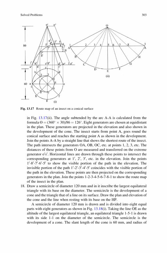
in Fig. 13.17(ii). The angle subtended by the arc A-A is calculated from the
formula ϴ¼ (360� � 30)/86¼ 126�. Eight generators are chosen at equidistantin the plan. These generators are projected in the elevation and also shown in
the development of the cone. The insect starts from point A, goes round the
conical surface and reaches the starting point A as shown in the development.
Join the points A-A by a straight line that shows the shortest route of the insect.
The path intersects the generators OA, OB, OC, etc. at points 1, 2, 3, etc. The
distances of these points from O are measured and transferred on the extreme
generator o0s0. Horizontal lines are drawn through these points to intersect the
corresponding generators at 10, 20, 30, etc. in the elevation. Join the points
10-80-70-60-50 to show the visible portion of the path in the elevation. The
invisible portion of the path 10-20-30-40-50 coincides with the visible portion of
the path in the elevation. These points are then projected on the corresponding
generators in the plan. Join the points 1-2-3-4-5-6-7-8-1 to show the route map
of the insect in the plan.
18. Draw a semicircle of diameter 120 mm and in it inscribe the largest equilateral
triangle with its base on the diameter. The semicircle is the development of a
cone and the triangle that of a line on its surface. Draw the plan and elevation of
the cone and the line when resting with its base on the HP.
A semicircle of diameter 120 mm is drawn and is divided into eight equal
parts with eight generators as shown in Fig. 13.18(i). Taking the line OE as the
altitude of the largest equilateral triangle, an equilateral triangle 1-5-1 is drawn
with its side 1-1 on the diameter of the semicircle. The semicircle is the
development of a cone. The slant length of the cone is 60 mm, and radius of
Fig. 13.17 Route map of an insect on a conical surface
Solved Problems 303

the cone base is given by the formula, r¼ (180�/360�)� 60¼ 30 mm. The plan
and elevation of the cone are drawn as shown in Fig. 13.18(ii). The eight
generators are also shown in the plan and elevation of the cone. The equilateral
triangle sides 1-5 and 5-1 cut seven generators and its side 1-1 lies on the
generator OA. The intersection points are marked on the generators in the
development. The points 5, 6, 7, 8 and 1 are located on the slant edge o0s0 takingthe distances of these points from O in the development. Horizontal lines are
drawn through the points 5, 6, 7, 8 and 1 to intersect the corresponding
generators at 50, 60, 70, 80 and 10 in the elevation of the cone. A smooth curve
is drawn passing through the points 50-60-70-80-10. It is to be noted that the points20, 30 and 40 are directly behind the points 80, 70 and 60. Hence, the line joiningthe points 10-20-30-40-50 will be invisible in the elevation. These points are
projected on the respective generators in the plan. A smooth curve is drawn
passing through the points 1-2-3-4-5-6-7-8-1 to complete the projection of the
triangle.
19. A vertical chimney, 60 cm in diameter, joins the roof of a boiler house, sloping
at an angle of 30� to the horizontal. The shortest height over the roof is 30 cm.
Determine the shape of sheet metal required to fabricate the chimney. Adopt a
suitable scale.
The plan and elevation of the chimney are drawn from the given data
adopting a scale of 1:10 as shown in Fig. 13.19(i). The sloping roof is drawn
at 30� to the horizontal and keeping 30 cm as the shortest height of the chimney.
Eight generators are shown in the plan and elevation of the chimney. The
intersection points of the roof are marked on the generators. A stretch out line
A-A of length equal to the circumference of the chimney is drawn with the
Fig. 13.18 Projections of cone from its development
304 13 Development of Surfaces

generators as shown in Fig. 13.19(ii). Horizontal lines are drawn through points
10, 20, 30, 40, 50, 60, 70 and 80 to intersect the corresponding generators to locate
points 1, 2, 3, 4, 5, 6, 7 and 8 in the development. A smooth curve is drawn
passing through the points 1-2-3-4-5-6-7-8-1 to complete the development of
the chimney.
20. A horizontal cylindrical boiler shell 1.5 m diameter is surmounted by a
cylindrical steam dome 0.75 m diameter. Draw the development of the surface
of the steam dome. Assume 1 m as its minimum height.
The elevation and left side elevation of the boiler shell and the steam dome
are drawn adopting a scale of 1:25 as shown in Fig. 13.20(i). Eight generators
are chosen on the surface of the steam dome as shown in the figure. The
intersection curve is obtained in the side elevation by projecting the points 10,20, 30 etc. in the elevation. A smooth curve is drawn passing through the points
300-400-500-600-700-800-100-200-300. A stretch out line C-C of length equal to the
circumference of the steam dome is drawn as shown in Fig. 13.20(ii). The
generators are also drawn. Horizontal lines are drawn through points 300, 400, 500,600, 700, 800, 100 and 200 to intersect the corresponding generators to locate points
3, 4, 5, 6, 7, 8, 1 and 2 in the development. A smooth curve is drawn passing
through the points 3-4-5-6-7-8-1-2-3 to complete the development of the
steam dome.
21. A cube, edge 40 mm, stands with a face on the HP with its vertical faces equally
inclined to the VP. A horizontal circular hole 30 mm diameter is drilled through
the cube. The axis of the hole is perpendicular to the VP and bisects the
opposite vertical edges. Draw the development of the lateral surfaces of the
cube with the hole.
Fig. 13.19 Development of a boiler chimney
Solved Problems 305

The plan and elevation of the cube are drawn as shown in Fig. 13.21(i). The
lateral surfaces of the cube are developed as shown in Fig. 13.21(ii). A circular
hole is drawn in the elevation, and eight points are marked on the circumfer-
ence of the hole. These points are then projected in the plan on the two faces
abfe and cbfg. The distance of the point 1 from e is measured and using this a
point is located on the edge EF in the development. A vertical line is drawn
through this point. A horizontal line is drawn through 10 in the elevation to
intersect the vertical line at point 1 in the development. The same procedure is
Fig. 13.20 Development of steam boiler dome
Fig. 13.21 Development of a cube with a circular hole
306 13 Development of Surfaces

followed to locate points 2 and 8 in the development. Horizontal lines are
drawn through points 30 and 70 in the elevation to locate points 3 and 7 directly
in the development. Points 4, 5 and 6 are located following the procedure
detailed for the points 2, 1 and 8. A smooth curve is drawn passing through the
points 1-2-3-4-5-6-7-8-1 intercepting the edge BF between the points 3 and
7. Since the circular hole runs through the solid, the curve is redrawn on the
other two faces cdhg and adhe to complete the development of the lateral
surfaces of the cube with the hole.
22. A square prism of base edge 40 mm is truncated by two section planes equally
inclined to its axis at 60� and intersect the axis at a height of 50 mm. Draw the
development of its lateral surfaces.
The plan and elevation of the square prism are drawn taking its height
50 mm as shown in Fig. 13.22(i). The development of lateral surfaces is
drawn as shown in Fig. 13.22(ii). The two section planes inclined at 60� to
the axis are drawn from the centre of the top of the prism in the elevation. The
section planes cut the four vertical edges besides passing through the two top
sides of the prism. The section points are marked as shown in the elevation.
Horizontal lines are drawn through the points 10, 20, 40 and 50 to intersect the
corresponding vertical edges at 1, 2, 4 and 5 in the development. Points 3 and
6 are located, respectively, at the mid-points of the top sides BC and DA in the
development. Points 1, 2, 3, 4, 5, 6, 1 are connected by straight thick lines and
also these points with the corresponding base points of the prism to complete its
development.
23. A rectangular pyramid of base edges 50 � 40 mm and height 70 mm is
sectioned by a plane parallel to one of its lateral faces. Distance between the
section plane and the face, which is parallel to the plane, is 10 mm. Draw the
development of the truncated pyramid.
Fig. 13.22 Development of sectioned square prism
Solved Problems 307

The plan and elevation of the rectangular pyramid are drawn as shown in
Fig. 13.23(i). Edge oc in the plan is revolved as shown to appear true length in
the elevation. The line o0s0 is the true length of the four lateral edges. An arc ofradius o0s0 is drawn with O as centre, and the four sides of the base in the plan
are transferred directly to the development by marking as successive chords
A-B, B-C, C-D and D-A along the arc as shown in Fig. 13.23(ii). Radial lines
are drawn from O to the base points A, B, C and D. A rectangle ABCD is also
drawn on the side CD to show the base of the pyramid in the development. The
section plane is drawn parallel to the face a0o0b0 and 10 mm from it in the
elevation. The section plane cuts the two slant edges o0c0 and o0d0 and the two
base edges bc and da. The section points 10, 20, 30 and 40 are marked in the
elevation. Horizontal lines are drawn through points 40 and 30 to intersect the
line o0s0 at points 4 and 3 to give the true length of the points from the vertex of
the pyramid. Points 4 and 3 are then marked on the slant edges OD and OC in
the development. The distance of point 1 from point a in the plan is transferred
to locate point 1 on the edge AD in the development. Point 2 is located on the
edge BC in the development following the same procedure. Points 1 and 2 are
also located in the rectangle ABCD in the development. The points 2-3-4-1 are
connected by straight lines. The development of the truncated pyramid is
completed by thick lines in Fig. 13.23(ii).
24. The development of a cylinder is a rectangle of 110 mm length and 55 mm
width. A semicircle of diameter 110 mm is inscribed in the rectangle. Draw the
projections of the cylinder showing the profile of the semicircle on the
elevation.
Fig. 13.23 Development of sectioned rectangular pyramid
308 13 Development of Surfaces

A rectangle of 110 mm length and 55 mm width is drawn as shown in
Fig. 13.24(i). The rectangle represents the development of a cylinder, and the
rectangle is divided into eight equal parts along its length with the generators
marked therein. A semicircle of diameter is inscribed in the rectangle, and the
intersections of the semicircle with the generators are marked as shown in the
figure. The diameter of the cylinder is found to 35 mm and the height of the
cylinder is 55 mm. The plan and elevation of the cylinder are drawn as shown in
Fig. 13.24(ii). The generators are also drawn by dividing the plan into eight
equal parts. Point 10 is located on the generator A by drawing a horizontal line
through point 1. The same procedure is followed to locate the remaining points
20, 30 etc. The visible profile of the semicircle 10-80-70-60-50 is shown by a
smooth curve, and the invisible profile is directly behind the visible profile.
25. The plan and part elevation of a dome, horizontal sections of which are regular
octagons, are shown in Fig. 13.25(i). Complete the elevation. Draw a develop-
ment of one of the eight-curved faces of the dome.
The plan and part elevation of the dome is shown in Fig. 13.25(i). The given
projections of the dome are redrawn as shown in Fig. 13.25(ii). The dome oab is
chosen to complete the elevation of the dome. A projector is drawn through a to
intersect the base of the dome at a0. Since the horizontal sections are regular
octagons, five lines are drawn parallel to the side ab in the plan. A projector is
drawn through d to intersect the dome edge o0b0 at d0. A horizontal line is drawn
from d0 to intersect the projector drawn through c at c0. Point c0 lies on the dome
edge o0a0. Points are located on the dome edges o0b0 and o0a0 following the same
procedure. The points on the edge o0a0 are transferred on the other side of the
dome to complete the elevation of the dome. It is evident that the arc length o0b0
is equal to one-fourth the circumference of the circle passing through the base
points of the dome. The arc length OB is found to be 5.5 m. The development of
one of the eight-curved faces is an isosceles triangle of base AB (equal to ab in
Fig. 13.24 Projections of a cylinder from its development
Solved Problems 309

this case) and sides OA and OB. The isosceles triangle OAB drawn in
Fig. 13.25(iii) is the development of one face of the dome.
26. A cube of 40 mm side rests on one of its faces on the HP and the lateral faces
equally inclined to the VP. It is sectioned by two section planes parallel to the
VP and perpendicular to the HP such that they bisect edges of its bases. Draw
the development of the surface of the cube.
The plan and elevation of the cube are drawn as shown in Fig. 13.26(i). The
development of the cube is drawn by thin lines with the top and bottom faces as
shown in Fig. 13.26(ii). The section planes are chosen parallel to the VP, and
the two planes cut the eight horizontal edges. The section points are marked in
the elevation. The section points are located in the development on the respec-
tive edges. The middle portion of the cube is retained, and the development of
the retained portion of the cube is drawn by thick straight lines including its top
and bottom faces.
27. Draw the development of post office envelope of size 220 mm � 110 mm with
overlaps of 10 mm for glueing/gumming when the development is folded up to
the form of envelope.
The front and back of the envelope are drawn as shown in Fig. 13.27(i) and
(ii). The development of the envelope with overlaps of 10 mm on the two sides
of the triangles ADE and BCE is drawn as shown in Fig. 13.27(iii).
28. Figure 13.28(i) shows the elevation of a sheet metal pipe S with two sheet metal
branches R and T. Draw the development of the surface of pipe S.
A circle of diameter 50 mm is drawn below the elevation of metal pipes to
represent the plan view of pipe S. The circle is divided into eight equal parts,
and the eight generators are marked in the elevation. These generators are cut at
Fig. 13.25 Development of a dome
310 13 Development of Surfaces

the two ends of the pipe, and the intersection points are numbered as shown in
Fig. 13.28(i). The stretch-out line A-A equal to the circumference of the circle
of diameter 50 mm is drawn, and the line is divided into eight equal parts to
represent the generators of the pipe S as shown in Fig. 13.28(ii). The intersec-
tion points are marked on the respective generators in the development by
drawing horizontal lines through the points in the elevation. Two smooth
curves are drawn passing through the points 1-2-3-4-5-6-7-8-1 and 9-10-11-
12-13-14-15-16-9. The extreme lines 1-9 on the generator A are drawn thick to
complete the development of the metal pipe S.
29. Figure 13.29(i) shows the plan of compound solid comprising of a half of
cylinder and a half of hexagonal prism, the common axis being 60 mm long. It
is cut by a section plane perpendicular to the VP, inclined at 45� to the HP and
bisecting the axis. Draw the development of the sectioned compound solid.
The plan and elevation of the compound solid are drawn as shown in
Fig. 13.29(ii). The full development of the lateral surfaces of the compound
Fig. 13.26 Development of sectioned cube
Fig. 13.27 Development of post office envelope
Solved Problems 311

solid is drawn by thin lines as shown in Fig. 13.29(iii). The section plane is
drawn in the elevation of the solid. The plane cuts two edges of the prism, two
common edges or generators of the compound solid and three generators of the
Fig. 13.28 Projection and development of a metal pipe
Fig. 13.29 Projections and development of compound solid
312 13 Development of Surfaces

cylinder. The seven points are numbered in the elevation. Horizontal lines are
drawn through these points to intersect the respective edges or the generators in
the development. The points 1-2-3-4 are connected by straight lines, and a
smooth curve is drawn passing through the points 4-5-6-7-1. The vertical edges
A1, B2, C3 and D4 are drawn by thick lines. The base line of the compound
solid is also drawn thick to complete the development of the cut compound
solid.
30. A vertical conical pipe in the form of a frustum of a cone with base 100 mm in
diameter, top 40 mm in diameter and height 50 mm has a side opening made by
a section plane perpendicular to the VP and inclined to the HP at 60� and
passing through the centre of the base rim. Draw the development of its lateral
surface. Draw its plan showing the points lying on its base and the section
plane.
The plan and elevation of the frustum of the cone are drawn as shown in
Fig. 13.30(i). The extreme generators of the cone are extended to meet at o0 inthe elevation. The slant length TL is found from the extreme generator o0d0
(i.e. o0s0) of the cone, and the development of the frustum of the cone is drawn
by thin lines as shown in Fig. 13.30(ii). The section plane, which is used to
make side opening, is drawn inclined at 60� to the HP and passing through the
centre of the base rim in the elevation. Since the section plane cuts one-half of
the cone, the right half of the cone is divided into four equal parts in the plan,
Fig. 13.30 Projections and development of frustum of conical pipe
Solved Problems 313

and the generators are marked in both the projections. The intersection points
are numbered in the elevation. Horizontal lines are drawn through these points
in the elevation to cut the extreme generator o0s0 giving the true distances of
these points on the respective generators from the point O in the development.
Points are located in the development. A smooth curve is drawn passing
through the points 1-2-3-4-5 to complete the development of the conical
pipe. Projectors are drawn through the points 10, 20, 30, 40 and 50 in the elevationto locate the points 1, 2, 3, 4 and 5 on the respective generators in the plan. A
smooth curve is drawn passing through these points. The semicircle fab and the
curve 1-2-3-4-5 show the points lying on the base of the cone and the section
plane.
31. Draw the development of the lateral surfaces of an oil can whose elevation is
given in Fig. 13.31(i).
The extreme generators of the top and bottom cones are extended to meet at
o0 and p0 to get the true length of the generators o0s0 and p0r0. The top circle of
conical part A is drawn and is divided into eight equal parts to show the eight
generators in the elevation. The intersection points are marked and are
projected on the slant length o0s0 to get the true length of these points from O
in the development. The development of cone A is shown in Fig. 13.31(ii). The
development of frustum of cone B is shown in Fig. 13.31(iii). The development
of the lateral surface of the cylindrical part C is shown in Fig. 13.31(iv). The
Fig. 13.31 Development of oil can
314 13 Development of Surfaces

bottom circular plate D is shown in Fig. 13.31(v) to complete the development
of the lateral surfaces of the oil can.
32. Draw the plan and elevation of a cylinder whose development with the line PQ
is shown in Fig. 13.32(i). Show the line PQ in the elevation. Does the line PQ
when transferred on the elevation represent any curve? If so, name the curve.
The diameter of the cylinder whose development is given in Fig. 13.32(i) is
35 mm and the height of the cylinder is 60 mm. The plan and elevation of the
cylinder are drawn as shown in Fig. 13.32(ii). The rectangle is divided into
eight equal parts along its length, and the plan of the cylinder is also divided
into eight equal parts. The generators are drawn in the elevation and also in the
development. The line PQ is drawn in the development. The line intersects the
generators at points 0, 1, 2, 3, etc. Horizontal lines are drawn through the points
0, 1, 2, 3, 4, etc. to intersect the respective generators at 00, 10, 20, 30, 40 etc. in theelevation. A smooth curve is drawn passing through these points. The part of
the curve from 00 to 40 is on the front half of the cylinder and is therefore visible;from 40 to 80 the curve is hidden. The curve shown in the elevation is a helix.
The curve is a double-curved line generated by a point that moves at uniform
rate around and also parallel to the axis. The distance the point moves parallel
to the axis during one revolution is called the pitch (p) or lead of the helix. The
curve shown is right hand helix. For a right hand helix beginning at point 00, thecurve moves upward around the cylinder in a counter-clockwise direction as
seen in the plan. The inclination of the helix or the pitch angle of the helix is the
angle ϴ on the development in Fig. 13.32(i). It can be shown that tan (ϴ)¼ (p)/
(∏ d), where p is the pitch and d is the diameter of the cylinder.
The most common application of the helix is screw threads of V and square
types. The helical grooves of square shape is used on cylindrical and drum
Fig. 13.32 Development of a cylinder
Solved Problems 315

cams and screw conveyors. The springs of square or round shapes are produced
by bending wires of respective cross sections into helical shapes.
33. A cylinder, diameter 50 mm and axis 72 mm, has three right hand helices on its
surface, starting from three equiangular points on its base. Draw the projections
of the helices and also their developments.
The plan and elevation of the cylinder, diameter of base 50 mm and axis
72 mm, are drawn as shown in Fig. 13.33(i). The plan is divided into 12 equal
parts, and the 12 generators are shown in the elevation. The axis is also divided
into 12 equal parts in the elevation. Three angular points a, c and e are chosen in
the plan. The point a moves upward around the cylinder in a counter clockwise
direction as seen in the plan and reaches the point b to complete the helix a0-b0
in the elevation. The point c moves around the cylinder and reaches the point d
to complete the helix c0-d0 in the elevation. The point e moves around the
cylinder and reaches the point f to complete the helix e0-f0 in the elevation. A
rectangle of length equal to the circumference of the base circle of the cylinder
and width equal to the axis of the cylinder is drawn as shown in Fig. 13.33(ii).
Twelve generators are drawn in the development of the cylinder. Horizontal
lines are drawn from the points on the helix in the elevation to intersect the
respective generators in the development. Straight lines A-B, C-D and E-F are
drawn connecting the respective points to show the helices in the development.
34. Draw one complete coil of a helical spring of square section of 10 mm side. The
outside diameter of the spring is 120 mm and the pitch is 60 mm.
The helical curves starting from four corners of the square section are to be
drawn. The helical curves which start from the outside corners of the square
move around the curved surface of an imaginary cylinder of diameter equal to
Fig. 13.33 Development of cylindrical helices
316 13 Development of Surfaces

the outside diameter of the spring. The helical curves which start from the
inside corners of the square move around the curved surface of an imaginary
cylinder of diameter equal to the inside diameter of the spring. The inside
diameter is given by the formula: d ¼ D � 2 � side of the square. The inside
diameter is 100 mm. Two concentric circles of diameter 120 mm and 100 mm
are drawn in the plan as shown in Fig. 13.34. The circles are divided into
12 equal parts. Draw two vertical lines through the extremities of the outside
circle. A length of pitch of the helix is placed, and the line is divided into
12 equal parts. The outer helices a0-b0 and c0-d0 are drawn for the imaginary
cylinder of 120 mm diameter. The inner helices e0-f0 and g0-h0 are drawn for theimaginary cylinder of 100 mm diameter. The pitch for both the helices is
60 mm. The visible helical portions of the spring alone are shown in the
elevation.
Fig. 13.34 Helical spring
(square in cross section)
Solved Problems 317

Practice Problems
1. Develop the entire surface of a pentagonal prism, side of base 30 mm and axis
50 mm.
2. Draw the development of the lateral surface of a square pyramid, side of base
30 mm and height 50 mm.
3. A hexagonal prism, side of base 30 mm and axis 50 mm, rests with its base on
the HP such that a rectangular face is parallel to the VP. It is cut by a section
plane inclined at 45� to the HP, perpendicular to the VP and passing through the
right extreme corner of the top end of the prism. Draw the development of the
truncated prism.
4. A vertical cylinder, 50 mm diameter and 60 mm height, rests with its base on
the HP. A square hole of 20 mm side is made so that the axis of the hole is
parallel to the HP and perpendicular to the VP. The faces of square hole are
equally inclined to the HP, and its axis bisects the axis of the cylinder. Draw the
development of the lateral surfaces of the cylinder with the square hole.
5. A cone, diameter of base 50 mm and height 65 mm, rests with its base on the
HP. It is cut by a section plane perpendicular to the VP, inclined at 30� to the
HP and intersecting the axis at a point 30 mm above the base. Draw the
development of truncated cone.
6. Draw a semi-circle of diameter 100 mm and in it inscribe the largest possible
circle. The semi-circle is the development of a cone and the circle that of a line
on its surface. Draw the projections of the cone showing those of circle also.
7. A rectangular pyramid, side of base 30 mm � 40 mm and axis 50 mm long,
stands with its base on the HP and a diagonal of its base parallel to the VP. It is
cut by a section plane perpendicular to the VP, inclined at 45� to the HP and
intersecting the axis at a point 20 mm distant from the vertex. Draw the
development of the lateral surface of the truncated pyramid.
8. A funnel is to be made of sheet metal. The funnel tapers from 100 mm diameter
to 40 mm diameter to a height of 30 mm and from 40 mm diameter to 20 mm
diameter to a height of 50 mm. The bottom of the funnel is levelled off to a
plane inclined at 45� to the axis. Draw the development of the funnel.
9. A cylinder of base diameter 50 mm is so truncated that its elevation is a semi-
circle of diameter 50 mm and its plan is a circle of diameter 50 mm. Draw the
development of its surface.
10. An equilateral triangle of 80 mm sides having a 20 mm diameter at its centre
represents the elevation of a cone with a circular hole. Draw the development of
its lateral surface.
318 13 Development of Surfaces

11. Draw the development of the lateral surfaces of the cut cylinder of 50 mm
diameter and height 70 mm cut in different ways shown in Fig. 13.35(i)–(iii).
12. Draw the development of the lateral surfaces of the cut cones of given dimen-
sions shown in Fig. 13.36(i)–(iii).
Fig. 13.35 Elevations of cut cylinders
Fig. 13.36 Elevations of cut cones
Practice Problems 319

Chapter 14
Isometric Projections
It is easy to draw the two principal views (plan and elevation) of an object from its
pictorial representation. The reverse is not always easy to visualize the object from
two of its principal views. A third view on the profile plane aids to visualize the
exact shape of the object. Isometric projection is an orthographic projection of an
object on the vertical plane showing its three dimensions in one view (elevation).
To understand the principles of isometric projection, let us consider the auxiliary
projection of a cube. The problem is one of drawing the projections of a cube when
one of its solid diagonals is perpendicular to the vertical plane. The solution for this
problem, which is self-explanatory, is given in Fig. 14.1.
The special features on the final elevation are summarized as follows:
1. The 12 edges of the cube are distinct.
2. Three edges d0h0, e0h0 and g0h0 are invisible.3. The 12 edges are equal in length and hence they are equally inclined to the VP.
4. The edges a0b0, c0d0, e0f0 and g0h0, which are parallel, are also parallel in the finalelevation.
5. The edges a0d0, b0c0, f0g0 and e0h0, which are parallel, are also parallel in the finalelevation.
6. The vertical edges a0e0, b0f0, c0g0 and d0h0 are also vertical in the final elevation.
7. The faces of the cube are equally inclined to the vertical plane.
8. The diagonal a0c0 on the face a0b0c0d0 is not foreshortened and is perpendicular
to the edge b0f0.9. The diagonal a0f0 on the face a0b0f0e0 is not foreshortened and is perpendicular to
the edge b0c0.10. The diagonal c0f0 on the face b0c0g0f0 is not foreshortened and is perpendicular to
the edge b0a0.11. The edges b0f0, b0c0 and b0a0 make equal inclination of each 120�.
The final elevation is the isometric projection of the cube.
Another special feature of the projection is given below:
© Springer Nature Singapore Pte Ltd. 2018
K. Rathnam, A First Course in Engineering Drawing,DOI 10.1007/978-981-10-5358-0_14
321

The foreshortened length c0-d0 is called the isometric length of the edge CD
(refer to Fig. 14.2). Consider the triangles CDP and c0-d0-P which are the right
angled triangles and have the common adjacent edge c0P,
c0Pc0d0
¼ cos 30�� � ¼
ffiffiffi3
p
2
c0PCD
¼ cos 45�� � ¼ 1
ffiffiffi2
p
Hence, c0d0CD
¼ffiffi2
pffiffi3
p ¼ 0:816
isometric length
actual length¼ 0:816
Fig. 14.1 Auxiliary projections of a cube
Fig. 14.2 Isometric projection of a square
322 14 Isometric Projections

The final elevation of the cube is redrawn together with the projections of the
cube in its simple position as shown in Fig. 14.3.
The three mutually perpendicular co-ordinate axes OX, OY and OZ are intro-
duced in the plan and elevation of the cube as shown in the figure. These axes which
appear inclined to each other at 120� in the isometric projection are called as the
isometric axes. Any plane parallel to two of the isometric axes is called an
isometric plane. The isometric axis OZ is always oriented in the vertical direction
in the isometric projection. The three horizontal edges parallel to the edge a0-b0 arealso parallel to the isometric axis OX, and the three horizontal edges parallel to b0-c0
are parallel to the isometric axis OY. The four vertical edges remain vertical and
parallel to the isometric axis OZ. The vertical faces a0-b0-f0-e0 and d0-c0-g0-h0 areparallel to the isometric plane XOZ. The vertical faces b0-c0-g0-f0 and a0-d0-h0-e0 areparallel to the isometric plane YOZ. The horizontal faces a0-b0-c0-d0 and e0-f0-g0-h0
are parallel to the isometric plane XOY.
The final isometric projection of the cube and the isometric scale are shown in
Fig. 14.4.
Since the isometric projection is a single view representation of an object, capital
letters are used to represent the angular points of the object. The invisible edges are
shown by dotted lines. Lengths of edges are marked along the isometric axes using
the isometric scale which is also as shown in Fig. 14.4. A horizontal line OA is
drawn, and two more lines OP and OQ inclined, respectively, at 30� and 45� to the
horizontal are also drawn. The actual scale in mm is marked on OQ. Vertical lines
are drawn from each of the division points on the actual scale to cut OP at the
corresponding division. The division point on OP measures the distance reduced to
isometric length. Lines which are not parallel to the co-ordinate axes cannot be
represented directly using the isometric scale as there will be distortion. It is to be
noted that the difference in length between the projections of equal diagonals BD
and AC is considerable.
Fig. 14.3 Projections of a cube and its isometric projection
14 Isometric Projections 323

Isometric Projection and Isometric View
Isometric projection of a solid is drawn by orienting the edges of the solid parallel to
the co-ordinate axes to the extent possible. The dimensions of the edges parallel to
the axes are reduced using the isometric scale and laid along the isometric axes. The
view obtained is the isometric projection of the solid. The solid can also be
represented on the isometric axes using the actual/true lengths instead of the
isometric lengths. The view drawn on the isometric axes using the actual length
is called Isometric View/Drawing, and the view drawn using the isometric scale is
called Isometric Projection. The projection obtained in isometric view will be
larger in size.
Solved Problems
1. Draw the isometric projection of an equilateral triangle of side 40 mm when it
is placed with its surface vertical and a side horizontal.
The plan and elevation of the vertical lamina are drawn keeping one of its
sides horizontal as shown in Fig. 14.5. The lamina is enclosed in a rectangle
a0o0d0c0. The co-ordinate axes o0x0 and o0z0 are chosen passing through the edgesof the rectangle as shown in the figure. The isometric projection can be drawn
using the two isometric axes OX and OZ with the included angle of 120� andthe corresponding isometric plane XOZ. The isometric length of side o0d0 isobtained from the isometric scale, and using this length the point D is located
along OX. Similarly, the isometric length of side o0a0 is obtained, and using thislength the point A is located along the axis OZ. Draw from D and A lines
parallel, respectively, to the isometric axes OZ and OX to locate the point of
intersection at C. Now AODC is the required parallelogram representing the
isometric projection of the rectangle a0o0d0c0. The mid-point of OD locates the
point B of the triangle. Join the points BA and BC. The triangle ABC is the
Fig. 14.4 Isometric
projections of a cube and
isometric scale
324 14 Isometric Projections

isometric projection of the given equilateral triangle. The projection can also be
obtained on the isometric plane YOZ.
2. Draw the isometric projection of a regular pentagon of 40 mm side when it is
placed with its surface horizontal and a side parallel to the vertical plane.
The plan of the pentagon of side 40 mm is drawn with a side parallel to VP,
and this plan is enclosed in a rectangle orst as shown in Fig. 14.6. The
co-ordinate axes ox and oy are drawn passing through the sides of rectangle.
The isometric projection can be drawn using the isometric plane XOY. The
isometric length of side ot is obtained, and using this length the point T is
located along OX. Similarly, the isometric length of side or is obtained, and
using this length the point R is located along OY. From points T and R, draw
lines parallel, respectively, to the isometric axes OY and OX to locate the
intersecting point S. The angular points of the pentagon lie on the circumfer-
ence of the parallelogram ORST. The mid-point of RS locates the point C. The
isometric length of side ob is obtained and the point B is located on OY. Since
Fig. 14.5 Projections of a lamina and its isometric projection
Fig. 14.6 Plan of a Pentagon and its isometric projection
Solved Problems 325

the distance of d from t is the same as the distance of b from o, the point D is
located on TS by drawing a line parallel to OX from B. The isometric length of
at is obtained and the point A is located on TO measuring its distance from
T. The point E is also located from this isometric length on line OT measuring
its distance from O. (Note: the error involved in obtaining the isometric length
at is small compared to the length oa). Join the points A, B, C, D, E and A to
give the isometric projection of the pentagon.
3. Draw the isometric projection of a semi-circular lamina of 60 mm in diameter
standing on its diameter with its surface vertical.
The elevation of the semi-circular lamina is drawn with its centre at d0 andthe diameter on HP as shown in Fig. 14.7. The lamina is enclosed in a rectangle
a0o0b0c0, and the co-ordinates o0x0 and o0z0 are chosen as indicated in the figure.
Join the point o0 and d0 and also b0 and d0. From d0, draw a vertical line to meet
o0x0 at point 20. The intersection of the line o0d0 on the circle is indicated as point10. The intersection of the line b0d0 on the circle is indicated as point 30. Linesare drawn perpendicular to a0c0 from 10 and 30 to meet the line a0c0 at 100 and 300.
The isometric projection can be drawn using the isometric plane XOZ. Since
the sides o0b0 and o0a0 of the rectangle are aligned along the o0x0 and o0z0 axes,their isometric lengths are obtained and points B and A are located along the
isometric axes as indicated. From points A and B, draw lines, respectively,
parallel to the isometric axes OX and OZ to locate the intersecting point C. The
mid-point of OB locates point 2 on the isometric projection of the semi-circular
lamina and points A and C are also points on the lamina. To locate point 1 on
the isometric projection, the distance between 100 and c0 is measured and the
isometric length of this distance is kept from C towards A to fix A1 on the
isometric line CA. From this point, a line is drawn parallel to the isometric axis
OZ and point 1 is located knowing the isometric length of the distance between
the points 100 and 10 in the elevation. The same procedure is repeated to locate
point 3 on the isometric projection. A smooth curve is drawn passing through
the points A, 1, 2, 3 and C. This curve represents the isometric projection of the
vertical semi-circular lamina standing on its diameter AC.
Fig. 14.7 Elevation of a semi-circular lamina and its isometric projection
326 14 Isometric Projections

4. Draw the isometric projection of a circular lamina of 80 mm in diameter when
its surface is vertical.
The circular lamina is enclosed in a square r0s0t0u0 as shown in Fig. 14.8.
Connect the diagonals r0t0 and s0u0 to intersect the circle at four points. The
mid-points of sides r0s0, s0t0, t0u0 and u0r0 are also marked as shown in the figure.
Name all the points as 1, 2, 3, 4, etc. The isometric projection can be drawn
using the isometric plane XOZ. As the sides t0u0 and t0s0 are aligned along the
axes o0x0 and o0z0, the isometric length of either t0u0 or t0s0 is obtained and pointsU and S are located along the isometric axes OX and OZ as indicated. From
points U and S, draw lines, respectively, parallel to the axes OZ and OX to
locate the intersecting point R. The rhombus RSTU represents the isometric
projection of the square. The diagonals RT and SU are connected to locate the
centre of circle. As the diagonal SU is perpendicular to the isometric axis OY,
the distance between S and U will be equal to the distance between s0 and u0.The distance of the point 2 and 6 from the circle centre will be equal to actual
radius of the circle. The points 2 and 6 are located on the diagonal SU. From
points 2 and 6, lines are drawn parallel to OX and OZ axes. These lines intersect
and locate points 4 and 8. The points 1, 3, 5 and 7 are marked as mid-points of
the sides. A smooth curve is drawn through these points to show the isometric
projection of the vertical circle.
5. A rectangular prism of size 30 � 20 � 80 mm lies on HP on one of its largest
faces with its axis parallel to both HP and VP. Draw its isometric projection.
The projections of the prism are drawn, and the co-ordinate axes are oriented
as shown in Fig. 14.9. The three edges b0a0, b0c0 and b0f0 of the prism are to be
oriented along the three isometric axes OX, OY and OZ. The isometric axes
OX, OY and OZ are drawn inclined to each other at 120� with the axis OZ
oriented in the vertical direction. The isometric lengths s1, s2 and s3 of the three
Fig. 14.8 Elevation of a circular lamina and its isometric projection
Solved Problems 327

edges 80 mm, 30 mm and 20 mm are obtained from the isometric scale. Point B
is located at O and point A is located on the isometric axis OX at a distance
s1 mm from B. Point C is located on the isometric axis OY at a distance s2 mm
from B. Point F is located on the isometric axis OZ at a distance s3 mm from
B. Lines are drawn from A and F, respectively, parallel to OZ and OX axes to
get the intersecting point E which represents isometric point of an angular point
of the prism. Lines are drawn from A and C, respectively, parallel to OY and
OX axes to locate other angular point D. Lines are drawn from C and F,
respectively, parallel to OZ and OY to locate yet another point G. From D,
draw a line parallel to OZ. From G, draw a line parallel to OX. From E, draw a
line parallel to OY. The intersection of these lines locates the point H. All the
eight points are located, and the isometric projection is obtained by joining
these points. The hidden edges DH, EH and GH are shown by dotted lines.
6. Draw the isometric projection of a pentagonal prism of edge of base 30 mm and
axis 70 mm long when the axis is horizontal.
The elevation of the pentagonal prism is drawn and is enclosed in a rectangle
o0r0s0t0 as shown in Fig. 14.10. The co-ordinate axes are also introduced in the
elevation. The isometric projection of the rectangle o0r0s0t0 is to be drawn on theisometric plane XOZ, and the axis is to be oriented parallel to the isometric axis
OY. The isometric length of o0r0 is obtained and point R is located on
OX. Similarly, the isometric length of o0t0 is obtained and point T is located
on OZ. From R and T lines are drawn, respectively, parallel to OZ and OX axes
to locate point S. The parallelogram ORST represents the isometric projection
of the rectangle. The isometric length of the axis of prism is obtained, and point
U is located on the isometric axis OY as shown in the figure. From U, a line is
drawn parallel to OX and another line is drawn parallel to OZ. From R, a line is
drawn parallel to OY to get the intersecting point P. From T, a line is drawn
parallel to OY to get the intersecting point Q as shown in the figure. From
points P and Q, lines are drawn, respectively, parallel to OZ and OX to locate
the intersecting point V. Join the points V and S. On the parallelogram ORST,
points A, B, C, D and E are located following the procedure detailed in Problem
2. From these points, lines are drawn parallel to OY to get the intersecting
Fig. 14.9 Projections of a rectangular prism and its isometric projection
328 14 Isometric Projections

points on the parallelogram UPVQ. These points represent the angular points
on the rear end of the prism. These points are joined to complete the isometric
projection of the pentagonal prism with the hidden edges shown by dotted lines.
7. Draw the isometric projection and isometric view of a cube of edge 50 mm.
The solution can be obtained directly without the orthographic projection of
the cube. The isometric projection of cube is drawn using isometric length of
edge as shown in Fig. 14.11. The isometric view of cube is also drawn using the
edge (true length) dimension as shown in Fig. 14.11.
8. Draw the isometric projection and isometric view of a sphere of diameter
50 mm and mark the lowest and highest points on its surface.
Fig. 14.10 Elevation of a pentagon and Isometric projection of pentagonal prism
Fig. 14.11 Isometric projection and isometric view of a cube
Solved Problems 329

The isometric projection of a sphere will be a circle of true radius r and it can
be drawn directly as shown in Fig. 14.12. Shown also in the figure is the
isometric view of the sphere with a circle of apparent enlarged radius reobtained on the isometric scale. The isometric length of the radius r (i.e. ri) is
placed above and below the centre of circle in the isometric projection to
indicate the highest and lowest points on the surface of the sphere. The true
radius is placed above and below the centre of the circle in the isometric view to
show the highest and lowest points on the surface of the sphere. The lowest
point will be the point of contact of the sphere on another solid in the isometric
projection/view of the solids in combination.
9. Draw the isometric projection of a circle of diameter 60 mm whose surface is
(i) horizontal and (ii) vertical. Use the four centre method.
The isometric length of the diameter of the circle is obtained from the
isometric scale, and the isometric projection of the square enclosing the circle
is drawn as rhombus RSTU on the isometric plane XOY as shown in Fig. 14.13.
The mid-points 1, 3, 5 and 7 on the four sides of the rhombus are marked. Draw
Fig. 14.12 Isometric projection and isometric view of a sphere
Fig. 14.13 Isometric projections of a circle (four centre method)
330 14 Isometric Projections

the diagonal RT. Join the points U and 3. This line intersects the diagonal at
A. Similarly obtain the point B. With centre A and radius A3, draw an arc 35.
Also draw an arc 17 with centre B. With centre U and radius U3, draw an arc
13. Also draw an arc 57 with centre S. The ellipse passing through the four
points represents the isometric projection of horizontal circle. The isometric
projection of vertical circle is drawn on the isometric plane XOZ as shown in
the figure. The same procedure is repeated in locating the points A and B on the
longer diagonal of the rhombus, and four circular arcs are drawn from the four
centres A, B, R and T to complete the isometric projection of the vertical circle.
10. Draw the isometric projection of a cylinder of diameter 50 mm and axis 70 mm
long when the axis is vertical.
The plan of cylinder is drawn and is enclosed in a square with the
co-ordinates ox and oy as shown in Fig. 14.14. The two diagonals ac and bd
are connected. Points 1, 2, 3, 4, 5, 6, 7 and 8 are indicated on the circumference
of the circle as shown in the figure.
The isometric projection of the square is drawn on the isometric plane XOY
using the isometric length of side oa or oc. Lines are drawn from A and C,
respectively, parallel to OY and OX to locate the point of intersection D. Join
the diagonals AC and BD to locate the circle centre. As the rhombus diagonal
AC which is perpendicular to the isometric axis OZ does not undergo
foreshortening, the points 4 and 8 are located on either side of the circle centre
using the true radius on the diagonal AC. From point 4, lines are parallel to OX
and OY. From 8 also lines are drawn parallel to OX and OY. Points 2 and 6 are
located on their intersections as shown in the figure. The mid-points of the sides
AB, BC, CD and DA are marked as 1, 3, 5 and 7. A smooth curve is drawn
passing through the points 1, 2, etc. The top end of the cylinder is now shown as
ellipse in the isometric plane XOY. Lines are drawn parallel to OZ from the
eight points as shown in the figure. Points are located on these lines using the
isometric length of the axis of cylinder. A smooth curve is drawn to represent
Fig. 14.14 Plan of cylinder and Its isometric projection
Solved Problems 331

the isometric projection of the bottom end of the cylinder. Two common
tangents representing the extreme generators of the cylinder are drawn to the
ellipses, and the hidden portion of the bottom ellipse is shown as dotted.
11. Draw the isometric projection of a hexagonal pyramid of edge of base 40 mm
and axis 70 mm long when its axis is vertical.
The orthographic projections of the hexagonal pyramid are drawn as shown
in Fig. 14.15. The solid is enclosed in a rectangular box, and the co-ordinate
axes are also oriented as shown in the figure. The base of the pyramid is
enclosed in a rectangle rstu. The isometric length of axis of pyramid is obtained
to locate the point S from O. From S, lines are drawn parallel to OX and OY
axes. The isometric length of rs is marked from S to locate point R on the line
drawn parallel to OX. Similarly, point T is located on the line drawn parallel to
OY using the isometric length of st. From R, a line is drawn parallel to
OY. From T, a line is drawn parallel to OX to intersect the line drawn from
R at point U. The parallelogram RSTU represents the isometric projection of
rectangle rstu. The mid-points of sides ST and RU locate the points B and
E. The distances between the points ar, fs, dt and cu are all equal. The isometric
length of ar is obtained and is marked from R towards S to locate point A. This
isometric length can be used to locate points F, C and D. The distance x1 of the
base point g from oy axis in the plan and the distance y1 of the same point from
ox axis are measured, and the isometric lengths are obtained. The isometric
length of x1 is marked along the line SR, and a line is drawn parallel to OY from
this point. The base point of the apex of the pyramid is located along this line
from the isometric length of y1. Draw a vertical line above this base point, and
using the isometric length of the axis of the pyramid the apex G is located on
Fig. 14.15 Projections of a hexagonal pyramid and its isometric projection
332 14 Isometric Projections

the vertical line. The apex is joined to the base points to complete the isometric
projection of the given pyramid. The hidden edges are shown by dotted lines.
12. Draw the isometric projection of cone of base diameter 50 mm and altitude
70 mm when the base is on HP.
This problem can be solved without its orthographic projections. The cone is
enclosed in a square prism of side 50 mm and axis 70 mm long. The isometric
length of the axis of cone is obtained and placed on the isometric axis OZ from
O to locate S the base point of the prism as shown in Fig. 14.16. From S, lines
are drawn parallel to OX and OY. The isometric length of the diameter of cone
is placed on both the lines from S to locate points R and T. From R and T, lines
are drawn, respectively, parallel to OY and OX to intersect at point U. The
rhombus RSTU represents the isometric projection of base of the prism. The
mid-points of the sides locate four points 1, 3, 5 and 7 on the base of the cone.
The diagonals RT and SU are connected to locate circle centre. Point 4 is
located at a distance equal to the radius of circle from the circle centre on the
line RT. Similarly, point 8 is located on the other side. From points 4 and
8, lines are drawn parallel to OX and OY to locate the intersecting points 2 and
6 on the diagonal SU. A line is drawn parallel to OZ from the circle centre, and
the apex A is located using the isometric length of the axis of the pyramid. A
smooth curve is drawn passing through the base points of the cone. Two
tangents are drawn from the apex A to the ellipse representing the extreme
generators of the cone. The invisible portion of the curve is drawn dotted.
13. The hexagonal prism edge of base 30 mm and axis 70 mm long rests with one
of its rectangular faces on HP and axis perpendicular to VP. It is cut by a plane
perpendicular to HP and inclined at 30� to VP bisecting the axis. Draw the
isometric projection of one part of the prism showing the section.
The plan and elevation of the hexagonal prism are drawn as shown in
Fig. 14.17. The prism is enclosed in a rectangular prism with m, n, p, q, r, s, t
and u as angular points, and the co-ordinates are also drawn as shown in the
Fig. 14.16 Isometric
projection of a cone
Solved Problems 333

figure. The section plane is drawn and the cutting points 1, 2, 3, 4, 5 and 6 are
marked on the longer edges. As the front portion is to be removed for obtaining
the isometric projection of the other part, the angular points a, b, c, d, e and f on
the rear end of the prism are marked as shown in the figure. The isometric
projection of the rectangle mnpq is drawn on the isometric plane XOZ using the
isometric lengths of its sides. The point S is located on the isometric axis OY
using the isometric length of the axis of the prism. From S and M, lines are
drawn, respectively, parallel to OX and OY to locate the intersecting point
R. From S and P, lines are drawn, respectively, parallel to OZ and OY to locate
point T. Lines are drawn from R and T parallel to OZ and OX to locate point U
(point U is not shown in the figure). The isometric projection of the rectangular
prism is obtained, and the angular points A, B, C, D, E and F on the rear end of
the prism are located following the procedure detailed for the base of the
hexagonal pyramid in problem 11. Draw a line parallel to OY from A and
mark point 1 using the isometric length of edge a1 in the plan. Lines are drawn
from other points B, C, D, E and F, and points 2, 3, 4, 5 and 6 are located using
the isometric lengths of the latter points from the former in the plan. The
section points are joined and the sectioned portion is hatched. The angular
points on the rear end of the prism are also connected to the respective section
points. The required isometric projection of one part of the prism is shown with
the invisible edges shown by dotted lines avoiding the sectioned portion.
Fig. 14.17 Projections of a sectioned hexagonal prism and its isometric projection
334 14 Isometric Projections

14. A square pyramid is placed over a cube of edge 50 mm such that the corners of
the base of the pyramid touch the mid-points of the top face of the cube. Draw
the isometric projection of the assembly. The axis of the pyramid is 60 mm.
The isometric projection of the cube is drawn on the isometric axes using the
isometric length of the cube edge as shown in Fig. 14.18. The mid-points of the
top face of the cube are located. The centre of the top face is obtained by
drawing the diagonals of the rhombus RSTU. A line is drawn parallel to OZ
above the top face, and the apex G of the pyramid is located on this line using
the isometric length of the axis of the pyramid. The slant edges of the pyramid
are joined and also the base edges. The invisible edges are shown by dotted
lines. This completes the isometric projection of the assembly of solids.
15. The outside dimensions of a box made of 5 mm thick wooden planks are
80 � 60 � 50 mm. The depth of the lid on outside is 10 mm. Draw the
isometric view of the box with the lid open at right angle.
The elevation of the box is drawn with the lid open at right angle as shown in
Fig. 14.19. The co-ordinate axes are indicated as shown in the figure. The three
isometric axes OX, OY and OZ are drawn. The isometric view of the bottom of
the box is drawn taking its true outside dimensions. The lid is also shown taking
its outside dimensions as shown in the figure. Since the thickness of the wooden
planks is 5 mm, the inside actual dimensions are reduced, and the isometric
view is drawn. The hidden edges are NOT shown in this case. The problem can
also be solved without the elevation.
16. Draw the isometric projection of a cylinder of 80 mm diameter and 100 mm
long with a 20 mm coaxial square hole. The cylinder is lying on HP with its axis
parallel to VP and the sides of hole making an angle of 45� with HP.
Fig. 14.18 Isometric
projections of composite
solids (cube and square
pyramid)
Solved Problems 335

As the axis of the cylinder is parallel to VP, the side elevation of the cylinder
with hole is drawn as shown in Fig. 14.20. The circle is enclosed in a square,
and the co-ordinate axes are oriented along the sides of the square. The
isometric projection of the square rstu is drawn on YOZ plane with isometric
Fig. 14.19 Projections of a
box and its isometric view
Fig. 14.20 Side elevation
of cylinder with square hole
and its isometric projection
336 14 Isometric Projections

length of the side rs. The diagonals of the rhombus RT and SU are connected to
locate the circle centre. The mid-points of sides UT, TS, SR and RU are marked
to locate points 1, 3, 5 and 7. Since the diagonal SU is perpendicular to the
isometric axis OX, the true diameter is placed on this diagonal to locate points
4 and 8 from the circle centre as indicated. From 4 and 8, lines are drawn
parallel to OY and OZ axes to locate points 2 and 6 on the diagonal RT. Lines
are drawn parallel to OX from each of the points 1, 2, 3 etc. The isometric
length of the axis of cylinder is obtained and is used to mark the respective
points on the respective lines to locate points on the other end of the cylinder as
shown in the figure. Connect points 15 and 37. The isometric length of 59 is
placed from points 1, 3, 5 and 7 as indicated to locate the angular points of the
square hole on one side of the cylinder. The respective points on the other side
of the cylinder are also marked by drawing lines parallel to OX from the
angular points of the hole obtained. Two common tangents are drawn to the
two ellipses representing the extreme generators, and the edges of the hole are
also connected to complete the isometric projection of the cylinder with square
hole. The invisible portion of the ellipse and edges of the hole are shown by
dotted lines.
17. A square prism, side of base 50 mm and height 60 mm, surmounts coaxially a
circular disc of 80 mm diameter and 40 mm thick. A sphere of 40 mm radius is
placed centrally over the square prism. Draw the isometric view of the assem-
blage of solids.
The isometric view of top of the circular disc is drawn following the four
centre method (see problem no. 9) on the isometric plane XOY as shown in
Fig. 14.21. The isometric view of bottom of the circular disc is also drawn
below the top end with the extreme generators joining the top and bottom ends
as shown in the figure. The centre of the top of the disc is located at O1. A
rhombus of sides 50 mm is drawn keeping its sides parallel to the isometric
axes OX and OY. A line is drawn parallel to OZ through O1 and point O2 is
located on this line such that the distance of O2 from O1 is equal to the height
of the square prism. Another rhombus of sides 50 mm is drawn keeping the
sides parallel to the isometric axes OX and OY. This rhombus represents the
isometric view of the top of the prism. The vertical edges of the prism are
shown connecting the top corner points with the respective bottom corner
points of the prism. A line is drawn through O2 and point O3, the center of
the sphere, is located on it such that the distance of O3 from O2 is equal to the
radius of the sphere. With centre O3 and the apparent radius, ra (to be obtained
from the isometric scale, see problem no. 8), a circle is drawn to show the
isometric view of the sphere. This completes the isometric view of the assem-
blage of solids.
18. Draw the isometric projection of the object shown in Fig. 14.22.
The object is enclosed in a square prism as shown in Fig. 14.22. The
isometric projection of the square prism is drawn on the isometric axes OX,
OY and OZ as shown in Fig. 14.23. The isometric projection of the base of the
cylinder is completed with eight points as shown in the figure. The points a, b,
Solved Problems 337

Fig. 14.21 Isometric view
of solids
Fig. 14.22 Projections of
an object
338 14 Isometric Projections

c, d and e on one side of cylinder are located in the plan and elevation of the
object. The points A and E are marked in the isometric projection as shown in
the figure. The point C is also marked as indicated. The isometric length of the
height of b0 from 20 is obtained and placed on the line drawn parallel to OZ from
2 to locate point B in the isometric projection. The same isometric length is
placed on another line drawn parallel to OZ from 4 to locate point D. A smooth
curve is drawn passing through A, B, C, D and E. The line AE is joined. The
same procedure is followed on the other side of the cylinder. The wedge-shaped
object representing the isometric projection of the given object is completed
with the invisible curves shown as dotted.
19. A pedestal consists of a square slab, side of base 60 mm and thickness 20 mm,
surmounted by a frustum of a square pyramid, side of base 40 mm, that at top
20 mm and height 60 mm, which is surmounted by a square pyramid having
side of base 20 mm and height 40 mm. All three solids are coaxial and are
similarly situated. Draw the isometric view of the pedestal.
A rhombus of sides 60 mm is drawn keeping its sides parallel to the
isometric axes OX and OY as shown in Fig. 14.24. This rhombus represents
the isometric view of top surface of the square slab. The thickness of the slab is
placed below the corners of the rhombus to complete the isometric view of the
square slab. On the top of the slab, draw a centralized rhombus of side 40 mm
keeping its sides also parallel to the axes OX and OY. The inner rhombus
represents the isometric view of the base of the frustum of the square pyramid.
A line is drawn parallel to OZ from O1, the centre of the rhombus, and point O2
is marked on this line such that the distance of O2 from O1 is equal to the height
of the frustum of the pyramid. A rhombus of sides 20 mm is drawn with centre
O2 and sides parallel to OX and OY. This rhombus represents the top of the
frustum of the pyramid and also the base of the square pyramid. A line is drawn
parallel to OZ from O2. The apex of the pyramid is located 40 mm above O2.
The base points are joined to the apex of the pyramid. The slanting edges of the
frustum of the pyramid are also joined to complete the isometric view of the
pedestal.
Fig. 14.23 Isometric
projection of the object
Solved Problems 339

20. Draw the isometric view of an octahedron of edge 50 mm with a face on the HP
and a solid diagonal parallel to the VP.
The plan and elevation of the octahedron with a face on the HP and a solid
diagonal parallel to the VP are drawn, and the projections are enclosed in a
transparent rectangular box as shown in Fig. 14.25. The coordinate axes are
Fig. 14.25 Isometric view of an octahedron
Fig. 14.24 Isometric view of a pedestal
340 14 Isometric Projections

also shown. The isometric view of the box is drawn measuring its dimensions
from the projections. The six angular points of the octahedron lie on the top and
bottom larger faces of the box. Point E is marked at the mid-point of the edge
MQ. Point F is marked at the mid-point of the edge ST. The horizontal x1between m and a in the plan is measured. Point A is located onMN such that the
distance AM is equal to x1 in the plan of orthographic projection. Point B is
located on QP using the same distance. Points C and D are also located on the
lines TU and SR using the same distance as shown in the figure. The angular
points A, B, C, D, E and F are joined to complete the isometric view of the
octahedron. The invisible edges BC, CD, CE and CF are shown by dotted lines.
21. Draw the isometric view of a hexagonal pyramid, side of base 25 mm and axis
70 mm long, when a face is on the HP with the axis parallel to the VP.
The plan and elevation of the hexagonal pyramid lying with a face on the HP
are drawn, and the projections are enclosed in a transparent rectangular box as
shown in Fig. 14.26. The coordinates are also shown in the projections. The
isometric view of the rectangular box is drawn measuring its dimensions from
its projections and orienting its edges parallel to the isometric axes OX, OY and
OZ. Point A is marked at the mid-point of the edge RU. Points D and E lie on
the edge ST and are located easily measuring the distances of d and e from s and
t in the plan. Point R1 is located on RS such that the distance of R1 from R is
equal to the horizontal distance x1 in the plan. Point U1 is located on UT using
the same horizontal distance x1. Lines are drawn parallel to OZ from R1 and U1
to meet the top edges MN and QP at M1 and Q1. Point C is located at the
mid-point of R1M1. Point F is located at the mid-point of U1Q1. Point R2 is
located on RS such that the distance of R2 from R is equal to the horizontal
distance x2 in the plan. Point U2 is located on UT using the same distance x2.
Fig. 14.26 Isometric view of a hexagonal pyramid
Solved Problems 341

Lines are drawn parallel to OZ from R2 and U2 to meet the edges MN and QP at
M2 and Q2. Join the line M2Q2. Point B is located on M2Q2 such that the
distance of B fromM2 is equal to the distance of D from S. Point G is located on
M2Q2 such that the distance of G from Q2 is equal to the distance of E from
T. Join these points to complete the isometric view of the hexagonal pyramid.
The invisible edges AE and AF are shown by dotted lines.
22. The plan and elevation of a wedge block are given in Fig. 14.27. Draw an
isomeric view of the block.
The isometric view of the rectangular prism is drawn taking the overall
dimensions from the projections as shown in Fig. 14.28. Points are marked on
the respective isometric axes to show the wedge portion from the dimensions
given in the projections. The isometric view is completed for the wedge block
as shown in the figure.
23. The plan and elevation of a recessed block are given in Fig. 14.29. Draw an
isometric view of the block.
The isometric view of the square prism is drawn taking the overall dimen-
sions from the projections as shown in Fig. 14.30. Points are marked on the
respective isometric axes to show the recessed portion from the dimensions
given in the projections. The isometric view is completed for the recessed block
as shown in the figure.
Fig. 14.27 Projections of a
wedge block
Fig. 14.28 Isometric view
of the block
342 14 Isometric Projections

24. The elevation and side elevation of an end stop are given in Fig. 14.31. Draw an
isometric view of the end stop.
The isometric view of the square prism is drawn taking the overall dimen-
sions from the projections as shown in Fig. 14.32. Points are marked on the
respective isometric axes and the isometric lines to show the steps from the
dimensions given in the projections. The isometric view is completed for the
end stop as shown in the figure.
Fig. 14.29 Projections of a
recessed block
Fig. 14.30 Isometric view
of the block
Fig. 14.31 Projections of
an end stop
Solved Problems 343

25. The elevation and side elevation of an angle stop are given in Fig. 14.33. Draw
an isometric view of the angle stop.
The isometric view of the rectangular prism is drawn taking the overall
dimensions from the projections shown in Fig. 14.34. Points are marked on the
respective isometric axes and the isometric lines to show the end points of angle
from the dimensions given in the projections. The isometric view is completed
for the angle stop as shown in the figure.
26. Six equal cubes of 40 mm side are arranged one on each face of a cube of
40 mm side. Draw an isometric view of the solid formed by these cubes.
Let the six cubes of 40 mm side be designated as A, B, C, D, E and F. These
cubes are arranged one on each face of the seventh cube G. Cube A is on the left
face of cube G. Cube B is on the top face of cube G. Cube C is on the right face
of cube G. Cube D is on the bottom face of cube G. Cube E is on the front face
of cube G. Cube F is on the back face of cube G. The isometric view of the
combination of cubes is shown in Fig. 14.35.
Fig. 14.32 Isometric view
of the stop
Fig. 14.33 Projections of
an angle stop
Fig. 14.34 Isometric view
of the angle stop
344 14 Isometric Projections

27. The elevation and side elevation of a cubical object are given in Fig. 14.36.
Draw its isometric view.
The isometric view of the cube is drawn in thin lines as shown in Fig. 14.37.
Point A is marked at the mid-point of top edge on the back face of the cube.
Point B is marked at the mid-point of the bottom edge on the front face of the
cube. These two points are joined by thick line. The top corner and the bottom
corner of the left face of the cube are also joined by thick line. The visible edges
of the cube are shown by thick lines to complete the isometric view of the
cubical object.
28. The elevation and side elevation of a cubical object are given in Fig. 14.38.
Draw its isometric view.
The isometric view of the cube is drawn in thin lines as shown in Fig. 14.39.
Point A is marked at the centre of the left face of the cube. Point B is marked at
Fig. 14.35 Isometric view
of cubes combination
Fig. 14.36 Projections of
cubical object
Fig. 14.37 Isometric view
of the object
Solved Problems 345

the centre of the front face of the cube. A rhombus is constructed by drawing
thick lines parallel to OX and OY axes from A and B as shown in the figure.
Point A is joined by thick line to the top corner on the left face of the cube.
Point B is joined by thick line to the top corner on the front face of the cube.
The centre of the cube is joined by thick line to the top corner on the top face of
the cube. The visible edges of the cube are drawn by thick lines to complete the
isometric view of the cubical object.
29. The elevation and side elevation of a cubical object are given in Fig. 14.40.
Draw its isometric view.
The isometric view of the cube is drawn in thin lines as shown in Fig. 14.41.
Point A is marked at centre of the left face of the cube. Point B is marked at the
centre of the cube. Join the points A and B by thick line. The mid-point of the
rear vertical edge on the left face of the cube is joined to points A and B by
thick lines as shown in the figure. The corners of the bottom edge on the front
face are joined to points A and B by thick lines. The visible edges of the cube
are shown by thick lines to complete the isometric view of the cubical object.
30. The elevation and side elevation of a cubical object are given in Fig. 14.42.
Draw its isometric view.
Fig. 14.38 Projections of
cubical object
Fig. 14.39 Isometric view
of the object
Fig. 14.40 Projections of
cubical object
346 14 Isometric Projections

The isometric view of the cube is drawn in thin lines as shown in Fig. 14.43.
Points are marked at intervals of 30 mm on the edge common to the left and
front faces of the cube. Thin lines are drawn parallel to OX on the front face
from the points on the common edge. Thin lines are drawn parallel to OY on the
left face from the points on the common edge. Points are marked at intervals of
40 mm on the top edges of the left and front faces of the cube. Thin lines are
Fig. 14.42 Projections of
cubical object
Fig. 14.43 Isometric view
of the object
Fig. 14.41 Isometric view
of the object
Solved Problems 347

drawn parallel to OZ on both the faces from points on the top edges. The
intersections of the lines on both the faces locate the end points of the steps.
Thick lines are drawn to show the steps as shown in the figure. The visible
edges of the cube are shown by thick lines to complete the isometric view of the
cubical object.
31. A waste paper basket is in the form of an inverted frustum of a hexagonal
pyramid with base 40 mm sides hexagon and top 70 mm sides hexagon. Draw
the isometric projection if its height is 120 mm.
Draw a hexagon abcdef of side 70 mm and enclose it in a rectangle rstu as
shown in Fig. 14.44 with the co-ordinate axes ox and oy as indicated. Draw
another hexagon of side 40 mm concentric with the former. The isometric
projection of the rectangular prism is drawn using the isometric lengths of sides
rs and st and the isometric length of the height of the pyramid as shown in
Fig. 14.45. The points A, B, C, D, E and F are marked on the circumference of
Fig. 14.45 Isometric
projection
Fig. 14.44 Plan of basket
348 14 Isometric Projections

the parallelogram RSTU. The mid-points of sides S1T1 and R1U1 on the lower
parallelogram are marked and connected. The isometric length of bb1 in the
plan is obtained and placed from the mid-point of S1T1 to locate point B1. The
same length is used to locate point E1 from the mid-point of R1U1. The point A1
is located from the isometric lengths of the distances of point a1 from ox and oy
axes. The same procedure is followed to locate other points on the bottom of the
basket. The isometric projection is completed by joining the two sets of the
points on the top and bottom of the hexagon. The invisible base edges and part
of invisible slant edges are shown by dotted lines.
Note: Refer to problems 28, 29 and 30. The isometric views of the cubical
objects show their forms more clearly than the corresponding orthographic pro-
jections. This is the chief advantage of the isometric projections/views. The draw-
backs of the isometric projections/views are that the drawings take more time to
prepare than orthographic views and that the drawings are not easily dimensioned.
Practice Problems
1. Draw the isometric projection of a triangular prism, edge of base 50 mm and
axis 70 mm long, when the axis is perpendicular to VP.
2. Draw the isometric projection of a square prism, edge of base 50 mm and axis
70 mm long, when the axis is vertical.
3. Draw the isometric projection of a tetrahedron of edge 50 mm when one of the
faces is on HP with an edge parallel to VP.
4. Draw the isometric projection of an octahedron of edge 50 mm when its axis/
solid diagonal is vertical.
5. A square pyramid, edge of base 40 mm and axis 60 mm long, is lying on one of
its triangular faces on HP and its axis parallel to VP. Draw the isomeric
projection of the pyramid.
6. A cylinder of diameter 50 mm and height 60 mm is resting on one of its ends on
HP. It is cut by a plane perpendicular to VP and inclined at 45� to HP. The
cutting plane passes through a point on its axis located at 20 mm from the top
end. Draw the isometric projection of the cut cylinder showing the cut surface.
7. A pentagonal pyramid, edge of base 30 mm and height 70 mm, stands on HP
such that an edge of base is parallel to VP and nearer to it. A section plane
perpendicular to VP and inclined at 30� to HP cuts the pyramid passing through
a point on the axis at a height of 35 mm from the base. Draw the isometric
projection of the truncated pyramid showing the cut surface.
8. A sphere of radius 30 mm is placed centrally on a square slab of size
60 mm � 10 mm. Draw the isometric projection and isometric view of the
solids in the given position.
9. A hemisphere of 40 mm diameter is nailed on the top surface of a frustum of a
square pyramid. The sides of the top and bottom faces of frustum are,
Practice Problems 349

respectively, 20 mm and 40 mm and its height is 50 mm. The axes of both the
solids coincide. Draw the isometric projection of the solids.
10. The basement of a pillar consists of three square blocks of size 3 m, 2.5 m and
2 m and height each equal to 0.5 m placed one over the other centrally with
largest block at the bottom. The pillar consists of frustum of a cone of bottom
diameter 2 m, top diameter 1.5 m and height 3 m, and on the top is placed
centrally a sphere of diameter 2 m. Draw the isometric projection of the pillar
and the basement. Adopt a suitable scale.
11. A hemisphere of radius 30 mm rests centrally on a cube of 60 mm side such that
the circular face of the hemisphere is at the top. Draw the isometric projection
of the solids in the given position.
12. Draw the isometric projection of a hexagonal pyramid, side of base 30 mm and
axis 60 mm, when a face on X-Y plane and a side of base contained by that face
recede to the left.
13. A frustum of a cone, diameter of base 60 mm, diameter at the top end 40 mm
and axis 50 mm, lies on the HP on a generator. Draw its isometric projection
when its top end is nearer to the observer than its base.
14. A cube of 60 mm edge is surmounted by a cylinder, 40 mm diameter and
80 mm axis coaxially. Draw the isometric view of the solids in the given
position.
15. A waste paper basket is in the form of a hollow inverted frustum of a square
pyramid. The upper end is a square of 100 mm side, the lower end is a square of
70 mm and the depth is 120 mm. Draw its isometric projection.
350 14 Isometric Projections

Chapter 15
Perspective Projections
Perspective projection is a method of pictorial representation of an object on a
transparent picture plane as seen by an observer stationed at a particular position
relative to the object. The object is placed behind the picture plane, and the observer
is stationed in front of the picture plane. The visual rays emanating from the eye of
the observer to the object pierce the picture plane and locate the position of the
object on the picture plane. The visual rays emanate from a common point known as
the station point or the eye of the observer. This type of projection is called
perspective projection. This is also known as scenographic projection or conver-
gent/conical projection. The method of preparing a perspective view differs from
the various other methods of projections discussed earlier.
Nomenclature of Perspective
The elements of perspective projection are shown pictorially in Fig. 15.1. The
important terms used in the perspective projections are defined below:
1. Ground plane (GP). This is the plane on which the object is assumed to be
placed.
2. Auxiliary plane (AGP). This is any plane parallel to the ground plane (not
shown in the figure).
3. Station point (SP). This is the position of the observer’s eye from where the
object is viewed.
4. Picture plane (PP). This is the transparent vertical plane positioned in between
the station point and the object to be viewed. Perspective is formed on this
vertical plane.
5. Horizon plane (HP). This is the imaginary horizontal plane perpendicular to the
picture plane and passing through the station point. This plane lies at the level
of the observer.
© Springer Nature Singapore Pte Ltd. 2018
K. Rathnam, A First Course in Engineering Drawing,DOI 10.1007/978-981-10-5358-0_15
351

6. Ground line (GL). This is the line of intersection of the picture plane with the
ground plane.
7. Auxiliary ground line (AGL). This is the line of intersection of the picture plane
with the auxiliary plane (not shown in the figure).
8. Horizon line (HL). This is the line of intersection of the horizon plane with the
picture plane. This line is parallel to the ground line.
9. Axis of vision (AV). This is the line drawn perpendicular to the picture plane
and passing through the station point. The axis of vision is also called the line of
sight or perpendicular axis.
10. Centre of vision (CV). This is the point through which the axis of vision pierces
the picture plane. This is also the point of intersection of horizon line with the
axis of vision.
11. Central plane (CP). This is the imaginary plane perpendicular to both the
ground plane and the picture plane. It passes through the centre of vision and
the station point while containing the axis of vision.
12. Visual rays (VR). These are imaginary lines or rays joining the station point to
the various points on the object. These rays converge to a point.
The orthographic projections of the perspective elements in third angle projec-
tion are shown in Fig. 15.2. The top portion represents the top view/plan of the
perspective elements. The bottom portion represents the front view/elevation of the
perspective elements. The distance of the eye or the station point from the picture
plane will be the distance of SP from PP. The height of the eye or the station point is
the distance of HL from GL or the distance of CV from GL. Though the distance
between PP and HL is arbitrary, it should preferably be longer than the distance of
the station point/eye from the picture plane. The top view or plan of the object is
drawn considering its position with respect to the picture plane. Let us assume a
vertical line AB as our object and proceed to show its top view a-b and front view
Fig. 15.1 Nomenclature of
perspective projection
352 15 Perspective Projections

a0-b0. The top views of the visual rays are then drawn by joining the points on the topview of the object with SP. In this case, both the rays coincide and pierce PP at one
point in the top view. The front views of the visual rays, which connect CV with the
front view of the points, are then drawn. From the point of intersection of the top
view of the visual ray with PP at a1, a projector is drawn to cut the front view of the
corresponding visual ray to show the perspective of the point A1 of the object. In
this case, we can extend this projector to cut the elevation of the other visual ray
also to get the perspective the other point B1. The line joining these two points is the
perspective or perspective view A1 B1 of the object.
We have shown in the Fig. 15.2 the orthographic projections of the perspective
elements which are needed to obtain the perspective of the line AB. The aforemen-
tioned procedure is the centre of vision or visual ray method. In this method, the top
view and the front view of the visual rays are drawn. The piercing point of the top
view of the visual ray is located on PP, and a projector is drawn from this point to
intersect the front view of the corresponding visual ray to fix the perspective of the
point on the object. Though this method can be used for solving many problems in
perspective, we may have to use many front view lines to get the required points in
the perspective. Also, one has to work in a limited space to get the final perspective
view, and it will be very difficult to locate the points accurately in the perspective.
In the vanishing point method, the top view of the visual rays will stay as such.
Instead of the front view of the visual rays, we locate the vanishing point on HL by
identifying the parallel lines on the top view of the object and drawing a line
parallel to them from SP to cut PP to locate the top view of the vanishing point. A
projector is drawn from this point to cut HL, and this will give the front view of the
vanishing point. The parallel lines on the top view are extended to meet PP, and
projectors are drawn from the meeting points to locate the front views of the
corresponding points having the same height as the points on the object. Then
these points on the front views are connected to the vanishing point. The perspec-
tive of the points will lie on these lines, and their exact location can be obtained by
drawing projectors from the piercing points of the top views of the visual rays with
the PP.
Fig. 15.2 Orthographic
projections of perspective
elements
Nomenclature of Perspective 353

The centre of vision or visual ray method is used to solve the first five problems,
and the vanishing point method is employed for the remaining problems.
Solved Problems
1. A point A lies 15 mm within the picture plane, 40 mm to the left of the eye and
on the ground. Another point B lies 20 mm within the picture plane, 15 mm to
the left of the eye and 10 mm above the ground. A third point C lies 30 mm
within the picture plane, 30 mm to the right of eye and at a height of 30 mm from
the ground. A fourth point D lies 15 mm without the picture plane, 40 mm to the
right of the eye and 50 mm above the ground. The eye is 75 mm from the picture
plane and 40 mm from the ground. Draw the perspective of the four points.
We shall draw the top view of picture plane (PP) and also the station point/eye
which is 75 mm from the picture plane as shown in Fig. 15.3. The top view of the
point A, which is 15 mm from PP and 40 mm to the left of SP, is also located as
shown in the figure. Similarly, the top views of B and C are located. The point D,
which lies 15 mm in front of the picture plane, is also located as shown in the
figure. The top views of the visual rays are drawn, and the piercing point a1, b1,
c1, and d1 are located on PP. Since the point D lies in front of PP, the top view of
this visual ray should be extended to meet PP.
The GL and HL, which are, respectively, intersections of horizon plane
(HP) and ground plane (GP) with the picture plane (PP), are drawn keeping a
Fig. 15.3 Perspective of
points in space
354 15 Perspective Projections

distance 40 mm being the height of the eye from the ground. The distance of HL
from PP should be longer than the distance of SP from PP. The centre of vision
CV, which is the front view of the station point, is located on HL. The front
views of the points are then located on the projectors drawn from the top views
of the points and taking the heights of the points from ground into account. The
front views of visual rays are drawn from the front views of the points to the
centre of vision (CV). Projectors are drawn from a1, b1, c1 and d1 to cut the
respective front view of the visual ray to get perspective of the points A1, B1, C1
and D1.
2. Five parallel lines, at intervals of 20 mm, lie on a horizontal plane 30 mm above
the ground. The lines are 80 mm long and parallel to the picture plane. They have
their left ends 20 mm to the left of the eye, which is 60 mm from the picture
plane and 50 mm above the ground. The first line is 10 mm within the picture
plane. Draw the perspective of these lines.
The top view and front view of the perspective elements which are needed for
the problem (i.e. PP, SP, HL and GL) are drawn as shown in Fig. 15.4. As the
Fig. 15.4 Perspective of
horizontal lines parallel to
picture plane
Solved Problems 355

lines are horizontal and parallel to the picture plane, the top views of the lines are
80 mm long and parallel to one another at intervals of 20 mm. The top views of
the lines are drawn parallel to PP with their left ends 20 mm to the left of SP and
the first line being 10 mm from PP. The front view of the eye (CV) is located on
HL by drawing a projector from SP. Since the horizontal lines are 30 mm above
ground and parallel to the picture plane, their front views will coincide and lie
30 mm above GL. The front views of the visual rays are drawn by joining the
ends of the front views with CV. Piercing points of top views of visual rays on
PP are obtained in the top view, and these points are designated as a1, b1, c1, d1,
etc. Projectors are drawn from these points to get the perspective of the points on
the respective visual rays in the front view. The end points of the lines are joined
to show the perspective of the lines. A1 B1 represents the perspective of the line
AB. One can observe that the perspective of horizontal line parallel to the picture
plane will also be horizontal.
3. Six parallel lines, all perpendicular to the picture plane and each 80 mm long, lie
on a horizontal plane 12 mm above the ground. The nearer ends of these lines lie
10 mm within the picture plane. The interval between each pair of adjacent lines
is 15 mm. The eye is at a distance of 70 mm from the picture plane, 50 mm from
the ground and directly in front of the third line from the left. Draw the
perspective of these lines.
The top view and front view of the perspective elements PP, HL and GL are
drawn as shown in Fig. 15.5. The top views of the six lines, which are perpen-
dicular to the picture plane with their nearest ends 10 mm from the picture plane,
are drawn keeping a distance of 15 mm between them as shown in the figure.
Since the eye is directly in front of the third line from the left, the top view of the
eye SP is located from PP as shown in the figure. The front view of the eye is
located on HL by drawing a projector from SP. The front view of each line will
be a point 12 mm above GL, and front views of the six lines lie on a horizontal
line 12 mm above GL as shown in the figure. The front views of visual rays are
drawn from the front views of these points to CV. As the front view of a line
coincides, the visual ray drawn from the front view of the line contains the
perspective of the end points and hence the line. The piercing points a1 and b1 of
the visual rays are located on PP in the top view. Projectors are drawn from these
points to intersect the corresponding visual ray in the front view. The
intersecting points are perspective points A1 and B1. As the points are on the
same visual ray, the perspective is distinguished by darkening it. The same
procedure is followed for other lines noting that end points of the lines lie on
horizontal lines as shown in the figure.
4. Draw the perspective view of a tetrahedron of 50 mm edge when resting on
ground plane on one of its faces with one of resting edges parallel to the picture
plane. The vertical axis of the tetrahedron is in between this parallel edge and the
picture plane, and 35 mm behind it. The station point is 40 mm in front of the
picture plane, 50 mm to the left of the axis and 30 mm above the ground.
The top view of tetrahedron is drawn with the edge a-b parallel to the picture
plane and the other two edges a-c and b-c pointing towards the picture plane as
356 15 Perspective Projections

shown in Fig. 15.6. The vertical axis of the tetrahedron passes through the point
d. The height of d0 (i.e. h) from the face/base A-B-C of tetrahedron is found out
as shown in the figure. The top view of the picture plane PP is drawn 35 mm
from the axis of tetrahedron. The top view of station point SP is located at a
distance of 40 mm from PP and 50 mm to the left of d (the axis of tetrahedron) as
shown in the figure.
The front views of perspective elements HL and GL are drawn keeping a
distance of 30 mm between them. The front view of station point is located on
HL at CV. The front view points a0, b0 and c0 are located on GL, and the front
view d0 is located above GL knowing the height of d0 from the face a-b-c. Four
lines are drawn from CV connecting front view points a0, b0, c0 and d0. The top
Fig. 15.5 Perspective of
horizontal lines
perpendicular to picture
plane
Solved Problems 357

views of visual rays are drawn from SP to the top view points a, b, c and
d. Piercing point of the visual ray SP-a is located on PP at a1, and a projector
is drawn from this point to intersect the line CV-a0 giving the perspective point
A1. The perspectives of other points are obtained following the same procedure.
These points are joined to show the perspective view of the tetrahedron. The
invisible edges are shown by dotted lines.
5. A hexagonal prism 25 mm side and 50 mm long is lying on one of its rectangular
faces on the ground plane. Draw the perspective view of the prism if one end of
the hexagonal face is on the picture plane and the station point is 80 mm in front
of the picture plane, 65 mm above the ground plane and lies in a central plane
which is 70 mm to the right of the axis of the prism.
The front views of perspective elements HL and GL are drawn as shown in
Fig. 15.7. The top view of the picture plane is also drawn. The front view of the
prism is drawn with a side of hexagon on GL, and the top view is projected from
the front view with one end of hexagonal face on PP. The top view of the station
point SP is located at a distance of 80 mm from PP and 70 mm to the right of the
axis of prism as shown in the figure.
The front view of the station point is located on HL at CV. Six lines are drawn
from CV joining the front views of the angular points of the prism. The front
view points which are on the picture plane represent the perspective of one end
Fig. 15.6 Perspective of
tetrahedron
358 15 Perspective Projections

of the hexagonal prism. The perspectives of other six points which are on the
other end of the prism are to be located on the six lines already drawn from
CV. The top views of visual rays are drawn from SP to meet the top views g, h, k,
l, m and n. The piercing point of visual ray ‘SP-l’ is located on PP at l1, and a
projector is drawn from this point to intersect the visual ray CV-D1 at L1. The
point L1 represents the perspective of the point L. The perspectives of the
remaining points are obtained following the same procedure. The perspective
points are joined to show the perspective view of the prism. The invisible edges
are shown by dotted lines.
6. A straight line AB, 40 mm long, is parallel to the ground and is 15 mm above
it. The line is inclined at 30� to the picture plane, and its end A is 20 mm behind
the picture plane. The station point is 40 mm above the ground, 50 mm in front of
the picture plane and is in front of the mid-point of AB. Draw the perspective of
AB. Another line CD lies directly below AB and on the ground. CD is also
40 mm long and is parallel to AB. Draw the perspective of CD also.
The top views of the straight lines AB and CD, which are inclined at 30� tothe picture plane, are drawn on a line inclined at 30� to horizontal as shown in
Fig. 15.8. The top view of picture plane is now drawn keeping a distance of
Fig. 15.7 Perspective of
hexagonal prism
Solved Problems 359

20 mm from the nearest end of the lines. The top view SP of the station point,
which lies in front of the mid-point of the lines, is located at a distance of 50 mm
from PP. The front view of the perspective elements HL and GL are drawn
keeping a distance of 40 mm between them.
The top view of vanishing point is located on PP by drawing a line from SP
parallel to the top views of the lines. The intersection of this line locates VP on
PP. The front view of vanishing point VP0 is located on HL by drawing a
projector from VP.
The line on which the top views of lines are shown is extended to cut PP at
O. A projector is drawn from O and on this projector are shown two points O10
and O20. The point O10 lies on GL indicating the locus of front views of the end
points of the line CD and the point O20 lies 15 mm above GL indicating the
height of the end points of the line AB. Lines are drawn joining VP0 to points O10
and O20. Locate piercing points b1 and a1 on PP by drawing visual rays from SP
to the top view points b and a. Projectors are drawn from a1 and b1 to intersect
the line VP0-O20 to give perspective A1 and B1 of the line AB. The line A1 B1
represents the perspective of the line AB. The projectors are extended to cut the
line VP0-O10 to give the perspective of the line CD (i.e. C1 D1).
7. Five vertical lines, each 50 mm long, stand in a row inclined at 30� to the pictureplane, receding to the right, with their lower ends on the ground, and at intervals
of 20 mm. The station point is 30 mm from the ground and 60 mm from the
picture plane. The station point is in front of the second line from the left which
Fig. 15.8 Perspective of
lines inclined to picture
plane
360 15 Perspective Projections

is 20 mm within the picture plane. Draw the perspective projections of these
lines.
The top views of five lines standing in a row are drawn on a line inclined at
30� to the horizontal as shown in Fig. 15.9. The top view of the picture plane PP
is now drawn keeping its distance 20 mm from the second line on the left. The
top view SP of station point, which is directly in front of the second line, is
located at a distance of 60 mm from PP. The front view of perspective elements
HL and GL are drawn keeping a distance of 30 mm between them.
The top view of vanishing point is located on PP by drawing a line from SP
and parallel to the orientation of lines in the top view (i.e. inclined at 30� to PP).The point of intersection of this parallel line locates the top view of vanishing
point VP on PP. The front view of vanishing point VP0 is located on HL.
The orientation line is extended to cut PP at O. A projector is drawn from O
and on this projector are shown two points O10 and O20. The point O10 lies on GLindicating the locus of front view of the points lying on ground and the point O20
is 50 mm above GL indicating height of the lines. Lines are drawn joining VP0 tothe points O10 and O20. Locate piercing points on PP by drawing visual rays from
SP for the line AB. From the piercing point, a projector is drawn to cut VP0-O20
to give perspective B1. The same projector is extended to cut the line VP0-O10 togive the perspective A1. The line A1B1 represents the perspective of the line
AB. The perspectives of other lines EF, GH and KL are obtained following the
above procedure. The perspective of the ends of the lines lies on VP0-010 andVP0-020. Hence, a projector is drawn from the top view of line CD, which is
Fig. 15.9 Perspective of
vertical lines aligned to
picture plane
Solved Problems 361

directly in front of the station point. The intersections of this projector with
VP0-010 and VP0-020 locate the ends C1 and D1 of the line.
8. A square ABCD of 40 mm side lies on the ground with the side AB inclined at
30� to the picture plane. The corner A lies 10 mm within the picture plane and
35 mm to the right of the station point. The corners B, C and D lie within the
picture plane. The station point is 70 mm from the picture plane and 45 mm from
the ground. Draw the perspective of the square ABCD.
The top view of the lamina is drawn with one side inclined at 30� to the
horizontal as shown in the Fig. 15.10. The top view PP of picture plane is drawn
keeping a distance of 10 mm from the nearest corner of the lamina. The top view
SP of station point is located 35 mm to the left of nearest corner and 70 mm from
PP. The front view of perspective elements HL and GL are drawn keeping a
distance of 45 mm between them. Since the top views of side a-b and d-c are
parallel, the vanishing point is located by drawing a line parallel to a-b from SP
to intersect PP at VP. The front view of vanishing point VP0 is located on
HL. The top views of the lines a-b and c-d are extended to cut PP at O and
M. Since the points lie on the ground, projectors are drawn from O and M to
locate O10 and M10 on GL. Draw lines joining VP0 to O10 and M10. Piercing pointa1 of the visual ray ‘SP-a’ is located on PP. A projector is drawn from a1 to
intersect the line VP0-O10 to fix the perspective A1 of the point A. The perspec-
tives of other points are obtained on the respective lines VP0-O10 and VP0-M10
following the same procedure. The four points are joined to give the perspective
of the square ABCD.
Fig. 15.10 Perspective of
square lamina
362 15 Perspective Projections

9. A regular hexagon of 30 mm side lies on a vertical plane inclined at 30� to the
picture plane, with a side on the ground, its nearest angular point being 25 mm
within the picture plane and 20 mm to the right of the eye. The eye is 70 mm
from the picture plane and 40 mm from the ground. Draw the perspective of the
hexagon.
The top view PP of the picture plane is drawn as shown in Fig. 15.11. The top
view SP of the station point is located at distance of 70 mm from PP. The front
view of perspective elements HL and GL is also drawn keeping a distance of
40 mm between them.
Since the hexagon lies on a vertical plane with a side on ground, its front view
is drawn with one side on GL. The top view of the hexagon is obtained on
PP. This top view is redrawn on a line inclined at 30� to PP with the nearest
angular point a being 25 mm from PP and 20 mm to the right of SP.
The vanishing point is located on a line drawn parallel to the top view of the
hexagon from SP to meet PP at VP. The front view VP0 of vanishing point is
located on HL. The top view of hexagon is extended to meet PP at O. A projector
is drawn from O to meet GL. Horizontal lines are drawn from the front view of
the hexagon already drawn on GL to intersect this projector at three point O10,O20 and O30. The point O10 represents the locus of angular points e0 and f0 whichlie on the ground. The point O20 represents the locus of points a0 and d0, and the
point O30 represents the locus of b0 and c0. Lines are drawn from VP0 to meet
these points O10, O20 and O30. Piercing point of visual ray SP-a is located on PP,and a projector is drawn from this point a1 to intersect the line VP0-O20 to give
the perspective A1 of angular point A. The perspectives of other angular points
are obtained following the same procedure. These points are joined to show the
perspective of the hexagon.
Fig. 15.11 Perspective of
hexagonal lamina
Solved Problems 363

10. A cube, edge 40 mm, lies with a face on the ground and an edge on the picture
plane. All the vertical faces are equally inclined to the picture plane. The station
point is 80 mm from the picture plane and 55 mm above the ground. The edge
of the cube on the picture plane is 10 mm to the right of the station point. Draw
the perspective of the cube.
The top view PP of the picture plane is drawn as shown in Fig. 15.12. The
top view SP of station point is located at a distance of 80 mm from PP. The
front view of perspective elements HL and GL are drawn keeping a distance of
55 mm between them.
The front view of the cube is drawn on GL as the solid lies with a face on the
ground. The top view obtained from the front view is redrawn with a vertical
edge on PP, 10 mm to the right of SP and the vertical faces equally inclined to
the picture plane.
The vanishing point is located by drawing a line parallel to the line a-d from
SP to cut PP at VP. The front view of vanishing point VP0 is located on
HL. Since the top view of edges b-c, f-g and e-h are also parallel to a-d, the
perspective of all eight points can be located from the vanishing point VP0. Thetop view of edge b-c is extended to meet PP at M. Since the top view a of edge
a-b lies on PP itself, there is no need to extend this line. A projector is drawn
from a to meet GL, and the front views of points a0 and e0 are located as shown
in the figure. Draw a projector fromM to meet GL at M10 representing the locus
Fig. 15.12 Perspective of
cube figure
364 15 Perspective Projections

of front views of points f0 and g0, and another point M20 is located representingthe locus of b0 and c0. Four lines are drawn from VP0 to meet the points a0, e0,M10 and M20. As the points a0 and e0 lie on the picture plane, these points
represent the perspective A1 and E1 of the edge AE of the cube. Piercing point
of the visual ray ‘SP-b’ is located on PP at b1. A projector is drawn from b1 to
intersect the line VP0-M20 to give perspective B1. The perspectives of other
points are obtained following the same procedure. These points are joined to
show the perspective of the cube. The invisible edges are shown by dotted lines.
11. A square prism, side of base 30 mm and axis 60 mm, lies with a face on the
ground, the nearest side of the base being 20 mm within the picture plane, and
30 mm to the left of the eye. The eye is 60 mm from the picture plane and
40 mm from the ground. Draw the perspective of the prism when its edges
recede to the right at an angle of 40�.The top view PP of the picture plane is drawn as shown in Fig. 15.13. The
top view SP of station point is located at a distance of 60 mm from PP. The
front views of perspective elements HL and GL are drawn keeping a distance of
40 mm between them. The front view of the square prism is drawn on GL, and
the top view is also drawn on PP as shown in the figure. The top view is redrawn
on lines receding to the right at 40� with its nearest side 20 mm from PP and
30 mm to the left of SP.
The vanishing point is located by drawing a line parallel to a-e and b-f from
SP to meet PP at VP. The front view of vanishing point VP0 is located on
HL. The top view lines a-e and b-f are extended to meet PP at O and
M. Projectors are drawn from O and M to meet GL, and points O10 and M10
are located on GL indicating the locus of points d0, h0, c0 and g0. On the
respective projectors, points O20 and M20 are also located at a distance
30 mm above GL representing the locus of points a0, e0, b0 and f0. Four lines
Fig. 15.13 Perspective of
square prism
Solved Problems 365

are drawn from VP0 to meet O10, M10, O20 and M20. Piercing point of visual ray‘SP-a’ is located on PP at a1, and a projector is drawn from a1 to intersect the
line VP0-O20 to give the perspective A1. The perspectives of other points are
obtained following the same procedure. The perspective points are joined to
show the perspective view of the square prism. The invisible edges are shown
by dotted lines.
12. Draw the perspective of a hexagonal pyramid, side of base 25 mm and axis
65 mm, when its base is on the ground and a side of its base parallel to the
picture plane. The axis of the pyramid is 30 mm within the picture plane and
10 mm to the right of the eye. The eye is 80 mm from the picture plane and
60 mm from the ground.
The top view of the hexagonal pyramid is drawn with a side parallel to the
picture plane (i.e. on a horizontal line) as shown in Fig. 15.14. The top view PP
of the picture plane is drawn at a distance of 30 mm from the apex of pyramid.
The top view SP of station point is located at a distance of 80 mm from PP and
10 mm to the left of apex. The front views of perspective elements HL and GL
are drawn keeping a distance of 60 mm between them.
Fig. 15.14 Perspective of
hexagonal pyramid
366 15 Perspective Projections

A close examination of the top view of pyramid shows that lines f-e, a-d and
b-c are parallel to one another. The vanishing point is located by drawing a line
parallel to a-d from SP to meet PP at VP as shown in the figure. The front view
of vanishing point VP0 is located on HL. The top view lines f-e, a-d and b-c are
extended to meet PP at O, M and N. Projectors are drawn from O, M and N to
meet GL at points O10, M10 and N10. These points represent the locus of basepoints of pyramid which lie on the ground. The point M20 is located on the
projector drawn from M at a distance of 65 mm from GL representing the
height of the pyramid. Four lines are drawn from VP0 to meet O10, M10, M20 andN10. Piercing point of the visual ray ‘SP-a’ is located on PP at a1 and a projector
is drawn from this point to intersect the line VP0-M10 to represent the perspec-
tive A1 of the base point A of the pyramid. Perspectives of other base points are
located following the same procedure. The perspective of apex is located on
VP0-M20 following the same procedure. The points are joined to show the
perspective view of the pyramid. The invisible edges are shown by dotted lines.
13. A square pyramid of side of base 30 mm and height 50 mm rests on the ground
with an edge of base inclined at 30� to the picture plane and the nearest corner
20 mmwithin the picture plane. The station point is on the central plane passing
through the apex of pyramid and is located 50 mm in front of the picture plane
and 60 mm above the ground. Draw the perspective view of the pyramid.
The top view PP of the picture plane is drawn as shown in Fig. 15.15. The
top view of square pyramid is drawn with a side of base inclined at 30� to PP
and the nearest corner of the base 20 mm from PP. The top view of station point
SP is located at a distance of 50 mm from PP on a projector drawn from the
apex of the pyramid in the top view. The front views of perspective elements
HL and GL are drawn keeping a distance of 60 mm between them. The
vanishing point is located by drawing a line parallel to a-d from SP to meet
Fig. 15.15 Perspective of
square pyramid
Solved Problems 367

PP at VP as shown in the figure. The front view of vanishing point VP0 islocated on HL. The top view lines a-d and b-c are extended to meet PP at O and
N. Projectors are drawn from O and N to meet GL at O10 and N10. One more
line is drawn parallel to a-d from t to meet PP at M. A projector is drawn from
M to meet GL, and a point M20 is located 50 mm above GL (i.e. the height of
the pyramid). Lines are drawn from VP0 to meet O10, N10 and M20. The piercingpoint of visual ray ‘SP-a’ is located on PP at a1, and a projector is drawn from
this point to intersect the line VP0-O10 at A1 to give the perspective of the base
point A of the pyramid. The perspectives of other points are obtained following
the same procedure. The perspective points are joined to show the perspective
view of the square pyramid. The invisible edges are shown by dotted lines.
14. A circle having a diameter of 50 mm and lying on the ground has its centre
30 mm within the picture plane, and 10 mm to the right of the station point,
which is 80 mm from the picture plane and 60 mm from the ground. Draw the
perspective of the circle.
The top view PP of the picture plane is drawn as shown in Fig. 15.16. The
top view of the circle which lies on the ground is drawn keeping its centre
30 mm within PP. The top view SP of the station point is located 80 mm from
Fig. 15.16 Perspective of
circle
368 15 Perspective Projections

PP and 10 mm to the left of the centre of circle. The front views of perspective
elements HL and GL are drawn keeping a distance of 60 mm between them.
The circle is divided into eight parts, and the chords are designated as b-h, c-g
and d-f as shown in the figure. This problem is essentially one of finding
perspective of eight points lying on the circumference of the circle. The
vanishing point is located by drawing a line parallel to top views of the chords
from SP to meet PP at VP. The front view of vanishing point VP0 is located on
HL. The chords in the top view are extended to meet PP at M, N and P. Two
more lines are drawn parallel to the chords from e and a to meet PP at Q and
O. Projectors are drawn from these points to meet GL at O10, M10, N10, P10 andQ10. Lines are drawn from VP0 to connect O10, M10, N10, P10 and Q10. Thepiercing point of visual ray ‘SP-a’ is located on PP at a1, and a projector is
drawn from a1 to intersect the line VP0-O10 to give the perspective A1 of the
point A. The perspectives of other points are obtained following the same
procedure. These points are joined by a smooth cure representing the perspec-
tive of circle.
15. A cylinder 50 mm in diameter and 70 mm long rests on the ground plane with
its axis horizontal. The front end of the axis is 20 mm from the picture plane
and 20 mm to the left of the eye. The axis recedes to the right at an angle of 45�.The eye is 60 mm from the picture plane and 40 mm from the ground plane.
Draw the perspective of the cylinder.
The top view PP of the picture plane is drawn as shown in Fig. 15.17. The
front views of perspective elements HL and GL are drawn keeping a distance of
40 mm between them. The front view and the top view of the cylinder are
drawn at the left extreme with eight generators at equal distance along its lateral
surface. The top view is redrawn with its axis front end 20 mm from PP and the
generators inclined at 45� to PP. The top view of station point SP is located
60 mm from PP and 20 mm to the right of front end of cylinder axis as shown in
the figure. The vanishing point is located by drawing a line parallel to the
generators from SP to meet PP at VP. The front view VP0 is located on HL. Thegenerators are extended to meet PP at five points, and projectors are drawn
from these points to meet GL. This problem is one of obtaining perspective of
eight generator ends (16 points) of the cylinder and joining them by smooth
curves. The generator extended from ‘a’ meets PP at O. A projector is drawn
from O and on this projector are shown two points O10 representing the locus ofgenerator lying on the ground and another point O20 representing the locus of
top-most generator. Lines are drawn from VP0 to connect O10 and O20. Thepiercing point of visual ray ‘SP-a’ is located at a1, and a projector is drawn fromthis point to intersect the line VP0-O20 giving the perspective A1. The same
projector on extension intersects the line VP-O10 to give the perspective of the
point lying on the ground. The same procedure is repeated to locate perspective
of the points at the front end and back end of each generator. The perspective
points are joined by smooth curves to represent the perspective of both ends of
the cylinder. Common tangents are drawn to the curves to show the enveloping
generators. The invisible portion of the back end of the cylinder is shown as
dotted.
Solved Problems 369

Practice Problems
1. Represent in perspective a point A on the ground plane, 20 mm to the right of the
eye and 10 mm from the picture plane; also a point B 20 mm to the left of the
eye, 10 mm from the picture plane and 30 mm above the ground plane. Join
AB. AB is the nearest side of a rectangle of which two other sides are horizontal
and 60 mm long. Complete the perspective representation of the rectangle.
Position of eye is 100 mm from the picture plane and 40 mm above the ground
plane.
2. A rectangular prism 90 mm � 50 mm wide and 40 mm high rests with one of its
largest rectangular faces on the ground. Nearest vertical edge of the prism is
10 mm behind the picture plane and is 30 mm to the right of the station point.
Longer edges are inclined towards the right at 30� to the picture plane. Draw the
perspective of the prism, if the station point is 45 mm above the ground, 100 mm
from the picture plane.
3. A pentagonal prism, side of base 20 mm and axis 60 mm, rests with a rectangular
face on the ground and a corner of one of its ends touching the picture plane. Its
axis recedes to the right at an angle of 30�. The eye lies in front of the midpoint
Fig. 15.17 Perspective of cylinder
370 15 Perspective Projections

of the axis and 65 mm from the picture plane. If the eye is in level with the top
edge of the prism, draw the perspective of the prism.
4. A pentagonal pyramid, side of base 20 mm and axis 50 mm, stands on the ground
with the nearest corner of its base 10 mm within the picture plane and 30 mm to
the right of the eye. The base edges containing the nearest corner are equally
inclined to the picture plane. The eye is 65 mm from the picture plane and 50 mm
above the ground. Draw the perspective of the pyramid.
5. A square prism of 20 mm side of base and height 40 mm rests with its base on
ground such that one of the rectangular faces is parallel to the picture plane and
10 mm behind it. The station point lies opposite to the axis of the prism, 60 mm
above the ground and 50 mm in front of the picture plane. Draw the perspective
view of the square prism.
6. A square pyramid of side of base 30 mm and height 50 mm rests centrally on the
top of a square prism, side of base 50 mm and height 20 mm with an edge of base
of either of the solids inclined at 30� to the picture plane and the nearest corner
20 mm from it. The station point is on the central plane passing through the apex
of the pyramid and is located 80 mm in front of the picture plane and 60 mm
above the ground. Draw the perspective view of the solids.
7. A rectangular pyramid, base measuring 60 mm � 30 mm and the axis 50 mm,
rests with its base on the ground plane such that the longer base edges recede to
the right at angle of 30�. The nearest base point is 20 mm within the picture
plane. The station point is 65 mm in front of the picture plane, 30 mm to the left
of the axis of the pyramid and 60 mm above the ground plane. Draw the
perspective view of the pyramid.
8. A hexagonal prism, side of base 30 mm and axis 60 mm, lies with a face on the
ground, the nearest corner of the base being 20 mm within the picture plane, and
30 mm to the right of the eye. The eye is 60 mm from the picture plane and
40 mm from the ground. Draw the perspective of the prism when its edges recede
to the right at an angle of 40�.
9. A hexagonal pyramid, side of base 30 mm and axis 50 mm, stands on the ground
with the nearest corner of its base 10 mm within the picture plane and 30 mm to
the right of the eye. The base edges containing the nearest corner are equally
inclined to the picture plane. The eye is 65 mm from the picture plane and 50 mm
above the ground. Draw the perspective of the pyramid.
10. A combination solid consists of a cylinder of 30 mm diameter and 50 mm
height placed centrally on a square prism of 60 mm side and 40 mm height. The
axes of the two solids are collinear. The combination is placed such that one of
the vertical faces of the square prism is inclined at 30� to the PP and a vertical
edge touches the PP. The station point is 80 mm in front of the PP, 100 mm
above the ground and is exactly in front of the vertical edge touching the
PP. Draw the perspective of the combination solid.
Practice Problems 371

Chapter 16
Objective Type Questions
1. The least number of straight lines required to form a rectilinear/recti-lineal
figure is
(i) 3 (ii) 4 (iii) 5 (iv) 6
2. Which of the figures are always similar?
(i) Polygons (ii) Rectangles (iii) Squares (iv) Triangles
3. If sum of the exterior angles of a polygon is equal the sum of the interior angles,
then the polygon has
(i) four sides (ii) six sides (iii) eight sides (iv) ten sides
4. If each of the interior angle of a regular polygon is 160�, then the polygon has
(i) 12 sides (ii) 14 sides (iii) 16 sides (iv) 18 sides
5. Through what angle does the hour hand of a clock rotate between Twelve
O’clock and ten minutes to One?
(i) 6� (ii) 12� (iii) 25� (iv) 30�
6. Which triangle with the given sides, in cm, is a right angled triangle?
(i) 1, 2 and 3 (ii) 3, 4 and 5 (iii) 4, 5 and 6 (iv) 5, 7 and 9
7. If the hypotenuse and one side of a right angled triangle are 6.5 cm and 2.5 cm,
then the other side, in cm, is
(i) 4 (ii) 5 (iii) 6 (iv) 7
8. If the area of an equilateral triangle is 25√3 cm2, then the length of its side, in
cm, is
(i) 5 (ii) 6 (iii) 8 (iv) 10
9. Which of the statements is incorrect for the diagonals of a rhombus?
(i) Bisect each other (ii) Are equal (iii) Are at right angles
(iv) Bisect opposite angles
10. Which of the geometric figures shown in Fig. 16.1 is a rhombus?
© Springer Nature Singapore Pte Ltd. 2018
K. Rathnam, A First Course in Engineering Drawing,DOI 10.1007/978-981-10-5358-0_16
373

11. Which one of the angles is a straight angle?
(i) 30� (ii) 90� (iii) 120� (iv) 180�
12. Identify the triangle whose orthocentre, centroid, centre of circumscribing
circle and centre of inscribing circle all coincide.
(i) Acute angled triangle (ii) Equilateral triangle
(iii) Isosceles triangle (iv) Right angled triangle
13. Points which lie on the circumference of a circle are said to be
(i) concurrent (ii) concyclic (iii) collinear (iv) congruent
14. How many escribed circles can be drawn to a triangle?
(i) One (ii) Two (iii) Three (iv) Four
15. The centroid of a triangle lies
(i) at its orthocentre (ii) at the centre of the circumscribing circle
(iii) at the intersection of its medians (iv) at the centre of the inscribing
circle
16. How is I section of connecting rod shown in section?
(i) Full section (ii) Broken section (iii) Revolved section
(iv) Half section
17. Which of the following is represented by thin continuous line in a view?
(i) Visible line (ii) Hidden line (iii) Centre line (iv) Locus line
18. Which of the following is represented by thin chain lines in a view?
(i) Extension lines (ii) Dimension lines (iii) Centre lines
(iv) Hidden lines
19. Which instrument is used to draw parallel lines?
(i) Mini-drafter (ii) French curve (iii) Divider (iv) Protractor
20. Which of the section symbols shown in Fig. 16.2 indicates the material steel?
Fig. 16.1 Geometric figures
Fig. 16.2 Material section symbols
374 16 Objective Type Questions

21. The shape of rice kernel is approximated as
(i) oblate ellipsoid (ii) prolate ellipsoid (iii) hyperboloid
(iv) paraboloid
22. Any material point moving in space in the gravity field will describe
(i) a cycloid (ii) an ellipse (iii) a hyperbola (iv) a parabola
23. Name the path of planet earth around the sun in our solar system.
(i) Circle (ii) Involute (iii) Ellipse (iv) Trochoid
24. The path of water jet issuing from a vertical orifice is
(i) elliptic (ii) parabolic (iii) hyperbolic (iv) cycloid
25. The shape of natural draft cooling tower in a thermal power plant is
(i) cycloid of revolution (ii) prolate ellipsoid
(iii) elliptical hyperboloid (iv) elliptical paraboloid
26. The shape of head lamp reflector of motor car is
(i) cycloid of revolution (ii) prolate ellipsoid (iii) Oblate ellipsoid
(iv) paraboloid
27. XY is a fixed straight line of indeterminate length. A part of it, BC, is the base
of an equilateral triangle ABC. The triangle rolls over, without slipping, on XY,
until AC lies on XY. The locus of point B describes
(i) a cycloid (ii) an arc of circle (iii) a straight line inclined to
XY (iv) a cissoid
28. The terminology latus rectum is associated with the curve
(i) cycloid (ii) helix (iii) involute (iv) parabola
29. Which curve finds its application in ballistics?
(i) Cycloid (ii) Ellipse (iii) Hyperbola (iv) Parabola
30. The terminology asymptote is associated with the curve
(i) circle (ii) ellipse (iii) hyperbola (iv) parabola
31. Which curve is associated in the representation of Boyle’s gas law?(i) Cycloid (ii) Ellipse (iii) Hyperbola (iv) Parabola
32. Identify the central conic curves.
(i) Circle and parabola (ii) Parabola and ellipse
(iii) Ellipse and hyperbola (iv) Hyperbola and circle
33. Which of the conditions is true for similar ellipses?
(i) Same directrices (ii) Same eccentricity (iii) Same foci
(iv) Same latus rectum
34. The liquid surface in a vessel rotating about its vertical axis with constant
velocity takes the shape of
(i) an ellipsoid (ii) a paraboloid (iii) a hyperboloid (iv) a
cycloid
35. The locus of the middle pints of a system of parallel chords of an ellipse is
(i) a straight line (ii) an ellipse (iii) an evolute (iv) an involute
16 Objective Type Questions 375

36. If the area of the figure AQNL shown in Fig. 16.3 is one-third of the area of the
rectangle APNL, then the curve AQN is
(i) a cycloid (ii) a parabola (iii) a cardioid (iv) an ellipse
37. The epicycloid will also be called as cardioid when the ratio of radius of rolling
circle to directing circle is
(i) 1/4 (ii) 1/3 (iii) 1/2 (iv) 1
38. The path followed by insects while approaching a burning candle is
(i) an Archimedean spiral (ii) a hyperbola (iii) a logarithmic spiral
(iv) a parabola
39. Of all curves, connecting two points A and B, the curve through which a
material point, accelerated by gravity, will move in the shortest time is
(i) parabola (ii) hyperbola (iii) ellipse (iv) cycloid
40. Which of the curves is used in the design of volute casing of centrifugal pump?
(i) Cycloid (ii) Helix (iii) Hyperbola (iv) Spiral
41. Which curve finds an application in screw thread formation?
(i) Cycloid (ii) Helix (iii) Involute (iv) Spiral
42. The path followed by a moving insect at constant speed along an oscillating/
swinging lever of a pendulum, when shown on Cartesian co-ordinates, is
(i) an Archimedean spiral (ii) a hyperbola (iii) a logarithmic spiral
(iv) a parabola
43. Consider the following conic curves obtained from a cone by different section
planes inclined to the axis of the cone:
1. Circles 2. Ellipses 3. Parabolas
Which of the curves are similar?
(i)1, 2 and 3 (ii) 1 and 2 (iii) 2 and 3 (iv) 1 and 3
44. Which of the surfaces is the most common form of a double-curved type?
(i) Right cylinder (ii) Oblique cylinder (iii) Cone (iv) Sphere
45. Which of the curves is used in the development of toothed quadrant gearing
found in measuring instruments?
(i) Archimedean spiral (ii) Logarithmic spiral (iii) Cylindrical helix
(iv) Cycloidal curve
46. Which curve is used in the development of tooth profiles in gearing?
(i) Archimedean spiral (ii) Logarithmic spiral (iii) Cylindrical helix
(iv) Involute of circle
Fig. 16.3 Geometric figure
376 16 Objective Type Questions

47. The ends of an epicycloid meet at a point when the ratio of the rolling circle
radius to the base circle radius is equal to
(i) 1/4 (ii) 1/2 (iii) 3/4 (iv) 1
48. The epicycloid developed by a rolling circle of radius 40 mm on a base circle of
radius 100 mm will be similar to another epicycloid developed by a rolling
circle of radius 30 mm on the base circle of radius
(i) 90 mm (ii) 85 mm (ii) 80 mm (iv) 75 mm
49. Which of the statements is true in orthographic projection of an object?
(i) First angle projection is obsolete everywhere
(ii) Third angle projection pertains to the fact that three views of an object
are shown
(iii) A reference/folding line is the line of intersection of two adjacent
projection planes
(iv) The elevation/front view shows the height and depth of the object
50. Which of the statements is true in the first angle method of orthographic
projection?
(i) The plan and elevation are designated as related views
(ii) The plan and right side elevation are designated as adjacent views
(iii) The elevation and the right side elevation are designated as adjacent
views
(iv) The elevation and the right side elevation are designated as related
views
51. Assertion (A): The object is kept in the first/third quadrant only in the ortho-
graphic projection to get the projections of the object.
Reason (R): The projections of the object will lie on one side of the
reference line if object is kept in the second/fourth quadrant.
(i) Both A and R are true and R is the correct explanation of A
(ii) Both A and R are true but R is not the correct explanation of A
(iii) A is true but R is false
(iv) A is false but R is true
52. The maximum number of basic views employed to describe completely an
object in the first/third angle method of projections is
(i) 2 (ii) 3 (iii) 4 (iv) 6
53. Which of the following methods belongs to the category ‘Orthographicprojection’?
(i) Aerial projection (ii) Isometric projection
(iii) Oblique projection (iv) Perspective projection
54. In which projection a minimum of two views of an object are shown?
(i) Isometric projection (ii) Oblique projection
(iii) Orthographic projection (iv) Dimetric projection
55. Which of the statements is true in orthographic projection of an object with
three principal views obtained on the principal planes?
(i) Horizontal plane appears edgewise in plan
(ii) Elevation shows the height and depth of the object
(iii) Profile plane appears edgewise in elevation
16 Objective Type Questions 377

(iv) Visible line in plan of an object must also be visible in side view
56. In orthographic multi-view projections, the vertical and horizontal dimensions
are assigned as height and width with depth as third dimension in each view.
Which statement is correct in the projection of an object having three
dimensions?
(i) The depth of plan is same as the width of side elevation
(ii) The depth of elevation is same as the height of side elevation
(iii) The height of elevation is same as the depth of side elevation
(iv) The width of plan is same as the depth of side elevation
57. Which statement is true in orthographic projection of a straight line?
(i) The straight line can project longer than the line itself
(ii) The inclination of the straight line with HP is always observed from its
elevation
(iii) The straight line may lie in only two principal planes at the same time
(iv) The inclination of the straight line with VP is always observed from its
plan
58. The plan and elevation of an object with two inclined surfaces in the first angle
projections are shown in Fig. 16.4
Fig. 16.4 Plan and
elevation of an object
378 16 Objective Type Questions

Which of the views shown in Fig. 16.5 represents correctly the left side
elevation/view?
59. The point whose elevation and plan are, respectively, 30 mm and 20 mm above
the reference line xy lies in
(i) first quadrant (ii) second quadrant (iii) third quadrant
(iv) fourth quadrant
60. The point whose elevation and plan are, respectively, 30 mm and 20 mm below
the reference line xy lies in
(i) first quadrant (ii) second quadrant (iii) third quadrant
(iv) fourth quadrant
61. A point L is 30 cm above HP and 40 mm in front of VP. The shortest distance of
the point from reference line xy, in mm, is
(i) 45 (ii) 50 (iii) 55 (iv) 60
62. The projections of a point coincide and both lie below the reference line xy. In
which quadrant, the point is situated?
(i) First quadrant (ii) Second quadrant (iii) Third quadrant
(iv) Fourth quadrant
63. Which statement is true in the orthographic projections of straight lines?
(i) The plans of all horizontal lines are parallel
(ii) Three parallel lines must also be equidistant
(iii) For a line to be parallel to a plane, the line must be parallel to a line on
that plane
(iv) For a horizontal line to be parallel to VP, the projection on VP is a point
64. Which statement is true in the orthographic projections of straight lines?
(i) Perpendicular lines do not necessarily intersect on their projections
(ii) The locus of points from the ends of a line is a circle
(iii) Only one line can be drawn perpendicular to a given line through a
specified point on the given line
(iv) Two lines perpendicular in space will appear perpendicular in any
orthographic view
65. Which statement is true for a straight line parallel to VP with its ends are
respectively in first and fourth quadrants?
(i) The line has no horizontal trace
(ii) The horizontal trace lies above the reference line xy
(iii) The horizontal trace lies on the reference line xy
(iv) The horizontal trace lies below the reference line xy
Fig. 16.5 Side elevations/
views of the object
16 Objective Type Questions 379

66. The pictorial representation of four straight lines are shown in Fig. 16.6
Which line has horizontal trace only?
(i) Line EF (ii) Line GH (iii) Line TU (iv) Line RS
67. The pictorial representation of a straight line AB is shown in Fig. 16.7 with the
distances marked in mm. What should be the distance of B from VP so that the
two traces of the line coincide and lie on the reference line xy?
(i) 6 mm (ii) 8 mm (iii) 10 mm (iv) 15 mm
68. When will traces of a line with its ends on two different quadrants lie on its
projections?
(i) One end in the first quadrant and the other end in the second quadrant
(ii) One end in the first quadrant and the other end in the third quadrant
(iii) One end in the first quadrant and the other end in the fourth quadrant
(iv) One end in the second quadrant and the other end in the third quadrant
Fig. 16.6 Pictorial representation of four lines
Fig. 16.7 Pictorial representation of a straight line AB
380 16 Objective Type Questions

69. Which one of the principal projections of a straight line AB shown in Fig. 16.8
needs an auxiliary projection to get its true length?
70. Which plane, whose projections are shown by its traces in Fig. 16.9, corre-
sponds to oblique group?
71. The sides of a 30�–60� set square, arranged in increasing order, are
(i) S, √2 S, √3 S (ii) S, √2 S, 2 S (iii) S, √3 S, 2 S (iv) S, 2 S, 3 S
72. The projections of a plate are squares as shown in Fig. 16.10.
Fig. 16.8 Principal projections of a straight line AB
Fig. 16.9 Projections of planes
Fig. 16.10 Projections of a plate
16 Objective Type Questions 381

The exact/true shape of the plate is
(i) square (ii) rectangle (iii) parallelogram (iv) rhombus
73. The vertical trace and the horizontal trace of the plane figure ABC whose
projections are shown in Fig. 16.11 lie respectively
(i) above the elevation and above the plan
(ii) below the elevation and above the plan
(iii) below the elevation and below the plan
(iv) above the elevation and below the plan
74. Identify the polyhedron which has 6 angular points and 12 edges.
(i) Dodecahedron (ii) Hexahedron (iii) Octahedron
(iv) Tetrahedron
75. Identify the polyhedron which has 8 angular points and 12 edges.
(i) Dodecahedron (ii) Hexahedron (iii) Octahedron
(iv) Tetrahedron
76. Which solid is referred to as solid of revolution?
(i) Cone (ii) Polyhedron (iii) Prism (iv) Pyramid
77. Which solid does not possess straight edges?
(i) Tetrahedron (ii) Prism (iii) Pyramid (iv) Cone
78. An octahedron rests on HP on one of its faces. The number of angular points
visible in the plan is
(i) 3 (ii) 4 (iii) 5 (iv) 6
79. Which projection of solid is considered as simple?
(i) A cube is hung freely from an angular point
(ii) An octahedron is hung freely from an angular point
(iii) A square pyramid is hung freely from a base corner point
(iv) A cone is hung freely from a point on its base
80. The centre of gravity of a right circular cone of height, h, from its apex is
(i) h/4 (ii) h/3 (iii) 2h/3 (iv) 3h/4
Fig. 16.11 Projections of a
plane figure
382 16 Objective Type Questions

81. An inverted conical pail which contains water initially is tilted so that water
oozes out. The outline of water surface inside the pail is
(i) circle (ii) cycloid (iii) ellipse (iv) concoid
82. The plan of a regular octahedron is halved by a section plane A-A parallel to VP
as shown in Fig. 16.12.
The true shape of the section obtained is
(i) an equilateral triangle (ii) a square (iii) a rhombus (iv) a
hexagon
83. The plan of a regular octahedron is halved by a section plane A-A parallel to VP
as shown in Fig. 16.13.
The true shape of the section obtained is
(i) an equilateral triangle (ii) a square (iii) a rhombus (iv) a
hexagon
84. Four identical cubes are cut by four section planes to obtain figures of different
sizes. Which figure has the maximum surface area?
(i) Equilateral triangle (ii) Hexagon (iii) Rectangle
(iv) Rhombus
Fig. 16.12 Sectional plan
of the octahedron
Fig. 16.13 Sectional plan
of the octahedron
16 Objective Type Questions 383

85. The true shape of section obtained on a tetrahedron when the cutting plane
passes through mid-points of any two adjacent edges and the centre of gravity is
(i) an equilateral triangle (ii) an isosceles triangle (iii) a square
(iv) a trapezium
86. The individual line method is the easiest one to obtain the curve of intersection
when
(i) vertical cylinder penetrates a horizontal cylinder
(ii) horizontal cylinder penetrates a vertical cylinder
(iii) vertical cone penetrates a horizontal cylinder
(iv) horizontal cylinder penetrates a vertical cone
87. The location of critical/key points on the interpenetrating curve/curve of
intersection needs extra construction lines in the case of
(i) vertical cylinder penetrating and bisecting a horizontal cylinder
(ii) horizontal cylinder penetrating and bisecting a vertical cylinder
(iii) vertical cone penetrating and bisecting a horizontal cylinder
(iv) horizontal cylinder penetrating and bisecting a vertical cone
88. Assertion (A): In obtaining the curves of intersection of two solids with curved
surfaces section planes are chosen to cut the penetrating solid.
Reason (R): The curves of intersection lie entirely on the surface of the
penetrating solid.
(i) Both A and R are true and R is the correct explanation of A
(ii) Both A and R are true but R is not the correct explanation of A
(iii) A is true but R is false
(iv) A is false but R is true
89. Which solid surface cannot be developed accurately?
(i) Cone (ii) Cylinder (iii) Sphere (iv) Tetrahedron
90. Which method is used to develop a hopper?
(i) Parallel line method (ii) Radial line method
(iii) Triangulation method (iv) Zone/polyconic method
91. The isometric projection of a horizontal square lamina with its sides parallel to
the horizontal reference axes will be
(i) a parallelogram (ii) a rhombus (iii) a rectangle (iv) a square
92. The isometric projection of a horizontal square lamina with its sides equally
inclined to VP will be
(i) a parallelogram (ii) a rhombus (iii) a rectangle (iv) a square
384 16 Objective Type Questions

93. The plan of a circular lamina in an enveloping square with its sides parallel to
horizontal reference axes is shown in Fig. 16.14 for obtaining isometric pro-
jection of the circle.
Which of the diameters does not undergo foreshortening in isometric
projection?
(i) RS (ii) TU (iii) EF (iv) GH
94. Assume that there are seven identical cubes and six cubes that are attached to
each face of the seventh cube. The outline of the isometric projections of the
cubes will be
(i) a parallelogram (ii) a rhombus (iii) a square (iv) a hexagon
95. The isometric projection of a cube is shown in Fig. 16.15.
How many diagonals on its faces do not undergo foreshortening?
(i) Three (ii) Four (iii) Six (iv) Eight
96. The nomenclature ‘centre of vision’ is associated with
(i) orthographic projection (ii) oblique projection
(iii) isometric projection (iv) perspective projection
97. Perspective projection belongs to the category
Fig. 16.14 Plan of a square
lamina
Fig. 16.15 Isometric
projection of a cube
16 Objective Type Questions 385

(i) parallel projection (ii) orthographic projection
(iii) isometric projection (iv) conical projection
98. Which projection/view is needed in getting the perspective view of an object
following the centre of vision method or the vanishing point method?
(i) Elevation (ii) Plan (iii) Right side elevation (iv) Left side
elevation
99. Which types of lines converge towards the centre of vision in perspective
projection?
(i) Vertical lines in a row inclined to the picture plane
(ii) Horizontal lines parallel to the picture plane
(iii) Horizontal lines perpendicular to the picture plane
(iv) Horizontal lines inclined at 45� to the picture plane
100. Identify the perspective projection/view of a cube from the views shown in
Fig. 16.16.
Answers
1. i 2. iii 3. i 4. iv 5. iii 6. ii 7. iii 8. iv 9. ii 10. iii
11. iv 12. ii 13. ii 14. iii 15. iii 16. iii 17. iv 18. iii 19. i 20. ii
21. ii 22. iv 23. iii 24. ii 25. iii 26. iv 27. ii 28. iv 29. iv 30. iii
31. iii 32. iii 33. ii 34. ii 35. i 36. ii 37. iv 38. iii 39. iv 40. iv
41. ii 42. i 43. iv 44. iv 45. iv 46. iv 47. iv 48. iv 49. iii 50. iii
51. i 52. iv 53. ii 54. iii 55. iii 56. iv 57. iii 58. iv 59. ii 60. iv
61. ii 62. iv 63. iii 64. iii 65. iii 66. i 67. iii 68. ii 69. ii 70. iv
71. iii 72. ii 73. ii 74. iii 75. ii 76. i 77. iv 78. iv 79. ii 80. iv
81. iii 82. iii 83. iv 84. iii 85. iii 86. iii 87. iv 88. i 89. iii 90. iii
91. ii 92. iii 93. iv 94. iv 95. iii 96. iv 97. iv 98. ii 99. iii 100. iv
Fig. 16.16 Views of a cube
386 16 Objective Type Questions

Bibliography
1. P. Abbott, Teach Yourself Geometry (The English Universities Press, London, 1959)
2. W. Abbott, Practical Geometry and Engineering Graphics (Blackie & Sons (India), Bombay,
1961)
3. W. Abbott, Technical Drawing (Blackie & Sons, London, 1976)
4. N.D. Bhatt, Engineering Drawing (Charotar Publishing Co., Anand, 1964)
5. K.R. Gopalakrishna, Engineering Drawing (Subhas Stores, Bangalore, 2001)
6. K.C. Jhon, P.I. Varghese, Engineering Graphics (Jovast Publishers, Trichur, India, 1989)7. D.A. Low, Practical Geometry and Graphics (Longmans, Green and Co., London, 1948)
8. W.J. Luzadder, Fundamentals of Engineering Drawing (Prentice Hall of India, New Delhi,
1988)
9. E.G. Pare, R.V. Loving, I.L. Hill, R.C. Pare, Descriptive Geometry: Metric (Macmillan,
New York, 1982)
10. N.S. Parthasarathy, V. Murali, Engineering Drawing (Oxford University Press, New Delhi,
2015)
11. M.B. Shah, B.C. Rana, Engineering Drawing (Pearson, Noida, 2014)
12. A.N. Siddique, Z.A. Khan, M. Ahmad, Engineering Drawing (Prentice Hall of India, New
Delhi, 2004)
13. B.L. Wellman, Technical Descriptive Drawing (McGraw Hill, New York, 1948)
14. C. Zwikker, Advanced Plane Geometry (North-Holland, Amsterdam, 1950)
© Springer Nature Singapore Pte Ltd. 2018
K. Rathnam, A First Course in Engineering Drawing,DOI 10.1007/978-981-10-5358-0
387


![FYdgYdcYf]k Yf\ FYdgYj]f]k - Samagra](https://static.fdokumen.com/doc/165x107/631f358f13819e2fbb0fa1db/fydgydcyfk-yf-fydgyjfk-samagra.jpg)