
JUN 1 41990 - DTIC
487
DTIC JUN 1 41990 N IN ADVANCED COMMUNICATION PROCESSING TECHNIQUES by Robert A. Scholtz CSt-90-04-01 Ip c N
-
Upload
khangminh22 -
Category
Documents
-
view
0 -
download
0
Transcript of JUN 1 41990 - DTIC

DTICJUN 1 41990
N
INADVANCED COMMUNICATION PROCESSING
TECHNIQUES
by
Robert A. Scholtz
CSt-90-04-01
Ip c N

RForm ApprovedREPORT DOCUMENIAiION PAGE 0,MB No. 0704-088
Public reporting burden for this collection of information is estimated to average i hour oer response. including the time for reviewing instructions searching existing data sources.gathering and maintaining the data needed, and completing and reviewing the collection of nformation. Send comments regarding this burden estimate or any other aspect of thiscollection of information. ,ncludng suggestions for reducing this burden to Washington Headguarter Services. Directorate for information Operations and Reports, 121S JeffersonDavis Highway, Suite 1204. Arvngton. JA 22202-4302. and to the Office of Management and Budget Paperwork Reduction Proect (0704-0188). Was ington, DC 20503.
1. AGENCY USE ONLY (Leave blank) 2. REPORT DATE 3. REPORT TYPE AND DATES COVERED
1 1990 Final 13 Feb 89 - 30 Jun 90
4. TITLE AND SUBTITLE S. FUNDING NUMBERS
Advanced Communication Processing Techniques DAALO3-89-G-0016
6. AUTHOR(S)
Robert A. Scholtz
7. PERFORMING ORGANIZATION NAME(S) AND ADDRESS(ES) 8. PERFORMING ORGANIZATION
REPORT NUMBER
Univ of Southern CaliforniaLos Angeles, CA 90089-0272
9. SPONSORING / MONITORING AGENCY NAME(S) AND ADDRESS(ES) 10. SPONSORING/ MONITORING
U. S. Army Research Off.Lce AGENCY REPORT NUMBER
P. 0. Box 12211 ARO 26634.1-EL-CFResearch Triangle Park, NC 27709-2211
11. SUPPLEMENTARY NOTES
The view, opinions and/or findings contained in this report are those of theauthor(s) and should not be construed as an official Department of the Armyposition, policy, or decision, unless so designated by other documentation.
2a. DISTRIBUTION / AVAILABILITY STATEMENT 17b. DISTRIBUTION CODE
Approved for public release; distribution unlimited.
13. ABSTRACT (Maximum 200 words)
This document contains the proceedings of the workshop "Advanced CommunicationProcessing Techniques," held May 14-17, 1989, near Ruidoso, New Mexico. Sponsored bythe Army Research Office (under Contract DAAL03-89-G-0016) and organized by the Com-munication Sciences Institute of the University of Southern California, the workshop had asits objective "to determine those applications of intelligent/adaptive communication signalprocessing that have been realized and to define areas of future research."
We at the Communication Sciences Institute believe that there are two emerging areaswhich deserve considerably more study in the near future: (1) Modulation characterization,i.e., the automation of modulation format recognition so that a receiver can reliably demod-ulate a signal without using a priori information concerning the signal's structure, and (2)
Continued on back
14. SUBJECT TERMS 15. NUMBER OF PAGES
Workshop, Advanced Communication, Communication Signal 476Processing, Modulation Characterization, Adaptive Coding 16. PRICE CODE
17. SECURITY CLASSIFICATION 18. SECURITY CLASSIFICATION 19. SECURITY CLASSIFICATION 20. LIMITATION OF ABSTRACT
OF REPORTI OF THIS PAGE OF ABSTRA"T
UNCLASSIFIED UNCLASSIFIED UNCLASSIFIED ULNSN 7540-01-280-5500 Standard Form 298 (Rev 2-89)
Prescribed by ANSI Std Z19-.298-102

ABSRACT CONTINUED:
the incorporation of adaptive coding into communication links and networks. (Encoders anddecoders which can operate with a wide variety of codes exist, but the way to utilize andcontrol them in links and networks is an issue.) To support these two new interest areas,one must have both a knowledge of (3) the kinds of channels and environments in which thesystems must operate, and of (4) the latest adaptive equalization techniques which might beemployed in these efforts.
The first two days ot the workshop were occupied by four sessions, each session headed bya panel of acknowledged experts from industry and academia. Each panel was commissionedto survey past efforts in a particular problem area and to propose problems which needfurther study. The topics for these four sessions were (a) military communication channels,(b) current issues in equalization, (c) adaptive coding for error correction, and (d) modulationcharacterization. The fifth session of the workshop, held on the morning of the third day,was available for three purposes: (1) To extend, if desired, any discussions from the previousfour sessions, (2) To summarize and critique the content of the workshop, propose othertopics for future discussions, etc., and (3) To discuss perceived problems in carrying outfuture research, e.g., funding, communication of results, etc.

III
ADVANCED COMMUNICATION PROCESSING TECHNIQUES
IThe proceedings of a workshop sponsored by the
U.S. ARMY RESEARCH OFFICEP.O. Box 12211
Research Triangle ParkNorth Carolina 27709
under Grant No. DAAL03-89-G-0016
and the
COMMUNICATION SCIENCES INSTITUTE WI
Department of Electrical Engineering C ,University of Southern California 6
Los Angeles, CA 90089-0272
Aceion For
NTIS CR..&
DIC T A B
May 14-17, 1989 u,, c~d
By
Av Ikbilly Codes
i IorDist SL",: la
f--I

TABLE OF CONTENTSCover Page ................................ Page i.
P reface ............................................................................................ iv .
Session 1 - Modulation Characterization ............ 1
Introduction - Charles L. Weber ....................................... 1
Bart Rice - Automatic and Interactive SignalC lassification .................................................. 3
Mark Wickert - Modulation Characterization UsingRate-Tone Generation Systems ............. 263 Steve Stearns Statistical Pattern Recognition
versus Model-Based Approaches toSignal Classification ......................... 42
Edgar Satorius - Application of Neural Networks toSignal Sorting ..................... 58
Interactive and Automatic Signal Analysisby Bart R ice ............................................. 77
Session 2 - Communication Channels ........ 104
Introduction - William C. Lindsey .................. 104
Phillip Bello - Radio Frequency Channels ............... 114Kenneth Wilson - Optical Channels ............................ 150Paul Sass - Wideband Channel Measurement
Experience ................................................ 1673 Allan Schneider - Delay Spread Estimation forTime Invariant Random Media ............ 196
US Army Communications - Electronics CommandWiueband Propagation MeasurementSystems (by SRI International) ......... 225
i Session 3 - Current Issues in Equalization ....... 242
i Introduction - Dennis Hall ....................... 242
John Proakis - Overview of Adaptive Equalization.. 242John Treichler - Adaptive IIR Equalization,
Frequency Domain Adaptive Filters ..... 255
11.

John Cioffi - Algorithms for Multipath,Multitone Equalizers ............................... 269
Brian Agee - Blind Adaptive Signal Restoration ...... 287
Session 4 - Adaptive Coding ........................... 332
I Introduction - Robert Peile ................................................ 332
3 Vedat Eyuboglu - Coding and Equalization ........... 334Allen Levesque - Error Control for the HF Channel .. 344Robert Peile - Adaptive Channel Modelling Using
Hidden Markov Chains ......................... 357Seymour Stein - Systems Perspectives ........................ 384
I Session 5 - Wrap-Up .................................................. 402
Introduction - Robert Scholtz ........................................... 402
Marvin Simon - New Ideas on Differential Detectionwith Multiple Symbol Memory ......... 402
Paul Sass - Issues in Tactical Networks ..................... 425Dennis Hall - Overview and Comments .......................... 454Robert Peile - Overview and Comments ........................ 458William Lindsey - Overview and Comments ................ 448Charles Weber - Overview and Comments ........... 450Herman Bustamante - 1105B Communication
Subsystem for Satellite Channels .... 461
Attendees
U A ddresses .................................................................................. 47 1P hoto ............................................................................................ 4 7 5Photo Key .................................. 476
iii.

PREFACE
This document contains the proceedings of the workshop "Advanced CommunicationProcessing Techniques,' held May 14-17, 1989, near Ruidoso, New Mexico. Sponsored bythe Army Research Office (under Contract DAAL03-89-G-0016) and organized by the Com-munication Sciences Institute of the University of Southern California, the workshop had asits objective "to determine those applications of intelligent/adaptive communication signalprocessing that have been realized and to define areas of future research."
We at the Communication Sciences Institute believe that there are two emerging areaswhich deserve considerably more study in the near future: (1) Modulation characterization,i.e., the automation of modulation format recognition so that a receiver can reliably demod-ulate a signal without using a priori information concerning the signal's structure, and (2)the incorporation of adaptive coding into communication links and networks. (Encoders anddecoders which can operate with a wide variety of codes exist, but the way to utilize andcontrol them in links and networks is an issue.) To support these two new interest areas,one must have both a knowledge of (3) the kinds of channels and environments in which thesystems must operate, and of (4) the latest adaptive equalization techniques which might beemployed in these efforts. .
The first two days of the workshop were occupied by four sessions, each session headed by (a panel of acknowledged experts from industry and academia. Each panel was commissionedto survey past efforts in a particular problem area and to propose problems which needfurther study. The topics for these four sessions were (a) military communication channels,(b) current issues in equalization, (c) adaptive coding for error correction, and (d) modulationcharacterization. The fifth session of the workshop, held on the morning of the third day,was available for three purposes: (1) To extend, if desired, any discussions from the previousfour sessions, (2) To summarize and critique the content of the workshop, propose othertopics for future discussions, etc., and (3) To discuss perceived problems in carrying outfuture research, e.g., funding, communication of results, etc.
All sessions were tape-recorded and transcribed in an effort to accurately preserve thesense of the discussions. Transcripts of presentations were edited for clarity and for insertingreferences to the speakers' slides, and the results were approved by the presenters. Hencethe following proceedings are, for the most part, not formally prepared papers, but editedtranscriptions.
Special thanks for the timely and high-quality production of these proceedings go toCathy Cassells and Milly Montenegro, the workshop administrative assistants. Thanks for ajob well done also go to Monisha Ghosh, David Rollins, and Michael Rude, who supervisedthe recording process, and edited the transcriptions of the sessions.
Dr. Robert A. Sch zWorkshop Chairman
iv.

ow 0c2 0
Cu 0 DOME 0n
U) cc U -
U) U) C/0SEE0)D"Cu 0
t0 0 Lo0 -) U)0)
or SOMM 000oo2 2MIMNU- Ow 0cc
0 00Co Cu 00 a.N CuMI t- N , 0 w a
(jr c0 Cu 0
cc . 4) C. 0 cI'Cu~c Cc..
0 mca h-
02 0- C0jU- CU -aSnEEE

ROBERT SCHOLTZ: Welcome to the helpers over here: Dave Rollins, MonishaWorkshop on Signal Processing Applications Ghosh and Mike Rude. They're all Ph.D.in Communications. This workshop is jointly students at USC; they're working in varioussponsored by the USC Communication Sci- aspects of some of the session topics. Theyences Institute and by the Army Research may come up to you and ask you what yourOffice. Complaints or constructive criticisms, name is because they're trying to keep trackwhatever ... please pass them on to me or to of who is asking questions and that sort ofDr. Sander (ARO) in the back - Bill, please thing, to make it easier for the transcriber towave your hand - and Jim Gault (ARO) - is get that information into the record. So don'tJim here? - Jim, over here, as well. look funny at them if they look at your name
I'd like to say a few words about the pro- tag or ask you who you are.
cess that we're undertaking here. We're go- OK, with that I'd like to turn this first ses-ing to transcribe the full proceedings of the sion over to Chuck Weber who'll introduce hisworkshop, that is, both the talks and the dis- panelists. We're not going to coffee break of-cussion. So we'd appreciate your help. When ficially until all the formal presentations areyou have to ask questions, we have a mike over and these speakers get their five min-here and we'll pass it to you. If possible re- utes' say about what they think the area is.member to state who you are so that in the After the coffee break, I really want to opentranscription we can even say who asked the the session to total discussion. So make somequestion, unless you want to remain totally notes. If you have a penetrating question,anonymous. If you really want to remain write it down. If you have a little question,anonymous, write the question on a piece of that's just, "Is that an x or a y, because Ipaper and pass it to one of my helpers and can't read it?" that's fine. Ask that duringthey will get it up to the chairman of the their presentation. But save the penetratingpanel who will ask the question. ones for the discussion time, and we're leav-
I All speakers, I would appreciate it if you ing well over an hour in each session for just
would get copies of your viewgraphs to Milly. interchange between panelists and attendees.
Milly, would you stand up? Milly is in the Charles, you're on ....
back of the room. She is the administra-tor of the whole workshop. If you have fi- CHARLES WEBER: Thank you,nancial problems or whatever, talk to Milly. Robert, and good morning. I've told each[LAUGHTER] She will also be correspond- of the panelists that I would give them 15ing with all the speakers, so you will get or 20 minutes each and I will take zero timecopies of our transcription for your editing be- for me. So the first thing we'll do is vio-fore the publication of the proceedings. The late that. [LAUGHTER, PAUSE] This mightwhole process typically will probably take un- even work!
til about November, would you say Milly? In order to at least get us started, I haveDecember, that's usually when the proceed- put together a viewgraph or two of whatings will come out transcribed, edited and might be considered motherhood, addressingpublished. Every attendee will receive a copy issues that may come up in the question ses-in the mail. sion, addressing what the goal of modulation
SI would also like to introduce my three characterization is (in lots of noise!).
3

Modulation Characterization
Environment:
* Signal Structure Known, Except for aSet of Parameters
* RCVR Noise - AWGN
* Possible Narrowband and/orWideband Random Interferences
* Filtering Effect / Channel Distortion- Excess Modulation
* Need for Adaptive Equalization
* Fading / Multipath* Need for Channel Characterization
Modulation Characterization
oal: Exploit Profile of Selected Digital Signalsto perform Det./ Est./ Classification
Tools: * Likelihood Functionals & Their Tests* Suboptimal Versions (GLF)* Parameter Estimation* Time/Frequency Correlation Tests
Ex. SPCR, Wigner-Ville Dist.* Ad-Hoc Schemes (e. g. Feature
Extraction, Pattern Recognition)* Neural Nets
Criteria:* Prob. of Detection and False Alarm* Variances of Parameter Estimators* Prob. of Correct Classiflcsation
and Rejection 0
2

In the exposure I've had to modulation band, channel effects, channel distortions,characterization, which is not extensive when and excess modulation.compared to what some of you in the au- One of the reasons for this viewgraph isdience have had, I'm viewing it as develop- to kind of give you a measure of how theing methods and algorithms which exploit workshop came about. We originally decidedthe profile of the selected digital - I guess that it would be on modulation characteriza-it wouldn't have to be digital a signal, but tion, and came to the conclusion that we'rethat's how I'm looking at it - and to per- really not going to be able to do four ses-form detection, estimation, and classification sions on modulation characterization. So wewithin a set of candidates. We could cer- wanted some sessions that would essentiallytainly use the maximum likelihood and gener- be in areas that would complement modu-alized likelihood functionals, and suboptimal Lation characterization. What came to ourversions of those. In addition, there is pa- mind was adaptive equalization and channelrameter estimation of those parameters tha' characterization as areas that would be verywe're not completely sure of in the waveform closely connected to modulation characteri-that we're characterizing. Then there is a zation, and we believe that that's certainlyvariety of schemes, correlation tests, spectral the case.correlation (which I have abbreviated SPCR) OK, that's really as much as I wanted toWigner-Ville. There's a whole list of time- say, just about, n terms of an introduction.frequency correlation methods and then more The first speaker - the first real speaker - isad hoc scheming, feature extraction, pattern Bart Rice from Lockheed, and he's going torecognition, and one I recently added, neural tell us about the automatic and interactive -nets, because Ed Satorious is going to tell us I put a few extra letters in there - signal clas-a little bit about this before this morning is sification. [LAUGHTER] Well, that's just aover, namely how neural nets will fit poten- test for us to see whether we're really goingtially in modulation characterization, to be able to pull this off .... Bart, can't you
I've also listed a couple of criteria. The tell? [LAUGHTER] If it was anybody else, Istandard Neyman-Pearson approach for de- wouldn't say ....tection, variances for parameter estimation, BART RICE: Automatic and Interac-and probability of direct classification and tive Signal Classificationrejection, if it happens to be an environ- I'm going to talk principally about ament which involves more than just Neyman- project that had to do with automatic charac-Pearson criterion. Hopefully therc will be terization of signals in voice channels. We'vecomments and additions to this before we're also done some work in the RF arena, wherethrough. we've also characterized automatically the
The second and last viewgraph, which kinds of signals that can appear there. I thinkwe can do in zero time, is to at least say the relevant points can be made by talkingsomething about the environment. He:e about our VCPM, our "voice channel pro-we assume some candidate known signal is cessing module" [VIEWGRAPH #2]. I guesspresent except for possibly a set of parame- the lesson on this picture [VIEWGRAPH #3]ters, receiver noise, a variety of interferences is that a system that did this kind of thingwhich might be narrowband and/or wide- was actually built and worked, and performed
3

SIGNAL ANALYSIS
BART RICE
ELECTRONIC SYSTEMS ARCHITECTURE
VIEWGRAPH 01
VOICE CHANNEL
SIGNAL PROCESSING
VIEWGRAPH *2
"qJ' Lockheed m~soos & *wce cwpwy. #. __________
4

all of the engineering functions as well as the out?" We would look at those pictures andalgorithmic functions to recognize the differ- say something like, "Well, if it's an FSK andent kinds of signals that could appear. We you put it through a frequency discriminator,would take in up to 300 channels that were you get a square wave that looks distinctive.frequency division multiplexed (FDM). We How can we capture that in a feature that wehad a transmultiplexer that would take an could use in a clustering program to separateFDM baseband into TDM form. The "Con- FSK from other modulation types?"tinuous Channel Processor" was a box that Another thing we did was to see how ro-performed 40-point transforms for the pur- bust these features were once we identifiedpose of what we call coarse classification. We them. We did that in two ways. We var-processed 300 channels in two Numerix 432 ied the signal-to-noise ratio and we also usedarray processors, which are 30 Megaflops ma- three different channel filters. One filter waschines. So, that's a lot of data to process in a a pristine filter which passed everything withhurry, in a machine with modest capabilities. a flat passband and zero group delay. An-
The first thing we did was to decide if other one was a filter that had given our de-the incoming signal was voice, because that modulator developers a hard time on a pre-would be the case most of the time. If it vious project. It was their worst-case filterwasn't, then we went on to our "fine clas- when trying to get the Godard algorithm tosifier." Data channels were dumped in the converge for V.29-modulated signals. It hadAP's and ping-ponged between a left mem- an interesting and a very sharp group delayory to a right memory. While one memory characteristic. Another one simply attenu-was filling up the other memory was being ated much of the upper-half band. It was,processed in real time, and we had 150 chan- I think, representative of a lot of older tele-nels going into each of the array processors. phone equipment that distorted the upper
The point of this [VIEWGRAPH #4] is part of the passband pretty badly. So, wethat the method by which we derived the al- used those three filters and required that our
gorithms was heavily based on graphics and features be robust, in the sense that their dis-
actually looking at various feature displays. tributions didn't change much when the sig-That puts our techniques largely into the ad nals were passed through any one of those
hoc category that Chuck was talking about. filters.
However, we also used some of the other, In our coarse classifier [VIEWGRAPH #5],more systematic methods, and I'll touch on we would perform interim decisions over athose. Basically, our approach was tbis: we second. We would integrate those over aboutidentified a large number of features - and I'll 10 seconds, although later on, in both ourtell you in a minute how we derived the fea- coarse and fine classifiers, some of the fea-tures - we created the software that would tures would be actually computed over muchcreate graphics and plot a variety of differ- shorter intervals. At the time we did this weent displays; we put tape on the wall and we weren't sure exactly how long feature com-mounted the displays. We looked at these vi- putation would take. This chart [VIEW-sual representations of the different modula- GRAPH #5] shows that the coarse classifiertion types, and we said "What is there about had interim decisions, integrated decisions,this particular modulation type that stands and there was a figure of merit associated
5

VCPM FUNCTIONAL ARCHITECTURE
1.7/3.4/6.0 MHz SAMPLING CLOCK 1.544 MHz CLOCK
I0 TIORIJ~lOORAC6OO.
i~~pu'r ~~300 VGC I,'u.O O,'
DEMUX150/300/600
' I*
CVGRUCC,: BAS BAND IST R522 TAI
=T 13 :
Msi~ "I ii+ii 1111 Ia::,':
VIWRP 035.
.~~~~ ~ ~ ~ ............................................................. .. .................................
L4 Z
13 Z1
' 9 g Mlo
a t % z -Zcc
0 90 A Z
F6

COARSE CLASSIFIER BLOCK DIAGRAM
SPICWIAa.Ot
FEAYUAIS
fLICU ri I ATO I
I: INTERIOCSN
# O NE G A P I f
~~Ufi FINEPI CLSIIRBOCK DIARA
I. mma -
VIEWGRAPA 06
FIN CLSSFIE BLCKDIARA

with the quality of each decision. state many times in a row. That turned out
The fine classifier [VIEWGRAPH #61 to be a very useful idea when we were dealing
block diagram shows the flow of the algo- with real-world signals and real-world chan-
rithms, and it lists some of the features that nels.
were used. One of the problems we had was Let me give you some examples of some ofa system constraint - we were only sampling the features and the kinds of graphics that weminimally. We had 4000 complex samples used to try to detect these things. This fig-per second in a 4 kilohertz channel. Now, ure [VIEWGRAPH #10] shows fluctuationsthat means that some of the things you'd in a voice signal. We took the envelope andlike to do, such as square the signal, look plotted it. These are three solid lines thatat the spectrum of the envelope, and com- look like they go together. The middle linepute various other non-linear things, cannot is a long term average, the lines above andbe done, because often when you do non- below are thresholds above and below, andlinear operations you expand the bandwidth. the wavy line is a short term average of theIf you're minimally sampled that means that energy. We counted the number of thresholdthe output of the non-linear operation is crossings in a certain interval. This techniquealiased. So, we had to design our recogniz- came from an off-hand remark of John Treich-ers using only operations that didn't increase ler - that you could detect voice very quicklybandwidth. This was a case where we had just from the fact that the energy fluctuatedto do some things that we knew were de- a lot. Once you think about it, it's obvious.cidedly suboptimal, because of system con- This is the same picture with a QPSK sig-straints. This figure [VIEWGRAPH #6] also nal [LAUGHTER] and you see that there areshows the various classes that we were clas- no fluctuations at all, because it's relativelysifying: voice, noise, frequency shift keyed, constant envelope. The short term averagesphase shift keyed (including QAMs and par- were 10 millisecond averages, and the longtial responses), unknown, and multichannel term averages were 1 second averages.voice frequency telegraphy. It could be FSK, We also used scatter plots [VIEWGRAPHon-off keyed, or PSK in the individual chan- #12] quite a lot, and what we found was that,nels. almost always, two or three of the features
In the fine classifier, we would perform were sufficient to characterize a given mod-the interim decisions and then we'd integrate ulation type and separate it from the other[VIEWGRAPH #8]. Then we would perform classes. We could almost always capture thata secondary integration, where we would es- separation pictorially in one or two scattertablish what we call a "steady state." If we plots. This scatter plot [VIEWGRAPH #121had gotten a certain number of integrated de- shows the crossings versus SNR. It shows thatcisions in a row that were the same, we said, you get a lot of crossings for the voice and"OK, we're in a steady state in that modula- very few for the bauded signals.tion type," and, therefore, to declare a change This is another scatter plot [VIEWGRAPH- that is, declare that we'd gone off or de- #13] for a different pair of features. It il-clare a change to a different modulation - we lustrates how the signals separate. This is ahad to have something extraordinary happen, power spectrum of a simulation of an R.35like declaring a different class from the steady [VIEWGRAPH #14] multichannel telegra-
8

9
N FEATURES
3 PEA11RE-2--ELTED (UDOSE PAAEFX
FEAUM-2--PSO AJTOCOMELAION A AI
PEATUM-4--VARIANCE AISJ11T UPPER AND0 LOWER
PMIOUIESOES
FEATUE---OELET!U FETUA1E----WW-4A140 TIME SEOLIENTIAL CORRELATION
FEATUE -$-ESTIMATED INA
FEATURE-ID--LOW FREOIENCY POWER FUCTUATION4S
MTWMI-11-PEFIENT HIGH FREOUENCY ENERGY
PFAII-12-LOW BAND SNA
fEATIJR-13 -PO LOW BAD AUtOCOARELATIOIH LAO RATIO
VIEWSRAPH *7
FINE CLASSIFIER
INTEGRATED DECISION AND FIGURE OF MERIT (FOM)
The FOM represents how close to & threshold a signal's feature% fall.
The integration length Is variable. If the sum of FOMs And the number of
consecutive occurrences of a decision over some It Second Interval are
greater than set thresholds. then an integrated decision is reported. The
next 9-k seconds of data art skipped.
A final consideration is the SNR. If the SNR is below a 'Poor Signal Qualityl
threshold, the integrated decision is 'unknown' regardless of the FOM and
Conlsecutive number of Interim Oecisions.
SECONDARY INTEGRATIONSecondary Integration handle% channel fades by using a transiton,
matrix. Several matrices art available to assign to each Channel,
VIEWGRAPH *S
9

J ~<2 MZ Z
Uc o0a qF -c 3 : v-0-0 < c LCc
I~ zw 0 -Zz2u w - . (o - j ?-
zJ La :o r J a ) j
N<7 J -c _ 2 .
0 0 zx<404ur 1< 8 .. 0L.LW aIi t
* - . l ~ c
0I
its 1,(
VIEWGRAPH 010
10 w)ixcleeqd10sie ftSIP SPACt Coirpan' Wnt

N ----- LONG, SHORT TERM POWER - OPSK
I is 4 is lie I8 lie Iis so jis 20WINDOW hum.
VIEWGRAPH Oil
Wodwd
SCATTER PLOT
VOICE. NOISE. FSK. PSI AT III d SNR0 VOICE A NOISE OTHSR
8WCD
o000
|1
611
Is g
2)Is
VIEWGRAPH O* 1ssr Same ioocrheew

phy signal. What stands out to you about different, and the assumed distribution justthis? It's the peak/valley structure of the wouldn't have been right. But, the thresh-spectrum. How do you capture that? We ob- old would have still been good. If you takeserved that if we shift the picture so that the a Bayesian approach, you get into likelihoodpeaks line up over the valleys, then the cor- ratio functions and probabilities of correct de-relation is low. Here's another one [VIEW- cisions based on the implicit assumption thatGRAPH #15], for an R.31, in which the chan- the computed feature values are independentnels are on-off keyed, and this has some noise samples from the distribution. This pictureon it. The Cepstrum [VIEWGRAPH #16] [VIEWGRAPH #17] is based on an ensem-also contains an obvious feature, but we did ble of signals. For a given MCFSK signal,not use it because it was not robust and it the feature values would have come up consis-required additional computation. tently in one of the two clusters, and therefore
the computed values were not independent.Here's a one dimensional plot [VIEW- So, a given signal with given characteristics
GRAPH #171 that we used. It shows the yields a distribution of the feature which maydistributions of this feature worked for the not be representative of the distribution as adifferent modulations. We took the spectrum whole. We'd have been fooling ourselves byand we correlated it against itself at an off- computing a quality measure based on, say,set of about 30 hertz, which is a reasonable successive feature values from the same signalchannel separation for these kinds of signals and assuming that the feature values so ob-in this environment. And, you see that, for taned were representative for the whole en-the multichannel signals, the correlation was semble. So, we didn't do it.much lower than it was for the single channelFSK and the PSK classes. Voice and ana- Of course, sometimes you can select fea-log fascimile were easily separated by other tures from the spectrum of the signal it-means. So, to separate the multichannel sig- self. There's an FSK with integer modulationnal from the FSKs and the PSKs, this cor- index [VIEWGRAPH #181 and, of course,relation technique did a very good job. By there are very distinctive peaks right at thethe way, this picture illustrates an important two keying frequencies. But, when you lookpoint. We would look at this picture and say, at the spectrum of an MSK [VIEWGRAPH"We'll set a threshold at about 0.7. That #19], you just see a lump. It just lookswill be our threshold for that feature, and it spectrally like any other PSK or QAM sig-will separate the multichannel signals from nal. But, if you look at the spectrum of thethe others." We might have been tempted to square you see two peaks, because the squaretry something Bayesian and assume that the is an FSK with modulation index 1. Unfortu-feature is Gaussian or has some known distri- nately, we couldn't compute the square. Webution with some mean. We might then look were constrained by the minimal 4 kilohertzat the distance between the computed fea- sampling rate. Note, by the way, that theture value and the mean. What we found out scales are different on the plots of the spec-was that these distributions were very hard trum and the spectrum of the square. Theto characterize. The one here is bimodal. spectrum of the square is compressed by aIf we had run another case, the locations factor of 2 relative to the spectrum. Thisof the clusters might have been somewhat is a useful display, because halfway between
12

13
SCATTER PLOTS AS A TOOL IN SIGNAL ANALYSIS
0.33- &
* CLEAR VOICE
* NARROW BAND FSKS+ WIDE SAND FSK
X WIDE BAND PSK
0.. 0 .1, .35 0.,9 0.S7 .O. 1.21 1.19
FEATURE 2
VIEWGRAPH 013
R.35 MCFSK POWER SPECTRUM J
i.
t'S
S.S 15 S O Is IUf I " I3O
VIEWGRAPH 014
1aLoc,, ,h13 Mtssas & Sodce C~1pdfl kic

~S~hJ PSD AND CEPSTRUM OF R.31 MCVFT 00K
0
0 so 100 ISO 2oo 250 300 iSO 4O,
FREQUENCY (Na) x 10-1
VIEWGRAP4 *15
ft=AWs Q ?de Ct1VdnY kl
CEPSTRUM OF R.31 MCVFT 00K
20
-0.-00 0.06 0.16 0.24 0.32 0.40 0.05 0.56 0.64
TIME los) x o
VIEWGRAPII 016
14 'n.YocAheedMisusieSp~ ocCovrp~oy ka

' mSSD PSD AUTOCORRELATION LAG RATIO
SNR a 40.0 dB
FEATURE VALUE DISTRIBUTION0.02 0.15 0.29 0.43 0.56 0.70 0.13 0.97
I I II
3 SCFSK ..
4 MCFSK .
SPK . -
7 FAX ...
I NOISE ,
VIEWGRAPH 017
hlossds &Some canvis t'
PSDs OF POWER OF SLOW FSK
S"SIGNAL POWERIN dil
M-27.46.
0 4, 100 )so z00 IS0 300 3S0 400FREQUENCY x- Io
JPOWER IN dill
-54.2 0 20 30 40 50 60 70 s0
FREQUENCY x IO2
VIEWGRAPH f18
I AIOss aaes e Cwrpatp

the two peaks is twice the carrier, which now lope. I could point out a number of other fea-lines up right at the center of the spectrum tures that one can exploit in the signal anal-above. But, what really stands out with MSK ysis mode. Quite a few of those are describedor with any FSK signal is the square wave in the attached paper, "Automatic and In-that comes out of a frequency discriminator teractive Signal Analysis." For example, in[VIEWGRAPH #201. If you take some nois- a bauded signal you see in the spectrum ofier ones you can clean those up a little bit the envelope, or in the spectrum of the out-with a median filter [VIEWGRAPH #21]. put of a delay-and-multiply process, a line atHere's an example of a noisy one where you the symbol rate. In the spectrum of the en-can see the 0's and l's, but when you put velope in a voice channel of a V.29 quadra-it through a median filter it is much cleaner. ture amplitude modulated (QAM) signal, youThe signal was oversampled, and the median see a baud rate spike come up at 2400 hertzfilter contained 21 points. If you turn ei- [VIEWGRAPH #25]. The presence of a baudther of these last charts sideways and sum rate spike is one indicator that the signal is"down the columns," you get what's called a a PSK or QAM. We also look at the spectral"frequency histogram." [VIEWGRAPH #22] shape and bandwidth and the relationship ofNow, that's a very distinctive picture, this that baud rate spike to the bandwidth. Thosetwo-level frequency histogram. To capture are other features for deciding that you havethis bimodality of the frequency histogram a QAM or a PSK signal. If you try to de-in a feature, we computed the mean, and modulate it, you don't obtain a recognizablethen we computed what we called an "up- "constellation." But, if you put the signalper mean" and a "lower mean." The upper through a Godard equalizer, it starts to con-mean was the mean of the values that were verge and you start to see the pattern emerge.above the mean, and the the lower mean was The carrier must be "despun" also. In thisthe mean of all the values that were below the picture [VIEWGRAPH #27], you can justmean. Then we computed the variance about barely see a constellation leaking through;the upper mean and the lower mean, and we but, if you run an automatic clustering al-added those together to obtain the feature. gorithm [VIEWGRAPH #28], it'll converge
The one-dimensional distribution [VIEW- to 16 clusters. You could then identify the
GRAPH #23] shows that, for FSKs, the vari- specific modulation type on the basis of that
ance was much less than for &he other modu- convergence. This is a 4 x 4 QAM.lation types. And, again, every one of these As mentioned before, you use not only afeatures that we chose was robust. The fea- blind equalizer but also to despin the car-ture distribution varied relatively little, the rier. In blind equalizer mode we used a car-face of considerable channel distortion and rier tracking technique that I guess one of ournoise. fellow engineers rediscovered, but which Jim
In the development of our automatic signal Mulligan developed several years ago. It'sclassification algorithms, we also did a lot of equivalent to one of the cases of the Goursat-signal analysis. We developed a signal anal- Benveniste blind equalizer. Once the blindysis software package in which we were not equalizer has converged and the constella-constrained by not being able to square the tion has been recognized, you can proceedsignal or look at the spectrum of the enve- into "decision directed mode." We have a
16

SPECTRA OF POWERS OF MSK
SIGNAL POWER IN dB- 0
" -25
0SO
o So t1000 150o 0 O Oo 300 ]Soo 4000FREQUENCY (Nil
SIGNAL xx2 POWER IN d6
0 1000 2000 3000 4oo S800 6000 7000 8ooFREQUENCY (Hi)
VIEWGRAPH f19
19,Lcheed,ssies U wae Cpdwfy #1c
'SEUP]) FREQUENCY DISCRIMINATOR OUTPUT OF MSK '5"
Iz
2U,000
0 aW. 0
TIME (ABOUT 0.011 SEC PER TIC)
VIEWGRAPH 020
17 IJ'Lockheedmass*s & $Awe cumvwnv hw

0Co 700 )a 7o-
LDPMOM.A TE FSO AFTER IE IfolAN
FIITR IS 4PPtIED
'-I,
1 VIWGRAPH 2
0.0.
o.0 Ch0 2 0 0 .0 6C b c-' ) C
0.S0 14.70 100.60 uso.so 200.40 210.30 300.20 310.10 400
FREQUENCY x 101
VIEWGRAPM #22
MISSVS~ & oRanw ~l&

I
I VAAIANCE ABOUT UPPER. LOWER FA[OUENCIES
FEATURE VALUE DISTRIBUTION
3.34 2.04 2.; 74 si 4 4'. I4 .6 5.4 6.24
Cv
3 PSK
NOISE
V IEWGRAP #23
PSDs OF POWERS OF BPSK'
0 .0SIGNAL POWER IN dO.0
pw :'.'..I F , .
$.3aso 10 10 IO 20 21 300 3s0 400
FREQUENCY X 101
SIGNAL xx2 POWER IN CISI ...... .
5I III , .
0 so~;0'IQ 3 0 40 0 o
FREQUENCY x to~
VIEWGRAPH 0 24
, , _ ls PSvJ F POWERS OF BPS
1 19 LcAheed
1 9 *& s w . . w cvvI i

' SSU 1600Hz SYMBOL RATE SUGGESTIVE OF V.27
SPECTRUM OF SIGNAL ENVELOPE
FREQUENCY x 10 1
VIEWIGRAPH 025
W)LockheedMjsxdes~ 6sp2.C CW'aw& *w
't 5 ) SPECTRUM OF SIGNAL ENVELOPE V.29 '4
02
Mao 6 SA#I m~l ?

SNOWSTORM AND CONVERGED CASE
6006.00
lr
• , .. ,. . : .... • . . * . . .. . ,'..
• . .. ::..:,...,r.. . ... ., * . *.l- .u / .,,g.
. .. . . . . ... . .l •. •. . . .. :01 6.00 .'
L ~~, O% .03 00..
-6.. 00
*0 a
").:"- ": "" " ", " .'.".** ."* .. "* ",.. * t"."
•" '"... .. *"''r. " . .. : .' ' , ..- ... : 3.: : 0.'.0 -".-," .
" . + .. ' o .. +. ..-- . .. I *o . | o * ... '~ ....
.. . .. .. . . .. . .*, ."."" .*" """:
U l,. % o .
4 .o -6.00
VJEWGRAPH 027
AWS spac.2e coowvy AV
- PICTORIAL EXAMPLE SHOWING... hJl CLUSTERING ALGORITHM PROCESSING STEPS
BEFORE CLUSTERING AFTER PASS I AFTER PASS 2A
- -
AFTER PASS 28 AFTER PASS 3 AFTER PASS *
VIEWGRAPH 128 *'v:JLockwee21ssaft & SAW cofw P/ ic
21

GENERALIZED QAM DEMODULATOR
EQUAIZE
DECODNER T
" --JENCDINGI)
VIEW6TAACK92
DEMODULATED 4 X 4 QAM
TM TIM CKN R
| ocooimo~r
600.00 66.00. 60.00 071.00 700.00TIME (TENS OF SYMBOLS)
I II m I I II
-~i" I 1 . o,1,o
II ______________OUTPUT OF
CARRIER TRACKER
< ,,. ,, I ! J I -: - * ° '
mu 00.00 I21.00 SO.00 7S.00 700.00 TIME ITkoi 9f $X*BQ
-20
05.00 G0.G "o 71.00 700TIME (TENS OF SYMBOLS)
CONSTELLATION
0
Aftsms sawe Cwrwmni &W
VIEWRAPH 00
____ 22

PARTIAL RESPONSE SIGNALS
THESE MODULATION TYPES POSE A UIFFICULT CHALLENGE FOR THE SIGNAL ANALYST.THE PRINCIPAL SIGNALS IN THIS CLASS ARE TERMED 'DUOBINARY* (CLASS 1)."MODIFIED ;)UOJBINRY' (LASS q), AND "QUADRATURE PARTIAL RESPONSE" (OPR).UTHERS INCLUDE CLASSES 2 AND 3 AND "OFFSET QUADRATURE PARTIAL RESPONSE"
(QQPR)
WHEIKEAS DESIGNERS OF COMMUNICATIONS SYSTEMS EMPLOYING GAM MODULATIONS
ATIliP1 I MINIMIZE INTERSYMBOL INIERFERENCE HY "PULSE SHAPING," PARTIALRESPONSE MODULATIONS REQUIRE THE DELIBERATE IMPOSITION OF 'CONTROLLED"
INTERSYdOL INTERFERENCE, WHICH MAY BE UNDONE AT THE RECEIVER. THE RESULTIS VERY SA."IH SYMBOL TRANSITIONS AND REMARKABLY SPECTRAL EFFICIENCY -2 SYMBLS PER SECOND PER HERTZ OF BANDWIDTH - THE THEORETICAL LIMIT
V IWGRAPH 031
Alssms s ,e Caoflhv #w
HISTOGRAM OF QUANTIZED SIGNALS = ])BASEBAND DUOBINARY
*•" 0.03
0.02
I-J
0.00 20: .400,90 61,04 61.92 102o00 122.00 I4J. J6 13.I84
QUANTIZATION LEVEL a 102
I V 1 WGRAPH #32
23 q ,)LocAheeamass simpe cwp4aly flc

SPECTRUM OF SIGNALENVELOPE OF DUOBINARY SIGNAL
SPECTRUM OF SIGNAL ENVELOPE OF OUOBINARY SIGNAL
0 li li lie li 3M 36 350 OFREQUENCY " Ill
VIEWGRAPH 033
PSDs OF POWERS OF A
MODIFIED DUOBINARY SIGNAL
I
* 00 Al i le oo MO 4b0 me 011110IUCY a gl
to is I s as ft
.04
* I3 t 14 0 O 0e T it 1PRIAIMINCT a lot
j SI. hAL as ,00 INI
P2.S@WWCY a te
31.30.I
VIEWGRAP 134

00
£L Caa
4. z0
x -1
N
a. LC
aa
3m 0
go N
N. Sa0
0 0 -
#A a 6J9Lt it a
W L 0. .
le. CO0
> c
N
c t 0 do.-
IL0 C oC 0. N L 0
0 a 02 c0 e.
01a3 C Sa a .4u, r, Icl e ; l- 4,c0 . " N
1. 5 a o r o 0 0 4
U 2-

software QAM demodulator [VIEWGRAPH ally new, but just some of the basics and#29] that then converges further. You can some of the things that you can do for get-see the trackers converge and go into tight ting rate tones out of digitally modulated sig-constellations [VIEWGRAPH #30]. nals. [VIEWGRAPH #2] So we'll look at
There are quite a few other things we could the performance characterization, we'll looktalk about here You have to do some dif. at the bandwidth and delay optimization offerent things for duo-binary signals. [VIEW- the basic receiver, we'll look at way of mak-GRAPHS #31, 32, 33] You don't see the ing the receiver not perform as well by us-spike in the spectrum of the envelope but ing bandlimiting pulse shapes. I've got oneyou see something in the 4th power. [VIEW- slide on just looking at multipath channelGRAPH #34] performance. Then we'll go into more com-
Let me just close with a chart here that plicated receiver structures which use powersummarizes. This chart [VIEWGRAPH #35] series models for the nonlinearity. Next we'llshows a number of properties of signals that look at the performance of these receiverscan be exploited for purposes of recogni- with very narrowband signals, we could alsotion: for voice, voice frequency telegraphy, consider an optimum structure. A lot offrequency shift keyed, MSK. Besides a spike things have been done here, but just the high-in the PSD of the 8th power of a quadrant- lights are presented here. The last topic con-symmetric QAM, you'll also see a spike in the siders a more exotic transmission scheme or4th power. You have to compute a long FFT communicator scheme, that will defeat evento pull it out. a 4th power nonlinearity if you combine both
You can see that our approach to signal pulse shaping and amplitude weighting. So
classification was largely ad hoc, it was heav- basically what's going on all the way through
ily graphics-based, and it worked in a real- this is looking at it from two points of view.
time system. There are several things that One is a person trying to gather information,have been done since - neural nets, some and the second point of view is the communi-of the work that Jerry Mendel has been do- cator trying to make it more difficult for that
ing at USC on higher order cumulants as a person to get his information about your sig-
source for signal features - that one can use nal.
for clustering. This work represents some fer- Here we have the abstract that I originallytile ground for further research. submitted for the workshop. [VIEWGRAPH
MARK WICKERT: Modulation #3] It's just telling you that rate tone gener-Characterization using Rate-Tone Genera- ation of digitally modulated signals take ad-tion Systems vantage of the cyclostationarity properties of
I want to begin with an outline of some the received signal to generate a rate tone.of the things that I will talk about. [VIEW- These receiving systems work well for thisGRAPH #1] This is going to be considerably purpose, but if you design your signals prop-more narrower in scope than what the first erly you can make these systems not worktalk was. well at all so that you can look at it from both
First I just want to go through, as an points of view. Some of the important thingsoverview of delay and multiply receivers are considering the modulation type, types ofwhich, I guess, is something that's not re- nonlinear operators, pulse shaping, and using
26

Modulation Characterization UsingRate Tone Generation Systems
Mark A. WickertElectrical and Computer Engineering Department
University of Colorado at Colorado SpringsColorado Springs, Colorado 80933-7150
t Electrical and Computer Engineering Department
University of Colorado at Colorado Springs
CS1 Workahop. Afaadti@w CO aui mmnu~
OUTLINE
0 Delay and Multiply Receiver
* Performance Characterization
* Bandwidth and Delay Optimization
* Bandlimiting Pulse Shapes
* Multipath Channels
C3 Power Series Nonlinearity
* Performance Characterization
* Narrow Bandwidth Signal Detector Law
C3 Combined Pulse Shaping and Amplitude Weighting
" Gaussian Symbols
" Quantized Symbols
* Optimum Four-Level Signal
VIEWGRAPH #1
27

amplitude weightings. The last item, some- This is just a look at what the output isthing I'm not really going to talk about, but for a high signal-to-noise ratio case [VIEW-something that does come up, is the type of GRAPH #5], just so it looks nicer. This isspectral analysis (estimation) you would use the spectrum coming out of the delay mul-to try to extract the features. tiply, and this is the fundamental rate tone,
the one that you're probably most interestedThis is just to define the delay and multi- in. This would be the third harmonic, this isply receiver. [VIEWGRAPH #4] The basic for a BPSK signal. The background at thisstructure, this is a lowpass model - it could point is all self-noise because here we have abe bandpass, this just happens to be the way very high signal-to-noise ratio. This was justthis figure was drawn - where the received an average periodogram spectral estimate.signal is, in this case, a binary phase shiftkeyed signal in additive white Gaussian noise. For moste te al t wenwre o-You have two main parameters that you can ig ewne ob bet goesmYou avetwomai paametrs hatyoucanof the noise components because analyticallyadjust at the receiver: the front-end prefilter- thene cment becau e lcling bandwidth and the time delay of the delay they're extremely difficult to calculate whenmultiplyitelf. The basice sectrum thatdy you get to higher order nonlinearities. So inmultiply itself. The basic spectrum that youantemtojuifsmefthweavobserve at the output i,(t) consists of a de- atmtt utf oeo ht ehvo r ao tee - this plot shows the different contributionssired rate line component plus noise t of the different noise terms that showed upIn this case cl is the Fourier coefficient ofthe undmenal ateton. Terearesevralin the denominator on the previous slide. Ifthe fundamental rate tone. There are severalyo'epraigwtalw Ltthfonspectral components that are related to the you're operating with a low N0 at the frontnoise terms that you get when you go through end of the system, say -10 dB or lower, you
the delay and multiply, the self-noise or sig- can neglect the self-noise and you can alsonal x signal (self-noise), signal x noise, and neglect the signal x noise. So most of the
time were were operating in that regime. Inthen noise x noise type terms, which all con-tribute to the background noise that you have developing our performance measure signal-
to deal with when you're trying to resolve the to-noise ratio, a model that just has that onenoise term in it is used, thus things are a lotspectral line. The equation that gives youeairItsntrvalbtt'aloese.
the fundamental rate tone is this convolution easier. It's not trivial but it's a lot easier.type integral in the frequency domain. The I guess another thing I didn't mention isreason why I'm displaying this is that later that signal-to-noise ratios may not seem likeon this relationship plays a very important a valid measure, but some of the analysesrole in being able to make that rate tone go that we had done involved looking at receiveraway. In other words, this is the transform operating characteristics. The statistics areof the basic pulse shape that comes through approximately Gaussian for large time band-the prefilter, and then this is it shifted over width products, so that that was a reasonableby whatever harmonic at the rate tone that measure of performance. We weren't workingyou're looking at. We'll see later that if you with probabilities of detection and false alarmjust make these bandlimited pulses and have except at the very beginning.it bandlimited to within one rate tone shift, OK, these are just some of the basic curvesyou get no overlaps. You can then make the that you'd get when trying to optimize the re-rate tone go away. ceiver. [VIEWGRAPH #6] The receiver has
28

CSI WorkShop Modulation Characteralion
INTRODUCTION
J Rate tone generation systems (circuits) take advantage of the cyclostation-arity of digitally modulated carriers to facilitate detection and estimation of thesymbol rate parameter. These systems provide good performance for signalinterception applications, however, the communicator can significantly re-duce the probability of being intercepted by such a system with careful signaldesign.
0 The following issues are important in the study of these systems:
" Signal Modulation Type
" Types of Nonlinear Operators
" Pulse Shaping
" Amplitude Weightings
" Spectrum Analysis Techniques
VIEWGRAPH #2
CS; WorksMp: Aodulaon Characterwujon
DELAY AND MULTIPLY RECEIVER
.(i) = A E 4&pQf - UT.) yWt(t)= LPF IF
n(l) = AWGN with PSD N./2 $+ k
o The Detectability Performance Measure is the SNR at the Output of theSecond BPF (spectral analysis operator)
SNRO = Ic'B [(s.. (A) + s... (A) + s.(
where
icil = Rate-Line AmplitudeA f P'r'P n_ f) d-2f(f
S, . = Signal times Signal (Self-Noise) PSD
S.x.(f) = Signal times Noise PSD
S,,,(f) = Noise times Noise PSD
VIEWGRAPH #329

cSi WormhIop: Modua*w cuadcenzwhon
DELAY AND MULTIPLY RECEIVER CONT.
0 The Power Spectrum at e(t) using 0 For Intercept Receiver ApplicationsAveraged Periodogram Spectral Es- where low E,/No values are expectedtimation. Note that the background it is reasonable to neglect the self-noise is primarily self-noise at high noise and very often also the signal-E./No levels, times-noise term
NP 1. Wn 1 I. Cc/No 20rdB. Nov m 1620 P(t) - REC, Wn 1.5. Tdn- 0.5
0
m .!-
~NOISE TERMS
- .0... NxN+9-20. N NxN+SxNS --- EXACT
) -30 J
-40064 128 192 256 -402
-20 -to 0 0 20o 1 2 3 4 E3/% (dB)
NORMAUZE FREQUENCY
VIEWGRAPH #4
CSI WorkMop: Mduits Cfwzutefhn
DELAY AND MULTIPLY RECEIVER: PERFORMANCE
0 Performance with BPSK: Optimization of the Receiver Parameters W and Td
P(t) - REC. Td, - 0.5 P(t) - REC, W n - 1.5-5 - _____
C 4• - .1 0. .1 0
-1 -- - -- -10 -
/ . -.. . .. . . .I . . .. .. -"- " . ..I I. \/.,- ,. ,, ',
-20 / -20 - / /
0.5 1.0 1.5 2.0 2.5 0.00 0.25 0.50 0.75 1.00Wn ES/NTn
-- - !d8........................ COdO
----- +5
VIEWGRAPH #530

to look at a particular spot in the frequency alize, but just have a limiting case where youdomain to pick up your modulated carrier, could get the rate line to go to zero. Then youand then it has to set the parameters of the could back off on a or make it closer to 1 andbandwidth of the front end filter, then set the you'd have a more gradual bandwidth roll-off.delay time. This is just showing you what So that was hypothesized as a means of justthe optimum bandwidth normalized to the looking at the performance of the delay andsymbol rate is. It's about 1.5 and it's fairly multiply with that type of pulse shape, or atbroad, and the optimum time delay is about least something that gives you a variable pa-0.5. This is for rectangular pulse shapes, the rameter allowing one to go from wideband tostandard types used for BPSK and QPSK. narrowband. There are lots of results com-So this just gives an idea where an operating piled.point might be for those types of modulation This is just one example in terms of howschemes. your receiver would have to operate if this
Maybe I should explain this normalization pulse shaping was occurring. [VIEWGRAPHbecause that's been a question before. The #8] This is just looking at as you change a.(I)2 is just thrown in the denominator there Obviously when a goes to zero you get noth-so the graphs can all appear stacked within ing because the overlap goes to zero. Butreasonable spacings of each other. Because the more important thing that you can ob-it's a squaring or a quadratic type operation serve from this is related to the bandwidththat you're going through, when the signal- parameter on the receiver front end. Recallto-noise ratio drops you get the square of the that 1.5 was about in the middle of the op-signal-to-noise ratio dropping the SNR at the timum region for the rectangular pulse. Welloutput. So that just keeps the curves from now that you've put some pulse shaping ongetting too widely spaced. But they're basi- your transmitted signal, if you go with 1.5cally all the same shape, even when you drop and you gradually decrease a, you can seedown in E that your performance is going down ratherNo *
OK, the next thing is just look at what rapidly. Whereas if you'd reoptimize the re-
happens if you do some pulse shaping. ceiver and have a narrow bandwidth ior that
[VIEWGRAPH #7] This is looking at a plot particular section that you're searching over,
of basically the integrand of that expression say to .6, you can sort of flatten it out an(
for the rate tone. [VIEWGRAPH #4] This maintain slightly better performance. I guess
is just some hypothetical frequency spectra what this is saying is that if you go to a non-
for the pulse shapes showing non-overlapping rectangular pulse shape you have more sensi-
pulse spectra. Something that we could eas- tivity in the receiver parameters, so if you're
ily model just for analytical purposes was a trying to optimize you'd have to be more
Nyquist type pulse shape, one that has a si- careful and maybe do finer levels of searching
nusoidal roll-off characteristic. It has a single or something, just because of the fact that
parameter, a, for its excess bandwidth and if it's more sensitive and you're going to loose
you let a go to zero then you get a rectangular more. You can't have as broad a region to
spectrum which is limited to half the symbol stay optimum over.
rate. You also have a si E shape for the pulse The power series nonlinearity is a meansshape which is not something you'd ever re- of trying to get back things that you've lost
31

CS! Workshop ModuaUfon Characlt-", on
DELAY AND MULTIPLY: PULSE SHAPING
[ The Rate Tone Strength can be Reduced by Minimizing the Pulse SpectrumOverlap as Shown below
P(f) P(I/T, - f)
V ,-1/(2T,) 0 1/(2T,) lI/T, 3/(2Tj
3 A Nyquist Pulse, with Excess Bandwidth Parameter (x, can be used to Createa Transmitted Signal with Bandlimited Spectrum having a Sinusoidal Roll-offCharacteristic
0 When a = 0 the Spectrum is a Rectangle with Lowpass Bandwidth 1/(2Ts)and the Rate Tone Amplitude Becomes Zero
VLEWGRAPH #6
CSI Worfhop: Moduton ChwmwcteiWn
DELAY AND MULTIPLY: PULSE SHAPING
0 The Nyquist Spectrum Signal Pulse has a Weaker Rate Tone when Com-pared to the Rectangular Pulse Shape of BPSK and is also More Sensitiveto Receiver Parameters
P(t) = NYQ, Tdn = 0.5, Es/N o -10dB-10
-15
v __Wn
c"4 -20- 1.50.20 ....... 1.00
M - - - 0.80/ > _____o_
-25 -v ,'--
-30 A
0.00 0.25 0.50 0.75 1.00ALPHA
VIEWGRAPH #7
32

CS1 Workshop. Modulaion Charactenaztion
* DELAY AND MULTIPLY: MULTIPATH CHANNELn(t)
fi) fit - PFt)
1For Fixed Channel Characteristics Severe Performance Degradations mayOccur ... .. ,
*. -
-,5.0 .........................
tIpoM-3. 1 " . -
O.3S 1.0 ! I 2.0 2!5
C3 If the Phase of the Secondary Path, €0, T,.), is taken to be Uniform on [0,
2], then the Delay and Multiply Receiver Performs as if no Multipath werePresent and Received Signal Power is the Noncoherent Sum
i VIEWGRAPH #8
CSl Workhop: ,advdin Ch&ut'enot'OA'
i POWER SERIES NONLINEARITY
r(t) I" 2W-" vel 'o_-p. = ,lnearity 'f," SNRQ
0i Nonlinearity OutputI~ Eckk E* (ti) A(~)2tfi(t) ik2i (1)
whereI were d(.) = (1,kP(t.- k7') (sig,,al modulation)
k=-00
C] Output SNR Expression i ,
i o Background Noise for Low Input SNR (E./No)
R. r-) NN a j k() n(;2 k, 2vii=1 -1 k=u'a &=o l
I( (r;2i - 2k,2j - 2n)
VIEWGRAPH #933
when you go to the more bandlimited sig- Fourier coefficient from this expression: thesenal. This model [VIEWGRAPH #10] now are moments, higher order moments, of theconsists of a bandpass filter which is just the noise process. So that the rate line actuallyRF version of what we were talking about be- is going to depend on not only the signal corn-fore, then an envelope detector and then some ponent coming in, but the noise is also goingnonlinearity - in this case the nonlinearity is to affect the rate tone itself which actuallyalways going to be some power function or complicates matters. It also makes some un-power series or just a single power function desirable things happen but it does allow you- and then the bandpass filter again. I guess to recover rate tones in bandlimited signals.I probably didn't mention before that this is The way you get some of these things calcu-the observation system out here, and in prac- lated is that first of all you have these highertice this would be replaced by some spectral order moments of the information signal it-estimation technique thrown out there. The self to calculate. The way that we've lookedbandpass filter is just a convenient model so at that is using cumulants of d(t). This isyou can say you're observing bandwidth B at the expression for the cumulants of the datasome center frequency. signal in terms of the cumulants of the ampli-
An expansion for f[ ] is the power series tude weights put on the data signal, and thennonlinearity - we see here that the power se- powers of the pulse shape function itself. Sories has coefficients ak. If you expand this this is where the idea of having a varied sym-envelope out here in terms of signal and in- bol probability distribution comes in. Beforephase and quadrature noise terms using the we go look at that though, one thing that webinomial expansion theorem you get some- did was just look at very narrow bandwidththing like this where the d(t) is the modu- signals just to see how this works with nar-lated pulse stream or the pulse stream which, rowing up the bandwidth.in this case, is going to have an amplitude First of all we know when the bandwidthweight ak and pulse shape p(t). The SNR gets less than 2 - there's no rateexpression, which corresponds to this, will tone gene symbol rate
agan b th Forie coffiien, te fnda toe gnertedby a squaring device or de-again be the Fourier coefficient, the funda- lay and multiply circuits in general. [VIEW-mental rate tone and then some noise spec- GRAPH #121 So you need to go to highertrum which comes from this e(t). If you ex- powers. The first thing we looked at wastract out just the noise-related terms - this 4th power. If you look at a power series andis the expression for the noise process right have all those terms collected together, or justat this point (e(t)) in terms of the autocor- even a 4th power circuit by itself, you have arelation function of the noise and weightings problem in that you get nulls generated inwith the ak's from the power series. the signal-to-noise ratio performance at var-
This is the way you go about calculating ious operating conditions. So you get somethe rate tone itself in terms of the Fourier se- very unpredictable results. You might haveries again. [VIEWGRAPH #11] This is the one particular input signal-to-noise ratio, oneexpression for ea(t), the part of the power se- pulse shape and it might work fine. Then youries output which will contain the rate tone might have a parameter change and find youonce you extract the Fourier coefficient. The drop into a deep null, because you have can-important thing to note here is getting this cellation effects. The fact is that the rate tone
34

CS1 Worishop. Modulation Characteizariton
RATE-LINE AMPLITUDE
j Rate-Line Fourier Coefficient
I ff 7.( WONYT. dJt
where
N k Z A(.2_-1 ,= al A =( 2
" Rate-Line Depends on Signal and Noise
O The Moments E{ an(t)) can be Found from the Cumulants of d(t) via aRecursive Relationship
The Cumulants are given by
Ad(,l) = A.(n)A - X "(t - kT) (Note: Ad(l) = md(t), Ad(2) = d(t))k-00
O The Cumulants X=(n) Depend on the Symbol Probability Distribution
VIEWGRAPH #10
CSl Worshp: MOAMM Cu wruoium",
NARROW BANDWIDTH SIGNALS
O For Signals with Pulse Bandwidth Less Than 1/(2T.) the Delay and MultiplyReceiver Fails (also the Square-Law Receiver)
" In General a Power Series Nonlinearity may be used to Generate a RateTone, but SNR, Nulls may Result
" For Binary Amplitude Weighting and Low Es/No a Power-Law Receiver maybe used to Generate Rate Tones from Bandlimited Signals
C3 Let 2k be the Detector Power-Law and W the Signal Lowpass PulseBandwidth, then we can Choose k as Follows
I2(k - I)W _ I < 2k1V
C] For Analysis Purposes a Pulse with Rectangular Spectrum as Shown Belowwas used N
a
-W W
VIEWGRAPH #1135

CS Workshlop Moau(mon crhatjcln.al'on
NARROW BANDWIDTH SIGNALS CONT.
J Single Power-Law Nonlinearity SNR Performance
Nonertv~ SPIe asSgna Bandridf4t.
-30
-40. /No ,, -10 d kzl
-50
-so - k 2
Z -70
-80
ku4
-LOO'0.0 0.2 0.4 0.6 0.8 1.0
Normalized Bandwidth i'Ts
VIEWGRAPH #12
CSI Workwp: Modukow Caracwmbon
COMBINED PULSE SHAPINGAND AMPLITUDE WEIGHTING
" To Begin with Suppose that the Symbol Amplitude Weights are Drawn from
a Continuous Distribution
" For (aj} a Sequence of Zero Mean, Unit Variance Gaussian R.V.s1, n=2
A4o(n) ={ :~7cVc0, otherwise
0 The Moments are Found to be
=(n)!!A [ Z P2 n evenT k=0 - T.
where
P2(f) = r(p2(j)}
0 If p(t) is Bandlimited to 1/(2T.) then P2(k/T,) - 0 for k # 0 then the Momentsare Constant with Respect to Time and there is No Rate Tone
VIEWGRAPH #1336

is now dependent upon not just the signal pa- take on some arbitrary distribution. Assumerameters but the noise as well. And of course that the symbol weights take on a unit meanthat is controlled by shaping that goes on in or zero mean unit variance Gaussian distribu-the receiver. So you get unpredictable things tion. That's just for modeling purposes only.that can happen, so that's something to be You go through the analysis of the momentsaware of. and here's the cumulants for that amplitude
Just to go to a simpler case of the power distribution. You go through the analysis ofseries, though, we've just worked with a low the moments of the data sequence itself, andEL here, consider a single power law device, you find out that if you bandlimit your pulsenot a sum of power law devices. A power law shape to 1/2 the symbol rate, the momentsdesign rule that was derived says that if you end up being constants. So there's no ratechoose the power law to be 2k, where k is an tone generated, it's just like a DC compo-integer, then - falls between these two limits, nent. You're not going to generate any ratethat's an approximately optimum power law tone. So that in general for a Gaussian am-to use. For analysis purposes, a bandlimited plitude weighting and bandlimited to 1/2 thespectrum, very ideal type of model, was used symbol rate, it doesn't matter what powerto get something that you could analytically law device you use. You get nothing.
calculate. That's not a practical system so what weSo when you go to plot out the perfor- considered doing was quantizing, making the
mance you see I guess what you'd expect to amplitude distributions be a quantized ver-see. [VIEWGRAPH #13] You see that with sion of something that might work betterk = 1 or a squaring circuit, the receiver fails than just the binary case. [VIEWGRAPHwhen you get bandlimited to half the symbol #15] So just to come up with the next higherrate. So then you'd switch over to a 4th power order receiver from the delay and multiply ordevice, and it fails when you get to a quar- squaring circuit, we just assumed we had ater, and then 6th power and then 8th power. 4th power nonlinearity, and further assumedAs you're continuing to use higher and higher that the receiver signal spectrum was rectan-powers, the noise is getting increased by those gular with some lowpass bandwidth W, so wecorresponding powers, and you're continuing could just have another parameter to vary.to drop down lower and lower in your out- The rate tone expression works out to lookput signal-to-noise ratios. So whether or not like this. It involves the pulse shape functionsyou can actually pull something out is ques- in the frequency domain. Note that P2(f) istionable, but theoretically the rate line does the convolution between p(f) with itself andexist. It's there in an ideal sense. So this then P4 (f) would be a 4th order convolution,would be sort of a rule for truly bandlimited so this is broader spectrum than P2(f). Thesignals, how you would go and switch to dif- second term in cl also involves the 4th cumu-ferent powers as the bandwidth decreases. lant. So if you could ... well, let me go further
OK, the last thing I want to look at is before I say what I was going to say. This isjust putting amplitude weighting on. [VIEW- just an example of some of the quantizationsGRAPH #141 The previous signal was just we could look at. This would just be puttingbinary amplitude weighting. So now what a uniform weighting, this would be like doingwe're going to do is let the symbol weights some M-ary amplitude distributions. But if
37

CS, workshop Modulation Characterization
PULSE AND AMPLITUDE WEIGHTING
ci Assume the Receiver consists of a Fourth Power Nonlinearity
f(.) = [.]4"i Further Assume that the Received Signal Spectrum is Rectangular with
Lowpass Bandwidth W
C3 The Rate Tone Expression is CI 18a 2. + GAl " '
[3 Quantized Symbol AmplitudesI~~ (a (a)
Uniform Ouanftier Nonuniform Ouariterci The Cumulants are =2.
A. (2) = 2 ~ ''. la21
VIEWGRAPH #14
CSi Woerhop: hMidum oluaton
OPTIMIZED FOUR LEVEL SIGNAL
C3 Choose the Distribution so X.(2) - 1 and A..(4) - 0
C) Using a Symmetric Distribution we Have Two Parameters to Choose; y, and
p 1 4
VIEWGRAPH #1538

you'd let it be non-uniform amplitude distri- seeing once you vary the bandwidth whatbution, perhaps just a quantized version of a happens. [VIEWGRAPH #17] As you getGaussian amplitude distribution, maybe that down to the half bandwidth point, the idealwould work in a limited sense like the Gaus- Gaussian goes away. The binary has a nullsian distribution, but yet have hopes of being and then comes back up again because thisrealizable. The cumulants for a general non- is a 4th power device. Remember I said ituniform amplitude distribution like this work has cancellation points. The quantized sig-out to these two equations. Here's the second nal with just 22 or four levels here, you get aand the fourth cumulant. The fourth cumu- considerable improvement as far as suppress-lant is the one we're interested in plugging ing the rate tone generated. This plot overinto our cl expression. This one we could take here then shows extending to more levels andcare of by letting this pulse shape be bandlim- using a wider quantization interval. Some ofited and then this term would drop out of cl the options you can get as far as suppressingfor the rate tone. So this is the one (elimi- the rate tone amplitude are shown here. Herenate A.(4)) we expanded this one out for just you're just using four levels so that when youa 4th four-level quantizer. You end up having spread them out further over a bigger ampli-then two parameters to vary. You have the tude region you actually come back up again,probability weights - if you have a four-level but if you used more levels you continue toquantizer you have the weights of each of the drop down, which is kind of like approach-four levels, but we made it symmetrical so ing the Gaussian again, then, by letting thethere were two probabilities and two ampli- spread (quantization interval) get big and thetude weights. Well, the probabilities have to number of levels get large.sum up to 1. [VIEWGRAPH #16] So if you These are some of the conclusions. [VIEW-vary the probability of one of those ampli- GRAPH #18] A lot of the points made weretude weights and then let the quantizer level on the negative aspects, I guess, how not tovary, you get this surface for the fourth cu- make it work. Rate tone detectability canmulant. There's a region in here which is sort be reduced by bandlimiting. We looked at,of horseshoe shaped which corresponds to the in particular, the case of the sinusoidal roll-fourth cumulant being zero, so that would be off; and what that does is that the insensitiv-the place you'd want to set amplitude weights ity of the parameters were increased, whichand quantizer probabilities so that you could means it would make it harder in general toget that fourth cumulant to go to zero. Then search to find something. I didn't show youwhat would happen is that a 4th power device this slide [VIEWGRAPH #9], but multipathwith a bandlimited signal would fail to gen- channels with fixed channel parameters youerate a rate tone. It's a bunch of conditions can get conditions where you wipe everythingand maybe it doesn't seem very realistic, but out. However if you have a channel where theit's just looking at ways of approaching some- phase is uniformly distributed, it turns outthing where you could wipe everything out. that it looks like the multipath just is a non-
Maybe something that's more practical is coherent power summing right at the receiver.
just not trying to be fancy with your quan- So you're not really in bad shape there.tizer, just making a quantized Gaussian ver- For bandlimited signals you want to usesion for your amplitude distribution and just the lowest power law which gives a rate tone,
39

CS1 Worw.oe. Modulalln Ch W,a¢ei .allon
FOURTH POWER CIRCUIT PERFORMANCE
O SNRo versus Signal Bandwidth 0 SNRo versus Quantizer Range forUniform Quantization of a GaussianDistribution
-20 , , -20 - , 1 ,
- E.N. .o-10d .
_30 WT, 0.5
E,/N~-l~dB40-
if -o .i-so
0 - -70
,1 .... Quanlzed -2:1 --- Gaussw _- - .
-70 1" I 90- 4 . -"1 " "0
0.25 0.50 0.75 1.00 0 1 2 3 4 5WTS aint
VIEWGRAPH #16
CSI Worsiop: adukatw Charnwoaa
CONCLUSIONS
C3 Rate Tone Detectability by a Delay and Multiply Circuit can be Reduced byUsing a Bandlimiting Pulse Shape Function
[3 A Pulse Spectrum with Sinusoidal Roll-off Increases the Sensitivity of theDelay and Multiply Receiver Prefilter Bandwidth
" Multipath Channels with Fixed Channel Parameters can Seriously Degradethe Performance of a Delay and Multiply Receiver
O For Bandlimited Signals using the Lowest Power Law which gives a RateTone is Approximately Optimum for Low Input SNRs
o Combined Higher Order Nonlinearities Suffer From Rate-Tone Cancellationfor Certain Combinations of Receiver and Signal Parameters
o Amplitude Distributions can be Optimized for Bandlimited signals to DefeatRate Tone Generation Circuits
O A Simple Four-Level Amplitude Signal can be Used to Defeat a Fourth-PowerReceiver
VIEWGRAPH #1740
Cl)
0
wj co>
0) NU .
~cE
z0U) 0
cz U
3: 0 U
.) E0 ( )3z -W 0 .Co CCO
ZIEBE

II
STATISTICAL PATTERN RECOGNITIONVERSUS MODEL-BASED APPROACHES
TO SIGNAL CLASSIFICATION
I
I SLDE I
II T ICHNOLOGY FOR
COMMUNICATIONSI MMI@14 INTERNATIONAL
Iik-94
STATISTICAL PATTERN RECOGNITIONi HAS BEEN USED FOR...
I
MODULATION IDENTIFICATIONMORSE DECODINGLANGUAGE IDENTIFICATIONATMOSPHERIC ANALYSIS
* BATTLEFIELD TARGET IDENTIFICATION
INTRUSION DETECTIONSPEAKER RECOGNITIONHANDWRITING AUTHENTICATION
I__SLIDE 2I
TcI TECHNOLOGY FOR 43TcCOMMUNICATIONS
MM.1014 INTERNATIONAL

ments of Signal Detection. I've generalized band audio or video signal which is observedthe picture somewhat to show some addi. for a finite amount of time. We extract sometional features. The conceptual idea here is number of features and produce a feature vec-that we have a signal space which I've labelled tor x which is finite dimensional. Then thatQ, which is divided into subclasses labelled gets passed to a pattern classifier which corn-with w (lower case omega), and that we have putes a set of discriminate functions, one forsome procedure nature, or an adversary se- each class. If there are m classes, there arelects a subclass and selects a signal within m discriminate functions. If the discriminatea subclass, and there is some probabilistic functions are interpreted as distances, thenmapping from that signal into an observation we'll choose the smallest discriminate func-space to produce a received signal. An ele- tion and report its index. The index will givement of a space called -1, I've labelled it r; us - depending on what resolution we're us-in general it's an analog waveform, usually at ing and the definition of what constitutes athe IF of a receiver. We then proceed to have class - a signal class, modulation, signal type.two mappings which result in a decision. The Within the class itll give us an I.D., and thefirst mapping consists of a feature extraction extreme case will do radio fingerprinting andand the second mapping consists of a classifier will identify a particular transmitter down todecision classification function. The result of the serial number of the transmitter.all three of those probabilistic mappings - the In a system where we're doing all of thesechannel function, the feature extraction and operations at the various levels, we'll par-the classification function - once they're all tition it so that we'll do the coarse resolu-specified, we can determine conditional prob- tion decision-making first and then the fineabilities of various class decisions conditioned decision-making later, and the system will beon various signal classes occurring, and these hierarchical. This picture shows the featuresdefine the elements of the confusion matrix. inside the feature extraction being computedThe confusion matrix is a square matrix of in parallel; in practice they're generally notconditional decision probabilities. You'll see that nicely divided. Some features will bethat the feature extraction classification func- computed from other features, so we have ation enters in the integrand in the form of a dependency. For example we may compute aproduct and the complexity of the decision spectrum, then from the spectrum we'll com-can be put either entirely in the feature ex- pute certain features, and then from thosetraction operation or entirely in the classifi- features we'll compute other derivative fea-cation function, or it can be divided between tures so that we don't have independent par-the two. It doesn't really have any effect on allel computation of each feature.the overall performance. The probability oferror is a means of summarizing what is in the I'm not addressing sequential decision-confusion matrix and it consists of a weight- making and I'm not addressing the difficultying of the diagonal elements with the prior of designing decision trees to implement se-probabilities in summing them, subtracting quential decision-making. I'm assuming herefrom 1. that we're talking about a cassifier that com-
putes all the features that are going to be[SLIDE 4] Showing the same figure we have computed and then looks at the entire vector
an input signal which is either an IF or a base- of features and makes a decision.44

* SIGNAL CLASSIFICATION PROCESS USINGSTATISTICAL PATTERN RECOGNITION
UfU ,r X A
ft(r Is) T(X Ir) g(aIX)
W1e r X a1
7t'
SIGNAL CHANNEL OBSERVATION FEATURE FEATURE CLASSIFICATION DECISIONSPACE FUNCTION SPACE EXTRACTION SPACE FUNCTION SPACE
PERFORMANCE MEASURES:I CONFUSION MATRIX: C - [C11J, C11 - P(alIw1) - 1JforI.) T(XIr) g(a1IX) dX dr
PROBABILITY OF ERROR: P.I PC, PC rx M~l" jl
SLIDE 3
TE ICHNOLOGY FORCOMMUNICATIONS
aINTERNATIONAL
PATTERN RECOGNITION APPROACH3 TO SIGNAL CLASSIFICATION
FETR PrIC1ASI..... .....
22 x 10
FC2I1IWAIIeo
Id I
3 SLIDE 4
TcI TECHNOL.OGY FOR 4 5COMMUNICATIONS ______________________________ ______
INTER NAT IONAL
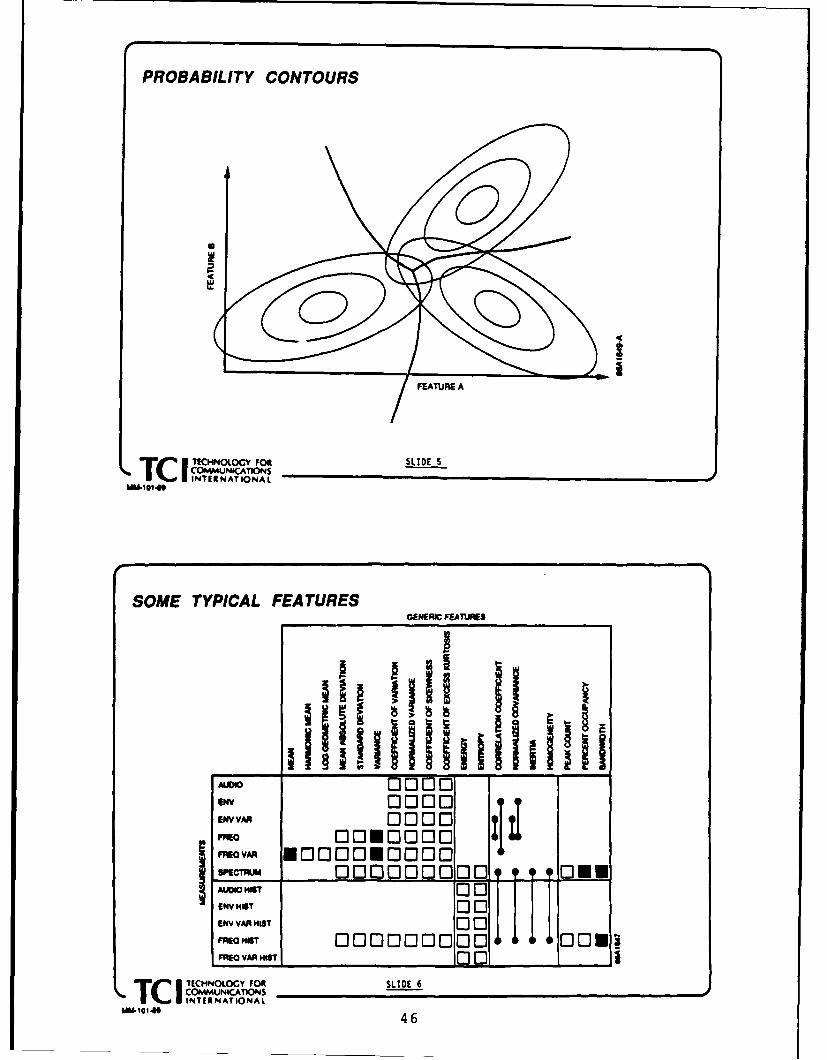
PROBABILITY CONTOURS
FEATURE A
T ITECHNOLOGY roo SLIDE 5COMUNICATIONSTOINTERNATIONAL
MM10146
SOME TYPICAL FEATURESGENERIC FEATURES
v SD ID111 l ii ItIaw 0000
EWNA 0000FEDA 000000
FRj T .Aoog00 ;00 0 0
ENV HOT 001ENV VAR MIST 0 1 0"*O-I, ooooon[cj~o 11 0 , 1sFREO VAR MIST00 _ ___
T C I ECNOLOGY FOl SLIDE 6• IICOMMuNiCATiONS•IOI W T TIONAL
--- ,o,6 46

The job of designing a classifier consists of features to choose features that have certaindetermining the boundaries between decision properties that we think are going to be use-regions that will separate the classes. Bound- ful a priori. For example it may happen thataries can be straight lines in the case of a all the collected signature data was collectedlinear classifier. It can be segments of lines at signal-to-noise ratios between 10 and 20connected in the case of a piecewise linear dB. If a classifier were optimized on such dataclassifier such as a nearest-neighbor classifier, you'd expect it to perform well on signalsThe boundaries can be constrained to be hy- between 10 and 20 dB signal-to-noise ratio.perplanes parallell to the all axes except one, If you gave it a signal with a signal-to-noiseand orthogonal to that one axis. That would ratio lower than 10 or higher than 20, yoube the case of a sequential classifier which is might expect it to fail and that's exactly whatmaking its decision on the basis of thresh- happens. Performance is not monotonic witholding individual feature values. The bound- signal-to-noise ratio unless we do somethingaries can be curved surfaces in the case of to cause it t a be monotonic. What we mightquadratic and higher order polynomial classi- do to cause it to be monotonic with signal-fiers. So there's a variety of options available to-noise ratio would be to require certain in-in determining the type of classifier and also variance properties, such as we might requirethe choice of features that are used. the features to be invariant with respect to
[SLIDE 71 In determining features the scale changes in amplitude of the input sig-
method that's used is entirely empirical. One nal. We might require the features to be in-simply constructs a large library of candidate variant with respect to frequency shifts. Wefeatures, computes them from the collected can't guarantee that a receiver will be tunedsamples of the signature data, and then uses precisely to the. center frequency of the sig-
an automatic feature selection program to de- nals, so if the receiver is mistuned slightly we
termine optimum subsets. We might start want the features to be invariant through thatwith 100 features, typically, and then deter- mistuning. [SLIDES 8,9]mine the optimum singleton feature, that is, Performance that is typically achievedthe best single feature. We'll determine the might look like this. We have a confusionperformance of a classifier using that feature, matrix here, where the numbers on the di-then we'll repeat that to determine the best agonal represent the probabilities of the vari-pair of features, the best triplet of features, ous types of correct decisions; the numbers onthe best quartuple of features. At each stage the off diagonal represent the different kindswe will find the performance of that feature of error. We have more than a Type 1 andset of that particular size, and we'll watch a Type 2 error, obviously. This is a multi-as the performance declines as the number of category decision problem. Each row of thisfeatures increases, determine a suitable oper- matrix sums to unit probability. The objec-ating point on this curve, and that will deter- tive, of course, is to design a confusion ma-mine the size of the feature set. trix that looks like the identity matrix, which
Now the particular features that are cho- has l's down the diagonal. In practice yousen, as you can see from this figure, are all can't do this, but you can typically get num-ad hoc statistics, descriptive statistics. We bers that are on the orders of 95%, 99% inattempt in constructing this list of candidate some cases. Error probabilities would be in
47

PE BOUND VERSUS SIZE OF FEATURE SET
3.0
S2.0
1.0
I I I I I I I I I I0
1 2 3 4 5 a 7 8 B 10
NUMER OF FEATURES
Tc I C=O4.moc FO SLIDE 7COMM UNICAIONS
INTERNATIONAL
EXAMPLE OF TYPICAL CLASSIFICATIONPERFORMANCE ACHIEVED BY STATISTICALPATTERN RECOGNITION METHOD
DECISION CLASS
FM AM OOK FSK CW PSK
FM: .89 .08 .01 .02 .00 .00
AM: .00 .97 .01 .01 .00 .01
OOK .03 .03 .93 .01 .00 .00TRUE CLASS
FSK: .06 .03 .01 .90 .00 .00
CW: .00 .00 .00 .00 1.00 .00
PSK: .00 .00 .00 .03 .00 .97
SLIDE 8
Tc I CHNOOGY FOR 48COMMUNICATIONS
• INTERNATIONALMMWI&I04S

the range of 5%; 10% representing a fairly formation that's available in the signals. Noweasy design number, 1% representing a dif- we don't always have good models, but inficult design number. It's easy to fool one- the case of communication and radar signalsself if you work with a small database be- that are being transmitted the modulationscause you can always get 100% on any small are well specified by the system design engi-database. If you test your classifier design on neer. The waveforms have specific structurethe same data that you designed it on, it's that's put in them to make them easy for aeasy to overlit the data and get perfect per- communication receiver to demodulate, andformance which won't extrapolate to the real there's no reason why an intercept receiverworld. couldn't use that same structure to its ad-
[SLIDE 9] If we show error probability ver- vantage.sus signal-to-noise ratio we get curves that Here we have an input from an antenna,look like this. However, the curve may not presumably a receiver front end, which I'vecontinue to decline as signal-to-noise ratio is called "signal preprocessor" which consists ofincreased because certain features are nonlin- various mixing operations and bandpass fl-ear functions of the data, and the distribution tering, producing a signal at either IF or base-of that feature will translate through the fea- band audio or video signal. The signal pro-ture space. And in translating it will even- cessing operations we would like to do wouldtually shift outside the, or cross over a, de- be to compute some type of generalized likeli-cision beundary. Once the probability mass hood function for every possible signal class.has crossed a decision boundary then that sig- We'd like that likelihood function to be basednal is misclassified, even though it may have on some knowledge of what the noise charac-very high signal-to-noise ratio. teristics are in the particular frequency band
So those are some of the practical prob- of interest, and also some knowledge of whatlems connected with statistical pattern recog- the channel is doing to the signal. The chan-nition. I haven't mentioned the size of the nel model would include the receiver front enddatabases that are typically used. We might in this case as well.collect sufficient data to compute maybe We can set this up as a multiple category3,000-10,000 feature vectors per class, and a hypothesis problem. Hypothesis H0 wouldtypical problem could have anywhere from 10 represent signal signal absent; we're lookingto 20 or 30 classes. In some cases the num- at noise only. And we'll have some numberbers are much higher. We have the luxury M of hypotheses that represent the differentof unlimited computer time to design these signal types that might be present. As dis-classifiers. So we can let the computer do its criminant functions we will take the a poste-number-crunching for several days at a time riori probability of the hypothesis, given theto come up with optimum selections, subsets observed waveform y(t). I'm going to normal-of features, optimum classifier weights and so ize all of these by the conditional probabilityon. of the Null Hypothesis to get ratios of these
[SLIDE 10] Now I'd like to shift to an al- a posteriori probabilities. My decision ruletogether different approach to signal recogni- would be to choose the Jh hypothesis if thetion. This is based on a model of how the jth discriminant function dominates all thesignals are generated and tries to exploit in- other discriminant functions. The discrimi-
49

PE VERSUS SIGNAL-TO-NOISE RATIO
AVERAGE ERROR
1.0 RT O
PERFORMANCE 90%cc 0.01(L
0.001
-8 -4 0 4 8 12 16 20
SNR
SLIDE 9TC J TEHOLG F
MODEL-BASED SIGNAL DETECTION ANDCLASSIFICATION
INPUT PREPOCESSOR FUNCTI MA)WINDER DECISION
MIOOLETCN CLASS AHALLP0680W IMPLSESMIDDLETON CLASS S
TC I TEHOOG O SLIDE 10
ITEE NATIONALMM~l~l 450

JOINT DETECTION AND CLA SSIFICA TION
HYPOTHESES: Ho SIGNAL ABSENT, AWON ONLY
Hi SIGNAL TYPE i PRESENT, i - 1,2..,M
DISCRIMINANT d 0 (y (t))- 1FUNCTIONS:
d (y P(H1 I y (t))d1(~t) - P(H0 I y (0)
P(H~d I yt)d(y(t)) - P(H0 I y (0)
RULE: 'CHOOSE H, IF di (y(t)) a dk(Y(t)) FOR k
CITECHNOLOGY FOR SLIDE 11T lCOMMUNICATIONSINTERtN ATIONAL I
SIMULTANEOUS DETECTIONAND CLASSIFICATION110 YQ
OSSERVATIOBINARY d 2 J 1AFIE CI0ON
Arm I t)
OBSERVATION ) 80M d2-) AFNOR-,mo
P(os0 y(t)) X
TECHNLOY FOR SLIDE 12COMMV~UNICATIONSTcINTIS NAT IONAL
uM&10149 51

nant function for the Null Hypothesis is unity eralized hypothesis tests (sometimes calledby virtue of the normalization, maximum likelihood tests). What we can do
[SLIDE 12] A block diagram, which says is to combine the features of all three into athe same thing as the equations, looks like single test. What I've shown here is a signalthis. We have these little boxes that I call that's parameterized with two parameter vec-binary a posteriori probability ratio comput- tors, which I've labelled I and 02. The firsters which simply compute these probability parameter vector, I , contains all the param-ratios, followed by a max taker that finds the eters that have a known probability distribu-largest discriminant function and reports the tion; and the second vector, & has all theindex. You'll notice that these discriminant parameters that have an unknown probabil-functions are related to likelihood functions, ity distribution. With respect to the first settesting each signal class against the Null Hy- of parameters I'm going to integrate them outpothesis. The likelihood ratios have to be as nuisance parameters in this integral, d-81.multiplied by the ratio of the priors, U in With respect to the second class of parame-order to establish the connection. ters I'm going to take a maximization, just as
Now you might think of this as a pat- I would in a maximum likelihood estimation
tern classifier where we have exactly M + 1 or a generalized likelihood ratio test.
features, the features are these discriminant The function p(11) is the joint density func-functions. The feature computation is car- tion of all the parameters in this vector, soried out in these [UNINTERPRETABLE, this is a multivariate.STATIC INTERFERENCE] probability ra- [SLIDE 14] A processor that implementstio computers. The classifier is simply the these discriminant functions looks like this.max finder. So all the complexity of fea- This is a literal interpretation of the equa-ture [UNINTERPRETABLE, STATIC IN- tion, and I'm not proposing that someoneTERFERENCE] computation is in the cal- build this thing as I've drawn it. This is aculation of these likelihood functionals. Now brute force, this is a conceptual block dia-we need to look at what the complexity is gram. We can think about it and talk abouthere because in a real problem an intercept it and maybe even compute its performance.receiver, unlike a communication receiver, There obviously are a number of simplifica-is faced with a far greater number of un- tions one would have to make.known parameters. [LONG PAUSE, POSSI- What we have here is a processor which,BLE DROPOUT] with respect to il, in the upper block 01 varies
[SLIDE 13] Now in statistical decision the- in each of these processing chains. We haveory we have hypothesis tests that are appro- a matched filter, an energy subtraction whichpriate to each of these three cases. In the first normalizes energy, exponentiation, and thencase where we have known parameters, we we multiply in a prior. Now I'm going to re-have simple hypothesis tests. In the second place the integral with a sum, and I'm goingcase where we have unknown parameters with to quantize the parameter space over 21 inknown probability distribution, we have com- such a way that I can make this replacementposite hypothesis tests. And in the third case of an integral by a sum. I'm going to holdwhere we have unknown parameters with un- the vector 02 constant within this box andknown probability distributions, we have gen- only vary 01. Each input into the summation
52

HYBRID GENERALIZED COMPOSITE TEST FORSIGNALS WITH UNKNOWN PARAMETERS
LET: y(t) - Sk(t, 0 1. t 2) + n(t)
WHERE: ak( t. () IS A CLASS k SIGNAL
WITH PARAMETERS l(k), ft 2(k)
P(f ) IS KNOWN(k)
P(A 2) IS UNKNOWN
n(t) IS AWGN
THEN:
dk(Y(t)) " max a W -,(t) sk(t ' , t )d 2 NP( I 1) dilk
TITCNLCY" ° ORsL.oE.,3COMMUNICATIONS
• INTERNATIONALMM-IO1.
PROCESSOR TO COMPUTE3 PROBABILITY RATIOS
. 40 X
IwENcTa ODFIE FOR ALL Sft M
_ A
K
TECHNLOGYFootSLIDE 14IcP COMMUNICATISONS A
mM'1@T.* INTERNATIONAL 53

device will represent a different value of 01. decision. If you do not collect a representa-Then I'm going to replicate this box many tive database then your design is not going totimes for different values of 02. So each repli- extrapolate well to the real world. The fea-cation of this box will have some different 02, tures that result are unrelated to the physicaland I'm going to quantize the C space. Fi- model. You can come up with very strangenally I'm going to take a max over the outputs moments being used as features, ratios of mo-of all these boxes, and then that will give me ments that are used as features that have nothe discriminant function. physical meaning. Error rates that are typ-
What I have here is a high degree of paral- ically achieved are in the 5% to 10% range,lelism. First of all the first box is replicated 1% at the best. The classifier is very easy to
multiple times for different values of &0. Then implement, the design procedures are auto-
the first box is replicated multiple times for matic. It's a cookbook procedure basically.
different values of 02. Then finally this entire The feature calculations are very complex,
picture is replicated multiple times, once for the classification is generally very simple in
every box that shows up labelled as binary terms of computation. There's no architec-
a posteriori probability ratio computer. And tural parallelism to exploit. As a rule, all the
we can go on because we could say that this features are quite different from each other
processor is being applied to an observation and one has to write subroutines that com-
that comes out of a channelized receiver, so pute each feature.this entire box could be replicated multiple The model-based approach, on the othertimes on each frequency and on each angle of hand, has a different set of advantages andarrival, if one wants to precede it with some disadvantages. First of all you do need tokind of a beamformer with fixed beams. So have models of the signals and of the noise aswe could easily have hierarchical, five layers they appear at the IF of the receiver. Thisof hierarchical parallelism here. knowledge or need for knowledge of a model
[SLIDE 15] At this point I want to sum- offsets the need to go out into the field and
marize the differences between the model- collect data. On these problems frequently
based approach, that I've just described, and one is interested in signals that don't appear
the statistical pattern recognition approach in nature. There may be certain military sig-
to signal classification. Statistical pattern nals that simply never are seen or at least you
recognition is statistical because it's working hope they never are seen, but you must design
on samples; that is, the design of the deci- a recognizer that will recognize those signals
sion function comes not from a theoretical very fast if they ever appear. You can't col-
model of what the waveforms look like, but lect signature data on those signals because
rather it comes from collected signals that are they simply don't manifest themselves in the
mapped and then various empirical methods real world. So the only way you could possi-
are applied. The classifier has to be optimized bly design a recognizer would be on the basis
both with respect to the choice of features of some description of the waveform.and with respect to the weights, the choice The model-based approach does not re-of classification function. Whatever informa- quire training. It uses all the available in-tions are stored in those collected samples, formation about the signals of interest. Thethat's the information that is used for the likelihood features are related to the physi-
54

COMPARISON OF APPROACHES TOSIGNAL RECOGNITION
STATISTICAL PATTERN RECOGNITION MODEL-BASED APPROACHREQUIRES STATISTICALLY-VALID REQUIRES MODELS OF SIGNALS AND
CALIBRATED DATA BASE OF NOISE
REQUIRES WEIGHT-TRAINING EXERCISE NO DATA OR TRAINING EXERCISE REQUIRED
USES ONLY THE INFORMATION STORED IN USES ALL AVAILABLE INFORMATION ABOUTTHE FEATURES EXTRACTED FROM THE DATA SIGNAL-OF-INTEREST
FEATURES UNRELATED TO UKELIHOOD 'FEATURES* HAVE MEANINGPHYSICAL MODEL RELATED TO PHYSICAL MODEL
5% TO 10% ERROR RATE TYPICAL ERROR RATE UNDER 1%
RELATIVELY STRAIGHTFORWARD COMPUTATIONALLY-INTENSIVE,TO IMPLEMENT BUT
SLOW DUE TO 1). LONG OBSERVATION TIME SUITABLE FOR IMPLEMENTATIONREQUIRED WITH HIGHLY PARALLEL
2). COMPLEX FEATURE ARCHITECTURESCALCULATIONS
LITT.E OR NO ARCHITECTURAL INTEGRATED DETECTION ANDPARALLELISM TO EXPLOIT RECOGNITION FUNCTIONS
T TCHNOOGY FOR SLIDE 1_It_ •COMMUNICATIONSTc INTERNATIONALWA-101,19
OPTICS VS SUPERCOMPUTERS
COMPUTATIONAL POWER PER UNIr VOLUME
PROCESSOR FLOPS/CUIN RELATIVE RATING (LOGARITHMIC)
OPTICAL: COUNTERPROPAGATING 2x 10 7.8PROCESSOR
ESL TRIPLE PROOUCT 8 x 10⁷ 7.3PROCESSOR
DIGITAL AT&T DSP 32C 3 x 10⁷ 6.8
THINKING MACHINES 1.3 x 10⁴ 3.6
CM-2
NUMERIX 332 7 x 10³ 3.3
IVAX 27 x 10 1.3
VAX 11/780 4x10 0
SOU&CE: A. HIELLANO . I4OnTED
TcI TECHNOLOGY FOR SLIDE 16
COMMUNICATION~SINTER NAT IONAL,o, ,5 5

cal model. The error rate can be made as In response to the other criticism, the in-small as one wishes, subject to signal-to-noise put device Bragg cells may not be the wayratio limitations. It's computationally inten- to go but there are a variety of new spatialsive but there's a high degree of parallelism light modulators that are available that workthat could be exploited. The detection and on different physical principles, including liq-recognition functions can be combined rather uid crystal devices. These may provide thethan having an energy detector which is not storage capacity necessary to make a devicesignal-specific, and then following that with work.a signal recognizer one could combine the de- [SLIDE 17] I show here fina-ly an opti-tection and recognition in one step. cal bank of matched filters. This is one of
[SLIDE 16] I have three more slides. I'd like the key ingredients in the model-based rec-to talk about implementation of this method ognizer. This would be implemented with anbriefly. If we look at digital techniques, the array of lenslets, a transparency that encodesdigital techniques simply are not fast enough the matched filters for the signals for vari-to handle the large number of parameters ous parameter values, and an array of pho-and the quantization of the parameter space todiodes. The array of lenslets: the cur-that's required. If we look at optical tech- rent densities that are achievable are aboutniques we discover that in terms of compu- 100 per centimeter of linear dimension ortational density, we can have more flops per 10,000 lenslets/cm2 . We have no problemcubic inch. The numbers that are available getting the photodiodes at densities greaterright now are on the order of 108 flops/in . than that. We could have several matchedThe numbers that are in the foreseeable fu- filters in a small region imaged by a singleture are on the order of 1011 flops/in3 . This lenslet onto a single diode. The energy sub-means that the analog optical processors have traction could be carried out after the photo-the potential for far greater computational diode.density than the fastest supercomputers. [SLIDE 18] Here's a picture of a processor
Now the frequent criticism of optical pro- which is- approximately 3 inches on a side.cessing is that the dynamic range is small It's the Dove Prism Correlator that was builtand the lack of input devices. The reply to for the U.S. Army by Perkin-Elmer. It showsthose two criticisms are that high dynamic essentially the same picture as in this bank ofrange is not required for carrying out the matched filters. The light path in this devicecomputations in one of these signal classifiers, is folded up so that the device will fit nicelyTypically 4 bits of computation, 5 bits, 5-bit into a compact physical geometry.wordlength is sufficient. The dynamic ranges And we have here a laser diode whichthat are achievable are in the order of 30 dB provides the input signal. The light pathor better, although generally not better than bounces out back here, spatially modulated40 dB. That's adequate. That's not adequate by a reflection mode modulator, comes backfor doing fitering and reproducing high fi- into the device, comes back up through thedelity replicas of signals, but it is adequate transparency, and then winds its way backfor doing the analog computations necessary down and comes out onto the photodetectorto implement these signal classification oper- array. This device also was designed for mis-ations. sile guidance and designed to recognize cer-
56

I OPTICAL MATCHED FILTER BANK
IC~~ltp ~ 0MrmIrm~o aucrrmnioI11012?a o u n
M/ 1911111111TI
U.S~lmx~ ARYDV xSMCREA3 OPTI~CAL ROCSO
TECHOLOG FORSLIDE 18COMMUNCATI5N

tain targets of interest, independent of the outstanding article.aspect angle and orientations. So it was do- Basically a network is just an intercon-ing image processing. nection of all these computational elements,
I'm proposing a replacement of this which are called neurons. They all operatematched filter with an array of matched flu- in parallel. Do they have to operate syn-ters. This I think is where things will be chronously? No, they don't have to be im-headed in the next fifteen years. This area plemented synchronously, they can be imple-of investigation started fifteen years ago and mented asynchronously. There's a lot of workit will probably be another fifteen years be- looking at these aspects which is going on atfore we see this type of device with the high a lot of different places including JPL. Theirdegree of parallelism that I'm anticipating. arrangement in patterns is reminiscent of bi-
WEBER: OK, we're running very late so ological neural nets, which is why they getwe'll take a break now. [PAUSE, BREAK] their name.
Here is Ed Satorius from JPL [PAUSE] and What I've done in this viewgraph [SLIDEhe's here! #1] is I've depicted an example of what a
ED SATORIUS: Application of Neural computing neuron might look like. In factNetworks to Signal Sorting I've shown a little bit more than that. You'll
[SLIDE #0] No, you don't have double vi- see this again in several of the diagrams thatsion - the viewgraph was really made like I will present here. I've included here an ad-that! ditional input, the so-called input neurons.
Alright, my talk by definition won't take These input neurons are special types of neu-as long as the other talks because this work rons which really don't do anything otheris in progress and not at any final state cer- than just pass the data through. The com-tainly where we could summarize a lot of re- puting neuron, though, takes the outputs or,suits. But it's nevertheless very interesting, in this case, just the input values, the N in-Somebody, one of my colleagues at JPL, said puts, weights them by constants or weights"Well, you know, neural networks are noth- them with parameters that can actually being more than parallel computational algo- adapted in the course of training this net-rithms and architectures, and why don't peo- work, called synapse weights, W's. These areple call them that?" Well, because I don't added together and the output is thresholdedthink you'd probably get as much money. through some type of nonlinearity, and you[LAUGHTER] So anyway this is the hot, new go on to the next layer to the final output.area in signal processing. But I think really This would be a mathematical representationthe important advances, I believe, are in the of this process. The sum of the weighted in-applications of this work. puts go through a nonlinearity and there's
I have a little overview, a definition of what typically a threshold, which is some sort of anneural networks are [SLIDE #1] from a recent internal threshold, that can also be adapted.IEEE Magazine article by Lippmann [IEEE This nonlinearity can be a wide class of non-ASSP Magazine, April 19871, a very nice ar- linearities, i.e., hard-limiters, signum func-ticle. If you're interested in or just want a tions and so on.high level overview of what neural networks I was at a talk a year ago or so and some-are and what different types exist, this is an body said, "Therefore a neuron is nothing
58

Edgar Satorius, Ramin Sadr
SLIDE #0
IJPLOVERVIEW OF NEURAL NETWORKS
*DEFINITION: A NEURAL NETWORK IS AN INTERCONNECTIORt OF COMPUTATIONAL ELEMENTS(NEURONS) OPERATING IN PARALLEL AND ARRANGED IN PATTERNS REMINISCENT OFBIOLO6ICAL NEURAL NETS
*COMPUTING NEURON:
* 2 OUTUTt~o wnonli)near Ity (hard I m Iter,
OuTPUTinternal threshold
N _4( N
*APPLICATIONS:
-MODELLING BIOLOGICAL SYSTEMS (McCulloth. Pitts; 1943. Grobsborg; 19861-SPECIAL-PURPOSE PROCESSORS [H4opfleid; 1982-86, Abu-Mostaf a, Psaltis; 19871-PATTERN RECOGNITION (Wldrow; 1986, Minsky. Papert, 19691-SPEECH ANALYSIS (Gold. 1986; Mueller. Lazzaro. 1986, Seinowsi, Rosenberg; 19861
alGUANTIZATION (Tank, Hopf lold; 1986, Kohonen, et. &1.; 1984, Reed, et. &1.; 19873-SIGNAL ANALYSIS [Anderson; 1988, Satorius. Sadr; 19891
SLIDE #1
59

more than a summing junction and since the of receiver for processing communication sig-whole world is made up of adders, then the nals. [SLIDE #2] You basically have an an-whole world is a neuial network." So you tenna input and you might have some typecould almost write any algorithm like a neural of a noise preprocessor so that interferencenetwork. Neural networks aren't new by any doesn't capture the SYSTEM dynamic range.means. They've been around for a long time The major components of these types of re-and they've been used in lots of applications. ceivers are comprised, first of all, of a rapidCertainly modeling biological systems would scanning spectrum analyzer. It does noth-be probably one of the first applications of ing more than scan repeatedly a very brcldneural networks. They're also used or pro- range encompassing maybe the VHF, UHF-posed for doing special purpose processing in band, HF-band and so on. This rapid scan-general. Abu Mostafa and Dimitras Psaltis ning spectrum analyzer dumps its data atand Hopfield, all at Caltech, have done a lot typically 25 kilohertz resolution so that youwork in this area. They've also been used may have thousands of frequency cells of am-heavily in pattern recognition. plitude information coming out of the spec-
Speech analys-s and recognition is another trum analyzer in orders of hundreds of mi-
important area for application of neural nets. croseconds. That's a lot of data that's com-
If one can develop a nifty way of doing speech ing t rough and can be increased by incorpo-recognition then little kids can work corn- rating multiple receivers so that you can ex-puters simply by talking into them. One tract additional information, including angle-big technique used in speech recognition is of-arriva estimates and so on. And this goescalled "Hidden Markov Models". An impor- into this magic box called a signal sorter. In
tant competitor to this is a feedforward neu- some applications you may also have a set-on
ral network incorporating back propagation receiver that's connected to the signal sortertraining. So this is a big, hot area in speech so you can extract modulation information.analysis. Vector quantization is also an im- This type of information is used for signalportant application area for neural networks detection, exploitation, or possibly for ECMas is signal analysis. communication jamming, or just for listening.
In signal analysis there's probably other The tough problem in building this sys-work that's going on, but I reference here tem is the signal sorter, and the really tough
some work by Jim Anderson at Brown who problem is doing it in real time. And thishas been doing some interesting work in is a tough problem because you're faced with
applying neural networks to characterizing this massive amount of information feeding inradar signals. In contrast, we've been look- from the spectrum analyzer, and you reallying at communication signal recognition, or have to do both the feature extraction andidentification which is really the first step. feature identification problems. Well, this isThe previous talk pointed out that in any precisely the function that we think mightidentification or recognition problem, there be able to be not replaced but perhaps aug-are really two parts: feature extraction and mented with, or complemented with, a neuralthen feature classification. The aspect that processor.we've been looking at initially is feature clas- Now the first sets of experiments that we'vesification. Here's a picture of a general type been looking at, which I'll go over here briefly,
60

JPL6ENERALIZED ARCHITECTURE FOR PROCESSING COMM SIGNALS
SIGNAL DETECTION/
EXPLOITATION
DISPLAY
IDE#
NOISE SCAN AL GIH D E M NTPREPROCESSOR SPECTRUM SORTING E D
ANALYZRR
r SET-ONRCECEI VER
SLIDE #2
F MODELLING AND AL60RITHM DEVELOPMENT
•A SIMPLE COMPUTER SIMULATION PROGRAM (NISII') FOR SYNTHESIZING OUTPUTSFROM THE SPECTRUM ANALYZER HAS ALREADY BEEN DEVELOPED:
F IXED-FREOUENCY/
FREOUENCY AGILEOUEMITTERS E ES: IATE GENERATE OUTPUT
ONEOFF POWER POWER/SYSATA NOISMASK DATA G SPECTAL/AOA .Ap. AOA DATA-SYSTA OR A FORSIGNAL DATA ON A IAT ERCHi AN RFI SCA-by-SCAN RESOLUTION
- FIG ENVELOPES ADCELL
OUTPUT AVAILABLE00FOR TRAINING
•SIMULATOR FEATURES: NEURAL NETWORK
-POWER DATA GENERATED BASED ON CHI-SGUARqE STATISTICS-AOA DATA FOR NOISE-ONLY BINS GENERATED BASED ON A UNIFORM DISTRIBUTION
-"-ADA DATA FOR RFI/SIGNAL SINS GENERATED BASED ON NORMAL DISTRIBUTION-RFI/SI6NAL ENVELOPES GENERATED RANDOML.Y:
w. POWERPOWER PO&I FIXED-FREQUENCY ENVELOPES AGILE ENVELOPES
P\ r- f / ,..p * ~ l: *,,. •TTIME
SLIDE #361

have been looking at incorporating a neu- these experiments, we have simulated a 16-ral processor for signal identification. Now channel spectrum analyzer, and in this casethere are neural networks and there are neu- the agile and fixed frequency emitters. Andral networks. Neural networks can broadly all of this spectral information over 16 chan-be categorized into two classes requiring su- nels is directly fed into a feedforward multi-pervised or unsupervised learning. The class layer neural network architecture.that we're looking at uses supervised learn- What we wanted the network to do is being, which means that you've got to train able to take all this mass of information andit; i.e., both the synapse weights and inter- separate it, and sort it, and tell us in the end,nal thresholds are established by training se- "Well there was, in fact, during this scan anquences. And you typically train this class agile emitter present; during this scan thereof neural networks with data sets in which was a fixed frequency emitter present; bothyou somehow have a rich mixture of the dif- were present, and so on." To do this I canferent types of the features or the characteris- only summarize the result. We did a lot oftics that you're trying to train this network to experiments just to get this far. The experi-exploit. Because once you've trained this net- ments were such that we found out that reallywork then, until it's retrained, it has to per- this problem is a pretty easy one.form signal identification on a class of datawhich it didn't see from the training. So it Here's a little bit harde. Lase, but never-has to do a lot of generalization of learning. theless an interesting one. tLIDE #5] ThisAnd that's the basic idea behind the super- particular case corresponds to a one-channelvised neural networks. overlap, fixed-agile emitter class. For this
case, we've tried to compare the neural net-Neural networks based on unsupervised work with a simple energy detector which
learning can actually extract features from does not perform a decision when the agilethe data, like clustering algorithms, but emitter falls into the fixed emitter frequencythat's an aspect that we haven't looked at. band. With this type of simple energy detec-The field is so rich that we've only been able tor, you would expect to see a 6% error rateto concentrate on one part. [SLIDE #3] To at a high SNR. And that's not quite right be-do this we set up a simulation model which cause we've got to be a little bit more carefulgenerated data out from the spectrum an- in about how we compute the error rates. Butalyzer. We also generated angle-of-arrival the point is that the neural network does ex-data - recall that if we did have multiple re- ceed the simple bound (i 6% error rate). Inceivers we could extract angle-of-arrival data. other words, the network is doing somethingWe did this for a couple of signal classes: a little bit more sophisticated than simplefrequency-agile and fixed-frequency emitters. energy thresholding. But what is it doing?In addition t simulating the spectrum an- It's not exploiting any temporal features ofalyzer output, we also simulate signal mask the signal. It can't be, it doesn't incorpo-data (signal on or off) to train the network. rate any memory. Based on looking at some
Here's an example of one experiment which of the synapse weights, what we've inferredwe've carried out representing some prelim- that it is doing is this: the network startedinary results separating frequency-agile and to realize that when the fixed frequency emit-fixed-frequency emitters. [SLIDE #4] In ter is on, it occupies two bins, but the agile
62

SEPARATING FREQUENCY AGILE AND FIXED EMITTERS
FREQ
16 NEURONS 16 NEURONS
15 *AOILE -- 010
......... . . . ..........
(BASED ON 10O TRAININO SCANS) .SE A: 2 FIXED EMITTERS .F
FAIE IFIXED&l AGILE
tO 20 30
i SLIDE #4
* JPlLSEPARATING OVERLAPPED FREQUENCY AGILE AND FIXED EM'ITTERS
,,5CSCANS
SIUA1RESUT
16 N(URONS ON N'IA A0S'.
ADO:LE I ,,--
3SIMlULATION RESULTS(BASEQON 1* TRANNOSCANS)Z 0
I FIXED& AGILE 1L £ .FIED E-.TER
I FR EQYCttANN(LO ERLAP='=. " 62 ElRC RATE FC.I SII1IFLC EIf4EO DETECTOR e SNR - ID
SLIDE #5-fi
63
YI1 r

Comparison of Maximum Likelihood Detector with FFNN
1.00. 0 - - -
0.90-
0.85-- FFNN-2
0.801Iw 10 2 3'0
SNR-dB
SLIDE #6
64

emitter only occupies one. Well somehow it other information? Angle-of-arrival informa-was able to start figuring out and be smart tion? One thing that people say about a net-about instantaneous frequency allocations for work that's very, very neat is that you canthese different emitters. That's just based simply fuse data types. Well we couldn't sim-on a rough intuitive argument looking at the ply fuse data types. [LAUGHTER] We triedsynapse weights. But something is happen- to simply fuse data types, but the dynamicing because the probability of correct identi- range problems prevented it. So there's afication for the neural network classifier is in lot of things that we've got to look at. Inexcess of 98% at high SNR. other words we have to be able to fuse both
Finally, we compared the neural network angle-of-arrival information as well as ampli-with a maximum likelihood detector for tude. That's got to help provided the angle-a simple fixed-fixed non-overlapped emitter of-arrival information isn't too bad, i.e., isn't
scenario. [SLIDE #6] In these experiments degraded too much. What about using mul-we locally optimized performance of the neu- tiple scans? Right now we are using a stupidral network at each SNR. But at each SNR network, because it's not exploiting any tem-we always carefully fed noise in and measured poral features in the data. So what we wantthe false alarm rate for that SNR. We took to look at is incorporating a buffer of multiplethe false alarm rates and we used those to scans up front to see if that doesn't help.compute the thresholds for a dual threshold So I don't know what the future is. It'sdetector system. As you can see, the max- certainly not at the point where I can go offimum likelihood detector outperformed the and build hardware, although a lot of peopleneural network because it is optimal for this know how to do that. A lot of people knowproblem. We are currently conducting more how to build hardware for these feedforwardcomparisons for the overlapped scenarios. neural networks, but I don't know if many
Well, I don't have any more charts, but I people know really how to fully get this thing
just want to leave you with this. Chuck said operational for a system. You train it forever
that one thing he wanted me to end with off-line and then you put it in the field; whatthatonethin hewantd m to nd ithif something changes? There are a lot of is-was where I think the future of neural net- soehing knw here are o t oit
works are. Well I don't know where the fu- sues. I don't know where it's going yet, but
ture of these networks are, because we have nevertheless it is interesting.
so many problems that aren't resolved yet. WEBER: Thank you, Ed. What I'd like
There's a ton of architectures - we've looked to do now is open it up to suggestions and
at one. Furthermore, the signal sorting prob- comments. We have two of these mikes that
lem is much more complicated than what we can pass around. OK ... Ray?
we've looked at, which is basically identify- RAYMOND PICKHOLTZ: OK, youing an emitter class that we know is present; hear me?
it's on or it's off. But where is it in fre- WEBER: OK, ready ...? Ray Pickholtz.quency? In other words you have to do some PICKHOLTZ: My original questionsort of tagging of the information. How will which I wrote down was for Mark, but I thinkthat be performed? Via a network? Maybe it applies also to Bart's talk, and that is:not. Maybe that'll be something separate and There are many situations, maybe most situ-this network will enhance that. What about ations, where you have not one signal present
65

but where you have many signals present, dif- Also it depends on how you do the cyclic spec-ferent signals, different modulation signals, trum. Some of those cyclostationary featuresbut very similar and very close together. For are weaker than principal CAF peaks, but letexample you might have multiple signals with Bill go from here.the same kind of modulation, with very, very WILLIAM GARDNER: Actually Iclose data rates. It would seem that the pro- have a comment on a slightly different ap-posal that Mark made about using some of proach than you were mentioning, Bart. Ifthese nonlinear processors for extracting rate you can do spatial filtering, in other wordsinformation would break down when you have if you have an antenna array available, youmultiple signals. And I have a similar ques- can in some cases really circumvent the prob-tion with respect to the kind of classification lem of identification of sorting by using blindtechniques that Bart talked about. It would adaptive algorithms that will automaticallyseem to me that at the very least you have to select only the signal of interest. For exampledo some kind of spatial sorting with arrays in if you know the baud rate of a signal of inter-order to isolate individual signals. But even est or, let's say, the chip rate, Brian Agee andif you do that there's always going to be some Steve Shellen and myself have been studyingremnant of the other signals present, which is what we call "spectral coherence restoral al-going to cause great problems in any of the gorithms" that will blindly adapt the arraytechniques that I've heard described. I was to extract only the signal with that baud ratewondering if we can have some comments on and, if you're within the capability of the an-that. tenna array, reject all other signals.
WEBER: Who wants to go first? Bart ...? RICE: Well, John Treichler has also shownRICE: I can go ... can I be heard? Is this a constant modulus algorithm will reject cer-
working? [TAPPING ON MICROPHONE] tain co-channel interference signals if youWEBER: Talk right up into it though. start the adaptive weights properly. Maybe
RICE: The co-channel interference prob- he can respond to that. Do you want to,lem: Of course, if you can filter things out John?
by direction o: arrival or by bandpass filter- JOHN TREICHLER: I would like toing then your problem is solved, and you can point out one thing, to go back to the orig-look at the signals one at a time. But if inal question. The particular problem thatyou have a co-channel interference problem - Bart was addressing here, that you have thea long-standing problem - then conventional luxury of knowing that any one channel thatfiltering won't help. Bill Gardner ought to you're looking at, there's only one signal in ittake a mike, because very often you can sep- at a time.arate the signals by means of their cyclosta- RICE: That's right ....tionary features. You can either do this in TREICHLER: Now that may not be ofthe cyclic spectrum or in the cross ambigu- broad interest to everybody in this room, butity function (CAF), and Bill has done a lot it happens to be the case in the applicationon showing that different shapes ih the cyclic he was looking at. And that's one of thespectrum character the modulation. We've reasons why the performance is so good, isalso looked at that, somewhat, and it works; you never really have to worry about the co-but we haven't gotten anything automatic. channel problem.
66

On to the other one, I'm going to hand terference on the basis of the modulus varia-it right back to Brian Agee in a minute. In tion of the signal.fact the early work we did [MICROPHONE STEARNS: I have something to add.MAKING NOISE] ... nice ... the early work The basic problem of co-channel interferencewe did with the constant modulus algorithm can be solved by attempting to filter the sig-was aimed at correcting multipath, but it was nals in such a way and in such a domain thatfairly quickly determined that co-channel in- you do get a single signal present in the anal-terference - we would sell it as co-channel, ysis band. You can sort the signals eitherbut in fact it needed to be very closely adja- by frequency, that is, determining frequencycent interference that looked like co-channel bands which are sufficiently narrow that you- could be nicely rejected by using the very only have a single signal present. You cansame algorithms. In that case, all we were do it spatially using antenna arrays. You canlooking for was simply the property of the have algorithms that will adaptively convergesignal that, if unencumbered with interfer- to a single signal, and this has been men-ence or multipath, it had a constant enve- tioned. A third method is sorting in the timelope. And that's really nice except that lots domain. If you're dealing with signals thatof things have constant envelopes, sinusoids are not on 100% of the time but that cyclefor one; carriers of FDFM signals where the on and off, and if you attempt to make amodulation index is quite low appear that series of decisions, then you can sometimesway. Lots of things can trick you with that, find points on which only a single signal iswhich was part of the motivation for Brian's present and the interfering signal is absent.and Bill's work on applying more sophisti- You can look at a long sequence of decisionscated ways of deciding if you're happy with and look at some metrics on the quality ofthe ... I mean, if the signal you're looking for those decisions, and find times when one sig-is really the right one. So I'd pass it on to nal will appear by itself and then times whenBrian and let him make a comment or two the other signal or signals will appear eachabout what you all are doing in that area .... by themselves, and accomplish the sorting in
BRIAN AGEE: I just want to make a the time domain as well as in the frequency
short comment that was kind of in the area domain and the spatial domain.
that Bill Gardner was talking about, and also The alternative if you cannot sort the sig-the comment that Bart Rice made about us- nals out in such a way to have a single sig-ing the constant modulus algorithm. Some of nal present, then there's the frontal assaultthe recent work that I've been doing in con- on the problem which is to try to design ajunction with some of my clients has been to hypothesis tezt that explicitly looks for hy-develop a multitarget constant modulus al- potheses taken two at a time. That is, you'llgorithm. I understand that AST also has de- define a new set of hypotheses which para-veloped a multitarget constant modulus algo- metrically assume two signals present at arithm which is capable of sorting, again en- time and parameters for both signals. This,vironments on the basis of constant modu- however, is very complicated because thelus, and overcomes that co-channel problem. number of parameters is so large that it's notIt also can do some identification of environ- considered a very practical method.ments as whether or not they're signal or in- WEBER: It seems like a key issue in all67

of this is how much you can get by with as- lute I, of course absolute Q.suming you know about the signal up front, WICKERT: Not that I'm aware of ....period. I mean, if you really don't know very STEIN: Anybody ....much, if most of your parameters are un- WICKERT: What I just mentioned is theknown and you're still trying to look to make only thing that we've done. We've looked ata characterization between two signals, essen- that and that was a power series approach,tially the same frequency domain, it could re- and we could not take it to its limit, but itally be tough. Whichever of these algorithms works. It works just a little bit better if you- I don't know if somebody wants to comment use matched filtering than if you use like aon some of that or not ... of the previous corn- square law device, so it really doesn't gainmentors. that much ....
RICE: Let me make one more comment. STEIN: Well what I'm curious about, isThere was a recent little vignette that's re- that kind of nonlinearity presumably has alllated in the Electronic Engineering Times powers in it and I'm curious about how itthat was not really explained. If you are faced would perform.with colored noise as opposed to an interfer- WICKERT: Well, that's where our modeling signal, the fellow claims to be able to syn- fell apart because we approached it using athesize the noise by means of fractals. That series, and we could only use a finite numberwas in one of the recent issues. He didn't of terms. So we were not actually getting
want to tell anybody about it. I think he was onergeSce.
holding it as proprietary. STEIN: Can I go with a second question?
SEYMOUR STEIN: Sort of the Pon- WEBER: Sure.
Fleischman .... STEIN: Also for Mark's talk. You pointedRICE: Yes! [LAUGHTER] out the tremendous benefits if you want notSTEIN: Got a different question. It's to be detected of using non-constant enve-
aimed at Mark's talk, but really an open lope signals, you know, by having a filter bitequestion. You identified power law analysis into the waveform. Unfortunately most peo-to get a chip rate line. There are techniques ple who design communications equipmentthat have been used in modem sync that in- keep insisting on wanting to do efficient am-volve nonlinearities that are not power law. plifiers, which are constant envelope or satu-Do you know of anybody who has tried to do rating. In past years there were people whodetailed analysis of the ability to use those played games with what I tend to call limiter-kinds of nonlinearities, you know, for weak filter-limiter-filter cascades, trying to gener-signal detection? ate what looked like signals with interesting
WICKERT: We actually did some of that properties then limiting them, then trying toby using a power series model to approximate put filters on to get rid of the spectral splat-like a log I0 function for noncoherent detec- ter, then limiting again, then filtering again,tion. etc. I'm kind of curious whether anybody
STEIN: I'm talking about something sim- that you know of is doing any research intopler than that, like taking comp .... trying to find out how far you might go with
WICKERT: Absolute value, or ...? the kind .... [TAPE ENDED] ... [LAUGH-STEIN: Taking INQ and just doing abso- TER]
68

WICKERT: The amplitude weightings from that standpoint, the technology that isand pulse shaping approach is a hypothesis. being used for the algorithms for the interceptIt was just something that just sort of came receiver are no where near the fundamentalup after looking at the equations. It's not bounds.anything that I have any answers to, it was The key limitation here is complexity. Ifjust a hypothesis. you look at the type of modeling assumptions
STEIN: OK, I guess my point is that until that the communication engineer uses whensomebody invents a miraculous linear ampli- he designs a communication receiver, he doesfier that satisfies comm. designers, it might not simply build his transmitter first and thenbe well to look at that kind of a problem collect signature data on the received wave-instead of talking about ... because there forms, and then try to design a pattern clas-are lots and lots of nice ways to generate a sifier to decide whether a 1 or a 0 was trans-Gaussian-looking signal that has very little mitted. Rather he is able to build a likelihoodfeature, but they can't be transmitted. ratio detector and then put that into the re-
WICKERT: Well, the 4-level signal isn't ceiver.that complicated, but it's still not constant On the other hand, the intercept re-envelope. So ... I don't know, I don't have ceiver, due to the complexity of building aanything else to say, I guess, unless somebody full model-based algorithm for interception,else wants to say something. doesn't have that luxury. So he's forced to
WEBER: Rob .... go to highly suboptimal techniques in orderROBERT PEILE: My question is much to identify the signal correctly. One of the
more general in nature. I would have thought things I'd like to see is, as the hardware tech-after this morning's talk that there must be nology gets better, we can implement moresome sort of information theoretic lower limit fully the kinds of techniques that we can writeon the uncertainty over any given set of as- out theoretical expressions for, and see thosesumptions on modulation. From these talks techniques get put into existing systems.it's not clear to me if you're more or less at RICE: If you have a complete and accu-that limit, a long way from it, getting close, or rate characterization of the distribution func-we're still doubling around. I've got no idea tions of the features for all of the differenthow successful these algorithms are at achiev- signal classes that you are interested in, thening the theoretical maximum, even under a you can obtain theoretical expressions forset of benevolent and unrealistic assumptions. those likelihood ratio functions and you can
STEARNS: Well, one way to look at it is determine the probability of each decision. Ofthat if you're trying to classify communica- course, it depends on what the signals aretion signals, keep in mind that the commu- and what the features are. The approach wenication receiver is able to demodulate these took was to run through as rich a set of rep-signals at very low bit error rates, looking at resentative test signals as we thought that weintervals of time that are very small. Whereas would have to handle, whose parameters coy-an intercept receiver, looking at much, much ered appropriate ranges. Plus, take into ac-longer intervals of time, perhaps 100 millisec- count things like the different noise levels andonds, perhaps 2 or 3 seconds, is able to get the different channel distortion characteris-error probabilities on the order of 101. So tics. Once you take all that into account, it's
69

very, very difficult to obtain a valid theoreti- stant modulus algorithm, to a QAM signalcal expression for the distribution of the fea- where we did not know what the constella-tures. So, the approach was much more ad tion was. Once we had despun the carrier,hoc. let the constant modulus algorithm converge
SATORIUS: You know, I guess that in and recognized the constellation, we switchedthe results we presented, we tried to do that. to the decision-directed mode. The exampleBut, you know, when you try to do it the I showed you had almost no noise on the sig-case you look at is kind of noninteresting, it's nal. That's the reason the clusters were socentral X2 and noncentral. tight.
STEARNS: Once the signal has been WELCH: Oh, but it looked like it had amapped into features a considerable amount lot of noise to me when ... the first pictureof information has already been lost. There's ....far more information about the signal avail- RICE: All of that was due to this chan-able in the continuous time domain signal nel distortion. When the blind equalizer con-than is preserved through the mapping into verged a little bit, the channel distortion wassome finite dimensional feature vector. So removed to the extent that the constellationfrom the standpoint of information theory, was recognizable, but not to the extent thatyour key loss occurs right at the very begin- the clusters were tight. The tight clusters re-ning, the very first step in the classification sulted after going to decision-directed demod-process. ulator where we knew what the constellation
LLOYD WELCH: It strikes me that was.there's really a sequential process going on. WELCH: Would that be insensitive toYou're talking about sort of the front end. your local carrier being off-phase?But after awhile, you've identified the mod- RICE: We had pulled the carrier in byulation type, you have a whole bank of re- that time. The way that the combined blindceivers, one of each type that's being manu- equalization technique and carrier despinningfactured, and you turn on the right one. So algorithm works is to apply the Godard al-there's no reason why you can't do just as well gorithm in conjunction with Jim Mulligan'sas the communication receiver does. But in technique of putting constellation points inline with that succession of steps, I wanted to each quadrant, and then pretending like thatask Bart a question. One of the slides that was the actual constellation in despinning theyou put up there was the effect of a clustering carrier with a relatively small gain, based onalgorithm that started off with what looked its distance from the nearest quadrant center.like pretty much of a mess, and wound up That method both equalized the channel andwith 16 categories and a quadriphase ampli- despun the carrier. We could be as much astude modulation. 100 hertz off in our estimate of carrier, and,
RICE: That's right, in blind equalization mode, both equalize andWELCH: I thought that was rather spec- recover and track the carrier.
tacular. Could you tell me a little bit more WEBER: John ....about that algorithm? TREICHLER: I thought I'd amplify on
RICE: Yeah, well, that was no more than that a little bit. There's been work going onapplying the Godard algorithm, or the con- by a number of different people in this partic-
70

ular area in the last couple of years. I'm not radon techniques where you simply sort of dosure exactly who has what and so, competi- averages across the constellation and look andtively speaking, I don't know anything. But see where the bumps line up. And you can,I can tell you a couple of benchmarks that I in situations even noisier than the one Bartknow of for a fact that the place I work, and showed, you can highly reliably identify con-that is that what you saw here was 16-QAM. stellations up to 256-QAM, even if they're notWell in fact you can go all the way up to completely despun. So, for example, say you256-QAM by the same technique quite reli- didn't despin it using this decision-aided tech-ably, with exactly the same algorithm. So as nique but simply by measuring the carrier bya result the algorithm doesn't need to know some other method. For example sometimeswhether it's 16-QAM to start with, or 64, or you can do a 4th law on the signal and get a128, or 256 even. Or that the constellation is little spectral line out there where you thinka square or a cross or any of the other fancier it is 4 times the carrier, and simply go downconstellations people come up with now for and try to despin using that, and the con-minimizing the peak-to-average ratio. stellation isn't quite stopped. Well, some of
Second point is that another way of look- these other techniques like the radon tech-
ing at that despinning that Bart was talk- niques can in fact work quite reliably even in
ing about, we referred to it as "gated deci- the face of that sort of uncertainty.
sion direction." And you can think of simply So there are lots of really neat things thatgating out any information that's inside of are going on for the high order QAM prob-a certain circle in the constellation, leaving lems, so long as there isn't a tremendousonly the corners out there. So you simply amount of noise or co-channel interference.... it's just like traditional decision-aided car- As soon as you have those problems, you'rerier tracking except you ignore any points on dead meat. You have to do something elsethe inside, the argument being only the high first in order to ....power points of the edges are the ones you RICE: I'd make one other comment aboutwant to trust. And that works quite well the Godard algorithm or the constant mod-so long as the constellation has points. If ulus algorithm. What that algorithm doessomebody starts trimming the constellation is actually adapt filter weights to minimizeto where they look circular then you have to the dispersion in the constellation points. Soplay other games, and there are other games those 256-QAMs or 16-QAMs even are faryou can play. from constant modulus signals. But yet the
The third point I want to make, extrapo- constant modulus algorithm fixes them rightlating a little bit further, I liked Bart's pic- up because what in fact it does is minimizeture with the clusters where he did the clus- the dispersion in the constellation points, andtering algorithm. There are other algorithms evidently that's what the channel effect is al-
you can do also to determine the size of the most always.constellation. Some work we've done at our AGEE: I have a question for Bart, pos-place and other people have done - the au- sibly also for John. Have you applied yourthor of the paper sitting next to me, so I clustering algorithm to the problem of sayshouldn't steal her thunder - but there are instead of recognizing the actual signal con-other techniques you can use. For example, stellation, recognizing the multiple modulus
71

that the signal constellation can be on, which togram even if there is a residual carrier.would allow it to be used before despinning? TREICHLER: This is John Treichler
RICE: Are you saying try to assume that again, and I badly want to give a non-answer.there are different modular rings and trying [LAUGHTER] At our own happy little corn-to make a decision as to which one you're pany, there are two rabid camps. One campclosest to? Is that ...? thinks this radon transform idea is neat and
AGEE: I'm saying trying to recognize robust and works all the time and is ....what kind of a QAM signal you have by recog- RICE: Which camp are you in, John?nizing the different moduli that the signal is [LAUGHTER]on, rather than actually despinning and rec- TREICHLER: There is another campognizing the constellation. [LAUGHTER] that believes that this radius
RICE: Well, I didn't do that. A fellow at method is the right one. The fact that youLockheed-Denver did that a few years ago, don't have to have the carrier perfectly ex-but he never really pushed it too far. He tracted, and therefore the constellation per-didn't do it on any channels that were dis- fectly identified, and things like that aretorted. He just did it on noisy synthesized very attractive. I have recently heard somesignals. He did that on a research effort, and of- [UNINTERPRETABLE] euphemisticallyI don't think ever continued to see how well say this - some highly respected people atit would work on real channels. your ex-employer who believe that the radius
But, yeah, if you do amplitude histogram- methods are just as good as anything thatming, those different moduli, those different keeps the two dimensional integrity of theQAM types, will have different amplitude his. constellation, and they're coming to like that.tograms. Is that what you mean? But the reason I claim this is a non-answer
AGEE: Yeah, I was wondering if that had is neither side has analyzed their methods orbeen done. tested them fully enough to really make any
RICE: Yeah, well he did that and it cer- clear claim which is better. It's obvious thattainly worked when there was no channel dis- if you didn't have to do any final despinning,tortion. I didn't trust it until the signal had that would be nice. But some people don'tbeen equalized somewhat. So, I'm not sure believe that giving up that extra dimensionhow well that works. of information is a good idea. So we'll see.
AGEE: I'm just saying if you used a CMA RICE: I might mention that the cluster-or a Godard algorithm in conjunction with ing technique in the picture I showed was notthis, it would be able to basically equalize the the one that we finally settled on. The onedistortion but it wouldn't be able to despin it that we wound up using was the following:unless you used like a Benveniste algorithm, set a circle at a radius equal to the squareone of those .... root of the energy. Put the hypothesized
RICE: Oh, yeah, I think that'll work, number of constellation points equally spacedBrian. I think it will. I mean, I think that around the circle, and then let them gravitatemy colleague showed that it would work if to cluster centers with an iterative algorithm.the channel was equalized. Because the am- If you had the the wrong number, the mea-plitude histogram doesn't take into account sure of dispersion would tell you that. If youcarrier offset, you get the same amplitude his- had the right number, the dispersion measure
72

would minimize. That idea worked extremely from an academic viewpoint. We have beenwell. There are lots of ways to skin that cat, working on this problem at USC also. ThatI think, is the following: What is the interpretation
WEBER: Andreas .... of all these ad hoc schemes from a likelihoodANDREAS POLYDOROS: Thank viewpoint, or from a fundamental decision
you. I'm Andreas Polydoros from USC. I'd theoretic viewpoint? That is, you do a fea-like to offer a thought or follow on Bob Peile's ture extraction. How does it really relate to
question ... can you hear me ... on the infor- a likelihood function? I think an academicmation theoretic viewpoint of the problem. job of that sort is very much required be-Let me change a little bit the terminology. I cause there are so many schemes around, thatwould call it "decision theoretic viewpoint," abound, and you can only start to put thembecause you're eventually in a specification into perspective if you ask yourself that veryproblem. You take a decision, a final deci- fundamental question. For instance we'vesion. You'll be surprised to see that if you looked at the connection of Bill Gardner's cy-ask the very simple question, "What is the clostationary processing to a likelihood func-performance of a joint estimation and deci- tion. And he has asked himself questionssion scheme, the simplest?" The answer is as to how that connects to ambiguity, pro-not known. You could answer about the vari- cessing, or Wigner distributions, and so on.ance, let's say, an estimate by a Cramer-Rao Then, but there still remains the question:bound. And you can answer the classification How would you connect that to a likelihoodprobability if you knew the parameters. You functional that takes into account the specificask yourself what is the classification proba- temporal features of the signal and so on?
bility of error if I do not know a parameter. Some of the answers are in. But I think, at
The answer is not known. It depends on the least in my mind, there is the dastard world,nature of the parameter. So if the parameter, there's also the academic world, and our jobfor instance, is the unknown data or the phase is to push those questions and at least posefor which you can write the distribution, you them. Some of the things that I see is thatmight be able to write down something be- we're asking questions: What happens if youcause of the joint estimator bit correlator of have two signals, three signals and so on? Butthe structure. But if you do not know that it's important to settle on different classes ofparameter and you look at any book or try models and in each one of them, to try toto write it down, the answer is not known. pose the questions. Because otherwise we're
getting confused as to what model applies toSo my point is that there are some very fun- where.
damental simple questions here that cannot
be answered, or have not been answered yet. WEBER: Bill ....That even regards a nice additive white Gaus- GARDNER: Yeah, I have some com-sian noise background. You start putting a ments in response to Seymour's remarks ear-Middleton model or filtering or so on, you lier, having to do with actually both that andstart to realize what the problems become the problem of trying to design a signal to beand come about. LPI while still not making the communica-
Now aside from that I think there's a big- tor's problem too difficult.ger question that we should be asking, at least If I'm not mistaken I think Mark's analysis
73

was applied to real PAM signals only. If you behavior of these ratios would be helpful inconsider complex PAM signals which would any way? And the second question, addressedbe the baseband models for the QAM digital to Ed, do you need to specify a set of featuressignals we'd be interested in, then this idea of, to your neural network receiver?let's say, dithering the amplitude with some- SATORIUS: Ah, the answer to that ques-thing like a Gaussian distribution, you would tion is, yeah, you do. You do that through thethen need a complex value Gaussian distribu- effectiveness of the training.tion, which means you would be ditnering the SOLIMAN: OK, in the case of digitalphase as well as the amplitude. But in fact likelihood signals, what set of features do youve know that if you dither only the phase think will be helpful in this case?
you can in fact prevent the regeneration of SATORIUS: Well, probably several. Onespectral lines with certain order nonlineari- would certainly be, which we didn't inputties. But then you're again presented ,ith a yet, angle-of-arrival, one would be amplitude.problem if you've used a pseudorandom se- Another would be basically the timing in-quence to dither the phase of a digital QAM formation that's extracted anyway from thesignal; you may considerably complicate the phasing of the hops in the case of the agilecommunicator's problem of undoing that at emitters. Those would be examples of fea-the receiving end. tures that should be put in. It's kind of like
If you take another approach of - take the the point that I - maybe Steve made aboutfact that any bauded signal, if it's bandlim- the co-channel interference problem, thatited to let's say 1/(N x the baud rate), you timing is helpful in separating out co-channelcannot regenerate a spectral line with a non- interference problems, and that would also belinearity of order less than N. But if you helpful for this network.bandlimited a bauded signal - to such as nar- WEBER: Steve ....row bandwidth - you've introduced very se- STEARNS: OK, in answer to the firstvere intersymbol interference, again making it question, the answer is yes. I think it wouldvery difficult for the communicator. It could be helpful to have some receivers that willbe possible, I guess, to reduce the information asymptotically approximate likelihood ratio,baud rate by a factor of N, and stuff in be- or the generalized likelihood ratio. The use-tween the information bauds known bauds, fulness would probably depend on whetherand perhaps use that to remove the severe we're talking about a high signal-to-noise ra-intersymbol interference at the receiver. But tio asymptotic receiver, or a low signal-to-still I think it seems like you're always stuck noise ratio asymptotic receiver.with this difficult problem. The more LPI I'd also like to comment on Andreas' point,you make the signal, the more difficult you that the performance of the type of structuremake it for the intended receiver to operate that I put up is unknown. You'll notice thatproperly. I didn't present any performance results for
WEBER: Samir .... it. Not only do we not have the performance,SAMIR SOLIMAN: I have two ques- we do not even have bounds on the perfor-
tions, one addressed to Steve. Do you think mance; nor can we obtain them by simula-a receiver which will approximate the likeli- tion because of the high degree of architec-hood ratios ... or consider this. Asymptotic tural parallelism which prevents that struc-
74

ture from even being simulated on a serial I get the impression that in 15 years time themachine or a supercomputer for any reason- performance will be much, much better thanable numbers of parameters. The only way these at the moment, which was the funda-to get the performance of that structure is to mental of my question. A second question,actually build one, and we're not at the point which is going back to the QAM question, iswhere that can be done yet. that I don't know anyone who uses 256-QAM
SATORIUS: But you know that's ex- who doesn't use trellis coded modulation totremely important from other points of view give you a large Euclidean distance separa-t-o. A company builds a machine that's sup- tion over time in an average sense. We'veposed to do this real time identification, they seemed to suggest that if it can help the trans-bring it into a sponsor, and the sponsor says, maitter and receiver, that ought to be able"OK, how well does this work on a very sim- to help an interception receiver. Has anyoneple problem?" And the guy says, "Oh, well tried to do a multidimensional look at wherewe get an error rate of .0000001 ... ," and would this large Euclidean distance help clas-
he can say, "That's neat, you just violated sify coded QAMs? [PAUSE] Maybe the an-the bounds on any probability you could de- swer's no! [LAUGHTER]rive from an information theoretic or from an WEBER: Nobody wants to say yes!analysis point of view." So, you know, it's an RICE: The QAM receiver that producedimportant issue. the tight clusters you saw also had a trellis
WEBER: With respect to the approxi- coding demodulation capability, but we nevermating the likelihood functional at low signal- tried to do Fnything with trellis coding beforeto-noise ratio, we've been doing some of that we had settled on the constellation and wentwith some success on some simple cases. In into decision-directed mode. Once we wentfact in a couple of cases that corresponded to into decision-directed mode, then we couldthe spectral correlation algorithm. It ended crank in the trellis coding but not before.up being the same function when you sim- PEILE: I suppose my point is that theplify the likelihood functional; in most of the presence of coding over known type ought toother cases it's not. But so far it's had to be help your classification in some sense.relatively simple models in order to really get RICE: Yeah, it should. There ought to beit to work for reasons that we've been talking a way to do that.about all morning. It's really difficult unless PEILE: Especially Euclidean distanceyou're really able to assume statistics. coding.
SOLIMAN: Samir Soliman again. I think TREICHLER: I'd like to make a com-the idea of using the approximation of the ment on that sometime.asymptotic type of receiver will help in pro- WEBER: John ....viding some bounds in the performance of TREICHLER: Ah, John Treichler again.such receivers. I apologize for once again speaking [LAUGH-
WEBER: That was really one of our mo- TER] and I'm going to give you yet anothertivations for doing that, was to get bounds. non-answer. Theoretically, yes. Trellis cod-Rob .... ing can give you another couple of dB. Any-
PEILE: OK, I'm glad I've put the question body who has looked at curves of detectabil-of bounds up because it's given me an insight. ity as a function of signal-to-noise ratio where
75

that couple dB may be crucial. The flip side lanta builds one ....of it, however, is that it increases the dimen- RICE: Super ... I think it's supergroup ....sionality of your search. Typically in the TREICHLER: ... Digital Communica-intercept column you already have a billion tion something or the other is the name ofthings to look at anyway, and you're often the company.willing to trade down looking for the simplest RICE: I think MCI uses that ....features first, sequentially, and then only nar- TREICHLER: And some of them will op-rowing your search as you proceed through. erate uncoded - yes, they were built for MCI,Typically you'd look for - let's use a case of and they were used to send a Ti over a super-these newer trellis coded modems that are in, group. Some of them have forward error cor-say, voice-band modems. You look first to see rection, not trellis coding; and some of themif it's 2400 baud. If it's 2400 baud, you try have no coding at all. What I've heard isto equalize a little bit and stop the constel- that their business has leveled out, then it'slation, figure out how big the constellation expanding no more - 0 into fiber, in the for-is. You then go into a decision-directed mode what-it's-worth category.and clean it up enough to where you have WEBER: One more comment from Bill,fairly accurate bit decisions or symbol deci- and then maybe we'll wind it down ... it'ssions. Then you go in and try to identify the getting time for a break ....trellis, and in fact there are ways to identify GARDNER: Yeah, I had a commentthe trellis if you know the constraint length, from a different point of view on the effect ofor if you know the constraint length to be a data encoding. Again if you're trying to de-small range of things. And so, yes, you could sign a signal to be LPI, you can exploit datasay I'd like to go all the way out to the end encoding. If you take a look at the generaland detect - with no probability distribution spectral correlation properties of all baudedwhatsoever, everything is equally likely - all signals, you find that the strength of a spec-trellises, all constellations, all baud rates, all tral line that can be regenerated with nonlin-center frequencies. But in fact the dimen- earities depends not only on the pulse shapesionality of that search is so horrible, as a or envelope, but also on any correlation thatpractical matter you don't do it that way. might be in the data. So in principle you can
WEBER: Bill? introduce correlation through encoding if you
STEIN: By the way, I believe if you go reduce the strength of regeneratable spectral
back a year or two ago you'll find some liter- lines. Thank you.
ature describing 256 and 1024-QAM modems WEBER: I'm sure we'll have chances to
being used on telephone cable lines. The 256 continue on with this, but thank you for
are not trellis coded, neither were the 1024. attending. We'll reconvene at 3:00 p.m.
The 256, I believe, were indicated to be a re.l with Bill Lindsey's "Communication Chan-
product that was already in operation in the nels" session.
U.S.RICE: I think MCI uses one ... don't they
have a group band modem?
TREICHLER: Yes, there are supergroupband modems and others. An outfit in At-
76

II
INTERACTIVE AND AUTOMATIC SIGNAL ANALYSIS
I Bart Rice, Roger Deaton, Clare Heiberger
Lockheed Missiles and Space Company, Inc.
I. INTRODUCTION an Independent Research and Development
Signal analysis is a large and expanding (IR&D) project which has resulted in sys-
field of activity. There are many reasons for tems for both interactive and automatic
analyzing signals. For example, the classical analysis of communications signals. The
system identification problem is addressed interactive analysis system is implemented
by analyzing the system output when the in software (FORTRAN on VAX/VMS
system input is known. A flexible modem machines, currently with Tektronix 401X
(MOdulator- DEModulator) which is used graphics terminals, VT100's with Digital
to demodulate signals which may have been Engineering RETROGRAPHICS VT640
modulated in one of a number of ways must cards, or GPX workstations). It infegrates a
quickly analyze an input signal to determine .rule-based" hierarchical decision tree with
the precise type of modulation and parame- an internally-developed Signal Analysis andters (symbol rate, carrier) so that, for exam- Simulation System (SASS) into a program
appropriate tables may be loaded for called RBAS (Rule-Based Analysis System).
correct demodulation and decoding. In The analyst, who can specify one of several
communications systems, it may be required (currently, two) skill levels at which he or
to route a received signal to an appropriate she wishes to operate, is prompted by RBAS
processor, such as a facsimile machine, to provide answers to a sequence of ques-
These functions have been complicated in tions about the signal being analyzed. Based
Srecent years by a marked increase in the on the answers, RBAS suggests various tests
number of possibilities. An analog channel, to conduct next (using SASS) and draws
for example, may contain a voiced signal or conclusions. In its present form, RBAS
a data signal in one of a variety of modula- does not attempt to answer the questions
tion formats. The receiving system must itself or to run the tests automatically. This
quickly determine which processor is could be done, however, if an application
appropriate for an incoming signal and allo- warranted it.
cate resources accordingly. Lockheed's automatic analysis system
There are several methods available accepts time-division multiplexed (TDM)for p,.rfnrming these analysis functions, channels sampled at 4000 complex sampleseither interactively, with an operator or per channel per second. In the present
analyst present, or automatically. Interactive configuration, the TDM data are obtained
signal analysis generally makes extensive use via a digital transmultiplexer operating on a
of graphics and may compute measures and digitized baseband of frequency-division
features as directed by the analyst. The multiplexed channels. The output of the
automatic techniques involve computation transmultiplexer is placed on a high-speed
of signal "measures" and "features" which bus. An internally-developed channel selec-characterize the relevant signal types, or at tor board and interface enables selected
least are sufficient to enable the different channels to be passed to either of two
signal "classes" to be distinguished from one Numerx MARS 432 array processors, whichanother on the basis of the computed are attached to a MicroVax 8200. Algo-features. rithms operating in the array processors
In the past couple of years. Lockheed compute signal features and analyze the sig-
Missiles and Space Company has engaged in nal via a hierarchical decision tree which
77I
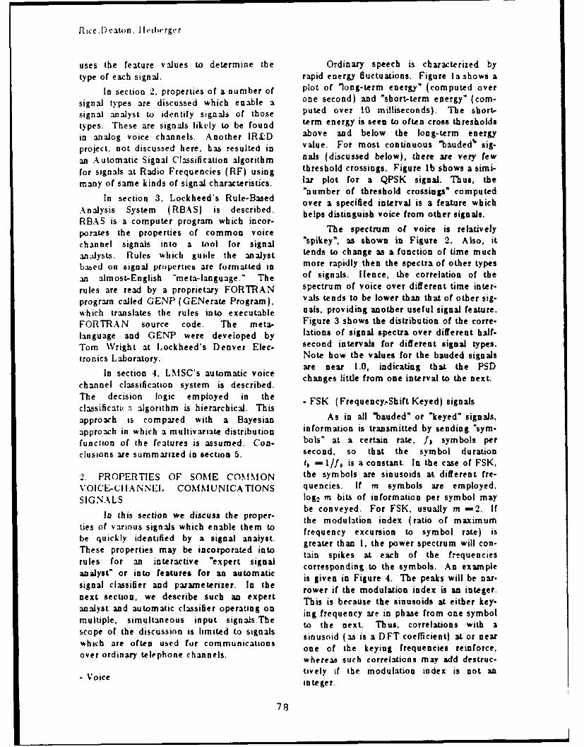
Ricc,Deatwn, I letcrgcr
uses the feature values to determine the Ordinary speech is characterized bytype of each signal. rapid energy fluctuations. Figure la shows a
In section 2, properties of a number of plot of long-term energy" (computed over
signal types are discussed which enable a one second) and "sbortterm energy" (com-signal analyst to identify signals of those puted over 10 milliseconds). The short-types. These are signals likely to be found term energy is seen to often cross thresholdsin anaog voice channels. Another IR D above and below the long-term energy
project. not discussed here, has resulted in value. For most continuous bauded ' sig-an Automatic Signal Classification algorithm nals (discussed below), there are very few
for signals at Radio Frequencies (RF) using threshold crossings. Figure lb shows a simi-
many of same kinds of signal characteristics. lar plot for a QPSK signal. Thus, the
In section 3, Lockheed's Rule-Based "number of threshold crossings" computedover a specified interval is a feature which
Analysis System (RBAS) is described, helps distinguish voice from other signals.RBAS is a computer program which incor-
porates the properties of common voice The spectrum of voice is relatively
channel signals into a tool for signal "spikey", as shown in Figure 2. Also, it
an dysts. Rules which guide the analyst tends to change as a function of time muchbabed on signal properties are formatted in more rapidly then the spectra of other types
an almost-English -meta-language." The of signals. Ifence, the correlation of the
rules are read by a proprietary FORTRAN spectrum of voice over different time inter-
program called GENP (GENerate Program), vals tends to be lower than that of other sig-which translates the rules into executable nals, providing another useful signal feature.FORTRAN source code. The meta- Figure 3 shows the distribution of the corre-language and GENT were developed by lations of signal spectra over different half-Tom Wright at Lockheed's Denver Elec- second intervals for different signal types.tronics Laboratory. Note how the values for the bauded signals
are near 1.0, indicating that the PSDIn section 4, LMSC's automatic voice changes little from one interval to the next.
channel classification system is described.
The decision logic employed in the - FSK (Frequency, Shift Keyed) signalsclassificati( n algorithm is hierarchical. Thisapproach as compared with a Bayesian As in all "bauded" or "keyed" signals,
approach in which a multivariate distribution information is transmitted by sending "sym-function of the features is assumed. Con- bols" at a certain rate, fj symbols perclusions are summarized in section 5. second, so that the symbol duration
= I /fl is a constant. In the case of FSK,'2. PROPERTIES OF SOME COMMON the symbols are sinusoids at different fre-VOICE-CIIANNEI. COMMUNICATIONS quencies. If m symbols are employed,SIGNALS log 2 m bits of information per symbol may
be conveyed. For FSK, usually m =2. IfIn this section we discuss the proper- the modulation index (ratio of maximum
ties of various signals which enable them to fee xcursion to ol rate)uibe quickly identified by a signal analyst. feunyecrint yblrt)ibhe quicklyetied bay e in ad anyt. greater than I, the power spectrum will con-These properties may be incorporated into ta spksaecho tefrqnis
rules for an interactive "expert signal corresponding to the symbols. An example
analyst" or into features for an automatic csrrisening to the pebos An ea -
signal classifier and parameterizer. In the is given in Figure 4. The peaks will be ar-rower if the modulation index is an integer.next section, we describe such an expert This is because the sinusoids at either key-
analyst and automatic classifier operating on i feue theinpsom one symultplesimutaneus nputsign~s.Te ig frequency are in phase from one symbol
multiple, simultaneous input signalsThe to the next. Thus, correlations with ascope of the discussion is limited to signals sinusoid (as is a DFT coefficient) at or nearwhich are often used for communications
one of the keying frequencies reinforce,whereas such correlations may add destruc-
- Voice tively if the modulation index is not aninteger.
78

Analysis of Communications Signals
Figure 5 shows the spectrum and the - MCVFT (Multi-Channel Voice-Frequencyspectrum of the square of a Minimum Shift Telegraphy)Keyed (MSK) signal, which may be Frequency-division multiplexing is aregarded as an FSK with modulation index well-established method for multiplexing5. Computing the spectra of signal powers multi-user digital data for simultaneous
using the analytic signal rather than the real transmission through a voice channel.signal prevents the appearance of spectral CCITT (in English, International Consulta.energy at certain other frequencies, which is tive Committee on Telegraphy anduseful since multiple spectral peaks can Telephony) Recommendations R.31, R.35,complicate analysis. When using the ana- R.36, and R.37 specify standards forlytic signal, the square of an FSK is another MCVFT modems. Signals in this generalFSK with twice the modulation index, class have very distinctive PSDs, with aThus, the square of an MSK is an FSK with "peak-valley" structure which distinguishesmodulation index 1, so its spectrum exhibits them from other signal types. Figure 10peaks separated by the symbol rate. If the shows the spectrum of an R.31 signal. Thespectra of the signal and its square are individual "sub-channels" or "canals" are on-presented as in Figures 5, with the spectrum off keyed (OOK), as can be seen from theof the square "compressed" by a factor of 2, "sonqram" of figure 11. R.35, R,36, andthe peaks in the spectrum of the square -line R.37 have low-rate FSK modulation in theup" under the actual keying frequencies in canals. Some MCVFTs can have low-ratethe plot of the spectrum of the signal. If PSK signals in the subchannels.the analysis system provides the capability ofmaking screen measurements using a cursor, - PSK (Phase-Shift-Keyed) Signalsthe analyst can estimate the locations of thepeaks in the spectra of the powers and These signals are generated by shiftingthereby obtain an estimate of the carrier and the phase of a co-stant amplitude carrier atsymbol rate. This technique of inspection of regular time intervals. Rapid phase shiftscymoprteed iseca e oors i n tic o are wide-band processes, but the signals are" co m p re ssed " sp e c tra o f p o w e rs o f a n a ly tic a d l m t . T h s e n r y i l o t t t esignals is quite helpful in analyzing several band-olmited. Thus, energy is lost a thetypes of signals, as will be illustrated below, symbol transitions, producing a temporary
drop in amplitude of the signal. Conse-Figure 6 shows the result of passing an quently, the signal envelope contains a
FSK signal through a frequency discrimina- periodic component at the symbol rate. Thistor. Figure 7 shows the frequency histo- phenomenon occurs in many bauded signals.gram of such a waveform (an MSK signal, It is manifested in the spectrum of thein this case). The output of a frequency envelope, as illustrated in Figure 12. Adiscriminator can be degraded by noise. symbol-rate component may also beFigure 8a gives an example. It may be pos- obtained by a delay-and-multiply of thesible to restore the two-level nature of the input signal, where the delay is a fraction ofwaveform by use of a median filter, which the symbol duration. This is the "chip raterejects isolated noise spikes (like a low-pass detector" commonly used for chip ratefilter) but maintains 'causal' rises or falls in recovery in spread spectrum systems.the signal level. Figure 8b shows the result Let us represent a PSK signal asof passing the (oversampled) waveform ofFigure 8a through 21-point median filter. ,(j). es(2" / t. #1) ,
One of the properties of MSK is that where the phase 0(t) "shifts" every Tits envelope is quite constant, like that of a seconds. For BPSK (Binary PSK) signals,sinusoid, much more so than amplitude- 1(t)- 0(t- T)=0 or r. Thus, 0(f)-00 ormodulated signals and even more so than +00 for some initial phase 00.phase modulated signals. And, like asinusoid, its histogram is "u-shaped", indi- The spectrum of a BPSK (and othercating that the MSK waveform spends most wSil and sp o lie a redof its time near ± I ,nd relatively little near bowl, while the spectrum of the square ofo l~gure9 cotais anexamle.the signal contains a spike at twice the car-
rier frequency. The spectrum of a BPSK sig-
79

llice. [) cDan. licilrrgcr
nal and its square are shown in Figures 13. If no randomizer is employed, theThe reason for this "spectral collapse" is modem in an idle state may alternate, at theclear from the equation symbol rate, between two phase states. The
l(2r2H+2E 0 ) spectrum of such a signal is likely to have a32({t Ce , I+2°J spectrum which resembles that of an FSK
since :2,o is either 0 or 27r, and s2(t) is .a signal. Inspection of the spectra of the
sinusoid at frequency 2f1. powers of the signal often reveal the true
Vestigial sideband signals (VSB) are nature of the signal. Figure 15 contaids the
BPSK or, more generally, ASK spectrum, the spectrum of the square, and
(Amplitude-Shift Keyed) signals in which the spectrum of the fourth power of such a
one of the two redundant sidebands has non-random QPSK signal. While the firsttwo spectra are atypical of a QPSK, the
been removed by filtering, except for a "ves- fo per reveal oda spe
tige" of the upper or lower sideband. fourth power reveals considerable spectral
(CCITT Group 2 facsimile signals are also collapsing at 4f, which should not occur in
VS13. These "analog fax" signals are easily an FSK signal.
identified from the End-of-Line dropouts One form of Differential QPSKwhich occur sixty times per second.) The (DQPSK) has 0(t) - 0(t- T) = ±ir/4 or
spectrum of I3PSK/VSB or ASK/VSB signals ± 3;r /4. Thus, 40(9)can take on any of eight
is very much like that of an ordinary PSK, phase values, 00 + k r/4, 0<k<7. But,
but the spectrum of the envelope does not the spectrum of the fourth power contains
contain a symbol-rate spike. The spectrum two spikes, centered at four times the carrier
of the square will contain a spike at 2f, and separated by twice the symbol rate. The
however. If the signal is basebanded with spectra of the first, second, and fourth
the recovered carrier, the missing sideband powers of a DQPSK (CCITT V.26b) is
reappears in the real part of the basebanded shown in Figure 16.signal. This is because of the shape of the This phenomenon can be explained byamplitude response of the VSB filter and the observing that (temporarily assuming thatfact that the spectrum of a rzal signal is h€=O) u(t)=s(1-T)e"', whereconjugate-symmetric. Thus, the spectrum 0 -(2k+1)7r/4, -2<k/<1. Thus,of the envelope (or square) of the real 84(t) =s( f- T)e" !-' (t- T). That is,basebanded signal will contain a symbol-rate s4(i) is a signal in "revs" (reversals), with
spike. period 2/T. It is a one-dimensional signal
For QPSK (Quadrature PSK) signals, and thus contains strong frequency com-o(t) - o( t- T) =0, ± r /-2, or Yr. Thus, ponents at ± 2/T. Reinserting a non-zerothe spectrum of the fourlh power of a QPSK carrier f , these components appear in thesignal contains a spike at four times the car- spectrum of 84( 1) at 4f, ± 2/T.rier frequency. The bpectra of a QPSK, its QPSK can be ideally represented bysquare, and fourth power are shown in Fig- the diagram in Figure 17, where, theoreti-ure 14. cally, a(t), b(t)=± 1, and they change to a
Certain PSK modems (MOdulator- new value at the same times, every TDEModulator) will revert to an "idle" state seconds, where fA =1/T. Offset QPSKwhile awaiting data. In this mode, a short (OQPSK), or Staggered QPSK (SQPSK), isrepetitive sequence is transmitted. Some- a modulation type in which the keying timestimes the repetitive pattern will be generated for a(t) and b(t) are offset by T/2 seconds.by a periodic "randomizer," or "scrambler." The spectrum of an OQPSK signal will lookIn this case, the spectrum will have a line like that of a QPSK signal, and, like astructure, where the lines are separated by QPSK, the spectrum of the fourth power1/(period of the sequence). The relative should contain a spike at 4f,. But, the
magnitudes of these spectral lines are spectrum of the square of an OQPSK will
obtained by multiplying spikes of equal contain spikes at 2f,± .5/, These will be
height by the spectrum of the signal in nor- somewhat weaker than those for an MSK
mal data transmission mode. signal. MSK and OQPSK are very similarmodulations (cf. 141), despite the fact thatOQPSK is regarded as a type of PSK,
80

Analysis of Communications Signals
whereas NISK is a kind of FSK. MSK may continuum of values because of noise, pulsebe obtained as an OQPSK with a raised shaping, band-limiting, intersymbol interfer-cosine pulse shaping. Often, a demodulator ence, and other distortions due to various
designed for one will also successfully channel effects. But, with proper process-demodulate the other. Also, in the spec- ing, if the noise and distortions are boundedtrum of the envelope of an OQPSK, the within limits (which vary according to QAMsecond harmonic of the symbol rate often type), the value of (a(t),b(9)) when I isappears as strongly as the symbol rate itself. near the center of the symbol interval isThis is discussed in more detail in the next close enough to the theoretical value of thesection. intended symbol to permit the demodulator
8-PSK signals can shift to any-of eight to correctly determine which symbol was
different phase states, transmitted during that interval.
0(t)- 0(t- T)=kir/4, 0<k<7. The As with PSK, for QAM signals theeighth power of an 8-PSK should exhibit a spectrum of the envelope or of the outputspectral collapse at 8fc, but often this spike of a delay-and-multiply process will containis qjuite weak and can be masked by noise. a symbol-rate spike. In general, it should beConsiderable integration may be required to possible to detect such a spike for any SNRdetect it reliably. Thus, 8-PSK signals are for which it is reasonable to continue theoften better identified by other methods. analysis. For example, the delay-and-This is especially true in voice-grade chan- multiply technique (the classical chip-ratenels, where the spectrum f the envelope is detector) is known to produce a recognizablelikely to reveal a symbol-rate spike at 1600 timing line for BPSKs and QPSKs withliz. Most other PRK (and QAM) signals negative SNRs. However, for signals withhave keying rates of 1200 or 2400 Hz. complex, multi-state constellations, the
'folding" techniques described above willQuadrature Amplitude Modulated (QAM) probably not produce any distinct features
signals which can be used to classify the signals,
The appearance of a symbol-rate spike although the fourth or eighth power of some
in the spectrum of the envelope or of the of these signals may contain detectable
output of a delay-and-multiply, together energy at 4f, or 8f, if long FFTs and con-
with a conclusion that the signal is not one siderable averaging are employed.
of the PSKs, indicates that the signal is a Noise presents fundamental limitationsQAM signal. QANIs may be represented as on our ability to determine the nature ofin Figure 17, where a(t) and b(t) may QAM (or other) signals. i:igures 19a andassume multiple values. If we define a 19b show three-dimensional plots of aQANI signal to be any signal modulated in CCITT V.29 constellation in which Gaussianthis way, then PSIK signals become a sub- clusters are placed about the constellationclass of the general class of QAM signals points to simulate the effect of additivedefined by the equation a2(t)+ b2 t) = white Gaussian noise at 20 dB SNR and 15constant. dB SNR, respectively. Even if the precise
In theory, for any given QAM modula- modulation type of the signal in Figure l9a
tion, the pairs (a(t),b(t)) take on only a is identified, the demodulated symbol
small number of possible values. The sequence would contain many errors. And,
values form the "constellation" of that QA N it would be useless to demodulate the signal
type. Some common constellations are of Figure lgb.
shown in Figure 18. A "symbol" consists of Other distortions besides noise, how-one of these pairs, and information is con- ever, have a greater impact on the difficultyveyed by the transitions from one symbol to of determining the constellation of a multi-another (in some PSKs, the symbol itself state QANI signal. The left half of Figureconveys the information, rather than the 20 shows a plot of the pairs (a(t),b(t)) attransition). Symbols are transmitted over times f in the middle of symbol intervals forspecified intervals of duration T, where, as a perfectly basebanded QAM signal with nobefore. lb =1IT is the symbol rate. In noise added, except that due to (12-bit)
practice, the pairs (a(t),b(t)) take on a quantization. The constellation is unrecog-
81

Rice,D eatun. lleiherger
nizable because of distortion due to QAM when the decision-directed equalizerbandlimiting, which produces intersymbol has converged. All of the original disper-interference. This signal demonstrates a sion in the consellations of Figure '20 waskeying spike in the spectrum of its due to channel distortion, not noise.envelope, but the spectra of the second, Sometimes the analysis of QAM sig-fourth, and eighth powers contain no nals can be facilitated if the modulation isidentifiable spikes. The signal may be unbalanced" (i. e., E(a 2(t)) 5E(,bh()enhanced by adjusting the taps of a transver- where E denotes expected value), as some-sal filter to minimize some error criterion, times occurs. The discussion in this case
under the assumption that so doing will also gives insight into the analysis of offsetinvert the channel response and result in a modulations, such as OQPSK.filter output with much less distortion. As observed above, the envelope of a
The most common adaptive filter used bauded signal contains useful information.for this purpose is the Godard Algorithm Digitally, this may be obtained by taking the[51, which minimizes the total amplitude Hilbert Transform of a signaldispersion of the signal. Figure 19b showsthe constellation of the signal at the output Z(t) =a(t)cos2rfct + b(t)sin2rfct
of a converged Gudard equalizer. The to obtainGodard algorithm has the advantage thatprecise carrier information is not necessary i( t)=- a(t)rin2rft +b(t)cos2ir fat,for the adaptive filter to converge, whereas whence z2(t)+ i
2(t)=a2 (t)+ b2(t). If,other techniques, such as the Benveniste- instead, we inspect z 2(t) separately, weGoursat III method, are more sensitive to obtainerror in the estimation of the carrier fre-quency. z 2 (t) = a2(t)cos(2x f, t) -b(t)sin 2(27r f, t)
Even for the Godard algorithm, accu- + 2a(t)b(t)cos(27rft)sin(27r ft)rate carrier recovery is required to actually =.5( 2(t) + b2 (t)) + .5(a 2(t)recognize the clusters in the constellation.If there is no carrier spike in the spectrum - b2(t).)cos(47rfat)of the fourth power or eighth power, thecenter of the "'inverted bowl" in the signalspectrum may be taken as a rough estimate The first term is, of course, theof the carrier. This estimate may be refined envelope squared. The third term hasby adjusting the estimate to "track" to an bandwidth approximately equal to the sumassumed four-phase constellation. This of the bandwidths of a(t) and b(t) (assum-technique is discussed further in tl,e next ing they are independent), centered at fre-section. quency 2fc It may cause a "hump" i, the
Once a QAN1 signal has been spectrum of y"(t), but no spikes.sufficiently equalized and basebanded, the The second term, however, has thesignal constellation may be recognized potentia for revealing information. Bothautomatically by phase- and amplitude- a2(t) and b2(t) contain frequency com-histogramming, or by clustering. Of course, ponents at the symbol rate fb Ifin interactive analysis mode, it may be E(a 2(t)) =E(b2(t)), then this term contri-identified by visual inspection. butes nothing to the spectrum. If, however,
At this point, the QAM demodulator the modulation is unbalanced, then thisswitches to "decision-directed" mode, in spectral component at the symbol rate "leakswhich the error signal used in adjusting the through." When it "mixes" with the sinusoidphase in the carrier-tracking loop and the cos(47rflt), the result is spectral lines attaps of the adaptive transversal equalizer is 2f,± fb in the spectrum of z 2(t). Thethe vector difference between the detected strength of these spikes is dependent on thephase and amplitude and the nearest con- amount of imbalance. Thus, estimates ofstellation point. Figure 21 shows the results both the symbol rate and the carrier areof the demodulation of a (noiseless) 16- available from the spectrum of the square.
82

Analysis of Communications Signals
The second term of the equation pro- The keying spike of a Class I partialvides information also in the case of "offset" response signal or quadrAture partialor "staggered" modulation types, such as response signals is at the center of the spec-OQPSK, in which symbol transitions in the trum. The histogram of a basebanded classtwo "arms" are offset by T/2, one-half of a I or class 4 partial response exhibits a "tri-symbol interval. This results in the symbol angular" structure (Figure 22), the number
rate components in a2(t) and b2(t) being of causal peaks depending on the number ofout of phase by T/2 seconds, or 180 amplitude states. Also, unlike almost'everydegrees. Thus, these components tend to other type of data communications signalcancel in the first term, a2(t)+ b1(t), and to except OOK, partial response signals have areinforce in the second term, again produc- valid state at amplitude 0. Thus, the signaling spectral lines at 2fz± f6. Note that if histogram tends to peak at the quantization
an offset-modulated signal is basebanded (i. level corresponding to amplitude 0, even ife., f/=-0). a strong symbol rate estimate is the carrier estimate is not accurate. Finally,obtained from computing the spectrum of the spectrum of the fourth power of a partialthe difference of the squares of the signal's response signal may contain a spike atreal and imaginary parts. 4f,+ b, as may be inferred from Mazo [61.
The observations above account forone of the principal recognition characteris- - Summary of signal properties
tics of offset modulations. Namely, when Many of the signal properties discussedthe signal is subjected to a non-linear pro- in this section are summarized in Figure 23.cess to produce a spectral symbol-rate line, Certainly, other types of signals may bethe spike of the second harmonic is as found in voice channels. Analog facsimile,strong or stronger than the one at the sym- various combinations of tones, pulsed sig-bol rate itself. Also, intuitively, the symbol nals, and others may also occur. The signaltransitions in such a signal occur at twice the types included here were chosen becauserate of the keying in each arm, so it is to be they represent a significant portion of theexpected that there will be a strong spike in challenges faced by a signal analyst attempt-the spectrum of envelope at twice the key- ing to interpret a sequence of digitized vol-ing rate. tage levels emanating from a typical voice
channel.
- Partial Response modulations
These modulations introduce deli- 3. RBAS - TE RULE-BASED ANALYSISberate intersymbol interference whi.'h can SYSTEMbe undone at the receiver, rather than Lockheed Missiles and Space Coin-minimize the intersymbol interference, as is pany, Inc., has developed an interactivedone in other modulation schemes. For a "Rule-Based Analysis System" (RBAS) forgood discussion, see 131. Like VSB signals, analyzing and parameterizing the types ofthese signals do not exhibit a keying spike in signals described in the previous section.the spectrum of the envelope or the output Analysis software has been integrated into aof a delay-and-multiply. Neither do they configuration-controlled package of VAX-exhibit a spike at 2f, in the spectrum of the FORTRAN programs called the Signalsquare, as do the VSBs. Class 4 partial Analysis and Simulation System (SASS).response signals are single sideband and RBAS may be regarded as a program whichusually insert the carrier at a recognizable gives expert advice on using SASS tolevel at one end of the signal band. The analyze a signal. SASS provides an analystspectrum itself is an inverted half-sine wave, with a considerable graphics capability (thewhich peaks somewhat more sharply than figures in this paper were produced usingthe spectrum of a PSK or QAI. After SASS). It is amenable to implementation inbasebanding, timing may be recovered by a compact Signal Analysis Workstation,passtug the signal through a sequence of which is currently being developed atrectifications and DC-not'h filters and then Lockheed.computing the spectrum, which should con- The architecture chosen for RBAS wastan a keying spike (cf. [71). that of an over-the-shoulder advisor for a
83!j

Rice.Deaton, Ilcaberger
user running SASS. Though RBAS is course, a desirable option for the analystincluded in SASS as a subsystem available might be to listen to the signal, if a digital-from the SASS menu, RBAS in its current to-analog converter, filter, amplifier, andform does not execute any SASS routines, speaker were available. Such a capabilityThis is left to the user.. RBAS, run on a could be easily implemented in software byseparate terminal from SASS (or a separate simply adding additional rules. If a signal iswindow of the same workstation), prompts not voiced, spectral, histogram, and otherthe user for answers to various questions plots are used to further classify the signalabout locations of spectral spikes, etc., and as FSK, PSK, QAM, etc. The structure ismakes recommendations about what next to quite general, so that the ability to handlerun to classify or parameterize the signal. It additional signal types may be included asalso gives instructions on how to execute soon as they are understood and rules arethe SASS programs. Its level of HELP is developed to classify and parameterize them.adjustable, so those users with greater skill Furthermore, all parts of RBAS interfaceget shorter HELP messages. Finally, based modularly. For example, if a signal is deter-on the results of the sequence of results mined to be QAM, the user has the oppor-from the various processing steps, RBAS tunity to perform QAM par " eterizationdraws conclusions about the signal type. and identification using a program called
RBAS is implemented as a set of AUTOPARM (AUTOmatic PARaMeter
almost-English rules that are translated by a estimation), a separate RBAS program
Lockheed-developed program GENP (GEN- developed under the same IR&D project.
crate Program) into an executable FOR- To aid in the parameterization andTRAN program. GENP accepts rules in a identification of a QAM signal, AUTO-form such as R14-NOISE = PARM initially guides the analyst inRI._LOW SNR AND. estimating signal parameters. To obtain aR16 FLAT SPECTRUM and produces rough estimate of the carrier frequency,FORTRAN code to evaluate each rule. several FFTs are computed and averaged toRBAS was developed using GENP rather approximate a smooth power spectrum. Thethan some conventional expert system carrier frequency is then estimated to be thelanguage because of the self-documenting location of the peak in the smoothed spec-characteristics of the rules, because the rules trum. This method generally provides anmay be easily changed, or deleted, or rear- estimate which is accurate to within about .5rangel, or supplemented, shortening percent, which is adequate to allow conver-development costs and increasing flexibility, gence of the process which follows. Next, abecause the program output by GENP is as coarse estimation of the symbol rate isfast as FORTRAN, and because it is compa- made. This is done by finding upper andtible with the signal processing software rou- lower frequencies about the estimated car-tines it may eventually call. rier frequency at which the signal PSD is
The major task on this IR&D project above a selectable threshold. Estimating thewas the development of rules to classify sig- symbol rate more precisely is accomplished
nals in voice channels. These rules urge the by computing the spectrum of the envelope
user to look at certain measures of the sig- of the signal and searching for peaks in the
nal, such as the spectrum, the histogram, vicinity of the initial, coarse estimate.the short-term versus long-term energy Next, AUTOPARM subjects the signalcomparison, etc., and to determine the sig- to the Godard blind equalization algorithmnal class from the encoded analytic rules. and to carrier tracking and symbol-rateThe decision tree used in shown in Figure tracking loops, to refine the carrier and24. First, rules to check the quality of the symbol-rate estimates and to determine thedata (SNR, clipping or insufficient use of precise QAM constellation. The carrierdigitizer dynamic range, etc.) are applied, tracking loop works by adjusting the phaseand the user is given the chance to filter the of the received signal to minimize thesignal. The signal is tlen checked to see if mean-squared Euclidean distance to a four-it is VOICE by inspecting the graph of phase constellation. It has worked for car-short-term versus long-term energy. Of rier offsets as large as 100 Ha. Once the
84

Analysis of Communications Signals
blind equalizer and the tracking loops have stream analysis capability, with programs toconverged, a phase amplitude plot readily determine and strip linear randomizers,
reveals the constellation, just as in Figure recover linear recursions, detect known pat-20. terns, determine parity check schemes, find
Detecting the constellation can also be frame lengths, and perform other functions
done automatically. Once the equalizer and which are useful in bitstream analysis.
carrier and symbol-rate trackers have con- These have not been incorporated in RBAS.
verged, it remains to cluster the detected At present, the analyst applies RBAS as
phase-amplitude points into a constellation, described above, to help in obtaining the
A number of clustering algorithms are avail- bitstream for further analysis using the
able for this purpose. The detected constel- Bitstream Analysis Subsystem of SASS.lation may then be compared with those in a
data base (this feature is not implemented at 4. LOCKHEED'S AUTOMATIC SIGNALthis time). If a match is found, demodula- ANALYSIS SYSTEMtion can proceed using the SASS QANI As part of the Lockheed IR&D pro-
demodulator in decision-directed mode with gram in signal analysis, a system wasthe selected constellation and its associated developed to perform automatic signalsymbols-to-bits conversion scheme. If there classification on multiple simultaneous chan-is no match, the QANI demodulation algo- nels. The signal classification function per-rithm utilizes the recovered constellation formed is at a somewhat higher level thanand produces a demodulated symbol stream that described in the previous section. Sig-for further analysis. nals are grouped into the categories (1)
While the current implementation of VOICE, (2) FSK, (3) PSK (including PSK,RBAS requires inputs and judgements from QAM, and Partial Response), (4) MCVFT,
an analyst, it is clear that these judgements (5)NOISE, and (6) UNKNOWN. No
could be made automatically. A peak detec- parameter estimates are reported in thetion routine would be required to estimate current version. A block diagram of this
symbol-rate spikes and carrier spikes, for signal classification algorithm is given in Fig-
example. In general, GENP is suitable for ure 25.
implementing a hierarchical decision tree The generally accepted approach toand calling routines to provide the answers automatic signal classification is to computerequired to descend the tree. (GENP has a set of n signal "features" which "separate"been used in precisely this way on another from one another the different signal typesLockheed IR&D project, on which an to be categorized. These features are usuallyautomatic signal classification algorithm for taken from signal "measures', which areRF signals was developed). It should be often more costly to compute. For example,noted that RBAS is not quite an expert sys- the input signal's power spectral densitytem according to the commonly accepted (PSD) estimated using FFT's, may be adefinition of the term, since it does not pro- (costly) measure, while the "percent ft- f2vide any traceaLility features to Allow a bandwidth" - the percentage of total signalreconstruction of the path taken through the energy between frequencies f I and /2 - maytree to arrive at the conclusion. But, it mar- be a useful signal feature computed fromries easily with FOR,TRAN subroutines and the PSD bins. As a further illustration, Fig-results in correct, efficient code. Incorpora- ure 26 shows the distributions by class of ation of new rules, modification of existing feature which we have termed the "auto-rules, and rearrangements of the order in correlation lag ratio" (which was suggested,which rules are executed are accomplished implemented, and tested by a colleague,by editing the rule file and creating a new George Burgess). It is computed by corre-FORTRAN program using GENP. lating the PSD coefficients offset by about
The final step in the analysis process 30 lit. Notice how the feature values for
is, perhaps, the largest. This is to demodu- NICVFT (R.31, R.35, R.36, R.37) signals
late the bignad to the hit level and an:lyze are markedly less than those for other
the bits. SASS contains such demodulation bauded signals. An initial feature set was
capabilities, and it also has a substantial bit selected by inspecting a large number of
85

Rice.Deawn, llcilerger
graphic outputs using as inputs signals from give the right classification decision but aeach class with a variety of parameters. The meaningless FOM. We discuss this furthersignals were subjected to additive white below.Gaussian noise at several signal-to-noise In the Bayesian approach, a likelihoodratios (SNR's) and to channel filters which ratio test determines the most likely signalprovided three levels of amplitude and class. Using Bayes' rule,group-delay distortion. Features whose dis-tributions were overly sensitive to these' p,p ( clas i/features)degradations were rejected. p( f eatureo/closs ilp(clase i)
Features were displayed using one -p(feaure#/clau j)p( c1a8 j)dimensional displays like Figure 26and two Idimensional "scatter plots," as in Figure 27. where p denotes a probability density func-For each class, three or fewer features were tion. Thus, if the joint density functions ofsufficient to separate a given class of signals the features and the a priori probabilities offrom the others. The separation using three the signal classes are known, then the max-features f 1,f2, and f1 could be displayed imum likelihood decision for the decisionwith three scarier plo.s, showing the distri- class is the one which gives the largest valueImtiois of each pair of realureb. When a bet of p,. In addition, the value of p, provides aof features was chosen, the separation of the ready-made FOM. The ratio of the largestsignal classes was confirmed stat tically p, to the next largest provides a measure ofusing various clustering programs from the confidence in the decision. Usually, forINISL software package. Usually, n, the computational reasons, log-probabilities arenumber of features, should be as small as used, so that multiplications and divisionspossible, for two reasons. First, computing are replaced by additions and subtractions.the features uses system resources, and If Gaussian probability density functions aresecond, decisions must be made based on assumed, the log-probability ratios may bethe set of computed signal features. In gen- computed without taking exponentials. Also,eral, the fewer the features, the simpler the if feature values computed over disjointdecision logic. This is particularly important time intervals may be regarded as indepen-when each feature is employed in each deci- dent, then the log-probabilites log p, may besion, as in the case of Bayesian decision added to form an accumulated FOM. Thus,logic. if the evidence in favor of any class is
We have opted for a hierarchical deci- insufficient (i.e., log p, is too small in rein.sion logic. Paths through the decision tree tion to the nearest competitor), the decisionare taken based on the relationships of may be deferred and another set of featuresfeatures to empirically determined threshold computed.values. Features not needed on a certain As attractive as this approach appearspath need not be computed, unless deciding at first, there are several difficulties. First,whether to compute a feature is as expen- the a priori probabilities must be known.sive as actually computing it. This can often Usually, they are assumed to be equal, buthappen when using array processors for this assumption is probably incorrect forexample, since computational tasks may be most real environments. These can beperformed more efficiently than logical ones. refined by accumulating channel statistics,The Figure of Merit (FOM) is based on the and the Lockheed system has that capability."closest" decision. If a feature value barely But, this means that the rarer, moreexceeds a threshold value, the FOM is lower interesting signal types, may be less likely tothan if the feature value clearly exceeds the be declared when they occur. This difficultythreshold. Thus, the FONI may be inter- is eliminated in the hierarchical approach bypreted as an indicator of the confidence on attempting to classify the most likely signalsthe decision, but it should not be interpreted first. Precise a priori probabilities are notas a "confidence" in any theoretical proba- necessary, only a rough order of frequencybilistic sense. This choice was made because of occurrence and/or priority.algorithms which provide a FOM which is a"probability of correct decision" may in fact
86

Analysis of Communications Signals
Second, the distributions or critical, depending on the application.p(featurcs/class=i) must be known for The fifth and perhaps the most subtleeach class. They can be computed using of the difficulties with the Bayesian approachempirical data and stored, but this requires a is that the distribution of feature values forconsiderable amount of storage, and care an incoming signal may be different frommust be taken or it can also be unreliable. those of the overall class to which that sig-Slight variations in computed feature values nal belongs. In particular, the assunptionfrom those used to "train" the system can that the feature values are independent overresult in the features falling in sparsely disjoint time windows may be accurate forpopulated bins, thereby producing low the signal itself but highly inaccurate for thevalues of logp, for the correct class. Usu- overall class to which the signal belongs.ally, the distribution is assumed to be mul- Again, the hierarchical approach is affectedtivariate Gaussian and parameterized. This little by perturbations in the feature distribu-assumption can be quite incorrect, depend- tions such as this. An additional advantageing on the features employed, and can lead to the hierarchical approach is that it can beto meaningless paraneters for the distribu- implemented using GENP. This was nothil Ily simply .'.....p..ring f,.atire vthles t,, done in the system under discussion here,tlhrcsholds as in the hicrarchical approach, but, as mentioned earlier, it was done onalgorithm performance is relatively insensi- another [R&D project which developed antive to the precise form of the distribution, automatic classification program for RF sig-
Third, as mentioned above, it is desir- nals. In that algorithm, incidentally, theable to minimize the number of features. ability to compute features only whenThis can be done statistically from a larger needed provided a very significant computa.feature set (cf. 121), but then the reduced tional advantage.set of features may lose their "heuristic" Still, in spite of these objections, avalue in that it may no longer be possible to Bayesian classifier can produce excellentinterpret a given feature as capturing some results (i.e., accurate classification deci-salient characteristic of some signal class. If sions). And, it has the huge advantage thata new signal class is added, the reduced the system can be easily "trained" for eachfeature set may or may not provide adequate signal class to obtain the distributionsseparation of the signal classes. The chances needed to compute the values log p,. Thethat it will are less for a "reduced" feature choice of which approach to take - Bayesianset. By using a larger feature set as in the or hierarchical - ultimately depends on thehierarchical algorithm, there is a greater particular application.likelihood that a new signal class may beaccommodated without modifications to the - Lockheed's Voice Channel Process-feature set, but rather by additions to the ing Module (VCPM)decision logic.
Lockheed's automatic voice channelfeatures must be computed to compute signal analysis system consists of six major
featurestsmuste begcomputed atFrcomputelog p,, even if the signal being analyzed may components (see Figure 28) a Frequency-
be categorized on the basis of only a few Division Multiplexed (FDM) demultiplexer,
features. This may not be serious, since the a voice-grade-channel distribution (VGCD)
principal computational cost is incurred in system, a continuous channel processor
obtaining the measures, as mentioned (CCP), classification algorithms, a card cage
above, (e.g. FFT or instantaneous fre- controller (CCC), and a station controller
quency) not the features (e.g., ratio of sums (SC). The FDM demultiplexer is a trans-
of some FFT bins). However, if unneces- multiplexer" which separates input FDMsary measures are computed, then the extra basebands into individual four-kilohertz
computation can be significant. This prob- channels an re-multiplexed into TDM
lem can be avoided in a hierarchical algo- (Time-Division Multiplexed) channels. The
rithm, since features (and measures) need TDM channels are passed to the VGCD sys-
only be computed as needed, as mentioned tem, which puts them on a high-speed dis-
earlier. This advantage can be insignificant tribution bus, to make the data available to
87
; m mira u w =

RiceDeawtn, Ileiberger
other processing units. The CCP selects is added to the FDM baseband at the inputvoice channels from the high-speed distribu- to the FDNM demultiplexer in a channeltion bus and acts as a front-end processor to known to be a guard band or an inactivethe classification algorithms. The channel. The i.ut baseband is demulti-classification algorithms receive the channel plexed, and the test tone data is passeddata from the CCP and perform a "coarse" through the syst~m and monitored by theclassification as to whether the signal is algorithms. This test serves as an overallvoice, noise, or some other type of corn- system health test. In the second diagnostic,munication signal. They perform a more psuedo-random bit patterns are taken fromdetailed "fine" signal classification on a the test pattern generator when data areselected subset of the channels. unavailable from a demultiplexer. The pat-Classification decisions, FONIs, and other terns are passed through the TDM multi-information are passed to the station con- plexer units and monitored by a test patterntroller, which logs the data to disk files for receiver uniL. The test pattern receiver unitpost processing and to displays for real-time monitors the test data on a bit-by-bit com-anal) -is. parison basis and flags errors to the con-
The FDM demultiplexer, the VGCD troller. In addition to these two tests, each,ytem, and the CCP are implemented in unit within the VGCD generates parity bitshardware and reside in two card cages. The and checks blocks of data to see that thehardware is controlled over a high-speed appropriate parity checks are satisfied.VNIE bus by a CCC. The algorithms areimplemented in software which resides in - Continuous Channel Pror,!.-snr Hardwaretwo high-speed array processors. A given The continu.;ous channel processorchannel can be selected for fine classification (CCP) hardware selects the 300 FDM-in either processor. lligh-level hardv ire a-I demultiplexed channels from the VGCDalgorithm control is obtained through a sta- bus. It then heterodynes the channelstion controller, which is implemented on a upward in frequency by 2000 Hz from theirgeneral purpose computer. initial frequency band between -2000 and
+ 2000 Hz to the band 0 - 4000 Hz. The- FDM Demultiplexer di a are then transformed using a 40-point
The FDNI demultiplexer demultiplexes Winograd-Fourier Transform (WFT), imple-150 channels from a 150-channel input mented in hardware. An integer-to-floatingFDNI baseband or 300 channels from either point conversion is performed, and the CCPa 300 or 600 channel input FDM baseband. then passes both the temporal and spectralThe 300 channels to demultiplex within the data to the array processors for signal600 channel baseband are selected through a classification.digital sub-band tuner within the demulti-plexer. The FDNI demultiplexer accounts - Classification Algorithmsfor differences in sampling rates by interpo- The classification algorithms in thelating the input samples to an internal sam- array processors can be broken into two dis-pling rate. This flexibility within the FD N tinct algorithms . the coarse classifier (CC)demultiplexer is accomplished by download- and the fine classifier (FC). The algorithmsing parameters from the controller. are controlled within the array processor by
algorithm control software which accumu-- Voice Grade Channel Distribution System lates the algorithm decisions and related
The voice grade channel distribution information and communicates the decisions(VGCD) system accepts output from up to to the station controller.eight demultiplexers and time division mul- The CC is the first algorithm to exam-tiplexes the data onto a high speed distibu- ine the spectral channel data received fromtion bus. Only one FDNI demultiplexer is the continuous channel processor and iscurrently implemented. The VGCD con- responsible for activity recognition, high-trols three diagnostics for on-line status level classification of the signal type, andmonitoring. In the first diagnostic, a test pat- signal-to-noise ratio (SNR) estimation ontern generator unit outputs a test tone which 300 channels. The CC algorithm performs
88 3

Analysis of Communications Signals
classification of signals as VOICE, NOISE, from the station controller. The CCC also
or OT1ER gnd returns its decision to the monitors the hardware for error conditionsstation controller every ten seconds. Along and flags the error conditions to the stationwith the classification decision, the algo- controller as detected.rithm returns a classification figure-of-merit(FOM) and an SNR estimate accurate to * 5. CONCLUSIONS1 dB. Consecutive noise decisions are used The vast majority of signals ito declare channel inactivity. channels may be automatically classified by
The fine classifier (FC) examines up to computing signal "features" which capturefifty channels of ter'tporal data received salient characteristics of the possible signalfrom the continuous channel hardware and type5 and by performing some form of clus-separates input signals into six categories : ter analysis on the detected features.VOICE, FSK, NICVFT, PSK/QANI/PR, Lockheed Missiles and Space Company, Inc.NOISE, or UNKNOWN. The fine classifier has developed a system for automaticreturns the classification decision and a analysis of multiple input signals using theseclassification FOM to the station controller principles.every 10 seconds. Interactive signal analysis involves use
System Control of a combination of visual graphic aids andparameter measurements. It can be facili-
The station controller (SC) functions tated by Lockheed's Rule-Based Analysisas the operator interface to the VCPM sys- System (RBAS), which guides an analysttem. The station controller is responsible a through the analysis of an input signal bynumber of functions, including high level means of a sequence of ouestions and con-control and status of the hardware and algo- clusions drawn from the answers to thoserithms, display of algorithm classification questions. Such a signal analysis "expert"decisions on tasked channels, maintenance can operate at one of several skill levels,of system tasking logs and algorithm deci- with the system providing more or less helpsion logs, and generation of processing his- to the analyst, as needed, Varying levels oftory and analysis reports. automation to the analysis process are possi-
VCPNI system control is accomplished ble also.principally through a VAXstation 100attached to a VAX 8200. Three other displaydevices allow the operator to monitor sys-tem status : the hardware status display, thealgorithm status display, and the algorithmgraphics display. The hardware stat',s displayis a SUN 2/160 color monitor attached tothe card cage controller. The algorithmstatus display is a VT220 terminal attachedto the VAX 8200, and the algorithm graph-ics display is a color monitor attached to asecond SUN 2/160. A future version of thesystem has been planned in which all ofthese functions will be available in singledisplay device.
The card cage controller (CCC) isresponsible for low-level control and statusof the FDM demultiplexer, the voice gradechannel distribution, tie TI trunk interface,and the continuous channel processorhardware The CCC downloads configurationparameters to the hmrJare in response toconfiguration tasking commands received
89

Rice,Dcaton, Ileiberger
5. References
III Albert Benveniste and Maurice Gour-sat, "Blind Equalizers," IEEE Transac-tions on Communications, Vol. COM-32, No. 8, August 1984, pp. 871-883.
[21 Richard 0. Duda and Peter E. Hart,Pattern Classification and SceneAnalysis, John Wiley and Sons, Inc.,New York, 1973, pp. 429-458.
(31 Kamilo Feher, Advanced Digital Com-munications, Prentice Hall, Inc., Engle-wood Cliffs, N. J., 1973, pp. 114-121.
141 K. Feher and B. Morais, "BandwidthEfficiency and Probability of Error Per-formance of MSK and Offset QPSKSystems," IEEE Transactions on Com.munications. Vol. CONI-27, No. 12,December 1979, pp. 1794-1801.
151 Dominique N. Godard, "Self-Recovering Equalization and CarrierTracking in Two-Dimensional DataCommunications Systems," IEEE Tran-sactions on Communications, Vol.COM-28, No. 11, November 1980, pp.
1867-1875.
[61 J. E. Mazo, "Jitter Comparison ofTones Generated by Squaring and byFourth Power Circuits," The Bell Sys-tem Techniral Journal, Vol. 57, No. 5,Nay-.iune 1978, pp. 1189-1199.
171 J. D. Olson, "A Technique of PCMTransmission over 2 Gllz MicrowaveRadio," IEEE Transactions on Cornmun-ications. Vol. CONI-23, No. 9, Sep-tember 1975, pp. 1004-1007.
90

Aaalysis of Comrunications Signals
00o S'0.00 100.00 1,50.00 2bo. Go 250.00 300.0o 3,50.00 4,o0.00 4o.0o 5,00.00
C! Figure Ia. Short-term versus l0ong-term energy - voice
E W!
a
a
00 25.00 s0.00 1.UO UU. 00 125.00 3,0.o00 5.00 260.00 25.00 50.Cc
Figure lb. Short-term versus long-term energy - QPSK
J0 2501 50.0 C 5.U IUU0E300 125.00 2SO-.10 415003 211000 400
F R E , r, .. . .. . . .. . . ...1 3
0' 0 0O; , 00C C 0 2C000 50.0 30. 2 50 . 0 40 0. CC
i ir ure 2. Power vpectrum of a voice signal.
91.
,0

Rice, Deaton, ilciberger
-0 16 0.oCU 3.17 z.3 0.50 0.6" 0.83 1.00
... •, " • -.. . .,-
".v . .. , :e:. ~~~~............. .:. .. .. :.. .... .
MCFSs . .<. "
Figure 3. Correlation of spectra over independent time intervals.
C 5INAL P3-ER IN 08
, I I
.g r c L ;Go. Cr :rs. : 200.00 50.C o 3oo. , 25o.0o 400.00FAIE~uFNC T -10
Figure 4. Power spectrum of FSK with integer modulation index.
SIGNAL POWER IN dB
S-2
00 Soo 1000 1500 2000 2500 1000 3S00 4000
FREQUENCY (Hz)SIGNAL xx2 POWER IN dB
cc - - .)
-50 ..0 1000 2000 3000 4000 5000 6000 7000 $000
FREQUENCY (11)
Figure 5. Spectra of NISK signal and its square.
92

Analysis of Communications Signals
Figure 6. FM-discriminated FSK signal.
FEGUENCT HISTOGRAM
C I
• ilt
-80 SO 70 IL.i 20 S S 00.40 j50.30 300.20 350.10 400.0
FREGuENCT -10
Figure 7 Frequency histogram of MSK signal.
Figure 8a. Demodulated FSK, SNR = 10.7 dB.
rL 00.: I
Sigure 81) Waveform Of 8a after applying 21-point median filter.
93

Rice, I)eawn, ileiberger
is al. I a SS 0l
Q4aAN t IATION LEVIL
Figure 9. U-shaped histogram of MSK signal.
0
uj
0
60,
0 so 100 so 200 250 300 350 4D0
FREWIJENCY (Hi| x 10
Figure 10. Spectrum of R.31 NICVFT.
94

Analysis of Communications Signals
IL
I -p
Idl
-
Figure 11. Sonogramn or R-31, showing the 24 80-baud 00K telegraphysubch3nnels.
S9ICTRUM OF SICNA% [N E OPE
Figure 12. Spectrum or envelope of PSK signal.
1 95

lice, DeaLwn, ileiberger
o SIGNAL POWER IN 00
6 ~~ -- -... r - -- - rr - -- - -
0 I ~ .V', ' "T;V_I I I
- r - - -- r -. - - - ---- r--- - l
SI I I v
0.00 50.00 o.00 S o0.00 200 00 ?so.00 300.00 3SO.00 40O. r,FREQUENCY 10"
0 SIGNAL-2 POWER IN 08
" r - ~r - - - - -
ILJ
00
0. 00 60.00 260. 3'0.000 G 0o oo 61n.oo 7o.o 0 o.FREOIJENCT T 10
Figure 13. Spectra of BPSK signal and its square.
- I
3. L 0.J0 i 0.0 : CC 3 240.00 ?00. 00 360.00 4,20.00 -80.00F8E~uErjClr -10
e1 5iGNAL-2. PO-ER :N 08
a II
a-.
8 JO p0 . 00 2 0 'a, 3 = 00I IC
-. ":N .. .. - " ,p
00
-- " ,, A..A"
:- ,, .. ,";~
Figure 14. Spectra of OPSK signal, its square, and its fourth power.
96

Aaalysts of Communications Signals
SIGNAL POWER IN dB
0
'16.2k f1WIWWU
0 60 120 180 2.0 300 360 '420 48.3
FREQUENCY x 101
..... -/ J SIGNAL xx2 POWER IN dIo
0 12 24 J6 Ais 60 72 84 96FREQUENCY K102
0--
SIGNAL xxii POWER IN d
"-28. 85
-57.69 "--'S 24 48 72 96 120 172 16B 192
FREQUENCY x 102
Figure 15. Spectra of powers of a non-random QPSK.
0
I
-I.6
0I4 4 2 3 2 4 6 9
FRQECI

R~ice, Deaton, lleiberger
CL
°~
.o ,o00 10.00 160.00 2 C C. ?00.00 360.00 420.00 480.00FREOuEhZ" iD0
S SICNPL--2 POWER IN 08
ap
X
C.0O ;,.0 .0 630 -0.O0 72.00 84.0 96.00
FREQuE;JC l 0
SICNAL-4 POWE. IN 08
LA4J
:.oo 4.00 48.00 72 3o 96.00 20.00 1 4.0Z 168.00 :92.00FEZuENCT ,10
Figure 16. Spectra of powers of a CCITT V.26b signal.
Cos 2rti
S(11 ' Ih=3(1) Cos 2Fy€ - 16=) SINarytC
,(Flo (S (0 ( 0) , 3). 9 f,
or Ics
Figure 17. Model for generation or two.dimensional signals.
98

A0alYsiS Of Communications Signals
* . 4.
Figre 8.Varou PS ad QNIcontelaton. From tolf* orgt
BPSK, PSQ K 8-PSK, V.29b, 8-PSK (two amplitudes), 16&PSK,
Figure 19a. 3-dimensional histogram or v.29 at 20 dB SNR.
.7.~
Z -W,//
N
Figure l~b. 3-dimensional bistogram of V.29 at 15 dB SNR.
99

Rice, Deaton, li,.berger
J ..
Figure 20. Amplitude-phase Plots of a QAM signal
ilefore-and-after Godard blind equalization... * .... .... .. .N .*
.- ' O
200 L~ ~OUTPUT OFTIA + TRACKER1 -I
two 00 625.00 650 00 675.00 700.00TiME (TENS OF SYM8OLSI
-1620
- ~ Iiuuu _OUTPUT OF
z CARRILK TRACKER
a10 71O0_ _ _wo0 00 625 00 bQs 00 6i 00 700 00
__-____ TIME TEI, uF SYMBOLS)
- 20
'40ou0 00 625 00 650 00 675 00 700.00
TIME (TENS Of SYMBOLSi
CONSTELLATION
• 0°
Fivire :21 Demdilaled I1;-QANI using a decision-directed equalizer.
100

Analysis of Communications Signals
Figure&T m LV| ** 1 )2 2)
Figure 22. "'riangular" histogram or a basebanded duobinary signal.
..IO.,aIT~rS OF Slicu.$~I' • 4M- vGCe VOlcId NCVPT S S A s P51 PS.IV $S16 Q Oss OP1K OPS K O-PS t CAN I-OuOfSSe DUO/iOp A-Ax
e~eoe06~lo t~ e yes
.o.Ctro, StraOe SOI.y P*5et 2 PA*.. .00 *1. 1og C.0
.*Vfl SVc~S a Sof o.Io*o *Iloolsy * ..,rg .soy y. 'Its p. , ian . .. y.# 2.$W yea pes yt 0 a0
08o 5-02 "0 ea
at .I . 1%0r
1 I 90 p.a yl sell 203 et
*pIk;I AS On PSn
2 CSr, I*€
eP 60,SI.. . %,*' l
Figurei 23 .0 DOSm loly caritic o vars s pesiblp0 data Ip @.*rI * .1*r r
t
* g4
o *a" .. - C5 ... .......
I"52i2'4'4 2-I.t *a00 QSS.Shll Ot
€ • +ol-+ yCO"S I h
Figure 23. Summary or' characteristics or various signal types.
SIGNAL CLASSICAZON
All signals
Radar Communzca ion Ober
Wide-band
AM FM PM
PartizlVoice C-FSK N% SK Htspon.m ,Al tLbr
I ". '\
R31 R35 R36 R37 16 32 64 ...
Figure 24. RBAS decision tree.
.01

Ili1ce, lDeatoc, lleibergcr
.SPS C~MVIG. time Remain t.
:56 ot t :[!STANTANEU
WINDOW AND FFTFRQEC
SNI FEATUJRE FSO 30 MI VARIANCE ABOUTf5' U) ALITOCCRRELAT ION 0 00 UPPER AmO LOWER
(RATIO 0( BIN SUtIS) FEATUREY
AVERAGE CECISION REPORTED DECISIONArD TRANSITION
iIATRix
Figure 25. Block diagram of the "Fine Classifier."
0.02 0.15 0.29 0.43 0.56 0.70 0.83 0-97
I I
SCFSK
MCFSK
PSK
FAX ..
NOISE
Figure 26. PSD Autocorrelation Lag Ratio.
0. 4I
0.33
wi 5
uJI
0.11 NARROW BAND FSK
X WIDE BAND PSK
0 0 0 17 0 35 5 2 0.69 0 87 1O04 1.21 1.39
FEATURE 2
Figure 27. Two-dimensional scatter plot, showing the extentto which two reatures separate signal classes.
102

i Analysis of Communications Signals
II
I Ftf1 vOICE GRACE CONTINUOUS
DEI J31PLEXER CHAUMI. DSiST IO HANIEL PROCESSOR
FDMfi i
DATA
CARD CADE CLASSIFICAT ONI COW, .E ALW Ri WI
CONTRO . LER
I
I Figure 28. Lockheed's Voice Cbannel Processing Module.
IIIIIIII3 103
I

CL >
0 x
EE0
da E06 -0 co
U-C 0C0*>r
=) CUcl-'.0
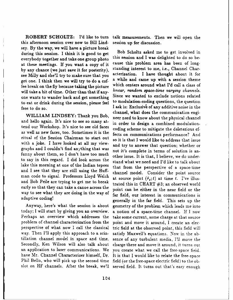
ROBERT SCHOLTZ: I'd like to turn talk measurements. Then we will open thethis afternoon session over now to Bill Lind- session up for discussion.sey. By the way, we will have a picture breakduring this session. I think it is good to get Bob Scholtz asked me to get involved ineverybody together and take one group photo this session and I was delighted to do so be-at these meetings. If you want a copy of it cause this problem area has been of long-by any chance (we just save it for posterity), standing interest to me, i.e., Channel Char-see Milly and she'll try to make sure that you acterization. I have thought about it forget one. I think then we will try to do a cof- a while and came up with a session themefee break on the fly because taking the picture which centers around what I'd call a class ofwill take a bit of time. Other than that if any- linear, random space-time varying channels.one wants to wander back and get something Since we wanted to exclude notions relatedto eat or drink during the session, please feel to modulation-coding questions, the questionfree to do so. I ask is: Exclusive of any additive noise in the
channel, what does the communication engi-WILLIAM LINDSEY: Thank you Bob, neer need to know about the physical channel
and hello again. It's nice to see so many at- in order to design a combined modulation-tend our Workshop. It's nice to see old faces coding scheme to mitigate the deleterious ef-as well as new faces, too. Sometimes it is the fects on communications performance? Andritual of the Session Chairman to start out so it is that I would like to address that issuewith a joke. I have looked at all my view- and try to answer that question; whether orgraphs and I couldn't find anything that was not it's complete in terms of solution is an-funny about them, so I don't have too much other issue. It is that, I believe, we do under-to say in this regard. I did look across the stand what we need and I'd like to talk aboutlake this morning at one of the Indian tepees that from the perspective of a space-timeand I see that they are still using the Huff- channel model. Consider the point sourceman code to signal. Professors Lloyd Welch at source point (f,; t) at time t. I've illus-and Bob Peile are trying to get me to break trated this in CHART #3; an observed worldearly so that they can take a canoe across the point can be either in the near field or theway to see what they are doing in the way of far field, our interest in communications isadaptive coding! generally in the far field. This sets up the
Anyway, here's what the session is about geometry of the problem which leads me intotoday; I will start by giving you an overview, a notion of a space-time channel. If I nowPerhaps an overview which addresses the take some current, some charge at that sourceproblem of channel characterization from the point and move it around, I create an elec-perspective of what now I call the classical tric field at the observed point, this field willway. Then I'll apply this approach to a scin- satisfy Maxwell's equations. Now in the ab-tillation channel model in space and time. sence of any turbulent media, I'll move theSecondly, Ken Wilson will also talk about charge there and move it around, it turns outan application to laser communications. We you create what we call the free-space field.have Mr. Channel Characterizer himself, Dr. It is that I would like to relate the free-spacePhil Bello, who will pick up the second time field (or the free-space electric field) to the ob-slot on HF channels. After the break, we'll served field. It turns out that's easy enough
104

s~t) so (t)s(t) /Channel. S()
- ( Characterization
s~t) s (t)
" Bill Lindsey : Overview: Space-Time ChannelsScintillation Chnnels
* Phil Bello HF Channels
• Ken Wilson : Optical Channels
• Break for group photograph
" Paul Sass Wideband Channel MeasurementExperience
* Allan Schneider Delay Spread Estimation forTime-Invariant Random Media
CHART l1
SESSION THEME: CONSIDER THE CLASS OFLINEARANDOM. SPACE-TIME VARYINGCHANNELS
QUESTION: Exclusive of the additive noise, what does aCommunications Engineer need to know about thechannel in order to design combined modulationcoding schemes to mitigate deleterious channeleffects on bit error probability?
CHART 02
105

Illustrating the Geometry Between the Source andObserved World-Point
01BSERVEDWORLD-.POINT
SOURCE +WORLD-POINT r( r;t)
Y x
z
CHART 03
Space-Time Field Concepts and Geometry
CHART 4
106

to do using Maxwell's equations. And when ing from the transformation of the time vari-you play with them a little bit and write them able. We can see that it is related to thein their integral form, you can actually show velocity of the medium and hence should bethat everything we see in the real world is kept track of if it is, you want to try to tiethrough a space-time filter. That's what this the physics of what's going on in the medium,equation says at the top here (CHART #5), in terms of what I've called the spatial trans-that is the free-space field is related to the form of the channel transmittance function.output field in a turbulent media through Now if you look at this for two cases, it'sa space-time filter. And we understand the very interesting. Many times I have lookedspace-time filter, it turns out that that it is at Phil Bello's paper on channel characteri-characterized in terms of Green's diadic func- zation and I couldn't figure out what he did,tion and hence, as far as we're concerned, but after a while I was able to see that, in fact,if we could get the free-space diadic Green's he showed that the channel is time-invariant,function and the Green's function in terms i.e., time-invariant in the sense that it doesn'tof a turbulent media through which the elec- depend upon time, and there's no such chan-tromagnetic wave is traveling, then one has nel, but at least we'd like to think that therewhat I call now a space-time channel trans- is. You can actually show that the outputmittance function, STCTF. The only "hook" spectrum is related to the spectral response inthen is how does one characterize this space- wave number to the input spectrum throughtime filter? I am going to talk about this this equation. So it is a product of trans-problem further. forms. If on the other hand, you deal with
the spatially-invariant channels, things thatNow if you take this equation and play do not change with delay, then it turns out
with it in the far field, which is interesting interestingly enough that the output signalto us with a point source, or you talk about a is related to the product of the signals. Sosource continuum of points, then the STCTF we see we have duality in channel responsestill holds and the same problem as before iS here whereas, when the input signal looksfaced. The space-time channel transmittance like a particle, the channel looks like a screenfunction is much more complicated, however, from the physics point of view with some ofBut if you go into the far field then you have the particles falling through. On the otherthis kind [CHART #6] of an input-output hand when it is time-invariant, the input sig-representation which is interesting to com- nal looks like a wave and the output signal ismunication engineers because they frequently related to the input signal through the con-look at the output of an IF strip and all they volutional integral. So in reality, whats hap-see is a voltage fluctuation versus time, and e se whats ap-that's what this chart is saying. It shows how pening is that something in between is always
(inthefarfied),th spce-imeinpt sg-what is taking place. But it turns out that(in the farfield), the space-time input sig- these two are interesting cases to study, andnal is related to the output signal; thus thearofgetspacilinrs.
output spectrum is a product of two spec-
tral factors. There's one dealing with the Now the next (CHART #7) shows some re-spatial wave vector and time. Normally we lationships that will differ slightly from thosedeal in characterization of channels strictly that engineers typically use as performancewith the temporal frequency variable result- characterization measures. It turns out if you
107

SYSTEM MODEL FOR SPACE-TIME CHANNEL
SPACE-TIME OUTPUT AFIELD INPUT FIELD
HAWo (?;t) r r-.s;t)
tchnevl S ST-CTFTransmittance
f*.r0 ATOSPHRE unction
qIARfl -A ;t)r. * -s
Q.(,y ;t) - ,n"'s Dyadlc Functions
CHART 05
FAR-FIELD RESPONSE OF SPACE-TIME CHANNELS
fC) " "roi7) '0
WHERE * ) HA(-)
TIME4NVARLANT
0S1() H(j;ItSI8)
DUALITY IN CHANNEL
RESPONSE
(a/x .w/v *wjv z ) BPATIALLY4NVARIANT
- VECTOR WAVE NUMBER 0 (1) - h(t)9(t)
So (w) - H(j.)l Sim)
CHART 16 C 041
108

Space-Time Correlation FunctionRC r r;t) I h'er*.$
andit 3
ST CTF Correlation ParamctersNOTATION DESCRIPTION DEFINITION
11C ~CORRELATION TIMEi 00 0, TC
LxCORRELATION DISTANCE IN x J h(AX04C4aa.O.?O)d"z
LYCORRELATION DISTANCE IN y J h(&zu.y.fz*O@F,;O)dey
LZCORRELATION DISTANCE IN z I *(ZIY.ZP;~h
CHART #7
JOINT SPACE-TIME AMPLITUDE AND PHASE PDF
CHART OP
109

look at the space-time correlation function of is actually propagating.the space-time channel transmittance func-tion, you get a correlation function of this Now I would lke to apply this notion toform and you can select and design some pa- the scintillation channel, then we'll take uprameters that are related to the correlation the other channels. Now since the geometry istime and correlation distance. Basically, the important, here is a particular type of geome-correlation time being the integral of the nor- try that I've looked at, viz., one with a satel-malized correlation function, the same notion lite transmitting signal energy to an Earthis indicated with the correlation distance. station through a plasma that is located inIt's typically these things that you're familiar the signal path. This will be what I call sce-
with. nario number one. A second scenario is wherethe media is disturbed (it didn't come out too
I don't want to spend a g&eat deal of time shaded), but the plasma is more diffuse, inhere. There are parameters which can be as- some it's more layered, so that with a combi-sociated with the channel memory. Typically nation of layers the theory could be put to-we talk about the coherence time as related gether from the boundary conditions (at theto inversely what we call the Doppler spread various layers) can be met so that the ampli-of the channel. Then in the case of correla- tude statistics, phase statistics as well as thetion distances, we've only dealt with just a space-time spectrum here, can be obtained atdelay spread in one direction and one has to the terminal. Now that you have the idea ofnormalize this by the velocity to get some- the geometry, it is that I have placed the for-thing related to the delay spread parameter ward axis of the transmitting antenna alongwhich is inversely proportional to the coher- the z-axis. This simplifies what I am goingence bandwidth. Now it is my desire for some to consider in the following discussion, viz.,time to relate these four parameters to what the case where energy is propagating in thethe radio physicists have been using for a z-direction. I'm not going to take into ac-number of years. By studying and playing count the transference plane because it's toowith this for a long time, it turns out that complicated to try to tell you what's going onthere are some things that are interesting to in that problem. I will try to illustrate whatdo and I'd like to show you what they are it takes to characterize this channel from awith respect to an application to the scintil- physics point of view and from a commu-lation channel. But in trying to answer the nication engineering point of view. Here isquestion posed earlier, it is my opinion that an interesting CHART that I made up. Itwe need a characterization of the space-time shows that various things drive the ioniza-channel which depends on the frequency band tion process in the Earth's atmosphere. Theyin the electromagnetic spectrum we are using. include cosmic rays, solar rays, and in rareAnd it also means that we need a statisti- cases maybe there's a nuclear detonation thatcal characterization of the STCTF function, would disturb the media; this would also be ofboth in terms in the physics of the medium, interest but I hope with zero probability. Sowhether it is friendly-hostile or combination I'm going to try to walk you through four orenvironments, in which the geometry of the five steps that I've been through over a periodtransmitter-receiver enters; it is the nature of of time. It shows one how to interconnect thethis function which the electromagnetic wave physics of the particles within the media to
110

the channel transmittance function in space which I've elected for reasons of good phys-and time and then demonstrate for you some ical arguments, to ignore here. The electrontypes of statistics that one can get out of this. density process, its standard deviation, theThe formulation goes like this. If you take ambient electron density which is present inthe plasma theory and you take a look at it, static situation, a scintillation strength whichit turns out that you can make a stochastic is a parameter for the statistics of the am-differential equation out of that theory and plitude and phase-time process, the space-derive the Lorentz force equation. As a con- time normalized correlation function whichsequence of deriving the Lorentz force equa- is dependent upon the electron density, andtion, you can come up with a description of a the correlation distances. So you see, whatspace-time ionization process driven by these drives these amplitude and phase processessources. And from that you can write a per- are related to each other through stochasticmittivity tensor which is random in nature. differential equations. Moreover what makesAnd this permittivity tensor is what is needed them stochastic is the fact that you're driv-to interconnect the physics of the medium to ing the equations with the space-time elec-Maxwell's equations. When you play that tron density process. By normalizing thingsgame, after much work, it turns out you can the parameter of great interest turns out towrite down some fairly interesting things in be this one which is characterized in terms ofterms of the space-time electron density pro- the variations in the density of the electroncess. Once you have this permittivity tensor, density. It is characterized as the functionit turns out you can formulate the space-time of the frequency in the electromagnetic spec-channel transmittance function in the follow- trum that you're using, the so-called plasmaing way. Now there are a lot of theories that frequency which is known as a function ofpeople have looked at in the past. Those that such parameters as the charge on the elec-deal with what I call weak fading or weak tron, its mass and so on. In fact, I show itscintillation effects, this can be absorbed as here. But here is the parameter of great in-a special case of a technique which was in- terest. You can see that if the frequency attroduced by Stokes himself in 1890. I do not which you're operating is greatly above thehave time to tell you what happened between plasma frequency that the effect of variations1890 and 1950. In the 50's Professor Richard in the electron density in the path of the sig-Bellman at USC took advantage of previous nal become inversely proportional to the fre-work and he formulated what he called an quency square. So that at lower frequencies,"invariant bedding technique" which you can such at HF, it would seem to be a higher de-apply to characterize the channel in terms of gree of fluctuations whereas if you go perhapsthe physics of the medium. to the optical channel then this scintillation
may not be as strong there. In fact, that isNow, I don't have time to tell you much indeed true in practice.
more about this other than give you some
bottom lines as to what happens. It turns I am now going to show you a comparisonout that there are some interesting physical of the statistics of the amplitude and phaseparameters that come out of the plasma the- process for propagation scenario No. 1 as de-ory and only a few of them that I'll relate rived based on using the invariant beddingto you because there are numerous others, technique. And as a by-product of this you
121

IISpace-Time Varing Channel
Spatially Invariant Spatially Variant
(Frequency Non-Selective) (Frequency Selective or Non-selective)
Time-Invariant Time-Varying Time-Invariant Time-Varying
Slow Fast Slow Fast
Channel Behaves Channel BehavesLike a Screen Like A Filter
s(t)h(t) - r(t) s(t) * h(t) = r(t)Duality inResponse
CHART 19
• Stokes - Huygens (circa 1890)
9 Ambarzumian, Atmospheric Scattering, 1943
I * Chandrasekhar; Principle of Invariance, 1950
3 Bremmer; WKB Approximation *, 1951
* Bellman, Harris, Kalaba of USC; 1958
I * WKB - Wentzel, Kramers, Brillouin
l CHART 110
112I

willsee other known solutions come out as the origin, and the phase is uniformly dis-special cases of a more general result. This tributed.is a very busy chart, but you can see thatI've tried to tell a story. If I can walk you show you soe pctur ethrough this chart, starting at the top and show you what the first order of phase-timethen going to the bottom. The conditions of statistics look like for this process. Nowscintillation are going from strong to weak to you have to think in three dimensions evennone. The methodology used to arrive at the though this is in a plane. Here is a statisti-characterization of space-time amplitude pro- cal characterization of the amplitude processcess of the electromagnetic wave is the WKB associated with the radio wave in the media.method. Next we say the Rytov result, and I will try to explain: This is probability axisthen the result coming from the geometrical and this is the scintillation strength (or thisoptics method. These are methods of what's is time, if you will, after an event disturbscalled smooth perturbations, if it is you read the ionosphere). For each one of these curvesbooks on radio-physics. It turns out that there are two parameters associated with it;you play the game in solving this differen- they relate the physics of the media to the pa-tial equation that I talked about, matching rameters that I'm going to talk about. Notice
boundary conditions, then the amplitude pro- that if there's no scintillation then this is acess as a function of positions Z 1, Z 2 at time T delta-function. Now the two parameters thatlooks like what is indicated here. The phase are here are the space-time correlation andprocess, to a first-order, is dIways Gaussian the scintillation strength. If the scintillationand depends on the integrated electron den- is weak, you would expect the amplitude andsity along the propagation path at time T. phase processes to be highly correlated at theThis is known. So the phase statistics are input and output of the two boundaries whichalways Gaussian. Now if we look down this define the turbulence region. For 0.9 correla-path indicated here, we go to sort of strong tion we see that the amplitude becomes some-scintillation. You get this kind of a function. thing like this. Now then, as I turn up theThis is driven, as you recall, by the electron intensity of the electron density fluctuations.density process. If you look at the weaker the spatial decorrelation reduces with timescintillation case, this becomes root Cauchy, and the scintillation strength comes up. Andwhere these are kind of the ratio of two Gaus- as I continue to increase the intensity of thesian processes. And then on even weak scin- electron density variations, the decorrelationtillation, Rytov's method, which leads to log- or the correlation in time decreases, and ofnormal statistics, is known and hence this course this goes up, all to such a point thatfunction reduces to that. And finally the geo- you can see that what is happening is that themetrical optics method accounts for the fluc- mcLR ,due of the signal is moving to zero.tuations of the phase process on the electro- It looks like the variance is about the samemagnetic wave. Of course, in the limit as you with regard to this particular density. And. ofturn the "scintillation off," then the ampli- course, in the limit the amplitude density be-tude statistics become deterministic with no comes a delta-function which lines at the ori-phase variation at the output. If scintillation gin. Now this density is unlike anything thatis strong then the amplitude density goes to I've worked; usually one assumes a Rayleighor Rician statistic. It turns out that when
113
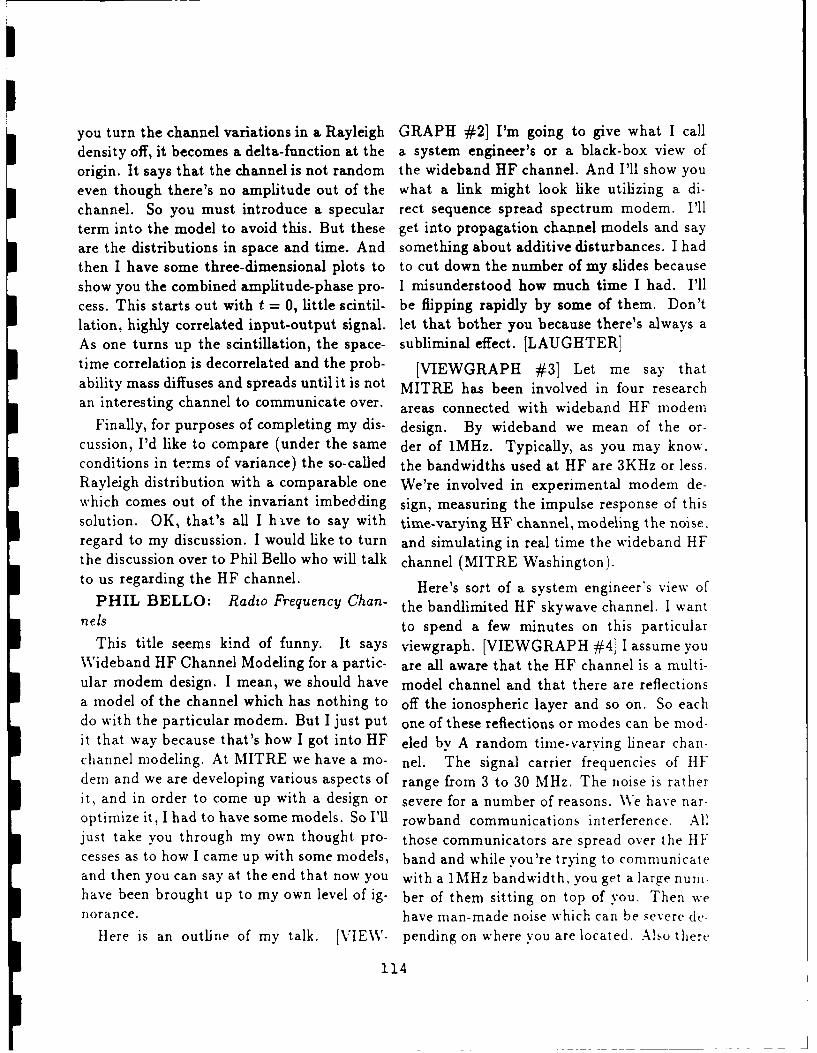
you turn the channel variations in a Rayleigh GRAPH #21 I'm going to give what I calldensity off, it becomes a delta-function at the a system engineer's or a black-box view oforigin. It says that the channel is not random the wideband HF channel. And I'll show youeven though there's no amplitude out of the what a link might look like utilizing a di-channel. So you must introduce a specular rect sequence spread spectrum modem. I'llterm into the model to avoid this. But these get into propagation channel models and sayare the distributions in space and time. And something about additive disturbances. I hadthen I have some three-dimensional plots to to cut down the number of my slides becauseshow you the combined amplitude-phase pro- I misunderstood how much time I had. I'llcess. This starts out with t = 0, little scintil- be flipping rapidly by some of them. Don'tlation, highly correlated input-output signal. let that bother you because there's always aAs one turns up the scintillation, the space- subliminal effect. [LAUGHTER]time correlation is decorrelated and the prob- [VIEWGRAPH #3] Let me say thatability mass diffuses and spreads until it is not MITRE has been involved in four researchan interesting channel to communicate over. areas connected with wideband HF modem
Finally, for purposes of completing my dis- design. By wideband we mean of the or-cussion, I'd like to compare (under the same der of 1MHz. Typically, as you may know.conditions in terms of variance) the so-called the bandwidths used at HF are 3KHz or less.Rayleigh distribution with a comparable one We're involved in experimental modem de-which comes out of the invariant imbedding sign, measuring the impulse response of thissolution. OK, that's all I hve to say with time-varying HF channel, modeling the noise.regard to my discussion. I would like to turn and simulating in real time the wideband HFthe discussion over to Phil Bello who will talk channel (MITRE Washington).to us regarding the HF channel. Here's sort of a system engineer's view of
PHIL BELLO: Radio Frequency Chan- the bandlimited HF skywave channel. I wantnels to spend a few minutes on this particular
This title seems kind of funny. It says viewgraph. [VIEWGRAPH #4] I assume youWideband HF Channel Modeling for a partic- are all aware that the HF channel is a multi-ular modem design. I mean, we should have model channel and that there are reflectionsa model of the channel which has nothing to off the ionospheric layer and so on. So eachdo with the particular modem. But I just put one of these reflections or modes can be mod-it that way because that's how I got into HF eled by A random time-varying linear chan-channel modeling. At MITRE we have a mo- nel. The signal carrier frequencies of HFdem and we are developing various aspects of range from 3 to 30 MHz. The noise is ratherit, and in order to come up with a design or severe for a number of reasons. We have nar-optimize it, I had to have some models. So I'll rowband communications interference. Alljust take you through my own thought pro- those communicators are spread over the HFcesses as to how I came up with some models, band and while you're trying to communicateand then you can say at the end that now you with a 1MHz bandwidth, you get a large nurn-have been brought up to my own level of ig- ber of them sitting on top of you. Then wenorance. have man-made noise which can be severe dc-
Here is an outline of my talk. [VIEW- pending on where you are located. Also there
114

WIDEBAND HF CHANNEL MODELINGFOR DIRECT SEQUENCE SPREAD SPECTRUM
MODEM DESIGN
Phillip A. BelloThe MITRE Corporation
presented at
ADVANCED COMMUNICATION PROCESSINGTECHNIQUES WORKSHOP
14-18 May 1989
VIEWGRAPH #1
OUTLINE
* A SYSTEM ENGINEER'S VIEWOF THE WIDEBAND HF CHANNEL
* A WIDEBAND HF DIRECT SEQUENCESPREAD SPECTRUM LINK
* PROPAGATION CHANNEL MODELS
* ADDITIVE DISTURBANCES
VIEWGRAPH 42
WJR115

MITRE R&D EFFORTS IN WIDEBAND HF* SPREAD SPECTRUM COMMUNICATIONS
0 EXPERIMENTAL MODEM DESIGN
0 BANDLIMITED IMPULSE RESPONSE MEASUREMENTS
0 NOISE MEASUREMENTS AND MODELING
0 REAL TIME CHANNEL SIMULATION
VIEWGRAPH #3
A SYSTEM ENGINEER'S VIEW OF THEI BANDLIMITED HF SKYWAVE CHANNEL
I S MARROWBAND INTERFERENCEM AN-MADE NOISE '1NON.
*ATMOSPHIRIC Noise J STATIONARY
ITRANSITTED RANDOMLY YIME-VARINTHIP SIGNAL LINEAR OPERATION I
1,1L 3 M~z)RECEIVEDNP SIONALI ANOWICTH RANDOMLY TIME.VARIANT
LINUAR OPERATION N
1 APPROXIMATE TWO-STATE CHANNELO NORMAL OR UNDISTURBED (SMOOTH IONOSPHERE)
0 DISTURS3Eo (IRREGULAR IONOSPHERE, (aWNN) a SUFFICIENTLY LARGE)
NON-STATIONARY
3 VIEWGRAPH #4&JTRE

is atmospheric noise caused by lightning and problem is, we introduce a term called quasi-intergalactic noise. Receiver noise isn't even stationarity. [VIEWGRAPH #5] We hopeup there, it's so small compared to every- that we can define the propagation mediumthing else. But the important thing to note is by a set of parameters and then if we freezethat the total additive disturbances are non- those parameters we can define a set of statis-stationary, unlike the additive white Gaus- tics for input-output behavior which are wellsian noise channel. Unfortunately, the HF defined and with which we can do all kindschannel has this property of being very non- of wonderful analysis. We could define howstationary, and in modem design and signal a modem operates, and how to optimize itsdetection processing you have to worry about design. But then those parameters containthat. As far as the propagation medium itself, the non-stationarity, and we let those param-you can approximate that roughly as a two- eters slowly vary. The essence of our solutionstate channel. The normal or undisturbed is to postulate quasi-stationarity and to hopestate is a smooth ionosphere. That is to say, that it's really true. It seems to be reasonablythe electron density, when plotted as a func- good, but time will tell. We can get our pa-tion of spatial coordinates has a smooth vari- rameters for this channel either of two ways.ation. The other state called disturbed, is We can do channel sounding or we can trydue to an irregular ionosphere. The mean propagational theoretic analyses. Bill Lind-squared value of the percentage fluctuation sey was introducing the ultimate in propaga-in electron density (AN/N)2 , is a critical pa- tional theoretic analysis. He has a solution torameter in determining the state of the chan- all radio communications problems in his for-nel. This parameter relates to one that Bill mulation. So this is a small corner of that.Lindsey mentioned. Depending on propaga- It's actually a fascinating theory as Bill istion conditions (AN/N) 2 can vary 10 orders finding out. There has been some work doneof magnitude. And the transition between though, and I'm going to show you some the-the normal state and the disturbed state is oretical predictions for the disturbed channelonly 1 order of magnitude. That is why I and compare them with actual measurementssay that it's almost like a two-state channel, if I can get to them within my time allotment.Of course as the fluctuations in the electron So what you do is postulate a stationarydensity get worse, the channel gets more dis- model with slowly varying parameters andturbed, but it is still classed as a disturbed then you do your design, build you modem,channel. And what I'd like to do is present to and then you collect statistics on these pa-you models of the non-disturbed channel and rameters. But to get the statistics you've gotof the disturbed channels, and some measure- to measure all day, different seasons, through-ments which support these models. I can't go out the year. In fact, it's a life-time job butthrough all the slides unfortunately, you've got to keep doing it.
Again, the propagation medium is non- Here's [VIEWGRAPH #6] a potentialstationary also. So here we have non- block diagram for a spread spectrum directstationary channel, non-stationary noise, and sequence modem used over the HF channel.what the devil do we do about it. How do we It's got coding and interleaving, frequencydesign a modem under these conditions? It's conversion, the usual things. The importanta puzzle. Well the potential solution to this thing I want you to look at is called a narrow-
117

QUASI-STATIONARY RADIO PROPAGATIONCHANNEL MODELING
* CHANNEL CONTAINS ONE OR MORE "BLACK BOXES"DESCRIBED BY RANDOMLY VARYING SYSTEM FUNCTIONS
" MODEL EACH SYSTEM FUNCTION WITH MINIMUM NUMBEROF PARAMETERS BY
CHANNEL SOUNDINGPROPAGATION-THEORETIC ANALYSES
" POSTULATE STATIONARY MODEL WITHSLOWLY VARYING PARAMETERS
" COLLECT STATISTICS ON PARAMETERS
VIEWGRAPH #5
SIMPLIFIED BLOCK DIAGRAM OF LINK PROCESSING
DIGITAL _r_ CODE AND DATA DSPN @AND UMITING REOUENCY
SOURC INTERLEAVE MODULATOR MODULATOR SIGNAL FILTER CONVERSIONOWN slov~uli CHO I we Ow POE AMP
NF PROPAGATION
RECET NANN
18 ANTENNASNARROW NANO
INTIRFIRtUC9 AN0AIINT NOI$1
FREOUENCY' BAN COMPLEX I NARROW BAND'
COVRSO I TNO AD DOWNCONVERTER - IN TER FE RENC€E I,--
CONV. FILTE AND A/D J [ .=,oR J-
DATA .- r0ZINTERLEAV'EI RAKE I
OUTPUT A' ND DECODE r{DEMODULATOR j
VI EWGRAPH #6
NTRE118

band interference excisor. The reason that one or more delays with the delays changingthat's necessary is, as I pointed out before, with frequency. The different traces corre-that the HF channel's got this tremendous sporid to 1 hop, 2 hops, 3 hops path and sonumber of interferers sitting on top of you. on. These may be further decomposed intoYou can remove them by some clever process- high-ray and low-ray, but I can't get into thating. It's an essential ingredient if you're going here. The important thing is that this is theto have any hope at all of doing wideband HF ionogram for a non-disturbed channel. It is acommunications. relatively dean trace. Now I'm going to show
I've shown a box called a rake demodula- you what the ionogram of the disturbed chan-tbr. I don't know if you're familiar with the nel looks like.Price and Green implementation of adaptive You see what happens (see VIEWGRAPHmatched filter-receiver for multipath channel. # 11) is you get spreading this way (verticallyIt's called a rake demodulator. This is the in delay). You had a thin line before but nowkind of thing that I've analyzed for the par- you've got spreading in the delay direction.ticular kinds of quasi-stationary models that That's the property of the disturbed channel.I'm going to show you. There is not time to VIEWGRAPH #12 shows the multi-modego into the structure of that particular mo- representation of the channel, the old standbydem. [VIEWGRAPH #7] That was one of in terms of modeling, time-varying disturbedthose subliminal ones that will stand you in channels and tap-delay lines. What you cangood stead later. say is that any linear, time-varying chan-
VIEWGRAPH #8 shows multiple rellec- nel can be represented parametrically astions off the ionosphere. VIEWGRAPH #9 a tapped-delay line in which the taps areshows you how the various layer heights spaced 1 over the bandwidth apart [VIEW-change with time. And the reason I'm show- GRAPH #13]. So you could say, well, great,ing that is I want you to understand that now you've got your model, you have param-during the day, as the layers go up and eterized it. Unfortunately that won't get youdown, that vertical motion for the undis- too far, because the multipath spreads can beturbed channel produces a Doppler shift. hundreds of microseconds and those taps areMode Doppler shift happens to be an im- 1 microsecond apart since you have a band-portant parameter in determining the perfor- width of 1 MHZ. So those time-varying com-mance of the rake modem which tries to com- plex coefficients may be hundreds in number.bine energy coherently and adaptively. To do What are you going to do with those hun-this it needs to measure the channel impulse dreds of coefficients? How are you going toresponse. Doppler shift is a parameter that characterize them? It's not too satisfactory.we have to collect more data on. I'll show you So you have to go and dig a little bit deepersome measurements later. to model this channel. Well, you start by
This is an ionogram. [VIEWGRAPH #10] looking at an idealized version of the iono-You may all be familiar with it, I don't know. gram [VIEWGRAPH #14] for 1 propagationJust give it a couple of minutes. What you do mode. You look at that and what it showsis transmit a pulse and vary the frequency of is that the group delay as a function of fre-the pulse and see what you get coming back. quency is approximately linear over 1 MHzAnd what you see is the energy coming back bandwidth, but there's some non-linearity in
119

A DECISION-DIRECTED COHERENT RAKE PROCESSOR
CMLXDELADEA
&UUM
VIEWRAP #7O
DSKWAV HF CHANNEL1In
"ATH'SI /4/ // iMAGNETIC
FILLIE
I 120

TYPICAL DAILY VARIATIONS IN LAYER HEIGHTSFOR SUMMER, WINTER AND THE EQUINOXES
IN MID-LATITUDES OF THE NORTHERN HEMISPHEREF. R. East, "The Properties of Ionosphere Which Offset HF Transmission",from Point-to-Point Telecommunications, Febr. 1965, pp. 5-22
FO (EU F, (JUNE)
UIONOGRAM
Homestad AF , Lt BdorM
km 213 1
too E LAYER
D LAYER
SINA A_STRENGTH I II
2 4 6 10 12 14 16 8 22 26HOURS-LOCAL TIME
FIREEC(M)
WKT
VIEWGRAPH #9
IONOGRAMHomestead AFB, FL to Bedford, MA
October 13, 1988 from 1200Z
STRENGTH
TIME2(MS)
2 6 10 14 Is 22 26 30FREQUENCY (MHz)
WMRVIEWGRAPH 0
121

SPREAD-F IONOGRAM
I ms
1 2 4BFreq (MHz)
From King [Jour. Atmos. and Terr. Physics, 19701
VIEWGRAPR #11
GENERAL MULTIMODAL REPRESENTATIONOF WIDEBAND HF CHANNEL
INPUT FL
IMPULSE IMPULSEIMUSRESPONSE RESPONSE RSOS
if f - OUTPUTSUMMING BUS ~ WMI
VIEWGRAPH #12

TAPPED DELAY LINE MODELFOR BAND LIMITED WBHF CHANNEL
CHANNELINPUT
FLhDELAY 09LAY ... DELAY
ONANNULOUTPUT
COMPLEX TAP WEIGHTS bc(t) DETERMINE CHANNEL CHARACTERISTICS.
W a BANDWIDTH OF TRANSMITED SIGNAL
NmTREVIEWGRAPH 113
IDEALIZED IONOGRAM EXAMPLE FORNON-DISTURBED CHANNEL
DELAY
2 11W
me-
FREOUENCY -. w
VIEWGRAPH #14
123

there. Your first concept is, OK. For the for the propagation mode is slow. In fact,non-disturbed channel, I can model this as the correlation time is around 45 seconds, soif it were a filter of 1 MHz bandwidth with a we truly have a slowly-varying power in thenon-linear group delay distortion. The other 1 MHz bandwidth. Thus the idea of quasi-thing to recall is that I told you that the lay- stationarity is not so far fetched. In otherers are moving with time. What's happen- words, we do have a dispersive channel buting is that that's moving, and because it's the total power received over a 1 MHz band-moving you've got a Doppler shift. So that width is varying slowly. Here's another ex-what we have is a dispersive filter, a slow ample. [VIEWGRAPH #19] In this case thetime-varying gain, and the slow time-varying HF medium didn't cooperate. There was aDoppler shift. That's what the model is over solar flare and we had slow fluctuation, buthere [VIEWGRAPH #151. This is our quasi- all of a sudden we're right down to the noisestationary model for the non-disturbed chan- floor. So we can't communicate at all undernel: slowly changing delay, a dispersive filter, those conditions.with hundreds of microseconds of delay possi- These [VIEWGRAPH #201 are probablybly, dispersion, slowly-varying Doppler shift. distributions of the signal power in a 1 MHzNow I've made some calculations as to how a bandwidth, comparing to the Rayleigh distri-rake modem would work assuming that you bution. And you can see there's quite a bit ofhad a white noise background (it could be variation, but it's not as bad as the Rayleighnon-stationary). And what you find is that distribution. Here's some collected measure-the short-term performance, i.e., the quasi- ments [VIEWGRAPH #21] These were donestationary performance with the parameters at MITRE again. There will be another pa-fixed, depend primarily on the received power per at MILCOM by Dan Perry discussingof all the taps in the tapped-delay line model. these measurements. There are 38 runs, 35It depends on the delay spread that you need minutes each, covering some time span, butto accommodate in the rake combiner. It who can say that that defines what the HFalso depends on the Doppler shift. There channel is going to do. At any rate, you seeis a Rome Air Development Center report the delay spread is on the right hand column,(RADC-TR-98-91) which has all the theoret- varied from 2 to 35 microseconds, the Dopplerical background to it, but there's a 1988 MIL- shifts are less than a Hertz, and so on.COM paper which has performance estimateswhich I'm not going to present here. What I'm now going to show you are some
measurements taken years ago by SRI inWhat you've got here are some measure- which they are primarily concerned with fre-
ments taken at MITRE recently. [VIEW- quency spread and Doppler shift. They hadGRAPH #18] We have a 1 MHz direct se- two paths [VIEWGRAPH #221. Normallyquence modem and we can measure the en- this path from Palo Alto to Fort Monmouth isergy in all those taps in the tapped-delay line a well-behaved, usually non-disturbed chan-channel model. Once again, we don't have nel. The one from Palo Alto to Thule, Green-time to discuss all those measurements. But land is usually quite disturbed because ityou look at the time axis, you've got min- goes through the Aurora. They didn't haveutes on the bottom and the fluctuation rate the hardware to measure the full impulse re-of this total energy of this 1 MHz bandwidth sponse so they just transmitted carriers and
124

QUASI-STATIONARY MODEL FOR NON-DISTURBED1 MHz BANDWIDTH PROPAGATION MODE
(USUALLY APPLICABLE TO MID-LATITUDE PATHS)
SLOW-CHANGING
SLOW-CHANGING TAWEGSDELAY %" (t))
COMPLEX DELAY DISPERSIVEINPU FILER ECOMPLEX
OUTPUT
HUNDREDSOFpv&/MHz) j 2 ixvt
ASSUMING SINGLE MODE, DLOPPIE-RIAT
SHORT TERM RAKE MODEMDOPESHFPERFORMANCE DEPENDS ON: (41 HZ USUALLY)
M 2 PERFORMANCE PREDICTIONS:
RECIVE POE MaoI I "Performance of Some Rake Modems Over themONon-Disturbed Wide land HF Channer, P. Blo
DELA SPRAD M gsMILCOM'8S Conference Record,IEEE/DoDIAFCEA.DELY SREA ~ ~"Perrfomac of Four Rake Modems Over the
I Non-Disturbed Wldeband HF Channel", P. Bello,DOPPLER SHIFT IRADC-TR.S89-91, March 1909, (F1962S1.46COOO1)
V IEWGRAPH #15
ILLUSTRATION OF MEASURED BANDLIMITEDIMPULSE RESPONSE SNAPSHOTS
b (2T) b (2T)
1ZeT2T
TIME7,,It
.00
DELAY
M!TREVIE .JRAPH #16

WIDEBAND HF DOPPLER SHIFT ANDTIME DELAY SPREAD DISPLAYS
I HOMESTEAD, FL TO BDFORD, MA
2,7Ir
(1: N AET52KL CI/EI ~0.6 RECIVE RECANGLA FITNZ3.6
(42 AM EDT)
RECEIVED H POWERvsTM: Y!CLRST
PROMarc 20,AL 19891 fro EDT)Z
6 ADIT w 0 80 25.88 M3.62M
I . Soarfiu = 22VIEWGRPH=21
REEVDPWRvuIM:TNA HSL
I ...........0~~~A 52015 205 0 3
2IE(m
CF 227dI .......... ....

RECEIVED POWER vs TIME: ANOMALOUS RESULTHomestead,, FL to Bedford, MA
March 9, 1989 from 15088Z
15
10 f0 25.885 MHz
-. .Solarfiux =207
0.............Reported Time,2
Outpu Soolar Floor.... ......-
-5 ~ ~ ~ ~ ~ TM (mm)................ ........ b
LU 1538Z
0 0 10__ _ is 20 5 30 3
RALEIG 1 A IN 1 CA AN27EB
10.2P WE (dO)MA 2
VIEWGRAPH '20

MIDLATITUDE CHANNELMEASUREMENTS SUMMARY
(2/27/89 -- 3/23/89 6.26 MHz, DAYTIME/NIGHTIME)
Received Power vs Time Doppler Shift Delay SpreadExperiment Experiment
38 Runs - 35 min each 33 Runs
Standard Decorrelation Doppler DelayDeviation Time Shift Spread
________ (d B) (sec) (Hz) I)
lowest 0.71 5 0.00 2
highest 4.91 350 0.66 35
median 2.34 37 0.16 7
VIEWGRAPH #21
MAP OF PROPAGATION PATHS(CARRIER TRANSMISSION ONLY)
SRI MEASUREMENTS, 1964:R. A. Shepherd and J. B. Lomax, "Frequency Spread In Ionospheric Radio Propagation",IEEE Trans. on Comm.Tech., April 1967
1600 1400 60' 40*
20' 6000
PALO MONMOUTH2
128

measure the power spectrum of the received you have a complete statistical description.signals. What you see here [VIEWGRAPH To be honest, you'd have to ask yourself,#23] is Doppler shift as a function of time "Well, how good a model is that anyway?"that they've measured. And you can see the And I wouldn't say that that's totally proven,size of it and how rapidly it varies. Truly but it's not bad from my point of view atthe Doppler shift is varying slowly. It has this stage. We're collecting more informa-excursions of plus or minus a Hertz roughly. tion. The scattering function has had sev-They collected data over long periods of time eral names [VIEWGRAPH #27]; Price andand this is probably actual distribution of Green in 1960 called it the "target scatteringDoppler shifts, one of the few available in function." Years ago I called it the "scatter-the world. These are the types of measure- ing function." Leon Wittmer, at the Defensements that you need to predict performance Nuclear Agency, has done a lot of work quiteof the rake modem. You can predict perfor- independently and reinvented it. He calledmance conditional on a given Doppler, condi- it the "generalized power spectrum." Andtional on the model delay dispersion, condi- other people have called it the "delay-Dopplertional on the given power, etc., but what are power spectrum," which is probably the mostthe probability distributions of these param- appropriate terminology.eters? Here are empirical probability distri-butions of Doppler shift based upon the SRI This is one of my few slides with equa-measurements taken years ago. We're just tions [VIEWGRAPH #28], just to motivatemastrtn taarryes nd eare- swhat this scattering function is. The complexstarting to carry out some needed measure-
ments again. Note that there are two traces Gaussian WSSUS channel can be viewed as
on VIEWGRAPH #24, one for the Fort Mon- sort of a densely tapped-delay line with in-mouth path and one for Thule. The Thule is finitesimal independently fluctuating scatter-a disturbed channel. The Doppler shift has ers. Each scatterer has a time-varying corn-around the same statistics but you'll see the plex gain which is the g(t, )d . And basi-
Doppler spread, which I'll discuss, is much cally, it is the power spectrum of the fluctu-worse for the disturbed channel. ation at the delay which is the scattering
function of delay-Doppler spectrum. I've justHere's the idealization of an ionogram of gone over it briefly for the lack of time, but
a disturbed channel [VIEWGRAPH #25 you can just visualize it as being the powerand here's a model for a disturbed chan- spectrum of the fluctuations at a given de-nel [VIEWGRAPH #26]. You have a slow lay. You can relate this to the tapped de-change in Doppler shift also but we replaced lay line model (see VIEWGRAPH 29), butthat simple dispersive time-invariant filter by I'm not going to present it because there isn'ta wide-sense stationary uncorrelated scatter- enough time. So you visualize the scatteringing channel, in which the tapped delay line function as something like a two-dimensionalmodel has randomly fluctuating independent power spectrum [VIEWGRAPH #30', andcomplex Gaussian tap weights. The thing when you integrate over Doppler, you getabout that particular model is that if you what is called "delay power spectrum" whichare able to specify what's called the scatter- gives the multipath profile. The width of thatzng function which describes the way power delay profile is the delay spread or the multi-intensity is scattered in delay and Doppler, path spread. On the other hand, if you inte-
129

AVERAGE DOPPLER SHIFTSFort Monmouth to Palo Alto Path, March 1964
SRI MEASUREMENTS, 1964:R. A. Shepherd and J. B. Lomax, "Frequency Spread In Ionospheric Radio Propagation",IEEE Trans. on Comm.Tech., April 1967
Ist F-REGION SUNRISE lit F-REGION SUNSET(2F MODE) (2F MODE)
s I I ' - y
- -3/21/64 --.- "-3/22/64- - .
U. -'-3/26/64
-/
w-0.8--
00 04 08 12 16 20 24GMT- hours
VIEWGRAPH #23
DISTRIBUTION OF AVERAGE DOPPLER SHIFTSON NORMAL PROBABILITY SCALE
SRI MEASUREMENTS, 1964:R. A. Shepherd and J. B. Lomax, "Frequency Spread In Ionospheric Radio Propagation",IEEE Trans. on Comm.Tech., April 1967
g 99
X0 90:-t 0.3
Xz 70IV;
,-0.c 30
-,FT. MONMOUTH
. - THULECX 0l 0.1.
0..1' O . I ' I I I ' ' I ' ' p p , j j , , , ,
-12 -08 "04 0 0.4 08AVERAGE DOPPLER SHIFT- c/s
MmVI EWqRAPH-'#Z4
130

IDEALIZED IONOGRAM EXAMPLEFOR DISTURBED CHANNEL
DELAY
2 ma-
FREQUENCY -
VIEWGRAPH #25
QUASI-STATIONARY MODEL FORDISTURBED 1 MHz WBHF PROPAGATION MODE
(USUALLY CONFINED TO TRANS-AURORAL, TRANS-EQUATORIAL, ANDSOME EVENING MID-LATITUDE PATHS)
COMPLEXSLOWLY GAUSSIAN
CHANGING TAP WEIGHTSCOMPLEX DELAY
INPUT ws COMPLEX4 CHNNELOUTPUT
CHANGINGDOPPLER
SHIFT
VIEWGRAPH #26
AmTR131

SCATTERING FUNCTION NAMES
TARGET SCATTERING FUNCTION R. Price & P. Green 1960
SCATTERING FUNCTION P. Bello 1963
GENERALIZED POWER SPECTRUM L. Wittwer 1979
DELAY DOPPLER SPECTRUM
NVTREVIEWGRAPH #27
COMPLEX GAUSSIAN WSSUS CHANNEL
COMPLEXINPUT 4 + dtz~t)t,z(t) _oo _g _t, __)d_ __ _ _ _ _ _ o __•_•
COMPLEXOUTPUT
SUMMING BUS ,0 w(I)
g(t,t,) IS COMPLEX GAUSSIAN PROCESS FOR FIXEDw(t) = fz(t-4 ) g(t,4,)d4,
g (t,k ) g (t+ 1, 'I) - Q(,,) (7-1
0(,t, 4 ) IS AUTOCORRELATION FUNCTION OF FLUCTUATIONS AT PATH DELAY
S(4,v) ,f Q(r, ) J 2 vT dr - DELAY-DOPPLER SPECTRUM
I POWER SPECTRUM OF FLUCTUATIONS AT DELAY 4
MIRT
VIEWGRAPH #28
132

TAPPED DELAY LINE MODEL
g(t, F) = g (t) ( .kA)
" COMPLEX TAP GAIN FUNCTIONS 9 k (t) BECOMECOMPLEX GAUSSIAN PROCESSES
" THE CORRELATION FUNCTION gk(t) gj(t+v ) DETERMINED BYS(4 ,v) AND TERMINAL EQUIPMENT BANDLIMITING FILTERIMPULSE RESPONSE, h(t).
* IF S( oV) CHANGES LITTLE FOR A CHANGES IN 4 THEN(gk (t)} BECOME STATISTICALLY INDEPENDENT ANDPOWER SPECTRUM OF g k(t) BECOMESP k (V) = lh( .-IkA)l1 2 S( 4,, V) d
S(4,v) IF S(,,v) CHANGES LITTLE FORDURATION OF Ih( )1 2
MITRE
VIEWGRAPH #29
DELAY SPECTRUM AND DOPPLER SPECTRUM
SCATTERING FUNCTIONS01, V )
DOPPLER
uJ / / /
Q. /0
DELAY DOPPLER SPECTRUM
DELAY SPECTRUM P(v)= fS( ,v) d4
OW , =S(4 ,v ) ddv
VIEWGPAPH #30
133

grate over delay, you get the Doppler power Monmouth-Palo Alto path. This has a veryspectrum which is the power spectrum of the narrow spread formed by adding all the prop-received carrier. The width of this power agation modes together. You can see the dif-spectrum is called the Doppler spread. ference between that and Thule-Palo Alto.
Now we will talk about some measure- However, this [VIEWGRAPH #32] is fromments, typical Thule and Fort Monmouth SRI to Fort Monmouth and it's got a bigto Palo Alto [VIEWORAPH #31] measure- mess. It's shifted, it has a mean Doppler shiftments. This view shows the Doppler power which is off to one side and totally uncharac-spectrum, which is the received power spec- teristic, and it turns out it is due to some
trum corresponding to a transmitted carrier, of the Aurora, the plasma, drifting off andNow you look at the power spectrum and you providing off-a~xis reflections because there's
say, "My God, that thing is terribly jagged." a wide beam antenna.
I have to tell you this. After talking to Doppler spread is the width of the powerthe people who've done the measurements I empirical cumulative probability distribu-discovered that instead of measuring power tions for the spectrum of the fading. And thisI spectrum they measured periodograms. I [VIEWGRAPH #33] shows the difference be-know this audience knows the difference be- tween Fort Monmouth and Thule-Palo Alto.tween a periodogram and a power spectrum Rather, note there's a ten to one difference in... I hope. The difference is if you take a ran- Doppler spread for the two paths.dom process and integrate over some finite Len Wagner of NRL has taken sometime interval to compute a Fourier transform, scattering function measurements [VIEW-you get a spectrum. If you form the magni- GRAPH #34]. You see how striated it is, hetude squared, it's a periodogram, but it's not did not do the averaging and that's the resulta power spectrum. You have to do further av- of doing the periodogram instead of a powereraging. And that fine structure is due to the spectrum. Now here are some SRI measure-fact that they didn't average. They didn't ments (see VIEWGRAPHS #35,37,39) takenaverage over frequency, or do successive snap more recently in Greenland for the disturbedshots. And I find out that everyone who has channel. And those are 5 dB contours for thecarried out these types of bound measure- scattering function. They are much smootherments have all measured periodograms. So because he averaged his periodogram in thewhen you look at them ... no, that's true, one frequency domain. But when he did, he saiddidn't, I'll show you at the end. But it seems it was for cosmetic purposes because it wasto be characteristic that they forget to do the too wild. He didn't realize that he was doingaveraging so it gets very ragged. But when the right thing.they do the average, they come out much Here's some theoretical predictions.more reasonable. Now this [VIEWGRAPH [VIEWGRAPHS #36,38,401 There's a fellow#321 is interesting because this was over the over at Mission Research Corp. working on aSRI of the Fort Moiimouth path which is sup- contract from DNA, a fellow by the name ofposed to be non-disturbed. It should have Nickish who has done some very interestingbeen well behaved. work. When SRI did these most recent ex-
Now let me go back to the previous periments, they had a radar, a back scatterone. [VIEWGRAPH #31] This is the Fort radar and they got some indirect data on elec-
134

TYPICAL POWER SPECTRAThule, Greenland and Fort Monmouth-to-Palo Alto Paths
SRI MEASUREMENTS, 1964:R. A. Shepherd and J. B. Lomax, "Frequency Spread In Ionospheric Radio Propagation",iEEE Trans. on Comrn.Tach., Aprl 1967
40Cr THULEw 30
0.20 '1 0.
S0
>_2502t 0 FORT
z11,200 MONMOUTH
wIQ150
w-, 100.
0 50
-10 -5 0 5 1ODOPPLEW " T- c/s
VIEWGRAPH #31
AN OFF-PATH MODEFort Monmouth to Palo Alto Path, March 1964
SRI MEASUREMENTS, 1964:R. A. Shepherd and J. B. Lomax, "Frequency Spread In Ionospheric Radio Propagation",IEEE Trana. on Comm.Tech., April 1967
I I I I
-120w 092FT MONMOUTH
0918 FT. 6/10/640 100 0920Z"8 2o,',2.31 c/s
-
Z 60
z 40-
"20 _0 1 . . . 1
-10 5 0 5 10DOPPLER SHIFT-c/s
VIEWGR H #32135

VR# p1463 SMayl MS PeB* 833 MITM0 4dam ,. MA Kaftw FRANOLN
DISTRIBUTIONS OF DOPPLER SPREADON NORMAL PROBABILITY SCALE
SRI MEASUREMENTS, 1964:R. A. Shepherd and J. B. Lomax, "Frequency Spread In Ionospheric Radio Prorogation",IEEE Trans. on Comm.Tech., April 1967
0.2 0.4 0.6 0.8 1.0 1.2 1.4 1.6 1.8
n- FT MONMOUTH< (UPPER SCALE)
020- THULE*(LOWER SCALE)
o 0z
MJT
VIEWGRAPH #33
EXAMPLE OF DISTURBED CHANNEL MEASUREMENTSFrobisher Bay, Canada to Rome, New York
(from NRL Experiments by Len Wagner)DELAY EXP 1 221. P DELAY(us) TM 13:7 (s
30 REO eG.S 1HrZ 329 0- ~
20 0.
isee
Be ee To oe .
mr)ok i rv rr w i DW~I'irn rnro 1117.
VIM~~ #34136

HF CHANNEL PROBEMEASURED SCATTERING FUNCTION
SRI MEASUREMENTS, Thule - Narssarssusq, Greenlandfor March 20, 1985 14:18 UT (5 dB contours).
R. P. Basler et e., "HF Channel Probe", DNA-TR.85-247, May 1985.1.00
0.90-
0.80 - Q
o. A.0.70
0.0
040
0.10 90.004o35_3025-20-15-10-S 0 5 10 15 20 25 30 35 40
Doppler Freq (Hz)
VIEWGRAPH #35
SCATTERING FUNCTION FIT OF THEMEASURED SCATTERING FUNCTION
SRI MEASUREMENTS, R. P. Bailer at W. Thule - Narstarssuaq, Greenlandfor March 20, 1985 14:18 UT (5 dB contours).
ANALYSIS by L. J. Nickiach, Mission Research Corporation, Carmel, Calilfornia.Report MRC/MRY.R.012, 31 December 1988.
1.0 1 1 1 1 1 1 1 I I I I I
0.9 -
0.8
0.7-
~0.6
~0.5-
0.3-
0.2
0.1-40Q-35 -30 -25 -20 -15 -10-5 0 5 10 15 20 25 30 35 40
Doppler* fr*equency rl1Z)
VAMH #36137

HF CHANNEL PROBEMEASURED SCATTERING FUNCTION
SRI MEASUREMENTS, Thule - Narssarssuaq, Greenlandfor March 20, 1985 21:08 UT (5 dB contours).
R. P. Basler et al., "HF Channel Probe", DNA.TR-85-247, May 1985.1.00
0.90
0.70 o
0.60 Os
050 •
0.40
0.30 4
0.20
0.10
0. A I.I'40-35-30-25-20-15-10-5 0 5 10 15 20 25 30 35 40
Doppler Freq (Hz)
VIEWGRAPH #37
SCATTERING FUNCTION FIT OF THEMEASURED SCATTERING FUNCTION
SRI MEASUREMENTS, R. P. Basiler et al. Thule - Nerssarssuaq, Greenlandfor March 20, 1985 21:08 UT (5 dB contours).
ANALYSIS by L. J. Nlcklsch, Mission Research Corporation, Carmel, California.Report MRC/MRY-R-012, 31 December 1988.
1.0 I I i I
0.9 -
0.8-
0.7 - 0.00.5 -
0.3 -
0.2 - -
0.1 -
0.0 I I I II-40-35-30-25-20-15-I0-5 0 5 10 15 20 25 30 35 40
Doppler frequency (11z)
VIH #38
138

HF CHANNEL PROBE UMEASURED SCATTERING FUNCTION
SRI MEASUREMENTS, Thule - Narssarssuaq, Greenlandfor October 17, 1984 22:03 UT (5 dB contours).
R. P. Bailer et al., "HF Channel Probe", DNA-TR-85-247, May 1985.1.00 I
0.70
:10.60 U~0.50
~0.40 I0.30
0.20
0.-10 L-40-35-30-25-20-15-10-5 0 5 10 15 20 25 30 35 40
D oppler Feq (Hz)
IVIEWGRAPH #39
SCATTERING FUNCTION FIT OF THE IMEASURED SCATTERING FUNCTION
SRI MEASUREMENTS, R. P. asler et al. Thule Narsrs.q. Orenlandfor October 17, 1984 22:03 UT (5 dD contours).
ANALYSIS by L. J. Nlcklc¢h, Mission Research Corporation, Carmel, California.Report MRC/MRY.R-012, 31 December 1988.
1 .0 I I I i I I I I I I
0.9 -
0.8- i
U.7 -
~0.6
~0.3
S0.2 -0
0.1 0
0.0 ,, I I I I I ]I /
-40-35-30-25-20-15-io-5 0 5 10 15 20 25 30 35 40
Do,.e,- fequC.y (11Z) IMWREVIEWGRAPH #40 1
139

tron density fluctuation. He used this data, to 127 dB as compared to the backgroundtogether with some theoretical work to pre- noise level which is around 115 dB. Now wedict what the scattering function would look say you can communicate over that mess.like theoretically. He's done some pretty goodmodeling and I'll show you two more exam- The nex t ide aumesRAPHSples of the modeling. This is another case and #45,46] say something about models devel-here's his model. Here's another case and this oped. I need to go back one [VIEWGRAPHis his model. But going back, look at the size #44]. You could set a threshold and getof the spreads here. We see close to one mil- cumulative distributions of power exceedinglisecond of a delay spread, and the Doppler the threshold andwr to develop an idea ofspreads are + or - 10 Hz. This is rapid fading, how the power where the threshold varieswith significant amounts of multipath spread. with the threshold level. So, thi s likdoneSo in summary, I say there's enough parame- experimentally and you get curves like thister information to allow the use of this quasi- [VIE WGRAPH #45] for cumulative distribu-stationary model, at least as a start for mo- on hat in ot iatakin maydem design which is an iterative process. We of them and looking at data in Europe, youhae ttesign moreh msaneraement css. e find out that the cumulative distributions canhave to take more measurements. A lot more
measurements are needed. be modeled by a truncated Pareto distribu-tion, which a log-log scale looks like [VIEW-
I wanted to say something about additive GRAPH #45]. But the important thing is ifnoise. The noise problem on the HF chan- you study this viewgraph here, you ask thenel is far worse than the propagation channel, following important question: As you beginwhich is bad enough. You see [VIEWGRAPH to eliminate parts of a band in order to re-#42], you have man made noise which varies move the interference, huw much of the bandvery much geographically, you have atmo- do you have to eliminate to cut down the in-spheric noise which varies seasonally, and you terference to significant values? Because ifhave interference. The interfering stations are you could just remove only 10-20% of thea real mess. This shows measurements of a band and cut down the interference by 30whole HF band. [VIEWGRAPH #43] You dB, you would have a chance of communi-see all those large interfering areas there. The cating. That's roughly what VIEWGRAPHdifference between the upper and lower figure #47 shows for that particular set of measure-is between day and night. You don't propa- ments taken at Bedford. You notice the axisgate well at high frequencies at night and ev- at the bottom, percentage of the band ex-erybody starts to crowd their transmissions cised. At 10% excision, looking upwards, thedown at lower frequencies. So the conges- intersection, you see you're a little over 180tion gets even worse at night. This [VIEW- dB as opposed to 210 dBs for 0% excision.GRAPH #44] is a 1 MHz power spectrum. You thus achieve a 30 dB improvement withWe took an FFT of a 105 millisecond seg- a 10% excision. Characteristically, looking atment of a 1 MHz bandwidth portion of the recent data, it appears you can achieve 20-30HF channel, where we are, at Bedford in Mas- dB reduction in the interference power withsachusetts. Now you look at that and see all 10-20% of the band excised. Excising 10 orthose spikes there, those are all interferers. 20 % of the band will only reduce the powerYou see how high they go. Some go up close in your spread spectrum signal by 1 dB. but
140

SUMMARY
* ENOUGH PARAMETER INFORMATION IS AVAILABLE TOALLOW USE OF THE PROPOSED QUASI-STATIONARYMODELS AS A BASIS FOR EXPERIMENTAL MODEMDESIGN AND PERFORMANCE ANALYSIS.
* MUCH MORE QUASI-STATIONARY PARAMETERMEASUREMENTS ARE NEEDED TO PREDICTLONG-TERM PERFORMANCE.
WJTREVIEWGRAPH #41
TYPICAL NOISE LEVELS
1 /DENVER. COLO. 17 MAN-MADE. BUSINESS140 . SUMMER 0 MAN-MADE, INDUSTRIAL
S 2000-2400 HR. & MAN-MADE, RESIDENTIAL
120 - 0 ATMOSPHERIC........... ATMOSPHERIC
A "'.. --- GALACTIC100- . MAN-MADE
wS0 go-
m BUSINESS AREAS
so- "OUIET RURAL AREAS
RESIDENTIAL AREAS
40 RUAARADENVER. COLO. . "20 - WINTER" "...•"" """"k1 - 1
0800-1200 HR.
010- 1 10 10 10'
FREOUENCY (MHz)
MEASURED AND EXPECTED NOISP LEVELS
FOR DENVER, COLORADO (CCIR AND ITS MODELS)
A PH #42141.

IHF BAND SPECTRA
SUMMER SOLSTICE, CENTRAL ENGLAND-4 '"Gott, lEE Proc., Dec.1985I TOTAL POWER .M0e IUAWNti!DA IiNO, N
I . - '
FRONY(Mma "NO
4 7j TOTAI POW R 42 M
J 1 24" Nf
4#4
VIEWGRAPH #43
WIDEBAND HF NOISE AND INTERFERENCEFull 1 MHz Spectrum at 8.0 MHz
170.
IGO
ISO.
140.•
130
10
~90
so
7,
|0 UNW1NDOWED FFT, 262144 POINTS, 9.5 Kz RESOLUTION30 10:01 PM EST, 9 APRIL 1987 MITRE, BEDFORD, MA SITE
VERT1CAL.Y POLARIZED LOG PERIODIC ARRAY10 SAMPLED AT 2.5 MHz RATE, DURATION 105 MSec
7. 7 - ; 7 9 "7 97 BD 19 .3 9 , a 5 9.6
VIEWGRAPH #44
142

WIDEBAND HF OCCUPANCYCumulative Probability Distributions, 1 MHz Bandwidth
B. D. Perry and L G. Abraheam, 'Wideband HF Interference and Noise Model Based on Measured Data",M&S-7, MITRE Corporation, March 1988. lEE Conference Publication 284, 4th International Conferenceon tIF Radio Systems and Techniques, London, U.K., April 1968.
-0.75 NIOMINAL RESOLUTION
-1.2 N____ Z
DURATIO 10 mc ALOS 10.0 PT
MODL OF- TREECEDSRBTOB.D Pryan .Riii, itefrnc n WdbndH Cm uictos-4rcedng.ithinspeiEffects SmposiumSpifedVUA197
10 -4.NTRERNE OER 5
so 100 120N140 1S0SISAN2W0D22
RELATIVESPOWEROINBANCWBDTS
VERTICALLYUMBE OOARZE LOGTPRIODIERRS
hqTRVIEWGRAPH #46

IPOWER REMAINING AFTER EXCISION VS
PERCENTAGE OF BAND EXCISED
i 2000 1.0
Z 140 . . . . . . .CY
M 110
c c 8 0
* WJT, R
|40 .. ..
a .01 0.1 1.0 10 100PERCENTAGE OF BAND EXCISED
MHz CENTER FREQUENCY
38.14 HZ RESOLUTION I MHz BANDWIDTH10:01 PM EST, 9 APRIL 1987, MITRE BEDFORD
VIEWGRAPH #47
BLOCK FFT INTERFERENCE SUPPRESSIONII
I MODIFY CELL
RECEIVER AID FFT OUTPUTS WHICH -1 TO
OEXCEED F DEMODULATOROUTPUT [ /THRESHOLD
I
i VIEWGRAPH #48
mm144

1 ms POST-EXCISOR NOISE POWER MEASUREMENTS
15,3S4 POINTS
SAMPLING RATE
VIEWGRAPH #49
Ims averages showing noise spike phenomenonoccurring every 16 msec.
Slob
3j-
3-
2-5
2-
1.5
Os
0-L l0 200 300. 400 S0o 600.
1000
MEVIEWGRAPH 050
145

Post-Excisor Residual Short Term Power vs Timefor Averacing Time T = 96 msec
2.5
2
-2.5
-0.5
0 2 6 a to 12 14 16 is
|(25 October 1988, 14:00 G.M.T.)
Lw
i VIEWGRAPH #51
Post-Excisor Residual Short Term Power vs Time~for Averag-ling Time T =,I sec
2.5
1.5
S 0.5
2
-0.5
.25
-2. 0 ' 2 ' . 4 0 t o 8 ,0 ' 100 120 140 16 IO
TDoME (&cc)
(25 October 1988, 14:00 G.M.T.)
VIEWGRAPH #52
146

Post-Excisor Residual Short Term Power vs Timefor-Averaging Time T_= 10 sec
LS5
2-
~0
2.0 200 400 (00 800 1000 1200 1400 3600 13800
11ME (SCc)
(25 October 1988, 14:00 G.M.T.)
VIEWGRAPH #53
PERCENTILES FOR THE CHANGE IN AVERAGE POWER19ETWEEN SUCCESSIVE INTEGRATION TIMES-- FOR POST-EXCISOR NOISE
2 3 0-MINUTE RECORD
0
INTEGRATION TIME (in seconds)
(9 January 1989, 12:22 G.M.r.)
VIEWGRAPH 54
&MR147
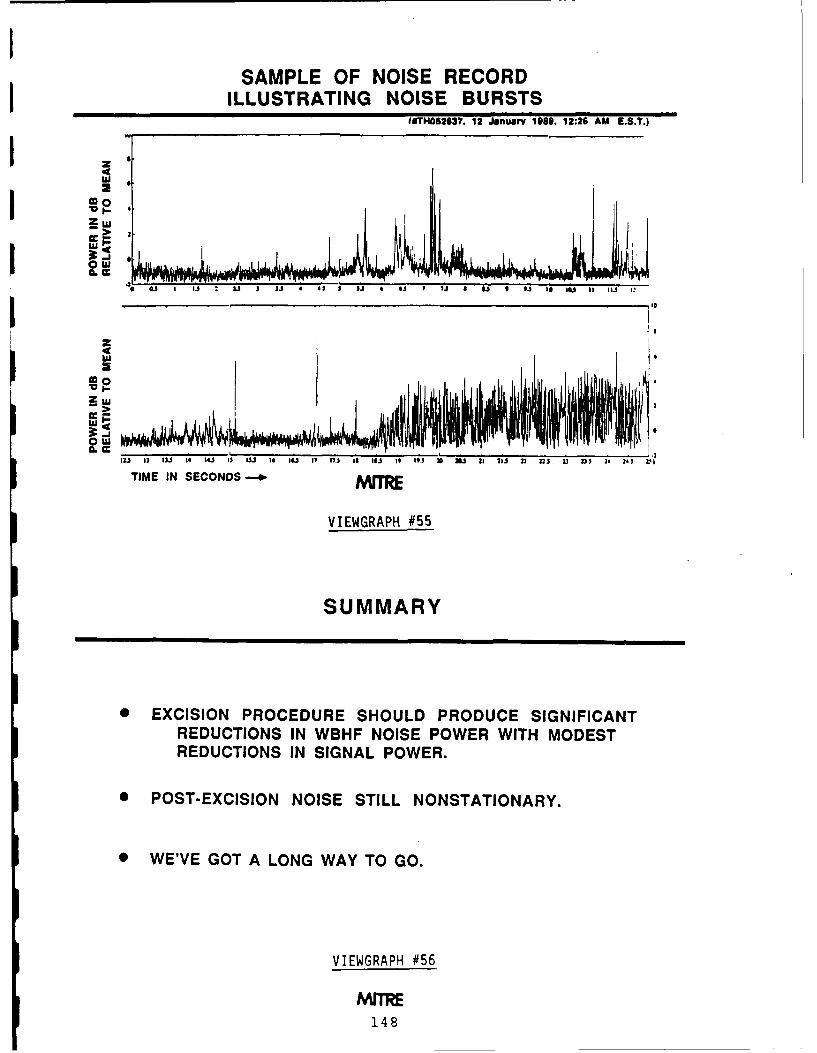
SAMPLE OF NOISE RECORDILLUSTRATING NOISE BURSTS
(IITH052137. 12 January 1S89. 12:26 AM 1.5.?.)
zowuziia1 U VEGAK#5 ~ 2lZ D~
REUTIN INSGALPWR
TIM POSECISIO NOS SILNOSAIAY
VIEWGRAPH #56
SU48R

WIDEBAND HF CHANNEL MODELINGFOR DIRECT SEQUENCE SPREAD SPECTRUM
MODEM DESIGNPhillip A. Bello
Disturbed Channel Propagation-Theoretic WorksWhich Evaluate Channel Parameters
Henry G. Booker and Tao Jing-Wei, "A Scintillation Theory of the Fading ofHF Waves Returned from the F Region: Receiver Near Transmitter," Journal ofAtmospheric and Terrestrial Physics 49, No. 9 (1987), 915-938.
Henry G. Booker, Jing-Wei Tao, and Amir B. Behroozi-Toosi, "A ScintillationTheory of Fading in Long Distance HF Ionospheric Communications." Journal ofAtmospheric and Terrestrial Physics 49, No. 9 (1987), 939-958.
J.-F. Wagen and K. C. Yeh. -Simulation of HF Propagation and Angle of Arrival ina Turbulent Ionosphere," Radio Science Vol. 24 No. 2 (March-April 1989), pages196-208.
L. J. Nickisch. "The Mutual Coherence Function in Extended Moving RandomMedia," MRC/MRY-R-012. .Iission Research Corporation, Carmel. C4 (December1988).
Wide Band HF Channel Measurements
L. S. Wagner, J. A. Goldstein and E. A. Chapman, "Wideband HF Channel Prober:System Report," NRL Report No. 8622, Naval Research Labs, W'ashington, DCAD-A127-040 (1983).
L. S. Wagner and J. A. Goldstein, "High Resolution Probing of the HF SkywaveChannel: F Layer Mode Fluctuations," Effect of the Ionosphere on C3 I Systems,J. M. Goodman, editor Ionnspheric Effects Symposium, L.C. 85-600558(1984), 63-73.
L. S. Wagner and J. A. Goldstein, "High Resolution Probing of the HF Iono-spheric Skywave Channel: F2 Layer Results," Radio Science Vol.20 No. 3 (1985),287-302.
Roy P. Basler, et al., "Ionospheric Distortion of HF Signals," Radio Science Vol.23,No.4 (July-August 1988). .. 569-579..
149

will cut down the interference greatly. What [ST CTF vg2] However, in staying with thewe're using at MITRE, at the moment, is a fiber optic cable a problem is generated forquick and dirty exciser; take an FFT, a block the problem that is solved - you end up withat a time, modify those FFT bins that exceed speckle. It turned out that not only do youthe threshold by throwing them away or clip- end up with spatial speckle that is static, butping them, then do an inverse FFT. Do this you end up with impacts on the waveformcontinually. Then you feed that to the rake that you produce at the far end of the link, atdemodulator. I don't think I'll discuss any the receiver. Because of the fact that the lasermore because I've run out of time. diode is shifting frequencies as the current is
LINDSEY: O.K. Phil, thank you very modulated, the spectrum at the input of the
much. We'll reserve questions and comments optical fiber is shifting, and the modal noise
till after our break, until all speakers have of the fiber gives a dynamic speckle prob-
completed their discussions. At this point I lem. This produces waveform amplitude dis-
would like to introduce Dr. Ken Wilson from tortions at locations in the far field, causing
Martin Marietta who will talk to us about a mismatch between the waveform and thetransmission of information via of the optical matched filter with an attendant decrease in
channel, and ... O.K. J think I'll just shove performance. This talk is only going to ad-
this back. Leave it here .... dress the static portions of the speckle mea-surements that were made in an attempt toKEN WILSON: Optical Channelsquantify this channel. Walt Bremmer also
[ST CTF vgl] Back in the 1984 time frame, presented at MILCOM '88 a series of mea-Martin Marietta had to come up with a free- surements (paper 32.6) that were dynamicspace optical communication link for inter- in nature and that unfortunately were notsatellite use. At that time, Martin had the a complete data set, that is, measurementsassistance of McDonald Douglas, one of the of dynamic speckle as a function of positionleaders in building such things. Suffice it throughout the whole beam. We will showto say that there was a falling out betweencontractors (a fact that plagues the relation- you cole ed setship to this day), and Martin cancelled the The problem faced by the communicationcontract with MacDac. Due to the tremen- system engineer is that of evaluating the ef-dous inertia in a design by the time a pro- fect of the dynamic speckle on the perfor-
gram reaches the Preliminary Design Review mance that can be delivered through the
stage, the method of coupling the laser diode speckle channel. Therefore we seek a method-
output to the focus of the transmitting opti- ology by which the performance of the chan-
cal system was already fixed - a multimode nel can be evaluated. One of the most inclu-
step index fiber optic cable was used. We sive channel models which has been formu-
stayed with this design for some very good lated is Lindsey's Space-Time Communica-
engineering reasons: it keeps the focal point tion Transmittance Function (ST CTF) chan-
constant, elimates any variation of the optical nel model. The objective of this talk is to
beam alignment with respect to thermal dis- show the progress that has been made in the
turbances of the laser diode heat sink, keeps application of this very general model to thethe laser diode heat off of the optical bench, laser speckle channel.
eases optical alignment, and so on. [ST CTF vg3j I'm going to rush through
150

APPLICATION OF THESPACE-TIME
COMMUNICATION TRANSMITTANCE FUNCTIONCHANNEL MODEL TO AFIBER OPTIC COUPLED
SEMICONDUCTOR LASER DIODE
MAY 14, 1989
Dr. Kenneth E. WilsonMark A Hennecken
MARTIN MARIETTAASTRONAUTICS GROUP
ST CTF vgl
BACKGROUND
" FIBER OPTIC COUPLING OF LASER DIODES USING MULTIMODE FIBERSGENERATES SPECKLE IN THE FAR FIELD. THE SPECKLE HAS SPATIAL ANDTEMPORAL CHARACTERISTICS THAT DEFINE A SPACE-TIME CHANNELWHEN PROJECTED FOR FREE SPACE LASER COMMUNICATION TRANSMISSION.
* THE IMPACT OF THIS DYNAMIC SPECKLE ON THE COMMUNICATIONCHANNEL PERFORMANCE SHOULD BE EVALUATED ANALYTICALLY.
APPLY THE SPACE-TIME COMMUNICATION TRANSMITTANCE FUNCTION(ST CTF) CHANNEL MODEL TO THE LASER SPECKLE CHANNEL BY EVALUATINGDATA THAT HAS BEEN TAKEN IN TERMS OF THE MODEL. THAT IS, MAKE ASTART AT BUILDING A CHANNEL MODEL.
ST CTF vg2
151

THE ST CTF CHANNEL MODEL
" THE MODEL AS ORIGINALLY FORMULATED BY LINDSEY AND LO RELATESTHE OBSERVED ELECTROMAGNETIC FIELD TO THE FIELD THAT WOULDBE PRESENT IN THE ABSENCE OF THE MEDIUM. THE SPACE-TIME CHANNELTRANSMITTANCE FUNCTION DEFINES THAT RELATIONSHIP:
7*3r (1 T',t .,*(ro ' ) r3 ,
Medium Present CTF Medium Absent
* THIS CAN BE PUT IN MATRIX NOTATION1h xy
Eox xxh h xz Ex
Eoy yx yy yz Ey
EozJ zx h zy hzzj EzJ
ST CTF vg3
THE ST CTF CHANNEL MODEL (Continued)
" THE SPACETIME CORRELATION FUNCTION IS DEFINED IN TERMS OF THE h's:
-c htj( . ; ) h (', 'r; t +,
* DEFINE THE NORMALIZED ST CTF CORRELATION FUNCTION AS
Rh-4.-* -,t
R h(ll , Fs;t )Ph,, (a r .r' ; t) )
ST CTF vg 4
152

these because I assume that you are al- assumed that the optical axis is in the direc-ready knowledgable about Lindsey's ST CTF tion of the positive z axis, so there is no z-model. As originally formulated, it was a variation and H,, in the matrix is equal to 1.polarization-dependent model where the out- The measurements were made in the steadyput is related to the input by the polariza- state and incoherently, so the t componenttion matrix H*. The polarization matrix ex- goes away. When the problem is consideredpresses the observed field (here on the left) in in rigorous detail, you find that in order toterms of the field that would exist at the ob- actually model the speckle pattern that youservation point if the dispersive medium were produce in the far field, all of these effectsabsent (here on the right). For notational have to be taken into account inside the opti-convenience a matrix can be used to repre- cal fiber. But the beauty of using the channelsent the components of the vector field, model is that it permits you to ignore some of
[ST CTF vg4] The correlation function is the physical details that you cannot actuallydefined in terms of the components of H*. It compute, and we cannot compute the speckleis the expectation value of H x H* for the ith pattern at the fiber output given the multi-and jh components. i and j typically rep- mode, multi-spectral optical input providedresent the spatial coordinates of the correla- by the laser diode source.tion function. We define a normalized space- [ST CTF vg7] Right on into the source, wetime correlation function as the ratio of these have a six-stripe laser diode with an outputcorrelations, normalized by the no-dispersion aperture of 56 microns driving a 75 microncase at the same point. Thi p will figure in diameter core optical fiber as shown on thethe integrals that we used to derive correla- next viewgraph. Let me go ahead and puttion time and correlation lengths. it up and talk to the physical configuration
[ST CTF vg5] And these are Bill's defini- directly.tion for correlation time and length. What is [ST CTF vg8] Here is a six-stripe diode.different about what we've done here is that This is about a 10-inch piece of step indexBill's model was formulated to handle polar- optical fiber cable with the indices of refrac-ization details of the channel. Most of the tion shown, having a 75 micron core and a 25fluctuations we're going to see are caused by micron thick cladding. The input to the fiberthe polarization details of the medium. How- is vertical because these particular diodes areever, .... 99% pure in polarization. The fiber is driven
[ST CTF vg6] Those details are essential in by multiple sources, the 6 stripes of the laser,the radio-frequency channel. For this particu- each source having multiple spectral lines. Ilar channel, we have a non-polarization sensi- did not show you the output spectrum of this.tive receiver. We have a photodiode detector let me see if I brought it with me [Yes, I did.that if a photon hits it, produces a photo- I'll show it to you in a minute'. The laserelectron with the probability associated with is near field coupled: the laser/fiber separa-the quantum efficiency of the photo detecting tion distance is 10 to 20 microns as opposedmaterial at that photon wavelength. The de- to a source aperture of 56 microns. thereforetector is polarization insensitive, therefore in you are in the near field. The stripes them-terms of the space-time correlation function, selves are alternating in phase with a 180-the Hi, are diagonal. Furthermore, we have degree phase shift. Without the fiber present
153

THE ST CTF CHANNEL MODEL (Continued)
* THEN THE CHANNEL CAN BE DESCRIBED IN TERMS OF CORRELATIONLENGTHS AND CORRELATION TIMES:
f .Phlj(r'U*rTo;t) d
Lx f -Phi(xAY=Az:0,;0)dx
L y f= - -s P ( a x n , a~ y , 4 z r 0 , -r , ; 0 ) d ,&y
Lz f Ph (AX:A y:O,&z, rOs;0) daz
ST CTF vg5
THE ST CTF MODEL APPLICATION
* THE ST CTF MODEL WAS FORMULATED TO HANDLE THE POLARIZATIONDETAILS OF THE CHANNEL. THESE DETAILS ARE ESSENTIAL TO THE RADIOFREQUENCY CHANNEL AND TO THE HETERODYNE LASER CHANNEL. THEYARE ALSO IMPORTANT IN THE FIBER OPTIC COUPLED LASER CHANNELIN COMPUTING THE SPECKLE PATTERN.
0 NO SERIOUS ATTEMPT WAS MADE TO COMPUTE THE SPECKLE PATTERN.INSTEAD, THE PATTERN WAS MEASURED AND IS STUDIED STATISTICALLY.
" THE DETECTOR WE USE IS POLARIZATION INSENSITIVE.
" THE MEASUREMENTS WE MADE ARE POLARIZATION INSENSITIVE.
" THEREFORE, IN TERMS OF THE ST CTF, THE h I ARE DIAGONAL.
" THE MEASUREMENTS HAVE NO z VARIATION, SO h ze I
" THE MEASUREMENTS WE MADE ARE STEADY STATE, SO = 0.
ST CTF vg6
154

FIBER OPTIC COUPLED LASER DIODE SOURCE
* A 6 STRIPE DIODE WAS USED TO DRIVE A 75 gm OPTICAL FIBER AS SHOWN.
* THE STRIPES ARE PHASE LOCKED AT SEVERAL FREQUENCIES (WAVELENGTHS)BY EVANESCENT COUPLING BETWEEN STRIPES.
* THE DIODE IS NEAR-FIELD COUPLED TO THE FIBER. THIS RESULTS IN A'SEVERAL COHERENT SOURCE' INPUT EXCITATION OF THE "MODES" OF THEFIBER. THE VARIOUS PATH LENGTHS (DIFFERENT FOR EACH MODE) CAUSECONSTRUCTIVE AND DESTRUCTIVE INTERFERENCE AT THE FIBER OUTPUT,PRODUCING THE INTENSITY VARIATION WE CALL SPECKLE.
* THE TRANSMITTING LENS IMAGES THE FIBER OUTPUT, PROJECTING IT TO ASPACE LIKE HYPERSURFACE AT -.
ST CTF v97
LASER SOURCE
6 Stnpe diode
in 1.486 75 Im 125 Mm
n a 1.457
- , - 26.6 cm p
10-20 pm
Laser Input to Fiber: Fiber:Polarization: vertical Spectran 75Multiple Sources (6) 75 'm core, n m 1.486Multiple Spectral Unes 125 gm cladding dia, n * 1.457Near Field Coupled Step IndexAlternating 1800 Phase Shift MultimodeEach stripe has gain at several distinct wavelengths Non-polarization preservingEach wavelength Is phase locked across the stripes Length - 10.5 in - 26.6 cmIndividual stinpe divergence - 20" x 400 Numerical Aperture * 0.292
ST CTF vg8
155

this phasing of the six element phased array hole whose 50 micron diameter approximates"antenna" produces the typical two lobe far the receiver aperture at the normal operat-field radiation pattern. As a laser, each stripe ing range of the communication link. Thehas gain at several distinctive wave-lengths, pin hole and avalanche photodiode detectorEach wavelength is phase locked across the (APD) are mounted on a Klinger motorizedstripes by evanescent coupling between ad- scanning z - y translation stage. The APDjacent stripes. The individual stripe radia- is a detector with internal gain. As such ittion angular divergence is about 20 degrees had sufficient signal output to directly driveby 40 degrees. Running down the lists here a 12 bit analog to digital converter. This wasto make sure that I've covered everything, all controlled by a HP-9000 Series 220 com-the fiber was a Spectran 75, with 75 micron puter. With this setup it was possible tu au-core and 125 micron cladding. It's a step in- tomate the measurement of the far-field atdex fiber therefore it is multimode and non- the 50 micron aperture over a 120 point on apolarization preserving. Its numerical aper- side square grid.ture for you optical people is 0.292. The diode [ST CTF vgl0] We measured that 120 x 120is near field coupled, and the transmitting grid in the far field, a measuremeat of a farlens images the fiber output, projecting it on field pattern that is essentially circular. Froma space-like hypersurface at infinity. Trans- this circular intensity distribution (convertedlated that means the lens focuses the output to power by sampling through a finite aper-surface of the fiber at infinity. ture) we took a 64 x 64 subarray from the cen-
[ST CTF vgSpect] Here is a typical spec- ter, indexed by integers m and n on 50 microntrum output of the laser diode showing the steps. From this I've computed the 2-D FFTkind of wavelengths or frequencies that you're directly, the probability density function, thegoing to see for one of these diodes. As I said, 2-D autocorrelation, the 2-D autocovariance,this is a multispectral diode due to the fact the 2-D power spectral density from the auto-that you can support several modes of oscil- covariance (rather than from the autocorrela-lation inside a laser cavity of the dimensions tion), and the space-time correlation lengthsused in this laser, because the laser cavity is from the autocorrelation function.fairly large. [ST CTF vgPedestal] Now we can go fairly
[ST CTF vg9] Here's how we made the rapidly here and flip through 2-D plots thatmeasurements. One of the differences be- convey little information but that show thattween the setup shown and setup used to pro- we did take the data on the basis that I said.twen the setup shwnll ansetu sea toe pr- Here's the 120 x 120 point grid. This spike induce the data I will present is that the ac-
tual space qualified laser diode modules were the back of the plot is a reference level, andnot used. Measurements of the actual space the pedestal with the jagged top is a typicalqualified laser diode modules were made and intensity plot.were not significantly different from the data [ST CTF vg64Subset i We take a 64 x 64you will see. The laser bias supply drove subset of that same data, and it looks likethe laser, which drove the optical fiber and that when you plot it out with hidden linetransmitting lens. The Fourier lens is used to suppression.transform to the far field here at the detec- [ST CTF vgpdf! When you take the wholetor. The far field is sampled through a pin pedestal that you saw earlier and plot the
156

TYPICAL SPECTRUM OF LASER DIODE w/ OPTICAL FIBER
.................. .................... -........ . . . . . . .....
......................
.841W'avel1enqth (: ri-1
ST CTF vgSpect
SPECKLE TEST MEASUREMENT SETUP
FourierLens.
Laser Bias 500 mm DtcoSupplyFocalSupyLength APD detector Bias Supply
Pinhole PlateLaser Diode sModule Optical Fiber .1.
Temperature /~ - 500 mm--o 4--500 mm -- pControlled / IIHost Sink Transmitting
Lens7.5 mm 11 Klinger motor5 mm 0a driven x- y1/1.5 translation stage
ST CTF vg9157

DATA TAKEN
* MEASURED THE POWER THROUGH A 50m APERTURE OVER A 120 x 120GRID IN THE FAR FIELD
* HAVE A 64 x 64 ARRAY OF DATA TAKEN FROM THE CENTER OFTHE 120 x 120grId:
p(m,n) : (m,n)c (1...64; 1...64)
" FROM THIS COMPUTED
. - 2-D FF' OF THE DATA DIRECTLY IN A 64 x 64 SUBSET
PROBABILITY DENSITY FUNCTION: MEAN, VARIANCE, SPECKLE CONTRAST
2-D AUTOCORRELATION: 64 x 64 -; 32 x 32 SUBSET
2-D AUTOCOVARIANCE: 64 x 64 -: 32 x 32 SUBSET
- - 2-D SPATIAL POWER SPECTRAL DENSITY FROM THE AUTOCOVARIANCE
- - THE ST CTF CORRELTATION LENGTHS FROM THE AUTOCORRELATION
ST CTF vglO
TYPICAL INTENSITY PLOT OF RAW DATA IN 120 x 120 GRID
ST CTF vgPedestal
158

TYPICAL INTENSITY PLOT OF RAW DATA IN 64 x 64 GRID
Ifi "I:.3 Wo iMULD Iwo - N3fl(Ho as) *TlUSIW15 MI Msn
£4.540110411
ST CTF v64Subset
PROBABILITY DENSITY FUNCTION
Prbaiity 091sity FisitioA - 1 (1) IDL f3S3
Th pS p& ~ - 1918.409,"
gn sim - -,96.214996
!C$ MC ~A. C1.1t* !2471S, 29 -u1Q )~~qf:I1AMS
TET ~~A.tiTC~ ILr~SV INPU *.v ThN r) upT:I1LAE f~iM
~ r~S159

probability density function, this is what you sity. When we take the autocorrelation of thisfind. Here is the mean value at 1.0. The data, you see a central spike which you wouldpdf is plotted around that value using his- hope to see, but you can tell by the shape heretogramic type of plotting. Originally the pdf that it's not well correlated with itself as youwas not used. We only started considering try to move away from a given point. Thisthe probability aspects of the problem when is a measure of how well distant values of in-we began working on the communication per- tensity are correlated with the value you justformance prediction consequences of speckle. left. So this is the autocorrelation function,This is what a communication engineer needs ...for the speckle because what you usually end [ST CTF vgACov] which is almost indis-up computing is a bit error rate conditioned tinguishable from the autocovariance for thison a given received signal level. Then you particular speckle pattern. That means thathave to treat that as the conditional compu- the subarray sums were approximately thetation it is, and use this probability density same over the pattern. So this is what hap-function on the intensity to compute the aver- pened before we learned of Bill's model.age bit error rate and probability of delivered [ST CTF vgSpPSD] We computed the spa-service. The pdf was a new result when we tial power spectral density of the data andcomputed it. When one has the pdf, one can were able to get the smoothing Bill has re-compute the contrast, a statistical measure of ferred to earlier. Thus we could estimate howthe variability of the speckle pattern used by much power is in the higher frequencies ofexperts in that field. I will not go into this that particular intensity fluctuation pattern.further. [ST CTF vgl2] This chart defines the ex-
[ST CTF vgll] Here is the notation for the act processing that was used to compute theFFT we took, the normal type of transform, autocorrelation and the autocovariance. Weexpressed in DFT form. computed the spatial power spectral density
ST CTF vgRawFFT] Here is the plot of with the FFT using the formulation that Ithe magnitude of the 2-dimensional FFT. had described earlier.This was rearranged to plot zero frequency [ST CTF vgl3] Finally, we went ahead andat the center of the plot, so the spikes at the learned Bill's model. He gave us a paper fromcenter denote low spatial frequencies - where MILCOM '88 and we went ahead and com-frequency is expressed in cycles per meter. puted the correlation lengths L= and L. usingYou can see that there is significant power in this discretized form of the integrals. Againthe higher frequencies meaning that the 2-D we used the normalized p, the normalizedsurface will be "rough". Note that from an space-time correlation function, since that'sanalysis point of view, that this type of plot where the information is about the pattern.is meaningless when attempting to determine [ST CTF vgl4] We computed the corre-statistical properties of a 2-dimensional ran- lation lengths shown. We had actually an-dom process. alyzed two distinctly different speckle pat-
i'ST CTF vgACorr] The proper thing to be terns, as the real reason for doing this workcomputing when analyzing statistical prop- was to find ways to reduce the speckle. Oneerties is the autocorrelation or autocovari- was generated by the step index fiber systemance. and from that the power spectral den- that was diagrammed in this talk, the other
160

DATA PROCESSING
* HAVE A 64 x 64 ARRAY OF DATA
p(m,n) : (m,n' a, (I...64; 1...64)
WHERE WE MEASURED VOLTAGES AT EACH POSITION.THE VOLTAGES ARE RELATED TO THE POWER BY
v a I RLu p Ro M R6
" FFT (in DFT form)
64 4 - 2x (m-1)/64 -I 2x (n-1)/647 (k,I) a 1 2: p(m,n) e 0MI Dal
THIS WAS REARRANGED TO PUT ZERO FREQUENCYAT THE CENTER OF THE PLOT.
ST CTF vgll
FFT OF INTENSITY DATA
Tll! *IZ-I:.3 lrDl lIJI:LI6D |I~Tn lt(I0 ISI) UtfIIM:SlIUUS $L I$.
T.~IS t.3
)iK, 11351 IW51 /r
M itUth w~ Ibmulizat~eft
ST CTF yj aWFFT
161

AUTOCORRELATION OF DATA
?1 10-C.3 WEI lI3D:LDD INN? BNTCN AM) 4MU13t1:ILhTOSO SRI. MISI. RUW3.?14
CUM-
ST CTF vgACorr
AUTOCOVARIANCE OF DATA
UT 119-Ci5 ii. 11 TIRER:LDGD lIPIJI RUTTIO 41) OUTPUI:SIIIAIES SOL AStI.
;A 11344-62
162

SPATIAL POWER SPECTRAL DENSITY OF DATA
TOT 311:.3 01 FI :LIDD 19M1 " *I(11 ) UT ::$11ATIS SL tSE.
IL .4236o*
( 1,) I V& sr C.,o) 0 I, aM - kith In Ibroalistim
ST CTF vgSpPSD
DATA PROCESSING (Continued)
" AUTO CORRELATION32 32
S, (k,I) = - p(15+m,15+n) p(m+k, n+l) PEAK AT (15,15)(32)m nt
NORMALIZED AUTOCORRELATION:P(k,) . It(k,l)
s( 15,15)
* AUTOCOVARIANCE
1 32 32 32 32
8 (k,I) =R.(k,I) - - 1 1 p(15+m,15+n) 1 1 p(m+k, n+I)mI 1 nl mmi nlt
" SPATIAL POWER SPECTRAL DENSITY
2-D FFT OF S (k,I)
ST CTF vg12
163

ST CTF MODEL PARAMETERS
* CORRELATION LENGTHS FROM THE AUTO CORRELATION
29Lx a 1: (k-15)a xp (k,15)
ka1
20Ly a 1. (k-lS) a yP (15,k).
kol
ST CTF vg13
RESULTS OF COMPUTATION
"CORRELATION LENGTHS
Lx Ly N x NY
ISL - 21.9 Am - 174.45 Am - 0.438 - 3.489
GRIN/LOOP 272.76 A~m 146.79 Am 5.455 2.935
" INTERPRETATION
An N LESS THAN I INDICATES A CORRELATION LENGTH LESS THAN THE 50 JimSTEP SIZE AND THE 50 Am APERTURE OF THE DETECTOR, WHICH I INTERPRETAS A DELTA FUNCTION
THE COMPUTATION OF CORRELATION LENGTH COULD OBVIOUSLY BE DONEfO.R VA.O'. - C!' x AND y OTHER THAN THE CENTER VALUE ( A SORT OFMARGINAL CORRELATION LENGTH).
IT IS NOT CLEAR THAT THE CORRELTATION LENGTH SHOULD NOT BECOMPUTED AS A RADIAL VALUE, GIVEN THE SYMMETRY OF THE SYSTEM.ARE WE MAKING SOME IMPLICIT ASSUMPTION ABOUT A FUNCTIONALRELATIONSHIP BETWEEN CORRELATION LENGTHS MEASURED ALONGORTHOGONAL DIRECTIONS? A RADIAL COMPUTATION WOULD ALLOWUS TO PUT SUCH AN ASSUMPTION TO THE TEST (OR TO TEST THE DATAAGAINST SUCH AN ASSUMPTION).
ST CTF vgl41G4

* La
Lu C
z 0U
CCLUI Eu 1-0j c >U
C, 0
z0 I
Lu Lu LLU c
ul LU L
9.0 Po
> qmi z 004W LUIL
L 0 0 c -
v C4)CC 4 ui
ILO 2 L
CL Lu~ P
Lu Z Z PZuJ
ZCL LU,0 U )z~~~ 0-0.)~0u c m L) -Z
>m 0 S 0
165

was generated with a graded index (GRIN) reported by Bremmer in the MILCOM '88fiber with a storage loop made by splicing a paper. It would be good to have a completeloop into the system using two fiber optic Y- set of such dynamic data. Unfortunately thecouplers. (This is actually a very interesting program involved views their problem as be-system from a theoretical viewpoint because ing solved because they took the easy wayof the Markov channel-with-memory consid- out. They got the actual modem that driveserations which result from photonic storage the laser and demodulates the received sig-in the optical fiber loop.) Because of time nal, they set up a complete loop-back linkconstraints I've suppressed showing you this and proved to themselves that with the gim-second case. The system that was actually bal jitters involved, and the waveform distor-put into the intersatellite link has a correla- tions involved, the system as designed deliv-tion length of-21 micons in x and 174 microns ered the performance that they required. Soin y. This corresponds to numbers of pixels, there's probably little motivation for takingif you will, on 50 micron centers of 0.4 and the full set of what I'd call dynamic data3.48. How does one interpret such a thing? over the complete 128 x 128 location inten-Well certainly the correlation lengths can be sity profile. We have not done any evaluationnegative in this case because we had a cen- analytically of the impact on the communica-ter at (0,0) in two dimensions. So you can tion system by using that probability densityhave correlation lengths going either way. I function or the outcome of the model. Whatinterpret the N here as being less than 1 as the model will allow you to do is model theindicating that you essentially have a delta- effect even in the static case of having gim-function. It's much less than the 50 micron bal jitter in this particular inter-satellite link.step size and therefore I say I've got a delta Because gimbal jitter is going to tend to makefunction in that particualr direction. that field "dance" in the far field while your
Thus, if you look back, which you can't do receiver is stationary with respect to that jit-because you don't have copies of the view- ter, you'll get a time variation based, even in
graphs, [but now you do in this written form] the static speckle case, on the gimbal jitter.everything was referenced to the center value Those things have not yet been computed,X and y of the autocorrelation function. Oh- and we reserve that for future work. Andviously you can start choosing values away that completes the presentation.from the center and do a kind of a marginal LINDSEY: The timing is just right. Wecomputation of correlation lengths as you are schedule to have our pictures taken and Imove away from the origin. Whether or don't know if the photographer is here or not.not you ought to be actually doing a radial I know he's arrived outside but just how longcomputation given the underlying cylindrical it takes for him to set up the camera and allsymmetry of the beam is a good question. those good things, I'm not sure. I think it'sThese are the issues that are starting to arise going to be outside on the lake or something.as we start to try to apply this model. So if you'd like to take a break and have coffee
ST CTF vgl5] So given that static data, or whatever fruit is back there ... I think wewe've made a beginning in applying the should have our break, take the picture, andspace-time correlation function model to it. then come back and complete our discussionsAs I mentioned, dynamic data was taken and with regards to measurements and so on. It
166

looks like they took our goodies away. We JTIDS coming along which was a frequencyabandoned them and they abandoned us so hopper over 250 MHz, centered around 1maybe we can get started yet. GHz. We had a few other systems that were
O.K. we'll change the tempo, I think in direct sequence, fairly nominal bandwidthsterms of our discussion and now we'll talk and we were talking about packet radio atabout taking measurements with regards to that time, using a direct sequence waveformcharacterization of various channel param- of up to 100 MHz or so. So we neededeters and maybe whatever, and the first wideband channel characterization data. Inspeaker after our break will be Paul Sass. round 1982, we started a program which wasPaul .... competitively solicited and won by SRI Inter-
PAUL SASS: Wideband Channel Mea- national to design and build a wideband PNsurement Ezperience channel probe operating over that frequency
band. At the same time we started with AlThanks, Bill. As has been said a few times, Sch
we are going to change the tempo. I'm not Schneider, who is joining me today, to look atgoing to compete with the theoreticians and one specific channel, the forested communica-goin tocompte iththe heoeticansandtion channel. He was involved from the begin-put up very many equations. What I'm going nn hann he as i e d heento do is try to share with you some of the hard ring in designing the experiments and help-lessons we've learned over the last 5-10 years g unlye th da. l s tream weactually, in the field. got involved with Ray Luebbers through the
presentin iArmy Research Office who was interested inThe material [SLIDES 1-2] I'm presenting the Geometric Theory of Diffraction and how
here, admittedly, is past history. We have it might apply to wideband channels. He hadbeen doing this, as I said, over quite some only applied it to CW or narrowband signalstime. But my motivation stems from a dis- up until that point. So he saw our measure-cussion I had with Mike Pursley about a year ment program as a unique opportunity to getor two ago where he was lamenting the fact me program ata.that we really didn't have the data to charac-terize the channel, whatever that means. I'm As I said, our work mainly stressed forestnot going to answer it like Bill Lindsey, but channels. The program in summary startedwhat I'm going to do is to share with you with a prototype built by the people out atsome of the data we have acquired and put ITS, Boulder, Colorado, Dr. George Huffordthe onus on you to tell me how we can use and company. Bob Hubbard built a proto-this data to get these answers. I'm not going type in 1979-80 time frame which was a wide-to propose getting a transmittance function band PN probe and demonstrated its appli-specifically but you'll see what we did. cation for channel characterization. It was
A little in the way of history. About 10 an analog system, very crude to use, but ba-years ago, we at Fort Monmouth initiated a sically it proved that you c'nuld use a systemprogram to go out in the field and make wide- like a PN probe to measure channels alongband channel characterization measurements. the lines of Phil Bello's work much earlierOur interests were in the UHF band, 200 than that. Over the period 1982-85. we ac-MHz to 2 GHz. We were interested in possi- tually built and tested and brought to thebly or ultimately deploying spread spectrum field an automated wideband measurementsystems in that frequency range. We had system to do that. [SLIDE 4' The system
167

z
-o ow
I-- 0v) z 0 0
< ~ ~ ~ - ZI-LU 0 0a
U i z Uj <Ui00 ata - 0 _
3 1 M- ri - 0 o0 z* 0 -
*z < I - Z~ ~ d
<0 < -' 0 gi < L
00Z(N0 2 < L)40< Wr L
z L-J 00 L 9-
<J 0wU U
a zto> _ C
z L6Lu ao LCOJ u M I
L) LLJ Q0I L LJC
LLI0KL)N
(Z
em6

I wI
0 W
0
26
Gal IL
0.C
z - 169

consisted of a transmitter in one vehicle and do your sampling, you can get a fairly accu-a receiver in another vehicle which I'll dis- rate representation of the time varying chan-cuss in a few minutes. Over the next two nel. This TVIR then becomes our measure-years, following that point in time, except for ment tool. It's an FFT away from getting thea little break to deal with some vehicle prob- transfer function of the channel. What welems that we had (and I'll talk about that), measure is actually the output delay spread,we compiled two years worth of a lot of data I believe, based on Phil Bello's work. At thein a variety of sites. We concentrated on the same time we use a lot of real time processingforests in Fort Lewis, Washington which were in the system to give the operator a real timelargely trunk-dominated forests. This means sample of what's happening in the channelthe levels at which we were transmitting were as well as setting ourselves up to do a lot oflargely through the trunks and not through off-line data analysis. The system was heav-the canopies. We also went to Connecticut ily computer-controlled. The receiver systemfor a different kind of tree, a deciduous tree, had an HP A-700 computer in it and enabledand examined the effects of leaves on propa- the operator to set up a whole experimentgating wideband signals. routine in advance and basically push a but-
As far as why we started, this is an old ton causing towers to go up, antennas to ro-
slide [SLIDE 5] I pulled out of my file from tate, frequencies to change, and things like
10 years ago. At that time, as I said, we that. It was very complicated, perhaps even
were talking about a generic spread spectrum too ambitious and you will see why in a few
UHF system, something called BIDS (battle- minutes.
field information distributing system). It is [SLIDE 10] This is a block diagram show-not clear whether it would be a frequency ing the measurement approach itself. As Ihopper or direct sequence, but it would oc- said, we generate a PN code, modulate an RFcupy significant bandwidth in the UHF band. carrier, and transmit it over two transmittersAnd we asked all these questions: What hap- simultaneously. We transmit on two chan-pens when you put the systems in forests, for nels and at the same time we receive over twoexample? What happens when you put the parallel channels, each of which did a cross-signals through forests, what kind of multi- correlation. Then we piece together the time-path is measurable in the forest, what kind varying impulse response. Once the TVIRof delay spread is measurable in the forest data was acquired, the data was dumped veryand what other variabilities do you see in the quickly to a front-end memory in the corn-forest? What are the parameters in the trees puter and from there written to mag tape forthemselves that affect propagation? subsequent processing. This slide is an ex-
The measurement approach itself relied on ample of what a TVIR looks like, obviouslya wideband PN code PSK transmitted signal. without any multipath. This is just a displayAt the receiver that signal is cross correlated of what a processed time-varying impulse re-with a reference, using what is called a slid- sponse could look like and the correspondinging correlator which was based on Phil Bello's FFT yields the spectrum of the received sig-earlier work. The result is a time-varying im- nal. Shown here is the full res3lution of thepulse response of the channel. And if you system. I'll summarize the system capabili-keep track of things changing and how you ties in a minute.
170

< w wj uZ L L). L0 z i:-
0z 0 Z UO z< zJr 0( Z < Ls.
0< ~ ~ L LDs< )~ W
w Is. <u <e 0 : 0 L
L< 0CL <~ 0 < ceUJ :
z- 0 = .u uj 0s.
gg zW 6A6~~0--
z
w
0c 0 C
0 zus. m mu -
<- u CC <
1.s 0 wu 0c 0
z z U
W0 0 u
c!. 0 ws .M
0 0 A $-
2o to'. Z 0 0 0
CoO. 0 Z 1Ia. 4 4 U. -I" 0W.* Z M
cc C) U. z 0 &
- a - -'.I 0 2A - 0 4 4- 1.I-u '. . Z 0 Lci
1< Ml I
ffi Z 1-. L 0
Os.0 @. 0 a. mu uZ a a. W I- 0 w 0 0 4
z. ao 30-
0 z 4c z Z 'a 0 ru *i ~ Li -
0 0 m
< 0 -C 0 - 4 4 4
Z w I- Ml us CC44
CL 0 0 W0 0 i 0
17J

00
c a I x ~ a*.4
a 4 ba
*p 0'1 3g4~44.4 0
.3Z.
-c c 4 0-
* A a 4
a W 06
w 7r
.C 44c4. 4v 4a a L
aq :0 a c -0 -
a~~~4 0 -r.. 0 o
zo 444 I
-
004V
I.:a:
.- Z
a : - 4 ~ a .Usa 5
44 I *
1w a o a
U a 0- 44~ 44 v
172p0.

--------------- -
aSO a w
- - - - - - - - --- - ~ - l - -I! * a-
u c r~ - - - - - - -. a-i-
I a Nit I
I 4
'I I j
ENa 0 U
ac-
w N 1w
o i !I t
31 -. -0I
£~4 *j 0
173-

In the forest channel, typical delay spreads free-space and simple two path reflections offlooked like this. [SLIDE 11] The top one runways. We progressed gradually to moreshows a delay spread of almost one and a half complicated channels like the forest. This oc-microseconds (1400 nanoseconds) with a ver- cured, as I said, over a period of two years oftical polarization antenna. With horizontal separate measurements, all of which are docu-polarization antennas we typically saw much mented to varying degrees in a whole numberlower delay spreads. But in this case we see of reports. My interest in coming here was200 nanoseconds of delay spread. We found to offer these reports or any of the data thatvery clearly that the forest did represent a any of you might be interested in.complex scattering channel to the receiver. That was all the theory. In theory it should
As far as the system capabilities itself, all work. When we took it into the field wewe had a transmitter and a receiver, each had a lot of problems. I wanted to brieflymounted in a vehicle, integral self-elevating review some of the experiences we had. Iantennas that could raise each antenna up to thought it would help some of the theoreti-65'. We used two different antennas, omni- cians here understand the difficulty in gettingdirectional and a 7 dB gain, log-periodic array the measurement data to support their theo-covering the band 200 MHz - 2 GHz. We had retical work.4 possible operating probe bandwidths rang- I have some slides on a few of the problems,ing from unmodulated CW signals all the way but let me just talk about the ones I don'tup to 250 MHz direct-sequence spread spec- have any slides on. Electromagnetic interfer-trum. We also had a variety of code lenghts ence presented a far greater problem than wewhich enabled us to look at different multi- expected. As I said, we were trying to char-path delay windows. And as I said, we were acterize hundreds of megahertz of bandwidthcapable of transmitting and receiving on two in the UHF band. When we took the systemsimultaneous channels. The final system de- into the field, we had a lot of trouble with oth-sign resulting from an agonizing process over ers in band emitters. We originally had thethe years was really a compromise between concept that Phil mentioned, of being able toour desire to achieve a total path-loss capa- excise small numbers of interference sources.bility of 155 dB and yet achieve both the res- but we found out that the interference envi-olution and delay-spread capability over the ronment was so severe that we had no chancefull characterization bandwidth. We achieved of excising in band interference with tunableall the desired parameter ranges, but we were notch filters. As a result, most of the use-unable to simultaneously achieve full path- ful data we got was confined to the forest,loss, full delay spread, and maximum resolu- where the sources of interference were basi-tion. cally shielded from the measurement.
The approach we took in bringing the sys- Another problem is caused by the fact thattern out into the field, as I said, was fairly the forests were extremely inhomogeneous. Inambitious, and started with well-understood fact, Al Schneider has spent a lot of time try-channels. Our first attempts to do system cal- ing to characterize these forests in soic nic a -ibration and make sure that everything was surable way. We've seen the same probleinworking the way it should, were obviously trying to make path-loss measurements in theover channels that were simple to measure: real world. We've set up UHF networks of 40
174

INTENSITY (COUNTS02 mINTSIT (onyuoTs)**2
n
IL Z 0 _ 1> > 0 'MI r nE0 z 3 ;
> fn.0 > >z o rr&
KnZ
m 0 0 0
m ~~ 'n 0 in'
,3 ~ C'M Z > mA 0 0
1= 3m m'
mm z . ;
a 0 !2 Z> 00 ~m r-
0n 0 i
mz $A 0, .= =c 0 hi) 1 N An
rc 0 It0 P,
o M
cm ~ N
175

or 50 radio nodes attempting to compare pre- and a half year period. In Fort Lewis alonedictions and path-loss measurements over the we wrote 50 mag tapes worth, or 15 gigabyteslinks in the 40-node network, and we have of digitized data. As the system compiled itshad a lot of problem comparing the theory TVIR, it wrote the results into a 2 MB front-to actual practice. The path-loss prediction end memory and subsequently dumped it tomodels that we have to deal with today are tape for analysis. The raw data acquisitionsemi-empirical in nature and produce proba- took anywhere from 4 seconds at full band-bilistic predictions. Designing a statistically width spread, to about 4 minutes of CW data.valid mesurement to compare to a sampled So that was the range of data we could ac-probability distribution proved difficult. quire before we'd fill our front end and have to
[SLIDE 13] "Mobile" means you need e- dump it to tape. It wasn't quite as dynamichides. We had a lot of troubles with vehicles and as easily handled as we had thought whenalone. I'll show you how the vehicles evolved, we first started.As I said, we started out with a concept 10 I wanted to review the data processing bur-years ago of small vehicles that can get in and den itself. Maybe you have a feel for the dataout of forests and move in and around terrain, analysis problem. The raw TVIR data, as IYou'll see what we ended up with. said, was first written to tape. The first pro-
[SLIDE 15] Cost was another problem. As cess in the data analysis routine was to cor-
far as cost, I thought I'd just show you the rect for imperfections in the hardware. Theprice tags on some portions of the measure- way the correlation receiver is structured, itrment program itself. This doesn't even in- uses 4 separate correlator channels, each ofdude the data analysis that we've done and which have I and Q channels. The phase er-all the work that Al Schneider has been do- rors between those correlator channels resulting with the data for the forested channels in errors in the resulting TVIR. An off-line
that he's interested in. But as you can see, analysis routine was written to remove thoseby the time we bought the measurement sys- phase-offsets on each of the 8 channels. Thistem, took care of the vehicular problems and produces a corrected complex TVIR. Thatventured into the field, we were left with was the first objective of the measurementa fairly expensive proposition. This is par- itself.
I ticularly frustrating since it didn't leave us Once we had obtained the corrected TVIR,enough budget to really analyze the data as we did a lot of summary data file manipula-thoroughly as we'd like. tions. We computed the average power TVIR
[SLIDES 16 ..19] This is a photo of part of and the spectrum, and wrote that to a sum-our data, currently in storage at SRI Inter- mary data file which included all the exper-national. We had a lot of philosophical argu- iment descriptive parameters, tree parame-ments over the years about the need to pre- ters, etc., everything that was stored in theserve raw data as opposed to reduced data. experiment set-up. That makes up the partWe've done both. We've not only compiled of the files that we ship around to most of tledata summaries of the raw data, but we've people who are looking at the data.also preserved the raw data itself. We've es- The raw mag tapes were processed off-linetimated that 7000 Gigabytes of raw data were at SRI and then written to a summary dataacquired in this measurement phase in a two file on an HP mag tape. In some cases they
176

LLT
Lu4 z3 0 E
z FC
I- 0
0 L00
z w/ z/ -/J U)
p- 0 F MU) I3 ( O.Ll 0 11
_ 0 0 F0J I- -0LL C C. 5 , . 1 4LJ
C.) LU 0 LU
ULI LU 2 R VM - LU m 2 cn Lu
0. U) L 0. L3 LU UU)LU cc) ~ L CL ox
LU UJ L
CC 0.4
L U <U.zJzr<(I) Ct 0 L U ,
I- w L z 0CZLU 0 LU
r 0> Z . a Z Ln Loui -m - = L %- LUr- 0 > uzo'
~ < 5 0- >LUZ~ -LU Zj U
- LZ LU C/) r z _-JJ
0 LO' r u, <J
U. LW 0 Uj )0L f 0 ... rUZ o .()0 U LU r a
<IL

.......L. ...
'dIA.L X3IdNOD A\Vd
VAVVIZ~ SNISS33OZ~gn No~
U IS.03Vd3O31
,iaNH VIH'
*1 f
-J
UJ
46' a 3e3 * o
16 a2 i -1i 1' a$
49W 41 f
'U. 3W309. Qai OroI IIjl~t ~i I

DATA PROCESSING SUMMARY (CONTINUED)
(:RAW COMPLEX TVIR
ILOW PASS FILTER USING
TIME-DOMAIN 3-POLE BLTTERWORTH FILTE
CORRECT FOR ANTENNA PHASE DISPERSIONWHEN RF FREQUENCY < 1000 MHz
CORRECTED COMPLEX
NEXT TVIR
SLIDE 17
DATA PROCESSING SUMMARY (CONCLUDED)
CORRECTED COMPLEX
TVIR
COMPUTE AVERAGE POWER TVIRAND AVERAGE POWER SPECTRUM
SUMMARY DATA FILE
SLIDE 18
179

WPMS DATA DISSEMINATION
S WPMS SUMMARY DATA FILEPRIM E COMPUTER DISC FILE (BINARY)
ASCII SUMMARY DATA PILE(PART OF HEADER. 1 OR MORE COMPLEX TVIRSMINIMUM. AVERAOE, MAXIMUM POWER TVIRS
SUMMARY DATA FILE3 MINIMULM, AVERAGE, MAXIMUM POWER SfZCTrRUM)IH FORMAT, 9-TRACK TAPE (BINARY) PRIME COMPUTER DISC FILE (ASCII)
CECOM TTPENNSYLVANIAT ASCII SUMMARY DATA PILE
II[ASCISUMMARY DATA FILEU HP A700 COMPUTTER DISC PILE (ASCII)
CYIERCO ASCII SUMMARY DATA FILECERCOMHP CARTRIDOE (STREAMER) TAPE (ASCII)
* SLIDE 19
I
O m - - (n2 m 2 0A mI!I mm-o._D '0 .ox
am 14 I .n*14" am
00
m mw*1 o180m
I

were converted to ASCII summary fies on things that we needed to go into the field,various other media. At Penn State Univer- the vehicle quickly grew. It was much biggersity Ray Luebbers worked directly from the than we wanted, and it limits what you canASCII summary file, but Al Schneider used do with a system like this, but we had to findan HP cartridge on a small HP 9816 corn- ways of felding this system. The reason weputer. So we converted to a few different initially accepted such a big vehicle was thatformats to provide it to as many people as it was provided to us free by an Air Forcepossible. Contract.
I said something about the vehicles. This I thought you would appreciate seeing somewas originally the general concept of the of the problems we had in the field. You cantransmitter vehicle. This was actually the ve- read it yourself. This was put together at myhide we used back in the 1979-80 time frame, request by one of the SRI engineers that ranto hold the probe transmitter. You can see the measurement phase. The real scary thing,the omni-directional antenna on the roof. We if you look at the bottom, is that this repre-actually went out and demonstrated that this sents a 3-day period in Fort Lewis, Washing-system could work. The receiver at that time ton.was a rented motor home that the folks at [SLIDE 21] One of the other things IITS had provided us. As shown here, one wanted to talk about was the problem causedof the first lessons we learned was that you by non-ideal measurement tools. There weredon't use guy wires in the woods. We had a two correctio'as that SRI had to implementlot of trouble with the towers in forests, try- in the data processing routines. The first wasing to elevate antennas to the various heights. the TVIR calibration because of phase-errorsThe tower we used 10 years ago needed guy between the correlator channels. They had towires and it was totally impossible to deal correct for that to come up with the correctedwith. As a result our next phase requirements TVIR. The other thing is the antenna disper-included measurement vehicles with integral, sion. The log-periodic arrays had non-linearnon-guyed towers. For a variety of reasons phase over the significant bandwidth that wethis is the ultimate transmitter vehicle we were measuring. Therefore, in order to get aended up with. As I said, it was a lot bigger corrected TVIR, we had to do some off-linethan the GMC suburban we started with. Af- calibration. In fact, SRI did a lot of workter a number of attempts to design and pur- trying to correct for the actual antenna dis-chase our own vehicles, we ended up with the persion measured with the log-periodic array.vehicle provided at no cost from another con- [SLIDE 26] The result is shown by the dot-tract. We modified it and installed the self- ted line of the correction. The solid line is the
erecting towers that you see on the back and TVIR before the correction was applied. The
went to the field in Fort Lewis. dotted line shows a nice narrow correlation
The receiver vehicle also got correspond- peak after correction. SRI found a fairly lin-ingly bigger. I didn't even bring a picture ear phase over the main beam of the antenna.of the receiver system. The receiver system Therefore, as long as you stayed within 45 de-includes several racks of HP equipment. It's grees of the main beam of the antenna, thefairly big and with all the creature comforts correction was valid. They also found thatand the air-conditioning and all the support the correction was more necessary at lower
181
Z8T
Wi Ii
z
0
RILuJ
0 V-
z
LU0
0
I-

O4
0a alo$LJIW P a
O. Io U g I O N L ON L C AG A S N L M 4N L
$'"oweSLID 23 fw
am I -"
1.;1
94 1 ssw66SII N&A 411.
z 40
0 11
UUIIIs
183I

~8T
z fat fa
w
0
oo
o LML
00 V7
o sm

w>I -IJ
X 4
w
z Wz_j
1 44

981
LUJ
U)
C,, .
LU cQ.W LU Qz
cj~ LU 0 CO LU a
Q 0 U0
CC. wi~~O-
U Q~L4c oO
CLi00 go~2 2
=0~~~ UC) Ii I-q UV NOI&VflNaLL £101 4.vd fl23
e
azC)4
0

L81
CLi
=w CAI
0 INlO pa hIItc-
(0Rw-

frequencies (below 1 GHz) and at the higher systems.chip rates. Another question we asked had to do with
O.K., I'm going to very quickly review the existence of resolvable multipath in thesome of the answers we've gotten. Al Schnei- foliage. The answer here is no. Althoughder is going to talk some more about the de- much of the measured TVIR data appears totailed work. The first question we were asking indicate resolvable multipath, Al Schneideris: Just how far can spread spectrum systems has completed more comprehensive analysiscommunicate through the trees? We found a of the multipath returns and confirmed thatlot of data, much of which we haven't even increasing bandwidth continues to produceyet analyzed, but we've found very definite new multipath components. Delay spreadfrequency and polarization dependencies. Al measurements are reasonably representative,Schneider has since developed models which however, typically producing coherence band-have been reasonably well validated, particu- widths of less than 10 MHz I showed yoularly in the trunk region of the forest. So we what the typical delay-spread looks like in theare fairly comfortable with our ability to pre- forest. One of the things that we definitelydict forest trunk region performance of UHF found was that delay-spreads with verticallysignals. We didn't spend much time in the polarized antennas were almost always signif-leaves in Connecticut. We ran out of time icantly greater than delay spreads with hori-and money but we did find that propagation zontally polarized antennas. Al's model alsothrough the leaf canopy also adds on the or- predicts that in the trunk-dominated forestder of 5-6 dB of attenuation. Of course I and intuition kind of confirms that.think he'd be very unhappy with me making We got interesting results in the delaya blanket statement like that. spread measurements and this SLIDE 32 con-
Another question relates to how well the firms what I said; basically that delay spreadsnarrowband predictions made in the past ap- with vertically polarized antennas (on theply to spread spectrum. Here we found cate- left) were significantly more in all cases thangorically, across the board, that spread spec- those with horizontal. We've measured a va-trum predictions need to account for all the riety of distances, a variety of frequencies, allscattered energy. Unless you account for all shown here, and a variety of antenna heightsthat scattered energy received as in our wide- (as you go up the page) all below the canopy.band received signal level, you're obviously Towards the top we were starting to see somethrowing out energy that exists at the spread possible canopy effects, as we approached thespectrum receiver. The narrowband measure- canopy. So we saw some non-ideal behaviorments, all of which are shown here, don't typi- in the data.cally account lot azty of that scattered energy. Another question related to antennaTherefore their measured path-loss is signifi- heights: [SLIDE 34] Where you put your an-cantly higher than what we measured in the tennas and what kind of ai,4'enIds you use inshaded region using integration of all the re- the trees. In the trunk region we saw very lit-ceived scattering energy. Therefore, as you tie height gain (or what's been called heightwoilld expect, our conclusion is that you can- gain) aatributed to the antennas. It reallynot rely on narrowband measurements to pre- didn't matter what the antenna height was,dict received signal level of spread spectrum as long as you were down in the trunks. Path-
188

iDelay Spread (na) Delay Spread (na) Delay Spread (na)
I- III,. I)
lIT l l I I *l 1\, -*
al ~. u I . . . sl
F '-( -,II ii, N II
x4 a 0
- m
gas.I . .. .. .... .. .
z
. m
U) In a.
* 9 1. 1 . I
CI
zzo
uC) CZ() 0w
i I I d III
189 I

061
'I.* 1
2 i
.. IT I I I I jj
040
I I- A I

161
CC
wo 00~>. ci
I 0~Uj c.
~~~0 ci
0 c0
ot -jQILC-C LU (n,
(flW LU
CL
I z
L.)wI z
I 0
LL Q L
I -i
wl LU -
I ji-

ISOUT PRRY WOODS SEFOR THINNING SOUTH PRRY WOODS AFTER THINNING
e vea
SDe Sa
Ld 0
e , e*
e .. C .. .. . .. ..... .. e ... c ..... .. .. .
P req ency -- 0 | 1 Prequenc -- OH
ISOUTH PERRI' WOODS 8EFORC THINNING SOUTH PCRRY WOO0S AlrTCR THINNING
I ! I C,*
i,
is i
e ~9 2 C .I requeny - O11 PrequencT - OH:Figure 3.13 Muftlpath Delay Spread Versus Frequency Before and After Thlnnfng
I SLIDE 39
I Venlcul Politrilitom Deily Spread - l
i 0 0 - -, 0l e - 0 0 -
o ~ h~m~ 00_+ *n i I ,
a =. "00, 0
*9

IWHAT EFFECTS DO LEAF AND GROUNDMOISTURE, GROUND CONDUCTIVITY HAVE?
NONE NOTICED, EVEN AFTER RAIN AT BOTHFT. LEWIS, WA AND COVENTRY, CN.
WHAT TIME VARIABILITY IS OBSERVED? I
TIME INVARIANT, EXCEPT FOR TERMINAL 5MOTION
SLIDE 41.
1
IIIIIIIII
193 I
I

3 loss was usually greater for vertical polar- ter. Tree type, seasonal variations, and rnis-ization than for horizontal polarization, and ture had no observable effect. Next to treedelay-spread was greater for vertical polar- density, the size of the trees (i.e. the widthizations. As expected, we saw a very defi- of the trunk) had a measurable effect.nite dependence of delay-spread on tree den- This is the curve I was alluding to before.sity. We had a unique opportunity to con- It shows a return to the Fort Lewis forest be-duct measurements in the same exact forest fore and after the thinning. A lot of the databefore and after it was thinned at Fort Lewis, shows this general behavior, but we unfortu-and that provided some very unique and in- nately don't have a lot of data points. ButIateresting data. I think the curve I want to the trends are generally fairly noticeable andrely on appears in a few slides. We went to we have to go back to the raw data to ex-a forest that had been planned for cutting by tract more in-depth measurements. Return-the foresters at Fort Lewis and we persuaded ing to the same trees after the thinning signif-
them to let us conduct measurements both icantly reduced the delay spread both for hor-before and after they made a 25% reduction izontal and vertical polarizations. (Questionin the density of the trees. The results were on leaves.] Again, this applies in the trunkvery interesting. region. And these were coniferous trees, so
As far as the propagation mechanism, there there were no leaves, only needles.had been some conjecture by a number of As far as stationarity of the :hannel, we3 people that there exists a so-called "lateral saw no time-variance at all in any of ourwave" which was an indirect up, over and measurements unless the terminal was mov-down mechanism, almost a wave-guiding ef- ing. There had been some reports of leavesfect along the top surface of the trees. We're blowing, changing the measured spectrum. Infairly comfortable now concluding that we fact, I've used them before in a paper I wrotehaven't seen any evidence of a "lateral wave" almost 10 years ago ... leaves changing theat these frequency ranges. The lateral wave visible spectrum in a JTIDS signal. We didn'tis a mechanism that was fairly well accepted see anything like that. We didn't see any vari-U in the 60s and 70s at VHF frequency ranges ability with t;-e, although there admittedlyand it was being extrapolated with very little wasn't very much wind. We didn't look atgrounds up to higher frequencies. We don't very many leaf-channels in high wind condi-feel that is correct. My one frustration is that tions, so that might be the reason. We sawwe didn't quite obtain the path lengths we no effect of leaf and ground moisture, groundwould have liked to in the forest. The forest conductivity, or any of those parameters thatwas just too lossy. And, as I said, the inco- the people that study trees tend to claim willherent scattering within the trunks was very effect propagation. We didn't see it.dominant. My last slide is simply a plea to this com-
As far as the forest parameters that deter- munity [SLIDE 43]. We know all the theoret-mine communications capability, just about icil applications of measurement data. Wethe most dominant one, by far, was tree den- heard about some this morning. Neverthe-sity. The number of trees per square area less, I'm really at a loss to propose how we(per acre) or whatever your measurement is, now use this data. I'd like to see indicationsis the most important and sensitive parame- of interest from this community. I would like
194I

3 10 zC > -z
mf
r >~ 00 r -4.Q 4 4->0
<( ;aZ 0r ,A Z
-O r> 3 -< 0 > n
M- 0> -
m 0 >zC7 > mlC 0 4 za o
4 r m -M4 3 or. - - o -
3- 0 'a - 22
m 0' Z-) 0 14 3om M>'az
M ; r, -0 00 n 0 - >c
> 0 m
-4 0-m
UR~
195

to offer any of the data, any of the reports in gation, there are things that I have becomeany form you'd like, to any of you to use for very sensitive to over the years. First of all.any of your work. This was, as I said, a long people that sponsor radio wave propagationexercise and we've made a lot of progress for studies always ask themselves when it's over,the forest environment. I don't think we've if they have thrown their money down somemade much progress in a non-forested envi- rat hole. Propagation studies do not comeronment and that, in a large sense, is the cheaply as you saw by this one - three-and-channel that I think, motivated Mike Purs- one-half million dollars, roughly. And theley's comments. I know that recently he's question is, have we gotten anything for ourbeen talking about the delay spread giving a money? So, right up front, when we startedgood measure of the irreducible error rate in working on this project, one of the things thatthe channel. I'd like to see how that can be I did was to take the set of questions thatexploited with the data we've acquired. Paul had laid on the team [which included
LINDSEY: Thank you Paul. We have one SRI, Penn. State and CyberCom], and tofiuial presentor, Al Schneider, regard to mea- keep that posted in front of my desk to re-surements of data. mind me that we were always working to-
ALLAN SCHNEIDER: Delay Spread ward some practical objectives and practical
Estimation for Time Invariant Random Me- problems. The second thing, to temper that
dza study, was to ask ourselves, what could we
The topic of this talk, its title anyway, is reasonably expect out of some sort of char-
"Delay-Spread Estimation for Time-Invariant nel model or propagation model. For those
Media." I've broadened the topic somewhat of you who have some background experi-bS di- ence in tropospheric scatter, for example, theBooker-Gordon theory - I don't know when
cated earlier in his talk. I thought you might it was proposed, some time around 1955 orbe interested in seeing some of the results to i as prpsed some time a 1so - has existed for a very long time anddate of our modeling and characterization of te hthis forest channel. First, I'm going to give there has been a lot of analysis done on it
thisforst hanel.Firt, m gingto iveand so forth. But when all's said and doneyou an overview of the incoherent channel for- and yo faced wt he praica poe
est ode, ad ten fte tht Ill et ntoand you're faced with the practical problemmore of the modelling details, and, finally, of designing a tropospheric scatter circuit, theidentify one of the problems that we had in last place you really want to start is with the
identify-onedof thetproblemsothataweohadBinanalyzing the data. One of the problems re- Booker-Gordon scattering formulation. Be-ally gave us a lot of pain until we finally dis- cause it simply does not provide quantita-all gae u a otof ainuntl e fnaly ds-tive answers that are consistent with mea-covered one solution for it. I'm not saying our ture a a.e It does a e o od job in giv-
solution is optimal, but at least it gave us one
way of getting consistent results. Of course, ing you some clue as to what the sensitiv-
one of the reasons I'm here is to solicit help. ity of a certain parameters is, but, quantita-You people here who have more experience in tively, when estimating, say, the transmissiondata processing and hypothesis testing than loss, whether it is 170 dB or 110 dB, Booker-we, might be able to see alternative ways so Gordon is not where you want to go. With
we, igh beabl toseealtrnaiveway sothat in mind, I felt that we had to keep ourthat we can improve tht inalysis of this data. feet on the fl if we er to e e wha
In canne moelin orradi wae prpa-feet on the floor if we were to recognize whatIn channel modeling or radio wave propa-
196

can we reasonably expect from a model that ders having some prescribed complex dielec-is significantly much more involved than the tric constant; branches the same way; andscattering in the troposphere. Scattering in leaves were modelled as disks. These canon-the troposphere, for example, involves elec- ical scatterers can be characterized by theirtromagnetic scattering in random media but so-called dyadic scattering amplitudes - youit's single scattering. Scattering in the forest take a single scatterer, put it out in free space,involves multiple scatter, a much more diffi- and describe the scattered far-field over thecult problem. full 47r solid angle in response to an inci-
dent plane wave. In the case of tree trunks,So with that prologue as preface, let me get you then assume that all the tree trunks are
into the forest model as a modeller might, standing parallel to each other and perpen-One of the first things you might want to dicular to the forest floor. They are randomlyconcern yourself with is, what are the envi- positioned on the forest floor, they have pre-ronmental forest parameters that are likely scribed distribution of trunk diameters, butto affect the transmission loss, delay- and they are all parallel to each other. In theDoppler-spread of a forest channel [SLIDE 1]. canopy we assume that the branches are ar-We tried to identify the key parameters that bitrarily oriented with prescribed, azimuthalmight affect forest propagation by represent- and elevation angle statistics; the leaves haveing the forest as a planar, stratified medium prescribed angle statistics. We then takeconsisting essentially of the forest floor, then the dyadic scattering amplitudes and tumble-above the forest floor a trunk-dominated re- average them over the angular distributionsgion, and above the trunk-dominated region of the scatterers in the canopy. On the basisa canopy consisting of branches and leaves, of these models; we were able to incorporateIt was our immediate objective to model this most of these forest parameters. For exam-random medium by using discrete scatterer ple, with the tree trunks, certainly the key pa-theory - the Foldy-Lax multiple scattering rameter, as Paul Sass mentioned previously,theory. You can find a description of it in is the tree trunk number density, (the num-Ishimaru's two-volume text (Academic Press, ber of scatterers per hectare of forest floor per1978). It allows us to account for polarization acre), but also important is the tree trunk di-effects as well as multiple scattering. Our ameter probability density function and alsomodel is, essentially, the Foldy-Lax theory. the effective height of the trunks to where theThe way it works is, you assume that the canopy begins. And you can imagine howmedium consists of a very large number of many other parameters might bear on thisdiscrete scatterers, and each of these scatter- problem - the forest homogeneity (tree trunkers is characterized in terms of its so-called T- number density varying from place to place),matrix, or, equivalently, in terms of its dyadic the reflection coefficient of the forest floor, thescattering amplitude. The dyadic scatter- tree water content, the dielectric constant ofing amplitudes are, in some sense, similar to green wood. All these parameters, and per-the dyadic Green's function that Bill men- haps others, might enter into our characteri-tioned earlier. The forest components (tree zation of the forest channel.trunks, branches, and leaves) are representedby so-called canonical scatterers. Specifi- Based on the Foldy-Lax theory, we werecally, trunks were modelled as dielectric cylin- able to characterize the scattered field. It
197

86T
-. W -U 0
z0
at 0
0 0 a 40
cc.10- ZC -
40~ 40 40 000 4 0cc X w g0a a a a i
I0 a
0 0 0
ZL >.
z ;
a 4li -7Z
10. L0.
aWA 9. 0 .
z CDLa a
00
C- -ac w 0
-1 -j0 0
-c
- ~ ~ acc 0.c

turns out that if the scatterers are small, in semble average; the fluctuation about the en-terms ,.f a wave length, they scatter isotrop- semble average is what constitutes the inco-ically. And when they scatter isotropically, herent channel component. So there's a ques-the Foldy-Lax theory allows you to get an ex- tion of semantics here which is fundamentalact solution for the mean scattered field and to understanding the characterization of thisalso an equation for its correlation function, channel. And it's especially so in this caseFor the space-frequency correlation function, because the forest, for all intents and pur-you can get a correlation equation for which poses, is time-invariant. At least over thisyou can get an exact solution when the tree frequency band where the frequencies rangetrunk diameters are small in comparison to from, let's say, 200 -MHz to 2000 MHZ, andthe wavelength. When you go to larger tree the wavelengths range from roughly 1 metertrunk diameters, the Foldy-Lax theory be- to 10 cms. In order to effect any substan-comes very involved - computationally te- tial forest movement, you have to move onedious - and then you have to go to something of the scatterers an appreciable portion of thelike transport theory, in which case you don't wavelength. Since the tree trunks tend to re-get exact solutions. You get big numerical main fairly well fixed (planted if you'll excusesolutions. We used a hybrid technique. We the pun), there's very little time fluctuationused the Foldy-Lax for the smaller tree trunk and phase incoherence. In other words, oncediameters, and then we used transport theory you transmit a signal, because the channelfor the larger ones. Using an approximate is time-invariant, the received phase of thattechnique, we also extended the thin-trunk signal does not vary with time.Foldy-Lax model to the thick trunk case. I When you have a large number of randomlycan't go .nto exactly how we did that here, positioned scatterers, it turns out that thebut I'll be glad to discuss it afterward. average field drops rapidly to zero, except
On this basis, we developed the following at very low frequencies. In the VHF band,
model for the forest [SLIDE 2]. We also as- for example, the coherent channel model is
sumed that the key radio parameters were the the dominant one and gives rise to the lat-frequency, of course, the transmitter power, eral wave investigated by Tamir. But at the
frqeny higher frequenis tsteichrn hnethe modulation type, the bandwidth, and the ige encies, it's the incoherent channelnoise figure. Ultimately we were hoping to model which is the most important one, and
nois fiure Ultmatly e wee hpin tothat's the only one that I'm going to discussget some measure of signal-to-noise ratio and thaoalso some measure of performance in a fre- today.quency dispersive channel. The forest chan- The model equations themselves are hor-
nel itself was divided into two parts. One was rendously complex as you might expect, deal-
called the coherent channel model and the ing with complex quantities, dyadic scatter-
other one the incoherent channel model. This ers, random media, and all the other things
is a common dichotomy, but an unfortunate that go up to make the forest channel. Never-
choice in terminology especially for commu- theless, it is possible to get engineering mod-
nications people because communicators like els [SLIDE 3] that people can actually use in
to measure coherence on the basis of phase practical situations and that's what I'd likestability. For electromagneticists, their idea to show you in the next few viewgraphs.
of the coherent component is really the en- SLIDE 4 presents the output menu of the
199

III
Coherent Channel Model
RadoP aFOw tI Path Parmte 'rst F t Para.IrequPhey Pahel I Tree-Y~ ; Performauc
[Noltei Fli ureth rl J I LPo[lar 'go'IIn 1 fEIu~ M
Pu-,
-- Incoherent Channel Model
ISLIDE 2
Fiqure 1-2: Forest Channel ModelI:
I
I............................. ............ .... ...........
CyberCom Incoherent rarest Transmislion Modelf or
SpecIfIc Attenu tion and Delay spread
I
SLIDE 3
200

computer program. It comes up on the screen quantities depend on the size of the scattererswhen you push RUN. What I'm going to show and also on the frequency.you is how you run the model, enter the in-put parameters, and obtain the outputs. Af- Certainly the most important forest pa-terward I'll get into the nitty-gritty of how rameter is the tree trunk number density (thewe actually try to measure some of these de- number of trees per acre), but second is thelay spread functions. The first thing that tree trunk diameter probability distributionthe model asks you is "What do you want [SLIDE 5]. Now in practical terms, you can'tin terms of an output?" We provide three expect soldiers to go out through the forestdifferent options: one is specific attenuation, and measure tree trunk diameter distribu-
the second one is albedo and cross-sections, tions each time they want to set up a tac-and the third one is delay spread. From the tical radio system. That doesn't make muchcommunications point of view it's the total practical sense. And if we had to come uptransmission loss which is of primary interest, with the tree trunk diameter distributions fortrasmisio los wichis f pimay iterstforests throughout the world, again the modelbut in most practical cases the forest is non-homogeneous and since the specific attenua- would be virtually unusable. It turns out thattion is directly proportional to the number of the foresters have found out that there aretrees per acre, you really have to integrate essentially two generic classes of tree trunkthe specific attenuation over the path profile diameter distributions. One is the so-calledof the trunk number density in order to come even-aged forest. An even-aged forest is oneup with the estimate of the transmission loss where perhaps through natural calamity, allon a non-homogeneous forest. So the most the trees have been burned off - like Yellow-fundamental quantity in terms of transmis- stone, two years ago - or like in a clear cut-sion loss really turns out to be the specific ting case where the foresters go in and harvestattenuation and that's usually measured in the whole area of trees. The forest is com-terms of dB per meter. The other output pletely wiped out, seedlings sprout up andoption that's of major interest to communi- after ten years or so you have an even-agedcators is delay spread. We want to know how forest. But all trees don't grow to the samethe signal spreads in time - what its disper- size - not all grow as rapidly - and there issive characteristics are - because we want to a distribution of tree trunk diameters; thisknow such things as intersymbol interference diameter-distribution tends to be normal. Al-and what we can expect from intersymbol in- ternatively in a natural forest - one that hasterference in terms of performance (bit-error matured and is continuing to renew itself -rates). The second output option (albedo and the diameter distribution turns out to be ex-cross-section) is more of a intermediate out- ponential. Foresters often call it the "inverse-put. It helps the user to interpret some of the J" distribution, but it is the same as the ex-results of the options 1 and 3. The albedo, ponential distribution. These diameter dis-just to refresh your memories, is the ratio tributions constitute the so-called canonicalof the scattering cross-section of a targeto forests that the model is based on. You spec-the total cross section. This output option ify whether it is even-aged or uneven-aged inplots that ratio, the albedo, and also the cross order to use one of those models. Alterna-sections of the scatterers themselves. These tively you can enter the specific tree trunk
diameter distributions you want.
201

Which one of these do you want to plot?
I- Specific Attenuation 2- Albodo/Crose-section3- Delay Spread 4- None of the above
Type I to 4. then (ENTER)
SLIDE 4
Enter Forest Type:
1-Even-aged 2-Uneven-aged 3-Measurod 4-South Perry S-CoventryTrees i- the---2- inch ----------bin--------*--0-Trees in the 2 - 2 inch bin - 0Trees in the 2 - 6 inch bin - 76Trees in the 6 - 6 inch bin - 76Trees in the 6 - 0 inch bin - 77Trees In the 10 - 10 inch bin 7Trees in the 12 - 14 Inch bin 675Trees in the 12 - 16 inch bin S23Trees in the 14 - 16 inch bin 372Trees In the 1f - 10 inch bin 251Trees in the 20 - 22 inch bin 11Trees in the 22 - 24 inch bin 11
Total number of trees * 469
Are these data correct (Y or N)?
Enter trunk diameter truncation limits
Truncation limits are 0 - 24 inches
Do you want to plot the Histogram of Trunk Dismeters?-- CT or N)
Enter Trunk Density (stems/hal Doefault-lO00J
Enter Path Length (m) (Default-3051
SLIDE 5
202

With that information, knowing the pa- first of all, the ratio of the two attenuations isrameters of the forest, you are able to start approximately equal to the albedo - about .6getting some of the output (SLIDE 6] (I want - or it's inverse, three-halves or 1.5. And theto pass over the intermediate calculations second thing we can notice from these curvesquickly). I call your attention, in the first is that as the frequency increases, the polar-case, to the upper curve, that plots the aver- ization dependence of the channel model es-age albedo per tree trunk, based on the tree- sentially disappears. This is consistent withtrunk diameter probability distribution. You theory which predicts that as objects becomeget different albedos depending on polariza- much larger in terms of a wavelength, theytion - you can see roughly that it is about 0.6. tend to lose their polarization dependence.That's a key parameter to keep in mind when So what you would do is, if you want to findI show you the next slide. The total cross sec- out the transmission loss on a particular pathtion is shown lower down in the viewgraph. through the forest, you'd run the model, come
Perhaps the most important parameter in up with the specific attenuation appropriate
any radio communication system is transmis- to that particular tree trunk number density
sion loss. If you don't have enough signal and diameter distribution,and then multiply
you're not going to get any reliable commu- it by the path length in that portion of the
nications whether you have delay spread or forest. Obviously, it's a numerical form of
not. This plot [SLIDE 7] shows the vari- WKB integration.
ation of the specific attenuation in dB per The second thing that the model allows youmeter as a function of frequency and corre- to do is to compute the delay spread. The de-sponds to the South Perry tract where we lay spread is nominally a function of distancemade the measurements. It's normalized to - how far you propagate through the forest -1000 trunks per hectare (a hectare is a 100 but it turns out that in an unbounded ran-meters on each side), the average diameter dom medium - which is what we have hereis 24.5 cms (they were rather husky trees), (we assume that the tree trunks extend anand the standard deviation and other param- infinite distance laterally) - the delay spreadeters of the distribution, are identified in the reaches some asymptote and levels off withfigure. The upper curve represents the atten- no increase. That's what this curve showsuation of the so-called coherent component [SLIDE 8]. These are the asymptotic limits.while the bottom curve represents the atten- It shows that the delay spread for vertically
uation of the incoherent component. It's the polarized waves is significantly higher than itincoherent component which dominates - it is for horizontally polarized waves. You'll no-has less specific attenuation than the coherent tice that there are occasional minima, for ex-does. You can see at the highest frequencies ample, near 450 MHz. They can be correlatedfor example, the coherent specific attenuation with creeping waves propagating around theis somewhat greater than 0.20 dB per meter circumference of the trees. If, for example,where the incoherent components it is proba- you find out what the circumference of thebly 0.15 By the time you integrate over a 100 tree is and compare it with the wavelength,meter path, the coherent component becomes you'll find out that they correspond to res-negligible. onances of creeping waves around the tree
One thing that you may notice from this is trunks. In practice, how important they are,
203

1
- .8 --....-...---- V!Hc-
Day - 24. 5 cmq"S ig - 11.1 cm
Dmax - s cmD rmin - .0 Cmi
200 Soo 100 2888
Frequency (MHz)
I " _South PerryU .. . . .. .. _ ___ .. . . .... . .. . . .. ; . . . .. . . .._
- V- - - .8-----
c=~~a -re24.5 cm-Iz
3SL.0E20 20
IhT-101/

South Perry
43
& I i | aT - 1889/h.
Da__w_ 24._ am
Dma rp. m
200 Soo6 1008 2000
Frequency (M Hz)
South Perr y
=" .1 -- *
'4-
RhaoT - t 000- 'h ea
o ,Day - 24.5 cm
- - - 68. a
O 1Dmin - 5.6 m:
20 5o 190 2000
Frequency (MHz)
SLIDE 7
205

1288 South Porry
Dist" 3e05.
I-I
960
. 2,
.2 488,0-_ - -- H-- - - --" F \'$oT -n" 1ooe,/,,
28 Dv 24.5 m
_ _ I g Gil.
i Dmax - 60.0 cm]
rin- 5.0 cml
28 588 108 288
Frequency (MHz)
SLIDE 8
206

I don't know because the tree trunks are not measurement in the forest, this may be whatperfectly smooth - there's bark and rough- the model predicts is the delay spread func-ness there - whereas we modeled the trees as tion [SLIDE 9). When you actually go out inperfectly smooth, finitely conducting dielec- the woods to make the measurements, whattric cylinders. you get looks something like this, a very
These then would be the parameters that ragged version [SLIDE 10]. Essentially whatan engineer might estimate from this partic- this raggedness reflects is the absence of en-ular forest channel model: total specific at- semble averaging. In the model we've devel-tenuation of the transmission loss, and de- oped here, we have done ensemble averaging.lay spread to get the dispersion of the forest. We have taken forests of known parametersDoppler does not arise because as I said, the - for example, a tree trunk number densitytrees, the leaves, etc. do not move appreci- of 1000 trees per hectare with a prescribedbly in terms of a wavelength, and as long as diameter distribution - and have consideredthe terminals are fixed, it means essentially these trees randomly positioned on the forestthat the forest is time-invariant - random but floor; then we have taken essentially the sametime-invariant. scatterers but reconfigured them on the for-
If you want to see what a theoretical delay est floor, and repeated the theoretical model-spread function looks like, it's plotted here ing. We did it again and again, and took an
[SLIDE 9]. I don't remember exactly what ensemble average. By so doing, we got thethe forest parameters were. This is just a smooth delay spread function you saw in the
generic plot of it. It's essentially exponential previous figure. But when you go out in the
but not quite. It actually has a little bit more forest to make a measurement, what you see
energy around the origin than an exponential is what you get. You've got the trunks thatfunction might have. But for all intents and are situated there. You go out and make yourpurposes, it looks like this. measurement and you get the delay spread
Now the purpose of the measurement pro- function that is appropriate to that configu-gram inadition tof wthe Paulassr n sad ration - a sample from the total ensemble ofgram, in addition to what Paul Sass said, all forests having the same parameters. It is
was, from our perspective, not only to ac- ntasml aeo aig Owlwa
quire measured data of delay spread and path not a simple case of saying, "OK, well, what
attenuation, but to validate the model itself. I'll do to smooth this is, I'll simply move myYou impy cnnotaffrd o rn 3 illon ol-antennas a little bit, or I'll go to another for-You simply cannot afford to run 3 million dol-
lar programs every time you want to find out est." When you go out and look at a forest,what the specific attenuation or delay spread you may swear that forest is homogeneous
is in a forest of interest. If you want to extrap- spatially, but 'm telling you that it's not.
olate your measured data, you need a reason- God has made them all inhomogeneous. Sotable model; if you want to be confident thatweable model; if ygo wantmoe onven tha do the two things that we'd like to do - es-
your model is a good model, you have to com- t
pare it with the measured data. And so that's mate specific attenuation and delay spread- as we look at these two figures - the mea-
what I'd like to address next and, as I do, I'm se oe a the tore o t ofgoing to get into just one small problem that srdoe n h hoeia nFrto
rosin thge intojsts onefm that all, from the practical point of view of com-arose in the analysis of that data. munications performance, we would like to
Before you go out to make a delay-spread
207

Go I >
HL Li
EE
U
CLC
E CL V)
- .. 4)
-0 r D4L DzV
I ID I I I I
apn- ijdwjj paziIlewj oN
208

NuE LO
L F
M U)
V.3 - S G
JLL 4-Li
-o (A-nC
L) - 0 *
LILO
L -
L -~LCL
N~-
(U Eo.a
CL &- E)~
apn4ijdw% POZIIVWJON
209

be able to say that the delay spread has some tively they look pretty similar. But in ordermeasure of width, whether it be 3 dB width, to get a quantitative measure, we had to getor l/e or 10 dB down - whatever we elect into the nitty gritty of actually assigning ato use. Is the measre of delay spread the measure of delay spread. The first approachsame for both the theoretical model and the that was taken was simply to use, as a mea-measurement, or at least within reasonable sure of delay spread, the second central mo-agreement? And the second thing we would ment. It's a reasonable measure, it's conve-like to do - more or less from the point of view nient, its unambiguous, and you can computeof confirming the validity of the model - is to it fast. The second central moment is alsodetermine if, in fact, this sample function is known as the standard deviation and shouldsome sort of exponential. The model predicts provide a good first estimate of the spread.essentially exponential dependence. Is this a But when we made those measurements andsample function of a randomized sample of put these data into the computer to makean exponential? Thus, there are two areas of the calculations, the values that we got forinterest here. the second central moment turned out to be
nearly an order of magnitude larger than oneWell, the first thing we did, to give us would suspect just from looking at the figure.
a little bit of confidence, was ask, "OK, if We would look at the figure and say, "Well,this is what a model predicts on an ensem- delay spread looks like about 100 nanosec-ble average basis and if we can assume that onds", and then would end up computing 700at any given differential delay (we're plotting nanoseconds. So when the data was plottedhere received power as a function of differ- and correlated against different things likeential delay), foi example let's say this one path length and frequency, the data pointsright here, that the composite or ensemble spread all over and looked inconsistent. Soaverage signal is actually arising from a large the questions were: what was causing thatnumber of scatterers, it seems reasonable to inconsistency, and what could we do abouta first approximation to assume that we es- it?sentially have the sum of a large number ofvectors of random phase, and as we're plot- That's what I'd like to take as my nextting here the power, that would tend to be an topic - as long as Bill's not going to cut meexponentially distributed random variable." off. Is that all right? ... [LAUGHTER]. ThenThe voltage would be Rayleigh distributed, let me be brief, and those that are interestedbut the power would be exponentially dis- in this problem, can see me afterwards.tributed. We then took this theoretical en- Let me first of all describe what I hadsemble average model [SLIDE 9] and we su- thought originally as the way I was goingperimposed on it the Rayleigh fading, or if to fit this data. First of all I thought, "Letyou will, the power exponential fading, and me test and see if it's an exponential." Butwe got a function that looks like this (SLIDE just how would I test an exponential olt this?11'. If you compare the measured result The next thought was, "Well, I can simplywhich is the bottom one, and the model result fit some exponential curve that went throughwhich is the top one, they look reasonably here using a least squares measure." But itgood at least qualitatively. It's not a quanti- turns out you really cannot do that becausetative measure of goodness-of-fit but qualita- a least-squares measure does not provide an
210
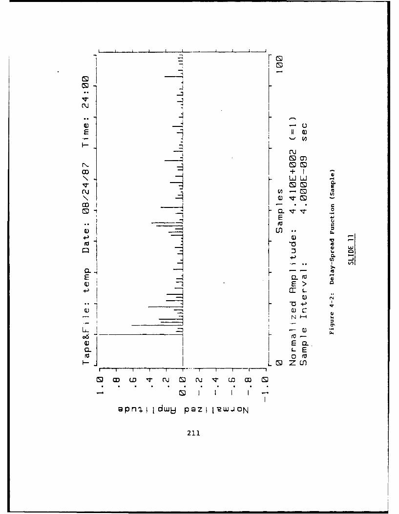
Q) u
E Iu
_ LCD
CLI-4E
43 LO rU+j -n
ia.
CLV
LF--06 E 2>Lk
fo 0 V
CD CU q- O
apfl-..1dwij P@ZL1RWJON
211

P.6 (T-T.)
-T T
Figure 4-39: PTVIR with outlier
SLIDE 12
212

Delay Spread Expansion Factor
o
C D ,ru
I C
o -
a' CDW
-3 -
(-A0
p.'
Co ,___
213

m 3 (signal)..- m 3 (noise).I ".
I ~ sprI 6 ..)."
'"N8. 01
I 2 0.6
I 0 .
CD
I'
0 1 2 3 4 5 6 7 8 9 10
Upper-Li mit/Time-Constant
Figure 4-41: PTVIR Summation-Limit Sensitivity Curves
I SLIDE 14
I
% 2,4
Uo

Delay Spread Error M%
-l Ir n M N n
oo LOn
0~
00
00 +.
0 *
0 *+0
0 C+C
-~ 0 or
W (D H
215

k-Flg-Fig-OJ-K-1, No..4095, CtmlO
Fig-g-1-
S-SPY "Nois )>etPpd
S-KN
Y
Delay CacBe"
Y
Figur 4-4: PTIR DlaySra loi
-"sLIDtE 16un
P T k )216

unbiased estimate - it turns out that Rayleigh heuristic algorithm that calculated the sec-fading tends to fade down more often than it ond central moment [SLIDE 16]. And al-fades up. It gives a bias and when I tried to though the algorithm itself has no known sta-employ that technique it did not work very tistical basis, it seems to lead to results whichwell. Furthermore, I had to determine where are consistent with the measurements. Andthe data began. that is all that one can expect from from any
model. Thank you.There were a lot of problems in trying to
use the least-squares technique. So we be- LINDSEY: Thank you Al. You know it'sgan to look at what was causing the difficul- frustrating to prepare all of these viewgraphsties. Why were the calculated delay spreads and then not have enough time to go throughso much larger than what appeared to be the them. I have to compliment the speakers oncorrect answers? One of the things we looked their diligent efforts and willingness to talkat was what is the effect of an outlier on a no longer than 20 minutes but I would likedelay spread calculation. This curve [SLIDE to spend a few minutes that we have to open12] represents the smooth exponential curve it up for some discussions. If there are anythat might describe the general shape of a questions and comments regarding any of themeasured delay spread function. That little talks, I'd be happy to hear them. Is there aline out there represents some outlier that question from the back? [CUTOFF ...] It'sarises as a consequence of Rayleigh (expo- fading ... we can hear you OK but maybe it'snential) upward power fading at a great de- not being recorded. ... Do you want to uselay. The second central moment depends on my mike?the square of the moment arm. As a conse- JOHN TREICHLER: Now I've got toquence, even this isolated outlier can, if suffi- remember my question. A couple of things.ciently distant with sufficient power, lead to One is, just for people in the audience whoall sorts of problems in overestimating the may in fact consider paying for experimentsdelay spread [SLIDE 13]. There were other like Paul was talking about, my experience isproblems as well [SLIDES 14 and 15]. For the amount of time and energy taken to re-example, when you make a measurement of duce the data is typically is 2, 3, 4, 5, some-the delay spread function you're not mena- times 10 times more than it was to actuallysuring only the exponential-like curve repre- run the experiment and the experiment al-sentative of the scattered signal. In addi- ways costs 90% of the money and you endtion, you have background noise - far out up with this tremendous pile of data and nohere where there's virtually no signal - con- time even to document it much less to re-tributed not by the medium but rather ther- duce it. Another point though is, when youmal noise and interference contributed by the consider ... that is, when you actually getreceiver. So when you calculate the second into designing the piece of equipment, youcentral moment, you're not calculating the spend as much time with very high pricedsecond central moment of the delay function, people arguing about what the data wouldbut rather the second central moment of the have been had you been able to collect it,delay spread function plus the noise. Because than you would going out to collect it in theof that we decided to clip off the noise values first place. [LAUGHTER] Having been in-and clip off the outliers and came up with a volved in a number of conversations over the
217

last 15 years, I heartily applaud efforts to go BELLO: I assume you took this data be-out and get the data to make it available, cause there are some tactical communica-
The one point I did want to make of a tech- tion links for example. But they wouldn'tnical nature is that I'm really amazed that all be stationary. Now, can you use youryou found no time variability in the last two data to predict Doppler spread due to mo-... I've been involved in a number of exper- tion because it'll be there in actual links. Didiments over the last ten, fifteen years look- you take the impulse responses spaced closeing over microwave data, and say the 6 GHz enough so you could piece them together?band. We've found it very time-variable. It SASS: That's exactly what we tried to dodepended on time of day, the amount of wind when we designed the system. We had athat went through the medium. Now, most of Doppler spread spec of 200 Hz, I believe itthis wasn't forest. It was like grassland and was and that was the ... we tried to makethings like that, but it was very time-variable, sure our sampling adhered to. So in fact weFirst thing in the morning things were mirror- did a number of experiments where we didlike and very steady, but just as soon as the space TVIR experiments spatially.winds came up you'd see time-variations of BELLO: What about Doppler?time scales in the order of fractions of a sec- SCHNEIDER: The forest channel modelond and see Doppler spreads on the order doesn't presently incorporate the Doppler,of 10 Hz in almost no time. Now when we although we have extended the model, atwere first doing this work we went to a fellow least heuristically, to look at radar returnsnamed Yudlebee out in the mid-West who from moving aircraft scanning over the topwas doing back-scatter and forward-scatter of canopy. However, it is fairly straightfor-and asked him why his data showed none of ward to put the Doppler shift into the multi-that time variation. He said "Ah! It wasn't ple scattering model.necessary in our experiments, we just aver- BELLO: But you haven't actually usedaged it out." So you have to be a little care- your data to predict Doppler spread due toful when you look at the data because in fact motion? Not yet?it was there and they confirmed it but it was SCHNEIDER: I guess I have to caveatunimportant to figuring out how good soy- that. When the delay spread functions werebeans were and so they didn't care. measured, in some cases they were repeated
SASS: Most of them were in the trunks in every four seconds, as Paul Sass said. Thesethe UHF frequency band and in that regime repeated measurements were then analyzedyou don't expect the wind to be blowing the in a time series to determine the variationtrunks as Al pointed out. I did point out that with time of the power in any of the delayin the trees in Connecticut we would have bins. We found that - for nearly all of theexpected some in the leaves, I'm not sure why data over the measurement intervals - whichit's not there. may extend over 15 or 20 minute intervals
TREICHLER: In your results I'm just - based on stationary transmitters and re-saying it's sort of surprising that given a fac- ceivers, there was no noticeable Doppler attor of only 3 variance in frequency we saw a all even though there may have been somefairly significant effect. slight wind up on top of the trees.
LINDSEY: Oh yes, Phil.. BELLO: I wasn't talking about that. I
218

was saying that in actual practice with one ing the effect on propagation, do you think
terminal moving, you will produce a Doppler you could have done anything with computer
spread. Have you ever used your fixed ir- simulation better than measurement, i.e. if
pulse response to reconstruct a time-variant you started today?
impulse response due to motion? Have corn- SASS: In the forest channel we didn't haveplex impulse responses been recorded? the model to do the simulation. You mean ....
SCHNEIDER: No. PEILE: Supposing you started today andBELLO: You haven't done that? instead of a complete scientific characteriza-
SASS: We have not, no. tion, if you started out with the question,
LINDSEY: Presumably you'd have to which parameters are the dominant ones,
move the transmitter relative to the receiver clearly a first-order as opposed to second-to get any Doppler spread measurement, order, my question is, could you have done
would you not? Unless .... anything but field measurements if you were
SASS: They've taken them spatially at starting today with today's technology of
different positions. computer simulation ability?
LINDSEY: Oh, different positions. SCHNEIDER: I think the problem is so
SASS: That v'-s the experiment we per- multi-dimensional. There are some parame-formed. We spatially ... that time-varying ters that we anticipated ahead of time, butimpulse response would be there if you were we don't even have to talk about hind sight
moving, because they htd been already correctly an-
BELLO: In other words by taking impulse ticipated. For example, the number of trees
response measurements one foot apart you per acre, the tree trunk diameters, etc. As
didn't find a complete, drastic change in ir- far as simulation is concerned, I don't know
pulse response? whether you are talking about perhaps simu-
SCHNEIDER: They have not yet been lating a forest with trees at certain positions
analyzed, Phil. and calculating the scattering from the trees
BELLO: Because I've noticed in many of and then adding them up on a Monte-Carlo
these you don't have to move much before basis.
you get a gross change - the impulse response PEILE: That's what I had in mind.
looks entirely different. You'd have to space SCHNEIDER: You really shouldn't say
your measurements very slightly apart in or- that because what you're saying is that the
der to see this effect. volumes of scattering theory that the electro-
SCHNEIDER: We have made some pre- magnetics people have put together is betterliminary calculations on the spacing, but that simulated. When you have random scatter-data has not yet been analyzed. ers, hundreds and thousands literally of them,
LINDSEY: Thank you. Any other corn- you really need to use sophisticated model-ments? Yes, sir. That's Bob Peile. Could ing techniques that are based on theoreticalyou give him a microphone. principles, rather than brute force techniques
ROBERT PEILE: With the benefit of based upon Monte-Carlo approaches. Also,hindsight and with today's technology, if you there are certain parameters that simply can-would set out with the object of finding which not be anticipated. For example, when we
parameter is the dominant one in determin- started, we didn't know whether rain might
219

have an effect on the attenuation through the ulation or the actual measurements.canopy. We thought, "Well, when it rains, SCHNEIDER: I'm talking about the ac-maybe we ought to see something." How tual measurements.would we have modeled that? For example, STEIN: OK. Your much earlier conclu-maybe we could have added a dielectric layer sion about invalidating the up, over and downof rain water about the leaf or put a dielectric model, I thought that that model applied toshell around the tree trunks or something like how you propagate over longer ranges in thethat. But as it turned out, there was no ef- jungle, not the short ranges.fect that was observed at all in that case. So SCHNEIDER: Well, the up-over-and-I don't think in that situation we could have down model is a consequence of the coher-done it a priori. In that case, I think the ent component. It arises as a consequence ofmeasurement would have been the only way being able to replace the random scatterersbecause of the complexity of the problem. within the forest by some equivalent or effec-
PEILE: So from that point of view, it was tive dielectric slab and then looking for theall worthwhile. critical angle of internal reflection. That's
SCHNEIDER: Oh, yes, absolutely. the angle at which the lateral wave propa-SEYMOUR STEIN: I have a question. gates over the tree tops. As you move upLINDSEY: O.K. Seymour Stein has a in frequency over 200 MHz, the size of the
question. Seymour .... scatterers and the separation between themSTEIN: If you can catch your attenuation become such that the coherence needed to
stuff, you've plotted it in dB per meter or launch a surface wave on a interface of twodB per kilometer. That implies exponential disparate dielectric constants is lost. Youattenuation. Is that what you observed with are not able to maintain the phase coherencerange? from the point at which the wave is launched.
SCHNEIDER: dB per meter. That's the theoretical reason why the lateralSTEIN: What kind of ranges did you test wave would probably not ever be observed at
over? frequencies above 300 MHz. In spite of theSCHNEIDER: We tested over 3 ranges - measurements we took - perhaps we didn't
3 distance measurements. The path loss mea- go out long enough, but we went out as farsurements were made over 3 parallel paths, as we possibly could within a homogeneousin essentially the same area of the forest in forest - we did not observe any.order to maximize the homogeneity over the STEIN: What would be your conclusionpaths. The shortest path was about 300 ft, about transmitting from a terminal down onthe other one around 500 ft, and the third the ground to a terminal up in the air someabout 1000 ft. After we measured the power, distance away? Are you saying that there'swe looked at the profile - the tree trunk num- no reasonable way to get from the top downber density along the path - and normalized without a horrible attenuation?that out in order to calculate the specific at- SCHNEIDER: When you say communi-tenuation. Only three paths were measured cating, do you mean a path between twoand they were differential measurements to antennas at the same height, or disparateget the specific attenuation. height, one inside and one outside?
STEIN: Are you talking about your sim- STEIN: One inside and one outside.
220
SCHNEIDER: No, I don't think there's be a gap.any low-loss mechanism that's going to be BELLO: Yes, I went through the thing toohelpful here. It's just simply going to be spe- quickly but each propagation mode would becific attenuation at that angle through the modeled by a tapped delay line which wouldforest. It will depend on angle. have hundreds of tap. The modes would be
STEIN: At these frequencies? separated by delays of the order of millisec-SCHNEIDER: Yes, at these frequencies, onds.
Seymour. SCHNEIDER: The second question ILINDSEY: Any further comments or had - you mentioned that one of the diffi-
questions? Yes, Sir. culties especially with an HF channel is the
SCHNEIDER: I had two questions for fact that the external noise tends to be non-Phil. When you spoke about the tapped de- gaussian.lay line representation for the HF channel BELLO: Non-stationary, andmodel, you mentioned that the spacing of the non-Gaussian too.taps had to be essentially the reciprocal of SCHNEIDER: I would suspect that be-the bandwidth and, because of the total de- cause it's non-gaussian, that would be an ad-lay spread of the channel, that it would take vantage to the communicator as opposed toperhaps thousands of taps to represent that a disadvantage.channel. The question I have is, when you've BELLO: Well, just think of what happenslooked at all these alternative channel models if you measure the noise power over short in-in your '63 paper that were effectively equiva- tervals of times, it fluctuates substantially.lent representations - tapped delay line mod- So, suppose you're trying to acquire a re-els and different transfer functions, power se- ceived spread-spectrum signal, you have tories, expansions and so forth - are you led set your thresholds higher to fix your false-to believe that perhaps for the HF channels alarm rates. It's clearly a loss to have thiswhere only a few of the taps are likely to be non-stationary fluctuation.active in the vicinity of the modes, that per- SCHNEIDER: I wasn't emphasizinghaps a different representation might afford non-stationarity. I was talking about the non-a more tractable channel model representa- gaussian aspect of it.tion? BELLO: Well, I wasn't talking about
BELLO: Well, it turns out that not just non-Gaussian, I was talking about non-the few number are active. The individual stationarity.propagation modes due to dispersion for ex- SCHNEIDER: Do you think the factample, even on an undisturbed channel at that it is non-gaussian is an advantage?short ranges can be several hundred microsec- BELLO: I haven't thought about theonds. But it's not small. Gaussian or non-Gaussian character. In
SCHNEIDER: Well, the differential de- many cases you're averaging so long that thelay - let's say between a 1-hop or a 2-hop short term statistics are nearly Gaussian. It'spath or between a high-angle ray or a low- just that the power varies rapidly over shortangle ray - can typically be on the order of intervals of time.milliseconds - that differential delay. So in LINDSEY: I guess my comment with re-each mode you may have a few but there may gard to non-Gaussian statistics, I think it
221

does help the communicator. That's an opin- was indicating that the scattering functionion that I feel intuitively and I think one could can be generalized. You can have a scatter-quantify that if used properly. ing function in delay, Doppler and direction
SCHNEIDER: I agree with you. cosine, or angle. And really that's what Bill
LINDSEY: On the other hand you open was talking about.
up the issue of theorists who like to deal with LINDSEY: I think it's exactly what mycomplex Gaussian envelopes you know. And model was saying that you have to take intowhat are you going to do if you don't have account the direction, not only just one di-that and that's the issue. I think the sta- rection that energy is coming at you but youtistical model which I talked about certainly need to take into account direction that en-indicated that statistics aren't Gaussian, and ergy is coming from the other two. Namely,even in some of the measurements that Phil we've probably looked at two dimensions,showed. Rayleigh is not the correct model. namely delay, although to me that's the di-But it fits in some areas and it's a good ana- rection of propagation of foresight of one an-lytically tractable approach to playing games tenna to another, and then if you have toto get numbers to design a modem, or what- worry about the other two coordinate axesever. We may be finished in fact .... Oh, no, which you should I think, then you'll beginwe have another comment. to see other things that may or may not be
STEVE STEARNS: This is Steve important. It may not be, but I think it is.
Stearns. I have a question for Phil Bello, a The ionosphere, I believe radio physicistsdifferent aspect of HF propagation. The scat- are still playing with what to do with thattering function formulation is useful for chan- problem but I think we are beginning to learnnel models where you have a single input and quite a bit of it. And the effectF of the lay-a single output, but another application, ra- ers can be handled in a transport theoreticaldio direction where you are using an array formulation which is the direction that I hadof antennas and you're interested in spatial taken to worry about multiple reflections be-diversity as opposed to mode diversity at a tween the various boundaries associated withsingle receiving antenna, are there any appro- the ionosphere.priate extensions to the model that you can BELLO: Let me point out that the prop-use for this case? Let me add a reason why agation physicists use something called aIm asking this question. The ionosphere is mutual coherence function and talk aboutnot modeled by a spherical layer at uniform basically the correlation of the fields sepa-height that is centered on the axis or center of rated in space and time for different trans-the earth. Rather it has tilts in it and conse- mitted frequencies. The three-dimensionalquently the angle of arrival that's measured Fourier transform of this correlation func-does not correspond at all to the great cir- tion yields the three-dimensional scatteringcle direction, or line varying to a source, and function. The work by Nikish I mentionedmoreover it fluctuates with time. I'm asking in my viewgraphs (in fact there will be athis question with regard to radio direction sheet of references on that), derives thisfinding systems at HF. three-dimensional spatial- time-frequency cor-
BELLO: I didn't have time to go into the relation functions. There are other referencesfull scale modeling, but I think Bill Lindsey in it, too.
222

LINDSEY: The Soviets are playing with STEIN: Well your pictures showed whatthat concept too. Soroski, and take-offs on looked like discrete scatterers.Kolmorogof's work, and so on. Seymour is SCHNEIDER: No, that's because that'slooking like he'd like to get involved in some- the chip resolution. But there was no co-thing here. herence or correlation between adjacent lines
STEIN: With respect to direction finding ever. You couldn't identify any discrete scat-you'd find that going back to this literature, terers.there's a lot of work on angular ... and we STEIN: Now let's not talk about discreteare not talking about mutual coherent func- scatterers, but discrete delays however theytion. We are talking about multiple modes are coming about. Did it keep breaking upwhich are quite discrete. And it's really the as we went to final resolution? If you didangular red that's the problem and nobody the same impulse response with two differentknows where the modes are coming from in resolutions, very close together in time, didany way that will enable you to do any the- you find breakup, or did you find ....oretical predictions. That's the problem. I SCHNEIDER: You mean a randomnesshave one final question that I'd like to take associated with the delays on adjacent bins?back to the measurement problem. Yes, they were always completely random-
LINDSEY: O.K. Seymour .... ized.STEIN: On of the practical issues when STEIN: Interesting. Thank you.
you get to very wide-band direct sequence is BELLO: I had one more thing to add tothe question of what you have to do to build what Seymour said. My comments apply toa ray combiner. Now how many taps do you the disturbed channel. You get to the dis-need. Can you build a spark combiner. Were turbed channel, that's where the scatteringany of the measurements done, (you had mul- function means something. The undisturbedtiple resolution) so that you had what amount is what Seymour was talking about.to simultaneous data on the same instanta- LINDSEY: O.K. with that I'd like to con-neous response with different resolutions to clude this session. On behalf of the Commu-tell whether they looked like discrete paths, nication Sciences Institute I'd like to thankor whether the paths kept breaking up if you the speakers Paul Sass, Al Schneider, Philwent to finer and finer resolutions? Bello, and Ken Wilson for taking time out of
SASS: We did some measurements like their regular busy schedule to prepare view-that but again they were in the forested chan- graphs and present the materials, and comenel. The system right now is being used by here and share with us the knowledge thatthe Department of Commerce to make some they've gained. On the other hand it wasmeasurements in the Denver area. So I think my pleasure to be involved with this sessionthat's the environment you'd want that data and thank the participants in the audience inin, in an urban environment, dealing with this session. Finally I'd like to
STEIN: What about interpretations for hand it over to our leader, Bob Scholtz, andthe forest channels? see if he has any direction to pass out.
SCHNEIDER: To the resolution of the SCHOLTZ: I don't think I really have anyequil.nent, we never noticed any discrete comments except you can see there are somescatterers. interesting discussions that will always de-
223

velop at the end of sessions. So the remainingpanelists, I've been noticing the talks creep.You know, the first one is 20 minutes, thenext 25, the next 30. It happens every ses-sion and in the next session everyone addsanother 5 on. So what I'd like to do is try tocut down the presentations. The discussionswill come and you'll get to say everything youwanted to say but it will be a slightly differentenvironment of give and take. So let's workon that for the next two sessions. Thank youvery much. Cocktails and entertainment arewaiting, hors d'oeuvres and all sorts of things,so let's get going.
224

U.S. ARMY COMMUNICATIONS-ELECTRONICS COMMANDWIDEBAND PROPAGATION MEASUREMENT SYSTEM
(Designed and Built By SRI International)
CECOM Project Leader:Kevin Lackey (201) 544-5680
SRI Project Leader:Boyd Fair (415) 859-3138
SYSTEM CAPABILITIES FACT SHEETOverview
The Wideband Propagation Measurement The received signal is cross correlated withSystem (WPMS) is specially designed and built a time-delayed replica of the transmittedto measure the very wide-bandwidth radio waveform which generates an amplitude-vs-propagation characteristics of communications time waveform called a time-varying impulse re-channels that interest the U.S. Army and other sponse (TVIR) of the communications channel.U.S. government agencies. These channels The TVIR is a representation of the responseprimarily consist of, but are not limited to, of the communications channel to an impulseforested and urban environments. The goal of input signal, perturbed by any scattering, mul-the WPMS program is to develop and verify a tipath, or absorption mechanisms.communications-propagation model for Although the WPMS is an asynchronousspread-spectrum signals that are propagated system, the TVIR data also provides a relativethrough these channels. time-of-arrival measurement of the multiple
The WPMS consists of two mobile vans, signal paths (multipath) generated within theone containing the transmitter subsystem and channel. The TVIR data are calibrated in ab-one containing the receiver and data-acquisi, solute received power.tion subsystem. The WPMS is designed to The resulting digitized spread-spectrumtransmit and receive two simultaneous spread- data can then be processed to measure severalspectrum signals that can be centered at any facets of the received signal: the level (usefulfrequency between 200 MHz and 2000 M . for computing path loss), Doppler shift, delayThese spread-spectrum signals are generated spread (a measure of the amount of existingby modulating the rf carrier with a pseudo- multipath, which is useful in computing therandom noise (PN) code which is then radiatedand received by the receiver system.
225

maximum data rate for a communications to automatically control the setup of the trans-channel), and the power spectrum of the trans- mitter and receiver hardware and to gather themitted signal at the receiver. These measure- data and record it onto magnetic tape. Thements can be made at any antenna height, raw data is then processed off-line to providefrom man-pack level up to 65 feet with either a set of calibrated summary data that can bedirectional (vertical, horizontal, or circular po- further analyzed by scientists and engineers in-larization) or omni-directional (vertical polari- terested in specific aspects of the spread-spec-zation) antennas. Mobile operation is also trum radio propagation problem.possible using roof-top antennas. The specific capabilities of the WPMS are
The WPMS system is semi-automatic. summarized in the following table.Previously generated experiment files are used
SYSTEM CAPABILITIES
GENERtAL
Carrier frequency range 200 to 2000 MHzDelay-spread range -1 to 20 usDelay-spread resolution 2 naDoppler-spread range .15 to 240 HzDoppler-spread resolution <2 HzTVIR amplitude resolution 0.1 dBTVlR multipath amplitude resolution -20 dE minMeasureable path los 155 dB min
ANTENNAS
Omnidirectional BiconicalDirectiona Crossed LPASTransmitter polarization V. H. RCPReceiver polarization V. H. RCP, LCPAzimuth 0 to 3600Height 5 to 6S ft
TRANSMrERS
Number 2Frequenc rng
Transmwte No1 200-la 1050 H&Transmitter No. 2 700 to 2000 MHz
ow outpt 00 W maRModulation PN sequence
Bi-phas modulation or CWClock race 50. 125. or 250 MHzInstantaneous null-to-null bandwidth 100, 250. or 500 MHzPN code length (chips) 255, 511. 1023, or 2047Control Locai or receiver computer
RECEIVER
Number 2Frequency range (each channel) 200 to 2000 WUSensitivity (23 dB SNR in 50 klz BW) -95 dmModulation PN sequence
Bi-phase modulation or CWClock rat 50, 125, or 250 NM]Instataneous null-so-null bandwidth 100, 250. or 500 MHzCode length (chips) 255, 511, 1023, or 2047
SLocal computera udynamic range 50 dB
S Input signal rang (at van wall) 0 to -95 dlmA C .(receiver computer controlled) Stopped in I-d0 increments
226
U.S. ARMY COMMUNICATIONS-ELECTRONICS COMMANDWIDEBAND PROPAGATION MEASUREMENT SYSTEM
(Designed and Built By SRI International)
CECOM Project Leader:Kevin Lackey (201) 544-5680
SRI Project Leader:Boyd Fair (415) 859-3136
EXECUTIVE SUMMARY
227
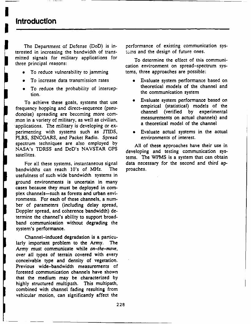
IIntroduction
The Department of Defense (DoD) is in- performance of existing communication sys-terested in increasing the bandwidth of trans- zJns and the design of future ones.mitted signals for military applications for To determine the effect of this communi-three principal reasons: cation environment on spread-spectrum sys-
* To reduce vulnerability to jamming tems, three approaches are possible:
* To increase data transmission rates * Evaluate system performance based onTo reduce the probability of intercep- theoretical models of the channel andtion. the communication system
To achieve these goals, systems that use o Evaluate system performance based on
frequency hopping and direct-sequence (pseu- empirical (statistical) models of the
donoise) spreading are becoming more com- channel (verified by experimental
mon in a variety of military, as well as civilian, measurements on actual channels) and
applications. The military is developing or ex- a theoretical model of the channel
perimenting with systems such as JTIDS, * Evaluate actual systems in the actualPLRS, SINCGARS, and Packet Radio. Spread environments of interest.spectrum techniques are also employed by All of these approaches have their use inNASA's TDRSS and DoD's NAVSTAR GPS developing and testing communication sys-satellites. tems. The WPMS is a system that can obtain
For all these systems, instantaneous signal data necessary for the second and third ap-bandwidths can reach 10's of MHz. The proaches.usefulness of such wide bandwidth systems inground environments is uncertain in manycases because they must be deployed in com-plex channels-such as forests and urban envi-ronments. For each of these channels, a num-ber of parameters (including delay spread,Doppler spread, and coherence bandwidth) de-termine the channel's ability to support broad-band communication without degrading thesystem's performance.
Channel-induced degradation is a particu-larly important problem to the Army. TheArmy must communicate while on-the-move,over all types of terrain covered with everyconceivable type and density of vegetation.Previous wide-bandwidth measurements offorested communication channels have shownthat the medium may be characterized byhighly structured multipath. This multipath,combined with channel fading resulting fromvehicular motion, can significantly affect the
228

Background
Channel Measurement Philosophy Time-Varying Impulse ResponseThe channels of interest can be modeled The purpose of the WPMS system is to
as randomly time-varying systems, for which measure the Time Varying-Impulse Responsethe only meaningful description is statistical. (TVIR) or an equivalent functional representa-The statistics of a given characterization, how- tion, known as the Output Delay-Spread Func-ever, may be deterministic, depending on un- tion (ODSF) of the channel. The ODSF andknown external parameters, such as season, TVIR are entirely equivalent; the only differ-moisture content, forest density, and the like. ence is the way in which the time and delay
The ultimate rationale behind a channel variables are referenced to the time the im-
characterization program is to evaluate the pulse is applied to the communications chan-charterfoman oamunication ete over nel. The delay variable of the ODSF is refer-performance of a communication system over enced (equals zero) to the time the impulse is
channels similar to those likely to be encoun- enced (u ze tommuectie th annel.
tered in practice. This evaluation requires a applied to the communications channel.characterization that encompasses "typical" as Therefore, the ODSF is equivalent to an oscil-characxte thannels. e omaeer, e loscope display of the response of the systemwell as extreme channels. However, because to a unit impulse for which the time origin of
Army communication systems must operate to osiil se o the time oh i of
over widely varying conditions, measuring all the oscilloscope is set to the time the impulse
the possible generic types of channels is im- was applied to the channel. This input time is
practical. Therefore, understanding the under- the only place "absolute" time appears in the
lying physical phenomena of the channels is ODSF.
necessary, so that the results of the measure- The function measured by the WPMS isment program can be extrapolated to any actually a time-shifted version of thechannel of interest. ODSF - offset in time by an unknown amount
of because of the unsynchronized nature of theThis extrapolation is easier if the effects ofSmauemn ytm
each of the various external parameters can be
separately identified. Then, a relationship be-
tween the statistical channel characterization System Overviewand the external parameters can be estab-lished. If identifying an effect with a particu- The WPMS uses a sliding-correlator archi-lar external parameter is not possible, it is im- tecture (SCA) to measure the TVIR of a propa-perative, at least, to try to control as many gation channel. In this approach, a wide-variables as possible. Such control is best ac- bandwidth pseudonoise code is used to modu-complished by using a simple channel such as late a UHF carrier at the transmitter. Thisa "standard" forest without any complicating composite signal is then cross-correlated at thefactors such as non-homogeneity, variable tree receiver with a duplicate code. In the receiver,sizes or types, hilly terrain, or similar condi- however, the clock for the shift register gener-tions. These factors can then be added later ating the duplicate code is stepped (slid) oneby extrapolating the statistical model devel- chip per PN code period relative to the trans-oped from the basic set of measurements. mitter clock; thus, if we compared the trans-This approach is preferred over measuring a mitter and receiver codes as a function ofnumber of complex channels, because identify- time, assuming they are being continuously re-ing cause with effect is difficult when too peated, we would observe the codes steppingmany variables are changing at once. (sliding) past each other.
229

The correlators are capable of operatingwith PN-code lengths of 255, 511, 1023, and T2047 chips at code speeds of 50, 125, and 250Mbits/sec. To shorten the correlation timesand to reduce the speed at which the Analog/ - ----- D
Digital connectors (A/Ds) must take data, four
parallel correlators are used in each receiverchannel. The second, third, and fourth cor- Figure 1. WPMS Block Diagramrelators correlate the received waveform with acopy of the PN-code that has been shifted rela- The RX/DDAS has been designed to pro-tive to the PN-code in the first correlator by vide automated control of the experiment and1/4, 1/2, or 3/4 chips, respectively, a "friendly" user interface for conducting and
This approach for system implementation designing channel-probe experiments. Theenables the basic design objectives for the application-level software for this interface isWPMS to be met at a reasonable cost. Select- designed to verify at each menu-driven prompting an SCA, however, is not without its prob- that the user enters "reasonable" informationlems. The use of the SCA must be carefully or specifies "reasonable" parameters for thecontrolled by the DDAS to ensure that valid experiment. These software checks help mini-data are collected regarding the time variabil- mize wasted experiment time caused by userity of the channel. In fact, all the requirements errors and minimize the probability of record-cannot be satisfied simultaneously (at reason- ing channel-probing data that are invalid orable cost). As a compromise solution to this not meaningful.problem, a multi-mode system of operation The TX subsystem normally acts as a slave[controlled by the Digital Data Acquisition Sys- to the RX/DDAS. That is, the transmitters aretem DDAS)J has been developed that permits controlled by the transmitter van controllerthe experimenter a tradeoff between conflict- (microcomputer), which receives its com-ing requirements in: mands from the RX/DDAS. A VHF communi-
* TVIR resolution in the time domain cations system is used between the two subsys-tems to transfer commands, acknowledge.
* TVIR bandwidth ments, and status information. When an ex-
" Duration (multipath-delay window) of periment is executed at the RX/DDAS, the ap-the TVIR in the time domain propriate commands are sent to the TX con-
" Total path loss measurable by the sys- troller. This controller locally controls theTta. ptransmitter hardware consistent with the RX/temn. DDAS commands. After the transmitter has
The WPMS is functionally divided into two been set up and the data recorded by the RX/subsystems. The first part, the Receiver/Digi- DDAS, the TX controller sends the TX statustal-Data-Acquisition-System (RX/DDAS), information to the RX/DDAS for inclusion incontains all the hardware necessary to receive, the header block of the recorded data.sample, process, and record the various chan-nel-probe signals that are used to characterizetime-varying radio propagation channels. Thesecond part of the WPMS consists of the trans-mitter (TX) and its microcomputer controller.
230

Conclusion
In this executive summary we have pre- These capabilities meet or exceed all ofsented a high-level overview of the WPMS, CECOM's requirements for the WPMS. Thisbuilt by SRI under contract to the US Army for state-of-the-art system provides the ability tothe purpose of gathering spread-spectrum measure ground-to-ground communicationpropagation data to characterize forested and channel characteristics with very high resolu-urban communication channels. This charac- tion, using very-wide-bandwidth probe sig-terization will be accomplished by using very- nals. These characteristics will be used to ver-wide-bandwidth, probe signals at frequencies ify and improve computer models that will, inranging from 200 to 2000 MHz. A summary turn, be used to evaluate the performance ofof the systems capabilities is shown on the ta- the Army's communication systems of the fu-bles that follow, ture.
__ __BANDWIDTH/CODE-LENGTH PARAMETERS
Chip Code Code Time to Acquire Number Time to-Acquire Number of DopplerBandwidth Length Length Length One TVIR of TVIRS Complete TVIR TVIRs in 128k Bandwidth(MHz) (ns) (Chips) (ms) (ms) to Integrate (ms) Samples (Hz)
50 20 255 5.100 1.306 2 2.611 512 191.483
50 20 511 10.220 5.233 1 5.233 256 95.554
50 20 1023 20.450 20.951 1 20.951 128 23.865
125 8 255 2.040 2.089 4 10.522 512 239.354
125 8 511 4.088 2.093 1 2.093 256 238.885
125 8 1023 8.184 8.390 1 8.380 128 59.663
125 8 2047 16.376 33.538 1 33.538 64 14.908
250 4 255 1.020 0.261 8 2.089 512 239.354
250 4 511 2.044 1.047 2 2.093 256 238.885
250 4 1023 4.092 4.190 1 4.190 128 119,326
250 4 2047 8.188 16.769 1 16.769 64 29.817
CW n/a n/a n/a n/a n/a n/a n/a 250.000
231

System Capabilities
GENERAL
Carrier frequency range 200 to 2000 MHzDelay-spread range -1 to 20 usDelay-spread resolution 2 nsDoppler-spread range -15 to 240 HzDoppler-spread resolution <2 HzTVIR amplitude resolution 0.1 dBTVIR multipath amplitude resolution -20 dB minMeasureable path loss 155 dB min
ANTENNAS
Omnidirectional BiconicalDirectional Crossed LPAsTransmitter polarization V, H, RCPReceiver polarization V, H, RCP, LCPAzimuth 0 to 3600Height 5 to 65 ft
TRANSMITTERS
Number 2Frequency range
Transmitter No. 1 200 to 1050 MI-IzTransmitter No. 2 700 to 2000 Miz
Power output 100 W maxModulation PN sequence
Bi-phase modulation or CWClock rate 50, 125, or 250 MHzInstantaneous null-to-null bandwidth 100, 250, or 500 MHzPN code length (chips) 255, 511, 1023, or 2047Control Local or receiver computer
RECEIVER
Number 2Frequency range (each channel) 200 to 2000 MHzSensitivity (23 dB SNR in 50 kHz BW) -95 dBmModulation PN sequence
Bi-phase modulation or CWClock rate 50, 125, or 250 MHzInstantaneous null-to-null bandwidth 100, 250, or 500 MHzCode length (chips) 255, 511, 1023, or 2047Control Local computerInstantaneous dynamic range 50 dBInput signal range (at van wall) 0 to -95 dBmAGC (receiver computer controlled) Stepped in 1-dB increments
232

U.S. ARMY COMMUNICATIONS-ELECTRONICS COMMANDWIDEBAND PROPAGATION MEASUREMENT SYSTEM
(Designed and Built By SRI International)
CECOM Project Leader:Kevin Lackey (201) 544-5680
SRI Project Leader:Boyd Fair (415) 859-3136
SAMPLE DATA
233
IIBackground
The data contained herein are actual data centered at the tick mark shown (mov-taken in a forest at Ft. Lewis, near Seattle, WA. able) on the top display.The WPMS was used to collect and record a 3. Figure 3. A real-time display of one ofvery-large volume of wide-bandwidth and CW the Delay Spectrums. Other types ofpropagation data on many different paths within thslay ctrs.nter typs ofthe forest. Measurements were made at an- vice. These include the relative phase
tenna heights ranging from 10 ft to 65 feet over angle-vs-time of the received signal
path lengths from 270 ft to 6000 ft. The major- the individual In-phase and Quadrature
ity of the data were gathered for both vertical the VRh a poaraspa
and horizontal polarizations, however some of TVIR amplitude a spectrum dis-
crossed-polarized and circularly polarization of t he am ple and a te is-
data was also taken. The radio frequencies play of the Doppler shift of the received
(rf) used were 300 MHz, 400 MHz, 850 MHz signal.
and 1050 MHz. These carriers were modu- 4. Figure 4. A post-processed display oflated to produce null-to-null bandwidths of 500 expanded TVIRs for vertical and hori-MHz for most of the measurements. zontal polarization for a free-space path
over a logging road within Ft. Lewis.The figures that follow are representative 5 Fi r 5 Aopot-pro cessed.L is.
samples of the data available form the WPMS. 5. Figure 5. A post-processed disnlayThe photographs are near-real-time data dis- showing the polarization dependence .'plays available in the field during the data- spread-spectrum signals when propa-
gathering portion of the experiment. The gated through a trunk-dominated forest
graphs that are Included are only some of the at Ft. Lewis.
ways the processed data can be displayed us- 6. Figure 6. A post-processed displaying the post-processing programs developed showing the polarization effect on de-for the WPMS. lay-spread encountered on many paths
1. Figure 1. Real-time displays of Time within the forest at Ft. Lewis.
Varying Impulse Response (TVIR) and 7. Figure 7. A post-processed display ofDelay Spectrum for two received sig- the calculated excess path loss encoun-nals. Note Wideband Received Signal tered within the Ft. Lewis forest at verti-Level (WRSL), Narrowband Received cal and horizontal polarization as a func-Signal Level (NRSL), and TVIR Re- tion of frequency and path length forceived Signal Level (TRSL), and calcu- spread-spectrum signals.lated Path Loss displays. Discrete fre- 8. Figure 8. A post-processed display ofquencies in the spectrum displays are the calculated excess path loss encoun-the result of rf carrier leakage and PN- tered within the Ft. Lewis forest at verti-code unbalance in the transmitter and cal and horizontal polarization as a func-receiver. tion of frequency and path length for cw
2. Figure 2. A real-time display of one of signals.the TVIR displays. The trace on top 9. Figure 9. A forester characterizing theshows the entire multipath delay-spread Ft. Lewis forest. These characteriza-range for the code-length chosen for tions are critical to the evaluation ofthe experiment. The bottom display Is computer models of radio wave propa-an expanded version of the top trace gation In forests.
234

10. Figure 10. The WPMS receiver/data experimental data and to control theacquisition van gathering data at Ft. WPMS transmitters, receivers and an-Lewis, WA. tennas.
11. Figure 11. The WPMS transmitter van 13. Figure 13. The WPMS transmitterradiating two simultaneous spread- equipment mounted inside the transmit-spectrum signals at Ft. Lewis. Note the ter vehicle.automatically raised and lowered an-tenna/tower subsystem. 14. Figure 14. The WPMS receiver systems
prior to installation in the receiver van.12. Figure 12. The Digital Data Acquisition
System used to process and record the
Figure 1.
J I "I
Figure 2.
235

Figure 3.
Figure 4.236

fl LEV1(PA7~ Pl.~l~bC~ ANLI INAIL ", M.~I C.P07?"C"I -0IIL76 1q E87
Pf01.dAA. '00
.1S; 36 3S '4h 11s so is 60 01 ALL SPA1AC sp *ORM.10ols **3"IS011 35 0 4S i0 SS" k0n b1 0 SLL 00 F' 0 81l0'1 'I I I00,' se
L
156
>1 ~DELA SptEAD0001067L :t 1760000::x x
*'1~~~.,x zoo xi01088 00 8
10.xlI
-. ~ ~ 7X81 I, X MS It x.1I'00N .PI.I11 l~'
x a-0 * 8. '0
01 ". 008'8oX .0 0
/, X
x x
10 ~ ~ ~ ~ s in . -10 1. 00atI$2 M 124 11 s 72 t%
PIll LOS-io00IL 0 EAYSRA O IOTL -N
0 1 11 1., o Tut YE 1110 0.1I
Figuregur 7.Fgue6
("'Is 0S.." 18 f237 rl ls

bO
[ :~ :: ~ 0 s0o:
400 --1
TV 30 30
I'. 300 00
3 0 30 'o so bo 70 301 0 10 S0 10 10 s0
07.7(NNA MEICHIS FT ANI(NNII MEIGHTS FT
0k-. N,' I~ 1% 1 0 SO. 0(3 12 1-16 11.120313 Figure 8.
Fiue923

Figure 10.
Figure 13.
FigureI11
Figuree 11.
FFigure 14.
239

U.S. ARMY COMMUNICATIONS-ELECTRONICS COMMANDWIDEBAND PROPAGATION MEASUREMENT SYSTEM
(Designed and Built By SRI International)
CECOM Project Leader:Kevin Lackey (201) 544-5680
SRI Project Leader:Boyd Fair (415) 859-3136
BIBLIOGRAPHY
Antenna Engineering Handbook, Jasik, H., ed. (McGraw-Hill Book Company, New York, NewYork, 1961)
Bentley, P. B., "Frequency Dispersion of a Log-Periodic Antenna, "Technical Note, ContractDAAB07-82-C-J097, SRI Project 4520, SRI International, Menlo Park, CA (February 1983)
Brown, G. S. and W. J. Curry, "A Theory and Model for Wave Propagation Through Foliage,"Radio Science, Vol 17, No. 5, pp. 1027-1036, (September 1982)
Dence, D. and T. Tamir, "Radio Loss of Lateral Waves in Forest Environments," Radio Science,Vol. 4, No. 4, pp. 307-318 (April 1969)
Fair, B. C. and M. S. Frankel, "Design Plan for Wideband Propagation MeasurementData/Acquisiton and Recording System," SRI Design Report 1, Contract DAAB07-82-C-J097,(September 1982)
Fair, B. C., R. A. Nelson and M. S. Frankel, "Wideband Propagation Measurement/Data Acqui-sition and Recording System," Semiannual Status Report 1, Contract DAAB07-82-C-J097, SRIProject 4520, SRI International, Menlo Park, CA (August 1983)
Fair, B. C., "Wideband Propagation Measurement/Data Acquisition and Recording System,"Semiannual Report 2, Contract DAAB07-82-C-J097, SRI Project 4520, SRI International,Menlo Park, CA (May 1985)
Frankel, M. S., "L-Band Forest Experiments," Packet Radio Temporary Note 254, SRIInternational (May 1978)
Head, H. T., "The Influence of Trees on Television Field Strengths at Ultra-High Frequencies,"Proc. IRE, Vol. 48, No. 6, pp. 1016-1029 (June 1960)
Herbstreit J. W. and W. Q. Crichlow, "Measurement of the Attenuation of Radio Signals byJungles," J. Research NBS Section D (Radio Sci.), Vol. 68D, No. 8, pp. 903-906 (August 1964)
Hodges, J. C., G. A. DesBrisay, C. L. Rino, B. C. Fair and J. Owen, "Site Selection Activities forthe WPMS," Semiannual Report 1, Contract DAAB07-85-C-K569, SRI Project 8899, SRI Inter-national, Menlo Park, CA (November 1986)
Hufford, G. R., L. Hubbard, J. Pratt, S. Adams, Paulson and P. Sass, "Wideband PropagationMeasurements in the Presence of Forests," CECOM Technical Report 82-CS029-F, (January1982)
Hufford, 0. A., Longley and W. Kissick, "A Guide to the Use of the ITS Irregular Terrain Modelin the Area Prediction Mode," NTIA Report 82-100, US Dept. Of Commerce, (April 1982)
Josephson B. and A. Blomquist, "The Influence of Moisture in the Ground, Temperature andTerrain on Ground Wave Propagation in the VHF-Vand," IRE Trans. Antennas and Propagation,Vol. AP-6, No. 2, pp. 169-172 (April 1958)
"JTIDS Ground Foliage Propagation Tests," Final Report, Contract F19628-75-C-0205,FR80-16-503, Hughes Aircraft Company, Fullerton, CA, (April 1980)
240

LaGrone A. H. and C. W. Chapman, "Some Propagation Characteristics of VHF Signals in theImmediate Vicinity of Trees," IRE Trans. Antennas and Propagation, Vol. AP-9, No. 5, pp.487-491, (September 1961)
LaGrone, A. H., "Height-Gain Measurements at VHF and UHF Behind a Grove of Trees," IEEETrans. Broadcasting, Vol. BC-9, No. 1, pp. 37-54 (February 1963)
Lang, R., A. Schneider, Seker and F. Altman, "UHF Radiowave Propagation Through Forests,"CyberCom Technical Report CTR-108-01, CECOM Technical Report 81-0136-4, ContractDAAK80-81-C-0136, (September 1982)
Lang, R., A. Schneider and F. Altman, "Scatter Model for Pulsed Radio Transmission ThroughForests," CyberCom Corp., CECOM Contract DAAK8O-81-C-0136, IEEE MILCOM '83,Washington, DC, (October 1983)
Lang, R., A. Schneider, F. Truong and S. Altman, "U-IF Radiowave Propagation ThroughForests," CyberCom Technical Report CTR-108-06, CECOM Technical Report 81-0136-6,Contract DAAK80-81-C-0136, (May 1984)
Murray, J., G. Hufford and J. Adams, "A Guide to Wideband Propagation Measurements andData Collection-Planning Reference," US Dept. of Commerce, Institute for TelecommunicationsSciences, (Revision 5) (December 1984)
Nelson, R. A., "UHF Propagation in Vegetative Media," Final Report, ContractDAAG29-76-D-0100, SRI Project 8998, SRI International, Menlo Park, CA (April 1980)
-s 6"Request for Proposal," Wideband Propagation Measurement/Data Acquisition and RecordingSystem, Contract DAAB07-82-C-J097, US Army CECOM, Fort Monmouth, NJ (May 1982)
Rice, P. L., "Some Effects of Buildings and Vegetation on VT-IF/UTIF Propagation," IEEEMountain West-EMC Conference (1971)
Rino, C. L., J. Owen, G. A. DesBrisay and B. C. Fair, "Calibration and Complex TVIR Con-struction for the WPMS System," Contract DAAB07-82-C-J097, SRI Project 4520, SRI Interna-tional, Menlo Park, CA (November 1985)
Rino, C. L., J. Owen, G. A. DesBrisay and B. C. Fair, "The Effects of Antennas in WPMSChannel Diagnostics," Semiannual Report 4, Contract DAAB07-82-C-J097, SRI Project 4520,SRI Internatibnal, Menlo Park, CA (June 1986)
Rino, C. L., J. Owen and 0. A. DesBrisay, "Data Collection Activities Using the WPMS,"Equipment, Test, and Demonstration Report, Contract DAAB07-82-C-J097, SRI Project 4520,SRI International, Menlo Park, CA (July 1986)
Sass, P., "Propagation Measurements for UHF Spread Spectrum Mobile Communications,"IEEE Transactions on Vehicular Technology, Vol. VT-32, No. 2, (May 1983)
Saxton, J. A. and J. A. Lane, "VHF and UHF Reception-Effects of Trees and Other Obstacles,"Wireess World, Vol. 61, No.5, pp. 229-232 (May 1955)
Schneider, A., "UHF Radiowave Propagation Through Forested Propagation Channels," NATOAGARD Conference Proceeding 363, on Propagation Influences on Digital TransmissionSystems, Athens, Greece, (June 1984)
Schneider, A. and F. Altman, "Proposed Forest Transmission Experiments," CyberCom Techni-cal Report CTR-108-07, Contract DAAK80-81-C-0136, (June 1984)
Staiman, D. and T. Tamir, "Nature and Optimization of the Ground (Lateral) Wave Excited bySubmerged Antennas," Proc. iEE, Vol. 113, No. 8, pp. 1299-1310 (August 1966)
Tamir, T., "Radio Wave Propagation Along Mixed Pathes in Forest Environments," IEEE Trans.Antennas and Propagation, Vol. AP-25, No. 4, pp. 471-477 (July 1977)
Trevor, B., "Ultra-High-Frequency Propagation Through Woods and Underbrush, RCA Review,
Vol. 5, No. 1, pp. 97-100 (July 1940)
241

amcnN
CE00 0
IU
o 0*0, UJ L
N 2N a"
E m C-i W CuW Na)3 cu U-0 N
.)> IN Z
0 -0 .r
Lu a Lam CuMINOR IMEN-
a) 0)mm 0MIE1;6) 0

ROBERT SCHOLTZ: Hello, hello .... JOHN PROAKIS: Overview of Adap-Have you found me yet? In an effort to get tive Equalizationthings started on time, I think we'll just let I should tell you that I did not bring a copythe stragglers miss the beginning. Looks like of my book to the Workshop, but one of thea little cool weather's blowing in .... If it gets people here does have a copy. I found it tooworse, I'll tell you this afternoon where we'll heavy to carry, frankly [LAUGHTER]. Buthave the cocktail party - we won't cancel it, Bill Lindsey was not worried about the weightwe'll just move it somewhere a little warmer. - he did manage to bring a copy.I'd like to invite Dennis Hall up now, from I'm going to give a brief overview of adap-TRW, who put together a terrific session for tive equalization techniques. We begin withyou. Dennis .... a general block diagram, shown in FIGURE
DENNIS HALL: Oh, yeah, my session #1. I've subdivided equalizers into threewas very easy to put together - almost every- different categories: linear equalizers, deci-one volunteered to do it, so it was only a mat- sion feedback equalizers, and equalizers basedter of playing phone tag long enough to talk on maximum likelihood sequence estimationto all of them. John Proakis is here, and he's using the Viterbi algorithm. Of the lineargoing to give us a quick overview and then equalizers, I'm going to confine my remarksgo into some of his current research. We're to time domain equalizers, since I know Johnreally fortunate to have John Treichler here; Treichler will talk about frequency domainhe's got a lot of experience in adaptive filters equalization. Of the three types that we haveand equalization. John Cioffi is here, he's ex. listed here, the linear equalizer is by far theploring some new things in multi-tone equal- simplest to implement and the one that givesizers, which I'm very anxious to hear about, the worst performance, basically, in a chan-and he's done a lot of work in multipath - nel that has significant intersymbol interfer-one of our students that we're sponsoring up ence. The second type, the decision feedbackto him is looking at that. And I think Brian equalizer, is more powerful as most of youAgee is going to close it off with reporting know. The third type, based on maximumsome of the continuation of some of his work likelihood sequence estimation, is the opti-on blind adaptive signal restoration, which mum equalization scheme, with one proviso,fits well into the modulation characterization that we know the probability density functionsession we had earlier. for the underlying statistics of the signal and
Let's see, John Proakis - we were lucky noise. If we do not know this and attemptthat we didn't have to pay him an honorarium to build a maximum likelihood sequence es-to speak with us [LAUGHTER], but you'll timation scheme for intersymbol interference,notice that his new book is out, or the 2nd it's quite possible that the performance willedition of his book, so each of us will have not be as good, for example, as the decisionto buy 20 copies of his book [LAUGHTER]. feedback equalizer, which does not make anyJohn Treichler - John graduated from Rice assumptions at all about the statistical prop-a couple of years before I did, and in such erties of the underlying noise process.he'll be the only speaker here who'll speak Let me first talk about linear equalizationclearly and without an accent [LAUGHTER]. in greater detail. Linear equalizers are usu-So that's all I have to open this up, so .... ally implemented in practice as fractionally
242

1
aSI I
4243

spaced equalizers, and by this I mean that will not comment any further on that.the incoming signal is sampled at least as fast The sequence estimation scheme requiresas the Nyquist rate. For example [FIGURE knowledge of the channel characteristics and#21, if we have a signal with a raised cosine for this purpose one can use an adaptive chan-spectrum and a roll-off factor of 3, the high- nel estimation -cheme as indicated in broadest frequency in the signal is where T is terms here [FIGURE #4], and feed the chan-the symbol interval. The signal, then, should nel characteristics to the Viterbi algorithm tobe sampled at least at twice that frequency, perform the equalization.which is , and then passed through an Now let's move on to the next level of FIG-equalizer with tap spacing of -Z. IF 8 = 1, URE #1 - the different structures for im-for example, the spacing will be 1; if/3 = 1/2, plementing equalizers. In the case of a lin-we can get by with sparser spacing of and ear equalizer, there are two basic structuresso forth. In general, then, the spacing is yN that one can employ: the transversal struc-where both M and N are integers. ture [FIGURE #5] or the lattice structure
The advantage of fractionally spaced equal- [FIGURE #6]. There are similar structuresizers is that in practice we do not know the for decision feedback equalizers. Associatedcharacteristics of the channel, and the frac- with the particular structures are a number oftionally spaced equalizer plays the role of a different algorithms which are listed in FIG-matched filter as well as an equalizer. Thus, URE #1. I have given the types and thein one structure we can implement, in an structures, followed by the algorithms thatadaptive fashion, a matched fiter and a linear one can apply to these various structures.equalizer. In the case of the transversal structure
A decision feedback equalizer [FIGURE there is the conventional LMS algorithm#3] simply uses a linear equalizer as a feed- [FIGURE #51, and then a number of so-forward filter and then employs the decisions called fast algorithms: the RLS Kalman, fastat the output of the decision device in a sec- Kalman and square root Kalman. All ofond filter, called a feedback filter, to can- these are recursive least squares methods forcel out intersymbol interference from previ- adjusting the coefficients of the transversalously detected symbols. This particular form structure. The problem with the transver-is the classical form of the decision feedback sal structure is that if we want to changeequalizer and has some problems if you have the length of the equalizer, we must go backcoded modulation. In coded modulation you and recompute the coefficients; that is, wewould like to have in your feedback filter the must begin anew. To avoid that problem oneactual decisions from the Viterbi decoder if can go to the lattice structure [FIGURE #6]it's a trellis code, or block decoder if it's a where we can simply add or delete sectionsblock code. As can be seen, this structure quite easily without affecting the coefficientsdoesn't lend itself very well to coded mod- of the other sections of the filter.ulation. For that purpose, there is another Similar remarks can be made about deci-structure which is slightly suboptimum called sion feedback equalizer algorithms, whereinthe prediction-type decision-feedback equal- the transversal structure - and by transver-izer. I believe that Vedat Eyuboglu is going sal I mean that we have two filters, each ofto say something about that later today, so I which is transversal, the feedforward and the
244

a a LA A
Nc
0 A
m~ 0 A
am~ 0
a-
.40
i a
00a
no - r
Po 0

'SI
b
04
C
N
'I
qg% ~ ~ ~*
*I'
246

j P) Cv (1) ell(t)+
+ + + + + N"
doo(s - 1) dl(t-1) dN - 70 - 1) dm. 1($- 1)
FOOY - 1) 1) rm - 3b if - 1) F)
boo(l) 72111 b# . 1 (1)Y(f) Slap stase Stage
N-I
im, --- ,L -7
j 3 fm - 1 1)
'rot
Input
L-j
Z z z z z z
C.3 C.1 to to ej
4
x +
Output
7-
247

feedback filter. One can use the LMS algo- number of computations to implement thisrithm [FIGURE #71, the Kalman-type fast type of filter.algorithms, or the square root algorithm for A decision feedback lattice equalizer isadjusting the coefficients. In the lattice there shown in Figure #10. It seems awfully com-are two versions of it, the so-called gradient plicated, but actually it's fairly simple. Welattice algorithm and a recursive least squares have two types of lattice stages. These arealgorithm, the so-called one-dimensional lattice stages
Finally, in the sequence estimation scheme and this is a typical stage here, and a num-for estimating the channel characteristics, the ber of two-dimensional lattice stages whichapplicable algorithms are again quite similar incorporate both the decisions as well as thesince this channel estimator is a transversal- incoming signal, and these involve a slightlytype filter. more complex (two-dimensional type) lattice
Let me briefly describe a recursive least stage, as shown here. But it is fairly simple in
squares lattice for those of you who are not that the input signal comes in here, the out-
familiar with these lattice-type algorithms. put of the decision device is as shown here,Each of the lattice stages in FIGURE #6i in- and that decision is fed back into this point
volves a couple of multiplications and a cou- for computing the various errors in each of
ple of additions and a unit of delay (FIGURE the stages of the lattice.
#81. This is the lattice part. There is also My reason for mentioning these different
a ladder part which involves multiplying the types of lattice filters is that they do present
so-called backward residuals or backward er- a number of nice properties over the transver-
rors by corresponding coefficients and then sal structures. Let me mention here that in
summing to get the output of the equalizer deciding which type of equalizer to use for an
[FIGURE #6]. This is the input signal, this application, we need to worry about the con-
is the output here, and the desired signal is vergence rate of the algorithm, the tracking
here. In an adaptive mode, of course, we're capability, the computational complexity as
feeding back previous decisions or the actual measured by the number of multiplications
decisions out of the decision device here. A and divisions per iteration, the stability of
simplification of that is the so-called gradi- the algorithm, the accuracy, and issues re-
ent lattice [FIGURE #9]. The simplification garding dynamic range if we have to imple-
is in a reduction of the computational corn- ment these algorithms in fixed-point arith-
plexity. The typical lattice stage involves, as metic, and scaling problems (see FIGURE
I said, multiplying by these reflection coeffi- #11). Finally, if we wish to implement these
cients and then adding the signals here. The in VLSI perhaps we would be interested in
bi(t) are the backward errors or the backward considering architectural issues, modularity
residuals and the fi(t) are the forward resid- and parallelism.
uals in the lattice. In the gradient lattice we The reason for considering the more corn-force the coefficients in the two arms to be plex lattice-type algorithms and recursivethe same, and we update these latter gains least squares transversal-type algorithms isvia an LMS-type algorithm in an attempt to simply the fact that they converge faster apd,reduce the computational complexity of the hence, make it possible for us to track time-filter. Later, I'll show you some results on the varying channel statistics. In FIGURE #12,
248

Io v .
a)
oA)
249

I show the convergence curves for a very bad eral hundred iterations. This instability is achannel, a channel that has a spectral null. well known problem with this particular algo-The eigenvalue ratio of the correlation ma- rithm. Recently, however, a Stanford gradu-trix is infinite in this case. These are sim- ate student by the name of Slock showed howulation results, or so-called learning curves, to stabilize this algorithm, but at an increasewhich show the initial convergence of the var- in the number of computations. So the stableious equalizers. The fastest converging equal- version of this algorithm has a higher slope,izer is a least squares lattice decision feedback but it is still linear in the number of computa-equalizer, which is the one I showed you in tions. The gradient lattice, as you can see, isFIGURE #10. the next best in terms of computational corn-
The gradient lattice converges almost as plexity, followed by the recursive least squaresrapidly. It's not an optimum equalizer in the lattice. And all of these three algorithms are
sense of convergence. We give up something linear in the number of computations as ain the convergence speed of the equalizer, but function of filter length.we end up with a structure that is less com- Finally, the so-called square root formplex computationally. The LMS algorithm, of the RLS transversal structure grows asas you can see, converges very, very slowly in the square of the number of computations.this case and takes several hundred more iter- Hence, for short equalizers it's quite compet-ations before it reaches this final value. Also itive with these other schemes, that is, forI show for comparison the mean square er- equalizers of five "r fewer taps. But for longror for a linear equalizer which we know per- equalizers the computational complexity goesforms very poorly on a channel that has a up very, very rapidly.spectral null. Next is a least squares lattice FIGURE #14 shows some results on thelinear equalizer. It converges relatively fastbut then, of course, it bottoms out at a much implemented in fixed-poiL arithmetic. Six-higher mean square error than the decision ipeetdi ie-or.aihei.Sx
teen bits is, for all practical purposes, float-feedback equalizer. ing point arithmetic, as far as the algorithms
The computational complexity of these dif- are concerned, there's no degradation in per-ferent structures is summarized in FIGURE formance. I show here the minimum mean#13, where I plot the number of multipli- square error (which is scaled by 10-') for thecations (complex multiplications) and divi- square root algorithm, the fast Kalmaa orsions as a function of the filter length. As RLS algorithm, two types of lattices, the so-you observe, the LMS algorithm involves the called conventional lattice and an error feed-least number of computations. Computa- back form of the lattice, and finally the LMStional complexity is twice the length of the algorithm. We observe that with 13-bit arith-filter. metic there's relatively little degradation in
The next simplest in terms of computations the performance of these various algorithms.is the fast RLS algorithm or fast Kalman- With 11 bits the square root algorithm is stilltype algorithm. I should mention here that performing quite well and the fast RLS isthis algorithm, at least for the computational also performing well. The conventional leastcomplexity which I show here, is based on squares lattice algorithm is quite sensitive toa form that usually goes unstable after sev- round-off noise and begins to give us poor
250

(1) -11)(t
t) ft) ( (2)
b) ,) b) .t) -i . (c)
( / I ,I M
KI-I •- l"
K I
b (t) bjj (2) f(2)(tb ( )m 9 1(t) IS 111( 2 M + l ( ( 1) ( t )
1--] f 2 ) t )
H. (t) W-I K S I(') -- ,---w (2) b. (2)- -b (2)W( ) (t) b W I - .cb °1
-. 4p b K--I- (t-
z- Z71-Dimenional
251
i0 (t).0 I (t) 12 (t) .L 1 () (t) 1(t) Lattice Stage
-~ ( t)l~t 02t- a4.t)*§*
14-K 2 f moCt)
Z b (t)
bU
-% -1
Q ~.4
251
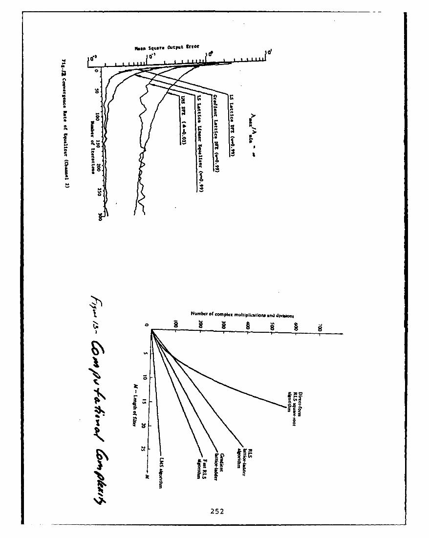
pageO Squiare OaePst ltOf
... I fit
I-I
&Iv
252-

results at this point. The modification to required. All of the results that I'm showingthe so-called error feedback form of the lat- you here are in journal papers that we havetice gives better performance. The LMS al- published, and also in the second editions ofgorithm is also degraded considerably for 11 my book on Digital Communications.bits. Finally at 9 bits, we note th&t the dif- To move to another related subject, Iference between the conventional lattice and should say something about blind equaliza-the error feedback form is significant. There's tion since there is so much interest amonga factor of 10 roughly in the minimum mean the various people here. There are a numbersquare error for these algorithms. The fast of algorithms that have been developed overKalman algorithm did not even converge in the last 10 or 15 years on blind equalizers (seethis case, but again if we employ the modi- FIGURE #15). The first one listed is Sato'sfication that has been proposed by Slock, I Algorithm, which is applicable to PAM, andbelieve that this will take care of the insta- has been around since 1975. Subsequently webility. have Godard's paper published in the early
(PROAKIS IS CONVERSING 80's, in which he gave an algorithm for QAM-
WITH STEIN, KAWAGUCHI AND type signals. Later, Benveniste and Goursat
IOTHERS, WHOSE QUESTIONS ARE proposed some alternative algorithms, which
NOT DETECTED BY THE MICRO- also seem to work quite well. Prati and Pic-PHN EE): I'm showing the michi give a so-called stop-and-go algorithm forPHONE): I'm showing the minimum meanblneqaitonndcimhtterag-square error scaled by 10'. Is this your ques- blind equalization and claim that their algo-
tion? [PAUSE] Oh, the eigenvalue ratio here rithms work better than the previous three
is 11. It's not a bad channel. This is not the algorithms.
same channel that I was dealing with earliei Listed as No. 5 is an algorithm that haswhich had a spectral null. These are the num- come to be known as Bussgang's Algorithm.ber of bits that we carry in all internal com- This was published in a paper by Bellini at aputations in the implementation of the equal- conference two or three years ago. There areizer, including the incoming signal which is some additional algorithms which are still un-3 quantized to 16, 13, 11 and 9 bits, respec- der development, some of which are based ontively. This was an equalizer of length 10 to higher order moments of the signal. These are12, so the number of eigenvalues is equal to cumulant-type methods which are still under
the number of taps in the equalizer. The ratio development. Perhaps some people may wishof the maximum to the minimum eigenvalue to comment on their experiences with thesehere is 11, which is an indication of how bad types of blind equalization algorithms.
or how good the channel is. When we mul- Let me conclude by mentioning what mytiply two numbers we truncate to 9 bits, for students and I are working on at Northeast-I example. So you can see that all of these al- er University [FIGURE #16]. I have a stu-gorithms are quite robust and some are more dent who's working on improving the perfor-robust than others. In the case of the lattice, mance of fractionally-spaced equalizers, ba-the error feedback form is certainly superior sically through the use of singular value de-and one that gives good performance. Hence, composition as a means for reducing the ex-I believe that it's a very nice structure to im- cess mean square error, which is generated inplement when a fast converging equalizer is fractionally-spaced equalizers. I'm not sure
253

a 0
~ ~" 5 .
IN. !
0 0 w
4*$. p= -"-" "
r-4
0.
.4'
.4 a. 1"~I. ,
v6
C4 on - - m
Pd .

how many of you are familiar with this par- JOHN TREICHLER: Adaptive 1IRticular problem, but in a fractionally-spaced Equalization, Frequency Domain Adaptiveequalizer we have a number of zero eigenval- Filtersues. In effect, if we implement the equalizer Let me add Item 4c to John's talk, rightin a conventional way, each tap contributes there [LAUGHTER] ... I can't resist already,linearly to the excess mean square error, the and that is that while I think there's defi-misadjustment error that Widrow talks about nitely room to develop new blind equaliza-in the LMS algorithm. What we're trying to tion algorithms, I think one of the most cry-do, through singular value decomposition, is ing needs is to understand the ones we've gotto isolate the zero eigenvalues and basically and how they work, and what performancereduce the amount of excess mean square er- can be expected of them. They're sort ofror that is contributed as a result of the frac- magic still. The handout you have says thattional tap spacing. The problems are compu- I'm going to talk about frequency domaintational in nature because it's computation- filters and maybe IIR filters, and stuff likeally difficult to do singular value decomposi- that. Since I've got 20 minutes instead oftion in an efficient manner. some much longer interval of time, I thought
Another topic involves the development of I'd talk about one of these topics and let thenew fast algorithms. In spite of what some others come later perhaps. I put these allpeople may believe, that fast algorithms have under the category of trying to reduce thealready been developed and that there's noth- amount of computation needed to do adap-ing new to be done here, I will say that this tive equalization or adaptive interference re-is not the case. It's possible to develop new duction, and I'll motivate that problem in afast algorithms for adaptive equalization, and moment. It's very nice having John go firsta number of these are currently being de- because now there's a whole bunch of thingsveloped by several people, one of whOM is I don't need to describe to you - and one ofFuyun Ling, who is working at Codex Corpo- them (all I'm going to talk about) is linearration. equalizers. I'm not going to talk about deci-
We're also working on channel estimation sion feedback and I'm not going to talk aboutalgorithms for equalization of mobile radio mean square error or Viterbi aided methods.channels. I think that's an interesting area I'm going to do straight stuff, and I'm goingfor additional work. And, finally, I mention to worry about how to minimize the amountblind equalization as the fourth item here, of computation. Not to say that the othersand the use of higher order moment methods don't have better performance, perhaps, butfor designing blind equalizers. Also, I believe I always find myself operating up at the verythat there is still some additional work to be edge of what you can really do in hardware,done on improving existing algorithms, such and you tend to go simple there. Like, howas the Godard Algorithm and Benveniste's do I minimize the number of computations,Algorithm. This concludes my talk. what's the simplest possible algorithm I can
HALL: Just a little over, OK. Very inter- use as opposed to the best performing?esting talk though. Okay, next is John Tre- Generally speaking, the systems that I'veichler, who needs no introduction - or has been traditionally interested in have somenone, either way! sort of adjustable digital filter [VIEW-
255

GRAPH #11. It says FIR, but you don't nec- is maybe a thousand times or maybe evenessarily need to believe it - it could be some- 10,000 times the sampling rate. Is it possiblething else, could be lattice which is FIR un- to ever get there?less it's an IIR lattice. Then what we want to Now there are several different methods,do is take a signal that's been horribly soiled and as I mentioned, given the fact that Iby multipath and/or interference, clean it up, promised up and down that this is only go-and pass it on to often a traditional signal de- ing to take 20 minutes, I'm only going tomodulator or detector. In order to choose the talk about one of these three areas [VIEW-transfer function of that filter, we're going to GRAPH #2]. 1 would be happy to have some-have some sort of performance measurement body ask me questions later in the day or to-and then based on that performance inea- morrow so I can talk about the others. Theresurement, turn around and adjust the filter have been three basic approaches that havecoefficients appropriately. I've shown a cou- come along for handling this. All have differ-ple of dotted lines here - maybe they both ent advantages and different amounts of suc-should be dotted. We either look at this Sig- cess, and different amounts of attention thatnal (the filter output) or perhaps this signal have been paid to them. All of them are lin-(the detector output) in order to help us de- ear equalizers. The first one which I am go-cide whether or not we're happy, and whether ing to talk about is frequency domain filteringor not to adjust the filter coefficients. where we try to use the FFT to help us. Oth-
The problems I want to talk about today ers are adaptive IIR filtering, and that soundsare those characterized by situations where I like a good idea, too. Hey, if I use IIR filters Iwould like to have an incredibly long impulse can get long impulse responses without muchresponse in my filter. Incredible might be, computation, and that's true ... but you alsoaccording to John Proakis' pictures, 13. But get some other stuff that you may not haveI was really thinking like hundreds or thou- wanted. Okay, then the last technique is tosands of taps. Situations where I'm trying to use sparse filters where I have a very long tapreceive, for example, a high bandwidth sig- delay line, but don't bother to put all the co-nal that requires a hi-h sampling rate in the efficients in. That turns out to have some nicepresence of fairly considerable multipath, im- applications where the filter needs to be re-pulresenresonses that last say microseconds, ally long and densely tapped because of theMicroseconds aren't very much if my s high sampling rate. I'd like to poke out apling rates are kilohertz, but if my sampling lot of interferers, I mean use a lot of notches,rate has to be, say, a hundred megahertz, in the transfer function. But a lot might beI've got a hundred tap filter, or maybe a 200 only a hundred, where in fact I may need aor 300 tap filter. Other situations where a thousand taps in order to get the resolutionlong impulse response is really important is I want. So are there games that I can playif I'm trying to excise narrowband interfer- where the degrees of freedom I need are muchence. Think back yesterday to Phil Bello's fewer that the number of taps I need to gaintalk about where I've got a measly megahertz the resolution I want? Now that I've teasedof bandwidth, but I have all these interfer- you about it, I'm not going to talk about it!ers in it, and I would like to chop them out. Okay, what I want to talk about today,In fact the resolution I would like to have at least in this interval, is frequency domain
256

I
REDUCING THE COMPUTATIONNEEDED FOR
ADAPTIVE INTERFERENCE SUPPRESSION
B-282-89
AST SYSTEM OBJECTIVE
DEVELOP A LONG-DURATION, LOW-COMPUTATION ADAPTIVE FILTER CAPABLE
OF MITIGATING TIME-VARYING MULTIPATH OR OTHER ADDITIVE INTERFERENCE
INPUT OUTPUT WAVEFORM.SIGNL ANINFORMATION
INTERFERENCE ADJUSTABLE INPUT SIGNAL SYMBOLS. ORM ODDIGu ATR DETECTION RESULTS
v I [6GAPH *I
25"7B-282-89
Fi iI OR DETETIOIN i•

adaptive filtering [VIEWGRAPH #3]. I'm atively weak broadband signals of interest ingoing to try to restrain myself and not tell the presence of a tremendous number of time-you what limited I know about it, but just varying narrowband interferers, and in thesome of the stuff at the top: what people are presence of multipath and in the presence ofdoing, what appears to work, where the prob- other things where I would like to be able tolems are, what you can hope from it, and so use this long equalizer. There are basicallyforth. I've started all these three sections, two technical approaches; I'm going to focusonly one of which I'm going to show you, with on one of them today, and I'm going to ex-the promise - you know, this is magic. Here's plain to you why I focus on that one [VIEW-what I'm going to go to NSF with, or Office of GRAPH #4]. The first one is the straightNaval Research or ARO, and say, "Here's the use of fast convolution and fast correlation.big deal, and I want a whole lot of money to If you think back to the block diagram, therestudy this." Okay, the promise is that I ought basically has to be in every adaptive filter, ato be able to reduce the amount of computa- filter, right up here, some method of decidingtion quite considerably for high-order high- whether the performance is good or bad, andresolution FIR filters. Why? Because the then some method of taking that error andFFT gives me, you know, log N as opposed to figuring out what set of impulse responses IN, and it's just natural. Now the other thing would like to use in the filter. If I'm inter-that's more subtle, but turns out to be just as ested in using a gradient descent technique,good an argument for the frequency domain like LMS or Godard or CMA or any of thesetechniques, is that it gives me an opportu- other things that we've talked about lately,nity to orthogonalize the input. Well, not then I can do the filtering with just purefor all signals, but it turns out lots and lots Oppenheim and Schafer fast convolution - Iof the signals that we practically care about guess I should actually go back to Tom Stock-might be characterized as relatively broad- ham and those guys, but the book you oughtband, with a whole lot of narrowband in- to see is the orange one - whereas zero-fillterference. You know about Karhuren-Loeve and FFT - and this is just a filter - and I telland all that, and I can orthogonalize it a it the impulse response, and low and beholdbunch of different ways, but it turns out that with log N improvement, I've built a filter. Iif my input is well characterized by a whole can build any FIR filter consistent with thebunch of narrowband signals, then an FFT length of the FFTs. Similarly if I send in anis a very nice way to somehow orthogonalize error signal, and a delayed input, I can useor separate or channelize all those different exactly the same techniques through the con-pieces. And that may allow to do something jugation to correlate the error with the input,neat, and we'll talk about that in a minute - and end up with an estimate of the gradient.it has to do with eigenvalues and such. Using only "fast convolution" and "fast cor-
relation" I have, with no mess whatever, aOK, successes, does anybody really use this rather straightforward implementation of an
stuff? Yes, these methods have already been aatv itrgain ecn-yei hadaptive filter gradient descent-type in the
proven, unfortunately in a few applications frequency domain. And that works, it worksI can't talk about broadly. But the people very nicely.have built these things and they work very,very well in applications where you have rel- OK, there is another method that's come
258

IA TJ ALTERNATIVE APPROACHES
* FREQUENCY DOMAIN FILTERING
* ADAPTIVE DR FILTERING
* SPARSE FIR FILTERING
VIEWGRAPH 02
8-282-89
_FREQUENCY DOMAINAMT ADAPTIVE FILTERING
THE PROMISE
- LOWER COMPUTATION REQUIRED FOR HIGH-ORDER, HIGH RESOLUTION FIR FILTERS
- IMPROVED CONVERGENCE SPEED ATTAINABLE BY ORTHOGONAL2NG THE INPUTSIGNAL
* SUCCEBSES
- VERY SUCCESSFUL IN RECOVERING WEAK BROADBAND SIGNALS IN THE PRESENCE OFTIME-VARYING, NARROWBAND INTERFERENCE
* TWO TECHNICAL APPROACHES
FAST CONVOLUTIONIFAST CORRELATION USING THE FFT
"FILTER BANK" OR TRANSMULTIPLEXER-BASED CHANNELIZED PROCESSING, ALSOUSING THE FFT
VIEWGRAPH 03
259
8-28249

A I TWO DESIGN ALTERNATIVES FORST FREQUENCY-DOMAIN FILTERING
FAST CONVOLUTION/CORRELATION METHOD TRANSMULTIPEXED-AED METHOD
RELATIVEo AlRBUTE
RAEFILTER"A" IGo
ADPIEUPDATIN ANvo BE DOEI h RQECYDMINO OAPPOA CHSIEDN
OFT PVTGRSPI .&A
-2829

IiI!
along lately that has even, apparently, more TREICHLER: Let me follow that up im-advantages. It uses what some of us have tra- mediately - these two methods aren't com-ditionally called "transmultiplexers". This is pletely distinct. I can start playing all sorts ofa name used in the multichannel telephone games back and forth between the two. I'veworld, mostly, to describe a technique from made them look as separate as possible forgoing from FDM to TDM, or from the fre- discussion purposes. I don't want to tell youquency domain channelizing of the input into by any means that this is it, and these are thea whole bunch of equal sized frequency chan- only ways to do it. But I do want to show younels and then reporting the samples out in what some of the significant differences are,sequence or in a time division form. I don't and I've chosen the poles of no weighting andwant to go into this too much here, but ba- extraordinary weighting, in order to give yousically they're built with a set of polyphase an idea of what can help and what can hurt.filters - the name I hate, but that's whateverybody calls them - followed by a DFT, OK, the other thing I've done is with mywhich is usually implemented as an FFT. The adaptive filter. I dechannelize, I multiplycombination of these gets you the same log each channel output - and what I've shown
combnaton f thse etsyou he ameloghere is a diagonal matrix - is a bin-by-binN improvement as before, but has the very hr a chanl atrix wishtin-bwinnice property that instead of just doing an or a channel-by-channel weighting with noFFT that has fairly sloppy 'i N frequency cross channel weighting going into what I callresponse, depending on how long I make these an inverse transmultiplexer, which you mayrespnse deendng n hw lng mae tesethink of as just an interpolator, and an up-subfilters here, these polyphase filters, I can thin of a t an iept and anumake brick wall, beautiful channelized filters, converter. All ito s put all these binsInstead of being down only 13 dB in the next back together into a time domain waveformbin, I can be down 60, 80, it all depends on at the same sampling rate as we went in. Sowhat I want Q to be and how much arithmetic I've channelized the signal, I've scaled it onaccuracy I'm willing to provide up there. It a channel-by-channel basis, and I've put italso has the subtle advantage that, now I'm back together. If this were an analog systemworking in blocks. This data comes in, say I these things would be at the same "samplingbuild a transmultiplexer that has a thousand rate", if you will, as the input, and I wouldn'tpoint FFT, and break the signal into a thou- have had to interpolate; but since I've deci-sand bins, well it turns out that the sampling mated here in the digital world, I have to in-rate here (at the channelizer output) is now terpolate. Now, notice something I've done1/1000 of the input rate. So whatever I deal here - and you may ask why, and I'll elab-with here on a channel-by-channel basis is at orate on this - I've shown the output com-a decimated rate, and I can do some very nice ing from the time domain waveform all thethings. way around through an error calculation and
Sback in. Now, why do I need to do that?STEWART LINSKY: Why can't you Well, I'll have you hold that thought for a
get the same thing by windowing the input We, Le e yo mpe tht to forh-on th FFTmoment. Let me compare these two meth-
ods for just a minute. Again, I've chosen toTREICHLER: You can. make them as different as possible. But what
LINSKY: OK. Is that the only advantages do they have in common, relative attributes?of this other program? [VIEWGRAPH #5] Both of them have sub-
261

stantially less computation, and to tell you that operation commutes with the frequencyexactly how much less computation than the transformation process, and I can do all thestraight time domain, you have to tell me updating in the frequency domain. You saywhat you really want to do. I've shown one that sounds nice; well, it turns out that it'sparticular method of doing the fast convolu- not just nice, it's really important. For ex-tion/fast correlation method; in fact there are ample, what if our error computation or ourdozens. There's a very nice paper that Clark, performance assessment method isn't linear?Mitra and Sid Parker did four or five years Say, ah well, you're talking about a new algo-ago on whole bunches of different ways of do- rithm, like those based on cumulants, you'reing that using 3, 4 or 5 FFTs and different talking about CMA, Godard - I'm talking thesorts of assumptions. Similarly, in the trans- more conventional decision direction method.mux method, or the channelized method, you The only way we currently know how to dohave to tell me how big Q is and how big the decision direction is to get filter-output wave-FFT is. Nonetheless, no matter how you do form and look at it IQ, and see how closeit, it's less. Like typically an order of mag- it is at the baud intervals to the constella-nitude or two less, so that's good. People tion points we would like to match, take thatargue which is more and which is less com- difference and go on. It's very much a timeputation between the two, and again I can domain operation. That's why that feedbackchange the rules, I can change the assump- loop I showed you from the output all the waytions, and I can make them relatively better back around exists.or worse than each other. Something that weshould note, however, is that the transport Now let's look at a couple of observations.delay through the thing happens to be much, One of them is this nonlinear performancemuch more with the transmultiplexer-based measurement, like decision direction, Godard
filter that has the very nice stopband perfor- or CMA. It doesn't commute, you have to
mance. Similarly if I want to start windowing use the loop or some better method, and
or weighting the fast convolution method, I there would appear to be no problem. The
end up having to bring more data in and in- transport delay, I pointed out, is bigger. The
troducing more transport delay there. The most important thing is people actually built
implications of that will become clear later. this thing expecting wonderful performance.Does it channelize wonderfully? Yes. Does
One of the most important things is my sig- it adapt really fast, like they expected it to?nal quality assessment. For example, those of No! And the question is why. Well, if youyou who take EE 373 at Stanford University go back to John Proakis' viewgraph, wherefrom Bernie Widrow, all he ever talks about he showed about eigenvalue ratios, the trickthe way I form an error, is I subtract the out- with LMS is that you look at the covarianceput of the filter from a God-given desired sig- matrix, and you look at the biggest eigenvaluenal, and I've got an error, and I go and adapt and the smallest eigenvalue, and the ratio ofwith it. That's a very nice, straightforward those tells you a lower bound on the nurn-linear operation, and if God always gave us ber of iterations it will take for that filter tothat desired signal to work with, we'd be in converge, depending on how you define "con-really good shape. If in fact it were there, verge". And then if you use an adaptationthen nice things happen because it's linear, coefficient that isn't full-out, you know, all
262

the way against the firewall, it's even slower. AA was a tenth - that means that it ought toSo this problem with eigenvalue disparity has adapt in ten iterations, which is a nice, safebeen a killer. Now if the input is mostly number - and here's what happens [m = 1dominated by interference, and if that in- curve]. But if I keep A the same value andterference can be channelized, and each one start making my transmultiplexers better andof those things falls in a separate bin, then better, attaining better and better adjacentyour eyes start opening wide, and you say, channel rejection, here's what starts happen-"I can use separate A's in every bin, and I ing to the transient response of that singlecan adjust those A's to optimize performance coefficient. Instead of converging in say 20in each bin separately, and I can make each iterations, it can take 80, 90, 100 and worse.one converge in only one step." Well, you (See curves for m = 3, 5, and 7.) The bettercan't! [VIEWGRAPH #61 Here's why. If I make the adjacent channel rejection in mythere were no delay in that feedback loop, bins, the worse the transient performance is.then what happens is that the adaptation be- So, you're dead meat, right? Well, yeah. Myhavior in each bin can be characterized as a final viewgraph [VIEWGRAPH #9] - whatsingle pole that lies somewhere between here this means is you've got to start looking at[z = 1], where t is zero, here [z = 0] where alternatives. That alone isn't going to get itA is such that A times the eigenvalue A is 1 for you. And what do you do? Maybe I ought- and if I keep cranking up A I can drive it to abandon the gradient descent and try tounstable. Now it turns out that as soon as use some closed-form methods or acceleratedI start using these transmultiplexers in order techniques so I get my improved performanceto get these very nice adjacent channel rejec- some other way. Heck, maybe I look at this astions [VIEWGRAPH #71, 1 start introducing a control problem and try to use feedforwarddelay in the loop and I start putting addi- compensation; you know that's a fairly es-tional poles at the center. As I start crank- tablished method, that might work. Maybe Iing up A - and remember I want to put it want to - the last two methods, [sorry Dennis]here [z = 0] - what happens is these guys do - the last two methods, I do have a viewgraphthe old root locus-spider spread, OK - that's for, and they are to play games, start playingTexas [LAUGHTER] - anyway, it's actually games. [VIEWGRAPH #10] Here is my orig-a Texas football play, everybody runs in all inal filter. Maybe I want to put something in-directions hoping to catch a long pass. Any- side the loop that just looks at the spectrum,way, what happens is this pole comes in from and tries to respond instantaneously and veryz = 1, and instead of getting anywhere close rapidly to the spectrum. Like if I see an inter-to z = 0, a pole comes out, these scatter, ferer pop up, hammer it down, and then comethese join and spread, and you go unstable around on a slower, known to be slower, ba-or oscillatory for much, much lower values of sis and clean up the mess. Another method isyt than you would have ever suspected. [OK, to somehow try to approximate all this stuff,two minutes, right? One minute? One and and if I can get the approximation inside ofa half! OK, so the bottom line - I ain't the two transmultiplexers, the fact that it'squite to the bottom line, but I'm getting close an approximation may not hurt me as bad as[LAUGHTER] - this is really good, no sweat!] the improvement I get by being able to do[VIEWGRAPH #8] Say I had set A so that everything on a bin-by-bin basis.
263

PROBLEMS INCOMPUTATIONAL PARADISE
OBSERVATIONS
NONUNEAR PERFORMANCE MEASUREMENTS (E., CMA AND/OR DECISION-DIRECTION) DONOT COMMUTE WITH FREQUENCY TRANSFORMATION OPERATIONS
-4 ERROR SENSING AND WEIGHT ADAPTATION CANNOT BE DONE PURELY IN THEFREQUENCY DOMAIN; CONVERSIONS INTO AND OUT OF THE TIME DOMAIN AREREQUIRED TO SENSE THE ERROR
* THE TRANSPORT DELAY OF A TRANSMUXBASED FILTER IS APPROXIMATELY ON SAMPLESvs. ABOUT 2N FOR A FAST CON'lioLUTION FILTER vm ABOUT N/2 FOR AN N-POUT TIME-DOMAIN FILTER
OBSERVED CONVERGENCE RATE PERFORMANCE OF THE CLOSED-LOOP TRANSMUX-BASEDFILTER IS FAR SLOWER THAN ANTICIPATED
QUESTIONS
- IS THE SLOW CONVERGENCE CONGENITAL?
IS IT RELATED TO THE OTHER OBJECTIONS?
- IS THERE A CURE?
VIEcWGRAPH 16
8-28249
A ROOT LOCUS FOR POLES OFADAPTATION PROCESS AS FUNCTION OF Il
THE EXPECTED TRANSIENT RESPONSE OF THE ADAPTIVE CONVERGENCE PROCESS w(z) CAN BE
ANALYZED USING ROOT LOCUS TECHNIQUES
EQUATIONS:
'tm ~ ~ ~ ~ ~ ~ . lawFAr .m ,tn
/111 ZEWRP
I;
2* * 4 U-m2+1
VIEWGRAPH $7
264 8-282-89

TRANSIENT PERFORMANCE AS AFUNCTION OF 14 X, AND LOOP DELAY
MOVEMENT OF THE POLES CAUSES OSCILLATORY OBSERVATIONSBEHAVIOR AND ULTIMATFLY INSTABIUTY * WITH NO DELAY. IX CAN BE SELECTED TO
1.0 1" - 3:& tMAKE A ALMOST UNITY AND ATTAIN VERY1.2 m -. :27' A t" FASTCONVERGENCE1.25 m-7 i-
1.0 * EVEN SHORT DELAYS FORCE L TO BE1.o0 REDUCED SUBSTANTIALLY, THUS GMNG
zUP MUCH OF THE TOUTED CONVERGENCE75 RATE ADVANTAGE
. LARGER Q PROVIDES BETTER BIN-TO-SINISOLATION BUT FORCES is TO BE LOWER
.25 YET
00 10 20 30 40 50 60 70 80 go tOO
ITERATIONAlMI
WEIGHT BEHAVIOR AS A FUNCTION OF LOOPDELAY FCR n 0
VIEWGRAPH 08
0-282-89
_____T APPROACHES TOAT SPEEDING UP CONVERGENCE
I ABANDON GRADIENT-DESCENT AND USE CLOSED-FORM OR ACCELERATED GRADIENTTECHNIQUJES
* USE FEED FORWARD COMPENSATION IN ADAPTATION LOOP TO IMPROVE TRANSIENTPERFORMANCE
* USE SPECTRAL INVERSION TECHNIQUES TO "PRE-EMPHASIZE FREQUENCY RESPONSEUNTIL CLOSED-LOOP OPERATION CAN BE EFFECTIVE
FIND COMPUTATIONALLY SIMPLER FREQUENCY-DOMAIN APPROXIMATION TO ERRORGENERATION PROCESS
VIEWGRAPH 09
2658-282-89

IAST TWO OF THE POSSIBLE APPROACHES
INNER LOOP FREQUENCY - DOMAINSPECTRAL INVERSION ERROR APPROXIMATION
o WIN" OFlow
WUT =@pwn
%me~ ~~ # KAa D--" Afap
VIcoGAH l
DOA a REDCE DMNiONAL.T FFLE IH MRV OVRECRATES ONOPV RCS8014 ANLYiAWOR
VIEWGRAPH 010
S-282-89

IA S'] IIR ADAPTIVE FILTERING (CONTINUED)
* PRACICAL SUCCESSES
COSRIE - -H" POLES LOCKED TO ZERO (THOMPSON)
" ONLY TWO POLES (CCITT ADPCU ALGORITHM)
*I-POLE DESIGNS IN FREQUENCY DOMAIN ADAPTIVE FILTERS
*ANALYTICAL AND PRACTICAL PROBLEMS
*HIGHER ORDER FILTERS HAVE SLOW ANDIOR UNCERTAIN OONVERGSICE
*CONSTRAINTS/ESTS TO ENSURE STABILITY ARE DIFFICULT AND HARD TOIMPLEMEN'T
*EQUALIZATION OF NON-MINIMUUP4iASE CHANNELS REQUIRES UNSTABLEPOLE/ZERO CHOICES
VIEWGRAPH 912
B-282-89
_______USING 1-POLE IIR FILTERS INFA= TRANSMUX-BASED INTERFERENCE "CANCELERS'
DIGITAL FILTER BANK .4DIGITAL INTERPOLATOR(rRANSMUX'I (TRANSMIJXI I
x (k) Tly0INPUT POLY.POLY
4- FIISTORDE yIRFITE
- WITH COMPLEX COEFFICIENTS
__________ -, 13-282-89
267

IAST' SPARSE FIR TIME-DOMAIN FILTERING
*APPROACH - THIN OUT ThE TAPS OF A LONG FIR ADAPTIVE FILTER
AM12
*POTENTIAL APPLICATIONS - THOSE WHERE DEGREES OF FREEDOM ARE MUCH LES THAN THELENGTH REQUIRED TO ATTAIN THE DESIRED RESOUTION
VIEWGRAPH #14
13-282-89
SPARSE FIR TIME-DOMAIN FILTERINGIASI](CONTINUED)
*FAVORAIL ATTRIBUTES
. SIMPLE EXTENSION OF STANDARD FIR TIMEDOUMN DESIGN
. GRADIENT4EARCH ALGORITHMS (LA, CMA AND LMS) WORK WITH NO CHANGE
*TECHNICAL RESEARCH ISSUES
*CHOICE OF TAP LOCATIONS
VIEWGRAPH *l1j
268

My summary comments are that frequency an additive white gaussian noise channel, it'sdomain techniques look really interesting and an additive gaussian noise channel - and wehave a lot of potential and in some applica- have a linear channel with some intersymboltions, where the adaptation can be internal- interference, and the worse the ISI gets, theized, already work wonderfully. But for all more interesting this particular problem be-these other things we'd like to be able to do comes. Let me then couch that channel inwith it in a communications situation, partic- a little broader setting [FOIL #4] where youularly decision direction and blind equalizers can see the channel right here in the middle,that are nonlinear in some sense, there's a lot and then we have some kind of transmit fil-of work to be done. ter, some type of receive filter (which we call
HALL: John's up at Stanford and he did an equalizer in this particular case), and thensome of the original work on the fast Kalman outside of that we'd like to put on some goodtechniques, and has promised us a look at codes. Now here I'm referring to coset codesmultitone equalizers. or trellis codes, which have arisen in the last
JOHN CIOFFI: Algorithms for Multi- 7 or 8 years as introduced by Ungerboeck and
path, Multitone Equalizers modified by many others. We'd like to con-two catenate those with the system to improveActually the title of the talk listed tothe overall gain for the system in terms of
things: multipath fading and multitone tecon di noi rhe es-
equalization. [FOIL #1] In putting together detection distance-to- noise ratio. The ques-
the talk, I decided I'd stick with just one i f you h
of those two topics, and I'm not going to answer is "yes" if you have intersymbol in-sa athing bot t he ran ckn oing mlti- terference in the channel and you combinesay anything about te t racking of multi- the functions; that is, if you design the codepath fades today. I'd prefer to focus on an and the filtering function together. So thisarea that's kind of grown pretty quickly and extends the original Ungerboeck ideas whererapidly in the last couple of years, the area he combined both coding with just the mod-of combining equalization and coding. Let ulation device, but basically did that for ame just give you an outline slide. [FOIL #2] channel which was free of intersymbol inter-We're looking at channels with intersymbol ference. How do you do it on a channel whichinterference, and we're trying to design codes has intersymbol interference? As I said, this
for those types of channels. So basically we're has ars en in t he As c oftrying to combine both good distance proper- problem has arisen in just the last couple ofties and spectral shaping properties in a sin- years, and there have been a number of solu-ties ndity. Sectalsing oberties in at sing tions proposed to it in a fairly rapid periodgle entity. So I'd like to begin by just looking of time; I know Vedat Eyuboglu from Codex
at some capacity arguments for intersymbol is going to be talking about another method
interference channels, and then looking at the of solving this problem this afternoon.
variety of different types of gains that you can
get, and then finally focus on the muLtichan- The classic result - and you can trace thisnel mctibods as a means to provide tne best all the way back to Shannon, but most peo-possible gains that you could achieve, pie find it in Gallager's book on Informatzon
Now this is perhaps close to Figure 1 in any Theory - is what is the capacity of a chan-modern communications textbook. [FOIL nel that has intersymbol interference with ad-#3] The key thing to note here is this is not ditive gaussian noise like this? The classic
269

Eqalin an offn
May 16, 1989
John M. Cioffi
Information Systems Laboratory
Stanford University
FOIL 0I
Outline
1. Capacity Arguments for ISI Channels
2. Separability of Gains- coding, shaping, equalization
3. Multichannel Methods
FOIL 02
270

Channel ModelN(f) (gaussian)
x(t)_ yAt)
Linear channel with ISI
Additive gaussian noise
FOIL 13
Combined Equalization and CodingN(f) (gua)
Joint Design of the Equalization (Filtering) and CodingFunctions
FOIL 04
271

approach to computing that capacity is the other sample which is 90% of the amplitudeso-called water filling approach. [FOIL #5] of the first sample. I've looked at what the ca-What you do is you take the channel transfer pacity of that particular channel is using thecharacteristic, in particular the power trans- water-filling technique, and that is the darkfer characteristic, and you basically invert it, line, which is somewhat less than the originaland then you take the amount of energy that channel, but basically parallels it, especiallyyou have to transmit, you have some kind of at the high signal-to-noise ratios.transmit power constraint, and you fill this Now this particular curve, right here, thebowl here, and that's what they call "water third curve, is basically the performance thatpouring". You pour water or energy into this you get using pulse amplitude modulation.bowl-type shape until you get to a level where This is a single dimensional channel we'reyou have basically the total of all the energy looking at here. What the performance wouldin there is equal to the power constraint that be if you had a certain signal-to-noise ra-you have in the transmitter. Associated with tio, say 12 dB, and you wanted to achievethat is some optimum bandwidth that you a certain error rate (10-6 is what we usedcan use on the particular channel. Then what here), how many bits/symbol could you getthe capacity calculation basically does is it over the channel with that particular errortakes the capacity at each of the infinitesi- rate? There's a fairly well known result, duemally small channels in the frequency domain to Dave Forney, that the flat PAM case is ba-and sums them, via an integral, over the en- sically 9 dB worse at error rate 10- 6 in thetire range, and that will be the capacity for channel capacity, but basically it tracks thatthe overall system with intersymbol interfer- curve just to the right of it, and they're dis-ence. So what I'd like to do is take an ex- placed this 9 dB difference. Now if you useample and look at this capacity calculation, very good trellis codes, using good codes withand compare it with what the conventional good shaping, you can basically achieve aboutapproach would be on a channel with inter- - these days, the best I know of is about 7.1symbol interference in this particular situa- dB of coding gain - so that you're about 1.7tion. dB away from that capacity curve. That's us-
So what we have here are four curves. The ing the 256-state trellis code combined withrightmost curve, or the best curve of the some of the very recent trellis shaping meth-bunch [FOIL #61, is an additive white gaus- ods. You can basically get that close to thesian noise channel which you can compute us- curve, at least at high signal-to-noise ratio.ing a well known formula: 1/2 log (1+SNR) is So basically you're almost there at capacitythe capacity for that channel. I've plotted it, on the flat channel.the vertical alas is bits/symbol or bits/T; and Now what happens if you put a linear feed-the horizontal axis here is the channel signal- forward equalizer, the type that John Proakisto-noise ratio. Now one of my students, Glen described earlier this morning, on the 1+0.9DDudevoir, has also done it for a fairly simple channel, you try to equalize it to be flat, ardtype of channel, it's just got one intersymbol then look at the performance of that systeminterference term, 1 + 0.9D, so that means in much the same way that we've looked atyou have a center tap on the channel and the performance of the flat channel. In otherthen delayed one unit in time you have an- words, we look at error rate 10" and see what
272

P Capacity Calculation--by Water-Pourn
N I 2
optimum bandwidth Q~
c±f 10 ) dfFOIL 05
5
--- Flat -Capcit
Flat -PAM4+ D P ... 'W........... ...... .. .......... ..............
'I3. .. .... .... ...
S 2 .5 . ... ............. .. ... ... . . .............. ...............
0.5 ... ............. .. ...... ........
00 5 10 15 20 25 30 35 40 45 50
Channel SNRFOIL *6
273

the data rate that could be achieved for any ago, where he showed that the decision feed-signal-to-noise ratio is. And you see it's more back equalizer is about as good as you canthan 9 dB away from its corresponding ca- ever expect to do on a channel at high signal-pacity curve. In fact, as you get out to very to-noise ratio. Well, high signal-to-noise ra-high signal-to-noise ratios it falls off consid- tio may be extremely high in certain practicalerably. So this is a motivation, just slapping applications, and the more severe your ISI isa feedforward equalizer on and concatenating on the channel, the higher that high SNR hasit with the code is not going to work unless to be before that argument basically holdsthe channel is pretty close to flat, and the true. So we have this motivation: presentmore severe the ISI on the channel, the fur- systems using the typical type of equalizationther off it's going to be. So that's really not on a channel with severe ISI really doesn't getthe way to try to combine your codes with where capacity arguments would tell you youequalization on this particular channel. should be on the channel.
Now I've also - one of my students, Jim So what I'd like to do now is look at howAslanis, did a couple of other plots of this you might get there [FOIL #8], and look at,same sort for two different channels. [FOIL at least, some fundamentals which you can#7] One is the classic 1 - D channel, AMI identify in that particular process. So I'vechannel if you like, up on the top plot, here. returned here to the slide I began with [FOILBasically we're looking at, in this case, the #9], describing combined equalization andperformance of a decision feedback equalizer coding, and I've augmented it by this formularather than a feedforward equalizer. The right here. There are three terms. Basicallysolid curve is, again, the capacity as com- -y is the overall coding gain for the system;puted via the water filling type plots. The that's the ratio of minimum distance in yoursecond curve is using a decision feedback coded system to the energy that it requires toequalizer and concatenating it with the best transmit with that given minimum distance,trellis code you can find. Look at the differ- and then you compare that for a well codedence between these two curves. Now for the system with a system which is basically pulse1 - D channel you can see the decision feed- amplitude modulation and uncoded. Andback equalizer performs a little bit better, it's there are three terms that you can identify incloser to that capacity curve, and it basically terms of the performance of this system. Twohugs it at high signal-to-noise ratios. But as of them are fairly well known at this point -the intersymbol interference gets more severe I think Dave Forney is the one who devel-on the channel, as in the bottom curve (I've oped them in his coset codes papers, whichgot a channel where I've thrown several ad- just appeared last year, so-called "fundamen-ditional 1 + D factors at it, and what that tal gain," which is basically a property of thedoes is force the channel spectrum towards trellis code itself without looking at the con-low frequencies), this gap widens. The de- stellation shaping effects. That can go up tocision feedback approach is not so good on abi, at 6 dB on the best known codes. There'sthis particular channel, but again you can see a second term called "shaping gain" whichthese two curves merging as you go off to very has to do solely with the actual shape of thehigh signal-to-noise ratio. This is a classic re- constellation and how close to a sphere it is insult that's basically due to Price twenty years N dimensions, and that can go up to about
274

1 .Caact Aruet.o IICanl
+
I
] 2. Separability of Gains- coding, shaping, .equalization
3. Multichannel Methods
SFOIL 8
-I275

Combined Equalization and CodingN(f) (punian)
7 7f + 7 + ye
fundamental gain shaping gain equalization gain
o .y,< 6dB O S.S dB 05 ̂ .9 <large IFOIL 09
Equalization Gain
SNRMS.DFE,Q go
SNRzF-DFE, Nyquist gg
go = first tap in min-phase equiv. echannel
= tap 0 of MSPR channel for w. pour xmit filter
EIxsl/2 H12Sill =Ex x H
Y2
FOIL 010
276

1.1 dB with the best known techniques for partial response channel, or the water pour-that. Then, finally, there's a third term that ing energy distribution ... I'll talk a littleI'm going to add, and this is the "equaliza- bit more about that. Basically what it is,tion gain." [FOIL #10] This is going to be is a least squares equivalent of this minimuma function of the channel that you're actu- phase channel. Then, finally, the signal-to-ally trying to use. On a flat channel, or a noise ratio that I use here, the little snr (us-channel with very low signal-to-noise ratio, ing lower case letters) is just basically theyou basically have 0 dB of equalization gain transmit energy x filter response which is a
noisethat you can achieve. But on some channels constant for any particular channel. So that'sthis number can be very large, and so it's im- the equalization gain.portant to look at this and what it could be,and then how would we achieve it. So that I promised I'd tell you a little bit morethird term, the equalization gain, I have de- about what that mean square partial re-
fined this way: it's the signal-to-noise ratio sponse, or least squares minimum phase chan-
of what I call the mean square error decision nel, is. [FOIL #11] What it is, is if you take
feedback equalizer; this is Salz's decision feed- your data sequence, you run it through some
back equalizer, if you're familiar with that kind of transmit filter where this transmit
particular result. Basically it uses the least filter basically has the shape, a square root
squares techniques rather than a zero forc- of the shape, which is associated with the
ing technique to design the d-!cision feedback water pouring energy distribution. You run
equalizer. And I use, for that equalizer, that through the channel. What you use over here
9 - that's the bandwidth that we saw ear- - this looks like a decision feedback equalizer,
lier from the water pouring calculation. So it's actually Salz's decision feedback equalizer
you find that optimum energy distribution, which is based on a mean square error criteria
use that with the decision feedback equalizer, - if you run that through the feedforward sec-
and that's what I'm going to say is about the tion of his decision feedback equalizer, what
best that you're going to be able to do on will happen here is that you don't quite get
your system. Then I compare that against the minimum phase equivalent for the chan-
what you might nominally try in a system like nel. You get, what I call, a mean square error
this, a zero forcing decision feedback equal- minimum phase channel. That was what that
izer, where you use the entire Nyquist band - go was associated with; it's the lead tap in
you just put ±1's or an i.i.d. data sequence, this least squares equivalent channel. If you
if you will, into the input of the channel. This want a formula for that, you just take the
is what I'll call the equalization gain. When channel autocorrelation function, normalize
you define it this way it basically adds in that it, and add to it, and then do athird term in the formula you saw on the pre- spectral factorization for that. This g here isvious viewgraph. You can actually prove - I the quantity that you're interested in. There
don't want to do it here - but it follows this are cepstral formulas that you can work out
simple formula here, where go is the first tap for this thing as well. The most interesting
in a so-called minimum phase equivalent for result that I found, about a year ago, was
whatever the ISI channel is; Jo is the first tap that if you look at the signal-to-noise ratio
or tap zero of what I call the mean square for this particular decision feedback equal-izer, the minimum mean square error decision
277

Mean Square Partial Response
(PP(t) = P1 q (t ) 90Op(-t)M.. =
Mcan-Squam DPE (Sa~z) W() 0(D') -Qi-Ir
1/12
C -L ± 1(+SNRms-DF. a)
FOIL Wl
Tomlins onPrecoder
Tomlinson P=ocWe Minimum-Phase Eguivalent Channel
Eliminates Error Propagation
loss of shaping, xmit power boost
FOIL #1?
278

feedback equalizer, when you use the water jay Kasturia, a past advisee of mine. Thefilling bandwidth, it turns out that the capac- first channel, the 1 - D, the gain is largestity for the channel with intersymbol interfer- at lower bits/T, and it basically goes to zeroence follows this particular formula here: it's as you get out to higher bits/T. As you have1/2 log2 (1+SNR) for this particular system. more severe ISI, there are huge gains to beNow that is a very convenient form, because had. Now some of these channels are a lit-what you can see is that this formula is very tie bit ridiculous in that they have very lowsimilar to the thing that you get for a flat frequency content and a high Nyquist rate.channel except that you just have the signal- But basically what's going on here is opti-to-noise ratio replaced by this mean square mizing the transmit bandwidth using theseerror decision feedback equalizer result. So techniques is a very important result that canwhat that says is now if you know how to show up in your overall gains. Now that's adesign a code, 7.1 dB of gain, for a chan- basic concept of that the equalization gain- Jnel which is flat, which is effectively what the know I'm running out of time here, I've beenperformance of this decision feedback channel getting some fingers, two and three, shown tois, you can basically do as well as you could me - all polite ones, right?]do on the flat channel, just using a signal-to- The approach that I've looked at most fornoise ratio in place of that.Thaprchtt veokdatmsfo
this is so-called multitone or multichannelA classic problem with decision feedback type signaling techniques [FOIL #14]. Basi-
is error propagation, which was not included cally what you do is you split your channel upin that last result. That's a very significant a la the same types of techniques that Johnproblem in a system that uses a decision feed- Treichler was talking about [FOIL #15], withback equalizer when you try to concatenate the transmultiplexing techniques, into a vari-that with a code, because the ecror rate on ety of parallel channels, and you try to againthe DFE output is very poor. If you use a allocate your energy from the transmitter ac-very good code it's going to be about 9 dB cording to some water pouring assignment -(6 dB code + 3 dB signal expansic") away it turns out that it's the same one that .iefrom what the actual coded performance is saw earlier. Wher you do that and you fixif you're just doing symbol-by-symbol de- the signal-to-noise ratio on all the outputstection, and that's an enormous problem in to your system to be constant, then maxi-those types of systems. So the recent ap- mize that signal-to-noise ratio, it turns outproaches to this have been to use the so-called that this thing we saw earlier for the meanTomlinson precoder [FOIL #12] which basi- square error decision feedback equalizer overcally shifts the feedback section to the trans- that water pouring bandwidth is the same asmitter with a very small penalty in transmit the signal-to-noise ratio that you get on thepower boost, and some small penalty in a loss multitone system when optimized over thatof shaping gain as well. So that's just a way same bandwidth. And in fact you get thisof getting around that particular difficulty. same capacity result where you could stick in
If you look at that particular system, these either of the signal-to-noise ratios there. Soare the types of gains that you see for a va- this is another technique for doing it. It hasriety of different partial response polynomi- no feedback in it and you basically go to theseals [FOIL #131, as were computed by San- parallel channel type approaches.
279

MSPR Gains 7e (dB)
SNRlbit/T 2bit/T 3bit/T 4bit/T
(1-D) 1.5 .8 .3 .1
(1+D)2 (1-D) 4.2 2.8 1.7 1.0
(1+D)3(1-D) 8 6 4 2.9- -'(1+D)4(1-D) 12.5 9.5 7 5
FOIL 013
Outline
1. Capacity Arguments for ISI Channels
2. Separability of Gains- coding, shaping, equalization
3. Multichannel Methods
FOIL 014
280
_ _ _ _ _ _ _ _ _ _ _ _ _ _ _ _ _I

Mutlichannel* Signalling
SN4Rvc.oM& a A afmm&)
UNm4~ NwjInfiniteIDimensional c = 1.Ig(+Nm.~jBlocks 2 o(1SR.)
I FOIL 115
Capacity... - parallel Channels
*--P u 4 A N10 Is/03
Sto a Now -4 to gld b MO Ra b d
F04 0163 281
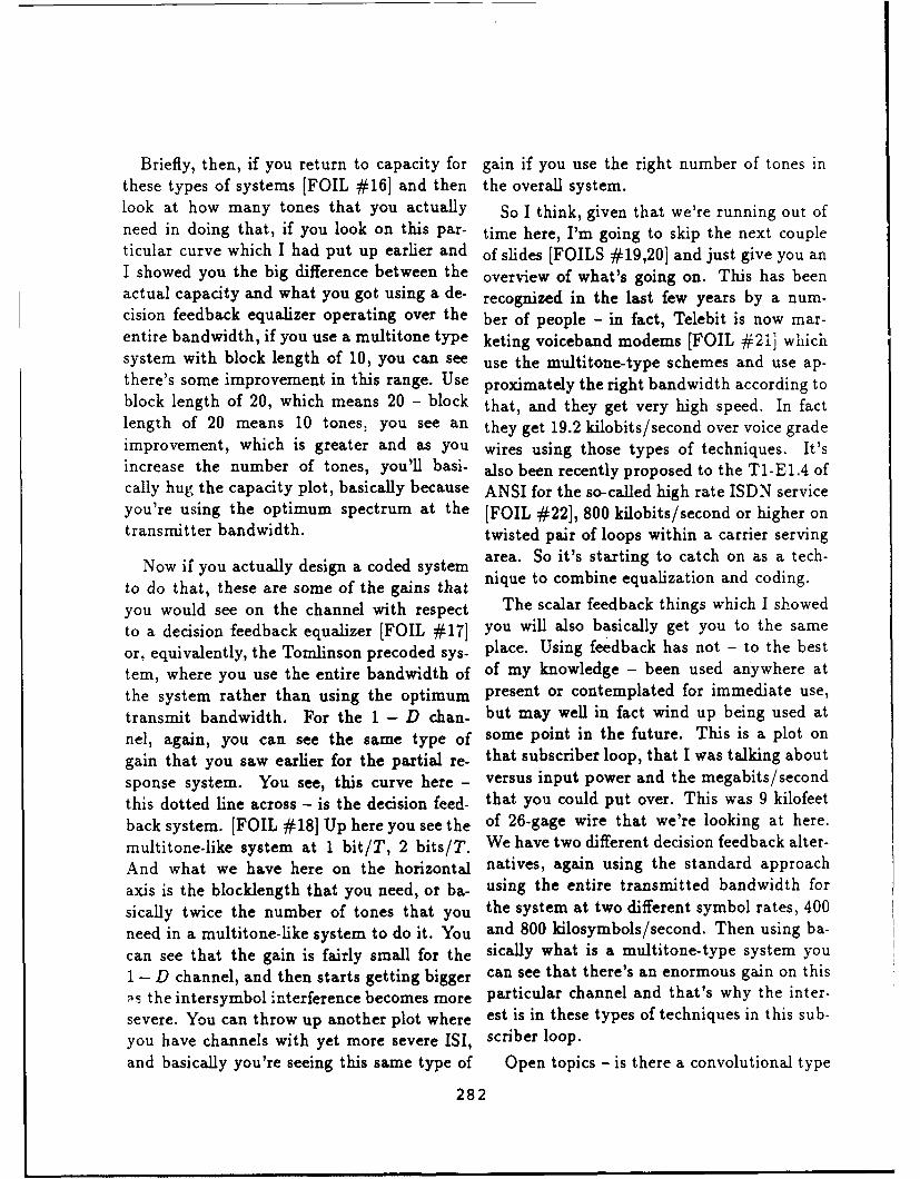
Briefly, then, if you return to capacity for gain if you use the right number of tones inthese types of systems [FOIL #16] and then the overall system.look at how many tones that you actually So I think, given that we're running out ofneed in doing that, if you look on this par- time here, I'm going to skip the next coupleticular curve which I had put up earlier and of slides [FOILS #19,20] and just give you anI showed you the big difference between the overview of what's going on. This has beenactual capacity and what you got using a de- recognized in the last few years by a num-cision feedback equalizer operating over the ber of people - in fact, Telebit is now mar-entire bandwidth, if you use a multitone type keting voiceband modems [FOIL #21] whichsystem with block length of 10, you can see use the multitone-type schemes and use ap-there's some improvement in this range. Use proximately the right bandwidth according toblock length of 20, which means 20 - block that, and they get very high speed. In factlength of 20 means 10 tones, you see an they get 19.2 kilobits/second over voice gradeimprovement, which is greater and as you wires using those types of techniques. It'sincrease the number of tones, you'll basi- also been recently proposed to the T1-E1.4 ofcally hug the capacity plot, basically because ANSI for the so-called high rate ISDN serviceyou're using the optimum spectrum at the [FOIL #22], 800 kilobits/second or higher ontransmitter bandwidth. twisted pair of loops within a carrier serving
Now if you actually design a coded system area. So it's starting to catch on as a tech-
to do that, these are some of the gains that nique to combine equalization and coding.
you would see on the channel with respect The scalar feedback things which I showed
to a decision feedback equalizer [FOIL #171 you will also basically get you to the same
or, equivalently, the Tomlinson precoded sys- place. Using feedback has not - to the best
tem, where you use the entire bandwidth of of my knowledge - been used anywhere at
the system rather than using the optimum present or contemplated for immediate use,transmit bandwidth. For the 1 - D chan- but may well in fact wind up being used at
nel, again, you can see the same type of some point in the future. This is a plot on
gain that you saw earlier for the partial re- that subscriber loop, that I was talking about
sponse system. You see, this curve here - versus input power and the megabits/second
this dotted line across - is the decision feed- that you could put over. This was 9 kilofeet
back system. [FOIL #18] Up here you see the of 26-gage wire that we're looking at here.
multitone-like system at 1 bit/T, 2 bits/T. We have two different decision feedback alter-
And what we have here on the horizontal natives, again using the standard approach
axis is the blocklength that you need, or ba- using the entire transmitted bandwidth for
sically twice the number of tones that you the system at two different symbol rates, 400
need in a multitone-like system to do it. You and 800 kilosymbols/second. Then using ba-
can see that the gain is fairly small for the sically what is a multitone-type system you
1 - D channel, and then starts getting bigger can see that there's an enormous gain on this
is the intersymbol interference becomes more particular channel and that's why the inter-
severe. You can throw up another plot where est is in these types of techniques in this sub-
you have channels with yet more severe ISI, scriber loop.
and basically you're seeing this same type of Open topics - is there a convolutional type
282

Codinga. Gain
3.0.
%i
3.
2.5 um3 u
-. -. *0**.-- -.. *-.- to.. -0 30 --- 30 6 0 g-oao4 t 0 4 o G 0 s 0
bldIg aks t
1-D (1+)'(1-DFOI.01
Coin Gaini
iDFOLf1 1+)(1D
Co1n Gainr
bwr 33 w
-2283

BLOCK DFE (Kasturia) (Also, J. Lechleider , Bellcore)Shaping filters Matched filters
Puls IOPecaPlscrs
Po O~ock peuiod T Nieb
PuiseresponacN PuiCespowS
a2 a
P2b2a
Thie I s arrive Pulse responsels esosocver4 ~b
Block
shaping filters dcso
FOIL 01
Block TomlinsonPrecoding
Px284

Status of CECmultitone - Telebit voiceband
modems, High-Rate ISDN
scalar feedback -?
FOIL 021
Vector Coding vs. DFE + Code2
1.8 - Vector Coding.. DFE 400 ksps
1.6 .... DIFE 800 ksps
S 1.4-
1.2-
........................
10-1 200 101 102
Input Power (mW)FOIL #22
285
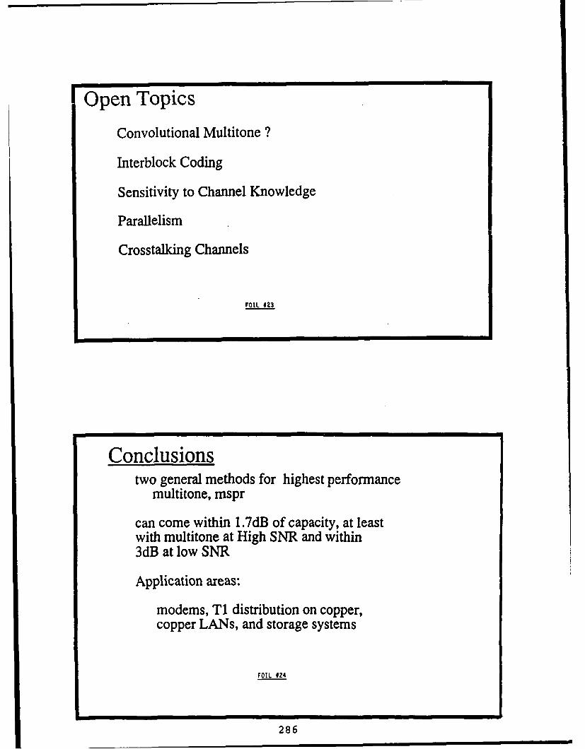
Open Topics
Convolutional Multitone ?
Interblock Coding
Sensitivity to Channel Knowledge
Parallelism
Crosstalking Channels
FOIL #23
Conclusionstwo general methods for highest performance
multitone, mspr
can come within 1.7dB of capacity, at leastwith multitone at High SNR and within3dB at low SNR
Application areas:
modems, T1 distribution on copper,copper LANs, and storage systems
FOIL 024
286

of multitone system where you could reduce paper several years ago with John Treichlerthe complexity of the system somewhat? In- on the constant modulus, and now he's gotterblock coding - this means designing codes his own company and he's pursuing similarwhich span basically all the tones in the sys- things ....tem rather than putting a separate trellis BRIAN AGEE: Blind Adaptive Signalcode on each tone in the system. How sen- Restorationsitive is this to actually knowing what your Thank you. I am going to be talking todaychannel is at the transmitter? [FOIL #23] about a general approach for designing struc-There's a significant amount of parallelism in tures and algorithms for blind adaptive signalthe actual construction of a multitone system, extraction, which I refer to as the propertyand some of the problems you see, especially restoral approach to blind adaptive signal ex-in the subscriber loop and the crosstalking traction. I believe that this approach is verychannels area, those haven't been completely pertinent to the topics that we have been dis-resolved as yet. It may be possible to improve cussing at this workshop, especially the topicsthose results I've shown you on the previous that were discussed at the yesterday's morn-
slide if someone can solve them. ing session. In particular, I think that this
So in conclusion, there are basically two technique specifically addresses the problemmethods that have arisen in the last cou- that was raised by Dr. Pickholtz at that ses-ple of years, really, that people have proved sion, of "How can we separate and sort co-are going to do as well on any channel with channel signals in a given environment?" IISI as you can do on a flat channel if you should also mention that this talk is going touse the right technique. The two techniques be a bit of a change of pace from the otherthat are known to work right now are ba- three presentations in this session, in that Isically an optimized multitone technique or am not going to be talking about equalization
what I call mean square partial response per se, but rather any technique for extract-techniques. Either of them will get you to ing signals from environments containing in-the same performance level, and that per- terference and linear channel distortion.formance level is within 1.7 dB of capacity Before I start talking about blind adapta-at high signal-to-noise ratio, or if you have tion, let me very quickly review the conven-a really low signal-to-noise ratio it's about tional adaptation approach, to show where3 dB away. [FOIL #24] It's already been blind adaptation departs from it. Slide AGI-applied in voiceband modems that are being 2 depicts a typical non-blind adaptive proces-marketed, and suggested for T1 distribution, sor. A vector sequence x(n) is formed fromthis is 1.5 megabits on copper twisted pairs. some received data set, using some fixed pre-There has been some interest I saw at ATT processing stage - for instance, by passing thein looking at copper local area networks us- received signal through a tap delay line filtering these types of techniques. Most recently and setting x(n) equal to the tap voltages, orpeople have been looking at these techniques by setting x(n) equal to the voltages on anfor storage systems as well. So that basically array of sensors. This vector signal is thenconcludes the talk .... passed through a linear combiner to yield out-
HALL: Thank you very much. Our final put signal setting y(n), and the weights ofspeaker is Brian Agee, who co-published a the combiner are adapted to optimize some
287

® THE PROPERTY-RESTORAL APPROACHTO BLIND ADAPTIVE SIGNAL EXTRACTION
THE PROPERTY-RESTORALAPPROACH
TOBLIND ADAPTIVE
SIGNAL EXTRACTION*
Brian G. AgeeAGI Engineering Consulting
Woodland, CA 95695
Portlkoe d the wo k preented here have b en tuded by ESL. Inc. (with potly M Ing tundkVg trm ft.Cadlomi Slod MIACO Progran . hAGOSyswn. Wc. E-Systens. Inc. and the Ndona Sieneo Foaodetb
AG I. I
A BACKGROUND:CONVENTIONAL ADAPTATION
-Example: MMSE linear processor
x(n) . 1,w op y(n)
s(n)
* Goal: adapt processor to restore SOl quaflty- minimize MSE < ie (n )12 >, BER, etc.- maximize SINR, likelihood function, etc.
* Probiefn : reuire$knowledge of $O! Waveform 0r channel I
AG 1-2
1989 ARO/USC Workshop May 1989288

measure of the quality of the signal of inter- ties, rather than some unobservable measureest (SOI) s(n) within y(n) (in this case the of the signal quality. This leads to the prop-mean-square-error between y(n) and s(n)). erty restoral approach.
However, in order to perform this optimiza In Slide AGI-5, I have listed a 4-step designtion, the receiver requires knowledge of ei- methodology for designing a property restoralther the SOI waveform or the transmission algorithm. This procedure is as follows.channel that the signal was transmitted over.In many applications, this information is not Step 1: Identify the exploitable properties
available at the receiver, and quality opti- of the SOI. Analyze the structure of the
mization cannot be performed. Instead, we SOI, and determine the properties of
must use blind adaptation techniques that that signal that distinguish it from the
can operate without the use of this informa- background interference.
tion. Step 2: Identify a signal extraction struc-Slide AGI-3 lists the assumptions that we te t a a n o tfctions:r1)
are operating under here that motivate the tre the c 01 frm the recived en
use of blind algorithms. We are going to as- eirnmt tha i rm the ierfe-
sume that the SOI is unknown over the recep- enend totion ro the ee -ence and distortion from the received sig-
tion interval, so we cannot use it fur adap- nal (the usual function); and 2) restoretation. We are also going to assume that the particular 501 properties that we arethe SOI transmission channel is also unknown trying to exploit. The second functionat the transmission start, and possibly time- adds a subtle constraint to the conven-varying over the reception interval. In an an- tional procedure for designing an extrac-tenna array application, for instance, these tion processor: the extraction must beassumptions would be consistent with appli- performed in a nontrivial manner thatcations where we do not have calibration data does not inadvertently impart the de-available at the receiver, or where our array sired signal properties to the processorgeometry is changing too quickly for us totrack changes in the cal data. in addition, output sn nspaicular, the res-sor must be constrained so that restoralwe are going to assume that the channel it- of the signal properties is tantamount toself may be time varying, for instance due tointerferers coming up or going down over thereception interval. Step 3: Design an objective function that is
So, the question is, "What can we do in this optimized when the SOI properties iden-situation?" We can't restore the SOI qual- tified in Step 1 have been imparted toity, because we can't observe the SOI qual- the signal at the output of the processority: we do not have access to either the trans- designed in Step 2.mitted signal waveform or transmission chan-nel. However, in many applications we do Step 4: Design an optimization algorithm toknow something about the SOI: it has some find the useful extrema of the objectiveknown structure or properties. What we can function designed in Step 3. Again, thetherefore do is try to optimize some observ- desired outcome is for restoral of theable measure of these known signal proper- signal properties to be tantamount to
289

®THE PROPERTY-RESTORAL APPROACHTO BLIND ADAPTIVE SIGNAL EXTRACTION
BLIND SIGNAL EXTRACTIONPROBLEM
" Assumptions- SOI unknown over reception Interval- SO[ transmission channel unknown at reception start,
possibly time-varying over reception Interval- Overall channel possibly dynamic over reception interval
* Applications- ESM systems (reconnaissance, acquisition)- EW/ECM systems (anti-jam, look-through)- Mobile & satellite communications- Low-cost telephony, data communications- Reception of broadcast signals
A-I.3
SHISTORICAL PERSPECTIVE
* Partially-blind techniques- Linearly-constrained BF (Griffiths '69, Frost '72)- Noise cancellation (Widrow '75)- Decision directed equalization (Proakis '69, Gersho '69)- Decision feedback equalization (Austin '67, Monsen '71)
* Truly-blind techniques- Sato's algorithm (Sato '75)- Reduced constellation algorithm (Godard '80)- Dispersion-directed aIgs. (Godard '80, Benveniste '80-'84)
- Constant/known modulus algorithms (Treichler '83, '85)
AI .4
1989 ARO/USC Workshop 290 May 1989

ITHE PROPERTY-RESTORAL APPROACHI ®ATO BLIND ADAPTIVE SIGNAL EXTRACTION
PROPERTY-RESTORAL
• Adapt processor to restore known SOI progerties- Modulus of FSK, PSK, FM SOls- Self-coherence of PCM, AM, FDM-FM SOIs
* Basic design methodology
1. Identify exploitable SOl properties2. Identify signal extractor structure3. Design property-restoral objective function4. Develop property-restoral adaptation algorithm
* Desired outcome: restored property 4* restored quality
AGI-5
S EXAMPLE: CONSTANTMODULUS PROPERTY
*SOI possesses constant complex envelope
S Kt It=
-Property dsroye by distortion, Interference
Irsamittod Ito a a rawiignna trory -4i
SNOI
1989 ARO/USC Workshop 291 May 1989

restoral of the signal quality at the pro- So, given this genesis, what's possible now?cessor output. Slide AGI-8 lists what I think is possible
now quite alot! The CMA was originallySlides AGI-6 and AGI-7 illustrate this ap- developed to adapt single-sensor FIR filters;
proach for the constant modulus algorithm since then, it has been applied to a num-(OMA), which was developed by John Tre- ber of different processor structures, includ-ichler and myself in the early 80's at ARGO ing multisensor antenna arrays and polariza-Systems [1]. This was the first algorithm that tion combiners [2], and it has been imple-(to my knowledge) explicitly used the prop- mented in frequency-domain as well as time-erty restoral concept in its development. At domain form (as discussed in John Treich-the time that we developed this algorithm, ler's presentation). In addition, a number ofwe were attempting to remove multipath in- fast and rapidly converging versions of theterference from an FM signal. The basic ap- CMA have been developed by myself and oth-proach was developed by noting that the FM ers [3,4], which allows the blind processingsignal can be represented as s(t) = e)(t) after concept to be applied to rapidly or dynami-it is transformed to complex baseband repre- cally time-varying environments. The prop-sentation. That means that the magnitude erty restoral concept has also been appliedor modulus of the signal is constant (equal to a number of new processor structures, in-to unity). However, this "constant modulus" eluding adaptive demodulators, which restoreproperty is destroyed if interference or dis- properties of the baseband symbol sequencetortion is added to the FM signal. This mo- rather than the transmitted signal waveformtivates a simple modification of the nonblind [5,6], and multitarget processors, which ex-processor shown in Slide AGI-2, by adapting tract multiple SOIs from the received envi-the linear combiner to minimize a measure of ronment [2,7]. This last extension addressesthe modulus variation of the signal at the pro- the sorting problem discussed in yesterday'scessor output. The particular modulus varia- morning session.tion measure shown in Slide AGI-7 is referredto here as the 1-2 constant modulus cost func- In addition, the modulus restoral approach
tion, which is my personal favorite for perfor- has been applied to a number of other kinds
mance and implementation reasons. Essen- of signal properties besides constant modulus.
tially, this cost function is the mean-squared- Most of these features fall into two general
error between the modulus of the processor classes: modulus features, or features of the
output signal and unity. If y(n) is equal to envelope of the signal; and self-coherence fea-
the transmitted signal, this cost function is tures or self-correlation of the SOL under tem-
equal to zero; if the modulus variation of y(n) poral, spectral or spatial displacement. How-
is low, the cost function value is also low. By ever, other features have also been exploited
adapting the linear combiner weights to mini- that fall into neither of these classes, or that
mize the cost function, we are hopefully going represent generalizations of these classes. In
to extract the SOI from the received environ- future, I believe that it shall be possible to
ment. In fact, this algorithm has worked very extend these approaches to a number of ad-
well in practice, and has been implemented ditional modulation features.
(under various names) in both military and Lastly, we are starting to get a muchcommercial communications systems. stronger theoretical understanding of how
292

THE PROPERTY-RESTORAL APPROACHTO BLIND ADAPTIVE SIGNAL EXTRACTION
CONSTANT MODULUSRESTORAL
-System Concept
LS/RLS+ r( n) compex
.1-2 Constant-Modulus Cost Function
F1-2(w) = <i y(n)-f(n)12 >
= < (ly(n)j- 1)2 >
AGI-7
SWHAT'S POSSIBLE
" Blind extraction possible via many structures, algorithms- Antenna arrays, filters and demodulators- Single-target or multitarget (multiport) processors- Time-domain or frequency-domain Implementations- Fast/rapidlv-converging algorithms
• Can exploit a lIn1Iiora of SOI modulation features- Modulus (envelope properties)- Spectral self-coherence (cyclostationarity)- General modulation properties (property-maDoing)
• Strong theoretical understanding beginning to emerge- Uniqueness proofs (Benveniste, Godard)- General convergent behavior (Lundel, Agee)- Ties to maximum-likelihood estimation (Agee)- Ties to POCS, EM signal enhancement methods (Agee)
AOt-8
2931989 ARO/USC Workshop May 1989

these algorithms work, from the original work that I have been working on lately. In partic-performed in this area by Benveniste [8] and ular, I am going to focus on those structuresGodard [9], and from more recent work per- that are particularly applicable to the modu-formed by John Lundel at Stanford and my- lation characterization and sorting problemsself at AGI and U.C. Davis. In particular, that people talked about in yesterday's morn-I have mathematically proven stability and ing session.convergence of a general class of algorithms The modulation properties that to mythat I refer to as property-mapping algorithms knowledge have been looked at to date are[3,AGI6], which encompass the class of modu- shown on Slide AGI-9. As I said on thelus restoral algorithms, and Lundel and I have previous slide, these properties generally fallindependently shown that these stationary into two categories: modulus properties, andpoints can correspond to capture of the dif- self-coherence properties. I have been look-ferent signals in the environment under fairly ing primarily at modulus properties and spec-representative conditions [6,10,11]. So, the tral self-coherence properties [15], which arestationary points of our objective function ac- caused by cyclostationarity of the signal andtually mean something in terms of SOI qual- commonly induced by periodic bauding, gat-ity. ing and mixing operations at the signal trans-
In my Doctoral research, I have also discov- mitter.ered some interesting ties between property The modulus properties that I have investi-restoral techniques and maximum likelihood gated in my research are listed on Slide AGI-estimators of the SOIs, and also ties to some 10. These properties are all extensions ofof the signal enhancement methods that have the "constant modulus property," that I dis-been developed in the field of image restora- cussed earlier. The constant modulus prop-tion. In particular, the property-mapping erty applies to signals with truly constantapproach that I have developed in [6] is moduli, such as CPFSK signals and FM sig-closely related to the method of projection nals, as well as signals with low (but nonzero)onto convex sets developed by Youla [12,13] modulus variation, such as AM signals (withand the property mapping signal enhance- low modulation index). The constant modu-ment method developed by Cadzow [14]. In lus property can also apply to signals whosefact, I believe that it should be possible to baseband or symbol sequence has a low mod-use Youla's and Cadzow's work to substan- ulus variation, such as PSK and PCM QAMtially generalize the blind processing tech- signals. The second class of properties, theniques that have been developed to date. "known modulus property," was originally
Obviously, there is a lot more that I could investigated by Frost (see [2]), and is ap-talk about today than I have time for. There- plicable to signals with a non-constant butfore, I'm going to focus on some specific re- nonrandom and known modulus, for instancesults in a couple of the areas discussed above, pulse communication signals, pulse radar sig-In particular, I want to talk a little about nals and return-to-zero FSK signals. To mythe new kind of property restoral approaches knowledge, this is the second technique thatthat I and other people are starting to look was developed explicitly using the propertyat, and discuss some of the more interesting restoral viewpoint.or novel structures for blind signal extraction The third class of properties, the "multiple
294

THE PROPERTY-RESTORAL APPROACHTO BLIND ADAPTIVE SIGNAL EXTRACTION
S.EXPLOITABLE PROPERTIES
* Modulus properties- Constant modulus / low modulus-variation- Known modulus- Known modulus distribution- Almost-periodic modulus
" Self-coherence properties- Spatial self-coherence- Temporal self-coherence- Spectral self-coherence, conjugate self-coherence- Higher-order self-coherence
* Other SOI properties- Signal transience- General signal properties (ML blind signal estimation)
AGI-9
MODULUS PROPERTIES
Property Definition Primary Application
Constant modulus s(o I = 1 All processors
Known modulus Js(t I = m(t) Filters
Multiple modulus Is(t) I e {m } Demodulators
Almost-periodic Is(t) I= Mk e j 2 jrat Antenna arraysmodulus k
1989 ARO/USC Workshop 295 May 1989

modulus property," has been independently because the filter can readily adjust the tim-investigated by myself and several others; in ing phase (as well as the shape) of the outputparticular Sethares, Rey and Johnson are re- signal modulus to that of our target modulus.porting on a version at the 1989 ICASSP con- Similarly, the multiple modulus algori'hm isference [16]. The multiple modulus property well suited to demodulator structures, whichis applicable to SOIs with non-constant and can restore properties of the baseband sym-random moduli, where the modulus distri- bol sequence, but they're not very applicablebution is defined over a discrete number of to adaptive arrays or filters, which can onlyknown levels. This property is held by the restore properties of the pre-demodulated sig-symbol sequence of OOK, ASK and PCM nal, because the mcdulvs of the signal wave-QAM (APK) signals. form can vary wildly between baud centers
The fourth class of modulus properties, even if it is restricted to a discrete number of
the "almost-periodic modulus property," has levels at the center of each baud.
been developed by myself to overcome some Slide AGI-11 describes the general ap-specific problems of the known modulus prop- proach that I've developed to exploit thiserty. The almost-periodic modulus property modulus restoral, which I refer to here as theis applicable to SOIs with unknown moduli property mapping approach. Basically I de-that are almost-periodic at some known set fine a property mapping cost function F(w)of harmonics. This property is held by pulse as a distance measure between the processorcommunication signals, pulse radar signals output signal y(t), and some SOI estimateand return-to-zero FSK signals. This prop- s(t). The processor output signal is assurederty is also applicable to many kinds of cy- to be in the linear subspace C. spanned byclostationary signals, for instance PCM QAM the received (and preprocessed) vector datasignals. x(t) while s(t) is assumed to be a member
Notice that there is a third column in this of the desired signal property set D,, whichTable (on Slide AGI-10), addressing the pri- is the set of all signals with the properties tomary application for these properties. As be restored by the processor. The cost func-I said earlier, the processing structure that tion is then minimized using an alternatingwe choose to perform our signal extraction is projections approach, which converges mono-very dependent on the properties that we're tonically to a stationary point of the costtrying to exploit. Some of these proper- function. For instance, if V. is the set ofties are more applicable to certain proces- all constant modulus waveforms (or symbolsor structures than others. For instance, the sequences), and the distance measure is theknown modulus property is not very appli- time-averaged squared error between y(t) andcable to memoryless antenna arrays, because s(t), then F(w) reduces to the 1-2 constantwe must know the timing phase as well as the modulus cost function and the property map-shape of the SOI modulus, in order to adapt ping algorithm reduces to the least squaresthe array to restore the correct modulus. In CMA described in [3]. Each of the other mod-most applications, however, the timing phase ulus properties shown on Slide AGI-10 canof the received SOI is not generally known. also be used to generate a property mappingOn the other hand, the known modulus prop- cost function and minimizing algorithm usingerty is highly exploitable in adaptive filters, the same general approach.
296

ATHE PROPERTY-RESTORAL APPROACHTO BLIND ADAPTIVE SIGNAL EXTRACTION
PROPERTY-MAPPING(A...... APPROACH" Alternating projections approach
Fmin (w) ->d [y (t ), S(t )], y (t) - S(t )E D s
1. min F w.r.t. s (t), given y (t)
2. min F w.r.t. y(t), given s(t)
* Powerful convergence properties- Monotonic convergence to stationary point- Very benign capture properties- Much faster than steepest-descent
" Close ties to signal enhancement techniques- Projection-onto-convex-set (Youla, Trussell)- Property-mapping signal enhancement (Cadzow)
* Close tie to maximum-likelihood blind signal estimator"
°GEOMETRICALINTERPRETATION
s0 (t)
Fmin
Yo (t) y, (t) Yopt (t)
AGI- 12
1989 ARO/USC Workshop 297 May 1989

3I
Slide AGI-12 provides a geometrical inter- nals of interest or not of interest on the basispretation of the basic property mapping algo- of those properties. Multitarget algorithmsrithm. Starting at some arbitrary data point have been developed by myself for two classesin the data subspace L., the optimal value of modulation properties: low modulus varia- Iof y(t) is arrived at by iteratively project- tion (constant modulus property), and knowning y(t) onto the desired signal set V, and spectral self-coherence.then back onto the data space L.. This pro- The multitarget property restoral algo- 1cess is continued until both y(t) and s(t) con- rithms developed to date by myself and oth-verge to a stationary solution; the final dis- ers have primarily been applied to antennatance between these signals is then equal to array processors, because it is so much easierthe convergent cost function value. Anyone to separate signals with antenna arrays thanhere who is familiar with the property map- with filters. I have also chosen to focus onping techniques developed by Youla or Cad- antenna arrays because my understanding ofzow should see some very strong similarities the theoretical behavior of the blind adap-between these approaches. As I have said be- tation algorithms that I have investigated to Ifore, I think that this similarity can be ex- date is so much stronger for these kinds of
ploited in the future to develop even more processors. However, it should be possible topowerful property restoral algorithms. extend some of these algorithms to adaptive
In the next slides I want to discuss the demodulators and filters as well.structures that I have applied the property Slides AGI-15 through AGI-18 present re-restoral approach to. The two particular sults of my work in developing a multitargetstructures that I will discuss today are mul- processor based on the least-squares CMA.titarget antenna arrays, which I think will be I will be discussing this processor in more Iof interest to people doing modulation char- detail at the 1989 MILCOM conference [7].
acterization, and the adaptive linear PAM de- The basic processor structure, shown in Slidemodulators, which may also have eventual AGI-15, is a multiport antenna array that Iapplication to modulation characterization, uses a matrix beamformer to form a vec-in cases where sorting must be performed us- tor of output signals from the vector inputing single-sensor processors. signal. Each column or port of the beam- I
As the name indicates, the objective of the former is adapted in parallel using a least-multitarget processor is to extract multiple squares CMA, with a soft orthogonality con-signals from a received data set. The term straint applied to force each port to a dif-"multitarget" is actually drawn from opti- ferent solution of the 1-2 constant modulusmization theory, where algorithms for find- cost function, that is, to force the signals at Iing multiple stationary points or local ex- the output of each port to have low corre-trema of an objective function are commonly lation. In addition, algorithm modificationsreferred to as multitarget optimization tech- have been added to allow the processor to Iniques. Multitarget algorithms can be used sort the output ports on the basis of modulusto not only extract multiple signals from the variation, in order to separate the active portsenvironment on the basis of their modula- (which have captured signals) from the inac-tion properties, but also to sort the extracted tive ports (which have locked into the noisesignals and determine whether they are sig- background); and to allow the processor to 3
298 I

THE PROPERTY-RESTORAL APPROACHTO BLIND ADAPTIVE SIGNAL EXTRACTION
NEW STRUCTURES
• Multitarget processors (property-based sorting)
• Adaptive demodulators (baseband property-restoral)
AGI-13
SMULTITARGET PROCESSORS
* Extract multiple signals from received environments- Primarily applicable to antlnnLr.ra processors- Also applicable to adaptive demodulators
" Allow sorting on basis of modulation properties- Sorting via modulus DroDerties- Sorting via self-coherence roDertiles
* Structures developed to date- Mulistage (sequential) structures (Treichler)- Ml~tIgJrt (parallel) structures (Agee)
AGI14
1989 ARO/USC Workshop 299 May 1989
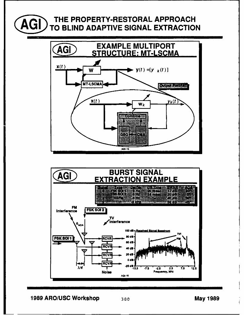
®I THE PROPERTY-RESTORAL APPROACH(:]A WTO BLIND ADAPTIVE SIGNAL EXTRACTION
~ EXAMPLE MULTIPORT-------STRUCTURE-: --MT-LSCMA
$~ BURST SIGNALEXTRACTION EXAMPLE
Interference
0)AOA ~trssc
1989 lo/S Wrsop 3 0d8 May98

quickly capture signals as they appear in the the first FSK signal disappears from the en-environment and maintain capture on those vironment, without any appreciable deviationsignals as the environment varies, from its optimal (time varying) performance.
This processor is illustrated in the next We can also use known spectral self-three slides (Slides AGI-16 through AGI-18) coherence properties of the SOIs to adapt afor a four-element narrowband antenna ar- multitarget processor. An advantage of thisray excited by white thermal noise, two very approach over the CMA-adapted multitargetstrong interference signals - a TV signal at antenna array is that the SCORE processor isa 50 dB signal-to-white-noise-ratio (SWNR) easily adapted to ezactly optimize our objec-and an FM signal at a 40 dB SWNR - and tive function, and the algorithm extracts onlyby two burst FSK SOIs. The FSK signals the signals with the desired self-coherenceare received at a 17 dB SWNR and a 20 dB properties from the received data. This isSWNR, respectively, which is very far below illustrated in Slides AGI-20 through AGI-23,the interferers, and have ON and OFF times for the cross-SCORE processor [15] shown onthat cause them to collide over the reception Slide AGI-19, and for a four-element antennainterval: the first FSK signals comes ON at array excited by two very strong interferers,20 msec into the collect and goes OFF at 30 a BPSK SOI with a 4 MHz data rate, andmsec into the collect, while the second FSK a 16 QAM signal with a 3 MHz data rate.signal comes ON about 24 msec into the col- By tuning the target spectral self-coherencelect - right in the middle o the first FSK frequency a of the processor to 4 MHz andsignal's ON time - and goes OFF at about 3 MHz, the processor is able Lo extract each24 msec into the reception interval, of the SOIs from the received data. This is
This is a very difficult kind of environment accomplishcd without using knowledge of the
for any blind or nonblind adaptive proces- direction of arrival of the SOls, and without
sor to deal with. However, the multitarget using any array calibration data either the
LSCMA is able to collect both signals without array manifold or the background noise co-
bit error in this collect. Essentially, the algo- variance.
rithm converges to all the stationary points The second class of processor structuresof the cost function. At the beginning of the that I want to discuss today is the adap-collect, Port 0 and Port 1 capture the two tive demodulator structures. The demodula-interferers, and identify the remaining ports tor structure assumed for linear-PAM SOIs isas "inactive." The active signal ports main- shown in Slide AGI-25; note that the demod-tain capture on the interferers over the re- ulator reduces to a simple fractionally tappedception interval, while Ports 3 and 2 cap- equalizer (FSE) for this type of signal. Thetures the first and second FSK signals, re- blind demodulator structure has two advan--pectively, over their ON times. Note that tages over the equivalent adaptive filter: itPort 3 maintains capture on the first FSK attempts to restore the properties of the base-signal, even when the other signal comes up, band symbol sequence, rather than the en-with some suboptimal performance (which it tire signal waveform; and it accomplishes thisquickly recovers from) right when the second restoral using a processor that is much moresignal comes ON. Similarly, Port 2 maintains powerful than an LTI filter. The first advan-capture on the second FSK signal even when tage obtains because the properties of the sig-
301

g i THE PROPERTY-RESTORAL APPROACH®G TO BLIND ADAPTIVE SIGNAL EXTRACTION
SACQUISITIO N PERFORMANCE36 U IM MM PO2 NE~al
30 Control Parameters24 = = *Block size 1.28 maec
IS USS = =- *Acq. threshold 7.00 d81lame" Noncapture blanking ON
f.tS Pftl .I 2 P.1003 CL 04
(P51(8011) (P8K Sol 2)
.10dB -10 do
-20d8B20d
Collectwob, ne Aa-7Collec t1W imeenA~I-1I
~ EXTRACTION PERFORMANCE20 do P51801 SolI FK01 2
Badud3 peakva Jitter Sa2d pne a kite
1989 ARO/USCWo ko 302 May198

THE PROPERTY-RESTORAL APPROACHTO BLIND ADAPTIVE SIGNAL EXTRACTION
$@~ .. CROSS-SCORE PROCESSOR
*IIIIa
x(t) 1 w/ _yt
I!CotrF ilter U( (t)
" Frequency-shlft value a IConjugation control (*)
AGI-19
jEXAMPLE SPECTRALLYSELF-COHERENT SIGNALS
Complex Modulation Self-Coherence Con]. Self-Coherence
Format Frequencies Freq. (± 2 x Carrier)
BPSK Symbol-Rate Mull. Symbol-Rate Mult.
OPSK Symbol-Rate Mull. None
MSK, SQPSK Symbol-Rate Mul. ± 1/2 Symbol-Rate± Symbol-Rate Mull
CPFSK Symbol-Rate Mult. Symbol Frequencies(h= multiple of 1/2)
FDM-FM Pilot-Tone Mull None
DSB / VSB AM None (complex repr.) 02 x carrier (real repr.)
SSB AM None (stat. baseband) None
AOl.-2
1989 ARO/USC Workshop 303 May 1989

® THE PROPERTY-RESTORAL APPROACHG1 TO BLIND ADAPTIVE SIGNAL EXTRACTION
EXAMPLERECEIVED ENVIRONMENT
3m0 Me~ 15M .45*8PSK 0 4MbWe 20 dB so*
FPDM F40 kH 30 dB 80*TV M~ 15625k~r 40 dB 411V'
6D0tInerfere
Sol 20 d8 ena v tru
~AG-20 d
SELF-COHERENCE SORTING~ PERFORMANCE
BaudRatsResoralOulut OSIC Ousdrature
Pitt 30 Sau-d . (0.2 mlba ud
1989 ~ ~ ~ ~ ~ [ =4/S orso 0 May 98

THE PROPERTY-RESTORAL APPROACHAGI1 TO BLIND ADAPTIVE SIGNAL EXTRACTION
JEIGENEQUATION SORTING... PERFORMANCE
Baud-Rate Restoral .t elFiter zero-delay allpal co t LO flte.CSuperior FF
g self-goherince = 4 MHz b .as
.0.
ex 0%Nq PKSN 1 I 0.6 -0.2 0.2 0.il 1
10dAx.GNq.S I -23 Baud Inteva
-q Suprio hulin o nrrowban 1.0Ou 0 falsRSKEMDm- N wia& d -- T 0 N.
* Very amenable to blind adaptation via modulus restoral- Insensitive to carrier offset- Delay ambiguity limited to unit-symbol
- S01 properties much1 more exact
* Disadvantaoes:l Susceptible to noise captureRequires knowledge of SOI symbol-rate
AGI.3
1989 ARO/USC Workshop 305 May 1989

® THE PROPERTY-RESTORAL APPROACH(: gG TO BLIND ADAPTIVE SIGNAL EXTRACTION
LINEAR-PAM
*G eneral demodulator structure (f *=N Xfd)
" Freq-domain (FFT, TMX)
*Equivalent structure for DMVX / FFT channelizatlon(fractIonally-spaced equalizer)
x(n)., N:1 ;(n)rato f. FIR w rate f. subsample rate fd
(jj>NARROWBAND DEMODULATION------ ---- EXAkMPLE
Environment* 10% Nyqulst QPSK* 13d411E/N* 1/3 symbol timing error
RunParmetrs* 1000 symbol collect* 2 samples/symbol (N = 2)
*64-taP FIR filter/demodulator processor*Static LSCMA adaptation algorithm
0.5. 0.5
.1.0* 01. 4.02 00.8 1.0 .10-. 0.2 0'2 0.8 1.0Dowd h itrva AGI26 Baud Itm
1989 ARO/USC Workshop 306 May 1989

II
nal symbol sequence are generally much more a 3 dB EblNo for the chip shaping assumed"exact" - a PSK symbol sequence, for in- here) and a PNSS interferer at a 30 dBstance, always has a constant modulus (even SWNR (33 dB E6 /No). This results in a
I if the PSK signal is frequency shifted), but signal-to-interference-and-noise-ratio (SINR)the PSK waveform can have a high modu- of about -30 dB, which is too low for thelus variation if it is generated using a spec- conventional matched-filter despreader to re-trally efficient pulse. The second advantage liably demodulate the SOI - the SINR at theresults from the superior performance of the demodulator output would only be at about
I optimal (nonblind) demodulator. The opti- -17 dB in this case. However, as Slide AGI-29mal demodulator reduces to the generalized shows, the FSE-based demodulator structurematched filter in stationary interference en- is able to increase the SINR of the demod-vironments; however, it has even more use- ulated message sequence to about +15 dB,ful properties in cyclostationary interference easily high enough for the low-error detectionenvironments. For instance, the linear PAM of the message sequence. In fact, the demod-demodulator has the capability to null-steer ulator has sacrificed one degree of freedom toon signals not of interest (or other SOIs) if null the interferer, and is using its remainingthey are also PAM with the same baud rate degrees of freedom to perform matched filteras the SOI. demodulation of the SOL. This is very similar
This nulling property is illustrated in Slides to the null-steering and beamforming opera-
AGI-28 and AGI-29, for an environment con- tions displayed by an antenna array when a
taining white noise; a particular kind of signal and interferer arrive at the array from
pseudonoise spread spectrum (PNSS) signal, different angles of arrival.
which I refer to here as PNSS modulation- Moreover, in this simulation the signal ex-on-pulse (PNSS-MOP) or phase-coded pulse- traction was accomplished blindly, using ancompression, received at a 0 dB SWNR with a LSCMA. Thus it is also possible to accom-16:1 spreading ratio; and a PNSS-MOP inter- plish this extraction without knowledge of theferer with the same message rate and spread- spreading sequence of the SOI.ing ratio and a 30 dB SWNR. A PNSS-MOP To conclude, I'd like to discuss a promisingsignal can be interpreted as any PNSS sig- area for future investigation of blind adap-nal where the code repeat rate is equal to the tive processing. In the area of process-data rate of the pre-spread message sequence. ing structures, the most interesting areas toIn this case, the signal can be thought of as a me are: development of general property-
linear-PAM signal, where the modulating se- mapping approaches for exploitation of ar-quence is the data or message sequence and bitrary SOI properties; generalization of thethe modulated pulse (rather than the mes- demodulator structures to allow extractionsage data) is spread by the code sequence. of basebands from more more exotic signalThe message sequence can therefore be ex-tracted directly from the received data using ear PAM); and extension of the multitar-
an FSE with an output data rate equal to the get algorithms to more exotic environments
5OI message rate. and processor structures. The appeal of theSo, our received data consists of white property-mapping approach is that is canU noise, a PNSS signal at a 0 dB SWNR (about be applied to any signal property, and that
307I

® THE PROPERTY-RESTORAL APPROACHAA ql TO BLIND ADAPTIVE SIGNAL EXTRACTION
EiflKw-crcted Ouadattare
.6.2...........-&dBNu- ....LS............
* 16-hi PN prAdn code MOP
* No timimare offAsee
20 kby/secOS mM~~iessaense*320 kW/ BPSK spreading sequence*16-chip PNespreading code (MOP) d100% Nyquist chip-haping r-0 3dB rceived SWNR (3 BSRNo ISctiming ar offset
S20 kbz care ofse unc
32lU kHz rirofe 0b
1989 ARO/USC Workshop 308 May 1989

THE PROPERTY-RESTORAL APPROACH
TO BLIND ADAPTIVE SIGNAL EXTRACTION
-- - EXTRACTION PERFORMANCE
- 1 kbaud (16 kchlp) collect- 32 samples per baud (2 samples per chip)- 64-tap FIR demodulator- Static LSCMA adaptation algorithm
15d8' Demod-cnrrecte ouadrwusMax attajnable SINRsi nal c .nmtollrn
10dB :S
5 dB CMA-adapted demod ""
Output SINR , . :''
0dB
Number of LSC A Pm.. AGI-20
S PROMISING AREAS- FORFUTURE INVESTIGATION
• Processor structures:- Property-mapping structures- General demodulator structures- Multitarget demodulators
* Algorithm Invention & development- General property-mapping algorithms- Combined POCS/PM and blind property-mapping algs.- Genetic algorithms
" Theoretical development- General convergence analysis- Extension of ML estimator
AGI-30
1989 ARO/USC Workshop 309 May 1989

it immediately results in a monotonically- 6. B. G. Agee, "The Property Restoral Ap-convergent adaptation algorithm. In partic- proach to Blind Adaptive Signal Extrac-ular, I believe that some very powerful new tion," Ph.D. Dissertation, University ofalgorithms and theory are going to result by California, Davis, CA, 1989.linking this approach with the methods ofYoula [12] and Cadzow [14], and I strongly 7. B. G. Agee, "Blind Separation and Cap-urge anyone interested in this area to famil- ture of Communication Signals Usingiarize themselves with this work. I also be- a Multitarget Constant Modulus Beam-lieve that it should be possible to use the former," in Proc. 1989 IEEE Militarynulling property of adaptive demodulators to Communications Conference, 1989.develop a multitarget demodulator that canseparate and sort signals in single-sensor sys- 8. A. Benveniste, M. Goursat, "Robusttems. Between all of these developments, I Identification of a Nonminimum Phasethink the time is growing near when we can System: Blind Adjustment of a Lin-actually address the co-channel sorting prob- ear Equalizer," IEEE Trans. Automat.lem posed by Dr. Pickholtz in yesterday's Contr., vol. AC-25, pp. 385-399, Junesession. 1980.
References
1. J. R. Treichler, B. G. Agee, "A New Ap- 9. D. N. Godard, "Self-Recovering Equal-proach to Multipath Correction of Con- ization and Carrier Tracking in Two-stant Modulus Signals," IEEE Trans. Dimensional Data Communication Sys-ASSP, vol. ASSP-31, pp. 459-472, April tems," IEEE Trans. Comm., vol. COM-1983. 28, pp. 186.7-1875, November 1980.
2. J. R. Treichler, M. L. Larimore, "New 10. J. Lundel, B. Widrow, "Application ofProcessing Techniques Based on the the Constant Modulus Adaptive Beam-Constant Modulus Algorithm," IEEE former to Constant and Non-ConstantTrans. ASSP, pp. 420-431, April 1985. Modulus Algorithms," in Proc. Twenty-
First Asilomar Conf. on Signals, Sys-3. B. G. Agee, "The Least-Squares CMA: temns and Computers, 1987.
A New Technique for Rapid Correction
of Constant Modulus Signals," in Proc. 11. B. G. Agee, "Convergent Behavior of1986 Intl. Conf. on ASSP, 1986. Modulus-Restoring Adaptive Arrays in
4. R. P. Gooch, J. Lundel, "The CM Array: Gaussian Interference Environments," in
An Adaptive Beamformer for Constant Proc. Twenty-Second Asilomar Confer-
Modulus Signals," in Proc. 1986 Intl. ence on Signals, Systems and Comput-
Conf. on ASSP, 1986. ers, 1988.
5. B. G. Agee, "The Baseband Modu- 12. D. C. Youla, H. Webb, "Image Restora-lus Restoral Approach to Blind Adap- tion by the Method of Convex Projec-tive Signal Demodulation," 1988 Digital tions: Part 1 - Theory," IEEE Trans.Signal Processing Workshop, September Med. Imaging, vol. MI-1, pp. 81-94,1988, Tahoe, CA. Oct. 1982.
310

13. M. I. Sezan, H. Stark, "Image Restora- magnetic recording channel to combine bothtion by the Method of Convex Projec- coding for distance properties and run lengthtions: Part 2 - Applications and Numer- limited coding for the purposes of fixing upical Results," IEEE Trans. Med. Imag- the intersymbol interference problem. It wasing, vol. MI-1, pp. 95-101, Oct. 1982. my understanding that they had made some
significant advances, especially with respect14. J. A. Cadzow, "to getting closer to the capacity of that mag-
a Composite Property Mapping Algo- netic recording channel.rithm," IEEE Trans. ASSP, January CIOFFI: I, too, have worked in the record-1988.
ing industry; in fact, when I was at IBM that15. B. G. Agee, S. V. Schell, W. A. Gard- was my job function. If I look at my cur-
ner, "Self-Coherence Restoral: A New rent base of funding, actually, it's a majorityApproaLL to Blind Adaptive Signal Ex- in that area from both IBM and the state oftraction Using Antenna Arrays," IEEE California. So I have looked at this problemProceedings, May 1990. for quite a while; I'm intimately familiar with
1the work by Wolf and Heegard as well. When16. W. A. Sethares, G. A. Rey, C. R. John- you come back to this particular slide, the
son, "Approaches to Blind Equalization same type of situation arises in what they'reodoing in that you have some kind of codingProc. 1989 IntL Conf. on ASSP, pp. gain for the system, and again they are look-972-975, 1989. ing at the combined equalization and coding
HALL: Thank you very much. We'll have problem. You correctly surmised, Ray, ex-a ten minute break and get back for the Ques- cept they have as well, or we have in magnetiction and Answer Session. [PAUSE] recording a binary constraint at this point in
RAYMOND PICKHOLTZ: I actually the network. [FOIL #4] It's two levels only.have two questions. First, one for John Cioffi The actual clock rate can be about as high ason the very excellent talk he gave about com- you'd like. The practical constraints on thebining equalization, pulse shaping and coding write clock in recording are not really limitingto try to get closer to the predicted capacity in this particular situation. But it's only twoof the kind of channels we're talking abouty levels because of the hysteresis effect whichI spoke to him briefly during the break, and occurs in magnetic media. Now when you'reI spke o hm biefy drin th brakandleft with the two level constraint like that,one of the questions I have is, "What is the re- ltth the te vel contrinte hat,lationship between this and some other work both of the techniques that I presented herethat's been done for a very special channel, will fail in that particular area because of thenamely the magnetic recording channel which fact that they require more than two levelsis, of course, a very special channel because it on the input to the channel. Both the Tom-essentially has only two levels that you deal linson precoder and multitone approaches arewith?" In particular, Jack Wolf at UCSD basically pretty widely dispersed over the en-and Chris Heegard at Cornell have done some tire transmit range of symbols that you couldconstructive coding - which I don't think, have.John, that you specifically talked about in Now for that particular channel the thingyour talk - some constructive coding for that you have to look at is this equalization gain.
311

Given you have a binary constraint, the only course, the gains that they predict for theirway to really get your density up is to increase codes are far less than what you see projectedthe clock rate. It has to increase - if you're on these other codes that you refer to becausegoing to use a code it has to go up above your they are considering that particular loss.actual data rate or data density for the disk. My gut feeling is that the actual way to doWhen you start running up symbol rates in it is to basically start to border on the rangesystems you have to take a very significant of an FM signal in magnetic recording. In ef-hit in equalization loss. You can try to model fect, you're doing FM with the square wave.the channel by an increasingly more compli- To use the thing that you'll incur is that incated series of partial response polynomials at most FM transmission paths you really don'thigher and higher densities, and try to design have such a severe ISI induced in a transmis-the codes for those situations. sion path. So my gut feeling is that's the way
I have a fundamental point of difference to go, but I can't say that it really is ....with both the Heegard and Wolf works. PICKHOLTZ: I agree with what you'reThey're not really here and they would ar- saying, John. The question I had is that:gue with me at length on this, as they have since, in the magnetic recording problem, youin the past, but when you start running up do have this severe constraint of two-level sig-the clock rate on the system there is a very nals, and therefore the only way you can go issignificant hit in equalization loss that you by some run limited coding pattern, it wouldhave to pay before you can -idd on a coding seem that your problem - you know, the gen-gain. I have yet to see a code that anyone eral problem here - would be easier, but thathas come up with where we cannot design you might be able to take advantage in thean uncoded system that would beat it signif- shaping characteristics of using some kind oficantly. So it's still an open problem, as far run length limited characteristics in a multi-as I'm concerned. level signal, rather than in a binary signal, as
I have one student in my group who works you have in magnetic recording.- he's well aware of this difficulty - and he CIOFFI: That's an interesting - a numbercame up with a code that did as well as an of people have raised that issue. I haven'tuncoded system, which is really nothing to seen any work along those lines yet, but Ibrag about. But in this sense where you have would agree that if you could solve the bi-to increase the clock rate, is the only way to nary problem then it might well apply to acode, you pay this equalization loss penalty. multilevel situation where you might have,Most of the coding approaches to that have, for clocking purposes or some other reason,one way or another, avoided including that a constraint on the number of levels in yourpenalty in the calculation. So I say it's an transmit - say 4 or 8 levels - rather than aopen problem at this point. I don't pretend continuum of levels which span the entire in-to have it solved; I don't think anyone else terval. I still see that as, it's in the samehas it solved at this point. The work that framework as you guessed, as the other prob-seems to be going the best along this line is lem, but I don't believe it's been solved justby a couple of guys, Paul Siegal and Raznik yet. But I think if you can solve one, youKarabed at IBM Research in San Jose, who can solve the other problem. It's a very goodunderstand this equalization loss issue. Of point that you raised, and that problem is
312

just intrinsically harder at this point to solve when you really want to have a multichannelbecause it has an additional constraint, with in the signal-to-noise ratio into independentrespect to the one that I was considering, decoders to be constant. Obviously the draw-
HALL: Ah, yeah, Dr. Peile .... back with that is throughput delay, having toPEILE: The question is for John Cioffi unset the codes on each channel.
again, and he knows the question .... It would CIOFFI: Right, well, the reason for goinghelp to have the slide up with the multichan- to the crossblock coding if you have n tonesnel model up so people could see it. While here, you go across the block with the codeJohn is finding the slide I'll just say that he rather than put a trellis code on each onementioned the need for the possibility for in- is delay. That's the reason for citing that.terblock coding, rather than have a bank of You say you've looked at the problem andindependent decoders, one for each channel. I have looked at a block code - if I rememberhad a look at that problem about a year ago, correctly from your paper ....I think about a year ago - I'll wait a second PEILE: It's a finite number of channelsuntil the slides are up. [PAUSE] That was where I had a ....the one - that'll do at any rate. CIOFFI: ... over a finite number of chan-
CIOFFI: My comment where I put up this nels ....summary .... PEILE: ... finite number of bits ....
PEILE: Yeah, the comment about in- CIOFFI: Yeah, and then you use a slightlyterblock .... different constraint. It may be possible to
CIOFFI: ... about interblock coding .... have other techniques that basically - I'll alsoPEILE: Yeah, but that's the diagram I get to this - are as close to capacity as you're
wanted to look at .... going to get within the multitone framework.CIOFFI: OK, sure. I wouldn't dispute that you can use slightlyPEILE: I looked at the possibility of hav- different design criterion and come up with
ing one code across all the channels rather the same type of result here.than having several independent decoders, What I was referring to with the crossblockpresumably identical, I don't know. But I coding is when you use a block code, there arehad one code across sets, and instead of mak- basically some edge effects that occur thating the signal-to-noise ratio constant into the you either have to get rid of using zero stuff-decoders I have tried to arrange the power ing or overlap save methods or some equiva-levels so the signal + noise into them was lent to that. What I think I was referring toconstant, more or less. I then took the code is kind of designing almost a convolutional orand adapted it to those conditions, so that trellis code that goes down this set and intothe output error in the decoder was about .... the next block, and into the next block after
CIOFFI: The output error rate was what? that ....PEILE: Well, the point is that as long as PEILE: I believe that's possible ....
the cide was adapted to the input conditions CIOFFI: ... and you have different num-they didn't have to be constant on each chan- bers of levels on each of these tones. Thisnel. By doing that I found at least some is a problem that someone actually raised atsets ,f conditions which seem to win; but it's Telebit - asked me if I knew a solution to this.not clear to me when that is a winner and They were very interested in designing a code
313

along those lines. So that's why I put up the CIOFFI: ... fixed block approach.interblock coding. So I was more referring to PEILE: I think Vedat disagrees with botha convolutional type thing, but would agree of us, but we'll find out this afternoonthat your method probably would get to this CIOFFI: Pardon?same performance level. PEILE: I think Vedat disagrees with both
PEILE: Well, I think you could almost of us, but we'll find out this afternoon.have a reverse concatenation, where you have CIOFFI: Yeah, well, we've had somethe inner code as a block code across the agreements and disagreements over the years,channels, and then a convolutional trellis go- but I welcome that .... Are you going to ...?ing along in time across the channels. BILL GARDNER: I think there might
CIOFFI: Right ... be a way to reinterpret your approach, and ifPEILE: ... Which is the other way around I'm right it may show a link to some earlier
the normal .... work. I think you can view, say, the convo-
CIOFFI: ... and the objective again is the lutional encoder and pulse shaping filter to-delay, get the delay down, because into mul- gether as a linear periodically time varyingtitone schemes are notorious. I guess I have processor. Also you can view the received fil-the "T" and the "L" transposed here - I got ter, linear demodulator and linear decoder as"mutlichannel" .... a periodically time varying processor.
PEILE: I'd also put out that you used to CIOFFI: OK.call them "eigenchannels," which I thought GARDNER: And Graef - I'm not sure ofwas a great name and now .... the pronunciation, it's G-R-A-E-F - in 1983
CIOFFI: Right, well, I was just trying to NATO-ASI (Adyanced Study Institute) did asimplify. In fact, I put vector here, I didn't paper on "Joint Optimization of Periodicallyreally put tones and, of course, the best thing Time Variant Transmit and Receive Proces-to do is not put a DFT-type thing there. sors," that I think may in fact be related toThere are better approaches - that's what I what you're looking at, by separately design-call "vector coding," which will give you, for ing the encoder and a pulse shaping filter ofa given fixed blocklength, a higher gain than the transmitter.the DFT approaches will. But you'll have CIOFFI: I'm not generally familiar withto know what the channel is in designing the that work, but we did try that approach ofvectors, whereas the DFT-type vectors are in- jointly designing both together, and we're notdependent of the channel. They converge to successful that way. This way you'll get asthe same thing as the blocklength goes to in- good a code as you're going to get. Use ei-finity. But your - I wouldn't dispute your ther of the two techniques that I presented.point at all, that there is, you know, proba- In fact, one of the agreements with Vedat wasbly other ways of designing the details of the last night at dinner. We agreed that that ap-code so that you would achieve the best per- proach is probably the wrong direction, thatformance. And what I meant by interblock you cannot get the gains that you'd like bycoding was to get the delay down, but go from concatenating the two together. To the bestblock to block in a finite-state type sense as of my knowledge, no one has solved that prob-opposed to .... lem. I'm not familiar with this particular
PEILE: OK, that was .... work, but based on several intelligent grad
314

students beating their heads at it, as well as polynomials from is my background in stor-other people I know who've looked at that age. They are a set of polynomials called "ex-particular approach, have not been success- tended partial response class," that peopleful. I just have a gut feeling that maybe that's like to use to approximate a magnetic stor-not the right direction to go. But given that age channel at increasingly higher and higherI haven't seen this '83 NATO study, I can't densities. The way you get higher densitiessay for sure .... is to take the 1 + D factor and increase the
GARDNER: OK, and I certainly can't exponent on that. So that's just one particu-either, but .... lar class, but what it represents is a series of
CIOFFI: ... just exactly what the gains increasingly low pass channels with more andwere. more severe ISI, which I used as a represen-
GARDNER: I want to look at it, anyway tative example to illustrate the point aboutthe distance to capacity increasing when you
CIOFFI: Well, certainly it would be a wel- have this more severe ISI in the channel.
come input to this study. One more question RICE: And the question for Brian was:in the back? "On your multilevel, your multi-amplitude,
BART RICE: I had a question for both instead of the constant modulus, your multi-John and Brian. I was interested in your pre- modulus algorithm, was that used to try to
coding polynomials. If I understood them equalize to the signal or to try to recognize
right, there were two that seemed conspic- the modulation type?" I was thinking about
uous by their absence, and those were the this after we talked yesterday. I think that
two that are associated with the duo binary the approach we took was to try to equalize
and modified duo binary. Duo binary should just using the constant modulus algorithm,be 1 + D and modified duo binary should be and then try to recognize the modulation
1 - D. Neither one of them was there, and type using the amplitude distribution. So are
I wondered if there was some reason for that. you trying to equalize also using the multi-
Also, how you got the polynomials you got. amplitude distribution?
CIOFFI: OK, the reason the 1 + D and AGEE: Yes. More exactly, I'm trying1 - D', which are the dual binary are not to extract that baseband sequence from theshown is because they're exactly the same as noise and interference by using its multiplethe 1 - D channel, the AMI channel. The modulus. The reason why I asked you that1 - D2 is basically 2-interleaved, 1 - D's on question yesterday was, one of the unan-the evens and odds, so you'll get exactly the swered questions is, "What can you do if yousame result. Because (1 + D)(1 - D) is just don't know what those modulus levels are?"1 - D2 , and it's going to be the same result. I'm curious to see if there's some way that theIn the 1 + D, the plus or minus sign really multiple-modulus approach can be combinedhas no effect, it just shifts the notch from with the clustering approach that you're us-Nyquist frequency down to DC, and they're ing, to look at the more general case wherecompletely symmetric. So the results would we just know it's a QAM signal but we don'tbe exactly the same as the 1 - D channel, know what its levels are at. But, yes, it was
Now where I got - the second part of your basically .n equalization approach.question - where I got these partial response RICE: I think that the ... we thought
315

about that and abandoned it because for also been able to prove, for certain kinds oftwo reasons. I think (1) we thought that if environments, that the stationary points ofthere was any performarice margin over the the algorithm are going to correspond to sig-ordinary constant modulus algorithm that nal capture. However, the multiple modulusit would be marginal; and (2) it depended algorithm has not at this point been simu-pretty carefully on where you placed the lated, so I don't have any hard experimentalrings, the amplitude rings, because - espe- results. But the theoretical results look verycially if you've got things coming from a de- good. My experience looking at the rapidlymodulated IQ point that came in between converging algorithms is that a lot of prob-two rings - it seemed like the probability of lems that are associated with the CMA justerror was too great of sending the error sig- go away when you start looking at the rapidlynal in the wrong direction. So we abandoned converging algorithms - problems with mis-that fairly quickly, but maybe too quickly. adjustment and things like this.
AGEE: Yes, I think there is a potential HALL: If you formulated that in a least
for a problem there, and that's again one of squares, couldn't you go ahead and add thethe reasons why I'd like to see the technique exact ring positions or the exact modulus val-extended to do some kind of adaptive deter ues to the least squares formulation, and just
mination of those modulus levels. However, adapt on those also?
with respect to your comment that you think AGEE: I'm not quite sure I understandthat it's going to have marginal performance your question. I probably shouldn't havetha n oused the term "least squares." It's the ter-improvement over the OMA, I disagree withmiooytaIdelpd
that because one of the notable properties of minology that I developed ....
the constant modulus or the dispersion di- HALL: Oh ....rected algorithms is that they converge very AGEE: It's not really a least squares algo-slowly for QAM signals. My interpretation rithm, it's more of an alternating projectionof why that's happening is that there is not a algorithm, and one of the projections is leastclose match between the property that we're squares and the other one is a projection ontotrying to restore and the signal that we're try. the desired signal set. Given that, could youing to extract. We're trying to use a constant rephrase your question, or did that ...?modulus property, but the signal doesn't have HALL: Mine pertained to a least squaresa constant modulus. So we have a residual formulation. You could just leave the mod-error in our modulus variation, which slows ulus, you know, like for QAM or 16 QAMadaptation. The idea here is that the multiple you have three modulus positions, right? Youmodulus approach is going to remove that er- could leave those as unknowns and solve forror and it should accelerate our convergence, those in your least squares formulation.The other thing is that I developed this ap- AGEE: Ah, possibly. You have to be care-proach in tandem with the least squares al- ful though to avoid a trivial solution. Thegorithm, which should further accelerate con- algorithm might just set all the modulus lev-vergence of the algorithm. I have to say that els equal to zero, and then set the processormost of my results in this area have been the- weight equal to zero, and then the cost func-oretical. I have been able to prove mono- tion becomes equal to zero. So you have totonic convergence of the algorithm; I have be a little careful.
316
I encountered the same problem with one of decision circles closer and closer together. Itthe other algorithms that I call the "adaptive becomes more and more sensitive and we saidmodulus algorithm," which works on this al- heck, so we ended up with sort of two ends ofmost periodic property of the modulus. I was the scale - Godard at one end that was excru-able to overcome that by dividing through by ciatingly simple, and then decision directedthe mean square error of the modulus itself. at the other end to handle the very high con-Unfortunately that's a lot more difficult to do stellations once Godard had stabilized.for the multiple modulus algorithm. If I kind AGEE: It just occurred to me that oneof wrote it out for you it would be easy to possibility is to do some kind of a variationsee, but it's just that the minimization prob- on the reduced constellation algorithm. Welem is very difficult if you turn it into a ratio might still be able to get some performanceof two time averages instead of just a single improvement if you choose a set of ringstime average. And then, John .... which is fairly dose to certain concentration
TREICHLER: Was he just trying to get of rings. You know, deliberately choose aout of the rest of the answer, or did he just smaller number of rings. I guess I didn't quiteoud of the rothanser, or dnd h e- answer your question. My answer is I don'thand me the microphone? I wanted to re- know, I think it's an interesting idea to try
spond a little bit to Bart's comment. I men-to adapt the modulus, and again that's why
tioned to Brian a few minutes ago that Monty t dp h ouuadaanta' hI was asking Bart Rice yesterday if he lookedFrost was the one who came up with that at any kind of clustering algorithms. I'd likeknown modulus scheme, exploiting the casewhere there's a known deterministic modulus to se some hn n that.variation. The varying envelope has no in- SCHOLTZ: Thank you, Dennis. Sinceformation, but it destroys the constant mod- I don't work in this area I'll probably haveulus property. Also, in a little internal tech to ask some dumb questions for the rest wnote he wrote in '82, '81, '83, sometime back the crowd that's being quiet. I don't knowin there, he suggested this multiple modulus they're staying quiet. [LAUGHTER]scheme for working what were in the trade You're talking about, for example, the con-known as V.29 modems, which at that time stant modulus algorithm, and you have thiswas considered to be a very hard problem. function that you'd like to minimize - I'veWe actually did a little simulation work on forgotten exactly what is the (modulus - 1)it, not a great deal, and found that in fact quantity squared, or something like that. I
it worked very nicely and it did in fact work can think of all sorts of other functions which
faster than pure Godard or CMA. The reason you would like to use. Now, why have you
we abandoned it was not that it didn't work, chosen that particular one? Is that a com-but that it didn't converge order of magni- plexity issue or is it a performance issue, ortudes faster than Godard. On the other end has anyone looked at all the other possible
of the scale it was a little bit more sensitive in functions that you could use to adapt on?
terms of where you chose the decision levels. [PAUSE] Is that a dumb question?But the big killer is we wanted to general- AGEE: No, it's not a dumb question; inize upward. We wanted to go not just at 16 fact, a large part of my research has been toQAM, but 32 and 64 and 128, and it gets try to determine which of these is best. Theremessier and messier as you try to pick these are several constant modulus cost functions;
317

at ARGOSystems, we generated what we call tle bit more robust if you don't know exactlythe "general p-q constant modulus cost func- what that signal feature is. So I guess mytion." One of the questions that has remained answer is is that there are a lot of differentunanswered is which one is best. And there criteria, and depending on which criteria youare different ways you can look at "best." use one algorithm is better than the other.From an implementation point of view I be- TREICHLER: Let me amplify with onelieve the 2-1 and 1-1 constant modulus algo- minor comment. We've formulated that gen-rithms are easiest to implement, and I think eral p - q description because in fact thereJohn is going to probably want to say some- was a great deal of argument in the begin-thing on that where the p - q cost function is ning. For the 2-2 case, even I could differen-given by < (IyIp - 1)q >. tiate the cost function, and so that's one of
From a performance point of view or from the reasons why we use that. My interest in
an implementation point of view the so-called the 1-1 algorithm is you're taking a magni-
p - 1 algorithms, which take the magnitude of tude, subtracting, and taking another magni-
the signal to the pth degree -1, tend to be the tude which, if you come in with 8 or 10 biteasiest to implement. However, the 2-2 CMA edata, means that from a numerical point ofeiew you're not doubling the wordlength oris the one that's been analyzed the most be- ncause it involves just second and fourth order quadrupling the wordlength. So that was my
moments, so people can say a lot about it. interest originally in pursuing the 1-1. We
The 1-2 algorithm has still other advantages - sort of ended up with these ones where yousquare once and magnitude once as a com-
I personally like that one best because it has avery interesting form. You can formulate it s promise between understanding the 1-1 and
that it looks a lot like a demod-remod type of 2-2 algorithms and making them reasonableto implement. You can do other things likealgorithm. Also it fits very well into the prop- m nt of the lo othe a gnitud e
erty mapping viewpoint, which allows you to magnitude of the log of the magnitude, and
develop rapidly converging adaptation algo- just all sorts of - I mean, you can do almost
rithms. Also, you can formulate the blind anything. Nobody really knows anything tosignal estimation problem in such a way that say what's better than the other, other thanthe ones Brian has looked at in detail.you can derive a maximum likelihood esti-mator of the signal, if you have an antenna AGEE: I had one last comment and that isarray and you've got temporally wide inter- that if you formulate the blind adaptive prob-ference, and you can show that the optimal lem as a property mapping algorithm, thenalgorithm optimias the 1-2 cost function. So you basically get one cost function form. Soin some cases that algorithm appears to be a lot of that problem goes away. Of course,best. On the other hand the analysis work there might still be a better form out therethat I've done shows that all of the p - q for a given implementation, so you shouldn'talgorithms have stationary points that cor- necessarily depend on it. But a lot of thatrespond to capture of the signal as the col- does go away. So I'm kind of settling on thelect time grows to infinity in certain environ- 1-2 algorithms for that reason.ments. That's kind of a really interesting re- SCHOLTZ: I have one other comment.sult. If you do a little bit more analysis, it I've just read a few papers on these subjects,looks like the 2-2 algorithm is possibly a lit- and I always thought that it was very inter-
318

esting in Widrow's algorithms, for example, the rest of the crowd in here seems to referthat you need the signal that you're trying to it. It's exactly the same algorithm as Go-to get before you can do anything, which dard's. The two names came from two differ-leads you to the decision-directed ideas. The ent application areas. John Cioffi and I werebeauty of the CMA algorithm is that you re- talking about this the other day, and thereally don't need to know much about the signal were at least four or five people at four orin order to be able to build this device, five organizations at the same time in the late
I'd like to hear a little bit more about '70s kicking around the same problem, mostsome of the other reference signals and how of them unknown to each other. In the mo-you would apply them. How would you use dem world, as they went from QPSK and 8-cyclostationary-stationary, for example? I PSK on up into QAM, there was a real ques-think you mentioned that in one of these tion of how in multi-user networks to attainblind equalization schemes. Is that a lead- equalization of an equalizer without having toing question? [LAUGHTER) In other words, go back and ask for training again from thehow much information do you really need to transmitter. People at AT&T Bell Labs wereknow to apply that particular approach? working on it, people at IBM were working
AGEE: I guess I'd say I should probably on it. The group I was in wasn't working ontalk about that off-line, because I could go on that; we didn't even know about those peo-to that for awhile, and I wouldn't want to do ple. We were trying to solve another problemthat! for a classified customer, and that was try-
SCHOLTZ: Could you answer just one ing to recover FDM/FM signals from a worldspecific question. How much do I really need of noise interference and multipath. In ourto know about the modulation format in or- case it was a really simple - well, it tookder to make that system work? In CMA all I us years to figure it out, but once you knowneed to know is that it's a constant envelope, the answer, everything is simple. We went inHow much more do I need to know to handle looking at all sorts of maximum likelihood,the cyclostationarity approach? channel modeling, channel estimation, and all
AGEE: I actually think I can do that in sorts of things like that. Finally, literally lateone night, I said, "Hmm, we know exactlya few viewgraphs. Essentially all you need to one tig a bou h i , n d tatliknow is one or two properties of the signal, that it is FM, and it ought to have a constant
such as its baud rate or the fact that it's a evlp i wond if oucanouse a o tBPSK signal or a QPSK signal. Let me just envelope. I wonder if you can use that?" OK.pt signapor a PSK tod sa te jut .this was in the late '70s sometime. That'sput up a viewgraph to demonstrate that..eaclthsaeimtewokasgign
it'll take me a second to find it. You might exactly the same time the work was going onwant to ask someone else a question while at Bell Labs and IBM and other places. Itwamtyint to skfsone thele aueston wle got published on that side and known as Go-I'm trying to find them, just to keep some dard's algorithm, because he's the first one
ntiity, Thwho got it into a conference and then into aREdy There'roomwants o oub she- paper. In our community it was classified for
bodyin he rom antsto now hy hena couple of years and finally bubbled up in theJohn Proakis put up his description of all the early 1980s, and it all depends on which com-
blind algorithms that existed, not mentioned early yos and it a s o which com-
on that list was constant modulus, yet half munity you came from as to what you call it.
319

AT&T is now looking at it in the microwave of cyclostationarity they do have. Almost anymodem area as well. But they are the same PCM signal, for instance, is going to have cy-thing. clostationarity at its symbol rate, or it's go-
PROAKIS: May I just add to that, John? ing to have self-coherence and multiples ofSeymour Stein and I and a couple of his peo- its symbol rate. So in order to implementple at Stein Associates in the early '70's were this algorithm, all that we need to know isdoing blind equalization for DPSK signals, what the symbol rate of the signal is, whichlong before the term "blind equalizer" was we have in a lot of applications. The algo-coined. So I have a feeling that the work rithms that we've developed right now canin the classified literature probably long pre. do a pretty good job of detecting the signaldates some of the things that were subse- if we know the baud rate of the signal of in-quently published by Sato, Godard and oth. terest to within 1% accuracy. The additionalers. parameter needed to configure the processor
TREICHLER: I actually believe that is the conjugation control, which is dependentGauss did it as part of a [LAUGHTER] clas- on whether or not we want to exploit what wesified document. call the "conjugate self-coherence feature" or
SCHOLTZ: Maybe it's time for some of the self-coherence feature of the signal.
you older people in the field to sit down and The optimal processor essentially solves awrite a history of equalization or something generalized eigenequation. The rank of thatlike that. eigenequation tells you the number of sig-
AGEE: OK, Slide AGI-19 shows the nals that are self-coherent at the target a,block diagram of the cross-SCORE processor, while the eigenvectors in the signal subspacewhich is one of the self-coherence restoral pro- of that eigenequation correspond to capturecessors that we've been investigating at UC- of each of the signals in that environment un-
Davis. The processor path takes the signal, der pretty general situations. In Slide AGI-
and passes it through a bearnformer to get 22, we set a = 4 MHz and basically capturedour output signal. The reference path forms a BPSK signal and ignored everything else;a crude reference of the signal of interest. The setting a to 3 MHz caused the algorithm tomain controls consist of a filter bank, which capture the QAM signal and ignored every-can be a delay line, or some kind of a filter, thing else. In Slide AGI-23, we replaced thator a straight line, for instance for Nyquist- 16 QAM signal by a BPSK signal with a dif-
shaped signals. The filter output signal is ferent roll-off, but the same baud-rate at thethen multiplied by a sinusoid and optionally first BPSK signal. As this slide shows, oneconjugated, and then passed through what of the modes of our eigenequation capturedwe call the control beamformer. The only one of the signals; the other mode of ourtwo parameters tl-at really determine the cy- eigenequation captured the other BPSK sig-clostationarity property that you're looking nal. So we don't need to know much about
at is a, the frequency shift parameter, and it.
this optional conjugation. All that you re- HALL: Let's see, I had a question for Johnally need to do is look at the various sig- Treichler. Something I asked him months agonals that you're searching for and figure out was on adaptive IR filters. Did you bringwhere are they self-coherent, and what kind anything on those at all or ...? We only have
320

0
1(/)U)
uwc1201
102

20 minutes left; I don't know if you can go cients rather than more, then everything getsinto it. better. So there was a fair amount of work
TREICHLER: I have some viewgraphs, I done on this. I haven't even begun to touchcan do it in 5! on all the people who did various things,
HALL: OK, that'd be great. I'd really like and I'm just trying to hit a few of them.to see that. Some people looked at taking the LMS algo-
TREICHLER: Nobody believes that! I rithm and extending it very straightforwardly
can hear the snickering from the crowd. into a direct form IIR filter; some of the
[LAUGHTER] Watch the watch! early ones I've mentioned here. Some people
It's really a pretty easy topic to talk about looked at again taking the least squares, tak-
because it hasn't gotten very far. I'm going to ing the squared error approach, but, instead
repeat Brian Agee and make a complete fool of just using LMS, preserve the whole equa-
of myself fumbling through viewgraphs here. tion for the gradient and recurse that. Sam
[PAUSE] [I found the one to start with, I've Stearns, Stan White, Nasir Ahmed from the
dumped three on the floor and] ... [VIEW- University of New Mexico all looked at var-
GRAPH #11]. ious schemes like that. Other people lookedOK, I've organized this sort of the same at them from a completely different point of
way. What is R adaptive fitering? Who view, of ARMA and ARMAX modeling. BenFriedlander, Martin Morf and a whole bunch
cares? What was the promise? Why do peo- of other folks at Stanford and other placesple want to look at it? looked at that. Rick Johnson, Mike Larimore
The idea of IIR filtering and the reason and I have looked at some other methods.why a bunch of people have worked on it We were using some nonlinear stability the-was that here was another methodology that ory ideas that were being promoted in thepromised to considerably reduce the compu- control world. So all sorts of people havetation in equalizers or adaptive filters when looked at it, and what I'm fumbling here for isyou were trying to model resonances or corn- the next viewgraph. Got it! [VIEWGRAPHpensate for spectral nulls. If somebody has #12]built a signal and transmitted it through achannel that had spectral nulling, for what- But in fact not much has come of it, andever reason, if I could do just the right IIR why is that? Well, it turns out that analyti-filter I could compensate for that. If in fact cally it's a real mess. Those people who haveI was doing, say, an adaptive line enhancer, had success with it have found ways to repre-as they call it in the sonar world, where I'm sent the problem as multichannel FIR filter-trying to look for resonances or very narrow- ing by various tricks and contrivances, andband signals and I would like to model those I'm sure Ben Friedlander will get me later foras little resonances, then maybe I'd like a fil- saying that. The methods that have actu-ter that is built that way. ally been used, people have had to simplify
The other thought is that perhaps I can get them rather considerably. A fellow namedfilters with very, very long impulse response, Paul Thompson at Sandia Labs came up withbut with very small dimensionality in terms a method that has been used where you adaptof the number of coefficients. Its the gen- the zeroes and you lock the poles in to sorteral rule that when one adapts fewer coeffi- of follow along on the same radius but back
322

N STI IIR ADAPTIVE FILTERING
* PROMISE
* REDUCE COMPUTATION CONSIDERABLY WHEN MODELING RESONANCES ORCOMPENSATING FOR SPECTRAL NULLS
* REDUCED DIMENSIONALITY OF FILTER MIGHT IMPROVE CONVERGENCERATES OF ADAPTIVE PROCESS
* ANALYTICAL WORK
. STRAIGHTFORWARD EXTENSION OF LUS - FEINTUCH, HORVATH
- RECURSIVE GRADIENT ESTIMATION - STEARNS, WHITE, AHMED
. ARMA AND ARMAX METHODS - MORF, FRIEDLANDER
. STABILITY-BASED METHODS - JOHNSON, ET. AL
VIEWGRAPH #11
B-282-89
I TI IIR ADAPTIVE FILTERING (CONTINUED)
* PRACTICAL SUCCESSES
- CONSTRAINED DESIGNS
* POLES LOCKED TO ZERO (THOMPSON)
* ONLY TWO POLES (CCITT ADPCM ALGORITHM)
. I-POLE DESIGNS IN FREQUENCY DOMAIN ADAPTIVE FILTERS
" ANALYTICAL AND PRACTICAL PROBLEMS
* HIGHER ORDER FILTERS HAVE SLOW AND/OR UNCERTAIN CONVERGENCE
. CONSTRAINTSITESTS TO ENSURE STABILITY ARE DIFFICULT AND HARD TOIMPLEMENT
- EQUALIZATION OF NON-MINIMUM-PHASE CHANNELS REQUIRES UNSTABLEPOLEIZERO CHOICES
VIEWGRAPH #12
323B-28249

off the unit circle some. There you can sir- and there's ever any chance of the channel I'mply look at it as an FIR filter and every- equalizing being non-minimum phase, even ifthing's cool. Probably the most practical and I've solved all the problems from the conver-common use of it right now is the CCITT gence and convergence rates and all that sortADPCM algorithm, that basically uses lin- of thing, the adaptive IIR equalizer wants toear predictive filtering in order to reduce the put poles outside the unit circle. So IIR filter-dynamic range of voice signals. You can get ing appears to be a computational panacea,the VLSI chips to do this and so forth. They but then you go look at it and say, "This isuse adaptive IIR filtering: 6 forward taps and crazy, I can't guarantee that my channel is2 feedback taps, only 2, and those are badly minimum phase," and therefore that my IIRconstrained; they don't want them to do any- equalizer will remain stable. Realizing thatthing bad. They constrain the maximum ra- then you don't even consider it any further.dius, and all sorts of other things about them.So that's not exactly like you really trust the Let me show you one place where it hasalgorithm, OK? I'll show you a picture in a proved useful ... I may never find the view-
minute of some other areas where people have graph again ... there's one on the floor ...
melded I-pole IIR filters, which it turns out aha, I see it [VIEWGRAPH #13] ... is to
you can say a fair amount about analytically use it in a situation like this: one of these
and you can prove work, and you can guaran- transmultiplexer-based or channelized inter-
tee their stability. I'll show you that picture ference cancellers. Think of a situation where
in a minute. I've got my signal broken into a thousand binsalready - I've already used the big transmul-
What have been the problems? Well, there tiplexer - but the interference is even nar-are two analytical problems which I'll talk rower than that. Let's consider a practicalabout first. It turns out that these things are problem where these bins might be a kilohertzhopelessly hard to analyze by people like me wide. But the interference I'm actually goingwho like nice, simple least squares problems. at is a push-to-talk carrier, and the carrier'sIt's hard to solve for the properties of them; come up and he hadn't even gone into mod-the solutions are hopelessly multimodal. It's ulation yet. Very typical, you punch the but-hard to come up with schemes that have guar- ton, you click the mike twice, or you punchanteed convergence. People have come up the carrier and you finally remember whatwith various schemes to do it. As I say, Rick it is that you're going to say, and then youJohnson and Mike Larimore and I did some finally start talking. For the first couple ofbased on stability theory, where you can in seconds this thing can be a sinusoid. I canfact guarantee convergence. But you need to view this carrier just as a sinusoid waveform,know so much about the system that you're very narrowband, and I put a single IIR filtertrying to model, that you may have well have in there or a single IIR filter - I didn't showdone something else instead. You need to it here, but with a zero on it - and adaptknow enough ahead of time to trick the algo- just these two coefficients? I can move thatrithm into being stable. And there are other zero and pole right over to where I want thatschemes for doing it, but all of them have signal cancelled, and instead of knocking outtheir hard parts. But the real killer has been the whole bin, the whole kilohertz wide bin,that if I want to build an equalizer out of this, I can only take out a couple hundred hertz
324

N
WC.)
LL..uJc I
~II
U)co
z
-Jk
325

or even a few hertz with something like this. can point to the ADPCM and I can point toPeople are using this and it does seem like a this, and there are placc. where it looks IR.good idea. You get around all the stability In fact, the whole point of this is to reduceproblems because all you have to do is con- the paramaterization to a negligible level tostrain the feedback coefficient to have mag- where you can use that scheme.nitude < 1, and because you've only got two I should point out in passing one of theweights, it's simple to converge. People have limitations of the transmultiplexer method isbeen actively looking at schemes like that. you have to make some guess once of whatBut other than that, IIR adaptive filtering the right bandwidth is for the bins, OK? Andis almost stillborn as a field, you're always wrong - some signals are big-
CIOFFI: In this case where you're doing ger, some signals are smaller. Using one-polethis type of thing to do an IIR, the FFT ma- IIR filters is a way of keeping your FFT fromtrix is probably just doing the eigenvalue de- having the bins too small. You can go aftercomposition, and all you're doing is knock- individual very narrowband interferers withing out the singular values which are small or simple IIR filters like that.large. It really isn't an IIR filter; it's just an- PROAKIS: I would like to offer an alter-other instance of these maximum likelihood native solution to the problem of IIR filter-detection type techniques where you form a ing. There is another structure for an adap-correlation matrix and knock out the small tive filter which really has not received suffi-eigenvalues. So .... cient attention. This is a so-called frequency
TREICHLER: Precisely. sampling version of an FIR filter, which con-CIOFFI: I would fall in the line that the sists of a comb filter in cascade with a par-
IIR filter is probably, you know .... There allel bank of resonators. These coefficients,aren't any good applications other than the which can be adjusted, are identical to theG.722 thing that you're talking about, which DFT coefficients. So they're simply a trans-is constrained. Because of the fact that formation of the time domain FIR filter pa-it's just an ill-posed problem. If you take rameters. The nice property of these coeffi-into constraints what's available to you, then cients is that in a sense we obtain orthogo-maybe you can do it. But generally speak- nality in the frequency domain through thising there really isn't a good solution because mechanism, and we can adjust the DFT coef-it's just ill-posed. It's more of a data corn- ficients independently. If we can put notchespression problem than it is an IIR adaptive in the spectrum, we can also put bumps in thefiltering problem, because you're trying to re- spectrum, depending on what it is that you'reduce the number of parameters that you use trying to do. We can use this for equalizationto model a system so it falls in the data com- purposes as well as for tone excision purposes.pression range, and is ill-posed as a filtering I think that this structure is probably moreproblem. suited to the kinds of things that you're try-
TREICHLER: I don't have any problem ing to do with IIR filtering, and I offer thiswith that assessment at all. I'm simply trying as an alternative.to point out that when I go through and say TREICHLER: I completely agree. Butthere are no practical applications - in fact I wanted to share just one other bias withif you want to be perverse about it, yeah, I you as we pass through here. In my profes-
326

YO( IT)
A ~- reusv dptv atr
Y(tT)
T AT
T T
A recursve adap iefle qialn oteoe hw bs.37IT
TX ,Owi',

sional life, I avoid IIR filters like the plague the filtering alone, much less in the measure-si:nply bccause of dynamic range and finite ment of the error function. It was suggested,word-length considerations. So if there's ever what if I window the FFTs? Every time youany FIR way of doing anything - feedforward, do that you're introducing more bulk delaypipeline, that sort of thing - that's the way and more transport delay, and you get intowe typically build things. But I completely further trouble with that mechanism.agree analytically with what John has said LLOYD WELCH: Is this a long tableabout this alternative approach. discussion or do you want me to sit ... ?
AGEE: I have a question for John Treich- LAUGHTER]ler. This is Brian Agee. Going back to your VEDAT EYUBOGLU: I want to makeoriginal talk, the one you gave in the first half, a comment that is related to the shaping gainyou talked a lot about the particular prob- that John Cioffi talked about and blind equal-lems that the transmultiplexer-based filtering ization. It seems like, based on recent re-had as far as transport delay and screwing search, soon we may be seeing signal con-up the poles and everything. How much of stellations that have non-uniform distribu-a problem occurs if you look at just FFT- tions, distributions that are close to Gaus-based techniques - overlap and add, that sort sian. On the other hand we know that if theof thing? Do any of these problems crop up? constellation is exactly Gaussian, the output
TREICHLER: Absolutely. It's only a of the channel does not contain any informa-
matter of degree. The first picture that I tion about the phase of the channel. On the
put just had the FFTs, had a fast convo- other hand it seems like ... so it would be im-
lution/fast correlation method. You end up possible to do blind equalization if the input
with a little bit of transport delay there sim- constellation was perfectly Gaussian. On the
ply because you have to gather up the data other hand it seems like one could use that to
into blocks in order to do an FFT, and then our advantage in applications where we are
you have to read it out the other end. If trying to avoid being detected. That is, try
it actually takes any time to compute any- to use a constellation that is, as a distribu-
thing like the FFTs you end up with more tion, as close to Gaussian as possible. Would
transport delay. Any time you have delay in you like to comment on that?any of these schemes, it causes you problems TREICHLER: First of all, I can't corn-with the updating. And while I'm here I also ment about all blind equalization methodshave concerns that the fancier and fancier you because I haven't looked at them all in equalmake your property restoral method of esti- detail. But it's definitely guaranteed that themating - looking for a baud tone, looking for dispersion direction - Godard, CMA or what-a pilot tone in an FDM baseband - the more ever - will definitely fail if the signal is Gaus-you have to narrowband to find something, sian. As a matter of fact Brian and someyou're going to introduce more delay yet. guys at our place have actually got formu-This is a problem we have to deal with be- las in terms of the kurtosis of the constella-cause we'd like to use these fancier schemes. tion that says if it's less than this, it works;The only reason I focused on the transmulti- and if it's greater than that, like Gaussian,plexer design is that it sort of represents the it doesn't. So yes, I would agree with youlimit of the most delay you would throw in, in that Gaussianity in the signal constellation
328

is going to make it less detectable and more do blind adaptation at the other end? Youwonderful, but it's going to make life very dif- know, you can go both ways on that, I guess.ficult for people like me. How can you make it hard to intercept, how
AGEE: I want to comment on that too. can you make it easy?There's a paper by Benveniste in the Trans- EYUBOGLU: Well, it seems like I agreeactions on Automatic Control, 1980, where with you that it would be very difficulthe just discusses the general problem of sig- to achieve a perfect Gaussian distribution.nal identification on Gaussian channels, and However, it seems on the other hand quitehe comes to the conclusion, as you've said, easy to achieve constellations that havethat if the signal is Gaussian, if the distribu- non-uniform Gaussian-like distributions. Sotion of the signal is Gaussian, then you're out as you approach the Gaussian distribution,of luck, and I would agree. I suspect the detectability is starting to
However, I would also say that some of the become more and more difficult on non-comments that Seymour Stein male yester- minimum phase trials.
day about how it affects the ability of the AGEE: I would agree.communicator to do his job also apply here. CIOFFI: I'd agree also that the techniqueAs you make the signal harder and harder to - especially, Vedat is asking the question be-intercept, you also make it harder and harder cause of the new methods from Codex, calledfor you yourself to receive. So there's kind "trellis shaping," which basically will give youof a fundamental paradox that I think you're that close to the Gaussian type distribution.going to have difficulty overcoming. The input is still an i.i.d. type sequence, so
A third comment I want to add is that couldn't that be exploited rather than thethere is one direction to go in if the amplitude Gaussian? In other words, you have basi-of the signal is Gaussian, and that is that the cally white Gaussian noise as the input toself-coherence restoral techniques are not de- the channel, and what you see on the outputpendent on the amplitude of the signal. They is then at least of magnitude characteristicwill work for certain applications - in partic- of the channel, which could then be used to,ular for antenna arrays - if the modulus of at least, get an initial guess at the equalizer.the signal is Gaussian, as long as the signal You wouldn't get any phase information thathas second order cyclostationarity. That can way about the channel, but the magnitudebe gotten around, as Mark Wickert said, by would still be there.reducing the excess bandwidth of that signal. EYUBOGLU: It's going to be there. TheBut if you do get down to lower excess band- phase information, that will be impossible towidth, then I think there are directions to go extract because the output of the channel isin exploiting higher order cyclostationarity of going to be a Gaussian signal, which is goingthe signal. to be perfectly described by its power spec-
The other question that I'd like to ask is tral density. It's not going to contain anyif you want to design a communications sys- information about the phase or the channel.tem, and you want to make that system low CIOFFI: I agree with that. You'd onlycost, is there a way you can design a system have the magnitude.and deliberately build in some known signal TREICHLER: Let me just say that thereproperties so that you can make it easy to are still some games you can play.
329

UI
HALL: John can solve your problem, no alternative to modulus restoral approaches, I 3matter what! D:. Peile has a question. just wanted to briefly remark since most of
PEILE: Yes, Rob Peile. The subject came you probably aren't familiar with this ideaback to making an interceptor's life difficult, to show you the analogy to something that ithough Vedat's raised a point. There's an- you probably are familiar with. This is theother point that occurred to me. If you take adaptive line enhancement technique to sep-the block lattice approach to coding and mod- arating broadband signals from narrowbandulation - you plot a set of points in, let's signals. Spectral line enhancers simply ex-say, 24 dimensional space - normally you ar- ploit the fact that narrowband signals haverange things so the two dimensional projec- temporal coherence, that is they're correlatedtions are nice and structured, so you can treat with time shifted versions of themselves withit as a sequence of complex samples from a relatively large shifts, whereas broadband sig- 3nice, structured QAM constellation. If you nals are uncorrelated. So you can process theapplied a unity transformation of some sort combination uf those signals to restore thisto the sphere packing or lattice points, you temporal coherence at an appropriate timenwould still have the same Euclidean distance shift to separate the broadband and narrow-properties, it would be marginally harder to band signals. The analogy is that in the spec-demodulate transmitter/receiver (not much tral self-coherence algorithms we're looking Ithough). But if as an interceptor you were at, all cyclostationary signals are correlatedtreating it as the sequence of points from two with frequency shifted versions of themselves,dimensional constellations or complex sam- but only at distinct :equency shifts corre-ples, it would be really unstructured. It sponding to periodicities of cyclostationaritywouldn't look like a QAM constellation, and like baud rates and carriers and so on. So by 3in any particular sample the projections or picking the right distinct frequency shift andcoordinates would just look like a mess. I restoring spectral coherence of that frequencythink that that would be easy to do, hard shift you can separate various cyclostationary Ito intercept, unless you started treating your signals. Thank you.samples as multidimensional quantities. Peo- HALL: OK, I'd like to thank the speakerspie agree with that, any comment? for a most entertaining session, and being so I
HALL: Yeah, that makes sense to me. cooperative in the time limits made my jobThat's another level of complexity that the very easy. 3communicator would add, which you may SCHOLTZ: Very briefly, Item No. 1: Ifwant to add anyway for coding purposes. the weather gets inclement, if it's too cold,
PEILE: I think it would be really easy to we'll just move the cocktail hour in probably Iimplement over, up and above the cost of im- to the Chiricahua Room, which is where theplementing the thing anyway. banquet is going to be tonight in the main
HALL: OK, let's see. Oh, Dr. Gardner - building.is it short? I have to get on a horse at 1:00 No. 2: I'd like to talk to the session chair-and I want to eat first, so .... [LAUGHTER] men for just about one minute up here so 3
GARDNER: Since the spectral self- Dennis can get on his horse, but I'd like tocoherence restoral approach that Brian has reach you. I'd like to make sure that all ofmentioned briefly does seem like a promising you come to the Wrap-up Session tomorrow. I
330 I

II
After the two talks I'd like to have a critiqueof the ;vorkshop and I'd also like people here,after hearing all this, to say, "Gee, what's leftto be done, where should basic research go?"in sort of a broad way without giving awayall your favorite secrets.
The last comment is we've had a lot of ex-tra viewgraphs that have come up outside theregular ones; I hope you'll also send copies ofthose so we can get them into the record.
Thank you all very much, we'll see you ati 3:00.
IiIII
III
II 331.
i

0 0
_ 0
0: Lu..0 w
o 0 LL I
L. CA moo
Cu Lu .N0 00C
o W) CLl

ROBERT PEILE: Let me start by in- COM, VHF or HF) - and where there mighttroducing the panel; Vedat Eyubolgu from be a threat of jamming.Codex, Allen Levesque from GTE, myself Error correction designed for a benevo-from USC, and Seymour Stein from SCPE. lent regime is not suited to an unbenevolent
I'm going to take a minute just to com- regime. There's a whole slew .f techniquesment on the name "Adaptive Coding." This which are appearing and have appeared. Youis probably the most ill-defined subject in can start off with Chase's code combining asthis workshop, in that adaptive coding means an important concept. Then you talk abouta lot of things to a lot of different people. hybrid ARQs, Type 1 and Type 2's, andSo I feel the need just to explain, just to then combinations of Type 1 and Type 2's.talk about the phrase "adaptive coding" for They seem to be appearing all over the place;a minute or two. I don't particularly want to there are a large number of different pro-define it because I think it's too early, but I tocols appearing under different conditions.wanit to delineate some areas. Under some conditions they give very high
The first area (which also came up in John throughput and under other conditions they
Cioffi's talk) is that adaptive coding means don't. That's a big motive for adaptive cod-
something in discussion of the bandlimited ing, to try and get better data communica-channel. A lot of people made the point that tions in tactical military communications. I
if you want to continue the gains in the ban- once pointed out flippantly that mobile com-
dlimited channel beyond trellis coded modu- munications tend to have mobile channels.
lation, you do not design a black box contain- Allen Levesque is going to review some of
ing an equalizer and a black box containing a these coding techniques and put them into
coding and modulation device; you mix them perspective.
up a bit. The first adaptive coding talk of this Another point people tend to forget is that,afternoon, Vedat's, is very similar in flavor to even if you look at what's available off theJohn Cioffi's talk. In fact John could have shelf this moment, there's an awful lot of for-been in this session and Vedat could have ward error correction available. Qualcommbeen in that session, it doesn't really make offers a chip with 4 or 5 modes of operation;much difference. The point is that one can other companies are producing competitivedesign coding with equalization and adap- chips. You can go to Cyclotomics and buytive equalization, and people call that adap- a box with dozens of codes in it. If you starttive coding. The motivation is clear enough: to concatenate them, there are literally hun-we're trying to get the last ounce of capac- dreds of codes you could use. This is the goodity out of the channel under less than ideal and the bad news. I have heard a lot of peopleconditions. say that they don't want hundreds of codes,
Another motivation for adaptive coding - they want to have something that's useful to
and what a lot of people refer to as adap- them. They don't want to train specialists,tive coding - is that people wish to take data they just want to have something that helpscommunication networks out of their original them. There's an operational requirement toenvironment, which was a benevolent office try and automate the process of coding, andregime, and put them in places that they were that's more in line with my talk.
not designed for - over radio networks (SAT- So these are three areas called "adaptive
332

Adaptive Coding
Panel:
Vedat Eyuboglu (Codex)
Alan Levesque (GTE)
Robert Peile (USC)
Seymour Stein (SPCE)
Adaptive Coding
Why:Technical FeasibilityOperational Requirement
Where:Mobile CommunicationsTelecommunicationsTactical Military Communications
What Is It?Error control in real-time
333

coding". But, of course, "adaptive coding" the same kinds of gains that you can on flatis part of a bigger thing called "adaptive sys- channels, on distorted channels, without sig-tems". The final speaker, Seymour Stein, is nificantly increasing the complexity.going to talk generally about which corner of [VIEWGRAPH #2] First I want to statethe big picture he sees adaptive coding fitting the problem. This figure is very similar tointo. Hopefully, this will lay the foundations the one that John showed earlier today. Ba-for a good discussion. I feel that, as this is an sically we have a channel that consists of aemerging area, the discussion is probably at linear filter and Gaussian noise, white or cor-least as important as any other area, maybe related, and we have a transmitter and a re-more so. It would be interesting to have some ceiver. The transmitter includes an encoderinput. whose output is generated at the baud rate,
OK, so with that rough overview, I would 1. The sequence that is generated (by thelike to turn over to Vedat .... encoder) is passed through a transmit filter
VEDAT EYUBOGLU: Coding and that provides pulse shaping. At the output ofEqualization the transmit filter we have an average power
Thank you, Rob. [VIEWGRAPH #1] constraint. In the receiver, we have a receive
Since the introduction, by Ungerboeck, of filter whose output is again sampled at thetrellis coded modulation schemes around the baud rate, and a decoder that tries to es-
late '70s and early '80s, we have seen a con- timate the bits that were transmitted. Thesiderable amount of work trying to extend main assumption here is that Gaussian noise
Ungerboeck's studies. In part these exten- and linear distortion are the dominant im-
sions focused on new codes to improve the pairments that we are trying to deal with.coding gain. In fact codes were found that This is typically the situation on voice band
offered some modest improvement over what modems, for example.Ungerboeck had described in his original pa- I'm going to restrict my attention to modu-per. Apart from that, it seems to me, one of lation schemes that are single carrier. I wantthe important observations was one made by to do this because most modems use single-Forney, who showed that the gain that can carrier schemes and therefore there is muchbe achieved with a coded modulation scheme more experience in them. Also, as John ex-can be separated into two parts. One is a plained earlier today, single-carrier systemsgain that is due to the fundamental trellis can achieve the same amounts of gain thatcode; the other is a smaller gain that can be can be achieved with multi-carrier systems.achieved by properly choosing the boundary The problem that we are trying to solveof the signal constellation. Forney called the here is to design an encoder-decoder pair, aslatter the "shaping gain." well as choose these (transmit and receive)
More recently, and as you've seen in John filters, so that we can maximize the bit rateCioffi's talk earlier today, there is some signif- when the probability of error and the com-icant interest in extending coded modulation plexity are restricted to lie below certain lim-schemes to channels that not only have Gaus- its. As it turns out, we don't have to re-sian noise but also introduce linear filtering design the encoder-decoder pair; we can useon the transmitted signal. Here I'm going the same codes that have been designed forto introduce a new scheme that can achieve white Gaussian noise channels. As I'm going
334

COMBINED CODING AND EOUALIZATIONFOR LINEAR DISTORTED CHANNELS
USING TRELLIS PRECODING
BY
M. VEDAT EYUBOGLU
CODEX CORPORATIONMOTOROLA
VIEWGRAPH #1
CSI WS-5/16/89
PROBLEM STATEMENT
Gaussian: .. ... ... ... ... ... ... ... . ;N oise .................................
bits: ' I/T I/T r
mITransmit AChannel Receive ei"-Encder ' - Filter -- Filer Filtr Decodr ,
"~ ~ ~ r a n- -- m. /:..... .Trn' itter ..... cc ................. civer
Fixed Average
Power
Assumptions: Gaussian noise and linear distortion are the dominantimpairments; Modulation: Single-carrier QAM.
Problem: Choose the encoder/decoder and the filters to maximize bitrate, while probability of error and complexity are kept below certainlimits.
VICWRAPH 1?
335 CSI WS-5116/89

to explain, with proper precoding operations, have been discovered in the last couple ofthese codes can be used on distorted channels years. Again, I'm focusing on single-carrieras well. systems. You can see that the first three
[VIEWGRAPH #3] First, I'm going to in- schemes are the ones that John Proakis de-troduce a classification of applications. The scribed: linear equalization, decision feed-scheme that I'm going to describe and the back equalization, and maximum likelihoodmulti-carrier one that John described require sequence estimation. All three could be usedknowledge of the channel at the transmitter. in a coded system.If such knowledge is available, and if in addi- Linear equalization is the simplest. It cantion the receiver also has knowledge about the be used either as a joint equalization schemechannel, then we can have joint transmitter- where part of the equalization is done in thereceiver equalization. This can be done in ap- transmitter and part in the receiver, or doneplications that are point-to-point, and where entirely in either the transmitter or the re-the channel is time invariant or very slowly ceiver. There is one difficulty when one usesvarying. linear equalization in conjunction with a code
There will be some applications where that is designed for a white Gaussian noiseequalization cannot be done at the transmit- channel. The noise, after it passes throughter. This includes, for example, broadcast this receive filter, becomes correlated at thechannels where you may have one transmit- input of the decoder, and that can create ater simultaneously communicating with two mismatch, and degrade the performance. Butreceivers. In this case, since effectively the there is a simple way of getting around thattransmitter is seeing two different channels, by putting an interleaver in the transmitter,it wouldn't know which channel to equalize, and a deinterleaver in the receiver before theAnother example where transmitter equaliza- decoder.tion wouldn't be possible is a simplex chan- The second scheme is decision feedbacknel, where the measured channel information equalization. As I'm going to illustrate, itcannot be sent back to the transmitter. plays a central role in combined coded modu-
There could be a third class, which I call lation and equalization. It turns out that the"pure transmitter equalization." It may be performance of the ideal DFE is the perfor-desirable to do equalization entirely in the mance that we should be trying to achieve,transmitter. An example of this is a polling and we can in fact approach capacity withsystem where one would like to achieve rapid an ideal DFE. However, in a coded system,inbound training. If all the equalization DFE cannot be applied in a straightforwardis done in the transmitter, it's not nec- manner, because the decoder in a coded sys-essary to train the receiver in every poll. tem has to delay decisions, whereas a deci-This also avoids any address recognition re- sion feedback equalizer requires decisions forquirements that are necessary for coefficient- feedback immediately. We proposed, somestorage schemes that use receiver equaliza- time ago, a scheme that uses interleaving in ation. somewhat different way to make delayed deci-
[VIEWGRAPH #4] This viewgraph shows sions available for decision feedback equaliza-a brief summary of known equalization tion. It's used with a predictive-form decisionschemes for coded systems, some of which feedback equalizer and it works well provided
336

A CLASSIFICATION
A. JOINT TRANSMITTER/RECEIVER EQUALIZATION: Transmitter andreceiver both have knowledge about the channel. (Point-to-point andTime-invariant Channels)
Service Channel
Main Channel
B. RECEIVER EQUALIZATION: (Broadcast Channels; also Simplex orTime-Varying Channels)
C. TRANSMITTER EQUALIZATION: (Polling System with rapid inboundtraining)
~vIE.PH 03
CSI WS-5/16/89
EOUALIZATION ALGORITHMS FOR CODED SINGLE-CARRIER QAM
GaussianN oise ..................................
Transmit Chann Receive-': ncar --- 1!......."Fa'm'ietFilter ... : Filter Filter Decoder .
.. .... ..fr. ... .... . .............. l e e . . .....Fixed Average
Power
• Linear Equalization with Interleaving (Joint)
" Decision-Feedback Equalization with Interleaving (Joint)
" Maximum-Likelihood Sequence Estimation (Joint or Receiver)-Reduced-State Sequence Estimation (RSSE)- M-Algorithm
• Generalized Precoding
- Trellis Precoding (Joint or Transmitter)
VIElGRAPH 14
CSI WS-5116/89337

that the feedback filter is not very long and a discrete equivalent form. Here I choose theprovided the system can tolerate long delays. transmit filter as simply a flat rectangular
The third scheme is maximum likelihood filter. The receive filter is chosen such that
sequence estimation. This is the optimum it provides whitening for the noise sequence,
receiver technique. Take any of the Unger- and at the same time it provides a causal
boeck codes, pass it through some channel response at this point (decoder input); I'm
filter, and then try to design your decoder going to call this minimum-phase response
in such a way that you not only decode the h(D). This is the same kind of filtering struc-
code, but at the same time resolve the in- ture that you would use in a decision feedback
tersymbol interference. It's well known that equalizer.
the complexity of maximum likelihood se- [VIEWGRAPH #6] So now the discrete-quence estimation can be very high. In fact time channel that we have consists of a causalit increases with the complexity of the code, minimum phase response, h(D), and a whitethe length of the channel impulse response Gaussian sequence n(D). We encode bitsthat is seen by the maximum likelihood se- into a sequence, e(D), and these are passedquence estimator, as well as the number of through the channel filter and received at thebits transmitted per symbol, which is typi- input of the decoder which tries to estimatecally large in trellis coded systems. We pro- the bits. First, I'm going to illustrate theposed a scheme, called RSSE, that reduces significance of the decision feedback equal-the complexity of MLSE in a structured and izer from the channel capacity point of view.systematic way. It uses set partitioning prin- I'm going to focus on the zero-forcing caseciples to construct reduced-state trellises that because my main interest is at high signal-can then be searched with the Viterbi algo- to-noise ratios. There are strong indicationsrithm. There is an alternative way of achiev- that one could reach similar conclusions ating reduced complexity sequence estimation, low signal-to-noise ratios by using the meanand that is the M-algorithm which is some- squared error criterion.what less structured than RSSE. Maximum In the ideal zero forcing decision feedbacklikelihood sequence estimation is of course a equalizer, we use the knowledge of the trans-receiver technique and these reduced com- mitted symbols, in this case e(D), and passplexity versions could be very attractive if in them through a feedback filter to cancel thefact we are not allowed to use any equaliza- tail of the impulse response h(D). Once yoution in the transmitter. do that, you are left with a channel that has
[VIEWGRAPH #5] Now I'm going to turn essentially one term, the first term of the im-to the case where I'm allowed to use transmit- pulse response, ho. This is a discrete-timeter equalization. Here the transmitter has in- ideal channel with white noise. Interestinglyformation about the channel. I'm going to you can show - and this is due to Price, showndescribe a scheme called "trellis precoding." in a paper that was published in 1972 whichThis scheme is also sufficient to approach ca- is, I believe, of very high importance and haspacity and its complexity is not high; it ap- been overlooked until recently - that at mod-pears to be a very practical system. Be- erate to high signal-to-noise ratios when youfore I describe it, I want to first reduce this compute the capacity of the channel, this ismodel that I showed (in the upper figure) to what you find (C = log2SIho12/No). Here, S
338

(JOINT)~ EOUALIZATION WITH TRELLIS -PRECODING
Gaussian
bit Transmit Channel Receive Z biti
........~~~~~....T. .................. ................. ece ive.r .......Fixed Average
Power S
Discrete-Equivalent Canonical Model:WhtGaussian
NoiseI/iT
bit bitsH(D) Decoder
Fixed AveragePower
-H(D) is minimum-phase.VIEWGRAPH 05
CSI WS-5/16/99
CHANNEL CAPACITY vs. IDEAL DFEIdeal Zcro-ForcingQDFE:nD
Equivalcnit Cliannel. () ~)N
Channel CapacitX: At moderate-to-high SNRs, the channel capacity is given byC = 1052 (S 1ho 12 IN ) (Price 1972) ; to approach capacity the transmittedsequence must have a Gaussian distribution (Sliapc: gain). If a codingscheme can approach. capacity on the flat channel, then the same code canapproach capacity on the distorted chainucl, providcd that thc performanccof ideal DFE can be achieved.
VIEWGRPH 06
339 CSI WS-5/16/99
is the maximum power that is available at coding) can achieve all of these.the output of the encoder, the power con- [VIEWGRAPH #7] This is the only slidestraint, and No is the spectral density of the that I'm going to show describing the prin-noise. This is saying that the channel ca- ciple of the scheme. The upper part is thepacity depends on the impulse response of transmitter, the lower part is the receiver.the channel only through the first coefficient, It may look complicated but actually fromh0 . It doesn't depend on the tail of the im- an implementation point of view it's reallypulse response. This is surprising because it's not. We have two trellis codes. One trel-been argued in the past that one advantage lis code is used in the standard way, likeof maximum likelihood sequence estimation Ungerboeck did, to achieve large minimumwas that it exploited the energy in the tail distance. But there is a second trellis codeof the impulse response, and arguments were that we use which is much simpler; it doesn'tmade that a DFE is in fact a suboptimum have to be a complex code; for example, astructure. However, when you approach ca- 4-state Ungerboeck code could be sufficient.pacity this doesn't hold anymore. You can That code is going to be used for precodingshow that a zero forcing DFE is in fact suffi- to achieve the performance of the ideal DFE,cient to approach capacity. Furthermore, the and furthermore to achieve shaping to give uschannel that the zero forcing DFE constructs a Gaussian-like distribution to conserve aver-or generates is an ideal channel. There is just age power.scaling and white noise. Therefore we can use The encoder collects bits in groups, as inthe codes that were designel for the white Ungerboeck coding, and uses a trellis code.Gaussian noise channel. In fact if one had This, for example, could be one of the 1- ora code that could approach capacity on the 2-dimensional Ungerboeck codes, or it couldwhite Gaussian noise channel, you could take be a 4- or 8-dimensional Wei code, or anythe same code and use it here (on the dis- code that is based on binary lattices. Thistorted channel) and it should also approach code adds redundancy and we obtain a newcapacity. The problem, of course, is that the set of bits. These are mapped with a simpleideal DFE performance cannot be achieved mapping operation into a sequence of com-because of the decision delays. plex symbols that I'm going call (D). This
One other comment: In order to approach mapping is, from a complexity point of view,capacity, the transmitted symbols must have no different from the mapping that woulda Gaussian distribution, or, when you look be used in an Ungerboeck code. But it hasat it in higher dimensions, the boundary to satisfy certain requirements. The regionof the signal constellation in higher dimen- where z(D) has to lie is important.sions must be a hypersphere. So an effective Now this sequence (z(D)) is passedscheme that can approach capacity must be through a filter, g(D), which is the inverseable to achieve this shaping gain, it must be of the channel h(D). That gives us the se-able to preserve the coding gain of the en- quence zl(D). Then we pass zI(D) through acoder that we get in the ideal channel, and decoder for the second code. So we are usingfurthermore must be able to achieve the ideal a decoder in the transmitter, a decoder for thezero forcing DFE's SNR performance. The second code, the code that is used for shapingscheme that I'm going to describe (trellis pre- and precoding. It's a simple code, therefore
340

this is a simple decoder. This decoder tries cases. If the channel was an ideal channel,to select a code sequence, c(D), such that the the scheme becomes trellis shaping. This is amean square error between c(D)g(D) and the scheme that gives you only the shaping gain;input sequence, zl(D), is minimized. I'm go- it has no precoding gain. On the other hand,ing to say a little more on how this can be if you chose the second code to be just an in-done, but let's continue and look at the out- teger lattice and made your decoder decisionsput. e(D) is then a sequence that is the input with no delay, then this becomes Tomlinsonz(D) minus the code sequence c(D) that is filtering, which was invented back in 1971.chosen by this decoder times the channel in- [VIEWGRAPH #7] The decoder used inverse g(D). After you pass through the chan- precoding is similar to a maximum likelihoodnel filter h(D), g(D) disappears, and we are sequence estimator. It's a decoder for a fl-left with z(D) - c(D), which we call y(D). tered code. So its complexity can be high. InSo you can see that the sequence that we are fact the optimum decoder cannot be a trellisgoing to receive is the input sequence z(D), decoder, it has to be a tree decoder. However,except it's translated by a sequence -c(D) one could use reduced complexity decodingfrom the shaping code. Then white Gaussian schemes like RSSE to drastically reduce itsnoise is added. There is one requirement here complexity. We showed that one can use awhich can be satisfied easily; this second code trellis search based on a trellis that is only asmust be a subcode of the first trellis code. complex as the second code that you're us-Then one can show that y(D) also belongs to ing. If you are itsing a 4-state code, you canthe first code. Therefore we can simply use get shaping gains that are often close to thethe same kind of decoder that we would use shaping gains that you get with trellis shap-to decode the first code to obtain an estimate ing.of the sequence y(D), and I'm going to call gthat (D). The complexity of this decoder is [VIEWGRtAPH #8] Some implementationnot higher than the complexity of the decoder issues. As I said, this is a practical system.that you would use on an ideal channel. Of course the transmitter has to have knowl-edge about the channel, and this can be done
Assuming that you haven't made any er- by using a training procedure before datarors, you have recovered z(D)-c(D). It turns transmission starts. One could simply sendout, because of the region in which this z(D) proper training symbols from the transmit-was chosen, a trivial decoder can extract the ter and adaptively learn a linear receive filter.sequence z(D), even though we don't know This receive filter would in fact be the feed-what c(D) is. Then a simple inverse mapping forward part of a decision feedback equalizer,gives us the bits. which can be broken into two parts: a lin-
This scheme can achieve the full gain of ear equalizer, whose output is sampled at thethe trellis code, it can achieve the full gain baud rate, followed by the filter h(D). Oneof an ideal DFE, and it can achieve nearly could learn the linear equalizer first and thenthe shaping gain that can be achieved with learn h(D), which is actually a prediction er-a scheme called "trellis shaping" introduced ror filter for the residual noise that we see atby Dave Forney. [VIEWGRAPH #101 It has the output of the linear equalizer. The in-in fact trellis shaping as well as the Tomlin- formation about h(D) could be sent back toson filtering [VIEWGRAPH #9] as special the transmitter, and it can then be held fixed
341

TRELLIS PRECODING
bits Trellis words Simple %()tea(D) a'DM NME c'(D)=c(D)s(D) e(D)=(a(D)-a:(D)lg(D)Coder Mapping se-IhD eoe
it Inverse x() Simple ylI(D-(D ML r rD)f"
Decoder Decoder y(D)-z(D)-c(D)
(Shaping) (Coding) w(D)
- A powerful trellis code is used for coding, another simpler trellis code is used forshaping and precoding. Tomlinson filtering and trellis shaping are special cases.
- Achieves full gain of the code, full gain of ideal DFE and nearly the same shape gain astrellis shaping.
-Shaping and precoding involves decoding a filtered trellis code; it can be implemented
using reduced-state sequence estimation techniques.
- Experiments show that for the 4-state 2D Ungerboeck code parallel decision feedbackdecoding can provide nearly the same shape gain as trellis shaping.
VIE4GRAPH *7
CSI WS-5116189
SYSTEM IMPLEMENTATION OF TRELLIS PRECODING
Insert trainingsymbols here Gaussian
bits / FiQRTOF" Channel Receive I/- it
b Preceder NYQUIST Filter INFilter Decoder
-Peak-to-average ratio can be controlled. liTLinear
-Can be made transparent to 90° or 180" -- Equalizerphase rotations.I_ '_--_ _ _ _ _ _ _ _
-Insensitive to small coefficient mismatch; continue to Relay back to transmitteradapt during for precoding, then
Noise Correlation can be used to monitor mismatch. precodins hold fized
- MSE criterion can be used to improve error rate at low SNR's.
- Increased sensitivity to phase jitter
- The baud rate (I/T) can be optimized using off-line channel probing.VI 3wGRAPN *6
342 CSI W.~Si/16/8
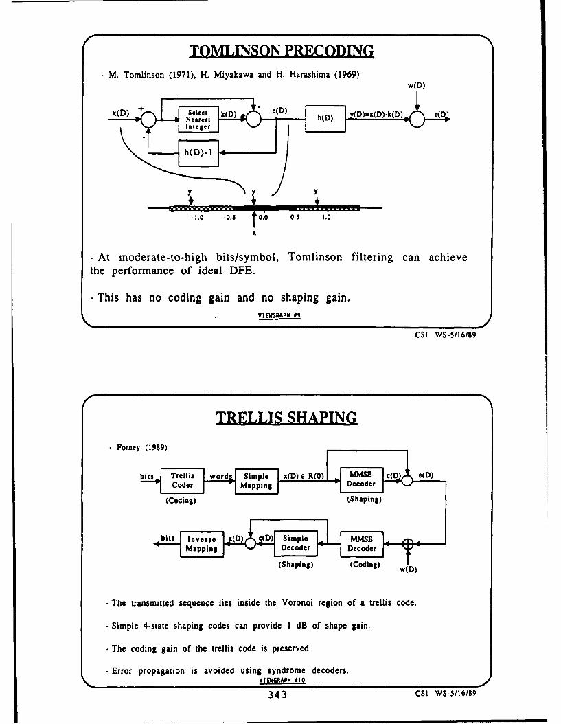
TOMLINSON PRECODING- M. Tomlinson (1971), H. Miyakawa and H. Harashima (1969)
4 4
-2.0 .0.5 t0.0 0.5 1.0
-At moderate -to -high bits/symbol, Tomlinson filtering can achievethe performance of ideal DFE.
- This has no coding gain and no shaping gain.-VIEWGRAP4 09
CSI WS-5/16/89
TRELLIS SHAPING
*Forney (1989)
bts Teli d Simple x(D) C R(O) MMSE c(D e(D)
- imle4-tae hain cdeaproide 1Dofsaecgain.
- Te(cdinoging of(hSteliacdeinpesrvd
- rrr roagtinMsavoduing synder dcDe rI
(ShOaping (Coing
343 C! WS-w(6/8

during data transmission whereas the linear equivalent of the decoder is actually insideequalizer could continue to adapt. the feedback loop and the g equals 1 over ...
Some system considerations: The peak-to- for reasons of stability, one thing, and for in-average ratio of the system, if you don't do stance if you have a notch, at DC, or some-anything about it, could be high, because thing like that in the channel, h(D), you'reyou are getting shaping gain, your constel- basically increasing your sensitivity to round-lation is becoming Gaussian-like. However, off error and that. So is that actually howwe found that we can put constraints, simple you're implementing it, or are you somehowconstraints, on the decoder in the transmit- sliding the decoder inside that filtering boxter to control the peak-to-average ratio and to put a dynamic range limit on the outputs?bring it close to what we would get on an EYUBOGLU: This doesn't have to beideal channel. We sacrificed little in shaping the way the scheme is implemented but Igain. The scheme can also be made transpar- thought that this is probably the easiest toent to 90* or 1800 phase rotations. So if you understand. You can represent this wholeuse a rotationally invariant code like the Wei thing in different forms.code that is used in the V.32 modem stan- ALLEN LEVESQUE: Error Controldard, then, provided you do the right things for the HF Channelin the shaping and precoding process, the The title that you see here on the view-whole thing can be transparent to 900 or 1800phase rotations, graph is somewhat different from what was
printed in the agenda. [TITLE SHEET] IWe don't think the scheme would be sensi- seemed to have come up with a third vari-tive to small coefficient mismatch. As I said, ation of the title that combines equalizationat low signal-to-noise ratios the mean squared and coding. It seems to be a popular formerror criterion can be used; in fact, in prac- for titles here ... maybe there's a messagetice that's what you would probably be using there about what subjects we should be pu-
since it's easier to adapt. suing in the future. When Rob was organiz-
Finally, so far, I've assumed that the baud ing the session and asked us to prepare corn-
rate was fixed. But to approach capacity on ments on various aspects of adaptive coding,
an arbitrary channel, one would have to opti- he also made the comment that we shouldmize the baud rate as well, and that could add some remarks about what we saw as fu-be done using an off-line channel probing ture worthwhile areas of research that shouldscheme. be pursued, items of particular importance
I have one more slide on transmitter equal- that should be given some emphasis. I took aization, but I'm going to stop. If you have cue from that and, rather than talking strictlyany questions I can show that later on. about adaptive coding, what I'm going to talk
JOHN CIOFFI: On your trellis precod- about is a somewhat broader idea of adapta-ing node, the one slide that you had up, I tion that would use capability that is avail-wonder if you could put that back up and able or is going to become available in variousI'll quickly ask the question. You have there adaptive equalizer modems for radio chan-g(D) = -h(') just preceding the minimum nels, and to use that capability in conjunc-mean square error decoder. A typical ap- tion with coding to try to do a more powerful,proach with Tomlinson filtering and such, the certainly a more flexible, job of adaptation to
344

COMBINED ADAPTIVE EQUALIZATIONAND ADAPTIVE CODING
FOR HF LINKS AND NETWORKS
A. H. LEVESQUE
CSI WORKSHOP ONADVANCED COMMUNICATION PROCESSING TECHNIQUES
16 MAY 1989
GTE GOVERNMENT SYSTEMS CORPORATIONELECTRONIC DEFENSE COMMUNICATIONS DIRECTORATE
100 FIRST AVENUEWALTHAM, MASSACHUSETTS 02254
TEL. (617) 466-3729
TITLE SHEET
OUTLINE
* HF CHANNEL CHARACTERISTICS
" NETWORKING FOR MILITARY APPLICATIONS
* ADAPTIVE CODING TECHNIQUES
* DEVELOPMENT OF SINGLE-TONEADAPTIVELY EQUALIZED MODEMS
• CONCEPTS FOR COMBINED ADAPTATIONOF MODEM AND CODING PARAMETERS
SHEET 02
cs WOnKS-OP 6&9 (4) 34 5

both links and eventually in networks. The stationary. Typically HF channels are talkedtalk is going to concentrate specifically on HF about in kind of a rough classification; that is,channels. their fading characteristics as being separable
HF is certainly of importance to the Army, into short-term, well-known, Rayleigh fading,one of our sponsors here, and other branches complex-Gaussian fading, and long-term fad-
of the military. It's a medium for which we ing which is approximately log-normal. This
in our own company, and other companies as is a rough characterization, but it's useful to
well, have done a lot of work in developing think about the channel that way.
a variety of modems, both conventional and It would be very desirable in trying to de-frequency-hopped, though I'm not going to sign systems for HF channels and eventuallyget into the issues of AJ today. Besides that, HF networks to be able to go to a book orHF seems to be almost everyone's favorite a library or database that would provide usmultipath fading channel. It's so troublesome the statistics on the various combinations ofthat we can continue to come up with clever channel characteristics. By this I mean signaltricks that we can develop and test, and if strength, and multipath, and Doppler, andthey don't work as well as we'd like we can I'm not going to go off into these in detail be-
always shake our heads and say, "Oh, well, cause Seymour Stein may comment on someyou know what HF is like, but next year we'll of these same issues. In fact, if anyone wantshave a better idea." a good, quick learn on HF, I certainly recom-
[SHEET #2] I'll say just a little bit about mend the article that Seymour wrote in theHF channel characteristics, but I really won't February 1987 issue of the JSA C. I'll mentionhave to say much because this was covered some of the points that he raised. It wouldvery well in Phil Bello's talk yesterday and be nice to be able to say that if the signalthe discussions that went with that. I'd like strength is such and such, then we will alsoto say just a little bit about networking and know that the multipath spread is as follows,about the developments that have been going and would know better how to adapt the mo-on in applying adaptive equalization to radio dem or make a selectirn of modem or cod-channels. We've heard a lot about adaptive ing for the channel. Unfortunately that sim-equalization this morning and again with Ve- ply does not exist. There are broad statisticsdat's talk on another area. There are some about the characteristics of the channels inspecial issues that arise in radio channels that these various categories, but that ideal sourceneed to be talked about. And I'll talk about of multivariate statistics simply does not ex-some comments for combining these forms of ist. So with all of this it would be very desir-adaptation. able in designing HF links and networks to be
[SHEET #31 We all know that HF is a able to provide means of adaptation to both
notorious multipath fading channel. In his short-term and long-term variations, and be-
talk yesterday, Phil Bello emphasized some- ing able to do this with the lack of the kind
thing that I really should have included in the of data that we would really like to have to
slide in probably big, bold letters, and that is design the links optimally.
that HF is a nonstationary channel. It's non- [SHEET #4] I want to comment on HFGaussian but perhaps the more troublesome networking because people in many organi-aspect is the fact that it can be very non- zations are coming to the realization that the
346

HF CHANNEL CHARA(TERISTICS
* MULTIPATH, FADING, NONSTATIONARITY
* SHORT-TERM (RAYLEIGH) AND
LONG-TERM (LOG-NORMAL) VARIATIONS
* LACK OF MULTI-VARIATE STATISTICS FOR HF
* DESIRABILITY OF ADAPTATION TO BOTHSHORT- AND LONG-TERM VARIATIONS
" (REF.: S. STEIN, JSAC FEB87, pp. 68-89)
SHEET 03CSI WORKSHO •l MI (4)
HF NETWORKING
* CONNECTIVITY WILL RELY ON MULTI-LINK ROUTING
* USEFUL TO "NEGOTIATE" BEST LINK THROUGHPUTRATE TO ESTABLISH END-TO-END CONNECTIVITY
• ADAPTIVE EQUALIZATION OR ADAPTIVE CODINGALONE MAY NOT PROVIDE SUFFICIENT FLEXIBILITYFOR THROUGHPUT OPTIMIZATION
SHEET *4
CSIWORKSHOP V/ 6'(44) 347

way to make full use of the HF medium is really makes sense to me to have the labelgoing to be through networking. There's cer- "adaptive" is various forms of hybrid ARQ.tainly work going on in the services on various I've written this here just to define a fewaspects of networking. There's work going on terms for the sake of some people that mightinn techniques for automatic link establish- not be familiar with these terms, and also toment which is a vital ingredient in getting a try to make a start toward a definition. I cannetwork up and making it work. But just to say what I don't regard as "adaptive" andsay a couple of things ... certainly connectiv- that's the simplest forms of ARQ with sim-ity in HF has to rely on multilink routing. A ple repetition. By the way, the term hybridvery simple example of this could be simply refers to the incorporation of error correctionsketched here by noting that if we want to with error detection. Simple ARQ you simplyget from point A to point B at a given time block the data, attach error detection pari-of day or night there - at that distance, even ties to every block and repeat the blocks thatif it might be a relatively short distance of don't make it. Hybrid incorporates forwarda few hundred miles - there may be no HF error correction and that's well established tofrequency available to make that connection. be the right way to do it. Simply repeating isHowever, we might be able to get from point not what I call adaptive any more than redi-A to point C through a channel on a much aling the telephone when you don't get yourlonger link and then back to point B. That, party is adaptive. I think the term adaptivein a snapshot, is the kind of thing that effec- is properly applied when we at least begin totive and efficient HF networking will enable talk about saving and combining code blocksus to do. When you lc-k at dependence upon that were previously transmitted with newlymultilink routing like this, one of the issues transmitted code block. Simple versions ofthat comes up is trying to match data rates this have been looked at; for example, major-on the links that you're putting together to ity voting across copies.try to make the circuit. It would be useful to Rob referred to code combining, defined byhave the capability to, for example, negotiate Chase, in which simply speaking you sendthe best link throughput on two or three links a forward-error-correction code; if it doesn'tin cascade in order to be able to establish decode properly you send another copy andthe end-to-end connectivity. The real point you combine these on a steady signal GaussI want to get to here is that adaptive coding noise channel. You would do, in fact, opti-individually or adaptive equalization by itself mal coherent combining. Without saying amay simply not provide the kind of flexibil- lot about it if you implement this as it's prop-ity that we would like to have for through- erly defined with maximum likelihood decod-put optimization or for operating effectively ing, it's a very efficient scheme because on ain networks. steady signal Gauss noise channel, the com-
[SHEET #5] Rob was kind enough to make munication efficiency as measured in Eb/No
a few remarks about adaptive coding to save stays exactly the same regardless of how
me a few words. I'll get down to the point many copies you have to combine.
here on my own view. That is that while the There are other refinements of hybrid ARQname has been applied to a number of coding that have been looked at. (See Bibliography.)techniques, the only area of techniques that Type-II hybrid ARQ is an efficient adaptive
348

HYBRID FEC/ARO CODING TECHNIQUES
NONADAPTIVE- HYBRID FEC/ARQ WITH SIMPLE REPETITION OF
ENTIRE CODE BLOCKS ("TYPE-I")
ADAPTIVE* HYBRID FEC/ARQ WITH COMBINING OF PREVIOUS
COPIES ( SINDHU; LAU & LEUNG; BENELLI; CHASE;KALLEL & HACCOUN, etc)
* HYBRID FEC/ARQ WITH INCREMENTALLYTRANSMITTED REDUNDANCY, "TYPE-Il"(MANDELBAUM; METZNER; LIN & YU; etc.)
• TYPE-Il HYBRID FEC/ARQ WITH CODE COMBINING(CHASE et. al.; KALLEL & HACCOUN, etc.)
" GENERALIZED HYBRID ARO, USING (mk,k) FECCODES, mk2, (KRISHNA, MORGERA, ODUOL)
• RATE-COMPATIBLE PUNCTURED CONVOLUTIONALCODES WITH ARO (HAGENAUER; KALLEL & HACCOUN)
SHEET 0SCSI WORKSHOP •5/16"9 (4)
ADAPTIVEL Y EQUALIZED MODEMS FOR HF
* SINGLE-TONE MPSK MODULATION WITHFORWARD-ERROR-CONTROL CODING
• USE CHANNEL EQUALIZATION (e.g., DFE) ORCOMBINED CHANNEL & DATA ESTIMATION (DDE)
* EQUALIZER PROVIDES A BUILT-IN QUALITYMETRIC ( MEAN SQUARE ERROR)
* CAN BE MERGED WITH ADAPTIVE CODING
SHEET 06
CSI WORKSHOP SO,&,9, (4 349

scheme in which only error-detection parity marrying of that characteristic of the sourcechecks are sent when the channel is good, with the rate-compatible punctured codesand error-correction parities are sent when and their properties is a very interesting one.the channel is bad. In a refinement called Hagenauer has done some work in wrappingGeneralized Hybrid ARQ, each retransnis- ARQ around that kind of technique.sion is used to send new parity blocks. Inother words the parities that are sent on the Let me draw one more little sketch here.resend are parities that actually change the What a number of these refinements of hy-structure of the code with each arriving new brid ARQ are doing can be kind of summa-
set of parities to improve the distance of the rized very briefly. What you're trying to docode. Work had been done early on by Met- - and I'll just say this is channel quality to
zner, Krishna, Morgera, and Haccoun, and make a crude sketch and code rate here. Eachsome other people in Canada have been fur- of these designs is based on some code whichther developing those ideas. is ... you can think of it this way ... of a
set of codes that ranges between some maxi-The last item I put on here, it's relatively mum rate and some minimum rate. Depend-
new work and I find it very interesting. Be- ing upon how many times you're willing toginning with the work of Hagenauer looking resend, that rate can be some very low num-at rate-compatible punctured convolutional ber down near zero. You're in some way try-codes that have a lot of interesting proper- ing to design a technique that will gracefullyties and are decoded with Viterbi decoders. match the code rate to the channel quality.The idea here is that the design is based on But the point - and a lot of these refinementswhat's called a mother code, which is the low- here, this and this, for example, have to doest rate code that you will use in the channel, with providing some finer intermediate steps,and higher rate codes are created by punctur- whereas for example simple code combininging symbols out of the stream that leaves the would go from rate 1/2 down to rate 1/4 andencoder. This technique has a lot of interest- down to rate 1/6. Some of these other tech-ing characteristics. One of them is you can niques provide for a finer grid, if you will, ofdo the puncturing in a way that the bits that code rates. But the point I want to get toare delivered by the decoder on the receive is that when you commit yourself to a designend are delivered with different levels of re- like this, you're living with some maximumliability. In other words, the post-decoding code rate. One of the aspects of simply try-bit error rate is actually different for different ing to use hybrid ARQ to adapt to channelbits leaving the decoder. Some work has been quality is that you can certainly see when thedone by Hagenauer and some people at ATT channel is getting poorer because you're de-Labs. tecting errors. When the channel goes into
Looking at, for example, applying that a region of good quality, the decoder doesn'ttechnique to coded speech transmission with really give you information as to how muchany one of the waveform coders, I think it's better the channel is getting. In other wordswell known that different bits in the encoded it doesn't really tell you how much better youstream are more or less critical for reconstruc- could do in terms of throughput if you weretion of the speech. True with sub-band de- to shift to a completely different code design.coders, with the LPC family, etc. So the I'll come back to that point in a moment.
350

[SHEET #61 We've heard a lot about adap- ship but zoughly speaking it's a good way totive equalizers here, but I just want to make think about it.) A very small change in thea few comments regarding the considerable channel structure can result in a large changework that's been done and being done to de- in the equalizer, and the equalizer trackingsign adaptively equalized modems for radio algorithm has the job of rapidly adjustingchannels. Again, a lot of attention to HF. to that. This scheme (Data-Directed Esti-They're all based on single tone, M-ary, PSK mation) gets around that problem, and it'smodulation, and they all have some form of been demonstrated with simulations that thiscoding incorporated into them. They use - technique in fact does a better job of track-and I'm making a distinction here - chan- ing rapid changes in the channel structure.nel equalization, for example decision feed- I don't think I want to take any more timeback, or combined channel and data estima- with that. I'll just leave with the commenttion. Let me just say briefly what I mean. that the reason John Proakis didn't call this
I had a discussion with John Proakis af- out as a special technique is that asymptoti-
ter his talk this morning. [SHEET #7] John cally when it converges the performance will
included this in the category of decision feed- be the same as a decision feedback equalizer.
back equalization, but it's really different. But the tracking characteristics are different
It's not really equalization. This is a form and the reason that I bring that up is that
that has been implemented that has resulted even the best of equalizer designs will once in
in a very effective modem design. [SHEET a while lose track of the channel and result in
#81 Here's a preamble and, in simple terms, bursts of errors. I'll come back to that point
the transmission format is alternating blocks in a minute.
of training data and source data symbols. The last two points I wanted to make hereIn the nutshell what's going on is that the is that these equalizers provide a built inblocks of training data are used to estimate channel quality metric. They provide a meanthe channel using, for example, a classical square error that's used in the tracking al-LMS technique, Levinson recursion for exam- gorithm and other information that could beple. Then when the channel impulse response used, for example, to derive a signal-to-noiseis known, the data block is estimated again ratio estimate. So that kind of a built-in mon-by LMS estimation. So what's really being itor of channel quality can then be used as adone here is channel estimation and data es- tool to help with the adaptive coding.timation, and the algorithm flips back and [SHEET #91 I'm trying to indicate here inforth between the two. one simple diagram the notion of using this
My point in bringing this up is that the capability and the signal processing capabil-reason that this particular technique was de- ity in the adaptive equalizer modem to im-vised was that it was based on the observation plement several forms of adaptation on thethat on HF channels, for example, there can HF l-'nk. The signal-to-noise ratio estimatebe some very abrupt changes in the channel could be used with a threshold test to re-impulse response. An equalizer has a rough train the equalizer to get out of the reallyinverse correspondence of channel transfer bad fades that send the equalizer off track.function to the the equalizer response. (We They could also be used to change the mod-know that it's not an exact inverse relation- ulation alphabet. There are a couple of stan-
351

DATA-DIRECTED ESTIMATION (DDE)
FOR FADING CHANNELS
* A HIGHLY ROBUST TECHNIQUE FOR FADINGMULTIPATH CHANNELS
- KNOWN (TRAINING) DATA BLOCKS ALTERNATEDWITH UNKNOWN (SOURCE) DATA BLOCKS
* RECEIVE PROCESSING ALTERNATES BETWEENCHANNEL ESTIMATION AND DATA ESTIMATION
• ESTIMATION LESS SENSITIVE TO RAPID CHANNELCHANGES THAN EQUALIZATION
* EXPERIENCE WITH DDE HAS INFLUENCED TWONEW MODEM STANDARDS (NATO STANAG 4285& MIL-STD-188-110, REV 2)
SHEET *7
CSI WORKSHOP. SO &89 (4)
DATA-DIRECTED ESTIMATION
CD DE
TRANSMISSION FORMAT:RECEIVE ..M DATA & SYBL SYMBOL$ SYMAB RHC AA hHO
N TRAINING 9YYOtJ UVMSOS 3Y1OA l SYMULSYMBOLS;SETI- I
. UPDATE CHANNELt.) TAP WEIGHTS NO I _ MA Y EUR
SOLVE 2 END
FOR M DATA SYMBOLS;SSYMBOLS i.
SET M 71 -41m (LMS) MI Ml •2
NO
SHEET *S
C31 WORKSHOP •/1 &9K9 (4)
352

MODEL FOR COMBINED ADAPTIVE EQUALIZATIONAND ADAPTIVE CODING
ENCODER MODULATOR11 FORWRD_ RECVAI DECODERTRANSLWITER CHANNEL D130
•RETRAI CLCHANGE • AROMODULATION CHANGE CODEALPHABET
RETURN 4CHANNEL
SHEET #9
CSI WORKSHOP 5/16&89 (4)
MODES OF ADAPTATION
CONDITION ADAPTATION
* SHORT-TERM FADING • HYBRID ARQ (ADAPTIVE)AND IMPULSE NOISE
" SEVERE FREQUENCY- - RETRAIN EQUALIZER ONSELECTIVE FADING REQUEST (WITH GO-BACK-N)(EQUALIZER DROPOUT)
" LONG-TERM FADING • CHANGE DATA RATEOR CHANNEL DEGRADATION (MODULATION ALPHABET),
AND/OR CHANGE CODE
SHEET 910
CSd RISHOP-V&n (4)U 353

2IJ
WWZ>J W
OW~~LL
z> 0 w
cc w (J) W
LL.
Cwlw
zcwCW ) LL-U -
zz
00Cd
w00
Z LI. LI.
354

o7 0.
.Cl 0
.- i Fn L.0 . - 7 ZC Y .. EL u
z -
M
.1c,
.3- C
Cw R c~U I
It ~ O.g wx;
c~ :c
gz <I- 8
E
E
2'
A j 12J~ 35

0a w IU. 2
c 0
1. 0
LA. 2 LC 2 o u.
E C.) l
-C i
Cow c 0 '
1 00
L~*.
F£ II I O
E E j i a~ :j.A988 hU. It~ U
c c U-
w -ZZ0 oA.
.Zc 356

dards being written. There is a version of and prolonged frequency selective fades thatMIL-STD-188-110 that will call out a single might cause the equalizer to drop out, can betone modem with a number of parameter se- dealt with by retraining. The very long termlections. (See Bibliography.) There is also a characteristics, when the channel at that par-NATO standard working its way through the ticular frequency begins to degrade, perhapsapproval process that will call out a transmis- the use of that channel can be prolongedsion format for adaptive equalization. I know by changing the data rate through selectionthe Army has a program in which they have of modulation alphabet and/or changing thefunded some developments and implementa- code.tions of adaptive equalizer modems. Those I had a few more slides but because I'vewill all be built with a number of selectable run out of time I will just look for my sum-modulation alphabets. So changing the mod- mary slide. [SHEET #11] So I'm suggestingulation alphabet is certainly one of the things this is an interesting and perhaps productivethat can be done. In addition to doing sim- area for new work: looking at ways of merg-ply hybrid ARQ, I'm suggesting the possibil- ing the processing capabilities and the algo-ity of actually using an adaptive algorithm to rithmic capabilities that are going to exist inchange the code selection as well. these new adaptive equalizer radio modems,
The other point that I would want to make and work this together with adaptive codingis one that has been made by a couple of to do a better job of making use of HF chan-people already, and that is that even though nels and eventually HF networks. Thank you.there's a coder built into the modem, that is ROBERT PElLE: Adaptive Channelnot going to help you keep track of the chan- Modeling Using Hidden Markov Chains1
nel. Because, for the reasons that have been Abstractdiscussed, you're not going to take the output We consider the use of hidden markov mod-symbols from the decoder which may, in fact, els and the forward-backward estimation al-also be coming out of an interleaving buffer gorithm for real-time channel modeling and,which further increases the delay. You're not hence, for automated adaptive forward errorgoing to try to bring those back and feed them correction coding. Extensive computer simu-into the equalization process. So even though lation results are presented and interpreted.you may have a very effective coder that has Design issues for adaptive protocols are ex-been selected to operate with a given equal- posed and discussed. The primary focus isizer mode, that coder really doesn't help you on digital errors typical of poor quality HFkeep track of the channel. skywave communication and use is made of
I'll finish up with this one. [SHEET #10) work on markov modeling of these channels
What I'm suggesting here is looking at multi- by previous workers [4-6]. Modifications for
ple modes of adaptation in which the kinds of less disturbed channels are discussed.
things we would ordinarily do such as hybrid 1. Introduction and Discussion
ARQ might be done to deal with the short- We consider the use of hidden markov mod-
term channel characteristics (fading, impulse eling and the forward-backward algorithm [7]noise, short-term interference, some forms of This work was supported in part by the U.S.jamming in frequency hop systems). The Army Research Office under Contract No. DAAL03-more severe problems in the channel, the deep 88-K-0168.
357

Ii
for adaptive channel modeling and, hence, for some arenas, essential. For example, conver-adaptive coding. Before presenting the re- sation with military instructors indicates thatsuits and details of the models, we consider increased training time for non-specialist mil-the motivation for adaptive coding and the itary operators is expensive and impracticalpresent state of coding technology. to the point of making operationally complex
tactical equipment unacceptable. Faced withPresently, a system designer is faced with a growing technical sophistication and with
large variety of commercially available coding need to reduce operational complexity, the
techniques. In regard to the choice, the stan- need for fully automated adaptive systems
dard advice is to "know thy channel" and pick rses.
a code accordingly. This ignores the practicalpoint that few system designers know their There are many different definitions andchannel perfectly or that there might not be possibilities for adaptive coding systems. In
a single system-wide stationary channel even this article, an adaptive coding scheme has
approximately knowable! Although this was the form depicted in Figure 1. There is a sin-
not the case for the traditional breakthrough gle duplex link between two communicating
areas of coding, e.g. commercial satellite agencies A and B. (In fact, adaptive coding
links, the problem of apt code selection is be- can be considered on the network level andcoming acute in both commercial and mil- the half-duplex level. Although this is not theitary communications. In the commercial case considered in this article, the results are
scenario, d-ta communications are being ex- relevant for these other scenarios.) The traffic
tended to mobile communications, e.g. the is encoded by A, sent across the link, possibly
Automated Train Control System (ATCS) corrupted by noise and decoded at B. To cor-
[50], data over FM radio and cellular radio. rect errors, it is necessary to locate errors and
There are obvious problems when the channel such location data is valuable information on
conditions are also variable and the noise lev- the link performance. This location data,els prevent ARQ techniques alone from being which may be viewed as self-derived side-
adequate. In the military scenario, the spread information, is fed to a database of statistics.
of data communications to tactical as well as The database is processed in order to get astrategic communications can change the fre- detailed verdict or update on the statisticalquency range, the mode of propagation and mechanism producing the noise. Upon theincrease the amount of deliberate or acciden- basis of the noise classification, A and B ne-
tal interference. Given a diversity of chan- gotiate and agree upon the most appropriate
nel conditioz, and the availability of multi- code for the channel in the A to B direction.
code implementations, the logical response is An identical process negotiates the most ap-to select a family of codes capable of meet- propriate code in the reverse direction.ing the majority of cases in which communi- It is important to note that adaptive cod-cation is required. This raises a control is- ing works in a different fashion on differentsue: how is the most suitable member of the channels. Some channels are noisy but sta-family selected? Even for specialists, man- tistically stationary, i.e. the conditions areual selection can be difficult on "real" chan- not time-varying. For such channels adap-nels. From the point of view of efficiency and tive coding amounts to an automatic config-ease of use, automation is desirable and, in uration upon activation. Other channels are
358

Channel
Encoder Q~Adv no hne Deiode
Noise ecans
Mnr e e hanimEtioe E eqec
Note Th uwae vnanons aht refeNoise Em~ sof tiatnnldz
Figre : Nu ech N ois M echns
Digit59

not stationary and the quality worsens and sor power makes the implementation ofimproves with time, e.g. the notorious HF short binary block codes extremely sim-skywave propagation media. In this environ- ple.ment, adaptive coding is constantly checkingand changing the strength of the code. In 4. For harsh channels, concatenated codessuch extreme circumstances, a fixed code will are well-suited. Concatenated codenot be even approximately suitable; if the places two codes in series. The codecode were chosen to match one of the many nearest the channel is known as the in-"worst cases," it will be extravagantly redun- ner code and is either a short binarydant for the benevolent periods of channel code or a convolutional code. By com-quality. Conversely, if it is suited for the good ments 1) and 2) above, there are manyperiods, it will collapse during the poor pe- choices available for the inner code. Theriods. Neither extreme is acceptable and the other (outer) code is, for sound techni-code needs to be changed in reaction to the cal reasons, nearly always an RS code.conditions. If the decoders are working, they By comment 2) above, there is a veryhave all the information necessary to achieve large choice for this outer code. Conse-this adaptation. quently, the range of concatenated codes
Besides desirability, the other motivation available for selection, even using presentis technical feasibility. There are several in- day equipment, is large.depth articles that chronicle the acceptance Returning to Figure 1, it is immediate thatand proliferation of error correction tech- e tuccess o F i e odi s hem e willniques and the increasing strength of im- the success of an adaptive coding scheme willplementable codes working at practical data rely upon the efficiency of the method usedrates [50-52]. To give some examples of read- to monitor the error data and classifying the
ily available forward error correcting technol- noise mechanism. The method reported upon
ogy: is that of hidden markov modeling. Section 2describes the method of hidden markov mod-
1. Qualcomm, Inc., offers a 17 Mbps VLSI eling, presents a rational for the selection ofconvolutional decoder and encoder that this technique and describes the applicationhas four different code options. CoM- of the powerful forward-backward algorithmpetitors are working on similar 20 Mbps for finding an estimate of the stationary hid-devices, den markov model and best approximates a
2. Cyclotomics, Inc., make a unit called the finite sequence of channel errors. Section 3describes the codes and channel models se-BCM2000 that offers a large array of user lce o iuainadScin4peet
selectable options as to Reed-Solomon lected for simulation and Section 4 presents(Scableinterlen options a mon- results. Section 5 discusses the results and(RS) code, interleaving options and con-
catenated options. Although the perfor- system issues. Section 6 discusses areas for
mance difference between many of the future work. Section 7 presents conclusions.
codes is not large, about 100 different 2. Hidden Markov Modeling
RS codes are available for selection on 2.1. Description of the channel andthe BCM2000. simulation model
Figure 2 shows the additive error chan-3. The growth of memory size and proces- nel that was investigated. A digital data
360

source i is encoded to give a digital stream less; the channel's memory is embeddedc. This stream is transmitted over a chan- in the markov state sequence.nel. A noise mechanism generates a digitalsequence e which is added (exclusive-or addi- The simulations made the assumption thattion) to to give a digital stream r. A decoder the decoders were supplying an accurate es-receives the stream r and processes it. One timate of the errors, i.e. that _ = e. Withoutput of the decoder is a sequence 1, the de- this assumption, which is discussed below,coder's estimate of the transmitted data i. i the simulations were of an equivalent addi-is passed to the data sink. Another output tive error channel shown in Figure 4. Theis an "impossible-to-decode" flag that allows noise generator of Figure 3 generates a se-the decoder to alert external circuitry of a quence e which is passed (via the decoder)detected glitch in the decoding process. The to a process which attempts to estimate thethird output is an estimate _ of the transmit- noise parameters. These estimates are passedted coded sequence c. This can be added to to a prediction mechanism that attempts tor- to give an estimate _ of the error sequence select the best possible code under the as-introduced by the noise mechanism. (In fact, sumption that the noise parameters will beseveral decoding algorithms give _ directly- static during the transmission of a codeword.Others might need a re-encoder to obtain As a calibration exercise, the true noise pa-or a.) The strategy of the proposed adaptive rameters are passed to an identical noise pre-coding scheme is to process _ to obtain an diction device that selects a code under theestimate of the noise mechanism parameters. same assumptioa. (This latter prediction isThe estimate is used to predict the severity referred to as the "Genie" prediction.)of forthcoming noise and to select a code ac- The above channel is a markov chain A forcordingly, (see Figure 1b). which there are N channel states. At time
Figure 3 shows the hypothesized model of t, the channel state is a random variable Qtthe noise mechanism. The channel is assumed with a sample space equal to space of possibleto have a finite and fixed number of states. At channel states. Transitions between Qt andeach bit interval the channel selects a state Qt+1 depend upon an N by N transition ma-according to the probabilities in a state tran- trix which has the i-th, j-th entry equal tosition matrix. The selected state is an address the probability of going from the i-th stateto a memory of bit error rate probabilities, to the j-th state,, say, at that time. WeThe output BER probability is an input to a refer to this matrix as At. In many markovdigital random error generator which gener- chains we can directly observe the state ofates either an error (1 in e) or a non-error (0 Q' at time t; in a hidden markov chain thisin _e) with the choice governed by the value of is not the case. A hidden markov chain is athe BER. Note: markov chain in which the data that can be
observed is a probabilistic function of the un-1. The state output error rates and the derlying state sequence. The observable data
state transition matrix can be time- can only indicate the relative likelihoods ofvarying and/or dependent upon the the possible state sequences. In the generalstatistics of the channel data C. model, suppose that we observe a variable
o = 0' that can be in one of M states. The2. The digital error generator is memory- probability of O =/ k given that Qt = " is
361

0 1e Error Sequence-1-Noise
Generator Noise ParameterEstimation:
Forward-BackwardNoise Algim
GeneratorParametes T
Noise Predictioun Nise Prediction
Code Selection cd eeto
'Genic' Prediction 4 Algorithm Prediction
Figure 4: Simulation Model
Fgure5: Output Code Error raue versus Channel DER for RM(16.S) van RS(31.k) codes100
10-'
10-2 - . ........
o10-3
I. 1 0 -4 .
10.6
0- . . 2) . ....
10-410.2 10-1 100
Channel BER
362

equal to b(k), where k : 1 < k < M and simulations. At another level, the assumptionj : 1 < j < N. We put the matrix of bt(k) of _ = e deserves comment. If the assumptionequal to Bt . is false, the decoder is not coping with the
In this channel model M = 2 and 0' equals prevailing noise conditions. This, for most0 or 1, i.e. e is a sample sequence selected decoders, will be very highly correlated withfrom 0. Given that Qt is in state j, b (O) is activity on the "Impossible-to-Decode" sig-the probability of a non-error and b(j) is the nal. This signal is seen as an interrupt to theprobability of an error. control protocols that prompts the logic to
Note that, for a stationary hidden markov strengthen the coding regardless of the out-chain, the 't' superscript may be removed put of the noise estimation process. In otherfrom aj, b(k), At and Bt. A cen- words, if the assumption is false, the func-tral problem with stationary hidden markov tionality of the algorithm is largely irrelevant.chains is to start with an observed sequence (However, the ability of the algorithm to re-01,02,03, ... , oT of samples or outcomes from gain stability after an inaccurate estimate iso and try to estimate: important.)
Finally, the entire model rests upon the1. the most likely state sequence of Q un- Fnly h niemdlrssuo h
1.dtermo elyng scese c osuitability of a hidden markov model for er-rors on a communications channel. A jus-
2. the most likely values for the aij,; tification for using hidden markov modelingwithin the adaptive coding context is given
3. the most likely values for the b,(k); in Section 2.2.2.2. Hidden markov channels and com-
4. the most likely value for r, the probabil- munications channelity of being in each state at time 1 (the municains haelinital tateproabiity ectr).Markov chains have been frequently used
to model time dispersive communications
The forward-backward algorithm provides an channels, e.g. HF, tropospheric scatter anditerative solution to this problem for station- microwave. In particular, there are importantary hidden markov chains, as discussed in articles by (in chronological order) Gilbert [1-Section 2.3. In the channel model, the algo- 2], Elliot [3], Fritchman [4], Adoul et al. [5]rithm supplies an estimate of the noise mech- and McManamon [6]. The last three haveanism from observing i. This estimate's ac- proved particularly important to this workcuracy depends upon the assumptions that as they provided data on transition matri-the noise mechanism is stationary across the ces observed on HF channels; these provedsamples and that 1 equals C. useful inputs to the simulations. These ar-
This raises several questions. Firstly, it is tides also contain data on the goodness ofnot clear how accurate the algorithm's es- fit between observed error data and the besttimates will be if the parameters are time- markov model.varying across the entire block of observed Two conceptual differences separates thedata. It is also not clear if the algorithm can work in [4] and [61 from this work. Firstly,function given bad initial estimates caused by these workers set up markov chains ratherviolent changes in the noise mechanism. Ad- than hidden markov chains. The channel wasdressing these issues was the major aim of the considered to have N states of which some
363

II
fraction always of which some fraction always section.causes an error and the others always coincide 2.3. The Forward-Backward Algorithmwith a non-error. The possibility of being in An excellent description of the forward-an unfavorable state and not getting an error backward algorithm, and its applications candoes not occur. The hidden markov chain in-cludes this formulation as a special case but be fon in aird Juang [] T htakes a more general perspective. The chan- rit an applied toxprobe ienel is seen as a probabilistic case of errors analysis and dgetalbseimagerather than identical to the appearance of er- renin and semtan sis midtrors. For example, the most prevalent cause procengran nasis [9-46] Giof por erfomane onHF ediais ul-the general nature of hidden markov models itof por erfomane onHF ediais ulis to be expected that the algorithm will findtipath, i.e. the existence of multiple pathswith multiple attenuations between transmit- many more applications. There are strong
similarities between the algorithm and thatter and receiver. One immediate possibility of the Viterbi/Betman algorithm [8]. This
is to model each path combination as a state is dce in [7]. The algorithm can bein a markov chain. With this formulation,isdcuedn[7.Teagrtmanbin amarov hai. Wth tis ormlatonapplied to doubly stochastic processes wherethe state sequence corresponds to a succes-
sion of path combinations. Each path combi- the random vaxiables are discrete or contin-nation will have a different received Signal-to- uous. Within the context of this work, weN ratio have applied the algorithm to binary data.Noise ratio and, hence, a different Bit Error Hwvr oespitctdsse ih
Rate after demodulation. In fact, this point However, a more sophisticated system mightis academic to the results and performance wish to iise codes that process soft-decision
is aadeic o th reult andperormncenoise data, e.g. continuous valued randomof the algorithms; the model finds the best
markov model fit regardless of physical inter- variables or random variables with 8 or 16
pretation. If it was desired to find the best output values. The algorithm is capable ofsuch extensions.
model with state error probabilities of zero
or one, this can be achieved by setting an ini- The Algorithm (as used in this work) ad-tial estimate for the probabilities as zero or dresses the following problem:one. Conversely, to retain the full power of Problem Statementthe model, this should be avoided. Given a finite data sequence e of '0' and
In summary, the multipath mechanism of 'l's, and given the number of states N,HF and other scintillation channels present find the parameters of the stationary hiddenconditions that it is natural to consider as markov chain with N states and initial statea time-varying hidden markov model. The probability vector that maximizes the proba-time-varying nature of these channels suggest bility of observing the given data.that short-term variations are caused by the Box 1 presents the algorithms. [7] explainsmarkov chain structure and long-term effects their derivation. The algorithm iterativelyby time variations in the markov model. Of finds markov models that approximate thecourse, such a model is only of use if there are observed data. It is possible to show [45] thatimplementable algorithms for extracting the each new model will lead to a higher proba-best hidden markov model from the observed bility of observing the given sequence thanerror statistics. This is the subject of the next the previous. More precisely, it was shown in
364

Box 1: Forward-Backward Algorithm
(A) Input:A = (aij) 15ij <NB =(b,(k)) ISj<N. Irk<M
= (;i), 1 <i 5N, initial state distribution vector
0 = (0 1, ... , OT) observed sequence
(B) Iterative Step:(1) Forwards Step:
1. 1 Put cx, (i) = xi be(01), 15 1i :N
1.2 For t = 1,2,.. ,-1, 1sj:N
)= c4(i)a 4 bj(Ot,)
1. 3 Put P =: aT 0i)i-i
(2) Backwards Step:2.1 Put 11r(i) = 1, ! si:<N
2.2 For t =T-1,T-2, ..., 1, t5i 5NN
(i) = , aijbj(O, l(J))j.1
(3) Intermediary Parameters:c4 (i).B, (i)
3.1 yt(i) P 1:<t ST, 1I SN
3.2 k(ij) = (Ot , IS T, l<Ji SN
(4) Re-estimation Formtulas:4.1 'i = Oy(), l(iN
4.2 ,j = "'T-1- - j)- y,(i)
01 OT1
4.3 bj(k)- M =Jt =
(C) Repetition:
Replace A ,B ,x by A',B and K and repeat Step B.
365

the Appendix A of [45] that: observed data. In other words, whereas theViterbi Algorithm is, in some sense, a global
Pr(e/A*) > Pr(_/A), solution, the above produces a series of localsolutions.
where A is the old model estimate and A. is Another practical factor relates to scaling.the new model estimate, ie. the re-estimation The estimation quantities rapidly diminish inguarantees a better model. size and, in a finite computer, some corrective
This indicates a highly desirable general action must be taken. This is discussed inproperty of the algorithm but the perfor- 45].mance still carries caveats. If the initial es- 3. Channel Model Experimentstimate is in a "saddle-point" region, the rate 3.1. General descriptionof climb of probability versus iteration can The efficiency of the described algorithmbe impractically slow. This can be compen- was examined by computer simulations. Thesated; one modification that has been sug- major elements of a simulation included:
gested involves monitoring the rate of climb.If the probability and rate of change are both 1. Input of the types of code to be adapted;unacceptably small, the process is forced to"shoot," i.e. change by a large in order to 2. Input of the underlying noise mechanismavoid the local trap [48]. In fact, in the ex- that it is wished to estimate;
periments involving channel models, a very 3. Generation of noise sample sequences infew number of iterations were necessary for accordance to the input noise mecha-convergence. It is also possible [45], in the nism;general case, for a bad initial estimate to mis-lead the estimation process for some period 4. Estimation of a hidden markov modelof time, i.e. many iterations are necessary. (HMM) that fits the noise sequence us-Again, in the experiments involving channel ing the forward-backward algorithm;models this seems less a factor than for thegeneral case. 5. Prediction of the best code to use given
The output of the algorithm, when there the estimated HMM;are disallowed transitions, may not be a valid 6. Prediction of the best code to use givenstate sequence. The solution determines the that the transmitter is told the true valuemost likely state at every instance. An alter- of the HMM at the start of each code-native solution would be to use the Viterbialgorithm to find the most likely path or state word, i.e. a "genie"-based prediction;sequence [8]. To clarify the difference it is in- 7. Output of results.teresting to consider the advantages and dis-advantages that would result from applying These are addressed below.the forward-backward algorithm to a convo- Types of codeslutional decoder instead of the Viterbi Algo- The particular class of codes that was em-rithm. The Viterbi Algorithm would produce phasized concatenated an RS(31, k) code onthe most likely state sequence. The forward- 5-bit symbols with that of a (16,5) binarybackward algorithm produces the sequence of Reed-Muller code. The Reed-Muller code-stateb that gives the lowest difference to the word is used to protect each symbol of the
366

RS code. The code is three binary error cor- noise and called the HMM estimation algo-recting and four binary error detecting. The rithm on a once per codeword basis. Forinput to the RS decoder is mostly correct or the codes discussed above, this constitutes aflagged as an erasure; symbol errors are in the length of 31.16 = 496 bits duration. In prac-minority. The RS(31, k) codes are allowed to tice, the noise data would be obtained fromvary k from 1 to 31; this is the parameter that the error-correcting decoder and it is logicalis the target of the adaptive coding. The code to call the estimation routine as the data be-redundancy, as presented in the results, is de- comes available. However, there is no reasonfined to be (31 - k)/31 where k is the selected that the HMM algorithm needs to be tied toredundancy. (For the true redundancy, this the codeword size, as discussed in Section 5.has to be increased.) The codes are strong Estimated code selectionat combating both burst and random errors. Given an HMM noise mechanism across aFigure 5 shows the performance against ran- codeword, code performance can be predicteddom errors. Note that error rates of worse by driving two further markov chains fromthan 1 in 10 are correctable with high proba- the HMM. Firstly, a markov chain is usedbility. (This class of codes, with k manually to compute the distribution of the numberselected, was implemented using DSP chips of errors that occur across the 16 bits of aby one of the authors in 1982 and used suc- Reed-Muller codeword. This gives the prob-cessfully with HF serial modems.) ability of a correct, erased and erroneous sym-Input parameters of the noise mecha- bol. A second markov chain then computesnism the distribution across the 31 symbols of the
In terms of channels, the experiments used RS code of the quantity:cyclostationary hidden markov models withperiod N as a noise mechanism, where N is a 2.(Number of symbol errors) + (Number of
variable. (This is described in 3.2.) The pa- symbol erasures).
rameters were selected from published litera- This last distribution leads to the probabilityture where possible and supplemented where of the RS(31, k) codes concatenated with thenecessary. All the noise was binary; no exper- RM code being able to correct in the pres-iments with "soft" Gaussian noise or quan- ence of the HMM. In the experiments thistized inputs were performed. process was performed using the estimate ob-Noise generation tained from the last codeword as an initial es-
The noise generation was based around timate of an HMM stationary across the sub-standard random number generation rou- sequent codeword. With this approximation,tines. It is well known that these models are the maximum value of k was selected thatnot ideal in terms of the higher order prop- made the probability of codeword error belowerties of a truly random number generator, a threshold set to 10- 4 in the experiments.However, these properties were not regarded Genie code predictionas critical to the experiments. And, if per- An approach was used whereby the modeltinent at all, constituted an additional chal- generated the code that the transmitterlenge to the HMM algorithm. would use if perfect a priori information wasHidden markov model estimation supplied by a benevolent "genie," see Figure
The computer model took a codeword of 4. In more detail, a code was selected using
367
the true value of the HMM at the start of A cyclostationary markov chain with pe-each codeword. This HMM was used to drive riod N was constructed by applying thisthe two markov models described above. Us- weighted sum combining to all the parame-ing the same 10' threshold and presuming ters of the underlying markov model. Thethat the model remained unchanged across input to the model includes:the codeword, a code was selected. Thiscode represents the best choice for a trans- 1. the period Nj;mitter lacking hindsight or sophisticated cir- 2. two estimates of the initial state proba-cuitry predicting the rate of change of markov bility vector;chains.Output of results 3. two state transition probability matrices;
Results were processed to give a graphical andview of how the selected redundancy variedwith time. This is the subject of Section 4. 4. two vectors giving the BER arising from3.2. Channels and noise generation each state.
Noise data was generated using cyclosta- Note that making the paired vectors or ma-tionary markov chains. The model used the trices identical implies that the input is notweighted sum of two fixed markov chains varied with time i e A = B implies Ct = A.where the weights varied sinusoidally with aperiod equal to that of the cyclostationarity. The construction was used in two ways.
More precisely, let A and B be any two ar- The principal use was to make the two transi-rays of real numbers of the same dimension. tion matrices identical and to have the outputrays, oral nmers the srayae son. BER vectors different. The result is to simu-
structed where: late an HF link that is stationary except fora periodic attenuation of the received signal.
Ct = a(t) . A + [1 - a(t)] • B, In other words, the probabilities of changingfrom state to state (or path to path) are un-
where: changed but the noise afflicting each and ev-ery state varies. The other use was to make
0 < a(t) < 1 the transition matrices different. The result-
a(t) = 0.5(1 + sin(2. 7r. f . t), (1) ing model is more complicated and was se-lected to represent a fundamental changing
where f has period N,, i.e. f. Nf = 1. Note of the multi-path spread with time as wellthat, if the original arrays were non-negative as variable attenuations. The markov modelswith either row or column sums equal to were updated at every other channel bit.unity, Ct has the same property. It follows The actual channel parameters were as fol-that if A and B were probability transition lows.matrices, Ct is a probability transition ma- Channel 1:trix for every possible t and Ct+N, = Ct. If A This model used a two state markov chainand B are two possible output BER matrices, for the underlying noise mechanism. In thisi.e. indexed by the channel states and giving example, the markov chain, state probabilitythe pronability of error and non-error for each vector and output BER vector were not time-state, Ct is also an output BER matrix. varying, giving a stationary noise mechanism.
368

The transition matrix was set equal to: BER vector was time-varying as for Channel
[.8 0. ~2. The transition matrix was set equal to:
0.3, 0.7 s 0.6, 0.4
The first state represents a "good" condition 0.4, 0.6
and the second represents a "bad" condition The output BER vectors were set toin that the probability of a non-error in the (0.01,0.05) and (0.01,0.1). The weighted sumtwo states are 0.99, 0.9 respectively, i.e. the of these vectors has a period of 4000 bits.good states gives a BER of 102 and a bad This model was selected to examine the ef-state gives a BER of 10-1. The simulation fects of making the lengths of good and badrun with an initial state probability of 0.5 for sequences more comparable.each state, i.e. with no preference to which Channel 4:state the experiment started in. This was identical to Channel 2 ex-
This model tends to produce bursts of data cept for the extremal values of the outputcontaining a relatively high density of errors BERs. These were set as (10-2, 10- 1) andseparated by longer intervals with a lower (3.10-2,3.10-1). The period was 4000 bits asdensity. before.Channel 2: Channel 2 was identical to The model was selected to provide aChannel 1 except that the output BERs of greater range of conditions than in Channelthe state were made time-varying. At one 2.extreme, the BERs were as in Channel 1, i.e. Channel 5: Channel 5 used a three state10- 2 and 10-'. At the other (worse) extreme markov chain. The noise mechanism is sta-the output BERs of the two states were set as tionary and uses values taken from [4] which,2.10-2 and 2.10- 1. In other words, the prob- in turn, were found by analyzing the errorsability of an error from a state was, at best, observed on a benevolent HF link. The tran-0.01 and 0.1 respectively and, at worst, 0.02 sition matrix is:and 0.2 respectively. The actual value at timet was equal to: 0.66, 0.0, 0.34 10.0, 0.9991, 0.0009
a(t).[0.01,0.1] + [1-a(t)].[0.02,0.2] 0.44, 0.34, 0.22
where a(t) varies sinusoidally between '0' and In accordance with the Fritchman models,'1'. The period of a(t) was set to 4000 bits, the associated probability of an error was seti.e. the time-varying chain is identical every as either 0 or 1. More precisely the probabil-4000 bits. The choice of this value is dis- ities were set as (0,0,1).cussed in the results section. Channel 6:
This model produces a similar effect to Channel 6 modified Channel 5 to give time-model 1 except that the density of errors in varying output Bit Error Rates of increasedboth the good and bad sections varies in in- intensity. The selected Output BERs var-tensity. ied between best and worst cases equal toChannel 3: [0.01,0.01,0.5] and [0.05,0.1,0.5]. The period
This model has two states as above. The cycle was set equal to 4000 bits.transition matrix was fixed but the output Channel 7:
369

Channel 7 has the same Fritchman-derived nel 8. The other was equal to:non-time-varying transition matrix as Chan-nel 6. However, the output BERs were made 0.66, 0.0, 0.44, 0.0more dynamic with a more severe worst case. 0.0, 0.9991, 0.34, 0.0The best case BERs were [0.01,0.01,0.5] and 0.44, 0.0009, 0.22, 0.0the worst case BERs were [0.9,0.9,0.5]. (The 1.0, 0.0, 0.0, 0.0reason for imposing such impossible worstcase conditions was to ascertain the speed The best and worst BER vectors were setthat the HMM estimation recovered from an to [0.05,0.01,0.01,0.5] and [0.1,0.1,0.1,0.5] re-extremely pessimistic initial condition.) spectively. The period was 4000 bits.Channel pb: 3.3. Other parameters and comments
The simulation model used a small numberChannel 7b was identical to Channel 7 ex- of iterations for the hidden markov model es-
cept that the period cycle was extended to timation, i.e. three. Experiments were per-40,000 bits, i.e. the conditions were slowly formed with larger values but with no ob-varied from best to worst case. served return in accuracy. At the end ofChannel 8: each codeword, two predictions were made as
Channel 8 took transition matrix values to the code redundancy to be utilized. Thethat were extracted from tests on an HF link first "genie-based" prediction used the actualand published in [6]. The transition matrix markov chain prevailing at the start of thewas not varied with time and is equal to: next codeword. The second used the HMM
estimate computed from the last codeword.This implies that there is a timelag between
0.698, 0.0, 0.0, 0.302 the genie and -the HMM predictions.0.0, 0.9976, 0.0, 0.0024 For any cyclostationary markov chain it is0.0, 0.0, 0.99935, 0.00065 possible to work out the marginal distribu-0.639, 0.264, 0.015, 0.0082 tion at a particular time. This allows the av-
erage probability of bit error on the channel
Unlike [6], the BERs were made time-varying to be computed at any time. This was com-rather than "0" or "1". The best and puted for the above models and the resultsworst cas.;s were set to [0.05,0.01,0.01,0.5] are discussed below. However, the channeland [0.1,0.1,0.1,0.5] respectively. The period BER results can be misleading. Being aver-was 4000 bits. aged marginal distributions, the BER versusChannel 8b time graphs exhibit no information as to the
burstiness of the distributions.This was identical to that of Channel 8 ex- buReslt
cept that the period of time variation was Figure 6 shows the average BER versusslowed down to 40000 bits.Fiue6sosteargeBRvssslo e dn ttime graph for Channel 1. The Markov chainChannel 9 is stationary implying that the marginal dis-
This channel varied the state transition tribution and average BER are constant. Fig-probability matrices between (essentially) ure 7 shows the results of the e.. de simulationsthat of Channel 5 and that of Channel 8. One for Channel 1. The straight line in Figure 7of the matrices was identical to that of Chan- represents the ideal "genie" prediction. The
370

other line describes the code redundancy rec- HMM estimate is clearly tracking the genieommended by the HMM estimation process. prediction accurately and quickly.Clearly the HMM estimation process is cen- Figure 12 shows the average BER versustered around the ideal prediction. It is worth time for Model 4. This channel is more ex-noting that the HMM deviations are to be treme than the foregoing; the time varia-expected, the noise samples over 496 bits can tion is larger and the worst case conditionsexhibit statistical deviations from the under- more extreme than any of the previous chan-lying model and make the "best" fit different nel models. Figure 13 shows the simula-from the average. Less formally, we can get tion results. The genie prediction reflectsgood auid bad stretches of data. Note that the channel conditions, oscillating betweena smoothing or averaging process applied to an RS redundancy of about 0.2 to 0.7. Thethe output would produce a very accurate es- HMM estimate is accurate in that the twotimate, albeit at a cost in adaptation to time lines are closely intertwined. The HMM es-variations. timate tends to be pessimistic. For exam-
Figure 8 shows the average BER versus ple, worst case redundancies of 0.8 are pre-time for Channel 2. The time variation im- dicted. This is not necessarily a fault of theposed by the sinusoidally weighted sum is algorithm; the model produces bursts. If aclearly discernable. Figure 9 shows the re- particular codeword hits a long burst, thesults of the simulations. There are two lines. HMM model is bound to produce an estimateThe genie prediction can be seen to be an ap- more pessimistic than the long-term average.proximation to a periodic sine wave. (The The time lag between the two predictions isdifference between codeword length and fun- clearly visible.damental frequency imposes some variation Figure 14 shows the average BER for Chan-in the genie prediction; on different cycles nel 5. The channel is not time-varying andthe predictions are made at slightly differ- produces a channel BER of below 0.003. Sim-ent phases.) The HMM estimate is also de- ulation results are not exhibited in this case;picted in Figure 9. The latter is necessarily the majority of codewords had no errors, i.e.less smooth than the "genie" estimate but it the estimation process had no input o.. whichis clearly tracking the genie estimate. The to function. In fact, the ideal RS code is nocodeword lag between the two estimates is RS code in this case; the RM code can func-evident. tion without assistance. In Section 5 we dis-
Figure 10 shows the averaged BER for cuss how the HMM model can be structuredmodel 3. The channel is evidently less se- to work in low error rate regimes.vere than Channel 2 as regards BER. How- Channel 6 consists of Channel 5 withever, the transition matrix is structured to the output Error Rates worsened and time-produce longer noise bursts. Figure 11 shows varying. Figure 15 shows the average BERthe results of simulations. The codes under versus time graph. Figure 16 shows the re-consideration tend to favor the presence of sults of the simulations. The HMM predic-noise bursts and this is reflected in the re- tion is clearly tracking the genie estimation.duced redundancy selected by both predic- The growth of the model from two to threetions. Moreover the variation in code re- states seems to have little effect on the accu-dundancy versus time is much reduced. The racy or inaccuracy of the model.
371

RS mdwidany Chumle BER
0 0 0 0 0 000 a a
<0
0 .j ......
..... .......... 0
...... .I .........
.............
RS M&dm Ohannd HER
o~~~~~4. - 4JW & 1
. 04 -
0372

RS mdurdancy Channel DEft
%0- ~ A CPI -J oS 10
.. ....
.. .. ... .. ... . .. .. ........ . ..... .. ... .. ...i ....
q&
RS ~ ~ mdA yCure
F-
37

Owrode BER
o ~.. .......
Cl
... ..... .... .. ..
I'r
ClL._AL----- -LLL
I 37.

Channel 7 consists of the same transition Figure 20 shows the average BER versusmatrix as used for Channels 5 and 6, but time graph for Channel 8. The added com-with the BER parameters varying in an ex- plexity of the four state markov chain clearlytreme fashion. Figure 17 shows the BER ver- does not prevent accurate tracking.sus time graph. The channel consists of very In Channel 8b, the rate of change of noisesharp changes between benevolent and (im- mechanism was reduced. Figure 22 shows thepossibly) bad channel conditions. Figure 18 simulation results. The genie prediction in-shows the effect on the predictions. The genie creases the predicted redundancy uniformly.prediction shows a sharp series of dives from However, although tracking the increase in aredundancy 1.0 (i.e. the code cannot cope) broad sense, the HMM estimate shows moreto about 0.1 and back. The HMM estimation divergence from the genie than in the othershows virtually the same results except that simulations. The likely explanation is thatthe best case redundancy tends to be slightly the channel has a relatively complex noiseworse than 0.1 and the periods of non-1.0 mechanism (4 states) and that the codewordredundancy tend to be slightly wider; the length of 496 bits is insufficient for the noiseHMM estimate is based upon observed data samples to present all attributes of the chainand hence periods of improving and declining to the HMM estimation algorithm. This is-hannel conditions tend to be predicted bet- discussed in Section 5.
l e,- than in the single snapshot mechanism of In Channel 9, the transition matrices werethe genie prediction. These results are im- varied with time. The time-varying stateportant for the following reason. At the start transition matrix was a mixture of the chan-of the simulations it was suspected that the nel 6 three state matrix and the channel 8HMM estimation process would not be accu- four state matrix. Figures 23 and 24 showrate under either of the following conditions: that the codes can cope with Channel 9.
5. Discussion of Results and Design Is-1. The initial estimate was considerably at sues
variance with the ideal answer; The central question is to the extent that athe results indicate than an adaptive cod-
2. A small number of iterations were used. ing scheme could be designed around the
forward-backward algorithm. The results in-Figure 18 shows that the process can adapt dicate that the algorithm tracks a channeland track over ige dynamic ranges. with a hidden markov chain noise mechanism
Channel 7b consisted of slowing down the (of sufficient severity) closely, providing pre-rate of change of conditions in Channel 7. dictions close to the best possible. Moreover,Figure 19 shows the results of the simulation. the work of [4-6] indicates that such a noiseOver the space of about 11-12 codewords, the mechanism is liable to exist on scintillatinggenie predicdion would increase the redun- channels. However there are several points todancy from below 0.1 to the maximum possi be made. An adaptive scheme will containble. Although necessarily lagging, the HMM three major components:estimation process agrees closely with theseresults. It is interesting that, at the 10-th 1. Codes; Ucodeword, the HMM estimate decreases theredundancy. 2. Channel Estimation;375
I

Figure 17: BER versus time for model 7100
.. .. .. .. . .. .. 4 . ... . . .
.. . . .. . . . ... .. . . . . ...... .
4 . ......... ......
... ..... .. .. ... .. ..
........V.. ... ......... .. ..- 1.... ...0. .. ..... ... . .. .... .. .. . ..I. .....
.. 0......... .. 0..6 0.8. 1.... 1..... .4. 1 . 1....8 ......
0 . .. I .. ..-... ...
0 . .............. .............. ....... ............ ...........
101
0 0. . . .8 1. . . .
ie in bdeword4
Fiue 8 Rt376 ormde

. .. .. ..
I.I
I .~. ............
... .. .. . .. . . .
£,(mnmmpa sm

8LE
iJ~.......o. .. ... .. .. .
.. . .... ..... .....0.... .. .....
I VLI0c 0 - 0i 0 0e000 0
4ampumm r

II
3. Adaptation Protocols. the advantage and disadvantage of producing
The first two areas would appear to be read- smoothed, averaged models more suited forThe irs tw aras oul apearto e rad-slowly varying channels than faster varying
ily designable, codes are readily obtainable channels. cf
and the results of Section 4 indicate an ef-
ficient estimation algorithm. However, there For slowly varying channels, a saving in
are some subtle points. For stationary chan- complexity is possible by altering the def-
nels, a worthwhile method to reduce code re- inition of the markov model. In the sim-dundancy and increase performance is to in- ulated model, the HMM produced a, out-
crease the length of the code. For an adaptive put on a once-per-channel-bit basis where thescheme this is not necessarily so worthwhile. output was a '0' (non-error) or '1' (error)
A longer code length increases the time be- respectively. In the alternative, an HMM
tween code alteration, increases the range of produces output on a once-per-error-bit basis Inoise conditions that one code must be able where the output is a positive integer equal
to combat, and causes more data to be lost to the number of bits since the last error.
in the event of an inability to decode. Con- The states of the HMM represent different Iversely, it is clear that the HMM will more ac- error rates as before, but the distribution of
curately estimate the markov model on longer the output of the state (i.e. an interarrival
stretches of data than short. This does not time) is given by a negative binomial distri-imply that long codes are better; several short bution. The effect of this model will be to
codes can be combined to give a longer block, impose a reduced memory requirement butThe optimal type of interleaving on an adap- with a loss in accuracy. (The loss of accu-
tively coded channel is not clear. Note that, if racy is imposed by the estimated state se-
the channel is predominantly non-noisy, long quence changing only at the error locations.
blocks of data are necessary to ensure suffi- This is not imposed by the simulated once-
cient amounts of errors. per-channel-bit model and, hence, the simu-
There are several possible ways of accom- lated model maximizes the estimate over a imodating these points. Perhaps the simplest larger set and is more accurate.) The once-
method is to activate the HMM only when a per-error-bit model will also have the disad-
certain number of errors have been observed vantage of being relatively slow to decrease I(in fact, the simulation software was origi- the redundancy. (This can be amelioratednally written on this basis). Thus the estima- using a mixture of the two methods.) The
tion process is busier during bad error peri- once-per-error-bit model seems to be attrac-
ods than quiet. This could easily be combined tive for relatively benign channels, e.g. ISDN
with a windowing process whereby each code- links [46].word results in noise data that is added to a The protocol design question has not beenbuffer or shift register. The buffer contains fully addressed in this study; it would havedata on the position of the most recent N er- been presumptive to design a scheme about Irors and this data is passed to the estimation an unproved estimation process. However,process on a once per codeword basis. On a there are -ome preliminary comments thatquiet channel, the N errors are obtained from can be made. In a block code scheme, itseveral codewords. On a noisy channel, the is possible to sacrifice one "slot" per blockdata represents less history. This method has for a control channel. Hence, if we used a 3
379 I

block code of length 32 symbols, we might bols of data of which 14 are correct and the fi-reserve one symbol for synchronization data nal symbol is non-data. (In a transform basedand one for code negotiation. (If the noise decoder, this final symbol Aill be all-zero, al-source is an intelligent jammer, the exact lo- lowing for non-activity monitoring to be usedcation of these slots within a block should be as a check for mismatched coding.) Going theunder cryptographic control.) If these control other way is more problematic; an RS(31,14)slots have their data repeated a fixed number decoder will not consider an RS(31,15) code-of codewords, the resulting slow speed chan- word to be a valid codeword with one error!nel can be made more robust (and more re- (This attribute can be put to use.) Con-dundant!) than the surrounding codewords. sider a high complexity adaptive scheme inOf course, the repetition slows the speed of which a receiver has a bank of decoders pro-adaptation commensurately. This had a di- cessing the received channel data in parallel;rect effect on the parameters chosen for the the most redundant decoder that signals asimulation. It is unlikely that a duplex adap- valid codeword would be trusted as the cor-tive scheme of the considered type operat- rect decoder for the transmission. This coulding on broadly equivalent severe error condi- be of use when a central receiver with plentytions on both links will be able to adapt the of computing power is listening to many low-codes within 4-6 codewords of transmission complexity receivers transmitting over chan-time. (In some scenarios, the assumptions nels of diverse qualities.) These commentsas to turnaround time are pessimistic. Many also suggest a practical way of absorbing thestudies assume a noiseless feedback path and variable throughput. It is natural to considerin some "star" networks, this can be ap- the K data symbols of an RS codeword asproached. The point is that not every du- K parallel, multiplexed traffic channels. Asplex link is so fortunate.) If the noise con- the codes have their redundancy increasedditions vary slowly in relation to the code- and decreased, the channels are dropped andwords, it is enough for the protocol to indi- re-opened accordingly. Given a priority al-cate that the redundancy should be kept as location of traffic to the RS data symbols orpresently set, increased by a preset quantity "channels," the adaptive coding can be easilyor decreased by a (possibly different) preset optimized to get as much of the most impor-quantity. Allowing for acknowledgments, this tant data through a channel as possible.indicates as little as two bits of data needs As a final protocol issue, it should be ap-to be coded in the control data. For more parent that the above comments have beendramatic changes, the redundancy needs to written with little concern for the standardbe changed within increased limits and more OSI model. It is an interesting point as tocontrol data is necessary. In fact, the coding whether adaptive coding, as defined in thiscan be arranged to allow for a limited degree study, is necessarily in conflict with the OSIof confusion between the transmitter and re- model.ceiver! If the codes are correctly designed, a 6. Conclusionsmismatched RS decoder can process a slightly On the basis of the simulations, it ap-different more redundant RS codeword. Forexample, an RS(31,15) decoder will process pears that the forward-backward algorithm
an RS(31,14) codeword to produce 15 syrn- can be used for channel modeling. The al-gorithm appears to track the prevailing con-
380

ditions closely and quickly. This solves a 3. E.O. Elliot, "A model of the switchedproblem of real-time channel estimation for telephone network for data communica-many classes of problem channels. If this ap- tions," Bell Sys. Tech. J., vol. 44, pp.proach is combined with the existing capa- 89-109, January 1965.bilities of forward error correction, adaptive 4. B.D. Fritchman, "A binary channel char-coding schemes become much closer to real- acterization using partitioned Markovity. It must be stressed that existing coding chains," IEEE Trans. Inform. Theory,options carry many possible choices of manu-ally selectable codes; the decoding algorithmswithin a family of codes are very similar. The 5. J-P.A. Adoul, B.D. Fritchman, L.M.type of proposed adaptive coding scheme rep- Kaval, "A critical statistic for channelsresents the addition of a controlling computer with memory," IEEE Trans. Inform.and a protocol scheme to such devices. Theory, vol. IT-18, pp. 133-141, Jan-
Such schemes will adjust the utilized code uary 1972.automatically from a range of possible op-tions in reaction to the channel conditions, 6. P. McManamon, "HF Markov chainmaximizing throughput while retaining data models and measured error averages,"integrity. This could enable the technology IEEE Trans. Comnun. Technol., vol.for a less sophisticated user than at present. COM-18, pp. 201-209, June 1970.This would have important consequences as 7. L.R. Rabiner and B.H. Juang, "An In-regards training, efficiency and acceptability troduction to Hidden Markov Models,"of low echelon data communication. IEEE ASSP Magazine, January 1986.
Further work into the definition, implemen-tation, simulation and trial of a full adaptive 8. G.D. Forney, Jr., "The Viterbi Algo-
coding scheme seem justified and desirable. rithm," Proc. IEEE, vol. 61, pp. 268-
Acknowledgment 278, 1973.
The authors would like to thank Narcisco 9. L.R. Bahl, F. Jelinek and R.L. Mer-Tan for his programming of the forwards- cer, "A maximum likelihood approachbackwards algorithm and for his comments as to continuous speech recognition," IEEEregards the rest of the simulation software. In Trans. on Pattern Analysis and Machineaddition, several conversations with Professor Intelligence, vol. PAMI-5, no. 2, pp.L. R. Welch were extremely useful. 179-190, March 1983.References
10. D.H. Ballard and J. Sklansky, "A ladder-1. E.N. Gilbert, "Capacity of a burst-noise structured decision tree for recogniz-
1.hanneGlbet, ys. Tech. J., vol. 39, ing tumors in chest radiographs," IEEEchannel," Bell STrans. Comput., vol. C-25, no. 5, pp.pp. 1253-1260, 1960. 503-513, May 1976.
2. E.N. Gilbert, "On the identifiability 11. L. Baum and T. Patrie, "Statistical in-problem for functions of finite Markov ference for probabilistic functions of fi-chains," Ann. Math. Stat., vol. 31, pp. nite state markov chains," Annals of668-697. Math. Stat., vol. 37, 1966.
381

12. G. Coleman and H.C. Andrews, "Image 21. L.A. Liporace, "Maximum likelihood es-segmentation and clustering," Proc. of timation for multivariate observations ofIEEE, vol. 67, no. 5, pp. 773-785, May markov sources," IEEE Trans. on In-1979. form. Theory, vol. IT-28, no. 5, pp.
729-734, 1982.13. D.B. Copper, "Maximum likelihood es-
timation of markov-process blob bound- 22. B.H. McCormick and S.N. Jayarama-aries in noisy images," IEEE Trans. on murthy, "A decision theory method forPattern Analysis and Machine Intelli- the analysis of texture," Intl. J. Com-gence, vol. PAMI-1, no. 4, pp. 372-284, put. Inform. Science, vol. 4, no. 1, pp.October 1979. 1-37, 1975.
14. D. Garber, "Computational models for 23. U. Montanari, "On the optimal detectiontexture analysis and texture synthesis," of curves in noisy pictures," Communi-Ph.D. thesis, University of Southern Cal- cations of ACM, vol. 14, pp. 335-345,ifornia, May 1981. May 1971.
15. R.M. Haralick, "Statistical and struc- 24. A. Nadas, "Hidden Markov Chains, thetural approaches to texture," IEEE Pro- Forward-Backward Algorithm, and Ini-ceedings, pp. 786-804, May 1979. tial Statistics," IEEE Trans. Acous-
tics, Speech and Signal Processing, vol.16. B. Julesz, "Visual pattern discrimina- ASSP-3, no. 2, pp. 504-505, April 1983.
tion," IRE Trans. on Inform. Theory,vol. 8, February 1962. 25. N.E. Nahi and M.H. Jahanshahi, "Image
boundary estimation," IEEE Trans. on17. R.L. Kashyap and R. Chellappa, "Es- Comput., vol. C-26, no. 8, pp. 772-781,
timation and choice of neighbors in August 1977.spatial-interaction models of image,"IEEE Trans. on Inform. Theory, pp. 26. N. Nahi and S. Lopez-Rora, "Estimation60-72, January 1983. detection of object boundaries in noisy
images," IEEE Trans. Automatic Con-18. K.I. Laws, "Texture image segmenta- trol, vol. AC-23, no. 5, pp. 834-845,
tion," Ph.D. thesis, University of South- 1978.ern California, January 1980.
27. W.K. Pratt, O.D. Faugeras and A. Gaga-19. H.Y. Lee and K.E. Price, "Using texture lowicz, "Applications of stochastic tex-
edge information in aerial image segmen- ture field models to image processing,"tation," USCISG, vol. 101, pp. 73-79, Proc. of IEEE, pp. 542-551, 1981.March 1982.
28. A. Rosenfeld and M. Thurston, "Edge20. H.Y. Lee, "Extraction of textured re- and curve detection for visual scene anal-
gions in aerial imagery," USCISG, vol. ysis," IEEE Thans. Comput., vol. C-20,102, pp. 53-64, October 1982. pp. 562-569, May 1971.
382
29. J.M. Tenenbaum, et al., "Map-guided in- speech recognition - a unified view,"terpretation of remotely senses imagery," AT&T 2-II Labs Tech. J., vol. 63, no.Proc. Nat. Comput. Conf., Anaheim, 7, pp. 1213-1243, September 1984.CA, pp. 391-408, June 1980. 38. S.E. Levinson, L.R. Rabiner and M.M.
30. C.W. Therrien, "An Sondhi, "An introduction to the applica-estimation-theoretic approach to terrain tion of the theory of probabilistic func-image segmentation," Computer Vision, tions of a Markov process to automaticGraphics and Image Processing, vol. 22, speech recognition," Bell Sys. Tech. J.,pp. 313-326, 1983. vol. 52, no. 4, part 1, pp. 1035-1074,
April 1983.31. J.W. Woods, "Markov image modeling,"
IEEE Trans. Automatic Control, vol. 39. L.E. Baum and J. Eagon, "An inequal-AC-23, pp. 846-850, October 1978. ity with applications to statistical pre-
diction for functions of markov processes32. J.K. Baker, "The Dragon System - and to a model for ecology," Bull. Amer.
An Overview," IEEE Trans. Acous- Math. Soc., vol. 73, pp. 360-363, 1963.tics, Speech and Signal Processing, vol.ASSP-23, no. 1, pp. 24-29, February 40. L.E. Baum, T. Petrie, G. Soules and N.1975. Weiss, "A maximization technique oc-
curring in the statistical analysis of prob-33. F. Jelinek, "Continuous speech recog- abilistic functions of markov chains,"
nition by statistical methods," Proc. Ann. Math. Statistic., vol. 41, pp. 164-IEEE, vol. 64, pp. 532-556, April 1976. 171, 1970.
34. A.B. Poritz, "Linear predictive hidden 41. L.R. Rabiner, B.H. Juang, S.E. Levinsonmarkov models and the speech signal," and M.M. Sondhi, "Recognition of iso-Proc. ICASSP '82, Paris, France, pp. lated digits using hidden markov mod-1291-1294, May 1982. els with continuous mixture densities,"
AT&T Bell Labs Tech. J., vol. 64, no.35. H. Bourlard, C.J. Wellekins and H. Ney, 3, pp. 1211-1234, July-August 1985.
"Connect--! digit recognition using vec-tor quantization," Proc. ICASSP '84, 42. B.H. Juang and L.R. Rabiner, "MixtureSan Diego, CA, pp. 26.10.1 - 26.10.4, autoregressive hidden markov models forMarch 1982. speech signals," IEEE Trans. Acous-
tics, Speech and Signal Processing, vol.36. L.R. Rabiner, S.E. Levinson and M.M. ASSP-33, no. 6, pp. 1404-1413, Decem-
Sondhi, "On the application of vector ber 1985.quantization and hidden markov modelsto speaker-independent, isolated word 43. L.M. Adeiman and J. Rerds, "On therecognition," Bell Sys. Tech. J., vol. 62, cryptanalysis of rotorno. 4, pp. 1075-1105, Apr'l 1983. machines and substitution-permutation
networks," IEEE Trans. Inform. The-37. B.H. Juang, "On the hidden markov or'y, vol. IT-28, no. 4, pp. 578-584, July
model and dynamic time warping for 1982.383

II
44. E.P. Neuberg, "Markov models for pho- I hope I know what to use when I ned tonetic text," J. Acoust. Soc. Am., vol. do a new system design. I've also learned to50, pp. 116(A), 1971. be very skeptical when the artists come up
with new ways to solve all the world's prob-45. N-K. Huang, "Markov probabilstic out- lems. And Rob said that's exactly the atti-
put models for texture-based image seg- tude he wanted to close off the panel session,mentation," Ph.D. thesis, University of and that's why I'm here. I'm the skeptic.Southern California, 1983. We also had a deal that I could be a silent
46. Y. Yamamoto and T. Wright, "Er- skeptic, that I was going to sit up here, notror performance in evolving digital net- have to give any formal talk until the ques-works including ISDNs," IEEE Com- tion period, and then I could join in. Then
mun. Mag., vol. 27, no. 4, April 1989. when I got here we found that Andy Viterbihad cancelled out, and so you get to hear me.
47. E.R. Berlekamp, "The technology of er- The good news about all that (and there'sror correcting codes," Proc. IEEE, vol. my title chart) is that I have only four charts.68, pp. 568-593, May 1980. [LAUGHTER]
48. E.R. Berlekamp, R.E. Peile and S.P. What I'm really going to do is try to talk
Pope, "The application of error correc- more generally about adaptation and then
tion to communications," IEEE Corn- make some comments about the possible role
mun. Mag., vol. 25, no. 4, April 1987. of adaptive coding in all this. Both AlLevesque and Rob have anticipated some of
49. W.W. Wu, D. Haccoun, R.E. Peile and my comments, but I'll repeat them anyway.Y. Hirata, "Coding for satellite commu- There are two primary reasons for adapta-nication," IEEE Selected Areas in Corn- tion in the radio channel. [CHART #1] Onemun., vol. SAC-5, no. 4, May 1987. reason for adaptations are the kinds of prob-
50. Advanced Tr-in Control Systems Spec- lems we find in fading multipath channels orifiatine 210:rMie CotrolnSs tos when we have moving terminals, more gen-Paicagon 210eb ile Cs eral than only HF channels. There are ob-
viously changes in channel gain. Typically
SEYMOUR STEIN: Systems Perspec- there are short-term changes that occur intives very short time scales like seconds, along with
I've done a lot of things in my career, but longer term changes. There are also long-being part of a panel of coding experts is a term changes in the nature of the channelreally new experience. Anyone who knows transfer function as the character of the mul-me probably wondered what I was doing on tipath somehow changes. I am a very properthe program. That was also what I told Rob skeptic, and you'll see why, as to whetherPeile when he first approached me to serve adaptation to the short-term changes is reallyhere. practical. For a longer term change, adapta-
My view of coding has always been that it's tion may be practical but needs to be put intoa black art. Antennas are also a black art. perspective.As a system designer I wait for the artists to The other kind of change that certainly thecome up and show me what they can do, and Army customer here or any military spon-
384

REASONS FOR ADAPTATION
* SIGNAL CHANGES:
- CHANGES IN CHANNEL GAIN
SHORT TERM (E.G. RAYLEIGH FADING)
LONG TERM (E.G. DIURNAL)
m CHANGES IN CHANNEL DISTORTION
MULTIPATH CHARACTER
0 NOISE CHANGES:
- BENIGN
INTERFERERS
IMPULSES
- HOSTILE
JAMMING
CHART #1
385

sor is interested in is the kind of change that now that they can see an end to the billions ofyou might think of in response to jamming. dollars they're spending on that system, it'sThese are applications where interferers that time to start thinking about the next gen-weren't there before suddenly show up and eration. If anybody here is looking for newyou have to try to cope with them - that is problems to conquer, I would very much rec-another kind of change. These are, in general, ommend thinking about how to build relaythe reasons people adapt. networks that operate on the battlefield. I re-
Another issue on adaptation that you have ally think that down to even the lowest ech-to recognize - and again, especially in the mil- elon, the days of omnidirectional communi-itary environment - is that we live in a world cation in an electronic warfare environmentwhere some messages are very short. Adapta- are numbered. We're going to have to go uption in reality may be what you do in order to in frequency, finding ways to use directionaltry to find a way to get the message through transmission. That's an aside, and as I saidin the first place. You don't have very much it has nothing to do with HF or coding.time for fancy adaptation like changing codes Another kind of adaptation is frequencybecause if you've gotten through at all, that's change. You find interference or you findit. So that in the sense it's been talked about you're not getting through at one frequency,here, adaptation really refers to more contin- you try another frequency. Some of the neweruous kind of links. HF systems in fact do exactly that and they
Now that word "adaptation" or "adaptive have been delighting the users because theyoperation" has been applied in all kinds of work. The traditional HF operation was rel-places, and I'm sure this is not a complete atively fixed frequency. The so-called "selec-list [CHART #2] but let me just list them. tive calling" systems try multiple frequenciesOne of the most important, most significant until they find one that gets through.
kinds of adaptation that has nothing to do Another kind of adaptation, transmitwith coding is that of using relay networks power level control, is one that is of great in-with alternate routing. It's the kind of thing terest to a lot of people, especially people try-that Al Levesque referred to as the probable ing to design covert communication systemsfuture of HF, but it applies to much more who want to operate at the lowest power level.than HF, and I'd like to make an aside here There is a slight connection with coding butthat has little to do with the topic. probably not with adaptive coding.
While coming up here I happened to read Receiver processing in many forms has alsoa trade journal in which some Army gen- been called adaptation. One example is theeral proudly announced that the Army is dynamic operation of an equalizer - we callnow within five years of completiLg its pro- them adaptive equalizers. They don't requirecurement of a system called TRITAC which two-way communications, however. I call thishas been in development and procurement a kind of implicit adaptation. That is, youfor twenty years. In 1995 the Army, as he build something like a Rake receiver, a di-said, is finally going to have a battlefield tele- versity combiner or an equalizer that simplyphony system which is fully digital, fully en- operates within alimited set of va,; -+ions andcrypted; it's going to do all kinds of great attempts to give you the best throughput inthings. The more important comment was: the light of those variations.
386

III
TYPES OF ADAPTATION" ALTERNATE ROUTING THROUGH RELAY NETWORK
- INCLUDING ADAPTIVE RADIO PATH SELECTION I* FREQUENCY CHANGE I* TRANSMIT POWER LEVEL CONTROL
* RECEIVER PROCESSING Im FILTERING TO MINIMIZE NOISE Im MATCHING TO SIGNAL VARIATIONS
(DIVERSITY, INCL. RAKE) I* VARY BANDWIDTH (FIXED THRUPUT RATE)
m SPECTRUM SPREADINGCHANGE CODE REDUNDANCY (CODE RATE) I
* CHANGE THRUPUT RATE (FIXED BANDWIDTH)
- CHANGE MODULATION
SPREADING
SIGNAL CONSTELLATION
- CHANGE CODE REDUNDANCY
- IMPLICIT VARIATION
ERROR DETECTION (POS. ACK) + REPEATS(INCLUDES CODE COMBINING)
CHART #2
I

The two areas that I can see that relate tection which in effect uses up part of yourto coding are: 1) the possibility of varying transmission time when you're not able tothe bandwidth, which again is not the sub- get through. It effectively lowers the aver-ject of this panel; the other is 2) changing the age data rate because you're doing repeatsthroughput rate, which is what I think people instead of sending new data.mean by adaptive coding. Varying the band- Now let's focus on the non-implicit formswidth, while not the subject of this panel, of adaptation, the forms of adaptation thatis a very respectable military notion because require two-way coordination, where we re-that's what spectrum spreading is all about. quire the transmitter to do something in re-By the way, for many reasons, I like to regard sponse to information sent from the receiverspectrum spreading as simply another kind and also require the receiver to know whatof code. It is in effect a low rate code if you the transmitter is doing. I've listed herethink about the bandwidth that's being used. [CHART #3] some of the classic problemsIn principle one could alter the code redun- that are encountered any time anybody hasdancy so as to use no more frequency than tried to investigate such a system. One isyou really need at any time. I don't know the very problem of trying to estimate ex-that anyone has proposed that for spreading actly what the problem is that you're try-and, again, I'm not going to say much more ing to cure because, obviously, the effective-about it. ness with which you cure it depends on how
Finally, changing the throughput rate is good you are in estimating what the prob-what I believe we are talking about as adap- lem is. The other issue that arises, and per-tive coding. There are three ways, all of haps the strongest reason for being skepticalwhich have been mentioned, I believe, for about using any kind of adaptation to copechanging the throughput rate. One is, obvi- with short-term fading, is that in general theously, to change the modulation that you're estimation process requires time, smoothingusing. Again within a fixed bandwidth you time. Very often that smoothing time turnscan vary the amount of spectrum spreading out to be longer than the time within whichyou're using. A classic statement about how the channel stays stationary. The coordina-a military equipment might be designed to tion you require between terminals requires ago from a benign to a jammed environment two-way link, and there are various ways tois, "Gee, we'll lower the data rate and just perhaps make that return service link moreuse the bandwidth that we've made available robust than the comm link. But in doingto get processing gain against the jamming." that, again, you give up channel capacity inA less sophisticated thing would be to just that reverse direction in some way. A biggerto think of altering signal constellations to problem when people have looked at feedbackchange the data throughput rate. If your of that type is that the delays and the errorsobject is to work at lower or higher Eb/No, do lead to potential system level instabilities.a change in the constellation will do that. Another aspect of adaptive coding thatChanging code redundancy, again, also does would begin to trouble me, especially afterexactly that. It changes in effect the Eb/No. some of the numbers I've heard, is the very
And finally there is what I called here an fact that in thinking of trying to build very"implicit variation." You can use error de- robust codes you typically end up talking
388

SYSTEM ISSUES IN ADAPTATION
(NON-IMPLICIT)
- MEASUREMENT/ESTIMATION PROCESS
ERRORS
SMOOTHING TIME VS. DYNAMICS OF PROBLEM
- NEED FOR COORDINATION BETWEENTERMINALS
REQUIRES OPERABLE TWO-WAY LINK
POTENTIAL INSTABILITIES DUE TO DELAYS
- CODING AND DECODING DELAYS(INCLUDING INTERLEAVING)
-COMPLEXITY LIMITS IN IMPLEMENTINGADAPTATION
CHART #3
389

II
IADAPTIVE CODING ISSUESI
1. DS SPREADING, WITH CHIP RATE VARIABLE
I (ANTI-JAM)
I SYMBOL MATCHED FILTERS FAVORS USE OF
"RANDOM" SEQUENCESIIS THERE A BETTER WAY TO SELECT
1SPREADING CODES?
2. VARYING CODE RATE WITHIN FIXED BANDWIDTH
SNRREQ = (Eb/No)R
- CODE SELECTION CAN CONTROL (Eb/No)
I FROM 12-15 dB (UNCODED) DOWN TO 1.5 dB
(3 dB PRACTICAL LIMIT?)
I- CAN VARY R DIRECTLY VS. AVAILABLE SNR
WITHOUT ADAPTIVE CODING
CAN BENEFITS OF ADAPTIVE CODE SELECTION
JUSTIFY THE COMPLEXITY/COST?
CHART #4
390

about very long codes, and long codes and in- the signal-to-noise ratio that's required to getterleaving introduce delay. Again, there are the performance we want is simply a productmany applications in which delay is almost a of that Eb/No and the throughput rate thatno-no as far as the user is concerned. Some- we're getting. One of the practical problemsbody being shot at doesn't want to be told is that the range of Eb/N that we can dothat he's getting better communication if he something about by coding is not very great.can only wait. The other problem with those If we go from a totally uncoded situation todelays is they foreclose on very rapid or real perhaps the computation limit, we're talk-time adaptation to very short-term changes. ing about a range in SNR from about 12-15
Finally the issue always in any kind of dB down to perhaps 1.5 dB. This would beadaptation will be the cost in trying to es- for an unfaded channel. For a faded channeltimate and understand the complexity limits those numbers might be from 20 dB down tothat are tolerable. That cost changes with perhaps 7 or 8 dB. When you think abouttime but it's always there. problems like jamming, or on HF propaga-
Finally I'll get to perhaps two questions tion paths dropping out on you, which are the
that I might challenge the adaptive coding kinds of problems that you might think you
people with [CHART #4]. One is with r- want to adapt to, it's not very clear that thatttal rangeof1dBsrelygigtbyyu
spect to viewing spread spectrum as a kind of to of 10 dB is really going to buy you
low rate coding. We always think of selecting very much. Particularly we never operate un-
spreading codes for randomness and we tend coded these days, most designs include some
to think of the codes in some sense as being simple codes to begin with, so that codingadaptation, it seems to me, is really unlikely
very random selections in a very large space. to m in te wa of imremntin
It occurs to me that I had never thought be- th
fore to even ask the question: We have such a e ability to deal with significant changes in
large space available. If we know something SNR.
about the problem we're coping with, for ex- The final comment here, very simply, is aample the nature of the jamming, might there complexity issue. If I can find a way to co-be subspaces that might still be very large ordinate, obviously I can vary the code rateand give us a lot of the advantages we're look- just by a simple modulation change, or by re-ing for but that might operate very effectively peating bits in a very simple and uncomplexagainst some jammer that itself was not blan- way without any need for adaptive coding.keting the entire signal space? The challenge So my question obviously comes back again:would be to figure out a way to convert in- Can the benefits be in some way shown to jus-formation like "this is a tone jammer that's tify what I take to be the probable complexityin this part of my spectrum" into information and cost of more sophisticated adaptive cod-on the design of a code. ing? Of course that's going to give Rob and
With respect to the kind of adaptive cod- a few others several years of further work in
ing that this panel has been looking at, I have order to try to justify all that. Thank you.
a very naive view of that, probably overly PEILE: OK, I think we'll take a break fornaive. Whatever the code, we describe its 10 or 15 minutes and then we'll have a dis-operation ultimately in terms of the Eb/No cussion session. Ten minutes, OK! [PAUSE]required per data bit, and therefore always Note that we have not talked about adap-
391

tive FEC on a network level, where FEC gets finished buying the tactical communicationinvolved in adaptive routing strategies. Work system below Core - the mobile subscriberdoes exist in that area. Missing packet prob- equipment, the combat net radio and ourlems and whatever hasn't been covered; we data distribution system. I'll be amplifyinghaven't covered everything, on this a little more tomorrow.
LLOYD WELCH: In your cyclostation- I think our challenge in this community isary simulations, where the code rate went up to target our research products now so thatand down, a thought that occurred to me: come 1995 we can kind of stage an attack onDoes it go down fast enough to prevent any improving these systems. We're not going tofailure to decode indicators? come in with a new system in 1995 and re-
PEILE: Well, that's a good question. My place this investment that the Army has justsimulations produced three columns of data. spent five or ten years on. We're going to haveThe column I did not show gave the redun- to improve the coexistence of these systems,dancy you should have used if you had known we're going to have to improve the surviv-what the noise was going to be. The ac- ability of these systems, we're going to havetual noise samples differ, of course, from the to improve the connectivity of these systems.noise model. Generally speaking, if you could That's what I'd like to see the research in thisdecode at all from the observed noise, you community start targeting, so come 1995 wecould decode with the predicted code. In can really apply these new concepts now.other words, the predicted code was able to MIKE PURSLEY: I'd just like to men-cope when things were capable of being coped tion two areas of application of adaptive cod-with. ing that haven't come up here, although Rob
I have a few examples where the noise sam- briefly alluded to the mobile tactical packetples scared the hidden Markov model into radio network. There certainly we have a verystating that it could not cope, even though important application of adaptive coding. Ifthe next noise samples were not too bad. you envision mobile terminals and possiblyWhen you looked at what was going on, in mobile jammers and other sources of inter-fact you could cope even on these examples. ference, then what you find is the link con-That's because my predictions tried to give a dition is varied tremendously throughout the10- 4 error rate. In practice you would simply network. The forward error control codingpin the redundancy to a pre-set maximum. on those links ought to account for what theThe predictions were pessimistic. It tended conditions are to the best that it can be in-to overshoot the redundancy rather than un- formed. The information there generally isdershoot. The predicted redundancy tended passed around very much in the same wayto come down and get it right. The valleys and may be part of the information that mustwere OK; the peaks were what shot up. be passed around for adaptive routing and
PAUL SASS: I'd like to just amplify on other adaptive protocols as well. Adaptivea comment that Seymour Stein made regard- forward error correction certainly fits in verying this 1995 date. In fact it's accurate. In well in the overall scheme of the radio network1995 the Army will not only have fiished and is one of the elements of an adaptive pro-purchasing its TRITAC system, which is the tocol sweep that needs to be developed andechelon above Core system, but will also have understood a great deal more.
392

The other area that I'm familiar with that ample, that show quite a bit of improvementhasn't been touched on is in the meteor burst that can be obtained through the use of adap-communication area. There are two uses tive coding and adaptive protocols, and morefor adaptive coding. Most of the trails that generally a wide range of adaptive protocolsappear are these so-called underdense trails - adaptive transmission, adaptive forwarding,where you have an exponential decay in the adaptive routing, adaptive error control cod-received signal power level as a function of ing.time. You'd like to do some kind of adap- In the meteor burst channel the problem,tive coding there to maximize the amount as I mentioned, is one of estimating the decayof information you can get over the channel rate on the channel. And that's not an easyduring the lifetime of the trail. It turns out problem; I don't want to minimize that. Itthat you have to estimate not only the receive looks like what you probably want to do is topower levels, but if you believe the exponen- start out with a pre-selected fixed rate codetial model you also have to estimate the decay until your estimates are reliable enough to tellrate and feed that into your adaptive coding. you enough about the channel which we beginThere's also the intertrail adaptivity that's to adapt intelligently. I think it remains to beimportant. Some of the trails are actually seen how much improvement can be obtainedso-called overdense where you have stronger there.signal power levels for a longer period of time. PEILE: Thank you, Mike. I agree weOf course there you'd like to use a very low haven't looked at that.rate code because you have a very clean sig- BILL LINDSEY: I'd like to make somenal, in that situation; you'd like to get high comments. In order to address this commu-throughput - high rate code, I'm sorry, I said nity I have to adapt myself - sometimes I'mthat wrongly. confused as to what I really am: whether I'm
STEIN: On those channels, the mobile an analyst, a systems engineer or a professor.channels and the meteor ones, do you know What I want to amplify exactly is in someenough about the variations you're trying to respect on what Seymour was saying and also
contend with to believe that changes in code what Paul has to say. First of all, it is a veryrate will really do the job? That's the ques- important issue, how do we transition exist-tion I was trying to ask. ing complex high-cost systems into networks
PURSLEY: OK, well let me talk first that are currently planned and currently op-about the mobile radio network. Again the erating? It is not a simple matter to exchangeinformation comes from the interference con- codex and modems and operating procedures,ditions that is observed by your neighbors, just because we as researchers have discov-and it gets passed around in the control and ered ways to adapt algorithms and modifyalso in the data packets. Just to the same them in real times. Certain environmentsextent that you can do adaptivity with any such as the military channel - for instance,of the protocols, you can do adaptivity with once you start putting closed loop type algo-the rate of the code. And yes, in that case, rithms in a system that can be jammed, es-I think you do know quite bit. We've done pecially from one end or the other, you havesome simulations on mobile partial band jam- problems with complex issues regarding howmers and frequency hop radio network, for ex- to mitigate against this kind of thing. It is a
393

tactic that we use in AJ systems to attempt though he didn't mention this specifically: Into design open loop algorithms, as opposed to channels which scintillate, it turns out evenclosed loop techniques such as phase locked at the present time, the memory that is re-devices and frequently there's a reason .... quired in an interleaver at the data rates we'dOne of the drivers we do not say go to coher- like to push through channels is not sufficientent systems aside from the issue of hopping from a technology point of view. Hence chan-bandwidth and what not. nel memory is an issue. That is to say we as
The notion of interoperability amongst coders, or you as coders and me as critiquesatellites and users has been around for a long at the moment, tend to dismiss the notiontime. It's sort of a requirement that the mil- of channel with memory. You always startitary has laid upon the community for a pe- out by assuming a memoryless channel andriod of time and people have talked and were hence you go from there by sticking in anfighting about waveform standards, waveform interleaver. That's valid insofar as it goes.designs, and they have not reached a solu- I think Bob Peile's work that he's doing istion with regard to that. The problem is a correct direction with respect to adaptivethat there are different environments, there coding in the sense that he is attempting toare different frequency bands, the data types accommodate some residual memory that oneare different, voice in some case, 75 bits in may not be able to overcome by using long in-some cases, and he'd like video data in some terleaver at the transmit side. The issues ofcases. So throttling algorithms and data rates delay I think Seymour brought out very well.and codex and modems is a very risky, risky I brought up jammer issues and dosed loops,situation as far as I'm concerned, low Eb/No designs.
Now that discussion that I'm making is In the HF channel itself, although I'm notprobably addressed from the satellite commu- an expert, I tend to think when you start net-nication point of view. I suspect strongly that working, that one has to be careful and notit doesn't hold when you talk about telephone have to sit back and say, "In order to controlchannel where I think bandwidth is fixed. this network you have to postulate a. sepa-Bandwidth is fixed and hence in an AJ chan- rate control channel and control from a sep-nel, for instance, you have bandwidth to play arate site," which would be one possible waywith although there becomes, at this point in of doing this. There are a lot of system issuestime, reasons to worry about adjacent chan- here that should be taken into considerationnel interference even though you have quite a when one attempts to direct his research to-large bandwidth to use. ward new concepts - what should I say - in
It is that the requirements of ... in an AJ coding.
system it is my belief that the system design I think that those are my comments. I be-as far as protection in the AJ environment lieve that Bob Peile's work is very interestingis that low Eb/N 0 is the requirement. Some - not to say that the other isn't interesting -of these coding techniques that we're talk- with respect to the telephone channel whiching about will force you to work with higher is a channel I've not really worked, I've justEb/No's, hence the jamming immunity will be read about it a little bit. The meteor chan-suffered in some sense. nel is a channel that's very interesting but I
Finally I think Seymour hit upon it, al- think he hit upon what the issues are there.
394

I
PEILE: I'd just like to say a few com- sible frequencies that you have classified asments both to Seymour Stein, who I delib- "good" or "bad". You select several "good"erately put on the panel to raise these ques- and "bad" channels, code over all of themtions, and Bill's critique. Firstly, I think we and transmit. At the decoder, if the errorought to make clear what we don't under- correction works, you will learn the accuracystand, or at least, I don't understand. Let me of your "good" and "bad" assessments, with-quote Andreas if he's still here. The other day out necessarily losing data quality. This canI thought he hit the nail on the head when he become part of an adaptive hop set scheme.said that we might partially understand some I'm not saying adaptive coding is the cure-techniques like code combining, but there are all. All I'm saying is that once you start tostill some very tricky questions, and we do think of a decoder as the source of informa-not understand the full implication of Type 1 tion on the system you're operating, then theand Type 2 hybrid ARQs; we're still research- critique is not whether or not coding is worth-ing. We might know how to implement the while but whether or not you can use thecodes these days, but we don't quite know information you've got anyway. That's thewhat to do with them in the fields of ARQ. slightly different perspective, I've got it.Again adaptive FEC is new, it's easy to crit- PURSLEY: Mike Pursley, again. Paulicize it. mentioned the equipment that we're going to
The point about any error correction de- have to work with and certainly one of thecoder is that, to do its job, it has to locate things that we're going to have available, Ithe error information. You either throw that believe, is the SINCGARS radio. The niceinformation away or you can exploit it in thing about that application, at least as farsome other part of the system. Most adap- as I can follow Bill's list of concerns, I'm nottive schemes involving forward error correc- sure that any of those things causes a problemtion say, "I'm not going to throw away the er- in the SINCGARS application. The SINC-ror location information; I can use it." Once GARS packet overlay ... therefore to make ityou start to relate that information to the into a packet radio network, we'll incorporatetask confronting other parts of adaptive sys- Reed-Solomon coding, and we have looked attems, then you should see coding as a com- adaptivity and we've looked at the kinds ofponent for a full adaptive system. problems that Bill is concerned about. Now I
I'd like to mention two things, in particu- won't say that we don't have those concerns
lar, to open up a few ideas. One is, when- for other radios - direct sequence radios or
ever I've talked to an HF engineer and talked non-spread radios - I certainly think we do.
about coding, he said, "Nah, all you do is PEILE: I would say that the frequencychange the frequency to a better one." And hopping radio with a constant band jammerit's true, I mean, I've played with HF radios is an application where coding gains can beand you do that. On the other hand you very large. This is a classical case where cod-can turn that answer on its head and reply, ing can give you gains out of all proportion to"OK, if real time frequency management re- an Eb/No measurement, simply because howally is the key to HF or one of the keys to jammed a jammed channel is might not mat-HF, why cannot forward error correction be ter. There are limits to Eb/No.part of that?" Suppose you have a set of pos- STEIN: Can I get one in quick or
395
LINDSEY: Oh, excuse me, go ahead .... remember very well. I'm used to the prob-STEIN: Is it live here? This one is live .... lem of coding for hoppers and not necessar-
PEILE: What if I say .... ily from jammers, but just from interferers.
STEIN: No one is doubting the impor- I remember seeing some statistics of channeltance of coding in radios. Coding has made a occupancy on VHF radio in Germany. Ev-tremendous difference right now in any kind ery Army in the vicinity was using the same
of HF modem design because coding has fi- band and each frequeicy was used, consider-nally allowed HF communicators to get rea- ably overused. It's not necessarily a deliber-
sonable diversity at reasonable cost. The ate partial band jammer. In general, if the
only questions that I was asking was about noise is not white, why not exploit the phe-
whether you want to start playing games by nomena?changing the codes in midstream. It's the STEIN: Well, again, let me ... for someadaption part that I'm being skeptical about. reason people seem to be astounded at the
As far as the effectiveness of codes in any of notion that coding is going to make frequencythese channels, there should be no argument hopping work. The correct statement is thatwhatsoever. Tremendous! nobody has every designed a frequency hop-
PEILE: Can you have cross-channel cod- ping system without starting out with theing? idea of having to introduce coding, because
STEIN: Sure. you know you're going to take hits. So codingLINDSEY: Let me make another corn- has been an integral part of frequency hop-
ment with respect to Bob Peile's partial band ping for thirty years, for as long as hoppersargument. If it is that you're designing an have been designed. The only thing that's
AJ modem, I'd like to make the comment happened recently is that codes have gottenthat one of the things you try to do is, of more sophisticated.course, use matched filter theory. And in us- LINDSEY: My comment was similar toing matched filter theory you usually say that what Seymour has to say. I think that Ithe noise is white, you've got the best thing should keep my mouth shut now, I'm amongthat you can do and we understand what de- friends, and talk with Bob off-line. I thinktection says in terms of optimum reception it's very interesting and it's not that I'mthere. In designing an AJ modem against against adaptive coding at all, and I don'tvarious jammers - and let's just take the par- want that to leak out with respect to thesetial band jammer - one of the things that you minutes. It is the notion of [LAUGHTER]
do in the processing in the modem if you're ... it does have to do with existing codes andsmart, you want to win a contract, you fig- algorithms. It's very complex. You have sev-ure out a way to mitigate that jammer and eral terminals fielded and you attempted toturn him into a white noise jammer. Hence coordinate them to serve all their algorithms,the algorithm is optimum in the face of white and what one guy needs is most likely whatnoise, so you should go back to the code that the other guy doesn't need. From a point-worked in that channel, to-point point of view, from say Point A to
PEILE: OK, I'd like to give a reference. Point B, the notion of adaptive coding as I'veI remember that Milstein gave a good paper heard here today has certainly been presentedon coding for hoppers at Brighton which I from a proper perspective. But looking at it
396

from systems issues, networking issues, I'm sion in San Diego, Ken Brayer at MITREvery skeptical about adaptive coding. I'm not presented some interesting results that wereskeptical about adaptive data rates, lowering based on, as I recall, error data collected onthe throughput; that can be done in order meteor burst channels. He evaluated the useto achieve some type of diversity, to mitigate of rather simple codes. I think he looked atchannel interference. So, Bob, you and I can simple error detection on short blocks, i.e.have some fun maybe next week continuing blocks that were typically shorter than thethis discussion. meteor trails. In addition, he looked at some
WELCH: OK, I'd like to ask Mike Pursley code selections that did a small amount ofa question. Is the time duration of these me- error correction in addition to residual errorteor bursts such that you can do this adaptive detection.coding? I mean, after all, the transmitter has Those results, while I don't remember allto decode some codewords, estimate what the the details, seem to make a good case forchannel is doing, feed that information back ARQ with block lengths that were expectedto the receive,. Do you have enough time to to be relatively short in contrast with thedo all that in a fair meteor burst? length of the meteor trails. Then you get to
PURSLEY: Well, what happens is you the end of the trail. You simply can't get thedon't know when you start how long this trail blocks through any more and, at some point,is going to last. If it's a very short trail, even repetition doesn't do you any good be-probably you're not going to adapt anything; cause the channel disappears. My question
you'll stay with your fixed rate code. On the is: Why wouldn't you view that as a goodother hand if you happen to get a long trail, approach to dealing with this unknown expo-you can milk it for all it's worth, especially nential decay? Pm not sure that I understandif you have duplex operation which is what the need for knowing in detail what the ex-we're primarily envisioning here. You can ponential decay of the trail is going to be.
milk more out of the tails when the power PURSLEY: I'm not sure I really under-level is beginning to drop off - you know, you stand your question. Certainly if we knowcan drop the rate of your code and get some that the trail is decaying, which for under-additional throughput on that trail. When dense trails they will, we clearly should haveyou begin you don't know what you're going more redundancy in the code to correct moreto get out of it. Maybe you won't have time errors. I'm not quite sure what you're askingto adapt at all and you'll stay with the fixed me in addition to that.rate code. If the trail lasts long enough then LEVESQUE: Well, as I recall, those re-you can begin to adapt and take advantage suits showed that when the trail was strongof the longer lasting trail. But I think the there were no errors to correct. There waskey question still is: Can you estimate the a transition period as the trail began to diedecay rate and how accurately do you have where a small amount of error correctionto estimate the decay rate to get reasonable seemed to do some good. But if you believeadaptation? We don't know that yet. Brayer's results, there was very little value
LEVESQUE: Al Levesque. I'd like to add in adding much error correction beyond just Ia comment to what Mike has just said. As I a few errors per block, because beyond thatrecall, I think it was the last MILCOM sea- point the channel disappeared anyway. In
397
I

other words, a very simple scheme in which His comment was that what we should beyou used ARQ with blocks that were signif- doing as researchers is to provide him oricantly shorter than the expected length of the Army or whoever this customer may be,the trail seemed to do the job very well. In "with techniques which can be incorporatedthe early part of it when the trail was well es- systematically post-1995 or whatever yeartablished you were getting the blocks through that is." Well, in order for this communitywith no detected errors. In that transition re- - I'm talking about the research communitygion there was some value to doing a small - to help meet that requirement and help giveamount of error correction, but then after you and give the country the greatest help inthat the trail was disappearing anyway. this direction, there should be a transfer of
PURSLEY: I'm not quite sure how we're information back the other way to this com-differing here. We certainly start out at the munity, which we're lacking. This session, invery high rate code and then we decrease the my opinion, manifests that clearly. We, as arate as we get into this transition region that community of researchers at the universities,you're talking about. We can operate - what specifically do not know in general what theI should say is we can get good performance requirements are relative to NASA commu-until we lose lock on the signal or something nications, military communications - thoselike that. But we can continue to drop the things that are evolving with time, forcingrate and get better and better performance requirements on system design engineers. Soout of it. We presented a paper in the same in order for researchers to guide themselvessession, by the way, that showed some of these and try to target things that will solve prob-optimal code configurations for packets as a lems, say post-1995, we reed to know whatfunction of the decay rate on the trail. the problem is and how to transition to it,
WELCH: Lloyd Welch, again. I think so that we may transition there. And so it
I might be leaning towards Seymour's view is that the problems have to be defined bywith respect to the meteor trails. If there someone other than the guy who is doing thereally is a decay, then a simple approach is, research, it sounds to me like. That's not theonce you've got a code that works, when the way it's been done. Usually the innovative
signal drops by 3 dB, I will decrease my baud and creative knowledge bases are developed
rate by 3 dB. I maintain the same Eb/No off at the university level and, of course, in in-
of the reflection. dustry too. So that was a comment that I
PURSLEY: Actually we've looked at a thought might be interesting.
combination of adjusting the symbol duration WELCH: Bill, you're an optimist, if youand the rate of the code. And yes, depend- think the customer can tell you what he needsing on the type of radio you're dealing with, ... [LAUGHTER] As a designer of error cor-you may be able to accomplish everything you recting codes, the most we could hope for outwant simply by changing the symbol dura- of a customer is a bit error rate. I mean, noth-tion. If it's a fixed rate radio you may not be ing about the structure of the error symbolsable to do that. or anything else.
LINDSEY: This is not technical, it's not PEILE: Absolutely nothing.picking on anybody. [LAUGHTER] WELCH: Absolutely nothing. They do
Paul Sass made an interesting comment. not know anything about how to describe the
398

error phenomena on a channel except maybe there's a lot still to be done there.a bit error rate. The other thing that's interesting is you
PEILE: This is an important point. Lloyd go to millimeter waves, and especially if youand I have worked together and we do get get really high frequencies, you're going tocustomers who'll just say it's got errors and start looking at mediums that depend on.... how much it's raining or how much mois-
WELCH: It's bad. ture is in the air and so on. You're going
PEILE: ... it's very bad .... to have to make a decision on what your cod-
WELCH: They want to fix it! ing scheme is going to be or how you're go-
PEILE: ... the details are your problem. ing to communicate across here, depending
LINDSEY: No, I believe you and I under- on what that medium is. I think, as you
stand it. Frequently one of your major jobs mentioned Bob [Peile], that no one wants to
in Phase 1 is to define the customer's prob- be sitting there and trying to figure this out.
lem and what his requirements are. I under- The guy that's operating the system does not
stand that. But the point I'm making is it want to say, "Gee, I should select this because
still is to motivate, if I could or if I can or if it's raining somewhat hard, or it's not rain-
we can, a flow of information back from the ing at all or maybe there's some moisture in
community who procures and makes acquisi- the air .... " Somehow you have to automate
tions of such complex systems. And by sys- that. I see that as relatively slow adaptation,
tens I mean systems composed of subsystems but something that is necessary to make the
which involve codes, modems, upconverters, things work at the higher frequencies. That's
antennas, etc. that go in to make up a com- been used or at least proposed in some satel-munication system. lite systems where you're talking down to a
UNINTERPRETABLE DISCUSSION rainy ground station, you know, putting moreONIN NBACKGROUNDISCU N and more coding on depending on what the
medium is. I think that's an interesting areaWEBER: Gaylord has been pretty quiet and where you can really affect slow adapta-
through this whole thing .... tions, and it'll add a great deal to the flexi-
GAYLORD HUTH: Yeah, I've been re- bility of the systems. 2
ally quiet the whole time. Let's see, one of the KEN WILSON: The comment on thethings that I wanted to talk about in terms of customers' knowledge of the channel modeladaptive coding is different than what we've I thought wastalked about so far. It was mentioned here a PEILE: I can't see who is talking ....couple times that as we go in the system with Could you give me your name please?the Army we're going to be talking about WILSON: I had missed the point ofmaybe higher frequencies, millimeter waves Paul's presentation when he gave an extendedand so on. And maybe you're not jammed presentation of the forest model. I thoughtany more. I think we've played the game that that was kind of ironic that we wouldwith jamming pretty heavily. I think we un- say that immediately after he'd given us thatderstand a lot on the link level - you know, model [LAUGHTER] and not only that, buthow to protect in terms of coding and spreadspectrum and so on. I don't know whether we 2H. Bustamante talked about this aspect in theknow that at the network level, and I think last session.
399
nobody jumped up and down and said, "OK, millimeter waves is when you're trying to benow I can go out and build his equalizer for covert and you want to put a rain margin in.him to handle that model and enable hi. com- You need to know how to control your power,munications through that medium." So, you your coding, the whole system, and there'shave a reply, sir .... not going to be somebody out there that's
WELCH: Yes, I didn't really mean to going to tell you. You know, if this isn't donemake such a blanket statement; there are ex- automatically in some way, it's not going toceptions, some people know what their chan- be done. The way most people communicate,nel is. But there are plenty more that don't! if given their shot, is to turn it up as high
LINDSEY: Can I get back into the as they can get it and blast through. But
act? Sorry, I've got a technical comment. if you're in a covert environment, and that's
[LAUGHTER] It follows along with Gay- what you're trying to achieve, then you don't
lord's comments here. First of all, in the use put a rain margin in - you don't do anything.
of millimeter waves to go to higher frequen- You're trying to decide what your power con-
cies I think that's certainly a proper direction trol is, what your coding is, what is the signal
to get on for many reasons we don't have to design at that point - and that has to be au-
address here. The point is that coding buys tomated somehow. I'm saying that adaptive
you currently what is the number he gave over coding is part of that game.
there. We know from 10- the best you can SASS: I just wanted to make a commentpick up is 10 or 11 dB, and right now maybe about Bill's comment about the lack of thewe're getting 6 or 7 dB of that. reverse information flow from the customer.
When you have millimeter waves that are I can spend 24 hours a day trying to guide
transmitted - in this case we're talking satel- the contractors I'm involved with, but I think
lite communications again - we understand similarly each of you has bonds with the in-
that when it rains you need to reserve in your dustrial community. The Army is buying its
power budget somewhere between 9 and 13 communication systems from probably fourdB, depending on what frequency you're talk- contractors: Hughes Aircraft, GD, ITT and
ing about, of course the level of the rain ac- GTE. Off the top of my head, these are the
tivity and what not, but it's usually 9-13 dB. four primary contractors building all of these
Now, with regard to coming in with the sys- radio systems that I'll talk about tomorrow to
tem engineering solution to say that I'm going some degree. You each have very close bonds
to play with coding above and beyond what with these contractors, a-d you ought to get
I've already got there ... maybe I've missed to them and let them know your capabilities,
your point. Then maybe you can comment and have them tell you what their problems
and make my point. are or what they envision as their next gen-
HUTH: My point wasn't to get away from eration of problems. At the same time, I try
fading margins. You need rain margins. My to do the same thing.
point about rain, about the design of a sys- PEILE: I think Paul's last point is a good
tem at this level, is that part of your gain - subjec* for the Wrap-up Session, let's have an
we've talked about this in terms of intercep- extended discussion of this thing. Are theretion or somebody knowing you're out there any more questions on adaptive coding?and so on. A lot of the things that happen at I would just like to mention something that
400

happened last week, as yet another applica-tion of adaptive coding. This came from thevery high speed networking people. Theymade the point that when they start reallywhizzing along at gigabits, their biggest prob-lem, because the switches are going to changetheir structure dramatically, might well bethe missing packet problem. Instead of usingARQ, there was a suggestion that forward er-ror correction in a network might be a bettersolution to the missing packet problem thanthe traditional solutions. It's funny how thesearguments that start with jammers and inter-ferers can come full circle and hit you whereyou're not expecting them.
I think we'll adjourn early.
401

I7
IL
Em LuE
05 0 0
0- E '0 . Q r
cc 0 cII0
I 0 0a 0
0 z.*o N 000
0 gn 0 ltommin cu0E
00 0C3) ac siinz
UUIM4 )c
Iz

ROBERT SCHOLTZ: At a meeting of I called it "New Ideas in Differentially Co-the Dean's Advisory Board at USC, Bob herent Detection." Actually that might beLucky made a comment to me that it was sur- a bad title. When I show you the idea thatprising that communication theory has lasted I would like to address today, I would yen-this long. It's provided all of us guys with a ture to say that many of you would thinkgreat career but I'm surprised that we can that it is really an old idea and no doubt hasstill make money doing this stuff. But Bob been done before; interestingly enough, thatLucky considers himself out of that field for was my reaction when I first thought aboutquite some time now. However Marvin [Si- it too. But in looking through the literature,mon] is still going great guns and he has an I really couldn't find where this was formallyinteresting talk for us this morning. Then addressed although it's hinted at in variousI'll have Paul Sass talk more about where places. So let me show you what I've got andthe army's plans are for communications in I'll let you people be the judge as to whetherthe future. And that may lead us up into it's new or old.the wrap up part of the session. I've asked Now, these comments are not intended toeach of the panel chairmen to put down a imply that the talk applies only to 2 PSK.few thoughts about what they think basic re- Actually it applies to MPSK.search ought to be in their areas. Is thereany left, or is it dead? What are the difficult Let me start out by reviewing the notionsproblems that are remaining in some of these of what I refer to as conventional differentialareas? Some will be easy to define. Some detection and I'll show you where I go fromaras mewill be veryadifficuI te. Som e there. With conventional differential detec-will be very difficult I think. Some of the ar- too ore o bev h eevdsgeas are very mature that we've talked about. tion, of course, you observe the received sig-Some are just hidden, some need to be di- nal over two smbol intervals which I'll calgested. And then, if anyone has any critiques the current and the previous, and you useor comments on the Workshop, I'd very much the previous symbol as reference to demod-like to hear them. ulate the present symbol which we'l refer to
Milly, Ms. Montenegro, do you have any as the current symbol. In order to do that,
comments you want to make to this group at you must have differential encoding at the
this point administratively? transmitter since you're looking at the dif-ference of phases between adjacent symbols.
[RESPONSE NOT RECORDED] From the standpoint of bit-error probability,SCHOLTZ: I'd like to say one thing with if you look at MPSK and do what we call
regard to Milly. This is the third workshop conventional differential detection, then youI've done and I've really come to rely a lot can derive asymptotically that the bit-erroron her for all of the administrative work so probability behaves according to this func-I hope we'll all give her a hand right now. tion. [VIEWGRAPH #1] This is a result that[LOUD APPLAUSE] Thank you very much. Dr. Pawula got a few years ago and repre-And Marvin ... take over. sents a very accurate approximation. In the
MARVIN SIMON: New Ideas on binary case the error probability turns out toDifferential Detection with Multiple Symbol be, as you all know, exponentially dependentMemory on Eb/No, whereas if you do coherent detec-
When Bob asked me for a title for this talk, tion in the binary case, you know the error
402

Marvin SimonDariush Divsalar
Jet Propulsion Laboratory
Multiple Symbol Differential Detection of MPSK
0 Conventional Differential Detection of MPSK -
9 Observe the received signal plus noise over two symbolintervals (the current an.! the previous)
9 Use the previous symbol as a demodulation reference for thecurrent symbol - partially-coherent detection.
" Requires differential encoding of the input data phases.
" Bit error probability performance, Pb, varies asymptotically as
I I + o E(_ fllog2 M 2cos-I- F0 M
Mwhere Es = energy/symbol, NO = noise spectral density. For
binary modulation (M= 2), P = lexp/- -,
VIDEGRAPH 01
403

probability goes like a complimentary error the gap between differential detection (2-function of Eb/No. There's a fairly signifi- symbol observation) and coherent detection.cant difference between those two behaviors. It turns out that we can actually fill that gapLet me just give you a few numerical points entirely and how much we fill that gap de-which serve aq a degree of merit. rVIEW- pends upon the length of the sequence weGRAPH #2] observe which I am denoting by n. You'll
If you look at the binary case, then at see that numerically later on. The inter-
Pb = 10 - the difference between the two esting part, of course, and again this is not
is about 3/4 dB. At 4 PSK the difference very surprising, is that you can formally show
is about 2.2 dB, at 8 PSK the difference is that as n goes to infinity, i.e., as you in-
about 2.5 dB, and as you go to larger and clude more and more memory or as you do
larger M it asymptotically approaches a 3 d]B a longer sequence estimation, you indeed ap-
difference. What I want to talk about to- proach coherent detection exactly. How close
day is a means of doing differentially coher- you come to that limit is the issue because the
ent detection but trying to essentially nar- scheme which I'm going to talk about has a
row down that performance gap, trying to complexity which grows, in effect, like MN.
approach coherent detection without actually So in that sense you're trading complexity
having to track or acquire a carrier, or things with performance but this is probably the
like that. [VIEWGRAPH #3] The scheme most significant point, and that is, practicallyreally involves what's referred to as multiple speaking with very few additional memories
symbol differential detection and I'll just sum- like 1 or 2, you can start to approach coherent
marize the ideas and then we'll go into the detection. You'll see that again numerically,actual discussion. Basically what we do is we as I said, a bit later. [VIEWGRAPH #5]observe the received signal over N-intervals So let's look at the mathematical modelrather than 2 intervals, and instead of es- for the problem. We're going to start outtimating symbol by symbol, we indeed use by transmitting MPSK which is a constanta maximum-likelihood sequence algorithm to power, constant envelope signal whose possi-detect the most current N - 1 symbols. The ble phase angles can be viewed as m pointsinteresting thing is that we still use the first uniformly distributed around a circle. Thesymbol in the sequence as the reference. So received signal is the transmitted signal vec-we have N symbols, we use the first as a ref- tor Sk times a phase angle ei"h where Ok rep-erence, and then we detect the next N - 1 in resents the unknown phase of the channel.a sequence estimation. The more interesting Again, in the absence of any information, wepoint I think, too, is the fact that the encod- assume this to be uniformly distributed anding for this scheme is still the exactly same of course we have the usual additive Gaus-differential encoding you would use as if you sian noise. So the problem is, as is true inhad conventional differential detection which, most maximum-likelihood sequence estima-by the way, would correspond to N = 2, the tion algorithms, we observe a received of N2-symbol observation. There's an interesting symbols sequence which I'll call r. In con-implication behind that which I'll mention ventional differential detection, you have tolater. [VIEWGRAPH #4] assume that the unknown phase is constant
So now what we're trying to do is bridge over 2 symbols. Here you have to assume that404

Comparison of Differentially Coherent and
Coherent Detection of MPSK
0 At Pb = 10"5 :
" M=2
(Eb/No)diff" = (Eb/NO)coh. + 0.75 dB
" M=4
(Eb/NO)diff. = (Eb/NO)coh. + 2.20 dB
" M=8
(Eb/NO)diff. = (Eb/NO)coh. + 2.50 dB
VIEWdGRAPH 02
Multiple Symbol Differential Detection ofMPSK
* Multiple Symbol Differential Detection of MPSK -
* Observe the received signal plus noise over N (more thantwo) symbol intervals.
e Use a maximum-likelihood sequence estimation algorithm todetect the current N-1 symbols (the first symbol again acts asthe reference phase)
e Requires identical differential encoding of the input dataphases as for conventional differential detection.
VIEWWPH #3
405

Multiple Symbol Differential Detection ofMPSK (cont'd)
* Error probability performance varies between that of conventionaldifferential detection and that of coherent detection depending onthe value of N.
e Theoretically, in the limit of infinite symbol observation, theerror probability performance becomes identical to thatcorresponding to coherent detection of MPSK withdifferentially encoded input phases.
* Practically, with only a few additional observationintervals, one can approach coherent detection performance.
VYIEWGRAPH 04
o a,O-i. + Z
•W .. N.-
VI S &o 0,
+b
0 >
00
406

the unknown phase is constant over N sym- so far there is nothing new but perhaps thebols. Now of course, the validity of this as- formulation. I'll tell you when something newsumption relates to the dynamics of the chan- takes place. [VIEWGRAPH #7] Really whatnel. How long can you essentially assume the I'm saying then, is that to compute that met-phase to be constant? And that essentially ric, what you want to do is compare each ofgives you an idea of how much memory you the transmitted phases in the sequence withcan use in this kind of a scheme. So based on the very first phase, which arbitrarily I've se-this we actually want to make a maximum- lected as my reference, and then multiply ej
likelihood sequence decision rule. [VIEW- of those phase differences times each of theGRAPH #6] So what we do, as all of you possible received signal samples plus noise.know, we form the a posteriori probability Now the point is, there's still a phase am-of the received vector given the transmitted biguity because I can phase rotate by anyvector, and since we don't know the phase angle and I still haven't changed anything.0 we average over that phase which happens So how do we resolve the phase ambiguity?to have a uniform distribution. This condi- The way we do that is to use classical differ-tional probability distribution is Gaussian. If ential encoding at the transmitter. The in-you go through some steps you can come up formation symbols, A¢'s, are then given aswith a metric, or decision rule, which says, as the difference between two adjacent trans-you well know, to correlate the received set nitted phases. So, if this is true, then theof signal samples with all the possible trans- phase difference between any phase in the se-mitted phases, take the magnitude squared of quence and the very first phase will be thethat sum, and make a decision according to sum of the pairwise adjacent phases which ofthe maximum. course would just be the sum of the informa-
a Ition symbols. So that metric that you sawWhat I'm going to do is show you an in- before now becomes the correlation of the re-
teresting interpretation of this and also show ceived signal plus noise samples with the sumyou where differential detection really fits into of all the information symbols from that pointthis thing as I see it. You obviously no- back, because basically you're looking at thetice that because this is a metric which in- difference between that phase and the firstvolves ej of the transmitted phases, I can which is the sum of all the information sym-add any phase, or essentially I can rotate the bols up to that point. I can interpret thisconstellation if you like by any phase angle, in an interesting way. Since ej of a sum ofand I don't change the metric because a shift phase angles can be written as the productin each of these phases by a fixed amount of ej of the phase angles, then the correlationdoesn't change the squared magnitude of that metric that I'm computing is really the corre-sum. So let me choose this arbitrary phase lation between any particular received signalthat I'm going to shift by as the first phase plus noise sample and the product of all ofin the sequence. In that case, equivalently I the transmitted symbols up until that pointcan look at this method which now says cor- starting at the beginning of the sequence.relate the received signal samples with the What I'm really doing is to take any pointdifference in phase between the phase of each in the sequence and take a particular correla-
symbol and the very first phase in the se- tion of the received signal plus noise samplequence. You can see that pictorially, again,
407

80t,
4-4
00
W +
*POU
I9I~11
AZLI
V -

at this point times the product of ej of all the sum of the present symbol and the pre-of those previous signals. We'll see why that vious symbol. Again you've got to remem-comes about. So, this is indeed the metric ber, I said that we add up all of the phasethat you would compute. To make a deci- prior to the point that we're observing insion, you would take that sequence of AO's the sequence. Now if you do a little alge-which maximize this metric. [VIEWGRAPH bra on that, you come down to the following#9] decision rule which chooses a pair of phases
Let me show you some special cases of this (you're observing 3 symbols and you're going
to apply your thinking. Let's look at what to decide on the most recent two). So choose
happens if we ju:st have one term. If we just the present symbol and the previous symbol
take one term in that sum, we get a metric jointly according to this algorithm. Now let's
that's independent entirely on phase. There's look at those 3 terms because this is kind of
no phase information in this, and thus this is interesting. The first term represents classi-
classical noncoherent detection. If we look at cal differential detection, the present symbol
N = 2 that is the present symbol, and the and the previous symbol. The second term is
previous symbol times ej of the present sym- also classical differential detection of the pre-
bol, we actually get 3 terms. The first two vious symbol and the one before that. These
terms are independent of the phase informa- two terms are what you'll do if you observe
tion, and thus we make a decision based on A~k and A4k-i alone and perform symbol-
the third term. This is classical differential by-symbol detection. But the fact that we're
coherent detection. So in that context, you doing a joint decision on A¢k-1 and Ak
can think of conventional differential detec- means we actually have to look at another
tion as being maximum-likelihood sequence term. And notice what that terms is. The
estimation where the sequence is actually two term is essentially a hybrid, if you like, of
symbols long, with unknown phase and you the first two terms. It's the present symbol
get indeed the conventional differential de- correlated with the symbol two symbols back,
tection algorithm which you all know looks weighted by the sum of these two phase angles
like this. [VIEWGRAPHS #10,111 In other upon which I'm trying to make a decision. So
words, you take the received signal plus noise, that third term is the extra term you need
multiply it by the complex conjugate of the because you're doing a sequence estimation
previous symbol plus noise, compare it to all as opposed to symbol by symbol detection.
the possible transmitted phase points around So let's look at the structure that this leads
the circle and choose that phase which gives to. [VIEWGRAPH #13] Again I'm not say-
the largest real part. So again, there's noth- ing that this is the structure you build, but
ing new here, only perhaps the formulation this is the structure that is easiest to explain
or the context in which I'm talking about it. as to what is really going on. Notice that
[VIEWGRAPH #12] what's in the dashed box is essentially thefirst term in that expression. In other wordsNow the interesting part happens when you this is classical differential detection of just
I look at N = 3. If I look at 3 terms in the met- the ps p sas e n a twoe symb o bu
ric, again I have 2 symbols back, one symbol servation. The dotted box represents a clas-
back weighted by the phase of the previous sical 2-symbol observation for the previous
symbol, and the present symbol weighted by
409I

Olt
0-0
u 0
Z1 -0 U:
4)~4 . ow
">, • ,
4).. 0
(UGJO ' ~ (I
E.--
o +•
W -) - i 0.
(U 0
-- II
0 0 Go
0b~ IZ6
OVA0 -W
I0
0 0 >
4) 3-

o. 4)
<
ua
X, =.. 0eQ , m
Rerrg,--=XX-,Y~-)op+ Y -YXA-A sinp
+ AV t i a
It
U-1[ I
I-Q ~ ~ ~ ~~~SC TmHmATto f MS Rcie
4.1

I
Special Cases (cont'd) j
*N=3 1
n7 =r,_, + r,_,e-j'd-' + rke-l(A0&*O'') =12. + Ikr* e-j("O+' , ~
r 2 + ; 2 + Ir2 + 2 Re iA -i
+ 2Re{r_1r- 2 e-JAOA- } + 2 Re{ir, e-j i9 Decision Rule !
choose Ado and Akl, if
Re{rkr _e-da +r r 2e--'+ r,"r" 2 is maximum I
First and second terms are identical to those used to make successiveand independent decisions on Ak and AOk.1. The third term is Irequired for optimum joint decision on Ak and A~k-1.
VIE WGRAPH 12 I
i
V2P M-1Choose.1) - .2 .~-1
Re( )
is largest
-je M1 Figure 2. Parallel implemettion of Mujltiple Bit Differential
V I EWAAPH 113
L__412___ _ __s4

phase Ok-. quence. We find the so-called pairwise error
Now you've also got a third term here. We probability of the bit streams which gener-
add these 3 terms taking ito account all pos- ated those sequences. We weight that by thesible combinations of the transmitted phases Hamming distance between the two bit se-
and we choose that pair of symbols as a se- quences which generate the two sequences AOquence estimate which leads to the largest and A¢ and then we divide that by the pos-
real part of that sum. So this is essentially sible number of combinations. So the key el-
the structure that you get based on one ad- ement in evaluating the bit-error rate is eval-
ditional symbol observation. Again, I don't uating this pairwise probability which is justsuggest that you build it that way. This is a sequence pairwise probability based on thewhat we call parallel structure, but it does metric that I showed you. Now there's twoshow the various components of this metric, approaches to doing this. One is trying to
I have a serial implementation which I'll just get an exact expression which in this particu-
put up for a second. [VIEWGRAPH #14] lar problem you can, or you can upper-bound
It's quite a bit simpler. In the serial imple- it by a Chernoff bound which is unfortunatelymentation, the dashed and dotted lines rep- the way we have to go when we do the coded
resent the same item as in the parallel im- case. (How am I doing on time? ... Less than
plementation. And this essentially represents half?) [VIEWGRAPH #16]
the new term that I have to add. You may Let me just show you the result that wewonder why the division by the magnitude of get (I don't want to bore you with equationsIrk-11' . I can show you very briefly why that but there's an interesting issue here) .... The
comes about. If you look at the third term pairwise error probability, and this is the re-in the metric, it represents the product of the sult that Seymour Stein and many other peo-first two terms, but I also pick up an addi- pie got years ago, can be expressed in terrrstional (rk..)(rki)*, that is, the magnitude of the Marcum Q-function of two arguments.squared of the middle symbol. So in order to Now this is the key parameter: E/No. Theget the third term, I can multiply the first two two argumentF of the Q-function pertain toand divide by this middle symbol magnitude E/No and the length of the sequence, and asquared. parameter which is called S. This 6 seems
Here it is. It's the product of these two to crop up in all the analyses of this kindterms divided by the magnitude of the mid- of problem, and what it represents again, isdle symbol-squared. Again, this is just an- that for each position in the sequence, takeother implemention. There are other ways. the product of all of the past correct symbolsO.K., how does this thing perform. [VIEW- prior to that position and the product of allGRAPH #15] That's perhaps the most inter- of the complex conjugates of the past erroresting question to ask. How does it perform symbols prior to that past position, and mul-relative to conventional differentially coher- tiply those two together. Now this is a non-ent detection? When we're doing a sequence linear parameter and so the point I want toestimation, what we try to do is find an up- mention right here before I get to the codedper bound on the performance. We -use a case is when you apply this in L coded en-union bound here, and compare some partic- vironment like trellis coding, Euclidean dis-ular transmitted sequence with some error se- tance is not an appropriate measure. And
413

ChooserkIx if
XIrk-I e(;.
rk-IFigure 3. SeriAl laplementstian of muiltiple Bit D~ifferential Detector; N *3
VIEIIGRAPH 014
Bit Error Probability Performance
Let u be the sequence of b = (N-I)lOg2M information bits that
produces At (Aft,~ Ak-l,.., AOk-N+2) at the transmitter and *i' the
sequence of b bits that result from the detection of Al.
1b: 1 XN-I W(!I ) Pr? 77~ 5b MN *I A
o w(,) = Hamming distance between u and uAL
0 P421> 771AOI}= pair-wise probability of error that a is
incorrectly chosen when indeed Aj was sent.
VIElIGRAPM 115
41.4

3 Pair-wise Error Probability(Exact Evaluation)
5Pr{#^7> 771,60 [1~4 - Q(-fb,V- ) + (a-, b]
.Q(ct43) = Marcum's Q-function
I~ { -} L [N ± NW2 13l2
1N-1 N-(N-i2 !_. (N-i2
_VIEWGRAP4 116
U Asymptotic Approximations toMarcum's Qj-Functiofl
a-0 2ira2
a 2ra I 2
B VIEWGRAPH-417
3 415
hopefully we'll have time to talk about what ing. Does anybody know why that's notthe right measure is. Now, if I put this back there? Remember we are talkina about dif-into the error probability expression, you'll ferential encoding. So really the fair com-get an answer in terms of Q-functions which parison is between this scheme and a differ-doesn't give you a lot of insight into how entially encoded PSK which as a factor ofthis thing performs. So what we did is we 1/2 when compared with non-differentiallyused some well-known asymptotic approxi- encoded PSK performance.mations [VIEWGRAPH #17] to the Marcum Let me just show you some curves on howQ-function, valid for large E/No, and lo and this thing looks. [VIEWGRAPH #191 Thesebehold we get some very nice simple results. are done using the exact expression, not us-Let me show you. [VIEWGRAPH #18] ing the asymptotic approximation. [QUES-
Let's look first at the case of the 3-symbol TION FROM THE BACK ... UNINTER-observation which is one additional memory. PRETABLE] Because it turns out N = 2 isLet's look at binary PSK. Now you recall for the singular case. It just doesn't fit into thatbinary DPSK, the bit-error probability is ex- expression. You're right, that expression isactly an exponential of E/No. So I have fac- only valid if N is greater than 2. For N = 2tored that term out over here. This is clas- we know the exact answer. In short, whensical conventional differential detection, and you approximate the Marcum Q-function thethe term in front of this factor essentially re- approximations that you have to make don'tflects the improvement in performance by go- hold when N = 2.ing to the 3-symbol observation. It's a very So let's look at a few performance curves.simple term. The most important thing to Here's classical DPSK with symbol observa-notice is that it decreases like (VEt71i)-. tion N = 2. Here's N = oo which is co-In other words, you get an additional er- herent PSK, and the interesting thing is ifror performance improvement with increas- you just go to N = 3, one additional sym-ing signal-to-noise ratio. Note that you don't bol, you pick up about 0.5 dB of the 0.75get any improvement in the error exponent. dB difference at 10- . And if you go up toNow if you generalize that to arbitrary length N = 5 you're pretty close to coherent perfor-sequences, instead of N = 3, you get again mance. So the thing that I want to leave youalmost the same result. Again, it's the clas- with in so far as DPSK is concerned is thatsical differential detection improved by this with very little additional memory, you canterm which is very simple to gain some in- start to approach coherent performance verytuition from. Now look what happens for quickly. You buy most of the gain with thelarge N. For large sequence length, the term first additional symbol of memory. I won'tV(N - 1)/(N - 2) goes to 1 as you can see, show you the equations but you can gener-and all I have left, if I look at the asymp- alize this to an arbitrary number of pointstotic approximation for the error function, on the circle. [VIEWGRAPH #20] Let meis coherent detection behavior. So that says just show you some other curves. [VIEW-that as E/No approaches infinity, I indeed ap- GRAPHS #21,221 For N = 4, again here isproach coherent detection performance. Now coherent detection and here's classical DPSK.you may ask where's the factor of 1/2 in As I said, there's about 2.2 dB difference be-front of here that you're all used to see- tween them at 10- . If I go to one additional
416

0% 6
30 Z
toJ
______ WJ - .L B
I I~~ - b ,-"-4c
PC"I
Cf) OJ >
z-
~ .5
ILI
e0~! z z
441
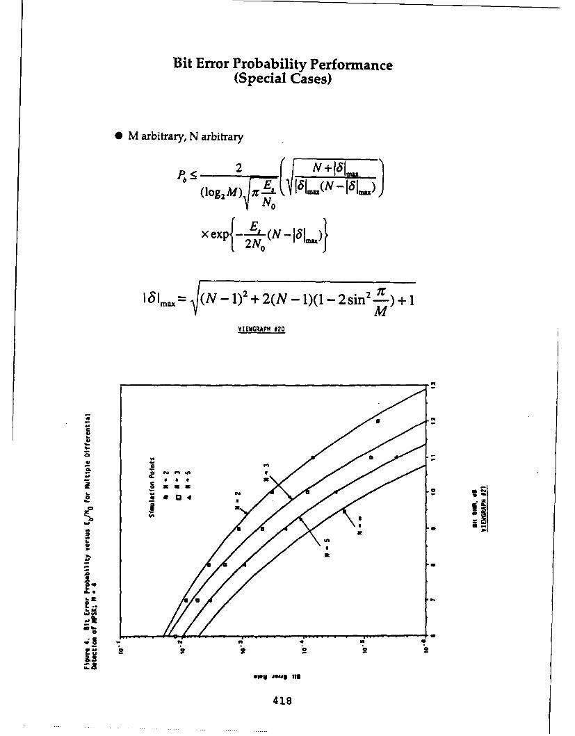
Bit Error Probability Performance(Special Cases)
* M arbitrary, N arbitrary
.N I8I2 ~ 5UN -I
(IogM) N0
xexp -2-L (N- 151)
1051mx= (N- 1)2 + 2(N - 1)(l1- 2 sin 2. .)+ 1M
VIEWiGRAPH 020
-o.
a.o
Oo U U0|Il
4.'
94
Lz
a.
~~418

a 0
CC'010'
GGo
VC .
-5
oa rlog I;
cis f
1 D1
-419

symbol memory, I pick up about I dB of that, words I take this uncoded metric, I applyand as I said for N = 5 you start to approach that to each branch of the trellis, and thencoherence. By the way, the points on there I go ahead and figure out what the appro-are simulation results and they fit very nicely priate distance structure is which, unfortu-with these tight upper bounds that I got by nately, I don't have time to talk about. Thenapproximating the Marcum Q-functions. As you go ahead, and this here is the interestingyou can see, they are very, very close. (VIEW- part. I'll just mention it without the details.GRAPH #24] It turns out that even though the distance
metric is not squared Euclidean distance, ILet me just briefly, in 5 minutes tell you can construct, (and this is just a mathemati-
how this can be applied in a trellis-coded en- cal construction, this is not actually the codevironment which is really what our motiva- you would build) another trellis code with ation was. (Maybe I don't need the pointer.) slightly larger multiplicity for which the Eu-I won't give you the details. In a trellis-coded clidean distance is again the proper metric.environment, a few years ago we introduced Therefore I can use all the analysis techniquessomething called a multiple trellis-code. A that I used before. I can go ahead and deter-multiple trellis code (maybe, I should tell you mine the error probability based upon well-that first) is a code where instead of output- known techniques. So I think the key point Iing 1 M-ary symbol at a time, essentially you is the application to a multiple trellis codeencode a set of input bits b into a set of s and the fact that you can indeed constructoutput symbols. You organize these s sym- an equivalent trellis code which has Euclidean Ibols into k groups of log 2 M symbols each, distance measure.and you output k M-ary symbols at a time.So the throughput is b/k which is a ratio- I'll just sum up with one comment which I Inal rather than an integer throughput as in would like to leave you with. [VIEWGRAPHthe conventional Ungerboeck-type code. This #231 Most of you know many applicationsgives you a lot of flexibility in designing a where differential detection is useful. The Itrellis code. The point is, that in this kind one that I'd like to at least suggest to youof a trellis code, instead of having one sym- as food for thought is on the benign channelbol assigned to every trellis branch, you have where we typically would use coherent de-a sequence of symbols (k) assigned to each tection requiring carrier acquisition, carriertrellis branch. As you can see, it lends itself phase tracking, lock detection, and other at-nicely to the multiple symbol DPSK detec- tendant functions. The reason people havetion scheme. What I actually do is construct shied away from differentially coherent detec-such a multiple trellis code and assign the so- tion systems like this was things like two and Icalled multiplicity, or number of symbols per a half dB penalty when you're using 8PSK.trellis branch equal to N - 1, the number of What I would like to suggest possibly is us-symbols that I am trying to estimate with my ing a scheme like this which is relatively sim- Imultiple symbol algorithm. So in a sense, you pie except for the additional complexity intro-can look at the trellis coding application as duced by the maximum-likelihood algorithm,a combination of a sequence or sub-sequence that is, using differentially coherent detectionassigned on a trellis code on which I apply the in a system where you might think of usinguncoded metric that I had before. In other only coherent detection. And with that I'll
420 I
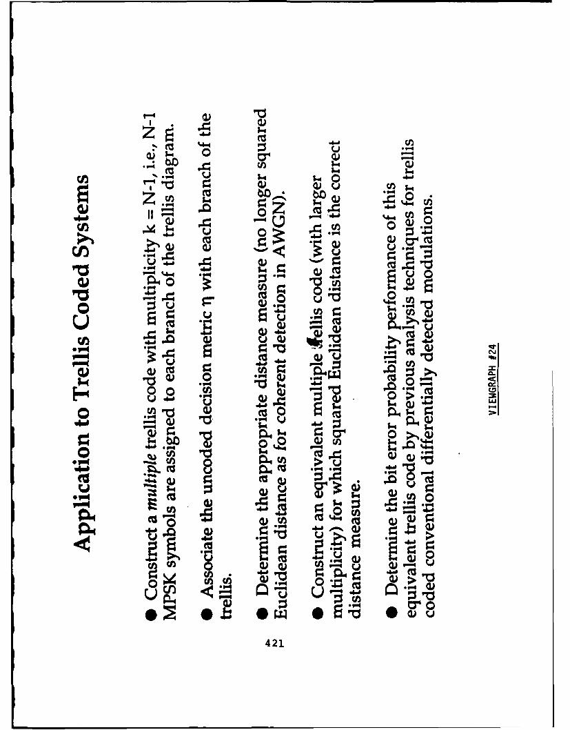
0 Z-0
o 11) . .
au 0 O
"00 .O.4a
oo OF"
00- CLOO V 4 " a"40.
"0 0 nO V
F-4 AV-V. P4 Q 4
*" -(U a4
0 O). (Uu V.4
(a: 140CA tu421

stop. I believe is not in a journal, but in a confer-
SCHOLTZ: Very good, Marv. Now it oc- ence, and I have to look it up if you're inter-
curs to me that this talk has been very differ- ested in looking at that. And more recently,ent from other talks that we've heard so far, in S.L. Rice's memorial proceedings on In-
and that's why it's given this morning. Now formation Theory, there's a paper where he
Marv, when you and I talked on the phone, it in essence is attempting to exploit this con-
seems to me you said it would be interesting if cept in MSK environment using differential
someone else here could point out where this encoding. I have to think, based on having
had been done before. And, for example, 7 read that paper and having seen your work forwas thinking about some of the stuff we heard the first time here that your analysis is very
on the equalization panel where they talked clean and there should be some coupling and
about despinning signals. I was wondering if abridging between those two pieces of work.
there was any relation between this despin- SIMON: Let me comment if I can on Bill'sning process, where you're taking out car- comments on the paper which just came out.rier rotations on successive samples, that is There's a paper by Leib and Pasupathy whichclosely related to what Mary is talking about. is in the November issue which just came
[SOMEONE IS COMMENTING WHICH out. I just got it about two days before IIS NOT BEING RECORDED.] came out here so I did prepare this view-
WILLIAM LINDSEY: I saw John's graph [VIEWGRAPH #8] and I'm glad you
hand up. I have two comments, one relative did bring it up. They essentially come up
to your statement there. Marvin's discussion with the same metric interestingly enough
here I think that the notion of rotation of the but the way they handle it is they don't
symbols as a consequence of frequency off- do maximum-likelihood sequence estimation.
set can be included but it isn't included in They essentially assume they have knowledge
his model at the moment. He's assuming fre- of all the previous symbols, and indeed do
quencies are known so that the symbols don't what I would call a decision-feedback kind
rotate when they come in. They are just off- of scheme. They are still doing symbol-by-
set by some constant phase over the n sym- symbol detection based upon previous knowl-
bols. It strikes me that he could perhaps put edge of all the previous symbols and in their
the frequency offset in. In which case there analysis, unfortunately, they do assume they
would be a bias in some things happening. He have perfect knowledge of all previous sym-
can analyze that I'm sure. I'd like to make bols. They don't allow for errors in the pre-
a statement relative to Gauss .... [LAUGH- vious symbols. So their results are very opti-
TER] When you started out you mentioned mistic. But indeed that's another twist to
it was or wasn't new. I think that this idea, this whole scheme. Instead of doing a se-
where it probably has been looked at but not quence estimation, as we've heard before, you
to the extent that you've been motivated to can actually do a decision feedback type of al-
go into the direction of it in, in particular, it is gorithm.
my belief that in 1962, Paul Wentz and John JOHN PROAKIS: O.K. Mary, I thinkHancock took a look at the notion of using your comment here with regard to the usemultiple symbols to improve differentially co- of decision feedback is a good point. I washerent detection. Where that was published wondering if you had made any comparisons
422

Leib and PasupathyIEEE Transactions on Information
Theory, November 1988(Distributed May 1989)
* Symbol by Symbol Detection as opposed toMaximum-Likelihood Sequence Estimation
* Decision on AOk (maximizing 11 over the M possiblevalues of A0k) requires knowledge of previous N-2transmitted symbols Akl,,Ak_2, ... ,Ak_ 2 .
* Used previous decisions A k 2,.A~k-N+2 forA~k_., A&k_ 2 ,..., A~kN+2 in 1l - decision feedbackscheme - subject to error propagation
* Computed error probability performance assuming noerrors in previous decisions, i.e., perfect knowledge of theprevious transmitted symbols - very optimistic.
VIEWGRAPH #8
423

with a decision feedback scheme? tionship. That's why I say it's been men-SIMON: No, because I just saw this. tioned and pointed out in a lot of places butPROAKIS: I believe that's an old scheme. I haven't seen it formally addressed.
It goes back to some work done by Bob Price JOHN CIOFFI: Maybe I misunderstood,in the early 60s and perhaps Bill Lindsey but on the decoder slide that you showed, youmay have looked at this problem in a num- said the complexity went up as mn. And Iber of papers that he published around 62-64. would think you could describe this with anThat's the conventional scheme. I think the m-state trellis and basically ....degradation in performance due to decision SIMON: No, I don't think you can be-errors is really very minor and that you be- cause its a non-linear algorithm. I don't thinkgin to see large gains in performance just by you can decode this with an m-state trellis.looking at phase estimation over a very small CIOFFI: You have impossible previousnumber of symbols. phases that you could be in, which would be
SIMON: I think as all decision feedback the error states, and then you just determineis concerned, that's a function of what error the metric on the basis of each of those pos-rates you are looking at. In a coded system sible previous states rather than working outwhere you might be looking at 10- symbol what the metric is for each of the sequenceserror rate, I think decision error rates are very is independently.important. And I think my scheme will win SIMON: Well maybe you can. I reallyout in that environment. So again, I don't haven't thought about that.want you to think only in terms of the un- GAYLORD HUTH: I have a question. Icoded environment, you have to think of the am interested in your scheme for a frequencycoded phase case too. hopping system. In this case, you are try-
SEYMOUR STEIN: Mary, if you move ing to estimate the phase over the hop. Inthe decision to the middle of the sequence, so the past, we have investigated ordinary dif-that you are looking at a total sequence and ferential demodulation and forward coherenttrying to make a decision about the symbol estimation. You cannot use a loop because ofin the middle, I think there is a very close re- the short duration of the hop. If I am goinglationship to some work using similar kinds of to use all the symbols (or a large number ofestimation for phase coherent FSK extending them) in the hop, why would I want to useover multiple symbols. differential estimation when I can use coher-
SIMON: Yes, but again, the difference in ent forward estimation across the hop? Are
CPM is you have built-in phase continuity you saying I am better off complexity-wise?because of the way you generate CPM. Here SIMON: Yes, again as in any coherentthe phase continuity is built in because of the scheme, only in the sense that this is onlychannel phase being kept constant. That's intended for schemes where you need fast car-what introduces the correlation between sym- rier acquisition and where you perhaps don'tbols. And there is a close relation conceptu- want the complexity of having to do acquisi-ally, but I don't think anyone has formally, tion, re-acquisition, tracking, whatever.that I have seen, addressed what the gains HUTH: What I was thinking is that inare in differential detection. So I agree with a frequency hop system, I am looking at ayou. Conceptually there's a very close rela- single hop at a time and I am performing
424

a phase estimation over the symbols in that strongly that there is a hang-up problem, thathop. I am not concerned about more than one the repetitivity with which you gather andhop at a time because the hops have indepen- gain the knowledge of the phase is totally de-dent phases. Assume that the phase does not pendent upon what random phase effort, rel-change over that hop. Now, all I have to do ative phase effort you come up with at theis estimate the phase. Why would I not just beginning of the hop.coherently estimate the phase rather than do HUTH: Not all phase estimation algo-a differential estimation? I questioned this rithms have a hang-up problem.for a long time since there are a number of LINDSEY: As I say, it is algorithm-schemes to coherently estimate the phase. dependent. It depends on how you do it so
SIMON: Yes, I will say by the way that I'd have to ... there's many ways. Proakis hasthere's another twist to the scheme and that some techniques in his books that I've lookedyou can actually use the first N - 1 symbols at that are free of this hang-up problem.to produce your carrier phase estimate and SCHOLTZ: I think the communica-then do what we again think as classical dif- tion theorists are seizing a session, finally.ferential detection which is related sort of to [LAUGHTER] I think we've given Mary atwhat you are suggesting. least a little feedback, probably what he was
HUTH: You see the advantage of coher- looking for from this group. So at this point,ently estimating the phase. I do not even I'd like to turn the session over to Paul Sasshave to use differential coding and therefore, here, who I think is going to give us a forwardI can eliminate its associated loss as well. I look into Army plans for communications.do not understand why I would want to use a PAUL SASS: Issues in Tactical Net-differential estimation at all if I am going to workstake n symbols across the hop? Thank you Bob. I'm going to try and move
LINDSEY: My opinion on the answer to kind of quickly although I won't be hittingthat question is as follows. If I understand you with any equations, so it should be fairlywhat you're talking about, and I think I do, enjoyable.you do still have the problem of phase am- What I planned on talking about was an ef-biguity resolution to take care of even if you fort that we started about a year ago at Fortgo with the coherent scheme from hop to hop Monmouth to try to make sure the commu-which means open loop phase estimation. I nications side of the Army in the local areathink its simpler, I think the algorithm that can keep up with the C 2 (Command and Con-you're talking about is simpler, so that's why trol) side of the Army over the next 20 years.perhaps you would do differential encoding, In fact this Tactical Local Area Networksto avoid that. You can avoid that ambigu- (TACLAN) program that I'm going to talkity, I understand in frame sync and many about is a long-range plan to help us evolveother ways, if that happens to be part of your from where we are today circa 1995 to wherewaveform design you would exploit that. The we have to be by the year 2015. So we areother issue might be dependent on how you looking ahead very far. My plans to start thedo the algorithm from hop to hop in terms of talk with a discussion of where we are todaygetting the phase quickly, it might turn out are supported by Seymour Stein's commentsthat there's a hang-up problem, and I suspect yesterday, so I'll begin with a real brief run
425

down on what we have in this 1990-1995 time lines that exist today. It is an AJ system, us-frame in the area of tactical communications. ing direct sequence 5 MHz MSK signals, and
As we said yesterday, the Army is cur- hops over a small number of channels to in-rently buying 3 major communications sys- crease the number of networks that can be
tems. The three systems are: the area sys- supported in the same geographical area. It
tem called MSE (Mobile Subscriber Equip- is fully secure, the security part being the
ment), the Data Distribution System called biggest barrier to the development and the
EPLRS (Enhanced Position Location and main reason it's taken so long to get it to the
Reporting System) with JTIDS providing a field.
small part of that data distribution capa- Again as I said, EPLRS uses a syn-bility, and of course the Combat Net Radio chronized, time-slotted architecture similarwhich ou know as SINCGARS. In all its wis- to JTIDS (many of you are familiar withdom, the Army about 5 years ago concluded JTIDS). It allocates time slots to specificthat EPLRS would provide data distribution users depending on their position updatefor the Army. The other systems are basically needs, depending on their movement onvoice systems although each of them has some the battlefield. A manpack will get fewerlimited data capability. I'll very quickly de- time slot allocations than a moving vehicle.scribe each of them for those of who haven't EPLRS consists of small user units (manpackseen them. radios) on the order of 500 per division, all
EPLRS is the first spread spectrum net- controlled by one central net control station,
work to actually reach the field. It's a time- or multiple redundant net control stations,
synchronized, direct sequence distributed but it is a centralized architecture. This is the
network that operates in the 400 MHz band, picture of what the radio looks like. Again, as
420 to 450 MHz actually. Its primary pur- I said, it provides to the user about a kilobit
pose was to do position location among the per second of usable data rate. EPLRS is be-
network participants and to distribute that ing built by Hughes Aircraft and I encourage
information as needed. It does it by do- you to discuss with them the applications of
ing time-of-arrival measurements, and pass- your theory to their system needs.
ing those time-of-arrival measurements to a MSE, the Mobile Subscriber Equipment, is
central computer called the Net Control Sta- another system that the Army got very se-tion which is not shown on this chart. That rious about deploying quickly. A few years
net control station computes, displays and ago the Army decided it couldn't tolerate the
distributes positions of the several hundred 15-20 year development cycle any more. The
network participants. EPLRS was developed Army went out and decided to acquire a non-
based on an Army marine requirement a long developmental (NDI) Mobile Subscriber Sys-
time ago. Five or ten years ago the Army tem. In fact, the fielding dates have proven
decided it wanted to add some limited data that you can buy a system off the shelf in
capability to these spread spectrum commu- fairly short time frame, much shorter than
nicating radios. So very limited data capabil- we've demonstrated in the past.
ity was added and about 1 kilobit per second MSE is basically a circuit switched tele-of user data throughput can be supported be- phone system for the battlefield. It pro-tween terminals. EPLRS supports data need- vides mobile subscriber services; it includes
426

TACTICAL LOCALAREA
NETWORKS(TACLAN)
PAUL SASSCENTER FOR C3 SYSTEMS
US ARMY CECOMFORT MONMOUTH
cico CvIECO CE OR COMMAND. CONROL. ANO COMUwuCTON SYSTEMS
EPLRS IS ONE OF THE ARMY'STRIAD OF BATTLEFIELD
COMMUNICATIONS SYSTEMS ______
TACTICAL FLOT
SLD *2DS
427
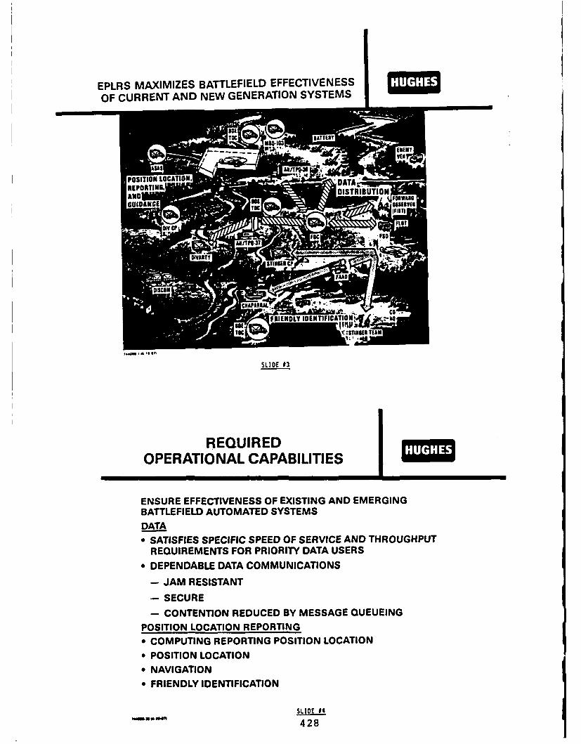
EPLRS MAXIMIZES BATTLEFIELD EFFECTIVENESSOF CURRENT AND NEW GENERATION SYSTEMS
LOCATION A C ALI
DENSURE EISTRIBUTION
* SAISFIS SECIFCRSEDOF SOERVIICEAND HrOUGHPUTS
~~REQUIRED ROIYDT SR
OPENABDAT CMMUNICTIOS I
ENJAMURESETAENI
BACTLETION REDUCAED YESSAEEEN
POSTIO OAIN EOTN
RECOMUIMNS REORN POITIO LCATIONR
POSITION LOCATIONREP
* NAVIGATION* FRIENDLY IDENTIFICATION
SLIDE #4REQUI42E8

a mobile radio telephone that provides dial- non-hopping full duplex FM radio. And thereup access for a VHF radio-equipped user on are a couple of other special purpose radiosthe battlefield, but the basic part of MSE is like an SHF down-the-hill shot for remotinga battlefield grid connected by line-of-sight certain switches in certain applications. I'vemultichannel shots. All these radio links also shown a radio access unit which is actu-shown here are multi-channel line-of-sight ally an assemblage of eight of these MSRTs.shots, connecting approximately 40 nodes in So you have a stack of 8 VHF non-hoppinga division. The different nodes in this chart radios providing a radio access unit which isare Node Central Switch (NCS), SEN is a the access point into the circuit switched sys-Small Extension Node, and there's another tern for these VHF mobile terminals.one called the Large Extension Node. There A couple of quick pictures. This is whatare several different hierarchical switch sizes, a multi-channel radio antenna assemblageall of them connected by multi-channel line- looks like with the large tactical radio. I amof-sight shots. There's also an extension to going to accelerate through these. As I said,mobile subscribers through a VHF radio that there are several band heads in this UHF ra-we'll talk about real quickly. dio that cover about 220 to 2 GHz. The
MSE provides 16 kilobits CVSD, full du- group data rates for these backbone trunkplex voice to all of its subscribers, the pri- channels vary from 250 KBps up to 1 ormary subscribers being digital telephones even 2 MBps capacity for interconnecting theconnected by wire to the switches. As I said, switches. This photo shows the MSRT, thethere's also the capability to connect 16 kilo- mobile radio telephone for the battlefield thatbit digital telephones through a VHF radio fits in a mobile vehicle providing the mobileto the switches. The system was bought as telephone with access into the switched sys-a complete package including shelters, fuel tern.tanks, all kinds of support, to actually sup- I wanted to show you what a typical switch-port a fielded system right out of the box. It ing center looks like on the battle field. Nowwas a 4 billion dollar procurement over the shown here something called a large exten-last few years and the primary contractor is sion node. Physically this is what makes upGTE. one of the nodes in this distributed network.
These are the components of the MSE sys- It is physically a number of trucks intercon-
tem as far as communications goes, and there nected with a lot of wiring, providing service
are several different users. The users include to different numbers of telephone subscribers
voice users through a variety of types of voice for each of the different size switches. Differ-
terminals, facsimile, as well as some very lim- ent size switches support different numbers of
ited data capability through the phone ter- subscribers obviously.
minal itself. As far as radio goes, there are One recent addition to the MSE systems isseveral different types. There's a line-of-sight called a packet overlay. The Army just re-multi-channel radio that operates in the UHF cently agreed to add packet switched databand, basically 220 MHz to 2 GHz in several capability to this circuit switched system.different bands just like today's multi-channel We're going to overlay packet switches ontoradio. There is a VHF radio called the Mobile the backbone line-of-sight multichannel net-Subscriber Radio Terminal (MSRT) that is a work just the way ARPANET or MILNET
429

EPLRS MAJOR ELEMENTSCONSIST OF NET CONTROL STATIONS
AND ENHANCED PLRS USER UNITS
AIRBORNERELAY UNIT UNIT(MANPACK UNIT PLUUSANTENNA TOWER)
AIRCRAFTPILOT CONTROLAIRCRAFTANDIPY
MANPACK UE
SURFACE
VEHICLEUNIT
SURFACE
NET CONTROL VEHICLE MODULESTATION
SLIDE 95
ENHANCED PLRS USER UNIT
USER-TO-USER UP TO 1200 bpsDATA COMMUNICATIONS DATA RATE
DUAL-LEVEL
S---CURITY HOST
16 WATTS
WEIGHT 22.5 LBS(INCLUDIES BATTERIESAND BATTERY BOX)VOLUME 660 CU IN.
430
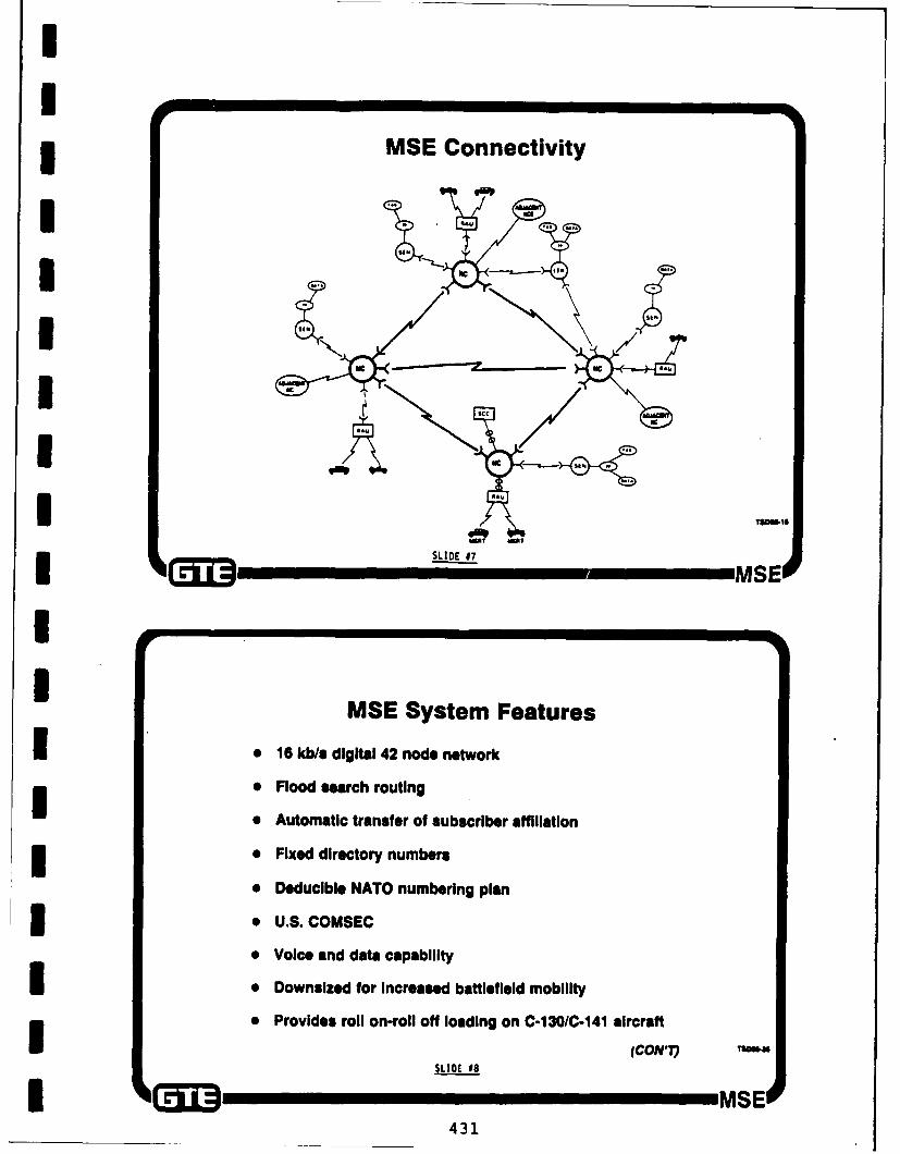
II* MSE Connectivity
I
I "Ta-m------e
ISLIDE 17T MSEk'l
II MSE System Features
I e 16 kb/s digital 42 node network
i * Flood search routing
* Automatic transfer of subscriber affiliation3 * Fixed directory numbers
* Deducible NATO numbering plan3 . U.S. COMSEC
* Voice and data capability
I e Downsized for Increased battlefield mobility
I * Provides roil on-roll off loading on C-130/C.141 aircraft
(CON') T3U4SLIDE 99
431

MSE System Components
* Users# Mobile Subscriber Radio Terminal (MSRT)* Digital Non-secure Voice Terminal (DNVT)# Digital facsimile
* Communicators# Switching
- Node Center Switch (NCS)- Large Extension Node (LEN) switch- Small Extension Node (SEN) switch
* Transmission- Une-of-sight (UHF) radio assemblages- Down-the-hill (SHF) radio equipment
# Mobile subscriber access- Radio access unit (RAU)
* Network control- System Control Center (SCC)- Management facility Too"- SSC interface (CON
SLIDE 9 MSE
Linomof-Sght Radio
MSE1432

Line-of-Sight Radio SetAN/GRC-226
" Frequency synthesized, microprocessor-controlled, digital radio
" Two frequency bands# 220 to 400 MHz (Band 1)# 1350 to 1850 MHz (Band 111)
" Three group data rates*256 Kbs*512 Kbs*1024 Kbs
* Components# Base band unit* RF Dipiexer Unit
SLIDE 011
MSEI
Mobile Subscriber Radio TelephoneTerminal
(U~ThMSEOSLIDE 12
433

Digital Non-Secure Voice Terminal (DNVT)
r~u~ LDE #13 MSE
Typical LEN Site
muse
f"~
UM C434

or DDN does its packet switching. In fact it bought and we'll have the bills paid by 1995the packet overlay that was just recently as Seymour mentioned yesterday, and there-purchased adds data service to MSE, using fore we're going to start looking to what wea standard BBN commercial product, a C3 are going to do now. I'll now describe whatpacket switch, to access the trunk side of the we see over the next twenty years.switch. It connects at the trunk side of the As far as TACLAN, we started a year agocircuit switch and provides ethernet as well trying to conceptualize an image of where weas X.25 service to the subscriber. This is a wanted to be in the 2010-2015 time frame.very important addition that we've fought for We identified a real void in the battlefield.about 7 years now. The void becomes very obvious when you
The last of the existing communications start recognizing that data usage is going tothat I'm going to talk about is SINCGARS. explode. The Army is now buying a familyIt's a slow frequency hopping 16 KBps voice of computers called the common hardware-radio. It's primary purpose is to provide voice software family which is a family of HP MIL-communications on the battlefield among all TOPE Unix machines that has a capabilitythe lower echeleon users. It also has a data of being local area netted on the battlefield.port which supports limited data capability. In doing that the Army puts its CommandIt allows 16 KBps without any error control and Control applications a step ahead of itsat all and with majority vote repetition cod- communications. So we realized that we'reing it will provide integral sub multiples of 16 going to have to get serious about providingKB but it has very limited data usage antici- certain things in the local access area, onepated, at least as of today. One of the things of which is local area nets, and we've gone ayou heard Mike Pursley mention is that we've lot further than-that. We recognized that webeen working for a number of years on devel- can't afford a wired command post; we haveoping packet data capability for the SINC- to have the ability for survivability of movingGARS radio. It's a recognition at least in command posts very quickly and not beingpart of the community th- tw thlat have constrained by the kind of wiring I showedthe SINCGARS radio are going to want to you in that large extension node wiring dia-build packet data networks out of the radios. gram. So we need the ability to communicateTo do that you have to basically add a net- with large capacities, wireless local area netswork layer protocol above the link and phys- if you will, while on the move or just in be-ical layer that the radio provides. In doing tween moves. We've got to get away fromthat you also want to upgrade the link layer wire. Fiber, while it gives us the capacity,error control that the radio is providing. So doesn't really get us away from the wiringthat's in fact what we have been doing in the problem although it does simplify the num-packet applique program. The SINCGARS ber of wires you need. That's the short termradio is being built in quantities of tens of view.thousands and the two contractors today are The next chart discusses the midterm.ITT and GD. Here I used an acronym, SICP (Standard In-
O.K. that's all I want to talk about. That tegrated Command Post), which is a programdescribes, in summary form, what tactical the Army has embarked on to basically con-communications are like today. We will have struct a family of command post configura-
435

9EV'
Z
LA.
,,U 0
0 0
iih
I
-- -
I 0"
I eel

E
E* 0
V
,0.
02 CVUa o°
0
LC
It
76 U.
| WHY IS IT NEEDED?
0 SHORT TERM VIEW:I -DATA USAGE WILL GROW AS MORE BATTLEFIELD AUTOMATED
SYSTEMS ARE FIELDED-LAN USAGE WILL GROW AS WIDEBAND LANS LEAD TO
I MULTIFUNCTION (IE, VOICE/DATA) WORKSTATIONS
-LANS APPEARING WITHIN COMMAND POSTS (IE, SICP) AND ATVARIOUS ECHELONS WILL NEED HIGH CAPACITY CIRCUTS WHICHPRESENTLY DO NOT EXIST
-FOR SURVIVABILITY, CPS NEED WIRELESS COMMUNICATIONS,DISPERSION BY FIBER, AND THE ABILITY TO COMMUNICATE WHILEON THE MOVE
0 LONG TERM VIEW:-MORE VOICE USERS WILL MIGRATE TO LOCAL NETWORKS
-ISDN WILL INEVITABLY IMPACT SUBSCRIBER DEVICES, NETWORKSERVICES, AND REQUIRED CONNECTIVITY
-IMPACT ON WIDE AREA NETWORK?
USER VIEWS ARE CRUCIAL!CECOM CENTER FOR COMMAND, CONTROL AND COMMUNICATIONS SYSTEMS
,I il'r ,-
437

~RANGE
WIDE AREA EXTENSION
TBIS CommINFORMATIONTRANSMPORT LOCALZEDAREA
Comm
LOCAL AREA WIDE AREAINTEGRATED VOICE/DATA/IMAGERY
SURVIVABLE INFORMATIONMOBILE COMMUNICATIONS GLHAL INFORMATION FLOWkmAHag CAPAC BACKBONEHIGH BANDWIDTH PACKET AND VIRTUAL CKTSEIM DYNAMIC RECONFIGURABLEE HANICE C, NETWORKMMW, IR
AND THEIR INTERCONNECTIONTHROUGH
NETWORK-OF-NETWORKS
SLIDE 19
I- STRATEGY* ENHANCE PERFORMANCE OF EXISTING/NEW SYSTEMS
* EMPHASIZE LABORATORY TESTS, USER TEST BEDS, ANDTECH DEMOS
* DEVELOP MILITARY-UNIQUE ASPECTS
* TAKE ADVANTAGE OF:
-INDEPENDENT RESEARCH AND DEVELOPMENT PROGRAM
-JOINT PROGRAMS
-DEFENSE ADVANCED RESEARCH PROJECTS AGENCY
-COMMERCIAL, NON-DEVELOPMENTAL ITEMS
-CANADIAN AND FOREIGN DEFENSE SHARING IN R&D
cucou cam" "m comm~ab coomo. No COUUWICINS EMS4SLIDE 20
438

tions out of a standard module, a standard the band we should target. There are a lot ofshelter which has a bunch of computers local nice attributes in that band and I think it'sarea netted together. We're trying now to ad- a perfect combination of packet networkingdress how that local area net will tie into the with a propagation medium that is difficult.backbone. Over the long term we see ISDN Those two technologies together can get us inbecoming a reality. We are trying to capi- the direction we need to go.talize on what the commercial world is doing The strategy we've identified is largely lim-in ISDN. I'm not sure how it will evolve into ited by reality, reality in the way of budgets,the access system. It may produce terminals and reality in the way our procurement sys-down at the subsciber level, but how it will tem has worked over the past. We are goingevolve into the switching and access system to start with an existing base of these sys-of the Army which is given to us by MSE at tems as they exist today. We are going tothis point is not clear, be limited in budgets so we are going to have
About a year ago the Army made a very to leverage as much as we can all the thingsconcerted effort to develop something called that are going on in the commercial world, ina technology-base investment strategy. It was IR&D programs at private industry, as well asa long-term investment plan to attack the dif- through joint programs among services. Andferent communication problems and try to we feel this internetwork architecture is a keydevelop strategies for solving them over the area that's going to need joint developmentlong term. It basically divided communica- over the next 10 years among all the services.tions into two regimes; local area and wide This slide is a little redundant. As far asarea. What I've tried to do here is summarize TACLAN goes, TACLAN is being conceptu-the key capabilities that we see being needed alized as the next generation local access sys-over the next 20 years in each of those ar- tem for the Army. It's got to start with whateas. The key message is capacity; you see we have today, it's got to provide wide-banda lot of packet data networks being used to interconnection among mobile fighting units,glue together all these heterogeneous commu- and dispersed command posts. That's its ma-nications systems in this notion of intercon- jor target. As LANs start to become morenected networks; the internetwork idea is be- used, it will be a natural evolution to mi-ing viewed as the answer to having these com- grate voice and other services onto the LAN.munications systems effectively interoperate That will help the wiring problem too. Weon the battlefield. In the local area we see see a number of technologies play a majormore use of higher bandwidth media whether role in this migration process. LAN technol-it is fiber LANs or just ethernets on coax or ogy coming out of the commercial world iswireless LANs. Low capacity wireless LAN already finding its way into military appli-capability, like an enhanced combat net radio, cations; both fiber and coaxial packet tech-perhaps can provide, is included in the long nology is going to be big part of the answer.term investment strategy. We also see that to That packet overlay onto MSE was a very ma-achieve increases in capacity, and to get a lot jor step in our view indicating an acceptanceof other things, we're going to have to move of packet technology as the glue that's goingup higher in the frequency band. Personally to tie together all these networks. There's aI've pushed real hard for millimeter wave as lot of gateway and bridge technology coming
439

WHAT IS TACLAN?TACLAN IS THE ARMY'S NOTIONAL SYSTEM I
FOR LOCALAREA COMMUNICATIONS
TACLAN:" MUST EVOLVE FROM TODAY'S COMM ARCHITECTURE
* WILL PROVIDE SECURE, SURVIVABLE INTERNETWORKEDCOMMUNICATIONS AMONG AUTONOMOUS FIGHTING UNITSAND DISPERSED CPs
* WILL INTEGRATE DATA, VOICE, GRAPHICS, AND PERHAPS VIDEO
* IS AN APPLICATION WHICH INTEGRATES: I-COAXIAL AND FIBER LAN TECHNOLOGY
-PACKET TECHNOLOGY I-GATEWAY AND BRIDGE TECHNOLOGY
-wIrEBAND MMW/MICROWAVE RADIO ICECOM CENTER FOR COMMAND. CONTROL AND COMWNI..._ S SVSTEI "
SLIDE 021
TACTICAL LOCAL AREA NETWORKS (TACLAN)-2015-
"="w'="~ ~ =mm ram= c p - -
S ASGA E 3
0 IorjotUmg"1
wvImv U""AT
ow ~ ~ SLID 9??no
440 1o

I I
WHO ARE TACLAN'S SUBSCRIBERS?
USERHERNET,I3 ACCS HP9000/300 SERIES ACCS WITH LAN CONNECTION
ACCS STANDARD HOSTSUPPORTS X.25 AND ACCSETHERNET LANCONNECTION AND AFULL SUITE TCP/IGPIP IMPLEMENTATION ACCS WITH X.25 CONNECTION
SLIDE 123
4% CECOM CENTER FOR COMMAND. CONTRO. AND COMUNICATIONS SY1TEM
I
i HOW WILL TACLAN HELP LOCALAREA COMMUNICATIONS?
I I * WIDER DISPERSION OF CP SHELTERS
0 MOBILE LAN OPERATION
I LESS WIRING/FASTER SET-UP &I TEAR-DOWN
0 VOICE/DATA INTEGRATION
FLEXIBLE LAN INTERCONNECTION
ISLIDE 024
cm EC9 NTSR FOR C OTAND co..mOe. COMAM ciiON SYSTEMS
I441

TACLAN* MIDTERM GOAL (NEXT TEN YEARS):
- WIDEBAND WIRELESS/FIBER
INTERCONNECTION OF LOCAL AREA
SUBSCRIBERS INTO ORGANIC TACTICAL
COMMUNICATIONS
" COMPONENT CAPABILITIES:- SECURE VOICE/DATA LAN
- WIRELESS LAN TECHNOLOGY
- FIBER OPTIC LAN/LAN INTERCONNECTS
- TACTICAL MULTIMEDIA GATEWAYS
o APPROACH:- PHASED DEMONSTRATIONS
- INTEGRATION INTO ATCCSSLIDE #25
CECOM CENTER FOR COMMAND, CONTROL AND COMIMJNICATIONS SYSTEMS
TACLAN COMPONENT TECHNOLOGIES
* INTEGRATED VOICE/DATA ON
SECURE LANs
* WIRELESS LANs
* FIBER OPTIC LANs/INTERCONNECTS,
* TACTICAL GATEWAY TECHNOLOGY
SLIDE 926
%CEOM CENTER FOIn COMMAND. CONTl ANo COMMUNICATIONS SYSTEMS
442

OBJECTIVE* MULTI-MEDIA INTERCONNECTION
I HFNHFCNR
I LOS M/W
MULTI-MEDIA -.-- FIEOPCGAEASHF/UHF SATELLITE
I WIRELINE
DIAL UP WIDEU AREA COMM
3 SLIDE 527
% CECOM CENTER FOR COMMAND, CONTROL AND COMMUNICATIONS SYSTEMS
I4

out of the commercial world to interconnect architectures. So a single ring fiber topologylocal area nets and, as we've said, the move isn't really going to hack it in the long term.higher in RF frequency to get higher capac- We need survivable dual-ring architecture likeity interconnections is something we are anx- FDDI-2. That's the long term. Initially justious to push. I sat down with the artist to a fiber ethernet will satisfy a lot of the prelim-try to come up with a picture and this has inary capability in the 1995 time frame. Thea lot of things in it. It's mainly useful for local area nets the Army is buying will havetalking to and I don't have a lot of time to a fiber capability to interconnect into MSE.talk to it. The technologies that are shown HALL: 10 MBs on the ethernet?here include a variety of media to intercon- SASS: Yes 10 MBs on the ethernet as thenect local area nets. Now, the local area nets start but as you start to move more of theare not only within single shelters. The local voice users on to the data LAN, then youarea nets start to leave controlled areas con- start needing more bandwidth. We don't yetnecting together different groups of shelters, have a good feel for the load, the capacityIn fact, in most applications you see a corn- required, but the evolution that we see hap-mand post consisting of a bunch of vehicles pening is as more LANs are installed for datadispersed over as wide an area as they can. users, the next logical step is to move thoseThe wider they can disperse, the more surviv- voice subscribers onto the land. Once youable they are in a tactical environment. That start doing that you start chewing up capac-creates a lot of problems. You see fiber inter- ity. That's when you start needing more andconnecting a lot of them, you see a number of more bandwidth.applications. I've shown a wireless local area CIOFFI: Following onto his question atnet where you have an application where you the 100 MB rate on the fiber, what lengthsdon't particularly want to wire up or perhaps are you looking at for distribution? Howyou want to interconnect mobile vehicles, as many kilometers?in tank-to-tank applications. There's a lot SASS: I can't answer that right now. Theof use of relay extensions as Seymour men-tioned. We're talking about packet networks nitial deployment of fiber LANs is a capa-very largely to interconnect distributed et- bility of distributing a command post I thinkver lagel tointrcnnet dstrbutd ht-over an 8 kilometer circle with a number oferogeneous media. We have RPV relays that nodes in that 8 kilometer. It's that order ofcan interconnect an isolated local area net sit-ting out here in the boondocks with a com- magnitude, it's kilometers that we are look-
mand post through various different media. ing for. That isn't supported by the 100 MBMotivation for fiber is capacity, not necessar- FDDI right now.ily interception as much, that definitely helps, Let me talk real quickly about what somebut .... of the pieces are. What this TACLAN notion
is going to do for us is summarized on thisDENNIS HALL: What kind of rates are chart. It will let us distribute these command
you looking at to justify fiber? posts over larger areas than they can right
SASS: The fiber systems we are using now now. Right now they are wired together, ini-are luoking at FDDI. So we are going to 100 tially they'll be wired together either on coax-MB or even higher capacities on the fiber ial or this initial fiber implementation that Inets. Wt. are also looking for survivable fiber told you, an 8 kilometer ring. That's not even
444

wide enough. For survivability in the battle- the next 10 years are wideband wireless andfield you'd like to distribute your command fiber LAN combinations, interconnection ofpost over even wider ranges. What's more the subscribers into one big organic local ac-important though is you'd like to have the cess system. The technologies that we hopecapability to move your command post fre- to exploit are listed here. Number one, wequently as well as while operating. So there- need secure combined voice and data localfore a wireless LAN capability becomes more area net capability, you need wireless LANimportant. Right now our only wireless corn- capability, we need a family of fiber LANmunications is very low capacity, and it's very ... LAN-interconnection technologies which,questionable whether we can use something if FDDI becomes real, will lead to FDDI, butlike a packet radio which is an experimental I'm really not sure I believe that FDDI willdevice, a couple of 100 kilobits to adequately ever be there. So it exists. I know it exists.interconnect mobile LANs. That's one of the I've heard some arguments in the communitythings we are trying to exploit over the next whether or not it will really be exploited infew years to just assess how fairly constrained the commercial world. And that's what wethroughputs can interconnect tactical lands are trying to leverage. We are trying to ex-doing an actual LANs in support of an ac- ploit whatever the commercial world picks uptual C2 . And as the command and control and carries.functions develop we'll start to see what kindof throughput we need to interconnect them. And the last one is the notion of a tacti-Obviously if you move away from wire the cab multi-media gateway which I want to talkbetter you are in terms of setting up and tear- about very quickly. The idea of a multi-mediaing down a command post. The argument gateway I think is the last issue I'm going to
about voice and data integration, I think it's talk about. Down at the subscriber, at this
natural and something that is going to take local area net, we would like to have a ca-
a lot of serious thought, once we put these pability of giving the subscriber of command
data LANs in, I tlink the natural migration and control system the choice of using what-
will be to get rid of all those single subscriber ever media he has available. He may have an
voice-telephone hookups you saw in the MSE EPLRS network, he may have a SINCGARS
wiring diagram. If ycu can integrate those network, he may have an HF network, and he
telephones on to the LAN then you start sig- has to have that choice of picking whatever
nificantly reducing the wiring burden of the media has to be in existence at that point,
command post which has computers and tele- happens to be most efficient for his need. To
phone subscribers sitting right next to each do that we feel a gateway capability will be
other. And what we are looking for is basi- required down at the local area at the sub-
cally a flexible family of technologies that can scriber. Currently there is a device which the
provide interconnection in the tactical area. Army is buying which is a very limited capa-bility in this direction and we hope to expand
We've targeted this a little better over the it to provide full ethernet gateway capabilitynext 10 years. We're trying to focus a lit- to a number of media, the media being links,tle more specifically on parts of that artis- the media being networks, the media beingtic picture I showed you. The specific ar- dial-up wire connections, whatever happenseas we're going to be concentrating on over to be there to give the tactical user the most
445

flexibility. That's all I have. of deployment flexibility. Capacity is another
SCHOLTZ: Are there any immediate good reason. The second comment is that aquestions? Yes John .... lot of smaller nations, Norway for example,
JOHN TREICHLER: This is a simple thought that the best upgrade to an MSE-
one. I didn't see any potential application of type system was to put some switching ca-
VSATs (Very Small Aperture Terminals) or pability into their multiplexors. If a switch
anything like that. Do you anticipate any use disappeared, they couldn't talk to each other
of things like that in the tactical setting? via a dumb multiplexor. An immediate up-
SASS: I think I had a Tactical Satellite grade was to distribute some very limited
(TACSAT) as one of the media on that last switching capability into the muscs. I think
chart. We in CECOM don't deal with the that's bound to continue. Finally, my ques-
satellite community very extensively. SAT- tion: The last time I talked to MSE people,
COMA is the Army's communications agency they had an upgrade program within the ex-
and of course their answer will be a lot differ- isting MSE project for taking a few of the
ent. It plays a part, it's got to be there as a more glaring deficiencies out of the system
media of choice for some applications. It does they had bought. When you refer to 1995,
not fit in very heavily to what we are trying is that something different than this upgrade
to show here in the local access area, but it program, or is that the upgrade program?
certainly exists. SASS: The upgrade program is part of
TREICHLER: The reason I asked is that the fielding schedule. What I was specifically
it certainly seems to have pluses and minuses talking about was when MSE would be de-
but a lot of the things you were very inter- ployed. In fact I'm not even sure 1995 is the
ested in moving toward, like no physical con- correct published date for that.
nections between the terminals and the abil- PEILE: What you're talking about is out-ity to work on the run and things like that, side of the upgrade program?seem to be things that VSAT was really built SASS: That's correct. The packet over- Ifor. I mean if truck drivers can use them, lay is something that's being bought todaythen tank drivers o-.aht to be able to use it and is going to be fielded with MSE by that
too. I can think of a lot of disadvantages like 1995 time frame. There are other upgradessurvivability if you have only one or two relay that the project manager plans throughoutpoints. If they are not survivable then your the procurement. I don't know whether it
system isn't. overlaps beyond 1995. 1 did want to com-SCHOLTZ: I think Bob Peile has a ques- ment about fiber. There's a lot of opportuni-
tion here. ties for fiber insertion into MSE and we areROBERT PEILE: I have two comments trying to push for that but as I said, MSE was
and a question. I worked on the Australian bought as a complete package. There are a
equivalent of MSE some years back. My lot of rooms for improvement that we see. If Ifirst comment is that the Australians adopted fact there's a lot of willingness to now thinkfiber optic cable for 512 kbit/s. This replaced about, now that the bill has been paid ba-
something like 7 tons of copper cable in an sically. And one very strong area is ECCM.average HQ and replaced 2-ton vehicles with There's a lot of opportunity both in the VHF
land rovers. It was no competition in terms mobile subscriber link, as well as the back- m446
I

bone line-of-sight. LINDSEY: The next question was on sur-LINDSEY: Paul, would you sort out the vivability.
notion of what you mean by improved data SASS: Survivability refers to the ability torates. I heard numbers like 10 MB to 100 keep communicating in the face of battlefieldMBs, point one, and would you also elaborate dynamics; dynamics caused by hostile action,on when you use the word survivable, what EW threats, and mobility. The dynamic andingredients of that term is with regard to how severe nature of anticipated EW threats, asyou used. Finally, a further comment on, you well as tactical mobility, are the two pressingwere proposing millimeter wave bands, yet in requirements that present the greatest chal-the TACLAN drawing that you demonstrated lenge.all the tie-ends of various lengths of what not, One of the problems that we face is that weI didn't see a satellite there but you did have must advance technology by leveraging thea deployed mobile post that seemed to be a developments in the commercial sector. Butcommand post lying around. Was that the in most cases this doesn't necessarily give uslength that you were going to employ the mil- the needed increase in survivability. We needlimeter wave technology? to specifically target the issue of survivability,
SASS: You did see a satellite? because it alone is the factor which differenti-LINDSEY: I saw something up in the air, ates our needs from those of the commercial
I don't know if it was a satellite or not? world. So at the same time that we attemptSASS: It was an RPV relay. to leverage commercial products, we need toLINDSEY: Oh, is that what it was! apply our limited R&D resources to improve
SASS: There are a lot of opportunities for survivability and still get a capability into the
unmanned aerial vehicles as relays of oppor- field in a reasonable time frame. That's a
tunity. In particular, millimeter wave system challenge for all of us.might benefit from that. I'm trying to keep SCHOLTZ: Mike?track of the questions. MICHAEL PURSLEY: Paul, you seem
LINDSEY: Point one was data rates. to minimize the data capabilities of SINC-SASS: What the Army has purchased with GARS, but it's considerably better than
its family of new computers is a 10 MB eth- EPLRS. What is going to handle the dataernet capability as well as a 10 MB fiber ca- if SINCGARS isn't?pability along with that. The only reason for SASS: EPLRS is the Army's data distri-looking at things like FDDI is increased ca- bution system ... [LAUGHTER] by decree.pacity as well as increased survivability from Nevertheless, there is an increasing aware-different ring architectures. I can't say that ness that SINCGARS will be the only ra-we've estimated the traffic load and we'll need dio that many of the data users will have. I49.2 MB. We don't know yet. The only thing don't agree that it is significantly better thanthat's clear is as voice subscribers start to EPLRS, but it certainly offers comparable ca-migrate on to the LAN, it chews up capacity pacity. At 16 KBps SINCGARS obviouslyrather quickly. I think each full duplex voice appears better, but by the time you start toconversation is estimated at about 100 KB build a network and add decent error control,of capacity. So that starts to eat into your you're going to be down to a competitive kilo-capacity and we'll need more. bit or so.
447

PURSLEY: You are talking about net- tial volunteers? Bill Lindsey waved his finger.work throughput rather than raw data rate [LAUGHTER] Oh, is that where you're goingout of the radio. But you're going to have Chuck or do you want to start it off? Bill,the same problem with EPLRS. The raw data why don't you take the floor. After all, knowrate of EPLRS will also decrease when used your channels is first command and right, soin a store-and-forward network. let's start there and see what we need.
SASS: That's basically true. Let me clar- LINDSEY: It is the kind of a questionify the question. EPLRS provides an adver- that we are all interested in but I have to saytised per circuit data capacity of up to 1200 that the answer is totally related to the kindsbaud simplex, or 600 baud full duplex. This is of things I'm trying to do in an analyticalonly a portion of the total capacity available way.to an individual EPLRS User Unit (EPUU). I was involved, as you recall, with the chan-An individual EPUU can access a total ca-Acitneidualy 4 Kcn mchs aof a whc- inel question here and I guess if I look at thispacity of nearly 4 KBps, much of which is chart which tries to explain the various pas-consumed with overhead and, as yousages and paths that the topis we've lookedout, depends on relay utilization,.ae n ah htth oisw'eloeat have addressed in the last two days. Relat-
Again I emphasize that there's been in- ing that to the future, I guess I would tend tocreasing awareness that the other systems are say that channels remain to be a problem of Igoing to have to share the data load on the great interest in terms of their characteriza-battlefield, as evidenced by the packet over- tion. I would like to emphasize, however, thelay onto MSE and the increasing interest in paths in this tree which I feel, if we investigatepacket appliques to SINCGARS. from the point of view of efficient communica-
SCHOLTZ: If there are no other imme- tions, will render something in terms of bene-diate questions I'd like to pass on to the fits to the community. There are paths in thisnext phase of this which is sort of a wrap-up tree where I think perhaps we've reached thesession and some of the things we've talked laws of diminishing return, i.e. to say, "Sure,about up to now including the last talk will there are interesting problems here to exploitprobably pop up again somewhere in the and papers to publish." But what we gainwrap-up. back from it is not so much in terms of en-
One of the things that I think would be gineering knowledge. In particular, the pathvery useful to our sponsors, the Army Re- to the left here, what I call spatially invariantsearch Office, is some discussion of where big channels or perhaps frequency non-selective,payoffs might be in basic research in the var- and in particular time-invariant channels inious areas that we've been talking about. It the additive white Gaussian noise channel.will help them probably lobby for funds and I This path has been beaten through to com-don't know what else they use these for. Bill pletion as far as I am concerned, whether it beSander could probably even brief us on that. NASA-related, commercial or military con-I've asked each of the panel chairmen per- munications. In the telephone channel I'mhaps to make a statement that we could chew not as familiar so I cannot say what is go-over for 10 minutes or so each on where basic ing on there and I'm sure there are expertsresearch opportunities lie in the four topical here who can address that ... but if I hadareas we have discussed. Do I have any ini- to put dollars into anything as far as channel
448

characterization understanding is concerned, say, well, if you have this parameter or pre-this path I wouldn't proceed to exploit. This conceive what the parameter value should be.path again is time-varying, slow and fast; this "'le effects of the earth's magnetic field, theis the case that I think we understand reason- effects of turbulence in the ionosphere can beably well from a modulation-coding point of folded into our channel models via of this in-view and there are some things that can be variant bedding technique that I talked aboutexploited there, but the big payoff in terms and I think that there's a lot of work thatof investment of dollars is in my opinion not could be done there. In the slow case, thisthere. notion of adaptive equalization is going to be
paying benefits as we learn to do that. That'sOver on the other side, having to do with the notion dealing with adaptive equalization
spatially varying type of channels where there in the spatial domain. Hence modulation andare frequency selective effects, there are two coding techniques are there to accommodatepaths listed there. The time-invariant chan- to channel models, or areas where I thinknel is one we've talked about equalizing yes- are fruitful. And indeed in many applica-terday, but because of its relationship to the tions there's knowledge that could be of valuespace-time channel we've talked about, that there. I think I'll cut off here and let the oth-channel continues to need work because the ers amplify with respect to their own individ-techniques down this path happen to do with ual areas.equalization. The solutions to problems aloLg SCHOLTZ: I'd like to make one commentthat path also fold in to techniques that canbe used in channels which are slowly time strictly from the academic point of view.varying as in the case of (HF) radio frequency That is, there seems to be a wealth of infor-type communications, or channels such as the mation out in this world somewhere. Maybelaser channel (with clouds) is an area that it's all in Phil Bello's head, or Al Schneider'scontinues to need work. So if I were to put or something like that. It would be a tremen-red and green with regard to future investi- dous service to the academic community ifgations I would sort of shade this dark red, some of these people would do a little digest-don't do anything there, I'd shade this little ing and put out a core dump in the form ofbit lighter red (I'm color blind so I couldn't a nice thick book which would really summa-bit igher ed ('m olo blnd s I ouln'trize their career experiences for us. At least Itell the difference), then over in this path, cer- ronet car couAlatitainly I would put green here. Green should don't know of any book that communicationcontinue in that direction in support of equal- theorists can jump in to and get really ba-ization, modulation coding techniques of the sic channel information that's deep and thor-
types that we've even heard here in the last ough. I would encourage anybody with thattwo days. Those paths I feel are quite fruitful. sort of background to please do something for
Over in this direction, I think I'm of the opin- us. That's my one comment to your sum-
ion that there's a lot to be done, in particular, mar,, Bill.
that's the path that I'm currently most in- LINDSEY: Thanks for reminding me. Iterested in with regards to incorporating the believe that is a good comment. Also the no-physics of the medium into the channel model tion of documentation is always an issue insuch that parameter sets associated with per- this business, capturing knowledge and doc-formance evaluations doesn't require one to umenting it for those who go behind us and
449

1I
with us and in front of us is always an issue clear from the feedback I got whether using Iin terms of research and cost. So frequently I maximum likelihood or generalized maximumsee lots of knowledge being gathered but it's likelihood or multiple classifiers, or somethingnot being captured. How to fix that or .... else is the approach that might be taken in
SCHOLTZ: ... or digest it .... order to create some goals that we can strive
LINDSEY: ... digest it and capture for towards.
later use by those who go behind us or with Another area is architecture. What archi- Ius or in the front of us. tecture might be taken? One is what we were
SCHOLTZ: Are there any more corn- saying on the bounds, the maximum like-ments on Bill's summary in the channel area? lihood, generlized likelihood approach, as a I... I think we took the easy one first, let's see methodology towards an architecture. Thewhat comes next. Chuck, would you like to other suggestion was: should it really be a Ibe next? Dennis is still working on his view- tree-oriented decision mechanism? That wasgraph over here. I know the guys you work left as a question whether each of these orwith haven't put anything in writing, they both might be the approach to take. Maybe Idon't speak up, I know the types .... part of this is where neural nets, artificial in-
CHARLES WEBER: Yes, that's my telligence, and training mechanisms fit.
first comment. After putting up my first cou- The third generated most of the feedback,ple of viewgraphs on Monday and listening namely the area of improved algorithms, i.e.to the speakers, I was left with the impres- keeping on with what we are doing and ex-sion that many problems had been solved, tending it to sequential classifiers. I thinkEven though the efforts were algorithmically Steve had several questions about sequentialdriven, few were written down. So, in or- classifiers. Should they be used and what fea-der to get a feel for what people thought are ture ordering is best? Is there a particular or-academic issues that could be addressed in dering of the chosen features and how robustacademia, I went to the speakers and some are they? Is there a minimal set of features? Inon-panel attendees. And, I think I ended up If we have a criteria for performance, what iswith more problems than were ever solved, it? Is it minimum time, minimum observa-I'm not sure I know where to begin. Some tion period, best detectability, and does thatof the problems that I initially thought were go back to the bound because all those mightonly academic and not very pertinent, in view affect the bound. It sounds like there's a gapof all the algorithms that we have for modula- between the philosophy of approach and thetion characterization, really are issues. There algorithms there. Maybe that's really what
was a lot of consistency in the problems that we are going after, maybe it's the missing linkcame back. in all of this.
The first was the area of bounds on mod- Measures versus features! Features, as Iulation characterization performance. We understand it, are like looking for something,have so many algorithms out there and so then you see this feature and you say it'smany things being done, there doesn't seem BPSK without knowing what the data rateto be a benchmark as to what we might be or the carrier frequency is, but you know it'sstriving for. How good is good? What re- BPSK. You then go from there, as opposedally is good seems to be evading us. It wasn't to measuring these parameters up front. Al-
450 I

ternatively we may measure chip rate, not in this community shouldn't be doing thingsknowing whether or not it's BPSK. Is there more like, say, Mark is doing where you'resomething to be said between these two ap- studying what defeats the signal intelligenceproaches? people and putting that in front in the sys-
Roger Peterson had a series of research tems you're building. And I haven't heardquestions, primarily involving wideband sig- much discussion of any of the things thatnals: determination of hop rate in strong in- Mark was talking about, for example, in bat-terference, and at low SNR. It's true that a lot tlefield communications. Maybe that's tooof the detectability algorithms for frequency short term a lifetime to worry about. Ihopping and/or direct sequence work well at don't know. But we are still talking aboutintermediate signal-to-noise ratios, so when BPSK and QPSK. I haven't heard anythingyou get down to -5dB per chip or lower, then about some of the shaping things we're talk-you have to integrate for a longer time. It ing about and hiding lines and stuff like that.seems that we need to know some waveform Maybe this is a question to Paul Sass to someparameters a priori in order to be effective in extent. Are you really worried about intelli-determining the presence of wideband wave- gence in any of the networks that you are con-forms. structing and is that an issue that any basic
research should be devoted to?The question that Roger raised which was
new to me, and an interesting one, was de- SASS: This is a tough question. It istermination of the frame rate. Not only do clearly of concern and it plays a part in theyou not know the code but you also do not developments as we progress.know the frame rate, and you'd like to make SCHOLTZ: Should we be spending timethose determinations. These are legitimate on that for you in any way, or don't you evenissues both in frequency-hopped and direct want us to talk about it?sequence environments. And also at in low SASS: No, I honestly don't know the an-signal ratios! Do we know how to do this at swer. Let me just say that for a numberhigh SNR's? of years we were approaching the design of
SCHOLTZ: Since I don't really work an LPI distributed spread spectrum network.in this field and Chuck is just starting, I That was a pure thrust we were taking asguess I can make my two cents known here. part of what motivated a lot of the researchSome of the problems here remind me of efforts we funded. Because of the funding re-things that we used to do back in radar. alities I've been describing, we weren't givenI had a fair amount of radar experience the freedom of actually pursuing that.back in the 50s, 60s and 70s. We typi- SCHOLTZ: You couldn't get into the de-cally started out designing a system and then tails of it as far as you would like? Bill, dowe started thinking about countermeasures, you have a comment on that?and then we started thinking about counter- WILLIAM SANDER: There are twocountermeasures and you keep playing this laboratories in the Army that address thosegame and pretty soon you realize that the issues. It's kind of not in the main streambest counter-countermeasures are really just of Paul's CECOM Ft. Monmouth's mission.good system design procedures the first time But there's an office at the Harry Diamondaround. I'm wondering whether somewhere Laboratory complex in Adelphi, Maryland
451

which is called the Survivability Management anything that impinges on it. Well, actually,Office and all of you know Dr. Don To- relatively few people ask that question. Theyrierri who works there. So he would be a say, Hey, my particular problem is teleprintervery good point of contact to discuss those is- signals and all I want to do is find those suck-sues. Then there is another laboratory called ers and measure the parameters and then setthe Vulnerability Assessment Laboratory and up a demodulator and go, as an example. Or,they're not part of either of these organiza- I want to be able to tell that from a coupletions ... probably SMO, Survivability Man- of other interferers or jammers. Or, I wantagement Office, is more akin to the commu- to, I want to ... and every office you go tonications kinds of survivability. The Vulner- has a different view of the problem. Andability Assessment Laboratory is located at every time they tell you what the problemWhite Sands Missile range, it also does the is you almost have to start at ground zerocommunication electronics survivability. But again, think about it and then look in yourthey do a number of other things. They are tool box and see what you've got. I tend tospread out over a much wider mission area. think about where the university people canBut those things are a very strong concern contribute most is putting tools in the tooland I suspect the Army is not doing a very box and figuring out how good those toolsgood job of integrating those things early into are and what they are good for from an ana-the planning of systems. lytical/theoretical point of view so that when
SCHOLTZ: I may be in the wrong corn- the more application-oriented or system en-
munity to even hear about this stuff, so that gineering types come in and look at it, they
could be the problem. Or maybe there really can deal with some truths rather than some
is something interesting there. John Treich- question marks.. And so I don't think there is
ler? a simple answer of measures and features. Ithink both of them are useful and it depends
TREICHLER: I wanted to go back to, on the application, and there is no way tothis will all come out at the end, but I know ahead of time.
did want to make one comment in response WEBER: Are you thinking that toolsto something Chuck said. I sort of expected e re ou than tat IBart Rice to jump up and make some corn- then are more important than robustness? Iments too. I'm going to sound horribly like hear you saying that each problem is now ad-a systems person and an applications personrather than an algorithm person even though TREICHLER: No, I'm adopting the per-I think of myself more as the latter. You verse point of view of, you tell me you've gottalked about features versus measures versus a technique for measuring the feature or per-other things. I think this is my third non- forming measurements, and I can almost al-answer. There's no right answer. You go to ways find an environment in which it's noteach particular customer who has a particu- robust. So I think even the concept of ro-lar problem and you ask him what he cares bustness is really environment-dependent asabout. And his answer might be, I want to well. And you sort of have to do value-freeknow every signal from every other signal in judgments of these various techniques and fig-the whole wide world. I'm going to put up ure out what each of them is good for inde-a 15 ft. whip antenna and I want to know pendently. And it's only in the context of a
452

system design that you can really say what plied research project. Another possibility isworks, what's good, what's bad, what's ro- one that you mentioned, Chuck, about se-bust. quential processing. Group three facsimile
SCHOLTZ: By the way, there's .... 1'11 signals can appear over voice grade channels.get to Bart in just a second, I think he feels There's a preamble for digital fax. If you onlyhe now has to speak now that his name has look at the modulation (after the preamble),been called. A couple of people mentioned it looks like many other communication sig-to me they were really waiting for a break. nals. But, the preamble is generally a dif-
I'd like to run this morning's meeting on the ferent modulation than the data. So, if youfly so if you want to take a coffee break for catch that preamble, and then a little lateryour own personal reasons, please go ahe-ad. you catch the other modulation type, thenSome people have to check out, some people that's a very strong indication that the signalhave to leave early and I don't want to lose is a facsimile signal. And, the decision wasany conversation during the break which has not based on any short little interval in whichbeen happening the last few days. So let's you say, "That's fax." Rather, it was basedkeep it going. on a time history of your short-term classifi-
WEBER: Bart, we knew we were going to cation decisions. This "sequential identifica-
get to you sooner or later .... tion" idea has a rule-based flavor to it, andI think it can form a nice line of inquiry for
BART RICE: The ideas of signal dassi- University research. There are a number offication and identification are slightly differ- others, too, in this same general area of ap-ent. For signal identification you're looking plications of Al to signal classification.for very specific things. For signal classfica-
tion you are trying to take in some energy SCHOLTZ: I was wondering whether the
and decide what kind it it is. Usually, the guy on your ... over on your left wanted to
identification follows the classification. But, say anything for the record. [LAUGHTER]
one area relevant to both that we didn't touch Is that a no? Samir, would you like to say
on very much is artificial intelligence. I think something?
that AI has a role here for University research SAMIR SOLIMAN: I think among thein this area, taking into account collateral in- set of questions you've posed, question num-formation as well as signal data and making bers 2 and 6 are highly related. The receiverclassfication decisions. Information about lo- structure depends on which approach you'llcations or other kinds of information about use: the maximum-likelihood approach or thethe signal that is not related to the waveform clustering pattern recognition approach. Initself can be captured in rules which can aid in other words, is it a parameter-measurementmaking decisions. One way to do that is take approach or feature-extraction approach? Ia Bayesian approach and adjust the a priori believe if you use a maximum-likelihoodprobabilities of certain signal classes in accor- approach, this will lead to an estimator-dance with the collateral information. Devel- correlator type of structure which is nothingopment of a framework for doing that and, more than parameter measurement. If youperhaps, development of an artificial inteili- use pattern recognition or clustering, this isgence system or data fusion system would, nothing more than defining a set of featuresI think, make a valuable and interesting ap- and then base your clustering technique on
453

that set of features. uations, with much poorly sighted repeatersWEBER: It could very well be. I wanted and so forth than AT&T, MCI and those peo-
to make one more comment about Mark's ple typically require. There are governmentpresentaton. Coming to some extent from agencies doing that sort of work and if thea radar background, I appreciate ve'y much Army is interested in knowing about that, I'mwhat he was doing, and I did detect essen- sure there are methods to find out. So it re-tially a gap between his research and the ally flips back the other way, do you really Iother talks. Maybe that is another w.-vy to ex- need it? You have to decide if spectral occu-press a gap that needs to be bridged, i.e. get pancy is important enough to go and make
his material more connected into the modu- use of those technologies because they do ex-lation characterization environment. Paul? ist. Basically what it comes down to is, if
SASS: I just wanted to raise a question. you've got enough SNR, there are methods
that hits us from time to time regarding m.d- to deal with the multipath problem, and, to
ulation. From time to time our command- some degree, the interference problem that
ing generals get visited by people like AT&T you would find in your sort of environment.
who demonstrate that they are going to a SCHOLTZ: Any further comments forhigher order of modulations. We get more Chuck's summary? Was that a commentand more bits per Hertz offered to us on a Ray? (LAUGHTER]platter, and the question that keeps coming HALL: I collected some comments, someup is how much in the way of spectrum occu- that Dr. Gardner had related to the con-pancy can we really improve by getting higher tinuation of that line to signal restorationorder modulations in a non-ideal channel en- work, primarily the inclusion of the multiplevironment like the military has to deal with. features, multiple optimization criteria typeWe don't have a commercial telephone envi- algorithms into their structures, a combina-ronment in our multi-channel systems. Does tion of both spatial and spectral methods intoit make any sense to strive for more and more the same thing. I think the need to startbits per Hz to solve the spectrum occupancy addressing what the computational require-problem, or are we just wasting our time go- ments are, when Brian Agee shows these niceing to higher and higher order of modulation scope-photolike things where signals are allalphabets? nicely separated out, well, how long did that
SCHOLTZ: I guess we could go back to run and how long did that take and is it pos-Shannon and start from there. sible to put that in a finite box? What's it's
WEBER: My first reaction is, you need going to cost Paul if he wants to do that? Theto have knowledge of the channel, second one, we've touched on that a couple
SCHOLTZ: John Treichler has a corn- of times already, and that is, Seymour Stein'sment I think. comment of the .... Mark Wickert started out
TREICHER: Let me say this about that from the interceptor attributing to the corn-somewhat elliptically. AT&T's idea of a good municator infinite power to disguise his sig-propagation channel and what you can really nal, and then the same thing goes the otherget away with are very different. There do way, contributing to the interceptor infiniteexist equalization techniques, methodologies processing power from which to separate outwhich allow you to work in much worse sit- interference or not. So I don't know if this
454

falls in the University's lap or maybe falls in ods. They are getting pretty fast, 10 symbolssome of the veteran analysis people that have and they are equalized. Dr. Proakis' workbeen around a long time, to formulate and was very good because it showed the corn-integrate a framework where we can trade-off plexity in how many operations per symbollike a radar equation, a simple thing, you've you've got to do to achieve that. It is kindgot to get so many bits across to the other of the environment that TRW is in. We'dside and if you go and try to make your ampli- like to see more work and it passes on thattudes look Gaussian where you give up 5 dB. the Government would like to see more workIt's the comment that Dr. Scholtz had earlier, done, reduced complexity algorithm. Whenthat's all folded into there. How much can you're up that 100 MBPS you don't want toyou give up versus which trick, and how much have to do a 1,000 operations per symbol toare you willing to defeat the interceptor or the equalize that channel, so the chart that Dr.jammer? And, there's levels to that. You re- Proakis showed something between the fastally need to define how to communicate. First RLS and LMS. I think there's a big gap therethe communicator needs to achieve some de- in complexity and performance that needs tofinable performance, some BER with some be filled and addressed. Then, in my ses-channel characteristic, then the first thing he sion and of course in Dr. Peile's session,would like to defeat is detection. So he'd like it's clear that waveform and information en-to be LPI in some sense. And the second coding and equalization are all tied right to-level he'd like to then defeat would be inter- gether. There's just no doubt about it. DFEsception and copy. So how much work does he and trellis decoders, somehow they are thehave to do. Maybe he doesn't care that some- same. And that really needs to be addressedbody knows where he is or knows that he's more from an integrated point of view andup and doesn't know where he is, that's an- get the signal processing people, the informa-other one too. You'd like to defeat the ability tion theorists and the comm theory peopleto be located by somebody. So, giving that all together in one framework where they canup, maybe all you want to be is secure so address the same problem. It's a hybrid ofyou don't want somebody to be able to copy those three fields.what your text is. That's either an encryp- Let's see, No. 5, this was a continuation oftion thing or a waveform isolation thing. Of the one I addressed earlier, just a level field ofcourse the last one is you just want to be able comparison for the existing algorithms, moreto talk. You don't care if someone gets your work like what Dr. Proakis did. That wasencrypted signal, maybe you're satisfied with wonderful, me as an industry user, I thoughtthat but you'd like to be jam proof in some that was great. Now I can see the tradeoff.situations. So I think, and obviously from Those are the kind of tools we need devel-the discussion earlier, other people think that oped to see if we should even launch in tothere needs to be just a common set of sys- look at adaptive lattice structures. The sta-tern level analysis done there that everyone bility is nice but the computation is for 100can work in and get the field level. MB length, it probably eliminates that as a
Point 3 is on the general area of equal- choice. But it's good to know that.
ization. It looks to me like the research is Then, probably on the equalization things,going for faster and faster convergent meth- we need to address better implementation.
455

I know this work has been going on. It re- simple problem with a single delay path butally didn't come out in our session but VLSI with a moving terminal. We observed in thattechniques, people have looked at micropro- case that if instead of taking the common ap-cessor implementations and what not. The proach, we attempted to estimate the param-other one is the convergence rate versus the eters of the multipath, namely the relative de-environment. I know John Cioffi has done lay and relative Doppler, we could then con-some work in multipath environment. Really struct an equalizer with time-varying weightstrying to define the multipath environment which were good for as long as you could as-to where you can say, I need recursive least sume that the Doppler itself had not changed.squares or LMS will do. How to find the dy- That's a much longer time between updates.namic environment such that a certain algo- And I always am struck by the idea that asrithm will address them? The other thing we processing improves, maybe someone shouldtalked about in the signal restoration area, re-examine that notion of trying to estimateor in the modulation characterization field, is the channel as part of the equalizer control al-the op's concept, or the operator issues. Are gorithm rather than assuming that you don'twe going to have Brian Agee out there in a know it; usually it's a set of discrete pathshalf-track looking at the screen, tweaking his that are changing with some temporarily con-multiple option criteria to separate these two stant Doppler shift.signals or I guess Bart Rice's thrust is to make SCHOLTZ: I think John Treichler alsoit all automatic so we can have something had a comment. Was it the same one?presented. I guess a little of that was ad- HALL: You know Seymour, the phonedressed h ut I see that when you go to deliver companies spend a lot of time trying to char-equipment, that also needs to be addressed. acterize their channels that way also.
SCHOLTZ: Any comments on that? Yes TREICHLER: I always agree with every-Seymour, I'm glad to hear you speaking up. thing Seymour says. I'm certainly not go-
STEIN: Some of the discussions on equal- ing to take issue with that. Actually I agreeizers during the last two days reminded me that a lot of the equalizer work that has beenof some work we did several years ago, and done today has been sort of, either nobodysome lines of investigation that I regard as went out and did the channel measurementscurrently on the shelf. One recurring prob- ahead of time or you weren't prepared to be-lem in equalizer design is the speed of con- lieve that what you measured was a generalvergence in trying to keep up with changes, enough view of the world and people tendwhich really becomes a problem when one to drop back and say, well just use tap-delayof the terminals is moving, especially when lines again and hope for the best, but that'sthe!re is multipath. Equalizers now are all de- only to ratify his comment. But one com-signed based on the notion that the channel ment I want to make, before I give the micro-is momentarily stationary, in a fixed condi- phone back to him because I see him risingtion. The equalizer is a filter designed to re- up in response, is that Dennis and I talked aact to that stationary condition, and then you few minutes ago and the point I would makesquirm when you find out that the stationary is regarding level No. 5 of this level fieldcondition doesn't last very long. The work comparison of existing algorithms. We havewe did several years ago involved a rather a large number of algorithms suggested, all
456
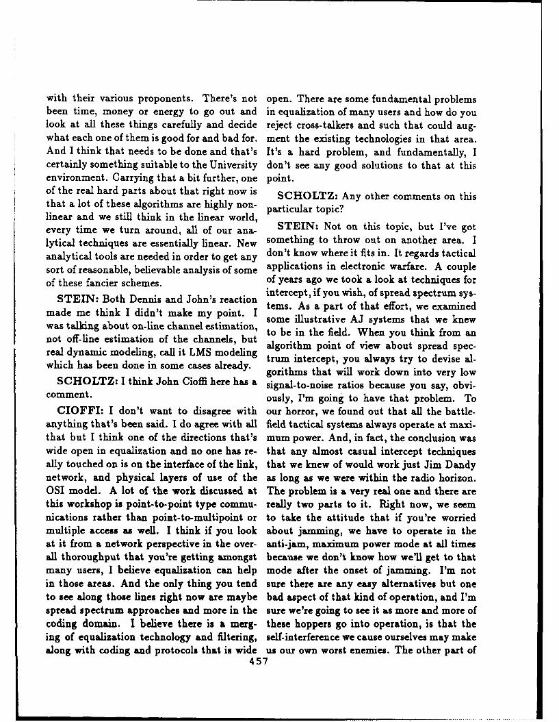
with their various proponents. There's not open. There are some fundamental problemsbeen time, money or energy to go out and in equalization of many users and how do youlook at all these things carefully and decide reject cross-talkers and such that could aug-what each one of them is good for and bad for. ment the existing technologies in that area.And I think that needs to be done and that's It's a hard problem, and fundamentally, Icertainly something suitable to the University don't see any good solutions to that at thisenvironment. Carrying that a bit further, one point.of the real hard parts about that right now is SCHOLTZ: Any other comments on thisthat a lot of these algorithms are highly non- particular topic?linear and we still think in the linear world, STEIN: Not on this topic, but I've gotevery time we turn around, all of our ana-lytical techniques are essentially linear. New something to throw out on another area. Iaalytical tooniqus are esey inder. e adon't know where it fits in. It regards tacticalanalytical tools are needed in order to get any apiain neetoi afr.Aculsort of reasonable, believable analysis of some applications in electronic warfare. A coupleof these fancier schemes. of years ago we took a look at techniques forof N thee tc heens. dohnsreac intercept, if you wish, of spread spectrum sys-
STEIN: Both Dennis and John's reaction tems. As a part of that effort, we examinedmade me think I didn't make my point. I some illustrative AJ systems that we knewwas talking about on-line channel estimation, to be in the field. When you think from annot off-line estimation of the channels, but algorithm point of view about spread spec-real dynamic modeling, call it LMS modeling trum intercept, you always try to devise al-which has been done in some cases already. gorithms that will work down into very low
SCHOLTZ: I think John Cioffi here has a signal-to-noise ratios because you say, obvi-comment. ously, I'm going to have that problem. To
CIOFFI: I don't want to disagree with our horror, we found out that all the battle-anything that's been said. I do agree with all field tactical systems always operate at maxi-that but I think one of the directions that's mum power. And, in fact, the conclusion waswide open in equalization and no one has re- that any almost casual intercept techniquesally touched on is on the interface of the link, that we knew of would work just Jim Dandynetwork, and physical layers of use of the as long as we were within the radio horizon.OSI model. A lot of the work discussed at The problem is a very real one and there arethis workshop is point-to-point type commu- really two parts to it. Right now, we seemnications rather than point-to-multipoint or to take the attitude that if you're worriedmultiple access as well. I think if you look about jamming, we have to operate in theat it from a network perspective in the over- anti-jam, maximum power mode at all timesall thoroughput that you're getting amongst because we don't know how we'll get to thatmany users, I believe equalization can help mode after the onset of jamming. I'm notin those areas. And the only thing you tend sure there are any easy alternatives but oneto see along those lines right now are maybe bad aspect of that kind of operation, and I'mspread spectrum approaches and more in the sure we're going to see it as more and more ofcoding domain. I believe there is a merg- these hoppers go into operation, is that theing of equalization technology and filtering, self-interference we cause ourselves may makealong with coding and protocols that is wide us our own worst enemies. The other part of
457

that coin is, everybody talks about an en- a burden to communicate for the field ele-emy capable of doing everything. Everybody ment that is required to report back. If themakes the assumption that jamming will sim- system is being jammed so the field elementply be there, while the fact is that most of has to raise its power to report back, thenthe jammers that are designed still do not it becomes more vulnerable to detection. Inengage in jamming Willy-Nilly; they respond these situations, communications makes theonly to a signal that they can hear. That no- field element vulnerable and if it becomes too Ition that you have to hear the signal means vulnerable, there will be no report back.that, despite the way we design our systems SCHOLTZ: You know, we are drifting anow, there is really a tremendous benefit to little bit from the subject. I really would likehaving LPI, meaning you try to operate at to have this conversation on record. But weminimum power. The weird thing is that in can finish Rob's panel and then I'll open itthe past, there have been systems that have up to more comments. I think we have somestarted out being called LPI systems and be- more comments here too on protocols andfore they ever got developed, the powers that variable rates, variable power level kinds ofbe had changed them into AJ systems. They things. Maybe we will have something to fo-were no longer even being labelled LPI. I keep cus on. Let's get Rob into this.feeling that's a mistake, but the critical issue PEILE: I would first like to formally thankinE all thwsuis howscaniyoutdoftheacoordhna-in all this is how can you do the coordina. my panel for their contributions. I would alsotion when you think of a fluid environment, like to thank the Army Research Office forso that you will somehow be able to convert funding the research behind my talk. Theover from one mode to the other. I'm not fun har c ein my talk.yThesummary of my panel is my own; my panelsure I am able to identify the nature of the members are free to disagree.research that's needed, but research leadingup to tests that would prove the ability to do The first subject we studied overlappedthat sort of thing would go a long way to- with the equalization panel, i.e. the sub-wards changing the way the designs are set. ject of co-designed coding, modulation andequalization. My first comment is that, as a
SCHOLTZ: Yes, Gaylord? research area, it is going great. If every re-
HUTH: I always had a problem when I search area was making such rapid progressworked on AJ and LPI systems whether any- we'd be very happy. This is almost an in-one really wants LPI. I have worked on sys- spirational area. I don't know if this is thetems where LPI was really needed but when greatest commercial success coding has everthe system was used most users turned up the had. I don't think so, probably a fire chippower to get AJ. This situation caused the in an IBM computer in the 60s made morepeople who needed LPI because of their vul- money. In terms of translating what is cod-nerability to be afraid to communicate and ing theory (and pretty abstract at that) intohave their location determined. As I men- selling products, this is great. I'm not sayingtioned to Paul, I really do not know whether we should stop funding this area. I'm justthere is a conscious effort to be truly covert saying the direction seems on-line. I have ain terms of LPI or any other aspects. Be- mild caveat about the subject being drivensides the Army environment, there are situ- by the telephone channel. We ought to re-ations such as report-back links where it is member that some channels do not have the
458 I

II3 same delay constraint as the telephone chan- try to build a system around them, it's not
nel. There is another research area that takes clear how they all fit together. I see that asthese new techniques and considers how they a research area where a lot more work needs
can be extended when there isn't a delay con- to be done. For example, code-combining isstraint. You can only do better. I see this getting on in age, but we still can't analyze itas a future area. There are techniques be- completely. I am not sure that it's the besting developed that do have relatively high thing to do without modification.delay throughputs. I know Vedat has done The last point (what most of the debatesome work in interleaving techniques and I've was about) is adaptive FEC as an adaptivedone some myself. John Cioffi brought up the system component. The debate (more or less)point that there is work to be done in point- centered around HF except for some men-to-multipoint techniques. That was a good tion of the meteor channel. How can adap-point. tive FEC serve as an adaptive system compo-
My next point was first brought up by Paul nent? I'm reminded at this point of a phraseSass. How do we transfer these magnificent that an engineer came out with years ago.techniques (which are getting close to Shan- He was bewailing his problems and a direc-non's capacity for the bandlimited channel), tor decided to be supportive and said, "Yo-L.make them robust, and bring them down to haven't got problems, you've got opportunithe power-limited channels that the military ties." The engineer replied, "I am surroundedcommunication environment are more tradi, by insurmountable opportunities." That's ationally interested in? There's plenty of ma- pessimistic view. I think research has to bechinery around which could potentially do done on a two-way basis. Explore the possi-this. I wouldn't say it's being done at the ble use of decoder error locations as a sourcemoment. The benefit is more bits per Hz un- of real time system assessment. As I said, ifder some harsher environments. I'm sure that the information is there, why throw it away?must be of research interest. It might be difficult, but why throw it away?
Alan Levesque surveyed hybrid ARQ tech- The re:.carch's onus is to expose the possi-
niques. It's my belief that we need a bet- bilities to the systems people. There's only
ter global view. It's also my belief that if I a limited amount you're going to achieve in
send everybody off into a set corner of the adaptive FEC on a link-to-link basis.
I room with a bit of paper, everyone could de- A lot of the objections to adaptive cod-sign a decent type-one or type-two hybrid ing reflected a basic premise. I have neverscheme, and subsequently we'd all argue for met an error correction application, a success-
years about which one was best. Recently, ful one anyway, which was really about errorI have seen several code combining, type-one correction. It was about something like dataand type-two ARQ times appearing, all with density, or about lower power, or about some
impressive performance graphs. We might other parameter. The real impact of coding,understand these schemes in isolation but I in the successful applications, has been to al-3 don't think we understand them globally. As ter a classical tradeoff. I think that adaptiveI said yesterday, the system issues are tricky. FEC researchers have to look at how the clas-You can analyze the components in isolation sical tradeoffs are altered by the presence of3 and get nice papers out of them but when you coding. That means they have to know what
459I

ADAPTIVE CODING - RESEARCH DIRECTIONS
1. CodingflodnfEgualn for BL Channels
A) Going Great!
B) Remember some Channels do not have delay
constraints.C) Transfer techniques down to PL/BL Channels.
_2. Hybrid ARO/FEQ Schemes
A) Need better global view of
Code-combining/Type 1/Type II
combinations + performance
B) System Issues
3. Adaptive FEC As an Adaptive System Component
A) Surrounded by Insurmountable Opportunities!
B) Explore possible use of decoder error locations as
source of real-time system assessment. Expose
possibilities in Systems/Networks.
C) Examine how the Classical trade-offs are altered
by presence of coding.
D) LISTEN TO OBJECTIONS: SEARCH FOR
DATA + EXPERIMENTS
E) Trial Systems
460

the classical tradeoffs are. And that means SCHOLTZ: Any questions or commentsthey've got to listen to people who have been directed at Rob's summary? Are there anyworking in adaptive systems. (Which is the adaptive coders?reason why I insisted that Seymour was on HERMAN BUSTAMANTE: I men-the panel.) You have to know the classical tioned earlier that we at Stanford Telecommtradeoffs and study how they are altered by have put together a system which in factthe presence of coding. might provide some information relating to
I think adaptive coding has to learn to lis- the kinds of systems that Rob Peile was justten to objections. The objections are well commenting on. If I might have a minute,founded in many cases. You have to search I have prepared some slides, which describefor channel data and experiment in some real the system I'd like to tell you about. Could Ichannels, which was a point made by Bob show you what I have? Thankyou.Scholtz. This is a major problem. How can What we are building at Stanford Telecom-coding people in an academic environment munications is a system we call the 1105Bhave access to communication channels? This communication sub-system. It operates inproblem is particularly acute if you're going satellite channels and primarily it is a TDMAto crucify a coding person for not having an- system. The features that might be of inter-alyzed real channels when he gets up and est to you [SLIDE 1] are shown here. It canpresents his theoretical analysis. I am con- operate either in single frequency or multi fre-stantly on the scrounge for data. Now I've quency mode. It includes not just what youheard other people say this, and I sometimes call the modem function but of course a mul-suspect it's crocodile tears, and they really tiplex function. It can accommodate up towant to have Gaussian noise analysis because 500 baseband channels and contains an auto-it's a lot easier, and the sums are easier. But matic patch panel capability. In other words,yes, I really do mean it. You need channel you can put in or take out any channels au-data, especially for HF which I regard as one tomatically given that you're providing theof the ultimate challenges of error-correction. baseband equipment.Ultimately, I don't think anyone will believe We are incorporating automatic power con-adaptive coding until you have some trial sys- trol and we are also doing adaptive, if youtems and some experiments and you can run will, modulation and coding characteristicthem. And I think research has to be guided control.towards that line. Let's do some theoreti- What we have is a problem that has beencal work. Let's look at the classical tradeoffs. mentioned by several speakers and particu-Let's position ourselves to the point that peo- larly by Rob Peile, and that is that we haveple believe us enough that they are willing to both a bandwidth constraint and a powerconsider an experiment that's worth doing. constraint that we have to stay within. InThat is a research direction which I believe is other words we are operating through a satel-important. lite, and the satellite resources are partitioned
O.K., that's a very personal summary of into bandwidth portions and power portions,research directions in adaptive coding. It's a and you are not permitted to exceed these.formative area so there's a lot more personal- Let's go back to the TDMA system. Weity in it, perhaps more than the other panels. are operating as a network with one user op-
461

erating as a master, let's call him our control 2/10ths of a dB, I don't remember exactly.terminal, and a number of field terminals. We That's the control we have on the transmitcan have up to 32 field terminals. The prob- level. We can accommodate at least a 20 dBlem is what do you do when you have rain? range and we can select the limits. For theWell you can say, let's just make sure we have data rate variability, as I mentioned, we go inadequate power and burn our way through. increments from 1 to 2 to 3 up to 16 whichWell that's nice but it might not be the most gives us 12 dB. And we are providing codingcost effective overall way to do things. What rates of 1/2, 4/7, and 3/4. This enables uswe have implemented is 3 methods of control. to provide gain steps that are on the orderOne of them is to control the uplink power of 1 dB over the entire range. And so herebut if you look at the link operating from the we have a combination of power control, cod-master to the field, uplink power doesn't do ing rate and, if you will, the effective datayou any good on the downlink. It will help rate to give us the total control capability Iyou on the uplink obviously but on the down- was talking about. The reason I wanted tolink you want to do other things. One of the come here is that I'm not satisfied with thethings you can do is vary the effective data overall performance in terms of how quicklyrate transmission. In other words, we vary we can respond, and in terms of how fine wethe effective data rate by extending the dura- do things. I'd like to be able to provide a3tion of the bit and in that way we can provide more rapid capability so that we can actuallyup to 12 dB additional margin in the link or track these rain fades much more rapidly andwe can provide 12 dB compensation for down- do the overall compensation better. That'slink attenuation. The problem we ran into the kind of help I'd like to find from whoeverwas that we didn't like the performance we would like to tell us how best to do it.were getting because the control steps were svery coarse. As you go from a symbol length We are also looking at other types of links,of 1 to 2 to 3 to 4, you're going in increments links which are not on continuously but whichof 0 dB to 3 dB to 4.7 to 6. The jumps are sort of hop but I can't go into the details. Thequite large and we wanted to have a finer con- system I have in mind may want to commu-trol. What we decided to do is to use coding nicate with one source, then another, thenrate variation in order to provide a finer con- another and I need to have very rapid ac-trol capability. What we've implemented is quisition, very rapid characterization of the
a system that can compensate up to 12 dB channel so I can establish the parameters I
rain-fade attenuation in 1 dB steps. It can want to operate with. That's why I was very
accommodate rain fades with up to 6 dB per interested in coming here. So I'm hoping that
minute fade rate and it can do it quite nicely with a combination of the methods that we've
for the system as a whole. The numbers I'll used here which is to do signal quality es-
show you may not seem very impressive but timation on both signals from the field and
if you look at it on a system basis, I think the master terminal and combining that with Iyou will agree that it can be quite useful. equalization, adaptive coding, what have you,
I'd like to think that the next generation ofThis summarizes [SLIDE 4] the parameters equipments will be even finer control, faster
that we've ended up with. For the uplink acting and maintain performance within frac-power control I believe the right number is tions of a dB rather than 1 dB or so. That's
462
I

1105B COMMUNICATION SUBSYSTEM
FOR
SATELLITE CHANNELS
HERMAN BUSTAMANTE
1105B COMMUNICATION- SUBSYSTEM I* ACCESS MODE TDMA
- MODULATION BPSK, OPSK
* CODING CONVOLUTIONAL CODINGVITERBI DECODINGK = 6, 7; R = 1/2, 4/7, 2/3, 3/4
- BURST RATE 64 Kbps TO 12.288 Mbps
- BASEBAND RATE 300 bps TO 2.048 Mbps, SYNC75 bps TO 19.2 Kbps, ASYNC
- # OF BASEBAND CHANNELS UP TO 500
-# OF NODES IN SUBNETWORK UP TO 32
THIS IS AN ENHANCEMENT FOR AN EXISITNG SYSTEM WHICH HASAPPROXIMATELY 150 OPERATING MODEMS IN THE FIELD.
STANFORD s~Lo0 *i ,TELECOM
DUPLEX OH CONTROL &MONITOR CHANNEL
BANDWIDTH & POWER ALLOCATION
" USES TRANSMIT POWER CONTROL FIELD #NFOR UPLINK FADE MITIGATION
. USES CODING RATE AND DATA RATEFOR DOWNLINK FADE MITIGATIONCAN ACCOMODATE 12 dB FADE AND UP I ELD
TO 6 DB/MIN FADE RATE
STANFORD SI tT m ",TELECOM
463

- TDMASINGLE FREQUENCYMULTI FREQUENCY
- MULTIPLEXER
- AUTOMATIC PATCH PANEL
- AUTOMATIC POWER CONTROL
- ADAPTIVE MODULATION/CODING CHARACTERISTICS
SLIDE 03
STANFORDTELECOM
OWE CONROL HARCTERISTICR.
- UPLINK POWER CONTROL RANGE< 0.5 dB STEPS> 20 dB RANGE, LIMITS SELECTABLE
- DATA RATE VARIABLE AS INTEGERS OF SYMBOL DURATIONSYMBOL PERIOD = 1, 2, 3, 49 .... 16BURST RATE = R, R/2, R/3, R/4, .... R/16GAIN STEPS = 0, 3, 4.7, 6s .... 12 dBTOO COARSE FOR LOWER VALUES
- GAIN STEPS DESIRED < I dB
- COMBINE DATA RATE CONTROL WITH CODING RATE CONTROLCAN MAINTAIN OPERATION WITHIN - I dB FOR FADE RATES
OF 2 dB/MINCAN MAINTAIN OPERATION WITHIN - 2.5 dB FOR FADE RATES
OF 6 dB/MINMAX FADE DEPTH OF 12 dB
SLIDE 04
STANFORD "',,- ,m ,TELECOM
464

I
all I wanted to tell you about. only comes into being during the ramping up
SCHOLTZ: It looks like we have some or ramping down phases. So looking at itquestions. Dennis? that way, it seems like we could tolerate a
HALL: What kind of ... right now you're couple of terminals going through this kind
tracking 6 dB per minute in rain fade? of condition and still not be concerned about
BUSTAMANTE: The reason we came overdriving the satellite if you will, and caus-
up with that number is that I tried to find ing any excess power utilization. It seemed
in the literature just how fast we needed to like a very safe assumption in that case. Now
track things when operating at X-band. I've when I say I would like to do it more rapidly,
done a lot of measurements at KU-band but I'm happy being able to track 6 dB fades per
I don't have personal experience at X-band. minute but I would like to be able to do it
Our people on the East Coast, however, have better than two and a half dB, that's what I
done some studies that indicate 6 dB/min to meant, finer control, more rapid recognition.
be fast enough to accommodate a very high PEILE: I have a question. If I could re-
percentage of what you would run into with member right, it's a true statement that your
X-band. That's how we chose that number. Viterbi decoder gives you other statistics or
HALL: What's your goal though? You some quality outputs which at the moment
said you'd like something that adapts faster? you're not using.
BUSTAMANTE: Well, what I meant by BUSTAMANTE: It's probably true butwe sort of did it with what we had availableIfaster is that we don't follow the signal pre-a hton ntm.Yuko etrta
cisely. What we have done is to define two at that point in time. You know better than
ranges of operation. Rain fades up to 2 anyone else what we've been doing.
dB/min and rain fades up to 6 dB/min. Rain PEILE: Yes,-because I designed the chip.
fades up to 2 dB/min we can track within 1 1 ought to say by the way that I worked
dB. Rain fades of 6 dB/min we can only track for Herman as a consultant and I found out
with 2 1/2 dB. It's not a simple problem. more about the system right now than I did
When you stop to think about it you've got by going to Stanford Telecommunications.
power controls going on, you're worried about [LAUGHTER]
your AGC, the degradation of your Viterbi BUSTAMANTE: We had a hard enough
decoding on and on. There's a whole mul- time understanding what we wanted to do
titude of things that come into it, so 2 1/2 with a Viterbi decoder let alone solve all the
dB looked like it was a realistic goal whicn other systems. If I told you about this, we'd
we have pretty well been able to achieve. We still be working on it.
can do better in terms of a n-gative margin, if SCHOLTZ: I think Paul Sass has a corn-you will. we are never farther away than 2 dB ment here.in a negative sense. We do sometimes over- SASS: I just have a general comment onshoot in the positive sense which means we the transfer of all this great adaptive codingare providing two and a half dB more power work into real systems. I've had to lose athan we really need. But we decided that lot of sleep over the problem of where in thewas something we could live with because we system you integrate things like very sophis-don't expect all terminals to be suffering rain ticated coding strategies. Very often we aresimultaneously. Besides which, this condition not given the freedom of designing a whole
465

new radio. What we're given is a radio that SASS: Again, you're assuming there thatprovides an uncorrected 16 Kb data port, for you had the channel coder on the channelexample, and we are asked how can we best side. That assumes you had the freedom toimprove the error performance of this with a design it in from the beginning. I'm sayingparticular application. What I'm asking you very often we're given a radio that doesn'tto consider is the impact of a security func- have the error control we want. We are justtion. I know this community doesn't like to given a data port through which we ....worry about security but time after time we HUTH: So you want to add a decoder ap-get bitten by the fact that there is a secu- plique to a system that already has a cryptority function that is effectively separating the device between the channel and the applique.channel and your observation of the channel SCHOLTZ: Yes, you're forced to that.from the coding that you do. And if you view HUTH: O.K., I understand. I have com-a security module as having an effect on the ments on that.channel error statistics, I think you have to SCHOLTZ: Any other comments onchange some of your strategies. Rob's presentation?
PEILE: I agree totally. Most coding dis- PEILE: Any comments I missed? Anycussions I get into seem to split schitzophreni- volunteers of data?cally between which side of the crypto you're I would like one comment on Gaylord'son. point about LPI. It might be semantic but
HUTH: When you are talking about when I was listening to the intercept receiverwhere the crypto device is, are you talking people it struck me that low probability ofabout having the crypto before or after the intercept was not necessarily low power. Itdecoder? may be low probability of detection is a dif-
SASS: I'm talking about having the crypto ferent thing than intercept. I think you canbetween the decoder and the front end. It make high power signals that look like noisedepends on whether you're transmitting or to the intercept receivers that we've heardreceiving for it to be called before or after. discussed. I discussed the idea of rotating
HUTH: The systems I have worked on a multi-dimensional constellation by just a
usually have the channel coder before the transformation. That just seems to makecrypto device. The channel is in the middle it very hard to classify in the present two-
with the error correcting code closest to the dimensional analyses.
channel. The crypto devices are further from HUTH: When I say LPI, I really meanthe channel yet. You may have error detec- covert. I am really talking about energy thattion coding beyond the crypto device. Since is being transmitted that could be used forthe crypto device is away from the channel, location rather than determining the trans-
you still have channel measurements. Even mitted message.though you do not have the data that you PEILE: Low probability of detection.can use, you do have the channel measure- HUTH: Yes, low probability of detectionments out of the decoders. Therefore, you (LPD) rather than necessarily intercept. Ican still do these kinds of adaptive decoding know of systems that need LPD. It is not dearschemes even though you do not know what from Paul's presentation whether LPD is im-the symbols are themselves. portant to him or not. The question is what
466

systems are important for general study. be used for signal exploitation. I think thatSCHOLTZ: I think Bill Lindsey had a was mentioned by Bart. Perhaps it might be
comment. a good idea in a future meeting like this to
LINDSEY: This comment is strictly di- get the level I community, which most of us
rected to Herman. I found his system de- here are, more aware of some of these higher
scription quite interesting from the terminal level problems so that we can address them
point of view, but what satellite do you have with the kinds of background and facilities
in mind to play that waveform design? Is we have. Perhaps we could even exploit these
there a processing satellite you have in mind? ideas to further develop adaptive processing.
[RESPONSE WAS NOT RECORDED.] It's One final comment is that, at least in thea bent pipe? O.K. I didn't get that part. commercial world where fiber optics is be-
SCHOLTZ: Ray .... ginning to dominate many of the transmis-
RAYMOND PICKHOLTZ: I'd just sion problems, many of the things I've heardtalked about aren't even an issue. That is in
justlik tomakea smmay obervtio onthe traditional sense. Nevertheless the net-this whole meeting that we had here. It's true tetaiinlsne eeteestentthat the title of this meeting was Advanced work issues remain an issue, at least at thethatuthetieofnts mroceing wsanced itthird and fourth level. Fast packet switchingCommunications Processing, and it seems to which contain fascinating theoretical ideas
me that virtually everything was focussed on
what people in networks call the level I, phys- ought to be looked at more closely in a fu-
ical layer problem. But as Paul Sass pointed ture meeting like this. Thanks.
out, and John Cioffi, I think stole a little bit SCHOLTZ: I think that's great. Are
of my thunder, there are the network issues. there more comments on adaptive coding be-
Some of these issues and problems migrate fore we sort of wrap up this meeting?
up higher into the layering structure. In fact PEILE: I would say that such a thingif you talk to people who've built commer- as adaptive coding in networks hasn't beencial networks, they'll tell you that the major touched in this meeting. I'd like to mentioncost and the major problems are in things this as a known omission.having to do with software issues rather than KENNETH WILSON: As long as we'rehardware issues. There are a great many un- throwing out possible research topics, onesolved, in fact, a great many undefined prob- that I had stumbled across within the lastlems and if you extend the notion of advanced two months is the issue of local communi-communications processing to include those cations in the community of space station.things, that's something that I think, in the One proposal at present is to use a radionext decade, will dominate the issues. Very frequency network based on KU-band withoften at the lower level when we talk about omni-directional antennas from extra vehic-coding and signal processing, we are very ular astronauts performing Extra Vehicularpleased if we get 3 or 5 dB improvement, but Activities (EVA). Because of public relationsthere are probably 10, 15 and 20 dB effects issues NASA wants to be able to bring backout there when you get into networking and to us, high definition, full color, full motionthere are a lot of open theoretical problems in video television broadcast into your livingrouting and flow control and in protocol ver- rooms so that they can maintain the publicification. Perhaps also, these protocols could relations necessary to maintain funding. As
467
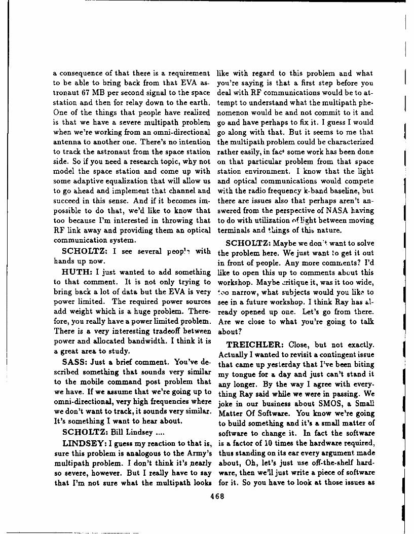
a consequence of that there is a requirement like with regard to this problem and whatto be able to bring back from that EVA as- you're saying is that a first step before youtronaut 67 MB per second signal to the space deal with RF communications would be to at-station and then for relay down to the earth, tempt to understand what the multipath phe-One of the things that people have realized nomenon would be and not commit to it andis that we have a severe multipath problem go and have perhaps to fix it. I guess I wouldwhen we're working from an omni-directional go along with that. But it seems to me that Iantenna to another one. There's no intention the multipath problem could be characterizedto track the astronaut from the space station rather easily, in fac+ some work has been doneside. So if you need a research topic, why not on that particular problem from that spacemodel the space station and come up with station environment. I know that the lightsome adaptive equalization that will allow us and optical communications would competeto go ahead and implement that channel and with the radio frequency k-band baseline, butsucceed in this sense. And if it becomes im- there are issues also that perhaps aren't an-possible to do that, we'd like to know that swered from the perspective of NASA havingtoo because I'm interested in throwing that to do with utilization of light between movingRF link away and providing them an optical terminals and th.ings of thib nature.communication system. SCHOLTZ: Maybe we don'4 want to solve
SCHOLTZ: I see several peop - with the problem here. We just want to get it outhands up now. in front of people. Any more comments? I'd
HUTH: I just wanted to add something like to open this up to comments abut thisto that comment. It is not only trying to workshop. Maybe critique it, was it too wide,bring back a lot of data but the EVA is very too narrow, what subjects would you like topower limited. The required power sources see in a future workshop. I think Ray has al-add weight which is a huge problem. There- ready opened up one. Let's go from there.fore, you really have a power limited problem. Are we close to what you're going to talkThere is a very interesting tradeoff between about?power and allocated bandwidth. I think it is TREICHLER: Close, but not exactly.a great area to study. Actually I wanted to revisit a contingent issue
SASS: Just a brief comment. You've de- that came up yesterday that I've been bitingscribed something that sounds very similar my tongue for a day and just can't stand itto the mobile command post problem that any longer. By the way I agree with every-we have. If we assume that we're going up to thing Ray said while we were in passing. Weomni-directional, very high frequencies where joke in our business about SMOS, a Smallwe don't want to track, it sounds very similar. Matter Of Software. You know we're goingIt's something I want to hear about. to build something and it's a small matter of
SCHOLTZ: Bill Lindsey .... software to change it. In fact the softwareLINDSEY: I guess my reaction to that is, is a factor of 10 times the hardware required,
sure this problem is analogous to the Army's thus standing on its ear every argument mademultipath problem. I don't think it's pnearly about, Oh, let's just use off-the-shelf hard-so severe, however. But I really have to say ware, then we'll just write a piece of softwarethat I'm not sure what the multipath looks for it. So you have to look at those issues as
468

well. The other thing is, we've been fighting ing it now, not get locked into TRITAC, thishere for a dB, half a dB, 2 dB, then I heard or that or whatever. You can start, in thein another talk we threw away factor of 10 industrial community, the academic commu-to 1 in data rate on the fiber optic LAN, be- nity, looking out there and saying, "Whatcause that's just what the protocol requires. research am I doing that generally leads to-So it's interesting how the rules change when wards that?" And the step up from therethe bandwidth is free. in terms of wonderfulness of customers is the
one who'll set out that outrageous require-My comment was about customers. That ment many years into the future and puts to-
came up yesterday. I think the very fact that gether a funding program in University andwe're here is an indication that this particu- industry and works with you. I'm not talk-lar customer has a fairly clear idea of what ing about outrageous amounts of money ei-needs to happen in order to make progress in ther, I'm just talking about enough to createa scientific and technical field. I just wanted a body of knowledge about the technologiesto tell you that I view customers in sort of required to achieve that objective. So then,three different grades and since nobody here 5 or 6 years from now when all of a suddenthat I know of is paying me, I think I don't somebody from Congress looks up and says,have to be too careful. The customer I fear "Oh my God, we need the following," there'sthe most is the one who walks in and says, a body of technology required to start Solv-"I want to buy this. Here's my spec. I don't ing the problem. Every little contract funded,know where I got my spec but here it is. And looking at every little piece of technology,what do you have off the shelf that can do may not get used, but it was all necessary tothis? And I really don't want to talk any cren.te the people and the interest to be abletechnical details." That just sort of scares me to come to workshops like this and so forth,to death. The next flavor of customer that is and share ideas. There's get to be a body ofdefinitely a big notch up from that, obviously knowledge. And if you carry that one stepanyone who'll talk to you is better than one further, the customer with the outrageous re-who won't. The next customer up that I like quirement who has some money and interestis the one who provides what I call the outra- to nurture along different organizations, andgeous requirements. He's the one who says, then, in addition, has some test bed capabil-"Not 2 dB better, not use the same radio and ity, where it's possible to come try your ideasdo this. But let's look out there a ways 10 out every so often, then you have reality toyears from now here's where I want to be. I go along with all of your ideas. I have cer-want to be able to have every infantry man in tainly met the ... "I need 10- 1 bit error ratethe Army have something that weighs 2 oz., and I don't care anything about it" customer,consumes no power and allows me to com- but my personal choice is to find the others,municate back to the President if necessary. to find the ones who are more technically in-Because the President thinks he ought to dic- terested, have technical judgment, in spite oftate every action on the battlefield." But you low pay in the Government, have perseveredsay, you can't do that. Well, if you set an and have been willing to stick in there for theoutrageous enough requirement, far enough grander good.out into the future, that makes you kick overstones, not get locked into the way I'm build- SCHOLTZ: More comments ... Gaylord
469

looks like he wants to say something. You must have solved a lot of problems atHUTH: I want to comment on some- this meeting! Does anyone have any execu-
thing that Paul said about the crypto devices. tive comments?You can do adaptive decoding techniques like Paul Sass raised a question. He thoughtthose Rob Peile was talking about in terms of people may have been subdued a little bitidentifying the channel including the crypto by the fact that they're speaking into micro-device. My question is whether that problem phones and these words will appear in print.falls into the University research area. Maybe This is an unclassified workshop and has al-Rob can tell you all about how to determine ways been. In theory that should be enoughthe underlying process that is creating the said one way or another. But I'd open theerrors through the crypto device. However, floor to the process of recording comments.sometimes you have to know how the mech- I think Bill Sander and the Army feel it'sanisms of the crypto device work in order a very fruitful thing to do, to really keep ato actually determine the error process. I record of this for other people who want toknow you can use Rob's approach because the hear what we said. Does anyone feel subduedcrypto device puts out certain error statistics by just this process of recording? [PAUSE]that you can work with and exploit. My ques- They are all subdued, they don't want to betion is, what can be done at the University? on the record to say it. [LAUGHTER] Il
SCHOLTZ: I don't know where it can be turn the mike off and we can have this discus-done. sion. [NO TAKERS] I wore my purple shirt
PEILE: The first thing to say is that this today because I thought Lloyd Welch's videoisn't a necessarily classified area. To know the tape needed a little more color! Are there anyeffect of a classified device on error statistics other comments about the worksanop and itsmight not mean that the statistics are classi- management? Bill (Sander], do you have anyfled. I've worked in coding for 5 years in the more comments as our sponsor? [MISSINGStates and I've never had a clearance. I've RESPONSE]worked i. a lot of cryptographic environments I myself would like to thank the people whoand it hasn't stopped me. The definition of came to the Workshop and especially to thethe channel can change. I would point out last session because it is a long drag to gothat soft decision information is practically a through two and a half days in this environ-definition of a security breach if it gets on the ment and ignore going horseback riding offred side of a crypto. Moreover, if you're go- hours, on hours and that sort of thing. I'ding to be on the red side of the crypto, you also like to thank the people that came frommight as well retreat even further into the slightly different areas because I'm a commu-OSI model. This ties in with Ray Pickholtz's nication theorists and most of my cronies arelast point. too. It's nice to see people from the Signal
SCHOLTZ: More comments, I've heard Processing community and some of the Chan-software development, I've heard questions nel Measurement people and we really appre-about networks and the protocols and the ciate your participation. We hope some of ourvulnerabilities at that level. Are there any future topics will be of interest to you andother things that people think really need you'll join us at a future workshop. Thanksome exploitation at a workshop? [PAUSE] you all very much and let's call it off for to-
day.
470 THE END

ATTENDEES - CSI-ARO WorkshopRuidoso, New Mexico
May 14-17, 1989
I A G EE, M r. Brian ......................................................................................................... (916) 661-1243 or 1102AGI Engineering, 741 Daniels St., Woodland, CA 95695
I A M ES, M r. Steve .................................................... .................................................................. (415) 852-4129Ford Aerospace & Comm. Corp., MS G79, 3939 Fabian Way, Palo Alto, CA 94303-4697
I BELLO , D r. Phillip A ................................................................................................. (617) 271-8081 or 6262MITRE Corporation. R312, Burlington Road, Bedford, MA 01730
I BRADSHAW, Dr. C ................................................... (703) 883-5667MITRE Corporation MZ245, 7525 Colshire Drive, McLean, VA 22102-3481
IBUSTAMANTE, Dr. Herman ........................................... (408) 980-5633Stanford Telecommunications, 2421 Mission College Blvd., Santa Clara, CA 95054
C A SSELLS, M s. C athy ............................................................................................................. (213) 743-8306Communication Sciences Institute, University of Southern California, Department of Elec Eng., Los Angeles, CA
90089-0272
C IO FFI, D r. John ....................................................................................................................... (415) 723-2150Stanford University, Information Systems Lab., EE-Department, Stanford, CA 94305
CO M PTO N , D r. Ted ................................................................................................................. (614) 292-5048Ohio State University, 2015 Neil Ave, Columbus, OH 43210
C REPEA U , D r. Paul ................................................................................................................. (202) 767-3397Electronics Eng. Comm. Sci., Naval Research Laboratories, Code 5523, Washington, DC 20375
D IZER, D r. Tom ........................................................................................................................ (703) 347-6415The Director, USA CCSW, Attn: AMSEL-PD-SW-TPO, Vint Hill Farms Station, Warrenton, VA 22186
I EYOBOGLU, Dr. M . V .................................................................................................. (617) 364-2000 x7248Manager Modem Research, Codex Corporation, 20 Cabot Blvd., Mansfield, MA 02048
FRIEDLANDER, Dr. Benjamin ............................................................................................. (415) 323-2608Signal Processing Technology Ltd., 703 Coastland Drive, Palo Alto, CA 94303
GARDN ER, Dr. W illiam ........................................................................................................ (707) 944-0648Dept. of Elec. Eng. & Comp Science, Univ. of Calif Davis, Davis, CA 95616
G A U LT, Dr. Jam es ................................................................................................................... (919) 549-0641SLCRO-EL , Electronics Division, Army Research Office , P.O. Box 12211 , Research Triangle Park, NC 27709-2211
G H OSH , M s. M onisha ............................................................................................................ (213) 743-0907Communication Sciences Institute, University of Southern California, Department of Elec Eng., Los Angeles, CA
90089-0272
471.

H A LL, D r. D ennis .................................................................................................................... (213) 812-1725TRW, Mail Code R12/2688, One Space Park, Redondo Beach, CA 90278
H U A N G , D r. T. C ..................................................................................................................... (213) 416-7182The Aerospace Corporation, M6/210, P.O. Box 92957, Los Angeles, CA 90009
H TH , D r. G aylord ................................................................................................................. (213) 641-8600AXIOMATIX Corporation , 9841 Airport Blvd. , Suite 1130, Los Angeles, CA 90045
KAWAGUCHI, Dr. Dean ....................................................................................................... (213) 813-7894TRW, Mail Code 03/2234, One Space Park, Redondo Beach, CA 90278
K U M A R , D r. V ijay .................................................................................................................. (213) 743-5387Communication Sciences Institute, University of Southern California, Department of Elec Eng., Los Angeles, CA
90089-0272
LEVESQ U E, D r. Allen H ........................................................................................................ (617) 466-3729GTE Govt. Systems Corp., EDCD - 2410, 100 First Ave., Waltham, MA 02254
LEYENDECKER, Dr. Robert L ...................................................................................... (703) 347-6492/6493U.S. Army, Center for Signals Warfare, AMSEL-RD-SW-TRS, Vint Hill Farms Station, Warrenton, VA 22186-5100
LIN D SEY, D r. W illiam ........................................................................................................... (213) 743-2349Communication Sciences Institute, University of Southern California, Department of Elec Eng., Los Angeles, CA
90089-0272
LIN SK Y, D r. Stuart .................................................................................................................. (213) 813-8034TRW, Mail Code 03/2240, One Space Park, Redondo Beach, CA 90278
MONTENEGRO, Ms. Milly ................................................................................................... (213) 743-5537Communication Sciences Institute, University of Southern California, Department of Elec Eng., Los Angeles, CA
90089-0272
MULLIGAN, Dr. James J ........................................................................................................ (703) 347-6493Director U.S. Army, Center for Signal Warfare , ATTN: AMSEL-RD-SW-PE , Vint Hill Farms Station,
Warrenton, VA 22186-5100
PAWLOWSKI, Dr. Peter R. .................................................................................................... (213) 812-0170TRW, Mail Code R12/2173, One Space Park, Redondo Beach, CA 90278
PEILE, D r. Robert ...................................................................................................................... (213) 743-0060Communication Sciences Institute, University of Southern California, Department of Elec Eng., Los Angeles, CA -
90089-0272
PETERSON, Dr. Roger L ......................................................................................................... (602) 732-2452 IMotorola Inc. , Strategic Electronics Div. , G 2242, 2501 S. Price Road , Chandler, AZ 85248-2899
PICKHOLTZ, Dr. Raymond ................................................................................................... (202) 994-6538School of Eng. & Appl. Science, George Washington University, Phillips Hall, Washington, DC 20052
472

PO LYDO RO S, D r. A ndreas ..................................................................................................... (213) 743-7257Communication Sciences Institute, University of Southern California, Department of Elec Eng., Los Angeles, CA
90089-0272
PRO A K IS, D r. John .................................................................................................................. (617) 437-4429Northeastern University, 411 Dana Hall, 360 Huntington Ave., Boston, MA 02115
PU RSLEY, D r. M ichael ............................................................................................................ (217) 333-2966University of Illinois, Coordinated Science Lab., 1101 W. Springfield Ave, Urbana, IL 61801
RHODES, Dr. Stephen D ............................................................................................... (703) 347-6492/6493U.S. Army. Center for Signals Warfare. AMSEL-RD-SW-TRS, Vint Hill Farms Station. W,rPnton, VA 22186-5100
RIC E, D r. Bart ............................................................................................................................ (408) 756-4892Consulting Engineer, Lockheed Missile & Space Co., 0/6231 - B/150, 1111 Lockheed Way, Sunnyvale, CA 94089-3504
RO LLIN S, M r. D avid ............................................................................................................... (213) 743-0907Communication Sciences Institute, University of Southern California, Department of Elec Eng., Los Angeles, CA
90089-0272
RU D E, M r. M ichael ................................................................................................................. (213) 743-3962Signal & Image Processing Institute, University of Southern California, Department of Elec Eng., Los Angeles, CA
90089-0272
SA D R , D r. R am in ..............................................................................................................................................Jet Propulsion Laboratories, 4800 Oak Grove Ave., MS 238-420, Pasadena, CA 91109
SANDER, Dr. William A ....................................................................................................... (919) 549-0641SLCRO-EL , Electronics Division, Army Research Office , P.O. Box 12211 , Research Triangle Park, NC 27709-2211
SA SS, D r. Paul .......................................................................................................................... (201) 532-0164Director, U.S. Army Commun & Elec., AT:. AMSEL-RD-COM-AC-B, Center for Comm. Sys., Ft. Monmouth, NJ
07703-5202
SATORIJS, Dr. Edgar H ......................................................................................................... (818) 354-3016Jet Propulsion Laboratory, 4800 Oak Grove Ave., MS 238420, Pasadena, CA 91109
SC H IFF, M r. M aurice ........................................................................................................................................Engineering Staff Specialist, General Dynamics Convair, P.O.B. 80847, San Diego, CA 92138
SCHNEIDER, Dr. Allan ......................................................................................................... (703) 522-0046Cybercorn Corp., 4105 N. Fairfax Dr., Arlington, VA 22203
SCHOLTZ, Dr. Robert .............................................................................................................. (213) 743-5546Communication Sciences Institute, University of Southern California, Department of Elec Eng., Los Angeles, CA
90089-0272
SIM O N , D r. M arvin ............................................................................................................... (818) 354-3955JPL, M.S. 161-228, 4800 Oak Grove Ave., Pasadena, CA 91109
473

SO LIM A N , D r. Sam ir .............................................................................................................. (214) 692-3112Southern Methodist University, Elec. Eng. Dept., Dallas, TX 75275-0335
STEA RN S, M r. Steve .............................................................................................................. (415) 795-5331Tech. for Comms. Intl., 34175 Ardenwood Blvd., Fremont, CA 94536-7705
STEIN , D r. Seym our ................................................................................................................ (617) 527-5551SCPE Inc., 56 Great Meadow Road, Newton, MA 02159
STO U T, D r. D avid .................................................................................................................... (408) 473-4690Ford Aerospace & Comm. Corp., WDL Division, 220 Henry Ford II Drive, P.O. Box 49041, San Jose, CA 95161-9041
TREICHLER, Dr. John R ......................................................................................................... (408) 749-1888Applied Signal Technology, 160 Sobrante Way, Sunnyvale, CA 94086
W AR D , D r. Robert ................................................................................................................... (213) 812-4124TRW, Mail Code R12/2043, One Space Park, Redondo Beach, CA 90278
WEBER, Dr. Charles .................................................................... (213) 743-2407Communication Sciences Institute, University of Southern California, Department of Elec Eng., Los Angeles, CA
90089-0272
W ELCH , D r. Lloyd ................................................................................................................... (213) 743-2699Communication Sciences Institute, University of Southern California, Department of Elec Eng., Los Angeles, CA
90089-0272
WICKERT, Dr. Mark A ........................................................................................................... (719) 593-3500University of Colorado 4-17400, College of Eng. & Applied Science, 1420 Austin Bluffs Parkway, Box 7150, Colorado
Springs, CO 80907-7150
WILSON, Dr. Kenneth E ........................................................................................................ (303) 971-7545Martin Marietta Corporation, P.O. Box 3912, Littleton, CO 80161
W O O D , D r Sally L .................................................................................................................... (408) 749-1888Dept. of Elec. Eng. & Computer Science, Santa Clara University, Santa Clara, CA 95053
ZH AN G , D r. Zhen .................................................................................................................... 213) 743-3910Communication Sciences Institute, University of Southern California, Department of Elec Eng., Los Angeles, CA
90089-0272
474

94
St.
Awl'
tit

I400.
I"*
V)p
* P1C(ILnt
I 11111
- 4A4
C14
g 13Ir
(D fg
mI
C47
![arXiv:2206.00761v1 [cs.LG] 1 Jun 2022](https://static.fdokumen.com/doc/165x107/6328f2a909048e4b7c062611/arxiv220600761v1-cslg-1-jun-2022.jpg)


![arXiv:2206.00666v1 [cs.SE] 1 Jun 2022](https://static.fdokumen.com/doc/165x107/6328e8022dd4b030ca0c55e9/arxiv220600666v1-csse-1-jun-2022.jpg)
![arXiv:1606.00180v1 [astro-ph.CO] 1 Jun 2016](https://static.fdokumen.com/doc/165x107/6325fb66051fac18490d8796/arxiv160600180v1-astro-phco-1-jun-2016.jpg)
![arXiv:1701.02153v2 [cond-mat.str-el] 1 Jun 2017](https://static.fdokumen.com/doc/165x107/632798f4e491bcb36c0b5c3b/arxiv170102153v2-cond-matstr-el-1-jun-2017.jpg)