JFL Hospital - USVI Department of Property & Procurement
573
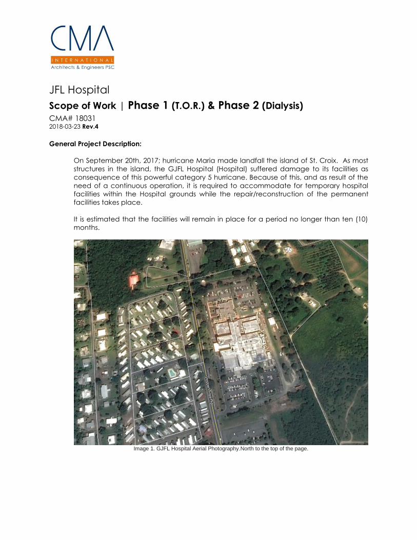
JFL Hospital Scope of Work | Phase 1 (T.O.R.) & Phase 2 (Dialysis) CMA# 18031 2018-03-23 Rev.4 General Project Description: On September 20th, 2017; hurricane Maria made landfall the island of St. Croix. As most structures in the island, the GJFL Hospital (Hospital) suffered damage to its facilities as consequence of this powerful category 5 hurricane. Because of this, and as result of the need of a continuous operation, it is required to accommodate for temporary hospital facilities within the Hospital grounds while the repair/reconstruction of the permanent facilities takes place. It is estimated that the facilities will remain in place for a period no longer than ten (10) months. Image 1. GJFL Hospital Aerial Photography.North to the top of the page.
-
Upload
khangminh22 -
Category
Documents
-
view
0 -
download
0
Transcript of JFL Hospital - USVI Department of Property & Procurement
JFL Hospital
Scope of Work | Phase 1 (T.O.R.) & Phase 2 (Dialysis)
CMA# 18031 2018-03-23 Rev.4
General Project Description:
On September 20th, 2017; hurricane Maria made landfall the island of St. Croix. As most
structures in the island, the GJFL Hospital (Hospital) suffered damage to its facilities as
consequence of this powerful category 5 hurricane. Because of this, and as result of the
need of a continuous operation, it is required to accommodate for temporary hospital
facilities within the Hospital grounds while the repair/reconstruction of the permanent
facilities takes place.
It is estimated that the facilities will remain in place for a period no longer than ten (10)
months.
Image 1. GJFL Hospital Aerial Photography.North to the top of the page.
GJFL Hospital – Phase 1 & Phase 2 (CMA #18031)
Scope of Work
March 23, 2018
2
1509 Ave. FD Roosevelt Guaynabo PR 00968 | www.cmapr.com | 787-792-1509 | [email protected]
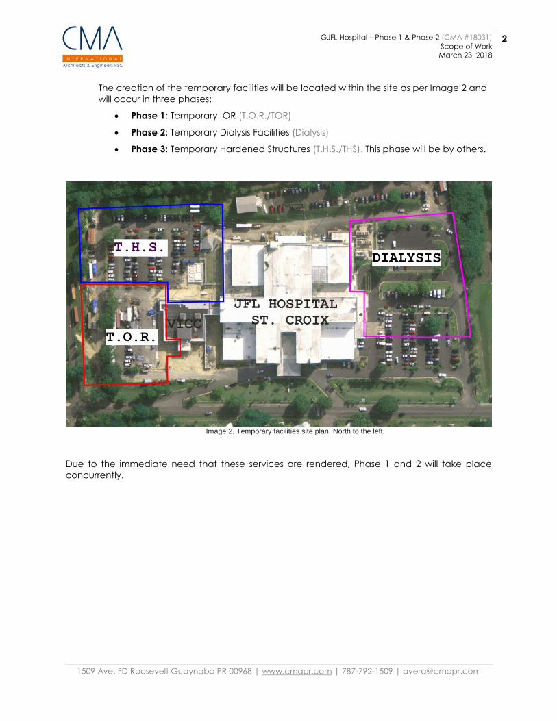
The creation of the temporary facilities will be located within the site as per Image 2 and
will occur in three phases:
Phase 1: Temporary OR (T.O.R./TOR)
Phase 2: Temporary Dialysis Facilities (Dialysis)
Phase 3: Temporary Hardened Structures (T.H.S./THS). This phase will be by others.
Image 2. Temporary facilities site plan. North to the left.
Due to the immediate need that these services are rendered, Phase 1 and 2 will take place
concurrently.
GJFL Hospital – Phase 1 & Phase 2 (CMA #18031)
Scope of Work
March 23, 2018
3
1509 Ave. FD Roosevelt Guaynabo PR 00968 | www.cmapr.com | 787-792-1509 | [email protected]
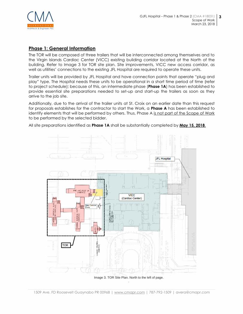
Phase 1: General Information
The TOR will be composed of three trailers that will be interconnected among themselves and to
the Virgin Islands Cardiac Center (VICC) existing building corridor located at the North of the
building. Refer to Image 3 for TOR site plan. Site improvements, VICC new access corridor, as
well as utilities’ connections to the existing JFL Hospital are required to operate these units.
Trailer units will be provided by JFL Hospital and have connection points that operate “plug and
play” type. The Hospital needs these units to be operational in a short time period of time (refer
to project schedule); because of this, an intermediate phase (Phase 1A) has been established to
provide essential site preparations needed to set-up and start-up the trailers as soon as they
arrive to the job site.
Additionally, due to the arrival of the trailer units at St. Croix on an earlier date than this request
for proposals establishes for the contractor to start the Work, a Phase A has been established to
identify elements that will be performed by others. Thus, Phase A is not part of the Scope of Work
to be performed by the selected bidder.
All site preparations identified as Phase 1A shall be substantially completed by May 15, 2018.
Image 3. TOR Site Plan. North to the left of page.
.
GJFL Hospital – Phase 1 & Phase 2 (CMA #18031)
Scope of Work
March 23, 2018
4
1509 Ave. FD Roosevelt Guaynabo PR 00968 | www.cmapr.com | 787-792-1509 | [email protected]
Phase 1: Scope of work
A. Civil Works
1. General
a. Some of the proposed utilities will not only manage the
Temporary Operating Rooms (TOR) area, but will have the
capacity to manage a future phase (Phase 3: Temporary
Hardened Structures, THS). This applies to the potable water,
medical gases and the sanitary system. All utilities will run
parallel to reduce the impact to the existing parking lot and
walkways.
b. The topographic survey is not available. Final layout, trailers
finish floor elevations (FFE) and utilities will be subject to the
existing conditions.
2. Grading:
a. Trailers Finish Floor Elevation (FFE) consider the existing ground
elevation, the height of each trailer and the Virgin Island
Cardiac Center (VICC) FFE. The placement of the trailers will be
performed by others (Phase A)
3. Water:
a. Refer to Mechanical Scope of Work.
4. Sanitary:
a. The main system will have the capacity to handle the TOR and
Phase 3 (THS) sanitary contribution and will discharge at an
existing manhole located between the VICC and the JFL Main
Building. Phase 2 will be connected to a sanitary line at the
south of the site.
5. Medical Gas:
a. Medical gas lines are proposed from the JFL Main Building
towards the Phase 1 (TOR).
6. Storm:
a. Rain water runoff will continue as usual toward the existing
catch basins.
7. Erosion and Sedimentation Control:
a. The design drawings will include guidelines for the temporary
erosion and sedimentation control measures to prevent soil
erosion and discharge of soil-bearing runoff to adjacent
sinkholes, rivers or creeks and airborne dust to adjacent
properties.
8. Trees:
a. Trees are not expected to be cut within the TOR area.
9. Demolition:
a. The proposed utilities will require partial demolition of existing
pavement at the parking lot and at walkways.
b. Were asphalt pavement is demolish, replace with new
aggregate base course and asphalt pavement surface.
GJFL Hospital – Phase 1 & Phase 2 (CMA #18031)
Scope of Work
March 23, 2018
5
1509 Ave. FD Roosevelt Guaynabo PR 00968 | www.cmapr.com | 787-792-1509 | [email protected]
B. Architectural
1. Connector between existing VICC building and TOR (New Connector
Entry):
a. Demolition is required at the existing perimeter wall and
removal of existing window to provide for the connection from
the existing building VICC into the TOR. An enclosed steel
structure with sloped floor will be developed to accommodate
for the change in elevation. New flooring and ceiling will be
required in this area as well as ceiling and floor transition.
b. 5/8” impact & moisture/mold resistant gypsum board panel will
finish the interior of the new corridor, primed and painted color
to match adjacent corridor color.
c. 2’x2’ acoustical ceiling tile on suspension system with 15/16”
face profile exposed T. Seismic anchoring for the ceiling
suspension system is required as well as heavy duty gauge.
Equal or similar to Optima by Armstrong Ceilings.
d. A new electrically operated, 2hr fire rated, hurricane resistant
6’-0” wide double door with narrow vision panel will be installed
at the transition between VICC building existing corridor and
the New Corridor Entry.
e. 12”x12” VCT flooring resistant to heavy foot and rolling load
traffic and 4” rubber cove base, colors to match adjacent
corridor. Equal or similar to: Standard Excelon Imperial Texture
by Armstrong Flooring Systems.
f. New corridor walls will be constructed out of structural steel
channel horizontal girts (refer to structural drawings). Exterior of
wall will be galvanized steel siding panels primed and painted
(color to be selected by Architect); while interior will be finished
with 5/8” high impact moisture and mold resistant gypsum
board panels. Insulation required in the interstitial space of the
walls.
g. Interior walls shall be primed and painted with epoxy based
paint. Bumper guards shall be installed at the interior walls to
protect walls from heavy equipment traffic. Bumper guards shall
match existing regarding manufacturer, type and color.
h. Exterior walls to receive rigid insulation, R Value of 13.
i. Roofing system will composed of metal deck, insulation, cover
board, and Modified Asphalt Roofing System – SBS. Shall comply
with FM Global Roof Nav Assembly Number 310916-213598-0.
j. Connection between the New Corridor Entry and the VICC
Building existing corridor will incorporate MM EIV-200 Expansion
Joint System, refer to Partial Plan @ New Corridor Entry. Shop
drawings shall be provided by contractor for approval prior
installation.
GJFL Hospital – Phase 1 & Phase 2 (CMA #18031)
Scope of Work
March 23, 2018
6
1509 Ave. FD Roosevelt Guaynabo PR 00968 | www.cmapr.com | 787-792-1509 | [email protected]
C. Structural
1. Structural restrain of trailers and trailer corridors
a. Wind and seismic restrain of trailers will consist of tie down
elements anchored to a new reaction concrete blocks. This
work shall be done in coordination with the trailers owner
representative present on the site. Welding or preformation of
none of the equipment units shall be permitted.
b. Anchorage consists of an anchor plate assemblies connected
with stainless steel threaded rods embedded with epoxy into
the new concrete blocks. The connection of the trailer to the
anchor plate will be done with a hot dip galvanized steel cable.
The cable shall include all end attachments compatible with
the required rated capacity of the assembly. A turnbuckle or an
equivalent mean of adjustment shall be provided at each
instance. It has been assumed that based on the amount of
anchor points to one of the trailers, at least twelve (12) anchor
plates assemblies will be required per each main trailer and four
(4) per connector/corridor segment. Resistance of the concrete
blocks depends upon the friction between the concrete and
the existing asphalt. Friction is to be enhanced with some rebar
dowels embedded into the asphalt at discrete points.
2. Support steel and wood bearing pads
a. A bearing pad consisting of an array of wood elements cap
with a steel bearing plate is detailed on the civil dwgs. This
element will lie over the existing ground or asphalt surface
depending of which trailer is being supported. Those pads
located on ground or green areas must have the ground
improved as shown in the structural details. Improvement
consists of removing 8 inches of top soil, compacting the soil
and placing 8” of gravel to match existing grading elevation.
After that, pads can be placed set in position. Final thickness of
the pad will depend on the necessary elevation to set the trailer
support. It is estimated to range between 12 inches and 16
inches. Add other layer of wood elements to achieve the
necessary elevation elevation. Wood must be pressure treated.
Where available connection of the cables must be done to the
predetermined anchor points on the body of the trailers. Where
not available, anchorage shall occur around the framing
element of the trailer chassis. Anchorage shall only be
performed at these rigid points without damaging the trailers
integrity. Welding or preformation of none of the equipment
units shall be permitted.
b. Provided that connection from the top of the trailer is needed,
a distribution element consisting of an HSS4x4 hot dip
galvanized steel cross member with a neoprene pad in
between the area in contact with the trailer roof over each
wing of the trailer (2 per trailer) will be installed from which tie
downs are anchored.
GJFL Hospital – Phase 1 & Phase 2 (CMA #18031)
Scope of Work
March 23, 2018
7
1509 Ave. FD Roosevelt Guaynabo PR 00968 | www.cmapr.com | 787-792-1509 | [email protected]
3. Main Connecting Corridor
a. The structure will consist of a rectangular steel framing
supported over a mat foundation floor slab. Steel framing will
consist of 6 steel columns supporting roof main beams and
secondary cold formed galvanized steel elements. A 1.5B roof
steel deck is to be provided over the roof beams. Roof panel
will be attached to framing with self-drilled Tek #12 fasteners
with ¾”Ø washers spaced at 6” o.c. Columns will be installed
directly over the foundation floor slab with cast in place anchor
rods. The edge of the slab will be thickened to serve as a
continuous foundation along both sides of the corridor. Short
diagonal knee braces will be installed in both directions of the
main frames. A metal siding panel consisting of Type E 26 gage
corrugated galvanized panel will be recommended. Metal
panel will be attached to horizontal girts consisting of C6
structural steel channels. Attachment is critical and will be
designed to provide the resistance required by wind pressures
resulting from wind analysis required by the code. Attachment
will consist of galvanized self-drilled Tek#12 screws with
watertight neoprene washers.
b. Columns, beams and other elements designations and
dimensions are shown in the structural drawings.
c. The roof will be designed for live load of 40 psf plus an
additional allowance of 10 psf for post installed components.
Wind loads will be calculated using a wind speed of 145 mph
at service level using an importance factor of 1.15. Similarly, a
roofing assembly will be provided with reported resistance in
excess of the required strength. Seismic forces will also be
calculated and structural strength and requirements will be
meet accordingly. Geotechnical investigation report will
provide design criteria and treatment required below the
foundation system. It can be assumed that at least 1’-0” ft.
below the proposed bottom of the concrete will have to be
filled with A-2-4 backfill material compacted to meet 95%
proctor test or crushed stone. This material can be used to raise
if necessary the existing grading in order to avoid additional
concrete volume to be deposited for the construction of the
foundation slab.
GJFL Hospital – Phase 1 & Phase 2 (CMA #18031)
Scope of Work
March 23, 2018
8
1509 Ave. FD Roosevelt Guaynabo PR 00968 | www.cmapr.com | 787-792-1509 | [email protected]
D. Mechanical Works
1. Medical Air, Medical Vacuum and Oxygen Piping
a. Contractor shall tie-in to existing oxygen, medical vacuum and
medical air lines running to VICC. Coordinate shutdowns with
Owner.
b. Provide new copper type K lines (2” medical vacuum, 1”
oxygen and 1” medical air) and run them in the plenum space
up to a point as illustrated in drawing P.1. See piping drawings
and specifications provided.
c. The new oxygen, medical vacuum and medical air lines will exit
the building and run alongside the building supported from the
exterior wall using galvanized steel Unistrut supports and
stainless steel anchors (see civil scope of work and diagrams)
and will branch off to provide future connection to the THS and
continue to the TOR area.
d. Coordinate with TOR vendor exact coupling size and type for
each service. All piping running to the TOR area shall run above
ground with supports (see civil drawings and scope of work for
details).
e. The excavation for the underground piping shall be
coordinated with other utilities.
f. Provide isolation valves at the inlet, outlet and every branch off.
Cap all free ends.
g. Provide miscellaneous steel supports and hangers at least every
6 feet.
h. Piping shall be pressure tested and cleaned according to NFPA
99 requirements and specifications.
i. Provide seismic supports in accordance with IBC 2003.
j. Buried pipe shall be protected using a halved PVC pipe
covering the pipes. The PVC cover shall be at least 2 nominal
sizes larger than the pipe.
k. Buried pipe shall be provided with a continuous warning
metallic marker at 12” below ground and along the piping run.
l. Construction shall comply with referenced standards and
specifications.
m. These are conceptual diagrams. The contractor shall provide
detailed shop drawings for approval to the architect/engineer.
n. Referenced Standards
1. Medical gas (including medical air) requirements for
healthcare facilities are governed by NFPA 99, Health Care
Facilities; and NFPA 99C, Gas and Vacuum. Systems. NFPA
99C is a separate publication of NFPA 99, Ch. 5, and of
related portions of other NFPA 99 chapters.
2. American Society of Civil Engineers/Structural Engineering
Institute:
a. ASCE/SEI 7-2005: Minimum Design Loads for
Buildings and Other Structures
3. American Society of Sanitary Engineering:
GJFL Hospital – Phase 1 & Phase 2 (CMA #18031)
Scope of Work
March 23, 2018
9
1509 Ave. FD Roosevelt Guaynabo PR 00968 | www.cmapr.com | 787-792-1509 | [email protected]
4. ASSE Standard #6010-2006: Medical Gas Systems Installers
5. ASSE Standard #6020-2006: Medical Gas Systems Inspectors
6. ASSE Standard #6030-2006: Medical Gas Systems Verifiers
7. ASME International:
a. ASME B16.22-2001: Wrought Copper and Copper
Alloy Solder Joint Pressure Fittings.
b. ASME B16.21-2005: Nonmetallic Flat Gaskets for Pipe
Flanges
c. ASME B31.1-2007: Power Piping
d. ASME B31.9-2009: Building Services Piping
e. ASME Boiler and Pressure Vessel Code: Section VIII,
"Pressure Vessels," Division 1; Section IX, "Welding
and Brazing Qualifications." 2007.
8. ASTM International:
a. ASTM B 819-00 (Reapproved 2006): Specification for
Seamless Copper Tube for Medical Gas Systems
9. Compressed Gas Association:
a. CGA G-4.1-2004: Cleaning Equipment for Oxygen
Service
10. NFPA
a. NFPA 99-2005: Health Care Facilities
b. NFPA 50-2003: Bulk Oxygen Systems at Consumer
Sites
11. Underwriters Laboratories Inc.
a. UL 60601-2005: Medical Safety Testing and
Certification Service
o. Medical Gas System Certification
1. Certification that medical gas piping systems for
healthcare facilities are required according to applicable
codes and standards. ASSE Standard #6020, Medical Gas
Systems Inspectors, governs qualifications for inspectors;
ASSE Standard #6030, Medical Gas Systems Verifiers,
governs testing and verification for certification of testing
agency personnel.
p. Piping Material Specifications
1. Aboveground and underground medical gas piping must
be ASTM B 819, Type K drawn-temper copper tube. Piping
NPS 3 (DN 80) and larger in systems operating at pressure
above 185 psig (1275 kPa) must be ASTM B 819, Type K,
drawn-temper copper tube.
2. Underground medical gas piping must be installed with a
protective cover as described in the scope of work. The
cover must be split or otherwise installed so that tubing
joints may be observed during testing.
3. Compressed-air, vacuum, medical gas, and other piping
shall be labeled and color-coded as per NFPA 99
requirements to help prevent cross connections.
GJFL Hospital – Phase 1 & Phase 2 (CMA #18031)
Scope of Work
March 23, 2018
10
1509 Ave. FD Roosevelt Guaynabo PR 00968 | www.cmapr.com | 787-792-1509 | [email protected]
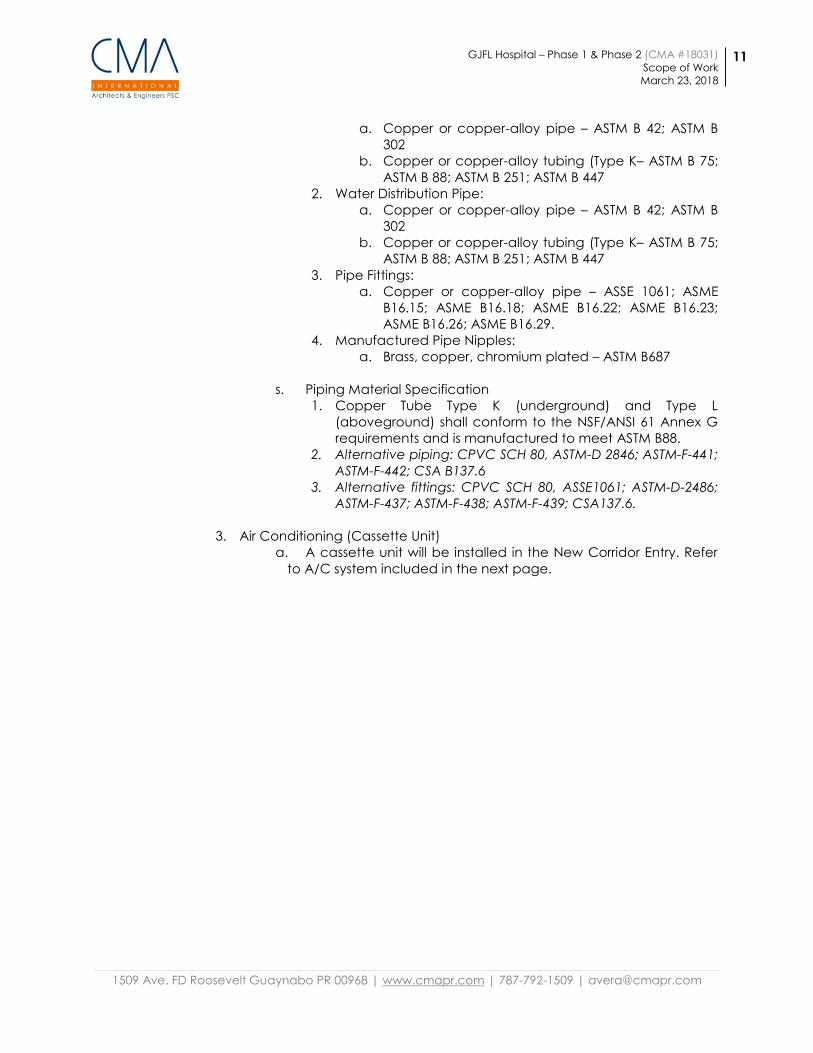
2. Potable Water Piping
a. Contractor shall tie-in to existing 4” CW, 4” HW and HWR lines
running inside existing hospital as illustrated in drawing P.1.
Coordinate shutdowns with Owner.
b. Provide new copper type K lines (3” HW, 3” CW and 3/4” HWR)
and run them in the plenum space up to a point as illustrated in
drawing P.1. See piping drawings and specifications provided.
c. The cold water line will exit the building and run alongside the
building supported from the exterior wall using galvanized steel
Unistrut supports and stainless steel anchors (see Civil scope of
work and diagrams) and will branch off to provide future
connection to the THS and continue to the TOR area.
d. The hot water lines will exit the building and run alongside the
building supported from the exterior wall using galvanized steel
Unistrut supports and stainless steel anchors (see civil scope of
work and diagrams) and will provide future connection to the
THS, there is no need to continue to the TOR.
e. All piping running to the TOR area shall run above ground with
supports (see civil drawings and scope of work for details).
f. The excavation for the underground piping shall be
coordinated with other new and existing utilities.
g. Coordinate with TOR vendor exact coupling size and type for
each service.
h. Provide isolation valves at the inlet, outlet and every branch off.
Cap all free ends.
i. Provide a memory stop 3/4” ball valve for balancing the hot
water return line (HWR)
j. Provide miscellaneous steel supports, hangers and rods at least
every 10 feet for piping 3” and above and at 5 feet for piping
3/4”.
k. For CPVC alternative provide miscellaneous steel supports,
hangers and rods 4 ft for 3” HW piping and above, 2.5 ft for ¾”
HWR piping, 7 ft for 3” CW piping and 5.5 ft for 1 ½” CW pipe.
l. HW and HWR lines shall be insulated with 2” thick foam glass for
the 3” HW lines and 1.5” thick foam glass for the ¾” HWR lines.
Insulation shall be protected with Pittsburgh Corning flexible
PITTWRAP insulation jacketing for direct burial underground. For
exposed aboveground piping provide 16 mil all service
aluminum jacket.
m. Buried pipe shall be provided with a continuous warning
metallic marker at 12” below ground and along the piping run.
n. Piping shall be pressure tested and cleaned according to
piping specifications.
o. Provide seismic supports in accordance with IBC 2003.
p. Construction shall comply with referenced standards and
specifications.
q. These are conceptual diagrams. The contractor shall provide
detailed shop drawings for approval to the architect/engineer.
r. Referenced Standards
1. Water Service Pipe:
GJFL Hospital – Phase 1 & Phase 2 (CMA #18031)
Scope of Work
March 23, 2018
11
1509 Ave. FD Roosevelt Guaynabo PR 00968 | www.cmapr.com | 787-792-1509 | [email protected]
a. Copper or copper-alloy pipe – ASTM B 42; ASTM B
302
b. Copper or copper-alloy tubing (Type K– ASTM B 75;
ASTM B 88; ASTM B 251; ASTM B 447
2. Water Distribution Pipe:
a. Copper or copper-alloy pipe – ASTM B 42; ASTM B
302
b. Copper or copper-alloy tubing (Type K– ASTM B 75;
ASTM B 88; ASTM B 251; ASTM B 447
3. Pipe Fittings:
a. Copper or copper-alloy pipe – ASSE 1061; ASME
B16.15; ASME B16.18; ASME B16.22; ASME B16.23;
ASME B16.26; ASME B16.29.
4. Manufactured Pipe Nipples:
a. Brass, copper, chromium plated – ASTM B687
s. Piping Material Specification
1. Copper Tube Type K (underground) and Type L
(aboveground) shall conform to the NSF/ANSI 61 Annex G
requirements and is manufactured to meet ASTM B88.
2. Alternative piping: CPVC SCH 80, ASTM-D 2846; ASTM-F-441;
ASTM-F-442; CSA B137.6
3. Alternative fittings: CPVC SCH 80, ASSE1061; ASTM-D-2486;
ASTM-F-437; ASTM-F-438; ASTM-F-439; CSA137.6.
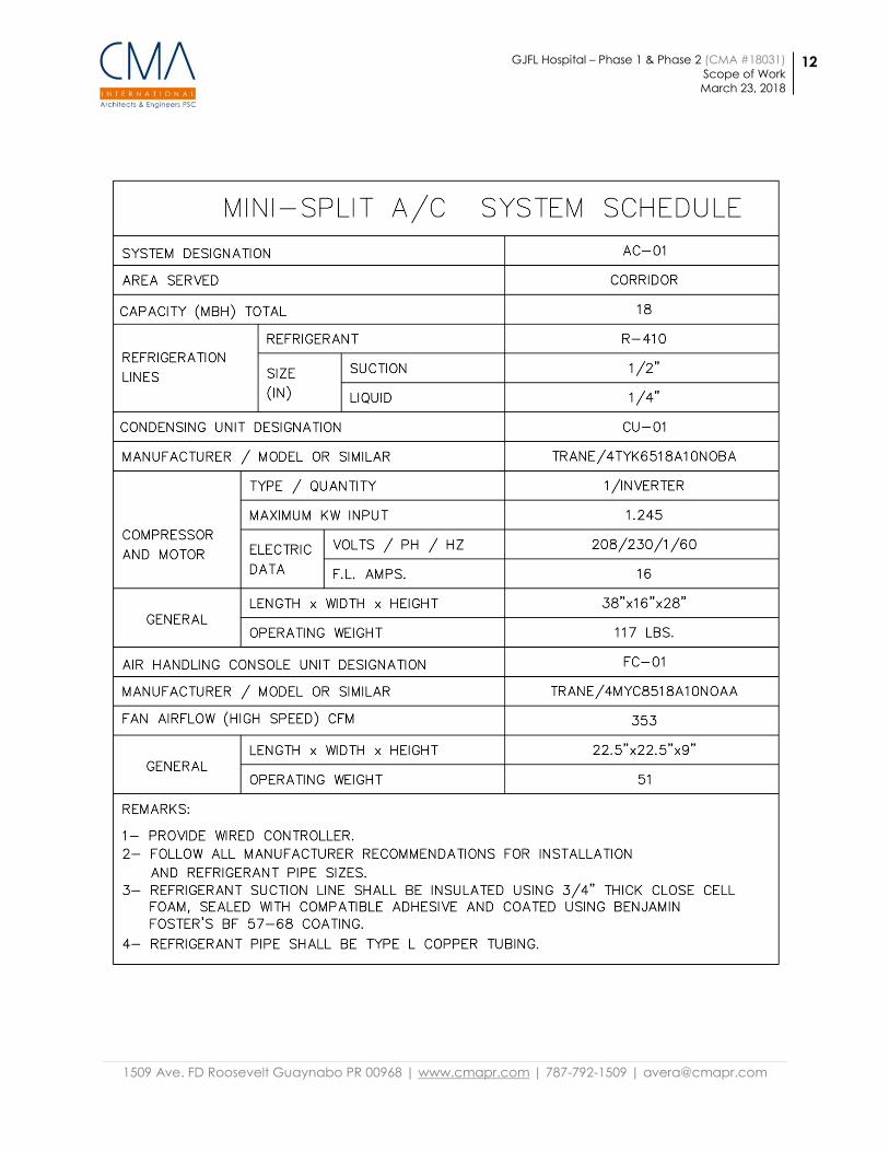
3. Air Conditioning (Cassette Unit)
a. A cassette unit will be installed in the New Corridor Entry. Refer
to A/C system included in the next page.
GJFL Hospital – Phase 1 & Phase 2 (CMA #18031)
Scope of Work
March 23, 2018
12
1509 Ave. FD Roosevelt Guaynabo PR 00968 | www.cmapr.com | 787-792-1509 | [email protected]
GJFL Hospital – Phase 1 & Phase 2 (CMA #18031)
Scope of Work
March 23, 2018
13
1509 Ave. FD Roosevelt Guaynabo PR 00968 | www.cmapr.com | 787-792-1509 | [email protected]
E. Electrical Works
The total estimated electrical load of the AMERCO and NORTH CAROLINA mobile
surgical units is 584 Amp/ 210 KVA at 208 Volt, 3 phase. The electrical connection
for these temporary facilities will be taken from the existing 2000 KVA outdoor pad
mounted transformer of the VICC. A 480V, 3 phase feeder will be tapped to the
transformer 480V section. A new outdoor 400 Amp fusible safety switch will be
installed within 10 Ft. of the transformer.
For Phase I a new 225 KVA outdoor dry type transformer will be installed adjacent
to the 400 AMP fusible switch. This transformer will feed a 208 V, 3 Phase, 4 wire
outdoor panelboard with branch circuit breakers for the connection of the
mobile units.
For the temporary connection of the mobile trailers a 225 KW rental electrical
generator shall be provided for the connection of the 208V panelboard. The
generator will be removed after the new 225 KVA transformer be installed and
connected.
The mobile units are provided with 100 Ft. long cables for the electrical power
connection. Cable trays mounted above grade will be provided for the
installation of the cables from the mobile units to the outdoor 208V panelboard.
For the trailer units that require feeder lengths in excess of 100 Ft, provide new
cables as indicated in the one line diagram.
The two (2) 125 kW standby generator, 225 Automatic transfer switch, 400 amp
double throw switch and associated electrical feeders shall be considered as
Alternate 1.
For the electrical works reference drawings see Appendix A.
1. Grounding
a. An earth ground system will be provided for the grounding
connection of the mobile units steel frames. A ground driven rod
will be provided for each mobile unit. The ground rods will be
interconnected with grounding cables. A grounding cable will
run to the 208V panelboard grounding bus.
2. Communications
a. Data (Cat. 6), fire alarm, telephone and TV cables will run along
the outdoor grade level cable tray from the mobile suites to the
communications room located at the first floor of the VICC.
b. Communication cables as well as patch panels will be owner
furnished, owner installed.
3. Site Lighting
a. One (1) existing wood light poles that interfere with the proposed
location of the trailers will be removed and relocated by others.
Refer to Drawings.

GJFL Hospital – Phase 1 & Phase 2 (CMA #18031)
Scope of Work
March 23, 2018
14
1509 Ave. FD Roosevelt Guaynabo PR 00968 | www.cmapr.com | 787-792-1509 | [email protected]
b. One (1) existing metal light poles that interfere with the proposed
location of the trailers shall be removed and relocated as part of
Phase 1A. The existing underground lighting feeder will be
extended to the new light pole location also as part of Phase 1A.
Refer to Drawings.
4. Electrical Provisions for future phase (Phase 3)
a. Spare electrical and communications underground conduits for
future Phase 3 will be provided. Conduits will be capped at
ends. See plans.
GJFL Hospital – Phase 1 & Phase 2 (CMA #18031)
Scope of Work
March 23, 2018
15
1509 Ave. FD Roosevelt Guaynabo PR 00968 | www.cmapr.com | 787-792-1509 | [email protected]
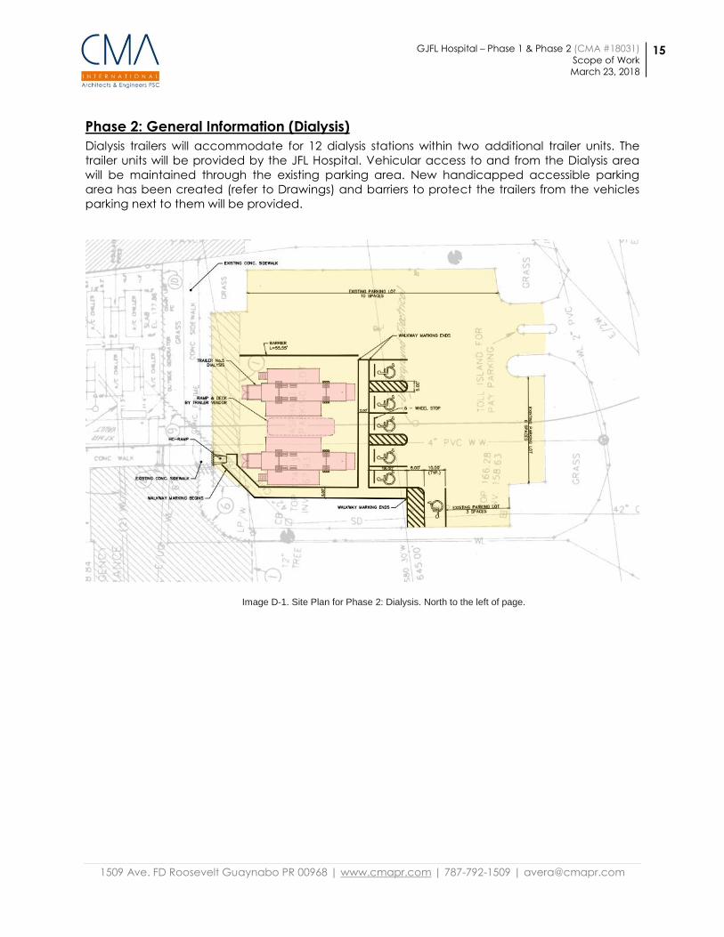
Phase 2: General Information (Dialysis)
Dialysis trailers will accommodate for 12 dialysis stations within two additional trailer units. The
trailer units will be provided by the JFL Hospital. Vehicular access to and from the Dialysis area
will be maintained through the existing parking area. New handicapped accessible parking
area has been created (refer to Drawings) and barriers to protect the trailers from the vehicles
parking next to them will be provided.
Image D-1. Site Plan for Phase 2: Dialysis. North to the left of page.
GJFL Hospital – Phase 1 & Phase 2 (CMA #18031)
Scope of Work
March 23, 2018
16
1509 Ave. FD Roosevelt Guaynabo PR 00968 | www.cmapr.com | 787-792-1509 | [email protected]
Phase 2: Scope of work
A. Civil Works
1. All utilities will occur underground.
2. A cold water line from chillers area – at the neighboring mechanical area-
to the trailers (refer to mechanical scope/drawings).
3. A sanitary force line with sanitary pump is proposed to provide
connection from the trailer to the existing sanitary system (refer to
mechanical scope/drawings).
4. Pavement marking will be required to reorganize the existing parking
areas and identify the new handicapped accessible parking spaces.
B. Architectural
1. No architectural works will be performed in this phase.
C. Structural
1. Structural restrain of trailers and trailer corridors
a. Wind and seismic restrain of trailers will consist of tie down
elements anchored to a new reaction concrete blocks. This
work shall be done in coordination with the trailers owner
representative present on the site. Welding or preformation of
none of the equipment units shall be permitted.
b. Anchorage consists of an anchor plate assemblies connected
with stainless steel threaded rods embedded with epoxy into
the new concrete blocks. The connection of the trailer to the
anchor plate will be done with a hot dip galvanized steel
cable. The cable shall include all end attachments compatible
with the required rated capacity of the assembly. A turnbuckle
or an equivalent mean of adjustment shall be provided at
each instance. It has been assumed that based on the
amount of anchor points to one of the trailers, at least twelve
(12) anchor plates assemblies will be required per each main
trailer and four (4) per connector/corridor segment. Resistance
of the concrete blocks depends upon the friction between the
concrete and the existing asphalt. Friction is to be enhanced
with some rebar dowels embedded into the asphalt at
discrete points.
2. Support steel and wood bearing pads
a. A bearing pad consisting of an array of wood elements cap
with a steel bearing plate is detailed on the civil dwgs. This
element will lie over the existing ground or asphalt surface
depending of which trailer is being supported. Those pads
located on ground or green areas must have the ground
improved as shown in the structural details. Improvement
consists of removing 8 inches of top soil, compacting the soil
and placing 8” of gravel to match existing grading elevation.
After that, pads can be placed set in position. Final thickness of
the pad will depend on the necessary elevation to set the
GJFL Hospital – Phase 1 & Phase 2 (CMA #18031)
Scope of Work
March 23, 2018
17
1509 Ave. FD Roosevelt Guaynabo PR 00968 | www.cmapr.com | 787-792-1509 | [email protected]
trailer support. It is estimated to range between 12 inches and
16 inches. Add other layer of wood elements to achieve the
necessary elevation. Wood must be pressure treated. Where
available connection of the cables must be done to the
predetermined anchor points on the body of the trailers.
Where not available, anchorage shall occur around the
framing element of the trailer chassis. Anchorage shall only be
performed at these rigid points without damaging the trailers
integrity. Welding or pre-formation of none of the equipment
units shall be permitted.
b. Provided that connection from the top of the trailer is needed,
a distribution element consisting of an HSS4x4 hot dip
galvanized steel cross member with a neoprene pad in
between the area in contact with the trailer roof over each
wing of the trailer (2 per trailer) will be installed from which tie
downs are anchored.
D. Mechanical Works
1. Potable Water Piping
a. Contractor shall tie-in to existing 4” CW running inside existing
hospital at the booster system within the mechanical room.
Coordinate shutdowns with Owner.
b. Provide new copper type K lines (1” CW) and run them in the
plenum space up to a point as illustrated in drawing P.2 and
from that point the lines will run underground. See piping
drawing and specifications provided.
c. The cold water line will exit the building and run underground
(see civil scope of work and diagrams).
d. The excavation for the underground piping shall be
coordinated with other utilities.
e. Coordinate with dialysis trailer vendor exact coupling size and
type for each service
f. Provide isolation valves at the inlet, outlet and every branch off.
Cap all free ends.
g. Provide miscellaneous steel supports, hangers and rods at least
every 6 feet for piping for 1” piping.
h. For CPVC alternative provide miscellaneous steel supports,
hangers and rods 5 ft for 1” CW piping.
i. Buried pipe shall be provided with a continuous warning
metallic marker at 12” below ground and along the piping run.
j. Piping shall be pressure tested and clean according to piping
specifications.
k. Construction shall comply with referenced standards and
specifications.
l. These are conceptual diagrams. The contractor shall provide
detailed shop drawings for approval from the
architect/engineer.
m. Referenced Standards
1. Water Service Pipe:
a. Copper or copper-alloy pipe – ASTM B 42; ASTM B 302
GJFL Hospital – Phase 1 & Phase 2 (CMA #18031)
Scope of Work
March 23, 2018
18
1509 Ave. FD Roosevelt Guaynabo PR 00968 | www.cmapr.com | 787-792-1509 | [email protected]
b. Copper or copper-alloy tubing (Type K– ASTM B 75;
ASTM B 88; ASTM B 251; ASTM B 447
2. Water Distribution Pipe:
a. Copper or copper-alloy pipe – ASTM B 42; ASTM B 302
b. Copper or copper-alloy tubing (Type K– ASTM B 75;
ASTM B 88; ASTM B 251; ASTM B 447
1. Pipe Fittings:
a. Copper or copper-alloy pipe – ASSE 1061; ASME B16.15;
ASME B16.18; ASME B16.22; ASME B16.23; ASME B16.26;
ASME B16.29.
1. Manufactured Pipe Nipples:
a. Brass, copper, chromium plated – ASTM B687
n. PIPING MATERIAL SPECIFICATION
1. Copper Tube Type K (underground) and Type L
(aboveground) shall conform to the NSF/ANSI 61 Annex G
requirements and is manufactured to meet ASTM B88.
2. Alternative piping: CPVC SCH 80, ASTM-D 2846; ASTM-F-441;
ASTM-F-442; CSA B137.6
3. Alternative fittings: CPVC SCH 80, ASSE1061; ASTM-D-2486;
ASTM-F-437; ASTM-F-438; ASTM-F-439; CSA137.6.
E. Electrical Works
1. The total estimated load for the mobile Dialysis units is 115 KVA. The
electrical connection for these units will be taken from an existing spare
500 Amp, 480V feeder located at the hospital mechanical yard. A new
400 Amp fusible safety switch will be provided at the mechanical yard. A
225 Amp feeder will be extended from the switch to a new 225 A
Automatic Transfer Switch (ATS). The ATS will be connected in the
emergency terminals to a 400A, 600V, NEMA 3R enclosure double throw
switch (MTS). The MTS will select between two 125KW standby generators.
The load terminals of the ATS will be connected to a new 150 KVA dry
type transformer. This transformer will feed a 208V, 3 phase 4 wire
panelboard with branch circuit feeders to feed the mobile Dialysis units.
Each of the two standby diesel engine generators will be rated 125 KW
with an outdoor weatherproof enclosure with sub-base fuel tank. The
feeders will run underground from the 208V panelboard to the Dialysis
units.
If the 150KVA dry type transformer, ATS and MTS are not readily available
for installation for the time frame of construction, the contractor shall
provide a rental generator as described on drawings. The rental
generator will be connected to the 208 v panelboard. After the ATS, MTS
and generators be installed the rental generator will be removed.
2. Grounding
a. An earth ground system will be provided for the grounding
connection of the mobile units steel frames. A ground driven rod
will be provided for each mobile unit. The ground rods will be
bonded together with grounding cables and a grounding cable
will run to the 208V panelboard grounding bus.
GJFL Hospital – Phase 1 & Phase 2 (CMA #18031)
Scope of Work
March 23, 2018
19
1509 Ave. FD Roosevelt Guaynabo PR 00968 | www.cmapr.com | 787-792-1509 | [email protected]
3. Communications
a. Data (Cat. 6), fire alarm, telephone and TV cables will run along
3-1”C from the mobile suites to the nearest telecommunications
room located at the first floor of the hospital building.
b. Data wires and cabling as well as patch panels and connections
work will be performed by the Owner.
c. Only roughing-in for data utilities are part of the project scope.
END OF DOCUMENT
Issued for Bid – Rev. A – March 23, 2018 Page 1 of 6
BID FORM – STIPULATED SUM (SINGLE PRIME CONTRACT)
PROJECT IDENTIFICATION: Phase 1 (T.O.R.) & Phase 2 (Dialysis)
Governor Juan F. Luis Hospital
ST. Croix, U.S. Virgin Islands
FROM BIDDER: _____________________________
_____________________________
_____________________________
_____________________________
TO OWNER: Angeline Ravariere - Acting Director of Facilities
Governor Juan F. Luis Hospital
St. Croix, U.S. Virgin Islands
1. The undersigned BIDDER proposes and agrees, if this Bid is accepted, to enter into an
agreement with OWNER in the form included in the Contract Documents to complete all Work
as specified or indicated in the Contract Documents for the Contract Price and within the
Contract time indicated in this Bid and in accordance with the Contract Documents.
2. BIDDER accepts all the terms and conditions of the Request for Proposal, Contract, General
Conditions and Addenda. The Bid will remain open for thirty (30) calendar days after the day
of Bid opening. BIDDER will sign the Agreement and submit any documents required by the
Contract Documents prior to the execution of the Contract.
3. In submitting this Bid, BIDDER represents, as more fully set forth in the Agreement, that:
A. BIDDER has examined copies of all the Contract Documents, Request for Proposal and
of the following Addenda:
Addendum No. ___________ Date: ______________
Addendum No. ___________ Date: ______________
Addendum No. ___________ Date: ______________
Addendum No. ___________ Date: ______________
Addendum No. ___________ Date: ______________
Addendum No. ___________ Date: ______________
B. BIDDER has examined the site and locality where the Work is to be performed, federal,
state and local laws, ordinances, rules and regulations, and the conditions affecting
cost, progress or performance of the Work, and has made such independent
investigations as BIDDER deems necessary.
C. This Bid is genuine and not made in the interest of or on behalf of any undisclosed
person, firm or corporation, and is not submitted in conformity with any agreement or
rules of any group, association, organization, or corporation; BIDDER has not directly
or indirectly induced or solicited any other BIDDER to submit a false or sham Bid;
BIDDER has not solicited or induced any person, firm or a corporation to refrain from
Bidding; and BIDDER has not sought by collusion to obtain for himself any advantage
over any other BIDDER or over OWNER.
Issued for Bid – Rev. A – March 23, 2018 Page 2 of 6
D. It is understood that the right is reserved by the Owner to reject any or all Bids and to
accept the Bid which, in its judgment, serves the best interests the Owner.
4. BIDDER, having examined Request for Proposal, Contract, General Conditions, Drawings,
Specifications and Addenda, related documents, and site of proposed Work, and being
familiar with all of conditions surrounding Work, including availability of materials and labor,
hereby proposes to furnish all labor, materials, tools, services, equipment, transportation
and supervision in accordance with the Drawings, Specifications and Addenda for the
stipulated sum amount of:
Dollars ($_________________).
Note: Amount shall be shown in both words and figures. In case of discrepancy, amount
shown in words will govern.
5. BIDDER affirms that the stipulated sum represents entire cost in accordance with Request
for Proposal, Contract, General Conditions, Drawings, Specifications, and Addenda and that
no claim will be made on account of any increase in wage scales, material prices, taxes,
insurance, cost indexes, or any other rates affecting construction industry or this project.
6. BIDDER agrees that the work will be substantially completed in the dates indicated below:
A. Phase 1A: May 10, 2018.
B. Phase 1 and Phase 2: No more than 60 consecutive calendar days after the Date of the
Notice to Proceed or the Date of execution of the Agreement, whichever comes first.
7. BIDDER accepts that if he fails to achieve Substantial Completion of the Work within the
Contract Time and as otherwise required by the Contract Documents, the OWNER will be
entitled to retain or recover from the Contractor, as liquidated damages and not as a penalty
the sum of $500.00 per calendar day commencing upon the first day following expiration of
the Contract Time and continuing until the Actual Date of Substantial Completion.
8. BIDDER affirms that to meet the substantial completion dates, the proposed work hours will
be _____ hours per day, _____ am to _____ pm, _____ days per week, Monday through
_________, the cost of which is reflected in our lump sum price.
9. BIDDER affirms that to meet the substantial completion dates, he will work at Phase 1A,
Phase 1 and Phase 2 simultaneously, the cost of which is reflected in our lump sum price.
BIDDER affirms that will supply enough properly skilled workers and proper materials to
meet the substantial completion dates.
10. The following documents are attached to and made a condition of the Bid:
A. Exhibit No. 1 - Bid Summary.
Issued for Bid – Rev. A – March 23, 2018 Page 3 of 6
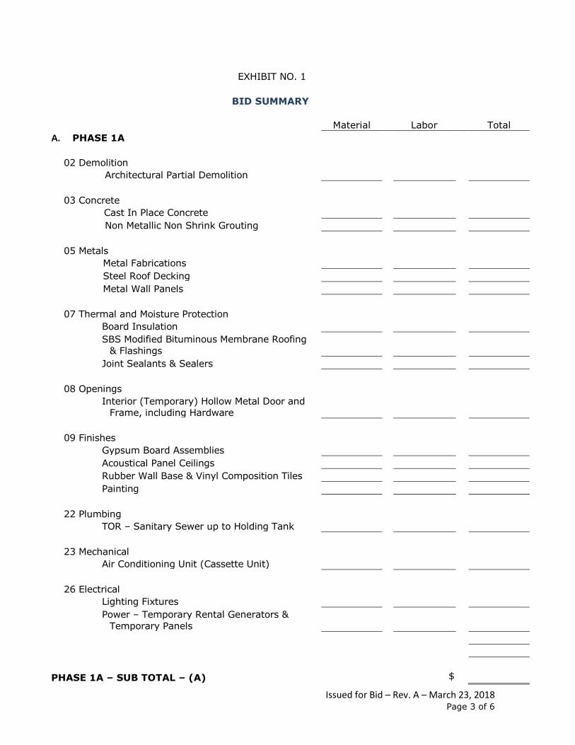
EXHIBIT NO. 1
BID SUMMARY
Material Labor Total
A. PHASE 1A
02 Demolition
Architectural Partial Demolition
03 Concrete
Cast In Place Concrete
Non Metallic Non Shrink Grouting
05 Metals
Metal Fabrications
Steel Roof Decking
Metal Wall Panels
07 Thermal and Moisture Protection
Board Insulation
SBS Modified Bituminous Membrane Roofing
& Flashings
Joint Sealants & Sealers
08 Openings
Interior (Temporary) Hollow Metal Door and
Frame, including Hardware
09 Finishes
Gypsum Board Assemblies
Acoustical Panel Ceilings
Rubber Wall Base & Vinyl Composition Tiles
Painting
22 Plumbing
TOR – Sanitary Sewer up to Holding Tank
23 Mechanical
Air Conditioning Unit (Cassette Unit)
26 Electrical
Lighting Fixtures
Power – Temporary Rental Generators &
Temporary Panels
PHASE 1A – SUB TOTAL – (A) $
Issued for Bid – Rev. A – March 23, 2018 Page 4 of 6
Material Labor Total
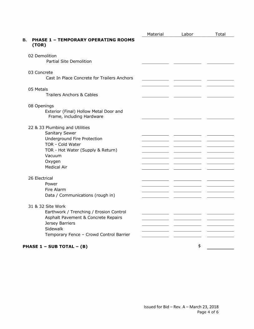
B. PHASE 1 – TEMPORARY OPERATING ROOMS
(TOR)
02 Demolition
Partial Site Demolition
03 Concrete
Cast In Place Concrete for Trailers Anchors
05 Metals
Trailers Anchors & Cables
08 Openings
Exterior (Final) Hollow Metal Door and
Frame, including Hardware
22 & 33 Plumbing and Utilities
Sanitary Sewer
Underground Fire Protection
TOR - Cold Water
TOR - Hot Water (Supply & Return)
Vacuum
Oxygen
Medical Air
26 Electrical
Power
Fire Alarm
Data / Communications (rough in)
31 & 32 Site Work
Earthwork / Trenching / Erosion Control
Asphalt Pavement & Concrete Repairs
Jersey Barriers
Sidewalk
Temporary Fence – Crowd Control Barrier
PHASE 1 – SUB TOTAL – (B) $
Issued for Bid – Rev. A – March 23, 2018 Page 5 of 6
Material Labor Total
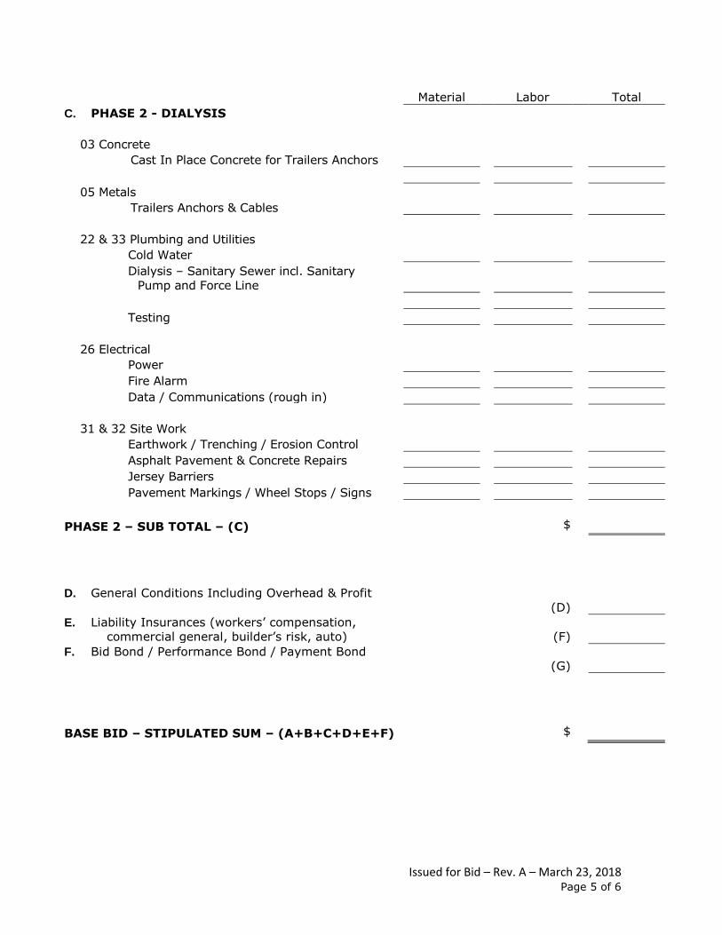
C. PHASE 2 - DIALYSIS
03 Concrete
Cast In Place Concrete for Trailers Anchors
05 Metals
Trailers Anchors & Cables
22 & 33 Plumbing and Utilities
Cold Water
Dialysis – Sanitary Sewer incl. Sanitary
Pump and Force Line
Testing
26 Electrical
Power
Fire Alarm
Data / Communications (rough in)
31 & 32 Site Work
Earthwork / Trenching / Erosion Control
Asphalt Pavement & Concrete Repairs
Jersey Barriers
Pavement Markings / Wheel Stops / Signs
PHASE 2 – SUB TOTAL – (C) $
D. General Conditions Including Overhead & Profit
(D)
E. Liability Insurances (workers’ compensation,
commercial general, builder’s risk, auto)
(F)
F. Bid Bond / Performance Bond / Payment Bond
(G)
BASE BID – STIPULATED SUM – (A+B+C+D+E+F) $
Issued for Bid – Rev. A – March 23, 2018 Page 6 of 6
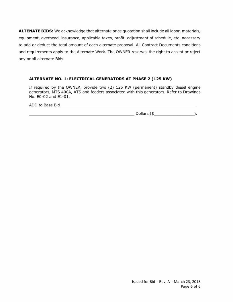
ALTENATE BIDS: We acknowledge that alternate price quotation shall include all labor, materials,
equipment, overhead, insurance, applicable taxes, profit, adjustment of schedule, etc. necessary
to add or deduct the total amount of each alternate proposal. All Contract Documents conditions
and requirements apply to the Alternate Work. The OWNER reserves the right to accept or reject
any or all alternate Bids.
ALTERNATE NO. 1: ELECTRICAL GENERATORS AT PHASE 2 (125 KW)
If required by the OWNER, provide two (2) 125 KW (permanent) standby diesel engine
generators, MTS 400A, ATS and feeders associated with this generators. Refer to Drawings
No. E0-02 and E1-01.
ADD to Base Bid
Dollars ($_________________).
TECHNICAL SPECIFICATIONS
Phase 1 (T.O.R.) & Phase 2 (Dialysis)
Issued for Bid
GOVERNOR JUAN F. LUIS HOSPITAL
St. Croix, U.S. Virgin Islands
March 21, 2018
Governor Juan F. Luis Hospital Phase 1 (T.O.R.) & Phase 2 (Dialysis) St. Croix, U.S. Virgin Islands
Table of Contents Issued for Bid – Rev. A CMA Architects & Engineers LLC 00 01 10-1 #18031 – March 21, 2018
DOCUMENT 00 01 10
TABLE OF CONTENTS
Status Revision Dated
DIVISION 00 – PROCUREMENT AND CONTRACTING
REQUIREMENTS
INTRODUCTION INFORMATION
00 01 10 Table of Contents IFB A 03/21/18
DIVISION 01 – GENERAL REQUIREMENTS
01 10 00 Summary of Work IFB A 03/21/18 01 20 00 Price and Payment Procedures IFB A 03/21/18 01 31 00 Administrative Requirements IFB A 03/21/18 01 33 00 Submittal Procedures IFB A 03/21/18 01 40 00 Quality Requirements IFB A 03/21/18 01 50 00 Temporary Facilities and Controls IFB A 03/21/18 01 60 00 Product Requirements IFB A 03/21/18 01 73 00 Execution and Closeout Requirements IFB A 03/21/18
DIVISION 02 – EXISTING CONDITIONS
02 41 13 Selective Site Demolition IFB A 03/21/18
DIVISION 03 - CONCRETE
03 11 13 Cast In Place Concrete Forming IFB A 03/21/18 03 21 11 Plain Steel Reinforcement Bars IFB A 03/21/18 03 31 13 Cast In Place Concrete IFB A 03/21/18 03 62 13 Non-Metallic Non-Shrink Grouting IFB A 03/21/18
DIVISION 05 – METALS
05 12 00 Structural Steel Framing IFB A 03/21/18 05 31 23 Steel Roof Decking IFB A 03/21/18 05 50 00 Metal Fabrications IFB A 03/21/18
DIVISION 06 – WOOD, PLASTICS AND COMPOSITES
06 10 00 Miscellaneous Rough Carpentry IFB A 03/21/18
DIVISION 07 - THERMAL AND MOISTURE PROTECTION
07 21 13 Board Insulation IFB A 03/21/18 07 52 16 SBS Modified Bituminous Membrane Roofing IFB A 03/21/18 07 62 00 Sheet Metal Flashing and Trim IFB A 03/21/18 07 92 13 Elastomeric Joint Sealants IFB A 03/21/18
Governor Juan F. Luis Hospital Phase 1 (T.O.R.) & Phase 2 (Dialysis) St. Croix, U.S. Virgin Islands
Table of Contents Issued for Bid – Rev. A CMA Architects & Engineers LLC 00 01 10-2 #18031 – March 21, 2018
DIVISION 08 - OPENINGS
08 12 13 Hollow Metal Frames IFB A 03/21/18 08 13 13 Hollow Metal Doors IFB A 03/21/18 08 71 00 Door Hardware IFB A 03/21/18
DIVISION 09 - FINISHES
09 21 16 Gypsum Board Assemblies IFB A 03/21/18 09 24 23 Portland Cement Plastering IFB A 03/21/18 09 51 13 Acoustical Panel Ceilings IFB A 03/21/18 09 65 13 Rubber Wall Base IFB A 03/21/18 09 65 19 Resilient Tile Flooring IFB A 03/21/18 09 91 00 Painting IFB A 03/21/18
DIVISION 13 – SPECIAL CONSTRUCTION
13 05 41 Seismic Control IFB A 03/21/18 13 05 42 Seismic Control and Vibration Isolation IFB A 03/21/18
DIVISION 22 – PLUMBING
22 05 18 Escutcheons for Plumbing Piping IFB A 03/21/18 22 05 19 Meters and Gages for Plumbing Piping IFB A 03/21/18 22 05 29 Pipe Hangers and Supports Pressure Systems IFB A 03/21/18 22 05 53 Identification for Plumbing Piping and Equipment IFB A 03/21/18 22 11 13 Facility Water Distribution Piping IFB A 03/21/18 22 13 13 Facility Sanitary Sewers IFB A 03/21/18 22 61 13 Compressed-Air Piping for Laboratory and
Healthcare Facilities IFB A 03/21/18 22 62 13 Vacuum Piping for Laboratory and Healthcare
Facilities IFB A 03/21/18 22 63 13 Piping for Laboratory and Healthcare Facilities IFB A 03/21/18
DIVISION 26 – ELECTRICAL
26 05 00 General Provisions IFB A 03/21/18 26 05 19 Conductors: Wires and Cables Up To 600 Volts IFB A 03/21/18 26 05 26 Grounding and Bonding IFB A 03/21/18 26 05 33.13 Raceways: Conduit System IFB A 03/21/18 26 05 33.16 Raceways: Conduit Fittings IFB A 03/21/18 26 05 33.29 Raceways: Outlet Boxes IFB A 03/21/18 26 05 33.33 Raceways: Junction, Pull and Cable Support
Boxes IFB A 03/21/18 26 05 36 Raceways: Cable Trays IFB A 03/21/18 26 05 43 Underground Duct System IFB A 03/21/18 26 08 00 Acceptance Testing IFB A 03/21/18 26 22 00 Low Voltage Dry Type Transformers IFB A 03/21/18 26 24 16 Circuit Breaker Panelboard IFB A 03/21/18 26 28 19 Enclosed Switches IFB A 03/21/18
Governor Juan F. Luis Hospital Phase 1 (T.O.R.) & Phase 2 (Dialysis) St. Croix, U.S. Virgin Islands
Table of Contents Issued for Bid – Rev. A CMA Architects & Engineers LLC 00 01 10-3 #18031 – March 21, 2018
DIVISION 31 – EARTHWORK
31 20 00 Earth Moving IFB A 03/21/18 31 23 33 Trenching and Backfilling IFB A 03/21/18 31 25 00 Erosion and Sedimentation Controls IFB A 03/21/18
DIVISION 32 – EXTERIOR IMPROVEMENTS
32 11 23 Aggregate Base Course IFB A 03/21/18 32 12 16 Asphalt Paving IFB A 03/21/18 32 17 23 Painted Pavement Markings IFB A 03/21/18
DIVISION 33 – UTILITIES
33 11 13 Site Water Utility Distribution Piping IFB A 03/21/18 33 11 19 Fire Suppression Utility Distribution Piping IFB A 03/21/18 33 13 00 Disinfecting of Water Utility Distribution IFB A 03/21/18 33 31 00 Sanitary Sewerage System IFB A 03/21/18
IFB = Issued for Bid
END OF TABLE OF CONTENTS
Governor Juan F. Luis Hospital Phase 1 (T.O.R.) & Phase 2 (Dialysis) St. Croix, U.S. Virgin Islands
Summary of Work Issued for Bid – Rev. A CMA Architects & Engineers LLC 01 10 00 - 1 #18031– March 21, 2018
SECTION 01 10 00
SUMMARY OF WORK
PART 1 - GENERAL
1.1 SECTION INCLUDES
A. Project Information.
B. Work covered by Contract Documents.
C. Work by Owner.
D. Purchase contracts.
E. Access to site.
F. Work restrictions.
G. Specification and drawing conventions.
H. Miscellaneous provisions.
I. Scope of Work – General.
J. Scope of Work – Phase 1 & 2.
1.2 RELATED SECTIONS
A. Remaining Division 01 Sections – General Requirements.
B. Division 02 through 41 Sections – Technical Specifications.
1.3 PROJECT INFORMATION
A. Project Identification: Governor Juan F. Luis Hospital Phase 1 (T.O.R.) & Phase 2 (Dialysis)
B. Project Location: Governor Juan F. Luis Hospital St. Croix, U.S. Virgin Islands
C. Owner: Governor Juan F. Luis Hospital
D. Architect-Engineer: CMA International Architects & Engineers PSC
1.4 WORK BY OWNER
A. General: Cooperate fully with Owner so work may be carried out smoothly, without interfering with or delaying work under this Contract or work by Owner. Coordinate the Work of this Contract with work performed by Owner.
B. Concurrent Work: Owner will perform the following construction operations at Project site. Those operations will be conducted simultaneously with work under this Contract.
1.5 PURCHASE CONTRACTS
A. General: Owner has negotiated purchase contracts with suppliers of material and equipment to be incorporated into the Work. Owner will assign these purchase contracts to Contractor. Include costs
Governor Juan F. Luis Hospital Phase 1 (T.O.R.) & Phase 2 (Dialysis) St. Croix, U.S. Virgin Islands
Summary of Work Issued for Bid – Rev. A CMA Architects & Engineers LLC 01 10 00 - 2 #18031– March 21, 2018
for purchasing, receiving, handling, storage if required, and installation of material and equipment in the Contract Sum, unless otherwise indicated.
1.6 ACCESS TO SITE
A. General: Contractor shall have limited use of Project site for construction operations as indicated on Drawings by the Contract limits and as indicated by requirements of this Section.
B. Use of Site: Limit use of Project site to areas within the Contract limits indicated. Do not disturb portions of Project site beyond areas in which the Work is indicated.
1. Limits: Confine construction operations to building under renovations.
2. Driveways, Walkways and Entrances: Keep main entrance to hospital, driveways parking garage, and entrances serving premises clear and available to Owner, Owner's employees, and emergency vehicles at all times. Do not use these areas for parking or storage of materials.
a. Schedule deliveries to minimize use of driveways and entrances by construction operations.
b. Schedule deliveries to minimize space and time requirements for storage of materials and equipment on-site.
C. Condition of Existing Building: Maintain portions of existing building affected by construction operations in a weathertight condition throughout construction period. Repair damage caused by construction operations.
1.7 WORK RESTRICTIONS
A. Work Restrictions, General: Comply with restrictions on construction operations.
1. Comply with limitations on use of public streets and with other requirements of authorities having jurisdiction.
B. Existing Utility Interruptions: Do not interrupt utilities serving facilities occupied by Owner unless permitted under the following conditions and then only after providing temporary utility services according to requirements indicated:
1. Notify Owner’s Representative not less than two (2) working days in advance of proposed utility interruptions.
2. Obtain Owner Representative’s written permission before proceeding with each utility interruption.
C. Noise, Vibration, and Odors: Coordinate operations that may result in high levels of noise and vibration, odors, or other disruption to Owner occupancy with Owner.
1. Notify Owner’s Representative not less than two (2) working days in advance of proposed disruptive operations.
2. Obtain Owner Representative’s written permission before proceeding with disruptive operations.
D. Nonsmoking Building: Smoking is not permitted within the Hospital Site.
E. Controlled Substances: Use of tobacco products and other controlled substances on Hospital facilities is not permitted.
Governor Juan F. Luis Hospital Phase 1 (T.O.R.) & Phase 2 (Dialysis) St. Croix, U.S. Virgin Islands
Summary of Work Issued for Bid – Rev. A CMA Architects & Engineers LLC 01 10 00 - 3 #18031– March 21, 2018
F. Employee Identification: Provide identification tags for Contractor personnel working on Hospital facilities. Require personnel to use identification tags at all times.
1.8 SPECIFICATION AND DRAWING CONVENTIONS
A. Specification Content: The Specifications use certain conventions for the style of language and the intended meaning of certain terms, words, and phrases when used in particular situations. These conventions are as follows:
1. Imperative mood and streamlined language are generally used in the Specifications. The words "shall," "shall be," or "shall comply with," depending on the context, are implied where a colon (:) is used within a sentence or phrase.
2. Specification requirements are to be performed by Contractor unless specifically stated otherwise.
B. Division 01 General Requirements: Requirements of Sections in Division 01 apply to the Work of all Sections in the Specifications.
C. Drawing Coordination: Requirements for materials and products identified on Drawings are described in detail in the Specifications. One or more of the following are used on Drawings to identify materials and products:
1. Terminology: Materials and products are identified by the typical generic terms used in the individual Specifications Sections.
2. Abbreviations: Materials and products are identified by abbreviations scheduled on Drawings.
3. Keynoting: Materials and products are identified by reference keynotes referencing Specification Section numbers found in this Project Manual.
1.9 MISCELLANEOUS PROVISIONS
A. Operation of Existing Facilities:
1. The existing Hospital facilities and its ancillary facilities must be kept in continuous operations throughout the entire construction period.
2. Contractor shall provide temporary facilities and make temporary modifications as necessary to keep the existing facilities in operation during the construction period.
B. Connections to Existing Facilities:
1. Contractor shall make all necessary connections to existing facilities. In each case, Contractor shall receive permission from the Owner’s On Site Representative prior to undertaking connections. Contractor shall protect facilities against deleterious substances and damage.
2. Connections to existing facilities shall be thoroughly planned in advance, and all required equipment, materials and labor shall be on hand at the time of undertaking the connections. Work shall proceed continuously (around the clock) if necessary to complete connections in the minimum time.
C. Safety Requirements:
1. The work site is within Hospital facilities and the Contractor shall comply at all times with the Owner’s safety requirements.
Governor Juan F. Luis Hospital Phase 1 (T.O.R.) & Phase 2 (Dialysis) St. Croix, U.S. Virgin Islands
Summary of Work Issued for Bid – Rev. A CMA Architects & Engineers LLC 01 10 00 - 4 #18031– March 21, 2018
2. It is the Contractor’s responsibility to provide safety equipment required to protect the Owner’s personnel and Owner’s property to the satisfaction of OSHA Standards for the Construction Industry (29 CFR Part 1926). This includes but is not limited to the follows:
a. Provide Owner approved fire blankets and welding boxes as required for welding.
b. Provide fire hoses with pressure to nozzle at all times when performing hot work. The hose will be manned at all times during working hours.
c. Provide adequate fire extinguishers when performing hot work.
d. In addition to the above, the Contractor shall bring, special emphasis to bear on the subject to safety by use of posters and other visual reminders and such other methods as he may devise. The Contractor’s proposed safety program is to be reviewed with the Owner’s On Site Representative prior to the start of field construction and integrated into the overall safety program.
3. The Contractor shall conduct an indoctrination session of the "Contractor Safety Regulations" with his own forces and subcontractors employees within the first week of employment. Each Contractor and Sub-Contractor employee receiving this indoctrination will be required to sign a Contractor’s form stating that he has received this training. Contractor shall conduct weekly safety meetings with his employees.
Governor Juan F. Luis Hospital Phase 1 (T.O.R.) & Phase 2 (Dialysis) St. Croix, U.S. Virgin Islands
Summary of Work Issued for Bid – Rev. A CMA Architects & Engineers LLC 01 10 00 - 5 #18031– March 21, 2018
SCOPE OF WORK GENERAL
Governor Juan F. Luis Hospital Phase 1 (T.O.R.) & Phase 2 (Dialysis) St. Croix, U.S. Virgin Islands
Summary of Work Issued for Bid – Rev. A CMA Architects & Engineers LLC 01 10 00 - 6 #18031– March 21, 2018
PART 2 - SCOPE OF WORK - GENERAL
2.1 GENERAL
A. The following is an outline of the general work requirements for Phase 1 (T.O.R.) and Phase 2 (Dialysis) at Governor Juan F. Luis Hospital. This outline is prepared as a guide only and is not to be considered as a complete description of the work requirements.
B. The Contractor shall construct the items listed below and the more specifically detailed in the drawings in strict accordance with the specifications listed elsewhere in the Contract Documents.
C. Where the Contractor’s work shall encounter existing construction, the Contractor shall verify the condition and dimensional accuracy before proceeding. Where the new construction, as specified, is in conflict with existing conditions, the Contractor shall immediately bring it to the attention of the Owner’s On Site Representative and/or Architect-Engineer for resolution.
D. All equipment and materials shall be installed in strict accordance with the printed instructions of the manufacturer, unless more stringent requirements are required by the Owner’s On Site Representative or are shown on the drawings.
E. Contractor shall notify and receive written approval from the Owner’s On Site Representative and/or Architect-Engineer for proposed deviations from Contract Documents. If proposed deviations are made without the Owner’s On Site Representative and/or Architect-Engineer written approval, this shall be considered as just cause for dismantling and removal of said work at Owner’s On Site Representative and/or Architect-Engineer discretion. Reconstruction and/or reinstallation of the work shall be at Contractor’s expense.
F. Owner’s On Site Representative, Architect-Engineer and/or his authorized representative shall have the right at all times to inspect and test the work and shall for this purpose have access to the work whenever it is in preparation or in progress. The Contractor shall provide necessary labor and proper facilities for such access, inspection and testing, and shall provide complete information concerning all materials entering into the work.
G. Contractor shall handle and haul all materials, equipment and tools from the designated storage area(s) to the work area.
H. Contractor shall provide all hoisting, scaffolding and/or shoring required for the complete installation of all materials, equipment or systems included in this Scope of Work.
I. Contractor shall provide all required cutting, drilling, bolting, welding, patching, weatherproof, etc. necessary to complete the work under this Scope of Work.
J. Contractor shall furnish the services of all trades necessary to complete all items enclosed in this Scope of Work.
K. Contractor shall furnish material and labor necessary to correct at his expense, any items improperly installed.
L. Contractor shall receive, unload, store and provide necessary weather protection for all materials, equipment and tools which he furnishes and installs. These items shall be stored in areas within El Día, Inc.’s premises designated by the Owner’s On Site Representative.
M. Contractor shall furnish, install and maintain all temporary field offices required for this work for the duration of this Contract. Location of temporary field office to be designated by the Owner’s Representative.
N. Contractor shall furnish all field engineering services required to complete this work.
Governor Juan F. Luis Hospital Phase 1 (T.O.R.) & Phase 2 (Dialysis) St. Croix, U.S. Virgin Islands
Summary of Work Issued for Bid – Rev. A CMA Architects & Engineers LLC 01 10 00 - 7 #18031– March 21, 2018
O. Contractor shall make all submittals and obtain all approvals as specified and required to complete this work.
P. Contractor shall provide all required guarantees and certification for items of work and systems installed under this contract.
Q. Rubbish and dirt resulting from the Contractor’s work shall be removed by the Contractor daily or more frequently as necessary to prevent the accumulation thereof and shall be disposed of as directed by the Owner’s On Site Representative and/or Architect-Engineer. Failure of the Contractor to clean up and remove rubbish as called for, will be cause for the Owner’s On Site Representative and/or Architect-Engineer to order this work to be done by others at the expense of the Contractor.
R. The areas assigned for Contractor’s use and areas in which he is doing construction work shall be cleaned thoroughly at least once daily. All construction debris shall be removed in a legal manner from the project site on a daily basis. Contractor is responsible for maintaining a high standard of housekeeping in his construction sites and storage areas at all times. Contractor shall store materials in a safe and organized manner and dispose off site material containers and construction debris on a daily basis.
S. All construction trailers, office sheds and warehouses used by the Contractor during the execution of this work shall be placed at the place (authorized by the Owner’s On Site Representative) within the project site.
T. When the work is being executed away from the premises, the Owner’s On Site Representative and Architect-Engineer shall be notified, in reasonable time, where such work is being done and when it will be ready for inspection, so that the Owner’s On Site Representative, the Architect-Engineer and/or his authorized representatives may, if they should so desire, inspect the same from time to time before delivery.
U. Contractor shall take necessary actions to eliminate possible fire hazards and to prevent damage to any construction work, building materials, equipment, temporary field offices, storage sheds and all other property.
V. Contractor shall protect all existing materials and areas against damage during the performance of his Work. Any damage to roads, parking lots, traffic coatings (parking lots), steel, concrete slabs, walls, roof, piping, equipment, etc., inflicted by this Contractor will be repaired at his expense.
W. Contractor shall contact Owner’s On Site Representative regarding safety requirements and shall comply with said requirements for the entire duration of the Contract.
X. The progress schedule will be monitored on a daily and/or weekly basis by the Owner’s On Site Representative and/or the Architect-Engineer, if it becomes apparent during the monitoring of the progress that slippage has occurred, then the Owner’s On Site Representative and/or the Architect-Engineer shall direct the Contractor to take all necessary steps to regain the slippage and maintain the additional manpower until such time that the progress agrees with the current schedule. This will be accomplished at no cost to Owner.
Y. The Contractor will be responsible for maintain the project with the maximum member of skilled workers to achieve the completion dates indicated in the construction schedule. If the Contractor determines that overtime and/or shift work is required to attain such dates, such costs shall be included in the Bid Proposal.
Z. Contractor shall hire and pay for the services of a testing laboratory to perform inspection and tests required by the respective Specification Sections. Testing, because of faulty work, will be paid by the Contractor.
1. Soil classification tests
Governor Juan F. Luis Hospital Phase 1 (T.O.R.) & Phase 2 (Dialysis) St. Croix, U.S. Virgin Islands
Summary of Work Issued for Bid – Rev. A CMA Architects & Engineers LLC 01 10 00 - 8 #18031– March 21, 2018
2. Soil compaction tests
3. Concrete compressive strength tests
4. Piping hydrostatic testing
5. Any other testing listed in both the drawings and technical specifications.
AA. During the construction, Contractor shall provide the quantity of filled or fully charged fire extinguishers and hose to meet safety and fire prevention practices established under NFPA 241.
AB. Welding, flame cutting or other operations involving the use of flame, arcs or sparking devices, will not be allowed without adequate protection. All combustible or flammable material shall be removed from the immediate working area or, if removal is impossible, all flammable or combustible materials shall be protected with suitable noncombustible shields to prevent spark, flames, or hot metal from reaching the flammable or combustible materials.
AC. Not more than one day’s supply of flammable liquids such as oil, gasoline, paint or paint solvent shall be brought into the buildings at any one time. All flammable liquids having a flash point of one hundred ten degrees Fahrenheit (110oF) or below which must be brought into the building shall be confined in Underwriters’ Laboratories labeled safety cans. If one day’s supply requires quantities greater than a safety can will hold, one (1) fifty-five (55) gallon drum may be used. Drums are to be equipped with safety bungs and U.L. listed pumps. The bulk supply of all flammables shall be stored at least seventy-five feet (75’-0") from the building or other combustible materials. Spigots on drums containing flammable liquids are prohibited on the project site.
AD. Flammable building materials located inside the building shall be kept to an absolute minimum.
AE. Oil-soaked rags, papers, and other combustible debris shall be removed from the building at the close of each day’s work. This material shall be stored in a suitable approved area away from all buildings and hauled away prior to reaching large accumulations.
AF. Burning of debris and rubbish on the site is not permitted.
AG. Materials and/or equipment stored within the building in cardboard cartons, wood crates or other combustible containers shall be stored in an orderly manner and accessibly located. Firefighting equipment of approved types shall be placed in the immediate vicinity of any materials or equipment stored in this type of crane or carton.
AH. No gasoline, benzene or like combustible materials shall be poured into sewers, manholes, or traps.
AI. The gases used for welding and cutting shall be purchased in cylinders. These cylinders shall be constructed and maintained in accordance with regulations of the U.S. Department of Transportation. The cylinders shall bear DOT markings and the contents of each cylinder shall be legibly marked in large letters.
AJ. Cylinders of oxygen and acetylene inside buildings shall be stored in areas that are well ventilated and free from moisture and water. Flammable substances, such as oil and volatile liquids shall not be stored in the same area. The area assigned to cylinder storage shall be well protected by location from possible damage by other types of activity. Oxygen cylinders stored inside shall be separated by a fire-resistant partition from cylinders containing flammable gases.
AK. Cylinders of oxygen and acetylene are to be protected from the hot sun by such means as canopies and/or sheds.
Governor Juan F. Luis Hospital Phase 1 (T.O.R.) & Phase 2 (Dialysis) St. Croix, U.S. Virgin Islands
Summary of Work Issued for Bid – Rev. A CMA Architects & Engineers LLC 01 10 00 - 9 #18031– March 21, 2018
AL. To avoid confusion, full cylinders and empty cylinders should be stored in separate groups. All empty cylinders shall be marked "Empty" or "MT."
AM. Flammable gas, such as acetylene, and other gases shall not be premixed with air or oxygen, prior to consumption, except at burner or in a cutting or welding torch designed for that purpose.
AN. Oxygen and acetylene shall be withdrawn from cylinders provided with regulators and/or pressure-reducing valves specifically designed for such purposes.
AO. All cylinders shall be set in a vertical position during storage at the job site and while in portable carts, when in use, and shall be fastened to insure against tipping.
AP. Owner reserves the right to perform work related to the Project with its own forces, and to award separate contracts in connection with other portions of the Project or another work on the Project Site which are not part of the Work. Owner shall provide for the coordination of the work of its own and of each separate contractor with the Work of Contractor (Work of this Bid Package) who shall cooperate therewith as provided herewith. Contractor (this Bid Package) shall afford Owner and separate contractors reasonable opportunity for the introduction and storage of their materials and equipment and for the execution of their work. Contractor shall connect and coordinate the work with the work of Owner and separate contractors as required by the Contract Documents. If any part of the Work (this Bid Package) depends for proper execution or results upon the work of Owner or any other separate contractor, Contractor shall, prior to proceeding with Work, promptly report to the Owner’s On Site Representative any discrepancies or defects that are reasonably discoverable which render such work unsuitable for proper execution and results. Failure of Contractor so to report shall constitute an acceptance of Owner’s or separate contractor’s work as fit and proper to receive the Work. Any costs caused by defective or ill timed work shall be borne by the party responsible therefore. Should Contractor (this Bid Package) cause damage to the work or property of Owner, or to other work or property on the Project site, Contractor (this Bid Package) shall promptly remedy such damages.
AQ. Wall Penetrations
1. Where pipes pass through sleeves (new construction) or core-drilled holes (existing construction) on non-rated construction, provide backer rod and fill outer ½ inch depth of the annular space with joint sealant as specified on Section 07 92 00.
2. Where pipes pass through fire-rated construction follow recommendations given on Section 07 84 43.
AR. Penetrations and Escutcheons
1. Provide galvanized steel sleeves where pipes or conduits pass through non-rated walls and floor slabs. Sleeves shall be a minimum of 2 inches larger than the pipe and extend 2 inches above floor slab and terminate flush at walls.
2. Provide escutcheons plates that are neat, rigid, securely attached where pipe or conduits penetrates walls or ceilings. Provide stainless steel or chrome plated brass in finished areas.
AS. Pipe and Equipment Identification
1. Piping
a. Identify all pipelines with adhesives markers indicating the contents and direction of flow, as listed in the Drawings. Markers shall be installed where piping changes direction or passes through walls or floors. Markers to be Brady, Seton or Perma-Color with the background color coding as required by OSHA. Coat with clear lacquer after installation and tape both ends of marker.
Governor Juan F. Luis Hospital Phase 1 (T.O.R.) & Phase 2 (Dialysis) St. Croix, U.S. Virgin Islands
Summary of Work Issued for Bid – Rev. A CMA Architects & Engineers LLC 01 10 00 - 10 #18031– March 21, 2018
b. Identify piping 2½ inches and smaller with ¾-inch minimum height lettering, every 20 feet and at valve locations.
c. Identify piping 3 inches and larger with 1¼ inch minimum height lettering, every 20 feet and at valve locations.
d. Provide arrows 6 inches long at each marker indicating direction of flow. If in both directions, provide double arrows.
e. Where piping is provided with insulation, provide the size letters scheduled above in accordance with the outside dimension of insulation.
f. Provide, in addition, a minimum of one marker in each room.
g. In the event that commercial markers are not available for certain lines, the legend may be stenciled on the background color.
h. Use markers and adhesive suitable for the humidity and for surface temperatures ranging from –20° to +150°F.
i. Provide identification labels for fire protection risers, feed mains, and cross mains only (branch piping need not have labels).
2. Equipment Identification:
a. Identify each new fan, pump, motor, motor starter, water heater, and similar equipment with laminated black plastic tags with engraved white core lettering. Use tags with a minimum thickness of 1/16-inch, a minimum size of 1½ inches x 4 inches, and with 1-inch high lettering. Acceptable manufacturers: Seton, WW Wilcox or Brady. Secure tags to equipment by means of screws or bolts.
b. All equipment shall have brass plates or tags that reference the maintenance manuals and the required routine maintenance action to be performed on the equipment.
c. Warning Signs: Place warning signs on all machines driven by electric motors which are controlled by fully automatic starters.
d. Valves:
1) Identify each valve with a brass tag, minimum 16 gage and 1½-inch diameter, with engraved lettering on both sides identifying the number and service of the valve. Number valves consecutively. Secure tags to valve with or approved removable rings.
2) Upon completion of the work, furnish the Architect with a complete schedule of the valves installed, together with a drawing or drawings identifying the location of the numbered valves, and the service which each controls. Mount one copy of each of the schedules and drawings under Plexiglass in satin finish aluminum frames in the equipment rooms or as directed by the Architect.
Governor Juan F. Luis Hospital Phase 1 (T.O.R.) & Phase 2 (Dialysis) St. Croix, U.S. Virgin Islands
Summary of Work Issued for Bid – Rev. A CMA Architects & Engineers LLC 01 10 00 - 11 #18031– March 21, 2018
SCOPE OF WORK PHASE 1 (T.O.R.) & PHASE 2 (DIALYSIS)
Governor Juan F. Luis Hospital Phase 1 (T.O.R.) & Phase 2 (Dialysis) St. Croix, U.S. Virgin Islands
Summary of Work Issued for Bid – Rev. A CMA Architects & Engineers LLC 01 10 00 - 12 #18031– March 21, 2018
PART 3 - SCOPE OF WORK: PHASE 1 (T.O.R.) & PHASE 2 (DIALYSIS)
3.1 GENERAL
A. Architectural, Civil, Structural, Mechanical and Electrical Work shall be in accordance with the Scope of Work, Drawings and Technical Specifications.
B. See scope of work on a separate document titled:
1. “Scope of Work: Phase 1 (T.O.R.) & Phase 2 (Dialysis)”
END OF SECTION
Governor Juan F. Luis Hospital Phase 1 (T.O.R.) & Phase 2 (Dialysis)
St. Croix, U.S. Virgin Islands
Price and Payment Procedures Issued for Bid – Rev. A
CMA Architects & Engineers LLC 01 20 00 - 1 #18031– March 21, 2018
SECTION 01 20 00
PRICE AND PAYMENT PROCEDURES
PART 1 - GENERAL
1.1 SECTION INCLUDES
A. Schedule of values.
B. Applications for payment.
C. Change procedures.
1.2 SCHEDULE OF VALUES
A. Submit printed schedule on Contractor's standard form or electronic media printout.
B. Submit four copies of the Schedule of Values within 10 calendar days after Date of Owner-
Contractor Agreement or Date of Notice to Proceed, whichever comes first.
C. Format:
1. The Contractor and each Subcontractor shall prepare a trade payment breakdown for the work
for which each is responsible.
2. Utilize the Table of Contents of this Project Manual.
3. Identify each line item with number of the major specification section.
4. The form shall be divided in detail sufficient to exhibit each section of the Work and shall be
updated as required by the Owner Representative.
5. Any trade breakdown which fails to include sufficient detail, is unbalanced or exhibits "front
loading" of the value of the Work shall be rejected.
6. If trade breakdown has been initially approved and subsequently used, but later found
improper for any reason, sufficient funds will be withheld from future Applications for Payment
to ensure an adequate reserve (exclusive of normal retainage) to complete the Work.
7. Include within each line item, a direct proportional amount of Contractor’s profit.
D. Revise schedule to list approved Change Orders, with each Application for Payment.
1.3 APPLICATIONS FOR PAYMENT
A. Submit four (4) copies of each Application and Certificate for Payment.
B. Content and Format: Utilize Schedule of Values for listing items in Application for Payment.
C. Submit preliminary application for payment to Owner's Representative, for review and concurrence, 5
calendar days prior to formal submission date. Include only percentage of completion figures, not
complete money tabulations. Resubmit corrected percentages with formal application for payment to
Owner’s Representative for his approval and signature prior to submittal to Owner.
D. Payment Period: Submit at intervals stipulated in the Agreement.
Governor Juan F. Luis Hospital Phase 1 (T.O.R.) & Phase 2 (Dialysis)
St. Croix, U.S. Virgin Islands
Price and Payment Procedures Issued for Bid – Rev. A
CMA Architects & Engineers LLC 01 20 00 - 2 #18031– March 21, 2018
E. First Application for Payment will not be processed until all the following documentation is approved
by the Owner Representative:
1. Schedule of Values
2. Schedule of Submittals
3. Cash-Flow (S-Curve)
4. Procurement Schedule Format
5. Construction Schedule (Cash-flow related)
F. No progress payment will be made until Record Documents are up to date (Refer to Section 01 73
00) and submittals of all products and materials submitted for payment have been approved by the
Architect – Engineer.
G. The progress payment 30 days before Substantial Completion will not be made until all operating
and maintenance manuals and guaranties are submitted as required in Section 01 73 00.
H. Progress payment may be withheld for failure to submit shop drawings and product data as
requested in Section 01 33 00.
I. Include the following documentation with each Application for Payment:
1. Record documents as specified in Section 01 73 00, for review by the Owner Representative
which will be returned to the Contractor. Certify as a part of each application for payment that
the project record documents are current at the time of application is submitted. The
Contractor shall require such drawings to be correct as a condition of approving any payment
to the trade Contractor and Subcontractor.
2. Written list identifying each location where materials are stored off the Project site and the
value of materials at each location. The Contractor shall procure insurance satisfactory to the
Owner for materials stored off the Project site in an amount not less than the total value
thereof.
3. As-Built construction progress schedules, revised and current as specified in Section 01 33 00.
If actual progress is behind schedule, discussion of a “catch up plan” that Contractor has
employed or will employ to recover the original Project Schedule.
4. An update of the Procurement Schedule.
5. An update of the S-Curve indicating projected and actual cash flow to date.
6. A 30-Day Look-Ahead Schedule of Project.
7. A summary of any claims anticipated by Contractor with respect to the Work, including the
anticipated cost and schedule impacts of any such claims.
8. Concrete compressive strength test results of concrete placed during the payment period
covered by the Application for Payment.
9. Compaction test results of fill material placed during the payment period covered by the
Application for Payment.
Governor Juan F. Luis Hospital Phase 1 (T.O.R.) & Phase 2 (Dialysis)
St. Croix, U.S. Virgin Islands
Price and Payment Procedures Issued for Bid – Rev. A
CMA Architects & Engineers LLC 01 20 00 - 3 #18031– March 21, 2018
1.4 CHANGE PROCEDURES
A. Submittals: Submit name of individual authorized to receive change documents, and be responsible
for informing others in Contractor's employ or Subcontractors of changes to the Work.
B. The Owner Representative will advise of minor changes in the Work not involving adjustment to
Contract Sum/Price or Contract Time.
C. The Owner Representative may issue a Proposal Request including a detailed description of
proposed change with supplementary or revised Drawings and specifications, a change in Contract
Time for executing the change with stipulation of overtime work required and the period of time
during which the requested price will be considered valid. Contractor will prepare and submit
estimate within 21 calendar days.
D. Stipulated Sum/Price Change Order: Based on Proposal Request and Contractor's fixed price
quotation or Contractor's request for Change Order as approved by Owner Representative.
1. Contractor shall submit proposals for changes in the Work to the Owner Representative within
21 calendar days after a modification is issued.
2. Proposals, to be submitted within 21 calendar days after receipt of request for proposal, shall
be in legible form (three copies), with an itemized breakdown that will include material,
quantities, unit prices, labor costs (separated into trades), construction equipment, etc. Labor
costs are to be identified with specific material placed or operation performed. The Contractor
must obtain and furnish with a proposal an itemized breakdown as described above, signed by
each subcontractor participating in the change regardless of tier.
3. Proposals will not be reviewed if the same does not comply with paragraph D.2.
E. Unit Price Change Order: For contract unit prices and quantities, the Change Order will be executed
on fixed unit price basis. For unit costs or quantities of units of work which are not pre-determined,
execute Work under Construction Change Directive. Changes in Contract Sum/Price or Contract
Time will be computed as specified for Time and Material Change Order.
F. Construction Change Directive: Owner Representative may issue directive, Construction Change
Directive signed by Owner Representative, instructing Contractor to proceed with change in the
Work, for subsequent inclusion in a Change Order. Document will describe changes in the Work, and
designate method of determining any change in Contract Sum/Price or Contract Time. Promptly
execute change.
G. Time and Material Change Order: Submit itemized account and supporting data after completion of
change, within time limits indicated in Conditions of the Contract. Owner Representative will
determine change allowable in Contract Sum/Price and Contract Time as provided in Contract
Documents.
H. Maintain detailed records of work done on Time and Material Force Account basis. Provide full
information required for evaluation of proposed changes, and to substantiate costs for changes in the
Work.
I. Document each quotation for change in cost or time with sufficient data to allow evaluation of
quotation.
J. Execution of Change Orders: Owner Representative will issue Change Orders for signatures of
parties as provided in Conditions of the Contract.
K. Correlation Of Contractor Submittals:
Governor Juan F. Luis Hospital Phase 1 (T.O.R.) & Phase 2 (Dialysis)
St. Croix, U.S. Virgin Islands
Price and Payment Procedures Issued for Bid – Rev. A
CMA Architects & Engineers LLC 01 20 00 - 4 #18031– March 21, 2018
1. Promptly revise Schedule of Values and Application for Payment forms to record each
authorized Change Order as separate line item and adjust Contract Sum/Price.
2. Promptly revise progress schedules to reflect change in Contract Time, revise sub-schedules
to adjust times for other items of work affected by the change, and resubmit.
3. Promptly enter changes in Project Record Documents.
PART 2 - PRODUCTS
Not Used.
PART 3 - EXECUTION
Not Used.
END OF SECTION
Governor Juan F. Luis Hospital Phase 1 (T.O.R.) & Phase 2 (Dialysis) St. Croix, U.S. Virgin Islands
Administrative Requirements Issued for Bid – Rev. A CMA Architects & Engineers LLC 01 31 00 - 1 #18031 – March 21, 2018
SECTION 01 31 00
ADMINISTRATIVE REQUIREMENTS
PART 1 - GENERAL
1.1 SECTION INCLUDES
A. Coordination and project conditions.
B. Preconstruction meeting.
C. Site mobilization meeting.
D. Progress meetings.
E. Pre-installation meetings.
1.2 COORDINATION AND PROJECT CONDITIONS
A. Coordinate scheduling, submittals, and Work of various sections of Project Manual to ensure efficient and orderly sequence of installation of interdependent construction elements, with provisions for accommodating items installed later.
1.3 PRECONSTRUCTION MEETING
A. Owner will schedule meeting after Notice of Award.
B. Attendance Required: Owner, Architect/Engineer and Contractor.
C. Agenda:
1. Execution of Owner-Contractor Agreement.
2. Submission of executed bonds and insurance certificates.
3. Distribution of Contract Documents.
4. Submission of list of Subcontractors, list of products, schedule of values, and progress schedule.
5. Designation of personnel representing parties in Contract, and Architect/Engineer.
6. Procedures and processing of field decisions, submittals, substitutions, applications for payments, proposal request, Change Orders, and Contract closeout procedures.
7. Scheduling.
8. Construction’s personnel parking.
9. Construction Compound.
D. Record minutes and distribute copies within two days after meeting to participants, with two copies to Architect/Engineer, Owner, and those affected by decisions made.
1.4 SITE MOBILIZATION MEETING
A. Owner will schedule meeting at Project site prior to Contractor occupancy.
Governor Juan F. Luis Hospital Phase 1 (T.O.R.) & Phase 2 (Dialysis) St. Croix, U.S. Virgin Islands
Administrative Requirements Issued for Bid – Rev. A CMA Architects & Engineers LLC 01 31 00 - 2 #18031 – March 21, 2018
B. Attendance Required: Owner, Architect/Engineer, Contractor, Contractor's Superintendent, Safety Officer, and major Subcontractors.
C. Agenda:
1. Use of premises by Owner and Contractor.
2. Owner's requirements.
3. Construction facilities and controls.
4. Temporary utilities provided by Owner.
5. Security and housekeeping procedures.
6. Schedules.
7. Submittal Procedures.
8. Application for payment procedures.
9. Procedures for testing.
10. Procedures for maintaining record documents.
11. Requirements for start-up of equipment.
D. Record minutes and distribute copies within two days after meeting to participants, with two copies to Architect/Engineer, Owner, and those affected by decisions made.
1.5 PROGRESS MEETINGS
A. Schedule and administer meetings throughout progress of the Work at maximum weekly intervals.
B. Make arrangements for meetings, prepare agenda with copies for participants, preside at meetings.
C. Attendance Required: Job superintendent, major subcontractors and suppliers, Owner, Architect/Engineer, as appropriate to agenda topics for each meeting.
D. Agenda:
1. Review minutes of previous meetings.
2. Review of Work progress.
3. Field observations, problems, and decisions.
4. Identification of problems impeding planned progress.
5. Review of submittals schedule and status of submittals.
6. Review of off-site fabrication and delivery schedules.
7. Maintenance of progress schedule.
8. Corrective measures to regain projected schedules.
9. Planned progress during succeeding work period.
10. Coordination of projected progress.
Governor Juan F. Luis Hospital Phase 1 (T.O.R.) & Phase 2 (Dialysis) St. Croix, U.S. Virgin Islands
Administrative Requirements Issued for Bid – Rev. A CMA Architects & Engineers LLC 01 31 00 - 3 #18031 – March 21, 2018
11. Maintenance of quality and work standards.
12. Effect of proposed changes on progress schedule and coordination.
13. Other business relating to Work.
E. Record minutes and distribute copies within two days after meeting to participants, with two copies to Architect/Engineer, Owner, and those affected by decisions made.
PART 2 - PRODUCTS
Not Used.
PART 3 - EXECUTION
Not Used.
END OF SECTION
Governor Juan F. Luis Hospital Phase 1 (T.O.R.) & Phase 2 (Dialysis)
St. Croix, U.S. Virgin Islands
Submittal Procedures Issued for Bid – Rev. A
CMA Architects & Engineers LLC 01 33 00 - 1 #18031 – March 21, 2018
SECTION 01 33 00
SUBMITTAL PROCEDURES
PART 1 - GENERAL
1.1 SECTION INCLUDES
A. Submittal procedures.
B. Construction progress schedules.
C. Requests for Information (RFI)
D. Proposed products list.
E. Product data.
F. Shop drawings.
G. Samples.
H. Design data.
I. Test reports.
J. Certificates.
K. Manufacturer's instructions.
L. Manufacturer's field reports.
M. Erection drawings.
N. Subcontractor’s Equipment Orders.
O. Subcontractor’s Coordination Drawings.
1.2 SUBMITTAL PROCEDURES
A. Transmit each submittal with Owner Representative accepted form.
B. Sequentially number transmittal forms. Mark revised submittals with original number and sequential
alphabetic suffix.
C. Identify Project, Contractor, subcontractor and supplier; pertinent drawing and detail number, and
specification section number, appropriate to submittal.
D. Apply Contractor's stamp, signed or initialed certifying that review, approval, verification of products
required, field dimensions, adjacent construction Work, and coordination of information is in
accordance with requirements of the Work and Contract Documents.
E. Schedule submittals to expedite Project, and deliver to Owner Representative at project site.
Coordinate submission of related items.
F. For each submittal for review, allow 10 days excluding delivery time to and from Contractor.
Governor Juan F. Luis Hospital Phase 1 (T.O.R.) & Phase 2 (Dialysis)
St. Croix, U.S. Virgin Islands
Submittal Procedures Issued for Bid – Rev. A
CMA Architects & Engineers LLC 01 33 00 - 2 #18031 – March 21, 2018
G. Identify variations from Contract Documents and product or system limitations which may be
detrimental to successful performance of completed Work.
H. Allow space on submittals for Contractor and Architect review stamps.
I. When revised for resubmission, identify changes made since previous submission.
J. Distribute copies of reviewed submittals as appropriate. Instruct parties to promptly report inability to
comply with requirements.
K. Submittals not requested will not be recognized or processed.
L. The Architect-Engineer’s review of Contractor’s submittals will be limited to examination of an initial
submittal and one (1) resubmittal. The Owner in entitled to obtain reimbursement from the Contractor
for amounts paid to the Architect-Engineer for evaluation of additional resubmittals.
1.3 CONSTRUCTION PROGRESS SCHEDULES
A. Submit to Architect - Engineer four (4) copies of initial schedules within 15 calendar days after Date
of Owner-Contractor Agreement or Date of Notice to Proceed, whichever comes first. After review,
resubmit required revised data within ten days.
B. Submit as-built Progress Schedules with each Application for Payment.
C. Distribute copies of reviewed schedules to Project site file, subcontractors, suppliers, and other
concerned parties.
D. Instruct recipients to promptly report, in writing, problems anticipated by projections indicated in
schedules.
E. The construction schedule shall be in a detailed precedence-style critical path management (“CPM”),
primavera-type format or Microsoft Project Manager format satisfactory to the Owner Representative.
Schedule shall also provide the following:
1. Graphic representation of each activity and events that will occur during performance of the
Work.
2. Identify each phase of construction and occupancy.
3. Set forth dates that are critical in ensuring the timely and orderly completion of the Work in
accordance with the requirements of the Contract Documents (hereinafter referred to as
“Milestone Dates”).
F. Upon review and acceptance by the Owner and the Architect – Engineer of the Milestone Dates, the
construction schedule shall be deemed part of the Contract Documents.
G. If not accepted, the construction schedule shall be promptly revised by the Contractor in accordance
with the recommendations of the Architect - Engineer and resubmitted for acceptance.
H. The Contractor shall monitor the progress of the Work for conformance with the requirements of the
construction schedule and shall promptly advise the Owner and Architect-Engineer of any delays or
potential delays.
I. The accepted construction schedule shall be updated to reflect actual conditions as set forth in
subparagraph 3.10.1 of the General Conditions or if requested by the Owner Representative.
Governor Juan F. Luis Hospital Phase 1 (T.O.R.) & Phase 2 (Dialysis)
St. Croix, U.S. Virgin Islands
Submittal Procedures Issued for Bid – Rev. A
CMA Architects & Engineers LLC 01 33 00 - 3 #18031 – March 21, 2018
J. In the event any progress report indicating and delays, the Contractor shall propose an affirmative
plan to correct the delay, including overtime and/or additional labor, if necessary. In no event shall
any progress report constitute an adjustment in the Contract Time, any Milestone Date, or the
Contract Sum unless such adjustment is agreed to by the Owner and authorized pursuant to Change
Order.
1.4 REQUESTS FOR INFORMATION (RFIs)
A. General: Immediately on discovery of the need for additional information or interpretation of the
Contract Documents, Contractor shall prepare and submit an RFI to the Architect - Engineer.
1. Coordinate and submit RFIs in a prompt manner so as to avoid delays in Contractor's work or
work of subcontractors.
B. Content of the RFI: Include a detailed, legible description of item needing information or interpretation
and the following:
1. Project name.
2. Project number.
3. Date.
4. Name of Contractor.
5. Name of Architect and Owner Representative.
6. RFI number, numbered sequentially.
7. RFI subject.
8. Specification Section number and title and related paragraphs, as appropriate.
9. Drawing number and detail references, as appropriate.
10. Field dimensions and conditions, as appropriate.
11. Contractor's suggested resolution. If Contractor's solution(s) impacts the Contract Time or the
Contract Sum, Contractor shall state impact in the RFI.
12. Contractor's signature.
13. Attachments: Include sketches, descriptions, measurements, photos, Product Data, Shop
Drawings, coordination drawings, and other information necessary to fully describe items
needing interpretation.
a. Include dimensions, thicknesses, structural grid references, and details of affected
materials, assemblies, and attachments on attached sketches.
C. RFI Forms: Software-generated form with substantially the same content as indicated above,
acceptable to Owner Representative.
D. Architect–Engineer’s Action: Architect-Engineer will review each RFI, determine action required, and
respond. Allow five working days for Architect's response for each RFI. RFIs received by Architect–
Engineer after 1:00 p.m. will be considered as received the following working day.
1. The following RFIs will be returned without action:
Governor Juan F. Luis Hospital Phase 1 (T.O.R.) & Phase 2 (Dialysis)
St. Croix, U.S. Virgin Islands
Submittal Procedures Issued for Bid – Rev. A
CMA Architects & Engineers LLC 01 33 00 - 4 #18031 – March 21, 2018
a. Requests for approval of submittals.
b. Requests for approval of substitutions.
c. Requests for coordination information already indicated in the Contract Documents.
d. Requests for adjustments in the Contract Time or the Contract Sum.
e. Requests for interpretation of Architect's actions on submittals.
f. Incomplete RFIs or inaccurately prepared RFIs.
2. Architect–Engineer’s action may include a request for additional information, in which case
Architect's time for response will date from time of receipt of additional information.
3. Architect–Engineer’s action on RFIs that may result in a change to the Contract Time or the
Contract Sum may be eligible for Contractor to submit Change Proposal according to Section
01 20 00.
a. If Contractor believes the RFI response warrants change in the Contract Time or the
Contract Sum, notify the Owner Representative in writing within five days of receipt of
the RFI response.
E. On receipt of Architect-Engineer action, update the RFI log and immediately distribute the RFI
response to affected parties. Review response and notify Owner Representative within five days if
Contractor disagrees with response.
F. RFI Log: Prepare, maintain, and submit a tabular log of RFIs organized by the RFI number. Submit
log weekly. Include the following:
1. Project name.
2. Name and address of Contractor.
3. Name and address of Architect-Engineer and Owner Representative.
4. RFI number including RFIs that were dropped and not submitted.
5. RFI description.
6. Date the RFI was submitted.
7. Date Architect–Engineer’s response was received.
8. Identification of related Minor Change in the Work, Construction Change Directive, and
Proposal Request, as appropriate.
9. The Owner is entitled to reimbursement from the Contractor for amounts paid to the Architect-
Engineer for evaluating and responding to the Contractor’s requests for information (RFI’s)
that are not prepared in accordance with the Contract Documents or when the requested
information is available to the Contractor from a careful study and comparison of the Contract
Documents, field conditions, other Owner-provided information, Contractor-prepared
coordination drawings, or prior Project correspondence or documentation.
Governor Juan F. Luis Hospital Phase 1 (T.O.R.) & Phase 2 (Dialysis)
St. Croix, U.S. Virgin Islands
Submittal Procedures Issued for Bid – Rev. A
CMA Architects & Engineers LLC 01 33 00 - 5 #18031 – March 21, 2018
1.5 PROPOSED PRODUCTS LIST
A. Within 15 calendar days after date of Owner-Contractor Agreement or date established on Notice to
Proceed whichever comes first, submit list of major products proposed for use, with name of
manufacturer, trade name, and model number of each product.
B. For products specified only by reference standards, give manufacturer, trade name, model or catalog
designation, and reference standards.
1.6 PRODUCT DATA
A. Product Data: Submit to Architect-Engineer for review for limited purpose of checking for
conformance with information given and design concept expressed in Contract Documents. Provide
copies and distribute in accordance with SUBMITTAL PROCEDURES article and for record
documents purposes described in Section 01 73 00.
B. Submit number of copies Contractor requires, plus two copies Architect/Engineer will retain.
C. Mark each copy to identify applicable products, models, options, and other data. Supplement
manufacturers' standard data to provide information specific to this Project.
D. Indicate product utility and electrical characteristics, utility connection requirements, and location of
utility outlets for service for functional equipment and appliances.
E. After review distribute in accordance with Submittal Procedures article above and provide copies for
record documents described in Section 01 73 00.
1.7 SHOP DRAWINGS
A. Shop Drawings: Submit to Architect-Engineer for review for limited purpose of checking for
conformance with information given and design concept expressed in Contract Documents. Produce
copies and distribute in accordance with SUBMITTAL PROCEDURES article and for record
documents purposes described in Section 01 73 00.
B. Indicate special utility and electrical characteristics, utility connection requirements, and location of
utility outlets for service for functional equipment and appliances.
C. Submit in form of one reproducible transparency and one opaque reproduction.
1.8 SAMPLES
A. Samples: Submit to Architect-Engineer for review for limited purpose of checking for conformance
with information given and design concept expressed in Contract Documents. Produce duplicates
and distribute in accordance with SUBMITTAL PROCEDURES article and for record documents
purposes described in Section 01 73 00.
B. Samples For Selection as Specified in Product Sections:
1. Submit to Owner’s Representative for aesthetic, color, or finish selection by Architect.
2. Submit samples of finishes from full range of manufacturers' standard colors or in custom
colors selected, textures, and patterns for Architect/Engineer selection.
3. After review, produce duplicates and distribute in accordance with SUBMITTAL
PROCEDURES article and for record documents purposes described in Section 01 73 00.
Governor Juan F. Luis Hospital Phase 1 (T.O.R.) & Phase 2 (Dialysis)
St. Croix, U.S. Virgin Islands
Submittal Procedures Issued for Bid – Rev. A
CMA Architects & Engineers LLC 01 33 00 - 6 #18031 – March 21, 2018
C. Submit samples to illustrate functional and aesthetic characteristics of Products, with integral parts
and attachment devices. Coordinate sample submittals for interfacing work.
D. Include identification on each sample, with full Project information.
E. Submit number of samples specified in individual specification sections; Architect/Engineer will retain
one sample.
F. Reviewed samples which may be used in the Work are indicated in individual specification sections.
G. Samples will not be used for testing purposes unless specifically stated in specification section.
1.9 DESIGN DATA
A. Submit for Architect-Engineer’s knowledge.
B. Submit for information for limited purpose of assessing conformance with information given and
design concept expressed in Contract Documents.
1.10 TEST REPORTS
A. Submit for Architect-Engineer’s knowledge.
B. Submit test reports for information for limited purpose of assessing conformance with information
given and design concept expressed in Contract Documents.
1.11 CERTIFICATES
A. When specified in individual specification sections, submit certification by manufacturer,
installation/application subcontractor, or Contractor to Architect/Engineer, in quantities specified for
Product Data.
B. Indicate material or product conforms to or exceeds specified requirements. Submit supporting
reference data, affidavits, and certifications as appropriate.
C. Certificates may be recent or previous test results on material or Product, but must be acceptable to
Architect/Engineer.
1.12 MANUFACTURER'S INSTRUCTIONS
A. When specified in individual specification sections, submit printed instructions for delivery, storage,
assembly, installation, start-up, adjusting, and finishing, to Owner’s Representative for delivery to
Architect-Engineer in quantities specified for Product Data.
B. Indicate special procedures, perimeter conditions requiring special attention, and special
environmental criteria required for application or installation.
1.13 MANUFACTURER'S FIELD REPORTS
A. Submit report in duplicate within 10 days of observation to Architect-Engineer for information.
B. Submit for information for limited purpose of assessing conformance with information given and
design concept expressed in Contract Documents.
1.14 ERECTION DRAWINGS
A. Submit drawings to Architect-Engineer.
Governor Juan F. Luis Hospital Phase 1 (T.O.R.) & Phase 2 (Dialysis)
St. Croix, U.S. Virgin Islands
Submittal Procedures Issued for Bid – Rev. A
CMA Architects & Engineers LLC 01 33 00 - 7 #18031 – March 21, 2018
B. Submit for information for limited purpose of assessing conformance with information given and
design concept expressed in Contract Documents.
C. Data indicating inappropriate or unacceptable Work may be subject to action by Architect-Engineer
or Owner’s Representative.
1.15 SUBCONTRACTOR'S EQUIPMENT ORDERS
A. Obtain from the plumbing, mechanical, fire protection and electrical subcontractors and submit within
eight (8) weeks after award of Contract verification that orders have been placed for the specified
major plumbing, mechanical and electrical equipment, including but not limited to items such as the
following: electrical panels, electrical fixtures, pumps, fan units, etc. and other items requiring long
lead time.
B. In addition to verification of equipment orders as requested in A above, obtain from those
subcontractors and submit within four (4) weeks of award of contract the brand names of all specified
equipment and materials they will be furnishing and installing on this job.
1.16 SUBCONTRACTOR'S COORDINATION DRAWINGS
A. Coordinate the installation of all the Work. To this end, obtain scaled installation drawings for the
HVAC, plumbing, fire protection and electrical subcontractors. The HVAC subcontractor shall
prepare one set of coordinate drawings showing the proposed installation, indicating scaled sizes
(not line drawings) and exact locations of ducts, pipes, conduits, and the required openings through
walls, floors, and roofs for their penetration. Include relation to all structural elements.
B. Architect will have the 1/8 in. scale original drawings blow up to 1/4 in. scale at Contractor's expense
if Contractor so requests.
C. For purposes of clarity and completeness make the final drawings a composite showing all the above
mentioned trades work. In addition to plan view, prepare sections indicating heights to clarify
clearances from structure and from each other. Use partial sections where necessary.
D. Upon review and acceptance by Contractor, submit three (3) sets to Architect-Engineer for review.
Review by Architect is to assist Contractor only. Responsibility for coordinating the work lies with the
Contractor. Installation shall be started only in areas the have been reviewed.
PART 2 - PRODUCTS
Not Used.
PART 3 - EXECUTION
Not Used.
END OF SECTION
Governor Juan F. Luis Hospital Phase 1 (T.O.R.) & Phase 2 (Dialysis)
St. Croix, U.S. Virgin Islands
Quality Requirements Issued for Bid – Rev. A
CMA Architects & Engineers LLC 01 40 00 - 1 #18031 – March 21, 2018
SECTION 01 40 00
QUALITY REQUIREMENTS
PART 1 - GENERAL
1.1 SECTION INCLUDES
A. Quality control and control of installation.
B. Tolerances.
C. References.
D. Testing and inspection services.
E. Manufacturers’ field services.
F. Examination.
G. Preparation.
1.2 QUALITY CONTROL AND CONTROL OF INSTALLATION
A. Monitor quality control over suppliers, manufacturers, products, services, site conditions, and
workmanship, to produce Work of specified quality.
B. Comply with manufacturers’ instructions, including each step in sequence.
C. When manufacturers’ instructions conflict with Contract Documents, request clarification from
Architect/Engineer before proceeding.
D. Comply with specified standards as minimum quality for the Work except where more stringent
tolerances, codes, or specified requirements indicate higher standards or more precise
workmanship.
E. Perform Work by persons qualified to produce required and specified quality.
F. Verify field measurements are as indicated on Shop Drawings or as instructed by manufacturer.
G. Secure products in place with positive anchorage devices designed and sized to withstand stresses,
vibration, physical distortion, or disfigurement.
1.3 TOLERANCES
A. Monitor fabrication and installation tolerance control of products to produce acceptable Work. Do not
permit tolerances to accumulate.
B. Comply with manufacturers’ tolerances. When manufacturers’ tolerances conflict with Contract
Documents, request clarification from Architect/Engineer before proceeding.
C. Adjust products to appropriate dimensions; position before securing products in place.
1.4 REFERENCES
A. For products or workmanship specified by association, trade, or other consensus standards, comply
with requirements of standard, except when more rigid requirements are specified or are required by
applicable codes.
Governor Juan F. Luis Hospital Phase 1 (T.O.R.) & Phase 2 (Dialysis)
St. Croix, U.S. Virgin Islands
Quality Requirements Issued for Bid – Rev. A
CMA Architects & Engineers LLC 01 40 00 - 2 #18031 – March 21, 2018
B. Conform to reference standard by date of issue current on date for receiving bids except where
specific date is established by code.
C. Obtain copies of standards where required by product specification sections.
D. When specified reference standards conflict with Contract Documents, request clarification from
Architect/Engineer before proceeding.
E. Neither contractual relationships, duties, nor responsibilities of parties in Contract nor those of
Architect/Engineer shall be altered from Contract Documents by mention or inference otherwise in
reference documents.
1.5 TESTING AND INSPECTION SERVICES
A. Contractor shall employ and pay for specified services of an independent firm to perform testing and
inspection services.
1. Prior to start of Work, submit testing laboratory name, address, and telephone number, and
names of full time registered Engineer specialist and responsible officer.
2. Submit copy of report of laboratory facilities inspection made by Materials Reference
Laboratory of National Bureau of Standards during most recent inspection, with memorandum
of remedies of deficiencies reported by inspection.
B. The independent firm will perform tests, inspections and other services specified in individual
specification sections and as required by Architect/Engineer.
1. Laboratory: Authorized to operate in the US Virgin Islands.
2. Laboratory Staff: Maintain full time registered Engineer on staff to review services.
3. Testing Equipment: Calibrated at reasonable intervals with devices of accuracy traceable to
National Bureau of Standards or accepted values of natural physical constants.
C. Testing, inspections and source quality control may occur on or off project site. Perform off-site
testing as required by Architect/Engineer or Owner.
D. Reports will be submitted by independent firm to Architect/Engineer and Contractor, in duplicate,
indicating observations and results of tests and indicating compliance or non-compliance with
Contract Documents.
E. Cooperate with independent firm; furnish samples of materials, design mix, equipment, tools,
storage, safe access, and assistance by incidental labor as requested.
1. Notify Architect/Engineer and independent firm 24 hours prior to expected time for operations
requiring services.
2. Make arrangements with independent firm and pay for additional samples and tests required
for Contractor’s use.
F. Testing and employment of testing agency or laboratory shall not relieve Contractor of obligation to
perform Work in accordance with requirements of Contract Documents.
G. Re-testing or re-inspection required because of non-conformance to specified requirements shall be
performed by same independent firm on instructions by Architect/Engineer. Payment for re-testing or
re-inspection will be charged to Contractor by deducting testing charges from Contract Sum/Price.
Governor Juan F. Luis Hospital Phase 1 (T.O.R.) & Phase 2 (Dialysis)
St. Croix, U.S. Virgin Islands
Quality Requirements Issued for Bid – Rev. A
CMA Architects & Engineers LLC 01 40 00 - 3 #18031 – March 21, 2018
H. Agency Responsibilities:
1. Test samples of mixes submitted by Contractor.
2. Provide qualified personnel at site. Cooperate with Architect/Engineer and Contractor in
performance of services.
3. Perform specified sampling and testing of products in accordance with specified standards.
4. Ascertain compliance of materials and mixes with requirements of Contract Documents.
5. Promptly notify Architect/Engineer and Contractor of observed irregularities or non-
conformance of Work or products.
6. Perform additional tests required by Architect/Engineer.
7. Attend preconstruction meetings and progress meetings.
I. Agency Reports: After each test, promptly submit two copies of report to Architect/Engineer and to
Contractor. When requested by Architect/Engineer, provide interpretation of test results. Include the
following:
1. Date issued.
2. Project title and number.
3. Name of inspector.
4. Date and time of sampling or inspection.
5. Identification of product and specifications section.
6. Location in Project.
7. Type of inspection or test.
8. Date of test.
9. Results of tests.
10. Conformance with Contract Documents.
J. Limits On Testing Authority:
1. Agency or laboratory may not release, revoke, alter, or enlarge on requirements of Contract
Documents.
2. Agency or laboratory may not approve or accept any portion of the Work.
3. Agency or laboratory may not assume duties of Contractor.
4. Agency or laboratory has no authority to stop the Work.
1.6 MANUFACTURERS’ FIELD SERVICES
A. When specified in individual specification sections, require material or product suppliers or
manufacturers to provide qualified staff personnel to observe site conditions, conditions of surfaces
and installation, quality of workmanship, start-up of equipment, test, adjust and balance of equipment
and as applicable, and to initiate instructions when necessary.
Governor Juan F. Luis Hospital Phase 1 (T.O.R.) & Phase 2 (Dialysis)
St. Croix, U.S. Virgin Islands
Quality Requirements Issued for Bid – Rev. A
CMA Architects & Engineers LLC 01 40 00 - 4 #18031 – March 21, 2018
B. Submit qualifications of observer to Architect/Engineer 30 days in advance of required observations.
Observer subject to approval of Architect/Engineer and Owner.
C. Report observations and site decisions or instructions given to applicators or installers that are
supplemental or contrary to manufacturers’ written instructions.
D. Refer to Section 01 33 00 - SUBMITTAL PROCEDURES, MANUFACTURERS’ FIELD REPORTS
article.
PART 2 - PRODUCTS
Not Used.
PART 3 - EXECUTION
3.1 EXAMINATION
A. Verify existing site conditions and substrate surfaces are acceptable for subsequent Work. Beginning
new Work means acceptance of existing conditions.
B. Verify existing substrate is capable of structural support or attachment of new Work being applied or
attached.
C. Examine and verify specific conditions described in individual specification sections.
D. Verify utility services are available, of correct characteristics, and in correct locations.
3.2 PREPARATION
A. Clean substrate surfaces prior to applying next material or substance.
B. Seal cracks or openings of substrate prior to applying next material or substance.
C. Apply manufacturer required or recommended substrate primer, sealer, or conditioner prior to
applying new material or substance in contact or bond.
END OF SECTION
Governor Juan F. Luis Hospital Phase 1 (T.O.R.) & Phase 2 (Dialysis)
St. Croix, U.S. Virgin Islands
Temporary Facilities and Controls Issued for Bid – Rev. A
CMA Architects & Engineers LLC 01 50 00 - 1 #18031 – March 21, 2018
SECTION 01 50 00
TEMPORARY FACILITIES AND CONTROLS
PART 1 - GENERAL
1.1 SECTION INCLUDES
A. Temporary Utilities:
1. Temporary electricity.
2. Telephone service.
3. Temporary water service.
4. Temporary sanitary facilities.
B. Construction Facilities:
1. Parking.
2. Progress cleaning and waste removal.
C. Temporary Controls:
1. Security.
2. Dust control.
3. Noise control.
4. Pollution control.
D. Specific Protection Work – fences and barriers.
E. Removal of utilities, facilities, and controls.
1.2 TEMPORARY ELECTRICITY
A. Owner will provide and pay for power service required from utility source as needed for construction
operations.
B. Provide temporary electric feeder from utility source.
C. Provide power outlets, with branch wiring and distribution boxes located at each floor or as required
for construction operations. Provide flexible power cords as required for portable construction tools
and equipment.
D. Provide main service disconnect and over-current protection at convenient location.
1.3 TELEPHONE SERVICE
A. Contractor shall provide, maintain, and pay for telephone service to Contractor’s field office at time of
project mobilization.
Governor Juan F. Luis Hospital Phase 1 (T.O.R.) & Phase 2 (Dialysis)
St. Croix, U.S. Virgin Islands
Temporary Facilities and Controls Issued for Bid – Rev. A
CMA Architects & Engineers LLC 01 50 00 - 2 #18031 – March 21, 2018
1.4 TEMPORARY WATER SERVICE
A. Owner will provide and pay for suitable water service as needed to maintain specified conditions for
construction operations.
B. Extend branch piping with outlets located so water is available by hoses with threaded connections.
1.5 TEMPORARY SANITARY FACILITIES
A. Contractor shall provide and maintain required facilities and enclosures. Existing facility use is not
permitted. Provide facilities at time of project mobilization. The use of building restrooms is not
permitted.
1.6 PARKING
A. Contractor shall provide parking facilities for his construction personnel.
1.7 PROGRESS CLEANING AND WASTE REMOVAL
A. Maintain areas under Contractor's control free of waste materials, debris, and rubbish. Maintain site
in a clean and orderly condition.
B. Remove debris and rubbish from pipe chases, plenums, attics, crawl spaces, and other closed or
remote spaces, prior to closing the space.
C. Contractor shall keep the premises free at all times from accumulations of waste materials and
rubbish. The Contractor shall provide and maintain adequate trash receptacles about the site and
inside the buildings, and shall promptly empty the containers when filled.
D. Contractor is responsible for maintaining a high standard of housekeeping (broom clean) inside the
construction areas, storage areas at all times. Contractor shall store materials in a safe and
organized manner. Contractor shall employ and pay a maintenance crew during the execution of this
Contract to provide housekeeping practices at all times. In addition to this housekeeping requirement
during the working hours, the construction area shall be left free of debris (broom clean) at the end of
each working day.
E. If, in the opinion of the Owner's Site Representative the Contractor fails to respond satisfactorily
within 24 hours to a written notice of poor housekeeping, the Owner's Site Representative will,
through a third party, execute a cleanup program. All costs incurred by the above shall be to the
Contractor's account.
F. Adequate cleanup will be a condition for recommendation of progress payment applications.
G. Control cleaning operations so that dust and other particulates will not adhere to wet or newly-coated
surfaces.
H. Remove waste materials, debris, and rubbish from site on a daily basis and dispose of off-site.
I. All wastes shall be removed from the site and disposed of in a manner complying with local
ordinances and antipollution laws.
1.8 SECURITY
A. Entry Control:
1. Restrict entrance of persons and vehicles into Project site and existing facilities.
Governor Juan F. Luis Hospital Phase 1 (T.O.R.) & Phase 2 (Dialysis)
St. Croix, U.S. Virgin Islands
Temporary Facilities and Controls Issued for Bid – Rev. A
CMA Architects & Engineers LLC 01 50 00 - 3 #18031 – March 21, 2018
2. Allow entrance only to authorized persons with proper identification.
3. Maintain log of workers and visitors, make available to Owner on request.
4. Owner will control entrance of persons and vehicles related to Owner's operations.
B. Personnel Identification:
1. Provide identification badge to each person authorized to enter premises.
2. Badge To Include: Personal photograph, name and employer.
3. Maintain list of accredited persons, submit copy to Owner on request.
4. Require return of badges at expiration of their employment on the Work.
C. Restrictions:
1. Do not allow cameras on site or photographs taken except by written approval of Owner.
1.9 DUST CONTROL
A. Execute Work by methods to minimize raising dust from construction operations.
B. Provide positive means to prevent air-borne dust from dispersing into atmosphere.
1.10 NOISE CONTROL
A. Provide methods, means, and facilities to minimize noise produced by construction operations.
1.11 POLLUTION CONTROL
A. Provide methods, means, and facilities to prevent contamination of soil, water, and atmosphere from
discharge of noxious, toxic substances, and pollutants produced by construction operations.
B. Comply with pollution and environmental control requirements of authorities having jurisdiction.
1.12 FIRE PROTECTION
A. Place one (1) new dry chemical fire extinguisher, minimum U.L. rating 2A-10BC, every 2,000 square
feet or fraction thereof, for the area under construction and within easy reach of mechanics who are
operating plumbers furnaces, burning or welding apparatus, etc.
B. In general, the use of open flame devices is prohibited. In the event that operations are undertaken
to which the use of an open flame device is essential, the Owner may require precautions in addition
to those given above as he deems necessary. Conduct all operations involving the use of open flame
devices only when a worker with approved firefighting equipment and training in its use is on duty at
the location of the operation.
1.13 GENERAL PROTECTION WORK
A. Protect all existing buildings, paving, site improvements and utilities from damage by construction
operations by dust protection, including dust barriers and sprinkling, barricades, or other material or
labor required whenever and wherever these may occur on-site or adjacent to the site.
1. Temporary Construction Fence:

Governor Juan F. Luis Hospital Phase 1 (T.O.R.) & Phase 2 (Dialysis)
St. Croix, U.S. Virgin Islands
Temporary Facilities and Controls Issued for Bid – Rev. A
CMA Architects & Engineers LLC 01 50 00 - 4 #18031 – March 21, 2018
2. Manufacturers that provide temporary construction fences complying with this requirement
includes but are not limited to:
a. Basis of Design: Tenax
1) Product: Griffin Plus Safety Fence
2) Height: 4-feet
3) Material: Polymer Type – HDPE
4) Color: Orange
b. Or approved equal.
c. Remove temporary construction fence upon completion of construction.
B. Protect concrete floor slabs from construction damage. In addition, provide wood planking for all
equipment which could damage the slabs.
C. Perform no work on concrete floors including stairs and landings that will detrimentally affect the
finish or appearance of uncovered floors or the application of finish flooring where called for. Do not
permit operations such as cutting or threading pipe, burring, or welding, paint mixing or clean up of
painting in these areas. Do not permit scissor scaffolds, vehicles, etc. with black rubber tires without
wrapping tires to prevent marking.
D. Take special care to protect all surfaces from welding damage.
E. Maintain extreme caution and care not to damage waterproof membranes. Do not drag equipment
and material across the surface. Cover area with 1/4 in. or thicker plywood or other approved
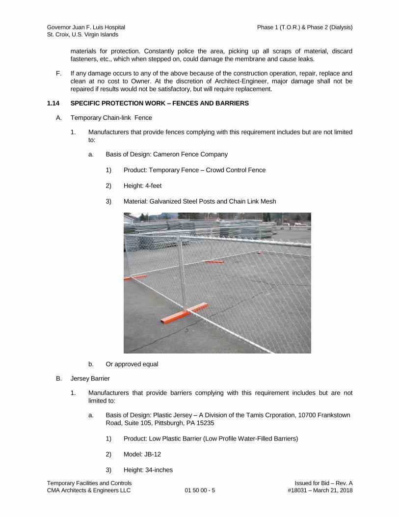
Governor Juan F. Luis Hospital Phase 1 (T.O.R.) & Phase 2 (Dialysis)
St. Croix, U.S. Virgin Islands
Temporary Facilities and Controls Issued for Bid – Rev. A
CMA Architects & Engineers LLC 01 50 00 - 5 #18031 – March 21, 2018
materials for protection. Constantly police the area, picking up all scraps of material, discard
fasteners, etc., which when stepped on, could damage the membrane and cause leaks.
F. If any damage occurs to any of the above because of the construction operation, repair, replace and
clean at no cost to Owner. At the discretion of Architect-Engineer, major damage shall not be
repaired if results would not be satisfactory, but will require replacement.
1.14 SPECIFIC PROTECTION WORK – FENCES AND BARRIERS
A. Temporary Chain-link Fence
1. Manufacturers that provide fences complying with this requirement includes but are not limited
to:
a. Basis of Design: Cameron Fence Company
1) Product: Temporary Fence – Crowd Control Fence
2) Height: 4-feet
3) Material: Galvanized Steel Posts and Chain Link Mesh
b. Or approved equal
B. Jersey Barrier
1. Manufacturers that provide barriers complying with this requirement includes but are not
limited to:
a. Basis of Design: Plastic Jersey – A Division of the Tamis Crporation, 10700 Frankstown
Road, Suite 105, Pittsburgh, PA 15235
1) Product: Low Plastic Barrier (Low Profile Water-Filled Barriers)
2) Model: JB-12
3) Height: 34-inches
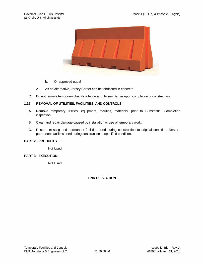
Governor Juan F. Luis Hospital Phase 1 (T.O.R.) & Phase 2 (Dialysis)
St. Croix, U.S. Virgin Islands
Temporary Facilities and Controls Issued for Bid – Rev. A
CMA Architects & Engineers LLC 01 50 00 - 6 #18031 – March 21, 2018
b. Or approved equal
2. As an alternative, Jersey Barrier can be fabricated in concrete.
C. Do not remove temporary chain-link fence and Jersey Barrier upon completion of construction.
1.15 REMOVAL OF UTILITIES, FACILITIES, AND CONTROLS
A. Remove temporary utilities, equipment, facilities, materials, prior to Substantial Completion
inspection.
B. Clean and repair damage caused by installation or use of temporary work.
C. Restore existing and permanent facilities used during construction to original condition. Restore
permanent facilities used during construction to specified condition.
PART 2 - PRODUCTS
Not Used.
PART 3 - EXECUTION
Not Used.
END OF SECTION
Governor Juan F. Luis Hospital Phase 1 (T.O.R.) & Phase 2 (Dialysis)
St. Croix, U.S. Virgin Islands
Execution and Closeout Requirements Issued for Bid – Rev. A
CMA Architects & Engineers LLC 01 73 00 - 1 #18031 – March 21, 2018
SECTION 01 73 00
EXECUTION AND CLOSEOUT REQUIREMENTS
PART 1 - GENERAL
1.1 SECTION INCLUDES
A. Substantial Completion.
B. Closeout procedures.
C. Final cleaning.
D. Starting of systems.
E. Demonstration and instructions.
F. Testing, adjusting and balancing.
G. Protecting installed construction.
H. Project record documents.
I. Operation and maintenance data.
J. Manual for materials and finishes.
K. Manual for equipment and systems.
L. Spare parts and maintenance products.
M. Product warranties and product bonds.
N. Maintenance service.
1.2 SUBSTANTIAL COMPLETION
A. The Owner shall consider the Work to be Substantial Complete when the following requirements are
met:
1. General
a. Final endorsement of the Fire Department.
1) Means of Egress, Fire Alarm and Fire Protection Systems.
b. Final endorsement of the Health Department.
c. All temporary construction items (not required for completion of the punch list) such as
temporary walls, temporary fencing, scaffolding, rigging, supports, strainers, blanks, etc.
are removed.
d. Record Drawings (Section 01 73 00) are transmitted and approved by the Owner.
e. All Final Operation and Maintenance Data Manuals transmitted and approved by the
Owner and Architect-Engineer.
Governor Juan F. Luis Hospital Phase 1 (T.O.R.) & Phase 2 (Dialysis)
St. Croix, U.S. Virgin Islands
Execution and Closeout Requirements Issued for Bid – Rev. A
CMA Architects & Engineers LLC 01 73 00 - 2 #18031 – March 21, 2018
f. All start-up of all systems completed and approved by the manufacturer’s technical
representative, Owner and Architect-Engineer.
g. Product Warranties and Bonds are transmitted to the Owner.
h. Manual for materials and finishes are transmitted to the Owner.
i. Manual for equipment and systems are transmitted to the Owner.
2. Architectural
a. Interior construction shall be completed with only minor Owner/Architect-Engineer
authorized punch list items remaining and Tenant is able to begin installation/operational
start-up/training on Equipment and/or systems.
b. Construction areas cleaned, mopped and wall wiped clean.
c. Doors and frames complete and operational.
d. All painting except for minor touch-up complete.
3. Mechanical/Plumbing/Fire Protection
a. All utility systems mechanically complete, tested and functional per design parameters.
This shall include ail ductwork, piping, insulation, controls and accessories.
b. All HVAC systems balanced to plus or minus ten percent (+/-10%) of design criteria.
c. Temporary construction and startup filters removed and final operating filters installed.
d. All piping has been hydrostatically or pneumatically tested and witnessed by Owner.
e. Piping systems have been insulated and identified as required. All valves tagged.
f. Piping systems have been flushed to remove foreign matter. All traps and strainers have
been cleaned.
g. Electrical connections have been completed, tested and verified.
h. Electrical motors have been checked with respect to amperage and rotation.
i. Equipment checked for alignment, balancing and noise. Equipment started up by factorv
representative and installation certified.
j. Systems for controlling room air volumes or pressurization tested, calibrated and fully
operational by manufacturer's technical personnel.
k. Fire protection system complete and operational including extinguishers, hoses, etc.
l. All seismic restraints installed.
4. Electrical
a. All power, lighting, control equipment, circuitry, systems, etc., complete, cleaned, tested
and functional. Meggar readings submitted and approved.
b. List of fuses and overload heaters approved. Proper size fuses and overload heaters
installed.
Governor Juan F. Luis Hospital Phase 1 (T.O.R.) & Phase 2 (Dialysis)
St. Croix, U.S. Virgin Islands
Execution and Closeout Requirements Issued for Bid – Rev. A
CMA Architects & Engineers LLC 01 73 00 - 3 #18031 – March 21, 2018
c. All protective devices set and functionally tested.
d. All lighting fixtures lamped per Contract Documents.
e. All receptacles functional.
f. All equipment and devices have been identified per the Contract Documents.
g. At least one (1) set of as built drawings available for switching and troubleshooting.
h. All interlocks tested and keys available to Owner.
i. All seismic restraints installed.
1.3 CLOSEOUT PROCEDURES
A. Submit written certification that Contract Documents have been reviewed, Work has been inspected,
and that Work is complete in accordance with Contract Documents and ready for
Architect/Engineer's final review.
B. Submit final Application for Payment identifying total adjusted Contract Sum, previous payments, and
sum remaining due. The following documents shall be transmitted with the Final Application for
Payment:
1. Statement that all punch list items have been corrected and accepted by the Owner’s On Site
Representative and Architect-Engineer.
2. Release from the Workmen Compensation Fund (“Fondo”).
3. Contractor’s Affidavit of Payment of Debts and Claims.
4. Contractor’s Affidavit of Release of Liens.
5. Consent of Surety to Final Payment.
1.4 FINAL CLEANING
A. Contractor shall execute final cleaning prior to final project assessment.
B. Clean interior glass, surfaces exposed to view; remove temporary labels, stains and foreign
substances, polish transparent and glossy surfaces, vacuum carpeted and soft surfaces.
C. Clean equipment and fixtures to sanitary condition with cleaning materials appropriate to surface and
material being cleaned.
D. Replace all filters of operating equipment.
E. Clean debris from roofs systems affected by construction.
F. Remove waste and surplus materials, rubbish, and construction facilities from site.
1.5 STARTING OF SYSTEMS (CONTRACTOR FURNISHED/INSTALLED)
A. Prior to Start Up
1. Prior to the startup, the Contractor shall ensure that the systems are ready to operate,
including, but not limited to the following:
Governor Juan F. Luis Hospital Phase 1 (T.O.R.) & Phase 2 (Dialysis)
St. Croix, U.S. Virgin Islands
Execution and Closeout Requirements Issued for Bid – Rev. A
CMA Architects & Engineers LLC 01 73 00 - 4 #18031 – March 21, 2018
a. Proper motor and fan/pump rotation.
b. Flushing and cleaning of the system.
c. Wiring.
d. Auxiliary connections.
e. Lubrication.
f. Venting.
g. Controls.
h. Installation of filters and strainers.
i. Setting of relief and safety valves.
2. All electrical testing must be completed and test results submitted before equipment startup to
avoid power interruptions during mechanical equipment startup and testing
3. The Contractor shall submit at least 60 days in advance a schedule listing the date of
completion of his work as it will be ready for equipment startup of electrical mechanical
equipment. This schedule shall include work on a system-by-system, floor-by-floor basis.
a. Two weeks prior to the startup of any major equipment, the Contractor shall certify in
writing that the systems will be complete and ready for startup. Completeness shall not
only include physical installation of individual pieces of equipment, but all related
elements of other crafts to make all equipment operate as a system.
b. The startup check list will cover all related crafts, e.g., controls, electrical, mechanical,
and a clean environment of equipment startup.
c. The Contractor shall schedule a tour with the Owner's On Site Representative and the
Engineer to review start-up conditions prior to equipment start-up. This tour shall take
place during the associated consultant's regularly scheduled visit. This tour does not
relieve the Contractor of any responsibilities to properly start equipment. The Architect-
Engineer will issue a notice of deficiencies that will be required to be corrected prior to
equipment start-up. The Contractor will be required to reschedule a back check with the
Architect-Engineer prior to attempting an equipment start-up and provide verification of
the manufacturer's representatives be present at equipment start-up.
4. Equipment of systems should not be started until systems and associated sub-systems are
completed. Verify that other continuing work could possibly damage completed systems if they
are in operation. Furnish signed off pre-startup checklist.
B. Start-Up and Commissioning
1. Start-Up and Commissioning of all equipment shall be completed and accepted by the
Owner’s On Site Representative prior to the Date of Substantial Completion.
2. System Start-up and Operation
a. The Contractor shall provide all labor, materials and services necessary for the initial
start-up and operation of all systems and equipment furnished and installed under this
Section.
Governor Juan F. Luis Hospital Phase 1 (T.O.R.) & Phase 2 (Dialysis)
St. Croix, U.S. Virgin Islands
Execution and Closeout Requirements Issued for Bid – Rev. A
CMA Architects & Engineers LLC 01 73 00 - 5 #18031 – March 21, 2018
b. The Contractor shall provide the services of qualified factory representatives for all
major equipment pre-start set-up, start-up and initial operation. Such periods shall be
sufficient to insure the proper operation of systems and equipment. Major equipment to
include, but not limited to air handling units, cooling towers, modular cooling units,
elevators, temperature controls, pump sets, fan systems, electrical systems, emergency
power, fire alarm systems and fire sprinkler, etc.
c. The Contractor and the manufacturer's technical representative shall check all
equipment during initial start-up to insure correct rotation, proper lubrication adequate
fluids or air flows, non-overloading electrical characteristics, proper alignment and
vibration isolation. Systems shall be checked for air and/or water flows throughout
without blockages. Air handling systems shall be checked for proper damper
connections and positions, aligned and adjusted belt drives, proper lubrication,
temporary air filters installed, non-excessive electrical characteristics and minimal
vibration. Other miscellaneous equipment shall be started and operated as described
above as applicable. Manufacturer's representative to submit a preliminary written copy
of equipment start-up check sheet prior to leaving job site.
d. After initial start-up and operation of systems, the Contractor shall submit a final report.
e. During initial operation of the system and until substantial completion, qualified
personnel shall be provided and designated for maintaining the equipment and systems
in good running order. Items such as strainer, clean-out, filter replacement, bearing
lubrication, packing replacement, and other consumables shall be provided without cost
to the Owner. Failure of equipment during this period due to lack of proper supervision is
the responsibility of the Contractor and continued failures shall be grounds for the
Owner to provide such services with back charges to the Contractor. Submit written
schedule of completed maintenance to the Architect-Engineer.
1.6 DEMONSTRATION AND INSTRUCTIONS
A. Demonstrate operation and maintenance of products to Owner's personnel at least three (3) weeks
prior to Date of Substantial Completion.
B. Demonstrate Project equipment and instruct in classroom environment located at project site and
instructed by qualified manufacturer's representative who is knowledgeable about the Project.
C. Utilize operation and maintenance manuals as basis for instruction. Review contents of manual with
Owner's personnel in detail to explain all aspects of operation and maintenance.
D. Demonstrate start-up, operation, control, adjustment, trouble-shooting, servicing, maintenance, and
shutdown of each item of equipment at scheduled time at equipment location.
E. Prepare and insert additional data in operations and maintenance manuals when need for additional
data becomes apparent during instruction.
F. The Contractor shall submit at least 60 days in advance a schedule listing proposed training
schedule for each system to the Architect-Engineer for review by the Architect-Engineer, Owner and
Commissioning Authority, under the following conditions.
1. Maintenance manuals are complete and accepted by the user a minimum of ten (10) working
days prior to any training.
2. Training will be scheduled for complete systems, not individual pieces of equipment.
3. Training schedule will be submitted to the Architect-Engineer and approved by the Owner.
Governor Juan F. Luis Hospital Phase 1 (T.O.R.) & Phase 2 (Dialysis)
St. Croix, U.S. Virgin Islands
Execution and Closeout Requirements Issued for Bid – Rev. A
CMA Architects & Engineers LLC 01 73 00 - 6 #18031 – March 21, 2018
G. The Contractor shall certify in writing ten (10) days prior to the training date that the systems is
complete and operational with a list of any exceptions from a complete system.
H. All training sessions shall be completed prior to the Date of Substantial Completion.
1.7 TESTING, ADJUSTING AND BALANCING
A. Contractor shall will appoint, employ, and pay for services of independent firm to perform testing,
adjusting, and balancing of air conditioning systems.
B. Reports will be submitted by independent firm to Architect/Engineer indicating observations and
results of tests and indicating compliance or non-compliance with requirements of Contract
Documents prior to the Date of Substantial Completion. Reports shall be signed by a certified testing
and balancing Engineer.
1.8 PROTECTING INSTALLED CONSTRUCTION
A. Protect installed Work and provide special protection where specified in individual specification
sections.
B. Provide temporary and removable protection for installed products. Control activity in immediate work
area to prevent damage.
C. Provide protective coverings at walls, projections, jambs, sills, and soffits of openings.
D. Protect finished floors, stairs, and other surfaces from traffic, dirt, wear, damage, or movement of
heavy objects, by protecting with durable sheet materials.
E. Prohibit traffic or storage upon waterproofed or roofed surfaces. When traffic or activity is necessary,
obtain recommendations for protection from waterproofing or roofing material manufacturer.
F. Prohibit traffic from landscaped areas.
1.9 PROJECT RECORD DOCUMENTS
A. Maintain on site one set of the following record documents; record actual revisions to the Work:
1. Drawings.
2. Specifications.
3. Addenda.
4. Change Orders and other modifications to the Contract.
5. Reviewed Shop Drawings, Product Data, and Samples.
6. Manufacturer's instruction for assembly, installation, and adjusting.
B. Maintain a complete set of drawings and specifications tagged "Record Documents" on the job for
the sole purpose of marking in all deviations from the original documents and noting accurately the
actual locations of underground lines, stubouts, etc. This information shall be kept current and shall
be inserted by Contractor and subcontractors under the observation of the Owner's On Site
Representative. Each person making a change shall identify the change marked with the date and
initials in a code and manner approved by the Contractor and Architect-Engineer. Progress billings
will not be paid until the Owner's On Site Representative has reported to the Architect-Engineer that
Record Documents are complete, and up to date as of the billing.
Governor Juan F. Luis Hospital Phase 1 (T.O.R.) & Phase 2 (Dialysis)
St. Croix, U.S. Virgin Islands
Execution and Closeout Requirements Issued for Bid – Rev. A
CMA Architects & Engineers LLC 01 73 00 - 7 #18031 – March 21, 2018
C. Specifications: Legibly mark and record at each product section description of actual products
installed, including the following:
1. Manufacturer's name and product model and number.
2. Product substitutions or alternates utilized.
3. Changes made by Addenda and modifications.
D. Record Drawings and Shop Drawings: Legibly mark each item to record actual construction
including:
1. Measured depths of foundations in relation to finish first floor datum.
2. Measured horizontal and vertical locations of underground utilities and appurtenances,
referenced to permanent surface improvements.
3. Measured locations of internal utilities and appurtenances concealed in construction,
referenced to visible and accessible features of the Work.
4. Field changes of dimension and detail.
5. Details not on original Contract drawings.
E. Submit documents to Architect/Engineer at Date of Substantial Completion.
1.10 OPERATION AND MAINTENANCE DATA
A. Submit data bound in 8-1/2 x 11 inch (A4) text pages, three D side ring binders with durable plastic
covers.
B. Prepare binder cover with printed title "OPERATION AND MAINTENANCE INSTRUCTIONS", title of
project, and subject matter of binder when multiple binders are required.
C. Internally subdivide binder contents with permanent page dividers, logically organized as described
below; with tab titling clearly printed under reinforced laminated plastic tabs.
D. Drawings: Provide with reinforced punched binder tab. Bind in with text; fold larger drawings to size
of text pages.
E. Contents: Prepare Table of Contents for each volume, with each product or system description
identified, typed on white paper, in three parts as follows:
1. Part 1: Directory, listing names, addresses, and telephone numbers of Architect/Engineer,
Contractor, Subcontractors, and major equipment suppliers.
2. Part 2: Operation and maintenance instructions, arranged by system and subdivided by
specification section. For each category, identify names, addresses, and telephone numbers
of Subcontractors and suppliers. Identify the following:
a. Significant design criteria.
b. List of equipment.
c. Parts list for each component.
d. Operating instructions.
Governor Juan F. Luis Hospital Phase 1 (T.O.R.) & Phase 2 (Dialysis)
St. Croix, U.S. Virgin Islands
Execution and Closeout Requirements Issued for Bid – Rev. A
CMA Architects & Engineers LLC 01 73 00 - 8 #18031 – March 21, 2018
e. Maintenance instructions for equipment and systems.
f. Maintenance instructions for special finishes, including recommended cleaning methods
and materials, and special precautions identifying detrimental agents.
3. Part 3: Project documents and certificates, including the following:
a. Shop drawings and product data.
b. Air and water balance reports.
c. Certificates.
d. Originals of warranties and bonds.
1.11 MANUAL FOR MATERIALS AND FINISHES
A. Submit two (2) copies of preliminary draft or proposed formats and outlines of contents before start of
Work. Architect/Engineer will review draft and return one copy with comments.
B. For equipment, or component parts of equipment put into service during construction and operated
by Owner, submit documents within ten days after acceptance.
C. Submit one copy of completed volumes 15 days prior to final inspection. Draft copy be reviewed and
returned after final inspection, with Architect/Engineer comments. Revise content of document sets
as required prior to final submission.
D. Submit two sets of revised final volumes in final form within 10 days after final inspection.
E. Building Products, Applied Materials, and Finishes: Include product data, with catalog number, size,
composition, and color and texture designations. Include information for re-ordering custom
manufactured products.
F. Instructions for Care and Maintenance: Include manufacturer's recommendations for cleaning agents
and methods, precautions against detrimental agents and methods, and recommended schedule for
cleaning and maintenance.
G. Moisture Protection and Weather Exposed Products: Include product data listing applicable
reference standards, chemical composition, and details of installation. Include recommendations for
inspections, maintenance, and repair.
H. Additional Requirements: As specified in individual product specification sections.
I. Include listing in Table of Contents for design data, with tabbed fly sheet and space for insertion of
data.
1.12 MANUAL FOR EQUIPMENT AND SYSTEMS
A. Submit two copies of preliminary draft or proposed formats and outlines of contents before start of
Work. Architect/Engineer will review draft and return one copy with comments.
B. For equipment, or component parts of equipment put into service during construction and operated
by Owner, submit documents within ten days after acceptance.
C. Submit one copy of completed volumes 15 days prior to final inspection. Draft copy be reviewed and
returned after final inspection, with Architect/Engineer comments. Revise content of document sets
as required prior to final submission.
Governor Juan F. Luis Hospital Phase 1 (T.O.R.) & Phase 2 (Dialysis)
St. Croix, U.S. Virgin Islands
Execution and Closeout Requirements Issued for Bid – Rev. A
CMA Architects & Engineers LLC 01 73 00 - 9 #18031 – March 21, 2018
D. Submit two sets of revised final volumes in final form within 10 days after final inspection.
E. Each Item of Equipment and Each System: Include description of unit or system, and component
parts. Identify function, normal operating characteristics, and limiting conditions. Include performance
curves, with engineering data and tests, and complete nomenclature and model number of
replaceable parts.
F. Panelboard Circuit Directories: Provide electrical service characteristics, controls, and
communications; typed.
G. Include color coded wiring diagrams as installed.
H. Operating Procedures: Include start-up, break-in, and routine normal operating instructions and
sequences. Include regulation, control, stopping, shut-down, and emergency instructions. Include
summer, winter, and special operating instructions.
I. Maintenance Requirements: Include routine procedures and guide for preventative maintenance and
trouble shooting; disassembly, repair, and reassembly instructions; and alignment, adjusting,
balancing, and checking instructions.
J. Include servicing and lubrication schedule, and list of lubricants required.
K. Include manufacturer's printed operation and maintenance instructions.
L. Include sequence of operation by controls manufacturer.
M. Include original manufacturer's parts list, illustrations, assembly drawings, and diagrams required for
maintenance.
N. Include control diagrams by controls manufacturer as installed.
O. Include Contractor's coordination drawings, with color coded piping diagrams as installed.
P. Include charts of valve tag numbers, with location and function of each valve, keyed to flow and
control diagrams.
Q. Include list of original manufacturer's spare parts, current prices, and recommended quantities to be
maintained in storage.
R. Include test and balancing reports as specified in Section 01 40 00.
S. Additional Requirements: As specified in individual product specification sections.
T. Include listing in Table of Contents for design data, with tabbed dividers and space for insertion of
data.
1.13 SPARE PARTS AND MAINTENANCE PRODUCTS
A. Furnish spare parts, maintenance, and extra products in quantities specified in individual
specification sections.
B. Deliver to Project site and place in location as directed by Owner; obtain receipt prior to final
payment.
1.14 PRODUCT WARRANTIES AND PRODUCT BONDS
A. Obtain warranties and bonds executed in duplicate by responsible subcontractors, suppliers, and
manufacturers, within ten days after completion of applicable item of work.
Governor Juan F. Luis Hospital Phase 1 (T.O.R.) & Phase 2 (Dialysis)
St. Croix, U.S. Virgin Islands
Execution and Closeout Requirements Issued for Bid – Rev. A
CMA Architects & Engineers LLC 01 73 00 - 10 #18031 – March 21, 2018
B. Execute and assemble transferable warranty documents and bonds from subcontractors, suppliers,
and manufacturers.
C. Verify documents are in proper form, contain full information, and are notarized.
D. Co-execute submittals when required.
E. Include Table of Contents and assemble in three D side ring binder with durable plastic cover.
F. Submit prior to final Application for Payment.
G. Time Of Submittals:
1. For equipment or component parts of equipment put into service during construction with
Owner's permission, submit documents within ten days after acceptance.
2. Make other submittals within ten days after Date of Substantial Completion, prior to final
Application for Payment.
3. For items of Work for which acceptance is delayed beyond Date of Substantial Completion,
submit within ten days after acceptance, listing date of acceptance as beginning of warranty or
bond period.
1.15 MAINTENANCE SERVICE
A. Furnish service and maintenance of components indicated in specification sections for one year from
date of Substantial Completion.
B. Examine system components at frequency consistent with reliable operation. Clean, adjust, and
lubricate as required.
C. Include systematic examination, adjustment, and lubrication of components. Repair or replace parts
whenever required. Use parts produced by manufacturer of original component.
D. Do not assign or transfer maintenance service to agent or Subcontractor without prior written consent
of Owner.
PART 2 - PRODUCTS
Not Used.
PART 3 - EXECUTION
Not Used.
END OF SECTION
Governor Juan F. Luis Hospital Phase 1 (T.O.R.) & Phase 2 (Dialysis) St. Croix, U.S. Virgin Islands
Selective Site Demolition Issued for Construction - Rev. 0 CMA Architect & Engineers LLC 02 41 13 - 1 #18031 – March 21, 2018
SECTION 02 41 13
SELECTIVE SITE DEMOLITION
PART 1 - GENERAL
1.1 SECTION INCLUDES
A. Examination of areas where demolition work will occur.
B. Preparation of demolition areas.
C. General demolition requirements.
D. Protection.
E. Dust and debris control.
F. Fire protection measures.
G. General demolition requirements.
H. Specific selective site demolition procedures.
I. Patching.
J. Disposition of demolished material.
K. Clean up of areas.
1.2 RELATED SECTIONS
A. Division 01 - General Requirements.
1.3 REFERENCES
A. ANSI A10.6 - Safety Requirements for Demolition Operations.
B. NFPA 241 – Safeguarding Construction Alteration, and Demolition Operations.
C. NFPA 5000 – Building Construction and Safety Code.
D. OSHA 29 CFR 1926 - Construction Industry Subpart T: Demolition.
1.4 DEFINITIONS
A. Remove: Detach items from existing construction and legally dispose of them off-site, unless indicated to be removed and salvaged or removed and reinstalled.
B. Existing to Remain: Existing items of construction that are not to be removed and that are not otherwise indicated to be removed, removed and salvaged, or removed and reinstalled.
1.5 SUBMITTALS
A. Section 01 33 00 – Submittal Procedures: Requirements for submittals.
B. Qualification Data: Submit data of demolition firm.
Governor Juan F. Luis Hospital Phase 1 (T.O.R.) & Phase 2 (Dialysis) St. Croix, U.S. Virgin Islands
Selective Site Demolition Issued for Construction - Rev. 0 CMA Architect & Engineers LLC 02 41 13 - 2 #18031 – March 21, 2018
C. Shop Drawings: Indicate location and construction of barricades, fences, and temporary work.
D. Record of Existing Conditions: The Contractor shall record, in the presence of the Construction Manager, the condition of structures and other facilities adjacent to areas of alteration or removal. Such record shall contain the location and extent of cracks and other damage and description of surface conditions that exist prior to the start of work. Copies of the record, signed by the Contractor and co-signed by the Construction Manager shall be submitted and the stated conditions before starting work shall be verified.
E. Proposed Dust Control and Noise Control Measures: Submit statement or drawing that indicates the measures proposed for use, proposed locations, and proposed time frame for their operation. Identify options if proposed measures are later determined to be inadequate.
F. Landfill Records: Indicate receipt and acceptance of solid wastes/demolished materials by a landfill facility licensed to accept solid wastes.
1.6 QUALITY ASSURANCE
A. Section 01 40 00 – Quality Requirements.
B. Demolition Firm Qualifications: An experienced firm that has specialized in demolition work similar in material and extent to that indicated for this Project.
C. Standards: Comply with ANSI A10.6 and NFPA 241.
1.7 REGULATORY REQUIREMENTS
A. Conform to applicable codes (federal, state and local) for demolition of structures, safety of adjacent structures, dust control, runoff control and disposal.
B. Obtain required permits from Authorities Having Jurisdiction (AHJ).
C. Notify Owner’s On Site Representative before starting work of this section.
D. Do not close or obstruct roadways, sidewalks or hydrants without permits.
E. Conform to applicable regulatory procedures when discovering hazardous or contaminated materials.
F. Comply with hauling and disposal regulations of Authorities Having Jurisdiction (AHJ).
1.8 JOB CONDITIONS
A. Section 01 73 00 – Execution.
B. Owner will occupy portions of building immediately adjacent to demolition areas. Conduct demolition so Owner’s operations will not be disrupted.
C. Inspect project work and check conditions under which work will be done.
D. The Owner assumes no responsibility for actual conditions of the work to be demolished. Conditions at the time of inspection for bidding purposes will be maintained by the Owner
Governor Juan F. Luis Hospital Phase 1 (T.O.R.) & Phase 2 (Dialysis) St. Croix, U.S. Virgin Islands
Selective Site Demolition Issued for Construction - Rev. 0 CMA Architect & Engineers LLC 02 41 13 - 3 #18031 – March 21, 2018
insofar as practicable, however, variations may occur due to the Owner’s removal and storage operations prior to the commencement of the demolition work.
E. The Contractor shall ensure coordination of his work with the Owner and all concerned so that all entrances and exits to adjacent areas of building remain accessible at all times.
F. Proceeding with the work shall be evidence of the acceptance by the Contractor of job conditions.
PART 2 - PRODUCTS
Not Used
PART 3 - EXECUTION
3.1 EXAMINATION
A. Section 01 31 00 – Project Management and Coordination.
B. Verify that utilities have been disconnected and capped.
C. Survey existing conditions and correlate with requirements indicated to determine extent of selective demolition required.
D. Inventory and record the conditions of items to be removed and reinstalled.
E. When unanticipated mechanical, electrical or structural elements that conflict with intended function or design area encountered, investigate and measure the nature and extent of conflict. Promptly submit a written report to Architect-Engineer.
F. Survey of Existing Conditions: Record existing conditions by use of measured drawings, preconstruction photographs or videotapes.
G. Perform surveys as the Work progresses to detect hazards resulting from selective demolition activities.
3.2 UTILITY SERVICES AND MECHANICAL/ELECTRICAL SYSTEMS
A. Existing Services/Systems: Maintain services/systems indicated to remain and protect them against damage during demolition operations.
B. Service/System Requirements: Locate, identify, disconnect, and seal or cap off indicated utility services and mechanical/ electrical systems serving areas to be demolished.
1. Owner or its authorized representative will arrange to shut off indicated services/systems when requested by Contractor.
2. If services/systems are required to be removed, relocated, or abandoned, before proceeding with demolition provide temporary services/systems that bypass area of demolition and that maintains continuity of services/systems to other parts of building.
3.3 PREPARATION
A. Provide, erect, and maintain temporary barriers and security devices.
Governor Juan F. Luis Hospital Phase 1 (T.O.R.) & Phase 2 (Dialysis) St. Croix, U.S. Virgin Islands
Selective Site Demolition Issued for Construction - Rev. 0 CMA Architect & Engineers LLC 02 41 13 - 4 #18031 – March 21, 2018
B. Temporary Facilities: Provide temporary barricades and other protection required to prevent injury to people and damage to adjacent facilities to remain.
1. Provide protection to ensure safe passage of people around selective demolition areas and to and from occupied portions of building.
C. Protect existing landscaping materials, appurtenances and structures which are not to be demolished.
D. Mark location of utilities.
3.4 PROTECTION
A. Traffic Control Signs: Where pedestrian and driver safety is endangered in the area of removal work, use traffic barricades with flashing lights. Notify Owner’s On Site Representative prior to beginning work.
B. Existing Work: Protect existing work which is to remain in place, be reused, or remain the property of the Owner. Repair items which are to remain and which are damaged during performance of the work to their original condition, or replace with new. Do not overload structural elements. Provide new supports and reinforcement for existing construction weakened by demolition or removal work. Repairs, reinforcement or structural replacement shall have Owner’s approval.
C. Facilities: Protect electrical and mechanical services and utilities. Where removal of existing utilities and pavement is specified or indicated, provide approved barricades, temporary covering of exposed areas, and temporary services or connections for electrical and mechanical utilities.
3.5 DUST AND DEBRIS CONTROL
A. Prevent the spread of dust and debris to surrounding areas and avoid the creation of a nuisance or hazard in the surrounding area.
B. Do not use water if it results in hazardous or objectionable conditions such as, but not limited to, flooding or pollution.
C. Clean the work area daily. The Owner reserves the right to cleanup any condition that in the Owner’s On Site Representative’s judgment is detrimental to the Owner and shall charge the cleanup expense to the amount due to the Contractor.
3.6 FIRE PROTECTION DURING DEMOLITION PHASE
A. Wherever a cutting torch or other equipment that might cause a fire is used, provide and maintain fire extinguishers nearby ready for immediate use. All possible users shall be instructed in use of fire extinguishers.
B. Hydrants shall be accessible at all times. No debris shall be permitted to accumulate within a radius of 20 feet of fire hydrants.
C. An overall demolition fire safety program shall be developed by Contractor. Essential items to be included but not limited to:
1. Good housekeeping.
Governor Juan F. Luis Hospital Phase 1 (T.O.R.) & Phase 2 (Dialysis) St. Croix, U.S. Virgin Islands
Selective Site Demolition Issued for Construction - Rev. 0 CMA Architect & Engineers LLC 02 41 13 - 5 #18031 – March 21, 2018
2. On-site security.
3. Installation of fire protection systems.
4. Preservation of existing systems during demolition.
5. Organization and training of an on-site fire brigade.
6. A pre-fire plan developed with the Owner.
7. Protection of existing structures and equipment from exposure to fire resulting from alternation and demolition operations.
3.7 DEMOLITION – GENERAL REQUIREMENTS
A. General: Demolish and remove existing construction only to the extent required by new construction and as indicated. Use methods required to complete the Work within limitations of governing regulations and as follows:
1. Proceed with selective demolition systematically, from higher to lower level.
2. Do not use cutting torches until work area is cleared of flammable materials. At concealed spaces, such as duct and pipe interiors, verify condition and contents of hidden space before starting flame-cutting operations. Maintain fire watch and portable fire-suppression devices during flame-cutting operations.
3. Maintain adequate ventilation when using cutting torches.
4. Remove decayed, vermin-infested, or otherwise dangerous or unsuitable materials and promptly dispose of off-site.
5. Dispose of demolished items and materials promptly.
6. Return elements of construction and surfaces that are to remain to condition existing before selective demolition operations began.
7. Disconnect and cap designated utilities within demolition areas.
8. Backfill areas excavated open pits and holes caused as a result of demolition.
9. Rough grade and compact areas affected by demolition to maintain site grades and contours.
10. Do not burn or bury materials on site. Leave site in clean condition.
B. Existing Items to Remain: Protect construction indicated to remain against damage and soiling during selective demolition. When permitted by Architect, items may be removed to a suitable, protected storage location during selective demolition and cleaned and reinstalled in their original locations after selective demolition operations are complete.
3.8 SPECIFIC SITE DEMOLITION PROCEDURES
A. Asphalt Paving: Remove ground, scarified, or sawcut asphalt paving (surface and base courses) including aggregate base course down to bare substrate. Provide neat sawcut at limits of asphalt paving removal as indicated.
Governor Juan F. Luis Hospital Phase 1 (T.O.R.) & Phase 2 (Dialysis) St. Croix, U.S. Virgin Islands
Selective Site Demolition Issued for Construction - Rev. 0 CMA Architect & Engineers LLC 02 41 13 - 6 #18031 – March 21, 2018
B. Portland Cement Concrete Paving: Remove ground, scarified, or sawcut Portland cement concrete paving including aggregate base course down to bare substrate. Provide neat sawcuts at limits of Portland cement concrete paving as indicated.
C. Sidewalks: Remove ground, scarified, or sawcut concrete sidewalks including crushed stone base down to bare substrate. Provide neat sawcuts at limits of concrete sidewalks as indicated.
D. Curb: Sawcut concrete at ends of demolition section and remove segment of curb down to bare substrate. Provide neat sawcuts at limits of curb removal as indicated.
E. Curb and Gutters: Sawcut concrete at ends of demolition sections and remove segment of curb and gutter down to bare substrate. Provide neat sawcuts at limits of curb and gutter removal as indicated.
F. Concrete: Sawcut concrete along straight lines to a depth of not less than 2 inches. Make each cut in walls perpendicular to the face and in alignment with the cut in the opposite face. Break the remaining concrete provided that the broken area is concealed in the finished work, and the remaining concrete is sound. At locations where the broken face cannot be concealed, grind smooth or saw cut entirely through the concrete.
G. Utilities: Remove existing utilities as indicated and terminate in a manner conforming to the nationally recognized code covering the specific utility and approved by the Owner’s On Site Representative. Remove related equipment and deliver to a location within site premises in accordance with the instructions of the Owner’s On Site Representative. If utility lines are encountered that are not shown on drawings, contact the Owner’s On Site Representative for further instructions.
3.9 PATCHING
A. Where removals leave holes and damaged surfaces exposed in the finished work, patch and repair these holes and damaged surfaces to match adjacent finished surfaces.
B. Where new work is to be applied to existing surfaces, perform removals and patching in a manner to produce surfaces suitable for receiving new work.
C. Finished surfaces of patched area shall be flush with the adjacent existing surface and shall match the existing adjacent surface as closely as possible as to texture and finish.
3.10 DISPOSITION OF DEMOLISHED MATERIALS
A. General: Except for items or materials to be reused, salvaged, reinstalled, or otherwise indicated to remain Owner’s property, remove demolished materials from Project site and legally dispose of them in an EQB (Environmental Quality Board) approved landfill.
B. Do not allow demolished materials to accumulate on-site.
C. Remove and transport debris in a manner that will prevent spillage on adjacent surfaces and areas.
D. Remove debris from elevated portions of building by chute, hoist, or other device that will convey debris to grade level in a controlled descent.
E. Burning: Do not burn demolished materials.
Governor Juan F. Luis Hospital Phase 1 (T.O.R.) & Phase 2 (Dialysis) St. Croix, U.S. Virgin Islands
Selective Site Demolition Issued for Construction - Rev. 0 CMA Architect & Engineers LLC 02 41 13 - 7 #18031 – March 21, 2018
F. Disposal: Transport demolished materials off Owner’s property and legally dispose of them.
3.11 CLEANUP
A. Remove and transport debris and rubbish in a manner that will prevent spillage on pavements, streets or adjacent areas.
B. Clean up spillage from pavements, streets and adjacent areas.
C. Return adjacent areas to condition existing before demolition operations began.
END OF SECTION
Governor Juan F. Luis Hospital Phase 1 (T.O.R.) & Phase 2 (Dialysis) St. Croix, U.S. Virgin Islands
Cast In Place Concrete Forming Issued for Bid - Rev. A CMA Architect & Engineers LLC 03 11 13 - 1 #18031 – March 21, 2018
SECTION 03 11 13
CAST IN PLACE CONCRETE FORMING
PART 1 - GENERAL
1.1 SECTION INCLUDES
A. Verification of lines, levels and centers.
B. Installation of formwork, including form facings.
C. Application of form release agent.
D. Installation of inserts, embedded parts and openings.
E. Form cleaning.
F. Erection formwork tolerances.
G. Field quality control.
H. Shores and supports.
I. Removal of forms.
J. Re-use of forms.
1.2 RELATED SECTIONS
A. Division 01 Sections - General Requirements.
B. Section 03 21 11 – Plain Steel Reinforcement Bars.
C. Section 03 31 13 - Cast-in-Place Concrete.
1.3 REFERENCES
A. ACI 117 – Tolerances for Concrete Construction and Materials.
B. ACI 301 - Specifications for Structural Concrete for Buildings.
C. ACI 318 – Building Code Requirements for Structural Concrete.
D. ACI 347 – Guide to Formwork for Concrete.
E. ACI 350 – Code Requirements for Environmental Engineering Concrete Structures.
F. AF & PA – National Design Specifications for Wood Construction.
G. APA/EWA PS1 – Voluntary Product Standard for Construction and Industrial Plywood.
1.4 PERFORMANCE AND DESIGN REQUIREMENTS
A. Contractor is solely responsible for the design and engineering formwork.
Governor Juan F. Luis Hospital Phase 1 (T.O.R.) & Phase 2 (Dialysis) St. Croix, U.S. Virgin Islands
Cast In Place Concrete Forming Issued for Bid - Rev. A CMA Architect & Engineers LLC 03 11 13 - 2 #18031 – March 21, 2018
B. Design formwork, shores, reshores, and backshores to support loads transmitted to them and to comply with applicable building code requirements. Design formwork to withstand pressure resulting from placement and vibration of concrete and to maintain specified tolerances.
C. Do not use earth cuts as forms for vertical and sloping surfaces.
D. Unless otherwise specified, maximum deflections of facing materials reflected on concrete surfaces exposed to view shall be 1/240 of span between structural members of formwork.
E. Provide form-facing materials to produce specified appearance and texture.
F. Design temporary openings where needed at base of vertical formwork to facilitate cleaning and inspection at construction joint and along form.
1.5 QUALITY ASSURANCE
A. Section 01 40 00 – Quality Requirements.
B. Perform Work in accordance with ACI 347.
C. Examine the conditions under which concrete formwork is to be erected. Do not proceed with the work until unsatisfactory conditions have been corrected.
D. For wood products furnished for work of this Section, comply with AF & PA.
E. Design formwork under direct supervision of a Professional Engineer licensed in the Commonwealth of Puerto Rico and experienced in design of this Work.
F. Allowable Tolerances: Construct formwork to provide completed cast-in-place concrete surfaces complying with the tolerances specified in ACI 347, and as follows:
1. Variation from plumb in lines and surfaces of columns, piers, walls, and arrises; 1/4 inch per 10 feet, but not more than 1 inch. For exposed corner columns, control joint grooves, and other conspicuous lines, 1/4 inch in any bay or 20 feet maximum; 1/2 inch maximum in 40 feet or more.
2. Variation from level or grade in slab soffits, ceilings, beam soffits, and in arrises 1/4 inch in 10 feet, 3/8 inch in any bay or 20 feet maximum, and 3/4 inch in 40 feet or more. For exposed lintels, sills, parapets, horizontal grooves and other conspicuous lines, 1/4 inch in any bay or 20 feet maximum and 1/2 inch in 40 feet or more.
3. Variation from position of the linear building lines and related columns, walls, and partitions, 1/2 inch in any bay or 20 feet maximum, and 1 inch in 40 feet or more.
4. Variation in sizes and locations of sleeves, floor openings, and wall openings, 1/4 inch.
5. Variation in cross-sectional dimensions of columns and beams and thickness of slabs and walls, minus 1/4 inch and plus 1/2 inch.
6. Variations in footings plan dimensions, minus 1/2 inch and plus 2 inches; misplacement of eccentricity, 2 percent of the footing width in direction of misplacement but not more than 2 inches; thickness reduction, minus 5 inches.
Governor Juan F. Luis Hospital Phase 1 (T.O.R.) & Phase 2 (Dialysis) St. Croix, U.S. Virgin Islands
Cast In Place Concrete Forming Issued for Bid - Rev. A CMA Architect & Engineers LLC 03 11 13 - 3 #18031 – March 21, 2018
7. Variation in steps; in a flight of stairs, 1/8 inch for rise and 1/4 inch for treads; in consecutive steps, 1/16 inch for rise and 1/8 inch for treads.
G. Before concrete placement check the lines and levels of erected formwork. Make corrections and adjustments to ensure proper size and locations of concrete members and stability of forming systems.
H. During concrete placement check formwork and related supports to ensure that forms are not displaced and that completed work will be within specified tolerances.
I. Engage a licensed surveyor to verify that the work is within specified allowable tolerances. The surveyor shall report in writing certifying the work as acceptable or indicating deviations from allowable tolerances.
1.6 SUBMITTALS
A. Section 01 33 00 – Submittal Procedures: Requirements for submittals.
B. Product Data: Provide data and installation instructions for proprietary materials including form coatings, form ties, expansion joint materials and accessories.
C. Form Facing Materials: Submit data on form-facing materials proposed for Project.
D. Samples: For each of the following materials:
1. Form-facing panels.
E. Formwork Shop Drawings (for record only): Show formwork construction, including form-facing joints, rustications, construction and contraction joints, form joint-sealant details, form tie locations and patterns, inserts and embedments, cutouts, cleanout panels, and other items that visually affect cast-in-place concrete.
F. Construction and Contraction Joints: Submit location and detail of construction and contraction joints if different from those indicated in Contract Documents.
G. Testing for Formwork Removal: Submit data on method of determining concrete strength for formwork removal.
1.7 DELIVERY, STORAGE AND HANDLING
A. Section 01 60 00 – Product Requirements: Products storage and handling requirements.
B. Deliver void forms and installation instructions in manufacturer’s packaging.
C. Store off ground in ventilated and protected manner to prevent deterioration from moisture.
1.8 COORDINATION
A. Section 01 31 00 – Project Management and Coordination: Coordination and project conditions.
B. Coordinate this Section with other Sections of work which require attachment of components to formwork.
Governor Juan F. Luis Hospital Phase 1 (T.O.R.) & Phase 2 (Dialysis) St. Croix, U.S. Virgin Islands
Cast In Place Concrete Forming Issued for Bid - Rev. A CMA Architect & Engineers LLC 03 11 13 - 4 #18031 – March 21, 2018
C. If formwork is placed after reinforcement resulting in insufficient concrete cover over reinforcement, request instructions from Architect/Engineer before proceeding.
PART 2 - PRODUCTS
2.1 MATERIALS – WOOD FORMS
A. Softwood Plywood: APA/EWA PS 1, C Grade, Group 2.
B. Lumber Forms:
1. Application: Use for edge forms and unexposed finish concrete.
2. Boards: 6 inches or 8 inches in width, shiplapped or tongue and groove, “Standard” Grade Douglas Fir, conforming to WCLIB Standard Grading Rules for West Coast Lumber. Surface boards on four sides.
C. Plywood Forms:
1. Application: Use for exposed finish concrete.
2. Forms: Conform to PS 1; full size 4 x 8 feet panels; each panel labeled with grade trademark of APA/EWA.
3. Plywood for Surfaces to Receive Membrane Waterproofing: Minimum of 5/8 inch thick; APA/EWA “B-B Plyform Structural I Exterior” grade.
4. Plywood where “Smooth Finish” is required, as indicated on Drawings: APA/EWA “HD Overlay Plyform Structural I Exterior” grade, minimum of 3/4 inch thick.
2.2 MATERIALS - PREFABRICATED FORMS
A. Acceptable Manufacturers:
1. Aluma-Systems Inc., Burke Co.
2. Economy Forms Corp.
3. Molded Fiber Glass Concrete Forms Co.
4. Symons Corp.
5. Western Forms, Inc.
B. Preformed Steel Forms: Minimum 16 gage matched, tight fitting, stiffened to support weight of concrete without deflection detrimental to tolerances and appearance of finished surfaces.
C. Framing, Studding and Bracing: Stud or No. 3 structural light framing grade.
2.3 MATERIALS - FORMWORK ACCESSORIES
A. Form Ties: Factory fabricated removable or snap-off type, galvanized metal, adjustable length, cone type, with waterproofing washer, 1½-inch back break dimension, free of defects that could leave holes larger than one inch in concrete surface. Form ties fabricated on the project site and wire ties are not acceptable. Use stainless steel form ties for
Governor Juan F. Luis Hospital Phase 1 (T.O.R.) & Phase 2 (Dialysis) St. Croix, U.S. Virgin Islands
Cast In Place Concrete Forming Issued for Bid - Rev. A CMA Architect & Engineers LLC 03 11 13 - 5 #18031 – March 21, 2018
planned exposed tie hole locations, where shown on the drawings. When used, break-back point may be 1-inch from outer concrete surface.
B. Spreaders: Standard, non-corrosive metal from clamp assembly, of type acting as spreaders and leaving no metal within 1 inch of concrete face. Wire ties, wood spreaders or through bolts are not permitted.
C. Form Anchors and Hangers
1. Do not use anchors and hangers exposed concrete leaving exposed metal at concrete surface.
2. Symmetrically arrange hangers supporting forms from structural steel members to minimize twisting or rotation of members.
3. Penetrations of structural steel members is not permitted.
D. Form Release Agent (Required in surfaces with Form Facing): Colorless mineral oil that will not stain concrete, or absorb moisture, or impair natural bonding or color characteristics of coating intended for use on concrete; nor impede the wetting of surfaces to be cured with water or curing compounds. Acceptable Manufacturers:
1. Arcal Chemical Corporation; Product: Arcal-80.
2. Greenstreak; Form Release 7000.
3. Industrial Synthetics Company; Product: Synthex.
4. Nox-Crete Company; Product: Nox-Crete form Coating.
E. Surface Retarder: Chemical liquid set retarder, for application on form-facing materials, capable of temporarily delaying final hardening of newly placed concrete surface to depth of reveal specified.
F. Corners: Chamfered, rigid plastic type; 3/4 inch by 45 degrees size; maximum possible lengths.
G. Dovetail Anchor Slot: Minimum 1- inch wide, 5/8-inch throat, 1-inch deep, nail holes at 4 inches on centers. 22 gage mill galvanized finish. Provide foam filler. Acceptable products are:
1. Dur-O-Wall Inc.; Model: Standard Dovetail Slot.
2. Heckmann Building Products, Inc.; Model: No. 100 Standard Dovetail Slot.
H. Bituminous Joint filler: ASTM D1751.
I. Nails, Spikes, Lag Bolts, Through Bolts, Anchorages: Sized as required, of sufficient strength and character to maintain formwork in place while placing concrete.
2.4 MATERIALS - METAL INSERTS
A. Use metal inserts for anchorage of materials or equipment to concrete construction as required for the work.
Governor Juan F. Luis Hospital Phase 1 (T.O.R.) & Phase 2 (Dialysis) St. Croix, U.S. Virgin Islands
Cast In Place Concrete Forming Issued for Bid - Rev. A CMA Architect & Engineers LLC 03 11 13 - 6 #18031 – March 21, 2018
B. Use adjustable wedge inserts of malleable cast iron, complete with bolts, nuts and washers; 3/4 inch diameter bolt size unless otherwise shown.
C. Use threaded inserts of malleable cast iron, furnished complete with full-depth bolts; 3/4 inch diameter bolt size, unless otherwise shown.
PART 3 - EXECUTION
3.1 EXAMINATION
A. Section 01 31 00 – Project Management and Coordination: coordination and project conditions.
B. Verify lines, levels and centers before proceeding with formwork. Verify dimensions agree with Drawings.
C. When formwork is placed after reinforcement resulting in insufficient concrete cover over reinforcement before proceeding, request instructions from Architect-Engineer.
3.2 INSTALLATION
A. Earth Forms:
1. Trench earth forms neatly, accurately, and at least 2 inches wider than footing widths indicated on Drawings.
2. Trim sides and bottom of earth forms.
3. Construct wood edge strips at top of each side of trench to secure reinforcing and prevent trench from sloughing.
4. Form sides of footings where earth sloughs.
5. Tamp earth forms firm and clean forms of debris and loose material before depositing concrete.
B. Formwork - General:
1. Provide top form for sloped surfaces steeper than 1.5 horizontal to 1 vertical to hold shape of concrete during placement, unless it can be demonstrated that top forms can be omitted.
2. Construct forms to correct shape and dimensions, mortar-tight, braced, and of sufficient strength to maintain shape and position under imposed loads from construction operations.
3. Camber forms where necessary to produce level finished soffits unless otherwise shown on Drawings.
4. Carefully verify horizontal and vertical positions of forms. Correct misaligned or misplaced forms before placing concrete.
5. Complete wedging and bracing before placing concrete.
C. Forms for Smooth Finish Concrete:
Governor Juan F. Luis Hospital Phase 1 (T.O.R.) & Phase 2 (Dialysis) St. Croix, U.S. Virgin Islands
Cast In Place Concrete Forming Issued for Bid - Rev. A CMA Architect & Engineers LLC 03 11 13 - 7 #18031 – March 21, 2018
1. Use steel, plywood or lined board forms.
2. Use clean and smooth plywood and form liners, uniform in size, and free from surface and edge damage capable of affecting resulting concrete finish.
3. Install form lining with close-fitting square joints between separate sheets without springing into place.
4. Use full size sheets of form lines and plywood wherever possible.
5. Tape joints to prevent protrusions in concrete.
6. Use care in forming and stripping wood forms to protect corners and edges.
7. Level and continue horizontal joints.
8. Keep wood forms wet until stripped.
D. Forms for Surfaces to Receive Membrane Waterproofing: Use plywood or steel forms. After erection of forms, tape form joints to prevent protrusions in concrete.
E. Framing, Studding and Bracing:
1. Space studs at 16 inches on center maximum for boards and 12 inches on center maximum for plywood.
2. Size framing, bracing, centering, and supporting members with sufficient strength to maintain shape and position under imposed loads from construction operations.
3. Construct beam soffits of material minimum of 2 inches thick.
4. Distribute bracing loads over base area on which bracing is erected.
5. When placed on ground, protect against undermining, settlement or accidental impact.
F. Erect formwork, shoring, and bracing to achieve design requirements, in accordance with requirements of ACI 301 and ACI 318.
G. Arrange and assemble formwork to permit dismantling and stripping. Do not damage concrete during stripping. Permit removal of remaining principal shores.
H. Obtain Architect/Engineer’s approval before framing openings in structural members not indicated on Drawings.
I. Install fillet and chamfer strips on external corners of beams, joists, columns, and any other concrete exposed to view.
J. Do not reuse wood formwork more than two (2) times for concrete surfaces to be exposed to view. Do not patch formwork.
3.3 APPLICATION - FORM RELEASE AGENT
A. Apply form release agent on formwork in accordance with manufacturer's recommendations.
Governor Juan F. Luis Hospital Phase 1 (T.O.R.) & Phase 2 (Dialysis) St. Croix, U.S. Virgin Islands
Cast In Place Concrete Forming Issued for Bid - Rev. A CMA Architect & Engineers LLC 03 11 13 - 8 #18031 – March 21, 2018
B. Apply prior to placement of reinforcing steel, anchoring devices, and embedded items.
C. Do not apply form release agent where concrete surfaces are indicated to receive special finishes or applied coverings that are affected by agent. Soak inside surfaces of untreated forms with clean water. Keep surfaces coated prior to placement of concrete.
D. Reuse and Coating of Forms: Thoroughly clean forms and reapply form coating before each reuse. For exposed work, do not reuse forms with damaged faces or edges. Apply form coating to forms in accordance with manufacturer’s specifications. Do not coat forms for concrete indicated to receive “scored finish”. Apply form coatings before placing reinforcing steel.
3.4 INSTALLATION - INSERTS, EMBEDDED PARTS, AND OPENINGS
A. Install formed openings for items to be embedded in or passing through concrete work.
B. Locate and set in place items required to be cast directly into concrete.
C. Coordinate with Work of other sections in forming and placing openings, slots, reglets, recesses, sleeves, bolts, anchors, other inserts, and components of other Work.
D. Install accessories straight, level, and plumb. Ensure items are not disturbed during concrete placement.
E. Provide temporary ports or openings in formwork where required to facilitate cleaning and inspection. Locate openings at bottom of forms to allow flushing water to drain.
F. Close temporary openings with tight fitting panels, flush with inside face of forms, and neatly fitted so joints will not be apparent in exposed concrete surfaces.
G. Form Ties:
1. Use sufficient strength and sufficient quantity to prevent spreading of forms.
2. Place ties at least 1 inch away from finished surface of concrete.
3. Leave inner rods in concrete when forms are stripped.
4. Space form ties equidistant, symmetrical and aligned vertically and horizontally unless otherwise shown on Drawings.
H. Arrangement: Arrange formwork to allow proper erection sequence and to permit form removal without damage to concrete.
I. Construction Joints:
1. Install surfaced pouring strip where construction joints intersect exposed surfaces to provide straight line at joints.
2. Just prior to subsequent concrete placement, remove strip and tighten forms to conceal shrinkage.
3. Show no overlapping of construction joints. Construct joints to present same appearance as butted plywood joints.
Governor Juan F. Luis Hospital Phase 1 (T.O.R.) & Phase 2 (Dialysis) St. Croix, U.S. Virgin Islands
Cast In Place Concrete Forming Issued for Bid - Rev. A CMA Architect & Engineers LLC 03 11 13 - 9 #18031 – March 21, 2018
4. Arrange joints in continuous line straight, true and sharp.
J. Embedded Items:
1. Make provisions for pipes, sleeves, anchors, inserts, reglets, anchor slots, nailers, and other features.
2. Do not embed wood or uncoated aluminum in concrete.
3. Obtain installation and setting information for embedded items furnished under other Specification sections.
4. Securely anchor embedded items in correct location and alignment prior to placing concrete.
5. Verify conduits and pipes, including those made of coated aluminum, meet requirements of ACI 318 for size and location limitations.
K. Openings for Items Passing Through Concrete:
1. Frame openings in concrete where indicated on Drawings. Establish exact locations, sizes, and other conditions required for openings and attachment of work specified under other sections.
2. Coordinate work to avoid cutting and patching of concrete after placement.
3. Perform cutting and repairing of concrete required as result of failure to provide required openings.
L. Screeds:
1. Set screeds and establish levels for tops of concrete slabs and levels for finish on slabs.
2. Slope slabs to drain where required or as shown on Drawings.
3. Before depositing concrete, remove debris from space to be occupied by concrete and thoroughly wet forms. Remove freestanding water.
M. Screed Supports:
1. For concrete over waterproof membranes and vapor barrier membranes, use cradle, pad or base type screed supports which will not puncture membrane.
2. Staking through membrane is not be permitted.
N. Cleanouts and Access Panels:
1. Provide removable cleanout sections or access panels at bottoms of forms to permit inspection and effective cleaning of loose dirt, debris and waste material.
2. Clean forms and surfaces against which concrete is to be placed. Remove chips, saw dust and other debris. Thoroughly blow out forms with compressed air just before concrete is placed.
Governor Juan F. Luis Hospital Phase 1 (T.O.R.) & Phase 2 (Dialysis) St. Croix, U.S. Virgin Islands
Cast In Place Concrete Forming Issued for Bid - Rev. A CMA Architect & Engineers LLC 03 11 13 - 10 #18031 – March 21, 2018
3.5 FORM CLEANING
A. Clean and remove foreign matter within forms as erection proceeds.
B. Clean formed cavities of debris prior to placing concrete.
C. Flush with water or use compressed air to remove remaining foreign matter. Ensure that water and debris drain to exterior through clean-out ports.
3.6 ERECTION FORMWORK TOLERANCES
A. Section 01 40 00 – Quality Requirements: Tolerances.
B. Construct formwork to maintain tolerances required by ACI 301.
C. Tolerances: Construct formwork to produce completed concrete surfaces within construction tolerances specified in ACI 117.
D. Form Facing:
E. Limit deflection of form-facing panels to not exceed ACI 303.1 requirements.
1. In addition to ACI 303.1 limits on form-facing panel deflection, limit cast-in-place architectural concrete surface irregularities, designated by ACI 347 as abrupt or gradual, as follows:
a. Class A, 1/8 inch.
3.7 FIELD QUALITY CONTROL
A. Section 01 40 00 – Quality Requirements.
B. Inspect erected formwork, shoring, and bracing to ensure that work is in accordance with formwork design, and that supports, fastenings, wedges, ties, and items are secure.
C. Do not reuse wood formwork more than 2 times for concrete surfaces to be exposed to view. Do not patch formwork.
D. Notify Architect-Engineer after placement of reinforcing steel in forms, but prior to placing concrete.
E. Schedule concrete placement to permit formwork inspection before placing concrete.
3.8 SHORES AND SUPPORTS
A. Comply with ACI 347 for shoring and reshoring in multistory construction, and as herein specified.
B. Remove shores and reshore in a planned sequence to avoid damage to partially cured concrete. Locate and provide adequate reshoring to safely support the work without excessive stress or deflection. Keep reshores in place a minimum of 15 days after placing upper tier, and longer if required, until the concrete has attained its required 28 day strength and heavy loads due to construction operations have been removed.
Governor Juan F. Luis Hospital Phase 1 (T.O.R.) & Phase 2 (Dialysis) St. Croix, U.S. Virgin Islands
Cast In Place Concrete Forming Issued for Bid - Rev. A CMA Architect & Engineers LLC 03 11 13 - 11 #18031 – March 21, 2018
3.9 REMOVAL OF FORMS
A. General: Formwork not supporting concrete, such as sides of beams, walls, columns, and similar parts of the work, may be removed after cumulatively curing at not less than 50 degrees F for 24 hours after placing concrete, provided concrete is sufficiently hard to not be damaged by form removal operation, and provided that curing and protection operations are maintained.
B. Formwork supporting weight of concrete, such as beam soffits, joists, slabs and other structural elements may not be removed in less than 14 days, and not until concrete has attained design 28 day compressive strength.
1. Determine potential compressive strength of in-place concrete by testing field-cured specimens representative of the concrete location or members, as specified in 3E series Sections.
C. Form facing material may be removed 4 days after placement, only if shores and other vertical supports have been arranged to permit removal of form facing material without loosening or disturbing shores and supports.
3.10 RE-USE OF FORMS
A. Clean and repair surfaces of forms to be re-used in the work. Split, frayed, delaminated or otherwise damaged form facing material will not be acceptable. Apply new form coating compound material to concrete contact surfaces as specified for new formwork.
B. When forms are extended for successive concrete placement, thoroughly clean surfaces, remove fins and laitance, and tighten forms to close all joints. Align and secure joints to avoid offsets. Do not use patched forms for exposed concrete surfaces, except as acceptable to the Engineer.
C. Form-Facing:
1. Clean and repair surfaces of forms to be reused in the Work. Do not use split, frayed, delaminated, or otherwise damaged form-facing material. Apply new form-release agent.
END OF SECTION
Governor Juan F. Luis Hospital Phase 1 (T.O.R.) & Phase 2 (Dialysis) St. Croix, U.S. Virgin Islands
Plain Steel Reinforcement Bars Issued for Bid - Rev. A CMA Architect & Engineers LLC 03 21 11 - 1 #18031 – March 21, 2018
SECTION 03 21 11
PLAIN STEEL REINFORCEMENT BARS
PART 1 - GENERAL
1.1 SECTION INCLUDES
A. Examination of substrates.
B. Preparation of reinforcing steel.
C. Placement of reinforcing steel bars including supports, ties, supports and accessories.
D. Field quality control.
1.2 RELATED SECTIONS
A. Division 01 Sections- General Requirements.
B. Section 03 11 13 – Cast In Place Concrete Forming.
C. Section 03 31 13 - Cast-in-Place Concrete.
D. Section 33 11 13 - Site Water Utility Distribution Piping.
E. Section 33 11 19 - Fire Suppression Utility Distribution Piping.
F. Section 33 31 00 – Sanitary Utility Sewerage Piping and Structures.
1.3 REFERENCES
A. ACI 117 – Standard Tolerances for Concrete Construction and Materials.
B. ACI 301 - Structural Concrete for Buildings.
C. ACI 315 - Details and Detailing of Concrete Reinforcement.
D. ACI 318 - Building Code Requirements for Reinforced Concrete.
E. ACI SP-66 - American Concrete Institute - Detailing Manual.
F. ASTM A82 - Cold Drawn Steel Wire for Concrete Reinforcement.
G. ASTM A184 - Fabricated Deformed Steel Bar Mats for Concrete Reinforcement.
H. ASTM A615 - Deformed and Plain Billet Steel Bars for Concrete Reinforcement.
I. ASTM A706 – Low Alloy Steel Deformed and Plain Bars for Concrete Reinforcement.
J. ASTM E329 – Specifications for Agencies Engaged in the Testing and/or Inspection of Materials Used in Construction.
K. CRSI (MSP-1) - Manual of Standard Practice.
Governor Juan F. Luis Hospital Phase 1 (T.O.R.) & Phase 2 (Dialysis) St. Croix, U.S. Virgin Islands
Plain Steel Reinforcement Bars Issued for Bid - Rev. A CMA Architect & Engineers LLC 03 21 11 - 2 #18031 – March 21, 2018
L. CRSI - Placing Reinforcing Bars.
M. CRSI – Reinforcement: Anchorages, Tap Splices and Connections.
N. CRSI 65 - Recommended Practice For Placing Bar Supports, Specifications and Nomenclature.
1.4 SUBMITTALS
A. Section 01 33 00 – Submittal Procedures: Requirements for Submittals.
B. Placing Drawings: Indicate bar sizes, spacings, locations, and quantities of reinforcing steel, bending and cutting schedules, and location of supporting and spacing devices. Comply with ACI 315 "Manual of Standard Practice for Detailing Reinforced Concrete Structures".
C. Certified Mill Certificates (For Record Purposes Only): Manufacturer's records of chemical and physical properties of all heats of billet steel bars and as well, 5 copies of an affidavit for all material stating that the respective material furnished meets the requirements for the steel reinforcement specified.
D. Splices: Submit list of splices and request to use splices not indicated in Contract Documents.
E. Mechanical Splices: Submit request to use mechanical splices not indicated in Contract Documents.
F. Column Dowels: Submit request to place column dowels without using templates.
G. Field Bending: Submit requests and procedure to field bend or straighten reinforcement partially embedded in concrete.
H. Reinforcement Relocation: Submit request to relocate any reinforcement that exceeds placement tolerances.
1.5 QUALITY ASSURANCE
A. Section 01 40 00 – Quality Requirements.
B. Perform Work in accordance with CRSI - Placing Reinforcing Bars, CRSI - Recommended Practice for Placing Bar Supports, and CRSI - Manual of Practice, ACI 301 and ACI SP-66. Maintain one copy of each document at the site.
C. Provide Architect/Engineer with access to fabrication plant to facilitate inspection of reinforcement. Provide notification of commencement and duration of shop fabrication in sufficient time to allow inspection.
D. Examine the substrate and the conditions under which concrete reinforcement is to be placed. Do not proceed with the work until unsatisfactory conditions have been corrected.
E. Fabricating and Placing Tolerances: Reinforcing bars shall be fabricated in accordance with the standard fabricating tolerances in Figures 4 and 5 of ACI 315. Reinforcement shall be placed to the following tolerances:
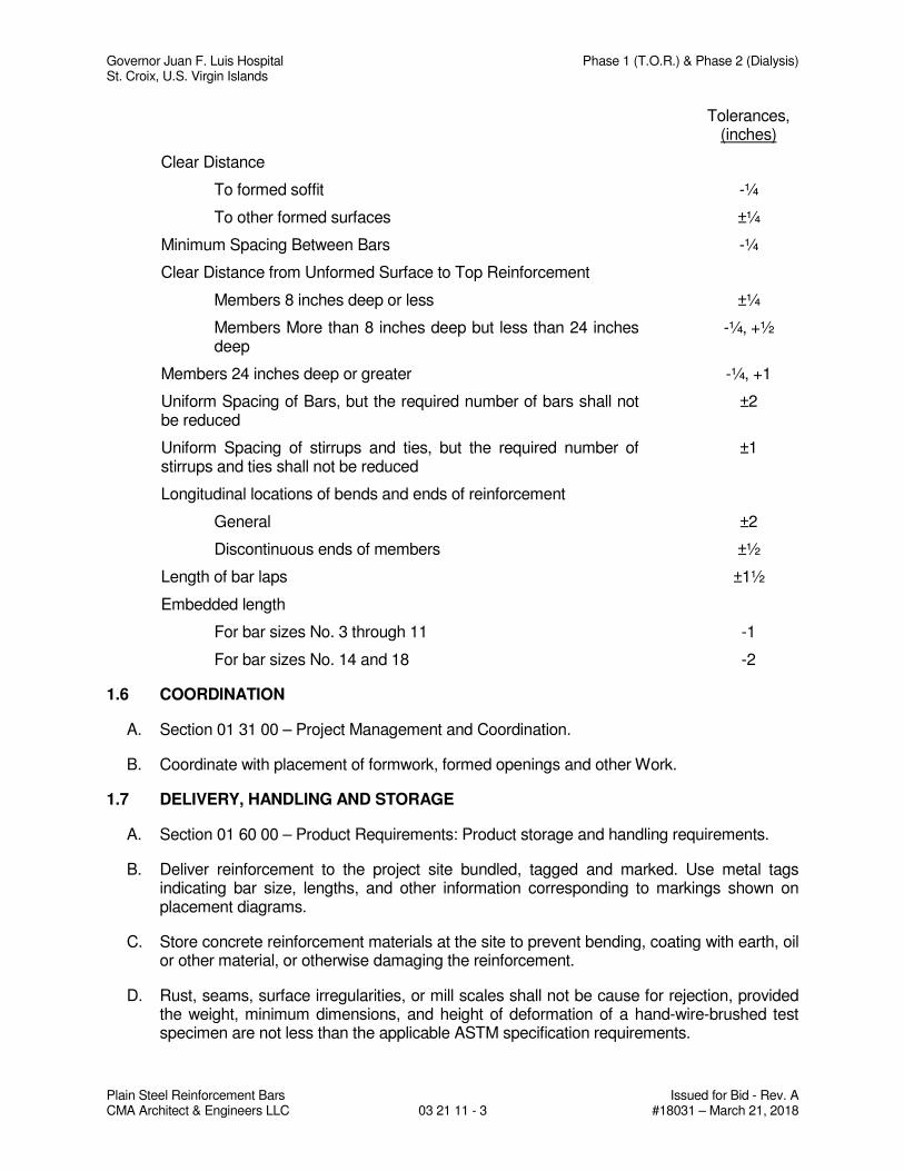
Governor Juan F. Luis Hospital Phase 1 (T.O.R.) & Phase 2 (Dialysis) St. Croix, U.S. Virgin Islands
Plain Steel Reinforcement Bars Issued for Bid - Rev. A CMA Architect & Engineers LLC 03 21 11 - 3 #18031 – March 21, 2018
Tolerances, (inches)
Clear Distance
To formed soffit -¼
To other formed surfaces ±¼
Minimum Spacing Between Bars -¼
Clear Distance from Unformed Surface to Top Reinforcement
Members 8 inches deep or less ±¼
Members More than 8 inches deep but less than 24 inches deep
-¼, +½
Members 24 inches deep or greater -¼, +1
Uniform Spacing of Bars, but the required number of bars shall not be reduced
±2
Uniform Spacing of stirrups and ties, but the required number of stirrups and ties shall not be reduced
±1
Longitudinal locations of bends and ends of reinforcement
General ±2
Discontinuous ends of members ±½
Length of bar laps ±1½
Embedded length
For bar sizes No. 3 through 11 -1
For bar sizes No. 14 and 18 -2
1.6 COORDINATION
A. Section 01 31 00 – Project Management and Coordination.
B. Coordinate with placement of formwork, formed openings and other Work.
1.7 DELIVERY, HANDLING AND STORAGE
A. Section 01 60 00 – Product Requirements: Product storage and handling requirements.
B. Deliver reinforcement to the project site bundled, tagged and marked. Use metal tags indicating bar size, lengths, and other information corresponding to markings shown on placement diagrams.
C. Store concrete reinforcement materials at the site to prevent bending, coating with earth, oil or other material, or otherwise damaging the reinforcement.
D. Rust, seams, surface irregularities, or mill scales shall not be cause for rejection, provided the weight, minimum dimensions, and height of deformation of a hand-wire-brushed test specimen are not less than the applicable ASTM specification requirements.
Governor Juan F. Luis Hospital Phase 1 (T.O.R.) & Phase 2 (Dialysis) St. Croix, U.S. Virgin Islands
Plain Steel Reinforcement Bars Issued for Bid - Rev. A CMA Architect & Engineers LLC 03 21 11 - 4 #18031 – March 21, 2018
PART 2 - PRODUCTS
2.1 MATERIALS – PLAIN STEEL REINFORCEMENT BARS
A. Reinforcing Steel: ASTM A615, 60 ksi yield grade; deformed billet steel bars, unfinished.
B. Weldable Reinforcing Steel: ASTM A706, Grade 60, deformed, unfinished.
C. Column Spirals: ASTM A82, plain, cold drawn wire; or ASTM A615, hot-rolled rods for spirals.
D. Reinforcement for Metal Pan Stair Fill: 2-inch wire mesh, either hexagonal mesh at 1.5 pounds per square yard, or square mesh at 1.17 pounds per square yard.
2.2 MATERIALS - SUPPORTS FOR PLAIN STEEL REINFORCEMENT BARS
A. Tie Wire: Minimum 16 gage annealed type.
B. Special Chairs, Bolsters, Bar Supports, Spacers Adjacent to Weather Exposed Concrete Surfaces: Plastic coated steel or Stainless steel type; size and shape as required. Comply with Class 1, maximum protection in CRSI Manual of Standard Practice.
C. Do not use wood, brick, and any other unacceptable material.
2.3 FABRICATION - PLAIN STEEL REINFORCEMENT BARS
A. Fabricate concrete reinforcing in accordance with CRSI Manual of Practice, ACI SP-66, ACI 318, and tolerances of ACI 117. In case of fabrication errors, do not rebend or straighten reinforcement in a manner that will injure or weaken the material.
B. Form standard hooks for 180 degree bends, 90 degree bends, stirrup and tie hooks, and seismic hooks as indicated on Drawings and approved shop drawings.
C. Form reinforcement bends with minimum diameters in accordance with ACI 318.
D. Fabricate column reinforcement with offset bends at reinforcement spices.
E. Form spiral column reinforcement from minimum 3/8 inch diameter continuous plain or deformed bar or wire.
F. Form ties and stirrups from the following:
1. For bars No. 10 and Smaller: No. 3 deformed bars.
2. For bars No. 11 and Larger; No. 4 deformed bars.
G. Welding of cross bars (tack welding) for assembly of reinforcement, supports, or embeded items is prohibited.
H. All reinforcement shall be bent cold, and shall not be bent or straightened in a manner that will injure the material.
Governor Juan F. Luis Hospital Phase 1 (T.O.R.) & Phase 2 (Dialysis) St. Croix, U.S. Virgin Islands
Plain Steel Reinforcement Bars Issued for Bid - Rev. A CMA Architect & Engineers LLC 03 21 11 - 5 #18031 – March 21, 2018
I. Unacceptable Materials: Reinforcement with any of the following defects will not be permitted in the work:
1. Bar lengths, depths and bends exceeding specified fabrication tolerances.
2. Bend or kinks not indicated on drawings or approved shop drawings.
3. Bars with reduced cross-section due to excessive rusting or other cause.
J. Identification of Reinforcing Steel:
1. Bundles of reinforcing bars shall be tagged showing quantity, grade, size, heat number and suitable identification to allow checking, sorting and placing.
K. Locate reinforcement splices not indicated on Drawings, at point of minimum stress. Review location of splices with Architect-Engineer. Indicate these splices on shop drawings.
PART 3 - EXECUTION
3.1 EXAMINATION
A. Section 01 31 00 – Project Management and Coordination.
B. Verify substrate is ready to receive reinforcing steel bars.
C. Advise General Contractor of any deficiencies prior to beginning of installation of reinforcing steel bars.
3.2 PREPARATION – PLAIN STEEL REINFORCEMENT BARS
A. All reinforcement, at the time concrete is placed, shall be free of mud, oil, or other materials that may adversely affect or reduce the bond.
B. Reinforcement with rust, mill scale, or a combination of both shall be considered satisfactory provided the minimum dimensions, weight, and height of deformations of a hand-wire brushed test specimen are not less than the applicable ASTM specification requirement.
3.3 PLACEMENT - PLAIN STEEL REINFORCEMENT BARS
A. General: Comply with the specified codes and standards, and Concrete Reinforcing Steel Institute (CRSI) recommended practice for "Placing Reinforcing Bars", for details and methods of reinforcement and supports, and as herein specified. Spacing of supports shall conform to ACI 315.
B. Tolerances: Place, support, and fasten reinforcement as shown on the approved Shop Drawings. Do not exceed the placing tolerances specified in ACI 117 before concrete is placed. Placing tolerances shall not reduce cover requirements except as specified in ACI 117.
C. Reinforcement Relocation: When necessary to move reinforcement beyond the specified placing tolerances to avoid interference with other reinforcement, conduits, or embedded items, submit the resulting arrangement of reinforcement for acceptance.
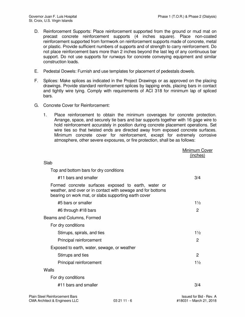
Governor Juan F. Luis Hospital Phase 1 (T.O.R.) & Phase 2 (Dialysis) St. Croix, U.S. Virgin Islands
Plain Steel Reinforcement Bars Issued for Bid - Rev. A CMA Architect & Engineers LLC 03 21 11 - 6 #18031 – March 21, 2018
D. Reinforcement Supports: Place reinforcement supported from the ground or mud mat on precast concrete reinforcement supports (4 inches square). Place non-coated reinforcement supported from formwork on reinforcement supports made of concrete, metal or plastic. Provide sufficient numbers of supports and of strength to carry reinforcement. Do not place reinforcement bars more than 2 inches beyond the last leg of any continuous bar support. Do not use supports for runways for concrete conveying equipment and similar construction loads.
E. Pedestal Dowels: Furnish and use templates for placement of pedestals dowels.
F. Splices: Make splices as indicated in the Project Drawings or as approved on the placing drawings. Provide standard reinforcement splices by lapping ends, placing bars in contact and tightly wire tying. Comply with requirements of ACI 318 for minimum lap of spliced bars.
G. Concrete Cover for Reinforcement:
1. Place reinforcement to obtain the minimum coverages for concrete protection. Arrange, space, and securely tie bars and bar supports together with 16 gage wire to hold reinforcement accurately in position during concrete placement operations. Set wire ties so that twisted ends are directed away from exposed concrete surfaces. Minimum concrete cover for reinforcement, except for extremely corrosive atmosphere, other severe exposures, or fire protection, shall be as follows:
Minimum Cover
(inches)
Slab
Top and bottom bars for dry conditions
#11 bars and smaller 3/4
Formed concrete surfaces exposed to earth, water or weather, and over or in contact with sewage and for bottoms bearing on work mat, or slabs supporting earth cover
#5 bars or smaller 1½
#6 through #18 bars 2
Beams and Columns, Formed
For dry conditions
Stirrups, spirals, and ties 1½
Principal reinforcement 2
Exposed to earth, water, sewage, or weather
Stirrups and ties 2
Principal reinforcement 1½
Walls
For dry conditions
#11 bars and smaller 3/4
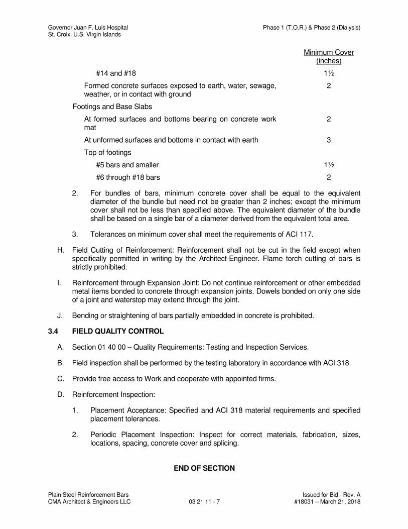
Governor Juan F. Luis Hospital Phase 1 (T.O.R.) & Phase 2 (Dialysis) St. Croix, U.S. Virgin Islands
Plain Steel Reinforcement Bars Issued for Bid - Rev. A CMA Architect & Engineers LLC 03 21 11 - 7 #18031 – March 21, 2018
Minimum Cover (inches)
#14 and #18 1½
Formed concrete surfaces exposed to earth, water, sewage, weather, or in contact with ground
2
Footings and Base Slabs
At formed surfaces and bottoms bearing on concrete work mat
2
At unformed surfaces and bottoms in contact with earth 3
Top of footings
#5 bars and smaller 1½
#6 through #18 bars 2
2. For bundles of bars, minimum concrete cover shall be equal to the equivalent diameter of the bundle but need not be greater than 2 inches; except the minimum cover shall not be less than specified above. The equivalent diameter of the bundle shall be based on a single bar of a diameter derived from the equivalent total area.
3. Tolerances on minimum cover shall meet the requirements of ACI 117.
H. Field Cutting of Reinforcement: Reinforcement shall not be cut in the field except when specifically permitted in writing by the Architect-Engineer. Flame torch cutting of bars is strictly prohibited.
I. Reinforcement through Expansion Joint: Do not continue reinforcement or other embedded metal items bonded to concrete through expansion joints. Dowels bonded on only one side of a joint and waterstop may extend through the joint.
J. Bending or straightening of bars partially embedded in concrete is prohibited.
3.4 FIELD QUALITY CONTROL
A. Section 01 40 00 – Quality Requirements: Testing and Inspection Services.
B. Field inspection shall be performed by the testing laboratory in accordance with ACI 318.
C. Provide free access to Work and cooperate with appointed firms.
D. Reinforcement Inspection:
1. Placement Acceptance: Specified and ACI 318 material requirements and specified placement tolerances.
2. Periodic Placement Inspection: Inspect for correct materials, fabrication, sizes, locations, spacing, concrete cover and splicing.
END OF SECTION
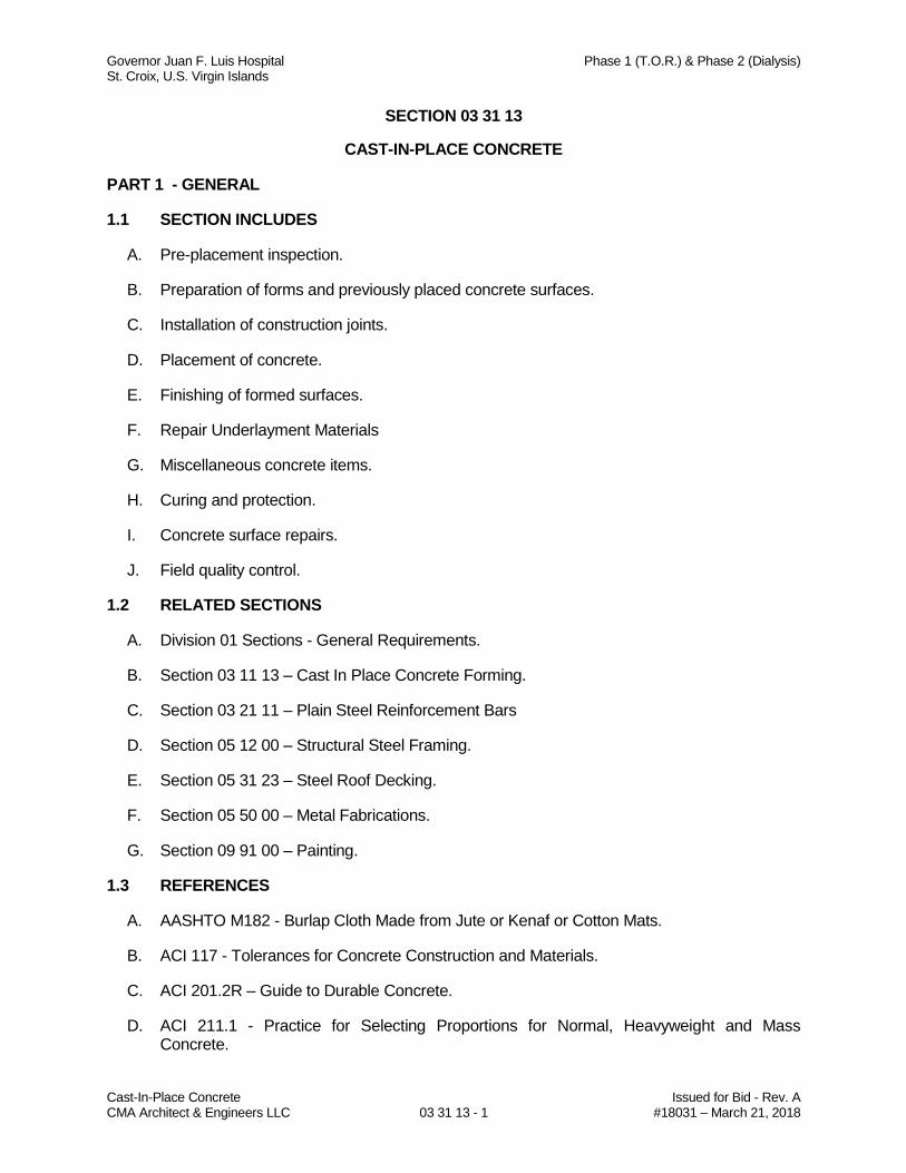
Governor Juan F. Luis Hospital Phase 1 (T.O.R.) & Phase 2 (Dialysis) St. Croix, U.S. Virgin Islands
Cast-In-Place Concrete Issued for Bid - Rev. A CMA Architect & Engineers LLC 03 31 13 - 1 #18031 – March 21, 2018
SECTION 03 31 13
CAST-IN-PLACE CONCRETE
PART 1 - GENERAL
1.1 SECTION INCLUDES
A. Pre-placement inspection.
B. Preparation of forms and previously placed concrete surfaces.
C. Installation of construction joints.
D. Placement of concrete.
E. Finishing of formed surfaces.
F. Repair Underlayment Materials
G. Miscellaneous concrete items.
H. Curing and protection.
I. Concrete surface repairs.
J. Field quality control.
1.2 RELATED SECTIONS
A. Division 01 Sections - General Requirements.
B. Section 03 11 13 – Cast In Place Concrete Forming.
C. Section 03 21 11 – Plain Steel Reinforcement Bars
D. Section 05 12 00 – Structural Steel Framing.
E. Section 05 31 23 – Steel Roof Decking.
F. Section 05 50 00 – Metal Fabrications.
G. Section 09 91 00 – Painting.
1.3 REFERENCES
A. AASHTO M182 - Burlap Cloth Made from Jute or Kenaf or Cotton Mats.
B. ACI 117 - Tolerances for Concrete Construction and Materials.
C. ACI 201.2R – Guide to Durable Concrete.
D. ACI 211.1 - Practice for Selecting Proportions for Normal, Heavyweight and Mass Concrete.
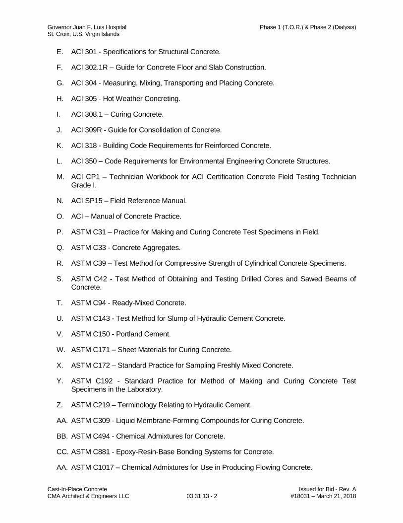
Governor Juan F. Luis Hospital Phase 1 (T.O.R.) & Phase 2 (Dialysis) St. Croix, U.S. Virgin Islands
Cast-In-Place Concrete Issued for Bid - Rev. A CMA Architect & Engineers LLC 03 31 13 - 2 #18031 – March 21, 2018
E. ACI 301 - Specifications for Structural Concrete.
F. ACI 302.1R – Guide for Concrete Floor and Slab Construction.
G. ACI 304 - Measuring, Mixing, Transporting and Placing Concrete.
H. ACI 305 - Hot Weather Concreting.
I. ACI 308.1 – Curing Concrete.
J. ACI 309R - Guide for Consolidation of Concrete.
K. ACI 318 - Building Code Requirements for Reinforced Concrete.
L. ACI 350 – Code Requirements for Environmental Engineering Concrete Structures.
M. ACI CP1 – Technician Workbook for ACI Certification Concrete Field Testing Technician Grade I.
N. ACI SP15 – Field Reference Manual.
O. ACI – Manual of Concrete Practice.
P. ASTM C31 – Practice for Making and Curing Concrete Test Specimens in Field.
Q. ASTM C33 - Concrete Aggregates.
R. ASTM C39 – Test Method for Compressive Strength of Cylindrical Concrete Specimens.
S. ASTM C42 - Test Method of Obtaining and Testing Drilled Cores and Sawed Beams of Concrete.
T. ASTM C94 - Ready-Mixed Concrete.
U. ASTM C143 - Test Method for Slump of Hydraulic Cement Concrete.
V. ASTM C150 - Portland Cement.
W. ASTM C171 – Sheet Materials for Curing Concrete.
X. ASTM C172 – Standard Practice for Sampling Freshly Mixed Concrete.
Y. ASTM C192 - Standard Practice for Method of Making and Curing Concrete Test Specimens in the Laboratory.
Z. ASTM C219 – Terminology Relating to Hydraulic Cement.
AA. ASTM C309 - Liquid Membrane-Forming Compounds for Curing Concrete.
BB. ASTM C494 - Chemical Admixtures for Concrete.
CC. ASTM C881 - Epoxy-Resin-Base Bonding Systems for Concrete.
AA. ASTM C1017 – Chemical Admixtures for Use in Producing Flowing Concrete.
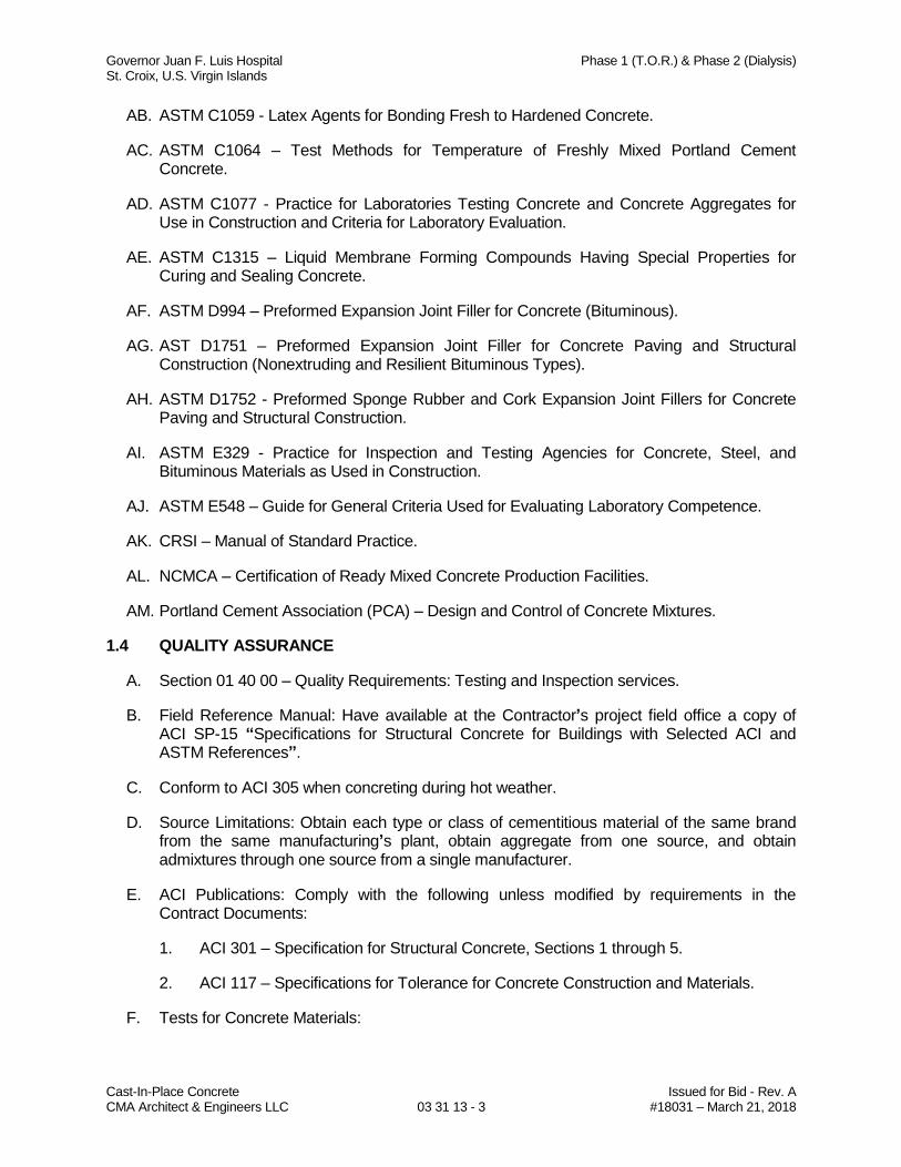
Governor Juan F. Luis Hospital Phase 1 (T.O.R.) & Phase 2 (Dialysis) St. Croix, U.S. Virgin Islands
Cast-In-Place Concrete Issued for Bid - Rev. A CMA Architect & Engineers LLC 03 31 13 - 3 #18031 – March 21, 2018
AB. ASTM C1059 - Latex Agents for Bonding Fresh to Hardened Concrete.
AC. ASTM C1064 – Test Methods for Temperature of Freshly Mixed Portland Cement Concrete.
AD. ASTM C1077 - Practice for Laboratories Testing Concrete and Concrete Aggregates for Use in Construction and Criteria for Laboratory Evaluation.
AE. ASTM C1315 – Liquid Membrane Forming Compounds Having Special Properties for Curing and Sealing Concrete.
AF. ASTM D994 – Preformed Expansion Joint Filler for Concrete (Bituminous).
AG. AST D1751 – Preformed Expansion Joint Filler for Concrete Paving and Structural Construction (Nonextruding and Resilient Bituminous Types).
AH. ASTM D1752 - Preformed Sponge Rubber and Cork Expansion Joint Fillers for Concrete Paving and Structural Construction.
AI. ASTM E329 - Practice for Inspection and Testing Agencies for Concrete, Steel, and Bituminous Materials as Used in Construction.
AJ. ASTM E548 – Guide for General Criteria Used for Evaluating Laboratory Competence.
AK. CRSI – Manual of Standard Practice.
AL. NCMCA – Certification of Ready Mixed Concrete Production Facilities.
AM. Portland Cement Association (PCA) – Design and Control of Concrete Mixtures.
1.4 QUALITY ASSURANCE
A. Section 01 40 00 – Quality Requirements: Testing and Inspection services.
B. Field Reference Manual: Have available at the Contractor’s project field office a copy of ACI SP-15 “Specifications for Structural Concrete for Buildings with Selected ACI and ASTM References”.
C. Conform to ACI 305 when concreting during hot weather.
D. Source Limitations: Obtain each type or class of cementitious material of the same brand from the same manufacturing’s plant, obtain aggregate from one source, and obtain admixtures through one source from a single manufacturer.
E. ACI Publications: Comply with the following unless modified by requirements in the Contract Documents:
1. ACI 301 – Specification for Structural Concrete, Sections 1 through 5.
2. ACI 117 – Specifications for Tolerance for Concrete Construction and Materials.
F. Tests for Concrete Materials:
Governor Juan F. Luis Hospital Phase 1 (T.O.R.) & Phase 2 (Dialysis) St. Croix, U.S. Virgin Islands
Cast-In-Place Concrete Issued for Bid - Rev. A CMA Architect & Engineers LLC 03 31 13 - 4 #18031 – March 21, 2018
1. For normal weight concrete, test aggregates by the methods of sampling and testing of ASTM C33.
2. For Portland cement, sample the cement and determine the properties by the methods of test of ASTM C150.
3. Submit written reports to the Architect-Engineer, for each material sampled and tested, prior to the start of work. Provide the project identifications name and number, date of report, name of contractor, name of concrete testing service, source of concrete aggregates, material manufacturer and brand name for manufactured materials, values specified in the referenced specification for each material, and test results. Indicate whether or not material is acceptable for intended use.
1.5 SUBMITTALS
A. Section 01 33 00 – Submittal Procedures: Requirements for submittals.
B. Product’s Data: Submit complete product data and installation instructions of each type of product indicated.
C. Material Certificate: For each of the following signed by manufacturers:
1. Cementitious materials.
2. Admixtures.
3. Curing materials.
4. Joint-filler strips.
5. Repair underlayment materials.
6. Sealer.
D. Concrete Mix Design: Submit concrete mix design for each strength and type of concrete. Each mix design submittal shall include the following:
1. Location of structure where concrete mix will be used, ie, foundations, walls, columns, beams, elevated slabs, stairs, etc.
2. Dosage of each component (cement, water, fine aggregate, coarse aggregate, admixtures) of the concrete mix design.
3. Data on trial mixture and certified laboratory test results of trial mixture.
4. Thirty (30) consecutive test results of the mix design used from a previous recorded project in accordance with ACI 301, Method 2.
5. Cement certification including type, class, producer’s names and plant location. Cement will be accepted on the basis of a manufacturer’s mill certificate that the cement furnished meets the physical and chemical characteristics of ASTM C150. The Architect-Engineer reserves the right, however, to sample and conduct such tests on cement as he deems necessary for compliance with the requirements of these specifications.
Governor Juan F. Luis Hospital Phase 1 (T.O.R.) & Phase 2 (Dialysis) St. Croix, U.S. Virgin Islands
Cast-In-Place Concrete Issued for Bid - Rev. A CMA Architect & Engineers LLC 03 31 13 - 5 #18031 – March 21, 2018
6. Gradation analysis of coarse aggregate in accordance with ASTM C33 including pit or quarry locations, producer’s name, gradations, specific gravities and weight retained per seive.
7. Gradation analysis of fine aggregate in accordance with ASTM C33 including pit or quarry locations, producer’s name, gradations, specific gravity and weight retained per sieve.
8. Data on admixtures including ASTM C494 classification, brand, manufacturer. Admixtures shall be the product of one manufacturer.
9. Indicate amounts of mixing water to be withheld for later addition at Project site.
10. Fine aggregate content.
11. Mortar fraction.
E. Test and Inspection Reports: Testing agencies shall report results of concrete and concrete material tests and inspections performed during the course of the Work to the Owner, Architect-Engineer, Contractor, and the Concrete Supplier.
1. Strength test reports (7 and 28 days) shall include locations in the Work where the batch represented by the test was deposited and the batch ticket number.
2. Reports of strength tests shall include detailed information of storage and curing of specimens prior to testing.
3. Final reports shall be provided within seven (7) calendar days of test completion.
F. Qualification Data: For testing agency.
G. Delivery Tickets: Furnish copies of delivery tickets for each load of concrete delivered to the site. Provide items of information as specified. Concrete supplier shall furnish to the Owner’s On Site Representative with each batch of concrete before unloading at the site, a delivery ticket on which is printed, stamped, or written, information concerning said concrete as follows:
1. Name of ready-mix company and batch plant, or batch plant number,
2. Serial number of ticket,
3. Date,
4. Truck number,
5. Name of purchaser,
6. Specific designation of job (name and location),
7. Specific class or designation of the concrete in conformance with that employed in job specifications,
8. Amount of concrete in cubic yards,
9. Time loaded or of first mixing of cement and aggregates, and
Governor Juan F. Luis Hospital Phase 1 (T.O.R.) & Phase 2 (Dialysis) St. Croix, U.S. Virgin Islands
Cast-In-Place Concrete Issued for Bid - Rev. A CMA Architect & Engineers LLC 03 31 13 - 6 #18031 – March 21, 2018
10. Water added by receiver of concrete and his initials.
H. Change of Materials: When brand, type, size, or source of cementitious materials, aggregates, water, or admixtures are proposed to be changed, new field data or data from new trial mixtures or evidence which indicates that the change will not adversely affect the relevant properties of the concrete shall submitted for acceptance prior to use in concrete.
1.6 CLOSEOUT SUBMITTALS
A. Section 01 77 00 – Closeout Procedures: Closeout procedures.
B. Project Record Documents: Accurately record actual locations of embedded utilities and components concealed from view in finished construction.
1.7 COORDINATION
A. Coordinate placement of joint devices with erection of concrete formwork and placement of form accessories.
1.8 DELIVERY AND STORAGE
A. Section 01 60 00 – Product Requirements.
B. Do not deliver concrete until forms, reinforcement, embedded items, sleeves, and chamfer strips are in place, ready for placement, and approved by the Owner’s on Site Representative and/or Architect/Engineer.
C. ACI 301 for job site storage of concrete aggregates.
PART 2 - PRODUCTS
2.1 MATERIALS - CONCRETE MATERIALS
A. Portland Cement: ASTM C150, Type I, gray. It shall be of the same brand and type, and from the same plant of manufacture as the portland cement used in the concrete represented by the submitted field test data or used in the trial mixtures.
B. Normal-Weight Aggregates: ASTM C33 unless otherwise specified. When a single size or a combination of two or more sizes of coarse aggregates are used, the final gradation shall conform to the grading requirements of ASTM C33 unless otherwise specified or permitted. Aggregates used in concrete shall be obtained from the same sources and have the same size ranges as the aggregates used in the concrete represented by submitted historical data, or used in trial mixtures.
1. Fine Aggregate: Clean, sharp, natural sand free from loam, clay, lumps or other deleterious substances. The use of manufactured sand is not permitted.
Sieve Designation Percent Passing
3/8 inch 100 No. 4 95 to 100 No. 8 80 to 100 No. 16 50 to 85
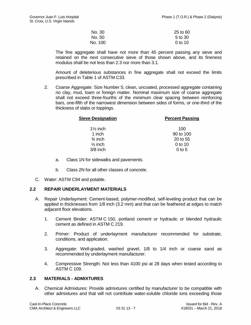
Governor Juan F. Luis Hospital Phase 1 (T.O.R.) & Phase 2 (Dialysis) St. Croix, U.S. Virgin Islands
Cast-In-Place Concrete Issued for Bid - Rev. A CMA Architect & Engineers LLC 03 31 13 - 7 #18031 – March 21, 2018
No. 30 25 to 60 No. 50 5 to 30 No. 100 0 to 10
The fine aggregate shall have not more than 45 percent passing any sieve and retained on the next consecutive sieve of those shown above, and its fineness modulus shall be not less than 2.3 nor more than 3.1.
Amount of deleterious substances in fine aggregate shall not exceed the limits prescribed in Table 1 of ASTM C33.
2. Coarse Aggregate: Size Number 5; clean, uncoated, processed aggregate containing no clay, mud, loam or foreign matter. Nominal maximum size of coarse aggregate shall not exceed three-fourths of the minimum clear spacing between reinforcing bars, one-fifth of the narrowest dimension between sides of forms, or one-third of the thickness of slabs or toppings.
Sieve Designation Percent Passing
1½ inch 100 1 inch 90 to 100 ¾ inch 20 to 55 ½ inch 0 to 10 3/8 inch 0 to 5
a. Class 1N for sidewalks and pavements.
b. Class 2N for all other classes of concrete.
C. Water: ASTM C94 and potable.
2.2 REPAIR UNDERLAYMENT MATERIALS
A. Repair Underlayment: Cement-based, polymer-modified, self-leveling product that can be applied in thicknesses from 1/8 inch (3.2 mm) and that can be feathered at edges to match adjacent floor elevations.
1. Cement Binder: ASTM C 150, portland cement or hydraulic or blended hydraulic cement as defined in ASTM C 219.
2. Primer: Product of underlayment manufacturer recommended for substrate, conditions, and application.
3. Aggregate: Well-graded, washed gravel, 1/8 to 1/4 inch or coarse sand as recommended by underlayment manufacturer.
4. Compressive Strength: Not less than 4100 psi at 28 days when tested according to ASTM C 109.
2.3 MATERIALS - ADMIXTURES
A. Chemical Admixtures: Provide admixtures certified by manufacturer to be compatible with other admixtures and that will not contribute water-soluble chloride ions exceeding those
Governor Juan F. Luis Hospital Phase 1 (T.O.R.) & Phase 2 (Dialysis) St. Croix, U.S. Virgin Islands
Cast-In-Place Concrete Issued for Bid - Rev. A CMA Architect & Engineers LLC 03 31 13 - 8 #18031 – March 21, 2018
permitted in hardened concrete. Do not use calcium chloride or admixtures containing calcium chloride.
1. Water-Reducing Admixture: ASTM C494, Type A.
2. Retarding Admixture: ASTM C494, Type B.
3. Water-Reducing and Retarding Admixture: ASTM C494, Type D.
4. High-Range, Water-Reducing Admixture: ASTM C494, Type F.
5. High-Range, Water-Reducing and Retarding Admixture: ASTM C494, Type G.
6. Plasticizing and Retarding Admixture: ASTM C1017, Type II.
B. Calcium Chloride: Use of calcium chloride in any form is strictly prohibited.
2.4 MATERIALS - CURING
A. For concrete indicated to be sealed, curing compound shall be compatible with sealer.
B. Evaporation Retarder: Waterborne, monomolecular film forming, manufactured for application to fresh concrete. Acceptable manufacturers and products are:
1. BASF Construction Chemicals – Building Systems; Product: Confilm.
2. Conspec by Dayton Superior; Product: Aquafilm.
3. Dayton Superior Corporation; Product: Sure Film (J-74).
4. Edoco by Dayton Superior; Product: BurkeFilm.
5. Euclid Chemical Company (The), an RPM Company; Product: Eucobar.
6. L&M Construction Chemicals, Inc.; Product: E-CON.
C. Absorptive Cover: AASHTO M 182, Class 2, burlap cloth made from jute or kenaf, weighing approximately 9 oz./sq. yd. when dry.
D. Moisture-Retaining Cover: ASTM C 171, polyethylene film or white burlap-polyethylene sheet.
E. Water: Potable.
F. Clear, Waterborne, Membrane-Forming Curing Compound: ASTM C 309, Type 1, Class B, nondissipating, certified by curing compound manufacturer to not interfere with bonding of floor covering. Acceptable manufactures and products are:
1. Burke by Edoco; Product: Product: Spartan Cote WB II.
2. Conspec Marketing & Manufacturing Co., Inc., a Dayton Superior Company; Product: Cure and Seal WB.
3. Euclid Chemical Company (The); Product: Aqua Cure VOX.
Governor Juan F. Luis Hospital Phase 1 (T.O.R.) & Phase 2 (Dialysis) St. Croix, U.S. Virgin Islands
Cast-In-Place Concrete Issued for Bid - Rev. A CMA Architect & Engineers LLC 03 31 13 - 9 #18031 – March 21, 2018
4. L&M Construction Chemicals, Inc.; Product: Dress & Seal WB.
5. Vexcon Chemicals, Inc.; Product: Starseal 309.
2.5 MATERIALS – EXPANSION AND ISOLATION JOINT FILLER STRIPS
A. Expansion and Isolation Joint Filler Strips: ASTM D1752, Type I (sponge rubber). Products complying with these requirements are:
1. A.C. Horn Co.; Product: Horn Darktone Sponge Rubber.
2. W.R. Meadows Co.; Product: Sponge Rubber Expansion Joint Filler.
3. Williams Products Co.; Product: Concrete Grey SBR Sponge.
2.6 CONCRETE MIXTURES, GENERAL
A. Prepare design mixtures for each type and strength of concrete, proportioned on the basis of laboratory trial mixture or field test data, or both, according to ACI 301.
1. Use a qualified independent testing agency for preparing and reporting proposed mixture designs based on laboratory trial mixtures.
B. Limit water-soluble, chloride-ion content in hardened concrete to the following:
1. Reinforced Concrete Exposed to Chloride: 0.15 percent by weight of cement.
2. Reinforced Concrete that will not be Dry or Protected from Moisture: 0.30 percent by weight of cement.
3. Reinforced Concrete that will be Dry or Protected from Moisture: 1.00 percent by weight of cement.
C. Admixtures: Use admixtures according to manufacturer’s written instructions.
1. Use water-reducing, high-range water-reducing or plasticizing admixture in concrete, as required, for placement and workability.
2. Use water-reducing and retarding admixture when required by high temperatures, low humidity, or other adverse placement conditions.
3. Use water-reducing admixture in pumped concrete, concrete for parking structure slabs, concrete required to be watertight, and concrete with a water-cementitious materials ratio below 0.50.
D. Ready Mixed Concrete: Measure, batch mix and deliver concrete in conformance with ASTM C94, and furnish batch ticket information.
1. When air temperature is between 85 and 90 degrees F, reduce mixing and delivery time from 1½ hours to 75 minutes.
2. When air temperature is above 90 degrees F, reduce mixing and delivery time to 60 minutes.
Governor Juan F. Luis Hospital Phase 1 (T.O.R.) & Phase 2 (Dialysis) St. Croix, U.S. Virgin Islands
Cast-In-Place Concrete Issued for Bid - Rev. A CMA Architect & Engineers LLC 03 31 13 - 10 #18031 – March 21, 2018
E. Cement Material Content: Adequate for concrete to satisfy the specified requirements for strength, water-cement ratio and finishing ability.
1. For concrete used in elevated floors, cement content shall not be less than indicated on Table 4.2.2.1 of ACI 301.
2. For concrete used in liquid retaining structures (fire protection, potable water, cooling tower and storm water cisterns), minimum cement content shall be as indicated in Paragraph 3.5 of ACI 350.
F. Fine aggregate content – Between 35% and 45% by mass.
G. Mortar fraction - Between 45% and 60% by mass.
2.7 CONCRETE MIXTURES FOR BUILDING ELEMENTS
A. Footings, Floors, Equipment Pads and Pedestals: Proportion normal-weight concrete mixture as follows:
1. Minimum Compressive Strength: 4000 psi at 28 days.
2. Maximum Water-Cementitious Materials Ratio: 0.45 maximum.
3. Slump Limit: 4 inches maximum or 8 inches maximum for concrete with verified slump of 2 to 4 inches before adding high-range water-reducing admixture or plasticizing admixture.
PART 3 - EXECUTION
3.1 PRE-PLACEMENT INSPECTION
A. Section 01 31 00 – Project Management and Coordination.
B. Before placing concrete, inspect and complete the formwork installation, reinforcing steel, and securely install all required inserts, anchors, sleeves, conduits and other items specified under other sections or as shown on the Contract Drawings to be embedded or cast-in.
C. Where concrete is placed on the ground or sub-course, the foundation upon which concrete is placed shall be clean, damp, and free from standing or running water. Prior to placing concrete, the earth foundation shall have been satisfactorily compacted.
D. Soil at bottom of foundation systems are subject to testing for soil bearing value by the testing laboratory, as directed by the Architect-Engineer. Place concrete immediately after approval of foundation excavations.
3.2 PREPARATION
A. Thoroughly wet wood forms immediately before placing concrete, as required where form coatings are not used.
B. Coordinate the installation of joint materials with placement of forms and reinforcing steel.
Governor Juan F. Luis Hospital Phase 1 (T.O.R.) & Phase 2 (Dialysis) St. Croix, U.S. Virgin Islands
Cast-In-Place Concrete Issued for Bid - Rev. A CMA Architect & Engineers LLC 03 31 13 - 11 #18031 – March 21, 2018
C. Prepare previously placed concrete by cleaning with steel brush and applying bonding agent.
D. In locations where new concrete is doweled to existing work, drill holes in existing concrete, insert steel dowels and pack solid with non-shrink grout.
3.3 INSTALLATION – FORMWORK
A. Refer to Section 03 11 13
3.4 INSTALLATION – PLAIN STEEL REINFORCEMENT BARS
A. Refer to Section 03 21 11
3.5 INSTALLATION - EMBEDDED ITEMS
A. Place and secure anchorage devices and other embedded items required for adjoining work that is attached to or supported by cast-in-place concrete. Use setting drawings, templates, diagrams, instructions, and directions furnished with items to be embedded.
1. Install anchor rods, accurately located, to elevations required and complying with tolerances in Section 7.5 of AISC’s “Code of Standard Practice for Steel Buildings and Bridges.”
2. Install dovetail anchor slots in concrete structures as indicated.
3. Install embedded plaster in grade beams to receive precast concrete wall panels. A registered surveyor shall verify location, elevation and levelness of each embedded plate prior and after concrete placement.
3.6 INSTALLATION – CONSTRUCTION JOINTS
A. General: Construct joints true to line with faces perpendicular to surface plane of concrete.
B. Construction Joints: Install so strength and appearance of concrete are not impaired, at locations indicated or as approved by Architect-Engineer.
1. Place joints perpendicular to main reinforcement. Continue reinforcement across construction joints, unless otherwise indicated. Do not continue reinforcement through sides of strip placements of floors and slabs.
2. Form keyed joints as indicated. Embed keys at least 1-1/2 inches into concrete.
3. Locate joints for beams, slabs, joists, and girders in the middle third of spans. Offset joints in girders a minimum distance of twice the beam width from a beam-girder intersection.
4. Locate horizontal joints in walls and columns at underside of floors, slabs, beams, and girders and at the top of footings or floor slabs.
5. Space vertical joints in walls as indicated. Locate joints beside piers integral with walls, near corners, and in concealed locations where possible.
Governor Juan F. Luis Hospital Phase 1 (T.O.R.) & Phase 2 (Dialysis) St. Croix, U.S. Virgin Islands
Cast-In-Place Concrete Issued for Bid - Rev. A CMA Architect & Engineers LLC 03 31 13 - 12 #18031 – March 21, 2018
6. Use a bonding agent at locations where fresh concrete is placed against hardened or partially hardened concrete surfaces.
7. Use epoxy-bonding adhesive at locations where fresh concrete is placed against hardened or partially hardened concrete surfaces.
3.7 PLACEMENT - CONCRETE
A. General:
1. Place concrete in compliance with the practices and recommendations of ACI 304, and as herein specified.
2. Before placing concrete, verify that installation of formwork, reinforcement, embedded items, and jointing is complete and that required inspections have been performed.
3. Do not add water to concrete during delivery, at Project site, or during placement unless approved by the Architect-Engineer.
B. Deposit concrete continuously in one layer or in horizontal layers of such thickness that no new concrete will be placed on concrete which has hardened sufficiently to cause the formation of seams or planes of weakness within the section. If a section cannot be placed continuously, provide construction joints as indicated. Perform concrete placing at such a rate that concrete which is being integrated with fresh concrete is still plastic. Deposit concrete as nearly as practicable to its final location to avoid segregation due to rehandling or flowing. Do not subject concrete to any procedure which will cause segregation.
C. Screed concrete which is to receive other construction to the proper level to avoid excessive skimming or grouting.
D. Do not use concrete which becomes non-plastic and unworkable, or does not meet the required quality control limits, or which has been contaminated by foreign materials. Do not use retempered concrete. Remove rejected concrete from the project site and dispose of it in an acceptable location.
E. Concrete Conveying:
1. Handle concrete from the point of delivery and transfer to the concrete conveying equipment and to the locations of final deposit as rapidly as practicable by methods which will prevent segregation and loss of concrete mix materials.
2. Provide mechanical equipment for conveying concrete to ensure a continuous flow of concrete at the delivery end. Provide runways for wheeled concrete conveying equipment from the concrete delivery point to the locations of final deposit. Keep interior surfaces of conveying equipment, including chutes, free of hardened concrete, debris, water, and other deleterious materials.
F. Placing Concrete into Forms:
1. Deposit concrete in forms in horizontal layers not deeper than 12 inches unless additional thickness is permitted by the Architect-Engineer, and in a manner to avoid inclined construction joints. Where placement consists of several layers, place each layer while preceding layer is still plastic to avoid cold joints.
Governor Juan F. Luis Hospital Phase 1 (T.O.R.) & Phase 2 (Dialysis) St. Croix, U.S. Virgin Islands
Cast-In-Place Concrete Issued for Bid - Rev. A CMA Architect & Engineers LLC 03 31 13 - 13 #18031 – March 21, 2018
2. Remove temporary spreaders in forms when concrete placing has reached the elevation of such spreaders.
3. Consolidate concrete placed in forms by mechanical vibrating equipment supplemented by hand-spading, rodding or tamping. Use equipment and procedures for consolidation of concrete in accordance with the recommended practices of ACI 309, to suit the type of concrete and project conditions. Vibration of forms and reinforcing will not be permitted, unless otherwise accepted by the Architect-Engineer.
4. Do not use vibrators to transport concrete inside of forms. Insert and withdraw vibrators vertically at uniformly spaced locations not farther than the visible effectiveness of the machine. Place vibrators to rapidly penetrate the layer of concrete and at least 6 inches into the preceding layer. Do not insert vibrators into lower layers of concrete that have begun to set. At each insertion, limit the duration of vibration to the time necessary to consolidate the concrete and complete embedment of reinforcement and other embedded items without causing segregation of the mix.
G. Bonding:
1. Roughen surfaces of set concrete at all joints, except where bonding is obtained by use of a concrete bonding agent, and clean surfaces of laitance, coatings, loose particles, and foreign matter. Roughen surfaces in a manner to expose bonded aggregate uniformly and to not leave laitance, loose particles of aggregate, or damaged concrete at the surface.
2. Prepare for bonding of fresh concrete to new concrete that has set but is not fully cured, as follows:
a. At joints between footings and walls or columns, and between walls or columns and beams or slabs they support, and elsewhere unless otherwise specified herein, dampen, but do not saturate, the roughened and cleaned surface of set concrete immediately before placing fresh concrete.
b. At joints in exposed work: At vertical joints in walls; at joints in girders, beams, supported slabs and other structural members; and at joints designed to contain liquids; dampen, but do not saturate, the roughened and cleaned surface of set concrete and apply a liberal coating of neat cement grout.
c. Use neat cement grout consisting of equal parts portland cement and fine aggregate by weight and not more than 6 gal. of water per sack of cement.
Apply with a stiff broom or brush to a minimum thickness of 116 inch. Deposit fresh concrete before cement grout has attained its initial set.
d. In lieu of neat cement grout, bonding grout may be a commercial bonding agent. Apply to cleaned concrete surfaces in accordance with the printed instruction of the bonding material manufacturer.
3. Prepare for bonding of fresh concrete to fully-cured hardened concrete or existing concrete by using an epoxy-resin bonding agent as follows:
a. Handle and store epoxy-resin adhesive binder in compliance with the manufacturer’s printed instructions, including safety precautions.
Governor Juan F. Luis Hospital Phase 1 (T.O.R.) & Phase 2 (Dialysis) St. Croix, U.S. Virgin Islands
Cast-In-Place Concrete Issued for Bid - Rev. A CMA Architect & Engineers LLC 03 31 13 - 14 #18031 – March 21, 2018
b. Mix the epoxy-resin adhesive binder in the proportions recommended by the manufacturer, carefully following directions for safety of personnel.
c. Before depositing fresh concrete, thoroughly roughen and clean hardened concrete surfaces and thick. Place fresh concrete while the epoxy-resin material is still tacky, without removing the in-place grout coat, and as directed by the epoxy-resin manufacturer.
H. Hot Weather Placement:
1. When hot weather conditions exist that would seriously impair the quality and strength of concrete, place concrete in compliance with ACI 305 and as herein specified.
2. Cool ingredients before mixing to maintain concrete temperature at time of placement below 90 degrees F. Mixing water may be chilled, or chopped ice may be used to control the concrete temperature provided the water equivalent of the ice is calculated to the total amount of mixing water.
3. Cover reinforcing steel with water-soaked burlap if it becomes too hot, so that the steel temperature will not exceed the ambient air temperature immediately before embedment in concrete.
4. Wet forms thoroughly before placing concrete.
5. Use set-control admixtures when required and accepted in mix designs.
3.8 FINISHING - FORMED SURFACES
A. Rough-Formed Finish:
1. As-cast concrete texture imparted by form-facing material with tie holes and defects repaired and patched. Remove fins and other projections that exceed specified limits on form-surface irregularities.
a. Apply to concrete surfaces not exposed to public view.
B. Smooth-Formed Finish:
1. As-cast concrete texture imparted by form-facing material, arranged in an orderly and symmetrical manner with a minimum of seams. Repair and patch tie holes and defects. Remove fins and other projections that exceed specified limits on formed-surface irregularities.
a. Apply to concrete surfaces exposed to public view.
b. To receive a rubbed finish, or
c. To be covered with a coating or covering material applied directly to concrete.
C. Rubbed Finish: Apply the following to smooth-formed finished as-cast concrete where indicated:
Governor Juan F. Luis Hospital Phase 1 (T.O.R.) & Phase 2 (Dialysis) St. Croix, U.S. Virgin Islands
Cast-In-Place Concrete Issued for Bid - Rev. A CMA Architect & Engineers LLC 03 31 13 - 15 #18031 – March 21, 2018
1. Smooth-Rubbed Finish: Not later than one day after form removal, moisten concrete surfaces and rub with carborundum brick or other abrasive until producing a uniform color and texture. Do not apply cement grout other that created by the rubbing process.
2. Grout-Cleaned Finish: Wet concrete surfaces and apply grout of a consistency of thick paint to coat surfaces and fill small holes. Mix one part portland cement to one and one-half parts fine sand with a 1:1 mixture of bonding admixture and water. Add white portland cement in amounts determined by trial batches so color of dry grout will match adjacent surfaces. Scrub grout into voids and remove excess grout. Where grout whitens, rub surface with clean burlap and keep surface damp by fog spray for at least 36 hours.
3. Cork-Floated Finish: Wet concrete surfaces and apply a stiff grout. Mix one part portland cement and one part fine sand with a 1:1 mixture of bonding agent and water. Add white portland cement in amounts determined by trial batches so color of dry grout will match adjacent surfaces. Compress grout into voids by grinding surface. In a swirling motion, finish surface with a cork float.
D. As-Cast Formed Finishes
1. Smooth-Formed Finish: As-cast concrete texture imparted by form-facing material, arranged in an orderly and symmetrical manner with a minimum of seams. Remove fins and other projections exceeding specified limits on formed-surface irregularities. Repair and patch tie holes and defects.
E. Related Unformed Surfaces:
1. At tops of walls, horizontal offsets, and similar unformed surfaces occurring adjacent to formed surfaces, strike off smooth and finish with a texture matching the adjacent formed surfaces. Continue the final surface treatment of formed surfaces uniformly across the adjacent unformed surfaces, unless otherwise shown.
3.9 REPAIR UNDERLAYMENT APPLICATION
A. Correct other low areas scheduled to receive floor coverings with a repair underlayment. Prepare, mix, and apply repair underlayment and primer according to manufacturer's written instructions to produce a smooth, uniform, plane, and level surface. Feather edges to match adjacent floor elevations.
3.10 MISCELLANEOUS CONCRETE ITEMS
A. Filling-In:
1. Fill-in holes and openings left in concrete structures for the passage of work by other trades, unless otherwise shown or directed, after the work of other trades is in place. Mix, place and cure concrete as herein specified, to blend with in-place construction. Provide all other miscellaneous concrete filling shown or required to complete the work.
Governor Juan F. Luis Hospital Phase 1 (T.O.R.) & Phase 2 (Dialysis) St. Croix, U.S. Virgin Islands
Cast-In-Place Concrete Issued for Bid - Rev. A CMA Architect & Engineers LLC 03 31 13 - 16 #18031 – March 21, 2018
B. Curbs:
1. Provide monolithic finish to interior curbs by stripping forms while concrete is still green and by steel-troweling surfaces to a hard, dense finish with corners, intersections, and terminations slightly rounded.
C. Equipment Bases and Foundations:
1. Provide machine and equipment bases and foundations, as shown on the drawings. Set anchor bolts for machines and equipment to template at correct elevations, complying with certified diagrams or templates of the manufacturer furnishing the machines and equipment.
3.11 CONCRETE PROTECTION AND CURING
A. General: Protect freshly placed concrete from premature drying and excessive hot temperatures. Comply with ACI 301 for hot-weather protection during curing.
B. Evaporation Retarder:
1. Apply evaporation retarder to unformed concrete surfaces if hot, dry, or windy conditions cause moisture loss approaching 0.2 lb/sq. ft. x h before and during finishing operations.
2. Apply according to manufacturer’s written instructions after placing, screeding, and bull floating or darbying concrete, but before float finishing.
C. Formed Surfaces:
1. Cure formed concrete surfaces, including underside of beams, supported slabs, and other similar surfaces.
2. If forms remain during curing period, moist cure after loosening forms.
3. If removing forms before end of curing period, continue curing for the remainder of the curing period.
D. Unformed Surfaces:
1. Begin curing immediately after finishing concrete.
2. Cure unformed surfaces, including floors and slabs, concrete floor toppings, and other surfaces.
E. Cure concrete according to ACI 308.1, by one or a combination of the following methods:
1. Moisture Curing: Keep surfaces continuously moist for not less than seven consecutive days with the following materials:
a. Water.
b. Continuous water-fog spray.
Governor Juan F. Luis Hospital Phase 1 (T.O.R.) & Phase 2 (Dialysis) St. Croix, U.S. Virgin Islands
Cast-In-Place Concrete Issued for Bid - Rev. A CMA Architect & Engineers LLC 03 31 13 - 17 #18031 – March 21, 2018
c. Absorptive cover, water saturated, and kept continuously wet. Cover concrete surfaces and edges with 12-inch lap over adjacent absorptive covers.
2. Moisture-Retaining-Cover Curing: Cover concrete surfaces with moisture-retaining cover for curing concrete, placed in widest practicable width, with sides and ends lapped at least 12 inches and sealed by waterproof tape or adhesive. Cure for not less than seven consecutive days. Immediately repair any holes or tears during curing period using cover material and waterproof tape.
a. Moisture cure or use moisture-retaining covers to cure concrete surfaces to receive floor coverings.
b. Cure concrete surfaces to receive floor coverings with moisture-retaining cover only.
3. Curing Compound: Apply uniformly in continuous operation by power spray or roller according to manufacturer’s written instructions. Recoat areas subjected to heavy rainfall within three hours after initial application. Maintain continuity of coating and repair damage during curing period.
a. After curing period has elapsed, remove curing compound without damaging concrete surfaces by method recommended by curing compound manufacturer unless manufacturer certifies curing compound will not interfere with bonding of floor covering used on Project.
b. The use of curing compound is not allowed on all slabs and ramps of parking building or any other slab to receive subsequent floor finishes.
F. Temperature of Concrete During Curing:
1. When the atmospheric temperature is 80 degrees F, and above, or during other climatic conditions which will cause too rapid drying of the concrete, make arrangements before the start of concrete placing for the installation of wind breaks or shading, and for fog spraying, wet sprinkling, or moisture-retaining covering. Protect the concrete continuously for the concrete curing period. Provide hot weather protection complying with the requirements of ACI 305.
2. Maintain concrete temperature as uniformly as possible, and protect from rapid atmospheric temperature changes. Avoid temperature changes in concrete which exceed 5 degrees F in any one hour.
G. Protection from Mechanical Injury:
1. During the curing period, protect concrete from damaging mechanical disturbances including load stresses, heavy shock, excessive vibration, and from damage caused by rain or flowing water. Protect all finished concrete surfaces from damage by subsequent construction operations.
3.12 CONCRETE SURFACE REPAIRS
A. Defective Concrete: Repair and patch defective areas when approved by Architect-Engineer. Remove and replace concrete that cannot be repaired and patched to Architect-Engineer’s approval.
Governor Juan F. Luis Hospital Phase 1 (T.O.R.) & Phase 2 (Dialysis) St. Croix, U.S. Virgin Islands
Cast-In-Place Concrete Issued for Bid - Rev. A CMA Architect & Engineers LLC 03 31 13 - 18 #18031 – March 21, 2018
B. Patching Mortar: Mix dry-pack patching mortar, consisting of one part portland cement to two and one-half parts fine aggregate passing a No. 16 sieve, using only enough water for handling and placing.
C. Patching Defective Areas:
1. Repair and patch defective areas with cement mortar immediately after removal of forms, but only when directed by the Architect-Engineer.
2. Cut out honeycomb, rock pockets, voids over ½-inch diameter, and holes left by tie rods and bolts, down to solid concrete but, in no case, to a depth of less than 1 inch. Make edges of cuts perpendicular to the concrete surface. Before placing the cement mortar, thoroughly clean, dampen with water, and brush-coat the area to be patched with neat cement grout. Proprietary patching compounds may be used when acceptable to the Architect-Engineer.
a. For exposed to public view surfaces, blend white portland cement and standard portland cement so that, when dry, the patching mortar will match the color of the surrounding concrete. Provide test areas at inconspicuous location to verify mixture and color match before proceeding with the patching. Compact mortar in place and strike off slightly higher than the surrounding surface.
3. Fill holes extending through concrete by means of a plunger-type gun or other suitable device from the least exposed face, using a flush stop held at the exposed face to ensure completely filling.
D. Repair of Formed Surfaces:
1. Repair exposed-to-view formed concrete surfaces, where possible, that contain defects which adversely affect the appearance of the finish. Remove and replace the concrete having defective surfaces if the defects cannot be repaired to the satisfaction of the Architect-Engineer. Surface defects, as such, include color and texture irregularities, cracks, spalls, air bubbles, honeycomb, rock pockets, and holes left by the rods and bolts; fins and other projections on the surface; and stains and other discolorations that cannot be removed by cleaning.
2. Repair concealed formed concrete surfaces, where possible, that contain defects that adversely affect the durability of the concrete. If defects cannot be repaired, remove and replace the concrete having defective surfaces. Surface defects, as such, include cracks in excess of 0.01 inch wide, cracks of any width and other surface deficiencies which penetrate to the reinforcement or completely through non-reinforced sections, honeycomb, rock pockets, holes left by tie rods and bolts, and spalls.
E. Repair of Unformed Surfaces:
1. Test unformed surfaces, such as monolithic slabs, for smoothness and to verify surface plane to the tolerances specified for each surface and finish. Correct low and high areas as herein specified.
2. Test unformed surfaces sloped to drain for trueness of slope, in addition to smoothness, using a template having the required slope. Correct high and low areas as herein specified.
Governor Juan F. Luis Hospital Phase 1 (T.O.R.) & Phase 2 (Dialysis) St. Croix, U.S. Virgin Islands
Cast-In-Place Concrete Issued for Bid - Rev. A CMA Architect & Engineers LLC 03 31 13 - 19 #18031 – March 21, 2018
3. Repair finish unformed surfaces that contain defects which adversely affect the durability of the concrete. Surface defects, as such, include crazing, cracks in excess of 0.01 inch wide or which penetrate to the reinforcement or completely through non-reinforced sections regardless of width, spalling, popouts, honeycomb, rock pockets, and other objectionable conditions.
4. Correct high areas in unformed surfaces by grinding, after the concrete has cured sufficiently so that repairs can be made without damage to adjacent areas.
5. Correct low areas in unformed surfaces during, or immediately after completion of surface finishing operations by cutting out the low areas and replacing with fresh concrete. Finish repaired areas to blend into adjacent concrete. Proprietary patching compounds may be used when acceptable to the Architect-Engineer.
6. Repair defective areas, except random cracks and single holes not exceeding 1-inch diameter, by cutting out and replacing with fresh concrete. Remove defective areas to
sound concrete with clean, square cuts, and expose reinforcing steel with at least 34-inch clearance all around. Dampen all concrete surfaces in contact with patching concrete and brush with a neat cement grout coating, or use concrete bonding agent. Place patching concrete before grout takes its initial set. Mix patching concrete of the same materials to provide concrete of the same type or class as the original adjacent concrete. Place, compact and finish as required to blend with adjacent finished concrete. Cure in the same manner as adjacent concrete.
7. Repair isolated random cracks and single holes not over 1-inch in diameter by the dry-pack method. Groove the top of cracks, and cut out holes to sound concrete and clean of dust, dirt and loose particles. Dampen all cleaned concrete surfaces and brush with a neat grout coating. Place dry-pack before the cement grout takes its initial set. Mix dry-pack, consisting of one part portland cement to 2½ parts fine aggregate passing a No. 16 mesh sieve, using only enough water as required for handling and placing. Compact dry-pack mixture in place and finish to match adjacent concrete. Keep patched areas continuously moist for not less than 72 hours.
8. Repair methods not specified above may be used, subject to the acceptance of the Architect-Engineer.
F. Perform structural repairs of concrete, subject to Architect-Engineer’s approval, using epoxy adhesive and patching mortar.
G. Repair material and installation not specified above may be used, subject to Architect-Engineer’s approval.
3.13 FIELD QUALITY CONTROL
A. Section 01 40 00 – Quality Requirements.
B. Testing: The Contractor shall employ and pay an approved qualified testing laboratory to perform field quality control testing and to submit reports.
C. Concrete Tests: Testing of composite samples of fresh concrete obtained according to ASTM C 172 shall be performed according to the following requirements:
Governor Juan F. Luis Hospital Phase 1 (T.O.R.) & Phase 2 (Dialysis) St. Croix, U.S. Virgin Islands
Cast-In-Place Concrete Issued for Bid - Rev. A CMA Architect & Engineers LLC 03 31 13 - 20 #18031 – March 21, 2018
1. Testing Frequency: Obtain at least one (1) composite sample for each 50 cu. yd. or fraction thereof of each concrete mixture placed each day.
a. When frequency of testing will provide fewer than five compressive-strength tests for each concrete mixture, testing shall be conducted from at least five randomly selected batches or from each batch if fewer than five are used.
2. Slump: ASTM C 143; one (1) test at point of placement for each composite sample, but not less than one (1) test for each day’s pour of each concrete mixture. Perform additional tests when concrete consistency appears to change.
3. Concrete Temperature: ASTM C 1064; one (1) test hourly when air temperature is 80 deg F and above, and one (1) test for each composite sample.
4. Compression Test Specimens: ASTM C 31.
a. Cast and laboratory cure two (2) sets of two standard cylinder specimens for each composite sample.
b. Cast and field cure two (2) sets of two standard cylinder specimens for each composite sample.
5. Compressive-Strength Tests: ASTM C 39; test one (1) set of two laboratory-cured specimens at 7 days and one set of two specimens at 28 days.
a. Test one (1) set of two field-cured specimens at 7 days and one (1) set of two specimens at 28 days.
b. A compressive-strength test shall be the average compressive strength from a set of two (2) specimens obtained from same composite sample and tested at age indicated.
6. When strength of field-cured cylinders is less than 85 percent of companion laboratory-cured cylinders, Contractor shall evaluate operations and provide corrective procedures for protecting and curing in-place concrete.
7. Strength of each concrete mixture will be satisfactory if every average of any three consecutive compressive-strength tests equals or exceeds specified compressive strength and no compressive-strength test value falls below specified compressive strength by more than 500 psi.
8. Test results shall be reported in writing to Architect-Engineer, concrete manufacturer, and Contractor within 48 hours of testing. Reports of compressive-strength tests shall contain Project identification name and number, date of concrete placement, name of concrete testing and inspecting agency, location of concrete batch in Work, design compressive strength at 28 days, concrete mixture proportions and materials, compressive breaking strength, and type of break for both 7- and 28-day tests.
9. Nondestructive Testing: Impact hammer, sonoscope, or other nondestructive device may be permitted by Architect-Engineer but will not be used as sole basis for approval or rejection of concrete.
Governor Juan F. Luis Hospital Phase 1 (T.O.R.) & Phase 2 (Dialysis) St. Croix, U.S. Virgin Islands
Cast-In-Place Concrete Issued for Bid - Rev. A CMA Architect & Engineers LLC 03 31 13 - 21 #18031 – March 21, 2018
10. Additional Tests: Testing agency shall make additional tests of concrete when test results indicate that slump, compressive strengths, or other requirements have not been met, as directed by Architect-Engineer. Testing agency may conduct tests to determine adequacy of concrete by cored cylinders complying with ASTM C 42 or by other methods as directed by Architect-Engineer.
11. Additional testing and inspecting, at Contractor’s expense, will be performed to determine compliance of replaced or additional work with specified requirements.
12. Correct deficiencies in the Work that test reports and inspections indicate dos not comply with the Contract Documents.
D. Defective Work:
1. Concrete work which does not conform to the specified requirements, including strength, tolerances, and finishes, shall be corrected at the Contractor’s expense. The Contractor shall also be responsible for the cost of corrections to any work affected by or resulting from corrections to the concrete work.
2. In the event the additional testing becomes necessary, the Contractor shall cooperate with and provide assistance to the Engineer in proceeding with the test.
3. Reasonable compensation will be allowed for any additional work required which is not the result of unacceptable materials.
END OF SECTION
Governor Juan F. Luis Hospital Phase 1 (T.O.R.) & Phase 2 (Dialysis) St. Croix, U.S. Virgin Islands
Non-Metallic Non-Shrink Grouting Issued for Bid - Rev. A CMA Architect & Engineers LLC 03 62 13 - 1 #18031 – March 21, 2018
SECTION 03 62 13
NON-METALLIC NON-SHRINK GROUTING
PART 1 - GENERAL
1.1 SECTION INCLUDES
A. Inspection of substrates.
B. Surface preparation.
C. Placing of non-metallic non-shrink grout.
D. Finishing.
E. Curing.
F. Schedule of installation.
1.2 RELATED SECTIONS
A. Division 01 Sections – General Requirements.
B. Section 03 11 13 – Cast In Place Concrete Forming.
C. Section 03 31 13 – Cast In Place Concrete.
D. Section 05 12 00 – Structural Steel Framing.
E. Division 21 Sections – Fire Suppression.
F. Division 22 Sections – Plumbing.
G. Division 26 Sections – Electrical.
1.3 REFERENCES
A. ASTM C109 - Test for Compressive Strength of Hydraulic Cement Mortars (Using 2-in. or 50-mm. Cube Specimens).
B. ASTM C191 - Test for Time of Setting of Hydraulic Cement by Vicat Needle.
C. ASTM C827 - Test for Early Volume change of Cementitious Mixtures.
D. CRD-C 621 – Specification for Nonshrink Grout.
1.4 SUBMITTALS
A. Section 01 33 00 – Submittal Procedures: Requirements for submittals.
B. Manufacturer's Data: Submit manufacturer's data of types of grout to be placed.
C. Certificate of Compliance: Submit information verifying that the grout exhibits the following:
Governor Juan F. Luis Hospital Phase 1 (T.O.R.) & Phase 2 (Dialysis) St. Croix, U.S. Virgin Islands
Non-Metallic Non-Shrink Grouting Issued for Bid - Rev. A CMA Architect & Engineers LLC 03 62 13 - 2 #18031 – March 21, 2018
1. Nonshrink: No shrinkage (0.0%) and a maximum 4.0 % expansion when tested in accordance with ASTM C827. No shrinkage (0.0%) and a maximum of 0.2% expansion in the hardened state when tested in accordance with CRD-C-621.
2. Compressive Strength: A minimum 28-day compressive strength of 5,000 psi when tested in accordance with ASTM C109.
3. Setting Time: A minimum initial set time of 60 minutes when tested in accordance with ASTM C191.
4. Technical Service: The manufacturer shall provide technical service upon request.
5. Composition: Nonshrink grout shall not contain metallic particles such as aluminum powders or iron filings, or expansive cement.
1.5 DELIVERY, STORAGE, AND HANDLING
A. Section 01 60 00 – Product Requirements.
B. Nonshrink nonmetallic cement-based grout should be shipped from the plants, palletized, shrink-wrapped, and delivered to the site in sound, dry packages.
C. It should be stored in a dry area.
D. Any material which becomes damp or otherwise defective should be immediately removed from the site.
1.6 JOB CONDITIONS
A. Section 01 60 00 – Product Requirements.
B. All necessary tools and materials should be as close as possible to the area being grouted, Mortar box, pencil vibrators, mortar mixer, wheelbarrow, shovel, hoe, water measuring container and grout should be within easy reach.
C. Comply with all government regulations regarding handling of cementitious products.
PART 2 - PRODUCTS
2.1 ACCEPTABLE MANUFACTURER AND PRODUCT
A. U.S. Grout Corporation; Product: Five Star Grout.
2.2 MATERIALS – NONSHRINK GROUT
A. Nonshrink Grout: Cement-based grout; no shrinkage under ASTM C827; no shrinkage under CRD-C-621; and must no contain no expensive cements or metallic powders such as aluminum o iron filings.
B. Water: Potable, clean and free from deleterious substances.
Governor Juan F. Luis Hospital Phase 1 (T.O.R.) & Phase 2 (Dialysis) St. Croix, U.S. Virgin Islands
Non-Metallic Non-Shrink Grouting Issued for Bid - Rev. A CMA Architect & Engineers LLC 03 62 13 - 3 #18031 – March 21, 2018
PART 3 - EXECUTION
3.1 INSPECTION
A. Section 01 31 00 – Project Management and Condition.
B. Inspect substrate prior to placement of grouting. Do not proceed until all deficiencies are corrected.
3.2 HOT WEATHER PROTECTION
A. For 24 hours prior to grouting, nonshrink grout should be stored in a cool, dry area with the temperature as close to 70 degrees Fahrenheit as possible.
B. Concrete should be soaked for 24 hours prior to grouting. One hour before grouting, cold spray should be used to cool concrete, steel, and forms in order to bring materials in contact with grout to temperatures below 90 degrees Fahrenheit. Excess water must be removed just prior to grouting.
C. Concrete, steel, and forms should be shaded from direct sunlight beginning 24 hours prior to placing grout. The shading device should not be removed until after three days or until the cement-based grout is adequately cured.
3.3 SURFACE PREPARATION
A. Concrete:
1. The concrete on which grout will bear should have attained its design strength before grouting.
2. Concrete should be sound.
3. Do not wet concrete. All surfaces to be in contact with the grout should be entirely free of oil, grease, laitance, curing compounds, and other deleterious substances.
4. Roughen the surfaces by chipping, sand blasting or other mechanical means to assure bond of the grout to the existing concrete.
B. Base Plates:
1. All metal surfaces of column base plates which are to be in direct contact with the grout should be thoroughly cleaned to bare metal immediately before grouting.
2. Leveling and alignment of equipment plates and column base plates should be performed according to the printed recommendations of the equipment manufacturer and/or project specifications.
3. Shims, wedges and blocks which are to be removed should be covered with putty, grease or similar non-bonding material to prevent the grout from adhering.
C. Anchor Bolts (Equipment)
Governor Juan F. Luis Hospital Phase 1 (T.O.R.) & Phase 2 (Dialysis) St. Croix, U.S. Virgin Islands
Non-Metallic Non-Shrink Grouting Issued for Bid - Rev. A CMA Architect & Engineers LLC 03 62 13 - 4 #18031 – March 21, 2018
1. All surfaces should be thoroughly cleaned of oil, grease and other deleterious substances, and must be dry.
2. Holes must be dried by evaporation, compressed air, or wicking with absorbent rags.
3. Any compressor used to blow out water or other substances from surfaces in contact with the grout should be equipped with an oil trap in the air line to prevent oil from being blow onto the contact surface and affecting the bond of the grout.
4. If equipment manufacturers require anchor bolts to remain isolated, sleeves should be used and filled with a pliable material such as dust seal, putty, silicone rubber molding compound or other material specified by the equipment manufacturer.
D. Surface Dryness: All surfaces must be kept completely dry before grouting.
E. Grout Removal: surfaces from which grout is to be removed after placing shall be treated with a paste wax or release agent before placement.
3.4 PLACING – NON METALLIC NON SHRINK GROUT
A. General: Nonshrink grout shall be thoroughly mixed to any desired consistency by varying the amount of water used. Do not proceed maximum recommended amount of mixing water. Follow manufacturer's printed instructions on each package.
B. Methods of Placing:
1. Nonshrink grout may be dry-packed, troweled, flowed, pumped, or vibrated into place.
2. Grout placement should be rapid and continuous so as to avoid cold joints under the base plate.
3. It should not be placed in layers.
4. All grouting should take place from overside to the other to avoid trapping air.
5. Forms shall be provided where structural components of base plates or bed plates will not confine the grout.
3.5 FINISHING
A. Just before the nonshrink grout has reached its final set (when grout can be cut with a steel trowel and will stand up without support), the forms must be removed and all the grout that is above the underside of the base plate must be cut back to the lower edge of the base plate.
B. A 45 degree angle cutback is required.
C. The grout should then be finished off with a wood float or brush finish.
Governor Juan F. Luis Hospital Phase 1 (T.O.R.) & Phase 2 (Dialysis) St. Croix, U.S. Virgin Islands
Non-Metallic Non-Shrink Grouting Issued for Bid - Rev. A CMA Architect & Engineers LLC 03 62 13 - 5 #18031 – March 21, 2018
3.6 CURING
A. Begin curing immediately after form removal, cutback, and finishing.
B. Nonshrink grout should be protected from extreme drying conditions by covering all exposed grout surfaces with continually wetted burlap, wetted flannel rags, sealed polyethylene, soaker hose and ponding for a minimum of seven (7) consecutive days.
3.7 SCHEDULE OF INSTALLATION – NON METALLIC NON SHRINK GROUT
A. Under each base plates of each steel columns.
B. At the joint between precast concrete wall panels and foundation walls.
C. Under each base plate of pumps and auxiliary equipment.
D. Any other use indicated in the drawings and technical specifications. END OF SECTION
Governor Juan F. Luis Hospital Phase 1 (T.O.R.) & Phase 2 (Dialysis)
St. Croix, U.S. Virgin Islands
Structural Steel Framing Issued for Bid - Rev. A
CMA Architect & Engineers LLC 05 12 00 - 1 #18031 – March 21, 2018
SECTION 05 12 00
STRUCTURAL STEEL FRAMING
PART 1 - GENERAL
1.1 SECTION INCLUDES
A. Preparation of Shop Drawings.
B. Fabrication including shop cleaning and prime painting.
C. Delivery to job site.
D. Examination of project conditions.
E. Survey of concrete pedestals and anchor bolt groups.
F. Field erection.
G. Bolted and welded connections.
H. Inspection and testing at the shop and field.
I. Touch-up paint after erection.
1.2 RELATED SECTIONS
A. Division 01 Sections - General Requirements.
B. Section 03 31 13 - Cast In Place Concrete: Setting anchor rods in concrete.
C. Section 03 62 13 – Non Metallic Non Shrink Grouting: Installation of non metallic non shrink grout under column base plates.
D. Section 05 31 23 – Steel Roof Decking.
E. Section 05 50 00 – Metal Fabrications: Steel fabrications affecting structural steel work.
F. Section 09 91 00 – Painting: Field painting of exposed exterior and interior structural steel members.
1.3 REFERENCES
A. ANSI/AISC 360-10 – Specification for Structural Steel Buildings
B. AISC 303-10 - Code of Standard Practice for Steel Buildings and Bridges
C. AISC 325-11 - Steel Construction Manual
D. AISC 326-09 - Detailing for Steel Construction
E. AISC 341-10 – Seismic Provisions for Structural Steel Buildings
Governor Juan F. Luis Hospital Phase 1 (T.O.R.) & Phase 2 (Dialysis)
St. Croix, U.S. Virgin Islands
Structural Steel Framing Issued for Bid - Rev. A
CMA Architect & Engineers LLC 05 12 00 - 2 #18031 – March 21, 2018
F. ASTM A6 – General Requirements for Rolled Structural Steel Bars, Plates, Shapes, and Sheet Piling
G. ASTM A36 – Carbon Structural Steel
H. ASTM A53 – Pipe, Steel, Black and Hot Dipped, Zinc Coated, Welded and Seamless
I. ASTM A108 – Steel Bars, Carbon, Cold Finished, Standard Quality
J. ASTM A216 – Steel Castings, Carbon, Suitable for Fusion Welding, for High Temperature Service
K. ASTM A325 – Structural Bolts, Steel, Heat Treated, 120/105 Ksi Minimum Tensile Strength.
L. ASTM A449 – Quenched and Tempered Steel Bolts and Studs
M. ASTM A500 – Cold Formed Welded and Seamless Carbon Steel Structural Tubing in Rounds and Shapes
N. ASTM A563 - Carbon and Alloy Steel Nuts
O. ASTM A572 - Standard Specification for High-Strength Low-Alloy Columbium-Vanadium Structural Steel
P. ASTM A668 – Steel Forgings, Carbon and Alloy for General Industrial Use
Q. ASTM A992 – Steel for Structural Shapes for Use in Building Framing
R. ASTM E94 - Guide for Radiographic Testing
S. ASTM E142 - Method for Controlling Quality of Radiographic Testing
T. ASTM E164 - Practice for Ultrasonic Contact Examination of Weldments
U. ASTM E165 – Test Method for Liquid Penetrant Examination
V. ASTM E709 – Guide for Magnetic Particle Examination
W. ASTM F436 - Hardened Steel Washers
X. ASTM F844 - Washers, Steel, Plain (Flat) Unhardened for General Use
Y. ASTM F959 - Compressible Washer Type Direct Tension Indicators for Use with Structural Fasteners
Z. ASTM F1554 – Anchor Bolts, Steel, 36, 55, and 105 Ksi Yield Strength
AA. ASTM F1852 – “Twisted Off” Type Tension Control Structural bolt/Nut/Washer Assemblies, Steel, Heat Treated, 120/105 Ksi Minimum Tensile Strength
BB. AWS D1.1 - Structural Welding Code – (Steel)
Governor Juan F. Luis Hospital Phase 1 (T.O.R.) & Phase 2 (Dialysis)
St. Croix, U.S. Virgin Islands
Structural Steel Framing Issued for Bid - Rev. A
CMA Architect & Engineers LLC 05 12 00 - 3 #18031 – March 21, 2018
CC. AWS D1.8 – Structural Welding Code – Seismic Supplement
DD. ANSI/AWS A2.4:2012 - Standard Symbols for Welding, Brazing and Nondestructive Examination
EE. OSHA 29 CFR Part 1926 – Subpart R Steel Erection
FF. SSPC PA1 - Shop, Field, and Maintenance Painting
GG. SSPC SP6/NACE No. 3 - Commercial Blast Cleaning
HH. SSPC QP3 – Standard Procedure for Evaluating Qualifications of Shop Painting Applicators
II. RCSC – Specification for Structural Joints Using ASTM A325 or A490 Bolts
JJ. RCSC (Educational Bulletin No. 3) – Recommendations for Purchasing, Receiving and Storing A325 and A490 Bolts
KK. RCSC (Educational Bulletin No. 4) – Recommended Erection and Field Inspection Procedures for High Strength Bolts in Structural Steel Assemblies
LL. 2011 PR Building Code
1.4 DEFINITIONS
A. Structural Steel: Elements of structural steel frame, as classified by AISC 303.
B. Seismic Force Resisting System: Elements of structural steel frame designated as “SFRS” or along grid lines designated as “SFRS” on Drawings, including columns, beams and braces and their connections.
C. Heavy Sections: Rolled and built-up sections as follows:
1. Shapes included in ASTM A6 with flanges thicker than 1½ inches.
2. Welded built-up members with plates thicker than 2 inches.
3. Column base plates thicker than 2 inches.
D. Protected Zone: Structural members or portions of structural members indicated as “Protected Zone” on Drawings. Connections of structural and nonstructural elements to protected zones are limited.
E. Demand Critical Welds: Those welds, the failure of which would result in significant degradation of the strength and stiffness of the Seismic-Load-Resisting System and which are indicated as “Demand Critical” or “Seismic Critical” on Drawings.
1.5 PERFORMANCE REQUIREMENTS
A. Moment Connections: Type PR, partially restrained; FR, fully restrained.
B. Construction: Moment frame; Braced frame.
Governor Juan F. Luis Hospital Phase 1 (T.O.R.) & Phase 2 (Dialysis)
St. Croix, U.S. Virgin Islands
Structural Steel Framing Issued for Bid - Rev. A
CMA Architect & Engineers LLC 05 12 00 - 4 #18031 – March 21, 2018
1.6 SUBMITTALS
A. Section 01 33 00 – Submittal Procedures: Procedures for submittals.
B. Product Data: Submit producer's or manufacturer's specifications and installation instructions for the following products. Include certified mill test reports and other data to show compliance with specifications (including specified standards).
1. Structural steel (each type) including chemical and physical properties.
2. Bolts, nuts and washers including mechanical properties and chemical analysis.
3. Direct-tension indicators.
4. Tension-control, high-strength bolt-nut washer assemblies.
5. Shear stud connectors.
6. Shop primer paint.
C. Shop Drawings: Submit shop drawings of structural steel work. Prepare in accordance with the AISC 326 and AISC 325 Shop drawings shall not be reproductions of contract drawings. Shop drawings shall be prepared using specialty application software from Tekla, SDS/2, Graitec, and others.
1. Include details of cuts, connections, splices, camber, holes, and other pertinent data.
2. Include embedment drawings.
3. Indicate welds by standard AWS symbols, distinguishing between shop and field welds, and show size, length, type of each weld, and grade of welding electrodes. Show backing bars that are to be removed and supplemental fillet welds where backing bars are to remain.
4. Indicate type, size, and length of bolts, distinguishing between shop and field bolts. Identify pretensioned and slip-critical high-strength bolted connections.
5. Identify members and connections of the seismic-load-resisting system.
6. Indicate locations and dimensions of protected zones.
7. Identify demand critical welds.
D. Welding Procedure Specification (WPSs) and Procedure Qualification Records (PQRs): Provide according to AWS D1.1, Structural Welding Code – Steel, for each welded joint whether prequalified or qualify by testing, including the following:
1. Power source (constant current or constant voltage).
2. Electrode manufacturer and trade name, for demand critical welds.
E. Qualification Data: For qualified Installer, fabricator, and professional engineer.
Governor Juan F. Luis Hospital Phase 1 (T.O.R.) & Phase 2 (Dialysis)
St. Croix, U.S. Virgin Islands
Structural Steel Framing Issued for Bid - Rev. A
CMA Architect & Engineers LLC 05 12 00 - 5 #18031 – March 21, 2018
F. Welding Certificates.
G. Paint Compatibility Certificates: From manufactures of Topcoats applied over shop primers, certifying that shop primers are compatible with topcoats.
H. Mill Test Reports for structural steel, including chemical and physical properties.
I. Procedure Test Reports: For the following:
1. Bolts, nuts, and washers including mechanical properties and chemical analysis.
2. Direct-Tension indicators.
3. Tension control, high strength bolt-nut-washer assemblies.
4. Shear stud connectors.
5. Shop primers.
J. Source quality-control reports.
K. Welder, Welding Operation and Tacker Qualification: Prior to welding, submit copies of certifications for each welder stating the type of welding and positions qualified for, the code and procedure qualified under, date qualified, and the firm and individual certifying the qualification tests. AWS qualifications should be no older than 1 year.
L. Erection Plan (For Record Purposes Only): Indicate the sequence of erection, temporary shoring and bracing, and a detailed sequence of welding, including each welding procedure required.
M. Setting Drawings and Templates: Provide setting drawings, template and directions for installation of anchor rods and other anchorages to be installed as work of other sections.
N. Test Reports: Submit reports of test conducted on shop and field bolted and welded connections. Include data on type(s) of tests conducted and test results.
O. Surveys: Submit signed and sealed surveys by a Registered Surveyor of the following surveys:
1. Elevation and locations of anchor rods and shear key pockets for the building columns. Indicate discrepancies between the field installation and Contract Documents, and whether these discrepancies will not permit the fabricated steel structure to be erected so as to comply with all tolerance requirements.
2. Upon completion of all bolting and/or welding on any part of the structural steel work prior to start of work by other trades that may be supported, attached, or applied to the work, submit a certified report of survey to Architect-Engineer for review. Report shall specify that the location of structural steel components is acceptable for plumbness, levelness and alignment within specified AISC tolerances.
P. Use of CAD Files and/or Copies of Design Drawings as Part of Shop or Erection Drawings.
a. See AISC 303-10, section 4.3.
Governor Juan F. Luis Hospital Phase 1 (T.O.R.) & Phase 2 (Dialysis)
St. Croix, U.S. Virgin Islands
Structural Steel Framing Issued for Bid - Rev. A
CMA Architect & Engineers LLC 05 12 00 - 6 #18031 – March 21, 2018
1.7 QUALITY ASSURANCE
A. Section 01 40 00 – Quality Requirements.
B. General: Materials and fabrication procedures are subject to inspection and test in the shop and field, conducted by an approved inspection agency. Such inspections and tests will not relieve Contractor of responsibility for providing materials and fabrication procedures in compliance with specified requirements. Promptly remove and replace materials or fabricated components which do not comply. The Fabricator and/or Erector shall provide all inspection personnel a safe means of access to materials and facilities involved in the quality assurance and control work in a timely manner (a minimum advanced notice of 2 full working days). Further, the Fabricator and/or Erector shall provide facilities as required to assist in quality assurance and control work.
C. Fabricator Qualifications: A qualified fabricator that participates in the AISC Quality Certification Program and is designated an AISC – Certified Plant, Category STD. The Fabricator shall have no less than 15 years experience in the fabrication of structural steel.
D. Erector Qualifications: A qualified erector who participates in the AISC Quality Certification Program and is designated an AISC – Certified Erector, Category CSE. The Erector shall have no less than 15 years experience in the fabrication of structural steel
E. Shop Painting Applicators: Qualified according to AISC’s Sophisticated Paint Endorsement P1, P2 or P3, or SSPC – QP3, Standard Procedure for Evaluating Qualifications of Shop Painting Applicators.
F. Welding Qualifications: Qualify procedures and personnel according to AWS D1.1. Provide certification that welders to be employed at the shop and field have satisfactorily passed AWS qualification tests within the previous 12 months. If recertification of welders is required, retesting will be Contractor's responsibility. Welding shall be performed in accordance with a Welding Procedure Specification (WPS) as required in AWS D1.1 and approved by the Architect-Engineer. The WPS variables shall be within the parameters established by the filler-metal manufacturer.
1. Welders and welding operators performing work on bottom-flange, demand-critical welds shall pass the supplemental welder qualification testing, as required by AWS D1.8. FCAW-S and FCAW-G shall be considered separate process for welding personnel qualification.
G. Welding Inspection: An AWS Certified Welding Inspector (CWI), shall ascertain that all fabrication and erection by welding is performed in accordance with the requirements of the Contract documents. The Inspector shall be an AWS Certified Welding Inspector (CWI) qualified and certified in accordance with provisions of AWS CQ1, Standard for Qualification and Certification of Welding Inspectors. A written report by the Certified Welding Inspector is required.
H. Tolerances: Tolerances in fabrication and erection shall be in accordance with AISC Code of Standard Practice.
I. Comply with applicable provisions of the following specifications and documents:
1. AISC 303.
Governor Juan F. Luis Hospital Phase 1 (T.O.R.) & Phase 2 (Dialysis)
St. Croix, U.S. Virgin Islands
Structural Steel Framing Issued for Bid - Rev. A
CMA Architect & Engineers LLC 05 12 00 - 7 #18031 – March 21, 2018
2. AISC 341.
3. AISC 360.
4. RCSC Specification for Structural Joints Using ASTM A325 or A490 Bolts.
1.8 DELIVERY AND STORAGE
A. Section 01 60 00 – Product Requirements: Product storage and handling requirements.
B. Fabricated Structural Steel shall be delivered in a sequence that will permit efficient and economical fabrication and erection, and that is consistent with requirements in the Contract Documents.
C. Anchor rods, washers, nuts and other anchorage that are to be built into concrete or masonry shall be shipped so that they will be available when needed.
D. All fastener components shall be stored in a manner that affords complete protection from moisture, heat and dirt contamination. Each day, upon removal from storage, each bucket of fasteners will be visually inspected for corrosion, contamination with dirt and condition of the lubricant. Any fastener found to be corroded, dirty or lacking the coating of lubricant present when delivered to the job site will be deemed unacceptable for installation.
1. Comply with manufacturer’s written recommendations for cleaning and lubricating ASTM F1852 fasteners and for retesting fasteners after lubrication.
E. Store materials to permit easy access for inspection and identification. Keep steel members off ground, using pallets, platforms or other supports. Protect steel members and packaged materials from erosion and deterioration.
F. Do not store materials on structure in a manner that might cause distortion or damage to members or supporting structures. Repair or replace damaged materials or structures as directed.
G. Structural steel members shall have erection plan number, match marks, and where applicable, critical weights placed thereon.
H. Take precautions to prevent damage to protective coatings on surfaces of materials.
I. Remove accumulations of mud, dirt and other foreign substances from materials immediately prior to erection.
1.9 JOB SITE CONDITIONS
A. Section 01 73 00 – Execution.
B. Coordinate selection of shop primers with topcoats to be applied over them. Comply with paint and coating manufacturer’s recommendations to ensure that shop primers and topcoats are compatible with one another.
C. Access Roads, Working Platform and Storage Space (General Contractor’s Responsibility).
Governor Juan F. Luis Hospital Phase 1 (T.O.R.) & Phase 2 (Dialysis)
St. Croix, U.S. Virgin Islands
Structural Steel Framing Issued for Bid - Rev. A
CMA Architect & Engineers LLC 05 12 00 - 8 #18031 – March 21, 2018
1. Adequate access roads into and through the job site for the safe delivery and movement of material to be erected.
2. A firm, properly graded, drained, convenient and adequate space at the job site for the operation of the Erector’s equipment.
3. Adequate storage space, when the structure does not occupy the full available job site, to enable the Fabricator and the Erector to operate at maximum practical speed.
D. Foundations, Piers and Abutments:
1. The accurate location, strength and suitability of, and access to, all foundations, piers and abutments shall be the responsibility of the General Contractor.
E. Building Lines and Bench Marks:
1. The General Contractor shall be responsible for the accurate location of building lines and bench marks at the job site and shall furnish the Erector with a plan that contains all such information. The General Contractor shall establish offset building lines and reference elevations at each level for the Erector’s use in the position of steel components.
1.10 COORDINATION
A. Section 01 31 00 – Project Management and Coordination.
B. Coordinate selection of shop primers with topcoats to be applied over them. Comply with paint and coating manufacturers’ recommendations to ensure that shop primers and topcoats are compatible with one another.
C. Furnish anchorage items to be embedded in or attached to other construction without delaying the Work. Provide setting diagrams, sheet metal templates, instructions and directions for installation.
D. Coordinate work with the following:
1. Section 05 21 19 and 05 31 23 for framed openings other than structural steel.
2. Section 05 50 00 for miscellaneous steel supports other than structural steel.
E. Scheduling:
1. At the time of placing mill order for structural steel, the Fabricator shall notify the Architect-Engineer of the final date when information may be received for inclusion of camber in the members.
PART 2 - PRODUCTS
2.1 MATERIALS – STRUCTURAL STEEL
A. W-Shapes: ASTM A992.
B. Structural T-Shapes: ASTM A992, or A572, Grade 50.
Governor Juan F. Luis Hospital Phase 1 (T.O.R.) & Phase 2 (Dialysis)
St. Croix, U.S. Virgin Islands
Structural Steel Framing Issued for Bid - Rev. A
CMA Architect & Engineers LLC 05 12 00 - 9 #18031 – March 21, 2018
C. Channels, Angles, M, S Shapes: ASTM A36.
D. Cold-Formed Square and Rectangular Hollow Structural Sections: ASTM A500, Grade B (42 ksi), structural tubing.
E. Plate and Bar: ASTM A36 or ASTM A572, Grade 50.
F. Steel Pipe: ASTM A53, Type E or S, Grade B
1. Weight class: Extra Strong.
2. Finish: Black except where indicated to be galvanized.
G. Steel Castings: ASTM A216, Grade WCB with supplementary requirements S11.
H. Steel Forgings: ASTM A668.
I. Welding Electrodes: Comply with AWS requirements.
2.2 MATERIALS – ANCHOR RODS, NUTS AND WASHERS
A. Headed Anchor Rods: ASTM F1554, Grade 55, weldable
1. Nuts: ASTM A563, heavy hex carbon-steel (two per bolt assembly).
2. Plate Washers: ASTM A36 carbon-steel (oversized base plate holes).
3. Washers: ASTM F436 hardened carbon-steel (two per bolt assembly).
4. Finish: Plain.
2.3 MATERIALS – HIGH STRENGTH BOLTS, NUTS, AND WASHERS
A. High-Strength Bolts: ASTM A325, Type 1, heavy hex steel structural bolts; plain finish.
1. Nuts: ASTM A563, Grade C, heavy hex carbon-steel; plain finish.
2. Washers: ASTM F436, Type 1, hardened carbon-steel; plain finish.
3. Direct-Tension Indicators: ASTM F959, Type 490, compressible-washer type with plain finish.
B. Tension-Control, High-Strength Bolt-Nut-Washer Assemblies: ASTM F1852, Type 1, heavy hex carbon-steel structural bolts with splined ends; plain finish.
1. Nuts: ASTM A563 heavy-hex carbon-steel nuts; plain finish.
2. Washers: ASTM F436 hardened carbon steel washers; plain finish.
2.4 MATERIALS – SHEAR CONNECTORS
A. Shear Connectors: ASTM A108, Grades 1015 through 1020, headed-stud type, cold-finished carbon steel; AWS D1.1, Type B.
Governor Juan F. Luis Hospital Phase 1 (T.O.R.) & Phase 2 (Dialysis)
St. Croix, U.S. Virgin Islands
Structural Steel Framing Issued for Bid - Rev. A
CMA Architect & Engineers LLC 05 12 00 - 10 #18031 – March 21, 2018
2.5 MATERIALS - WELDING
A. Welding Electrodes and Rods: AWS D1.1.
B. Filler Metal (SFRS): All complete-joint-penetration groove welds used in the primary members and connections in the SFRS shall be made with a filler metal that has a minimum Charpy V-North (CVN) toughness of 20 ft-lbs at minus 20 degrees F, as determined by AWS Classification or manufacturer certification.
2.6 MATERIALS - SHOP AND TOUCH UP PRIMER PAINT
A. Shop and Touch-up Primer Paint (Interior Surfaces): SSPC-Paint 25, Type I, zinc oxide, alkyd, linseed oil primer.
2.7 MATERIALS – NON METALLIC NON SHRINK GROUTING
A. Non-Metallic Non-Shrink Grout: Refer to Section 03 62 13.
2.8 FABRICATION – STRUCTURAL STEEL FRAMING
A. Structural Steel: Fabricate and assemble in shop to greatest extent possible. Fabricate according to AISC 303.
1. Camber structural steel members where indicated.
2. Fabricate beams with rolling camber up.
3. Identify high strength structural steel according to ASTM A6 and maintain markings until structural steel has been erected.
4. Mark and match – mark materials for field assembly. North faces of all columns shall be in some manner marked on each section above and below all field splices.
5. Complete structural steel assemblies, including welding of units, before starting shop priming operations.
6. Whenever possible, milling and finishing of structural steel items shall be performed after they are completely assembled to directly associated components. Milled surfaces shall be true, square with axis, and free of burns and imperfections.
B. Thermal Cutting: Perform thermal cutting by machine to greatest extent possible.
1. Plane thermally cut edges to be welded to comply with requirements in AWS D1.1.
C. Bolt Holes: Cut, drill or punch standard bolt holes perpendicular to metal surfaces.
D. Finishing: Accurately finish ends of columns and other members transmitting bearing loads to have a roughness height value measured in accordance with ASTM B46.1 that is equal to or less than 500. The use of any fabricating technique that produces such a finish is permitted.
Governor Juan F. Luis Hospital Phase 1 (T.O.R.) & Phase 2 (Dialysis)
St. Croix, U.S. Virgin Islands
Structural Steel Framing Issued for Bid - Rev. A
CMA Architect & Engineers LLC 05 12 00 - 11 #18031 – March 21, 2018
E. Shear Connectors: Prepare steel surfaces as recommended by manufacturer of shear connectors. Use automatic end welding of headed-stud shear connectors according to AWS D1.1 and manufacturer’s written instructions.
F. Holes: Provide holes required for securing other work to structural steel and for passage of other work through steel framing members.
1. Cut, drill, or punch holes perpendicular to steel surfaces. Do not thermally cut bolt holes or enlarge holes by burning.
2. Base Plate Holes: Cut, drill mechanically thermal cut, or punch holes perpendicular to steel surfaces.
3. Weld threaded nuts to framing and other specialty items indicated to receive other work.
G. Fabrication Tolerances: Section 6.4 of AISC 303.
2.9 SHOP CONNECTIONS
A. High-Strength Bolts: Shop install high strength bolts according to RCSC’s Specification for Structural Joints Using ASTM A325 or A490 Bolts for type of bolt and type of joint specified.
1. Joint Type: Snug tightened.
B. Weld Connections: Comply with AWS D1.1 and AWS D1.8 for tolerances, appearances, welding procedure specifications, weld quality, and for methods used in correcting welding work.
1. Assemble and weld built-up sections by methods that will maintain true alignment of axes without exceeding tolerances in AISC 303 for mill material.
2.10 SHOP CLEANING
A. Surface Preparation: Clean surfaces to be painted or hot-dip galvanized. Remove loose rust and mill scale and spatter, slag, or flux deposits, Prepare surfaces according to the following specifications and standards:
1. SSPC-SP6/NACE No. 3, Commercial Blast Cleaning.
2.11 APPLICATION – SHOP PRIMER PAINT
A. Priming: Immediately after surface preparation, apply primer paint according with SSPC PA1 at a rate recommended by the paint manufacturer to provide a dry film thickness of not less than 2.0 mils. Use priming methods that result in full coverage of joints, corners, edges and exposed surfaces.
1. Stripe paint corners, crevices, bolts, welds and sharp edges.
2. Apply two (2) coats of shop paint to inaccessible surfaces after assembly or erection. Change color of second coat to distinguish it from first.
B. Shop prime steel surfaces except the following:
Governor Juan F. Luis Hospital Phase 1 (T.O.R.) & Phase 2 (Dialysis)
St. Croix, U.S. Virgin Islands
Structural Steel Framing Issued for Bid - Rev. A
CMA Architect & Engineers LLC 05 12 00 - 12 #18031 – March 21, 2018
1. Surfaces embedded in concrete or mortar. Extend priming of partially embedded members to a depth of 2 inches.
2. Surfaces to be field welded.
3. Surface to be high-strength bolted with slip-critical connections.
4. Surfaces to receive sprayed fire-resistive materials (applied fireproofing).
5. Galvanized surfaces.
C. Do not apply paint in foggy or rainy weather, or when the ambient temperature is over 95 degrees F.
D. Repair damaged primed surfaces with an additional coat of primer.
2.12 SHOP QUALITY CONTROL
A. Section 01 40 00 – Quality Requirements.
B. General: The Contractor shall engage an independent testing and inspection agency approved by the Owner and Architect-Engineer to inspect high-strength bolted connections and welded connections and to perform tests and prepare test reports. All services performed by the testing agency shall be paid for by the Contractor.
1. Testing agency shall conduct and interpret tests and state in each report whether test specimens comply with requirements and specifically state any deviations therefrom.
2. Provide access for testing agency to places where structural steel work is being fabricated or produced so that required inspection and testing can be accomplished.
3. Testing agency may inspect structural steel at plant before shipment; however, Architect-Engineer reserves right, at any time before final acceptance, to reject material not complying with specified requirements.
4. Prepare test and inspection reports. Provide copy of the reports to Owner’s Representative.
C. Remedial Action Work: Correct deficiencies in structural steel work which inspections and laboratory test reports have indicated to be not in compliance with requirements. Perform additional tests, at Contractor's expense, as may be necessary to reconfirm any non-compliance of original work, and as may be necessary to show compliance of corrected work.
D. Shop Quality Control
1. Bolt Inspection:
a. Inspect high-strength bolted connections in accordance AISC Specifications for Structural Joints Using ASTM A325 or A490 Bolts.
b. Slip-Critical Connections: Inspect 10 percent of bolts, but not less than 2 bolts, selected at random in each connection in accordance with AISC Specifications
Governor Juan F. Luis Hospital Phase 1 (T.O.R.) & Phase 2 (Dialysis)
St. Croix, U.S. Virgin Islands
Structural Steel Framing Issued for Bid - Rev. A
CMA Architect & Engineers LLC 05 12 00 - 13 #18031 – March 21, 2018
for Structural Joints Using ASTM A325 or A490 Bolts. Inspect all bolts in connection when one or more are rejected.
c. Fully Pre-tensioned Connections: Inspect 10 percent of bolts, but not less than 2 bolts, selected at random in 25 percent of connections in accordance with AISC Specification for Structural Joints Using ASTM A325 or A490 Bolts. Inspect all bolts in connection when one or more are rejected.
d. Bolts installed by turn-of-nut tightening may be inspected with calibrated wrench when visual inspection was not performed during tightening.
e. Snug Tight Connections: Inspect 10 percent of connections verifying that plies of connected elements have been brought into snug contact.
f. Inspect field erected assemblies; verify locations of structural steel for plumbness, level, and alignment.
2. Weld Inspection:
a. Certify welders and conduct inspections and test as required. Record types and locations of defects found in work. Record work required and performed to correct deficiencies.
b. Perform visual inspections of all welds.
c. Perform test on 100 percent of full and partial penetration welds as follows. Inspection procedures listed are to be used at the option of the Testing Agency. If more than 20 percent of welds made by a welder contain defects identified by testing, then all welds made by that welder shall be tested by radiographic or ultrasonic testing.
1) Liquid Penetrant Inspection: ASTM E165.
2) Magnetic Particle Inspection: ASTM E709; performed on root pass and on finished weld. Cracks or zones of incomplete fusion or penetration not acceptable.
3) Radiographic Inspection: ASTM E94 and ASTM E142; minimum quality level “2-2T”.
4) Ultrasonic Inspection: ASTM E164.
d. Inspect welding equipment for capacity, maintenance and working condition.
e. Verify specified electrodes and handling and storage of electrodes in accordance with AWS D1.1.
f. Inspect preparation and assembly of materials to be welded for conformance with AWS D1.1.
Governor Juan F. Luis Hospital Phase 1 (T.O.R.) & Phase 2 (Dialysis)
St. Croix, U.S. Virgin Islands
Structural Steel Framing Issued for Bid - Rev. A
CMA Architect & Engineers LLC 05 12 00 - 14 #18031 – March 21, 2018
g. Inspect preheating and interpass temperatures for conformance with AWS D1.1.
h. Verify that quality of welds meet requirements of AWS D1.1. Verify quality of shop and field butt welds greater than 13 mm (1/2 inch) by ultrasonic procedure. Ultrasonic procedure shall conform to AWS D1.1.
i. Measure 25 percent of fillet welds.
j. Non-destructive Testing of Welds: Ultrasonic testing shall conform to ASTM E164. Divide moment connections into groups of shop and field fabricated containing not less than 40 connections. Test 25 percent of connections in each group. If any weld is rejected, test all connections in group.
k. Verify that correction of rejected welds are made in accordance with AWS D1.1.
l. In addition to visual inspection, test and inspect field welded shear connectors according to requirements in AWS D1.1 for stud welding and as follows:
1) Perform bend tests if visual inspections reveal either a less–than-continuous 360-degree flash or welding repairs to any shear connector.
2) Conduct tests on additional shear connections if weld fracture occurs on shear connectors already tested, according to requirements in AWS D1.1.
PART 3 - EXECUTION
3.1 EXAMINATION
A. Section 01 31 00 – Project Management and Coordination.
B. Verify elevations of concrete bearing surfaces and locations and projections of anchor rods, bearing plates, and other embedments for compliance with project and tolerance requirements.
1. Prepare a certified survey of bearing surfaces, anchor rods, bearing plates, and other embedments showing dimensions, locations, angles, and elevations.
C. The Owner shall be notified in writing of conditions which will adversely affect the execution, timely completion and quality of the work.
D. Fabrication defects which may influence completion and performance of the structural steel erection shall be corrected in accordance with the applicable specification.
E. The erection shall not proceed until such corrections have been made.
F. Commencement of erection shall be construed as work in-place being adequate and acceptable for satisfying the requirements of this specification.
Governor Juan F. Luis Hospital Phase 1 (T.O.R.) & Phase 2 (Dialysis)
St. Croix, U.S. Virgin Islands
Structural Steel Framing Issued for Bid - Rev. A
CMA Architect & Engineers LLC 05 12 00 - 15 #18031 – March 21, 2018
3.2 PREPARATION
A. Dimensions, measurements and other data shall be checked and compared with associated construction to assure proper location, coordination and installation of the structural steel.
B. Temporary bracing, anchoring and leveling devices necessary for erection and stability shall be placed before fastening permanent members. Bracing and shims shall be of sufficient strength to bear imposed loads without deformation of permanent steel members. Remove temporary bracing as required when permanent members are in place and final connections are made. Provide temporary guy lines to achieve proper alignment of the structures as erection proceeds.
C. If required at completion of erection, leave temporary bracing in-place until such time that the construction of the work has progressed to a point where the erected steel can remain in a safe condition. Maintain bracing so that the erected steel will remain true to line, plumb and elevation. Realign steel as to tolerances specified until turned over to the Owner.
3.3 ERECTION – STRUCTURAL STEEL FRAMING
A. Connections – General.
1. Confirm that shop connections were welded or bolted as shown on drawings. Field connections shall be bolted or welded as shown on the drawings or specified herein. Combinations of bolts and welds for load transmission in the same faying surface of connections are not permitted.
2. Any connection not shown on the drawings shall be performed by the Fabricator to meet the conditions and requirements shown on the Contract Drawings and/or specified herein. The design forces to be used for the connections by the Fabricator for each connection shall be provided in some easily trackable manner for review by the Architect-Engineer
3. Each connection not shown on the shop or erection drawings shall have the capacity to develop the reaction indicated. If these reactions are not shown by the Architect-Engineer, then the connections shall be designed to support the uniform load end reaction as calculated from the table of “Uniform Load Constants” in the AISC Manual of Steel Construction, for the given shape, span, and steel specification of the member, but in no case shall the minimum of 10 Kips (ASD) be reduced and no less than 2 bolts shall be utilized.
4. The Fabricator/Erector shall review the requirements of all connections and the anchorages provided and shall be fully responsible to determine their adequacy for erection loading and stability. If in his opinion larger/more robust connections etc. are needed he shall so indicate on the shop drawings and provide such for the erection as part of his work.
5. Holes for attachment of collateral materials or equipment to the structural steel and holes for passage of other work through structural steel shall be provided. Provide threaded nuts welded to framing, and other specialty items as shown on the drawings to receive other work.
Governor Juan F. Luis Hospital Phase 1 (T.O.R.) & Phase 2 (Dialysis)
St. Croix, U.S. Virgin Islands
Structural Steel Framing Issued for Bid - Rev. A
CMA Architect & Engineers LLC 05 12 00 - 16 #18031 – March 21, 2018
6. Cut, drill or punch holes perpendicular to metal surfaces. Do not flame cut holes or enlarge holes by burning. Enlargement of all holes are subject to written review of the Architect-Engineer.
7. Furnish rigid templates and other devices necessary for presetting anchor rods and other anchors to accurate locations.
8. Prepare all drilled concrete holes per manufacturer’s written requirements which shall receive any and all adhesive or mechanical anchors.
9. Field degreasing and preparation of all bolts and fasteners shall be per SSPC SP-3 whereupon the bolt assembly shall be primed and painted in the field after installation.
B. Bolted Connections:
1. Provide high-strength threaded fasteners as applicable for all bolted connections which are to be bearing type connections. When high-strength threaded fasteners are required for bearing type connections, threading of fasteners shall be excluded from shear plane of the connection. This shall be clearly indicated on the shop drawings.
2. Use ASTM A-325, Type 1, high-strength threaded fasteners specified for bolting structural carbon steel, except when quantity of bolts required for the connection cannot be accommodated within the available space, then contact the Architect-Engineer.
3. Field Bolted steel to steel connections shall be tightened using proprietary means if necessary to properly install threaded fasteners per the tension indicator fastener manufacturer for all fastener assemblies conforming to ASTM A1852. All field connections not of ASTM A307 materials, adhesive anchors or requiring lock nuts shall be tension indicator fasteners providing equivalence to ASTM A1852 bolts fully tensioned and used per the contract documents with threads excluded from shear plane. No reuse of previously fully tightened fasteners is permitted.
4. Provide fasteners with a flat washer under the element turned in tightening when using ASTM A325 bolts, except that, when a sloped surface is encountered provide a beveled washer that corresponds to slope of contact surface.
5. Bolted construction shall conform to the following requirements.
a. Drift punching to match unaligned holes will not be permitted.
b. Enlargement of holes necessary to make connections resulting from misfit shall be done by reaming or drilling. Do not enlarge holes by flame cutting, burning or by use of drift pins. Use a minimum 3/8-inch thick plate washer at all enlarged or oversized holes for concrete anchorages. Weld the plate washer after bolt installation.
c. Use bolts of larger diameter when the bolt hole diameter exceeds the bolt diameter by more than 1/16-inch.
C. Welded Connections:
Governor Juan F. Luis Hospital Phase 1 (T.O.R.) & Phase 2 (Dialysis)
St. Croix, U.S. Virgin Islands
Structural Steel Framing Issued for Bid - Rev. A
CMA Architect & Engineers LLC 05 12 00 - 17 #18031 – March 21, 2018
1. Welding, including procedures, appearance and quality of welds, and methods for correcting welding work, shall be in conformance with AWS D1.1 and prequalified procedures, and shall be submitted for review to the Architect-Engineer.
2. Weld structural steel by the shielded metal-arc method as applicable. Use AWS A5.1 and AWS A5.17 filler metals specified for welding structural carbon steel.
3. Minimum size of fillet welds shall be 3/16-inch if not indicated otherwise on drawings.
4. Assemble and weld built-up sections by methods which will produce true alignment of axis without warp.
5. All HSS sections shall be constructed with 1/8-inch thick closure plates and seal welded ends unless otherwise noted.
6. Welding shall be limited to the shielded metal-arc method.
7. Erection bolts used in welded construction shall be removed and the hole filled with plug welds or HSB. This shall be indicated on the shop drawings.
8. When Welding is performed on bars, plates or other structural components embedded in concrete, allowance shall be made for the thermal expansion of the steel to prevent spalling or cracking of the concrete, or significant destruction of the bond between the concrete and the steel.
D. Columns:
1. Column members shall be one piece, without splices, except as otherwise shown on the drawings. Splices desired for convenience of the Erector shall be subject to review by the Architect-Engineer.
2. When splices in columns are permitted, mill columns at splices only if so detailed.
3. Setting or leveling plates and base plates for columns shall be furnished as shown on the drawings. Plates shall be provided with integral leveling nuts or devices located beyond the periphery of plates.
4. Setting or leveling plates shall be furnished for all grouted assemblies of 3/16-inch thickness and shall have a central hole for grouting no less than 3-inch in diameter.
E. Setting Bases and Bearing Plates:
1. Clean the bottom surface of base plates, the top surface of bearing areas, and pockets for shear lug embedments.
2. Set attached base plates and bearing plates for structural members on wedges, or other adjustable devices.
3. Tighten the anchor bolts after the supported members have been positioned and plumbed. Do not remove wedges or shims, but if protruding, cut off flush with the edge of the base or bearing plate.
Governor Juan F. Luis Hospital Phase 1 (T.O.R.) & Phase 2 (Dialysis)
St. Croix, U.S. Virgin Islands
Structural Steel Framing Issued for Bid - Rev. A
CMA Architect & Engineers LLC 05 12 00 - 18 #18031 – March 21, 2018
F. Erection of Structural Steel Components:
1. Erection of structural steel shall be in conformance with erection drawings and instructions accepted by the Erector, and applicable requirements specified herein in Paragraphs “Quality Assurance” and “Fabrication” of this specification.
2. For the erection of structural steel and related work, comply with the AISC 303, ANSI “Safety Requirements for Steel Erection, A10.13,” and with OSHA and any other specified or applicable requirements. Maintain work in a safe and stable condition during erection.
3. Provide temporary planking and working platforms as required and as necessary to effectively complete the work. Remove temporary planking and platforms only upon completion of other work which may be dependent upon such temporary facilities. This includes pan stair infills.
4. On elevated steel - provide continuous temporary 42-inch high (above finished floor or work level whichever is greater) safety cable or wood barriers at perimeters and at openings in decks larger than 2 feet in either direction. Maintain planking over all other deck openings. Provide safety and fall protection as required by OSHA.
G. Assembly:
1. Structural steel shall be accurately assembled to the lines and elevations indicated, and within the specified erection tolerances. Provisions shall be taken as required to compensate for the effects of wind during erection stability and erection stresses. Only light drifting will be permitted to draw members together.
2. The various members forming parts of a complete frame or structure after being assembled shall be aligned, fitted close together and adjusted accurately before being permanently fastened. Adjacent members shall have all parts well pinned and firmly drawn together before commencing permanent fastening.
3. Splices will be permitted only where shown on the erection drawings and accepted by the Architect-Engineer. Fastening splices of compression members shall be done after the abutting surfaces have been brought into contact.
4. Bearing surfaces and other surfaces which will be in permanent contact shall be cleaned before the members are assembled.
5. Flame cutting will not be permitted to alter or correct structural framing without prior written approval of the Architect-Engineer for each occurrence.
6. Perform necessary adjustments to compensate for discrepancies in elevations and alignment as acceptable to the Architect-Engineer.
H. Temporary Connections:
1. As soon as a structural steel member is set, temporarily fasten with a sufficient number of temporary erection bolts to insure the safety of the structure until permanently fastened. In no case shall less than two (2) bolts per connection be used.
Governor Juan F. Luis Hospital Phase 1 (T.O.R.) & Phase 2 (Dialysis)
St. Croix, U.S. Virgin Islands
Structural Steel Framing Issued for Bid - Rev. A
CMA Architect & Engineers LLC 05 12 00 - 19 #18031 – March 21, 2018
I. Alignment:
1. After structural frame has been completely aligned, plumbed and set, grout solid under all column base plates as specified unless grout is needed for erection strength or serviceability requirements.
3.4 REPAIR/RESTORATION
A. Preparation touchup of all primed and painted surfaces is required. Preparation shall be per SSPC SP-3 and touch up shall provide an acceptable finish appearance to the Architect-Engineer as well as equal or better coating.
B. Interior structural steel to receive application of spray applied fireproofing shall be free of primer and paint coatings.
C. All welded, heat affected zones and abraded areas due to assembly and placement shall be touched up with matching prime paint based on adjacent paint/prime or coating.
3.5 FIELD QUALITY CONTROL
A. Section 01 40 00 – Quality Requirements.
B. General: The Contractor shall engage an independent testing and inspection agency approved by the Owner and Architect-Engineer to inspect high-strength bolted connections and welded connections and to perform tests and prepare test reports. All services performed by the testing agency shall be paid for by the Contractor.
1. Testing agency shall conduct and interpret tests and state in each report whether test specimens comply with requirements and specifically state any deviations therefrom.
2. Provide access for testing agency to places where structural steel work is being fabricated or produced so that required inspection and testing can be accomplished.
3. Testing agency may inspect structural steel at plant before shipment; however, Architect-Engineer reserves right, at any time before final acceptance, to reject material not complying with specified requirements.
4. Prepare test and inspection reports. Provide copy of the reports to Owner’s Representative.
C. Remedial Action Work: Correct deficiencies in structural steel work which inspections and laboratory test reports have indicated to be not in compliance with requirements. Perform additional tests, at Contractor's expense, as may be necessary to reconfirm any non-compliance of original work, and as may be necessary to show compliance of corrected work.
D. Field Quality Control
1. Bolt Inspection:
a. Inspect high-strength bolted connections in accordance AISC Specifications for Structural Joints Using ASTM A325 or A490 Bolts.
Governor Juan F. Luis Hospital Phase 1 (T.O.R.) & Phase 2 (Dialysis)
St. Croix, U.S. Virgin Islands
Structural Steel Framing Issued for Bid - Rev. A
CMA Architect & Engineers LLC 05 12 00 - 20 #18031 – March 21, 2018
b. Slip-Critical Connections: Inspect 10 percent of bolts, but not less than 2 bolts, selected at random in each connection in accordance with AISC Specifications for Structural Joints Using ASTM A325 or A490 Bolts. Inspect all bolts in connection when one or more are rejected.
c. Fully Pre-tensioned Connections: Inspect 10 percent of bolts, but not less than 2 bolts, selected at random in 25 percent of connections in accordance with AISC Specification for Structural Joints Using ASTM A325 or A490 Bolts. Inspect all bolts in connection when one or more are rejected.
d. Bolts installed by turn-of-nut tightening may be inspected with calibrated wrench when visual inspection was not performed during tightening.
e. Snug Tight Connections: Inspect 10 percent of connections verifying that plies of connected elements have been brought into snug contact.
f. Inspect field erected assemblies; verify locations of structural steel for plumbness, level, and alignment.
2. Weld Inspection:
a. Certify welders and conduct inspections and test as required. Record type and locations of defects found in work. Record work required and performed to correct deficiencies.
b. Perform visual inspection of all welds.
c. Perform tests on 100 percent of full and partial penetration welds as follows. Inspection procedures listed are to be used at the option of the Testing Agency. If more than 20 percent of welds made by a welder contain defects identified by testing, then all welds made by that welder shall be tested by radiographic or ultrasonic testing.
1) Liquid Penetrant Inspection: ASTM E165.
2) Magnetic Particle Inspection: ASTM E709; performed on root pass and on finished weld. Cracks or zones of incomplete fusion or penetration not acceptable.
3) Radiographic Inspection: ASTM E94 and ASTM E142; minimum quality level “2-2T”.
4) Ultrasonic Inspection: ASTM E164.
d. Inspect welding equipment for capacity, maintenance and working condition.
e. Verify specified electrodes and handling and storage of electrodes in accordance with AWS D1.1.
f. Inspect preparation and assembly of materials to be welded for conformance with AWS D1.1.
Governor Juan F. Luis Hospital Phase 1 (T.O.R.) & Phase 2 (Dialysis)
St. Croix, U.S. Virgin Islands
Structural Steel Framing Issued for Bid - Rev. A
CMA Architect & Engineers LLC 05 12 00 - 21 #18031 – March 21, 2018
g. Inspect preheating and interpass temperatures for conformance with AWS D1.1.
h. Verify that quality of welds meet requirements of AWS D1.1. Verify quality of shop and field butt welds greater than 13 mm (1/2 inch) by ultrasonic procedure. Ultrasonic procedure shall conform to AWS D1.1.
i. Measure 25 percent of fillet welds.
j. Non-destructive Testing of Welds: Ultrasonic testing shall conform to ASTM E164. Divide moment connections into groups of shop and field fabricated containing not less than 40 connections. Test 25 percent of connections in each group. If any weld is rejected, test all connections in group.
k. Verify that the correction of rejected welds is made in accordance with AWS D1.1.
l. In addition to visual inspection, test and inspect field welded shear connectors according to requirements in AWS D1.1 for stud welding and as follows:
1) Perform bend tests if visual inspections reveal either a less–than-continuous 360-degree flash or welding repairs to any shear connector.
2) Conduct tests on additional shear connections if weld fracture occurs on shear connectors already tested, according to requirements in AWS D1.1.
END OF SECTION
Governor Juan F. Luis Hospital Phase 1 (T.O.R.) & Phase 2 (Dialysis) St. Croix, U.S. Virgin Islands
Steel Roof Decking Issued for Bid - Rev. A CMA Architect & Engineers LLC 05 31 23 - 1 #18031 – March 21, 2018
SECTION 05 31 23
STEEL ROOF DECKING
PART 1 - GENERAL
1.1 SECTION INCLUDES
A. Examination of supporting frame and field conditions.
B. General installation procedure.
C. Installation of steel roof decking.
D. Installation of deck accessories.
E. Installation of framed openings.
F. Field quality control.
G. Repairs and protection.
1.2 RELATED SECTIONS
A. Division 1 Sections – General Requirements.
B. Section 05 12 00 – Structural Steel Framing: Deck supporting framing and for shop and field welded shear connectors.
C. Section 05 50 00 – Metal Fabrications: Framing deck openings with miscellaneous steel shapes.
D. Section 07 52 16 – Styrene Butadiene Styrene (SBS) Modified Bituminous Membrane Roofing.
E. Section 09 91 00 – Painting: Field Painting of exposed steel roof deck.
1.3 REFERENCES
A. AISI - North American Specification for the Design of Cold-Formed Steel Structural Members.
B. AISI - Commentary on North American Specification for the Design of Cold-Formed Steel Structural Members.
C. ASTM A653 - Steel Sheet, Zinc-Coated (Galvanized) or Zinc-Iron Alloy-Coated (Galvannealed) by the Hot-Dip Process
D. ASTM A780 - Practice for Repair of Damaged and Uncoated Areas of Hot-Dip Galvanized Coatings.
E. ASTM A902 – Terminology Relating to Metallic Coated Steel Products.
F. ASTM A924 – General Requirements for Steel Sheet, Metallic Coated by the Hot Dip Process.
Governor Juan F. Luis Hospital Phase 1 (T.O.R.) & Phase 2 (Dialysis) St. Croix, U.S. Virgin Islands
Steel Roof Decking Issued for Bid - Rev. A CMA Architect & Engineers LLC 05 31 23 - 2 #18031 – March 21, 2018
G. ASTM E119 - Test Methods for Fire Tests of Building Construction and Materials.
H. ASTM E329 - Agencies Engaged in the Testing and/or Inspection of Materials Used in Construction.
I. ASTM E936 – Roof System Assemblies Employing Steel Deck, Preformed Roof Insulation, and Bituminous Built Up Roofing.
J. AWS D1.1 – Structural Welding Code – Steel.
K. AWS D1.3 – Structural Welding Code – Sheet Steel.
L. DOD-P-21035(SH) – Paint, High Zinc Dust Content, Galvanizing Repair.
M. FM Global – Approval Guide, Building Materials.
N. FM Global – Approval Standard 4450 – Class I Insulated Steel Deck Roofs.
O. FM Global Loss Prevention Data Sheet 1-28 - Wind Loads to Roof Systems and Roof Deck Securement.
P. FM Global Loss Prevention Data Sheet 1-29 - Roof Deck Securement and Above Deck Roof Components.
Q. ANSI/SDI RD-2010 Standard for Steel Roof Deck
R. ANSI/SDI QA/QC-2011 Quality Control and Quality Assurance for Installation of Steel Deck
S. SDI COSP14 Code of Standard Practice
T. SDI MOC2 Manual of Construction with Steel Deck
U. SDI RDDM Roof Deck Design Manual
V. SDI DDM03 Diaphragm Design Manual, Third Edition, including all errata and addendums.
W. Latest edition of SDI Position and White Papers
X. SSPC - Systems and Specifications: SSPC Painting Manual. Vol. 2.
Y. SSPC-Paint 20 - Paint Specification No. 20: Zinc-Rich Primers (Type I, “Inorganic,” and Type II, “Organic”).
Z. UL 580 – Tests for Uplift Resistant of Roof Assemblies.
1.4 ACTION SUBMITTALS
A. Section 01 33 00 – Submittal Procedures.
B. Product Data: For each type of deck, accessory, and product indicated.
1. Decking units
2. Galvanizing repair paint
3. Mechanical fasteners
Governor Juan F. Luis Hospital Phase 1 (T.O.R.) & Phase 2 (Dialysis) St. Croix, U.S. Virgin Islands
Steel Roof Decking Issued for Bid - Rev. A CMA Architect & Engineers LLC 05 31 23 - 3 #18031 – March 21, 2018
4. Welding rods and accessories
5. Accessories
C. Shop Drawings: Include layout and types of deck panels, anchorage details, reinforcing channels, pans, cut deck openings, special jointing, accessories, and attachments to other construction.
1.5 INFORMATIONAL SUBMITTALS
A. Section 01 33 00 – Submittal Procedures.
B. Welding Certificates: For each welder.
C. Product Certificates: For each type of steel deck, signed by product manufacturer.
D. Mill Certificate: Submit mill certificate indicating mechanical properties (Quality, Grade, Yield, and Tensile Strength and Elongation).
E. Field quality-control test and inspection reports.
F. Product Test Reports: Based on evaluation of comprehensive tests performed by a qualified testing agency, indicating that each of the following complies with requirements:
1. Power-actuated mechanical fasteners.
G. Research/Evaluation Reports: For steel roof deck.
1.6 QUALITY ASSURANCE
A. Section 01 40 00 – Quality Requirements.
B. Testing Agency Qualifications: An independent agency qualified according to ASTM E 329 for testing indicated.
C. Welding Qualifications: Qualify procedures and personnel according to AWS D1.3, “Structural Welding Code - Sheet Steel.”
1. Perform test on test pieces in positions and with clearance equivalent to these actually encountered.
2. If a test weld fails to meet requirements, perform an immediate retest of two (2) test welds until each test weld passes.
3. Failure in the immediate retest will require the welder be retested after further practice or training, performing a complete set of test welds.
D. Certification of Power – Actuated Tool Operator: Submit Manufacturer’s certificate attesting that the operators have been trained and have the necessary experience to properly use the low velocity power – actuated tool.
E. Factory Mutual (FM Global) Listing: Provide steel roof deck evaluated by FM Global and listed in its “Approval Guide, Building Materials” for Class 1 fire rating and Class 1-135 (field) windstorm ratings.
Governor Juan F. Luis Hospital Phase 1 (T.O.R.) & Phase 2 (Dialysis) St. Croix, U.S. Virgin Islands
Steel Roof Decking Issued for Bid - Rev. A CMA Architect & Engineers LLC 05 31 23 - 4 #18031 – March 21, 2018
1.7 DELIVERY, STORAGE, AND HANDLING
A. Section 01 60 00 – Product Requirements.
B. Protect steel deck from corrosion, deformation, and other damage during delivery, storage, and handling.
C. Stack steel deck on platforms or pallets and slope to provide drainage. Protect with a waterproof covering and ventilate to avoid condensation.
D. Exercise care when unloading steel roof deck from a truck to prevent damage due to slings or blocking. Bundles in storage should be positioned so as not to cause camber, distortion, or permanent set.
E. Storage of steel deck shall comply with SDI’s Manual of Construction with Steel Deck.
PART 2 - PRODUCTS
2.1 ACCEPTABLE MANUFACTURERS – STEEL ROOF DECKING (FM GLOBAL APPROVED)
A. Nucor Corp. Vulcraft Division; Product: Refer to Structural Drawings.
B. Other acceptable manufacturers:
1. Roof Deck, Inc. 2. Consolidated Systems Inc. 3. Canaam/United Steel Deck 4. New Millennium Building Systems
2.2 PERFORMANCE REQUIREMENTS
A. AISI Specifications: Comply with calculated structural characteristics of steel deck according to AISI’s “North American Specification for the Design of Cold Formed Steel Structural Members”.
B. Fire-Resistance Ratings: Comply with ASTM E119; testing by a qualified testing agency. Identify products with appropriate markings of applicable testing agency.
1. Indicate design designations from UL’s “Fire Resistance Directory” or from the listing of another qualified testing agency.
2.3 MATERIALS – STEEL ROOF DECK
A. Steel Roof Deck: Fabricate panels, without top-flange stiffening grooves, to comply with ANSI/SDI standards, and with the following:
1. Galvanized Steel Sheet: ASTM A 653, Structural Steel (SS), Grade 80 (550), G90 zinc coating.
2.4 MATERIALS – WELDING
A. Welding Methods and Materials: AWS D1.1 and AWS D1.3.
Governor Juan F. Luis Hospital Phase 1 (T.O.R.) & Phase 2 (Dialysis) St. Croix, U.S. Virgin Islands
Steel Roof Decking Issued for Bid - Rev. A CMA Architect & Engineers LLC 05 31 23 - 5 #18031 – March 21, 2018
2.5 MATERIALS – FASTENERS
A. Mechanical Fasteners: FMG Approved. Corrosion resistant, low velocity, pneumatically driven carbon steel fasteners; or self-drilling, self-threading screw. Acceptable manufacturers are:
1. As indicated on Drawings.
B. Sidelap Fasteners: Corrosion resistant, hexagonal washer head; self-drilling, carbon-steel screws, No. 10 minimum diameter. Acceptable manufacturer and product is:
1. As indicated on Drawings.
2.6 MATERIALS – GALVANIZING REPAIR PAINT
A. Galvanizing Repair Paint: ASTM A780 or DOD-P-21035A(SH). Acceptable manufacturer and product is:
1. CRC; Product: Zinc-It Cold Galvanize Coating.
2.7 MATERIALS – FRAMED OPENINGS
A. Provide hot-rolled carbon steel angles or channels conforming to ASTM A36.
2.8 MATERIALS - ACCESSORIES
A. General: Provide manufacturer’s standard accessory materials (not lighter than 20 gage) for deck that comply with requirements indicated.
B. Flexible Closure Strips (Non-Fire Rated Construction): Vulcanized, closed-cell, synthetic rubber.
C. Miscellaneous Sheet Metal Deck Accessories: Steel sheet, minimum yield strength of 33,000 psi, not less than 0.0359-inch design uncoated thickness, of same material and finish as deck; of profile indicated or required for application.
D. End closures (Fire – Rated Construction): Fabricated of sheet metal by the deck manufacturer. Provide end closures minimum 0.028 inch thick to close open ends at exposed edges of floors, parapets, end walls, leaves and opening through deck.
E. Partition Closures: Provide closures for closing voids above interior walls and partitions that are perpendicular to the direction of the configurations
1. Provide rubber, plastic, or sheet metal closures above typical partitions.
2. Provide sheet steel closures above fire-resistant interior walls and partitions located on both sides of wall or partition.
3. Provide glass fiber blanket insulation in the surface between pairs of closures at acoustical partitions.
F. Sheet Metal Collar: Where deck is cut for passage of pipes, duct, columns, etc., and deck is to remain exposed, provide a neatly cut sheet metal collar to cover edges of deck. Do not cut deck until installation of supplemental supports.
Governor Juan F. Luis Hospital Phase 1 (T.O.R.) & Phase 2 (Dialysis) St. Croix, U.S. Virgin Islands
Steel Roof Decking Issued for Bid - Rev. A CMA Architect & Engineers LLC 05 31 23 - 6 #18031 – March 21, 2018
G. Cover Plates: Sheet metal to close panel edges and end conditions, and where panels change direction or butt.
H. Pour Stops and Girder Fillers: Steel sheet, minimum yield strength of 33,000 psi, of same material and finish as deck, and of thickness and profile recommended by SDI Publication No. 30 for overhang and slab depth.
I. Column Closures, End Closures, Z-Closures, and Cover Plates: Steel sheet, of same material, finish, and thickness as deck, unless otherwise indicated.
J. Recessed Sump Pans: Single-piece steel sheet, 0.0747 inch thick, of same material and finish as deck, with 3-inch- wide flanges and level recessed pans of 1-1/2-inch minimum depth. For drains, cut holes in the field.
K. Flat Sump Plate: Single-piece steel sheet, 0.0747 inch thick, of same material and finish as deck. For drains, cut holes in the field.
PART 3 - EXECUTION
3.1 EXAMINATION
A. Section 01 31 00 – Project Management and Coordination.
B. Prior to starting placement of the steel roof deck and accessories, the Deck Erector and General Contractor shall jointly verify that the supporting members are properly aligned and level to permit proper bearing of the steel roof deck panels and accessories.
C. Deck Erector shall bring any deficiencies in writing to the attention of the General Contractor for proper remedial action. Deck units shall not be placed until necessary corrections are made and the same are approved by the Deck Erector.
3.2 INSTALLATION, GENERAL
A. Install deck panels and accessories according to applicable specifications and commentary in ANSI/SDI documents, as well as manufacturer’s written instructions and requirements in this Section.
B. Install temporary shoring before placing deck panels, if required to meet deflection limitations.
C. Locate deck bundles to prevent overloading of supporting members.
D. Place deck panels on supporting frame and adjust to final position with ends accurately aligned and bearing on supporting frame before being permanently fastened. Do not stretch or contract side-lap interlocks.
E. Place deck panels flat and square and fasten to supporting frame without warp or deflection.
F. Cut and neatly fit deck panels and accessories around openings and other work projecting through or adjacent to deck.
G. Provide additional reinforcement and closure pieces at openings as required for strength, continuity of deck, and support of other work. Coordinate with Section 05 50 00.
Governor Juan F. Luis Hospital Phase 1 (T.O.R.) & Phase 2 (Dialysis) St. Croix, U.S. Virgin Islands
Steel Roof Decking Issued for Bid - Rev. A CMA Architect & Engineers LLC 05 31 23 - 7 #18031 – March 21, 2018
H. Permanently anchor units placed by the end of the working day.
I. Installation holes shall be sealed with a closure plate 2 gauges thicker than deck and mechanically fastened to deck. Steel deck with holes visible from below will be rejected. Deck units that are bent, warped or damaged in any way which would impair the strength of appearance of the deck shall be removed from the Project site.
J. Comply with AWS requirements and procedures for manual shielded metal arc welding, appearance and quality of welds, and methods used for correcting welding work.
K. Mechanical fasteners may be used in lieu of welding to fasten deck only if they are approved by the Architect-Engineer in writing. Locate mechanical fasteners and install according to deck manufacturer’s written instructions.
3.3 INSTALLATION – STEEL ROOF DECKING
A. Unless indicated otherwise in the Contract drawings, fasten roof-deck panels to steel supporting members (roof field, corners and perimeters) by arc spot (puddle) welds of the surface diameter indicated or arc seam welds with an equal perimeter that is not less than 1-1/2 inches long, and as follows:
1. Weld Diameter: 5/8 inch, nominal.
2. Weld Spacing: Weld edge and interior ribs of deck units with a minimum of two welds per deck unit at each support. Space welds as indicated on the drawings. Welds shall be made only by operators previously qualified by tests prescribed in AWS D1.1 to perform tye type of work required.
B. Unless indicated otherwise in the Contract drawings, fasten side laps and perimeter edges of panels between supports, at intervals not exceeding the lesser of 1/2 of the span or 18 inches, and as follows:
1. Mechanically fasten with self-drilling, No. 10 diameter or larger, carbon-steel screws.
C. End Bearing: Install deck ends over supporting frame with a minimum end bearing of 1-1/2 inches, with end joints as follows:
1. End Joints: Lapped 2 inches minimum.
3.4 INSTALLATION – ACCESSORIES
A. Roof Sump Pans and Sump Plates: Install over openings provided in roof deck and weld or mechanically fasten flanges to top of deck. Space welds or mechanical fasteners not more than 12 inches apart with at least one weld or fastener at each corner.
1. Install reinforcing channels or zees in ribs to span between supports and weld or mechanically fasten.
B. Miscellaneous Roof-Deck Accessories: Install ridge and valley plates, finish strips, end closures, and reinforcing channels according to deck manufacturer’s written instructions. Weld or mechanically fasten to substrate to provide a complete deck installation.
1. Weld cover plates at changes in direction of roof-deck panels, unless otherwise indicated.
Governor Juan F. Luis Hospital Phase 1 (T.O.R.) & Phase 2 (Dialysis) St. Croix, U.S. Virgin Islands
Steel Roof Decking Issued for Bid - Rev. A CMA Architect & Engineers LLC 05 31 23 - 8 #18031 – March 21, 2018
C. Flexible Closure Strips: Install flexible closure strips over partitions, walls, and where indicated. Install with adhesive according to manufacturer’s written instructions to ensure complete closure. Do not install if fire-rated partitions are installed.
D. Closures Above Partitions: Provide for closing voids between cells over partitions that are perpendicular to direction of cells. Provide a one-piece closure strip for partitions 4 inch nominal or less in thickness and two-piece closure strip for widen partitions. Provide sheet metal closures above fire-rated partitions at both sides of partitions with space between filled with fiberglass insulation. Provide flexible rubber closures above acoustic-rated partitions at both sides of partition with space between filled with blanket insulation.
E. Cover Plates: Where concrete leakage would be a problem, provide metal cover plates, or joint tape, at joints between decking sheets, to be covered with concrete fill.
F. Column Closures: Provide for spaces between decking and columns which penetrates the deck. Field cut closure plate to fit column in the field and tack weld to decking and columns.
G. Access Hole Covers: Provide to seal holes cut in decking to facilitate welding of decking to structural supports.
3.5 INSTALLATION – FRAMED OPENINGS
A. Reinforce and frame openings through roof deck as necessary for rigidity and load carrying capacity.
B. Reinforce all openings larger than 12 inches square with steel channels (C8).
C. Drill or cut holes or other openings required by the work of other trades and adequately reinforce by the respective trades; obtain approval of the Architect-Engineer for such holes or other openings larger than 12 inches in diameter.
D. Openings shall not interfere with seismic members such as chords or drag struts.
3.6 FIELD QUALITY CONTROL
A. Section 01 40 00 – Quality Requirements.
B. Testing Agency: Engage a qualified independent testing and inspecting agency to perform field tests and inspections and prepare test reports.
C. Field welds will be subject to inspection.
D. Non welded fasteners used for deck attachment shall be inspected by a qualified representative of the fasteners manufacturer. This representative shall periodically visit the work to observe the installation process and that equipment calibration is being performed as required to develop the design capacities of the fasteners.
E. Inspect the steel roof deck top surface for flatness after installation.
1. Top flanges of each sheet shall be flat with concavity or convexity not to exceed 1/16-inch. A straightedge placed across any three contact surfaces shall leave a gap of not more than 1/16-inch between the straightedge and any point of the contact surface; when gap is more than 1/16-inch, provide corrective measure or replacement.
Governor Juan F. Luis Hospital Phase 1 (T.O.R.) & Phase 2 (Dialysis) St. Croix, U.S. Virgin Islands
Steel Roof Decking Issued for Bid - Rev. A CMA Architect & Engineers LLC 05 31 23 - 9 #18031 – March 21, 2018
F. Testing agency will report inspection results promptly and in writing to Contractor and Architect-Engineer.
G. Remove and replace work that does not comply with specified requirements.
H. Additional inspecting, at Contractor’s expense, will be performed to determine compliance of corrected work with specified requirements.
3.7 REPAIRS AND PROTECTION
A. Galvanizing Repairs: Prepare and repair damaged galvanized coatings on both top and bottom surfaces of deck with galvanized repair paint according to ASTM A 780 and manufacturer’s written instructions.
1. After completion of installation of steel roof decking.
2. Prior to installation of roof members system.
B. Remove any unused steel deck, edge trimmings, screws, but ends of welding electrodes and other debris from completed installation.
C. Provide final protection and maintain conditions to ensure that steel deck is without damage or deterioration at time of Substantial Completion.
END OF SECTION
Governor Juan F. Luis Hospital Phase 1 (T.O.R.) & Phase 2 (Dialysis)
St. Croix, U.S. Virgin Islands
Metal Fabrications Issued for Bid - Rev. A
CMA Architect & Engineers LLC 05 50 00 - 1 #18031 – March 21, 2018
SECTION 05 50 00
METAL FABRICATIONS
PART 1 - GENERAL
1.1 WORK INCLUDED
A. Shop fabricated ferrous metal items, galvanized and prime painted.
B. Refer to Schedule at end of this Section.
1.2 RELATED SECTIONS
A. Division 01 Sections - General Requirements.
B. Section 03 31 13 – Cast In Place Concrete.
C. Section 05 12 00 – Structural Steel Framing.
D. Section 05 31 23 – Steel Roof Decking.
E. Section 07 92 13 – Elastomeric Joint Sealant.
F. Division 26 Sections – Electrical.
1.3 REFERENCES
A. AISC 325- Manual of Steel Construction.
B. ANSI/AISC 360 - Specifications for the Design, Fabrication and Erection of Structural Steel for Buildings.
C. AISC 303 – Code of Standard Practice for Steel Buildings and Bridges.
D. AISC 326-09 - Detailing for Steel Construction
E. ANSI A10.3 - Safety Requirements for Power Actuated Systems.
F. ANSI 14.3 - Safety Requirements for Fixed Ladders.
G. ASTM A36 - Structural Steel.
H. ASTM A53 - Hot-Dipped, Zinc-coated Welded and Seamless Steel Pipe.
I. ASTM A123 - Zinc (Hot-Galvanized) Coatings on Products Fabricated from Rolled, Pressed and Forged Steel Shapes, Plates, Bars, and Strip.
J. ASTM A153 - Zinc Coating (Hot Dip) on Iron and Steel Hardware.
K. ASTM A307 - Low-Carbon Steel Externally and Internally Threaded Fasteners.
L. ASTM A325 - High Strength Bolts for Structural Steel Joints.
Governor Juan F. Luis Hospital Phase 1 (T.O.R.) & Phase 2 (Dialysis)
St. Croix, U.S. Virgin Islands
Metal Fabrications Issued for Bid - Rev. A
CMA Architect & Engineers LLC 05 50 00 - 2 #18031 – March 21, 2018
M. ASTM A386 - Zinc-Coating (Hot-Dip) on Assembled Steel Products.
N. ASTM A500 – Cold Formed Welded and Seamless Carbon Steel Structural Tubing in Rounds and Shapes.
O. ASTM A525 - Steel Sheets, Zinc Coated (Galvanized) by Hot Dip Process, General Requirements.
P. AWS D1.1 - Structural Welding Code.
Q. FS TT-V-51 - Varnish; Asphalt.
R. FS FF-S-325 - Shield, Expansion; Nail, Expansion; and Nail, Drive Screw (Devices, Anchoring, Masonry).
S. FS FF-P-395 - Pin, Drive, Guided and Pin, Drive, Power Actuated.
T. FS GGG-D-777 - Driver, Projectile Unit, Powder Actuated (High Velocity) (Above Water Only); Pin, Drive, Powder Actuated and Cartridge, Powder Actuated Tool.
U. DOD-P-21035 - Paint, High Zinc Dust Content, Galvanizing Repair
V. MIL-STD-889 - Dissimilar Metals
W. NAAMM - Metal Finishes Manual
X. SSPC SP6 - Commercial Blast Cleaning
Y. 2011 PR Building Code
1.4 QUALITY ASSURANCE
A. Section 01 40 00 – Quality Requirements.
B. Field Measurements: Before fabrication, take and verify all necessary field measurements.
C. Qualifications of Welders: AWS D1.1 using procedures, materials and equipment for the type required for the work.
1.5 SUBMITTALS
A. Section 01 33 00 – Submittal Procedures.
B. Shop Drawings: Indicate profiles, sizes, connection attachments, reinforcing, anchorage, size and type of fasteners, and accessories. Include erection drawings, elevations, and details where applicable. Indicate welded connections using standard AWS welding symbols. Indicate net weld lengths.
1.6 DELIVERY, STORAGE, AND HANDLING
A. Section 01 60 00 – Product Requirements.
B. Protect from corrosion, deformation, and other types of damage.
Governor Juan F. Luis Hospital Phase 1 (T.O.R.) & Phase 2 (Dialysis)
St. Croix, U.S. Virgin Islands
Metal Fabrications Issued for Bid - Rev. A
CMA Architect & Engineers LLC 05 50 00 - 3 #18031 – March 21, 2018
C. Store items in an enclosed area free from contact with soil and weather.
D. All damaged items shall be replaced by the Contractor.
PART 2 - PRODUCTS
2.1 MATERIALS
A. Steel and Iron: If not specified otherwise, use standard mill finished structural steel shapes or bar iron in compliance with AISC Specifications for Design, Fabrication and Erection of Structural Steel for Buildings.
B. Structural Steel: ASTM A36.
C. Structural Tubing: ASTM A500, Grade B, Fy = 46 ksi.
D. Steel Pipe: ASTM A53, Type E or S, Grade B.
E. Bolts, Nuts, and Washers: A325.
F. Expansion Shields: FS FF-S-325, of group, type, class, and style best suited for the purpose. Provide shields recessed not less than 2 1/2 inches into concrete or masonry, unless indicated otherwise.
G. Toggle Bolts: ANSI B18.2.1 and ANSI B18.5.
H. Powder-Driven Fasteners: FS FF-P-395 or FS GGG-D-777. Follow safety provisions of ANSI A10.3.
I. Lock Washers: Circular washers shall conform to ANSI B18.22.1. Beveled washers for American Standard Beams and Channels shall be square or rectangular, taper in thickness, and be smooth. Lock wishers shall conform to FS FF-W-84.
J. Welding Materials: AWS D1.1; type required for materials being welded.
K. Primer (Shop and Touch-up Primer Paint):
1. Universal Shop Primer: Fast-curing, lead- and chromate-free, universal modified-alkyd primer complying with MPI#79 and compatible with topcoat.
2. Use primer containing pigments that make it easily distinguishable from zinc-rich primer.
L. Touch-up Primer for Galvanized Surfaces: Mil. Spec. DOD-P-21035. Products complying with these requirements are: CRC Zinc-it Cold Galvanizing Compound manufactured by CRC Chemicals Co.
M. Dissimilar Materials: Where dissimilar materials are in contact with concrete, mortar, masonry, wood, or absorptive materials subject to wetting, protect the surfaces with a coat of bituminous paint or a coat of varnish conforming to FS TT-V-51 or a coat of zinc chromate primer conforming to FS TT-P-645 to prevent galvanic or corrosive action.
Governor Juan F. Luis Hospital Phase 1 (T.O.R.) & Phase 2 (Dialysis)
St. Croix, U.S. Virgin Islands
Metal Fabrications Issued for Bid - Rev. A
CMA Architect & Engineers LLC 05 50 00 - 4 #18031 – March 21, 2018
2.2 FABRICATION
A. Verify dimensions on site prior to shop fabrication.
B. Perform metal fabrications in accordance with approved shop drawings.
C. Fabricate items with joints tightly fitted and secured.
D. Fit and shop assemble in largest practical sections, for delivery to site.
E. Grind exposed welds flush and smooth with adjacent finished surface. Ease exposed edges to small uniform radius.
F. Exposed Mechanical Fastenings: Flush countersink screws or bolts; unobtrusively located; consistent with design of structure, except where specifically noted otherwise.
G. Make exposed joints butt tight, flush, and hairline.
H. Supply components required for anchorage of metal fabrications. Fabricate anchorage and related components of same material and finish as metal fabrication, except where specifically noted otherwise.
2.3 FINISHES
A. Galvanizing: Hot-dip galvanized items specified to be zinc-coated, after fabrication where practicable. Galvanizing: ASTM A123, ASTM A153 and ASTM A525, as applicable. Repair surfaces damaged by welding or other means with galvanizing repair paint conforming to DOD-P-21035 or by the application of stick or thick paste material specifically designed for repair of galvanizing, as approved. Clean areas to be repaired and remove the slag from the welds. Surfaces to which stick or paste material is applied, shall be heated with a torch to a temperature sufficient to melt the metallics in stick or paste; spread the molten material uniformly over surfaces to be coated and wipe the excess material off.
B. Shop Cleaning and Painting: After surface preparation, apply primer as specified. Do not coat surfaces of items to be embedded in concrete. Recoat damaged surfaces using surface preparation, treatment, primer and paint that was applied to the adjacent surfaces upon completion of work. Do not apply bituminous protective coatings to items to be finish painted. Do not clean or paint surface when damp or exposed to foggy or rainy weather, when the metallic surfaces temperature is within 5 degrees F of the dew point of the surrounding air, or when the surface temperature is over 95 degrees F.
C. Surface Preparation: Unless otherwise specified herein, abrasive blast clean surfaces in accordance with SSPC SP6. Surfaces that will be exposed in spaces above ceiling, attic spaces, crawl spaces, furred spaces, and chases may be cleaned in accordance with SSPC SP3 in lieu of being blast cleaned. Wash cleaned surfaces which become contaminated with rust, dirt, oil, grease, or other contaminants with solvents until thoroughly clean. Steel to be embedded in concrete shall be free of dirt and grease. Do not paint or galvanize bearing surfaces, including contact surfaces within friction-type joints, but coat them with an approved rust preventive, applied in the shop. Remove such coating just prior to field erection using a remover approved by the rust preventive manufacturer. Surfaces, when assembled, shall be free of rust, grease, dirt and other foreign matter.
Governor Juan F. Luis Hospital Phase 1 (T.O.R.) & Phase 2 (Dialysis)
St. Croix, U.S. Virgin Islands
Metal Fabrications Issued for Bid - Rev. A
CMA Architect & Engineers LLC 05 50 00 - 5 #18031 – March 21, 2018
D. Nonferrous Metal Surfaces: Protect by plating, anodic, organic, or other coatings as specified.
PART 3 - EXECUTION
3.1 PREPARATION
A. Obtain Architect/Engineer approval prior to site cutting or making adjustments not scheduled.
B. Clean and strip site primed steel items to bare metal where site welding is scheduled.
C. Make provision for erection loads with temporary bracing. Keep work in alignment.
D. Supply items required to be cast into concrete or embedded in masonry with setting templates to appropriate Sections.
3.2 INSTALLATION
A. Install items plumb and level, accurately fitted, free from distortion or defects.
B. Perform field welding in accordance with AWS D1.1.
C. After installation, touch-up field welds, scratched or damaged surfaces with primer. Use primer paint consistent with shop coat.
3.3 ANCHORAGE, FASTENINGS, AND CONNECTIONS
A. Anchorage: Provide anchorage for fastening work securely in place. Set anchors in concrete as the work progresses and space not more than 2 feet on centers unless indicated otherwise. Sizes, kinds, and spacings of anchors not indicated or specified shall be as necessary for the purpose, as approved. Anchorage not otherwise specified or indicated includes slotted inserts, expansion shields, and powder-driven fasteners, when approved for concrete; toggle bolts and through bolts for masonry; machine and carriage bolts for steel. Provide inserts of suitable and approved types where required for support or anchorage of equipment and finish construction. Inserts shall be gray or malleable iron castings or galvanized steel unless indicated or specified otherwise. Slotted inserts shall be of types required to engage with anchors. Except where specified otherwise, anchors and anchor bolts in exterior walls shall be zinc-coated and all other anchors and anchor bolts shall be heavily coated with bituminous paint.
B. Fastenings: Do not use wood plugs in any material. Use non-ferrous attachments for non-ferrous metal. Make exposed fastenings of compatible materials, generally matching in color and finish, and harmonizing with the material to which fastenings are applied. Conceal fastenings where practicable. Drill and punch to produce clean true lines and surfaces. Countersink metalwork to receive hardware.
C. Threaded Connections: Make threaded connections up tight so that treads are entirely concealed. Make bolted work up tight and nick the threads or bush the stem to prevent loosening. Abutting bars shall be shouldered and headed, dowelled and pinned. Pass small bars through larger bars and pin. Rivet, bolt, and screw heads shall be flat and countersunk
Governor Juan F. Luis Hospital Phase 1 (T.O.R.) & Phase 2 (Dialysis)
St. Croix, U.S. Virgin Islands
Metal Fabrications Issued for Bid - Rev. A
CMA Architect & Engineers LLC 05 50 00 - 6 #18031 – March 21, 2018
in exposed work and elsewhere as required. Machine removable members and fit and secure by means of screws or bolts of proper size and approved spacing.
D. Anchors and Connecting Members: Provide in concrete or masonry as the work progresses, to avoid unnecessary cutting and drilling. Cut, fit, and drill as necessary so all materials are properly set in place and to permit engaging work to be properly installed.
E. Design Connections: Where not shown or indicated, connection details shall be in accordance with AISC and connections shall be provided using common steel bolts. Provide necessary holes for securing work to building. Use lock washers under nuts.
F. Built-In Work: Metal work built-in with concrete or masonry shall be formed for anchorage, or be provided with suitable anchoring devices as shown or as required. Furnish metal work in ample time for securing in place as the work progresses.
3.4 WELDING
A. Perform welding, welding inspection, and corrective welding, in accordance with AWS D1.1. Weld in a manner to prevent permanent distortion of the connected parts. Weld continuously along the entire area of contact except where tack welding is permitted. Do not tack weld exposed connections. Grind smooth visible welds in the finished installation.
3.5 SCHEDULE OF METAL FABRICATIONS
A. Provide and install items listed in Schedule and shown on Drawings with anchorage and attachments necessary for installation.
B. The Schedule is a list of principal items only. Refer to Drawing details for items not specifically scheduled.
C. Ledge and shelf angles, and channels and plates not attached to structural framing, for support of metal decking prime paint finish.
END OF SECTION
Governor Juan F. Luis Hospital Phase 1 (T.O.R.) & Phase 2 (Dialysis) St. Croix, U.S. Virgin Islands
Rough Carpentry Issued for Bid - Rev. A CMA Architect & Engineers LLC 06 10 00 - 1 #18031 – March 21, 2018
SECTION 06 10 00
ROUGH CARPENTRY
PART 1 - GENERAL
1.1 SECTION INCLUDES
A. Examination of substrates and conditions.
B. General installation procedures.
C. Installation of fasteners.
D. Installation of plywood backing panels for mounting electrical and telephone equipment.
E. Installation of roof wood nailers and cants.
1.2 RELATED SECTIONS
A. Division 01 - General Requirements.
B. Section 05 31 23 - Steel Roof Decking.
C. Section 07 52 16 - SBS Modified Bituminous Membrane Roofing.
D. Section 07 62 00 - Sheet Metal Flashings and Trims.
E. Section 07 92 13 - Elastomeric Joint Sealants.
F. Section 09 91 00 – Painting.
G. Division 26 Sections - Electrical.
1.3 REFERENCES
A. PS-1 - Construction and Industrial Plywood.
B. PS-20 - American Softwood Lumber Standard.
C. ANSI B18.2.1 - Square and Hex Bolts and Screws, Inch Series Including Hex Cap Screws and Lag Screws.
D. ANSI B18.2.2 - Square and Hex Nuts.
E. ANSI B18.5 - Round Head Bolts.
F. ANSI B18.6.1 - Wood Screws.
G. APA 1982 - APA Design/Construction Guide, Residential and Commercial.
H. AWPA C2 - Standard for the Preservative Treatment of Lumber, Timber, Bridge Ties, and Mine Ties by Pressure Treatment.
Governor Juan F. Luis Hospital Phase 1 (T.O.R.) & Phase 2 (Dialysis) St. Croix, U.S. Virgin Islands
Rough Carpentry Issued for Bid - Rev. A CMA Architect & Engineers LLC 06 10 00 - 2 #18031 – March 21, 2018
I. Factory Mutual Research Corporation (FMRC) - Loss Prevention Data 1-49 Perimeter Flashing.
1.4 QUALITY ASSURANCE
A. Section 01 40 00 – Quality Requirements
B. Installation of wood nailers and cant strips shall be in accordance with Loss Prevention Data 1-49 Perimeter Flashing.
1.5 SUBMITTALS
A. Section 01 33 00 – Submittal Procedures.
B. Preservative Treated Wood Products: Submit each type of preservative treated wood product including certification by treating plant stating type of preservative solutions and pressure process used, net amount of preservative retained and compliance with applicable standards.
C. Waterborne Treated Products: Submit statement that moisture content of treated materials was reduced to levels indicated before shipment to Project Site.
D. Manufacturer Instructions: Submit chemical treatment manufacturer’s instructions for handling, storing, installing and finishing treated materials.
E. Fastener Data: Submit fastener data for each type of fastener.
F. Material Safety Data Sheets: Submit MSDS for each treated wood product used.
1.6 DELIVERY, STORAGE AND HANDLING
A. Section 01 60 00 – Project Requirements
B. Take special care to protect all wood products from moisture, termites and excessive sun. Provide proper ventilation. Use no products which are rotted, decayed, have termites or have been attacked by them, or which are warped or twisted.
PART 2 - PRODUCTS
2.1 MATERIALS - WOOD
A. Furnish all lumber to comply with the following:
1. Furnish each piece grade marked by the appropriate trade association. APA for plywood, WCLIB or WWPA for all other wood.
2. Lumber size and patterns: surface four sides, unless otherwise noted. Dress sizes to UBC Standard 25-1. Work to sizes shown and required.
3. Boards and dimension lumber 2 inches or less in thickness shall have an average moisture content of 19 percent or less but no portion of a shipment shall be over 25 percent. Air dried lumber is desired but, if necessary, lumber may be kiln-dried, however, the drying process must be slow and regulated to cause only an amount of
Governor Juan F. Luis Hospital Phase 1 (T.O.R.) & Phase 2 (Dialysis) St. Croix, U.S. Virgin Islands
Rough Carpentry Issued for Bid - Rev. A CMA Architect & Engineers LLC 06 10 00 - 3 #18031 – March 21, 2018
checking comparable with air-dried stock. All wood thicker than 2 1/2 inches shall be well seasoned stock, moisture content not to exceed 18 percent.
B. Wood grades and Uses: Use the following materials for the uses indicated:
1. All blocking and backing: Douglas Fir No. 2.
2. Plywood backing: Douglas Fir CC-Ext-APA (plugged), thicknesses as shown.
2.2 MATERIALS – PLYWOOD PANELS
A. Plywood Panels: DOC PS-1, “US Product Standard for Construction and Industrial Plywood”.
B. Trademark: Factory marked panels with APA trademark evidencing compliance with grade requirements.
2.3 MATERIALS - FASTENINGS AND MISCELLANEOUS
A. Nails: Common wire nails, galvanized where exposed to weather. At plywood, use barbed plywood type nails.
B. Screws: Bright steel unless noted otherwise, self tapping where attaching to light gauge metal framing. Use galvanized or cadmium plated where exposed to weather and at gutter plywood.
C. Bolts: ASTM A307 mild steel, with square heads or hex nuts, and malleable iron or steel plate washers, all galvanized where exposed to weather.
D. Powder Driven Fasteners: Ramset, Drive-It, or Hilti of types shown.
E. Expansion Bolts: Wej-It, Kwik-Bolt, or Hilti integral unit expansion bolts.
F. Miscellaneous Fasteners and Accessory Devices: Galvanized steel appropriate to the use and as shown.
G. Building Paper: 15 lb. asphalt in pregnated felt.
2.4 MATERIALS - PRESERVATIVE TREATMENT
A. Preservative Treatment: Water born chromated copper arsenate (CCA) to comply with AWPA Standard P5. Acceptable manufacturers and Products: Kopper's "Wolmanized," Niedermeyer - Martin "Niedo/CCA," Osmose "K-33," or Hooever-Universal "Dixie CCA."
B. Apply all preservative treatment to comply with AWPA Standard C1 and the appropriate standards as follows:
1. Plywood: AWPA Standard C9, above grade use.
2. All other wood: AWPA Standard C9, above grade use.
C. Provide preservative treatment for all wood at the roof, such as insulation nailers, cants, curbs, plywood backup, etc., and for all wood in contact with concrete.
Governor Juan F. Luis Hospital Phase 1 (T.O.R.) & Phase 2 (Dialysis) St. Croix, U.S. Virgin Islands
Rough Carpentry Issued for Bid - Rev. A CMA Architect & Engineers LLC 06 10 00 - 4 #18031 – March 21, 2018
PART 3 - EXECUTION
3.1 INSTALLATION - GENERAL
A. Carefully select all members so that knot and obvious defects will not interfere with placing bolts, or proper nailing, or making proper connections.
B. Install all materials securely, with appropriate fastenings, whether specifically shown or not.
3.2 INSTALLATION - FASTENERS
A. Nails:
1. Penetration: half length of nail into piece receiving point.
2. Do not drive nails closer together than half their length, nor closer to edge of piece than 1/4 their length.
3. Space and size nails so that splitting will not occur. Pre-bore holes for nails where necessary to prevent splitting. Bore diameter of holes smaller than diameter of nail or spike (75 percent of diameter).
4. At plywood nailings use edge distances of not less than 3/8 inch.
B. Screws:
1. Turn screws into place, do not drive.
2. Countersink where heads will interfere or as required. Use countersink application at plywood. Use two screws per support member at plywood gutter support.
3. Screw bore holes the same diameter and depth as shank. Bore holes for threaded portion of screws with bit no larger than base of thread.
C. Bolts:
1. Install in drilled holes 1/32 inch to 1/16 inch oversize.
2. Washers: Provide all bolts bearing on wood, unless noted otherwise on the drawings, with washers under heads and nuts.
3.3 INSTALLATION - WOOD NAILERS AND CANTS
A. Bolts anchoring wood nailers to concrete walls:
1. ½-inch diameter spaced 4-feet apart, staggered if the nailer is wider than 6 inches.
2. At outside building corners, bolts should be 2-feet apart, 8-feet each way from the corner.
3. As an alternate, 3/8-inch bolts can be spaced 2-feet 8-inches apart and 16 inches on centers at corners.
As per Section
07 62 00
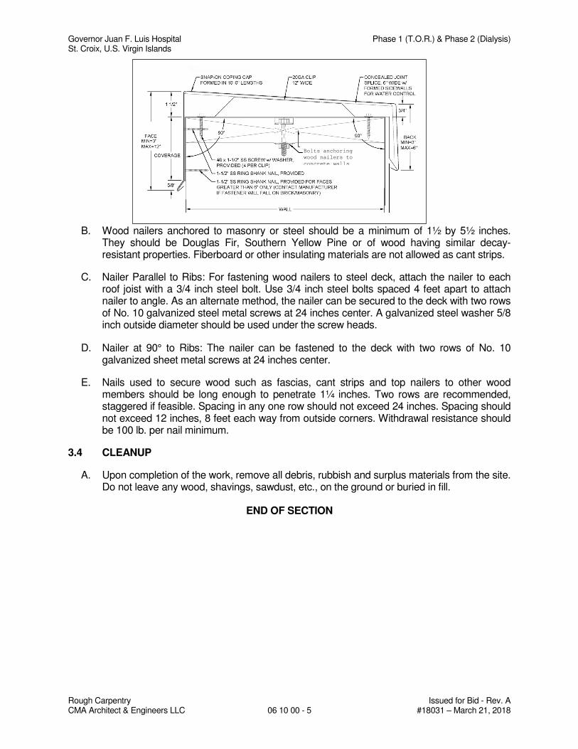
Governor Juan F. Luis Hospital Phase 1 (T.O.R.) & Phase 2 (Dialysis) St. Croix, U.S. Virgin Islands
Rough Carpentry Issued for Bid - Rev. A CMA Architect & Engineers LLC 06 10 00 - 5 #18031 – March 21, 2018
B. Wood nailers anchored to masonry or steel should be a minimum of 1½ by 5½ inches. They should be Douglas Fir, Southern Yellow Pine or of wood having similar decay-resistant properties. Fiberboard or other insulating materials are not allowed as cant strips.
C. Nailer Parallel to Ribs: For fastening wood nailers to steel deck, attach the nailer to each roof joist with a 3/4 inch steel bolt. Use 3/4 inch steel bolts spaced 4 feet apart to attach nailer to angle. As an alternate method, the nailer can be secured to the deck with two rows of No. 10 galvanized steel metal screws at 24 inches center. A galvanized steel washer 5/8 inch outside diameter should be used under the screw heads.
D. Nailer at 90° to Ribs: The nailer can be fastened to the deck with two rows of No. 10 galvanized sheet metal screws at 24 inches center.
E. Nails used to secure wood such as fascias, cant strips and top nailers to other wood members should be long enough to penetrate 1¼ inches. Two rows are recommended, staggered if feasible. Spacing in any one row should not exceed 24 inches. Spacing should not exceed 12 inches, 8 feet each way from outside corners. Withdrawal resistance should be 100 lb. per nail minimum.
3.4 CLEANUP
A. Upon completion of the work, remove all debris, rubbish and surplus materials from the site. Do not leave any wood, shavings, sawdust, etc., on the ground or buried in fill.
END OF SECTION
Bolts anchoring
wood nailers to
concrete walls
Governor Juan F. Luis Hospital Phase 1 (T.O.R.) & Phase 2 (Dialysis) St. Croix, U.S. Virgin Islands
Board Insulation Issued for Bid – Rev. A CMA Architects & Engineers LLC 07 21 13 - 1 #18031 – March 21, 2018
SECTION 07 21 13
BOARD INSULATION
PART 1 - GENERAL
1.1 SECTION INCLUDES
A. Examination of substrates and conditions.
B. Preparation of substrates.
C. General installation instructions.
D. Installation of board insulation.
E. Protection.
F. Schedule of installation - board insulation.
1.2 RELATED SECTIONS
A. Division 01 Sections – General Requirements.
B. Section 09 21 16 – Gypsum Board Assemblies.
1.3 REFERENCES
A. ASTM C203 – Standard Test Methods for Breaking Load and Flexural Properties of Block Type Thermal Insulation
B. ASTM C209 – Standard Test Methods for Cellulosic Fiber Insulating Board
C. ASTM C518 – Standard Test Methods for Steady State Thermal Transmission Properties by Means of the Heat Flow Meter Apparatus
D. ASTM C1289 - Faced Rigid Cellular Polyisocyanurate Thermal Insulation Board
E. ASTM D1623 - Standard Test Methods for Tensile and Tensile Adhesion Properties of Rigid Cellular Plastics
F. ASTM D2126 - Standard Test Methods for Response of Rigid Cellular Plastics to Thermal and Humid Aging
G. ASTM E84 - Test Method for Surface Burning Characteristics of Building Materials
H. ASTM E96 - Standard Test Methods for Water Vapor Transmission of Materials
1.4 ACTION SUBMITTALS
A. Section 01 33 00 - Submittal Procedures.
B. Product Data: For each type of product indicated.
Governor Juan F. Luis Hospital Phase 1 (T.O.R.) & Phase 2 (Dialysis) St. Croix, U.S. Virgin Islands
Board Insulation Issued for Bid – Rev. A CMA Architects & Engineers LLC 07 21 13 - 2 #18031 – March 21, 2018
1.5 INFORMATIONAL SUBMITTALS
A. Section 01 33 00 - Submittal Procedures
B. Product Test Reports: Based on evaluation of comprehensive tests performed by a qualified testing agency, for each product.
C. Research/Evaluation Reports: For foam-plastic insulation, from ICC-ES.
1.6 QUALITY ASSURANCE
A. Section 01 40 00 – Quality Requirements.
B. Surface-Burning Characteristics: As determined by testing identical products according to ASTM E 84 by a qualified testing agency. Identify products with appropriate markings of applicable testing agency.
1.7 DELIVERY, STORAGE AND HANDLING
A. Section 01 60 00 – Product Requirements.
B. Protect insulation materials from physical damage and from deterioration due to moisture, soiling, and other sources. Store inside and in a dry location. Comply with manufacturer's written instructions for handling, storing, and protecting during installation.
C. Protect foam-plastic board insulation as follows:
1. Do not expose to sunlight except to necessary extent for period of installation and concealment.
2. Protect against ignition at all times. Do not deliver foam-plastic board materials to Project site before installation time.
3. Quickly complete installation and concealment of foam-plastic board insulation in each area of construction.
PART 2 - PRODUCTS
2.1 MATERIALS - FOAM-PLASTIC BOARD INSULATION
A. Foil-Faced, Polyisocyanurate Board Insulation: ASTM C 1289, Type I, Class 2, with maximum flame-spread and smoke-developed indexes of 75 and 450, respectively, per ASTM E 84. R-Value of 25.2; board thickness equal to 4.0 inches; board size equal to 4 feet by 10 feet with square edge.
PART 3 - EXECUTION
3.1 PREPARATION
A. Clean substrates of substances that are harmful to insulation or that interfere with insulation attachment.
Governor Juan F. Luis Hospital Phase 1 (T.O.R.) & Phase 2 (Dialysis) St. Croix, U.S. Virgin Islands
Board Insulation Issued for Bid – Rev. A CMA Architects & Engineers LLC 07 21 13 - 3 #18031 – March 21, 2018
3.2 INSTALLATION, GENERAL
A. Comply with insulation manufacturer's written instructions applicable to products and applications indicated.
B. Install insulation that is undamaged, dry, and unsoiled and that has not been left exposed to rain at any time.
C. Extend insulation to envelop entire area to be insulated. Cut and fit tightly around obstructions and fill voids with insulation. Remove projections that interfere with placement.
D. Provide sizes to fit applications indicated and selected from manufacturer's standard thicknesses, widths, and lengths. Apply single layer of insulation units to produce thickness indicated unless multiple layers are otherwise shown or required to make up total thickness.
3.3 INSTALLATION OF INSULATION FOR FRAMED CONSTRUCTION
A. Apply insulation units to substrates by method indicated, complying with manufacturer's written instructions. If no specific method is indicated, bond units to substrate with adhesive or use mechanical anchorage to provide permanent placement and support of units.
B. Foam-Plastic Board Insulation: Seal joints between units by applying adhesive, mastic, or sealant to edges of each unit to form a tight seal as units are shoved into place. Fill voids in completed installation with adhesive, mastic, or sealant as recommended by insulation manufacturer.
3.4 INSTALLATION OF INSULATION FOR CONCRETE SUBSTRATES
A. Install board insulation on concrete substrates by adhesively attached, spindle-type insulation anchors as follows:
1. Fasten insulation anchors to concrete substrates with insulation anchor adhesive according to anchor manufacturer's written instructions. Space anchors according to insulation manufacturer's written instructions for insulation type, thickness, and application indicated.
2. Apply insulation standoffs to each spindle to create cavity width indicated between concrete substrate and insulation.
3. After adhesive has dried, install board insulation by pressing insulation into position over spindles and securing it tightly in place with insulation-retaining washers, taking care not to compress insulation below indicated thickness.
4. Where insulation will not be covered by other building materials, apply capped washers to tips of spindles.
3.5 PROTECTION
A. Protect installed insulation from damage due to harmful weather exposures, physical abuse, and other causes. Provide temporary coverings or enclosures where insulation is
Governor Juan F. Luis Hospital Phase 1 (T.O.R.) & Phase 2 (Dialysis) St. Croix, U.S. Virgin Islands
Board Insulation Issued for Bid – Rev. A CMA Architects & Engineers LLC 07 21 13 - 4 #18031 – March 21, 2018
subject to abuse and cannot be concealed and protected by permanent construction immediately after installation.
3.6 INSULATION SCHEDULE
1. As indicated on Drawings.
END OF SECTION
Governor Juan F. Luis Hospital Phase 1 (T.O.R.) & Phase 2 (Dialysis) St. Croix, U.S. Virgin Islands
SBS Modified Bituminous Membrane Roofing Issued for Bid - Rev. A CMA Architect & Engineers LLC 07 52 16 - 1 #18031 – March 21, 2018
SECTION 07 52 16
SBS MODIFIED BITUMINOUS MEMBRANE ROOFING
PART 1 - GENERAL
1.1 SECTION INCLUDES
A. Examination.
B. Preparation.
C. Roof insulation mechanically fastened to roof deck.
D. Installation of mechanically fastened base sheet.
E. SBS Modified Bituminous Membrane Roofing with base flashings at parapets and mineral surface cap.
F. Protection of applied roofing.
G. Cleaning.
1.2 RELATED SECTIONS
A. Division 01 – General Requirements.
B. Section 06 10 00 – Rough Carpentry: Wood nailers and cants.
C. Section 07 62 00 - Sheet Metal Flashing and Trim.
D. Section 07 92 00 – Elastomeric Joint Sealants.
1.3 REFERENCES
A. ASCE 7, Minimum Design Loads for Buildings and Other Structures.
B. AMERICAN STANDARD OF TESTING METHODS (ASTM):
1. ASTM C 726 - Standard Specification for Mineral Wool Roof Insulation Board.
2. ASTM C 728 - Standard Specification for Perlite Thermal Insulation Board.
3. ASTM C 836 - Standard Specification for High Solids Content, Cold Liquid-Applied Elastomeric Waterproofing Membrane for Use with Separate Wearing Course.
4. ASTM C 920 - Standard Specification for Elastomeric Joint Sealants
5. ASTM C 1177 - Standard Specification for Glass Mat Gypsum Substrate for Use as Sheathing.
6. ASTM C 1278 - Standard Specification for Fiber-Reinforced Gypsum Panel.
7. ASTM C 1289 - Standard Specification for Faced Rigid Cellular Polyisocyanurate Insulation Board.
Governor Juan F. Luis Hospital Phase 1 (T.O.R.) & Phase 2 (Dialysis) St. Croix, U.S. Virgin Islands
SBS Modified Bituminous Membrane Roofing Issued for Bid - Rev. A CMA Architect & Engineers LLC 07 52 16 - 2 #18031 – March 21, 2018
8. ASTM D 41 - Standard Specification for Asphalt Primer Used in Roofing, Damp proofing, and Waterproofing.
9. ASTM D 312- Standard Specification for Asphalt Used in Roofing.
10. ASTM D 1970 - Standard Specification for Self-Adhering Polymer Modified Bituminous Sheet Materials Used as Steep Roofing Underlayment for Ice Dam Protection.
11. ASTM D 2178 - Standard Specification for Asphalt Glass Felt Used in Roofing and Waterproofing.
12. ASTM D 3019 - Standard Specification for Lap Cement Used with Asphalt Roll Roofing, Non-Fibered, Asbestos-Fibered, and Non-Asbestos-Fibered.
13. ASTM D 3746 - Standard Test Method for Impact Resistance of Bituminous Roofing System.
14. ASTM D 4586 - Standard Specification for Asphalt Roof Cement, Asbestos-Free.
15. ASTM D 4601 - Standard Specification for Asphalt-Coated Glass Fiber Base Sheet Used in Roofing.
16. ASTM D 5147 - Standard Test Methods for Sampling and Testing Modified Bituminous Sheet Material.
17. ASTM D 5849 - Standard Test Method for Evaluating Resistance of Modified Bituminous Roofing Membrane to Cyclic Fatigue (Joint Displacement)
18. ASTM D 6162 - Standard Specification for Styrene Butadiene Styrene (SBS) Modified Bituminous Sheet Materials Using a Combination of Polyester and Glass Fiber Reinforcements.
19. ASTM D 6163 - Standard Specification for Styrene Butadiene Styrene (SBS) Modified Bituminous Sheet Materials Using Glass Fiber Reinforcements.
20. ASTM D 6164 - Standard Specification for Styrene Butadiene Styrene (SBS) Modified Bituminous Sheet Materials Using Polyester Reinforcements.
21. ASTM D 6298 - Standard Specification for Fiberglass Reinforced Styrene-Butadiene-Styrene (SBS) Modified Bituminous Sheets with a Factory Applied Metal Surface.
22. ASTM D 7379 - Standard Test Methods for Strength of Modified Bitumen Sheet Material Laps Using Cold Process Adhesive.
23. ASTM E 108 - Standard Test Methods for Fire Tests of Roof Coverings.
24. ASTM E 1980 - Standard Practice for Calculating Solar Reflectance Index of Horizontal and Low-Sloped Opaque Surfaces.
C. AMERICAN NATIONAL STANDARDS INSTITUTE (ANSI):
1. ANSI/SPRI/FM 4435/ES-1 Wind Design Standard for Edge System Used with Low Slope Roofing System.
Governor Juan F. Luis Hospital Phase 1 (T.O.R.) & Phase 2 (Dialysis) St. Croix, U.S. Virgin Islands
SBS Modified Bituminous Membrane Roofing Issued for Bid - Rev. A CMA Architect & Engineers LLC 07 52 16 - 3 #18031 – March 21, 2018
2. ANSI/SPRI FX-1, Standard Field Test Procedure for Determining the Withdrawal Resistance of Roofing Fasteners.
3. ANSI/SPRI IA-1, Standard Field Test Procedure for Determining the Mechanical Uplift Resistance of Insulation Adhesives over Various Substrates.
4. ANSI/FM 4474- American National Standard for Evaluating the Simulated Wind Resistance of Roof Assemblies Using Static Positive and/or Negative Differential Pressures.
D. FACTORY MUTUAL (FM):
1. FM 4450 - Approval Standard - Class I Insulated Steel Roof Decks.
2. FM 4470 - Approval Standard - Class I Roof Covers.
E. INTERNATIONAL CODES COUNCIL (ICC):
1. 2009 International Building Code (IBC).
F. NATIONAL ROOFING CONTRACTORS ASSOCIATION (NRCA).
G. SHEET METAL AND AIR CONDITIONING CONTRACTORS NATIONAL ASSOCIATION INC. (SMACNA) Architectural Sheet Metal Manual.
H. UNDERWRITERS LABORATORY (UL):
1. UL 790 Standard Test Methods for Fire Tests of Roof Coverings.
2. UL 1256 – Fire Test of Roof Deck Constructions.
1.4 PERFORMANCE REQUIREMENTS
A. General Performance: Installed membrane roofing and base flashings shall withstand specified uplift pressures, thermally induced movement, and exposure to weather without failure due to defective manufacture, fabrication, installation, or other defects in construction. Membrane roofing and base flashings shall remain watertight.
B. Material Compatibility: Provide roofing materials that are compatible with one another under conditions of service and application required, as demonstrated by membrane roofing manufacturer based on testing and field experience.
C. System Description:
1. Roofing System: Multi-Ply, SBS Modified Bitumen.
2. Application: New Roof.
3. Cover Securement: Mechanically Fastened to Deck.
4. Deck Type: Metal Deck.
5. Adhering Method: torched (cold adhesive only if meet required wind uplift).
6. Base Sheet: One.
Governor Juan F. Luis Hospital Phase 1 (T.O.R.) & Phase 2 (Dialysis) St. Croix, U.S. Virgin Islands
SBS Modified Bituminous Membrane Roofing Issued for Bid - Rev. A CMA Architect & Engineers LLC 07 52 16 - 4 #18031 – March 21, 2018
7. Number of SBS-Modified Asphalt Sheets (Ply): One.
8. Cover (Cap Ply): One.
a. Surfacing Type: SBS-Modified Asphalt Sheet (Cap) applied onto a polyester reinforcement with a polypropylene film underside.
D. FM Approvals Listing: Provide membrane roofing, base flashings, and component materials that comply with requirements in ANSI/FM 4474, FM Approvals 4450 and FM Approvals 4470 as part of a membrane roofing system, and that are listed in FM Approvals’ “RoofNav” for Class 1 or noncombustible construction, as applicable. Identify materials with FM Approvals markings. Refer to Roof Nav Assembly attached at the end of this Section.
E. Fire Classification:
1. Performance testing shall be in accordance with FM 4450 or FM 4470.
a. Meets requirements of FM Class A.
2. Performance testing shall be in accordance with FM 4450 or FM 4470 to meet the specified requirements for interior flame spread and fuel contribution.
a. Meets requirements of FM Class 1.
F. Impact Resistance:
1. Performance testing for impact resistance shall be in accordance with FM 4450 or FM 4470 to meet the specified impact resistance requirements.
a. Meets requirements for FM-SH (Severe Hail).
1.5 SUBMITTALS
A. Section 01 33 00 – Submittal Procedures.
B. RoofNav Assembly Number meeting the Performance Requirements.
C. Product Data: Within 10 calendar, days after the Contractor has received the Owner's Notice Proceed submit:
1. Materials list of items proposed to be provided under this Section.
2. Manufacturer's specifications and other data needed to prove compliance with the specified requirements.
3. Manufacturer's recommended installation procedures which, when approved by the Engineer, will become the basis for accepting or rejecting actual installation procedures used on the work.
D. Shop Drawings: For roofing system. Include plans, elevations, sections, details, and attachments to other work.
1. Base flashings and membrane terminations.
2. Tapered insulation, including slopes.
Governor Juan F. Luis Hospital Phase 1 (T.O.R.) & Phase 2 (Dialysis) St. Croix, U.S. Virgin Islands
SBS Modified Bituminous Membrane Roofing Issued for Bid - Rev. A CMA Architect & Engineers LLC 07 52 16 - 5 #18031 – March 21, 2018
3. Crickets, saddles, and tapered edge strips, including slopes.
4. Insulation, substrate board and Base Sheet fastening patterns for field-of-roof, perimeter and corners locations.
E. Qualification Data: For qualified Installer.
F. Samples for Verification: For the following products:
1. Sheet roofing materials, including base sheet, base ply, and membrane cap sheet and flashing sheet, of color specified.
2. Roof insulation and substrate board.
3. Six insulation fasteners of each type, length, and finish.
G. Qualification Data: For qualified Installer.
1. Installer shall be authorized by the manufacturer to install specified materials prior to the bidding period through satisfactory project completion.
H. Manufacturer Certificates: Signed by roofing manufacturer certifying that roofing system complies with requirements specified in “Performance Requirements” Article.
1. Submit evidence of complying with performance requirements.
I. Product Test Reports: Based on evaluation of comprehensive tests performed by manufacturer and witnessed by a qualified testing agency, for components of membrane roofing system.
J. Maintenance Data: For roofing system to include in maintenance manuals.
K. Warranties: Sample of special warranties.
1.6 QUALITY ASSURANCE
A. Section 01 40 00 – Quality Requirements.
B. Use adequate numbers of skilled workmen who are thoroughly trained and experienced in the necessary crafts and who are completely familiar with the specified requirements and the methods needed for proper performance of the work of this Section.
C. Use of subcontractor is not allowed.
D. Comply with codes, ordinances, rules and regulations of all governmental authorities having jurisdiction on the work, and with the following standards as applicable to the work:
Any approved agency having a service for the inspection of material and finished products during manufacture.
ASTM - American Society of Testing and Materials
FM - Factory Mutual
OSHA - Occupational Safety and Health Administration
Governor Juan F. Luis Hospital Phase 1 (T.O.R.) & Phase 2 (Dialysis) St. Croix, U.S. Virgin Islands
SBS Modified Bituminous Membrane Roofing Issued for Bid - Rev. A CMA Architect & Engineers LLC 07 52 16 - 6 #18031 – March 21, 2018
UL - Underwriters Laboratories, Inc.
NFPA - National Wire Protection Association
E. Manufacturer Qualifications:
1. A qualified manufacturer that is UL listed and FM Approvals approved for membrane roofing system identical to that used for this Project.
2. Manufacture shall have 20 years of experience manufacturing SBS-modified bitumen roofing materials.
F. Manufacturer Representative: Require manufacturer to send a qualified technical representative to the project site, when required, for the purpose of rendering advice concerning the proper installation of materials. Begin the installation of each major roofing component only in the presence of the manufacturer's technical representative. Technical representative shall be independent from sales.
G. Installer Qualifications: Engage an experienced Installer to perform installation of SBS Modified Bituminous Membrane Roofing who has specialized in the installation of SBS Modified Bituminous Membrane Roofing equal to that required for this project and who is acceptable to by manufacturer of SBS Modified Bituminous Membrane Roofing.
1. Applicators shall have completed projects of similar scope using same materials as specified herein.
2. Applicators shall be skilled in the application methods for all materials.
3. Installer shall maintain a daily record, on-site, documenting material installation and related project conditions.
H. Installer Certification: Obtain written certification from manufacturer of SBS Modified Bituminous Membrane Roofing certifying that Installer is approved by manufacturer for installation of specified. Provide copy of certification to Architect-Engineer prior to award of roofing work.
I. Installer’s Field Supervision: Require Installer to maintain a full-time supervisor/foreman who is on job site during times that SBS Modified Bituminous Membrane Roofing work is in progress and who is experienced in installation of roofing systems equal to type and scope required for this Project.
J. Roof System: All components of the roof system shall be the product of a single manufacturer.
K. Work of this Section to conform to manufacturer’s printed instructions, guidelines stated herein and NRCA Roofing and Waterproofing Manual.
1.7 JOB CONDITIONS
A. Section 01 73 00 – Execution.
B. Weather Conditions: Proceed with roofing work only when weather conditions are in compliance with manufacturer’s printed recommended limitation, and when conditions will permit the work to proceed in accordance with requirements and the manufacturer’s printed recommendations.
Governor Juan F. Luis Hospital Phase 1 (T.O.R.) & Phase 2 (Dialysis) St. Croix, U.S. Virgin Islands
SBS Modified Bituminous Membrane Roofing Issued for Bid - Rev. A CMA Architect & Engineers LLC 07 52 16 - 7 #18031 – March 21, 2018
C. Do not apply roofing membrane when there is surface moisture or visible dampness on the deck surface.
D. Roof applications should be planned and coordinated so that no more insulation is installed daily that can be covered with the completed membrane and surface cap on the end of the same day. If weather or other conditions make it impossible to gravel-in at the end of the day, all insulation must be covered with the complete roof membrane.
E. Coordinate the work of installing associated metal flashings as the work of this section progresses.
1.8 DELIVERY, STORAGE, AND HANDLING
A. Section 01 60 00 – Product Requirements.
B. Deliver roofing materials to Project site in original containers with seals unbroken and labeled with manufacturer’s name, product brand name and type, date of manufacture, approval or listing agency markings, and directions for storing and mixing with other components.
C. Store liquid materials in their original undamaged containers in a clean, dry, protected location and within the temperature range required by roofing system manufacturer. Protect stored liquid material from direct sunlight.
1. Discard and legally dispose of liquid material that cannot be applied within its stated shelf life.
D. Protect roof insulation materials from physical damage and from deterioration by sunlight, moisture, soiling, and other sources. Store in a dry location. Comply with insulation manufacturer’s written instructions for handling, storing, and protecting during installation.
E. Handle and store roofing materials and place equipment in a manner to avoid permanent deflection of deck.
1.9 PROJECT CONDITIONS
A. Section 01 60 00 – Product Requirements.
B. Weather Limitations: Proceed with installation only when existing and forecasted weather conditions permit roofing system to be installed according to manufacturer’s written instructions and warranty requirements.
1.10 PROTECTION OF PROPERTY
A. Protective Coverings: Install protective coverings at paving and building walls adjacent to hoist and kettles prior to starting the work. Lap protective coverings not less than 6 inches, secure against wind, and vent to prevent collection of moisture on covered surfaces. Protective coverings shall remain in place for the duration of the roofing work.
B. Flame-Heated Equipment: Locate and use flame-heated equipment at locations that will not endanger the structure or other materials on the site or adjacent property. Do not place flame-heated equipment on the roof. Provide and maintain one fire extinguisher of appropriate type and size adjacent to flame-heated equipment.
Governor Juan F. Luis Hospital Phase 1 (T.O.R.) & Phase 2 (Dialysis) St. Croix, U.S. Virgin Islands
SBS Modified Bituminous Membrane Roofing Issued for Bid - Rev. A CMA Architect & Engineers LLC 07 52 16 - 8 #18031 – March 21, 2018
1.11 WARRANTY
A. Section 01 77 00 – Closeout Requirements.
B. Roofing and flashing shall be guaranteed to remain water tight and in good conditions for a period of fifteen (15) years from the date of acceptance of the work by the owner. The Contractor shall provided bonded roof guarantee through a surety Company for the total cost of the roofing work, or other guarantee acceptable to the Owner to make any repair and replacement needed on the roof without any additional cost to the Owner, for any part of the roof that fails to meet the guarantee during that period.
C. In lieu of the written bonded roof guarantee through a surety Company referred to above, the Contractor may file with the Owner a 15 years guarantee of a responsible manufacturer of the materials used or to be used in the roofing work; provide, however, that in consideration thereof, the Contractor hereby authorizes the owner (1) to proceed with and make any roof repairs for the account and at the expenses of the Contractor in the event the later or any subcontractor thereof fails to undertakes such work within 7 days after being requested in writing to do so as an obligation included in the guarantee of the Contractor, any amounts expended by the owner pursuant to (1) above, as well as the amount of any claim, action or demand of the Owner against the Contractor, predicated upon or arising from such roofing work so guaranteed by the Contractor.
D. Warranty: Shall be signed by the Roof Manufacturer and co-signed by the Contractor and Roofing subcontractor.
E. Warranty: Cover damage to Work resulting from failure to resist penetration of moisture.
F. Include materials and workmanship for the following items within Warranty:
1. Membranes.
2. Bituminous flashings, including metal flashings and accessories supplied by roofing membrane manufacturer.
3. Insulation.
4. Asphalt bitumen.
G. Include the following items within Warranty:
1. At least two (2) roofing inspections by Manufacturer’s Roofing Quality Control Inspector prior the Final Acceptance of the Work.
2. Attach copy of Record Document Roof Plan Drawings, Roof Detail Drawings, and Record Roofing Specification Section to Warranty.
PART 2 - PRODUCTS
2.1 SBS-MODIFIED BITUMINOUS MEMBRANE ROOFING
A. Manufacturer: Basis of design
1. Danosa Caribbean, Inc.
B. Other acceptable manufacturers: Subject to compliance with performance requirements:
Governor Juan F. Luis Hospital Phase 1 (T.O.R.) & Phase 2 (Dialysis) St. Croix, U.S. Virgin Islands
SBS Modified Bituminous Membrane Roofing Issued for Bid - Rev. A CMA Architect & Engineers LLC 07 52 16 - 9 #18031 – March 21, 2018
1. Soprema, Inc.
2. GAF Materials Corporation
3. Johns Manville
4. Siplast, Inc.
2.2 SBS-MODIFIED ASPHALT-SHEET MATERIALS (ROOF FIELD, PERIMETER AND CORNERS)
A. Refer to Roof Nav Assembly attached at the end of this Section.
2.3 MATERIALS - AUXILIARY ROOFING MEMBRANE
A. General: Auxiliary materials recommended by roofing system manufacturer for intended use and compatible with roofing membrane.
1. Liquid-type auxiliary materials shall comply with VOC limits of authorities having jurisdiction.
B. Roofing Asphalt: ASTM D 312, Type III or IV as recommended by roofing system manufacturer for application.
C. Cold-Applied Adhesive: Roofing system manufacturer’s standard asphalt-based, one- or two-part, asbestos-free, cold-applied adhesive specially formulated for compatibility and use with roofing membrane and base flashings.
D. Elastomeric Joint Sealants: As specified in Section 07 92 13.
E. Metal Flashing Sheet: As specified in Section 07 62 00.
F. Miscellaneous Accessories: Provide those recommended by roofing system manufacturer.
PART 3 - EXECUTION
3.1 EXAMINATION
A. Section 01 31 00 – Project Management and Coordination.
B. Examine substrates, areas, and conditions, with Installer present, for compliance with the following requirements and other conditions affecting performance of roofing system:
1. Verify that roof openings and penetrations are in place and curbs are set and braced and that roof drain bodies are securely clamped in place.
2. Verify that wood cants, blocking, curbs, and nailers are securely anchored to roof deck at penetrations and terminations and that nailers match thicknesses of insulation.
3. Remove all wet materials prior to application of the new roof system, with wet insulation being replaced with dry material.
4. Cut out blisters.
C. Proceed with installation only after unsatisfactory conditions have been corrected.
Governor Juan F. Luis Hospital Phase 1 (T.O.R.) & Phase 2 (Dialysis) St. Croix, U.S. Virgin Islands
SBS Modified Bituminous Membrane Roofing Issued for Bid - Rev. A CMA Architect & Engineers LLC 07 52 16 - 10 #18031 – March 21, 2018
3.2 PREPARATION
A. Clean substrate of dust, debris, moisture, and other substances detrimental to roofing installation according to roofing system manufacturer’s written instructions. Remove sharp projections.
B. Prevent materials from entering and clogging roof drains and conductors and from spilling or migrating onto surfaces of other construction. Remove roof-drain plugs when no work is taking place or when rain is forecast.
3.3 INSULATION INSTALLATION (FIELD, PERIMETER AND CORNERS)
A. Comply with roofing system manufacturer’s written instructions and FM Approved Roofing Assembly for installing roof insulation.
B. Cant Strips: Install and secure preformed 45-degree insulation cant strips at junctures of roofing membrane system with vertical surfaces or angle changes more than 45 degrees.
C. Install tapered insulation under area of roofing to conform to slopes indicated.
D. Install insulation with long joints of insulation in a continuous straight line with end joints staggered between rows, abutting edges and ends between boards. Fill gaps exceeding 1/4 inch with insulation.
1. Cut and fit insulation within 1/4 inch of nailers, projections, and penetrations.
E. Install insulation under area of roofing to achieve required thickness.
F. Trim surface of insulation where necessary at roof drains so completed surface is flush and does not restrict flow of water.
G. Install tapered edge strips at perimeter edges of roof that do not terminate at vertical surfaces.
H. Preliminary Securement of Insulation: Provide preliminary securement of insulation boards when mechanically fastened roof covers are used (single-plies or multi-plies with fastened base sheets). Install a minimum of two fasteners per 4 x 4 ft (1.2 x 1.2 m) board or four fasteners per 4 x 8 ft (1.2 x 2.4 m) board, unless the manufacturer requires a greater number. Additional insulation fastening is not required in the perimeter and corner areas.
1. Fasten insulation according to requirements in FM Approvals’ “RoofNav” for specified Windstorm Resistance Classification.
2. For steel deck construction, the fastener must be long enough to be driven into the steel deck at least 3/4 inch.
3.4 SUBSTRATE BOARD INSTALLATION
A. Install substrate board above insulation board with long joints in continuous straight lines, perpendicular to roof slopes with end joints staggered between rows. Tightly butt substrate boards together.
1. Fasten substrate board to deck according to recommendations in FM Approvals' "RoofNav", FM Global Loss Prevention Data Sheet 1-29 and paragraph titled: Preliminary Securement of Insulation, above.
Governor Juan F. Luis Hospital Phase 1 (T.O.R.) & Phase 2 (Dialysis) St. Croix, U.S. Virgin Islands
SBS Modified Bituminous Membrane Roofing Issued for Bid - Rev. A CMA Architect & Engineers LLC 07 52 16 - 11 #18031 – March 21, 2018
3.5 ROOFING MEMBRANE INSTALLATION, GENERAL
A. Install roofing membrane system according to roofing system manufacturer’s written instructions and applicable recommendations in ARMA/NRCA’s “Quality Control Guidelines for the Application of Polymer Modified Bitumen Roofing”.
B. Start installation of roofing membrane in presence of roofing system manufacturer’s technical personnel.
C. Cooperate with testing agencies engaged or required to perform services for installing roofing system.
D. Coordinate installation of roofing system so insulation and other components of the roofing membrane system not permanently exposed are not subjected to precipitation or left uncovered at the end of the workday or when rain is forecast.
1. At end of each day’s work, provide tie-offs to cover exposed roofing membrane sheets and insulation with a course of coated felt set in roofing cement or hot roofing asphalt, with joints and edges sealed.
2. Complete terminations and base flashings and provide temporary seals to prevent water from entering completed sections of roofing system.
3. Remove and discard temporary seals before beginning work on adjoining roofing.
E. Asphalt Heating: Heat and apply SBS-modified roofing asphalt according to roofing system manufacturer’s written instructions.
F. Substrate-Joint Penetrations: Prevent roofing asphalt and adhesives from penetrating substrate joints, entering building, or damaging roofing system components or adjacent building construction.
3.6 INSTALLATION - BASE-SHEET
A. Install lapped base-sheet course, extending sheet over and terminating beyond cants.
B. Mechanical attachment of base sheets with fasteners and batten bars according to the FM Approvals - “RoofNav” approved assembly and FM Global Data Sheet 1-29 Roof Deck Securement and Above-Deck Roof Components.
C. Ensure all roof cover fasteners engage the top flanges of steel deck.
D. Install batten bars and fastener rows perpendicular to steel deck ribs.
E. Attach base sheet as follows:
1. Mechanically fasten to substrate (Roof Field).
a. Row Spacing: As per approved RoofNav Assembly to meet wind uplift requirement.
b. On Center: As per approved RoofNav Assembly to meet wind uplift requirement.
Governor Juan F. Luis Hospital Phase 1 (T.O.R.) & Phase 2 (Dialysis) St. Croix, U.S. Virgin Islands
SBS Modified Bituminous Membrane Roofing Issued for Bid - Rev. A CMA Architect & Engineers LLC 07 52 16 - 12 #18031 – March 21, 2018
c. Fasteners placed within the minimum (As per approved RoofNav Assembly to meet wind uplift requirement.) in. wide side laps.
2. Mechanically fasten to substrate (Roof Perimeter).
a. Row Spacing: As per approved RoofNav Assembly to meet wind uplift requirement.
b. On Center: As per approved RoofNav Assembly to meet wind uplift requirement.
3. Mechanically fasten to substrate (Roof Corner).
a. Row Spacing: As per approved RoofNav Assembly to meet wind uplift requirement.
b. On Center: As per approved RoofNav Assembly to meet wind uplift requirement.
3.7 INSTALLATION - SBS-MODIFIED BITUMINOUS MEMBRANE
A. Install modified bituminous roofing membrane sheet (Base Ply) and cap sheet according to roofing manufacturer’s written instructions, starting at low point of roofing system. Extend roofing membrane sheets over and terminate beyond cants, installing as follows:
1. Unroll roofing membrane sheets and allow them to relax for minimum time period required by manufacturer.
2. Torch apply to substrate (cold adhesive only if meet required wind uplift).
3. Heat welded attachment of ply membranes shall be accomplished with even heat distribution across the entire width of the sheet. There shall be enough heat applied to the back of the sheet so that a small flow of asphalt precedes the roll as it is installed. The bead of asphalt shall be visible and should ooze out at the side lap.
B. Laps: Accurately align roofing membrane sheets, without stretching, and maintain uniform side and end laps. Stagger end laps. Completely bond and seal laps, leaving no voids.
1. Repair tears and voids in laps and lapped seams not completely sealed.
C. Install roofing membrane sheets so side and end laps shed water.
3.8 INSTALLATION - FLASHING AND STRIPPING
A. Install base flashing over cant strips and other sloped and vertical surfaces, at roof edges, and at penetrations through roof; secure to substrates according to roofing system manufacturer’s written instructions, and as follows:
1. Prime substrates with asphalt primer if required by roofing system manufacturer.
2. Backer Sheet Application: Mechanically fasten backer sheet to walls or parapets. Adhere backer sheet over roofing membrane at cants in cold-applied adhesive.
3. Flashing Sheet Application: Torch apply flashing sheet to substrate. (cold adhesive only if meet required wind uplift).
Governor Juan F. Luis Hospital Phase 1 (T.O.R.) & Phase 2 (Dialysis) St. Croix, U.S. Virgin Islands
SBS Modified Bituminous Membrane Roofing Issued for Bid - Rev. A CMA Architect & Engineers LLC 07 52 16 - 13 #18031 – March 21, 2018
B. Extend base flashing up walls or parapets above roofing membrane up to the cant and 4 inches onto field of roofing membrane.
C. Mechanically fasten top of base flashing securely at terminations and perimeter of roofing.
D. Install roofing membrane cap-sheet stripping where metal flanges and edgings are set on membrane roofing according to roofing system manufacturer’s written instructions.
3.9 FIELD QUALITY CONTROL
A. Section 01 40 00 – Quality Requirements.
B. Testing Agency: Owner will engage a qualified testing agency to perform tests and inspections and to prepare test reports.
C. Final Roof Inspection: Arrange for roofing system manufacturer’s technical personnel to inspect roofing installation on completion.
1. Notify Architect and Owner 48 hours in advance of date and time of inspection.
D. Field Wind Uplift Tests:
1. Conduct field uplift tests on re-covered roof installations. Conduct tests in accordance with FM Global Data Sheet 1-52 Field Uplift Tests.
2. Contractor shall repair the area where the roof uplift tests are performed according to FM Global Data Sheet 1-30 – Repair of Wind Damage Roof Systems.
E. Roofing system will be considered defective if it does not pass tests and inspections.
1. Additional testing and inspecting, at Contractor’s expense, will be performed to determine if replaced or additional work complies with specified requirements.
3.10 PROTECTING AND CLEANING
A. Protect roofing system from damage and wear during remainder of construction period. When remaining construction will not affect or endanger roofing, inspect roofing for deterioration and damage, describing its nature and extent in a written report, with copies to Architect and Owner.
B. Correct deficiencies in or remove roofing system that does not comply with requirements, repair substrates, and repair or reinstall roofing system to a condition free of damage and deterioration at time of Substantial Completion and according to warranty requirements.
END OF SECTION
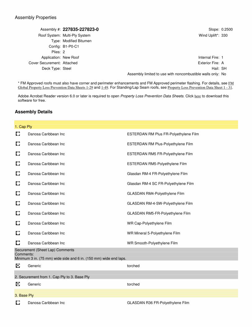
Assembly Properties
Assembly #: 227835-227823-0 Slope: 0.2500
Roof System: Multi-Ply System Wind Uplift*: 330
Type: Modified Bitumen
Config: B1-P0-C1
Plies: 2
Application: New Roof Internal Fire: 1
Cover Securement: Attached Exterior Fire: A
Deck Type: Steel Hail: SH
Assembly limited to use with noncombustible walls only: No
* FM Approved roofs must also have corner and perimeter enhancements and FM Approved perimeter flashing. For details, see FM
Global Property Loss Prevention Data Sheets 1-29 and 1-49. For Standing/Lap Seam roofs, see Property Loss Prevention Data Sheet 1 - 31.
Adobe Acrobat Reader version 6.0 or later is required to open Property Loss Prevention Data Sheets. Click here to download this software for free.
Assembly Details
1. Cap Ply
Danosa Caribbean Inc ESTERDAN RM Plus FR-Polyethylene Film
Danosa Caribbean Inc ESTERDAN RM Plus-Polyethylene Film
Danosa Caribbean Inc ESTERDAN RM5 FR-Polyethylene Film
Danosa Caribbean Inc ESTERDAN RM5-Polyethylene Film
Danosa Caribbean Inc Glasdan RM-4 FR-Polyethylene Film
Danosa Caribbean Inc Glasdan RM-4 SC FR-Polyethylene Film
Danosa Caribbean Inc GLASDAN RM4-Polyethylene Film
Danosa Caribbean Inc GLASDAN RM-4-SW-Polyethylene Film
Danosa Caribbean Inc GLASDAN RM5-FR-Polyethylene Film
Danosa Caribbean Inc WR Cap-Polyethylene Film
Danosa Caribbean Inc WR Mineral 5-Polyethylene Film
Danosa Caribbean Inc WR Smooth-Polyethylene Film
Securement (Sheet Lap) Comments Comments: Minimum 3 in. (75 mm) wide side and 6 in. (150 mm) wide end laps.
Generic torched
2. Securement from 1. Cap Ply to 3. Base Ply
Generic torched
3. Base Ply
Danosa Caribbean Inc GLASDAN R36 FR-Polyethylene Film
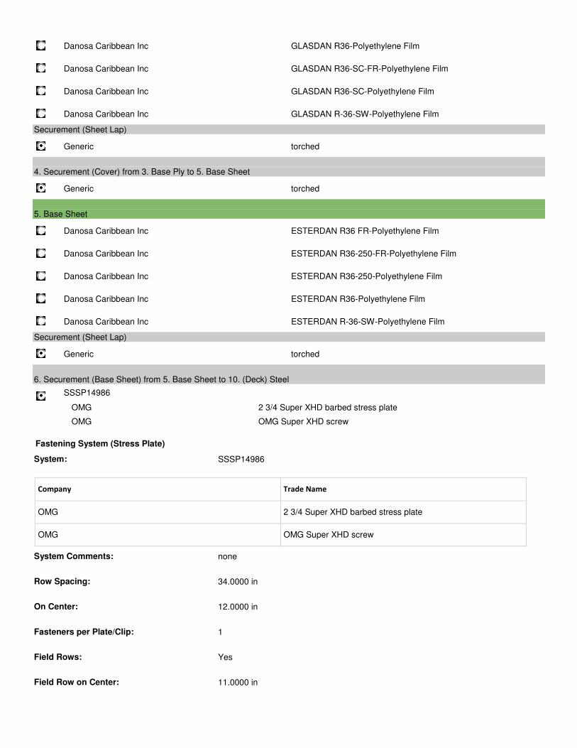
Danosa Caribbean Inc GLASDAN R36-Polyethylene Film
Danosa Caribbean Inc GLASDAN R36-SC-FR-Polyethylene Film
Danosa Caribbean Inc GLASDAN R36-SC-Polyethylene Film
Danosa Caribbean Inc GLASDAN R-36-SW-Polyethylene Film
Securement (Sheet Lap)
Generic torched
4. Securement (Cover) from 3. Base Ply to 5. Base Sheet
Generic torched
5. Base Sheet
Danosa Caribbean Inc ESTERDAN R36 FR-Polyethylene Film
Danosa Caribbean Inc ESTERDAN R36-250-FR-Polyethylene Film
Danosa Caribbean Inc ESTERDAN R36-250-Polyethylene Film
Danosa Caribbean Inc ESTERDAN R36-Polyethylene Film
Danosa Caribbean Inc ESTERDAN R-36-SW-Polyethylene Film
Securement (Sheet Lap)
Generic torched
6. Securement (Base Sheet) from 5. Base Sheet to 10. (Deck) Steel
SSSP14986
OMG 2 3/4 Super XHD barbed stress plate
OMG OMG Super XHD screw
Fastening System (Stress Plate)
System: SSSP14986
Company Trade Name
OMG 2 3/4 Super XHD barbed stress plate
OMG OMG Super XHD screw
System Comments: none
Row Spacing: 34.0000 in
On Center: 12.0000 in
Fasteners per Plate/Clip: 1
Field Rows: Yes
Field Row on Center: 11.0000 in
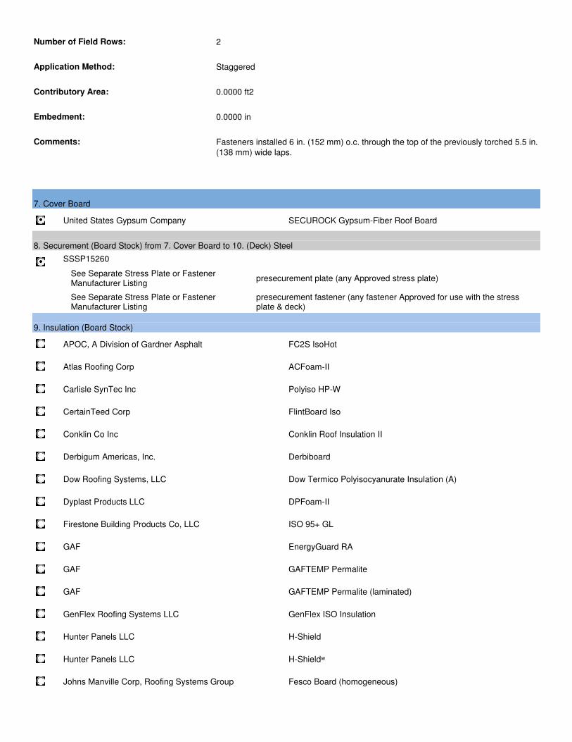
Number of Field Rows: 2
Application Method: Staggered
Contributory Area: 0.0000 ft2
Embedment: 0.0000 in
Comments: Fasteners installed 6 in. (152 mm) o.c. through the top of the previously torched 5.5 in.
(138 mm) wide laps.
7. Cover Board
United States Gypsum Company SECUROCK Gypsum-Fiber Roof Board
8. Securement (Board Stock) from 7. Cover Board to 10. (Deck) Steel
SSSP15260
See Separate Stress Plate or Fastener Manufacturer Listing
presecurement plate (any Approved stress plate)
See Separate Stress Plate or Fastener Manufacturer Listing
presecurement fastener (any fastener Approved for use with the stress plate & deck)
9. Insulation (Board Stock)
APOC, A Division of Gardner Asphalt FC2S IsoHot
Atlas Roofing Corp ACFoam-II
Carlisle SynTec Inc Polyiso HP-W
CertainTeed Corp FlintBoard Iso
Conklin Co Inc Conklin Roof Insulation II
Derbigum Americas, Inc. Derbiboard
Dow Roofing Systems, LLC Dow Termico Polyisocyanurate Insulation (A)
Dyplast Products LLC DPFoam-II
Firestone Building Products Co, LLC ISO 95+ GL
GAF EnergyGuard RA
GAF GAFTEMP Permalite
GAF GAFTEMP Permalite (laminated)
GenFlex Roofing Systems LLC GenFlex ISO Insulation
Hunter Panels LLC H-Shield
Hunter Panels LLC H-Shieldʷ
Johns Manville Corp, Roofing Systems Group Fesco Board (homogeneous)
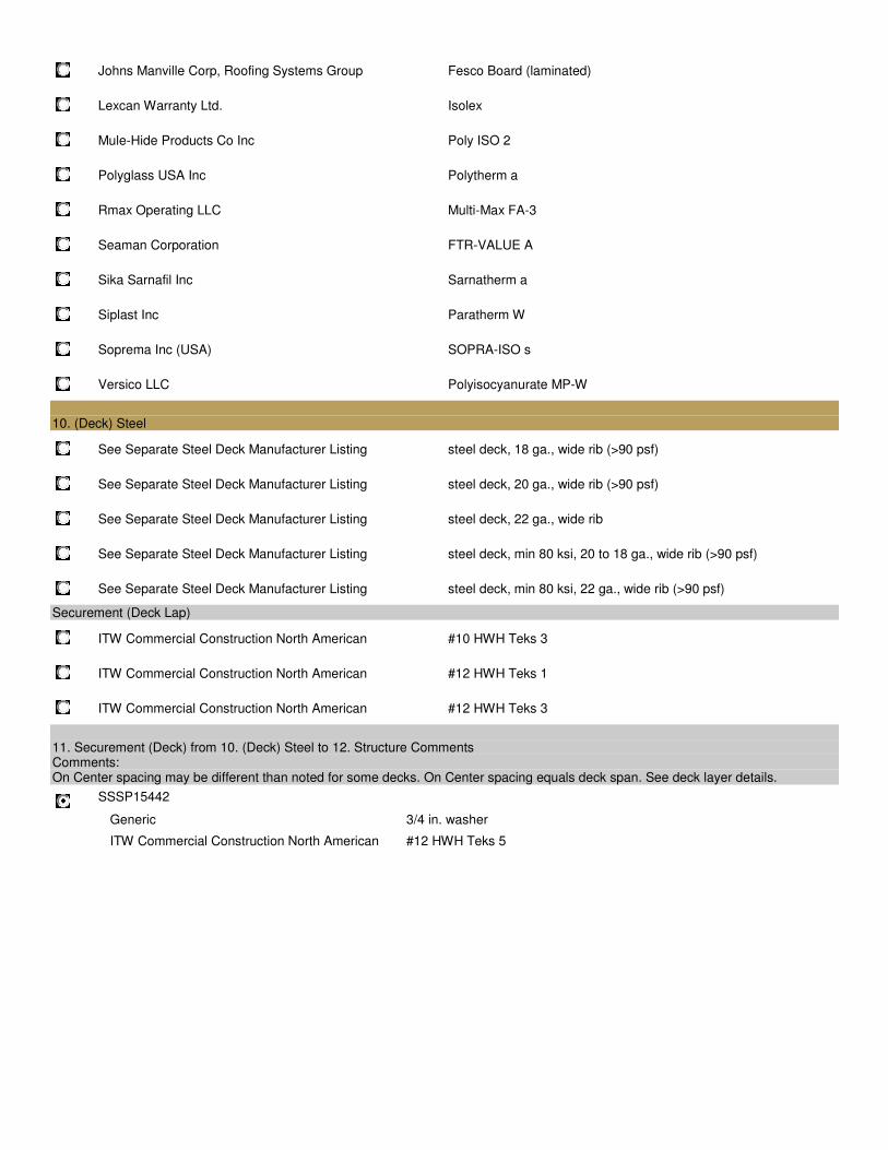
Johns Manville Corp, Roofing Systems Group Fesco Board (laminated)
Lexcan Warranty Ltd. Isolex
Mule-Hide Products Co Inc Poly ISO 2
Polyglass USA Inc Polytherm a
Rmax Operating LLC Multi-Max FA-3
Seaman Corporation FTR-VALUE A
Sika Sarnafil Inc Sarnatherm a
Siplast Inc Paratherm W
Soprema Inc (USA) SOPRA-ISO s
Versico LLC Polyisocyanurate MP-W
10. (Deck) Steel
See Separate Steel Deck Manufacturer Listing steel deck, 18 ga., wide rib (>90 psf)
See Separate Steel Deck Manufacturer Listing steel deck, 20 ga., wide rib (>90 psf)
See Separate Steel Deck Manufacturer Listing steel deck, 22 ga., wide rib
See Separate Steel Deck Manufacturer Listing steel deck, min 80 ksi, 20 to 18 ga., wide rib (>90 psf)
See Separate Steel Deck Manufacturer Listing steel deck, min 80 ksi, 22 ga., wide rib (>90 psf)
Securement (Deck Lap)
ITW Commercial Construction North American #10 HWH Teks 3
ITW Commercial Construction North American #12 HWH Teks 1
ITW Commercial Construction North American #12 HWH Teks 3
11. Securement (Deck) from 10. (Deck) Steel to 12. Structure Comments Comments: On Center spacing may be different than noted for some decks. On Center spacing equals deck span. See deck layer details.
SSSP15442
Generic 3/4 in. washer
ITW Commercial Construction North American #12 HWH Teks 5
Governor Juan F. Luis Hospital Phase 1 (T.O.R.) & Phase 2 (Dialysis)
St. Croix, U.S. Virgin Islands
Sheet Metal Flashing and Trim Issued for Bid - Rev. A
CMA Architect & Engineers LLC 07 62 00 - 1 #18031 – March 21, 2018
SECTION 07 62 00
SHEET METAL FLASHING AND TRIM
PART 1 - GENERAL
1.1 SECTION INCLUDES
A. Examination of substrates.
B. Installation of underlayment.
C. General installation procedures.
D. Installation of roof drainage system.
E. Installation of roof flashings.
F. Installation of miscellaneous flashings.
G. Erection tolerances.
H. Cleaning and protection.
1.2 RELATED SECTIONS
A. Division 01 - General Requirements.
B. Section 03 31 13 – Cast In Place Concrete.
C. Section 05 50 00 – Metal Fabrications.
D. Section 06 10 00 - Rough Carpentry: Wood cants and nailers.
E. Section 07 52 16 – Styrene Butadiene Styrene Modified Bituminous Membrane Roofing.
F. Section 07 92 13 – Elastomeric Joint Sealants.
1.3 REFERENCES
A. ASTM B209 - Aluminum and Aluminum Alloy Sheet and Plate.
B. ASTM C920 – Elastomeric Joint Sealants.
C. ASTM C1311 – Solvent Release Sealants.
D. ASTM D226 – Asphalt Saturated Organic Felt used in Roofing and Waterproofing.
E. ASTM D1198 – Asphalt Base Emissions for Use as Protective Coatings for Metal.
F. ASTM D4397 – Polyethylene Sheeting for Construction, Industrial and Agricultural Applications.
G. ASTM D4586 – Asphalt Roof Cement, Asbestos Free.
H. FM Global – Loss Prevention Data Sheet 1-28: Design Wind Loads.
Governor Juan F. Luis Hospital Phase 1 (T.O.R.) & Phase 2 (Dialysis)
St. Croix, U.S. Virgin Islands
Sheet Metal Flashing and Trim Issued for Bid - Rev. A
CMA Architect & Engineers LLC 07 62 00 - 2 #18031 – March 21, 2018
I. FM Global - Loss Prevention Data Sheet 1-49: Perimeter Flashing.
J. NRCA (National Roofing Contractors Association) - Roofing and Waterproofing Manual.
K. SEI/ASCE 7 – Minimum Design Loads for Buildings and Other Structures.
L. NAAMM - Metal Finishes Manuel for Architectural and Metal Products.
M. SMACNA (Sheet Metal and Air Conditioning Contractor’s National Association) - Architectural Sheet Metal Manual.
1.4 PERFORMANCE REQUIREMENTS
A. General: Sheet metal flashing and trim assemblies as indicated shall withstand wind loads, structural movement, thermally induced movement, and exposure to weather without failure due to defective manufacture, fabrication, installation, or other defects in construction. Completed sheet metal flashing and trim shall not rattle, leak, or loosen, and shall remain watertight.
B. Provide roof edge flashing and copings capable of resisting the following forces according to recommendations in FM Global Loss Prevention Data Sheet 1-49:
1. Wind Zone 3: For velocity pressures of 46 to 104 lbf/sqft: 208 lbf/sqft perimeter uplift force, 312 lbf/sqft corner uplift force, and 104 lbf/sqft outward force.
C. Thermal Movements: Provide sheet metal flashing and trim that allows for thermal movements from ambient and surface temperature changes.
1. Temperature Change (Range): 120 deg F, ambient; 180 deg F, material surfaces.
1.5 QUALITY ASSURANCE
A. Section 01 40 00 – Quality Requirements.
B. Installer: Company specializing in sheet metal flashing work with five years minimum experience.
C. Fabricator Qualifications: Shop that employs skilled workers who custom fabricate sheet metal flashing and trim similar to that required for this Project and whose products have a record of successful in-service performance.
D. Sheet Metal Flashing and Trim Standard: Comply with SMACNA’s Architectural Sheet Metal Manual or the National Roofing Contractors Association – “Roofing Manual” unless more stringent requirements are specified or shown on Drawings.
E. Mockups: Build mockups to verify selections made under sample submittals and to demonstrate aesthetics effects and set quality standards for fabrication and installation.
1. Build mockup of typical cap flashing, equipment support and pipe penetration. Cap flashing shall be approximately 5 feet long, including supporting construction cleats, seams, attachments, and accessories.
Governor Juan F. Luis Hospital Phase 1 (T.O.R.) & Phase 2 (Dialysis)
St. Croix, U.S. Virgin Islands
Sheet Metal Flashing and Trim Issued for Bid - Rev. A
CMA Architect & Engineers LLC 07 62 00 - 3 #18031 – March 21, 2018
2. Approval of mockups does not constitute approval of deviations from the Contract Documents contained in mockups unless Architect-Engineer specifically approves such deviations in writing.
3. Approved mockups may be come part of the completed work if undisturbed at time of Substantial Completion.
1.6 SUBMITTALS
A. Section 01 33 00 – Submittal Procedures: Requirements for submittals.
B. Product Data: For each type of product indicated. Include construction details, material descriptions, dimensions of individual components and profiles, and finishes for each manufactured product and accessory.
C. Shop Drawings: Show fabrication and installation layout of sheet metal flashing and trim, including plans, elevations, expansion joint locations, and keyed details. Distinguish between shop and field assembled work. Include the following:
1. Identification of material, thickness, weight, and finish for each item and location in Project.
2. Details for forming sheet metal flashing and trim, including profiles, shapes, seams, and dimensions.
3. Details for joining, supporting, and securing sheet metal flashing and trim, including layout of fasteners, cleats, clips and other attachments. Include pattern of seams.
4. Details of termination points and assemblies, including fixed points.
5. Details of expansion joints and expansion joint covers, including showing direction of expansion and contraction.
6. Details of connection to adjoining work.
7. Detail formed flashing and trim at a scale of not less than 1½ inches per 12 inches (1:10).
D. Samples for Initial Selection: for each type of sheet metal flashing, trim, and accessory indicated.
E. Samples for Verification: For each type of exposed finish required, prepared on Samples of size indicated below:
1. Sheet Metal Flashing: 12 inches long by actual width of unit, including finished seam and in required profile. Include fasteners, cleats, clips, closures, and other attachments.
2. Trim, Metal Closures, Expansion Joints, Joint Intersections, and Miscellaneous Fabrications: 12 inches long and in required profile. Include fasteners and other exposed accessories.
3. Accessories and Miscellaneous Materials: Full size Samples.
Governor Juan F. Luis Hospital Phase 1 (T.O.R.) & Phase 2 (Dialysis)
St. Croix, U.S. Virgin Islands
Sheet Metal Flashing and Trim Issued for Bid - Rev. A
CMA Architect & Engineers LLC 07 62 00 - 4 #18031 – March 21, 2018
4. Anodized Aluminum Sample: Samples to show full range to be expected for each color required.
F. Qualification Data: For qualified fabricator.
1.7 DELIVERY, STORAGE AND HANDLING
A. Section 01 60 00 – Product Requirements.
B. Stack preformed material to prevent twisting, bending, or abrasion, and to provide ventilation.
C. Prevent contact with materials during storage which may cause discoloration, staining, or damage.
D. Protect strippable protective covering on sheet metal flashing and trim form exposure to sunlight and high humidity, except to the extent necessary for the period of sheet metal flashing and trim installation.
PART 2 - PRODUCTS
2.1 MATERIALS – SHEET METALS
A. General: Protect mechanical and other finishes on exposed surfaces from damage by applying a strippable, temporary protective film before stripping.
B. Aluminum Sheet: ASTM B209, alloy as standard with manufacturer for finish required, with temper as required to suit forming operations and performances required.
1. Surface: Smooth, flat.
2.2 MANUFACTURED PRODUCTS - COPING
A. Parapet Coping, engineered metal coping with hold down cleats and metal drain chairs for capping most any parapet:
1. Material: Aluminum
2. Gauge/Thickness: 0.050-inch.
3. Cleat: Galvanized Steel; 16 gauge (FM 1-180).
4. Finish: Kynar 500 coating; color selected from manufacturer’s color chart.
5. Fabricated to the wall width required between 6-inch and 32-inch.
6. Tested per ANSI/SPRI ES-1 to meet or exceed design pressures at roof edge.
7. FM Approved.
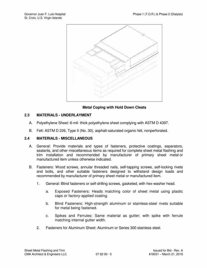
Governor Juan F. Luis Hospital Phase 1 (T.O.R.) & Phase 2 (Dialysis)
St. Croix, U.S. Virgin Islands
Sheet Metal Flashing and Trim Issued for Bid - Rev. A
CMA Architect & Engineers LLC 07 62 00 - 5 #18031 – March 21, 2018
Metal Coping with Hold Down Cleats
2.3 MATERIALS - UNDERLAYMENT
A. Polyethylene Sheet: 6-mil- thick polyethylene sheet complying with ASTM D 4397.
B. Felt: ASTM D 226, Type II (No. 30), asphalt-saturated organic felt, nonperforated.
2.4 MATERIALS - MISCELLANEOUS
A. General: Provide materials and types of fasteners, protective coatings, separators, sealants, and other miscellaneous items as required for complete sheet metal flashing and trim installation and recommended by manufacturer of primary sheet metal or manufactured item unless otherwise indicated.
B. Fasteners: Wood screws, annular threaded nails, self-tapping screws, self-locking rivets and bolts, and other suitable fasteners designed to withstand design loads and recommended by manufacturer of primary sheet metal or manufactured item.
1. General: Blind fasteners or self-drilling screws, gasketed, with hex-washer head.
a. Exposed Fasteners: Heads matching color of sheet metal using plastic caps or factory-applied coating.
b. Blind Fasteners: High-strength aluminum or stainless-steel rivets suitable for metal being fastened.
c. Spikes and Ferrules: Same material as gutter; with spike with ferrule matching internal gutter width.
2. Fasteners for Aluminum Sheet: Aluminum or Series 300 stainless steel.
Governor Juan F. Luis Hospital Phase 1 (T.O.R.) & Phase 2 (Dialysis)
St. Croix, U.S. Virgin Islands
Sheet Metal Flashing and Trim Issued for Bid - Rev. A
CMA Architect & Engineers LLC 07 62 00 - 6 #18031 – March 21, 2018
C. Sealant Tape: Pressure-sensitive, 100 percent solids, gray polyisobutylene compound sealant tape with release-paper backing. Provide permanently elastic, nonsag, nontoxic, nonstaining tape 1/2 inch wide and 1/8 inch thick.
D. Elastomeric Sealant: ASTM C 920, elastomeric silicone polymer sealant; low modulus; of type, grade, class, and use classifications required to seal joints in sheet metal flashing and trim and remain watertight.
E. Butyl Sealant: ASTM C 1311, single-component, solvent-release butyl rubber sealant; polyisobutylene plasticized; heavy bodied for hooked-type expansion joints with limited movement.
F. Epoxy Seam Sealer: Two-part, noncorrosive, aluminum seam-cementing compound, recommended by aluminum manufacturer for exterior nonmoving joints, including riveted joints.
G. Bituminous Coating: Cold-applied asphalt emulsion complying with ASTM D 1187.
H. Asphalt Roofing Cement: ASTM D 4586, asbestos free, of consistency required for application.
2.5 FABRICATION, GENERAL
A. General: Custom fabricate sheet metal flashing and trim to comply with recommendations in SMACNA’s “Architectural Sheet Metal Manual” that apply to design, dimensions, geometry, metal thickness, and other characteristics of item indicated. Fabricate items at the shop to greatest extent possible.
1. Fabricate sheet metal flashing and trim in thickness or weight needed to comply with performance requirements, but not less than that specified for each application and metal.
2. Obtain field measurements for accurate fit before shop fabrication.
3. Form sheet metal flashing and trim without excessive oil canning, buckling, and tool marks and true to line and levels indicated, with exposed edges folded back to form hems.
4. Conceal fasteners and expansion provisions where possible. Exposed fasteners are not allowed on faces exposed to view.
B. Fabrication Tolerances: Fabricate sheet metal flashing and trim that is capable of installation to a tolerance of 1/4 inch in 20 feet on slope and location lines as indicated and within 1/8-inch offset of adjoining faces and of alignment of matching profiles.
C. Sealed Joints: Form nonexpansion but movable joints in metal to accommodate elastomeric sealant.
D. Expansion Provisions: Where lapped expansion provisions cannot be used, form expansion joints of intermeshing hooked flanges, not less than 1 inch deep, filled with butyl sealant concealed within joints.
E. Fabricate cleats and attachment devices from same material as accessory being anchored or from compatible, noncorrosive metal.
Governor Juan F. Luis Hospital Phase 1 (T.O.R.) & Phase 2 (Dialysis)
St. Croix, U.S. Virgin Islands
Sheet Metal Flashing and Trim Issued for Bid - Rev. A
CMA Architect & Engineers LLC 07 62 00 - 7 #18031 – March 21, 2018
F. Fabricate cleats and attachment devices of sizes as recommended by SMACNA’s “Architectural Sheet Metal Manual” and by FMG Loss Prevention Data Sheet 1-49 for application, but not less than thickness of metal being secured. Cleats (hook strips) should be at least one gauge heavier than the fascia metal.
G. Seams for Aluminum: Fabricate nonmoving seams with flat-lock seams. Form seams and seal with epoxy seam sealer. Rivet joints where necessary for strength.
H. Do not use graphite pencils to mark metal surfaces.
2.6 FABRICATIONS - LOW-SLOPE ROOF SHEET METAL
A. Parapet Scuppers: Fabricate scuppers of dimensions required with closure flange trim to exterior, 4-inch- wide wall flanges to interior, and base extending 4 inches beyond cant or tapered strip into field of roof. Fasten gravel guard angles to base of scupper. Fabricate from the following materials:
1. Aluminum: 0.032 inch thick.
B. Splash Pans: Fabricate from the following materials:
1. Aluminum: 0.040 inch thick.
C. Base Flashing: Fabricate from the following materials:
1. Aluminum: 0.040 inch thick.
D. Counterflashing: Fabricate from the following materials:
1. Aluminum: 0.032 inch thick.
E. Roof-Penetration Flashing: Fabricate from the following materials:
1. Galvanized Steel: 0.028 inch thick.
F. Roof-Drain Flashing: Fabricate from the following materials:
1. Zinc-Tin Alloy-Coated Stainless Steel: 0.015 inch thick.
2.7 FABRICATIONS - WALL SHEET METAL
A. Wall Expansion-Joint Cover: Fabricate from the following materials:
1. Aluminum: 0.040 inch thick.
2.8 FABRICATIONS - MISCELLANEOUS SHEET METAL
A. Equipment Support Flashing: Fabricate from the following materials:
1. Aluminum-Zinc Alloy-Coated Steel: 0.028 inch thick.
B. Overhead-Piping Safety Pans: Fabricate from the following materials:
1. Aluminum-Zinc Alloy-Coated Steel: 0.040 inch thick.
Governor Juan F. Luis Hospital Phase 1 (T.O.R.) & Phase 2 (Dialysis)
St. Croix, U.S. Virgin Islands
Sheet Metal Flashing and Trim Issued for Bid - Rev. A
CMA Architect & Engineers LLC 07 62 00 - 8 #18031 – March 21, 2018
PART 3 - EXECUTION
3.1 EXAMINATION
A. Section 01 31 00 – Project Management and Coordination: Coordination and project conditions.
B. Examine substrates, areas, and conditions, with Installer present, to verify actual locations, dimensions and other conditions affecting performance of the Work.
1. Verify compliance with requirements for installation tolerances of substrates.
2. Verify that substrate is sound, dry, smooth, clean, sloped for drainage, and securely anchored.
C. Verify roof openings, curbs, pipes, sleeves, ducts, and vents through roof are solidly set and nailing strips, cants are located.
D. Verify roof termination and base flashings are in place sealed, and secure.
E. For the record, prepare written report, endorsed by Installer, listing conditions detrimental to performance of the Work.
F. Proceed with installation only after unsatisfactory conditions have been corrected.
3.2 INSTALLATION - UNDERLAYMENT
A. General: Install underlayment as indicated on Drawings.
B. Polyethylene Sheet: Install polyethylene sheet with adhesive for anchorage to minimize use of mechanical fasteners under sheet metal flashing and trim. Apply in shingle fashion to shed water, with lapped and taped joints of not less than 2 inches.
C. Felt Underlayment: Install felt underlayment with adhesive for temporary anchorage to minimize use of mechanical fasteners under sheet metal flashing and trim. Apply in shingle fashion to shed water, with lapped joints of not less than 2 inches.
3.3 INSTALLATION, GENERAL
A. General: Anchor sheet metal flashing and trim and other components of the Work securely in place, with provisions for thermal and structural movement. Use fasteners, protective coatings, separators, sealants, and other miscellaneous items as required to complete sheet metal flashing and trim system.
1. Install sheet metal flashing and trim true to line and levels indicated. Provide uniform, neat seams with minimum exposure of solder, welds, and sealant.
2. Install sheet metal flashing and trim to fit substrates and to result in watertight performance. Verify shapes and dimensions of surfaces to be covered before fabricating sheet metal.
3. Install exposed sheet metal flashing and trim without excessive oil canning, buckling, and tool marks.
Governor Juan F. Luis Hospital Phase 1 (T.O.R.) & Phase 2 (Dialysis)
St. Croix, U.S. Virgin Islands
Sheet Metal Flashing and Trim Issued for Bid - Rev. A
CMA Architect & Engineers LLC 07 62 00 - 9 #18031 – March 21, 2018
4. Install sealant tape where indicated.
5. Torch cutting of sheet metal flashing and trim is not permitted.
6. Do not use graphite pencils to mark metal surfaces.
B. Metal Protection: Where dissimilar metals will contact each other or corrosive substrates, protect against galvanic action by painting contact surfaces with bituminous coating or by other permanent separation as recommended by SMACNA.
1. Coat back side of uncoated aluminum sheet metal flashing and trim with bituminous coating where flashing and trim will contact wood, ferrous metal, or cementitious construction.
2. Underlayment: Where installing metal flashing directly on cementitious or wood substrates, install a course of felt underlayment and cover with a slip sheet or install a course of polyethylene sheet.
C. Expansion Provisions: Provide for thermal expansion of exposed flashing and trim. Space movement joints at a maximum of 10 feet with no joints allowed within 24 inches of corner or intersection. Where lapped expansion provisions cannot be used or would not be sufficiently watertight, form expansion joints of intermeshing hooked flanges, not less than 1 inch deep, filled with sealant concealed within joints.
D. Fastener Sizes: Use fasteners of sizes that will penetrate wood sheathing not less than 1-1/4 inches for nails and not less than 3/4 inch for wood screws or metal decking not less than recommended by fastener manufacturer to achieve maximum pull-out resistance.
E. Seal joints as shown and as required for watertight construction.
1. Where sealant-filled joints are used, embed hooked flanges of joint members not less than 1 inch into sealant. Form joints to completely conceal sealant. When ambient temperature at time of installation is moderate, between 40 and 70 deg F, set joint members for 50 percent movement each way. Adjust setting proportionately for installation at higher ambient temperatures.
2. Prepare joints and apply sealants to comply with requirements in Section 07 92 13.
F. Rivets: Rivet joints in uncoated aluminum where indicated and where necessary for strength.
3.4 INSTALLATION - ROOF DRAINAGE SYSTEM
A. General: Install sheet metal roof drainage items to produce complete roof drainage system according to SMACNA recommendations and as indicated. Coordinate installation of roof perimeter flashing with installation of roof drainage system.
B. Splash Pans: Install where downspouts discharge on low-slope roofs. Set in asphalt roofing cement compatible with roofing membrane.
C. Parapet Scuppers: Install scuppers where indicated through parapet. Continuously support scupper, set to correct elevation, and seal flanges to interior wall face, over cants or tapered edge strips, and under roofing membrane.
Governor Juan F. Luis Hospital Phase 1 (T.O.R.) & Phase 2 (Dialysis)
St. Croix, U.S. Virgin Islands
Sheet Metal Flashing and Trim Issued for Bid - Rev. A
CMA Architect & Engineers LLC 07 62 00 - 10 #18031 – March 21, 2018
1. Anchor scupper closure trim flange to exterior wall and seal with elastomeric sealant to scupper.
D. Expansion-Joint Covers: Install expansion-joint covers at locations and of configuration indicated. Lap joints a minimum of 4 inches in direction of water flow.
3.5 INSTALLATION - ROOF FLASHING
A. General: Install sheet metal flashing and trim to comply with performance requirements, sheet metal manufacturer’s written installation instructions, and SMACNA’s “Architectural Sheet Metal Manual.” Provide concealed fasteners where possible, set units true to line, and level as indicated. Install work with laps, joints, and seams that will be permanently watertight and weather resistant.
B. Copings: Anchor to resist uplift and outward forces according to recommendations in FMG Loss Prevention Data Sheet 1-49 for specified wind zone and as indicated.
1. Interlock exterior bottom edge of coping with continuous cleat anchored to substrate at 16-inch centers.
2. Anchor interior leg of coping with screw fasteners and washers at 20-inch centers.
3. Copings should be sloped toward the roof side.
4. The substrate should be flat and level from front to back. Shim areas not level.
5. The first cleat/chair set should be installed with the center line of the cleat set to the miter leg length and 24-inches from the end of a wall.
6. Install cleats/chairs sets at all corners and ends first, then work along the wall to the center locating sets every 60-inches on center for walls less than 17-inches and 40-inches on center for walls 17-inches - 32-inches.
7. Adjust the cleat location in the middle of a run to fit a short coping length. This procedure will provide a symmetrical appearance of the installed coping. Install metal gutter chair/concealed joint covers at joint locations.
8. Hook coping face leg over the cleat face (front) leg and swing over the top. Snap the roof side (back) leg by pressing firmly down on the back edge directly over the cleat chair sets.
9. Allow 1/8-inch at each joint.
C. Pipe or Post Counterflashing: Install counterflashing umbrella with close-fitting collar with top edge flared for elastomeric sealant, extending a minimum of 4 inches over base flashing. Install stainless-steel draw band and tighten. The use of pitch-pocket is prohibited.
D. Counterflashing: Coordinate installation of counterflashing with installation of base flashing. Insert counterflashing in reglets or receivers and fit tightly to base flashing. Extend counterflashing 4 inches over base flashing. Lap counterflashing joints a minimum of 4 inches and bed with sealant. Secure in a waterproof manner by means of anchor and washer at 36-inch centers.
Governor Juan F. Luis Hospital Phase 1 (T.O.R.) & Phase 2 (Dialysis)
St. Croix, U.S. Virgin Islands
Sheet Metal Flashing and Trim Issued for Bid - Rev. A
CMA Architect & Engineers LLC 07 62 00 - 11 #18031 – March 21, 2018
E. Roof-Penetration Flashing: Coordinate installation of roof-penetration flashing with installation of roofing and other items penetrating roof. Seal with elastomeric sealant and clamp flashing to pipes that penetrate roof.
3.6 INSTALLATION - MISCELLANEOUS FLASHING
A. Overhead-Piping Safety Pans: Suspend pans independent from structure above as indicated on Drawings. Pipe and install drain line to plumbing waste or drainage system.
B. Equipment Support Flashing: Coordinate installation of equipment support flashing with installation of roofing and equipment. Weld or seal flashing with elastomeric sealant to equipment support member.
3.7 INSTALLATION – SHEET METAL FLASHINGS
A. Conform to drawing details and requirements of SMACNA and NRCA Manuals, and FM 1-49.
B. Hook Strips: It shall be continuous (0.060 inch thick). They shall be secured with annular threaded nails long enough to penetrate the wood 1¼ inches. The nail head should be 3/16 inch minimum. When screws are used, they should be No. 8 minimum and long enough to penetrate the wood 3/4 inch or metal 3/8 inch. Fasteners should be spaced 14 inches center to center. Fastener shall be corrosion-resistant steel. Hook strips shall be installed on both sides of nailer.
C. Flashings: A space shall be left between sections of flashings to allow for expansion of the metal. The joint shall be closed with a cover plate of the same metal and gage of the flashing.
D. Metal fascia and cant flashing shall be secured to wood nailers at the bottom of both edges with a continuous hook strip. Metal sections shall be secured at each end under the joint cover in the outside face with two large nails through slotted holes to permit expansion and construction. Nail heads should be larger than the slotted holes. Four inch wide joint covers should be hooked over the metal at the upper and lower ends.
3.8 ERECTION TOLERANCES
A. Section 01 40 00 – Quality Requirements: Tolerances.
B. Installation Tolerances: Shim and align sheet metal flashing and trim within installed tolerance of 1/4 inch in 20 feet on slope and location lines as indicated and within 1/8-inch offset of adjoining faces and of alignment of matching profiles.
C. Installation Tolerances: Shim and align sheet metal flashing and trim within installed tolerances specified in MCA’s “Guide Specification for Residential Metal Roofing.”
3.9 CLEANING AND PROTECTION
A. Clean off excess sealants.
B. Remove temporary protective coverings and strippable films as sheet metal flashing and trim are installed unless otherwise indicated in manufacturer’s written installation instructions. On completion of installation, remove unused materials and clean finished surfaces. Maintain in a clean condition during construction.
Governor Juan F. Luis Hospital Phase 1 (T.O.R.) & Phase 2 (Dialysis)
St. Croix, U.S. Virgin Islands
Sheet Metal Flashing and Trim Issued for Bid - Rev. A
CMA Architect & Engineers LLC 07 62 00 - 12 #18031 – March 21, 2018
C. Replace sheet metal flashing and trim that have been damaged or that have deteriorated beyond successful repair by finish touchup or similar minor repair procedures.
END OF SECTION
Governor Juan F. Luis Hospital Phase 1 (T.O.R.) & Phase 2 (Dialysis)
St. Croix, U.S. Virgin Islands
Elastomeric Joint Sealants Issued for Bid - Rev. A
CMA Architect & Engineers LLC 07 92 13 - 1 #18031 – March 21, 2018
SECTION 07 92 13
ELASTOMERIC JOINT SEALANTS
PART 1 - GENERAL
1.1 SECTION INCLUDES
A. Inspection of joint surfaces and dimensions.
B. Preparation of joint surfaces.
C. Installation of joint backing materials (non-rated walls).
D. Installation of packing material (fire-rated walls).
E. Installation of joint sealant.
F. Field quality control.
G. Protection and cleaning.
H. Schedule installation of joint sealants – exterior and interior.
1.2 RELATED SECTIONS
A. Division 01 - General Requirements.
B. Section 03 31 13 - Cast-In-Place Concrete: Sealants used in conjunction with Cast-In-Place Concrete.
C. Section 05 50 00 – Metal Fabrications: Sealants used in conjunction with Metal Fabrications.
D. Section 06 10 00 – Rough Carpentry: Sealants used in conjunction with Rough Carpentry.
E. Section 07 52 16 - SBS Modified Bituminous Membrane Roofing.
F. Section 07 62 00 – Sheet Metal Flashings and Trims: Sealants used in conjunction with Sheet Metal Flashings and Trims.
G. Section 08 12 13 – Hollow Metal Frames: Sealants used in conjunction with Hollow Metal Frames.
H. Section 08 71 00 – Door Hardware: Sealants used in conjunction with Door Hardware.
I. Section 09 21 16 – Gypsum Board Assemblies: Sealants used in conjunction with Gypsum Board Assemblies.
J. Section 09 24 23 – Portland Cement Plaster: Sealants used in conjunction with Portland Cement Plaster.
Governor Juan F. Luis Hospital Phase 1 (T.O.R.) & Phase 2 (Dialysis)
St. Croix, U.S. Virgin Islands
Elastomeric Joint Sealants Issued for Bid - Rev. A
CMA Architect & Engineers LLC 07 92 13 - 2 #18031 – March 21, 2018
1.3 REFERENCES
A. ASTM C510 - Test Method for Staining and Color Change of Single or Multicomponent Joint Sealants.
B. ASTM C794 - Test Method for Adhesion in Peel of Elastomeric Joint Sealants.
C. ASTM C834 - Latex Sealing Compounds.
D. ASTM C920 - Elastomeric Joint Sealants.
E. ASTM D1056 - Flexible Cellular Materials - Sponge or Expanded Rubber.
F. ASTM D1565 - Flexible Cellular Materials - Vinyl Chloride Polymers and Copolymers (Open Cell Foam).
G. ASTM D2203 - Test Method for Staining from Sealants.
H. FS TT-S-227 - Sealing Compound, Rubber Base, Two Component.
I. FS TT-S-230 - Sealing Compounds, Synthetic-Rubber Base, Single Component, Chemically Curing.
J. FS TT-S-1543 - Sealing Compound, Silicone Rubber Base.
1.4 QUALITY ASSURANCE
A. Section 01 40 00 – Quality Requirements.
B. Single Source: Each joint sealant system material, or if not the products of a single manufacturer, all components of the system shall be approved by the manufacturer whose sealants is to be installed on the system.
C. Accessory Materials: Associated accessory such as backer rods and/or compressible fillers shall be acceptable to the manufacturer of the sealant which would contact such accessory materials.
D. Manufacturer's Representative: Do not use sealant produced by a manufacturers who will not agree to send a qualified technical representative to the project site, when required, for the purpose of rendering advice concerning the proper installation of materials. Begin the installation of each major type of sealant only in the presence of the manufacturer's technical representative.
E. Staining Tests: Provide sealant systems which shall not cause staining of substrate surfaces. Manufacturer shall perform staining tests of sealant systems in accordance with ASTM C510 and ASTM D2203 for each substrate condition.
F. Bond Test: Manufacturer shall test each sealant for bond with each joint substrate condition as per ASTM C794, minimum 15 lbs pull strength with no loss of adhesion.
G. Sample Joint: Before sealant work is started, provide a sample of each type of finished joint where directed. Sample shall show the workmanship, bond, and color of sealant. The workmanship, bond, and color of sealant throughout the project shall match the approved sample joints.
Governor Juan F. Luis Hospital Phase 1 (T.O.R.) & Phase 2 (Dialysis)
St. Croix, U.S. Virgin Islands
Elastomeric Joint Sealants Issued for Bid - Rev. A
CMA Architect & Engineers LLC 07 92 13 - 3 #18031 – March 21, 2018
H. Installer Qualifications: Engage an experienced Installer to perform joint sealant work who has specialized in the installation of joint sealant systems similar to that required for this project and who is acceptable to by manufacturer of joint sealant materials.
I. Installer Certification: Obtain written certification from manufacturer of joint sealant certifying that Installer is approved by manufacturer for installation of specified joint sealant. Provide copy of certification to Architect-Engineer prior to award of joint sealant work.
J. Installer's Field Supervision: Require Installer to maintain a full-time supervisor/foreman who is on jobsite during times that joint sealant work is in progress and who is experienced in installation of joint and accessory materials sealant similar to type and scope required for this Project.
K. Installer: Sealant installer shall have a minimum of five year documented experience.
1.5 SUBMITTALS
A. Section 01 33 00 – Submittal Procedures.
B. Certificates of Compliance: Submit five copies of certificates from the manufacturers attesting that materials meet the specified requirements.
C. Manufacturer's Descriptive Data: Submit five copies of complete descriptive data for each type of material. Clearly mark data to indicate type of sealant the Contractor intends to provide. Data shall state conformance to specified requirements.
D. Samples: Three 12-inch long cured samples of each selected color sealant for each type of sealant exposed to view. The samples (sealant and backing materials) shall be installed between two strips of material matching or representative of the surfaces where sealant will be used. Samples shall be prepared to represent typical joint widths. The samples shall be reviewed for color and texture. Do not submit tubes of caulk or sealant.
E. Certification of Storage: Submit Contractor's certification that all materials were stored in accordance with the sealant manufacturer's written recommendations for the duration of the work.
1.6 GUARANTEE
A. Section 01 77 00 – Closeout Procedures.
B. Provide one year warranty under provisions of Section 01700.
C. Warranty: Replace sealants which fail because of loss of cohesion or adhesion, or do not cure.
D. In addition to the guarantee required in Section 01700 for all work, furnish an additional guarantee for a period of five (5) years after the Date of Substantial Completion against leaks and defects which indicate imminent leaking such as bubbles, tears, or separation from sides of joints. Repair al such leaks and defects immediately upon notice from Owner.
1.7 JOB CONDITIONS
A. Section 01 60 00 – Product Requirements.
Governor Juan F. Luis Hospital Phase 1 (T.O.R.) & Phase 2 (Dialysis)
St. Croix, U.S. Virgin Islands
Elastomeric Joint Sealants Issued for Bid - Rev. A
CMA Architect & Engineers LLC 07 92 13 - 4 #18031 – March 21, 2018
B. Weather: Do not proceed with installation of sealants under adverse weather conditions. Proceed with the work only when forecasted weather conditions are favorable for proper cure and development of early bond strength.
C. Protection: Protect building surfaces adjacent to joints to be sealed from coming in contact with materials of the sealant application.
1.8 DELIVERY AND STORAGE
A. Section 01 60 00 – Product Requirements.
B. Deliver materials to the job site in unopened manufacturers' external shipping containers, with brand names, date of manufacture, color, and material designation clearly marked thereon.
C. Containers of elastomeric sealant shall be labeled as to type, class, grade, and use.
D. Carefully handle and store materials to prevent inclusion of foreign materials and under conditions recommended by the manufacturer.
E. Do not accept or retain materials which have exceeded the shelf life recommended by the manufacturer.
PART 2 - PRODUCTS
2.1 MATERIALS - JOINT SEALANTS
A. Type 1: Urethane - Single component, non sag; conforming to requirements of FS TT-S-00230C, Type II, Class A. Products complying with these requirements are:
1. Dynatrol I - Pecora Corporation.
2. Dymonic - Tremco.
3. 1A - Sika Corporation
B. Type 2: Urethane - Single Component, self leveling; conforming to requirements of FS TT-S-00230C, Type I, Class A. Products complying with these requirements are:
1. Urexpan NR-201 - Pecora Corporation.
2. 45 - Vulkem.
3. 1A, SL - Sika Corporation.
C. Type 3: Urethane - Two component, nonsag; conforming to requirements of FS TT-S-00227E, Type II, Class A. Products complying with these requirements are:
1. Dynatrol II - Pecora Corporation.
2. Dymeric - Tremco.
3. NP II - Sonneborn Building Products.
Governor Juan F. Luis Hospital Phase 1 (T.O.R.) & Phase 2 (Dialysis)
St. Croix, U.S. Virgin Islands
Elastomeric Joint Sealants Issued for Bid - Rev. A
CMA Architect & Engineers LLC 07 92 13 - 5 #18031 – March 21, 2018
D. Type 4: Urethane - Two component, self leveling; conforming to requirements of FS TT-S-00227E, Type I, Class A. Products complying with these requirements are:
1. Urexpan NR-200 - Pecora Corporation.
2. THC 900 - Tremco.
3. 255 - Vulkem.
E. Type 5: Acrylic Latex - single component; conforming to requirements of ASTM C834. Products complying with these requirements are:
1. AC-20 - Pecora Corporation.
2. Acrylic Latex - Tremco.
3. Sonolac - Sonneborn Building Products.
F. Type 6: Silicone - single component, glazing applications; conforming to requirements of FS TT-S-001543, Class A. Products complying with these requirements are:
1. 863 - Pecora Corporation.
2. 999 - Dow Chemical.
3. 1200 - General Electric.
G. Type 7: Acoustical Sealant - single component; conforming to requirements of ASTM C834. Products complying with these requirements are:
1. AC-20 Acoustical Sealant - Pecora Corporation.
2. Acoustical Sealant - Tremco.
3. Pl Acoustical Sealant; Chemrex, Inc.
4. Sheetrock Acoustical Sealant - USG.
H. Type 8: Epoxidized Polyurethane: Three component, non-sag; conforming to FS TT-S-00227E, Class A, Type II; ASTM C920, Type M, Grade NS, Class 50, Use T, I Class 2, M, A and O. Products complying with these requirements are:
1. Dymeric 240 – Tremco Inc.
I. Type 9: Silicone Rubber: Single component, fungicidal, mildew resistant, high humidity and temperature extremes applications; conforming to the requirements of FS TT-S-001543, Class A. Products complying with these requirements are:
1. 786 Mildew Resistant Silicone Sealant – Dow Corning.
J. Type 10: Silicone Sealant: Interior grade sealant for application in manufacturing and process areas, laboratories, and other locations indicated on the drawings shall be a USDA approved, FDA acceptable single-component silicone rubber. Silicone sealant shall be moisture cured, non-sagging, and resistant to 25 percent maximum total joint movement conforming to ASTM C-920. Products complying with these requirements are:
Governor Juan F. Luis Hospital Phase 1 (T.O.R.) & Phase 2 (Dialysis)
St. Croix, U.S. Virgin Islands
Elastomeric Joint Sealants Issued for Bid - Rev. A
CMA Architect & Engineers LLC 07 92 13 - 6 #18031 – March 21, 2018
1. Dow Corning 999-A - Dow Corning.
2. Dow Corning 732 - Dow Corning.
3. Construction 1200 - General Electric Company.
4. Construction SCS 1000 - General Electric Company.
5. Pecora 863 - Pecora Corporation.
K. Type 11: Fire Barrier Sealant
1. Provide intumescent fire, smoke and water blocking strips, pipe wrap sheets, putty or caulking at all penetrations through fire walls or wherever else indicated on the drawings at fire-rated walls and at elevated slabs between floors. Products to be used must be factory mutual approved. Acceptable products are those indicated in Sections 07 84 13 - Penetration Firestopping and 07 84 43 - Joint Firestopping.
2.2 MATERIALS - ACCESSORIES
A. Primer: Non-staining type, recommended by sealant manufacturer to suit application.
B. Joint Cleaner: Non-corrosive and non-staining type, recommended by sealant manufacturer; compatible with joint forming materials.
C. Joint Filler: ASTM D1056; round, closed cell polyethylene foam rod; oversized 30 to 50 percent.
D. Bond Breaker Type: Polyethylene or other material as manufactured or specified by the sealant manufacturer to prevent three sided adhesion in locations where backer-rod cannot be used.
E. Joint Backing Rod: Compressible resilient, closed cell polyethylene acceptable to the sealant manufacturer. Joint backing rod shall exhibit good compressive recovery characteristics, low water absorption, and be non-staining. Material impregnated with oil or bitumen shall not be used. Joint backing shall be compatible with the sealant. The size and shape of the joint backing rod shall be as recommended by the sealant manufacturer for the intended application. Products complying with these requirements are:
1. Ethafoam SB – Dow Chemical Company.
2. Sonofoam Bacher Rod – Sonneborn Building Products.
3. Expand-O-Foam – Williams Products, Inc.
4. Denver Foam – Backer Rod Manufacturing, Inc.
F. Packing Material (2-Hour Fire Rated Precast Concrete Wall Panels): Minimum 5.0 PCF mineral wool batt insulation.
PART 3 - EXECUTION
3.1 INSPECTION
A. Section 01 31 00 – Project Management and Coordination.
Governor Juan F. Luis Hospital Phase 1 (T.O.R.) & Phase 2 (Dialysis)
St. Croix, U.S. Virgin Islands
Elastomeric Joint Sealants Issued for Bid - Rev. A
CMA Architect & Engineers LLC 07 92 13 - 7 #18031 – March 21, 2018
B. Verify joint dimensions, physical, and environmental conditions are acceptable to receive work of this Section.
C. Beginning of installation means acceptance.
3.2 PREPARATION – JOINT SURFACES
A. Clean, prepare, and size joints in accordance with manufacturer's instructions. Remove any loose materials and other foreign matter which might impair adhesion of sealant.
B. Verify that joint shaping materials and release tapes are compatible with sealant.
C. Examine joint dimensions and size materials to achieve required width/depth ratios.
D. Use joint filler to achieve required joint depths, to allow sealants to perform properly.
E. Use bond breaker where required.
3.3 INSTALLATION – PACKING MATERIAL (2–HOUR FIRE-RATED PRECAST CONCRETE WALL PANELS)
A. Two-Hour Fire Rated Panels: Minimum 5.0 PCF mineral wood batt insulation installed in joint opening and as a permanent form. Pieces of batt cut to minimum width of 3½ inches and installed edge-first into joint opening, parallel with joint direction, such that the batt sections are compressed minimum 25 percent in thickness and such that the compressed batt sections are recessed from each surface of wall as required to accommodate the required thickness of fill material. Adjoining length of batt to be tightly-butted with butted seams spaced minimum 29 inches apart along the length of the joint (Refer to System No. WW-S-1018 at end of Section).
3.4 INSTALLATION – JOINT SEALANTS
A. Install sealant in accordance with manufacturer's printed instructions.
B. Apply sealant within recommended temperature ranges. Consult manufacturer when sealant cannot be applied within recommended temperature ranges.
C. Tool joints as indicated.
D. Joints: Free of air pockets, foreign embedded matter, ridges, and sags.
3.5 FIELD QUALITY CONTROL
A. Section 01 40 00 – Quality Requirements.
B. Manufacturer's Field Service: Provide for exterior sealant work. At the start of installation, periodically as the work progresses, and after completion, furnish the services of the sealant manufacturer's technical representative at the job site as necessary to advise on every phase of the work. As a minimum furnish full-time attendance during the first 2 work days, at least once every week thereafter, and furnish technical assistance to the installer as may be required.
C. Water Hose Tests (AAMA 501.2)
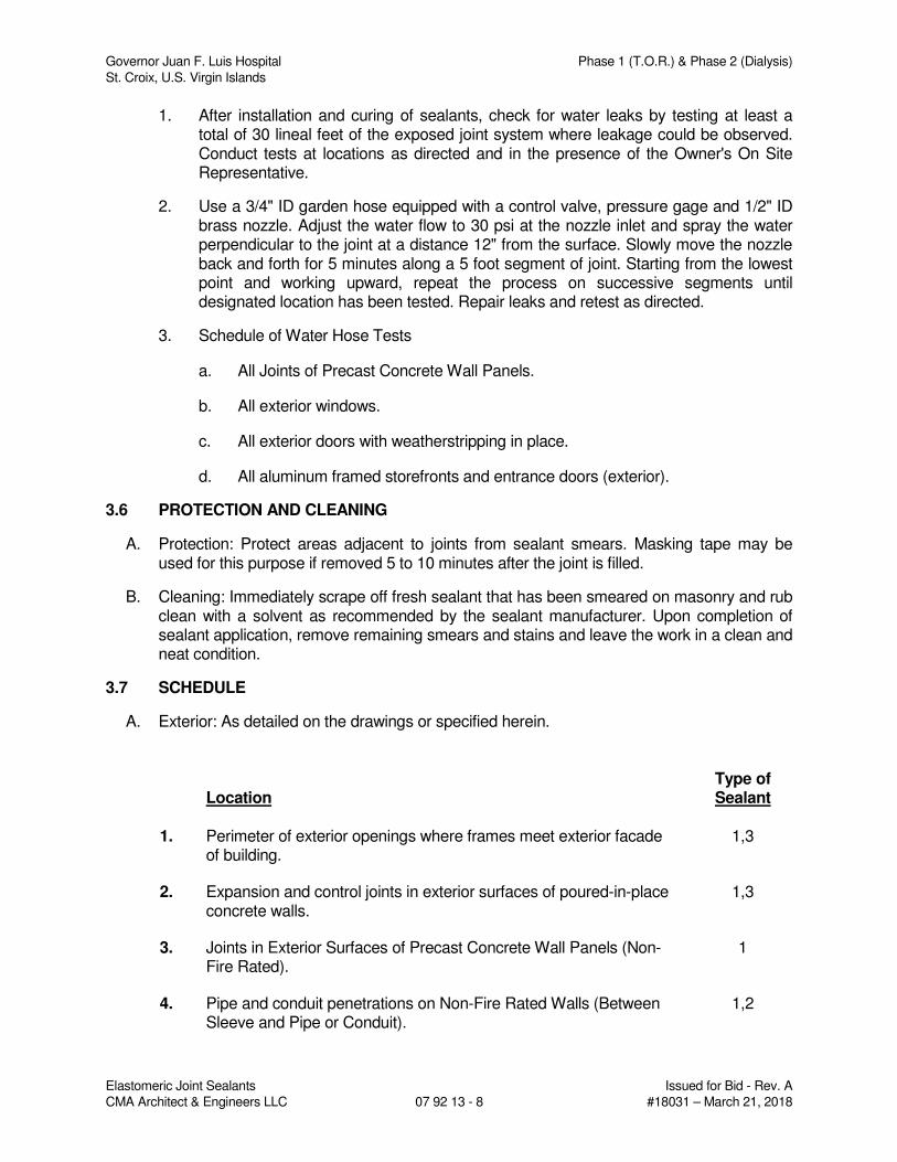
Governor Juan F. Luis Hospital Phase 1 (T.O.R.) & Phase 2 (Dialysis)
St. Croix, U.S. Virgin Islands
Elastomeric Joint Sealants Issued for Bid - Rev. A
CMA Architect & Engineers LLC 07 92 13 - 8 #18031 – March 21, 2018
1. After installation and curing of sealants, check for water leaks by testing at least a total of 30 lineal feet of the exposed joint system where leakage could be observed. Conduct tests at locations as directed and in the presence of the Owner's On Site Representative.
2. Use a 3/4" ID garden hose equipped with a control valve, pressure gage and 1/2" ID brass nozzle. Adjust the water flow to 30 psi at the nozzle inlet and spray the water perpendicular to the joint at a distance 12" from the surface. Slowly move the nozzle back and forth for 5 minutes along a 5 foot segment of joint. Starting from the lowest point and working upward, repeat the process on successive segments until designated location has been tested. Repair leaks and retest as directed.
3. Schedule of Water Hose Tests
a. All Joints of Precast Concrete Wall Panels.
b. All exterior windows.
c. All exterior doors with weatherstripping in place.
d. All aluminum framed storefronts and entrance doors (exterior).
3.6 PROTECTION AND CLEANING
A. Protection: Protect areas adjacent to joints from sealant smears. Masking tape may be used for this purpose if removed 5 to 10 minutes after the joint is filled.
B. Cleaning: Immediately scrape off fresh sealant that has been smeared on masonry and rub clean with a solvent as recommended by the sealant manufacturer. Upon completion of sealant application, remove remaining smears and stains and leave the work in a clean and neat condition.
3.7 SCHEDULE
A. Exterior: As detailed on the drawings or specified herein.
Location Type of Sealant
1. Perimeter of exterior openings where frames meet exterior facade
of building. 1,3
2. Expansion and control joints in exterior surfaces of poured-in-place concrete walls.
1,3
3. Joints in Exterior Surfaces of Precast Concrete Wall Panels (Non-Fire Rated).
1
4. Pipe and conduit penetrations on Non-Fire Rated Walls (Between Sleeve and Pipe or Conduit).
1,2
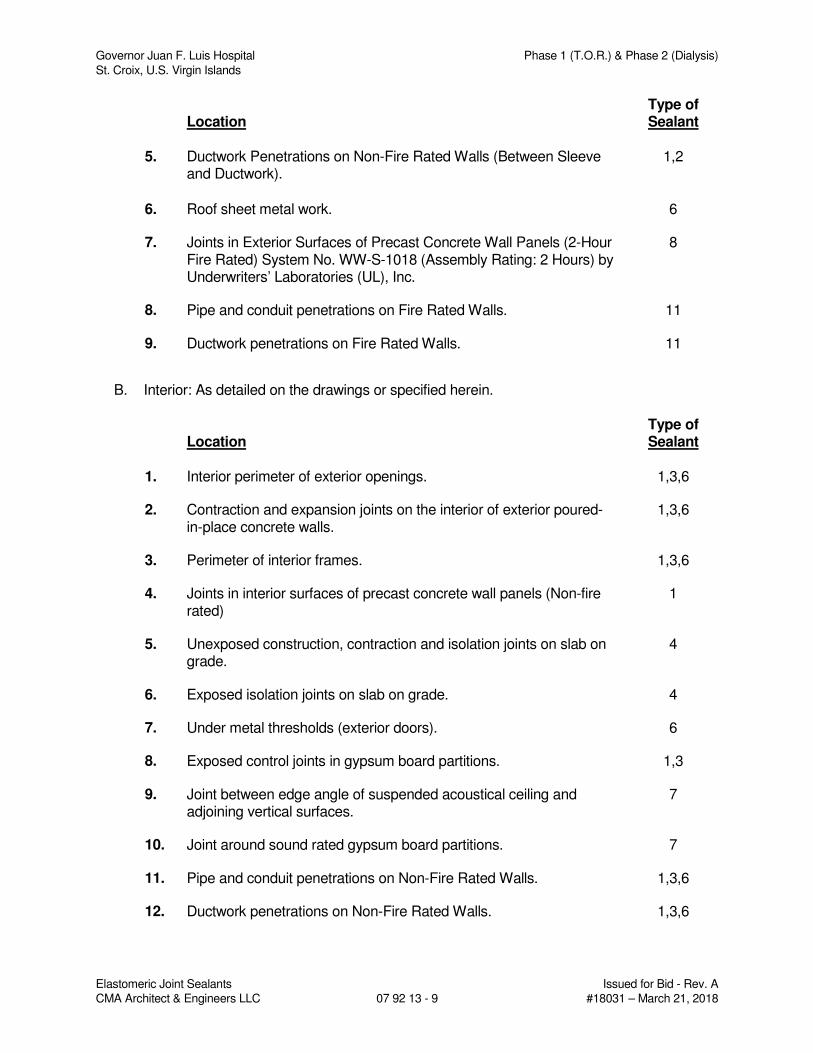
Governor Juan F. Luis Hospital Phase 1 (T.O.R.) & Phase 2 (Dialysis)
St. Croix, U.S. Virgin Islands
Elastomeric Joint Sealants Issued for Bid - Rev. A
CMA Architect & Engineers LLC 07 92 13 - 9 #18031 – March 21, 2018
Location Type of Sealant
5. Ductwork Penetrations on Non-Fire Rated Walls (Between Sleeve
and Ductwork). 1,2
6. Roof sheet metal work. 6
7. Joints in Exterior Surfaces of Precast Concrete Wall Panels (2-Hour Fire Rated) System No. WW-S-1018 (Assembly Rating: 2 Hours) by Underwriters’ Laboratories (UL), Inc.
8
8. Pipe and conduit penetrations on Fire Rated Walls. 11
9. Ductwork penetrations on Fire Rated Walls. 11
B. Interior: As detailed on the drawings or specified herein.
Location Type of Sealant
1. Interior perimeter of exterior openings. 1,3,6
2. Contraction and expansion joints on the interior of exterior poured-in-place concrete walls.
1,3,6
3. Perimeter of interior frames. 1,3,6
4. Joints in interior surfaces of precast concrete wall panels (Non-fire rated)
1
5. Unexposed construction, contraction and isolation joints on slab on grade.
4
6. Exposed isolation joints on slab on grade. 4
7. Under metal thresholds (exterior doors). 6
8. Exposed control joints in gypsum board partitions. 1,3
9. Joint between edge angle of suspended acoustical ceiling and adjoining vertical surfaces.
7
10. Joint around sound rated gypsum board partitions. 7
11. Pipe and conduit penetrations on Non-Fire Rated Walls. 1,3,6
12. Ductwork penetrations on Non-Fire Rated Walls. 1,3,6
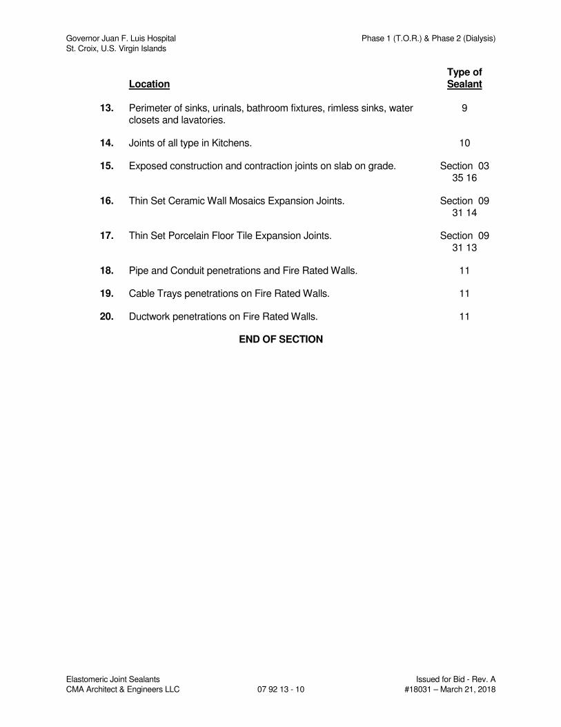
Governor Juan F. Luis Hospital Phase 1 (T.O.R.) & Phase 2 (Dialysis)
St. Croix, U.S. Virgin Islands
Elastomeric Joint Sealants Issued for Bid - Rev. A
CMA Architect & Engineers LLC 07 92 13 - 10 #18031 – March 21, 2018
Location Type of Sealant
13. Perimeter of sinks, urinals, bathroom fixtures, rimless sinks, water
closets and lavatories. 9
14. Joints of all type in Kitchens. 10
15. Exposed construction and contraction joints on slab on grade. Section 03 35 16
16. Thin Set Ceramic Wall Mosaics Expansion Joints. Section 09 31 14
17. Thin Set Porcelain Floor Tile Expansion Joints. Section 09 31 13
18. Pipe and Conduit penetrations and Fire Rated Walls. 11
19. Cable Trays penetrations on Fire Rated Walls. 11
20. Ductwork penetrations on Fire Rated Walls. 11
END OF SECTION
Governor Juan F. Luis Hospital Phase 1 (T.O.R.) & Phase 2 (Dialysis) St. Croix, U.S. Virgin Islands
Hollow Metal Frames Issued for Bid - Rev. A CMA Architect & Engineers LLC 08 12 13 - 1 #18031 – March 21, 2018
SECTION 08 12 13
HOLLOW METAL FRAMES
PART 1 - GENERAL
1.1 SECTION INCLUDES
A. Examination of substrates areas and conditions.
B. Preparation
C. Installation of hollow metal frames
D. Adjusting and cleaning
1.2 RELATED SECTIONS
A. Division 01 Sections – General Requirements.
B. Section 07 92 13 – Elastomeric Joint Sealants.
C. Section 08 71 00 – Door Hardware: For door hardware for hollow metal doors and frames.
D. Section 09 21 16 – Gypsum Board Assemblies
E. Section 09 91 00 – Painting: For field painting of hollow metal frames.
1.3 REFERENCES
A. ASTM A153 – Zinc Coating (Hot Dip) on Iron and Steel Hardware
B. ASTM A653 – Steel Sheet, Zinc Coated (Galvanized) or Zinc Iron Alloy Coated (Galvannealed) by the Hot Dip Process
C. ASTM A879 – Steel Sheet, Zinc Coated by the Electrolytic Process for Application Requiring Designation of the Coating Mass on Each Surface.
D. ASTM A1008 – Steel, Sheet, Cold Rolled, Carbon, Structural, High Strength Low Alloy, High Strength Low Alloy with Improved Formability, Solution Hardened, and Bake Hardenable.
E. ASTM A1011 – Steel, Sheet and Strips, Hot Rolled, Carbon, Structural, High Strength Low Alloy, High Strength Low Alloy with Improved Formability, and Ultra High Strength.
F. ASTM C143 – Test Method for Slump of Hydraulic Cement Concrete
G. ASTM C476 – Grout for Masonry
H. ASTM C665 – Mineral Fiber Blanket Thermal Insulation for Light Frame Construction and Manufactured Housing.
I. ASTM E136 – Test Method for Behavior of Materials in a Vertical Tube Furnace at 750 Degrees C.
Governor Juan F. Luis Hospital Phase 1 (T.O.R.) & Phase 2 (Dialysis) St. Croix, U.S. Virgin Islands
Hollow Metal Frames Issued for Bid - Rev. A CMA Architect & Engineers LLC 08 12 13 - 2 #18031 – March 21, 2018
J. BHMA A156.115 – Hardware Preparation in Steel Doors and Steel Frames (ANSI)
K. NFPA 80 – Fire Doors and Other Opening Protectives (ANSI)
L. NFPA 252 – Fire Tests of Door Assemblies (ANSI)
M. NFPA 257 – Fire Test for Windows and Glass Block Assemblies (ANSI)
N. SDI A250.4 – Test Procedure and Acceptance Criteria for Physical Endurance for Steel Doors and Hardware Reinforcing (ANSI)
O. SDI A250.6 – Recommended Practice for Hardware Reinforcing on Standard Steel Doors and Frames (ANSI)
P. SDI A250.8 – Recommended Specifications for Standard Steel Doors and Frames (ANSI)
Q. SDI A250.11 – Recommended Erection Instructions for Steel Frames (ANSI)
R. UL 9 – Fire Tests of Windows Assemblies
S. UL 10C – Positive Pressure Fire Tests of Doors Assemblies
T. UL 1784 – Air Leakage Tests for Door Assemblies
1.4 DEFINITIONS
A. Minimum Thickness: Minimum thickness of base metal without coatings according to SDI A250.8.
1.5 COORDINATION
A. Section 01 31 00 – Project Management and Coordination
B. Coordinate anchorage installation for hollow-metal frames. Furnish setting drawings, templates, and directions for installing anchorages, including sleeves, concrete inserts, anchor bolts, and items with integral anchors. Deliver such items to Project site in time for installation.
1.6 PREINSTALLATION MEETINGS
A. Section 01 31 00 – Project Management and Coordination
B. Preinstallation Conference: Conduct conference at Project site.
C. Attendees: Architect-Engineer, General Contractor and Door and Frame Installer.
1.7 ACTION SUBMITTALS
A. Section 01 33 00 – Submittal Procedure
B. Product Data: For each type of product.
1. Include construction details, material descriptions, fire-resistance ratings, temperature-rise ratings, and finishes.
Governor Juan F. Luis Hospital Phase 1 (T.O.R.) & Phase 2 (Dialysis) St. Croix, U.S. Virgin Islands
Hollow Metal Frames Issued for Bid - Rev. A CMA Architect & Engineers LLC 08 12 13 - 3 #18031 – March 21, 2018
C. Shop Drawings: Include the following:
1. Frame details for each frame type, including dimensioned profiles and metal thicknesses.
2. Locations of reinforcement and preparations for hardware.
3. Details of each different wall opening condition.
4. Details of anchorages, joints, field splices, and connections.
5. Details of moldings, removable stops, and glazing.
6. Details of conduit and preparations for power, signal, and control systems.
D. Samples for Verification: Prepare Samples to demonstrate compliance with requirements for quality of materials and construction. Show profile, corner joint, floor and wall anchors, and silencers. Include separate section showing fixed hollow-metal panels and glazing if applicable.
E. Schedule: Provide a schedule of hollow-metal work prepared by or under the supervision of supplier, using same reference numbers for details and openings as those on Drawings. Coordinate with final Door Hardware Schedule.
1.8 INFORMATIONAL SUBMITTALS
A. Section 01 33 00 – Submittal Procedures
B. Product Test Reports: For each type of frame assembly, for tests performed by a qualified testing agency.
C. Oversize Construction Certification: For assemblies required to be fire rated and exceeding limitations of labeled assemblies.
1.9 DELIVERY, STORAGE, AND HANDLING
A. Section 01 60 00 – Product Requirements
B. Deliver hollow-metal work palletized, packaged, or crated to provide protection during transit and Project-site storage. Do not use nonvented plastic.
C. Deliver welded frames with two removable spreader bars across bottom of frames, tack welded to jambs and mullions.
D. Store hollow-metal work vertically under cover at Project site with head up. Place on minimum 4-inch- high wood blocking. Provide minimum 1/4-inch space between each unit to permit air circulation.
PART 2 - PRODUCTS
2.1 ACCEPTABLE MANUFACTURERS – HOLLOW METAL FRAMES
A. Amweld International, LLC.
B. Ceco Door Products; an Assa Abloy Group company.
Governor Juan F. Luis Hospital Phase 1 (T.O.R.) & Phase 2 (Dialysis) St. Croix, U.S. Virgin Islands
Hollow Metal Frames Issued for Bid - Rev. A CMA Architect & Engineers LLC 08 12 13 - 4 #18031 – March 21, 2018
C. Curries Company; an Assa Abloy Group company.
D. Pioneer Industries, Inc.
E. Republic Doors and Frames.
F. Steelcraft; an Ingersoll-Rand company.
G. Source Limitations: Obtain hollow-metal work (doors and frames) from single source from single manufacturer.
2.2 REGULATORY REQUIREMENTS
A. Fire-Rated Assemblies: Complying with NFPA 80 and listed and labeled by a qualified testing agency acceptable to Authorities Having Jurisdiction (AHJ) for fire-protection ratings and temperature-rise limits indicated, based on testing at positive pressure according to NFPA 252 or UL 10C.
2.3 INTERIOR HOLLOW METAL FRAMES
A. Construct interior hollow metal frames to comply with the standards indicated for materials, fabrication, hardware locations, hardware reinforcement, tolerances, and clearances, and as specified.
B. Heavy-Duty Frames: SDI A250.8, Level 2.
1. Physical Performance: Level B according to SDI A250.4.
2. Materials: Metallic-coated steel sheet (hot-dipped with a zinc alloy iron coating – galvannealed), minimum thickness of 0.053 inch (16 Gage).
3. Construction: Slip-on drywall and Full profile welded.
4. Exposed Finish: Prime.
2.4 EXTERIOR HOLLOW-METAL FRAMES
A. Construct exterior frames to comply with the standards indicated for materials, fabrication, hardware locations, hardware reinforcement, tolerances, and clearances, and as specified.
B. Heavy-Duty Frames: SDI A250.8, Level 2.
1. Physical Performance: Level B according to SDI A250.4.
2. Materials: Metallic-coated steel sheet (hot-dipped with a zinc alloy iron coating – galvannealed), minimum thickness of 0.053 inch (16 Gage), with minimum A40 coating.
3. Construction: Full profile welded.
4. Exposed Finish: Prime.
2.5 MATERIALS – FRAME ANCHORS
A. Jamb Anchors:
Governor Juan F. Luis Hospital Phase 1 (T.O.R.) & Phase 2 (Dialysis) St. Croix, U.S. Virgin Islands
Hollow Metal Frames Issued for Bid - Rev. A CMA Architect & Engineers LLC 08 12 13 - 5 #18031 – March 21, 2018
1. Stud-Wall Type: Designed to engage stud, welded to back of frames; not less than 0.042 inch thick.
2. Compression Type for Drywall Slip-on Frames: Adjustable compression anchors.
3. Postinstalled Expansion Type for In-Place Concrete: Minimum 3/8-inch- diameter bolts with expansion shields or inserts. Provide pipe spacer from frame to wall, with throat reinforcement plate, welded to frame at each anchor location.
B. Floor Anchors: Formed from same material as frames, minimum thickness of 0.042 inch , and as follows:
1. Monolithic Concrete Slabs: Clip-type anchors, with two holes to receive fasteners.
2.6 MATERIALS – HOLLOW METAL FRAMES
A. Metallic-Coated Steel Sheet: ASTM A 653, Commercial Steel (CS), Type B.
B. Frame Anchors: ASTM A 879, Commercial Steel (CS), 04Z (12G) coating designation; mill phosphatized.
1. For anchors built into exterior walls, steel sheet complying with ASTM A 1008 or ASTM A 1011, hot-dip galvanized according to ASTM A 153, Class B.
C. Inserts, Bolts, and Fasteners: Hot-dip galvanized according to ASTM A 153.
D. Power-Actuated Fasteners in Concrete: Fastener system of type suitable for application indicated, fabricated from corrosion-resistant materials, with clips or other accessory devices for attaching hollow-metal frames of type indicated.
E. Grout: ASTM C 476, except with a maximum slump of 4 inches, as measured according to ASTM C 143.
F. Mineral-Fiber Insulation: ASTM C 665, Type I (blankets without membrane facing); consisting of fibers manufactured from slag or rock wool with 6- to 12-lb/cu. ft. density; with maximum flame-spread and smoke-developed indexes of 25 and 50, respectively; passing ASTM E 136 for combustion characteristics.
G. Glazing: Comply with requirements in Section 08 81 00 – Glass Glazing.
H. Bituminous Coating: Cold-applied asphalt mastic, compounded for 15-mil dry film thickness per coat. Provide inert-type noncorrosive compound free of asbestos fibers, sulfur components, and other deleterious impurities.
2.7 FABRICATION – HOLLOW METAL FRAMES
A. Fabricate hollow-metal work to be rigid and free of defects, warp, or buckle. Accurately form metal to required sizes and profiles, with minimum radius for metal thickness. Where practical, fit and assemble units in manufacturer's plant. To ensure proper assembly at Project site, clearly identify work that cannot be permanently factory assembled before shipment.
Governor Juan F. Luis Hospital Phase 1 (T.O.R.) & Phase 2 (Dialysis) St. Croix, U.S. Virgin Islands
Hollow Metal Frames Issued for Bid - Rev. A CMA Architect & Engineers LLC 08 12 13 - 6 #18031 – March 21, 2018
B. Hollow-Metal Frames: Where frames are fabricated in sections due to shipping or handling limitations, provide alignment plates or angles at each joint, fabricated of same thickness metal as frames.
1. Provide countersunk, flat- or oval-head exposed screws and bolts for exposed fasteners unless otherwise indicated.
2. Grout Guards: Weld guards to frame at back of hardware mortises in frames to be grouted.
3. Floor Anchors: Weld anchors to bottoms of jambs with at least four spot welds per anchor
4. Jamb Anchors: Provide number and spacing of anchors as follows:
a. Masonry Type: Locate anchors not more than 16 inches from top and bottom of frame. Space anchors not more than 32 inches o.c., to match coursing, and as follows:
1) Two anchors per jamb up to 60 inches high.
2) Three anchors per jamb from 60 to 90 inches high.
3) Four anchors per jamb from 90 to 120 inches high.
4) Four anchors per jamb plus one additional anchor per jamb for each 24 inches or fraction thereof above 120 inches high.
b. Stud-Wall Type: Locate anchors not more than 18 inches from top and bottom of frame. Space anchors not more than 32 inches o.c. and as follows:
1) Four anchors per jamb from 60 to 90 inches high.
c. Compression Type: Not less than two anchors in each frame.
d. Postinstalled Expansion Type: Locate anchors not more than 6 inches from top and bottom of frame. Space anchors not more than 26 inches o.c.
5. Head Anchors: Two anchors per head for frames more than 42 inches wide and mounted in metal-stud partitions.
6. Door Silencers: Except on weather-stripped frames, drill stops to receive door silencers as follows. Keep holes clear during construction.
a. Single-Door Frames: Drill stop in strike jamb to receive three door silencers.
b. Double-Door Frames: Drill stop in head jamb to receive two door silencers.
7. Terminated Stops (Interior Non-Rated Hollow Metal Frames): Terminate stops 6 inches above finish floor with a 45-degree angle cut, and close open end of stop with steel sheet closure. Cover opening in extension of frame with welded-steel filler plate, with welds ground smooth and flush with frame.
Governor Juan F. Luis Hospital Phase 1 (T.O.R.) & Phase 2 (Dialysis) St. Croix, U.S. Virgin Islands
Hollow Metal Frames Issued for Bid - Rev. A CMA Architect & Engineers LLC 08 12 13 - 7 #18031 – March 21, 2018
C. Hardware Preparation: Factory prepare hollow-metal work to receive templated mortised hardware; include cutouts, reinforcement, mortising, drilling, and tapping according to SDI A250.6, the Door Hardware Schedule, and templates.
1. Reinforce frames to receive nontemplated, mortised, and surface-mounted hardware.
2. Comply with applicable requirements in SDI A250.6 and BHMA A156.115 for preparation of hollow-metal work for hardware.
D. Stops and Moldings: Provide stops and moldings around glazed lites and louvers where indicated. Form corners of stops and moldings with butted or mitered hairline joints.
1. Single Glazed Lites: Provide fixed stops and moldings welded on secure side of hollow-metal work.
2. Multiple Glazed Lites: Provide fixed and removable stops and moldings so that each glazed lite is capable of being removed independently.
3. Provide fixed frame moldings on outside of exterior and on secure side of interior frames.
4. Provide loose stops and moldings on inside of hollow-metal work.
5. Coordinate rabbet width between fixed and removable stops with glazing and installation types indicated.
2.8 STEEL FINISHES
A. Prime Finish: Clean, pretreat, and apply manufacturer's standard primer.
1. Shop Primer: Manufacturer's standard, fast-curing, lead- and chromate-free primer complying with SDI A250.10; recommended by primer manufacturer for substrate; compatible with substrate and field-applied coatings despite prolonged exposure.
2.9 ACCESSORIES
A. Grout Guards: Formed from same material as frames, not less than 0.016 inch thick.
PART 3 - EXECUTION
3.1 EXAMINATION
A. Section 01 31 00 – Project Management and Coordination
B. Examine substrates, areas, and conditions, with Installer present, for compliance with requirements for installation tolerances and other conditions affecting performance of the Work.
C. Examine roughing-in for embedded and built-in anchors to verify actual locations before frame installation.
Governor Juan F. Luis Hospital Phase 1 (T.O.R.) & Phase 2 (Dialysis) St. Croix, U.S. Virgin Islands
Hollow Metal Frames Issued for Bid - Rev. A CMA Architect & Engineers LLC 08 12 13 - 8 #18031 – March 21, 2018
D. Prepare written report, endorsed by Installer, listing conditions detrimental to performance of the Work.
E. Proceed with installation only after unsatisfactory conditions have been corrected.
3.2 PREPARATION
A. Remove welded-in shipping spreaders installed at factory. Restore exposed finish by grinding, filling, and dressing, as required to make repaired area smooth, flush, and invisible on exposed faces.
B. Drill and tap frames to receive nontemplated, mortised, and surface-mounted hardware.
3.3 INSTALLATION – HOLLOW METAL FRAMES
A. General: Install hollow-metal work plumb, rigid, properly aligned, and securely fastened in place. Comply with Drawings and manufacturer's written instructions.
B. Hollow-Metal Frames: Install hollow-metal frames of size and profile indicated. Comply with SDI A250.11 as required by standards specified.
1. Set frames accurately in position; plumbed, aligned, and braced securely until permanent anchors are set. After wall construction is complete, remove temporary braces, leaving surfaces smooth and undamaged.
a. At fire-rated openings, install frames according to NFPA 80.
b. Where frames are fabricated in sections because of shipping or handling limitations, field splice at approved locations by welding face joint continuously; grind, fill, dress, and make splice smooth, flush, and invisible on exposed faces.
c. Install frames with removable stops located on secure side of opening.
d. Install door silencers in frames before grouting.
e. Remove temporary braces necessary for installation only after frames have been properly set and secured.
f. Check plumb, square, and twist of frames as walls are constructed. Shim as necessary to comply with installation tolerances.
g. Field apply bituminous coating to backs of frames that will be filled with grout.
2. Floor Anchors: Provide floor anchors for each jamb and mullion that extends to floor, and secure with postinstalled expansion anchors.
a. Floor anchors may be set with power-actuated fasteners instead of postinstalled expansion anchors if so indicated and approved on Shop Drawings.
3. Metal-Stud Partitions: Solidly pack mineral-fiber insulation inside frames.
Governor Juan F. Luis Hospital Phase 1 (T.O.R.) & Phase 2 (Dialysis) St. Croix, U.S. Virgin Islands
Hollow Metal Frames Issued for Bid - Rev. A CMA Architect & Engineers LLC 08 12 13 - 9 #18031 – March 21, 2018
4. Masonry Walls: Coordinate installation of frames to allow for solidly filling space between frames and masonry with grout.
5. Concrete Walls: Solidly fill space between frames and concrete with mineral-fiber insulation.
6. In-Place Concrete Construction: Secure frames in place with postinstalled expansion anchors. Countersink anchors, and fill and make smooth, flush, and invisible on exposed faces.
7. In-Place Metal Stud Partitions: Secure slip-on drywall frames in place according to manufacturer's written instructions.
8. Installation Tolerances: Adjust hollow-metal door frames for squareness, alignment, twist, and plumb to the following tolerances:
a. Squareness: Plus or minus 1/16 inch, measured at door rabbet on a line 90 degrees from jamb perpendicular to frame head.
b. Alignment: Plus or minus 1/16 inch, measured at jambs on a horizontal line parallel to plane of wall.
c. Twist: Plus or minus 1/16 inch, measured at opposite face corners of jambs on parallel lines, and perpendicular to plane of wall.
d. Plumbness: Plus or minus 1/16 inch, measured at jambs at floor.
C. Glass Glazing: Comply with installation requirements in Section 08 81 00 – Glass glazing and with hollow-metal manufacturer's written instructions.
1. Secure stops with countersunk flat- or oval-head machine screws spaced uniformly not more than 9 inches o.c. and not more than 2 inches o.c. from each corner.
3.4 ADJUSTING AND CLEANING
A. Final Adjustments: Remove and replace defective work, including hollow-metal work that is warped, bowed, or otherwise unacceptable.
B. Remove grout and other bonding material from hollow-metal work immediately after installation.
C. Metallic-Coated Surface Touchup: Clean abraded areas and repair with galvanizing repair paint according to manufacturer's written instructions.
D. Touchup Painting: Cleaning and touchup painting of abraded areas of paint are specified in painting Sections.
END OF SECTION
Governor Juan F. Luis Hospital Phase 1 (T.O.R.) & Phase 2 (Dialysis) St. Croix, U.S. Virgin Islands
Hollow Metal Doors Issued for Bid - Rev. A CMA Architect & Engineers LLC 08 13 13 - 1 #18031 – March 21, 2018
SECTION 08 13 13
HOLLOW METAL DOORS
PART 1 - GENERAL
1.1 SECTION INCLUDES
A. Examination of substrate areas and conditions.
B. Preparation.
C. Installation of hollow metals doors.
D. Adjusting and cleaning.
1.2 RELATED SECTIONS
A. Division 01 Sections – General Requirements
B. Section 08 12 13 – Hollow Metal Frames: For hollow metal frames.
C. Section 08 71 00 – Door Hardware
D. Section 09 91 00 – Painting: For field painting of hollow metal doors.
1.3 REFERENCES
A. ASTM A153 – Zinc Coating (Hot Dip) on Iron and Steel Hardware
B. ASTM A653 – Steel Sheet, Zinc Coated (Galvanized) or Zinc Iron Alloy Coated (Galvannealed) by the Hot Dip Process
C. ASTM A879 – Steel Sheet, Zinc Coated by the Electrolytic Process for Application Requiring Designation of the Coating Mass on Each Surface.
D. ASTM A1008 – Steel, Sheet, Cold Rolled, Carbon, Structural, High Strength Low Alloy, High Strength Low Alloy with Improved Formability, Solution Hardened, and Bake Hardenable.
E. ASTM A1011 – Steel, Sheet and Strips, Hot Rolled, Carbon, Structural, High Strength Low Alloy, High Strength Low Alloy with Improved Formability, and Ultra High Strength.
F. ASTM C665 – Mineral Fiber Blanket Thermal Insulation for Light Frame Construction and Manufactured Housing.
G. ASTM C1363 – Test Method for the Thermal Performance of Building Materials and Envelope Assemblies by Means of Hot Box Apparatus.
H. ASTM E136 – Test Method for Behavior of Materials in a Vertical Tube Furnace at 750 Degrees C.
I. BHMA A156.115 – Hardware Preparation in Steel Doors and Steel Frames (ANSI)
J. NFPA 80 – Fire Doors and Other Opening Protectives (ANSI)
Governor Juan F. Luis Hospital Phase 1 (T.O.R.) & Phase 2 (Dialysis) St. Croix, U.S. Virgin Islands
Hollow Metal Doors Issued for Bid - Rev. A CMA Architect & Engineers LLC 08 13 13 - 2 #18031 – March 21, 2018
K. NFPA 105 – Installation of Smoke – Control Doors Assemblies (ANSI)
L. NFPA 252 – Fire Tests of Door Assemblies (ANSI)
M. NFPA 257 – Fire Test for Windows and Glass Block Assemblies (ANSI)
N. SDI A250.4 – Test Procedure and Acceptance Criteria for Physical Endurance for Steel Doors and Hardware Reinforcing (ANSI)
O. SDI A250.6 – Recommended Practice for Hardware Reinforcing on Standard Steel Doors and Frames (ANSI)
P. SDI A250.8 – Recommended Specifications for Standard Steel Doors and Frames (ANSI)
Q. SDI A250.10 – Test Procedure and Acceptance Criteria for Prime Painted Steel Surfaces for Steel Doors and Frames (ANSI)
R. UL 9 – Fire Tests of Windows Assemblies
S. UL 10C – Positive Pressure Fire Tests of Doors Assemblies
T. UL 1784 – Air Leakage Tests for Door Assemblies
1.4 DEFINITIONS
A. Minimum Thickness: Minimum thickness of base metal without coatings according to SDI A250.8.
1.5 COORDINATION
A. Coordinate anchorage installation for hollow-metal frames. Furnish setting drawings, templates, and directions for installing anchorages, including sleeves, concrete inserts, anchor bolts, and items with integral anchors. Deliver such items to Project site in time for installation.
1.6 ACTION SUBMITTALS
A. Section 01 33 00 – Submittal Procedures
B. Product Data: For each type of product.
1. Include construction details, material descriptions, core descriptions, fire-resistance ratings, temperature-rise ratings, and finishes.
C. Shop Drawings: Include the following:
1. Elevations of each door type.
2. Details of doors, including vertical- and horizontal-edge details and metal thicknesses.
3. Locations of reinforcement and preparations for hardware.
4. Details of each different wall opening condition.
Governor Juan F. Luis Hospital Phase 1 (T.O.R.) & Phase 2 (Dialysis) St. Croix, U.S. Virgin Islands
Hollow Metal Doors Issued for Bid - Rev. A CMA Architect & Engineers LLC 08 13 13 - 3 #18031 – March 21, 2018
5. Details of accessories.
6. Details of moldings, removable stops, and glazing.
7. Details of conduit and preparations for power, signal, and control systems.
D. Schedule: Provide a schedule of hollow-metal work prepared by or under the supervision of supplier, using same reference numbers for details and openings as those on Drawings. Coordinate with final Door Hardware Schedule.
1.7 INFORMATIONAL SUBMITTALS
A. Section 01 33 00 –Submittal Procedures
B. Product Test Reports: For each type of hollow-metal door and frame assembly, for tests performed by a qualified testing agency.
C. Oversize Construction Certification: For assemblies required to be fire rated and exceeding limitations of labeled assemblies.
1.8 DELIVERY, STORAGE, AND HANDLING
A. Section 01 60 00 – Product Requirements
B. Deliver hollow-metal work palletized, packaged, or crated to provide protection during transit and Project-site storage. Do not use nonvented plastic.
C. Store hollow-metal work vertically under cover at Project site with head up. Place on minimum 4-inch- high wood blocking. Provide minimum 1/4-inch space between each stacked door to permit air circulation.
PART 2 - PRODUCTS
2.1 ACCEPTABLE MANUFACTURERS – HOLLOW METAL DOORS
A. Amweld International, LLC.
B. Ceco Door Products; an Assa Abloy Group company.
C. Curries Company; an Assa Abloy Group company.
D. Pioneer Industries, Inc.
E. Republic Doors and Frames.
F. Steelcraft; an Ingersoll-Rand company.
G. Source Limitations: Obtain hollow-metal work from single source from single manufacturer.
2.2 REGULATORY REQUIREMENTS
A. Fire-Rated Assemblies: Complying with NFPA 80 and listed and labeled by a qualified testing agency acceptable to Authorities Having Jurisdiction (AHJ) for fire-protection ratings and temperature-rise limits indicated, based on testing at positive pressure according to NFPA 252 or UL 10C.
Governor Juan F. Luis Hospital Phase 1 (T.O.R.) & Phase 2 (Dialysis) St. Croix, U.S. Virgin Islands
Hollow Metal Doors Issued for Bid - Rev. A CMA Architect & Engineers LLC 08 13 13 - 4 #18031 – March 21, 2018
2.3 INTERIOR HOLLOW METAL DOORS
A. Construct interior hollow metal doors to comply with the standards indicated for materials, fabrication, hardware locations, hardware reinforcement, tolerances, and clearances, and as specified.
B. Heavy-Duty Doors: SDI A250.8, Level 2.
1. Physical Performance: Level B according to SDI A250.4.
2. Doors:
a. Type: As indicated in the Door and Frame Schedule.
b. Thickness: 1-3/4 inches.
c. Face: Metallic-coated, cold-rolled steel sheet (hot-dipped with a zinc alloy iron coating-galvannealed), minimum thickness of 0.042 inch (18 Gage).
d. Edge Construction: Model 2, Seamless.
e. Core: Manufacturer's standard kraft-paper honeycomb, polystyrene, polyurethane, polyisocyanurate, mineral-board, or vertical steel-stiffener core at manufacturer's discretion.
3. Exposed Finish: Prime.
2.4 EXTERIOR HOLLOW METAL DOORS
A. Construct exterior hollow metal doors to comply with the standards indicated for materials, fabrication, hardware locations, hardware reinforcement, tolerances, and clearances, and as specified.
B. Extra-Heavy-Duty Doors: SDI A250.8, Level 3.
1. Physical Performance: Level A according to SDI A250.4.
2. Doors:
a. Type: As indicated in the Door and Frame Schedule.
b. Thickness: 1-3/4 inches
c. Face: Metallic-coated steel sheet (hot-dipped with a zinc alloy iron coating-galvannealed), minimum thickness of 0.053 inch, with minimum A40 (ZF120) coating.
d. Edge Construction: Model 2, Seamless.
e. Core: Manufacturer's standard kraft-paper honeycomb, polystyrene, polyurethane, polyisocyanurate, mineral-board, or vertical steel-stiffener core at manufacturer's discretion.
f. Core: Vertical steel stiffener.
Governor Juan F. Luis Hospital Phase 1 (T.O.R.) & Phase 2 (Dialysis) St. Croix, U.S. Virgin Islands
Hollow Metal Doors Issued for Bid - Rev. A CMA Architect & Engineers LLC 08 13 13 - 5 #18031 – March 21, 2018
1) Thermal-Rated Doors: Provide doors fabricated with thermal-resistance value (R-value) of not less than 2.1 deg F x h x sq. ft./Btu when tested according to ASTM C 1363.
2.5 HOLLOW METAL PANELS
A. Provide hollow-metal panels of same materials, construction, and finish as adjacent door assemblies.
2.6 MATERIALS - GENERAL
A. Metallic-Coated Steel Sheet: ASTM A 653, Commercial Steel (CS), Type B.
B. Glazing: Comply with requirements in Section 08 81 00.
2.7 FABRICATION – HOLLOW METAL DOORS
A. Fabricate hollow-metal work to be rigid and free of defects, warp, or buckle. Accurately form metal to required sizes and profiles, with minimum radius for metal thickness. Where practical, fit and assemble units in manufacturer's plant. To ensure proper assembly at Project site, clearly identify work that cannot be permanently factory assembled before shipment.
B. Hollow-Metal Doors:
1. Steel-Stiffened Door Cores: Provide minimum thickness 0.026 inch , steel vertical stiffeners of same material as face sheets extending full-door height, with vertical webs spaced not more than 6 inches apart. Spot weld to face sheets no more than 5 inches o.c. Fill spaces between stiffeners with glass- or mineral-fiber insulation.
2. Fire Door Cores: As required to provide fire-protection and temperature-rise ratings indicated.
3. Vertical Edges for Single-Acting Doors: Bevel edges 1/8 inch in 2 inches.
4. Top Edge Closures: Close top edges of doors with flush closures of same material as face sheets.
5. Bottom Edge Closures: Close bottom edges of doors where required for attachment of weather stripping with end closures or channels of same material as face sheets.
6. Exterior Doors: Provide weep-hole openings in bottoms of exterior doors to permit moisture to escape. Seal joints in top edges of doors against water penetration.
7. Astragals: Provide overlapping astragal on one leaf of pairs of doors where required by NFPA 80 for fire-performance rating or where indicated. Extend minimum 3/4 inch beyond edge of door on which astragal is mounted or as required to comply with published listing of qualified testing agency.
2.8 STEEL FINISHES
A. Prime Finish: Clean, pretreat, and apply manufacturer's standard primer.
Governor Juan F. Luis Hospital Phase 1 (T.O.R.) & Phase 2 (Dialysis) St. Croix, U.S. Virgin Islands
Hollow Metal Doors Issued for Bid - Rev. A CMA Architect & Engineers LLC 08 13 13 - 6 #18031 – March 21, 2018
1. Shop Primer: Manufacturer's standard, fast-curing, lead- and chromate-free primer complying with SDI A250.10; recommended by primer manufacturer for substrate; compatible with substrate and field-applied coatings despite prolonged exposure.
2.9 ACCESSORIES
A. Louvers: Provide louvers for interior doors, where indicated, which comply with SDI 111C, with blades or baffles formed of 0.020-inch- thick, cold-rolled steel sheet set into 0.032-inch- thick steel frame.
1. Sightproof Louver: Stationary louvers constructed with inverted-V or inverted-Y blades.
2. Fire-Rated Automatic Louvers: Louvers constructed with movable blades closed by actuating fusible link, and listed and labeled for use in fire-rated door assemblies of type and fire-resistance rating indicated by same qualified testing and inspecting agency that established fire-resistance rating of door assembly.
PART 3 - EXECUTION
3.1 EXAMINATION
A. Section 01 31 00 – Project Management and Coordination.
B. Examine substrates, areas, and conditions, with Installer present, for compliance with requirements for installation tolerances and other conditions affecting performance of the Work.
C. Prepare written report, endorsed by Installer, listing conditions detrimental to performance of the Work.
D. Proceed with installation only after unsatisfactory conditions have been corrected.
3.2 PREPARATION
A. Drill and tap doors to receive nontemplated, mortised, and surface-mounted door hardware.
3.3 INSTALLATION – HOLLOW METAL DOORS
A. General: Install hollow-metal work plumb, rigid, properly aligned, and securely fastened in place. Comply with Drawings and manufacturer's written instructions.
B. Hollow-Metal Doors: Fit hollow-metal doors accurately in frames, within clearances specified below. Shim as necessary.
1. Non-Fire-Rated Steel Doors:
a. Between Door and Frame Jambs and Head: 1/8 inch plus or minus 1/32 inch.
b. Between Edges of Pairs of Doors: 1/8 inch to 1/4 inch plus or minus 1/32 inch.
Governor Juan F. Luis Hospital Phase 1 (T.O.R.) & Phase 2 (Dialysis) St. Croix, U.S. Virgin Islands
Hollow Metal Doors Issued for Bid - Rev. A CMA Architect & Engineers LLC 08 13 13 - 7 #18031 – March 21, 2018
c. At Bottom of Door: 3/4 inch plus or minus 1/32 inch.
d. Between Door Face and Stop: 1/16 inch to 1/8 inch plus or minus 1/32 inch.
2. Fire-Rated Doors: Install doors with clearances according to NFPA 80.
C. Glazing: Comply with installation requirements in Section 08 80 00 and with hollow-metal manufacturer's written instructions.
1. Secure stops with countersunk flat- or oval-head machine screws spaced uniformly not more than 9 inches o.c. and not more than 2 inches o.c. from each corner.
3.4 ADJUSTING AND CLEANING
A. Final Adjustments: Check and readjust operating hardware items immediately before final inspection. Leave work in complete and proper operating condition. Remove and replace defective work, including hollow-metal work that is warped, bowed, or otherwise unacceptable.
B. Remove grout and other bonding material from hollow-metal work immediately after installation.
C. Metallic-Coated Surface Touchup: Clean abraded areas and repair with galvanizing repair paint according to manufacturer's written instructions.
D. Touchup Painting: Cleaning and touchup painting of abraded areas of paint are specified in painting Sections.
END OF SECTION
Governor Juan F. Luis Hospital Phase 1 (T.O.R.) & Phase 2 (Dialysis) St. Croix, U.S. Virgin Islands
Door Hardware Issued for Bid - Rev. A CMA Architect & Engineers LLC 08 71 00 - 1 #18031 – March 21, 2018
SECTION 08 71 00
DOOR HARDWARE
PART 1 - GENERAL
1.1 SECTION INCLUDES
A. Examination of doors and frames.
B. Preparation of doors and frames.
C. Installation of door hardware for swinging doors.
D. Field quality control.
E. Adjusting.
F. Cleaning and protection.
G. Demonstration.
H. Door Hardware Schedule.
1.2 RELATED SECTIONS
A. Division 01 Sections – General Requirements.
B. Section 07 92 13 - Elastomeric Joint Sealants.
C. Section 08 12 13 - Hollow Metal Frames: For door silencers provided as part of hollow-metal frames.
D. Section 08 13 13 – Hollow Metal Doors: For astragals provided as part of labeled fire-rated doors.
1.3 REFERENCES
A. ANSI/SDI A250.6 - Recommended Practice for Hardware Reinforcing on Standard Steel Doors and Frames
B. ANSI/SDI A250.8 - Recommended Specifications for Standard Steel Doors and Frames ASTM International
C. ASTM E 283 - Test Method for Determining the Rate of Air Leakage Through Exterior Windows, Curtain Walls, and Doors Under Specified Pressure Differences Across the Specimen
D. BHMA A156.1 - Butts and Hinges (ANSI)
E. BHMA A156.2 - Bored and Preassembled Locks & Latches (ANSI)
F. BHMA A156.3 - Exit Devices (ANSI)
G. BHMA A156.4 - Door Controls - Closers (ANSI)
Governor Juan F. Luis Hospital Phase 1 (T.O.R.) & Phase 2 (Dialysis) St. Croix, U.S. Virgin Islands
Door Hardware Issued for Bid - Rev. A CMA Architect & Engineers LLC 08 71 00 - 2 #18031 – March 21, 2018
H. BHMA A156.5 - Auxiliary Locks and Associated Products (ANSI)
I. BHMA A156.6 - Architectural Door Trim (ANSI)
J. BHMA A156.13 - Mortise Locks & Latches Series 1000 (ANSI)
K. BHMA A156.16 - Auxiliary Hardware (ANSI)
L. BHMA A156.18 - Materials and Finishes (ANSI)
M. BHMA A156.21 - Thresholds (ANSI)
N. BHMA A156.22 - Gasketing and Edge Seal Systems (ANSI)
O. BHMA A156.28 - Recommended Practices for Keying Systems (ANSI)
P. DHI WDHS.4 - Recommended Hardware Reinforcement Locations for Mineral Core Wood Flush Doors
Q. NFPA 80 - Fire Doors and Fire Windows
R. NFPA 252 - Methods of Fire Tests of Door Assemblies
S. UL 10C - Positive Pressure Fire Tests of Door Assemblies
1.4 ACTION SUBMITTALS
A. Section 01 33 00 – Submittal Provision.
B. Product Data: For each type of product indicated. Include construction and installation details, material descriptions, dimensions of individual components and profiles, and finishes.
1.5 INFORMATIONAL SUBMITTALS
A. Section 01 33 00 – Submittal Procedures
B. Qualification Data: For Installer and Architectural Hardware Consultant.
C. Product Test Reports: For compliance with accessibility requirements, based on evaluation of comprehensive tests performed by manufacturer and witnessed by a qualified testing agency, for door hardware on doors located in accessible routes.
D. Warranty: Special warranty specified in this Section.
1.6 CLOSEOUT SUBMITTALS
A. Section 01 77 00 – Closeout Procedures
B. Maintenance Data: For each type of door hardware to include in maintenance manuals. Include final hardware and keying schedule.
1.7 MAINTENANCE MATERIAL SUBMITTALS
A. Section 01 77 00 – Closeout Procedures
Governor Juan F. Luis Hospital Phase 1 (T.O.R.) & Phase 2 (Dialysis) St. Croix, U.S. Virgin Islands
Door Hardware Issued for Bid - Rev. A CMA Architect & Engineers LLC 08 71 00 - 3 #18031 – March 21, 2018
B. Furnish extra materials that match products installed and that are packaged with protective covering for storage and identified with labels describing contents.
1. Door Hardware:
1.8 QUALITY ASSURANCE
A. Section 01 40 00 – Quality requirements.
B. Installer Qualifications: Supplier of products and an employer of workers trained and approved by product manufacturers and an Architectural Hardware Consultant who is available during the course of the Work to consult with Contractor, Architect-Engineer, and Owner about door hardware and keying.
1. Warehousing Facilities: In Project's vicinity.
2. Scheduling Responsibility: Preparation of door hardware and keying schedules.
C. Architectural Hardware Consultant Qualifications: A person who is experienced in providing consulting services for door hardware installations that are comparable in material, design, and extent to that indicated for this Project and who is currently certified by DHI as follows:
D. Source Limitations: Obtain each type of door hardware from a single manufacturer.
E. Fire-Rated Door Assemblies: Where fire-rated door assemblies are indicated, provide door hardware rated for use in assemblies complying with NFPA 80 that are listed and labeled by a qualified testing agency, for fire-protection ratings indicated, based on testing at positive pressure according to NFPA 252 or UL 10C, unless otherwise indicated.
F. Means of Egress Doors: Latches do not require more than 15 lbf to release the latch. Locks do not require use of a key, tool, or special knowledge for operation.
G. Accessibility Requirements: For door hardware on doors in an accessible route, comply with the U.S. Architectural & Transportation Barriers Compliance Board's ADA-ABA Accessibility Guidelines.
1. Provide operating devices that do not require tight grasping, pinching, or twisting of the wrist and that operate with a force of not more than 5 lbf.
2. Comply with the following maximum opening-force requirements:
a. Interior, Non-Fire-Rated Hinged Doors: 5 lbf applied perpendicular to door.
b. Fire Doors: Minimum opening force allowable by Authorities Having Jurisdiction (AHJ).
3. Bevel raised thresholds with a slope of not more than 1:2. Provide thresholds not more than 1/2 inch high and 3/4 inch high for exterior sliding doors.
4. Adjust door closer sweep periods so that, from an open position of 70 degrees, the door will take at least 3 seconds to move to a point 3 inches from the latch, measured to the leading edge of the door.
Governor Juan F. Luis Hospital Phase 1 (T.O.R.) & Phase 2 (Dialysis) St. Croix, U.S. Virgin Islands
Door Hardware Issued for Bid - Rev. A CMA Architect & Engineers LLC 08 71 00 - 4 #18031 – March 21, 2018
H. Keying Conference: Conduct conference at Project site to comply with requirements in Section 01 31 00 In addition to Owner, Contractor, and Architect-Engineer, conference participants shall also include Installer's Architectural Hardware Consultant and Owner's security consultant. Incorporate keying conference decisions into final keying schedule after reviewing door hardware keying system including, but not limited to, the following:
1. Function of building, flow of traffic, purpose of each area, degree of security required, and plans for future expansion.
2. Preliminary key system schematic diagram.
3. Requirements for key control system.
4. Requirements for access control.
5. Address for delivery of keys.
1.9 DELIVERY, STORAGE, AND HANDLING
A. Section 01 60 00 – Product Requirements
B. Inventory door hardware on receipt and provide secure lock-up for door hardware delivered to Project site.
C. Tag each item or package separately with identification coordinated with the final door hardware schedule, and include installation instructions, templates, and necessary fasteners with each item or package.
D. Deliver keys to manufacturer of key control system for subsequent delivery to Owner.
E. Deliver keys and permanent cores to Owner by registered mail or overnight package service.
1.10 COORDINATION
A. Section 01 31 00 – Project Management and Coordination
B. Coordinate layout and installation of floor-recessed door hardware with floor construction. Cast anchoring inserts into concrete.
C. Installation Templates: Distribute for doors, frames, and other work specified to be factory prepared. Check Shop Drawings of other work to confirm that adequate provisions are made for locating and installing door hardware to comply with indicated requirements.
D. Security: Coordinate installation of door hardware, keying, and access control with Owner's security consultant.
E. Existing Openings: Where hardware components are scheduled for application to existing construction or where modifications to existing door hardware are required, field verify existing conditions and coordinate installation of door hardware to suit opening conditions and to provide proper door operation.
1.11 WARRANTY
A. Section 01 77 00 – Closeout Procedures.
Governor Juan F. Luis Hospital Phase 1 (T.O.R.) & Phase 2 (Dialysis) St. Croix, U.S. Virgin Islands
Door Hardware Issued for Bid - Rev. A CMA Architect & Engineers LLC 08 71 00 - 5 #18031 – March 21, 2018
B. Special Warranty: Manufacturer's standard form in which manufacturer agrees to repair or replace components of door hardware that fails in materials or workmanship within specified warranty period.
1. Failures include, but are not limited to, the following:
a. Structural failures including excessive deflection, cracking, or breakage.
b. Faulty operation of doors and door hardware.
c. Deterioration of metals, metal finishes, and other materials beyond normal weathering and use.
2. Warranty Period: Three years from date of Substantial Completion, unless otherwise indicated.
a. Exit Devices: Two (2) years from Date of Substantial Completion.
b. Manual Closers: Ten (10) years from Date of Substantial Completion.
1.12 MAINTENANCE SERVICE
A. Section 01 77 00 – Closeout Procedures
B. Maintenance Tools and Instructions: Furnish a complete set of specialized tools and maintenance instructions for Owner's continued adjustment, maintenance, and removal and replacement of door hardware.
C. Maintenance Service: Beginning at Substantial Completion, provide six (6) months of full maintenance by skilled employees of door hardware Installer. Include quarterly preventive maintenance, repair or replacement of worn or defective components, lubrication, cleaning, and adjusting as required for proper door and door hardware operation. Provide parts and supplies that are the same as those used in the manufacture and installation of original products.
PART 2 - PRODUCTS
2.1 SCHEDULED DOOR HARDWARE
A. Provide door hardware for each door as scheduled in Part 3 "Door Hardware Schedule" Article or on Drawings to comply with requirements in this Section.
1. Door Hardware Sets: Provide quantity, item, size, finish or color indicated, and named manufacturers' products.
B. Designations: Requirements for design, grade, function, finish, size, and other distinctive qualities of each type of door hardware are indicated in Part 3 "Door Hardware Schedule" Article. Products are identified by using door hardware designations, as follows:
1. Named Manufacturers' Products: Manufacturer and product designation are listed for each door hardware type required for the purpose of establishing minimum requirements. Manufacturers' names are abbreviated in Part 3 "Door Hardware Schedule" Article.
Governor Juan F. Luis Hospital Phase 1 (T.O.R.) & Phase 2 (Dialysis) St. Croix, U.S. Virgin Islands
Door Hardware Issued for Bid - Rev. A CMA Architect & Engineers LLC 08 71 00 - 6 #18031 – March 21, 2018
2.2 MATERIALS - HINGES
A. Hinges: BHMA A156.1. Provide template-produced hinges for hinges installed on hollow-metal doors and hollow-metal frames.
1. Manufacturers: Subject to compliance with requirements, provide products by one of the following:
a. McKinney Products Company; an ASSA ABLOY Group company.
2.3 MATERIALS - MECHANICAL LOCKS AND LATCHES
A. Lock Functions: As indicated in door hardware schedule.
B. Lock Throw: Comply with testing requirements for length of bolts required for labeled fire doors, and as follows:
1. Bored Locks: Minimum 1/2-inch latchbolt throw.
2. Mortise Locks: Minimum 3/4-inch latchbolt throw.
C. Lock Backset: 2-3/4 inches, unless otherwise indicated.
D. Lock Trim:
1. Description: As indicated on Drawings.
2. Levers: Cast.
3. Escutcheons (Roses): Wrought.
4. Dummy Trim: Match lever lock trim and escutcheons.
5. Operating Device: Lever with escutcheons (roses).
E. Strikes: Provide manufacturer's standard strike for each lock bolt or latchbolt complying with requirements indicated for applicable lock or latch and with strike box and curved lip extended to protect frame; finished to match lock or latch.
1. Flat-Lip Strikes: For locks with three-piece antifriction latchbolts, as recommended by manufacturer.
F. Bored Locks: BHMA A156.2; Grade 1; Series 4000.
1. Manufacturers: Subject to compliance with requirements, provide products by one of the following:
a. SARGENT Manufacturing Company; an ASSA ABLOY Group company.
G. Mortise Locks: BHMA A156.13; Operational Grade 1; stamped steel case with steel or brass parts; Series 1000.
1. Manufacturers: Subject to compliance with requirements, provide products by one of the following:
a. SARGENT Manufacturing Company; an ASSA ABLOY Group company.
Governor Juan F. Luis Hospital Phase 1 (T.O.R.) & Phase 2 (Dialysis) St. Croix, U.S. Virgin Islands
Door Hardware Issued for Bid - Rev. A CMA Architect & Engineers LLC 08 71 00 - 7 #18031 – March 21, 2018
2.4 MATERIALS - AUXILIARY LOCKS
A. Bored Auxiliary Locks: BHMA A156.5: Grade 1; with strike that suits frame.
1. Manufacturers: Subject to compliance with requirements, provide products by one of the following:
a. SARGENT Manufacturing Company; an ASSA ABLOY Group company.
2.5 MATERIALS - MANUAL FLUSH BOLTS
A. Manual Flush Bolts: BHMA A156.16; minimum 3/4-inch throw; designed for mortising into door edge.
1. Manufacturers: Subject to compliance with requirements, provide products by one of the following:
a. Trimco.
2.6 MATERIALS - EXIT DEVICES AND AUXILIARY ITEMS
A. Exit Devices and Auxiliary Items: BHMA A156.3.
1. Manufacturers: Subject to compliance with requirements, provide products by one of the following:
a. SARGENT Manufacturing Company; an ASSA ABLOY Group company.
2.7 MATERIALS - LOCK CYLINDERS
A. Lock Cylinders: Tumbler type, constructed from brass or bronze, stainless steel, or nickel silver.
1. Manufacturer: Same manufacturer as for locking devices.
B. Standard Lock Cylinders: BHMA A156.5; Grade 1; permanent cores that are interchangeable; face finished to match lockset.
C. Construction Master Keys: Provide cylinders with feature that permits voiding of construction keys without cylinder removal. Provide 10 construction master keys.
D. Construction Cores: Provide construction cores that are replaceable by permanent cores. Provide 10 construction master keys.
2.8 MATERIALS - KEYING
A. Keying System: Factory registered, complying with guidelines in BHMA A156.28, Appendix A. Incorporate decisions made in keying conference.
1. No Master Key System: Only change keys operate cylinder.
2. Master Key System: Change keys and a master key operate cylinders.
3. Grand Master Key System: Change keys, a master key, and a grand master key operate cylinders.
Governor Juan F. Luis Hospital Phase 1 (T.O.R.) & Phase 2 (Dialysis) St. Croix, U.S. Virgin Islands
Door Hardware Issued for Bid - Rev. A CMA Architect & Engineers LLC 08 71 00 - 8 #18031 – March 21, 2018
4. Great-Grand Master Key System: Change keys, a master key, a grand master key, and a great-grand master key operate cylinders.
5. Existing System:
a. Master key or grand master key locks to Owner's existing system.
b. Re-key Owner's existing master key system into new keying system.
6. Keyed Alike: Key all cylinders to same change key.
B. Keys: Nickel silver.
1. Stamping: Permanently inscribe each key with a visual key control number and include the following notation:
a. Notation: "DO NOT DUPLICATE”
2. Quantity: In addition to one extra key blank for each lock, provide the following:
a. Cylinder Change Keys: Three.
b. Master Keys: Five.
c. Grand Master Keys: Five.
d. Great-Grand Master Keys: Five.
2.9 MATERIALS - KEY CONTROL SYSTEM
A. Key Control Cabinet: BHMA A156.5; metal cabinet with baked-enamel finish; containing key-holding hooks, labels, 2 sets of key tags with self-locking key holders, key-gathering envelopes, and temporary and permanent markers; with key capacity of 150 percent of the number of locks.
1. Manufacturers: Subject to compliance with requirements, provide products by one of the following:
a. American Key Boxes and Cabinets.
b. GE Security, Inc.
c. HPC, Inc.
d. Lund Equipment Co., Inc.
e. MMF Industries.
f. Tri Palm International.
2. Wall-Mounted Cabinet: Cabinet with hinged-panel door equipped with key-holding panels and pin-tumbler cylinder door lock (Minimum 25 hooks).
2.10 MATERIALS - OPERATING TRIM
A. Operating Trim: BHMA A156.6; stainless steel, unless otherwise indicated.
Governor Juan F. Luis Hospital Phase 1 (T.O.R.) & Phase 2 (Dialysis) St. Croix, U.S. Virgin Islands
Door Hardware Issued for Bid - Rev. A CMA Architect & Engineers LLC 08 71 00 - 9 #18031 – March 21, 2018
1. Manufacturers: Subject to compliance with requirements, provide products by one of the following:
a. Trimco.
2.11 MATERIALS - ACCESSORIES FOR PAIRS OF DOORS
A. Coordinators: BHMA A156.3; consisting of active-leaf, hold-open lever and inactive-leaf release trigger; fabricated from steel with nylon-coated strike plates; with built-in, adjustable safety release; and with internal override.
B. Astragals: BHMA A156.22.
2.12 MATERIALS - SURFACE CLOSERS
A. Surface Closers: BHMA A156.4; rack-and-pinion hydraulic type with adjustable sweep and latch speeds controlled by key-operated valves and forged-steel main arm. Comply with manufacturer's written recommendations for size of door closers depending on size of door, exposure to weather, and anticipated frequency of use. Provide factory-sized closers, adjustable to meet field conditions and requirements for opening force.
1. Manufacturers: Subject to compliance with requirements, provide products by one of the following:
a. SARGENT Manufacturing Company; an ASSA ABLOY Group company.
2.13 MECHANICAL STOPS AND HOLDERS
A. Wall- and Floor-Mounted Stops: BHMA A156.16; polished cast brass, bronze, or aluminum base metal.
1. Manufacturers: Subject to compliance with requirements, provide products by one of the following:
a. Trimco.
2.14 MATERIALS - DOOR GASKETING
A. Door Gasketing: BHMA A156.22; air leakage not to exceed 0.50 cfm per foot of crack length for gasketing other than for smoke control, as tested according to ASTM E 283; with resilient or flexible seal strips that are easily replaceable and readily available from stocks maintained by manufacturer.
1. Manufacturers: Subject to compliance with requirements, provide products by one of the following:
a. Pemko Manufacturing Co.; an ASSA ABLOY Group company.
2.15 MATERIALS - THRESHOLDS
A. Thresholds: BHMA A156.21; fabricated to full width of opening indicated.
1. Manufacturers: Subject to compliance with requirements, provide products by one of the following:
Governor Juan F. Luis Hospital Phase 1 (T.O.R.) & Phase 2 (Dialysis) St. Croix, U.S. Virgin Islands
Door Hardware Issued for Bid - Rev. A CMA Architect & Engineers LLC 08 71 00 - 10 #18031 – March 21, 2018
a. Pemko Manufacturing Co.; an ASSA ABLOY Group company.
2.16 METAL PROTECTIVE TRIM UNITS
A. Metal Protective Trim Units: BHMA A156.6; fabricated from 0.050-inch- thick stainless steel; with manufacturer's standard machine or self-tapping screw fasteners.
1. Manufacturers: Subject to compliance with requirements, provide products by one of the following:
a. Trimco.
2.17 MATERIALS - AUXILIARY DOOR HARDWARE
A. Auxiliary Hardware: BHMA A156.16.
1. Manufacturers: Subject to compliance with requirements, provide products by one of the following:
a. Trimco.
2.18 FABRICATION
A. Manufacturer's Nameplate: Do not provide products that have manufacturer's name or trade name displayed in a visible location except in conjunction with required fire-rated labels and as otherwise approved by Architect.
1. Manufacturer's identification is permitted on rim of lock cylinders only.
B. Base Metals: Produce door hardware units of base metal indicated, fabricated by forming method indicated, using manufacturer's standard metal alloy, composition, temper, and hardness. Furnish metals of a quality equal to or greater than that of specified door hardware units and BHMA A156.18.
C. Fasteners: Provide door hardware manufactured to comply with published templates prepared for machine, wood, and sheet metal screws. Provide screws that comply with commercially recognized industry standards for application intended, except aluminum fasteners are not permitted. Provide Phillips flat-head screws with finished heads to match surface of door hardware, unless otherwise indicated.
1. Concealed Fasteners: For door hardware units that are exposed when door is closed, except for units already specified with concealed fasteners. Do not use through bolts for installation where bolt head or nut on opposite face is exposed unless it is the only means of securely attaching the door hardware. Where through bolts are used on hollow door and frame construction, provide sleeves for each through bolt.
2. Fire-Rated Applications:
a. Machine Screws: For the following:
1) Strike plates to frames.
2) Closers to doors and frames.
Governor Juan F. Luis Hospital Phase 1 (T.O.R.) & Phase 2 (Dialysis) St. Croix, U.S. Virgin Islands
Door Hardware Issued for Bid - Rev. A CMA Architect & Engineers LLC 08 71 00 - 11 #18031 – March 21, 2018
b. Steel Through Bolts: For the following unless door blocking is provided:
1) Surface hinges to doors.
2) Closers to doors and frames.
3) Surface-mounted exit devices.
3. Spacers or Sex Bolts: For through bolting of hollow-metal doors.
4. Gasketing Fasteners: Provide noncorrosive fasteners for exterior applications and elsewhere as indicated.
2.19 FINISHES
A. Provide finishes complying with BHMA A156.18 as indicated in door hardware schedule.
B. Protect mechanical finishes on exposed surfaces from damage by applying a strippable, temporary protective covering before shipping.
C. Appearance of Finished Work: Variations in appearance of abutting or adjacent pieces are acceptable if they are within one-half of the range of approved Samples. Noticeable variations in the same piece are not acceptable. Variations in appearance of other components are acceptable if they are within the range of approved Samples and are assembled or installed to minimize contrast.
PART 3 - EXECUTION
3.1 EXAMINATION
A. Section 01 31 00 – Project Management and Coordination.
B. Examine doors and frames, with Installer present, for compliance with requirements for installation tolerances, labeled fire-rated door assembly construction, wall and floor construction, and other conditions affecting performance.
C. Proceed with installation only after unsatisfactory conditions have been corrected.
3.2 PREPARATION
A. Steel Doors and Frames: For surface applied door hardware, drill and tap doors and frames according to ANSI/SDI A250.6.
B. Wood Doors: Comply with DHI WDHS.4 "Recommended Hardware Reinforcement Locations for Mineral Core Wood Flush Doors."
3.3 INSTALLATION – DOOR HARDWARE
A. Mounting Heights: Mount door hardware units at heights to comply with the following unless otherwise indicated or required to comply with governing regulations.
1. Standard Steel Doors and Frames: ANSI/SDI A250.8.
B. Install each door hardware item to comply with manufacturer's written instructions. Where cutting and fitting are required to install door hardware onto or into surfaces that are later to be painted or finished in another way, coordinate removal, storage, and reinstallation of
Governor Juan F. Luis Hospital Phase 1 (T.O.R.) & Phase 2 (Dialysis) St. Croix, U.S. Virgin Islands
Door Hardware Issued for Bid - Rev. A CMA Architect & Engineers LLC 08 71 00 - 12 #18031 – March 21, 2018
surface protective trim units with finishing. Do not install surface-mounted items until finishes have been completed on substrates involved.
1. Set units level, plumb, and true to line and location. Adjust and reinforce attachment substrates as necessary for proper installation and operation.
2. Drill and countersink units that are not factory prepared for anchorage fasteners. Space fasteners and anchors according to industry standards.
C. Hinges: Install types and in quantities indicated in door hardware schedule but not fewer than the number recommended by manufacturer for application indicated or one hinge for every 30 inches (750 mm) of door height, whichever is more stringent, unless other equivalent means of support for door, such as spring hinges or pivots, are provided.
D. Lock Cylinders: Install construction cores to secure building and areas during construction period.
1. Replace construction cores with permanent cores as indicated in keying schedule on directed by Owner.
2. Furnish permanent cores to Owner for installation.
E. Key Control System: Tag keys and place them on markers and hooks in key control system cabinet, as determined by final keying schedule.
F. Thresholds: Set thresholds for exterior doors and other doors indicated in full bed of sealant complying with requirements specified in Section 07 92 13.
G. Stops: Provide floor stops for doors unless wall or other type stops are indicated in door hardware schedule. Do not mount floor stops where they will impede traffic.
H. Perimeter Gasketing: Apply to head and jamb, forming seal between door and frame.
I. Meeting Stile Gasketing: Fasten to meeting stiles, forming seal when doors are closed.
J. Door Bottoms: Apply to bottom of door, forming seal with threshold when door is closed.
3.4 FIELD QUALITY CONTROL
A. Section 01 40 00 – Quality Requirements.
B. Independent Architectural Hardware Consultant: Owner will engage a qualified independent Architectural Hardware Consultant to perform inspections and to prepare inspection reports.
1. Independent Architectural Hardware Consultant will inspect door hardware and state in each report whether installed work complies with or deviates from requirements, including whether door hardware is properly installed and adjusted.
3.5 ADJUSTING
A. Initial Adjustment: Adjust and check each operating item of door hardware and each door to ensure proper operation or function of every unit. Replace units that cannot be adjusted to operate as intended. Adjust door control devices to compensate for final operation of
Governor Juan F. Luis Hospital Phase 1 (T.O.R.) & Phase 2 (Dialysis) St. Croix, U.S. Virgin Islands
Door Hardware Issued for Bid - Rev. A CMA Architect & Engineers LLC 08 71 00 - 13 #18031 – March 21, 2018
heating and ventilating equipment and to comply with referenced accessibility requirements.
1. Door Closers: Adjust sweep period to comply with accessibility requirements and requirements of Authorities Having Jurisdiction (AHJ).
3.6 CLEANING AND PROTECTION
A. Clean adjacent surfaces soiled by door hardware installation.
B. Clean operating items as necessary to restore proper function and finish.
C. Provide final protection and maintain conditions that ensure that door hardware is without damage or deterioration at time of Substantial Completion.
3.7 DOOR HARDWARE SCHEDULE
A. As indicated on Drawings.
END OF SECTION
Governor Juan F. Luis Hospital Phase 1 (T.O.R.) & Phase 2 (Dialysis) St. Croix, U.S. Virgin Islands
Gypsum Board Assemblies Issued for Bid - Rev. A CMA Architect & Engineers LLC 09 21 16 - 1 #18031 – March 21, 2018
SECTION 09 21 16
GYPSUM BOARD ASSEMBLIES
PART 1 - GENERAL
1.1 SECTION INCLUDES
A. Examination of substrates and adjoining construction.
B. Installation of gypsum board panels on metal framing for partitions and furring.
C. Installation of exterior gypsum sheathing on metal framing for exterior ceilings.
D. Installation of trims and control joints.
E. Exterior sheathing.
F. Finishing of gypsum board panels.
G. Schedule of gypsum board panel finishing.
H. Tolerances.
I. Attachments.
1.2 RELATED SECTIONS
A. Division 01 Sections - General Requirements.
B. Section 05 50 00 - Metal Fabrications.
C. Section 05 31 23 - Steel Roof Decking.
D. Section 07 92 13 – Elastomeric Joint Sealants.
E. Section 08 12 13 – Hollow Metal Frames.
F. Section 09 91 00 – Painting.
1.3 REFERENCES
A. ASTM C 11 - Definitions of Terms Relating to Gypsum and Related Building Materials and Systems.
B. ASTM C 36 - Gypsum Wallboard.
C. ASTM C 475 - Joint Treatment Materials for Gypsum Wallboard Construction.
D. ASTM C 646 - Steel Drill Screws for Application of Gypsum Sheet Material to Light Gage Steel Studs.
E. ASTM C 665 - Insulation Blankets, Thermal Fiber, for Ambient Temperatures.
F. ASTM C 840 - Application and Finishing of Gypsum Board.
Governor Juan F. Luis Hospital Phase 1 (T.O.R.) & Phase 2 (Dialysis) St. Croix, U.S. Virgin Islands
Gypsum Board Assemblies Issued for Bid - Rev. A CMA Architect & Engineers LLC 09 21 16 - 2 #18031 – March 21, 2018
G. ASTM C 919 - Sealants in Acoustical Application.
H. ASTM C 1002 - Steel Drill Screws for the Application of Gypsum Board or Metal Plaster Bases.
I. ASTM C 1047 - Accessories for Gypsum Wallboard and Gypsum Veneer Board.
J. ASTM C1177 - Standard Specification for Glass Mat Gypsum Substrate for Use as Sheathing.
K. ASTM D 3273 – Test Method for Resistance to Growth of Mold on the Surface of Interior Coatings in an Environmental Chamber.
L. ASTM D 3274 – Test Method for Evaluating Degree of Surface Disfigurement of Paint Films by Fungal or Algal Growth, or Soil and Dirt Accumulation.
M. ASTM E84 - Standard Test Method for Surface Burning Characteristics of Building Materials.
N. ASTM E136 - Standard Test Method for Behavior of Materials in a Vertical Tube Furnace at 750°C.
O. GA-201 - Gypsum Board for Walls and Ceilings.
P. GA-214 - Levels of Gypsum Board Finish.
Q. GA-216 - Recommended Specifications for Application and Finishing of Gypsum Board.
R. GA-232 - Painting New Gypsum Board
S. GA-234 - Control Joints for Fire Resistance Rated Systems
T. GA-505 - Gypsum Board Products - Glossary of Terminology.
1.4 DEFINITIONS
A. Gypsum Board Construction Terminology: Refer to ASTM C 11 and GA 505 for definitions of terms for gypsum board construction not other wise defined in this section or other reference standards.
1.5 ACTION SUBMITTALS
A. Section 01 33 00 – Submittal Procedures.
B. Product Data: Submit manufacturer's product specifications and installation instructions, including data as may be required to show compliance with this specification for each type of product specified (gypsum board panels, metal framing, fasteners, joint treatment materials, trims and control joints).
C. Shop Drawings: Indicate prefabricated work, component details, stud layout, framed openings, anchorage to structures, type and location of fasteners and accessories or items required of other related work. Describe method for securing studs to tracks, splicing, and for blocking and reinforcement to framing connections.
Governor Juan F. Luis Hospital Phase 1 (T.O.R.) & Phase 2 (Dialysis) St. Croix, U.S. Virgin Islands
Gypsum Board Assemblies Issued for Bid - Rev. A CMA Architect & Engineers LLC 09 21 16 - 3 #18031 – March 21, 2018
D. Fire-Test-Response Reports: From a qualified independent testing and inspecting agency substantiating each gypsum board assembly’s required fire-resistance rating.
1. Include data substantiating that elevator entrances and other items that penetrate each gypsum board shaft-wall assembly do not negate fire-resistance rating.
1.6 QUALITY ASSURANCE
A. Section 01 40 00 – Quality Requirements.
B. Single-Source Responsibility for Panel Products: Obtain each type of gypsum board and other panel products from a single manufacturer.
C. Single-Source Responsibility for Finishing Materials: Obtain finishing materials from either the same manufacturer that supplies gypsum board and other panel products or from a manufacturer acceptable to gypsum board manufacturer.
D. Mockups: Before beginning gypsum board installation, install mockups of at least 100 square feet in surface area to demonstrate aesthetic effects and set quality standards for materials and executions.
1. Install Mockups for the following:
a. Level 5 finish.
2. Apply final decoration indicated (painting), on exposed surfaces for review of mockups.
3. Simulate finished lighting conditions for review of mockups.
4. Subject to compliance with requirements, approved mockups may become part of the completed Work if undisturbed at time of Substantial Completion.
E. Fire-Test-Response Characteristics: Where fire-resistance-rated gypsum board assemblies are indicated, provide gypsum board assemblies that comply with the following requirements:
1. Fire-Resistance Ratings: As indicated by design designations in UL “Fire Resistance Directory”.
2. Gypsum board assemblies indicated are identical to assemblies tested for fire resistance according to ASTM E 119 by an independent testing and inspecting agency acceptable to authorities having jurisdiction.
3. Deflection and Firestop Track: Top runner provided in fire-resistance-rated assemblies indicated is labeled and listed by UL, or another testing and inspecting agency acceptable to authorities having jurisdiction.
F. STC-Rated Assemblies: For gypsum board assemblies indicated to have STC ratings, provide assembly materials and construction complying with requirements of assemblies whose STC ratings were determined according to ASTM E 90 and classified according to ASTM E 413 by a qualified independent testing agency.
Governor Juan F. Luis Hospital Phase 1 (T.O.R.) & Phase 2 (Dialysis) St. Croix, U.S. Virgin Islands
Gypsum Board Assemblies Issued for Bid - Rev. A CMA Architect & Engineers LLC 09 21 16 - 4 #18031 – March 21, 2018
1.7 COORDINATION
A. Section 01 31 00 – Project Management and Coordination.
B. Coordinate placement of components within stud framing system (horizontal bridging, corners, abutting partitions, door jambs and heads, window sills, heads and jambs, etc.)
1.8 ENVIRONMENTAL REQUIREMENTS
A. Section 01 73 00 – Execution.
B. Environmental Conditions, General: Establish and maintain environmental conditions for applying and finishing gypsum board to comply with ASTM C 840 requirements or gypsum board manufacturer’s recommendations, whichever are more stringent.
C. Room Temperatures: For non-adhesive attachment of gypsum board to framing, maintain not less than 40 degrees Fahrenheit.
D. Ventilation: Ventilate building spaces as required to dry joint treatment materials. Avoid drafts during hot, dry weather to prevent finishing materials from drying too rapidly.
E. Protect gypsum products from direct exposure to rain, sunlight, or other excessive weather conditions.
F. Do not install paper – faced gypsum panels until installation areas are enclosed and conditioned.
G. Do not install panels that are wet, those that are moisture damaged, and those that are mold damaged.
1. Indications that panels are wet or moisture damaged include, but are not limited to discoloration, sagging, or irregular shape.
2. Indications that panels are mold damaged include, but are not limited to, fuzzy or splotchy surface contamination and discoloration.
1.9 DELIVERY, HANDLING AND STORAGE
A. Section 01 60 00 – Product Requirements.
B. All materials should be delivered in original packages, containers or bundles bearing brand name, applicable standard designation, and name of manufacturer or supplier for whom product is manufactured.
C. All materials should be dept dry and stored inside a watertight building, protected against weather, direct sunlight, construction traffic, and other potential causes of damage.
D. Gypsum board should be neatly stacked flat with care taken to prevent sagging or damages to edges, ends and surface. Materials used as storage supports should be at least 4 inches in width and of uniform depth. Supports should be carefully aligned from bottom to top so that each tier rests on solid bearing. Gypsum board supports are not allowed.
Governor Juan F. Luis Hospital Phase 1 (T.O.R.) & Phase 2 (Dialysis) St. Croix, U.S. Virgin Islands
Gypsum Board Assemblies Issued for Bid - Rev. A CMA Architect & Engineers LLC 09 21 16 - 5 #18031 – March 21, 2018
PART 2 - PRODUCTS
2.1 ACCEPTABLE MANUFACTURERS – INTERIOR GYPSUM WALLBOARD (PARTITIONS, FURRING AND FASCIAS)
A. Gold Bond Building Products; Fire Shield Wallboard Type X.
B. United States Gypsum Company; Type X, Sheetrock Firecode “C”.
C. Unless otherwise noted, US Gypsum products are the established standard.
2.2 MATERIALS – INTERIOR GYPSUM WALLBOARD (PARTITIONS, FURRING AND FASCIAS)
A. Interior Gypsum Wallboard: ASTM C36; fire resistive type, UL rated and FM approved; 5/8 -inch thick x 48 inches wide, maximum permissible lengths, ends square cut, tapered edges.
B. Foil-Backed Gypsum Board: ASTM C1396; 5/8 – inch, Type X, tapered edges (at non rated walls), 5/8 – inch, Type C, tapered edges (at fire rated walls).
2.3 ACCEPTABLE MANUFACTURERS - WATER RESISTANT GYPSUM BACKING BOARD (WET AREAS)
A. Unites States Gypsum Company; Sheetrock Water Resistant Fire Core Type X.
B. Unless otherwise noted, U.S. Gypsum Products as the established standard.
2.4 MATERIALS - WATER RESISTANT GYPSUM BACKING BOARD (WET AREAS)
A. Water Resistant Gypsum Backing Board: ASTM C630, Type X (Fire Resistant); 48 inches wide, 5/8-inch thick, tapered edges.
B. Glass Mat Water Resistant Gypsum Backing Board: ASTM C1178.
2.5 ACCEPTABLE MANUFACTURERS - ABUSE RESISTANT GYPSUM BACKING BOARD
A. Unites States Gypsum Company; Fiberock Interior Panels, AR (Abuse Resistant).
2.6 MATERIALS - ABUSE RESISTANT GYPSUM BACKING BOARD
A. Abuse Resistant Gypsum Board: ASTM C1278; 48 inches wide, 5/8-inch thick, tapered edges.
1. Abuse Resistant: Engineered to provide increased resistance to abrasion, indentation and penetration.
2. Mold Resistant: ASTM D3273 - Standard Test Method for Resistance to Growth of Mold on the Surface of Interior Coatings in an Environmental Chamber.
3. Fire Resistant: UL Classified for fire resistance (FRX-G).
Governor Juan F. Luis Hospital Phase 1 (T.O.R.) & Phase 2 (Dialysis) St. Croix, U.S. Virgin Islands
Gypsum Board Assemblies Issued for Bid - Rev. A CMA Architect & Engineers LLC 09 21 16 - 6 #18031 – March 21, 2018
2.7 ACCEPTABLE MANUFACTURERS – GYPSUM WALLBOARD (CEILING AND SOFFITS)
A. Unites States Gypsum Company; Sheetrock Brand Interior Ceiling Panels, Sag Resistant.
2.8 MATERIALS - GYPSUM WALLBOARD (CEILING AND SOFFITS)
A. Interior Gypsum Wallboard Panels: ASTM C1395, ½-inch thick, maximum permitted lengths, tapered edges.
2.9 MATERIALS - TRIMS
A. General: Provide steel corner beads, edge trim, and control/expansion joints which comply with ASTM C 1047 with hot-dipped galvanized finish in accordance with ASTM A 525, G 90 or heavier coating.
B. Corner Beads:
1. “Dur-A-Bead Bi, 103”; United States Gypsum Co.
2. “Wallboard Corner Bead”; Gold Bond Building Products.
C. Edge Trim:
1. Type “LC”:
a. “Series 200-A”; United Stated Gypsum.
b. “No. 100 Wallboard Casing”; Gold Bond Building Products.
2. Type “L”:
a. “Series 200-A”; United Stated Gypsum.
b. “No. 200 Wallboard Casing”; Gold Bond Building Products.
D. Control Joint: “Sheetrock Zinc Control Joint No. 093, United States Gypsum.
2.10 MATERIALS - JOINT TREATMENT FOR INTERIOR GYPSUM BOARD
A. Perforated Joint Tape: ASTM C475.
1. Brand Joint Tape, United States Gypsum
B. Tile Backer Tape: DUROCK Brand Tile Backer Tape
C. Joint Compound: ASTM C 475
1. First Coat:
a. “Durabond 210”, United States Gypsum.
b. “Sta-Smooth 180”, Gold Bond Building Products.
2. Second Coat:
Governor Juan F. Luis Hospital Phase 1 (T.O.R.) & Phase 2 (Dialysis) St. Croix, U.S. Virgin Islands
Gypsum Board Assemblies Issued for Bid - Rev. A CMA Architect & Engineers LLC 09 21 16 - 7 #18031 – March 21, 2018
a. “Durabond 90”, United States Gypsum.
b. “Sta-Smooth Lite”, Gold Bond Building Products.
3. Third Coat:
a. “Ready-Mixed Compound Topping”, United States Gypsum.
b. “Ready-Mixed Topping Compound”, Gold Bond Building Products.
4. Fourth Coat:
a. “Ready-Mixed Compound Topping”, United States Gypsum.
b. “Ready-Mixed Topping Compound”, Gold Bond Building Products.
2.11 MATERIALS - FASTENERS
A. Gypsum Board Screws: ASTM C 1002.
1. Type S: Used for fastening gypsum board to steel framing members.
B. Screw Length
1. For all single layer gypsum board construction: 1-inch.
C. Metal Framing to Structure-Screws: Power driver screw, complying with ASTM C 646, fasteners shall withstand 190 pound single shear resistance; 200 pound bearing force when driver through structural head or base; without exceeding allowable design stress in runner, fastener, or structural support.
D. Metal Framing to Concrete Structure-Nails: No. 8 concrete stub nails, case harder, 3/4” long.
2.12 MATERIALS - SOUND ATTENUATION
A. Sealant: Acrylic latex, skinning type.
1. “Tremco Acoustical Sealant”, Tremco, Inc.
2. “Sheetrock Acoustical Sealant”, United States Gypsum Co.
B. Acoustical Insulation (Wall Assemblies): Unfaced glass or slag mineral fiber blanket complying with ASTM C 665, Type 1; 3½-inches thick, Greenguard Indoor Air Quality Certified.
1. “Sound Attenuation Batt Insulation”, Owens-Corning Fiberglass Corp.
2. “NoiseReducer Sound Attenuation Batts”, Certain Teed Corp.
C. Acoustical Insulation (Ceiling Assemblies): Fiber glass acoustical insulation for ceilings. Complies with ASTM C 665; preformed glass fiber batt insulation; Greenguard Indoor Air Quality Certified.
Governor Juan F. Luis Hospital Phase 1 (T.O.R.) & Phase 2 (Dialysis) St. Croix, U.S. Virgin Islands
Gypsum Board Assemblies Issued for Bid - Rev. A CMA Architect & Engineers LLC 09 21 16 - 8 #18031 – March 21, 2018
1. Facing: ASTM C 665, Type 1, Unfaced.
a. Fire Hazard Classification: ASTM E 84:
1) Maximum Flame Spread Index; 25.
2) Maximum Smoke Developed Index; 50.
b. Noncombustibility: ASTM E 136, passes.
c. Thermal Resistance: R of 11.
1) Thickness: 3-1/2 inches.
2) Width: 24 inches.
2. Acceptable Manufacturers and Products.
a. “Sonobatts Insulation”, Owens-Corning Fiberglass Corp.
b. “NoiseReducer Sound Attenuation Batts”, Certain Teed Corp.
2.13 MATERIALS - MISCELLANEOUS
A. Spout Grout: ASTM C 475, setting-type joint compound of type recommended for spot grout hollow metal door frames.
B. Accessories.
1. Screws, metal framing: Bugle or wafer head, self-tapping, rust-resistant, fine thread for heavy-steel gauge. Bugle or wafer head, rust-resistant sharp point, fine thread for light-gauge metal framing or furring.
PART 3 - EXECUTION
3.1 EXAMINATION
A. Section 01 31 00 – Project Management and Coordination
B. Examine substrates and adjoining construction for compliance with requirements for installation tolerances and other conditions affecting performance of gypsum board construction. Do not proceed with installation until unsatisfactory conditions have been corrected.
3.2 INSTALLATION - GYPSUM BOARD PANELS, GENERAL
A. Gypsum Board Application Standard: Install and finish gypsum board to comply with ASTM C 840.
B. Cut the gypsum board by scoring and breaking or by sawing, working from the face side. When cutting by scoring, cut the face paper with a sharp knife or other suitable tool. Break the gypsum board by snapping the gypsum board in the reverse direction, or cut the back paper with a knife or suitable tool.
Governor Juan F. Luis Hospital Phase 1 (T.O.R.) & Phase 2 (Dialysis) St. Croix, U.S. Virgin Islands
Gypsum Board Assemblies Issued for Bid - Rev. A CMA Architect & Engineers LLC 09 21 16 - 9 #18031 – March 21, 2018
C. Cut edges and ends of the gypsum board shall be smoothed to obtain neat joints when installed. Holes for pipes, fixtures, or other small openings shall be scored on the back and the face in outline before removal or cut out with a saw or special tool designed for this purpose. Where gypsum board meets projecting surfaces, it shall be scribed and cut neatly.
D. Install sound attenuation blankets where indicated, prior to gypsum board unless readily installed after board has been installed. Sound attenuation blankets shall extend full height of wall, including entire areas of walls above ceilings.
E. Locate exposed end-butt joints as far from center of walls and ceilings as possible, and stagger not less than 24 inches in alternate courses of board.
F. Install ceiling boards across framing in the manner which minimizes the number of end-butt joints, and which avoids end joints in the central area of each ceiling. Stagger end joints at least 24 inches.
G. Install wall/partition boards in manner which minimizes the number of end-butt joints or avoids them entirely where possible. At high walls, install boards horizontally with end joints staggered over studs.
H. Install exposed gypsum board with face side out. Do not install imperfect, damaged or damp boards. Butt boards together for a light contact at edges and ends with not more than 1/16 inch open space between boards. Do not force into place.
I. Locate either edge or end joints over supports, except in horizontal applications where intermediate supports or gypsum board back-blocking is provided behind end joints. Position boards so that like edges abut, tapered edges against tapered edges and mill-cut or field-cut ends against mill-cut or field cut ends. Do not place tapered edges against cut edges or ends. Stagger vertical joints over different studs on opposite sides of partitions.
J. Attach gypsum board to steel studs so that leading edge or end of each board is attached to open (unsupported) edge of stud flange first.
K. Attach gypsum board to supplementary framing and blocking provided for additional support at openings and cutouts.
L. Spot grout hollow metal door frames for solid core wood doors, hollow metal doors and doors over 32 inches wide. Apply spot grout at each jamb anchor clip just before inserting board into frame.
M. Cover both faces of steel stud partition framing with gypsum board in concealed spaces (above ceilings, etc.), except in chase walls which are braced internally.
1. Except where concealed application is required for sound, fire, air, or smoke ratings, coverage may be accomplished with scraps of not less than 8 square feet and area, and may be limited to not less than 75 percent of full coverage.
2. Fit gypsum board around ducts, pipes, and conduits.
N. Where interior partitions are indicated to extend to the structure above, the drywall shall also extend to the structure with the same number of layers as required below the ceiling.
Governor Juan F. Luis Hospital Phase 1 (T.O.R.) & Phase 2 (Dialysis) St. Croix, U.S. Virgin Islands
Gypsum Board Assemblies Issued for Bid - Rev. A CMA Architect & Engineers LLC 09 21 16 - 10 #18031 – March 21, 2018
O. Isolate perimeter of non-load-bearing drywall partitions at structural abutments- Provide 1/4 to 1/2 inch space and trim edge with “U” bead edge trim. Seal joints with acoustical sealant.
P. Locate joints at openings so that no end joint will align with edges of opening. Stagger end joints. Do not allow joints on opposite sides of a partition to occur on the same stud. Maximum joint width permitted: 1/4 inch at butt joints and from bottom of sheet to floor slab. In double layer application, stagger joints in face layer from those in base layer and on opposite sides of partition.
Q. Drive fasteners in field of panel first, working towards end and edges. Hold panel in firm contact with framing while driving fasteners. Space perimeter fasteners at least 3/8 inch from ends and edges. Drive fasteners home with heads slightly below surface of panels to provide a uniform dimple formed by driving tool. Do not break face paper. Remove all improperly driven fasteners.
R. All dents or gouges on the face of the gypsum board shall be brought up to a smooth level plane with the surface of the board.
S. Mechanical fasteners shall be set below the plane of the surface of the board.
T. All joints shall be true and even.
U. All gypsum board shall be tight against the framing member or substrate.
V. Gypsum board shall be kept free of any dirt, oil, or other foreign matter that cause a lack of bond. Foreign matter shall be removed.
W. When gypsum board is to be applied to both ceiling and walls, apply the gypsum first to the ceiling and then to the walls.
3.3 INSTALLATION – FOIL-BASKET GYPSUM BOARD
A. Foil-Basket Type: As indicated on Drawings.
3.4 INSTALLATION – CEMEMTITIOUS BACKER UNITS
A. Cementitious Backer Units: ANSI A108.11, at locations indicated to receive tiles.
3.5 INSTALLATION - GYPSUM BOARD PANELS: SINGLE LAYER METHODS
A. Single Layer Gypsum Board:
1. On ceilings apply gypsum board prior to wall/partition board installation.
2. On partitions/walls apply gypsum board vertically (parallel to framing), unless otherwise indicated, and provide sheet lengths which will minimize end joints.
3. On partitions/walls 8' - 1” or less in height and high wall areas over 15' - 0” in height apply gypsum board horizontally (perpendicular to framing) with end joints staggered over studs; use maximum length sheets possible to minimize end joints.
4. On partitions/walls with thin-set ceramic tile and similar rigid applied wall finishes install gypsum board as follows:
Governor Juan F. Luis Hospital Phase 1 (T.O.R.) & Phase 2 (Dialysis) St. Croix, U.S. Virgin Islands
Gypsum Board Assemblies Issued for Bid - Rev. A CMA Architect & Engineers LLC 09 21 16 - 11 #18031 – March 21, 2018
a. In “dry” areas install regular gypsum board.
b. In “wet” locations at restrooms install cementitious backer units to comply with ASTM C 840.
B. Fastening Methods:
1. Single Layer Application: 12 inches on centers in panel field and 8 inches on centers at perimeter.
3.6 INSTALLATION - TRIMS AND CONTROL JOINTS
A. General: Use same fasteners to anchor trim flanges as required to fasten gypsum board.
B. Corner Beads: Installed at external corners.
C. Edge Trim: Installed where gypsum board would be left exposed or semi-exposed.
1. Install “LC” bead where drywall construction is tightly abutted to other construction and backflange can be attached to framing or supporting substrate.
2. Install “L” bead where edge trim can only be installed after gypsum board is installed.
3. Install U-type trim where edge in exposed, revealed, gasketed, or sealant-filed (including expansion joints).
D. Control Joints: Joints shall be installed to meet fire requirements of wall.
1. Walls/Partitions: Install control joints at 30' - 0” on center and no longer than 10' - 0” from corners of walls and where dissimilar inset meet and remain in the same plain.
2. Ceilings: Install control joints at 30' - 0” on center each direction and adhere wings of “A”, “U” and “T” ceiling areas are joined.
3.7 INSTALLATION - SOUND RATED CONSTRUCTION
A. At sound-rated walls hold gypsum board 1/4 inch back at all perimeters and apply acoustical sealant. Install boards with long edges parallel to framing. Stagger second layer horizontal joints 24 inches and vertical joints 16 inches from first layer.
B. At metal frames in sound walls, insert all layers of gypsum board fully into frames to make snug contact with back side of frame face.
C. At sound walls, seal around all penetrations, perimeters, control and expansion joints, openings with acoustical sealant complying with ASTM C919 and manufacturer's printed recommendations for location of edge trim and close off sound-flanking paths around or through construction, including sealing of partitions above acoustical ceilings.
3.8 INSTALLATION - FIRE RATED CONSTRUCTION
A. Where fire rated construction is required, install all materials to provide the fire rating required. Install approved gypsum board boxes over recessed light fixtures. Line recesses from such items as connectors with gypsum board.
Governor Juan F. Luis Hospital Phase 1 (T.O.R.) & Phase 2 (Dialysis) St. Croix, U.S. Virgin Islands
Gypsum Board Assemblies Issued for Bid - Rev. A CMA Architect & Engineers LLC 09 21 16 - 12 #18031 – March 21, 2018
3.9 FINISHING
A. General: Comply with ASTM C 840 and GA 214.
B. Apply joint treatment at gypsum board joints, flanges of corner beads, edge trim, and control joints, penetrations, fastener heads and surface defects to produce a smooth surface ready to receive finishes.
1. Apply tape at joints between gypsum board, except where trim accessories are indicated.
2. Apply joint treatment in coats and sand between coats and after last coat.
3. Feather coats onto adjoining surfaces so that maximum camber is 1/32” using at 6 inch wide tool for the 1st and 2nd coats and a 12 inch wide tool for the 3rd coat.
C. Finishing Water-Resistant Gypsum Board: Comply with ASTM C 840 and manufacturer's written recommendations for application intended.
D. Levels of Gypsum Board Finish:
1. Level 0: No taping, finishing, or accessories required.
2. Level 1: All joints and interior angles shall have tape embedded in joint compound. Surface shall be free of excess joint compound. Tool marks and ridges are acceptable.
3. Level 2: Not Used.
4. Level 3: Not Used.
5. Level 4: Not Used.
6. Level 5: All joints and interior angles shall have tape embedded in joint compound and three separate coats of joint compound applied over all joints, angles, fastener heads, and accessories followed by application of thin skim coat of joint compound over the entire wall surface. After the skim coat has dried, the entire surfaces should be primed with a flat latex paint with high solid content applied undiluted. The surface shall be smooth and free of tool marks and ridges.
3.10 SCHEDULES - GYPSUM BOARD FINISHING
A. Levels of Gypsum Board Finishing:
1. Level 0: Provide in temporary construction.
2. Level 1: Provide in plenum areas above ceilings, in attics, in areas where the assembly would generally be concealed.
3. Level 2: Not Used.
4. Level 3: Not Used.
5. Level 4: Not Used.
Governor Juan F. Luis Hospital Phase 1 (T.O.R.) & Phase 2 (Dialysis) St. Croix, U.S. Virgin Islands
Gypsum Board Assemblies Issued for Bid - Rev. A CMA Architect & Engineers LLC 09 21 16 - 13 #18031 – March 21, 2018
6. Level 5: Provide in partitions which are to receive paint.
3.11 TOLERANCES
A. Section 01 40 00 – Quality Requirements
B. Maximum Variation of Finished Gypsum Board Surface from True Flatness: 1/8” in 10' - 0” in any direction.
END OF SECTION
Governor Juan F. Luis Hospital Phase 1 (T.O.R.) & Phase 2 (Dialysis) St. Croix, U.S. Virgin Islands
Portland Cement Plastering Issued for Bid - Rev. A CMA Architect & Engineers LLC 09 24 23 - 1 #18031 – March 21, 2018
SECTION 09 24 23
PORTLAND CEMENT PLASTERING
PART 1 - GENERAL
1.1 SECTION INCLUDES
A. Inspection of surfaces.
B. Surface preparation.
C. Installation of accessories.
D. Application of Portland cement plaster system over monolithic concrete surfaces.
E. Patching and pointing.
F. Tolerances.
G. Adjusting.
H. Cleaning and protection.
1.2 RELATED SECTIONS
A. Division 01 Sections - General Requirements.
B. Section 03 31 13 – Cast In Place Concrete.
C. Section 07 92 13 – Elastomeric Joint sealants.
1.3 REFERENCES
A. ACI 524 – Guide to Portland Cement Plastering.
B. ASTM C150 - Portland Cement.
C. ASTM C206 - Finishing Hydrated Lime.
D. ASTM C207 - Hydrated Lime for Masonry Purposes.
E. ASTM C897 - Aggregate for Job-Mixed Portland Cement Based Plasters.
F. ASTM C926 - Application of Portland Cement-Based Plaster.
G. ASTM C932 – Surface Applied Bonding Agents for Exterior Plastering.
H. ASTM C1063 – Installation of Lathing and Furring to Receive Interior and Exterior Portland Cement-Based Plaster.
I. ASTM C1116 – Fiber Reinforced Concrete and Shotcrete.
J. NCMA TEK 9-3A – Plaster and stucco for Concrete Masonry.
K. PCA (Portland Cement Association) - Plaster (Stucco) Manual.
Governor Juan F. Luis Hospital Phase 1 (T.O.R.) & Phase 2 (Dialysis) St. Croix, U.S. Virgin Islands
Portland Cement Plastering Issued for Bid - Rev. A CMA Architect & Engineers LLC 09 24 23 - 2 #18031 – March 21, 2018
1.4 QUALITY ASSURANCE
A. Section 01 40 00 – Quality Requirements.
B. Applicator: Company or personnel specializing in performing work of this section with minimum five years documented experience.
C. Perform Portland cement plaster work in accordance with ASTM C926.
D. Mockups: Before plastering, install mockups of at least 100 square feet in surface area to demonstrate aesthetic effects and set quality standards for materials and execution.
1. Install mockups for each type of finish indicated.
2. For interior plasterwork, simulate finished lighting conditions for review of mockups.
3. Approved mockups may become part of the completed work if undisturbed at time of Substantial Completion.
1.5 SUBMITTALS
A. Section 01 33 00 – Submittal Procedures: Requirements for submittals.
B. Product Data: Submit data for each type of product indicated.
C. Shop Drawings: Show locations and installation of control and expansion joints including plans, elevations, sections, details of components, and attachments to other work.
1.6 PRE-INSTALLATION MEETINGS
A. Section 01 31 00 – Project Management and Coordination.
B. Convene minimum two weeks prior to commencing work of this section.
1.7 ENVIRONMENTAL REQUIREMENTS
A. Comply with ASTM C926 requirements.
B. Interior Plasterwork: Maintain room temperatures at greater than 70 degrees F for at least 48 hours before plaster application, and continuously during and after application.
1. Avoid conditions that result in plaster drying out during curing period. Distribute heat evenly; prevent concentrated or uneven heat on plaster.
2. Ventilate building spaces as required to remove water in excess of that required for hydrating plaster in a manner that prevents drafts of air from contacting surfaces during plaster application and until plaster is dry.
C. Exterior Plastering
1. Apply and cure plaster to prevent drying out during curing period. Use procedures required by climatic conditions, including moist curing, providing coverings, and providing barriers to deflect sunlight and wind.
Governor Juan F. Luis Hospital Phase 1 (T.O.R.) & Phase 2 (Dialysis) St. Croix, U.S. Virgin Islands
Portland Cement Plastering Issued for Bid - Rev. A CMA Architect & Engineers LLC 09 24 23 - 3 #18031 – March 21, 2018
1.8 DELIVERY, STORAGE, AND HANDLING
A. Store materials inside cover and keep them dry and protected against damage from weather, direct sunlight, surface contamination, corrosion, construction traffic, and other causes.
B. Store bulk materials in area of intended use and exercise caution to prevent subsequent contamination and segregation of bulk materials prior to use.
PART 2 - PRODUCTS
2.1 MATERIALS - PLASTER BASE COAT
A. Cement: ASTM C150, Type I Portland cement, gray.
B. Lime: ASTM C206, Type S.
C. Aggregate: ASTM C897, Natural sand, within the following sieve sizes and percentage retained limits:
Sieve Size Percent Retained
No. 4 0 No. 8 0 to 5 No. 16 5 to 30 No. 30 30 to 65 No. 50 65 to 95 No. 100 90 to 100
1. Not more than 50 percent shall be retained between any two consecutive sieves shown in the above table, not more than 25 percent between No. 50 and No. 100 sieves. The amount of material finer than a No. 200 sieve shall not exceed 3 percent.
2. Fineness modulus shall fall between 2.05 and 3.05.
D. Water: Clean, fresh, potable and free of mineral or organic matter which can affect the set, the plaster, or any metal in the system.
E. Bonding Agent: ASTM C932; type recommended for bonding plaster to concrete surfaces.
F. Fibers (Exterior Applications): ½ inch nominal length glass fibers meeting requirements of ASTM C1116.
2.2 MATERIALS - PLASTER FINISH COAT
A. Cement: As specified for plaster base coat, grey color.
B. Lime: As specified for plaster base coat.
C. Aggregate: ASTM C897; natural sand, natural color, and shall be graded within the limits shown above for base coats, except that all of the sand shall pass the No. 30 sieve.
D. Water: Clean, fresh, potable and free of mineral or organic matter which can affect plaster.
Governor Juan F. Luis Hospital Phase 1 (T.O.R.) & Phase 2 (Dialysis) St. Croix, U.S. Virgin Islands
Portland Cement Plastering Issued for Bid - Rev. A CMA Architect & Engineers LLC 09 24 23 - 4 #18031 – March 21, 2018
2.3 MATERIALS – PLASTIC TRIMS
A. Acceptable Manufacturers:
1. Alabama Metal Industries Corporation (AMICO).
2. Plastic Components, Inc.
3. Vinyl Corporation.
B. Cornerbeads: High-impact PVC; with perforate flanges
1. Small nose cornerbead; use unless otherwise indicated.
2. Small nose cornerbead recommended by manufacturer for use where durable corner is required; use on columns.
3. Bull nose cornerbead, radius ¾ inch minimum; use at locations indicated on Drawings.
C. Casing Beads: High-impact PVC; with perforated flanges in depth required to suit plaster bases indicated and flange length required to suit applications indicated.
1. Square-edge style; use unless otherwise indicated.
2. Bull nose style, radius ¾ inch minimum; use at locations indicated on Drawings.
D. Control Joints: High-impact PVC; one-piece-type, folded pair of unperforated screeds in M-shaped configuration; with perforated flanges and removable protective tape on plaster face of control joints.
E. Expansion Joints: High-impact PVC; two-piece type, formed to produce slip-joint and square-edged ½-inch wide reveal; with perforated concealed flanges.
2.4 PLASTER MIXES
A. General: comply with ASTM C926 for applications indicated.
1. Fiber Content: Add fiber to base-coat mixes after ingredients have mixed at least two minutes. Comply with fiber manufacturer’s written instructions for fiber quantities in mixes, but do not exceed 1 lb of fiber/cu ft of cementitious materials. Reduce aggregate quantities accordingly to maintain workability.
B. Base-Coat Mixes for Use Over Monolithic Concrete: Single base coats for two-coat plasterwork as follows:
1. Portland Cement Mix: For cementitious materials, mix 1 part portland cement and 0 to ¾ part lime. Use 2½ to 4 parts aggregate per part of cementitious materials (sum of separate volumes of each component materials).
C. Job-Mixed Finish-Coat Mixes:
1. Portland Cement Mix: For cementitious materials, mix 1 part portland cement and ¾ to 1½ parts lime. Use 1½ to 3 parts aggregate per part of cementitious materials (sum of separate volumes of each component materials).
Governor Juan F. Luis Hospital Phase 1 (T.O.R.) & Phase 2 (Dialysis) St. Croix, U.S. Virgin Islands
Portland Cement Plastering Issued for Bid - Rev. A CMA Architect & Engineers LLC 09 24 23 - 5 #18031 – March 21, 2018
D. Mix only as much plaster as can be used prior to initial set.
E. Mix materials dry, to uniform color and consistency, before adding water.
F. Protect mixtures from contamination and excessive evaporation.
G. Do not retemper mixes after initial set has occurred.
PART 3 - EXECUTION
3.1 INSPECTION
A. Section 01 31 00 – Project Management and Coordination: Coordination and project conditions.
B. Clean surfaces to which plaster is to be applied of all projections, dust, loose particles, grease, bond breakers, and other foreign matter.
C. Concrete: Verify surfaces are flat, honeycomb is filled flush, and surface is ready to receive work of this Section. Verify no bituminous, water repellent, or form release agents exist on concrete surface that are detrimental to plaster bond.
D. Examine welded hollow metal frames, cast-in anchors, and structural framing, for compliance with requirements and other conditions affecting performance.
E. Grounds and Blocking: Verify items within walls for other Sections of work have been installed. Check metal grounds, corner beads, screeds, and other accessories carefully for alignment before work is started.
F. Mechanical and Electrical: Verify services within walls have been tested and approved.
G. Beginning of installation means acceptance of existing conditions.
3.2 PREPARATION
A. Protect adjacent work from soiling, spattering, moisture deterioration, and other harmful effects caused by plastering. Install and maintain floor protective coverings at all times during the application of plaster.
B. Clean concrete surfaces of foreign matter. Clean surfaces using acid solutions, solvents, or detergents. Wash surfaces with clean water.
C. Roughen smooth concrete surfaces and apply bonding agent. Apply in accordance with manufacturer's instructions.
3.3 INSTALLATION - ACCESSORIES
A. Install according to ASTM C 1063 and at locations indicated on Drawings.
B. Reinforcement for External Corners:
1. Install lath-type external-corner reinforcement at exterior locations.
2. Install cornerbead at interior locations.
Governor Juan F. Luis Hospital Phase 1 (T.O.R.) & Phase 2 (Dialysis) St. Croix, U.S. Virgin Islands
Portland Cement Plastering Issued for Bid - Rev. A CMA Architect & Engineers LLC 09 24 23 - 6 #18031 – March 21, 2018
C. Control Joints: Install control joints at locations indicated on Drawings and in specific locations approved by Architect-Engineer for visual effect as follows:
1. As required to delineate plasterwork into areas (panels) of the following maximum sizes:
a. Vertical Surfaces: 144 sq. ft.
b. Horizontal and other Nonvertical Surfaces: 100 sq. ft.
2. At distances between control joints of not greater than 18 feet o.c.
3. As required to delineate plasterwork into areas (panels) with length-to-width ratios of not greater than 2-1/2:1.
4. Where control joints occur in surface of construction directly behind plaster.
5. Where plasterwork areas change dimensions, to delineate rectangular-shaped areas (panels) and to relieve the stress that occurs at the corner formed by the dimension change.
3.4 APPLICATION – PORTLAND CEMENT PLASTER
A. General: Apply plaster in accordance with ASTM C926.
1. Do not deviate more than plus or minus ¼ inch 10 feet from a true plane in finished plaster surfaces, as measured by a 10-foot straightedge placed on surface.
2. Grout hollow metal frames, bases, and similar work occurring in plastered areas, with base coat plaster material, before lathing where necessary.
3. Finish plaster flush with metal frames and other built-in metal times or accessories that act as a plaster ground, unless otherwise indicated. Where casing bead does not terminate plaster at metal frame, cut base coat free from metal frame before plaster sets and groove finish coat at junctures with metal.
4. Provide plaster surfaces that are ready to receive field-applied finishes indicated.
B. Bonding Compound: Apply on concrete plaster bases.
C. Base Coat: Apply to a nominal thickness of 3/8 inch over concrete surfaces.
D. Finish Coat: Apply to a nominal thickness of 1/8 inch over the base coat.
E. Moist cure base coat.
F. After curing, dampen base coat prior to applying finish coat.
G. Apply finish coat and wood float to a smooth and consistent finish.
H. Avoid excessive working of surface. Delay trowelling as long as possible to avoid drawing excess fines to surface.
I. Moist cure finish coat for minimum period of 48 hours.
J. Concealed Interior Plasterwork
Governor Juan F. Luis Hospital Phase 1 (T.O.R.) & Phase 2 (Dialysis) St. Croix, U.S. Virgin Islands
Portland Cement Plastering Issued for Bid - Rev. A CMA Architect & Engineers LLC 09 24 23 - 7 #18031 – March 21, 2018
1. Where plaster application will be concealed behind built-in cabinets, similar furnishings, and equipment, apply finish coat.
2. Where plaster application will be concealed above suspended ceilings and in similar locations, finish coat may be omitted.
3. Where plaster application will be used as a base for adhesive application of tile and similar finishes, finish coat may be omitted.
3.5 PATCHING AND POINTING
A. Upon completion, cut out and patch loose, cracked, damaged, or defective plaster. Patching shall match existing work in texture, color, and shall be finished flush with plaster previously applied.
B. Do all pointing and patching of plastered surfaces abutting or adjoining any other finish work in a neat and workmanlike manner.
3.6 TOLERANCES
A. Section 01 40 00 – Quality Requirements: Tolerances.
B. Maximum Variation from Flat Surface: 1/8 inch in 10 feet.
3.7 ADJUSTING
A. Section 01 73 00 – Execution.
B. Remove damaged or defective plaster with finish coat materials spray applied to entire finish coat surface.
3.8 CLEANING AND PROTECTION
A. Remove temporary protection and enclosure of other work.
B. Promptly remove plaster from door frames, windows, and other surfaces not indicated to be plastered.
C. Repair floors, walls, and other surfaces stained, marred, or otherwise damaged during plastering.
END OF SECTION
Governor Juan F. Luis Hospital Phase 1 (T.O.R.) & Phase 2 (Dialysis)
St. Croix, U.S. Virgin Islands
Acoustical Panel Ceilings Issued for Bid - Rev. A
CMA Architect & Engineers LLC 09 51 13 - 1 #18031 – March 21, 2018
SECTION 09 51 13
ACOUSTICAL PANEL CEILINGS
PART 1 - GENERAL
1.1 SECTION INCLUDES
A. Verification of existing conditions.
B. Installation of suspension system with lateral bracing requirements including seismic compression posts, beam and retaining clips, and corner covers.
C. Installation of acoustical panel ceiling.
D. Tolerances.
E. Joint sealant at penetrations.
F. Protection of installed work.
G. Attachments.
1.2 RELATED SECTIONS
A. Division 01 Sections - General Requirements.
B. Section 05 55 00 - Metal Fabrications: Metal substructures above ceiling in case suspension system cannot be directly hung from main building structure.
C. Section 07 92 13 – Elastomeric Joint Sealants: Elastomeric Joint Sealant at joint between edge angle and adjoining structure.
D. Division 21 Sections – Fire Suppression: Sprinkler heads in ceiling system.
E. Division 23 Sections – Ventilation and Air Conditioning (HVAC): Air diffusion devices in ceiling system.
F. Division 26 Sections - Electrical: Light fixtures, fire alarm components and public address system in ceiling system.
1.3 REFERENCES
A. ASTM A641 – Zinc Coated (Galvanized) Carbon Steel Wire (AKA Hanger Wire).
B. ASTM A653 – Steel Sheet, Zinc Coated (Galvanized) or Zinc Iron Alloy Coated (Galvannealed) by the Hot Dip Process.
C. ASTM C635 - Manufacture, Performance, and Testing of Metal Suspension System for Acoustical Tile and Lay In Panel Ceilings.
D. ASTM C636 - Installation of Metal Ceiling Suspension Systems for Acoustical Tile and Lay-In Panels.
E. ASTM E1264 - Classification of Acoustical Ceiling Products.
Governor Juan F. Luis Hospital Phase 1 (T.O.R.) & Phase 2 (Dialysis)
St. Croix, U.S. Virgin Islands
Acoustical Panel Ceilings Issued for Bid - Rev. A
CMA Architect & Engineers LLC 09 51 13 - 2 #18031 – March 21, 2018
F. Ceilings and Interior Systems Construction Association (CISCA) – Acoustical Ceilings: Use and Practice.
G. Ceilings and Interior Systems construction Association (CISCA) – Guidelines for Seismic Restraint Direct Hung Suspended Ceiling Assemblies (Seismic Zones 3 & 4).
1.4 ACTION SUBMITTALS
A. Section 01 33 00 – Submittal Procedures.
B. Product Data: For each type of product
C. Samples: For each exposed product and for each color and texture specified, 6 inches in size.
1.5 INFORMATIONAL SUBMITTALS
A. Section 01 33 00 – Submittal Procedures.
B. Coordination Drawings: Reflected ceiling plans, drawn to scale, on which the following items are shown and coordinated with each other, using input from installers of the items involved:
1. Suspended ceiling components.
2. Structural members to which suspension systems will be attached.
3. Size and location of initial access modules for acoustical panels.
4. Items penetrating finished ceiling including the following:
a. Lighting fixtures
b. Air outlets and inlets.
c. Speakers.
d. Sprinklers.
e. Access panels.
f. Exit signs.
g. Smoke detectors.
h. Seismic joints.
5. Perimeter moldings.
C. Qualification Data: For testing agency.
D. Product Test Reports: For each acoustical panel ceiling, for test performed by manufacturer and witnessed by a qualified testing agency.
Governor Juan F. Luis Hospital Phase 1 (T.O.R.) & Phase 2 (Dialysis)
St. Croix, U.S. Virgin Islands
Acoustical Panel Ceilings Issued for Bid - Rev. A
CMA Architect & Engineers LLC 09 51 13 - 3 #18031 – March 21, 2018
E. Evaluation Reports: For each acoustical panel ceiling suspension system and anchor and fastener type, from ICC-ES.
F. Field quality-control reports.
1.6 CLOSEOUT SUBMITTALS
A. Section 01 77 00 – Closeout Procedures.
B. Maintenance Data: For finishes to include in maintenance manuals.
1.7 MAINTENANCE MATERIAL SUBMITTALS
A. Section 01 77 00 – Closeout Procedures.
B. Furnish extra materials that match products installed and that are packaged with protective covering for storage and identified with labels describing contents.
1. Acoustical Ceiling Panels: Full-size panels equal to 2 percent of quantity installed.
2. Suspension-System Components: Quantity of each exposed component equal to 2 percent of quantity installed.
3. Hold-Down Clip: Equal to 2 percent of quantity installed.
4. Impact Clips: Equal to 2 percent of quantity installed.
5. Compression Posts: Equal to 2 percent of quantity installed.
1.8 QUALITY ASSURANCE
A. Section 01 40 00 – Quality Requirements.
B. Testing Agency Qualifications: Qualified according to NVLAP for testing indicated.
C. Mockups: Build mockups to verify selections made under sample submittals and to demonstrate aesthetic effects and set quality standards for materials and execution.
1. Build mockup of typical ceiling area as shown on Drawings.
D. Source Limitations: Obtain each type of acoustical ceiling panel supporting supervision system through one source from a single manufacturer.
1.9 DELIVERY, STOARAGE, AND HANDLING
A. Section 01 60 00 – Product Requirements.
B. Deliver acoustical panels, suspension-system components, and accessories to Project site in original, unopened packages and store them in a fully enclosed, conditioned space where they will be protected against damage from moisture, humidity, temperature extremes, direct sunlight, surface contamination, and other causes.
C. Before installing acoustical panels, permit then to reach room temperature and stabilized moisture content.
Governor Juan F. Luis Hospital Phase 1 (T.O.R.) & Phase 2 (Dialysis)
St. Croix, U.S. Virgin Islands
Acoustical Panel Ceilings Issued for Bid - Rev. A
CMA Architect & Engineers LLC 09 51 13 - 4 #18031 – March 21, 2018
D. Handle acoustical panels carefully to avoid chipping edges or damaging units in any way.
1.10 FIELD CONDITIONS
A. Section 01 60 00 – Product Requirements.
B. Environmental Limitations: Do not install acoustical panel ceilings until spaces are enclosed and weatherproof, wet work in spaces is completed and dry, work above ceilings is complete, and ambient temperature and humidity conditions are maintained at the levels indicated for Project when occupied for its intended use.
1. Pressurized Plenums: Operated ventilation system for not less than 48 hours before beginning acoustical panel ceiling installation.
1.11 EXTRA MATERIALS
A. Section 01 73 00 – Execution and Closeout Requirements.
B. For amount of extra materials refer to Maintenance Material Submittals paragraph above.
PART 2 - PRODUCTS
2.1 PERFORMANCE REQUIREMENTS
A. Seismic Performance: Acoustical ceiling shall withstand the effects of earthquake motions determined according to ASCE/SEI7 (Zone 3).
B. Surface Burning Characteristics: Comply with ASTM E84; testing by a qualified testing agency. Identify products with appropriate markings of applicable testing agency.
1. Flame Spread Index: Comply with ASTM E1264 for Class A materials.
2. Smoke Developed Index: 50 or less.
2.2 ACCEPTABLE MANUFACTURER - SUSPENSION SYSTEM
A. Armstrong World Industries, Inc. (Basis of Design)
B. Or Approved Equal.
2.3 MATERIALS - SUSPENSION SYSTEM
A. Grid: ASTM C635, heavy duty, double web, 15/16-inch flange width, exposed T; ungasketed; components die cut and interlocking; G90 hot dip galvanized with prefinished aluminum capping. Color: White (WH)
1. Prelude XL 15/16” Exposed Tee System
a. Heavy Duty Main Beam: Item No. 8301.
b. Cross Tee: Item No. XL8341.
c. Molding (7/8-inch wide): Item No. 7800.
d. Color: White
Governor Juan F. Luis Hospital Phase 1 (T.O.R.) & Phase 2 (Dialysis)
St. Croix, U.S. Virgin Islands
Acoustical Panel Ceilings Issued for Bid - Rev. A
CMA Architect & Engineers LLC 09 51 13 - 5 #18031 – March 21, 2018
B. Accessories: Hold-down clips, beams and retaining clips, and lateral bracing systems including seismic compression posts required for suspended grid system.
1. 2-inches Beam End Retaining Clip: Item No. BERC 2 (attached and unattached).
2. Universal Hold Down Clip: Item No. UHDC.
C. Hanger Wire: Minimum 12 gauge, galvanized, soft-annealed, mild steel wire.
D. Seismic Compression Posts: (18 inches to 102 inches long): ICBO Approved; adjustable posts for different heights. Acceptable product: USG/Donn Suspension Systems.
1. Adjustable 18 inches to 30 inches: Catalog No. VSA18/30.
2. Adjustable 30 inches to 48 inches: Catalog No. VSA30/48.
3. Adjustable 48 inches to 84 inches: Catalog No. VSA48/84.
4. Adjustable 84 inches to 102 inches: Catalog No. VSA84/102
E. Wire Ties: 18-gauge/galvanized, annealed steel wire.
2.4 ACCEPTABLE MANUFACTURER - ACOUSTICAL LAY IN PANELS
A. Armstrong World Industries. (Basis of Design)
B. Or Approved Equal.
2.5 MATERIALS - ACOUSTICAL LAY IN PANELS
A. ACT-1: Acoustic Ceiling Panels
1. Optima - Health Zone
a. Item No. 3114P
2.6 MATERIALS – ACOUSTICAL SEALANT
A. Acoustical Sealant for Exposed and Concealed Joints: Manufacturer’s standard nonsag, paintable, nonstaining latex, with a VOC content of 250g/L or less when calculated according to 40 CFR 59, Subpart D (EPA Method 24), complying with ASTM C 834 and effective in reducing airborne sound transmission through perimeter joints and openings in building construction as demonstrated by testing representative assemblies according to ASTM E90. Acceptable products are:
1. Pecora Corporation; AC-20 FTR Acoustical and Insulation Sealant.
2. USG Corporation; Sheetrock Acoustical Sealant.
B. Acoustical Sealant for Concealed Joints: Manufacturer’s standard nondrying, nonhardening, nonskinning, nonstaining, gunnable, synthetic-rubber sealant, with a VOC content of 250g/L or less when calculated according to 40 CFR 59, Subpart D (EPA Method 24), recommended for sealing interior concealed joints to reduce airborne sound transmission. Acceptable products are:
Governor Juan F. Luis Hospital Phase 1 (T.O.R.) & Phase 2 (Dialysis)
St. Croix, U.S. Virgin Islands
Acoustical Panel Ceilings Issued for Bid - Rev. A
CMA Architect & Engineers LLC 09 51 13 - 6 #18031 – March 21, 2018
1. OSI Sealants, Inc.; Pro-Series SC-175 Rubber Base Sound Sealant.
2. Pecora Corporation; BA-98.
3. Tremco, Inc.; Tremco Acoustical Sealant.
PART 3 - EXECUTION
3.1 EXAMINATION
A. Section 01 31 00 – Administrative Provisions.
B. Verify that existing conditions are ready to receive work.
C. Verify that layout of hangers will not interfere with other work.
D. Beginning of installation means acceptance of existing conditions.
3.2 INSTALLATION – LAY IN GRID SUSPENSION SYSTEM
A. General
1. Install system in accordance with ASTM C635 and UBC Standard 25-2 and manufacturer’s printed instructions and as supplemented in this Section.
2. Install system capable of supporting imposed loads to a deflection of 1/360 maximum. Install entire ceiling level within 1/8 inch in 12 feet.
3. Install after above ceiling work is complete. Coordinate the location of hangers with other work.
4. Hang system independent of walls, columns, ducts, pipes and conduit. Where carrying members are spliced, avoid visible displacement of face plane of adjacent members.
5. Where ducts or other equipment prevent the regular spacing of hangers, reinforce the nearest affected hangers and related carrying channels to span the extra distance.
6. Locate system on room axis according to reflected plan.
7. Hangers shall be plumb and shall not press against insulation covering ducts or pipes. If some hangers must be splayed, countersplaying or other approved means shall be used to offset the horizontal force.
8. Where main runners are supported directly by hangers, leveling shall be performed with the supporting hanger taut. Local kinks or bends shall not be made in hanger wires as a means of leveling main runners. In installation where hanger wires are wrapped through or around main runners, the wires loops shall be tightly wrapped and sharply bent.
9. Cross runners shall be supported by either main runners or by other cross runners to within 1/32-inch of the required center distances. This tolerance shall be noncumulative beyond 12 feet. Intersecting runners shall form a right angle. The exposed surfaces of two intersecting runners shall lie within a vertical distance of
Governor Juan F. Luis Hospital Phase 1 (T.O.R.) & Phase 2 (Dialysis)
St. Croix, U.S. Virgin Islands
Acoustical Panel Ceilings Issued for Bid - Rev. A
CMA Architect & Engineers LLC 09 51 13 - 7 #18031 – March 21, 2018
0.015 inch of each other with the abutting (cross) members always above the continuous main member.
B. Vertical Hangers
1. Suspension wires shall not be smaller than No. 12 gage spaced at 4 feet on center along each main runner.
2. Each vertical wire shall be attached to the ceiling suspension number and to the support above with a minimum of three (3) turns. Connection devices at the supporting construction shall be capable of carrying not less than 100 pounds.
3. Suspension wires shall not hang more than 1 in 6 out-of-plumb unless countersloping wires are provided.
4. Wires shall not attach to or bend around interfering material or equipment. A trapeze or equivalent device shall be used where obstructions preclude direct suspension. Trapeze suspension shall be a minimum of back-to-back 1¼-inch cold rolled channels for spans exceeding 48 inches.
C. Perimeter Hangers
1. The terminal ends of each cross runner and main runner shall be supported independently a maximum of 8 inches from each wall or ceiling discontinuity with No. 12 gage wires.
D. Lateral Force Bracing Requirements:
1. Secure all connection devices to building structure. Each connection shall be capable of supporting 100 pounds.
2. Horizontal restraints shall be effected by four (4) No. 12 gage wires secured to the main runner within 2 inches of the cross runner intersection and splayed 90 degrees from each other at an angle not exceeding 45 degrees from the plane of the ceiling. A strut fastened to the main runner shall be extended to and fastened to the structural members supporting the roof or floor above. The strut shall be adequate to resist the vertical component induced by the bracing wires. These horizontal restraint points shall be placed not more than 12 feet on center in both directions with the first point within 6 feet from each wall.
3. Lateral-force bracing members shall be spaced a minimum of 6 inches from all horizontal piping or ductwork that is not provided with bracing restraints for horizontal forces. Bracing wires shall be attached to the grid and to the structure in such a manner that they can support a design load of not less than 200 pounds or the actual design load, whichever is greater, with a safety factor of 2.
4. Ends of main runners and cross members shall be tied together to prevent their spreading.
5. Stabilize members perpendicular to wall immediately adjacent and parallel to wall.
6. Install seismic joints at location indicated on reflected ceiling plans.
Governor Juan F. Luis Hospital Phase 1 (T.O.R.) & Phase 2 (Dialysis)
St. Croix, U.S. Virgin Islands
Acoustical Panel Ceilings Issued for Bid - Rev. A
CMA Architect & Engineers LLC 09 51 13 - 8 #18031 – March 21, 2018
E. Light Fixtures
1. Positively attach all light fixtures to suspension system, each device shall have capacity of 100 percent of fixture weight in any direction.
2. Provide 12 gauge supplemental support within 3 inches of each corner of light fixture, air outlet and return grilles.
3. All lighting fixtures shall be positively attached to the suspended ceiling system. The attachment device shall have a capacity of 100 percent of the lighting fixture weight acting in any direction. No. 12 gage hangers shall be attached to the grid members within 3 inches of each corner of each fixture.
4. Lighting fixture weighing less than 56 pounds shall have, in addition to the requirements outlined on H.8, two No. 12 gage hangers connected from the fixture housing to the structure above. These wires may be slack.
5. Lighting fixtures weighing 56 pounds or more shall be supported directly from the structure above by approved hangers.
6. Pendant-Hung lighting fixtures shall be supported directly from the structure above with No. 9 gage wire or approved alternate support without using the ceiling suspension system for direct support.
F. Air Terminals or Services
1. Ceiling mounted air terminals or services weighing less than 20 pounds shall be positively attached to the ceiling suspension main runners or to cross runners with the same carrying capacity as the main runners. Provide 12 gauge supplemental support within 3 inches of each corner of each ceiling mounted air terminals or services.
2. Terminal or services weighing 20 pounds, but not more than 56 pounds, in addition to the requirements outlined on H.12, two No. 12 gage hangers connected from the terminal or service to the ceiling system hangers or to the structure above. These wires may be slack.
3. Terminals or services weighing more than 56 pounds shall be supported directly from the structure above by approved hangers.
G. Do not support components on main runners or cross runners if weight causes total dead load to exceed deflection capability.
H. Do not eccentrically load system, or produce rotation of runners.
I. Install edge molding at intersection of ceiling and vertical surfaces, using longest practical lengths. Miter corners. Provide edge moldings at junctions with other interruptions. Field rabbett panel edge. Where round obstructions occur, provide preformed closers to match edge molding.
1. Apply acoustical sealant in a continuous ribbon concealed on back of vertical legs of molding before they are installed (new edge moldings).
Governor Juan F. Luis Hospital Phase 1 (T.O.R.) & Phase 2 (Dialysis)
St. Croix, U.S. Virgin Islands
Acoustical Panel Ceilings Issued for Bid - Rev. A
CMA Architect & Engineers LLC 09 51 13 - 9 #18031 – March 21, 2018
2. Apply acoustical sealant in a continuous ribbon at joint between edge molding and wall (existing moldings).
J. Acoustical Clouds - Lateral Force Bracing:
1. Secure all acoustical clouds as shown in Sketch SK-111210-01 – Seismic restraints for suspended ceiling clouds, attached at the end of this section.
3.3 INSTALLATION - ACOUSTICAL LAY IN PANELS
A. Fit acoustical units in place, free from damaged edges or other defects detrimental to appearance and function.
B. Lay directional patterned units one way with pattern parallel to longest room axis. Fit border trim neatly against abutting surfaces.
C. Install units after above ceiling work is complete.
D. Install acoustic units level, in uniform plane, and free from twist, warp and dents.
E. Where round obstructions occur, install preformed closures to match perimeter molding.
F. Install hold-down clips to retain acoustical ceiling panels tight to grid system within 30 feet radius of an exterior door.
G. Provide at least a ½ inch gap around ceiling penetrations for sprinklers.
3.4 TOLERANCES
A. Variation from Flat and Level Surface: 1/8 inch in 12 feet.
B. Variation from Plumb of Grid Members Caused by Eccentric Loads: Two degrees maximum.
3.5 INSTALLATION – SEALANT AT PENETRATIONS
A. Seal all joints around pipes, ducts or electrical outlets penetrating the ceiling.
B. Apply a continuous ribbon of acoustical sealant on vertical web of wall or edge moldings as per section 07 92 13.
3.6 PROTECTION OF INSTALLED WORK
A. Remove solid or discolored unit surface after installation.
B. Remove damaged or improperly installed units and install new materials.
END OF SECTION
Governor Juan F. Luis Hospital Phase 1 (T.O.R.) & Phase 2 (Dialysis)
St. Croix, U.S. Virgin Islands
Resilient Wall Base Issued for Bid - Rev. A
CMA Architect & Engineers LLC 09 65 13 - 1 #18031 – March 21, 2018
SECTION 09 65 13
RESILIENT WALL BASE
PART 1 - GENERAL
1.1 SECTION INCLUDES
A. Examination of wall surfaces.
B. Preparation of wall surfaces.
C. Installation of resilient wall base including premolded outside and inside corners.
D. Cleaning and protection.
1.2 RELATED SECTION
A. Division 01 Sections – General Requirements.
B. Section 03 31 13 – Cast In Place Concrete.
C. Section 09 21 16 – Gypsum Board Assemblies.
D. Section 09 24 23 – Portland Cement Plastering
E. Section 09 65 19 – Resilient Tile Flooring.
1.3 REFERENCES
A. ASTM D1566 – Terminology Relating to Rubber.
B. ASTM E84 – Standard Test Method for Surface Burning Characteristics of Bedding Materials.
C. ASTM F1861 – Resilient Wall Base.
D. NFPA 258 – Research Test Method for Determining Smoke Generation of Solid Materials.
A. 40 CFR 59, Subpart D – National Volatile Organic Compound Emission Standards for Architectural Coatings.
1.4 QUALITY ASSURANCE
A. Section 01 40 00 – Quality Requirements.
B. Installer Qualifications: Engage an experienced Installer to perform rubber wall base work who has specialized in the installation of rubber wall base systems similar to that required for this project and who is acceptable to by manufacturer of wall base materials.
C. Installer Certification: Obtain written certification from manufacturer of rubber wall base certifying that Installer is approved by manufacturer for installation of specified rubber wall base system. Provide copy of certification to Architect-Engineer prior to award of rubber wall base work.
Governor Juan F. Luis Hospital Phase 1 (T.O.R.) & Phase 2 (Dialysis)
St. Croix, U.S. Virgin Islands
Resilient Wall Base Issued for Bid - Rev. A
CMA Architect & Engineers LLC 09 65 13 - 2 #18031 – March 21, 2018
D. Installer's Field Supervision: Require Installer to maintain a full-time supervisor/foreman who is on jobsite during times that rubber wall base work is in progress and who is experienced in installation of rubber wall base systems similar to type and scope required for this Project.
E. Manufacturer Qualifications: Obtain primary products including adhesives and primer from a single manufacturer.
F. Fire Test Performance
1. Provide materials having the following classifications or properties when tested in accordance with the standard fire tests referenced.
a. Flame Spread: Not more than 75 per ASTM E84.
b. Smoke Developed: Not more than 450 per ASTM E84.
c. Smoke Density: Not more than 450 per NFPA 258.
1.5 SUBMITTALS
A. Section 01 33 00 – Submittal Provisions
B. Product Data: Submit manufacturer’s technical data and installation instructions for rubber wall base and adhesive.
C. Manufacturer's Color Chart: Include full color charts of rubber wall base.
D. Samples for Initial Selection: Submit two samples illustrating color.
E. Samples for Verification: For each type of product indicated, in manufacturer’s standard size samples but not less than 12 inches long, of each rubber wall base color.
F. Manufacturer's Installation Instructions: Indicate special procedures, perimeter conditions requiring special attention, and protection of floor during installation.
1.6 DELIVERY, STORAGE, AND HANDLING
A. Section 01 60 00 – Product Requirements.
B. Deliver rubber wall base to the project site in original factory containers, each carton clearly marked as to manufacturer, pattern, size, gauge, and lot number.
C. Deliver adhesives to be used for rubber wall base to the project site in original factory containers, each container clearly marked as to manufacturer.
D. Store materials to prevent damage.
E. Store rubber wall base and installation materials in dry spaces protected from the weather, with ambient temperatures maintained within ranges recommended by manufacturer, but not less than 50 degrees F or more than 90 degrees F.
1.7 JOB CONDITIONS
A. Section 01 60 00 – Product Requirements.
Governor Juan F. Luis Hospital Phase 1 (T.O.R.) & Phase 2 (Dialysis)
St. Croix, U.S. Virgin Islands
Resilient Wall Base Issued for Bid - Rev. A
CMA Architect & Engineers LLC 09 65 13 - 3 #18031 – March 21, 2018
B. Maintain the temperature of the space to receive the flooring and the materials to be installed at a minimum of 70 degrees F and no more than 95 degrees F for at least 48 hours before installation, during installation, and 48 hours after installation.
C. Store materials for three days prior to installation in area of installation to achieve temperature stability.
D. Maintain ambient temperature required by adhesive manufacturer three days prior to, during, and 24 hours after installation of materials.
E. Install rubber wall base after all other trades, including painting, have been completed.
1.8 MAINTENANCE DATA
A. Section 01 77 00 – Closeout Procedures.
B. Maintenance Instructions: Submit copies of maintenance instructions prior to final acceptance of the work. Instructions shall contain project name, name of Contractor, name of resilient flooring manufacturer, brand name, color and grain designation, manufacturer's recommended cleaning materials and application methods, including precautions in the use of cleaning materials that may be detrimental to flooring surfaces when improperly applied and suggested schedule for cleaning, stripping and re-waxing.
1.9 EXTRA MATERIALS
A. Section 01 77 00 – Closeout Procedures.
B. Upon completion of the wall base installation, extra material of each type, color, from the same lot as installed shall be furnished at the rate of 50 lineal feet of rubber wall base of each material and color installed.
1.10 WARRANTY
A. Section 01 77 00 – Closeout Procedures.
B. Include one year warranty that products are free from defects in materials and workmanship.
PART 2 - PRODUCTS
2.1 ACCEPTABLE MANUFACTURERS – RESILIENT WALL BASE
A. Johnsonite, Inc.; Product: As indicated on Drawings.
2.2 MATERIALS – RESILIENT WALL BASE
A. As indicated on Drawings.
2.3 MATERIALS - ACCESSORIES
A. Trowelable Leveling and Patching Compounds: Latex-modified, portland cement based or blended hydraulic cement based formulation provided or approved rubber wall base manufacturer.
Governor Juan F. Luis Hospital Phase 1 (T.O.R.) & Phase 2 (Dialysis)
St. Croix, U.S. Virgin Islands
Resilient Wall Base Issued for Bid - Rev. A
CMA Architect & Engineers LLC 09 65 13 - 4 #18031 – March 21, 2018
B. Wall Base Adhesives: Water-based/rubber-resin (moisture and alkali resistant) that complies with wall base material manufacturer's written recommendations for type of resilient material, type and location of substrate, and end use of area to be covered. Use adhesive that comply with the following limits for VOC content when calculated according to 40 CFR 59, Subpart D (EPA Method 24): Not more than 50g/L.
PART 3 - EXECUTION
3.1 EXAMINATION OF WALL SURFACES
A. Section 01 31 00 – Administrative Requirements.
B. Ensure wall surfaces are clean and free from dust, paint, oil, grease, curing agents, parting compounds, surface hardeners, sealers, solvents, old adhesives, and other extraneous substances.
C. Ensure wall contact surfaces to ½ inch below top of resilient wall base are clean and free from dirt, paint, oil, grease, wall covering, old adhesives, and other extraneous substances.
D. Beginning of installation means acceptance of surface and conditions.
3.2 PREPARATION - SUBSTRATES
A. Prepare substrates according to manufacturer’s written recommendations to ensure adhesion of resilient wall base.
B. Remove substrate coatings and other substances that are incompatible with adhesives and that contain soap, wax, oil, or silicone, using mechanical methods recommended by manufacturer. Do not use solvents.
C. Use trowelable leveling and patching compound to fill cracks, holes, and depressions in substrates.
D. Move resilient products and installation materials into spaces where they will be installed at least 48 hours in advance of installation.
1. Do not install resilient products until they are the same temperature as the space where they are to be installed.
E. Proceed with installation only after unsatisfactory conditions have been corrected.
3.3 INSTALLATION - RESILIENT WALL BASE
A. Apply wall base to walls, columns, pilasters casework and cabinets in toe spaces, and other permanent fixtures in rooms and areas where wall base is required.
B. Install rubber wall base in lengths as long as practicable without gaps at seams and with tops of adjacent pieces aligned.
C. Tightly adhere rubber wall base to substrate throughout length of each piece, with base in continuous contact with horizontal and vertical substrates.
D. Do not stretch wall base during installation.
Governor Juan F. Luis Hospital Phase 1 (T.O.R.) & Phase 2 (Dialysis)
St. Croix, U.S. Virgin Islands
Resilient Wall Base Issued for Bid - Rev. A
CMA Architect & Engineers LLC 09 65 13 - 5 #18031 – March 21, 2018
E. On exposed masonry surfaces or other irregular substrates, fill voids along top edge of rubber wall base with manufacturer’s recommended adhesive filler material.
F. Premolded Corners: Install premolded corners (outside and inside) before installing straight pieces.
G. Spread uniform coat of adhesive on the back of wall base with notched trowel, or apply the adhesive directly to the wall itself. Stay approximately 1/4” below top edge to prevent oozing of excessive adhesive.
H. Press wall base firmly against the wall, making sure that the toe hugs the floor. Roll wall base with hand roller or apply pressure with soft cloth to insure a smooth, secure bond.
I. Wipe off excess adhesive immediately using cloth moistened with water.
J. Scribe and fit to door frames and other interruptions.
3.4 CLEANING AND PROTECTION
A. Perform the following operations immediately after completing rubber wall base installation:
1. Remove adhesive and other blemishes from exposed surfaces.
2. Damp-mop surfaces to remove marks and soil.
END OF SECTION
Governor Juan F. Luis Hospital Phase 1 (T.O.R.) & Phase 2 (Dialysis)
St. Croix, U.S. Virgin Islands
Resilient Tile Flooring Issued for Bid - Rev. A
CMA Architect & Engineers LLC 09 65 19 - 1 #18031 – March 21, 2018
SECTION 09 65 19
RESILIENT TILE FLOORING
PART 1 - GENERAL
1.1 SECTION INCLUDES
A. Surface preparation of floor substrate.
B. Moisture tests of floor substrate.
C. Installation of resilient tile flooring.
D. Installation of vinyl mouldings.
E. Cleaning of vinyl composition tile.
F. Protection of finished work.
G. Acceptance provisions.
1.2 RELATED SECTIONS
A. Division 01 – General Requirements.
B. Section 03 31 13 – Cast In Place Concrete.
C. Section 09 65 13 – Resilient Wall Base.
1.3 REFERENCES
A. ASTM E84 - Surface Burning Characteristics of Building Materials.
B. ASTM E648 - Critical Radiant Flux of Floor Covering Systems.
C. ASTM E662 – Standard Test Method for Specific Optical Density of Smoke Generated by Solid Materials.
D. ASTM F710 - Preparing Concrete Floors and Other Monolithic Floors to Receive Resilient Flooring.
E. ASTM F1066 - Vinyl Composition Floor Tile.
F. NFPA 253 – Standard Method of Test for Critical Radiant Flux for Floor Covering Systems Using a Radiant Heat Energy Source.
G. 40 CFR 59, Support D (EPA Method 24): National Volatile Organic Compound Emission Standard for Architectural Coatings.
1.4 PERFORMANCE REQUIREMENTS
A. Conform to applicable code for fire performance ratings as follows:
1. Flooring, critical radiant flux (CRF)): Minimum 0.45 watt per square centimeter, per ASTM E648 or NFPA 253.
Governor Juan F. Luis Hospital Phase 1 (T.O.R.) & Phase 2 (Dialysis)
St. Croix, U.S. Virgin Islands
Resilient Tile Flooring Issued for Bid - Rev. A
CMA Architect & Engineers LLC 09 65 19 - 2 #18031 – March 21, 2018
2. Flooring, smoke developed: Maximum 450, per ASTM E662.
1.5 QUALITY ASSURANCE
A. Section 01 40 00 – Quality Requirements.
B. Manufacturer: Company specializing in manufacturing products specified in this section with minimum ten years documented experience.
C. Installer Qualifications: Engage an experienced Installer, with minimum five years documented experience, to perform vinyl composition tile work who has specialized in the installation of vinyl composition tile similar to that required for this project and who is acceptable to by manufacturer of tile materials.
D. Installer Certification: Obtain written certification from manufacturer of vinyl composition tile certifying that Installer is approved by manufacturer for installation of specified vinyl composition tile. Provide copy of certification to Architect-Engineer prior to award of tile work.
E. Installer's Field Supervision: Require Installer to maintain a full-time supervisor/foreman who is on jobsite during times that tile work is in progress and who is experienced in installation of vinyl composition tile similar to type and scope required for this Project.
F. Manufacturer Single Source: Obtain primary products including adhesives and primer from a single manufacturer.
1.6 SUBMITTALS
A. Section 01 33 00 – Submittal Procedures: Procedures for submittals.
B. Product Data: Indicate data on specified products, describing physical and performance characteristics; including sizes and patterns and colors available; and installation instructions.
C. Installation Drawings: Indicate seaming plan, borders, patterns and layout.
D. Samples: Submit three (3) samples, 3x3 inches in size illustrating color and pattern for each type of floor and color specified.
1.7 CLOSEOUT SUBMITTALS
A. Section 01 77 00 – Closeout Procedures.
B. Operation and Maintenance Data: Submit maintenance procedures, recommended maintenance materials, and suggested schedule for cleaning, stripping and waxing.
1.8 DELIVERY, STORAGE, AND HANDLING
A. Section 01 60 00 – Product Requirements: Product storage and handling requirements.
B. Deliver vinyl composition tile, adhesives and accessories to the project site in manufacturer’s original unopened containers, each carton clearly marked as to manufacturer, pattern, size, gauge, and lot number.
Governor Juan F. Luis Hospital Phase 1 (T.O.R.) & Phase 2 (Dialysis)
St. Croix, U.S. Virgin Islands
Resilient Tile Flooring Issued for Bid - Rev. A
CMA Architect & Engineers LLC 09 65 19 - 3 #18031 – March 21, 2018
C. Store all materials and adhesives in a controlled space protected from the weather and maintained at a minimum temperature of 65 degrees F and maximum of 100 degrees F.
1.9 ENVIRONMENTAL REQUIREMENTS
A. Section 01 60 00 – Product Requirements.
B. Maintain the temperature of the space to receive the flooring, with the materials to be installed, at a minimum of 65°F for and maximum of 100 degrees F for at least 48 hours prior to, during and 48 hours after installation. Maintain a minimum temperature of 55 degrees F thereafter.
C. Condition all flooring materials and adhesives to room temperature for at least 48 hours prior to starting the installation.
D. Install flooring after the building has been enclosed and all other trades, including painting, have been completed.
E. All surfaces to receive vinyl composition tile shall be dry, clean and smooth.
1.10 EXTRA MATERIALS
A. Section 01 77 00 – Closeout Procedures.
B. Upon completion of the resilient flooring installation, extra material of each type, color, and pattern from the same lot as installed shall be furnished at the rate of two (2) cartons of tile for each 5000 tiles (or fraction thereof) installed.
1.11 WARRANTY
A. Section 01 77 00 – Closeout Procedures.
B. Include one year warranty that products are free from defects in materials and workmanship.
PART 2 - PRODUCTS
2.1 ACCEPTABLE MANUFACTURER – RESILIENT TILE FLOORING
A. Armstrong World Industries, Inc.
1. Model: As indicated on Drawings.
2.2 MATERIALS – RESILIENT TILE FLOORING
A. Vinyl Composition Tile: ASTM F1066; non-asbestos formulated, Class 2 (through pattern tile).
1. Size: 12 x 12 inch.
2. Thickness: 1/8 inch.
3. Pattern: Through pattern.
Governor Juan F. Luis Hospital Phase 1 (T.O.R.) & Phase 2 (Dialysis)
St. Croix, U.S. Virgin Islands
Resilient Tile Flooring Issued for Bid - Rev. A
CMA Architect & Engineers LLC 09 65 19 - 4 #18031 – March 21, 2018
2.3 MATERIALS – SETTING MATERIALS
A. Primer: Comply with the resilient flooring manufacturer's written recommendations for type and location of substrate and end use of area to be covered. Primer shall be non-staining to the resilient flooring.
B. Adhesive: Water-based/rubber-resin (moisture and alkali resistant) that complies with resilient material manufacturer's written recommendations for type of resilient material, type and location of substrate, and end use of area to be covered. Use adhesive that comply with the following limits for VOC content when calculated according to 40 CFR 59, Subpart D (EPA Method 24): Not more than 50g/L.
2.4 MATERIALS - ACCESSORIES
A. Vinyl Mouldings: As manufactured by Mercer Products Company, Inc.
1. 633 Tile Reducer
2. 733 Underslung Reducer (Self-Stick)
2.5 MATERIALS – SEALER/WAX
A. Floor Sealer: Water-based polymeric coating.
1. SC Johnson Wax; "Technique" Base Coat
B. Floor Wax: Metal-complexed synthetic polymer floor finish.
1. SC Johnson Wax; "Vectra" Floor Finish
PART 3 - EXECUTION
3.1 EXAMINATION
A. Section 01 31 00 – Project Management and Coordination: Verification of existing conditions.
B. Verify that slab on grade are installed over a suitable capillary water barrier containing a suitable moisture retardant membrane.
C. Ensure that concrete floors (on grade and elevated) are dry and exhibit neutral alkalinity, carbonization, or dusting. Moisture test concrete floors using the Rubber Manufacturer's Association Test. Maximum Moisture emission: 3 lbs./1000 square feet/24 hours. Do not proceed with installation of resilient tile flooring floor if this emission is exceeded.
D. Surfaces to receive resilient tile flooring shall be maintained at an ambient temperature of at least 65 degrees F for at least 48 hours prior to and during installation, and for 48 hours after completion of installation.
E. Ensure floor surfaces are smooth and flat with minimum variation of 1/8 inch in 10 feet.
F. Ensure floor surfaces are clean and free from dust, paint, oil, grease, curing agents, parting compounds, surface hardeners, sealers, solvents, old adhesives, and other extraneous substances.
Governor Juan F. Luis Hospital Phase 1 (T.O.R.) & Phase 2 (Dialysis)
St. Croix, U.S. Virgin Islands
Resilient Tile Flooring Issued for Bid - Rev. A
CMA Architect & Engineers LLC 09 65 19 - 5 #18031 – March 21, 2018
G. Ensure wall contact surfaces to ½ inch below top of wall base are clean and free from dirt, paint, oil, grease, wall covering, old adhesives, and other extraneous substances.
H. Beginning of installation means acceptance of surface and conditions.
3.2 PREPARATION OF FLOOR SURFACES
A. Remove sub-floor ridges, trowel marks, and bumps. Fill minor or local low spots, cracks, joints, holes, and other defects with hydraulic cement underlayment (Section 03 54 16) to achieve smooth, flat, hard surface.
B. Prohibit traffic until filler is cured.
C. Vacuum clean substrate.
D. If recommended by the floor manufacturer, floor surface shall be coated with a primer in accordance with the manufacturer's printed instructions for type and location of substrate. Primer shall be worked well into substrate with a straightedge, squeegee, brush or other approved applicator.
E. Building expansion joints, if any, shall be true and aligned by means of metal expansion strips and resilient flooring shall be butted or leveled against exposed edges.
3.3 INSTALLATION – RESILIENT TILE FLOORING
A. Install resilient tile flooring in strict accordance with manufacturer’s written instructions over approved subfloors using the Armstrong’s Vinyl Composition Tile Installation System with full-spread S-750 Adhesive.
B. Mix tile from container to ensure shade variations are consistent when tile is placed.
C. Trowel spread (fine notch) only enough adhesive to permit installation of materials before initial set. Spread rate: 275-350 square feet per gallon.
D. Set flooring in place, press with heavy roller to attain full adhesion.
E. Lay flooring with joints and seams parallel to building lines to produce symmetrical tile pattern.
F. Install tile to pattern as specified on drawings. Allow minimum 1/2 full size tile width at room or area perimeter.
G. Terminate flooring at centerline of door where adjacent floor finish is dissimilar.
H. Install resilient edge strips (vinyl mouldings) at unprotected or exposed edges, and where flooring terminates.
I. Scribe flooring to walls, columns, cabinets, floor outlets, and other appurtenances to produce tight joints.
J. Install flooring in pan type floor access covers. Maintain floor pattern.
K. At movable partitions install flooring under partitions without interrupting floor pattern.
Governor Juan F. Luis Hospital Phase 1 (T.O.R.) & Phase 2 (Dialysis)
St. Croix, U.S. Virgin Islands
Resilient Tile Flooring Issued for Bid - Rev. A
CMA Architect & Engineers LLC 09 65 19 - 6 #18031 – March 21, 2018
3.4 INSTALLATION - VINYL MOULDINGS
A. Area must be dry, clean and free of any contamination such as plaster, paint, oil, grease and old adhesive.
B. Use a chalk line or straight edge to mark where the moulding should be installed. Cut the moulding to the proper length.
C. Spread the specified adhesive on the flooring and the moulding according to the directions on the adhesive container.
D. Allow the adhesive to dry or set according to the adhesive written instructions.
E. Install moulding using the chalk line mark or by the straight edge to ensure the moulding is straight.
3.5 CLEANING AND WAX
A. Remove access adhesive from floor, base, and wall surfaces without damage.
B. Prior to Substantial Completion, clean, seal and wax floor and base surfaces.
C. Floor Sealer: If floor is new, thoroughly remove the "factory" finish. Rinse well and let dry. Apply 3 uniform coats (2,000 square feet per gallon) of floor sealer using a clean mop.
D. Floor Wax: Apply three coats in full and uniform manner (2,000 square feet per gallon). Let dry thoroughly 40-50 minutes before applying successive coats.
3.6 PROTECTION OF FINISHED WORK
A. Prohibit traffic on floor finish for 48 hours after installation.
B. From the time of cleaning until final acceptance, the resilient flooring shall be covered with clean, heavy-duty building paper before traffic is permitted. Vegetable fiberboard, plywood, or other suitable material that will not mar the resilient flooring shall be placed over the resilient flooring in areas used as passageways by workmen, in areas subject to floor damage because of subsequent building operations, and elsewhere as directed.
3.7 ACCEPTANCE PROVISIONS
A. Rejection: Resilient tile flooring will be rejected for any of the following deficiencies:
1. Having colors and patterns that do not match the color and pattern of the approved samples.
2. Having out-of-line seams, open seams, air pockets, buckles, loose edges, mismatched edges, and stains that cannot be removed by cleaning.
3. Chipped, cracked, or damaged resilient flooring and flooring rejected for any other out-of-specification condition shall be replaced with new materials at no additional expense to the Owner.
B. Repairing: Damaged and unacceptable portions of completed work shall be removed and replaced with new work to match adjacent surfaces at no additional cost to the Owner.
Governor Juan F. Luis Hospital Phase 1 (T.O.R.) & Phase 2 (Dialysis)
St. Croix, U.S. Virgin Islands
Resilient Tile Flooring Issued for Bid - Rev. A
CMA Architect & Engineers LLC 09 65 19 - 7 #18031 – March 21, 2018
END OF SECTION
Governor Juan F. Luis Hospital Phase 1 (T.O.R.) & Phase 2 (Dialysis) St. Croix, U.S. Virgin Islands
Painting Issued for Bid - Rev. A CMA Architect & Engineers LLC 09 91 00 - 1 #18031 – March 21, 2018
SECTION 09 91 00
PAINTING
PART 1 - GENERAL
1.1 SECTION INCLUDES
A. Inspection of surfaces.
B. Surface preparation.
C. Painting schedule.
D. Field application of interior and exterior painting.
E. Field Quality Control
1.2 RELATED SECTIONS
A. Division 1 Sections – General Requirements.
B. Section 03 31 13 – Cast In Place Concrete.
C. Section 05 12 00 - Structural Steel Framing.
D. Section 05 50 00 – Metal Fabrications.
E. Section 09 21 16 – Gypsum Board Assemblies.
F. Section 09 24 23 – Cement Plastering.
1.3 REFERENCES
A. ANSI/ASTM D16 - Definitions of Terms Relating to Paint, Varnish, Lacquer, and Related Products.
B. ANSI/ASTM D660 - Method of Evaluating Degree of Checking of Exterior Paints.
C. ASTM D3276 - Recommended Guide for Paint Inspectors.
D. PDCA (Painting and Decorating Contractors of America) – Architectural Specifications Manual.
E. SSPC (Steel Structures Painting Council) – Steel Structures Painting Manual.
1.4 SUBMITTALS
A. Section 01 33 00 – Submittal Procedures.
B. Product Data: Submit data on finishing products.
C. Samples:
Governor Juan F. Luis Hospital Phase 1 (T.O.R.) & Phase 2 (Dialysis) St. Croix, U.S. Virgin Islands
Painting Issued for Bid - Rev. A CMA Architect & Engineers LLC 09 91 00 - 2 #18031 – March 21, 2018
1. Submit two paper chip samples, 2 x 2 inch in size illustrating range of colors and textures available for each surface finishing product scheduled.
2. Submit two painted samples, illustrating selected colors and textures for each color and system selected with specified coats cascaded. Submit on tempered hardboard 2 x 2 inch in size.
D. Manufacturer's Installation Instructions: Submit special surface preparation procedures, substrate conditions requiring special attention, and any other specific requirements.
1.5 CLOSEOUT SUBMITTALS
A. Section 01 77 00 – Closeout Requirements.
B. Operation and Maintenance Data: Submit data on cleaning, touch-up, and repair of painted and coated surfaces.
1.6 QUALITY ASSURANCE
A. Section 01 40 00 – Quality Requirements.
B. Manufacturer: Company specializing in manufacturing products specified in this section with minimum three years documented experience.
C. Applicator Qualifications: Engage an experienced applicator to perform painting work who has specialized in the application of painting systems similar to that required for this project and who is acceptable to by manufacturer of specified paint.
D. Applicator Certification: Obtain written certification from manufacturer of paints certifying that Applicator is approved by manufacturer for application of specified paint systems. Provide copy of certification to Architect-Engineer prior to award of paint work.
1.7 DELIVERY, STORAGE, AND HANDLING
A. Section 01 60 00 – Product Requirements: Product storage and handling requirements.
B. Deliver products to site in sealed and labeled containers; inspect to verify acceptability.
C. Container Label: Include manufacturer's name, type of paint, brand name, lot number, brand code, coverage, surface preparation, drying time, cleanup requirements, color designation, and instructions for mixing and reducing.
D. Paint Materials: Store at minimum ambient temperature of 45 degrees F (7 degrees C) and maximum of 90 degrees F (32 degrees C), in ventilated area, and as required by manufacturer's printed instructions.
1.8 ENVIRONMENTAL REQUIREMENTS
A. Section 01 60 00 – Product Requirements.
B. Do not apply materials when surface and ambient temperatures are outside temperature ranges required by paint product manufacturer.
Governor Juan F. Luis Hospital Phase 1 (T.O.R.) & Phase 2 (Dialysis) St. Croix, U.S. Virgin Islands
Painting Issued for Bid - Rev. A CMA Architect & Engineers LLC 09 91 00 - 3 #18031 – March 21, 2018
C. Do not apply exterior coatings during rain when relative humidity is outside humidity ranges, or moisture content of surfaces exceed those required by paint product manufacturer.
D. Provide lighting level of 80 ft candle measured mid-height at substrate surface.
1.9 WARRANTY
A. Section 01 77 00 – Closeout Requirements.: Product warranties and product bonds.
B. Furnish five year manufacturer warranty for paints and coatings.
1.10 EXTRA MATERIALS
A. Supply 4 gallons of each color, type, and surface texture; store where directed.
B. Label each container with color, type, texture, room locations, in addition to manufacturer's label.
PART 2 - PRODUCTS
2.1 ACCEPTABLE MANUFACTURERS - PAINT
A. Benjamin Moore.
B. BLP Mobile Paints Manufacturing.
C. Glidden Coatings.
D. PPG Architectural Finishes.
E. The Sherwin – Williams Company. (Basis of Design)
2.2 MATERIALS
A. Paint, Varnish, Stain, Enamel, Lacquer and Fillers: The designations in the painting schedule are for ICI/Devoe Coatings, except where otherwise noted. Colors shall be selected by the Architect/Engineer from ICI/Devoe colors and natural colors.
B. Paint Accessory Materials: (Linseed oil, shellac, turpentine and other materials not specifically indicated herein but required to achieve the finishes specified) of high quality and approved manufacturer.
C. Paints: Ready-mixed except field catalyzed coatings. Pigments fully ground maintaining a soft paste consistency, capable of readily and uniformly dispersed to a complete homogeneous mixture.
D. Paints to have good flowing and brushing properties and be capable of dry or curing free of streaks or sags.
PART 3 - EXECUTION
3.1 INSPECTION OF SURFACES
A. Section 01 31 00 – Project Management and Coordination.
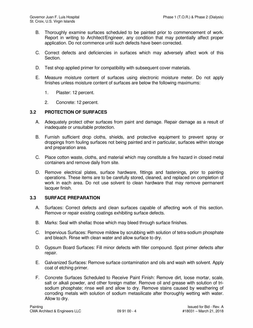
Governor Juan F. Luis Hospital Phase 1 (T.O.R.) & Phase 2 (Dialysis) St. Croix, U.S. Virgin Islands
Painting Issued for Bid - Rev. A CMA Architect & Engineers LLC 09 91 00 - 4 #18031 – March 21, 2018
B. Thoroughly examine surfaces scheduled to be painted prior to commencement of work. Report in writing to Architect/Engineer, any condition that may potentially affect proper application. Do not commence until such defects have been corrected.
C. Correct defects and deficiencies in surfaces which may adversely affect work of this Section.
D. Test shop applied primer for compatibility with subsequent cover materials.
E. Measure moisture content of surfaces using electronic moisture meter. Do not apply finishes unless moisture content of surfaces are below the following maximums:
1. Plaster: 12 percent.
2. Concrete: 12 percent.
3.2 PROTECTION OF SURFACES
A. Adequately protect other surfaces from paint and damage. Repair damage as a result of inadequate or unsuitable protection.
B. Furnish sufficient drop cloths, shields, and protective equipment to prevent spray or droppings from fouling surfaces not being painted and in particular, surfaces within storage and preparation area.
C. Place cotton waste, cloths, and material which may constitute a fire hazard in closed metal containers and remove daily from site.
D. Remove electrical plates, surface hardware, fittings and fastenings, prior to painting operations. These items are to be carefully stored, cleaned, and replaced on completion of work in each area. Do not use solvent to clean hardware that may remove permanent lacquer finish.
3.3 SURFACE PREPARATION
A. Surfaces: Correct defects and clean surfaces capable of affecting work of this section. Remove or repair existing coatings exhibiting surface defects.
B. Marks: Seal with shellac those which may bleed through surface finishes.
C. Impervious Surfaces: Remove mildew by scrubbing with solution of tetra-sodium phosphate and bleach. Rinse with clean water and allow surface to dry.
D. Gypsum Board Surfaces: Fill minor defects with filler compound. Spot primer defects after repair.
E. Galvanized Surfaces: Remove surface contamination and oils and wash with solvent. Apply coat of etching primer.
F. Concrete Surfaces Scheduled to Receive Paint Finish: Remove dirt, loose mortar, scale, salt or alkali powder, and other foreign matter. Remove oil and grease with solution of tri-sodium phosphate; rinse well and allow to dry. Remove stains caused by weathering of corroding metals with solution of sodium metasilicate after thoroughly wetting with water. Allow to dry.
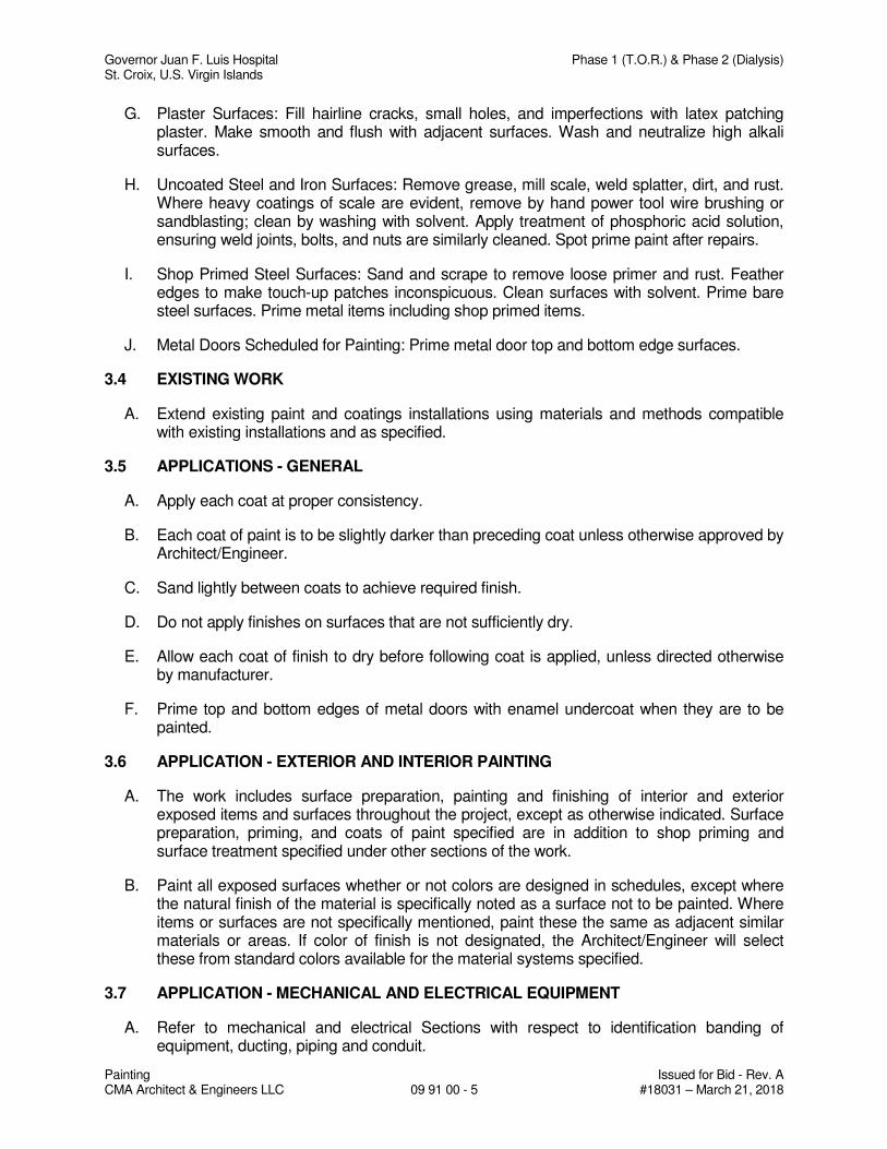
Governor Juan F. Luis Hospital Phase 1 (T.O.R.) & Phase 2 (Dialysis) St. Croix, U.S. Virgin Islands
Painting Issued for Bid - Rev. A CMA Architect & Engineers LLC 09 91 00 - 5 #18031 – March 21, 2018
G. Plaster Surfaces: Fill hairline cracks, small holes, and imperfections with latex patching plaster. Make smooth and flush with adjacent surfaces. Wash and neutralize high alkali surfaces.
H. Uncoated Steel and Iron Surfaces: Remove grease, mill scale, weld splatter, dirt, and rust. Where heavy coatings of scale are evident, remove by hand power tool wire brushing or sandblasting; clean by washing with solvent. Apply treatment of phosphoric acid solution, ensuring weld joints, bolts, and nuts are similarly cleaned. Spot prime paint after repairs.
I. Shop Primed Steel Surfaces: Sand and scrape to remove loose primer and rust. Feather edges to make touch-up patches inconspicuous. Clean surfaces with solvent. Prime bare steel surfaces. Prime metal items including shop primed items.
J. Metal Doors Scheduled for Painting: Prime metal door top and bottom edge surfaces.
3.4 EXISTING WORK
A. Extend existing paint and coatings installations using materials and methods compatible with existing installations and as specified.
3.5 APPLICATIONS - GENERAL
A. Apply each coat at proper consistency.
B. Each coat of paint is to be slightly darker than preceding coat unless otherwise approved by Architect/Engineer.
C. Sand lightly between coats to achieve required finish.
D. Do not apply finishes on surfaces that are not sufficiently dry.
E. Allow each coat of finish to dry before following coat is applied, unless directed otherwise by manufacturer.
F. Prime top and bottom edges of metal doors with enamel undercoat when they are to be painted.
3.6 APPLICATION - EXTERIOR AND INTERIOR PAINTING
A. The work includes surface preparation, painting and finishing of interior and exterior exposed items and surfaces throughout the project, except as otherwise indicated. Surface preparation, priming, and coats of paint specified are in addition to shop priming and surface treatment specified under other sections of the work.
B. Paint all exposed surfaces whether or not colors are designed in schedules, except where the natural finish of the material is specifically noted as a surface not to be painted. Where items or surfaces are not specifically mentioned, paint these the same as adjacent similar materials or areas. If color of finish is not designated, the Architect/Engineer will select these from standard colors available for the material systems specified.
3.7 APPLICATION - MECHANICAL AND ELECTRICAL EQUIPMENT
A. Refer to mechanical and electrical Sections with respect to identification banding of equipment, ducting, piping and conduit.

Governor Juan F. Luis Hospital Phase 1 (T.O.R.) & Phase 2 (Dialysis) St. Croix, U.S. Virgin Islands
Painting Issued for Bid - Rev. A CMA Architect & Engineers LLC 09 91 00 - 6 #18031 – March 21, 2018
B. Remove grilles, covers, and access panels for mechanical and electrical systems from location and paint separately.
C. Finish paint primed equipment to color selected.
D. Prime and paint insulated and bare pipes, conduits, boxes, insulated and bare ducts, hangers, brackets, collars and supports, except where items are plated or covered with a pre-finished coating.
E. Replace identification markings on mechanical or electrical equipment when painted over or spattered.
F. Paint interior surfaces of air ducts, convector and baseboard heating cabinets that are visible through grilles and louvers with one coat of flat black paint, to limit of sight line. Paint dampers exposed immediately behind louvers, grilles, convector and baseboard cabinets to match face panels.
G. Paint exposed conduit and electrical equipment occurring in finished areas. Color and texture to match adjacent surfaces.
H. Paint both sides and edges of plywood backboards for electrical equipment before installing backboards and mounting equipment on them.
I. Color code equipment, piping, conduit and exposed ductwork in accordance with requirements indicated. Color banding and identification (flow arrows, naming, numbering, etc.)
3.8 PAINTING NOT INCLUDED
A. Shop Priming: Unless otherwise specified, shop priming of ferrous metal items is included under the various sections for structural steel, miscellaneous metals, hollow metal work, and fabricated components. Touch-up of damaged primed surfaces is included in the painting work.
B. Prefinished Items: Do not include painting when factory-finishing is specified, except all roof mounted prefinished mechanical equipment is to be field-painted.
C. Concealed Surfaces: Painting is not required on surfaces such as walls or ceilings in concealed areas and generally inaccessible areas, foundation spaces, furred areas, utility tunnels.
D. Finish Metal Surfaces: Architectural metal surfaces of anodized aluminum, stainless steel, chromium plate, copper, bronze, and similar finished materials will not require finish painting.
E. Operating Parts and Labels: Moving parts of operating units, mechanical and electrical parts, such as valve and damper operations, linkages, sinkages, sensing devices, motor and fan shafts will not require finish painting, unless otherwise indicated. Do not paint over any code-required labels, such as Underwriters' Laboratories and Factory Mutual, or any equipment identification, performance rating, name or nomenclature plates.
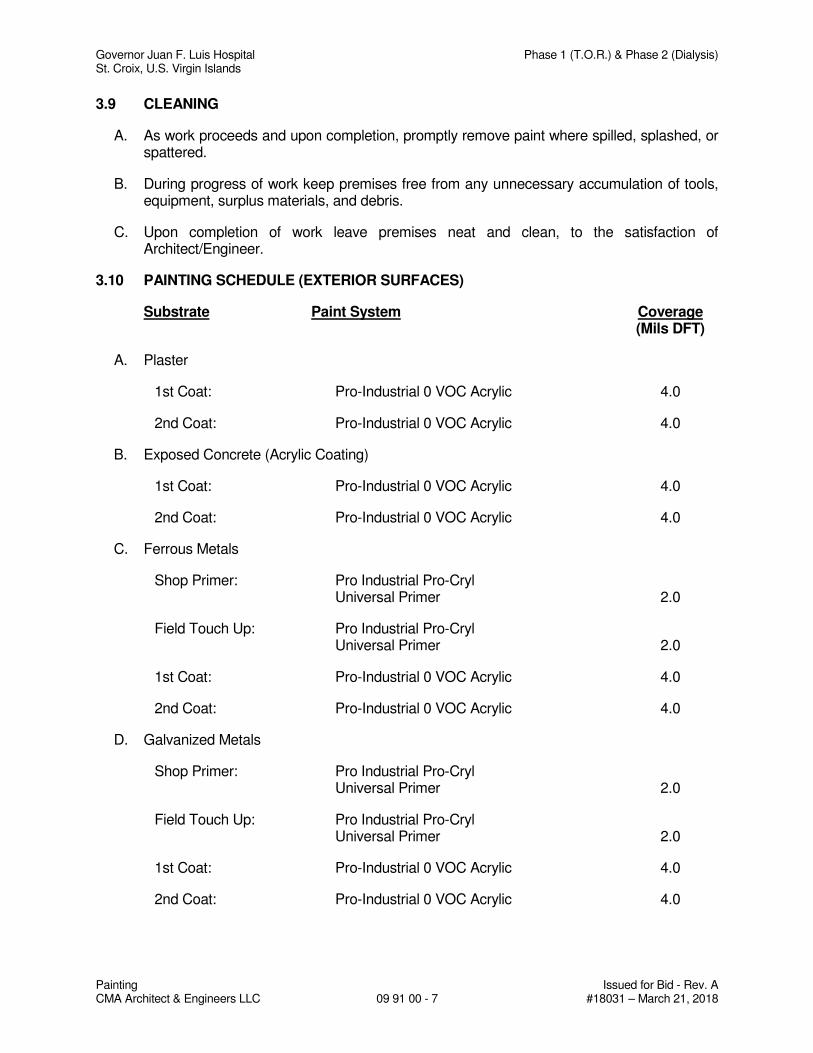
Governor Juan F. Luis Hospital Phase 1 (T.O.R.) & Phase 2 (Dialysis) St. Croix, U.S. Virgin Islands
Painting Issued for Bid - Rev. A CMA Architect & Engineers LLC 09 91 00 - 7 #18031 – March 21, 2018
3.9 CLEANING
A. As work proceeds and upon completion, promptly remove paint where spilled, splashed, or spattered.
B. During progress of work keep premises free from any unnecessary accumulation of tools, equipment, surplus materials, and debris.
C. Upon completion of work leave premises neat and clean, to the satisfaction of Architect/Engineer.
3.10 PAINTING SCHEDULE (EXTERIOR SURFACES)
Substrate Paint System Coverage (Mils DFT)
A. Plaster
1st Coat: Pro-Industrial 0 VOC Acrylic 4.0
2nd Coat: Pro-Industrial 0 VOC Acrylic 4.0
B. Exposed Concrete (Acrylic Coating)
1st Coat: Pro-Industrial 0 VOC Acrylic 4.0
2nd Coat: Pro-Industrial 0 VOC Acrylic 4.0
C. Ferrous Metals
Shop Primer: Pro Industrial Pro-Cryl Universal Primer 2.0
Field Touch Up: Pro Industrial Pro-Cryl Universal Primer 2.0
1st Coat: Pro-Industrial 0 VOC Acrylic 4.0
2nd Coat: Pro-Industrial 0 VOC Acrylic 4.0
D. Galvanized Metals
Shop Primer: Pro Industrial Pro-Cryl Universal Primer 2.0
Field Touch Up: Pro Industrial Pro-Cryl Universal Primer 2.0
1st Coat: Pro-Industrial 0 VOC Acrylic 4.0
2nd Coat: Pro-Industrial 0 VOC Acrylic 4.0
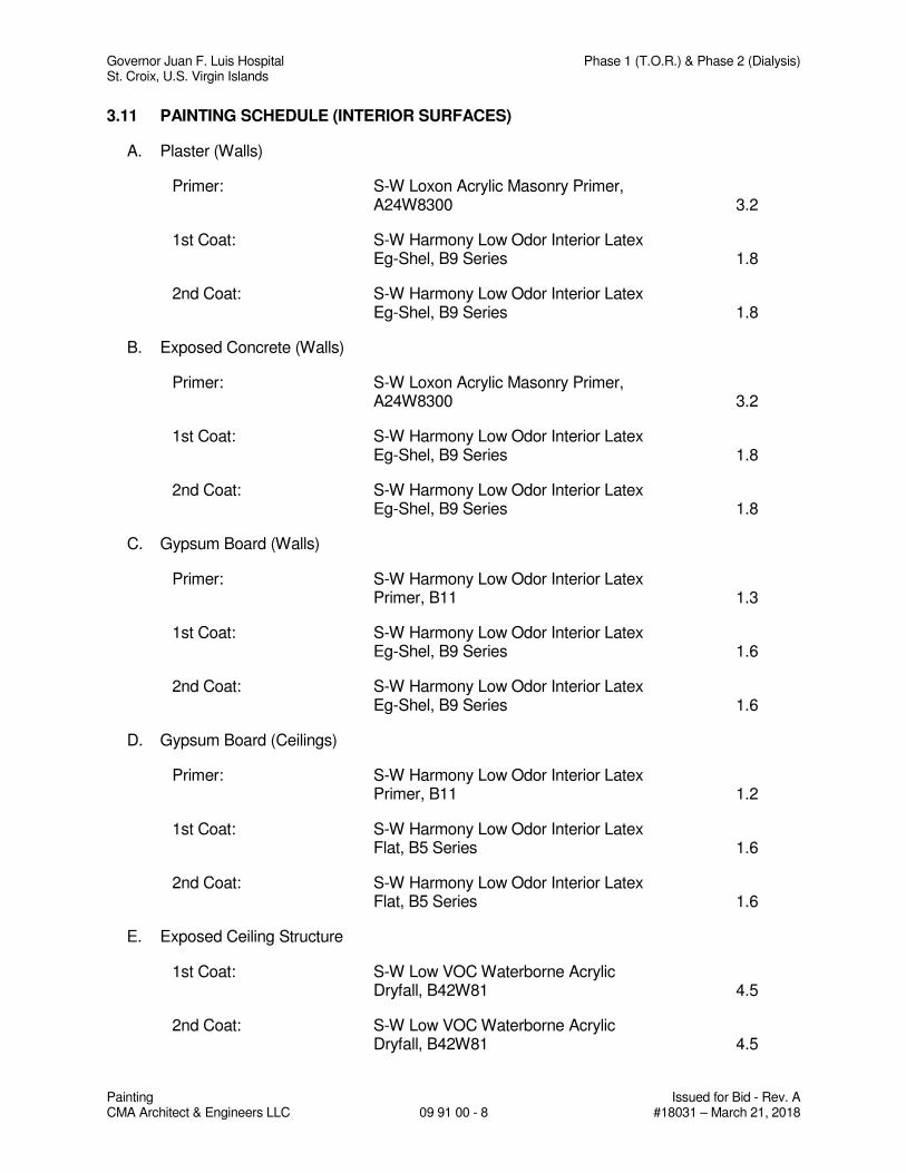
Governor Juan F. Luis Hospital Phase 1 (T.O.R.) & Phase 2 (Dialysis) St. Croix, U.S. Virgin Islands
Painting Issued for Bid - Rev. A CMA Architect & Engineers LLC 09 91 00 - 8 #18031 – March 21, 2018
3.11 PAINTING SCHEDULE (INTERIOR SURFACES)
A. Plaster (Walls)
Primer: S-W Loxon Acrylic Masonry Primer, A24W8300 3.2
1st Coat: S-W Harmony Low Odor Interior Latex Eg-Shel, B9 Series 1.8
2nd Coat: S-W Harmony Low Odor Interior Latex Eg-Shel, B9 Series 1.8
B. Exposed Concrete (Walls)
Primer: S-W Loxon Acrylic Masonry Primer, A24W8300 3.2
1st Coat: S-W Harmony Low Odor Interior Latex Eg-Shel, B9 Series 1.8
2nd Coat: S-W Harmony Low Odor Interior Latex Eg-Shel, B9 Series 1.8
C. Gypsum Board (Walls)
Primer: S-W Harmony Low Odor Interior Latex Primer, B11 1.3
1st Coat: S-W Harmony Low Odor Interior Latex Eg-Shel, B9 Series 1.6
2nd Coat: S-W Harmony Low Odor Interior Latex Eg-Shel, B9 Series 1.6
D. Gypsum Board (Ceilings)
Primer: S-W Harmony Low Odor Interior Latex Primer, B11 1.2
1st Coat: S-W Harmony Low Odor Interior Latex Flat, B5 Series 1.6
2nd Coat: S-W Harmony Low Odor Interior Latex Flat, B5 Series 1.6
E. Exposed Ceiling Structure
1st Coat: S-W Low VOC Waterborne Acrylic Dryfall, B42W81 4.5
2nd Coat: S-W Low VOC Waterborne Acrylic Dryfall, B42W81 4.5
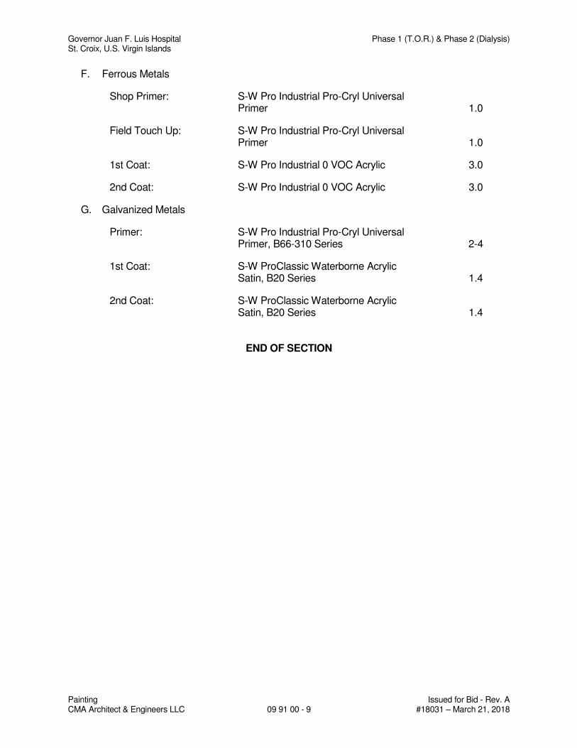
Governor Juan F. Luis Hospital Phase 1 (T.O.R.) & Phase 2 (Dialysis) St. Croix, U.S. Virgin Islands
Painting Issued for Bid - Rev. A CMA Architect & Engineers LLC 09 91 00 - 9 #18031 – March 21, 2018
F. Ferrous Metals
Shop Primer: S-W Pro Industrial Pro-Cryl Universal Primer 1.0
Field Touch Up: S-W Pro Industrial Pro-Cryl Universal Primer 1.0
1st Coat: S-W Pro Industrial 0 VOC Acrylic 3.0
2nd Coat: S-W Pro Industrial 0 VOC Acrylic 3.0
G. Galvanized Metals
Primer: S-W Pro Industrial Pro-Cryl Universal Primer, B66-310 Series 2-4
1st Coat: S-W ProClassic Waterborne Acrylic Satin, B20 Series 1.4
2nd Coat: S-W ProClassic Waterborne Acrylic Satin, B20 Series 1.4
END OF SECTION
Governor Juan F. Luis Hospital Phase 1 (T.O.R.) & Phase 2 (Dialysis) St. Croix, U.S. Virgin Islands
Seismic Control Issued for Bid - Rev. A CMA Architect & Engineers LLC 13 05 41 - 1 #18031 – March 21, 2018
SECTION 13 05 41
SEISMIC CONTROL
PART 1 - GENERAL
1.1 WORK INCLUDED
A. Contractor shall provide seismic restraints for pipes, ductwork conduits, cable trays and equipment as required to properly secure them to the building structural frame or floor. This requirement shall be applicable to all material being furnished under the mechanical and/or electrical trade. See Table 13 05 41-1 at end of section.
B. Contractor shall coordinate installation of seismic restraints with other trades to assure required access to structural members.
C. All seismic restraints shall be attached to components of the structure that have been designed or checked for the additional forces the restraints will induce.
1.2 REFERENCES
A. ANSI B31.1: Power Piping.
B. NFPA 13: Standard for Installation of Sprinkler System.
C. SMACNA SRMGMS: Seismic Restraint Manual Guidelines for Mechanical Systems.
D. SMACNA HVACDCS: HVAC Construction Standards - Metal and Flexible.
E. 2011 PR Building Code
1.3 SUBMITTALS
A. Seismic snubbers for equipment.
B. Seismic bracings for ductwork.
C. Seismic bracings for pipes, conduits and cable trays.
1.4 GENERAL REQUIREMENTS FOR BRACING OF DUCTS (REFERENCE SMACNA SRMGMS)
A. Brace rectangular ducts with cross sectional areas of 6 square feet and larger. Brace flat oval ducts in the same manner as rectangular ducts. Brace round ducts with diameters of 28 inches and larger.
Exception: No bracing is required if the duct is suspended by hangers 12 inches or less in length, as measured from the top of the duct to the bottom of the support where the hanger is attached. Hangers must be positively attached to the duct within 2 inches of the top of the duct with a minimum of two #10 sheet metal screws.
B. Transverse bracing shall occur at the interval specified in SMACNA's SRMGMS, or at both ends if the duct run is less than the specified interval. Transverse bracing shall be installed at each duct run and at each end of a duct run, with a minimum of one brace at each end.
Governor Juan F. Luis Hospital Phase 1 (T.O.R.) & Phase 2 (Dialysis) St. Croix, U.S. Virgin Islands
Seismic Control Issued for Bid - Rev. A CMA Architect & Engineers LLC 13 05 41 - 2 #18031 – March 21, 2018
C. Longitudinal bracing shall occur at the interval specified in SMACNA's SRMGMS, with at least one brace per duct run. Transverse bracing for one duct section may also act as longitudinal bracing for a duct section connected perpendicular to it if the bracing is installed within four feet of the intersection of the ducts and if the bracing is sized for the larger duct. Duct joints shall conform to SMACNA duct construction standards.
D. A group of ducts may be combined in a larger frame so that the combined weights and dimensions of the ducts are less than or equal to the maximum weight and dimensions of the duct for which bracing details are selected. (Example: to brace a 30" x 30" duct beside a 54" x 28" duct, select bracing for an 84" x 42" duct. The horizontal dimension of the 84" x 42" duct is equal to that of the combined ducts and its weight is greater than their combined weights.)
E. Walls, including gypsum board nonbearing partitions, which have ducts running through them may replace a typical transverse brace. Provide solid blocking around duct penetrations at stud wall construction. In these cases, the additional seismic loads on the walls will be provided to the designer of the wall framing.
F. Unbraced ducts shall be installed with a 6" minimum clearance to vertical ceiling hanger wires.
G. Wherever possible, and allowed by SMACNA SRMGMS, use cable in lieu of channels for bracing.
1.5 GENERAL REQUIREMENTS FOR BRACING OF PIPES (REFERENCE SMACNA SRMGMS)
A. Bracing details, schedules, and notes apply to all types of pipe, conduit, cable trays and all types of joints.
B. Brace all piping as described in 1., 2., and 3. below.
Exception: Piping suspended by individual hangers 12 inches or less in length, as measured from the top of the pipe to the bottom of the support where the hanger is attached, need not be braced.
1. Brace all fuel oil piping, gas piping, such as fuel gas, LP gas piping and compressed air piping that is 1 inch nominal diameter or larger.
2. Brace all piping located in boiler rooms, mechanical equipment rooms, and refrigeration mechanical rooms that is 1¼ inches nominal diameter and larger.
3. Brace all pipes 2½ inches nominal diameter and larger.
C. Transverse bracing shall be at 40 feet maximum except where a lesser spacing is indicated in the tables for bracing of pipes.
D. Longitudinal bracing shall be at 80 feet maximum except where a lesser spacing is indicated in the tables. In pipes where thermal expansion is a consideration, an anchor point may be used as the specified longitudinal brace provided that it has a capacity equal to or greater than a longitudinal brace. The longitudinal braces and connections must be capable of resisting the additional force induced by expansion and contraction.
Governor Juan F. Luis Hospital Phase 1 (T.O.R.) & Phase 2 (Dialysis) St. Croix, U.S. Virgin Islands
Seismic Control Issued for Bid - Rev. A CMA Architect & Engineers LLC 13 05 41 - 3 #18031 – March 21, 2018
E. For fuel oil and all gas piping, as specified in B.1., the bracing details, schedules, and notes may be used, except that transverse bracing shall be at 20 feet maximum, and longitudinal bracing shall be at 40 feet maximum.
F. Transverse bracing for one pipe section may also act as longitudinal bracing for a pipe section of the same size connected perpendicular to it if the bracing is installed within 24 inches of the elbow or tee.
G. Seismic braces for pipes on trapeze hangers may be used.
H. Provide flexibility in joints where pipes pass through building walls or seismic joints or expansion joints or where rigidly supported pipes connect to equipment with vibration isolators. For threaded piping, the flexibility may be provided by the installation of swing joints. For piping with manufactured ball joints, select the length of piping offset using Seismic Drift in place of the expansion given in the joint manufacturer's selection table. Seismic Drift = 0.015 feet per foot of height above the base where seismic separation occurs.
I. Branch lines may not be used to brace main lines.
J. A rigid piping system shall not be braced to dissimilar parts of the building or to two dissimilar building systems that may respond differently during an earthquake.
K. Cast iron pipe of all types and any other pipe joined with a shield and clamp assembly, where the top of the pipe is 12 inches or more from the supporting structure, shall be braced on each side of a change in direction of 90 degrees or more. Riser joints shall be braced or stabilized between floors.
L. Vertical risers shall be laterally supported with a riser clamp at each floor.
M. For risers in hubless piping systems where the riser joints are unsupported between floors, see page 9.11 of SMACNA's SRMGMS for brace.
N. Wherever possible, and allowed by SMACNA SRMGMS, use cable in lieu of channel for bracing.
PART 2 - PRODUCTS
2.1 ACCEPTABLE MANUFACTURERS
A. Mason Industries, Inc.
B. Vibration Mounting and Controls
C. Fee and Mason MFG Co.
D. Piping Technology and Products Inc.
E. B-line systems.
F. Grinell Corp.
Governor Juan F. Luis Hospital Phase 1 (T.O.R.) & Phase 2 (Dialysis) St. Croix, U.S. Virgin Islands
Seismic Control Issued for Bid - Rev. A CMA Architect & Engineers LLC 13 05 41 - 4 #18031 – March 21, 2018
2.2 GENERAL
A. All vibration isolated equipment shall be mounted on rigid steel frames or concrete bases unless the equipment manufacturer certified direct attachment capability. Each spring mounted base shall have a minimum of four all-directional seismic snubbers that are double acting and located as close to the vibration isolators as possible to facilitate attachment both to the base and the structure. The snubbers shall consist of interlocking steel members restrained by shock absorbent rubber materials. Elastomeric materials shall be replaceable and a minimum of 3/4" thick. Snubbers shall be manufactured with an air gap between hard and resilient material of not less than 1/8" nor more than 1/4". Snubbers shall be installed with factory set clearances. Capacity of seismic snubbers at 3/8" deflection shall be 3 to 4 times the load assigned to the mount grouping in its immediate area. Submittals shall include load deflection curves up to 1/2" deflection in the X, Y and Z planes. Tests shall be conducted in an independent laboratory or under the signed supervision of an independent registered engineer. The snubber assemblies shall be bolted to the test machine as the snubber is normally installed. Test reports shall certify that neither the neoprene elements nor the snubber body sustained and obvious deformation after release of load.
B. All pipes and ducts shall be provided with seismic restraints in accordance with seismic hazard level "B" (SHL-B) of the "Seismic Restraint Manual: Guidelines for Mechanical Systems" (1991 Edition) published by SMACNA and in accordance with the 2011 PR Building Code.
PART 3 - EXECUTION
3.1 INSTALLATION/APPLICATION/ERECTION
A. Install equipment seismic snubbers and pipes and ductwork seismic bracings in accordance to the manufacturer's recommendation and/or SMACNA SRMGMS guidelines.
END OF SECTION
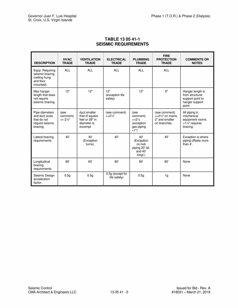
Governor Juan F. Luis Hospital Phase 1 (T.O.R.) & Phase 2 (Dialysis) St. Croix, U.S. Virgin Islands
Seismic Control Issued for Bid - Rev. A CMA Architect & Engineers LLC 13 05 41 - 5 #18031 – March 21, 2018
TABLE 13 05 41-1 SEISMIC REQUIREMENTS
DESCRIPTION HVAC
TRADE VENTILATION
TRADE ELECTRICAL
TRADE PLUMBING
TRADE
FIRE PROTECTION
TRADE COMMENTS OR
NOTES
Equp. Requiring seismic bracing (ceiling hung and floor mounted).
ALL ALL ALL ALL ALL
Max hanger length that does not require seismic bracing.
12" 12" 12" (exception life safety)
12" 6" Hanger length is from structural support point to hanger support point.
Pipe diameters and duct sizes that do not require seismic bracing.
(see comment) <= 2½"
duct smaller than 6 square feet or 28" in diameter is excempt
(see comment) <=2½"
(see comment) <=2½ (exception gas piping <1")
(see comment) <=2½" on mains, 2" and smaller on branches.
All piping in mechanical equipment rooms >1¼" requires bracing.
Lateral bracing requirements.
40' 30' (Exception
turns).
40' 40' (Exception
no hub piping 20' lat.
and 40' longt.)
40' Exception is where piping offsets more than 4'.
Longitudinal bracing requirements.
80' 60' 80' 80' 80' None
Seismic Design acceleration factor.
0.5g 0.5g 0.5g (except for
life safety) 0.5g 1g None
Governor Juan F. Luis Hospital Phase 1 (T.O.R.) & Phase 2 (Dialysis) St. Croix, U.S. Virgin Islands
Seismic Control and Vibration Isolation Issued for Bid - Rev. A CMA Architects & Engineers LLC 13 05 42 - 1 #18031 – March 21, 2018
SECTION 13 05 42
SEISMIC CONTROL AND VIBRATION ISOLATION
PART 1 - GENERAL
1.1 WORK INCLUDED
A. Contractor shall provide seismic restraints for pipes, ductwork, and equipment as required to properly secure them to the building structural frame or floor. It shall be mounted on vibration isolators to prevent the transmission of vibration and mechanically transmitted sound to the building structure. Vibration isolators shall be selected in accordance with the weight distribution so as to produce reasonably uniform deflections. This requirement shall be applicable to all material being furnished under the mechanical and electrical trade. See table 13 05 42-1 at end of section.
B. Contractor shall coordinate installation of seismic restraints with other trades to assume required access to structural members.
1.2 REFERENCES
A. ANSI B31.1: Power Piping.
B. NFPA 13: Standard for Installation of Sprinkler System.
C. SMACNA SRMGMS: Seismic Restraint Manual Guidelines for Mechanical Systems.
D. SMACNA HVACDCS: HVAC Construction Standards – Metal and Flexible.
1.3 SUBMITTALS
A. The manufacturer of seismic restraints and vibration isolation shall provide submittals for products used on equipment, ductwork, and pipes as follows:
1. Catalog cuts or data sheets on vibration isolators and specific restraints detailing compliance with the specification.
2. Detailed schedules of flexible and rigidly mounted equipment, showing vibration isolators and seismic restraints by referencing numbered descriptive drawings.
3. Shop drawings with fabrication details for equipment bases including dimensions, structural member sizes and support point locations.
4. Provide all details of suspension and support for ceiling hung equipment.
5. Where walls, floors, slabs or supplementary steel work are used for seismic restraint locations, details of acceptable attachment methods for ducts, conduit and pipe must be included and approved before the condition is accepted for installation. Restraint manufacturers’ submittals must include spacing, static loads and seismic loads at all attachment and support points.
6. Provide specific details of seismic restraints and anchors; include number, size and locations for each piece of equipment.
Governor Juan F. Luis Hospital Phase 1 (T.O.R.) & Phase 2 (Dialysis) St. Croix, U.S. Virgin Islands
Seismic Control and Vibration Isolation Issued for Bid - Rev. A CMA Architects & Engineers LLC 13 05 42 - 2 #18031 – March 21, 2018
7. Seismic restraint calculations must be provided for all connections of equipment to the structure. Calculations must be stamped by a registered professional engineer with at least five years of seismic design experience, licensed.
8. All restraining devices shall have a preapproval number from California OSHPD or some other recognized government agency showing maximum restraint ratings. Preapprovals based on independent testing are preferred to preapprovals based on calculations. Where preapproved devices are not available, submittals based on independent testing are preferred. Calculations (including the combining of tensile and shear loadings) to support seismic restraint designs must be stamped by a registered professional engineer with at least five years of seismic design experience and licensed. Testing and calculations must include both shear and tensile loads as well as one test or analysis at 45º to the weakest mode.
9. Analysis must indicate calculated dead loads, static seismic loads and capacity of materials utilized for connections to equipment and structure. Analysis must detail anchoring methods, bolt diameter, embedment and/or welded length. All seismic restraint devices shall be designed to accept, without failure, the forces detailed in Table 15210-1 acting through the equipment center of gravity. Overturning moments may exceed forces at ground level.
1.4 DEFINITIONS
A. Life Safety Systems
1. All systems involved with fire protection including sprinkler piping, fire pumps, jockey pumps, fire pump control panels, service water supply piping, water tanks, fire dampers and smoke exhaust systems.
2. All systems involved with and/or connected to emergency power supply including all generators, transfer switches, transformers and all flow paths to fire protection and/or emergency lighting systems.
3. All medical and life support systems.
4. Fresh air relief systems on emergency control sequence including air handlers, conduit, duct, dampers, etc.
5. All life safety equipment has an asterisk on the equipment schedule.
B. Positive Attachment is defined as a cast-in anchor, a drill-in wedge anchor, a double sided beam clamp loaded perpendicular to a beam, or a welded or bolted connection to structure. Single sided “C” type beam clamps for support rods of overhead piping, ductwork, fire protection, electrical conduit, bus duct, or cable trays, or any other equipment are not acceptable on this project as seismic anchor points.
C. Transverse Bracing is defined as the restraint(s) applied to limit motion perpendicular to the centerline of the pipe, duct or conduit.
D. Longitudinal Bracing is defined as the restraint(s) applied to limit motion parallel to the centerline of the pipe, duct or conduit.
Governor Juan F. Luis Hospital Phase 1 (T.O.R.) & Phase 2 (Dialysis) St. Croix, U.S. Virgin Islands
Seismic Control and Vibration Isolation Issued for Bid - Rev. A CMA Architects & Engineers LLC 13 05 42 - 3 #18031 – March 21, 2018
E. Failure is defined as the discontinuance of any attachment point between equipment or structure, vertical permanent deformation greater than 1/8” (3 mm) and/or horizontal permanent deformation greater than 1/4” (6 mm).
1.5 GENERAL
A. All vibration isolated equipment shall be mounted on rigid steel frames or concrete bases unless the equipment manufacturer certified direct attachment capability. Each spring mounted base shall have a minimum of four all-directional seismic snubbers that are double acting and located as close to the vibration isolators as possible to facilitate attachment both to the base and the structure. The snubbers shall consist of interlocking steel members restrained by shock absorbent rubber materials. Elastomeric materials shall be replaceable and a minimum of 3/4 inch thick. Snubbers shall be manufactured with an air gap between hard and resilient material of not less than 1/8 inch or more than 1/4 inch. Snubbers shall be installed with factory set clearances. Capacity of seismic snubbers at 3/8 inch deflection shall be 3 to 4 times the load assigned to the mount grouping in its immediate area. Submittals shall include load deflection curves up to 1/2 inch deflection in the X, Y and Z planes. Test shall be conducted in an independent laboratory or under the signed supervision of and independent registered engineer. The snubber assemblies shall be bolted to the test machine as the snubber is normally installed. Test reports shall certify that neither the neoprene elements nor the snubber body sustained and obvious deformation after release of load.
B. All pipes and ducts shall be provided with seismic restraints in accordance with seismic hazard level “B” (SHL-B) of the “Seismic restrain Manual: Guidelines for Mechanical Systems” (1991 Edition) published by SMACNA and in accordance with the P.R. Building code No. 7, as amended.
C. All isolators and isolation materials shall be of the same manufacturer and shall be certified by the manufacturer.
D. It is the intent of the seismic portion of this specification to keep all mechanical and electrical building system components in place during a seismic event.
E. This specification is considered to be minimum requirement for seismic consideration and is not intended as a substitute for legislated, more stringent, national, state or local construction requirements.
F. Any variance or non-compliance with these specification requirements shall be corrected by the contractor in an approved manner.
G. Seismic restraints shall be designed in accordance with seismic force levels as detailed in Table 13 05 42-1 at the end of the section.
H. The work in this section includes, but is not limited to the following:
1. Seismic snubbers for equipment.
2. Seismic bracing for ductwork.
3. Seismic bracing for pipes.
4. Vibration isolation for piping, ductwork and equipment.
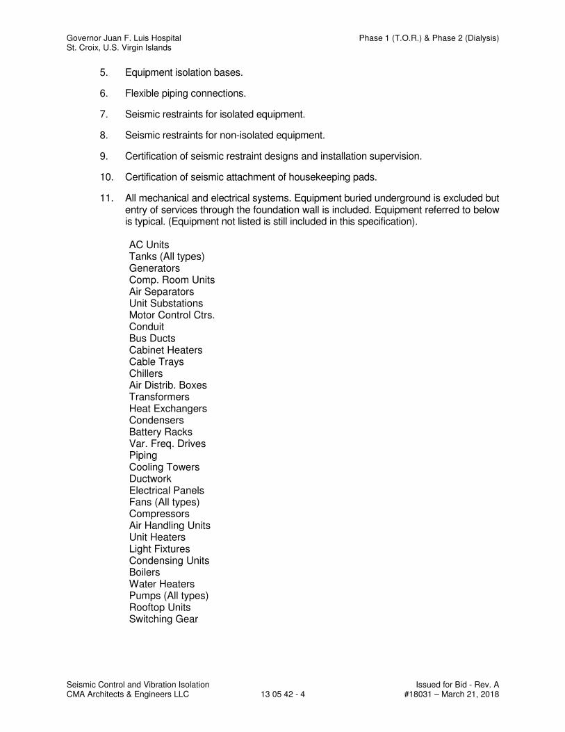
Governor Juan F. Luis Hospital Phase 1 (T.O.R.) & Phase 2 (Dialysis) St. Croix, U.S. Virgin Islands
Seismic Control and Vibration Isolation Issued for Bid - Rev. A CMA Architects & Engineers LLC 13 05 42 - 4 #18031 – March 21, 2018
5. Equipment isolation bases.
6. Flexible piping connections.
7. Seismic restraints for isolated equipment.
8. Seismic restraints for non-isolated equipment.
9. Certification of seismic restraint designs and installation supervision.
10. Certification of seismic attachment of housekeeping pads.
11. All mechanical and electrical systems. Equipment buried underground is excluded but entry of services through the foundation wall is included. Equipment referred to below is typical. (Equipment not listed is still included in this specification).
AC Units Tanks (All types) Generators Comp. Room Units Air Separators Unit Substations Motor Control Ctrs. Conduit Bus Ducts Cabinet Heaters Cable Trays Chillers Air Distrib. Boxes Transformers Heat Exchangers Condensers Battery Racks Var. Freq. Drives Piping Cooling Towers Ductwork Electrical Panels Fans (All types) Compressors Air Handling Units Unit Heaters Light Fixtures Condensing Units Boilers Water Heaters Pumps (All types) Rooftop Units Switching Gear
Governor Juan F. Luis Hospital Phase 1 (T.O.R.) & Phase 2 (Dialysis) St. Croix, U.S. Virgin Islands
Seismic Control and Vibration Isolation Issued for Bid - Rev. A CMA Architects & Engineers LLC 13 05 42 - 5 #18031 – March 21, 2018
1.6 MANUFACTURER’S RESPONSIBILITY
A. Manufacturer of vibration isolation and seismic control equipment shall have the following responsibilities:
1. Determine vibration isolation and seismic restraint sizes and locations.
2. Provide vibration isolation and seismic restraints as scheduled or specified.
3. Provide calculations and materials if required for restraint of unisolated equipment.
4. Provide installation instructions, drawings and trained field supervision to insure proper installation and performance.
1.7 RELATED WORK
A. Housekeeping pad reinforcement and monolithic pad attachment to the structure details and design shall be prepared by the restraint vendor if not already indicated on the drawings.
B. Housekeeping pads shall be coordinated with restraint vendor and sized to provide a minimum edge distance of ten (10) bolt diameters all around the outermost anchor bolt to allow development of full drill-in wedge anchor ratings. If cast-in anchors are to be used, the housekeeping pads shall be sized to accommodate the ACI requirements for bolt coverage and embedment.
C. Contractor shall supply supplementary support steel for all equipment, piping, ductwork, etc. including roof mounted equipment, as required or specified.
D. Contractor shall supply restraint attachment plates cast into housekeeping pads, concrete inserts, double sided beam clamps, etc. in accordance with the requirements of the vibration vendor’s calculations.
PART 2 - PRODUCTS
2.1 PRODUCT DESCRIPTIONS
A. Vibration Isolators and Seismic Restraints.
1. Two layers of 3/4 inch thick neoprene pad consisting of 2 inch square waffle modules separated horizontally by a 16 gauge galvanized shim. Load distribution plates shall be used as required.
2. Bridge-bearing neoprene mountings shall have a minimum static deflection of 0.2 inch and all directional seismic capability. The mount shall consist of a ductile iron casting containing two separated and opposing molded neoprene elements. The elements shall prevent the central threaded sleeve and attachment bolt from contacting the casting during normal operation. The shock absorbing neoprene materials shall be compounded to bridge-bearing specifications.
3. Sheet metal panels shall be bolted to the walls or supporting structure by assemblies consisting of a neoprene bushing cushioned between 2 steel sleeves. The outer sleeve prevents the sheet metal from cutting into the neoprene. Enlarge panel holes as required. Neoprene elements pass over the bushing to cushion the back panel horizontally. A steel disc covers the inside neoprene element and the inner steel
Governor Juan F. Luis Hospital Phase 1 (T.O.R.) & Phase 2 (Dialysis) St. Croix, U.S. Virgin Islands
Seismic Control and Vibration Isolation Issued for Bid - Rev. A CMA Architects & Engineers LLC 13 05 42 - 6 #18031 – March 21, 2018
sleeve is elongated to act as a stop so tightening the anchor bolts does not interfere with panel isolation in 3 planes. Bushing assemblies can be applied to the ends of steel cross members where applicable. All neoprene shall be bridge bearing quality.
4. A one piece molded bridge bearing neoprene washer/bushing. The bushing shall surround the anchor bolt and have a flat washer face to avoid metal to metal contact.
5. Spring isolators shall be free standing and laterally stable without any housing and complete with a molded neoprene cup or 1/4 inch neoprene acoustical friction pad between the base plate and the support. All mountings shall have leveling bolts that must be rigidly bolted to the equipment. Spring diameters shall be no less than 0.8 of the compressed height of the spring at rated load. Springs shall have a minimum additional travel to solid equal to 50% of the rated deflection. Submittals shall include spring diameters, deflection, compressed spring height and solid spring height.
6. Restrained spring mountings shall have a mounting, within a rigid housing that includes vertical limit stops to prevent spring extension when weight is removed. The housing shall serve as blocking during erection. A steel spacer shall be removed after adjustment. Installed and operating heights are equal. A minimum clearance of 1/2 inch shall be maintained around restraining bolts and between the housing and the spring so as not to interfere with the spring action. Limit stops shall be out of contact during normal operation. Since housings will be bolted or welded in position there must be an internal isolation pad. Housing shall be designed to resist all seismic forces.
7. Spring mountings built into a ductile iron or steel housing to provide all directional seismic snubbing. The snubber shall be adjustable vertically and allow a maximum of 1/4 inch travel in all directions before contacting the resilient snubbing collars.
8. Air springs shall be manufactured with upper and lower steel sections connected by a replaceable flexible nylon reinforced neoprene element. Air spring configuration shall be multiple bellows to achieve a maximum natural frequency of 3 Hz. Air springs shall be designed for a burst pressure that is a minimum of three times the published maximum operating pressure. All air spring systems shall be connected to either the building control air or a supplementary air supply and equipped with three leveling valves to maintain leveling within plus or minus 1/8 inch. Submittals shall include natural frequency, load and damping tests performed by an independent lab or acoustician.
9. Restrained air spring mountings shall have an air spring as described in Specification 8, within a rigid housing that includes vertical limit stops to prevent air spring extension when weight is removed. The housing shall serve as blocking during erection. A steel spacer shall be removed after adjustment. Installed and operating heights are equal. A minimum clearance of 1/2 inch shall be maintained around restraining bolts and between the housing and the air spring so as not to interfere with the air spring action. Limit stops shall be out of contact during normal operation. Housing shall be designed to resist all seismic forces.
10. Hangers shall consist of rigid steel frames containing minimum 1 1/4 inch thick neoprene elements at the top and a steel spring seated in a steel washer reinforced neoprene cup on the bottom. The neoprene element and the cup shall have neoprene bushings projecting through the steel box. To maintain stability the boxes shall not be articulated as clevis hangers nor the neoprene element stacked on top of the spring. Spring diameters and hanger box lower hole sizes shall be large enough
Governor Juan F. Luis Hospital Phase 1 (T.O.R.) & Phase 2 (Dialysis) St. Croix, U.S. Virgin Islands
Seismic Control and Vibration Isolation Issued for Bid - Rev. A CMA Architects & Engineers LLC 13 05 42 - 7 #18031 – March 21, 2018
to permit the hanger rod to swing through a 30º arc from side to side before contacting the rod bushing and short circuiting the spring. Submittals shall include a hanger drawing showing the 30º capability.
11. Hangers shall be precompressed and locked at the rated deflection by means of a resilient seismic upstop to keep the piping or equipment at a fixed elevation during installation. The hangers shall be designed with a release mechanism to free the spring after the installation is complete and the hanger is subjected to its full load. Deflection shall be clearly indicated by means of a scale. Submittals shall include a drawing of the hanger showing the 30º capability.
12. Seismic Cable Restraints shall consist of galvanized steel aircraft cables sized to resist seismic loads with a minimum safety factor of two and arranged to provide all-directional restraint. Cables must be prestretched to achieve a certified minimum modulus of elasticity. Cable end connections shall be steel assemblies that swivel to final installation angle and utilize two clamping bolts to provide proper cable engagement. Cables must not be allowed to bend across sharp edges.
13. Seismic solid braces shall consist of steel angles or channels to resist seismic loads with a minimum safety factor of 2 and arranged to provide all directional restraint. Seismic solid brace end connectors shall be steel assemblies that swivel to the final installation angle and utilize two through bolts to provide proper attachment.
14. Steel angles, sized to prevent buckling, shall be clamped to pipe or equipment rods utilizing a minimum of three ductile iron clamps at each restraint location when required. Welding of support rods is not acceptable.
Note: Sections 12 - 14 apply to trapeze as well as clevis hanger locations. At
trapeze anchor locations piping must be shackled to the trapeze. Specifications apply to hanging equipment as well.
15. Pipe clevis cross bolt braces are required in all restraint locations. They shall be special purpose preformed channels deep enough to be held in place by bolts passing over the cross bolt.
16. All-directional seismic snubbers shall consist of interlocking steel members restrained by a one-piece molded neoprene bushing of bridge bearing neoprene. Bushing shall be replaceable and a minimum of 1/4 inch thick. Rated loadings shall not exceed 1000 psi. A minimum air gap of 1/8 inch shall be incorporated in the snubber design in all directions before contact is made between the rigid and resilient surfaces. Snubber end caps shall be removable to allow inspection of internal clearances. Neoprene bushings shall be rotated to insure no short circuits exist before systems are activated.
17. All directional seismic snubbers shall consist of interlocking steel members restrained by shock absorbent rubber materials compounded to bridge bearing specifications. Elastomeric materials shall be replaceable and a minimum of 3/4 inch thick. Rated loadings shall not exceed 1000 psi. Snubbers shall be manufactured with an air gap between hard and resilient material of not less than 1/8 inch nor more that 1/4 inch. Snubbers shall be installed with factory set clearances. The capacity of the seismic snubber at 3/8 inch deflection shall be equal or greater than the load assigned to the mounting grouping controlled by the snubber multiplied by the applicable “G” force. Submittals shall include the load deflection curves up to 1/2 inch deflection in the X, Y and Z planes.
Governor Juan F. Luis Hospital Phase 1 (T.O.R.) & Phase 2 (Dialysis) St. Croix, U.S. Virgin Islands
Seismic Control and Vibration Isolation Issued for Bid - Rev. A CMA Architects & Engineers LLC 13 05 42 - 8 #18031 – March 21, 2018
18. Stud wedge anchors shall be manufactured from full diameter wire, not from undersized wire that is “rolled up” to create the thread. The stud anchor shall also have a safety shoulder which fully supports the wedge ring under load.
19. Female wedge anchors are preferred in floor locations so isolators or equipment can be slid into place after the anchors are installed. Anchors shall be manufactured from full diameter wire, and shall have a safety shoulder to fully support the wedge ring under load.
20. Vibration isolation manufacturer shall furnish integral structural steel bases. Rectangular bases are preferred for all equipment. Centrifugal refrigeration machines and pump bases may be T or L shaped where space is a problem. Pump bases for split case pump shall include supports for suction and discharge elbows. All perimeter members shall be steel beams with a minimum depth equal to 1/10 of the longest dimension of the base. Base depth need not exceed 14 inch provided that the deflection and misalignment is kept within acceptable limits as determined by the manufacturer. Height saving brackets shall be employed in all mounting locations to provide a base clearance of 1 inch.
21. Vibration isolation manufacturer shall furnish rectangular steel concrete pouring forms for floating and inertia foundations. Bases for split case pumps shall be large enough to provide for suction and discharge elbows. Bases shall be a minimum of 1/12 of the longest dimension of the base but not less than 6 inch. The base depth need not exceed 12 inch unless specifically recommended by the base manufacturer for mass or rigidity. Forms shall include minimum concrete reinforcing consisting of 1/2 inch bars welded in place on 6 inch centers running both ways in a layer 1 1/2 inch above the bottom. Forms shall be furnished with steel templates to hold the anchor bolts sleeves and anchors while concrete is being poured. Height saving brackets shall be employed in all mounting locations to maintain a 1 inch clearance below the base. Wooden formed bases leaving a concrete rather then a steel finish are not acceptable.
22. Curb mounted rooftop equipment shall be mounted on spring isolation curbs. The lower member shall consist of a sheet metal Z section containing adjustable and removable steel springs that support the upper floating section. The upper frame must provide continuous support for the equipment and must be captive so as to resiliently resist wind and seismic forces. All directional neoprene snubber bushings shall be a minimum of 1/4 inch thick. Steel springs shall be laterally stable and rest on 1/4 inch thick neoprene acoustical pads. Hardware must be plated and the springs provided with a rust resistant finish. The curbs waterproofing shall consist of a continuous galvanized flexible counter flashing nailed over the lower curbs waterproofing and joined at the corners by EPDM bellows. All spring locations shall have access ports with removable waterproof covers. Lower curbs shall have provision for 2 inch of insulation. The roof curbs shall be built to seismically contain the rooftop unit. The unit must be solidly fastened to the top floating rail, and the lower Z section anchored to the roof structure.
23. Flexible Spherical Expansion Joints
a. Flexible spherical expansion joints shall employ peroxide cured EPDM in the covers, liners and Kevlar® tire cord frictioning. Any substitutions must have equal or superior physical and chemical characteristics. Solid steel rings shall be used within the raised face rubber flanged ends to prevent pullout. Flexible cable bead wire is not acceptable. Sizes 2 inch and larger shall have two
Governor Juan F. Luis Hospital Phase 1 (T.O.R.) & Phase 2 (Dialysis) St. Croix, U.S. Virgin Islands
Seismic Control and Vibration Isolation Issued for Bid - Rev. A CMA Architects & Engineers LLC 13 05 42 - 9 #18031 – March 21, 2018
spheres reinforced with a ductile iron external ring between spheres. Flanges shall be split ductile iron or steel with hooked or similar interlocks. Sizes 16 inch to 24 inch may be single sphere. Sizes 3/4 inch to 1 1/2 inch may have threaded two piece bolted flange assemblies, one sphere and cable retention. Connectors shall be rated at 250 psi up to 170ºF with a uniform drop in allowable pressure to 215 psi at 250ºF in sizes through 14 inch. 16 inch through 24 inch single sphere minimum ratings are 180 psi at 170ºF and 150 psi at 250ºF. Higher rated connectors may be used to accommodate service conditions. All expansion joints must be factory tested to 150% of rated pressure for 12 minutes before shipment. Safety factors to burst and flange pullout shall be a minimum of 3/1. Concentric reducers to the above ratings may be substituted for equal ended expansion joints.
b. Expansion joints shall be installed in piping gaps equal to the length of the expansion joints under pressure. Control rods need only be used in unanchored piping locations where the manufacturer determines the installation exceeds the pressure requirement without control rods. If control rods are used, they must have 2 inch thick Neoprene washer bushings large enough in diameter to take the thrust at 1000 psi maximum on the washer area.
c. Submittals shall include two test reports by independent consultants showing minimum reductions of 20 dB in vibration accelerations and 10 dB in sound pressure levels at typical blade passage frequencies on this or a similar product by the same manufacturer. All expansion joints shall be installed on the equipment side of the shut off valves.
24. Flexible stainless steel hose shall have stainless steel braid and carbon steel fittings. Sizes 3 inch and larger shall be flanged. Smaller sizes shall have male nipples. Minimum lengths shall be as tabulated:
Flanged
3 x 14 6 x 20 12 x 28
4 x 15 8 x 22 14 x 30
5 x 19 10 x 26 16 x 32
Male Nipples
1/2 x 9 1¼ x 13 2 x 14
3/4 x 10 1½ x 13 2½ x 18
1 x 11
25. Hoses shall be installed on the equipment side of the shut-off valves horizontally and parallel to the equipment shafts wherever possible

Governor Juan F. Luis Hospital Phase 1 (T.O.R.) & Phase 2 (Dialysis) St. Croix, U.S. Virgin Islands
Seismic Control and Vibration Isolation Issued for Bid - Rev. A CMA Architects & Engineers LLC 13 05 42 - 10 #18031 – March 21, 2018
26. All-directional acoustical pipe anchor, consisting of two sizes of steel tubing separated by a minimum 1/2 inch thick 60 durometer neoprene. Vertical restraint shall be provided by similar material arranged to prevent vertical travel in either direction. Allowable loads on the isolation material should not exceed 500 psi and the design shall be balanced for equal resistance in any direction.
27. Pipe guides shall consist of a telescopic arrangement of two sizes of steel tubing separated by a minimum 1/2 inch thickness of 60 durometer neoprene. The height of the guides shall be preset with a shear pin to allow vertical motion due to pipe expansion or contraction. Shear pin shall be removable and reinsertable to allow for selection of pipe movement. Guides shall be capable of + 1 5/8 inch motion, or to meet local requirements.
28. Split Wall Seals consist of two bolted pipe halves with minimum 3/4 inch thick neoprene sponge bonded to the inner faces. The seal shall be tightened around the pipe to eliminate clearance between the inner sponge face and the piping. Concrete may be packed around the seal to make it integral with the floor, wall or ceiling if the seal is not already in place around the pipe prior to the construction of the building member. Seals shall project a minimum of l inch past either face of the wall. Where temperatures exceed 240ºF, 10# density fiberglass may be used in lieu of the sponge.
29. The horizontal thrust restraint shall consist of a spring element in series with a neoprene molded cup as described in specification 5 with the same deflection as specified for the mountings or hangers. The spring element shall be designed so it can be preset for thrust at the factory and adjusted in the field to allow for a maximum of 1/4 inch movement at start and stop. The assembly shall be furnished with 1 rod and angle brackets for attachment to both the equipment and the duct work or the equipment and the structure. Horizontal restraints shall be attached at the centerline of thrust and symmetrical on either side of the unit.
30. Housekeeping pad anchors shall consist of a ductile iron casting that is tapered and hexagonal, smaller at its base than at its top. The upper portion shall have holes for rebar to pass thru. The anchor shall be continuously threaded from top to bottom for the attachment of soleplates. Housekeeping pad anchors shall be attached to the structural slab using a stud wedge anchor.
2.2 ACCEPTABLE MANUFACTURERS
A. Mason Industries, Inc.
B. Vibration Mounting and Controls
C. Fee and Mason MFG Co.
D. Piping Technology and Products, Inc.
E. B-line Systems.
F. Grinnell Corp.
G. International Seismic Application Technology (ISAT).
Governor Juan F. Luis Hospital Phase 1 (T.O.R.) & Phase 2 (Dialysis) St. Croix, U.S. Virgin Islands
Seismic Control and Vibration Isolation Issued for Bid - Rev. A CMA Architects & Engineers LLC 13 05 42 - 11 #18031 – March 21, 2018
PART 3 - EXECUTION
3.1 GENERAL
A. All vibration isolators and seismic restraint systems must be installed in strict accordance with the manufacturers written instructions and all certified submittal data.
B. Installation of vibration isolators and seismic restraints must not cause any change of position of equipment, piping or duct work resulting in stresses or misalignment.
C. No rigid connections between equipment and the building structure shall be made that degrades the noise and vibration control system herein specified.
D. The contractor shall not install any equipment, piping, duct or conduit which makes rigid connections with the building unless isolation is not specified. “Building” includes, but is not limited to, slabs, beams, columns, studs and walls.
E. Coordinate work with other trades to avoid rigid contact with the building.
F. Any conflicts with other trades which will result in rigid contact with equipment or piping due to inadequate space or other unforeseen conditions should be brought to the architects/engineers attention prior to installation. Corrective work necessitated by conflicts after installation shall be at the responsible contractor’s expense.
G. Bring to the architects/engineers attention any discrepancies between the specifications and the field conditions or changes required due to specific equipment selection, prior to installation. Corrective work necessitated by discrepancies after installation shall be at the responsible contractor’s expense.
H. Correct, at no additional cost, all installations which are deemed defective in workmanship and materials at the contractor’s expense.
I. Overstressing of the building structure must not occur because of overhead support of equipment. Contractor must submit loads to the structural engineer of record for approval. Generally bracing may occur from:
1. Flanges of structural beams.
2. Upper truss cords in bar joist construction.
3. Cast in place inserts or wedge type drill-in concrete anchors.
J. Cable restraints shall be installed slightly slack to avoid short circuiting the isolated suspended equipment, piping or conduit.
K. Cable assemblies are installed taut on non-isolated systems. Seismic solid braces may be used in place of cables on rigidly attached systems only.
L. At all locations where restraints are attached to pipe clevis’s, the clevis cross bolt must be reinforced with braces.
M. Drill-in concrete anchors for ceiling and wall installation shall be female wedge type for floor mounted equipment.
N. Vibration isolation manufacturer shall furnish integral structural steel bases as required. Independent steel rails are not permitted on this project.
Governor Juan F. Luis Hospital Phase 1 (T.O.R.) & Phase 2 (Dialysis) St. Croix, U.S. Virgin Islands
Seismic Control and Vibration Isolation Issued for Bid - Rev. A CMA Architects & Engineers LLC 13 05 42 - 12 #18031 – March 21, 2018
O. Hand built elastomeric expansion joints may be used when pipe sizes exceed 24 inch.
P. Where piping passes through walls, floors or ceilings the vibration isolation manufacturer shall wall seals.
Q. Air handling equipment and centrifugal fans shall be protected against excessive displacement which results from high air thrust in relation to the equipment weight.
R. Locate isolation hangers as near to the overhead support structure as possible.
S. All fire protection equipment is considered life safety equipment and shall be seismically restrained using the seismic force levels for life safety equipment in Table 15210-1.
3.2 VIBRATION ISOLATION OF PIPING
A. Heat exchanger’s and expansion tanks are considered part of the piping run. The first three isolators from the isolated equipment will have the same static deflection as specified for the mountings under the connected equipment. If piping is connected to equipment located in basements and hangs from ceilings under occupied spaces the first three hangers shall have 0.75 inch deflection for pipe sizes up to and including 3 inch, 1 1/2 inch deflection for pipe sizes up to and including 6 inch, and 2 1/2 inch deflection thereafter. Hangers shall be located as close to the overhead structure as practical. Where piping connects to mechanical equipment install expansion joints or stainless hoses if expansion joints are not suitable for the service.
B. Riser isolation: Risers shall be suspended hangers or supported by mountings, anchored and guided with sliding guides. Steel springs shall be a minimum of 0.75 inch except in those expansion locations where additional deflection is required to limit load changes to + 25% of the initial load. Submittals must include riser diagrams and calculations showing anticipated expansion and contraction at each support point, initial and final loads on the building structure, spring deflection changes and seismic loads. Submittal data shall include certification that the riser system has been examined for excessive stresses and that none will exist in the proposed design.
3.3 SEISMIC RESTRAINT OF PIPING (REFERENCE SMACNA SRMGMS)
A. Seismically restrain all piping below:
1. Fuel oil piping, gas piping, medical gas piping, and compressed air piping that is 1 inch nominal diameter or larger.
2. Piping located in boiler rooms, mechanical equipment rooms, and refrigeration equipment rooms that is 1 1/4 inch and larger.
3. All other piping 2 1/2 inch diameter and larger.
B. Transverse piping restraints shall be at 40 feet maximum spacing for all pipe sizes, except where lesser spacing is indicated in the table for bracing pipes.
C. Longitudinal restraints shall be at 80 feet maximum spacing for all pipe sizes, except where lesser spacing is indicated in the tables.
D. Where thermal expansion is a consideration, guides and anchors may be used as transverse and longitudinal restraints provided they have a capacity equal to or greater to a longitudinal brace. The longitudinal braces and connections must be capable of resisting the additional force induced by expansion and contraction.
Governor Juan F. Luis Hospital Phase 1 (T.O.R.) & Phase 2 (Dialysis) St. Croix, U.S. Virgin Islands
Seismic Control and Vibration Isolation Issued for Bid - Rev. A CMA Architects & Engineers LLC 13 05 42 - 13 #18031 – March 21, 2018
E. For fuel oil and all gas piping (as specified in A.1. of this section), the bracing details, schedules, and notes may be used, except that transverse restraints must be at 20 feet maximum and longitudinal restraints at 40 feet maximum.
F. Transverse restraint for one pipe section may also act as a longitudinal restraint for a pipe section of the same size connected perpendicular to it if the restraint is installed within 24 inches of the elbow or tee.
G. Seismic braces for pipes on trapeze hangers may be used.
H. Provide flexibility in joints where pipes pass through building seismic joints or expansion joints or where rigidly supported pipes connect to equipment with vibration isolators. For threaded piping, the flexibility may be provided by the installation of swing joints. For piping with manufactured ball joints, select the length of the piping offset using Seismic Drift in place of the expansion given in the joint manufacturer’s selection table. Seismic Drift = 0.015 feet per foot of height above the base where seismic separation occurs.
I. Hold down clamps must be used to attach pipe to all trapeze members before applying restraints in a manner similar to clevis supports.
J. Branch lines may not be used to restrain main lines.
K. All rigid piping system shall not be braced to dissimilar parts of the building or to two dissimilar building systems that may respond differently during an earthquake.
L. Cast iron pipe of all types, glass pipe and any other pipes joined with a shield and clamp assembly, where the top of the pipe is 12 inches or more from the supporting structure, shall be braced on each side of a change in direction of 90 degrees or more. Riser joints shall be braced or stabilized between floors.
M. Vertical risers shall be laterally supported with a riser clamp at each floor.
N. For risers in humbles piping systems where the riser joints are unsupported between floors, see page 9.11 of SMACNA’s SRMGMS for brace.
O. Wherever possible, and allowed by SMACNA SRMGMS, use cable in lieu of channel for bracing.
P. All fire protection piping shall be braced in accordance with NFPA 13 and 14.
3.4 VIBRATION ISOLATION OF DUCTWORK
A. All discharge runs for a distance of 50 feet from the connected equipment shall be isolated from the building structure by means of hangers or floor isolators. Spring deflection shall be a minimum of 0.75 inch.
B. All duct runs having air velocity of 1000 fpm or more shall be isolated from the building structure by hangers or floor supports. Spring deflection shall be a minimum of 0.75 inch.
3.5 SEISMIC RESTRAINT OF DUCTWORK (REFERENCE SMACNA SRMGMS)
A. Restrain rectangular ducts with cross sectional area of 6 sq.ft. or larger.
B. Restrain round ducts with diameters of 28 inch or larger.
C. Restrain flat oval ducts the same as rectangular ducts of the same nominal size.
Governor Juan F. Luis Hospital Phase 1 (T.O.R.) & Phase 2 (Dialysis) St. Croix, U.S. Virgin Islands
Seismic Control and Vibration Isolation Issued for Bid - Rev. A CMA Architects & Engineers LLC 13 05 42 - 14 #18031 – March 21, 2018
D. Transverse restraints shall occur at the interval specified in SMACNA SRMGMS, or at both ends of the duct run if less than the specified interval. Transverse restraints shall be installed at each duct turn and at each end of a duct run.
E. Longitudinal restraints shall occur at the interval specified in SMACNA SRMGMS with at least one restraint per duct run. Transverse restraints for one duct section may also act as a longitudinal restraint for a duct section connected perpendicular to it if the restraints are installed within four feet of the intersection of the ducts and if the restraints are sized for the larger duct. Duct joints shall conform to SMACNA duct construction standards.
F. The ductwork must be reinforced at the restraint locations. Reinforcement shall consist of an additional angle on top of the ductwork that is attached to the support hanger rods. Ductwork is to be attached to both upper angle and lower trapeze.
G. A group of ducts may be combined in a larger frame so that the combined weights and dimensions of the ducts are less than or equal to the maximum weight and dimensions of the duct for which bracing details are selected.
H. Walls, including gypsum board non bearing partitions, which have ducts running through them, may replace a typical transverse brace. Provide channel framing around ducts and solid blocking between the duct and frame.
I. Unbraced ducts shall be installed with a 6 inch minimum clearance to vertical ceiling hanger wires.
J. Wherever possible, and allowed by SMACNA SRMGMS, use cable in lieu of channel for bracing.
3.6 SEISMIC RESTRAINT OF ELECTRICAL SERVICES
A. All electrical conduit 2 1/2 inch in diameter and larger shall be restrained with seismic cable restraints or solid brace restraints.
B. All electrical bus ducts, cable trays and ladder trays shall be restrained with seismic cable restraints or solid brace restraints.
C. Transverse restraints shall occur at 30 feet intervals or both ends if the electrical run is less than the specified interval. Transverse restraints shall be installed at each electrical services turn and at each end of the electric run.
D. Longitudinal restraints shall occur at 60 feet intervals with at least one restraint per electric run. Transverse restraints for one electric section may also act as a longitudinal restraint for a duct for an electric section connected perpendicular to it if the restraints are installed within 4 feet of the intersection of the electric run and if the restraints are sized for the larger electric run.
E. All rigid floor mounted equipment must have a resilient media between the equipment mounting hole and the anchor bolt. Anchor bolts shall be designed in accordance with Table 15210-1 seismic forces.
F. Wall and floor mounted panels shall be mounted with bushings and anchor bolts.
3.7 SEISMIC RESTRAINT EXCLUSIONS
A. Piping
Governor Juan F. Luis Hospital Phase 1 (T.O.R.) & Phase 2 (Dialysis) St. Croix, U.S. Virgin Islands
Seismic Control and Vibration Isolation Issued for Bid - Rev. A CMA Architects & Engineers LLC 13 05 42 - 15 #18031 – March 21, 2018
1. Gas piping less than 1 inch inside diameter.
2. Piping in boiler and mechanical rooms less than 1 1/4 inch inside diameter.
3. All other piping less than 2 1/2 inch inside diameter.
4. All piping suspended by individual hangers 12 inch or less as measured from the top of the pipe to the bottom of the support where the hanger is attached. However, if the 12 inch limit is exceeded by any hanger in the run, seismic bracing is required for the run. The 12 inch exemption applies for trapeze supported systems if the top of each item supported by the trapeze qualifies.
B. Duct work
1. Rectangular and square and ducts that are less than 6 square feet in cross sectional area.
2. Oval ducts that are less than 6 square feet in cross sectional area based on nominal size.
3. Round duct less than 28 inch in diameter.
4. All duct suspended by hangers 12 inch or less in length as measured from the top of the duct to the point of attachment to the structure. Hangers must be attached within 2 inch of the top of the duct with a minimum of two #10 sheet metal screws. If the 12 inch limit is exceeded by any hanger in the run, seismic bracing is required for the run.
C. Suspended Equipment
1. VAV boxes and fan powered equipment weighing less than 50 lbs. and rigidly connected to the supply side of the duct system and supported with a minimum of 4 hanger rods.
D. Electrical
1. All conduits less than 2 1/2 inch diameter suspended by individual hanger rods.
2. All conduits suspended by individual hangers 12 inch or less as measured from the top of the conduit to the bottom of the support where the hanger is a attached. However, if the 12 inch limit is exceeded by any hanger in the run, seismic bracing is required for the run. The 12 inch exemption applies for trapeze supported systems if the top of each item supported by the trapeze qualifies.
3.8 INSTALLATION/APPLICATION/ERECTION
A. All equipment seismic snubbers and pipes and ductwork seismic restraints and vibration isolators must be installed in strict accordance with seismic codes, component manufacturer’s and building construction standards and/or SMACNA SRMGMS guidelines. Whenever a conflict occurs between the manufacturer’s or construction standards, the most stringent shall apply.
NOTE: TABLE 13 05 42-1 THAT FOLLOWS IS PART OF THIS SPECIFICATION.
END OF SECTION
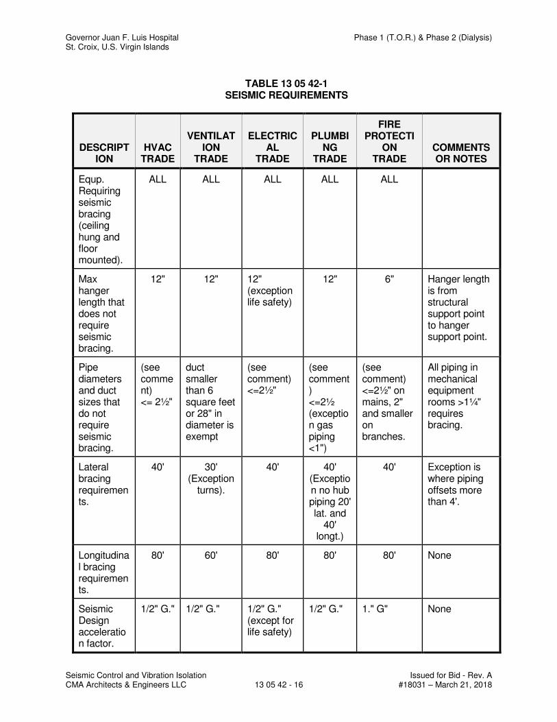
Governor Juan F. Luis Hospital Phase 1 (T.O.R.) & Phase 2 (Dialysis) St. Croix, U.S. Virgin Islands
Seismic Control and Vibration Isolation Issued for Bid - Rev. A CMA Architects & Engineers LLC 13 05 42 - 16 #18031 – March 21, 2018
TABLE 13 05 42-1 SEISMIC REQUIREMENTS
DESCRIPTION
HVAC TRADE
VENTILATION
TRADE
ELECTRICAL
TRADE
PLUMBING
TRADE
FIRE PROTECTI
ON TRADE
COMMENTS OR NOTES
Equp. Requiring seismic bracing (ceiling hung and floor mounted).
ALL ALL ALL ALL ALL
Max hanger length that does not require seismic bracing.
12" 12" 12" (exception life safety)
12" 6" Hanger length is from structural support point to hanger support point.
Pipe diameters and duct sizes that do not require seismic bracing.
(see comment) <= 2½"
duct smaller than 6 square feet or 28" in diameter is exempt
(see comment) <=2½"
(see comment) <=2½ (exception gas piping <1")
(see comment) <=2½" on mains, 2" and smaller on branches.
All piping in mechanical equipment rooms >1¼" requires bracing.
Lateral bracing requirements.
40' 30' (Exception
turns).
40' 40' (Exception no hub piping 20' lat. and
40' longt.)
40' Exception is where piping offsets more than 4'.
Longitudinal bracing requirements.
80' 60' 80' 80' 80' None
Seismic Design acceleration factor.
1/2" G." 1/2" G." 1/2" G." (except for life safety)
1/2" G." 1." G" None
Governor Juan F. Luis Hospital Phase 1 (T.O.R.) & Phase 2 (Dialysis) St. Croix, U.S. Virgin Islands
Escutcheons for Plumbing Piping Issued for Bid - Rev. A CMA Architect & Engineers, LLC 22 05 18 - 1 #18031 – March 21, 2018
SECTION 22 05 18
ESCUTCHEONS FOR PLUMBING PIPING
PART 1 - GENERAL
1.1 RELATED DOCUMENTS
A. Drawings and general provisions of the Contract, including General and Supplementary Conditions and Division 01 Specification Sections, apply to this Section.
1.2 SUMMARY
A. Section Includes:
1. Escutcheons. 2. Floor plates.
1.3 DEFINITIONS
A. Existing Piping to Remain: Existing piping that is not to be removed and that is not otherwise indicated to be removed and salvaged, or removed and reinstalled.
1.4 ACTION SUBMITTALS
A. Product Data: For each type of product.
PART 2 - PRODUCTS
2.1 MANUFACTURERS - see schedule
2.2 ESCUTCHEONS
A. One-Piece, Stainless-Steel Type: With polished stainless-steel finish.
B. One-Piece, Cast-Brass Type: With polished, chrome-plated finish and setscrew fastener.
2.3 FLOOR PLATES
A. Split Floor Plates: Cast brass with concealed hinge.
Governor Juan F. Luis Hospital Phase 1 (T.O.R.) & Phase 2 (Dialysis) St. Croix, U.S. Virgin Islands
Escutcheons for Plumbing Piping Issued for Bid - Rev. A CMA Architect & Engineers, LLC 22 05 18 - 2 #18031 – March 21, 2018
PART 3 - EXECUTION
3.1 INSTALLATION
A. Install escutcheons for piping penetrations of walls, ceilings, and finished floors.
B. Install escutcheons with ID to closely fit around pipe, tube, and insulation of insulated piping and with OD that completely covers opening.
1. Escutcheons for New Piping:
a. Piping with Fitting or Sleeve Protruding from Wall: One-piece, deep pattern. b. Bare Piping at Wall and Floor Penetrations in Finished Spaces: One-piece
stainless steel with polished stainless-steel finish. c. Bare Piping in Unfinished Service Spaces: One-piece cast brass with
polished, chrome-plated finish.
C. Install floor plates for piping penetrations of equipment-room floors.
D. Install floor plates with ID to closely fit around pipe, tube, and insulation of piping and with OD that completely covers opening.
1. New Piping: One-piece, floor plate.
3.2 FIELD QUALITY CONTROL
A. Using new materials, replace broken and damaged escutcheons and floor plates.
END OF SECTION
Governor Juan F. Luis Hospital Phase 1 (T.O.R.) & Phase 2 (Dialysis) St. Croix, U.S. Virgin Islands
Meters and Gages for Plumbing Piping Issued for Bid - Rev. A CMA Architect & Engineers, LLC 22 05 19 - 1 #18031 – March 21, 2018
SECTION 22 05 19
METERS AND GAGES FOR PLUMBING PIPING
PART 1 - GENERAL
1.1 RELATED DOCUMENTS
A. Drawings and general provisions of the Contract, including General and Supplementary Conditions and Division 01 Specification Sections, apply to this Section.
1.2 SUMMARY
A. Section Includes:
1. Bimetallic-actuated thermometers. 2. Filled-system thermometers. 3. Thermowells. 4. Dial-type pressure gages. 5. Gage attachments. 6. Test plugs. 7. Test-plug kits.
B. Related Requirements:
1. Section 221113 "Facility Water Distribution Piping" for domestic water meters and combined domestic and fire-protection water-service meters outside the building.
1.3 ACTION SUBMITTALS
A. Product Data: For each type of product.
1.4 INFORMATIONAL SUBMITTALS
A. Product Certificates: For each type of meter and gage.
1.5 CLOSEOUT SUBMITTALS
A. Operation and Maintenance Data: For meters and gages to include in operation and maintenance manuals.
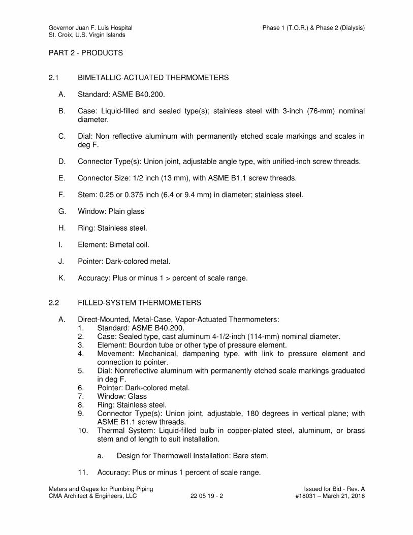
Governor Juan F. Luis Hospital Phase 1 (T.O.R.) & Phase 2 (Dialysis) St. Croix, U.S. Virgin Islands
Meters and Gages for Plumbing Piping Issued for Bid - Rev. A CMA Architect & Engineers, LLC 22 05 19 - 2 #18031 – March 21, 2018
PART 2 - PRODUCTS
2.1 BIMETALLIC-ACTUATED THERMOMETERS
A. Standard: ASME B40.200.
B. Case: Liquid-filled and sealed type(s); stainless steel with 3-inch (76-mm) nominal diameter.
C. Dial: Non reflective aluminum with permanently etched scale markings and scales in deg F.
D. Connector Type(s): Union joint, adjustable angle type, with unified-inch screw threads.
E. Connector Size: 1/2 inch (13 mm), with ASME B1.1 screw threads.
F. Stem: 0.25 or 0.375 inch (6.4 or 9.4 mm) in diameter; stainless steel.
G. Window: Plain glass
H. Ring: Stainless steel.
I. Element: Bimetal coil.
J. Pointer: Dark-colored metal.
K. Accuracy: Plus or minus 1 > percent of scale range.
2.2 FILLED-SYSTEM THERMOMETERS
A. Direct-Mounted, Metal-Case, Vapor-Actuated Thermometers: 1. Standard: ASME B40.200. 2. Case: Sealed type, cast aluminum 4-1/2-inch (114-mm) nominal diameter. 3. Element: Bourdon tube or other type of pressure element. 4. Movement: Mechanical, dampening type, with link to pressure element and
connection to pointer. 5. Dial: Nonreflective aluminum with permanently etched scale markings graduated
in deg F. 6. Pointer: Dark-colored metal. 7. Window: Glass 8. Ring: Stainless steel. 9. Connector Type(s): Union joint, adjustable, 180 degrees in vertical plane; with
ASME B1.1 screw threads. 10. Thermal System: Liquid-filled bulb in copper-plated steel, aluminum, or brass
stem and of length to suit installation.
a. Design for Thermowell Installation: Bare stem.
11. Accuracy: Plus or minus 1 percent of scale range.
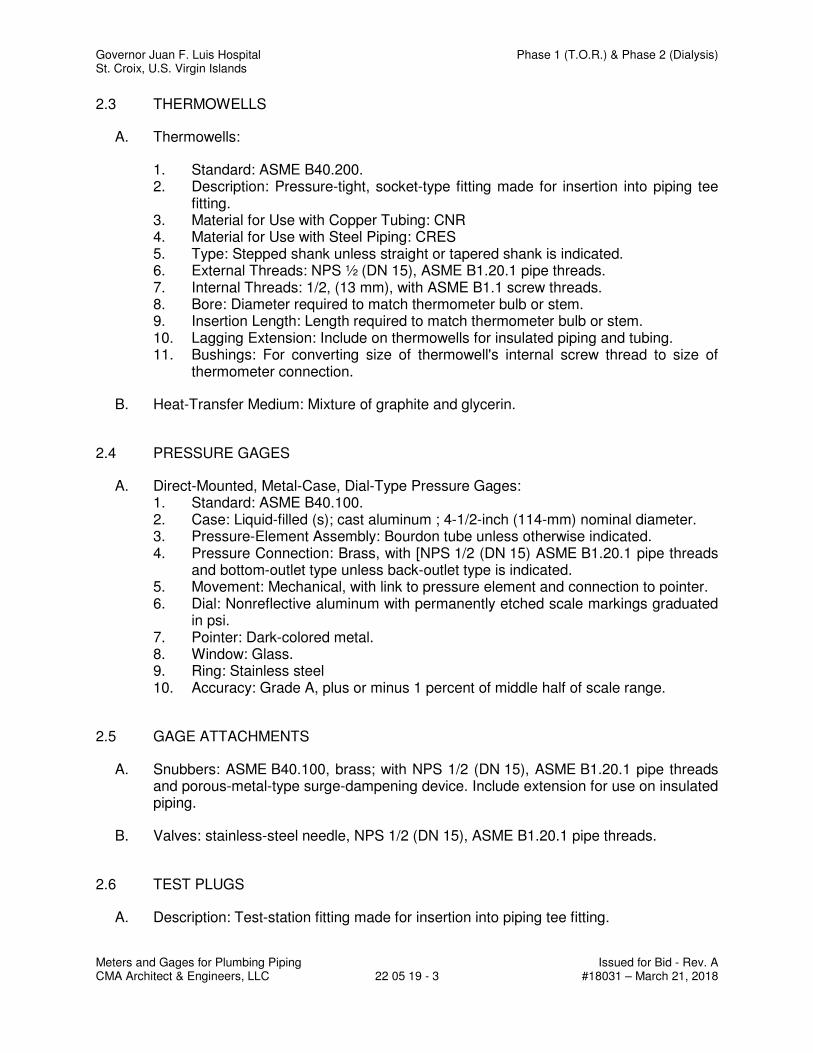
Governor Juan F. Luis Hospital Phase 1 (T.O.R.) & Phase 2 (Dialysis) St. Croix, U.S. Virgin Islands
Meters and Gages for Plumbing Piping Issued for Bid - Rev. A CMA Architect & Engineers, LLC 22 05 19 - 3 #18031 – March 21, 2018
2.3 THERMOWELLS
A. Thermowells:
1. Standard: ASME B40.200. 2. Description: Pressure-tight, socket-type fitting made for insertion into piping tee
fitting. 3. Material for Use with Copper Tubing: CNR 4. Material for Use with Steel Piping: CRES 5. Type: Stepped shank unless straight or tapered shank is indicated. 6. External Threads: NPS ½ (DN 15), ASME B1.20.1 pipe threads. 7. Internal Threads: 1/2, (13 mm), with ASME B1.1 screw threads. 8. Bore: Diameter required to match thermometer bulb or stem. 9. Insertion Length: Length required to match thermometer bulb or stem. 10. Lagging Extension: Include on thermowells for insulated piping and tubing. 11. Bushings: For converting size of thermowell's internal screw thread to size of
thermometer connection.
B. Heat-Transfer Medium: Mixture of graphite and glycerin.
2.4 PRESSURE GAGES
A. Direct-Mounted, Metal-Case, Dial-Type Pressure Gages: 1. Standard: ASME B40.100. 2. Case: Liquid-filled (s); cast aluminum ; 4-1/2-inch (114-mm) nominal diameter. 3. Pressure-Element Assembly: Bourdon tube unless otherwise indicated. 4. Pressure Connection: Brass, with [NPS 1/2 (DN 15) ASME B1.20.1 pipe threads
and bottom-outlet type unless back-outlet type is indicated. 5. Movement: Mechanical, with link to pressure element and connection to pointer. 6. Dial: Nonreflective aluminum with permanently etched scale markings graduated
in psi. 7. Pointer: Dark-colored metal. 8. Window: Glass. 9. Ring: Stainless steel 10. Accuracy: Grade A, plus or minus 1 percent of middle half of scale range.
2.5 GAGE ATTACHMENTS
A. Snubbers: ASME B40.100, brass; with NPS 1/2 (DN 15), ASME B1.20.1 pipe threads and porous-metal-type surge-dampening device. Include extension for use on insulated piping.
B. Valves: stainless-steel needle, NPS 1/2 (DN 15), ASME B1.20.1 pipe threads.
2.6 TEST PLUGS
A. Description: Test-station fitting made for insertion into piping tee fitting.
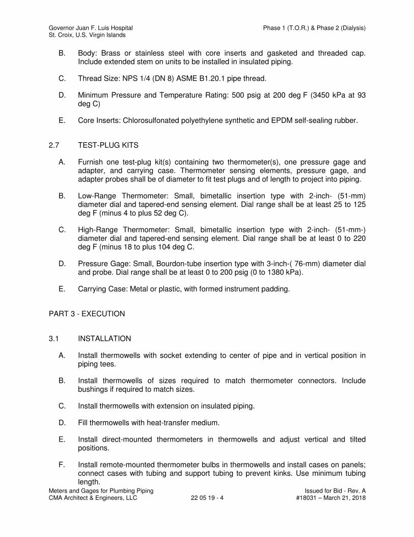
Governor Juan F. Luis Hospital Phase 1 (T.O.R.) & Phase 2 (Dialysis) St. Croix, U.S. Virgin Islands
Meters and Gages for Plumbing Piping Issued for Bid - Rev. A CMA Architect & Engineers, LLC 22 05 19 - 4 #18031 – March 21, 2018
B. Body: Brass or stainless steel with core inserts and gasketed and threaded cap. Include extended stem on units to be installed in insulated piping.
C. Thread Size: NPS 1/4 (DN 8) ASME B1.20.1 pipe thread.
D. Minimum Pressure and Temperature Rating: 500 psig at 200 deg F (3450 kPa at 93 deg C)
E. Core Inserts: Chlorosulfonated polyethylene synthetic and EPDM self-sealing rubber.
2.7 TEST-PLUG KITS
A. Furnish one test-plug kit(s) containing two thermometer(s), one pressure gage and adapter, and carrying case. Thermometer sensing elements, pressure gage, and adapter probes shall be of diameter to fit test plugs and of length to project into piping.
B. Low-Range Thermometer: Small, bimetallic insertion type with 2-inch- (51-mm) diameter dial and tapered-end sensing element. Dial range shall be at least 25 to 125 deg F (minus 4 to plus 52 deg C).
C. High-Range Thermometer: Small, bimetallic insertion type with 2-inch- (51-mm-) diameter dial and tapered-end sensing element. Dial range shall be at least 0 to 220 deg F (minus 18 to plus 104 deg C.
D. Pressure Gage: Small, Bourdon-tube insertion type with 3-inch-( 76-mm) diameter dial and probe. Dial range shall be at least 0 to 200 psig (0 to 1380 kPa).
E. Carrying Case: Metal or plastic, with formed instrument padding.
PART 3 - EXECUTION
3.1 INSTALLATION
A. Install thermowells with socket extending to center of pipe and in vertical position in piping tees.
B. Install thermowells of sizes required to match thermometer connectors. Include bushings if required to match sizes.
C. Install thermowells with extension on insulated piping.
D. Fill thermowells with heat-transfer medium.
E. Install direct-mounted thermometers in thermowells and adjust vertical and tilted positions.
F. Install remote-mounted thermometer bulbs in thermowells and install cases on panels; connect cases with tubing and support tubing to prevent kinks. Use minimum tubing length.
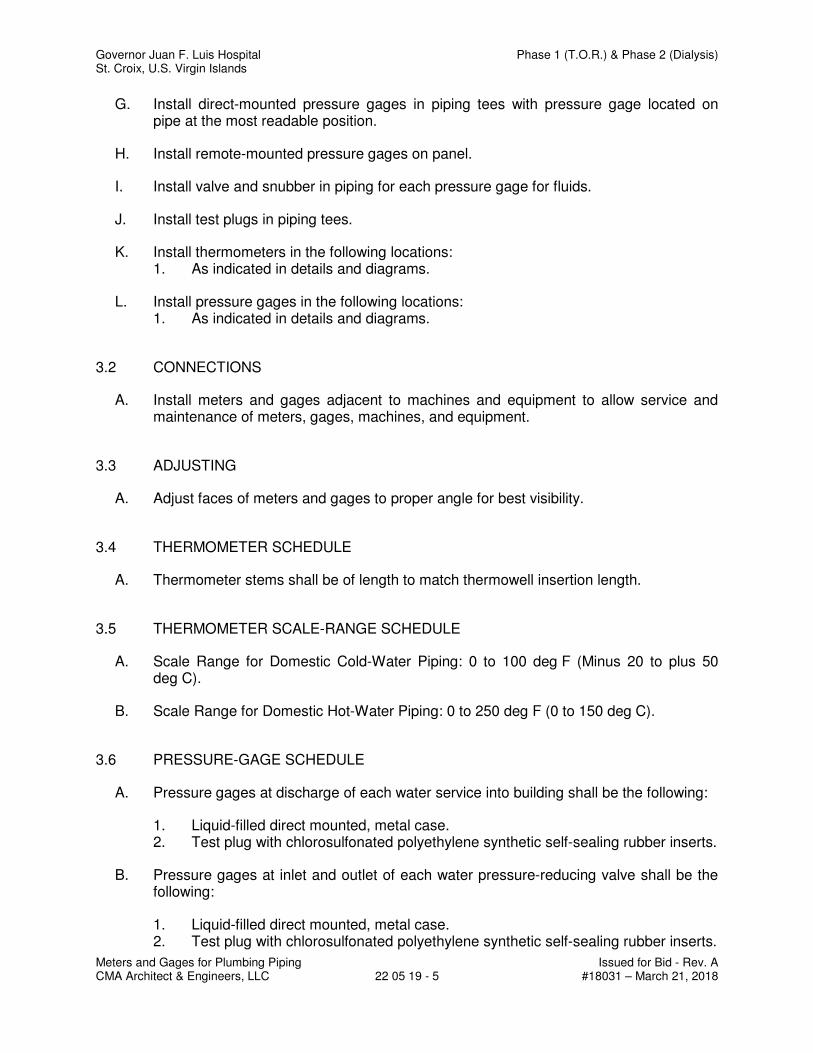
Governor Juan F. Luis Hospital Phase 1 (T.O.R.) & Phase 2 (Dialysis) St. Croix, U.S. Virgin Islands
Meters and Gages for Plumbing Piping Issued for Bid - Rev. A CMA Architect & Engineers, LLC 22 05 19 - 5 #18031 – March 21, 2018
G. Install direct-mounted pressure gages in piping tees with pressure gage located on pipe at the most readable position.
H. Install remote-mounted pressure gages on panel.
I. Install valve and snubber in piping for each pressure gage for fluids.
J. Install test plugs in piping tees.
K. Install thermometers in the following locations: 1. As indicated in details and diagrams.
L. Install pressure gages in the following locations: 1. As indicated in details and diagrams.
3.2 CONNECTIONS
A. Install meters and gages adjacent to machines and equipment to allow service and maintenance of meters, gages, machines, and equipment.
3.3 ADJUSTING
A. Adjust faces of meters and gages to proper angle for best visibility.
3.4 THERMOMETER SCHEDULE
A. Thermometer stems shall be of length to match thermowell insertion length.
3.5 THERMOMETER SCALE-RANGE SCHEDULE
A. Scale Range for Domestic Cold-Water Piping: 0 to 100 deg F (Minus 20 to plus 50 deg C).
B. Scale Range for Domestic Hot-Water Piping: 0 to 250 deg F (0 to 150 deg C).
3.6 PRESSURE-GAGE SCHEDULE
A. Pressure gages at discharge of each water service into building shall be the following:
1. Liquid-filled direct mounted, metal case. 2. Test plug with chlorosulfonated polyethylene synthetic self-sealing rubber inserts.
B. Pressure gages at inlet and outlet of each water pressure-reducing valve shall be the following:
1. Liquid-filled direct mounted, metal case. 2. Test plug with chlorosulfonated polyethylene synthetic self-sealing rubber inserts.
Governor Juan F. Luis Hospital Phase 1 (T.O.R.) & Phase 2 (Dialysis) St. Croix, U.S. Virgin Islands
Meters and Gages for Plumbing Piping Issued for Bid - Rev. A CMA Architect & Engineers, LLC 22 05 19 - 6 #18031 – March 21, 2018
3.7 PRESSURE-GAGE SCALE-RANGE SCHEDULE
A. Scale Range for Water Service Piping: 0 to 160 psi (0 to 1100 kPa)
END OF SECTION
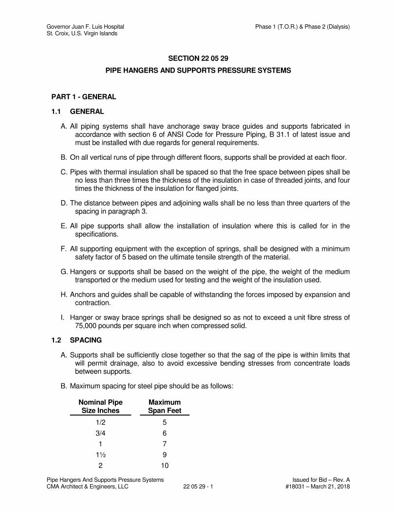
Governor Juan F. Luis Hospital Phase 1 (T.O.R.) & Phase 2 (Dialysis) St. Croix, U.S. Virgin Islands
Pipe Hangers And Supports Pressure Systems Issued for Bid – Rev. A CMA Architect & Engineers, LLC 22 05 29 - 1 #18031 – March 21, 2018
SECTION 22 05 29
PIPE HANGERS AND SUPPORTS PRESSURE SYSTEMS
PART 1 - GENERAL
1.1 GENERAL
A. All piping systems shall have anchorage sway brace guides and supports fabricated in accordance with section 6 of ANSI Code for Pressure Piping, B 31.1 of latest issue and must be installed with due regards for general requirements.
B. On all vertical runs of pipe through different floors, supports shall be provided at each floor.
C. Pipes with thermal insulation shall be spaced so that the free space between pipes shall be no less than three times the thickness of the insulation in case of threaded joints, and four times the thickness of the insulation for flanged joints.
D. The distance between pipes and adjoining walls shall be no less than three quarters of the spacing in paragraph 3.
E. All pipe supports shall allow the installation of insulation where this is called for in the specifications.
F. All supporting equipment with the exception of springs, shall be designed with a minimum safety factor of 5 based on the ultimate tensile strength of the material.
G. Hangers or supports shall be based on the weight of the pipe, the weight of the medium transported or the medium used for testing and the weight of the insulation used.
H. Anchors and guides shall be capable of withstanding the forces imposed by expansion and contraction.
I. Hanger or sway brace springs shall be designed so as not to exceed a unit fibre stress of 75,000 pounds per square inch when compressed solid.
1.2 SPACING
A. Supports shall be sufficiently close together so that the sag of the pipe is within limits that will permit drainage, also to avoid excessive bending stresses from concentrate loads between supports.
B. Maximum spacing for steel pipe should be as follows:
Nominal Pipe Size Inches
Maximum Span Feet
1/2 5
3/4 6
1 7
1½ 9
2 10
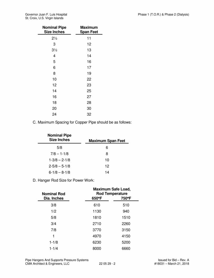
Governor Juan F. Luis Hospital Phase 1 (T.O.R.) & Phase 2 (Dialysis) St. Croix, U.S. Virgin Islands
Pipe Hangers And Supports Pressure Systems Issued for Bid – Rev. A CMA Architect & Engineers, LLC 22 05 29 - 2 #18031 – March 21, 2018
Nominal Pipe Size Inches
Maximum Span Feet
2½ 11
3 12
3½ 13
4 14
5 16
6 17
8 19
10 22
12 23
14 25
16 27
18 28
20 30
24 32
C. Maximum Spacing for Copper Pipe should be as follows:
Nominal Pipe Size Inches
Maximum Span Feet
5/8 6
7/8 – 1-1/8 8
1-3/8 – 2-1/8 10
2-5/8 – 5-1/8 12
6-1/8 – 8-1/8 14
D. Hanger Rod Size for Power Work:
Nominal Rod Dia. Inches
Maximum Safe Load,
Rod Temperature
650°°°°F 750°°°°F
3/8 610 510
1/2 1130 940
5/8 1810 1510
3/4 2710 2260
7/8 3770 3150
1 4970 4150
1-1/8 6230 5200
1-1/4 8000 6660
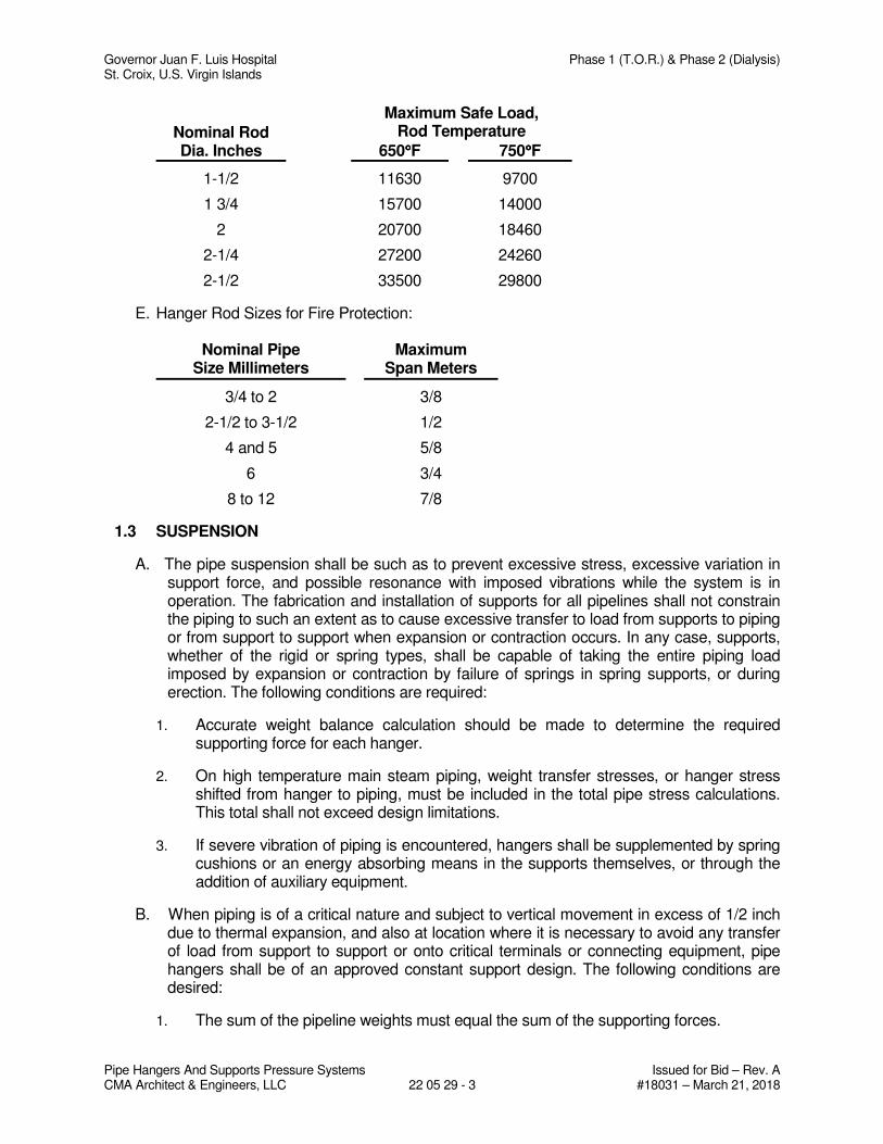
Governor Juan F. Luis Hospital Phase 1 (T.O.R.) & Phase 2 (Dialysis) St. Croix, U.S. Virgin Islands
Pipe Hangers And Supports Pressure Systems Issued for Bid – Rev. A CMA Architect & Engineers, LLC 22 05 29 - 3 #18031 – March 21, 2018
Nominal Rod Dia. Inches
Maximum Safe Load,
Rod Temperature
650°°°°F 750°°°°F
1-1/2 11630 9700
1 3/4 15700 14000
2 20700 18460
2-1/4 27200 24260
2-1/2 33500 29800
E. Hanger Rod Sizes for Fire Protection:
Nominal Pipe Size Millimeters
Maximum Span Meters
3/4 to 2 3/8
2-1/2 to 3-1/2 1/2
4 and 5 5/8
6 3/4
8 to 12 7/8
1.3 SUSPENSION
A. The pipe suspension shall be such as to prevent excessive stress, excessive variation in support force, and possible resonance with imposed vibrations while the system is in operation. The fabrication and installation of supports for all pipelines shall not constrain the piping to such an extent as to cause excessive transfer to load from supports to piping or from support to support when expansion or contraction occurs. In any case, supports, whether of the rigid or spring types, shall be capable of taking the entire piping load imposed by expansion or contraction by failure of springs in spring supports, or during erection. The following conditions are required:
1. Accurate weight balance calculation should be made to determine the required supporting force for each hanger.
2. On high temperature main steam piping, weight transfer stresses, or hanger stress shifted from hanger to piping, must be included in the total pipe stress calculations. This total shall not exceed design limitations.
3. If severe vibration of piping is encountered, hangers shall be supplemented by spring cushions or an energy absorbing means in the supports themselves, or through the addition of auxiliary equipment.
B. When piping is of a critical nature and subject to vertical movement in excess of 1/2 inch due to thermal expansion, and also at location where it is necessary to avoid any transfer of load from support to support or onto critical terminals or connecting equipment, pipe hangers shall be of an approved constant support design. The following conditions are desired:
1. The sum of the pipeline weights must equal the sum of the supporting forces.
Governor Juan F. Luis Hospital Phase 1 (T.O.R.) & Phase 2 (Dialysis) St. Croix, U.S. Virgin Islands
Pipe Hangers And Supports Pressure Systems Issued for Bid – Rev. A CMA Architect & Engineers, LLC 22 05 29 - 4 #18031 – March 21, 2018
2. The sum of the moments of piping weight acting at their center of gravity and the supporting forces shall be equal to zero.
3. Constant support hangers must be calibrated to support the exact load of the piping system.
C. Pipe hangers located at points that are subject to vertical thermal movement and not covered by paragraph 2 shall be of an approved variable spring design.
1. The variation of hanger forces during operation shall not exceed 25 percent of the actual load.
D. All flexibly supported lines shall be suitably sway braced to prevent undue or unwanted movement or vibration, but such sway brace shall not interfere with the proper thermal movement of the piping. An approved sway brace that provides an instant counteracting force should be applied where required to control the piping.
E. Piping systems, where flexibility is not desirable, shall be supported to rigid hangers.
F. All parts of the supporting equipment shall be fabricated and assembled so that they will not be disengaged by movement of the supported pipe.
1. Hanger rods shall be provided with welded or forged eyes or suitable sockets to permit lateral movement of the piping without setting up severe bending action in the rod.
2. Pipe rings to be made of malleable iron shall be fitted with an adequate adjusting nut of the locking type threaded to a rod that will allow adjustment after erection while still supporting the load.
3. Screw adjustments shall be fabricated so that all threaded members will have a true and complete depth of thread. The turnbuckle or adjusting nut shall have its full length or thread in service while in use and the amount of adjustment shall be plainly visible at all times.
a. All screw or equipment adjustment shall be provided with suitable locking features.
4. Hanger rod sizes shall be as shown in these specifications.
5. All welding shall be in accordance with American Society of Mechanical Engineers, Welding Qualifications.
PART 2 - PRODUCTS Not Used
PART 3 - EXECUTION Not Used END OF SECTION
Governor Juan F. Luis Hospital Phase 1 (T.O.R.) & Phase 2 (Dialysis) St. Croix, U.S. Virgin Islands
Identification for Plumbing Piping and Equipment Issued for Bid - Rev. A CMA Architect & Engineers, LLC 22 05 53 - 1 #18031 – March 21, 2018
SECTION 22 05 53
IDENTIFICATION FOR PLUMBING PIPING AND EQUIPMENT
PART 1 - GENERAL
1.1 RELATED DOCUMENTS
A. Drawings and general provisions of the Contract, including General and Supplementary Conditions and Division 01 Specification Sections, apply to this Section.
1.2 SUMMARY
A. Section Includes: 1. Warning signs and labels. 2. Pipe labels. 3. Valve tags. 4. Warning tags.
1.3 ACTION SUBMITTALS
A. Product Data: For each type of product indicated.
B. Samples: For color, letter style, and graphic representation required for each identification material and device.
C. Valve numbering scheme.
D. Valve Schedules: For each piping system to include in maintenance manuals.
PART 2 - PRODUCTS
2.1 WARNING SIGNS AND LABELS
A. Material and Thickness: Multilayer, multicolor, plastic labels for mechanical engraving, 1/8 inch (3.2 mm) thick, and having predrilled holes for attachment hardware.
B. Letter Color: Red
C. Background Color: White
D. Maximum Temperature: Able to withstand temperatures up to 160 deg F (71 deg C).
Governor Juan F. Luis Hospital Phase 1 (T.O.R.) & Phase 2 (Dialysis) St. Croix, U.S. Virgin Islands
Identification for Plumbing Piping and Equipment Issued for Bid - Rev. A CMA Architect & Engineers, LLC 22 05 53 - 2 #18031 – March 21, 2018
E. Minimum Label Size: Length and width vary for required label content, but not less than 2-1/2 by 3/4 inch (64 by 19 mm).
F. Minimum Letter Size: 1/2 inch (13 mm) for viewing distances up to 72 inches (1830 mm), and proportionately larger lettering for greater viewing distances. Include secondary lettering two-thirds to three-quarters the size of principal lettering.
G. Fasteners: Stainless-steel self-tapping screws.
H. Adhesive: Contact-type permanent adhesive, compatible with label and with substrate.
I. Label Content: Include caution and warning information plus emergency notification instructions.
2.2 PIPE LABELS
A. General Requirements for Manufactured Pipe Labels: Preprinted, color-coded, with lettering indicating service, and showing flow direction.
B. Pretensioned Pipe Labels: Precoiled, semirigid plastic formed to partially cover circumference of pipe and to attach to pipe without fasteners or adhesive.
C. Self-Adhesive Pipe Labels: Printed plastic with contact-type, permanent-adhesive backing.
D. Pipe Label Contents: Include identification of piping service using same designations or abbreviations as used on Drawings; also include pipe size and an arrow indicating flow direction.
1. Flow-Direction Arrows: Integral with piping-system service lettering to accommodate both directions or as separate unit on each pipe label to indicate flow direction.
2. Lettering Size: Size letters according to ASME A13.1 for piping.
2.3 VALVE TAGS
A. Valve Tags: Stamped or engraved with 1/4-inch (6.4-mm) letters for piping system abbreviation and 1/2-inch (13-mm) numbers.
1. Tag Material: stainless steel, 0.025-inch (0.64-mm) minimum thickness, and having predrilled or stamped holes for attachment hardware.
2. Fasteners: Brass S-hook.
B. Valve Schedules: For each piping system, on 8-1/2-by-11-inch (A4) bond paper. Tabulate valve number, piping system, system abbreviation (as shown on valve tag), location of valve (room or space), normal-operating position (open, closed, or modulating), and variations for identification. Mark valves for emergency shutoff and similar special uses.
1. Valve-tag schedule shall be included in operation and maintenance data.
Governor Juan F. Luis Hospital Phase 1 (T.O.R.) & Phase 2 (Dialysis) St. Croix, U.S. Virgin Islands
Identification for Plumbing Piping and Equipment Issued for Bid - Rev. A CMA Architect & Engineers, LLC 22 05 53 - 3 #18031 – March 21, 2018
2.4 WARNING TAGS
A. Description: Preprinted or partially preprinted accident-prevention tags of plasticized card stock with matte finish suitable for writing.
1. Size: Approximately 4 by 7 inches (100 by 178 mm) 2. Fasteners: Brass grommet and wire 3. Nomenclature: Large-size primary caption such as "DANGER," "CAUTION," or
"DO NOT OPERATE." 4. Color: Safety yellow background with black lettering.
PART 3 - EXECUTION
3.1 PREPARATION
A. Clean piping and equipment surfaces of substances that could impair bond of identification devices, including dirt, oil, grease, release agents, and incompatible primers, paints, and encapsulates.
3.2 GENERAL INSTALLATION REQUIREMENTS
A. Coordinate installation of identifying devices with completion of covering and painting of surfaces where devices are to be applied.
B. Coordinate installation of identifying devices with locations of access panels and doors.
C. Install identifying devices before installing acoustical ceilings and similar concealment.
3.3 PIPE LABEL INSTALLATION
A. Piping Color Coding: Painting of piping is specified in Section 099123 "Interior Painting." Section 099600 "High-Performance Coatings."
B. Stenciled Pipe Label Option: Stenciled labels may be provided instead of manufactured pipe labels, at Installer's option. Install stenciled pipe labels, complying with ASME A13.1, color-coded bands or rectangles on each piping system.
1. Identification Paint: Use for contrasting background. 2. Stencil Paint: Use for pipe marking.
C. Pipe Label Locations: Locate pipe labels where piping is exposed or above accessible ceilings in finished spaces; machine rooms; accessible maintenance spaces such as shafts, tunnels, and plenums; and exterior exposed locations as follows:
1. Near each valve and control device. 2. Near each branch connection, excluding short takeoffs for fixtures and terminal
units. Where flow pattern is not obvious, mark each pipe at branch. 3. Near penetrations through walls, floors, ceilings, and inaccessible enclosures.
Governor Juan F. Luis Hospital Phase 1 (T.O.R.) & Phase 2 (Dialysis) St. Croix, U.S. Virgin Islands
Identification for Plumbing Piping and Equipment Issued for Bid - Rev. A CMA Architect & Engineers, LLC 22 05 53 - 4 #18031 – March 21, 2018
4. At access doors, manholes, and similar access points that permit view of concealed piping.
5. Near major equipment items and other points of origination and termination. 6. Spaced at maximum intervals of 50 feet (15 m) along each run. Reduce intervals
to 25 feet (7.6 m) in areas of congested piping and equipment. 7. On piping above removable acoustical ceilings. Omit intermediately spaced
labels.
D. Directional Flow Arrows: Arrows shall be used to indicate direction of flow in pipes, including pipes where flow is allowed in both directions.
E. Pipe Label Color Schedule:
1. Medical Air Piping:
a. Background: Yellow b. Letter Colors: Black
2. Oxygen Piping:
a. Background: Green b. Letter Colors: white
3. Domestic Water Piping
a. Background: Green b. Letter Colors: white
4. Sanitary Waste Piping:
a. Background Color: Green b. Letter Color: White
5. Vacuum Piping:
a. Background: White b. Letter Colors: Black
3.4 VALVE-TAG INSTALLATION
A. Install tags on valves and control devices in piping systems, except check valves, valves within factory-fabricated equipment units, shutoff valves, faucets, convenience and lawn-watering hose connections, and similar roughing-in connections of end-use fixtures and units. List tagged valves in a valve schedule.
B. Valve-Tag Application Schedule: Tag valves according to size, shape, and color scheme and with captions similar to those indicated in the following subparagraphs:
1. Valve-Tag Size and Shape:
Governor Juan F. Luis Hospital Phase 1 (T.O.R.) & Phase 2 (Dialysis) St. Croix, U.S. Virgin Islands
Identification for Plumbing Piping and Equipment Issued for Bid - Rev. A CMA Architect & Engineers, LLC 22 05 53 - 5 #18031 – March 21, 2018
a. All services : 1-1/2 inches (38 mm) round
2. Valve-Tag Colors:
a. Cold Water: Safety green. b. Hot Water: Safety green c. Oxygen: Safety green d. Vacuum: White e. Medical Air: Yellow
3. Letter Colors:
a. Cold Water: White b. Hot Water: White c. Oxygen: White d. Vacuum: Black e. Medical Air: Black
3.5 WARNING-TAG INSTALLATION
A. Write required message on, and attach warning tags to, equipment and other items where required.
END OF SECTION

Governor Juan F. Luis Hospital Phase 1 (T.O.R.) & Phase 2 (Dialysis) St. Croix, U.S. Virgin Islands
Facility Water Distribution Piping Issued for Bid - Rev. A CMA Architect & Engineers, LLC 22 11 13 - 1 #18031 – March 21, 2018
SECTION 22 11 13
FACILITY WATER DISTRIBUTION PIPING
PART 1 - GENERAL
1.1 RELATED DOCUMENTS
A. Drawings and general provisions of the Contract, including General and Supplementary Conditions and Division 01 Specification Sections, apply to this Section.
1.2 SUMMARY
A. This Section includes water-distribution piping and related components outside the building for water service.
B. Utility-furnished products include water meters that will be furnished to the site, ready for installation.
1.3 DEFINITIONS
A. EPDM: Ethylene propylene diene terpolymer rubber.
B. LLDPE: Linear, low-density polyethylene plastic.
C. PA: Polyamide (nylon) plastic.
D. PE: Polyethylene plastic.
E. PP: Polypropylene plastic.
F. PVC: Polyvinyl chloride plastic.
G. RTRF: Reinforced thermosetting resin (fiberglass) fittings.
H. RTRP: Reinforced thermosetting resin (fiberglass) pipe.
1.4 ACTION SUBMITTALS
A. Product Data: For each type of product indicated.
Governor Juan F. Luis Hospital Phase 1 (T.O.R.) & Phase 2 (Dialysis) St. Croix, U.S. Virgin Islands
Facility Water Distribution Piping Issued for Bid - Rev. A CMA Architect & Engineers, LLC 22 11 13 - 2 #18031 – March 21, 2018
1.5 INFORMATIONAL SUBMITTALS
A. Coordination Drawings: For piping and specialties including relation to other services in same area, drawn to scale. Show piping and specialty sizes and valves, meter and specialty locations, and elevations.
B. Field quality-control test reports.
1.6 CLOSEOUT SUBMITTALS
A. Operation and Maintenance Data: For water valves and specialties to include in emergency, operation, and maintenance manuals.
1.7 QUALITY ASSURANCE
A. Regulatory Requirements:
1. Comply with requirements of utility company supplying water. Include tapping of water mains and backflow prevention.
2. Comply with standards of authorities having jurisdiction for potable-water-service piping, including materials, installation, testing, and disinfection.
3. Comply with standards of authorities having jurisdiction for fire-suppression water-service piping, including materials, hose threads, installation, and testing.
B. Piping materials shall bear label, stamp, or other markings of specified testing agency.
C. Electrical Components, Devices, and Accessories: Listed and labeled as defined in NFPA 70, Article 100, by a testing agency acceptable to authorities having jurisdiction, and marked for intended use.
D. Comply with ASTM F 645 for selection, design, and installation of thermoplastic water piping.
E. Comply with FMG's "Approval Guide" or UL's "Fire Protection Equipment Directory" for fire-service-main products.
F. NFPA Compliance: Comply with NFPA 24 for materials, installations, tests, flushing, and valve and hydrant supervision for fire-service-main piping for fire suppression.
1. Potable-water piping and components shall comply with NSF 14, NSF 61, and NSF 372.
1.8 DELIVERY, STORAGE, AND HANDLING
A. Preparation for Transport: Prepare valves, including fire hydrants, according to the following:
1. Ensure that valves are dry and internally protected against rust and corrosion.
Governor Juan F. Luis Hospital Phase 1 (T.O.R.) & Phase 2 (Dialysis) St. Croix, U.S. Virgin Islands
Facility Water Distribution Piping Issued for Bid - Rev. A CMA Architect & Engineers, LLC 22 11 13 - 3 #18031 – March 21, 2018
2. Protect valves against damage to threaded ends and flange faces. 3. Set valves in best position for handling. Set valves closed to prevent rattling.
B. During Storage: Use precautions for valves, including fire hydrants, according to the following:
1. Do not remove end protectors unless necessary for inspection; then reinstall for storage.
2. Protect from weather. Store indoors and maintain temperature higher than ambient dew-point temperature. Support off the ground or pavement in watertight enclosures when outdoor storage is necessary.
C. Handling: Use sling to handle valves and fire hydrants if size requires handling by crane or lift. Rig valves to avoid damage to exposed parts. Do not use handwheels or stems as lifting or rigging points.
D. Deliver piping with factory-applied end caps. Maintain end caps through shipping, storage, and handling to prevent pipe-end damage and to prevent entrance of dirt, debris, and moisture.
E. Protect stored piping from moisture and dirt. Elevate above grade. Do not exceed structural capacity of floor when storing inside.
F. Protect flanges, fittings, and specialties from moisture and dirt.
G. Store plastic piping protected from direct sunlight. Support to prevent sagging and bending.
1.9 PROJECT CONDITIONS
A. Interruption of Existing Water-Distribution Service: Do not interrupt service to facilities occupied by Owner or others unless permitted under the following conditions and then only after arranging to provide temporary water-distribution service according to requirements indicated:
1. Notify Owner no fewer than two days in advance of proposed interruption of service.
2. Do not proceed with interruption of water-distribution service without Construction Manager's and Owner's written permission.
1.10 COORDINATION
A. Coordinate connection to water main with utility company.
Governor Juan F. Luis Hospital Phase 1 (T.O.R.) & Phase 2 (Dialysis) St. Croix, U.S. Virgin Islands
Facility Water Distribution Piping Issued for Bid - Rev. A CMA Architect & Engineers, LLC 22 11 13 - 4 #18031 – March 21, 2018
PART 2 - PRODUCTS
2.1 PERFORMANCE REQUIREMENTS
A. Seismic Requirements – Mechanical Systems:
B. Piping Systems including hangers shall have seismic restraints as per the International Building Code.
C. Seismic Requirements: Elements of permanent nonstructural components (cooling tower, piping systems, pumps, any other mechanical equipment, etc.) and their attachments shall be designed to resist the total design seismic forces prescribed in Chapter 13 – Seismic Design Requirements for Nonstructural Components of ASCE 7-05. Attachments shall include anchorages and required bracings (lateral and longitudinal). The following seismic criteria shall be used to compute the design seismic forces:
D. Spectral Response Acceleration Factor (SS): as per IBC code.
E. Importance Factor, Ip = 1.5.
F. Site Class D.
G. Piping Subcontractor shall retain a consultant to develop a seismic restraint system and perform seismic calculations in accordance with Chapter 13 of ASCE 7-05. Calculations, restraint selections details shall be done by a Professional Engineer experienced in seismic restraint design and licensed in the U.S. Virgin Islands. Shop drawings and calculations shall be signed and sealed by this Professional Engineer.
H. Acceptable Consultants and Manufacturers of Seismic Restraint Systems:
1. ISAT (International Seismic Application Technology)
6600 Artesia Boulevard
Buena Park, CA 90620
Phone: (877) 999-4828; (714) 994-6353
Fax: (714) 523-0845
2. Mason Industries, Inc.
350 Nabro Drive
Hauppage, NY 11788
Phone: (631) 348-0282
Fax: (631) 348-0279
Governor Juan F. Luis Hospital Phase 1 (T.O.R.) & Phase 2 (Dialysis) St. Croix, U.S. Virgin Islands
Facility Water Distribution Piping Issued for Bid - Rev. A CMA Architect & Engineers, LLC 22 11 13 - 5 #18031 – March 21, 2018
2.2 PIPING MATERIALS
A. Comply with requirements in "Piping Schedule" Article for applications of pipe, tube, fitting materials, and joining methods for specific services, service locations, and pipe sizes.
B. Potable-water piping and components shall comply with NSF 14, NSF 61, and NSF 372.
2.3 COPPER TUBE AND FITTINGS
A. Soft Copper Tube: ASTM B 88, Type K, water tube, annealed temper.
1. Copper, Solder-Joint Fittings: ASME B16.18, cast-copper-alloy or ASME B16.22, wrought-copper, solder-joint pressure type. Furnish only wrought-copper fittings if indicated.
B. Hard Copper Tube: ASTM B 88, Type K water tube, drawn temper.
1. Copper, Solder-Joint Fittings: ASME B16.18, cast-copper-alloy or ASME B16.22, wrought-copper, solder-joint pressure type. Furnish only wrought-copper fittings if indicated.
C. Bronze Flanges: ASME B16.24, Class 150, with solder-joint end. Furnish Class 300 flanges if required to match piping.
D. Copper Unions:
1. MSS SP-123. 2. Cast-copper-alloy, hexagonal-stock body. 3. Ball-and-socket, metal-to-metal seating surfaces. 4. Solder-joint or threaded ends.
E. Copper, Brass or Bronze, Pressure-Seal-Joint Fittings:
1. Fittings: Cast-brass, cast-bronze, or wrought-copper with EPDM O-ring seal in each end. Sizes NPS 2-1/2 and larger with stainless steel grip ring and EPDM O-ring seal.
2. Minimum 200-psig working-pressure rating at 250 deg F.
2.4 PIPING SPECIALTIES
A. Transition Fittings: Manufactured fitting or coupling same size as, with pressure rating at least equal to and ends compatible with, piping to be joined.
B. Tubular-Sleeve Pipe Couplings:
Governor Juan F. Luis Hospital Phase 1 (T.O.R.) & Phase 2 (Dialysis) St. Croix, U.S. Virgin Islands
Facility Water Distribution Piping Issued for Bid - Rev. A CMA Architect & Engineers, LLC 22 11 13 - 6 #18031 – March 21, 2018
1. Description: Metal, bolted, sleeve-type, reducing or transition coupling, with center sleeve, gaskets, end rings, and bolt fasteners and with ends of same sizes as piping to be joined.
a. Standard: AWWA C219. b. Center-Sleeve Material: Stainless steel c. Gasket Material: Natural or synthetic rubber. d. Pressure Rating: 150 psig minimum. (to be confirmed) e. Metal Component Finish: Corrosion-resistant coating or material.
C. Split-Sleeve Pipe Couplings:
1. Description: Metal, bolted, split-sleeve-type, reducing or transition coupling with sealing pad and closure plates, O-ring gaskets, and bolt fasteners.
a. Standard: AWWA C219. b. Sleeve Material: Stainless steel c. Sleeve Dimensions: Of thickness and width required to provide pressure
rating. d. Gasket Material: O-rings made of EPDM rubber, unless otherwise
indicated. e. Pressure Rating: 150 psig minimum (to be confirmed). f. Metal Component Finish: Corrosion-resistant coating or material.
D. Flexible Connectors:
1. Nonferrous-Metal Piping: Bronze hose covered with bronze wire braid; with copper-tube, pressure-type, solder-joint ends or bronze flanged ends brazed to hose.
2. Ferrous-Metal Piping: Stainless-steel hose covered with stainless-steel wire braid; with ASME B1.20.1, threaded steel pipe nipples or ASME B16.5, steel pipe flanges welded to hose.
2.5 CORROSION-PROTECTION PIPING ENCASEMENT
A. Encasement for Underground Metal Piping:
1. Standards: ASTM A 674 or AWWA C105. 2. Form: Sheet or tube. 3. Material: LLDPE film of 0.008-inch minimum thickness, or high-density,
crosslaminated PE film of 0.004-inch minimum thickness. 4. Material: High-density, crosslaminated PE film of 0.004-inch minimum thickness. 5. Color: Color coded by service
2.6 GATE VALVES
A. Bronze Gate Valves:
1. OS&Y, Rising-Stem Gate Valves:
Governor Juan F. Luis Hospital Phase 1 (T.O.R.) & Phase 2 (Dialysis) St. Croix, U.S. Virgin Islands
Facility Water Distribution Piping Issued for Bid - Rev. A CMA Architect & Engineers, LLC 22 11 13 - 7 #18031 – March 21, 2018
a. Description: Bronze body and bonnet and bronze stem.
1) Standards: UL 262 and FMG approved. 2) Minimum Pressure Rating: 175 psig. 3) End Connections: Threaded.
2. Nonrising-Stem Gate Valves:
a. Description: Class 125, Type 1, bronze with solid wedge, threaded ends, and malleable-iron handwheel.
1) Standard: MSS SP-80.
2.7 GATE VALVE ACCESSORIES AND SPECIALTIES
A. Tapping-Sleeve Assemblies:
1. Description: Sleeve and valve compatible with drilling machine.
a. Standard: MSS SP-60. b. Tapping Sleeve: stainless-steel, two-piece bolted sleeve with flanged outlet
for new branch connection. Include sleeve matching size and type of pipe material being tapped and with recessed flange for branch valve.
c. Valve: AWWA, bronze, nonrising-stem, resilient-seated gate valve with one raised face flange mating tapping-sleeve flange.
B. Valve Boxes: Comply with AWWA M44 for cast-iron valve boxes. Include top section, adjustable extension of length required for depth of burial of valve, plug with lettering "WATER," and bottom section with base that fits over valve and with a barrel approximately 5 inches in diameter.
1. Operating Wrenches: Steel, tee-handle with one pointed end, stem of length to operate deepest buried valve, and socket matching valve operating nut.
2.8 BALL VALVES
I. Heavy pattern forged design, Full-port flow, RPTFE seats and packing, Adjustable stem packing, Blow-out proof stem, Corrosion resistant materials, 100% Factory tested, Lead free dezincification Resistant brass.
a) NSF/ANSI 61-G
b) NSF/ANSI 372 Lead Free
c) Rating: 600 CWP (1/4” - 2”)
d) Rating: 400 CWP (2-1/2” - 4”)
e) Steam rating: 150 psi SWP
Governor Juan F. Luis Hospital Phase 1 (T.O.R.) & Phase 2 (Dialysis) St. Croix, U.S. Virgin Islands
Facility Water Distribution Piping Issued for Bid - Rev. A CMA Architect & Engineers, LLC 22 11 13 - 8 #18031 – March 21, 2018
f) Vacuum service to 29 in. Hg.
g) Provide stem extension in insulated pipes.
2.9 CHECK VALVES
A. AWWA Check Valves:
1. Description: Swing-check type with resilient seat. Include interior coating according to AWWA C550 and ends to match piping.
a. Standard: AWWA C508. b. Pressure Rating: 175 psig.
B. UL/FMG, Check Valves:
1. Description: Swing-check type with pressure rating; rubber-face checks, unless otherwise indicated; and ends matching piping.
a. Standards: UL 312 and FMG approved. b. Pressure Rating: 175 psig
2.10 CORPORATIONS VALVES AND CURB VALVES
A. Service-Saddle Assemblies: Comply with AWWA C800. Include saddle and valve compatible with tapping machine.
1. Service Saddle: Copper alloy with seal and AWWA C800, threaded outlet for corporation valve.
2. Corporation Valve: Bronze body and ground-key plug, with AWWA C800, threaded inlet and outlet matching service piping material.
3. Manifold: Copper fitting with two to four inlets as required, with ends matching corporation valves and outlet matching service piping material.
B. Curb Valves: Comply with AWWA C800. Include bronze body, ground-key plug or ball, and wide tee head, with inlet and outlet matching service piping material.
C. Service Boxes for Curb Valves: Similar to AWWA M44 requirements for cast-iron valve boxes. Include cast-iron telescoping top section of length required for depth of burial of valve, plug with lettering "WATER," and bottom section with base that fits over curb valve and with a barrel approximately 3 inches in diameter.
1. Shutoff Rods: Steel, tee-handle with one pointed end, stem of length to operate deepest buried valve, and slotted end matching curb valve.
2.11 PRESSURE-REDUCING VALVES
A. Water Regulators:
Governor Juan F. Luis Hospital Phase 1 (T.O.R.) & Phase 2 (Dialysis) St. Croix, U.S. Virgin Islands
Facility Water Distribution Piping Issued for Bid - Rev. A CMA Architect & Engineers, LLC 22 11 13 - 9 #18031 – March 21, 2018
1. Standard: ASSE 1003. 2. Pressure Rating: Initial pressure of 150 psig. 3. Size: see drawings 4. Design Flow Rate: to be determined 5. Design Inlet Pressure: to be determined 6. Design Outlet Pressure Setting: to be determined 7. Body: Bronze with chrome-plated finish for NPS 2 and smaller; cast iron with
interior lining complying with AWWA C550 and FDA approved for NPS 2-1/2 and NPS 3.
8. Valves for Booster Heater Water Supply: Include integral bypass. 9. End Connections: Threaded for NPS 2 and smaller; flanged for NPS 2-1/2 and
NPS 3.
2.12 BACKFLOW PREVENTERS
A. Reduced-Pressure-Principle Backflow Preventers:
1. Standard: AWWA C511 2. Operation: Continuous-pressure applications. 3. Pressure Loss: 5 psig maximum, design flow range. 4. Size: see drawings. 5. Design Flow Rate: to be determined. 6. Selected Unit Flow Range Limits: to be determined. 7. Pressure Loss at Design Flow Rate: <5psig for NPS 2 and smaller; <5 psig for
NPS 2-1/2 and larger. 8. Body: Bronze for NPS 2 and smaller; stainless steel for NPS 2-1/2 and larger. 9. End Connections: Threaded for NPS 2 and smaller; flanged for NPS 2-1/2 and
larger. 10. Configuration: Designed for horizontal, straight through flow. 11. Accessories:
a. Valves: Ball type with threaded ends on inlet and outlet of NPS 2 and smaller; OS&Y gate type with flanged ends on inlet and outlet of NPS 2-1/2 and larger.
b. Air-Gap Fitting: ASME A112.1.2, matching backflow preventer connection.
B. Backflow Preventer Test Kits:
1. Description: Factory calibrated, with gages, fittings, hoses, and carrying case with test-procedure instructions.
PART 3 - EXECUTION
3.1 EARTHWORK
A. Refer to Section 312000 "Earth Moving" for excavating, trenching, and backfilling.
Governor Juan F. Luis Hospital Phase 1 (T.O.R.) & Phase 2 (Dialysis) St. Croix, U.S. Virgin Islands
Facility Water Distribution Piping Issued for Bid - Rev. A CMA Architect & Engineers, LLC 22 11 13 - 10 #18031 – March 21, 2018
3.2 PIPING SCHEDULE
A. General: Use pipe, fittings, and joining methods for piping systems according to the following applications.
B. Transition couplings and special fittings with pressure ratings at least equal to piping pressure rating may be used, unless otherwise indicated.
C. Do not use flanges or unions for underground piping.
D. Flanges, unions, grooved-end-pipe couplings, and special fittings may be used, instead of joints indicated, on aboveground piping and piping in vaults.
E. Underground water-service piping NPS 3/4 to NPS 3 shall be the following:
1. Soft copper tube, ASTM B 88, Type K, solder-joint fittings or brazed joints.
F. Aboveground Water-Service Piping NPS 3/4 to NPS 3 shall be the following:
1. Hard copper tube, ASTM B 88, Type K solder-joint fittings or brazed joints.
3.3 VALVE APPLICATIONS
A. General Application: Use mechanical-joint-end valves for NPS 3 and larger underground installation. Use threaded- or flanged-end valves for installation in vaults. Use UL/FMG, nonrising-stem gate valves for installation with indicator posts. Use corporation valves and curb valves with ends compatible with piping, for NPS 2 and smaller installation.
B. Drawings indicate valve types to be used. Where specific valve types are not indicated, the following requirements apply:
1. Underground Valves, NPS 3 and Larger: AWWA, cast-iron, nonrising-stem, metal high-pressure, resilient-seated gate valves with valve box.
2. Underground Valves, NPS 4 and Larger, for Indicator Posts: UL/FMG, cast-iron, nonrising-stem gate valves with indicator post.
3. Use the following for valves in vaults and aboveground:
a. Gate Valves, NPS 2 and Smaller: Bronze, nonrising stem. b. Gate Valves, NPS 3 and Larger: AWWA, cast iron, OS&Y rising stem,
resilient seated c. Check Valves: AWWA C508, swing type. d. Ball valves : NPS 4 and smaller : Bronze, adjustable stem.
4. Pressure-Reducing Valves: Use for water-service piping in vaults and aboveground to control water pressure.
5. Relief Valves: Use for water-service piping in vaults and aboveground.
a. Air-Release Valves: To release accumulated air.
Governor Juan F. Luis Hospital Phase 1 (T.O.R.) & Phase 2 (Dialysis) St. Croix, U.S. Virgin Islands
Facility Water Distribution Piping Issued for Bid - Rev. A CMA Architect & Engineers, LLC 22 11 13 - 11 #18031 – March 21, 2018
b. Air/Vacuum Valves: To release or admit large volume of air during filling of piping.
c. Combination Air Valves: To release or admit air.
6. Detector Check Valves: Use for water-service piping in vaults and aboveground to detect unauthorized use of water.
3.4 PIPING SYSTEMS - COMMON REQUIREMENTS
A. See Section 330500 "Common Work Results for Utilities" for piping-system common requirements.
3.5 PIPING INSTALLATION
A. Water-Main Connection: Arrange with utility company for tap of size and in location indicated in water main.
B. Water-Main Connection: Tap water main according to requirements of water utility company and of size and in location indicated.
C. Make connections larger than NPS 2 with tapping machine according to the following:
1. Install tapping sleeve and tapping valve according to MSS SP-60. 2. Install tapping sleeve on pipe to be tapped. Position flanged outlet for gate valve. 3. Use tapping machine compatible with valve and tapping sleeve; cut hole in main.
Remove tapping machine and connect water-service piping. 4. Install gate valve onto tapping sleeve. Comply with MSS SP-60. Install valve with
stem pointing up and with valve box.
D. Make connections NPS 2 and smaller with drilling machine according to the following:
1. Install service-saddle assemblies and corporation valves in size, quantity, and arrangement required by utility company standards.
2. Install service-saddle assemblies on water-service pipe to be tapped. Position outlets for corporation valves.
3. Use drilling machine compatible with service-saddle assemblies and corporation valves. Drill hole in main. Remove drilling machine and connect water-service piping.
4. Install corporation valves into service-saddle assemblies. 5. Install manifold for multiple taps in water main. 6. Install curb valve in water-service piping with head pointing up and with service
box.
E. Comply with NFPA 24 for fire-service-main piping materials and installation.
1. Install PE corrosion-protection encasement according to ASTM A 674 or AWWA C105.
2. Install copper tube and fittings according to CDA's "Copper Tube Handbook."
Governor Juan F. Luis Hospital Phase 1 (T.O.R.) & Phase 2 (Dialysis) St. Croix, U.S. Virgin Islands
Facility Water Distribution Piping Issued for Bid - Rev. A CMA Architect & Engineers, LLC 22 11 13 - 12 #18031 – March 21, 2018
F. Install ductile-iron, water-service piping according to AWWA C600 and AWWA M41.
1. Install PE corrosion-protection encasement according to ASTM A 674 or AWWA C105.
G. Install PE pipe according to ASTM D 2774 and ASTM F 645.
H. Install PVC, AWWA pipe according to ASTM F 645 and AWWA M23.
I. Bury piping with depth of cover over top at least 30 inches with top at least 12 inches below level of maximum frost penetration, and according to the following:
1. Under Driveways: With at least 36 inches cover over top. 2. In Loose Gravelly Soil and Rock: With at least 12 inches additional cover.
J. Install piping by tunneling or jacking, or combination of both, under streets and other obstructions that cannot be disturbed.
K. Extend water-service piping and connect to water-supply source and building-water-piping systems at outside face of building wall in locations and pipe sizes indicated.
1. Terminate water-service piping at building wall until building-water-piping systems are installed. Terminate piping with caps, plugs, or flanges as required for piping material. Make connections to building-water-piping systems when those systems are installed.
L. Install underground piping with restrained joints at horizontal and vertical changes in direction. Use restrained-joint piping, thrust blocks, anchors, tie-rods and clamps, and other supports.
M. See Section 211200 "Fire-Suppression Standpipes," Section 211313 "Wet-Pipe Sprinkler Systems," and Section 211316 "Dry-Pipe Sprinkler Systems" for fire-suppression-water piping inside the building.
N. See Section 221116 "Domestic Water Piping" for potable-water piping inside the building.
3.6 PIPE SLEEVES
A. Provide all pipe openings through walls, partitions and slabs with sleeves having an internal diameter at least 1" larger than the outside diameter of the pipe for uninsulated lines or of the insulation for insulated services. Holes for sleeves in existing buildings are to be neatly cut.
B. Install sleeves through interior walls and partitions flush with finished surfaces; sleeves through outside walls are to project ½" on outside of the finished wall. Floor sleeves are to project 2" above finished floors.
C. Set sleeves in place before pouring concrete or securely fasten and grout in with cement.
Governor Juan F. Luis Hospital Phase 1 (T.O.R.) & Phase 2 (Dialysis) St. Croix, U.S. Virgin Islands
Facility Water Distribution Piping Issued for Bid - Rev. A CMA Architect & Engineers, LLC 22 11 13 - 13 #18031 – March 21, 2018
D. Sleeve Construction: 1. Interior Partitions: No. 22 gauge galvanized sheet steel with soldered joint. 2. Interior Masonry Walls and Floors: Schedule 40 galvanized steel pipe, or
stainless steel where shown on drawings. 3. Exterior Walls: Schedule 40 galvanized steel pipe.
E. Interior Walls: Fill the space between outside of pipe or insulation and the inside of the sleeve or framed opening with fiber glass. Exterior Walls: Pack with oakum, seal with lead and watertight mastic or asphalt.
F. Roofs: Refer to drawings for details. Coordinate work with roofing contractor.
G. Provide escutcheons on both sides of the penetration through the structure for all pipes exposed to view passing through walls, floors, ceilings, and partitions, whether or not insulated. For pipes passing through floors, escutcheons shall fit over the sleeves.
3.7 JOINT CONSTRUCTION
A. See Section 330500 "Common Work Results for Utilities" for basic piping joint construction.
B. Make pipe joints according to the following:
1. Copper-Tubing, Pressure-Sealed Joints: Join copper tube and pressure-seal fittings with tools and procedures recommended by pressure-seal-fitting manufacturer. Leave insertion marks on pipe after assembly.
2. Ductile-Iron Piping, Gasketed Joints for Water-Service Piping: AWWA C600 and AWWA M41.
3. Ductile-Iron Piping, Gasketed Joints for Fire-Service-Main Piping: UL 194. 4. Ductile-Iron Piping, Grooved Joints: Cut-groove pipe. Assemble joints with
grooved-end, ductile-iron-piping couplings, gaskets, lubricant, and bolts according to coupling manufacturer's written instructions.
5. PE Piping Insert-Fitting Joints: Use plastic insert fittings and fasteners according to fitting manufacturer's written instructions.
6. PVC Piping Gasketed Joints: Use joining materials according to AWWA C900. Construct joints with elastomeric seals and lubricant according to ASTM D 2774 or ASTM D 3139 and pipe manufacturer's written instructions.
7. Fiberglass Piping Bonded Joints: Use adhesive and procedure recommended by piping manufacturer.
8. Install dielectric fittings in piping at connections of dissimilar metal piping and tubing.
a. Dielectric Fittings for NPS 2 and Smaller: Use dielectric unions. b. Dielectric Fittings for NPS 2-1/2 to NPS 4 Use dielectric flanges.
3.8 ANCHORAGE INSTALLATION
A. Anchorage, General: Install water-distribution piping with restrained joints. Anchorages and restrained-joint types that may be used include the following:
Governor Juan F. Luis Hospital Phase 1 (T.O.R.) & Phase 2 (Dialysis) St. Croix, U.S. Virgin Islands
Facility Water Distribution Piping Issued for Bid - Rev. A CMA Architect & Engineers, LLC 22 11 13 - 14 #18031 – March 21, 2018
1. Concrete thrust blocks. 2. Locking mechanical joints. 3. Set-screw mechanical retainer glands. 4. Bolted flanged joints. 5. Heat-fused joints. 6. Pipe clamps and tie rods.
B. Install anchorages for tees, plugs and caps, bends, crosses, valves, and hydrant branches. Include anchorages for the following piping systems:
1. Gasketed-Joint, Ductile-Iron, Water-Service Piping: According to AWWA C600. 2. Gasketed-Joint, PVC Water-Service Piping: According to AWWA M23. 3. Bonded-Joint Fiberglass, Water-Service Piping: According to AWWA M45. 4. Fire-Service-Main Piping: According to NFPA 24.
C. Apply full coat of asphalt or other acceptable corrosion-resistant material to surfaces of installed ferrous anchorage devices.
3.9 VALVE INSTALLATION
A. AWWA Gate Valves: Comply with AWWA C600 and AWWA M44. Install each underground valve with stem pointing up and with valve box.
B. AWWA Valves Other Than Gate Valves: Comply with AWWA C600 and AWWA M44.
C. UL/FMG, Gate Valves: Comply with NFPA 24. Install each underground valve and valves in vaults with stem pointing up and with vertical cast-iron indicator post.
D. UL/FMG, Valves Other Than Gate Valves: Comply with NFPA 24.
E. MSS Valves: Install as component of connected piping system.
F. Corporation Valves and Curb Valves: Install each underground curb valve with head pointed up and with service box.
G. Pressure-Reducing Valves: Install in vault or aboveground between shutoff valves. Install full-size valved bypass.
H. Relief Valves: Comply with AWWA C512. Install aboveground with shutoff valve on inlet.
3.10 BACKFLOW PREVENTER INSTALLATION
A. Install backflow preventers of type, size, and capacity indicated. Include valves and test cocks. Install according to requirements of plumbing and health department and authorities having jurisdiction.
B. Do not install backflow preventers that have relief drain in vault or in other spaces subject to flooding.
Governor Juan F. Luis Hospital Phase 1 (T.O.R.) & Phase 2 (Dialysis) St. Croix, U.S. Virgin Islands
Facility Water Distribution Piping Issued for Bid - Rev. A CMA Architect & Engineers, LLC 22 11 13 - 15 #18031 – March 21, 2018
C. Do not install bypass piping around backflow preventers.
D. Support NPS 2-1/2 and larger backflow preventers, valves, and piping near floor and on brick or concrete piers.
3.11 PROTECTIVE ENCLOSURE INSTALLATION
A. Install concrete base level and with top approximately 2 inches above grade.
B. Install protective enclosure over valves and equipment.
C. Anchor protective enclosure to concrete base.
3.12 CONNECTIONS
A. See Section 330500 "Common Work Results for Utilities" for piping connections to valves and equipment.
B. Connect water-distribution piping to existing water main. Use tapping sleeve and tapping valve.
C. Connect water-distribution piping to interior domestic water piping.
D. Connect waste piping from concrete vault drains to sanitary sewerage system. See Section 221313 "Facility Sanitary Sewers" for connection to sanitary-sewer drainage system..
E. Ground equipment according to Section 260526 "Grounding and Bonding for Electrical Systems."
F. Connect wiring according to Section 260519 "Low-Voltage Electrical Power Conductors and Cables."
3.13 FIELD QUALITY CONTROL
A. Piping Tests: Conduct piping tests before joints are covered and after concrete thrust blocks have hardened sufficiently. Fill pipeline 24 hours before testing and apply test pressure to stabilize system. Use only potable water.
B. Hydrostatic Tests: Test at not less than one-and-one-half times working pressure for two hours.
1. Increase pressure in 50-psig increments and inspect each joint between increments. Hold at test pressure for 1 hour; decrease to 0 psig. Slowly increase again to test pressure and hold for 1 more hour. Maximum allowable leakage is 2 quarts per hour per 100 joints. Remake leaking joints with new materials and repeat test until leakage is within allowed limits.
Governor Juan F. Luis Hospital Phase 1 (T.O.R.) & Phase 2 (Dialysis) St. Croix, U.S. Virgin Islands
Facility Water Distribution Piping Issued for Bid - Rev. A CMA Architect & Engineers, LLC 22 11 13 - 16 #18031 – March 21, 2018
C. Prepare reports of testing activities.
3.14 IDENTIFICATION
A. Install continuous underground warning tape during backfilling of trench for underground water-distribution piping. Locate below finished grade, directly over piping. Underground warning tapes are specified in Section 312000 "Earth Moving."
B. Permanently attach equipment nameplate or marker indicating plastic water-service piping, on main electrical meter panel. See Section 330500 "Common Work Results for Utilities" for identifying devices.
3.15 CLEANING
A. Clean and disinfect water-distribution piping as follows:
1. Purge new water-distribution piping systems and parts of existing systems that have been altered, extended, or repaired before use.
2. Use purging and disinfecting procedure prescribed by authorities having jurisdiction or, if method is not prescribed by authorities having jurisdiction, use procedure described in NFPA 24 for flushing of piping. Flush piping system with clean, potable water until dirty water does not appear at points of outlet.
3. Use purging and disinfecting procedure prescribed by authorities having jurisdiction or, if method is not prescribed by authorities having jurisdiction, use procedure described in AWWA C651 or do as follows:
a. Fill system or part of system with water/chlorine solution containing at least 50 ppm of chlorine; isolate and allow to stand for 24 hours.
b. Drain system or part of system of previous solution and refill with water/chlorine solution containing at least 200 ppm of chlorine; isolate and allow to stand for 3 hours.
c. After standing time, flush system with clean, potable water until no chlorine remains in water coming from system.
d. Submit water samples in sterile bottles to authorities having jurisdiction. Repeat procedure if biological examination shows evidence of contamination.
B. Prepare reports of purging and disinfecting activities.
END OF SECTION
Governor Juan F. Luis Hospital Phase 1 (T.O.R.) & Phase 2 (Dialysis) St. Croix, U.S. Virgin Islands
Facility Sanitary Sewers Issued for Bid - Rev. A CMA Architect & Engineers, LLC 22 13 13 - 1 #18031 – March 21, 2018
SECTION 22 13 13
FACILITY SANITARY SEWERS
PART 1 - GENERAL
1.1 RELATED DOCUMENTS
A. Drawings and general provisions of the Contract, including General and Supplementary Conditions and Division 01 Specification Sections, apply to this Section.
1.2 SUMMARY
A. Section Includes: 1. PVC pipe and fittings. 2. Nonpressure-type transition couplings. 3. Cleanouts. 4. Encasement for piping. 5. Manholes. 6. Concrete.
1.3 DEFINITIONS
A. FRP: Fiberglass-reinforced plastic.
1.4 ACTION SUBMITTALS
A. Product Data: For the following:
1. Pipe and fittings. 2. Non-pressure and pressure couplings 3. Cleanouts.
1.5 INFORMATIONAL SUBMITTALS
A. Coordination Drawings:
1. Show pipe sizes, locations, and elevations. Show other piping in same trench and clearances from sewer system piping. Indicate interface and spatial relationship between manholes, piping, and proximate structures.
2. Show system piping in profile. Draw profiles to horizontal scale of not less than 1 inch equals 50 feet and to vertical scale of not less than 1 inch equals 5 feet.
Governor Juan F. Luis Hospital Phase 1 (T.O.R.) & Phase 2 (Dialysis) St. Croix, U.S. Virgin Islands
Facility Sanitary Sewers Issued for Bid - Rev. A CMA Architect & Engineers, LLC 22 13 13 - 2 #18031 – March 21, 2018
Indicate manholes and piping. Show types, sizes, materials, and elevations of other utilities crossing system piping.
B. Product Certificates: For each type of pipe and fitting.
C. Field quality-control reports.
1.6 DELIVERY, STORAGE, AND HANDLING
A. Do not store plastic manholes, pipe, and fittings in direct sunlight.
B. Protect pipe, pipe fittings, and seals from dirt and damage.
C. Handle manholes according to manufacturer's written rigging instructions.
1.7 FIELD CONDITIONS
PART 2 - PRODUCTS
2.1 PVC PIPE AND FITTINGS
A. PVC Gravity Sewer Piping:
1. Pipe and Fittings: ASTM F 679, [T-1] [T-2] wall thickness, PVC gravity sewer pipe with bell-and-spigot ends and with integral ASTM F 477, elastomeric seals for gasketed joints.
2.2 NONPRESSURE-TYPE TRANSITION COUPLINGS
A. Comply with ASTM C 1173, elastomeric, sleeve-type, reducing or transition coupling; for joining underground nonpressure piping. Include ends of same sizes as piping to be joined and include corrosion-resistant-metal tension band and tightening mechanism on each end.
B. Sleeve Materials: 1. For Plastic Pipes: ASTM F 477, elastomeric seal or ASTM D 5926, PVC. 2. For Dissimilar Pipes: ASTM D 5926, PVC or other material compatible with pipe
materials being joined.
C. Shielded, Flexible Couplings:
1. Description: ASTM C 1460, elastomeric or rubber sleeve with full-length, corrosion-resistant outer shield and corrosion-resistant-metal tension band and tightening mechanism on each end.
D. Nonpressure-Type, Rigid Couplings:
Governor Juan F. Luis Hospital Phase 1 (T.O.R.) & Phase 2 (Dialysis) St. Croix, U.S. Virgin Islands
Facility Sanitary Sewers Issued for Bid - Rev. A CMA Architect & Engineers, LLC 22 13 13 - 3 #18031 – March 21, 2018
1. Description: ASTM C 1461, sleeve-type, reducing- or transition-type mechanical coupling; molded from ASTM C 1440, TPE material; with corrosion-resistant-metal tension band and tightening mechanism on each end.
2.3 CLEANOUTS
A. Cast-Iron Cleanouts:
1. Description: ASME A112.36.2M, round, gray-iron housing with clamping device and round, secured, scoriated, gray-iron cover. Include gray-iron ferrule with inside calk or spigot connection and countersunk, tapered-thread, brass closure plug.
2. Top-Loading Classification(s): Heavy Duty. 3. Sewer Pipe Fitting and Riser to Cleanout: ASTM A 74, Service class, cast-iron
soil pipe and fittings.
B. PVC Cleanouts:
1. Description: PVC body with PVC threaded plug. Include PVC sewer pipe fitting and riser to cleanout of same material as sewer piping.
2.4 ENCASEMENT FOR PIPING
A. Standard: ASTM A 674 or AWWA C105/A21.5.
B. Material high-density, cross-laminated polyethylene film of 0.004-inch minimum thickness.
C. Form: Sheet or tube.
D. Color: color to match service.
2.5 MANHOLES
A. Standard Precast Concrete Manholes:
1. Description: ASTM C 478, precast, reinforced concrete, of depth indicated, with provision for sealant joints.
2. Diameter: 48 inches minimum unless otherwise indicated. 3. Ballast: Increase thickness of precast concrete sections or add concrete to base
section, as required to prevent flotation. 4. Base Section: 6-inch minimum thickness for floor slab and 4-inch minimum
thickness for walls and base riser section; with separate base slab or base section with integral floor.
5. Riser Sections: 4-inch minimum thickness, of length to provide depth indicated. 6. Top Section: Eccentric-cone type unless concentric-cone or flat-slab-top type is
indicated; with top of cone of size that matches grade rings. 7. Joint Sealant: ASTM C 990, bitumen or butyl rubber.
Governor Juan F. Luis Hospital Phase 1 (T.O.R.) & Phase 2 (Dialysis) St. Croix, U.S. Virgin Islands
Facility Sanitary Sewers Issued for Bid - Rev. A CMA Architect & Engineers, LLC 22 13 13 - 4 #18031 – March 21, 2018
8. Resilient Pipe Connectors: ASTM C 923, cast or fitted into manhole walls, for each pipe connection.
9. Steps: ASTM A 615/A 615M, deformed, 1/2-inch steel reinforcing rods encased in ASTM D 4101, PP; wide enough to allow worker to place both feet on one step and designed to prevent lateral slippage off step. Cast or anchor steps into sidewalls at 12- to 16-inch intervals. Omit steps if total depth from floor of manhole to finished grade is less than 60 inches .
10. Adjusting Rings: Interlocking HDPE rings, with level or sloped edge in thickness and diameter matching manhole frame and cover, and with height as required to adjust manhole frame and cover to indicated elevation and slope. Include sealant recommended by ring manufacturer.
11. Grade Rings: Reinforced-concrete rings, 6- to 9-inch total thickness, with diameter matching manhole frame and cover, and with height as required to adjust manhole frame and cover to indicated elevation and slope.
B. Manhole Frames and Covers:
1. Description: Ferrous; 24-inch ID by 7- to 9-inch riser, with 4-inch- minimum-width flange and 26-inch- diameter cover. Include indented top design with lettering cast into cover, using wording equivalent to "SANITARY SEWER."
2. Material: ASTM A 536, Grade 60-40-18 ductile iron unless otherwise indicated.
C. Manhole-Cover Inserts:
1. Description; Manufactured, plastic form, of size to fit between manhole frame and cover and designed to prevent stormwater inflow. Include handle for removal and gasket for gastight sealing.
2. Type: Solid
2.6 CONCRETE
A. General: Cast-in-place concrete complying with ACI 318, ACI 350, and the following:
1. Cement: ASTM C 150/C 150M, Type II. 2. Fine Aggregate: ASTM C 33/C 33M, sand. 3. Coarse Aggregate: ASTM C 33/C 33M, crushed gravel. 4. Water: Potable.
B. Portland Cement Design Mix: 4000 psi minimum, with 0.45 maximum water/cementitious materials ratio.
1. Reinforcing Fabric: ASTM A 1064/A 1064M, steel, welded wire fabric, plain. 2. Reinforcing Bars: ASTM A 615/A 615M, Grade 60 deformed steel.
C. Manhole Channels and Benches: Factory or field formed from concrete. Portland cement design mix, 4000 psi minimum, with 0.45 maximum water/cementitious materials ratio. Include channels and benches in manholes.
Governor Juan F. Luis Hospital Phase 1 (T.O.R.) & Phase 2 (Dialysis) St. Croix, U.S. Virgin Islands
Facility Sanitary Sewers Issued for Bid - Rev. A CMA Architect & Engineers, LLC 22 13 13 - 5 #18031 – March 21, 2018
1. Channels: Concrete invert, formed to same width as connected piping, with height of vertical sides to three-fourths of pipe diameter. Form curved channels with smooth, uniform radius and slope.
a. Invert Slope: 1 percent through manhole.
2. Benches: Concrete, sloped to drain into channel.
a. Slope: 4 percent.
D. Ballast and Pipe Supports: Portland cement design mix, 3000 psi minimum, with 0.58 maximum water/cementitious materials ratio.
1. Reinforcing Fabric: ASTM A1064/A 1064M, steel, welded wire fabric, plain. 2. Reinforcing Bars: ASTM A 615/A 615M, Grade 60 deformed steel.
PART 3 - EXECUTION
3.1 EARTHWORK
A. Excavating, trenching, and backfilling are specified in Section 312000 "Earth Moving."
3.2 PIPING INSTALLATION
A. General Locations and Arrangements: Drawing plans and details to indicate general location and arrangement of underground sanitary sewer piping. Location and arrangement of piping layout take into account design considerations. Install piping as indicated, to extent practical. Where specific installation is not indicated, follow piping manufacturer's written instructions.
B. Install piping beginning at low point, true to grades and alignment indicated with unbroken continuity of invert. Place bell ends of piping facing upstream. Install gaskets, seals, sleeves, and couplings according to manufacturer's written instructions for using lubricants, cements, and other installation requirements.
C. Install manholes for changes in direction unless fittings are indicated. Use fittings for branch connections unless direct tap into existing sewer is indicated.
D. Install proper size increasers, reducers, and couplings where different sizes or materials of pipes and fittings are connected. Reducing size of piping in direction of flow is prohibited.
E. When installing pipe under streets or other obstructions that cannot be disturbed, use pipe-jacking process of microtunneling.
F. Install gravity-flow, nonpressure, drainage piping according to the following:
Governor Juan F. Luis Hospital Phase 1 (T.O.R.) & Phase 2 (Dialysis) St. Croix, U.S. Virgin Islands
Facility Sanitary Sewers Issued for Bid - Rev. A CMA Architect & Engineers, LLC 22 13 13 - 6 #18031 – March 21, 2018
1. Install piping pitched down in direction of flow, at minimum slope of 1 percent unless otherwise indicated.
2. Install piping NPS 6 and larger with restrained joints at tee fittings and at changes in direction. Use corrosion-resistant rods, pipe or fitting manufacturer's proprietary restraint system, or cast-in-place-concrete supports or anchors.
3. Install piping with 36-inch (see civil drawings) minimum cover. 4. Install PVC gravity sewer piping according to ASTM D 2321 and ASTM F 1668.
G. Clear interior of piping and manholes of dirt and superfluous material as work progresses. Maintain swab or drag in piping, and pull past each joint as it is completed. Place plug in end of incomplete piping at end of day and when work stops.
3.3 PIPE JOINT CONSTRUCTION
A. Join gravity-flow, nonpressure, drainage piping according to the following: 1. Join PVC gravity sewer piping according to ASTM D 2321 and ASTM D 3034 for
elastomeric-seal joints or ASTM D 3034 for elastomeric-gasket joints. 2. Join dissimilar pipe materials with nonpressure-type, flexible couplings.
B. Pipe couplings, expansion joints, and deflection fittings with pressure ratings at least equal to piping rating may be used in applications below unless otherwise indicated.
1. Use nonpressure flexible couplings where required to join gravity-flow, nonpressure sewer piping unless otherwise indicated.
a. Shielded flexible couplings for pipes of same or slightly different OD.
2. Use pressure pipe couplings for force-main joints.
3.4 MANHOLE INSTALLATION
A. General: Install manholes complete with appurtenances and accessories indicated.
B. Install precast concrete manhole sections with sealants according to ASTM C 891.
C. Install FRP manholes according to manufacturer's written instructions.
D. Form continuous concrete channels and benches between inlets and outlet.
E. Set tops of frames and covers flush with finished surface of manholes that occur in pavements. Set tops 3 inches above finished surface elsewhere unless otherwise indicated.
F. Install manhole-cover inserts in frame and immediately below cover.
3.5 CONCRETE PLACEMENT
A. Place cast-in-place concrete according to ACI 318.
Governor Juan F. Luis Hospital Phase 1 (T.O.R.) & Phase 2 (Dialysis) St. Croix, U.S. Virgin Islands
Facility Sanitary Sewers Issued for Bid - Rev. A CMA Architect & Engineers, LLC 22 13 13 - 7 #18031 – March 21, 2018
3.6 CLEANOUT INSTALLATION
A. Install cleanouts and riser extensions from sewer pipes to cleanouts at grade. Use cast-iron soil pipe fittings in sewer pipes at branches for cleanouts, and use cast-iron soil pipe for riser extensions to cleanouts. Install piping so cleanouts open in direction of flow in sewer pipe.
1. Use Heavy-Duty, top-loading classification cleanouts in vehicle-traffic service
areas. 2. Use Extra-Heavy-Duty, top-loading classification cleanouts in roads.
B. Set cleanout frames and covers in earth in cast-in-place-concrete block, 18 by 18 by 12 inches deep. Set with tops 1 inch above surrounding grade.
C. Set cleanout frames and covers in concrete pavement and roads with tops flush with pavement surface.
3.7 CONNECTIONS
A. Connect nonpressure, gravity-flow drainage piping to building's sanitary building drains specified in Section 221316 "Sanitary Waste and Vent Piping."
B. Connect force-main piping to building's sanitary force mains specified in Section 221316 "Sanitary Waste and Vent Piping." Terminate piping where indicated.
C. Make connections to existing piping and underground manholes.
1. Use commercially manufactured wye fittings for piping branch connections. Remove section of existing pipe, install wye fitting into existing piping, and encase entire wye fitting plus 6-inch overlap with not less than 6 inches of concrete with 28-day compressive strength of 3000 psi.
2. Make branch connections from side into existing piping, NPS 4 to NPS 20. Remove section of existing pipe, install wye fitting into existing piping, and encase entire wye with not less than 6 inches of concrete with 28-day compressive strength of 3000 psi.
3. Make branch connections from side into existing piping, NPS 21 or larger, or to underground manholes by cutting opening into existing unit large enough to allow 3 inches of concrete to be packed around entering connection. Cut end of connection pipe passing through pipe or structure wall to conform to shape of, and be flush with, inside wall unless otherwise indicated. On outside of pipe or manhole wall, encase entering connection in 6 inches of concrete for minimum length of 12 inches to provide additional support of collar from connection to undisturbed ground.
a. Use concrete that will attain a minimum 28-day compressive strength of 3000 psi unless otherwise indicated.
b. Use epoxy-bonding compound as interface between new and existing concrete and piping materials.
Governor Juan F. Luis Hospital Phase 1 (T.O.R.) & Phase 2 (Dialysis) St. Croix, U.S. Virgin Islands
Facility Sanitary Sewers Issued for Bid - Rev. A CMA Architect & Engineers, LLC 22 13 13 - 8 #18031 – March 21, 2018
4. Protect existing piping and manholes to prevent concrete or debris from entering while making tap connections. Remove debris or other extraneous material that may accumulate.
3.8 IDENTIFICATION
A. Comply with requirements in Section 312000 "Earth Moving" for underground utility identification devices. Arrange for installation of green warning tapes directly over piping and at outside edges of underground manholes.
1. Use detectable warning tape over ferrous piping. 2. Use detectable warning tape over nonferrous piping and over edges of
underground manholes.
3.9 FIELD QUALITY CONTROL
A. Inspect interior of piping to determine whether line displacement or other damage has occurred. Inspect after approximately 24 inches of backfill is in place, and again at completion of Project.
1. Submit separate report for each system inspection. 2. Defects requiring correction include the following:
a. Alignment: Less than full diameter of inside of pipe is visible between structures.
b. Deflection: Flexible piping with deflection that prevents passage of ball or cylinder of size not less than 92.5 percent of piping diameter.
c. Damage: Crushed, broken, cracked, or otherwise damaged piping. d. Infiltration: Water leakage into piping. e. Exfiltration: Water leakage from or around piping.
3. Replace defective piping using new materials, and repeat inspections until defects are within allowances specified.
4. Reinspect and repeat procedure until results are satisfactory.
B. Test new piping systems, and parts of existing systems that have been altered, extended, or repaired, for leaks and defects.
1. Do not enclose, cover, or put into service before inspection and approval. 2. Test completed piping systems according to requirements of authorities having
jurisdiction. 3. Schedule tests and inspections by authorities having jurisdiction with at least 24
hours' advance notice. 4. Submit separate report for each test. 5. Hydrostatic Tests: Test sanitary sewerage according to requirements of
authorities having jurisdiction and the following:
a. Fill sewer piping with water. Test with pressure of at least 10-foot head of water, and maintain such pressure without leakage for at least 15 minutes.
Governor Juan F. Luis Hospital Phase 1 (T.O.R.) & Phase 2 (Dialysis) St. Croix, U.S. Virgin Islands
Facility Sanitary Sewers Issued for Bid - Rev. A CMA Architect & Engineers, LLC 22 13 13 - 9 #18031 – March 21, 2018
b. Close openings in system and fill with water. c. Purge air and refill with water. d. Disconnect water supply. e. Test and inspect joints for leaks.
6. Force Main: Perform hydrostatic test after thrust blocks, supports, and anchors have hardened. Test at pressure not less than 1-1/2 times the maximum system operating pressure, but not less than 150 psig.
a. Ductile-Iron Piping: Test according to AWWA C600, "Hydraulic Testing" Section.
b. PVC Piping: Test according to AWWA M23, "Testing and Maintenance" Chapter.
7. Manholes: Perform hydraulic test according to ASTM C 969.
C. Leaks and loss in test pressure constitute defects that must be repaired.
D. Replace leaking piping using new materials, and repeat testing until leakage is within allowances specified.
3.10 CLEANING
A. Clean dirt and superfluous material from interior of piping with potable water.
END OF SECTION
Governor Juan F. Luis Hospital Phase 1 (T.O.R.) & Phase 2 (Dialysis) St. Croix, U.S. Virgin Islands
Compressed-Air Piping for Laboratory and Healthcare Facilities Issued for Bid - Rev. A CMA Architect & Engineers, LLC 22 61 13 - 1 #18031 – March 21, 2018
SECTION 22 61 13
COMPRESSED-AIR PIPING FOR LABORATORY AND HEALTHCARE FACILITIES
PART 1 - GENERAL
1.1 RELATED DOCUMENTS
A. Drawings and general provisions of the Contract, including General and Supplementary Conditions and Division 01 Specification Sections, apply to this Section.
1.2 SUMMARY
A. Section Includes:
1. Medical compressed-air piping, designated "medical air."
B. Related Requirements:
1. Section 226400 "Medical Gas Alarms" for combined medical air, vacuum, and
gas alarms.
1.3 DEFINITIONS
A. Medical compressed-air piping systems include medical air, dental air, instrument air, and medical laboratory air.
B. Nonmedical compressed-air piping systems include laboratory air piping systems.
1.4 ACTION SUBMITTALS
A. Product Data: For each type of product.
1.5 INFORMATIONAL SUBMITTALS
A. Qualification Data: For Installer and testing agency.
B. Seismic Qualification Data: Certificates, for compressed-air manifolds, accessories, and components, from manufacturer.
1. Basis for Certification: Indicate whether withstand certification is based on actual test of assembled components or on calculation.
Governor Juan F. Luis Hospital Phase 1 (T.O.R.) & Phase 2 (Dialysis) St. Croix, U.S. Virgin Islands
Compressed-Air Piping for Laboratory and Healthcare Facilities Issued for Bid - Rev. A CMA Architect & Engineers, LLC 22 61 13 - 2 #18031 – March 21, 2018
2. Dimensioned Outline Drawings of Equipment Unit: Identify center of gravity and locate and describe mounting and anchorage provisions.
3. Detailed description of equipment anchorage devices on which the certification is based and their installation requirements.
C. Material Certificates: Signed by Installer certifying that medical compressed-air piping materials comply with requirements in NFPA 99 for positive-pressure medical gas systems.
D. Retain "Field Quality-Control Reports" Paragraph below if Contractor is retaining "Brazing" Paragraph in "Quality Assurance" Article.
E. Field quality-control reports: Brazing certificates.
F. Source Quality Control Reports:
1. Certificates of Shop Inspection and Data Report for Bulk Gas Storage Tanks: As required by ASME Boiler and Pressure Vessel Code Section VIII.
1.6 CLOSEOUT SUBMITTALS
A. Operation and Maintenance Data: For compressed-air piping specialties to include in emergency, operation, and maintenance manuals.
1.7 MAINTENANCE MATERIAL SUBMITTALS
A. Furnish extra materials that match products installed and that are packaged with protective covering for storage and identified with labels describing contents.
1. Quick-Coupler Service Connections: Furnish complete non-interchangeable medical compressed-air pressure outlets.
a. Medical Air: Equal to 10 percent of amount installed, but no fewer than 3 units.
1.8 QUALITY ASSURANCE
A. Installer Qualifications:
1. Medical Air Piping Systems for Healthcare Facilities: According to ASSE Standard #6010 for medical-gas-system installers.
2. Shape-Memory-Metal Coupling Joints: An authorized representative who is trained and approved by manufacturer.
B. Testing Agency Qualifications: An independent testing agency, with the experience and capability to conduct the vacuum piping testing indicated, that is[ a member of the Medical Gas Professional Healthcare Organization or is an NRTL, and that is acceptable to authorities having jurisdiction.
Governor Juan F. Luis Hospital Phase 1 (T.O.R.) & Phase 2 (Dialysis) St. Croix, U.S. Virgin Islands
Compressed-Air Piping for Laboratory and Healthcare Facilities Issued for Bid - Rev. A CMA Architect & Engineers, LLC 22 61 13 - 3 #18031 – March 21, 2018
1. Qualify testing personnel according to ASSE Standard #6020 for medical-gas-system inspectors and ASSE Standard #6030 for medical-gas-system verifiers.
C. Brazing: Qualify processes and operators according to ASME Boiler and Pressure Vessel Code, Section IX, "Welding and Brazing Qualifications"; or AWS B2.2, "Standard for Brazing Procedure and Performance Qualification."
PART 2 - PRODUCTS
2.1 SYSTEM DESCRIPTION
A. Medical air operating at 50-55 psig (to be confirmed).
2.2 PERFORMANCE REQUIREMENTS
A. Seismic Requirements – Mechanical Systems:
B. Piping Systems including hangers shall have seismic restraints as per International Building Code.
C. Seismic Requirements: Elements of permanent nonstructural components (cooling tower, piping systems, pumps, any other mechanical equipment, etc.) and their attachments shall be designed to resist the total design seismic forces prescribed in Chapter 13 – Seismic Design Requirements for Nonstructural Components of ASCE 7-05. Attachments shall include anchorages and required bracings (lateral and longitudinal). The following seismic criteria shall be used to compute the design seismic forces:
D. Spectral Response Acceleration Factor (SS): as per IBC code.
E. Importance Factor, Ip = 1.5.
F. Site Class D.
G. Piping Subcontractor shall retain a consultant to develop a seismic restraint system and perform seismic calculations in accordance with Chapter 13 of ASCE 7-05. Calculations, restraint selections details shall be done by a Professional Engineer experienced in seismic restraint design and licensed in the U.S. Virgin Islands. Drawings and calculations shall be signed and sealed by this Professional Engineer.
H. Acceptable Consultants and Manufacturers of Seismic Restraint Systems:
1. ISAT (International Seismic Application Technology)
6600 Artesia Boulevard
Buena Park, CA 90620
Phone: (877) 999-4828; (714) 994-6353
Fax: (714) 523-0845
Governor Juan F. Luis Hospital Phase 1 (T.O.R.) & Phase 2 (Dialysis) St. Croix, U.S. Virgin Islands
Compressed-Air Piping for Laboratory and Healthcare Facilities Issued for Bid - Rev. A CMA Architect & Engineers, LLC 22 61 13 - 4 #18031 – March 21, 2018
2. Mason Industries, Inc.
350 Nabro Drive
Hauppage, NY 11788
Phone: (631) 348-0282
Fax: (631) 348-0279
2.3 PIPES, TUBES, AND FITTINGS
A. Comply with NFPA 99.
1. For medical air, all positive pressure compressed air piping, tubing, and fittings shall have been manufacturer cleaned, purged, and sealed as for oxygen service, according to CGA G-4.1.
a. Each length of tubing shall be delivered plugged or capped by the manufacturer and kept sealed until prepared for installation.
b. Fittings and other components shall be delivered manufacturer sealed and labeled, and kept sealed until prepared for installation.
B. Comply with ASME B31.1, "Power Piping," for laboratory air piping operating at more than 150 psig.
C. Comply with ASME B31.9, "Building Services Piping," for laboratory air piping operating at 150 psig or less.
D. Copper Medical Gas Tube: ASTM B 819, Type K, seamless, drawn temper. Include standard color marking "MED" or "OXY/MED" in green for Type K tube.
E. Wrought-Copper Fittings: ASME B16.22, solder-joint pressure type.
F. Copper Unions: ASME B16.22 or MSS SP-123, wrought-copper or cast-copper alloy.
G. Flexible Pipe Connectors:
1. Description: Corrugated-bronze tubing with bronze wire-braid covering and ends brazed to inner tubing.
a. Working-Pressure Rating: 250 psig minimum. b. End Connections: Plain-end copper tube.
2.4 JOINING MATERIALS
A. Brazing Filler Metals: AWS A5.8/A5.8M, BCuP Series, copper-phosphorus alloys.
B. Threaded-Joint Tape: PTFE.
Governor Juan F. Luis Hospital Phase 1 (T.O.R.) & Phase 2 (Dialysis) St. Croix, U.S. Virgin Islands
Compressed-Air Piping for Laboratory and Healthcare Facilities Issued for Bid - Rev. A CMA Architect & Engineers, LLC 22 61 13 - 5 #18031 – March 21, 2018
2.5 VALVES
A. Zone-Valve Box Assemblies: Box with medical gas valves, tube extensions, and gages.
1. Steel Box with Stainless-Steel Cover:
a. Description: Formed steel box with cover, anchors for recessed mounting, holes with grommets in box sides for tubing extension protection, and of size for single or multiple valves with pressure gages and in sizes required to permit manual operation of valves. Medical air and medical vacuum tubing, valves, and gages may be incorporated in zone valve boxes for medical gases.
1) Positive pressure compressed air valves shall have been manufacturer cleaned, purged, and sealed as for oxygen service, according to CGA G-4.1.
a) Valves shall be delivered sealed and labeled and kept sealed until prepared for installation.
b. Interior Finish: Factory-applied white enamel. c. Cover Plate: Stainless-steel with frangible or removable windows. d. Valve-Box Windows: Clear or tinted transparent plastic with labeling that
includes rooms served, according to NFPA 99.
B. Ball Valves:
1. Standard: MSS SP-110. 2. Description: Three-piece body, brass or bronze. 3. Pressure Rating: 300 psig minimum. 4. Ball: Full-port, chrome-plated brass. 5. Seats: PTFE or TFE. 6. Handle: Lever with locking device. 7. Stem: Blowout proof with PTFE or TFE seal. 8. Ends: Manufacturer-installed ASTM B 819, copper-tube extensions. 9. Positive pressure medical air valves shall have been manufacturer cleaned,
purged, and sealed as for oxygen service, according to CGA G-4.1.
a. Valves shall be delivered sealed and labeled and kept sealed until prepared for installation.
C. Check Valves:
1. Description: In-line pattern, bronze. 2. Pressure Rating: 300 psig minimum. 3. Operation: Spring loaded. 4. Ends: Manufacturer-installed ASTM B 819, copper-tube extensions. 5. Positive pressure compressed air valves shall have been manufacturer cleaned,
purged, and sealed as for oxygen service, according to CGA G-4.1.
Governor Juan F. Luis Hospital Phase 1 (T.O.R.) & Phase 2 (Dialysis) St. Croix, U.S. Virgin Islands
Compressed-Air Piping for Laboratory and Healthcare Facilities Issued for Bid - Rev. A CMA Architect & Engineers, LLC 22 61 13 - 6 #18031 – March 21, 2018
a. Valves shall be delivered sealed and labeled and kept sealed until prepared for installation.
D. Medical Gas Safety Valves:
1. Bronze body. 2. ASME-construction, poppet, pressure-relief type. 3. Settings to match system requirements. 4. Positive pressure compressed air valves shall have been manufacturer cleaned,
purged, and sealed as for oxygen service, according to CGA G-4.1.
a. Valves shall be delivered sealed and labeled and kept sealed until prepared for installation.
E. Compressed-Air Safety Valves:
1. Bronze body. 2. ASME-construction, poppet, pressure-relief type. 3. Settings to match system requirements. 4. Positive pressure compressed air valves shall have been manufacturer cleaned,
purged, and sealed as for oxygen service, according to CGA G-4.1.
a. Valves shall be delivered sealed and labeled and kept sealed until prepared for installation.
F. Pressure Regulators:
1. Bronze body and trim. 2. Spring-loaded, diaphragm-operated, relieving type. 3. Manual pressure-setting adjustment. 4. Rated for 250-psig minimum inlet pressure. 5. Capable of controlling delivered air pressure within 0.5 psig for each 10-psig inlet
pressure. 6. Positive pressure medical air regulators shall have been manufacturer cleaned,
purged, and sealed as for oxygen service, according to CGA G-4.1.
a. Valves shall be delivered sealed and labeled and kept sealed until prepared for installation.
2.6 MEDICAL COMPRESSED-AIR SERVICE CONNECTIONS
A. General Requirements for Medical Compressed-Air Service Connections:
1. All positive pressure compressed air service connections shall be manufacturer cleaned, purged, and sealed as for oxygen service in accordance with CGA G-4.
2. Suitable for specific medical air pressure and service listed. 3. Include roughing-in assemblies, finishing assemblies, and cover plates. 4. Individual cover plates are not required if service connection is in multiple unit or
assembly with cover plate. 5. Recessed-type units made for concealed piping unless otherwise indicated.
Governor Juan F. Luis Hospital Phase 1 (T.O.R.) & Phase 2 (Dialysis) St. Croix, U.S. Virgin Islands
Compressed-Air Piping for Laboratory and Healthcare Facilities Issued for Bid - Rev. A CMA Architect & Engineers, LLC 22 61 13 - 7 #18031 – March 21, 2018
B. Roughing-in Assembly:
1. Steel outlet box for recessed mounting and concealed piping. 2. Brass-body outlet block with secondary check valve that will prevent gas flow
when primary valve is removed. 3. Double seals that will prevent air leakage. 4. ASTM B 819, NPS 3/8 copper outlet tube brazed to valve with service marking
and tube-end dust cap.
C. Finishing Assembly:
1. Brass housing with primary check valve. 2. Double seals that will prevent air leakage. 3. Cover plate with gas-service label.
D. Quick-Coupler Pressure Service Connections:
1. Outlets for medical air and instrument air with noninterchangeable keyed indexing to prevent interchange between services.
2. Constructed to permit one-handed connection and removal of equipment. 3. With positive-locking ring that retains equipment stem in valve during use.
E. Cover Plates:
1. One piece. 2. stainless steel. 3. Permanent, color-coded, identifying label matching corresponding service.
2.7 COMPRESSED-AIR-CYLINDER STORAGE RACKS
A. Wall Storage Racks: Fabricate racks with chain restraints for upright cylinders as indicated or provide equivalent manufactured wall racks.
B. Freestanding Storage Racks: Fabricate racks as indicated or provide equivalent manufactured storage racks.
2.8 NITROGEN
A. Comply with USP 32 - NF 27 for oil-free dry nitrogen.
PART 3 - EXECUTION
3.1 PREPARATION
A. Cleaning of Medical Gas Tubing: If manufacturer-cleaned and -capped fittings or tubing is not available or if precleaned fittings or tubing must be recleaned because of
Governor Juan F. Luis Hospital Phase 1 (T.O.R.) & Phase 2 (Dialysis) St. Croix, U.S. Virgin Islands
Compressed-Air Piping for Laboratory and Healthcare Facilities Issued for Bid - Rev. A CMA Architect & Engineers, LLC 22 61 13 - 8 #18031 – March 21, 2018
exposure, have supplier or separate agency acceptable to authorities having jurisdiction perform the following procedures:
1. Clean medical gas tube and fittings, valves, gages, and other components of oil, grease, and other readily oxidizable materials as required for oxygen service according to CGA G-4.1.
2. Wash medical gas tubing and components in hot, alkaline-cleaner-water solution of sodium carbonate or trisodium phosphate in proportion of 1 lb of chemical to 3 gal. of water.
a. Scrub to ensure complete cleaning. b. Rinse with clean, hot water to remove cleaning solution.
3.2 PIPING INSTALLATION
A. Drawing plans, schematics, and diagrams indicate general location and arrangement of compressed-air piping. Indicated locations and arrangements were used to size pipe and calculate friction loss, expansion, air-compressor sizing, and other design considerations. Install piping as indicated unless deviations to layout are approved on coordination drawings.
B. Comply with NFPA 99 for installation of compressed-air piping.
C. Install piping concealed from view and protected from physical contact by building occupants unless otherwise indicated and except in equipment rooms and service areas.
D. Install piping indicated to be exposed and piping in equipment rooms and service areas at right angles or parallel to building walls. Diagonal runs are prohibited unless specifically indicated otherwise.
E. Install piping above accessible ceilings to allow sufficient space for ceiling panel removal and coordinate with other services occupying that space.
F. Install piping adjacent to equipment and specialties to allow service and maintenance.
G. Install compressed-air piping with 1 percent slope downward in direction of flow.
H. Install nipples, unions, special fittings, and valves with pressure ratings same as or higher than system pressure rating used in applications specified in "Piping Schedule" Article unless otherwise indicated.
I. Install eccentric reducers, if available, where compressed-air piping is reduced in direction of flow, with bottoms of both pipes and reducer fitting flush.
J. Install branch connections to compressed-air mains from top of main. Provide drain leg and drain trap at end of each main and branch and at low points.
Governor Juan F. Luis Hospital Phase 1 (T.O.R.) & Phase 2 (Dialysis) St. Croix, U.S. Virgin Islands
Compressed-Air Piping for Laboratory and Healthcare Facilities Issued for Bid - Rev. A CMA Architect & Engineers, LLC 22 61 13 - 9 #18031 – March 21, 2018
K. Install thermometer and pressure gage on discharge piping from each air compressor and on each receiver. Comply with requirements in Section 220519 "Meters and Gages for Plumbing Piping."
L. Install piping to permit valve servicing.
M. Install piping free of sags and bends.
N. Install fittings for changes in direction and for branch connections.
O. Install medical air piping to medical air service connections specified in this Section, to medical air service connections in equipment specified in Section 226313 "Gas Piping for Laboratory and Healthcare Facilities," and to equipment specified in other Sections requiring medical air service.
P. Piping Restraint Installation: Install seismic restraints on compressed-air piping. Seismic-restraint devices are specified in Section 220548 "Vibration and Seismic Controls for Plumbing Piping and Equipment."
Q. Install compressed-air service connections recessed in walls. Attach roughing-in assembly to substrate; attach finishing assembly to roughing-in assembly.
R. Connect compressed-air piping to air compressors and to compressed-air outlets and equipment requiring compressed-air service.
S. Install unions in copper compressed-air tubing adjacent to each valve and at final connection to each machine, specialty, and piece of equipment.
T. Install escutcheons for piping penetrations of walls, ceilings, and floors. Comply with requirements for escutcheons specified in Section 220518 "Escutcheons for Plumbing Piping."
3.3 VALVE INSTALLATION
A. Install shutoff valve at each connection to and from compressed-air equipment and specialties.
B. Install check valves to maintain correct direction of compressed-air flow from compressed-air equipment.
C. Install valve boxes recessed in wall and anchored to substrate. Single boxes may be used for multiple valves that serve same area or function.
D. Install zone valves and gages in valve boxes. Rotate valves to angle that prevents closure of cover when valve is in closed position.
E. Install pressure regulators on compressed-air piping where reduced pressure is required.
Governor Juan F. Luis Hospital Phase 1 (T.O.R.) & Phase 2 (Dialysis) St. Croix, U.S. Virgin Islands
Compressed-Air Piping for Laboratory and Healthcare Facilities Issued for Bid - Rev. A CMA Architect & Engineers, LLC 22 61 13 - 10 #18031 – March 21, 2018
3.4 PIPE SLEEVES
A. Provide all pipe openings through walls, partitions and slabs with sleeves having an internal diameter at least 1" larger than the outside diameter of the pipe for uninsulated lines or of the insulation for insulated services. Holes for sleeves in existing buildings are to be neatly cut.
B. Install sleeves through interior walls and partitions flush with finished surfaces; sleeves through outside walls are to project ½" on outside of the finished wall. Floor sleeves are to project 2" above finished floors.
C. Set sleeves in place before pouring concrete or securely fasten and grout in with cement.
D. Sleeve Construction:
1. Interior Partitions: No. 22 gauge galvanized sheet steel with soldered joint.
2. Interior Masonry Walls and Floors: Schedule 40 galvanized steel pipe, or stainless steel where shown on drawings.
3. Exterior Walls: Schedule 40 galvanized steel pipe.
E. Interior Walls: Fill the space between outside of pipe or insulation and the inside of the sleeve or framed opening with fiber glass. Exterior Walls: Pack with oakum, seal with lead and watertight mastic or asphalt.
F. Roofs: Refer to drawings for details. Coordinate work with roofing contractor.
G. Provide escutcheons on both sides of the penetration through the structure for all pipes exposed to view passing through walls, floors, ceilings, and partitions, whether or not insulated. For pipes passing through floors, escutcheons shall fit over the sleeves.
3.5 JOINT CONSTRUCTION
A. Remove scale, slag, dirt, and debris from outside of cleaned tubing and fittings before assembly.
B. Threaded Joints: Apply appropriate tape to external pipe threads.
C. Brazed Joints: Join copper tube and fittings according to CDA's "Copper Tube Handbook," "Brazed Joints" chapter. Continuously purge joint with oil-free dry nitrogen during brazing.
D. Flanged Joints: Install flange on copper tubes. Use pipe-flange gasket between flanges. Join flanges with gasket and bolts according to ASME B31.9 for bolting procedure.
Governor Juan F. Luis Hospital Phase 1 (T.O.R.) & Phase 2 (Dialysis) St. Croix, U.S. Virgin Islands
Compressed-Air Piping for Laboratory and Healthcare Facilities Issued for Bid - Rev. A CMA Architect & Engineers, LLC 22 61 13 - 11 #18031 – March 21, 2018
E. Shape-Memory-Metal Coupling Joints: Join new copper tube to existing tube according to procedures developed by fitting manufacturer for installation of shape-memory-metal coupling joints.
3.6 COMPRESSED-AIR SERVICE COMPONENT INSTALLATION
A. Install compressed-air pressure control panel in walls. Attach to substrate.
B. Install compressed-air manifolds anchored to substrate.
C. Install compressed-air cylinders and connect to manifold piping.
D. Install compressed-air manifolds with seismic restraints as indicated.
3.7 HANGER AND SUPPORT INSTALLATION
A. Comply with requirements in Section 220548 "Vibration and Seismic Controls for Plumbing Piping and Equipment" for seismic-restraint devices.
B. Comply with requirements in Section 220529 "Hangers and Supports for Plumbing Piping and Equipment" for pipe hanger and support devices.
C. Vertical Piping: MSS Type 8 or Type 42, clamps.
D. Individual, Straight, Horizontal Piping Runs:
1. 100 Feet and Less: MSS Type 1, adjustable, steel, clevis hangers. 2. Longer than 100 Feet: MSS Type 43, adjustable, roller hangers.
E. Multiple, Straight, Horizontal Piping Runs 100 Feet or Longer: MSS Type 44, pipe rolls. Support pipe rolls on trapeze. Comply with requirements in Section 220529 "Hangers and Supports for Plumbing Piping and Equipment" for trapeze hangers.
F. Base of Vertical Piping: MSS Type 52, spring hangers.
G. Support horizontal piping within 12 inches of each fitting and coupling.
H. Rod diameter may be reduced one size for double-rod hangers, with 3/8-inch- minimum rods.
I. Install hangers for copper tubing with the following maximum horizontal spacing and minimum rod diameters:
1. NPS 1/4: 60 inches with 3/8-inch rod. 2. NPS 3/8 and NPS 1/2: 72 inches with 3/8-inch rod. 3. NPS 3/4: 84 inches with 3/8-inch rod. 4. NPS 1: 96 inches with 3/8-inch rod. 5. NPS 1-1/4: 108 inches with 3/8-inch rod. 6. NPS 1-1/2: 10 feet with 3/8-inch rod.
Governor Juan F. Luis Hospital Phase 1 (T.O.R.) & Phase 2 (Dialysis) St. Croix, U.S. Virgin Islands
Compressed-Air Piping for Laboratory and Healthcare Facilities Issued for Bid - Rev. A CMA Architect & Engineers, LLC 22 61 13 - 12 #18031 – March 21, 2018
7. NPS 2: 11 feet with 3/8-inch rod.
J. Install supports for vertical copper tubing every 10 feet.
3.8 IDENTIFICATION
A. Install identifying labels and devices for nonmedical laboratory compressed-air piping, valves, and specialties. Comply with requirements in Section 220553 "Identification for Plumbing Piping and Equipment."
B. Install identifying labels and devices for medical compressed-air piping systems according to NFPA 99. Use the following or similar captions and color-coding for piping products where required by NFPA 99:
1. Medical Air: Black letters on yellow background. 2. Medical Laboratory Air: Black letters on yellow-and-white checkerboard
background.
3.9 FIELD QUALITY CONTROL FOR MEDICAL COMPRESSED-AIR PIPING IN HEALTHCARE FACILITIES
A. Testing Agency: Owner will engage a qualified testing agency to perform tests and inspections of medical compressed-air piping in healthcare facilities and to prepare test and inspection reports.
B. Tests and Inspections:
1. Medical Compressed-Air Testing Coordination: Perform tests, inspections, verifications, and certification of medical compressed-air piping systems concurrently with tests, inspections, and certification of medical gas piping and medical vacuum piping systems.
2. Preparation: Perform the following Installer tests according to requirements in NFPA 99 and ASSE Standard #6010:
a. Initial blowdown. b. Initial pressure test. c. Cross-connection test. d. Piping purge test. e. Standing pressure test for positive-pressure medical compressed-air
piping. f. Repair leaks and retest until no leaks exist.
3. System Verification: Perform the following tests and inspections according to NFPA 99, ASSE Standard #6020, and ASSE Standard #6030:
a. Standing pressure test. b. Individual-pressurization cross-connection test. c. Valve test. d. Master and area alarm tests.
Governor Juan F. Luis Hospital Phase 1 (T.O.R.) & Phase 2 (Dialysis) St. Croix, U.S. Virgin Islands
Compressed-Air Piping for Laboratory and Healthcare Facilities Issued for Bid - Rev. A CMA Architect & Engineers, LLC 22 61 13 - 13 #18031 – March 21, 2018
e. Piping purge test. f. Piping particulate test. g. Piping purity test. h. Final tie-in test. i. Operational pressure test. j. Medical air purity test. k. Verify correct labeling of equipment and components.
4. Testing Certification: Certify that specified tests, inspections, and procedures have been performed and certify report results. Include the following:
a. Inspections performed. b. Procedures, materials, and gases used. c. Test methods used. d. Results of tests.
C. Remove and replace components that do not pass tests and inspections and retest as specified above.
3.10 PROTECTION
A. Protect tubing from damage.
B. Retain sealing plugs in tubing, fittings, and specialties until installation.
C. Clean tubing not properly sealed, and where sealing is damaged, according to "Preparation" Article.
3.11 PIPING SCHEDULE
A. Connect new tubing to existing tubing with memory-metal couplings.
B. Flanges may be used where connection to flanged equipment is required.
C. Medical Air Piping except Instrument Air Piping Larger Than NPS 3 and Operating at More Than 185 psig: Type K, copper medical gas tube; wrought-copper fittings; and brazed joints.
D. Instrument Air Piping Larger Than NPS 3 and Operating at More Than 185 psig: Type K, copper tube; wrought-copper fittings; and brazed joints.
3.12 VALVE SCHEDULE
A. Shutoff Valves: Ball valve with manufacturer-installed ASTM B 819, copper-tube extensions.
B. Zone Valves: Ball valve with manufacturer-installed ASTM B 819, copper-tube extensions with pressure gage on one copper-tube extension.
END OF SECTION
Governor Juan F. Luis Hospital Phase 1 (T.O.R.) & Phase 2 (Dialysis) St. Croix, U.S. Virgin Islands
Vacuum Piping for Laboratory and Healthcare Facilities Issued for Bid - Rev. A CMA Architect & Engineers, LLC 22 62 13 - 1 #18031 – March 21, 2018
SECTION 22 62 13
VACUUM PIPING FOR LABORATORY AND HEALTHCARE FACILITIES
PART 1 - GENERAL
1.1 RELATED DOCUMENTS
A. Drawings and general provisions of the Contract, including General and Supplementary Conditions and Division 01 Specification Sections, apply to this Section.
1.2 SUMMARY
A. Section Includes:
1. Medical-surgical vacuum piping, designated "medical vacuum."
B. Related Requirements:
1. Section 226400 "Medical Gas Alarms" for vacuum piping alarms.
1.3 DEFINITIONS
A. WAGD: Waste anesthetic gas disposal.
B. Medical vacuum piping systems include medical vacuum, WAGD and HVE medical piping systems.
1.4 ACTION SUBMITTALS
A. Product Data: For each type of product.
1.5 INFORMATIONAL SUBMITTALS
A. Qualification Data: For Installer and testing agency.
B. Material Certificates: Signed by Installer certifying that medical vacuum piping materials comply with requirements in NFPA 99.
C. Brazing certificates.
D. Field quality-control reports.
Governor Juan F. Luis Hospital Phase 1 (T.O.R.) & Phase 2 (Dialysis) St. Croix, U.S. Virgin Islands
Vacuum Piping for Laboratory and Healthcare Facilities Issued for Bid - Rev. A CMA Architect & Engineers, LLC 22 62 13 - 2 #18031 – March 21, 2018
1.6 CLOSEOUT SUBMITTALS
A. Operation and Maintenance Data: For vacuum piping specialties to include in emergency, operation, and maintenance manuals.
1.7 MAINTENANCE MATERIAL SUBMITTALS
A. Furnish extra materials that match products installed and that are packaged with protective covering for storage and identified with labels describing contents. (Coordinate with TOR vendor exact coupling size and type.)
1. Quick-Coupler Service Connections: Furnish complete non-interchangeable medical vacuum suction inlets.
a. Medical Vacuum: Equal to 3 additional units
2. D.I.S.S. Service Connections: Furnish complete medical vacuum suction inlets complying with CGA V-5.
a. Medical Vacuum D.I.S.S. No. 1220: Equal to 3 additional units
b. QUALITY ASSURANCE
B. Installer Qualifications:
1. Medical Vacuum Piping Systems for Healthcare Facilities: According to ASSE Standard #6010 for medical-gas-system installers.
2. Pressure-Seal Joining Procedure for Copper Tubing: An authorized representative who is trained and approved by manufacturer.
3. Extruded-Tee Outlet Procedure: An authorized representative who is trained and approved by manufacturer.
4. Shape-Memory-Metal Coupling Joints: An authorized representative who is trained and approved by manufacturer.
C. Testing Agency Qualifications: An independent testing agency, with the experience and capability to conduct the vacuum piping testing indicated, that is a member of the Medical Gas Professional Healthcare Organization or is an NRTL, and that is acceptable to authorities having jurisdiction.
1. Qualify testing personnel according to ASSE Standard #6020 for medical-gas-system inspectors and ASSE Standard #6030 for medical-gas-system verifiers.
D. Brazing: Qualify processes and operators according to ASME Boiler and Pressure Vessel Code, Section IX, "Welding and Brazing Qualifications"; or AWS B2.2, "Standard for Brazing Procedure and Performance Qualification."
Governor Juan F. Luis Hospital Phase 1 (T.O.R.) & Phase 2 (Dialysis) St. Croix, U.S. Virgin Islands
Vacuum Piping for Laboratory and Healthcare Facilities Issued for Bid - Rev. A CMA Architect & Engineers, LLC 22 62 13 - 3 #18031 – March 21, 2018
PART 2 - PRODUCTS
2.1 SYSTEM DESCRIPTION
A. Medical vacuum operating at – 20 in.Hg (to be confirmed)
2.2 PERFORMANCE REQUIREMENTS
A. Seismic Requirements – Mechanical Systems:
B. Piping Systems including hangers shall have seismic restraints as per the International Building Code.
C. Seismic Requirements: Elements of permanent nonstructural components (cooling tower, piping systems, pumps, any other mechanical equipment, etc.) and their attachments shall be designed to resist the total design seismic forces prescribed in Chapter 13 – Seismic Design Requirements for Nonstructural Components of ASCE 7-05. Attachments shall include anchorages and required bracings (lateral and longitudinal). The following seismic criteria shall be used to compute the design seismic forces:
D. Spectral Response Acceleration Factor (SS): as per IBC code.
E. Importance Factor, Ip = 1.5.
F. Site Class D.
G. Piping Subcontractor shall retain a consultant to develop a seismic restraint system and perform seismic calculations in accordance with Chapter 13 of ASCE 7-05. Calculations, restraint selections details shall be done by a Professional Engineer experienced in seismic restraint design and licensed in the U.S. Virgin Islands. Shop drawings and calculations shall be signed and sealed by this Professional Engineer.
H. Acceptable Consultants and Manufacturers of Seismic Restraint Systems:
1. ISAT (International Seismic Application Technology)
6600 Artesia Boulevard
Buena Park, CA 90620
Phone: (877) 999-4828; (714) 994-6353
Fax: (714) 523-0845
2. Mason Industries, Inc.
350 Nabro Drive
Hauppage, NY 11788
Phone: (631) 348-0282
Fax: (631) 348-0279
Governor Juan F. Luis Hospital Phase 1 (T.O.R.) & Phase 2 (Dialysis) St. Croix, U.S. Virgin Islands
Vacuum Piping for Laboratory and Healthcare Facilities Issued for Bid - Rev. A CMA Architect & Engineers, LLC 22 62 13 - 4 #18031 – March 21, 2018
2.3 PIPES, TUBES, AND FITTINGS
A. Comply with NFPA 99 for medical vacuum piping materials.
B. Copper Medical Gas Tube: ASTM B 819, Type K drawn-temper copper tube that has been manufacturer cleaned, purged, and sealed for medical gas service or according to CGA G-4.1 for oxygen service. Include standard color marking "OXY," "MED," "OXY/MED," "OXY/ACR," or "ACR/MED" in blue.
C. Copper Water Tube: ASTM B 88, Type M, seamless, drawn temper, which has been manufacturer cleaned, purged, and sealed for medical gas service or according to CGA G-4.1 for oxygen service.
D. Wrought-Copper Fittings: ASME B16.22, solder-joint pressure type that has been manufacturer cleaned, purged, and sealed for medical gas service or according to CGA G-4.1 for oxygen service.
E. Copper Unions: ASME B16.22 or MSS SP-123, wrought-copper or cast-copper alloy.
F. Pressure-Seal Fittings:
1. NPS 2 and Smaller: Wrought-copper fitting with EPDM O-ring seal in each end. 2. NPS 2-1/2 to NPS 4: Bronze fitting with stainless-steel grip ring and EPDM O-
ring seal in each end.
G. Extruded-Tee Outlets: ASTM F 2014 procedure for making branch outlets in copper tube.
H. Transition Fittings: PVC socket type with copper threaded insert on one end.
I. Flexible Pipe Connectors:
1. Description: Corrugated-bronze tubing with bronze wire-braid covering and ends brazed to inner tubing.
a. Working-Pressure Rating: 250 psig minimum. b. End Connections: Plain-end copper tube.
2.4 JOINING MATERIALS
A. Solder Filler Metals: ASTM B 32, lead-free alloys. Include water-flushable flux according to ASTM B 813.
B. Threaded-Joint Tape: PTFE.
2.5 VALVES
A. General Requirements for Valves: Manufacturer cleaned, purged, and bagged according to CGA G-4.1 for oxygen service.
Governor Juan F. Luis Hospital Phase 1 (T.O.R.) & Phase 2 (Dialysis) St. Croix, U.S. Virgin Islands
Vacuum Piping for Laboratory and Healthcare Facilities Issued for Bid - Rev. A CMA Architect & Engineers, LLC 22 62 13 - 5 #18031 – March 21, 2018
1. Exception: Factory cleaning and bagging are not required for valves for WAGD service.
B. Zone-Valve Box Assemblies: Box with medical gas valves, tube extensions, and gages.
1. Zone-Valve Boxes:
a. Steel Box with Stainless-Steel Cover:
b. Description: Formed steel box with cover, anchors for recessed mounting, holes with grommets in box sides for tubing extension protection, and of size for single or multiple valves with pressure gages and in sizes required to permit manual operation of valves. Medical air and medical vacuum tubing, valves, and gages may be incorporated in zone valve boxes for medical gases.
1) Interior Finish: Factory-applied white enamel. 2) Cover Plate: stainless-steel with frangible or removable windows. 3) Valve-Box Windows: Clear or tinted transparent plastic with labeling
that includes rooms served, according to NFPA 99.
C. Copper-Alloy Ball Valves:
1. Standard: MSS SP-110. 2. Description: Three-piece body, brass or bronze. 3. Pressure Rating: 300 psig minimum. 4. Ball: Full-port, chrome-plated brass. 5. Seats: PTFE or TFE. 6. Handle: Lever with locking device. 7. Stem: Blowout proof with PTFE or TFE seal. 8. Ends: Manufacturer-installed ASTM B 819, copper-tube extensions
D. Check Valves:
1. Description: In-line pattern, bronze. 2. Pressure Rating: 300 psig minimum. 3. Operation: Spring loaded. 4. Ends: Manufacturer-installed ASTM B 819, copper-tube extensions.
2.6 NITROGEN
A. Comply with USP 32 - NF 27 for oil-free dry nitrogen.
Governor Juan F. Luis Hospital Phase 1 (T.O.R.) & Phase 2 (Dialysis) St. Croix, U.S. Virgin Islands
Vacuum Piping for Laboratory and Healthcare Facilities Issued for Bid - Rev. A CMA Architect & Engineers, LLC 22 62 13 - 6 #18031 – March 21, 2018
PART 3 - EXECUTION
3.1 PREPARATION
A. Cleaning of Medical Gas Tubing: If manufacturer-cleaned and -capped fittings or tubing is not available or if precleaned fittings or tubing must be recleaned because of exposure, have supplier or separate agency acceptable to authorities having jurisdiction perform the following procedures:
1. Clean medical gas tube and fittings, valves, gages, and other components of oil, grease, and other readily oxidizable materials as required for oxygen service according to CGA G-4.1.
2. Wash medical gas tubing and components in hot, alkaline-cleaner-water solution of sodium carbonate or trisodium phosphate in proportion of 1 lb of chemical to 3 gal. of water.
a. Scrub to ensure complete cleaning. b. Rinse with clean, hot water to remove cleaning solution.
3.2 PIPING INSTALLATION
A. Drawing plans, schematics, and diagrams indicate general location and arrangement of vacuum piping. Indicated locations and arrangements were used to size pipe and calculate friction loss, expansion, vacuum producer sizing, and other design considerations. Install piping as indicated unless deviations to layout are approved on coordination drawings.
B. Comply with NFPA 99 for installation of vacuum piping.
C. Install piping concealed from view and protected from physical contact by building occupants unless otherwise indicated and except in equipment rooms and service areas.
D. Install piping indicated to be exposed and piping in equipment rooms and service areas at right angles or parallel to building walls. Diagonal runs are prohibited unless specifically indicated otherwise.
E. Install piping above accessible ceilings to allow sufficient space for ceiling panel removal and coordinate with other services occupying that space.
F. Install piping adjacent to equipment and specialties to allow service and maintenance.
G. Install vacuum piping with 1 percent slope downward in direction of flow.
H. Install nipples, unions, special fittings, and valves with pressure ratings same as or higher than piping pressure rating used in applications specified in "Piping Schedule" Article unless otherwise indicated.
Governor Juan F. Luis Hospital Phase 1 (T.O.R.) & Phase 2 (Dialysis) St. Croix, U.S. Virgin Islands
Vacuum Piping for Laboratory and Healthcare Facilities Issued for Bid - Rev. A CMA Architect & Engineers, LLC 22 62 13 - 7 #18031 – March 21, 2018
I. Install eccentric reducers, if available, where vacuum piping is reduced in direction of flow, with bottoms of both pipes and reducer fitting flush.
J. Provide drain leg and drain trap at end of each main and branch and at low points.
K. Install thermometer and vacuum gage on inlet piping to each vacuum producer and on each receiver and separator. Comply with requirements in Section 220519 "Meters and Gages for Plumbing Piping."
L. Install piping to permit valve servicing.
M. Install piping free of sags and bends.
N. Install fittings for changes in direction and for branch connections. Extruded-tee branch outlets in copper tubing may be made where specified.
O. Install medical vacuum piping from medical vacuum service connections specified in this Section, to equipment specified in Section 226219 "Vacuum Equipment for Laboratory and Healthcare Facilities," and to equipment specified in other Sections requiring medical vacuum service.
P. Install medical vacuum service connections recessed in walls. Attach roughing-in assembly to substrate; attach finishing assembly to roughing-in assembly.
Q. Install medical vacuum bottle bracket adjacent to each wall-mounted medical vacuum service connection suction inlet.
R. Connect vacuum piping to vacuum producers and to equipment requiring vacuum service.
S. Install unions in copper vacuum tubing adjacent to each valve and at final connection to each machine, specialty, and piece of equipment.
3.3 VALVE INSTALLATION
A. Install shutoff valve at each connection to and from vacuum equipment and specialties.
B. Install check valves to maintain correct direction of vacuum flow to vacuum-producing equipment.
C. Install zone valves and gages in valve boxes. Rotate valves to angle that prevents closure of cover when valve is in closed position.
D. Install flexible pipe connectors in suction inlet piping to each vacuum producer.
Governor Juan F. Luis Hospital Phase 1 (T.O.R.) & Phase 2 (Dialysis) St. Croix, U.S. Virgin Islands
Vacuum Piping for Laboratory and Healthcare Facilities Issued for Bid - Rev. A CMA Architect & Engineers, LLC 22 62 13 - 8 #18031 – March 21, 2018
3.4 PIPE SLEEVES
A. Provide all pipe openings through walls, partitions and slabs with sleeves having an internal diameter at least 1" larger than the outside diameter of the pipe for uninsulated lines or of the insulation for insulated services. Holes for sleeves in existing buildings are to be neatly cut.
B. Install sleeves through interior walls and partitions flush with finished surfaces; sleeves through outside walls are to project ½" on outside of the finished wall. Floor sleeves are to project 2" above finished floors.
C. Set sleeves in place before pouring concrete or securely fasten and grout in with cement.
D. Sleeve Construction:
1. Interior Partitions: No. 22 gauge galvanized sheet steel with soldered joint.
2. Interior Masonry Walls and Floors: Schedule 40 galvanized steel pipe, or stainless steel where shown on drawings.
3. Exterior Walls: Schedule 40 galvanized steel pipe.
E. Interior Walls: Fill the space between outside of pipe or insulation and the inside of the sleeve or framed opening with fiber glass. Exterior Walls: Pack with oakum, seal with lead and watertight mastic or asphalt.
F. Roofs: Refer to drawings for details. Coordinate work with roofing contractor.
G. Provide escutcheons on both sides of the penetration through the structure for all pipes exposed to view passing through walls, floors, ceilings, and partitions, whether or not insulated. For pipes passing through floors, escutcheons shall fit over the sleeves.
3.5 JOINT CONSTRUCTION
A. Ream ends of pipes and tubes and remove burrs.
B. Remove scale, slag, dirt, and debris from outside of cleaned tubing and fittings before assembly.
C. Remove scale, slag, dirt, and debris from inside and outside of pipe and fittings before assembly.
D. Threaded Joints: Apply appropriate tape to external pipe threads.
E. Brazed Joints: Join copper tube and fittings according to CDA's "Copper Tube Handbook," "Brazed Joints" chapter. Do not use flux. Continuously purge joint with oil-free dry nitrogen during brazing.
F. Soldered Joints: Apply ASTM B 813, water-flushable flux to tube end. Join copper tube and fittings according to ASTM B 828.
Governor Juan F. Luis Hospital Phase 1 (T.O.R.) & Phase 2 (Dialysis) St. Croix, U.S. Virgin Islands
Vacuum Piping for Laboratory and Healthcare Facilities Issued for Bid - Rev. A CMA Architect & Engineers, LLC 22 62 13 - 9 #18031 – March 21, 2018
G. PVC-to-Copper Joints: Join transition fitting PVC socket end as solvent-cemented joint to PVC pipe and join fitting end with insert to copper tube as threaded joint.
H. Extruded-Tee Outlets: Form branches in copper tube according to ASTM F 2014, with tools recommended by tube manufacturer.
I. Flanged Joints:
1. Copper Tubing: Install flange on copper tubes. Use pipe-flange gasket between flanges. Join flanges with gasket and bolts according to ASME B31.9 for bolting procedure.
2. PVC Piping: Install PVC flange on PVC pipes. Use pipe-flange gasket between flanges. Join flanges with gasket and bolts according to ASME B31.9 for bolting procedure.
J. Pressure-Sealed Joints: Join copper tube and copper and copper-alloy fittings with tools recommended by fitting manufacturer.
K. Shape-Memory-Metal Coupling Joints: Join new copper tube to existing tube according to procedures developed by fitting manufacturer for installation of shape-memory-metal coupling joints.
L. Solvent-Cemented Joints: Clean and dry joining surfaces. Join PVC pipe and fittings according to the following:
1. Comply with ASTM F 402 for safe-handling practice of cleaners, primers, and solvent cements.
2. Apply primer and join according to ASME B31.9 and ASTM D 2672 for solvent-cemented joints.
3.6 HANGER AND SUPPORT INSTALLATION
A. Comply with requirements in Section 220529 "Hangers and Supports for Plumbing Piping and Equipment" for pipe hanger and support devices.
B. Vertical Piping: MSS Type 8 or Type 42, clamps.
C. Individual, Straight, Horizontal Piping Runs:
1. 100 Feet and Less: MSS Type 1, adjustable, steel, clevis hangers. 2. Longer Than 100 Feet: MSS Type 43, adjustable, roller hangers.
D. Multiple, Straight, Horizontal Piping Runs 100 Feet or Longer: MSS Type 44, pipe rolls. Support pipe rolls on trapeze. Comply with requirements in Section 220529 "Hangers and Supports for Plumbing Piping and Equipment" for trapeze hangers.
E. Base of Vertical Piping: MSS Type 52, spring hangers.
F. Support horizontal piping within 12 inches of each fitting and coupling.
Governor Juan F. Luis Hospital Phase 1 (T.O.R.) & Phase 2 (Dialysis) St. Croix, U.S. Virgin Islands
Vacuum Piping for Laboratory and Healthcare Facilities Issued for Bid - Rev. A CMA Architect & Engineers, LLC 22 62 13 - 10 #18031 – March 21, 2018
G. Rod diameter may be reduced one size for double-rod hangers, with 3/8-inch- minimum rods.
H. Install hangers for copper tubing with the following maximum horizontal spacing and minimum rod diameters:
1. NPS 1/4: 60 inches with 3/8-inch rod. 2. NPS 3/8 and NPS 1/2: 72 inches with 3/8-inch rod. 3. NPS 3/4: 84 inches with 3/8-inch rod. 4. NPS 1: 96 inches with 3/8-inch rod. 5. NPS 1-1/4: 108 inches with 3/8-inch rod. 6. NPS 1-1/2: 10 feet with 3/8-inch rod. 7. NPS 2: 11 feet with 3/8-inch rod. 8. NPS 2-1/2: 13 feet with 1/2-inch rod. 9. NPS 3: 14 feet with 1/2-inch rod.
I. Install supports for vertical copper tubing every 10 feet.
3.7 IDENTIFICATION
A. Install identifying labels and devices for laboratory vacuum piping, valves, and specialties. Comply with requirements in Section 220553 "Identification for Plumbing Piping and Equipment."
B. Install identifying labels and devices for medical vacuum piping systems according to NFPA 99. Use the following or similar captions and color-coding for piping products where required by NFPA 99:
1. Medical Vacuum: Black letters on white background. 2. WAGD: White letters on violet background.
3.8 FIELD QUALITY CONTROL FOR HEALTHCARE FACILITY MEDICAL VACUUM PIPING
A. Testing Agency: Owner will engage a qualified testing agency to perform tests and inspections of medical vacuum piping systems in healthcare facilities and to prepare test and inspection reports.
B. Tests and Inspections:
1. Medical Vacuum Testing Coordination: Perform tests, inspections, verifications, and certification of medical vacuum piping systems concurrently with tests, inspections, and certification of medical compressed-air piping and medical gas piping systems.
2. Preparation: Perform the following Installer tests according to requirements in NFPA 99 and ASSE Standard #6010:
a. Initial blowdown. b. Initial pressure test.
Governor Juan F. Luis Hospital Phase 1 (T.O.R.) & Phase 2 (Dialysis) St. Croix, U.S. Virgin Islands
Vacuum Piping for Laboratory and Healthcare Facilities Issued for Bid - Rev. A CMA Architect & Engineers, LLC 22 62 13 - 11 #18031 – March 21, 2018
c. Cross-connection test. d. Piping purge test. e. Standing pressure test for vacuum systems. f. Repair leaks and retest until no leaks exist.
3. System Verification: Perform the following tests and inspections according to NFPA 99, ASSE Standard #6020, and ASSE Standard #6030:
a. Standing pressure test. b. Individual-pressurization cross-connection test. c. Valve test. d. Master and area alarm tests. e. Piping purge test. f. Final tie-in test. g. Operational vacuum test. h. Verify correct labeling of equipment and components.
4. Testing Certification: Certify that specified tests, inspections, and procedures have been performed and certify report results. Include the following:
a. Inspections performed. b. Procedures, materials, and gases used. c. Test methods used. d. Results of tests.
C. Remove and replace components that do not pass tests and inspections and retest as specified above.
3.9 PROTECTION
A. Protect tubing from damage.
B. Retain sealing plugs in tubing, fittings, and specialties until installation.
C. Clean tubing not properly sealed, and where sealing is damaged, according to "Preparation" Article.
3.10 PIPING SCHEDULE
A. Connect new copper tubing to existing copper tubing with memory-metal couplings.
B. Flanges may be used where connection to flanged equipment is required.
C. Medical Vacuum Piping: Use copper medical gas tube, wrought-copper fittings, and brazed joints.
Governor Juan F. Luis Hospital Phase 1 (T.O.R.) & Phase 2 (Dialysis) St. Croix, U.S. Virgin Islands
Vacuum Piping for Laboratory and Healthcare Facilities Issued for Bid - Rev. A CMA Architect & Engineers, LLC 22 62 13 - 12 #18031 – March 21, 2018
3.11 VALVE SCHEDULE
A. Shutoff Valves:
1. Copper Tubing: Copper-alloy ball valve with manufacturer-installed ASTM B 819, copper-tube extensions.
B. Zone Valves: Copper-alloy ball valve with manufacturer-installed ASTM B 819, copper-tube extensions with pressure gage on one copper-tube extension.
END OF SECTION
Governor Juan F. Luis Hospital Phase 1 (T.O.R.) & Phase 2 (Dialysis) St. Croix, U.S. Virgin Islands
Gas Piping for Laboratory and Healthcare Facilities Issued for Bid - Rev. A CMA Architect & Engineers, LLC 22 63 13 - 1 #18031 – March 21, 2018
SECTION 22 63 13
GAS PIPING FOR LABORATORY AND HEALTHCARE FACILITIES
PART 1 - GENERAL
1.1 RELATED DOCUMENTS
A. Drawings and general provisions of the Contract, including General and Supplementary Conditions and Division 01 Specification Sections, apply to this Section.
1.2 SUMMARY
A. Section Includes: 1. Oxygen piping, designated "medical oxygen."
B. Owner-Furnished Material: 1. Owner will furnish gases for medical gas concentration testing specified in this
Section.
C. Related Requirements:
1. Section 226400 "Medical Gas Alarms" for combined medical air, vacuum, and
gas alarms.
1.3 DEFINITIONS
A. CR: Chlorosulfonated polyethylene synthetic rubber.
B. Medical gas piping systems include medical oxygen for healthcare facility patient care.
1.4 ACTION SUBMITTALS
A. Product Data: For each type of product.
B. Shop Drawings: Include diagrams for power, signal, and control wiring.
1.5 INFORMATIONAL SUBMITTALS
A. Qualification Data: For Installer and testing agency.
Governor Juan F. Luis Hospital Phase 1 (T.O.R.) & Phase 2 (Dialysis) St. Croix, U.S. Virgin Islands
Gas Piping for Laboratory and Healthcare Facilities Issued for Bid - Rev. A CMA Architect & Engineers, LLC 22 63 13 - 2 #18031 – March 21, 2018
B. Seismic Qualification Data: Certificates, for gas manifolds, from manufacturer.
1. Basis for Certification: Indicate whether withstand certification is based on actual test of assembled components or on calculation.
2. Dimensioned Outline Drawings of Equipment Unit: Identify center of gravity and locate and describe mounting and anchorage provisions.
3. Detailed description of equipment anchorage devices on which the certification is based and their installation requirements.
C. Material Certificates: Signed by Installer certifying that medical gas piping materials comply with requirements in NFPA 99 for positive-pressure medical gas systems.
D. Field Quality Control Reports: Brazing certificates.
1.6 CLOSEOUT SUBMITTALS
A. Operation and Maintenance Data: For medical gas piping specialties to include in emergency, operation, and maintenance manuals.
1.7 MAINTENANCE MATERIAL SUBMITTALS
A. Furnish extra materials that match products installed and that are packaged with protective covering for storage and identified with labels describing contents.
1. Quick-Coupler Service Connections: Furnish complete noninterchangeable medical gas pressure outlets and suction inlets. a. Medical Oxygen: Equal 3 additional units. b. Medical Air: Equal to 3 additional units. c. Medical Vacuum: Equal 3 additional units.
2. D.I.S.S. Service Connections: Furnish complete medical gas pressure outlets and suction inlets complying with CGA V-5. a. Medical Oxygen D.I.S.S. No. 1240: Equal to 3 additional units. b. Medical Air D.I.S.S. No. 1160: Equal to 3 additional units. c. Medical Vacuum D.I.S.S. No. 1220: Equal to 3 additional units.
1.8 QUALITY ASSURANCE
A. Installer Qualifications:
1. Medical Gas Piping Systems for Healthcare Facilities: According to ASSE Standard #6010 for medical-gas-system installers.
2. Bulk Medical Gas Systems for Healthcare Facilities: According to ASSE Standard #6015 for bulk-medical-gas-system installers.
3. Shape-Memory-Metal Coupling Joints: An authorized representative who is trained and approved by manufacturer.
Governor Juan F. Luis Hospital Phase 1 (T.O.R.) & Phase 2 (Dialysis) St. Croix, U.S. Virgin Islands
Gas Piping for Laboratory and Healthcare Facilities Issued for Bid - Rev. A CMA Architect & Engineers, LLC 22 63 13 - 3 #18031 – March 21, 2018
B. Testing Agency Qualifications: An independent testing agency, with the experience and capability to conduct the medical gas piping testing indicated, that is a member of the Medical Gas Professional Healthcare Organization or is an NRTL, and that is acceptable to authorities having jurisdiction.
1. Qualify testing personnel according to ASSE Standard #6020 for medical-gas-system inspectors and ASSE Standard #6030 for medical-gas-system verifiers.
C. Brazing: Qualify processes and operators according to ASME Boiler and Pressure Vessel Code, Section IX, "Welding and Brazing Qualifications"; or AWS B2.2, "Standard for Brazing Procedure and Performance Qualification."
PART 2 - PRODUCTS
2.1 SYSTEM DESCRIPTION
A. Medical oxygen operating at – 50-55 psig (to be confirmed)
2.2 PERFORMANCE REQUIREMENTS
A. Seismic Requirements – Mechanical Systems:
B. Piping Systems including hangers shall have seismic restraints as per International Building Code.
C. Seismic Requirements: Elements of permanent nonstructural components (cooling tower, piping systems, pumps, any other mechanical equipment, etc.) and their attachments shall be designed to resist the total design seismic forces prescribed in Chapter 13 – Seismic Design Requirements for Nonstructural Components of ASCE 7-05. Attachments shall include anchorages and required bracings (lateral and longitudinal). The following seismic criteria shall be used to compute the design seismic forces:
D. Spectral Response Acceleration Factor (SS): as per IBC code.
E. Importance Factor, Ip = 1.5.
F. Site Class D.
G. Piping Subcontractor shall retain a consultant to develop a seismic restraint system and perform seismic calculations in accordance with Chapter 13 of ASCE 7-05. Calculations, restraint selections details shall be done by a Professional Engineer experienced in seismic restraint design and licensed in the U.S. Virgin Islands. Shop drawings and calculations shall be signed and sealed by this Professional Engineer.
H. Acceptable Consultants and Manufacturers of Seismic Restraint Systems:
Governor Juan F. Luis Hospital Phase 1 (T.O.R.) & Phase 2 (Dialysis) St. Croix, U.S. Virgin Islands
Gas Piping for Laboratory and Healthcare Facilities Issued for Bid - Rev. A CMA Architect & Engineers, LLC 22 63 13 - 4 #18031 – March 21, 2018
1. ISAT (International Seismic Application Technology)
6600 Artesia Boulevard
Buena Park, CA 90620
Phone: (877) 999-4828; (714) 994-6353
Fax: (714) 523-0845
2. Mason Industries, Inc.
350 Nabro Drive
Hauppage, NY 11788
Phone: (631) 348-0282
Fax: (631) 348-0279
1.2 PERFORMANCE REQUIREMENTS
A. Seismic Performance: Medical gas manifolds and bulk medical gas storage tanks shall withstand the effects of earthquake motions determined according to ASCE/SEI 7 and IBC.
1. The term "withstand" means "the medical gas manifolds and bulk medical gas storage tanks will remain in place without separation of any parts when subjected to the seismic forces specified and the manifolds and tanks will be fully operational after the seismic event.
2. Component Importance Factor is 1.5 3. For Component Amplification Factor and Component Response Modification
Factor see IBC.
1.3 PIPES, TUBES, AND FITTINGS
A. Comply with NFPA 99.
B. For all medical gases, all positive pressure medical gas piping, tubing, and fittings shall have been manufacturer cleaned, purged, and sealed for oxygen service, according to CGA G-4.1.
1. Each length of tubing shall be delivered plugged or capped by the manufacturer and kept sealed until prepared for installation.
2. Fittings and other components shall be delivered manufacturer sealed and labeled, and kept sealed until prepared for installation.
C. Copper Medical Gas Tube: ASTM B 819, Type K seamless, drawn temper. Include standard color marking "OXY," "MED," "OXY/MED," "OXY/ACR," or "ACR/MED" in green for Type K tube and blue for Type L tube.
D. Wrought-Copper Fittings: ASME B16.22, solder-joint pressure type.
E. Copper Unions: ASME B16.22 or MSS SP-123, wrought-copper or cast-copper alloy.
Governor Juan F. Luis Hospital Phase 1 (T.O.R.) & Phase 2 (Dialysis) St. Croix, U.S. Virgin Islands
Gas Piping for Laboratory and Healthcare Facilities Issued for Bid - Rev. A CMA Architect & Engineers, LLC 22 63 13 - 5 #18031 – March 21, 2018
F. Cast-Copper-Alloy Flanges: ASME B16.24, Class 150.
1. Pipe-Flange Gasket Materials: ASME B16.21, nonmetallic, flat, asbestos-free, 1/8-inch maximum thickness, full-face type.
2. Flange Bolts and Nuts: ASME B18.2.1, carbon steel.
G. Shape-Memory-Metal Couplings:
1. Description: Cryogenic compression fitting made of nickel-titanium, shape-memory alloy.
1.4 JOINING MATERIALS
A. Brazing Filler Metals: AWS A5.8/A5.8M, BCuP Series, copper-phosphorus alloys.
B. Threaded-Joint Tape: PTFE.
1.5 VALVES
A. Zone-Valve Box Assemblies: Box with medical gas valves, tube extensions, and gages.
1. Positive pressure medical gas valves, for all medical gas types, shall have been manufacturer cleaned, purged, and sealed for oxygen service, according to CGA G-4.1.
a. Valves shall be delivered sealed and labeled and kept sealed until prepared for installation.
2. Steel Box with Stainless-Steel Cover:
a. Description: Formed steel box with cover, anchors for recessed mounting, holes with grommets in box sides for tubing extension protection, and of size for single or multiple valves with pressure gages and in sizes required to permit manual operation of valves. Medical air and medical vacuum tubing, valves, and gages may be incorporated in zone valve boxes for medical gases.
1) Interior Finish: Factory-applied white enamel. 2) Cover Plate: Stainless steel with frangible or removable windows. 3) Valve-Box Windows: Clear or tinted transparent plastic with labeling
that includes rooms served, according to NFPA 99.
b. Positive pressure medical gas valves, for all medical gas types, shall have been manufacturer cleaned, purged, and sealed for oxygen service, according to CGA G-4.1.
1) Valves shall be delivered sealed and labeled and kept sealed until prepared for installation.
Governor Juan F. Luis Hospital Phase 1 (T.O.R.) & Phase 2 (Dialysis) St. Croix, U.S. Virgin Islands
Gas Piping for Laboratory and Healthcare Facilities Issued for Bid - Rev. A CMA Architect & Engineers, LLC 22 63 13 - 6 #18031 – March 21, 2018
B. Ball Valves:
1. Standard: MSS SP-110. 2. Description: Three-piece body, brass or bronze. 3. Pressure Rating: 300 psig minimum. 4. Ball: Full-port, chrome-plated brass. 5. Seats: PTFE or TFE. 6. Handle: Lever with locking device 7. Stem: Blowout proof with PTFE or TFE seal. 8. Ends: Manufacturer-installed ASTM B 819, copper-tube extensions. 9. Positive pressure medical gas valves, for all medical gas types, shall have been
manufacturer cleaned, purged, and sealed for oxygen service, according to CGA G-4.1.
a. Valves shall be delivered sealed and labeled and kept sealed until prepared for installation.
C. Emergency Oxygen Connections: Low-pressure oxygen inlet assembly for connection to building oxygen piping systems.
1. Enclosure: Weatherproof hinged locking cover with caption similar to "Emergency Low-Pressure Gaseous Oxygen Inlet."
2. Inlet: Manufacturer-installed, NPS 1 or NPS 1-1/4, ASTM B 819, copper tubing with NPS 1 minimum ball valve.
3. Safety Valve: Bronze-body pressure relief valve set at 75 or 80 psig. 4. Instrumentation: Pressure gage. 5. Positive pressure medical gas valves, for all medical gas types, shall have been
manufacturer cleaned, purged, and sealed for oxygen service, according to CGA G-4.1.
a. Valves shall be delivered sealed and labeled and kept sealed until prepared for installation.
D. Medical Gas Safety Valves:
1. Bronze body. 2. ASME-construction, poppet, pressure-relief type. 3. Settings to match system requirements. 4. Positive pressure medical gas valves, for all medical gas types, shall have been
manufacturer cleaned, purged, and sealed for oxygen service, according to CGA G-4.1.
a. Valves shall be delivered sealed and labeled and kept sealed until prepared for installation.
E. Pressure Regulators:
1. Bronze body and trim. 2. Spring-loaded, diaphragm-operated, relieving type. 3. Manual pressure-setting adjustment.
Governor Juan F. Luis Hospital Phase 1 (T.O.R.) & Phase 2 (Dialysis) St. Croix, U.S. Virgin Islands
Gas Piping for Laboratory and Healthcare Facilities Issued for Bid - Rev. A CMA Architect & Engineers, LLC 22 63 13 - 7 #18031 – March 21, 2018
4. Rated for 250-psig minimum inlet pressure. 5. Capable of controlling delivered gas pressure within 0.5 psig for each 10-psig
inlet pressure. 6. Positive pressure medical gas valves, for all medical gas types, shall have been
manufacturer cleaned, purged, and sealed for oxygen service, according to CGA G-4.1.
a. Valves shall be delivered sealed and labeled and kept sealed until prepared for installation.
1.6 MEDICAL GAS SERVICE CONNECTIONS
A. General Requirements for Medical Gas Service Connections:
1. All positive pressure medical gas service connections, for all medical gas type, shall be manufacturer cleaned, purged, and sealed as for oxygen service in accordance with CGA G-4.
2. Suitable for specific medical gas pressure and suction service listed. 3. Include roughing-in assemblies, finishing assemblies, and cover plates. 4. Individual cover plates are not required if service connection is in multiple unit or
assembly with cover plate. 5. Recessed-type units made for concealed piping unless otherwise indicated.
B. Roughing-in Assembly:
1. Steel outlet box for recessed mounting and concealed piping. 2. Brass-body outlet block with secondary check valve that will prevent gas flow
when primary valve is removed. Suction inlets to be without secondary valve. 3. Double seals that will prevent gas leakage. 4. ASTM B 819, NPS 3/8 copper outlet tube brazed to valve with service marking
and tube-end dust cap.
C. Finishing Assembly:
1. Brass housing with primary check valve. 2. Double seals that will prevent gas leakage. 3. Cover plate with gas-service label.
D. Quick-Coupler Pressure Service Connections: Outlets for oxygen with noninterchangeable keyed indexing to prevent interchange between services, constructed to permit one-handed connection and removal of equipment, and with positive-locking ring that retains equipment stem in valve during use.
E. Quick-Coupler Pressure Service Connections: Outlets for medical air with noninterchangeable keyed indexing to prevent interchange between services, constructed to permit one-handed connection and removal of equipment, and with positive-locking ring that retains equipment stem in valve during use.
F. Quick-Coupler Suction Service Connections: Inlets for medical vacuum with noninterchangeable keyed indexing to prevent interchange between services,
Governor Juan F. Luis Hospital Phase 1 (T.O.R.) & Phase 2 (Dialysis) St. Croix, U.S. Virgin Islands
Gas Piping for Laboratory and Healthcare Facilities Issued for Bid - Rev. A CMA Architect & Engineers, LLC 22 63 13 - 8 #18031 – March 21, 2018
constructed to permit one-handed connection and removal of equipment, and with positive-locking ring that retains equipment stem in valve during use.
G. D.I.S.S. Pressure Service Connections: Outlets, complying with CGA V-5, with threaded indexing to prevent interchange between services, constructed to permit one-handed connection and removal of equipment.
1. Medical Air: D.I.S.S. No. 1160. 2. Instrument Air: D.I.S.S. No. 1160.
H. D.I.S.S. Suction Service Connections: Inlets, complying with CGA V-5, with threaded indexing to prevent interchange between services, constructed to permit one-handed connection and removal of equipment.
1. Medical Vacuum: D.I.S.S. No. 1220. 2. WAGD: D.I.S.S. No. 2220.
I. Cover Plates: One piece, stainless steel and permanent, color-coded, identifying label matching corresponding service.
1.7 MEDICAL GAS MANIFOLDS
A. Manufacturer cleaned, purged, and sealed, for all medical gas type, for oxygen service in accordance with CGA G-4.1.
B. Comply with NFPA 99 for high-pressure medical gas cylinders.
C. Electrical Components, Devices, and Accessories: Listed and labeled as defined in NFPA 70, by a testing agency acceptable to authorities having jurisdiction, and marked for intended use.
D. Central Control-Panel Unit:
1. Weatherproof cabinet. 2. Supply and delivery pressure gages. 3. Electrical alarm-system connections and transformer. 4. Indicator lights or devices. 5. Manifold connection. 6. Pressure changeover switch. 7. Line-pressure regulator. 8. Shutoff valves. 9. Safety valve.
E. Manifold and Headers:
1. Duplex, nonferrous-metal header for number of cylinders indicated, divided into two equal banks.
2. Designed for 2000-psig minimum inlet pressure. 3. Cylinder-bank headers with inlet (pigtail) connections complying with CGA V-1.
Governor Juan F. Luis Hospital Phase 1 (T.O.R.) & Phase 2 (Dialysis) St. Croix, U.S. Virgin Islands
Gas Piping for Laboratory and Healthcare Facilities Issued for Bid - Rev. A CMA Architect & Engineers, LLC 22 63 13 - 9 #18031 – March 21, 2018
4. Individual inlet check valves, shutoff valve, pressure regulator, check valve, and pressure gage.
F. Operation: Automatic, pressure-switch-activated changeover from one cylinder bank to the other when first bank becomes exhausted, without line-pressure fluctuation or resetting of regulators and without supply interruption by shutoff of either cylinder-bank header.
G. Mounting: Wall with mounting brackets for manifold control cabinet and headers.
H. Label manifold control unit with permanent label identifying medical gas type and system operating pressure.
I. Medical Oxygen Manifolds: (to be determined) cylinders and (to be determined)-psig line pressure.
J. Medical Gas Cylinders: Furnished by Owner.
1.8 NITROGEN
A. Comply with USP 32 - NF 27 for oil-free dry nitrogen.
PART 2 - EXECUTION
2.1 PREPARATION
A. Cleaning of Medical Gas Tubing: If manufacturer-cleaned and -capped fittings or tubing is not available or if precleaned fittings or tubing must be recleaned because of exposure, have supplier or separate agency acceptable to authorities having jurisdiction perform the following procedures:
1. Clean medical gas tube and fittings, valves, gages, and other components of oil, grease, and other readily oxidizable materials as required for oxygen service according to CGA G-4.1.
2. Wash medical gas tubing and components in hot, alkaline-cleaner-water solution of sodium carbonate or trisodium phosphate in proportion of 1 lb of chemical to 3 gal. of water.
a. Scrub to ensure complete cleaning. b. Rinse with clean, hot water to remove cleaning solution.
2.2 EARTHWORK
A. Comply with requirements in Section 312000 "Earth Moving" for excavating, trenching, and backfilling and for underground warning tapes.

Governor Juan F. Luis Hospital Phase 1 (T.O.R.) & Phase 2 (Dialysis) St. Croix, U.S. Virgin Islands
Gas Piping for Laboratory and Healthcare Facilities Issued for Bid - Rev. A CMA Architect & Engineers, LLC 22 63 13 - 10 #18031 – March 21, 2018
2.3 PIPING INSTALLATION
A. Drawing plans, schematics, and diagrams indicate general location and arrangement of gas piping. Indicated locations and arrangements were used to size pipe and calculate friction loss, expansion, and other design considerations. Install piping as indicated unless deviations to layout are approved on coordination drawings.
B. Comply with NFPA 99 for installation of medical gas piping.
C. Install piping concealed from view and protected from physical contact by building occupants unless otherwise indicated and except in equipment rooms and service areas.
D. Install piping indicated to be exposed and piping in equipment rooms and service areas at right angles or parallel to building walls. Diagonal runs are prohibited unless specifically indicated otherwise.
E. Install piping above accessible ceilings to allow sufficient space for ceiling panel removal and coordinate with other services occupying that space.
F. Install piping adjacent to equipment and specialties to allow service and maintenance.
G. Install nipples, unions, special fittings, and valves with pressure ratings same as or higher than system pressure rating used in applications specified in "Piping Schedule" Article unless otherwise indicated.
H. Install piping to permit valve servicing.
I. Install piping free of sags and bends.
J. Install fittings for changes in direction and for branch connections.
K. Install medical gas piping to medical gas service connections specified in this Section, to medical gas service connections in equipment specified in this Section, and to equipment specified in other Sections requiring medical gas service.
L. Install exterior, buried medical gas piping in protective conduit fabricated with PVC pipe and fittings. Do not extend conduit through foundation wall.
M. Install medical gas service connections recessed in walls. Attach roughing-in assembly to substrate; attach finishing assembly to roughing-in assembly.
N. Connect gas piping to gas sources and to gas outlets and equipment requiring gas service.
O. Install unions in copper tubing adjacent to each valve and at final connection to each specialty and piece of equipment.
P. Install escutcheons for piping penetrations of walls, ceilings, and floors. Comply with requirements for escutcheons specified in Section 220518 "Escutcheons for Plumbing Piping."
Governor Juan F. Luis Hospital Phase 1 (T.O.R.) & Phase 2 (Dialysis) St. Croix, U.S. Virgin Islands
Gas Piping for Laboratory and Healthcare Facilities Issued for Bid - Rev. A CMA Architect & Engineers, LLC 22 63 13 - 11 #18031 – March 21, 2018
2.4 VALVE INSTALLATION
A. Install shutoff valve at each connection to gas laboratory and healthcare equipment and specialties.
B. Install check valves to maintain correct direction of gas flow from laboratory and healthcare gas supplies.
C. Install valve boxes recessed in wall and anchored to substrate. Single boxes may be used for multiple valves that serve same area or function.
D. Install zone valves and gages in valve boxes. Arrange valves so largest valve is lowest. Rotate valves to angle that prevents closure of cover when valve is in closed position.
E. Install pressure regulators on gas piping where reduced pressure is required.
F. Install emergency oxygen connection with pressure relief valve and full-size discharge piping to outside, with check valve downstream from pressure relief valve, and with ball valve and check valve in supply main from bulk oxygen storage tank.
2.5 PIPE SLEEVES
A. Provide all pipe openings through walls, partitions and slabs with sleeves having an internal diameter at least 1" larger than the outside diameter of the pipe for uninsulated lines or of the insulation for insulated services. Holes for sleeves in existing buildings are to be neatly cut.
B. Install sleeves through interior walls and partitions flush with finished surfaces; sleeves through outside walls are to project ½" on outside of the finished wall. Floor sleeves are to project 2" above finished floors.
C. Set sleeves in place before pouring concrete or securely fasten and grout in with cement.
D. Sleeve Construction: 1. Interior Partitions: No. 22 gauge galvanized sheet steel with soldered joint. 2. Interior Masonry Walls and Floors: Schedule 40 galvanized steel pipe, or
stainless steel where shown on drawings. 3. Exterior Walls: Schedule 40 galvanized steel pipe.
E. Interior Walls: Fill the space between outside of pipe or insulation and the inside of the sleeve or framed opening with fiber glass. Exterior Walls: Pack with oakum, seal with lead and watertight mastic or asphalt.
F. Roofs: Refer to drawings for details. Coordinate work with roofing contractor.
G. Provide escutcheons on both sides of the penetration through the structure for all pipes exposed to view passing through walls, floors, ceilings, and partitions, whether or not insulated. For pipes passing through floors, escutcheons shall fit over the sleeves.
Governor Juan F. Luis Hospital Phase 1 (T.O.R.) & Phase 2 (Dialysis) St. Croix, U.S. Virgin Islands
Gas Piping for Laboratory and Healthcare Facilities Issued for Bid - Rev. A CMA Architect & Engineers, LLC 22 63 13 - 12 #18031 – March 21, 2018
2.6 JOINT CONSTRUCTION
A. Ream ends of PVC pipes and remove burrs.
B. Remove scale, slag, dirt, and debris from outside of cleaned tubing and fittings before assembly.
C. Threaded Joints: Apply appropriate tape to external pipe threads.
D. Brazed Joints: Join copper tube and fittings according to CDA's "Copper Tube Handbook," "Brazed Joints" chapter. Continuously purge joint with oil-free, dry nitrogen during brazing.
E. Shape-Memory-Metal Coupling Joints: Join new copper tube to existing tube according to procedures developed by fitting manufacturer for installation of shape-memory-metal coupling joints.
2.7 HANGER AND SUPPORT INSTALLATION
A. Comply with requirements in Section 220529 "Hangers and Supports for Plumbing Piping and Equipment" for pipe hanger and support devices.
B. Vertical Piping: MSS Type 8 or Type 42, clamps.
C. Individual, Straight, Horizontal Piping Runs:
1. 100 Feet and Less: MSS Type 1, adjustable, steel, clevis hangers. 2. Longer Than 100 Feet: MSS Type 43, adjustable, roller hangers.
D. Multiple, Straight, Horizontal Piping Runs 100 Feet or Longer: MSS Type 44, pipe rolls. Support pipe rolls on trapeze. Comply with requirements in Section 220529 "Hangers and Supports for Plumbing Piping and Equipment" for trapeze hangers.
E. Base of Vertical Piping: MSS Type 52, spring hangers.
F. Support horizontal piping within 12 inches of each fitting and coupling.
G. Rod diameter may be reduced one size for double-rod hangers, with 3/8-inch- minimum rods.
H. Install hangers for copper tubing with the following maximum horizontal spacing and minimum rod diameters:
1. NPS 1/4: 60 inches with 3/8-inch rod. 2. NPS 3/8 and NPS 1/2: 72 inches with 3/8-inch rod. 3. NPS 3/4: 84 inches with 3/8-inch rod. 4. NPS 1: 96 inches with 3/8-inch rod. 5. NPS 1-1/4: 108 inches with 3/8-inch rod. 6. NPS 1-1/2: 10 feet with 3/8-inch rod. 7. NPS 2: 11 feet with 3/8-inch rod.
Governor Juan F. Luis Hospital Phase 1 (T.O.R.) & Phase 2 (Dialysis) St. Croix, U.S. Virgin Islands
Gas Piping for Laboratory and Healthcare Facilities Issued for Bid - Rev. A CMA Architect & Engineers, LLC 22 63 13 - 13 #18031 – March 21, 2018
8. NPS 2-1/2: 13 feet with 1/2-inch rod. 9. NPS 3: 14 feet with 1/2-inch rod.
I. Install supports for vertical copper tubing every 10 feet.
2.8 IDENTIFICATION
A. Install identifying labels and devices for specialty gas piping, valves, and specialties. Comply with requirements in Section 220553 "Identification for Plumbing Piping and Equipment."
B. Install identifying labels and devices for healthcare medical gas piping systems according to NFPA 99. Use the following or similar captions and color-coding for piping products where required by NFPA 99:
1. Carbon Dioxide: Black or white letters on gray background. 2. Helium: White letters on brown background. 3. Nitrogen: White letters on black background. 4. Nitrous Oxide: White letters on blue background. 5. Oxygen: White letters on green background or green letters on white
background.
2.9 FIELD QUALITY CONTROL FOR HEALTHCARE FACILITY MEDICAL GAS
A. Testing Agency: Owner will engage a qualified testing agency to perform tests and inspections.
B. Tests and Inspections:
1. Medical Gas Piping Testing Coordination: Perform tests, inspections, verifications, and certification of medical gas piping systems concurrently with tests, inspections, and certification of medical compressed-air piping and medical vacuum piping systems.
2. Preparation: Perform the following Installer tests according to requirements in NFPA 99 and ASSE Standard #6010:
a. Initial blowdown. b. Initial pressure test. c. Cross-connection test. d. Piping purge test. e. Standing pressure test for positive-pressure medical gas piping. f. Standing pressure test for vacuum systems. g. Repair leaks and retest until no leaks exist.
3. System Verification: Perform the following tests and inspections according to NFPA 99, ASSE Standard #6020, and ASSE Standard #6030:
a. Standing pressure test. b. Individual-pressurization cross-connection test.
Governor Juan F. Luis Hospital Phase 1 (T.O.R.) & Phase 2 (Dialysis) St. Croix, U.S. Virgin Islands
Gas Piping for Laboratory and Healthcare Facilities Issued for Bid - Rev. A CMA Architect & Engineers, LLC 22 63 13 - 14 #18031 – March 21, 2018
c. Valve test. d. Master and area alarm tests. e. Piping purge test. f. Piping particulate test. g. Piping purity test. h. Final tie-in test. i. Operational pressure test. j. Medical gas concentration test. k. Medical air purity test. l. Verify correct labeling of equipment and components. m. Verify medical gas supply sources.
4. Testing Certification: Certify that specified tests, inspections, and procedures have been performed and certify report results. Include the following:
a. Inspections performed. b. Procedures, materials, and gases used. c. Test methods used. d. Results of tests.
C. Remove and replace components that do not pass tests and inspections and retest as specified above.
D. Prepare test and inspection reports.
2.10 PROTECTION
A. Protect tubing from damage.
B. Retain sealing plugs in tubing, fittings, and specialties until installation.
C. Clean tubing not properly sealed, and where sealing is damaged, according to "Preparation" Article.
2.11 DEMONSTRATION
A. Owner's maintenance personnel to adjust, operate, and maintain bulk gas storage tanks.
2.12 PIPING SCHEDULE
A. Connect new tubing to existing tubing with memory-metal couplings.
B. Medical Gas Piping Larger than NPS 3 and Operating at More Than 185 psig: Type K, copper tube; wrought-copper fittings; and brazed joints.
Governor Juan F. Luis Hospital Phase 1 (T.O.R.) & Phase 2 (Dialysis) St. Croix, U.S. Virgin Islands
Gas Piping for Laboratory and Healthcare Facilities Issued for Bid - Rev. A CMA Architect & Engineers, LLC 22 63 13 - 15 #18031 – March 21, 2018
2.13 VALVE SCHEDULE
A. Shutoff Valves: Ball valve with manufacturer-installed ASTM B 819, copper-tube extensions.
B. Zone Valves: Ball valve with manufacturer-installed ASTM B 819, copper-tube extensions with pressure gage on one copper-tube extension.
END OF SECTION

Governor Juan F. Luis Hospital Phase 1 (T.O.R.) & Phase 2 (Dialysis) St. Croix, U.S. Virgin Islands
General Provisions Issued for Bid – Rev. A CMA Architects & Engineers LLC 26 05 00 - 1 #18031 – March 21, 2018
SECTION 26 05 00
GENERAL PROVISIONS
PART 1 - GENERAL
1.1 SUMMARY
A. Section includes General Provisions for Electrical Installation.
1.2 RELATED SECTIONS
A. All sections included in this Project.
1.3 REFERENCES
A. All work shall be in accordance with latest edition of all applicable codes and standards to include, but not limited to, the following:
1. AEIC – Association of Edison Illuminating Companies
2. ANSI – American National Standards
3. ASTM – American Society for Testing and Materials
4. CBM – Certified Ballast Manufacturers
5. FMS – Factory Mutual System
6. ICEA – Insulated Cable Engineers Association
7. IEEE – Institute of Electrical and Electronic Engineers
8. NBS – National Bureau of Standards
9. NEC – National Electrical Code
10. NEMA – National Electric Manufacturers Association
11. NESC – National Electrical Safety Code
12. NETA – International Electrical Testing Association
13. NFPA – National Fire Protection Association
14. OSHA – Occupational Safety and Health Act.
15. WAPA – Virgin Islands Water and Power Authority
16. UL – Underwriters Laboratories
1.4 SYSTEM DESCRIPTION
A. The work covered by this specification shall include furnishing all labor, material, equipment and services to construct and install the complete electrical system as shown on Drawings and Specifications.
Governor Juan F. Luis Hospital Phase 1 (T.O.R.) & Phase 2 (Dialysis) St. Croix, U.S. Virgin Islands
General Provisions Issued for Bid – Rev. A CMA Architects & Engineers LLC 26 05 00 - 2 #18031 – March 21, 2018
1.5 DESIGN DRAWINGS
A. The Architect-Engineer’s drawings shall serve as the working drawings. They indicate the general layout of the complete electrical system.
B. Field verification of scale dimensions on plans is directed since actual locations, distances and levels will be governed by actual field conditions.
C. The Electrical Contractor shall also review civil, architectural, structural and mechanical drawings to avert possible installation conflicts. Should drastic change from original plans be necessary to resolve such conflicts, the contractor shall notify the Architect-Engineer, and secure written approval and agreement on necessary adjustments before the installation is started.
D. Discrepancies shown on different plans, or between plans and actual field conditions, or between plans and specifications, shall promptly be brought to the attention of the Architect-Engineer for a decision.
E. All items not specifically mentioned in the specifications or noted in the drawings but which are obviously necessary to make a complete working installation shall be included.
1.6 TEMPORARY POWER
A. The Electrical Contractor shall furnish, install, maintain, and remove after construction is completed a temporary power and lighting system. He shall coordinate the characteristics of the system with the General Contractor.
1.7 SAFETY PRECAUTIONS
A. The Electrical Contractor shall furnish and place proper guards as per OSHA regulations for prevention of accidents. He shall provide and maintain any other construction required to secure safety of life or property, including the maintenance of sufficient lights.
1.8 SUBMITTALS
A. The Electrical Contractor shall submit detailed dimensioned shop drawings covering all items of equipment, data for each type of product used in the Project. No equipment should be ordered until these shop drawings and/or data sheets have been approved.
1.9 CLOSEOUT SUBMITTALS
A. Record Drawings:
1. The Electrical Contractor shall keep a complete set of drawings at the site of work for the express and only purpose of noting thereon on a continuous basis all changes in construction, layout or conduit, ducts, etc., which are effected during construction due to field conditions, change orders, etc.
2. This set of provisional record drawings shall be kept up to date with all changes noted thereon, and these provisional record drawings shall be submitted for the inspection and approval of the Architect-Engineer at least five days prior to any partial monthly payment.
3. Upon termination of the work, the Owner shall furnish a complete set of copies, on which the Electrical Contractor shall, in a neat and workmanlike manner, make a complete record of all changes and revisions to the original work. These drawings shall be delivered to the owner before final liquidation of the contract.
B. Manuals:
Governor Juan F. Luis Hospital Phase 1 (T.O.R.) & Phase 2 (Dialysis) St. Croix, U.S. Virgin Islands
General Provisions Issued for Bid – Rev. A CMA Architects & Engineers LLC 26 05 00 - 3 #18031 – March 21, 2018
1. The Electrical Contractor shall provide the Owner with three bound copies of Instruction Manuals on the operation and maintenance of each piece of equipment installed, including: inspection, maintenance, cleaning, grounding, precaution and operation.
2. At the time the manuals are given, the Electrical Contractor shall supply the Owner with three copies of the equipment manufacturer’s recommended spare parts list.
3. The Electrical Contractor shall provide three copies of the time current curves of each protective device furnished.
1.10 DELIVERY, RECEIVING AND STORING
A. All electrical materials, equipment and accessories required to complete the work shall be delivered to, received, unloaded and stored by the Electrical Contractor until they are installed.
B. Prior to shipment, all items shall be protected or crated to prevent damage during shipment and handling. Wooden covers shall protect equipment flange faces. Electrical Contractor shall perform all required uncrating, unpacking, cleaning and inspection prior to installation.
C. All items shall be inspected as soon as they are received to determine if any damage has occurred in transit. Damaged items shall be repaired or replaced immediately to prevent delay in the construction schedule.
D. All items shall be properly protected during all phases of the work. Materials, equipment and accessories, which are not weatherproof, shall be protected against weather damage during storage. The Electrical Contractor shall be responsible for the safekeeping of all items during receiving, storing and installation.
E. Defective equipment or equipment damaged in the course of relocation, installation, or test shall be replaced or repaired in a manner meeting with the approval of the Owner.
PART 2 - PRODUCTS
2.1 GENERAL
A. Electrical materials shall be new and products of recognized manufacturers and as noted on the drawings and/or stated in these specifications.
2.2 SPECIFICATION BY BRAND NAME
A. It is the intent of these specifications to establish quality standards of materials and equipment installed. Hence, specific items are identified by manufacturer, trade name or catalog designation.
2.3 SUBSTITUTIONS
A. Should the Electrical Contractor propose to furnish material and equipment other than those specified as permitted by the “approved equal” clause, he shall clearly indicate in the bid proposal all substitutions. Indicating complete description (manufacturer, brand name, catalog number, etc.) and technical data for all items.
B. Acceptance or rejection of the proposed substitutions shall be subject to approval of the Owner representative. If requested the Electrical Contractor shall submit samples of both the specified and the proposed items for inspection.
C. Electrical Contractor shall be responsible for notifying any other Contractor whose work should become affected due to the substitution of a piece of equipment other than that which is incurred by the other trades due to the substitution.
Governor Juan F. Luis Hospital Phase 1 (T.O.R.) & Phase 2 (Dialysis) St. Croix, U.S. Virgin Islands
General Provisions Issued for Bid – Rev. A CMA Architects & Engineers LLC 26 05 00 - 4 #18031 – March 21, 2018
PART 3 - EXECUTION
3.1 LABOR
A. All workmanship shall be first class and performed by persons qualified in this trade.
B. Insofar as is it possible, the Electrical Contractor shall keep the same foremen and workmen throughout the project duration.
3.2 SUPERVISION
A. During the entire progress of the job, the Electrical Contractor shall have a competent experienced engineer and all necessary assistants. This engineer shall not be changed during the progress of the job without the consent of the Owner representative.
3.3 SLEEVES, OPENINGS, AND INSERTS
A. The Electrical Contractor shall furnish and install all sleeves or openings through floor or walls required for passage of all conduits or ducts installed by him. If openings are done on fire rated walls or floor, those openings shall be sealed in order to maintain the fire rating integrity.
B. The Electrical Contractor shall furnish and install all inserts and hangers required to support bus ducts, conduits, pull boxes, luminaires, etc. Refer to sections 13 05 41 “Seismic Control” and 13 05 42 “Seismic control and Vibration Isolation”.
C. If the sleeves, hangers, inserts, etc. are improperly installed, the Electrical Contractor shall do all necessary cutting and patching at this own expense, to rectify the errors.
3.4 CUTTING AND PATCHING
A. Cutting of walls, partitions, floor and roof that may be necessary for this installation shall be done in a neat workmanlike manner. Openings shall be cut only large enough to facilitate the installation.
B. Cutting of structural members or cutting that in any manner weakens the structure is forbidden.
C. Patching shall be done with the same type of material as was removed. The completed patching work shall restore the surface to its original appearance. Rubble and excess patching material shall be promptly removed from the premises.
D. Patching of waterproofed surfaces shall be done in a manner, which shall render the area completely waterproof.
3.5 EXCAVATION AND BACKFILL
A. All excavation trenching and backfilling required for properly installing the electrical duct systems shall be provided as part of the electrical work unless otherwise stated in the specifications or on the drawings.
B. Trenches shall be dug to the proper alignment and required depth only so far in advance of pipe laying as required to permit orderly progress of the work. Trenches shall be only wide enough to permit satisfactory joining of piping.
C. All excavations shall be kept free of water by pumping or other approved means, during progress of the work and until the excavations are backfilled. Backfilling shall be done immediately after the work has been inspected and approved.
D. Where sub-grade soils are unstable and cannot properly support piping, trenches shall be excavated at least six inches deeper than required, backfilled with an approved fill material to the proper elevation and compacted.
Governor Juan F. Luis Hospital Phase 1 (T.O.R.) & Phase 2 (Dialysis) St. Croix, U.S. Virgin Islands
General Provisions Issued for Bid – Rev. A CMA Architects & Engineers LLC 26 05 00 - 5 #18031 – March 21, 2018
E. Special conditions for anchors, supports, thrust blocks, etc., shall be as indicated on the drawings.
F. Backfilling shall not be done until testing has been satisfactorily completed and approved and all concrete appurtenances have been properly cured.
G. Backfill shall be select material, free from rock larger than four inches in diameter and free from deleterious material. The backfill shall be tamped in layers not exceeding six inches in depth and shall be sufficiently damp to permit thorough compaction on each side of the pipe to provide solid support and backing against the external surface, to an elevation of at least 12 inches above the top of the pipe. The balance of the fill shall contain no rock larger than eight inches in its largest dimension and free from deleterious matter. The balance shall be compacted thoroughly by puddling or flooding, or by tamping if the material does not consolidate readily by puddling.
H. All excess excavated material not used for backfill shall be removed from the site.
3.6 FIELD QUALITY CONTROL
A. All material and workmanship shall be subject to inspection, examination and test by the Owner representative at any and all times during construction.
B. After the installation is completed, the Electrical Contractor shall conduct an operating test for approval. The equipment shall be demonstrated to operate in accordance with the requirements of these specifications. The test shall be performed in the presence of the Owner representative.
C. The Electrical Contractor shall furnish promptly, without additional charge, all reasonable facilities, labor, materials and equipment for the safe and convenient inspection and tests that may be required by the Owner representative.
D. The electrical installation shall meet the approval of the Virgin Islands Water and Power Authority as required, and the Electrical Contractor shall furnish a Certificate of this approval.
3.7 CLEANING AND PAINTING
A. All equipment, luminaires, conduits, ducts and other exposed work shall be thoroughly cleaned. All plated, polished or painted work shall be bright and clean.
B. All equipment shall have factory standard finish unless otherwise called by technical specification for special treatment. Painting Contractor will provide other painting.
3.8 GUARANTEE OF WORK
A. All the work herein specified shall be guaranteed free from labor and material defects for one year after the work is received. The Electrical Contractor shall deliver a document covering the terms of this guarantee to the Owner.
END OF SECTION
Governor Juan F. Luis Hospital Phase 1 (T.O.R.) & Phase 2 (Dialysis) St. Croix, U.S. Virgin Islands
Conductors: Wires and Cables Up To 600 Volts Issued for Bid – Rev. A CMA Architects & Engineers LLC 26 05 19 - 1 #18031 – March 21, 2018
SECTION 26 05 19
CONDUCTORS: WIRES AND CABLES UP TO 600 VOLTS
PART 1 - GENERAL
1.1 SUMMARY
A. Section includes wire and cable up to 600 volts to be installed in conduits, wireways, and surface mounted raceways; and wire connectors and connections.
B. Related Sections:
1. Section 26 05 26 – Grounding and Bonding
2. Section 26 08 00 – Acceptance Testing
1.2 REFERENCES
A. All work shall be in accordance with all latest edition of applicable codes, standards, and regulations to include, but not limited to, the following:
1. NEC – National Electrical Code
2. OSHA – Occupational Safety and Health Act.
3. UL – Underwriters Laboratories
4. ANSI – American National Standards
5. ASTM – American Society for Testing and Materials
6. NEMA – National Electrical Manufacturers Association
7. NETA – InterNational Electrical Testing Association
8. ICEA – Insulated Cable Engineers Association
9. IEEE – Institute of Electrical and Electronic Engineers
10. WAPA – Virgin Islands Water and Power Authority
1.3 SYSTEM DESCRIPTION
A. Product Requirements: Provide products as follows:
1. Stranded conductor for feeders and branch circuits larger than 10 AWG.
2. Stranded conductors for control circuits.
3. Conductor not smaller than 12 AWG for power and lighting circuits.
4. Conductor not smaller than 16 AWG for control circuits.
B. Wiring Methods: Provide the following wiring methods:
1. Interior Locations: Use THHN/THWN insulation in raceway.
2. Wet or Damp Interior Locations: Use RHH/RHW-2 XLP insulation in raceway
Governor Juan F. Luis Hospital Phase 1 (T.O.R.) & Phase 2 (Dialysis) St. Croix, U.S. Virgin Islands
Conductors: Wires and Cables Up To 600 Volts Issued for Bid – Rev. A CMA Architects & Engineers LLC 26 05 19 - 2 #18031 – March 21, 2018
3. Exterior Locations: Use RHH/RHW-2 XLP insulation in raceway
4. Underground Locations: Use RHH/RHW-2 XLP insulation in raceway.
5. Control Circuits: Use General Purpose multi-conductor cable in raceway.
1.4 SUBMITTALS
A. Product Data: Submit for each conductor, splice and termination devices.
1.5 QUALIFICATIONS
A. Manufacturer: Company specializing in manufacturing products specified in this section with a minimum of three years experience.
1.6 DELIVERY, STORAGE, AND HANDLING
A. All materials furnished under this section shall be new, and unused.
B. Wire and Cable shall be delivered to the job in standard coils or reels with approved tags noting length, wire or cable size, insulation type and manufacturer’s name.
C. All materials shall be protected from weather and damage during storage and handling at the job.
PART 2 - PRODUCTS
2.1 GENERAL
A. Conductors shall be concentric stranded annealed uncoated copper.
B. For entire wire and cable installation, some of the following types, as noted on Drawings, shall be used:
1. THHN or THWN
2. RHH or RHW-2 or USE-2, XLP insulation
3. General Purpose Control Cable
4. Multicolor Cable
C. Wire and cable shall have permanent identification of manufacturer and classification visible on the outer jacket.
D. Wire and cable shall be factory color-coded by integral pigmentation, with a separate color for each phase and neutral conductor. The grounding conductor shall be color-coded green.
2.2 THHN OR THWN
A. Listed by UL as Type THHN or THWN per UL Standard 83.
B. Maximum conductor temperature 90C in dry locations, 75C in wet locations in accordance with NEC.
C. Copper single-conductor, PVC insulation and covered with nylon sheath.
D. Insulation Voltage Rating: 600 volts.
2.3 RHH OR RHW-2 OR USE-2, XLP INSULATION
A. Listed by UL as Type RHH or RHW-2 or USE-2 per UL Standards 44 and 854.
Governor Juan F. Luis Hospital Phase 1 (T.O.R.) & Phase 2 (Dialysis) St. Croix, U.S. Virgin Islands
Conductors: Wires and Cables Up To 600 Volts Issued for Bid – Rev. A CMA Architects & Engineers LLC 26 05 19 - 3 #18031 – March 21, 2018
B. Maximum conductor temperature 90C in dry or wet locations (RHW-2), 90C in dry locations (RHH) in accordance with NEC.
C. Copper single-conductor, cross-linked polyethylene insulation.
D. Insulation Voltage Rating: 600 volts.
2.4 GENERAL PURPOSE CONTROL CABLE
A. Copper multi-conductor control cable. Polyethylene insulated individual cables with overall PVC jacket. In accordance with ICEA Pub. No. S-73-532.
B. Maximum continuous conductor temperature 75C.
C. Insulation Voltage Rating: 600 volts.
2.5 MULTICONDUCTOR CABLE
A. Comply with NEMA WC 70/ICEA S-95-658. Some of the following types, as noted on drawings, shall be used:
1. Armored Cable, Type AC.
2. Metal Clad Cable, Type MC.
3. Mineral Insulated, Metal-sheated cable, Type MI
4. Non-metallic-sheated cable, Type SO
5. Type USE with ground wire.
2.6 SPLICES, TAPS AND TERMINATIONS
A. Splices, taps and terminations shall have capacities equivalent to the conductors without overheating, be mechanically strong and enduring.
B. All splices and joints shall be covered with an insulation equivalent to 150 percent of insulation rating of that of the conductors or with an insulating device suitable for that purpose.
C. Splices and taps for power wiring and lighting conductors sizes No. 10 AWG and smaller shall be made by using insulated spring-type connectors of the proper size.
D. Splices and taps for power wiring and lighting feeder conductors, sizes No. 8 AWG and larger shall be made by using compression-type connectors.
E. Terminations of conductors shall be made using compression-type terminals.
F. Connectors and terminals shall be made of high conductivity electrolytic copper, electro-tin plated.
2.7 LUBRICATION FOR CONDUCTOR INSTALLATION
A. Conductor pulling lubricants used to reduce the coefficient of friction between the conductor and the containing conduit shall be compatible with the materials of construction of the conductor.
B. Lubricating oils or graphite based pulling compounds shall not be used.
2.8 CONDUCTOR MARKERS
A. Conductor markers shall be corrosion and water resistant.
Governor Juan F. Luis Hospital Phase 1 (T.O.R.) & Phase 2 (Dialysis) St. Croix, U.S. Virgin Islands
Conductors: Wires and Cables Up To 600 Volts Issued for Bid – Rev. A CMA Architects & Engineers LLC 26 05 19 - 4 #18031 – March 21, 2018
PART 3 - EXECUTION
3.1 EXAMINATION
A. Verify interior of the building has been protected from weather.
B. Verify mechanical work likely to damage wire and cable has been completed.
C. Verify raceway installation is complete and supported.
3.2 INSTALLATION
A. Completely and thoroughly swab raceway before installing the conductors.
B. Pull conductors into raceway at same time.
C. Cable shall be installed in accordance with manufacturer’s recommendations. At no time during of after installation shall the cable be bent to a radius smaller than manufacturer’s recommendation.
D. All conductors shall be spliced or terminated only in outlets or junction boxes. No splices shall be pulled into conduit.
E. All cables and joints in pull and splice boxes shall be properly arranged. Each feeder or conductor group shall have a permanent tag with suitable numbers and letters for easy identification. Inscriptions shall conform to the feeder designation system as indicated on Drawings.
F. The cut ends of the cables shall not be left with the insulation exposed to moisture. Unless splicing is to be done immediately, the ends should be properly sealed.
G. All wires No. 10 AWG and smaller at outlet, pull and junction boxes shall extend a minimum of 6 inches for connections. Excess wire shall be provided even if wire loops through the box.
H. All control and alarm conductors shall be installed with no splices. All required terminations shall be made on terminal strips.
I. Wiring Connections:
1. All conductor ends shall be carefully stripped of insulation to avoid nicking the metal.
2. Clean conductor surfaces before installing terminals and connectors.
3. Make splices, taps, and terminations to carry full ampacity of conductors with no perceptible temperature rise.
4. All conductor splices, taps, and terminations, upon completion, shall present a uniform appearance and shall be completely sealed against moisture penetration.
5. Tape insulated conductors and connectors with electrical tape or heat-shrinkable products to 150 percent of insulation rating of conductor.
6. Where conductors are to be connected to metallic surfaces the bare surface of the metal shall be polished before installing the connector.
J. Color Coding:
1. Wire and cable shall be color-coded as indicated on Drawings.
2. For wire sizes 10 AWG and smaller, wire shall be factory coded by integral pigmentation.
Governor Juan F. Luis Hospital Phase 1 (T.O.R.) & Phase 2 (Dialysis) St. Croix, U.S. Virgin Islands
Conductors: Wires and Cables Up To 600 Volts Issued for Bid – Rev. A CMA Architects & Engineers LLC 26 05 19 - 5 #18031 – March 21, 2018
3. For cable sizes 8 AWG and larger, identify the cable with colored tape at terminals, splices and boxes.
4. The ground conductors shall be color-coded green.
5. The neutral conductors shall be color-coded white. When two or more neutrals are located in one conduit, individually identify each with proper circuit number.
3.3 FIELD QUALITY CONTROL
A. Testing:
1. Perform inspection and test listed in NETA, Section 7.3.2 (Cables: Low Voltage), Section 7.13 (Grounding System).
2. All three-phase power receptacles shall be checked with a phase-meter to assure clockwise phase rotation.
3. Test all wiring, apparatus and equipment for continuity, ground and short circuits with a megger before circuits are energized.
4. Measure the insulation resistance of all electric feeder circuits and equipment. Where the insulation is not free of grounds or short circuits, replace the faulty portions of the circuit or equipment.
5. Make tests after installation and after all terminations are complete but prior to connection to any apparatus, equipment or bus work. New cables shall not have been energized at system voltage prior to acceptance testing. After completion of successful testing, energize cables at system operating voltage as promptly as possible.
6. Test all ground system as indicated on Section 26 05 26.
END OF SECTION
Governor Juan F. Luis Hospital Phase 1 (T.O.R.) & Phase 2 (Dialysis) St. Croix, U.S. Virgin Islands
Grounding and Bonding Issued for Bid – Rev. A CMA Architects & Engineers LLC 26 05 26 - 1 #18031 – March 21, 2018
SECTION 26 05 26
GROUNDING AND BONDING
PART 1 - GENERAL
1.1 SUMMARY
A. Section includes:
1. Rod Electrodes
2. Conductors
3. Grounding well components
4. Mechanical connectors
5. Exothermic connections
B. Related Sections:
1. Section 26 08 00 – Acceptance Testing
1.2 REFERENCES
A. ANSI C1 / NFPA 70 – National Electrical Code
B. ANSI C114.1 / IEEE Std. 142 – Recommended practice for Grounding of Industrial and Commercial Buildings
C. NETA (International Electrical Testing Association) – Acceptance Testing Specifications for Electrical Power Distribution Equipment and Systems.
D. UL 467 – Applicable requirements of UL Standards, pertaining to grounding and bonding of systems, circuits and equipment.
1.3 SYSTEM DESCRIPTION
A. Provide materials and labor to ground electrical systems as shown on Drawings to include but not limited to, the following:
1. Raceway system.
2. Feeders
3. Motor, Motor Starters, Transformers, Panelboards, Switchboards.
4. Receptacles and electrical enclosures.
5. Center point of delta-wye Transformers.
B. Provide Building Ground Loop when indicated on Drawings and connect structural columns to the building ground loop as shown on Drawings.
1.4 PERFORMANCE REQUIREMENTS
A. Grounding System Resistance: 5 ohms maximum except as otherwise indicated on Drawings.
Governor Juan F. Luis Hospital Phase 1 (T.O.R.) & Phase 2 (Dialysis) St. Croix, U.S. Virgin Islands
Grounding and Bonding Issued for Bid – Rev. A CMA Architects & Engineers LLC 26 05 26 - 2 #18031 – March 21, 2018
1.5 SUBMITTALS
A. Product Data: Submit data for each type of product used in the Project.
B. Test Reports: Indicate overall resistance to ground, resistance of the individual ground rods or triangular ground mat. Report values greater than 5 ohms for remedial action.
1.6 CLOSEOUT SUBMITTALS
A. Project Record Documents: Record actual locations of components and grounding electrodes.
1.7 DELIVERY, STORAGE, AND HANDLING
A. All material shall be new, unused and delivered in original manufacturer’s packaging.
B. Protect from weather and construction traffic, dirt, water, chemical and mechanical damage, by storing in original packaging.
PART 2 - PRODUCTS
2.1 GENERAL
A. Except as otherwise indicated, provide electrical grounding and bonding systems indicated on Drawings; with assembly of materials, including, but not limited to: cable/wires, connectors, solderless lug terminals, bus-bar conductors, grounding electrodes and plate electrodes, bonding jumper braid, and additional accessories needed for a complete installation.
B. All materials shall be listed and approved for the intended application.
2.2 MANUFACTURERS
A. Subject to compliance with requirements, provide grounding and bonding products of one of the following manufacturer (for each type of product):
1. Blackburn (T&B)
2. Burndy Corporation.
3. Cadweld Div; Erico Products Inc.
4. Copperweld.
5. East Jordan Iron Works (ground test boxes).
6. Josam Manufacturing Company (ground test boxes).
7. OZ Gedney Div; General Signal Corp.
8. Penn-Union.
9. Thomas and Betts Corp.
10. Stewart R. Browne (clamps).
11. Sherman (lugs and connectors).
12. Kearney (lugs and connectors).
Governor Juan F. Luis Hospital Phase 1 (T.O.R.) & Phase 2 (Dialysis) St. Croix, U.S. Virgin Islands
Grounding and Bonding Issued for Bid – Rev. A CMA Architects & Engineers LLC 26 05 26 - 3 #18031 – March 21, 2018
2.3 CABLE
A. Soft drawn, copper, bare or insulated (as indicated), stranded, with 95% conductivity.
B. Ground Cable to be sized in accordance with NEC Tables.
2.4 BUS-BAR CONDUCTORS
A. Copper bus bar, minimum ¼ inch by 2 inches, unless indicated otherwise, with length as indicated on drawings. Bus bar shall be continuous throughout its length without joints or splices.
2.5 BONDING JUMPER BRAID
A. Stainless Steel braided tape, constructed of 30-gage bare stainless steel wires and properly sized for indicated applications.
2.6 GROUND ELECTRODES
A. Ground Rods: shall be ¾ inch by 10-foot copper clad steel unless otherwise specified on Drawings.
B. Ground Test Boxes: Shall be 8 inch diameter by 24 inch long concrete pipe with belled end and a cast iron cover with legend “GROUND” embossed en top.
2.7 CONNECTIONS
A. Provide compression type cable connectors on underground installations, which are expressly intended, for that purpose by the manufacturer.
B. Ground connections to ground rods shall be pressure connectors.
C. Provide exothermic welded connections where grounding conductors connect to building structural elements and for other applications as shown on Drawings. Provide exothermic – welding kits of types recommended by kit manufacturer for materials being joined and installation conditions.
D. Provide ground clamp connectors for joining ground cable to pipe or plate. Clamps shall be fabricated of high-strength metals to provide corrosion-resistant permanently tight connection.
2.8 GOUNDING AND BONDING CLAMPS: CONDUIT TO TRAY
A. Provide grounding and bonding clamp connecting rigid steel, IMC or EMT conduit to aluminum or steel cable tray.
B. Grounding and bonding clamps shall assure electrical continuity and have capacity to conduct safely any fault current likely to be imposed. Clamps shall meet the applicable requirements of ANSI C33.8 (UL 467).
PART 3 - EXECUTION
3.1 EXAMINATION
A. Verify existing conditions under which electrical grounding and bonding connections are to be made. Do not proceed with work until unsatisfactory conditions have been corrected in a manner acceptable to installer.
B. Verify final backfill and compaction has been completed before driving rod electrodes.
Governor Juan F. Luis Hospital Phase 1 (T.O.R.) & Phase 2 (Dialysis) St. Croix, U.S. Virgin Islands
Grounding and Bonding Issued for Bid – Rev. A CMA Architects & Engineers LLC 26 05 26 - 4 #18031 – March 21, 2018
3.2 INSTALLATION
A. Install grounding loops, which encircle the building and are connected to structural columns, and to driven electrodes, as indicated on Drawings. Use exothermic connection to connect the ground cable to the column. Exothermic welds shall be made strictly in accordance with the weld manufacturer’s written recommendations. Welds which are “puffed up” or which show convex surfaces indicating improper cleaning are not acceptable.
B. Protect ground cables crossing expansion joints or similar separations in structures and pavements by use of approved devices or methods of installation which provide the necessary slack in the cable across the joint to permit movement. Use stranded or other approved flexible copper cable run or jumper across such separation.
C. Install rod electrodes at locations indicated on Drawings. The rod electrode shall be driven full length into the earth. The maximum resistance of a driven ground shall not exceed 5 ohms. If this resistance cannot be obtained with a single rod, a sufficient number of additional rods shall be installed not closer than 6 feet in center so that the resultant resistance will be within that limit.
D. Install ground test boxes for grounding electrodes with detachable cable connections at locations indicated on the drawings. Install well box top flush with the finished grade.
E. Equipment Grounding Conductor: Install separate, insulated conductor within each feeder and branch circuit raceway. Terminate each end on suitable lug, bus or bushing.
F. Permanently ground entire light and power system in accordance with NEC, including service equipment, distribution switchboards, distribution panels, lighting panelboards, switch and starter enclosures, motor frames, grounding type receptacles, and other exposed non-current carrying metal parts of electrical equipment.
G. Install branch circuits feeding isolated ground receptacles with separate insulated grounding conductor, connected only at isolated ground receptacle, ground terminals, and at ground bus of serving panel.
H. The ground connection of the electric system neutral shall be made in each Substation. An insulated neutral conductor must be carried from the Switchgear neutral bus back to the transformer neutral. The insulated neutral conductor must not be grounded on the downstream side of the Switchgear in the feeders.
I. Accomplish grounding of electrical system by using insulated grounding conductor installed with feeders and branch circuit conductors in conduits. Size grounding conductors in accordance with NEC. Install from grounding bus of serving panel to ground bus of served panel, grounding screw of receptacles, lighting fixture housing, light switch outlet boxes or metal enclosures of service equipment. Ground conduits by means of grounding bushings on terminations at panelboards with installed number 12 AWG conductor to grounding bus.
J. Effectively ground the secondaries of all 208Y/120 volt and 480Y/277 volt transformers by connecting the winding mid-point to the building grounding system.
K. Cable Tray System Grounding:
1. All metal sections of a cable tray system shall be bonded and effectively grounded to provide a continuous circuit for fault current. Each conduit leaving the tray shall be grounded.
2. Cable tray system shall be electrically connected to enclosures in which the cables terminate. Connecting grounding conductors and bonding jumpers between enclosures and cable tray system shall be located as close to the cables as practical.
Governor Juan F. Luis Hospital Phase 1 (T.O.R.) & Phase 2 (Dialysis) St. Croix, U.S. Virgin Islands
Grounding and Bonding Issued for Bid – Rev. A CMA Architects & Engineers LLC 26 05 26 - 5 #18031 – March 21, 2018
3. Cable tray system shall be bonded together at all locations where cables change from one tray system to another. Bonding jumpers between different cable tray systems shall be located as close to the cables as possible.
L. Permanently attach equipment and grounding conductors prior to energizing equipment.
M. To ensure that difference in potential does not exist on the ground system, all grounds, i.e. system, equipment, isolated and lightning protection must be tied to the same building ground grid system. Individual or separate systems can not exist. There is only one grounding system for a building.
3.3 FIELD QUALITY CONTROL
A. Inspect and test in accordance with NETA.
B. Grounding and Bonding: Perform inspections and tests listed in NETA, Section 7.13
C. Perform ground resistance testing in accordance with IEEE 142.
D. Perform leakage current tests in accordance with NFPA 99.
E. Perform continuity testing in accordance with IEEE 142
F. When improper grounding is found on receptacles, check receptacles in entire project and correct. Perform retest.
G. An independent testing laboratory engaged in the business of electrical acceptance testing similar to the inspections and tests specified shall perform the testing. The testing laboratory shall have a minimum of five years experience.
H. The testing laboratory shall submit proof of qualifications to the Owner. Proof shall include but not be limited to:
1. Name of the required registered electrical engineer.
2. Certified International Electrical Testing Association (NETA) test technician.
3. Experience as a testing laboratory for a minimum of five years.
4. Equipment available for use in this project.
I. Test in cooperation with other affected contractors. The Owner shall approve the schedule of tests. Three day notice shall be given prior to testing, unless otherwise necessary or specified.
J. All testing shall be performed according to the manufacturer’s instructions and test value limitations indicated by testing equipment company or equipment manufacturer.
K. The reference Standards are available as follows:
1. NETA Grounding System Tests International Electrical Testing Association (NETA) P.O. Box 687, Morrison, CO 80465 Tel: (303) 697-8441; Fax: (303) 697-8431 E-mail: [email protected] – Web site: www.netaworld.org
2. IEEE Std. 142, IEEE Std 81, and IEEE Std. 80 Institute of Electrical and Electronic Engineers (IEEE) IEEE Customer Service Center 445 Hoes Lane P.O. Box 1331
Governor Juan F. Luis Hospital Phase 1 (T.O.R.) & Phase 2 (Dialysis) St. Croix, U.S. Virgin Islands
Grounding and Bonding Issued for Bid – Rev. A CMA Architects & Engineers LLC 26 05 26 - 6 #18031 – March 21, 2018
Piscataway, NJ 08855-1331 Tel: (732) 981-0060; E-mail: ieee.org/shop
3. NFPA 99 National Fire Protection Association 1 Battery March Park, Quincy MA 02269-9101 Tel: (800) 344-3555
END OF SECTION
Governor Juan F. Luis Hospital Phase 1 (T.O.R.) & Phase 2 (Dialysis) St. Croix, U.S. Virgin Islands
Raceways: Conduit System Issued for Bid – Rev. A CMA Architects & Engineers LLC 26 05 33.13 - 1 #18031 – March 21, 2018
SECTION 26 05 33.13
RACEWAYS: CONDUIT SYSTEM
PART 1 - GENERAL
1.1 SUMMARY
A. Section includes conduit and tubing
B. Related Sections:
1. Section 26 05 26 – Grounding and Bonding
2. Section 26 05 33.16 – Conduit Fittings
3. Section 26 05 33.29 – Outlet Boxes
4. Section 26 05 33.33 – Junction Boxes, Pull Boxes and Cable Support Boxes
5. Section 26 05 34 – Auxiliary Gutters
1.2 REFERENCES
A. ANSI C80.1 – Rigid Steel Conduit, Zinc Coated.
B. ANSI C80.3 – Electrical Metallic Tubing, Zinc Coated.
C. UL6 – Rigid Steel Conduit.
D. UL1242 – Intermediate Metal Conduit.
E. ANSI/UL651 – Rigid Nonmetallic Conduit.
F. UL1 – Flexible Metal Conduit.
G. NEMA FB1: Fittings, For Electrical Metallic Tubing.
H. NEMA RN1: PVC Externally Coated Galvanized Rigid Steel Conduit.
I. NEMA TC-2: PVC Tubing and Conduit.
J. NEMA TC-3: PVC Fittings for Rigid PVC Conduit.
1.3 SYSTEM DESCRIPTION
A. Provide conduit system as indicated on Drawings, and at other locations required for splices, taps, wire pulling, equipment connections, and compliance with regulatory requirements. Raceway and boxes are shown in approximate locations unless dimensioned. Provide raceway to complete wiring system.
B. For entire conduit system installation, some of the following types, as noted on Drawings shall be used:
1. Galvanized Rigid Steel Conduit
2. Electrical Metallic Tubing (EMT).
3. Intermediate Metal Conduit (IMC).
Governor Juan F. Luis Hospital Phase 1 (T.O.R.) & Phase 2 (Dialysis) St. Croix, U.S. Virgin Islands
Raceways: Conduit System Issued for Bid – Rev. A CMA Architects & Engineers LLC 26 05 33.13 - 2 #18031 – March 21, 2018
4. Plastic Coated Rigid Steel Conduit.
5. All Plastic Polyvinyl Chloride Rigid Conduit (PVC).
6. Flexible Metal Conduit.
7. Liquid Tight Flexible Metal Conduit.
C. Unless otherwise indicated on Drawings the following types of conduit shall be provided:
1. Underground: Galvanized Rigid Steel Conduit or Rigid Plastic Polyvinyl Chloride Conduit. Conduit shall be encased in at least 3 inches of concrete on all sides.
2. Concrete Slab on Grade: Galvanized Rigid Steel Conduit or Rigid Plastic Polyvinyl Chloride Conduit. Conduit shall be encased in at least 3 inches of concrete on all sides.
3. Concrete Slab above Grade: Galvanized Rigid Steel Conduit, Electrical Metallic Tubing, Intermediate Metal Conduit, or Rigid Plastic Polyvinyl Chloride Conduit.
4. Outdoor Locations: Galvanized Rigid Steel Conduit.
5. Wet and Damp Locations: Plastic Coated Galvanized Rigid Steel Conduit or Rigid Plastic Polyvinyl Chloride Conduit.
6. Concealed Dry Locations: Galvanized Rigid Steel Conduit, Electrical Metallic Tubing or Intermediate Metal Conduit.
7. Exposed Dry Locations: Galvanized Rigid Steel Conduit or Intermediate Metal Conduit.
8. Hazardous Areas: Galvanized Rigid Steel Conduit.
D. Unless otherwise indicated on Drawings the following type of flexible conduits shall be provided for the final connection of the equipment:
1. Luminaries or similar equipment: Flexible Metallic Conduit
2. Motors, Transformers or other services where the equipment has to be moved within narrow limits or where vibration is presented: Liquid Tight Flexible Metal Conduit.
3. Hazardous locations: Explosion Proof Flexible Metal Conduit. Provide explosion proof fittings as recommended by their manufacturer.
4. Locations where water or other liquids of vapors might contact the conduits: Liquid Tight Flexible Conduit. Provide watertight fittings as recommended by their manufacturer.
1.4 SUBMITTALS
A. Product Data: Submit data for each type of conduit used in the Project.
1.5 CLOSEOUT SUBMITTALS
A. Project Record Documents: Record actual routing of conduits larger than 1-1/2 inch trade size.
1.6 DELIVERY, STORAGE, AND HANDLING
A. Protect conduit from corrosion and entrance of debris by storing above grade. Provide appropriate covering.
B. Protect PVC conduit from sunlight.
Governor Juan F. Luis Hospital Phase 1 (T.O.R.) & Phase 2 (Dialysis) St. Croix, U.S. Virgin Islands
Raceways: Conduit System Issued for Bid – Rev. A CMA Architects & Engineers LLC 26 05 33.13 - 3 #18031 – March 21, 2018
PART 2 - PRODUCTS
2.1 METAL CONDUIT
A. Rigid Steel Conduit shall be hot-dipped galvanized and shall meet the requirements of ANSI Standard C80.1, and UL6.
B. Intermediate Metal Conduit (IMC) shall be hot-dipped galvanized steel and shall meet the requirements of UL Standard UL1242.
C. Metal conduits, tubing and fittings shall be listed and labeled as defined in NFPA 70, by a qualified testing agency, and marked for intended location and application.
2.2 PVC COATED METAL CONDUIT
A. Plastic Coated Rigid Steel Conduit shall be hot-dipped galvanized steel with 40 mil nominal PVC bonded coating and shall meet the requirements of UL Standard for rigid metallic conduit prior to coating, and shall comply with NEMA RN1.
2.3 ELECTRICAL METALLIC TUBING
A. Electrical Metallic Tubing (EMT) shall be hot-dipped or electro-galvanized steel and shall meet the requirements of ANSI Standard C80.3 for Electrical Metallic Tubing, and UL 797.
2.4 NONMETALLIC CONDUIT
A. Nonmetallic Conduit shall be rigid and shall meet the requirements of ANSI/UL651 and NEMA TC2 Standards for Rigid Nonmetallic Conduit. The schedule of the conduit shall be as indicated on Drawings.
B. Non metallic conduits, tubing and fittings shall be listed and labeled as defined by NFPA 70, by a qualified testing agency and marked for intended location and application.
2.5 FLEXIBLE METAL CONDUIT
A. Flexible Metal Conduit for general purpose areas shall be hot-dipped galvanized steel, and shall meet the requirements of UL1 Standard for Flexible Metal Conduit.
B. Flexible Metal Conduit for hazardous areas shall have steel or bronze end fittings, bronze flexible core with bronze braid covering, and shall be rated for the area classification and in accordance with UL866 Standard covering flexible conduit for use in hazardous areas.
2.6 LIQUIDTIGHT FLEXIBLE METAL CONDUIT
A. Liquidtight Flexible Metal Conduit shall have a flexible galvanized steel core covered with a smooth, abrasion-resistant, liquid tight, polyvinyl chloride cover, and shall meet the requirements of Ul-1 and UL 360 Standards for Flexible Conduit.
PART 3 - EXECUTION
3.1 EXAMINATION
A. Verify outlet locations and routing and termination locations of raceway prior to rough in.
B. Coordinate the work with that of other trades to ensure that items such as junction boxes, cabinets, etc., are true and level with finished floor.
Governor Juan F. Luis Hospital Phase 1 (T.O.R.) & Phase 2 (Dialysis) St. Croix, U.S. Virgin Islands
Raceways: Conduit System Issued for Bid – Rev. A CMA Architects & Engineers LLC 26 05 33.13 - 4 #18031 – March 21, 2018
C. No electrical work shall be installed in areas where the work of other trades might cause physical damage to wires, conduit, equipment, boxes or fittings until the work of the other trades has been completed.
3.2 INSTALLATION
A. Conduit ends shall be cut square and reamed to remove burrs and sharp edges.
B. Threaded joints shall connect heavy wall conduit. Field threads shall be of the same type and have same effective length as factory cut threads. All threads shall be coated at time of assembly with thread compound.
C. Conduit joints shall be made with approved couplings or unions. Running threads shall not be used on conduit for connection of couplings.
D. Bends and offsets in conduit up to ¾ inch may be made at site provided they are made with an approved hickey or conduit bending machine. In the case of 1 inch or larger conduit, elbows and offsets made by the manufacturer shall be used unless the Contractor is authorized to make them at the site, using a properly designed conduit bending machine that will not deform, crush nor injure the conduit. The inside and outside of all bends and offsets shall be smooth and free form irregularities. Minimum radius of bends shall be as required by National Electrical Code. Install no more than the equivalent of three 90 degree bends in any conduit run except for control wiring for which fewer bends are allowed. Support within 12 inches of changes in direction.
E. For sharp bends on exposed rigid conduit, conduit bodies may be used. Conduit bodies shall be installed with the cover opening in the vertical plane or downward in the horizontal plane.
F. All conduit terminations at panels and cabinets shall be made so that conduit enters perpendicular to corresponding side and, if necessary, a drilling template is to be constructed to assure proper positioning.
G. Exercise all necessary precautions to prevent the lodgment of dirt, plaster or trash in conduits. Cap spare conduits to exclude dirt and foreign matter. A run of conduit which has become clogged shall be entirely freed of these accumulations or shall be replaced.
H. Concealed conduit shall be run in a direct line with long sweep bends and offsets.
I. Exposed conduit shall be run in a neat workmanlike manner at right angles and parallel to building lines. Parallel conduits shall be run straight and true with uniform and symmetrical offsets.
J. Conduit shall not be installed behind ladder rungs or platform levels in such a manner as may cause a false or insecure step.
K. Conduit shall be located to avoid boilers, hot pipelines or other places of high ambient temperatures. Conduit shall not be installed closer than twelve inches parallel to these hot surfaces.
L. In wet locations conduit shall be mounted so that there is at least ¼ inch air space between the conduit and the wall or other supporting surface.
M. Support raceway using coated steel or malleable iron straps, lay-in adjustable hangers, clevis hangers, and split hangers.
N. Where practicable, group conduit runs together and support using conduit rack.
O. Do not support raceway with wire or perforated pipe straps. Remove wire used for temporary supports.
P. Do not attach raceway to ceiling support wires or other piping systems.
Governor Juan F. Luis Hospital Phase 1 (T.O.R.) & Phase 2 (Dialysis) St. Croix, U.S. Virgin Islands
Raceways: Conduit System Issued for Bid – Rev. A CMA Architects & Engineers LLC 26 05 33.13 - 5 #18031 – March 21, 2018
Q. For conduits being installed in concrete slabs, the following requirements shall apply:
1. Outside diameters of the conduit shall not exceed one third of the slab thickness.
2. Avoid crossing the conduits wherever practicable.
3. Make the couplings and connections watertight. Compounds used on their threads shall be of the conductive type to insure low resistance grounding continuity through the conduits.
4. Install the conduit approximately at the center of the slab thickness so the conduits will have not less than ¾ inch of concrete around them.
5. Provide clear spaces between the conduits, not less than six times their outside diameters, except at conduit crossings.
R. For conduits, which project or extend through the roof membrane, install roof pitch pockets in a manner, which is compatible with the particular type of roofing material and installation in accordance with manufacturer recommendations.
S. When required provide the following conduit fittings:
1. Whenever conduits cross the expansion joints use approved expansion fittings.
2. Whenever conduits cross fire-rated walls and floors use approved fire-seal fittings in order to maintain the original fire-rating.
3. Whenever conduits pass trough concrete foundation or a structure below grade or below ground water level or at entry points through an exterior wall use an approved seal fitting assuring watertight installation.
T. Install suitable pull string or cord in each empty raceway except sleeves and nipples.
U. Provide markers for all spare conduits. Install markers at the point of origin and at the point of termination or each spare conduit. The markers at the origin of the conduit shall indicate the termination of the conduit such as column line, panel, motor control center, etc.
V. Terminate all spare raceways a minimum of 6 inches above the finished floor or slab except inside switchboard. Inside switchboard or other equipment, turn up conduits a minimum of a standard elbow length and terminate in a coupling the top of which is flush with the concrete floor. Insert a pipe plug into the coupling to prevent the entrance of dirt into conduit.
W. Install conduit hubs to fasten conduit to sheet metal boxes in damp and wet locations.
X. For nonmetallic conduit the following requirements shall apply:
1. Join nonmetallic conduit using cement as recommended by manufacturer. Wipe conduit dry and clean before joining. Apply full even coat of cement to entire area inserted in fitting. Allow joint to cure for 20 minutes.
2. Only elbows made by the manufacturer shall be used in nonmetallic conduit.
3. A ground conductor shall be run in nonmetallic conduits.
END OF SECTION
Governor Juan F. Luis Hospital Phase 1 (T.O.R.) & Phase 2 (Dialysis) St. Croix, U.S. Virgin Islands
Raceways: Conduit Fittings Issued for Bid – Rev. A CMA Architects & Engineers LLC 26 05 33.16 - 1 #18031 – March 21, 2018
SECTION 26 05 33.16
RACEWAYS: CONDUIT FITTINGS
PART 1 - GENERAL
1.1 SUMMARY
A. Section includes all necessary fittings for the conduit system.
B. Related Sections:
1. Section 26 05 26 – Grounding and Bonding
2. Section 26 05 33.13 – Conduit system
3. Section 26 05 33.29 – Outlet Boxes
4. Section 26 05 33.33 – Junction Boxes, Pull Boxes and Cable Support Boxes
5. Section 26 05 34 – Auxiliary Gutters
1.2 REFERENCES
A. All work shall be in accordance with all applicable codes and standards to include, but not limited to, the following:
1. NEC – National Electrical Code
2. OSHA – Occupational Safety & Health Act.
3. UL – Underwriters Laboratories
4. ANSI – American National Standards
5. NEMA – National Electric Manufacturers Association
1.3 SYSTEM DESCRIPTION
A. Provide fittings for the following types of conduits as indicated on Drawings:
1. Rigid Steel Conduit
2. Electrical Metallic Tubing (EMT)
3. Intermediate Metal Conduit (IMC)
4. Plastic Coated Rigid Steel Conduit.
5. All Plastic Polyvinyl Chloride Conduit (PVC).
6. Flexible Metal Conduit.
7. Liquid Tight Flexible Metal Conduit.
1.4 SUBMITTALS
A. Product Data: Submit data for each of the fittings used in the Project.
Governor Juan F. Luis Hospital Phase 1 (T.O.R.) & Phase 2 (Dialysis) St. Croix, U.S. Virgin Islands
Raceways: Conduit Fittings Issued for Bid – Rev. A CMA Architects & Engineers LLC 26 05 33.16 - 2 #18031 – March 21, 2018
1.5 DELIVERY, STORAGE AND HANDLING
A. All materials furnished under this section shall be new, unused and delivered in original manufacturer’s packaging.
B. All materials shall be labeled and identified for intended application.
C. All materials shall be protected from damage at all times and stored in staging areas.
PART 2 - PRODUCTS
2.1 GENERAL
A. Fittings include all accessories to the conduit system such as, but not limited to, conduit hubs, expansion couplings, conduit couplings, conduit connectors, locknuts and bushings.
2.2 BUSHINGS
A. Provide threaded type bushings where conduit enters a box, pull box, cabinet or auxiliary gutter. The bushing shall be of insulated type where raceways containing ungrounded conductor No. 4 AWG or larger enter a box, pull box, junction box, cabinet or auxiliary gutter.
2.3 LOCKNUTS
A. Conduit locknuts shall be made of punched steel or malleable iron, galvanized or cadmium plated, tapped in accordance with American Standard for conduit threads. Minimum thickness shall be such that the locknut will have approximately one and one half-full threads.
2.4 RIGID CONDUIT UNIONS
A. Rigid conduit unions shall be of steel or malleable iron, plated or galvanized.
2.5 ELECTRICAL METALLIC TUBING COUPLINGS
A. EMT couplings shall be of compression type, rain and concrete tight. They shall be made of formed steel or malleable iron with galvanized or cadmium finish and equipped with a steel gripping ring.
2.6 ELECTRICAL METALLIC TUBING CONNECTORS
A. EMT connectors shall be of compression type, rain and concrete tight, with nylon insulated throat. They shall be made of formed steel or malleable iron with galvanized or cadmium finishes and equipped with a steel gripping ring.
2.7 RIGID PLASTIC POLYVINYL CHLORIDE COUPLINGS
A. PVC couplings shall be produced by the same manufacturer of the conduit and shall be tested in accordance with the testing requirements defined in NEMA TC-3 and UL-514.
2.8 RIGID PLASTIC POLYVINYL CHLORIDE CONNECTORS
A. PVC connectors shall be produced by the same manufacturer of the conduit and shall be tested in accordance with the testing requirements defined in NEMA TC-3 and UL-514.
2.9 FLEXIBLE METAL CONDUIT CONNECTORS
A. Flexible metal conduit connectors shall be steel or malleable iron, galvanized or cadmium plated, and equipped for squeeze or clamp slipproof positive grip means for fastening the flexible conduit. They shall be tested in accordance with the testing requirements defined in NEMA FB-1.
Governor Juan F. Luis Hospital Phase 1 (T.O.R.) & Phase 2 (Dialysis) St. Croix, U.S. Virgin Islands
Raceways: Conduit Fittings Issued for Bid – Rev. A CMA Architects & Engineers LLC 26 05 33.16 - 3 #18031 – March 21, 2018
2.10 LIQUID TIGHT FLEXIBLE METAL CONDUIT CONNECTORS
A. Connectors for liquid tight flexible conduit shall be watertight construction with bodies made of malleable iron or steel, galvanized or cadmium finish, and shall be listed by UL for use in wet areas. They shall be tested in accordance with the testing requirement defined in NEMA FB-1.
2.11 COMBINATION COUPLINGS FLEXIBLE LIQUID TIGHT CONDUIT TO RIGID CONDUIT.
A. The combination coupling shall be suitable for connecting rigid conduit directly to flexible liquid tight conduit without any intermediate fitting, such as an ordinary conduit coupling.
B. Combination coupling shall be watertight construction with bodies made of malleable iron, cadmium plated. The coupling shall be female threaded on one end for screwing directly on rigid threaded conduit, and equipped on the other end with grounding bushing, molded compression sealing ring and gland nut, for fastening and holding the flexible conduit in the coupling.
2.12 SEALING FITTINGS
A. Sealing fittings shall be of the malleable iron type with cadmium finish.
2.13 FIRE-SEAL FITTINGS
A. Fire-Seal Fitting shall have an hourly fire-rating equal to or higher than the fire rating of the floor or wall through which the conduit passes.
2.14 WATER-TIGHT SEAL FITTINGS
A. Thruwall and Floor Water-Tight Seal Fitting shall provide a positive means of sealing conduits where they pass through a concrete foundation of a structure below grade or below ground water level or at entry points through a concrete wall. They shall be labeled and identified for this application.
2.15 EXPANSION FITTINGS
A. Expansion fitting shall consist of an expansion head and body together with necessary weatherproof packing and retainer fittings. Both the head and body shall be hot dipped galvanized malleable iron.
2.16 CONDUIT BODIES
A. Conduit Bodies shall be protected both inside and outside (except at threaded joints) by suitable coatings, such as zinc or cadmium, to provide a high degree of corrosion protection.
B. Cast alloy covers equipped with stainless steel screws shall be used for outdoor installations or in highly corrosive locations.
C. Neoprene rubber gaskets shall be used between the conduit bodies and covers, outdoors and in damp, wet, and corrosive locations.
D. Where Plastic Coated Rigid Steel Conduit is used conduit bodies shall be furnished with an outside surface coating of high molecular weight, polyethylene polyvinyl chloride (PVC) plastic. The minimum thickness for the coating shall be 40 mils. Cover screws shall be stainless steel.
PART 3 - EXECUTION
3.1 INSTALLATION
A. Connectors and couplings:
1. Rigid metal conduit joints shall be made with approved couplings or unions. Running threads shall not be used on conduit for connection at couplings.
Governor Juan F. Luis Hospital Phase 1 (T.O.R.) & Phase 2 (Dialysis) St. Croix, U.S. Virgin Islands
Raceways: Conduit Fittings Issued for Bid – Rev. A CMA Architects & Engineers LLC 26 05 33.16 - 4 #18031 – March 21, 2018
2. Rigid metal conduit terminals at boxes and cabinets shall be rigidly secured with double locknut and bushing, in a manner that the system will be electrically continuous.
3. All metal conduits entering an enclosure having concentric or eccentric knockouts shall be bonded to the enclosure with grounding bushings.
4. Threaded conduit joints, exposed to wet, damp, corrosive or outdoor conduits: Apply listed compound to threads of raceway and fittings before making up joints. Follow compound manufacturers written instructions.
5. Coat field cut threads on PVC. Coated raceways with a corrosion – preventive conductive compound prior to assembly.
B. Sealing Fittings:
1. The installation of sealing fittings shall conform to the requirements of Section 501-5 of the National Electrical Code.
2. No splices shall be permitted in sealing fittings.
3. Sealing fittings shall be installed with their openings and covers accessible and properly located for applying the sealing compound.
4. Sealing fitting plugs shall not be installed for 24 hours after pouring sealing compound.
5. Vertical sealing fittings shall not be accepted in horizontal conduit runs.
C. Drain Fittings:
1. Drain fittings shall be provided to minimize the accumulation of moisture at low points where raceways and equipment enclosures are installed in humid atmospheres, wet locations or where they are subject to periods of different temperatures.
2. Drain fittings shall be provided to minimize the effect of condensation in locations where moisture or water can penetrate to the interior of raceways and equipment enclosures.
3. Drain fittings shall be provided where water accumulation is probable. In vertical raceway runs the drain fitting shall provide continuous draining. In horizontal raceway runs, the conduit shall be sloped towards the enclosure provided with a drain fitting (minimum slope ½ inch per 10 feet).
4. Where seal and drain fittings are installed, seals shall be placed in such a manner that they will not interfere with the natural flow of the condensate in the conduits toward the drain fittings.
D. Fire-Seal Fittings;
1. Openings through floors and walls in which conduit pass shall be sealed by fire stop fittings.
2. The fittings shall be installed in accordance with the manufacturer’s recommendations in order to maintain the original fire-rating of the floor or wall.
E. Water-Tight Seal Fittings:
1. Whenever conduits pass through a concrete foundation or a structure below grade or below ground water level or at entry points through an exterior wall use an approved seal fitting assuring watertight installation.
2. The fittings shall be installed in accordance with the manufacturer’s recommendations.
Governor Juan F. Luis Hospital Phase 1 (T.O.R.) & Phase 2 (Dialysis) St. Croix, U.S. Virgin Islands
Raceways: Conduit Fittings Issued for Bid – Rev. A CMA Architects & Engineers LLC 26 05 33.16 - 5 #18031 – March 21, 2018
F. Expansion Joints:
1. Expansion joints with ground jumper shall be provided where required by structural conditions.
2. Expansion joints with ground jumper shall be provided in long runs of metallic raceways in locations, which are subject to temperature differentials.
3. The straight run shall be fixed permanently to its supporting member at the approximate center between expansion joints, with other points supported in such a manner that longitudinal expansion is not resisted. Supports must be provided within 2 feet on both sides of any expansion joint.
4. Expansion joint for rigid plastic conduit shall be provided where required to compensate for thermal expansion and contraction.
G. Conduit Bodies:
1. No splices shall be permitted in conduit bodies.
2. Conduit bodies shall be installed with their openings and covers accessible. Conduit bodies shall be installed with the cover opening in the vertical plane or downward in the horizontal plane.
H. Supports:
1. Exposed conduits shall be securely fastened in place, and hangers, supports of fastening shall be provided at each elbow and at the end of each straight run terminating at a box, cabinet or fitting.
2. The spacing of supports shall be as indicated on Drawings. When not specified, maximum support spacing shall be as follows:
a. Rigid Metal Conduit:
1) 1 inch and smaller 7 feet
2) 1-1/4 inch and over 10 feet
b. Electric Metallic Tubing:
1) 1 inch and smaller 4 feet
2) 1-1/4 inch and over 10 feet
c. Rigid Plastic Conduit
1) 2 inch and smaller 4 feet
2) 2-1/2 and over 6 feet
3. Horizontal conduits supporting pendant luminaries shall have conduit clamps as near to the fixture as possible.
4. Horizontal and vertical conduit runs may be supported by one-hole pipe straps with clamp-backs, or other approved devices with suitable bolts, expansion shields of beam clamps for mounting to building structure or special brackets..
5. Supporting devices shall not be affixed directly to a metal roof deck. Equipment and appurtenances, including conduit, shall be installed with sufficient clearance below the metal
Governor Juan F. Luis Hospital Phase 1 (T.O.R.) & Phase 2 (Dialysis) St. Croix, U.S. Virgin Islands
Raceways: Conduit Fittings Issued for Bid – Rev. A CMA Architects & Engineers LLC 26 05 33.16 - 6 #18031 – March 21, 2018
roof deck to prevent damage from screws of other fasteners, which may be used in future roof repairs or replacements.
6. For solid masonry or reinforced concrete structure:
a. Install expansion anchors and bolts or approved power-set fasteners.
b. Expansion anchors shall not be less than ¼ inch diameter and shall extend not less than 2 inches into concrete or masonry.
c. Power-set fasteners shall not be less than ¼ inch diameter and shall extend not less than 1 ¼ inch into the concrete..
7. Special hanger assemblies, as specified on drawings, shall be used to support groups of parallel conduits. Hangers shall be made of durable materials suitable for the applications involved. Where excessive conditions are encountered, hanger assemblies shall be protected after fabrication by galvanizing, special paint or other suitable preservative methods.
8. The required strength of the supporting equipment and size and type of anchors shall be based on the combined weight of conduit, hanger and wires.
9. In wet locations, all supports, bolts, straps, screws, etc. shall be of corrosion resistant materials or protected against corrosion by approved corrosion resistant materials.
10. In an insulated structure, the conduit supports shall be installed prior to the insulating material and with such a length as to prevent the conduit from becoming imbedded in the insulation.
11. When flexible metal conduit is installed it shall be secured by approved means at intervals not exceeding 3 feet and within 12 inches on each side of every outlet box or fitting, except for lengths of not over 16 inches at terminals where flexibility is necessary.
END OF SECTION
Governor Juan F. Luis Hospital Phase 1 (T.O.R.) & Phase 2 (Dialysis) St. Croix, U.S. Virgin Islands
Raceways: Outlet Boxes Issued for Bid – Rev. A CMA Architects & Engineers LLC 26 05 33.29 - 1 #18031 – March 21, 2018
SECTION 26 05 33.29
RACEWAYS: OUTLET BOXES
PART 1 - GENERAL
1.1 SUMMARY
A. Section includes outlet boxes
B. Related Sections:
1. Section 26 05 33.13 – Conduit System
2. Section 26 05 33.16 – Conduit Fittings
1.2 REFERENCES
A. All work shall be in accordance with all applicable codes and standards to include, but not limited to, the following:
1. NEC – National Electric Code
2. OSHA – Occupational Safety & Health Act
3. UL – Underwriters Laboratories
4. ANSI – American National Standards Institute
5. NEMA – National Electric Manufacturers Association.
1.3 SYSTEM DESCRIPTION
A. Provide outlet boxes as indicated on Drawings. Outlet boxes are shown in approximate locations unless dimensioned.
1.4 SUBMITTALS
A. Product Data: Submit data for each type of outlet box used in the Project.
1.5 DELIVERY, STORAGE AND HANDLING
A. All materials furnished under this section shall be new, unused and delivered in original manufacturer’s packaging.
B. All materials shall be labeled and identified for intended application.
C. All materials shall be protected from damage at all times and stored in staging areas.
PART 2 - PRODUCTS
2.1 GENERAL
A. The box for each type of outlet shall be as specified in the Outlet Schedule on Drawings.
B. Boxes shall be furnished drilled and tapped to receive a grounding screw.
Governor Juan F. Luis Hospital Phase 1 (T.O.R.) & Phase 2 (Dialysis) St. Croix, U.S. Virgin Islands
Raceways: Outlet Boxes Issued for Bid – Rev. A CMA Architects & Engineers LLC 26 05 33.29 - 2 #18031 – March 21, 2018
2.2 WALL AND CEILING BOXES
A. Wall and ceiling boxes shall be standard square or octagonal galvanized stamped steel boxes, at least 4 inches wide and 1-½ inches deep. Each box shall be of sufficient size to provide free space for all conductors enclosed in the box and accommodate the specified conduits and wiring device or devices indicated on the Drawings. Sheet metal outlet and device outlets shall comply with NEMA OS1 and UL 514A.
B. All boxes shall have plaster covers to bring openings flush with finished wall or not more than ¼ inch under wall surface.
C. Install 3/8-inch fixture stud in lighting fixture outlet boxes as may be required.
2.3 BOXES IN CONCRETE SLAB
A. Outlet boxes installed in concrete slab shall be standard (4 inches octagonal) deep concrete rings with appropriate covers. Install concrete rings so those conduits entering sides of boxes can clear steel reinforcing rods.
B. Install 3/8-inch fixture stud in lighting fixture outlet boxes as may be required. Outlet boxes designed for attachment of luminaires weighing more than 50lb shall be listed and marked for the maximum allowable weight.
2.4 BOXES IN EXPOSED INSTALLATION
A. Outlet boxes in exposed installations and when specified on Drawings shall be of the cast-metal type with threaded openings or threaded hubs.
2.5 BOXES IN WET AND DAMP LOCATIONS
A. Outlet boxes exposed to weather or in damp locations shall be of the cast-metal type with threaded hubs for conduit connections and with neoprene gasketed covers and stainless steel cover screws.
2.6 BOXES IN HAZARDOUS AREAS
A. In hazardous areas, boxes shall be approved for the type of hazard determined in accordance with the National Electrical Code classification. At least five full threads shall be engaged on all conduit connections to box hubs.
2.7 FLOOR BOXES
A. Unless otherwise indicated on Drawings, boxes for floor outlets shall be of cast-metal, threaded conduit entrance, waterproof type with means for adjusting cover plate to finished floor level. Boxes shall have an approved gasket or seal between the adjusting ring and box. Cover plates shall be of heavy brass with permanent ring and box.
B. When a Poke-Thru System is indicated on Drawings, provide devices UL listed and classified for this type of installation in order to meet the requirements for fire classification for up to four hour floor slabs. These devices shall be installed in accordance with the manufacturer’s recommendations. Provide flush or pedestal type of service box as indicated on Drawings.
PART 3 - EXECUTION
3.1 EXAMINATION
A. Verify outlet locations and routing and termination location of raceways prior to rough in.
B. Coordinate the work with that of other trades to ensure that the outlet boxes are true and level with finished ceiling, wall or floor.
Governor Juan F. Luis Hospital Phase 1 (T.O.R.) & Phase 2 (Dialysis) St. Croix, U.S. Virgin Islands
Raceways: Outlet Boxes Issued for Bid – Rev. A CMA Architects & Engineers LLC 26 05 33.29 - 3 #18031 – March 21, 2018
C. No electrical work shall be installed in areas where the work of other trades might cause physical damage to wires, conduit, equipment, boxes or fittings until the work of the other trades has been completed.
3.2 INSTALLATION
A. Outlets shall be located in the locations shown on the drawings. Outlet boxes shall be located so that when fixtures or other fittings are installed, they will be symmetrically located according to the room layout and will not interfere with other work or equipment.
B. The height of the outlet boxes above finished floor level shall be as indicated on Drawings.
C. Wall lighting outlets shall be located centered in columns or in wall above doors when installed in these locations.
D. Clock outlets and/or exit light outlets over doors shall be installed at a height, which will center the clock or exit light between top of door trim and ceiling.
E. Wall switch outlets, when located near doors, shall be installed on the lock side of the door and at a maximum distance of 6 inches from door trim.
F. Wall outlets shall be installed with edges plumb and level. Locate wall outlets of same type at same level in each room, except where otherwise indicated.
G. Wall outlets of different types (receptacles, telephone, data, etc.) that are indicated in the same location and at the same height shall be located at a maximum distance of 6 inches between center of outlets, except where otherwise indicated.
H. Where rows of ceiling outlets occur, align them carefully.
I. Open knockouts in outlet boxes only if required for inserting conduit. Seal unused openings as approved.
J. Boxes shall be fastened in place to prevent movement during concrete pour.
K. Boxes located in partitions such as gypsum board, metal, lath and plaster, or any other similar partition shall be adequately supported using approved devices.
L. The opening in outlet boxes shall be closed during the plastering and/or concrete pour of structures with plain paper or clip-on blank metal plates. The use of newspaper will not be permitted.
3.3 CLEANING
A. Clean interior of boxes to remove dust, debris and other material.
END OF SECTION
Governor Juan F. Luis Hospital Phase 1 (T.O.R.) & Phase 2 (Dialysis) St. Croix, U.S. Virgin Islands
Raceways: Junction, Pull & Cable Support Boxes Issued for Bid – Rev. A CMA Architects & Engineers LLC 26 05 33.33 - 1 #18031 – March 21, 2018
SECTION 26 05 33.33
RACEWAYS: JUNCTION, PULL & CABLE SUPPORT BOXES
PART 1 - GENERAL
1.1 SUMMARY
A. Section includes Junction, Pull and Cable Support Boxes.
B. Related Sections:
1. Section 26 05 33.13 – Conduit System
1.2 REFERENCES
A. All work shall be in accordance with all applicable codes and standards to include, but not limited to, the following:
1. NEC – National Electrical Code
2. OSHA – Occupational Safety and Health Act
3. UL – Underwriters Laboratories
4. ANSI – American National Standards Institute
5. NEMA – National Electric Manufacturers Association
1.3 SYSTEM DESCRIPTION
A. Provide Junction Boxes, Pull Boxes and Cable Support Boxes as indicated on Drawings. Boxes are shown in approximate locations unless dimensioned.
1.4 SUBMITTALS
A. Product Data: Submit data for each type of box used in the Project.
1.5 DELIVERY, STORAGE AND HANDLING
A. All materials furnished under this section shall be new, unused and delivered in original manufacturer’s packaging.
B. All materials shall be labeled and identified for intended application.
C. All materials shall be protected from damage at all times and stored in staging areas.
PART 2 - PRODUCTS
2.1 GENERAL
A. Minimum size of boxes shall be as required by the National Electrical Code for the number of conduits and conductors entering and leaving it. Where intermediate cable supports are necessary because of box dimensions, insulated, removable cross brackets to support the conductors shall be provided.
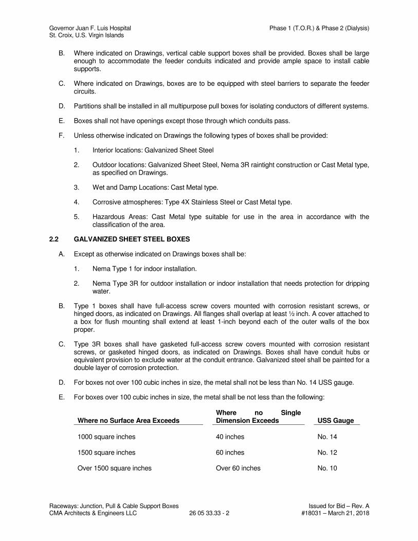
Governor Juan F. Luis Hospital Phase 1 (T.O.R.) & Phase 2 (Dialysis) St. Croix, U.S. Virgin Islands
Raceways: Junction, Pull & Cable Support Boxes Issued for Bid – Rev. A CMA Architects & Engineers LLC 26 05 33.33 - 2 #18031 – March 21, 2018
B. Where indicated on Drawings, vertical cable support boxes shall be provided. Boxes shall be large enough to accommodate the feeder conduits indicated and provide ample space to install cable supports.
C. Where indicated on Drawings, boxes are to be equipped with steel barriers to separate the feeder circuits.
D. Partitions shall be installed in all multipurpose pull boxes for isolating conductors of different systems.
E. Boxes shall not have openings except those through which conduits pass.
F. Unless otherwise indicated on Drawings the following types of boxes shall be provided:
1. Interior locations: Galvanized Sheet Steel
2. Outdoor locations: Galvanized Sheet Steel, Nema 3R raintight construction or Cast Metal type, as specified on Drawings.
3. Wet and Damp Locations: Cast Metal type.
4. Corrosive atmospheres: Type 4X Stainless Steel or Cast Metal type.
5. Hazardous Areas: Cast Metal type suitable for use in the area in accordance with the classification of the area.
2.2 GALVANIZED SHEET STEEL BOXES
A. Except as otherwise indicated on Drawings boxes shall be:
1. Nema Type 1 for indoor installation.
2. Nema Type 3R for outdoor installation or indoor installation that needs protection for dripping water.
B. Type 1 boxes shall have full-access screw covers mounted with corrosion resistant screws, or hinged doors, as indicated on Drawings. All flanges shall overlap at least ½ inch. A cover attached to a box for flush mounting shall extend at least 1-inch beyond each of the outer walls of the box proper.
C. Type 3R boxes shall have gasketed full-access screw covers mounted with corrosion resistant screws, or gasketed hinged doors, as indicated on Drawings. Boxes shall have conduit hubs or equivalent provision to exclude water at the conduit entrance. Galvanized steel shall be painted for a double layer of corrosion protection.
D. For boxes not over 100 cubic inches in size, the metal shall not be less than No. 14 USS gauge.
E. For boxes over 100 cubic inches in size, the metal shall be not less than the following:
Where no Surface Area Exceeds Where no Single Dimension Exceeds USS Gauge
1000 square inches 40 inches No. 14 1500 square inches 60 inches No. 12 Over 1500 square inches Over 60 inches No. 10
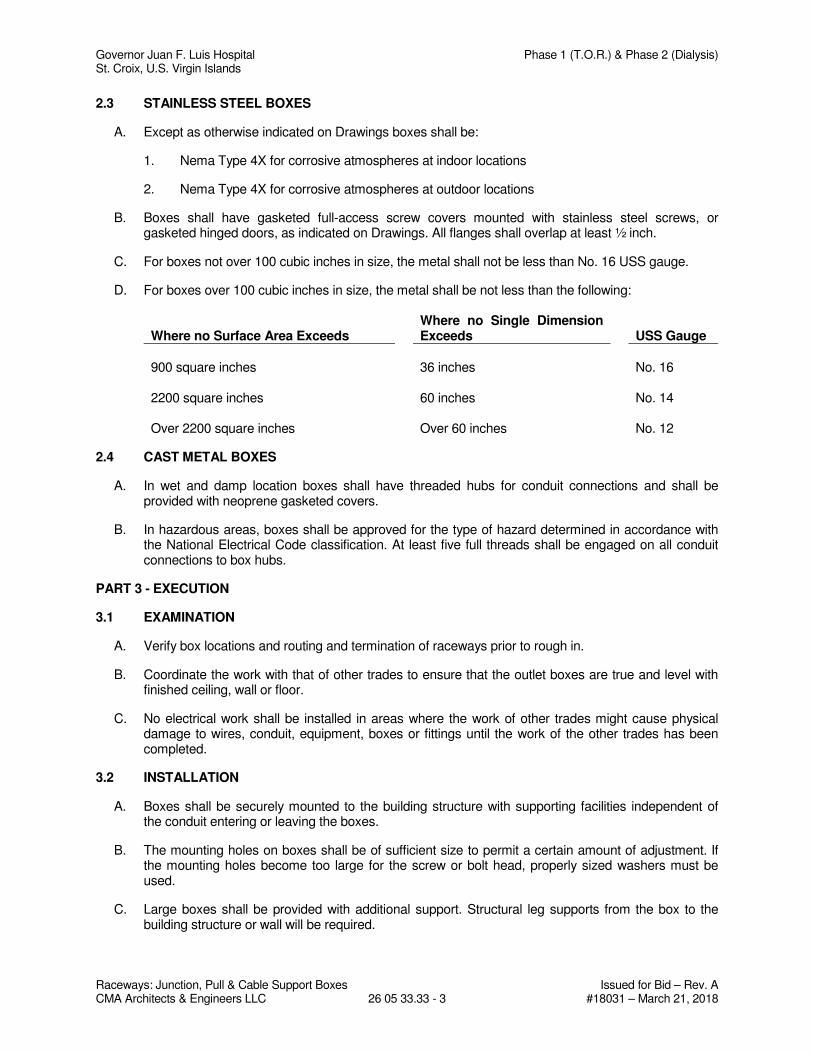
Governor Juan F. Luis Hospital Phase 1 (T.O.R.) & Phase 2 (Dialysis) St. Croix, U.S. Virgin Islands
Raceways: Junction, Pull & Cable Support Boxes Issued for Bid – Rev. A CMA Architects & Engineers LLC 26 05 33.33 - 3 #18031 – March 21, 2018
2.3 STAINLESS STEEL BOXES
A. Except as otherwise indicated on Drawings boxes shall be:
1. Nema Type 4X for corrosive atmospheres at indoor locations
2. Nema Type 4X for corrosive atmospheres at outdoor locations
B. Boxes shall have gasketed full-access screw covers mounted with stainless steel screws, or gasketed hinged doors, as indicated on Drawings. All flanges shall overlap at least ½ inch.
C. For boxes not over 100 cubic inches in size, the metal shall not be less than No. 16 USS gauge.
D. For boxes over 100 cubic inches in size, the metal shall be not less than the following:
Where no Surface Area Exceeds Where no Single Dimension Exceeds USS Gauge
900 square inches 36 inches No. 16 2200 square inches 60 inches No. 14 Over 2200 square inches Over 60 inches No. 12
2.4 CAST METAL BOXES
A. In wet and damp location boxes shall have threaded hubs for conduit connections and shall be provided with neoprene gasketed covers.
B. In hazardous areas, boxes shall be approved for the type of hazard determined in accordance with the National Electrical Code classification. At least five full threads shall be engaged on all conduit connections to box hubs.
PART 3 - EXECUTION
3.1 EXAMINATION
A. Verify box locations and routing and termination of raceways prior to rough in.
B. Coordinate the work with that of other trades to ensure that the outlet boxes are true and level with finished ceiling, wall or floor.
C. No electrical work shall be installed in areas where the work of other trades might cause physical damage to wires, conduit, equipment, boxes or fittings until the work of the other trades has been completed.
3.2 INSTALLATION
A. Boxes shall be securely mounted to the building structure with supporting facilities independent of the conduit entering or leaving the boxes.
B. The mounting holes on boxes shall be of sufficient size to permit a certain amount of adjustment. If the mounting holes become too large for the screw or bolt head, properly sized washers must be used.
C. Large boxes shall be provided with additional support. Structural leg supports from the box to the building structure or wall will be required.
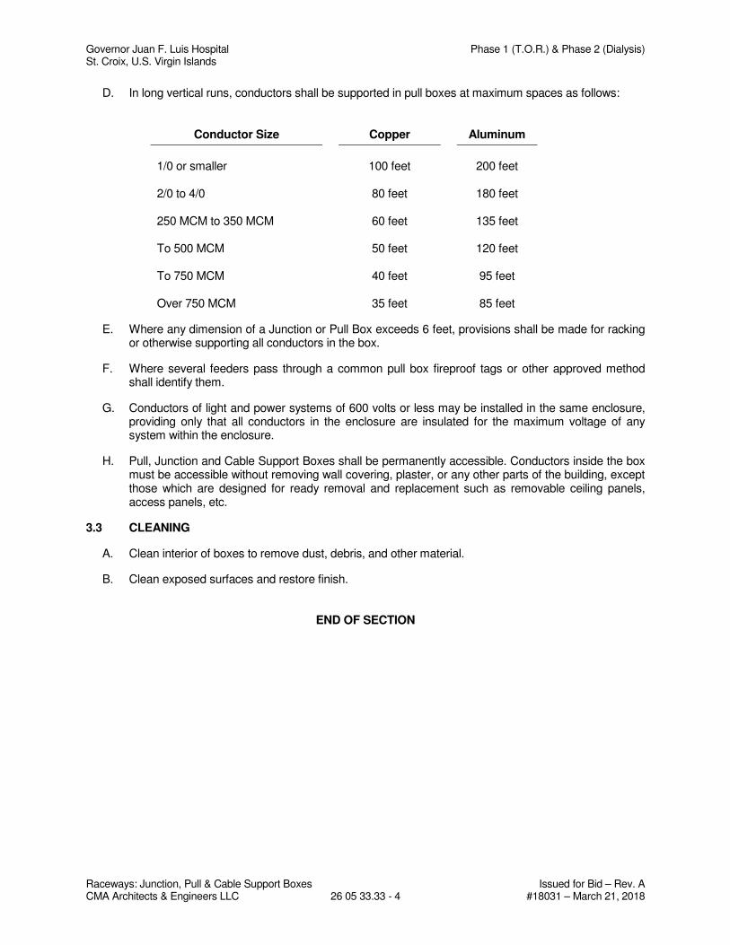
Governor Juan F. Luis Hospital Phase 1 (T.O.R.) & Phase 2 (Dialysis) St. Croix, U.S. Virgin Islands
Raceways: Junction, Pull & Cable Support Boxes Issued for Bid – Rev. A CMA Architects & Engineers LLC 26 05 33.33 - 4 #18031 – March 21, 2018
D. In long vertical runs, conductors shall be supported in pull boxes at maximum spaces as follows:
Conductor Size Copper Aluminum
1/0 or smaller 100 feet 200 feet 2/0 to 4/0 80 feet 180 feet 250 MCM to 350 MCM 60 feet 135 feet To 500 MCM 50 feet 120 feet To 750 MCM 40 feet 95 feet Over 750 MCM 35 feet 85 feet
E. Where any dimension of a Junction or Pull Box exceeds 6 feet, provisions shall be made for racking or otherwise supporting all conductors in the box.
F. Where several feeders pass through a common pull box fireproof tags or other approved method shall identify them.
G. Conductors of light and power systems of 600 volts or less may be installed in the same enclosure, providing only that all conductors in the enclosure are insulated for the maximum voltage of any system within the enclosure.
H. Pull, Junction and Cable Support Boxes shall be permanently accessible. Conductors inside the box must be accessible without removing wall covering, plaster, or any other parts of the building, except those which are designed for ready removal and replacement such as removable ceiling panels, access panels, etc.
3.3 CLEANING
A. Clean interior of boxes to remove dust, debris, and other material.
B. Clean exposed surfaces and restore finish.
END OF SECTION
Governor Juan F. Luis Hospital Phase 1 (T.O.R.) & Phase 2 (Dialysis) St. Croix, U.S. Virgin Islands
Raceways: Cable Trays Issued for Bid - Rev. A CMA Architects & Engineers LLC 26 05 36 - 1 #18031 – March 21, 2018
SECTION 26 05 36
RACEWAYS: CABLE TRAYS
PART 1 - GENERAL
1.1 SUMMARY
A. Section includes Cable Trays.
B. Related Sections:
1. Section 26 05 26 – Grounding and Bonding
2. Section 26 05 33.13 – Raceways: Conduit System
1.2 REFERENCES
A. All work shall be in accordance with all applicable codes and standards to include, but not limited to, the following:
1. NEC – National Electrical Code
2. OSHA – Occupational Safety and Health Act.
3. UL – Underwriters Laboratories
4. ANSI – American National Standards Institute
5. NEMA – National Electric Manufacturers Association
6. ASTM – American Society for Testing and Materials.
1.3 SYSTEM DESCRIPTION
A. Provide Metal Cable Tray System to support cable systems, as indicated on Drawings.
1.4 SUBMITTALS
A. Shop Drawings: Indicate tray type, dimensions, support points, and finishes
B. Product Data: Submit fittings and accessories
C. Manufacturer’s Installation Instructions: Submit application conditions, instructions of use and instructions for the installation of Product.
1.5 CLOSEOUT SUBMITTALS
A. Project Record Documents: Record actual routing of Cable Tray and locations of supports.
1.6 DELIVERY, STORAGE AND HANDLING
A. All materials furnished under this section shall be new and unused.
B. All materials shall be labeled and identified for intended application.
C. All materials shall be protected from damage at all times and stored in staging area.
Governor Juan F. Luis Hospital Phase 1 (T.O.R.) & Phase 2 (Dialysis) St. Croix, U.S. Virgin Islands
Raceways: Cable Trays Issued for Bid - Rev. A CMA Architects & Engineers LLC 26 05 36 - 2 #18031 – March 21, 2018
PART 2 - PRODUCTS
2.1 GENERAL
A. Where indicated on Drawings, an approved metal Cable Tray System to support cable system shall be furnished and installed complete with the required couplings, accessories, elbows, tees, crosses, branch and reducer sections, and cable drop out accessories.
B. As indicated on Drawings the Cable Tray system shall be of the following NEMA VE 1 Class designation:
1. Class A. Supporting cable static weight: 50 pounds per foot
2. Class B. Supporting cable static weight: 75 pounds per foot.
3. Class C. Supporting cable static weight: 100 pounds per foot.
C. Types: As indicated on Drawings the Cable Trays shall be of the following types:
1. Metal Ladder-Type. Dimensions, spacing between rungs, radius of fittings, as indicated on Drawings.
2. Metal Ventilated Trough-Type. Dimensions, radius of fittings, as indicated on Drawings.
3. Metal Solid-Bottom-Type. Dimensions, radius of fittings, as indicated on Drawings.
4. Metal Channel-Type. Dimensions radius of fittings, as indicated on Drawings.
D. Material: As indicated on Drawings the cable trays shall be constructed of the following materials:
1. Steel ASTM A525 pregalvanized. Suitable for use in normal indoor dry application.
2. Steel ASTM A123 hot dipped galvanized after fabrication. Suitable for use in outdoor application.
3. Aluminum. Suitable for use in indoor and outdoor application.
4. PVC coated cable tray. Steel or aluminum cable tray protected with a polyvinyl chloride coating or finish. Suitable for use where highly corrosive conditions exist.
E. Where indicated on Drawings, an approved tray cover shall be provided to protect the cables. Covers shall be securely fastened to the cable tray sections by means of suitable cover connectors.
F. The interiors of all types of cable trays shall be smooth and free of any projections that might injure cable sheaths and jackets. All splice plates shall be installed on the outside surfaces of the supports. Round-head bolts, screws, or other fasteners (heads inside) are to be used exclusively.
G. The components of the Cable Tray System shall be constructed and installed to ensure adequate electrical continuity of the complete system.
H. When indicated on Drawings cable separators or dividers shall be provided. They shall be fabricated of the same material as all the other cable tray fittings and shall include necessary splice clips and mounting bolts, nuts, and washers. All exposed edges must be smooth and free of any projections that might injure cable sheath and jackets. Where necessary to cross cables over separator or divider strips, the cables shall be supported free of the top edge of the strips, or the strips shall be provided with cable protectors where cables cross over.
I. Wire mesh cable tray sections and components for communications systems.
Governor Juan F. Luis Hospital Phase 1 (T.O.R.) & Phase 2 (Dialysis) St. Croix, U.S. Virgin Islands
Raceways: Cable Trays Issued for Bid - Rev. A CMA Architects & Engineers LLC 26 05 36 - 3 #18031 – March 21, 2018
1. Provide wire mesh cable tray of types and sizes indicated; with connector assemblies, clamp assemblies, connector plates, splice plates and splice bars. Construct units with rounded edges and smooth surfaces; in compliance with applicable standards; and with the following additional construction features.
2. Materials and Finishes: Material and finish specifications for Carbon Steel Wire are as follows:
a. Electro-Plated Zinc Galvanizing: Straight sections shall be made from steel meeting the minimum mechanical properties of ASTM A 510, Grade 1008 and shall be electro-plated zinc in accordance with ASTM B633, Type III, SC-1.
J. Type of wire mesh cable tray support system.
1. All straight section longitudinal wires shall be constructed with a continuous top wire safety edge. Safety edge must be kinked and T-Welded on all tray sizes.
2. Wire mesh cable tray shall be made of high strength steel wires and formed into a standard 2 inch by 4 inch wire mesh pattern with intersecting wires welded together. All mesh sections must have at least one bottom longitudinal wire along entire length of straight section.
3. Wire mesh cable tray sizes shall conform to the following nominal criteria:
a. Straight sections shall be furnished in standard 118 inch lengths.
b. Wire diameter shall be 0.196” minimum on all mesh sections.
4. All fittings shall be field formed, from straight sections, in accordance with manufacturer’s instructions.
5. In order for system to be approved as an Equipment Ground Conductor (EGC), all splicing assemblies shall be UL/CSA approved as an EGC.
6. Wire mesh cable tray supports shall be center support hangers, trapeze hangers or wall brackets as indicated in drawings.
7. Trapeze hangers or center support hangers shall be supported by 1/4 inch or 3/8 inch diameter rods.
8. Special accessories shall be furnished as required to protect, support and install a wire mesh cable tray support system.
PART 3 - EXECUTION
3.1 EXAMINATION
A. Verify cable tray locations, routing and terminations of raceways prior to rough in.
B. Coordinate the work with that of other trades to ensure that the cable trays are true and level with finished ceiling, wall or floor.
C. No electrical work shall be installed in areas where the work of other trades might cause physical damage to cables, cable tray or fittings until the work of the other trades has been completed.
3.2 INSTALLATION
A. The installation of the cable tray system shall conform to the requirements of Article 318 of the National Electrical Code and shall be in accordance with NEMA VE.2.
Governor Juan F. Luis Hospital Phase 1 (T.O.R.) & Phase 2 (Dialysis) St. Croix, U.S. Virgin Islands
Raceways: Cable Trays Issued for Bid - Rev. A CMA Architects & Engineers LLC 26 05 36 - 4 #18031 – March 21, 2018
B. Cable Tray System shall be supported from the building structure as indicated on Drawings. Supports for horizontal cable tray shall be provided at each connection point and at end or each run. Vertical cable tray elbows shall be supported at each end. A fitting which is used, as the end of a run drop out shall have a support attached to it.
C. Mounting and hanging materials shall be compatible with the material used in fabricating the cable tray sections and fittings. When installing aluminum trays in outdoor and wet locations, it is necessary to consider the possibility of galvanic corrosion. Neoprene spacer gaskets or equivalent shall be installed between the bottom of cable tray side channels and supporting steel or other metallic members which are not galvanized, or otherwise suitably plated. In highly corrosive areas, stainless steel bolts and fastenings shall be used.
D. The fastening or anchoring of cable trays through bottom sections with bolts or screws upon which cables may rest is prohibited.
E. Install expansion connectors as indicated on Drawings or as recommended by manufacturer. Supports must be provided within 2 feet on both sides of any expansion joint.
F. Openings for cable tray penetrations through fire-resistant rated walls, partitions, floors, or ceilings shall be fire-stopped using approved methods. The installation shall be so made that possible spread of fire or smoke will not be substantially increased.
G. Cable trays shall be installed in such a manner that they will be readily accessible from ladders or scaffold for installing or removing cables. Adequate access to cable trays at each fitting shall be assured.
H. Ample work space shall be provided above and along at least one side of cable trays. Where installed in tiers, the minimum vertical clearance between tiers shall be 12 inches. Minimum clearance of six inches shall be maintained above the top tier and the ceiling, beams, or other obstructions. Where trays are installed side by side, a minimum working space of 24 inches shall be maintained on one side of each cable tray. Working space of 32 inches shall be provided above trays in adjacent rows.
I. Steel or aluminum cable tray systems shall be permitted to be used as equipment grounding conductors provided that the NEC-318.7 requirements are met.
J. Each conduit leaving the cable tray shall be securely bonded using bolted mechanical connectors. Grounding and bonding clamps shall assure electrical continuity and have capacity to conduct safely any fault current likely to be imposed. Any non-conductive paint, enamel, or similar coating is required to be removed at contact surface.
K. Cable tray system shall be bonded together at all locations where cables change from one system to another. Bonding jumpers between different cable tray systems shall be located as close to the cables as practical.
L. Cable tray system shall be electrically connected to enclosures in which the cables terminate. Connecting grounding conductors and bonding jumpers between enclosures and cable tray system shall be located as close to the cables as practical.
M. Materials used for grounding must be compatible with those used for grounding in the cable tray system. Copper bonding and grounding conductors and bronze clamps shall be used with galvanized steel trays. Aluminum conductors, or tinned copper conductors, together with aluminum-type clamps, or bronze fittings hot-tinned plated, shall be used with aluminum cable trays.
N. If a separate grounding conductor is required it shall be installed inside the cable tray. The round head of the bolts of all connecting clamps and conductor support clips shall be in the interior of the cable tray in order to avoid damage to the cables. Side channels of straight sections and fittings shall
Governor Juan F. Luis Hospital Phase 1 (T.O.R.) & Phase 2 (Dialysis) St. Croix, U.S. Virgin Islands
Raceways: Cable Trays Issued for Bid - Rev. A CMA Architects & Engineers LLC 26 05 36 - 5 #18031 – March 21, 2018
have holes punched in their web section to receive bolts of the grounding clamps and cable tray clamps. No holes shall be drilled or punched in either the top or bottoms legs of any side channel.
O. Cable trays shall be kept free of all materials except conductors intended to be supported thereon.
3.3 CLEANING
A. Clean interior of cable trays to remove dust, debris, and other material.
B. Clean exposed surfaces and restore finish.
END OF SECTION
Governor Juan F. Luis Hospital Phase 1 (T.O.R.) & Phase 2 (Dialysis) St. Croix, U.S. Virgin Islands
Underground Duct System Issued for Bid - Rev. A CMA Architects & Engineers LLC 26 05 43 - 1 #18031 – March 21, 2018
SECTION 26 05 43
UNDERGROUND DUCT SYSTEM
PART 1 - GENERAL
1.1 SUMMARY
A. Section includes underground duct construction for electrical distribution systems.
1.2 RELATED SECTIONS
A. Section 26 05 26 – Grounding and Bonding
1.3 REFERENCES
A. All work shall be in accordance with all applicable codes and standards to include, but not limited to, the following:
1. NEC – National Electrical Code
2. OSHA – Occupational Safety & Health Act
3. UL – Underwriters Laboratories
4. ANSI – American National Standards
5. ASTM – American Society for Testing and Materials.
6. NEMA – National Electric Manufacturers Association
7. WAPA – Virgin Islands Water and Power Authority
1.4 SYSTEM DESCRIPTION
A. Provide all labor and materials to complete trenching, duct system, manholes, concrete encasement when required, backfilling, and pavement repair for the construction of electrical distribution system as indicated on drawings.
B. As indicated on Drawings the duct installation for the electrical distribution system shall be of the following types:
1. Conduit installation with concrete encasement.
2. Conduit installation without concrete encasement.
1.5 SUBMITTALS
A. Product Data: Submit data for each type of conduit, pre-fabricated manholes, conduit spacers, marking tape and accessories used in the Project.
1.6 CLOSEOUT SUBMITTALS
A. Project Record Documents: Furnish one set of marked copies of contract drawings, showing exact routing and depths of all underground conduits, manholes, pull boxes and
Governor Juan F. Luis Hospital Phase 1 (T.O.R.) & Phase 2 (Dialysis) St. Croix, U.S. Virgin Islands
Underground Duct System Issued for Bid - Rev. A CMA Architects & Engineers LLC 26 05 43 - 2 #18031 – March 21, 2018
hand holes. Furnish scaled plot plans showing principal outline of buildings and structures. Reference conduits, ducts, box walls, and all bends deviating from straight line, dimensionally from fixed objects or structures.
1.7 COORDINATION
A. Resolve interference with other underground ducts, piping or equipment, either new or existing.
1.8 DELIVERY, STORAGE AND HANDLING
A. All materials furnished under this section shall be new, unused and delivered in original manufacturer’s packaging.
B. All materials shall be protected from damage at all times and stored in staging areas.
PART 2 - PRODUCTS
2.1 CONDUITS
A. All conduits shall be provided with fittings and accessories.
B. Conduit installation with concrete encasement: As indicated on drawings the conduit shall be:
1. Rigid Steel: hot dipped galvanized
2. Plastic: Polyvinyl chloride (PVC) conduit, DB-120 or Schedule 40 approved for use as raceway for 90 degree C conductors.
C. Conduit installation without concrete encasement: As indicated on Drawings the conduit shall be:
1. Plastic: Polyvinyl chloride (PVC) conduit, DB-120 or Schedule 40 approved for use as raceway for 90 degree C conductors.
2.2 CONDUIT SPACERS
A. Provide conduit spacers made of plastic to maintain spacing of 3 inches (76 mm) between conduits.
2.3 GRAVEL FILL
A. Clean 3 inches maximum size, not more than 70 percent passing No. 4 sieve, not more than 10 percent passing No. 200 mesh sieve.
2.4 CONCRETE
A. 3,000 psi at 28 days. Minimum 5-1/2 sacks cement, maximum 1-inch coarse aggregate. Aggregate to meet ASTM C33.
2.5 REINFORCEMENT
A. ASTM A-615 Grade 40
Governor Juan F. Luis Hospital Phase 1 (T.O.R.) & Phase 2 (Dialysis) St. Croix, U.S. Virgin Islands
Underground Duct System Issued for Bid - Rev. A CMA Architects & Engineers LLC 26 05 43 - 3 #18031 – March 21, 2018
2.6 PAVEMENT
A. 6-inch run off crush stone base course, grading Class B.
B. 4-inch bituminous base course B-1
C. 2-inch bituminous surface course S-1
D. All materials measured at depth after compaction.
PART 3 - EXECUTION
3.1 PAVEMENT CUTTING
A. Cut pavement in straight lines, as required for trench excavation.
B. Remove and legally dispose of pavement materials.
3.2 TRENCH EXCAVATION
A. Prior to opening an excavation, effort shall be made to determine whether underground installations (sewer, water, fuel, electrical lines, telephone lines, etc.) will be encountered and, if so, where such underground installations are located. When the excavation approaches the estimated location of such an installation, the exact location shall be determined and when it is uncovered, proper supports shall be provided for the existing installation.
B. Includes all earth and miscellaneous material encountered that is possible to excavate with a one-cubic yard backhoe in good working condition. Excavate to exact depth and grade with bottom tamped hard. Report wet or unstable trench bottom to Owner. Should Owner deem unsuitable, excavate to depth as directed and backfill with approved bedding material as directed by Owner. The duct structure should be kept dry until the concrete envelope has been poured. The trench must be pumped where there is an excessive amount of water.
C. The trench bottom should be level. The levelness of the duct structure is determined by the levelness of the trench bottom. All sharp bends should be avoided in the excavation.
D. Banks and Sides: Angle or recline to sheathing, shoring and bracing as required for safety, and conforming to all applicable laws, rules, regulations, and codes.
E. Protection: Provide lights and barricades to properly protect persons and property per all applicable laws and regulations.
F. Disposal of excess Excavated Material: Legally dispose all excess excavated material off site.
3.3 INSTALLATION OF CONDUITS
A. Install conduit indicated to be encased in concrete with concrete, spacers, reinforcing, etc. as specified and as indicated.
B. Install conduit runs following routing on drawings and running in straight lines as far as possible. Where deviation from a straight line becomes necessary, install bends of sufficient radius for proper rodding and installation of cables.
Governor Juan F. Luis Hospital Phase 1 (T.O.R.) & Phase 2 (Dialysis) St. Croix, U.S. Virgin Islands
Underground Duct System Issued for Bid - Rev. A CMA Architects & Engineers LLC 26 05 43 - 4 #18031 – March 21, 2018
C. Accomplish changes in direction of runs exceeding total of 10 degrees, either vertical or horizontal, by long sweep bends having a minimum radius of curvature of 25 feet (7.62 m), except that manufactured bends used at ends of short runs of 100 feet (30.48 m) or less and then only at or close the end of run. Long sweep bends made up or one or more curved or straight sections and/or combinations thereof. Install manufactured bends with minimum radius of 36 inches (915 mm) where larger radius cannot be used.
D. Lay duct lines to minimum slope of 3 inches (76 mm) per 100 feet (30.48 m) and slope to manholes, as indicated. Duct lines are to slope away from buildings where possible.
E. Stagger joints in conduits at least 6 inches (150 mm). Do not allow couplings to rest on bottom of trench. Install couplings for plastic conduit in accordance with manufacturer'’ recommendations.
F. Install spacers at intervals of approximately 5 feet (1.52 m) and stagger between tiers of ducts to provide not less than 12 inches (300 mm) of longitudinal separation. The maximum intervals between spacers on curved sections should not exceed 4 feet (1.22 m). Install base spacers to provide at least 3 inches (76 mm) between bottom of trench and underside of bottom conduits. Completely fill space with concrete. Firmly tied conduits and spacers together with pieces of heavy twine (not wire) before concrete is placed.
G. Due to magnetic induction under no circumstances shall reinforcement rod or magnetic type material be used to support conduits or used between duct lines.
H. Prior to placing of concrete, remove all dirt, sand, and any other debris from between conduits and from trench bottoms. Hold conduits in place to prevent floating or accidental movement.
I. Install concrete encasements so minimum clearance of 12 inches (300 mm) from concrete to parallel pipes, lines, structures, etc. is maintained. Where ducts cross, minimum clearance of 6 inches (150 mm) will be acceptable. Do not allow the top of concrete to be less than 36 inches (915 mm) below finished grade or paving. Submit special conditions, which may require lesser clearances for approval.
J. No sharp objects, such as reinforcing rods, spades, etc. should be used for tamping the concrete envelope around the ducts. Wooden tampers are recommended. Concrete vibrators should never be used for tamping.
K. Exposed duct ends shall be protected during pouring so that concrete cannot get inside ducts.
L. Where a connection is made to existing ductline, firmly fond or dowel concrete encasement to existing encasement.
M. Where electrical ducts cross under roads, encase them in concrete.
N. Keep conduits clean of concrete, dirt, and other substances during the course of construction. After the duct lines have been completed, pull a standard flexible mandrel not less than 12 inches (300 mm) long, having a diameter approximately ¼ inch (6 mm) less than the inside diameter of the conduit, through each conduit, after which, pull a brush with stiff bristles through each conduit to make certain than no particles of earth, sand or gravel have been left in the line. Replace conduit runs that not allow the
Governor Juan F. Luis Hospital Phase 1 (T.O.R.) & Phase 2 (Dialysis) St. Croix, U.S. Virgin Islands
Underground Duct System Issued for Bid - Rev. A CMA Architects & Engineers LLC 26 05 43 - 5 #18031 – March 21, 2018
passage of the mandrel at any additional cost to the Owner. Pneumatic rodding may be used to draw in the lead wire. Plug and seal spare conduits after cleaning.
3.4 TRENCH BACKFILL
A. Materials: Where no pavement occurs, use excavated material. Where pavement occurs, use gravel.
B. Start after approval by Owner. Backfill should not be placed until the concrete has been allowed sufficient time to set. A minimum time of 48 hours after pouring of concrete is recommended.
C. Place:
1. Conduit encased in concrete: Material used in backfilling around duct banks should be fine and free from lumps, well tampered beneath and adjacent to the sides of the concrete envelope. Place 6-inch layers from bottom of excavation to bottom of paving. No boulders or stones over 4 inches. Tamp each 6-inch layer with mechanical tamper.
2. Conduit without concrete encasement: Backfill shall contain no boulders or stones over 1-inch to a point 12 inches above raceways. Tamp each 6-inch layer with mechanical tamper.
D. Compaction: Uniformly spread each layer moisten or dry, as required, and then compact so unit dry weight of the compacted material meets or exceeds 95 percent Modified Proctor, as per ASTM D-1557. Provide a minimum of 4-field density tests to verify compaction.
3.5 PLACING PAVEMENT
A. Place each layer separately and compact to depths specified. Comply with specifications of the Virgin Islands Water and Power Authority.
3.6 MANHOLES, PULL BOXES, AND HAND HOLES
A. General
1. Unless otherwise indicated, install tops of manhole covers in unpaved areas approximately 2 inches (25 mm) above finished grade and in paved areas install flush with finished surface of paving.
2. Install galvanized corrosion-resistant channel support with continuous slot and required fittings designed for concrete encasement.
3. Where duct lines, enter thin wall terminate conduits with end bells.
4. Damp proofing: Apply two coats of bituminous damp proofing material to exterior surfaces of wall. Apply by brush or spray, in accordance with manufacturer’s instructions. Allow time between coats to permit sufficient drying.
B. Prefabricated:
1. Shall be approved by Virgin Islands Water and Power Authority.
Governor Juan F. Luis Hospital Phase 1 (T.O.R.) & Phase 2 (Dialysis) St. Croix, U.S. Virgin Islands
Underground Duct System Issued for Bid - Rev. A CMA Architects & Engineers LLC 26 05 43 - 6 #18031 – March 21, 2018
C. Cast in Place:
1. Construct them of Class A (3,000 psi) concrete cast in place, as indicated.
2. Place a 6-inch (150 mm) crushed stone base under each manhole.
3. Construct cast-in-place manholes, pull boxes, and hand holes with forms, complete with centering cores and molds to conform to shape, form, line, and grade required, and maintain sufficiently rigid to prevent deformation under load. Make all joints leak proof and arrange horizontally or vertically. Place forms on successive units for continuos surfaces and fit to accurate alignment, assuring a smooth completed surface, free from irregularities.
4. At convenient point close to wall, drive two- (2) 5/8-inch by 8-feet long copper-clad steel ground rods into earth as indicated. Extend ground rod approximately 5 inches (125 mm) above finished manhole floor. After completion of manhole, connect 6-foot (1.83 m) length of No. 2/0 AWG bare copper wire to ground rod and coil it within manhole.
5. Size space and place reinforcing bars, as indicated and as specified.
6. Set frames to the required grade in full bed of concrete mortar, to take watertight connection.
3.7 CLEANING
A. Clean interior of manholes, pull boxes and hand holes to remove dust, debris, and other material.
END OF SECTION
Governor Juan F. Luis Hospital Phase 1 (T.O.R.) & Phase 2 (Dialysis) St. Croix, U.S. Virgin Islands
Acceptance Testing Issued for Bid – Rev. A CMA Architects & Engineers LLC 26 08 00 - 1 #18031 – March 21, 2018
SECTION 26 08 00
ACCEPTANCE TESTING
PART 1 - GENERAL
1.1 SUMMARY
A. Section includes Acceptance Testing for Electrical Power Distribution Equipment and Systems.
1.2 APPLICABLE REFERENCES
A. All inspections and field tests shall be in accordance with the latest edition of the following codes, standards, and specifications except as provide otherwise herein.
1. ASTM – American Society for Testing and Materials
2. ANSI – American National Standards Institute
3. IEEE – Institute of Electrical and Electronic Engineers
4. ICEA – Insulated Cable Engineers Association
5. NETA – International Electrical Testing Association
6. NEMA – National Electrical Manufacturer’s Association
7. NEC – National Electrical Code
8. NFPA – National Fire Protection Association
9. OSHA – Occupational Safety and Health Administration
10. WAPA – Virgin Islands Water and Power Authority
11. UL – Underwriters Laboratories, Inc.
1.3 EQUIPMENT AND SYSTEMS TO BE TESTED
A. Transformers
B. Cables and Wires
C. Metal-Enclosed Busways
D. Outdoor Bus Structures
E. Switches
F. Circuit Breakers
G. Switchgear and Switchboard Assemblies
H. Instrument Transformers
I. Metering
J. Protective Relays
Governor Juan F. Luis Hospital Phase 1 (T.O.R.) & Phase 2 (Dialysis) St. Croix, U.S. Virgin Islands
Acceptance Testing Issued for Bid – Rev. A CMA Architects & Engineers LLC 26 08 00 - 2 #18031 – March 21, 2018
K. Ground-Fault Protection System
L. Surge Arrestors
M. AC Motors
N. AC Generators
O. Motor Control
P. Adjustable Speed Drive Systems
Q. Emergency Systems
R. Uninterruptible Power Systems
S. Capacitors
T. Direct-Current Systems
U. Grounding Systems.
1.4 SYSTEM DESCRIPTION
A. The work covered by this specification shall include furnishing all labor, material, equipment and services to perform de acceptance tests for the complete electrical system.
B. Preliminary acceptance tests are defined as those tests and inspections required to determine that the equipment involved may be energized for final operations tests.
C. Final acceptance will depend upon equipment performance, characteristics, ant their compliance with the intended design as determined by system operational tests defined in this and other sections of these specifications.
D. Use the standards of the industry such as IEE, NEMA, ANSI, IPCEA, NETA and guides in testing the equipment.
E. Follow all Virgin Islands Water and Power Authority (WAPA) regulations.
1.5 QUALIFICATIONS
A. The testing shall be performed by an independent testing laboratory engaged in the business of electrical acceptance testing similar to the inspections and tests specified. Testing laboratory shall have a minimum of five years experience.
B. The testing laboratory shall submit proof of qualifications to the Owner. Proof shall include but not be limited to:
1. Name of the required registered professional engineer.
2. Qualifications of test personnel: Minimum of two years supervised field experience, or certified National Electrical Testing Association (NETA) test technician.
3. Experience as a testing laboratory for a minimum of five years.
4. Equipment available for use on this project.
C. Membership in the NETA may be submitted in addition to the above list to substantiate qualifications.
Governor Juan F. Luis Hospital Phase 1 (T.O.R.) & Phase 2 (Dialysis) St. Croix, U.S. Virgin Islands
Acceptance Testing Issued for Bid – Rev. A CMA Architects & Engineers LLC 26 08 00 - 3 #18031 – March 21, 2018
1.6 TEST PROCEDURE
A. The Owner will provide a set of project electrical documents to assist in ascertaining the extent of the project testing.
B. The testing laboratory shall be responsible for tests and test record for each item to be tested.
C. Test in the presence of the Owner’s representative at the option of the Owner.
D. Report immediately to the Owner any system, material, or workmanship which is defective, in compliance with the specifications.
E. Provide necessary test equipment and be responsible for setting-up test equipment, wire checks of factory wiring, and any other preliminary work in preparation for the electrical acceptance tests.
F. Having a calibration program which maintains applicable test instrumentation within rated accuracy. Accuracy shall be traceable to the National Bureau of Standards. Calibration frequency shall be in accordance with the following schedule:
1. Field instruments: six months maximum
2. Laboratory instruments: 12 months maximum.
G. Dated calibration shall be visible on equipment.
H. Test in cooperation with other affected subcontractors. The schedule of tests shall be approved by the Owner’s representative. Three day notice shall be given prior to testing, unless otherwise necessary or specified.
I. Advice the manufacturer’s representative of tests performed on their equipment. Give a minimum of ten calendar day notice to permit him to witness the equipment under test, should be desire.
J. Certain pieces of equipment have the services of a manufacturer’s service engineer who will assist in performing the tests on the equipment. When this service is provided, he will verify and sign each report form.
K. Tests shall be non-destructive and shall not exceed the manufacturer’s recommended limit for the equipment being tested.
L. Where required for the validity of tests of safety of equipment and personnel, isolate equipment to be tested from the system.
M. All testing shall be performed according to the manufacturer instructions and test value limitation indicated by testing equipment company or equipment manufacturer.
1.7 TEST REPORT
A. Incorporate a record of inspections and tests into the test report.
B. The test report shall be bond and certified by the testing laboratory.
C. Furnish seven (7) copies of the complete report to the Owner, no later than 30 days after completion of project. At the discretion of the Owner’s representative, due to the installation scheduling of specific items of equipment or for other reasons, testing may be subdivided into several smaller packages. In that case, one copy of a test report shall be submitted no later than 30 days after completion of each test package, and an inclusive test report containing the package reports shall be submitted in the quantity and the time specified above for the complete project.
D. Include the following in the test report:
Governor Juan F. Luis Hospital Phase 1 (T.O.R.) & Phase 2 (Dialysis) St. Croix, U.S. Virgin Islands
Acceptance Testing Issued for Bid – Rev. A CMA Architects & Engineers LLC 26 08 00 - 4 #18031 – March 21, 2018
1. Summary of the project.
2. Description of the equipment tested.
3. Description of test performed.
4. List of test equipment used and calibration dates.
5. Test results.
6. Conclusions and recommendation, if any.
E. Where adjustment, modifications, or repairs are made to equipment in order to meet the equipment and/or system specifications, the test results and reports shall indicate the “as left” condition.
F. The test forms shall include but not be limited to the following:
1. Name plate catalog number, serial number, and rating.
2. Desired performance or performance range.
3. Measure performances.
4. Test equipment used.
5. Test personnel and date.
6. Any discrepancies or repairs made.
G. Test forms that are different than NETA copyrighted test report forms shall be approved by the Owner’s representative.
1.8 VISUAL INSPECTION
A. Prior to testing, equipment shall be visually inspected to determine that there is no physical damage, loose bolts or missing parts, and the equipment is supplied in agreement with the contract documents, and properly installed and connected.
1.9 ENVIRONMENTAL CONDITIONS
A. Temperature
1. Test results shall be corrected to 20 degrees C both actual ambient temperature test reading and calculated, corrected to temperature, test values shall be reported.
2. Test shall not be made on any equipment when the insulation temperature is below 0 degrees C.
B. Humidity
1. Test shall not be made on any equipment where the relative humidity is above 70 percent. Deviations of this requirement will only be made by the Owner’s representative, if it can be demonstrated that the higher humidity will not affect the test or that the higher humidity can be accounted for adequately in interpreting the test results.
PART 2 - PRODUCTS
2.1 GENERAL
A. Non used
Governor Juan F. Luis Hospital Phase 1 (T.O.R.) & Phase 2 (Dialysis) St. Croix, U.S. Virgin Islands
Acceptance Testing Issued for Bid – Rev. A CMA Architects & Engineers LLC 26 08 00 - 5 #18031 – March 21, 2018
PART 3 - EXECUTION
3.1 TRANSFORMERS
A. Dry Type Air-Cooled, 600 volt and below – Small (167 kVA Single-Phase, 500 kVA Three-Phase, and Smaller).
1. Perform inspection and tests listed in NETA, Section 7.2.1.1
B. Dry-Type Air-Cooled, All above 600 Volt and 600 Volt and Below-Large (Greater than 167 kVA Single-Phase and 500 kVA Three-Phase)
1. Perform inspection and tests listed in NETA, Section 7.2.1.2
2. Perform any additional test required by WAPA latest regulations.
C. Liquid-Filled
1. Perform inspection and test listed in NETA, Section 7.2.2
2. Perform any additional test required by WAPA latest regulations.
3.2 CABLES
A. Low-Voltage, 600 Volt Maximum
1. Perform inspection and test listed in NETA, Section 7.3.2
B. Medium-Voltage, 69 kV Maximum
1. Perform inspection and test listed in NETA, Section 7.3.3
2. Perform any additional test required by WAPA latest regulations.
C. High-Voltage
1. Perform inspection and test listed in NETA, Section 7.3.3
2. Perform any additional test required by WAPA latest regulations
3.3 METAL-ENCLOSED BUSWAYS
A. Perform inspection and test listed in NETA, Section 7.4.
3.4 OUTDOOR BUS STRUCTURES
A. Perform inspection and test listed in NETA, Section 7.21
B. Perform any additional test required by WAPA latest regulations.
3.5 SWITCHES
A. Low-Voltage
1. Perform inspection and test listed in NETA, Section 7.5.1.1
B. Medium-Voltage, Metal-Enclosed
1. Perform inspection and test listed in NETA, Section 7.5.1.2
Governor Juan F. Luis Hospital Phase 1 (T.O.R.) & Phase 2 (Dialysis) St. Croix, U.S. Virgin Islands
Acceptance Testing Issued for Bid – Rev. A CMA Architects & Engineers LLC 26 08 00 - 6 #18031 – March 21, 2018
2. Perform any additional test required by WAPA latest regulations.
C. High and Medium Voltage, Open
1. Perform inspection and test listed in NETA, Section 7.5.1.3
2. Perform any additional test required by WAPA latest regulations.
D. Oil Switches: Medium-Voltage
1. Perform inspection and test listed in NETA, Section 7.5.2
2. Perform any additional test required by WAPA latest regulations.
E. Vacuum Switches: Medium Voltage
1. Perform inspection and test listed in NETA, Section 7.5.3
2. Perform any additional test required by WAPA latest regulations.
F. SF6 Switches: Medium Voltage
1. Visual and Mechanical Inspection. Perform inspection and test listed in NETA, Section 7.5.4.
a. Inspect for physical damage and compare nameplate data with plans and specifications
b. Inspect anchorage, alignment and grounding.
c. Perform all mechanical operation and contact blade alignment tests on both the circuit switcher and its operating mechanism in accordance with manufacturer’s instruction.
d. Check tightness of bolted bus joints by calibrated torque wrench method. Refer to manufacturer’s instruction for proper foot pound level.
2. Electrical Tests
a. Measure contact resistance
b. Perform switcher travel time test if unit is properly equipped for this test.
c. Circuit switcher shall be tripped by operation of each protective device.
d. Perform insulation resistance test on each pole to ground.
e. Perform ac or dc over potential test on each pole to ground and pole to pole.
f. Perform insulation resistance test on all control wiring at 1000 volts dc (Do not perform this test on wiring connected to solid state relays).
g. All tests indicated in this section shall be verified with equipment manual and manufacturer instructions and recommendations.
3.6 CIRCUIT BREAKERS
A. Low-Voltage: Insulated/Molded Case
1. Perform inspection and test listed in NETA, Section 7.6.1.1
Governor Juan F. Luis Hospital Phase 1 (T.O.R.) & Phase 2 (Dialysis) St. Croix, U.S. Virgin Islands
Acceptance Testing Issued for Bid – Rev. A CMA Architects & Engineers LLC 26 08 00 - 7 #18031 – March 21, 2018
B. Low-Voltage: Power
1. Perform inspection and test listed in NETA, Section 7.6.1.2
C. Medium-Voltage: Air
1. Perform inspection and test listed in NETA, Section 7.6.2.1
2. Perform any additional test required by latest WAPA regulations
D. Medium-Voltage: Oil
1. Perform inspection and test listed in NETA, Section 7.6.2.2
2. Perform any additional test required by latest WAPA regulations
E. Medium-Voltage: Vacuum
1. Perform inspection and test listed in NETA, Section 7.6.2.3
2. Perform any additional test required by latest WAPA regulations
F. Medium-Voltage: SF6
1. Perform inspection and test listed in NETA, Section 7.6.2.4
2. Perform any additional test required by latest WAPA regulations
G. High-Voltage: Oil
1. Perform inspection and test listed in NETA, Section 7.6.3.1
2. Perform any additional test required by latest WAPA regulations.
H. High-Voltage: SF6
1. Perform inspection and test listed in NETA, Section 7.6.3.2
2. Perform any additional test required by latest WAPA regulations.
3.7 SWITCHGEAR AND SWITCHBOARD ASSEMBLIES
A. Perform inspection and test listed in NETA, Section 7.1
3.8 INSTRUMENT TRANSFORMERS
A. Perform inspection and tests listed in NETA, Section 7.10
3.9 METERING
A. Perform inspection and tests listed in NETA, Section 7.11
3.10 PROTECTIVE RELAYS
A. Perform inspection and tests listed in NETA, Section 7.9
B. Perform any additional test required by latest WAPA regulations.
Governor Juan F. Luis Hospital Phase 1 (T.O.R.) & Phase 2 (Dialysis) St. Croix, U.S. Virgin Islands
Acceptance Testing Issued for Bid – Rev. A CMA Architects & Engineers LLC 26 08 00 - 8 #18031 – March 21, 2018
3.11 GROUND-FAULT PROTECTION SYSTEM
A. Perform inspection and tests listed in NETA, Section 7.14
3.12 SURGE ARRESTORS
A. Low-Voltage Surge Protection Devices
1. Perform inspections and tests listed in NETA, Section 7.19.1
B. Medium and High-Voltage Surge Protection Devices
1. Perform inspections and tests listed in NETA, Section 7.19.2
3.13 AC MOTORS
A. Perform inspection and test listed in NETA, Section 7.15.1.1
3.14 AC GENERATORS
A. Perform inspection and test listed in NETA, Section 7.15.2.1
3.15 MOTOR CONTROL
A. Motor Starters: Low Voltage
1. Perform inspection and test listed in NETA, Section 7.16.1.1
B. Motor Starters: Medium Voltage
1. Perform inspection and test listed in NETA, Section 7.16.1.2
C. Motor Control Centers: Low and Medium Voltage
1. Perform inspection and tests listed in NETA, Section 7.16.2.1
3.16 ADJUSTABLE SPEED DRIVE SYSTEMS
A. Perform inspection and test listed in NETA, Section 7.17
3.17 EMERGENCY SYSTEMS
A. Engine Generator
1. Perform inspection and test listed in NETA, Section 7.22.1
B. Automatic Transfer Switches
2. Perform inspection and test listed in NETA, Section 7.22.3
3.18 UNINTERRUPTIBLE POWER SYSTEMS
A. Perform inspection and test listed in NETA, Section 7.22.2
3.19 CAPACITORS
A. Perform inspection and test listed in NETA, Section 7.20.1
Governor Juan F. Luis Hospital Phase 1 (T.O.R.) & Phase 2 (Dialysis) St. Croix, U.S. Virgin Islands
Acceptance Testing Issued for Bid – Rev. A CMA Architects & Engineers LLC 26 08 00 - 9 #18031 – March 21, 2018
3.20 DIRECT-CURRENT SYSTEMS
A. Batteries
1. Perform inspection and test listed in NETA, Section 7.18.1
B. Battery Chargers
1. Perform inspection and test listed in NETA, Section 7.18.2
3.21 GROUNDING SYSTEMS
A. Perform inspection and test listed in NETA, Section 7.13
3.22 REFERENCES
A. The reference Standards are available as follows:
International Electrical Testing Association (NETA) P.O. Box 687, Morrison, CO 80465 Tel: (303)697-8441; Fax (303)697-8431 E-mail: [email protected] – Web site: www.netaworld.org
B. Approved Testing Companies includes, but are not limited to:
1. EISEC RR3, Box 3160 Río Piedras, PR 00928 Tel: (787)764-5015, (787)764-5130; Fax (787)751-3526 Mr. Angel González, Mr. Ramón E. León.
2. Phasor Engineering Inc. Box 9012, Ponce, PR 00732-9012 Tel: 844-9336, 844-3040; San Juan 727-4655 Mr. Rafael Castro
3. Power Engineering,Inc St. D, Cataño, PR 00632 G.P.O Box 1905 San Juan, PR 00936 Tel: (787)788-6052 (787)788-6340, (787)788-5121, (787)788-6380 Mr. Félix J. Velázquez
END OF SECTION
Governor Juan F. Luis Hospital Phase 1 (T.O.R.) & Phase 2 (Dialysis) St. Croix, U.S. Virgin Islands
Low Voltage Dry Type Transformers Issued for Bid – Rev. A CMA Architects & Engineers LLC 26 22 00 - 1 #18031 – March 21, 2018
SECTION 26 22 00
LOW VOLTAGE DRY TYPE TRANSFORMERS
PART 1 - GENERAL
1.1 SUMMARY
A. Section includes:
1. Air-cooled, dry type transformers for lighting and power loads, with primaries and secondaries rated 600 volts or less.
2. Air-cooled, dry type transformers for nonlinear loads, with primaries and secondaries rated 600 volts or less.
1.2 RELATED SECTIONS
A. 26 05 26 – Grounding and Bonding.
B. 26 08 00 – Acceptance Testing.
1.3 REFERENCES
A. All work shall be in accordance with all applicable codes and standards to include, but not limited to, the following:
1. NEC – National Electrical Code
2. OSHA – Occupational Safety and Health Act
3. UL – Underwriters Laboratories
4. ANSI – American National Standards Institute
5. NEMA – National Electric Manufacturers Association
6. IEEE – Institute of Electrical and Electronic Engineers
1.4 SUBMITTALS
A. Product Data: Submit outline and support point dimensions of enclosures and accessories, minimum clearances, unit weight, voltage, kVA, k-factor, and impedance ratings and characteristics, performance for each type and size of transformer, tap configurations, insulation system type, and rated temperature rise.
B. Shop Drawings:
1. Detail equipment assemblies and indicate dimensions, weights, loads, required clearances, method of field assembly, components, and location and size of each field connection.
2. Vibration Isolation Base Details: Detail fabrication including anchorages and attachments to structure and to supported equipment.
3. Include diagrams for power, signal, and control wiring
C. Test Reports: Indicate loss data, efficiency at 25, 50, 75 and 100 percent rated load, and sound level.
Governor Juan F. Luis Hospital Phase 1 (T.O.R.) & Phase 2 (Dialysis) St. Croix, U.S. Virgin Islands
Low Voltage Dry Type Transformers Issued for Bid – Rev. A CMA Architects & Engineers LLC 26 22 00 - 2 #18031 – March 21, 2018
1.5 CLOSEOUT SUBMITTALS
A. Project Record Documents: Record actual locations of transformers.
B. Provide written instructions for the maintenance of the transformer, in accordance with the manufacturer’s recommendations.
1.6 DELIVERY, STORAGE AND HANDLING
A. Store in clean, dry space. Maintain factory wrapping and provide additional canvas or plastic cover to protect units from dirt, water, construction debris, and traffic.
B. Handle in accordance with manufacturer’s written instructions. Lift only with lugs provided. Handle carefully to avoid damage to transformer internal components, enclosure, and finish.
PART 2 - PRODUCTS
2.1 GENERAL
A. Manufacturers: As indicated on Drawings.
B. Primary and Secondary Voltages as indicated on Drawings.
C. Sound Levels: Minimum of 3 dBA less than NEMA ST 20 standard sound levels when factory tested according to IEEE C57-12.91.
D. Fungus Proofing: Permanent fungicidal treatment for coil and core
E. Isolate core and coil from enclosure using vibration-absorbing mounts.
F. Enclosure: NEMA ST 20, Type 1. Furnish lifting eyes and brackets.
G. Mounting:
1. 1-15 kVA: Suitable for wall mounting
2. 25-75 kVA: Suitable for wall, floor or trapeze mounting.
3. Larger than 75 kVA: Suitable for floor mounting.
H. Nameplate: Engraved, laminated-plastic or metal nameplate for each transformer, mounted with corrosion-resistant screws. Include transformer connection data.
I. As indicated on Drawings dry type transformers shall be as follows:
1. General Purpose Transformers for lighting and power loads: two-winding transformers; shielded transformers; autotransformers; and buck-and-boost transformers.
2. Transformers for nonlinear loads.
2.2 GENERAL PURPOSE TWO WINDING TRANFORMERS
A. Product Description: NEMA ST 20, factory-assembled and tested, air-cooled, dry type transformers, ratings as indicated on Drawings for 60-Hz service.
B. Insulation system and average winding temperature rise for rated kVA as follows:
1. 3-9 kVA: Class 185 degrees C with 115 degrees C rise.
Governor Juan F. Luis Hospital Phase 1 (T.O.R.) & Phase 2 (Dialysis) St. Croix, U.S. Virgin Islands
Low Voltage Dry Type Transformers Issued for Bid – Rev. A CMA Architects & Engineers LLC 26 22 00 - 3 #18031 – March 21, 2018
2. 15-500 kVA: Class 220 degrees C with 80, 115 or 150 degrees C rise, as indicated on Drawings.
C. Enclosure Temperature: Do not exceed 35 degrees C rise above a 40 degrees C ambient at warmest point at full load.
D. Winding Taps: Except as otherwise indicated on Drawings:
1. Transformers less than 15 kVA: Four 2-1/2 percent taps: 2 above and 2 below rated primary volts.
2. Transformers 15 kVA and larger: Six 2-1/2 percent taps: 2 above and 4 below rated primary volts.
E. Basic Impulse Level: 10 kV for transformers less than 300 kVA, 30 kV for transformers 300 kVA and larger.
F. Coil Conductors: Continuous copper or aluminum (as indicated on Drawings) windings with terminations brazed or welded.
G. Ground core and coil assembly to enclosure by means of visible flexible copper grounding strap.
2.3 SHIELDED TRANSFORMERS
A. Product description: NEMA ST20, factory assembled, air-cooled, dry type shielded isolation transformers, rating as indicated on Drawings.
B. Insulation system and average winding temperature rise for rated kVA: Class 220 with 150 degrees C rise.
C. Enclosure Temperature: Do not exceed 50 degrees C rise above a 40 degrees C ambient at warmest point at full load.
D. Winding Taps: Six 2-1/2 percent taps: 2 above and 4 below rated primary volts.
E. Noise Isolation: As indicated on Drawings noise insulation as follows:
1. With common-mode noise attenuation of 120 dB and a transverse-mode noise attenuation of 30 dB.
2. With common-mode noise attenuation of 120 dB and a transverse-mode noise attenuation of 60 dB.
F. Basic Impulse Level: 10 kV for transformers less than 300 kVA, 30 kV for transformers 300 kVA and larger.
G. Coil Conductors: Continuous copper or aluminum (as indicated on Drawings) windings and terminations brazed or welded.
H. Ground core and coil assembly to enclosure with visible flexible copper grounding strap.
I. Winding Shield: Electrostatic, with separate insulated grounding connection.
2.4 AUTOTRANSFORMERS
A. Product Description: NEMA ST 20, factory-assembled, air-cooled, dry type autotransformers, ratings as indicated on Drawings.
Governor Juan F. Luis Hospital Phase 1 (T.O.R.) & Phase 2 (Dialysis) St. Croix, U.S. Virgin Islands
Low Voltage Dry Type Transformers Issued for Bid – Rev. A CMA Architects & Engineers LLC 26 22 00 - 4 #18031 – March 21, 2018
B. Insulation system and average winding temperature rise for rated kVA: Class 185 with 115 degrees C. rise.
C. Enclosure Temperature: Do not exceed 35 degrees C rise above a 40 degrees C ambient at warmest point at full load.
D. Use three-legged core construction.
E. Coil conductors: Continuous copper or aluminum (as indicated on Drawings) windings with terminations brazed or welded.
F. Ground core and coil assembly to enclosure by means of visible flexible copper grounding strap.
2.5 BUCK-AND-BOOST TRANSFORMERS
A. Product Description: NEMA ST 1, factory-assembled, dry type two winding buck and boost transformers, ratings as indicated on Drawings.
B. Coil Conductors: Copper or aluminum continuous windings, as indicated on Drawings.
C. Lugs: Suitable for terminating conductors sized for full load ampacity of transformer unit when operating in buck-and-boost configuration shown.
D. Enclosure: NEMA ST 1, Type 1.
2.6 TRANSFORMERS FOR NONLINEAR LOADS.
A. Product Description: NEMA ST 20, factory-assembled, air cooled dry type transformers, ratings as indicated on Drawings, designed to supply 50 or 100 percent nonlinear load.
B. K-Factor Rating: Transformers indicated to be K-factor rated shall comply with UL 1561 requirements for nonsinusoidal load current-handling capability to the degree defined by designated K-factor.
1. Unit shall not overheat when carrying full-load current with harmonic distortion corresponding to designated K-factor.
2. Indicate value of K-factor on transformer nameplate.
3. Unit shall meet requirements of NEMA TP 1 when tested according to NEMA TP 2 with a K-factor equal to one.
C. Core Flux Density: Below saturation at 10 percent primary overvoltage.
D. Insulation and temperature rise: Class 220 insulation systems with 80, 115 or 150 degrees C average winding temperature rise.
E. Enclosure Temperature: Do not exceed 35 degrees C rise above 40 degrees C ambient at warmest point at full load.
F. Winding Taps: Six 2-1/2 percent taps: 2 above and 4 below rated primary volts.
G. Basic Impulse Level: 10 kV for transformers less than 300 kVA, 30 kV for transformers 300 kVA and larger.
H. Neutral: Rated 200 percent of full load current for K-factor rated transformers.
I. Coil Conductors: Continuous copper or aluminum (as indicated on Drawings) windings with terminations brazed or welded. Individually insulate secondary conductors and arrange to minimize
Governor Juan F. Luis Hospital Phase 1 (T.O.R.) & Phase 2 (Dialysis) St. Croix, U.S. Virgin Islands
Low Voltage Dry Type Transformers Issued for Bid – Rev. A CMA Architects & Engineers LLC 26 22 00 - 5 #18031 – March 21, 2018
hysteresis and eddy current losses at harmonic frequencies. Size secondary neutral conductor at twice secondary phase conductor ampacity.
J. Electrostatic Shield: Copper, between primary and secondary windings.
K. Ground core and coil assembly to enclosure by means of visible flexible copper grounding strap.
PART 3 - EXECUTION
3.1 EXAMINATION
A. Verify that mounting supports are properly sized and located, including concealed bracing in walls.
3.2 INSTALLATION
A. Set transformers plumb and level.
B. Support transformers as follows:
1. Mount wall-mounted transformers using integral flanges or accessory brackets furnished by the manufacturer.
2. Mount floor-mounted transformers on vibration isolating pads suitable for isolating transformer noise from building structure.
3. Mount trapeze-mounted transformers as indicated on Drawings.
C. Provide seismic restraints.
D. Use liquid tight flexible steel conduit with appropriate connectors, 2 feet minimum length, for connection to transformer enclosure. Make conduit connections to side panel of enclosure.
E. Sufficient space shall be provided all around the transformer to assure adequate ventilation. Verify that field measurements are as needed to maintain working clearances required by NFPA 70 and manufacturer's written instructions.
F. Install grounding and bonding in accordance with Section 26 05 26.
3.3 ADJUSTING
A. Measure primary and secondary voltages and make appropriate tap adjustments.
3.4 TESTS
A. Tests and Inspections:
1. Perform each visual and mechanical inspection and electrical test stated in NETA ATS for dry-type, air-cooled, low-voltage transformers. Certify compliance with test parameters.
2. Remove and replace units that do not pass tests or inspections and retest as specified above.
3.5 CLEANING
A. Clean exposed surfaces and restore finish; do not use compressed air to assist in cleaning.
END OF SECTION
Governor Juan F. Luis Hospital Phase 1 (T.O.R.) & Phase 2 (Dialysis) St. Croix, U.S. Virgin Islands
Circuit Breaker Panelboard Issued for Bid – Rev. A CMA Architects & Engineers LLC 26 24 16 - 1 #18031 – March 21, 2018
SECTION 26 24 16
CIRCUIT BREAKER PANELBOARD
PART 1 - GENERAL
1.1 SUMMARY
A. Section includes Distribution and Branch Circuit Panelboards.
1.2 RELATED SECTIONS
A. Section 26 05 26 – Grounding and Bonding.
B. Section 26 08 00 – Acceptance Testing.
1.3 REFERENCES
A. All work shall be in accordance with all applicable codes and standards to include, but not limited to, the following:
1. NEC – National Electrical Code
2. OSHA – Occupational Safety and Health Act
3. UL – Underwriters Laboratories
4. ANSI – American National Standards Institute
5. NEMA – National Electric Manufacturers Association
1.4 SUBMITTALS
A. Shop Drawings: Indicate outline and support point dimensions, voltage, main bus ampacity, integrated short circuit ampere rating, and circuit breaker arrangement and sizes.
B. Product Data: Submit catalog data showing specified features of standard products.
1.5 CLOSEOUT SUBMITTALS
A. Project Record Documents: Record actual locations of Panelboards and record actual circuit arrangement.
B. Operation and Maintenance Data: Submit recommended maintenance procedures and intervals.
1.6 MAINTENANCE MATERIALS
A. Furnish two of each panelboard key.
1.7 DELIVERY, STORAGE AND HANDLING
A. Accept panelboards on site. Inspect for damage
B. Panelboards shall be protected from damage at all times and stored in staging areas.
Governor Juan F. Luis Hospital Phase 1 (T.O.R.) & Phase 2 (Dialysis) St. Croix, U.S. Virgin Islands
Circuit Breaker Panelboard Issued for Bid – Rev. A CMA Architects & Engineers LLC 26 24 16 - 2 #18031 – March 21, 2018
PART 2 - PRODUCTS
2.1 GENERAL
A. Panelboards shall be dead front, safety type constructed and labeled in accordance with Underwriter’s Laboratories Standard UL-67, latest revision.
B. Panelboards shall be constructed using copper bus. Bus structure and main lugs or main breaker shall have current ratings as shown on Drawings.
C. When indicated on Drawings Sub-Feed Lugs or Feed-Thru Lugs shall be provided.
D. A bolted ground bus shall be included in all panelboards.
E. Full size insulated neutral bus shall be included for panelboards shown with neutral, except as otherwise indicated on Drawings. Neutral busing shall have a suitable lug for each outgoing feeder requiring a neutral connection.
F. Panelboard Enclosure:
1. As otherwise indicated on Drawings, enclosure shall be NEMA 1.
2. Boxes shall be galvanized sheet steel. The rigidity and gauge of steel shall be as specified in Underwriter’s Laboratories Standard UL50. The dimensions of wiring gutters shall be in accordance with Underwriter’s Laboratories Standard UL67.
3. Cabinet fronts shall be either flush or surface type as indicated on Drawings. Fronts shall be of sheet steel with rust-inhibiting primer and baked enamel finish. They shall be equipped with door, semi-concealed hinges, combination catch and flush type-lock, quarter-turn adjustable trim clamps, and directory cardholder. All locks shall be keyed alike.
4. When indicating on Drawings, panelboards shall be provided with door-in-door construction of the cabinet front to permit access to the wiring trough without removing the cabinet front.
G. Branch Circuit Breakers:
1. Molded case circuit breakers shall meet Underwriter’s Laboratories Standard UL489. Ground Fault Circuit Interrupter breakers shall meet Underwriter’s Laboratories Standard UL943.
2. Circuit breakers shall be quick-make, quick-break and trip indicating. They shall be fully interchangeable without disturbing adjacent units.
3. All two and three pole breakers shall have common trips.
4. Provisions for additional breakers shall be such that no additional connectors will be required to add breakers.
5. Individual circuit numbers shall be affixed to each breaker in a uniform position.
6. Branch breakers shall be bolt-on type or plug-in type, as indicated on Drawings.
H. Short-circuit Rating: Each panelboard, as a complete unit, shall have a rating equal or greater than the integrated equipment rating shown in the panelboard schedule on Drawings. Bus bracing shall be adequate to withstand the forces exerted by the let-through current.
2.2 DISTRIBUTION PANELBOARD AND POWER PANELBOARD
A. Distribution and Power Panelboards shall be suitable for the service indicated on Drawings.
Governor Juan F. Luis Hospital Phase 1 (T.O.R.) & Phase 2 (Dialysis) St. Croix, U.S. Virgin Islands
Circuit Breaker Panelboard Issued for Bid – Rev. A CMA Architects & Engineers LLC 26 24 16 - 3 #18031 – March 21, 2018
B. Main lugs or main breaker, branch circuit breakers, short-circuit rating, and enclosure shall be as indicated on Drawings.
C. A laminated master nameplate shall be provided as indicated on Drawings.
2.3 LIGHTING PANELBOARD
A. Lighting Panelboards shall be suitable for the service indicated on Drawings.
B. Main lugs or main breaker, branch circuit breakers, short-circuit rating, and enclosure shall be as indicated on Drawings.
C. Branch circuit breakers shall be listed as Type SWD for lighting circuits.
D. A laminated master nameplate shall be provided as indicated on Drawings.
2.4 RECEPTACLE PANELBOARD
A. Receptacle Panelboards shall be suitable for the service indicated on Drawings.
B. Main lugs or main breaker, branch circuit breakers, short-circuit rating, and enclosure shall be as indicated on Drawings.
C. A laminated master nameplate shall be provided as indicated on Drawings.
PART 3 - EXECUTION
3.1 INSTALLATION
A. Recessed panelboards mounted in walls shall be so installed that the front edge of the panelboard will not set back of the finished surface more than ¼ inch.
B. Surface mounted panelboards shall be mounted with structural steel backing members that provide a one-inch minimum spacing from the wall.
C. When panelboards are mounted on a rack the installation shall be done as indicated on the drawing details.
D. Install filler plates for unused spaces in panelboards.
E. Provide typed circuit directory for each branch circuit panelboard. Revise directory to reflect circuit changes.
F. Install engraved master nameplates as indicated on Drawings.
G. Install spare conduits out of each recessed panelboard to accessible locations above ceiling. Minimum spare conduits: 5 empty 1-inch. Identify each as SPARE.
H. Ground and bond panelboard enclosure according to Section 26 05 26. Connect equipment ground bars of panels in accordance with NEC Article 517.
3.2 CLEANING
A. Clean interior of panelboards to remove dust, debris, and other material.
B. Clean exposed surfaces and restore finish.
END OF SECTION
Governor Juan F. Luis Hospital Phase 1 (T.O.R.) & Phase 2 (Dialysis) St. Croix, U.S. Virgin Islands
Enclosed Switches Issued for Bid – Rev. A CMA Architects & Engineers LLC 26 28 19 - 1 #18031 – March 21, 2018
SECTION 26 28 19
ENCLOSED SWITCHES
PART 1 - GENERAL
1.1 SUMMARY
A. Section includes fusible and nonfusible switches, for use as disconnects in service and distribution system rated 600 volts or less.
B. Related Sections:
1. 26 05 26 – Grounding and Bonding
2. 26 08 00 – Acceptance Testing
3. 26 28 13 – Fuses
1.2 REFERENCES
A. All work shall be in accordance with all applicable codes and standards to include, but not limited to, the following:
1. NEC – National Electrical Code
2. OSHA – Occupational Safety and Health Act
3. UL – Underwriters Laboratories
4. ANSI – American National Standards Institute
5. NEMA – National Electric Manufacturers Association
6. NETA – InterNational Electrical Testing Association
1.3 SUBMITTALS
A. Product Data: Submit catalog data showing switch ratings and enclosure dimensions.
1.4 CLOSEOUT SUBMITTALS
A. Project Record Documents: Record actual locations of enclosed switches and ratings of installed fuses.
1.5 DELIVERY, STORAGE AND HANDLING
A. All enclosed switches shall be new and unused.
B. Enclosed switches shall be protected from damage at all times and stored in staging areas.
PART 2 - PRODUCTS
2.1 GENERAL
A. Manufacturers: As indicated on Drawings.
B. Enclosed switches shall be heavy-duty types. Poles, ampere ratings, volts, and fuses as indicated on Drawings.
Governor Juan F. Luis Hospital Phase 1 (T.O.R.) & Phase 2 (Dialysis) St. Croix, U.S. Virgin Islands
Enclosed Switches Issued for Bid – Rev. A CMA Architects & Engineers LLC 26 28 19 - 2 #18031 – March 21, 2018
C. Enclosed switches shall have quick-make and quick-break operating handles and mechanism, which shall be an integral part of the box, not the cover.
D. Furnish an interlock mechanism such that the switch door cannot be opened when the switch is “ON” or the switch operated when the door is open. Switch blade ends shall be visible when in the “OFF” position with the enclosure cover open.
E. Provisions shall be made for padlocking the switch in the “OFF” position only, with at least three padlocks. It shall be possible to place the padlocks only after the switch mechanism has positively operated.
F. Furnish switches with current carrying parts entirely copper.
G. Service Entrance: Switches identified for use as service equipment are to be labeled for this application. Furnish solid neutral assembly and equipment ground bar.
H. Switch Ratings:
1. Horsepower rating for ac or dc as indicated on Drawings.
2. Short Circuit Current Rating: UL listed for 10,000 rms symmetrical amperes when used with or protected by Class H or K fuses (30-600 ampere); 100,000 rms symmetrical amperes when used with or protected with Class L fuses (800-1200 ampere); 200,000 rms symmetrical amperes when used with or protected with Class R or Class J fuses (30-600 ampere switches employing appropriate fuse rejection scheme); 200,000 rms symmetrical amperes when used with or protected with Class L fuses (800-1200 amperes).
I. Switch Enclosure: Except as otherwise indicated on Drawings switches shall be provided in the following enclosures:
1. Interior Dry Locations: NEMA Type 1, General Purpose.
2. Outdoor Locations: NEMA Type 3R, Raintight Construction.
3. Wet and Damp Locations: NEMA Types 4/4X, Stainless Steel Construction.
4. Hazardous Locations: NEMA Types 7-9.
PART 3 - EXECUTION
3.1 INSTALLATION
A. Set enclosures plumb and symmetrical with surrounding equipment.
B. Support enclosures as indicated on Drawings.
C. Switch enclosures shall have ½ inch air space between walls and enclosure back; arrange this by means of pipe sleeves slipped over securing bolts or other approved means.
D. Install fuses for fusible disconnect switches. Refer to Section 26 28 13 for product requirements.
E. Install engraved plastic nameplates as indicated on Drawings.
F. Apply adhesive tag inside door of each fused switch indicating NEMA fuse class and size installed.
G. Ground and bond switch enclosure according to Section 26 05 26.
Governor Juan F. Luis Hospital Phase 1 (T.O.R.) & Phase 2 (Dialysis) St. Croix, U.S. Virgin Islands
Enclosed Switches Issued for Bid – Rev. A CMA Architects & Engineers LLC 26 28 19 - 3 #18031 – March 21, 2018
3.2 FIELD QUALITY CONTROL
A. Perform inspection and tests listed in NETA, Section 7.5.1.1 (Switches: Low Voltage), Section 7.13 (Grounding System).
3.3 CLEANING
A. Clean interior of switch enclosures to remove dust, debris, and other material.
B. Clean exposed surfaces and restore finish.
END OF SECTION
Governor Juan F. Luis Hospital Phase 1 (T.O.R.) & Phase 2 (Dialysis) St. Croix, U.S. Virgin Islands
Earth Moving Issued for Bid - Rev. A CMA Architect & Engineers, LLC 31 20 00 - 1 #18031 – March 21, 2018
SECTION 31 20 00
EARTH MOVING
PART 1 - GENERAL
1.1 SECTION INCLUDES
A. Examination of existing conditions.
B. Preparation of subgrade.
C. Excavation – general.
D. Excavation for structures.
E. Excavation for walks and pavements.
F. Excavation for utility trenches.
G. Subgrade inspection.
H. Unauthorized excavation.
I. Storage of soil materials.
J. Installation of backfill.
K. Installation of fills.
L. Soil moisture control.
M. Compaction of soil backfills and fills.
N. Grading.
O. Protection.
P. Disposal of surplus and waste materials.
Q. Field quality control.
1.2 RELATED SECTIONS
A. Division 01 - General Requirements.
B. Section 03 31 13 – Cast In Place Concrete.
A. Section 31 23 33 - Trenching and Backfilling.
1.3 REFERENCES
A. Environmental Quality Board (EQB) – Approved CES Plan.
B. EPA 832/R-92-005 – Storm Water Management for Construction Activities: Developing Pollution Prevention Plans and Best Management Practices.
Governor Juan F. Luis Hospital Phase 1 (T.O.R.) & Phase 2 (Dialysis) St. Croix, U.S. Virgin Islands
Earth Moving Issued for Bid - Rev. A CMA Architect & Engineers, LLC 31 20 00 - 2 #18031 – March 21, 2018
C. AASHTO M145 - The Classification of Soils and Soils - Aggregate Mixtures for Highway Construction Purposes.
D. ASTM C136 - Sieve Analysis of Fine and Coarse Aggregates.
E. ASTM D1140 - Amount of Material in Soils Finer than the No. 200 Sieve.
F. ASTM D1556 – Test Method for Density of Soil in Place by the Sand - Cone Method.
G. ASTM D1557 - Test Method for Moisture-Density Relations of Soils and Soil- Aggregate Mixture Using 10-lb. Hammer and 18-inch Drop.
H. ASTM D1586 – Test Method for Penetration Test and Split Barrel Sampling of Soils.
I. ASTM D2167 – Test Method for Density and Unit Weight of Soil in Place by the Rubber Balloon Method.
J. ASTM D2922 - Test Methods for Density of Soil and Soil-Aggregate in Place by Nuclear Methods (Shallow Depth).
K. ASTM D2940 – Graded Aggregate Material for Bases or Subbases for Highways or Airports.
L. ASTM D3740 – Practice for Minimum Requirements for Agencies Engaged in the Testing and/or Inspection of Soil and Rock as Used in Engineered Design and Construction.
M. ASTM D4318 - Test Method for Liquid Limit, Plastic Limit, and Plasticity Index of Soils.
N. ASTM E329 – Agencies Engaged in the Testing and/or Inspection of Materials Used in Construction.
O. ASTM E548 – Guide for General Criteria Used for Evaluating Laboratory Competence.
P. OSHA 29 CFR, Part 1926; Occupational Safety and Health Standards - Excavations.
Q. SAE J-732 – Specification Definitions: Loaders.
R. SAE J-1179 – Hydraulic Excavator and Backhoe Digging Forces.
1.4 DEFINITIONS
A. Backfill: Approved excavated soil material or borrow soil used to fill an excavation.
B. Borrow Soil: Soil imported from offsite (Classified as A-2-4 or better) for use as fill or backfill.
C. Excavation: Removal of material encountered above subgrade elevations and to lines and dimensions indicated.
1. Authorized Additional Excavation: Excavation below subgrade elevations or beyond indicated lines and dimensions as directed by the Geotechnical Engineer and/or Architect-Engineer. Authorized additional excavation and replacement material will be paid for according to Contract provisions for changes in the work.
2. Bulk Excavation: Excavation more than 10 feet in width and more than 30 feet in length.
Governor Juan F. Luis Hospital Phase 1 (T.O.R.) & Phase 2 (Dialysis) St. Croix, U.S. Virgin Islands
Earth Moving Issued for Bid - Rev. A CMA Architect & Engineers, LLC 31 20 00 - 3 #18031 – March 21, 2018
3. Unauthorized Excavation: Excavation below subgrade elevations or beyond indicated lines and dimensions without direction by Geotechnical Engineer and/or Architect-Engineer. Unauthorized excavation, as well as remedial work directed by Geotechnical Engineer and/or Architect-Engineer, shall be without additional compensation.
D. Fill: Approved soil materials used to raise existing grades.
E. Rock: Rock material in beds, ledges, unstratified masses, conglomerate deposits, and boulders of rock material that exceed 1 cubic yard for bulk excavation or ¾ cubic yard for footing, trench, and pit excavation that cannot be removed by rock excavating equipment equivalent to the following in size and performance ratings, without systematic drilling, ram hammering, ripping, or blasting, when permitted:
1. Excavation of Footings, Trenches, and Pits: Late-model, track-mounted hydraulic excavator, equipped with 42-inch wide, maximum, short-tip-radius rock bucket; rated at not less than 138-hp flywheel power and bucket-curling force of not less than 28,090 lbf and stick-crowd force of not less than 18,650 lbf; measured according to SAE J-1179.
2. Bulk Excavation: Late-model, track-mounted loader; rated at not less than 210-hp flywheel power and developing a minimum of 48,510 lbf breakout force with a general purpose bare bucket; measured according to SAE J-732.
F. Rock: Rock material in beds, ledges, unstratified masses, conglomerate deposits, and boulders of rock material ¾ cubic yard or more in volume that exceed a standard penetration resistance of 100 blows/2 inches when tested by an independent geotechnical testing agency, according to ASTM D1586.
G. Structures: Building, footing, foundations, retaining walls, slabs, tanks, curbs, mechanical and electrical appurtenances, or other man-made stationary features constructed above or below the ground surface.
H. Subgrade: Surface or elevation remaining after completing excavation, or top surface of a fill or backfill immediately below subbase, aggregate base course (asphalt paving or portland cement concrete paving), or topsoil materials.
I. Subbase Course: Course placed between the subgrade and aggregate base course for asphalt paving, or course between the subgrade and a portland cement concrete paving.
J. Aggregate Base Course: Course placed between the subgrade or subbase and the base course of asphalt paving; or course placed between the subgrade or subbase and portland cement concrete paving.
K. Base Course: Course placed between the subgrade and sidewalk, or curb, or curb and gutter, or cross gutter, or wheelchair ramp, or equipment pad.
L. Utilities: On-site underground pipes, conduits, ducts, and cables, as well as underground services within buildings.
M. Working Platform: A layer of compacted crushed rock or natural stone that replaces the in-situ soil to provide a stable, uniform bearing foundation for construction equipment to facilitate further site construction. Material and thickness of working platform shall be at the discretion of the Contractor.
Governor Juan F. Luis Hospital Phase 1 (T.O.R.) & Phase 2 (Dialysis) St. Croix, U.S. Virgin Islands
Earth Moving Issued for Bid - Rev. A CMA Architect & Engineers, LLC 31 20 00 - 4 #18031 – March 21, 2018
1.5 QUALITY ASSURANCE
A. Section 01 40 00 – Quality Requirements.
B. Compaction: Unless noted otherwise, the term “compaction” refers to the percentage of maximum dry density as determined by ASTM D1557. Field tests of compacted density will be in accordance with ASTM D1556 or ASTM D2922.
C. Quality Control Testing During Construction: Geotechnical Engineer shall observe proofrolling, test and approve fill material, (borrow and previously excavated soil material), subgrades and each fill layer before further construction work is performed. Testing and approval of each fill layer shall be done to demonstrate conformance to compaction and other requirements.
D. Geotechnical Testing Agency Qualifications: An independent testing agency qualified according to ASTM E329 to conduct soil materials testing, as documented according to ASTM D3740 and ASTM E548.
E. Lines and Grades
1. The drawings indicate horizontal and vertical control points for use by Contractor.
2. The Contractor shall employ a Licensed Surveyor to layout and maintain all lines and grades required for locations of all structures, roads, pavements, walks, and parking areas requiring excavation, filling and backfilling as indicated on the drawings.
1.6 SUBMITTALS
A. Section 01 33 00 – Submittal Procedures: Requirements for submittals.
B. Product Data: Submit product data for geotextiles.
C. Samples: Submit 12-by-12 inch sample of subdrainage and separation geotextiles.
D. Material Test Reports: From a qualified testing agency indicating and interpreting test results for compliance of the following with requirements indicated:
1. Classification according to AASHTO M145 for each on-site and borrow soil material proposed for fill and backfill.
2. Laboratory compaction curve according to ASTM D1557 for each on-site and borrow soil material proposed for fill and backfill.
E. Seismic Survey Report: For record purposes, from seismic survey agency.
1.7 DELIVERY, STORAGE, AND HANDLING
A. Section 01 60 00 – Product Requirements.
B. Deliver and store materials in a manner to prevent contamination or segregation.
C. Store geotextiles to prevent exposure to direct sunlight in accordance with the manufacturer’s printed recommendations.
Governor Juan F. Luis Hospital Phase 1 (T.O.R.) & Phase 2 (Dialysis) St. Croix, U.S. Virgin Islands
Earth Moving Issued for Bid - Rev. A CMA Architect & Engineers, LLC 31 20 00 - 5 #18031 – March 21, 2018
PART 2 - PRODUCTS
2.1 MATERIALS – SOILS
A. General Requirements: Shall be free of debris, roots, wood, scrap material, vegetation, refuse, soft unsound particles, deleterious, or objectionable materials. Unless specified otherwise, the maximum particle diameter shall be one-half the lift thickness at the location of intended use.
B. Backfill and Fill: AASHTO M145, Subgroup A-2-4 or better, with a maximum ASTM D4318 liquid limit of 35, maximum ASTM D4318 plasticity index of 12 and a maximum of 25 percent by weight passing ASTM D1140, No. 200 sieve.
1. A-2-6 material may be used upon written approval from the Engineer.
C. Subbase Material: Naturally or artificially graded mixture of natural or crushed gravel, crushed stone, and natural or crushed sand; ASTM D2940; with at least 90 percent passing a 1½-inch sieve and not more than 12 percent passing a No. 200 sieve.
D. Base Course: Naturally or artificially grade mixture of natural or crushed gravel, crushed stone, and natural or crushed sand; ASTM D2940; with at least 95 percent passing a 1½-inch sieve and not more than 8 percent passing a No. 200 sieve.
E. Unsatisfactory Soil Material: Soil Classification Groups: A-2-7, A-4, A-5, A-6 and A-7 according to AASHTO M145, or a combination of these groups. Unsatisfactory soils also includes fills or backfills not maintained within 2 percent or optimum moisture content at time of compaction.
PART 3 - EXECUTION
3.1 EXAMINATION
A. Section 01 31 00 – Project Management Coordination: Coordination and project conditions.
B. The Contractor and its subcontractors shall visit and examine the job site prior to beginning work to verify accuracy and suitability of conditions for the work.
C. Any defects or errors which would cause defective installation/application of products, or cause latent defects in workmanship and/or function shall be identified to the Owner’s On Site Representative and corrected prior to installation.
3.2 SURFACE PREPARATION
A. Protect structures, utilities, sidewalks, pavements, and other facilities from damage caused by settlement, lateral movement, undermining, washout, and other hazards created by earthwork operations.
B. Unsuitable Material: Remove vegetation, delayed vegetable matter, sod, mulch, and rubbish underneath paved areas or concrete slabs and from fills less than 4 feet deep.
C. Proofrolling: After stripping, proofroll the existing subgrade with six passes of a 15-ton, pneumatic-tired roller (Use of a vibratory roller is not permitted). Operate the roller in a systematic manner to assure the number of passes overall areas, and at speeds between 2½ to 3½ miles per hour. When proofrolling under structures, one half of the passes made with the roller shall be in a direction perpendicular to the other passes. Proofrolling shall be
Governor Juan F. Luis Hospital Phase 1 (T.O.R.) & Phase 2 (Dialysis) St. Croix, U.S. Virgin Islands
Earth Moving Issued for Bid - Rev. A CMA Architect & Engineers, LLC 31 20 00 - 6 #18031 – March 21, 2018
performed in the presence of the Geotechnical Engineer. Any rutting or pumping of material shall be undercut and replaced with selected material.
D. Preparation of subgrade for earthwork operations including removal of vegetation, topsoil, debris, obstructions, and deleterious materials from ground surface as per Section 31 10 00.
E. Protect and maintain erosion and sedimentation controls which are specified in Section 31 25 00 during earthwork operations.
3.3 PROTECTION
A. Bench Marks: Protect all bench marks, monuments and any other reference points during the execution of the work. If disturbed, restore to original condition at no cost to the Owner.
B. Excavation: Provide and maintain at all times excavation protection in strict accordance with OSHA 29 CFR, Part 1926.
C. Surface Drainage:
1. Completely drain construction site during periods of construction to keep soil materials sufficiently dry to permit construction operations to successfully progress.
2. Provide ditches, swales, and other drainage features and equipment as required to maintain dry soils at all times.
3. When unsuitable working platforms for equipment operation and unsuitable soil support for subsequent construction features develop, remove the unsuitable material and provide new soil material as specified herein.
D. Dewatering:
1. The Contractor shall provide and maintain at all times adequate dewatering equipment to remove and dispose of all surface and ground water entering excavations, trenches, or other parts of the work.
2. Each excavation shall be kept dry during subgrade preparation and continually thereafter until the structure to be built is completed to the extent that no damage from hydrostatic pressure, flotation, or other cause will result.
3. All excavations for concrete structures or trenches which extend down to or below ground water shall be dewatered by lowering and keeping the ground water level beneath such excavations 12 inches or more below the bottom of the excavation.
4. The Contractor shall be held responsible for the condition of any pipe or conduit which he may use for drainage purposes, and all such pipes or conduits shall be left clean and free of sediment.
5. Do not use excavated trenches as temporary drainage ditches.
E. Existing Service Lines, Utilities and Structures:
1. The Contractor shall perform the work of this specification so as to avoid damage to existing structures and utilities.
Governor Juan F. Luis Hospital Phase 1 (T.O.R.) & Phase 2 (Dialysis) St. Croix, U.S. Virgin Islands
Earth Moving Issued for Bid - Rev. A CMA Architect & Engineers, LLC 31 20 00 - 7 #18031 – March 21, 2018
2. Existing utility lines that are to be retained and that are shown on the drawings, or otherwise brought to the attention of the Contractor prior to excavation, as well as utility lines constructed during excavation operations, shall be protected during excavation and backfilling and of any other stage of construction and, if damaged, shall be repaired by the Contractor at no cost to the Owner.
3. Movement of construction machinery and equipment over pipes and utilities during construction shall be at the Contractor’s risk.
4. Excavation made with power-driven equipment is not permitted within two (2) feet of known PREPA or PRASA owned utility or subsurface construction.
5. For work immediately adjacent to or for excavations exposing a utility or other buried obstruction, excavate by hand.
6. Start hand excavation on each side of the indicated obstruction and continue until the obstruction is uncovered or until clearance for the new grades is assured.
7. In the event that the Contractor damages or uncovers any existing utility lines that are not shown, or the location of which are not known to the Contractor, such repairs will be ordered.
8. When utility lines that are to be removed or relocated are encountered within the areas of operations, the Contractor shall notify the Owner’s On Site Representative in ample time for the necessary measures to be taken to prevent interruption of service.
F. Blasting: No blasting or other form of explosives for excavation will be permitted.
3.4 EXCAVATION - GENERAL
A. Unclassified Excavation: Excavate to subgrade elevations regardless of the character of surface and subsurface conditions encountered. Unclassified excavated materials may include rock, soil materials, and obstructions. No changes in the Contract Sum or the Contract Time will be authorized for rock excavation or removal of obstructions.
1. If excavated materials intended for fill and backfill include unsatisfactory soil materials and rock, replace with satisfactory soil materials.
2. Remove rock to lines and grades indicated to permit installation of permanent construction without exceeding the following dimensions:
a. 24 inches outside of concrete forms other than at footings.
b. 12 inches outside of concrete forms at footings.
c. 6 inches outside of minimum required dimensions of concrete cast against grade.
d. Outside dimensions of concrete walls indicated to be cast against rock without forms or exterior waterproofing treatments.
e. 6 inches beneath bottom of concrete slabs on grade.
B. Excavation work shall be performed in a safe and proper manner with appropriate precautions being taken against all hazards.
Governor Juan F. Luis Hospital Phase 1 (T.O.R.) & Phase 2 (Dialysis) St. Croix, U.S. Virgin Islands
Earth Moving Issued for Bid - Rev. A CMA Architect & Engineers, LLC 31 20 00 - 8 #18031 – March 21, 2018
1. Excavation shall provide adequate working space and clearances for the work to be performed therein and for installation and removal of concrete forms.
2. Subgrade surfaces shall be clean and free of loose material of any kind when concrete is placed thereon.
3. Excavate to the contours, elevation, and dimensions indicated. Reuse excavated materials meeting the specified requirements for the material type required at the intended location.
4. Keep excavations free from water.
5. Excavate soil disturbed or weakened by Contractor’s operations, soils softened or made unsuitable for subsequent construction due to exposure to weather; refill with fill material and compact to 95 percent of ASTM D1557 maximum density.
6. Unless specified otherwise, refill excavations cut below indicated depth with fill material and compact to 95 percent of ASTM D1557 maximum density.
7. Unauthorized excavation, as well as remedial work directed by the Architect/Engineer and/or the Geotechnical Engineer, shall be at the expense of the Contractor.
C. Additional Excavation:
1. When excavation has reached required subgrade elevations, the Geotechnical Engineer will make an inspection of conditions. If unsuitable bearing materials are encountered at the required subgrade elevations, carry excavations deeper and replace the excavated material as directed by the Geotechnical Engineer.
2. Removal and disposal of unsuitable material below required subgrade elevations and its replacement as directed will be paid on the basis of contract conditions relative to changes in the work.
D. Utilization of Excavated Material:
1. Satisfactory excavated material, classified as A-2-4 or better, required for filling and backfilling operations shall be stockpiled in approved on-site locations, until the material is ready to be placed.
2. All unsatisfactory materials and excess satisfactory excavated materials not required for filling and backfilling operations shall be removed in a legal manner from Owner’s property.
3. No satisfactory excavated material shall be wasted without specific written authorization from the Owner’s On Site Representative.
E. Shoring:
1. Shoring, including sheet piling, shall be furnished and installed as necessary to protect workmen, banks, adjacent paving, structures and utilities.
2. Shoring, bracing and sheeting shall be removed, unless otherwise directed by the Owner’s On-Site Representative as excavations are backfilled in a manner to prevent caving.
Governor Juan F. Luis Hospital Phase 1 (T.O.R.) & Phase 2 (Dialysis) St. Croix, U.S. Virgin Islands
Earth Moving Issued for Bid - Rev. A CMA Architect & Engineers, LLC 31 20 00 - 9 #18031 – March 21, 2018
3. Shoring of excavations shall be in accordance with OSHA safety requirements.
F. Erosion and Sediment Control:
1. Erosion and sediment control measures shall be provided by the Contractor during excavation operations in conformance with applicable codes and laws.
2. Methods of erosion and sediment control shall include straw or hay bales, temporary ditches, porous dikes or other procedures as indicated by the CES Plan, to minimize the erosion of, or transport and deposit of sediment beyond the limits of the work of this project.
3.5 EXCAVATION - STRUCTURES
A. Excavate to indicated elevations and dimensions within a tolerance of plus or minus 1 inch. If applicable, extend excavations a sufficient distance from structures for placing and removing concrete formwork, for installing services and other construction, and for inspections.
1. Follow the recommendations of the Subsoil Exploration Report, paragraph 11.2 regarding Stripping, Proofrolling and Re-Compaction.
B. Excavations for Footings and Foundations:
1. Do not disturb bottom of excavation.
2. Excavate by hand to final grade just before placing concrete reinforcement.
3. Trim bottoms to required lines and grades to leave solid base to receive other work.
C. Excavation for Underground Tanks, Basins, and Mechanical or Electrical Utility Structures:
1. Excavate to elevations and dimensions indicated within a tolerance of plus or minus 1 inch.
2. Do not disturb bottom of excavations intended as bearing surfaces.
3.6 EXCAVATION - WALKS AND PAVEMENTS
A. Excavate surfaces under walks and pavements to indicated lines, cross sections, elevations, and subgrades.
B. Proofroll subgrades.
3.7 EXCAVATION - UTILITY TRENCHES
A. Excavation for utility trenches shall be executed in accordance with Section 31 23 33.
3.8 SUBGRADE INSPECTION
A. Notify Geotechnical Engineer when excavations have reached required subgrade.
B. If Geotechnical Engineer determines that unsatisfactory soil is present, continue excavation and replace with compacted backfill or fill material as directed.
Governor Juan F. Luis Hospital Phase 1 (T.O.R.) & Phase 2 (Dialysis) St. Croix, U.S. Virgin Islands
Earth Moving Issued for Bid - Rev. A CMA Architect & Engineers, LLC 31 20 00 - 10 #18031 – March 21, 2018
C. Proof-roll below the buildings slabs and pavements with heavy pneumatic-tired equipment to identify soft pockets and areas of excess yielding. Do not proof-roll wet or saturated subgrades.
1. Completely proof-roll subgrade in one direction, repeating proof-rolling in direction perpendicular to first direction. Limit vehicle speed to 3 miles per hour.
2. Proof-roll with a loaded 10-wheel, tandem-axle dump truck weighing not less than 15 tons.
3. Excavate soft spots, unsatisfactory soils, and areas of excessive pumping or rutting, as determined by Geotechnical Engineer, and replace with compacted backfill or fill as directed.
D. Authorized additional excavation and replacement material will be paid for according to Contract provisions for unit prices.
E. Reconstruct subgrades damaged by rain, accumulated water, or construction activities, as directed by Geotechnical Engineer, without additional compensation.
3.9 UNAUTHORIZED EXCAVATION
A. Fill unauthorized excavation under foundations or wall footings by extending bottom elevation of concrete foundation or footing to excavation bottom, without altering top elevation. Lean concrete fill, with 28-day compressive strength of 2500 psi, may be used when approved by Architect-Engineer and/or Geotechnical Engineer.
B. Fill unauthorized excavations under other construction as directed by Architect.
3.10 STORAGE OF SOIL MATERIALS
A. Stockpile borrow soil materials and excavated satisfactory soil materials without intermixing. Place, grade, and shape stockpiles to drain surface water. Cover to prevent windblown dust.
B. Stockpile soil materials away from edge of excavations. Do not store within drip line of remaining trees.
3.11 INSTALLATION – BACKFILL
A. Place and compact backfill in excavations promptly, but not before completing the following:
1. Construction below finish grade including, where applicable, subdrainage, dampproofing and waterproofing.
2. Surveying locations of underground utilities for Record Documents.
3. Testing and inspecting underground utilities.
4. Removing concrete formwork.
5. Removing trash and debris.
6. Removing temporary shoring and bracing, and sheeting.
Governor Juan F. Luis Hospital Phase 1 (T.O.R.) & Phase 2 (Dialysis) St. Croix, U.S. Virgin Islands
Earth Moving Issued for Bid - Rev. A CMA Architect & Engineers, LLC 31 20 00 - 11 #18031 – March 21, 2018
7. Installing permanent or temporary horizontal bracing on horizontally supported walls.
B. Place backfill on subgrades free of mud or any other deleterious materials.
C. Backfilling shall be placed in such a manner as to minimize wedging action or eccentric loading upon or against any foundation or structures. Slopes bounding or within areas to be backfilled shall be stepped or serrated to prevent sliding of the backfill material. During backfilling operations and in formation of embankments, equipment that will overload the structure in passing over and compacting the backfill material shall not be used.
D. Heavy equipment for spreading and compacting backfill shall not be operated closer to foundation walls than a distance equal to the height of backfill above the top of the footing; the area remaining shall be compacted by power driven hand tampers suitable for the materials being compacted. Backfill shall not be placed against foundation walls prior to seven (7) days after completion of the walls. As far as practicable, backfill shall be brought up evenly on each side of the wall.
3.12 INSTALLATION - FILL
A. General Requirements:
1. Satisfactory material A-2-4 or better shall be used in bringing fills to lines and grades as shown on the drawings, and for replacing unsatisfactory material.
2. Fill materials shall be placed in layers not exceeding 8 to 12 inches (loose measure). Compaction shall be to 95 percent Modified Proctor Maximum Density (ASTM D1557).
3. Compaction shall be accomplished by rolling with tamping or pneumatic tired rollers, 3-wheel power rollers or other acceptable rollers.
4. The slope of the original ground upon which the fill is to be placed shall be plowed or scarified to a depth as approved ty the Geotechnical Engineer and/or his authorized representative.
5. Each layer of fill shall be spread evenly and shall be thoroughly mixed during the spreading operations.
6. Each layer shall be leveled and smoothed, before starting the next layer, by means of power-driven graders, bulldozers or other suitable equipment. Hauling and spreading equipment shall be operated over the full width of each layer.
7. When fill material includes rock, no large rock shall be allowed to nest and all voids shall be carefully filled with small stone or earth and properly compacted. No rocks in excess of 6 inches in largest dimension, shall be permitted within thirty inches (30”) of the finish grade.
8. Each layer of fill material shall be moistened or dried to a uniform moisture content suitable to obtain the maximum compacted density.
9. Fill slopes shall be compacted by means of sheeps foot rollers or other suitable equipment.
10. In limited areas hand tampers may be used in lieu of large compaction equipment.
Governor Juan F. Luis Hospital Phase 1 (T.O.R.) & Phase 2 (Dialysis) St. Croix, U.S. Virgin Islands
Earth Moving Issued for Bid - Rev. A CMA Architect & Engineers, LLC 31 20 00 - 12 #18031 – March 21, 2018
B. Ground Surface Preparation: Remove vegetation, debris, unsatisfactory soil materials, obstructions, and deleterious materials from ground surface prior to placement of fills. Bench sloped surfaces steeper than one vertical to six horizontal. When existing ground surface has a density less than that specified under compaction for the particular area, break up the ground surface, pulverize, moisture-condition to the optimum moisture condition, and compact to required depth and percentage of maximum density.
C. Fill: Provide for the general site, under sidewalks and pavements, under steps and ramps, under building slab and footings and foundations. Place in 6 inch lifts. Place backfill adjacent to structures as the structural elements are completed and accepted. Backfill against concrete only when approved. Place and compact material to avoid loading upon or against the structure.
D. Crushed Stone (Base Course): Provide under sidewalks, curbs, curb and gutters, cross gutters and concrete pads.
3.13 SOIL MOISTURE CONTROL
A. Uniformly moisten or aerate subgrade and each subsequent fill or backfill soil layer before compaction to within 2 percent of optimum moisture content.
B. Do not place backfill or fill soil material or surfaces that are muddy.
C. Remove and replace, or scarify and air dry otherwise soil material that exceeds optimum moisture content by 2 percent and is too wet to compact to specified dry unit weight.
3.14 COMPACTION – SOIL BACKFILLS AND FILLS
A. Proofroll, under the full-time observation of the Geotechnical Engineer, the subgrade in all cut areas beneath pavements, walks, ramps, structures, behind earth retaining structures and all areas to receive fills or embankments.
1. Areas to be proofrolled shall be tested with a minimum of a two-pass coverage in each direction of a rubber-tired proofroller or other heavy rubber tired construction equipment conforming to loading per HS-15 or greater, unless failure occurs during the first coverage.
2. An area will be considered covered when the out to out dimension of the wheels of the proofroller has passed over it four times. An additional coverage may be required by the Geotechnical Engineer to ensure that a suspicious area is stable.
3. The roller shall be operated in a systematic manner so that the member of coverages over all areas designated can be readily determined.
4. The equipment shall be operated at speed not to exceed five (5) miles per hour not be less than 2½ miles per hour.
5. Proofrolling shall be done only in the presence of the Geotechnical Engineer.
6. Proofrolling shall not be done where water is ponded on the surface or when rainfall has occurred within the previous 24 hours.
7. Excavate those areas where, in the opinion of the Geotechnical Engineer, proofrolling indicates unstable subgrade, inadequate bearing or excessive rutting occurs. Both
Governor Juan F. Luis Hospital Phase 1 (T.O.R.) & Phase 2 (Dialysis) St. Croix, U.S. Virgin Islands
Earth Moving Issued for Bid - Rev. A CMA Architect & Engineers, LLC 31 20 00 - 13 #18031 – March 21, 2018
moisture content and density shall be evaluated along with visual soil classification. The elevation or depth of excavation shall be that necessary to correct the unstable condition or as directed by the Geotechnical Engineer. Reconcile volumes of cut and fill material daily between all parties.
B. Place backfill and fill soil materials in layers not more than 8 inches in loose depth for material compacted by heavy compaction equipment, and not more than 4 inches in loose depth for material compacted by hand-operated tampers.
C. Place backfill and fill soil materials evenly on all sides of structures to required elevations, and uniformly along the full length of each structure.
D. Compact soil materials to not less than the following percentages of maximum dry unit weight according to ASTM D1557:
1. General Site: Compact underneath areas designated for vegetation and areas outside the 5-foot line of the structure to 85 percent.
2. Under Structures, Building Slabs, and Steps: Scarify and recompact top 12 inches of existing subgrade and each layer of fill or backfill material at 95 percent.
3. Adjacent Areas: Compact areas within 5 feet of structures to 90 percent.
4. Under Walks and Ramps: Scarify and recompact top 6 inches below subgrade and compact each layer of backfill or fill material at 95 percent.
5. Under Pavements: Scarify and recompact top 12 inches of existing subgrade and each layer of fill or backfill material at 95 percent.
6. Under Lawn and Unpaved Areas: Scarify and recompact top 6 inches below subgrade and compact each layer of backfill or fill material at 85 percent.
3.15 GRADING
A. General: Uniformly grade areas to a smooth surface, free of irregular surface changes. Comply with compaction requirements and grade to cross sections, lines, and elevations indicated.
1. Provide a smooth transition between adjacent existing grades and new grades.
2. Cut out soft spots, fill low spots, and trim high spots to comply with required surface tolerances.
B. Site Grading: Slope grades to direct water away from buildings and to prevent ponding. Finish subgrades to required elevations within the following tolerances:
1. Lawn or Unpaved Areas: Plus or minus 1 inch.
2. Walks: Plus or minus 1 inch.
3. Pavements: Plus or minus ½ inch.
C. Grading inside Building Lines: Finish subgrade to a tolerance of ½ inch when tested with a 10-foot straightedge.
Governor Juan F. Luis Hospital Phase 1 (T.O.R.) & Phase 2 (Dialysis) St. Croix, U.S. Virgin Islands
Earth Moving Issued for Bid - Rev. A CMA Architect & Engineers, LLC 31 20 00 - 14 #18031 – March 21, 2018
3.16 PROTECTION
A. Protecting Graded Areas: Protect newly graded areas from traffic and erosion. Keep free of trash and debris.
B. Repair and reestablish grades to specified tolerances where completed or partially completed surfaces become eroded, rutted, settled, or where they lose compaction due to subsequent construction operations or weather conditions.
1. Scarify or remove and replace soil material to depth as directed by the Geotechnical Engineer and/or Architect-Engineer; reshape and recompact.
C. Where settling occurs before Project correction period elapses, remove finished surfacing, backfill with additional soil material, compact, and reconstruct surfacing.
3.17 DISPOSITION OF SURPLUS AND WASTE MATERIALS
A. Disposal: Remove surplus soil and waste material, including trash and debris and legally dispose of it off Owner’s property.
B. Landfill Manifesto: Submit to the Owner copy of manifesto of approved landfill accepting surplus and waste material.
3.18 FIELD QUALITY CONTROL
A. Section 01 40 00 – Quality Requirements.
B. General
1. Geotechnical Engineer shall observe fill and subgrades during proofrolling to evaluate suitability of surface material to receive fill or base course. Provide recommendations to the Owner’s On Site Representative regarding suitability or unsuitability of areas where proofrolling was observed. Where unsuitable results are observed, witness excavation of unsuitable material and recommend to the Owner’s On Site Representative extent of removal and replacement of unsuitable materials and observe proofrolling of replaced areas until satisfactory results are obtained.
2. Geotechnical Engineer shall provide full time observation of fill placement and compaction and field density testing in building areas to verify that earthwork compaction obtained is in accordance with Contract Documents.
3. Geotechnical Engineer shall provide full time observation of fill placement and compaction and field density testing in pavement areas to verify that earthwork compaction obtained is in accordance with contract Documents.
4. Provide supervised geotechnical technician to inspect excavation, subsurface preparation, and backfill for structural fill.
5. Allow Geotechnical Engineer to inspect and test subgrades and each fill or backfill layer. Proceed with subsequent earthwork only after test results for previously completed work comply with requirements.
Governor Juan F. Luis Hospital Phase 1 (T.O.R.) & Phase 2 (Dialysis) St. Croix, U.S. Virgin Islands
Earth Moving Issued for Bid - Rev. A CMA Architect & Engineers, LLC 31 20 00 - 15 #18031 – March 21, 2018
C. Testing Compaction
1. Determine maximum density and optimum moisture content for each type of fill, backfill and subgrade material used in compliance with ASTM D1557 Method A.
2. Make field density tests in accordance with ASTM D1556; ASTM D2167; or ASTM D2922.
3. ASTM D1140 for material finer than No. 200 sieve; ASTM D4318 for liquid limit and ASTM D4318 for plastic limit; ASTM D1557 for moisture density relations.
D. Field Density Tests:
1. Overall and Site Grading: One (1) density test shall be taken per 5,000 square feet per 6 inches of fill at locations as approved by the Owner’s On site Representative.
2. Building Slab Subgrade: At least one (1) test of subgrade for every 2000 square feet of building slab, but in no case fewer than three (3) tests. In each compacted fill layer, perform one (1) test for every 2000 square feet of overlying building slab, but in no case fewer than three (3) tests.
3. Foundation Wall Backfill: One (1) test per 100 feet of each layer of compacted fill layer but in no case fewer than two (2) tests per layer.
4. Pavement Subgrade: One (1) test for each 3000 square feet of compacted fill layer, but in no case fewer than two (2) tests per layer.
5. Curb, Curb and Gutter, Cross Gutter, Sidewalk and Wheelchair Ramps: One (1) test for each 100 feet of compacted fill layer, but in no case fewer than two (2) tests per layer.
6. Footing Subgrade: At least one (1) test for each layer of soil on which footings will be placed. Subsequent verification and approval of each footing subgrade may be based on a visual comparison of each subgrade with related tested subgrade when acceptable to Geotechnical Engineer or his authorized representative. In each compacted fill layer below wall footings, perform one (1) field density test for every 100 feet of wall. Verify subgrade is level, all loose or disturbed soils have been removed, and correlated actual soil conditions observed with those indicated by test borings.
E. When Testing Agency reports that subgrades, fills, or backfills have not achieved degree of compaction specified, scarify and moisten or aerate, or remove and replace soil to depth required; recompact and retest until specified compaction is obtained.
F. Testing for Footing Bearing Capacity: Evaluate if suitable bearing capacity material is encountered in each footing subgrade.
G. Testing Materials: Test suitability of on-site and off-site borrow as directed by the Geotechnical Engineer or his authorized representative.
END OF SECTION
Governor Juan F. Luis Hospital Phase 1 (T.O.R.) & Phase 2 (Dialysis) St. Croix, U.S. Virgin Islands
Trenching And Backfilling Issued for Bid - Rev. A CMA Architect & Engineers LLC 31 23 33 - 1 #18031 – March 21, 2018
SECTION 31 23 33
TRENCHING AND BACKFILLING
PART 1 - GENERAL
1.1 SECTION INCLUDES
A. Examination of bottom and sides of excavation.
B. Protection.
C. Surface preparation.
D. Trenching.
E. Installation of bedding, haunching, initial and final backfill.
F. Compaction.
G. Installation of Underground Warning Tape.
H. Special earthwork installation requirements.
I. Finish operations.
J. Field Quality Control.
1.2 RELATED SECTIONS
A. Division 01 - General Requirements.
B. Section 02 41 19 – Selective Site Demolition.
C. Section 33 11 13 – Site Water Utility Distribution Piping.
D. Section 33 11 19 – Fire Suppression Utility Distribution Piping.
E. Section 33 31 13 – Site Sanitary Sewerage System.
1.3 REFERENCES
A. ASTM C136 - Sieve or Screen Analysis of Fine and Coarse Aggregates.
B. ASTM D1140 – Amount of Material in Soils Finer than the No. 200 Sieve.
C. ASTM D1556 - Density of Soil in Place by the Sand Cone Method.
D. ASTM D1557 – Laboratory Compaction Characteristics of Soil Using Modified Effort (56,000 ft-lb f/ft3 (2,700 kN-m/m3).
E. ASTM D2321 - Underground Installation of Flexible Thermoplastic Sewer Pipe.
F. ASTM D2487 - Classification of Soils for Engineering Purposes.
G. ASTM D2774 – Underground Installation of Thermoplastic Pressure Piping.
Governor Juan F. Luis Hospital Phase 1 (T.O.R.) & Phase 2 (Dialysis) St. Croix, U.S. Virgin Islands
Trenching And Backfilling Issued for Bid - Rev. A CMA Architect & Engineers LLC 31 23 33 - 2 #18031 – March 21, 2018
H. ASTM D2922 - Density of Soil and Soil Aggregate in Place by Nuclear Methods (Shallow Depth).
I. ASTM D3017 – Water Content of Soil and Rock in Place by Nuclear Methods (Shallow Depth).
J. ASTM D3839 – Underground Installation of Flexible Reinforced Thermosetting Resin Pipe and Reinforced Plastic Mortar Pipe.
K. ASTM D4318 - Test Method for Liquid Limit, Plastic Limit and Plasticity Index of Soils.
L. AWWA C600 – Installation of Ductile Iron Water Mains and Their Appurtenances.
M. AWWA M23 – PVC Pipe: Design and Installation.
N. OSHA 29 CFR, Part 1926, Sub-Part P - Excavation, Trenching and Shoring.
1.4 SUBMITTALS
A. Section 01 33 00 – Submittal Procedures: Procedures for submittals.
B. Certified Laboratory Test Reports: Submit laboratory certified test reports for bedding, haunching, initial and final backfill tested in accordance with ASTM C136 and ASTM D2487.
C. Product Data: Submit manufacturer's descriptive literature, detailed specifications, available performance data, instructions, and recommendations for installation of underground warning tape.
D. Trenching Protection Plan: Describe sheeting, shoring and bracing materials and installation required to protect excavations and adjacent structures and property; include structural calculations to support plan. Prepare trenching protection plan under direct supervision of a Professional Engineer experienced in design of this work and licensed.
E. Materials Source: Submit name of imported fill materials suppliers.
1.5 COORDINATION
A. Section 01 31 00 – Project Management and Coordination.
B. Verify Work associated with lower elevation utilities is complete before placing higher elevation utilities.
1.6 PROTECTION
A. Shoring and Sheeting: Provide shoring, bracing and sheeting where necessary. In addition to the requirements of OSHA 29 CFR, Part 1926, Sub-Part P, meet the following requirements: prevent undermining of pavements and slabs; banks may be sloped where space permits and as directed and; where shoring and sheeting materials must be left in place in the completed work to prevent settlements or damage to adjacent structures or as directed, backfill the excavation to 3 feet below the finished grade and remove the remaining exposed portion of the shoring before completing the backfill.
B. Dewatering: Include in dewatering the collection and disposal of all forms of surface and sub-surface water that are encountered in the course of construction. Dewatering plan shall
Governor Juan F. Luis Hospital Phase 1 (T.O.R.) & Phase 2 (Dialysis) St. Croix, U.S. Virgin Islands
Trenching And Backfilling Issued for Bid - Rev. A CMA Architect & Engineers LLC 31 23 33 - 3 #18031 – March 21, 2018
be based on site surface and sub-surface conditions, available soil and hydrological data. Water shall be removed by pumping on other methods to prevent the softening of surfaces exposed by excavation. Use filters on the dewatering devices to prevent the removal of fines from the soil.
C. Utilities: Movement of construction machinery and equipment over pipes and utilities during construction shall be at the Contractor’s risk.
1. Perform work adjacent to non-owner utilities as indicated in accordance with procedures outlined by the utility company (PREPA or PRASA).
2. Excavation made with power-driven equipment is not permitted within two feet of known Owner-owned utilities or subsurface construction.
3. For work immediately adjacent to or for excavations exposing a utility on other buried obstruction, excavate by hand.
4. Start hand excavation on each side of the indicated obstruction and continue until the obstruction is uncovered or until clearance for the new grade is assured.
5. Support uncovered lines or other existing work affected by the contract excavation until approval for backfill is granted by the Owner’s On Site Representative.
6. Report damage to utility lines or subsurface construction immediately to the Owner’s On Site Representative.
1.7 DELIVERY, STORAGE AND HANDLING
A. Section 01 60 00 – Product Requirements.
B. Deliver and store materials in a manner to prevent contamination, segregation and other damage.
PART 2 - PRODUCTS
2.1 MATERIALS - BEDDING, HAUNCHING, INITIAL AND FINAL BACKFILL
A. General: Free of debris, roots, wood, scrap material, vegetable matter, refuse, soft unsound particles, deleterious or objectionable materials.
B. Bedding, Haunching and Initial Backfill: Clean, crushed stone material classified as GW by ASTM D2487 of which no more than 10 percent by weight shall be finer than the No. 200 sieve. A minimum of 10 percent of the particles shall have at least one fractured face and the maximum particle size shall be 3 inches.
C. Final Backfill (Unpaved Areas): Material excavated on the site of this project. This material is unclassified and no testing will be required before use as backfill.
D. Final Backfill (Under Roads and Paved Areas): AASHTO M145, Subgroup A-2-4 or better, with a maximum ASTM D4318 liquid unit of 35, maximum ASTM D4318 plasticity index of 12 and a maximum of 25 percent by weight passing ASTM D1140, No. 200 sieve.
E. Materials For Use In Pipe Installations: Bedding, haunching, initial and final backfill materials shall conform to requirements specified herein, except as modified herein by the respective specifications and requirements listed below:
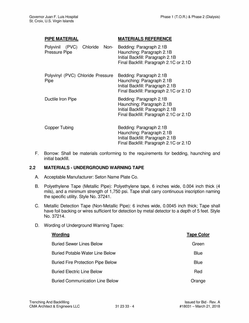
Governor Juan F. Luis Hospital Phase 1 (T.O.R.) & Phase 2 (Dialysis) St. Croix, U.S. Virgin Islands
Trenching And Backfilling Issued for Bid - Rev. A CMA Architect & Engineers LLC 31 23 33 - 4 #18031 – March 21, 2018
PIPE MATERIAL MATERIALS REFERENCE
Polyvinil (PVC) Chloride Non-Pressure Pipe
Bedding: Paragraph 2.1B Haunching: Paragraph 2.1B Initial Backfill: Paragraph 2.1B Final Backfill: Paragraph 2.1C or 2.1D
Polyvinyl (PVC) Chloride Pressure Pipe
Bedding: Paragraph 2.1B Haunching: Paragraph 2.1B Initial Backfill: Paragraph 2.1B Final Backfill: Paragraph 2.1C or 2.1D
Ductile Iron Pipe Bedding: Paragraph 2.1B Haunching: Paragraph 2.1B Initial Backfill: Paragraph 2.1B Final Backfill: Paragraph 2.1C or 2.1D
Copper Tubing Bedding: Paragraph 2.1B
Haunching: Paragraph 2.1B Initial Backfill: Paragraph 2.1B Final Backfill: Paragraph 2.1C or 2.1D
F. Borrow: Shall be materials conforming to the requirements for bedding, haunching and initial backfill.
2.2 MATERIALS - UNDERGROUND WARNING TAPE
A. Acceptable Manufacturer: Seton Name Plate Co.
B. Polyethylene Tape (Metallic Pipe): Polyethylene tape, 6 inches wide, 0.004 inch thick (4 mils), and a minimum strength of 1,750 psi. Tape shall carry continuous inscription naming the specific utility. Style No. 37241.
C. Metallic Detection Tape (Non-Metallic Pipe): 6 inches wide, 0.0045 inch thick; Tape shall have foil backing or wires sufficient for detection by metal detector to a depth of 5 feet. Style No. 37214.
D. Wording of Underground Warning Tapes:
Wording Tape Color
Buried Sewer Lines Below Green
Buried Potable Water Line Below Blue
Buried Fire Protection Pipe Below Blue
Buried Electric Line Below Red
Buried Communication Line Below Orange
Governor Juan F. Luis Hospital Phase 1 (T.O.R.) & Phase 2 (Dialysis) St. Croix, U.S. Virgin Islands
Trenching And Backfilling Issued for Bid - Rev. A CMA Architect & Engineers LLC 31 23 33 - 5 #18031 – March 21, 2018
PART 3 - EXECUTION
3.1 EXAMINATION
A. Section 01 31 00 – Project Management and Coordination: Coordination and project conditions.
B. Verify bottom and side of excavation prior to installation of bedding.
3.2 PROTECTION
A. Shoring and Sheeting: Provide shoring, bracing, cribbing, trench boxes, underpinning, and sheeting as required by field conditions. Include provisions in the shoring and sheeting plan that will accomplish the following:
1. Prevent undermining of pavements, foundations and slabs.
2. Prevent slippage or movement in banks or slopes adjacent to the excavation.
B. Dewatering
1. Plan for and provide the structures, equipment, and construction for the collection and disposal of surface and subsurface water encountered in the course of construction.
C. Water Removal
1. Remove water by pumping or other methods to prevent the softening of surfaces exposed by excavation, prevent hydrostatic uplift, and provide a stable trench condition for installation of the utility. Use screens and gravel packs or other filtering systems on the dewatering devices to prevent the removal of fines from the soil.
2. Operate the dewatering system continuously 24 hours a day, 7 days per week until construction work below existing water levels is complete. Measure and record the performance of the dewatering system at the same time each day with observation wells and piezometers installed in conjunction with the dewatering system. After placement of the pipe or conduit and the initial backfill, the water level may be allowed to rise but at no time allow it to rise higher than one foot below the prevailing level of excavation or backfill. Have a back-up pump and system available for immediate use.
D. Structures and Surfaces
1. Protect newly backfilled areas and adjacent structures, slopes, or grades from traffic, erosion settlement, or any other damage. Repair and reestablish damaged or eroded grades and slopes and restore surface construction prior to acceptance. Protect existing streams, ditches, and storm drain inlets from water-borne soil by means of straw bale dike or filter fabric dams.
E. Disposal of Excavated Material
1. Dispose of excavated material so that it will not obstruct the flow of runoff, streams, endanger a partly finished structure, impair the efficiency or appearance of any facilities, or be detrimental to the completed work.
Governor Juan F. Luis Hospital Phase 1 (T.O.R.) & Phase 2 (Dialysis) St. Croix, U.S. Virgin Islands
Trenching And Backfilling Issued for Bid - Rev. A CMA Architect & Engineers LLC 31 23 33 - 6 #18031 – March 21, 2018
3.3 SURFACE PREPARATION
A. Stockpiling Topsoil: Strip suitable soil from the site where excavation or grading is indicated and stockpile separately from other excavated material. Material unsuitable for use as topsoil shall be wasted. Locate topsoil so that the material can be used readily for the finished grading. Where sufficient existing topsoil conforming to the material requirements is not available on site, provide borrow materials suitable for use as topsoil. Protect topsoil and keep in segregated piles until needed.
B. Cutting Pavement, Curbs, and Gutters: Saw cut with neat, parallel, straight lines one foot wider than trench width on each side of trenches and one foot beyond each edge of pits. When the saw cut is within 5 feet of an existing joint, remove pavement to the existing joint.
3.4 TRENCHING - GENERAL
A. Keep excavations free from water while construction is in progress.
B. Notify the Architect-Engineer immediately in writing if it becomes necessary to remove rock or hard, soft, weak, or wet material to a depth greater than indicated.
C. Make trench sides as nearly vertical as practicable except where sloping of sides is allowed. Sides of trenches shall not be sloped from the bottom of the trench up to the elevation of the top of the pipe, conduit or duct.
D. Excavate ledge rock, boulders, and other unyielding material to an overdepth at least 6-inches below the bottom of the pipe, conduit, duct and appurtenances unless otherwise indicated or specified.
E. Blasting will not be permitted.
F. Overexcavate soft, weak, or wet excavations. Use bedding material placed in 6-inch maximum layers to refill overdepths to the proper grade. At the option of the Contractor, the excavations may be cut to an overdepth of not less than 4-inches and refilled to required grade as specified.
G. Grade bottom of trenches accurately to provide uniform bearing and support for each section of pipe, conduit, duct or structure on undisturbed soil, or bedding material as indicated or specified at every point along its entire length except for portions where it is necessary to excavate for bell holes and for making proper joints.
H. Dig bell holes and depressions for joints after trench has been graded and dimension as required for properly making the particular type of joint to ensure that the bell does not bear on the bottom of the excavation.
3.5 INSTALLATION - SHORING AND SHEETING
A. Shore and sheet excavations as described in the plan submitted with various member sizes arranged to prevent injury to persons and damage to structures.
B. Arrange shoring and sheeting to preclude injurious caving during removal.
C. Obtain approval from the Geotechnical Engineer (paid by the Contractor) prior to removing shoring, sheeting, or bracing in excavations adjacent to on-grade slabs, foundations, or other structural elements.
Governor Juan F. Luis Hospital Phase 1 (T.O.R.) & Phase 2 (Dialysis) St. Croix, U.S. Virgin Islands
Trenching And Backfilling Issued for Bid - Rev. A CMA Architect & Engineers LLC 31 23 33 - 7 #18031 – March 21, 2018
3.6 INSTALLATION - BEDDING
A. For utility lines and utility line structures shall be of the materials and depths as specified.
B. Place bedding in 6 inch maximum loose lifts.
C. Provide uniform and continuous support for each section of structure except at bell holes or depressions necessary for making proper joints.
D. Concrete craddles shall be installed in lieu of bedding for a particular type of pipe material only if it is indicated on the drawings.
3.7 INSTALLATION – HAUNCHING
A. Construct haunching in one operation as indicated and specified on this section.
B. Install in 6-inch thick maximum layers.
C. Work in around pipe by hand to provide uniform support.
D. Place and work by hand to insure all excavated voids and haunch areas are filled. Use vibratory computers.
3.8 INSTALLATION – INITIAL AND FINAL BACKFILL
A. Shall be as specified. Surround pipes with backfill as indicated.
B. Ensure that backfill is placed completely under pipe haunches.
C. Place initial backfill in 6-inch maximum loose lifts to one foot above pipe crown unless otherwise specified. Bring up evenly on each side, and for the full length, of the structure.
D. Ensure that no damage is done to structures or protective coatings thereon.
E. Place the remainder of the backfill (final backfill) in 12-inch maximum loose lifts unless otherwise specified.
F. Compact each loose lift as specified in Paragraph "General Compaction" before placing the next lift.
G. Where unacceptable settlements occur in trenches and pits due to improper compaction, excavate to the depth necessary to rectify the problem, then backfill and compact the excavation as specified herein and restore the surface to the required elevation.
H. Coordinate backfilling with testing of utilities.
I. Testing for the following shall be complete before final backfilling: water distribution, storm drainage, sanitary sewer, and underground fire protection system.
3.9 COMPACTION
A. General:
1. Use hand-operated, plate type, vibratory or other suitable hand tampers in areas not accessible to larger rollers or compactors.
Governor Juan F. Luis Hospital Phase 1 (T.O.R.) & Phase 2 (Dialysis) St. Croix, U.S. Virgin Islands
Trenching And Backfilling Issued for Bid - Rev. A CMA Architect & Engineers LLC 31 23 33 - 8 #18031 – March 21, 2018
2. Avoid damaging pipes and protective pipe coatings.
3. If necessary, alter, change, or modify selected equipment or compaction methods to meet specified compaction requirements.
B. Compaction of Material in Subcuts or Overexcavations
1. In rock, compact to 95 percent of ASTM D1557 maximum density.
2. In soft, weak, or wet soils, tamp refill material to consolidate to density of adjacent material in trench wall.
3. In stable soils, compact to 90 percent of ASTM D1557 maximum density.
C. Compaction of Bedding:
1. In soil compact to 90 percent of ASTM D1557 maximum density.
D. Compaction of Backfill:
1. Surrounding pipes shall be to 90 percent of ASTM D1557 maximum density except where bedding and backfill are the same material, compact to the specified density of the bedding.
2. Under areas to be seeded or sodded compact succeeding layers of backfill to 85 percent of ASTM D1557 maximum density.
3.10 INSTALLATION - UNDERGROUND WARNING TAPE
A. Install underground warning tape directly above utility line at a depth of 18 inches below finish grade.
B. Tape to run continuous from manhole and have 3 feet slack rolled up at each end.
C. Record location on as-builts drawings.
3.11 SPECIAL EARTHWORK INSTALLATION REQUIREMENTS
A. For Site Water Distribution, Underground Fire Main System, Sanitary Sewage, Storm Drainage, and Irrigation shall conform to the requirements specified herein for bedding, haunching, initial and final backfill, and compaction, except as modified by the respective specifications listed below for specific pipe materials.
PIPE MATERIALS INSTALLATION REFERENCE
Polyvinil (PVC) Chloride Non-Pressure Pipe
Refer to Sketch at end of Section
Polyvinyl (PVC) Chloride Pressure Pipe Refer to Sketch at end of Section
Copper Tubing Refer to Sketch at end of Section
B. Manholes and Other Appurtenances: Provide at least 12-inches clear from outer surfaces to the embankment or shoring. Remove rock as herein specified. Remove unstable soil that is incapable of supporting the structure to an overdepth of one foot and refill with gravel or
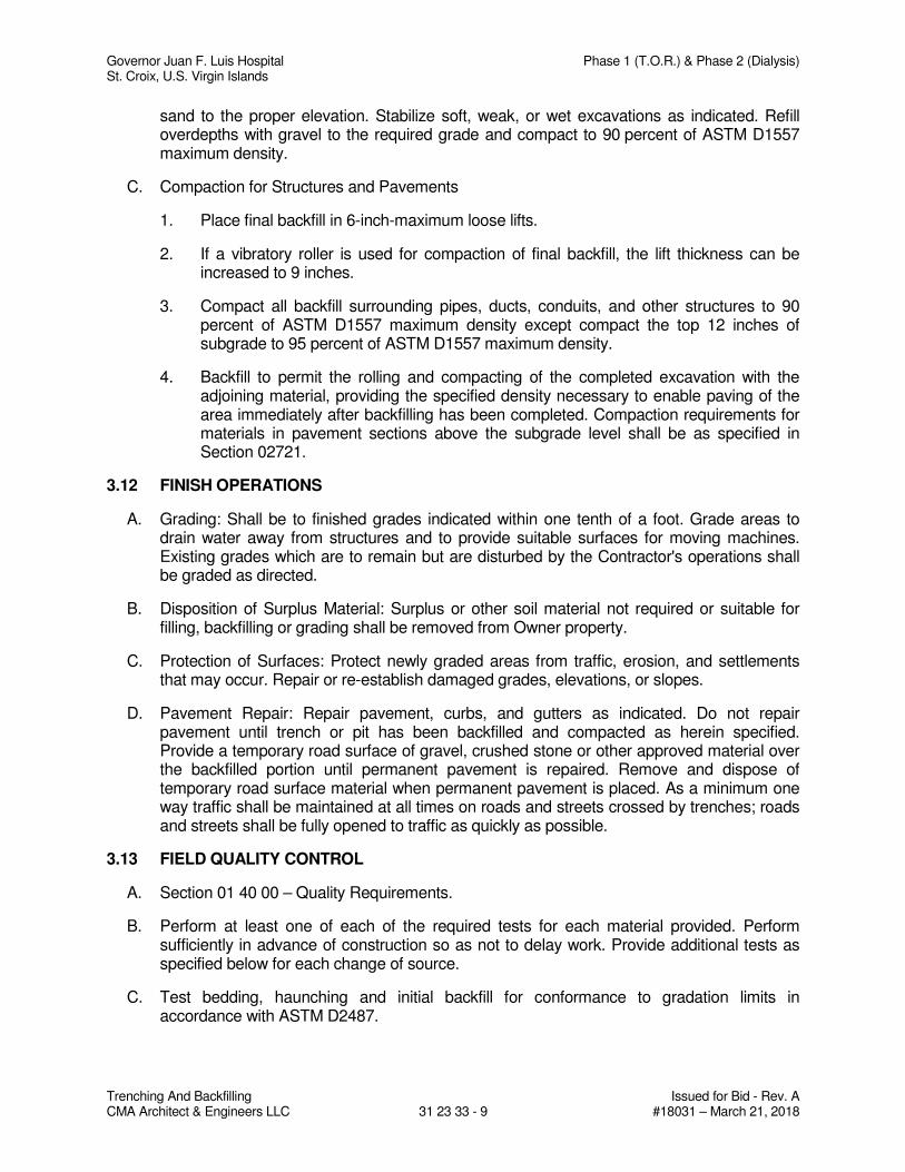
Governor Juan F. Luis Hospital Phase 1 (T.O.R.) & Phase 2 (Dialysis) St. Croix, U.S. Virgin Islands
Trenching And Backfilling Issued for Bid - Rev. A CMA Architect & Engineers LLC 31 23 33 - 9 #18031 – March 21, 2018
sand to the proper elevation. Stabilize soft, weak, or wet excavations as indicated. Refill overdepths with gravel to the required grade and compact to 90 percent of ASTM D1557 maximum density.
C. Compaction for Structures and Pavements
1. Place final backfill in 6-inch-maximum loose lifts.
2. If a vibratory roller is used for compaction of final backfill, the lift thickness can be increased to 9 inches.
3. Compact all backfill surrounding pipes, ducts, conduits, and other structures to 90 percent of ASTM D1557 maximum density except compact the top 12 inches of subgrade to 95 percent of ASTM D1557 maximum density.
4. Backfill to permit the rolling and compacting of the completed excavation with the adjoining material, providing the specified density necessary to enable paving of the area immediately after backfilling has been completed. Compaction requirements for materials in pavement sections above the subgrade level shall be as specified in Section 02721.
3.12 FINISH OPERATIONS
A. Grading: Shall be to finished grades indicated within one tenth of a foot. Grade areas to drain water away from structures and to provide suitable surfaces for moving machines. Existing grades which are to remain but are disturbed by the Contractor's operations shall be graded as directed.
B. Disposition of Surplus Material: Surplus or other soil material not required or suitable for filling, backfilling or grading shall be removed from Owner property.
C. Protection of Surfaces: Protect newly graded areas from traffic, erosion, and settlements that may occur. Repair or re-establish damaged grades, elevations, or slopes.
D. Pavement Repair: Repair pavement, curbs, and gutters as indicated. Do not repair pavement until trench or pit has been backfilled and compacted as herein specified. Provide a temporary road surface of gravel, crushed stone or other approved material over the backfilled portion until permanent pavement is repaired. Remove and dispose of temporary road surface material when permanent pavement is placed. As a minimum one way traffic shall be maintained at all times on roads and streets crossed by trenches; roads and streets shall be fully opened to traffic as quickly as possible.
3.13 FIELD QUALITY CONTROL
A. Section 01 40 00 – Quality Requirements.
B. Perform at least one of each of the required tests for each material provided. Perform sufficiently in advance of construction so as not to delay work. Provide additional tests as specified below for each change of source.
C. Test bedding, haunching and initial backfill for conformance to gradation limits in accordance with ASTM D2487.
Governor Juan F. Luis Hospital Phase 1 (T.O.R.) & Phase 2 (Dialysis) St. Croix, U.S. Virgin Islands
Trenching And Backfilling Issued for Bid - Rev. A CMA Architect & Engineers LLC 31 23 33 - 10 #18031 – March 21, 2018
D. Test bedding, haunching and initial backfill for moisture-density relationship in accordance with ASTM D1557.
E. Perform density and moisture test in randomly selected locations and in accordance with ASTM D1556, ASTM D2922 and ASTM D3017 as follows:
1. Bedding, Haunching, Initial and Final Backfill: One (1) test per 50 linear feet in each lift.
2. Appurtenance Structures: One (1) test per 100 square feet or fraction thereof in each lift.
F. Where ASTM D2922 and ASTM D3017 are used to test field compaction densities, verify test results by performing at least one (1) test per day using ASTM D1556 at a location already tested in accordance with ASTM D2922.
G. Perform at least one (1) additional test using ASTM D1556 for every ten (10) tests performed with a nuclear device at locations checked in accordance with ASTM D2922.
END OF SECTION
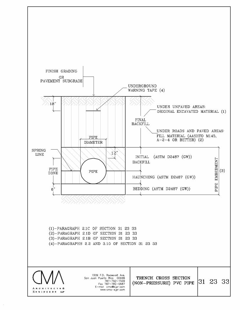
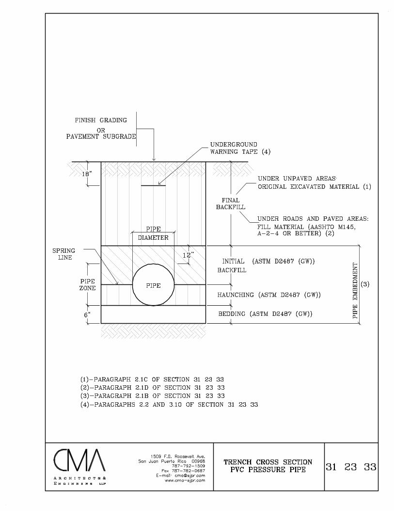
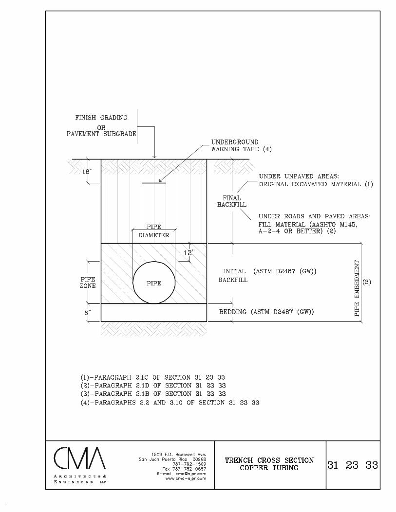
Governor Juan F. Luis Hospital Phase 1 (T.O.R.) & Phase 2 (Dialysis) St. Croix, U.S. Virgin Islands
Erosion And Sedimentation Controls Issued for Bid - Rev. A CMA Architect & Engineers, LLC 31 25 00 - 1 #18031 – March 21, 2018
SECTION 31 25 00
EROSION AND SEDIMENTATION CONTROLS
PART 1 - GENERAL
1.1 SECTION INCLUDES
A. General requirements
B. Installation of erosion and sedimentation controls.
C. Removal of temporary erosion control features.
D. Maintenance of erosion control measures.
E. Protection during supervision of Contract Time.
F. Surface water management, stormwater runoff control and erosion control.
1.2 RELATED SECTIONS
A. Division 01 Sections - General Requirements
B. Section 31 20 00 – Earth Moving
C. Section 31 23 33 – Trenching and Backfilling
1.3 REFERENCES
A. EQB Approved CES Plan
1.4 SUBMITTALS
A. Section 01 33 00 – Submittal Procedures.
B. Submit copies of a certification from the manufacturer and/or supplier that all materials used in this work meet the appropriate project specification.
1.5 QUALITY ASSURANCE
A. Section 01 40 00 – Quality Requirements
B. The Contractor shall implement CES Plan Measures indicated in the drawings.
C. The Architect – Engineer will monitor and prepare monthly reports to EQB.
1.6 CONTROL OF CONTRACTOR’S OPERATIONS WHICH MAY RESULT IN WATER POLLUTION
A. Take sufficient precautions to prevent pollution of streams, channels and other water impoundments, with fuels, oils, bitumens, calcium chloride, or other harmful materials. Conduct and schedule operations so as to avoid or otherwise minimize pollution or siltation of such streams, etc. Do not dump the residue from dust collector or washer into any water body.
Governor Juan F. Luis Hospital Phase 1 (T.O.R.) & Phase 2 (Dialysis) St. Croix, U.S. Virgin Islands
Erosion And Sedimentation Controls Issued for Bid - Rev. A CMA Architect & Engineers, LLC 31 25 00 - 2 #18031 – March 21, 2018
B. Construction operations in channels and other impoundments shall be restricted to those areas where it is necessary to perform filling or excavation to accomplish the work shown in the Contract Documents and to those areas which must be entered to construct temporary or permanent structures. As soon as conditions permit, promptly clear channels and impoundments of all obstructions placed therein or caused by construction operations.
C. Except as necessary for construction, do not deposit excavated material in channels or impoundments, or in a position close enough thereto, to be washed away by high water or runoff.
D. Where pumps are used to remove highly turbid waters from enclosed construction areas or forms, treat water prior to discharge into storm sewer system. Pump the water into grassed swales, appropriate vegetated areas, or sediment basins, or confine it by an appropriate enclosure such as siltation curtains when other methods are not considered appropriate.
E. Do not disturb lands or waters outside the limits of construction, except as may be found necessary to complete the work.
1.7 START OF WORK
A. Prior to starting work the Contractor shall, field survey and stake the limits of construction.
B. Obtain the Owner’s approval of the field survey.
C. Install all silt fence, hay bale and enviro fence along the limits of construction as indicated on the drawings and approved CES Plan.
D. Obtain the Owner’s and Environmental Quality Board approval of the installed erosion and sedimentation control measures.
E. Initiate permitted operations.
PART 2 - PRODUCTS
2.1 GENERAL
A. Materials used for the construction of the temporary erosion and sedimentation control measures are not to be incorporated into the completed project and therefore may be new or used materials.
B. No testing of materials used in construction of temporary erosion control features will be required.
PART 3 - EXECUTION
3.1 GENERAL REQUIREMENTS
A. Temporary erosion control features shall consist of, but not to be limited to, temporary sodding, sandbagging, ,slope drains, sediment basins, artificial coverings, berms, baled hay or straw, floating silt barriers, staked silt barriers and skated fences.
B. Incorporate permanent erosion control features into the project at the earliest practical time. Correct conditions, using temporary measures, that develop during construction to control erosion prior to the time it is practical to construct permanent control features.
Governor Juan F. Luis Hospital Phase 1 (T.O.R.) & Phase 2 (Dialysis) St. Croix, U.S. Virgin Islands
Erosion And Sedimentation Controls Issued for Bid - Rev. A CMA Architect & Engineers, LLC 31 25 00 - 3 #18031 – March 21, 2018
C. Construct temporary and permanent erosion and sediment control measures to prevent the pollution of adjacent water ways in conformance with the laws, rules and regulations of Federal, State and local agencies.
3.2 INSTALLATION – EROSION AND SEDIMENTATION CONTROLS
A. Sandbagging: This work shall consist of furnishing and placing sandbags in configurations, so as to control erosion and siltation.
B. Slope Drains: This work shall consist of constructing slope drains, utilizing pipe, filter fabric mats, rubble, cement concrete, asphaltic concrete plastic sheeting, or other acceptable materials in accordance with details shown in PRHTA Standards or as may be approved as suitable to adequately perform the intended function.
C. Sediment Basins: Sediment basins shall be constructed in accordance with the details shown in the drawings or as suitable to adequately perform the intended function. Sediment basins shall be cleaned out as often necessary.
D. Artificial Coverings: This work shall consist or furnishing and applying fiber mats, netting, plastic sheeting, or other approved covering to the earth surfaces.
E. Berms: This work shall consist of construction of temporary earth berms to divert the flow water from an erodible surface.
F. Baled Hay or Straw:
1. This work shall consist of construction of baled hay or straw dams to protect against downstream accumulation of silt. The baled hay or straw dams shall be constructed in accordance with the details shown in PRHTA Standards.
2. The dams shall be placed so as to effectively control silt dispersion under conditions presents on this project. Alternate solutions and usage of materials may be used if approved.
G. Temporary Silt Fences and Staked Silt Barriers: This work shall consist of furnishing, installing, maintaining and removing staked turbidity barriers in accordance with the manufacturer’s directions, these specifications and the details as shown in the drawings.
H. Floating Silt Barriers: This work shall consist of installing, maintaining, and removal of floating silt barriers to contain turbidity that may occur as the result of dredging, filling, or other construction activities in waters of the State. The type barrier used, the deployment and maintenance of the barrier will be such as to minimize dispersion of turbid waters from the construction site. Alternate methods or materials may be used provided that compliance with applicable permit conditions and State water quality standards are maintained.
I. Enviro Fence: This work shall consist of furnishing, installing, maintaining and removing staked geo-grid fence in accordance with these specification, the Drawings, and the manufacturer’s recommendations.
3.3 REMOVAL OF TEMPORARY EROSION CONTROL FEATURES
A. In general, remove or incorporate into soil any temporary erosion control features existing at the time of construction of the permanent erosion control features in such manner that
Governor Juan F. Luis Hospital Phase 1 (T.O.R.) & Phase 2 (Dialysis) St. Croix, U.S. Virgin Islands
Erosion And Sedimentation Controls Issued for Bid - Rev. A CMA Architect & Engineers, LLC 31 25 00 - 4 #18031 – March 21, 2018
there will be not detrimental effect. Removal of such measures shall not occur prior to receipt of approvals from the Owner.
3.4 MAINTENANCE OF EROSION CONTROL FEATURES
A. General: Provide continuous routine maintenance of permanent and temporary erosion control features until the project is completed and accepted.
3.5 PROTECTION DURING SUSPENSION OF CONTRACT TIME
A. In the event that it is necessary that the construction operations be suspended for any appreciable length of time, shape the top of the earthwork in such a manner as to permit runoff of rainwater and construct earth berms along the top edges of embankments to intercept runoff water. Provide temporary slope drains to carry runoff from cuts and embankments which are located in the vicinity of rivers, streams, canals, lakes, and impoundments. Should such preventive measures fail, immediately take such other action as necessary to effectively prevent erosion and siltation.
3.6 SURFACE WATER MANAGEMENT, STORMWATER RUNOFF CONTROL AND EROSION CONTROL
A. In addition to all other applicable laws, ordinances, codes, rules, regulations, orders and decrees with which Contractor is obligated to comply, the Contractor expressly affirms that it has made itself familiar with, and shall fully comply with, the Storm Water Pollution Prevention Plan (SWPPP) for this project.
B. Concurrently with the execution of the Agreement by the Contractor or 7 days before the Contractor begins work, whichever is earlier, the Contractor shall submit to the Owner for delivery to USEPA a completed and executed ‘Notice of Intent’ (NOI)for Storm Water Discharges Associated with Industrial Activity Under the NPDES General Permit, EPA Form 3510-6(0-92), and the Contractor shall submit to the Owner a completed and executed Contractor’s Certification on a form to be provided by the Owner.
C. The Contractor shall be responsible for all runoff control efforts, including without limitation providing protection of areas receiving runoff, in accordance with any applicable regulations, codes, plans and permits.
D. The Contractor shall furnish, install and maintain, at no additional cost to the owner, all necessary surface protection such as temporary retention basins, silt screens, diapers, jute mesh, filter fabric, hay bales, sod, sandbags, etc., for turbidity control and to prevent erosion and surface degradation.
E. The Contractor recognizes and agrees that should any of the ponds, lakes, canals or other bodies of water adjacent to the site become contaminated due to the actions or inactions of the Contractor, the costs to flocculate, clean or remedy such contamination by any means necessary of required, will be borne by the Contractor. The Owner shall take turbidity readings on a regular basis and shall enforce all applicable environmental regulations.
END OF SECTION
Governor Juan F. Luis Hospital Phase 1 (T.O.R.) & Phase 2 (Dialysis) St. Croix, U.S. Virgin Islands
Aggregate Base Course Issued for Bid – Rev. A CMA Architect & Engineers LLC 32 11 23 - 1 #18031 – March 21, 2018
SECTION 32 11 23
AGGREGATE BASE COURSE
PART 1 - GENERAL
1.1 SECTION INCLUDES
A. Preparation of surface.
B. Placing of aggregate base course.
C. Field quality control.
1.2 RELATED SECTIONS
A. Division 01 Sections - General Requirements.
B. Section 31 20 00 – Earth Moving.
C. Section 32 12 16 - Asphalt Paving.
D. Section 32 13 13 – Concrete Paving
1.3 REFERENCES
A. AASHTO T27 – Sieve Analysis of fine and Course Aggregate.
B. AASHTO T84 - Specific Gravity and Absorption of Fine Aggregate.
C. AASHTO T85 - Specific Gravity and Absorption of Coarse Aggregate.
D. AASHTO T96 - Resistance to Abrasion of Small Size Coarse Aggregate by Use of the Los Angeles Machine.
E. AASHTO T104 – Soundness of Aggregate by Use of Sodium Sulfate or Magnesium Sulfate.
F. AASHTO T180 – Moisture Density Relative of Soils Using a 4.54 Kg (10 lb) Rammer and a 457 mm (18 in) Drop.
G. AASHTO T191 - Density of Soil In-Place by the Sand - Cone Method.
H. AASHTO T205 - Density of Soil In-Place by the Rubber-Balloon Method.
I. AASHTO T238 - Density of Soil-Aggregate In-Place by Nuclear Methods (Shallow Depth).
1.4 QUALITY ASSURANCE
A. Section 01 40 00 – Quality Requirements.
B. Source of Materials: The Contractor shall furnish the Architect-Engineer with the exact location of the source of the aggregate which he proposes to use.
C. Testing: Testing laboratory will take samples from the selected source for testing for conformance with the specified quality and gradation requirements. After the aggregate source has been accepted, the Architect-Engineer has the option of further sampling and
Governor Juan F. Luis Hospital Phase 1 (T.O.R.) & Phase 2 (Dialysis) St. Croix, U.S. Virgin Islands
Aggregate Base Course Issued for Bid – Rev. A CMA Architect & Engineers LLC 32 11 23 - 2 #18031 – March 21, 2018
testing of materials delivered to the project site and this cost shall be borne by the Contractor.
D. Basis of Acceptance: Any material that fail to meet specification requirements following delivery and placement shall be removed at the Contractor's expense and shall be replaced by acceptable material. Any new source of materials proposed by the Contractor requires sampling, testing and acceptance by the Architect-Engineer prior to delivery of materials to the project site.
1.5 SUBMITTALS
A. Section 01 33 00 – Submittal Procedures: Procedures for submittals.
B. Test Reports: Results of field test shall be submitted. Test shall include material gradation, liquid limit and plastic limit.
PART 2 - PRODUCTS
2.1 MATERIALS – AGGREGATE BASE COURSE
A. Aggregate Base Course: Hard durable particles of fragments of crushed stone, or crushed or natural gravel conforming to the following grading requirements:
Sieve
Designation Percentage by Weight
Passing Square Mesh Sieve
1½-inch 100 1-inch - ½-inch 40-75 No. 4 30-60 No. 10 - No. 200 5-12
and meeting the following requirements:
1. Material shall be free from lumps of clay, vegetable matter or other objectionable matter.
2. The course aggregate not passing the No. 8 sieve shall have a percentage of wear, when tested by AASHTO T96, of not more than 45.
3. Maximum number of pieces with elongated faces shall not exceed 15 percent. An elongated face is one where the ratio of the longest dimension to the shortest dimension exceeds 5.
4. The fraction passing the No. 200 sieve shall not be greater than two-thirds (2/3) of the fraction passing the No. 40 sieve.
5. The fraction passing the No. 40 sieve shall have a liquid limit not greater than 25 and a plasticity index not greater than 6.
6. When crushed aggregate is used, not less than 50 percent by weight of the particles retained in the No. 4 sieve shall have at least one fractured face.
Governor Juan F. Luis Hospital Phase 1 (T.O.R.) & Phase 2 (Dialysis) St. Croix, U.S. Virgin Islands
Aggregate Base Course Issued for Bid – Rev. A CMA Architect & Engineers LLC 32 11 23 - 3 #18031 – March 21, 2018
B. Filler Material: If additional material is necessary for meeting the grading requirement or for satisfactory bonding of the material, it shall be uniformly blended with the base course material at the screening and crushing plant. Such filler material shall be obtained from the crushing of stone or gravel.
PART 3 - EXECUTION
3.1 PREPARATION OF SURFACE
A. The subgrade or subbase on which the base course is to be placed shall have been completed and the surface finished in accordance with the requirements of Section 02310. Immediately before placing base course material, the subgrade or subbase shall be checked as to conformity with grade and cross section.
B. No base course shall be placed on the subgrade or subbase unless it is reasonably dry and free from impounded water, and the surface finish accepted by the Owner's On Site Representative or his authorized representative.
3.2 PLACING - AGGREGATE BASE COURSE
A. The base course material shall be spread on the prepared surface and compacted in layers not exceeding 6 inches in thickness. When more than one layer is required, each layer shall be shaped and compacted before the succeeding layer is placed.
B. Placing shall be from spreader boxes or from vehicles equipped to distribute the material in a uniform layer or windrow without segregation of size. The layer or windrow shall be of such size that when spread and compacted, the layer shall have the required thickness. Spreading may be by motor grader.
3.3 MIXING AND SPREADING
A. If after the layer of base course material has been placed and spread as indicated above, it is found that it is not uniform, it shall be thoroughly mixed to its full depth by means of power graders, traveling mixers or other mixing equipment approved by the Owner's On Site Representative or his authorized representative. During the mixing, water shall be added in the amount necessary to provide the optimum moisture content for compaction.
B. When mixed, the material shall be spread smoothly to a uniform thickness and in the case of the top course, to the cross section shown on the plans. Spreading and compaction shall be completed within 24 hours after mixing.
C. Filler material, when added on the roadbed, shall be thoroughly mixed into the aggregate layer as in paragraph 3.3 A.
3.4 COMPACTION
A. Immediately following spreading and smoothing, each layer shall be compacted to its full width. Compaction effort shall continue until the base aggregate material reaches a density of at least 83 percent of its solid volume density. The solid volume density of the aggregate shall be computed on the basis of its bulk specific gravity as determined by AASHTO T 84 and T 85, and the dry weight of the aggregate. The in-place density of the compacted aggregate base shall be determined by the use of AASHTO T 191, T 205 or T 238.
Governor Juan F. Luis Hospital Phase 1 (T.O.R.) & Phase 2 (Dialysis) St. Croix, U.S. Virgin Islands
Aggregate Base Course Issued for Bid – Rev. A CMA Architect & Engineers LLC 32 11 23 - 4 #18031 – March 21, 2018
B. The surface of each layer shall be maintained during the compaction operations in such a manner that a uniform texture is produced and the aggregate firmly keyed. If required, water shall be uniformly sprinkled over the base materials during compaction in the amount necessary for proper consolidation.
C. Any irregularities or depressions that develop under rolling shall be corrected by loosening the material at these places and adding or removing material until the surface is smooth and uniform.
D. Along curbs, headers, and walls, and at all places not accessible to the roller, the base course material shall be thoroughly compacted with mechanical tampers.
3.5 THICKNESS REQUIREMENTS
A. The thickness of the completed base course shall not vary by more than ¼-inch from that called for in the plans. Test holes shall be dug, at the discretion of the Owner's On Site Representative or his authorized representative, at the center and sides of the base course to determine if its compacted thickness is within the allowed tolerance. Any areas not within the allowable tolerance shall be corrected by removing or adding material as necessary and shaping and compacting it as specified.
B. The Contractor shall refill the test holes in such manner as to leave the finished surface compacted, smooth and uniform, to the satisfaction of the Engineer.
3.6 SURFACE FINISH REQUIREMENTS
A. The finished surface of the base course shall conform so nearly to that required by the plans that it will nowhere vary by more than ¼-inch when tested with a 10-foot straightedge. Straightedges shall be furnished by the Contractor at no extra cost and shall remain the property of the Contractor.
B. Any areas where the surface variation exceeds the ¼-inch tolerance shall be reworked by the Contractor until the variation falls within this limit.
C. The finished surface shall be rolled as necessary to maintain a smooth, even, uniformly compacted base until any surface or treatment that may be provided for in the same contract is placed thereon.
3.7 FIELD QUALITY CONTROL
A. Section 01 40 00 – Quality Requirements.
B. Determine maximum density and optimum moisture content for aggregate base material in accordance with AASHTO T180, method D.
C. Make a minimum of three (3) field density tests on each day’s final compaction on each aggregate course in accordance with AASHTO T191.
D. Sample and test aggregate as necessary to insure compliance with specification requirements for gradation (AASHTO T27), wear (AASHTO T96), and soundness (AASHTO T104).
END OF SECTION
Governor Juan F. Luis Hospital Phase 1 (T.O.R.) & Phase 2 (Dialysis) St. Croix, U.S. Virgin Islands
Asphalt Paving Issued for Bid – Rev. A CMA Architect & Engineers LLC 32 12 16 - 1 #18031 – March 21, 2018
SECTION 32 12 16
ASPHALT PAVING
PART 1 - GENERAL
1.1 SECTION INCLUDES
A. Preparation of subgrade.
B. Placement of base and surface course.
C. Protection of finishes surfaces.
D. Field quality control.
1.2 RELATED SECTIONS
A. Division 01 Section - General Requirements.
B. Section 31 20 00 – Earth Moving: Preparation of site for paving.
C. Section 32 01 16 – Cold Milling Asphalt Paving.
D. Section 32 11 23 - Aggregate Base Course.
E. Section 32 16 14 – Cast In Place Concrete Curbs.
F. Section 32 16 15 – Cast In Place Concrete Curb and Gutters
G. Section 32 17 23 – Painted Pavement Markings.
1.3 REFERENCES
A. Asphalt Institute Manual MS-4 - The Asphalt Handbook.
B. Asphalt Institute Manual MS-8 - Asphalt Paving Manual.
C. AASHTO T27 – Sieve Analysis of Fine and Coarse Aggregate.
D. AASHTO T96 – Resistance to Degradation of Small Size Coarse Aggregate by Abrasion and Impact in the Los Angeles Machine.
E. ANSI A10.17 - Safe Operating Practice for Asphalt Pavement Construction.
F. ASTM F1188 – Bulk Specific Gravity and Density of Compacted Bituminous Mixtures Using Paraffin Coated Specimens.
G. ASTM D1559 – Resistance to Plastic Flow of Bituminous Mixtures Using Marshall Apparatus.
1.4 QUALITY ASSURANCE
A. Section 01 40 00 – Quality Requirements
B. Perform all work specified herein in accordance with USVI - Department of Public Works.
Governor Juan F. Luis Hospital Phase 1 (T.O.R.) & Phase 2 (Dialysis) St. Croix, U.S. Virgin Islands
Asphalt Paving Issued for Bid – Rev. A CMA Architect & Engineers LLC 32 12 16 - 2 #18031 – March 21, 2018
C. Grade Control: Establish and maintain the required lines and grades, including crown and cross-slope, for each course during construction operations.
1.5 SUBMITTALS
A. Section 01 33 00 – Submittal Procedures
B. Mix Design: Submit each type of mix design to be used on the project.
1.6 JOB CONDITIONS
A. Section 01 73 00 – Execution
B. Paving materials shall be placed only during dry weather and on dry surfaces.
C. Traffic Control: Vehicular traffic including heavy equipment shall not be permitted in the pavement until the surface temperature has cooled to at least 120 degrees Fahrenheit. Surface temperature shall be measured by approved surface thermometers or other satisfactory methods.
D. Conduct mixing and delivery of bituminous materials and paving operations in accordance with ANSI A10.17.
PART 2 - PRODUCTS
2.1 MATERIALS
A. General: Asphalt paving materials shall conform to the requirements of USVI - Department of Public Works and to requirements of the Asphalt Institute which specifications shall apply hereto as though written in full herein.
B. Base Course: Warm Asphalt Concrete Pavement – Class “A” Grading “E”, Type 1 (Surface).
PART 3 - EXECUTION
3.1 SURFACE PREPARATION
A. Excavate to subgrade level.
B. Proof roll excavated surface using 10-ton rubber tired rollers or 3-ton vibratory rollers. Compact subgrade to at least 95 percent of Modified Proctor of ASTM D1557.
C. Remove spongy and yielding materials which will not compact and replace with aggregate base course as directed by the Architect/Engineer.
D. Prior to laying of the asphalt paving, clean underlying course of all foreign or objectionable matter with power blowers or power brooms, supplemented by hand brooms on other cleaning method where necessary.
3.2 PLACEMENT - BASE COURSE
A. Spread aggregate in continuous layers so that it will compact to required thickness.
Governor Juan F. Luis Hospital Phase 1 (T.O.R.) & Phase 2 (Dialysis) St. Croix, U.S. Virgin Islands
Asphalt Paving Issued for Bid – Rev. A CMA Architect & Engineers LLC 32 12 16 - 3 #18031 – March 21, 2018
B. Compact with power roller weighing at least 10 tons. Compact from sides to center. Along curbs, headers or other areas not accessible to roller compact with mechanical or hand tampers.
3.3 PLACEMENT - SURFACE COURSE
A. Spread surface course in continuous layers so that it will compact to required thickness.
B. Roll continuously from outer edges to center. Continue rolling to uniform texture and compaction, true to level and cross section. Trim edges neatly.
3.4 THICKNESS OF ASPHALT PAVING
A. In place compacted thickness will not be acceptable if exceeding allowable variation from thickness shown on drawings, when tested in conformance with USVI - Department of Public Works.
3.5 SURFACE SMOOTHNESS
A. Test finished surface of each asphalt paving course for smoothness, using a 10-foot straightedge applied parallel to and at right angles to center line of paved areas.
B. Surface will not be acceptable if exceeding the following:
1. Base Course: 1/4 inch in 10 feet.
2. Surface Course: 1/4 inch in 10 feet.
3. Crowned Surfaces: Test crowned surfaces with a crown template, centered and at right angles to the crown. Surfaces will not be acceptable if varying more than 1/4-inch from the template.
3.6 FINISHED GRADES
A. The finish grades of each course placed shall not vary from the finish elevations, profiles, and cross sections indicated on the drawings by more than 1/2 inch.
B. The finished surface of the final wearing course will be tested by the Architect/Engineer by running lines of levels at intervals of 25 feet or less longitudinally and transversely to determine elevations of completed pavement.
C. Within 45 days after completion of final placement, the Contractor shall perform a level survey at the specified grid spacing and plot the results on a plan drawn to the same scale as the drawings. Elevating not in conformance with the specified tolerance shall be noted on the plan in an approved manner. The survey shall be performed by a Registered Land Surveyor paid by the Contractor.
D. The Contractor shall correct deficient paved areas by removing existing work and replacing with new materials meeting the specifications without additional cost to the Owner. Skin patching for correcting low areas will not be permitted.
3.7 CLEANING AND PROTECTION
A. Any foreign material which may have accumulated on the surface of any course shall be removed before the course is rolled or subsequent courses are placed thereon.
Governor Juan F. Luis Hospital Phase 1 (T.O.R.) & Phase 2 (Dialysis) St. Croix, U.S. Virgin Islands
Asphalt Paving Issued for Bid – Rev. A CMA Architect & Engineers LLC 32 12 16 - 4 #18031 – March 21, 2018
B. Protect curbs, bumpers, buildings, fencing, automobiles, etc., from airborne on splashed bituminous material.
C. Maintain roads used by construction vehicles and personnel passable throughout the construction period.
D. Remove dirt, mud, debris and other objectionable materials from roads at the end of the job.
3.8 FIELD QUALITY CONTROL
A. Section 01 40 00 – Quality Requirements
B. Aggregate: Sample and test aggregate in stock pile and hot-bins as necessary to insure compliance with specification requirements for gradation (AASHTO T27), wear (AASHTO T96), and soundness (AASHTO T104).
C. Temperature: Check temperatures of each load of asphalt concrete at mixing plant and at site of paving operation.
D. Density: Make a minimum of two (2) field density tests in accordance with ASTM D1188 and comparative 50-blow Marshall tests in accordance with ASTM D1559 of asphalt base and surface course for each day’s paving operation.
END OF SECTION
Governor Juan F. Luis Hospital Phase 1 (T.O.R.) & Phase 2 (Dialysis) St. Croix, U.S. Virgin Islands
Painted Pavement Markings Issued for Bid – Rev. A CMA Architect & Engineers LLC 32 17 23 - 1 #18031 – March 21, 2018
SECTION 32 17 23
PAINTED PAVEMENT MARKINGS
PART 1 - GENERAL
1.1 SECTION INCLUDES
A. Examination of pavement surfaces
B. Application of painted pavement markings to asphalt and concrete surfaces.
C. Application of painted lines to basketball court concrete surfaces.
D. Protecting and cleaning
1.2 RELATED SECTIONS
A. Division 01 Sections – General Requirements
B. Section 32 12 16 – Asphalt Paving
C. Section 32 13 13 – Concrete Paving
1.3 REFERENCES
A. AASHTO M248 – Ready Mixed White and Yellow Traffic Paints
B. FS TT-P-1952E – Paint, Traffic and Airfield Marking Waterforms
C. ASTM D8 – Terminology Related to Materials for Roads and Pavements
D. 40 CFR, Part 59, Subpart D – National volatile Organic Compound Emission Standards for Architectural Coatings.
E. U.S Architectural & Transportation Barriers Compliance Board - American with Disabilities Act (ADA) and Architectural Barriers Act (ABA) Accessibility Guidelines for Buildings and Facilities.
F. U.S. Department of Justice – ADA Business Brief: Restriping Parking Lots.
1.4 PREINSTALLATION MEETINGS
A. Section 01 31 00 – Project Management and Coordination
B. Preinstallation Conference: Conduct conference at Project site.
1. Review methods and procedures related to marking pavement including, but not limited to, the following:
a. Pavement aging period before application of pavement markings.
b. Review requirements for protecting pavement markings, including restriction of traffic during installation period.
Governor Juan F. Luis Hospital Phase 1 (T.O.R.) & Phase 2 (Dialysis) St. Croix, U.S. Virgin Islands
Painted Pavement Markings Issued for Bid – Rev. A CMA Architect & Engineers LLC 32 17 23 - 2 #18031 – March 21, 2018
1.5 ACTION SUBMITTALS
A. Section 01 33 00 – Submittal Procedures
B. Product Data: For each type of product.
1. Include technical data and tested physical and performance properties.
C. Shop Drawings: For pavement markings.
1. Indicate pavement markings, colors, lane separations, defined parking spaces, and dimensions to adjacent work.
2. Indicate, with international symbol of accessibility, spaces allocated for people with disabilities.
D. Samples: For each exposed product and for each color and texture specified; on rigid backing, 8 inches square.
1.6 QUALITY REQUIREMENTS
A. Section 01 40 00 – Quality Assurance
B. Regulatory Requirements: Comply with materials, workmanship, and other applicable requirements of Puerto Rico Highway and Transportation Authority for pavement-marking work.
1.7 FIELD CONDITIONS
A. Section 01 73 00 – Execution
B. Environmental Limitations: Proceed with pavement marking only on clean, dry surfaces and at a minimum ambient or surface temperature of 40 deg F for alkyd materials or 55 deg F for water-based materials, and not exceeding 95 deg F.
PART 2 - PRODUCTS
2.1 ACCEPTABLE MANUFACTURERS – PAINTED PAVEMENT MARKINGS
A. Manufacturers: Subject to compliance with requirements, provide products by one of the following:
1. Benjamin Moore & Co.
2. PPG Industries.
3. Pratt & Lambert.
4. Sherwin-Williams Company (The).
2.2 MATERIALS – PAVEMENT MARKING PAINT
A. Pavement-Marking Paint: Alkyd-resin type, lead and chromate free, ready mixed, complying with AASHTO M 248, Type N; colors complying with FS TT-P-1952.
1. Color: White.
Governor Juan F. Luis Hospital Phase 1 (T.O.R.) & Phase 2 (Dialysis) St. Croix, U.S. Virgin Islands
Painted Pavement Markings Issued for Bid – Rev. A CMA Architect & Engineers LLC 32 17 23 - 3 #18031 – March 21, 2018
2.3 ACCEPTABLE MANUFACTURERS – BASKETBALL COURT LINES
A. Manufacturers: Subject to compliance with requirements, provide products by one of the following:
1. Decoturf; A Division of California Sports Surfaces.
2.4 MATERIALS – BASKETBALL COURT LINES
A. Court marking for Basketball: Acrylic Color Playing Surface (DecoColor MP Classic and DecoBase I) – for use as the finish color and texture.
1. Color: White.
PART 3 - EXECUTION
3.1 EXAMINATION
A. Section 01 31 00 – Project Management and Coordination
B. Verify that pavement is dry and in suitable condition to begin pavement marking according to manufacturer's written instructions.
C. Proceed with pavement marking only after unsatisfactory conditions have been corrected.
3.2 APPLICATION - PAVEMENT MARKINGS
A. Do not apply pavement-marking paint until layout, colors, and placement have been verified with Architect-Engineer.
B. Allow paving to age for a minimum of 30 days before starting pavement marking.
C. Sweep and clean surface to eliminate loose material and dust.
D. Apply paint with mechanical equipment to produce pavement markings, of dimensions indicated, with uniform, straight edges. Apply at manufacturer's recommended rates to provide a minimum wet film thickness of 15 mils.
1. Apply graphic symbols and lettering with paint-resistant, die-cut stencils, firmly secured to pavement. Mask an extended area beyond edges of each stencil to prevent paint application beyond the stencil. Apply paint so that it cannot run beneath the stencil.
3.3 APPLICATION - BASKETBALL COURT LINES
A. All areas to be color coated shall be clean, free from sand, clay, grease, dust, salt or other foreign matters. The Contractor shall obtain the Architect-Engineer's approval, prior to applying any surface treatment.
B. Blend DecoBase I and DecoColor MP with a mechanical mixer to achieve a uniform mixture. The mix shall be in accordance with manufacturer’s printed instructions:
C. Application shall be made by 50 durometer rubber faced squeegees. The mixture should be poured on to the court surface and spread to a uniform thickness in a regular pattern.
Governor Juan F. Luis Hospital Phase 1 (T.O.R.) & Phase 2 (Dialysis) St. Croix, U.S. Virgin Islands
Painted Pavement Markings Issued for Bid – Rev. A CMA Architect & Engineers LLC 32 17 23 - 4 #18031 – March 21, 2018
D. A total of 2 applications of textured DecoColor MP shall be made to achieve a total application rate of not less than 0.10 gal./sy. No application should be made until the previous application is thoroughly dry.
E. Line Painting
1. Line shall be 2-inch wide unless otherwise noted on the drawings. Lines shall be carefully laid out in accordance with ASBA and USTA guidelines. The area to be marked shall be taped to insure a crisp line. Application shall be made by brush or roller at the rate of 150-200 sf./gal.
3.4 PROTECTING AND CLEANING
A. Protect pavement markings from damage and wear during remainder of construction period.
B. Clean spillage and soiling from adjacent construction using cleaning agents and procedures recommended by manufacturer of affected construction.
END OF SECTION
Governor Juan F. Luis Hospital Phase 1 (T.O.R.) & Phase 2 (Dialysis) St. Croix, U.S. Virgin Islands
Site Water Utility Distribution Piping Issued for Bid - Rev. A CMA Architect & Engineers, LLC 33 11 13 - 1 #18031 – March 21, 2018
SECTION 33 11 13
SITE WATER UTILITY DISTRIBUTION PIPING
PART 1 - GENERAL
1.1 SECTION INCLUDES
A. Verification of existing conditions.
B. Preparation of pipe materials and fittings.
C. Installation of pipe and thrust blocks.
D. Installation of valves.
E. Installation of service connections.
F. Disinfection of domestic water piping system.
G. Field quality control.
1.2 RELATED SECTIONS
A. Division 01 Sections - General Requirements.
B. Section 31 23 33 – Trenching and Backfilling: Trench Excavation, bedding, haunching, initial and final backfill and installation of warning tape.
C. Section 33 13 00 – Disinfecting of Water Utility Distribution.
1.3 REFERENCES
A. ASTM B32 - Solder Metal.
B. ASTM B61 - Steam or Valve Bronze Castings.
C. ASTM B62 - Composition Bronze or Ounce Metal Castings.
D. ASTM B88 - Seamless Copper Water Tube.
E. ASTM D698 - Moisture Density Relations of Soils and Soil -Aggregate Mixtures Using a 5.5-lb Rammer and 12-inch Drop.
F. ANSI B16.18 - Cast Copper Alloy Solder Joint Pressure Fittings.
G. ANSI B16.22 - Wrought Copper and Copper Alloy Solder Joint Pressure Fittings.
H. ANSI B16.26 - Cast Copper Alloy Fittings for Flared Copper Tubes.
I. ANSI/AWWA C500 - Gate Valves, 3 through 38 inches NPS for Water and Sewage Systems.
1.4 SUBMITTALS
A. Section 01 33 00 – Submittal Procedures.
Governor Juan F. Luis Hospital Phase 1 (T.O.R.) & Phase 2 (Dialysis) St. Croix, U.S. Virgin Islands
Site Water Utility Distribution Piping Issued for Bid - Rev. A CMA Architect & Engineers, LLC 33 11 13 - 2 #18031 – March 21, 2018
B. Manufacturer's Data: Submit five (5) copies of manufacturer's data and/or drawings of pipe, fittings, joints, gate valves, water meters, and valve boxes.
1.5 DELIVERY, STORAGE, AND HANDLING
A. Section 01 60 00 – Product Requirements.
B. Delivery and Storage: Inspect materials delivered to site for damage. Unload and store with minimum handling. Store materials in enclosures or under protective covering. Store rubber gaskets not to be installed immediately under cover, out to direct sunlight. Do not store materials directly on the ground. Keep interior of pipes and fittings free of dirt and debris.
C. Handling: Handle pipe, fittings, valves, and other accessories in such a manner as to ensure delivery to the trench in sound, undamaged condition. Avoid injury to coatings and linings ofpipe and fittings; make satisfactory repairs if coatings or linings are damaged. Carry pipe to the trench; do not drag it.
PART 2 - PRODUCTS
2.1 MATERIALS - WATER SERVICE PIPING
A. Copper Tubing and Associated Fittings: ASTM B88, Type K; ANSI B16.18 or ANSI B16.22 solder fittings using ASTM B32, 50-50 tin-lead solder; ANSI B16.26 flared joint fittings.
B. Accessories: Provide flanges, connecting pieces, transition glands, transition sleeves, and other adapters as required.
2.2 MATERIALS - WATER PIPING ACCESSORIES
A. Gate Valves, General: Valves shall have nonrising stems and shall be double-disc parallel or inclined seat type. Valves shall open by counter clockwise rotation of the valve stem. Valves shall have O-ring steam seals, except when gearing is specified, use conventional packing. Stuffing boxes shall be bolted and constructed to permit easy removal of parts for repair.
B. Valves smaller than 3-inch Size: AWWA C500, except for size. Valves shall be designed for a working pressure of 175 PSIG.
C. Valve Boxes: Each gate valve on buried piping shall be provided with an adjustable cast iron valve box of a size suitable for the valve. Provide each cast-iron box with a heavy coat of bituminous paint. The head shall be round and lid shall have the word "WATER" cast on it. The least diameter of the box shaft shall be 5.25 inches.
2.3 MATERIALS - IDENTIFICATION ITEMS
A. Warning Tapes: Refer to Section 31 23 33 - Trenching and Backfilling.
B. Identification Tags and Plates (Valves): Provide valves with tags or plates numbered and stamped for their usage. Plates and Tags shall be of brass or non-ferrous material and shall be mounted or attached to the valve.
Governor Juan F. Luis Hospital Phase 1 (T.O.R.) & Phase 2 (Dialysis) St. Croix, U.S. Virgin Islands
Site Water Utility Distribution Piping Issued for Bid - Rev. A CMA Architect & Engineers, LLC 33 11 13 - 3 #18031 – March 21, 2018
PART 3 - EXECUTION
3.1 INSTALLATION – GENERAL REQUIREMENTS
A. Sewer Piping or Sewer Manholes: No water piping shall pass through or come in contact with any part of a sewer manhole.
B. Pipe Laying and Jointing: The following conditions shall be followed in the execution of the work.
1. Inspect pipe, fittings, valves, and accessories before and after installation. Those found defective shall be replaced with new materials. Remove fins and burrs from pipe and fittings.
2. Before placing in position, clean pipe, fittings, valves, and accessories and maintain in a good condition.
3. Provide facilities for lowering sections of pipe into trenches. Do not drop or dump pipe, fittings, valves, or any other water piping material into trenches.
4. Cut pipe accurately to measurements established at the site and work into place without springing or forcing. Replace pipe or fitting that does not allow sufficient space for proper installation of jointing material with new pipe or fittings of proper dimensions.
5. Grade the piping in straight lines; avoid the formation of any dips or low points. Support pipe at its proper elevation and grade; ensure firm and uniform support. Wood support blocking will not be permitted.
6. Lay pipe so that the full length of each section of pipe and each fitting will rest solidly on the pipe bedding; excavate recesses to accommodate bells, joints, and couplings.
7. Keep trenches free of water until joints have been completely assembled.
8. When work is not in progress, the open ends of pipe and fittings are to be covered with wood blocks or bulkheads so that no trench water, earth or other substances will enter the pipe or fittings.
9. Depth of cover over top of pipe shall be not less than 2.5 feet.
10. All joint materials shall be approved prior to use. Only one type or brand shall be used throughout the work for similar conditions unless the change is specifically authorized in writing by the Architect-Engineer. Joints shall be prepared and seated in the manner recommended by the manufacturer. Mechanical means shall be used for seating all rubber gasket joints when manual means will not result in pushing and holding the pipe home.
11. The seating of each joint shall be checked. Each joint is to be thoroughly secured and free from movement before the next joint is laid. Care shall be taken to insure that completed joints remain intact.
C. Installation of Warning Tape: Attach wire to top of pipe to prevent displacement during construction operations.
Governor Juan F. Luis Hospital Phase 1 (T.O.R.) & Phase 2 (Dialysis) St. Croix, U.S. Virgin Islands
Site Water Utility Distribution Piping Issued for Bid - Rev. A CMA Architect & Engineers, LLC 33 11 13 - 4 #18031 – March 21, 2018
3.2 INSTALLATION - WATER SERVICE PIPING
A. Installation: Terminate water service at location in the drawings; such water service piping shall be closed with plugs or caps and staked with wood markers.
B. Metallic Piping: Install pipe and fittings in accordance with the general requirements for installation of piping and with the applicable requirements of AWWA C600 for pipe installation, except as otherwise indicated.
C. Joints for Copper Tubing: Cut copper tubing with square ends; remove fins and burrs. Replace dented, gouged, or otherwise damaged tubing with new tubing. Before making joint, clean ends of tubing and interior of fitting or coupling with wire brush or abrasive. Apply a rosin flux to the tubing end and on recess inside of fitting or coupling. Insert tubing end into fitting or coupling for the full depth of the recess and solder.
D. Installation of Valves and Valve Boxes: Valves and Valve boxes shall be set plumb, with valve boxes centered directly over the valves.
3.3 DISINFECTION OF PIPING
A. Refer to Section 33 13 00 - Disinfecting of Water Utility Distribution.
3.4 FIELD TESTS AND INSPECTIONS
A. General: Perform all field tests, and provide all labor, equipment, and incidentals required for testing. The Contractor shall produce evidence, when required, that any item of work have been constructed in accordance contract requirements. Allow concrete to cure a minimum of five (5) days before testing any section of piping where concrete thrust blocks have been provided.
B. Testing Procedure for Water Service Piping:
1. Copper Tubing: AWWA C600 for hydrostatic testing. No leakage shall be allowed.
END OF SECTION
Governor Juan F. Luis Hospital Phase 1 (T.O.R.) & Phase 2 (Dialysis) St. Croix, U.S. Virgin Islands
Fire Suppression Utility Distribution Piping Issued for Bid - Rev. A CMA Architect & Engineers LLC 33 11 19 - 1 #18031 – March 21, 2018
SECTION 33 11 19
FIRE SUPPRESSION UTILITY DISTRIBUTION PIPING
PART 1 - GENERAL
1.1 SECTION INCLUDED
A. Underground fire sprinkler mains complete with underground risers ending at a flange 6 inches above finish grade with a blank flange bolted on top. Risers shall be located as shown on the drawings.
B. Trenching and backfill for all underground piping.
C. Connections to existing private water main.
D. System and Sectional control valves.
E. All required on-site hydrants, key gate valves and related pipe and fittings.
F. Furnish and install a tamper switch on each post indicator and/or OS&Y valve.
G. All painting of portions of the fire protection system required to be painted by the Rating Agency.
H. Conformance to all design requirements of the Rating Agency. Preparation of all required Shop Drawings and Details for the approval and installation of the system.
I. Coordination as required to obtain approval of the Rating Agency, and other authorities having jurisdiction. Obtaining their written approval of the system.
J. All permit and inspection fees for the work under this section.
K. Coordination of installation of electrical conduit for supervisory systems.
L. Arranging for all required inspections by the local officials and by the Rating Agency. Cost of all testing and of special inspection required by them.
M. Hydrostatically testing of new mains and lead ins.
N. Flushing of piping before leave on service.
O. Coordination with plant personnel and Factory Mutual when valve closures or any other work on the system impair existing fire protection system.
1.2 RELATED SECTIONS
A. Division 01 Sections - General Requirements.
B. Section 31 23 33 – Trenching and Backfilling: Bedding, Haunching, Initials and Final Backfill. Installation of Underground Warning Tape.
1.3 REFERENCES
A. Fire Department Regulations.
Governor Juan F. Luis Hospital Phase 1 (T.O.R.) & Phase 2 (Dialysis) St. Croix, U.S. Virgin Islands
Fire Suppression Utility Distribution Piping Issued for Bid - Rev. A CMA Architect & Engineers LLC 33 11 19 - 2 #18031 – March 21, 2018
B. Factory Mutual Engineering and Research Corporation (FMRC) - Regulations and Approval Guide.
C. Underwriters' Laboratories Regulations.
D. NFPA 13 - Standard for the Installation of Sprinkler Systems.
E. NFPA 14 - Standard for the Installation of Standpipe and Hose Systems.
F. NFPA 24 - Standard for the Installation of Private Fire Main and their Appurtenances.
1.4 QUALITY ASSURANCE
A. Section 01 40 00 – Quality Requirements.
B. Codes and Standards: Special attention shall be given to the local fire regulations. Special attention shall be given to the local rulings of the Rating Agency. Nothing in this specification or on the plans shall be construed as permitting a departure from any applicable federal, state, and local building and safety codes, ordinances and regulations and/or Rating Agency.
C. Contractor Qualifications: Contractor must be licensed to install underground fire protection lines. No portion of the installation of the Underground Fire Protection System (except excavation and backfilling) shall be subcontracted.
1.5 RATING AGENCY
A. All work shall comply with the requirements of the Rating Agency. Nothing in these specifications shall construe as permitting a departure from such requirements.
1.6 SUBMITTALS
A. Section 01 33 00 – Submittal Procedures.
B. Material Lists and Calculations: Submit five (5) copies to the Architect/Engineer.
C. Shop Drawings: Submit one sepia and two blueprints to the Architect/Engineer for its review. Shop drawings shall show all details and information required by NFPA 13 and/or 24. In addition, all earthquake bracing (longitudinal and lateral) and/or thrust blocks (design and location shall be shown. Architect/Engineer will check shop drawings for conformance to the remainder of the contract requirements. Architect/Engineer will not approve these shop drawings. After these shop drawings have been reviewed by the Architect/Engineer, they will be transmitted to the Rating Agency for its formal review and approval.
D. If the review by the Rating Agency requires revisions to the drawings, the Contractor shall incorporate these comments into the drawings and resubmit the shop drawings to the Rating Agency for its review and final approval.
E. After the Rating Agency provide shop drawings with the stamps of approval/acceptance without comments, the Contractor shall submit to the Architect/ Engineer one sepia of these shop drawings.
Governor Juan F. Luis Hospital Phase 1 (T.O.R.) & Phase 2 (Dialysis) St. Croix, U.S. Virgin Islands
Fire Suppression Utility Distribution Piping Issued for Bid - Rev. A CMA Architect & Engineers LLC 33 11 19 - 3 #18031 – March 21, 2018
F. Final as-built drawings shall be submitted in accordance with paragraph B above, showing exact dimensional locations of all underground piping and of all risers, mains, and cross mains.
G. On completion of the job, furnish the Architect/Engineer with a copy of the "Contractors Material and Test Certificate" (Part A and/or B) and a copy of the transmittal letter sending the certificate to the Rating Agency.
1.7 DESIGN OF SYSTEMS
A. The riser locations are shown on the Drawings.
B. All work shall be designed in accordance with the requirements of local Fire Marshal, the Rating Agency, the latest editions of NFPA 13, 14, and 24, and the appropriate edition of the Building Code (as modified by local ordinance or ruling).
C. Fire Protection System lines shall be design so as to avoid all other utility lines, conduit, and structural components shown on the Drawings. Fire Protection System lines must give way to all gravity lines.
PART 2 - PRODUCTS
2.1 MATERIALS
A. General: All material shall be new and currently listed in the Underwriters' Laboratories, Inc., Fire Protection Equipment List, and the Factory Mutual Approval Guide for use as intended in underground fire line installations, and shall be acceptable to the local fire department. Material that is pending approval shall not be acceptable.
B. Underground and Under Building Piping: Cement-lined ductile iron bell and spigot with mechanical joint lined.
C. Fittings: Lined cast iron with mechanical joints.
D. Piping and Fittings: Class 250 in accordance with ANSI/ AWWA Standards.
E. Hydrants: In compliance with local regulation, and shall be installed with key gate valves.
F. Post Indicators: Mueller "Type A-20800" or approved equal (UL Listed), adjustable type indicator post pre-drilled and tapped to accept a tamper switch. Valve shall open counter-clockwise.
PART 3 - EXECUTION
3.1 GENERAL REQUIREMENTS
A. Prior to bid, visit the job site and familiarize with local conditions including verification of the location of the existing utilities. It shall be this contractor's responsibility to connect to the underground yard fire mains.
B. All piping shall be installed in a manner acceptable to the local fire department and the Rating Agency.
C. Underground piping shall be installed in strict accordance with the Manufacturers Installation Guide.
Governor Juan F. Luis Hospital Phase 1 (T.O.R.) & Phase 2 (Dialysis) St. Croix, U.S. Virgin Islands
Fire Suppression Utility Distribution Piping Issued for Bid - Rev. A CMA Architect & Engineers LLC 33 11 19 - 4 #18031 – March 21, 2018
D. Backfill shall be accomplished in strict accordance with the Manufacturers Installation Guide and the Backfill Section of this Specification.
E. All piping shall be pressure tested and flushed according to the procedures set forth in NFPA 13 and 24.
F. This contractor shall be responsible for determining the bearing capacity of the soil (see Soils Report). All thrust blocks shall be designed to conform to the requirements of NFPA 24, taking into consideration the bearing capacity of the soil. Size and design of thrust blocks shall be shown on shop drawings.
G. All equipment installed under this contract shall be properly thrust blocked and earthquake braced. This contractor shall be responsible for the proper design and installation of the equipment and for satisfying the local fire department and the Rating Agency that this requirement has been met.
H. All equipment installed under this contract shall be protected from external damage. This contractor shall be responsible for the proper design and installation of the equipment and for satisfying the local fire department, the Rating Agency, and the Project Representative that this requirement has been met. Shop Drawings shall show details of protection equipment.
I. The fire service underground main lead-in connection to the sprinkler riser inside the building should consist of a cement lined ductile iron flange and spigot piece with tie rods or flange by mechanical joints adapter with tie rods. Number and size of tie rods should be in accordance with Table 2 of FM Data Sheet 3-10, and the tie rods should be completely coated to protect against corrosion. For a vertical connection through the concrete floor, the tie rods should be from the flange and spigot piece or the flange by mechanical joint adapter to the underground elbow at the base of the riser. For horizontal connection through a concrete basement wall, the tie rods should be from the flange and spigot piece or the flange by mechanical joint adapter to the first elbow or a dead man anchor outside the building. Set screw type flange adapters should not be used. Provide the minimum 2 inch space around the main where it passes through the concrete floor or wall should be filled with flexible material.
J. This contractor shall furnish and install all sleeves required for his work. Where it passes thru concrete and sleeves are not installed, all penetrations shall be core drilled. All penetrations shall be approved by the Architect/Engineer before drilling.
K. This contractor shall be responsible for any damage to other work caused by his installation or by leaks in the fire protection lines.
L. This contractor shall be responsible for coordinating his work with the electrical, mechanical, and plumbing contractors and with other trades.
M. All work shall be done in a neat and workmanlike manner.
N. The tops of all post indicator valves shall be 30 inches above finish grade unless otherwise specified by the local fire department. These devices shall be painted as required by the local fire department.
Governor Juan F. Luis Hospital Phase 1 (T.O.R.) & Phase 2 (Dialysis) St. Croix, U.S. Virgin Islands
Fire Suppression Utility Distribution Piping Issued for Bid - Rev. A CMA Architect & Engineers LLC 33 11 19 - 5 #18031 – March 21, 2018
O. Hydrants shall be installed with key gate valves arranged so that the hydrant bury can be removed without shutting down the yard main. Hydrants shall be installed so that the bottom flange is 2 inches above finish grade unless otherwise specified by the local fire department.
P. When excavation of rock is encountered, remove all rock necessary to provide a clearance of at least 6 inches below and on each side of all pipe, valve and fittings. When excavation is completed, place a bed of sand, crushed stone or earth that is free from stones, on the bottom of the trench to a minimum depth of 6 inches. Level and tamp the bedding material.
Q. Do not allow foreign material and water to enter the pipe during installation. At times when pipe laying is not in progress, close the open ends of pipe by installing a watertight plug or by other means. Revert pipe flotation by backfilling as necessary.
R. Hydrostatically test new mains to determine if the joints are tight and assure that these are no defective pipes or fittings. Before tests are made, tamp clean backfill to a depth of at least to the center line of ductile iron pipe. Leave the joints clear until the tests have been completed satisfactorily. Hydrostatically test all new piping at not less than 200 psi pressure for two hours. Proper test certificate shall be submitted as evidence of the test.
S. New piping shall be flushed before leave on service. A minimum flow of 880 gpm for the 6 inch-diameter pipe and a minimum of 2400 gpm for the 10-inch diameter pipe shall be obtained to ensure proper velocity for pipe cleaning.
T. All valve closures which impair existing fire protection system should be closely coordinated with plant fire protection personnel and Factory Mutual Atlanta District Office. The Southeast Operations Center Customer Services Desk should be notified at (770) 662-5700. The Factory Mutual Red Tag Permit System should be used to monitor all valve operations.
U. Underground Warning Tape: Refer to Section 31 23 33 - Trenching and Backfilling.
3.2 AS BUILT DRAWINGS
A. Keep a current set of as built drawings on the job at all times. These drawings should be up-dated as changes are made and shall be kept in the Construction Office.
B. Keep a current set of specifications and Materials List, with catalog cuts, in the Construction Office at all times.
C. On completion of the project, submit to the Architect/Engineer two copies of a loose-leaf manual containing manufacturer's cuts for all equipment.
3.3 CLEAN UP
A. Perform the work under this section so as to keep affected portions of the site neat, clean and orderly at all times. Upon completion of the work under this section, remove immediately all surplus materials, rubbish and equipment associated with of used in the performance of this work. Failure to perform such cleanup operations within 24 hours of notice by the Architect/Engineer shall be considered adequate grounds for having the work done by others at this subcontractor's expense.
END OF SECTION
Governor Juan F. Luis Hospital Phase 1 (T.O.R.) & Phase 2 (Dialysis) St. Croix, U.S. Virgin Islands
Disinfecting Of Water Utility Distribution Issued for Bid - Rev. A CMA Architect & Engineers, LLC 33 13 00 - 1 #18031 – March 21, 2018
SECTION 33 13 00
DISINFECTING OF WATER UTILITY DISTRIBUTION
PART 1 - GENERAL
1.1 SECTION INCLUDES
A. Verification of piping systems.
B. Disinfection of water utility distribution system.
C. Field quality control.
1.2 RELATED SECTIONS
A. Division 01 Sections - General Requirements.
B. Section 35 11 16 - Site Water Utility Distribution Piping: Product and Execution requirements for installation, testing, of site domestic water distribution piping.
1.3 REFERENCES
A. AWWA B300 - Hypochlorites.
B. AWWA B301 - Liquid Chlorine.
C. AWWA B302 - Ammonium Sulfate.
D. AWWA B303 - Sodium Chlorite.
E. AWWA C600 - Installation of Ductile-Iron Water Mains and Their Appurtenances.
F. AWWA C651 - Disinfecting Water Mains.
1.4 SUBMITTALS
A. Section 01 33 00 - Submittal Procedures: Requirements for submittals.
B. Product Data: Submit procedures, proposed chemicals, and treatment levels for review.
C. Test Reports: Indicate results comparative to specified requirements.
D. Certificate: Certify cleanliness of water distribution system meets or exceeds specified requirements.
1.5 CLOSEOUT SUBMITTALS
A. Section 01 77 00 - Closeout Procedures: Requirements for submittals.
B. Disinfection Report:
1. Type and form of disinfectant used.
2. Date and time of disinfectant injection start and time of completion.
3. Test locations.
Governor Juan F. Luis Hospital Phase 1 (T.O.R.) & Phase 2 (Dialysis) St. Croix, U.S. Virgin Islands
Disinfecting Of Water Utility Distribution Issued for Bid - Rev. A CMA Architect & Engineers, LLC 33 13 00 - 2 #18031 – March 21, 2018
4. Name of person collecting samples.
5. Initial and 24 hour disinfectant residuals in treated water in ppm for each outlet tested.
6. Date and time of flushing start and completion.
7. Disinfectant residual after flushing in ppm for each outlet tested.
C. Bacteriological Report:
1. Date issued, project name, and testing laboratory name, address, and telephone number.
2. Time and date of water sample collection.
3. Name of person collecting samples.
4. Test locations.
5. Initial and 24 hour disinfectant residuals in ppm for each outlet tested.
6. Coliform bacteria test results for each outlet tested.
7. Certify water conforms, or fails to conform, to bacterial standards of authority having jurisdiction.
D. Water Quality Certificate: Certify water conforms to quality standards of authority having jurisdiction, suitable for human consumption.
1.6 QUALITY ASSURANCE
A. Section 01 40 00 – Quality Requirements.
B. Perform Work in accordance with AWWA C651.
C. Water Treatment Firm: Company specializing in disinfecting potable water systems specified in this section with minimum three years documented experience.
D. Testing Firm: Company specializing in testing potable water systems, certified in the U.S. Virgin Islands.
E. Submit bacteriologist's signature and authority associated with testing.
PART 2 - PRODUCTS
2.1 MATERIALS - DISINFECTION CHEMICALS
A. Chemicals: AWWA B300, Hypochlorite, AWWA B301, Liquid Chlorine, AWWA B302, Ammonium Sulfate, and AWWA B303, Sodium Chlorite.
PART 3 - EXECUTION
3.1 EXAMINATION
A. Section 01 31 00 – Project Management and Coordination: Verification of existing conditions before starting work.
Governor Juan F. Luis Hospital Phase 1 (T.O.R.) & Phase 2 (Dialysis) St. Croix, U.S. Virgin Islands
Disinfecting Of Water Utility Distribution Issued for Bid - Rev. A CMA Architect & Engineers, LLC 33 13 00 - 3 #18031 – March 21, 2018
B. Verify piping system has been cleaned, inspected, and pressure tested.
C. Perform scheduling and disinfecting activity with start-up, water pressure testing, adjusting and balancing, demonstration procedures, including coordination with related systems.
3.2 INSTALLATION - DISINFECTION
A. Provide and attach required equipment to perform the Work of this section.
B. Perform disinfection of water distribution system and installation of system and pressure testing. Refer to Section 02512.
C. Inject treatment disinfectant into piping system.
D. Maintain disinfectant in system for 24 hours.
E. Flush, circulate, and clean until required cleanliness is achieved; use domestic water.
F. Replace permanent system devices removed for disinfection.
3.3 FIELD QUALITY CONTROL
A. Section 01 40 00 - Quality Requirements.
B. Disinfection, Flushing, and Sampling:
1. Disinfect pipeline installation in accordance with AWWA C651. Use of liquid chlorine is not permitted
2. Upon completion of retention period required for disinfection, flush pipeline until chlorine concentration in water leaving pipeline is no higher than that generally prevailing in existing system or is acceptable for domestic use.
3. Legally dispose of chlorinated water. When chlorinated discharge may cause damage to environment, apply neutralizing chemical to chlorinated water to neutralize chlorine residual remaining in water.
4. After final flushing and before pipeline is connected to existing system, or placed in service, employ an approved independent testing laboratory to sample, test and certify water quality suitable for human consumption.
END OF SECTION
Governor Juan F. Luis Hospital Phase 1 (T.O.R.) & Phase 2 (Dialysis)
St. Croix, U.S. Virgin Islands
Sanitary Utility Sewerage Piping and Structures Issued for Bid - Rev. A
CMA Architect & Engineers, LLC 33 31 00 - 1 #18031 – March 21, 2018
SECTION 33 31 00
SANITARY UTILITY SEWERAGE PIPING AND STRUCTURES
PART 1 - GENERAL
1.1 SECTION INCLUDES
A. Examination of areas and conditions.
B. Preparation.
C. Installation of PVC piping and fittings.
D. Field quality control.
1.2 RELATED SECTIONS
A. Division 01 - General Requirements.
B. Section 02 41 13 – Selective Site Demolition.
C. Section 31 22 33 – Trenching and Backfilling: Trench Excavation, Pipe Bedding, Haunching, Initial and Final Backfill including Underground Warning Tape.
1.3 REFERENCES
A. AASHTO M105 - Gray Iron Castings.
B. ASTM A48 - Gray Iron Castings.
C. ASTM C923 – Resilient Connectors Between Reinforced concrete Manhole Structures, Pipes and Laterals.
D. ASTM D3034 - Type PSM Poly (Vinyl-Chloride) (PVC) Sewer Pipe and Fittings.
E. ASTM D3212 - Joints for Drain and Sewer Plastic Pipe Using Flexible Elastomeric Seals.
F. ASTM F477 - Elastomeric Seals (Gaskets) for Joining Plastic Pipe.
1.4 QUALITY ASSURANCE
A. Section 01 40 00 – Quality Requirements.
B. Installer: Minimum five (5) years of documented experience in the installation of sanitary sewer systems.
C. Testing:
1. Perform exfiltration tests in conformance to local jurisdiction regulations.
Governor Juan F. Luis Hospital Phase 1 (T.O.R.) & Phase 2 (Dialysis)
St. Croix, U.S. Virgin Islands
Sanitary Utility Sewerage Piping and Structures Issued for Bid - Rev. A
CMA Architect & Engineers, LLC 33 31 00 - 2 #18031 – March 21, 2018
2. The Contractor shall assign a responsible person to be independent representative to witness testing and to sign as witness of times, pressure and losses of testing media for all testing.
3. After producing the specified test pressure, disconnect the pressurizing source, do not introduce further pressure for the duration of the test period. Repair leaky piping and test.
4. Repeat the procedure until the entire system is proven tight.
5. Submit to the Architect-Engineer for review a log of all tests made which shall include time, temperature, pressure, water makeup and other readings, necessary to indicate the systems have been operated and tested in the manner outlined herein.
1.5 SUBMITTALS
A. Section 01 33 00 – Submittal Procedures.
B. Manufacturer's Data: Submit five copies of the manufacturer's standard drawings or catalog cuts of pipe, fittings, joints and couplings, steps, frames and covers and manhole accessories.
C. Certificates of Compliance: Submit five copies of manufacturer's certificates of compliance for each of the materials specified herein.
D. Record Documents: Accurately record (by means of instrumentation) the following:
1. Actual locations of pipe runs, connections and cleanouts.
2. Locate by coordinates location of cleanouts.
3. Invert elevation of cleanouts.
1.6 DELIVERY, HANDLING AND STORAGE
A. Section 01 60 00 – Product Requirements.
B. Piping: Inspect materials delivery to the site for damage; store with minimum of handling. Store materials on site in enclosures or under protective coverings. Store plastic pipe and gaskets under cover out of direct sunlight. Do not store materials directly on the ground. Keep inside of pipes and fittings free of dirt and debris.
C. Metal Items: Check upon arrival; identify and segregate as to types, functions and sizes. Store in a manner affording easy accessibility and not causing excessive rusting or coating with grease or other objectionable materials.
D. Handle pipe, fittings, and other accessories in such manner as to ensure delivery to the trench in sound undamaged condition. Carry pipe to trench; do not drag it. Do not leave rubber gaskets and plastic piping that are not to be installed immediately in the sunlight, but store under cover out of direct sunlight.
Governor Juan F. Luis Hospital Phase 1 (T.O.R.) & Phase 2 (Dialysis)
St. Croix, U.S. Virgin Islands
Sanitary Utility Sewerage Piping and Structures Issued for Bid - Rev. A
CMA Architect & Engineers, LLC 33 31 00 - 3 #18031 – March 21, 2018
PART 2 - PRODUCTS
2.1 MATERIALS - PIPING
A. Polyvinyl Chloride (PVC) Plastic Piping and Fittings: ASTM D3034 SDR 35 (4-inch to 15-inch diameter), with ends suitable for elastomeric gasket joints. Fittings and specials shall conform to the applicable requirements.
2.2 MATERIALS - JOINTS AND JOINTING
A. Polyvinyl Chloride (PVC) Plastic Piping: Joints shall conform to ASTM D3212. Gaskets shall conform to ASTM F477.
2.3 MATERIALS - CLEANOUTS
A. Gray-Iron Cleanouts (Paved Areas): ASME A112.36, 2M, round, gray-iron housing with clamping device and round, secured, scoriated, gray-iron cover. Include gray-iron ferrule with inside calk or spigot connection and countersunk, tapered-thread, brass closure plug.
1. Acceptable Manufacturers:
a. Josam Company
b. Smith, Jay R. Mfg. Co.
c. Zurn Industries, Inc., Zurn Specification Drainage Operation
2. Top-Loading classification: Extra-heavy duty.
3. Sewer Pipe Fitting and Riser to Cleanout: ASTM A74, Service class, cast iron soil pipe and fittings.
2.4 MATERIALS – CONCRETE
A. Characteristics of Concrete:
1. Compressive Strength (28 days): 4000 psi.
2. Slump: 4 inches maximum at point of placement.
3. Water/Cement Ratio: 0.50 maximum.
PART 3 - EXECUTION
3.1 INSPECTION
A. Section 01 30 00 – Project Management and Coordination.
B. Installer shall examine the areas and conditions under which sanitary sewer system is to be installed. Do not proceed with the work until unsatisfactory conditions have been corrected in a manner acceptable to the Installer.
Governor Juan F. Luis Hospital Phase 1 (T.O.R.) & Phase 2 (Dialysis)
St. Croix, U.S. Virgin Islands
Sanitary Utility Sewerage Piping and Structures Issued for Bid - Rev. A
CMA Architect & Engineers, LLC 33 31 00 - 4 #18031 – March 21, 2018
3.2 EXCAVATION AND PREPARATION FOR SANITARY SEWERS
A. Perform trench excavation for sanitary sewer to line and grade shown in accordance with Section 02324 and as modified herein.
B. If the excavation exceeds the indicated dimensions, encase the pipe or install pipe of higher strength.
C. Excavate trenches to provide a uniform continuous bearing and support for the pipe on structure on solid ground between joints.
D. Whenever the character of the material at the bottom of the excavation is found unsuitable, excavate below subgrade to a depth of 3 feet maximum and install either gravel or concrete cradle for whatever distance is required. Subgrade is defined at the underside of the barrel of the pipe or the underside of the masonry structure.
E. Keep all trenches and excavations free of water during construction and until final inspection.
3.3 INSTALLATION - GENERAL
A. Location: The work covered by this section shall terminate at a point approximately 5 feet from the building, unless otherwise indicated on the drawings.
B. Trenching: Do trenching in accordance with Section 31 23 33.
C. Connections to Existing Lines: Make connections to existing lines in an approved manner. Conduct work so that there is minimum interruption of service on existing line.
D. Each pipe and fitting will be inspected before and after installation and those found defective will be rejected.
E. Provide proper facilities for lowering sections of pipe into trenches.
F. Run piping parallel to exterior walls of building unless otherwise indicated.
G. Keep piping free from contact with structure or installed items.
H. Lay piping on a firm sand bedding for the entire trench length except where otherwise directed.
I. Install gaskets in accordance with the manufacturer's printed recommendations.
J. Make joints to other pipe materials in accordance with the recommendations of the plastic pipe manufacturer.
K. Underground Warning Tape: Refer to Section 31 23 33.
3.4 INSTALLATION - PVC PIPING
A. Install pipe and fittings in accordance with the general requirements for installation of pipe lines. Lay pipe in a firm bedding as per Section 02324 for the entire trench length except where otherwise supported. Employ partial backfilling and cradling to secure piping during backfilling operation. Make joints with the gaskets previously specified for joints with this
Governor Juan F. Luis Hospital Phase 1 (T.O.R.) & Phase 2 (Dialysis)
St. Croix, U.S. Virgin Islands
Sanitary Utility Sewerage Piping and Structures Issued for Bid - Rev. A
CMA Architect & Engineers, LLC 33 31 00 - 5 #18031 – March 21, 2018
piping. Make joints to other pipe materials in accordance with the recommendations of the plastic pipe manufacturer.
3.5 CLEANING OF PIPE DURING INSTALLATION
A. Clean the interior of pipe of dirt and other superfluous material as the work progresses. Maintain a swab or drag in the line and pull past each joint as it is completed.
B. Place plugs in the ends of uncompleted pipe at the end of the day or whenever work stops.
C. Flush lines between manholes, if required, to remove collected debris.
3.6 FIELD TESTS AND INSPECTIONS
A. Section 01 40 00 – Quality Requirements.
B. General: The Owner's On Site Representative and/or his authorized representative will conduct field inspections and witness all field tests specified in this section. The Contractor shall perform all field tests and provide all labor, equipment, water and electric power required for testing. The Contractor shall be able to produce evidence, when requested, that any item of work has been constructed properly in accordance with the drawings and specifications.
C. Interior Inspections: Inspect pipe to determine whether line displacement or other damage has occurred. Make inspections after lines between manholes or manhole locations have been installed. If the inspection indicates poor alignment, debris, displaced pipe, infiltration or other defects take whatever steps are necessary to correct such defects.
D. Preparation of the Sewer Line
1. The sewer line shall be free of debris prior to testing.
2. The manholes, the ends of the branches, laterals, wyes and stubs to be included in the test shall be plugged. All plugs shall be secured to prevent leakage blowout due to testing pressure.
E. Pipeline Testing:
1. General: Check each straight run of pipeline for gross deficiencies by holding a light in a manhole; it shall show a practically full circle of light through the pipeline when viewed from the adjoining end of line.
F. Exfiltration Testing
1. Determine the groundwater elevation at both ends of the test section. If the groundwater level is less than 2 feet above the crown of the pipe measured from the highest elevation of the sewer, the exfiltration test shall be used.
2. Plug all pipe outlets discharging into the upstream manhole and the test section outlet. Fill the sewer line with water.
3. At the upstream manhole the test head shall be established as minimum of 2 feet above the crown of the pipe, or at least 2 feet above existing groundwater, whichever is higher.
Governor Juan F. Luis Hospital Phase 1 (T.O.R.) & Phase 2 (Dialysis)
St. Croix, U.S. Virgin Islands
Sanitary Utility Sewerage Piping and Structures Issued for Bid - Rev. A
CMA Architect & Engineers, LLC 33 31 00 - 6 #18031 – March 21, 2018
4. Allow the pipe to remain saturated for a period long enough to allow water absorption in the pipe, a minimum of 4 hours and up to a maximum of 72 hours. After the absorption period, refill the pipe to the required test head.
5. Measure the leakage over a timed test period. The minimum test period shall be 15 minutes and the maximum shall not exceed 24 hours.
6. The allowable leakage shall not exceed 50 gallons per inch of pipe diameter per mile in a 24-hour period.
7. If the measured rate of leakage is less than or equal to the allowable leakage, the test section of sewer tested is acceptable.
8. If the test section fails, it shall be repaired and retested in accordance with this procedure. The groundwater elevation shall be re-determined prior to a second test and the test head adjusted, if necessary, in accordance with paragraph 3.11F.4.
G. Deflection Testing
1. Perform a deflection test on entire length of installed plastic pipeline on completion of work adjacent to and over the pipeline, including leakage tests, backfilling, placement of fill, grading, paving, concreting, and any other superimposed loads. Deflection of pipe in the installed pipeline under external loads shall not exceed 4.5 percent of the average inside diameter of pipe. Determine whether the allowable deflection has been exceeded by use of a pull-through device or a deflection measuring device.
a. Pull-through device: This device shall be a spherical, spheroidal, or elliptical ball, a cylinder, or circular sections fused to a common shaft. Circular sections shall be so spaced on the shaft that distance from external faces of front and back sections will equal or exceed diameter of the circular section. Pull-through device may also be of a design promulgated by the Uni-Bell Plastic Pipe Association, provided that the device meets the applicable requirements specified in this paragraph, including those for diameter of the device. Ball, cylinder, or circular sections shall conform to the following:
1) A diameter, or minor diameter as applicable, of 95 percent of the average inside diameter of the pipe; tolerance of plus 0.5 percent will be permitted.
Governor Juan F. Luis Hospital Phase 1 (T.O.R.) & Phase 2 (Dialysis)
St. Croix, U.S. Virgin Islands
Sanitary Utility Sewerage Piping and Structures Issued for Bid - Rev. A
CMA Architect & Engineers, LLC 33 31 00 - 7 #18031 – March 21, 2018
2) A homogeneous material throughout, with a density greater than 1.0 as related to water at 4 degrees C 39.2 degrees F, and a surface Brinell hardness of not less than 150.
3) Center bored and through bolted with a 6 mm 1/4 inch minimum diameter steel shaft having a yield strength of not less than 483 MPa 70,000 pounds per square inch, with eyes or loops at each end for attaching pulling cables.
4) Each eye or loop shall be suitably backed with a flange or heavy washer such that a pull exerted on opposite end of shaft will produce compression throughout remote end.
b. Deflection measuring device: Sensitive to 1.0 percent of the diameter of the pipe being tested and accurate to 1.0 percent of the indicated dimension. Deflection measuring device shall be approved by the Contracting Officer prior to use.
2. Pull-through device: Pass the pull-through device through each run of pipe, either by pulling it through or flushing it through with water. If the device fails to pass freely through a pipe run, replace pipe which has the excessive deflection and completely retest in same manner and under same conditions as specified.
3. Deflection measuring device procedure: Measure deflections through each run of installed pipe. If deflection readings in excess of 4.5 percent of average inside diameter of pipe are obtained, retest pipe by a run from the opposite direction. If retest continues to show a deflection in excess of 4.5 percent of average inside diameter of pipe, remove pipe which has excessive deflection, replace with new pipe, and completely retest in same manner and under same conditions.
4. Warranty period test: Pipe found to have a deflection of greater than 5 percent of average inside diameter when deflection test is performed just prior to end of one-year warranty period shall be replaced with new pipe and tested as specified for leakage and deflection.
END OF SECTION
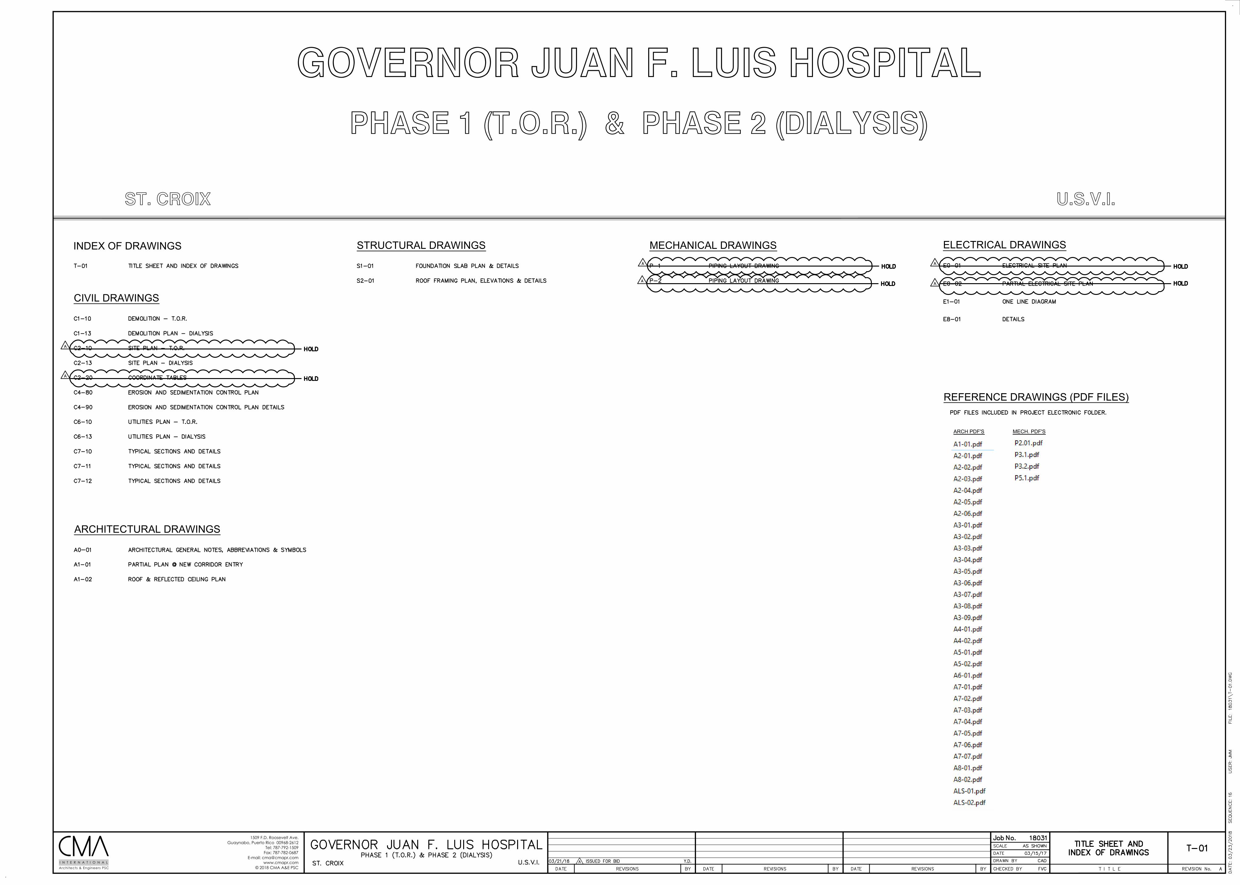
PHASE 1 (T.O.R.) & PHASE 2 (DIALYSIS)
GOVERNOR JUAN F. LUIS HOSPITAL
ST. CROIX U.S.V.I.
INDEX OF DRAWINGS STRUCTURAL DRAWINGS MECHANICAL DRAWINGS ELECTRICAL DRAWINGS
REFERENCE DRAWINGS (PDF FILES)
ARCH PDF'S MECH. PDF'S
ARCHITECTURAL DRAWINGS
CIVIL DRAWINGS
1509 F.D. Roosevelt Ave.Guaynabo, Puerto Rico 00968-2612
Tel: 787-792-1509Fax: 787-782-0687
E-mail: [email protected]
© 2018 CMA A&E PSCArchitects & Engineers PSCI N T E R N A T I O N A L
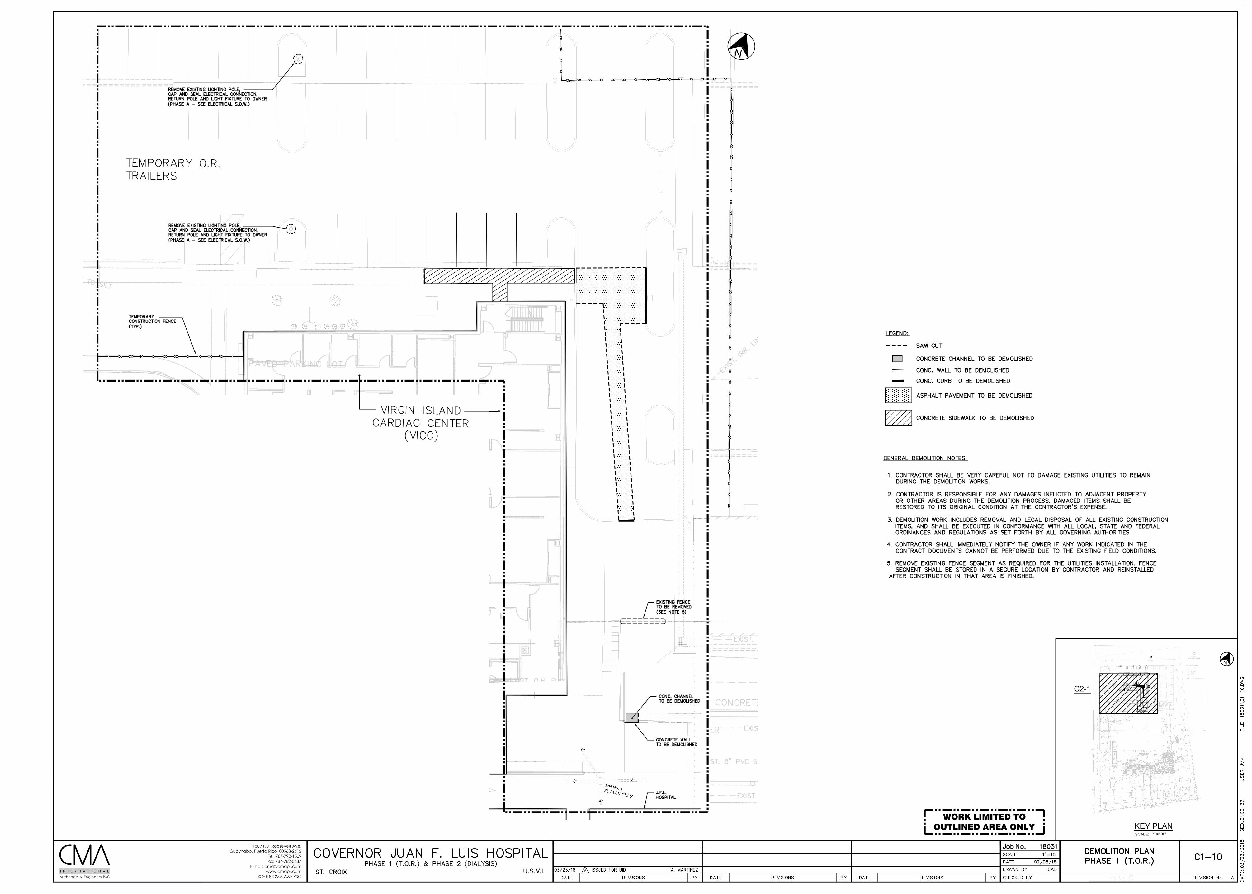
N
SCALE:
KEY PLAN1"=100'
C2-10
WORK LIMITED TOOUTLINED AREA ONLY
1509 F.D. Roosevelt Ave.Guaynabo, Puerto Rico 00968-2612
Tel: 787-792-1509Fax: 787-782-0687
E-mail: [email protected]
© 2018 CMA A&E PSCArchitects & Engineers PSCI N T E R N A T I O N A L
MH No. 1FL ELEV 173.5'
8" 8"
6"
4"
N
N
N
MH No. 1FL ELEV 173.5'
8" 8"
6"
4"
N
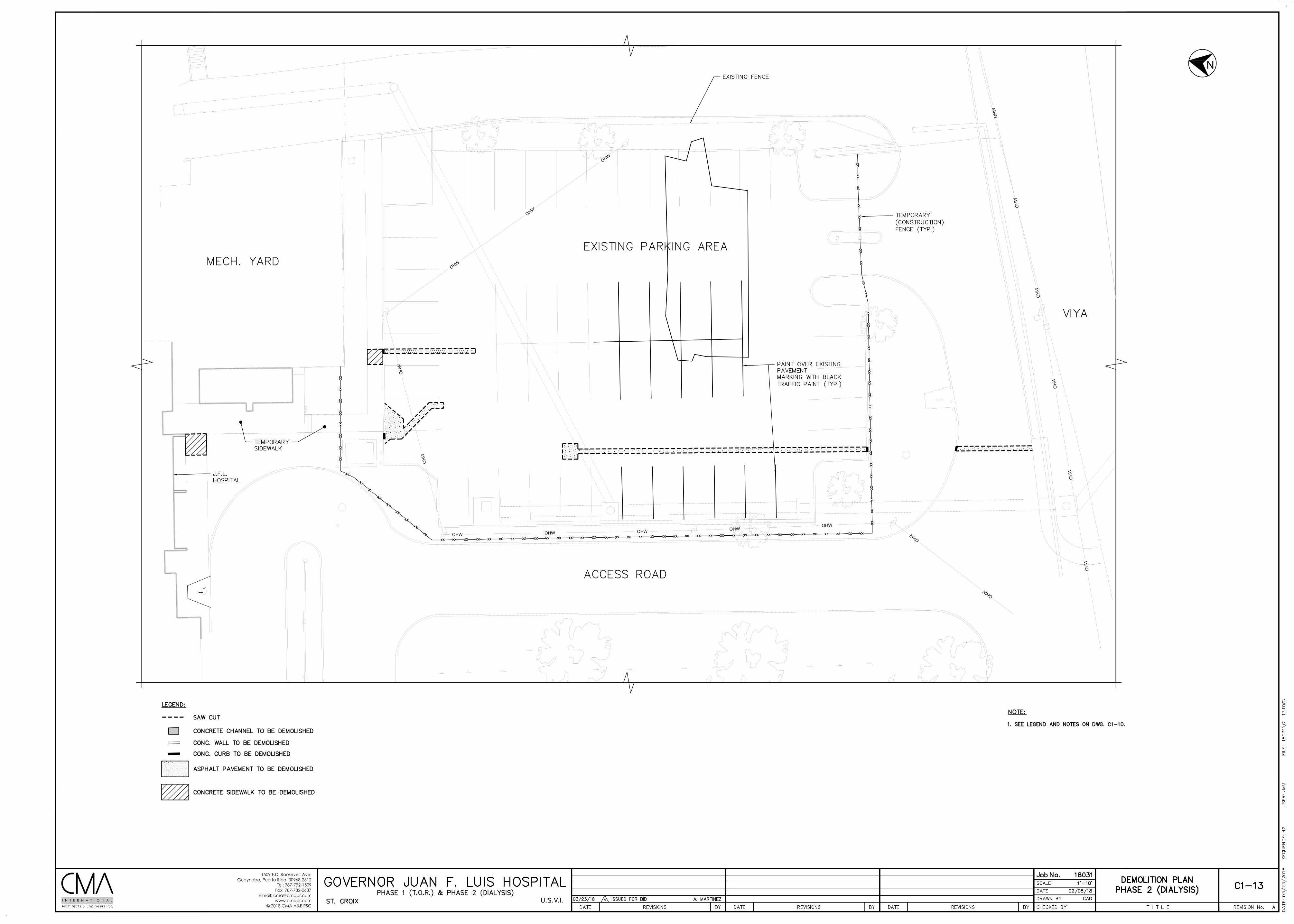
1509 F.D. Roosevelt Ave.Guaynabo, Puerto Rico 00968-2612
Tel: 787-792-1509Fax: 787-782-0687
E-mail: [email protected]
© 2018 CMA A&E PSCArchitects & Engineers PSCI N T E R N A T I O N A L
N
OHW
OHW
OHWOHWOHWOHWOHW
OH
W
OH
W
OHW
OHW
OHW
OH
W
OH
W
OH
W
OH
W
OH
W
OH
W
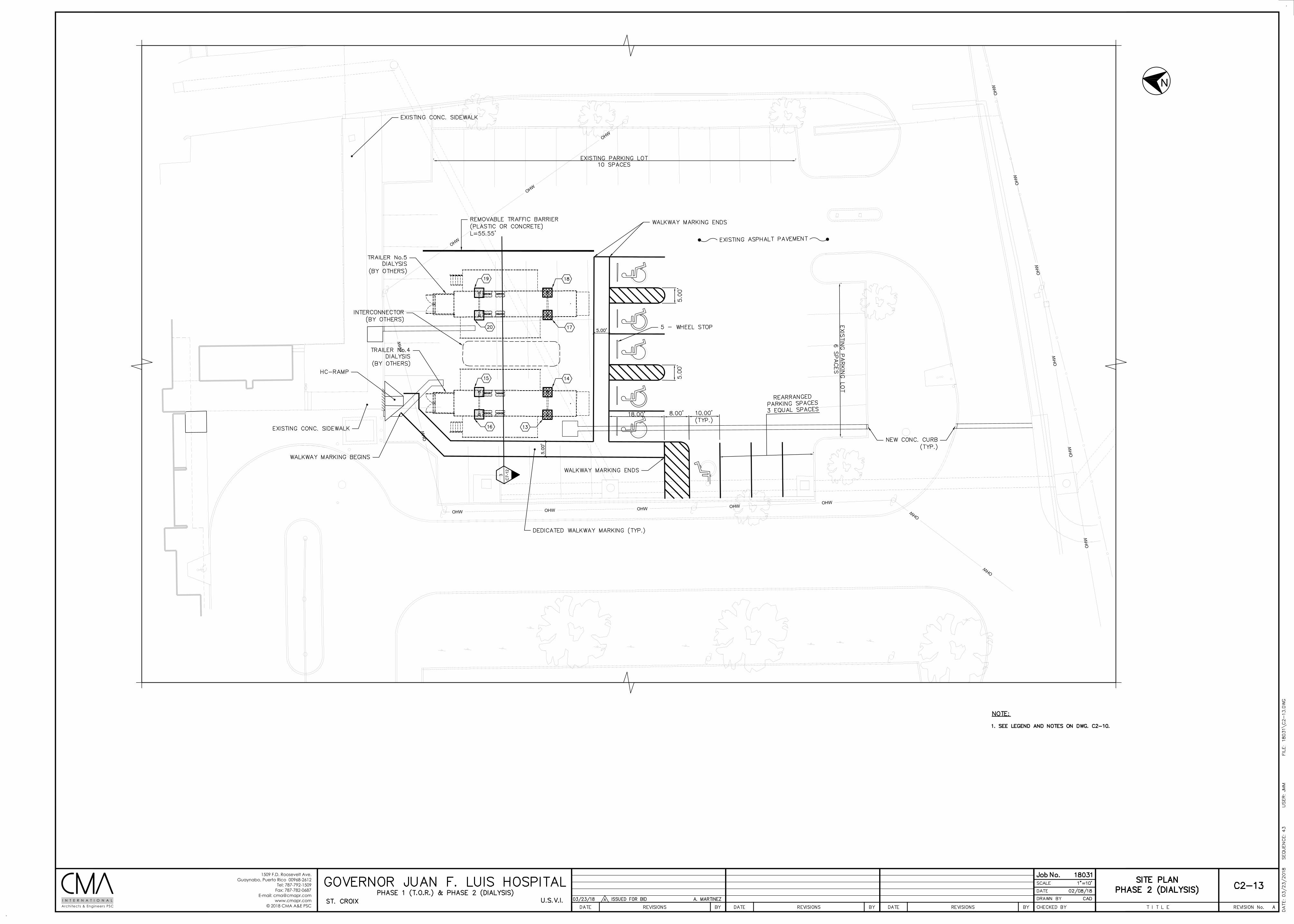
1509 F.D. Roosevelt Ave.Guaynabo, Puerto Rico 00968-2612
Tel: 787-792-1509Fax: 787-782-0687
E-mail: [email protected]
© 2018 CMA A&E PSCArchitects & Engineers PSCI N T E R N A T I O N A L
N
3C
7-12
OHW
OHW
OHWOHWOHWOHWOHW
OH
W
OH
W
OHW
OHW
OHW
OH
W
OH
W
OH
W
OH
W
OH
W
OH
W
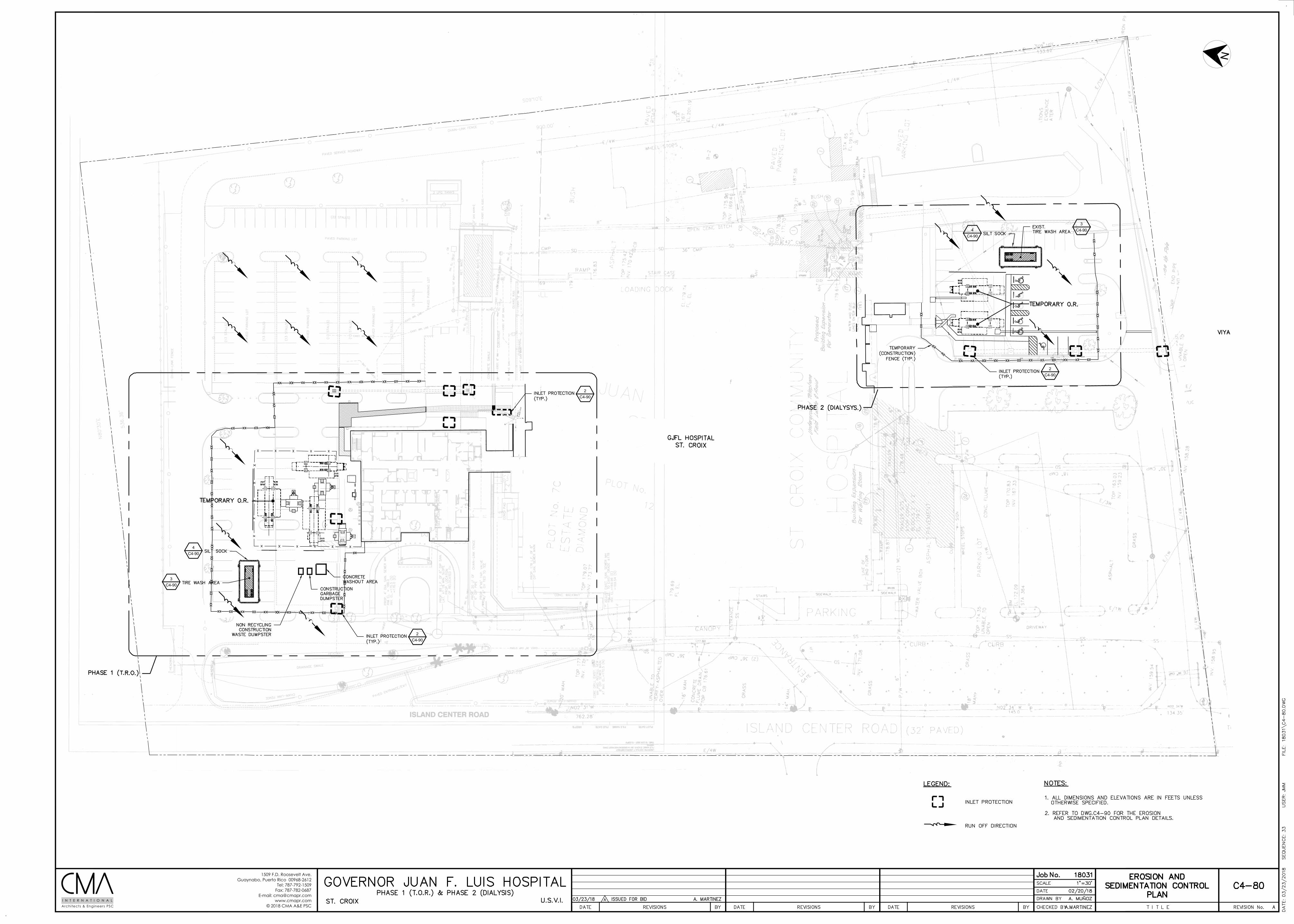
1509 F.D. Roosevelt Ave.Guaynabo, Puerto Rico 00968-2612
Tel: 787-792-1509Fax: 787-782-0687
E-mail: [email protected]
© 2018 CMA A&E PSCArchitects & Engineers PSCI N T E R N A T I O N A L
N
2C4-90
2C4-90
4C4-90
3C4-90
MH
No.
1FL
ELE
V 17
3.5'
8"8"
6"
4"
2C4-90
OHW
OHW
OHWOHWOHWOHWOHW
OH
W
OH
W
OHW
OHW
OHW
OHW
OHW
OH
W
OH
W
OH
W
OH
W
OH
W
OH
W
OH
W
OH
W
OH
W
4C4-90
3C4-90
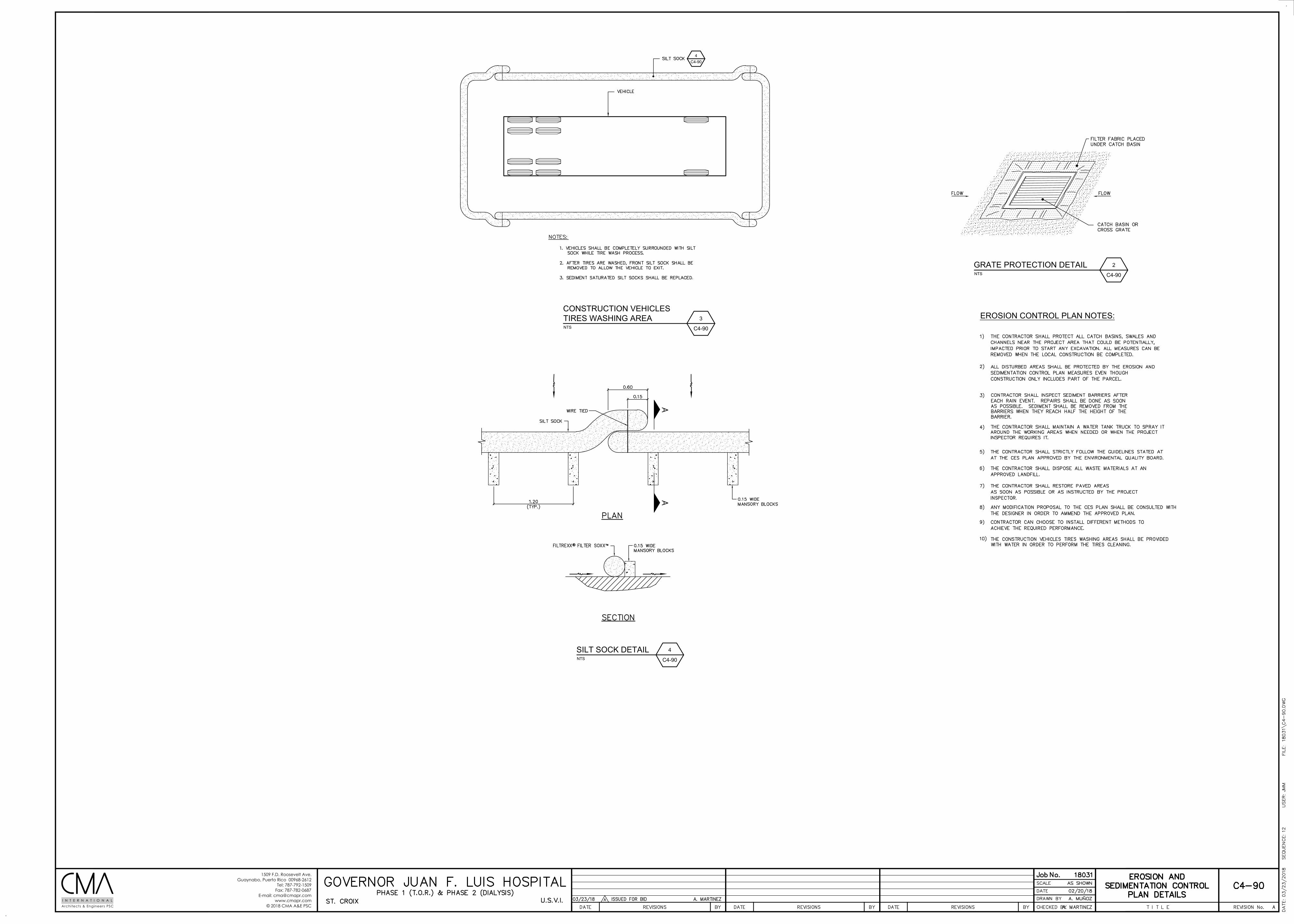
1509 F.D. Roosevelt Ave.Guaynabo, Puerto Rico 00968-2612
Tel: 787-792-1509Fax: 787-782-0687
E-mail: [email protected]
© 2018 CMA A&E PSCArchitects & Engineers PSCI N T E R N A T I O N A L
EROSION CONTROL PLAN NOTES:
NTS
2
C4-90
GRATE PROTECTION DETAIL
NTS
3
C4-90
CONSTRUCTION VEHICLESTIRES WASHING AREA
NTS
4
C4-90
SILT SOCK DETAIL
4C4-90
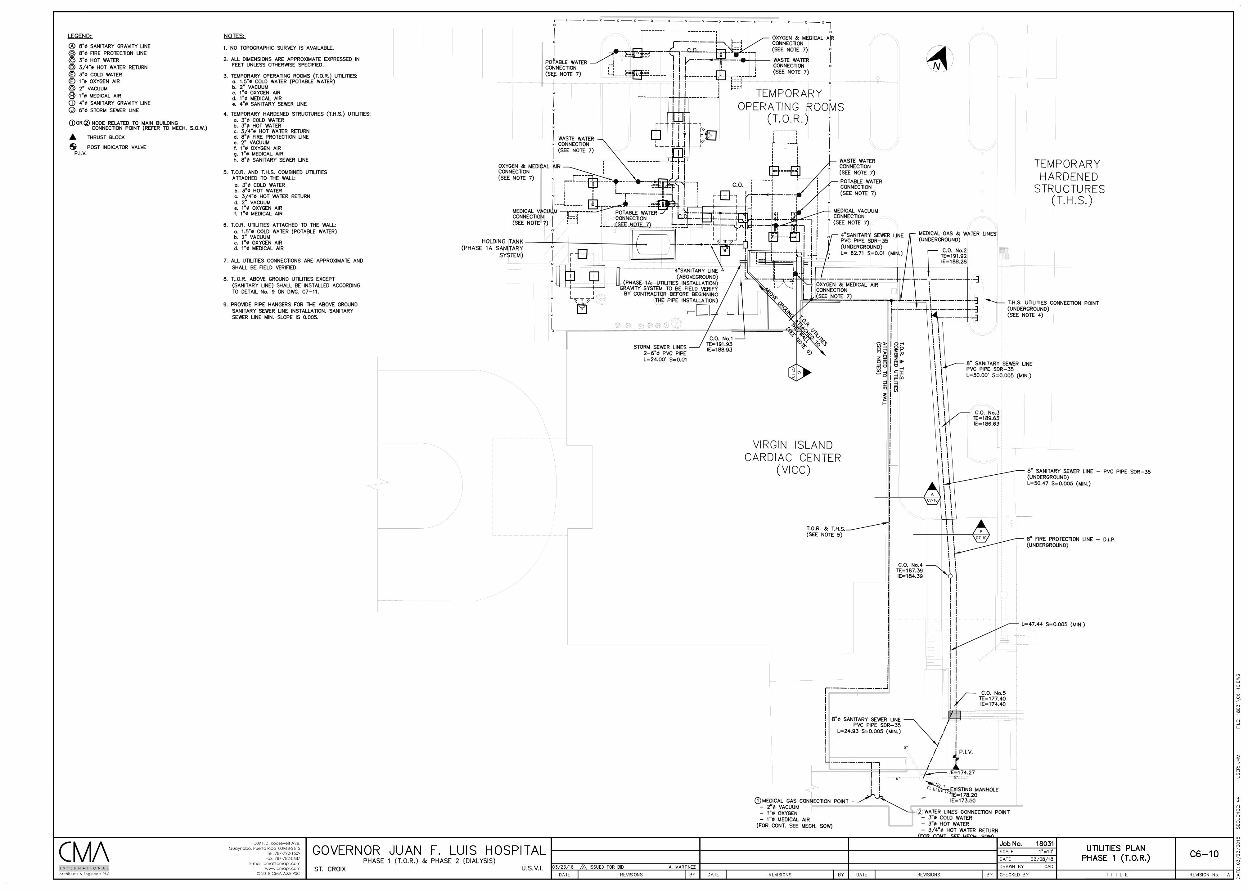
1509 F.D. Roosevelt Ave.Guaynabo, Puerto Rico 00968-2612
Tel: 787-792-1509Fax: 787-782-0687
E-mail: [email protected]
© 2018 CMA A&E PSCArchitects & Engineers PSCI N T E R N A T I O N A L
N
BC7-10
AC7-10
CC
7-10
MH No. 1FL ELEV 173.5'
8" 8"
6"
4"
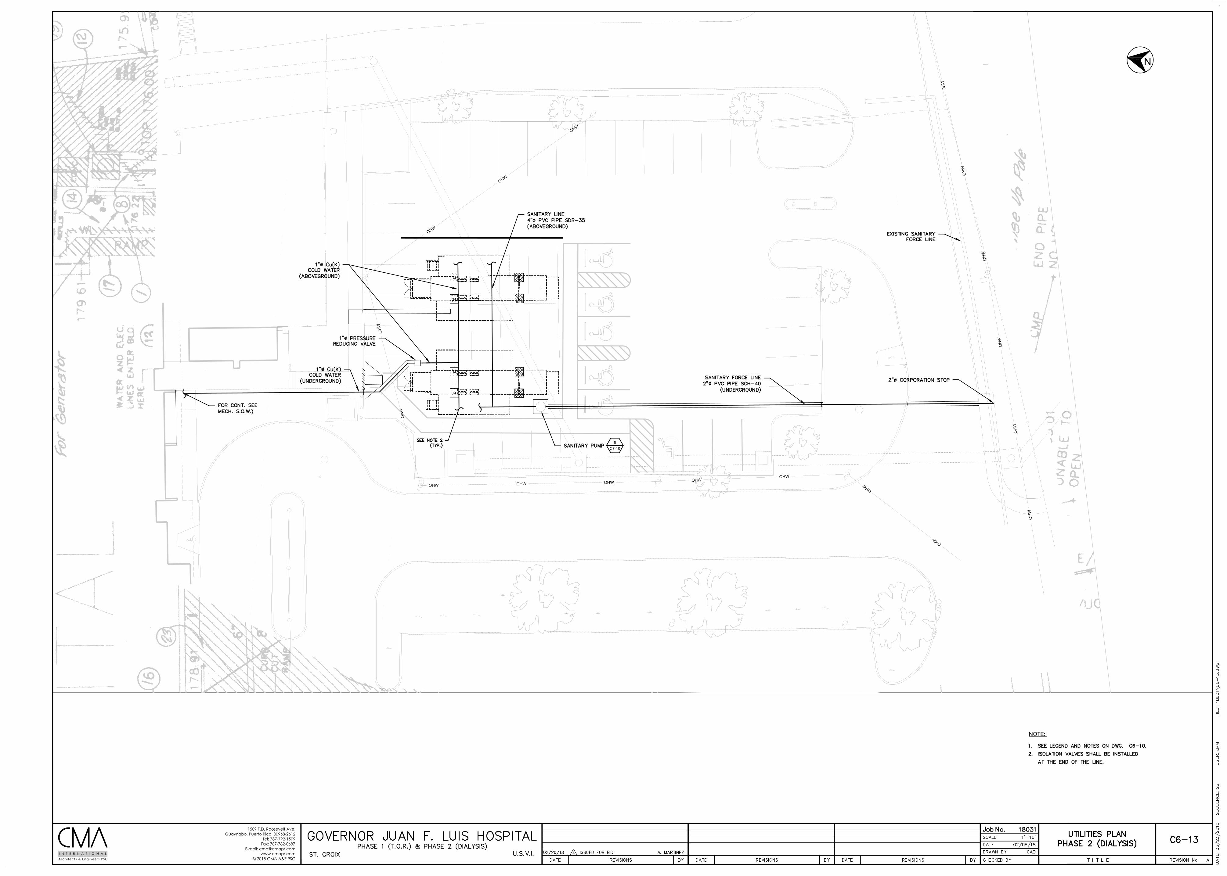
1509 F.D. Roosevelt Ave.Guaynabo, Puerto Rico 00968-2612
Tel: 787-792-1509Fax: 787-782-0687
E-mail: [email protected]
© 2018 CMA A&E PSCArchitects & Engineers PSCI N T E R N A T I O N A L
N
OHW
OHW
OHWOHWOHWOHWOHW
OH
W
OH
W
OHW
OHW
OHW
OH
W
OH
W
OH
W
OH
W
OH
W
OH
W
6C7-10
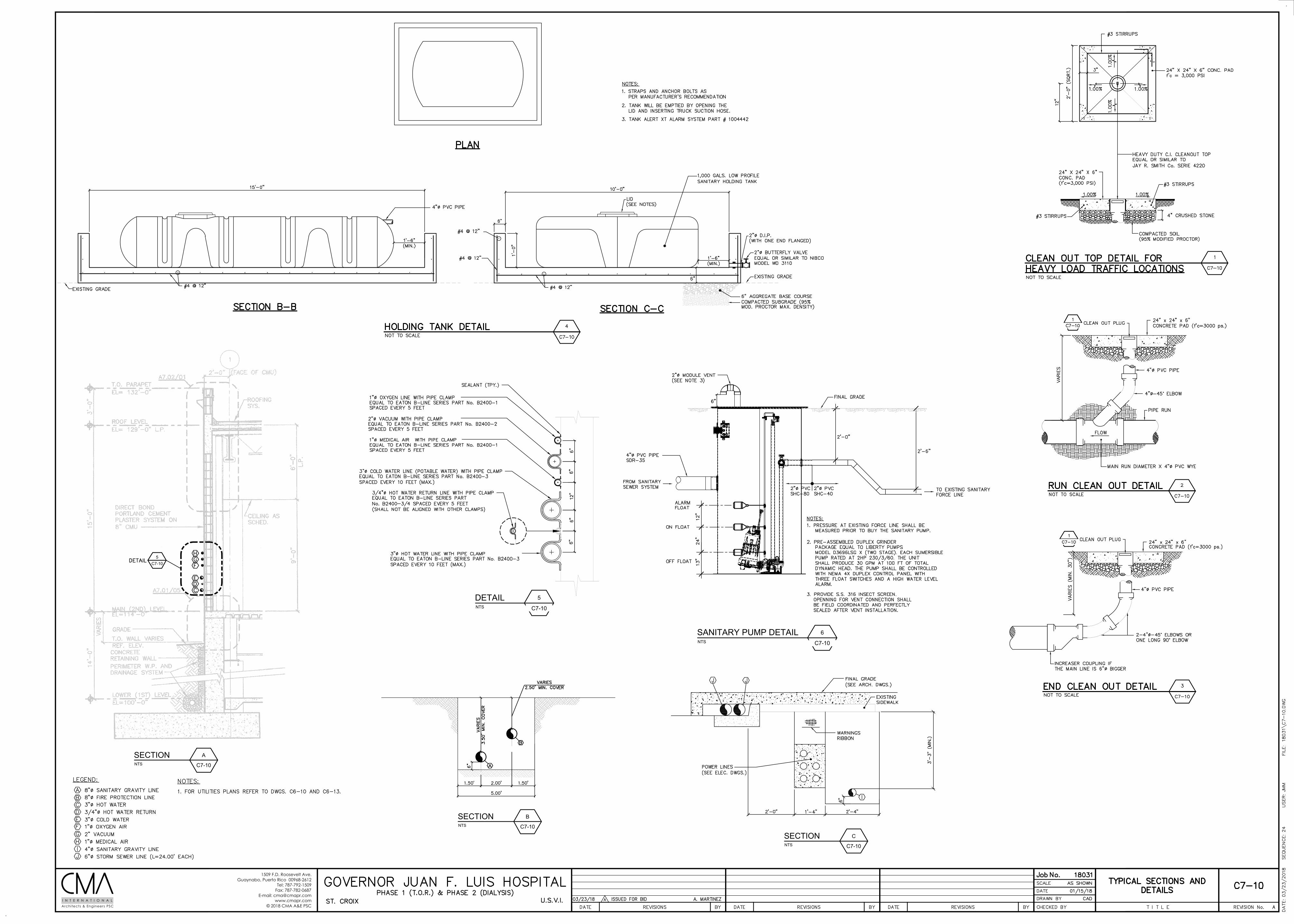
1509 F.D. Roosevelt Ave.Guaynabo, Puerto Rico 00968-2612
Tel: 787-792-1509Fax: 787-782-0687
E-mail: [email protected]
© 2018 CMA A&E PSCArchitects & Engineers PSCI N T E R N A T I O N A L
NTS
6
C7-10
SANITARY PUMP DETAIL
NTS
5
C7-10
DETAIL
NTS
B
C7-10
SECTION
NTS
A
C7-10
SECTION
NTS
C
C7-10
SECTION
5C7-10
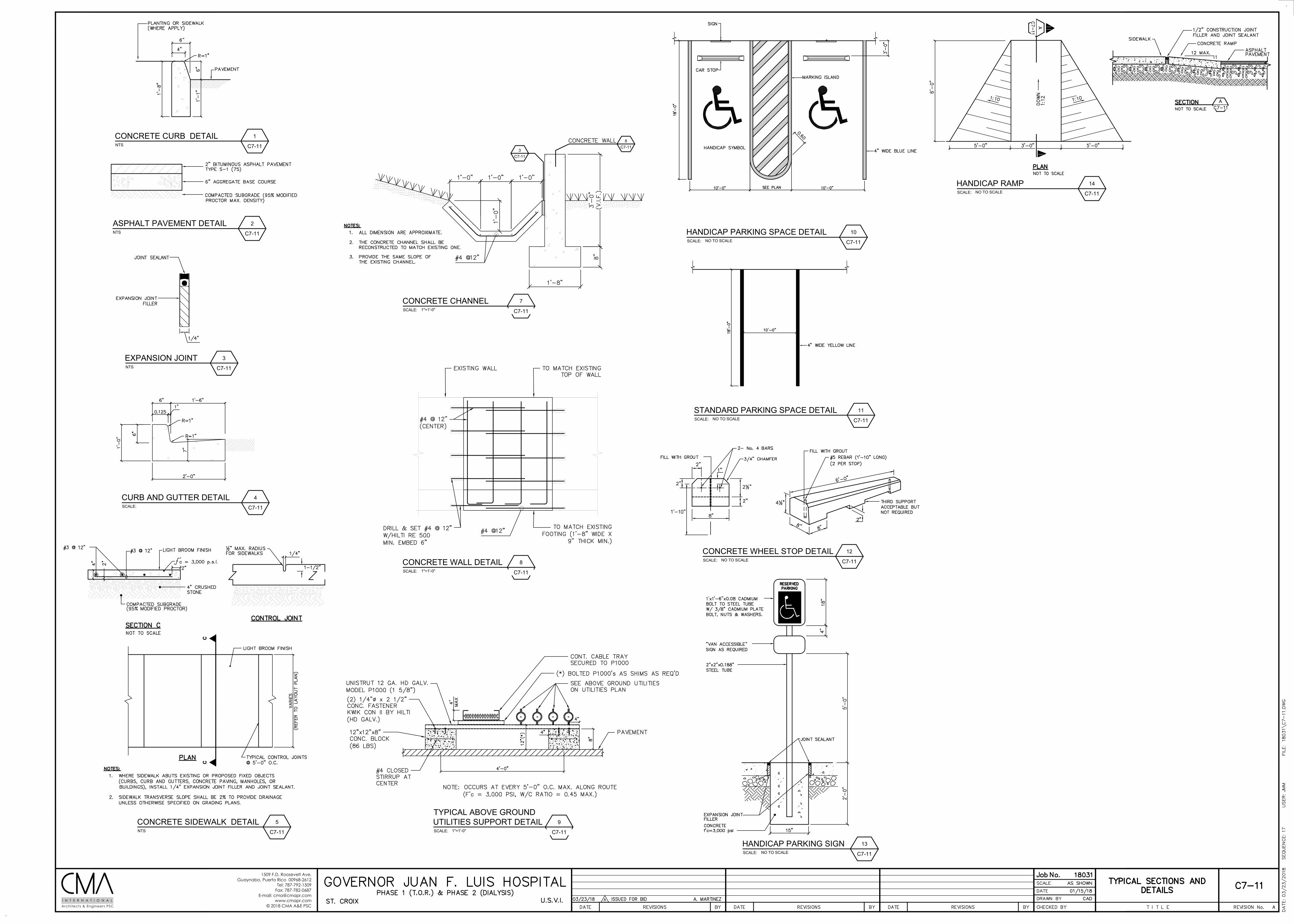
1509 F.D. Roosevelt Ave.Guaynabo, Puerto Rico 00968-2612
Tel: 787-792-1509Fax: 787-782-0687
E-mail: [email protected]
© 2018 CMA A&E PSCArchitects & Engineers PSCI N T E R N A T I O N A L
NTS
3
C7-11
EXPANSION JOINT
NTS
2
C7-11
ASPHALT PAVEMENT DETAIL
NTS
5
C7-11
CONCRETE SIDEWALK DETAIL
NTS
1
C7-11
CONCRETE CURB DETAIL
SCALE:
9
C7-11
TYPICAL ABOVE GROUNDUTILITIES SUPPORT DETAIL
1"=1'-0"
SCALE:
7
C7-11
CONCRETE CHANNEL1"=1'-0"
3C7-11
SCALE:
12
C7-11
CONCRETE WHEEL STOP DETAILNO TO SCALE
SCALE:
13
C7-11
HANDICAP PARKING SIGNNO TO SCALE
SCALE:
11
C7-11
STANDARD PARKING SPACE DETAILNO TO SCALE
SCALE:
10
C7-11
HANDICAP PARKING SPACE DETAILNO TO SCALE
SCALE:
8
C7-11
CONCRETE WALL DETAIL1"=1'-0"
SCALE:
14
C7-11
HANDICAP RAMPNO TO SCALE
SCALE:
4
C7-11
CURB AND GUTTER DETAIL
8C7-11
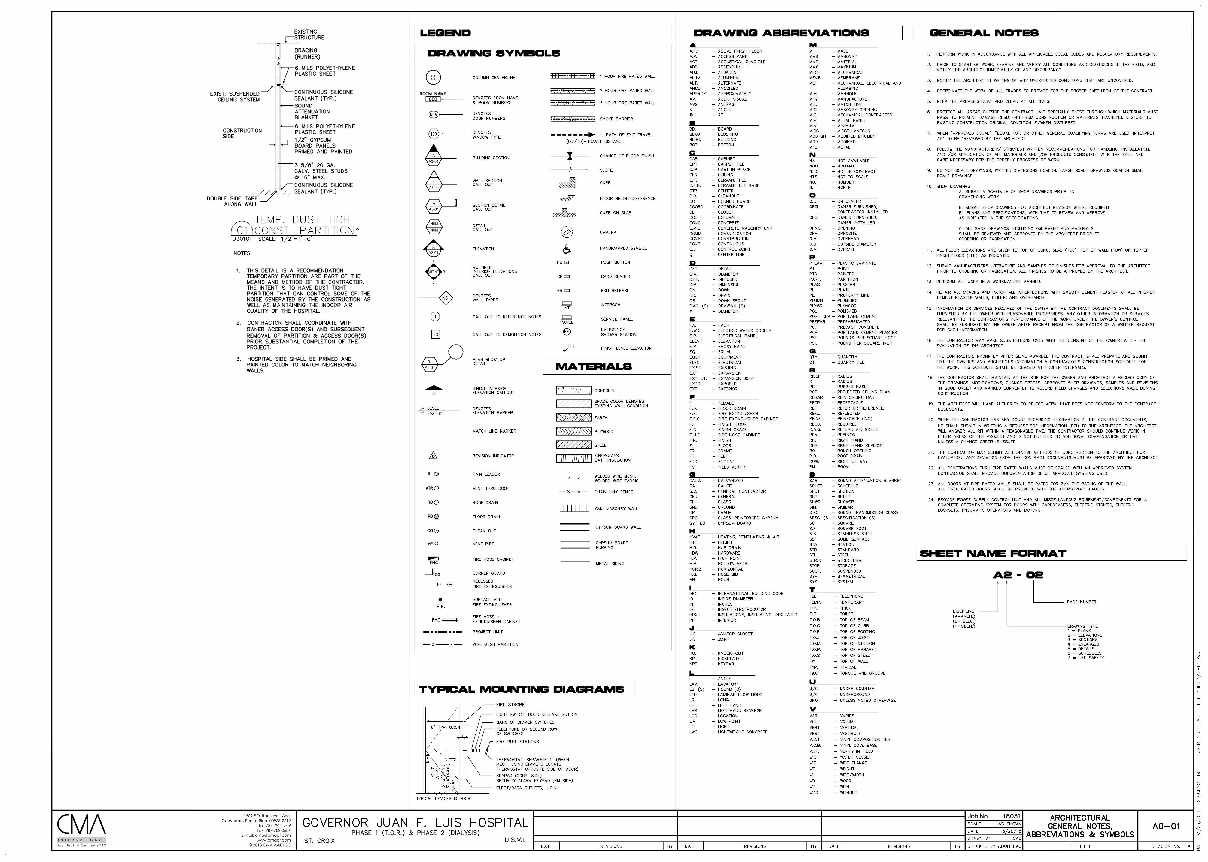
1509 F.D. Roosevelt Ave.Guaynabo, Puerto Rico 00968-2612
Tel: 787-792-1509Fax: 787-782-0687
E-mail: [email protected]
© 2018 CMA A&E PSCArchitects & Engineers PSCI N T E R N A T I O N A L
00
A
A3-01
A
A2-01
R
B
L SHT.NO
T
NUM
NUM
01
A5-01
A
A5-01
1
A3-11
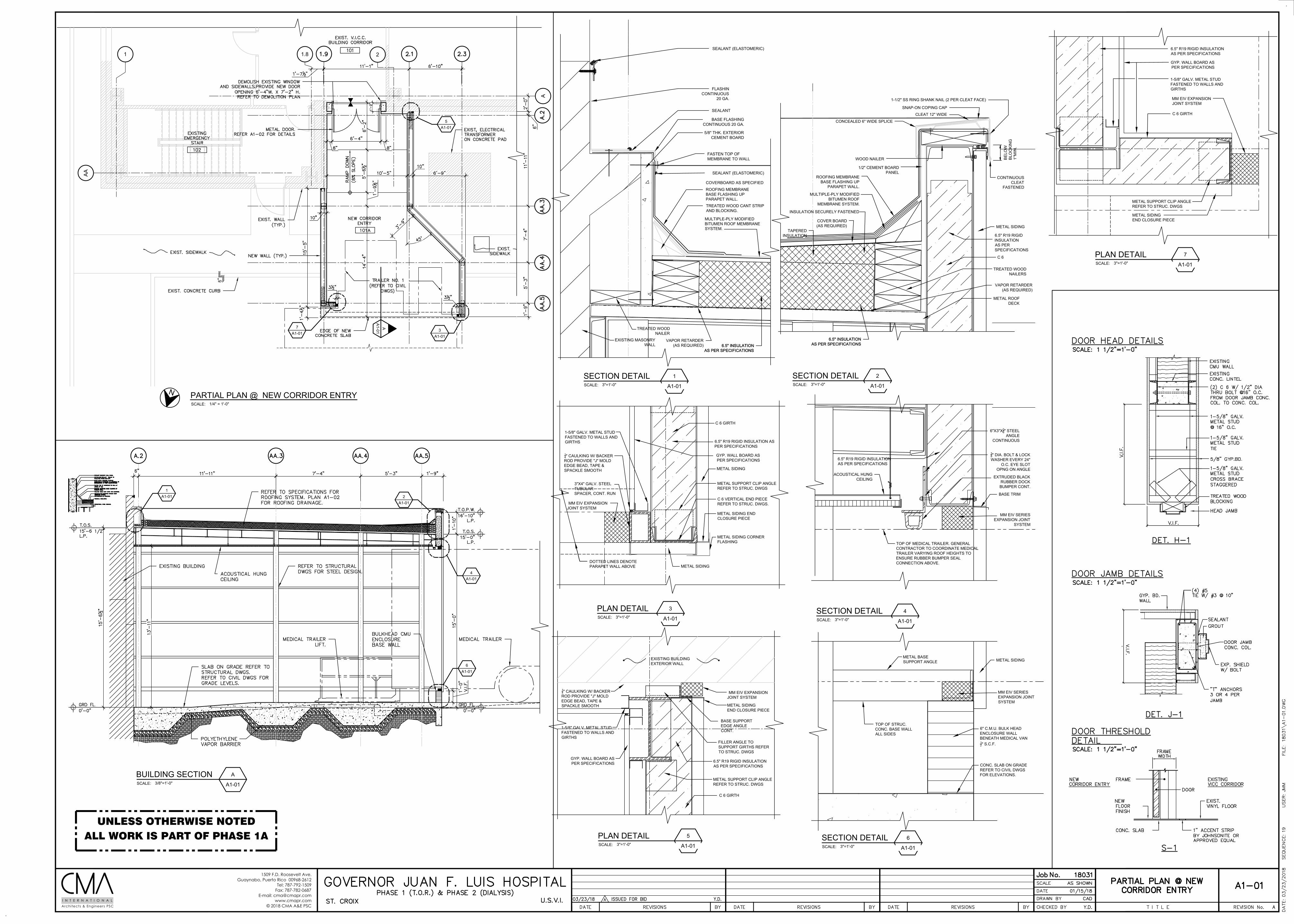
1509 F.D. Roosevelt Ave.Guaynabo, Puerto Rico 00968-2612
Tel: 787-792-1509Fax: 787-782-0687
E-mail: [email protected]
© 2018 CMA A&E PSCArchitects & Engineers PSCI N T E R N A T I O N A L
SCALE:
PARTIAL PLAN @ NEW CORRIDOR ENTRY1/4" = 1'-0"
SCALE:
A
A1-01
BUILDING SECTION3/8"=1'-0"
SCALE:
1
A1-01
SECTION DETAIL3"=1'-0" SCALE:
2
A1-01
SECTION DETAIL3"=1'-0"
SCALE:
4
A1-01
SECTION DETAIL3"=1'-0"
SCALE:
5
A1-01
PLAN DETAIL3"=1'-0"
SCALE:
3
A1-01
PLAN DETAIL3"=1'-0"
SCALE:
6
A1-01
SECTION DETAIL3"=1'-0"
6.5" INSULATIONAS PER SPECIFICATIONS
6.5" INSULATIONAS PER SPECIFICATIONS
SCALE:
7
A1-01
PLAN DETAIL3"=1'-0"
N
ALL WORK IS PART OF PHASE 1AUNLESS OTHERWISE NOTED
5A1-01
3A1-01
AA
1-01
1 1.8 2
AA
7A1-01
1A1-01 2
A1-01
4A1-01
6A1-01
ROOFING MEMBRANEBASE FLASHING UPPARAPET WALL.TREATED WOOD CANT STRIPAND BLOCKING.
FASTEN TOP OFMEMBRANE TO WALL
MULTIPLE-PLY MODIFIEDBITUMEN ROOF MEMBRANESYSTEM.
TREATED WOODNAILER
COVERBOARD AS SPECIFIED
EXISTING MASONRYWALL
VAPOR RETARDER(AS REQUIRED)
SEALANT (ELASTOMERIC)
5/8" THK. EXTERIORCEMENT BOARD
BASE FLASHINGCONTINUOUS 20 GA.
SEALANT
FLASHINCONTINUOUS
20 GA.
SEALANT (ELASTOMERIC)
6.5" INSULATIONAS PER SPECIFICATIONS
6.5" INSULATIONAS PER SPECIFICATIONS
1''M
IN.
1-1/2" SS RING SHANK NAIL (2 PER CLEAT FACE)
SNAP-ON COPING CAP
CLEAT 12" WIDE
CONCEALED 6" WIDE SPLICE
1/2" CEMENT BOARDPANEL
WOOD NAILER
CONTINUOUSCLEAT
FASTENED
BE
LOW
BLO
CK
ING
ROOFING MEMBRANEBASE FLASHING UP
PARAPET WALL.
INSULATION SECURELY FASTENED
COVER BOARD(AS REQUIRED) METAL SIDING
C 6
TREATED WOODNAILERS
METAL ROOFDECK
VAPOR RETARDER(AS REQUIRED)
6.5" R19 RIGIDINSULATIONAS PERSPECIFICATIONS
TAPEREDINSULATION
MULTIPLE-PLY MODIFIEDBITUMEN ROOF
MEMBRANE SYSTEM.
6"X3"X38" STEEL
ANGLECONTINUOUS
38" DIA. BOLT & LOCKWASHER EVERY 24"
O.C. EYE SLOTOPNG ON ANGLE
EXTRUDED BLACKRUBBER DOCKBUMPER CONT.
BASE TRIM
MM EIV SERIESEXPANSION JOINT
SYSTEM
TOP OF MEDICAL TRAILER. GENERALCONTRACTOR TO COORDINATE MEDICALTRAILER VARYING ROOF HEIGHTS TOENSURE RUBBER BUMPER SEALCONNECTION ABOVE.
ACOUSTICAL HUNGCEILING
6.5" R19 RIGID INSULATIONAS PER SPECIFICATIONS
A
MM EIV EXPANSIONJOINT SYSTEM
METAL SIDINGEND CLOSURE PIECE
BASE SUPPORTEDGE ANGLECONT.
METAL SUPPORT CLIP ANGLEREFER TO STRUC. DWGS
C 6 GIRTH
14" CAULKING W/ BACKERROD PROVIDE "J" MOLDEDGE BEAD, TAPE &SPACKLE SMOOTH
1-5/8" GALV. METAL STUDFASTENED TO WALLS ANDGIRTHS
GYP. WALL BOARD ASPER SPECIFICATIONS
EXISTING BUILDINGEXTERIOR WALL
FILLER ANGLE TOSUPPORT GIRTHS REFERTO STRUC. DWGS
6.5" R19 RIGID INSULATIONAS PER SPECIFICATIONS
METAL SIDING
C 6 GIRTH
METAL SUPPORT CLIP ANGLEREFER TO STRUC. DWGS
GYP. WALL BOARD ASPER SPECIFICATIONS
C 6 VERTICAL END PIECEREFER TO STRUC. DWGS.
METAL SIDING ENDCLOSURE PIECE
METAL SIDING CORNERFLASHING
METAL SIDING
14" CAULKING W/ BACKERROD PROVIDE "J" MOLDEDGE BEAD, TAPE &SPACKLE SMOOTH
1-5/8" GALV. METAL STUDFASTENED TO WALLS ANDGIRTHS
3"X4" GALV. STEELTUBULARSPACER, CONT. RUN
MM EIV EXPANSIONJOINT SYSTEM
DOTTED LINES DENOTEPARAPET WALL ABOVE
6.5" R19 RIGID INSULATION ASPER SPECIFICATIONS
MM EIV SERIESEXPANSION JOINTSYSTEM
METAL SIDINGMETAL BASESUPPORT ANGLE
TOP OF STRUC.CONC. BASE WALLALL SIDES
6" C.M.U. BULK HEADENCLOSURE WALLBENEATH MEDICAL VAN12" S.C.F.
CONC. SLAB ON GRADEREFER TO CIVIL DWGSFOR ELEVATIONS.
MM EIV EXPANSIONJOINT SYSTEM
METAL SIDINGEND CLOSURE PIECE
METAL SUPPORT CLIP ANGLEREFER TO STRUC. DWGS
C 6 GIRTH
1-5/8" GALV. METAL STUDFASTENED TO WALLS ANDGIRTHS
GYP. WALL BOARD ASPER SPECIFICATIONS
6.5" R19 RIGID INSULATIONAS PER SPECIFICATIONS
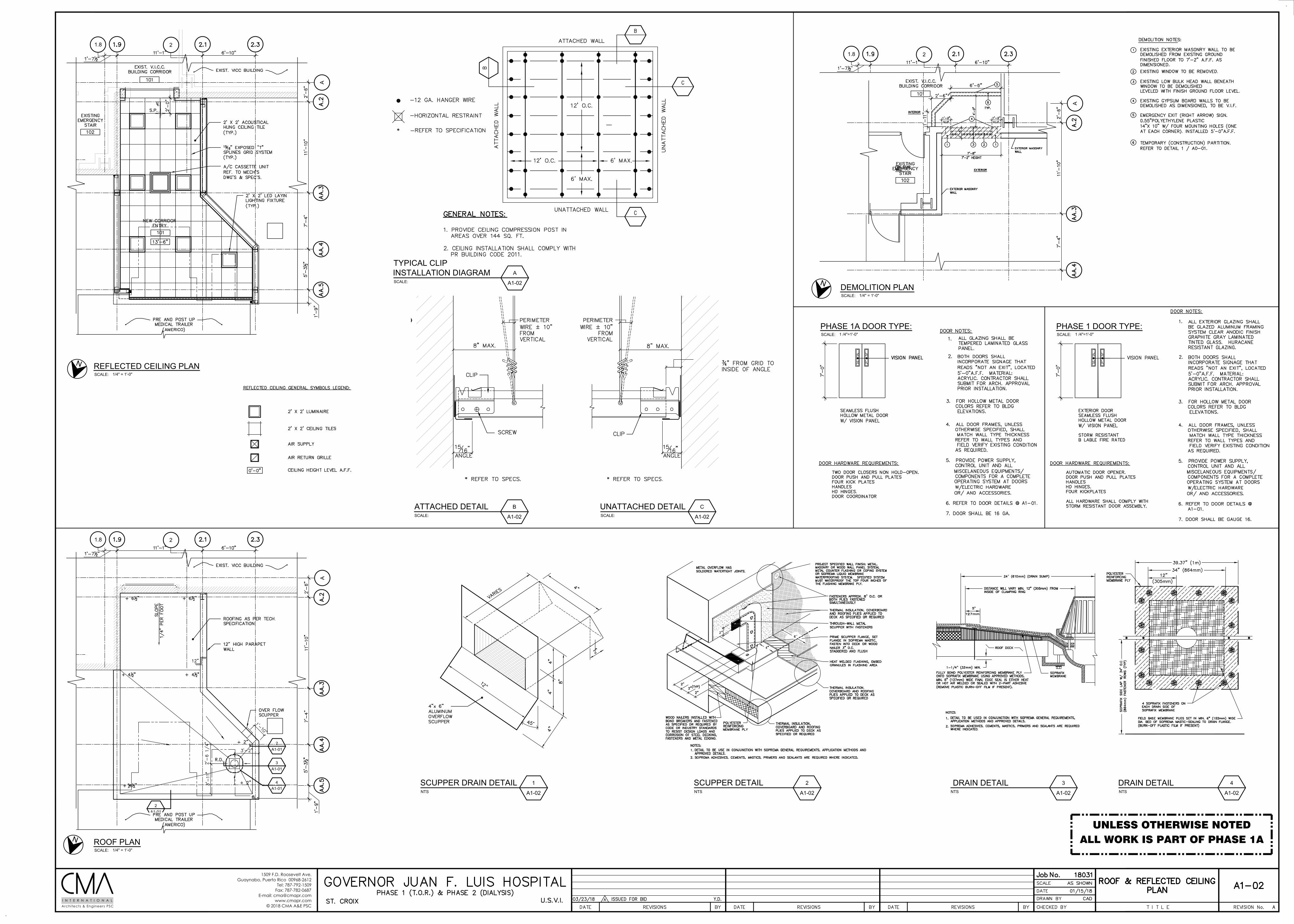
1509 F.D. Roosevelt Ave.Guaynabo, Puerto Rico 00968-2612
Tel: 787-792-1509Fax: 787-782-0687
E-mail: [email protected]
© 2018 CMA A&E PSCArchitects & Engineers PSCI N T E R N A T I O N A L
SCALE:
B
A1-02
ATTACHED DETAILSCALE:
C
A1-02
UNATTACHED DETAIL
NTS
1
A1-02
SCUPPER DRAIN DETAILNTS
2
A1-02
SCUPPER DETAILNTS
3
A1-02
DRAIN DETAILNTS
4
A1-02
DRAIN DETAIL
SCALE:
REFLECTED CEILING PLAN1/4" = 1'-0"
SCALE:
ROOF PLAN1/4" = 1'-0"
4A1-01
2A1-01
3A1-01
2A1-01
SCALE:
A
A1-02
TYPICAL CLIPINSTALLATION DIAGRAM
SCALE:
DEMOLITION PLAN1/4" = 1'-0"
N
N
N
SCALE:
PHASE 1A DOOR TYPE:1 /4"=1'-0" SCALE:
PHASE 1 DOOR TYPE:1 /4"=1'-0"
ALL WORK IS PART OF PHASE 1AUNLESS OTHERWISE NOTED
1.8 2
AA
1.8 2
1.8 2
A
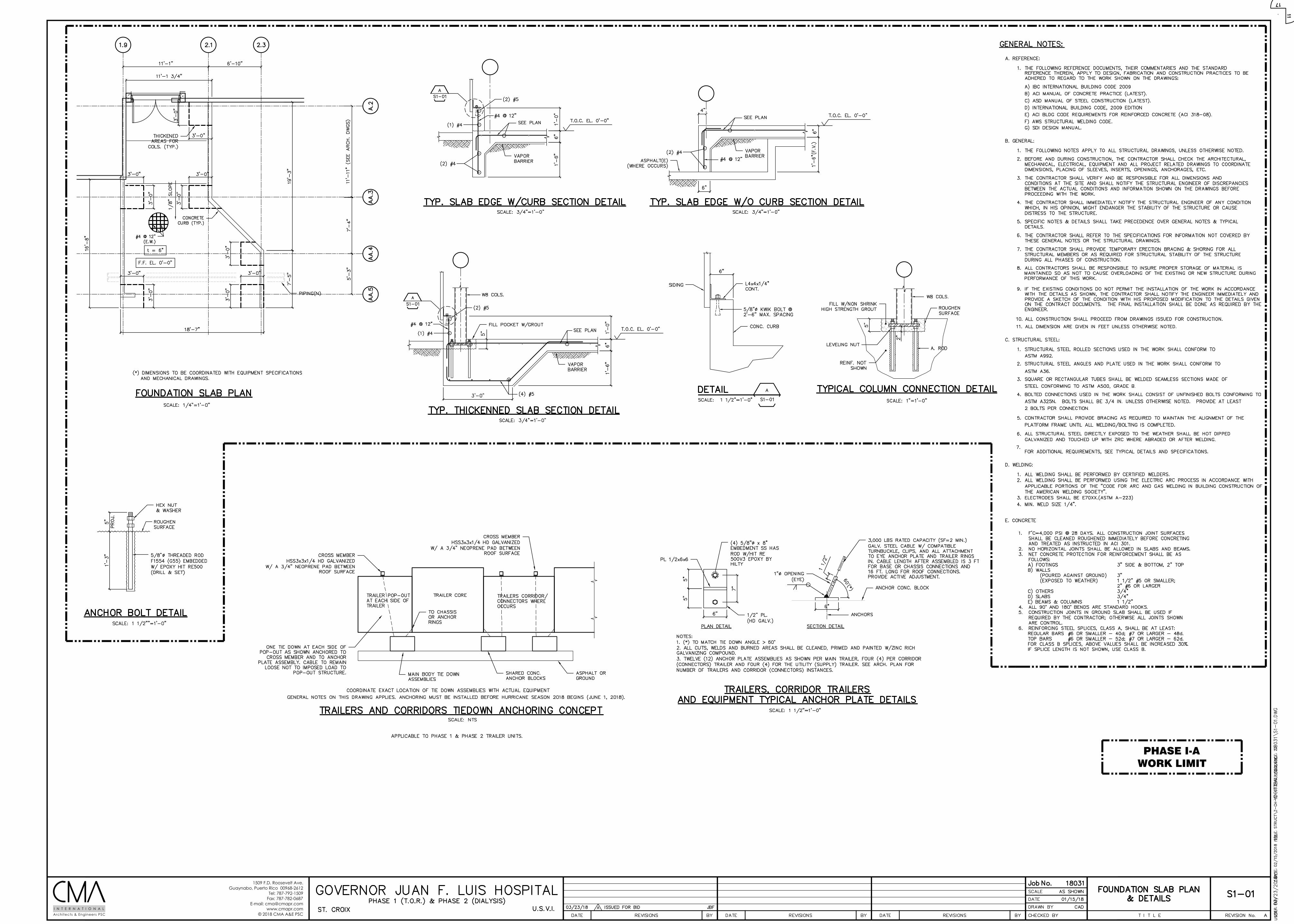
1509 F.D. Roosevelt Ave.Guaynabo, Puerto Rico 00968-2612
Tel: 787-792-1509Fax: 787-782-0687
E-mail: [email protected]
© 2018 CMA A&E PSCArchitects & Engineers PSCI N T E R N A T I O N A L
PHASE I-AWORK LIMIT
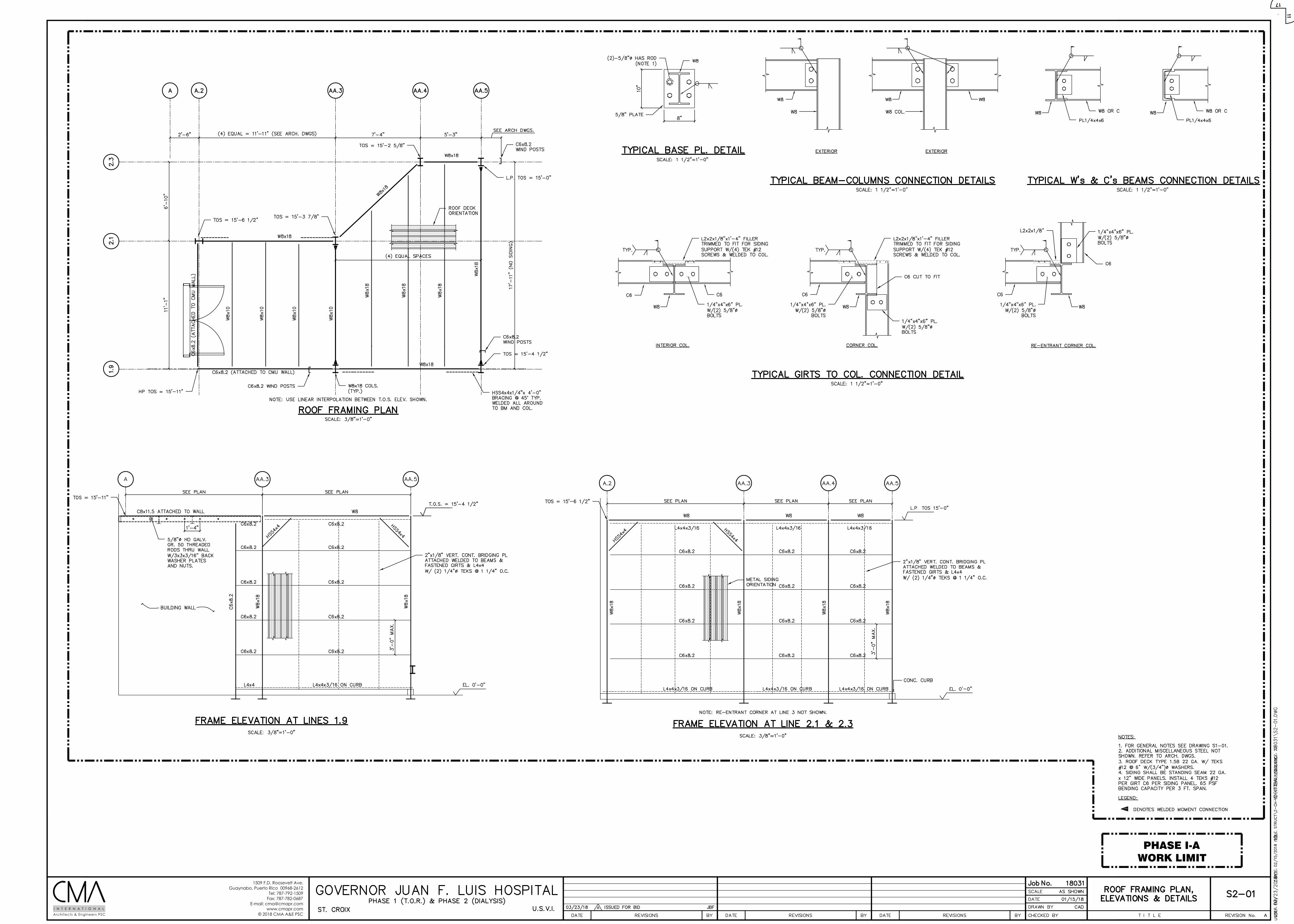
1509 F.D. Roosevelt Ave.Guaynabo, Puerto Rico 00968-2612
Tel: 787-792-1509Fax: 787-782-0687
E-mail: [email protected]
© 2018 CMA A&E PSCArchitects & Engineers PSCI N T E R N A T I O N A L
PHASE I-AWORK LIMIT
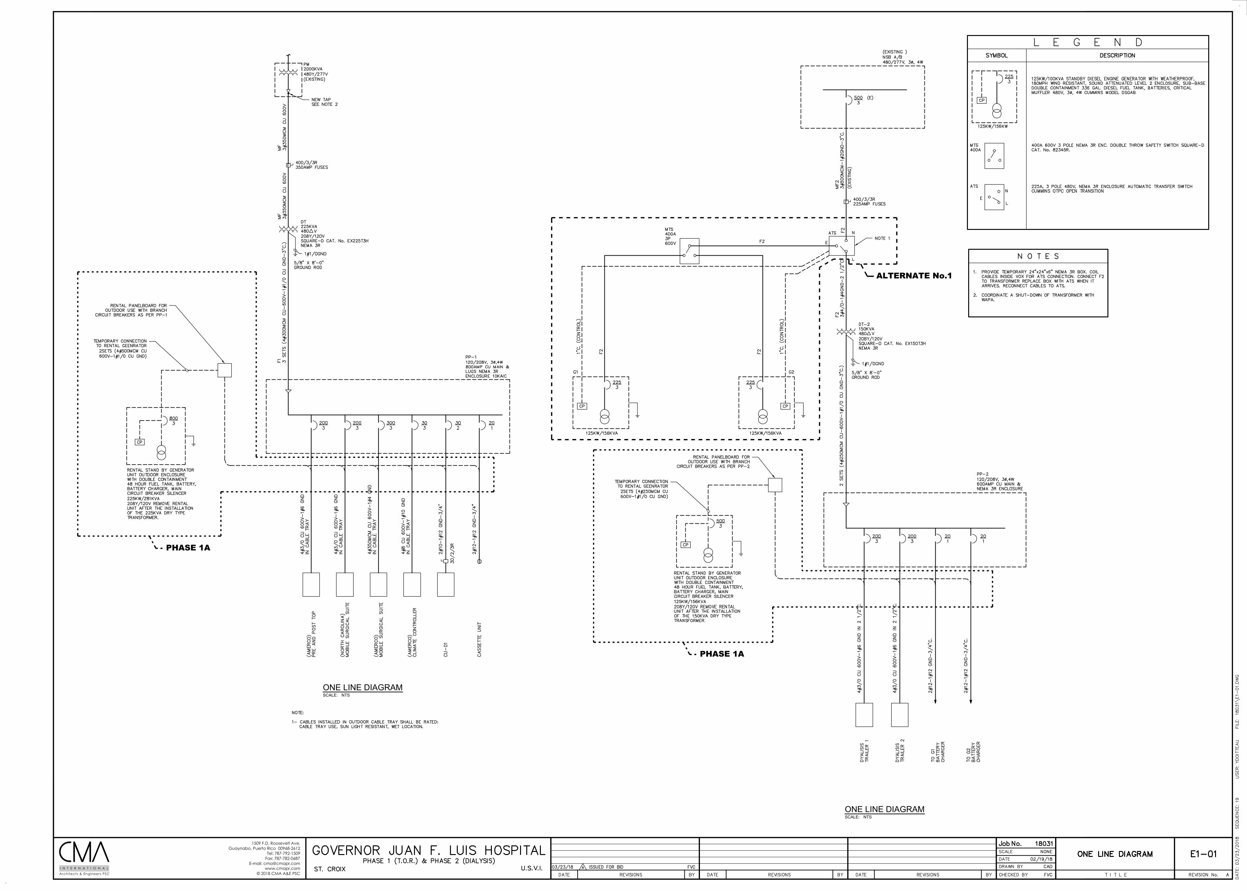
1509 F.D. Roosevelt Ave.Guaynabo, Puerto Rico 00968-2612
Tel: 787-792-1509Fax: 787-782-0687
E-mail: [email protected]
© 2018 CMA A&E PSCArchitects & Engineers PSCI N T E R N A T I O N A L
SCALE:
ONE LINE DIAGRAM
NTS
SCALE:
ONE LINE DIAGRAM
NTS
ALTERNATE No.1
PHASE 1A
PHASE 1A
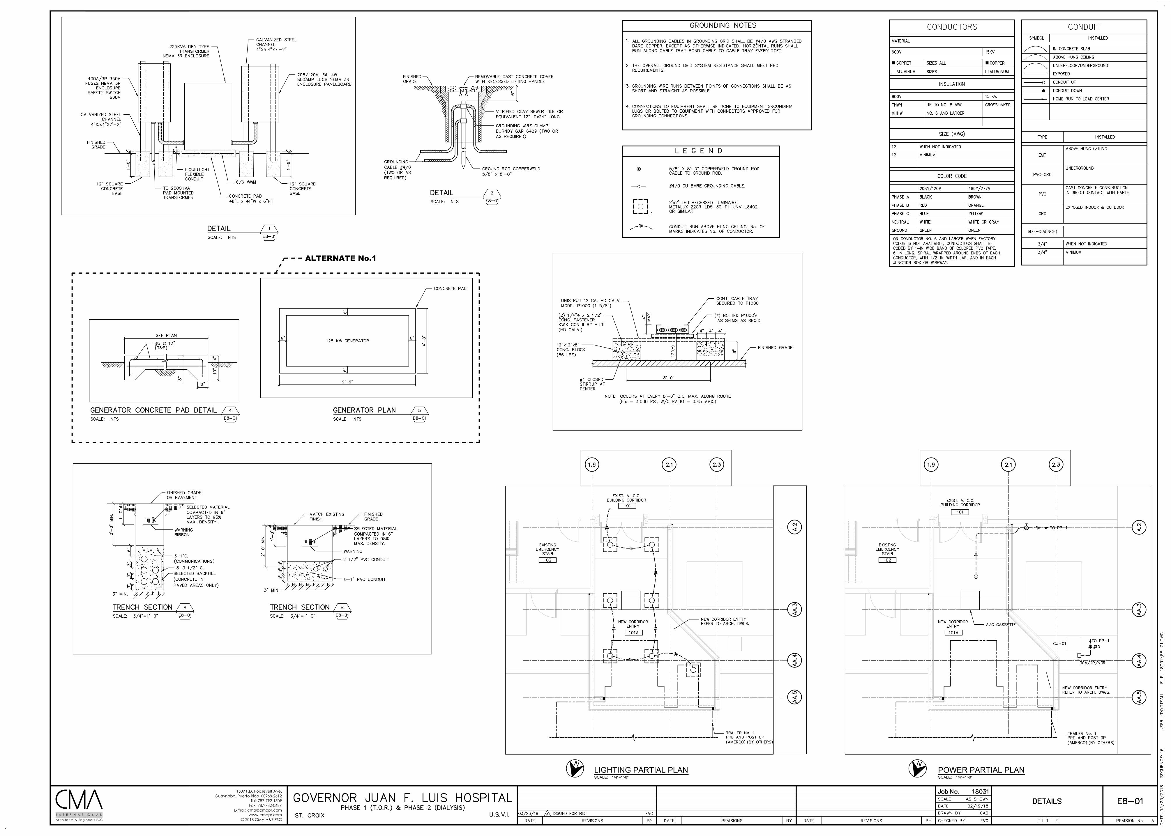
1509 F.D. Roosevelt Ave.Guaynabo, Puerto Rico 00968-2612
Tel: 787-792-1509Fax: 787-782-0687
E-mail: [email protected]
© 2018 CMA A&E PSCArchitects & Engineers PSCI N T E R N A T I O N A L
SCALE:
LIGHTING PARTIAL PLAN
1/4"=1'-0" SCALE:
POWER PARTIAL PLAN
1/4"=1'-0"
ALTERNATE No.1
N N

REFERENCE DRAWINGS