
Procurement of Plant - PGCB
163
Procurement of Plant Design, Supply, and Installation Single-Stage: Two-Envelope Tender Procedure TENDER DOCUMENT for Procurement of Design, Supply, Installation, Testing & Commissioning of 400kV & 230kV underground XLPE cable Transmission lines on Chattogram Area.(Package-2) Issued on: June 10, 2021 Invitation for Tenders No.: 27.21.0000.101.07.311.21.2532 Contract Ref. No.: PGCB/AIIB/0088A-BGD/TL/P-2 Employer: Power Grid Company of Bangladesh Limited (PGCB) Country: Bangladesh Volume 2 of 3
-
Upload
khangminh22 -
Category
Documents
-
view
4 -
download
0
Transcript of Procurement of Plant - PGCB

Procurement of Plant
Design, Supply, and Installation
Single-Stage: Two-Envelope Tender Procedure
TENDER DOCUMENT for
Procurement of
Design, Supply, Installation, Testing & Commissioning of 400kV & 230kV underground XLPE cable Transmission lines on
Chattogram Area.(Package-2)
Issued on: June 10, 2021
Invitation for Tenders No.: 27.21.0000.101.07.311.21.2532
Contract Ref. No.: PGCB/AIIB/0088A-BGD/TL/P-2
Employer: Power Grid Company of Bangladesh Limited (PGCB)
Country: Bangladesh
Volume 2 of 3

Contents of the Tender Documents
Volume 1
Section I. Instructions to Bidders (ITB)
Section II. Bid Data Sheet (BDS)
Section III. Evaluation and Qualification Criteria
Section IV. Bidding Forms
Section V. Eligible Countries
Section VI. Employer's Requirements
Section VII. General Conditions of Contract (GCC)
Section VIII. Special Conditions of Contract (PCC)
Section IX. Contract Forms
Volume 2
Scope of Works
Technical Specifications
Drawings forming Part of the Specification
Volume 3
Schedule A: Introduction & Preamble to the Price & Technical Schedules
Schedule B: Bid Prices & Schedules
Schedule C: Bar Chart Program of Key Activities-Delivery & Completion Time Schedule
Schedule D: Manufacturers, Places of Manufacture and Testing
Schedule E: Technical Particulars and Guarantees
Schedule F: Proposed Subcontractors


POWER GRID COMPANY OF BANGLADESH LIMITED
Tender Documents
for
Procurement of Plant
Design, Supply, Installation, Testing & Commissioning of 400kV and
230 kV Underground Cable Transmission Lines on Chattogram area
(Package-2).
SECTION 1
SCOPE OF WORK

Section 1 Scope of Work
i
SECTION 1
SCOPE OF WORK
CONTENTS
CLAUSE NO. TITLE PAGE NO.
1.1 GENERAL .......................................................................................................................................... 1
1.2 EXTENT OF SUPPLY ....................................................................................................................... 1
1.2.1 Scope .................................................................................................................................................. 1
1.2.2 Estimated and Final Quantities ........................................................................................................... 1
1.2.3 Modifications ...................................................................................................................................... 2
1.3 TERMINAL POINTS ......................................................................................................................... 2
1.4 CONTRACTUAL COMPLETION DATES ...................................................................................... 2
1.5 PROGRAMME OF WORK ................................................................................................................ 2
1.6 SAFETY MEASURES
1.7 COORDINATION AND COOPERATION WITH OTHER CONTRACTS
1.8 INSPECTION
APPENDIX

Section 1 Scope of Work
1-1
SECTION 1
SCOPE OF WORK
1.1 GENERAL
The Extent of Supply is described in the following clauses and in the respective Sections of the
Specification. All work not expressly called for in the Specification, but necessary for the
completion of the work shall be performed and furnished by the Contractor at no additional
cost to the Employer.
The Contract shall comprise the design, manufacture, testing, supply, insurance, delivery to site,
erection and setting to work the Plants and Facilities. The plant and facilities include
underground XLPE power cables, terminal towers and gantry structures, surge arrestors, cable
joints, cable sealing ends, optical fibre cables, optical fiber cable termination kits and
accessories. The scope also include the replacement and/or adjustment of defective material
and workmanship for the duration of the 12 month warranty period of the transmission line(s)
detailed in the ‘Extent of Supply’ and associated Appendix 1.A1.
1.2 EXTENT OF SUPPLY
1.2.1 Scope
The Extent of Supply comprises the design, manufacture, testing, supply, insurance, shipping,
loading and unloading, delivery to site the Plants and Facilities. The Plants and Facilities
include XLPE power cables, surge arrestors, cable joints, cable sealing ends, optical fibre
cables, optical fiber cable termination kits and accessories. The scope also include checking the
proposed route alignments and laying the cables as per specified manner, installation of, surge
arrestor, relevant structures, cable joints and cable sealing ends. To make security, Testing and
commissioning of the same and supply of spares, tools, equipment (if any) as set out in this
bidding document is also included in the scope of this Contract.
1.2.2 Estimated and Final Quantities
The quantities set out in the Schedules are, unless otherwise defined, estimated quantities of the
Works required. They are not to be assumed as the actual and final quantities to be executed by
the Contractor in fulfilment of his obligations under the Contract.
Manufacturing and delivery quantities are to be established by the Contractor, and agreed upon
by the Employer, within three (3) months from the date of signing of the Contract.

Section 1 Scope of Work
1-2
1.2.3 Modifications
The transmission line(s) shall be completely in accordance with the Specification and
associated design and general arrangement/outline drawings. Any modifications thereto are
subject to written confirmation by the Employer.
1.3 TERMINAL POINTS
The terminal points for the supply and installation of the transmission line(s) are defined in
Appendix 1.A3.
1.4 CONTRACTUAL COMPLETION DATES
All the items of work under the scope of the contract shall be completed within the completion
time stated in Volume 1 of 2 of the Bidding Document.
1.5 PROGRAMME OF WORK
Within 4 (four) weeks of signing of the contract the Contractor shall submit to the Employer
for approval, 5 (five) copies of a bar chart detailing the plant manufacture, testing, delivery and
erection programme (as appropriate) for the complete Contract Works.
The bar chart shall indicate the various phases of work for all appropriate items of the Contract,
from commencement of the Contract to its final completion eg. design, survey, approval of
drawings, ordering of materials, manufacture, testing, delivery, erection and commissioning.
The bar chart shall, when appropriate, allow the requisite periods of approval by the Employer,
and/or any other regulatory body.
If at any time during the execution of the Contract it is found necessary to modify the approved
bar chart, the Contractor shall inform the Employer and submit a modified bar chart for
approval. Such approval is not deemed to be consent to any amendments to the contractual
completion date(s).
Modifications which may affect site work and associated local arrangements must provide a
sufficient notice period to allow for any necessary re-arrangements. It should be recognised that
where certain power line outages for crossing purposes have been specified, it may not be
possible for these to be replanned due to system operational constraints and this should be
allowed for in the overall programme.
1.6 SAFETY MEASURES
The Contract Price shall include the cost for all necessary safety and health procedures to be
taken by Contractor and Sub-Contractors under the Project, including following safety
measures (not limited to):

Section 1 Scope of Work
1-3
- The Contractor shall submit to the Project Manager the work program including concrete
safety plans to be done by Contractor (and Sub-Contractors) for protection of general
public from accidents and for prevention of traffic accident in the project sites.
- “Health & Safety (Accident Prevention) Officer” shall be continuously stationed in the
project construction site throughout the construction period.
- In case power shutdown of existing facility of PGCB/PDB/REB is required for
Contractor’s works, the Contractor shall submit a safety and work plan and request the
power outage at an appropriate time, subject to approval of the Project Manager.
- The Contractor shall immediately notify to the Project Manager in case any fatal, major or
other accident, which may involve serious injuries, occurs during the period throughout
implementation of Project.
1.7 COORDINATION AND COOPERATION WITH OTHER CONTRACTS
The Contractor shall cooperate with the Employer and other contractors to ensure the
satisfactory completion of the Project.
The Contractor shall be responsible for design on the Plant interfacing with any items of
equipment which will be installed by other contractor(s), when needed.
The Project Manager may call a coordination meeting(s) with other contractors. The
Contractor shall dispatch qualified engineer(s) and settle all design parameters, interface
conditions and other matters by these coordination meetings. The necessary expenses such as
round-trip international air ticket, accommodation, inland travel charge, etc shall be borne by
the Contractor, and such a cost shall be deemed to be included in the Contract Price.

Section 1 Scope of Work
1-4
1.8 INSPECTION
The Contract Price shall include all costs of factory inspections of Employer, and the on-site
training for operation and maintenance staffs of Employer for the following items (but not
limited to). The program of training and factory inspection shall be subject to approval of the
Project Manager.
Factory Inspection for 230kV & 400 kV Power Cable, Joints and Cable Termination,
Optical Fiber Cable (OFC) & Fittings
Two (2) engineers nominated by the Employer shall participate in the inspection and
witnessing of factory acceptance tests at individual factories for 230kV & 400 kV power
cable, cable sealing ends, and cable joints for each shipment.
Pre-shipment inspection may waive upon submission of satisfactory test reports as per
specification if the shipment quantity is less than 10% of total materials of respective item.
However, such small shipment may be allowed only for once for each item.
The cost of the air fare, hotel charges, laundry expenses, travelling expenses, food, health
facilities, insurance and all other related cost shall be borne by the Contractor. Each visit must be
minimum of 7 days or more (if required) excluding travel time. A per diem allowance of US$ 100 or
equivalent shall be additionally given to the Employer's Engineers per head including travel time by the
Contractor. All costs for the above visits are deemed to be included in the Contract Price.

Section 1 Scope of Work
1-5
APPENDIX 1.A1
SCOPE AND EXTENT OF DEFINITE WORK
(1) Anowara-Ananda bazar (New Mooring) 400 kV Double Circuit Trasnmission Line.
Underground Cable portion:
The last 5.253km (approx.) section approaching to Ananda bazar (New Mooring) substation, 400 kV
double circuit underground cables with 6 nos. of single-core Cu 2000mm2 XLPE cables and one (1)
no. of 48 core optical fibre cables shall be installed.
At the connection point where the 400kV overhead line will be conected to underground cables, six (6)
nos. of outdoor cable sealing end and six (6) nos. of 230kV surge arrestors will be installed. Details of
the overhead to underground transition compound and scope under this Contract has been shown in the
typical schematic drawing no. PGCB/400KV/OH-UG/Anow-Ananda/TL.
The Bidder shall supply and erect chain link fence with a height of 2.0m in accordance with BS 1722
part 10 or similar surrounding the transposition compound as shown in drawing no. PGCB/400KV/OH-
UG/Anow-Ananda/TL price of which is also deemed to be included in the contract price.
(2) Anandabazar-Rampur 230kV Double Cicrcuit Underground Cable Transmission Line.
Approximately 3.77 km from Anandabazar substation to Rampur substaion, 230 kV double circuit
underground cables with 6 nos. of single-core Cu 2000mm2 XLPE cables and one (1) no. of 48 core
optical fibre cables shall be installed.
(3) Khulshi-Anandabazar 230kV Double Cicrcuit Underground Cable Transmission Line.
Approximately 6.1 km from Khushi substation to Ananabazar substaion, 230 kV double circuit
underground cables with 6 nos. of single-core Cu 2000mm2 XLPE cables and one (1) no. of 48 core
optical fibre cables shall be installed.
(4) Madunaghat-Khulshi 230kV Double Cicrcuit Underground Cable Transmission Line.
Approximately 14.58 km from Madunaghat substation to Khulshi substaion, 230 kV double circuit
underground cables with 6 nos. of single-core Cu 2000mm2 XLPE cables and one (1) no. of 48 core
optical fibre cables shall be installed.

Section 1 Scope of Work
1-6
The scope of works has been described briefly in this section which may not covered all the works to be
done under this Contract. Bidders are requested to go through carefully the complete bidding document
to understand the detailed scope of works.
It may be mentioned here that, if the contract consists of multiple section/part/line then, in case of non-
availability of a particular tower/item for a line section, the Contractor will be allowed to use that
particular tower/item from another section without any change in the quoted rate.

Section 1 Scope of Work
1-7
APPENDIX 1.A2
TERMINAL POINTS
(1) Anowara-Ananda bazar(New Mooring) 400 kV Double Circuit Trasnmission Line
(Underground Cable portion)
For overhead to underground cable termination a schematic diagram of a typical transition compound
arrangement has been shown in the drawing no. PGCB/400KV/OH-UG/Anow-Ananda/TL. Necessary
400kV terminal gantry beam and column will be constructed under this contract. Overhead transmission
line contractor will terminate the slack span from terminal tower to Gantry beam. necessary connection
from Slack span to Cable sealing end with LA is under scope of this contract.
400kV underground cables at Ananda bazra (New Mooring) substation:
Six (6) nos. of XLPE underground cables shall be installed through concrete cable trench and connected
to 230kV outdoor cable sealing end to connect GIS switchgear equipment including supply and
installation of cable terminal equipment. Cable trench in the premises of Ananda bazar (New Mooring)
substation will be constructed by other contractor.
Fiber optic underground cable shall be terminated at the termination box inside the control room
building of Ananda bazar(New Mooring) GIS substation. The termination boxes shall be supplied and
installed under this Contract.
(2) Anandabazar-Rampur 230kV Double Cicrcuit Underground Cable Transmission Line.
230kV underground cables at Anandabazar substation:
Six (6) nos. of XLPE underground cables shall be installed through concrete cable trench and
connected to 230kV indoor GIS switchgear equipment including supply of cable terminal equipment
(both male and female part) to connect 230kV GIS equipment. Cable trench in the premises of
Anandabazar substation will be constructed by other contractor. Housing(female part) of the termination
shall be installed by Substation Contractor/GIS manufacturer. It is the responsibility of the contractor under
this contract to match the cable terminal equipment with GIS and to complete the connection with GIS. The
scope also includes supply and installation of ladder type support for the XLPE cables from cable basement to
GIS equipment inside the GIS building(if required).
Fiber optic underground cable shall be terminated at the termination box inside the control room
building of Anandabazar GIS substation. The termination boxes shall be supplied and installed under
this Contract.
230kV underground cables at Rampur substation:
Six (6) nos. of XLPE underground cables shall be installed through concrete cable trench and
connected to 230kV indoor GIS switchgear equipment including supply and installation of cable
terminal equipment (both male and female part) to connect 230kV GIS equipment. necessary cable

Section 1 Scope of Work
1-8
trench in the premises of Rampur substation shall be constructed under this contract. It is the
responsibility of the contractor under this contract to match the cable terminal equipment with GIS and to
complete the connection with GIS. The scope also includes supply and installation of ladder type support for
the XLPE cables from cable basement to GIS equipment inside the GIS building(if required).
Fiber optic underground cable shall be terminated at the termination box inside the control room
building of Rampur GIS substation. The termination boxes shall be supplied and installed under this
Contract.
(3) Khulshi-Anandabazar 230kV Double Cicrcuit Underground Cable Transmission Line.
230kV underground cables at Khulshi substation:
Six (6) nos. of XLPE underground cables shall be installed through concrete cable trench and connected
to 230kV indoor GIS switchgear equipment including supply of cable terminal equipment (both male
and female part) to connect 230kV GIS equipment. Cable trench in the premises of Khulshi substation
will be constructed by other contractor. Housing(female part) of the termination shall be installed by
Substation Contractor/GIS manufacturer. It is the responsibility of the contractor under this contract to match
the cable terminal equipment with GIS and to complete the connection with GIS. The scope also includes
supply and installation of ladder type support for the XLPE cables from cable basement to GIS equipment
inside the GIS building(if required).
Fiber optic underground cable shall be terminated at the termination box inside the control room
building of Khulshi GIS substation. The termination boxes shall be supplied and installed under this
Contract.
230kV underground cables at Anandabazar substation:
Six (6) nos. of XLPE underground cables shall be installed through concrete cable trench and
connected to 230kV indoor GIS switchgear equipment including supply of cable terminal equipment
(both male and female part) to connect 230kV GIS equipment. Cable trench in the premises of
Anandabazar substation will be constructed by other contractor. Housing(female part) of the termination
shall be installed by Substation Contractor/GIS manufacturer. It is the responsibility of the contractor under
this contract to match the cable terminal equipment with GIS and to complete the connection with GIS. The
scope also includes supply and installation of ladder type support for the XLPE cables from cable basement to
GIS equipment inside the GIS building(if required).
Fiber optic underground cable shall be terminated at the termination box inside the control room
building of Anandabazar GIS substation. The termination boxes shall be supplied and installed under
this Contract.
(4) Madunaghat-Khulshi 230kV Double Cicrcuit Underground Cable Transmission Line
230kV underground cables at Madunaghat substation:

Section 1 Scope of Work
1-9
Six (6) nos. of XLPE underground cables shall be installed through concrete cable trench and connected
to 230kV intdoor GIS switchgear equipment including supply of cable terminal equipment (both male
and female part) to connect 230kV GIS equipment. Cable trench in the premises of Madunaghat
substation will be constructed by other contractor. Housing(female part) of the termination shall be
installed by Substation Contractor/GIS manufacturer. It is the responsibility of the contractor under this
contract to match the cable terminal equipment with GIS and to complete the connection with GIS. The scope
also includes supply and installation of ladder type support for the XLPE cables from cable basement to GIS
equipment inside the GIS building(if required).
Fiber optic underground cable shall be terminated at the termination box inside the control room
building of Madunaghat GIS substation. The termination boxes shall be supplied and installed under
this Contract.
230kV underground cables at Khulshi substation:
Six (6) nos. of XLPE underground cables shall be installed through concrete cable trench and connected
to 230kV outdoor GIS switchgear equipment including supply of cable terminal equipment (both male
and female part) to connect 230kV GIS equipment. Cable trench in the premises of Khulshi substation
will be constructed by other contractor. Housing(female part) of the termination shall be installed by
Substation Contractor/GIS manufacturer. It is the responsibility of the contractor under this contract to match
the cable terminal equipment with GIS and to complete the connection with GIS. The scope also includes
supply and installation of ladder type support for the XLPE cables from cable basement to GIS equipment
inside the GIS building(if required).
Fiber optic underground cable shall be terminated at the termination box inside the control room
building of Khulshi GIS substation. The termination boxes shall be supplied and installed under this
Contract.
Above mentioned underground cable line will cross canal/khal, railway track at different
locations through cable bridge or Horizontal Directional Drilling (HDD) or any othe possible
means acceptable to the Employer.The maximum length shall be 400m for HDD.
Preferable methodology for cable trench:
Sl No. Cable Route Methodology Preference
1 Along the Road Excavation
2 Road crossing Excavation/HDD Excavation
3 Rail Crossing HDD
4 Canel/Khal crossing Cable bridge/HDD Cable bridge
5 Along the Canel Cable bridge/HDD Cable bridge
6 Inside substation Concrete cable trench
N.B. For Road crossing excavation will be prefered and for Canel crossing cable bridge will be
prefered. However,if it is not allowed by the respective authority then HDD methodology
shall be used. Quantity of HDD work for any double circuit cable line section shall be
measured from one pit to another pit (Required cable length of any single XLPE cable only).

POWER GRID COMPANY OF BANGLADESH LIMITED
Tender Documents
for
Procurement of
Design, Supply, Installation, Testing & Commissioning of 400kV &
230kV underground XLPE cable Transmission lines on Chattogram
Area.(Package-2)
SECTION 2
SITE PARTICULARS


Section 2 Site Particulars
i
SECTION 2
SITE PARTICULARS
CONTENTS
CLAUSE NO. TITLE PAGE NO.
2.1 GENERAL ................................................................................. Error! Bookmark not defined.
2.2 LOCATION ............................................................................... Error! Bookmark not defined.
2.3 CLIMATIC ................................................................................ Error! Bookmark not defined.
APPENDIX


Section 2 Site Particulars
1-1
SECTION 2
SITE PARTICULARS
TECHNICAL SPECIFICATIONS
1. Site Particulars
General
The location of the transmission line(s) and associated climatic conditions described in the following
clauses are given for guidance only.
Location
For details of the location of the transmission line(s) reference should be made to associated drawings
included with the specification.
Climatic Conditions
For details of the climatic conditions associated with the site, please refer to Annex 2-1.The Contractor
is advised to make a thorough study of local climatological records, since no delays to the completion
date due to adverse weather conditions shall be accepted.

Section 2 Site Particulars
1-2
Annex 2-1: Climatic Conditions
The climatic conditions associated with the site are summarised below. However, the Contractor is
advised to make a thorough study of local climatological records, since no delays to the completion
dates due to adverse weather conditions shall be accepted.
All plant and equipment supplied under the contract shall be entirely suitable for the climatic
conditions prevailing at site.
The project area and vicinity is close to sea level and is in a tropical climate. The ambient shade
temperature variation is between 4 °C and 45 °C with periods of high humidity.
Between May and November, low-lying areas are subject to flooding. Flooding countermeasure shall
be taken for the civil design, so as not to affect any equipment or works during the wet season. As per
the recorded past maximum flood water levels in the project area, sufficient ground level height for
land formation is required at the Contractor's responsibility. On certain sites, the flooding can be taken
as an advantage in that the heavy loads may be floated on barges to close proximity of the sites.
The project area is a designated zone of moderate earthquake intensity. The seismic factor is 0.1 g.
Atmospheric pollution is moderate and no special insulator design or washing is required. The area is
subject to high winds of typhoon strength.
Description Unit Required
Maximum ambient shade temperature °C 45
Minimum ambient shade temperature °C 4
Maximum daily average temperature °C 35
Every Day Temperature for design (EDT) °C 30
Maximum annual average temperature °C 25
Maximum wind velocity for line design purposes km/h refer to the tower section
Minimum wind velocity for line rating purposes km/h 3.2
Solar radiation W/m² 1000
Rainfall mm/year 2500
Relative humidity, maximum % 100
Relative humidity, average % 80
Altitude m < 1000
Atmospheric pollution - medium
Icing no ice or snow expected
Seismic factor g 0.1
Soil type - alluvial
Soil temperature (at 1.1 m) °C 30 °C at 1.1 meter depth
Soil thermal resistivity °Cm/W 1.5
Isokeraunic level (thunderstorm days/year) days/year 80
The information in this clause is given solely for the general assistance of Bidders and no
responsibility for it will be accepted nor will any claim based on this clause be considered.

POWER GRID COMPANY OF BANGLADESH LIMITED
Tender Documents
for
Procurement of Plant
Design, Supply, Installation, Testing & Commissioning of 400kV &
230kV underground XLPE cable Transmission lines on Chattogram
Area.(Package-2)
SECTION 3
QUALITY ASSURANCE

Section 3 Quality Assurance
i
SECTION 3
QUALITY ASSURANCE
CONTENTS
CLAUSE NO. TITLE PAGE NO.
3.1 GENERAL ...................................................................................................................................... 2
3.2 QUALITY ASSURANCE PROGRAMINIE .................................................................................. 2
3.3 QUALITY PLAN ............................................................................................................................ 3
3.4 RELATED STANDARDS ............................................................................................................... 3
3.5 QUALITY CONTROL .................................................................................................................... 4
3.5.1 Inspection and Testing ............................................................................................................. 4
3.5.2 Type, Sample and Routine Tests .............................................................................................. 4
3.5.3 Certificate of Conformity ......................................................................................................... 4
3.6 NON CONFORMING PRODUCTS ............................................................................................... 4
3.7 MONITORING OF QUALITY ASSURANCE ARRANGEMENTS ............................................ 4
3.8 SUPPLIERS AND SUB-CONTRACTORS .................................................................................... 5
3.9 METHOD STATEMENTS .............................................................................................................. 5
APPENDIX

Section 3 Quality Assurance
2
SECTION 3
QUALITY ASSURANCE
3.1 GENERAL
3.1.1 The quality assurance arrangements shall conform to the appropriate sections of ISO 9001:2008.
3.1.2 The Contractor's/Supplier's Quality Programme for the Works shall define the systems and
procedures adopted to ensure compliance with the Contract requirements. These systems shall
include the following:
Hold Point "A stage in the implementation of project works including material procurement or
fabrication/workmanship process beyond which work shall not proceed without the documented
approval of the Employer or their appointed representatives".
Notification Point "A stage in the implementation of project works including material procurement
or fabrication/workmanship process for which advance notice of the activity is required to permit
attendance".
3.1.3 The Contractor/Supplier is required to give the Employer or their appointed representatives the
requisite period of notice of any Notification Point for which attendance is required.
3.2 QUALITY ASSURANCE PROGRAMINIE
3.2.1 The Quality Assurance Programme shall give a description of the quality system for the Works and
shall include the following details:
(a) The structure of the Contractor's/Supplier's organization.
(b) The duties and responsibilities of staff assigned to ensure quality of the work.
(c) The system for purchasing, taking delivery and verification of materials.
(d) The system for ensuring quality of workmanship.
(e) The system for control of documentation.
(f) The system for retention of records.
(g) The arrangements for the Contractor's/Suppliers auditing.
(h) A list of the administrative and work procedures required to achieve and verify the
Contract's Quality requirements. These procedures shall be made readily available to the
Employer for inspection on request.

Section 3 Quality Assurance
3
3.2.2 The Quality Assurance programme for the Works shall be submitted to the Employer for approval
within 4(four) weeks of contract effective date; unless the Contractor’s/Supplier's Quality System
has been previously audited and approved by the Employer on behalf of the Employer/Purchaser.
This is a Hold Point.
3.3 QUALITY PLAN
3.3.1 A specific Quality Plan for each section of the work shall be produced by the contractor and/or
Supplier. Each Quality Plan shall set out the activities in a logical sequence and shall take into
account the following:
(a) An outline of the proposed work and programme sequence.
(b) The structure of the Contractor's and/or Supplier's Organisation for the contract.
(c) The duties and responsibilities of staff assigned to ensure quality of work for the contract.
(d) Hold and Notification points.
(e) Submission of Engineering documents required by this Specification.
(f) The inspection of materials and components on receipt.
Reference to the Contractor's and/or Supplier's quality assurance procedures appropriate to
each activity.
(h) Inspection during fabrication/construction.
(i) Final inspection and tests.
3.3.2 The Contractor's and/or Supplier's Quality Plan shall be submitted to the Employer for approval
within 4(four) weeks of contract effective date. This is a Hold Point.
3.4 RELATED STANDARDS
3.4.1 The IEC and BS Standards, together with other references referred to in this Specification are listed
in Appendix D1 of each appropriate section, it is the Contractor's/ Supplier's responsibility to
ensure they are in possession of the latest edition, including all amendments current on the defined
date prior to the bid closing date.
3.4.2 Materials or equipment conforming to alternative international or national standards will be
considered by the Employer, provided that these standards ensure an equivalent or higher quality.
3.4.3 The Contractor/Supplier shall bring to the attention of the Employer any inconsistencies between
the requirements of these Standards and this specification.
Where equivalent standard(s) are offered as an alternative, the Contractor/Supplier shall provide

Section 3 Quality Assurance
4
two copies of English language translations of the standard(s) at no extra cost to the contract.
3.5 QUALITY CONTROL
3.5.1 Inspection and Testing
The prime responsibility for inspection and testing rests with Contractor/Supplier. The inspection
and acceptance of drawings, materials and workmanship; or the waiver of inspection by the
Employer does not relieve the Contractor/Supplier of any obligations or responsibilities to carry
out the work in accordance with the Contract. The inspection and testing shall be documented such
that it is possible to verify that it was undertaken. Records of inspection shall include as a
minimum the contract identity, the name of inspector/tester, date of inspection/test,
operation/inspection, technique used, acceptance standard and acceptability.
3.5.2 Type, Sample and Routine Tests
Type, sample and routine tests shall be undertaken as appropriate on all components supplied
and/or installed under this contract, in accordance with the requirements of this specification.
3.5.3 Certificate of Conformity
Prior to the issue of the 'Release Certificate' or agreement to shipping, the Contractor/Supplier shall
submit to the Employer 3(three) copies of the completed Certificate of Conformity (see Appendix
3.Al). The certificate shall be supported by copies of the appropriate material test certificates,
inspection records, type and sample test reports as detailed in the relevant section of this
specification.
3.6 NON CONFORMING PRODUCTS
The Employer shall review the non-conforming products in accordance with BS EN ISO 9001.
3.7 MONITORING OF QUALITY ASSURANCE ARRANGEMENTS
3.7.1 Monitoring of the Quality Assurance Arrangements may be undertaken by the Employer during the
course of the contract. This will take the form of surveillance of the activities at work locations
and/or by formal audits of the Contractor's/Suppliers systems and procedures which constitute his
Quality Assurance Arrangements. Corrective actions shall be agreed and implemented in respect of
any deficiencies.
3.7.2 The Contractor/Supplier shall provide all facilities including access (including his suppliers or
subcontractors), which may be required by the Employer for monitoring activities.

Section 3 Quality Assurance
5
3.8 SUPPLIERS AND SUB-CONTRACTORS
The Contractor/Supplier shall ensure that any suppliers or sub-contractors appointed by him under
the Contract, shall conform to the requirements of this Specification. Prior to the appointment of
any supplier/subcontractor the Contractor/Supplier shall ensure that their Quality Assurance
Arrangements comply with the requirements of ISO 9001:2008 and this Specification.
The Contractor's auditing of his supplier's/subcontractor's Quality Assurance arrangements shall be
documented to demonstrate to the Employer their extent and effectiveness.
3.9 METHOD STATEMENTS
Prior to commencing any section of the work, the Contractor shall submit method statements in
accordance with the requirement of the relevant section of this Specification. Submission of these
method statements shall be treated as Hold Points.
When requested by the Employer or their appointed representatives, additional method statements
related to specific items of work shall be provided by the Contractor.

Section 3 Quality Assurance
6
APPENDIX 3.A1
CERTIFICATE OF CONFORMITY
To: Director (Technical) From: (Contractor Details)
Power Grid Company of Bangladesh Ltd
Institution of Engineers Bangladesh (IEB) Bhaban (4th Floor)
Ramna, Dhaka-1000
Bangladesh
*To be marked for the attention of.....................................................................................
CONTRACT ...................................................................................................
................................................. .................................................
...................................................................................................
We certify that the products detailed below have been inspected, tested and unless noted to the contrary,
conform in all respects to the requirements.
Quantity Description Attachments
Please
tick
Test reports (details)
Other (as per relevant
sections)
☐
☐
Test reports (details)
Other (as per relevant
sections)
☐
☐
Test reports (details)
Other (as per relevant
sections)
☐
☐
Dated ---------------------------------- Signed --------------------------------
Status --------------------------------

Section 3 Quality Assurance
7
APPENDIX 3.B1
ENGINEERING DOCUMENTS TO BE SUBMITTED BY THE CONTRACTOR
Clause Reference
Documents Description Comment
3.2.2
3.3.2
Quality Assurance Programme
Quality plan
3.4.4 Equivalent Standards If applicable
APPENDIX 3.C1
NOTIFICATION AND HOLD POINTS
Clause Reference Notification Points Hold Point
3.2.2
3.3.2
Quality Assurance
Programme
Quality Plan

Section 3 Quality Assurance
8
APPENDIX 3.Dl
REFERENCE STANDARDS
The reference standards and other documents referred to in this Section of the Specification are listed
below:
ISO 9001:2008 Quality management systems - Requirements.
APPENDIX 3.E1: Field Quality Plan for Transmission Lines
Standard Field Quality Plan for Transmission Lines - Document No.
PGCB/FQP/TL/001, Rev. 00
No. Descripti
on of Activity
Items to be
Checked
Tests / Checks
to be done Ref. Documents
Check/Testing Counter Check / Test by Employer
Accepting Authority in
Employer Agency Extent
1. Detailed Survey
a. Route alignment
Optimization of route length
a. Preliminary survey
b. Topographical map
c. Tower spotting data
given by Engineer
Contractor 100% at Field 100% based on record
documents
Project in charge
b. Route profiling
a. Route
alignment
Contractor 100% at Field 100% based on record
documents
Line in charge
2. Check Survey
final length
1. Alignment 2. Final length
a. Route alignment
Contractor -do-
100% at Field -do-
i) Final length to be checked on 100% basis
based on records /docu
ments
Section In charge
3. Detailed Soil Investigation
a. Bore log 1. Depth of bore log 2. SPT 3. Collection of samples
As per Employer's
Specification
Contractor 100% at Field To witness 40% at field
Section in charge
b. Tests on samples
As per tech. Specs.
As per Employer's
Specification
Lab approved by
Employer
100% by testing lab
Review of lab test results
Line in charge based on the report review
by site engineer.
4. Foundation works
A. Materials 1. Cement
1. Source approval
Source meeting Employer's
Specification /approved vendor
Contractor As proposed by Contractor
To verify the proposal
based on the supply made and factory test results.
Line in charge
2. Physical tests
As per Annex 3-1
Samples to be taken
jointly with Employer and tested
Review of all MTC's and one
sample for every 500 MT
100% review of lab test
results
Line in charge

Section 3 Quality Assurance
9
No. Descripti
on of Activity
Items to be
Checked
Tests / Checks
to be done Ref. Documents
Check/Testing Counter Check / Test by Employer
Accepting Authority in
Employer Agency Extent
at Employer approved
lab
3. Chemical Tests Chemical composition of Cement
-do- Contractor to submit
MTC
100% review of MTC by
Contractor
100% review of MTC
Line in charge
2. Reinforcement Steel
1. Source approval
To be procured from main
producers only.
Contractor As proposed by Contractor
To review the proposal
based on the documents.
Line in charge.
2. Physical and chemical analysis test
As per Annex 3-1
Contractor to submit
MTC
All MTCs 100% review of MTC
Line in charge
3. Coarse Aggregates
1. Source approval
Source meeting Employer
Specification
Contractor Proposed by the Contractor, indicating the location of the
quarry and based on the test results of Joint samples
tested in Employer
approved lab
To review the proposal
based on the documents
Line in charge
2. Physical tests
As per Annex 3-1
Samples to be taken
jointly and tested in
Employer-approved
lab
One sample per lot of 200 cum or part thereof
100% review of lab test
results
Line in charge
4. Fine aggregate
1. Source approval
Source meeting Employer
Specification
Contractor Proposed by the Contractor, indicating the location of the
quarry and based on the
results of Joint samples tested
in Employer approved lab.
To review the proposal
based on the documents.
Line in charge
2. Physical test
As per Annex 3-6
Samples to be taken
jointly and tested in Employer approved
lab
One sample per lot of 200 cum or part thereof
100% review of lab test
results
Line in charge
5. Water 1.Cleanness (Water shall be fresh and clean)
Employer's Specification
Contractor 100% visual check at Field
Verification at random
Site Engineer
2. Suitability of water for concreting
Employer's Specification
Contractor 100%Visual Check at Field
Verification at random
Site Engineer

Section 3 Quality Assurance
10
No. Descripti
on of Activity
Items to be
Checked
Tests / Checks
to be done Ref. Documents
Check/Testing Counter Check / Test by Employer
Accepting Authority in
Employer Agency Extent
B. Classification
1. Visual observation of soilstrata 2. Groundwater level 3. History of water table in adj. area/surface water 4. Soil Investigation wherever required
Employer's Specification
Contractor 100% at Field 100% at Field a. Section in charge b. In case of WBC/SFR /FS acceptance by line in charge c. For Spl. foundations /pile foundations acceptance by Project Engineer in charge
C. Concrete Works a. Before concreting
1. Bottom of excavated earth
Depth of foundation
Approved drawings
Contractor 100% at field 100% check by Employer
Site Engineer
2. Stub setting
1) Centre Line 2) Diagonals 3) Level of stubs
-do- -do- -do- -do- -do-
3. Reinforcement steel
Placement Bar bending schedule
-do- -do- -do- -do-
b. During concreting
1. Workability
Slump test Range 50 mm to100 mm refer
document at Annex 3-1(5)
Contractor 100%atfield 40% check at random
Site Engineer
2. Concrete strength
Cubes comp strength
PWD SPEC as referred in
document at Annex 3-1(5)
Casting of cubes at
site. Cubes to be tested
at Employer-approved
lab for 28days
strength
One sample of4cubes in each tower
locations/ per 6cumconcreting/per day work
100% review of lab test
results.Cubesat40% location
are to be taken in
presence of Employer's
officials
Section in charge

Section 3 Quality Assurance
11
No. Descripti
on of Activity
Items to be
Checked
Tests / Checks
to be done Ref. Documents
Check/Testing Counter Check / Test by Employer
Accepting Authority in
Employer Agency Extent
5. Pile foundations
1. All materials like cement, steel, coarse / fine aggregate, water
To be tested as per procedure enumerated in the respective columns above
2. Before concreting
1. Check for centre line of each pile
Approved Drawings
Contractor 100% 100% Site Engr.
2. Check for diameter /verticality of each pile
-do- -do- -do- -do- -do-
3. Check for depth of each pile
-do- -do- -do- -do- -do-
3. During concreting
a. Workability
1. Slump test 150-200mm as per
Employer's Specif.
Contractor For each pile 100% at field Site ENGINEER
b. Concrete strength
2. Cubes compressive strength
As per Employer's
specifications
Contractor. One set of
cubes (min. 4 pieces) to
be taken and tested for 7 & 28
days strength at Employer-approved laboratory
One set for each pile. For
pile caps, beams,
chimney, one sample for
every 6 m³ or part thereof for
each day of concreting.
100% cubes for piles, 20%
pile caps, beams,
chimney etc. to be taken in presence of Employer's
officials. 100% review
of test results.
Section in charge.
6. Final Testing
a. Pre- commissioning of lines
a. Readiness of lines for pre- commissioning
1. Completeness of line. 2. Meggar test of line
As per approved drawings / Employer's latest pre-
commissioning procedures
Contractor 100% 100% joint checking
Project in charge
b. Commissioning of line
Readiness of lines for commissioning
2. Digital photograph of each tower to ascertain the completeness of tower.
a. Employer's latest pre-
commissioning procedures
b. Pre-commissioning
report c. CEA
clearance
-do- -do- -do- -do-
3. Electrical Inspectors
-do- -do- -do- -do-

Section 3 Quality Assurance
12
No. Descripti
on of Activity
Items to be
Checked
Tests / Checks
to be done Ref. Documents
Check/Testing Counter Check / Test by Employer
Accepting Authority in
Employer Agency Extent
clearance from CEA
APPENDIX 3.F1: Acceptance Criteria and Permissible Limits
Annex 3-1(1): Acceptance Criteria and Permissible Limits for
Cement
1. Mechanical and physical requirements given as characteristic
values
Strength
Class*
Early Strength Standard Strength Initial Setting Time
(min.)
Soundness
(mm) 2days 7days 28days
32.5N - ≥ 16.0 ≥ 32.5 ≥ 75.0
≤ 10.0
32.5R ≥ 10.0 -
42.5N ≥ 10.0 - ≥ 42.5 ≥ 60.0
42.5R ≥ 20.0 -
52.5N ≥ 20.0 - ≥ 52.5 ≥ 45.0
52.5R ≥ 30.0 -
2. Chemical requirements given as characteristic values
Property Strength Class* Requirements
Loss on ignition All ≤5.0%
Insoluble residue All ≤5.0%
Sulphate content
32.5N
32.5R
42.5N
≤3.5%
42.5R
52.5N
52.5R
≤4.0%
Chloride content All ≤0.1%
* A class with ordinary early strength, indicated by N and a class with high early strength indicated
by R.
* The requirements are not limited to, those mentioned above. For details of the requirements
shall be made to the BS EN 197-1.

Section 3 Quality Assurance
13
Annex 3-1(2): Acceptance Criteria and Permissible Limits for
Reinforcement Steel
No. Name of the Test
Carbon Steel Bars as per BS 4449
Remarks Grade 250 Grade 460
i) Chemical analysis test
Carbon 0.25% max. 0.25% max.
Sulphur 0.06% max. 0.05% max.
Phosphorus 0.06% max. 0.05% max.
ii) Physical tests
Specified characteristic strength 250 N/mm³ 460 N/mm³ Testing in approved lab
Minimum elongation 22% 12% Testing in approved lab
iii) Bend & re-bend tests Pass Pass Testing in approved lab
The requirements are not limited to those mentioned above. For details of the requirements, refer
toBS4449.

Section 3 Quality Assurance
3-14
Annex 3-1(3): Acceptance Criteria and Permissible Limits for
Coarse Aggregate
3.
Coarse Aggregates - Physical Tests
a.
Determinatio
n of particles
size
a. Sieve
Designatio
n
Percentage passing for Single-Sized
Aggregate
of Nominal Size
Percentage Passing for Grades
Aggregate of
Nominal Size
40mm 20mm
16m
m
12.5m
m 10mm 40mm 20mm 16mm
12.5m
m
63mm 100 - - - - - - - -
40mm 85-
100
100 - - - 95-100 100 - -
20mm 0-20 85-
100
100 - - 30-70 95-100 100 100
16mm - - 85-
100
100 - - - 90-100 -
12.5mm - - - 85-100 100 - - - 90-100
10mm 0-5 0-20 0-30 0-45 85-
100
10-35 25-35 30-70 40-85
4.75mm - 0-5 0-5 0-10 0-20 0-5 0-10 0-10 0-10
2.36mm - - - - 0-5 - - - -
b. Flakiness index Not to exceed 25%
c. Crushing value Not to exceed 45%
d. Presence of
deleterious material
Total presence of deleterious materials not to exceed 5%
e. Soundness test (for
concrete work subject
to frost action)
12% when tested with sodium sulphate and 18% when tested with magnesium
sulphate

Section 3 Quality Assurance
3-15
Annex 3-1(4): Acceptance Criteria and Permissible Limits for
Fine Aggregate
4
Fine aggregates - Physical
Tests
Sieve
Designation
Percentage Passing for Graded Aggregate of
Nominal Size
F.A. Type
I
F.A. Type
II
F.A. Type
III
a) Determination of
particle size
10 mm 100 100 100
4.75 mm 90-100 90-100 90-100
2.36 mm 60-95 75-100 85-100
1.18 mm 30-70 55-90 75-100
600 microns12.5
mm
15-34 35-59 60-79
300 microns 5-20 8-30 12-40
150 microns 0-10 0-10 0-10
b) Silt content Not to exceed
8%
Not to exceed
8%
Not to exceed
8%
c) Presence of deleterious
material
Total presence of deleterious materials shall not exceed 5%
d) Soundness Applicable
to concrete work subject
to frost action
12% when tested with sodium sulphate and 15% when tested with
magnesium sulphate
Section 3 Quality Assurance
3-16
Annex 3-1(5): Acceptance Criteria and Permissible Limits for
Concrete Work
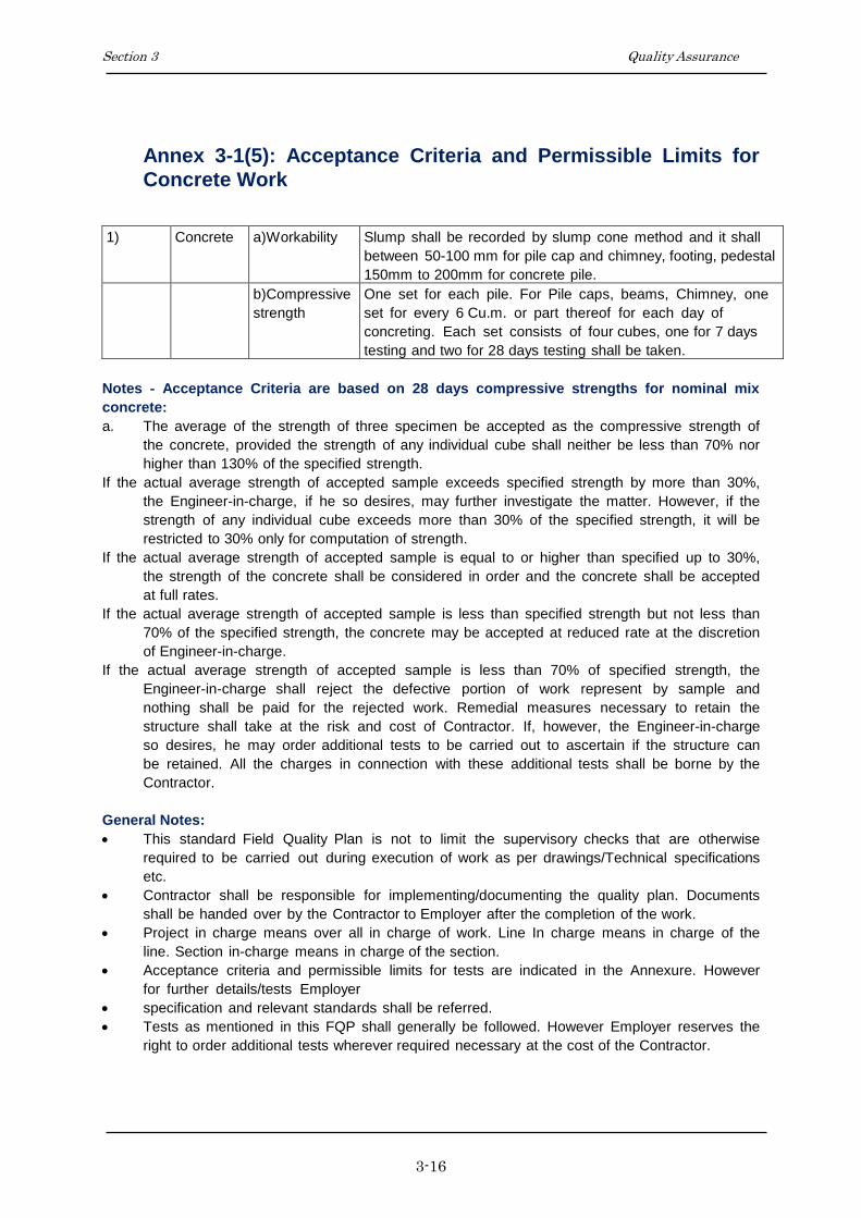
1) Concrete a)Workability Slump shall be recorded by slump cone method and it shall
between 50-100 mm for pile cap and chimney, footing, pedestal
150mm to 200mm for concrete pile.
b)Compressive
strength
One set for each pile. For Pile caps, beams, Chimney, one
set for every 6 Cu.m. or part thereof for each day of
concreting. Each set consists of four cubes, one for 7 days
testing and two for 28 days testing shall be taken.
Notes - Acceptance Criteria are based on 28 days compressive strengths for nominal mix
concrete:
a. The average of the strength of three specimen be accepted as the compressive strength of
the concrete, provided the strength of any individual cube shall neither be less than 70% nor
higher than 130% of the specified strength.
If the actual average strength of accepted sample exceeds specified strength by more than 30%,
the Engineer-in-charge, if he so desires, may further investigate the matter. However, if the
strength of any individual cube exceeds more than 30% of the specified strength, it will be
restricted to 30% only for computation of strength.
If the actual average strength of accepted sample is equal to or higher than specified up to 30%,
the strength of the concrete shall be considered in order and the concrete shall be accepted
at full rates.
If the actual average strength of accepted sample is less than specified strength but not less than
70% of the specified strength, the concrete may be accepted at reduced rate at the discretion
of Engineer-in-charge.
If the actual average strength of accepted sample is less than 70% of specified strength, the
Engineer-in-charge shall reject the defective portion of work represent by sample and
nothing shall be paid for the rejected work. Remedial measures necessary to retain the
structure shall take at the risk and cost of Contractor. If, however, the Engineer-in-charge
so desires, he may order additional tests to be carried out to ascertain if the structure can
be retained. All the charges in connection with these additional tests shall be borne by the
Contractor.
General Notes:
This standard Field Quality Plan is not to limit the supervisory checks that are otherwise
required to be carried out during execution of work as per drawings/Technical specifications
etc.
Contractor shall be responsible for implementing/documenting the quality plan. Documents
shall be handed over by the Contractor to Employer after the completion of the work.
Project in charge means over all in charge of work. Line In charge means in charge of the
line. Section in-charge means in charge of the section.
Acceptance criteria and permissible limits for tests are indicated in the Annexure. However
for further details/tests Employer
specification and relevant standards shall be referred.
Tests as mentioned in this FQP shall generally be followed. However Employer reserves the
right to order additional tests wherever required necessary at the cost of the Contractor.

POWER GRID COMPANY OF BANGLADESH LIMITED
Tender Documents
for
Procurement of Plant
Design, Supply, Installation, Testing & Commissioning of 400kV &
230kV underground XLPE cable Transmission lines on Chattogram
Area.(Package-2)
SECTION 4
DESIGN PARTICULARS

Section 4 Design Particulars
i
SECTION 4
DESIGN PARTICULARS
CONTENTS
CLAUSE NO. TITLE PAGE NO.
4.1 PHILOSOPHY OF DESIGN ......................................................................................................... 1
4.2 UNITS OF MEASUREMENT ...................................................................................................... 1
4.3 DOCUMENT SUBMISSIONS ..................................................................................................... 1
4.4 DESIGN CALCULATIONS.......................................................................................................... 1
4.5 DRAWINGS .................................................................................................................................. 2
4.5.1 General Requirements ............................................................................................................ 2
4.5.2 Computer Generated Drawings .............................................................................................. 3
4.5.3 Contract Drawing List ............................................................................................................ 3
4.5.4 Contract Record Drawings ..................................................................................................... 3
4.5.5 Route Maps ............................................................................................................................ 4
4.6 SUPPLY AND INSTALLATION MATERIAL MANUAL .......................................................... 4
4.8 MAINTENANCE MANUAL ....................................................................................................... 4
4.9 SAMPLES AND MODELS .......................................................................................................... 5
4.10 PHOTOGRAPHS ...................................................................................................................... 5
APPENDIX

Section 4 Design Particulars
4-1
SECTION 4
DESIGN PARTICULARS
4.1 PHILOSOPHY OF DESIGN
The philosophy of design contained within this specification is based upon deterministic
principles, whereby the applied loading multiplied by the appropriate safety factor must be less
than the ultimate strength of the component.
In tendering the Contractor/Supplier will be deemed to have concurred, as a practical
manufacturer, with the design and layout of the Works as being sufficient to ensure reliability
and safety in operation, freedom from undue stresses and satisfactory performance in all other
essentials as a working plant.
The transmission line(s) shall be designed with high reliability and low cost maintenance as the
primary consideration in accordance with the relevant sections of the Specification.
The design shall incorporate all reasonable precautions and provisions for the safety of those
concerned in the erection and subsequent maintenance of the Contract Works.
4.2 UNITS OF MEASUREMENT
In all correspondence, technical schedules, design calculations and drawings, the metric (SI)
units of measurement shall be used. Angular measurement shall be degrees, with 90°
comprising a right angle.
4.3 DOCUMENT SUBMISSIONS
The Contractor/Supplier shall submit to the Employer all design calculation drawings, method
statements, test programmes, test records etc as defined in Appendix 4.B1 of the relevant
sections of the Specifications, or as otherwise agreed by the Employer. For details of the
number of copies and time periods for approval, reference should be made to Appendix 4.A1.
4.4 DESIGN CALCULATIONS
All sets of calculations shall be complete, bound, properly titled and given a unique drawing
number (see Clause 4.5.1). The binding shall be such as to allow the easy introduction of
subsequent pages if necessary.

Section 4 Design Particulars
4-2
Bound into each set shall be a fully detailed index. Following this shall be a Design
Information sheet(s) which shall incorporate the following details:
(a) Amended sheets should retain the same sheet number, but have a lower case revision letter
suffix i.e. sheet 14 when amended becomes 14a, then 14b.
(b) Additional sheets that needed to be inserted shall be given the sheet number they are added
to, plus an upper case letter prefix i.e. additional sheets to piece 60 become A60, B60 etc.
and if subsequently amended A60a etc.
(c) The design concept shall be summarised;
(d) Full details of manuals, design papers or other aids referred to in the text shall be given,
with photocopies of relevant sheets if appropriate;
(e) Full loadings shall be reiterated, with their derivation if appropriate;
(f) Design stresses shall be reiterated;
(g) Code or standard references should be quoted, and equations written out in full for
initial calculations;
Should the Contractor/Supplier be required to re-submit amended calculation or
additional sheet(s), the following annotation shall be adopted.
Where computer programs are used for design calculations a full explanation in the
English language shall be provided to assist the Employer's approval of the calculations
for each and every program used. Details must include name of program, author,
source, comprehensive description of theoretical basis including all references to
relevant documentation, checks undertaken on program and a list of projects on which
the program has been used.
4.5 DRAWINGS
4.5.1 General Requirements
Drawing shall be to scale, fully detailed and all dimensions shall be in Metric Units. General
arrangement drawings submitted shall be to a scale of not less than 1 to 50 and all detailed
drawings not less than 1 to 20.
Drawings sheets shall conform in size to BS 3429, main A0, Al, A2, A3 and A4.
The sheet size is to be stated on the drawing within or adjacent to the title block.
Drawings shall be to BS 308 or equivalent.
The scale used shall be stated on the drawing as a ratio together with a linear scale at a
convenient position along the margin of the original drawing sheet.

Section 4 Design Particulars
4-3
The physical draughting requirements in respect of line density, strength, contrast, spacing and
character liability shall be met to ensure drawings are suitable for microfilming in accordance
with BS 5536 and the Specification for micro-copying, of drawings to BS 4210.
All drawings shall bear a title in English, serial number of the main Contract, drawing number
shall be unique to this Contract and scale. The system of numbering and layout of the title
block will be to the approval of the Employer. The title block shall include the name and
address of the Employer and the Employer. The revision notes shall detail the nature of each
revision. The revision shall be enclosed in a cloud with the revision letter indicated.
4.5.2 Computer Generated Drawings
The submission of computer generated drawings by electronic transmission or in diskette
format shall be subject to agreement by both the Employer/Purchaser and the Employer.
4.5.3 Contract Drawing List
At defined intervals the Contractor/Supplier shall submit the requisite number of copies of the
Contract Drawing List.
The list shall contain the following information:
(a) Drawing number;
(b) Drawing title;
(c) Revision status;
(d) Approval status.
All changes since the previous issue shall be clearly indicated and when agreed onlv the front
(index) sheet and revised sheets need to be submitted.
4.5.4 Contract Record Drawings
The Contractor/Supplier shall submit to the Employer:
(a) A final issue of the Contract Drawing List indicating which of the drawings, design
calculations, method statements etc. he proposes to issue as final contract drawings.
These drawings shall be updated to incorporate all modifications made during erection
and commissioning.
(b) Requisite number of prints of each schedule, including where appropriate the Supply
and Installation Material Manual.
(c) Requisite number of drawings, including design calculations, schedules including the
supply and Installation Material Manual in CD format in either WPG/
DXFPDF/DWG/DOC format.

Section 4 Design Particulars
4-4
(d) Requisite number of polyester/transparency film copy of each drawing, including
design calculations, profiles and route maps.
The distribution of the contract record drawings will be advised by the Employer.
4.5.5 Route Maps
During, the progress of the work the Contractor shall record on Installation Material Manual
(SIMM's) and on a set of Survey Maps of approved scale such particulars as will allow an
accurate reference to be made afterwards in case of any faults or projected modifications to the
line.
The date included on the SIMMs shall be submitted to the Employer, to whom facilities shall
be given for examining such records during the progress of the work.
4.6 SUPPLY AND INSTALLATION MATERIAL MANUAL
As soon as final support positions have been selected and approved, the Contractor shall
provide the requisite copies of the A4 size Supply and Installation Material Manual (SIMM).
The appropriate reference drawing numbers shall also be included. Preliminary copies of
SIMMs shall be available prior to any site work commencing, together with material summaries.
This is a Hold Point.
4.8 MAINTENANCE MANUAL
The Contractor/Supplier shall provide at the specified period before the end of the construction
period of the Contract, a maintenance manual covering, the following information:-
(a) Type and description of all plant erected, together with names and addresses of
manufacturer;
(b) Methods of assembly of all fittings;
(c) Recommendations of preventive maintenance including frequency of inspections;
(d) List of recommend maintenance equipment with a description of its use and
limitations;
(e) Personnel safety equipment requirements and any risk assessments required.
The above information must be specified in this Contract and entirely in the English language.
Drawings and diagrams shall be used where necessary to enable the Employer/Purchaser
properly to maintain the whole of the Works.

Section 4 Design Particulars
4-5
The manual shall be suitably bound within a hard cover and all materials used shall be
reasonably hard wearing.
The manual shall be submitted to the Employer. This is a Hold Point.
4.9 SAMPLES AND MODELS
If the nature of the Works makes it desirable, the Contractor/Supplier may be asked to submit
or prepare for the Employer such samples, patterns and models as the Employer may
reasonably require for the purpose of design approval at the expense of the Contractor/Supplier.
4.10 PHOTOGRAPHS
The Contractor/Supplier shall make all arrangements to provide progress photographs
(including electronic data) of all tests and such sections of the work in progress as directed by
the Employer. Each photograph shall be of size 25 cm x 20 cm suitably entitled. The electronic
data (softcopy) of the photographs shall be the property of the Employer/Purchaser and no
prints from these negatives shall be supplied to any persons unless under the Authority of the
Employer/Purchaser.
The Contractor/Supplier will normally be required to provide every month at his own cost the
3(three) sets of unmounted progress photographs and their electronic data (softcopy) suitably
inscribed, on portions of the Work- in progress, throughout the period of construction. Any
variation to these quantities will only be with the permission of the Employer.

Section 4 Design Particulars
4-6
APPENDIX 4.A1
TIME INTERVALS FOR DOCUMENTS SUBMISSION, OR TEST &
INSPECTION NOTIFICATION AND NUMBER OF SUBMISSION COPIES
Item Time
intervals
(weeks)
Notification
Period
(Days)
No. of Copies
Submission of :
Contract Drawing List 4 - 5
Maintenance Manual 26 - 10
Method Statement
- Overall 12 - 5
- Detailed 4 - 5
Programme of Works
Programme of Reports (Weekly) 1 - 5
(Monthly) 4 - 5
Quality Assurance Programme 4 - 5
Quality Plan 4 - 5
Preliminary Supply & Install
Material Manual 12 - 5
Time Intervals
Currency of Standards 4 - -
Drawing Approval 3 - -
Commencement of Work after issue of
Notice
1 - -
Suspension of Work 1 - -
Notification of Periods:
Type Tests - Overseas - 28 -
- Local - 7 -
Sample Test – overseas - 14 -
Inspection of Work on Site - 3 -
Final Line Inspection - 14 -
Commencement of Survey - 7 -
Copies:
Drawings for Approval - - 5
Approved Drawings - - 5

Section 4 Design Particulars
4-7
APPENDIX 4.A1 Contd.
Item Time
intervals
(weeks)
Notification
Period
(Days)
No. of Copies
Test Programme - 45 5
Final Supply Installation Material
Manuals - - 5
Installation Instructions - - 5
Contract Records
- Prints - - 6
- Transparencies - - 1
- CD - -S 2
Test Reports - - 5
Certificate of Conformity - - 5
English Language Translation of
‘equivalent’ standards
- -
1
Applicable Reference Standards 4 - 1
Note: The time interval refers to the appropriate time period in weeks required
before or after a specified event e.g. the Contract Drawing List shall be
submitted at 4 week intervals, while the Applicable Reference Standards
shall be submitted 4 weeks after signing of the Contract.

Section 4 Design Particulars
4-8
APPENDIX 4.Bl
ENGINEERING DOCUMENTS TO BE SUBMITTED BY CONTRACTOR
Clause
Reference
Document Description Comment
4.5.3
4.5.4
4.5.5
4.7
4.8
4.9
Contract Drawing List
Contract Record List
Route Maps
Supply and Install Material Manual
Maintenance Manual
Photographs
APPENDIX 4.Cl
NOTIFICATION AND HOLD POINTS
Clause
Reference
Notification Points Hold Points
4.7
4.8
Supply and Install
Material Manual
Maintenance Manual

Section 4 Design Particulars
4-9
APPENDIX 4.Dl
REFERENCE STANDARDS
The reference standards and other documents referred to in this Section of the specification
are listed below:
BS 308: Engineering Drawing practice

POWER GRID COMPANY OF BANGLADESH LIMITED
Tender Documents
for
Procurement of Plant
Design, Supply, Installation, Testing & Commissioning of 400kV &
230kV underground XLPE cable Transmission lines on Chattogram
Area.(Package-2)
SECTION 5
ACCESS

Section 5 Access
i
SECTION 5
ACCESS
CONTENTS
CLAUSE NO. TITLE PAGE NO.
5.1 WAYLEAVES ...................................................................................................................................... 2
5.1.1 General ......................................................................................................................................... 2
5.1.2 Wayleave Schedule ....................................................................................................................... 2
5.2 ACCESS TO SITE, NOTICE OF ENTRY ........................................................................................... 2
5.2.1 Access Routes - General ............................................................................................................... 2
5.2.2 Commencement of Work .............................................................................................................. 3
5.2.3 Suspension of Work ...................................................................................................................... 3
5.2.4 Compliance with Occupier's Requirements .................................................................................. 3
5.4 CROSSING OF OBSTACLES ............................................................................................................. 3
5.4.1 General ......................................................................................................................................... 3
5.4.2 Public Utilities .............................................................................................................................. 4
5.5 DAMAGE ............................................................................................................................................. 4
5.5.1 General ......................................................................................................................................... 4
5.5.2 Contractor's Responsibility .......................................................................................................... 4
5.5.3 Livestock, Dogs ............................................................................................................................ 4
APPENDIX

Section 5 Access
5-2
SECTION 5
ACCESS
5.1 WAYLEAVES
5.1.1 General
Wayleaves and access facilities subject to the requirements of landowners and occupiers, will
be provided by the Employer to enable the Contractor to carry out the erection of the Contract
Works but such facilities will not necessarily include facilities for storing material nor
necessarily include access for wheeled vehicles.
The Contractor will satisfy himself that the necessary rights of entry and access have been
obtained before entry is effected.
The Contractor shall indicate to the Employer such pipes or other obstructions, telephone,
telegraph and power lines which infringe the clearances specified or otherwise fail to satisfy the
requirements of the Specification.
The necessary permission for the removal of obstructions such as trees and for the permanent
removal or guarding of pipes, telegraph, telephone and power lines will be obtained by the
Employer at the cost of Contractor. All such costs shall deem to be included in the Contract
Price.
5.1.2 Wayleave Schedule
Before the Contractor commences work on any property he shall obtain from the Employer a
wayleave schedule including details of any special requirements of the occupiers concerned.
5.2 ACCESS TO SITE, NOTICE OF ENTRY
5.2.1 Access Routes - General
The Employer may indicate to the Contractor the general route for access to each or any
position as agreed by the Employer, otherwise the Contractor shall make all necessary
arrangements (other than questions of wayleaves) with the occupier.
Subject to the provisions of the preceding paragraph the Contractor shall before commencing
work-, at his own expenses, do what is necessary to make the access suitable for his use and
shall take all reasonable precautions to avoid damage, including, if required the erection of
temporary fences or gates where permanent fences, hedges or gates have been removed. The
Contractor shall not be entitled to any additional payment in the event of a particular access
being difficult.

Section 5 Access
5-3
The Contractor shall be responsible for maintaining agreed access routes, without undue
widening, in a usable condition for the duration of the Contract and the occupier shall not be
put to any inconvenience in gaining access to his land or buildings. No unauthorised access
route shall be taken by the Contractor.
5.2.2 Commencement of Work
The Contractor shall be responsible, before beginning work on any property for obtaining
confirmation from the Employer that wayleaves are in order and any agreed accesses, have not
been altered and for giving not less than 48 hours notice to the occupiers that work is to begin.
Work shall proceed on any land within the requisite period of such notice being given to the
occupier.
5.2.3 Suspension of Work
Where work is to be suspended without the expectation of it being resumed within the specified
period, the Contractor must notify the occupier of such intention and shall similarly give the
occupier prior notification of the resumption of work. The purpose of this Clause is to assist in
maintaining good relations between the occupier, the Contractor and the Employer and to keep
the occupier informed of what is going to happen on or across his land.
5.2.4 Compliance with Occupier's Requirements
The Contractor shall at all times during the execution of the Works ensure compliance with all
such reasonable requirements of the occupier as are brought to the Contractor's notice by the
Employer. The Contractor shall not be entitled to any additional payment in respect of his
compliance with the reasonable requirements of the occupier.
5.4 CROSSING OF OBSTACLES
5.4.1 General
The Contractor shall, at his own expense, make any necessary arrangements and take the
necessary precautions where the route crosses telecommunication, power or pipe lines,
antiquities or other obstructions or ground over or across which installation cannot be carried
out in the normal manner or has to be avoided. These arrangements must be submitted to the
Employer. This is a Hold Point.
Where the line is set across a power line, telecommunication line, gas pipe line, sewarage line,
drain, fence, hedge, bank or wall etc. and in case the said existing installation can not be by
passed through re-route, the Contractor shall remove and reinstate the existing installation at his
own expense and he shall be responsible at his own expense for making good to the satisfaction
of the Employer, owners and tenants concerned, all land, property, roads, drains, fences, walls,
hedges, gates and the like which he has damaged or disturbed during the execution of the
Contract Works and shall remove all surplus material after installation. The Contractor shall

Section 5 Access
5-4
take proper precautions to prevent the straying of and damage to livestock until after the
backfilling of excavations and permanent reinstatement of such installation which is completed.
5.4.2 Public Utilities
The Contractor shall ensure that the erection of the Contract Works does not cause damage to
or interference with existing telecommunication, power or pipe lines, drainage etc.
Where appropriate Authorities affected deem it necessary for the protection of their employees,
property, or the public or for the assistance of traffic to provide flagmen and watchmen, the
cost of such provision shall be borne by the Contractor. Where required by the appropriate
Authorities work shall be carried on outside normal hours and at the Contractor's own expense.
The Contractor shall also be liable to make good at least to the original condition or
compensate the owners, operators and users or any public undertaking in respect of any damage
however caused to their property, lands or roads arising, out of or in consequence of the
execution of the Works.
5.5 DAMAGE
5.5.1 General
The Contractor shall take all reasonable precautions to avoid damage to land, property, roads,
crops, field drains, fences walls, hedges, gates, trees, power line, pipeline, sewarage line etc
and the like and shall ensure that the work is adequately supervised so that any damage is
reduced to the minimum. As otherwise provided, the Contractor will be liable for all damage
arising by or in consequence of the Works including damage to crops, trees house and shall pay
compensation or make good the same, as applicable.
5.5.2 Contractor's Responsibility
The Contractor's liability for loss or damage shall extend to any such loss or damage resulting
from the employment of a Subcontractor. This does not relieve the Contractor of his liability
for all actions of his Subcontractor.
5.5.3 Livestock, Dogs
Adequate provision shall be made by the Contractor to prevent the straying of or injury to
livestock during the execution of the Works and until the permanent reinstatement of fences,
walls, hedges, gates and the like is completed.
The Contractor shall not bring any dog on or near the site or suffer or permit any of his
employees, representatives or agents or any Subcontractor to bring any dog on or near the site
and shall cause the immediate removal of any dog which may be on or near the Site in breach
of this provision.

Section 5 Access
5-5
The Contractor shall be liable for any injury to or loss of livestock due in the opinion of the
Employer to failure to comply with the above requirements.

Section 5 Access
5-6
APPENDIX 5.Al
ROUTE CLEARANCE
The Contractor shall be responsible to take clearance from relevant authorities. The Employer shall cooperate
in this regard.

6/1
POWER GRID COMPANY OF BANGLADESH LIMITED
Tender Documents
for
Procurement of Plant
Design, Supply, Installation, Testing & Commissioning of 400kV and 230
kV Underground Cable Transmission Lines on Chattogram area
(Package-2).
SECTION 6
SURVEY AND GEOTECHNICAL INVESTIGATIONS

6/2
SECTION 6
SURVEY AND GEOTECHNICAL INVESTIGATIONS
6.1 GENERAL INFORMATION & SCOPE OF WORK
The Engineer will indicate to the Contractor either on maps or during visits to the
Sites the proposed route of the transmission line. The Contractor shall give the
Engineer the requisite period of notice prior to commencing the survey. This is a
Hold Point.
The technical specifications covers detailed survey including route alignment based
on the intermediate GPS readings & Tentative route alignment finalized by the
Employer, check survey, contouring, and soil investigation for the transmission lines
/ part of the transmission lines covered under this specification as included in the
schedule of prices.
Contractor shall provide at site all required survey instruments to the satisfactions of
the Employer so that the work can be carried out accurately according to
specifications and drawings. Contractor shall arrange to collect the data regarding
change of course of rivers, major natural streams and nalas, etc., encountered along
the transmission line route from the best available sources and shall furnish complete
hydrological details including maximum velocity discharge, highest flood level
(H.F.L), scour depth etc. of the concerned rivers, major streams and nalas (canals).
6.1.1 The scope of work inter-alia shall include the following:-
a. Detailed Survey using GPS, Total Work stations, long range scanners & Digital
theodolite of reasonable accuracies or alternatively using ALTM (Airborne
Laser Terrain Modeling) techniques, inter-alia including :
Selected route along with plan details.
b. Check survey including digitized contouring at undulated / hilly tower locations.
c. Soil Investigation
d. Preparation of Survey reports including estimation of Bill of Quantities,
identification and explanation of route constraints (like Forest, Animal/Bird
sanctuary, reserve coal belt areas, oil pipe line/underground inflammable pipe
lines etc.), infrastructure details available en-route etc.

6/3
6.1.2 The Provisional quantities for the scope of work are indicated in relevant Price
Schedules of bidding documents. The final quantities for route alignment & detailed
survey (quantities in “km” unit) shall be the Horizontal route length along the
approved route alignment. For contouring at undulated/hilly tower locations and soil
investigations (quantities in “Locations.” unit), the actual quantities to be executed
shall be decided by Site Engineer-in-charge during execution stage and the final
quantities shall be as approved by Site Engineer-in-charge. The route alignment,
detailed survey, contouring, soil investigation etc shall be carried out by the
Contractor as per the technical specifications stipulated herein.
6.1.3 The Contractor must note that the Employer shall not be responsible for loss or
damage to properties, trees etc. due to contractor’s work during survey. The
Contractor shall indemnify the Employer for any loss or damage to properties, trees
etc. during the survey work.
6.1.4 The Contractor should note that Employer will not furnish topographical maps but
will make available assistance that may be required in obtaining these by providing
letters of recommendation to the concerned authorities. Further, in case the
contractor opts for use of ALTM techniques for detailed survey, he shall be
responsible for obtaining necessary clearances/permissions, as may be required from
concerned authorities. The Employer will provide assistance that may be required in
obtaining these clearances/ permissions by providing letters of recommendation to
the concerned authorities.
6.1.5 The bidder shall give along with their bid clause by clause commentary indicating
their confirmation / comments/ observation in respect of all clauses of technical
specification.
6.1.6 The work shall be carried out by the contractor using modern surveying techniques.
The bidder shall indicate in his offer, the detailed description of the procedure to be
deployed. available with the bidder or his associates shall also be furnished with the
bid.
6.1.7 The Contractor shall also engage services of a reputed geo-technical/geologist
consultant or experts from independent educational/research institutions for
examining stability aspects of the selected transmission line route.
6.1.8 After carrying out the detailed survey and soil investigations, the contractor shall
estimate complete BOQ of the transmission lines and submit the same (as per the
BOQ format enclosed with the Technical Specifications) to the Employer.
6.2 CONTRACTOR'S SURVEY
6.2.1 Access for Survey

6/4
For details of the access arrangement for survey, reference should be made to
Appendix 5.Al. The Contractor's Surveyor shall in all cases announce himself to the
occupier/landowner immediately before entering any private property for the
purpose of survey. The Contractor shall comply with all national and local
regulations regarding barricades, detour arrangements, and warning signs. Damage
to roads, footpaths, bridges, ditches, etc., caused by the Contractor shall be repaired
at his expense.
6.2.2 Survey Methodology & Precision
All elevations shall be referenced to benchmarks established by the Public Work
Devision of Bangladesh / Survey of Bangladesh. Survey operations shall begin and
end at benchmarks approved by the Employer.
During the leveling of the profile, check surveys will be affected at intervals not
exceeding 50 Kms. with benchmarks of known elevations. The difference in
elevations as surveyed by the contractor and as declared by Public Work Devision of
Bangladesh / Survey of Bangladesh for these benchmarks shall not exceed the
precision required for 3rd order surveys e ≤ 24k where k is the distance between
benchmarks in km and e is the difference between elevations in mm but not exceed
300 mm.
In the absence of suitable benchmarks the leveling shall be done by two independent
leveling parties working in opposite directions along the same line. The difference
in elevations between the two surveys shall not exceed the precision required for 3rd
order surveys as stated above.
All important objects and features along the transmission line centerline (railways,
highways, roads, canals, rivers, transmission lines, distribution lines, telephone lines
etc.) shall be surveyed and located with a positional accuracy of 1:2000 between
points of known horizontal position.
6.2.3 Route Alignment
6.2.3.1 The route Alignment shall be carried out by the contractor using topographical maps
and preliminary route alignment finalized by the Employer with GPS.
6.2.3.2 The routing of the transmission line shall be most economical from the point of
view of construction and maintenance. The contractor shall identify & examine
alternative route alignments and suggest to the Employer the optimal route
alignment.
6.2.3.3 Routing of transmission line through protected/reserved forest area should be
avoided. In case it is not possible to avoid the forests or areas having
6.2.3.4 The route should have minimum crossings of Major River, National/State highways,
overhead EHV power line and communication lines.
6.2.3.5 The number of angle points shall be kept to minimum.

6/5
6.2.3.6 The distance between the terminal points specified shall be kept shortest possible,
consistent with the terrain that is encountered.
6.2.3.7 Marshy and low lying areas, river beds and earth slip zones shall be avoided to
minimize risk to the foundations.
6.2.3.8 It would be preferable to utilize level ground for the alignment.
6.2.3.9 Crossing of communication line shall be minimized and it shall be preferably at
right angle. Proximity and parallelism with telecom lines shall be eliminated to
avoid danger of induction to them.
6.2.3.10 Areas subjected to flooding such as nalah shall be avoided.
6.2.3.11 Restricted areas such as civil and military airfield shall be avoided. Care shall also
be taken to avoid aircraft landing approaches.
6.2.3.12 All alignment should be easily accessible both in dry and rainy seasons to enable
maintenance throughout the year.
6.2.3.13 Certain areas such as quarry sites, tea, tobacco and saffron fields and rich
plantations, gardens & nurseries which will present the Employer problems in
acquisition of right of way and way leave clearance during construction and
maintenance should be avoided.
6.2.3.14 Angle points should be selected such that shifting of the point within 100 m radius
is possible at the time of construction of the line.
6.2.3.15 The line routing should avoid large habitations, densely populated areas, Forest,
Animal/Bird sanctuary, reserve coal belt areas, oil pipe line/underground
inflammable pipe lines etc. to the extent possible.
6.2.3.16 The areas requiring special foundations and those prone to flooding should be
avoided.
6.2.3.17 For examination of the alternatives & identification of the most appropriate route,
besides making use of information/data/details available/extracted through, the
contractor shall also carryout reconnaissance/preliminary survey as may be required
for verification & collection of additional information /data /details.
6.2.3.18 The contractor shall submit his preliminary observations & suggestions along with
various information/data /details collected and also processed satellite imagery data,
scanned topographical map data marked with the alternative routes etc. The final
evaluation of the alternative routes shall be conducted by the contractor in
consultation with Employer’s representatives and optimal route alignment shall be
proposed by the contractor. Digital terrain modeling using contour data from
topographical maps shall be done by the contractor for the selected route. A fly
through perspective using suitable software(s) shall be developed for further
refinement of the selected route, if required. Site visit and field verification shall be
conducted by the contractor jointly with the Employer’s representative for the
proposed route alignment.
6.2.3.19 Final digitized route alignment drawing with latest topographical and other
details/features including all rivers, railway lines, canals, roads etc. up to 8 kms on

6/6
both sides of selected route alignment shall be submitted by the contractor for
Employer’s approval along with report containing other information/details as
mentioned above.
6.2.3.20 Changes in the route alignment, if any, during detail survey, shall be incorporated in
the final digitized route alignment drawings.
6.2.4 Detailed Survey
6.2.4.1 The detailed survey shall be carried out using GPS, Total stations, digital theodolites
etc. along the approved route alignment. As an alternative, the contractor may also
use ALTM (Airborne Laser Terrain Modeling) techniques of equal or better
accuracy for the detailed survey.
6.2.4.2 Soil resistivity, along the route alignment shall be measured in dry weather by four
electrode method keeping inter-electrode spacing of 50 mtrs. For calculating soil
resistivity formula 2ar (Where a=50 m and r= megger reading in ohms) shall be
adopted. Measurement shall be made at every 2 to 3 km along the length of the
route. In case soil characteristics changes within 2 to 3 km, values shall have to be
measured at intermediate locations also. Megger reading and soil characteristics
should also be indicated in the soil resistivity results.
6.2.5 Route Marking
6.2.5.1 The route of the transmission line shall be recorded using GPS/DGPS of positional
accuracy less than 3m.
6.2.5.2 The co-ordinates of all the angle points as well as other important crossings,
landmarks etc. shall be recorded using GPS for easy relocating.
6.2.5.3 At the starting point of the commencement of route survey the co-ordinates shall be
recorded. A punch mark on the top section of the angle iron shall be made to
indicate location of the survey instrument. The co-ordinates of the location of the
survey instrument shall also be recorded. Further, the co-ordinates at prominent
position at intervals of not more than 750 meter along the transmission line to be
surveyed up to the next angle point shall also be recorded. Wooden peg 50 x 50 x
650mm size shall also be driven at prominent position at intervals of not more than
750 meter along the transmission line to be surveyed up to the next angle point.
Wire nails of 100mm length should be fixed on the top of these pegs to show the
location of instrument. The peg shall be driven firmly into the ground to project 100
mm only above ground. Wherever the line alignment crosses the EHT line, Railway
line, P&T line or roads, the contractor shall record co-ordinates on the points of
crossing. Wherever line route alignment passes over permanent land marks such as
rock, boulders, culverts etc. suitable white paint marks with directional and
Employer markings shall be made and co-ordinates recorded. At angle position
stone/concrete pillars of 150 x 150 x 100 mm in size with Employer marked on
them shall be embedded into the ground for easy identification.

6/7
6.2.10 Check Survey
The Contractor shall carry out a check survey of the whole route. Profile drawings
will be made available to the Contractor, who will be required to check the profile
(ground line) survey. The line routes may need to be changed at some locations due
to site constraints. The Contractor shall propose such changes after surveying the
new line routes. No extra cost for survey and preparation of all drawings of such
change of route will be paid to the Contractor.
6.3 GEOTECHNICAL INVESTIGATION
6.3.1 General
Geotechnical investigation shall be undertaken in accordance with the technical
requirements detailed in the following clauses. For details of the type and
frequency of the investigation reference should be made to Appendix 6.A4.
Employer requires that a detailed Geotechnical investigation be carried out at
various locations to provide the designer with sufficiently accurate information,
both general and specific, about the substrata profile and relevant soil and rock
parameters at site on the basis of which the foundation can be classified and
designed rationally.
All investigation, unless specified otherwise shall be in accordance with the
requirements of BS 5930.
These specifications provide general guidelines for geotechnical investigation of
normal soils. Cases of marshy locations and locations affected by salt water or
saltpeter shall be treated as special locations and the corresponding description in
these specifications shall apply. Any other information required for such locations
shall be obtained by Contractor and furnished to Employer.
The Contractor shall give the Engineer the requisite period of notice prior to
commencing the geotechnical investigation. This is a Hold Point.
6.3.2 Scope
6.3.2.1 The scope of work includes detail soil investigations and furnishing bore log data at
each circuit of transposition location and both bank of canal for Cable Bridge.
Based on the bore log data / soil parameter /soil investigation results, the
Contractor shall recommend the type of foundations suitable for each locations and
the same shall be got approved by the Employer.

6/8
6.3.2.2 These specifications cover the technical requirements for a detailed Geotechnical
investigation and submission of a detailed Geotechnical Report. The work shall
include mobilization of all necessary tools and equipment, provision of necessary
engineering supervision and technical personnel, skilled and unskilled labour, etc.
as required carrying out the entire field investigation as well as laboratory tests,
analysis and interpretation of data collected and preparation of the Geotechnical
Report. Contractor shall also collect data regarding variation of subsoil water table
along the proposed line route. Detailed methodology for subsoil investigation shall
be submitted before implementing the subsoil investigation. All laboratory tests
shall be done at the test facility approved by the Employer. The Contractor may
appoint a sub contractor to carry out the site geotechnical investigation but
aforementioned works shall be supervised by a contractor’s engineer who had a
bachelor’s degree in Civil Engineering and had at least 5 years of site experience in
geotechnical investigation work. All work and all lab work shall be witnessed by
the above mentioned contractor’s engineer who shall countersign all recorded data.
6.3.2.3 Contractor shall make his own arrangements to establish the co-ordinate system
required to position boreholes, tests pits and other field test locations as per the
drawings/sketches supplied by Employer. Contractor shall determine the reduced
levels (R.L’s) at these locations with respect to benchmarks used in the detailed
survey. Two reference benchmarks shall be established based on survey data/details.
Contractor shall provide at site all required survey instruments to the satisfactions
of the Employer so that the work can be carried out accurately according to
specifications and drawings. Contractor shall arrange to collect the data regarding
change of course of rivers, major natural streams and nalas, etc., encountered along
the transmission line route from the best available sources and shall furnish
complete hydrological details including maximum velocity discharge, highest flood
level (H.F.L), scour depth etc. of the concerned rivers, major streams and nalas
(canals).
6.3.2.4 The field and laboratory data shall be recorded on the proforma recommended in
relevant Standards. Contractor shall submit to Employer two copies of field bore
logs (one copy each to Employer project and Head Office) and all the field records
(countersigned by the Employer) soon after the completion of each boreholes/test.
6.3.2.5 Whenever Contractor is unable to extract undisturbed samples, he shall
immediately inform the Employer. Special care shall be taken for locations where
marshy soils are encountered and Contractor in such cases shall ensure that
specified numbers of vane shear tests are performed and the results correlated with
other soil parameters.
6.3.2.6 The Contractor shall interact with the Employer to get acquainted with the different
types of structures envisaged and in assessing the load intensities on the foundation
for the equipment support structures and cable bridges in order to enable him to
make specific recommendation for the depth, founding strata, type of foundation
and the allowable bearing pressure.
6.3.2.7 After reviewing Contractor’s geotechnical investigation draft report, Employer will
call for discussions, to be held normally within one week, in order to comment on

6/9
the report in the presence of Contractor’s Geotechnical Engineer. Any expenditure
associated with the redrafting and finalizing the report, traveling etc. shall be
deemed included in the price schedule.
6.3.2.8 Contractor shall carry out all work expressed and implied in these specifications in
accordance with requirements of the specification.
6.3.2.9 The contractor shall prepare and submit soil profile along the transmission line
route ( in digitized form, with digitized route alignment drawing as base) indicating
salient soil characteristics / features, water table etc based on detailed soil
investigations and other details / information collected during detailed survey.
6.3.3 General Requirements
6.3.3.1 Wherever possible, Contractor shall research and review existing local knowledge,
records of test pits, boreholes, etc., types of foundations adopted and the behaviour
of existing structures, particularly those similar to the present project.
6.3.3.2 Contractor shall make use of information gathered from nearby quarries, unlined
wells excavation etc. Study of the general topography of the surrounding areas will
often help in the delineation of different soil types.
6.3.3.3 Contractor shall gather data regarding the removal of overburden in the project area
either by performing test excavations, or by observing soil erosion or land slides in
order to estimate reconsolidation of the soil strata. Similarly, data regarding recent
land fills shall be studied to determine the characteristic of such land fills as well as
the original soil strata.
6.3.3.4 The water level in neighboring streams and water courses shall be noted.
Contractor shall make enquiries and shall verify whether there are abandoned
underground works e.g. worked out ballast pits, quarries, old brick fields, mines,
mineral workings etc.
6.3.3.5 It is essential that equipment and instruments be properly calibrated at the
commencement of the work. If the Employer so desires, Contractor shall arrange
for having the instruments tested at an approved laboratory at its cost and shall
submit the test reports to the Employer. If the Employer desires to witness such
tests, Contractor shall arrange for the same.
6.4 Field Investigation for Soils
Tentative numbers of detailed soil investigation to be done is given in Schedule of
prices in biding documents.
6.4.1 Ground Water

6/10
6.4.4.1. One of the following methods shall be adopted for determining the elevation of
ground water table in boreholes as per relevant BS standard and the instructions of
the Employer:
a) In permeable soils, the water level in the borehole shall be allowed to stabilize after
depressing it adequately by bailing before recording its level. Stability of sides and
bottom of the boreholes shall be ensured at all times.
b) For both permeable and impermeable soils, the following method shall be suitable.
The borehole shall be filled with water and then bailed out to various depths.
Observations on the rise or fall of water level shall be made at each depth. The
level at which neither fall nor rise is observed shall be considered the water table
elevation and confirmed by three successive readings of water level taken at two
hours interval.
6.4.4.2. If any variation of the ground water level is observed in any specific boreholes, the
water level in these boreholes shall be recorded during the course of the filed
investigation. Levels in nearby wells, streams, etc., if any, shall also be noted in
parallel.
6.4.4.3. Subsoil water samples
a) Subsoil water samples shall be collected for performing chemical analysis.
Representative ground water samples shall be collected when first encountered in
boreholes and before the addition of water to aid boring or drilling.
b) Chemical analysis of water samples shall include determination of pH value,
turbidity, sulphate and chloride contents, presence of organic matter and suspended
solids. Chemical preservatives may be added to the sample for cases as specified in
the test methods.
6.4. 5 Vane Shear Test. (required for boreholes where Undisturbed sampling is not
possible) (Only at Special Locations)
Field vane shear test shall be performed inside the borehole to determine the shear
strength and bearing capacity of cohesive soils, especially of soft and sensitive
clays, which are highly susceptible to sampling disturbance. Equipment,
accessories, test procedures, field observations shall correspond to BS 5930. Tests
may also be conducted by direct penetration from ground surface. If the cuttings at
the test depth in the borehole show any presence of gravel, sand shells, decomposed
wood, etc., which is likely to influence the test results substantially, the test at that
particular depth may be omitted with the permission of the Employer. However, the
test shall be conducted at a depth where these obstructions cease to occur. On
completion of the test, the results shall be reported in an approved proforma as
specified in BS 5930,
6.5 Laboratory Testing

6/11
6.5.1 Essential Requirements
a) Depending on the types of substrata encountered, appropriate laboratory tests shall
be conducted on soil and rock samples collected in the field. Laboratory tests shall
be scheduled and performed by qualified and experienced personnel who are
thoroughly conversant with the work. Tests indicated in the schedule of items shall
be performed on soil, water and rock samples as per relevant British codes or the
equivalent codes approved by the Employer. One copy of all laboratory test data
records shall be submitted to Employer. Laboratory tests shall be carried out
concurrently with the field investigations as initial laboratory test results could be
useful in planning the later stages of field work. A schedule of laboratory tests shall
be established by Contractor to the satisfaction of the Employer within one week of
completion of the first borehole;
b) Laboratory tests shall be conducted using approved apparatus complying with the
requirements and specification of BS 1377 or other approved standards for this type
of work. It shall be checked that the apparatus are in good working condition before
starting the laboratory tests. Calibration of all the instruments and their accessories
shall be done carefully and precisely at an approved laboratory.
c) All samples, whether undisturbed or disturbed shall be extracted, prepared and
examined by competent personnel properly trained and experienced in soil
sampling. examination, testing and in using the apparatus in conformance with the
specified standards;
d) Undisturbed soil samples retained in liners or seamless tube samplers shall be
removed, without causing any disturbance to the samples, using suitably designed
extruders just prior to actual testing. If the extruder is horizontal, proper support
shall be provided to prevent the sample from breaking. For screw tube extruders,
the pushing head shall be free from the screw shaft so that no torque is applied to
the soil sample in contact with the pushing head. For soft clay samples, the sample
tube shall be cut by means of a high speed hacksaw to proper test length and placed
over the mould before pushing the sample into it with a suitable piston;
e) While extracting a sample from a liner or tube, care shall be taken to assure that its
direction of movement is the same as that during sampling to avoid stress reversal;
6.5.2 Tests
6.5.2.1 Tests as indicated in these specifications and as may be requested by the Employer,
shall be conducted. These tests shall include but may not be limited to the
following :
a) Tests of undisturbed and disturbed samples
Visual and engineering classification;
Sieve analysis and hydrometric analysis;
Liquid, plastic and shrinkage limits;
Specific gravity;

6/12
b) Tests of undisturbed samples:
Bulk density and moisture content;
Relative density(for sand);
Unconfined compression test;
Direct shear test or Triaxial shear tests (depending on the type of soil
and field conditions undisturbed or remoulded samples):
i. Unconsolidated undrained;
ii. Consolidated drained test;
c) Chemical analysis of sub soil water.
6.5.3 Salient Test Requirement
a) Triaxial shear tests shall be conducted on undisturbed soil samples, saturated
by the application of back pressure. Only if the water table is at sufficient
depth so that chances of its rising to the base of the footing are small or nil, the
triaxial tests shall be performed on specimens at natural moisture content.
Each test shall be carried out on a set of three test specimens from one sample
at cell pressures equal to 100, 200 and 300 KPa respectively or as required
depending on the soil conditions:
b) Direct shear test shall be conducted on undisturbed soil samples. The three
normal vertical stresses for each test shall be 100, 200 and 300 KPa or as
required for the soil conditions;
6.6 Test Level
6.6.1 Level 1
Level 1 geotechnical investigation shall be based on a visual-tactile examination
of disturbed soil samples for the determination of both soil classification and
strength. Visual-tactile examination shall be undertaken in accordance with the
recommendations of ASTM D2488. Samples shall be taken from either trial pits,
bore holes, hand held augers, or if specified during course of the foundation
excavation.
Where dynamic probing is used in conjunction with a higher level geotechnical
investigation technique, the probe shall be calibrated to the satisfaction of the
Engineer against the results of the higher level tests. Details of the Contractor's
calibration proposals and calibration results shall be submitted to the Engineer.
This is a Hold Point.
6.6.2 Level 2
Level 2 geotechnical investigation shall be based on in-situ testing for the
determination of the soil strength and laboratory tests of disturbed samples for the
determination of soil classification such as particle size distribution, Atterberg

6/13
limits. For details of the soil classification reference should be made to Appendix
6.A6.
In-situ testing, shall comply with the following requirements:
(a) Non-cohesive soil - standard penetration tests (SPTs), cone penetration tests
(CPTs), or in the absences of large gravel content pressure meter tests (PMTs).
(b) Cohesive soil - As for non cohesive soils except that use of SPTs is subject to
the Engineer's approval. Vane shear tests (VSTS) may also be used in fairly
uniform fully saturated soils.
(c) Rock - Weak rock SPTs, medium to hard rock PMTs.
Where it is proposed to determine the soil classification indirectly from the in-situ
tests eg. CPTs, cross correlation shall be undertaken at specified intervals using auger
borings.
Laboratory soil classification tests for non-cohesive soils shall be particle size
distribution, moisture content and relative density, whilst those for cohesive soils shall
be moisture content and Atterberg limits. Whilst strength tests shall be direct shear
box (immediate) and bulk density for non-cohesive soils and unconfined compressive
strength, direct shear box (immediate) and bulk, density for cohesive soils. All
laboratory testing shall be undertaken in accordance with BS 1377.
Where appropriate ground water levels shall be recorded in all boreholes.
6.6.3 Level 3
Level 3 geotechnical investigation shall be based on in-situ testing (as for Level 2) for
the determination of the soil strength and the recovery of disturbed soil samples for
subsequent laboratory testing.
Laboratory soil classification tests for non-cohesive soils shall be particle size
distribution, moisture content and relative density, whilst those for cohesive soils shall
be moisture content and Atterberg limits. Whilst strength tests shall be direct shear
box (immediate) and bulk density for non-cohesive soils and unconfined compressive
strength, laboratory vane shear and bulk, density for cohesive soils. All laboratory
testing shall be undertaken in accordance with BS 1377.
6.6.4 Level 4
Level 4 geotechnical investigation shall be based on a combination of in-situ testing
(as for level 2) and recovery of disturbed/undisturbed soil samples for subsequent
laboratory testing.
Laboratory soil classification tests shall be as per Level 3, whilst strength tests shall be
direct shear and bulk density for cohesive soils and unconfined compressive strength,
laboratory vane shear, triaxial compression (undrained) as appropriate and bulk

6/14
density for Non cohesive soils. All laboratory testing shall be undertaken in
accordance with BS 1377.
6.7 Geotechnical Investigation Report
6.7.1 General
Contractor shall submit a formal report containing geological information of the
region, procedures adopted for geotechnical investigation, field observations,
summarized test data, conclusions and recommendations. The report shall also
include detailed bore logs, subsoil sections, field test results, laboratory observations
and test results both in tabular as well as graphical form, practical and theoretical
considerations for the interpretation of test results, supporting calculations for the
conclusions drawn, etc. Initially, Contractor shall submit three copies of the report in
draft form for Employer’s review;
a) Contractor’s Geotechnical engineer shall visit Employer’s Corporate/main site
Office for a detailed review based on Employer’s comments in order to discuss
the nature of modifications, if any, to be done in the draft report. Contractor
shall incorporate in the report the agreed modifications and resubmit the
revised draft report for approval. Three copies of the detailed final approved
report shall be submitted to Employer together with one set of reproducible of
the graphs, tables etc.
b) The detailed final report based on field observations, in-situ and laboratory
tests shall encompass theoretical as well as practical considerations for
foundations for different types of structures.
6.7.2 Data to be furnished
6.7.2.1 The report shall also include the following:
a) A plot plan/location plan showing the locations and reduced levels of all field
test e.g. boreholes, trial pits, static cone penetration tests, dynamic cone
penetration tests, etc., property drawn to scale and dimensioned with reference
to the established grid lines;
b) A true cross section of all individual boreholes and test pits with reduced
levels and co-ordinates showing the classification and thickness of individual
stratum, position of ground water table, various in-situ tests conducted,
samples collected at different depths and the rock stratum, if encountered;
c) Geological information of the area including geomorphology, geological
structure, etc.
d) Observations and data regarding change of course of rivers, velocity, scour
depths, slit factor, etc., and history of flood details for mid stream and river
bank locations;

6/15
e) Past observations and historical data, if available, for the area or for other areas
with similar soil profile, or with similar structures in the surrounding areas;
f) Plot of Standard Penetration Test (uncorrected and corrected N values) with
depth for each test site;
g) Results of all laboratory test summarised according to Table 1 (i) for each
sample as well as (ii) for each layer, along with all the relevant charts, tables,
graphs, figures, supporting calculations.
h) For all triaxial shear tests, stress vs. strain diagrams as well as Mohr’s circle
envelopes shall be furnished. If back pressure is applied for saturation, the
magnitude of the same shall be indicated. The value of modulus of elasticity
(E) shall be furnished for all tests along with relevant calculations;

6/16
Table-1
SUMMARY OF RESULTS OF LABORATORY TESTS ON SOIL AND WATER SAMPLES
1. Bore hole test pit. no
2. Depth (m)
3. Type of sample
4. Density(kg/m3) a) Bulk b) Dry. c) Submerged
5. Water content (%)
6. Particle Size (%) a) Gravel b) Sand c) Silt d) Clay
7. Consistency properties a) LL b) PL c) PI d) LI
8. Soil a) Classification - b) Description c) Specific gravity
9. Strength Test a) Type b) C (Cohesion) c) Ø (angle of internal friction) d) Angle of repose
10. Shrinkage limit(%)
11. Relative Density (%)
12. Remarks

6/17
Notations:
I. For type of Sample:
DB - Disturbed bulk soil sample.
DP - Disturbed SPT soil sample
DS - Disturbed samples from cutting edge of undisturbed soil sample.
RM - Remoulded soil sample
UB - Undisturbed block soil sample
US - Undisturbed soil sample by sampler
W - Water sample
II. For Strength Test :
SCPT - Static Cone Penetration Test
UCC - Unconfined Compression Test
VST - Vane Shear Test
Tuu - Unconsolidated Undrained Triaxial Test
Note: Replace T by D for Direct Shear Test
Tod - Consolidation Drained Triaxial Test
III. For Others :
LL - Liquid Limit (%)
PL - Plastic Limit
PI - Plasticity Index
LI - Liquidity Index
C - Cohesion (kPa)
Ø - Angle of Internal Friction (degrees)
S-Pr. - Swelling Pressure (kPa)
e0 - Initial Void Ratio
Pc - Reconsolidation Pressure (kPa)
Cc - Compression Index
DP - Change in Pressure (kPa)
mv - Coefficient of Volume Compressibility (m2/KN)
Cv - Coefficient of Consolidation (m2/hr)
IV. For Chemical Test
As per Specifications - Clause 6.7.4

6/18
6.7.3 Recommendations
6.7.3.1 Recommendations shall be provided for each tower location duly considering
soil type and tower spotting data. The recommendations shall provide all
design parameters and considerations required for proper selection,
dimensioning and future performance of tower foundations and the following:
a) The subsurface material must provide safe bearing capacity and uplift
resistance by incorporating appropriate safety factors thereby avoiding rupture
under ultimate loads;
b) Movement of the foundation, including short and long term components under
transient and permanent loading, shall be strictly controlled with regard to
settlement, uplift, lateral translation and rotation:
c) Core resistance, frictional resistance total resistance, relation between core
resistance, Standard Penetration Test N value.
d) For shallow foundation the following shall be indicated with comprehensive
supporting calculations:
e) Net Safe allowable bearing pressure for isolated square footing of sizes 4.0,
5.0, 6.0 & 7.0 m at three different founding depths of 2 and 3 & 3.5m below
ground level considering both shear failure and settlement criteria giving
reasons for type of shear failure adopted in the calculation.
i. Net safe allowable bearing pressure for raft foundations of widths
greater than 5m at 2.0, 3.0 and 4.0m below ground level considering
both shear failure and settlement criteria.
ii. Rate and magnitude of settlement expected of the structure.
iii. Net safe bearing capacity for foundation sizes mentioned in para(i)
above, modulus of sub grade reaction, modules of elasticity from plate
load test results along with time settlement curves and load settlement
curve in both natural and log graph, variation of Modulus of sub grade
reaction with size, shape and depth of foundation.
f) The stable slopes for shallow and deep excavations, active and passive earth
pressure at rest and angle of repose for sandy soils shall be furnished. The
loading of the foundations shall not compromise the stability of the
surrounding subsurface materials and the stability of the foundation shall be
ensured against sliding or overturning:-
g) Depending on the subsurface material, water table level and tower type, either
reinforced concrete isolated pad and chimney, cast-in-situ bored pile of special
foundations shall be installed at a given location.
h) Net Safe allowable bearing pressure and uplift resistance shall be provided for
the various sizes of isolated square footings founded at various depths below
ground level considering both shear failure and movement criteria; rate and

6/19
magnitude of movement expected of the structure (settlement, uplift, rotation)
shall also be given.
i) In cases where normal open cast/pile foundations appear to be impractical,
special pile foundations shall be given due consideration along with the
following:
i. Type of pile foundation and reasons for recommending the same duly
considering the soil characteristics.
ii. Suitable founding strata for the pile:
iii. Estimated length of pile for 500, 750 and 1000 KN and 4500 KN
capacities; end bearing and frictional resistance shall be indicated
separately:
iv. Magnitude of negative skin friction or uplift forces due to soil swelling.
j) Where the subsoil water and soil properties are found to be chemically
aggressive. Contractor shall take suitable precautions during construction
including any protective coating to be applied on the foundations;
susceptibility of soil to termite action and remedial measures for the same shall
be dealt with;
k) Suitability of locally available soils at site for filling, backfilling and adequate
compaction shall be investigated.
l) If expansive soil such as black cotton soil is encountered recommendation of
removal or retainment of the same shall be given in the latter case, detailed
specifications of special requirements shall also be given;
m) Susceptibility of subsoil strata to liquefaction in the event of earthquake and
remedial measures, if required, shall be considered.
n) Any other information of special significance such as dewatering schemes, etc.
which may have a bearing on the design and construction shall be provided.
o) Recommendations for additional soil investigations, beyond the scope of the
present work, shall be given if Contractor considers such investigations
necessary.
6.7.4 Hydrogeological Conditions
6.7.4.1 The maximum elevation of ground water table, amplitudes of its fluctuations
and data on water aggressivity with regard to foundation structure materials
shall be reported. While preparing ground water characteristics the following
parameters should be specified for each acquifer:
a) bicarbonate alkalinity mg-eq/(deg),
b) pH value
c) content of aggressive carbon dioxide, mg/l;
d) content of magnesia salts. mg/l, recalculated in terms of ions Mg+2;
6/20
e) content of ammonia salts, mg/l, recalculated in terms of ions NH4+
f) content of caustic alkalis, mg/l, recalculated in terms of ions Na+ and K+
g) contents of chlorides,mg/l recalculated in terms of ions Cl-
h) contents of sulphates, mg/l, recalculated in terms of ions SO4-2
i) aggregate content of chlorides, sulphates, nitrates, carbonates and other salts.
mg/l.
6.8 Rates and Measurements
6.8.1 Rates
The contractor’s quoted rates shall be inclusive of making observations,
establishing the ground level and co-ordinates at the location of each borehole, test
pit etc. No extra payments shall be made for conducting Standard Penetration Test,
collecting, packing, transporting of all samples and cores, recording and submittal
of results on approved formats.
6.9 FIELD QUALITY PLAN
A standard Field Quality Plan is annexed to Section VI of this document. The
bidders are requested to convey their acceptance to the same along with their offer.
6.10 FOUNDATION SETTING LEVEL DIAGRAMS
Where specified foundation setting level diagrams shall be prepared for specific
tower positions. At a scale of 1:200 (horizontally and vertically) the foundation
excavation and setting levels on the two diagonals (drawn separately) shall be
shown, together with a record of the applicable foundation design, leg and body
extensions and tower centre-peg -co-ordinates.

6/21
APPENDIX 6.A1/1
LINE DESIGN SPAN CRITERIA-Not Applicable.
Please refer to Section 8 of this specification

6/22
APPENDIX 6.A2
CLEARANCE TO OBSTACLES-Not Applicable.
The minimum clearances defined below shall not be infringed at the specified maximum
conductor temperature with the phase conductors and suspension insulators hanging vertically
or deflected to any angle upto 70° from the vertical.
Nominal system voltage (kV) 230
Maximum conductor temperature (°C) 80
Description of Clearance Minimum Clearance
Ground (see note d) (m) 8.0
Roads (m) 9.0
Buildings, structures, walls or other objects on
which a person can stand or against which
he can lean a ladder (see note b) (m) 7.0
Trees (see note c) (m) 5.5
Shrubs (m) 5.5
Railways (measured from railway track) (m) 10.0
River Crossing (m) 25.0
Notes:
(a) Clearances are measured to the nearest projection of an object.
(b) These clearances also apply to earthed metalclad buildings.
(c) Clearances applicable to trees under the transmission line and to trees adjacent
to the line. Clearances also applicable to trees falling, towards the line with
conductors hanging in a vertical plane.
(d) The clearence shall be measured from the highest flood level.

6/23
Clearances where Transmission Lines Cross-Not Applicable.
Where a transmission line crosses above or below another transmission line, the following
clearances shall be obtained.
In still air, and with the phase conductor temperature of the lower transmission line at 5°C
and 80°C for upper transmission line, whilst the assumed phase conductor temperature of
the higher transmission line is at its maximum operating temperature, the following
minimum clearances between the lowest conductor (phase or earth) of the higher
transmission line are applicable:
System voltage (see Note i) 230 kV
(a) The highest conductor (phase or earth) of the lower
transmission line (see Note ii) 5.5 m
Note:
i) The voltage specified is that for which transmission lines are ultimately designed to
operate.
ii) Clearances are determined by the ultimate voltage of either the upper or lower
transmission line, whichever is the greater.
iii) Clearances are determined by the ultimate voltage of the upper/lower transmission
line.
In addition to the above at the point of crossing, the clearance in (a) shall be obtained
assuming the conductors of the lower transmission may swing up to 45° from the vertical.
The sags of the upper and lower transmission lines shall be those at the maximum operating
temperature.

6/24
APPENDIX 6.A3
CROSSING OF OBSTACLES
Pipeline crossings shall not be at angle to the normal greater than 20 degrees.
Crossings of power supply and communication circuits shall not be at angle to the normal
greater than 45 degrees without previous agreement of the Engineer.

6/25
APPENDIX 6.A4
GEOTECHNICAL INVESTIGATION
Geotechnical Investigation Level Frequency
Level 2 1 nos for each circuit of transposition location.
1 nos on each bank of canal for cable bridge
Level 4 At river crossing, anchor towers and rigid frame
tower.
Ground water samples shall be taken at each canal bank location for cable bridge, every
tension tower and all river crossing, anchor tower positions for chemical analysis.
APPENDIX 6.A5
Not used

6/26
APPENDIX 6.A6
SOIL CLASSIFICATION BY UNITED SOIL CLASSIFICATION SYSTEM
Major
Divisions
(1)
Subdivisions
(2)
USCS
Symbol
(3)
Typical names
(4)
Laboratory classification criteria
(5)
Coarse-
grained
soils
(more than
50%
retained
on No.200
sieve)
Gravels
(More than
50%
of coarse
fraction
retained on
No.4 sieve)
GW
Well-graded gravels or
gravel-sand mixtures,
little or no fines.
Less than 5% fines. CU≥4 and 1≤ CC≤3
GP
Poorly graded gravels
or gravelly sands, little
or no fines.
Less than 5% fines. Does not meet CU and/or
CC criteria listed above.
GM Silty gravels, gravel-
sand-clay mixtures. Less than 12% fines.
Minus No.40 soil plots
below the A-line.
GC Clayey gravels, gravel-
sand-clay mixtures. Less than 12% fines.
Minus No.40 soil plots on
or above the A-line.
Sands
(50% or more
of coarse
fraction
passes No.4
sieve)
SW
Well-graded sands or
gravelly sands, little or
no fines.
Less than 5% fines. CC ≥6 and 1≤ CC ≤3.
SP
Poorly graded sands or
gravelly sands, little or
no fines.
Less than 5% fines. Does not meet CU and/or
CC criteria listed above.
SM Silty sands, sand-silt
mixtures. Less than 12% fines.
Minus No.40 soil plots
below the A-line.
SC Clayey sands, sand-
clay mixtures. Less than 12% fines.
Minus No.40 soil plots on
or above the A-line.
Fine-
grained
soils
(50% or
more
passes the
No.200
sieve)
Silts and
clays
(liguid limit
less than 50)
ML
Inorganic silts, rock
flour, silts of low
plasticity
Inorganic soil PI<4 or plots below A-
line
CL
Inorganic clays of low
plasticity, gravelly clays,
sandy clays, etc.
Inorganic soil PI>7and plots on or
above A-line
OL
Organic silts and
organic clays of low
plasticity
Organic soil LL(oven dried)/LL(not
dried)<0.75
Silts and
clays
(liguid limit
50 or more)
MH
Inorganic silts,
micaceous silts, silts of
high plasticity
Inorganic soil Plots below A-line
CH
Inorganic highly plastic
clays, fat clays, silty
clays, etc.
Inorganic soil Plots on or above A-line
OH
Organic silts and
organic clays of high
plasticity
Organic soil LL(oven dried)/LL(not
dried)<0.75
Peat Highly
organic PT
Peat and other highly
organic soils
Primarily organic matter, dark in color, and
organic odor
** If 4≤ PI≤7 and PI plots above A-line, then dual symbols (e.g. CL-ML) are required

6/27
APPENDIX 6.B1
ENGINEERING DOCUMENTS TO BE SUBMITTED BY CONTRACTOR
Clause
Reference
Document Description Comment
6.2.5 Route map, Mouza map & Profile drawings
6.3.1 Slope stability analysis If specified
6.6.1 Dynamic probe Calibration details
6.7 Geotechnical Investigation Test results
APPENDIX 6.C1
NOTIFICATION AND HOLD POINTS
Clause
Reference
Notification Point Hold Point
6.1 Survey
6.2.5 Route maps, mouza maps
and profile drawings
6.7 Geotechnical Investigation
6.6.1 Dynamic probe Calibration
6.6.1 Level 1
APPENDIX 6.D1
REFERENCE STANDARDS
The reference standards and other documents referred to in this Section of the Specification
are listed below:
BS 1377 : Method of tests for soils civil engineering purposes.
BS 5930 : Code of Practice for site investigation.
ASTM D2488 : Standard recommended practice for description of soil visual manual
procedure.

POWER GRID COMPANY OF BANGLADESH LIMITED
Tender Documents
for
Procurement of Plant
Design, Supply, Installation, Testing & Commissioning of 400kV & 230kV
underground XLPE cable Transmission lines on Chattogram Area.(Package-2)
SECTION 7
230 kV & 400 kV POWER CABLES, CABLE TERMINATING ACCESSORIES
AND CABLE LAYING

Section 7 Power Cables, Cable Terminating Accessories & Cable Laying
i
SECTION 16
230 kV & 400 kV POWER CABLES, CABLE TERMINATING ACCESSORIES
AND CABLE LAYING
CONTENTS
CLAUSE NO. TITLE PAGE NO.
7.1 SCOPE ..................................................................................................................................................... 1
7.2 STANDARD ........................................................................................................................................... 1
7.3 CONDITIONS OF OPERATION ........................................................................................................... 1
7.4 SERVICES .............................................................................................................................................. 1
7.4.1 General ................................................................................................................................................ 1
7.4.2 Performance Requirements .................................................................................................................. 2
7.5 TYPE APPROVAL ................................................................................................................................. 2
7.6 CABLE LENGTHS ................................................................................................................................ 3
7.7 CABLE DRUMS ..................................................................................................................................... 3
7.8 MEASURMENTS ................................................................................................................................... 3
7.9 SPARE CABLE ....................................................................................................................................... 3
7.10 SPECIAL TOOLS ................................................................................................................................... 3
7.11 CABLE JOINTING INSTRUCTIONS AND DRAWINGS ................................................................... 3
7.12 CABLE SPECIFICATION ...................................................................................................................... 4
7.12.1 General ............................................................................................................................................ 4
7.12.2 Conductors ...................................................................................................................................... 4
7.12.3 Conductor Screen ............................................................................................................................ 4
7.12.4 Insulation ......................................................................................................................................... 5
7.12.5 Insulation Screen ............................................................................................................................. 5
7.12.6 Metallic Sheath ................................................................................................................................ 6
7.12.7 MDPE Outer Sheath ................................................................................................................................ 6
7.12.8 Anti-Termite Protection................................................................................................................... 6
7.12.9 Identification of Cable ..................................................................................................................... 6
7.13 SEALING AND DRUMMING ............................................................................................................... 6
7.14 ACCESSORIES ....................................................................................................................................... 7
7.14.1 Outdoor terminations ................................................................................................................................ 7
7.14.2 Gas Immersed Terminations ............................................................................................................ 7
7.14.3 Joints ............................................................................................................................................... 8
7.15 INSTALLTION OF CABLES ................................................................................................................. 8
7.15.1 General ............................................................................................................................................ 8
7.15.2 Scope ............................................................................................................................................... 8

Section 7 Power Cables, Cable Terminating Accessories & Cable Laying
ii
7.15.3 Route Survey ................................................................................................................................... 8
7.15.4 Location of Joint bays ..................................................................................................................... 9
7.15.5 Installation of underground Cables .................................................................................................. 9
7.15.6 Bonding ................................................................................................................................................. 10
7.16 TESTS ................................................................................................................................................... 10
7.16.1 General .......................................................................................................................................... 10
7.16.2 Type Tests ..................................................................................................................................... 10
7.16.3 Routine Tests ................................................................................................................................. 10
7.16.4 Sample Tests ................................................................................................................................. 10
7.16.5 Tests at site after installation ......................................................................................................... 10
7.17 EARTHING SYSTEM .......................................................................................................................... 10
7.18 SURGE ARRESTERS ........................................................................................................................... 11
7.18.1 General .......................................................................................................................................... 11
7.18.2 Test ................................................................................................................................................ 12
APPENDIX

Section 7 Power Cables, Cable Terminating Accessories & Cable Laying
16-1
SECTION 7
POWER CABLES, CABLE TERMINATING ACCESSORIES
AND CABLE LAYING
7.1 SCOPE
These clauses describe the General Technical Requirements for the 230kV and 400kV power cables,
cable terminating accessories and installation of cables and shall be read in conjunction with the
Project Requirements, Schedules and Drawing in the specification.
The Contractor shall demonstrate that the cables have been design, built and installed in accordance
with the relevant international standards and the specification. It shall also operate and perform on
site in accordance with the requirements of the specification and in the environment defined therein.
The design shall be proven by the submission of test certificates covering all specified tests deemed
to be pertinent to the plant and to the conditions in which it will operate at the time of Bidding.
The scope of work also includes supply and installation of cable joints and sealing ends.
7.2 STANDARD
The cable and accessories shall comply with this specification and the latest version of relevant IEC,
BS standards or approved equivalent.
7.3 CONDITIONS OF OPERATION
The cable shall be manufactured in Triple Extrusion in one Operation and shall be cured in Dry
Curing Process in order to have maximum reliability.
The specified manufacturing process is the vertical continuous vulcanisation (VCV) line to ensure
the highest standards of concentricity. The cable manufacturer shall confirm in their offer that they
shall use their manufacturing process and enclose necessary documents with their offer.
The cable shall be single core XLPE insulated cable with stranded copper conductor. The conductor
screen consists of an extruded layer firmly bonded to the XLPE insulation. The nominal system
voltage to which the cables will be connected is 230kV and 400kV and the highest operating voltage
Um will be 245kV and 440 kV respectively. The operating current will be 1150 amps at 230kV
double circuits with trefoil formation and cross bonding system, and 1150 amps at 400kV double
circuit trefoil formation and cross bonding system.
The cable shall be designed to operate continuously at temperature of 90ºC. Each conductor and the
metal sheath/screen shall be capable of carrying the specified fault current for the specified time and
its final temperature shall not exceed 250ºC for conductor and the appropriate specified value for
metal sheath/screen respectively. An adequate measure should be taken to protect against ingress of
moisture and water.
7.4 SERVICES
7.4.1 General
All 230kV and 400kV cable circuit shall be installed by direct burial at an average depth of 1.5
meter from finished ground level to the top of cables.

Section 7 Power Cables, Cable Terminating Accessories & Cable Laying
16-2
The cable sealing ends shall be terminated with porcelain/polymeric bushing terminations in
outdoor installation or shall be suitable for terminating the cables directly into the GIS switchgear.
The terminations shall be suitable for outdoor installation in heavily polluted atmosphere and shall
be made completely weather proof through the cable sealing ends.
The cable joints shall be suitable for underground buried installation with uncontrolled backfill and
chances of flooding by water. The cable joints shall have adequate mechanical protection feature.
7.4.2 Performance Requirements
System Electrical Parameters and Climatic Condition
The cable and accessories shall be suitable for use under the following conditions:
(a) Normal system voltage 230kV 400kV
(b) Highest system voltage 245kV 440kV
(c) System frequency 50Hz
(d) System earthing Solidly earthed
(e) Impulse level 1050kV 1425kV
(f) Maximum earth fault current of Metallic Sheath 40kA 50kA
(g) Maximum duration of fault current 3 Second
(h) Maximum continuous conductor temperature 90°C
(i) Maximum conductor temperature under short circuit 250°C
(j) Average ambient air temperature 40°C
(k) Maximum ground temperature (Trench) 30°C
(l) Soil Thermal receptivity (ground level) 120°C cm/watt
(m) Symmetrical short circuit rating for 1 sec. 280kA 280kA
The current rating of the cable in trenches shall be determined by the calculation method given in
IEC 60287.
7.5 TYPE APPROVAL
The cables and accessories shall have satisfactorily passed type approval tests in accordance with
the Specification and details of the cable designs offered shall be given in the Schedule of
Particulars and Guarantees. Type test reports shall include cable design details and design drawings
of each jointing accessory included in the type test.
The Contractor shall certify that the cables and/or accessories offered will be identical in all
essential particulars in respect of design, materials and workmanship with the cables and/or
accessories for which type approval certificates are offered in support of this bid.
The Contractor shall also ensure that all materials used will be subjected to and shall have
satisfactorily withstood such tests as are customary in the manufacture of the types of cable
specified.
Records of such tests shall be available for inspection, if required by the Employer.

Section 7 Power Cables, Cable Terminating Accessories & Cable Laying
16-3
7.6 CABLE LENGTHS
The cables shall be supplied in specified drum length bearing in mind the transport limitations in
gaining access to the site. No drum shall contain more than one length.
The correct total quantity, the number of drums, the length of cable on each drum shall be
ascertained by the Contractor from the Employer at the time of manufacture. This is in view of any
change in the already finalized route plan, profile, which may arise due to any unforeseen
circumstances between the period of placing the order and commencement of manufacture.
7.7 CABLE DRUMS
Cable drums shall be non-returnable and shall be made of steel suitably protected against corrosion.
They shall be lagged with closely fitting battens in accordance with the relevant BS or equivalent
IEC standard.
Each cable drum shall bear a distinguishing number and particulars specified in Section 9 of this
specification on the outside of one flange. An arrow on both flanges shall indicate the direction of
rolling. The method of drum marking shall be to the Employer’s approval.
Cable maintenance lengths and spare lengths shall be wound on to steel drums before they are
handed over to the employer’s stores. Particulars of the cable (as stand above) shall be clearly
marked on one flange.
7.8 MEASURMENTS
There will be on measurements on completion of the works except where the extent of work varies
from that specified herein. In this event measurements of length for the purposes of payment shall
be to the nearest half meter and measurements shall be made jointly by the contractor and the
Employer.
7.9 SPARE CABLE
In addition to the cable maintenance lengths supplied against the Schedule of Spares the Employer
shall have the option to purchases from the Contractor at the rates stated in the Schedule any spare
cut lengths of cable for future maintenance purposes.
Brass or other approved sealing caps of the correct size shall be supplied for each end of spare cut
cable lengths to enable them to be properly stored for future maintenance purposes. The Contractor
shall be responsible for the immediate sealing of such cut lengths and the cost thereof shall be
deemed to be included in the contract price.
7.10 SPECIAL TOOLS
The contractor must arrange the additional (in quantity and capacity) and/or special equipment
which is not mentioned in the list of equipment Requirements, in Section VI of Volume 1 but
technically requires for timely completion of the works without any extra cost of employer.
7.11 CABLE JOINTING INSTRUCTIONS AND DRAWINGS
Copies of the instructions for the jointing of each type of cable terminating and jointing accessories
supplied shall be submitted to the Employer for approval before any work is commenced at site.
One copy of each instruction shall be bound into each copy of the Operating and Maintenance

Section 7 Power Cables, Cable Terminating Accessories & Cable Laying
16-4
Instructions to be supplied to the Employer at the completion of the Contract for the usage of the
Employer.
The following drawings shall be submitted by the Contractor for approval by the Employer. "As
installed" drawings of cable routes shall be drawn to a scale of 1/200. The route shall be
dimensioned in such manner that it may be used for pinpointing accurately the cables in the future.
All drawings shall be submitted for approval before the issue of the Taking-Over certificate.
7.12 CABLE SPECIFICATION
7.12.1 General
The 230KV and 400 kV single core cables shall comprise a Milliken type construction copper
conductor of 2000mm2, XLPE insulation simultaneously applying a semiconducting conductor
screen, a thermosetting insulating dielectric and a semiconducting insulation screen. The extruded
core shall be cured by using a dry curing process and the by-products of crosslinking removed by a
prolonged degassing process. The core shall be sheathed overall with an appropriate metal sheath
and protected with a continuously extruded polymeric outer sheath. A thin layer of graphite or semi-
conducting polymer shall be applied overall and firmly bonded to permit testing of the cable outer
sheath.
230KV and 400 kV insulated cables shall comply with the requirements of IEC 62067 plus any
additional requirements specified hereafter. The cable shall be designed for a reliable service life of
at least 30 years.
7.12.2 Conductors
Conductors shall be stranded, annealed, high conductivity copper.
The copper wire before shaping shall be smooth, uniform in quality, free from scale, inequalities,
spills, splits and other defects and should comply with the requirements of international
specification IEC 60228.
When made up from shaped wires the conductor shall be clean and uniform in size and shape and its
surface shall be free from sharp edges and unless otherwise approved shall be taped with a layer of
conducting or semi-conducting material.
Not more than two joints shall be allowed in any of the single wires forming each length of
conductor and no joint shall be within 300 mm of any other joint in the same layer. The jointing of
wires shall be by brazing, silver soldering cold welding or electrical welding. No joint shall be made
in the wire after it has been formed up into the required length.
The conductor will be water blocked to meet the requirements of IEC 62067, using water blocking
tapes around each layer of conductor wires to form a water barrier to prevent water penetration
along the conductor in case the cable damaged. A radial water barrier over the conductor alone is
not acceptable. The use of water blocking powder on its own is not permitted.
7.12.3 Conductor Screen
A conductor screen shall be used to provide a smooth interface between the conductor and the cable
insulation. A suitable semi-conducting binder tape will be applied over the conductor to prevent the

Section 7 Power Cables, Cable Terminating Accessories & Cable Laying
16-5
extruded screen falling between the interstices of the conductor strands.
The semi-conducting screen will have a spot minimum thickness of 0.5mm.
The conductor screen will be made from semiconducting cross linked polyethylene (XLPE) using
carbon black material and will be applied as part of a triple extrusion process.
The conductor screen shall be extruded and consist of a black, semi-conducting thermoset material
fully compatible with the conductor and extruded insulation. The outer surface of the semi-
conducting screen shall be super smooth, cylindrical and firmly bonded to the overlying insulation.
A smoothness assessment should be conducted on extruded tape samples of the semiconducting
screen material. The contact surface between the screen and the insulation shall be cylindrical,
smooth and free from protrusions and irregularities that extend more than 0.125mm into the
insulation.
7.12.4 Insulation
The insulation shall be an extruded cross linked polyethylene (XLPE) material forming a concentric
dielectric surrounding the conductor.
The extruded conductor screen, insulation and insulation screen shall be manufactured to the highest
standards of concentricity, diameter roundness and longitudinal diameter stability.
The materials for the manufacture of 230kVand 400 kV cables shall be delivered in clean bulk
containers.
The specified and required manufacturing process is the vertical continuous vulcanisation
(VCV)/Catenary continuous vulcanisation (CCV) line to ensure the highest standards of
concentricity.
Every effort is to be made by the manufacturer to ensure the purity of the insulation extruded on the
cable core. Frequent sampling during compound manufacture should take place.
The thickness of the insulation shall be minimum 21mm for 230kV power cables and minimum
27mm for 400kV power cables as the minimum average value measured according to IEC
Publication 62067 and IEC 60840 respectively.
7.12.5 Insulation Screen
The insulation screen shall be extruded and consist of a black, semiconducting thermoset material
fully compatible with the extruded insulation. The interface between the insulation and the
semiconducting screen shall be super smooth, cylindrical and firmly bonded.
Testing of the material should be as for the conductor screen.
To reduce the methane content of XLPE at a heat treatment after curing shall be carried out.
The extruded conductor screen, insulation and insulation screen shall be manufactured to the highest
standards of concentricity, diameter roundness and longitudinal diameter stability. The
Bidder/Contractor shall provide a detailed description on the extrusion, curing, cooling and heat
treatment after curing processes

Section 7 Power Cables, Cable Terminating Accessories & Cable Laying
16-6
7.12.6 Metallic Sheath
Provision should be made to prevent the longitudinal penetration of water along the interface
between the cable core and the metallic sheath by the application of suitable water swellable tapes
applied over the cable core.
The metallic sheath is required to fulfill the following requirements:
a. provide a radial watertight barrier to the ingress of moisture into the extruded cable core,
b. provide a low resistance path for cable charging current,
c. provide protection against minor accidental damage caused by third party interference
with cable during installation and service and
d. be capable of sustaining the specified earth fault currents for the time stipulated by the
Emgineer.
The metallic sheath shall consist of the extruded corrugated seamless aluminum sheath. Aluminium
used for the sheath shall have the minimum purity of 99.5% and shall be of best quality metal free
from pinhole flaws and other imperfections. The minimum thickness at any point shall not fall
below 85% of the specified nominal thickness by more than 0.1mm.
7.12.7 MDPE Outer Sheath
After applying the bitumin compound over the aluminium sheath, the extruded medium density
polyethylene material (MDPE) outer sheath shall be applied.
The nominal thickness of outer sheath shall be not less the specified value. The minimum thickness
at any point shall not fall below 85% of the specified nominal thickness by more than 0.1mm.
An outer conductive coating (graphite coating or extruded layer) shall be applied to the outer sheath
to serve as an electrode for the voltage test on the outer sheath.
7.12.8 Anti-Termite Protection
An approved chemical additive shall be added to the cable outer sheath compound to protect it from
termite attack.
7.12.9 Identification of Cable
The outer MDPE sheath of all cables shall carry the following identification marks in one meter
intervals approximately.
"ELECTRIC CABLES 230000 Volts or 400000 Volts and cross section in sq. mm. cu. PGCB, the
name of the manufacture and the year of fabrication."
The letters and numerals shall comply with IEC or BS Publication.
7.13 SEALING AND DRUMMING
Immediately after the works tests, both ends of the cable shall be sealed against the ingress of
moisture, dirt and insects and the end projecting from the drum shall be adequately protected against
mechanical damage during handling. The cable drums shall be arranged to take a round spindle and
be lagged with strong, closely fitting battens so as to prevent damage to the cable. Only steel cable

Section 7 Power Cables, Cable Terminating Accessories & Cable Laying
16-7
drum shall be used.
The complete cable shall be rolled on steel cable drums capable of withstanding the rough handling
during transport without damage of the cable and enabling easy and safe unrolling of the cable
during erection.
Each drum shall have marked in indelible paint on both flanges, the following indications besides
the shipping instructions.
- Destination
- Type of cable
- Exact length
- Net and gross weight
- Trade mark
- An arrow painting in the direction of unrolling
7.14 ACCESSORIES
This section specifies technical requirements for cable accessories for connecting and terminating
230 kV and 400kV copper conductor XLPE Insulated underground cables. The cable accessories
comprise but are not limited to joints, bonding and earthing accessories, and terminations forming
230kV or 400kV cable systems.
The Bidder/Contractor shall be required that all the cables, joints, terminations and other accessories,
are made by the same manufacturer to ensure compatibility, reliability and responsibility. The cable
accessories must be type tested to the internationally recognised standards.
7.14.1 Outdoor terminations
Termination insulators must be manufactured from Porcelain or polymeric materials, all materials
shall be fully factory tested during production. In accordance with IEC 60815 the pollution level
specified is ‘Heavy’, due to the exposure of the terminations to salt-laden winds of the sea.
The stress control method must allow for the thermal expansion of the cable and the tenderer must
state how this is achieved. The sealing ends shall be filled with high viscosity polyisobutylene,
silicone oil, or equivalent and expansion devices shall be provided where necessary.
Corona shields and arcing rings or horns shall be provided at the top of each open type termination
and a horn or ring at the base. The base itself shall be insulated from supporting steelwork by
mounting upon porcelain pedestal type insulators.
Outdoor sealing end supporting structure shall be constructed of galvanised steel and their design
shall be subject to the written approval of the Employer. The minimum height above ground of the
structure shall be 2500 mm for 230kV power cables and 3400mm for 400kV power cables.
7.14.2 Gas Immersed Terminations
Gas immersed terminations at the SF6 switchgear shall comply with the requirements of the latest
version of IEC 60859. The Contractor shall demonstrate that terminations meet the mechanical
loading of IEC 60859. The terminations shall be of plug-in “dry type” construction, containing an
epoxy resin insulator and an elastomeric stress cone, such that the terminations can be made

Section 7 Power Cables, Cable Terminating Accessories & Cable Laying
16-8
separate from the GIS and then subsequently plugged into GIS without the need for degassing. The
insulator shall have a blind-ended construction to eliminate the possibility of SF6 gas leaking into
the cable termination via the conductor connection.
The conductor connection will be made using a compression connector.
The cable glands of the sealing ends shall be insulated from the SF6 switchgear, and transformers
7.14.3 Joints
All joints shall be supplied complete according to the Bidder’s practice.
Conductor connection shall be Crimping, screw connector etc type and Welding should be avoided
in that case. Slip on type EPDM, EPR or Silicon rubber pre-moulded insulating block including the
semi-conducting layers shall be used.
The joints shall be Pre-moulded type suitable for the type of cables offered and shall be suitable for
underground-buried installation. The Interface pressure between cable insulation and joint rubber
block insulator shall be maintained over 0.15 MPa.
The Bidder/Contractor shall, in great detail, explain his proposed method of jointing.
Metallic sheath separation shall be provided at the insulation joint.
The cable metallic sheaths shall be connected in a technically suitable way to the copper housing to
withstand short-circuit currents as per requirement mentioned in clause 7.4.2.
The two sides of the metallic sheaths shall be isolated, and each to be connected to the link box.
Finally, the outer covering of a protective glass fiber box casing shall be provided.
The protective glass fiber box casing shall be filled with water-proof compound, to the full
satisfaction of the Employer.
7.15 INSTALLTION OF CABLES
7.15.1 General
The successful bidder shall carry out all activities connected with the laying and installation of the
XLPE power cables and completion of the work for which the project is intended and to the full
satisfaction of the employer.
The bidder shall submit a CPM to complete the cable installation.
7.15.2 Scope
This part covers route survey, proposed method of cable laying-directly buried/cables in ducts/pipes
at road crossing of trenches and construction of joint bays as per requirement of the field conditions.
The scope also includes supply of all requisite labour, tools and materials like sand bricks, pipes,
joint marker and route markers and all other consumables required for the completion of work.
7.15.3 Route Survey
The successful contractor shall make a detailed survey of the cable route after the award of contract
to decide the requirements of the following:
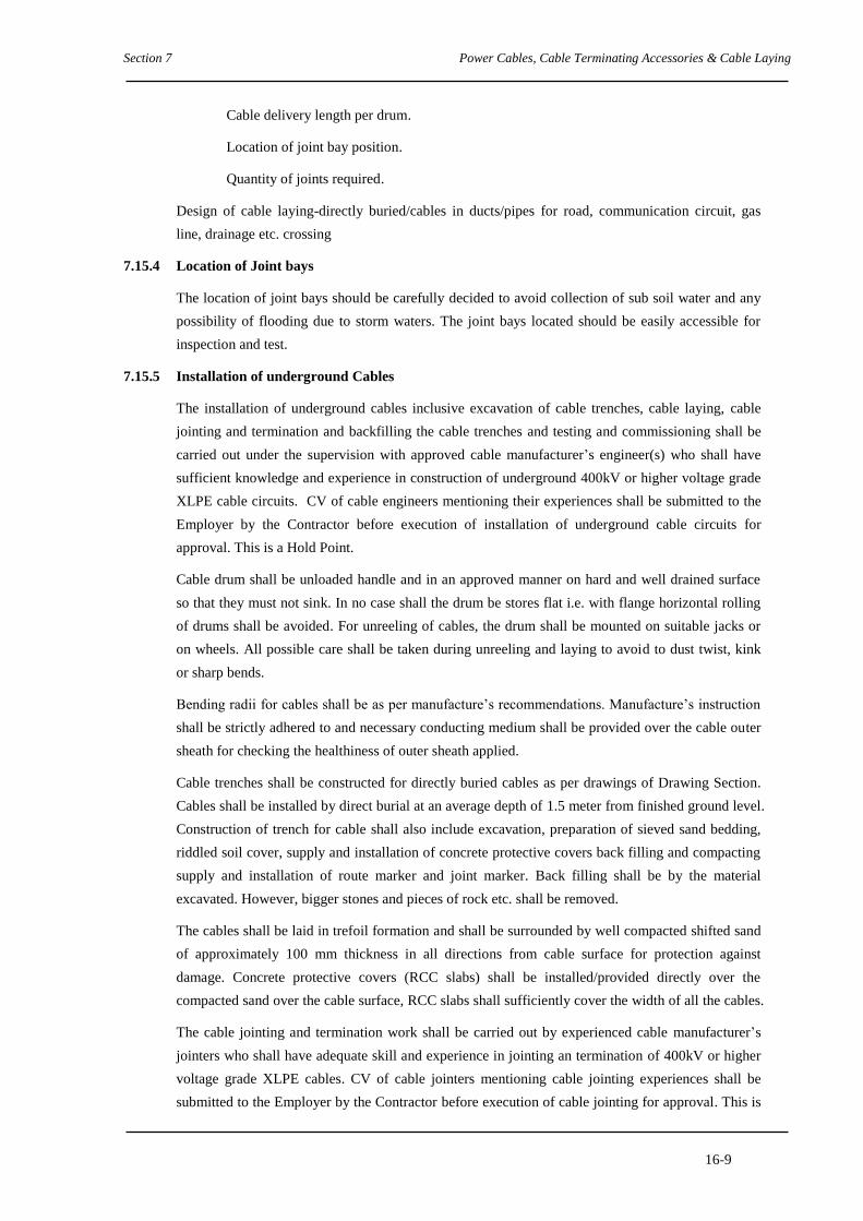
Section 7 Power Cables, Cable Terminating Accessories & Cable Laying
16-9
Cable delivery length per drum.
Location of joint bay position.
Quantity of joints required.
Design of cable laying-directly buried/cables in ducts/pipes for road, communication circuit, gas
line, drainage etc. crossing
7.15.4 Location of Joint bays
The location of joint bays should be carefully decided to avoid collection of sub soil water and any
possibility of flooding due to storm waters. The joint bays located should be easily accessible for
inspection and test.
7.15.5 Installation of underground Cables
The installation of underground cables inclusive excavation of cable trenches, cable laying, cable
jointing and termination and backfilling the cable trenches and testing and commissioning shall be
carried out under the supervision with approved cable manufacturer’s engineer(s) who shall have
sufficient knowledge and experience in construction of underground 400kV or higher voltage grade
XLPE cable circuits. CV of cable engineers mentioning their experiences shall be submitted to the
Employer by the Contractor before execution of installation of underground cable circuits for
approval. This is a Hold Point.
Cable drum shall be unloaded handle and in an approved manner on hard and well drained surface
so that they must not sink. In no case shall the drum be stores flat i.e. with flange horizontal rolling
of drums shall be avoided. For unreeling of cables, the drum shall be mounted on suitable jacks or
on wheels. All possible care shall be taken during unreeling and laying to avoid to dust twist, kink
or sharp bends.
Bending radii for cables shall be as per manufacture’s recommendations. Manufacture’s instruction
shall be strictly adhered to and necessary conducting medium shall be provided over the cable outer
sheath for checking the healthiness of outer sheath applied.
Cable trenches shall be constructed for directly buried cables as per drawings of Drawing Section.
Cables shall be installed by direct burial at an average depth of 1.5 meter from finished ground level.
Construction of trench for cable shall also include excavation, preparation of sieved sand bedding,
riddled soil cover, supply and installation of concrete protective covers back filling and compacting
supply and installation of route marker and joint marker. Back filling shall be by the material
excavated. However, bigger stones and pieces of rock etc. shall be removed.
The cables shall be laid in trefoil formation and shall be surrounded by well compacted shifted sand
of approximately 100 mm thickness in all directions from cable surface for protection against
damage. Concrete protective covers (RCC slabs) shall be installed/provided directly over the
compacted sand over the cable surface, RCC slabs shall sufficiently cover the width of all the cables.
The cable jointing and termination work shall be carried out by experienced cable manufacturer’s
jointers who shall have adequate skill and experience in jointing an termination of 400kV or higher
voltage grade XLPE cables. CV of cable jointers mentioning cable jointing experiences shall be
submitted to the Employer by the Contractor before execution of cable jointing for approval. This is

Section 7 Power Cables, Cable Terminating Accessories & Cable Laying
16-10
a Hold Point.
Bidder shall carry out the earthing of cable metallic sheath with the cross bonding system.
The sheath/screen shall be bonded to the earth through disconnecting type link boxes at straight
through joints and both end of cable terminations to avoid any induced voltage.
7.15.6 Bonding
The cables shall be installed as an insulated sheath system. Single core cable sheaths shall be
earthed with the cross bonding system.
Bonding leads shall be of sufficient cross sectional area to carry the maximum imposed short circuit
level. A schematic diagram detailing the proposed bonding system with describing the detailed
earthing items such as the bonding leads, link boxes and all the necessary equipment shall be
submitted with the Bid.
7.16 TESTS
7.16.1 General
All type, routine and sample tests for cable and its accessories shall be carried out in accordance
with the requirement of IEC 62067.
The bidder must furnish the type tests report from an independent laboratory for type tests
conducted on cable and its accessories of same or higher voltage grade.
The bidder shall give clear three weeks notice in advance to the employer to arrange for
inspection/witness of tests.
7.16.2 Type Tests
The cables to be supplied by the Contractor under this Contract shall be type tested as per the
requirement of IEC 62067 and the type test reports shall be submitted by the Bidders with their bids.
7.16.3 Routine Tests
The specified tests in IEC62067 shall be carried out on each manufactured length of cable.
7.16.4 Sample Tests
The tests specified in IEC62067 shall be carried out on samples which taken to represent batches.
7.16.5 Tests at site after installation
Tests on new installations are carried out according to IEC 62067 when the installation of the cable
system has been completed.
7.17 EARTHING SYSTEM
The cross-bonding system of the single-core 230kV and 400kV cable sheath circuit as well as
design of the relative individual accessories shall be subject to the approval of Employer.
The cable sheaths shall be directly earthed through link boxes at every third joint bay. At the
intermediate joints the sheaths shall be earthed through voltage limiters to limit steep-fronted
transient over voltages to a value which can be safely withstood by the sheath insulation.

Section 7 Power Cables, Cable Terminating Accessories & Cable Laying
16-11
The voltage limiters shall be made of non-linear resistors.
At all joints where cables are not cross-bonded (at solidly bonded joints on the cross-bonded
system) all cable sheaths are to be connected directly through isolation links to earth without sheath
voltage limiters.
7.18 SURGE ARRESTERS
7.18.1 General
Surge arresters shall be of the type employing non-linear metal oxide resistors without spark gaps.
The Contractor shall demonstrate by calculations that the surge arresters will adequately protect the
switchgear arrangement proposed.
Arresters shall be designed and tested in accordance with the requirements of IEC 99-4. Any
departure shall be the subject of agreement between the Employer and the Contractor.
Surge arresters shall be housed in porcelain insulators designed to withstand extremes of the
environment described. The insulation shall have a minimum creepage distance of 25 mm/kV rated
system phase to phase voltage. Porcelain shall comply with IEC 233. The method of sealing against
the ingress of moisture shall be of a type well proven in service and the manufacturing procedures
shall include an effective leak test which can be demonstrated to the inspecting engineer if required.
The internal components of arresters shall be arranged to minimise radial voltage stresses, internal
corona and to ensure minimal capacitive coupling with any conducting layer of pollutant on the
outside of the porcelain housing.
Good electrical contact shall be maintained between resistor blocks taking account of any thermal
expansion and contraction of the block or mechanical shock during transport and erection, by
installing a well proven clamping system.
Metal oxide arresters installed outdoors shall be able to dissipate, when new, twice the energy
generated in the resistor blocks when energised at their maximum continuous operating voltage
immediately having been subjected to the discharge duties specified in IEC 99-4 and assuming that
the porcelain housing and the surrounding air is at least 5°C higher than the maximum ambient air
temperature specified.
Good quality control of the manufacturing process of the resistors shall be ensured by rigorous
testing procedures. The procedures shall ensure that the characteristics of the blocks are, and will
remain, within the specified limits when new and throughout the anticipated life of the arresters.
Samples may be selected at random by the Employer for special tests to be agreed with the
manufacturer.
All surge arresters shall be fitted with a pressure relief diaphragm which shall prevent explosive
shattering of the porcelain housing in the event of an arrester failure and the arrester shall have been
tested according to the high and low current tests specified in IEC 99-1.
Arresters shall be supplied complete for installation in an outdoor switchyard, including insulating
bases and surge counters, one per phase, and, if applicable, grading rings. The material used for
terminals shall be compatible with that of the conductors to which they are to be connected.

Section 7 Power Cables, Cable Terminating Accessories & Cable Laying
16-12
Each arrester shall be identified by a rating plate in accordance with the requirements of IEC 99-4.
In addition an identification mark shall be permanently inscribed on each separately housed unit of a
multi-unit arrester so that units can be replaced in the correct position in the event of them being
dismantled.
Surge counters shall have an internal assembly which is matched to the line discharge capability of
the arrester and shall include a leakage current meter with a bi-linear scale for ease of reading.
Auxiliary contacts are to be provided to signal remote indication of counter operation.
7.18.2 Test
Routine tests shall be carried out in accordance with the requirements of this Specification and as
per IEC 99-4.
The following routine tests shall be carried out all arrester units in accordance with Clause 8.1 of
IEC 99-4:
(a) Measurement of reference voltage
(b) Residual voltage test
(c) Partial discharge test
(d) Housing leakage test
(e) Current distribution test for multi-column arresters
The following acceptance tests shall be carried out on one complete arrester of each voltage rating
and/or type being supplied, all in accordance with Clause 8.2 of IEC 99-4:
(a) Measurement of power frequency voltage at reference current
(b) Lighting impulse residual voltage at nominal discharge current
(c) Partial discharge current
(d) Accelerated ageing test followed by an operating duty test (details are to be agreed
with the Employer).

Section 7 Power Cables, Cable Terminating Accessories & Cable Laying
16-13
APPENDIX 7.Al
REFERENCE STANDARDS
The reference standards and other documents referred to in this Section of the Specification are listed
below:
The cable and accessories shall be comply with the current issues of IEC standards and
documents detailed in this specification or other approved equivalent.
IEC 60 228 Conductors for insulated cable
IEC 60 229 Test on cable over sheaths
IEC 60 230 Impulse test on cables and their accessories
IEC 60 270 Partial discharge measurements
IEC 60 287 Calculation of continuous current carrying capacity
IEC 60 502 Power cables with extruded insulation for rated voltage above 30 kV upto 150
kV
IEC 60 840 Power cables with extruded insulation and their accessories for rated voltages
above 30kV (Um=36kV) up to 150kV (Um=550kV) – Test methods and
requirements
IEC 62 067 Power cables with extruded insulation and their accessories for rated voltages
above 150kV (Um=170kV) up to 500kV (Um=170kV) – Test methods and
requirements
IEEE 48 Test procedures and requirements for High-Voltage cable termination
IEEE 404 Joints for use with solid dielectric cables rated voltage 5 kV – 138 kV

POWER GRID COMPANY OF BANGLADESH LIMITED
Tender Documents
for
Procurement of Plant
Design, Supply, Installation, Testing & Commissioning of 400kV &
230kV underground XLPE cable Transmission lines on Chattogram
Area.(Package-2)
SECTION 8
OPTICAL FIBRE CABLE AND REQUIRED ACCESSORIES

Section 8
i
SECTION 8
OPTICAL FIBRE CABLE AND REQUIRED ACCESSORIES
CONTENTS
CLAUSE NO. TITLE PAGE NO.
8.1 SCOPE ..................................................................................................................................................... 1
8.1.1 General ............................................................................................................................................. 1
8.1.2 Types and Uses ................................................................................................................................ 1
8.2 DESIGN ................................................................................................................................................... 1
8.2.1 Reliability ......................................................................................................................................... 1
8.2.2 Optical Fibre .................................................................................................................................... 1
8.3 PACKING ................................................................................................................................................ 2
8.3.1 Drum ................................................................................................................................................ 2
8.3.2 Cable end ......................................................................................................................................... 2
8.4 OPTICAL JOINT BOXES ...................................................................................................................... 2
8.4.1 General ............................................................................................................................................. 2
8.4.2 Characteristics .................................................................................................................................. 2
8.5 FIBRE OPTIC TERMINATION ENCLOSURE .................................................................................... 3
8.6 FIBRE OPTIC PIGTAILS ....................................................................................................................... 4
8.6.1 General ............................................................................................................................................. 4
8.7 PROTECTIVE TREATMENT ................................................................................................................ 4
8.7.1 Optical Fibre cable ........................................................................................................................... 4
8.7.2 Ingress of Moisture .......................................................................................................................... 4
8.8 INSTALLATION .................................................................................................................................... 4
8.8.1 General ............................................................................................................................................. 4
8.8.2 Workmanship ................................................................................................................................... 5
8.8.3 Optical Fibre Joints .......................................................................................................................... 5
8.9 QUALITY CONTROL ............................................................................................................................ 5
8.9.1 General ............................................................................................................................................. 5
8.9.2 Optical Fibres ................................................................................................................................... 6
8.9.3 Optical Joint Boxes .......................................................................................................................... 6
8.9.4 Non-metallic Underground Fibre Optic Cable ................................................................................. 6
8.9.5 Fibre Optic Cables ........................................................................................................................... 6
8.9.6 Test Certificates ............................................................................................................................... 6
8.9.7 Certificates of Conformity ............................................................................................................... 6
8.9.8 Factory Acceptance Tests ................................................................................................................ 6
8.10 TESTING AND COMMINSSIONING ................................................................................................... 7
8.10.1 General ............................................................................................................................................. 7
8.10.2 Routine Test of Materials ................................................................................................................. 7
8.10.3 Sample Test of Cable ....................................................................................................................... 7
8.10.4 Routine Test of Cable ...................................................................................................................... 7
APPENDIX

Section 8 Optical Fibre Cable and Required Accessories
8-1
SECTION 8
OPTICAL FIBRE CABLE AND REQUIRED ACCESSORIES
8.1 SCOPE
8.1.1 General
This section covers optical fibres suitable for incorporation into the non-metallic underground
fibre optic cables.
8.1.2 Types and Uses
The specified requirements for the single mode optical fibre shall be complied with the
requirement of Appendix 8.A1.
8.2 DESIGN
8.2.1 Reliability
The overall system design of the fibre optic system shall meet the following minimum
requirements:
The product reliability is to be ensured strictly through quality testing of each product
batch. Both initial and periodical quality testing is to be performed to assure the cable
performance and durability in the field environment.
Increase in optical system transmission attenuation due to accumulated ageing and other
effects at the end of five years not more than 0.05 dB/km.
8.2.2 Optical Fibre
8.2.2.1 General
Optical fibres shall be single mode fibre. The fibres shall be coded for ready identification at
each end. Single mode fibres shall conform to ITU-T G652 or to IEC 60793-2-B1 and
Appendix 8.A1.
The optical fibre coating material shall be mechanically strippable. The optical fibres shall be
capable of being joined by fusion splicing techniques.
The optical fibres shall not be subjected to any critical stresses when the cable is at its
maximum system loading, reference Appendix 8.A1.
The fibre optic cable shall be circular in cross section and shall be designed so that any cable
strain is not directly imported on the optical fibres. The cables shall not include any metallic
components to prevent high induced voltage when used alongside the power cables.

Section 8 Optical Fibre Cable and Required Accessories
8-2
8.2.2.2 Constructional Features of Optical Fibre Cable
The constructional features of the optical fibre cable shall be complied with the following
requirements and data.
Optical fibre Table 1, Figure 1 and 2
Loose buffer tube Table 2 and Figure 3
Cable Table 3 and Figure 4
Colour code Table 4
After finalisation of the drum lengths, the Contractor/Supplier shall submit the calculation
results for the expected overall attenuation and dispersion. This is a Hold Point. This will be
compared with the actual values measured after a completion of the installation.
8.2.2.3 Characteristics
Optical properties of the optical fibre: Table 5
8.2.2.4 Marking
The following marks shall be carried out onthe cable sheath with suitable method in one
meter intervals:
Symbol of FOC
Number of fibre core
Manufacturer Name
Year of manufacture
Length marking
8.3 PACKING
8.3.1 Drum
The cable will be delivered in the length required on a suitable drum.
8.3.2 Cable end
The both end of the cable shall be fitted with a suitable cap to protect the FOC from the
ingress/penetration of water or dirt.
8.4 OPTICAL JOINT BOXES
8.4.1 General
Optical joint boxes shall be provided to protect the splice joints, when individual lengths of
fibre optic cables are jointed. The optical joint Boxes shall protect the splice from both
mechanical and environmental damage.
8.4.2 Characteristics

Section 8 Optical Fibre Cable and Required Accessories
8-3
The joint boxes shall consist of high impact plastic ABS box to IEC 60529 IP54.
The external housing shall be designed so that rainwater is directed-away from the door, and
there shall be no water ingress when the door is opened.
The door of the box shall be fitted with captive hinges and shall be fastened shut by screw
fixings.
The bottom of the box shall be fitted with a gland plate with four entry points suitable for a
certain number of different FOC diameters. The joint boxes shall be supplied complete with
all fittings to secure and seal the cable in the gland plates or blank the unused spigots. Cable
cleats to secure the fibre optic underground cable shall be fitted inside the box. The cleats
shall not have a detrimental effect on the performance of the optical fibres when tightened to
the recommended torque.
The top and bottom of the joint box shall be vented, and the vents provided with vermin
shields.
The box shall be supplied complete with internal splice cassettes to accommodate the
required number of splices. Glands shall be fitted to accommodate the underground fibre
optic cable.
Required drawings and specifications are to be supplied along with the document and
standard of specification is to be referred to.
8.5 FIBRE OPTIC TERMINATION ENCLOSURE
At both end of a FOC line fibre optic termination equipment (FOTE) is to be installed, where
the FOC shall be terminated, spare length and pigtails are safely fixed. The FOTE should
provide easy access to the FOC for maintenance and operation purposes. The interior of the
FOTE has to contain cable trays to allow safety store of fibres and splices in accordance with
the FOC specification.
The drawing and specifications of the FOTE are to be submitted with the Offer and standard
of specification is to be referred to. The enclosure shall perform the following functions:
FOTE shall support, organise and protect the optical fibres and the fibre splices whilst
ensuring that the optical fibre minimum – bending radius is not exceeded.
The splice tray shall not have any sharp edges or protrusions that may damage the optical
fibre cable.
FOTE shall provide entry for FOC up to 48 fibres
Number tags for tube and fibre identification are to be included.
FOTE shall provide mounting positions for the bulkhead FC/PC type connectors on
which the cable will be terminated.
FOTE shall allow patching of fibres.
FOTE shall consist of two (2) separate, lockable compartments, one to connect the FOC
with pigtails to the couplings and store the spare length of the FOC / pigtails accurately
and a second compartment which provide access to the other site of the coupling only.

Section 8 Optical Fibre Cable and Required Accessories
8-4
This type of enclosure shall be mounted on the wall at a conveniently accessible height.
8.6 FIBRE OPTIC PIGTAILS
8.6.1 General
Where a termination enclosure is installed, all fibres of all cables are to be terminated on
pigtails with a minimum length of 1 m.
The pigtail shall be a Kevlar (or aramide) reinforced and plastic coated optical fibre
conforming to ITU-T Recommendation G652. For terminating and connecting the FOC
FC/PC type connectors shall be provided. The connector shall be inserted on the cable side of
the bulkhead (feed-through) connector in the termination enclosure.
All connectors shall be supplied with a removable cap to be protected against moisture and
dust ingress when not connected to a coupling.
Required drawing and specifications are to be supplied with the offer and standard of
speciation is to be mentioned.
8.7 PROTECTIVE TREATMENT
8.7.1 Optical Fibre cable
Where two layers of wire strands are provided over the optical sub-unit, the external surface
of the optical sub-unit and the inner strand layer shall be greased, using approved conductor
grease.
8.7.2 Ingress of Moisture
The cable shall be capped before shipment to prevent the ingress of water.
8.8 INSTALLATION
8.8.1 General
The manufacturer of the Optical fibre cable will be responsible for the supervision of
installation by the Contractor, to ensure that overall system reliability requirements are met.
To ensure that this is undertaken, the manufacturer will provide the services of a suitably
qualified/experienced installation supervisor, who shall supervise the installation of the
Works and shall advise the Employer and the Contractor in matters of methods procedures
and precautions to be followed and will be responsible for all matters pertaining to the quality
of the installation. The manufacturer’s installation supervisor shall make at least four visits of
2(two) weeks each during progress of Optical fibre cable installation work for the purpose.
The Contractor shall provide the Employer with a method statement giving sequential details
of the stripping procedure and the optical fibre jointing (splicing) procedure. The method
statement shall take full cognizance of the manufacturer's installation instructions.

Section 8 Optical Fibre Cable and Required Accessories
8-5
The underground optical fibre cable shall be installed through a HDPE duct through out the
length of the cable. The permissible bending radius of the FOC has to be considered in design
of the cable route. The HDPE duct has to be sealed on the end to avoid animals, e.g. rats can
not get in and eat the FOC.
The cable should be installed at least 6” inch above the level of power cable.
The overall attenuation of the installed cable shall not exceed that calculated using the
attenuation and splice loss values specified in Appendix 8.A1.
The Contractor shall give the Employer the requisite period of notice prior to commencing
the tests. This is a Notification Point. Details of the test results shall be submitted to the
Employer.
The manufacturer of the FOC is requested to co-operate with the Fibre Optic Terminal
Equipment Manufacturer (if this is under a separate contract) and shall supply all technical
data requested.
The method statement shall be submitted to the Employer for acceptance with the requisite
period prior to optical fibre jointing commences. This a Hold Point.
The following tests shall be undertaken by the Contractor:
Prior to installation the fibre optic cable shall be tested with an OTDR on each fibre to
ensure that no physical damage has occurred to the fibre during, delivery and shall be
compared with the results prior to despatch
After installation the above test shall be repeated to ensure that no damage has occurred
to the fibre during installation
An end-to-end attenuation measurement shall be taken in each direction on each fibre
using an optical source and optical power meter
The overall attenuation of the installed cable shall not exceed that calculated using the
attenuation and splice loss values specified in Appendix 8.A1. The tests records have to be
submitted to the Employer for approval.
8.8.2 Workmanship
The Contractor shall ensure that the fibre optic cables are not strained or damaged either
mechanically or optically during laying out and paying out of cable and jointing. If necessary,
the Contractor shall demonstrate the suitability of his proposed method, including the choice
of running blocks prior to the commencement of laying out and paying out operations.
8.8.3 Optical Fibre Joints
Optical fibre joints between non-metallic underground fibre optic cables shall be housed in
optical joint boxes.
8.9 QUALITY CONTROL
8.9.1 General

Section 8 Optical Fibre Cable and Required Accessories
8-6
Type, sample and routine tests shall be undertaken on non metallic underground fibre optic
cable, all fittings & accessories and the optical fibres in accordance with the requirements of
this Specification, ITU-T G652, IEC 60793 and IEC 60794 as appropriate. Contract drawings
previously submitted to the Employer shall be available at the time of testing.
The Contractor/Manufacturer shall give the Employer the requisite period of notice prior to
undertaking the tests, and shall submit to the Employer a test programme and procedures for
approval. This is a Hold Point.
Type test of offered Optical Fiber Cable (OFC) will be waived during execution of the
Contract if the Contractor submit the satisfactory type test reports of same OFC. In case, the
type test of OFC is conducted during execution of Contract, the test to be witnessed by
Employer’s Engineers.
8.9.2 Optical Fibres
Optical fibres shall be tested in accordance with the requirements of ITU-T G652 and IEC
60793 as appropriate.
8.9.3 Optical Joint Boxes
Optical joint boxes shall be visually inspected to ensure they meet the specified requirements.
If the external housing or its door show any signs of distortion than the box shall be rejected.
Details of the inspection shall be recorded and shall be made available to the Employer upon
request.
8.9.4 Non-metallic Underground Fibre Optic Cable
Non metallic underground fibre optic cable and the optical fibres shall be tested in
accordance with the requirements of ITU-T G652, IEC 60793 and IEC 60794 as appropriate.
8.9.5 Fibre Optic Cables
All fibre optic cables shall be tested prior to despatch using an OTDR on each fibre.
8.9.6 Test Certificates
Test records, covering Type and Sample tests shall be made available to the Employer.
8.9.7 Certificates of Conformity
When requested copies of the following certificates/records shall also be forwarded:
Optical joint boxes visual inspection records
Routine test records
The records of the OTDR test results
8.9.8 Factory Acceptance Tests
Following tests shall be performed for FOC
Water immersion/penetration tests for all FOC Type

Section 8 Optical Fibre Cable and Required Accessories
8-7
Cable tensile strength tests for all FOC Types
Repeat bending performance test for all FOC types
Fibre strain test for all FOC Types
Mode field concentricity error measurement on all fibres on all FOC Types
Following tests shall be performed for fiber
Cladding diameter measurement
Mode diameter on each fibre
Cut-off wave length on each fibre
Optical Time Domain Reflectometer (OTDR) scan results for each fibre at the system
wave length (attenuation test)
8.10 TESTING AND COMMINSSIONING
8.10.1 General
The Contractor shall provide details of all proposed type, routine, sample, pre-commissioning
and commissioning tests to be carried out on each FOC cable type, for each drum of cable
delivered and each FOC link installed, as appropriate.
8.10.2 Routine Test of Materials
The Contractor shall provide test certificates for routine tests which are performed to ensure
basic materials meet the requirements of the FOC Types.
8.10.3 Sample Test of Cable
Contractors shall provide test certificates of sample tests which are performed on each drum
of cable manufactured. Such certificates shall include as a minimum:
Cladding diameter measurement
Mode diameter on each fibre
Cut-off wave length on each fibre
Optical Time Domain Reflectometer (OTDR) scan results for each fibre at the system
wave length (attenuation test)
8.10.4 Routine Test of Cable

Section 8 Optical Fibre Cable and Required Accessories
8-8
Contractors shall provide test certificates of routine tests which are performed on each cable
Batch manufactured. The routine test shall include as a minimum:
Water immersion/penetration tests for all FOC Type
Cable tensile strength tests for all FOC Types
Repeat bending performance test for all FOC types
Fibre strain test for all FOC Types
Cladding diameter measurement for all fibres on all FOC Types
Mode field concentricity error measurement on all fibres on all FOC Types

Section 8 Optical Fibre Cable and Required Accessories
8-9
Table 1. Construction of the optical fiber
Item Specification
Fiber Type Matched Clad type single mode optical fiber The
optical fiber are compliance with recommendation
G.652.B
Core Material Doped silica
Material Silica
Diameter 125 + 1 µm
Inner layer Material UV curable acrylate
Material UV curable acrylate
Diameter 245 ± 10 µm
Core / cladding concentricity € error Max. 0.8 µm
Cladding non-circularity Max. 1 %
Mode field diameter 9.0 µm ± 0.5 urn at 1310 nm
Identification Color coating
Proof test level Equivalent to 1% strain, 1 sec.
245 µm
Core
Cladding
Primary Coating
(Inner)
Primary Coating (Outer)
Color Coating
Fig.1 Cross sectional view of
optical fibre
Core
Cladding Core
Fig.2 Refractive Index Difference
(Refractive Index difference:
0.36%)

Section 8 Optical Fibre Cable and Required Accessories
8-10
Table 2. Construction of loose buffer tube
Item Specification
Spec. The same as Table 1
Fiber/Tube Max. 12
Filling Material Thixotropic Jelly Compound
Material PBT or equivalent with color coding
Nom. Outer Dia. (mm) 2.5
Color Code Table 4
Not to scale
Not to scale
Fig. 3 Cross sectional view of loose buffer tube (12F/tube)
Optical fiber (Table 1)
Filling jelly compound
Loose buffer Tube

Section 8 Optical Fibre Cable and Required Accessories
8-11
Table 3 Construction of cable
Item Specification
Fiber Number 48
Spec. The same as Table 2.
Fiber/tube 12
Number 4
Material FRP (Fiber reinforced with plastic) rod
Dia. (mm) 2.0±0.1
Material Plastic rod, colored natural
Dia. (mm) 2.5±0.1
Number 1
Binder Material Nylon Yarn(s)
Flooding Compound Material Water Resistant Compound
Strength Element Material Aramid Yarn(s)
Material
Material
Plastic thread High Density Polyethylene,
colored black
Thickness (mm) 1.0 ± 0.15
Ripcord 2 Material Aramid Thread
Armor Flooding Material Water Resistant Compound
Outer Sheath Material
Thickness (mm)
High Density Polyethylene, colored black
1.310.2
Material Polyamide, colored black
Thickness (mm) 0.7±0.2
Cable dimension Approx. (mm) -
Cable weight ' Approx. (kg/km) -
Structure Fig. 4

Section 8 Optical Fibre Cable and Required Accessories
8-12
Cable Construction for -----fiber cable
Not to Scale
Fig. 4 Cable C
Optical Fiber Loose
Buffer Tube
Tube Filling Compound
Filler
Central Strength Member
Core Binder
Ripcord 1
Flooding Compound
Strength Element
inner Sheath Armor
Flooding Corrugated
Armor Ripcord 2
Outer Sheath
Polyamide Sheath
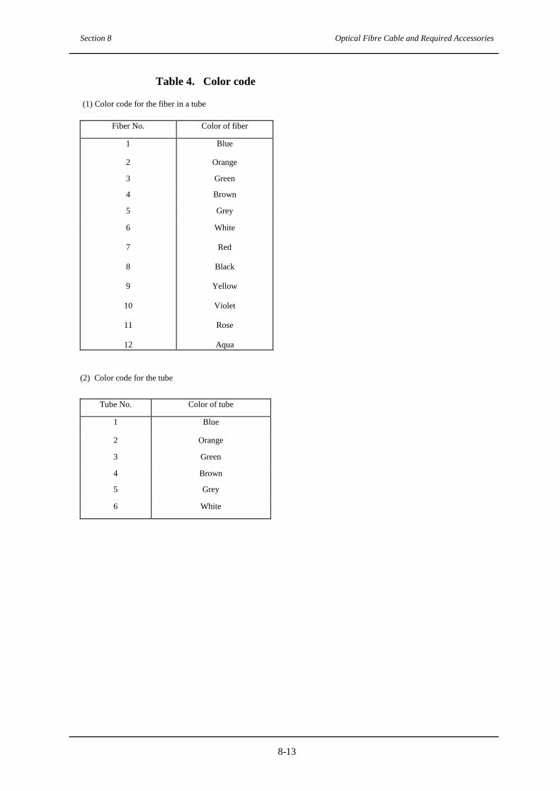
Section 8 Optical Fibre Cable and Required Accessories
8-13
Table 4. Color code
(1) Color code for the fiber in a tube
Fiber No. Color of fiber
1 Blue
2 Orange
3 Green
4 Brown
5 Grey
6
7
8
9
10
11
12
White
Red
Black
Yellow
Violet
Rose
Aqua
(2) Color code for the tube
Tube No. Color of tube
1 Blue
2 Orange
3 Green
4 Brown
5 Grey
6 White

Section 8 Optical Fibre Cable and Required Accessories
8-14
Table 5. Mechanical properties of the cable
Item Specification
Maximum tensile strength 2700 N
Bending radius of the cable
• at no load
• at half max. design tensile load
• at max. design tensile load
Min. 10D mm Min. 20D mm Min. 20D mm
(D : Overall Cable diameter (mm))
Temperature range
Operation Installation
-10° to 70T
-10° to 70°C

Section 8 Optical Fibre Cable and Required Accessories
8-15
APPENDIX 8.A1
SINGLE MODE OPTICAL FIBRE CABLE REQUIREMENTS
Table: 5
Coating diameter
μm 250 ± 15
Cladding diameter
μm 125 ± 3
Cladding non-circularity
% ≤2
Mode field diameter
μm 8.6 ~ 9.5
Mode field concentricity error
μm ≤1
Cut off wave length
nm ≤1,270
Attenuation at (maximum average) 1285 nm 1330 dB/km ≤0.40
Attenuation at (maximum average) 1550 nm dB/km ≤0.25
Zero dispersion wave length
nm ≤1,321
Chromatic dispersion at 1285 nm 1330 ps/(km-nm) ≤3.50
Chromatic dispersion at 1550 nm ps/(km-nm) ≤20
Individual splice loss
dB ≤0.10
Mean splice loss
dB ≤0.06

Section 8 Optical Fibre Cable and Required Accessories
8-16
APPENDIX 8.B1
ENGINEERING DOCUMENTS TO BE SUBMITTED BY CONTRACTOR
Clause
Reference
Document Description Comment
4.1
8.4.3
8.6.1
8.7.1
8.7.1
8.7.2
8.7.4
8.7.8
8.7.8
8.7.9
8.7.10
Expected overall attenuation and dispersion
Optical Joint Boxes - Contract drawings Fixing clamps -
contract drawings
Installation instructions
Method Statement
Optical fibre cable fittings
Non-metallic underground fibre optic cable and optical
fibres - Type test certificates
Type test programme
Optical fibre cable test
Optical joint boxes - visual inspection test records
Optical fiber cable fittings and optical fibres - Type test
records
Optical fibre cable fitting & optical fibres
- Routine test records
Certificate of Conformity
Installation test records
Documentary evidence
& Test proposals

Section 8 Optical Fibre Cable and Required Accessories
8-17
APPENDIX 8.C1
NOTIFICATION AND HOLD POINTS
Clause
Reference
Notification Point Hold Point
8.4.1
8.6.1
8.7.1
8.7.2
8.7.10
Installation Tests
Contract drawings
Method Statement
Type test programme
Optical Fibre Test-Test Proposal
Type & Routine Test Proposal

Section 8 Optical Fibre Cable and Required Accessories
8-18
APPENDIX 8.Dl
REFERENCE STANDARDS
The reference standards and other documents referred to in this Section of the Specification are listed
below:
IEC 60529: Classification of decrees of protection provided by enclosures
IEC 60793- 1: Optical Fibres Part 1: Generic Specification
IEC 60793-2: Optical Fibres Part 2: Product Specification
IEC 60794-1: Optical Fibre Cable Part 1: Generic Specification
IEC 60794-2: Optical Fibre Cable Part 2: Product Specification
BS 729: Specification for hot dip galvanised coatings on iron and steel articles
BS 1490: Specification for Aluminium and aluminium alloy ingots and castings for general
engineering purposes
BS 3100: Specification for steel castings for general engineering purposes
BS 3643: Ingot zinc
BS 4190: Specification for ISO Metric hexagon bolts, screws and nuts
BS EN 1676: Aluminium and aluminium alloys - Alloyed ingots for remelting
BS EN10025: Specification for hot rolled products of non-alloying structural steels and their technical
delivery requirements.
ITU-T G652: Characteristics of single mode optical fibre cable.

POWER GRID COMPANY OF BANGLADESH LIMITED
Tender Documents
for
Procurement of Plant
Design, Supply, Installation, Testing & Commissioning of 400kV &
230kV underground XLPE cable Transmission lines on Chattogram
Area.(Package-2)
SECTION 9
PACKING, PROTECTION AND DESPATCH MARKING

Section 9 Packing, Protection and Despatch Marking
i
SECTION 9
PACKING, PROTECTION AND DESPATCH MARKING
CONTENTS
CLAUSE NO. TITLE PAGE NO.
9.1 GENERAL ............................................................................................................................................... 1
9.2 CONTAINERISATION .......................................................................................................................... 1
9.3 CABLE .................................................................................................................................................... 2
9.4 ASSOCIATED ACCESSORIES ............................................................................................................. 2

Section 9 Packing, Protection and Despatch Marking
9-1
SECTION 9
PACKING, PROTECTION AND DESPATCH MARKING
9.1 GENERAL
The following minimum packing methods shall be adopted for suppliers external to the country
of the transmission line installation, unless otherwise specified.
The Supplier shall be entirely responsible for ensuring that the packing is suitable for transit
and storage and will be held responsible for any shortages or damage during transit.
Wherever possible, the Supplier shall utilise shipping by container vessels in the containers of
the correct type for the item being shipped to reduce the likelihood of damage to the items. If
containerisation is not possible the requirements of the following clauses shall be applicable.
All materials shall be carefully packed in a manner suitable for transport to and storage under
the climatic conditions present. Items packed in cases or crates shall be so secured that they are
not free to move, and cannot work loose in transit.
Wood wool is to be avoided as a packaging material as far as possible.
Waterproof paper and felt lining are to overlap at the seams by at least 12 mm, and the seams
secured together in an approved manner, but the enclosure is to be provided with vermin proof
screened openings to permit ventilation.
A packing note in a weatherproof plastic envelope is to be securely attached to the right hand
lower corner of one side of all cases or crates. A copy of the packing list shall also be included
inside.
All packing cases or crates shall be marked on the outside to show the correct way up and
where relevant, where the weight is bearing and the correct positions for slings.
Shipping mark, numbers and symbols will be provided by the Employer. These marks shall be
applied to cable drums and cases either by the use of a waterproof stencil, flo-pen or any other
permanent method. The use of tie-on tags is not permitted. Cases shall be marked on two
opposite sides.
ALL MARKS SHALL BE CLEARLY LEGIBLE AT THE TIME OF DESPATCH.
9.2 CONTAINERISATION
Where materials shipped by the use of containers, a reduced level of packing, is acceptable.
(a) Strap-band centres may be increased to 3m for 32 mm x 0.8 mm bands and 2.5m for
19 mm x 0.8 mm bands.

Section 9 Packing, Protection and Despatch Marking
9-2
(b) The use of wire through bundle ends is not required.
(c) Cases may be 20 mm thick timber.
9.3 CABLE
Cable shall be supplied on drums of sufficient sturdiness to withstand overseas shipment, and
the drums shall be securely battened to prevent damage to the cable.
Steel drums shall be used for cable to be supplied and shall comply with the requirements of
this specification or other equivalent National Standards.
Drums shall be provided with a secure waterproof label displaying the maker's name, type, size
and length of cable on the drum. Drum serial number shall be either chiselled into one drum
flange or impressed onto a secure metallic label. Drums shall be painted on all outer surfaces.
Drums shall display an arrow and the words "Roll This Way" on each flange to show the
correct direction of rolling.
9.4 ASSOCIATED ACCESSORIES
Associated accessories shall be cased (maximum net mass 500 kg).
Cases shall be of sturdy construction, made from new 25 mm thick timber and constructed with
annular (rag) nails. They shall have packing pieces on the underside to enable the use of fork-
lift trucks.

POWER GRID COMPANY OF BANGLADESH LIMITED
Tender Documents
for
Procurement of Plant
Design, Supply, Installation, Testing & Commissioning of 400kV &
230kV underground XLPE cable Transmission lines on Chattogram
Area.(Package-2)
SECTION 10
DRAWINGS

DRAWING LIST (Pacakge-2)
Drawing No. Title
PGCB/400KV/OH-UG/Anow-Ananda/TL Typical Transition Compound Arrangement.


POWER GRID COMPANY OF BANGLADESH LTD
SEC 11: Building and Civil Engineering Works (For AIS) 10/1
POWER GRID COMPANY OF BANGLADESH LIMITED
Tender Documents
for
Procurement of Plant
Design, Supply, Installation, Testing & Commissioning of 400kV and 230
kV Underground Cable Transmission Lines on Chattogram area
(Package-2).

POWER GRID COMPANY OF BANGLADESH LTD
SEC 11: Building and Civil Engineering Works (For AIS) 10/2
SECTION 11 CIVIL ENGINEERING WORKS

POWER GRID COMPANY OF BANGLADESH LTD
SEC 11: Building and Civil Engineering Works (For AIS) 10/3
SECTION 11
CIVIL ENGINEERING WORKS TABLE OF CLAUSES
11.1 GENERAL ............................................................................................................................... 4
11.1.1 SCOPE OF WORK .......................................................................................................................... 4 11.1.2 BIDDER TO SATISFY HIMSELF AS TO ALL CONDITIONS ................................................................................ 4 11.1.3 WAYLEAVES, LAND PURCHASE AND PLANNING PERMISSION ....................................................................... 4 11.1.4 SITE SURVEY DRAWINGS ................................................................................................................ 5 11.1.5 EARTH WORKS ............................................................................................................................ 5 11.1.7 PROGRAMME ............................................................................................................................... 6 11.1.8 MONTHLY PROGRESS CERTIFICATES/PROGRESS REPORTS ....................................................................... 6 11.1.9 TEMPORARY FACILITIES .................................................................................................................. 6 11.1.10 SITE SUPERVISION........................................................................................................................... 7 11.1.11 DESIGNS AND DRAWINGS ................................................................................................................... 7
11.2 REFERENCES .......................................................................................................................... 7
11.2.1 GENERAL ................................................................................................................................... 7 11.2.2 DESIGN AND CONSTRUCTION STANDARDS ............................................................................................ 7
11.3 DESIGN .................................................................................................................................. 9
11.3.2 GROUND CONDITIONS, FOUNDATIONS AND SITE INVESTIGATION .................................................................. 9 11.3.4 SURFACING ............................................................................................................................... 10 11.3.24PAINTS AND PAINTING ..................................................................................................................... 11 11.3.26CONCRETE .................................................................................................................................. 11
11.4 CONCRETE WORKMANSHIP .................................................................................................... 13
11.4.1 GENERAL ................................................................................................................................. 13 11.4.2 AGGREGATES ............................................................................................................................ 13 11.4.3 SAMPLING ................................................................................................................................ 14 11.4.4 GRADING ................................................................................................................................. 14 11.4.5 CEMENT ................................................................................................................................... 14 11.4.6 WATER .................................................................................................................................... 14 11.4.7 REINFORCING ............................................................................................................................ 14 11.4.8 STORAGE ................................................................................................................................. 15 11.4.9 DESIGN MIX .............................................................................................................................. 15 11.4.10 MIXING AND PLACING OF CONCRETE ............................................................................................ 16 11.4.11 TESTING OF CONCRETE ............................................................................................................ 17 11.4.12 FORMWORK .......................................................................................................................... 18 11.4.13 REINFORCING STEEL ............................................................................................................... 19 11.4.14 CONSOLIDATION OF CONCRETE .................................................................................................. 19 11.4.15 CURING OF CONCRETE............................................................................................................. 19 11.4.16 HOT WEATHER CONCRETING ..................................................................................................... 19
11.5 WORKMANSHIP OF ALL OTHER MATERIALS .............................................................................. 20
11.6 LAND DEVELOPMENT WORK : ................................................................................................. 20

POWER GRID COMPANY OF BANGLADESH LTD
Sec 10B: Building & Civil Engineering Works 10/4
SECTION 11
CIVIL ENGINEERING WORKS
11.1 GENERAL
This section covers all earth work, foundations associated with the project together with site
preparation, cable trenches, backfilling and chain link fencing etc .
11.1.1 Scope of Work
The work includes the design, detailing, construction and maintenance of the following:
(i) site preparation including retaining walls, cutting or filling up to the level specified
in11.1.4 and levelling as well as compaction.
(iii) foundations for all equipment, cable bridge and any other structure foundation
required for the project
(iv) cable trench consisting of structural reinforced concrete cover, brick walls, side
interlocking block.
(v) road including access road and roadways within sites, surfacing the entire area
within site boundary and surface water drainage.
(vi) construction of chain link fencing at perimeter of the site (around the transposition
compound)
vii) For road crossing Horizontal directional drilling (HDD) shall be performed.For canal
crossing HDD or steel cable bridge shall be performed.
11.1.2 Bidder to satisfy himself as to all conditions
The Bidder shall assess:
(i) access conditions at site, plus ground condition and ground bearing capacity
(ii) transport costs, materials costs and restrictions of availability of supply of materials
locally
(iii) importation restrictions and delay due to customs controls
(iv) restrictions imposed by existing equipment on sequence of construction, access, etc.
(v) restrictions caused by cable laying and overhead line Bidders
(vi) ground conditions and temporary works required to provide support during excavation
11.1.3 Wayleaves, Land Purchase and Planning Permission
The Employer will be responsible for the purchase of all land within the permanent site
boundary and the purchase of all land required to the base of the fill of any batter slopes. The

POWER GRID COMPANY OF BANGLADESH LTD
Sec 10B: Building & Civil Engineering Works 10/5
Employer willalso be responsible for obtaining land to provide a permanent single access to
site from a nearby road or waterway.
During the construction period the Bidder shall be responsible for maintaining this access
road in a reasonable condition by reinstating damage caused by his construction traffic and
Employer’s traffic.
Should the Bidder require more than one single access to a site or require additional land for
construction activities outside the permanent site boundary, he shall be responsible for the
purchase or wayleave of the required land.
The Employer will be responsible for applying for planning permission. The Bidder shall be
responsible for completing the approved site survey and the approved site layout plan,
together with the approved architectural elevations of all facades of any buildings, by the key
date given in the programme so that the Employer may use these drawings to apply for
planning permission.
11.1.4 Site Survey Drawings
The Bidder shall prepare a survey at 1:200 scale showing existing ground levels on a
maximum 10 metre grid and details of all features above and below the ground within the site
boundary and up to 15 metres beyond it by the key date stated in the programme. Levels
shall be related to bench marks clearly indicated on the plan. The plan shall be submitted to
approval by the Engineer and the approved substation building plinth levels shall be given on
site plan. The Bidder shall propose the building floor level to the. Engineer.The final
ground/formation level of the site will be 500mm above the existing ground level
11.1.5 Earth Works
Fill where required shall be carried out by the Bidder. Source of fill material and Retaining
wall shall be planned and approved by the Employer. The Bidder shall be responsible for
providing a level or uniform sloping site to suit his substation layout design. The final
ground/formation levels (i.e. the level below the brick surfacing) shall be stated on the site
survey plan to be prepared by the Bidder.
11.1.6 Engineer’s and Employer’s Accommodation/Surveying Equipment
On each major site the Contractor shall provide an office of approx size 5 x 8m equipped with desk, 1 executive chair, 2 visitor chairs, light, fan and air conditioner, toilet with wash basin etcfor the sole use of the Employer’s Engineer and his inspectors. Similar facilities are to be provided for the supervision consultant of the Employer.
11.1.7 Surveying Equipment
The Contractor shall loan his surveying instruments with surveyor to the Employer and his staff when required. Instrument checks shall be carried out at monthly intervals.

POWER GRID COMPANY OF BANGLADESH LTD
Sec 10B: Building & Civil Engineering Works 10/6
11.1.8 Programme
The Bidder's programme shall at Bid stage define the following key dates. Where drawings
are to be submitted for approval, they shall be submitted at least 6 weeks before the key
dates to allow for the Engineer to comment and his comments to be incorporated in the
drawings:
1 Issue of approved site survey drawing complete with soil levels and prdestal top levels
2 Issue of approved electrical layout drawings
3 Completion of Site Investigation field work
4 Issue of approved Site Investigation Final report
5 Completion of loading tests on a foundation on fill site and any other site where
settlement is likely to be a problem
6 Issue of approved drawings required for Planning Permission
7 Issue of a full complete set of civil building drawings
8 Construction start date
9 Date access will be given for:
i) Installation of equipment in Buildings
ii) Installation of outdoor plant
10 Construction finish date
The drawing programme shall ensure that complete set of approved civil building drawings
will be issued at least 21 days before construction start, in accordance with the Project
Requirements.
The Construction programme shall be expressed in an 'S' curve for the whole project, with
the percentage (of the total value of work in the schedules) each month.
11.1.9 Monthly Progress Certificates/Progress Reports
In accordance with the Project Requirements the Bidder shall submit agreed progress
certificates before the seventh day of the next month. These certificates shall state the
percentage completion of each item in the schedules and shall state the overall percentage
completion. An updated 'S' curve shall be submitted with the progress certificates.
11.1.10 Temporary Facilities
The Bidder shall provide all temporary buildings, workshops, cement and lime stores and
latrines required for his use. The Bidder shall agree the location of these buildings with the
Engineer, after submitting a drawing showing their proposed location.
When a Bidder is placed in possession of a site, or part of a site, he shall erect temporary

POWER GRID COMPANY OF BANGLADESH LTD
Sec 10B: Building & Civil Engineering Works 10/7
fencing immediately to protect the site until the boundary wall shall be erected.
11.1.11 Site Supervision
Although the civil and building works may be let as a sub-contract to an approved local
Bidder, the main Bidder shall ensure that an expatriate supervisor in his direct employ is
continuously available at site during construction. This supervisor shall have at least a
working command of spoken English and be able to read, understand and discuss
specifications and drawings.
The Bidder shall notify the Employer and Engineer in writing of major field works two days
before the work starts for the activities as described below:
i) subsoil investigation
ii) Every concrete pour and foundation casting
11.1.12 Designs and Drawings
The Bidder shall obtain the Engineer's approval for the use of all design codes and standards
before design work starts. The Bidder shall supply one copy of all of codes for
employer’sEngineer. If non-English equivalent National codes are adopted, the Bidder shall
supply English translations of these Codes to the Engineer.
One copy of calculations along with all soft (software) copies shall be submitted together with
drawings. To avoid possible misunderstandings, calculations will not be approved separately
from drawings.
The Bidder shall generally submit a complete set of of drawings of each item sequentially for
approval after initially getting the electrical layout and section approved. Where possible,
drawings shall be standardized and general drawings shall be issued covering several sheets.
The Bidder shall provide a co-ordination plan at scale 1:200 showing busbar sizes, structure
types, foundation types, cable trenches, roads, ducts, buildings, boundary walls, earthing,
drainage and all services in this Contract.
11.2 REFERENCES
11.2.1 General
The design and construction shall conform to the latest edition of the relevant Codes and
Standards. Any proposed substitution for the listed Standards by an equivalent Standard will
be subject to approval by the Engineer. Relevant Standards include, but are not limited to,
those listed in sub section 11.2.2 below.
11.2.2 Design and Construction Standards
BS12 Portland Cement

POWER GRID COMPANY OF BANGLADESH LTD
Sec 10B: Building & Civil Engineering Works 10/8
BS EN 124 Gully and Manhole tops for vehicular and pedestrian areas
BS 812 Testing aggregates
BS 882 Aggregates from natural sources for concrete
BS 1377 Methods of test for soils for civil engineering purposes
BS 1722: Part 10 Anti-intruder fences
BS 1881 Testing concrete
BS 2853 Design and testing of overhead runway beams
BS 3148 Methods of test for water for making concrete
BS 3921 Clay bricks
BS 4449 Steel bars for the reinforcement of concrete
BS 5262 External renderings
BS 5395 Stairs, ladders and walkways
BS 5572 Sanitary pipework
BS 5628 Code of practice for use of masonry
BS 5930 Code of practice for site investigations
BS 6031 Code of practice for earthworks
BS 6367 Code of practice for drainage of roofs and paved areas
BS 6399: Part 1Code of practice for dead and imposed loads
BS 6399: Part 2 Code of practice for wind loads
BS 6465 Sanitary installations
BS 6651 Code of practice for protection of structures against lightning
BS 6700 Design, installation, testing and maintenance of services supplying water for domestic use
BS 8004 Code of practice for foundations
BS 8005 Sewerage
BS 8100 Lattice towers and masts
BS 8102 Code of practice for protection of structures against water from the ground
BS 8110 Structural use of concrete
BS 8206 Lighting for buildings
BS 8215 Code of practice for design and installation of damp-proof courses in masonry
BS 8290 Suspended ceilings
BS 8301 Code of practice for building drainage

POWER GRID COMPANY OF BANGLADESH LTD
Sec 10B: Building & Civil Engineering Works 10/9
11.3 DESIGN
11.3.1 Ground Conditions, Foundations and Site Investigation
(a) Fill Sites
The Bidder shall impose the site layout on the survey to check for uneven depth of fill
below any foundation and where uneven depth of fill exists his foundation proposals
shall restrict final differential settlement to a 1 in 400 slope.
If a fill site has not been exposed to one wet season before foundation work starts, the
Bidder shall flood the site to a depth of 50mm for 10 days (Not required on hydraulic fill
sites). This requirement is because silty sands will generally compact to a denser
condition on first time flooding.
On all fill sites the Bidder shall pipe rainwater from down pipes down to paddy level and
shall prevent water ponding in open foundations and backfill all foundations as soon as
possible.
When a filled site is handed over to the Bidder, the Bidder shall become responsible for
maintaining the entirety of the fill in good condition, including all better slopes.
(b) Unfilled Sites
Original delta levels are generally below road level. Therefore most sites are historically
fill sites but fill settlement can sensibly be considered complete, where fill is over 3 years
old.
(c) Foundations
Foundations of equipment, Cable Bridge, chain link fencing and other structure
foundations shall be provided shallow/deep as per subsoil investigation report,
settlement test as well as plate bearing test. In case of shallow foundation for equipment
the bearing capacity of proposed soil level shall be checked by the Plate Bearing Test.
Piles shall be concrete (cast-in-situ or precast) complying with BS 8004.For structural
design of cast in situ piles, guidelines provided in Annexure 11.1 should be followed.
For shallow foundations the minimum depth of foundations shall be 1.5m.
All formations shall be hand rammed or mechanically compacted before placing 70mm
minimum thickness of Class B concrete blinding, within 24 hours of bottoming
excavation, which blinding shall project 300mm minimum distance beyond all footings.
Each footing shall be inspected by the Engineer. Where soil condition is poor (on fill
sites or already filled sites) or where the Bidder leaves foundations exposed and soil
conditions deteriorate, one of the following measures shall be carried out as agreed with
the Engineer:
i) Blinding depth and projection shall be increased as necessary. ii) Soft soil shall be removed and replaced with compacted viti sand with the top 300mm

POWER GRID COMPANY OF BANGLADESH LTD
Sec 10B: Building & Civil Engineering Works 10/10
(Minimum) consisting of sandandkhoa (brick chips) in 2:3 ratio with 95% level of compaction.
The cost of this work shall be borne by the Bidder.
The Bidder shall propose the allowable bearing pressure for all foundations based on
soil strength parameters only and shall not be increased while wind loads exceeds 25%
of dead load as well as shall not exceed 125kN/m2 .
The deepest parts of any foundations shall be completed first. All foundations shall be
completed and backfilled, including all cable tunnel and cable trench work. All other
foundations shall be backfilled within 7 days of completing concreting.
All exposed concrete and the outer surfaces of cable trenches and cable tunnels shall
receive two coats of bitumastic paint before backfilling to reduce ingress of water. The
Concrete surface shall be ground smooth and all air holes etc filled (rubbed down with a
cement slurry) before painting.
The Bidder shall monitor settlement of all foundations each month and report this
settlement to the Engineer until settlement has reduced to less than 1.5mm in 3 months.
The tops of all foundations shall terminate 200 mm. above site average finished surface
level. All exposed edges shall have 20 mm x 20 mm. chamfers.
Excavation shall only be carried out when the ground water table is at least 1000mm
below foundation level. The excavation shall be kept dry during the construction period
by providing sumps and pumps as required. During the rainy season, shelters shall be
erected over all open excavations.
Any over excavation shall be filled with Class B concrete.
All backfill shall be compacted to 95% maximum dry density as defined by BS 1377 test
method part 4, 2.5 kg rammer.
Before starting foundation work the Bidder shall clear all sites of trees, tree roots, shrubs,
debris, surplus soil, and any buildings.
Foundations shall be designed to resist uplift, assuming the water table is at ground
level and the weight of soil resting on a foundation is that included within a 15˚ frustum.
11.3.2 Surfacing
For the whole of the transposition compound area the ground shall be surfaced with gravel or
other readily available local stone as approved by the Engineer. The transposition compound
area surfacing shall be clean, thoroughly washed when necessary, and free from clay, soil or
contaminating material and shall be graded from 20 -50mm, laid and lightly compacted to a
finished thickness of 175mm. Below the gravel layer there shall be a 75mm brick layer with
cement mortar (1:6), laid over a 75mm level of fine sand spread over the finished fill site.
Outside of the designated surfacing areas if any, shall be turfed. Turf shall be of good quality,

POWER GRID COMPANY OF BANGLADESH LTD
Sec 10B: Building & Civil Engineering Works 10/11
free from weeds and other impurities. Samples of the turf which is proposed to use shall be
submitted to the Engineer for his approval. The turfs shall be laid to even surfaces on a bed
of plastic/vegetable soil of 150mm thickness over Finished Ground level (FGL), which shall
be raked and consolidated to provide a suitable bed.
On sloping surfaces the Bidder shall provide and fix wooden pegs to retain turfs.
All areas to be surfaced shall first be treated with a total weed killer in accordance with the
manufacturer's instructions. Weed killer shall only be applied in dry weather when there is no
risk of it being washed out to adjacent agricultural areas.
The entire surface within boundary walls shall be of uniform sloping site, sloping at
1 in 150minimum slope to open channels around the entire perimeter. These
channels shall be designed for a rainfall intensity of 60 mm per hour. Outside the
boundary wall the Bidder shall be responsible for drainage up to 20 metres from the
wall and will at some sites need to construct outlets with suitable erosion protection
down to paddy level.
11.3.3 Cable Trench
The Bidder shall base his design of cable trench following bid drawing and subsoil
investigation report.
11.3.4 Fences and Gates
The Bidder shall base his design of chain link fencing and gates following bid drawing and
subsoil investigation report. The Bidder shall erect a permanent fence 2.50m high with
750mm high barbed wire (Reference Dwg PGCB/400kV/OH-UG/TL/FN) in accordance with
BS 1722 part 10 or similar approved.
11.3.5 Paints and Painting
All exposed parts of foundations, the outer faces of cable trenches and cable tunnels shall be
painted with two coats of bitumastic paint.
All ungalvanized metalwork shall receive two coats of red oxide paint at least 4 days before
installation and shall receive two finishing coats of paint after installation, each coat being of
different colour. Surface preparation before painting shall be SA 2.5 or an agreed rust
convertor acid shall be used. All galvanized steel, including all brick ties, boundary wall wire
supports, cranebeams, baseplates and holding down bolts and concrete plinths shall receive
two coats of bitumastic paint. Galvanized steel shall not be painted until the surface has
weathered.
11.3.6 Concrete
Only two class of concrete shall be used. Class A shall be used for all structural work, cable
trench cover, side interlocking block, piling and for all foundations which are not unreinforced
massive blocks. Class B concrete shall be used for blinding, pipe surround and unreinforced
or nominally reinforced concrete. Road slabs and floor slabs all shall be reinforced Class A

POWER GRID COMPANY OF BANGLADESH LTD
Sec 10B: Building & Civil Engineering Works 10/12
concrete.
Class A Class B
MinCement Content 360kg/m3 170kg/m3
Max Water Cement ratio 0.55 -
Coarse Aggregate type Broken stone Jhama brick
Max Coarse aggregate size 20mm 25mm
Method of Batching Volume batching Volume batching
Min Characteristic of Trial
Mix at 28 days 30N/mm2
Min characteristic strength
of trial mix at 7 days 14N/mm2 -
Min characteristic strength
of works cubes at 28 days 20N/mm2 -
Slump Range
Slump for concrete placed 50-100mm
below water in piling 150-200mm
It should be noted that minimum specified cement content will produce significantly stronger
concrete. The Bidder's design shall be based on a 28 day crushing strength of 20N/mm2.
Design shall be in accordance with this Contract and BS 8110 or other agreed standard.
Minimum cover to rebars shall be 60mm where concrete is in contact with backfilled soil
against a shuttered face, 100mm where concrete is cast against soil, and 30mm for all above
ground concrete. In detailing bars which traverse a member, a reduction of 5mm shall be
made for a bent bar and 10mm for a straight bar to ensure adequate cover. Exposed ends of
sunshades and roof projection shall have 70mm minimum cover.
All concrete design shall ensure easy access for vibrators of 50mm. minimum diameter. Because of the slowness of concreting using local methods of transport, congested reinforcement details and shapes which are difficult to concrete should not be used. The location of all cold joints shall be agreed in writing with the Engineer and all joint surfaces shall be scabbled. All joints shall be horizontal or formed against vertical stop ends. All cold joints shall be indicated on drawings. Roof slabs shall generally be cast in one continuous operation.Where curing compounds are used to protect exposed surfaces from solar radiation and improve moisture retention, they shall be subject to the approval of the Employer. This is a Hold Point.
11.3.7Concrete Reinforcement
The Bidder may use locally available mild steel bars from approved sources or import steel
bars to any agreed standard. No bar or stirrup shall be smaller than 6mm diameter to ensure
adequate rigidity during concreting.

POWER GRID COMPANY OF BANGLADESH LTD
Sec 10B: Building & Civil Engineering Works 10/13
If locally purchased bars are used, bending tests and tensile tests shall be carried out to
ensure the bars meet the design standard adopted and weight per unit length shall be tested
regularly.
Bar bending lists shall generally be shown on drawings, where possible with a diagrammatic
representation of each bar to ensure clarity and ease site communication. The Engineer will
not systematically check the accuracy of every bar on bar lists when approving drawings. The
Bidder shall therefore arrange to check all bar lists. Drawings shall detail all chairs and ties
and include these on bar lists.
Bars shall be tied at every intersection and the ends of tie wire bent away from concrete
surfaces.
Anti crack bars shall be provided at changes in slab or wall thickness and at the corners of
every rectangular opening.
11.4 CONCRETE WORKMANSHIP
11.4.1 General
At all stages in the production, mixing, placing and curing of concrete, the work will be
inspected by the Engineer’s representative. If any material, dimension or practice is not at
least equal to the standards set out herein, it shall be rejected and alternatives compliant with
the said standards, and in addition to the satisfaction of the Engineer, shall be implemented.
11.4.2 Aggregates
Coarse aggregate shall be capable of passing through a 20mm sieve and be retained on a
5mm sieve. Fine aggregate shall be not larger than 5mm and not smaller than 0.06mm and
shall be sharp in texture.
All aggregates shall be free of harmful quantities of organic impurities, clay, silt, salt or
unsound particles. The amount of clay, silt and fine dust present in aggregate, whether as
coatings or separate particles, may not be more than:
15% by weight in crushed sand 3% by weight in natural or crushed gravel sand 1% by weight
in coarse aggregate.
If the Engineer considers that any aggregate which the Bidder proposes to use contains an
excess of fine particles or any harmful substances, the Bidder shall either replace the
aggregate or, at his option and entirely at his expense, institute a series of approved tests at
an approved laboratory to determine the nature and extent of the fine particles and harmful
substances. Following receipt by the Engineer of the results of the analysis and tests, he will
advise the Bidder in writing whether the proposed aggregate may or may not be used. The
Engineer’s decision in this respect shall be final.
Tests to determine the extent of impurities or fine particles shall include (but shall not be

POWER GRID COMPANY OF BANGLADESH LTD
Sec 10B: Building & Civil Engineering Works 10/14
restricted to) the relevant tests specified in BS 882:1992, ASTM. C40-79 (Colormetric test)
and ASTM. C33-82.
11.4.3 Sampling
At least four weeks before he envisages first receiving aggregate from any source the Bidder,
in the presence of the Engineer, shall obtain samples for testing. Samples shall be taken in
accordance with the procedure quantities laid down in BS 812 and shall be subjected to
those tests which the Engineer considers necessary to demonstrate the soundness of the
material.
Such tests shall be carried out in an approved manner at the Bidder’s expense and may
include the manufacture, both in the laboratory and at site, of test cubes or cylinders to
determine crushing strength.
11.4.4 Grading
The Bidder shall ensure that his offer includes the full cost of obtaining and transporting
suitably graded stone aggregates to site.
Grading of aggregates should, together with the required minimum cement content and water
cement ratio, ensure adequate durability, density and characteristic strength of the finished
concrete. The Bidder shall submit in writing to the Engineer the makeup of the mix he
proposes to use, together with the grading analysis for the particular material and any details
concerning his or others’ experience with the use of aggregate obtained from the same
source.
11.4.5 Cement
Ordinary Portland Cement shall comply with BS 12A. The Bidder may obtain cement, bagged
or in bulk, from any approved source in Bangladesh but shall always submit sufficient
samples from each delivery, as required by the Engineer, to ensure that all cement complies
with the minimum requirements of BS 12A. All cement shall be stored in a weathertight shed
at least 300mm off the floor. Regular checks shall be made on the weight of cement in each
bag.
11.4.6 Water
All water used in the preparation of concrete for foundations shall be clean, fit for drinking
and free from all earth, vegetable matter and alkaline substances, whetherin solution or in
suspension, and shall comply with BS 3148.
11.4.7 Reinforcing
Where reinforcing is specified in any foundation design, it shall comply with BS 4449 or an
approved similar standard. Before any reinforcing is used, the Bidder shall provide the
Engineer with a certified mill certificate, verifying its grade and quality, and proof test such

POWER GRID COMPANY OF BANGLADESH LTD
Sec 10B: Building & Civil Engineering Works 10/15
samples as the Engineer considers necessary. All reinforcement shall be clean and free from
loose mill scale, dust, loose rust and paint, oil or any other coating which in the opinion of the
Engineer may destroy or reduce bond.
11.4.8 Storage
The Bidder shall ensure that all the materials he provides for the preparation of concrete shall
be stored in a manner which prevents contamination by dust, clay, water or any other harmful
material.
Heaps of coarse and fine aggregate shall be separated by at least one metre.
Where aggregate is tipped directly onto the ground, the bottom 20cm of the heaps shall not
be used. Bagged cement shall be protected from rain, mixing water or damp soil during
storage/transport. Cement from accidentally split or damaged bags shall not be used.
Where the Engineer considers it necessary, special precautions shall be taken to ensure that
aggregate stored on site shall remain dust free. Such precautions may include the bagging of
aggregate at the pit if sites are adjacent to dusty roads or if heavy rain is liable to wash out
fine material or saturate the aggregate to an extent which might influence the water content
of a mix.
Where the Bidder establishes central depots for receiving cement prior to despatch to
individual sites, he shall ensure that the cement storage areas are sufficiently raised above
the surrounding ground to prevent contamination of the cement by surface water. The
material from which storage plinths are made shall be approved by the Engineer.
11.4.9 Design Mix
Prior to ordering any aggregate the Bidder shall inform the Engineer of the source(s) of his
aggregates and deliver samples to the Engineer. The Bidder will authorise at an approved
laboratory tests to show the sieve analyses, relative densities, moisture content of the
samples of aggregate from each source. At least four test specimens of concrete shall be
mixed at an approved laboratory and tested after 7 and 28 days.
Depending on the moisture content of the samples of aggregate the Bidder will report to the
Engineer on the expected water/cement ratio and the aggregate/cement ratio of concrete to
be produced on site.
Following the successful testing of the laboratory samples the Bidder shall make trial mixes
at site (from which he will take at least 4 test specimens) using the proportions advised to the
Engineer (and in the presence of the Engineer) and using the equipment he intends to use in
the normal day to day manufacturing of concrete. The minimum 28 day crushing strength of
any such test specimen shall be not less than 20 N/mm2.
After successful testing of the test specimens made at site, the Engineer may then approve
the source(s) of aggregate and the mix design.

POWER GRID COMPANY OF BANGLADESH LTD
Sec 10B: Building & Civil Engineering Works 10/16
No changes to the approved mix design will be permitted unless the type or source of
aggregate differs from those already tested, in which case further tests at both the laboratory
and at site will be made.
Any concrete placed which does not conform to the approved mix designs, shall be removed
and replaced by the Bidder at his own cost.
11.4.10 Mixing and Placing of Concrete
Proportions of aggregates and cement and the quantity of water for each batch of concrete
shall be closely monitored by an experienced mixer operator. Aggregate shall preferably be
weight batched but, where this is not possible, volume batching shall be permitted, provided
that the net volumes of the loading equipment are approved by the Engineer. Containers for
measuring quantities of water shall be clearly marked and only approved quantities of water
shall be used in the manufacture of concrete.
Mechanical mixers shall be in good condition and well maintained. After loading, the
constituent parts of the concrete shall be mixed together for a period of not less than two
minutes or 30 revolutions of the barrel, whichever is the greater. For mixers with a capacity
greater than 1.5m3 these periods may be increased if the Engineer so requires.
When the constituents are adequately mixed, the fresh concrete shall be discharged from the
mixer and placed in the foundation with the minimum of delay. Chutes shall be used to
ensure that fresh concrete is not dropped by more than 1.5 metres.
No concrete shall be placed until all form work, installation of parts to be embedded, and
preparation of surfaces involved in the placing have been approved. No concrete shall be
placed in or through water, except with the written permission of the Engineer, and the
method of
depositing such concrete shall be approved by the Engineer. Concrete shall not be placed in
running water and shall not be subjected to the action of running water until after the
concrete has hardened for seven days. All surfaces of forms and embedded materials that
have become encrusted with dried mortar or grout from concrete previously placed, mud or
other foreign material, shall be cleaned of all such refuse before the surrounding or adjacent
concrete is placed. Immediately before placing concrete, all surfaces of foundations upon or
against which the concrete is to be placed shall be free from standing water, mud and other
foreign matter. The surfaces of concrete which have set, and against which new concrete is
to be poured, shall be thoroughly cleaned to remove all foreign material and laitance, and be
saturated with water immediately before placing concrete. Concrete shall be deposited
continuously and as rapidly as possible until the unit being poured is complete. If for any
reason the work is stopped before completing the unit of operation, a construction joint shall
be installed in accordance with the instructions of the Engineer. Concrete shall be so
deposited as to maintain, until the completion of a unit, a plastic surface approximately
horizontal.

POWER GRID COMPANY OF BANGLADESH LTD
Sec 10B: Building & Civil Engineering Works 10/17
The method and equipment used for transporting concrete shall be such that concrete having
the required composition and consistency will be delivered as near as practical to its final
position without segregation or loss of slump. All concrete mixing and placing equipment and
methods shall be subject to approval by the Engineer. Concrete placement will not be
permitted when, in the opinion of the Engineer, weather conditions or other pertinent factors
prevent proper placement and consolidation.
Bidders are reminded that, as a minimum standard, the following series of inspections should
be carried out by the Bidder before concreting can begin:
1 Formwork coated with mould oil and correct in type, quantity and condition
2 Centre lines of template to coincide at the centre peg
3 Formwork to be well strutted and correctly located
4 Vibrator to be in working order
5 Mixer to be in working order
6 There is provision to maintain continuous mixing and pouring, by hand if necessary, in
the event of a mixer breaking down
7 Where necessary, re-bar is on site ready bent and complete with tie wire, stirrups and
concrete or plastic preformed spacer packs
8 A reliable level is at hand
9 There is sufficient aggregate, cement and water to complete the pour
10 Excavations are safe and not cluttered around the top edges
11 The mixer barrel is clean, and the paddles are complete and in place and the barrel will
rotate at the speed specified by the Manufacturer
12 A suitable chute is in place
13 Both an air thermometer and concrete thermometer are on site
14 There is a large quantity of hessian sacking at hand
Where any of the above items are not complied with, the Engineer may suspend concreting
pending their implementation.
11.4.11 Testing of Concrete
Samples shall be taken and tested in accordance with BS 1881. Testing shall be carried out
by an approved laboratory, who shall arrange to immediately notify the Bidder and the
Employer in writing of any cube failure. Failed cubes shall be kept for reference.
Concrete for the test specimens shall be taken at the point of deposit. To ensure that the
specimens are representative of the concrete, a number of samples shall be taken from
different points. Each sample shall be large enough to make one test specimen and shall be

POWER GRID COMPANY OF BANGLADESH LTD
Sec 10B: Building & Civil Engineering Works 10/18
taken from one point in the work.
The tests specimens shall be stored at the site at a place free from vibration, under damp
sacks for 24 hours +½ hour, after which time they shall be removed from the moulds, marked
and stored in water at a temperature of 10˚ to 21˚C until the test date. Specimens which are
to be sent to a laboratory for testing shall be packed for transit in damp sand or other suitable
damp material, and shall reach the laboratory at least 24 hours before test. On arrival at the
laboratory, they shall be similarly stored in water until the date of the test.
One compression plate of the testing machine shall be provided with a ball seating in the
form of a portion of a sphere, the centre of which coincides with the central point of the face
of the plate. Test specimens shall be placed in the machine in such a manner that the load is
applied to the sides of the specimen as cast.
Cube strengths for concrete are to be not less than 14N/mm2 within seven days after mixing
and 20N/mm2 within 28 days after mixing.
One cube shall be tested at 7 days to obtain an indication of the concrete strength. The
remaining three cubes shall be tested at 28 days and the average of their strengths shall be
calculated. Should the average of the cube strengths fall below the specified 28 days cube
strength, the Engineer may order the affected concrete to be removed and replaced at the
Bidder’s expense, or the Engineer may allow the Bidder to take a cylinder for further testing
in accordance with BS 1881, if Schmidt Hammer readings indicate below strength concrete.
The diameter of the cylinder shall be not less than three times the size of the maximum
aggregate and its length will be at least double the diameter, after allowing for preparation
and facing prior to the test. Both a report and compression test will be completed for the
sample in accordance with BS 1881. Only one such test will be permitted from any one
sample and if the crushing strength of the sample is in excess of that required by the design
the Engineer may, after the Bidder has made suitable repairs to the part disturbed by taking
the sample, accept the concrete.
11.4.12 Formwork
Formwork shall conform to the shape, lines and dimensions of the concrete as called for on
the Plans and shall be sufficiently strong to carry the dead weight of the concrete without
undue deflection or bulging, and sufficiently tight to prevent leakage of mortar. It shall be
properly braced and tied together so as to maintain position and shape. Members used in
forms at exposed surfaces shall be dressed to uniform thickness and shall be free from loose
knots or other defects. Joints in forms shall be horizontal or vertical. At all unexposed
surfaces and rough work, undressed timber may be used. Timber reused in shutters shall
have nails withdrawn and surfaces to be in contact with concrete thoroughly cleaned before
being reused. Formwork shall not be disturbed until a minimum of 48 hours has passed from
time of placement and concrete has hardened sufficiently to support any construction loads
that may be imposed. When stripping forms, metal wedges or tools shall not be used to pry

POWER GRID COMPANY OF BANGLADESH LTD
Sec 10B: Building & Civil Engineering Works 10/19
panels loose. If wedging is necessary, it shall be done with wood wedges lightly tapped to
break adhesion. All columns and beams will have exposed edges chamfered 20 mm x 20mm.
11.4.13 Reinforcing Steel
Steel reinforcing bars shall be positioned in the concrete at the places shown on the
drawings, or where reasonably directed by the Engineer.
Before reinforcing bars are placed in position, surfaces shall be cleaned of heavy flaky rust,
loose mill scale, dirt, grease and all foreign matter. Once in position, reinforcing bars shall be
maintained in a clean condition until they are completely embedded in concrete. Reinforcing
bars shall have at least the minimum concrete cover shown on the drawings. Reinforcing
bars shall be accurately placed and secured in position, such that they will not move during
placing of concrete. Precast concrete block spacers may be used for supporting reinforcing
bars.
11.4.14 Consolidation of Concrete
Concrete shall be consolidated to maximum practical density, without segregation, by
vibration so that it is free from pockets of coarse aggregate and closes against all surfaces
and embedded materials. Vibration of concrete in structures shall be by electric or
pneumatic-driven immersion type vibrators of 50mm minimum diameter, operating at speeds
of at least 8,000rpm when immersed in concrete. The vibrator shall be inserted vertically at
close enough intervals so that the zones of influence overlap. The vibrator shall be inserted
to the full depth of the layer being treated and withdrawn slowly. When concrete is being
placed in layers, the tip of the vibrator shall extend approximately 100mm. into the underlying
layer. Vibrators shall not be used to move concrete horizontally. Care shall be exercised to
avoid over-vibration of the concrete and direct contact between the vibrator and reinforcing
shall be avoided.
11.4.15 Curing of Concrete
For foundations where excavations are to be backfilled immediately following the striking of
shutters, the concrete is to be thoroughly wetted before backfilling commences. Where
shutters are to be struck and backfilling of the excavation is not to take place immediately,
the concrete is to be covered with wetted hessian sacking and be enclosed in polythene
sheeting to avoid rapid drying of the concrete.
11.4.16 Hot Weather Concreting
In hot weather the following additional precautions shall be taken.
(a) In hot weather suitable means shall be provided to shield the aggregate stockpiles
from the direct rays of the sun or to cool the mixing water/aggregates to ensure
that the temperature of the concrete when deposited shall not exceed 32˚C.

POWER GRID COMPANY OF BANGLADESH LTD
Sec 10B: Building & Civil Engineering Works 10/20
(b) In hot dry weather suitable means shall be provided to avoid premature stiffening
of concrete placed in contact with hot dry surfaces. Where necessary the surfaces,
including reinforcement, against which the concrete is to be placed shall be
shielded from the rays of the sun and shall be sprayed with water to prevent
excessive absorption by the surfaces of water from the final concrete.
11.5 WORKMANSHIP OF ALL OTHER MATERIALS
This specification only describes concrete work in detail. All other materials workmanship
shall be in accordance with an agreed standard. Before starting any new item of work the
Bidder shall submit samples of the materials to the Engineer for approval in writing and the
method of installation shall also be approved. The first item of any type to be installed shall
be inspected and checked in detail by the Engineer before other items are constructed.
11.6 Land development work :
11.6.1 Land development work shall be carried out by dredged filling material or by carriedearth/viti sand using the following methods:
(a) Land development by dredge filling material:
Land development by dredge filling materials means dredging by cutter suction dredger for
collection and direct pumping of dredged fill materials by 18” dia. Or more cutter suction
dredgers from the pre-selected river bed through pipe line to the proposed fill site in wet and
liquefied condition. The dredged material will be placed at site directly and excess water will be
removed out of the site. Spreading and compaction of fill material will be carried out in layers.
The layer thickness shall be determined on the quality of dredged fill material.Each layer should
be compacted to a minimum of 95% optimum density as defined by the Proctor Test.
(b) Land development by carried earth/viti sand:
The responsibility of selecting proper location of collection of fill materials (such as earth/viti
sand) will rest on the contractor, subject to the approval of the employer. The contractor shall
obtain prior necessary permission from the concerned owner/authority paying royalties, all
taxes, duties etc. as per prevailing Govt. / semi Govt. / Autonomous organization rule with the
intimation to employer for collecting the required fill material. In this case mini suction dredger
can be used to collect fill material from nearby river. The crops compensation resulting from
the damage of crops during pipe line installation and any other activities shall be paid by the
contractor and the cost deem to be included in the price.All fill shall be compacted in layers
not exceeding 150mm deep to a minimum of 95% optimum density as defined by the Proctor
Test.

POWER GRID COMPANY OF BANGLADESH LTD
Sec 10B: Building & Civil Engineering Works 10/21
11.6.2 The quoted rates are inclusive of all the costs for supply of materials and hire charges for equipment and accessories etc. required to execute the works by the Contractor.
11.6.3 Before land filling, The Contractor has to construct necessary dyke/embankment for protection the developed land.
11.6.4 The rates are inclusive of all the royalties, taxes, VAT, octroi etc. to be paid to Govt. & semi-Govt. Organization or to any person for the earth borrowed from.
11.6.5 If the Contractor uses the land beyond the control of the Employer, the cost/hire charges, octroi etc. so required will be paid by the Contractor for carrying, laying & installation of equipment, tools & pipes etc. over that land.
11.6.6 The Contractor is responsible to obtain the permission/approval from the competent authority for the works as mentioned in clause no. 4 & 5 above.
11.6.7 The Contractor shall execute the pre-work measurements jointly with the representative of Employer for the area to be filled prior to start the land development work.
11.6.8 The Contractor, along with his bid shall furnish the detailed procedure of whole works with a list of manpower, tools & equipment required to execute the same. He shall, if the proposal is by dredged filling also show in the drawing location of the river bed to be dredged and the route of pipe lines from the dredging point to the filling area.
11.6.9 The Contractor shall clean and remove the unspecified & the unsuitable materials which do not mix with the earth at his own cost and responsibility.The work may be increased or decreased as per site requirement and no extra price escalation by the contractor for such increase of work shall be entertained.
11.6.10 The Contractor will arrange the testing of the samples of the fill materials & compaction tests of developed areas by Laboratory approved by employer. The cost of any or all such tests shall be borne by the Contractor.
11.6.11 The Contractor shall protect & maintain all the materials, equipment etc. against any theft or damage etc. at his own cost until the final executed works are handed over to the Employer.
11.6.12 After 30 days of completion of the land development work, the contractor will arrange the joint survey (Post-work measurement) along with the employer representative. The quantity of land development shall be calculated by the contractor and checked by the employer according to this joint post-work measurement and the pre-work measurement taken prior to start the work (as mentioned in clause no.7). The rates in the schedule are inclusive of all surveys/pre & post-work measurements.
11.6.13 The security of the equipment and materials used and the safety of the personnel engaged in the work shall be at the risk and responsibility of the Contractor.

POWER GRID COMPANY OF BANGLADESH LTD
Sec 10B: Building & Civil Engineering Works 10/22
ANNEXURE-11.1
DETERMINATION OF DEPTH OF FIXITY, LATERAL DEFLECTIONAND
MAXIMUM MOMENT OF LATERALLY LOADED PILES
10-1. DETERMINATION OF LATERAL DEFLECTION AT THE PILEHEAD AND
DEPTH OF FIXITY
11.1.1 The Iong flexible pile, fully or partially embedded, is treated as a cantilever fixed at
some depth below the ground level ( see Fig. 2 ).
11-1.2 Determine the depth of fixity and hence the equivalent length ofthe cantilever using
the plots given in Fig. 2.
Where 𝑇 = (𝐸𝐼
𝐾1)(
1
5)
(k1 is a constants given below, E is the Young’s modulus of the pile material in kg/cm2 and I
is the moment of inertia of the pile cross-section in cm4 ).
Note: Fig. 2 is valid for long flexible piles where the embedded length Le is ≥ 4R or 4T.
K1 is the constant of modulus of horizontal subgrade reaction, Values of k1 are given below:
Average SPT from
Ground level upto 7.5
Meter Depth
Value of
constant k1
(Kg/cm3)
≤5 0.146
>5-10 0.525
>10 1
Table 1: Values of constant k1

POWER GRID COMPANY OF BANGLADESH LTD
Sec 10B: Building & Civil Engineering Works 10/23
11.1.3 Knowing the length of the equivalent cantilever the pile head deflection ( Y ) shall be
computed using the following equations:
𝑌 =𝑄(𝐿1 + 𝐿𝑓)
3
3𝐸𝐼
………………for free head pile
=𝑄(𝐿1+𝐿𝑓)
3
12𝐸𝐼
…………………..for fixed head pile
Here,
Y in cm
Q is the lateral load in kg
11.2. DETERMINATION OF MAXIMUM MOMENT IN THE PILE
11.2.1 The fixed end moment ( MF) of the equivalent cantilever is higher than the actual
maximum moment ( M) of the pile. The actual maximum moment is obtained by multiplying
the fixed end moment of the equivalent cantilever by a reduction factor, m given in Fig. 3.
The fixed end moment of the equivalent cantilever is given by:
𝑀𝑓 = 𝑄(𝐿1+Lf) ………………for free head pile
=𝑄(𝐿1+𝐿𝑓)
2 …………………..for fixed head pile
The actual maximum moment ( M) = m ( Mf)

POWER GRID COMPANY OF BANGLADESH LTD
Sec 10B: Building & Civil Engineering Works 10/24
11.2.2 Reinforcement of upper section of pile should be provided upto 1.25x Lf depth

SEC 11: Supporting Structures for Outdoor Equipment 11/1
SECTION 12
SUPPORTING STRUCTURES FOR OUTDOOR EQUIPMENT
TABLE OF CLAUSES
12.1 SCOPE ................................................................................................................................... 3
12.2 STRUCTURE ARRANGEMENT .................................................................................................... 3
12.3 DESIGN .................................................................................................................................. 3
12.3.1 GENERAL ................................................................................................................................... 3 12.3.2 ASSUMED LOADING COMBINATIONS .................................................................................................... 4 12.3.3 LINE TERMINATION STRUCTURES ....................................................................................................... 5 12.3.3 CABLE BRIDGE STRUCTURES ............................................................................................................ 5 12.3.4 PARTIAL LOAD FACTORS ................................................................................................................. 5 12.3.5 WIND LOADING ............................................................................................................................. 5 12.3.6 EQUIPMENT AND CONDUCTOR TERMINATIONS ........................................................................................ 6 12.3.7 SAFETY AND ACCESS REQUIREMENTS ................................................................................................. 7 12.3.8 STRUCTURAL DESIGN ..................................................................................................................... 8 12.3.9 DESIGN SUBMISSIONS .................................................................................................................... 8
12.4 MATERIALS ............................................................................................................................ 9
12.5 WORKMANSHIP ....................................................................................................................... 9
12.6 PROTECTIVE TREATMENT ....................................................................................................... 10
12.7 QUALITY CONTROL ................................................................................................................ 10
12.7.1 GENERAL ................................................................................................................................. 10 12.7.2 WELDING.................................................................................................................................. 10 12.7.3 CHECK ERECTION ....................................................................................................................... 11 12.7.4 GALVANISING ............................................................................................................................. 11 12.7.5 TOLERANCES ............................................................................................................................. 11
12.8 ERECTION ............................................................................................................................ 12

SEC 11: Supporting Structures for Outdoor Equipment 11/2

SEC 11: Supporting Structures for Outdoor Equipment 11/3
SECTION 12
SUPPORTING STRUCTURES FOR OUTDOOR EQUIPMENT
12.1 SCOPE
Where specified structures shall be provided under this contract for supporting the
conductors, busbars, insulators, isolating switches, circuit breakers, current and voltage
transformers, surge arresters, line traps, coupling capacitors, sealing ends or cable boxes
and cables where necessary, steel cable bridges and other items of plant generally as
shown on the relevant drawings. Facilities shall also be provided where specified for the
termination of the incoming transmission lines.
All structure designs shall be such as to facilitate inspection, painting, maintenance, repairs
and operation with the continuity of supply being the prime consideration.
12.2 STRUCTURE ARRANGEMENT
The arrangement of the high level structures supporting conductors and/or busbars shall be
either lattice structures primarily composed of angle sections, or low visual impact A-frame
type structures primarily composed of welded hollow or composite sections. Angle, hollow
or composite sections shall be either steel or aluminium as specified. For lattice structures a
fully triangulated system of bracings shall preferably be adopted. For A-frame structures the
primary connections between major components shall be bolted, for ease of transportation
and erection.
Low level support structures shall be either lattice structures primarily composed of angle
sections or 'moment' type structures primarily composed of welded hollow or composite
sections.
The design and arrangement of supporting structures shall be subject to approval by the
Engineer.
The type of arrangement of high level structures and acceptable materials for both high and
low level structures shall be as specified in the Schedule of Technical Requirements.
12.3 DESIGN
12.3.1 General
The supporting structures shall be designed to ensure that the specified minimum phase,
earth and section clearances are maintained under all conditions. Where applicable special
attention shall be paid to the design of the line termination structures to ensure minimum
phase clearance is obtained for the complete range of angles of entry specified.
The strength and rigidity of structures shall be such that the alignment of the equipment
which they carry shall not be affected by the static and dynamic loads to which the
structures are subjected.

SEC 11: Supporting Structures for Outdoor Equipment 11/4
The assumptions made in the overall structural design especially in the load transfer betwe
en the gantry beam and column shall be adequately reflected in the design and detailing of
the beam-column connection.
12.3.2 Assumed Loading Combinations
The supporting structures for equipment shall be designed to resist the ultimate applied
loading, determined in accordance with the following load combinations:
Load Combination 1 - Design Wind, Coincident Temperature, (Ice)
(a) The wind pressure specified in the Schedule of Technical Requirements Appendix 12
of this Section, applied to the projected area of all conductors and electrical
equipment;
(b) The wind pressure specified in the Schedule of Technical Requirements applied to the
projected area of all members of the windward face of structure;
(c) Where appropriate the conductor and/or earthwire tensions or busbar forces, including
due allowance for both horizontal and vertical deviations /inclinations;
(d) Self weight of the equipment and structure;
(e) When stated in the Schedule of Technical Requirements the effects of the specified
radial ice thickness shall be taken into account in the determination of the wind area of
the conductor, earthwire, busbar, electrical equipment and the supporting structure, the
conductor and earthwire tensions and the self weight of the equipment and the
structure.
The wind directions considered shall include transverse, longitudinal and if appropriate 45˚ t
o the major axis of the structure.
Load Combination 2 - Still Air, Short Circuit, Minimum Temperature or Maximum
Operating Temperature
(a) Conductor and/or earthwire tensions or busbar forces including the dynamic affects
calculated in accordance with IEC 865-1.
(b) Self weight of the equipment and structure;
Load Combination 3 - Still Air, Seismic, Coincident Temperature (Ice)
(a) Conductor and/or earthwire tensions or busbar forces;
(b) Seismic forces;
(c) Self weight of the equipment and structure;

SEC 11: Supporting Structures for Outdoor Equipment 11/5
(d) When stated in the Schedule of Requirements the effects of the specified radial ice
thickness.
Seismic forces shall be applied as a static horizontal force transversely and alternatively
longitudinally to the major axis of the structure, and shall be equal in value to the seismic
coefficient stated in the Schedule of Technical Particulars multiplied by the self weight of
the conductor, earthwire, busbar, electrical equipment and structure, and applied at the
centre of gravity of the equipment and structure as appropriate.
Load Combination 4 - Still Air, Erection, Coincident Temperature
(a) Conductor and/or earthwire tensions or busbar forces;
(b) Self weight of the equipment and structure.
For erection conditions any one complete phase conductor bundle or busbar or earthwire
shall be assumed not to be erected in any one span.
For the purposes of design all high level structures shall be considered as terminal
structures. For multi-bay continuous structures, central columns shall be designed for the
most onerous condition of adjacent bays being loaded or unloaded.
12.3.3 Line Termination Structures
For details of the incoming transmission line phase conductor and earthwire details, and
angles of entry reference should be made to the Schedule of Technical Requirements &
relevant drawings.
12.3.4 Cable Bridge Steel Structures
Cable Bridge structures shall be design to support cable, maintaining circuit clearance. The
self-weight of Cable Bridge, cable and optical fibre, wind load, earthquake load etc shall be
considered during design of cable bridge structures. The design and construction shall
conform to the latest edition of the relevant Codes and Standards. The design and
arrangement of cable bridge structures shall be subject to approval by the Engineer.
Structure designs shall be such as to facilitate inspection, painting, maintenance, repairs
and operation with the continuity of supply being the prime consideration.
12.3.5 Partial Load Factors
The partial load factors to be applied to the loading combinations determined in accordance
with Clause 12.3.2 shall be as specified in the Schedule of Technical Requirements.
12.3.6 Wind Loading

SEC 11: Supporting Structures for Outdoor Equipment 11/6
The reference wind pressure to be adopted for the design of the outdoor supporting
structures shall be based upon the value specified in the Schedule of Technical
Requirements. The reference wind pressure qref N/m2 at a height of 10m above ground
level shall be subjected to variation for height and shape of the structure or equipment
under consideration to give the total wind load.
The total wind load on the structure or equipment surface shall be determined from the
expression:
The total wind load on the structure or equipment surface shall be determined from the
expression:
Fw = qref
H 2α
Cshp WA 10
where Fw = The calculated total wind load on the structure or equipment:
q ref = reference wind pressure
H = Height to top of the panel under consideration
α = power law index
Cshp = aerodynamic shape factor
WA = windward face area of the structure or equipment
The aerodynamic shape factor Cshp shall be as specified:
Flexible conductors 1.0
Earthwires 1.2
Tubular busbars Re < 4.1 x 10⁵ 1.2 [1]
4.1 x 10⁵< Re < 8.2 x 10⁵ 0.6
Support insulators, porcelain for apparatus or cap & pin insulator strings 1.2 [2]
Flat truss structures consisting of profiles 1.6
Square & rectangular lattice towers & supports consisting of profiles 2.8
Sharp edged structures & components other than above 2.0
Flat truss structures consisting of tubes 1.2
Square & rectangular lattice towers & supports consisting of tubes 2.1
Notes: [1] Re = Reynolds Number
[2] Based on external diameter of insulator.
12.3.7 Equipment and Conductor Terminations
All supporting structures shall be provided with such holes, bolts and fittings as may be
necessary to accommodate insulators, isolating switches and other equipment provided

SEC 11: Supporting Structures for Outdoor Equipment 11/7
under the Contract.
Where incoming transmission lines and/or conductors and/or earthwires are terminated at
structures with tension sets, approved shackle or swivel attachments shall be provided. To
facilitate maintenance and erection, additional attachment points shall be provided adjacent
to the main termination attachment. The supply and connection of the incoming
transmission line will be undertaken under a separate contract.
Structures required to support cable sealing ends shall be provided with arrangements for
supporting the cables. Attachment holes for the connection of earthwire bonds shall be
provided adjacent to the earthwire attachment point. Attachment holes for the connection of
the substation earthing grid shall be provided on the vertical face of the structure,
approximately 300mm above the top of concrete. Foundation holding-down bolts shall not
be used for the attachment of earth connections.
12.3.8 Safety and Access Requirements
To facilitate safe inspection and maintenance all supporting structures which cannot be
maintained from ground level shall be provided with climbing facilities, inter-circuit screens,
guards etc in appropriate positions as agreed with the Engineer.
All members inclined at 40˚ or less to the horizontal, shall be designed to resist a mid-point
load of 1.5 kN, with no other loading being considered.
Where specified step bolts of an approved type shall be fitted to supporting structures at not
more than 450 mm centres starting as near as practicable to the base and continuing to
within 1m below the top of the structure. It shall be noted on the erection drawings that all
step bolts are to be removed after construction for a distance of 2.0m above ground level.
Adequate clearance shall be provided between the step bolts and any obstructions which
might interfere with their use. Step bolts shall not be less than 16mm diameter, project not
less than 150mm, and be fixed with nut, washer and nut.
Where specified ladders of an approved type generally in accordance with the requirements
of BS 4211, 450mm wide and 350mm rung spacing shall be fitted to supporting structures.
They shall be incorporated into the structure either integrally or separately. Where specified
cage protection or fall arrest systems shall be fitted to the ladder. Means shall be provided
to prevent unauthorised access of ladders.
Intercircuit screens shall be provided where necessary to prevent access between adjacent
circuits on multi-bay structures. Inter-circuit screens shall be fabricated from a 50mm x
50mm mesh formed from 3mm diameter galvanised steel wire.
All structures shall be fitted with identification/notice plates as appropriate.

SEC 11: Supporting Structures for Outdoor Equipment 11/8
12.3.9 Structural Design
The allowable ultimate unit stresses used in the determination of the nominal member
strength of supporting structures shall be based on the following:
Lattice steel structures ANSI/ASCE 10-90
Steel A frame or moment structures BS 5950
Aluminium structures BS 8118: Part I
Partial factors to be applied to member nominal strength determined in accordance with the
above stated codes shall be as specified in the Schedule of Technical Requirements. For
ANSI/ASCE 10-90 the appropriate reference stress levels shall be based on the values
specified in BS 5950.
The maximum allowable slenderness ratios shall not exceed the following:
Steel /Aluminium
For column or support leg members, beam chords 120
For other load bearing compression members 200
For secondary (redundant bracings) 250
For tension only members 350
Members shall be of such shape, size and length to preclude damage or failure from
vibration or stress reversal, including the detailing of connections.
Minimum member thickness and diameter of bolts shall be as specified in the Schedule of
Technical Requirements
Holding down bolts shall be used to connect the structures to their foundations. The design
of holding down bolts shall make adequate provision for combined axial and shear forces.
The nuts of all bolts attaching conductors, busbars or earthwire tension sets etc, shall be
locked with a locknut. No screwed threads shall form part of a shearing plane between
members, and bolts shall not project more than 10mm beyond the nut.
12.3.10 Design Submissions
The Bidder shall submit all design calculations & drawings (with all soft/software copies)
and method statements as required. All sets of calculations shall be complete, bound,
properly titled and given a unique drawing number. An agreed system of identification of the
structure design reference, fabrication drawings and substation general arrangement
drawings shall be used.

SEC 11: Supporting Structures for Outdoor Equipment 11/9
Calculations shall contain a Design Information sheet, derivation of all applied loadings
including sag and tension and dynamic tension calculations, the design load for each
member group under the critical loading case, member size, slenderness ratio, allowable
load, end connection detail and foundation load schedule. Codes or standard references
should be quoted and where computer programs are used, a full explanation in the English
language shall be provided to assist the Engineer's approval of the calculation.
12.4 MATERIALS
All steel shall comply with BS EN 10025 or BS EN 10210 as appropriate and shall be
suitable for all usual fabrication processes including hot and cold working within the
specified ranges. The Bidder must take due cognisance of the minimum ambient
temperature, quality of steel, charpy impact value and stress relieving.
The quality of finished steel shall be in accordance with BS EN 10163. All steel shall be free
from blisters, scale, lamination, segregation's and other defects. There shall be no rolling
laps at toes of angles or rolled in mill scale.
Hot rolled steel plate 3mm thick or above shall be in accordance with the requirements of
BS EN 10029.
Bolts and nuts shall be ISO Metric Black Hexagon to BS 4190 and shall be threaded ISO
Metric
Course Pitch to BS 3643: Part 2, Tolerance Class 7H/8g. Only one grade of steel shall be
used per bolt diameter. Washers shall be in accordance with BS 4320 Grade E and BS
4464 Type B as appropriate.
Consumables used in metal arc welding shall be in accordance with the relevant standard.
All materials for aluminium. structures shall be in accordance with BS 8118: Part 2.
12.5 WORKMANSHIP
The Bidder shall submit panel assembly (fabrication) drawings which shall show all
materials in place, complete with all fabrication and connection details. A complete
tabulation listing all pieces, bolts, nuts, washers etc shall also be shown on the drawings.
The Bidder shall make changes to the fabrication details which the Engineer determines
necessary to make the finished structure conform to the requirements and intent of the
specification.
The Bidder shall submit a detailed Method Statement of his proposed fabrication
procedures including quality control procedures to ensure satisfactory assembly and
erection, interchangeability of similar members, accuracy of dimensions, position and

SEC 11: Supporting Structures for Outdoor Equipment 11/10
alignment of holes.
All welding shall be carried in accordance with BS 5135 for steel structures and BS 8118
Part 2 for aluminium structures. All members shall be stamped on before galvanising or
other protective coatings, using characters 10mm high and shall be clearly legible after
galvanising.
11.6 PROTECTIVE TREATMENT
Unless otherwise specified after fabrication, all structural steelwork, including bolts, nuts
and washers shall be hot dipped galvanised to meet the requirements of BS 729. Bolt
threads shall be cleaned of surplus spelter by spinning or brushing. Dies shall not be used
for cleaning threads other than on nuts. Nuts shall be galvanised and tapped 0.4mm
oversize and threads shall be oiled.
Excessively thick or brittle coatings due to high levels of silicon or phosphorous in steel,
which may result in an increased risk of coating damage and/or other features that make
the final product non-fit-for purpose shall be cause for rejection. Protective treatment for
aluminiurn shall be in accordance with the requirements of BS 8118.
Galvanising thickness and aluminium protection procedure shall be as specified in the
Schedule of Technical Requirements
12.7 QUALITY CONTROL
12.7.1 General
Routine tests on raw materials and fabricated individual members shall be undertaken in
accordance with BS EN 10025, BS EN 10210 and BS 8118 as appropriate.
All steel ex-mills or received from merchant's stock shall be marked to identify the cast or
casts from which it was rolled in accordance with Section 9 of BS EN 10025 and Section 10
of BS 102 10, and shall be covered by the appropriate (mill) certificate. The optional impact
test BS EN 10210 option 1.6 for quality JO is required.
The material grades or alloy categories of individual pieces of steel/aluminium shall be
capable of positive identification at all stages of the fabrication process.
Bolts and nuts shall be covered by the appropriate test certificate to prove compliance with
BS 4190.
12.7.2 Welding
Unless specified to the contrary all structural welds shall be undertaken using approved
welding procedures in accordance with BS EN 288. All welders shall be tested to the
requirements of BS EN 287.

SEC 11: Supporting Structures for Outdoor Equipment 11/11
All welding shall be subject to a non-destructive testing (NDT) programme, which shall
include visual, ultrasonic and magnetic particle testing as appropriate. Visual inspection
shall be in accordance with BS 5289, ultrasonic to BS 3923 and magnetic particle to BS
6072. Acceptance criteria shall be in accordance with BS 5135, except for porosity and BS
8118: Part 2. All welds especially butt welds must be continuous to ensure a pickle-tight
connection when galvanised.
The Bidder's NDT programme shall be submitted to the Engineer for approval prior to the
commencement of fabrication.
12.7.3 Check Erection
Prototype structures shall be check erected in order to verify the accuracy of detailing and
fabrication.
The degree of check erection shall be sufficient to verify not only the main structure, but all
auxiliary steelwork. Sufficient blocking and support shall be provided to prevent distortion
and overstressing of members to ensure proper fit. Assembly shall be accomplished without
extraordinary effort to align bolt holes, or to force pieces into position. Bolt holes shall not
be reamed or enlarged. Any damage to protective coatings during check erection if the
check erection is undertaken on coated structures, shall be recoated at the fabricator's cost.
12.7.4 Galvanising
Tests on galvanised members and components shall be carried out at the works to ensure
compliance with the requirements of BS 729.
12.7.5 Tolerances
The fabrication tolerances after galvanising for steel members, which are not to be
considered cumulative shall be as follows:
(a) On linear dimensions of nominal sections as per BS 4, BS 4848, BS EN 10024, BS EN
10034 & BS EN 10056-2.
(b) On overall length of member ± lmm
(c) On centres of holes ± lmm
(d) On groups of holes ± 2mm
(e) On back-gauges ± lmm
(f) On corresponding holes in opposite faces of a member ± lmm
(g) On specified hole diameter on the punch side (in the black), ± 0.3%
or when drilled -0mm

SEC 11: Supporting Structures for Outdoor Equipment 11/12
(h) Taper on the punched holes as measured between the specified hole diameter on the
punch side and the hole diameter on the die's side (in the black) ± l.0mm
(i) On specified bends, open and closed flanges ± 0.02%
The pennitted tolerances for straightness after galvanising shall not exceed an offset of 1:
1000.
Tolerances for aluminium structures shall be in accordance with BS 8118: Part 2.
12.8 ERECTION
The Bidder shall when requested provide the Engineer with a Method Statement detailing
his proposed erection methods. Due cognisance shall be taken of the relevant parts of BS
5531 and current health and safety legislation.
All structural members stored on site shall be kept clear of the ground where possible.
Contact with substances likely to attack the protective coatings shall be avoided and all
members kept in a clean and tidy condition. Care shall be taken to prevent
damage/deterioration of any protective coating during transportation, storage and erection.
Unless otherwise agreed damaged members shall be replaced. The renovation of damaged
areas of protective coatings shall be carried out using techniques agreed with the Engineer.
The Bidder shall ensure that the structures are not strained or damaged in any way during
erection. Structures shall be erected vertically within a tolerance at the top, or the centre of
the beam of 0.5% of the overall structure height before equipment installation or
conductor/busbar stringing.

SEC 11: Supporting Structures for Outdoor Equipment 11/13
APPENDIX TO SECTION 12
Line Description
1. Structure Arrangement [clause 12.2]
High Level
Low Level
Primary Material
Lattice or A-Frame
Lattice or Moment
Steel
2. Load Combination 1 [clause 12.3.2] Structures only
Structures Busbars etc.
Wind pressure at above G.L. qref kN/m2 3.54 1.21
Power Law factor α 0 0.095
Coincident temperature ˚C 5
Radial ice thickness mm 0
Density of ice kg/m3 -
Load Combination 2
Minimum temperature ˚C 5
Maximum operating temperature ˚C 80
Load Combination 3
Seismic coefficient 0.1g
Coincident temperature ˚C 5
3. Line Termination Structure [clause 12.3.3] Phase Earthwire
Conductor Designation - -
Type - -
Number of sub-conductors
-
-
Maximum working tension per Subconductor (132kV) kN
Maximum working tension per Phase (230kV) kN
Maximum working tension per Phase (400kV) kN
7.0
20
40
4.5
4.5
4.5
(All of the above shall be finalized during execution. Actual working tension shall be considered if found greater in execution stage.)
Wind pressure kN/m2
1.40
1.76
Radial ice thickness mm 0 0
Maximum downlead span m 75 75
Maximum angle of entry horizontal deg. 45 45
Vertical deg. 0-30 0-30
Low duty tension set wind area m2 0.7 -
Mass kgs 100 -
4. Partial Load Factors [clause 12.3.5] Steel Aluminium
Load Combination 1 1.35 N/A
2 1.0 N/A
3 1.0 N/A
4 1.5 1.5

SEC 11: Supporting Structures for Outdoor Equipment 11/14
Line Description
5. Safety and Access Requirements [clause 12.3.8] High Level Low Level
Step bolts YES NO
Ladders: YES NO
Cage protection NO NO
Fall arrest system NO NO
6. Partial Material Factors [clause 12.3.9]
Steel 0.85
Aluminium -
Foundations 0.76
7. Minimum Member Thickness [clause 12.3.9] Steel Aluminium
Main member mm 6.0
Other bracing members mm 5.0
Secondary (redundant) members mm 5.0 N/A
Plates mm mm 6.0
Bolt diameters mm 16.0
Minimum thickness specified shall apply to both hot rolled and
hollow sections
8. Protective Treatment [clause 12.6]
Galvanising thickness μm 85 N/A
Protection procedure BS 729 No