পাওয়ার গ্রীড কোম্পানী অব বাংলাদেশ লিঃ (পিজিসিবি) - PGCB ...
Upload
khangminh22Category
view
1download
0
POWER GRID COMPANY OF BANGLADESH LIMITED
Bidding Document for
Procurement of
Design, Supply, Installation, Testing & Commissioning of 132kV GIS Substation at APSCL area as replacement of
existing 132kV AIS substation and associated shifting of existing 132kV lines/transformer/power station
connections to GIS on Turnkey Basis.
(Contract No. PGCB/132KV/ASHUGANJ-GIS/SS)
Volume 3 of 3
Invitation for Bids No. 27.21.0000.101.07.131.19.1226 Employer: Power Grid Company of Bangladesh Limited (PGCB) Country: Peoples Republic of Bangladesh Funded by: Government of Bangladesh and PGCB

Design, Supply, Installation, Testing & Commissioning of 132kV GIS Substation at APSCL area as replacement of
existing of 132kV AIS station and associated shifting of existing 132kV lines/transformer/power station connections to
GIS on Turnkey Basis
Contents of the Tender Dossier Volume 1
Section I. Instructions to Bidders (ITB) Section II. Bid Data Sheet (BDS) Section III. Evaluation and Qualification Criteria Section IV. Bidding Forms Section V. Eligible Countries Section VI. Employer'sRequirements Section VII. General Conditions of Contract (GCC) Section VIII. Special Conditions of Contract (PCC) Section IX. Contract Forms
Volume 2
Scope of Works Technical Specifications Drawings forming Part of Specifications
Volume 3 Schedule A: Introduction & Preamble to the Price & Technical Schedules Schedule B: Bid Prices & Schedules Schedule C: Bar Chart Program of Key Activities-Delivery & Completion Time Schedule Schedule D: Manufacturers, Places of Manufacture and Testing Schedule E: Technical Particulars and Guarantees Schedule F: Proposed Subcontractors
Design, Supply, Installation, Testing & Commissioning of 132kV GIS Substation at APSCL area as replacement of
existing of 132kV AIS station and associated shifting of existing 132kV lines/transformer/power station connections to
GIS on Turnkey Basis
Table of Contents Page
1. Schedule A: Introduction and Preamble to the Price and Technical Schedules 1
1.1 Description of the Overall Project 1 1.2 Description of this Package 1
1.2.1 Renovation of existing 132 kV AIS Substation Ashuganj to 132kV GIS 5 1.3 Detailed Description of the Scope of Supply for SCADA, Control & Monitoring
System 16 1.3.1 Overall Scope of Work and Supply 16 1.3.2 Adaptation and Configuration of the NLDC 17 1.3.3 General Principle and Description of SCMS/SAS 19 1.3.4 Scope of Work and Supply at New Substations 22 1.3.5 Engineering Services 23
1.4 Detailed Description of the Scope of Supply for the Telecommunication System 25 1.4.1 Recommendation of Communication System 25 1.4.2 Architecture of the Overall Telecommunication System 26 1.4.3 Scope of Work and Supply 26 1.4.4 Engineering Services 27
1.5 Terminal Points 28 1.5.1 Transmission Line Circuit Connections 28 1.5.2 Communication and SCADA Equipment 28
2. Schedule B: Bid Prices & Schedules 30
3. Schedule C: Bar Chart Program of Key Activities - Delivery & Completion Time Schedule 31
4. Schedule D: Manufacturers, Places of Manufacture and Testing 32
5. Schedule E: Technical Particulars and Guarantees 35
5.1 General 35 5.2 Technical Data Schedules 35
5.2.1 A: Switchgear 230 kV (Not Applicable) 36 5.2.2 B: Switchgear 132 kV 37 5.2.3 C: Switchgear 33 kV 45 5.2.4 D: Transformers 54 5.2.5 F: Auxiliary Transformers 61 5.2.6 G-P: Control, Relay Protection, Substation Automation System&
Metering 65 5.2.7 Digital Fault and Disturbance Recorder (DFDR) 124 5.2.8 132kV XLPE Cable and Terminations 127 5.2.9 Optical Fibre Cable 138
6. Schedule F: Subcontractors 140
7. Schedule G: Departure from Specification (Not Applicable) 141
8. Schedule H : Drawings and Other Technical Information to Provided with bid 142

Design, Supply, Installation, Testing & Commissioning of 132kV GIS Substation at APSCL area as replacement of
existing of 132kV AIS station and associated shifting of existing 132kV lines/transformer/power station connections to
GIS on Turnkey Basis
Table of Contents Page
9. Schedule I: Type Test Requirement 146
- 1 -
Design, Supply, Installation, Testing & Commissioning of 132kV GIS Substation at APSCL area as replacement of
existing of 132kV AIS station and associated shifting of existing 132kV lines/transformer/power station connections to
GIS on Turnkey Basis
1. Schedule A: Introduction and Preamble to the Price and Technical Schedules
1.1 Description of the Overall Project
The Government of Bangladesh undertakes extensive efforts to meet the growing electricity demand and to minimize the unpleasant consequences of the load shedding throughout the country. In that re-spect, it developed the ambitious plan to provide electricity throughout the country by the year 2021. Ashuganj is one of the most important power generation hub in Bangladesh. There are seven (7) nos. 132kV double circuit lines and several power plant connected at Ashuganj 132kV Bus. Due to aging, most of the switchgear and 132kV bus at Ashuganj substation are not in suitable condition. In this view as per direction of the Ministry of Energy, Power & Mineral Resources, feasibility was done for replac-ing the existing old 132kV AIS substation by GIS substation to avoid risk of unwanted failure cause by aging. Based on this feasibility, the project was formulated. The objective of this project is to build new 132kV GIS substation at Ashuganj 230/132kV Substation area and reroute all existing 132kV feeder from AIS switchyard to new 132kV GIS substation.
1.2 Description of this Package
The scope of works under this turnkey contract is: design, supply, manufacture, quality assurance, inspection and testing, delivery, new packing for export, insurance, shipment & transport to the site, complete construction and installation, jointing, terminating, bonding, earthing, painting, setting to work, site testing and commissioning, defect liability for all equipment, including all civil works of renovation of existing 132/33 kV substation. All necessary works have to be included in the contract price, including all kinds of dismantling works, if any. The civil design has to incorporate countermeasures against flooding so as not to affect any substa-tion equipment during the wet season.Given the recorded past maximum flood water level in the pro-ject area, sufficient ground level height for land formation is required at the Contractor's responsibility. The Bidders are advised to conduct site visits, to inform themselves and to carry out their own as-sessment on all concern sites according to their needs before the submission of their bids. The Em-ployer may arrange necessary permission, if required by the Bidders. The geotechnical studies and soil investigations are in the Contractor’s scope of work. The civil design and backfilling has to consider and incorporate protection measures against flooding. The sufficient ground level height for land formation is required at the Contractor’s responsibility and
will be subject of the Employer’s approval. Finishing ground level (FGL) shall be at least 500 mm above the highest flooding level (HFL). The Bidders has to inform themselves about the HFL. Generally, land development of new substation shall be made for the total substation area and

- 2 -
Design, Supply, Installation, Testing & Commissioning of 132kV GIS Substation at APSCL area as replacement of
existing of 132kV AIS station and associated shifting of existing 132kV lines/transformer/power station connections to
GIS on Turnkey Basis
boundary wall shall be made for the total substation area Generally, land development of the substation that has to be extended/renovated shall be made only for the required substation area, and extension of the boundary wall shall be made only if it is required The Contractor's responsibility is to provide that all parts of the works becompleted in every respect for commercial operation, to the requirements of the Engineer. All details, accessories, etc. required for the complete installation and satisfactory operation of the works not specifically mentioned in this specification are deemed included in the contract price. The Contractor is responsible for ensuring that all and/or any item(s) of work required for the safe, effi-cient and satisfactory completion and functioning of the works are included in the bid price,whether they be described in the specification or not. In case of extension and renovation works, not all required as-built drawings may be available for the existing plant and equipment, which require modification/renovation; the Contractor is also responsible to make drawings as required to complete the works. The drawings provided in the bidding documents are indicative only and hence do not reflect the entire scope of works. The Bidder has to consider all tender drawings as preliminary and for tender purposes only. The drawings may be changed at the time of execution. All dimensions are preliminary and gen-eral. Not all equipment is shown on the drawings. Details are not shown at all. The Contractor has to make engineering and to provide detail calculation, detail design and detail drawings of the complete facilities, which will be subject of the Employer’s approval. The Bidderis deemed to have visited the site, inspected, gathered data and verified details of the as-built system in order to design, supply and interface their new equipment. The other ends of the transmission lines have to be covered from the telecommunication point of view under the scope of this contract. All equipment and services have to be provided. All necessary materials, adjustments, dismantling, remedial and tiding-up work in order to complete the work specified shall be included in the contract price. The bid price shall include costs of witnessing of factory acceptance tests by the Employer's Engi-neer (two Engineers in each visit, for at least 7 (seven days)) for: • autotransformers 230/132 kV, • gas insulated switchgear (GIS) 132 kV, • substation automation system and protection relays, • communication equipment and gateway; Factory acceptance tests shall be organized separately for each equipment. Overseas Training Contractor shall conduct training on Financial Management for two PGCB official in reputed training institute for relevant training outside Employer’s country for 14 days.

- 3 -
Design, Supply, Installation, Testing & Commissioning of 132kV GIS Substation at APSCL area as replacement of
existing of 132kV AIS station and associated shifting of existing 132kV lines/transformer/power station connections to
GIS on Turnkey Basis
Contractor shall conduct training on Procurement Management in the Public Sector for two PGCB Engineers in reputed training institute for relevant training outside Employer’s country for 14 days. All the costs related to the above visits including return airfare from Bangladesh to the Manufac-tures/contractor’s Head office or relevant office/plant/factory, Hotel Fare, Food cost, Travelling cost, laundry expenses, medical insurances and all other costs shall be borne by the Contractor. A diem al-lowance of US$ 100(One hundred) shall be given by the Contractor additionally to each Engi-neer/official of the Employer per day including the travelling time. All costs of above visits shall deemed to be included in the Contract Price. The bid price shall include costs of training during and after the installation. The Contractor should provide trainer(s) for on-site training on operation and maintenance of the works, for each new substa-tion, for no more than 15 (fifteen) Employer's staff for minimum 1 (one) week. The bid price shall include supply and delivery of mandatory spare parts, maintenance tools and test equipment. The bid price shall include all other miscellaneous works required. The "Schedule of Requirements" for equipment, materials and services and the detailed technical specifications of equipment and materials as included in Volume 3 of the bidding documents shall be read in conjunction with the scope of works described herein. The programme of works shall be as shown in Schedule C - Times for Delivery and Completion. With-in one month of acceptance of the bid, the Contractor shall submit a programme chart detailing times required for the design, supply, delivery, installation, testing and commissioning for the complete work. New 132 kV GIS Switchgears For all new 132 kV GIS switchgears, Bidders shall provide as part of the bidding documents: • conceptual method statements incl. gas schematics and relevant chamber pressures, etc., for sev-
eral applicable cases (BB, BC, CB, DS, ES, outgoing, etc.), in order to ensure that a single failure and its repair would still ensure the minimum operation requirements.
• segregation of compartments • barrier insulators • compartment pressures during repair allowing operation of unaffected switchgear • accessibility of individual bays and their drives During the design stage, the method statements must be enhanced to prove the final feasibility of a repair with minimum impact on operation of the unaffected switchgear. A brief description of works under this contract is given below. The following method of reference shall be used to identify the various required items:
Denomination Description
A 230 kV switchgear B 132 kV switchgear C 33 kV switchgear D 230/132/33 kV auto transformers and 132/33 kV transformers
- 4 -
Design, Supply, Installation, Testing & Commissioning of 132kV GIS Substation at APSCL area as replacement of
existing of 132kV AIS station and associated shifting of existing 132kV lines/transformer/power station connections to
GIS on Turnkey Basis
Denomination Description
E Neutral earthing equipment F Earthing / auxiliary transformers G Control, protection, substation automation and metering etc. H Fibre optic multiplexer equipment for communication and protection I Multicore low voltage power and control cables J Batteries, chargers and DC distribution K LVAC distribution L Civil works, building and foundations M Building lighting, small power and air conditioning N Switchyard lighting P Earthing and lightning protection Q 230 kV and 132 kV Cable R Mandatory Spares S Maintenance Equipment T Test Equipment
The Contractor is to carry out the works taking full account of the limitations imposed by existing sites and the requirement to maintain all existing supplies during the construction works. Any temporary works, structures, connections, etc., necessary to achieve this requirement are to be included in the bid price. The works under this turnkey contract include the following:
• Renovation of existing 132 kVAIS Substation at Ashuganj to 132kV GIS

- 5 -
Design, Supply, Installation, Testing & Commissioning of 132kV GIS Substation at APSCL area as replacement of
existing of 132kV AIS station and associated shifting of existing 132kV lines/transformer/power station connections to
GIS on Turnkey Basis
1.2.1 Renovation of existing 132 kVAIS Substation Ashuganj to 132kV GIS
A new 132kVoutdoor GIS substation Ashuganj shall be constructed near existing 132kV AIS swic-thyard. All the existing feeders of the AIS switchyard shall be shifted to new GIS. The new GIS shall be connected to the existing seven (7) nos. 132 kV overhead transmission line (Kishoreganj-1 & 2, Ghorashal-1 & 2, Brahmanbaria-1 & 2, Sahjiabazar), existing seven (7) nos. power station feeders, four (4) nos. existing 132/33 kV Power transformers, two (2) 230/132kV Power transformers and two 132/6.9kV Station Auxiliary transformers. The scope of work under this turnkey contract includes design, supply, delivery, installation, testing & commissioning of: Two (2) three phase power autotransformers 230/132/33 kV, 225/300 MVA. 132 kV GIS switchgear with twenty six bays and space for future extension by four, with: – 132 kV double busbar system – Seven (7) 132 kV overhead transmission line bays – Seven (7) 132 kVpower station bays – Four (4) 132/33 kVpower transformer bays – Two (2) 230/132/33 kVauto transformer bays – Two (2) 132/6.9 kVStation auxiliary transformer bays – Four (4) 132kV spare feeder bays – one (1) 132 kV bus sectionalizer bay – Two (2) 132 kV bus coupler bay 132 kV GIB connection for 132kV overhead line bays 132kV XLPE cable connections for power station feeders and transformer feeders Four (4) existing power transformers 132/33 kV, 50/75 MVA (T-3), 25/41 MVA (T-4), 25 MVA (TR
AU), 25 MVA (TR AV) shall be connected to the new 132 kV GIS Switchgear Two (2) existing station auxiliary transformers 132/6.9 kV, 25 MVA (OAT-4), 18 MVA (OAT-3) shall
be connected to the new 132 kV GIS Switchgear Seven (7) existing power station feedersUnit-1, Unit-2, GT-2, 150 MW GT, 75 MW ST, 55 MW Pre-
cision Energy, 50 MW Gas Enginer shall be connected to the new 132 kV GIS Switchgear two (2) three phase, 33/0.415 kV, 500 kVA, auxiliary/earthing power transformers SCADA control for all existing 132kV feeders relocated to new 132kV GIS associated substation control and monitoring system, relay protection, metering, telecommunica-
tion, AC & DC auxiliary power supply, cables, metal structure, earthing and lightning protection. land development of complete switchyard area by cutting, land filling, compacting up to a suitable
level including slope protection.The approximate total area of the substation is 10 acres. complete outdoor civil works, including switchyard panel room (SPR) 132 kV gantry foundation,
132 kV and 33 kV equipment foundation, power transformer and auxiliary transformer foundations, blast wall, substation main gate and guard house, security boundary wall and internal fencing, ac-cess road, internal roads and parking, concrete culvert, surface and switchyard drainage system including outfall, cable trench including soak pit, PVC pipes, etc., switchyard surface finishing and gravel surfacing
Complete civil works and facilities for one new 132 kV control building with basement, including foundation works, super structure works, finishing works like rendering, painting, water supply, sanitary, floor finishing, rain water drainage system, lightning protection, etc.
Complete water supply including deep tube well for drinking water, pump house, pump, water res-ervoir, water pipe lines, etc., sewage facilities including septic tank, etc.
The existing control room of APSCL should remain on the same position and existing con-trol room shall contain 230kV control and protection of existing switchyard, All necessary equipment and works shall be provided for connection and integration of existing control

- 6 -
Design, Supply, Installation, Testing & Commissioning of 132kV GIS Substation at APSCL area as replacement of
existing of 132kV AIS station and associated shifting of existing 132kV lines/transformer/power station connections to
GIS on Turnkey Basis
room panel/equipment to new control room panel/equipment of 132kV GIS. All necessary equipment and works shall be done for connection and integration of existing
power station (which are currently connected to 132kV existing swicthyard) control room panel/equipment to new control room panel/equipment of 132kV GIS.
The existing 33 kV switchgear shall remain on the same position. If possible, all connec-tions with the existing 33 kV switchgear shall remain on the same position.
The existing switchgear 132 kV has to be completely dismantled after completion of 132kV outdoor GIS and stored at the storage place, the area has to be cultivated, and not used equipment and material has to be removed.
The equipment to be supplied, installed and commissioned is shown on the bid drawings.
No. Equipment Unit Qty.
B 132 kVSwitchgear, Equipment Connection and Steel Structures
Complete equipment for switchgear 132 kV shall be designed, supplied, delivered, installed, tested and commissioned, under this contract, com-prise the following:
BG.1.1 A complete outdoor GIS overhead line feeder 170 kV, 3150 A busbars / 2000 A feeder, 50 kA, 50Hz, 750/325 kV BIL, equipped with:
Set 6
Q0 - One (1) set of three pole, single pole operation, GIS type, SF6 gas circuit breaker with three spring-stored energy operating mechanism
Q1, Q2, Q9 - Three (3) sets of three pole, three positions, motor oper-ated, insulated disconnector with earthing switch
Q8 - One (1) set of three pole, make-proof, motor operated earthing switch
T1 -Three (3) single-phase, 5-core, multi ratio, 3200-1600-800/1/1/1/1/1 A, GIS type current transformers
T5 - Three (3) single-phase, 2-secondary winding, 132/V3 / 110/V3 / 110/V3 kV/V/V, GIS type voltage transformers
T6 - One (1) set of three-phase, GIS type, hand operated disconnector link
SA - Three (3) single-phase outdoor surge arresters, GIS type Z2 - One (1) set of three phase outdoor GIB with three outdoor GIS/AIR
bushings GIS.X - Control cabinet, cables, metal support structure, grounding, etc.
and all accessories for complete bay BG.1.2 A complete outdoor GIS overhead line feeder 170 kV, 3150 A busbars /
2000 A feeder, 50 kA, 50Hz, 750/325 kV BIL, equipped with: Set 1
Q0 - One (1) set of three pole, single pole operation, GIS type, SF6 gas circuit breaker with three spring-stored energy operating mechanism
Q1, Q2, Q9 - Three (3) sets of three pole, three positions, motor oper-ated, insulated disconnector with earthing switch
Q8 - One (1) set of three pole, make-proof, motor operated earthing switch
T1 -Three (3) single-phase, 5-core, multi ratio, 3200-1600-800/1/1/1/1/1 A, GIS type current transformers
T5 - Three (3) single-phase, 2-secondary winding, 132/V3 / 110/V3 / 110/V3 kV/V/V, GIS type voltage transformers
- 7 -
Design, Supply, Installation, Testing & Commissioning of 132kV GIS Substation at APSCL area as replacement of
existing of 132kV AIS station and associated shifting of existing 132kV lines/transformer/power station connections to
GIS on Turnkey Basis
No. Equipment Unit Qty.
T6 - One (1) set of three-phase, GIS type, hand operated disconnector link
SA - Three (3) single-phase outdoor surge arresters, GIS type Z1 - One (1) set of three-phase, GIS type, cable compartment GIS.X - Control cabinet, cables, metal support structure, grounding, etc.
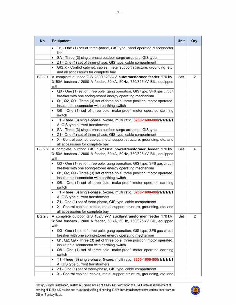
and all accessories for complete bay BG.2.1 A complete outdoor GIS 230/132/33kV autotransformer feeder 170 kV,
3150A busbars / 2000 A feeder, 50 kA, 50Hz, 750/325 kV BIL, equipped with:
Set 2
Q0 - One (1) set of three pole, gang operation, GIS type, SF6 gas circuit breaker with one spring-stored energy operating mechanism
Q1, Q2, Q9 - Three (3) set of three pole, three position, motor operated, insulated disconnector with earthing switch
Q8 - One (1) set of three pole, make-proof, motor operated earthing switch
T1 -Three (3) single-phase, 5-core, multi ratio, 3200-1600-800/1/1/1/1/1 A, GIS type current transformers
SA - Three (3) single-phase outdoor surge arresters, GIS type Z1 - One (1) set of three-phase, GIS type, cable compartment X - Control cabinet, cables, metal support structure, grounding, etc. and
all accessories for complete bay BG.2.2 A complete outdoor GIS 132/33kV powertransformer feeder 170 kV,
3150A busbars / 2000 A feeder, 50 kA, 50Hz, 750/325 kV BIL, equipped with:
Set 4
Q0 - One (1) set of three pole, gang operation, GIS type, SF6 gas circuit breaker with one spring-stored energy operating mechanism
Q1, Q2, Q9 - Three (3) set of three pole, three position, motor operated, insulated disconnector with earthing switch
Q8 - One (1) set of three pole, make-proof, motor operated earthing switch
T1 -Three (3) single-phase, 5-core, multi ratio, 3200-1600-800/1/1/1/1/1 A, GIS type current transformers
Z1 - One (1) set of three-phase, GIS type, cable compartment X - Control cabinet, cables, metal support structure, grounding, etc. and
all accessories for complete bay BG.2.3 A complete outdoor GIS 132/6.9kV auxilarytransformer feeder 170 kV,
3150A busbars / 2000 A feeder, 50 kA, 50Hz, 750/325 kV BIL, equipped with:
Set 2
Q0 - One (1) set of three pole, gang operation, GIS type, SF6 gas circuit breaker with one spring-stored energy operating mechanism
Q1, Q2, Q9 - Three (3) set of three pole, three position, motor operated, insulated disconnector with earthing switch
Q8 - One (1) set of three pole, make-proof, motor operated earthing switch
T1 -Three (3) single-phase, 5-core, multi ratio, 3200-1600-800/1/1/1/1/1 A, GIS type current transformers
Z1 - One (1) set of three-phase, GIS type, cable compartment X - Control cabinet, cables, metal support structure, grounding, etc. and

- 8 -
Design, Supply, Installation, Testing & Commissioning of 132kV GIS Substation at APSCL area as replacement of
existing of 132kV AIS station and associated shifting of existing 132kV lines/transformer/power station connections to
GIS on Turnkey Basis
No. Equipment Unit Qty.
all accessories for complete bay BG.2.4 A complete outdoor GIS power stationfeeder 170 kV, 3150A busbars /
2000 A feeder, 50 kA, 50Hz, 750/325 kV BIL, equipped with: Set 7
Q0 - One (1) set of three pole, gang operation, GIS type, SF6 gas circuit breaker with one spring-stored energy operating mechanism
Q1, Q2, Q9 - Three (3) set of three pole, three position, motor operated, insulated disconnector with earthing switch
Q8 - One (1) set of three pole, make-proof, motor operated earthing switch
T1 -Three (3) single-phase, 5-core, multi ratio, 3200-1600-800/1/1/1/1/1 A, GIS type current transformers
SA - Three (3) single-phase outdoor surge arresters, GIS type Z1 - One (1) set of three-phase, GIS type, cable compartment X - Control cabinet, cables, metal support structure, grounding, etc. and
all accessories for complete bay BG.3.1 A complete outdoor GIS bus sectionalize bay 170 kV, 3150A busbars /
3150 A feeder, 50 kA, 50Hz, 750/325 kV BIL, equipped with: Set 1
Q0 - Two (2) sets of three pole, gang operation, GIS type, SF6 gas cir-cuit breaker with one spring-stored energy operating mechanism
T1 -Three (3) single-phase, 5-core, multi ratio, 3200-1600/1/1/1/1/1 A, GIS type current transformers
T2 -Three (3) single-phase, 5-core, multi ratio, 3200-1600/1/1/1/1/1 A, GIS type current transformers
Q11, Q12, Q21, Q22 - Four (4) set of three pole, three position, motor operated, insulated disconnector with earthing switch
X - Control cabinet, cables, metal support structure, grounding, etc. and all accessories for complete bay
BG.3.2 A complete outdoor GIS bus coupler bay 170 kV, 3150A busbars / 3150 A feeder, 50 kA, 50Hz, 750/325 kV BIL, equipped with:
Set 2
Q0 - One (1) set of three pole, gang operation, GIS type, SF6 gas circuit breaker with one spring-stored energy operating mechanism
Q1, Q2 - Two (2) set of three pole, three position, motor operated, insu-lated disconnector with earthing switch
T1 -Three (3) single-phase, 5-core, multi ratio, 3200-1600/1/1/1/1/1 A, GIS type current transformers
X - Control cabinet, cables, metal support structure, grounding, etc. and all accessories for complete bay
BG.3.3 A complete outdoor GIS metering bay 145 kV, 3150A busbars, 50 kA, 50Hz, 750/325 kV BIL, equipped with:
Set 2
Q21, Q22 - Two (2) set of three pole, three position, motor operated, in-sulated disconnector
T5 - Three (3) single-phase, 2-winding, 132/V3 / 110/V3 / 110/V3kV/110/V3kV, GIS type voltage transformers
X - Control cabinet, cables, metal support structure, grounding, etc. and all accessories for complete bay
BG.4 A complete outdoor GIS busbars earthing bay 170 kV, 3150A busbars, 50 kA, 50Hz, 750/325 kV BIL, equipped with:
Set 2
Q81, Q82 - Two (2) set of three pole, make-proof, motor operated
- 9 -
Design, Supply, Installation, Testing & Commissioning of 132kV GIS Substation at APSCL area as replacement of
existing of 132kV AIS station and associated shifting of existing 132kV lines/transformer/power station connections to
GIS on Turnkey Basis
No. Equipment Unit Qty.
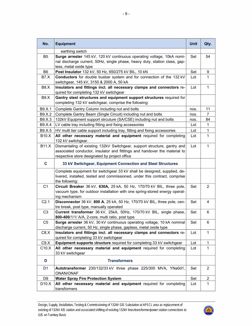
earthing switch B5 Surge arrester 145 kV, 120 kV continuous operating voltage, 10kA nomi-
nal discharge current, 50Hz, single phase, heavy duty, station class, gap-less, metal oxide type
Set 54
B6 Post Insulator 132 kV, 50 Hz, 650/275 kV BIL, 10 kN Set 9 B7.X Conductors for double busbar system and for connection of the 132 kV
switchgear, 145 kV, 3150 & 2000 A, 50 kA Lot 1
B8.X Insulators and fittings incl. all necessary clamps and connectors re-quired for completing 132 kV switchgear
Lot 1
B9.X Gantry steel structures and equipment support structures required for completing 132 kV switchgear, comprise the following:
B9.X.1 Complete Gantry Column including nut and bolts nos. 11 B9.X.2 Complete Gantry Beam (Single Circuit) including nut and bolts nos. 7 B9.X.3 132kV Equipment support strcuture (SA/CSE) including nut and bolts nos. 84 B9.X.4 LV cable tray including fitting and fixing accessories Lot 1
B9.X.5 HV multi tier cable support including tray, fitting and fixing accessories Lot 1 B10.X All other necessary material and equipment required for completing
132 kV switchgear. Lot 1
B11.X Dismantaling of existing 132kV Switchgear, support structure, gantry and associated conductor, insulator and fittitngs and handover the material to respective store designated by project office
Lot 1
C 33 kV Switchgear, Equipment Connection and Steel Structures
Complete equipment for switchgear 33 kV shall be designed, supplied, de-livered, installed, tested and commissioned, under this contract, comprise the following:
C1 Circuit Breaker 36 kV, 630A, 25 kA, 50 Hz, 170/70 kV BIL, three pole, vacuum type, for outdoor installation with one spring-stored energy operat-ing mechanism
Set 2
C2.1 Disconnector 36 kV, 800 A, 25 kA, 50 Hz, 170/70 kV BIL, three pole, cen-tre break, post type, manually operated
Set 4
C3 Current transformer 36 kV, 25kA, 50Hz, 170/70 kV BIL, single phase, 800-400/1/1/ A/A, 2-core, multi ratio, post type
Set 6
C5 Surge arrester 36 kV, 30 kV continuous operating voltage, 10 kA nominal discharge current, 50 Hz, single phase, gapless, metal oxide type
Set 6
C8.X Insulators and fittings incl. all necessary clamps and connectors re-quired for completing 33 kV switchgear
Lot 1
C9.X Equipment supports structure required for completing 33 kV switchgear Lot 1 C10.X All other necessary material and equipment required for completing
33 kV switchgear Lot 1
D Transformers
D1 Autotransformer 230/132/33 kV three phase 225/300 MVA, YNa0d1, ONAN/ONAF
Set 2
D9 Water Spray Fire Protection System Set 2 D10.X All other necessary material and equipment required for completing
transformers Lot 1
- 10 -
Design, Supply, Installation, Testing & Commissioning of 132kV GIS Substation at APSCL area as replacement of
existing of 132kV AIS station and associated shifting of existing 132kV lines/transformer/power station connections to
GIS on Turnkey Basis
No. Equipment Unit Qty.
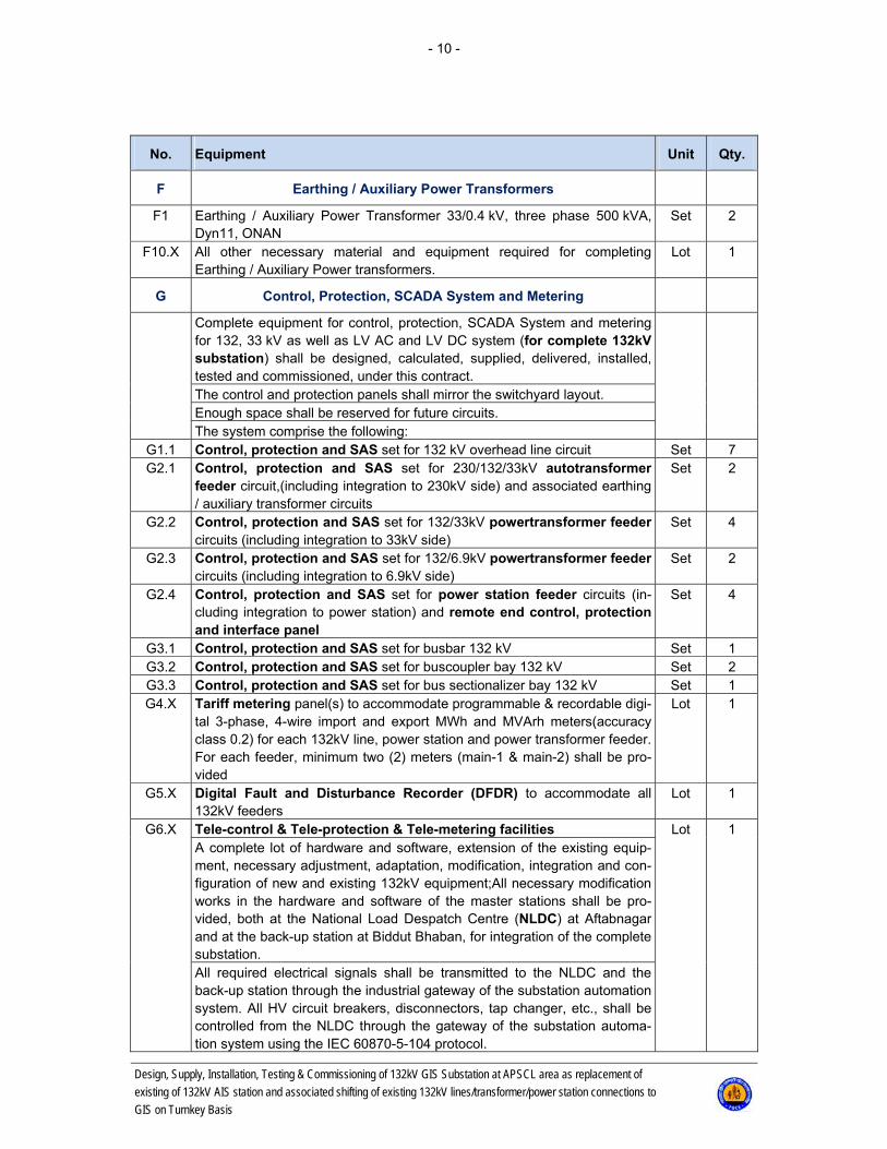
F Earthing / Auxiliary Power Transformers
F1 Earthing / Auxiliary Power Transformer 33/0.4 kV, three phase 500 kVA, Dyn11, ONAN
Set 2
F10.X All other necessary material and equipment required for completing Earthing / Auxiliary Power transformers.
Lot 1
G Control, Protection, SCADA System and Metering
Complete equipment for control, protection, SCADA System and metering for 132, 33 kV as well as LV AC and LV DC system (for complete 132kV substation) shall be designed, calculated, supplied, delivered, installed, tested and commissioned, under this contract.
The control and protection panels shall mirror the switchyard layout. Enough space shall be reserved for future circuits. The system comprise the following:
G1.1 Control, protection and SAS set for 132 kV overhead line circuit Set 7 G2.1 Control, protection and SAS set for 230/132/33kV autotransformer
feeder circuit,(including integration to 230kV side) and associated earthing / auxiliary transformer circuits
Set 2
G2.2 Control, protection and SAS set for 132/33kV powertransformer feeder circuits (including integration to 33kV side)
Set 4
G2.3 Control, protection and SAS set for 132/6.9kV powertransformer feeder circuits (including integration to 6.9kV side)
Set 2
G2.4 Control, protection and SAS set for power station feeder circuits (in-cluding integration to power station) and remote end control, protection and interface panel
Set 4
G3.1 Control, protection and SAS set for busbar 132 kV Set 1 G3.2 Control, protection and SAS set for buscoupler bay 132 kV Set 2 G3.3 Control, protection and SAS set for bus sectionalizer bay 132 kV Set 1 G4.X Tariff metering panel(s) to accommodate programmable & recordable digi-
tal 3-phase, 4-wire import and export MWh and MVArh meters(accuracy class 0.2) for each 132kV line, power station and power transformer feeder. For each feeder, minimum two (2) meters (main-1 & main-2) shall be pro-vided
Lot 1
G5.X Digital Fault and Disturbance Recorder (DFDR) to accommodate all 132kV feeders
Lot 1
G6.X Tele-control & Tele-protection & Tele-metering facilities Lot 1 A complete lot of hardware and software, extension of the existing equip-ment, necessary adjustment, adaptation, modification, integration and con-figuration of new and existing 132kV equipment;All necessary modification works in the hardware and software of the master stations shall be pro-vided, both at the National Load Despatch Centre (NLDC) at Aftabnagar and at the back-up station at Biddut Bhaban, for integration of the complete substation. All required electrical signals shall be transmitted to the NLDC and the back-up station through the industrial gateway of the substation automation system. All HV circuit breakers, disconnectors, tap changer, etc., shall be controlled from the NLDC through the gateway of the substation automa-tion system using the IEC 60870-5-104 protocol.
- 11 -
Design, Supply, Installation, Testing & Commissioning of 132kV GIS Substation at APSCL area as replacement of
existing of 132kV AIS station and associated shifting of existing 132kV lines/transformer/power station connections to
GIS on Turnkey Basis
No. Equipment Unit Qty.
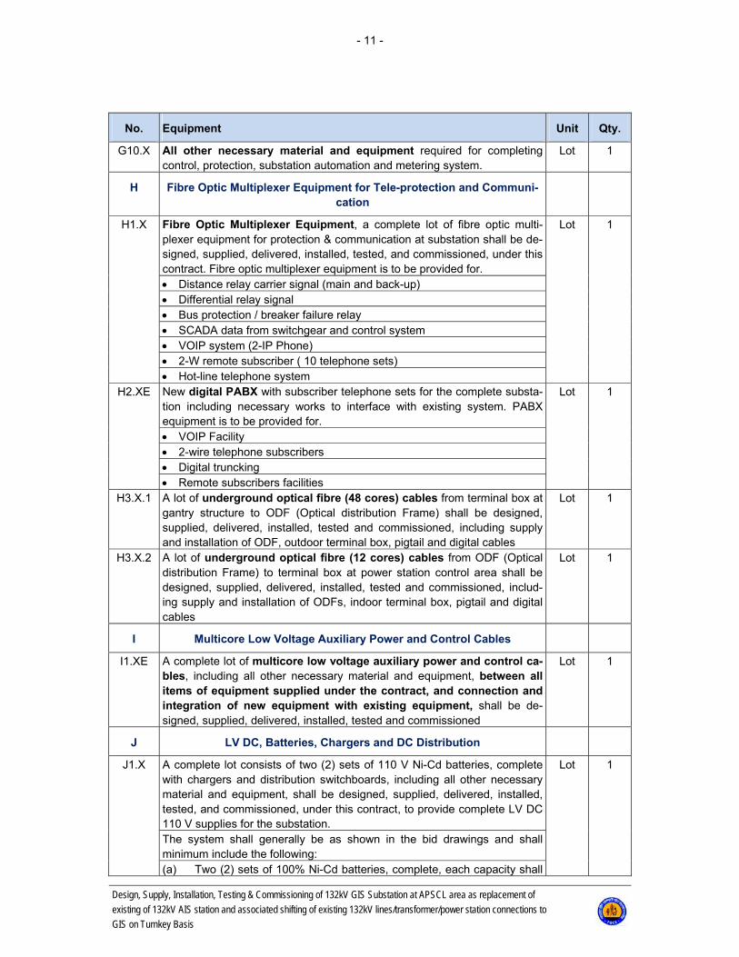
G10.X All other necessary material and equipment required for completing control, protection, substation automation and metering system.
Lot 1
H Fibre Optic Multiplexer Equipment for Tele-protection and Communi-cation
H1.X Fibre Optic Multiplexer Equipment, a complete lot of fibre optic multi-plexer equipment for protection & communication at substation shall be de-signed, supplied, delivered, installed, tested, and commissioned, under this contract. Fibre optic multiplexer equipment is to be provided for.
Lot 1
Distance relay carrier signal (main and back-up) Differential relay signal Bus protection / breaker failure relay SCADA data from switchgear and control system VOIP system (2-IP Phone) 2-W remote subscriber ( 10 telephone sets) Hot-line telephone system
H2.XE New digital PABX with subscriber telephone sets for the complete substa-tion including necessary works to interface with existing system. PABX equipment is to be provided for.
Lot 1
VOIP Facility 2-wire telephone subscribers Digital truncking Remote subscribers facilities
H3.X.1 A lot of underground optical fibre (48 cores) cables from terminal box at gantry structure to ODF (Optical distribution Frame) shall be designed, supplied, delivered, installed, tested and commissioned, including supply and installation of ODF, outdoor terminal box, pigtail and digital cables
Lot 1
H3.X.2 A lot of underground optical fibre (12 cores) cables from ODF (Optical distribution Frame) to terminal box at power station control area shall be designed, supplied, delivered, installed, tested and commissioned, includ-ing supply and installation of ODFs, indoor terminal box, pigtail and digital cables
Lot 1
I Multicore Low Voltage Auxiliary Power and Control Cables
I1.XE A complete lot of multicore low voltage auxiliary power and control ca-bles, including all other necessary material and equipment, between all items of equipment supplied under the contract, and connection and integration of new equipment with existing equipment, shall be de-signed, supplied, delivered, installed, tested and commissioned
Lot 1
J LV DC, Batteries, Chargers and DC Distribution
J1.X A complete lot consists of two (2) sets of 110 V Ni-Cd batteries, complete with chargers and distribution switchboards, including all other necessary material and equipment, shall be designed, supplied, delivered, installed, tested, and commissioned, under this contract, to provide complete LV DC 110 V supplies for the substation.
Lot 1
The system shall generally be as shown in the bid drawings and shall minimum include the following: (a) Two (2) sets of 100% Ni-Cd batteries, complete, each capacity shall
- 12 -
Design, Supply, Installation, Testing & Commissioning of 132kV GIS Substation at APSCL area as replacement of
existing of 132kV AIS station and associated shifting of existing 132kV lines/transformer/power station connections to
GIS on Turnkey Basis
No. Equipment Unit Qty.
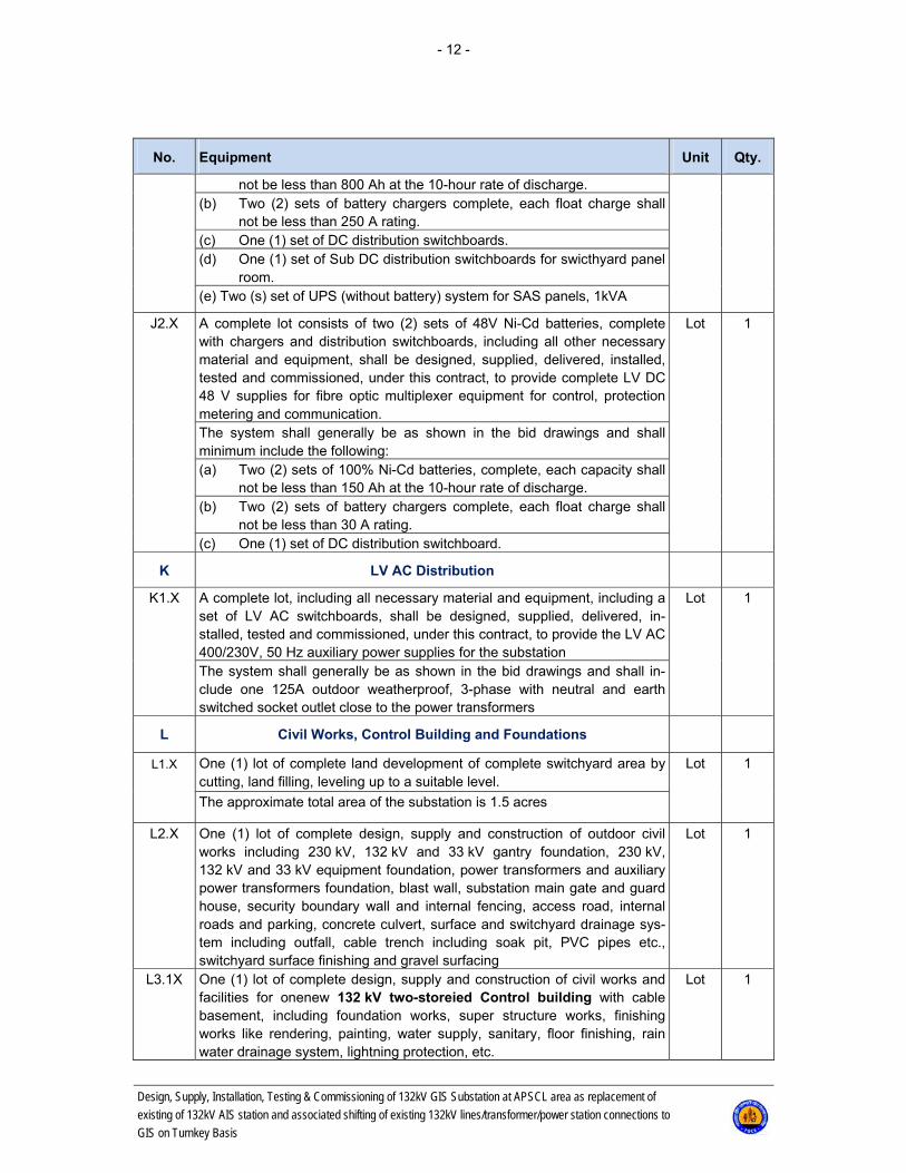
not be less than 800 Ah at the 10-hour rate of discharge. (b) Two (2) sets of battery chargers complete, each float charge shall
not be less than 250 A rating. (c) One (1) set of DC distribution switchboards. (d) One (1) set of Sub DC distribution switchboards for swicthyard panel
room. (e) Two (s) set of UPS (without battery) system for SAS panels, 1kVA
J2.X A complete lot consists of two (2) sets of 48V Ni-Cd batteries, complete with chargers and distribution switchboards, including all other necessary material and equipment, shall be designed, supplied, delivered, installed, tested and commissioned, under this contract, to provide complete LV DC 48 V supplies for fibre optic multiplexer equipment for control, protection metering and communication.
Lot 1
The system shall generally be as shown in the bid drawings and shall minimum include the following: (a) Two (2) sets of 100% Ni-Cd batteries, complete, each capacity shall
not be less than 150 Ah at the 10-hour rate of discharge. (b) Two (2) sets of battery chargers complete, each float charge shall
not be less than 30 A rating. (c) One (1) set of DC distribution switchboard.
K LV AC Distribution
K1.X A complete lot, including all necessary material and equipment, including a set of LV AC switchboards, shall be designed, supplied, delivered, in-stalled, tested and commissioned, under this contract, to provide the LV AC 400/230V, 50 Hz auxiliary power supplies for the substation
Lot 1
The system shall generally be as shown in the bid drawings and shall in-clude one 125A outdoor weatherproof, 3-phase with neutral and earth switched socket outlet close to the power transformers
L Civil Works, Control Building and Foundations
L1.X One (1) lot of complete land development of complete switchyard area by cutting, land filling, leveling up to a suitable level.
Lot 1
The approximate total area of the substation is 1.5 acres
L2.X One (1) lot of complete design, supply and construction of outdoor civil works including 230 kV, 132 kV and 33 kV gantry foundation, 230 kV, 132 kV and 33 kV equipment foundation, power transformers and auxiliary power transformers foundation, blast wall, substation main gate and guard house, security boundary wall and internal fencing, access road, internal roads and parking, concrete culvert, surface and switchyard drainage sys-tem including outfall, cable trench including soak pit, PVC pipes etc., switchyard surface finishing and gravel surfacing
Lot 1
L3.1X One (1) lot of complete design, supply and construction of civil works and facilities for onenew 132 kV two-storeied Control building with cable basement, including foundation works, super structure works, finishing works like rendering, painting, water supply, sanitary, floor finishing, rain water drainage system, lightning protection, etc.
Lot 1
- 13 -
Design, Supply, Installation, Testing & Commissioning of 132kV GIS Substation at APSCL area as replacement of
existing of 132kV AIS station and associated shifting of existing 132kV lines/transformer/power station connections to
GIS on Turnkey Basis
No. Equipment Unit Qty.
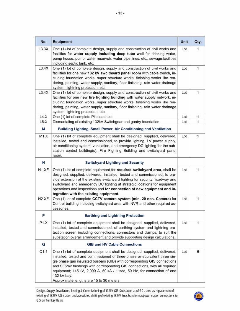
L3.3X One (1) lot of complete design, supply and construction of civil works and facilities for water supply including deep tube well for drinking water, pump house, pump, water reservoir, water pipe lines, etc., sewage facilities including septic tank, etc.
Lot 1
L3.4X One (1) lot of complete design, supply and construction of civil works and facilities for one new 132 kV swcithyard panel room with cable trench, in-cluding foundation works, super structure works, finishing works like ren-dering, painting, water supply, sanitary, floor finishing, rain water drainage system, lightning protection, etc.
Lot 1
L3.4X One (1) lot of complete design, supply and construction of civil works and facilities for one new fire fignting building with water supply network, in-cluding foundation works, super structure works, finishing works like ren-dering, painting, water supply, sanitary, floor finishing, rain water drainage system, lightning protection, etc.
Lot 1
L4.X One (1) lot of complete Pile load test Lot 1 L5.X Dismantaling of existing 132kV Switchgear and gantry foundation Lot 1
M Building Lighting, Small Power, Air Conditioning and Ventilation
M1.X One (1) lot of complete equipment shall be designed, supplied, delivered, installed, tested and commissioned, to provide lighting, LV power supply, air conditioning system, ventilation, and emergency DC lighting for the sub-station control building(s), Fire Fighting Building and switchyard panel room.
Lot 1
N Switchyard Lighting and Security
N1.XE One (1) lot of complete equipment for required switchyard area, shall be designed, supplied, delivered, installed, tested and commissioned, to pro-vide extension of the existing switchyard lighting for security, roadway and switchyard and emergency DC lighting at strategic locations for equipment operations and inspections and for connection of new equipment and in-tegration with the existing equipment.
Lot 1
N2.XE One (1) lot of complete CCTV camera system (min. 20 nos. Camera) for Control building including switchyard area with NVR and other required ac-cessories.
Lot 1
P Earthing and Lightning Protection
P1.X One (1) lot of complete equipment shall be designed, supplied, delivered, installed, tested and commissioned, of earthing system and lightning pro-tection screen including connections, connectors and clamps, to suit the substation overall arrangement and provide supporting design calculations.
Lot 1
Q GIB and HV Cable Connections
Q1.1 One (1) lot of complete equipment shall be designed, supplied, delivered, installed, tested and commissioned of three-phase or equivalent three sin-gle phase gas insulated busbars (GIB) with corresponding GIS connections and SF6/air bushings with corresponding GIS connections, with all required equipment; 145 kV, 2,000 A, 50 kA / 1 sec, 50 Hz, for connection of one 132 kV bay. Approximate lengths are 15 to 30 meters
Lot 6

- 14 -
Design, Supply, Installation, Testing & Commissioning of 132kV GIS Substation at APSCL area as replacement of
existing of 132kV AIS station and associated shifting of existing 132kV lines/transformer/power station connections to
GIS on Turnkey Basis
No. Equipment Unit Qty.
Q.2.1 complete equipment shall be designed, supplied, delivered, installed, tested and commissioned of three single phase XLPE cables with corre-sponding Cable End Terminals; equipped with:
Q.2.1.1 132kV single core 2000sqmm copper conductor, XLPE insulated, corrugated Al sheathed & MDPE outer sheathed cable
meter 2300
Q.2.1.2 132kV single core 800sqmm copper conductor, XLPE insulated, corrugated Al sheathed & MDPE outer sheathed cable
meter 6200
Q.2.1.3 132kV single core 630sqmm copper conductor, XLPE insulated, corrugated Al sheathed & MDPE outer sheathed cable
meter 10700
Q.2.1.4 Complete GIS Cable Sealing End for above cable mentioned in item Q.2.1.1 for each phase including all related accessories
Set 9
Q.2.1.5 Complete GIS Cable Sealing End for above cable mentioned in item Q.2.1.2 for each phase including all related accessories
Set 15
Q.2.1.6 Complete GIS Cable Sealing End for above cable mentioned in item Q.2.1.3 for each phase including all related accessories
Set 24
Q.2.1.7 Outdoor Cable Sealing End for above cable mentioned in item Q.2.1.1 for each phase including all related accessories
Set 9
Q.2.1.8 Outdoor Cable Sealing End for above cable mentioned in item Q.2.1.2 for each phase including all related accessories
Set 12
Q.2.1.9 Outdoor Cable Sealing End for above cable mentioned in item Q.2.1.3 for each phase including all related accessories
Set 12
Q.2.1.10 Straight Through/Insulated Joint suitable for above cable mentioned in item Q.2.1.2 for rach phase including all related accessories
Set 3
Q.2.1.11 Straight Through/Insulated Joint suitable for above cable mentioned in item Q.2.1.3 for each phase including all related accessories
Set 12
Q.2.1.12 Link Box for earthing at straight through/insulated joint for each phase in-cluding all related accessories
Set 3
Q.2.1.13 Link Box for earthing at GIS/outdoor cable sealing end for each phase in-cluding all related accessories
Set 12
Q3.1 One (1) lot of complete equipment shall be designed, supplied, delivered, installed, tested and commissioned of three-phase or three single phase cables and cable end terminal and correspondent equipment 36 kV, 185mm2, 25 kA / 1 sec, 50 Hz. for one autotransformer tertiary circuit
Lot 2
R Mandatory Spares
R1 Supply of complete spares and spare parts of transformer, switchgear, con-trol equipment, protection relays, meters, as per quantity mentioned in Schedule B. Test equipment are to be supplied from Europe, USA or Japan origin. Printed catalogue, operation and service manual are to be provided. The materials shall have to be handed over to the designated store as per instruction of the Engineer
as per sch. B
S Maintenance Equipment
S1 Supply of maintenance equipment as per quantity mentioned in Schedule B. Equioment are to be supplied from EU, UK USA or Japan origin. Printed
as per sch. B
- 15 -
Design, Supply, Installation, Testing & Commissioning of 132kV GIS Substation at APSCL area as replacement of
existing of 132kV AIS station and associated shifting of existing 132kV lines/transformer/power station connections to
GIS on Turnkey Basis
No. Equipment Unit Qty.
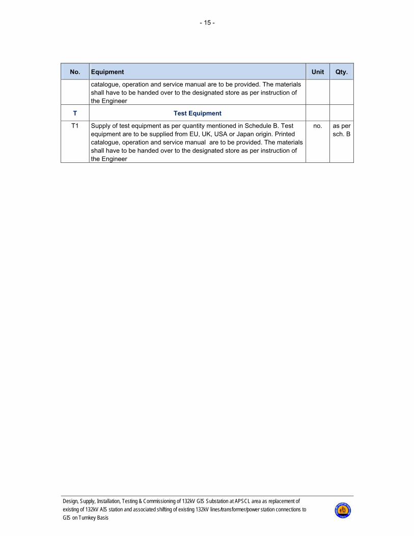
catalogue, operation and service manual are to be provided. The materials shall have to be handed over to the designated store as per instruction of the Engineer
T Test Equipment
T1 Supply of test equipment as per quantity mentioned in Schedule B. Test equipment are to be supplied from EU, UK, USA or Japan origin. Printed catalogue, operation and service manual are to be provided. The materials shall have to be handed over to the designated store as per instruction of the Engineer
no. as per sch. B

- 16 -
Design, Supply, Installation, Testing & Commissioning of 132kV GIS Substation at APSCL area as replacement of
existing of 132kV AIS station and associated shifting of existing 132kV lines/transformer/power station connections to
GIS on Turnkey Basis
1.3 Detailed Description of the Scope of Supply for SCADA, Con-trol & Monitoring System
1.3.1 Overall Scope of Work and Supply
The SCADA system will be based on: The communication with the NLDC shall be via the supplied gateway for Control and Monitoring
System of the substation. Industrial gateway shall be implemented at each involved substation for remote monitoring & con-
trol from the National Despatch Centre. It shall provide all the necessary control and monitoring fa-cilities for 132 kV level and auxiliaries.
Contractor shall supply, install 2 (two) numbers of Industrial gateway and will be configured as master - hot standby mode or one gateway will report to main station & another will report to backup station. Gateway shall be capable report to both Main master station at Rampura (through VLAN network) & Standby Master Station at Biddyut Bhaban (through routed network) simultane-ously. It will be configured according to the signal list, communication parameter, IP address, sta-tion address, etc. provided by PGCB. The Gateway shall have adequate capacity (minimum 25% additional spare point with license) to meet to the future extensions of substation.
In case of windows operating system based gateway there should be USB port, VGA port, HDD/flash memory with one spare parts, TFT monitor with mouse and key board, etc. Hard disk should be 50% free and CPU loading maximum of 30% at normal condition. If gateway is firmware based then 02(two) nos. of control card is required. Gateways also have minimum 06 nos LAN port & redundant power supply. There should be GPS facilities for time synchronization. In addition, cy-ber security has to be ensured at field level with firewall.Supported Protocol shall be IEC 60870-5-104, 61850 & MOD Bus, etc.
One laptop for each vendor & same software version is required with Acronis True image or Ghost or similar software for system back up & restoration.
All necessary adaptation work and configuration of the existing SCADA platform of the NLDC to in-tegrate the Substations and the new bays shall be provided.
- 17 -
Design, Supply, Installation, Testing & Commissioning of 132kV GIS Substation at APSCL area as replacement of
existing of 132kV AIS station and associated shifting of existing 132kV lines/transformer/power station connections to
GIS on Turnkey Basis
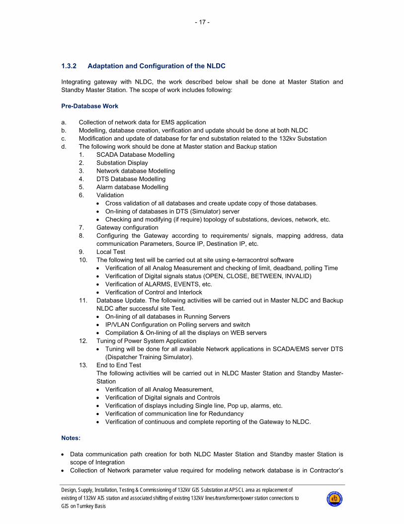
1.3.2 Adaptation and Configuration of the NLDC
Integrating gateway with NLDC, the work described below shall be done at Master Station and Standby Master Station. The scope of work includes following: Pre-Database Work a. Collection of network data for EMS application b. Modelling, database creation, verification and update should be done at both NLDC c. Modification and update of database for far end substation related to the 132kv Substation d. The following work should be done at Master station and Backup station
1. SCADA Database Modelling 2. Substation Display 3. Network database Modelling 4. DTS Database Modelling 5. Alarm database Modelling 6. Validation
Cross validation of all databases and create update copy of those databases. On-lining of databases in DTS (Simulator) server Checking and modifying (if require) topology of substations, devices, network, etc.
7. Gateway configuration 8. Configuring the Gateway according to requirements/ signals, mapping address, data
communication Parameters, Source IP, Destination IP, etc. 9. Local Test 10. The following test will be carried out at site using e-terracontrol software
Verification of all Analog Measurement and checking of limit, deadband, polling Time Verification of Digital signals status (OPEN, CLOSE, BETWEEN, INVALID) Verification of ALARMS, EVENTS, etc. Verification of Control and Interlock
11. Database Update. The following activities will be carried out in Master NLDC and Backup NLDC after successful site Test. On-lining of all databases in Running Servers IP/VLAN Configuration on Polling servers and switch Compilation & On-lining of all the displays on WEB servers
12. Tuning of Power System Application Tuning will be done for all available Network applications in SCADA/EMS server DTS
(Dispatcher Training Simulator). 13. End to End Test
The following activities will be carried out in NLDC Master Station and Standby Master-Station Verification of all Analog Measurement, Verification of Digital signals and Controls Verification of displays including Single line, Pop up, alarms, etc. Verification of communication line for Redundancy Verification of continuous and complete reporting of the Gateway to NLDC.
Notes: Data communication path creation for both NLDC Master Station and Standby master Station is
scope of Integration Collection of Network parameter value required for modeling network database is in Contractor’s

- 18 -
Design, Supply, Installation, Testing & Commissioning of 132kV GIS Substation at APSCL area as replacement of
existing of 132kV AIS station and associated shifting of existing 132kV lines/transformer/power station connections to
GIS on Turnkey Basis
scope of work Contractor will conduct necessary work for both at NLDC & Substation (if required) Requirements / Signals Indications: Digital Input (Double Point)
The following indications shall be provided – Circuit Breaker, Isolator & Earth Switch Open/ Close for line, transformer, bus coupler – Circuit Breaker for Reactor/Capacitor bank & 33kv Loadshed feeder Load Flows, System Voltage and frequency
Electrical quantities shall be provided to enable the following measurements – Voltage (kV), Frequency (Hz) for Busbar – Megawatt (MW), MegaVar (MVAR), Amperes (AMP), Voltage (kV) for Line – MW, MVAR, Amperes, kV at both sides, Tap Position Indication (TPI) for Transformer – Megavar for Reactor/Capacitor bank Alarms: Digital Input (Single Point): – Remote/ Local Switch for all Circuit Breakers. – Bay Fault (DC Fail for Transformer Panel). – Breaker Fault (OR gate Spring Charge, SF6 Low). – Protection Class-1 (Distance, Differential). – Protection Class-2 (Over current, Earth fault). – Protection Class-3 (bus bar). – Transformer Alarm (Buchholz Alarm, Oil Level Low). – Transformer Trip (Buchholz Trip, PRD Trip) – Transformer Temperature Alarm (Oil Temp Alarm, Winding Temperature). – Transformer Temperature Trip (Oil Temp trip, Winding Temperature trip). – Tap Changer Alarm. – Tap changer trip. – Tap changer high limit. – Tap changer low limit. – Auto recloses operated – DC fail – AC fail Controls-Digital Output (Double point)
The following facilities shall be controlled from the NLDC – Circuit Breaker and Motorized Isolator Open/ Close for Line, Transformer bay & bus coupler, – Circuit Breaker Open/ Close for 33kV load shed feeder – Tap Changer Raise/ Lower for Transformer Network modelling parameters
Line length, line conductor type, short circuit data for zero sequence (%R, %X, % of full charging susceptance), etc.
The SCADA system of the National Load Despatch Centre is based on ALSTOM platform. The com-munication protocol to be used for data exchange between the NLDC and the substations shall be IEC 60870-5-104 for the data transmission from Aminbazar substation.
- 19 -
Design, Supply, Installation, Testing & Commissioning of 132kV GIS Substation at APSCL area as replacement of
existing of 132kV AIS station and associated shifting of existing 132kV lines/transformer/power station connections to
GIS on Turnkey Basis
Adaptation work and configuration of the NLDC will mainly consist of: Modelling the new substations and new bays. Database update of NLDC. Configuration of Existing NLDC SCADA EMS Systemto display the single line diagrams, statuses,
alarms, measurements of the new substations and new bays. Database creation / modification & update at respective SCADA/EMS servers at all master station. Creation of associate display and modification of existing displays wherever required. Point to point test. 1.3.3 General Principle and Description of SCMS/SAS
The substation control and monitoring system shall have distributed client/server architecture. It shall consist of: The BCU equipment, which will be installed at the bay level, The substation level equipment, to be installed in the control room, A redundant communication network between station level and bay level for data exchange to limit
the number of cables and ensure extension of the system. The exchange of information between distributed single bay unit and central substation control level shall be performed through redun-dant fibre optic wires. The communication network shall be based on the following architecture:
– One optical double-ring LAN with protection and BCU, – One UPT CAT 5 redundant LAN at substation level. The station level equipment will be power supplied from the two independent AC sources: One from the AC station auxiliaries 230 V AC 50 Hz, The second one from a UPS, An automatic change over shall prevent supply interruption. In the event of loss of supply or disconnection for any reason, the system shall reboot automatically (without loss of stored information) and will update statuses of all devices when the power supply re-covers. The updating process shall not inhibit control functions. The substation control level must support future expansion of substation control system, having a 25% of resources as minimum. At bay level, all control functions, data acquisition interlocking functions shall be done in the bay con-trol devices within the bay level equipment. Each feeder shall be equipped with an individual bay con-trol device. For the data acquisition of substation auxiliaries, information (LV/MV switchgear, station battery, charger, UPS, etc.,) a local RTU (or BCPU) shall be provided and installed in the control building. The bay control devices shall be connected to the station level via a redundant optical fibre communication link. The bay level equipment shall comprise at least the following elements: Bay control unit (BCU). Bay computer shall be separate unit (not incorporated in the protection
unit). Input / output modules for digital and analogue signals,

- 20 -
Design, Supply, Installation, Testing & Commissioning of 132kV GIS Substation at APSCL area as replacement of
existing of 132kV AIS station and associated shifting of existing 132kV lines/transformer/power station connections to
GIS on Turnkey Basis
Communication with protection equipment and analogue signals, Redundant optical fibre communication with substation level or ring bus communication, Backup mimic panel (for AIS and Indoor GIS) for maintenance control and measurements. One two
position switch shall be provided on control panel: – Local: Only local control is enabled, the interlocking function is on bay level only, no synchroniza-
tion, – Remote: Only remote control is enabled.
In both cases, all the data must be transmitted to the higher level (NLDC), Communication port for operation / maintenance from a laptop computer. Bay control units shall be supplied from 110 V DC. In the event of loss of supply or disconnection for any reason, the system shall reboot automatically (without loss of stored information) and will update statuses of all devices when the power supply re-covers. The updating process shall not inhibit control functions. There should not be any loss of data due to the loss of auxiliary supply. It shall be taken into consideration that additional bay control units can be added to the system, with-out disturbance of the system, for future expansion. A provision of 20% in bay units' expansion is re-quired, as well as a provision of 10% in I/O signals, within each bay. Control and supervision of the system will be possible from different levels: NLDC, Substation control level from the operator workstation, Bay control level. On all levels, a correct interlocking will be ensured which provides the highest safety for staff and equipment. On the substation control level, the interlocking is managed by the microprocessor-based system, on the bay level it is performed by hard wiring. The substation control system shall follow the specifications of IEC family 61850, 60870-5-101/104, 60870-5-102 and 60870-5-103. It is an obligatory requirement that the same Manufacturer supplies equipment and software for both the substation control and supervision system and the protection sys-tem. List of Signals The list below states the types of signals for the different configurations of bay types to assist in the determination of needs and possibilities for each of analysed systems of the future substation. The es-timated signals are shown in the tables and include but not limited to: Signalling: Protection (start, tripping, zones/phases, AR, communication send/receive), Automatic systems (start, tripping, operation, working mode) Central systems (backup trips, trip during long power swing, busbar protection and breaker failure,
protection off, remote control off, feeder maintenance off), Switching equipment (manual control, emergency trip), Mode of operation: Local / Remote.
- 21 -
Design, Supply, Installation, Testing & Commissioning of 132kV GIS Substation at APSCL area as replacement of
existing of 132kV AIS station and associated shifting of existing 132kV lines/transformer/power station connections to
GIS on Turnkey Basis
Warning: Protection (faults), Automatic systems (faults), Fault locator (faults), Event recorder (faults), Control systems (voltage control), Breaker (control blocking from a gas pressure low, a gas pressure low, AR inhibit from driver fault,
driver supply voltage loss, driver fault, pole discordance). High voltage switch position: Breaker (separate pole - each 2 bits), Disconnectors (separate pole - each 2 bits), Earth switches (separate pole - each 2 bits). Control: Breaker (close, open), Disconnectors (close, open), Line earth switch (close, open), Automatic systems (off, on,) Voltage regulation systems (choice of voltage level, regulation mode, tap changer control). Series interfaces: From digital protections and disturbance recorder, From diagnostic system of primary equipment, From monitoring system (transformer, etc.). Measurements: Phase currents, Phase voltages Real power and energy for both directions, Reactive power and energy for both directions, Frequency, power factor, Device switching statistics. Metering (for planning / operation not for commercial purpose): Real energy for both directions, Reactive energy for both directions. Auxiliary systems: Aux 33 kV AC, Aux.400/230 V AC, Aux.110V DC, Aux.220V AC UPS, Aux.48 V DC, Fire protection, Security light, Alarm system, HVAC, Telecommunication alarms, GPS time synchronizing input (NTP Protocol).

- 22 -
Design, Supply, Installation, Testing & Commissioning of 132kV GIS Substation at APSCL area as replacement of
existing of 132kV AIS station and associated shifting of existing 132kV lines/transformer/power station connections to
GIS on Turnkey Basis
1.3.4 Scope of Work and Supply at New Substations
The substation control system refers to the station level and bay level controls. The station level con-trol equipment shall include the following: Station Level Arrangement of the all bays 2 (two) independent station computers operating on a main and hot standby basis, 2 (two) operator workstations including 2 x 21" colour monitors (complete with appropriate desk
and chair). The second operator workstation shall have the capability to be used as Employer's Representa-
tive workstation, Additional operator workstation (HMI) and interface panels in Unit-3, Unit-4, 225MW CCP, 55MW
Precision, 50MW Gas Engine, Unit-1, Unit-2 and APSCL Control room. Any existing interfaceof DCS/Other system of existing power station with 132kV existing control
and protection system shall be restored back for new control and protection system of 132kV GIS. Two (2) numbers of independent SCADA Gateways Black & white A 4 laser printer, Colour A 3 laser printer, Common bay control unit for monitoring auxiliary power supply and all other equipment on a sub-
station level (telemetry, telecommunication, HVAC, fire protection, etc.), Satellite clock, which should run on SNTP protocols. The satellite clock will provide the reference
time to the comprehensive Substation Control and Monitoring System and protection relays through IEC61850 substation LAN., The satellite clock system will be complete with GPS receiver, antenna and time synchronisation ports.
Interface for laptop computer for maintenance, information transfer and emergency HMI, Non-fail power supply system, Communication network equipment (substation local area network, field communication network,
optical couplers, etc.), Optical connection for data exchange with the NLDC. Configuration of the new/existing gateway. The station computers in the substation must be separate machines from the station HMI (operator workstation) and should be located in the control panels, and not on the control desk with the HMI. Bay Level The control system of the bay level at substation shall be carried out with microprocessor based Bay Control Unit (BCU) control system. All BCUs shall be provided with IEC 61850 Edition 2 communica-tion ports. The connections between BCUs and the station level shall be based on redundant fibre optic links. These communication ports will be used for control, indication and alarm systems to the substation automation system and SCADA. The BCU shall be provided for all: 132 kV transmission line bays, 132kV power station bays 230/132 kV and 132/33 kV power and auxiliary transformers, 132 kV busbars Auxiliaries.

- 23 -
Design, Supply, Installation, Testing & Commissioning of 132kV GIS Substation at APSCL area as replacement of
existing of 132kV AIS station and associated shifting of existing 132kV lines/transformer/power station connections to
GIS on Turnkey Basis
A bay control unit (BCU) shall provide the following: Control for each individual circuit / bay with a LCD mimic and user interface for control and monitor-
ing of the circuit / bay, Interface for protection devices that cannot directly interface with the substation control system lo-
cal area network, Interface for laptop computer for maintenance, information transfer and emergency HMI, Interlocking functions (soft and hard wired). Station level control functions shall include the following: Control of all switching devices, Real-time indication of events and alarms, Display of analogue values and high / low limit checking, Display of historical values, Data archiving, Disturbance monitoring and analysis, Trend display, Protection and control relay setting information, Protection relay fault and disturbance records, Time synchronization, Interlocking function to prevent unsafe operator action (display message if operator attempts an in-
appropriate action), Self-check and diagnostic, Manual data setting by the operator, including: Hand dressed data entry, Control inhibit setting, Alarm inhibit setting, Maintenance tag setting, High / low limit setting. Remote access to substation control system from SCADA system using a TCP / IP link. All peripheral devices that constitute the substation automation system should be supervised and monitored by Control through IEC 61850 or any other compatible protocol. 1.3.5 Engineering Services
General The engineering services shall be provided by the Contractor to the extent and detail necessary for a turnkey project. They shall include drawings, instructions and all other technical documents required allow the Contractor to build, erect, commission, operate and maintain the substation systems, even if these are not specifically mentioned in these Technical Requirements. Design Services The Contractor shall design in detail the general layout of the SCADA and substation control system, based on the preliminary design and modifications agreed. This general layout shall be submitted to the Employer / Employer's Representative for approval and comments. It shall also include all detailed
- 24 -
Design, Supply, Installation, Testing & Commissioning of 132kV GIS Substation at APSCL area as replacement of
existing of 132kV AIS station and associated shifting of existing 132kV lines/transformer/power station connections to
GIS on Turnkey Basis
structural drawings, detailed descriptions and reports required to permit an exact understanding of the solution adopted. Once the general layout is approved, the Contractor shall include the following as a minimum require-ment: Design of all works required for the implementation and extension of the SCADA and substation
control system, General layouts for the SCADA and substation control system, Engineering of SCADA and substation control system, All necessary calculations. These engineering services shall also include: Design reports, Complete drawings of all systems, Integration in existing SCADA system.

- 25 -
Design, Supply, Installation, Testing & Commissioning of 132kV GIS Substation at APSCL area as replacement of
existing of 132kV AIS station and associated shifting of existing 132kV lines/transformer/power station connections to
GIS on Turnkey Basis
1.4 Detailed Description of the Scope of Supply for the Telecom-munication System
The communication part of the project shall provide the interconnection between all substations in-volved in the Project: Renovation of existing 132 kVAIS Substation Ashuganj to 132kV GIS The purpose of the telecommunication system is to provide all the necessary telecommunication channels for the following sub-systems: SCADA for data exchange between the substations and the National Load Despatch Centre
(NLDC) by two communication technologies i.e. LAN & WAN Tele-protection to enable the communication between line differential protection relays and be-
tween distance protection relays, Telephone to enable telephone communication between the substations and NLDC, Metering: Data transfer between meters and the entity in charge of collecting and processing me-
tering data, Any other telecommunication channels. 1.4.1 Recommendation of Communication System
Telecom Equipment(Optical Transmission and ADD/DROP MUX) STM-16/64 / 10G or 100G / DWDM – MPLS (Layer-3) ADD/DROP Multiplexer (PDH) Services: LAN Service (IP Phone, RTU/SAS, Office LAN etc) WAN Services (RTU, CC camera, DFDR, etc) E1/TDM/Tributary Services (PABX, etc) NMS: End-to-End Trail management Protection management (I+I MPS, MSSP RING, SNCP, SNCPM) Clock management DCN Channel management Existing equipment and facilities in PGCB Telecommunication Network STM-1/4/8 – FOX-515/615 – MSE-5010 (OSN-1500B) – MSE-5001 (Metro) ADD/DROP Multiplexer (PDH) – DXC-5000 – FOX-515/615 – SOPHO PABX – Cisco Call Manager
- 26 -
Design, Supply, Installation, Testing & Commissioning of 132kV GIS Substation at APSCL area as replacement of
existing of 132kV AIS station and associated shifting of existing 132kV lines/transformer/power station connections to
GIS on Turnkey Basis
Services: LAN Service (IP Phone, RTU/SAS etc) WAN Services (RTU, CC camera, DFDR, etc) TDM/Tributary Services (PABX, etc) NMS : FOXMAN-UN/U-2000 – End-to-End Trail management – Protection management (I+I MPS, MSSP RING, SNCP, SNCPM) – Clock management – DCN Channel management 1.4.2 Architecture of the Overall Telecommunication System
Two (2) new SDH & PDH multiplexers (and with two (2) optical boosters only if it is required),PABX and one (1) 48 cores Optical Distribution Frames (ODF).
A scheme of the overall telecommunication system is attached at the following drawings:
Telecommunication Schematic Block Diagram 1.4.3 Scope of Work and Supply
The scope of work and supply of the telecommunication system: One (1) optical fibre cable from the gantry/power station control room of each of 132 kV
OHL/Power station feeders to the substation communication room, including 48 cores and non-metallic (underground/armoured) but with the same optical characteristics with the OPGW (compli-ant to ITU-T-G 655 recommendation), shall be provided, for each of 132 kV OHL/Power station feeders.
One (1) Optical Distribution Frames (ODF), of 48 cores capacity each, shall be provided, for each of 132 kV OHL/Power station feeders. ODF shall be installed in the telecommunication / control room to facilitate the termination of fibres, testing and isolating of both the optical fibre cable and fi-bre optic terminal equipment.
Two (2) Optical SDH / PDH multiplexers, shall be provided, , including: – Duplicate CPU – Duplicate power supply – One optical STM-16 ports – One optical STM-4 ports for each 132 kV transmission line – Four16x2 Mbps (E1) drop card – Four 8x2 Mbps (E1) elect. Card – One card with four ports 10/100 Base T LAN – One card with four ports 10/100 Base T Router – One card with 10x2-w voice for FXS – Required no. of cards with 4x4 commands for distance protection after detail design – The optical SDH / PDH multiplexer shall be preferably of ABB FOX 515/FOX 615 type or AREVA
MSE-5010 (OSN-1500B) type to ensure fully integration with existing FOX 515/FOX 615.

- 27 -
Design, Supply, Installation, Testing & Commissioning of 132kV GIS Substation at APSCL area as replacement of
existing of 132kV AIS station and associated shifting of existing 132kV lines/transformer/power station connections to
GIS on Turnkey Basis
Min. 32 subscriber PABX with VOIP/IP Phone facility and remote subscriber facility. Depending of the length of each 230 kV and/or 132 kV one or two optical boosters may be re-
quired.
1.4.4 Engineering Services
General The engineering services shall be provided by the Contractor to the necessary extent and detail of a turnkey project. They shall include drawings, instructions and all other technical documents required to allow the Contractor to build, erect, commission, operate and maintain the telecommunication system, even if these are not specifically mentioned in these Technical Requirements. Design Services The Contractor shall design in detail the general layout of the telecommunication system, based on the preliminary design and modifications agreed. This general layout shall be submitted to the Em-ployer / Employer's Representative for approval and comments. It shall also include all detailed struc-tural drawings, detailed descriptions and reports required to permit an exact understanding of the solu-tion adopted. Once the general layout is approved, the Contractor shall include following as a minimum requirement: design of all works required for the implementation and extension of the telecommunication sys-
tem, general layouts of the telecommunication system, engineering of telecommunication system, all necessary calculations.
These engineering services shall also include: design reports, complete drawings of all system, integration in the existing telecommunication system.

- 28 -
Design, Supply, Installation, Testing & Commissioning of 132kV GIS Substation at APSCL area as replacement of
existing of 132kV AIS station and associated shifting of existing 132kV lines/transformer/power station connections to
GIS on Turnkey Basis
1.5 Terminal Points
1.5.1 Transmission Line Circuit Connections
The slack spans including overhead earth wires between the 230 kV and 132 kV overhead line termi-nal towers and the substation gantry structures shall be supplied and terminated by theContractor of this contract. All required insulators and hardwires shall also be supplied by theContractor of this con-tract. Eyebolts/U-bolts or other suitable fixtures for terminating the slack spans on the switchyard gantry shall be provided under this substation contract. The Contractor of this contract shall provide a jumper from the slack span of sufficient length to termi-nate on the substation entry equipment. The supply of appropriate clamps and the actual termination of the jumper to the substation equipment shall be carried out under this contract. Bonding of the incoming earth wire to the station earthing screen and supply of earthing conductor and connection of the terminal tower earth electrode into the substation earth grid shall be carried out un-der this contract. The Contractor of this contractshall terminate the OPGW at the substation gantry in the terminal joint boxes supplied under this contract. The connection between OPGW joint boxes at the substation gan-try and control room building via underground/armored optical fibre cables shall be carried out under this contract;it includes supply & installation of fibre optic cable of a size similar to the OPGW. 1.5.2 Communication and SCADA Equipment
The voice communication, tele-protection signalling and main distribution frame (MDF) for optical fibre cable will be supplied and installed under this contract. Necessary equipment for incorporating new & existing equipment system into the existing SCADA system shall also be supplied and installed under this contract: Complete design, supply, delivery, installation, testing & commissioning of hardware and software shall be provided for the tele-control & tele-metering facilities required at the existing National Load Despatch Centre (NLDC) at Rampura for integration of the scope of the work. In order to provide the tele-control & tele-metering facilities required at the existing NLDC, all plant supplied under this contract shall be equipped with potential free auxiliary contacts for indications and alarms. CT and VT circuits shall be fitted, where required, with the appropriate shorting and fused ter-minals. All required electrical signals for signalization and control shall be transmitted to the NLDC through the Industrial Gateway of the substation automation systemor RTU. All HV breakers, motorized discon-nectors, tap changer, etc. shall be controlled form NLDC through the Gateway or RTU of the substa-tion automation system using IEC 60870-5-104 protocol. Necessary transducer, control & interposing relays, RTUs, etc. shall be used. Necessary interfacing between the Substation Automation gateway and the communication equipment is to be carried out.
- 29 -
Design, Supply, Installation, Testing & Commissioning of 132kV GIS Substation at APSCL area as replacement of
existing of 132kV AIS station and associated shifting of existing 132kV lines/transformer/power station connections to
GIS on Turnkey Basis
Sufficient investigations shall be made on the existing telecommunication and SCADA system for new and existing transmission lines and associated new and existing substations so that the necessary equipment shall be provided for complete telecommunication system after the new and existing transmission lines and substations are connected/reconnected. All and complete connection between the new equipment and the existing equipment for control & pro-tection system, SCADA, communication system, and low voltage supply system shall be provided. The other ends of Transmission Lines have to be covered from the tele-communication point of view under the scope of this contract. All equipment and services have to be provided In addition, to implement the complete SCADA system after completion of the project, modifi-cation of the existing software in the master and back-up computer of the national control cen-tre, and modification /extension /renovation of hardware (installing additional printed circuit cards or other equipment, etc. if required) shall be made under this contract.

- 30 -
Design, Supply, Installation, Testing & Commissioning of 132kV GIS Substation at APSCL area as replacement of
existing of 132kV AIS station and associated shifting of existing 132kV lines/transformer/power station connections to
GIS on Turnkey Basis
2. Schedule B: Bid Prices & Schedules
The attached price schedules shall be filled by the Bidder, signed and stamped and shall be attached to the bid. Please use the attached excel file.
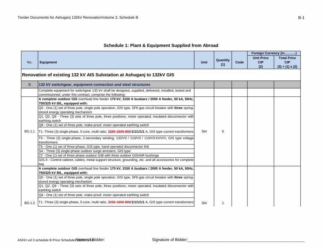
Tender Documents for Ashuganj 132kV RenovationVolume 3, Schedule B B-1
No. Equipment UnitQuantity
(1)Code
Unit PriceCIP(2)
Total PriceCIP
(3) = (1) x (2)
B 132 kV switchgear, equipment connection and steel structures
Complete equipment for switchgear 132 kV shall be designed, supplied, delivered, installed, tested and commissioned, under this contract, comprise the following:A complete outdoor GIS overhead line feeder 170 kV, 3150 A busbars / 2000 A feeder, 50 kA, 50Hz,750/325 kV BIL, equipped with:Q0 - One (1) set of three pole, single pole operation, GIS type, SF6 gas circuit breaker with three spring-stored energy operating mechanismQ1 Q2 Q9 Three (3) sets of three pole three positions motor operated insulated disconnector with
Schedule 1: Plant & Equipment Supplied from Abroad
Renovation of existing 132 kV AIS Substation at Ashuganj to 132kV GIS
Foreign Currency (in……….)
Q1, Q2, Q9 - Three (3) sets of three pole, three positions, motor operated, insulated disconnector withearthing switchQ8 - One (1) set of three pole, make-proof, motor operated earthing switch
T1 -Three (3) single-phase, 5-core, multi ratio, 3200-1600-800/1/1/1/1/1 A, GIS type current transformers
T5 - Three (3) single-phase, 2-secondary winding, 132/V3 / 110/V3 / 110/V3 kV/V/V, GIS type voltagetransformersT6 - One (1) set of three-phase, GIS type, hand operated disconnector linkSA - Three (3) single-phase outdoor surge arresters, GIS typeZ2 - One (1) set of three phase outdoor GIB with three outdoor GIS/AIR bushingsGIS.X - Control cabinet, cables, metal support structure, grounding, etc. and all accessories for completebayA complete outdoor GIS overhead line feeder 170 kV, 3150 A busbars / 2000 A feeder, 50 kA, 50Hz,750/325 kV BIL, equipped with:Q0 - One (1) set of three pole, single pole operation, GIS type, SF6 gas circuit breaker with three spring-stored energy operating mechanismQ1, Q2, Q9 - Three (3) sets of three pole, three positions, motor operated, insulated disconnector withearthing switch
Q8 - One (1) set of three pole, make-proof, motor operated earthing switch
T1 -Three (3) single-phase, 5-core, multi ratio, 3200-1600-800/1/1/1/1/1 A, GIS type current transformers
BG.1.1 Set 6
Set 1BG.1.2
ASHU vol 3 schedule B Price Schedules 2019 05 18Name of Bidder: Signature of Bidder:____________________________________________________

Tender Documents for Ashuganj 132kV RenovationVolume 3, Schedule B B-2
No. Equipment UnitQuantity
(1)Code
Unit PriceCIP(2)
Total PriceCIP
(3) = (1) x (2)
Schedule 1: Plant & Equipment Supplied from Abroad
Foreign Currency (in……….)
T5 - Three (3) single-phase, 2-secondary winding, 132/V3 / 110/V3 / 110/V3 kV/V/V, GIS type voltagetransformers
T6 - One (1) set of three-phase, GIS type, hand operated disconnector link
SA - Three (3) single-phase outdoor surge arresters, GIS type
Z1 - One (1) set of three-phase, GIS type, cable compartment
GIS.X - Control cabinet, cables, metal support structure, grounding, etc. and all accessories for completebayA complete outdoor GIS 230/132/33kV auto transformer feeder 170 kV, 3150A busbars / 2000 Afeeder, 50 kA, 50Hz, 750/325 kV BIL, equipped with:Q0 - One (1) set of three pole, gang operation, GIS type, SF6 gas circuit breaker with one spring-storedenergy operating mechanismQ1, Q2, Q9 - Three (3) set of three pole, three position, motor operated, insulated disconnector withearthing switchQ8 - One (1) set of three pole, make-proof, motor operated earthing switch
T1 -Three (3) single-phase, 5-core, multi ratio, 3200-1600-800/1/1/1/1/1 A, GIS type current transformers
SA - Three (3) single-phase outdoor surge arresters, GIS typeZ1 - One (1) set of three-phase, GIS type, cable compartment X - Control cabinet, cables, metal support structure, grounding, etc. and all accessories for completebayA complete outdoor GIS 132/33kV power transformer feeder 170 kV, 3150A busbars / 2000 A feeder,50 kA, 50Hz, 750/325 kV BIL, equipped with:Q0 - One (1) set of three pole, gang operation, GIS type, SF6 gas circuit breaker with one spring-storedenergy operating mechanismQ1, Q2, Q9 - Three (3) set of three pole, three position, motor operated, insulated disconnector withearthing switchQ8 - One (1) set of three pole, make-proof, motor operated earthing switch
T1 -Three (3) single-phase, 5-core, multi ratio, 3200-1600-800/1/1/1/1/1 A, GIS type current transformers
Z1 - One (1) set of three-phase, GIS type, cable compartment
X - Control cabinet, cables, metal support structure, grounding, etc. and all accessories for complete bay
BG.2.1 Set 2
BG.2.2 Set 4
ASHU vol 3 schedule B Price Schedules 2019 05 18Name of Bidder: Signature of Bidder:____________________________________________________

Tender Documents for Ashuganj 132kV RenovationVolume 3, Schedule B B-3
No. Equipment UnitQuantity
(1)Code
Unit PriceCIP(2)
Total PriceCIP
(3) = (1) x (2)
Schedule 1: Plant & Equipment Supplied from Abroad
Foreign Currency (in……….)
A complete outdoor GIS 132/6.9kV auxilary transformer feeder 170 kV, 3150A busbars / 2000 Afeeder, 50 kA, 50Hz, 750/325 kV BIL, equipped with:Q0 - One (1) set of three pole, gang operation, GIS type, SF6 gas circuit breaker with one spring-storedenergy operating mechanismQ1, Q2, Q9 - Three (3) set of three pole, three position, motor operated, insulated disconnector withearthing switch
Q8 - One (1) set of three pole, make-proof, motor operated earthing switch
T1 -Three (3) single-phase, 5-core, multi ratio, 3200-1600-800/1/1/1/1/1 A, GIS type current transformers
Z1 - One (1) set of three-phase, GIS type, cable compartment
BG.2.3 Set 2
X - Control cabinet, cables, metal support structure, grounding, etc. and all accessories for complete bay
A complete outdoor GIS power station feeder 170 kV, 3150A busbars / 2000 A feeder, 50 kA, 50Hz,750/325 kV BIL, equipped with:Q0 - One (1) set of three pole, gang operation, GIS type, SF6 gas circuit breaker with one spring-storedenergy operating mechanismQ1, Q2, Q9 - Three (3) set of three pole, three position, motor operated, insulated disconnector withearthing switch
Q8 - One (1) set of three pole, make-proof, motor operated earthing switch
T1 -Three (3) single-phase, 5-core, multi ratio, 3200-1600-800/1/1/1/1/1 A, GIS type current transformers
SA - Three (3) single-phase outdoor surge arresters, GIS type
Z1 - One (1) set of three-phase, GIS type, cable compartment
X - Control cabinet, cables, metal support structure, grounding, etc. and all accessories for complete bay
A complete outdoor GIS bus sectionalize bay 170 kV, 3150A busbars / 3150 A feeder, 50 kA, 50Hz,750/325 kV BIL, equipped with:Q0 - Two (2) sets of three pole, gang operation, GIS type, SF6 gas circuit breaker with one spring-stored energy operating mechanism
T1 -Three (3) single-phase, 5-core, multi ratio, 3200-1600/1/1/1/1/1 A, GIS type current transformers
Set 7BG.2.4
BG 3 1 Set 1
ASHU vol 3 schedule B Price Schedules 2019 05 18Name of Bidder: Signature of Bidder:____________________________________________________

Tender Documents for Ashuganj 132kV RenovationVolume 3, Schedule B B-4
No. Equipment UnitQuantity
(1)Code
Unit PriceCIP(2)
Total PriceCIP
(3) = (1) x (2)
Schedule 1: Plant & Equipment Supplied from Abroad
Foreign Currency (in……….)
T2 -Three (3) single-phase, 5-core, multi ratio, 3200-1600/1/1/1/1/1 A, GIS type current transformers
Q11, Q12, Q21, Q22 - Four (4) set of three pole, three position, motor operated, insulated disconnectorwith earthing switch
X - Control cabinet, cables, metal support structure, grounding, etc. and all accessories for complete bay
A complete outdoor GIS bus coupler bay 170 kV, 3150A busbars / 3150 A feeder, 50 kA, 50Hz,750/325 kV BIL, equipped with:Q0 - One (1) set of three pole, gang operation, GIS type, SF6 gas circuit breaker with one spring-storedenergy operating mechanismQ1, Q2 - Two (2) set of three pole, three position, motor operated, insulated disconnector with earthing
BG.3.1 Set 1
BG 3 2 Set 2( ) p p p gswitch
T1 -Three (3) single-phase, 5-core, multi ratio, 3200-1600/1/1/1/1/1 A, GIS type current transformers
X - Control cabinet, cables, metal support structure, grounding, etc. and all accessories for complete bay
A complete outdoor GIS metering bay 145 kV, 3150A busbars, 50 kA, 50Hz, 750/325 kV BIL,equipped with:Q21, Q22 - Two (2) set of three pole, three position, motor operated, insulated disconnector T5 - Three (3) single-phase, 2-winding, 132/V3 / 110/V3 / 110/V3kV/110/V3kV, GIS type voltagetransformers
X - Control cabinet, cables, metal support structure, grounding, etc. and all accessories for complete bay
A complete outdoor GIS busbars earthing bay 170 kV, 3150A busbars, 50 kA, 50Hz, 750/325 kV BIL,equipped with:Q81, Q82 - Two (2) set of three pole, make-proof, motor operated earthing switch
B5Surge arrester 145 kV, 120 kV continuous operating voltage, 10kA nominal discharge current, 50Hz,single phase, heavy duty, station class, gapless, metal oxide type
Set 54
B6 Post Insulator 132 kV, 50 Hz, 650/275 kV BIL, 10 kN Set 9
B7.XConductors for double busbar system and for connection of the 132 kV switchgear, 145 kV, 3150 &2000 A, 50 kA
Lot 1
B8.XInsulators and fittings incl. all necessary clamps and connectors required for completing 132 kVswitchgear
Lot 1
BG.3.2 Set 2
BG.3.3 Set 2
BG.4 Set 2
ASHU vol 3 schedule B Price Schedules 2019 05 18Name of Bidder: Signature of Bidder:____________________________________________________
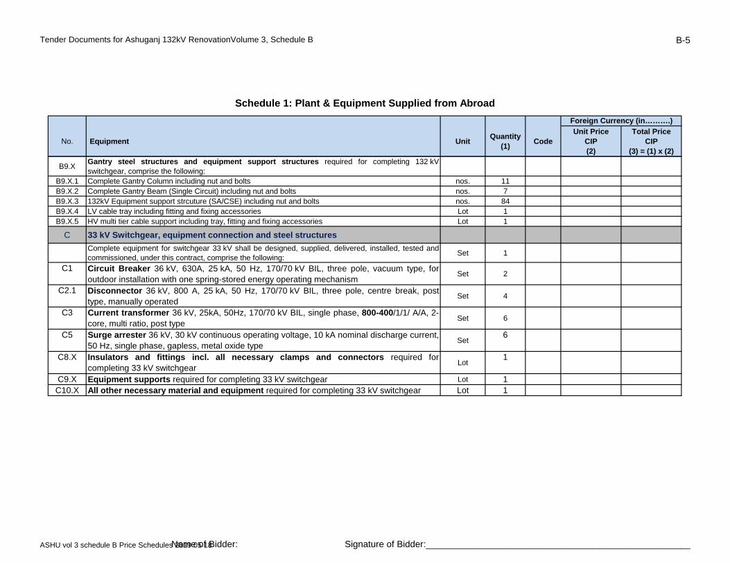
Tender Documents for Ashuganj 132kV RenovationVolume 3, Schedule B B-5
No. Equipment UnitQuantity
(1)Code
Unit PriceCIP(2)
Total PriceCIP
(3) = (1) x (2)
Schedule 1: Plant & Equipment Supplied from Abroad
Foreign Currency (in……….)
B9.XGantry steel structures and equipment support structures required for completing 132 kVswitchgear, comprise the following:
B9.X.1 Complete Gantry Column including nut and bolts nos. 11B9.X.2 Complete Gantry Beam (Single Circuit) including nut and bolts nos. 7B9.X.3 132kV Equipment support strcuture (SA/CSE) including nut and bolts nos. 84B9.X.4 LV cable tray including fitting and fixing accessories Lot 1B9.X.5 HV multi tier cable support including tray, fitting and fixing accessories Lot 1
C 33 kV Switchgear, equipment connection and steel structures
Complete equipment for switchgear 33 kV shall be designed, supplied, delivered, installed, tested andcommissioned, under this contract, comprise the following:
Set 1
C1 Circuit Breaker 36 kV, 630A, 25 kA, 50 Hz, 170/70 kV BIL, three pole, vacuum type, foroutdoor installation with one spring-stored energy operating mechanism
Set 2
C2.1 Disconnector 36 kV, 800 A, 25 kA, 50 Hz, 170/70 kV BIL, three pole, centre break, posttype, manually operated
Set 4
C3 Current transformer 36 kV, 25kA, 50Hz, 170/70 kV BIL, single phase, 800-400/1/1/ A/A, 2-core, multi ratio, post type
Set 6
C5 Surge arrester 36 kV, 30 kV continuous operating voltage, 10 kA nominal discharge current,50 Hz, single phase, gapless, metal oxide type
Set6
C8.X Insulators and fittings incl. all necessary clamps and connectors required forcompleting 33 kV switchgear
Lot1
C9.X Equipment supports required for completing 33 kV switchgear Lot 1C10.X All other necessary material and equipment required for completing 33 kV switchgear Lot 1
ASHU vol 3 schedule B Price Schedules 2019 05 18Name of Bidder: Signature of Bidder:____________________________________________________
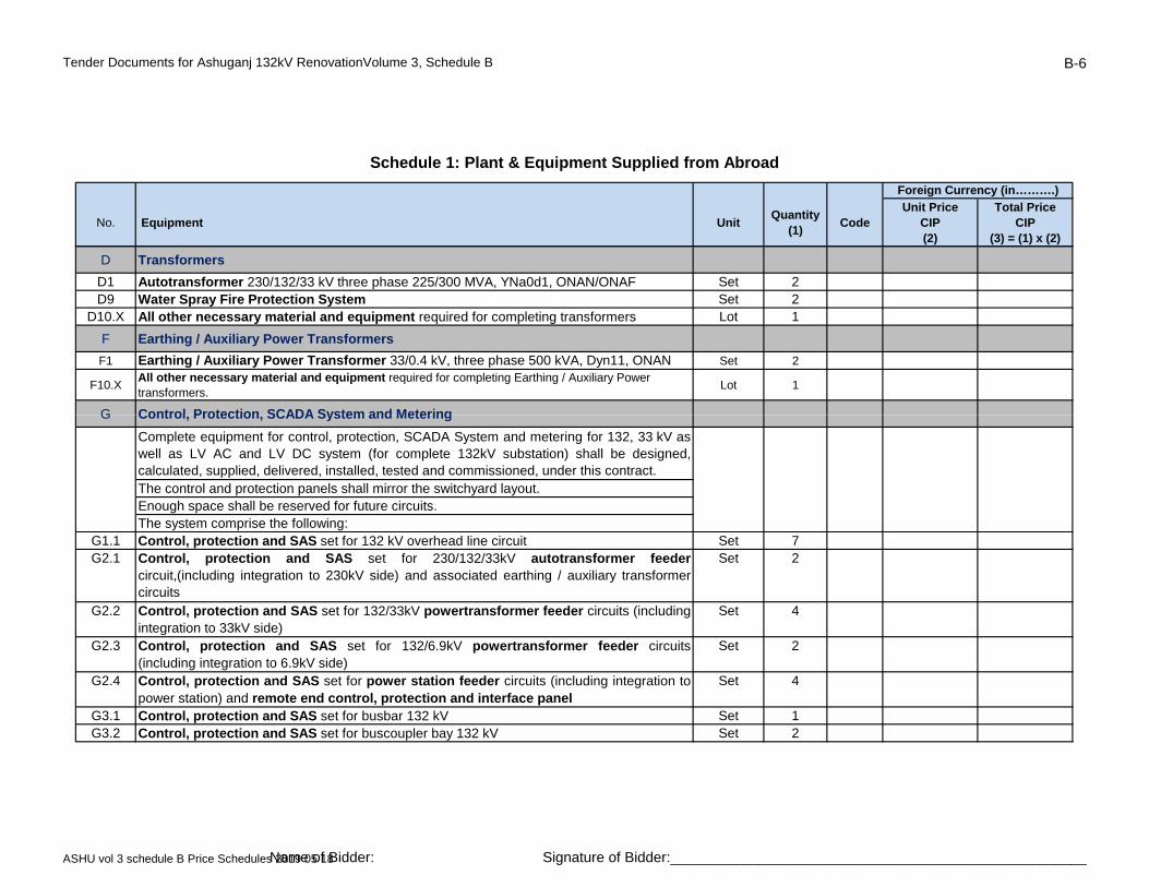
Tender Documents for Ashuganj 132kV RenovationVolume 3, Schedule B B-6
No. Equipment UnitQuantity
(1)Code
Unit PriceCIP(2)
Total PriceCIP
(3) = (1) x (2)
Schedule 1: Plant & Equipment Supplied from Abroad
Foreign Currency (in……….)
D Transformers
D1 Autotransformer 230/132/33 kV three phase 225/300 MVA, YNa0d1, ONAN/ONAF Set 2D9 Water Spray Fire Protection System Set 2
D10.X All other necessary material and equipment required for completing transformers Lot 1
F Earthing / Auxiliary Power Transformers
F1 Earthing / Auxiliary Power Transformer 33/0.4 kV, three phase 500 kVA, Dyn11, ONAN Set 2
F10.XAll other necessary material and equipment required for completing Earthing / Auxiliary Power transformers.
Lot 1
G Control Protection SCADA System and MeteringG Control, Protection, SCADA System and Metering
Complete equipment for control, protection, SCADA System and metering for 132, 33 kV aswell as LV AC and LV DC system (for complete 132kV substation) shall be designed,calculated, supplied, delivered, installed, tested and commissioned, under this contract.The control and protection panels shall mirror the switchyard layout.Enough space shall be reserved for future circuits.The system comprise the following:
G1.1 Control, protection and SAS set for 132 kV overhead line circuit Set 7G2.1 Control, protection and SAS set for 230/132/33kV autotransformer feeder
circuit,(including integration to 230kV side) and associated earthing / auxiliary transformercircuits
Set 2
G2.2 Control, protection and SAS set for 132/33kV powertransformer feeder circuits (includingintegration to 33kV side)
Set 4
G2.3 Control, protection and SAS set for 132/6.9kV powertransformer feeder circuits(including integration to 6.9kV side)
Set 2
G2.4 Control, protection and SAS set for power station feeder circuits (including integration topower station) and remote end control, protection and interface panel
Set 4
G3.1 Control, protection and SAS set for busbar 132 kV Set 1G3.2 Control, protection and SAS set for buscoupler bay 132 kV Set 2
ASHU vol 3 schedule B Price Schedules 2019 05 18Name of Bidder: Signature of Bidder:____________________________________________________
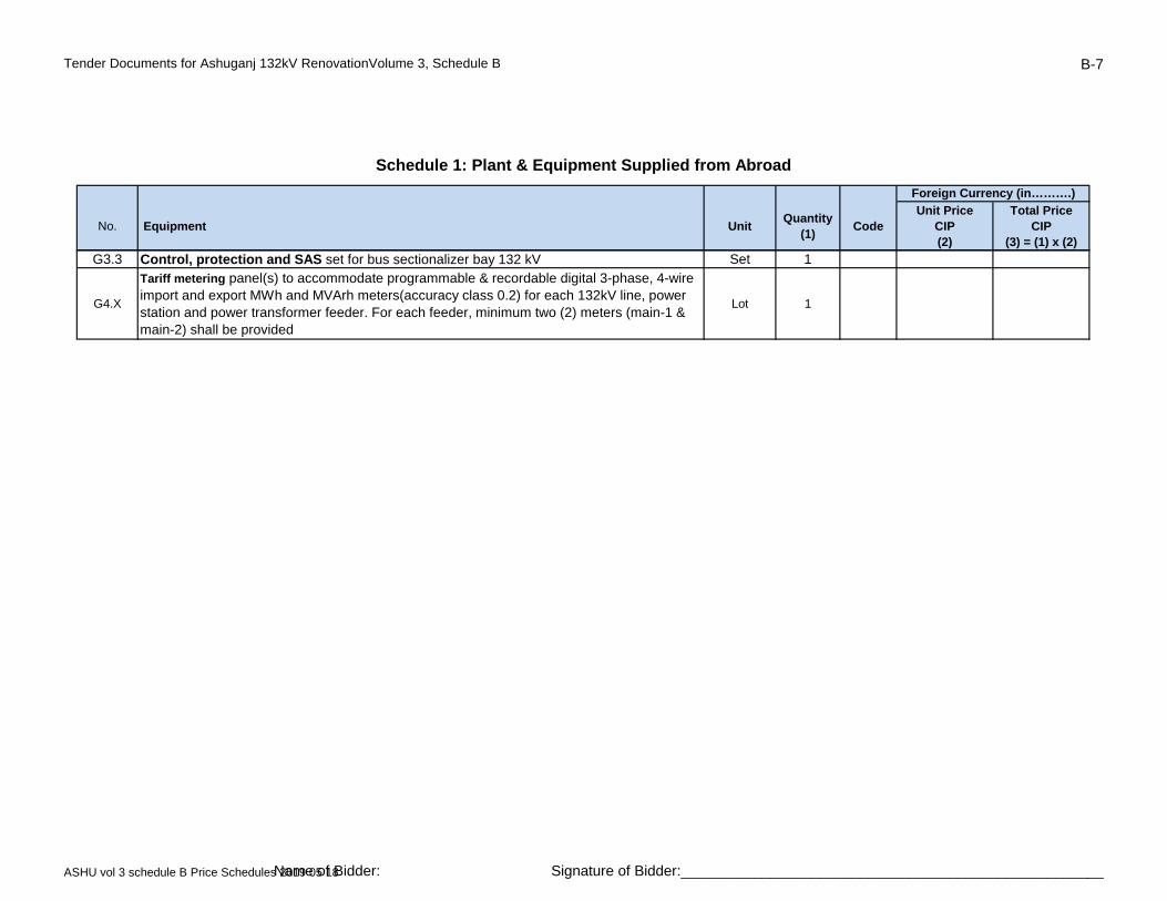
Tender Documents for Ashuganj 132kV RenovationVolume 3, Schedule B B-7
No. Equipment UnitQuantity
(1)Code
Unit PriceCIP(2)
Total PriceCIP
(3) = (1) x (2)
Schedule 1: Plant & Equipment Supplied from Abroad
Foreign Currency (in……….)
G3.3 Control, protection and SAS set for bus sectionalizer bay 132 kV Set 1
G4.X
Tariff metering panel(s) to accommodate programmable & recordable digital 3-phase, 4-wire import and export MWh and MVArh meters(accuracy class 0.2) for each 132kV line, power station and power transformer feeder. For each feeder, minimum two (2) meters (main-1 & main-2) shall be provided
Lot 1
ASHU vol 3 schedule B Price Schedules 2019 05 18Name of Bidder: Signature of Bidder:____________________________________________________

Tender Documents for Ashuganj 132kV RenovationVolume 3, Schedule B B-8
No. Equipment UnitQuantity
(1)Code
Unit PriceCIP(2)
Total PriceCIP
(3) = (1) x (2)
Schedule 1: Plant & Equipment Supplied from Abroad
Foreign Currency (in……….)
G5.X Digital Fault and Disturbance Recorder (DFDR) to accommodate all 132kV feeders Lot 1Tele-control & Tele-protection & Tele-metering facilities,A complete lot of hardware and software, extension of the existing equipment, necessary adjustment, adaptation, modification, integration and configuration of new and existing 132kV equipment;All necessary modification works in the hardware and software of the master stations shall be provided, both at the National Load Despatch Centre (NLDC) at Aftabnagar and at the back-up station at Biddut Bhaban, for integration of the complete substation.All required electrical signals shall be transmitted to the NLDC and the back-up station through the industrial gateway of the substation automation system. All HV circuit breakers, disconnectors, tap changer, etc., shall be controlled from the NLDC through the gateway of the substation automation system using the IEC 60870-5-104 protocol
G6.X 1Lot
system using the IEC 60870 5 104 protocol.
G10.XAll other necessary material and equipment required for completing control, protection, substation automation and metering system.
Lot 1
H Fibre Optic Multiplexer Equipment for Tele-protection and Communication
Fibre Optic Multiplexer Equipment, a complete lot of fibre optic multiplexer equipment for protection & communication at substation shall be designed, supplied, delivered, installed, tested and commissioned, under this contract. Fibre optic multiplexer equipment is to be provided for.
· Distance relay carrier signal (main and back-up)· Differential relay signal· Bus protection / breaker failure relay· SCADA data from switchgear and control system· VOIP system (2-IP Phone)· 2-W remote subscriber ( 10 telephone sets)· Hot-line telephone systemNew digital PABX with subscriber telephone sets for the complete substation includingnecessary works to interface with existing system. PABX equipment is to be provided for.
· VOIP Facility
· 2-wire telephone subscribers
· Digital truncking
Lot
Lot 1H1.XE
H1.X 1
ASHU vol 3 schedule B Price Schedules 2019 05 18Name of Bidder: Signature of Bidder:____________________________________________________
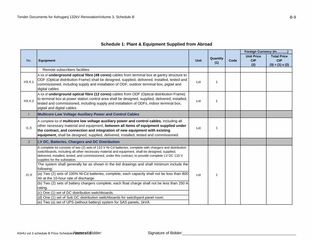
Tender Documents for Ashuganj 132kV RenovationVolume 3, Schedule B B-9
No. Equipment UnitQuantity
(1)Code
Unit PriceCIP(2)
Total PriceCIP
(3) = (1) x (2)
Schedule 1: Plant & Equipment Supplied from Abroad
Foreign Currency (in……….)
· Remote subscribers facilities
H3.X.1
A lot of underground optical fibre (48 cores) cables from terminal box at gantry structure to ODF (Optical distribution Frame) shall be designed, supplied, delivered, installed, tested and commissioned, including supply and installation of ODF, outdoor terminal box, pigtail and digital cables
Lot 1
H3.X.2
A lot of underground optical fibre (12 cores) cables from ODF (Optical distribution Frame) to terminal box at power station control area shall be designed, supplied, delivered, installed, tested and commissioned, including supply and installation of ODFs, indoor terminal box, pigtail and digital cables
Lot 1
C CI Multicore Low Voltage Auxiliary Power and Control Cables
I1.X
A complete lot of multicore low voltage auxiliary power and control cables, including all other necessary material and equipment, between all items of equipment supplied under the contract, and connection and integration of new equipment with existing equipment, shall be designed, supplied, delivered, installed, tested and commissioned
Lot 1
J LV DC, Batteries, Chargers and DC Distribution
A complete lot consists of two (2) sets of 110 V Ni-Cd batteries, complete with chargers and distribution switchboards, including all other necessary material and equipment, shall be designed, supplied, delivered, installed, tested, and commissioned, under this contract, to provide complete LV DC 110 V supplies for the substation.
The system shall generally be as shown in the bid drawings and shall minimum include thefollowing:(a) Two (2) sets of 100% Ni-Cd batteries, complete, each capacity shall not be less than 800Ah at the 10-hour rate of discharge.(b) Two (2) sets of battery chargers complete, each float charge shall not be less than 250 Arating.(c) One (1) set of DC distribution switchboards.(d) One (1) set of Sub DC distribution switchboards for swicthyard panel room.(e) Two (s) set of UPS (without battery) system for SAS panels, 1kVA
LotJ1.X 1
ASHU vol 3 schedule B Price Schedules 2019 05 18Name of Bidder: Signature of Bidder:____________________________________________________
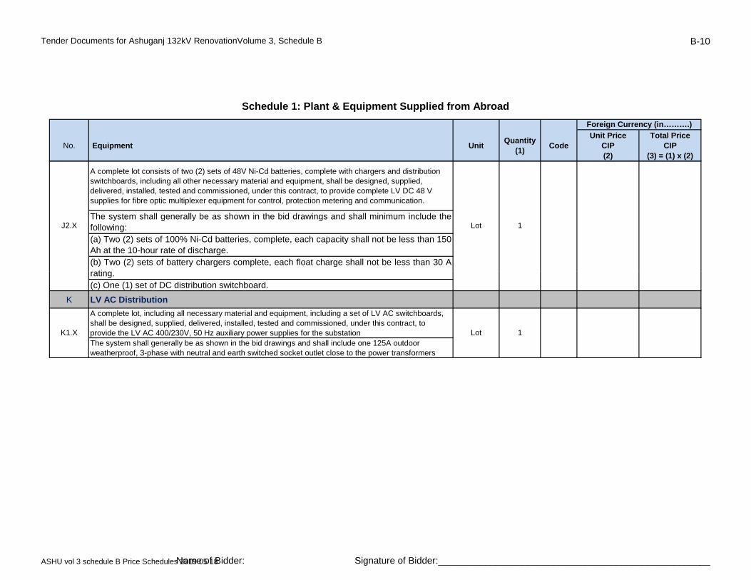
Tender Documents for Ashuganj 132kV RenovationVolume 3, Schedule B B-10
No. Equipment UnitQuantity
(1)Code
Unit PriceCIP(2)
Total PriceCIP
(3) = (1) x (2)
Schedule 1: Plant & Equipment Supplied from Abroad
Foreign Currency (in……….)
A complete lot consists of two (2) sets of 48V Ni-Cd batteries, complete with chargers and distribution switchboards, including all other necessary material and equipment, shall be designed, supplied, delivered, installed, tested and commissioned, under this contract, to provide complete LV DC 48 V supplies for fibre optic multiplexer equipment for control, protection metering and communication.
The system shall generally be as shown in the bid drawings and shall minimum include thefollowing:(a) Two (2) sets of 100% Ni-Cd batteries, complete, each capacity shall not be less than 150Ah at the 10-hour rate of discharge.(b) Two (2) sets of battery chargers complete, each float charge shall not be less than 30 A
ti
LotJ2.X 1
rating.(c) One (1) set of DC distribution switchboard.
K LV AC Distribution
A complete lot, including all necessary material and equipment, including a set of LV AC switchboards, shall be designed, supplied, delivered, installed, tested and commissioned, under this contract, to provide the LV AC 400/230V, 50 Hz auxiliary power supplies for the substationThe system shall generally be as shown in the bid drawings and shall include one 125A outdoor weatherproof, 3-phase with neutral and earth switched socket outlet close to the power transformers
LotK1.X 1
ASHU vol 3 schedule B Price Schedules 2019 05 18Name of Bidder: Signature of Bidder:____________________________________________________
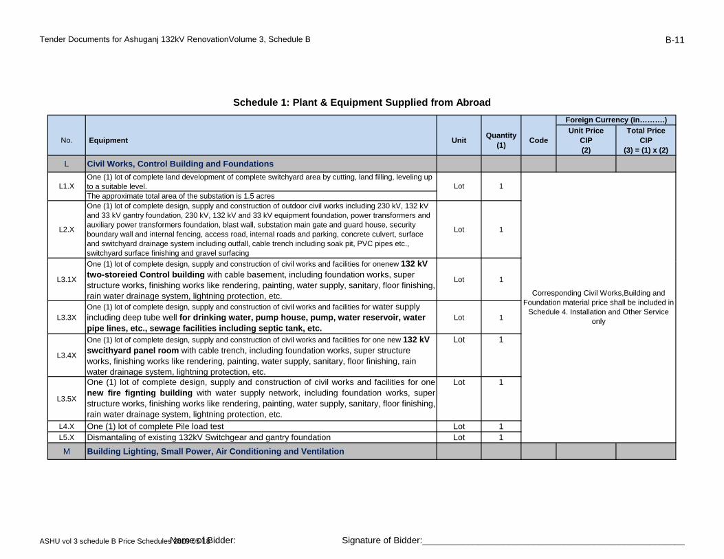
Tender Documents for Ashuganj 132kV RenovationVolume 3, Schedule B B-11
No. Equipment UnitQuantity
(1)Code
Unit PriceCIP(2)
Total PriceCIP
(3) = (1) x (2)
Schedule 1: Plant & Equipment Supplied from Abroad
Foreign Currency (in……….)
L Civil Works, Control Building and Foundations
One (1) lot of complete land development of complete switchyard area by cutting, land filling, leveling up to a suitable level.The approximate total area of the substation is 1.5 acres
L2.X
One (1) lot of complete design, supply and construction of outdoor civil works including 230 kV, 132 kV and 33 kV gantry foundation, 230 kV, 132 kV and 33 kV equipment foundation, power transformers and auxiliary power transformers foundation, blast wall, substation main gate and guard house, security boundary wall and internal fencing, access road, internal roads and parking, concrete culvert, surface and switchyard drainage system including outfall, cable trench including soak pit, PVC pipes etc., switchyard surface finishing and gravel surfacing
Lot 1
O (1) l t f l t d i l d t ti f i il k d f iliti f 132 kV
LotL1.X 1
L3.1X
One (1) lot of complete design, supply and construction of civil works and facilities for onenew 132 kV two-storeied Control building with cable basement, including foundation works, super structure works, finishing works like rendering, painting, water supply, sanitary, floor finishing, rain water drainage system, lightning protection, etc.
Lot 1
L3.3XOne (1) lot of complete design, supply and construction of civil works and facilities for water supply including deep tube well for drinking water, pump house, pump, water reservoir, water pipe lines, etc., sewage facilities including septic tank, etc.
Lot 1
L3.4X
One (1) lot of complete design, supply and construction of civil works and facilities for one new 132 kV swcithyard panel room with cable trench, including foundation works, super structure works, finishing works like rendering, painting, water supply, sanitary, floor finishing, rain water drainage system, lightning protection, etc.
Lot 1
L3.5X
One (1) lot of complete design, supply and construction of civil works and facilities for onenew fire fignting building with water supply network, including foundation works, superstructure works, finishing works like rendering, painting, water supply, sanitary, floor finishing,rain water drainage system, lightning protection, etc.
Lot 1
L4.X One (1) lot of complete Pile load test Lot 1L5.X Dismantaling of existing 132kV Switchgear and gantry foundation Lot 1
M Building Lighting, Small Power, Air Conditioning and Ventilation
Corresponding Civil Works,Building and Foundation material price shall be included in
Schedule 4. Installation and Other Service only
ASHU vol 3 schedule B Price Schedules 2019 05 18Name of Bidder: Signature of Bidder:____________________________________________________

Tender Documents for Ashuganj 132kV RenovationVolume 3, Schedule B B-12
No. Equipment UnitQuantity
(1)Code
Unit PriceCIP(2)
Total PriceCIP
(3) = (1) x (2)
Schedule 1: Plant & Equipment Supplied from Abroad
Foreign Currency (in……….)
M1.XOne (1) lot of complete equipment shall be designed, supplied, delivered, installed, tested and commissioned, to provide lighting, LV power supply, air conditioning system, ventilation, and emergency DC lighting for the substation control building(s), Fire Fighting Building and switchyard panel room.
Lot 1
N Switchyard Lighting and Security
N1.XE
One (1) lot of complete equipment for required switchyard area, shall be designed, supplied, delivered, installed, tested and commissioned, to provide extension of the existing switchyard lighting for security, roadway and switchyard and emergency DC lighting at strategic locations for equipment operations and inspections and for connection of new equipment and integration with the existing equipment
Lot 1
and integration with the existing equipment.
N2.XE One (1) lot of complete CCTV camera system (min. 20 nos. Camera) for Control buildingincluding switchyard area with NVR and other required accessories.
Lot1
P Earthing and Lightning Protection
P1.XOne (1) lot of complete equipment shall be designed, supplied, delivered, installed, tested and commissioned, of earthing system and lightning protection screen including connections, connectors and clamps, to suit the substation overall arrangement and provide supporting design calculations.
Lot 1
Q GIB and HV Cable Connections
One (1) lot of complete equipment shall be designed, supplied, delivered, installed, tested and commissioned of three-phase or equivalent three single phase gas insulated busbars (GIB) with corresponding GIS connections and SF6/air bushings with corresponding GIS connections, with all required equipment; 145 kV, 2,000 A, 50 kA / 1 sec, 50 Hz, for connection of one 132 kV bay.Approximate lengths are 15 to 30 meters
Q.2.1
complete equipment shall be designed, supplied, delivered, installed, tested andcommissioned of three single phase XLPE cables with corresponding Cable End Terminals;equipped with:
Q.2.1.1132kV single core 2000sqmm copper conductor, XLPE insulated, corrugated Al sheathed &MDPE outer sheathed cable
meter 2300
Q1.1 Lot 6
ASHU vol 3 schedule B Price Schedules 2019 05 18Name of Bidder: Signature of Bidder:____________________________________________________
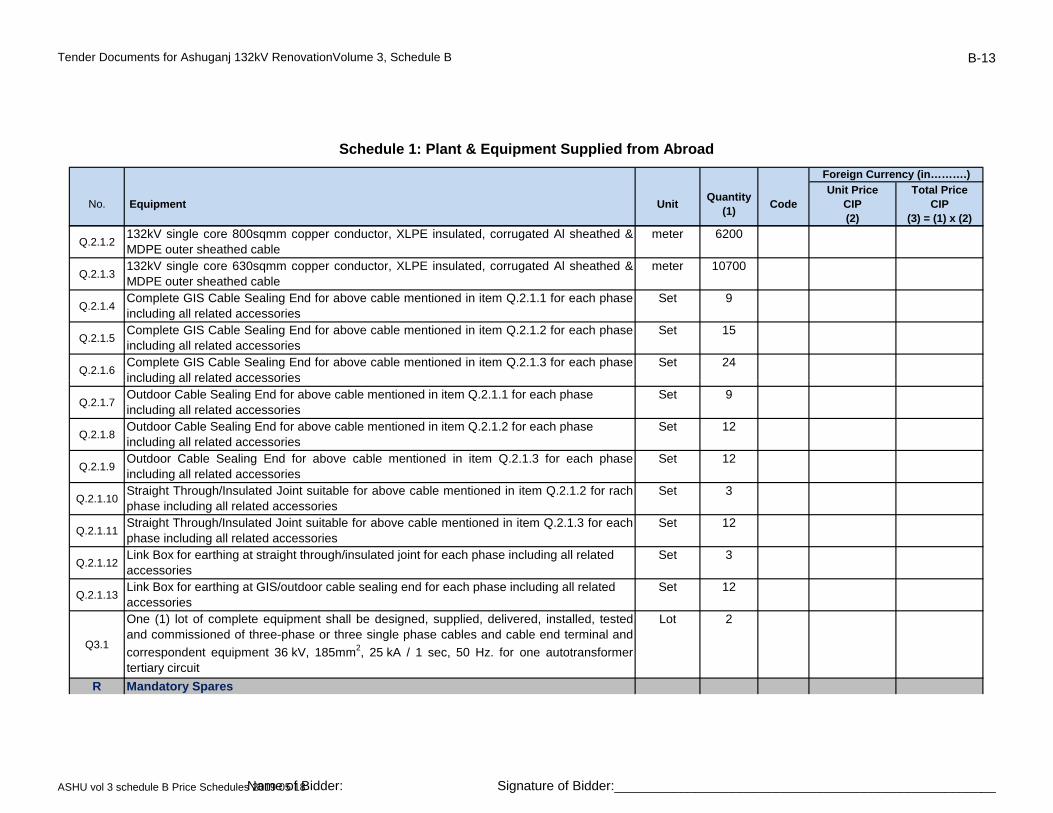
Tender Documents for Ashuganj 132kV RenovationVolume 3, Schedule B B-13
No. Equipment UnitQuantity
(1)Code
Unit PriceCIP(2)
Total PriceCIP
(3) = (1) x (2)
Schedule 1: Plant & Equipment Supplied from Abroad
Foreign Currency (in……….)
Q.2.1.2132kV single core 800sqmm copper conductor, XLPE insulated, corrugated Al sheathed &MDPE outer sheathed cable
meter 6200
Q.2.1.3132kV single core 630sqmm copper conductor, XLPE insulated, corrugated Al sheathed &MDPE outer sheathed cable
meter 10700
Q.2.1.4Complete GIS Cable Sealing End for above cable mentioned in item Q.2.1.1 for each phaseincluding all related accessories
Set 9
Q.2.1.5Complete GIS Cable Sealing End for above cable mentioned in item Q.2.1.2 for each phaseincluding all related accessories
Set 15
Q.2.1.6Complete GIS Cable Sealing End for above cable mentioned in item Q.2.1.3 for each phaseincluding all related accessories
Set 24including all related accessories
Q.2.1.7Outdoor Cable Sealing End for above cable mentioned in item Q.2.1.1 for each phase including all related accessories
Set 9
Q.2.1.8Outdoor Cable Sealing End for above cable mentioned in item Q.2.1.2 for each phase including all related accessories
Set 12
Q.2.1.9Outdoor Cable Sealing End for above cable mentioned in item Q.2.1.3 for each phaseincluding all related accessories
Set 12
Q.2.1.10Straight Through/Insulated Joint suitable for above cable mentioned in item Q.2.1.2 for rachphase including all related accessories
Set 3
Q.2.1.11Straight Through/Insulated Joint suitable for above cable mentioned in item Q.2.1.3 for eachphase including all related accessories
Set 12
Q.2.1.12Link Box for earthing at straight through/insulated joint for each phase including all related accessories
Set 3
Q.2.1.13Link Box for earthing at GIS/outdoor cable sealing end for each phase including all related accessories
Set 12
Q3.1
One (1) lot of complete equipment shall be designed, supplied, delivered, installed, testedand commissioned of three-phase or three single phase cables and cable end terminal and
correspondent equipment 36 kV, 185mm2, 25 kA / 1 sec, 50 Hz. for one autotransformertertiary circuit
Lot 2
R Mandatory Spares
ASHU vol 3 schedule B Price Schedules 2019 05 18Name of Bidder: Signature of Bidder:____________________________________________________
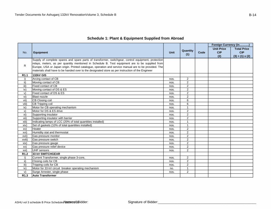
Tender Documents for Ashuganj 132kV RenovationVolume 3, Schedule B B-14
No. Equipment UnitQuantity
(1)Code
Unit PriceCIP(2)
Total PriceCIP
(3) = (1) x (2)
Schedule 1: Plant & Equipment Supplied from Abroad
Foreign Currency (in……….)
R
Supply of complete spares and spare parts of transformer, switchgear, control equipment, protectionrelays, meters, as per quantity mentioned in Schedule B. Test equipment are to be supplied fromEurope, USA or Japan origin. Printed catalogue, operation and service manual are to be provided. Thematerials shall have to be handed over to the designated store as per instruction of the Engineer
R1.1 132kV GISi) Arcing contact of CB nos. 2ii) Moving contact of CB nos. 2iii) Fixed contact of CB nos. 2iv) Moving contact of DS & ES nos. 2v) Fixed contact of DS & ES nos. 2vi) Blast nozzle nos. 2)vii) CB Closing coil nos. 6viii) CB Tripping coil nos. 6ix) Motor for CB operating mechanism nos. 1x) Motor for DS & ES drive nos. 2xi) Supporting insulator nos. 2xii) Supporting insulator with barrier nos. 2xiii) Indicating lamps of LCC (20% of total quantities installed) nos. 1xiv) Set of gaskets (10% of total quantities installed) nos. 1xv) Heater nos. 2xvi) Humidity stat and thermostat nos. 2xvii) Gas pressure monitor nos. 2xviii) Gas pressure switch nos. 2xix) Gas pressure gauge nos. 2xx) Gas pressure relief device nos. 2xxi) UHF sensors nos. 2R1.2 33 kV SWITCHGEAR
i) Current Transformer, single phase 3-core, nos. 2ii) Closing coils for CB nos. 2iii) Tripping coils for CB nos. 2iv) Motor for 33 kV circuit breaker operating mechanism no. 1v) Surge Arrester, single phase nos. 2
R1.3 Auto Transformer
ASHU vol 3 schedule B Price Schedules 2019 05 18Name of Bidder: Signature of Bidder:____________________________________________________
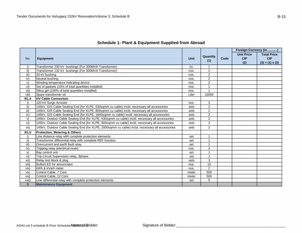
Tender Documents for Ashuganj 132kV RenovationVolume 3, Schedule B B-15
No. Equipment UnitQuantity
(1)Code
Unit PriceCIP(2)
Total PriceCIP
(3) = (1) x (2)
Schedule 1: Plant & Equipment Supplied from Abroad
Foreign Currency (in……….)
i) Transformer 230 kV bushings (For 300MVA Transformer) no. 1ii) Transformer 132 kV bushings (For 300MVA Transformer) nos. 2iii) 33 kV bushing nos. 2iv) Neutral bushing nos. 2v) Winding temperature indicating device nos. 2vi) Set of gaskets (10% of total quantities installed) nos. 1vii) Silica gel (100% of total quantities installed) nos. 1viii) Spare transformer oil Liter 10000
R1.4 HV Cable Connectioni) 120 kV Surge Arrester nos. 3ii) 145kV, GIS Cable Sealing End (for XLPE, 630sqmm cu cable) incld. necessary all accessories sets 2iii) 145kV, GIS Cable Sealing End (for XLPE, 800sqmm cu cable) incld. necessary all accessories sets 2iv) 145kV, GIS Cable Sealing End (for XLPE, 1600sqmm cu cable) incld. necessary all accessories sets 2v) 145kV, Outdoor Cable Sealing End (for XLPE, 630sqmm cu cable) incld. necessary all accessories sets 2vi) 145kV, Outdoor Cable Sealing End (for XLPE, 800sqmm cu cable) incld. necessary all accessories sets 2
vii) 145kV, Outdoor Cable Sealing End (for XLPE, 2000sqmm cu cable) incld. necessary all accessories sets 2
R1.5 Protection, Metering & Othersi) Line distance relay with complete protection elements set 1ii) Transformer differential relay with complete REF function set 1iii) Overcurrent and earth fault relay set 1iv) Tripping relay (electrical reset) nos. 3v) Bay control unit set 1vi) Trip Circuit Supervision relay, 3phase set 1vii) Relay test block & plug sets 3viii) Bulbs/LED for annunciator nos. 10vix) kWh & kVarh meter nos. 2vx) Control Cable, 7 Core meter 500vxi) Control Cable, 12 Core meter 500vxii) Line differential relay with complete protection elements set 5S Maintenance Equipment
ASHU vol 3 schedule B Price Schedules 2019 05 18Name of Bidder: Signature of Bidder:____________________________________________________
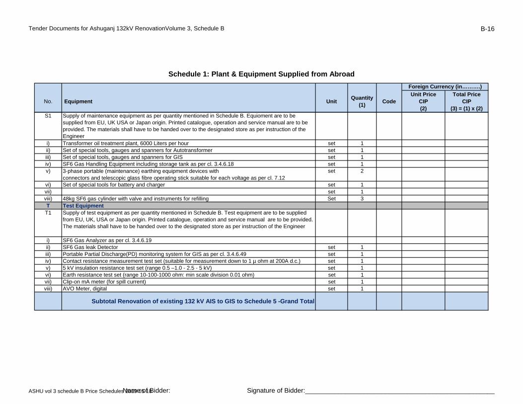
Tender Documents for Ashuganj 132kV RenovationVolume 3, Schedule B B-16
No. Equipment UnitQuantity
(1)Code
Unit PriceCIP(2)
Total PriceCIP
(3) = (1) x (2)
Schedule 1: Plant & Equipment Supplied from Abroad
Foreign Currency (in……….)
S1 Supply of maintenance equipment as per quantity mentioned in Schedule B. Equioment are to be supplied from EU, UK USA or Japan origin. Printed catalogue, operation and service manual are to be provided. The materials shall have to be handed over to the designated store as per instruction of the Engineer
i) Transformer oil treatment plant, 6000 Liters per hour set 1ii) Set of special tools, gauges and spanners for Autotransformer set 1iii) Set of special tools, gauges and spanners for GIS set 1iv) SF6 Gas Handling Equipment including storage tank as per cl. 3.4.6.18 set 1v) 3-phase portable (maintenance) earthing equipment devices with
connectors and telescopic glass fibre operating stick suitable for each voltage as per cl. 7.12set 2
vi) Set of special tools for battery and charger set 1vii) set 1viii) 48kg SF6 gas cylinder with valve and instruments for refilling Set 3T Test EquipmentT1 Supply of test equipment as per quantity mentioned in Schedule B. Test equipment are to be supplied
from EU, UK, USA or Japan origin. Printed catalogue, operation and service manual are to be provided. The materials shall have to be handed over to the designated store as per instruction of the Engineer
i) SF6 Gas Analyzer as per cl. 3.4.6.19ii) SF6 Gas leak Detector set 1iii) Portable Partial Discharge(PD) monitoring system for GIS as per cl. 3.4.6.49 set 1iv) Contact resistance measurement test set (suitable for measurement down to 1 µ ohm at 200A d.c.) set 1v) 5 kV insulation resistance test set (range 0.5 –1.0 - 2.5 - 5 kV) set 1vi) Earth resistance test set (range 10-100-1000 ohm: min scale division 0.01 ohm) set 1vii) Clip-on mA meter (for spill current) set 1viii) AVO Meter, digital set 1
Subtotal Renovation of existing 132 kV AIS to GIS to Schedule 5 -Grand Total
ASHU vol 3 schedule B Price Schedules 2019 05 18Name of Bidder: Signature of Bidder:____________________________________________________
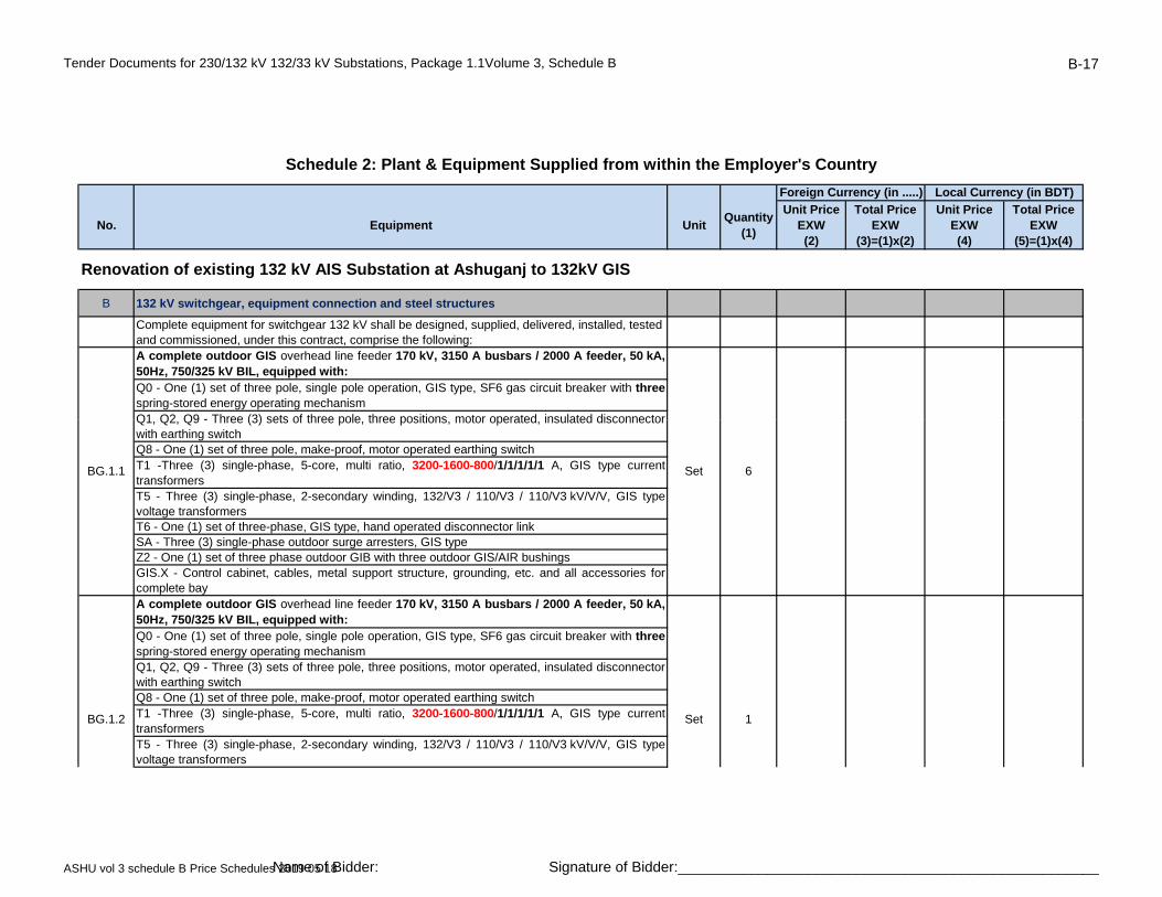
Tender Documents for 230/132 kV 132/33 kV Substations, Package 1.1Volume 3, Schedule B B-17
No. Equipment UnitQuantity
(1)
Unit PriceEXW(2)
Total PriceEXW
(3)=(1)x(2)
Unit PriceEXW(4)
Total PriceEXW
(5)=(1)x(4)
B 132 kV switchgear, equipment connection and steel structures
Complete equipment for switchgear 132 kV shall be designed, supplied, delivered, installed, tested and commissioned, under this contract, comprise the following:A complete outdoor GIS overhead line feeder 170 kV, 3150 A busbars / 2000 A feeder, 50 kA,50Hz, 750/325 kV BIL, equipped with:Q0 - One (1) set of three pole, single pole operation, GIS type, SF6 gas circuit breaker with three spring-stored energy operating mechanismQ1 Q2 Q9 - Three (3) sets of three pole three positions motor operated insulated disconnector
Schedule 2: Plant & Equipment Supplied from within the Employer's Country
Foreign Currency (in .....) Local Currency (in BDT)
Renovation of existing 132 kV AIS Substation at Ashuganj to 132kV GIS
Q1, Q2, Q9 - Three (3) sets of three pole, three positions, motor operated, insulated disconnectorwith earthing switchQ8 - One (1) set of three pole, make-proof, motor operated earthing switchT1 -Three (3) single-phase, 5-core, multi ratio, 3200-1600-800/1/1/1/1/1 A, GIS type currenttransformersT5 - Three (3) single-phase, 2-secondary winding, 132/V3 / 110/V3 / 110/V3 kV/V/V, GIS typevoltage transformersT6 - One (1) set of three-phase, GIS type, hand operated disconnector linkSA - Three (3) single-phase outdoor surge arresters, GIS typeZ2 - One (1) set of three phase outdoor GIB with three outdoor GIS/AIR bushingsGIS.X - Control cabinet, cables, metal support structure, grounding, etc. and all accessories forcomplete bayA complete outdoor GIS overhead line feeder 170 kV, 3150 A busbars / 2000 A feeder, 50 kA,50Hz, 750/325 kV BIL, equipped with:Q0 - One (1) set of three pole, single pole operation, GIS type, SF6 gas circuit breaker with three spring-stored energy operating mechanismQ1, Q2, Q9 - Three (3) sets of three pole, three positions, motor operated, insulated disconnectorwith earthing switchQ8 - One (1) set of three pole, make-proof, motor operated earthing switchT1 -Three (3) single-phase, 5-core, multi ratio, 3200-1600-800/1/1/1/1/1 A, GIS type currenttransformersT5 - Three (3) single-phase, 2-secondary winding, 132/V3 / 110/V3 / 110/V3 kV/V/V, GIS typevoltage transformers
BG.1.1 Set 6
BG.1.2 Set 1
ASHU vol 3 schedule B Price Schedules 2019 05 18Name of Bidder: Signature of Bidder:____________________________________________________
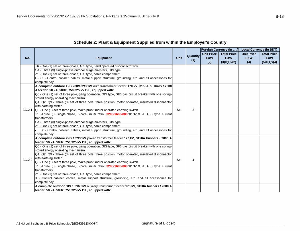
Tender Documents for 230/132 kV 132/33 kV Substations, Package 1.1Volume 3, Schedule B B-18
No. Equipment UnitQuantity
(1)
Unit PriceEXW(2)
Total PriceEXW
(3)=(1)x(2)
Unit PriceEXW(4)
Total PriceEXW
(5)=(1)x(4)
Schedule 2: Plant & Equipment Supplied from within the Employer's Country
Foreign Currency (in .....) Local Currency (in BDT)
T6 - One (1) set of three-phase, GIS type, hand operated disconnector linkSA - Three (3) single-phase outdoor surge arresters, GIS typeZ1 - One (1) set of three-phase, GIS type, cable compartmentGIS.X - Control cabinet, cables, metal support structure, grounding, etc. and all accessories forcomplete bayA complete outdoor GIS 230/132/33kV auto transformer feeder 170 kV, 3150A busbars / 2000A feeder, 50 kA, 50Hz, 750/325 kV BIL, equipped with:Q0 - One (1) set of three pole, gang operation, GIS type, SF6 gas circuit breaker with one spring-stored energy operating mechanismQ1, Q2, Q9 - Three (3) set of three pole, three position, motor operated, insulated disconnectorwith earthing switchQ8 - One (1) set of three pole, make-proof, motor operated earthing switchT1 -Three (3) single-phase, 5-core, multi ratio, 3200-1600-800/1/1/1/1/1 A, GIS type currenttransformersSA - Three (3) single-phase outdoor surge arresters, GIS typeZ1 - One (1) set of three-phase, GIS type, cable compartment X - Control cabinet, cables, metal support structure, grounding, etc. and all accessories forcomplete bayA complete outdoor GIS 132/33kV power transformer feeder 170 kV, 3150A busbars / 2000 Afeeder, 50 kA, 50Hz, 750/325 kV BIL, equipped with:Q0 - One (1) set of three pole, gang operation, GIS type, SF6 gas circuit breaker with one spring-stored energy operating mechanismQ1, Q2, Q9 - Three (3) set of three pole, three position, motor operated, insulated disconnectorwith earthing switchQ8 - One (1) set of three pole, make-proof, motor operated earthing switchT1 -Three (3) single-phase, 5-core, multi ratio, 3200-1600-800/1/1/1/1/1 A, GIS type currenttransformersZ1 - One (1) set of three-phase, GIS type, cable compartmentX - Control cabinet, cables, metal support structure, grounding, etc. and all accessories forcomplete bayA complete outdoor GIS 132/6.9kV auxilary transformer feeder 170 kV, 3150A busbars / 2000 Afeeder, 50 kA, 50Hz, 750/325 kV BIL, equipped with:
BG.2.1 Set 2
BG.2.2 Set 4
ASHU vol 3 schedule B Price Schedules 2019 05 18Name of Bidder: Signature of Bidder:____________________________________________________
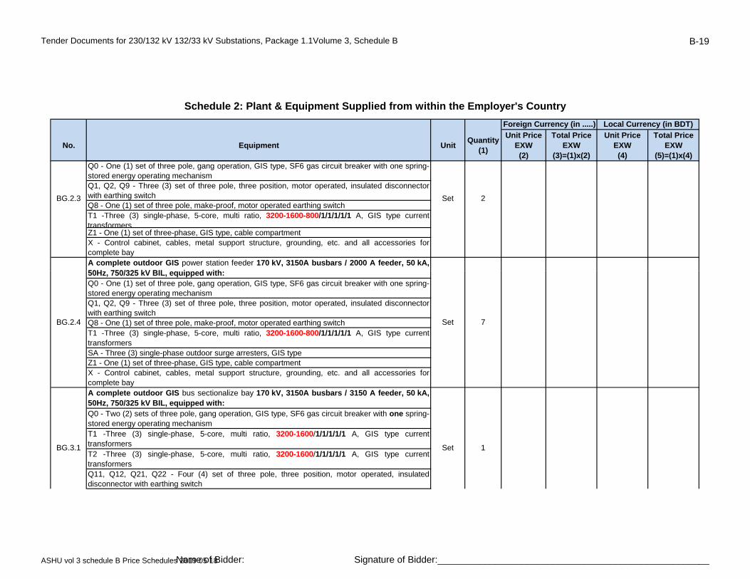
Tender Documents for 230/132 kV 132/33 kV Substations, Package 1.1Volume 3, Schedule B B-19
No. Equipment UnitQuantity
(1)
Unit PriceEXW(2)
Total PriceEXW
(3)=(1)x(2)
Unit PriceEXW(4)
Total PriceEXW
(5)=(1)x(4)
Schedule 2: Plant & Equipment Supplied from within the Employer's Country
Foreign Currency (in .....) Local Currency (in BDT)
Q0 - One (1) set of three pole, gang operation, GIS type, SF6 gas circuit breaker with one spring-stored energy operating mechanismQ1, Q2, Q9 - Three (3) set of three pole, three position, motor operated, insulated disconnectorwith earthing switchQ8 - One (1) set of three pole, make-proof, motor operated earthing switchT1 -Three (3) single-phase, 5-core, multi ratio, 3200-1600-800/1/1/1/1/1 A, GIS type currenttransformersZ1 - One (1) set of three-phase, GIS type, cable compartmentX - Control cabinet, cables, metal support structure, grounding, etc. and all accessories forcomplete bayA complete outdoor GIS power station feeder 170 kV, 3150A busbars / 2000 A feeder, 50 kA,50H 750/325 kV BIL i d ith
BG.2.3 Set 2
50Hz, 750/325 kV BIL, equipped with:Q0 - One (1) set of three pole, gang operation, GIS type, SF6 gas circuit breaker with one spring-stored energy operating mechanismQ1, Q2, Q9 - Three (3) set of three pole, three position, motor operated, insulated disconnectorwith earthing switchQ8 - One (1) set of three pole, make-proof, motor operated earthing switchT1 -Three (3) single-phase, 5-core, multi ratio, 3200-1600-800/1/1/1/1/1 A, GIS type currenttransformersSA - Three (3) single-phase outdoor surge arresters, GIS typeZ1 - One (1) set of three-phase, GIS type, cable compartmentX - Control cabinet, cables, metal support structure, grounding, etc. and all accessories forcomplete bayA complete outdoor GIS bus sectionalize bay 170 kV, 3150A busbars / 3150 A feeder, 50 kA,50Hz, 750/325 kV BIL, equipped with:Q0 - Two (2) sets of three pole, gang operation, GIS type, SF6 gas circuit breaker with one spring-stored energy operating mechanismT1 -Three (3) single-phase, 5-core, multi ratio, 3200-1600/1/1/1/1/1 A, GIS type currenttransformersT2 -Three (3) single-phase, 5-core, multi ratio, 3200-1600/1/1/1/1/1 A, GIS type currenttransformersQ11, Q12, Q21, Q22 - Four (4) set of three pole, three position, motor operated, insulateddisconnector with earthing switch
BG.2.4 Set 7
BG.3.1 Set 1
ASHU vol 3 schedule B Price Schedules 2019 05 18Name of Bidder: Signature of Bidder:____________________________________________________
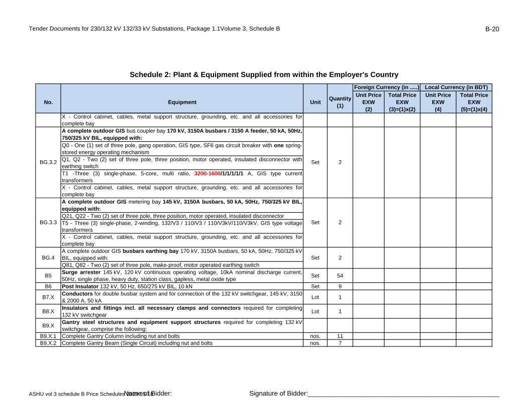
Tender Documents for 230/132 kV 132/33 kV Substations, Package 1.1Volume 3, Schedule B B-20
No. Equipment UnitQuantity
(1)
Unit PriceEXW(2)
Total PriceEXW
(3)=(1)x(2)
Unit PriceEXW(4)
Total PriceEXW
(5)=(1)x(4)
Schedule 2: Plant & Equipment Supplied from within the Employer's Country
Foreign Currency (in .....) Local Currency (in BDT)
X - Control cabinet, cables, metal support structure, grounding, etc. and all accessories forcomplete bayA complete outdoor GIS bus coupler bay 170 kV, 3150A busbars / 3150 A feeder, 50 kA, 50Hz,750/325 kV BIL, equipped with:Q0 - One (1) set of three pole, gang operation, GIS type, SF6 gas circuit breaker with one spring-stored energy operating mechanismQ1, Q2 - Two (2) set of three pole, three position, motor operated, insulated disconnector withearthing switchT1 -Three (3) single-phase, 5-core, multi ratio, 3200-1600/1/1/1/1/1 A, GIS type currenttransformersX - Control cabinet, cables, metal support structure, grounding, etc. and all accessories for
BG.3.2 Set 2
pp g gcomplete bayA complete outdoor GIS metering bay 145 kV, 3150A busbars, 50 kA, 50Hz, 750/325 kV BIL,equipped with:Q21, Q22 - Two (2) set of three pole, three position, motor operated, insulated disconnector T5 - Three (3) single-phase, 2-winding, 132/V3 / 110/V3 / 110/V3kV/110/V3kV, GIS type voltagetransformersX - Control cabinet, cables, metal support structure, grounding, etc. and all accessories forcomplete bayA complete outdoor GIS busbars earthing bay 170 kV, 3150A busbars, 50 kA, 50Hz, 750/325 kVBIL, equipped with:Q81, Q82 - Two (2) set of three pole, make-proof, motor operated earthing switch
B5Surge arrester 145 kV, 120 kV continuous operating voltage, 10kA nominal discharge current,50Hz, single phase, heavy duty, station class, gapless, metal oxide type
Set 54
B6 Post Insulator 132 kV, 50 Hz, 650/275 kV BIL, 10 kN Set 9
B7.XConductors for double busbar system and for connection of the 132 kV switchgear, 145 kV, 3150& 2000 A, 50 kA
Lot 1
B8.XInsulators and fittings incl. all necessary clamps and connectors required for completing132 kV switchgear
Lot 1
B9.XGantry steel structures and equipment support structures required for completing 132 kVswitchgear, comprise the following:
B9.X.1 Complete Gantry Column including nut and bolts nos. 11B9.X.2 Complete Gantry Beam (Single Circuit) including nut and bolts nos. 7
BG.3.3 Set 2
BG.4 Set 2
ASHU vol 3 schedule B Price Schedules 2019 05 18Name of Bidder: Signature of Bidder:____________________________________________________

Tender Documents for 230/132 kV 132/33 kV Substations, Package 1.1Volume 3, Schedule B B-21
No. Equipment UnitQuantity
(1)
Unit PriceEXW(2)
Total PriceEXW
(3)=(1)x(2)
Unit PriceEXW(4)
Total PriceEXW
(5)=(1)x(4)
Schedule 2: Plant & Equipment Supplied from within the Employer's Country
Foreign Currency (in .....) Local Currency (in BDT)
B9.X.3 132kV Equipment support strcuture (SA/CSE) including nut and bolts nos. 84B9.X.4 LV cable tray including fitting and fixing accessories Lot 1B9.X.5 HV multi tier cable support including tray, fitting and fixing accessories Lot 1
C 33 kV Switchgear, equipment connection and steel structuresComplete equipment for switchgear 33 kV shall be designed, supplied, delivered, installed, testedand commissioned, under this contract, comprise the following:
Set 1
C1 Circuit Breaker 36 kV, 630A, 25 kA, 50 Hz, 170/70 kV BIL, three pole, vacuum type, for outdoorinstallation with one spring-stored energy operating mechanism
Set 2
C2.1 Disconnector 36 kV, 800 A, 25 kA, 50 Hz, 170/70 kV BIL, three pole, centre break, post type,manually operated
Set 4
C3 Current transformer 36 kV, 25kA, 50Hz, 170/70 kV BIL, single phase, 800-400/1/1/ A/A, 2-core,Set 6
multi ratio, post typeSet 6
C5 Surge arrester 36 kV, 30 kV continuous operating voltage, 10 kA nominal discharge current, 50Hz, single phase, gapless, metal oxide type
Set 6
C8.X Insulators and fittings incl. all necessary clamps and connectors required for completing33 kV switchgear
Lot 1
C9.X Equipment supports required for completing 33 kV switchgear Lot 1
C10.X All other necessary material and equipment required for completing 33 kV switchgear Lot 1D TransformersD1 Autotransformer 230/132/33 kV three phase 225/300 MVA, YNa0d1, ONAN/ONAF Set 2D9 Water Spray Fire Protection System Set 2
D10.X All other necessary material and equipment required for completing transformers Lot 1F Earthing / Auxiliary Power TransformersF1 Earthing / Auxiliary Power Transformer 33/0.4 kV, three phase 500 kVA, Dyn11, ONAN Set 2
F10.XAll other necessary material and equipment required for completing Earthing / Auxiliary Power transformers.
Lot 1
G Control, Protection, SCADA System and MeteringComplete equipment for control, protection, SCADA System and metering for 132, 33 kV as well asLV AC and LV DC system (for complete 132kV substation) shall be designed, calculated, supplied,delivered, installed, tested and commissioned, under this contract.The control and protection panels shall mirror the switchyard layout.Enough space shall be reserved for future circuits.
ASHU vol 3 schedule B Price Schedules 2019 05 18Name of Bidder: Signature of Bidder:____________________________________________________

Tender Documents for 230/132 kV 132/33 kV Substations, Package 1.1Volume 3, Schedule B B-22
No. Equipment UnitQuantity
(1)
Unit PriceEXW(2)
Total PriceEXW
(3)=(1)x(2)
Unit PriceEXW(4)
Total PriceEXW
(5)=(1)x(4)
Schedule 2: Plant & Equipment Supplied from within the Employer's Country
Foreign Currency (in .....) Local Currency (in BDT)
The system comprise the following:G1.1 Control, protection and SAS set for 132 kV overhead line circuit Set 7G2.1 Control, protection and SAS set for 230/132/33kV autotransformer feeder circuit,(including
integration to 230kV side) and associated earthing / auxiliary transformer circuitsSet 2
G2.2 Control, protection and SAS set for 132/33kV powertransformer feeder circuits (includingintegration to 33kV side)
Set 4
G2.3 Control, protection and SAS set for 132/6.9kV powertransformer feeder circuits (includingintegration to 6.9kV side)
Set 2
G2.4 Control, protection and SAS set for power station feeder circuits (including integration to powerstation) and remote end control, protection and interface panel
Set 4
G3.1 Control, protection and SAS set for busbar 132 kV Set 1, pG3.2 Control, protection and SAS set for buscoupler bay 132 kV Set 2G3.3 Control, protection and SAS set for bus sectionalizer bay 132 kV Set 1
G4.X
Tariff metering panel(s) to accommodate programmable & recordable digital 3-phase, 4-wire import and export MWh and MVArh meters(accuracy class 0.2) for each 132kV line, power station and power transformer feeder. For each feeder, minimum two (2) meters (main-1 & main-2) shall be provided
Lot 1
G5.X Digital Fault and Disturbance Recorder (DFDR) to accommodate all 132kV feeders Lot 1Tele-control & Tele-protection & Tele-metering facilities,
A complete lot of hardware and software, extension of the existing equipment, necessary adjustment, adaptation, modification, integration and configuration of new and existing 132kV equipment;All necessary modification works in the hardware and software of the master stations shall be provided, both at the National Load Despatch Centre (NLDC) at Aftabnagar and at the back-up station at Biddut Bhaban, for integration of the complete substation.
All required electrical signals shall be transmitted to the NLDC and the back-up station through the industrial gateway of the substation automation system. All HV circuit breakers, disconnectors, tap changer, etc., shall be controlled from the NLDC through the gateway of the substation automation system using the IEC 60870-5-104 protocol.
G10.XAll other necessary material and equipment required for completing control, protection, substation automation and metering system.
Lot 1
H Fibre Optic Multiplexer Equipment for Tele-protection and Communication
G6.X Lot 1
ASHU vol 3 schedule B Price Schedules 2019 05 18Name of Bidder: Signature of Bidder:____________________________________________________
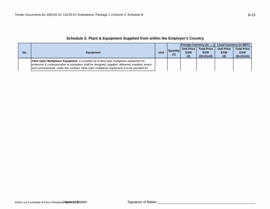
Tender Documents for 230/132 kV 132/33 kV Substations, Package 1.1Volume 3, Schedule B B-23
No. Equipment UnitQuantity
(1)
Unit PriceEXW(2)
Total PriceEXW
(3)=(1)x(2)
Unit PriceEXW(4)
Total PriceEXW
(5)=(1)x(4)
Schedule 2: Plant & Equipment Supplied from within the Employer's Country
Foreign Currency (in .....) Local Currency (in BDT)
Fibre Optic Multiplexer Equipment, a complete lot of fibre optic multiplexer equipment for protection & communication at substation shall be designed, supplied, delivered, installed, tested and commissioned, under this contract. Fibre optic multiplexer equipment is to be provided for.
ASHU vol 3 schedule B Price Schedules 2019 05 18Name of Bidder: Signature of Bidder:____________________________________________________
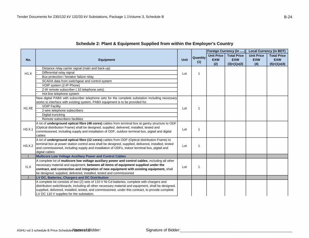
Tender Documents for 230/132 kV 132/33 kV Substations, Package 1.1Volume 3, Schedule B B-24
No. Equipment UnitQuantity
(1)
Unit PriceEXW(2)
Total PriceEXW
(3)=(1)x(2)
Unit PriceEXW(4)
Total PriceEXW
(5)=(1)x(4)
Schedule 2: Plant & Equipment Supplied from within the Employer's Country
Foreign Currency (in .....) Local Currency (in BDT)
· Distance relay carrier signal (main and back-up)· Differential relay signal· Bus protection / breaker failure relay· SCADA data from switchgear and control system· VOIP system (2-IP Phone)· 2-W remote subscriber ( 10 telephone sets)· Hot-line telephone systemNew digital PABX with subscriber telephone sets for the complete substation including necessaryworks to interface with existing system. PABX equipment is to be provided for. · VOIP Facility· 2-wire telephone subscribers
H1.X Lot 1
H1.XE Lot 1 2 wire telephone subscribers
· Digital truncking· Remote subscribers facilities
H3.X.1
A lot of underground optical fibre (48 cores) cables from terminal box at gantry structure to ODF (Optical distribution Frame) shall be designed, supplied, delivered, installed, tested and commissioned, including supply and installation of ODF, outdoor terminal box, pigtail and digital cables
Lot 1
H3.X.2
A lot of underground optical fibre (12 cores) cables from ODF (Optical distribution Frame) to terminal box at power station control area shall be designed, supplied, delivered, installed, tested and commissioned, including supply and installation of ODFs, indoor terminal box, pigtail and digital cables
Lot 1
I Multicore Low Voltage Auxiliary Power and Control Cables
I1.X
A complete lot of multicore low voltage auxiliary power and control cables, including all other necessary material and equipment, between all items of equipment supplied under the contract, and connection and integration of new equipment with existing equipment, shall be designed, supplied, delivered, installed, tested and commissioned
Lot 1
J LV DC, Batteries, Chargers and DC DistributionA complete lot consists of two (2) sets of 110 V Ni-Cd batteries, complete with chargers and distribution switchboards, including all other necessary material and equipment, shall be designed, supplied, delivered, installed, tested, and commissioned, under this contract, to provide complete LV DC 110 V supplies for the substation.
ASHU vol 3 schedule B Price Schedules 2019 05 18Name of Bidder: Signature of Bidder:____________________________________________________

Tender Documents for 230/132 kV 132/33 kV Substations, Package 1.1Volume 3, Schedule B B-25
No. Equipment UnitQuantity
(1)
Unit PriceEXW(2)
Total PriceEXW
(3)=(1)x(2)
Unit PriceEXW(4)
Total PriceEXW
(5)=(1)x(4)
Schedule 2: Plant & Equipment Supplied from within the Employer's Country
Foreign Currency (in .....) Local Currency (in BDT)
The system shall generally be as shown in the bid drawings and shall minimum include thefollowing:(a) Two (2) sets of 100% Ni-Cd batteries, complete, each capacity shall not be less than 800 Ah atthe 10-hour rate of discharge.(b) Two (2) sets of battery chargers complete, each float charge shall not be less than 250 Arating.(c) One (1) set of DC distribution switchboards.(d) One (1) set of Sub DC distribution switchboards for swicthyard panel room.(e) Two (s) set of UPS (without battery) system for SAS panels, 1kVAA complete lot consists of two (2) sets of 48V Ni-Cd batteries, complete with chargers and distribution switchboards, including all other necessary material and equipment, shall be designed,
J1.X Lot 1
supplied, delivered, installed, tested and commissioned, under this contract, to provide complete LV DC 48 V supplies for fibre optic multiplexer equipment for control, protection metering and communication.The system shall generally be as shown in the bid drawings and shall minimum include thefollowing:(a) Two (2) sets of 100% Ni-Cd batteries, complete, each capacity shall not be less than 150 Ah atthe 10-hour rate of discharge.(b) Two (2) sets of battery chargers complete, each float charge shall not be less than 30 A rating.
(c) One (1) set of DC distribution switchboard.
K LV AC Distribution
A complete lot, including all necessary material and equipment, including a set of LV AC switchboards, shall be designed, supplied, delivered, installed, tested and commissioned, under this contract, to provide the LV AC 400/230V, 50 Hz auxiliary power supplies for the substation
The system shall generally be as shown in the bid drawings and shall include one 125A outdoor weatherproof, 3-phase with neutral and earth switched socket outlet close to the power transformers
L Civil Works, Control Building and FoundationsOne (1) lot of complete land development of complete switchyard area by cutting, land filling, leveling up to a suitable level.The approximate total area of the substation is 1.5 acres
L1.X Lot 1
K1.X Lot 1
J2.X Lot 1
ASHU vol 3 schedule B Price Schedules 2019 05 18Name of Bidder: Signature of Bidder:____________________________________________________
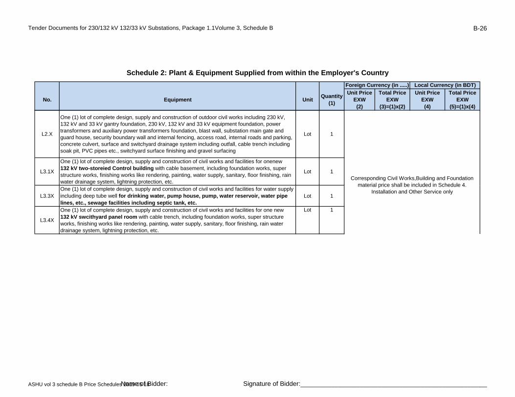
Tender Documents for 230/132 kV 132/33 kV Substations, Package 1.1Volume 3, Schedule B B-26
No. Equipment UnitQuantity
(1)
Unit PriceEXW(2)
Total PriceEXW
(3)=(1)x(2)
Unit PriceEXW(4)
Total PriceEXW
(5)=(1)x(4)
Schedule 2: Plant & Equipment Supplied from within the Employer's Country
Foreign Currency (in .....) Local Currency (in BDT)
L2.X
One (1) lot of complete design, supply and construction of outdoor civil works including 230 kV, 132 kV and 33 kV gantry foundation, 230 kV, 132 kV and 33 kV equipment foundation, power transformers and auxiliary power transformers foundation, blast wall, substation main gate and guard house, security boundary wall and internal fencing, access road, internal roads and parking, concrete culvert, surface and switchyard drainage system including outfall, cable trench including soak pit, PVC pipes etc., switchyard surface finishing and gravel surfacing
Lot 1
L3.1X
One (1) lot of complete design, supply and construction of civil works and facilities for onenew 132 kV two-storeied Control building with cable basement, including foundation works, super structure works, finishing works like rendering, painting, water supply, sanitary, floor finishing, rain water drainage system, lightning protection, etc.
Lot 1Corresponding Civil Works,Building and Foundation
material price shall be included in Schedule 4
L3.3XOne (1) lot of complete design, supply and construction of civil works and facilities for water supply including deep tube well for drinking water, pump house, pump, water reservoir, water pipe lines, etc., sewage facilities including septic tank, etc.
Lot 1
L3.4X
One (1) lot of complete design, supply and construction of civil works and facilities for one new 132 kV swcithyard panel room with cable trench, including foundation works, super structure works, finishing works like rendering, painting, water supply, sanitary, floor finishing, rain water drainage system, lightning protection, etc.
Lot 1
material price shall be included in Schedule 4. Installation and Other Service only
ASHU vol 3 schedule B Price Schedules 2019 05 18Name of Bidder: Signature of Bidder:____________________________________________________

Tender Documents for 230/132 kV 132/33 kV Substations, Package 1.1Volume 3, Schedule B B-27
No. Equipment UnitQuantity
(1)
Unit PriceEXW(2)
Total PriceEXW
(3)=(1)x(2)
Unit PriceEXW(4)
Total PriceEXW
(5)=(1)x(4)
Schedule 2: Plant & Equipment Supplied from within the Employer's Country
Foreign Currency (in .....) Local Currency (in BDT)
L3.5X
One (1) lot of complete design, supply and construction of civil works and facilities for one new fire fignting building with water supply network, including foundation works, super structure works,finishing works like rendering, painting, water supply, sanitary, floor finishing, rain water drainagesystem, lightning protection, etc.
Lot 1
L4.X One (1) lot of complete Pile load test Lot 1
L5.X Dismantaling of existing 132kV Switchgear and gantry foundation Lot 1
M Building Lighting, Small Power, Air Conditioning and Ventilation
M1.X
One (1) lot of complete equipment shall be designed, supplied, delivered, installed, tested and commissioned, to provide lighting, LV power supply, air conditioning system, ventilation, and emergency DC lighting for the substation control building(s), Fire Fighting Building and switchyard
l
Lot 1
panel room.N Switchyard Lighting and Security
N1.XE
One (1) lot of complete equipment for required switchyard area, shall be designed, supplied, delivered, installed, tested and commissioned, to provide extension of the existing switchyard lighting for security, roadway and switchyard and emergency DC lighting at strategic locations for equipment operations and inspections and for connection of new equipment and integration with the existing equipment.
Lot 1
N2.XE One (1) lot of complete CCTV camera system (min. 20 nos. Camera) for Control buildingincluding switchyard area with NVR and other required accessories.
Lot1
P Earthing and Lightning Protection
P1.X
One (1) lot of complete equipment shall be designed, supplied, delivered, installed, tested and commissioned, of earthing system and lightning protection screen including connections, connectors and clamps, to suit the substation overall arrangement and provide supporting design calculations.
Lot 1
Q GIB and HV Cable Connections
One (1) lot of complete equipment shall be designed, supplied, delivered, installed, tested and commissioned of three-phase or equivalent three single phase gas insulated busbars (GIB) with corresponding GIS connections and SF6/air bushings with corresponding GIS connections, with all required equipment; 145 kV, 2,000 A, 50 kA / 1 sec, 50 Hz, for connection of one 132 kV bay.
Approximate lengths are 15 to 30 meters
Q1.1 Lot 6
ASHU vol 3 schedule B Price Schedules 2019 05 18Name of Bidder: Signature of Bidder:____________________________________________________
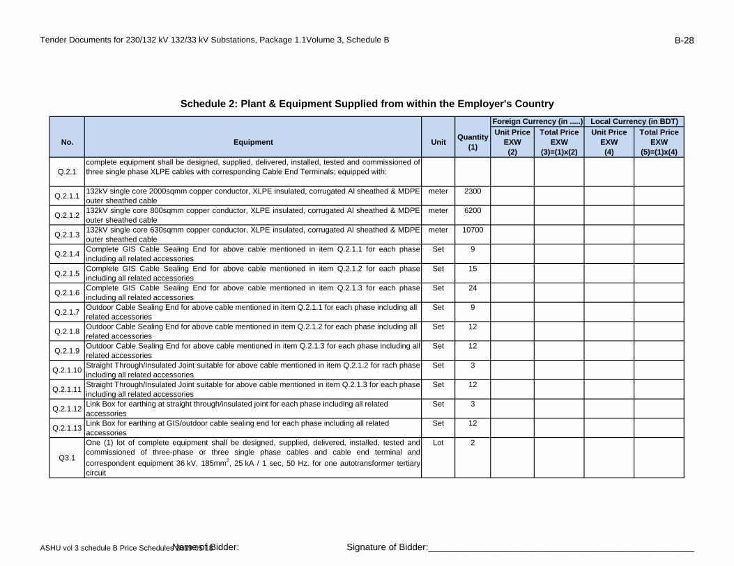
Tender Documents for 230/132 kV 132/33 kV Substations, Package 1.1Volume 3, Schedule B B-28
No. Equipment UnitQuantity
(1)
Unit PriceEXW(2)
Total PriceEXW
(3)=(1)x(2)
Unit PriceEXW(4)
Total PriceEXW
(5)=(1)x(4)
Schedule 2: Plant & Equipment Supplied from within the Employer's Country
Foreign Currency (in .....) Local Currency (in BDT)
Q.2.1complete equipment shall be designed, supplied, delivered, installed, tested and commissioned ofthree single phase XLPE cables with corresponding Cable End Terminals; equipped with:
Q.2.1.1132kV single core 2000sqmm copper conductor, XLPE insulated, corrugated Al sheathed & MDPEouter sheathed cable
meter 2300
Q.2.1.2132kV single core 800sqmm copper conductor, XLPE insulated, corrugated Al sheathed & MDPEouter sheathed cable
meter 6200
Q.2.1.3132kV single core 630sqmm copper conductor, XLPE insulated, corrugated Al sheathed & MDPEouter sheathed cable
meter 10700
Q.2.1.4Complete GIS Cable Sealing End for above cable mentioned in item Q.2.1.1 for each phaseincluding all related accessories
Set 9
Q.2.1.5Complete GIS Cable Sealing End for above cable mentioned in item Q.2.1.2 for each phaseincluding all related accessories
Set 15
Q.2.1.6Complete GIS Cable Sealing End for above cable mentioned in item Q.2.1.3 for each phaseincluding all related accessories
Set 24
Q.2.1.7Outdoor Cable Sealing End for above cable mentioned in item Q.2.1.1 for each phase including all related accessories
Set 9
Q.2.1.8Outdoor Cable Sealing End for above cable mentioned in item Q.2.1.2 for each phase including all related accessories
Set 12
Q.2.1.9Outdoor Cable Sealing End for above cable mentioned in item Q.2.1.3 for each phase including allrelated accessories
Set 12
Q.2.1.10Straight Through/Insulated Joint suitable for above cable mentioned in item Q.2.1.2 for rach phaseincluding all related accessories
Set 3
Q.2.1.11Straight Through/Insulated Joint suitable for above cable mentioned in item Q.2.1.3 for each phaseincluding all related accessories
Set 12
Q.2.1.12Link Box for earthing at straight through/insulated joint for each phase including all related accessories
Set 3
Q.2.1.13Link Box for earthing at GIS/outdoor cable sealing end for each phase including all related accessories
Set 12
Q3.1
One (1) lot of complete equipment shall be designed, supplied, delivered, installed, tested andcommissioned of three-phase or three single phase cables and cable end terminal and
correspondent equipment 36 kV, 185mm2, 25 kA / 1 sec, 50 Hz. for one autotransformer tertiarycircuit
Lot 2
ASHU vol 3 schedule B Price Schedules 2019 05 18Name of Bidder: Signature of Bidder:____________________________________________________
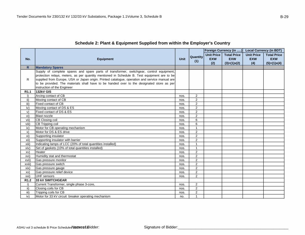
Tender Documents for 230/132 kV 132/33 kV Substations, Package 1.1Volume 3, Schedule B B-29
No. Equipment UnitQuantity
(1)
Unit PriceEXW(2)
Total PriceEXW
(3)=(1)x(2)
Unit PriceEXW(4)
Total PriceEXW
(5)=(1)x(4)
Schedule 2: Plant & Equipment Supplied from within the Employer's Country
Foreign Currency (in .....) Local Currency (in BDT)
R Mandatory Spares
R
Supply of complete spares and spare parts of transformer, switchgear, control equipment,protection relays, meters, as per quantity mentioned in Schedule B. Test equipment are to besupplied from Europe, USA or Japan origin. Printed catalogue, operation and service manual areto be provided. The materials shall have to be handed over to the designated store as perinstruction of the Engineer
R1.1 132kV GISi) Arcing contact of CB nos. 2ii) Moving contact of CB nos. 2iii) Fixed contact of CB nos. 2iv) Moving contact of DS & ES nos. 2v) Fixed contact of DS & ES nos. 2vi) Blast nozzle nos. 2vii) CB Closing coil nos. 6viii) CB Tripping coil nos. 6ix) Motor for CB operating mechanism nos. 1x) Motor for DS & ES drive nos. 2xi) Supporting insulator nos. 2xii) Supporting insulator with barrier nos. 2xiii) Indicating lamps of LCC (20% of total quantities installed) nos. 1xiv) Set of gaskets (10% of total quantities installed) nos. 1xv) Heater nos. 2xvi) Humidity stat and thermostat nos. 2xvii) Gas pressure monitor nos. 2xviii) Gas pressure switch nos. 2xix) Gas pressure gauge nos. 2xx) Gas pressure relief device nos. 2xxi) UHF sensors nos. 2
R1.2 33 kV SWITCHGEARi) Current Transformer, single phase 3-core, nos. 2ii) Closing coils for CB nos. 2iii) Tripping coils for CB nos. 2iv) Motor for 33 kV circuit breaker operating mechanism no. 1
ASHU vol 3 schedule B Price Schedules 2019 05 18Name of Bidder: Signature of Bidder:____________________________________________________
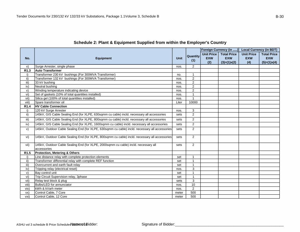
Tender Documents for 230/132 kV 132/33 kV Substations, Package 1.1Volume 3, Schedule B B-30
No. Equipment UnitQuantity
(1)
Unit PriceEXW(2)
Total PriceEXW
(3)=(1)x(2)
Unit PriceEXW(4)
Total PriceEXW
(5)=(1)x(4)
Schedule 2: Plant & Equipment Supplied from within the Employer's Country
Foreign Currency (in .....) Local Currency (in BDT)
v) Surge Arrester, single phase nos. 2R1.3 Auto Transformer
i) Transformer 230 kV bushings (For 300MVA Transformer) no. 1ii) Transformer 132 kV bushings (For 300MVA Transformer) nos. 2iii) 33 kV bushing nos. 2iv) Neutral bushing nos. 2v) Winding temperature indicating device nos. 2vi) Set of gaskets (10% of total quantities installed) nos. 1vii) Silica gel (100% of total quantities installed) nos. 1viii) Spare transformer oil Liter 10000
R1.4 HV Cable Connectioni) 120 kV Surge Arrester nos. 3ii) 145kV, GIS Cable Sealing End (for XLPE, 630sqmm cu cable) incld. necessary all accessories sets 2
iii) 145kV, GIS Cable Sealing End (for XLPE, 800sqmm cu cable) incld. necessary all accessories sets 2
iv) 145kV, GIS Cable Sealing End (for XLPE, 1600sqmm cu cable) incld. necessary all accessories sets 2
v) 145kV, Outdoor Cable Sealing End (for XLPE, 630sqmm cu cable) incld. necessary all accessories sets 2
vi) 145kV, Outdoor Cable Sealing End (for XLPE, 800sqmm cu cable) incld. necessary all accessories sets 2
vii) 145kV, Outdoor Cable Sealing End (for XLPE, 2000sqmm cu cable) incld. necessary all accessories
sets 2
R1.5 Protection, Metering & Othersi) Line distance relay with complete protection elements set 1ii) Transformer differential relay with complete REF function set 1iii) Overcurrent and earth fault relay set 1iv) Tripping relay (electrical reset) nos. 3v) Bay control unit set 1vi) Trip Circuit Supervision relay, 3phase set 1vii) Relay test block & plug sets 3viii) Bulbs/LED for annunciator nos. 10vix) kWh & kVarh meter nos. 2vx) Control Cable, 7 Core meter 500vxi) Control Cable, 12 Core meter 500
ASHU vol 3 schedule B Price Schedules 2019 05 18Name of Bidder: Signature of Bidder:____________________________________________________

Tender Documents for 230/132 kV 132/33 kV Substations, Package 1.1Volume 3, Schedule B B-31
No. Equipment UnitQuantity
(1)
Unit PriceEXW(2)
Total PriceEXW
(3)=(1)x(2)
Unit PriceEXW(4)
Total PriceEXW
(5)=(1)x(4)
Schedule 2: Plant & Equipment Supplied from within the Employer's Country
Foreign Currency (in .....) Local Currency (in BDT)
vxii) Line differential relay with complete protection elements set 5S Maintenance EquipmentS1 Supply of maintenance equipment as per quantity mentioned in Schedule B. Equioment are to be
supplied from EU, UK USA or Japan origin. Printed catalogue, operation and service manual are to be provided. The materials shall have to be handed over to the designated store as per instruction of the Engineer
i) Transformer oil treatment plant, 6000 Liters per hour set 1ii) Set of special tools, gauges and spanners for Autotransformer set 1iii) Set of special tools, gauges and spanners for GIS set 1iv) SF6 Gas Handling Equipment including storage tank as per cl. 3.4.6.18 set 1v) 3-phase portable (maintenance) earthing equipment devices with set 2
connectors and telescopic glass fibre operating stick suitable for each voltage as per cl. 7.12vi) Set of special tools for battery and charger set 1vii) set 1viii) 48kg SF6 gas cylinder with valve and instruments for refilling Set 3T Test EquipmentT1 Supply of test equipment as per quantity mentioned in Schedule B. Test equipment are to be
supplied from EU, UK, USA or Japan origin. Printed catalogue, operation and service manual are to be provided. The materials shall have to be handed over to the designated store as per instruction of the Engineer
i) SF6 Gas Analyzer as per cl. 3.4.6.19ii) SF6 Gas leak Detector set 1iii) Portable Partial Discharge(PD) monitoring system for GIS as per cl. 3.4.6.49 set 1iv) Contact resistance measurement test set (suitable for measurement down to 1 µ ohm at 200A d.c.) set 1
v) 5 kV insulation resistance test set (range 0.5 –1.0 - 2.5 - 5 kV) set 1vi) Earth resistance test set (range 10-100-1000 ohm: min scale division 0.01 ohm) set 1vii) Clip-on mA meter (for spill current) set 1viii) AVO Meter, digital set 1
Subtotal Renovation of existing 132 kV AIS to GIS to Schedule 5 -Grand Total
ASHU vol 3 schedule B Price Schedules 2019 05 18Name of Bidder: Signature of Bidder:____________________________________________________

Tender Documents for 230/132 kV 132/33 kV Substations, Package 1.1Volume 3, Schedule B B-32
No. Description UnitQuantity
(1)
Unit Price Foreign Portion
(2)
Total Price Foreign Portion
(3)=(1)x(2)
Unit Price Local Portion
(4)
Total Price Local Portion
(5)=(1)x(4)
Renovation of existing 132 kV AIS Substation at Ashuganj to 132kV GIS
Design and engineering services, local and foreign part Lump sum 1
Schedule 3: Design Services
Foreign Currency (in .......) Local Currency (BDT)
Subtotal Renovation of existing 132 kV AIS to GIS to Schedule 5 -Grand Total
ASHU vol 3 schedule B Price Schedules 2019 05 18Name of Bidder: Signature of Bidder:____________________________________________________

Tender Documents for 230/132 kV 132/33 kV Substations, Package 1.1Volume 3, Schedule B B-33
No. Equipment UnitQuantity
(1)
Unit Price Foreign Portion
(2)
Total Price Foreign Portion
(3)=(1)x(2)
Unit Price Local
Portion(4)
Total Price Local
Portion (5)=(1)x(4)
B 132 kV switchgear, equipment connection and steel structuresComplete equipment for switchgear 132 kV shall be designed, supplied, delivered, installed, tested and commissioned, under this contract, comprise the following:A complete outdoor GIS overhead line feeder 170 kV, 3150 A busbars / 2000 A feeder,50 kA, 50Hz, 750/325 kV BIL, equipped with:Q0 - One (1) set of three pole, single pole operation, GIS type, SF6 gas circuit breakerwith three spring-stored energy operating mechanism
Schedule 4: Installation and Other Services
Foreign Currency (in .......) Local Currency (BDT)
Renovation of existing 132 kV AIS Substation at Ashuganj to 132kV GIS
Q1, Q2, Q9 - Three (3) sets of three pole, three positions, motor operated, insulateddisconnector with earthing switchQ8 - One (1) set of three pole, make-proof, motor operated earthing switchT1 -Three (3) single-phase, 5-core, multi ratio, 3200-1600-800/1/1/1/1/1 A, GIS typecurrent transformersT5 - Three (3) single-phase, 2-secondary winding, 132/V3 / 110/V3 / 110/V3 kV/V/V, GIStype voltage transformersT6 - One (1) set of three-phase, GIS type, hand operated disconnector linkSA - Three (3) single-phase outdoor surge arresters, GIS typeZ2 - One (1) set of three phase outdoor GIB with three outdoor GIS/AIR bushingsGIS.X - Control cabinet, cables, metal support structure, grounding, etc. and allaccessories for complete bayA complete outdoor GIS overhead line feeder 170 kV, 3150 A busbars / 2000 A feeder,50 kA, 50Hz, 750/325 kV BIL, equipped with:Q0 - One (1) set of three pole, single pole operation, GIS type, SF6 gas circuit breakerwith three spring-stored energy operating mechanismQ1, Q2, Q9 - Three (3) sets of three pole, three positions, motor operated, insulateddisconnector with earthing switchQ8 - One (1) set of three pole, make-proof, motor operated earthing switchT1 -Three (3) single-phase, 5-core, multi ratio, 3200-1600-800/1/1/1/1/1 A, GIS typecurrent transformers
BG.1.1 Set 6
BG.1.2 Set 1
ASHU vol 3 schedule B Price Schedules 2019 05 18Name of Bidder: Signature of Bidder:____________________________________________________

Tender Documents for 230/132 kV 132/33 kV Substations, Package 1.1Volume 3, Schedule B B-34
No. Equipment UnitQuantity
(1)
Unit Price Foreign Portion
(2)
Total Price Foreign Portion
(3)=(1)x(2)
Unit Price Local
Portion(4)
Total Price Local
Portion (5)=(1)x(4)
Schedule 4: Installation and Other Services
Foreign Currency (in .......) Local Currency (BDT)
T5 - Three (3) single-phase, 2-secondary winding, 132/V3 / 110/V3 / 110/V3 kV/V/V, GIStype voltage transformersT6 - One (1) set of three-phase, GIS type, hand operated disconnector linkSA - Three (3) single-phase outdoor surge arresters, GIS typeZ1 - One (1) set of three-phase, GIS type, cable compartmentGIS.X - Control cabinet, cables, metal support structure, grounding, etc. and allaccessories for complete bayA complete outdoor GIS 230/132/33kV auto transformer feeder 170 kV, 3150A busbars/ 2000 A feeder, 50 kA, 50Hz, 750/325 kV BIL, equipped with:Q0 - One (1) set of three pole, gang operation, GIS type, SF6 gas circuit breaker with onespring-stored energy operating mechanismQ1, Q2, Q9 - Three (3) set of three pole, three position, motor operated, insulateddisconnector with earthing switchQ8 - One (1) set of three pole, make-proof, motor operated earthing switchT1 -Three (3) single-phase, 5-core, multi ratio, 3200-1600-800/1/1/1/1/1 A, GIS typecurrent transformersSA - Three (3) single-phase outdoor surge arresters, GIS typeZ1 - One (1) set of three-phase, GIS type, cable compartment X - Control cabinet, cables, metal support structure, grounding, etc. and allaccessories for complete bayA complete outdoor GIS 132/33kV power transformer feeder 170 kV, 3150A busbars /2000 A feeder, 50 kA, 50Hz, 750/325 kV BIL, equipped with:Q0 - One (1) set of three pole, gang operation, GIS type, SF6 gas circuit breaker with onespring-stored energy operating mechanismQ1, Q2, Q9 - Three (3) set of three pole, three position, motor operated, insulateddisconnector with earthing switchQ8 - One (1) set of three pole, make-proof, motor operated earthing switchT1 -Three (3) single-phase, 5-core, multi ratio, 3200-1600-800/1/1/1/1/1 A, GIS typecurrent transformersZ1 - One (1) set of three-phase, GIS type, cable compartmentX - Control cabinet, cables, metal support structure, grounding, etc. and all accessories forcomplete bay
BG.2.1 Set 2
BG.2.2 Set 4
ASHU vol 3 schedule B Price Schedules 2019 05 18Name of Bidder: Signature of Bidder:____________________________________________________
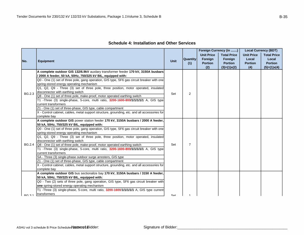
Tender Documents for 230/132 kV 132/33 kV Substations, Package 1.1Volume 3, Schedule B B-35
No. Equipment UnitQuantity
(1)
Unit Price Foreign Portion
(2)
Total Price Foreign Portion
(3)=(1)x(2)
Unit Price Local
Portion(4)
Total Price Local
Portion (5)=(1)x(4)
Schedule 4: Installation and Other Services
Foreign Currency (in .......) Local Currency (BDT)
A complete outdoor GIS 132/6.9kV auxilary transformer feeder 170 kV, 3150A busbars/ 2000 A feeder, 50 kA, 50Hz, 750/325 kV BIL, equipped with:Q0 - One (1) set of three pole, gang operation, GIS type, SF6 gas circuit breaker with onespring-stored energy operating mechanismQ1, Q2, Q9 - Three (3) set of three pole, three position, motor operated, insulateddisconnector with earthing switchQ8 - One (1) set of three pole, make-proof, motor operated earthing switchT1 -Three (3) single-phase, 5-core, multi ratio, 3200-1600-800/1/1/1/1/1 A, GIS typecurrent transformersZ1 - One (1) set of three-phase, GIS type, cable compartment
BG.2.3 Set 2
( ) p yp pX - Control cabinet, cables, metal support structure, grounding, etc. and all accessories forcomplete bayA complete outdoor GIS power station feeder 170 kV, 3150A busbars / 2000 A feeder,50 kA, 50Hz, 750/325 kV BIL, equipped with:Q0 - One (1) set of three pole, gang operation, GIS type, SF6 gas circuit breaker with onespring-stored energy operating mechanismQ1, Q2, Q9 - Three (3) set of three pole, three position, motor operated, insulateddisconnector with earthing switchQ8 - One (1) set of three pole, make-proof, motor operated earthing switchT1 -Three (3) single-phase, 5-core, multi ratio, 3200-1600-800/1/1/1/1/1 A, GIS typecurrent transformersSA - Three (3) single-phase outdoor surge arresters, GIS typeZ1 - One (1) set of three-phase, GIS type, cable compartmentX - Control cabinet, cables, metal support structure, grounding, etc. and all accessories forcomplete bayA complete outdoor GIS bus sectionalize bay 170 kV, 3150A busbars / 3150 A feeder,50 kA, 50Hz, 750/325 kV BIL, equipped with:Q0 - Two (2) sets of three pole, gang operation, GIS type, SF6 gas circuit breaker withone spring-stored energy operating mechanismT1 -Three (3) single-phase, 5-core, multi ratio, 3200-1600/1/1/1/1/1 A, GIS type currenttransformers
BG.2.4 Set 7
BG 3 1 Set 1
ASHU vol 3 schedule B Price Schedules 2019 05 18Name of Bidder: Signature of Bidder:____________________________________________________

Tender Documents for 230/132 kV 132/33 kV Substations, Package 1.1Volume 3, Schedule B B-36
No. Equipment UnitQuantity
(1)
Unit Price Foreign Portion
(2)
Total Price Foreign Portion
(3)=(1)x(2)
Unit Price Local
Portion(4)
Total Price Local
Portion (5)=(1)x(4)
Schedule 4: Installation and Other Services
Foreign Currency (in .......) Local Currency (BDT)
T2 -Three (3) single-phase, 5-core, multi ratio, 3200-1600/1/1/1/1/1 A, GIS type currenttransformersQ11, Q12, Q21, Q22 - Four (4) set of three pole, three position, motor operated, insulateddisconnector with earthing switchX - Control cabinet, cables, metal support structure, grounding, etc. and all accessories forcomplete bayA complete outdoor GIS bus coupler bay 170 kV, 3150A busbars / 3150 A feeder,50 kA, 50Hz, 750/325 kV BIL, equipped with:Q0 - One (1) set of three pole, gang operation, GIS type, SF6 gas circuit breaker with one spring-stored energy operating mechanism
BG.3.1 Set 1
p g gy p gQ1, Q2 - Two (2) set of three pole, three position, motor operated, insulated disconnectorwith earthing switchT1 -Three (3) single-phase, 5-core, multi ratio, 3200-1600/1/1/1/1/1 A, GIS type currenttransformersX - Control cabinet, cables, metal support structure, grounding, etc. and all accessories forcomplete bayA complete outdoor GIS metering bay 145 kV, 3150A busbars, 50 kA, 50Hz,750/325 kV BIL, equipped with:Q21, Q22 - Two (2) set of three pole, three position, motor operated, insulateddisconnector T5 - Three (3) single-phase, 2-winding, 132/V3 / 110/V3 / 110/V3kV/110/V3kV, GIS typevoltage transformersX - Control cabinet, cables, metal support structure, grounding, etc. and all accessories forcomplete bayA complete outdoor GIS busbars earthing bay 170 kV, 3150A busbars, 50 kA, 50Hz,750/325 kV BIL, equipped with:Q81, Q82 - Two (2) set of three pole, make-proof, motor operated earthing switch
B5Surge arrester 145 kV, 120 kV continuous operating voltage, 10kA nominal dischargecurrent, 50Hz, single phase, heavy duty, station class, gapless, metal oxide type
Set 54
B6 Post Insulator 132 kV, 50 Hz, 650/275 kV BIL, 10 kN Set 9
BG.3.2 Set 2
BG.3.3 Set 2
BG.4 Set 2
ASHU vol 3 schedule B Price Schedules 2019 05 18Name of Bidder: Signature of Bidder:____________________________________________________
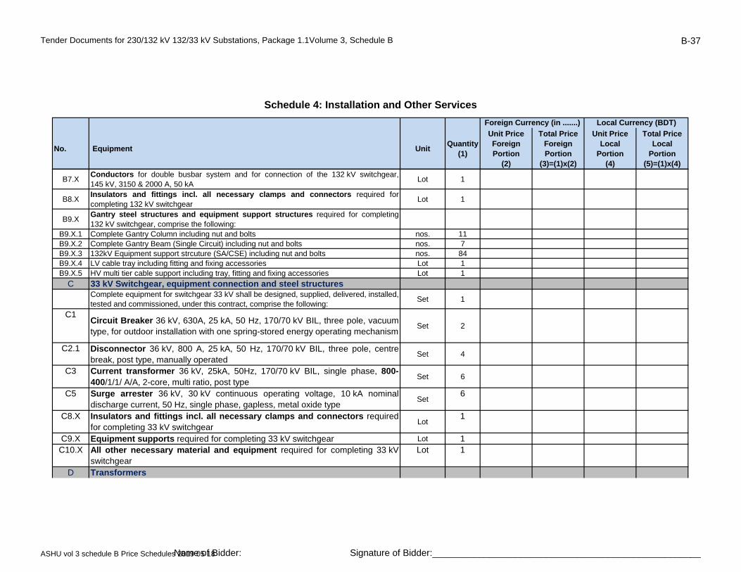
Tender Documents for 230/132 kV 132/33 kV Substations, Package 1.1Volume 3, Schedule B B-37
No. Equipment UnitQuantity
(1)
Unit Price Foreign Portion
(2)
Total Price Foreign Portion
(3)=(1)x(2)
Unit Price Local
Portion(4)
Total Price Local
Portion (5)=(1)x(4)
Schedule 4: Installation and Other Services
Foreign Currency (in .......) Local Currency (BDT)
B7.XConductors for double busbar system and for connection of the 132 kV switchgear,145 kV, 3150 & 2000 A, 50 kA
Lot 1
B8.XInsulators and fittings incl. all necessary clamps and connectors required forcompleting 132 kV switchgear
Lot 1
B9.XGantry steel structures and equipment support structures required for completing132 kV switchgear, comprise the following:
B9.X.1 Complete Gantry Column including nut and bolts nos. 11B9.X.2 Complete Gantry Beam (Single Circuit) including nut and bolts nos. 7B9.X.3 132kV Equipment support strcuture (SA/CSE) including nut and bolts nos. 84B9.X.4 LV cable tray including fitting and fixing accessories Lot 1y g g gB9.X.5 HV multi tier cable support including tray, fitting and fixing accessories Lot 1
C 33 kV Switchgear, equipment connection and steel structuresComplete equipment for switchgear 33 kV shall be designed, supplied, delivered, installed,tested and commissioned, under this contract, comprise the following:
Set 1
C1Circuit Breaker 36 kV, 630A, 25 kA, 50 Hz, 170/70 kV BIL, three pole, vacuumtype, for outdoor installation with one spring-stored energy operating mechanism
Set 2
C2.1 Disconnector 36 kV, 800 A, 25 kA, 50 Hz, 170/70 kV BIL, three pole, centrebreak, post type, manually operated
Set 4
C3 Current transformer 36 kV, 25kA, 50Hz, 170/70 kV BIL, single phase, 800-400/1/1/ A/A, 2-core, multi ratio, post type
Set 6
C5 Surge arrester 36 kV, 30 kV continuous operating voltage, 10 kA nominaldischarge current, 50 Hz, single phase, gapless, metal oxide type
Set6
C8.X Insulators and fittings incl. all necessary clamps and connectors requiredfor completing 33 kV switchgear
Lot1
C9.X Equipment supports required for completing 33 kV switchgear Lot 1C10.X All other necessary material and equipment required for completing 33 kV
switchgearLot 1
D Transformers
ASHU vol 3 schedule B Price Schedules 2019 05 18Name of Bidder: Signature of Bidder:____________________________________________________
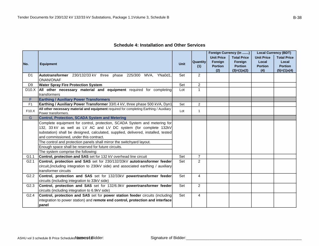
Tender Documents for 230/132 kV 132/33 kV Substations, Package 1.1Volume 3, Schedule B B-38
No. Equipment UnitQuantity
(1)
Unit Price Foreign Portion
(2)
Total Price Foreign Portion
(3)=(1)x(2)
Unit Price Local
Portion(4)
Total Price Local
Portion (5)=(1)x(4)
Schedule 4: Installation and Other Services
Foreign Currency (in .......) Local Currency (BDT)
D1 Autotransformer 230/132/33 kV three phase 225/300 MVA, YNa0d1,ONAN/ONAF
Set 2
D9 Water Spray Fire Protection System Set 2D10.X All other necessary material and equipment required for completing
transformersLot 1
F Earthing / Auxiliary Power TransformersF1 Earthing / Auxiliary Power Transformer 33/0.4 kV, three phase 500 kVA, Dyn1 Set 2
F10.XAll other necessary material and equipment required for completing Earthing / Auxiliary Power transformers.
Lot 1
G Control, Protection, SCADA System and Metering
Complete equipment for control, protection, SCADA System and metering for132, 33 kV as well as LV AC and LV DC system (for complete 132kVsubstation) shall be designed, calculated, supplied, delivered, installed, testedand commissioned, under this contract.The control and protection panels shall mirror the switchyard layout.Enough space shall be reserved for future circuits.The system comprise the following:
G1.1 Control, protection and SAS set for 132 kV overhead line circuit Set 7G2.1 Control, protection and SAS set for 230/132/33kV autotransformer feeder
circuit,(including integration to 230kV side) and associated earthing / auxiliarytransformer circuits
Set 2
G2.2 Control, protection and SAS set for 132/33kV powertransformer feedercircuits (including integration to 33kV side)
Set 4
G2.3 Control, protection and SAS set for 132/6.9kV powertransformer feedercircuits (including integration to 6.9kV side)
Set 2
G2.4 Control, protection and SAS set for power station feeder circuits (includingintegration to power station) and remote end control, protection and interfacepanel
Set 4
ASHU vol 3 schedule B Price Schedules 2019 05 18Name of Bidder: Signature of Bidder:____________________________________________________

Tender Documents for 230/132 kV 132/33 kV Substations, Package 1.1Volume 3, Schedule B B-39
No. Equipment UnitQuantity
(1)
Unit Price Foreign Portion
(2)
Total Price Foreign Portion
(3)=(1)x(2)
Unit Price Local
Portion(4)
Total Price Local
Portion (5)=(1)x(4)
Schedule 4: Installation and Other Services
Foreign Currency (in .......) Local Currency (BDT)
G3.1 Control, protection and SAS set for busbar 132 kV Set 1G3.2 Control, protection and SAS set for buscoupler bay 132 kV Set 2G3.3 Control, protection and SAS set for bus sectionalizer bay 132 kV Set 1
G4.X
Tariff metering panel(s) to accommodate programmable & recordable digital 3-phase, 4-wire import and export MWh and MVArh meters(accuracy class 0.2) for each 132kV line, power station and power transformer feeder. For each feeder, minimum two (2) meters (main-1 & main-2) shall be provided
Lot 1
G5.X Digital Fault and Disturbance Recorder (DFDR) to accommodate all 132kV feeders Lot 1
Tele-control & Tele-protection & Tele-metering facilities,A complete lot of hardware and software, extension of the existing equipment, necessary adjustment, adaptation, modification, integration and configuration of new and existing 132kV equipment;All necessary modification works in the hardware and software of the master stations shall be provided, both at the National Load Despatch Centre (NLDC) at Aftabnagar and at the back-up station at Biddut Bhaban, for integration of the complete substation.
All required electrical signals shall be transmitted to the NLDC and the back-up station through the industrial gateway of the substation automation system. All HV circuit breakers, disconnectors, tap changer, etc., shall be controlled from the NLDC through the gateway of the substation automation system using the IEC 60870-5-104 protocol.
G10.XAll other necessary material and equipment required for completing control, protection, substation automation and metering system.
Lot 1
H Fibre Optic Multiplexer Equipment for Tele-protection and Communication
Fibre Optic Multiplexer Equipment, a complete lot of fibre optic multiplexer equipment for protection & communication at substation shall be designed, supplied, delivered, installed, tested and commissioned, under this contract. Fibre optic multiplexer equipment is to be provided for.
· Distance relay carrier signal (main and back-up)
G6.X Lot 1
ASHU vol 3 schedule B Price Schedules 2019 05 18Name of Bidder: Signature of Bidder:____________________________________________________
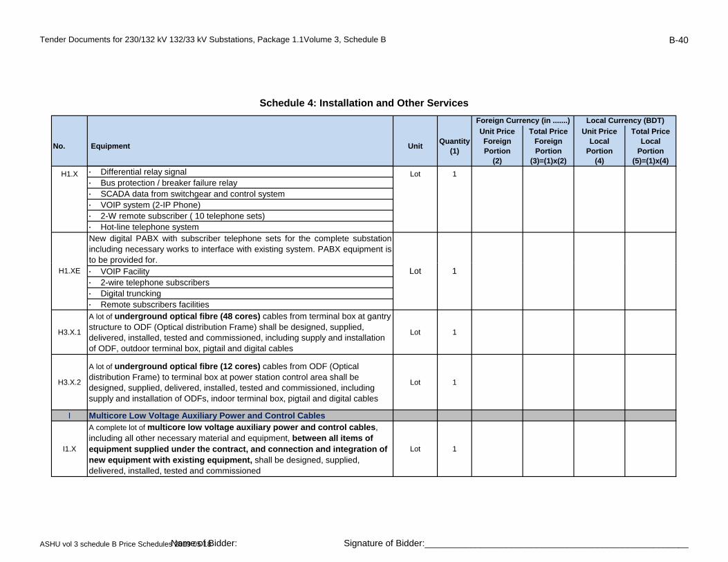
Tender Documents for 230/132 kV 132/33 kV Substations, Package 1.1Volume 3, Schedule B B-40
No. Equipment UnitQuantity
(1)
Unit Price Foreign Portion
(2)
Total Price Foreign Portion
(3)=(1)x(2)
Unit Price Local
Portion(4)
Total Price Local
Portion (5)=(1)x(4)
Schedule 4: Installation and Other Services
Foreign Currency (in .......) Local Currency (BDT)
· Differential relay signal· Bus protection / breaker failure relay· SCADA data from switchgear and control system· VOIP system (2-IP Phone)· 2-W remote subscriber ( 10 telephone sets)· Hot-line telephone systemNew digital PABX with subscriber telephone sets for the complete substationincluding necessary works to interface with existing system. PABX equipment isto be provided for.
H1.X Lot 1
p· VOIP Facility· 2-wire telephone subscribers· Digital truncking· Remote subscribers facilities
H3.X.1
A lot of underground optical fibre (48 cores) cables from terminal box at gantry structure to ODF (Optical distribution Frame) shall be designed, supplied, delivered, installed, tested and commissioned, including supply and installation of ODF, outdoor terminal box, pigtail and digital cables
Lot 1
H3.X.2
A lot of underground optical fibre (12 cores) cables from ODF (Optical distribution Frame) to terminal box at power station control area shall be designed, supplied, delivered, installed, tested and commissioned, including supply and installation of ODFs, indoor terminal box, pigtail and digital cables
Lot 1
I Multicore Low Voltage Auxiliary Power and Control Cables
I1.X
A complete lot of multicore low voltage auxiliary power and control cables, including all other necessary material and equipment, between all items of equipment supplied under the contract, and connection and integration of new equipment with existing equipment, shall be designed, supplied, delivered, installed, tested and commissioned
Lot 1
H1.XE Lot 1
ASHU vol 3 schedule B Price Schedules 2019 05 18Name of Bidder: Signature of Bidder:____________________________________________________
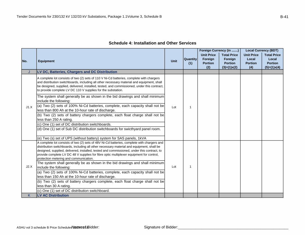
Tender Documents for 230/132 kV 132/33 kV Substations, Package 1.1Volume 3, Schedule B B-41
No. Equipment UnitQuantity
(1)
Unit Price Foreign Portion
(2)
Total Price Foreign Portion
(3)=(1)x(2)
Unit Price Local
Portion(4)
Total Price Local
Portion (5)=(1)x(4)
Schedule 4: Installation and Other Services
Foreign Currency (in .......) Local Currency (BDT)
J LV DC, Batteries, Chargers and DC Distribution
A complete lot consists of two (2) sets of 110 V Ni-Cd batteries, complete with chargers and distribution switchboards, including all other necessary material and equipment, shall be designed, supplied, delivered, installed, tested, and commissioned, under this contract, to provide complete LV DC 110 V supplies for the substation.
The system shall generally be as shown in the bid drawings and shall minimuminclude the following:(a) Two (2) sets of 100% Ni-Cd batteries, complete, each capacity shall not beless than 800 Ah at the 10 hour rate of discharge
J1.X Lot 1less than 800 Ah at the 10-hour rate of discharge.(b) Two (2) sets of battery chargers complete, each float charge shall not beless than 250 A rating.(c) One (1) set of DC distribution switchboards.(d) One (1) set of Sub DC distribution switchboards for swicthyard panel room.
(e) Two (s) set of UPS (without battery) system for SAS panels, 1kVAA complete lot consists of two (2) sets of 48V Ni-Cd batteries, complete with chargers and distribution switchboards, including all other necessary material and equipment, shall be designed, supplied, delivered, installed, tested and commissioned, under this contract, to provide complete LV DC 48 V supplies for fibre optic multiplexer equipment for control, protection metering and communication.
The system shall generally be as shown in the bid drawings and shall minimuminclude the following:(a) Two (2) sets of 100% Ni-Cd batteries, complete, each capacity shall not beless than 150 Ah at the 10-hour rate of discharge.(b) Two (2) sets of battery chargers complete, each float charge shall not beless than 30 A rating.(c) One (1) set of DC distribution switchboard.
K LV AC Distribution
J2.X Lot 1
ASHU vol 3 schedule B Price Schedules 2019 05 18Name of Bidder: Signature of Bidder:____________________________________________________
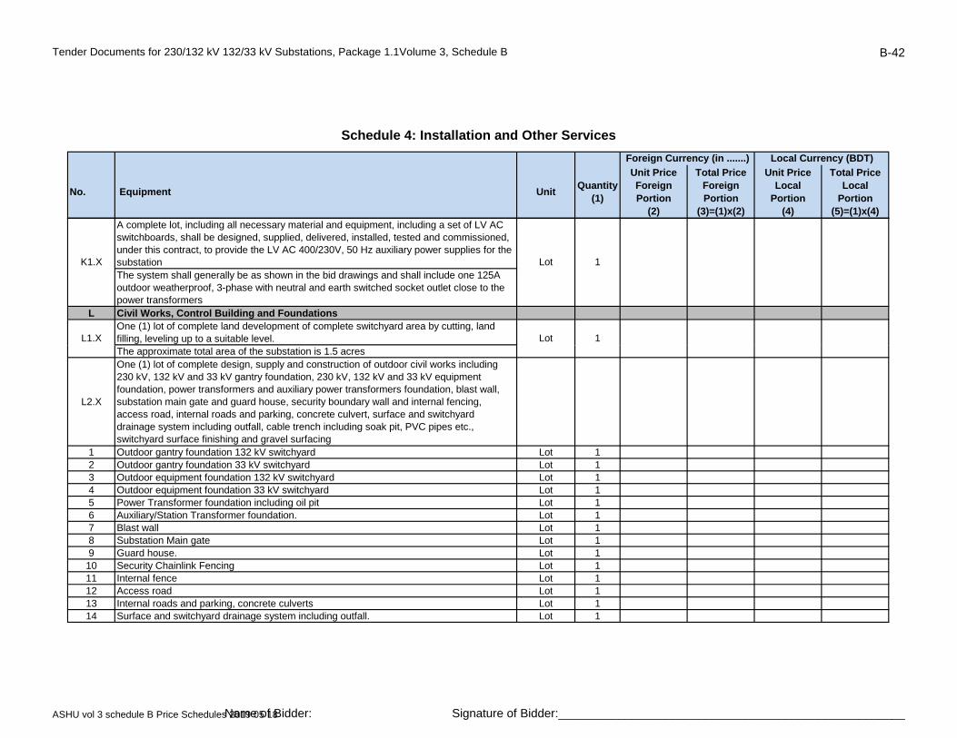
Tender Documents for 230/132 kV 132/33 kV Substations, Package 1.1Volume 3, Schedule B B-42
No. Equipment UnitQuantity
(1)
Unit Price Foreign Portion
(2)
Total Price Foreign Portion
(3)=(1)x(2)
Unit Price Local
Portion(4)
Total Price Local
Portion (5)=(1)x(4)
Schedule 4: Installation and Other Services
Foreign Currency (in .......) Local Currency (BDT)
A complete lot, including all necessary material and equipment, including a set of LV AC switchboards, shall be designed, supplied, delivered, installed, tested and commissioned, under this contract, to provide the LV AC 400/230V, 50 Hz auxiliary power supplies for the substationThe system shall generally be as shown in the bid drawings and shall include one 125A outdoor weatherproof, 3-phase with neutral and earth switched socket outlet close to the power transformers
L Civil Works, Control Building and FoundationsOne (1) lot of complete land development of complete switchyard area by cutting, land filling, leveling up to a suitable level.
K1.X Lot 1
L1.X Lot 1The approximate total area of the substation is 1.5 acres
L2.X
One (1) lot of complete design, supply and construction of outdoor civil works including 230 kV, 132 kV and 33 kV gantry foundation, 230 kV, 132 kV and 33 kV equipment foundation, power transformers and auxiliary power transformers foundation, blast wall, substation main gate and guard house, security boundary wall and internal fencing, access road, internal roads and parking, concrete culvert, surface and switchyard drainage system including outfall, cable trench including soak pit, PVC pipes etc., switchyard surface finishing and gravel surfacing
1 Outdoor gantry foundation 132 kV switchyard Lot 12 Outdoor gantry foundation 33 kV switchyard Lot 13 Outdoor equipment foundation 132 kV switchyard Lot 14 Outdoor equipment foundation 33 kV switchyard Lot 15 Power Transformer foundation including oil pit Lot 16 Auxiliary/Station Transformer foundation. Lot 17 Blast wall Lot 18 Substation Main gate Lot 19 Guard house. Lot 110 Security Chainlink Fencing Lot 111 Internal fence Lot 112 Access road Lot 113 Internal roads and parking, concrete culverts Lot 114 Surface and switchyard drainage system including outfall. Lot 1
ASHU vol 3 schedule B Price Schedules 2019 05 18Name of Bidder: Signature of Bidder:____________________________________________________

Tender Documents for 230/132 kV 132/33 kV Substations, Package 1.1Volume 3, Schedule B B-43
No. Equipment UnitQuantity
(1)
Unit Price Foreign Portion
(2)
Total Price Foreign Portion
(3)=(1)x(2)
Unit Price Local
Portion(4)
Total Price Local
Portion (5)=(1)x(4)
Schedule 4: Installation and Other Services
Foreign Currency (in .......) Local Currency (BDT)
15 Cable Trench including soak pit, PVC pipes etc. Lot 116 Switchyard surface finishing. Lot 117 Gravel surfacing. Lot 1
18Boundary wallPayment will be on actual basis
m 50
L3.1X
One (1) lot of complete design, supply and construction of civil works and facilities for onenew 132 kV two-storeied Control building with cable basement, including foundation works, super structure works, finishing works like rendering, painting, water supply, sanitary, floor finishing, rain water drainage system, lightning protection etc
Lot 1
protection, etc.1 Complete Foundation works. Lot 12 Complete Super structures works. Lot 1
3Complete all finishing works like rendering, painting, water supply, sanitary, floor finish, furniture, etc.
Lot 1
L3.3XOne (1) lot of complete design, supply and construction of civil works and facilities for water supply including deep tube well for drinking water, pump house, pump, water reservoir, water pipe lines, etc., sewage facilities including septic tank, etc.
Lot 1
1Water supply, including Pump house with deep tube well for drinking water, motor, pump, water reservoir, water pipe line, necessary fittings etc. all complete.
Lot 1
2 Sewage facilities, including Septic tank, soak well etc. all complete Lot 1
L3.4X
One (1) lot of complete design, supply and construction of civil works and facilities for one new 132 kV swcithyard panel room with cable trench, including foundation works, super structure works, finishing works like rendering, painting, water supply, sanitary, floor finishing, rain water drainage system, lightning protection, etc.
1 Complete Foundation works. Lot 12 Complete Super structures works. Lot 1
3Complete all finishing works like rendering, painting, water supply, sanitary, floor finish, furniture, etc.
Lot 1
ASHU vol 3 schedule B Price Schedules 2019 05 18Name of Bidder: Signature of Bidder:____________________________________________________
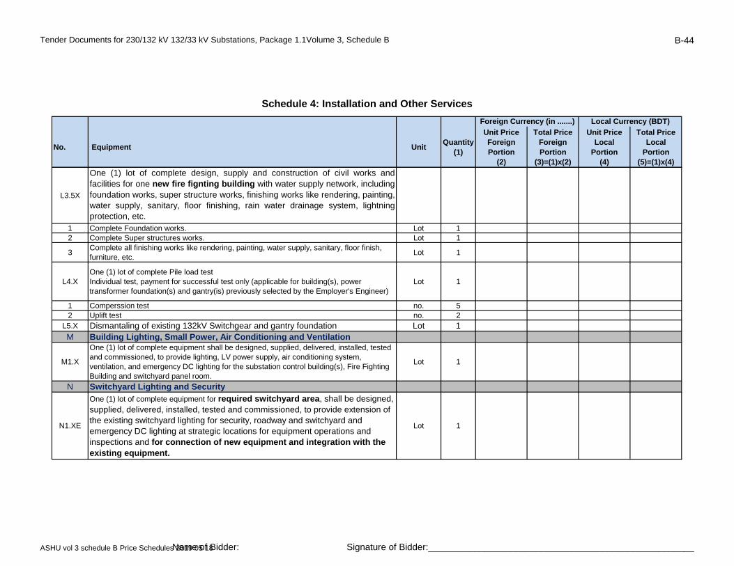
Tender Documents for 230/132 kV 132/33 kV Substations, Package 1.1Volume 3, Schedule B B-44
No. Equipment UnitQuantity
(1)
Unit Price Foreign Portion
(2)
Total Price Foreign Portion
(3)=(1)x(2)
Unit Price Local
Portion(4)
Total Price Local
Portion (5)=(1)x(4)
Schedule 4: Installation and Other Services
Foreign Currency (in .......) Local Currency (BDT)
L3.5X
One (1) lot of complete design, supply and construction of civil works andfacilities for one new fire fignting building with water supply network, includingfoundation works, super structure works, finishing works like rendering, painting,water supply, sanitary, floor finishing, rain water drainage system, lightningprotection, etc.
1 Complete Foundation works. Lot 12 Complete Super structures works. Lot 1
3Complete all finishing works like rendering, painting, water supply, sanitary, floor finish, furniture, etc.
Lot 1
L4.XOne (1) lot of complete Pile load testIndividual test, payment for successful test only (applicable for building(s), power transformer foundation(s) and gantry(is) previously selected by the Employer's Engineer)
Lot 1
1 Comperssion test no. 52 Uplift test no. 2
L5.X Dismantaling of existing 132kV Switchgear and gantry foundation Lot 1M Building Lighting, Small Power, Air Conditioning and Ventilation
M1.X
One (1) lot of complete equipment shall be designed, supplied, delivered, installed, tested and commissioned, to provide lighting, LV power supply, air conditioning system, ventilation, and emergency DC lighting for the substation control building(s), Fire Fighting Building and switchyard panel room.
Lot 1
N Switchyard Lighting and Security
N1.XE
One (1) lot of complete equipment for required switchyard area, shall be designed, supplied, delivered, installed, tested and commissioned, to provide extension of the existing switchyard lighting for security, roadway and switchyard and emergency DC lighting at strategic locations for equipment operations and inspections and for connection of new equipment and integration with the existing equipment.
Lot 1
ASHU vol 3 schedule B Price Schedules 2019 05 18Name of Bidder: Signature of Bidder:____________________________________________________
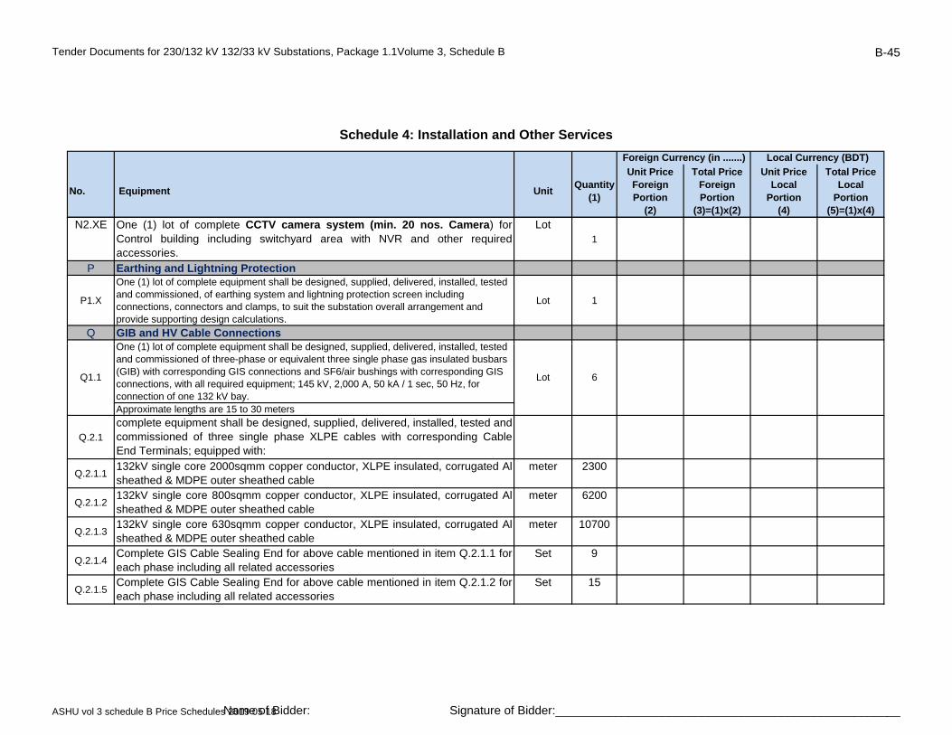
Tender Documents for 230/132 kV 132/33 kV Substations, Package 1.1Volume 3, Schedule B B-45
No. Equipment UnitQuantity
(1)
Unit Price Foreign Portion
(2)
Total Price Foreign Portion
(3)=(1)x(2)
Unit Price Local
Portion(4)
Total Price Local
Portion (5)=(1)x(4)
Schedule 4: Installation and Other Services
Foreign Currency (in .......) Local Currency (BDT)
N2.XE One (1) lot of complete CCTV camera system (min. 20 nos. Camera) forControl building including switchyard area with NVR and other requiredaccessories.
Lot1
P Earthing and Lightning Protection
P1.X
One (1) lot of complete equipment shall be designed, supplied, delivered, installed, tested and commissioned, of earthing system and lightning protection screen including connections, connectors and clamps, to suit the substation overall arrangement and provide supporting design calculations.
Lot 1
Q GIB and HV Cable ConnectionsO (1) l t f l t i t h ll b d i d li d d li d i t ll d t t dOne (1) lot of complete equipment shall be designed, supplied, delivered, installed, tested and commissioned of three-phase or equivalent three single phase gas insulated busbars (GIB) with corresponding GIS connections and SF6/air bushings with corresponding GIS connections, with all required equipment; 145 kV, 2,000 A, 50 kA / 1 sec, 50 Hz, for connection of one 132 kV bay.Approximate lengths are 15 to 30 meters
Q.2.1
complete equipment shall be designed, supplied, delivered, installed, tested andcommissioned of three single phase XLPE cables with corresponding CableEnd Terminals; equipped with:
Q.2.1.1132kV single core 2000sqmm copper conductor, XLPE insulated, corrugated Alsheathed & MDPE outer sheathed cable
meter 2300
Q.2.1.2132kV single core 800sqmm copper conductor, XLPE insulated, corrugated Alsheathed & MDPE outer sheathed cable
meter 6200
Q.2.1.3132kV single core 630sqmm copper conductor, XLPE insulated, corrugated Alsheathed & MDPE outer sheathed cable
meter 10700
Q.2.1.4Complete GIS Cable Sealing End for above cable mentioned in item Q.2.1.1 foreach phase including all related accessories
Set 9
Q.2.1.5Complete GIS Cable Sealing End for above cable mentioned in item Q.2.1.2 foreach phase including all related accessories
Set 15
Q1.1 Lot 6
ASHU vol 3 schedule B Price Schedules 2019 05 18Name of Bidder: Signature of Bidder:____________________________________________________

Tender Documents for 230/132 kV 132/33 kV Substations, Package 1.1Volume 3, Schedule B B-46
No. Equipment UnitQuantity
(1)
Unit Price Foreign Portion
(2)
Total Price Foreign Portion
(3)=(1)x(2)
Unit Price Local
Portion(4)
Total Price Local
Portion (5)=(1)x(4)
Schedule 4: Installation and Other Services
Foreign Currency (in .......) Local Currency (BDT)
Q.2.1.6Complete GIS Cable Sealing End for above cable mentioned in item Q.2.1.3 foreach phase including all related accessories
Set 24
Q.2.1.7Outdoor Cable Sealing End for above cable mentioned in item Q.2.1.1 for each phase including all related accessories
Set 9
Q.2.1.8Outdoor Cable Sealing End for above cable mentioned in item Q.2.1.2 for each phase including all related accessories
Set 12
Q.2.1.9Outdoor Cable Sealing End for above cable mentioned in item Q.2.1.3 for eachphase including all related accessories
Set 12
Straight Through/Insulated Joint suitable for above cable mentioned in item Set 3Q.2.1.10
Straight Through/Insulated Joint suitable for above cable mentioned in itemQ.2.1.2 for rach phase including all related accessories
Set 3
Q.2.1.11Straight Through/Insulated Joint suitable for above cable mentioned in itemQ.2.1.3 for each phase including all related accessories
Set 12
Q.2.1.12Link Box for earthing at straight through/insulated joint for each phase including all related accessories
Set 3
Q.2.1.13Link Box for earthing at GIS/outdoor cable sealing end for each phase including all related accessories
Set 12
Q3.1
One (1) lot of complete equipment shall be designed, supplied, delivered,installed, tested and commissioned of three-phase or three single phase cables
and cable end terminal and correspondent equipment 36 kV, 185mm2, 25 kA / 1sec, 50 Hz. for one autotransformer tertiary circuit
Lot 2
R Mandatory Spares
R
Supply of complete spares and spare parts of transformer, switchgear, control equipment,protection relays, meters, as per quantity mentioned in Schedule B. Test equipment are tobe supplied from Europe, USA or Japan origin. Printed catalogue, operation and servicemanual are to be provided. The materials shall have to be handed over to the designatedstore as per instruction of the Engineer
R1.1 132kV GISi) Arcing contact of CB nos. 2ii) Moving contact of CB nos. 2
ASHU vol 3 schedule B Price Schedules 2019 05 18Name of Bidder: Signature of Bidder:____________________________________________________
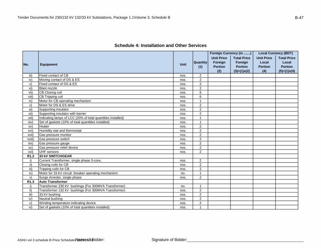
Tender Documents for 230/132 kV 132/33 kV Substations, Package 1.1Volume 3, Schedule B B-47
No. Equipment UnitQuantity
(1)
Unit Price Foreign Portion
(2)
Total Price Foreign Portion
(3)=(1)x(2)
Unit Price Local
Portion(4)
Total Price Local
Portion (5)=(1)x(4)
Schedule 4: Installation and Other Services
Foreign Currency (in .......) Local Currency (BDT)
iii) Fixed contact of CB nos. 2iv) Moving contact of DS & ES nos. 2v) Fixed contact of DS & ES nos. 2vi) Blast nozzle nos. 2vii) CB Closing coil nos. 6viii) CB Tripping coil nos. 6ix) Motor for CB operating mechanism nos. 1x) Motor for DS & ES drive nos. 2xi) Supporting insulator nos. 2xii) Supporting insulator with barrier nos. 2xiii) Indicating lamps of LCC (20% of total quantities installed) nos. 1xiv) Set of gaskets (10% of total quantities installed) nos. 1xv) Heater nos. 2xvi) Humidity stat and thermostat nos. 2xvii) Gas pressure monitor nos. 2xviii) Gas pressure switch nos. 2xix) Gas pressure gauge nos. 2xx) Gas pressure relief device nos. 2xxi) UHF sensors nos. 2
R1.2 33 kV SWITCHGEARi) Current Transformer, single phase 3-core, nos. 2ii) Closing coils for CB nos. 2iii) Tripping coils for CB nos. 2iv) Motor for 33 kV circuit breaker operating mechanism no. 1v) Surge Arrester, single phase nos. 2
R1.3 Auto Transformeri) Transformer 230 kV bushings (For 300MVA Transformer) no. 1ii) Transformer 132 kV bushings (For 300MVA Transformer) nos. 2iii) 33 kV bushing nos. 2iv) Neutral bushing nos. 2v) Winding temperature indicating device nos. 2vi) Set of gaskets (10% of total quantities installed) nos. 1
ASHU vol 3 schedule B Price Schedules 2019 05 18Name of Bidder: Signature of Bidder:____________________________________________________

Tender Documents for 230/132 kV 132/33 kV Substations, Package 1.1Volume 3, Schedule B B-48
No. Equipment UnitQuantity
(1)
Unit Price Foreign Portion
(2)
Total Price Foreign Portion
(3)=(1)x(2)
Unit Price Local
Portion(4)
Total Price Local
Portion (5)=(1)x(4)
Schedule 4: Installation and Other Services
Foreign Currency (in .......) Local Currency (BDT)
vii) nos. 1viii) Spare transformer oil Liter 10000
R1.4 HV Cable Connectioni) 120 kV Surge Arrester nos. 3ii) 145kV, GIS Cable Sealing End (for XLPE, 630sqmm cu cable) incld. necessary all
accessoriessets 2
iii) 145kV, GIS Cable Sealing End (for XLPE, 800sqmm cu cable) incld. necessary all accessories
sets 2
iv) 145kV, GIS Cable Sealing End (for XLPE, 1600sqmm cu cable) incld. necessary all accessories
sets 2
v) 145kV, Outdoor Cable Sealing End (for XLPE, 630sqmm cu cable) incld. necessary all accessories
sets 2
vi) 145kV, Outdoor Cable Sealing End (for XLPE, 800sqmm cu cable) incld. necessary all accessories
sets 2
vii) 145kV, Outdoor Cable Sealing End (for XLPE, 2000sqmm cu cable) incld. necessary all accessories
sets 2
R1.5 Protection, Metering & Othersi) Line distance relay with complete protection elements set 1ii) Transformer differential relay with complete REF function set 1iii) Overcurrent and earth fault relay set 1iv) Tripping relay (electrical reset) nos. 3v) Bay control unit set 1vi) Trip Circuit Supervision relay, 3phase set 1vii) Relay test block & plug sets 3viii) Bulbs/LED for annunciator nos. 10vix) kWh & kVarh meter nos. 2vx) Control Cable, 7 Core meter 500vxi) Control Cable, 12 Core meter 500vxii) Line differential relay with complete protection elements set 5S Maintenance Equipment
ASHU vol 3 schedule B Price Schedules 2019 05 18Name of Bidder: Signature of Bidder:____________________________________________________

Tender Documents for 230/132 kV 132/33 kV Substations, Package 1.1Volume 3, Schedule B B-49
No. Equipment UnitQuantity
(1)
Unit Price Foreign Portion
(2)
Total Price Foreign Portion
(3)=(1)x(2)
Unit Price Local
Portion(4)
Total Price Local
Portion (5)=(1)x(4)
Schedule 4: Installation and Other Services
Foreign Currency (in .......) Local Currency (BDT)
S1 Supply of maintenance equipment as per quantity mentioned in Schedule B. Equioment are to be supplied from EU, UK USA or Japan origin. Printed catalogue, operation and service manual are to be provided. The materials shall have to be handed over to the designated store as per instruction of the Engineer
i) Transformer oil treatment plant, 6000 Liters per hour set 1ii) Set of special tools, gauges and spanners for Autotransformer set 1iii) Set of special tools, gauges and spanners for GIS set 1iv) SF6 Gas Handling Equipment including storage tank as per cl. 3.4.6.18 set 1v) 3-phase portable (maintenance) earthing equipment devices with
connectors and telescopic glass fibre operating stick suitable for each voltage as per cl. set 2
7.12vi) Set of special tools for battery and charger set 1vii) Set of special tools for ACDB and DCDB set 1viii) 48kg SF6 gas cylinder with valve and instruments for refilling Set 3T Test EquipmentT1 Supply of test equipment as per quantity mentioned in Schedule B. Test equipment are to
be supplied from EU, UK, USA or Japan origin. Printed catalogue, operation and service manual are to be provided. The materials shall have to be handed over to the designated store as per instruction of the Engineer
i) SF6 Gas Analyzer as per cl. 3.4.6.19ii) SF6 Gas leak Detector set 1iii) Portable Partial Discharge(PD) monitoring system for GIS as per cl. 3.4.6.49 set 1iv) Contact resistance measurement test set (suitable for measurement down to 1 µ ohm at
200A d.c.) set 1
v) 5 kV insulation resistance test set (range 0.5 –1.0 - 2.5 - 5 kV) set 1vi) Earth resistance test set (range 10-100-1000 ohm: min scale division 0.01 ohm) set 1vii) Clip-on mA meter (for spill current) set 1viii) AVO Meter, digital set 1X Installation and Other Services
X2Installation, testing and commissioning of the equipment, necessary adjustment, adaptation, modification, integration and configuration of the equipment - General item, for all services not mentioned before
Lump sum 1
ASHU vol 3 schedule B Price Schedules 2019 05 18Name of Bidder: Signature of Bidder:____________________________________________________

Tender Documents for 230/132 kV 132/33 kV Substations, Package 1.1Volume 3, Schedule B B-50
No. Equipment UnitQuantity
(1)
Unit Price Foreign Portion
(2)
Total Price Foreign Portion
(3)=(1)x(2)
Unit Price Local
Portion(4)
Total Price Local
Portion (5)=(1)x(4)
Schedule 4: Installation and Other Services
Foreign Currency (in .......) Local Currency (BDT)
X3 Transport of material and equipment Lump sum 1X4 Insurance of material and equipment during transport Lump sum 1Y Factory Acceptance Tests and Trainings - for complete packageY1 Cost and expenses related to the Factory Acceptance Tests Lump sum 1Y2 Cost and expenses related to the Trainings Lump sum 1
Subtotal Renovation of existing 132 kV AIS to GIS to Schedule 5 -Grand Total
ASHU vol 3 schedule B Price Schedules 2019 05 18Name of Bidder: Signature of Bidder:____________________________________________________
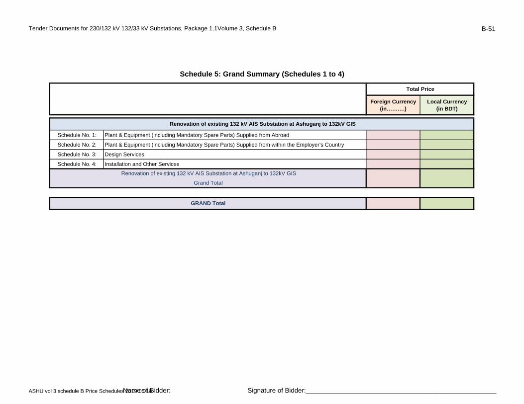
Tender Documents for 230/132 kV 132/33 kV Substations, Package 1.1Volume 3, Schedule B B-51
Foreign Currency(in……….)
Local Currency(in BDT)
Schedule No. 1: Plant & Equipment (including Mandatory Spare Parts) Supplied from Abroad
Schedule No. 2: Plant & Equipment (including Mandatory Spare Parts) Supplied from within the Employer’s Country
Schedule No. 3: Design Services
Schedule No. 4: Installation and Other Services
GRAND Total
Renovation of existing 132 kV AIS Substation at Ashuganj to 132kV GIS
Schedule 5: Grand Summary (Schedules 1 to 4)
Total Price
Renovation of existing 132 kV AIS Substation at Ashuganj to 132kV GIS
Grand Total
ASHU vol 3 schedule B Price Schedules 2019 05 18Name of Bidder: Signature of Bidder:____________________________________________________
Tender Documents for 230/132 kV 132/33 kV Substations, Package 1.1Volume 3, Schedule B B-52
Item Country Code
Country of Origin
ASHU vol 3 schedule B Price Schedules 2019 05 18Name of Bidder: Signature of Bidder:____________________________________________________
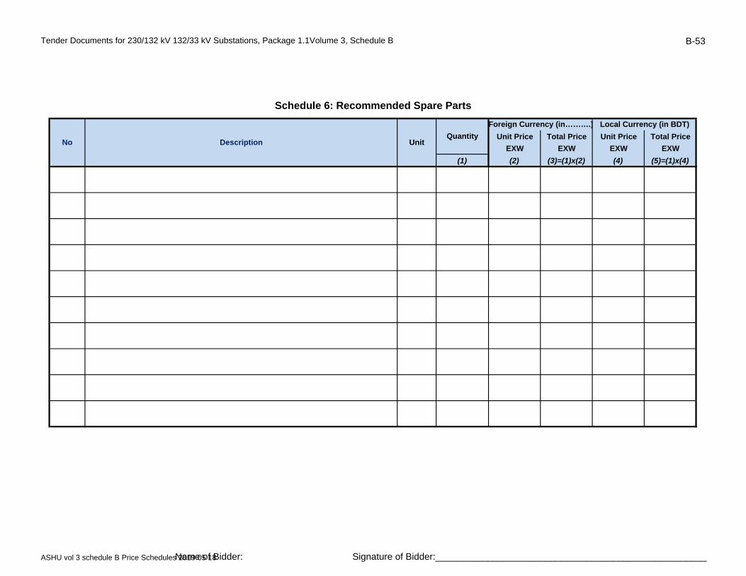
Tender Documents for 230/132 kV 132/33 kV Substations, Package 1.1Volume 3, Schedule B B-53
Unit Price Total Price Unit Price Total Price
EXW EXW EXW EXW
(1) (2) (3)=(1)x(2) (4) (5)=(1)x(4)
Schedule 6: Recommended Spare Parts
No Description UnitQuantity
Foreign Currency (in……….) Local Currency (in BDT)
ASHU vol 3 schedule B Price Schedules 2019 05 18Name of Bidder: Signature of Bidder:____________________________________________________
- 31 -
Design, Supply, Installation, Testing & Commissioning of 132kV GIS Substation at APSCL area as replacement of
existing of 132kV AIS station and associated shifting of existing 132kV lines/transformer/power station connections to
GIS on Turnkey Basis
3. Schedule C: Bar Chart Program of Key Ac-tivities - Delivery & Completion Time Schedule
The schedule has to be filled by the Bidder and to be attached to the bid. The Bidders may use the attached excel file.
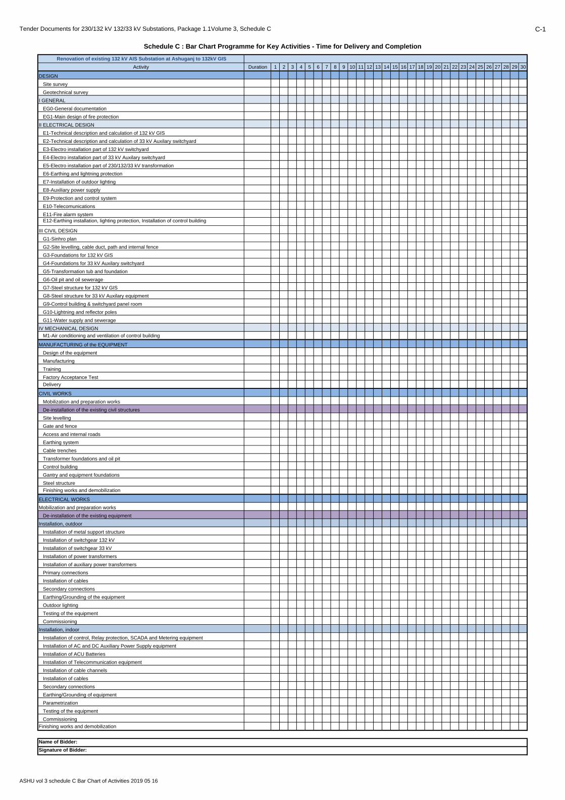
Tender Documents for 230/132 kV 132/33 kV Substations, Package 1.1Volume 3, Schedule C C-1
Renovation of existing 132 kV AIS Substation at Ashuganj to 132kV GIS
Activity Duration 1 2 3 4 5 6 7 8 9 10 11 12 13 14 15 16 17 18 19 20 21 22 23 24 25 26 27 28 29 30
DESIGN
Site survey
Geotechnical survey
I GENERAL
EG0-General documentation
EG1-Main design of fire protection
II ELECTRICAL DESIGN
E1-Technical description and calculation of 132 kV GIS
E2-Technical description and calculation of 33 kV Auxilary switchyard
E3-Electro installation part of 132 kV switchyard
E4-Electro installation part of 33 kV Auxilary switchyard
E5-Electro installation part of 230/132/33 kV transformation
E6-Earthing and lightning protection
E7-Installation of outdoor lighting
E8-Auxiliary power supply
E9-Protection and control system
E10-Telecomunications
E11-Fire alarm system E12-Earthing installation, lighting protection, Installation of control building
III CIVIL DESIGN
G1-Sinhro plan
G2-Site levelling, cable duct, path and internal fence
G3-Foundations for 132 kV GIS
G4-Foundations for 33 kV Auxilary switchyard
G5-Transformation tub and foundation
G6-Oil pit and oil sewerage
G7-Steel structure for 132 kV GIS
G8-Steel structure for 33 kV Auxilary equipment
G9-Control building & switchyard panel room
G10-Lightning and reflector poles
G11-Water supply and sewerage
IV MECHANICAL DESIGN
M1-Air conditioning and ventilation of control building
MANUFACTURING of the EQUIPMENT
Design of the equipment
Manufacturing
Training
Factory Acceptance Test
Delivery
CIVIL WORKS
Mobilization and preparation works
De-installation of the existing civil structures
Site levelling
Gate and fence
Access and internal roads
Earthing system
Cable trenches
Transformer foundations and oil pit
Control building
Gantry and equipment foundations
Steel structure
Finishing works and demobilization
ELECTRICAL WORKS
Mobilization and preparation works
De-installation of the existing equipment
Installation, outdoor
Installation of metal support structure
Installation of switchgear 132 kV
Installation of switchgear 33 kV
Installation of power transformers
Installation of auxiliary power transformers
Primary connections
Installation of cables
Secondary connections
Earthing/Grounding of the equipment
Outdoor lighting
Testing of the equipment
Commissioning
Installation, indoor
Installation of control, Relay protection, SCADA and Metering equipment
Installation of AC and DC Auxiliary Power Supply equipment
Installation of ACU Batteries
Installation of Telecommunication equipment
Installation of cable channels
Installation of cables
Secondary connections
Earthing/Grounding of equipment
Parametrization
Testing of the equipment
Commissioning
Finishing works and demobilization
Schedule C : Bar Chart Programme for Key Activities - Time for Delivery and Completion
Name of Bidder:
Signature of Bidder:
ASHU vol 3 schedule C Bar Chart of Activities 2019 05 16

- 32 -
Design, Supply, Installation, Testing & Commissioning of 132kV GIS Substation at APSCL area as replacement of
existing of 132kV AIS station and associated shifting of existing 132kV lines/transformer/power station connections to
GIS on Turnkey Basis
4. Schedule D: Manufacturers, Places of Manufacture and Testing
The following form shall be filled and attached to the bid. Bidders are free to propose/list more than one Manufacturer for each item. Quoted rates and prices are deemed to apply to whichever Manufacturer is appointed, and no adjust-ment of the rates and prices will be permitted.Their participation shall be confirmed with the Manufac-turer's Authorization letter(s), as required. In case more than one Manufacturer has been proposed, the Employer has right to choose one or more of them, or can ask for replacement. Should a Manufacturer be determined to be unacceptable, the bid will not be rejected, but the Bidder will be required to substitute an acceptable Manufacturer without any change to the bid price. Prior to signing the contract, the corresponding appendix to the Contract Agreement shall be com-pleted, listing the approved Manufacturers for each item concerned.
Manufacturers
The following Manufacturers are proposed for carrying out the facilities:
Item Equipment Type of Equipment
Manufacturer'sName
and Address
Place of Manufac-
tureand Testing Nationality
Power Transformer
1.1. Power transformer
230/132/33 kV
1.2 230kV Bushing
1.3 132kV Bushing
1.4 33kV Bushing
1.5 PRD
1.6 Buchholz relay
1.7 Water Spray System
Auxiliary Power Transformer
2 Auxiliary power trans-
former 33/0.4 kV
230 kV Equipment
3.6. Surge arresters
230 kV
132 kV Equipment
4.1. GIS 132 kV
4.2. Current transformers
132 kV (in GIS)

- 33 -
Design, Supply, Installation, Testing & Commissioning of 132kV GIS Substation at APSCL area as replacement of
existing of 132kV AIS station and associated shifting of existing 132kV lines/transformer/power station connections to
GIS on Turnkey Basis
Item Equipment Type of Equipment
Manufacturer'sName
and Address
Place of Manufac-
tureand Testing Nationality
4.3. Voltage transformers
132 kV (in GIS)
4.4. Surge arresters
132 kV (in GIS)
4.5. Surge arresters
132 kV (AIS)
HV Cable and Cable Termination
5.1 Outdoor Cable Termi-
nation
5.2 GIS Cable Termination
5.3 XLPE HV Cable
5.4 Cable Joints
33 kV Equipment
6.1. Circuit breakers 33 kV
6.2. Disconnectors 33 kV
6.3. Current transformers
33 kV
6.4. Surge arresters 33 kV
Control, Protection, and Metering Equipment
7.1 Control & monitoring
equipment
7.2 Relay protection
equipment
7.3. Control & protection
panels
7.4. Metering equipment
7.5. Metering panels
7.6. DFDR
Telecommunication Equipment
8.1. Fiber Optic Multiplexer
equipment
8.2. PABX
8.3 Optical Fiber Cable
Auxiliary Power Supply Equipment
9.1. 110V and 48V battery
9.2. Charger
9.3 DC distribution
switchboard
9.4 AC distribution
switchboard
Conductors, Insulators & Fittings
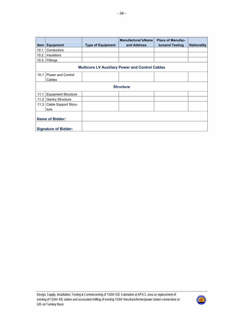
- 34 -
Design, Supply, Installation, Testing & Commissioning of 132kV GIS Substation at APSCL area as replacement of
existing of 132kV AIS station and associated shifting of existing 132kV lines/transformer/power station connections to
GIS on Turnkey Basis
Item Equipment Type of Equipment
Manufacturer'sName
and Address
Place of Manufac-
tureand Testing Nationality
10.1. Conductors
10.2. Insulators
10.3. Fittings
Multicore LV Auxiliary Power and Control Cables
10.1 Power and Control
Cables
Structure
11.1 Equipment Structure
11.2 Gantry Structure
11.3 Cable Support Struc-
ture
Name of Bidder:
Signature of Bidder:
- 35 -
Design, Supply, Installation, Testing & Commissioning of 132kV GIS Substation at APSCL area as replacement of
existing of 132kV AIS station and associated shifting of existing 132kV lines/transformer/power station connections to
GIS on Turnkey Basis
5. Schedule E: Technical Particulars and Guarantees
5.1 General
The technical data schedules hereafter provide more details on the specific technical criteria and complement the Information given in the Bidding documents. They form an essential part of bid submission and will be used in bid evaluation. They should be fully completed and submitted with the bid.
5.2 Technical Data Schedules
Please find hereafter the following schedules:

- 36 -
Design, Supply, Installation, Testing & Commissioning of 132kV GIS Substation at APSCL area as replacement of
existing of 132kV AIS station and associated shifting of existing 132kV lines/transformer/power station connections to
GIS on Turnkey Basis
5.2.1 A: Switchgear 230 kV (Not Applicable)

- 37 -
Design, Supply, Installation, Testing & Commissioning of 132kV GIS Substation at APSCL area as replacement of
existing of 132kV AIS station and associated shifting of existing 132kV lines/transformer/power station connections to
GIS on Turnkey Basis
5.2.2 B: Switchgear 132 kV
5.2.2.1 BG: GIS Switchgear 132 kV
No. Description Minimum Requirements
Guaranteed Unit Data
1. Switchgear 1320 kV- General 1.1. Manufacturer Insert
1.2 Type Insert
1.3 Model designation Insert
1.4 Country of origin Insert
1.5 Nominal system voltage kVrms 132
1.6 Highest voltage for equipment Un kVrms 170
1.7 Rated lightning impulse withstand voltage kVpeak ≥750
1.8 Rated short duration power frequency voltage kV ≥325
1.9 Rated frequency fr Hz 50
1.10 Rated current Ir
Busbars A ≥ 3150
Line bay A ≥ 2000
Transformer bay A ≥ 2000
Bus Coupler bay A ≥ 3150
Bus Sectionalizer bay A ≥ 3150
1.11 Rated short-circuit breaking current Isc kA rms ≥ 50
1.12 Duration of short-circuit s ≥ 1
1.13 Rated peak withstand current Ip (equal short-
circuit making current) kA ≥ 100
Control voltage V. DC 110
Motor - auxiliary supply voltage V. DC 110
Heater supply voltage V. Hz 230. 50
1.14 Type of busbars - Double, sectionalize
2. Circuit Breaker 2.1 Isolating and quenching medium SF6
2.2 Type of circuit breaker GIS / Outdoor
2.3 Design Single breaking
2.4 Operating mechanism Motor-wound spring
2.5 Number of poles pcs. 3
2.6 Number of operating mechanisms per circuit
breaker
Line bay pcs. 3
Transformer bay pcs. 1
Bus Coupler bay pcs. 1
2.7 D.C. component of the rated short-circuit breaking
current % > 30
2.8 Rated operating sequence O-0.3 s-CO-3 min-CO
2.9 Auto reclosing
Line bay 1p+3p
Transformer bay 3p
Bus Coupler bay 3p

- 38 -
Design, Supply, Installation, Testing & Commissioning of 132kV GIS Substation at APSCL area as replacement of
existing of 132kV AIS station and associated shifting of existing 132kV lines/transformer/power station connections to
GIS on Turnkey Basis
No. Description Minimum Requirements
Guaranteed Unit Data
2.10
Maximum total break time (trip initiation to final
arc extinction) pos.3.7.135 acc. to IEC 62271-
100)
ms ≤ 60
2.11 Time of final arc extinction (3.7..134 acc. IEC
62271-100) ms 20 ± 5
2.12 Restrike performance during capacitive current
switching Class C2
2.13
Number of operations without maintenance
CO at no-load
CO at rated current
CO at rated breaking current Isc
≥ 10000
≥ 2500
≥ 5
2.14 The frequency of mechanical operations Class M2
2.15 Rated electrical endurance Class Min E1
Operating mechanism
2.13 Number of making coils pcs. 1
2.14 Number of breaking coils pcs. 2
2.15 Minimum number of available contacts (NO/NC) 12NO+12NC
Accessories in central control panel
2.16 Anti-pumping relay Yes
2.17 Local/remote control selector switch Yes
2.18 Local operation push buttons Yes
2.19 Minimum pressure lock-out and alarm relays Yes
2.20 Operation counter Yes
3. Disconnector 3.1 Type GIS / Outdoor
3.2 Type of disconnector
Three pole,
three position (close/open/earthed),
motor operated,
insulated,
with earthing switch
Yes
Three pole,
make-proof,
motor operated earthing switch
Yes
Three pole,
Disconnector Link,
hand operated
Yes
3.3 Number of poles pcs. 3
3.4 Number of operating mechanism pcs. 1
3.5 Type of operating mechanism
Three position Motor driven
Make-proof Motor-wound spring
Disconnector Link Manual
4. Current Transformer 4.1 Type GIS / Outdoor
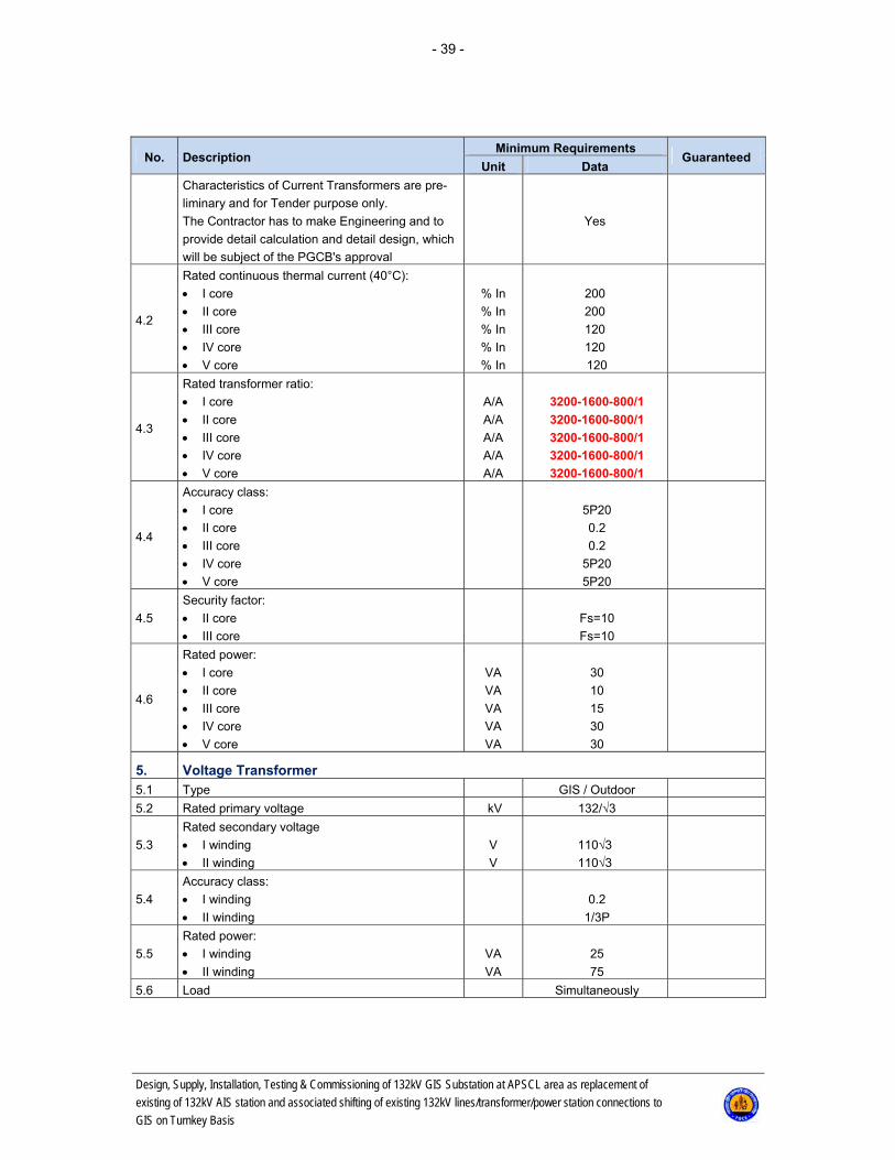
- 39 -
Design, Supply, Installation, Testing & Commissioning of 132kV GIS Substation at APSCL area as replacement of
existing of 132kV AIS station and associated shifting of existing 132kV lines/transformer/power station connections to
GIS on Turnkey Basis
No. Description Minimum Requirements
Guaranteed Unit Data
Characteristics of Current Transformers are pre-
liminary and for Tender purpose only.
The Contractor has to make Engineering and to
provide detail calculation and detail design, which
will be subject of the PGCB's approval
Yes
4.2
Rated continuous thermal current (40°C):
I core
II core
III core
IV core
V core
% In
% In
% In
% In
% In
200
200
120
120
120
4.3
Rated transformer ratio:
I core
II core
III core
IV core
V core
A/A
A/A
A/A
A/A
A/A
3200-1600-800/1
3200-1600-800/1
3200-1600-800/1
3200-1600-800/1
3200-1600-800/1
4.4
Accuracy class:
I core
II core
III core
IV core
V core
5P20
0.2
0.2
5P20
5P20
4.5
Security factor:
II core
III core
Fs=10
Fs=10
4.6
Rated power:
I core
II core
III core
IV core
V core
VA
VA
VA
VA
VA
30
10
15
30
30
5. Voltage Transformer 5.1 Type GIS / Outdoor
5.2 Rated primary voltage kV 132/√3
5.3
Rated secondary voltage
I winding
II winding
V
V
110√3
110√3
5.4
Accuracy class:
I winding
II winding
0.2
1/3P
5.5
Rated power:
I winding
II winding
VA
VA
25
75
5.6 Load Simultaneously
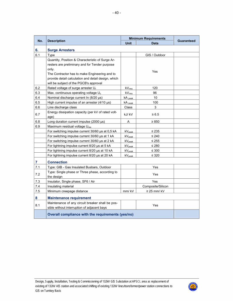
- 40 -
Design, Supply, Installation, Testing & Commissioning of 132kV GIS Substation at APSCL area as replacement of
existing of 132kV AIS station and associated shifting of existing 132kV lines/transformer/power station connections to
GIS on Turnkey Basis
No. Description Minimum Requirements
Guaranteed Unit Data
6. Surge Arresters 6.1 Type GIS / Outdoor
Quantity, Position & Characteristic of Surge Ar-
resters are preliminary and for Tender purpose
only.
The Contractor has to make Engineering and to
provide detail calculation and detail design, which
will be subject of the PGCB's approval
Yes
6.2 Rated voltage of surge arrester Ur kVrms 120
6.3 Max. continuous operating voltage Uc kVrms 96
6.4 Nominal discharge current In (8/20 μs) kA peak 10
6.5 High current impulse of an arrester (4/10 μs) kA peak 100
6.6 Line discharge class Class 3
6.7 Energy dissipation capacity (per kV of rated volt-
age) kJ/ kV ≥ 6.5
6.8 Long duration current impulse (2000 μs) A ≥ 850
6.9 Maximum residual voltage Ures
For switching impulse current 30/60 μs at 0,5 kA kVpeak ≤ 235
For switching impulse current 30/60 μs at 1 kA kVpeak ≤ 240
For switching impulse current 30/60 μs at 2 kA kVpeak ≤ 255
For lightning impulse current 8/20 μs at 5 kA kVpeak ≤ 280
For lightning impulse current 8/20 μs at 10 kA kVpeak ≤ 300
For lightning impulse current 8/20 μs at 20 kA kVpeak ≤ 320
7 Connection 7.1 Type: GIB - Gas Insulated Busbars, Outdoor Yes
7.2 Type: Single phase or Three phase, according to
the design Yes
7.3 Insulator, Single phase, SF6 / Air Yes
7.4 Insulating material Composite/Silicon
7.5 Minimum creepage distance mm/ kV ≥ 25 mm/ kV
8 Maintenance requirement
8.1 Maintenance of any circuit breaker shall be pos-
sible without interruption of adjacent bays Yes
Overall compliance with the requirements (yes/no)

- 41 -
Design, Supply, Installation, Testing & Commissioning of 132kV GIS Substation at APSCL area as replacement of
existing of 132kV AIS station and associated shifting of existing 132kV lines/transformer/power station connections to
GIS on Turnkey Basis
5.2.2.2 B1.1: Circuit Breaker 132 kV, 3150 A, three OM (Not Applicable)
5.2.2.3 B1.2: Circuit Breaker 132 kV, 2000 A, three OM (Not Applicable)
5.2.2.4 B1.3: Circuit Breaker 132 kV, 1250 A, three OM (Not Applicable)
5.2.2.5 B1.4: Circuit Breaker 132 kV, 3150 A, one OM (Not Applicable)
5.2.2.6 B1.5: Circuit Breaker 132 kV, 2000 A, one OM (Not Applicable)
5.2.2.7 B1.6: Circuit Breaker 132 kV, 1250 A, one OM (Not Applicable)
5.2.2.8 B2.1: Disconnector 132 kV, 3150 A, with Earthing Switch (Not Applicable)
5.2.2.9 B2.2: Disconnector 132 kV, 2000 A, with Earthing Switch (Not Applicable)
5.2.2.10 B2.3: Disconnector 132 kV, 1250 A, with Earthing Switch (Not Applicable)
5.2.2.11 B2.4: Disconnector 132 kV, 3150 A (Not Applicable)
5.2.2.12 B2.5: Disconnector 132 kV, 2000 A (Not Applicable)
5.2.2.13 B2.6: Disconnector 132 kV, 1250 A (Not Applicable)
5.2.2.14 B3.1: Current Transformer 132 kV, 3200-1600-800/1 A/A (Not Applicable)
5.2.2.15 B3.2: Current Transformer 132 kV, 1600-800-400/1 A/A (Not Applicable)
5.2.2.16 B4: Voltage Transformer 132 kV(Not Applicable)

- 42 -
Design, Supply, Installation, Testing & Commissioning of 132kV GIS Substation at APSCL area as replacement of
existing of 132kV AIS station and associated shifting of existing 132kV lines/transformer/power station connections to
GIS on Turnkey Basis
5.2.2.17 B5: Surge Arrester 132 kV
No. Description Minimum Requirements
Guaranteed Unit Data
1. Surge Arresters - General 1.1 Manufacturer Insert
1.2 Type Insert
1.3 Model designation Insert
1.4 Country of origin Insert
1.5 Standards IEC 60099-4
1.6 Quality control ISO 9001
1.7 Design Metal oxide, gapless,
outdoor
1.8 Short circuit testing authority Insert authority
2. Surge Arresters - Characteristics 2.1 Nominal system voltage kVrms 132
2.2 Highest voltage for equipment Un kVrms 145
2.4 Rated voltage of surge arrester Ur kVrms 120
2.5 Max. continuous operating voltage Uc kVrms 96
2.8 Rated frequency Hz 50
2.9 Nominal discharge current In (8/20 μs) kA peak 10
2.10 High current impulse of an arrester (4/10 μs) kA peak 100
3. Surge Arresters - Design and Construction 3.1 Line discharge class Class 3
3.2 Energy dissipation capacity (per kV of rated
voltage) kJ/ kV ≥ 6.5
3.3 Long duration current impulse (2000 μs) A ≥ 850
3.4 Maximum residual voltage Ures
3.4.1 For switching impulse current 30/60 μs at
0,5 kA kVpeak ≤ 235
3.4.2 For switching impulse current 30/60 μs at 1 kA kVpeak ≤ 240
3.4.3 For switching impulse current 30/60 μs at 2 kA kVpeak ≤ 255
3.4.4 For lightning impulse current 8/20 μs at 5 kA kVpeak ≤ 280
3.4.5 For lightning impulse current 8/20 μs at 10 kA kVpeak ≤ 300
3.4.6 For lightning impulse current 8/20 μs at 20 kA kVpeak ≤ 320
3.5. Dielectric endurance of arrester housing)
3.5.1 Lightning impulse withstand voltage of arrester
housing up (1.2/50 μs) kV ≥ 550
3.5.2 Power frequency withstand voltage of arrester
housing (1 min wet) kV ≥ 250
3.6. Mechanical requirements
3.6.1 Specified short-term load SSL (Fdyn) N ≥ 3750
3.6.2 Specified long-term load SSL (Fstat) N ≥ 2500
3.7 Minimum creepage distance mm/ kV ≥ 25 mm/ kV
3.8. Housing insulating material Composite/Silicon
3.9 Insulating basement Yes
3.10 Surge arrester height mm Insert
3.11 Surge arrester weight kg Insert
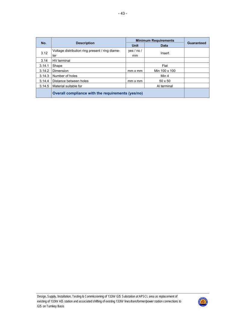
- 43 -
Design, Supply, Installation, Testing & Commissioning of 132kV GIS Substation at APSCL area as replacement of
existing of 132kV AIS station and associated shifting of existing 132kV lines/transformer/power station connections to
GIS on Turnkey Basis
No. Description Minimum Requirements
Guaranteed Unit Data
3.12 Voltage distribution ring present / ring diame-
ter
yes / no /
mm Insert
3.14 HV terminal
3.14.1 Shape Flat
3.14.2 Dimension mm x mm Min 100 x 100
3.14.3 Number of holes Min 4
3.14.4 Distance between holes mm x mm 50 x 50
3.14.5 Material suitable for Al terminal
Overall compliance with the requirements (yes/no)

- 44 -
Design, Supply, Installation, Testing & Commissioning of 132kV GIS Substation at APSCL area as replacement of
existing of 132kV AIS station and associated shifting of existing 132kV lines/transformer/power station connections to
GIS on Turnkey Basis
5.2.2.18 B6: Post Insulator 132 kV
No. Description Minimum Requirements
Guaranteed Unit Data
1. Post Insulators - General
1.1 Manufacturer Insert
1.2 Type Insert
1.3 Model designation Insert
1.4 Country of origin Insert
1.5 Standards
IEC 60168
IEC 60273
IEC 60672
IEC 60694
1.6 Quality control ISO 9001
1.7 Design Solid core, porcelain,
outdoor
2 Post Insulators - Characteristics
2.1 Nominal system voltage kVrms 132
2.2 Highest voltage for equipment Un kVrms 145
2.3 Rated lightning impulse withstand voltage kVpeak 650
2.4 Rated short duration power frequency voltage kV 275
2.5 Rated frequency fr Hz 50
2.6 Minimum creepage distance mm/ kV Min. ≥ 25 mm/ kV
2.7 Failing load bending (p0) (C10) N ≥ 10000
2.8 Failing load torsion Nm ≥ 4000
3 Post Insulators - Design and Construction
3.1 Insulation material Porcelain, brown
3.2 Material quality acc. IEC 60672 Min. C130
3.3 Insulator height mm Insert
3.4 Max. diameter of insulating part mm Insert
3.5 Diameter of upper base mm Insert
3.6 Number of holes on upper base Insert
3.7 Diameter distance between holes on upper base mm Insert
3.8 Hole type on upper base Insert
3.9 Diameter on lower base mm Insert
3.10 Number of holes on lower base Insert
3.11 Diameter distance between holes on lower base mm Insert
3.12 Hole type on lower base Insert
3.13 Insulator weight kg Insert
Overall compliance with the requirements (yes/no)
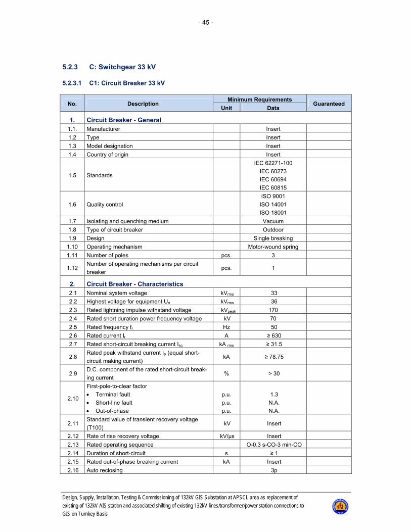
- 45 -
Design, Supply, Installation, Testing & Commissioning of 132kV GIS Substation at APSCL area as replacement of
existing of 132kV AIS station and associated shifting of existing 132kV lines/transformer/power station connections to
GIS on Turnkey Basis
5.2.3 C: Switchgear 33 kV
5.2.3.1 C1: Circuit Breaker 33 kV
No. Description Minimum Requirements
Guaranteed Unit Data
1. Circuit Breaker - General 1.1. Manufacturer Insert
1.2 Type Insert
1.3 Model designation Insert
1.4 Country of origin Insert
1.5 Standards
IEC 62271-100
IEC 60273
IEC 60694
IEC 60815
1.6 Quality control
ISO 9001
ISO 14001
ISO 18001
1.7 Isolating and quenching medium Vacuum
1.8 Type of circuit breaker Outdoor
1.9 Design Single breaking
1.10 Operating mechanism Motor-wound spring
1.11 Number of poles pcs. 3
1.12 Number of operating mechanisms per circuit
breaker pcs. 1
2. Circuit Breaker - Characteristics 2.1 Nominal system voltage kVrms 33
2.2 Highest voltage for equipment Un kVrms 36
2.3 Rated lightning impulse withstand voltage kVpeak 170
2.4 Rated short duration power frequency voltage kV 70
2.5 Rated frequency fr Hz 50
2.6 Rated current Ir A ≥ 630
2.7 Rated short-circuit breaking current Isc kA rms ≥ 31.5
2.8 Rated peak withstand current Ip (equal short-
circuit making current) kA ≥ 78.75
2.9 D.C. component of the rated short-circuit break-
ing current % > 30
2.10
First-pole-to-clear factor
Terminal fault
Short-line fault
Out-of-phase
p.u.
p.u.
p.u.
1.3
N.A.
N.A.
2.11 Standard value of transient recovery voltage
(T100) kV Insert
2.12 Rate of rise recovery voltage kV/μs Insert
2.13 Rated operating sequence O-0.3 s-CO-3 min-CO
2.14 Duration of short-circuit s ≥ 1
2.15 Rated out-of-phase breaking current kA Insert
2.16 Auto reclosing 3p
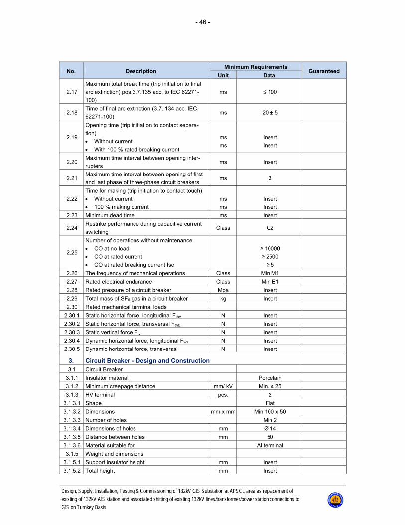
- 46 -
Design, Supply, Installation, Testing & Commissioning of 132kV GIS Substation at APSCL area as replacement of
existing of 132kV AIS station and associated shifting of existing 132kV lines/transformer/power station connections to
GIS on Turnkey Basis
No. Description Minimum Requirements
Guaranteed Unit Data
2.17
Maximum total break time (trip initiation to final
arc extinction) pos.3.7.135 acc. to IEC 62271-
100)
ms ≤ 100
2.18 Time of final arc extinction (3.7..134 acc. IEC
62271-100) ms 20 ± 5
2.19
Opening time (trip initiation to contact separa-
tion)
Without current
With 100 % rated breaking current
ms
ms
Insert
Insert
2.20 Maximum time interval between opening inter-
rupters ms Insert
2.21 Maximum time interval between opening of first
and last phase of three-phase circuit breakers ms 3
2.22
Time for making (trip initiation to contact touch)
Without current
100 % making current
ms
ms
Insert
Insert
2.23 Minimum dead time ms Insert
2.24 Restrike performance during capacitive current
switching Class C2
2.25
Number of operations without maintenance
CO at no-load
CO at rated current
CO at rated breaking current Isc
≥ 10000
≥ 2500
≥ 5
2.26 The frequency of mechanical operations Class Min M1
2.27 Rated electrical endurance Class Min E1
2.28 Rated pressure of a circuit breaker Mpa Insert
2.29 Total mass of SF6 gas in a circuit breaker kg Insert
2.30 Rated mechanical terminal loads
2.30.1 Static horizontal force, longitudinal FthA N Insert
2.30.2 Static horizontal force, transversal FthB N Insert
2.30.3 Static vertical force Ftv N Insert
2.30.4 Dynamic horizontal force, longitudinal Fwx N Insert
2.30.5 Dynamic horizontal force, transversal N Insert
3. Circuit Breaker - Design and Construction 3.1 Circuit Breaker
3.1.1 Insulator material Porcelain
3.1.2 Minimum creepage distance mm/ kV Min. ≥ 25
3.1.3 HV terminal pcs. 2
3.1.3.1 Shape Flat
3.1.3.2 Dimensions mm x mm Min 100 x 50
3.1.3.3 Number of holes Min 2
3.1.3.4 Dimensions of holes mm Ø 14
3.1.3.5 Distance between holes mm 50
3.1.3.6 Material suitable for Al terminal
3.1.5 Weight and dimensions
3.1.5.1 Support insulator height mm Insert
3.1.5.2 Total height mm Insert

- 47 -
Design, Supply, Installation, Testing & Commissioning of 132kV GIS Substation at APSCL area as replacement of
existing of 132kV AIS station and associated shifting of existing 132kV lines/transformer/power station connections to
GIS on Turnkey Basis
No. Description Minimum Requirements
Guaranteed Unit Data
3.1.5.3 Pole weight kg Insert
3.1.5.4 Weight of operating mechanism kg Insert
3.1.5.5 Total weight (with metal structure) kg Insert
3.1.6 Minimum distance
3.1.6.1 Between poles mm Insert
3.1.6.2 To ground mm Insert
3.2 Operating mechanism
3.2.1 Type Insert
3.2.2 Motor - auxiliary supply voltage V. DC 110
3.2.3 Rated power of motor W Insert
3.2.4 Control voltage V. DC 110
3.2.5 Number of making coils pcs. 1
3.2.6 Rated power of making coils W Insert
3.2.7 Number of breaking coils pcs. 1
3.2.8 Rated power of breaking coils W Insert
3.2.9 Heater Yes
3.2.10 Heater supply voltage V. Hz 230. 50
3.2.11 Total heater power W Insert
3.2.12 Minimum number of available contacts
(NO/NC/V) 6NO+6NC+1V
3.2.15 Water-tight corrosion-resistant housing IP54
3.2.17 Operating mechanism material Al or stainless steel
3.2.19 Local/remote control selector switch Yes
3.4 Local operation push buttons
3.4.1 Anti-pumping relay Yes
3.4.2 Operation counter Yes
3.4.3 Motor MCB (miniature circuit breakers) Yes
3.4.4 Heater - 230 V, 50 HZ Yes
3.4.5 Cu earthing rails inside central control cabinet Yes
3.4.6 Detachable plates, the bottom of central control
cabinet Yes
3.4.7 Galvanized horizontal and vertical metal struc-
ture with minimum 70 μm zinc layer Yes
Overall compliance with the requirements (yes/no)
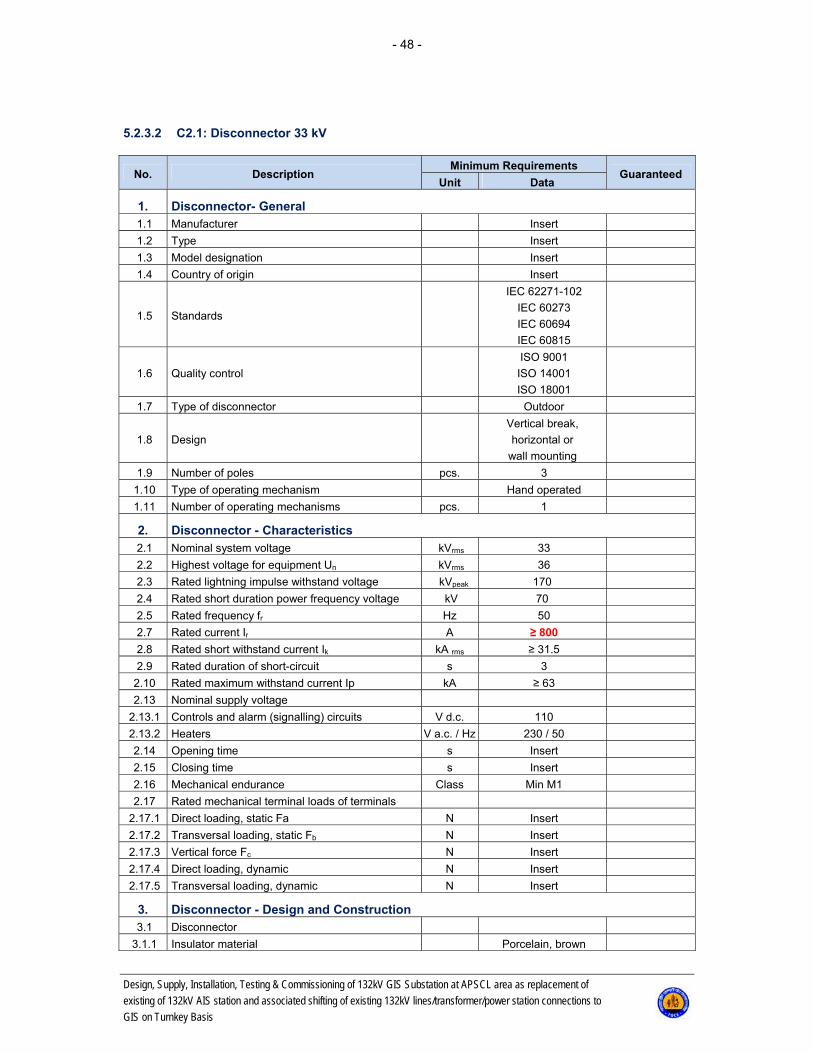
- 48 -
Design, Supply, Installation, Testing & Commissioning of 132kV GIS Substation at APSCL area as replacement of
existing of 132kV AIS station and associated shifting of existing 132kV lines/transformer/power station connections to
GIS on Turnkey Basis
5.2.3.2 C2.1: Disconnector 33 kV
No. Description Minimum Requirements
Guaranteed Unit Data
1. Disconnector- General 1.1 Manufacturer Insert
1.2 Type Insert
1.3 Model designation Insert
1.4 Country of origin Insert
1.5 Standards
IEC 62271-102
IEC 60273
IEC 60694
IEC 60815
1.6 Quality control
ISO 9001
ISO 14001
ISO 18001
1.7 Type of disconnector Outdoor
1.8 Design
Vertical break,
horizontal or
wall mounting
1.9 Number of poles pcs. 3
1.10 Type of operating mechanism Hand operated
1.11 Number of operating mechanisms pcs. 1
2. Disconnector - Characteristics 2.1 Nominal system voltage kVrms 33
2.2 Highest voltage for equipment Un kVrms 36
2.3 Rated lightning impulse withstand voltage kVpeak 170
2.4 Rated short duration power frequency voltage kV 70
2.5 Rated frequency fr Hz 50
2.7 Rated current Ir A ≥ 800
2.8 Rated short withstand current Ik kA rms ≥ 31.5
2.9 Rated duration of short-circuit s 3
2.10 Rated maximum withstand current Ip kA ≥ 63
2.13 Nominal supply voltage
2.13.1 Controls and alarm (signalling) circuits V d.c. 110
2.13.2 Heaters V a.c. / Hz 230 / 50
2.14 Opening time s Insert
2.15 Closing time s Insert
2.16 Mechanical endurance Class Min M1
2.17 Rated mechanical terminal loads of terminals
2.17.1 Direct loading, static Fa N Insert
2.17.2 Transversal loading, static Fb N Insert
2.17.3 Vertical force Fc N Insert
2.17.4 Direct loading, dynamic N Insert
2.17.5 Transversal loading, dynamic N Insert
3. Disconnector - Design and Construction 3.1 Disconnector
3.1.1 Insulator material Porcelain, brown
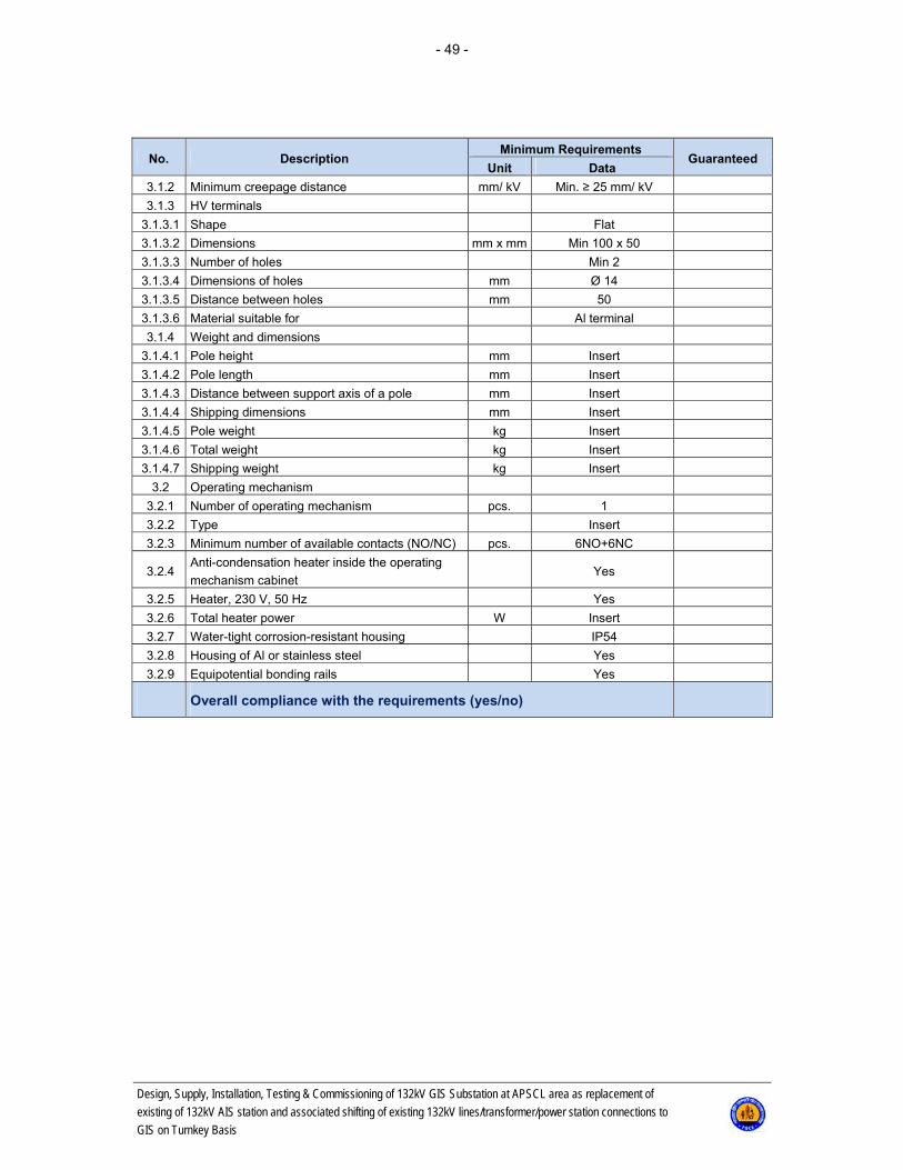
- 49 -
Design, Supply, Installation, Testing & Commissioning of 132kV GIS Substation at APSCL area as replacement of
existing of 132kV AIS station and associated shifting of existing 132kV lines/transformer/power station connections to
GIS on Turnkey Basis
No. Description Minimum Requirements
Guaranteed Unit Data
3.1.2 Minimum creepage distance mm/ kV Min. ≥ 25 mm/ kV
3.1.3 HV terminals
3.1.3.1 Shape Flat
3.1.3.2 Dimensions mm x mm Min 100 x 50
3.1.3.3 Number of holes Min 2
3.1.3.4 Dimensions of holes mm Ø 14
3.1.3.5 Distance between holes mm 50
3.1.3.6 Material suitable for Al terminal
3.1.4 Weight and dimensions
3.1.4.1 Pole height mm Insert
3.1.4.2 Pole length mm Insert
3.1.4.3 Distance between support axis of a pole mm Insert
3.1.4.4 Shipping dimensions mm Insert
3.1.4.5 Pole weight kg Insert
3.1.4.6 Total weight kg Insert
3.1.4.7 Shipping weight kg Insert
3.2 Operating mechanism
3.2.1 Number of operating mechanism pcs. 1
3.2.2 Type Insert
3.2.3 Minimum number of available contacts (NO/NC) pcs. 6NO+6NC
3.2.4 Anti-condensation heater inside the operating
mechanism cabinet Yes
3.2.5 Heater, 230 V, 50 Hz Yes
3.2.6 Total heater power W Insert
3.2.7 Water-tight corrosion-resistant housing IP54
3.2.8 Housing of Al or stainless steel Yes
3.2.9 Equipotential bonding rails Yes
Overall compliance with the requirements (yes/no)
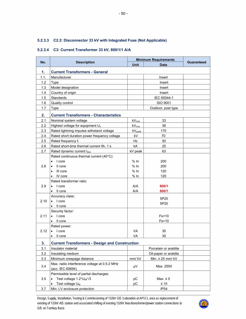
- 50 -
Design, Supply, Installation, Testing & Commissioning of 132kV GIS Substation at APSCL area as replacement of
existing of 132kV AIS station and associated shifting of existing 132kV lines/transformer/power station connections to
GIS on Turnkey Basis
5.2.3.3 C2.2: Disconnector 33 kV with Integrated Fuse (Not Applicable)
5.2.3.4 C3: Current Transformer 33 kV, 800/1/1 A/A
No. Description Minimum Requirements
Guaranteed Unit Data
1. Current Transformers - General 1.1. Manufacturer Insert
1.2 Type Insert
1.3 Model designation Insert
1.4 Country of origin Insert
1.5 Standards IEC 60044-1
1.6 Quality control ISO 9001
1.7 Type Outdoor, post type
2. Current Transformers - Characteristics 2.1 Nominal system voltage kVrms 33
2.2 Highest voltage for equipment Un kVrms 36
2.3 Rated lightning impulse withstand voltage kVpeak 170
2.4 Rated short duration power frequency voltage kV 70
2.5 Rated frequency fr Hz 50
2.6 Rated short-time thermal current Ith, 1 s kA 25
2.7 Rated dynamic current Idyn kV peak 63
2.8
Rated continuous thermal current (40°C):
I core
II core
III core
IV core
% In
% In
% In
% In
200
200
120
120
2.9
Rated transformer ratio:
I core
II core
A/A
A/A
800/1
800/1
2.10
Accuracy class:
I core
II core
5P20
5P20
2.11
Security factor:
I core
II core
Fs=10
Fs=10
2.12
Rated power:
I core
II core
VA
VA
30
30
3. Current Transformers - Design and Construction 3.1 Insulator material Porcelain or araldite
3.2 Insulating medium Oil-paper or araldite
3.3 Minimum creepage distance mm/ kV Min. ≥ 25 mm/ kV
3.4 Max. radio interference voltage at 0.5-2 MHz
(acc. IEC 60694) μV Max. 2500
3.5
Permissible level of partial discharges:
Test voltage 1.2*UM/√3
Test voltage UM
pC
pC
Max. ≤ 5
≤ 10
3.7 Min. LV enclosure protection IP54

- 51 -
Design, Supply, Installation, Testing & Commissioning of 132kV GIS Substation at APSCL area as replacement of
existing of 132kV AIS station and associated shifting of existing 132kV lines/transformer/power station connections to
GIS on Turnkey Basis
No. Description Minimum Requirements
Guaranteed Unit Data
3.8 HV terminals
3.8.1 Shape Flat
3.8.2 Position Horizontal
3.8.3 Dimensions mm x mm Min 100 x 50
3.8.4 Number of holes Min 2
3.8.5 Dimensions of holes mm Ø 14
3.8.6 Distance between holes mm 50
3.8.7 Material suitable for Al terminal
3.10 Mass and dimensions
3.11 Total mass kg Insert
3.13 Height mm Insert
Overall compliance with the requirements (yes/no)

- 52 -
Design, Supply, Installation, Testing & Commissioning of 132kV GIS Substation at APSCL area as replacement of
existing of 132kV AIS station and associated shifting of existing 132kV lines/transformer/power station connections to
GIS on Turnkey Basis
5.2.3.5 C4: Voltage Transformer 33 kV (Not Applicable)
5.2.3.6 C5: Surge Arrester 33 kV
No. Description Minimum Requirements
Guaranteed Unit Data
1. Surge Arresters - General 1.1 Manufacturer Insert
1.2 Type Insert
1.3 Model designation Insert
1.4 Country of origin Insert
1.5 Standards IEC 60099-4
1.6 Quality control ISO 9001
1.7 Design Metal oxide, gapless,
outdoor
1.8 Short circuit testing authority Insert authority
2. Surge Arresters - Characteristics 2.1 Nominal system voltage kVrms 33
2.2 Highest voltage for equipment Un kVrms 36
2.4 Rated voltage of surge arrester Ur kVrms 30
2.5 Max. continuous operating voltage Uc kVrms 24
2.8 Rated frequency Hz 50
2.9 Nominal discharge current In (8/20 μs) kA peak 10
2.10 High current impulse of an arrester (4/10 μs) kA peak 100
3. Surge Arresters - Design and Construction 3.1 Line discharge class Class 3
3.2 Energy dissipation capacity (per kV of rated
voltage) kJ/ kV ≥ 6.5
3.3 Long duration current impulse (2000 μs) A ≥ 850
3.4 Maximum residual voltage Ures
3.4.1 For switching impulse current 30/60 μs at
0,5 kA kVpeak ≤ 65
3.4.2 For switching impulse current 30/60 μs at 1 kA kVpeak ≤ 67.5
3.4.3 For switching impulse current 30/60 μs at 2 kA kVpeak ≤ 70
3.4.4 For lightning impulse current 8/20 μs at 5 kA kVpeak ≤ 75
3.4.5 For lightning impulse current 8/20 μs at 10 kA kVpeak ≤ 80
3.4.6 For lightning impulse current 8/20 μs at 20 kA kVpeak ≤ 90
3.5. Dielectric endurance of arrester housing)
3.5.1 Lightning impulse withstand voltage of arrester
housing up (1.2/50 μs) kV ≥ 235
3.5.2 Power frequency withstand voltage of arrester
housing (1 min wet) kV ≥ 105
3.6. Mechanical requirements
3.6.1 Specified short-term load SSL (Fdyn) N ≥ 7500
3.6.2 Specified long-term load SSL (Fstat) N ≥ 5000
3.7 Minimum creepage distance mm/ kV ≥ 25 mm/ kV
3.8. Housing insulating material Composite/Silicon
3.9 Insulating basement Yes
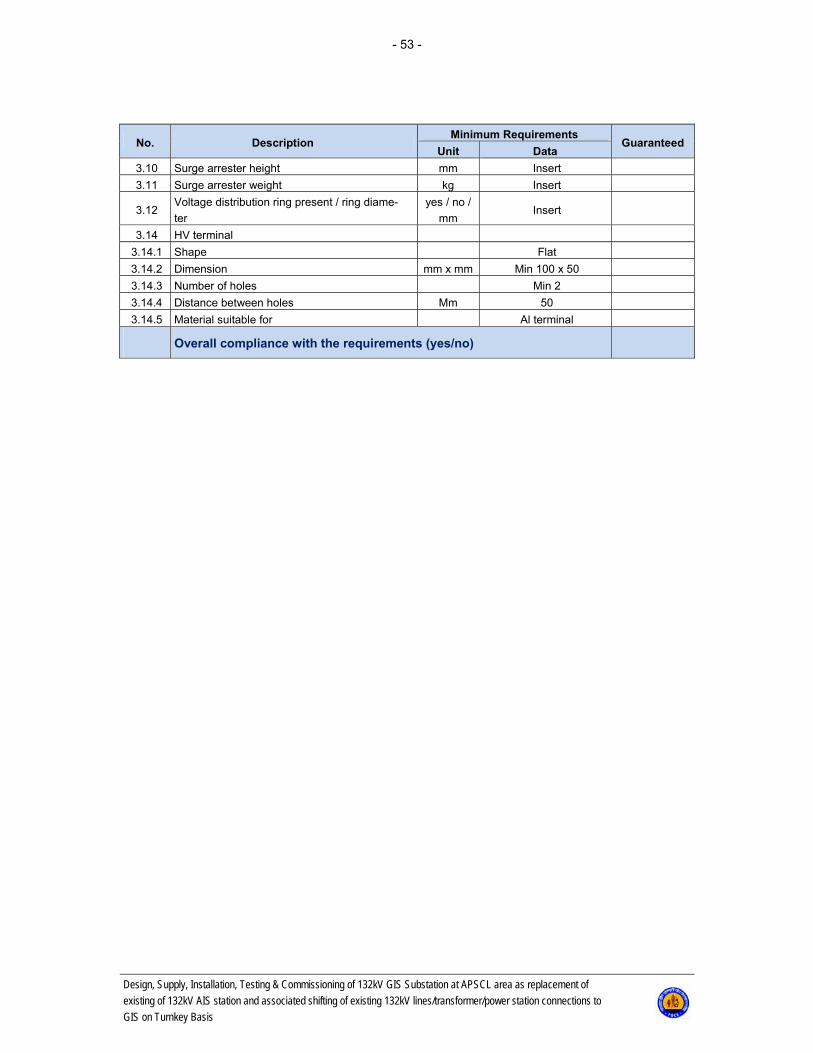
- 53 -
Design, Supply, Installation, Testing & Commissioning of 132kV GIS Substation at APSCL area as replacement of
existing of 132kV AIS station and associated shifting of existing 132kV lines/transformer/power station connections to
GIS on Turnkey Basis
No. Description Minimum Requirements
Guaranteed Unit Data
3.10 Surge arrester height mm Insert
3.11 Surge arrester weight kg Insert
3.12 Voltage distribution ring present / ring diame-
ter
yes / no /
mm Insert
3.14 HV terminal
3.14.1 Shape Flat
3.14.2 Dimension mm x mm Min 100 x 50
3.14.3 Number of holes Min 2
3.14.4 Distance between holes Mm 50
3.14.5 Material suitable for Al terminal
Overall compliance with the requirements (yes/no)
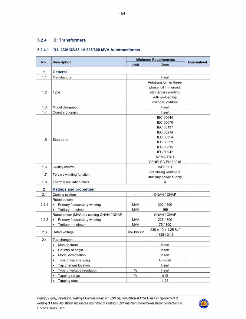
- 54 -
Design, Supply, Installation, Testing & Commissioning of 132kV GIS Substation at APSCL area as replacement of
existing of 132kV AIS station and associated shifting of existing 132kV lines/transformer/power station connections to
GIS on Turnkey Basis
5.2.4 D: Transformers
5.2.4.1 D1: 230/132/33 kV 225/300 MVA Autotransformer
No. Description Minimum Requirements
Guaranteed Unit Data
1 General 1.1 Manufacturer Insert
1.2 Type
Autotransformer three-
phase, oil immersed,
with tertiary winding,
with on-load tap
changer, outdoor
1.3 Model designation Insert
1.4 Country of origin Insert
1.5 Standards
IEC 60044
IEC 60076
IEC 60137
IEC 60214
IEC 60354
IEC 60529
IEC 60815
IEC 60947
NEMA TR-1
CENELEC EN 50216
1.6 Quality control ISO 9001
1.7 Tertiary winding function Stabilizing winding &
auxiliary power supply
1.8 Thermal insulation class A
2 Ratings and properties 2.1 Cooling system - ONAN / ONAF
2.2.1
Rated power:
Primary / secondary winding
Tertiary - minimum
MVA
MVA
300 / 300
100
2.2.2
Rated power (MVA) by cooling ONAN / ONAF
Primary / secondary winding
Tertiary - minimum
MVA
MVA
ONAN / ONAF
225 / 300
75 / 100
2.3 Rated voltage kV/ kV/ kV230 ± 10 x 1,25 % /
/ 135 / 34,5
2.4 Tap changer:
Manufacturer Insert
Country of origin Insert
Model designation Insert
Type of tap changing On-load
Tap changer location Insert
Type of voltage regulation % Insert
Tapping range % ±10
Tapping step 1.25
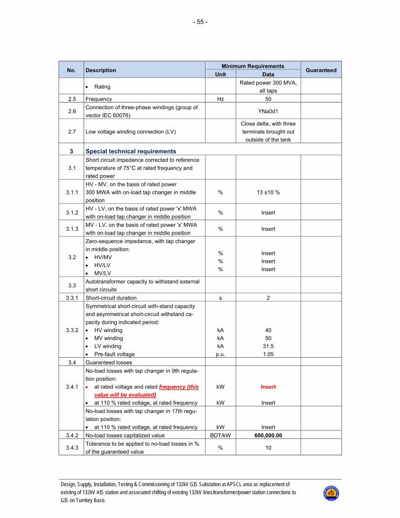
- 55 -
Design, Supply, Installation, Testing & Commissioning of 132kV GIS Substation at APSCL area as replacement of
existing of 132kV AIS station and associated shifting of existing 132kV lines/transformer/power station connections to
GIS on Turnkey Basis
No. Description Minimum Requirements
Guaranteed Unit Data
Rating Rated power 300 MVA,
all taps
2.5 Frequency Hz 50
2.6 Connection of three-phase windings (group of
vector IEC 60076) YNa0d1
2.7 Low voltage winding connection (LV)
Close delta, with three
terminals brought out
outside of the tank
3 Special technical requirements
3.1
Short circuit impedance corrected to reference
temperature of 75°C at rated frequency and
rated power
3.1.1
HV - MV, on the basis of rated power
300 MWA with on-load tap changer in middle
position
% 13 ±10 %
3.1.2 HV - LV, on the basis of rated power 'x' MWA
with on-load tap changer in middle position % Insert
3.1.3 MV - LV, on the basis of rated power 'x' MWA
with on-load tap changer in middle position % Insert
3.2
Zero-sequence impedance, with tap changer
in middle position:
HV/MV
HV/LV
MV/LV
%
%
%
Insert
Insert
Insert
3.3 Autotransformer capacity to withstand external
short circuits
3.3.1 Short-circuit duration s 2
3.3.2
Symmetrical short-circuit with-stand capacity
and asymmetrical short-circuit withstand ca-
pacity during indicated period:
HV winding
MV winding
LV winding
Pre-fault voltage
kA
kA
kA
p.u.
40
50
31.5
1.05
3.4 Guaranteed losses
3.4.1
No-load losses with tap changer in 9th regula-
tion position:
at rated voltage and rated frequency (this
value will be evaluated)
at 110 % rated voltage, at rated frequency
kW
kW
Insert
Insert
No-load losses with tap changer in 17th regu-
lation position:
at 110 % rated voltage, at rated frequency
kW
Insert
3.4.2 No-load losses capitalized value BDT/kW 600,000.00
3.4.3 Tolerance to be applied to no-load losses in %
of the guaranteed value % 10
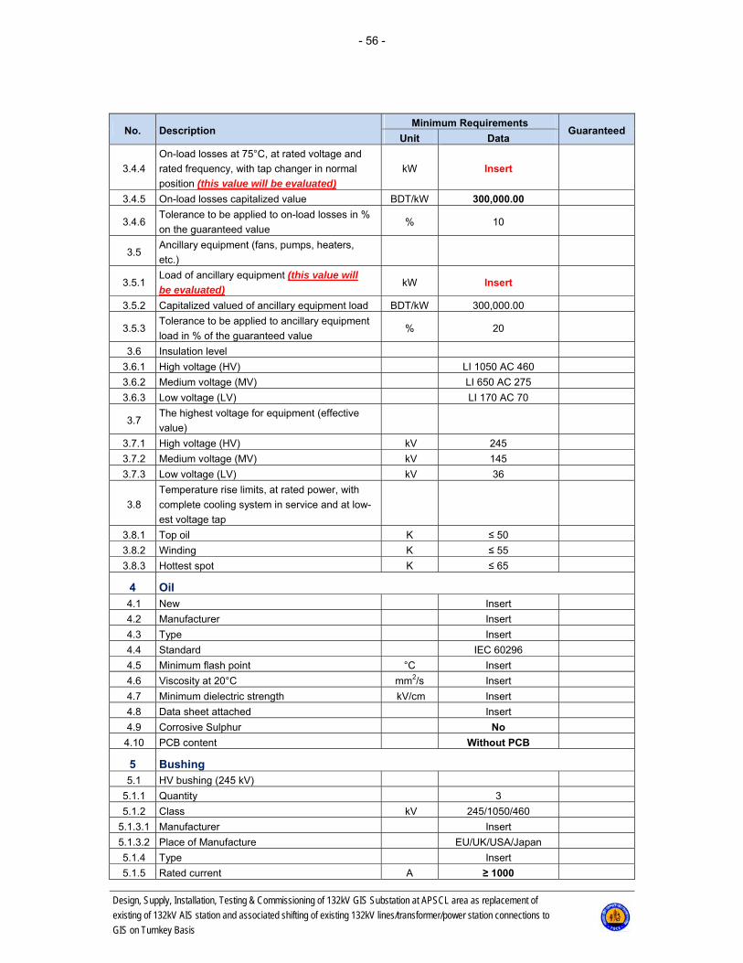
- 56 -
Design, Supply, Installation, Testing & Commissioning of 132kV GIS Substation at APSCL area as replacement of
existing of 132kV AIS station and associated shifting of existing 132kV lines/transformer/power station connections to
GIS on Turnkey Basis
No. Description Minimum Requirements
Guaranteed Unit Data
3.4.4
On-load losses at 75°C, at rated voltage and
rated frequency, with tap changer in normal
position (this value will be evaluated)
kW Insert
3.4.5 On-load losses capitalized value BDT/kW 300,000.00
3.4.6 Tolerance to be applied to on-load losses in %
on the guaranteed value % 10
3.5 Ancillary equipment (fans, pumps, heaters,
etc.)
3.5.1 Load of ancillary equipment (this value will
be evaluated) kW Insert
3.5.2 Capitalized valued of ancillary equipment load BDT/kW 300,000.00
3.5.3 Tolerance to be applied to ancillary equipment
load in % of the guaranteed value % 20
3.6 Insulation level
3.6.1 High voltage (HV) LI 1050 AC 460
3.6.2 Medium voltage (MV) LI 650 AC 275
3.6.3 Low voltage (LV) LI 170 AC 70
3.7 The highest voltage for equipment (effective
value)
3.7.1 High voltage (HV) kV 245
3.7.2 Medium voltage (MV) kV 145
3.7.3 Low voltage (LV) kV 36
3.8
Temperature rise limits, at rated power, with
complete cooling system in service and at low-
est voltage tap
3.8.1 Top oil K ≤ 50
3.8.2 Winding K ≤ 55
3.8.3 Hottest spot K ≤ 65
4 Oil 4.1 New Insert
4.2 Manufacturer Insert
4.3 Type Insert
4.4 Standard IEC 60296
4.5 Minimum flash point °C Insert
4.6 Viscosity at 20°C mm2/s Insert
4.7 Minimum dielectric strength kV/cm Insert
4.8 Data sheet attached Insert
4.9 Corrosive Sulphur No
4.10 PCB content Without PCB
5 Bushing 5.1 HV bushing (245 kV)
5.1.1 Quantity 3
5.1.2 Class kV 245/1050/460
5.1.3.1 Manufacturer Insert
5.1.3.2 Place of Manufacture EU/UK/USA/Japan
5.1.4 Type Insert
5.1.5 Rated current A ≥ 1000

- 57 -
Design, Supply, Installation, Testing & Commissioning of 132kV GIS Substation at APSCL area as replacement of
existing of 132kV AIS station and associated shifting of existing 132kV lines/transformer/power station connections to
GIS on Turnkey Basis
No. Description Minimum Requirements
Guaranteed Unit Data
5.1.6 Minimum creepage distance (25 mm/ kV) mm/ kV ≥ 25 mm/ kV
5.2 MV bushings (145 kV)
5.2.1 Quantity 3
5.2.2 Class kV 145/650/275
5.2.3.1 Manufacturer Insert
5.2.3.2 Place of Manufacture EU/UK/USA/Japan
5.2.4 Type Insert
5.2.5 Rated current A ≥ 1600
5.2.6 Minimum creepage distance (25 mm/ kV) mm/ kV ≥ 25 mm/ kV
5.3 LV bushings (36 kV)
5.3.1 Quantity 4
5.3.2 Class kV 36/170/70
5.3.3.1 Manufacturer Insert
5.3.3.2 Place of Manufacture EU/UK/USA/Japan
5.3.4 Type Insert
5.3.5 Rated current A ≥ 2000
5.3.6 Minimum creepage distance (25 mm/ kV) mm/ kV ≥ 25 mm/ kV
6 Design Data
6.1
Audible noise level (acc. to NEMA TR1), at
105 % of rated voltage, at maximum power
and with complete cooling system in service
dB Insert
6.2 Radio Interference Voltage at 0.5 MHz as
specified in IEC 60694 μV 2500 max
7 Weights and dimensions 7.1 Total weight of transformer, ready for service kg Insert
7.2
Outer dimensions:
Length
Width
mm
mm
Insert
Insert
7.3 Informative dimensional sketch To be enclosed with bid
8 Tap changer
8.1 Tap position indicator Digital code matrix
(BCD)
8.2 Auxiliary supply 3x400 V / 230 V, 50 Hz
9 Auxiliary power supply 9.1 Motors 3x400 V / 50 Hz
9.2 Heaters 230 V / 50 Hz
9.3 Control voltage 110 V DC
9.4 Oil pump 3x400 V / 50 Hz
10 Current transformer incorporated into the power autotransformer
10.1 CT in HV bushings, for protection, WTI and
Tap Changer
In all phases, 4 cores
characteristics shall be
defined in design stage
One core shall be
1200/1 for protection

- 58 -
Design, Supply, Installation, Testing & Commissioning of 132kV GIS Substation at APSCL area as replacement of
existing of 132kV AIS station and associated shifting of existing 132kV lines/transformer/power station connections to
GIS on Turnkey Basis
No. Description Minimum Requirements
Guaranteed Unit Data
10.2 CT in MV bushings, for protection, WTI and
Tap Changer
In all phases, 4 cores
characteristics shall be
defined in design sta-
geOne core shall be
2000/1 for protection
One core shall be
2000/1 for metering
10.3 CT in neutral bushing , for protection
In all phases, 2 cores
characteristics shall be
defined in design stage
11 Layout 11.1 Primary winding bushings Longitudinal axis
11.2 Secondary winding bushings Longitudinal axis
(opposite to HV)
11.3 Conservator tank To be defined
in design stage
11.4 Tap changer To be defined
in design stage
11.5 Control cabinet To be defined
in design stage
11.6 Coolers To be defined
in design stage
12 Cooling groups 12.1 Number of cooling groups (total) Qty. 4
12.2 Number of cooling groups (for rated power) Qty. 3
12.3 Number of stand-by cooling groups Qty. 1
13 Dehydrating breather 13.1 Type of dehydrating breather Insert
13.2 Dehumidifying agent kg Insert
14 Autotransformer tank 14.1 Type of design
14.2
Thickness of transformer tank:
Sides
Bottom
Top
mm
mm
mm
Insert
Insert
Insert
14.3 Material of the autotransformer tank Insert
14.4 Corrosion protection of the tank YES
14.5 Vacuum withstand of the complete tank with
cooler mbar 1
14.6 Over-pressure withstand of the complete auto-
transformer bar 0.3
15 Conservator 15.1 Type With diaphragm
15.2 Number of compartments pcs. 2
15.3 Oil level indicators with alarm for minimum oil
level pcs. 2
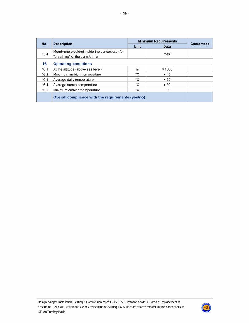
- 59 -
Design, Supply, Installation, Testing & Commissioning of 132kV GIS Substation at APSCL area as replacement of
existing of 132kV AIS station and associated shifting of existing 132kV lines/transformer/power station connections to
GIS on Turnkey Basis
No. Description Minimum Requirements
Guaranteed Unit Data
15.4 Membrane provided inside the conservator for
''breathing'' of the transformer Yes
16 Operating conditions 16.1 At the altitude (above sea level) m ≤ 1000
16.2 Maximum ambient temperature °C + 45
16.3 Average daily temperature °C + 35
16.4 Average annual temperature °C + 30
16.5 Minimum ambient temperature °C 5
Overall compliance with the requirements (yes/no)

- 60 -
Design, Supply, Installation, Testing & Commissioning of 132kV GIS Substation at APSCL area as replacement of
existing of 132kV AIS station and associated shifting of existing 132kV lines/transformer/power station connections to
GIS on Turnkey Basis
5.2.4.2 D2: 132/33 kV 80/120 MVA Power Transformer (Not Applicable)

- 61 -
Design, Supply, Installation, Testing & Commissioning of 132kV GIS Substation at APSCL area as replacement of
existing of 132kV AIS station and associated shifting of existing 132kV lines/transformer/power station connections to
GIS on Turnkey Basis
5.2.5 F: Auxiliary Transformers
5.2.5.1 F1: 33/0.415 kV500 kVA, ZNyn11, Auxiliary Transformer
No. Description Minimum Requirements
Guaranteed Unit Data
1 General
1.1 Manufacturer Insert
1.2 Type
Power transformer
three-phase, oil im-
mersed, two windings,
without tertiary winding,
with off-load tap
changer, outdoor
1.3 Model designation Insert
1.4 Country of origin Insert
1.5 Standards IEC 60076
1.6 Quality control ISO 9001
2 Ratings and properties
2.1 Rated power: kVA 500
2.2 Type of cooling ONAN / ONAF - ONAN
2.3 Rated voltage kV/V 33 ± 2 x 2,5 % / 415
2.4
Tap changer:
Type of tap changing
Tapping range
Tapping step
Rating
%
%
Off-load
±5
2.5
Rated power 200 kVA,
all taps
2.5 Frequency Hz 50
2.6 Connection of three-phase windings (group of
vector IEC 60076) ZNyn11
3 Special technical requirements
3.1 Power transformer capacity to withstand exter-
nal short circuits
3.1.1 Short-circuit duration s 3
3.1.2
Symmetrical short-circuit with-stand capacity
and asymmetrical short-circuit withstand capac-
ity during indicated period:
MV winding
LV winding
kA
kA
25
-
3.2 Guaranteed losses
3.2.1 No-load losses with tap changer in normal posi-
tion, at rated voltage and rated frequency kW Insert
3.2.2 Tolerance to be applied to no-load losses in %
of the guaranteed value % 10
3.2.3
On-load losses at 75°C, at rated voltage and
rated frequency, with tap changer in normal po-
sition
kW Insert

- 62 -
Design, Supply, Installation, Testing & Commissioning of 132kV GIS Substation at APSCL area as replacement of
existing of 132kV AIS station and associated shifting of existing 132kV lines/transformer/power station connections to
GIS on Turnkey Basis
No. Description Minimum Requirements
Guaranteed Unit Data
3.2.4 Tolerance to be applied to on-load losses in %
on the guaranteed value % 10
3.3 Insulation level
3.3.1 Medium voltage (MV) LI 170 AC 70
3.3.2 Low voltage (LV) LI - AC 3
3.4 The highest voltage for equipment (effective
value)
3.4.1 Medium voltage (MV) kV 36
3.4.2 Low voltage (LV) kV 1.1
3.5
Temperature rise limits, at rated power, with
complete cooling system in service and at low-
est voltage tap
3.5.1 Top oil K ≤ 50
3.5.2 Winding K ≤ 55
3.5.3 Hottest spot K ≤ 65
4 Oil
4.1 New Insert
4.2 Manufacturer Insert
4.3 Type Insert
4.4 Standard IEC 60296
4.5 Minimum flash point °C Insert
4.6 Viscosity at 20°C mm2/s Insert
4.7 Minimum dielectric strength kV/cm Insert
5 Bushing
5.1 MV bushing (36 kV)
5.1.1 Quantity 3 + 1
5.1.2 Class kV 36/170/70
5.1.3 Manufacturer Insert
5.1.4 Type Insert
5.1.5 Rated current A ≥ 100
5.1.6 Minimum creepage distance (25 mm/ kV) mm/ kV ≥ 25 mm/ kV
5.2 LV bushings (3 kV)
5.2.1 Quantity 3 + 1
5.2.2 Class kV 3
5.2.3 Manufacturer Insert
5.2.4 Type Insert
5.2.5 Rated current A ≥ 400
5.2.6 Minimum creepage distance (25 mm/ kV) mm/ kV ≥ 25 mm/ kV
6 Weights and dimensions
6.1 Total weight of transformer, ready for service kg Insert
6.2
Outer dimensions:
Length
Width
mm
mm
Insert
Insert
6.3 Informative dimensional sketch To be enclosed with bid
7 Dehydrating breather
7.1 Type of dehydrating breather Insert

- 63 -
Design, Supply, Installation, Testing & Commissioning of 132kV GIS Substation at APSCL area as replacement of
existing of 132kV AIS station and associated shifting of existing 132kV lines/transformer/power station connections to
GIS on Turnkey Basis
No. Description Minimum Requirements
Guaranteed Unit Data
7.2 Dehumidifying agent kg Insert
8 Conservator
8.1 Type With dehydrating
breather
8.2 Number of compartments pcs. 1
8.3 Oil level indicators with alarm for minimum oil
level pcs. 1
9 Operating conditions
9.1 At the altitude (above sea level) m ≤ 1000
9.2 Maximum ambient temperature °C + 45
9.3 Average daily temperature °C + 35
9.4 Average annual temperature °C + 30
9.5 Minimum ambient temperature °C 5
Overall compliance with the requirements (yes/no)

- 64 -
Design, Supply, Installation, Testing & Commissioning of 132kV GIS Substation at APSCL area as replacement of
existing of 132kV AIS station and associated shifting of existing 132kV lines/transformer/power station connections to
GIS on Turnkey Basis
5.2.5.2 F2: 33/0.415 kV 200 kVA, Dyn11, Auxiliary Transformer (Not Applicable)

- 65 -
Design, Supply, Installation, Testing & Commissioning of 132kV GIS Substation at APSCL area as replacement of
existing of 132kV AIS station and associated shifting of existing 132kV lines/transformer/power station connections to
GIS on Turnkey Basis
5.2.6 G-P: Control, Relay Protection, Substation Automation System& Metering
All auxiliary equipment such as MCBs, heaters, lighting, AC sockets, terminals, auxiliary relays, wiring and necessary electrical/optical converters for communication, etc. shall be foreseen Enough auxiliary relays/contactors for OHL/transformer/busbar protection shall be foreseen and deliv-ered as built-in elements in the cubicles. The central unit for busbar protection must be supported for min. 16 bays. The design proposal of the cubicles is subject of approval. The cubicles shall be delivered completely wired and tested. 5.2.6.1 14291 - Control Cubicle for OHL & Bus Coupler
No. Description Minimum Requirements
GuaranteedUnit Data
14291 Control Cubicle for OHL &Bus Couplers with Switch / Code number: 14291 1.1 Control cubicle for OHL &bus couplers with LAN switch
1.1.1 Bay control unit for OHL &bus couplers (Code: 14251) pcs. 1
1.1.2 Back-up control panel (Code: 14254) pcs. 1
1.1.3 Front panel annunciation for OHL & TR (Code: 14255) pcs. 1
1.1.4 Ethernet switch-process LAN (Code: 14273) pcs. 1
1.2 Other equipment (specify if any) Insert
Overall compliance with the requirements (yes/no)
5.2.6.2 14292 - Control Cubicle for Power Transformers HV Side
No. Description Minimum Requirements
GuaranteedUnit Data
14292 Control Cubicle for Power Transformers HV Side with LAN Switch / Code number: 14292
1.1 Control cubicle for power transformers HV side with LAN switch
1.1.1 Bay control unit for power transformers HV&LV
(Code: 14252) pcs. 1
1.1.2 Back-up control panel (Code: 14254) pcs. 1
1.1.3 Front panel annunciation for OHL & TR (Code: 14255) pcs. 1
1.1.4 Ethernet switch process LAN (Code: 14273) pcs. 1
1.2 Other equipment (specify if any) Insert
Overall compliance with the requirements (yes/no)

- 66 -
Design, Supply, Installation, Testing & Commissioning of 132kV GIS Substation at APSCL area as replacement of
existing of 132kV AIS station and associated shifting of existing 132kV lines/transformer/power station connections to
GIS on Turnkey Basis
5.2.6.3 14293 - Control Cubicle for Power Transformers LV Side
No. Description Minimum Requirements
GuaranteedUnit Data
14293 GENERAL (Control Cubicle for Power Transformers LV Side / Code number: 14293) 1.1 Control cubicle for power transformers LV side
1.1.1 Bay control unit for power transformers HV&LV
(Code: 14252) pcs. 1
1.1.2 Back-up control panel (Code: 14254) pcs. 1
1.1.3 Front panel annunciation for OHL & TR (Code: 14255) pcs. 1
1.1.4 Ethernet switch-process LAN (Code: 14273) pcs. 1
1.1.5 AVR (Code: 14008) pcs. 1
1.2 Other equipment (specify if any) Insert
Overall compliance with the requirements (yes/no)
5.2.6.4 14294 - Control Cubicle for LV AC & DC Switchgear
No. Description Minimum Requirements
GuaranteedUnit Data
14294 Control Cubicle for LV AC & DC SWG / Code number: 14294 1.1 Control cubicle for LV AC&DC SWG
1.1.1 Bay control unit for LV AC&DC SWG (Code: 14253) pcs. 4
1.1.2 Front panel annunciation for control room
(Code: 14256) pcs. 1
1.1.4 Horn on/off switch Yes
Overall compliance with the requirements (yes/no)
5.2.6.5 14295 - Control Cubicle for SCADA Server
No. Description Minimum Requirements
GuaranteedUnit Data
14295 Control Cubicle for SCADA Server / Code number: 14295 1.1 Cubicle for SCADA servers
1.1.1 SCADA server (Code: 14261) pcs. 2
1.1.2 Ethernet switch-process LAN (Code: 14273) pcs. 2
1.1.3 Ethernet switch-control room LAN (Code: 14274) pcs. 2
Overall compliance with the requirements (yes/no)

- 67 -
Design, Supply, Installation, Testing & Commissioning of 132kV GIS Substation at APSCL area as replacement of
existing of 132kV AIS station and associated shifting of existing 132kV lines/transformer/power station connections to
GIS on Turnkey Basis
5.2.6.6 14101 - Protection Cubicle No. 1 for 230 kV OHL (Not Applicable)
5.2.6.7 14102 - Protection Cubicle No. 2 for 230 kV OHL (Not Applicable)

- 68 -
Design, Supply, Installation, Testing & Commissioning of 132kV GIS Substation at APSCL area as replacement of
existing of 132kV AIS station and associated shifting of existing 132kV lines/transformer/power station connections to
GIS on Turnkey Basis
5.2.6.8 14103 - Protection Cubicle No. 3 for 132 kV OHL
No. Description Minimum Requirements
GuaranteedUnit Data
14103 Protection Cubicle No. 3 for 132 kV OHL / Code number: 14103 1.1 Protection cubicle No. 3 for 132 kV OHL-Long
1.1.1 Protection terminal for 132 kV OHLMain 1 (Code: 14003) pcs. 1
1.1.2 Protection terminal for 132 kV OHL Main 2 (Code: 14004) pcs. 1
1.1.3 Busbar & breaker failure protection bay unit (Code: 14010) pcs. 1
1.1.4 Trip circuit supervision relay (Code: 14011) pcs. 6
1.1.5 Tripping unit (Code: 14012) pcs.
8
(To be confirmed
with detailed de-
sign)
1.1.6 Test socket (Code: 14013) pcs. 3
Overall compliance with the requirements (yes/no)
5.2.6.9 14104 - Protection Cubicle No. 4 for Power Transformer HV Side
No. Description Minimum Requirements
GuaranteedUnit Data
14104 Protection Cubicle No. 4 for Power Transformer HV Side / Code number: 14104) 1.1 Protection cubicle No. 5 for Power Transformer HV Side
1.1.1 Protection terminal for power transformer Main 1 (Code:
14005) pcs. 1
1.1.2 Busbar & breaker failure protection bay unit (Code: 14010) pcs. 1
1.1.3 Trip circuit supervision relay (Code: 14011) pcs. 6
1.1.4 Tripping unit (Code: 14012) pcs.
4
(To be confirmed
with detailed de-
sign)
1.1.5 Test socket (Code: 14013) pcs. 2
Overall compliance with the requirements (yes/no)
5.2.6.10 14105 - Protection Cubicle No. 5 for Power Transformer LV Side
No. Description Minimum Requirements
GuaranteedUnit Data
14105 Protection Cubicle No. 5 for Power Transformer LV Side / Code number: 14105 1.1 Protection cubicle No. 5 for Power Transformer LV Side
1.1.1 Protection terminal for power transformer Main 2 (Code:
14006) pcs. 1
1.1.2 Protection terminal for power transformer LV Side (Code:
14007) pcs. 1
1.1.3 Busbar & breaker failure protection bay unit (Code: 14010) pcs. 1
1.1.4 Trip circuit supervision relay (Code: 14011) pcs. 2
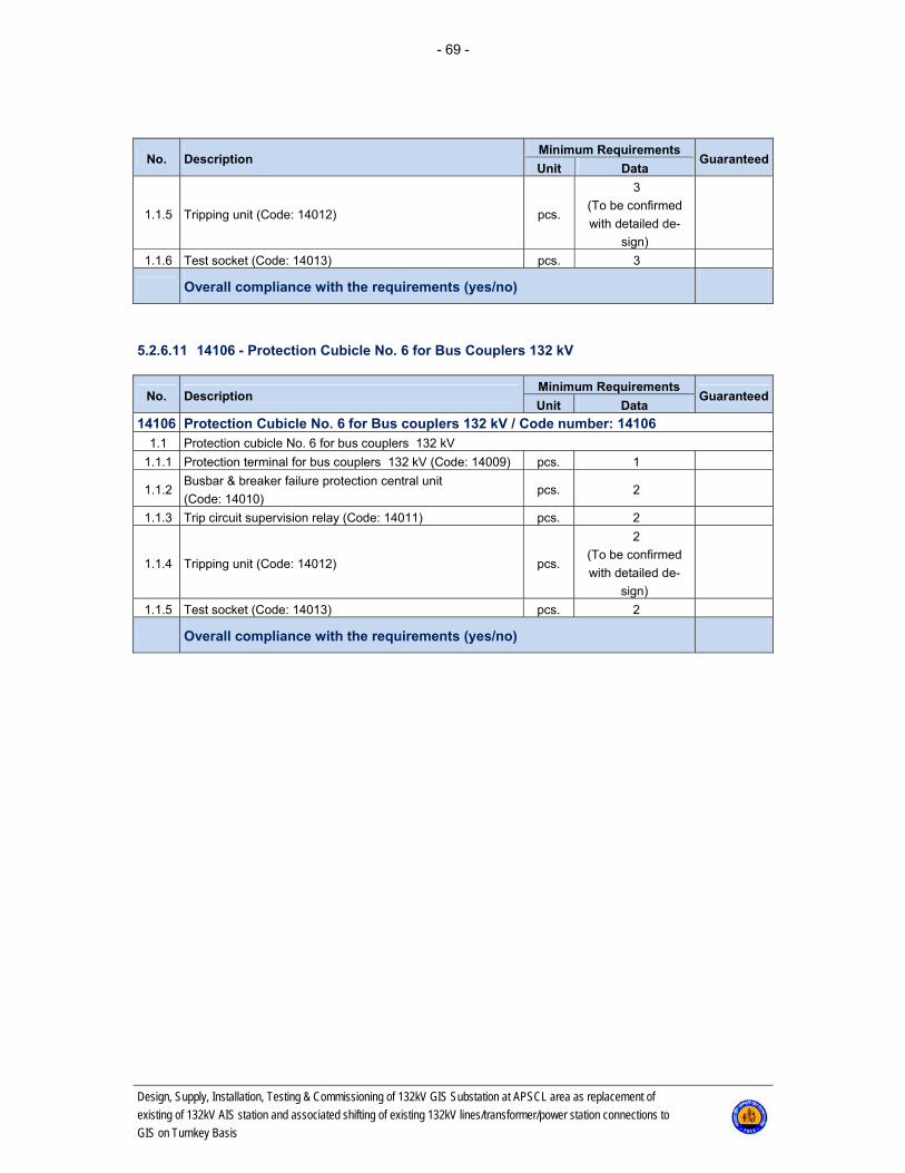
- 69 -
Design, Supply, Installation, Testing & Commissioning of 132kV GIS Substation at APSCL area as replacement of
existing of 132kV AIS station and associated shifting of existing 132kV lines/transformer/power station connections to
GIS on Turnkey Basis
No. Description Minimum Requirements
GuaranteedUnit Data
1.1.5 Tripping unit (Code: 14012) pcs.
3
(To be confirmed
with detailed de-
sign)
1.1.6 Test socket (Code: 14013) pcs. 3
Overall compliance with the requirements (yes/no)
5.2.6.11 14106 - Protection Cubicle No. 6 for Bus Couplers 132 kV
No. Description Minimum Requirements
GuaranteedUnit Data
14106 Protection Cubicle No. 6 for Bus couplers 132 kV / Code number: 14106 1.1 Protection cubicle No. 6 for bus couplers 132 kV
1.1.1 Protection terminal for bus couplers 132 kV (Code: 14009) pcs. 1
1.1.2 Busbar & breaker failure protection central unit
(Code: 14010) pcs. 2
1.1.3 Trip circuit supervision relay (Code: 14011) pcs. 2
1.1.4 Tripping unit (Code: 14012) pcs.
2
(To be confirmed
with detailed de-
sign)
1.1.5 Test socket (Code: 14013) pcs. 2
Overall compliance with the requirements (yes/no)

- 70 -
Design, Supply, Installation, Testing & Commissioning of 132kV GIS Substation at APSCL area as replacement of
existing of 132kV AIS station and associated shifting of existing 132kV lines/transformer/power station connections to
GIS on Turnkey Basis
5.2.6.12 14251 - Bay Control Unit for OHL and Bus Couplers
No. Description Minimum Requirements
Guaranteed Unit Data
14251 Bay Control Unit for OHL and Bus Couplers / Code number: 14251 1.1 Manufacturer Insert
1.2 Country of origin Insert
1.3 Terminal type Insert
1.4 Terminal version (software version) Insert
1.5 Standards IEC
2 Characteristics 2.1 Auxiliary supply voltage
2.1.1 Rated auxiliary supply voltage V d.c. 110 ±15 %
2.1.2
Interruption in auxiliary d.c. voltage:
Without resetting
Restart time
ms
s
> 50
Insert
2.2 a.c. current inputs
2.2.1 Number of inputs Min. 4
2.2.2 Rated current Ir A 1
2.2.3 Permissive overload, continuous 4xIr
2.2.4 Permissive overload, 1 s 100xIr
2.2.5 Burden at Ir VA < 0.5
2.3 a.c. voltage inputs
2.3.1 Number of inputs Min. 4
2.3.2 Rated voltage Ph-Ph Ur V 100
2.3.3 Permissive overload, continuous % Ur 150
2.3.4 Permissive overload, 1 s % Ur 250
2.3.5 Burden at Ur VA < 0.3
2.4 Binary inputs Min. 45
2.4.1 Number of BI groups with common root Max. 4
2.4.2 Number of inputs per BI group with common
root Max. 8
2.4.3 Rated voltage V d.c. 110
2.5 Binary outputs Min. 24
2.5.1 Number of BO with common contact Max. 4
2.5.2 Rated voltage V d.c. 110
2.5.3 Breaking capacity at inductive load with
L/R<40 ms, at rated voltage A 0.1
2.5.4 Current carrying capacity at rated voltage for
signalling contacts, continuous A Insert
2.5.5 Number of tripping contacts (high-speed out-
put) pcs. Insert
2.5.6 Current carrying capacity at rated voltage for
tripping contacts, continuous A 5
2.6 LED indications
2.6.1 Number of LED's Min. 16
2.6.2 Multi-colour LED's Yes/No Insert
2.7 Communication ports Yes
2.7.1 Port for front-connected PC
2.7.1.1 Protocols supported Insert
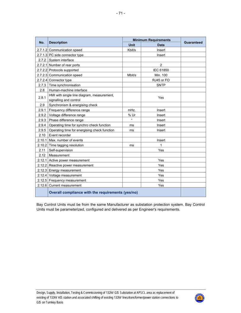
- 71 -
Design, Supply, Installation, Testing & Commissioning of 132kV GIS Substation at APSCL area as replacement of
existing of 132kV AIS station and associated shifting of existing 132kV lines/transformer/power station connections to
GIS on Turnkey Basis
No. Description Minimum Requirements
Guaranteed Unit Data
2.7.1.2 Communication speed Kbit/s Insert
2.7.1.3 PC side connector type Insert
2.7.2 System interface
2.7.2.1 Number of rear ports 2
2.7.2.2 Protocols supported IEC 61850
2.7.2.3 Communication speed Mbit/s Min. 100
2.7.2.4 Connector type RJ45 or FO
2.7.3 Time synchronisation SNTP
2.8 Human-machine interface
2.8.1 HMI with single line diagram, measurement,
signalling and control Yes
2.9 Synchronism & energising check
2.9.1 Frequency difference range mHz. Insert
2.9.2 Voltage difference range % Ur Insert
2.9.3 Phase difference range ° Insert
2.9.4 Operating time for synchro check function ms Insert
2.9.5 Operating time for energising check function ms Insert
2.10 Event recorder
2.10.1 Max. number of events Insert
2.10.2 Time tagging resolution ms 1
2.11 Self-supervision Yes
2.12 Measurement
2.12.1 Active power measurement Yes
2.12.2 Reactive power measurement Yes
2.12.3 Energy measurement Yes
2.12.4 Voltage measurement Yes
2.12.5 Frequency measurement Yes
2.12.6 Current measurement Yes
Overall compliance with the requirements (yes/no)
Bay Control Units must be from the same Manufacturer as substation protection system. Bay Control Units must be parameterized, configured and delivered as per Engineer's requirements.

- 72 -
Design, Supply, Installation, Testing & Commissioning of 132kV GIS Substation at APSCL area as replacement of
existing of 132kV AIS station and associated shifting of existing 132kV lines/transformer/power station connections to
GIS on Turnkey Basis
5.2.6.13 14252 - Bay Control Unit for Power Transformers HV & LV
No. Description Minimum Requirements
Guaranteed Unit Data
14252 Bay Control Unit for Power Transformers HV&LV / Code number: 14252 1.1 Manufacturer Insert
1.2 Country of origin Insert
1.3 Terminal type Insert
1.4 Terminal version (software version) Insert
1.5 Standards IEC
2 Characteristics 2.1 Auxiliary supply voltage
2.1.1 Rated auxiliary supply voltage V d.c. 110 ±15 %
2.1.2
Interruption in auxiliary d.c. voltage:
Without resetting
Restart time
ms
s
> 50
Insert
2.2 a.c. current inputs
2.2.1 Number of inputs Min. 4
2.2.2 Rated current Ir A 1
2.2.3 Permissive overload, continuous 4xIr
2.2.4 Permissive overload, 1 s 100xIr
2.2.5 Burden at Ir VA < 0.5
2.3 a.c. voltage inputs
2.3.1 Number of inputs Min. 4
2.3.2 Rated voltage Ph-Ph Ur V 100
2.3.3 Permissive overload, continuous % Ur 150
2.3.4 Permissive overload, 1 s % Ur 250
2.3.5 Burden at Ur VA < 0.3
2.4 mA inputs
2.4.1 Number of mA inputs pcs. Min. 2
2.4.2 Input range 4-20 mA
2.5 Binary inputs Min. 45
2.5.1 Number of BI groups with common root Max. 4
2.5.2 Number of inputs per BI group with common root Max. 8
2.5.3 Rated voltage V d.c. 110
2.6 Binary outputs Min. 24
2.6.1 Number of BO with common contact Max. 4
2.6.2 Rated voltage V d.c. 110
2.6.3 Breaking capacity at inductive load with
L/R<40 ms, at rated voltage A 0.1
2.6.4 Current carrying capacity at rated voltage for
signalling contacts, continuous A Insert
2.6.5 Number of tripping contacts (high-speed output) pcs. Insert
2.6.6 Current carrying capacity at rated voltage for
tripping contacts, continuous A 5
2.7 LED indications
2.7.1 Number of LED's Min. 16
2.7.2 Multi-colour LED's Yes/No Insert

- 73 -
Design, Supply, Installation, Testing & Commissioning of 132kV GIS Substation at APSCL area as replacement of
existing of 132kV AIS station and associated shifting of existing 132kV lines/transformer/power station connections to
GIS on Turnkey Basis
No. Description Minimum Requirements
Guaranteed Unit Data
2.8 Communication ports Yes
2.8.1 Port for front-connected PC
2.8.1.1 Protocols supported Insert
2.8.1.2 Communication speed Kbit/s Insert
2.8.1.3 PC side connector type Insert
2.8.2 System interface
2.8.2.1 Number of rear ports 2
2.8.2.2 Protocols supported IEC 61850
2.8.2.3 Communication speed Mbit/s Min. 100
2.8.2.4 Connector type RJ45 or FO
2.8.3 Time synchronisation SNTP
2.9 Human-machine interface
2.9.1 HMI with single line diagram, measurement, sig-
nalling and control Yes
2.10 Synchronism & energising check
2.10.1 Frequency difference range mHz. Insert
2.10.2 Voltage difference range % Ur Insert
2.10.3 Phase difference range ° Insert
2.10.4 Operating time for synchro check function ms Insert
2.10.5 Operating time for energising check function ms Insert
2.11 Event recorder
2.11.1 Max. number of events Insert
2.11.2 Time tagging resolution ms 1
2.12 Self-supervision Yes
2.13 Measurement
2.13.1 Active power measurement Yes
2.13.2 Reactive power measurement Yes
2.13.3 Energy measurement Yes
2.13.4 Voltage measurement Yes
2.13.5 Frequency measurement Yes
2.13.6 Current measurement Yes
Overall compliance with the requirements (yes/no)
Bay Control Units for Transformer HV & LV side must be from the same Manufacturer as substation protection system. Bay Control Units for Transformer HV & LV side must be parameterized, configured and delivered as per Engineer's requirements.

- 74 -
Design, Supply, Installation, Testing & Commissioning of 132kV GIS Substation at APSCL area as replacement of
existing of 132kV AIS station and associated shifting of existing 132kV lines/transformer/power station connections to
GIS on Turnkey Basis
5.2.6.14 14253 - Bay Control Unit for LV AC & DC
No. Description Minimum Requirements
Guaranteed Unit Data
14253 Bay Control Unit for LV AC&DC -SWG / Code number: 14253 1.1 Manufacturer Insert
1.2 Country of origin Insert
1.3 Terminal type Insert
1.4 Terminal version (software version) Insert
1.5 Standards IEC
2 Characteristics 2.1 Auxiliary supply voltage
2.1.1 Rated auxiliary supply voltage V d.c. 110 ±15 %
2.1.2
Interruption in auxiliary d.c. voltage:
Without resetting
Restart time
ms
s
> 50
Insert
2.2 a.c. current inputs
2.2.1 Number of inputs Min. 3
2.2.2 Rated current Ir A 5
2.2.3 Permissive overload, continuous 4xIr
2.2.4 Permissive overload, 1 s 100xIr
2.2.5 Burden at Ir VA
2.3 a.c. voltage inputs
2.3.1 Number of inputs Min. 3
2.3.2 Rated voltage Ph-Ph Ur V 250
2.3.3 Permissive overload, continuous % Ur 150
2.3.4 Permissive overload, 1 s % Ur 250
2.3.5 Burden at Ur VA
2.4 mA inputs
2.4.1 Number of mA inputs pcs. Min. 4
2.4.2 Input range 4-20 mA
2.5 Binary inputs Min. 45
2.5.1 Number of BI groups with common root Max. 4
2.5.2 Number of inputs per BI group with common
root Max. 8
2.5.3 Rated voltage V d.c. 110
2.6 Binary outputs Min. 4
2.6.1 Number of BO with common contact Insert
2.6.2 Rated voltage V d.c. 110
2.6.3 Breaking capacity at inductive load with
L/R<40 ms, at rated voltage A 0.1
2.6.4 Current carrying capacity at rated voltage for
signalling contacts, continuous A Insert
2.6.5 Number of tripping contacts (high-speed out-
put) pcs. Insert
2.6.6 Current carrying capacity at rated voltage for
tripping contacts, continuous A 5
2.7 LED indications
2.7.1 Number of LED's Insert

- 75 -
Design, Supply, Installation, Testing & Commissioning of 132kV GIS Substation at APSCL area as replacement of
existing of 132kV AIS station and associated shifting of existing 132kV lines/transformer/power station connections to
GIS on Turnkey Basis
No. Description Minimum Requirements
Guaranteed Unit Data
2.7.2 Multi-colour LED's Yes/No Insert
2.8 Communication ports Yes
2.8.1 Port for front-connected PC
2.8.1.1 Protocols supported Insert
2.8.1.2 Communication speed Kbit/s Insert
2.8.1.3 PC side connector type Insert
2.8.2 System interface
2.8.2.1 Number of rear ports 2
2.8.2.2 Protocols supported IEC 61850
2.8.2.3 Communication speed Mbit/s Min. 100
2.8.2.4 Connector type RJ45 or FO
2.8.3 Time synchronisation SNTP
2.9 Human-machine interface
2.9.1 HMI with single line diagram, measurement,
signalling and control Yes
2.10 Event recorder
2.10.1 Max. number of events Insert
2.10.2 Time tagging resolution ms 1
2.11 Self-supervision Yes
2.12 Measurement
2.12.1 Voltage measurement Yes
2.12.2 Frequency measurement Yes
2.12.3 Current measurement Yes
Overall compliance with the requirements (yes/no)
Bay Control Units must be from the same Manufacturer as substation protection system. Bay Control Units must be parameterized, configured and delivered as per Engineer's requirements.
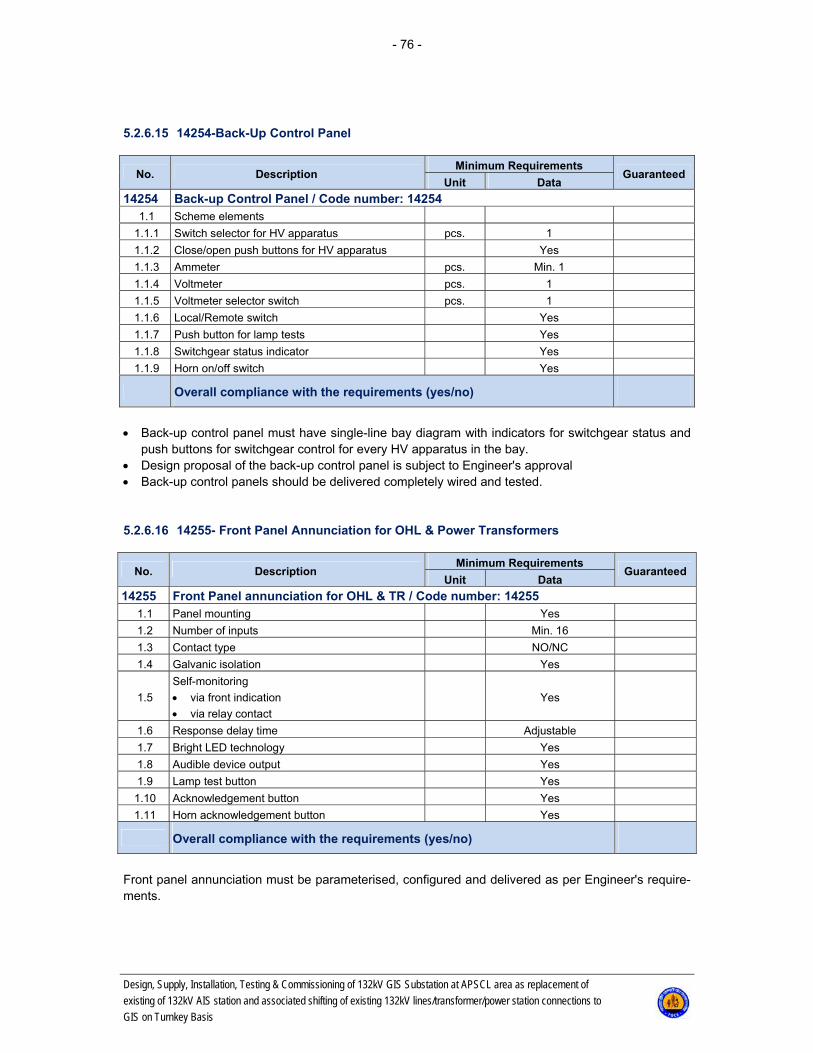
- 76 -
Design, Supply, Installation, Testing & Commissioning of 132kV GIS Substation at APSCL area as replacement of
existing of 132kV AIS station and associated shifting of existing 132kV lines/transformer/power station connections to
GIS on Turnkey Basis
5.2.6.15 14254-Back-Up Control Panel
No. Description Minimum Requirements
Guaranteed Unit Data
14254 Back-up Control Panel / Code number: 14254 1.1 Scheme elements
1.1.1 Switch selector for HV apparatus pcs. 1
1.1.2 Close/open push buttons for HV apparatus Yes
1.1.3 Ammeter pcs. Min. 1
1.1.4 Voltmeter pcs. 1
1.1.5 Voltmeter selector switch pcs. 1
1.1.6 Local/Remote switch Yes
1.1.7 Push button for lamp tests Yes
1.1.8 Switchgear status indicator Yes
1.1.9 Horn on/off switch Yes
Overall compliance with the requirements (yes/no)
Back-up control panel must have single-line bay diagram with indicators for switchgear status and
push buttons for switchgear control for every HV apparatus in the bay. Design proposal of the back-up control panel is subject to Engineer's approval Back-up control panels should be delivered completely wired and tested. 5.2.6.16 14255- Front Panel Annunciation for OHL & Power Transformers
No. Description Minimum Requirements
Guaranteed Unit Data
14255 Front Panel annunciation for OHL & TR / Code number: 14255 1.1 Panel mounting Yes
1.2 Number of inputs Min. 16
1.3 Contact type NO/NC
1.4 Galvanic isolation Yes
1.5
Self-monitoring
via front indication
via relay contact
Yes
1.6 Response delay time Adjustable
1.7 Bright LED technology Yes
1.8 Audible device output Yes
1.9 Lamp test button Yes
1.10 Acknowledgement button Yes
1.11 Horn acknowledgement button Yes
Overall compliance with the requirements (yes/no)
Front panel annunciation must be parameterised, configured and delivered as per Engineer's require-ments.

- 77 -
Design, Supply, Installation, Testing & Commissioning of 132kV GIS Substation at APSCL area as replacement of
existing of 132kV AIS station and associated shifting of existing 132kV lines/transformer/power station connections to
GIS on Turnkey Basis
5.2.6.17 14256- Front Panel Annunciation for Control Room
No. Description Minimum Requirements
Guaranteed Unit Data
14256 Front Panel annunciation for Control Room / Code number: 14256 1.1 Panel mounting Yes
1.2 Number of inputs Min. 48
1.3 Contact type NO/NC
1.4 Galvanic isolation Yes
1.5
Self-monitoring
via front indication
via relay contact
Yes
1.6 Response delay time Adjustable
1.7 Bright LED technology Yes
1.8 Audible device output Yes
1.9 Lamp test button Yes
1.10 Acknowledgement button Yes
1.11 Horn acknowledgement button Yes
Overall compliance with the requirements (yes/no)
Front panel annunciation must be parameterised, configured and delivered as per Engineer's require-ments.
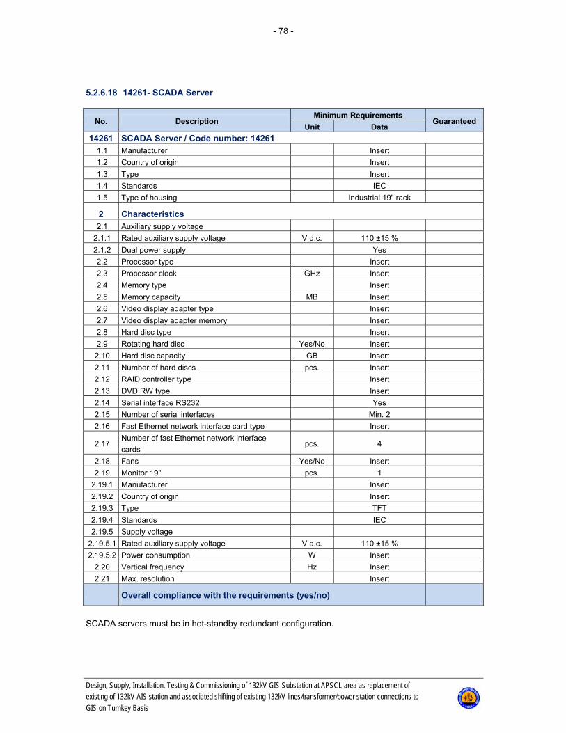
- 78 -
Design, Supply, Installation, Testing & Commissioning of 132kV GIS Substation at APSCL area as replacement of
existing of 132kV AIS station and associated shifting of existing 132kV lines/transformer/power station connections to
GIS on Turnkey Basis
5.2.6.18 14261- SCADA Server
No. Description Minimum Requirements
Guaranteed Unit Data
14261 SCADA Server / Code number: 14261 1.1 Manufacturer Insert
1.2 Country of origin Insert
1.3 Type Insert
1.4 Standards IEC
1.5 Type of housing Industrial 19" rack
2 Characteristics 2.1 Auxiliary supply voltage
2.1.1 Rated auxiliary supply voltage V d.c. 110 ±15 %
2.1.2 Dual power supply Yes
2.2 Processor type Insert
2.3 Processor clock GHz Insert
2.4 Memory type Insert
2.5 Memory capacity MB Insert
2.6 Video display adapter type Insert
2.7 Video display adapter memory Insert
2.8 Hard disc type Insert
2.9 Rotating hard disc Yes/No Insert
2.10 Hard disc capacity GB Insert
2.11 Number of hard discs pcs. Insert
2.12 RAID controller type Insert
2.13 DVD RW type Insert
2.14 Serial interface RS232 Yes
2.15 Number of serial interfaces Min. 2
2.16 Fast Ethernet network interface card type Insert
2.17 Number of fast Ethernet network interface
cards pcs. 4
2.18 Fans Yes/No Insert
2.19 Monitor 19" pcs. 1
2.19.1 Manufacturer Insert
2.19.2 Country of origin Insert
2.19.3 Type TFT
2.19.4 Standards IEC
2.19.5 Supply voltage
2.19.5.1 Rated auxiliary supply voltage V a.c. 110 ±15 %
2.19.5.2 Power consumption W Insert
2.20 Vertical frequency Hz Insert
2.21 Max. resolution Insert
Overall compliance with the requirements (yes/no)
SCADA servers must be in hot-standby redundant configuration.
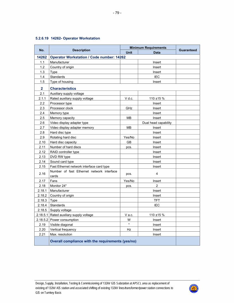
- 79 -
Design, Supply, Installation, Testing & Commissioning of 132kV GIS Substation at APSCL area as replacement of
existing of 132kV AIS station and associated shifting of existing 132kV lines/transformer/power station connections to
GIS on Turnkey Basis
5.2.6.19 14262- Operator Workstation
No. Description Minimum Requirements
Guaranteed Unit Data
14262 Operator Workstation / Code number: 14262 1.1 Manufacturer Insert
1.2 Country of origin Insert
1.3 Type Insert
1.4 Standards IEC
1.5 Type of housing Insert
2 Characteristics 2.1 Auxiliary supply voltage
2.1.1 Rated auxiliary supply voltage V d.c. 110 ±15 %
2.2 Processor type Insert
2.3 Processor clock GHz Insert
2.4 Memory type Insert
2.5 Memory capacity MB Insert
2.6 Video display adapter type Dual head capability
2.7 Video display adapter memory MB Insert
2.8 Hard disc type Insert
2.9 Rotating hard disc Yes/No Insert
2.10 Hard disc capacity GB Insert
2.11 Number of hard discs pcs. Insert
2.12 RAID controller type Insert
2.13 DVD RW type Insert
2.14 Sound card type Insert
2.15 Fast Ethernet network interface card type Insert
2.16 Number of fast Ethernet network interface
cards pcs. 4
2.17 Fans Yes/No Insert
2.18 Monitor 24" pcs. 2
2.18.1 Manufacturer Insert
2.18.2 Country of origin Insert
2.18.3 Type TFT
2.18.4 Standards IEC
2.18.5 Supply voltage
2.18.5.1 Rated auxiliary supply voltage V a.c. 110 ±15 %
2.18.5.2 Power consumption W Insert
2.19 Visible diagonal " Insert
2.20 Vertical frequency Hz Insert
2.21 Max. resolution Insert
Overall compliance with the requirements (yes/no)

- 80 -
Design, Supply, Installation, Testing & Commissioning of 132kV GIS Substation at APSCL area as replacement of
existing of 132kV AIS station and associated shifting of existing 132kV lines/transformer/power station connections to
GIS on Turnkey Basis
5.2.6.20 14263- Printer
No. Description Minimum Requirements
Guaranteed Unit Data
14263 Printer / Code number: 14263 1.1 Manufacturer Insert
1.2 Model Insert
1.3 Country of origin Insert
1.4 Standards IEC / ISO
2 Characteristics 2.1 Auxiliary supply voltage
2.1.1 Rated auxiliary supply voltage V d.c. 110 ±15 %
2.2 Type Colour laser
2.3 Format A4
2.4 Resolution dpi Insert
2.5 Memory MB Insert
2.6 Parallel port Yes/No Insert
2.7 Fast Ethernet port Yes
2.8 USB port Yes/No Insert
2.9 Minimum speed Page/min Insert
Overall compliance with the requirements (yes/no)
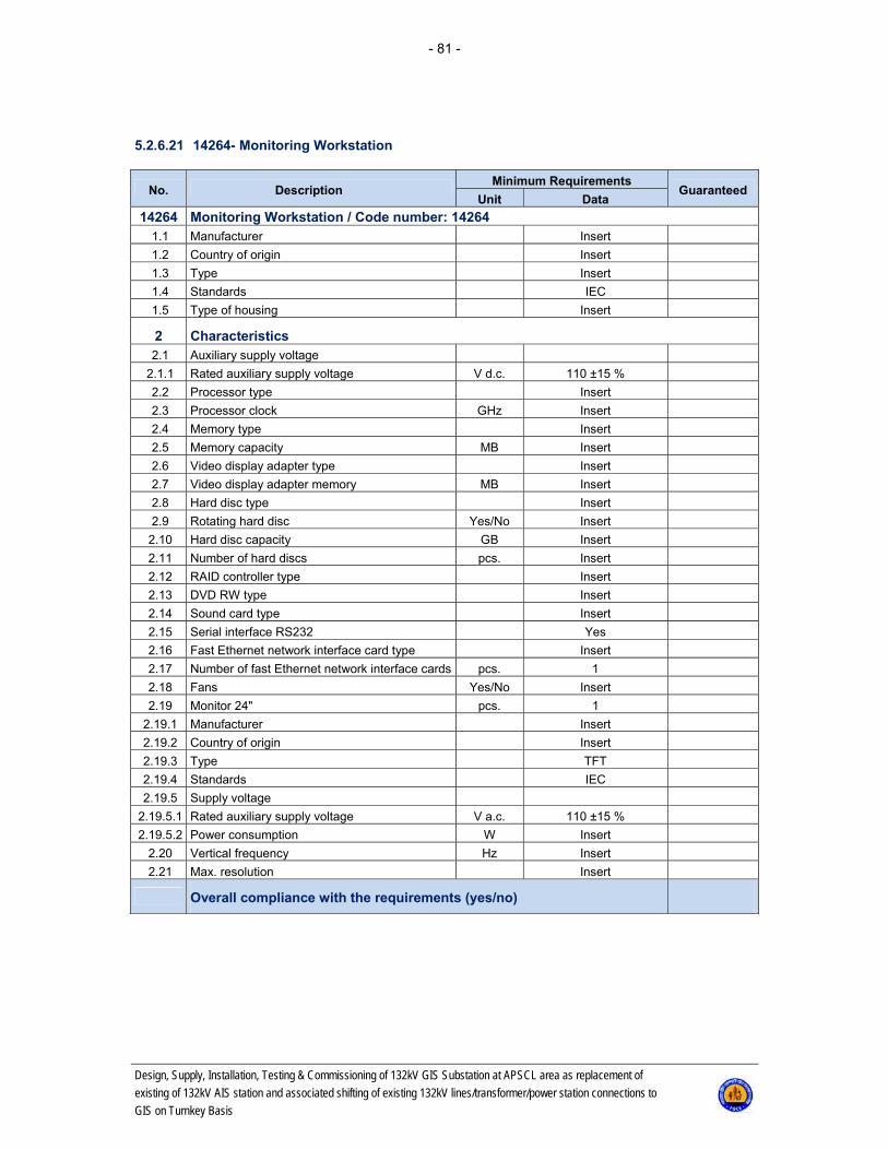
- 81 -
Design, Supply, Installation, Testing & Commissioning of 132kV GIS Substation at APSCL area as replacement of
existing of 132kV AIS station and associated shifting of existing 132kV lines/transformer/power station connections to
GIS on Turnkey Basis
5.2.6.21 14264- Monitoring Workstation
No. Description Minimum Requirements
Guaranteed Unit Data
14264 Monitoring Workstation / Code number: 14264 1.1 Manufacturer Insert
1.2 Country of origin Insert
1.3 Type Insert
1.4 Standards IEC
1.5 Type of housing Insert
2 Characteristics 2.1 Auxiliary supply voltage
2.1.1 Rated auxiliary supply voltage V d.c. 110 ±15 %
2.2 Processor type Insert
2.3 Processor clock GHz Insert
2.4 Memory type Insert
2.5 Memory capacity MB Insert
2.6 Video display adapter type Insert
2.7 Video display adapter memory MB Insert
2.8 Hard disc type Insert
2.9 Rotating hard disc Yes/No Insert
2.10 Hard disc capacity GB Insert
2.11 Number of hard discs pcs. Insert
2.12 RAID controller type Insert
2.13 DVD RW type Insert
2.14 Sound card type Insert
2.15 Serial interface RS232 Yes
2.16 Fast Ethernet network interface card type Insert
2.17 Number of fast Ethernet network interface cards pcs. 1
2.18 Fans Yes/No Insert
2.19 Monitor 24" pcs. 1
2.19.1 Manufacturer Insert
2.19.2 Country of origin Insert
2.19.3 Type TFT
2.19.4 Standards IEC
2.19.5 Supply voltage
2.19.5.1 Rated auxiliary supply voltage V a.c. 110 ±15 %
2.19.5.2 Power consumption W Insert
2.20 Vertical frequency Hz Insert
2.21 Max. resolution Insert
Overall compliance with the requirements (yes/no)

- 82 -
Design, Supply, Installation, Testing & Commissioning of 132kV GIS Substation at APSCL area as replacement of
existing of 132kV AIS station and associated shifting of existing 132kV lines/transformer/power station connections to
GIS on Turnkey Basis
5.2.6.22 14273- Ethernet Switch Process LAN
No. Description Minimum Requirements
Guaranteed Unit Data
14273 Ethernet Switch-Process LAN / Code number: 14273 1.1 Terminal Type Insert
1.2 Terminal version (software version) Insert
1.3 Standards IEC
2 Characteristics 2.1 Auxiliary supply voltage
2.1.1 Rated auxiliary supply voltage V d.c. 110 ±15 %
2.1.2 Dual power supply Yes
2.2 Ethernet ports
2.2.1 Number of ports
Min. 6xRJ45 or
Min. 6xFO for IED con-
nections AND 2xFO
(1 GB) for process LAN
2.2.1 Type of ports RJ45 or FO and Fibre
Optical (1 GB)
2.3 Immunity to EMI and heavy electrical surges Insert
2.4 Temperature range
2.4.1 Operation 0..50°C
2.4.2 Storage 20..+70°C
2.5 Switching method an layer
Store & Forward Layer 3
(IEC 61850), RSTP
(802.1w); eRSTPTM or
RSTP (802.1D-2004)
network fault recovery
2.6 Switching latency ≤ 5μs
2.7 Switching bandwidth ≤ 1.6 Gbps
2.8 Failsafe output relay Potential-free
2.9 Cyber security features
2.9.1 Multi-level passwords Yes
2.9.2 SSH/SSL encryption Yes
2.9.3 Enable/disable ports, MAC based port security Yes
2.9.4 Port based network access control Yes
2.10 System features
2.10.1 Automatic learning negotiation and crossover
detection
2.10.2 Port configuration, status, statistics, mirroring,
security
2.10.3 Network fault recovery ≤ 5 ms
2.11 Type Test Reports To be included with bid
2.12 Installation Indoor
Overall compliance with the requirements (yes/no)
Technical characteristics of optical ports of process LAN Ethernet switches must comply with appro-priate characteristics of fibre optic cables for protection and control (see Code No. 14296).

- 83 -
Design, Supply, Installation, Testing & Commissioning of 132kV GIS Substation at APSCL area as replacement of
existing of 132kV AIS station and associated shifting of existing 132kV lines/transformer/power station connections to
GIS on Turnkey Basis
5.2.6.23 14274- Ethernet Switch Control Room
No. Description Minimum Requirements
Guaranteed Unit Data
14274 Ethernet Switch-Control Room / Code number: 14274 1.1 Terminal Type Insert
1.2 Terminal version (software version) Insert
1.3 Standards IEC
2 Characteristics 2.1 Auxiliary supply voltage
2.1.1 Rated auxiliary supply voltage V d.c. 110 ±15 %
2.1.2 Dual power supply Yes
2.2 Ethernet ports
2.2.1 Number of ports Min. 16
2.2.1 Type of ports RJ45
2.3 Immunity to EMI and heavy electrical surges Insert
2.4 Temperature range
2.4.1 Operation 0..50°C
2.4.2 Storage 20..+70°C
2.5 Switching method an layer
Store & Forward Layer 3
(IEC 61850), RSTP
(802.1w); eRSTPTM or
RSTP (802.1D-2004)
network fault recovery
2.6 Switching latency ≤ 5μs
2.7 Switching bandwidth ≤ 1.6 Gbps
2.8 Failsafe output relay Potential-free
2.9 Cyber security features
2.9.1 Multi-level passwords Yes
2.9.2 SSH/SSL encryption Yes
2.9.3 Enable/disable ports, MAC based port security Yes
2.9.4 Port based network access control Yes
2.10 System features
2.10.1 Automatic learning negotiation and crossover
detection
2.10.2 Port configuration, status, statistics, mirroring,
security
2.10.3 Network fault recovery ≤ 5 ms
2.11 Type Test Reports To be included with bid
2.12 Installation Indoor
Overall compliance with the requirements (yes/no)

- 84 -
Design, Supply, Installation, Testing & Commissioning of 132kV GIS Substation at APSCL area as replacement of
existing of 132kV AIS station and associated shifting of existing 132kV lines/transformer/power station connections to
GIS on Turnkey Basis
5.2.6.24 14281- Protection Monitoring Software
No. Description Minimum Requirements
Guaranteed Unit Data
14281 Protection Monitoring Software / Code number: 14281 1.1 Protection Monitoring Software
1.1.1 Communication with protection terminals Yes
1.1.2 Protection terminal configuration Yes
1.1.3 Protection terminal parameter setting Yes
1.1.4 Disturbance data collecting Yes
1.1.5 Disturbance data analysing Yes
1.1.6 Other software: Insert
Overall compliance with the requirements (yes/no)

- 85 -
Design, Supply, Installation, Testing & Commissioning of 132kV GIS Substation at APSCL area as replacement of
existing of 132kV AIS station and associated shifting of existing 132kV lines/transformer/power station connections to
GIS on Turnkey Basis
5.2.6.25 14282- SCADA Software
No. Description Minimum Requirements
Guaranteed Unit Data
14282 SCADA Software / Code number: 14282 1.1 Basic SCADA server software
1.1 Basic SCADA server software pcs. 2
1.1.1 Communication with 2 higher level control
centres Yes
1.1.2 Real-time database management Yes
1.1.3 Data processing Yes
1.1.4 Data acquisition Yes
1.1.5 Alarm and event processing Yes
1.1.6 Data archiving Yes
1.1.7 Report generation and printing Yes
1.1.8 Redundancy management Yes
1.2 Operator workstation software pcs. 2
1.3 Communication software pcs. 2
1.3.1 Communication with 2 higher level control
centres Yes
1.4 Application libraries pcs. 1, optional
1.5 Software tools pcs. 1
1.5.1 Database creating, maintaining and viewing Yes
1.5.2 User interface definition Yes
1.5.3 Report definition Yes
1.5.4 System configuration Yes
1.5.5 Historical data maintaining Yes
1.5.6 Database and historical data export/import Yes
1.5.7 Analysis and diagnostic tools Yes
1.5.8 Training simulator Yes
1.5.9 Other software tools according to Contractor's
concept: Insert
Overall compliance with the requirements (yes/no)
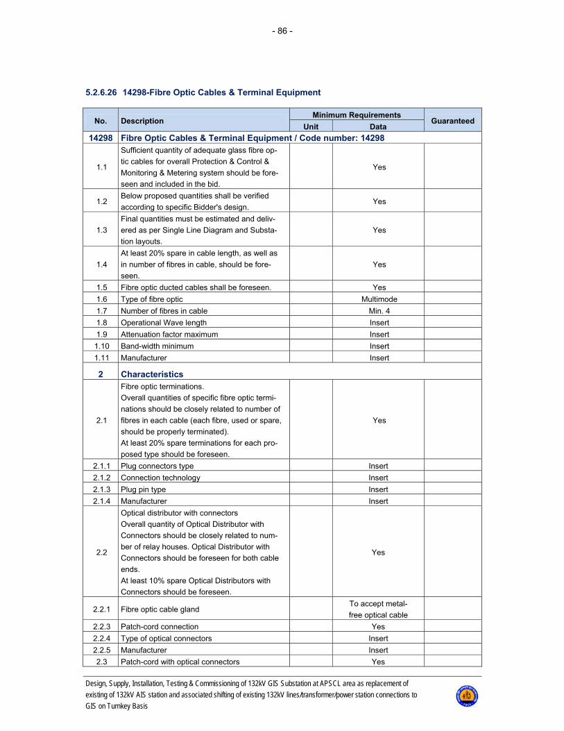
- 86 -
Design, Supply, Installation, Testing & Commissioning of 132kV GIS Substation at APSCL area as replacement of
existing of 132kV AIS station and associated shifting of existing 132kV lines/transformer/power station connections to
GIS on Turnkey Basis
5.2.6.26 14298-Fibre Optic Cables & Terminal Equipment
No. Description Minimum Requirements
Guaranteed Unit Data
14298 Fibre Optic Cables & Terminal Equipment / Code number: 14298
1.1
Sufficient quantity of adequate glass fibre op-
tic cables for overall Protection & Control &
Monitoring & Metering system should be fore-
seen and included in the bid.
Yes
1.2 Below proposed quantities shall be verified
according to specific Bidder's design. Yes
1.3
Final quantities must be estimated and deliv-
ered as per Single Line Diagram and Substa-
tion layouts.
Yes
1.4
At least 20% spare in cable length, as well as
in number of fibres in cable, should be fore-
seen.
Yes
1.5 Fibre optic ducted cables shall be foreseen. Yes
1.6 Type of fibre optic Multimode
1.7 Number of fibres in cable Min. 4
1.8 Operational Wave length Insert
1.9 Attenuation factor maximum Insert
1.10 Band-width minimum Insert
1.11 Manufacturer Insert
2 Characteristics
2.1
Fibre optic terminations.
Overall quantities of specific fibre optic termi-
nations should be closely related to number of
fibres in each cable (each fibre, used or spare,
should be properly terminated).
At least 20% spare terminations for each pro-
posed type should be foreseen.
Yes
2.1.1 Plug connectors type Insert
2.1.2 Connection technology Insert
2.1.3 Plug pin type Insert
2.1.4 Manufacturer Insert
2.2
Optical distributor with connectors
Overall quantity of Optical Distributor with
Connectors should be closely related to num-
ber of relay houses. Optical Distributor with
Connectors should be foreseen for both cable
ends.
At least 10% spare Optical Distributors with
Connectors should be foreseen.
Yes
2.2.1 Fibre optic cable gland To accept metal-
free optical cable
2.2.3 Patch-cord connection Yes
2.2.4 Type of optical connectors Insert
2.2.5 Manufacturer Insert
2.3 Patch-cord with optical connectors Yes
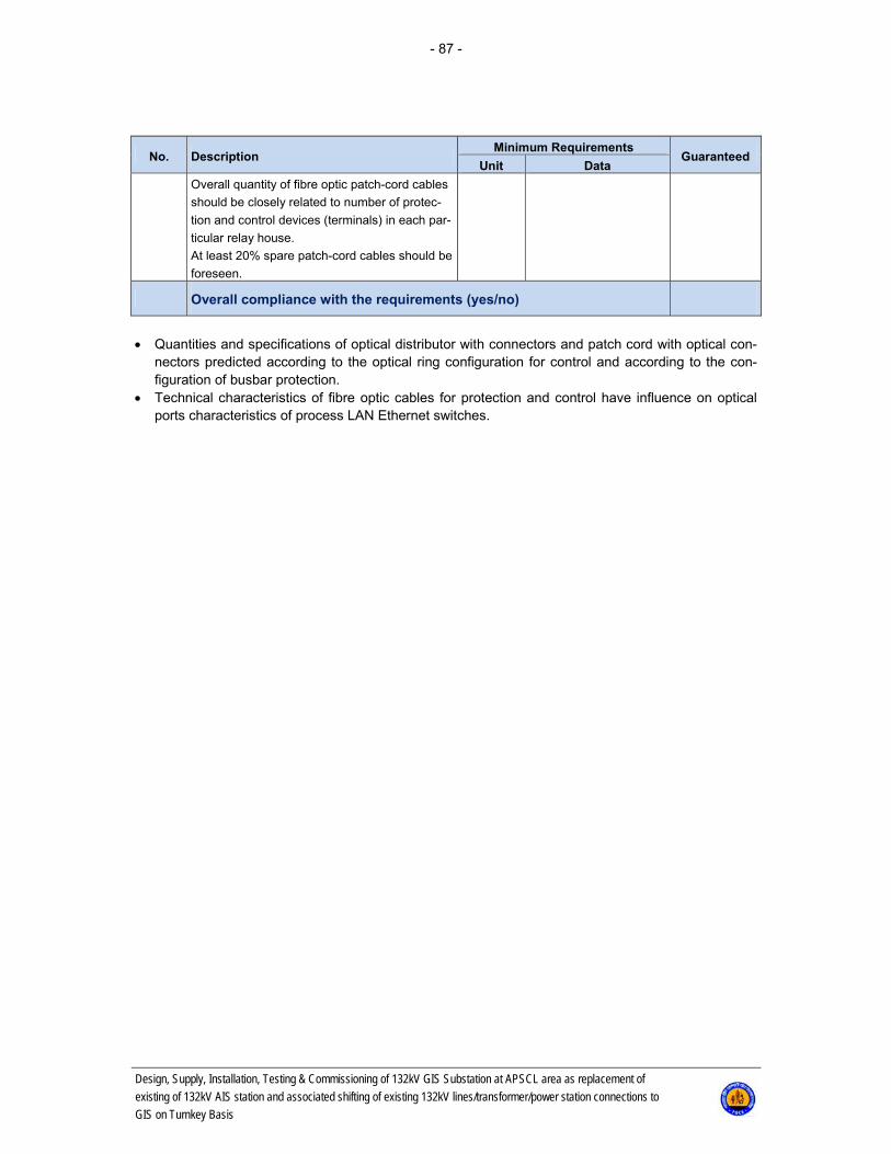
- 87 -
Design, Supply, Installation, Testing & Commissioning of 132kV GIS Substation at APSCL area as replacement of
existing of 132kV AIS station and associated shifting of existing 132kV lines/transformer/power station connections to
GIS on Turnkey Basis
No. Description Minimum Requirements
Guaranteed Unit Data
Overall quantity of fibre optic patch-cord cables
should be closely related to number of protec-
tion and control devices (terminals) in each par-
ticular relay house.
At least 20% spare patch-cord cables should be
foreseen.
Overall compliance with the requirements (yes/no)
Quantities and specifications of optical distributor with connectors and patch cord with optical con-
nectors predicted according to the optical ring configuration for control and according to the con-figuration of busbar protection.
Technical characteristics of fibre optic cables for protection and control have influence on optical ports characteristics of process LAN Ethernet switches.
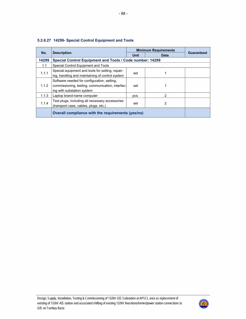
- 88 -
Design, Supply, Installation, Testing & Commissioning of 132kV GIS Substation at APSCL area as replacement of
existing of 132kV AIS station and associated shifting of existing 132kV lines/transformer/power station connections to
GIS on Turnkey Basis
5.2.6.27 14299- Special Control Equipment and Tools
No. Description Minimum Requirements
Guaranteed Unit Data
14299 Special Control Equipment and Tools / Code number: 14299 1.1 Special Control Equipment and Tools
1.1.1 Special equipment and tools for setting, repair-
ing, handling and maintaining of control system set 1
1.1.2
Software needed for configuration, setting,
commissioning, testing, communication, interfac-
ing with substation system
set 1
1.1.3 Laptop brand-name computer pcs. 2
1.1.4 Test plugs, including all necessary accessories
(transport case, cables, plugs, etc.) set 2
Overall compliance with the requirements (yes/no)
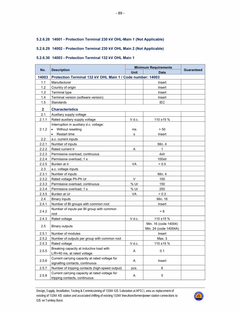
- 89 -
Design, Supply, Installation, Testing & Commissioning of 132kV GIS Substation at APSCL area as replacement of
existing of 132kV AIS station and associated shifting of existing 132kV lines/transformer/power station connections to
GIS on Turnkey Basis
5.2.6.28 14001 - Protection Terminal 230 kV OHL-Main 1 (Not Applicable)
5.2.6.29 14002 - Protection Terminal 230 kV OHL Main 2 (Not Applicable)
5.2.6.30 14003 - Protection Terminal 132 kV OHL Main 1
No. Description Minimum Requirements
Guaranteed Unit Data
14003 Protection Terminal 132 kV OHL Main 1 / Code number: 14003 1.1 Manufacturer Insert
1.2 Country of origin Insert
1.3 Terminal type Insert
1.4 Terminal version (software version) Insert
1.5 Standards IEC
2 Characteristics 2.1 Auxiliary supply voltage
2.1.1 Rated auxiliary supply voltage V d.c. 110 ±15 %
2.1.2
Interruption in auxiliary d.c. voltage:
Without resetting
Restart time
ms
s
> 50
Insert
2.2 a.c. current inputs
2.2.1 Number of inputs Min. 4
2.2.2 Rated current Ir A 1
2.2.3 Permissive overload, continuous 4xIr
2.2.4 Permissive overload, 1 s 100xIr
2.2.5 Burden at Ir VA < 0.5
2.3 a.c. voltage inputs
2.3.1 Number of inputs Min. 4
2.3.2 Rated voltage Ph-Ph Ur V 100
2.3.3 Permissive overload, continuous % Ur 150
2.3.4 Permissive overload, 1 s % Ur 250
2.3.5 Burden at Ur VA < 0.3
2.4 Binary inputs Min. 16
2.4.1 Number of BI groups with common root Insert
2.4.2 Number of inputs per BI group with common
root < 8
2.4.3 Rated voltage V d.c. 110 ±15 %
2.5 Binary outputs Min. 16 (code 14004)
Min. 24 (code 14004A)
2.5.1 Number of modules Insert
2.5.2 Number of outputs per group with common root Max. 3
2.5.3 Rated voltage V d.c. 110 ±15 %
2.5.5 Breaking capacity at inductive load with
L/R<40 ms, at rated voltage A 0.1
2.5.6 Current carrying capacity at rated voltage for
signalling contacts, continuous A Insert
2.5.7 Number of tripping contacts (high-speed output) pcs. 6
2.5.8 Current carrying capacity at rated voltage for
tripping contacts, continuous A 5
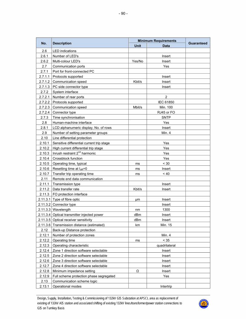
- 90 -
Design, Supply, Installation, Testing & Commissioning of 132kV GIS Substation at APSCL area as replacement of
existing of 132kV AIS station and associated shifting of existing 132kV lines/transformer/power station connections to
GIS on Turnkey Basis
No. Description Minimum Requirements
Guaranteed Unit Data
2.6 LED indications
2.6.1 Number of LED's Insert
2.6.2 Multi-colour LED's Yes/No Insert
2.7 Communication ports Yes
2.7.1 Port for front-connected PC
2.7.1.1 Protocols supported Insert
2.7.1.2 Communication speed Kbit/s Insert
2.7.1.3 PC side connector type Insert
2.7.2 System interface
2.7.2.1 Number of rear ports 2
2.7.2.2 Protocols supported IEC 61850
2.7.2.3 Communication speed Mbit/s Min. 100
2.7.2.4 Connector type RJ45 or FO
2.7.3 Time synchronisation SNTP
2.8 Human-machine interface Yes
2.8.1 LCD alphanumeric display, No. of rows Insert
2.9 Number of setting parameter groups Min. 4
2.10 Line differential protection
2.10.1 Sensitive differential current trip stage Yes
2.10.2 High current differential trip stage Yes
2.10.3 Inrush restraint 2nd harmonic Yes
2.10.4 Crossblock function Yes
2.10.5 Operating time, typical ms < 30
2.10.6 Resetting time at Idiff=0 ms Insert
2.10.7 Transfer trip operating time ms < 40
2.11 Remote end data communication
2.11.1 Transmission type Insert
2.11.2 Data transfer rate Kbit/s Insert
2.11.3 FO protection interface
2.11.3.1 Type of fibre optic μm Insert
2.11.3.2 Connector type Insert
2.11.3.3 Wavelength nm 1300
2.11.3.4 Optical transmitter injected power dBm Insert
2.11.3.5 Optical receiver sensitivity dBm Insert
2.11.3.6 Transmission distance (estimated) km Min. 15
2.12 Back-up Distance protection
2.12.1 Number of protection zones Min. 4
2.12.2 Operating time ms < 35
2.12.3 Operating characteristic quadrilateral
2.12.4 Zone 1 direction software selectable Insert
2.12.5 Zone 2 direction software selectable Insert
2.12.6 Zone 3 direction software selectable Insert
2.12.7 Zone 4 direction software selectable Insert
2.12.8 Minimum impedance setting Ω Insert
2.12.9 Full scheme protection phase segregated Yes
2.13 Communication scheme logic
2.13.1 Operational modes Intertrip
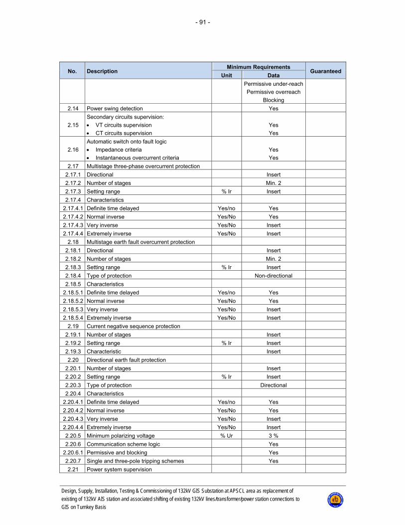
- 91 -
Design, Supply, Installation, Testing & Commissioning of 132kV GIS Substation at APSCL area as replacement of
existing of 132kV AIS station and associated shifting of existing 132kV lines/transformer/power station connections to
GIS on Turnkey Basis
No. Description Minimum Requirements
Guaranteed Unit Data
Permissive under-reach
Permissive overreach
Blocking
2.14 Power swing detection Yes
2.15
Secondary circuits supervision:
VT circuits supervision
CT circuits supervision
Yes
Yes
2.16
Automatic switch onto fault logic
Impedance criteria
Instantaneous overcurrent criteria
Yes
Yes
2.17 Multistage three-phase overcurrent protection
2.17.1 Directional Insert
2.17.2 Number of stages Min. 2
2.17.3 Setting range % Ir Insert
2.17.4 Characteristics
2.17.4.1 Definite time delayed Yes/no Yes
2.17.4.2 Normal inverse Yes/No Yes
2.17.4.3 Very inverse Yes/No Insert
2.17.4.4 Extremely inverse Yes/No Insert
2.18 Multistage earth fault overcurrent protection
2.18.1 Directional Insert
2.18.2 Number of stages Min. 2
2.18.3 Setting range % Ir Insert
2.18.4 Type of protection Non-directional
2.18.5 Characteristics
2.18.5.1 Definite time delayed Yes/no Yes
2.18.5.2 Normal inverse Yes/No Yes
2.18.5.3 Very inverse Yes/No Insert
2.18.5.4 Extremely inverse Yes/No Insert
2.19 Current negative sequence protection
2.19.1 Number of stages Insert
2.19.2 Setting range % Ir Insert
2.19.3 Characteristic Insert
2.20 Directional earth fault protection
2.20.1 Number of stages Insert
2.20.2 Setting range % Ir Insert
2.20.3 Type of protection Directional
2.20.4 Characteristics
2.20.4.1 Definite time delayed Yes/no Yes
2.20.4.2 Normal inverse Yes/No Yes
2.20.4.3 Very inverse Yes/No Insert
2.20.4.4 Extremely inverse Yes/No Insert
2.20.5 Minimum polarizing voltage % Ur 3 %
2.20.6 Communication scheme logic Yes
2.20.6.1 Permissive and blocking Yes
2.20.7 Single and three-pole tripping schemes Yes
2.21 Power system supervision

- 92 -
Design, Supply, Installation, Testing & Commissioning of 132kV GIS Substation at APSCL area as replacement of
existing of 132kV AIS station and associated shifting of existing 132kV lines/transformer/power station connections to
GIS on Turnkey Basis
No. Description Minimum Requirements
Guaranteed Unit Data
2.21.1 Broken conductor check Yes
2.21.2 Overload protection
2.21.2.1 Setting range of 1 stage % Ir Insert
2.21.2.2 Time delay range of 1 stage min > 20
2.21.2.3 Setting range of 2 stage % Ir Insert
2.21.2.4 Time delay range of 2 stage s > 20
2.21.2.5 Blocking external (system or HMI) Yes
2.22 Autoreclosing
2.22.1 Number of shots Min. 2
2.22.2 AR program 1/3 pole
2.22.3 Reclosing pulse duration s Insert
2.22.4 Dead time range s Insert
2.22.5 Counters for AR operation Yes
2.22.6 Inhibit time range s Insert
2.22.7 Reclaim time range s Insert
2.22.8 Synchronism & energising check during 3 ph
AR Yes
2.22.9 Evolving faults treatment Yes
2.22.10 AR blocking for CB not ready Yes
2.22.11 AR operation 1/3ph in 1st and 2nd zone Yes
2.23 Synchronism & energising check
2.23.1 Frequency difference range mHz. Insert
2.23.2 Voltage difference range % Ur Insert
2.23.3 Phase difference range ° Insert
2.23.4 Operating time for synchro check function ms Insert
2.23.5 Operating time for energising check function ms Insert
2.24 Disturbance recorder
2.24.1 Number of digital signals Min. 40
2.24.2 Number of analogue signals Min. 8
2.24.3 External/manual initiation of recording Insert
2.24.4 Sampling rate kHz Insert
2.24.5 Pre-fault time ms ≥ 300
2.24.6 Recording time ms ≥ 2000
2.24.7 Number of recorded disturbances Min. 5
2.24.8 Total recording time with max. analogue and bi-
nary signals s > 10
2.24.9 Output file comtrade format Yes
2.25 Event recorder
2.25.1 Max. number of events Insert
2.25.2 Time tagging resolution ms 1
2.26 Fault locator, measurement in (km) Yes
2.27 Self-supervision Yes
2.28 Measurement
2.28.1 Active power measurement Yes
2.28.2 Reactive power measurement Yes
2.28.3 Voltage measurement Yes
2.28.4 Current measurement Yes

- 93 -
Design, Supply, Installation, Testing & Commissioning of 132kV GIS Substation at APSCL area as replacement of
existing of 132kV AIS station and associated shifting of existing 132kV lines/transformer/power station connections to
GIS on Turnkey Basis
No. Description Minimum Requirements
Guaranteed Unit Data
3 Additional requirements 3.1 Test socket Yes
3.2 Setting and configuration of Protection Terminal
approved by Engineer Yes
Overall compliance with the requirements (yes/no)

- 94 -
Design, Supply, Installation, Testing & Commissioning of 132kV GIS Substation at APSCL area as replacement of
existing of 132kV AIS station and associated shifting of existing 132kV lines/transformer/power station connections to
GIS on Turnkey Basis
5.2.6.31 14004 - Protection Terminal 132 kV OHL Backup
No. Description Minimum Requirements
Guaranteed Unit Data
14004 Protection Terminal 132 kV OHL Main 2 / Code number: 14004 1.1 Manufacturer Different than Main 1
1.2 Country of origin Insert
1.3 Terminal type Insert
1.4 Terminal version (software version) Insert
1.5 Standards IEC
2 Characteristics 2.1 Auxiliary supply voltage
2.1.1 Rated auxiliary supply voltage V d.c. 110 ±15 %
2.1.2
Interruption in auxiliary d.c. voltage:
Without resetting
Restart time
ms
s
> 50
Insert
2.2 a.c. current inputs
2.2.1 Number of inputs Min. 4
2.2.2 Rated current Ir A 1
2.2.3 Permissive overload, continuous 4xIr
2.2.4 Permissive overload, 1 s 100xIr
2.2.5 Burden at Ir VA < 0.5
2.3 a.c. voltage inputs
2.3.1 Number of inputs Min. 4
2.3.2 Rated voltage Ph-Ph Ur V 100
2.3.3 Permissive overload, continuous % Ur 150
2.3.4 Permissive overload, 1 s % Ur 250
2.3.5 Burden at Ur VA < 0.3
2.4 Binary inputs Min. 16
2.4.1 Number of BI groups with common root Insert
2.4.2 Number of inputs per BI group with common
root < 8
2.4.3 Rated voltage V d.c. 110 ±15 %
2.5 Binary outputs Min. 16
2.5.1 Number of modules Insert
2.5.2 Number of outputs per group with common root Max. 3
2.5.3 Rated voltage V d.c. 110 ±15 %
2.5.4 Breaking capacity at inductive load with
L/R<40 ms, at rated voltage A 0.1
2.5.5 Current carrying capacity at rated voltage for
signalling contacts, continuous A Insert
2.5.6 Number of tripping contacts (high-speed output) pcs. 6
2.5.7 Current carrying capacity at rated voltage for
tripping contacts, continuous A 5
2.6 LED indications
2.6.1 Number of LED's Insert
2.6.2 Multi-colour LED's Yes/No Insert
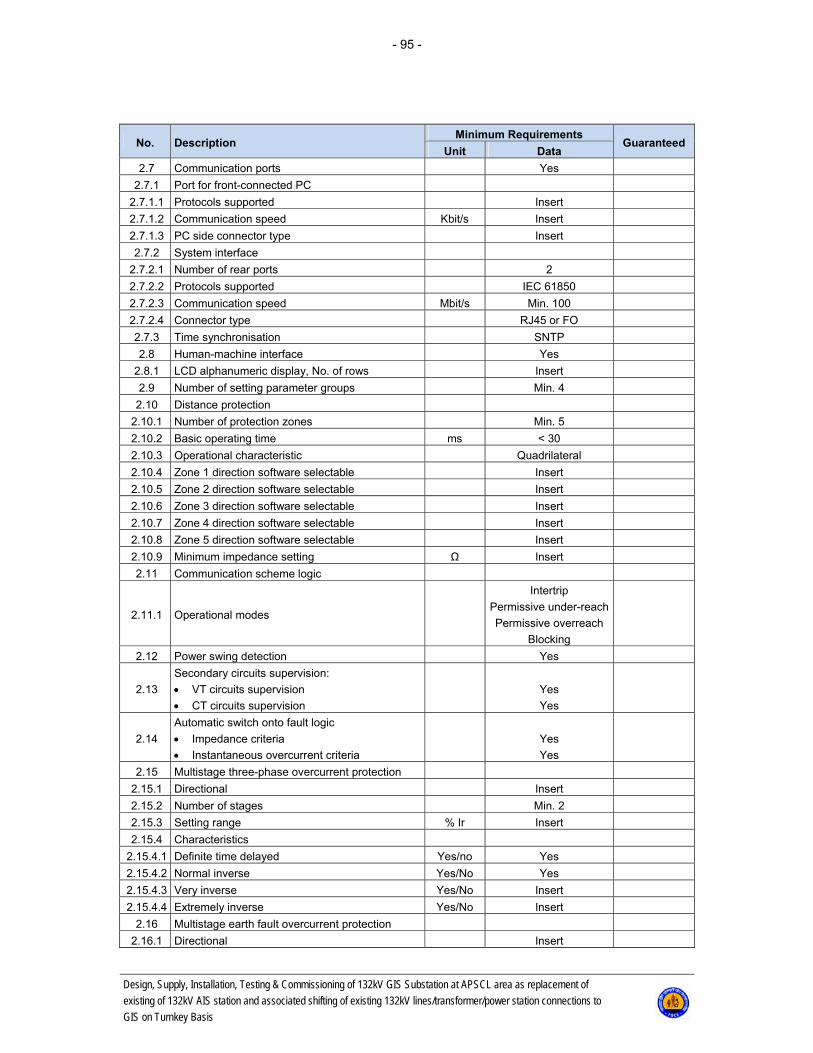
- 95 -
Design, Supply, Installation, Testing & Commissioning of 132kV GIS Substation at APSCL area as replacement of
existing of 132kV AIS station and associated shifting of existing 132kV lines/transformer/power station connections to
GIS on Turnkey Basis
No. Description Minimum Requirements
Guaranteed Unit Data
2.7 Communication ports Yes
2.7.1 Port for front-connected PC
2.7.1.1 Protocols supported Insert
2.7.1.2 Communication speed Kbit/s Insert
2.7.1.3 PC side connector type Insert
2.7.2 System interface
2.7.2.1 Number of rear ports 2
2.7.2.2 Protocols supported IEC 61850
2.7.2.3 Communication speed Mbit/s Min. 100
2.7.2.4 Connector type RJ45 or FO
2.7.3 Time synchronisation SNTP
2.8 Human-machine interface Yes
2.8.1 LCD alphanumeric display, No. of rows Insert
2.9 Number of setting parameter groups Min. 4
2.10 Distance protection
2.10.1 Number of protection zones Min. 5
2.10.2 Basic operating time ms < 30
2.10.3 Operational characteristic Quadrilateral
2.10.4 Zone 1 direction software selectable Insert
2.10.5 Zone 2 direction software selectable Insert
2.10.6 Zone 3 direction software selectable Insert
2.10.7 Zone 4 direction software selectable Insert
2.10.8 Zone 5 direction software selectable Insert
2.10.9 Minimum impedance setting Ω Insert
2.11 Communication scheme logic
2.11.1 Operational modes
Intertrip
Permissive under-reach
Permissive overreach
Blocking
2.12 Power swing detection Yes
2.13
Secondary circuits supervision:
VT circuits supervision
CT circuits supervision
Yes
Yes
2.14
Automatic switch onto fault logic
Impedance criteria
Instantaneous overcurrent criteria
Yes
Yes
2.15 Multistage three-phase overcurrent protection
2.15.1 Directional Insert
2.15.2 Number of stages Min. 2
2.15.3 Setting range % Ir Insert
2.15.4 Characteristics
2.15.4.1 Definite time delayed Yes/no Yes
2.15.4.2 Normal inverse Yes/No Yes
2.15.4.3 Very inverse Yes/No Insert
2.15.4.4 Extremely inverse Yes/No Insert
2.16 Multistage earth fault overcurrent protection
2.16.1 Directional Insert
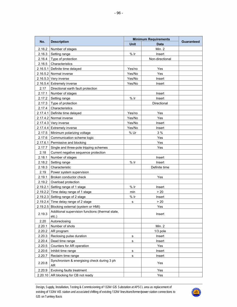
- 96 -
Design, Supply, Installation, Testing & Commissioning of 132kV GIS Substation at APSCL area as replacement of
existing of 132kV AIS station and associated shifting of existing 132kV lines/transformer/power station connections to
GIS on Turnkey Basis
No. Description Minimum Requirements
Guaranteed Unit Data
2.16.2 Number of stages Min. 2
2.16.3 Setting range % Ir Insert
2.16.4 Type of protection Non-directional
2.16.5 Characteristics
2.16.5.1 Definite time delayed Yes/no Yes
2.16.5.2 Normal inverse Yes/No Yes
2.16.5.3 Very inverse Yes/No Insert
2.16.5.4 Extremely inverse Yes/No Insert
2.17 Directional earth fault protection
2.17.1 Number of stages Insert
2.17.2 Setting range % Ir Insert
2.17.3 Type of protection Directional
2.17.4 Characteristics
2.17.4.1 Definite time delayed Yes/no Yes
2.17.4.2 Normal inverse Yes/No Yes
2.17.4.3 Very inverse Yes/No Insert
2.17.4.4 Extremely inverse Yes/No Insert
2.17.5 Minimum polarizing voltage % Ur 3 %
2.17.6 Communication scheme logic Yes
2.17.6.1 Permissive and blocking Yes
2.17.7 Single and three-pole tripping schemes Yes
2.18 Current negative sequence protection
2.18.1 Number of stages Insert
2.18.2 Setting range % Ir Insert
2.18.3 Characteristic Definite time
2.19 Power system supervision
2.19.1 Broken conductor check Yes
2.19.2 Overload protection
2.19.2.1 Setting range of 1 stage % Ir Insert
2.19.2.2 Time delay range of 1 stage min > 20
2.19.2.3 Setting range of 2 stage % Ir Insert
2.19.2.4 Time delay range of 2 stage s > 20
2.19.2.5 Blocking external (system or HMI) Yes
2.19.3 Additional supervision functions (thermal state,
etc.) Insert
2.20 Autoreclosing
2.20.1 Number of shots Min. 2
2.20.2 AR program 1/3 pole
2.20.3 Reclosing pulse duration s Insert
2.20.4 Dead time range s Insert
2.20.5 Counters for AR operation Yes
2.20.6 Inhibit time range s Insert
2.20.7 Reclaim time range s Insert
2.20.8 Synchronism & energising check during 3 ph
AR Yes
2.20.9 Evolving faults treatment Yes
2.20.10 AR blocking for CB not ready Yes

- 97 -
Design, Supply, Installation, Testing & Commissioning of 132kV GIS Substation at APSCL area as replacement of
existing of 132kV AIS station and associated shifting of existing 132kV lines/transformer/power station connections to
GIS on Turnkey Basis
No. Description Minimum Requirements
Guaranteed Unit Data
2.20.11 AR operation 1/3ph in 1st and 2nd zone Yes
2.21 Synchronism & energising check
2.21.1 Frequency difference range mHz. Insert
2.21.2 Voltage difference range % Ur Insert
2.21.3 Phase difference range ° Insert
2.21.4 Operating time for synchro check function ms Insert
2.21.5 Operating time for energising check function ms Insert
2.22 Disturbance recorder
2.22.1 Number of digital signals Min. 40
2.22.2 Number of analogue signals Min. 8
2.22.3 External/manual initiation of recording Yes
2.22.4 Sampling rate kHz Insert
2.22.5 Pre-fault time ms ≥ 300
2.22.6 Recording time ms ≥ 2000
2.22.7 Number of recorded disturbances Min. 5
2.22.8 Total recording time with max. analogue and bi-
nary signals s > 10
2.22.9 Output file comtrade format Yes
2.23 Event recorder
2.23.1 Max. number of events Insert
2.23.2 Time tagging resolution ms 1
2.24 Fault locator, measurement in (km) Yes
2.25 Self-supervision Yes
2.26 Measurement
2.26.1 Active power measurement Yes
2.26.2 Reactive power measurement Yes
2.26.3 Voltage measurement Yes
2.26.4 Current measurement Yes
3 Additional requirements 3.1 Test socket Yes
3.2 Setting and configuration of Main Protection Ter-
minal approved by Engineer Yes
Overall compliance with the requirements (yes/no)

- 98 -
Design, Supply, Installation, Testing & Commissioning of 132kV GIS Substation at APSCL area as replacement of
existing of 132kV AIS station and associated shifting of existing 132kV lines/transformer/power station connections to
GIS on Turnkey Basis
5.2.6.32 14005 - Protection Terminal for Power Transformers Main 1
No. Description Minimum Requirements
Guaranteed Unit Data
14005 Protection Terminal for Power Transformers Main 1 / Code number: 14005 1.1 Manufacturer Insert
1.2 Country of origin Insert
1.3 Terminal type Insert
1.4 Terminal version (software version) Insert
1.5 Standards IEC
2 Characteristics 2.1 Auxiliary supply voltage
2.1.1 Rated auxiliary supply voltage V d.c. 110 ±15 %
2.1.2
Interruption in auxiliary d.c. voltage:
Without resetting
Restart time
ms
s
> 50
Insert
2.2 a.c. current inputs
2.2.1 Number of inputs Min. 9
2.2.2 Rated current Ir A 1
2.2.3 Permissive overload, continuous 4xIr
2.2.4 Permissive overload, 1 s 100xIr
2.2.5 Burden at Ir VA < 0.5
2.3 a.c. voltage inputs
2.3.1 Number of inputs Min 4
2.3.2 Rated voltage Ph-Ph Ur V 100
2.3.3 Permissive overload, continuous % Ur 150
2.3.4 Permissive overload, 1 s % Ur 250
2.3.5 Burden at Ur VA < 0,3
2.4 Binary inputs Min. 16
2.4.1 Number of BI groups with common root Insert
2.4.2 Number of inputs per BI group with common
root < 8
2.4.3 Rated voltage V d.c. 110 ±15 %
2.5 Binary outputs Min. 16
2.5.1 Number of modules Insert
2.5.2 Number of outputs per group with common root Max. 3
2.5.3 Rated voltage V d.c. 110 ±15 %
2.5.4 Breaking capacity at inductive load with
L/R<40 ms, at rated voltage A 0.1
2.5.5 Current carrying capacity at rated voltage for
signalling contacts, continuous A Insert
2.5.6 Number of tripping contacts (high-speed output) pcs. 6
2.5.7 Current carrying capacity at rated voltage for
tripping contacts, continuous A 5
2.6 LED indications
2.6.1 Number of LED's Insert
2.6.2 Multi-colour LED's Yes/No Insert
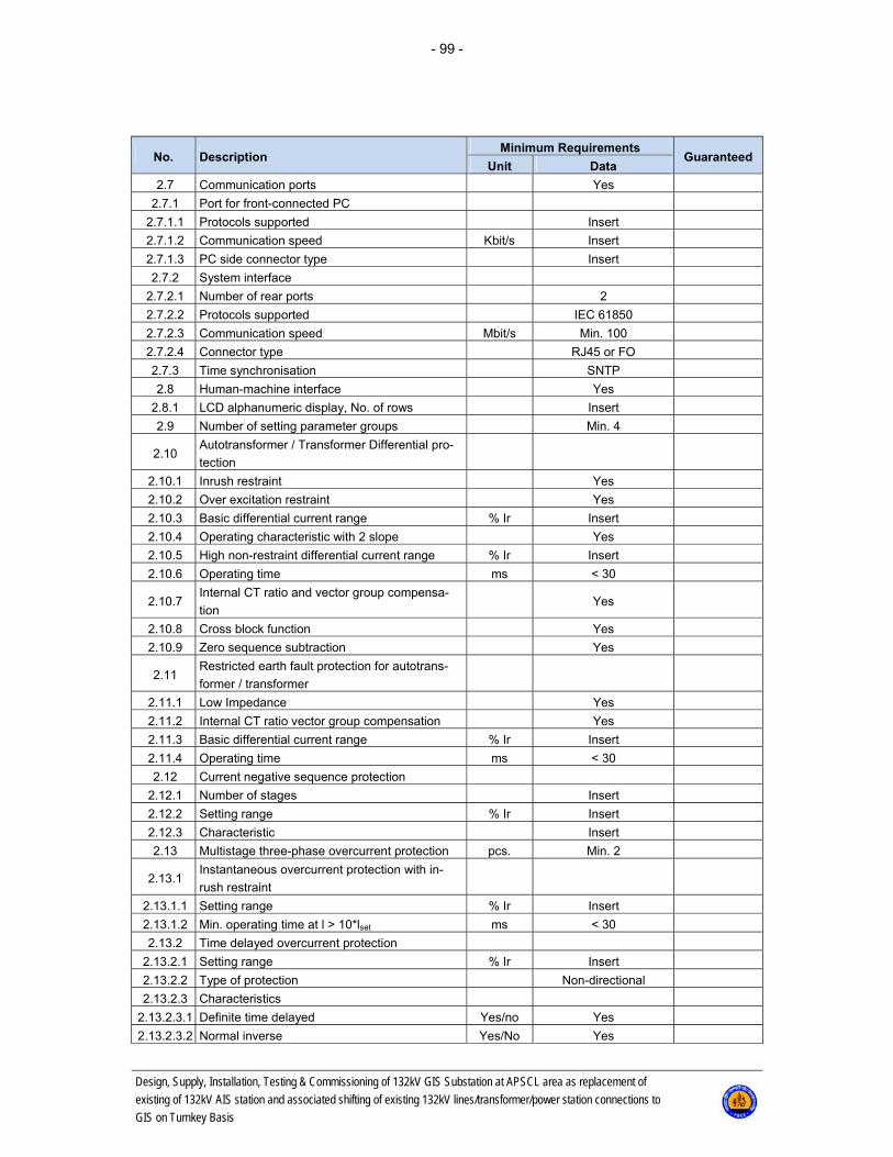
- 99 -
Design, Supply, Installation, Testing & Commissioning of 132kV GIS Substation at APSCL area as replacement of
existing of 132kV AIS station and associated shifting of existing 132kV lines/transformer/power station connections to
GIS on Turnkey Basis
No. Description Minimum Requirements
Guaranteed Unit Data
2.7 Communication ports Yes
2.7.1 Port for front-connected PC
2.7.1.1 Protocols supported Insert
2.7.1.2 Communication speed Kbit/s Insert
2.7.1.3 PC side connector type Insert
2.7.2 System interface
2.7.2.1 Number of rear ports 2
2.7.2.2 Protocols supported IEC 61850
2.7.2.3 Communication speed Mbit/s Min. 100
2.7.2.4 Connector type RJ45 or FO
2.7.3 Time synchronisation SNTP
2.8 Human-machine interface Yes
2.8.1 LCD alphanumeric display, No. of rows Insert
2.9 Number of setting parameter groups Min. 4
2.10 Autotransformer / Transformer Differential pro-
tection
2.10.1 Inrush restraint Yes
2.10.2 Over excitation restraint Yes
2.10.3 Basic differential current range % Ir Insert
2.10.4 Operating characteristic with 2 slope Yes
2.10.5 High non-restraint differential current range % Ir Insert
2.10.6 Operating time ms < 30
2.10.7 Internal CT ratio and vector group compensa-
tion Yes
2.10.8 Cross block function Yes
2.10.9 Zero sequence subtraction Yes
2.11 Restricted earth fault protection for autotrans-
former / transformer
2.11.1 Low Impedance Yes
2.11.2 Internal CT ratio vector group compensation Yes
2.11.3 Basic differential current range % Ir Insert
2.11.4 Operating time ms < 30
2.12 Current negative sequence protection
2.12.1 Number of stages Insert
2.12.2 Setting range % Ir Insert
2.12.3 Characteristic Insert
2.13 Multistage three-phase overcurrent protection pcs. Min. 2
2.13.1 Instantaneous overcurrent protection with in-
rush restraint
2.13.1.1 Setting range % Ir Insert
2.13.1.2 Min. operating time at l > 10*lset ms < 30
2.13.2 Time delayed overcurrent protection
2.13.2.1 Setting range % Ir Insert
2.13.2.2 Type of protection Non-directional
2.13.2.3 Characteristics
2.13.2.3.1 Definite time delayed Yes/no Yes
2.13.2.3.2 Normal inverse Yes/No Yes

- 100 -
Design, Supply, Installation, Testing & Commissioning of 132kV GIS Substation at APSCL area as replacement of
existing of 132kV AIS station and associated shifting of existing 132kV lines/transformer/power station connections to
GIS on Turnkey Basis
No. Description Minimum Requirements
Guaranteed Unit Data
2.13.2.3.3 Very inverse Yes/No Insert
2.13.2.3.4 Extremely inverse Yes/No Insert
2.14 Multistage earth fault overcurrent protection pcs. Min. 2
2.14.1 Instantaneous earth fault overcurrent protection
with inrush restraint
2.14.1.1 Setting range % Ir Insert
2.14.1.2 Min. operating time at l > 10*lset ms < 30
2.14.2 Time delayed earth fault overcurrent protection
2.14.2.1 Setting range % Ir Insert
2.14.2.2 Type of protection Non-directional
2.14.2.3 Characteristics
2.14.2.3.1 Definite time delayed Yes/no Yes
2.14.2.3.2 Normal inverse Yes/No Yes
2.14.2.3.3 Very inverse Yes/No Insert
2.14.2.3.4 Extremely inverse Yes/No Insert
2.15 Thermal overload protection Yes
2.16 Disturbance recorder
2.16.1 Number of digital signals Min. 40
2.16.2 Number of analogue signals Min. 9
2.16.3 External/manual initiation of recording
2.16.4 Sampling rate kHz Insert
2.16.5 Pre-fault time ms ≥ 300
2.16.6 Recording time ms ≥ 2000
2.16.7 Number of recorded disturbances Min. 5
2.16.8 Total recording time with max. analogue and
binary signals s > 10
2.16.9 Output file comtrade format Yes
2.17 Event recorder
2.17.1 Max. number of events Insert
2.17.2 Time tagging resolution ms 1
2.18 Self-supervision Yes
3 Additional requirements 3.1 Test socket Yes
3.2 Setting and configuration of Protection Terminal
approved by Engineer Yes
Overall compliance with the requirements (yes/no)

- 101 -
Design, Supply, Installation, Testing & Commissioning of 132kV GIS Substation at APSCL area as replacement of
existing of 132kV AIS station and associated shifting of existing 132kV lines/transformer/power station connections to
GIS on Turnkey Basis
5.2.6.33 14006 - Protection Terminal for Power Transformers Main 2
No. Description Minimum Requirements
Guaranteed Unit Data
14006 Protection Terminal for Power Transformers Main 2 / Code number: 14006 1.1 Manufacturer Different than Main 1
1.2 Country of origin Insert
1.3 Terminal type Insert
1.4 Terminal version (software version) Insert
1.5 Standards IEC
2 Characteristics 2.1 Auxiliary supply voltage
2.1.1 Rated auxiliary supply voltage V d.c. 110 ±15 %
2.1.2
Interruption in auxiliary d.c. voltage:
Without resetting
Restart time
ms
s
> 50
Insert
2.2 a.c. current inputs
2.2.1 Number of inputs Min. 9
2.2.2 Rated current Ir A 1
2.2.3 Permissive overload, continuous 4xIr
2.2.4 Permissive overload, 1 s 100xIr
2.2.5 Burden at Ir VA < 0.5
2.3 a.c. voltage inputs
2.3.1 Number of inputs Min 4
2.3.2 Rated voltage Ph-Ph Ur V 100
2.3.3 Permissive overload, continuous % Ur 150
2.3.4 Permissive overload, 1 s % Ur 250
2.3.5 Burden at Ur VA < 0,3
2.4 Binary inputs Min. 16
2.4.1 Number of BI groups with common root Insert
2.4.2 Number of inputs per BI group with common
root < 8
2.4.3 Rated voltage V d.c. 110 ±15 %
2.5 Binary outputs Min. 16
2.5.1 Number of modules Insert
2.5.2 Number of outputs per group with common
root Max. 3
2.5.3 Rated voltage V d.c. 110 ±15 %
2.5.4 Breaking capacity at inductive load with
L/R<40 ms, at rated voltage A 0.1
2.5.5 Current carrying capacity at rated voltage for
signalling contacts, continuous A Insert
2.5.6 Number of tripping contacts (high-speed
output) pcs. 6
2.5.7 Current carrying capacity at rated voltage for
tripping contacts, continuous A 5
2.6 LED indications
2.6.1 Number of LED's Insert
2.6.2 Multi-colour LED's Yes/No Insert

- 102 -
Design, Supply, Installation, Testing & Commissioning of 132kV GIS Substation at APSCL area as replacement of
existing of 132kV AIS station and associated shifting of existing 132kV lines/transformer/power station connections to
GIS on Turnkey Basis
No. Description Minimum Requirements
Guaranteed Unit Data
2.7 Communication ports Yes
2.7.1 Port for front-connected PC
2.7.1.1 Protocols supported Insert
2.7.1.2 Communication speed Kbit/s Insert
2.7.1.3 PC side connector type Insert
2.7.2 System interface
2.7.2.1 Number of rear ports 2
2.7.2.2 Protocols supported IEC 61850
2.7.2.3 Communication speed Mbit/s Min. 100
2.7.2.4 Connector type RJ45 or FO
2.7.3 Time synchronisation SNTP
2.8 Human-machine interface Yes
2.8.1 LCD alphanumeric display, No. of rows Insert
2.9 Number of setting parameter groups Min. 4
2.10 Autotransformer / Transformer Differential
protection
2.10.1 Inrush restraint Yes
2.10.2 Overexcitation restraint Yes
2.10.3 Basic differential current range % Ir Insert
2.10.4 Operating characteristic with 2 slope Yes
2.10.5 High non-restraint differential current range % Ir Insert
2.10.6 Operating time ms < 30
2.10.7 Internal CT ratio and vector group compen-
sation Yes
2.10.8 Crossblock function Yes
2.10.9 Zero sequence subtraction Yes
2.11 Restricted earth fault protection for auto-
transformer / transformer
2.11.1 Low Impedance Yes
2.11.2 Internal CT ratio vector group compensation Yes
2.11.3 Basic differential current range % Ir Insert
2.11.4 Operating time ms < 30
2.12 Current negative sequence protection
2.12.1 Number of stages Insert
2.12.2 Setting range % Ir Insert
2.12.3 Characteristic Insert
2.13 Multistage three-phase overcurrent protec-
tion pcs. Min. 2
2.13.1 Instantaneous overcurrent protection with in-
rush restraint
2.13.1.1 Setting range % Ir Insert
2.13.1.2 Min. operating time at l > 10*lset Ms < 30
2.13.2 Time delayed overcurrent protection
2.13.2.1 Setting range % Ir Insert
2.13.2.2 Type of protection Non-directional
2.13.2.3 Characteristics
2.13.2.3.1 Definite time delayed Yes/no Yes
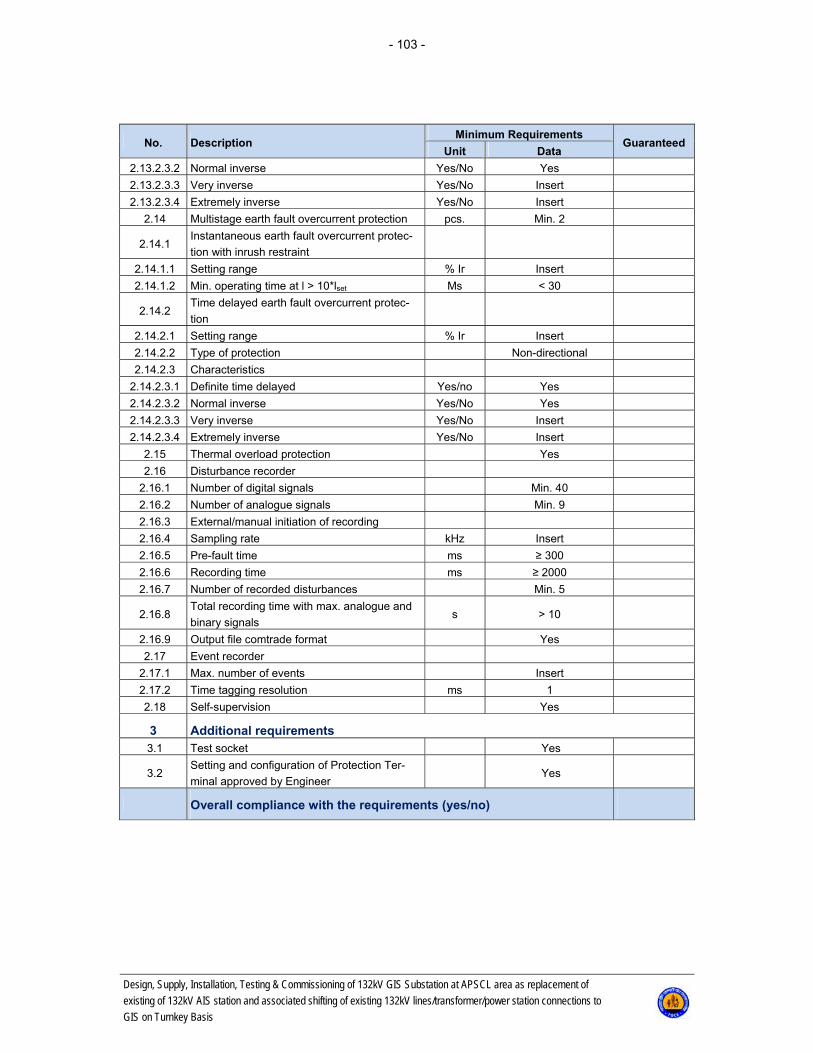
- 103 -
Design, Supply, Installation, Testing & Commissioning of 132kV GIS Substation at APSCL area as replacement of
existing of 132kV AIS station and associated shifting of existing 132kV lines/transformer/power station connections to
GIS on Turnkey Basis
No. Description Minimum Requirements
Guaranteed Unit Data
2.13.2.3.2 Normal inverse Yes/No Yes
2.13.2.3.3 Very inverse Yes/No Insert
2.13.2.3.4 Extremely inverse Yes/No Insert
2.14 Multistage earth fault overcurrent protection pcs. Min. 2
2.14.1 Instantaneous earth fault overcurrent protec-
tion with inrush restraint
2.14.1.1 Setting range % Ir Insert
2.14.1.2 Min. operating time at l > 10*lset Ms < 30
2.14.2 Time delayed earth fault overcurrent protec-
tion
2.14.2.1 Setting range % Ir Insert
2.14.2.2 Type of protection Non-directional
2.14.2.3 Characteristics
2.14.2.3.1 Definite time delayed Yes/no Yes
2.14.2.3.2 Normal inverse Yes/No Yes
2.14.2.3.3 Very inverse Yes/No Insert
2.14.2.3.4 Extremely inverse Yes/No Insert
2.15 Thermal overload protection Yes
2.16 Disturbance recorder
2.16.1 Number of digital signals Min. 40
2.16.2 Number of analogue signals Min. 9
2.16.3 External/manual initiation of recording
2.16.4 Sampling rate kHz Insert
2.16.5 Pre-fault time ms ≥ 300
2.16.6 Recording time ms ≥ 2000
2.16.7 Number of recorded disturbances Min. 5
2.16.8 Total recording time with max. analogue and
binary signals s > 10
2.16.9 Output file comtrade format Yes
2.17 Event recorder
2.17.1 Max. number of events Insert
2.17.2 Time tagging resolution ms 1
2.18 Self-supervision Yes
3 Additional requirements3.1 Test socket Yes
3.2 Setting and configuration of Protection Ter-
minal approved by Engineer Yes
Overall compliance with the requirements (yes/no)
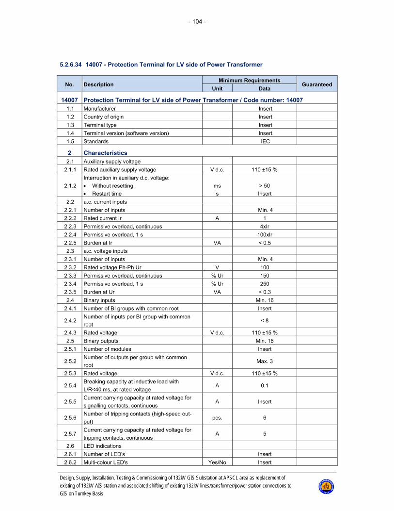
- 104 -
Design, Supply, Installation, Testing & Commissioning of 132kV GIS Substation at APSCL area as replacement of
existing of 132kV AIS station and associated shifting of existing 132kV lines/transformer/power station connections to
GIS on Turnkey Basis
5.2.6.34 14007 - Protection Terminal for LV side of Power Transformer
No. Description Minimum Requirements
Guaranteed Unit Data
14007 Protection Terminal for LV side of Power Transformer / Code number: 14007 1.1 Manufacturer Insert
1.2 Country of origin Insert
1.3 Terminal type Insert
1.4 Terminal version (software version) Insert
1.5 Standards IEC
2 Characteristics 2.1 Auxiliary supply voltage
2.1.1 Rated auxiliary supply voltage V d.c. 110 ±15 %
2.1.2
Interruption in auxiliary d.c. voltage:
Without resetting
Restart time
ms
s
> 50
Insert
2.2 a.c. current inputs
2.2.1 Number of inputs Min. 4
2.2.2 Rated current Ir A 1
2.2.3 Permissive overload, continuous 4xIr
2.2.4 Permissive overload, 1 s 100xIr
2.2.5 Burden at Ir VA < 0.5
2.3 a.c. voltage inputs
2.3.1 Number of inputs Min. 4
2.3.2 Rated voltage Ph-Ph Ur V 100
2.3.3 Permissive overload, continuous % Ur 150
2.3.4 Permissive overload, 1 s % Ur 250
2.3.5 Burden at Ur VA < 0.3
2.4 Binary inputs Min. 16
2.4.1 Number of BI groups with common root Insert
2.4.2 Number of inputs per BI group with common
root < 8
2.4.3 Rated voltage V d.c. 110 ±15 %
2.5 Binary outputs Min. 16
2.5.1 Number of modules Insert
2.5.2 Number of outputs per group with common
root Max. 3
2.5.3 Rated voltage V d.c. 110 ±15 %
2.5.4 Breaking capacity at inductive load with
L/R<40 ms, at rated voltage A 0.1
2.5.5 Current carrying capacity at rated voltage for
signalling contacts, continuous A Insert
2.5.6 Number of tripping contacts (high-speed out-
put) pcs. 6
2.5.7 Current carrying capacity at rated voltage for
tripping contacts, continuous A 5
2.6 LED indications
2.6.1 Number of LED's Insert
2.6.2 Multi-colour LED's Yes/No Insert
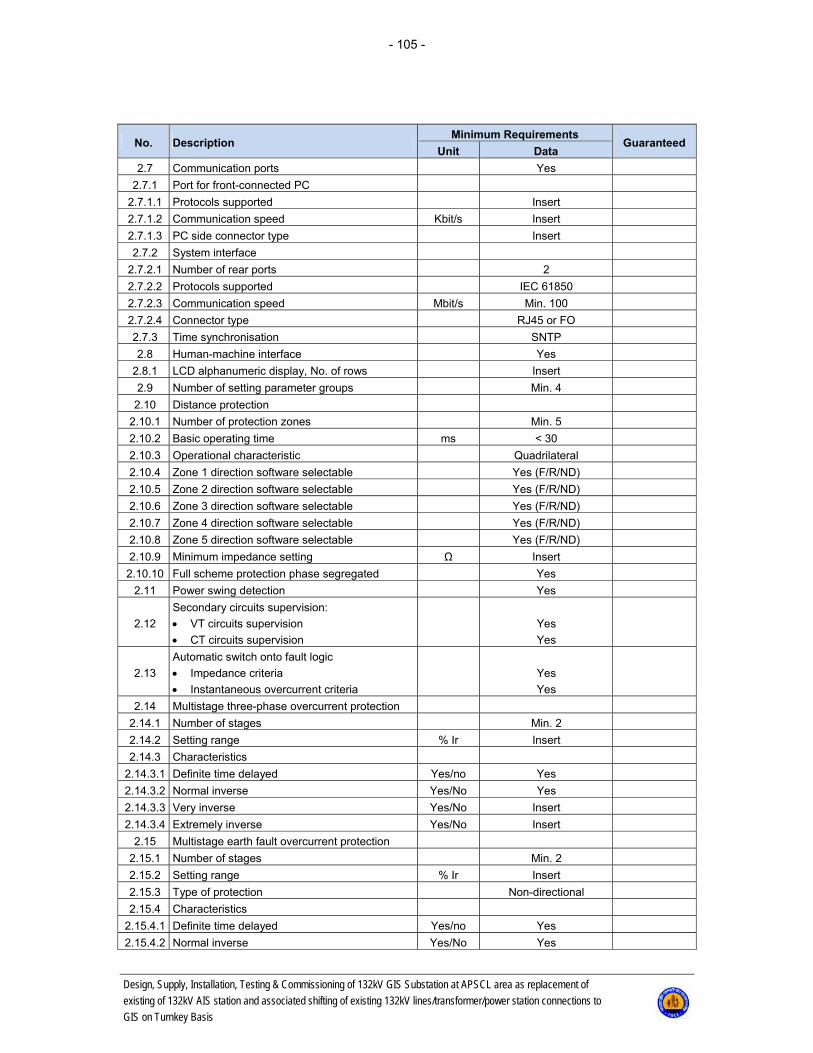
- 105 -
Design, Supply, Installation, Testing & Commissioning of 132kV GIS Substation at APSCL area as replacement of
existing of 132kV AIS station and associated shifting of existing 132kV lines/transformer/power station connections to
GIS on Turnkey Basis
No. Description Minimum Requirements
Guaranteed Unit Data
2.7 Communication ports Yes
2.7.1 Port for front-connected PC
2.7.1.1 Protocols supported Insert
2.7.1.2 Communication speed Kbit/s Insert
2.7.1.3 PC side connector type Insert
2.7.2 System interface
2.7.2.1 Number of rear ports 2
2.7.2.2 Protocols supported IEC 61850
2.7.2.3 Communication speed Mbit/s Min. 100
2.7.2.4 Connector type RJ45 or FO
2.7.3 Time synchronisation SNTP
2.8 Human-machine interface Yes
2.8.1 LCD alphanumeric display, No. of rows Insert
2.9 Number of setting parameter groups Min. 4
2.10 Distance protection
2.10.1 Number of protection zones Min. 5
2.10.2 Basic operating time ms < 30
2.10.3 Operational characteristic Quadrilateral
2.10.4 Zone 1 direction software selectable Yes (F/R/ND)
2.10.5 Zone 2 direction software selectable Yes (F/R/ND)
2.10.6 Zone 3 direction software selectable Yes (F/R/ND)
2.10.7 Zone 4 direction software selectable Yes (F/R/ND)
2.10.8 Zone 5 direction software selectable Yes (F/R/ND)
2.10.9 Minimum impedance setting Ω Insert
2.10.10 Full scheme protection phase segregated Yes
2.11 Power swing detection Yes
2.12
Secondary circuits supervision:
VT circuits supervision
CT circuits supervision
Yes
Yes
2.13
Automatic switch onto fault logic
Impedance criteria
Instantaneous overcurrent criteria
Yes
Yes
2.14 Multistage three-phase overcurrent protection
2.14.1 Number of stages Min. 2
2.14.2 Setting range % Ir Insert
2.14.3 Characteristics
2.14.3.1 Definite time delayed Yes/no Yes
2.14.3.2 Normal inverse Yes/No Yes
2.14.3.3 Very inverse Yes/No Insert
2.14.3.4 Extremely inverse Yes/No Insert
2.15 Multistage earth fault overcurrent protection
2.15.1 Number of stages Min. 2
2.15.2 Setting range % Ir Insert
2.15.3 Type of protection Non-directional
2.15.4 Characteristics
2.15.4.1 Definite time delayed Yes/no Yes
2.15.4.2 Normal inverse Yes/No Yes
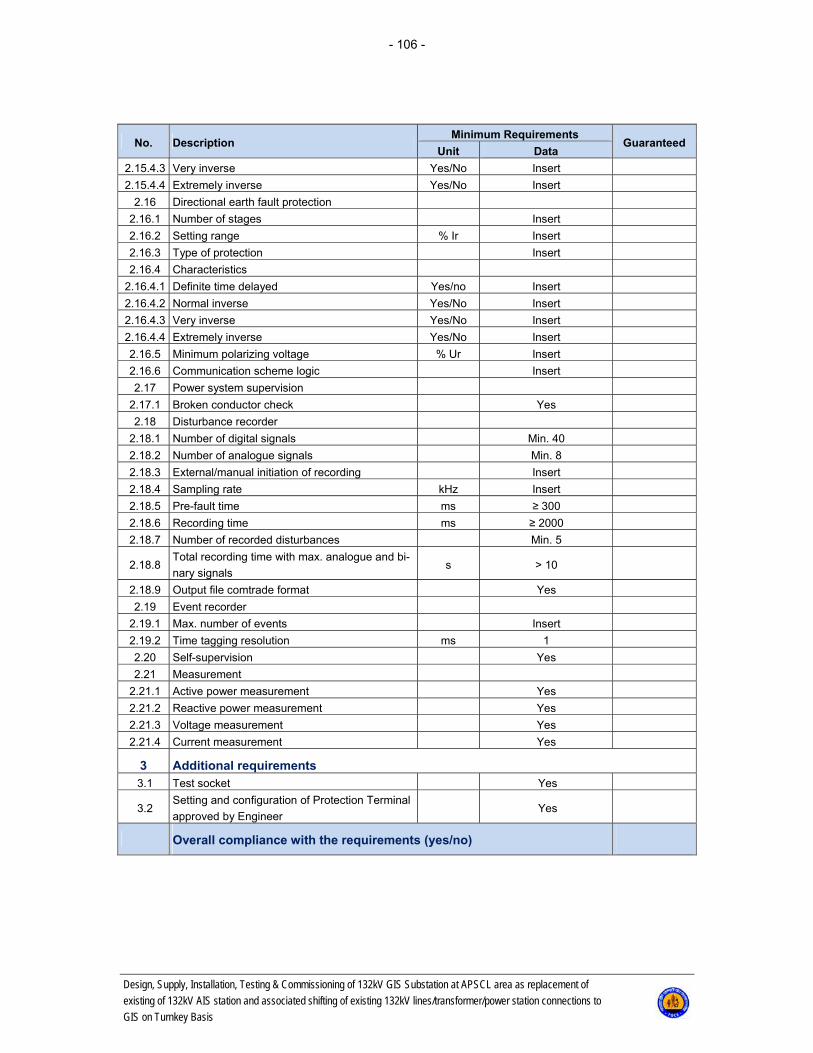
- 106 -
Design, Supply, Installation, Testing & Commissioning of 132kV GIS Substation at APSCL area as replacement of
existing of 132kV AIS station and associated shifting of existing 132kV lines/transformer/power station connections to
GIS on Turnkey Basis
No. Description Minimum Requirements
Guaranteed Unit Data
2.15.4.3 Very inverse Yes/No Insert
2.15.4.4 Extremely inverse Yes/No Insert
2.16 Directional earth fault protection
2.16.1 Number of stages Insert
2.16.2 Setting range % Ir Insert
2.16.3 Type of protection Insert
2.16.4 Characteristics
2.16.4.1 Definite time delayed Yes/no Insert
2.16.4.2 Normal inverse Yes/No Insert
2.16.4.3 Very inverse Yes/No Insert
2.16.4.4 Extremely inverse Yes/No Insert
2.16.5 Minimum polarizing voltage % Ur Insert
2.16.6 Communication scheme logic Insert
2.17 Power system supervision
2.17.1 Broken conductor check Yes
2.18 Disturbance recorder
2.18.1 Number of digital signals Min. 40
2.18.2 Number of analogue signals Min. 8
2.18.3 External/manual initiation of recording Insert
2.18.4 Sampling rate kHz Insert
2.18.5 Pre-fault time ms ≥ 300
2.18.6 Recording time ms ≥ 2000
2.18.7 Number of recorded disturbances Min. 5
2.18.8 Total recording time with max. analogue and bi-
nary signals s > 10
2.18.9 Output file comtrade format Yes
2.19 Event recorder
2.19.1 Max. number of events Insert
2.19.2 Time tagging resolution ms 1
2.20 Self-supervision Yes
2.21 Measurement
2.21.1 Active power measurement Yes
2.21.2 Reactive power measurement Yes
2.21.3 Voltage measurement Yes
2.21.4 Current measurement Yes
3 Additional requirements 3.1 Test socket Yes
3.2 Setting and configuration of Protection Terminal
approved by Engineer Yes
Overall compliance with the requirements (yes/no)
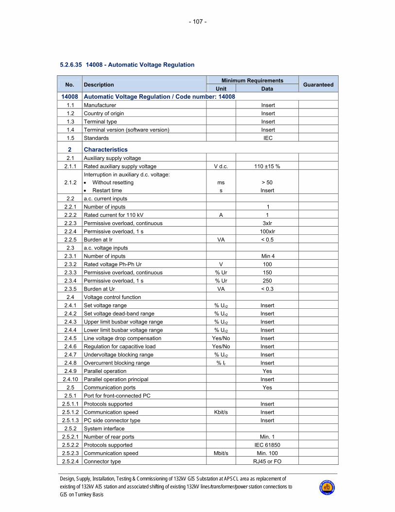
- 107 -
Design, Supply, Installation, Testing & Commissioning of 132kV GIS Substation at APSCL area as replacement of
existing of 132kV AIS station and associated shifting of existing 132kV lines/transformer/power station connections to
GIS on Turnkey Basis
5.2.6.35 14008 - Automatic Voltage Regulation
No. Description Minimum Requirements
Guaranteed Unit Data
14008 Automatic Voltage Regulation / Code number: 14008 1.1 Manufacturer Insert
1.2 Country of origin Insert
1.3 Terminal type Insert
1.4 Terminal version (software version) Insert
1.5 Standards IEC
2 Characteristics 2.1 Auxiliary supply voltage
2.1.1 Rated auxiliary supply voltage V d.c. 110 ±15 %
2.1.2
Interruption in auxiliary d.c. voltage:
Without resetting
Restart time
ms
s
> 50
Insert
2.2 a.c. current inputs
2.2.1 Number of inputs 1
2.2.2 Rated current for 110 kV A 1
2.2.3 Permissive overload, continuous 3xIr
2.2.4 Permissive overload, 1 s 100xIr
2.2.5 Burden at Ir VA < 0.5
2.3 a.c. voltage inputs
2.3.1 Number of inputs Min 4
2.3.2 Rated voltage Ph-Ph Ur V 100
2.3.3 Permissive overload, continuous % Ur 150
2.3.4 Permissive overload, 1 s % Ur 250
2.3.5 Burden at Ur VA < 0.3
2.4 Voltage control function
2.4.1 Set voltage range % Ur2 Insert
2.4.2 Set voltage dead-band range % Ur2 Insert
2.4.3 Upper limit busbar voltage range % Ur2 Insert
2.4.4 Lower limit busbar voltage range % Ur2 Insert
2.4.5 Line voltage drop compensation Yes/No Insert
2.4.6 Regulation for capacitive load Yes/No Insert
2.4.7 Undervoltage blocking range % Ur2 Insert
2.4.8 Overcurrent blocking range % Ir Insert
2.4.9 Parallel operation Yes
2.4.10 Parallel operation principal Insert
2.5 Communication ports Yes
2.5.1 Port for front-connected PC
2.5.1.1 Protocols supported Insert
2.5.1.2 Communication speed Kbit/s Insert
2.5.1.3 PC side connector type Insert
2.5.2 System interface
2.5.2.1 Number of rear ports Min. 1
2.5.2.2 Protocols supported IEC 61850
2.5.2.3 Communication speed Mbit/s Min. 100
2.5.2.4 Connector type RJ45 or FO
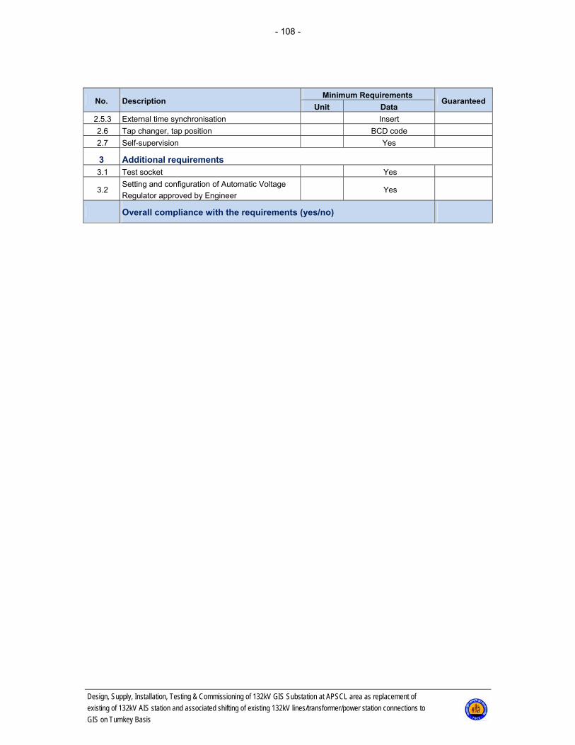
- 108 -
Design, Supply, Installation, Testing & Commissioning of 132kV GIS Substation at APSCL area as replacement of
existing of 132kV AIS station and associated shifting of existing 132kV lines/transformer/power station connections to
GIS on Turnkey Basis
No. Description Minimum Requirements
Guaranteed Unit Data
2.5.3 External time synchronisation Insert
2.6 Tap changer, tap position BCD code
2.7 Self-supervision Yes
3 Additional requirements 3.1 Test socket Yes
3.2 Setting and configuration of Automatic Voltage
Regulator approved by Engineer Yes
Overall compliance with the requirements (yes/no)

- 109 -
Design, Supply, Installation, Testing & Commissioning of 132kV GIS Substation at APSCL area as replacement of
existing of 132kV AIS station and associated shifting of existing 132kV lines/transformer/power station connections to
GIS on Turnkey Basis
5.2.6.36 14009 - Protection Terminal for Bus couplers 132 kV
No. Description Minimum Requirements
Guaranteed Unit Data
14009 Protection Terminal for Bus couplers 132 kV / Code number: 14009 1.1 Manufacturer Insert
1.2 Country of origin Insert
1.3 Terminal type Insert
1.4 Terminal version (software version) Insert
1.5 Standards IEC
2 Characteristics 2.1 Auxiliary supply voltage
2.1.1 Rated auxiliary supply voltage V d.c. 110 ±15 %
2.1.2
Interruption in auxiliary d.c. voltage:
Without resetting
Restart time
ms
s
> 50
Insert
2.2 a.c. current inputs
2.2.1 Number of inputs Min. 4
2.2.2 Rated current Ir A 1
2.2.3 Permissive overload, continuous 4xIr
2.2.4 Permissive overload, 1 s 100xIr
2.2.5 Burden at Ir VA < 0.5
2.3 a.c. voltage inputs
2.3.1 Number of inputs Min. 4
2.3.2 Rated voltage Ph-Ph Ur V 100
2.3.3 Permissive overload, continuous % Ur 150
2.3.4 Permissive overload, 1 s % Ur 250
2.3.5 Burden at Ur VA < 0.3
2.4 Binary inputs Min. 8
2.4.1 Number of BI groups with common root Insert
2.4.2 Number of inputs per BI group with com-
mon root Insert
2.4.3 Rated voltage V d.c. 110 ±15 %
2.5 Binary outputs Min. 8
2.5.1 Number of modules Insert
2.5.2 Number of outputs per group with common
root Max. 3
2.5.3 Rated voltage V d.c. 110 ±15 %
2.5.4 Breaking capacity at inductive load with
L/R<40 ms, at rated voltage A 0.1
2.5.5 Current carrying capacity at rated voltage
for signalling contacts, continuous A Insert
2.5.6 Number of tripping contacts (high-speed
output) pcs. 6
2.5.7 Current carrying capacity at rated voltage
for tripping contacts, continuous A 5
2.6 LED indications
2.6.1 Number of LED's Insert
2.6.2 Multi-colour LED's Yes/No Insert

- 110 -
Design, Supply, Installation, Testing & Commissioning of 132kV GIS Substation at APSCL area as replacement of
existing of 132kV AIS station and associated shifting of existing 132kV lines/transformer/power station connections to
GIS on Turnkey Basis
No. Description Minimum Requirements
Guaranteed Unit Data
2.7 Communication ports Yes
2.7.1 Port for front-connected PC
2.7.1.1 Protocols supported Insert
2.7.1.2 Communication speed Kbit/s Insert
2.7.1.3 PC side connector type Insert
2.7.2 System interface
2.7.2.1 Number of rear ports 2
2.7.2.2 Protocols supported IEC 61850
2.7.2.3 Communication speed Mbit/s Min. 100
2.7.2.4 Connector type RJ45 or FO
2.7.3 Time synchronisation SNTP
2.8 Human-machine interface Yes
2.8.1 LCD alphanumeric display, No. of rows Insert
2.9 Number of setting parameter groups Min. 4
2.10 Multistage three-phase overcurrent protec-
tion
2.10.1 Instantaneous overcurrent protection
2.10.1.1 Setting range % Ir Insert
2.10.1.2 Min. operating time at l > 10*lset ms 30
2.10.2 Time delayed overcurrent protection
2.10.2.1 Setting range % Ir Insert
2.10.2.2 Type of protection Non-directional
2.10.2.3 Characteristics
2.10.2.3.1 Definite time delayed Yes/no Yes
2.10.2.3.2 Normal inverse Yes/No Yes
2.10.2.3.3 Very inverse Yes/No Insert
2.10.2.3.4 Extremely inverse Yes/No Insert
2.11 Multistage earth fault overcurrent protection
2.11.1 Instantaneous earth fault overcurrent pro-
tection
2.11.1.1 Setting range % Ir Insert
2.11.1.2 Min. operating time at l > 10*lset ms 30
2.11.2 Time delayed earth fault overcurrent pro-
tection
2.11.2.1 Setting range % Ir Insert
2.11.2.2 Type of protection Non-directional
2.11.2.3 Characteristics
2.11.2.3.1 Definite time delayed Yes/no Yes
2.11.2.3.2 Normal inverse Yes/No Yes
2.11.2.3.3 Very inverse Yes/No Insert
2.11.2.3.4 Extremely inverse Yes/No Insert
2.12 Directional earth fault protection
2.12.1 Number of stages Insert
2.12.2 Setting range % Ir Insert
2.12.3 Type of protection Directional
2.13.4 Characteristics
2.13.4.1 Definite time delayed Yes/no Yes

- 111 -
Design, Supply, Installation, Testing & Commissioning of 132kV GIS Substation at APSCL area as replacement of
existing of 132kV AIS station and associated shifting of existing 132kV lines/transformer/power station connections to
GIS on Turnkey Basis
No. Description Minimum Requirements
Guaranteed Unit Data
2.13.4.2 Normal inverse Yes/No Yes
2.13.4.3 Very inverse Yes/No Insert
2.13.4.4 Extremely inverse Yes/No Insert
2.13.5 Minimum polarising voltage % Ur 3 %
2.14 Current negative sequence protection
2.14.1 Number of stages Insert
2.14.2 Setting range % Ir Insert
2.14.3 Characteristic Insert
2.15 Disturbance recorder
2.15.1 Number of digital signals Min. 40
2.15.2 Number of analogue signals Min. 8
2.15.3 External/manual initiation of recording Insert
2.15.4 Sampling rate kHz Insert
2.15.5 Pre-fault time ms ≥ 300
2.15.6 Recording time ms ≥ 2000
2.15.7 Number of recorded disturbances Min. 5
2.15.8 Total recording time with max. analogue
and binary signals s > 10
2.15.9 Output file comtrade format Yes
2.16 Event recorder
2.16.1 Max. number of events Insert
2.16.2 Time tagging resolution ms 1
2.17 Self-supervision Yes
3 Additional requirements 3.1 Test socket Yes
3.2 Setting and configuration of Protection
Terminal approved by Engineer Yes
Overall compliance with the requirements (yes/no)
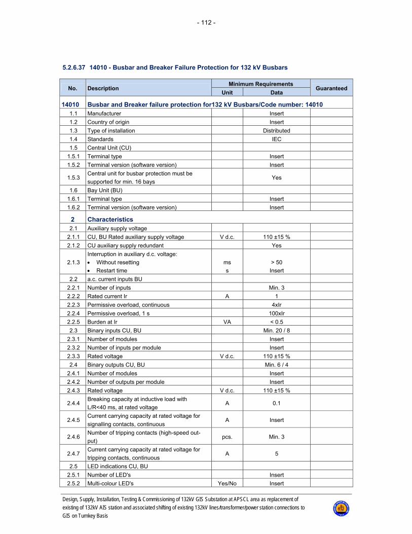
- 112 -
Design, Supply, Installation, Testing & Commissioning of 132kV GIS Substation at APSCL area as replacement of
existing of 132kV AIS station and associated shifting of existing 132kV lines/transformer/power station connections to
GIS on Turnkey Basis
5.2.6.37 14010 - Busbar and Breaker Failure Protection for 132 kV Busbars
No. Description Minimum Requirements
Guaranteed Unit Data
14010 Busbar and Breaker failure protection for132 kV Busbars/Code number: 14010 1.1 Manufacturer Insert
1.2 Country of origin Insert
1.3 Type of installation Distributed
1.4 Standards IEC
1.5 Central Unit (CU)
1.5.1 Terminal type Insert
1.5.2 Terminal version (software version) Insert
1.5.3 Central unit for busbar protection must be
supported for min. 16 bays Yes
1.6 Bay Unit (BU)
1.6.1 Terminal type Insert
1.6.2 Terminal version (software version) Insert
2 Characteristics 2.1 Auxiliary supply voltage
2.1.1 CU, BU Rated auxiliary supply voltage V d.c. 110 ±15 %
2.1.2 CU auxiliary supply redundant Yes
2.1.3
Interruption in auxiliary d.c. voltage:
Without resetting
Restart time
ms
s
> 50
Insert
2.2 a.c. current inputs BU
2.2.1 Number of inputs Min. 3
2.2.2 Rated current Ir A 1
2.2.3 Permissive overload, continuous 4xIr
2.2.4 Permissive overload, 1 s 100xIr
2.2.5 Burden at Ir VA < 0.5
2.3 Binary inputs CU, BU Min. 20 / 8
2.3.1 Number of modules Insert
2.3.2 Number of inputs per module Insert
2.3.3 Rated voltage V d.c. 110 ±15 %
2.4 Binary outputs CU, BU Min. 6 / 4
2.4.1 Number of modules Insert
2.4.2 Number of outputs per module Insert
2.4.3 Rated voltage V d.c. 110 ±15 %
2.4.4 Breaking capacity at inductive load with
L/R<40 ms, at rated voltage A 0.1
2.4.5 Current carrying capacity at rated voltage for
signalling contacts, continuous A Insert
2.4.6 Number of tripping contacts (high-speed out-
put) pcs. Min. 3
2.4.7 Current carrying capacity at rated voltage for
tripping contacts, continuous A 5
2.5 LED indications CU, BU
2.5.1 Number of LED's Insert
2.5.2 Multi-colour LED's Yes/No Insert

- 113 -
Design, Supply, Installation, Testing & Commissioning of 132kV GIS Substation at APSCL area as replacement of
existing of 132kV AIS station and associated shifting of existing 132kV lines/transformer/power station connections to
GIS on Turnkey Basis
No. Description Minimum Requirements
Guaranteed Unit Data
2.6 Communication ports CU, BU
2.6.1 Port for front-connected PC
2.6.1.1 Protocols supported Insert
2.6.1.2 Communication speed Kbit/s Insert
2.6.1.3 PC connector type Insert
2.6.2 CU, BU communication media FO
2.6.3 CU rear station (system) communication ports
2.6.3.1 Number of rear ports Insert
2.6.3.2 Protocols supported IEC 61850
2.6.3.3 Communication speed Mbit/s Insert
2.6.3.4 Connector type RJ45
2.6.4 Time synchronisation SNTP
2.7 Busbar differential protection
2.7.1 Operating time ms < 20
2.7.2 Internal CT radio adaptability Yes
2.7.3 Multiple tripping criteria, check and bus zone Yes
2.7.4 Current transformer supervision Yes
2.7.5 External signal of load transfer starting Insert
2.7.6
Busbar protection system should be suit-
able/adaptable for future switchgear extension
or modification
Yes
2.7.7 Bay-selective intertripping Yes
2.7.8 Phase-segregated measurement system Yes
2.8 Breaker failure protection
2.8.1 Setting range % Ir Insert
2.8.2 Re-trip time delay range s 0-1
2.8.3 Re-trip operation mode 1/3ph Yes
2.8.4 Back-up time delay range s 0-1
2.8.5 Trip operating time setting resolution ms 1
2.8.6 Trip delay range s 0-1
2.8.7 Single-phase with/without current Yes
2.8.8 2-stage operation bay trip repeat/trip busbar Insert
2.8.9 Selectable operation mode (current, unbal-
ance, low current) Insert
2.8.10 Independent settable delay times for all opera-
tion modes Yes
2.8.11 Low current mode using the circuit breaker
auxiliary contact Yes
2.8.12 End fault protection Yes
2.8.13 Independent breaker failure protection per bay
unit Yes
2.9 Disturbance recorder CU, BU
2.9.1 Number of digital signals Insert
2.9.2 Number of analogue signals Insert
2.9.3 External/manual initiation of recording Insert
2.9.4 Sampling rate kHz Insert
2.9.5 Pre-fault time ms ≥ 300

- 114 -
Design, Supply, Installation, Testing & Commissioning of 132kV GIS Substation at APSCL area as replacement of
existing of 132kV AIS station and associated shifting of existing 132kV lines/transformer/power station connections to
GIS on Turnkey Basis
No. Description Minimum Requirements
Guaranteed Unit Data
2.9.6 Recording time ms ≥ 2000
2.9.7 Number of recorded disturbances Min. 5
2.9.8 Total recording time with max. analogue and
binary signals s > 10
2.9.9 Output file comtrade format Yes
2.10 Event recorder CU, BU
2.10.1 Max. number of events Insert
2.10.2 Time tagging resolution ms 1
2.11 Self-supervision CU, BU Yes
3 Additional requirements 3.1 Test socket BU Yes
3.2 Setting and configuration approved by Engi-
neer Yes
3.4
Centralised, user-friendly configuration and
all necessary software tools for full param-
eterization, and (re)configuration in case of
extensions should be delivered
Yes
Overall compliance with the requirements (yes/no)

- 115 -
Design, Supply, Installation, Testing & Commissioning of 132kV GIS Substation at APSCL area as replacement of
existing of 132kV AIS station and associated shifting of existing 132kV lines/transformer/power station connections to
GIS on Turnkey Basis
5.2.6.38 14011 - Trip Circuit Supervision Relay
No. Description Minimum Requirements
Guaranteed Unit Data
14011 Trip Circuit Supervision Relay / Code number: 14011 1.1 Manufacturer Insert
1.2 Country of origin Insert
1.3 Type Insert
1.4 Standards IEC
2 Characteristics 2.1 Auxiliary supply voltage
2.1.1 Rated auxiliary supply voltage V d.c. 110 ±15 %
2.2 Binary outputs
2.2.1 Number of outputs NO/NC Min. 2/2
2.2.2 Rated voltage V d.c. 110
2.2.3 Breaking capacity at inductive load with
L/R<40 ms, at rated voltage A 0.1
2.2.4 Current carrying capacity at rated voltage for
signalling contacts, continuous A Insert
2.3 Supervised circuits
2.3.1 Voltage range of supervised circuits V d.c. 110 ±15 %
2.3.2 Injected current of supervised circuits mA Insert
2.3.3 Operating time range s Insert
2.3.4 Resetting time range s Insert
Overall compliance with the requirements (yes/no)
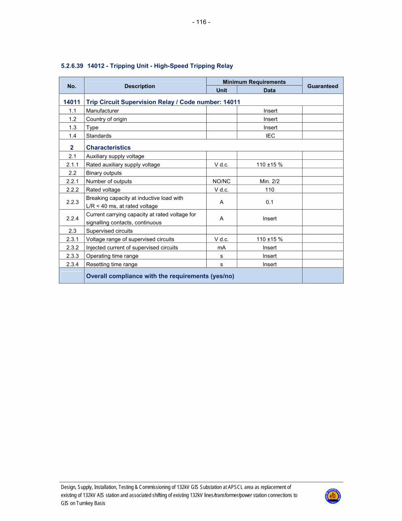
- 116 -
Design, Supply, Installation, Testing & Commissioning of 132kV GIS Substation at APSCL area as replacement of
existing of 132kV AIS station and associated shifting of existing 132kV lines/transformer/power station connections to
GIS on Turnkey Basis
5.2.6.39 14012 - Tripping Unit - High-Speed Tripping Relay
No. Description Minimum Requirements
Guaranteed Unit Data
14011 Trip Circuit Supervision Relay / Code number: 14011 1.1 Manufacturer Insert
1.2 Country of origin Insert
1.3 Type Insert
1.4 Standards IEC
2 Characteristics 2.1 Auxiliary supply voltage
2.1.1 Rated auxiliary supply voltage V d.c. 110 ±15 %
2.2 Binary outputs
2.2.1 Number of outputs NO/NC Min. 2/2
2.2.2 Rated voltage V d.c. 110
2.2.3 Breaking capacity at inductive load with
L/R < 40 ms, at rated voltage A 0.1
2.2.4 Current carrying capacity at rated voltage for
signalling contacts, continuous A Insert
2.3 Supervised circuits
2.3.1 Voltage range of supervised circuits V d.c. 110 ±15 %
2.3.2 Injected current of supervised circuits mA Insert
2.3.3 Operating time range s Insert
2.3.4 Resetting time range s Insert
Overall compliance with the requirements (yes/no)

- 117 -
Design, Supply, Installation, Testing & Commissioning of 132kV GIS Substation at APSCL area as replacement of
existing of 132kV AIS station and associated shifting of existing 132kV lines/transformer/power station connections to
GIS on Turnkey Basis
5.2.6.40 14013 - Test Socket
No. Description Minimum Requirements
Guaranteed Unit Data
14013 Test socket / Code number: 14013 1.1 Manufacturer Insert
1.2 Country of origin Insert
1.3
Type
Line main 1 and 2
Line back-up and bus coupler
Transformer main 1 and 2
Bay unit BBF
Distance protection (code 14007)
Insert
1.4 Standards IEC
1.5 Each protection device must have its own test
socket Yes
1.6
Test socket must obtain safe online protection
testing and maintaining, and performing whole
tripping test with following AR
Yes
1.7
Test socket should have enough contacts to:
Short-circuit current inputs from CT's
Isolate voltage inputs from VT's
Isolate trip circuit for each phase separately
Isolate CB close command
Isolate signalling voltage
Inhibit breaker failure initialising
Inhibit sending of communication signal
Allow functional testing of protection
Yes
1.8 Socket should be designed for 4 mm banana
plugs access Yes
Overall compliance with the requirements (yes/no)
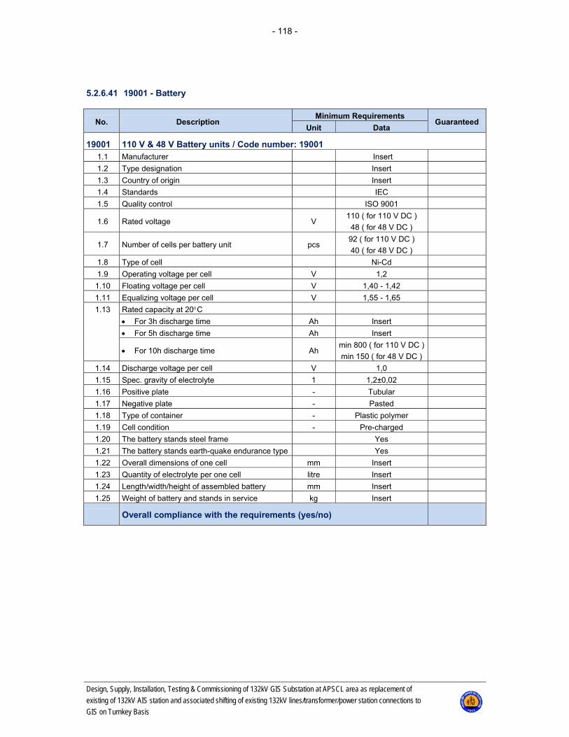
- 118 -
Design, Supply, Installation, Testing & Commissioning of 132kV GIS Substation at APSCL area as replacement of
existing of 132kV AIS station and associated shifting of existing 132kV lines/transformer/power station connections to
GIS on Turnkey Basis
5.2.6.41 19001 - Battery
No. Description Minimum Requirements
Guaranteed Unit Data
19001 110 V & 48 V Battery units / Code number: 19001 1.1 Manufacturer Insert
1.2 Type designation Insert
1.3 Country of origin Insert
1.4 Standards IEC
1.5 Quality control ISO 9001
1.6 Rated voltage V 110 ( for 110 V DC )
48 ( for 48 V DC )
1.7 Number of cells per battery unit pcs 92 ( for 110 V DC )
40 ( for 48 V DC )
1.8 Type of cell Ni-Cd
1.9 Operating voltage per cell V 1,2
1.10 Floating voltage per cell V 1,40 - 1,42
1.11 Equalizing voltage per cell V 1,55 - 1,65
1.13 Rated capacity at 20C
For 3h discharge time Ah Insert
For 5h discharge time Ah Insert
For 10h discharge time Ah min 800 ( for 110 V DC )
min 150 ( for 48 V DC )
1.14 Discharge voltage per cell V 1,0
1.15 Spec. gravity of electrolyte 1 1,2±0,02
1.16 Positive plate - Tubular
1.17 Negative plate - Pasted
1.18 Type of container - Plastic polymer
1.19 Cell condition - Pre-charged
1.20 The battery stands steel frame Yes
1.21 The battery stands earth-quake endurance type Yes
1.22 Overall dimensions of one cell mm Insert
1.23 Quantity of electrolyte per one cell litre Insert
1.24 Length/width/height of assembled battery mm Insert
1.25 Weight of battery and stands in service kg Insert
Overall compliance with the requirements (yes/no)
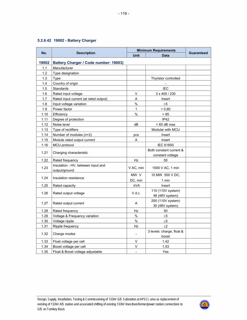
- 119 -
Design, Supply, Installation, Testing & Commissioning of 132kV GIS Substation at APSCL area as replacement of
existing of 132kV AIS station and associated shifting of existing 132kV lines/transformer/power station connections to
GIS on Turnkey Basis
5.2.6.42 19002 - Battery Charger
No. Description Minimum Requirements
Guaranteed Unit Data
19002 Battery Charger / Code number: 19003) 1.1 Manufacturer
1.2 Type designation
1.3 Type Thyristor controlled
1.4 Country of origin -
1.5 Standards IEC
1.6 Rated input voltage V 3 x 400 / 230
1.7 Rated input current (at rated output) A Insert
1.8 Input voltage variation % 5
1.9 Power factor 1 > 0,80
1.10 Efficiency % > 85
1.11 Degree of protection IP42
1.12 Noise level dB < 65 dB max
1.13 Type of rectifiers Modular with MCU
1.14 Number of modules (n+2) pcs Insert
1.15 Module rated output current A Insert
1.16 MCU protocol IEC 61850
1.21 Charging characteristic Both constant current &
constant voltage
1.22 Rated frequency Hz 50
1.23 Insulation - HV, between input and
output/ground V AC, min 1000 V AC, 1 min
1.24 Insulation resistance MW; V
DC, min
10 MW, 500 V DC,
1 min
1.25 Rated capacity kVA Insert
1.26 Rated output voltage V d.c. 110 (110V system)
48 (48V system)
1.27 Rated output current A 250 (110V system)
30 (48V system)
1.28 Rated frequency Hz 50
1.29 Voltage & Frequency variation % 5
1.30 Voltage ripple % 5
1.31 Ripple frequency Hz 2
1.32 Charge modes - 3 levels: charge, float &
boost
1.33 Float voltage per cell V 1.42
1.34 Boost voltage per cell V 1.53
1.35 Float & Boost voltage adjustable - Yes
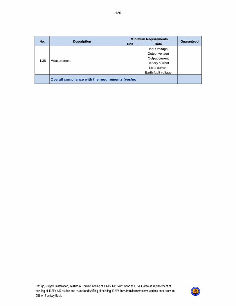
- 120 -
Design, Supply, Installation, Testing & Commissioning of 132kV GIS Substation at APSCL area as replacement of
existing of 132kV AIS station and associated shifting of existing 132kV lines/transformer/power station connections to
GIS on Turnkey Basis
No. Description Minimum Requirements
Guaranteed Unit Data
1.36 Measurement
Input voltage
Output voltage
Output current
Battery current
Load current
Earth-fault voltage
Overall compliance with the requirements (yes/no)

- 121 -
Design, Supply, Installation, Testing & Commissioning of 132kV GIS Substation at APSCL area as replacement of
existing of 132kV AIS station and associated shifting of existing 132kV lines/transformer/power station connections to
GIS on Turnkey Basis
5.2.6.43 Fibre Optic Multiplexer Equipment
No. Description Minimum Requirements
Guaranteed Unit Data
1 General:
Manufacturer
Model No.
Type
1.1 Type of multiplexer SDH: ADM
1.2 Complying to ITU-T rec. Yes
1.3 Transmission Capacity Mbit/s STM-4: 620
1.4 Access capacity on 64 Kbit/s channels Minimum 200
1.5 Access capacity on 2 Mbit/s channels Minimum 40
1.6 Redundant central processor Shall be available
1.7 Digital cross connect function Fully non-blocking
2 Available aggregates:
2.1 Optical aggregates (ITU-T G.957) L-1.1, L-1.2
3 Available trunk interfaces:
3.1 HDB3, 2 Mbit/s interfaces per module No. Minimum 8
3.2 Complying to ITU-T rec. G.703, transparent
G.704, selectable
3.3
HDSL, 2Mbit/s interface:
no of copper wires
Capacity on 2Mbit/s or on 1Mbit/s
Capacity selectable
No. of
channels
channels /
pair of
wire
4 or 2
30 or 15
30 / 2 pairs
30 / 1 pair
15 / 1 pair
4 Available user interfaces
4.1 Voice interfaces for trunk lines:
4.1.1 1 + 1 com path protection, available for all yes
4.1.2
Analogue, 4wire with E&M:
Input level
Output level
dBr
dBr
+7.5 … -16.0
+7.0 … -16.5
4.1.3
Analogue, 2wire with E&M:
Input level
Output level
dBr
dBr
+6.5 … -12.5
-1.0 … -20.0
4.1.4 Digital, 2Mbit/s CAS or PRI yes
4.2 Voice interfaces for remote subscriber:
4.2.1 2wire, subscriber side dBr -5 ... +4/-7.5 ... -1
4.2.2 2wire, PABX side dBr -5 ... +4/-7.5 ... -3
4.3 Integrated teleprotection
4.3.1 Interface for Commands:
4.3.1.1 Number of independent commands No. 4
4.3.1.2 Transmission time max. ms 6
4.3.1.3 Signal voltage Vpeak 250
4.3.1.4 1 + 1 com path protection yes
4.3.2 Interface(s) for Differential Protection:
4.3.2.1 Electrical interface: G.703 Kbit/s 64
4.3.2.2 Optical Interface Kbit/s Minimum 64

- 122 -
Design, Supply, Installation, Testing & Commissioning of 132kV GIS Substation at APSCL area as replacement of
existing of 132kV AIS station and associated shifting of existing 132kV lines/transformer/power station connections to
GIS on Turnkey Basis
No. Description Minimum Requirements
Guaranteed Unit Data
4.4 Data: channels per module
4.4.1 1 + 1 com path protection, available for all yes
4.4.2 V.24/V.28 (RS-232): up to 38.4kbit/s No. 4
4.4.3 V.11/X.24 (RS-422):64kbit/s No. 4
4.4.4 V.35:64kbit/s No. 4
4.4.5 V.36 (RS-449):64kbit/s No. 2
4.4.6 G.703:64kbit/s No. 8
4.4.7
Ethernet:
10/100 BaseT
WAN capacity
Protocols
No.
Mbit/s
-
4
Min:2x 2Mbit/s
Min.:IP
4.5 Integrated alarm gathering module:
4.5.1 Number of external alarms per module No. Min. 20
4.5.2 Auxiliary power supply for ext. contacts Yes
4.6 Network Management System
4.6.1 Type/Name of configuration tool
4.6.2 For fault / configuration management Yes / yes
4.6.3 For local / remote operation Yes / yes
4.6.4 Data communication network (DCN) Ethernet / IPor
Ethernet / OSI
4.7 Ambient Conditions:
4.7.1 Storage: ETS 300 019-1-1, class 1.2 °C / %
hum -5 ... + 55 / class 1.2
4.7.2 Transport: ETS 300 019-1-2, class 2.2 °C / %
hum -5 ... + 70 / class 2.2
4.7.3 Operation: ETS 300 019-1-3, class 3.1E °C / %
hum -5 … +45 / class 3.1E
4.8 Power Supply
4.8.1 Operation V DC 48 / 60(-15/+20%)
4.8.2 Fully redundant power supply yes
Overall compliance with the requirements (yes/no)
5.2.6.44 PABX
SL. no. DESCRIPTION UNIT REQUIRED Guaranteed
1.0 GENERAL:
1.1 Type IP PABX
1.2 Complying to ITU-T rec. Yes
1.3 Analogue Trunk Connectivity Yes
1.4 Digital Trunk Connectivity(E1/T1) Yes
1.5 10/100 BaseT Ethernet Connection Yes 1.6 No of Subscribers No. Up to 32
2.0 Trunk Connectivity
2.1 Analogue Trunk
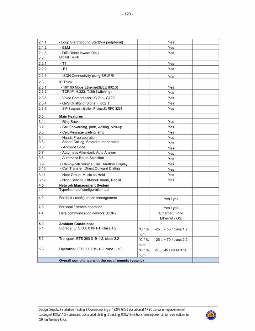
- 123 -
Design, Supply, Installation, Testing & Commissioning of 132kV GIS Substation at APSCL area as replacement of
existing of 132kV AIS station and associated shifting of existing 132kV lines/transformer/power station connections to
GIS on Turnkey Basis
2.1.1 - Loop Start/Ground Start(Via peripheral) Yes
2.1.2 - E&M Yes
2.1.3 - DID(Direct Inward Dial) Yes
2.2 Digital Trunk
2.2.1 - T1 Yes
2.2.2 - E1 Yes
2.2.3 - ISDN Connectivity using BRI/PRI Yes
2.3 IP Trunk
2.3.1 - 10/100 Mbps Ethernet(IEEE 802.3) Yes 2.3.2 - TCP/IP, H.323, T.38(Switching) Yes
2.3.3 - Voice Compressor : G.711, G729 Yes
2.3.4 - QoS(Quality of Signal) : 802.1 Yes
2.3.5 - SIP(Session Initiation Protocol): RFC 3261 Yes
3.0 Main Features
3.1 - Ring Back Yes
3.2 - Call Forwarding, park, waiting, pick-up Yes
3.3 - Call/Message waiting lamp Yes
3.4 - Hands Free operation Yes 3.5 - Speed Calling, Stored number redial Yes 3.6 - Account Code Yes 3.7 - Automatic Attendant, Auto Answer Yes 3.8 - Automatic Route Selection Yes
3.9 - Call-by-call Service, Call Duration Display Yes 3.10 - Call Transfer, Direct Outward Dialing Yes
3.11 - Hunt Group, Music on Hold Yes
3.12 - Night Service, Off-hook Alarm, Redial Yes
4.0 Network Management System 4.1 Type/Name of configuration tool
4.2 For fault / configuration management Yes / yes
4.3 For local / remote operation Yes / yes
4.4 Data communication network (DCN) Ethernet / IP or
Ethernet / OSI
5.0 Ambient Conditions: 5.1 Storage: ETS 300 019-1-1, class 1.2 °C / %
hum
-25 .. + 55 / class 1.2
5.2 Transport: ETS 300 019-1-2, class 2.2 °C / %
hum
-25 .. + 70 / class 2.2
5.3 Operation: ETS 300 019-1-3, class 3.1E °C / %
hum
-5 .. +45 / class 3.1E
Overall compliance with the requirements (yes/no)
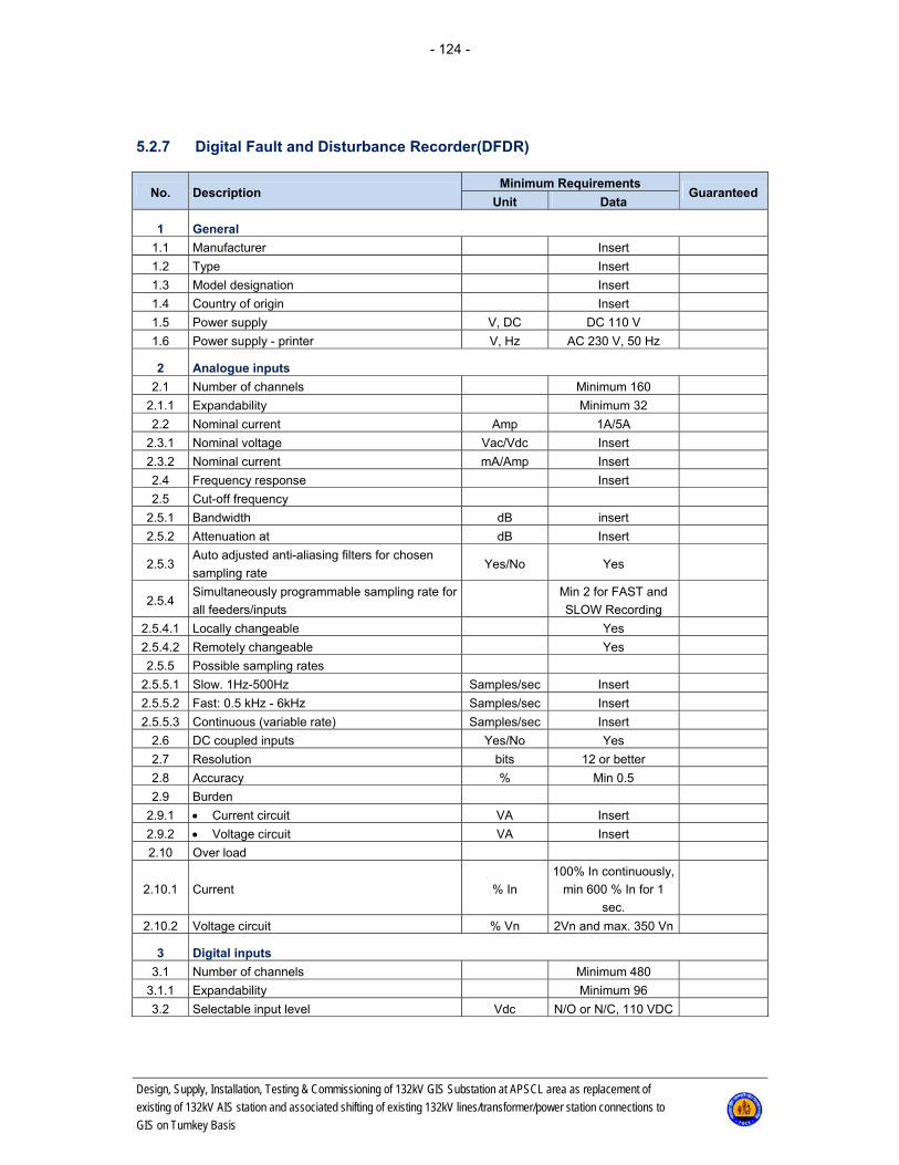
- 124 -
Design, Supply, Installation, Testing & Commissioning of 132kV GIS Substation at APSCL area as replacement of
existing of 132kV AIS station and associated shifting of existing 132kV lines/transformer/power station connections to
GIS on Turnkey Basis
5.2.7 Digital Fault and Disturbance Recorder(DFDR)
No. Description Minimum Requirements
Guaranteed Unit Data
1 General
1.1 Manufacturer Insert
1.2 Type Insert
1.3 Model designation Insert
1.4 Country of origin Insert
1.5 Power supply V, DC DC 110 V
1.6 Power supply - printer V, Hz AC 230 V, 50 Hz
2 Analogue inputs
2.1 Number of channels Minimum 160
2.1.1 Expandability Minimum 32
2.2 Nominal current Amp 1A/5A
2.3.1 Nominal voltage Vac/Vdc Insert
2.3.2 Nominal current mA/Amp Insert
2.4 Frequency response Insert
2.5 Cut-off frequency
2.5.1 Bandwidth dB insert
2.5.2 Attenuation at dB Insert
2.5.3 Auto adjusted anti-aliasing filters for chosen
sampling rate Yes/No Yes
2.5.4 Simultaneously programmable sampling rate for
all feeders/inputs
Min 2 for FAST and
SLOW Recording
2.5.4.1 Locally changeable Yes
2.5.4.2 Remotely changeable Yes
2.5.5 Possible sampling rates
2.5.5.1 Slow. 1Hz-500Hz Samples/sec Insert
2.5.5.2 Fast: 0.5 kHz - 6kHz Samples/sec Insert
2.5.5.3 Continuous (variable rate) Samples/sec Insert
2.6 DC coupled inputs Yes/No Yes
2.7 Resolution bits 12 or better
2.8 Accuracy % Min 0.5
2.9 Burden
2.9.1 Current circuit VA Insert
2.9.2 Voltage circuit VA Insert
2.10 Over load
2.10.1 Current % In
100% In continuously,
min 600 % In for 1
sec.
2.10.2 Voltage circuit % Vn 2Vn and max. 350 Vn
3 Digital inputs
3.1 Number of channels Minimum 480
3.1.1 Expandability Minimum 96
3.2 Selectable input level Vdc N/O or N/C, 110 VDC
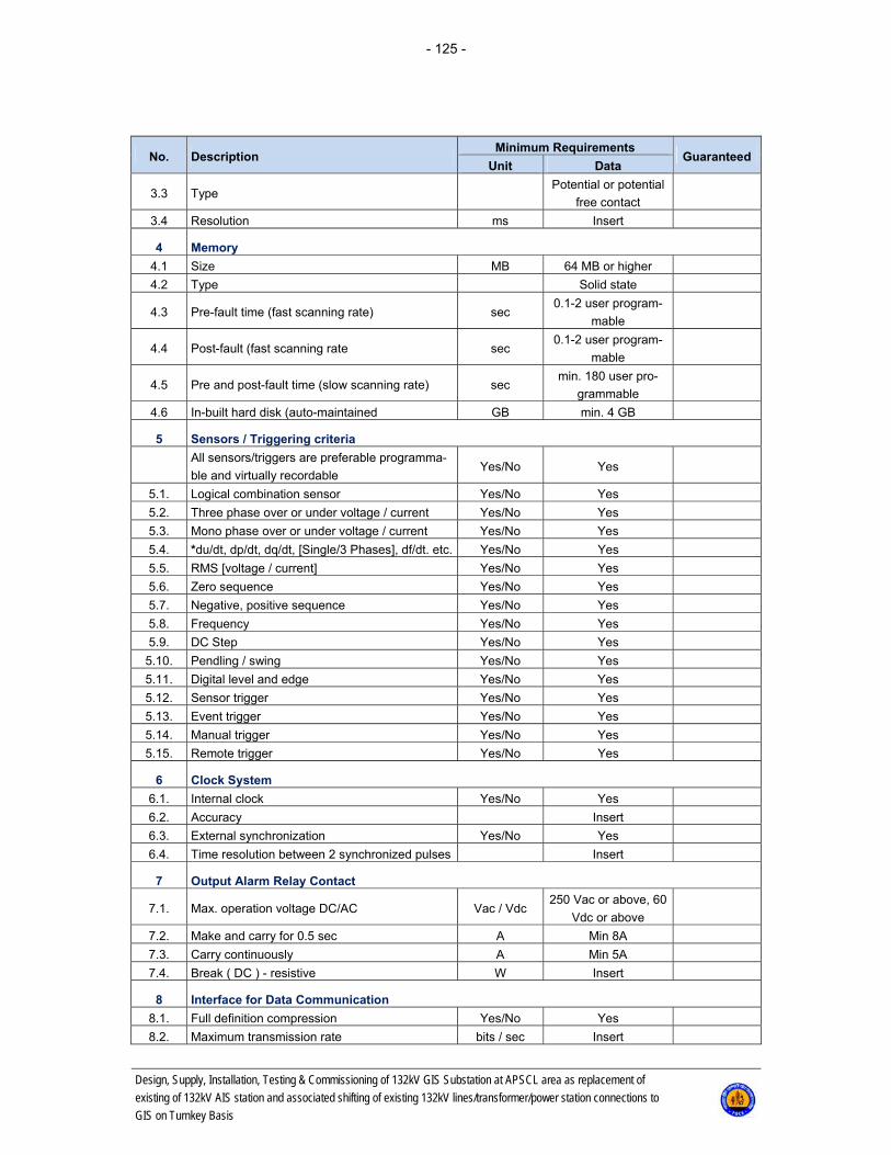
- 125 -
Design, Supply, Installation, Testing & Commissioning of 132kV GIS Substation at APSCL area as replacement of
existing of 132kV AIS station and associated shifting of existing 132kV lines/transformer/power station connections to
GIS on Turnkey Basis
No. Description Minimum Requirements
Guaranteed Unit Data
3.3 Type Potential or potential
free contact
3.4 Resolution ms Insert
4 Memory
4.1 Size MB 64 MB or higher
4.2 Type Solid state
4.3 Pre-fault time (fast scanning rate) sec 0.1-2 user program-
mable
4.4 Post-fault (fast scanning rate sec 0.1-2 user program-
mable
4.5 Pre and post-fault time (slow scanning rate) sec min. 180 user pro-
grammable
4.6 In-built hard disk (auto-maintained GB min. 4 GB
5 Sensors / Triggering criteria
All sensors/triggers are preferable programma-
ble and virtually recordable Yes/No Yes
5.1. Logical combination sensor Yes/No Yes
5.2. Three phase over or under voltage / current Yes/No Yes
5.3. Mono phase over or under voltage / current Yes/No Yes
5.4. *du/dt, dp/dt, dq/dt, [Single/3 Phases], df/dt. etc. Yes/No Yes
5.5. RMS [voltage / current] Yes/No Yes
5.6. Zero sequence Yes/No Yes
5.7. Negative, positive sequence Yes/No Yes
5.8. Frequency Yes/No Yes
5.9. DC Step Yes/No Yes
5.10. Pendling / swing Yes/No Yes
5.11. Digital level and edge Yes/No Yes
5.12. Sensor trigger Yes/No Yes
5.13. Event trigger Yes/No Yes
5.14. Manual trigger Yes/No Yes
5.15. Remote trigger Yes/No Yes
6 Clock System
6.1. Internal clock Yes/No Yes
6.2. Accuracy Insert
6.3. External synchronization Yes/No Yes
6.4. Time resolution between 2 synchronized pulses Insert
7 Output Alarm Relay Contact
7.1. Max. operation voltage DC/AC Vac / Vdc 250 Vac or above, 60
Vdc or above
7.2. Make and carry for 0.5 sec A Min 8A
7.3. Carry continuously A Min 5A
7.4. Break ( DC ) - resistive W Insert
8 Interface for Data Communication
8.1. Full definition compression Yes/No Yes
8.2. Maximum transmission rate bits / sec Insert
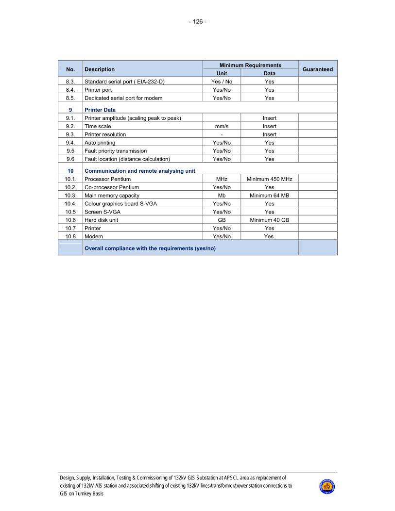
- 126 -
Design, Supply, Installation, Testing & Commissioning of 132kV GIS Substation at APSCL area as replacement of
existing of 132kV AIS station and associated shifting of existing 132kV lines/transformer/power station connections to
GIS on Turnkey Basis
No. Description Minimum Requirements
Guaranteed Unit Data
8.3. Standard serial port ( EIA-232-D) Yes / No Yes
8.4. Printer port Yes/No Yes
8.5. Dedicated serial port for modem Yes/No Yes
9 Printer Data
9.1. Printer amplitude (scaling peak to peak) Insert
9.2. Time scale mm/s Insert
9.3. Printer resolution - Insert
9.4. Auto printing Yes/No Yes
9.5 Fault priority transmission Yes/No Yes
9.6 Fault location (distance calculation) Yes/No Yes
10 Communication and remote analysing unit
10.1. Processor Pentium MHz Minimum 450 MHz
10.2. Co-processor Pentium Yes/No Yes
10.3. Main memory capacity Mb Minimum 64 MB
10.4. Colour graphics board S-VGA Yes/No Yes
10.5 Screen S-VGA Yes/No Yes
10.6 Hard disk unit GB Minimum 40 GB
10.7 Printer Yes/No Yes
10.8 Modem Yes/No Yes.
Overall compliance with the requirements (yes/no)
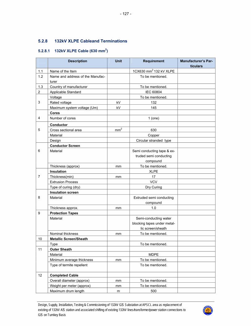
- 127 -
Design, Supply, Installation, Testing & Commissioning of 132kV GIS Substation at APSCL area as replacement of
existing of 132kV AIS station and associated shifting of existing 132kV lines/transformer/power station connections to
GIS on Turnkey Basis
5.2.8 132kV XLPE Cableand Terminations
5.2.8.1 132kV XLPE Cable (630 mm2)
Description Unit Requirement Manufacturer’s Par-
ticulars
1.1 Name of the Item 1CX630 mm2 132 kV XLPE
1.2 Name and address of the Manufac-
turer
To be mentioned.
1.3 Country of manufacturer To be mentioned.
2 Applicable Standard IEC 60804
3
Voltage To be mentioned.
Rated voltage kV 132
Maximum system voltage (Um) kV 145
4
Cores
Number of cores 1 (one)
5
Conductor
Cross sectional area mm2 630
Material Copper
Design Circular stranded type
6
Conductor Screen
Material Semi conducting tape & ex-
truded semi conducting
compound
Thickness (approx) mm To be mentioned.
7
Insulation XLPE
Thickness(min) mm 17
Extrusion Process VCV
Type of curing (dry) Dry Curing
8
Insulation screen
Material Extruded semi conducting
compound
Thickness approx. mm 1.0
9 Protection Tapes
Material Semi-conducting water
blocking tapes under metal-
lic screen/sheath
Nominal thickness mm To be mentioned.
10 Metallic Screen/Sheath
Type To be mentioned.
11
Outer Sheath
Material MDPE
Minimum average thickness mm To be mentioned.
Type of termite repellent To be mentioned.
12
Completed Cable
Overall diameter (approx) mm To be mentioned.
Weight per meter (approx) mm To be mentioned.
Maximum drum length m 500

- 128 -
Design, Supply, Installation, Testing & Commissioning of 132kV GIS Substation at APSCL area as replacement of
existing of 132kV AIS station and associated shifting of existing 132kV lines/transformer/power station connections to
GIS on Turnkey Basis
Description Unit Requirement Manufacturer’s
Particulars
13 Cable Drums
Overall diameter (approx) mm To be mentioned.
Width (approx) mm To be mentioned.
Weight loaded (approx) kg To be mentioned.
14 Continuous current carrying capac-
ity based on the conditions
laid in the ground.
(with detail calculation)
One circuit A To be mentioned.
Two circuit A To be mentioned.
Four circuit A To be mentioned.
Drawn into ducts A To be mentioned.
One circuit A To be mentioned.
Two circuit A To be mentioned.
Four circuit A To be mentioned.
In air A To be mentioned.
15 Permissible overload in service
conditions for a period of
2 hrs in a day
100 hrs in a month 500
hrs in total life
16
Max conductor temperature
Laid direct in ground ºC To be mentioned.
Drawn into ducts ºC To be mentioned.
Laid in air ºC To be mentioned.
17 Conductor short circuit current for
one second cable loaded as above
prior to short circuit
90 kA for 1 sec.
-do- for three second A To be mentioned.
Final conductor temperature ºC To be mentioned.
18 Sheath earth fault current carrying
capacity for three second cable
loaded as above prior to earth fault
50 kA for 1 sec
(with detail calculation).
Final metallic sheath temperature ºC To be mentioned.
19 Max. dielectric stress all the con-
ductor screen (assumed smooth)
To be mentioned.
20 Minimum radius of bend around
which cable can be laid
Laid direct 20 x overall diameter of
cable in meters
In ducts To be mentioned.
In air To be mentioned.
21 Nominal internal diameter of pipes
on ducts through which cable may
be pulled
22 Maximum DC resistance per km of
cable at 20ºC
Of conductor ohm 0.028
Of metallic layer To be mentioned.
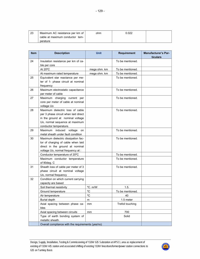
- 129 -
Design, Supply, Installation, Testing & Commissioning of 132kV GIS Substation at APSCL area as replacement of
existing of 132kV AIS station and associated shifting of existing 132kV lines/transformer/power station connections to
GIS on Turnkey Basis
23 Maximum AC resistance per km of
cable at maximum conductor tem-
perature
ohm 0.022
Item Description Unit Requirement Manufacturer’s Par-
ticulars
24 Insulation resistance per km of ca-
ble per core
To be mentioned.
At 20ºC mega ohm. km To be mentioned.
At maximum rated temperature mega ohm. km To be mentioned.
25 Equivalent star reactance per me-
ter of 1- phase circuit at nominal
frequency
To be mentioned.
26 Maximum electrostatic capacitance
per meter of cable
To be mentioned.
27 Maximum charging current per
core per meter of cable at nominal
voltage Uo
To be mentioned.
28 Maximum dielectric loss of cable
per 3 phase circuit when laid direct
in the ground at nominal voltage
Uo, normal sequence at maximum
conductor temperature.
To be mentioned.
29 Maximum induced voltage on
metal sheath under fault condition
To be mentioned.
30 Maximum dielectric dissipation fac-
tor of charging of cable when laid
direct in the ground at nominal
voltage Uo, normal frequency at :
To be mentioned.
Conductor temperature of 20ºC To be mentioned.
Maximum conductor temperature
of 90deg. C
To be mentioned.
31 Sheath loss of cable per meter of 3
phase circuit at nominal voltage
Uo, normal frequency
To be mentioned.
32 Condition on which current carrying
capacity are based
Soil thermal resistivity ºC. m/W 1.5.
Ground temperature ºC To be mentioned.
Air temperature ºC 40
Burial depth m 1.5 meter
Axial spacing between phase ca-
bles
mm Trefoil touching
Axial spacing between circuits mm 700
Type of earth bonding system of
metallic sheath.
Solid
Overall compliance with the requirements (yes/no)

- 130 -
Design, Supply, Installation, Testing & Commissioning of 132kV GIS Substation at APSCL area as replacement of
existing of 132kV AIS station and associated shifting of existing 132kV lines/transformer/power station connections to
GIS on Turnkey Basis
5.2.8.2 132kV XLPE Cable (800 mm2)
Description Unit Requirement Manufacturer’s Par-
ticulars
1.1 Name of the Item 1CX800 mm2 132 kV XLPE
1.2 Name and address of the Manufac-
turer
To be mentioned.
1.3 Country of manufacturer To be mentioned.
2 Applicable Standard IEC 60804
3
Voltage To be mentioned.
Rated voltage kV 132
Maximum system voltage (Um) kV 145
4
Cores
Number of cores 1 (one)
5
Conductor
Cross sectional area mm2 800
Material Copper
Design Circular stranded type
6
Conductor Screen
Material Semi conducting tape & ex-
truded semi conducting
compound
Thickness (approx) mm To be mentioned.
7
Insulation XLPE
Thickness(min) mm 17
Extrusion Process VCV
Type of curing (dry) Dry Curing
8
Insulation screen
Material Extruded semi conducting
compound
Thickness approx. mm 1.0
9 Protection Tapes
Material Semi-conducting water
blocking tapes under metal-
lic screen/sheath
Nominal thickness mm To be mentioned.
10 Metallic Screen/Sheath
Type To be mentioned.
11
Outer Sheath
Material MDPE
Minimum average thickness mm To be mentioned.
Type of termite repellent To be mentioned.
12
Completed Cable
Overall diameter (approx) mm To be mentioned.
Weight per meter (approx) mm To be mentioned.
Maximum drum length m 500
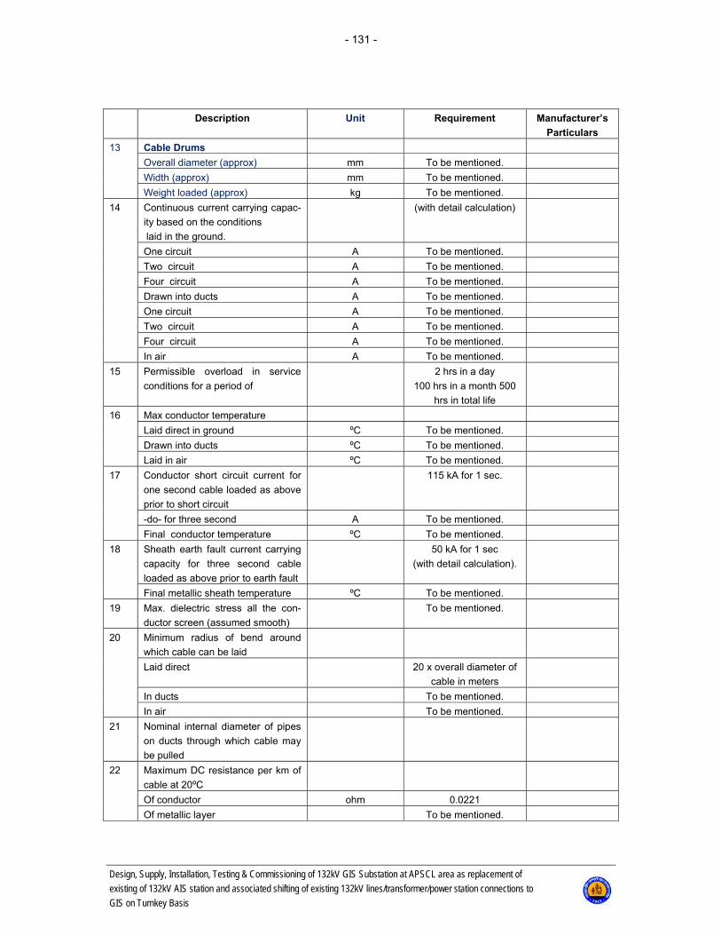
- 131 -
Design, Supply, Installation, Testing & Commissioning of 132kV GIS Substation at APSCL area as replacement of
existing of 132kV AIS station and associated shifting of existing 132kV lines/transformer/power station connections to
GIS on Turnkey Basis
Description Unit Requirement Manufacturer’s
Particulars
13 Cable Drums
Overall diameter (approx) mm To be mentioned.
Width (approx) mm To be mentioned.
Weight loaded (approx) kg To be mentioned.
14 Continuous current carrying capac-
ity based on the conditions
laid in the ground.
(with detail calculation)
One circuit A To be mentioned.
Two circuit A To be mentioned.
Four circuit A To be mentioned.
Drawn into ducts A To be mentioned.
One circuit A To be mentioned.
Two circuit A To be mentioned.
Four circuit A To be mentioned.
In air A To be mentioned.
15 Permissible overload in service
conditions for a period of
2 hrs in a day
100 hrs in a month 500
hrs in total life
16
Max conductor temperature
Laid direct in ground ºC To be mentioned.
Drawn into ducts ºC To be mentioned.
Laid in air ºC To be mentioned.
17 Conductor short circuit current for
one second cable loaded as above
prior to short circuit
115 kA for 1 sec.
-do- for three second A To be mentioned.
Final conductor temperature ºC To be mentioned.
18 Sheath earth fault current carrying
capacity for three second cable
loaded as above prior to earth fault
50 kA for 1 sec
(with detail calculation).
Final metallic sheath temperature ºC To be mentioned.
19 Max. dielectric stress all the con-
ductor screen (assumed smooth)
To be mentioned.
20 Minimum radius of bend around
which cable can be laid
Laid direct 20 x overall diameter of
cable in meters
In ducts To be mentioned.
In air To be mentioned.
21 Nominal internal diameter of pipes
on ducts through which cable may
be pulled
22 Maximum DC resistance per km of
cable at 20ºC
Of conductor ohm 0.0221
Of metallic layer To be mentioned.

- 132 -
Design, Supply, Installation, Testing & Commissioning of 132kV GIS Substation at APSCL area as replacement of
existing of 132kV AIS station and associated shifting of existing 132kV lines/transformer/power station connections to
GIS on Turnkey Basis
23 Maximum AC resistance per km of
cable at maximum conductor tem-
perature
ohm 0.020
Item Description Unit Requirement Manufacturer’s Par-
ticulars
24 Insulation resistance per km of ca-
ble per core
To be mentioned.
At 20ºC mega ohm. km To be mentioned.
At maximum rated temperature mega ohm. km To be mentioned.
25 Equivalent star reactance per me-
ter of 1- phase circuit at nominal
frequency
To be mentioned.
26 Maximum electrostatic capacitance
per meter of cable
To be mentioned.
27 Maximum charging current per
core per meter of cable at nominal
voltage Uo
To be mentioned.
28 Maximum dielectric loss of cable
per 3 phase circuit when laid direct
in the ground at nominal voltage
Uo, normal sequence at maximum
conductor temperature.
To be mentioned.
29 Maximum induced voltage on
metal sheath under fault condition
To be mentioned.
30 Maximum dielectric dissipation fac-
tor of charging of cable when laid
direct in the ground at nominal
voltage Uo, normal frequency at :
To be mentioned.
Conductor temperature of 20ºC To be mentioned.
Maximum conductor temperature
of 90deg. C
To be mentioned.
31 Sheath loss of cable per meter of 3
phase circuit at nominal voltage
Uo, normal frequency
To be mentioned.
32 Condition on which current carrying
capacity are based
Soil thermal resistivity ºC. m/W 1.5.
Ground temperature ºC To be mentioned.
Air temperature ºC 40
Burial depth m 1.5 meter
Axial spacing between phase ca-
bles
mm Trefoil touching
Axial spacing between circuits mm 700
Type of earth bonding system of
metallic sheath.
Solid
Overall compliance with the requirements (yes/no)
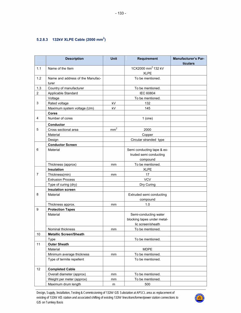
- 133 -
Design, Supply, Installation, Testing & Commissioning of 132kV GIS Substation at APSCL area as replacement of
existing of 132kV AIS station and associated shifting of existing 132kV lines/transformer/power station connections to
GIS on Turnkey Basis
5.2.8.3 132kV XLPE Cable (2000 mm2)
Description Unit Requirement Manufacturer’s Par-
ticulars
1.1 Name of the Item 1CX2000 mm2 132 kV
XLPE
1.2 Name and address of the Manufac-
turer
To be mentioned.
1.3 Country of manufacturer To be mentioned.
2 Applicable Standard IEC 60804
3
Voltage To be mentioned.
Rated voltage kV 132
Maximum system voltage (Um) kV 145
4
Cores
Number of cores 1 (one)
5
Conductor
Cross sectional area mm2 2000
Material Copper
Design Circular stranded type
6
Conductor Screen
Material Semi conducting tape & ex-
truded semi conducting
compound
Thickness (approx) mm To be mentioned.
7
Insulation XLPE
Thickness(min) mm 17
Extrusion Process VCV
Type of curing (dry) Dry Curing
8
Insulation screen
Material Extruded semi conducting
compound
Thickness approx. mm 1.0
9 Protection Tapes
Material Semi-conducting water
blocking tapes under metal-
lic screen/sheath
Nominal thickness mm To be mentioned.
10 Metallic Screen/Sheath
Type To be mentioned.
11
Outer Sheath
Material MDPE
Minimum average thickness mm To be mentioned.
Type of termite repellent To be mentioned.
12
Completed Cable
Overall diameter (approx) mm To be mentioned.
Weight per meter (approx) mm To be mentioned.
Maximum drum length m 500

- 134 -
Design, Supply, Installation, Testing & Commissioning of 132kV GIS Substation at APSCL area as replacement of
existing of 132kV AIS station and associated shifting of existing 132kV lines/transformer/power station connections to
GIS on Turnkey Basis
Description Unit Requirement Manufacturer’s
Particulars
13 Cable Drums
Overall diameter (approx) mm To be mentioned.
Width (approx) mm To be mentioned.
Weight loaded (approx) kg To be mentioned.
14 Continuous current carrying capac-
ity based on the conditions
laid in the ground.
(with detail calculation)
One circuit A To be mentioned.
Two circuit A To be mentioned.
Four circuit A To be mentioned.
Drawn into ducts A To be mentioned.
One circuit A To be mentioned.
Two circuit A To be mentioned.
Four circuit A To be mentioned.
In air A To be mentioned.
15 Permissible overload in service
conditions for a period of
2 hrs in a day
100 hrs in a month 500
hrs in total life
16
Max conductor temperature
Laid direct in ground ºC To be mentioned.
Drawn into ducts ºC To be mentioned.
Laid in air ºC To be mentioned.
17 Conductor short circuit current for
one second cable loaded as above
prior to short circuit
287 kA for 1 sec.
-do- for three second A To be mentioned.
Final conductor temperature ºC To be mentioned.
18 Sheath earth fault current carrying
capacity for three second cable
loaded as above prior to earth fault
50 kA for 1 sec
(with detail calculation).
Final metallic sheath temperature ºC To be mentioned.
19 Max. dielectric stress all the con-
ductor screen (assumed smooth)
To be mentioned.
20 Minimum radius of bend around
which cable can be laid
Laid direct 20 x overall diameter of
cable in meters
In ducts To be mentioned.
In air To be mentioned.
21 Nominal internal diameter of pipes
on ducts through which cable may
be pulled
22 Maximum DC resistance per km of
cable at 20ºC
Of conductor ohm 0.009
Of metallic layer To be mentioned.

- 135 -
Design, Supply, Installation, Testing & Commissioning of 132kV GIS Substation at APSCL area as replacement of
existing of 132kV AIS station and associated shifting of existing 132kV lines/transformer/power station connections to
GIS on Turnkey Basis
23 Maximum AC resistance per km of
cable at maximum conductor tem-
perature
ohm 0.017
Item Description Unit Requirement Manufacturer’s Par-
ticulars
24 Insulation resistance per km of ca-
ble per core
To be mentioned.
At 20ºC mega ohm. km To be mentioned.
At maximum rated temperature mega ohm. km To be mentioned.
25 Equivalent star reactance per me-
ter of 1- phase circuit at nominal
frequency
To be mentioned.
26 Maximum electrostatic capacitance
per meter of cable
To be mentioned.
27 Maximum charging current per
core per meter of cable at nominal
voltage Uo
To be mentioned.
28 Maximum dielectric loss of cable
per 3 phase circuit when laid direct
in the ground at nominal voltage
Uo, normal sequence at maximum
conductor temperature.
To be mentioned.
29 Maximum induced voltage on
metal sheath under fault condition
To be mentioned.
30 Maximum dielectric dissipation fac-
tor of charging of cable when laid
direct in the ground at nominal
voltage Uo, normal frequency at :
To be mentioned.
Conductor temperature of 20ºC To be mentioned.
Maximum conductor temperature
of 90deg. C
To be mentioned.
31 Sheath loss of cable per meter of 3
phase circuit at nominal voltage
Uo, normal frequency
To be mentioned.
32 Condition on which current carrying
capacity are based
Soil thermal resistivity ºC. m/W 1.5.
Ground temperature ºC To be mentioned.
Air temperature ºC 40
Burial depth m 1.5 meter
Axial spacing between phase ca-
bles
mm Trefoil touching
Axial spacing between circuits mm 700
Type of earth bonding system of
metallic sheath.
Solid
Overall compliance with the requirements (yes/no)

- 136 -
Design, Supply, Installation, Testing & Commissioning of 132kV GIS Substation at APSCL area as replacement of
existing of 132kV AIS station and associated shifting of existing 132kV lines/transformer/power station connections to
GIS on Turnkey Basis
5.2.8.4 Cable Sealing End
5.2.8.4.1 132 kV Outdoor Cable Sealing End
Item Description Unit Requirement Manufacturer’s
Particulars 1 Manufacturer Insert 2 Name Insert 3 Country of manufacturing Insert 4 Voltage rating kV 145 5 Current rating amp As per cable spec
6 Type
Elastomeric stress cone with
porcelain/polymeric insulator.
Insert
7 Insulator material Porcelain/Polymeric
bushing Insert
8 Pollution severity levels Heavy Insert 9 Pitch circle diameter mm Insert 10 Overall length of insulator mm Insert
11 Weight of bushing including sealingcompound
kg Insert
12 Total creepage distance of outdoor sealing end
mm 4500mm (min)
13 Total creepage distance of shed-ding
mm 450mm (approx)
14 Impulse withstand voltage (Exter-nal)
Insert
14.1 (a) Positive kV 650 14.2 (b) Negative kV 650
15 Standards
IEC 60840 IEC 60815
16 Height of steel mounting structure over the finished switchyard level
Insert
17 Rated Short-time withstand current kA/sec 50/1 18 Rated Peak Current A
Overall compliance with the requirements (yes/no)
5.2.8.4.2 132kV GIS Cable Sealing End
Item Description Unit Requirement Manufacturer’s
Particulars 1 Manufacturer name and address Insert 2 Voltage rating kV 145 3 Current rating amp As per cable 4 Type Dry/Fluid
5 Insulator material Epoxy bushing
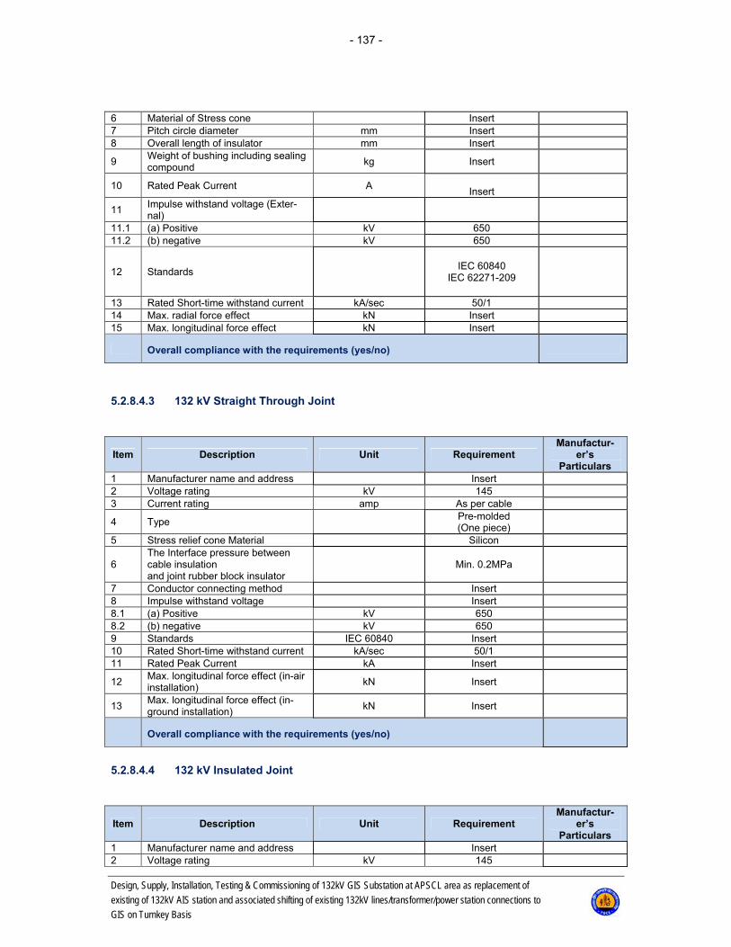
- 137 -
Design, Supply, Installation, Testing & Commissioning of 132kV GIS Substation at APSCL area as replacement of
existing of 132kV AIS station and associated shifting of existing 132kV lines/transformer/power station connections to
GIS on Turnkey Basis
6 Material of Stress cone Insert 7 Pitch circle diameter mm Insert 8 Overall length of insulator mm Insert
9 Weight of bushing including sealing compound
kg Insert
10 Rated Peak Current A
Insert
11 Impulse withstand voltage (Exter-nal)
11.1 (a) Positive kV 650 11.2 (b) negative kV 650
12 Standards
IEC 60840 IEC 62271-209
13 Rated Short-time withstand current kA/sec 50/1 14 Max. radial force effect kN Insert 15 Max. longitudinal force effect kN Insert
Overall compliance with the requirements (yes/no)
5.2.8.4.3 132 kV Straight Through Joint
Item Description Unit Requirement Manufactur-
er’s Particulars
1 Manufacturer name and address Insert 2 Voltage rating kV 145 3 Current rating amp As per cable
4 Type
Pre-molded (One piece)
5 Stress relief cone Material Silicon
6 The Interface pressure between cable insulation and joint rubber block insulator
Min. 0.2MPa
7 Conductor connecting method Insert 8 Impulse withstand voltage Insert 8.1 (a) Positive kV 650 8.2 (b) negative kV 650 9 Standards IEC 60840 Insert 10 Rated Short-time withstand current kA/sec 50/1 11 Rated Peak Current kA Insert
12 Max. longitudinal force effect (in-air installation)
kN Insert
13 Max. longitudinal force effect (in-ground installation)
kN Insert
Overall compliance with the requirements (yes/no)
5.2.8.4.4 132 kV Insulated Joint
Item Description Unit Requirement Manufactur-
er’s Particulars
1 Manufacturer name and address Insert 2 Voltage rating kV 145

- 138 -
Design, Supply, Installation, Testing & Commissioning of 132kV GIS Substation at APSCL area as replacement of
existing of 132kV AIS station and associated shifting of existing 132kV lines/transformer/power station connections to
GIS on Turnkey Basis
3 Current rating amp As per cable
4 Type
Pre-molded (One piece)
5 Stress relief cone Material Silicon
6 The Interface pressure between cable insulation and joint rubber block insulator
Min. 0.2MPa
7 Conductor connecting method Insert 8 Impulse withstand voltage Insert 8.1 (a) Positive kV 650 8.2 (b) negative kV 650 9 Standards IEC 60840 Insert 10 Rated Short-time withstand current kA/sec 50/1 11 Rated Peak Current kA Insert
12 Max. longitudinal force effect (in-air installation)
kN Insert
13 Max. longitudinal force effect (in-ground installation)
kN Insert
Overall compliance with the requirements (yes/no)
5.2.9 Optical Fibre Cable
Item Parameter Unit Requirement Manufacturer’s
Particulars
1. Optical Fibre Cable designation &
type
2. Reference standard
CCITT G652.D / IEC
793-2-B1
3. No. of Fibre 48
4. Type of fiber single mode
5. Internal fibre tube diameter mm
6. Overall diameter mm
7. Fiber Core Material Doped silica
8. Fiber Cladding Material Silica
9. Fiber Cladding Diameter 125 + 1 µm
10. Primary Coating Inner layer Mate-
rial UV curable acrylate
11. Primary Coating Outer layer Mate-
rial UV curable acrylate
12. Primary Coating Outer layer Dia-
mater
245 ± 10 µm
13. Core / cladding concentricity € error
Max. 0.8 µm
14. Cladding non-circularity Max. 1 %
15. Mode field diameter
9.0 µm ± 0.5 urn at
1310 nm
16. Identification
Color coating
17. Fiber/Tube Max. 6
18. Filling Material
Thixotropic Jelly
Compound
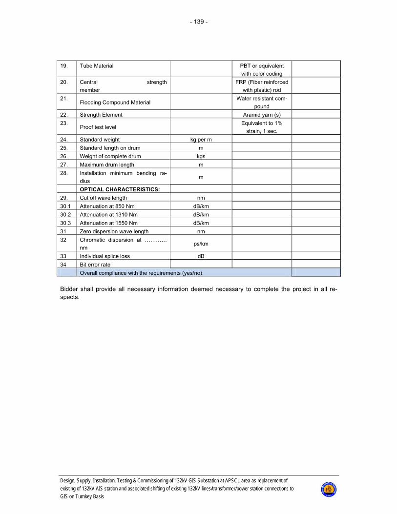
- 139 -
Design, Supply, Installation, Testing & Commissioning of 132kV GIS Substation at APSCL area as replacement of
existing of 132kV AIS station and associated shifting of existing 132kV lines/transformer/power station connections to
GIS on Turnkey Basis
19. Tube Material
PBT or equivalent
with color coding
20. Central strength
member
FRP (Fiber reinforced
with plastic) rod
21. Flooding Compound Material
Water resistant com-
pound
22. Strength Element Aramid yarn (s)
23. Proof test level
Equivalent to 1%
strain, 1 sec.
24. Standard weight kg per m
25. Standard length on drum m
26. Weight of complete drum kgs
27. Maximum drum length m
28. Installation minimum bending ra-
dius m
OPTICAL CHARACTERISTICS:
29. Cut off wave length nm
30.1 Attenuation at 850 Nm dB/km
30.2 Attenuation at 1310 Nm dB/km
30.3 Attenuation at 1550 Nm dB/km
31 Zero dispersion wave length nm
32 Chromatic dispersion at …………
nm ps/km
33 Individual splice loss dB
34 Bit error rate
Overall compliance with the requirements (yes/no)
Bidder shall provide all necessary information deemed necessary to complete the project in all re-spects.
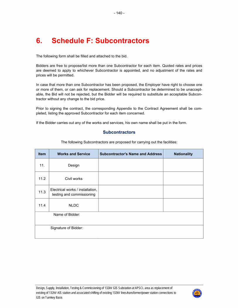
- 140 -
Design, Supply, Installation, Testing & Commissioning of 132kV GIS Substation at APSCL area as replacement of
existing of 132kV AIS station and associated shifting of existing 132kV lines/transformer/power station connections to
GIS on Turnkey Basis
6. Schedule F: Subcontractors
The following form shall be filled and attached to the bid. Bidders are free to propose/list more than one Subcontractor for each item. Quoted rates and prices are deemed to apply to whichever Subcontractor is appointed, and no adjustment of the rates and prices will be permitted. In case that more than one Subcontractor has been proposed, the Employer have right to choose one or more of them, or can ask for replacement. Should a Subcontractor be determined to be unaccept-able, the Bid will not be rejected, but the Bidder will be required to substitute an acceptable Subcon-tractor without any change to the bid price. Prior to signing the contract, the corresponding Appendix to the Contract Agreement shall be com-pleted, listing the approved Subcontractor for each item concerned. If the Bidder carries out any of the works and services, his own name shall be put in the form.
Subcontractors
The following Subcontractors are proposed for carrying out the facilities:
Item Works and Service Subcontractor's Name and Address Nationality
11. Design
11.2 Civil works
11.3 Electrical works / installation, testing and commissioning
11.4 NLDC
Name of Bidder:
Signature of Bidder:

- 141 -
Design, Supply, Installation, Testing & Commissioning of 132kV GIS Substation at APSCL area as replacement of
existing of 132kV AIS station and associated shifting of existing 132kV lines/transformer/power station connections to
GIS on Turnkey Basis
7. Schedule G: Departure from Specification (Not Applicable)
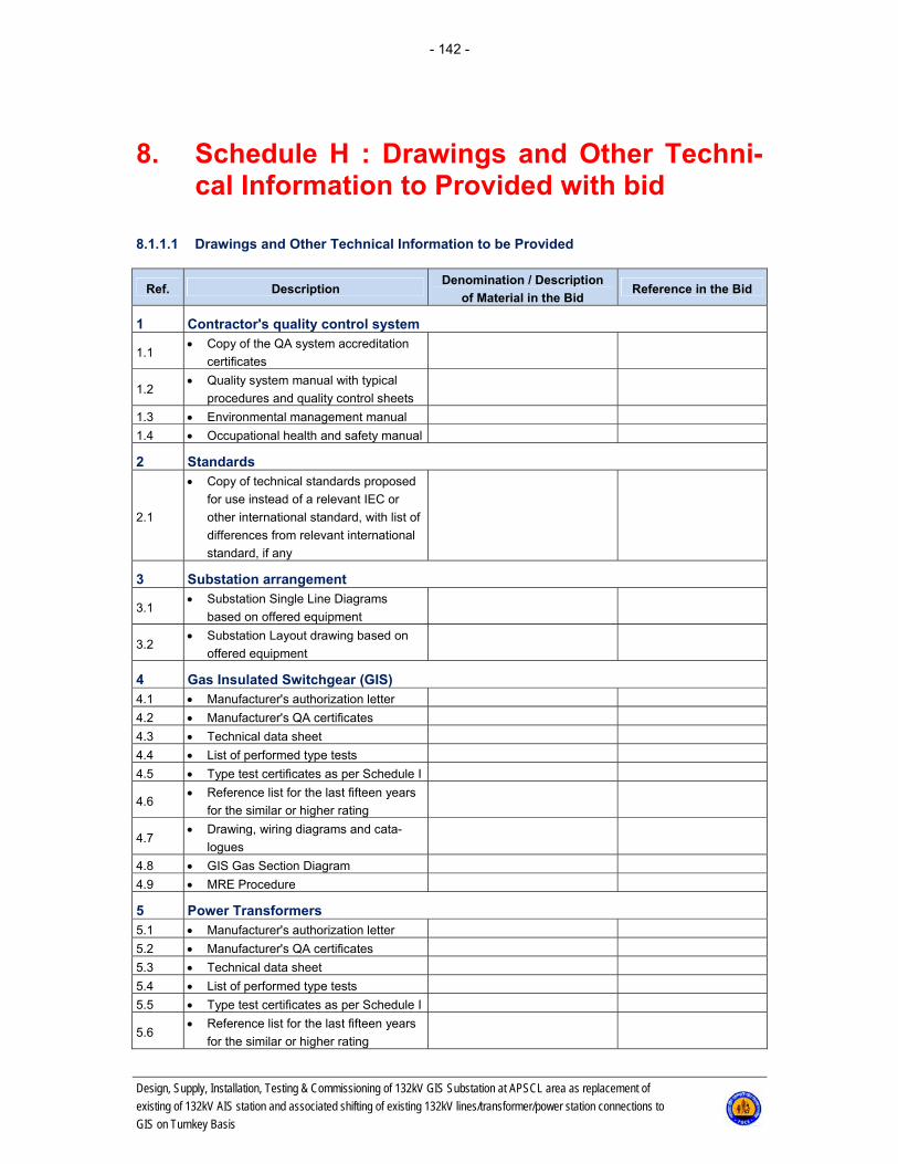
- 142 -
Design, Supply, Installation, Testing & Commissioning of 132kV GIS Substation at APSCL area as replacement of
existing of 132kV AIS station and associated shifting of existing 132kV lines/transformer/power station connections to
GIS on Turnkey Basis
8. Schedule H : Drawings and Other Techni-cal Information to Provided with bid
8.1.1.1 Drawings and Other Technical Information to be Provided
Ref. Description Denomination / Description
of Material in the Bid Reference in the Bid
1 Contractor's quality control system
1.1 Copy of the QA system accreditation
certificates
1.2 Quality system manual with typical
procedures and quality control sheets
1.3 Environmental management manual
1.4 Occupational health and safety manual
2 Standards
2.1
Copy of technical standards proposed
for use instead of a relevant IEC or
other international standard, with list of
differences from relevant international
standard, if any
3 Substation arrangement
3.1 Substation Single Line Diagrams
based on offered equipment
3.2 Substation Layout drawing based on
offered equipment
4 Gas Insulated Switchgear (GIS) 4.1 Manufacturer's authorization letter
4.2 Manufacturer's QA certificates
4.3 Technical data sheet
4.4 List of performed type tests
4.5 Type test certificates as per Schedule I
4.6 Reference list for the last fifteen years
for the similar or higher rating
4.7 Drawing, wiring diagrams and cata-
logues
4.8 GIS Gas Section Diagram
4.9 MRE Procedure
5 Power Transformers 5.1 Manufacturer's authorization letter
5.2 Manufacturer's QA certificates
5.3 Technical data sheet
5.4 List of performed type tests
5.5 Type test certificates as per Schedule I
5.6 Reference list for the last fifteen years
for the similar or higher rating

- 143 -
Design, Supply, Installation, Testing & Commissioning of 132kV GIS Substation at APSCL area as replacement of
existing of 132kV AIS station and associated shifting of existing 132kV lines/transformer/power station connections to
GIS on Turnkey Basis
Ref. Description Denomination / Description
of Material in the Bid Reference in the Bid
5.7 Drawing, wiring diagrams and cata-
logues
6 Current transformers for GIS 6.1 Manufacturer's authorization letter
6.2 Manufacturer's QA certificates
6.3 Technical data sheet
6.4 List of performed type tests
6.5 Type test certificates as per Schedule I
6.6 Reference list for the last fifteen years
for the offered type
6.7 Drawing, wiring diagrams and cata-
logues
7 GIS Voltage transformers 7.1 Manufacturer's authorization letter
7.2 Manufacturer's QA certificates
7.3 Technical data sheet
7.4 List of performed type tests
7.5 Type test certificates as per Schedule I
7.6 Reference list for the last fifteen years
for the offered type
7.7 Drawing, wiring diagrams and cata-
logues
8 GIS and AIS Surge arresters 8.1 Manufacturer's authorization letter
8.2 Manufacturer's QA certificates
8.3 Technical data sheet
8.4 List of performed type tests
8.5 Type test certificates as per Schedule I
8.6 Reference list for the last ten years for
the offered type
8.7 Drawing and catalogues
9 Control system 9.1 Manufacturer's authorization letter
9.2 Manufacturer's QA certificates
9.3 Technical data sheet
9.4 List of performed type tests
9.5 Type test certificates as per Schedule I
9.6 Reference list for the last ten years for
the offered type
9.7 Drawing, block diagrams and cata-
logues
10 Relay Protection System 10.1 Manufacturer's authorization letter
10.2 Manufacturer's QA certificates
10.3 Technical data sheet
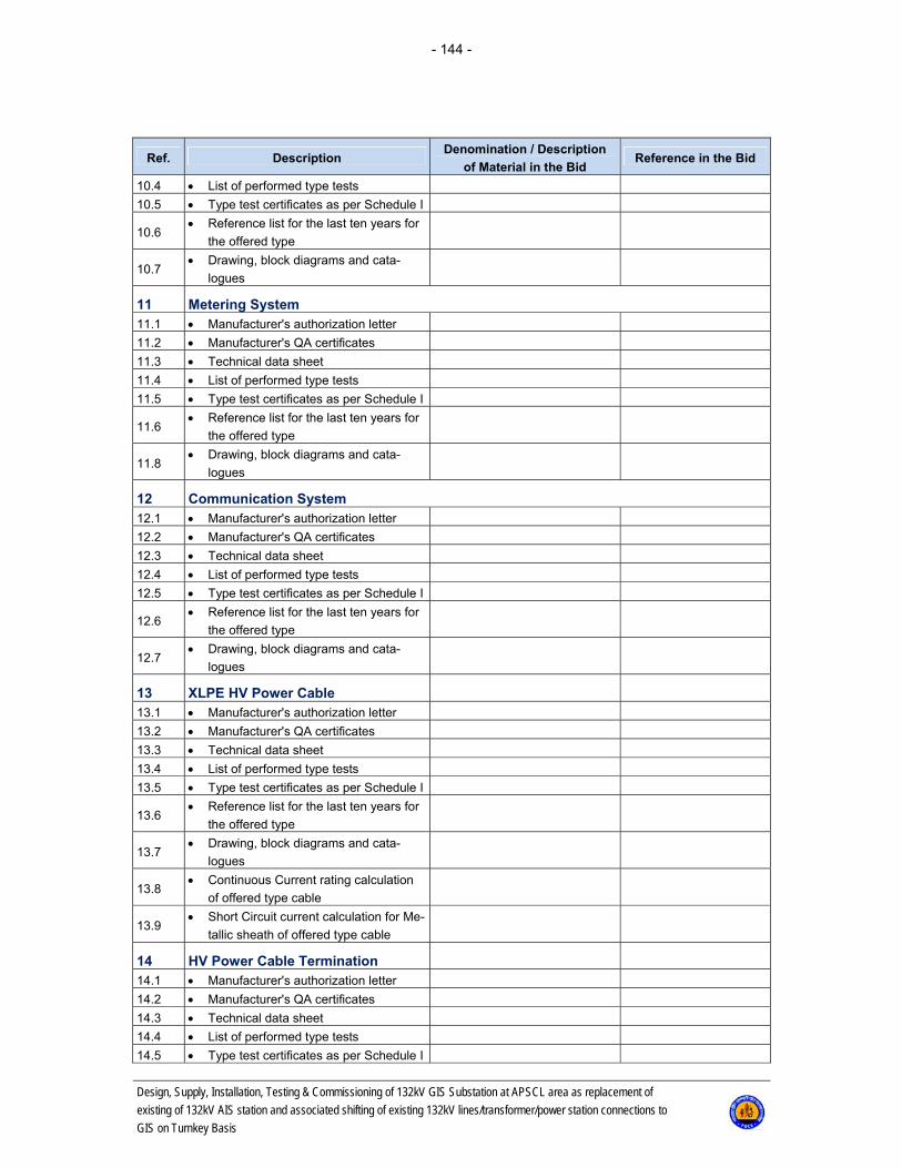
- 144 -
Design, Supply, Installation, Testing & Commissioning of 132kV GIS Substation at APSCL area as replacement of
existing of 132kV AIS station and associated shifting of existing 132kV lines/transformer/power station connections to
GIS on Turnkey Basis
Ref. Description Denomination / Description
of Material in the Bid Reference in the Bid
10.4 List of performed type tests
10.5 Type test certificates as per Schedule I
10.6 Reference list for the last ten years for
the offered type
10.7 Drawing, block diagrams and cata-
logues
11 Metering System 11.1 Manufacturer's authorization letter
11.2 Manufacturer's QA certificates
11.3 Technical data sheet
11.4 List of performed type tests
11.5 Type test certificates as per Schedule I
11.6 Reference list for the last ten years for
the offered type
11.8 Drawing, block diagrams and cata-
logues
12 Communication System 12.1 Manufacturer's authorization letter
12.2 Manufacturer's QA certificates
12.3 Technical data sheet
12.4 List of performed type tests
12.5 Type test certificates as per Schedule I
12.6 Reference list for the last ten years for
the offered type
12.7 Drawing, block diagrams and cata-
logues
13 XLPE HV Power Cable
13.1 Manufacturer's authorization letter
13.2 Manufacturer's QA certificates
13.3 Technical data sheet
13.4 List of performed type tests
13.5 Type test certificates as per Schedule I
13.6 Reference list for the last ten years for
the offered type
13.7 Drawing, block diagrams and cata-
logues
13.8 Continuous Current rating calculation
of offered type cable
13.9 Short Circuit current calculation for Me-
tallic sheath of offered type cable
14 HV Power Cable Termination
14.1 Manufacturer's authorization letter
14.2 Manufacturer's QA certificates
14.3 Technical data sheet
14.4 List of performed type tests
14.5 Type test certificates as per Schedule I
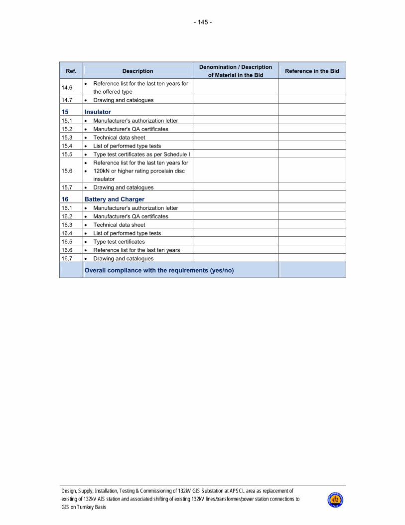
- 145 -
Design, Supply, Installation, Testing & Commissioning of 132kV GIS Substation at APSCL area as replacement of
existing of 132kV AIS station and associated shifting of existing 132kV lines/transformer/power station connections to
GIS on Turnkey Basis
Ref. Description Denomination / Description
of Material in the Bid Reference in the Bid
14.6 Reference list for the last ten years for
the offered type
14.7 Drawing and catalogues
15 Insulator
15.1 Manufacturer's authorization letter
15.2 Manufacturer's QA certificates
15.3 Technical data sheet
15.4 List of performed type tests
15.5 Type test certificates as per Schedule I
15.6
Reference list for the last ten years for
120kN or higher rating porcelain disc
insulator
15.7 Drawing and catalogues
16 Battery and Charger
16.1 Manufacturer's authorization letter
16.2 Manufacturer's QA certificates
16.3 Technical data sheet
16.4 List of performed type tests
16.5 Type test certificates
16.6 Reference list for the last ten years
16.7 Drawing and catalogues
Overall compliance with the requirements (yes/no)

- 146 -
Design, Supply, Installation, Testing & Commissioning of 132kV GIS Substation at APSCL area as replacement of
existing of 132kV AIS station and associated shifting of existing 132kV lines/transformer/power station connections to
GIS on Turnkey Basis
9. Schedule I: Type Test Requirement
Type test requirements for the major plant/equipment are as follows: • The type test certificates of the equipment of similar or higher specifications (voltage & capacity),
required by the bid shall be submitted as per relevant IEC standards. • Type test certificates for power transformer shall be issued by a STL1member testing organisa-
tion/laboratory in the manner mentioned in the STL Guides or from the Manufacturer's own testing laboratory.
• Tests carried out at the Manufacturer's own testing laboratory must have been witnessed and certi-
fied by a transformer-testing expert from a STLmember-testing organisation. • Type test certificates for GIS Equipment shall be issued by a STL1member testing organisa-
tion /laboratory in the manner mentioned in the STL Guides. • Type test certificates of surge arresters shall be issued by a STL1 Member testing organisa-
tion/laboratory in the manner as mentioned in the STL Guides. Type test certificates for other equipment shall be issued by an independent testing laboratory. Type test requirement major plant/equipment:
Following type test certificates of the equipment of similar or higher specifications (voltage & ca-pacity) required by the bid shall be submitted as per relevant IEC and shall be from any independ-ent testing laboratory except Power transformer, GIS, circuit breaker and Lightning Arrester. Type test certificates of Power Transformer, GIS and Lightning Arrester shall be issued by any one of the independent testing laboratories listed below or from manufacturer's own testing labora-tory. Test carried out at manufacturer's own testing laboratory must have been witnessed and cer-tified by a representative from the below listed independent testing laboratories. Short listed independent testing laboratories: - 1. KEMA Laboratories - DNV GL – Netherlands/USA 2. CESI – Italy 3. PEHLA Laboratory– Germany 4. CERDA– France 5. Powertech Laboratories Inc. – USA 6. Hitachi Ltd., High Voltage & High Power Testing Laboratory – Japan 7. Toshiba Corp. Hamakawasaki High Voltage and High Power Testing Laboratory – Japan 8. KERI – Korea
1 STL: Short-Circuit Testing Liaison (Refer to http://www.stl-liaison.org/web/02_About.php)

- 147 -
Design, Supply, Installation, Testing & Commissioning of 132kV GIS Substation at APSCL area as replacement of
existing of 132kV AIS station and associated shifting of existing 132kV lines/transformer/power station connections to
GIS on Turnkey Basis
(i) Power Transformer
(a) Temperature rise test.(b) Dielectric tests (Induced over voltage test, Lightning impulse voltage withstand test,
Separate source voltage withstand test).(c) Short circuit withstand test (special test) *.
* short circuit test certificates/reports shall be of minimum 220kV, 225MVA threephase inter bus Power Transformer.
(ii) GIS Switchgear(a) On one Complete Switchgear
Sl No IEC 62271-203 Clause
Test Name
i. 6.2 Dielectric tests:- Lightning impulse voltage tests
- Power-frequency voltage testsii. 6.4 Measurement of the resistance of circuitsiii. 6.5 Temperature-rise testsiv. 6.6 Short-time and peak withstand current testsv. 6.104 Pressure test on partitionsvi. 6.105 Test under conditions of arcing due to an internal
faultvii. 6.106 Insulator tests
(b) Circuit Breaker
Sl No IEC 62271-203 Clause
Test Name
ii. 6.101 Mechanical and environment al testsiii. 6.103 Test circuits for short circuit making and
breaking testsiv. 6.108 Single-phase and double-earth fault testsv. 6.109 Short-line fault testsvi. 6.110 Out-of-phase making and breaking tests
(c) Disconnector & Earthing Switch
Sl No IEC 62271-203 Clause
Test Name
ii. 6.101 Tests to prove the short-circuit making perfor-mance of earthing switches
iii. 6.102 Operating and mechanical endurance testsiv. 6.106 Bus-transfer current switching testsv. 6.107 Induced current switching tests
(d) Current Transformer
i. Short-time current tests
ii. Temperature-rise test
iii. Impulse tests on primary winding

- 148 -
Design, Supply, Installation, Testing & Commissioning of 132kV GIS Substation at APSCL area as replacement of
existing of 132kV AIS station and associated shifting of existing 132kV lines/transformer/power station connections to
GIS on Turnkey Basis
(e) Voltage Transformer
i. Temperature-rise test
ii. Lightning Impulse test
(f) Gas leakage rate (Per year)
(iii) Lightning arrester (AIS)
(a) Power frequency voltage withstands and lightning impulse voltage withstand tests oncomplete arrester housing.
(b) Operating duty test.(c) Long duration current impulse withstands test.(d) Residual voltage test.(e) Pressure relief test.(f) Artificial pollution test.
(iv) XLPE Power Cable
(a) Bending test followed by partial discharge test(b) Tan Delta measurement(c) Heating cycle voltage test(d) Partial discharge tests: At ambient temperature, and At high temperature.(e) Switching impulse voltage test(f) Lightning impulse voltage test(g) Short Circuit Capability Test
(v) Insulator
(a) Post Insulator(i) Dry lightning-impulse withstand voltage test(ii) Dry or wet switching-impulse withstand voltage tests(iii) Dry power-frequency withstand voltage test ( Indoor PI)(iv) Wet power-frequency withstand voltage test (Outdoor PI)
(b) Disk Insulator(On insulator unit)(i) Dry lightning impulse voltage withstand test;(ii) Wet power frequency voltage withstand test;(iii) Electro-mechanical failing load test;(iv) Thermal mechanical performance test;(v) Impulse voltage puncture test;(vi) Power arc test.
(vi) For Protective relays:
Type test certificates from independent reputed testing laboratory for Protective relays as perIEC 61850.
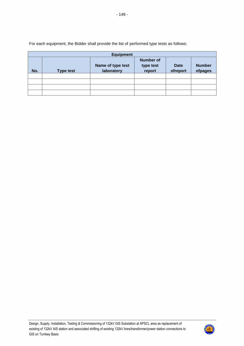
- 149 -
Design, Supply, Installation, Testing & Commissioning of 132kV GIS Substation at APSCL area as replacement of
existing of 132kV AIS station and associated shifting of existing 132kV lines/transformer/power station connections to
GIS on Turnkey Basis
For each equipment, the Bidder shall provide the list of performed type tests as follows:
Equipment
No. Type test Name of type test
laboratory
Number of type test
report Date
ofreport Number ofpages
Copyright © 2022 FDOKUMEN