Jet-Pong Coin JP100 User's Manual - Valley Dynamo Parts
87
ORIGINAL INSTRUCTIONS
-
Upload
khangminh22 -
Category
Documents
-
view
4 -
download
0
Transcript of Jet-Pong Coin JP100 User's Manual - Valley Dynamo Parts

ORIGINAL INSTRUCTIONS

Jet-Pong Coin JP100 User’s Manual
Preface

Jet-Pong Coin JP100 User’s Manual
Preface
©2022 Valley-Dynamo
All rights reserved. No Part of this work covered by the copyright hereon may be reproduced or used in any form
or by any means—graphic, electronic, or mechanical, including photocopying, recording, taping, music, video,
software or information storage and retrieval systems without express written permission of Valley-Dynamo and
Aerr Technologies.
Jet-Pong TM
is a registered trademark. Reg. No. 5,962,669 and 1,925,931
United States Patent # 7,673,877 B2
Canada Patent # 2,566,249
United States Patent Filing # 63/190,372
Jet-Pong Coin JP100 User’s Manual
Document Revision – 4.0 Date – 05/18/2022
Dear Customer,
Thank you for choosing a quality engineered Valley-Dynamo product. Jet-Pong has been built with
comprehensive quality assurance to ensure your satisfaction and trouble free use of the product.
This manual was written to assist you with Set-Up, Operation, Maintenance & Troubleshooting. Below is a list of
sales and technical support contacts.
Special thanks to Aerr-Technologies for developing the technology and to Voyager, a Canadian band for
developing much of the music.
We sincerely hope that you and your customers will enjoy playing Jet-Pong.
Valley-Dynamo
www.valley-dynamo.com
7115 Belton St.
Richland Hills, TX 76118
U.S.A.
National Sales Email: [email protected]
International Sales Email: [email protected]
Technical Assistance: [email protected]
Tech Support Hotline (during business hours Central U.S. Time): 1-972-595-5300 (follow prompts for Tech
Support)
Spare Parts: www.valley-dynamoparts.com
An Electronic Version of this manual can be found at: www.valley-dynamoparts.com

Jet-Pong Coin JP100 User’s Manual
Table of Contents
Table of Contents
Section 1 - Warranty .................................................................................................................................................1
Section 2 - Declaration of Conformity ....................................................................................................................3
Section 3 – Warnings & Notices ..............................................................................................................................5
Section 4 – Quick Set-Up .........................................................................................................................................7
Quick Set-Up: ................................................................................................................................................... 7
Test Run: ........................................................................................................................................................ 13
Section 5 – Rules of Play ...................................................................................................................................... 17
Section 6 – Routine Maintenance ........................................................................................................................ 19
Section 7 – Power Up, Configuration & Operation ............................................................................................. 25
Power Up: ....................................................................................................................................................... 25
Configuration: ................................................................................................................................................ 26
Operation: ....................................................................................................................................................... 36
Section 8 – Electrical Drawings & Replacement Parts List ............................................................................... 43
Electrical Drawings: ...................................................................................................................................... 43
Replacement Parts List: ................................................................................................................................ 66
Section 9 – Troubleshooting ................................................................................................................................ 67
Troubleshooting Screens: ............................................................................................................................ 67
Troubleshooting Symptoms & Related Drawings: ..................................................................................... 75

Jet-Pong Coin JP100 User’s Manual
Preface
1 | P a g e
Section 1 - Warranty
Valley-Dynamo warrants its new products to be free from defects resulting from faulty manufacture or
faulty components under the following terms and conditions:
WARRANTY PERIOD
90-day warranty period
WARRANTY SERVICE
Valley-Dynamo will, at its sole option, repair, upgrade or replace this product in the event of any defect in
materials or workmanship during the warranty period. This shall be Valley-Dynamo's sole obligation, and the
customer's sole remedy, for any warranty claim.
Valley-Dynamo will request that you provide the complete Model Number & Serial Number of the unit (not just the
last 5 digits), or other proof of purchase such as an invoice or receipt.
OPERATORS AND END USERS – While our Tech Support staff is available to assist with diagnosis and
troubleshooting, contact your Distributor for Warranty Service on your equipment.
DEALERS AND DISTRIBUTORS – To obtain replacement and an RMA number, contact Valley-Dynamo
referencing the Model number and Serial number of the unit and the nature of the problem. Valley-Dynamo will,
at its discretion, send replacement parts and/or issue an RMA for the return of failed parts. To avoid billing issues,
request an RMA when the failed part is present or readily available. Credit will be issued only upon receipt and
inspection of the RMA. Valley-Dynamo may send replacement parts or issue an account credit. NO REFUNDS.
Valley-Dynamo reserves the right to cancel outstanding RMAs 30 days after issue. Items returned without an
RMA will not be inspected or credited and may be refused or returned at Customer Expense.
REPLACEMENT PARTS COVERAGE – Valley-Dynamo warrants replacement parts for 90 days from the date of
purchase. To obtain a replacement and an RMA number, contact Valley-Dynamo referencing the nature of the
problem and provide proof of purchase. Valley-Dynamo will, at its discretion, send replacement parts and/or issue
an RMA for the return of failed parts. To avoid billing issues, request an RMA when the failed part is present or
readily available. Upon receipt and inspection of the RMA, Valley-Dynamo may send replacement parts or issue
an account credit. NO REFUNDS. Valley-Dynamo reserves the right to cancel outstanding RMAs 30 days after
issue. Items returned without an RMA will not be inspected or credited and may be refused or returned at the
Customer’s Expense.
SCOPE OF COVERAGE
Note that our warranty is not an unconditional guarantee for the duration. Valley-Dynamo products are made to
our exacting standards and known for their durability, but are not indestructible and may require periodic
maintenance in order to function properly.

Jet-Pong Coin JP100 User’s Manual
Preface
2 | P a g e
The following are not covered by the warranty:
1) Shipping or transport damage.
2) Normal wear and tear.
3) Damage or deterioration resulting from neglect, misuse, accident, liquid spills, improper installation, abuse,
pets, burns or mishandling.
4) Incidental or consequential damage (except at Valley-Dynamo’s discretion).
5) Removal or installation charges.
6) Shipping charges except at Valley-Dynamo’s discretion.
7) Unauthorized modification of the product.
8) Use of this product with unapproved parts, conversion kits or accessories.
9) Damage from fire, flood, lightning or other acts of nature.
EXCLUSION OF DAMAGES
Valley-Dynamo’s sole obligation and liability under this warranty is limited to the repair or replacement of a
defective product at our option. Valley-Dynamo shall not, in any event, be liable for any incidental or
consequential damages resulting from interruption of service, loss of business or revenue, or for liability in tort
relating to this product or resulting from its use or possession.
LIMITATIONS OF IMPLIED WARRANTIES
There are no other warranties, expressed or implied, including but not limited to those of merchantability, revenue
generation, or fitness for a particular purpose. The duration of implied warranties is limited to the period specified
in the Warranty Period section above.
Jet-Pong Coin JP100 User’s Manual
Declaration of Conformity
3 | P a g e
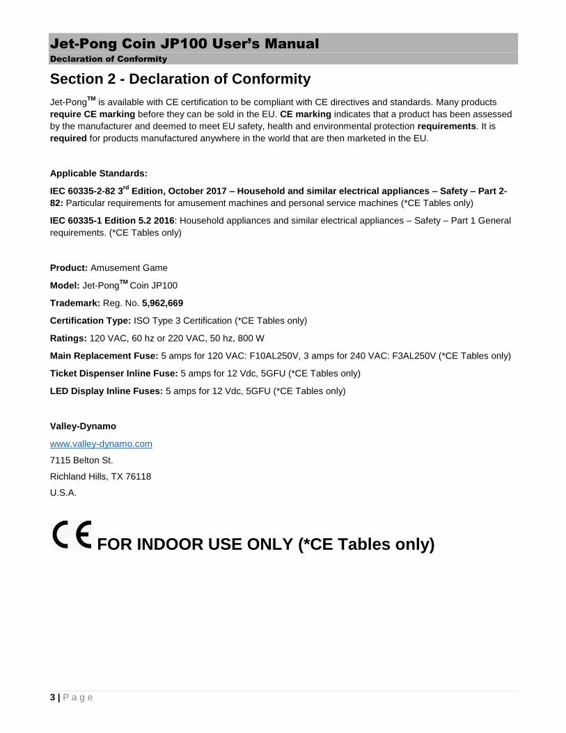
Section 2 - Declaration of Conformity
Jet-PongTM
is available with CE certification to be compliant with CE directives and standards. Many products
require CE marking before they can be sold in the EU. CE marking indicates that a product has been assessed
by the manufacturer and deemed to meet EU safety, health and environmental protection requirements. It is
required for products manufactured anywhere in the world that are then marketed in the EU.
Applicable Standards:
IEC 60335-2-82 3rd
Edition, October 2017 – Household and similar electrical appliances – Safety – Part 2-
82: Particular requirements for amusement machines and personal service machines (*CE Tables only)
IEC 60335-1 Edition 5.2 2016: Household appliances and similar electrical appliances – Safety – Part 1 General
requirements. (*CE Tables only)
Product: Amusement Game
Model: Jet-PongTM
Coin JP100
Trademark: Reg. No. 5,962,669
Certification Type: ISO Type 3 Certification (*CE Tables only)
Ratings: 120 VAC, 60 hz or 220 VAC, 50 hz, 800 W
Main Replacement Fuse: 5 amps for 120 VAC: F10AL250V, 3 amps for 240 VAC: F3AL250V (*CE Tables only)
Ticket Dispenser Inline Fuse: 5 amps for 12 Vdc, 5GFU (*CE Tables only)
LED Display Inline Fuses: 5 amps for 12 Vdc, 5GFU (*CE Tables only)
Valley-Dynamo
www.valley-dynamo.com
7115 Belton St.
Richland Hills, TX 76118
U.S.A.
FOR INDOOR USE ONLY (*CE Tables only)

Jet-Pong Coin JP100 User’s Manual
Quick Set-Up
5 | P a g e
Section 3 – Warnings & Notices
USE OF NON-VALLEY-DYNAMO PARTS OR CIRCUIT MODIFICATIONS MAY CAUSE
SERIOUS INJURY OR EQUIPMENT DAMAGE! USE ONLY GENUINE VALLEY-DYNAMO
AUTHORIZED PARTS.
For safety and reliability, substitute parts and modifications are not recommended.
Substitute parts or modifications may void FCC type acceptance.
Use only authorized components and parts. Failure to do so will void warranty and may result in incorrect and/or unsafe operation.
WARNING
Disconnect power supply before any maintenance or services.
Plug this game into a properly grounded outlet to prevent shock hazards and assure proper game operation.
Do not use an adaptor plug to defeat the power cord's grounding pin.
Do not cut off the ground pin.
Do not use the power cord if damaged.
Information in this manual is subject to change without notice. Valley-Dynamo reserves the right to make
improvements in the equipment function, design or components as engineering or manufacturing methods may
warrant.
FOR GENUINE VALLEY-DYNAMO PARTS AND SERVICE CONTACT YOUR LOCAL AUTHORIZED VALLEY-
DYNAMO DISTRIBUTOR.
PARTS CAN ALSO BE ORDERED AT: WWW.VALLEY-DYNAMOPARTS.COM
SAFE OPERATION *** CAUTION ***
Do not throw debris into the cups.
Do not spill liquids onto or into the game (use beverage holders to hold your drink).
Do not attempt to burn the ping pong balls (they are flammable).
Do not lean on the Lexan side shields.
Do not drop or place objects down the Ball Chute Exhaust.
Do not throw balls at people.
Keep eyes and face away from Ball Chute Exhaust when launching balls.
Set the speaker volume at a safe dB level.
Do not set objects down on the table.
Properly insert the Prop Stick when lifting the table Lid. (*CE Tables only)
Turn off the On/Off switch at the rear and unplug the power cord before replacing any components.

6 | P a g e
Jet-Pong can be used by children aged 8 years and above and persons with reduced physical, sensory or mental capabilities or lack of experience and knowledge with proper supervision and instruction.
Children under the age of 8 shall not play with the appliance.
Cleaning and user maintenance shall not be performed by children without supervision.
Do not clean any parts of the game by waterjet.
FORESEEABLE MISUSE
Do not throw debris into the cups. This will create jams possibly requiring a technician to troubleshoot the jam while power is on and the lid open.
Do not drop or place objects down the Ball Chute Exhaust. This will create jams possibly requiring a technician to troubleshoot the jam while power is on and the lid open.
Do not spill liquids onto or into the game (use beverage holders to hold your drink). This could potentially cause an electrical hazard.
Keep eyes and face away from Ball Chute Exhaust when launching balls. This could cause bodily injury.
Do not set objects down on the table. A spill could potentially cause an electrical hazard.
Make use of the Prop Stick when lifting the table Lid. The Prop Stick will protect you in case of hydraulic cylinder failure. (*CE Tables only)

7 | P a g e
Section 4 – Quick Set-Up
Quick Set-Up:
Note: This section can be performed by children aged 8 years and above and persons with reduced physical, sensory or mental capabilities or lack of experience and knowledge with proper supervision and instruction.
1) Remove all packaging.
CAUTION: Watch for sharp nails, staples, screws, etc.
2) Get assistance to manually lift the game onto the floor and in location. Adjust levelers to insure the table
is level. Level the cabinet so that it is leaning 2 degrees towards the players. This will allow balls on the
game top to roll back to the players.
CAUTION: Do not use a lift truck to lift under the table sides. You may destroy the LED
lights and T-Molding.
3) Remove the Coin Door key from the Coin Return and unlock the Coin Door. Remove Accessory Bag
inside Cash Box.

8 | P a g e
4) Remove the Triangle Cup Tray Assembly, Black Ball Return shelf, Power cord and Ball Shield from the
inside of the cabinet and set aside.
5) Mount the Back Box Marquee on the rear of the cabinet, using (6) 3/8” x 2 ½” Steel Dowels, (2) Mending
Plates, and (4) 3/8-16 x ¾” Hex Head Bolts. Be careful not to crimp the Led Strips inside the T-Molding.
Please notice the Clearance Notches on the cabinet for safe routing of the LED Strips.
CAUTION: Make sure all bolts are installed and secure.

9 | P a g e
6) Connect the 12Vdc Power and HDMI Cable into the back of the monitor.
7) Connect the LED Strips to the Led Strip Cables connected to the SP901E Video Controller. Make sure
they run through the black raceway and then close the tray covers.
8) Place the black Ball Return shelf in place so that the grey ribbon cable and 12Vdc cable (black & yellow)
remain on top of the shelf. Secure the shelf using screw provided on the Shelf. It will align with a pre-
drilled hole in the support cleat.
9) Connect the grey ribbon cable and 12Vdc cable to the Triangle Cup Tray Assembly. Make certain the
connector has locked into place. Place the Triangle Cup Tray Assembly on top of the (3) Black stand-
offs. Reach under the tray to feed the excess cables down through the black wire way so they don’t
interfere with rolling balls.

10 | P a g e
CAUTION: Place the excess ribbon and 12 Vdc cable down the black plastic pipe so it
doesn’t interfere with the balls.
10) Insert the (10) Red Solo Cups into the Cup Holders without breaking or loosening the Cup Holder
Fingers. The Cup Holder fingers reduce the amount of time a ball spins inside the cup.
11) Connect the 12Vdc Back Box Marquee power supply cable at the top back and push the connector into
the top hole.

11 | P a g e
12) Connect the 110Vac power cable into the rear of the cabinet and into a wall plug rated for at least 5
amps. Notice the fuse holder beside the On/Off switch.
CAUTION: For locations using 220V, the (2) Power Supplies inside the cabinet must be
switched to 220V, before making the wall connection.
13) Turn on the Power On switch at the rear of the game and observe that all lights and displays turn on.
14) Open the front left service door and press the Service Button. This will provide you with service screens
on the HMI. These screens help you configure your game and test that everything is working. Please
refer to Section 7 and 9 for more details on how to configure and troubleshoot.
15) Once configured, insert coins or bills (if equipped) to play your first game. See “Test Run” instructions
below. If you don’t have any coins you can press the Service Button and then Free Play on the HMI
Touch Screen to play. Alternatively there is a white wire jumper that can be inserted in the Processor
Carrier Board inside the game.

12 | P a g e
16) Once everything is working install the Ball Shield by removing the Protective Film and inserting it into
the rear slot near the cups.
17) Remove the Protective Coating from the Side Shields. Using a 4mm or 5/32” hex Allen-key install the
Side Shields using the screws provided in the Cash Box. Do not overtighten.
Note: There are extra balls and cups in the game should you need them in the future. There is also a
remote control for the LED strips in the T-Molding. You can place your advertising on the D15 USB stick
provided and then insert it into the D15.
The game comes preloaded with 30 Ping Pong balls. You should see the last ball in the clear pipe
exposed at the exit of the metal Inlet Trough. It is important that you don’t overfill the pipe past this
location otherwise you run the risk of jams.

13 | P a g e
Set-up Parts Listing
Part Number Description Quantity per
Game
NI20300890 1/2-13 LEG LEVELER HEX NUT 4
JP-20510030 16 OZ RED SOLO CUP - STANDARD DISPOSABLE 20
JP-21710170 40mm PING PONG BALL 50
20515140 C/T LEG LEVELER 4
NI870007405 CORNER CASTING BOLT 3/8-16 x 3/4" 8
JP-20100130 DEC HEAD BOLT, 1/4-20 X .984 16
JP-20600060 MENDING PLATE 2
20606760 STEEL DOWEL 3/8X2 1/2" 6
Test Run:
1) Wait for the game to power up.
2) Jet-Pong is preconfigured to accept 4 quarters or 1 dollar bill for each player to play from Sun-Thurs. On
Fri-Sat it is 5 quarters or 1 dollar bill + 1 quarter. NOTE: Refer to Section 7 for details on how to change
this. Insert quarters or bills to begin playing with 2 players (Home Green on the left, Away Red on the
right).
3) Press the flashing Green Pushbutton to Start Game.

14 | P a g e
4) Grab the ball in the air when it launches.
5) Throw the ball into one of the Red Solo cups lit up by the Green LEDs.
6) The Green LEDs under this cup should go out, cheering should occur and the rear Video Display should
show a message for example GOAL!!! The rear Video Display and the HMI Touch Screen will then
display which cup was made.

15 | P a g e
7) Repeat steps 3-6 above for the Red Pushbutton.
8) Repeat above until the game is finished. Each player gets 10 balls.

Jet-Pong Coin JP100 User’s Manual
Rules of Play
17 | P a g e
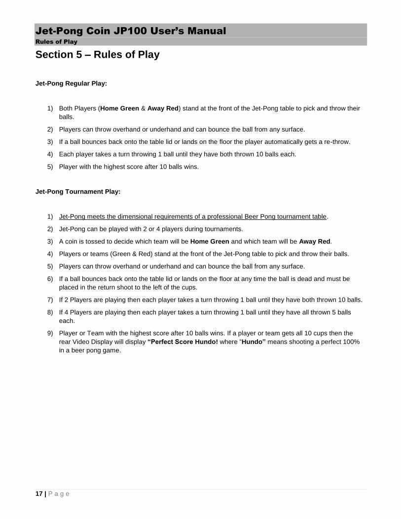
Section 5 – Rules of Play
Jet-Pong Regular Play:
1) Both Players (Home Green & Away Red) stand at the front of the Jet-Pong table to pick and throw their
balls.
2) Players can throw overhand or underhand and can bounce the ball from any surface.
3) If a ball bounces back onto the table lid or lands on the floor the player automatically gets a re-throw.
4) Each player takes a turn throwing 1 ball until they have both thrown 10 balls each.
5) Player with the highest score after 10 balls wins.
Jet-Pong Tournament Play:
1) Jet-Pong meets the dimensional requirements of a professional Beer Pong tournament table.
2) Jet-Pong can be played with 2 or 4 players during tournaments.
3) A coin is tossed to decide which team will be Home Green and which team will be Away Red.
4) Players or teams (Green & Red) stand at the front of the Jet-Pong table to pick and throw their balls.
5) Players can throw overhand or underhand and can bounce the ball from any surface.
6) If a ball bounces back onto the table lid or lands on the floor at any time the ball is dead and must be
placed in the return shoot to the left of the cups.
7) If 2 Players are playing then each player takes a turn throwing 1 ball until they have both thrown 10 balls.
8) If 4 Players are playing then each player takes a turn throwing 1 ball until they have all thrown 5 balls
each.
9) Player or Team with the highest score after 10 balls wins. If a player or team gets all 10 cups then the
rear Video Display will display “Perfect Score Hundo! where “Hundo” means shooting a perfect 100%
in a beer pong game.


19 | P a g e
Section 6 – Routine Maintenance
Note: This section can be performed by children aged 8 years and above and persons with reduced physical, sensory or mental capabilities or lack of experience and knowledge with proper supervision and instruction.
Cleaning:
CAUTION: Please remove power by turning the ON/OFF switch at the rear to the OFF position and unplug the power cord before cleaning.
Use Windex or similar cleaner to wipe down the entire table where needed. This includes the HMI (Human
Machine Interface) Touch screen, Video Display, Table Lid LED Plastic cover, Beverage Holders, Push-Button
Lights, Side Shields, Table Graphics, Coin/Bill Acceptor, Ticket Dispenser, the black Ball Return floor under the
Triangle Cup Assembly, etc.
Cup Inspection:
Inspect Red Solo cups for any hair line fractures, dents, etc. Replace cups where necessary.
Cup Finger Inspection:
Inspect Cup Fingers for damage or loss. Repair where needed. You can order more from Valley-Dynamo if
required. The purpose of these fingers is to reduce the amount of spinning when the ball enters the cup thus
speeding up the game.
Ball Inspection:
CAUTION: Please remove power by turning the ON/OFF switch at the rear to the OFF position and unplug the power cord before lifting the Table Lid unless you absolutely must have power on for viewing balls in “Free Play” or “Auto Cycle”. Properly insert the Prop Stick (*CE tables only) when lifting the table Lid.
Using the key in the Accessories Bag, unlock and open the Table Lid. If any of the balls look damaged then place
the game into “Free Play” mode (refer to Section 7) and press buttons until the damaged ball(s) surfaces through
the Ball Exhaust Chute. You may also want to consider cleaning each ball before placing them back in the game.

20 | P a g e
Ball Return Inspection:
CAUTION: Please remove power by turning the ON/OFF switch at the rear to the OFF position and unplug the power cord before lifting the Table Lid unless you absolutely must have power on for viewing balls in “Free Play” or “Auto Cycle”. Properly insert the Prop Stick (*CE tables only) when lifting the table Lid.
Inspect the underside of the Triangle Cup Assembly to make sure no balls are trapped and that no debris is
stopping the balls from rolling down into the metal Inlet Trough chute. Inspect the chute for any debris as well.
Search for any debris that may be lodged in the Ball Return piping. If debris is found you can try to place the
game into “Free Play” mode and press buttons until the debris works itself down to the wire frame Solenoid
Trough. If this does not work you may have to disconnect the piping or blow it clean using a vacuum cleaner
blower. “Auto Cycle” mode is also another option for cleaning out balls.
LED Inspection & Remote Controller Battery Replacement:
CAUTION: This procedure requires the power to be on during inspection.
Inspect all LED lights to make sure they are all working. The LED lighting in the T-Molding is controlled by the
remote controller in the Accessory Bag. You can press various buttons to select the color or speed of these LEDs.
Note that there is a battery in the remote controller (CR2025 Lithium Battery 3V) that may need replacing every
few years. If you find an LED strip that is not working refer to Section 9 – Troubleshooting for details.
The LED lights under the Triangle Cup Assembly can be turned on using the Troubleshooting screen on the
HMI Touch Screen. Refer to Section 9 – Troubleshooting for details.
The LED lights on the Table Lid under the black plastic can be inspected for any LED lights that are not working.
If you find an LED that is not working refer to Section 9 – Troubleshooting for details.
Inspect the LED lights in the Beverage Holders and around the Ball Exhaust Chute to make sure they are all on. If
you find an LED that is not working refer to Section 9 – Troubleshooting for details.
Inspect the LED Lights inside the speakers to make sure they both work. If you find a set that is not working refer
to Section 9 – Troubleshooting for details.

21 | P a g e
Pushbutton Inspection:
CAUTION: This procedure requires the power to be on and the lid closed during inspection.
The Pushbutton lights and switches on the Control Panel Console can be tested using the Troubleshooting
screen on the HMI Touch Screen. Refer to Section 9 – Troubleshooting for details. Open the Ticket Dispenser
door and press the Service Button to make sure the HMI Touch Screen changes accordingly.
Sensor Inspection:
CAUTION: This procedure requires the power to be on and the lid closed during inspection.
The ball sensors under the Triangle Cup Assembly can be tested using the Troubleshooting screen on the HMI
Touch Screen. Refer to Section 9 – Troubleshooting for details.
Ticket Dispenser Inspection:
CAUTION: This procedure requires the power to be on and the lid closed during inspection.
The ticket dispenser can be tested using the Troubleshooting screen on the HMI Touch Screen. Refer to Section
9 – Troubleshooting for details. There is a button on the side of the Ticket Dispenser to manually feed tickets.
Try pressing this button to make sure tickets feed properly.
Coin Mech & Bill Acceptor Inspection:
CAUTION: This procedure requires the power to be on and the lid closed during inspection.
The coin mech and bill acceptor can be tested using the Troubleshooting screen on the HMI Touch Screen. Refer
to Section 9 – Troubleshooting for details. Check the Coin Mech light to make sure it is not burned out. Inspect
the mechanical mechanisms on both the Coin Mech and Bill Acceptor for any major wear or jamming issues.
Blower Fan Inspection:
CAUTION: This procedure requires the power to be on and the lid closed during inspection.
The blower fan can be tested using the Troubleshooting screen on the HMI Touch Screen. Refer to Section 9 –
Troubleshooting for details.

22 | P a g e
Solenoid Inspection:
CAUTION: This procedure requires the power to be on and the lid opened during inspection.
Solenoids can be tested using the Troubleshooting screen on the HMI Touch Screen. Refer to Section 9 –
Troubleshooting for details. NOTE: these have to be tested one at a time. Make sure that the Solenoid springs
are not compressed when the solenoids are in the Off state. Over time these springs may compress not allowing
them to pull back to the Off position fully. If this is the case then you must replace the springs.
Exhaust Chute Inspection:
CAUTION: This procedure requires the power to be on and the lid opened during inspection.
Make sure there is no debris in the Exhaust Chute. Make sure that balls can just slightly pass by the Speed
Reducer screw located near the exit. If this screw is too tight then balls will not slow down and will fly out of the
chute. If too loose, balls will get stuck. Refer to Section 9 – Troubleshooting for details. Tighten the 2 lower
Solenoid Trough screws on the Exhaust Chute above the Blower Fan:
Table Lid Supports Inspection:
CAUTION: This procedure requires the power to be on and the lid opened during inspection.
Make sure there is nothing restricting the Table Lid Supports. Make sure all lid support screws are secure. If the
table lid is having trouble staying open then please order new supports from Valley-Dynamo.

23 | P a g e
Blower Fan Inspection:
CAUTION: This procedure requires the power to be on and the lid closed during inspection.
Using the Troubleshooting screen on the HMI Touch Screen, turn on and off the Blower Fan manually to make
sure it functions correctly. Make sure the capacitor on the 2 pin power connector is secure. Refer to Section 9 –
Troubleshooting for details. The capacitor filters any electrical noise generated by the fan.
Wiring Inspection:
CAUTION: This procedure requires the power to be off and the lid opened during inspection.
Inspect all wiring for burn marks, melting, loose connections, etc. Over time, screws on the power supplies that
hold down wiring will loosen. It is recommended that all of these screw terminals get tightened periodically.
Music, Cheers, Videos & Ads Inspection:
CAUTION: This procedure requires the power to be on and the lid closed during inspection.
Using the Troubleshooting screen on the HMI Touch Screen you can test each of 8 songs, cheers, goal videos
and advertising. Refer to Section 9 – Troubleshooting for details.
Overall System Check:
CAUTION: This procedure requires the power to be on and the lid opened during inspection.
By placing the game in “Auto Cycle” you can have the game automatically cycle 10 balls Green and 10 balls
Red. You will need to place these balls in a box and when the automatic cycle ends place the balls in the Inlet
Trough near the cups. This is a good way to test many things at the same time such as lights, solenoids, fan,
LEDs, music, videos, etc. Refer to Section 9 – Troubleshooting for details.


25 | P a g e
Section 7 – Power Up, Configuration & Operation
Power Up:
CAUTION: Lid shall be kept closed during power up.
Turn power on the game by pressing the toggle switch at the rear of the table. The LED indicator on the toggle
switch should turn on.
The following devices should power up: T-Molding LED Lights, Beverage Holder LEDs, Ball Exhaust Chute LEDs,
Table Lid LED Matrix, HMI (Human Machine Interface) Touch Screen, rear Video Scoreboard Display, Triangle
Cup Assembly LEDs, etc.
The HMI and rear Video Scoreboard Display will initially display the Jet-Pong logo screen.
Once power up is complete the HMI will display the FINAL SCORE screen.
Note: Recycling power is a good way to reset the game.

26 | P a g e
Configuration:
The HMI Touch Screen allows the owner to configure the game using a “Configuration” screen. Open the Ticket
Dispenser Door and press the “Service” button.
The “Configuration” screen will display like this on the HMI Touch Screen:

27 | P a g e
Hour/Day/Month/Year: This allows you to adjust these for your time zone. Simply touch the number you want to
change and use the pop-up keypad to enter the new number and then press Enter. You will notice in the top left a
Minimum and Maximum range for each number. If the date is not being saved after a power failure, then it’s time
to replace the battery on the Main Processor. (5-year life expectancy) Refer to Section 8 – Spare Parts List.
# of Green Games or Red Games: These fields keep track of the total # of games that each side has played.
(Maximum of 32,767) You can reset these counters by pressing the “Reset” buttons. Note: There is also a
physical counter near the coin tray that is non-resettable. It is the sum total of all single and two player games.
Music Before Game: Pressing this button will turn green and allow music to play before a game. There are a
total of 8 tunes that cycle one after the other. These files reside on a microSD card on the sound module.
Music During Game: Pressing this button will turn green and allow music to play during a game. When a goal is
scored a Cheer will interupt the song. If this is set to off (red) the Cheers will still play when a goal is scored.
Max Game Time: This is the maximum time that a game can last. Once this time is reached the game will end.
Shot Clock: This is the amount of time allowed before a pushbutton is enabled and flashes again. Note that this
value gets reset to 0 whenever a cup is made.

28 | P a g e
Last Shot: This is the amount of time allowed on a player’s very last shot (ball #10). This gets added to the Shot
Clock time on the HMI and rear Scoreboard Video Display.
Green Tickets Enabled: Pressing this button will turn green and will enable the left Green Ticket dispenser and
all of its associated HMI screens.
Red Tickets Enabled: Pressing this button will turn green and will enable the right Red Ticket dispenser and all
of its associated HMI screens.
# of Tickets to Dispense Based on Score: You can enter a number from 0.0 to 9.9 in these fields by pressing
the field and entering in your number. If you were to enter 2.5 for Winner and 1 for Loser and the final score was
Green 7 and Red 2 then 7 x 2.5 = 17.5 (18 rounded up) tickets would dispense for Green and 2 tickets for Red. If
both ticket dispensers are enabled and wired then 18 tickets would dispense from the Green Ticket Dispenser
and 2 tickets would dispense from the Red Ticket Dispenser. If only 1 Ticket Dispenser is enabled and wired then
18 + 2 tickets would dispense from the 1 Ticket Dispenser. A screen will display after the game is over to let both
players know how many tickets they each won. As the tickets are being dispensed the counter beside these
numbers increment.
# of Tickets For a Perfect Score of 10: You can enter a number from 0-99 in this field by pressing the field and
entering in your number. Since a perfect score is so hard to get, it should be rewarded with even more tickets.
GAME MASTER RESET: This button does the same thing as recycling power.
FREE PLAY: This button allows players to play for free once you “Return to Main Screen”. After a game is over
the score is reset and a new game will begin. Another way to achieve this is to install the white “Free Play”
jumper into the processor Carrier Board:

29 | P a g e
# of Credits for 1 Person to Play: You can enter a number from 1-20 in this field by pressing the field and
entering in your number. If you were to enter 7 then both players would each need to insert 7 coins for a total of
14 coins. If the coins are quarters then this would equate to $1.75/player. NOTE: If someone wishes to play by
themselves they would simply insert 7 coins and then press the flashing Green pushbutton to get started. If a
second player comes along after Green has started and inserts 7 coins then Red can join in. Both Green and Red
will still only get 10 balls each to throw.
The bill accepter has dip switch settings on it that are set to send 4 credits (pulses) when $1 is inserted.
# of Credits for 1 Person Fri/Sat: If you want to charge more on a busy Friday or Saturday you can enter a
different # of credits for these days. The game uses an internal clock/calendar to monitor the day of the week.
Make sure the Hour/Day/Month/Year is displaying correctly.
No Activity Reset Time: If there is no activity such as pressing buttons, sensing balls or entering coins the game
will time out and reset after this amount of time.
Troubleshooting Screens: If you need to perform troubleshooting simply press the “Troubleshooting
Screens” button.
Return to Main Screen: If you are finished you can simply press “Return to Main Screen” to display the game
status. NOTE: To return to “Configuration” screen you would need to press the “Service” button again.
Music & Cheers: Jet-Pong comes preloaded with music and cheers on a MicroSD card mounted on a Blue
Sound Module located on the main processor Carrier board. There are 8 music files and 8 Cheers. These are
.mp3 files. Technically you could load your own 8 songs and 8 cheers but you would have to make sure you own
the music licenses for each.
Bluetooth Audio: If you don’t want to hear any music or cheers from the game at all you can Bluetooth music to
the game from your computer or phone by moving the audio cable from the blue Sound Module on the PLC
Carrier board to the input of the Bluetooth device mounted to the Audio Amplifier. Then simply synch your phone
in Bluetooth settings to the KN320 device.

30 | P a g e
Videos & Ads on Rear Scoreboard Display: Jet-Pong has videos & ads that display on the rear Scoreboard. 8
Ads can be added using software if you have an EA9 or with a USB stick if you have an mTV-100.
Videos:
Sample Ads:
EA9 Procedure:
You will need to unlock the table lid using the key provided in the Accessories Bag and then lift the lid up. The
EA9 is located towards the back on the left hand-side. Read the label to make sure it is an EA9 and not an MTV-
100. You will need a windows laptop with wifi or an ethernet cable to plug in direct. You can use the HMI Touch
Screen ethernet cable temporarily if you don’t have a cable. If you’re not going to use wifi then plug the ethernet
cable into your laptop with the other end into the wireless router.
Download, Unzip and install the EA9 “C-More” Software onto your laptop from this link:
https://www.dropbox.com/sh/eg0gbmeqml709rj/AABoYPJGFO-mic2-Kq1ZuBRra?dl=0
Download the EA9 program located in the “Jet-Pong EA9 Program Folder” at this link:
https://www.dropbox.com/sh/yn3trl3v6yufkir/AAA72K8qQZa8F8EXwyP5JH2La?dl=0

31 | P a g e
If you wish to continue using the Jet-Pong Logo then you will also need to download “Jet-Pong Logo.bmp” onto
your laptop.
Click your Wifi Settings icon and click WIFI-5G-###### for your Jet-Pong Wireless Router. Each Jet-Pong
Wireless Router will have a unique 6 digit #.
Double click the “Jet-Pong EA9 Program” on your laptop once it’s downloaded.
On the Screen Navigation window at the left center, scroll down to Screen 21. You will find a Jet-Pong Logo.bmp
on this screen. Click the screen. You will see Screen 21 appear on the right hand side. Click the Jet-Pong Logo to
see green handles around it:

32 | P a g e
Press the Delete key on your keyboard. This will delete the Jet-Pong logo on Screen 21. Now along the top, press
“Object”, “Bitmap”, “Static Bitmap”. Your pointer is now a +. Select the top left corner of the page that the logo
was on and swipe down to the lower right. The Static Bitmap General tab should appear:
Click Read from … Disk and locate your bitmap files on your computer. They will need to be 1280 x 720 p. Click
the file you want to use. Click Shrink to get the image to fit in this window. Then click “Ok”.
Repeat this for Screens 22-28.
Then press “Send”
Then click Ethernet.
Then press Browse.

33 | P a g e
Select the network that will find 192.168.1.207 EA9-RHMI
Press OK. Then press Transfer.
Once your program transfers you should see each of your images display on the rear Video Display. You may
need to adjust colors and sizes of your images and then reinsert them on the appropriate screen # to get them to
display the way you want.
If you can’t get your wifi connection to work you can use a physical connection per the following:
Set the ethernet port on your laptop to 192. 168. 1.50 with a subnet mask of 255.255.255.0. How you set this will
depend on which version of Windows you are using. If you’re not familiar with this you can Google search “How
to set the address on your ethernet port” for more details.
In Windows 10:
1) Open Settings
2) Click on Network & Internet
3) Click on Ethernet.
4) Click on the current network connection.
5) Under the “IP Settings” section, click the Edit button.
6) Using the drop-down menu, select the Manual option.
7) Turn on the IPv4 toggle switch.
8) Make a note of your current settings so when you’re done you can return to these settings. Taking a screen
shot with your phone may be helpful.
9) Set the IP address to 192.168.1.50 with a subnet mask of 255.255.255.0.

34 | P a g e
In other Windows 7 or 8:
1) Click Start menu.
2) Type Network and Sharing Center in search field.
3) Click Local Area Connection.
4) Click Properties.
5) Double click Internet Protocol Version 4 (TCP/IPv4).
6) Select “Using the following IP Address” bullet.
7) Make a note of your current settings so when you’re done you can return to these settings. Taking a screen
shot with your phone may be helpful.
8) Type in IP address: 192.168.1.50
9) Type in Subnet mask: 255.255.255.0
10) Click “Ok”. Click “Ok”. Click “Close”.
Now try to Transfer your program. Once you complete your download you can set your IP address on your laptop
back to its old settings.
mTV-100 Procedure:
Turn the power off on the game. Lift the lid and towards the back left there is a module that is labeled mTV-100
with a USB stick plugged in it. Remove the USB stick from the mTV-100. Install it in your computer’s USB port.
Place your photos into each of these 8 folders. They must be 1280 x 720 p. Remove the USB Stick from the
computer and install it back into the USB port on the mTV-100. Power up the game. Your ads should display on
the rear Scoreboard Video Display when the game is not being played.
D15 LED Table Lid Display Advertising Loading Procedure:
Jet-Pong has videos & photo advertisements that can display on the Table Lid using the D15 LED Controller
microprocessor located under the table lid. The D15 comes preloaded with these files. If you want to customize
your own ads, you can simply load and play them from a USB stick. They must be 240 x 120 p. Check the bag of
components that came with your table for this USB stick labeled D15.

35 | P a g e
Insert the D15 USB stick into your laptop. You should see the following files on the stick:
Video labeled “1” above will play for a few seconds, then the photo ad “1_Sample_Ad1”, then the video labeled
“2”, etc. After the last photo ad “7_Sample_Ad7” finishes it will repeat the cycle and so video “1” will play.
Simply replace any video or photo files you like using the same names so that they will play in the same order.
Load your video ads (.mP4 files) and photo ads (.jpg images) onto the USB Stick. Remove the USB Stick from
your computer and install it into the USB port on the D15. You do not need to power down the D15 for this. Your
ads should display on the Table Lid Display within a few seconds. Check them all to make sure you are happy
with the way they are displaying. You may need to edit these for color or resolution.
T-Molding LED Lights: The LED lighting in the T-Molding is controlled by the remote controller in the Accessory
Bag. You can press various buttons to select the color or speed of these LEDs. Note that there is a battery in the
remote controller (CR2025 Lithium Battery 3V) that may need replacing every few years. If you find an LED strip
that is not working refer to Section 9 – Troubleshooting for details.

36 | P a g e
Operation:
1) Jet-Pong is preconfigured to accept 4 quarters or 1 dollar bill for each player to play. NOTE: Refer to
Configuration on previous pages for details on how to change this.
2) Insert 8 quarters or 2 x $1 bills to begin playing with 2 players (Green on the left, Red on the right). A
Credit screen displays the number of credits required and paid by each player.
Any credits paid beyond the required amount get added to the Extra Credits field.
The Green player presses the flashing Green Pushbutton to start the game.
If someone wishes to play by themselves they would simply insert the number of credits required and
then press the flashing Green pushbutton to get started. If a second player comes along after Green has

37 | P a g e
already started and inserts the required number of credits then Red can join in. Both Green and Red will
still only get 10 balls each to throw. If there are enough Extra Credits after a game then a new game will
start.
3) Once the Green button is pressed the following screen will display on the HMI:
The following screen displays on the rear Video Display. The SHOT CLOCK will time down.
4) The Green player grabs the ball that is floating in the air after it exits the Ball Exhaust Chute and throws
the ball overhand or underhand into one of the cups lit up by the Green LEDs. They can bounce the ball

38 | P a g e
off any surface if they wish. If a ball bounces back onto the table lid or lands on the floor the player
automatically gets a re-throw. Note that the table should be leveled to 2 degrees to allow balls to roll
towards the players.
5) If a cup is made the Green LEDs under that cup will turn off, cheering will occur, the rear Video Display
will show a goal scored image, HMI will display which cup was made and will increment Green’s score.
The HMI Touch Screen will also indicate how many balls are left to throw and a Shot Clock.
The rear Video Display will then show a similar screen to the HMI indicating what cups have been made,
number of balls left, the score and a Shot Clock.
6) The Red player can now press the flashing Red pushbutton and the cycle repeats until both players have
thrown 10 balls each. Note: If the players stop playing for X minutes (Adjustable from the Configuration
Screen) it is assumed they have abandoned the game and it will automatically reset clearing any past
credits inserted in the game. Pressing the Game Reset on the Configuration Screen of the HMI or
recycling power on the game will perform the same function.

39 | P a g e
7) Both players repeat the above until all 10 balls each have been thrown.
8) If you have one or two ticket dispensers installed and enabled from the “Configuration” screen, tickets
will automatically dispense to the winner and loser based on what you set-up. See “Configuration”
details on previous pages.
9) The following screen will appear to show the number of tickets that Green Home and Red Away wins
and the actual number of tickets dispensed:
If ticket dispensers are empty or jammed a message screen like this will display:

40 | P a g e
10) The following HMI and rear Video Display screen will appear once all of the tickets have dispensed:
11) After a few seconds the rear Video Display will display advertising. Refer to the “Configuration” section
on previous pages for more details on how to load your own ads.

41 | P a g e
12) To attract customers, LED Displays on the table lid provide video animations and more advertising. Refer
to “Configuration” section on previous pages for more details on how to load your own videos and ads.
LED Lights below the Red Solo cups will strobe. Music will play “Before Game” or “During Game” if
enabled on the “Configuration” screen.

42 | P a g e
Also the T-Molding LED lights will light up in various colors and strobe if configured to do so. See
“Configuration” section on previous pages for more details on how to change this.

Jet-Pong Coin JP100 User’s Manual
Electrical Drawings & Replacement Parts List
43 | P a g e
Section 8 – Electrical Drawings & Replacement Parts List
Electrical Drawings:
The purpose of including electrical drawings is to assist you with identifying each of the replacement components
and also for troubleshooting in the next section 9. Drawings ending with E relate to electrical wiring and H relate to
wire harnesses.

44 | P a g e

45 | P a g e

46 | P a g e

47 | P a g e

48 | P a g e

49 | P a g e

50 | P a g e

51 | P a g e

52 | P a g e

53 | P a g e

54 | P a g e

55 | P a g e

56 | P a g e

57 | P a g e

58 | P a g e

59 | P a g e

60 | P a g e

61 | P a g e

62 | P a g e

63 | P a g e

64 | P a g e

65 | P a g e

66 | P a g e
Replacement Parts List:
The following is a Replacement Parts List. Please use the Valley-Dynamo part numbers on this list when
ordering from our parts department: www.valley-dynamoparts.com.

Jet-Pong Coin JP100 User’s Manual
Troubleshooting
67 | P a g e
Section 9 – Troubleshooting
CAUTION: Some of these troubleshooting procedures will require power on the table while the lid is open. Do not touch any live exposed screw terminals, connections, etc. that are powered.
Troubleshooting Screens:
The HMI Touch Screen comes equipped with “Troubleshooting” screens that can help you troubleshoot. Open
the Ticket Dispenser door and press the “Service” button. This will take you to a “Configuration” screen. Then
press the “Troubleshooting Screens” button.
This will display the following:
Cup Sensors:
CAUTION: This procedure requires the power to be on and the lid closed.
The Triangle Cup Assembly circuit board comes with 2 sets of sensors on each cup. Both sensors are used to
detect that a ball has landed in the cup. If one sensor fails it will indicate in green “On”. With no balls entering the

68 | P a g e
cups all of these sensors should indicate red “Off”. If not you can try to clean that sensor or bend it slightly so
they are properly aligned. If 2 sensors on 1 cup fail then you will need to replace the Cup Holder Triangle
Assembly circuit board otherwise that cup will not get added to the score when a ball passes through it. You can
change the minimum “On Time” of the Cup Sensors in order to debounce them.
The round light indicators along the bottom of the above screen display the status of other inputs on the game:
push-buttons, coin pulse, bill pulse and ticket motor.
Console Pushbuttons:
CAUTION: This procedure requires the power to be on and the lid closed.
If you press the Green Pushbutton on the console you will see the far left indicator light turn green and display
“Green PB On”. Pressing the Red Pushbutton will activate the next indicator “Red PB On”.
Green Coin Pulse:
CAUTION: This procedure requires the power to be on and the lid closed.
If a coin is inserted in the green coin mech the “Green Coin Pulse” light will indicate green momentarily. The
counter below it will increment. You can reset this counter by pressing the “Reset” button below it. You can
adjust the minimum “On” time and “Off” time of this pulse in order to debounce the switch.

69 | P a g e
Red Coin Pulse:
CAUTION: This procedure requires the power to be on and the lid closed.
If a coin is inserted in the red coin mech the “Red Coin Pulse” light will indicate red momentarily. The counter
below it will increment. You can reset this counter by pressing the “Reset” button below it. You can adjust the
minimum “On” time and “Off” time of this pulse in order to debounce the switch.
Bill Pulse:
CAUTION: This procedure requires the power to be on and the lid closed.
If a bill is inserted in the Bill Accepter the “Bill Pulse” light will turn green momentarily several times. The counter
below it will increment by 4 for each $1 inserted. You can reset this counter by pressing the “Reset” button below
it. You can adjust the minimum “On” time and “Off” time of this pulse in order to debounce the switch.
Green Ticket Motor:
CAUTION: This procedure requires the power to be on and the lid opened.
To test your ticket dispenser you can enter a number from 2-99 under the “Green Ticket Motor” light. Then
press “Dispense” to dispense that number of tickets. This can be useful when trying to feed in a new stack of
tickets or for clearing a ticket jam. The number of tickets dispensed will indicate as well.
Red Ticket Motor:
CAUTION: This procedure requires the power to be on and the lid opened.
To test your ticket dispenser you can enter a number from 2-99 under the “Red Ticket Motor” light. Then press
“Dispense” to dispense that number of tickets. This can be useful when trying to feed in a new stack of tickets or
for clearing a ticket jam. The number of tickets dispensed will indicate as well.

70 | P a g e
Next Screen:
You can press the “Next Screen” button to get to the next screen which will look like this:
Test Green Cups:
CAUTION: This procedure requires the power to be on and the lid closed.
The Triangle Cup Assembly circuit board has 2 sets of Green LEDs. If 1 set burns out you still have another
Green set as a back-up. To make sure all Green LEDs are working you press the “Test Green Cups” button. To
turn these LEDs off you simply press the button again.

71 | P a g e
Test Red Cups:
CAUTION: This procedure requires the power to be on and the lid closed.
The Triangle Cup Assembly circuit board also has 2 sets of Red LEDs. If 1 set burns out you still have another
Red set as a back-up. To make sure all Red LEDs are working you press the “Test Red Cups” button. To turn
these LEDs off you simply press the button again.
Test Green PB Light:
CAUTION: This procedure requires the power to be on and the lid closed.
To test the Green PB Light on the main console you can press the “Test Green PB Light”. You will see the
Green PB Light turn on. To turn this light off you simply press the button again. Notice the Green and Red Cup
leds are strobing during this test. This is simply showing the status of the Green and Red Cup leds as they are
sequencing.
Test Red PB Light:
CAUTION: This procedure requires the power to be on and the lid closed.
To test the Red PB Light on the main console you can press the “Test Red PB Light”. You will see the Red PB
Light turn on. To turn this light off you simply press the button again.

72 | P a g e
Test Sol1 Retract Cylinder:
CAUTION: This procedure requires the power to be on and the lid opened.
To test the 1st electric solenoid cylinder that the balls see first (the one holding back many balls under the table
lid) you press “Test Sol1 Retract Cylinder”. NOTE: To shut off or extend the solenoid cylinder you simply press
the button again or let it time out.
Test Sol2 Retract Cylinder:
CAUTION: This procedure requires the power to be on and the lid opened.
To test the 2nd electric solenoid cylinder (the one that allows a ball to drop on top of the Fan) you press “Test
Sol2 Retract Cylinder”. NOTE: To shut off or extend the solenoid cylinder you simply press the button again or
let it time out.
Test Fan:
CAUTION: This procedure requires the power to be on and the lid opened.
To test the Fan you can press “Test Fan”. You will see the Fan turn on. To turn the fan off you simply press the
button again.
Test Green Tick Dispenser:
CAUTION: This procedure requires the power to be on and the lid opened.
To test the Green Ticket Dispenser you can press “Test Green Tick Dispenser”. This button will turn green. You
will see the Green Ticket Dispenser motor turn on and dispense tickets. To turn the motor off simply press this
button again.
Test Red Tick Dispenser:
CAUTION: This procedure requires the power to be on and the lid opened.
To test the Red Ticket Dispenser you can press “Test Red Tick Dispenser”. This button will turn green. You will
see the Red Ticket Dispenser motor turn on and dispense tickets. To turn the motor off simply press this button
again.
AUTO CYCLE:
CAUTION: This procedure requires the power to be on and the lid opened.
To have the game automatically cycle you can press the “AUTO CYCLE” button. This button will turn green. The
game will automatically cycle through one entire 2 player game. To initiate a new AUTO CYCLE you must press
the button off and then back on again. This is a good way to clean out the ball return piping and to test the
functionality of the game.

73 | P a g e
Next Screen:
You can press the “Next Screen” button to get to the next screen which will look like this:
Test Video 1:
CAUTION: This procedure requires the power to be on and the lid closed.
To test Video 1 on the rear Video Display press “Test Video 1”. You should see the following screen:
Test Video 2-8:
CAUTION: These procedures require the power to be on and the lid closed.
To test Video 2-8 on the rear Video Display press “Test Video 2-8”.

74 | P a g e
Test Ad 1-8:
CAUTION: This procedure requires the power to be on and the lid closed.
To test Ads 1-8 on the rear Video Display press “Test Ad1-8”. You should see advertising like this:
Test Cheer 1-8:
CAUTION: This procedure requires the power to be on and the lid closed.
To test Cheers 1-8 on the rear Video Display press “Test Cheers 1-8”. You will hear cheers from the crowd
through the speakers.
Test Music 1-8:
CAUTION: This procedure requires the power to be on and the lid closed.
To test Music 1-8 on the rear Video Display press “Test Music 1-8”. You will hear music through the speakers.
Return to Main Screen:
CAUTION: This procedure requires the power to be on and the lid closed.
To return to the Main Screen simply press the “Next Screen” button to get to the “Configuration” screen and
then press “Return to Main Screen”.

75 | P a g e
Troubleshooting Symptoms & Related Drawings:
Symptom #1: No Power at All
CAUTION: This procedure requires the power to be on and the lid opened. When lifting the lid attach the Prop Stick as a safety measure. (*CE Tables only)
1) Check that the 120Vac/230Vac cord is plugged into the wall outlet and that your breaker for the wall outlet
has not tripped.
2) Check that the 120Vac/230Vac cord is plugged into the rear of the Jet-Pong table and that the toggle
switch is in the “On” position. Check the fuse in the toggle switch housing to make sure it has not blown.
There is a spare fuse in the holder.
3) Check the 12Vdc Power Supply connections to make sure you have AC power going in and 12 Vdc
power coming out.
Symptom #2: Rear Video Display Faulty
CAUTION: This procedure requires the power to be on and the lid opened. When lifting the lid attach the Prop Stick as a safety measure. (*CE Tables only)
1) Check the 12 Vdc cord that plugs into the left side of the Video Display. Check the other end of this cord
to make sure it is plugged in properly.

76 | P a g e
2) Use the troubleshooting screens on the HMI to test a sample Video. See instructions earlier in this
chapter for details.
3) Make sure the HDMI cable is plugged into the Video Display. Make sure the other end is plugged into the
Video Black Box.
4) Make sure the USB stick is secure in the Video Black Box if using an mTV-100.
5) Make sure the Video Black Box has 12 Vdc power. There is an LED indicator light on the Video Black
Box.
6) Make sure the USB stick is still working. If you plug the USB stick into your computer it should have Ads
on it.
Symptom #3: HMI Touch Screen Faulty
CAUTION: This procedure requires the power to be on and the Control Console to be removed.
1) Make sure 12Vdc power is available to the rear of the HMI. You will need to remove the Control Console
by removing the screws around the perimeter of the black plastic console.
2) Make sure Ethernet cable is plugged in at the HMI and at the Wireless Router.
Symptom #4: Table Lid LED Display Faulty
CAUTION: This procedure requires the power to be on and the lid opened. When lifting the lid attach the Prop Stick as a safety measure. (*CE Tables only)
1) Lift the table lid. Attach the Prop Stick as a safety measure (*CE Tables only). Make sure there is 12Vdc
power going to the LED Matrix Processor.
2) Make sure all of the ribbon cables and power cables are secure at the LED Matrix Processor and at the
LED Modules.
3) Lift the table lid. Attach the Prop Stick as a safety measure.
4) Make sure all of the ribbon cables and power cables are secure at the LED Matrix Processor and at the
LED Modules.
5) There is a small pushbutton on the LED Matrix Display processor that you can press several times to test
the LED Matrix Display for any burned out LEDs.

77 | P a g e
Symptom #5: Red Solo Cup Triangle Faulty
CAUTION: This procedure requires the power to be on and the lid opened. When lifting the lid attach the Prop Stick as a safety measure. (*CE Tables only)
1) Use the “Troubleshooting” screen on the HMI Touch Screen to test these LEDs.
2) Check the 12Vdc connector at the rear of Triangle Cup Assembly to make sure it is not loose and that
there is 12Vdc power on it.
3) Check the ribbon cable connector at the rear of Triangle Cup Assembly to make sure it is not loose and is
locked in place.
4) Lift the Table Lid. Insert the Prop Stick. Make sure the ribbon cable connector is secure on the PLC
Expansion board.
5) Check the 12Vdc connector on the PLC Expansion board to make sure it is secure and that there is
12Vdc power on it.
6) Check to make sure all terminals are tight on the PLC Expansion board.
7) Check the 12Vdc connector on the PLC Processor board to make sure it is secure and that there is
12Vdc power on it. You should see LEDs on the PLC Processor.
8) If the above does not work then replace the Triangle Cup Assembly circuit board.
Symptom #6: Beverage Holder LEDs Faulty
CAUTION: This procedure requires the power to be on and the Control Console to be removed.
1) Make sure 12Vdc power is available to the rear of the Beverage Holder. You will need to remove the
Control Console by removing the screws around the perimeter of the black plastic.
Symptom #7: Exhaust Chute Faulty
CAUTION: This procedure requires the power to be on and the Control Console to be removed.
1) Make sure 12Vdc power is available to the rear of the Exhaust Chute. You will need to remove the
Control Console by removing the screws around the perimeter of the black plastic.
Symptom #8: Speaker LEDs Faulty
CAUTION: This procedure requires the power to be on and the Control Console to be removed.
1) Make sure 12Vdc power is available to the rear of the Speaker LEDs. You will need to remove the Control
Console by removing the screws around the perimeter of the black plastic.
Symptom #9: T-Molding LEDs Faulty
CAUTION: This procedure requires the power to be on and the lid opened. When lifting the lid attach the Prop Stick as a safety measure. (*CE Tables only)

78 | P a g e
1) Check for loose connections at the LED T-Molding Lighting controller SP901E.
2) Locate the Handheld Controller for the LED Lighting and try pressing various buttons including “On” and
“Off”. Replace batteries in this Handheld Controller if necessary. See Section 6 – Routine Maintenance
for details. If this does not work then replace the Handheld Controller.
3) Lift the Black Cable Tray cover mounted on the inside wall of the rear of the table (one on each side).
Check to make sure all LED strip connectors are plugged in and secure.
4) If the above does not work then replace the defective LED stripping in the T-Molding.
5) If the above does not work then replace the defective controller SP901E.
Symptom #10: Coin Mech(s) Faulty
CAUTION: This procedure requires the power to be on and the lid opened. When lifting the lid attach the Prop Stick as a safety measure. (*CE Tables only)
1) Use the HMI “Troubleshooting” screen to test the Coin Mech(s). See instructions earlier in this chapter
for details.
2) Have someone insert a coin while you watch the LED inputs on the PLC Processor. The LED input
should flash when a coin is inserted. If not then check connections and cable harness from the PLC
Processor to the Coin Mech switch.
3) Make sure the number of coins required to start the game is properly set up on the “Configuration”
screen discussed in Section 7.
4) If the Coin Mech LED is not working unlock and open the Coin Mech door. Check the connection and
cable harness to the Coin Mech LED light back to the PLC Carrier Board. Check for 12Vdc power at the
Coin Mech LED.
Symptom #11: Bill Acceptor Faulty
CAUTION: This procedure requires the power to be on and the lid opened. When lifting the lid attach the Prop Stick as a safety measure. (*CE Tables only)
1) Use the HMI “Troubleshooting” screen to test the Bill Acceptor. See instructions earlier in this chapter
for details.
2) Have someone insert a bill while you watch the LED inputs on the PLC Processor. The LED input should
flash fast several times when a bill is inserted. If not then check connections and cable harness from the
PLC Processor to the Bill Acceptor. Check power to the Bill Acceptor.
3) Make sure the number of credits required to start the game is properly set up on the “Configuration”
screen discussed in Section 7.

79 | P a g e
4) Make sure the number of pulses is set up properly on the Bill Acceptor itself.
5) Inspect the Bill Accepter to make sure it is not full or jammed.
Symptom #12: Credit System Faulty
CAUTION: This procedure requires the power to be on and the lid opened. When lifting the lid attach the Prop Stick as a safety measure. (*CE Tables only)
1) Check the “Configuration” and “Troubleshooting” screens to make sure the proper number of credits
are starting the game. On Fridays/Saturdays check to make sure the number of credits for these days is
properly configured. If Friday/Saturday is not functioning properly then the main Processor battery
(CR1632 3V Lithium) will need to be replaced. It has a 5 year life expectancy. Then re-enter the time &
date and possibly any other important “Configuration” info for your game.
Symptom #13: Credit Counter Faulty
CAUTION: This procedure requires the power to be on and the lid opened. When lifting the lid attach the Prop Stick as a safety measure. (*CE Tables only)
1) Open the Coin Mech Door. Check the wiring connections and harness from the mechanical counter to the
PLC Carrier Board.
Symptom #14: Ticket Dispenser(s) Faulty
CAUTION: This procedure requires the power to be on and the lid opened. When lifting the lid attach the Prop Stick as a safety measure. (*CE Tables only)
1) A warning message will display on the HMI Touch Screen when one or both ticket trays are empty:

80 | P a g e
2) Use the troubleshooting screen to test the Ticket Dispenser. See instructions earlier in this chapter for
details.
3) If the tray is not empty check all connections and cable harness to/from the Ticket Dispenser. There
should be 12Vdc power at the connector to the Ticket Dispenser.
4) Check the ticket dispenser to make sure there are tickets available and that there are no jams. You may
need to remove the Control Console by removing the screws around the perimeter of the black plastic.
There is a button on the ticket dispenser to manually feed tickets.
Symptom #15: Pushbutton LEDs Faulty
CAUTION: This procedure requires the power to be on and the lid opened. When lifting the lid attach the Prop Stick as a safety measure. (*CE Tables only)
1) Make sure 12Vdc output wiring is secure at the rear of the Pushbutton Light. You will need to remove the
Control Console by removing the screws around the perimeter of the black plastic.
2) Twist the LED Light holder at the rear and pull it out to inspect the LED to make sure it is secure in the
holder.
3) Replace the LED Light as a last resort. Make sure + and – are correct. See Section 8 – Spare Parts
List.
Symptom #16: Pushbutton Switches Faulty
CAUTION: This procedure requires the power to be on and the lid opened. When lifting the lid attach the Prop Stick as a safety measure. (*CE Tables only)
1) Use the “Troubleshooting” screen to test the Pushbutton switches. See instructions earlier in this
chapter for details.
2) Have someone press the Pushbutton while you check the status of the inputs on the PLC Processor.
3) Check all connections and cable harness to/from the Pushbutton switch. You will need to remove the
Control Console by removing the screws around the perimeter of the black plastic.
4) Replace the contact switch on the Pushbutton. Refer to Section 8 – Spare Parts List for details.
Symptom #17: Service Button Faulty
CAUTION: This procedure requires the power to be on and the lid opened. When lifting the lid attach the Prop Stick as a safety measure. (*CE Tables only)
1) Have someone press the Service Button while you check the status of the inputs on the PLC Processor.
2) Check all connections and cable harness to/from the Service Button.
3) If not working then replace the Service Button. Refer to Section 8 – Spare Parts List for details.
Symptom #18: Audio Faulty
CAUTION: This procedure requires the power to be on and the lid opened. When lifting the lid attach the Prop Stick as a safety measure. (*CE Tables only)
1) Increase the volume on the Audio Amplifier.

81 | P a g e
2) Inspect all audio amplifier connections to make sure there is 12Vdc power going to it, that the speaker
connection is secure and that the incoming audio cable from the PLC Sound Module is secure.
3) Check the wire connections and cable harness at the speakers. You will need to remove the Control
Console by removing the screws around the perimeter of the black plastic.
4) Power the game down, remove and inspect the MicroSD card in the PLC Sound Module to make sure it
has all of these sound files on it. If not, download these files from this link:
https://www.dropbox.com/sh/7q0n0dh3vrpxoa3/AAA1EsIVtHgvqMrk_VVKGWgna?dl=0
Symptom #19: Ball Delivery Faulty
CAUTION: This procedure requires the power to be on and the lid opened. When lifting the lid attach the Prop Stick as a safety measure. (*CE Tables only)
1) Press the next flashing button to see if a ball arrives. If a ball does not arrive then press the next flashing
button while watching the 2 solenoid cylinders to see what the problem is. If one of the Solenoid Cylinders
is causing the balls to jam then adjust or replace the solenoid cylinder. If the balls are jammed upstream
try to clear the jam. This may require taking the piping apart by unscrewing the clamps or use of a
vacuum cleaner blower to blow balls and /or debris towards the wire frames to clean out any debris.
2) Use the “Troubleshooting” screen to test the Solenoid Cylinders and Fan. See instructions earlier in this
chapter for details. If one of the Solenoid Cylinders or Fan is not working then check connections and
cable harnesses to the applicable device.
3) If the above does not work then replace the non-functioning Solenoid Cylinder or Fan. Refer to Section 8
– Spare Parts List for details.

82 | P a g e
Symptom #20: Goal Scoring Faulty
CAUTION: This procedure requires the power to be on and the lid opened. When lifting the lid attach the Prop Stick as a safety measure. (*CE Tables only)
1) Use the “Troubleshooting” screen to test all of the Triangle Cup Assembly sensors. See instructions
earlier in this chapter for details. If a sensor is not working bend the led sensor (re-align) on both sides so
that they are directly facing each other.
2) Check the 12Vdc connector at the rear of Triangle Cup Assembly to make sure it is not loose and that
there is 12Vdc power on it.
3) Check the ribbon cable connector at the rear of Triangle Cup Assembly to make sure it is not loose and is
locked in place and at the PLC Carrier board connector as well.
4) If the above does not work then replace the Triangle Cup Assembly circuit board. Refer to Section 8 –
Spare Parts List for details.
Symptom #21: Abnormal Noise Issues
CAUTION: This procedure requires the power to be on and the lid opened. When lifting the lid attach the Prop Stick as a safety measure. (*CE Tables only)
1) Open the table lid and listen for the source of the noise.
2) If the source of the noise is the Blower Fan then shut off the power and unplug the power cord. Dismantle
the Blower Fan to see if there is any debris inside it. Remove the debris and reinstall the fan. Plug the
cord back in and turn on the game to see if the noise has disappeared. If not then replace the Blower
Fan.
3) If the source of the noise is the 5 Vdc Power Supply Fan then shut off the power and unplug the cord.
Dismantle the 5 Vdc Power Supply Fan to see if there is any debris inside it. Remove the debris and
reinstall the power supply. Plug the cord back in and turn on the game to see if the noise has
disappeared. If not then replace the Blower Fan.
4) If the source of the noise is the 12 Vdc Power Supply Fan then shut off the power and unplug the cord.
Dismantle the 12 Vdc Power Supply Fan to see if there is any debris inside it. Remove the debris and
reinstall the power supply. Plug the cord back in and turn on the game to see if the noise has
disappeared. If not then replace the Blower Fan.
5) If the source of the noise is the solenoids then use the “Troubleshooting” screens to test the solenoids
to narrow down the source. If the solenoids or trough need mechanical adjustment then turn off the power
and unplug the cord. Make the needed adjustment. Plug the cord back in and turn on the game to see if
the noise has disappeared. If not then repeat the above a few times until the noise disappears otherwise
replace the solenoid in question.
6) If the source of the noise is coming from the audio speakers then use the “Troubleshooting” screens to
test the various Cheers and Music to see if it’s a particular file that may be corrupted. If the noise is
consistent with all music then check all audio connections. Try reloading the Cheers and Music as per
Symptom #18. Try moving the audio cable to the Bluetooth device input and test use your Bluetooth on
your phone to play music. If this works then replace the blue Sound Module on the PLC Carrier board. If
this does not work then try replacing the speakers or audio amplifier. Refer to Section 8 – Spare Parts
List for details.

83 | P a g e
Symptom #22: Free Play Jumper Faulty
CAUTION: This procedure requires the power to be on and the lid opened. When lifting the lid attach the Prop Stick as a safety measure. (*CE Tables only)
1) Insert the “Free Play Jumper” into the PLC Carrier board. If the game does not go into “Free Play” mode
within a few seconds then inspect the jumper to make sure the wires are on the correct pins. See table in
this section for drawing references.
If this does not work then replace the PLC Carrier Board and/or PLC SmartTile Controller. Please contact Valley-
Dynamo Tech Support Hotline (during business hours Central U.S. Time): 1-972-595-5300 (follow prompts for
Tech Support)
Symptom #23: Balls Not Rolling Back to Player on Table Lid
CAUTION: This procedure requires the power to be on and the lid closed.
1) Grab a ball and place it on the table lid near the Clear Ball Guard near the Red Solo Cups. The ball
should roll towards the front of the game. If not adjust the table levelers under the table so that the table
lid is leaning 2 degrees towards the players.
84 | P a g e