JAERI-M - International Atomic Energy Agency
96
JAERI-M 87-131 PROGRESS REPORT ON SAFETY RESEARCH OF HIGH-LEVEL WASTE MANAGEMENT FOR THE PERIOD APRIL 1986 TO MARCH 1987 August 1987 (Eds.) Haruto NAKAMURA and Shingo TASHIRO B*flC?2)flFX ( J9r Japan Atomic Energy Research institute -M 87-131 PROGRESSREPORTONSAFETYRESEARCH OFHIGH-LEVELWASTEMANAGEMENTFOR THEPERIODAPRIL1986TOMARCH1987 August 1987 (Eds.) Haruto NAKAMURA andShingo TASHIRO 日本原子力研究所 AtomicEnergyResearch Insfifufe
-
Upload
khangminh22 -
Category
Documents
-
view
0 -
download
0
Transcript of JAERI-M - International Atomic Energy Agency

J A E R I - M 87-131
PROGRESS REPORT ON SAFETY RESEARCH OF HIGH-LEVEL WASTE MANAGEMENT FOR THE PERIOD APRIL 1986 TO MARCH 1987
August 1987
(Eds.) Haruto NAKAMURA and Shingo TASHIRO
B * f l C ? 2 ) f l F X ( J 9 r Japan Atomic Energy Research institute
~AERr -M
87-131
PROGRESS REPORT ON SAFETY RESEARCH
OF HIGH-LEVEL WASTE MANAGEMENT FOR
THE PERIOD APRIL 1986 TO MARCH 1987
August 1987
(Eds.) Haruto NAKAMURA and Shingo TASHIRO
日本原子力研究所Jc~:xm Atomic Energy Research Insfifufe

JAERI-Mi*#- hji. B#m?j]ffi?zm<T^miz2:nn:^&m,%®£t?t. K^mm&bWi. B*Bt?aWftiftttfl&flt«8MII»imi* (T319-il:»W»«J«ffl5*«tt)
JAERI-M reports are issued irregularly. Inquiries about availability of the reports should be addressed to Information Division, Department
of Technical Information, Japan Atomic Energy Research Institute, Tokai-mura, Naka-gun, Ibaraki-ken 319-11, Japan.
© Japan Atomic Energy Research Institute, 1987
B^W.ftim^.Plr
)AERI-MレポートIム日本原子力研究所が不定期に公刊している研究報告書です。
入手の閉会わせは. 日本原子力研究所技術情報部情報資料課(干319-11茨城県那珂郡東海村)
あて,お申しこしくださも~なお,このほかに財団法人原子力弘済会資料センター(干319-11茨城
県那珂郡東海村日本原子力研究所内)で複写による実費頒布をおこなっております。
JAERI-M reports are issued irregularly
Inquiries about availability of廿官 repo出品目叫dbe addre邸edto Infoπnati∞臥泊sion.Depa此rnent
of Technical Information. Japan Atomic Energy Research Institute. Tokai--mura. Naka-gun.
Ibaraki-ken 319-11. )apan.
。JapanAtomlc Energy Research Institute. 1987
編集兼発行 日本原子力研究所
印 刷 目立高速印刷株式会社

JAERI-M 87-131
Progress Report on Safety Research of High-Level Waste Management for the Period April 1986 to March 1987
(Eds.) Haruto NAKAMURA and Shingo TASHIRO Department of Environmental Safety Research
Tokai Research Establishment Japan Atomic Energy Research Institute
Tokai-mura, Naka-gun, Ibarakl-ken
(Received July 30, 1987)
Researches on high-level waste management at the High Level Waste Management Laboratory and the Waste Safety Testing Facility Operation Division of the Japan Atomic Energy Research Institute in the fiscal year of 1986 are reviewed in the report.
Topics in the three sections are as follows: 1) Non-radioactive research has been continued on Synroc irradiation and modellings of waste form leaching. 2) Research results are described in the section of Safety Evaluation for Geological Disposal on engineered barriers, field tests, safety assessment models, migration, natural analogue, seabed disposal and conceptual design of a repository. 3) Adsoption behaviour of plutonium on leach-containers and migration of leached cesium in a rock column are described in the section of Safety Examination of Vitrified Forms in the Hot Cells of WASTEF.
Keywords: High-level Radioactive Waste, Waste Management, Safety Study, Glass Form, Geologic Disposal, Natural Analogue, Seabed Disposal, WASTEF, Hot Examination, Synroc
(1)
JAERI四 M87-131
progress Report on Safety Research of High-Leve1 Waste
Management for the Period Apri1 1986 to March 1987
(Eds .) Haruto NAKAMURA血 dSh担 goTASHIRO
Department of Environmenta1 Safety Research
Tokai Research Estab1ishment
Japan Atomic Energy Research Institute
Tokai-mura, Naka-gun, Ibaraki-ken
(Received Ju1y 30, 1987)
Researches on high-1eve1 waste management at the High Leve1 Waste
Management Laboratory and the Waste Safety Testing Faci1ity句eration
Division of the Japan Atomic Energy Research Institute in the fisca1
year of 1986 are reviewed in the report.
Topics in the three sections are田 f0110ws:
1) Non四 radioactiveresearch has been continued on Synroc irrlldiation and
mode11ings of waste form 1eaching.
2) Research results are described in the section of Safety Evaluation
for Ge010gica1 Disposa1 on engineered barriers. fie1d tests. safety
assessment mode1s, migration, natura1 ana10gue, seabed disposal and conceptua1 design of a repository.
3) Adsoption behaviour of p1utonium on 1each-containers ano migration of
1eached cesium in a rock c01umn are described in the sectic/D of Safety
Examination of Vitrified Forms in the Hot Ce11s of WASTEF.
Keywords: High-leve1 Radioactive Waste, Waste Management, Safety Study, G1ass Form, Ge010gic Disposal, Natural Analogue, Seabed Disposal, WASTEF, Hot Examination, Synroc
(1)

J A E R I - M 8 7 - 1 3 1
( t t ) * » teA-EHtt W g
(1987 * P 7 £ 3 0 B g J I )
i€ ^ ^ i l g l l i f t & S M t f f f l & ^ i W A S T E F S a i c f c ^ - t f l B f n e i ^ K K ^ J f c L f c j ^
1) - > J / D ^^«gf t fS0f8S* ' feHft«£atb©*7 '^f t**«I^S*i / :o
2) mmmfi<D%&&&m-?i±, A i ^ y r , 7 4-^vum, s^ t t»«*f*, »
© 7* h - !> A ©^as^u&iytgs* 7 A+T?©aiti-fe -> * *. ogfff**ia«s tix^ 5o
3K*W3£3r: T 319 -11 3?«!l i5^SS^««fi^^e« 2 - 4
(2)
]AERI-M 87-131
高レベル廃棄物処理処分の安全性研究に関する昭和61年度報告書
日本原子力研究所東海研究所環境安全研究部
(編)中村治人・田村晋吾
( 1987年 7月30日受狸)
高レベル廃棄物処理処分研究室と WASTEF管理において昭和61年度に実施した高レ
ベル廃棄物処理処分に関する研究を報告書にまとめた。
主要点は次の通り。
1)シンロヴク照射及び廃棄物固化体浸出のモデル化が継続された。
2 )地層処分の安全性評価では,人工バリア,フィールド試験,安全性評価モデル,移
行,ナチュラルアナログ,海洋底処分及び処分場の概念設計が記載されている。
3) WASTEFでのホマトセルにおけるガラス固化体の安全性試験では.浸出容器へ
のプルトニウムの汚染挙動及び岩石カラム中での浸出セシウムの移行が記載されてい
る。
東海研究所:干319-11茨域県那珂郡東海村白方字白糠2-4
(2)

J A E R I - M 87-131
Contents
Introduction 1
1. Waste Forms Examination 2 1.1 The leaching model of nuclear waste glasses 2 1.2 Irradiation test of Synroc 10 1.3 Program for analysis of electron diffraction patterns 14
2. Safety Evaluation for Geological Disposal 16 2.1 Engineered barrier 16
(1) Buffer material test 16 (2) Stress corrosion cracking of austenitic stainless
steel in a granite groundwater at elevated temperature under gamma-ray irradiation 22
(3) Slow strain rate stress-corrosion test under gamma-ray irradiation for container materials 25
2.2 Field test 30 (1) Buffer material test 30 (2) In-situ corrosion test 37
2.3 Nuclide migration experiment 40 (1) Diffusion of "non-sorbing" ions in rock pores 40
2.4 Natural analogue 44 (1) Red coloration of a granitic rock along fractures 44
2.5 Subseabed disposal 50 (1) Distribution of redox-sensitive elements in undisturbed
and disturbed sea floor sediments at Antibes site, France taken during HOCUS project 50
2.6 Model for safety assessment 55 (1) Numerical model of radionuclide migration 55 (2) HYDROCOIN study 56
2.7 Conceptual design of repository for safety assessment in the preclosure period 59
(3)
JAERI-M 87・131
Contents
Introduction ..."."".""""""""""""""""""""""""""""""""""".."""""""""""" 1
1. Waste FOI1DS Examination """""""""""""""""""""".""""""."""""..."." 2
1.1 The 1eaching mode1 of nuc1ear waste glas目e目.. . . . . . . , . . . . " " . . . 2
1.2 Irradiation test of Synroc ."""....."."."..."".""...".."..".". 10
1.3 Program for ana1ysis of e1ectron diffraction pattern目 ・・・・・・・・ 14
2. Safety Eva1uation for Geo1ogica1 Disposa1 ..................・・・・・ 16
2.1 Engineered barrier ・・・・・・・・・・・・・・・・・・・・・・・・・・・・・・・・・・・・・・・・・・・ 16
(1) Buffer material test ・・・・・・・・・・・・・・・・・・・・・・・・・・・・・・・・・・・・ 16
(2) Stress corrosion cracking of austenitic sta1n1ess
stee1 in a granite groundwater at e1evated temperature
under ga皿ma-rayirradiation .............................22
(3) Slow strain rate stress田 corrosiontest under gamma-ray
irradiation for container materia1s ...........・・・・・・・・・・ 25
2.2 Fie1d test ・・・・・・・・・・・・・・・・・・・・・・・・・・・・・・・・・・・・・・・・・・・・・・・・・・・ 30
(1) Buffer materia1 test ....・・・・・・・・・・・・・・・・・・・・・・・・・・・・・・・・ 30
(2) In皿 situcorrosion test ..................................37
2.3 Nuc1ide migration experiment .................................40
(1) Diffusion of "non-sorbing" ions in rock pores ••••••••••• 40
2.4 Natura1血alogue""........"""."..".....""""....."."..".."".",, 44
(1) Red co1oration of a granitic rock a10ng fractures ・・・・・・・ 44
2.5 Subseabed disposa1 ...........................................50
(1) Distribution of redox-sensitive e1ements in undisturbed
and disturbed sea f100r sediments at Antibcs site,
France taken during HOCUS project .......................50
2.6 MOdel for safety assessment ..................................55
(1) Nu皿 rica1mode1 of radionuc1ide migration ...............55
(2) HYDRc∞OIN study "........................................ 56
2.7 白 nceptua1design of repository for safety assessment
in the prec10sure period .....................................59
131

JAERI-M 87-131
3. Safety Examination of Vitrified Forms in the Hot Cells of WASTEF 62
3.1 Preparedness for the actual waste treatment 63 3.2 Cold tests with MCC-4 type low flow-rate leaching test
apparatus 66 3.3 In-cell Synroc solidficatIon apparatus 69 3.4 Contamination and decontamination behaviour of volatilized
cesium from glass onto container materials 75 3.5 Adsorption of plutonium and curium leached from waste
glass on various materials for leach-container 79 3.6 Cs migration by column test 82
(4)
]AERI・M 87・131
3. SafE!-ty Exa皿inationof Vitrified Forms in the Hot Ce11s
of WASTEF • • • • • • • • • • • • • • • • • • • • • • • • • . • a - • • • • • • • • • • • • • • • • • • • • • • • • •• 62
3.1 Preparedness for the actual waste treatment ••••••..••••••••.•• 63
3.2 Co1d tests with MCC-4 type 10w f1ow-rate 1eaching test
apparatus ........................................,.......,...... 66
3.3 In-ce11 Synroc solidfication apparatus ・・・・・・・・・・・・・・・・・・・・・・・・ 69
3.4 Contamination and decontamination behaviour of vo1ati1ized
cesium from glass onto container materia1s •••••••••••••••••••• 75
3.5 Adsorption of p1utonium and curium 1eached from waste
glass on various materials for 1each-container •••••.•••••••••• 79
3.6 Cs migration by co1umn test ••••••••••••••••••••••••••••••••.•• 82
(4)

JAERI-M 87-131
4 A*** 1 i mmmmwvu,® 2
1.1 « * * * # * xHfc#©*t t i*7»* 2 1. 2 SYNROC©Ji*fg£«* 10 1.3 S7- | s I t i f^^-> ' )»?*f f f l7 , , a /7A 14
2 mmmft®%&wis& ie 2. 1 X ^ ^ U T 16
a) mmuomm 16
Kfttun 22 (3) ®m#<D r mmMT<o&m&tim-kmti!&& 25
2. 2 7 -r - ^ KUffc 30 (1) &»#©fi$f8 30 (2) HffiHJS&llf* 37
2.3 ttafFftttit 40 (1) g5ffil» + 0"#««" -f^CDfttt 40
2.4 ^&ffl<Elll£ 44 a) 7 7 * * • - fc»-> fc?en@4)ottfifta«t 44
2.5 « # E T M T > 50 (1) H0Custtii-e'g&flKiS*ifc7 ? yx 7 - ^ - 7 * 1 ^ h®jgig±#08&
fc»5c»e««tt5G*©»:)1i 50 2.6 3?£tP«*fOi' 55
a) * « * « ? © « * » * f* 55 (2) HYDROCOINT0JttSEW35 56
2.7 A&«n«ffio£&ffff®ao«atttto«&Rti- 59 3 WASTEF(0*-y l - - fe*T»#7Xlf l :# i0^t ta« 62
3.1 $Bfttt8CSfct'®a<Dlptt 63 3.2 MCC-4fflffiffiig&ffl»l*£iIfc«fcS=»-.'i'KH;ft 66 3.3 -f J"-feel'sYNROCH'ffc#8!ft«H 69 3.4 # 7 X J : 0 8 £ # f t i e J P & # * L f c * ^ 9 * 0 & a & & N t f t 4 W 75 3.5 JSI3g«!A '7X«fc!9a t t JL^7 , ^h-7A, * ^ 'J 7 ACatHSCKSSg
^ © R * 79 3.6 * 7 A|$|*ICJ; £ - b ^ 7 A © ^ f t 82
(5)
JAERI-M 87・131
目 次
まえカtき...・H ・....・H ・-
1 廃棄物固化体の試験 H ・H ・....・H ・-…・・・・・・・・・・・・・・・・・・・・・・・・・・・・・・・・・・・・・・・・・・・・・・・・・・・・・・・・・・・・・・・・・・・・・・・・ 2
1. 1 核廃棄物ガラス固化体の浸出モデル・H ・H ・....・H ・...・H ・....・H ・....・H ・.........・H ・....・H ・ 2
1. 2 S YNROCの照射試験 …・・・・・・・・・・・・・・・・・・・・・・・・・・・・・・・・・・・・・・・・・・・・・・・・・・・・・・・・・・・・・・・・・・・・・・・・・・・・・・ 10
1.3 電子回折パターン解折用プログラム・H ・H ・.......・H ・....・H ・....・H ・...・H ・....・H ・...・H ・-… 14
2 地層処分の安全評価…・0...・H ・....・H ・......・H ・.....・ H ・-…'"・H ・-…...・H ・-…....・a・-…...・H ・-… 16
2. 1 工学パリ ア............・H ・H ・-・・・・・・・・・・・・・・・・・・・・・・・・・・・・・・・・・・・・・・・・・・・・・・・・・・・・・・・・・・・・......・H ・....・H ・" 16
(1) 緩衝材の試験 ・・ H ・H ・・・・・・・・・・・・・・・・・・・・・・・・・・・・・・・・・・・・・・・・・・・・・・・・・・・・・・・・・・・・・・・・・・・・・・・・・・・・・・・・・・・・・・ 16
(2) 花闘岩地下水中における高温下 T線照射下でのステンレス鋼の応力
腐食割れ…....・H ・....・H ・...・H ・..…・H ・H ・.....・H ・....・H ・..…H ・H ・..……・....・H ・.......・H ・.....・H ・. 22
(3) 容器材の r線照射下の低歪応力腐食割れ試厳…....・H ・...・H ・H ・H ・....・H ・....・H ・...・H ・ 25
2.2 フィールド実験 …・・・ー…....・H ・....・H ・-…....・H ・...・H ・-…・H ・H ・...・H ・H ・H ・-…H ・H ・-…・・ 30
(1) 緩衝材の試験・H ・H ・-…...・H ・.....・H ・...・H ・.....・H ・-…...・H ・-……….....・H ・....・H ・-…...・H ・ 30
(2) 原位置腐食実験....・H ・-…H ・H ・-…....・H ・....・H ・....・H ・...・H ・.....・H ・....・H ・....・H ・....・H ・・・・ 37
2.3 核種移行試験・…....・H ・...・H ・....・H ・....・H ・-…..,・H ・....・H ・.....・H ・...・H ・.....・H ・....・H ・..... 40
(1) 岩石空降中の"非吸着"イオンの拡散....・H ・...・H ・....・H ・H ・H ・...・H ・....・H ・.......・H ・..... 40
2.4 天然相似現象....・H ・...・H ・.....・H ・...・H ・-・…H ・H ・...・H ・.......・H ・...・H ・.......・H ・-…・・H ・H ・.. 44
(1) フラクチャーに沿った花閥岩中の紅色化現象…'"・H ・....・H ・.....・H ・-…・H ・H ・.....・H ・. 44
2.5 海洋底下処分・H ・H ・....・H ・.....・H ・...・H ・.....・H ・...・H ・-…....・H ・....・H ・-…...・H ・....・H ・-…・ 50
(1) HOCUS計画で採取されたフランスアンチープサイトの海底土中の酸
化還元11:敏威な元素の分布・H ・H ・....・H ・H ・H ・.......・H ・....・H ・.....・H ・....・H ・...・H ・......・H ・.... 50
2.6 安全評価モデル....・H ・-…・・H ・H ・.......・H ・...・H ・.......・H ・....・H ・....・H ・H ・H ・.....・H ・...・H ・... 55
(1) 核種移行の数値解モデル....・H ・...・H ・....・H ・....…....・H ・-…....・H ・...・H ・-…...・H ・...・H ・ 55
(2) HYDROCO 1 Nでの比絞研究…H ・H ・...……・H ・H ・H ・H ・..…H ・H ・......・H ・..…H ・H ・...… 56
2. 7 処分場閉鎖前の安全評価の為の処分施設の概念設計....・H ・...・・・・・H ・H ・..,・H ・.....・H ・. 59
3 WASTEFのホ甲トセルでのガラス固化体の安全性試験…..,・H ・....・H ・......・H ・...・H ・... 62
3.1 実固化体取扱いの為の準備…....・H ・.......・H ・.......・H ・....・H ・H ・H ・-…・….....・H ・...・H ・-… 63
3.2 MCC-4型低流速浸出試験装置によるコールド試験…....・H ・...・H ・-……・・H ・H ・.. 66
3.3 インセ JレSYNROC由化体製作装置 H ・H ・H ・H ・.......・H ・..…H ・H ・-…....・H ・-…...・H ・. 69
3.4 ガラスより容器材料に揮発付着したセシウムの汚換及び除換挙動…………….. 75
3.5 廃棄物ガラスより浸出したプルトユウム,キュリウムの浸出訴験容器
への吸着・H ・...……...・H ・-…・....・H ・....・H ・...
(5)

JAERI-M 87-131
Introduction
As the high-level radioactive waste management in Japan has become a realistic time schedule, needs have been raised for safety data of the related techniques to the management. The High Level Radioactive Waste Management Laboratory and the WASTEF (Waste Safety Testing Facility) Operation Division of the Japan Atomic Energy Research Institute have conducted studies on safety evaluation of the management technology and development of future techniques to meet the needs.
This report is divided into three sections; waste form examination, safety evaluation for geological disposal and safety examination of vitrified forms in the hot cells of WASTEF.
The waste form examination has continued to compile source term data for a long term safety assessment of the waste management.
The studies on the geological disposal contain labo-scale examination of buffer materials and host rocks, nuclide migration, natural analogue, etc.
In WASTEF hot experiments have been performed using radioactive sources on the performance and durability of materials to be used for the management to obtain radioactive data, especially of transuranic elements, precise data using radio tracers and demostrative data using radiation source and actual waste.
The annual progress reports have been pressed in the following numbers; JAERI-M 82-145, 83-076, 84-133, 85-090 and 86-131.
- 1 -
]AERI-M 87・131
工.ntroductio.n
As the high-1eve1 radioactive waste ma.nagement in Japan has become
a rea1istic time schedu1e, needs have been raised for safety data of the re1ated techniques to the managωnent. The High Leve1 Radioactive Waste
Management Laboratory and the WASTEF何回teSafety Testing Faci1ity)
Operation Division of the Japan Atomic Energy Research Institute have
conducted studies on safety eva1uation of the management techn010gy and
deve10pment of future techniques to meet the needs.
This report is divided into three sections; waste form examination, safety eva1uation for ge010gica1 disposa1 and safety examination of
vitrified forms in the hot ce11s of WASTEF.
The waste form examination has continued to compi1e source term
data for a 10ng term safety assessment of the waste management.
The studies on the geo10gica1 disposa1 contain 1abo-sca1e examination
of buffer materia1s and host rocks, nuc1ide migration, natura1 ana1ogue, etc.
In WASTEF hot expel'i司自ltshave been performed using radioactive
sources on the performance a~d durabi1ity of materia1s to be used for
the ma.nagement to obtain radioactive data, especia11y of transuranic e1ements, precise data using radio tracers and demostrative data using
radiation source and actua1 waste.
The annua1 progress reports have been pressed in the f0110wing
numbers; JAERI-M 82-145, 83・076,84-133, 85-090 and 86-131.
-1-

JAERI-M 87-131
1. Waste Forms Examination T. Banba
Examinations of glass waste forms have been carried out In order to elucidate the leaching mechanisms of them. In the past year, we set about developing a leaching model for a long-term prediction of leach rates, in which the growth of surface layers is taken account of.
A SYNROC waste form is one of the most favorable alternatives because of its stability assurance for a long time. Cooperation between Japan and Australia on development of SYNROC waste forms has progressed favorably. The irradiation tests of SYNROC waste forms were carried out by using the oxygen ion beam of a Van de Graaff accelerator.
Besides, a program for analysis of electron diffraction patterns obtained by the transmission electron microscope (TEM) was developed in order to identify easily the crystals of various waste forms such as SYNROCs.
1.1 A leaching model of nuclear waste glasses T. Banba
The present work was undertaken to develop the three dimensional spherical mathematical leaching model which emphasized the surface layer growth and element immobilization reaction inside the layers. To determine the growth rate of the surface layers, especially, two simple models were examined.
[Leaching Model] The model adopts the following assumptions for the foundation of the
mathematical representation of each species transport. 1) Glass specimen considered here is a sphere, so diffusion occurs in a spherical geometry. 2) The surface layer-solution interface remains at the original position. 3) The position coordinate of the bulk glass-surface layer interface is expressed as a function of time. 4) Immobilization reaction in the surface layers is an irreversible first-order reaction. 5) A fictitious film exists at the solution-svr;ace layer interface. There are many discussions about the processes occurring at the solution-surface layer interface (see, for example, Ref. 1), but there is no consensus about them
2 yet. Therefore, we adopt here the fifth assumption which is applicable for any process. The concept of this model is shown in Fig. 1, schematically.
-2 -
JAERI-M 87・131
1. Waste Forms Examination
T. Banba
Examinations of g1ass waste forms have been carried out in order to
e1ucidate the 1eaching mechanisms of them. In the past year, we set about
deve10ping a 1eaching mode1 for a 10ng田 termprediction of 1each rates.
in which the growth of surface 1ayers is taken account of.
A SYNROC waste form is one of the most favorab1e a1ternatives
because of its stabi1ity assurance for a 10ng time. Cooperation between
Japan and Australia on deve10pment of SYNROC waste forms has progressed
favorab1y. The irradiation tests of SYNROC waste forms were carried
out by using the oxygen ion beam of a Van de Graaff accelerator.
Besides. a program for ana1ysis of e1ectron diffraction patterns
obtained by the transmission e1ectron microscope (TEM) was deve10ped in
order to identify easi1y the crysta1s of various waste forms such as
SYNROCs.
1.1 A 1eaching mode1 of nuc1ear waste g1asses
T. Banba
The present work was undertaken to deve10p the three dimensiona1
spherica1 mathematica1 1eaching mode1 which emphasized the surface 1ayer
growth and e1ement immobi1ization reaction inside the 1ayers. To
determine the growth rate of the surface 1ayers. especia11y, two simp1e models were examir.ed.
CLeaching Mode1]
百1emodel adopts the f0110wing assumptions for the fo四1dationof the
mathematica1 representation of each species transport. 1) G1回 sspecimen
considered here is a sphere, so diffusion occurs in a spherica1 geometry.
2)百1esurface 1ayer-solution interface remains at the original position.
3)官1eposition coordinate of the bulk g1ass-surface layer interface is
expressed踊 afW1ction of time. 4) Immobilization目 actionin the
surface 1ayers is an irreversib1e first-order reaction. 5) A fictitious
fi1m exists at the solution-s1:':";ace 1ayer interface. 百1ereare many
discussions about the processes occurring at the s01ution-surface 1ayer
interface (see, for examp1e, Ref. 1), but there is no consensus about them 2
yet. Therefore, we adopt here the fifth assumption-which is app1icab1e
for any process. 百1econcept of this mode1 is shown in Fig. 1, sche~tica11y.
ntu

J A E R I - M 87-131
These assumptions give the following equations for diffusion of a given element A in the bulk glass,
9c Al 3t
DAb 3 ,2 8 CA1, 2 „ K r 3r ; ' r 3r
r > r > 0 c — (1)
and in the surface layers,
8 cAl DAs 3 . 2 8 cAl, . 3t * 2 „ u 3r ' ~ KA CA1 * r 3r
P. > r > r (2)
where the immobilization reaction is represented by
U CA2 . at " ACAI-. R > r > r (3)
The glass-surface layer interface position r is given by
r c = f(t) . (4)
The initial conditions are
"Al "AO UA2 0.0 , 0 < r < R, t - 0 (5)
The boundary conditions are
3c Al As 3r
KA ( CA1 r-R " CA J ' r-R
r - R (6)
3c Al As 3r
3c Al Ab
r-rr 3r r-r„
r » r (7)
3c "Ab
Al 3r r-0
r - 0 (8)
The equations obtained by using the Crank-Nicholson implicit method are implemented in a computer code, named "LEACH-2".
-3 -
]AERI・M 87・131
These assumptiQns give the fo11owing equations for diffusion of a
given e1ement A 10 the bu1k g1ass,
CAl _ D Ab o , ~~2 oCAl 一一 = τ一一 (r てでいot 2 o
r dr r > r > 0 C
(1)
and 1n the surface 1ayers,
'Al _ DAs a ___2 aCAl 一一一 = 一一一ー (r 一一一., -k.c., at 2 _ ar' "A-A1'
r dr R> r> r
c (2) f
where the immobi1ization reaction is represented by
uCA2
-帽・ー・・・ー・ 邑... " ()t "A-AL・
R > r > r c
(3)
The glassRSUrface layer 111terface poS1t1on rC1S 81ven by
rCEf{t〉 (4)
The initia1 conditions are
c._. c._ 0.0 'Al -AO'-A2 o三r三R,t - 0 (5)
The boundary cond1t1onS are
3c.・
-DA_~I に (cι 噌 I_n -c. ) , ..-or '-I~ 日日
r-R
r -R (6)
r -r c (7)
r -0 (8)
The equations obtained by us1ng the Crank-H1cho1son imp1icit method
are 1mp1eme[).ted 1n a computer code, named "LEACH-2".
qo

JAERI-M 87-131
[Examples of Determination of the Moving Boundary Location] Two simple models are presented here to determine the location of
moving boundary.
1) Reaction Controlled Model Fig. 2(a) shows the concentration distribution of species A in the
glass under the reaction controlled mechanisms. This distribution is similar to that of sodium in the glass. Therefore, assuming that the following chemical reaction occurs in the glass,
A(glass) + b B(solution) A(solution) + c C(glass), (9)
the concentration distribution of species B is shown in Fig. 2(b). This reaction has been proposed as the relationship of alkali ion(A) to 3 hydrogen ion(B) by Boksay et al. . If the reaction yield of B is defined by dN_, that of A becomes dN_/b. So, the reaction between reaction yields and the change of specimen shape is
-dN. - -dN_/b - -c.dV - -4irc.r 2dr (10) A B A A c e
Also, as the reaction yield is proportional to the surface area of the bulk glass, the reaction rate per unit surface area becomes
1 dN. A _ 1 _L SL 4irr c dt 2
4irr c b dt
ae ( l / b ) k s c B f (11)
Substitution of eq. (10) Into eq. (11) gives
dr fc
And integration of eq. (12) gives
-4
JAER トM 87・131
[Examp1es of Determ1nation of the Moving Boundary Location1
Two simp1e mode1s are presented here to determine the 10cation of
moving boundary.
1) React.ion Control1ed恥 de1
Fig. 2(a) shows the concentration distribution of species A in the
g1ass under the reaction contro11ed mechanisms. This distribution is
simi1ar to that of sodium in the g1ass. Therefore, assuming that the f0110wing chemica1 reaction occurs in the g1as8,
A(g1ass) + b B(s01ution) A(801ution) + c C(g1ass), (9)
the concentration distribution of species B is shown in Fig. 2(b). 百lis
reaction ha,s been proposed as the re1ationship of a1kali ion(A) to 3
hydrogen ion(B) hy Boksay et a1.-. If the reaction yie1d of B is defined
by dNB, th此 ofA becomes dNB/b. 50, the reaction between reaction yie1ds
and the change of specimen shape is
-dN. --dNn/b • -c.dV圃 -4'官cr2dr A --'B'-- -A-' ~"-A-c (10)
Also, as the reaction yield is proportiona1 to the. surface area of the bulk g1ass, the reaction rate per unit surface area becomes
ー(1/b)k_cs-Bf
5ubstitution of eq. (10) into eq. (11) gives
drc kg -,、--ョs --" ーA dt b -Bf •
And integration of eq. (12) gives
t bc.
一一ー (R-r_) 日 s-Bf
-4-
(11)
(12)
(13)

JAERI-M 87-131
The time required until the reaction is completed is obtained by setting r - 0: c
be R
By using eq. (14) the position of moving boundary becomes
t/tQ - 1 - (rc/R) . (15)
2) Diffusion Controlled Model Fig. 3(a) and (b) show the concentration distributions of species A
and B in the glass, respectively, under the diffusion controlled mechanisms. These distributions imply that the diffusion of species B in the surface layers controls the chemical reaction cf these species. In this reaction, both species B and bulk glass-surface layer inter iface move to the center of specimen. However, since the latter moves much slower than the former does, it can be assumed that ,the distance from the center to the bulk glass-surface layer interface is constant as against the concentration change of B in the surface layers. Namely, we assume that the diffusion of A is quasi-steady state as against the moving of that interface.
The amount of diffusing species B through the surface layers (i.e. the range from R to r ) is constant. Hence, defining the amount of conversion of B into the different product at the bulk glass-surface layer interface, N„, we get
2 2 - dN„/dt * 4irr F„ - 4TTR F„ - constant, (16) is a as
where F is the diffusion flux of B and subscript s represents the original glass surfs into eq. (16) gives original glass surface. Substitution of Fick's first law, FB»D_(dc_/dr),
Jo D a
o -dBL/dt - 4wr D_(dc„/dr) - constant, (17)
The integrated form of eq. (17) i s as follows:
^ B 1 1 ~ -ST ( ^ " T > - 4 l r t J B C B g • < 1 8 >
]AERI・M 87・131
百letime required unti1 the reaction is comp1eted is obtained by setting
r ・0:c
-Eム
Ri-B
Aa-nH
c-s
hu-b晶
園
nu
併』 (14)
By using eq. (14) the position of moving boundary becomes
t/to ・1圃 (r/R) • (15)
2) Diffusion Contr011ed助 de1
Fig. 3(a)皿 d(b) show the concentration distribution目 ofspecies A
and B in the g1ass, respective1y, under the diffusion contr011ed mechanisms. These distributions imply that the diffusion of species B in the surface
1ayers contr01s the ch創Dica1reaction c; these species. 1n this reaction, both species B and bulk g1ass-surface 1ayer interface move to the center
of spe~imen. However, since the 1atter moves much s10wer than the former does, it can be assumed that,the distance from the center to the bu1k
g1ass-surface 1ayer interface is constant as against the concentration
change of B 1n the surface 1ayers. Name1y. we assume that the diffu目ion
of A is quas1圃 steady8tate as aga1nst the似 )vingof that interface.
The amount of diffusing species B through the 8urfac(~ 1ayers (i.e.
the range from R to r_) i8 constant. Hence, defining the a即 untof c
conversion of B into the different product at the bu1k g1ass-surface 1ayer
interface, NB, we get
-dNB/dt -4τr2FBZhR2FBSEConst皿 t, (16)
where FB
is the diffusion f1ux of B and subscript s represents the
original g1ass surface. Substitution of Fick's first 1aw, FB-DB(dcB/dr), into eq. (16) gives
明剖B/dt-4宵r2DB{dCBfdr)=constant, (17)
The integTated form of eq. (17) is掴 f0110ws:
dNB , 1 1 -ーー{一ー一}
dt 'r.'. R c
- 4宵D_c_B-Bg • (18)
RU

JAERI-M 87-131
where c B =» I dc„. Substitution of eq.(10) into eq. (18) gives J r c
- C A < — - 4 " ) r 2dr - S . dt . (19) A r R c c D
And by integration of eq. (19) we get 2 be R r 9 r -
t - TJT*— U - 3 ( - V + 2(-V} . (20) 6 D B C B g R R
By setting r = 0 , 2 bc.R
'o - n j ^ • cm Substituting eq. (21) into eq. (20), we get the following objective formula of the position of moving boundary:
r 2 r 3 £- = 1 - 3<-jf) + 2(-f) . (22)
These examples will provide useful clues for the future formulation of the moving boundary location of waste glass.
NOMENCLATURE
c & 0 = Initial concentration of A in the glass. CA1 = concentration of a diffusing element A. CA2 = concentration of a immobilized element A. c^2_ = surface concentration of A. c^ • concentration of A in the solution. cBf * concentration of B in the solution. D^t, =» diffusion coefficient of A in the bulk glass. D ^ « diffusion coefficient of A in the surface layers, D B = diffusion coefficient of B in the surface layers. F B « diffusion flux of B. k^ = reaction rate constant in the surface layers. k s = reaction rate constant per unit surface area.
- 6 -
]AERI-M 87・131
fR 抽 ere c 叶 dcn • Substitution of eq.(10) into eq. (18) gives
Bg L -c
-c(Li)r2dr E55Eadt・A' r R ' -c -~ C h
c (19)
And by integration of eq. (19) we get
bc a R 2r内 r 内
t 園 EfT{1-3〈i〉+2{」)}.B 且g 品品
(20)
By setting rC EO,
-ee
q41
・一nu
A
一cB
C
一D
hu
一ζu--nu
↑』 (21)
Substituting eq. (21) into eq. (20), we get the fo11owing objective
formu1a of the position of moving boundary:
十 r,..2 r,.. 3 ~ 1 -3(ー)+ 2(ー)-0 日目
(22)
These examp1es wi11 provide usefu1 c1ues for the future formu1ation
of the moving boundary 1ocation of waste g1ass.
NOM凹 CLATURE
=むlitia1concentration of A in the g1ass. AO cA1 concentration of a diffu自inge1ement A.
cA2 concentration of a immobi1ized e1ement A.
cA1 z surface concentration of A.
cA -concentration of A in the so1ution.
ーconcentration of B in the so1ution. cBf
DAb -diffusion coefficient of A in the bu1k g1ass.
DAs -diffusion coefficient of A inιhe surface 1ayers.
DB = diffusion coefficient of B in the surface 1ayers.
FB -dlffusion f1ux of B.
kA -reaction rate constant in the surface 1ayers.
ks z reaction rate constant per unit surface area.
-6-

JAERI-M 87-131
K^ = film mass transfer coefficient of A. r = space coordinate measured from the center of a spherical specimen. r c • position coordinate of the bulk glass-surface layer interface. R = radius of a specimen. t • time. to " time required until r c - 0.
REFERENCES
1. J. F. Flintoff and A. B. Harker, Scientific Basis for Nuclear Waste Management VIII. p.147, C. M. Jantzen, J. A. Stone, r.nd R. C. Ewing, Eds., Materials Research Society, Pittsburgh (1985).
2. R. B. Bird, W. E. Stewart, and E. N. Lightfoot, Transport Phenomena, P.522, John Wiley & Sons, Inc., New York (1960).
3. Z. Boksay, G. Bouquet, and S. Dobos, Phys. Chem. Glasses. 9, 69 (1968).
- 7 -
JAERI・M 87・131
KA ~ fi1m mass transfer coefficient of A.
r 8 space coordinate measured from the center of a spherica1 specimen.
rc -position coordinate of the bu1k g1ass-surface 1ayer i.nterface.
R ~ radius of a specimen.
t .. time.
to .. time required unti1 rC .. O.
REFERENCES
1. J. F. F1intoff and A. B. Harker, ~cientific 担且旦主主担且盟主也監呈
Managemen~ VIII, p.147, C. M. Jantzen, ,T. A. Stone, c.nd R. C. Ewing,
Eds., Materia1s Research Society, Pittsburgh (1985). 2. R. B. Bird, W. E. Stewart,剖dE. N. Lightfoot, Tr型盟旦tPh旦ome盟,
P.522, John Wi1ey & Sons, Inc., New York (1960).
3. Z. Boksay, G. Bouquet, and S. Dobos, Phys・旦盟・旦盟笠旦, 9, 69
(1968) •
-7-

J A E R l - M 87-131
glass 1 layers solution itious
film
Fig. 1 Schematic representation of spherical leaching model
- 8 -
-
JAERI-M 87・131
ー一ー--ー一 『
・・.ー ーー -bulk 91白 S
「
solution ficlitious film
Fig. 1 Schematic representation of spherical leaching model
-8-

J A E R I - M 87-131
O c .g s <WI
o 4-1
glass-t- surface-layers
fictitious film
1 solution ^_
-».r 0 r c R
Distance from the center
(a) Species A
co. o
glass-t surface-layers
fictitious I film
—*-solution
0 rc R
Distance from the center
(b) Species B Fig. 2(a),(b) Concentration distribution of species A and
B in glass under reaction controlled model
< o c o
c at o c o o
w
*°r j
glass-^-surioce+i-*- solution 5-*! layers
fictitious ( film
R Distance from the center
(a) Species A
CO
c o
c <u o c o o
glass —k-surfoce-J layers
(fictitious I film
solution
<lrf»
0 r c R
Distance from the center
(b) Species B
r^0
Fig. 3(a),(b) Concentration distribution of species A and B in glass under diffusion controlled model
- 9 -
JAERI-M 87・131
ficlilious
gf…rfc回ムぷ+鈎UI loy曹rs
ならf
ら=Or
-恥
EE''EEEZEal--t
国
』
OCOZE-cωubυ
fictilious film
lι副uliongloss+sur院 E
I loy問〈』O
R 「、ユ。「
R 『ヒ
Distance from the center
~=ら『
(b) Species B
Concentration distribution of species A and B in glass under reaction controIled model
バiclilious¥ lilm v品目solulion活
用
聞
euh叫↓l
・・'Ili--
0
国』。
品11111111』
cozo』
-cωυcou
Distance from the center
fictitious Ililm
t...I.-solulion
(a) Species A
Fig. 2 (a), (b)
gloss-*"印刷:e.
I loyer吉
ロH
lill-t
な=c;
守oi
〈』
ocozo』
-cωucoυct=o
r G
Distance fr加 1the center
r 。r R
Distance from the center
(b) Species B
Concentration . distribution of species A and B in glass under diffusion controlled model
-9-
(a) Species A
Fig.3(a),(b)

JAERI-M 87-131
1.2 Irradiation test of Synroc H. Mitamura and T. Murakami
[Introduction] Synroc incorporates the various radwaste elements as dilute solid
solutions in three main constituent minerals, namely hollandite (BaAl2Ti,016), perovskite (CaTiOj and zirconolite (CaZrTi-O-). Since the actinide elements are incorporated especially in perovskite and zirconolite, these crystalline phases are to be subjected to significant radiation damage for a disposal time. For simulation of the knock-on damage, irradiation test using oxygen ions was conducted at room temperature on thin disks of Synroc containing 10 wt% of a simulated high level nuclear waste.
[Experimental] (2) Before irradiation, both sides of Synroc specimens of 3 mm in
diameter and 0.2 mm thick were ion-milled using 6 kV argon ions to electron transparency for observation by transmission electron microscopy. The specimens were irradiated on one side with 0.4 MeV of oxygen ions acceler-
12 -2 -1 ated by a Van de Graaff generator at a dose rate of 1.4x10 ions.cm «s 16 —2 to the total dose of 2.2x10 ions.cm . Some of the specimens were
covered with a 150-mesh copper grid of 30 urn thick to compare irradiated and unirradiated parts in the same observation condition.
[Results and Discussion] Calculated values of displacement per atom are two and seven at the
surface and at the peak, respectively, and calculated irradiation depth is up to approximately 0.8 ym for the total dose. Figure 1 shows a transmission electron micrograph of an irradiated Synroc specimen covered with a mesh copper grid. Since edges in the irradiated part ("I") appears to keep its original features, the obscurity may be not due to heat damage, but due to real radiation damage. A selected area electron diffraction pattern in this figure was obtained from the irradiated part indicated by a black arrow. The pattern contains amorphous halos and diffraction spots. This means that the irradiated part becomes electron-diffraction amorphous.
Energy dispersive X-ray analysis was carried out to examine changes in composition after irradiation. Since areas between 2pm x 2um and 6um x 6|im were selected at random to conduct the area analysis, these
-10-
]AERI‘M 87・131
1.2 1rradiation test of Synroc
H. Mita皿uraand T. Murakami
[1ntroduction] (1)
Synroc'-' incorporates the various radwaste e1ements as di1ute so1id
so1utions in three main constituent minera1s, name1y ho11andite
(BaAl2Ti
6016
), perovskite (CaTi03) and zircono1ite (CaZrTi
207). Since the
actinide e1ements are incorporated especia11y in perovskite and zircono1ite, these crysta11ine phases are to be subjected to significant radiation
damage for a disposa1 time. For simulation of the knock四 onda皿age,irradi-
ation test using oxygen ions was conducted at room temperature on thin
disks of Synroc containing 10 wt% of a simu1ated high 1eve1 nuc1ear waste.
[Experimenta1] (2)
Before irradiation, both sides of Synroc specimens'-' of 3 mm in
diameter and 0.2 mm thick were ion-mi11ed using 6 kV argon ions to e1ectron
transparency for observation by transm1ssion e1ectron microscopy. The
specimens were irradiated on one side with 0.4 MeV of oxygen ions acce1er-12 ー2 四 l
ated by a Van de Graaff generator at a dose rate of 1.4 x 10--ions .cm -.s 16 ・2
to the tota1 dose of 2.2 x 10--ions.cm - Some of the specimens were
covered with a 150・meshcopper grid of 30 ~m thick to compare irradiated
and unirradiated parts in the same observation condition.
何esu1tsand Discussion]
Ca1cu1ated values of disp1acement per atom are two and seven at the
surface and at the peak. respective1y. and ca1cu1ated irradiation depth is
up to approximate1y 0.8 ~m for the tota1 dose. Figure 1 shows a trans-
mission e1ectron micrograph of an irradiated Synroc specim阻 coveredwith
a mesh copper grid. Since edges in the irradiated part ("1") appears to
keep its origina1 features. the obscurity may be not due to heat damage.
but due to rea1 radiation damage. A se1ected area e1ectron diffraction
pattern in this figure was obtained from the irradiated part indicated by
a b1ack arrow. The pattern contains amorphous ha10s and rliffraction
spots. This means that the irradiated part becomes e1ectron-diffraction
amorphous.
Energy dispersive X-ray ana1ysis was carried out to examine changes
in composition after irradiation. Since areas between 2~m x 2~m and
6~m x 6~m were se1ected at random to conduct the area ana1ysis, these
-10-

J JAERI-M 87-131
rectangles contained at least several grains which are mostly submicron in size. This area analysis can therefore give the mean compositions of the masked and the irradiated parts to some extent. Figures 2 and 3 are typical X-ray spectra of the masked and the irradiated areas, respectively. Comparison of these figures implies that irradiation altered composition of the thin specimen.
[References]
1. RINGWOOD, A. E., KESSON, S. E., WARE, N. 6., HIBBERSON, W., and MAJOR, A., "Immobilisation of high level nuclear reactor waste in Synroc", Nature, 278 (1979) pp. 219-223.
2. MITAMURA, H., AMAYA, T., MURAKAMI, T., NAKAMURA, H., NAGANO, T., and BANBA, T., "A new method using titanium hydride for fabrication of Synroc", Ceram. International (in press).
-11-
'J
JAERI-M 87・131
rectang1es contained at 1east severa1 grains油 ichare most1y submicron
in size. This area analysis can therefore give the mean compositions of
the masked and the irradiated parts to some extent. Figures 2 and 3 are
typical X-ray spectra of the masked and the irradiated areas, respective1y. Comparison of these figures imp1ies that irradiation a1tered composition
of the thin specimen.
[References]
1. RINGWOOD. A. E.. KESSON, S. E.. WARE. N. G., HIBBERSON. W.. and MAJOR. A., "Imm.obilisation of high 1eve1 nuc1ear reactor waste in Synroc", Nature, 278 (1979) pp. 219-223.
2. MITAMURA, H., AMAYA, T., MURAKAMI. T., NAKAMURA. H., NAGANO, T., and BANBA, T., "A new method using titanium hydride for fabrication
of Synroc", Cer岨 .Internationa1 (in press).
-11-

CO I
a 50
S 09
Fig , 1 Transmission electron micrograph of a Synroc specimen after i r rad ia t ion with 0.4 MeV
oxygen Ions to a to ta l dose of 2.2 x 1 0 1 0 1ons.cm~z. Masked and I r rad ia ted parts are shown
by "M" and " I " , respectively. A selected area diffraction pattern in the lower l e f t hand
corner corresponds to the i r radiated part shown by the black arrow. A black bar is 1 urn.
』〉阿如何・
-Z∞47HU-
1 1""-
l-Ml
Fi9. Transmission e1ectron岡icrographof a Synroc specimen after irradiation with 0.4 HeV 16 ,___ __-2 oxygen 10ns to a tota1 dose of 2.2 x 10'<1 1ons.c圃 Maskedand 1rrad1ated parts are shown
by "M" and "1", respective1y.・ Ase1ected area diffraction pattern in the lower 1eft hand
corner corr問問Idsto the irrad1ated part shown by the b1ack arrow. A black bar 15 1111.

JAERI-M 87-131
1024
CO •+—
cz o o
— 512 >-CO
\ Ca
-Ti
Nd / F e I \
5.12
ENERGY (keV)
Cu
10.24
Fig • 2 Typical energy dispersive X-ray spectrum of a masked area
(6 urn x € urn).
1024
CO
~c =3 o o
> -
co
512 -
5.12
ENERGY (keV) 10.24
Fig . 3 Typical energy dispersive X-ray spectrum of an I r radiated
area (2 urn x 2 urn). i urn x d un
- 1 3 -
4・JAERI-M 87・131
/
1024
{ω吉コOU}
Sr+ Si
Zr
512 〉ト一
ωZUトZ
一10.24 5.12
。。ENERGY (keV)
Typical energy dispersive X-ray spectrum of a masked area 2 Fig •
(6 r x 6 ym).
ク
1024
AL
512
{ω↑cコOU)
〉ト一
ωzuトz-
10.24 5.12 。。
ENERGY (keV) Typical energy dfspersfv~ X-ray spectru問。fan irradiated
¥ 、
-13-
area (21m x 21m)・
3 Ffg •

J A E R I - M 87-131
1.3 Program for analysis of electron diffraction patterns T. Nagano
Synroc is a nuclear waste form and is composed of micro crystals of three major mineral phases, namely hollandite, perovskite and zirconolite. For characterization of Synroc, the transmission electron microscopy is one of the most favorable methods since it supplies the information about microscope images and electron diffraction patterns of a sample specimen. These diffraction patterns can be used for identification of crystals because they reflect the crystal structures. In the interpretation of the electron diffraction patterns, indexing of each diffraction spot is indispensable and it is required to list d-spacings equivalent to Miller's indices with each diffraction spot by trial and error. Therefore, the work of identification of various diffraction patterns is complicated and timeconsuming. In order to identify the diffraction patterns rapidly and efficiently the following programs were developed using a personal computer. These programs are (1) program for list-' s d-spacings equivalent to Miller's indices and (2) program for drawing electron diffraction patterns along given' zone axes.
In order to verify the propriety of the present program, electron diffraction patterns of two crystals, gold and molybdenum oxide, drawn by the program were compared with those obtained from the TEM observation. Fig. 1 and Photo. 1 show electron diffraction patterns of gold along zone axis[100] obtained by the calculation and by TEM observation, respectively. As can be seen, there is close agreement between both results. The electron diffraction patterns of molybdenum oxide along zone axis[010] by the calculation (Fig. 2) also agrees with that by TEM observation (Photo. 2). Although actual pattern (Photo. 2) shows a difference of intensity between the different spots, the present program takes no account of intensity of each diffraction spot.
The present program can apply to all fundamental crystalline phases and all zone axes. Therefore it is very useful in interpreting electron diffraction patterns about crystalline phases produced in Synroc and also in surface layers of high-level waste glasses and natural mineral phase assemblages such as granite.
-14-
JAERI-M 87-131
1.3 program for ana1ysis of e1ectron diffraction patterns
T. Nagano
Synroc is a nuc1ear waste form and is composed of micro crysta1s of
three major minera1 phases, name1y h011andite, perovskite却 dzircon01ite.
For characterization of Synroc, the transmission e1ectron microscopy is one of the most favorab1e methods since it supp1ies the information about
microscope images and e1ectron diffraction patterns of a samp1e specimen.
These diffraction patterns can be used for identif1cat10n of crysta1s
because they ref1ect the crysta1 structures. In the interpretation of the
e1ectron diffraction pattenls, indexing of each diffraction spot is indis-
pensab1e and 1t is requ1red to 11st d-spac1ngs equ1va1ent to M111er's
indices with each diffraction spot by trial and error. Therefore, the work of ident1fication of various diffraction patterns is comp1icated
and t1meconsuming. In order to identify the d:'-ffract10n patterns rap1d1y
and efficient1y the f0110w1ng programs were developed using a persona1
computer. These programs are (1) program for 1ist_'_"~ d-spacings equiva1ent
to M111er's indices剖 d (2) program for drawing e1ectron d1ffraction
patterns a10ng given' zone axes.
In order to verify the propriety of the present program, e1ectron diffract10n patterns of two crysta1s, gold and molybdenum oxide, drawn by the program were compared with those obta1ned from the TEM observat10n.
Fig・1and Photo. 1 show e1ectron diffraction patterns of g01d a10ng zone
axis [100) obtained by the calcu1atiotl血 dby TEM observation, respective1y.
As can be seen, there 1s c10se agreement between both resu1ts. The
e1ectron diffraction patterns of mo1ybdenum oxide a10ng zone axis[010]
by the ca1cu1ation (Fig. 2) a1so agrees with that by TEM observation
(Photo. 2). A1though actua1 pattern (Photo. 2) shows a d1ffer田 ceof
intens1ty between the different spots, the present program takes no account of intensity of each diffraction spot.
The present program can app1y to a11 fundamenta1 crysta11ine phases
&ld al1 zone axes. Therefore 1t 1s very usefu1 in interpret1ng e1ectron
diffract10n patterns about crysta11ine phases produced in Synroc and a1so
1n surface 1ayers of h1gh-1eve1 waste g1asses and natura1 minera1 phase
assemb1ages such as granite.
-14-

' • -v-, ( 0 0 1 ) 0-1 0 )
• . 0 . • _i. ( 0 0 1 ) . . . . . MM 1 0 0 )
Fig.l Electron diffraction pattern of gold (Au) along zone axis [100] obtained froa the program.
Fig.2 Electron diffraction pattern of •oiybdenui oxide (Mo0 3) along zone axis [010] obtained froii the prograi.
Photo.2 Electron diffraction pattern of •oiybdenui oxide (MoM 3) obtained froa the TEH observation.
Photo.1 Electron diffraction pattern of gold (Au) obtained froa the TEN observation.
• nu
nu nu
白
U
R
---
• • • ---
• • • . • • • • • • • • • ・ ..v守口100:• ‘
• Fig.2 Electron diffraction pattern of ・olybdenu・oxide(HoOa) along
zone axis (010] obtained fro. the progra.r
• • • • • aE『・」oo
hu
n--F
・FEL-L,
.
&bed-圃圃
&L ....
,.
'・νA
F
・
nva---
自-
nHai-F
・
0nHF
・
-o
品L
,,“a-
c
h
ast
rn
aanv圃圃
aE-IO
---a・F
・
』
a
a
E
、‘,nHuu-AU
OAe
rr、n
且
E
・E-
CAua
e--&ι・
・80hu
p巴
-eo
l -e-
i
"F
• •
~
』〉阿
mH'Z∞4
・H曲目
Photo.2 Electron diffraction pattern of ・olybdenu・oxide(HoHa) obtained fro・theTEH observation.
Photo.1 EJectron diffraction pattern of soJd (Au) obtained-fro・theTEH observation.
-5l

J A E R I - M 87-131
2. Safety Evaluation for Geological Disposal S. Muraoka
An extensive R and D has been carried out for the long term assessment of the geological disposal of high-level waste. The research activities for the present period are as follows;
By analysing the results of heating tests both in laboratory and in the field, thermal characteristics of buffer materials were evaluated.
Corrosion tests were carried out to study the durability of the container materials under a simulated disposal condition.
Diffusion of non-sorbing iodide ions in granite and tuff was studied. As a natural analogue study, fixation of groundwater elements around
a fracture of a granitic rock has been studied to get fundamental information of groundwater-rock interactions.
By participating in the HOCUS project of the safety evaluation of subseabed disposal organized by OECD/NEA, vertical distributions of elements were investigated on sea floor sediment cores.
The computer code MIG2DF was developed to estimate the radionuclide migration in geosphere and HYDROCOIN level-2 problems were tackled by using 2D-SEEP and 3D-SEEP.
From this year we have initiated the conceptual design study of a repository system in the safety assessment point cf view for the preclosure period.
2.1 Engineered barrier
(1) Buffer material test T. Suzuki and S. Amagai
[Introduction] The results of heater test were reported in the previous progress
report JAERI-M 86-131 last year. By analyzing the results, the thermal conductivities of the buffer material has been calculated by using 2D-SEEP code [1].
In addition, the radial distribution of water contents In some areas was measured in order to analyze the relationship between water content and thermal conductivities of the buffer material.
-16-
JAF.RI-M 87・131
2. Safety Eva1uation for Ge010gica1 Disposa1
S. Muraoka
An extensive R and D has been carried out for the 10ng term assessment
of the ge010gica1 disposa1 of high-1eve1 waste. The research activities
for the present period are as f0110ws;
By ana1ysing the resu1ts of heating tests both in 1aboratory and in
the fie1d, therma1 characteristir.s of buffer materia1s were evaluated.
Corrosion tests were carried out to study the durabi1ity of the
container materia1s under a simu1ated disposa1 condition.
D1ffusion of non-sorbing iod.ide ions in granite and tuff was studied.
As a natura1 ana10gue study, fixation of groundwater e1ements arotmd a fracture of a granitic rock has been studied to get fundamenta1 infor-
mation of groundwater-rock interactions.
By participating in the HOCUS project of the safety eva1uation of
subseabed disposa1 organized by OECD/NEA, vertica1 distributions of e1ements were investigated on se~ f100r sediment cores.
The computer code MIG2DF was deve10ped to estimate the radionuc1ide
migration in geosphere and HYDROCOIN 1eve1-2 prob1ems were tackl.ed by
using 2D-SEEP and 3D-SEEP.
From this year we have initiated the conceptua1 design study of a
repository system in the safety assessment point ~f view for the
prec10sure period.
2.1 Engineered barrier
(1) Buffer materia1 test
T. Suzuki and S. Amagai
[Introduction]
The results of heater test were reported 10 the previous progress
report JAERI-M 86-131 1ast year. By ana1yzing the results, the therma1 conductivities of the buffer materia1 has been ca1cu1ated by using
2D-SEEP code [1].
In addition, the radia1 distribution of water contents in aome areas was measured 1n order to ana1yze the re1ationship between water content
and therma1 conductivities of the buffer materia1.
-16ー

J A E R I - M 87-131
[Equipment and experiment] The testing equipment is shown in Fig. 1. In order to simulate the
heat generation from HLW, an electric heater was set in the center of the equipment. The simulated buffer material which were the mixtures of bentonite (8wt%) and zircon sand (92wt%), were filled up in a vessel around the heater. The moisture content of the buffer material was 2.82 wt% 3 before the test. The density of the material was 3.18 g/cm . The vessel containing heater and the buffer material was made of steel, and was set in a water tank to keep the equipment at a constant temperature during the experiment. For the thermal conductivity measurement, five thermocouples were installed in the buffer material and connected to a data acquisition system. The buffer material in the vessel were heated at an electric power of 1.0 Kw/h. In order to measure the radial distribution of water contents in the buffer material, three holes were bored on the wall of the equipment as shown in Fig. 2. Through the each hole, the buffer materials have been sampled as crumbled powder every 20 mm by a drill. Water contents were measured for the samples by using a gravimetric method and the radial distribution of water contents was determined.
[Results and discussion] In a homogeneous cylindrical medium, the distribution of temperature
is given by the following equation (1);
t = t r ( t r t 2 ) * l n ( r / r i ) / l n ( r 2 / r i ) ( 1 )
where
r-,r,r„ : radial distance from axis
t 1 tt,t 9 : temperature
There is a discrepancy between the observed temperature and the calculated one by using equation (1) as shown in Fig. 3. It means that,
-17-
]AERI-M 87・131
[Equipment叩 dexperiment]
The testing equipment i日 shownin Fig. 1. In order to simu1ate the
heat generation from HLW, an e1ectric heater was set in the center of the equipment. The simu1ated buffer materia1 which were the mixtures of
bentonite (8wt%) and zircon sand (92wt%), were fi11ed up in a vesse1 around
the heater. The moisture content of the buffer materia1 was 2.82 wt%
before the test ・百ledensity of the materia1 was 3.18 g/cm3 • The vesse1
containing heater and the buffer materia1 was made of stee1, and was set in a water tank to keep the equipment at a constant temperature during
the experiment. For the therma1 conductivity measurement, five thermo-coup1es were insta11ed in the buffer materia1 and connected to a data
acquisition system. The buffer materia1 in the vesse1 were heated at an
e1ectric power of 1.0 Kw/h. In order to measure the radia1 distribution
of water contents in the buffer materia1, three ho1es were bored on the wa11 of the equipment as shown in Fig. 2. Through the each ho1e, the buffer materia1s have been samp1ed as crumb1ed powder every 20 mm by a
dri11. Water contents were measured for the samp1es by using a gravimetric
method and the radia1 distribution of water contents was determined.
[Resu1ts and discussion]
In a homogeneous cy1indrica1 medium, the distribution of temperature is given by the fo11owing equation (1);
where
t = t1-(t1-t2)*1n(r/r1)/1n(r2/r1) •••••• (1)
r"r,r 1'.'.2
t. • t. t 1'~' ~2
radia1 distance from axis
temperature
There ie a discrepancy between the observed temperature and the
ca1cu1ated one by using 何 回 目on(1) as ShOWl1 in Fig. 3. It means tbat,
-11ー

JAERI-M 87-131
in the buffer material, thermal conductivity became not homogeneous in the course of heating and the equipment became too complex to regard it as a simple cylindrical model.
The 2D-SEEP finite element code was used to calculate the thermal conductivity. The finite element grids used in the calculation is shown in Fig. 4. Buffer material was devided into four areas by using the grids as shown in Fig. 5. A thermal conductivity of vessel X- was equals to 53.5 [w/m.k] in the test. Each variable X-, X., X„, and X, was assumed to be the average thermal conductivity in each area. A series of calculations was carried out to find the best fit curve and the distribution of thermal conductivities was determined as shown in Fig. 6.
Generally, a thermal conductivity of mixtures of coarse-grained and finti-grained materials is influenced by their composition, density, temperature, and moisture content. In this test, the composition and the density were fixed through the test, and the temperature was kept under 200[°C], and it is difficult to assume that the thermal conductivity of the buffer material changed under the influence of these conditions. On the other hand, as reported by Radhakrishna[2], the moisture content have the great influence on the thermal conductivities of clay based materials at the value of moisture content from 0 Z to 4 %. The radial moisture content distribution in the buffer material after the heater test determied by the gravimetric method is shown in Fig. 7. The thermal conductivities at the inner part were lower than those at the outer part, and these results can be explained by the fact that the evaporation of moisture within the buffer material occurred to a greater degree at the inner part than at the outer part. And it should also be noted that, in this test, thermal conductivities were considered to be overestimated because of a heat loss from the electric heater through the buffer material.
[References]
[1] Private communication [2] H.S. Radhakrishna and K.K. Tsui,
"Proceedings of the workshop on near-field phenomena in geologic repositories for radioactive waste", Nuclear Energy Agency, Paris, France. OECD. (1981) p.329-344
-18-
JAERI-M 87・131
in the buffer materia1, therma1 conductivity became not homogeneous in
the course of heating and the equipment became too comp1ex to regard it
as a simp1e cy1indrica1 mode1.
The 2D-SEEP finite e1ement code was used to ca1cu1ate the therma1
conductivity. The finite e1ement grids used in the ca1cu1ation is自hown
in Fig. 4. Buffer materia1 was devided into four areas by using the grids
as shown in Fig. 5. A thermal conductivity of ve自selλ5 was equals to
53.5 [w/m.k] in the test. Each variab1e λ 入 入 andA. wa自 assumedl' "2' "3・ 4to be the average therma1 conductivity in each area. A series of ca1cu-
lations was carried out to find the best fit curve and the distribution of
therma1 conductivities was determined as shown in Fig・6.
Genera11y, a then国 1conductivity of mixtures of coarse四 grainedand
fin民-grainedmateria1s is inf1uenced by their composition, density,
temperature, and moisture content. In this test, the composition and the density were fixed through the test, and the temperature was kept under 200[OC], and it 1s difficult to assume that the ther田 1conductivity
of the buffer material changed under the inf1uence of these conditions.
on the other hand, as reported by Radhakrishna[2] , the moisture content have the great influence on the thermal conductivities of clay based
materials at the value of moisture content from 0 % to 4 %. The radial
moisture content distribution in the buffer material after the heater te自t
determied by the gravimetric method is sho切 1in Fig. 7. 百lethermal
conductivities at the inner part were lower than those at the outer
part, and these results can be explained by the fact that the evaporation of mo~sture within the buffer material occurred to a greater degree at the
inner part than at the outer part. And it shou1d a1so be noted that, in this test, thermal conductivities were considered to be overestimated because of a heat loss from the electric heater through the buffer materia1.
[References]
[1] Private communication
[2J H.S. Radhakrishna and K.K. Tsui, "Proceedings of the workshop on near-field phenol鴎 nain geo1ogic
repos1tories for radioactiv芭 waste",恥 clearEnergy Agency, Paris, France. OECD. (1981) p.329-344
-18-

JAERI-M 87-131
Fig. 1 Tha aquipaant at anginaasad barriar parfaraaacas taat A; alaesrie hoittr. B; bu£far satarials C; outas vassal 0; innar vassal E; therao cauplaa
R»2 FoaHlons of aomoUifJiolM ror inpoNilni wot or contonfa
•m-
JAERI-M 87・131
。L
耳
c
A g
F1q. 1 T111・電u1;:s=・nl:01.・nq111・・z・c1b&r:1・::51・:fcn::ancast:・.1:A;・l・c:':-1cI:!UI:・r.81 bu1.:I: ..tlr!&ls C; 'OUt:I:: "1.~.1 D7 1=11:‘'1"11 EI也・:=。白押11.
同102"・8It拘帽・f...酬同M 帽 f町-割'嗣Iw.rt町e町官町f.
-19ー

JAERI-M 87-131
DM.
113 203 Radial dlrtonct from
centir gf hMttruinm)
Fig.3 Observed temperature and calculated one using equation <a). JJP
Tlwrmo eoupli
IP Fig.4. The finite element grid.
0)
>
.u 3 •o c o u 10 E t_ 0)
JZ -H 0) 0» ID t. 01 > ID
Fig.5 Arrangement of averaged thermal conductivities 1n calculation using 2D-SEEP.
113 143 173 203 233 Radial distance from center of heater, (mm)
Fig.6 Determined average thermal conductivities 1n each area using 2D-SEEP.
•20-
JAERI・M 87・131
.・由回・同・4
11'"・'"・・・u・u.肉g・2
250
2目白
B
233 '官3 203 RadtaL dlstanc・什cm
E開 t・f"atT帽す・f".(Inm)
50
E , ~e
Fig.3 Observed temperature and caLculated one using eQua七10n(a).
113
eLement gr1d. Flg .4,
The千lnfte
2.0
。
。1.0ト
。
回』
113 143 173
Radial distance 1rom center of heater. (mm)
~ーーーーー-
203 233
。
(ぷ・
E¥』〉
)hZ〉官。コ宮』。。}ロ巨」@Z」「
。
口聾
ωωFUFF〉
FUFUコhucou
重量・」悶
ELmzuFωm悶
Lω〉悶
Flg.6 Determined everege thermeL conductivit1es ln eech eree us1ng 2D-SEEP.
-20ー
Flg.5 Arrengement of everaged thermaL conductiv1t1es fn calculat10n us1ng 2D-SEEP.

JAERI-M 87-131
5fc
g I
142.5 162.5 182.5 202.5 222.5 242.5 Rodial distance from center of heater, (mm)
Fig. 7 Radial distribution of water content.
- 2 1 -
+o z -
υ
」由
E+O -Z
JAER ト M 87・131
3.0
ム。10 hole(.a)
巴16.. ho!e(b) 。
合 |口 hole!C)
。固
1.0
歯
8 O 142.5 162.5 182.5 202.5 222.5 242.5
Rodiol distonce from center of heoter. (rnm)
Fig.7 Radial distribution of water content.
-21-

JAERI-M 87-131
(2) Stress corrosion cracking of austenitic stainless steels in a granite groundwater at an elevated temperature under gamma-ray irradiation
M. Kumata [Introduction]
Austenitic stainless steels have been considered as a canister material for vitrified high level radioactive wastes (HLW). The canister would be exposed under gamma-ray radiation and high temperature conditions caused by the decay heat of vitrified HLW for long time periods. For the purpose of evaluation of canister materials under near-field condition, the stress corrosion cracking (SCC) test was carried out. C-ring and double U-bent specimens of the sensitized austenitic stainless steels have been exposed in a granite groundwater at a high temperature under gamma-ray irradiation for 30 days.
[Experimental] Test Materials and Specimen; The stainless steels tested were
commercial Type 304 ss and Type 309s ss, whose chemical compositions are given in Table 1. In order to simulate the thermal history of the canister during HLW vitrification, sensitization heat treatments shown in Table 1 were carried out. In the case of Type 309s ss, a part of samples was water quenched as shown in Table 1, to examine the heat treatment effect on stress corrosion cracking under gamma-ray irradiation. Stress was applied in three ways, one was by bending two coupon specimens along their longitudinal direction into a double U-bent type, and the second into a notched double U-bent type, the third was by thightning a nut on a bolt across the legs of the C-ring. The C-ring specimens were made by cutting 1.5 cm wide ring from the heat-treated, 0.2 cm wall tubing and then notched in the center of the top. Three or six specimens were used for each test.
SCC test with Gamma-ray Irradiation; Type 304 ss and Type 309s ss specimens were immersed into a granite groundwater in a autoclave with small granite disks to insulate samples each other. The autoclave was set up in front of Co source in a cave of the Takasaki Establishment of JAERI. Temperature and pressure of the autoclave was maintained at 250°C and 4.3 MPa (about saturated water vapor pressure) for 30 days. The dose rate was kept at 0.92x10 R/h and 1.74x10 R/h by varing the
-22-
JAERI-M 87・J31
(2) Stress corrosion cracking of austenitic stain1ess stee1s in
a granite groundwater at an e1evated temperature under
gamma四 rayirradiation
M. Kumata
[1ntroduction]
Austenitic stain1ess stee1s have been considered as a canister
materia1 for vitrified high 1eve1 radioactive wastes (HLW). The canister
wou1d be exposed under gamma-ray radiation and high temperature conditions
caused by the decay heat of vitrified HLW for 10ng time periods. For the
purpose of eva1uation of canister materia1s under near-fie1d condition, the stress corrosion cracking (SCC) test was carried out. C田 .ringand
doub1e U-bent specimens of the sensitized austenitic stain1ess stee1s have
been exposed in a granite groundwater at a high temperature under gamma-
ray irradiation for 30 days.
[Experimenta1]
Test Materia1s and Specim直~; The stain1ess stee1s tested were
commercia1 Type 304 ss and Type 309s ss, whose chemica1 compositions are given in Tah1e 1. 1n order to simu1ate the therma1 history of the canister
during HLW vitrification, sensitization heat treatments shown in Tab1e 1
were carried out. 1n the case of Type 309s ss, a part of samp1es was
water quenched as shown in Tab1e 1, to examine the heat treatment effect on stress corrosion cracking under gβ皿ma-rayirradiation. Stress was
app1ied in three ways, one was by bending two coupon specimens a10ng their
1ongitudina1 direction into a doub1e U-bent type, and the second into a
notched doub1e U-bent type, the third was by thightning a nut on a b01t
across the 1egs of the C-ring. The C-ring specimens were made by cutting
1.5 cm wide ring from the heat-treated, 0.2 cm wa11 tubing and then notched in the center of the top. Three or six specimens were used for each test.
sCC test with G四回ーray1rradiatio!!; Type 304 ss and Type 309s ss
specimens were immersed into a granite groundwater in a autoc1ave with
sma11 granite disks to insu1ate samp1es e温chother. The autoc1ave was 60
set up in front of --Co source in a cave of the Takasaki Estab1ishment
of JAERI. Temperature and pressure of the autoc1ave was maintained at
250・Cand 4.3町 a(about saturated water vapor pressure) for 30 days. 5 _.. _. __. n5
百ledose rate was kept at 0.92 x 10'" R/h and 1.74 x 10.... R/h by varing the
-22-

J A E R I - M 87-131
distance from the Co source to each specimen. Cold experiments without gamma-ray irradiation were also carried out for comparison.
[Results] For Type 304 ss, all specimens exposed under gamma-ray irradiation
showed no SCC susceptibility with the naked eye, in the case of three stress conditions and for the total dose ranging from 0.99x10 R to
g 1.20x10 R. For Type 309s ss all specimens exposed under gamma-ray irradiation showed no SCC susceptibility with the naked eye, in the case of two types of heat treatment and for the total dose ranging from 0.62 x
o o 10 R to 0.94x10 R. In the cold experiments for both steels, all specimens showed no SCC susceptibility either. It was concluded that Type 304 ss and Type 309 s ss showed soundness in granite groundwater
Q at 250°C with total gamma-ray irradiation dose up to about 10 R.
-23-
JAERI-M 87・131
60 distance from theて Cosource to each specimen. Cold experiments without
gamma-ray irradiation were also carried out for comparison.
[Resu1ts]
For Type 304 ss, a11 specimens exposed under gamma-ray irradiation
showed no SCC susceptibility with the naked eye, in the case of three stress conditions and for the total dose ranging from 0.99 x 10
8 R to
l .2O X 108R.For Type 309自 ssall specimens exposed under gamma-ray
irradiation showed no SCC susceptibility with the naked eye, in the case of two types of heat treatment and for the total dose ranging from 0.62 x
108R too .94X108R.In the cold exper1ments for both stee1s,a11
specimens showed no SCC susceptibility either. It was concluded that
Type 304 ss and Type 309 s ss showed soundness in granite groundwater
at 250。cwith tota1gamma-ray 1rradiation dose up to about 108R.
-23-

Table 1 Chemical composition and heat treatment of test materials
Steel Chemical Composition Heat * Treatment Steel
C Si Mn P S Ni Cr Heat * Treatment
Type 304 ss 0.048 0.44 1.30 0.034 0.021 8.55 17.72 0.08 0.43 0.86 0.030 0.006 8.42 18.06
700°C x 100 min —»Air cooling + 500°C x 24 hr -» Air cooling Type 309s ss 0.14 0.56 1.53 0.023 <0.005 14.3 23.76
700°C x 100 min —»Air cooling + 500°C x 24 hr -» Air cooling
A part fo Type 309s ss was heat treated as 1050°C x 30 min + water quenching
」〉阿河マ窓白
7HE
Chemica1 composition and heat treatment of七estmateria1s
Stee1 Chemica1 Composition Hea七* C Si Mn P s Ni Cr Treatment
Type 304 S5 0.048 0.44 1. 30 0.034 0.021 8.55 17.72 7000C x 100 min
0.08 0.43 0.86 0.030 0.006 8.42 18.06 一~Air coo1ing +
4.3¥不可 5000C x 24 hr Type 3095 55 0.14 0.56 1.53
→ Air cooling
Tab1e 1
* A part fo Type 3095 55 was heat treated a5 10500C x 30 min + water quenching
lN品1

J A E R I - M 87-131
(3) Slow Strain Rate Stress-corrosion Test under Gamma-ray irradiation for container materials
S. Amagai and S. Muraoka [Introduction]
In the safety assessment of geological disposal of high-level waste the performance of the container material must be evaluated.
This study aimed to evaluate the influence of gamma-ray irradiation on stress corrosion cracking (SCC) of candidate alloys for canister and over pack materials. In this study, stress corrosion cracking test was carried out for Type 304 stainless steel and 1020 low carbon steel.
[Experimental] The stress corrosion susceptibility was studied by the Slow Strain
Rate techniques (SSRT). The test equipment is shown in Fig. 1. Round tention specimens were machined from rods of Type 304 stainless steel and 1020 carbon steel. In order to clarify the influence of the gamma-ray irradiation on SCC, specimens were thermally treated. About 240 ml of a test solution was poured into the test cell. The test solution was a simulated basalt ground water, and its synthetic composition is shown in Table 1. Test temperati-re was kept at 90CC during the test run. The surface of the solution in the cell was swept by Ar gas to keep the initial electro-chemical condition. Gamma-ray irradiation test was carried out in the hot cave with a Co-60 source (about 2.9 kCi). Irradiation dose rate was 2.8 x10 R/hr at the specimen.
[Results and discussion] Fig. 2 shows the stress-strain curves of Type 304 stainless steel
and 1020 carbon steel under gamma-ray irradiation and non-irradiation respectively. In the case of Type 304 stainless steel, maximum stress under gamma-ray irradiation is lager than under non-irradiation. In the case of 1020 carbon steel, no obvious difference was observed under both gamma-ray irradiation and non-irradiation. Photo 1 and photo 2 show microphotograph of the fracture surface of Type 304 stainless steel and 1020 carbon steel for the purpose of comparison. Type 304 stainless steel shows the susceptibility of stress corrosion cracking under both gamma-ray irradiation and non-irradiation. On the other hand, in the case of 1020 carbon steel, stress corrosion cracking was not observed under both conditions.
-25-
]AERI-M 87・131
(3) Slow Strain Rate Stress-corrosion Test under Ga皿 a-ray
irradiation for container materia1s
S. A皿agaiand S. Muraoka
[lntroduction]
1n the safety assessment of geo10gica1 disposa1 of high-1eve1 waste
the performance of the container materia1 must be eva1uated.
This study aimed to eva1uate the inf1uence of gamma-ray irradiation
on stress corrosion cracking (SCC) of candidate a110ys for canister and
over pack materia1s. 1n this study, stress corros10n cracking test was carried out for Type 304 stain1ess stee1 and 1020 10w carbon stee1.
[EJ王perimenta11
The stress corrosion susceptibility was studied by the Slow Strain
Rate techniques (SSRT). The test equipment is shown in Fig. 1. Round
tention specimens were machined from rods of Type 304 stain1ess stee1 and
1020 carbon stee1. 1n order to c1arify the inf1uence of the gamma-ray
irradiation on SCC, specimens were therma11y treated. About 240 m1 of
a test solution was poured into the test ce11. The test solution was a
simulated basa1t ground water, and its synthetic composition is shown 1n
Tab1e 1. Test temperat~re was kept at 900C during the test run. The
surface of the solution in the ce11 was swept by Ar gas to keep the
initia1 e1ectro-chemica1 condition. Gamma-ray irradiation test was
carried out in the hot cave with a Co-60 source (about 2.9 kCi). 4
1rradiation dose rate was 2.8 x 10'R/hr at the specimen.
[Resu1ts却 ddiscussion]
Fig. 2 shows the stress四 straincurves of Type 304 stain1ess stee1
and 1020 carbon stee1 under ga皿 a-rayirradiation and non-irradiat10n
respective1y. 1n the case of Type 304 stain1ess stee1, maximum stress
under gamma-ray irradiation is 1ager than under non四 irradiation. 1n the
case of 1020 carbon stee1, no obvious difference was observed under both gamma-ray irradiation and non-irradiation. Photo 1 and photo 2 show
microphotograph of the fracture surface of l)pe 304 stain1ess steel and
1020 carbon stee1 for the purpose of comparison. Type 304 stain1ess stee1
shows the susceptibi1ity of stress corrosion cracking under both gamma-ray
irradiation and non-irrad1ation. on the other hand, in the case of 1020 carbon stee1, stress corrosion cracking was not observed under both conditions.
-25-

J A E R I - M 87-131
The Index of stress corrosion cracking [1] was applied to our results to analyse the susceptibility of SCC. The results indicated that Type 304 stainless steel was more susceptible to stress corrosion cracking under gamma-ray irradiation than under non-irradiation, but 1020 carbon steel was not susceptible to stress corrosion cracking under both conditions.
The number of tests must be increased to clarify the influence of gamma-ray irradiation, because the phenomena of SCC is a rather statistical one. And also electro-chemical approach should be applied to understand the effect of gamma-ray irradiation to SCC susceptibility.
[Reference]
[1] Hideya Okada, Yuzo Hosoi, Seizaburo Abe and Shuichi Yamamoto, "A Rapid Testing Method of Stress Corrosion Cracking of Austenitic Stainless Steels." JOURNAL OF THE JAPAN INSTITUTE OF METALS, Vol. 38, 646-653 (1974)
-26-
]AERI-M 87・131
The index of stress corrosion cracking [1] was applied to our results to
ana1yse the susceptibility of SCC. The results indicated that Type 304
stainle自自 steel was more susceptible to stress corrosion cracking under
gamma-ray irradiation than under non-irradiation, but 1020 carbon steel was not susceptible to stress corrosion cracking under both conditions.
The number of te自tsmust be increased to clarify the influence of
gamma-ray irradiation, because the phenomena of SCC is a rather statistical
one. And also electro四 chemicalapproach should be applied to understand
the effect of gamma-ray irradiation to SCC susceptibility.
[Reference]
山 HideyaOkada, Yuzo Hosoi, Seizaburo Abe and Shuichi Yamamoto, "A Rapid Testing Method of Stress Corrosion Cracking of Austenitic
Stainless Steels." JOURNAL OF THE JAPAN工NST工TUTEOF METALS, Vol. 38, 646-653 (1974)
-26-

toad Cell
Tensile Gripes
Reflux C o n d e n s e r
M C o R a d i a t i o n S o u r c e
V Ar Gas Bin
T h e r a o c o u p I a
Spec I •
Reflux C o n d e n s e r Conectl<
Ar Gas Peed
Test S o l u t i o n H
T e f l o n T u b e
Salt B r i d i e
Erect rlc Band Heater
>
k 00
Fig. 1 Slow Strain Rate Test Equipment
』〉何河
7'玄∞叶'】
ω日
Raflux Cond ・IIser Co・・::l I OD
&r Gu Peed
Teflon Tube
s ・ItBrldl・
T・・1111・Grlp・a
国
E・t・r・DC・111・clrod・
¥仙・r.:I ""'1
Slow Straln Rate Test Equlpment Fig.l
〆白

JAERI-M 87-131
Hoa-lrnllatri y «-9.ixir»
strain/•/. strain/*/.
Fig. 2 Stress-strain curves of Type 304 stainless steel and 1020 carbon steel
Table 1 Composition of Synthetfc Basalt
ground water
Cemica1 Species mg/L
N a 393 K 4.14 C a 0.26 M g 0.009
F. 38.7 C 1 389 s oA
h 160
IUAJ- KUJ SUS 304
Itaii-lrra4l»tid ••9.1X11-'
flO
- 2 8 -
JAERトM 87・131
ロ))1α氾
LONC訂以JI"ISteel SUS 304
関
"..-Irr・.1・t..i.9,1)(11押
/[)
団広三、
mg』窃
aJ
lIo..-lrr叫i・e・dh・9,1><11"
str部V・I・
咽仏芝、国叫由主国
304
stainless steel and 1020 carbon steel
Type Stress-strain curves 01 Fig.2
Compositlon 01 synthetfc 8asal t
water ground
Toble 1
IIIg/L Species Cemical
393 4.14 0.26 O.日09
a
g
N
K
C
M
a
38.7
389 160
-28-
E
C 1
S 04

JAERI-M 87-131
A i r Irradiated Non-irradiated
Photo 1 Fracture surface of Type 304 stainless steel
A i r Irradiated Non-irradiated
Photo 2 Fracture surface of 1020 carbon steel
- 2 9 -
JAERI・M 87・131
Air Irradlated Non-irradiated
Photo 1 Fracture sur1ace 01 T ype 304 stainless steel
Air Irradiated Non-irradiated
Photo 2 Fracture sur1ace 01 1020 carbon steel
-29-

JAERI-M 87-131
2.2 Field Test
(1) Buffer Material Test M. Kumata
[Introduction] Compacted sand/bentonite mixtures are being considered for use as
buffer materials, an engineered barrier component of a vitrified high level radioactive waste (HLW) package, in the concept for geological disposal of HLw ' . In order to test these characteristics in situ, a heater test with the buffer material was carried out at a field experimental room which was constructed at 40 m depth below surface in a granite
3) rock mass at the Inada quarry . At first, as a preliminary experiment, in the case of no groundwater flow, the thermal characteristics of the buffer material was examined with a large electric heater in a test hole.
[Experimental] Materials: The buffer material used in this study was prepared by
compaction of a mixture of air-dry bentonite powder and quartz sand under 2 a pressure of approximately 200 kg/cm with a small amount of tap water.
The bentonite used in the study was a commercially available material, "Volclay MX 80", composed mainly of sodium montmorillonite. Chemical composition of the bentonite is shown in Table 1. The quartz sand consisted of particles about 0.15-2.3 mm in diameter. The bentonite and the quarts sand were mixed in a weight ratio of 7:3. The mixture was milled in a soil mixer then pressed with about 165-270 kg/cm in a molding box. Through this operation the test blocks of the buffer material were obtained with a bulk density of 2.015 to 2.026 g/cm and a water content ranging between 15.1 and 17.0 %. Buffer material blocks were tightly arranged around the heater (Fig. 1). Shape of a buffer material block is a 45° part of a 15 cm thick ring, with an inner and outer diameters of 52.8 cm and 90 cm. Some basic physical data of the buffer material are given in Table 2.
Test hole: A hole for the experiment was drilled in the granite from the test room floor with 1 m diameter and 5 m depth. A large steel can was fitted in the hole to be obstruct groundwater into the hole from the wall and bottom of the hole.
Heater: The size of the heater is 0.4 m in diameter and 1.5 m in length. Thirty-two (32) heater elements were set in a SUS 304 stainless
-30-
JAERI-M 87・131
2.2 Fie1d Test
(1) Buffer Materia1 Test
M. Kumata
[Introduction]
Compacted sand/bentonite mixtures are being considered for use as
buffer materials, an engineered barrier component of a vitrified high
1eve1 radioactive waste (HLW) package, in the concept for ge010gica1 ,.,1,2)
disposal of HLW-'-'. In order to test these characteristics in situ, a
heater test with the buffer materia1 was carried out at a field experi圃
menta1 room which was constructed at 40 m depth be10w surface in a granite 3)
rock mass at the Inada quarry-'. At first, as a pre1iminary experiment, in the case of no groundwater f10w, the therma1 characteristics of the buffer materia1 was examined with a 1arge e1ectric heater in a test h01e.
[Experimenta1]
虫旦且註呈2 官lebuffer materia1 used in this study was prepared by
compaction of a mixture of air-dry bentonite powder and quartz sand under 2
a pressure of approximate1y 200 kg/cm~ with a sma11 amount of tap water.
The bentonite used in the study was a commercia11y avai1ab1e materia1, "V01c1ay MX 80", composed main1y of sodium 1IIOntmorillonite.αlemica1
composition of the bentonite is shown in Tab1e 1. The quartz sand
consisted of partic1es about 0.15-2.3 mm in diameter. The bentonite and
the quartz sand were mixed in a weight ratio of 7:3. The mixture was
E111ed1n a S011mbEer then pressed with about 165-270kgftm21n am1d1ng
box. Through this operation the test blocks of the buffer materia1 were 3 obtained with a bu1k density of 2.015 to 2.026 g/cmJ and a water content
ranging between 15.1 and 17.0 %. Buffer回 teria1b10cks were tight1y
arranged around the heater (Fig. 1). Shape of a buffer materia1 b10ck is
a 450 part of a 15 cm thick ring, with an inner and outer diameters of 52.8 cm and 90 cm. Some basic physica1 data of the buffer materia1 are
given in Tab1e 2.
生st担主主 Ah01e for the experiment was dri11ed in the granite
from the test room f100r with 1 m diameter and 5 m depth. A 1arge stee1
can was fitted in the h01e to be obstruct groundwater into the h01e from
the wa11 and bottom of the h01e.
Heater: The size of the heater is 0.4 m in diameter and 1.5 m in
1ength. Thirty-two (32) heater e1ements were set in a SUS 304 stain1~ss
nu qu

J A E R I - M 87-131
steel capsule. This large heater was set In the center of the test hole at the depth of 3.75 m. The heater was operated initially at 4 lew power and later at 3 kw during 1800 hours by the output controller.
The major objective of the test was to record the development of temperature fields and moisture change in the buffer material. The test blocks of the buffer material were set up in the hole arround the heater from the bottom up to the test room floor (Fig. 2). In order to measure the temperature change, 60 sheated thermocouples were used in the buffer material, and 45 thermocouples were used in the granite rock mass. At the excavation of the hole 36 samples were taken to obtain a detailed picture of the water content distribution.
[Results] 1) The temperature distribution in the hole and surrounding granite
after the heating of 1800 hours are shown in Fig. 3. The maximum temperature in the hole was about 208°C after 1800 hours at the nearest part of the buffer material to the heater.
2) There was a heat-induced redistribution of the original water content through which partial drying took place close to the heater, while water was accumulated at the outside of the dry area (Fig. 4). In the dry area up to 200°C, the minimum water content of the buffer material block was about 2 %. Some blocks of the buffer material in the area of over 100°C were taken into several pieces because of a shrinkage of the buffer material itself resulting from an evaporation of an initial moisture.
3) Comparing with the observed temperature distribution and the calculated one which was obtained by FEM-based calculation using analytical
4) program "MARC" , it was revealed that the thermal conductivity of the buffer material changed depending on the temperature and moisture during the heater experiment.
-31-
jAERト M 87・131
自tee1capsu1e. This 1arge heater was set in the center of the test ho1e
at the depth of 3.75 m. The heater was operated initia11y at 4 kw power
and 1ater at 3 kw during 1800 hours by the output contro11er.
The major objective of the test was to record the deve10pment of
temperature fie1ds and moisture change in the buffer materia1. The test
b10cks of the buffer materia1 were set up in the ho1e arround the heater
from the bottom up to the test room f100r (Fig. 2). In order to measure
the temperature change, 60 sheated thermocoup1es were used in the buffer materia1, and 45 thermocoup1es were used in the granite rock mass. At
the excavation of the ho1e 36 samp1es were taken to obtain a detai1ed
picture of the water content distribution.
[Resu1ts]
1) 百let四 peraturedistribution in the ho1e and surrounding granite
after the heating of 1800 hours are shown in Fig. 3. The maximum tempera-
ture in the ho1e was about 208・Cafter 1800 hours at the nearest part of
the buffer materia1 to the heater.
2) There was a heat-induced redistribution of the origina1 water
content ,through which partia1 drying took p1ace c10se to the heater.
whi1e water was accumu1ated at the outside of the dry area (Fig・4).
In the dry area up to 200oC. the minimum water content of the buffer
materia1 b10ck was about 2 %. Some b10cks of the buffer materia1 in
the area of over 100・Cwere taken into severa1 pieces because of a
shrinkage of the buffer materia1 itse1f resu1ting from an evaporation
of an initia1 moisture.
3) Comparing with the observed t四 peraturedistribution and the ca1cu-
1ated one which was obtained by FEM-based ca1cu1ation using ana1ytica1 1...... .,.."..4) progra皿"~仏RC"" , lt was revea1ed that the therma1 conductivity of the
buffer materia1 changed dep~nding on the temperature and moisture during
the heater experiment.
‘.4
qd

JAERI-M 87-131
References
1) Wood, M.I. et al. (1981) : RHO-BWI-SA 80. 2) Nuttall, K. et al. (1986) : Froc. Int. Symp. Siting, Design and
Construction of Underground Repositories for Radioactive Wastes, IAEA, pp.431-448.
3) Kumata, M. et al. (1986) : Froc. 2nd. Int. Conf. Radioactive Waste Management, Canadian Nucl. Soc, pp.326-331.
4) Structure analysis with MARC-CDC, "Course note", vol. IV, MARC Analysis Research Co.
-32-
JAERI・M 87・131
References
1) Wood, M.I. et a1. (1981) RHO圃 BWI-SA80.
2) Nutta11, K. et a1. (1986) Proc. Int. Symp. Siting, Design and Construction of Underground Repositories for Radioactive Wastes, IAEA, pp.431・448.
3) Kumata, M. et a1. (1986) Proc. 2nd. Int. Conf. Radioactive Waste
Management, Canadian Nucl. Soc., pp.326-331. 4) Structure analysis with MARC-CDC, "Course note", vol. IV, MARC
Analysis Research Co.
n4
40

J A E R I - M 87-131
Table 1 Chemical compiosit ion of the bentonite
S 1 0 2 AI2O3 Fe 2 0 , i M K 0 CaO N a 2 0 KzO FeO TiOz other H 2 0
58.0
6 4.0
18.0 \
21.0
2.5 I
2.8
2.5
3.2
0.1
1.0
1.5 \
2.7
0.2 \
0.4
0.2
0.4
0.1
0.2
0.5
0.8
5.0
6.0
Table 2 Propert ies of the buf fer mater ia l *
Bulk d e n s i t y
Water c o n t e n t
Heat c o n d u c t i v i t y
Heat c a p a c i t y
g/cm1 % cal/m.s.°C cal/g.°C
2 . 0 2 1 5 . 9 0 .227 0 .197
*Average for room tempera ture
- 3 3 -
JAERI・M 87・131
Table 1 Chemical compiosition of the bentonite
Si02 A1203 Fe20,1 Mg 0 CaO Na20 K20 Fe 0 Ti02 other H20
58.0 18.0 2.5 2.5 Q.l
i 1S 1 l 1o 14 2 0.2 0.1 0.5 5.0
64.0 21.0 2.8 3.2 1.0 2.1 0.4 0.2 0.8 I 6.0 ........ 圃圃圃・
Table 2 Properttes of the bUTTermateri a1*
Bu1k Water Heat Heat density content conductivity capacity
ヲ/cm1亀 伺 11m.5. Oc 明!!9.三L
2.02 15.9 0.227 0.19~ *Average for room temperature
。aqa

JAE
RI-M
87-131
3 01
10
a T
I ai
<U
.E +> <J
a A
(X
c F
•r—
o o ai Ul
<*-3
o S.
1.1 o
Ji
«t-u o
<u t-
jO
3 +>
•o X
at F
S= F
•r-•D
t-
C
+> « VI
t-~-
O
<u *J
at •r-C
a.
o s
-4
-34
-
experimental ro師
(unitj皿}
90 0
』〉伺
m-・・富田
-7-ω-
o
2
3
186 5 Z 8 186
w e‘
heater
surface area A -5 0 2.9 '"
vo 1 ume v -7 5 4 4 '" 5
6
7 Iml
o 2 34
(mJ
Example of trimmed blocks of compacted Fig. 1
Main features of the buffer mi!terial test Fig. 2
bentonite/sand mixture for use in a heater hole

J A E R I - M 8 7 - 1 3 ]
0.00 m —
0.50m —
1.30 m —
1.50m —
2.40m —
2.75m —
3.15m —
3.45m —
3.75 m —
4.05m —
4.35m —
4.65m — 4.75m —
-0.00m
—0.50m
— 1.30m
—Z. 40m
—2.75m
—3.15m
—3.75 m
—4.35 m
— 4.75m
7.00m — 19.9 19.5
• *—20 _ 700m 20.0 198
Fig. 3 Temperature distribution and isothermal curves in
the hole and surrounding granite
-35-
JAERト M 87・131
1.3 0.9 O.Om 0.9 1.3
O.OOm - ーーO.OOm
0.50m -割、!l 24.2 2!l" 26.2 24.5
-0.50m
1.30mー -1.30m
1.5Cm -
2.40mー / ~18.J ~6K ¥ 一之~Om
2.75mー39.7 ::I~... ?".~ ILムJf'=I !I ¥ ¥H ~_..~ -."- 晶、 -2.75m
3.15mー / ~""~h41.0 I !I~'"司 k 1 -3.15m
40 3.45mー
3.:-Smー~~9 ~.~ltJIゐ! ;I~α什1 や -3.7Sm
4.05mー
4.35mー ~lLj~6.91 !Iト~~V / -4.35m
4目65m- ~:4 句。。刊E\ ~r<u・~I ~仁lJl.T ノ54.75mー
-4.75m
(unit.:'C)
1240・ 1
7.00m- 20ココ;;--- ーー・ーーー...--20 - 7.00m 20.0 措圃
Fig. 3 Temperature dfstributfon and fsothermal curves fn
the hole and surrounding granfte
Ea qa

JAERI-M 87-131
moisture ' temperature
Fig. 4 Moisture and temperature distributions in the hole (at 1800 hours heating)
-36-
]AERl・M 87-131
-1白
、
,
l
e
,
•.
‘・・0
・ai・e
・-
-
-
a
司、..
.
.
.
.
. ,
守1
・h
・0
・・・0
・
Moisture and temperature distributions in
the hole (at 1800 hours heatfng)
-36-
Fig. 4

J A E R I - M 87-131
(2) In-situ corrosion test S. Muraoka
In the geological disposal of high-level waste, the canister and/or the overpack is one of the most important engineered barriers. The in-situ stress corrosion cracking (SCC) test for 10 kinds of metal, as shown in Table 1, has been carried out from Dec. 1984 for sensitized specimens by double U bend method in an experimental room at the Inada quarry. The results of 1.5 years experiment show the susceptibility of type 304 L stainless steel and Hastelloy C to SCC among 10 alloys.
Fig. 1 summarizes the patterns of crack growth of the notched specimens of these materials. According to the results of ground water
2-analysis, the aqueous concentration of cl and SO, la the test holes were 3.5 ppm and 3 ppm respectively. It is difficult to rank the susceptibility to SCC of candidate materials only from these results. In the range of this experimental condition it decreases in the order of type 304L stainless steel, Hastelloy C, type 304EL stainless steel, Inconel 600, Inconel 625 and Incoloy 800.
It is important to perform this kind of test for a long period in the durability evaluation point of view. As for such materials as 304L stainless steel and Hasteloy C which cracked in the early stage of the test, the cause should be analysed in detail to understand the mechanism of crack propagation. It is also important to carry out the tests by using of a lot of specimens to evaluate its life statiscally. We are now carrying out the SCC test under gamma-ray irradiation simulating the disposal condition as described in 2.2.1. As a next step, the test should be performed in the underground condition to evaluate the corrosion behavior in the real repository condition.
-37-
]AERI-M 87-131
(2) 1n-situ corrosion test
S. Muraoka
1n the ge010gica1 disposa1 of high-1eve1 waste, the canister血 d/or
the overpack is one of the most important engineered barriers. The in-
situ stress corrosion cracking何CC)test for 10 kinds of meta1, as shown in Tab1e 1, has been carried out from Dec. 1984 for sensitized specimens by doub1e U bend method in an experimenta1 room at the 1nada quarry.
The resu1ts of 1.5 years experiment show the susceptibi1ity of type 304 L
stain1ess stee1 and Haste110y C to SCC among 10 a110ys.
Fig. 1 summarizes the patterns of crack growth of the notched
specimens of these materia1s. According to the resu1ts of ground water . __2-
ana1ysis, the aqueous concentration of c1 and S04 :1.11 the test h01es were
3.5 ppm and 3 ppm respective1y. 1t is difficu1t to rank the susceptibi1ity
to SCC of candidate materia1s on1y from these resu1ts. 1n the range of
this experimenta1 condition it decreases in the order of type 304L stain-
1ess stee1, Haste110y C, type 304EL stain1ess stee1, 1ncone1 600, 1ncone1 625 and 1nc010y 800.
1t is important to perform this kind of test for a 10ng period in the
durabi1ity eva1uation point of view. As for such materia1s as 304L stain-
1ess stee1 and Haste10y C which cracked in the ear1y stage of the test, the cause shou1d be ana1ysed in detai1 to understand the mechanism of
crack propagation. 1t is a1so important to carry out the tests by using
of a 10t of specimens to eva1uate its 1ife statisca11y. We are now
carrying out the SCC test under gamma-ray irradiation simu1ating the
disposa1 condition as described in 2.2.1. As a next step, the test shou1d
be performed in the underground condition to eva1uate the corrosion
behavior in the rea1 repository condition.
n,e
qo

Table 1 Chemical composition and heat treatment
A l l o y
Element (%)
Heat t rea tment A l l o y C S i M n P S N i C r F e M o o thers
Heat t rea tment
SUS 304 ss SUS 304L ss SUS 304EL ss
0.075 0.52 0.95 0.010 0.024 9.2 18.22 ba l . 0.035 0.46 0.96 0.032 0.004 8.52 18.11 bal . 0.015 0.59 1.50 0.034 0.003 10.20 18.16 ba l .
70O"CxlO0min-»A.C. - * 5 0 0 * C x 2 4 h - * A . C .
SUS 309S ss 0.14 0.56 1.53 0.023 <0.005 14.30 23.76 bal . 1050"Cx30min-i .W.C. - » 7 0 0 - C x l 0 0 m i n W \ . C . — 5 0 0 « C x 2 t h - » A . C .
Incoloy 825
Inconel 600
Inconel 625
Hastelloy C*
Cu;2.0 0.003 0.34 0.68 0.020 0.002 40.66 22.41 ba l . 3.00 Ti ,0 .8
A J ; O . I O Ai;o. i6
0.050 0.33 0.50 0.004 0.001 bal . 15.37 6—10 - Cu;0.5aax Hb;3.65
0.05 0.25 0.25 0.007 0 .008 /61 .0 21.5 3.89 9.00 Ti ,0.2 Al;0.20
0.1 0.7 0.7 - - 57 16 5 17 WJ4
1100*Cx30min^-W.C. - W O C C x l O O m i n W i . C . ->500"Cx2f th-»A.C.
Ticode 12* 0.012 - - - - 0.84 - 0.09 0.34 Ti 198.9 700"CxlOOmin— A . C . - *500"Cx2 i (h— A . C .
Tl 0.045 Fe, 0.069 9, 0.0026 H, 0.0045 Ni, 99.88 Ti
700"CxlOOmin— A . C . - *500"Cx2 i (h— A . C .
Note A.C. : Air Cooli ng W.C. : Water Cooling
* : Nominal value
』〉刷
mHag∞ア】印】
1 Chemical composition and h~at treatment
E1ement (%)
A110y Heat treatment C S i Mn P s N C r F e Mo others
SUS 304 ss 0.075 0.52 0.95 0.01i1 0.024 9.2 18.22 bal. ー ー 700・CxlOOmi n →A.C. SUS 304L ss 0.035 0.48 0.96 0.032 0.004 8.52 18.11 bal. ー ー → 500・Cx24h→A.C.
SUS 304EL ss 0.015 0.59 ¥.50 0.034 0.003 10.20 18.16 bal. ー ー
1050・Cx30min→W.C.SUS 309S ss 0.14 0.56 1.53 Q.023 <0.005 14.30 23.76 baI. ー ー ー+700・CxIOOmin..A.C.
→ 500・Cx24h--A.C.
Cu;2.0
Incoloy 825 0.003 0.34 0.68 0.020 0.002 40.66 22.41 bal. 3.00 TI ;0.8 Ai ;0.10
AI ;0.16 1100・Cx30min-W.C.Inconel 600 0.050 0.33 0.50 0.004 0.001 bal. 15.37 6-10 ー Cu;0.5・ax-700・Cx1 OOmi n+A.C.
Hb;3.65 一,500・Cx2州→A.C.Inconel 625 0.05 0.25 0.25 0.001 0.008 161.0 2¥.5 3.89 9.00 TI ;0.2
AI ;0.20
Hastelloy C・ 0.1 0.1 0.1 ー ー 51 16 5 t1 'J;4
Tlcode 12・ 0.012 ー ー ー ー 0.84 ー 0.09 0.34 TI ;98.9 700・Cxl00min_A.C.ー込500・Cx24h-ーA.C.
TI 0.045 f"e. 0.069 9. 0.0026.H. 0.0045 Ni. 99.88 Ti
Table
ー
ω∞l
ge
nu
s--
nia
--ov
l
o
。cl
o
a
ern
e-t
,
•.
‘v・
・1ao
AWN
Note A.C. W.C.
事

-6S-
crack
depth
(Mm)
crack
dtpth (mm)
crack
depth
(mm) (
i- o £0
•j
rt
-p
*~*
4 o
<D
*• H
to
CO
o 1
c+
o •J
2!
4 c<
-e+
o
cr
«<
u •B
H
-•r
l a
o 1°
0
c+
O
a a
£->i
a
P>
1 u
n a
u P-
u a
o M
CV
] >i>
a M
i c+
ct
a>
<*
o X P>
p>
crack
depth (mm)
crack
depth (mm)
.is
crack
depth (mm)
B01
o •< (X
c •1
p- tJ on P- a i
\
<+ 5-
\
IEI-
Z8
W-I
H3V
f
,・、,E E 、ザ』
F ・.. 0.
ω06 I 守、-…一一1111 /1 一-... / , u / 勾 /... / -U I /
0-2 4
{EE}
sdFaω司
au--hu
u
、,
ゐι
-
F
E
M
・E
.
ad
戸、J
・
-、,n
,t
I
』〉何
m-'玄∞叶
'H臼】
(unths) ti圃e
巨富
山一一一之i
(.onths)
E e 、回,
[n-s1tu ~ a
(25・C}3
"" u -L U
"().11・・一一一一一一一一一一一一一12・13
ti皿,園。nths)
tim,
ー
ω由l
(.onths) ti田e
E E
-=
τ2
~ 021 U. _由仁三三i
0-2 4
fhQ.喝』l
-=,.、“E 0.. 鋼 、d
τョ
"" u .. L 也2
Lab
(75・C)
〈・onths)ti皿e(.onths) time
in-situ during a110ys 七¥10of patterns grol~th Crack F ig. 1
stress corrosion cracking test
type 304 ss, 1eft: Haste110y C r13ht:

JAERI-M 87-131
2.3 Nuclide migration experiment
(1) Diffusion of "non-sorbing" ions in rock pores H. Kita
[Introduction] In a safety assessment of the high-level waste disposal in deep
geological formations, it is generally recognized that radionuclides are transported to the biosphere by groundwater flows through the fracture networks within the rock body.
Besides the radionuclide transport with moving groundwater, the importance of radionuclide diffusion in pores and micro-fissures in rock matrix must be recognized. In the case of no groundwater flow or a very little flow in no-fractured rock matrix, diffusion is a main mechanism of radionuclide migration. Even in the case of considerable groundwater flow in fractured rocks, diffusion coefficient of radionuclide through the pore of rock matrix is one of basic parameters of radionuclide retardation in the perpendicular direction to the main fracture.
Measurements of diffusion coefficients of an "non-sorbing" ion were conducted on granite and tuff samples, which were selected as typical igneous and sedimentary rocks in Japan, using iodide anion as a tracer.
[Experimental] Diffusion experiment was carried out at ambient temperature using
an acrylic resin cell divided into two compartments by a disc rock sample of 30 mm in diameter and 5 mm thick (Fig. 1).
The rock samples having no oriented major fissures were sealed into aclylic resin holders. These holders were screwed on the center cell walls and the sealing between the holders and cell walls were provided by "o" rings and silicon sealant.
One compartment provided a reservoir of diffusing species, and the other a measurement cell. The measurement cell was filled with 600 ml of distilled water and the reservoir cell was filled to an equal depth with 1 M KI solution. Prior to experiments, the rock samples were saturated with distilled water by immersing them for several days.
Iodide concentration in the measurement cell was measured as a function of time, using an ion selective eletrode directly into the measurement cell.
-40-
JAERI-M 87・131
2.3 Nuc1ide migration experiment
(1) Diffusion of "non-sorbing" ions in rock pores
H. Kita
[Introduction]
In a safety assessment of the high-level waste disposal in deep
geological formations, it i日 generallyrecognized that radionuclides are
transpoI'ted to the biosphere by groundwater f10ws through the frac:ture
networks within the rock body.
Besides the radionuclide transport with moving groundwater, the importance of radionuclide diffusion in pores and micro-fissures :Ln rock
matrix must be recognized. In the case of no groundwater flow or a very
little flow in no-fractured rock matrix. diffusion is a main mechanism of
radionuclide migration. Even in the case of considerab1e groundwater
f10w in fractured rocks. diffusion coefficient of radionuclide through
the pore of rock matrix is one of basic parameters of radionuclide
retardation in the perpendicu1ar direction to the main fracture.
Keasurements of diffusion coefficients of an "non-sorbing" ion were
conducted on granite and tuff samples, which were selected as typical igneous and sedimentary rocks in Japan. using iodide anion as a tracer.
[Experimenta1]
Diffusion experiment was carried out at a血bienttemperature using
an acry1ic resin ce11 divided into two compartments by a disc rock sa皿.ple
of 30 mm in diameter血 d5 mm thick (Fig・1).
The rock s岨 p1eshaving no oriented major fissures were sea1ed into
aclylic resin ho1ders. These holders were screwed on the center ce11 wa11s
and the sea1ing between the holders and cell walls were provided by "0"
rings and silicon sea1ant.
One compartment provided a reservoir of diffusing species, and the other a measurement cell. 百lemeasurement cell was filled with 600 m1 of
distilled water and the reservoir cell was filled to an equal depth with
1 M K工solution. Pt'ior to experiments, the rock samples were saturated with dist111ed water by immersing them for severa1 days.
Iod1de concentration in the measurement cel1 was measured as a
function of ti祖e.using an ion se1ective eletrode diTect1y into the
measurement ce11.
-40-

JAERI-M 87-131
[Results and Disccusion] Fig. 2 shows the concentration of iodide anions which have diffused
through pieces of a granite sample from Inada and a tuff sample from Izu, as a function of time. The curves can be fitted to straight lines by the asymtopic solution of the diffusion equation (Bradbury, 19S2; Shagius and Neretnieks, 1986):
C 2 - (De C± A / V A) t - o A 1 Cj / 6 C 2 V
where D is the effective diffusion coefficient, C, the concentration in e 1 the reservoir, C» the concentration in the measurement cell (with C 2«C-), A the cross-sectional area of the rock sample, 1 the sample thickness, V the volume of distilled water in the measurement cell, t the time. The rock capacity factor a is defined here by
a = e + pRd
with the porosity e, the density of rock p and the distribution ratio Rd. D and a can be obtained respectively from the slope and the intercept of the fitted straight line.
The diffusion results for the granite and tuff samples are given in Table 1. A good agreement of two values of D determined by two different runs for the granite sample can be noticed. However there is a difference of a factor of about 2 for the D values obtained by a duplicate run for the tuff sample.
a is the sum of a physical contribution such as porosity and a chemical contribution such as sorption, but the present experiment only yields an apparent value of a and so the each contributions of the porosity and the sorption cannot be separated. If the iodide anion has no sorption on rocks (Rd=0) then ct « e. It seems that the a values for the granite samples are larger than the porosity for no-fissured granites (about 0.01 in this case). It could be explained by a sorption of the iodide anion on these rocks. It is difficult to measure the distribution ratio for weakly sorbed species, so an independent measurement of the porosity is needed to estimate values of Rd.
D e is derived independently of a. This means that diffusivity can be determined by this technique, with an accuracy of at least an order level, although further detailed studies of contributions of a are required.
The D values of two rock types show that the diffusivity of iodide anion is much larger in the tuff sample than in the granite sample. This
-41-
JAERI-M 87・131
[Resu1ts血 dDisccusion]
Fig. 2 shows the concentration of iodide anions which have diffused
through pieces of a granite samp1e from Inada and a tuff samp1e from Izu, as a function of time. The curves can be fitted to straight 1ines by the
asymtopic s01ution of the diffusion equation (Bradbury. 1982; Shagius and
Neretnieks. 1986):
c2
- (De
C1
A I V且) t田 αA1 C1 I 6 C2 V
here D is the effective diffusion coefficient. C. the concentration in e ---..--------.---------.. -------~-..-. -1
the reservoir, C2
the concentration in the measurement ce11 (with C2<<C
1).
A the cross-sectiona1 area of the rock samp1e. 1 the samp1e thickness, V
the v01ume of disti11ed water in the measurement ce11. t the time. 百1e
rock capacity factor αis defined here by
α e: + pRd
with the porosity e:, the density of rock p and the distribution ratio Rd.
De and αcan be obtained respective1y from the s10pe and the intercept of
the fitted straight 1ine.
百1ediffusion resu1ts for the granite and tuff saDlp1es are given in
Tab1e 1. A good agreement of two va1ue目 ofD_ determined by two different e
runs for the granite samp1e can be noticed. However there is a difference
of a factor of about 2 for the D_ va1ues obtained by a dup1icate run for e
the tuff samp1e.
a is the sum of a physica1 contribution such as porosity and a
chemica1 contribution such as sorption. but the present experiment on1y
yie1ds an apparent va1ue of a and so the each contributions of the porosity
and the sorption cannot be separated. If the iodide anion has no sorption
on rocks (Rd=O) then a -e:. It seems that the a va1ues for the granite
samp1es are 1arger than the porosity for no-fissured granites (about 0.01
in this case). It cou1d be exp1ained by a sorption of the iodide anion on
these rocks. It is difficu1t to measure the distribution ratio for weak1y
sorbed species, so an independent measurement of the porosity is needed to estimate va1ues of Rd.
De is derived independent1y of a. 百1ismeans that diffusivity can be
determined by this technique, with an accuracy of at 1east an order 1eve1, a1though further detai1ed studies of contributions of a are required.
The De va1ues of two rock types show that the diffusivity of iodide
anion is much 1arger :I.!l the t!!ff samp1e than in the gr.anite samp1e. 百1is
-41ー

JAERI-M 87-131
fact can be understood by the difference of their porosities (0.2 for the tuff sample and 0.01 for the granite sample).
[References]
Bradbury, M.H., Lever, D., and KAnsey, D., 1982. Aquous Phase Diffusion in Crystalline Rock, in Scientific Basis for Nuclear Waste Management V. vol. 11, pp. 569-578, Elsevier, New York.
Skagius, K., and Neretnieks, I., 1986. Porosity and Diffusivities of Some Nonsorbing Species in Crystalline Rocks, Water Resources Research, vol. 22, No. 3, pp.389-398.
-42-
JAERI・M 87・131
fact can be unde四 toodby the d1fference of the1r poros1ties (0.2 for the
tuff samp1e and 0.01 for the gran1te samp1e).
[References J
Bradbl1ry, M.H.. Lever. D., and氏insey.D., 1982. Aquous Phase D1ffus1on
1n Crysta111ne Rock, 1n Sc1ent1f1c Bas1s for Nuc1ear Wa目teManagement
v. vo1. 11, pp. 569圃 578,E1sev1er, New York. Skag1us, K.. and Neretn1eks. I., 1986. Poros1ty and D1ffus1v1t1es of
Some Nonsorb1ng Spec1es 1n Crysta111ne Rocks, Water Resources Research, vo1. 22. No. 3, pp.389-398.
-42-

JAERI-M 87-131
Table 1 Results of the diffusivity and a value determinations.
D„ ( m 2/s ) Granite
Tuff
2.2 x 10 2.6 x 10'
i-12 •12
5.3 x 10" 1 ] 9.3 x 1 0 - 1 1
0.31 0.09
0.20 0.33
S~? $—? lmol/1
KI solution
"o" ring
silicon sealant
51 distilled
water
^ - i \ r o . , rock sample
100 mm 100 mm 5 mm
^ £
/rock sample
90 mm
Fig. 1 Description of the diffusion cell.
100 200 TIME (days)
2 3 4 TIME (days)
Fig. 2 The diffusion of Iodide anion through rock discs. a):granite, b):tuff.
- 4 3 -
a E100o
a E
。凶C0 3
JAERI-M 87・131
Tab1e 1 Resu1ts of the diffusivity and αva1ue determ1nations.
De (m2/s) α
Granite 2.2x10-112 2 0.31 2.6 x 10- 0.09
Tuff 5.3x10-111 1 0.20 9.3 x 10- 0.33
100 mm J I 90mm
Fig. 1 Descript10n of the d1ffus1on ce11.
a E 岳5001
b
)
300
出 100
言100 200 TIME (days)
F1g. 2 The diffus10n of 1od1de an10n through rock d1scs. a):granite. b):tuff.
-43-

JAERI-M 87-131
2.4 Natural analogue
(1) Red coloration of a granitic rock along fractures S. Nakashima
1) Introduction Application of natural phenomena to the safety evaluation of radio
active waste disposal has many approaches covering various disciplines. Among many aspects of this "natural analogue" study, a) elucidation of mechanisms of trace element migration-fixation processes in geosphere which might also work for waste radionuclides, and b) evaluation of their quantitative aspects In a geological time scale, are of primary Importance.
Study of microphases In minerals and rocks, which are supposed to play an Important role in radionuclide migration-fixation, is now in progress. The characterization of microphases in minerals such as micro-inclusions, crystal defects, crystal boundaries and metamict minerals by means of mlcroanalytical devices will provide useful informations on possible sites for radionuclide fixation and on the long-term stability of fixed radionuclides in these sites. An example of this approach is presented below.
2) Fixation of groundwater elements in crystalline phases (a) Red coloration of feldspars along fracture
Occurence of red feldspars are common in alteration zones of feldspar-bearing rocks, especially granitic rocks. This phenomenon can be considered to be a clear evidence of groundwater-rock interaction. The origin of red color of these altered feldspars has been considered to be the presence of iron, but its chemical form in feldspars has not yet been well established. Iron can be present in the crystal structure, as iron-bearing mlcrocrystals such as hematite(1) or as iron staining on the grain boundaries and cleavage planes (2).
b) Microphase characterization in minerals Scanning electron microscopy equipped with energy dispersive X-ray
analyzer (SEM-EDX) was applied to characterize the microphases in a red feldspar from altered granitic rock from Northwest Kyushu, Japan. Red feldspars are observed only in alteration zones along fractures (Fig. 1). Among feldspars of this altered zones, white feldspars are also recognized together with red feldspars.
-44-
]AERトM 87・131
2.4 Natura1 ana10gue
(1) Red c010ration of a granitic rock a10ng fractures
S. Nakashima
1) Introduction
App1ication of natura1 phenomena to the safety eva1uation of radio-
active wa自tedispo自a1has many approaches covering various discip1ines.
Among many aspects of this "natura1 ana10gue"自tudy,a) e1ucidation of
mechanisms of trace e1ement migration-fixation proce自白esin geo自phere
which might a1so work for wa目teradionuc1ides, and b) eva1uation of their quantitative aspects in a ge010gica1 time sca1e, are of primary importance.
Study of microphases in minera1s and rock目, which are supposed to
p1ay an important r01e in radionuc1ide migration-fixation, is now in progress. The characterization of micropha自esin minera1s such as micro-
inc1usions, crysta1 defects, crystal boundaries and metamict minera1s by means of microana1ytica1 devices wi11 provide u目efu1informations on
po自sib1esites for radionuc1ide fixation and on the 10ng-term自tability
of fixed radionuc1ides in the自esites. An examp1e of thi自 approachis
presented be10w.
2) Fixation of groundwater tl:.ements in crystalline pha自e自
(a) Red c010ration of fe1dspa1's a10ng fracture
Occurence of red fe1dspars are common in a1teration zones of fe1dspar-
bearing rocks, especia11y granitic rocks. 官官isphenomenon can be considered
to be a c1ear evidence of groundwater-rock interaction. The origin of red
c010r of these a1tered fe1dspars has been considered to be the presence
of iron, but it自 chemica1form in fe1dspars has not yet been we11
estab1ished. Iron can be present in the crysta1 structure, as iron-bearing microcrysta1s such as he回 tite(1)or as iron staining on the grain
boundarie自 andc1eavage p1anes (2).
b) 阻 crophasecharacterization in minera1s
Scanning e1ectron microscopy equipped with energy dispersive X-ray
analyzer (S副・回X)was app1ied to characterize the microphases in a red
fe1dspar from a1tered granitic rock from Northwest Kyushu, Japan. ~ed
fe1d自parsare observed on1y in a1teration zones a10ng fracture自 (Fig.1).
Among fe1dspars of this a1tered zones, white fe1dspars are a1so recognized together with red fe1dspars.
-<<-

JAERI-M 87-131
SEM-EDX analyses of these altered feldspars having both whitish and reddish parts indicate that potassium rich parts correspond to the whitish parts. The reddish parts appear to correspond to the Na-Ca rich parts (Flagioclase molecule: N a A l S i „ 0 „ - C a A l 2 S i 2 0 R ) . Iron is found to be present in a part of these Na-Ca rich parts in the order of 20 \im, while no iron was detected by this SEM-EDX technique in plagioclase feldspars from less altered zone. Quantitative analyses of these Fe rich phases in red altered feldspars reveal that they are epidote group minerals
oj. 3+ 34. [Ca 2(Al,Fe J T)_Si 30 1 2<OH)], which contains generally Fe replacing Al of the crystal structure. But these minerals have greenish, yellowish or greyish colors and do not show pink or red colors except for the 2+ presence of Mn in Ca site, which is not the case here. He should then look for submicron iron containing microphases in order to elucidate the origin of the red color of these altered feldspars.
Transmission electron microscopy equipped with energy dispersive X-ray analyzer (TEM-EDX) was used to search for submicron phases in red altered feldspars. This technique reveals the presence of iron minerals in the order of 0.5 um. We are now trying to characterize these micro-crystals by means of electron diffraction technique in order to know if they are iron oxides such as hematite (Fe.O,) or iron hydroxides such as goethite (FeCOH).
A tentative explanation of the red color in the altered feldspars studied here is the presence of iron containing submicron microphases such as hematite in plagioclase feldspars. These irons, which can be supplied by groundwaters during alteration of iron bearing minerals (for instance, hornblende in this study), might be precipitated as iron oxides or hydroxides into favorable sites in minerals. Similar phenomena can be supposed for some dissolved radionuclides in groundwater.
Trace element fixation in the form of microinclusions in minerals can be the main mechanism of water-rock interaction in the present case. On the other hand, it should be noted also that calcium sites in rocks can be one of the possible sites for the fixation of dissolved metal cations, having higher valence states and larger ionic radii. In fact, rare-earths, U and Th are commonly found to be present in Ca-containing natural minerals such as allanite. The close exchange relationship between Ca and U in the course of water-rock interaction has been already noticed (3). The calcium sites in minerals, together with microinclusions, grain boundaries and crystal defects, are then considered to play an
-45-
]AERト M 87・131
SEM,・EDXana1yses of these altered feldspars having both whitish an,d
reddish parts indicate that potassium rich parts correspond to the whitish
parts. The reddish parts appear to correspond to the Na-Ca rich parts
(Plagioclase molecule: NaAlSi30S-CaAl2Si20S). Iron is found to be present
in a part of these Na-Ca rich parts in the order of 20 ~m , while no iron
was detected by this SEM,圃EDXtechnique in plagioclase feldspars from less
altered zone. Quantitative analyses of these Fe rich phases in red
altered feldspars reveal that they are epidote group minerals 3+, ~~ ~ ,~..,' __3+
[Ca2(Al , Fe~T)3Si3012(OH)]. which contains generally FeJ
' replacing A1
of the crystal structure. But these miuerals have greenish, yellowish
or greyish co1ors and do not show pink or red co1ors except for the 2+
presence of Mn-' in Ca site. which is not the case here. We shou1d then
100k for submicron iron containing microphases in order to elucidate the
origin of the red co1or of these a1tered fe1dspars.
Transmission e1ectron microscopy equipped with energy dispersive
X-ray analyzer 何回司田町 wasused to search for submicron phases in red
a1tered fe1dspars. This technique reveals the presence of iron minera1s
in the order of 0.5 ~m. We are now trying to characterize these micro・
crysta1s by means of e1ectron diffraction technique in order to know if
they are iron oxides such as hematite (Fe203) or iron hydroxides such as
goethite (FeO・OH).
A tentative explanation of the red co1or in the altered feldspars
studied here is the presence of iron containing submicron microphases
such as hematite in plagioc1ase fe1dspars. These irons, which can be supp1ied by groundwaters during a1teration of iron bearing minera1s (for
inst祖国, hornb1ende in this study), might be precipitated as iron oxides
or hydroxides into favorab1e sites in minera1s. Simi1ar phenomena can be
supposed for some disso1ved radionuc1ides in groundwater.
Trace e1ement fixation in the form of microinc1usions in minera1s
can be the main mechanism of water-rock interaction in the present case.
on the other hand, it shou1d be noted a1so that ca1ciu血 sitesin rocks
can be one of the possible sites for the fixation of dissolved meta1
cations, having higher va1ence states and 1arger ionic radii. In fact, rare-earths. U and Th are common1y found to be present in Ca-containing
natura1 minerals such as a11anite. The c10se exchange re1ationship
between Ca and U in the course of water-rock interaction ha
-J5-

JAER1-M 87-131
important role in the radionuclide immobilization. These results suggest applications of microphase characterization
techniques to the study of trace element migration and fixation in rocks, as a natural analogue to the radioactive waste disposal.
(c) Water in altered minerals A first trial of the application of infrared microspectroscopy to the
characterization of minerals is in progress (a). The infrared spectra of 20 x 20 urn area of the above mentioned feldspars were measured. Red altered feldspars appear to have higher content of molecular water (peak around 3630 cm" ) than less altered white feldspars (Fig. 2). This result shows an evidence of hydrolysis of feldspars along groundwater paths. Analyses of spatial distribution of water (OH and HgO) by means of infrared microspectroscopy can be then useful in evaluating spatial distribution of influence of groundwater which is related to alteration front.
(d) Alteration front in rocks The studied red coloration of feldspars in granitic rocks are limited
to only a few centimeters width from the fracture (Fig. 1). This width of red colored zone can be considered to be an example of spatial limit of groundwater-rock interaction : alteration front.
A numerical model for the evaluation of this alteration front was applied recently by FUJIM0T0 (1987) to explain spatial distributions of natural alteration zones of rocks (5). The author employed the term PV/Ak as an indicator of the alteration width, based on the following one dimentional mass balance equation in the case where the diffusion of an element in water is negligible compared with the **ater velocity:
3C. 3Ci . — i - - V — - + (C. -C.) (1) 3t ax P ieq i
C.,C. : concentration of species i in water and that in equilibrium state,
p, V : density of water and water penetration velocity A : contact area of rock and water k : rate constant of a first-order reaction such as
dissolution and precipitation
-46-
JAERI-M 87・131
1mportant r01e 1n the rad10nuc1ide i皿 obilization.
These resu1ts suggest app11cat10ns of microphase character1zat10n
techn1ques to the study of trace element m1grat1on and f1xat1on 1n rocks, as a natura1 ana10gue to the rad10active waste d1sposa1.
(c) Water 1n a1tered minera1s
A first tria1 of the f'pplication of 1nfrared microspectro自copyto the
character1zation of m1nera1s is in progress (a). 百1einfrared spectra
of 20 x 20 ¥Jm area of the above mentioned fe1dspars were measured. Red
a1tered fe1dspars appear to have h1gher content of m01ecu1ar water (peak
around 3630 cm 1)than 1ess a1tered white fe1dspar目 (F1g・2)・百11sresu1t
shows an ev1dence of hydrolys1s of fe1dspars along groundwater paths.
加 alysesof spat1al d1str1but10n of water (OH and H20) by means of 1nfrared
microspectroscopy can be then usefu1 1n evaluat1ng spat1a1 d1str1but10n
of 1nf1uence of groundwater wh1ch 1s re1ated to a1terat10n front.
(d) Alterat10n front 1n rocks
The stud1ed red c010rat10n of fe1dspars 1n gran1t1c rocks are 11mited
to on1y a few centimeters width from the fracture (F1g・1). Th1s width of
red c010red zonecan be cons1dered to be an examp1e of spatia1 1im1t of
groundwater-rock 1nteract10n a1terat10n front.
A numer1cal mode1 for the evaluat10n of th1s a1terat10n front was
app11ed recent1y by FUJIMOTO (1987) to exp1a1n spat1a1 d1str1but1ons of
natura1 a1terat10n zones of rocks (5). The author emp10yed the term
ρvl肱 asan 1nd1cator of the alterat10n width, based on the f0110wing one d1ment10na1 mass ba1ance equat10n in the case where the d1ffus10n
of an e1e皿ent1n water 1s neg11g1b1e compared with the明'aterve10city:
ac. aCi 日
ーニー-v一一+.~ (C~__ -CA) at axρ1eq -1
C~ , C~__: concentrat10n of species i 1n water and that 1n 1'-1eq equ111br1um state.
ρ, V dens1ty of water and water penetrat10n ve10city
A contact area of rock and water
k rate constant of a f1rst-order react10n such as
d1ss01ut10n and prec1p1tat10n
-46-
(1)

JAERI-M 87-131
t : time x : distance from the starting point of rock column.
This kind of approach, can be used in evaluating quantitatively the spatial limit of water-rock interaction.
REFERENCES
1. DEER W.A., HOWIE R,A. and ZUSSMAN J. (1966). An introduction to the rock forming minerals. Longman, London.
2. ISSHIKI N. (1958). Notes on rock-forming minerals (3) Red coloration of anorthite from Hachijo-jima. J. Geol. Soc. Japan, 64, 644-647.
3. NAKASHIMA S. and IIYAMA J.T. (1983). Behavior of uranium'during the formation of granitic magma by anatexis (II). Influence of major element cations on the mobility of uranium. C.R. Acad. Sci. Paris. t.296, serie II. p.1425-23. (in French)
4. NAKASHIMA S. (1987). Infrared microspectroscopy of minerals: a new microphase characterization technique in earth sciences. NIHONDENSHI News, 27, 1'2, 12-17. (in Japanese)
5. FUJIMOTO K. (1987). Factors to control the width of a partially altered zone. Mining Geology, 37.1, 45-54. (in Japanese)
-47-
JAERI-M 87・131
t time
x distance from the starting point of rock co1umn.
This kind of approach、canbe used in eva1uating quantitative1y the
spatia1 1imit of water-rock interaction.
REFERENCES
1. DEER W.A., HOW1E R.A. and ZUSSMAN J. (1966). An introduction to the
rock forming minera1s. Longman, London. 2. 1SSH1K1 N. (1958). Notes on rock-forming minera1s (3) Red c010ration
of anorthite fr咽 Hachijo-ji岨・ J.Ge01. Soc. Japan. 64. 644-647.
3. NAKASH1MA S. and 11YAMA J.T. (1983). Behavior of uranium'dur.ing the
formation of granitic回 gmaby anatexis (11). 1nf1u回 ceof major
e1ement cations on the mobi1ity of uranium. C .R. Acad. Sci. Paris.
t .296. serie 11. p.142主三三.!.(i.n French)
4. NAKASH1臥 S. (1987). Infrared microspectroscopy of minera1s: a
new microphase characterization technique in earth sciences.
N!HONDENSH1 NI開 s.27. 1・2.12-17!. (in Japanese)
5. FUJ1MOTO K. (1987). Factors to contr01 the width of a partia11y
a1tered zone. !:i!ning Ge010p:y. 37.1. 45-5~. (in Japanese)
-47-

JAERI-M 87-131
mm
Fig.l Schematic drawing of a red altered granitic rock sample from Northwest Kyushu, Japan. , F : fracture filled with prehnite: Ca 2(Al,Fe J +) 2Si30 1 0(0H)2
^ { : feldspars with dots representing schematically the density of Ujj, reddish color 1111]: quartz • | : black to greenish black minerals such as hornblende and chlorite.
- 4 8 -
]AERI-M 87・131
F
10 mm
Fig.l Schematic drawing of a red altered granitic rock sample from Northwest Kyushu. Japan. l ;'~f~;~t~~;-fi}~;d"~i_th prehnite: _ ~a2(Al_. Fe3:~2S!3010<.~H)2 同:feldspars with dots representing schematically'-the-density of lI"ftft reddish co 1 or WU: quartz 111: black to greenish black minerals such as hornblen品川 chlori弘
-48-

J A E R I - M 37-131
Water Sl-OH
\ -Quartz i 3230
3448 ^
Fed feldspars
White feldspars
Chlorite
TRflNSMITTflNCE 0.2
3560 3400
4000 ' 3600 ' 32b Wave number (cm-1)
2800
Fig.2 Infrared spectra of 20 x 20 jum area of minerals in the red
altered granitic rock. Broad bands at 3000-3500 cm -' can be attributed
to OH groups bound to Si and AT, while a sharp band at 3628 cm"' can
be due to molecular water in minerals.
- 4 9 -
JAERI-M 37・131
51-OH AI-OH
司
-EEE
・E
・-EEaaae
例4
・0
F巴F
』N
a
Ta
Ta
,
•• MH
CM
M阿
円円
。HT
・
α1工,orite"'1~1
2857
Fig.2 Infrared spectra of 20 x 20 pm area of m1nerals in the red
altered granitic roc~ 8road bands at 3000-3500 cm-1 can be attributed
to OH groups bound to S1 and A 1. wh i1 e a sharp band at 3628 cm・1can
be due to molecular w5ter 1n minerals.
-49-

JAERI-M 87-131
2.5 Subseabed disposal S. Nakashima
Subseabed disposal of high-level radioactive wastes is considered to be an alternative future option for the radioactive waste disposal. This option has been evaluated internationally by many investigators under the organization of OECD/NEA. After having studied main properties of deep-sea sediments by an international cruise for deep-sea drilling-penetrating programs, OECD/NEA organized another project for evaluating hole closure characters after the penetrator input (HOCUS: Hole Closure Experiments in Sediments). We participated in this HOCUS project by sampling and analyzing sea floor sediments before and after the penetration at Antibes site in the North-west French Mediterranean continental shelf during November 1986. Our main purpose of the partipipation is to know if the sediment characters are disturbed by the penetration in the light of the distribution of redox-sensitive elements.
(1) Distribution of redox-sensitive elements in undisturbed and disturbed sea floor sediments at Antibes site, France taken during HOCUS project.
S. Nakashima [Introduction]
The redox environment in the sediments causes the redistribution of several redox-sensitive trace metals such as U, Mn, Cu, Ni and V (BONATTI et al., 1971). The distribution of these elements are closely related to the presence of organic matter and the redox processes resulted in concentration peaks of these elements at the same depth in the depth profile (COLLEY et al., 1984). Consequenty, the concentration peaks of these elements can be taken as certain key beds in sea floor sediments.
In order to study the hole closure state after the penetration of several penetrators in sea floor sediments, aiming the safety assessment of the seabed disposal of radioactive wastes, vertical distribution of several redox-sensitive elements were investigated on the uppermost 200cm of the two sediment cores: one from the undisturbed part and another from the penetrated part. The vertical distribution of these elements will provide informations on sediment mixing, caused by the hole closure during and after the penetration.
-50-
JAERI-M 87-131
2.5 Subseabed disposa1
S. Nakashima
Subseabed disposal of high-1eve1 radioactive wastes is considered to
be an a1ternative future option for the radioactive waste disposal.
This option has been eva1uated internationa11y by many investigators
under the organization of OECD/NEA. After having studied main properties
of deep-自easediments by an internationa1 cruise for deep-sea dri11ing-
penetrating progr四 s. OECD/NEA organized another project for eva1uating
ho1e closure characters after the penetrator input (HOCUS: Hole C10sure
Experiments in Sediments). We participated in this HOCUS project by
sa皿p1ingand ana1yzing sea f100r sediments before and after the penetration
at T.ntibes site in the North田 westFrench肱,diterraneancontinental she1f
during November 1986. Our main purpose of the partipipation is to know
if the sediment characters are disturbed by the penetration in the 1ight
of the distribution of redox-sensitive e1ements.
(1) Distribution of redox-sensitive e1ements in undi自turbedand
disturbed sea floor sediments at Antibes site. France taken
during HOCUS project.
S. Nakashima
[Introduction]
The redox environment in the sediments causes the redistribution of
several redox-sensitive trace metals such as U, Mn, Cu, Ni and V (BONATTI
et a1., 1971). The distribution of these elements are c1ose1y re1ated
to the presence of organic matter and the redox processes resu1ted in
concentration peaks of these e1ements at the same depth in the depth
profi1e (COLLEY et a1., 1984). Consequenty, the concentration peaks of
these e1ements can be taken as certain key beds in sea f100r sediments.
In order to study the ho1e c10sure state after the penetration of
severa1 penetrators in sea f100r sediments, aiming the safety assessment
of the seabed disposa1 of radioactive wastes, vertical distribution of severa1 redox-sensitive e1ements were investigated on the uppermost 200cm
of the two sediment cores: one from the undisturbed part and another
from the penetrated part. The vertica1 distribution of these e1ements
wi11 provide informations on sediment mixing. caused by the ho1e c10sure
during and after the penetration.
-50-
1¥

JAERI-M 87-131
[Methods] The Antibes site is situated at about 5 km from Antibes in the
North-west French Mediterranean Sea. One of the undisturbed sediment cores (K5) was taken from the clayish
sediments at the water depth of 266 m. The disturbed sediment core (No.3) was taken inside the BRE penetrator hole. The BRE penetrator has a diameter of 35.6 cm, a length of 300 cm and a weight of 1500-1600 kg. This penetrator was launched from the ship CASTOR 02 and the depth of penetration in the sediments from the tail of the penetrator is 6.5 m. A 6 m core was taken inside this penetrator hole. The position of this core is about 150 m east-southeast from the core K5. The water depth is about 266 m, which is about the same depth as that of the core K5. Th^ appearence of the sediments is just the same as that of the core K5.
Subsampling of the sediments were made on land by using a plastic box of 2 cm cube on these two cores every 20 cm from the top of the cores downward to 200 cm.
The subsamples were dried at 110°C and ground in agate. Organic carbon and carbonate contents were determined using an induction furnace and hydrochloric acid decomposition treatments. Transition metal elements were analyzed by ICF on the solution prepared by an acid decomposition of sediments. Uranium content was determined on the sample solution by a colorimetry using Arsenazo III.
[Results and Discussion] Undisturbed sediments
Depth profiles of the element contents on a dry sediment basis in the undisturbed sediments (core K5) are presented in Fig. 1. The carbonate content as C0„ wt % is homogenous around 16 %, reflecting a homogenous feature of the sediments throughout 200 cm.
The redox front can be set in the depth profiles of U, Mn and organic carbon contents of the sediments by a concentration peak of U which is accompanied by an increase of organic carbon content and by a decrease of Mn content (WILSON et al., 1985). Though this type of redox front is not so clear in the present case, it can be tentatively set around the depth of 40 cm.
The organic carbon content shows higher values at 20 cm, 60 cm and 120-160 cm. This pattern appears to have no correlation with U and Mn
-51-
]AERI-M 87・131
[MethodsJ
The Antibes site is situated at about 5 km from Antibes in the
North-west French Mediterranean Sea.
One of the undisturbed sediment cores (K5) was taken from the c1ayish
sediments at the water depth of 266 m. The disturbed sediment core (No.3)
was taken inside the BRE penetrator ho1e. The BRE penetrator has a dia皿eter
of 35.6 cm, a 1ength of 300 cm and a weight of 1500-1600 kg. This pene-
trator was 1aunched from the ship CASTOR 02 and the depth of penetration
in the sediments from the tai1 of the penetrator is 6.5 m. A 6 m core
was taken inside this penetrator ho1e. The position of this core is about
150 m east-southeast from the core K5. The water depth is about 266 m, which is about the sa皿edepth as that of the core K5. Th~ appearence of
the sediments is just the same as that of the core K5.
Subsamp1ing of the sediments were made on 1and by using a p1astic
box of 2 cm cube on these two cores every 20 cm from the top of the cores
downward to 200 cm.
The subsamp1es were dried at 1100C and ground in agate. Organic
carbon田 dcarbonate contents were determined u目ingan induction furnace
and hydroch10ric acid decomposition treatments. Transition meta1 e1ements
were ana1yzed by ICP on the s01ution prepared by an acid decomposition of
sediments. Uranium content was determined on the samp1e s01ution by a
c010rimetry using Arsenazo III.
[Resu1ts and Discussion]
Undisturbed sediments
Depth profi1es of the e1ement contents on a dry sediment basis in the
undisturbed sediments (core K5) are presented in Fig. 1. 百lecarbonate
content as CO2
wt % is homogenous around 16 %, ref1ecting a ho出1genous
feature of the sediments throughout 200 cm.
The redox front can be set in the depth profi1es of U, Mn and organic とarboncontents of the sediments by a concentration peak of U which is
accompa旦iedby an increase of organic carbon content and by a decrease
of Mn content (WILSON et a1., 1985). Though this type of redox front is
not so c1ear in the pre目entcase, it can be tentative1y set around the depth of 40 cm.
The organic carbon content shows higher va1ues at 20 cm, 60 cm and 120-160 cm. This pattern appears to have no corre1ation with U and Mn
-51-

JAERI-M 87-131
contents. On the other hand, Cu, Mi and V contents have their peaks at similar depths (20 cm, 80 cm and 120-140 cm) to that of organic carbon. This fact suggests some associations of these transition elements with organic matter. The present sediment core can be considered to have three layers enriched in organic carbon, Cu, Ni and V at depths of 20 cm, 60-80 cm and 120-160 cm.
Disturbed sediments Depth profiles of the element contents on a dry sediment basis in
the disturbed sediment core No.3 (C3) is presented in Fig. 2. The carbonate content appears to have a homogeous feature around 16 % just as the case of the undisturbed sediment core.
The redox front is difficult to determine in this case because of an absence of a decrease of Mn content in the uppermost part of the core. However, a peak of U content can suggest the redox front around 40 cm, which is similar to that of the undisturbed sediments.
The organic carbon content is high at 5 cm, 85 cm and 165 cm, while those of Cu, Ni and V have their peaks around 5 cm, 85 cm and 125 cm. Despite some difference at the deeper part between the peak positions of organic carbon and those of Cu, Ni and V, the sediments can be considered to have three layers rich in organic carbon, Cu, Ni and V in the 200 cm core around 5 cm, 85 cm 125-165 cm. The positions of these layers are very similar to those of the undisturbed sediments.
The vertical distribution of U in this core has somewhat inverse feature comparing with that of organic carbon. This fact suggests that most of U may not be bound directly to organic matter. This opposit distribution between U and organic carbon can be explained by a hypothesis that a part of organic matter can be consumed directly to precipitate U from pore waters by a reduction process during sediment diagenesis. The direct uranium reduction capacity of some types of organic matter has been already noticed (NAKASHIMA et al., 1984). The U content profile shows a different distribution pattern, especially at the deeper part of the cores, between undisturbed and disturbed sediments. An increasing feature downward to 200 cm in the undisturbed sediments is opposed by a decreasing feature in the disturbed sediments. This fact leaves a possibility of a drag, by the penetrator, of the sediments at the deeper part of the core. However, the depth profiles of other elements do not confirm this hypothesis, except for that of organic carbon.
-52-
JAERI-M 87・131
contents. 伽1the other hand. CU. Ni and V contents have their peaks at
simi1ar depths (20 cm, 80 cm and 120-140 cm) to that of organic carbon. Thi日 factsuggests some associations of these transition e1ements with
organic matter. The present sediment core can be considered to have three
1ayers enriched in organic carbon. Cu, Ni血 dV at depths of 20 cm, 60-80 cm and 120・160cm.
Disturbed sediments
Depth profi1es of the e1ement contents on a dry sediment basis in
the di日turbedsediment core No.3 (C3) is presented in Fig. 2. The
carbonate content appears to have a homogeous feature around 16 % just
as the case of the undisturbed sediment core.
The redox front is difficu1t to determine in this case because of
an absence of a decrease of Mn content in the uppermost part of the core.
However, a peak of U content can suggest the redox front around 40 cm.
which is simi1ar to that of the undisturbed sediments.
The organic carbon content is high at 5 cm, 85 cm and 165 cm. whi1e those of Cu, Ni and V have their peaks around 5 cm, 85 cm and 125 cm. Despite some difference at the deeper part between the peak positions
of organic carbon and those of Cu, Ni and V. the sediments can be considered to have three 1ayers rich in organic carbon, Cu, Ni and V
in the 200 cm core around 5 cm, 85 cm 125-165 cm. The positions of
these 1ayers are very simi1ar to those of the undisturbed sediments.
The vertical distribution of U in this core has somewhat inverse
feature comparing with that of organic carbon. This fact suggests that
most of U may not be bound direct1y to organic matter. This opposit
distribution between U and organic carbon can be exp1ained by a hypothesis
that a part of organic matter can be consumed direct1y to precipitate U
from pore waters by a reduction process during sediment diagenesis. The
direct uranium reduction capacity of some types of organic matter has
be回 a1readynoticed (N肱 ASHlMAet a1., 1984). The U content profi1e
shows a different distribution pattern, especia11y at the deeper part of
the cores, between undisturbed and disturbed sediments. An increasing
feature downward to 200 cm in the undisturbed sediments is opposed by a
decreasing feature in the disturbed sediments. This fact 1eaves a possi-
bi1ity of a drag, by the penetrator, of the sediments at the deeper part of the core. However, the depth profi1es of other e1ements do not confirm this hypothesis, except for that of organic carbon.
-52-

J A E R I - M 8 7 - 1 3 1
[Conclusions] All these results suggest that the surface sediments disturbed by the
penetrator show no significant change in vertical distribution of several redox-sensitive elements, except for U and organic carbon at the deeper part, during the penetration and the hole closure. No dramatic vertical mixing of the uppermost sediments during the hole closure can be then supposed. However, it should not be neglected that dissolved oxygens introduced by the penetration may alter the redox environment resulting in the decrease in barrier properties, in terms of reduction processes, for the radionuclides originating from radioactive wastes disposed by penetrators in seabeds.
[References]
BONATTI E., FISHER D.E., JOENSUU 0. and RYDELL H.S. (1971). Post-depositional mobility of some transition elements, phosphorous, uranium and thorium in deep sea sediments. Geochimica et Cosmochimlca Acta, 35, 189-201.
COLLEY S., THOMSON J., WILSON T.R.S. and HIGGS N.C. (1984). Post-depositional migration of elements during diagenesis in brown clay and turbidite sequences in the North East Atlantic, Geochimica et Cosmochimica Acta, 48, 1223-1235.
NAKASHIMA S., DISNAR J-R., PERRUCHOT A. and TRICHET J. (1984). Experimental study of mechanisms of fixation and reduction of uranium by sedimentary organic matter under diagenetic and hydrothermal conditions. Geochimica et Cosmochimica Acta, 48, 2321-2329.
WILSON T.R.S., THOMSON J., COLLEY S. HYDES D.J., HIGGS N.C. and SORENSEN J. (1985). Early organic diagenesis: The significance of progressive subsurface oxidation fronts in pelagic sediments. Geochimica et Cosmochimica Acta, 49, 811-822.
-53-
]AERl・M 87・131
[Conc1usions]
Al1 these resu1ts suggest that the surface sediments disturbed by the
penetrator show no significant change in vertica1 distribution of several
redox-sensitive elements, except for U and organic carbon at the deeper
part, during the penetration and the h01e closure. No dramatic vertica1
mixing of the巴ppermostsediments during the hole closure can be then
supposed. However, it shou1d not be neg1ected that dissolved oxygens introduced by the penetration may alter the redox environment resulting
in the decrease in barrier properties, in terms of reduction processes, for the radionuc1ides originating from radioactive wastes disposed by
penetrators in seabeds.
[References]
BONATTI E., FISHER D.E., JOENSUU O. and RYDELL H.S. (1971). Post-
depositional mobility of some transition elements, phosphorous, uranium and thorium in deep sea sediments. Geochimica et Cosmochimica Act!!, 35, 189-201.
COLLEY S., THOMSON J., WILSON T.R.S. and HIGGS N.C. (1984). Post-
depositiona1 migration of e1ements during diagenesis in brown clay and
turbidite sequences in the North East Atlantic, ceochimica et Cosmochimica Act!!, 48, 1223-1235.
Nは ASHD仏 S.,DISNAR J-R., PERRUCHOT A. and TRICHET J. (1984). Experi-
mental study of mechanisms of fixation and reduction of uranium by
sedimentary organic matter under diagenetic and hydrotherma1 conditions.
Geochimica et Cosmochimica Acta, 48, 2321四 2329.
WILSON T.R.~. , THOMSO明 J.,COLLEY S. HYDES D.J., HIGGS N.C. and SOR副 S町 J. (1985). Early organic diagenesis: The signi日canceof
progressive subsurface oxidation fronts in pelagic sediments.
Geochimica et Cosmochimica Act!!, 49, 811-822.
向。ED

J A E R I - M 8 7 - 1 3 1
K5 Depth (cm)
20-40 60-80-
100-120-140-160 1B0 ZOO
Carbonate , " • , U , , M n ( , C U , , Nl , v (co 2 wi%) (wtJi) (ppm) (ppm) (ppm) (ppm) (ppm)
10 IS SO 0.6 10 0 2 4 300 380 10 20 30 40 60 70 80
* > - »
•
—t— "*" •
- 4 - * -*—
* : -+- •
•>
Fig.l Solid phase concentratlon-versus-depth profiles for carbonate (as CO2), organic carbon, U, Mn, Cu, N1 and V for the undisturbed sediment core K5. Their concentrations are expressed In wt Z or ppm on a dry sediment basis.
possible layers rich in organic carbon, Cu, N1 and V possible redox front.
=>
N0.3 Carbonate , * • , U 4 , M n , ,CU . , Nl , ,V , Depth a ' < w ' p p p p p p p p p p
(cm) • D 15 20 0.6 10 (
• « , > 2 4 3 00 380 10 20 30 40 1 !0 70 SO
-flfc • « •
> 2 4 3 -*•+•
20- - • - - • • _ • _ . • •*• — 40- _ • _ -•* = J > - _*- • «* _ • .
60- _ • _ - f * • - _*_ • «•• -*_ 80- _ H _ * * • « * • •"•- _^. -•* * •+••+ -fc . * .
100- - • - -•• — — * •»• - • -120-140- —•— •*•
- f - -*" " r 160- -*- 4 - _ • _ — • • * • _ • _
180- _*. -»- - 4 - - * - 4 •*• _»_ 200^
Flg.2 So l id phase concentratlon-versus-depth prof i les for carbonate (as COj). organic carbon, U, Mn, Cu, N1 and V for the disturbed sediment core taken Inside the penetrator hole C3 (No.3). Their concentrations are expressed 1n wt% or ppm on a dry sediment basis.
- • : possible layers rich In organic carbon, Cu, N1 and V - K : possible redox front.
-54-
]AERI-M 87・131
K5BZJWEC問 U tpMpmn } cu NI V Depth (COi wt", (wt,,) (ppm) (p-pm) (ppm) (ppm) (cm)
10 曹 20 O.tHO 0 2 ・500。 ヨ園田開 20 50 40
20 --4・4・ ー+同40 --4回 争ーヂ • ... -ゃ.
60 -- 4岡 周囲... + 4・ -ゃ.
80 ー+ー 免 -噌- -f・・ -・.<砂 -・・喝・ 圃』・+・100 -+- 4・ 司ー -f・・ • 場・ ー争・120 ー与田 時中 -+・ -f・・ ゆ . ゆ申'+-h 140 旬国.... 4・ -場ー -- • 場・160 -f・・ .... -噌- -fー・ + ... -噌ー1目。 --... -噌- -・- • 4・ -+-
200
F1g.1 So11d phase concentration-versus-depth prof11es for carbonate (a~ , CO2), org~,'!.1c _~arbon , U, Mn, CU, Ni and V for the u~di sturbed sediment core K5. Their concentrat1ons are expressed in wt % or ppm on a dry sed1ment basiL ー~: possible layers rich 1n organic carbon, Cu, N1 and V .ヘ possibleredox front.
N 3C刑
f点m)Mn CU {pNpl ml {品川tDcem0pJ ・fh阪b4ml.ftwf別 (JIJIm) (p-pIII)
10 I!I 20 0.11 lO 0 2 4 500 S開制, 20 50 40 哩07080o
20
40 ---和 争ー -・ー • -・・ -+-60 -f同・ -+ -場ー -・母国. 4ル -・・ -+-80 -+- -・. -・. ...岨 -・ー 叫・・ . -・・4・ -・・・4・100 -t・・ 4・ -t- -・ー • 4・ .... ・120 -t・・ ...+ .... ・ -f・・ +4o ー惨 + ー惨 + 140 -・←ー -・. ... ・・ -・ー • 4・ -t-
160 -t・・ 4・ -t- • 4・ -t-
180 -- 4・ ... 岨 -+- • 4・ -+-
201
Fig.2 Solid phase concentration-versus-depth profiles for carbonate (as., C02~' organ,ic. car~on! . U, Mn, CU', Ni and V for the d1sturbed sed1町lentcore taken inside the penetrator hole C3 (No.3). Their concentrations are expressed 1" wt% or ppm on a dry sediment basis. 田~: poss1ble layers r1ch 1n organ1c carbon. Cu. N1 and V J¥poss1ble redox front.
-54-

JAERI-M 87-131
2.6 Model for safety assessment H. Kimura
(1) Numerical model of radionuclide migration Computer code MIG2DF was developed to quantify radionuclide migration
from the radioactive waste repository to the biosphere. MIG2DF finite element code can handle radionuclide transport and saturated-unsaturated groundwater flow in the two dimensional porous medium. In this model, the fluid properties are assumed to be independent of concentration of nuclide, and the adsorption reaction is described by linear isotherms. The radionuclide convective and dispersive transport equations are solved by using Upstream Finite Element Method to eliminate the oscillation of numerical solutions when convective transport dominates the dispersive one.
The governing equation describes the convective-dispersive transport, radioactive decay and retardation by the adsorption of nuclide:
8C \ - £ - div(D grad Cfc) - div^u) - X ^ ^
+ VA-A-l + % (1>
where R, is the retardation factor of radionuclide k, C. is the concentration of radionuclide k, g_ is the dispersion coefficient tensor and is given by
D i j ~= *il»l«u + <VV ] f L + Dd T«u ( 2 )
D is the transverse dispersion coefficient, D T is the longitudinal dispersion coefficient, D, is the molecular diffusion coefficient, x is tortousity, u is the Darcy velocity, \. is the decay constant of radionuclide k and Q. is the source term of radionuclide k. This equation is discretized in space using Bubnov-Galerkin method and discretized in time by Crank-Nicholson method. The non-linear equation is solved by a kind of successive substitution method.
We calculated one dimensional radionuclide migration problems to verify MIG2DF code, and got good agreements with the analytical solutions.
-55-
JAERI-M 87-131
2.6 MOde1 for safety assessment
H. Kimura
(1) Numerica1 mode1 of radionuc1ide migration
Computer code MIG2DF was deve10ped to quantify radionuc1ide migration
from the radioactive waste repository to the biosphere. MIG2DF finite
e1ement code can hand1e radionuc1ide transport and saturated-unsaturated
groundwater f10w in the two dimensiona1 porous medium. In this mode1.
the f1uid properties are assumed to be independent of concentration of
nuc1ide, and the adsorption reaction is described by 1inear isotherms. The radionuc1ide convective and dispersive 口組sportequations are solved
by using Upstream Finite E1ement Method to e1iminate the osci11ation of
numerica1 solutions when convective transport dominates the dispersive
one.
The governing equation describes the convective-dispersive transport, radioactive decay and retardation by the adsorption of nuc1ide:
ac. ... l1tτt ・ div(旦gradCk)圃 div(<1tu)ー入kl1tCk
+λ R,. ,C.. , + Q. k-1"'k-1-k・1 ' "<k (1)
where l1t is the retardation factor of radionuc1ide k, Ck
is the concen-
tration of radionuc1ide k,旦 isthe dispersion coefficient tensor and is
given by
E D |216+〈D-D}.221+ij - -T ,-, -ij , '-L -T' I~I
DT is the tr田 sversedispersion coefficient, DL
is the 1ongitudina1
(2)
dispersion coefficient, D~ is the molecular diffusim~ coefficient, T is ー, -d tortousity, u is the Darcy ve1ocity,λk is the decay constant of radio-
nuc1ide k and Qk i8 the source term of radionuc1ide k. This equation i6
discretized in space usお19Bubnov-Galerkin method and discretized in
time by Crank-Nicholson method. The non-linear equation i8 solved by
a kind of successive substitution method.
We ca1culated one dimensional radionuclide migration problems to
verify MIG2DF code. and got good agreements with the ana1ytical solutions.
-55-

JAERI-M 87-131
(2) HYDROCOIN study HYDROCOIN (International project for studying groundwater hydrology
modelling strategies) level-2 study deals with validation of models using field and laboratory experiments and comprises five cases. We calculated four cases (case 1, 3, 4, 5) of level-2 study using 2D-SEEP and 3D-SEEP rode, and got reasonable agreements with experimental data.
Calculated result of level-2 case 4 problem, a three dimensional regional groundwater flow in low permeability rocks of Ficeance Basin, Colorado, USA (Figure 1) is shown as the representative of these studies. The areal extent of the region is about 70-80 km, and the geological formation of this basin is divided into five layers. There are rainfall recharges at the top surface, and drainages along the southern boundary. Figure 2 shows the vertical view of finite element mesh used in the 3D-SEEP code, and figure 3 shows calculated hydraulic heads and heads obtained by kringing from measured values along a straight line in layer 4.
-56-
JAERI-M 87・131
(2) HYDROCOIN study
HYDROCOIN (International project for studying groundwater hydrology
mode11ing strategies) 1eve1-2 study deals with va1idation of mode1s using
fie1d and 1aboratory experiments and comprises five casel~. We ca1cu1ated
four cases (case 1. 3. 4. 5) of leve1-2 study using 2D-SEEP and 3D-SEEP
~ode , and got reasonab1e agreements with experimenta1 data.
Ca1cu1ated resu1t of 1eve1-2 case 4 prob1em. a three dimensiona1
regional groundwater flow in 10w permeabi1ity rocks of Piceance Basin, Co1orado, USA (Figure 1) is shown as the representative of these studies. The area1 extent of the region is about 70-80 km, and the geo1ogica1 formation of this basin is divided into five 1ayers. There are rainfall
recharges at the top surface. and drainages along the southern boundary.
Figure 2 shows the vertica1 view of finite e1ement mesh used in the
3D-SEEP code. and figure 3 shows ca1cu1ated hydraulic heads and heads
obtained by kringing from measured values along a straight 1おlein layer
4.
-56-

JAERI-M 87-131
i i • i i i i i i i i i < >
riralnoga Iknmln
1
> • •
0 • M b B U » *ZL9-€Ttm
Fig. 1 Map of Piceance Basin, Northwestern Colorado.
-57-
JAERI-M 87・131
ill---l「ll-
.「了寸,
.副ι1:Df Kz:.::圃~
Northweste:r:沼Colorado.Map oE Piceance Basin.
-57-
l Fig.

JAERI-M 87-131
/ i I i \ M \ N. 1 M M N.
\ 1 1 / 1 \ ^ " \ 1 1 \ 1 / ! /
M M V ^ \
V 1 1 \_L_ \
XI 1 I I \
M / N / N 1 / ) \ \ \I\I\IN7^\|
\ N \
F i g . 2 Finite element mesh
Z400|
l|2200j a <
^ 2000| < e a > "" 1800
1600
Layer 4 Line 1
• • • • • • • • • * _ i * T o 5 5 3 a 4 0 3 3 S o 7 0
Y <K») Fig . 3 Predicted heads (thick curyes) and heads obtained by
kriging frooi Measured values along a straight l ine i n one of the layers .
- 5 8 -
JAERI-M 87・131
担
問
。
担
制
問
問
g-a〈製品。「吉〈巴
a〉=
施。。
Fig • 2 Fini te .1em・n色回esh
2.400ト J肉、、 Layer4 Line 1
調:J 20--30
γω・3Fig. 3 Predieted heads (也iclceu~帽) and h.ads obta:ineci by
~l.cinr; !roa闘 U 田 edvalu・salon&, . straich色 1却・却 qned 曲 .1町'ers.
一時一

JAERI-M 87-131
2.7 Conceptual design of repository for safety assessment in the preclosure period
H. Nakamura Dose to man at accidents in preclosure period can not be neglected
even if the probability is very small, because potential radioactivity causing the dose will be high due to the wastes existing near the working area. Examination of possible accidents and development of safety assessment method have been started as five years programme.
Concepts of repository to be discussed in the programme were taken as the first task. The concepts in various projects such as STRIPA, Project Gewahr, Concept in Canada and Basalt project in Hanford, were reviewed and informations on safety designs of underground facilities such as hydroelectric power stations and tunnels were surveyed by contracting the works with a general construction company. A meeting of experts on geology, hydrology and corrosion of metal was held for recommendations.
Potential disposal sites and any designs of disposal facilities have not yet been proposed in Japan. Therefore, various options were considered and their weights of consideration were discussed as follows.
1) Length of preclosure period 1 Non-monitorring 2 Monitorrlng for short period necessary to confirm the safety designs,
especially heating effects on properties of rock mass 3 Long-term storage for leaving enough time for the development of
new technologies and/or for obtaining much more public acceptance of the disposal options
The order of consideration will be 2 > 1 > 3 .
2) Counterplan for water leakage in preclosure period 1 Pumping out 2 Grouting in order to be no leakage
Option 1 will be mainly considered.
3) Packaging for the transport to underground facilities 1 Canister 2 Canister with metal overpack 3 Canister with metal overpack and buffer material
-59-
JAERI-M 87・131
2.7 Conceptua1 design of repository for safety assessment
in the prec10sure period
H. Nakamura
Dose to man at accidents in prec10sure period can not be neg1ected
even if the probability is very smal1t because potentia1 radioactivity
causing the dose wi11 be high due to the wastes existing near the working
area. Exam:l.nation of possib1e accidents and deve10pment of safety
assessment method have been started as five years programme.
Concepts of repository to be discussed in the programme were taken
as the first task. 四時 conceptsin various projects such as STRIPA, project Gewahr. Concept in Canada and Basa1t project in Hanford, were reviewed and informations on safety designs of underground faci1ities
such as hydroe1ectric power stations and tunne1s were surveyed by contract-
ing the works with a genera1 construction company. A meet1ng of experts
on geo1ogyt hydro1ogy and corrosion of meta1 was he1d for recommendations.
Potentia1 d1sposal sites and any designs of d1sposal facilities
have not yet been proposed in Japan. 百lerefore,various options were
considered and their weights of consideration were discussed as fol1ows.
1) Length of preclosure period
1 Non-monitorring
2 Monitorr1ng for short period necessary to confirm the safety designst
especia11y heating effects on properties of rock mass
3 Long圃 tcrm8torage fcr leaving enough time for the deve10pment of
new techno1ogies and/or for obtaining much 1DOre 'public acceptance
of the disposa1 options
官leorder of consideration wi11 be 2 > 1 > 3
2) Counterp1an for water 1eakage in prec10sure period
1 Pumping out
2 Grouting in order to be no leakage
Option 1 will be main1y considered.
3) packaging for the transport to underground facilities
1 Canister
2 Canister with meta1 overpack
3 Canister with meta1 overpack and buffer material
-59-

JAERI-M 87-131
The order will be 2 > 1 > 3 . Contact handling together with non-contact one will be considered for 2 and 3 .
4) Site 1 Mountain —- Hard rock — deep underground 2 Plain -- Soft rock ~ non-deep underground 3 Continental shelf — soft rock — non-deep underground
There are no logical reasons in above combinations, which are selected to reduce cases to ba assessed. The order will be 2 > 1 > 3 .
5) Shape of disposal tunnel 1 Plain type ~ Fig. l-(a) 2 Block type — Fig. l-(b) 3 Silo type — Fig. l-(c)
The order will be 1 > 2 - 3 . 2 and 3 should be considered more in Japan than others, because the desireable rock mass is available only in a small region.
6) Enplacement position 1 Center of the tunnel 2 Well in the tunnel floor 3 Horizontal or vertical tube between two tunnels
The order will be 2 > 1 - 3 , but the order will be changed due to other combined options. For instance, when a contact handling option of the waste package is used, 1 will be the disireable option.
These options and the orders may be changed during further discussion on the programme of safety assessments of disposal facilities in preclosure period.
-60-
JAER トM 87・131
The order will be 2 > 1 > 3. Contact handl1ng together with
non-contact one wi11 be considered for 2 and 3
4) Site
l' Mountain --Hard rock --deep underground
2 P1a1n -- 80ft rock・圃 non-deepunderground
3 Continenta1 she1f --soft rock --non-deep underground
There are no 10gica1 reasons in above combinations, which are se1ected to reduce cases to ba assessed. 四時 orderwill be 2 > 1 )0 3 •
5) 8hape of disposa1 tunne1
1 P1ain type四-Fig. 1-(a)
2 B10ck type --F1g・1-(h)
3 Sl10 type圃- Fig・1四 (c)
The order will be 1 > 2 圃 3 • 2 and 3 shou1d be considered
moreむ1Japan than others, because the desireab1e rock mass is avai1ab1e on1y in a smal1 region.
6) Enp1acem回 tposit1on
1 Center of the tunne1
2 We11 in the tunne1 floor
3 Horizonta1 or vertica1 tube between two tunne1s
百1eorder will be 2 > 1 ・3, but tbe order wi11 be cbanged due to otber combined options. For instance, when a contact band1ing
opt10n of tbe waste package is used, 1 wi11 be the disireab1e option.
These options and tbe orders may be cbanged during furtber discus-
s10n on tbe programme of safety assesements of disposa1 faci1ities in
preclosure period.
-60-

JAERI-M 87-131
iM&ssfc
(a) Plain type ( b ) B l o c k type { c ) s i l o t y p e
Fig. i Shape of disposal tunnel
-61-
(a) Plain type
JAERI-M 87・131
市;'也_..~
、~=-~弓し
(b) Block type
Fi9. 1 Shape of disposal tunnel
-61-
(c) Silo type

JAERI-M 87-131
3. Safety Examination of Vitrified Forms in the Hot Cells of WASTEF
S. Tashiro
The WASTEF (Waste Safety Testing Facility) has continued studies on performance and long-term durability of vitified forms and other materials to be used for high-level waste management.
In the fiscal year, seven vitrified products were made with radioactive simulated wastes for the examinations as listed in Table 1. Preparedness for actual waste treatment, MCC-4 type leaching apparatus, in-cell Synroc apparatus, plutonium adsorption behaviour onto leach container and volatilized radioactive cesium behaviour are described here as main activities at WASTEF.
Behaviour of volatilized radioactive ruthenium, migration behaviour of leached radioactive substances in rocks and accelerated alpha radiation stability tests under beta and gamma irradiation have been also made at WASTEF and such results will be reported in the next year.
Co-operative programs with USNRC and ANSTO (previous AAEC) have also continued in the WASTEF work. Co-operative program with PNC on leaching method of vitrified forms has been finished and will be continued as a new subject on alpha radiation effects in the following year.
In order to take steps to meet expanded subjects at WASTEF, two sets of glove-box were installed connecting to the already used glove-box line. The safety examination of the competent authorities has been cleared.
Table 1 Specification of Vitrified Forms
Serial Number Volume
Radionuclides in the Forms
The Purpose of Vitrification
lllllll 1 1
0.3ml 8.3ml 8.3a I 1 1 1 1 1 1
FP ( 2 mCl) Np-237 (0.27mCi) Np-237 (0.27mCi) Np-237 (0.27aCi) FP (4.3 aCi) Cs-134 (950 aCI) Ce-144 ( 4.5 CI)
Preparation of actual waste test Leachabillty examination Leachabilily exaaination teachability exaaination Preparation of actual waste test Radioactivity balance test Radioactivity balance test
-62-
JAERI-M 87・131
3. Safety Examination Q.f Vitrified Forms in the Hot Cel1s of WASTEF
S. Tashiro
The WASTEF (Waste Safety Te自tingFacility) has continued自tudieson
performance and 10ng-term durabi1ity of vitifiedform自 andother materia1日
to be used for high-level waste management.
In the fisca1 year, seven vitrified products were made with radio-active simu1ated wastes for the examinations as 1isted in Table 1.
Preparedness for actual waste tr~atment , MCC-4 type leaching apparatus, in-ce11 Synroc apparatus, plutonium adsorption behaviour onto 1each container and v01ati1ized radioactive cesium behaviour are described
here as main activities at WASTEF.
Behaviour of vo1atilized radioactive ruthenium, migration behaviour of leached radioacti~e substances in rocks and acce1erated a1pha radiation
stability tests under beta and gamma irradiation have been a1so made at
WASTEF and such results will be reported in the next year.
Co四 operativeprograms with USNRC and ANSTO (previous AAEC) have a1so
continued in the WASTEF work. Co・operativeprogram with PNC on leaching
method of vitrified forms has been fini自hedand will be continued as a
new subject on alpha radiation effects in the following year.
In order to take steps to meet expanded subjects at WASTEF, two sets
of glove-box were insta11ed connecting to the already used glove-box
line. The safety examination of the competent authorities has been
c1eared.
Table 1 Specification of Vitrified Forms
5erial Radionuc1ides Tlle Purpose oC Vi trification Nu.ber Volu鳳e in the Jloru
1186001 PP ( 2 .CJ) Preparation oC actual waste test 118600詰 8.3周l Np・237(0. 27.C J) LoachabllJtyexa鯛ina tion 1186003 8.3・l Np-237 (0.27周Cj) Leachlbll J ty exa嗣ina tlon 11860日4 8.3回l Np-237 (日.27嗣Cj) Leachabllltyexa.inatlon 11116005 Fp. (~.3 .CJ) Prep・ratlo目。1actulJ waste test 1186006 Cs-13~ {9S0 .W・ RadJoactlvl ty b・lancetest 11860日7 Ce・lH( 4.5 CI) Radloactivity ballnce test
-62-

J A E R I - M 87-131
3.1 Preparedness for the actual waste treatment S. Kikkwa and T. Tuboi
It is planned at WASTEF to produce glass samples using actual wastes and carry out the various characterization tests in the next fiscal year of 1987. The actual waste (total volume; 15 liter, specific activity; 300 Ci/liter) will be transported in a Cendrillon container from the PNC Reprocessing Plant. Prior to the treatment of actual wastes at WASTEF, appropriate preparedness has been done for the transportation work between the cask and the receiving vessel in the No. 2 cell, and for the denitration process in the vitrification apparatus. This report describes the results and the future subjects.
1) Transportation work of actual wastes to the receiving vessel in the No. 2 cell using a Cendrillon container The cask which contains actual wastes will be carried on a trailer
into the loading dock of WASTEF and then craned into the isolation room to connect to a pipe line on the back shielding wall of the No. 2 cell using a transportation bridge. Then the liquid waste will be transported into the vessel by a steam ejector which is installed in the No. 2 cell (Fig. 1). To make a series of the work sure, a transportation practice was performed using a simulated liquid waste containing 800 mCi of cerium-144.
During the practice radiation streaming from the bridge pipe line, operation control rode etc. and air tightness of the container were measured.
Table 1 shows the radiation dose rate at various locations during the transportation of radioactivity. It could be estimated based on the result that the radiation dose rate at the handling and the exhaust filter will be approximately 300 mrem/hr and 400 mrem/hr respectively in the case of actual wastes. This needs additional shieldings or other methods for radiation control. Regarding the air tightness test of the
—8 container using helium, the leak rate was 5 x10 and "his value is sufficiently below the criteria of 1 x 10 . It could promise safe transportation of actual wastes.
(2) Denitration process with the vitrification apparatus The actual liquid waste is subjected to be denitrated prior to
vitrification with the vitrification apparatus at WASTEF. The process
-63-
]AERI-M 87・131
3.1 Preparedness for the actual waste treatment
S. Kikkwa and T. Tuboi
It is p1anned at WASTEF to produce glass samp1es using actua1 wastes
and carry out the various characterization tests in the next fisca1 year
of 1987. The actua1 waste (tota1 v01ume; 15 1iter. specific activity;
300 Ci/1iter) wi11 be transported in a Cendri110n container from the PNC
Reprocessing P1ant. Prior to the treatment of actua1 wastes at WASTEF.
appropriate preparedness has been done for the transportation work between
the cask and the receiving vesse1 in the No. 2 ce11. and for the
denitration process in the vitrification apparatus. This report describes
the resu1ts and the future subjects.
1) Transportation work of actua1 wastes to the receiving vesse1
in the No. 2 ce11 using a Cendri110n container
The cask which contains actua1 wastes wi11 be carried on a trai1er
into the 10ading dock of WASTEF and then craned into the i日olationroom
to connect to a pipe 1ine on the back shie1ding wa11 of the No. 2 ce11
using a transportation bridge. Then the 1iquid waste wi11 be transported
into the vesse1 by a steam ejector which is insta11ed in the No. 2 ce11
(Fig・1). To make a series of the work sure, a transportation practice
was performed using a simu1ated 1iquid waste containing 800 mCi of cerium-
144.
During the practice radiation streaming from the bridge pipe 1ine.
operation contro1 rode etc. and air tightness of the container were
measured.
Tab1e 1 shows the radiation dose rate at various 10cations during
the transportation of radioactivity. It cou1d be esti皿atedbased on the
resu1t that the radiation dose rate at the hand1ing and the exhaust
fi1ter will be approxi四 te1y300 mrem/hr and 400 mrem/hr respective1y
in the case of actual wastes. This needs additiona1 shie1dings or other
methods for radiation contro1. Regarding the air tightness test of the
container using he11um,the 1eak rate was 5X10⁸and ごhisva1ue is -6
sufficient1y be10w the cr1ter1a of 1 x 10 - It cou1d prom1se safe
transportation of actua1 wastes.
(2) Denitration process with the vitrification apparatus
The actua1 1iquid waste is subjected to be denitrated prior to
vitrification with the vitrification apparatus at WASTEF. The process
-63-

JAERI-M 87-131
is performed by addition of nitrous acid and formic acid, and heating up to 100°C. For the preparedness the diagrams of the heating and addition of formic acid were confirmed.
Consequently 20 mole of nitric acid in 10 liter of simulated liquid waste was decomposed by addition of 0.4 mole of nitrous acid and 2.26 liter of formic acid (85%) in 2 liter/hr of flow rate resulting pH 1.4 of the acidity in 2 hours. It is concluded that the result will be sufficient and the method will be preferable for the actual waste treatment.
Table 1 Radiation dose rate during transportation work
Location Radiation level (ar/h)
A :Gap of operation handle 0.08
B'Upper Cendrillon container B.G C :Lower Cendrillon container B.G D'Shielding tray B. G
E'Side bridge B. G
F=Offgas filter 0.1
- 6 4 -
i
JAERI-M 87・131
is performed by addition of nitrous acid and formic acid. and heating
up to 100・C. For the preparedness the diagrams of the heating and
ad4ition of formic acid were confirmed.
Consequent1y 20 mo1e of nitric acid in 10 1iter of simu1ated 1iquid
waste was decomposed by addition of Q.4 mo1e of nitrous acid and 2.26
liter of formic acid (85%) in 2 1iter/hr of flow rate resulting pH 1.4
of the acidity in 2 hours. It is concluded that the result will be
sufficient and the method will be preferable for the actua1 waste treatment.
Table 1 Radiation dose rate durins transportation work
Location Radiation level (・r/h)
A:Gap of operation handle 0.08
B:Upp圃rCendrillon container B.G
C:Lower C圃ndrilloncontaIner B. G
>>:Shieldins tray B. G
E:Side bridse B.G
F:OffSIS filter O. 1
-64-

Isolat ion roow Shielding » . l l
' / / / / /
Fi«-1 Flow chart of transportation of actual waste fro. tendril Ion container to the cell vessel
A
/
No. 2 Cell -ft > Offgas line
Liquid waste -?pre treatment
Actual waste storage vessel
7—7—7—Z
h之主且Shieldin, "all I solation roo.
』〉何回N
H
・・豆∞
J7H臼】
Offgas 1 ine
Stea・ejector¥、
'ノゲ
ケ//
CIeanin, solution
ー
由
回
i
Fi<<-l Flo" chart of transportation of actual "a,te fro. Clndrillon contai回ertethe Eel i vessei.

J A E R I - M 87-131
3.2 Cold tests with MCC-4 type low flow-r .-e leaching test apparatus
T. Sagawa Low flow-rate leaching tests of HLW vitrified forms have been
initiated at: WASTEF under the co-operative program with USNRC, using a cold simulated waste form and basalt brine to obtain reference data on the performance of the apparatus prior to the hot tests.
The apparatus has a design preferable to MCC-4 type test and composes of reserve tank, microtube pump, thermo-bath, receiver bottle, pipe line and control panel. The reserve tank of polyethylene provides Ar gas pouring through the cap to prevent the basalt brine from contacting with
2 3 air. The microtube pumps, three sets of 10 ml/yr, seven sets of 10 ml/yr
4 and three sets of 10 ml/yr, can transfer the leachant from the reserve tank to the leaching cells with a 10 % accuracy of each designed flow-rate. Two sets of the air bath are controled upto 200 °C with SCR-PID controller. During the tests the temperature in the bath are measured with 10 sets of Ft resistant temperature measuring devices and automatically recorded. The leaching cell of stainless steel are composed of Type A 3 -1 and Type B. The Type A is for specimen of 10 m SA/V. The Type B is
2 -1 -1 for specimen of 10 m SA/V and 10 SA/V. Supporting stands are also made of stainless steel and the contact area with the glass specimen is smaller than 5 % of the total area of specimen surface. Sampling tube of stainless steel is attached with ribbon heater to keep the sampled leachate at the same temperature as in the leaching cell so that no component deposits to the inner wall of tube will be formed.
The cold tests were started in January 1987 and will end in July 1987. 3 Two types of specimen are used. One is pineapple-sliced specimen for 10
2 -i -1 and 10 m SA/V, another is block specimen for 10 m SA/V. The experimental parameters concerning the relationship between specimen and flow-rate are summerized in Table 1. The leaching temperature is kept at 90±1 °C. The acidity and the leached substance contents of sampled leachate are measured. Figure 1 shows boron concentration of leachate in relation with leaching time giving a reasonable result and proving good operation as an intermediate evaluation.
-66-
]AERI-M 87・131
3.2 C01d tests with MCC-4 type 10w f10w四r~.~e 1eaching test apparatus
T. Sagawa
Low f1ow-rate 1eaching tests of HLW vitrified forms have been
initiated at: WASTEF under the co帽 operativeprogram with USNRC. using a
c01d simu1ated waste form and basa1t brine to obtain reference data on
the performance of the apparatus prior to the hot tests.
The apparatus has a design preferab1e to MCC・4type test and co圃poses
of reserve tank. microtube pump, thermo四 bath,receiver bottle, pipe line and contr01 pane1. The reserve tank of p01yethy1ene provides Ar gas
pouring through the cap to prevent the basa1t brine from contact1ng w1th 2
a1r.me microtube pmps,three sets of 10 mlfyh seven sets of 103mlfyr 4
血 dthree sets of 10~ m1/yr, can transfer the 1eachant from the reserve tank to the 1each1ng ce11s with a 10 % accuracy of each des1gned f10w-
rate. Two sets of the a1r bath are contr01ed upto 200・Cw1th SCR-PID
contr011er. During the tests the temperature in the bath are measured
with 10 sets of Pt resistant temperature measuring devices and automatica11y
recorded. 百le1eaching ce11 of stain1ess stee1 are composed of Type A 3 ・1and Type B. 百leType A is for specimen of 10J
m-~ SA/V. The Type B is 2 ・1__.., , ._-1
for spec1men of 10~ m-~ SA/V and 10-~ SA/V. Supporting stands are a1so
made of stainless stee1 and the contact area with the g1ass specム.men1s
smal1er than 5 % of the total area of speci'団.ensurface. Samp1ing tube of
Btain1ess stee1 1s attached with r1bbon heater to keep the samp1ed
1eachate at the same temperature as in the 1each1ng ce11 so that no
eomponent deposits to the inner wa11 of tube wi11 be formed.
The c01d tests were started in January 1987 and wi11 end in Ju1y 1987.
Two types of specimen are used. One 1s p1neapp1e圃 slicedspec1men for 103 2 ・・1__. ・1_ _ •
and 10-m -SA/V, another is b10ck specimen for 10 m -SA/V. The回 peri-
mental par,四etersconcerning the re1ationship between specimen and f10w-
rate are summer1zed 1n Tab1e 1. The 1each1ng temperature 1s kept at 90士1
・C. The acidity and the 1eached subst血 cecontents of sa皿.p1ed1eachate
are measured. Figure 1 shows boron concentration of 1eachate in
re1at1on with 1each1ng time g1ving a reasonab1e resu1t and proving good
operat10n as an 1ntermed1ate eva1uat1on.
-66-

T a b l e 1 P l a n n e d e x p e r i m e n t a l p a r a m e t e r s o f t h e c o l d t e s t
Test, no Celt Specimen SA/V (•-l)
Puap rate (al/year)
Slap line Frequency (days)
Feeding aode & Flow rate (Pulsed or continuous)
1
Type A
Type A * 103 1 0 0 6 5 P. 17.8al/65days
2
Type A
Blank 1 0 0 6 5 P. 17.8al/65days 2
Type A
Blank 1 0 0 6 5 P. 17.8al/65days
3 Type A Type A * 103 10 0 0 2 0 C. 2. 74a 1/day
4
Type A
Type A * 103 10 0 0 2 0 C. 2.74al/day
S
Type A
Blank 10 0 0 2 0 C. 2. 74al/day S
Type A
Blank 10 0 0 2 0 C. 2. 74al/day
6
Type B
Type A * * 10* 10 0 0 2 0 C. 2. 74al/day
7
Type B
Type A * * 10* 1 0 0 0 2 0 C. 2.74al/day
8
Type B
Type B * * * 10 10 0 0 2 0 C. 2. 74a 1/day
9 Type B Tepe B * * *10 10 0 0 2 0 C. 2. 74al/day
1 0
Type B
Type B * * *10 10 0 0 0 Stapling on 4.8. 16 and every 16days
C. 27. 4el/day
1 1
Type B
Type B * * * 1 0 10 0 0 0 * C. 27. 4a 1/day
1 2
Type B
Blank 10 0 0 0 * C. 27. 4al/day 1 2
Type B
Blank 10 0 0 0 * C. 27. 4al/day
*e .g . Fifty 80anODX23aaIDx3BBT (lass s l i c e s . ~ 5 . OOOea* total SA in SOOca3 synthetic basalt ground water le»chatt= 1000a*1 SA/V
* * e . g . Five 80BBODX23BBIOX3BBT glass sl ices in SOOca3 leachate * * * e . g. One 50aa^X7aaT (lass block in SOOca3 leachate
』〉刷
mH'Z2'MMM
t e s t
I Tut. no Cell Speci.en 品川 Pu.p rate Sa.plin, FrequeDcy Feedill' .ode & Flow rate (.・1) {回I/year) (days) (Pulsed or c帥 ti問。us)
1 Type A 本103 100 6 5 P. 17.8.1/65day.
2 Bhnk 一 100 6 5 P. 17.8・1/65d・Y's Type A Typ. A 本103 1 0 0 0 2 0 C. 2.74・I/day4 Type A * 103 1 0 0 0 2 0 C. 2. 74・I/day5 Blank 一 1 0 0 0 2 0 C. 2. U・I/day6 Type A 本*102 100 0 20 C. 2.74.I/d・F7 Type A * * 102 100 0 20 C. 2. 74・l/day8 Type B *事事 10 1 0 0 0 20 C. 2. U・I/dayg Type B Tepe B *事*10 1 0 9 0 2 0 C. 2.7.・I/day
1 0 Type B *本*10 1 0 0 0 0 Sa.plin, OD ..8.18 C. 27. .r:d/day and e~ery 18day.
1 1 Type B *事*10 100 0 0 ,. C. 27. .・I/day
1 2 Bhnk 一 100 0 0 '" C. 27. .・I/day
C 0 1 d t h e 。fp • r • m e t e r s exper mental Pl.nned 1 T. b 1 •
ヨ
耳障ー.,. Fi fty 80..0DX 23回 IDx3aaT,I&$s slic:u.-5. 000c.2 total SA in 500c.3 syntbetic basalt ,roulld water leacbate==1000.-1 SA!Y Fi刊 80..0Dx23回 IDx3回 T,la5s slices in 500c:.3 leacbate 0111 50回~ X7 .. T ,1'55 block ill 500c.J le.cbate
**・.1.*耳障耳障 e.I.

JAERI-M 87-131
^ u < * -w » I
\ \ »i \ \ ' • \ \ V i i \ \ M
h\ t •I
\ ! II l|
! * '
\ f
V l\ \ 1*
11 • 1
F""" > "* -» ^ Qi? "?( tf> * \\ ' •
£ * 1 £ * \ * \ \ \ \ 11 \ \ ' i \ \ it
•* w \ ! \ \ ' * * * * ^ * -%> W \ \ '
^k * -V V \ ^ \ Vv »\
O • x D < 9 f ^ v \ ** • i i i i i i ! t NS. sX « 1 1 1 1 1 i
i i ^ v \ *
O • x D <l 6 * \ V
I l i i l . i i , ^ t~. <o in -*
( | / 1 « « ) u o J o g
to w
o w
B
0 h
0 <o a 0 O V
a o u 6 . m
- 6 8 -
四
回
。
咽
“
回
目
。
ω噌
@
同
島
民
d-ω
固... {
聞
h
岨噌日・同叫ト
回
。
咽
“
.h-Fa-uaou回
O
h・0伺
ー、a泊。
神川川いいけ神HHいけ川神VY1-H仲HH
川川打川砂川、、t
-
A
“
。。同
。帽,,、、,,
o
'"
P
JAERI-M 87・131
円
4
V
AF¥d『同?・・0同日
{
A
可
骨
)
(』くd
『師"・・NOH)
(』
24a)
{
キ
‘
)
【』
F¥4師
"-a同【EH一}』』目¥-偏向。【
..
.. .. 骨~ 唱ト..
H
.
回
晴
弘
)~:
。ゃ
o •
ロdx • O
o <1 x • O
.... N c') ザul
uO..l og
一回一
匂3
(1/1圃}ー-
。。OJ o .-1

JAERI-M 87-131
3.3 In-cell Synroc solidification apparatus S. Hatsumoto
A program on Synroc development has been carried out as a future alternative of high-level radioactive waste solidification under cooperation with the Australian Nuclear Science & Technology Organisation (ANSTO). For the program a hot cell apparatus; In-cell Synroc Solidification Apparatus, was installed in the hot cell of WASTEF to solidify actual waste and TRU element in Synroc. The apparatus consists of three parts; a pretreatment pot, a hot press and a system for off-gas treatment. Fig. 1 shows the flow sheet. The followings describe the details.
(1) Pretreatment pot In the pot, slurry mixture of precursor and radioactive simulated
wastes are adjusted in acidity finally to pH 9 by addition of aquous ammonia, dried in flowing nitrogen atomosphere, then calcinated in reducing atomosphere by Ar-4XH„ flowing, and then resulted in homogeneous calcine. (Fig. 2)
The pot of SUS 304L is attached with a heating furnace, a propeler, inlet/outlet of gas etc. and such attachments can be dismantled by cell crane and manipulator. The rotating propeler contacts lightly to the bottom of the pot with the self-weight. The rotating rate is controled continuously upto 200 rpm. temperature control in the pot is made by a temperature controller which is set in the operation area connecting a thermocoupple in the rotating shaft. (Fig. 3)
Ar-H, gas flows through the bottom of the pot as cooling the rotating shaft and the pressure in the pot is kept at -301> -100 mmH.O by a exhaust blower. The calcination temperature is 750 °C. The volume of pot is approximately 1000 ml (80 mm x200 mmH) and the pot can produce 30 g of calcine a batch.
(2) Hot press The calcine is mixed with titanium powder by a V-tyled mixer, and
pressed and sintered at a high temperature to make to fine Synroc products. The heating unit with high frequency induction method can raise the temperature of the furnace to the operation temperature of 1200 °C in 30 minuts. The temperature is controled through a thermocoupple which is set in a small hole near the specimen of graphite mold. The power to
-69-
JAERI-M 87・131
3.3 In-ce11 Synroc s01idification apparatus
S. Matsumoto
A program on Synroc deve10p盟enthas been carried out as a future
a1ternative of high-1eve1 radioactive wa日tes01idification under co-
operation with the Austra1t唱nNuc1ear Science & Techn010gy Organi圃ation
(ANSTO). For the program a hot ce11 apparatus; In-ce11 Synroc S01idifi・
cation Apparatus, was insta11ed in the hot ce11 of WASTEF to s01idify
actua1 waste and TRU e1ement in Synroc. The apparatus consists of three
parts; a pretreatment pot, a hot press and a system for off-gas treatment.
Fig. 1 shows the f10w sheet. The f0110wings describe t~e detai1s.
(1) Pretreatment pot
In the pot, s1urry mixture of precursor and radioactive simu1ated wastes are adjusted in acidity fina11y to pH 9 by addition of aquous
ammonia, dried in f10wing nitrogen atomosphere, then ca1cinated in reducing atomosphere by Ar・4%H
2f1owing, and then resu1ted in ho田 geneous
ca1cine. (Fig. 2)
The pot of SUS 304L is attached with a heating furnace, a prope1er, in1et/out1et of gas etc. and auch attachments can b~ dis回 nt1edby cell
crane and manipu1ator. The rotating prope1er contacta 1ight1y to the
bottom of the pot with the ae1f-weight. The rotsting rate is contr01ed
cont1ouous1y upto 200 rpm. temperature contr01 :fn the pot is made by a
temperature contr011er which is set in tbe operation area connecting a
thermocoupp1e in the rotating ahaft. (Fig. 3)
Ar-H2
gas f10ws through the bottom of the pot as co01ing the rotating
shaft and the pressure in the pot is kept at -30 'u -100 1111語120by a exhaust
b10wer. 百leca1cination temperature i8 750・c. The v01u鵬 ofpot is
approximate1y 1000 m1 (80 1IIID x 200 1111剖 andthe pot目立 produce30 g of
ca1cine a batch.
(2) Hot preaa
The ca1c1oeis mixed with titanium powder by a V-ty1ed mixer, and pressed and sintered at a high temperature to maka to fine Synroc product8.
The heat10g unit with high frequency induction method can raise the
temperature of the furnace to the operation temperature of 1200・Cin
30 m1.nuts. 百letemperature 1s contro1ed through a ther回 coupp1ewhich
i8 set 10 a sma:.:.1 ho1e near the specimen of graphite mo1d. The power to
-69-
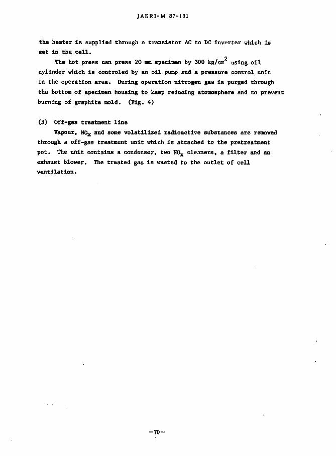
JAERI-M 87-131
the heater is supplied through a transistor AC to DC inverter which is set in the cell.
The hot press can press 20 mm specimen by 300 kg/cm' using oil cylinder which is controled by an oil pump and a pressure control unit in the operation area. During operation nitrogen gas Is purged through the bottom of specimen housing to keep reducing atomosphere and to prevent burning of graphite mold. (Fig. 4)
(3) Off-gas treatment line Vapour, N0 X and some volatilized radioactive substances are removed
through a off-gas treatment unit which is attached to the pretreatment pot. The unit contains a condenser, two N0 X cleaners, a filter and an exhaust blower. The treated gas is wasted to the outlet of cell ventilation.
-70-
JAERI-M 87・131
the heater is supplied through a transistor AC to DC inverter which is
set in the cell.
The hot press can press 20 mm specimen by 300 kg/cm2
using oi1
cylinder which is controled by an oil pump snd a pressure control unit
in the operation area. During operation nitrogen gas is purged through
the bottom of specimen housing to keep reducing atomosphere and to prevent
burning of graphite mold. (Fig. 4)
(3) Off-gas treatment line
Vapour. NOx and some volatilized radioactive substances are removed
through a off-gas treatment unit which i8 attached to the pretreatment
pot. The unit contains a condenser. two NOx cle~ners. a filter and an
exhaU8t blower. 官letreated gas i8 wasted to the outlet of cell
ventilation.
-70-

JAERI-M 87-131
Hydroxide-route Precursor-I
Aqueous Anronia
Aqueous Armenia
Ar-4%Hn (or N2-3.5%H2)
Off Gas Treating System
T Off Gas
Off Gas < -
> / i ; ; '
Beaker
Nonradioactive Simulated High Level Waste
Mixing: p H ^
Mixture
V ^
Calciner
[Cold Area Operation]
[Hot Cell Operation]
r—— Solution of 2 4 4 C m in Nitric Acid 1 Cor. H u w ;
Mixing: pH«-9 Drying: ~ 7 0 °C, > 24 h Calcining: 750 °C, < 4 h
Calcine
IT (^27 g per one run of calcinig)
Ti Powder: 2 wt%
IMixer
Mixture
Induction Heating Uniaxial Press
SYMCC
Hot Press ing: Graphite Mold, < 1200 °C, 300 kg/cm2
(20 mil x 10 rnn per one run of hot pressing,
Density*' 4.2 g/cm2)
Fig. 1 Process Flow Diagram of Synroc S o l i d i f i c a t i o n at WASTEF
- 7 1 -
JAERI-M 87・131
町droxide-rOll国 Pr館町501' Nonradioactive S.inulated High Leve1 Wa5te
Aqu区別sAnm::lnia
均 U区別sAnm::lnia
JU"-4恕i2(or N2'・3.5組 2)
Off Gas
N2
Off Gas
MiXt田e
Mixお19: 戸内9
CCo1d位岨 q湾 阻 止onJ
CHot Cell O!;泡rati.onJ
So1uti.∞ of 244an in Ni世'icAcid (or, Hl.w)
Mix却炉開""9
町戸崎,..,布。'C,> 24h
白 1cini珂 750Oc, < 4 h
白 1cお1e (~27 9戸 rone run of司 Uおug)
lr札副首 2惜
lMixer
Mixture
aa混0::
Hot Pressing: G~hite Mo1d, < 12∞OC, 3∞kg!ロ.rf.
~ __ 1 (20 mn' x 10 mn
戸 rα種目1of lx沈 pressむ19,民団ity,.., 4.2 g/arf)
Fi9. 1 Process Flow Diagram of Synroc So1idification at WASTEF
一71-

CO I
21 Buffer 20 Limit Switch 19 Nozzle for OFF-Gas 18 Nozzle for Ar-H2 Gas 17 Slip-ring 16 15
Thermocouple Thermocouple
14 Lid Flange 13 Motor for Mixer 12 Mixer 11 Driving Gear 10 Nozzle for Cooling Water 9 Mechanical Seal 8 Bellows 7 Pot for Drying and Calcining 6 Motor 5 Elevator 4 Pivot Shaft for Furnace 3 Heater 2 Casing of Furnace 1 Frame No. Name of Parts
Fig. 2 Calciner for Synroc Solidification
』〉切
mHeg∞叫・】臼】
21 Buffer
20 Limit Switch
19 Nozz1e for OFF-Gas
18 Nozz1e for Ar-H2 Gas
17 Slip-ring
16 Thermocouple
15 Thermocouple
14 Lid Flange
13 Motor for Mixer
12 Mixer
11 Driving Gear
10 Nozz1e for Cooling Water
9 Mechanica1 Sea1
8 Bellows
7 Pot for Drying and Ca1cining
6 Motor
5 E1evator
4 Pivot Shaft for Furnace
3 Heater
2 Casing of Furnace
1 Frame
No. Name of Parts
o .。
-t N
Calciner for Synroc Solidification 2 Fig.

JAERI-M 87-131
OFF Gass TH/C Ar-H? Gass
Down
SUS Wool
Diffusion Pipe
Rotary Axis Pot
Fig . 3 Deta i l s of Pretreatment Pot
- 7 3 -
JAERI-M 87・131
a日a日a
nu n
,-M
一
FM
,,, H
申
ι
Up
Down
Diffusion Pipe
中80DDD
Fig. 3 Details of Pretreatment Pot
-73-

JAER
I-M 87-131
ulator ulator
CO
ter
0)
ainer rial Coil Ins
cfl O
i CM
,™
M
*J u
ainer
a) (ri
S3 I*
<U
Join
n) 4J
4J oo
o u 0
ind Join -PI
T)
Con S
tin I s
for
CO 4
J <4H
0) s
l-i CO
in 60
•o H
9 10
0) H
CO 01 3 5
CU
8 Hose upl
u 0
ula Pre hin Rod £ £
las amp n-H
HI
pec Hoi
CM
M-l
Hose 0
•H
£> (0
co 0) f
CO
o 4J
CO
O
o
ydraul
0 IK
) 3
rt 4J
4J f •H
m
00
uring iiermo ydraul emigl lidin all B
5!
raphi raphi Quartz YNROC
O 3 T3 0
ranul YNROC eedin Name
cj
H
so en
CO
« 5!
u> o
Quartz
CO
H
o CO
F
*
m
•* en
(N
H
o o\
00 r«.
\o in
•* CO
CM
H
o
H
H
H
H
H
H
H
0) in v M
o 03
CT>
fa
-74
-
』〉伺
mTZ∞ア】臼】
15 Curing Bose for Water
14 Thermocoup1e
13 Hydrau1ic Cy1inder
12 Semig10bular Joint
11 S1iding Press-P1ate
10 Ball Bushing
9 A1umina Rod
8 Graphit:e Rod
7 Graph:ite Hou1d
6 Quartz-G1ass Container
5 SYNROC Samp1e Materia1
4 Induction-Heating Coi1
3 Granulated A1u皿inaInsulator
2 SYNROC Specimen
1 Feeding Ho1e for N2-Gas
No. Name of Parts
。hvhv
-J 必..
Hot Press Fig. 4

J A E R I - M 87-131
3.4 Contamination and decontamination behaviour of volatilized cesium from waste glass onto container materials
Y. Togashi
In a process of pouring molten glass containg high-level radioactive wastes into canisters, radioactive contamination might happen on the surface of canisters by volatile radioactive substances. Considering that the contamination could be a source term for accidental safety assessment of the storage facility, a demonstrative examination has been carried out to know the contamination and decontamination behaviour.
1) Experimental The apparatus for a sorption test of volatile radioactive substances
is shown in Fig. 1. A glass product of simulated high-level radioactive 137 waste containing about 1 mCi of Cs was molten in a crucible which was
set in an electric furnace. Specimens were placed with a holder above a crucible. The surface of SUS 304L stainless steel which represents a canister material was exposed to the fume from the molten glass, then radioactivity on the surface of specimens was measured by a scintilation counter.
The contamination specimens were soaked for a given period in 10 % HCl solution and water at room temperature. Decontamination factor (DF) was calculated from the ratio of the activity of specimens before decontamination to that after it.
2) Results and discussion Fig. 2 shows the radioactivity of volatile radioactive substance on
the surface of the specimen. The amount of volatile radioactive substances increases according to the exposure time. Fig. 3 shows results of decontamination tests using specimens which were exposed at 900 °C of fume temperature and for 60 minutes. DF was settled at the first one minute of soaking time, and was constant with respect to soaking time. HCl solution has an more ability on decontamination than water.
Fig. 4 shows results of decontamination tests using specimens which were exposed at 900 °C of temperature and for 4 hours. In this case, HCl solution and water have nearly the same ability on decontamination, and have smaller ability on decontamination in comparision with former results.
-75-
JAERI-M 87・131
3.4 Contamination and decontamination behaviour of vo1ati1ized cesium
from waste glass onto container materia1s
Y. Togashi
In a process of pouring mo1ten glass contlling high-1eve1 radioactive
wastes into canisters, radioactive contamination might happen on the surface of canisters by volatile radioactive substances. Considering
that the contamination could be a source term for accidenta1 safety
assessment of the storage faci1ity, a demonstrative examination has been
carried out to know the conta皿inationand deCOl.ltamination behaviour.
1) Experimental
The apparatus for a sorption test of vo1ati1e radioactive substances
is sT.own in Fig. 1. A glass product of simu1ated high四 1eve1radioactive 137
waste containing about 1 mCi of -_.CS was mo1ten in a crucib1e which was
set in an e1ectric furnace. Specimens were p1aced with a ho1der above
a crucib1e. The surface of SUS 304L stainless stee1 which represents a
canister materia1 was exposed to the fume from the mo1ten glass, then radioactivity on the surface of specim田 swas measured by a scinti1ation
counter.
The contamination specimens were soaked for a giv白1period in 10 %
HC1 solution and water at room temperature. Decont個 inationfactor (DF)
was ca1cu1ated from the ratio of the activity of specimens before
decontamination to that after it.
2) Resu1ts and discussion
Fig. 2 shows the radioactivity of vo1ati1e radioactive substance on
the surface of the sp~c旭町The amount of vo1ati1e radioactive substances
increases according to the exposure time. Fig. 3 shows resu1ts of
decontamination tests using specimens which were exposed at 900・Cof
fume temperature and for 60 minutes. DF was sett1ed at the first one
minute of soaking time. and was constant with respect to soaking time.
HCl solution has an more abi11ty on decontaminat10n than water.
Fig. 4 shows resu1ts of decontamination tests using specimens which
were exposed at 900 Oc of temperature and ior 4 hours. In this case, HC1 solution and water have near1y the same abi11ty on decontamination, and have sma11er abi1ity on decontaminationお1comparision w!th former results.
-75-
JAERI-M 87-131
So far, the general situation of decontamination and decontamination tests has been outlined. Even if we use the same decontamination solution, DF differs depending on the contamination conditions of specimens. Especially, it is necessary to examine detailed decontamination tests.
-76-
]AERI-M 87・131
So far, the general situation of decontamination and decontamination tests has been outlined. Even if we use the same decontamination solution, DF differs depending on the contamination conditions of specimens.
Especially, it is necessary to examine detailed decontamination tests.
~、
-76-

Thtjrmocoupl o
i
< 59
Hot der uni c : « «
Fig. l Apparatus for sorption tests of vo la t i l i zed radioactive
substances fro* wast* glasses.
10300 r
5000
TEMPERATURE(°C)
• 1000 + 900 * 800 o 700 X 600
20 40 60 80
EXPOSURE TIME(MINI
100 120
Fig.2 Increase with tine of sorption of a volatilized radioactive substance l 1 3 7Cs) on the surface of SUS 304L specimens.
> PJ 70
』〉何
m-'玄∞
J7】
ω-
TEMPERATURE(oC)
1000
+ 900
市 800
。700
x 600
10日目。
5000
E20z、明』
Z2-u
5t
5t
l51[
仁コi
:::l
un‘巴 :ftl.
Apparatus for sorptfon tests of vo1atl1fud r・dioactive substances f.・o・wast.glasses •
• 、Ffg.l
120
Increase wfth tf岡eof sorptfon of a Yolatfliz~d radfoactlve
suTstance [137Csl on the surface ~f sus 304l specl 周~ns.
100 80
EXPOSURE TIHE(MINI
60 40 zo
Ffg.2

1000
100
10 0 10 20 30 40 SO SO 70 BO 90 100 110 120
SOAKING TIME(MIN)
Fig.3 Oecontaminatlon e f fec t of 10 t HO solution and water for
specimens which were exposed a t 900 °C of fume
temperature and for 60 minutes.
1000 r
100
10
> PJ I—* I
s oo
0 10 20 30 40 50 60 70 80 90 100 110 120 SOAKING TIME(MIN)
Ffg.4 Decontamination ef fect of 10 X HO solution and water for
specimens which were exposed at 900 °C of fume
temperature and for 4 hours.
14∞l
1000
L -100
aHU
‘,‘ ー内HUt
-aMM
au-
-aHu'
a司
J-auu
向
MM
aHu--aHU
E
AHU
P崎AM
aHu
sa司aHU
角
dd
白
HU‘,‘
角川
M-aHu'
aHU
ー
SOAKIHG TIME(MIH)
Fig.3 Oetonta.in・tioneffett of 10 ¥ HCl solution and >11tH for
spet!珊ens Whlth were exposed at 900 Oc of fu.e
te爾peratureInd for 60欄!nut!!.
100目
1叩
.... 申
10
aH日"• ‘,‘ 1
凹H"1
1
aHu"
• a削目"• 1
nMu胡• g
白HM"" "M. '
,, aH
日"• "
hM
aHu"
• 戸崎j叫M
白HM
.
.
. 司唱
向HM3
aHu"
• 司,‘白
"M.
• 1
‘ .. a ....... E
‘ ..... E .. 目.. ‘ .. 冒‘.向HM
ー ' ιー----L--....J
SOAKIHG TIME(MIH)
』〉開問
7z ∞寸'00 H
F19.4 0・!conta.lna t 、oneffett of 10 ¥ HCl .olutlon and water for
spec!・ens Whlch were e昆posed at 9000C of fu嗣e
te.perature and for ・hours.

J A E R I - M 87-131
3.5 Adsorption of plutonium and curium leached from waste glass on various materials for leach-container
T. Banba
The adsorption tendency of leached-out radionuclides on the surface of leach-containers, during the leaching experiment of high-level waste glasses, was studied. A flow sheet of experimental procedures is shown in Fig. 1. The test pieces of silica glass, PFA teflon, gold and stainless steel, which are candidates for a leach-container, were immersed in deionized water with the waste glass containing Pu-238 or Cm-244 in a Pyrex glass container at 100°C. Fig. 2 shows the results of the adsorption and desorption of plutonium and curium on the test pieces. The silica glass was found to have the smallest contamination of Pu-238 and Cm-244 and can be decontaminated with dilute nitric acid. Measurement of radioactivity and observation by alpha autoradiography were made on both contaminated and decontaminated test pieces. Adsorption and desorption of curium and plutonium were discussed in relation with difference of materials, time dependence and acidity of leachate. Curium, which has been previously leached out from waste glasses, showed a relatively simple adsorption and desorption behavior. In the case of plutonium, the colloidal species would take a large part in the adsorption and desorption processes. The relationship between the ratio of the colloidal to the ionic species of plutonium and the adsorption-desorption behavior was discussed. The observation of alpha autoradiographs elucidated that the ionic adsorption was desorbed more easily than the colloidal one.
-79-
JAERI-M 87回 131
3.5 Adsorption of p1utonium and curium 1eached from waste g1ass
on various materials for leach-container
'1'. Banba
The adsorption tendency of 1eached-out radionuc1ide自 onthe surface
of leach皿 containers,during the leaching experiment of high-1eve1 waste
g1asses, was studied. A f10w sheet of experimenta1 procedures is shown
in Fig. 1. The test pieces of si1ica g1a自由, PFA tef1on, go1d and stain1ess
stee1, which are candidate自 fora 1each-container, were immersed in deionized water with the waste g1ass containing PU・238or Cm-244 in a
Pyrex g1ass container at 100oC. Fig. 2 shows the resu1ts of the adsorption
and desorption of p1utonium and curium on the test pieces. The si1ica
g1ass was found to have the sma11est contamination of Pu-238 and Cm-244
and can be decontaminated with di1ute nitric acid. Measurement of radio田
activity and observation by a1pha autoradiography were盟adeon both
contaminated and decontaminated test pieces. Adsorption and desorption
of curium and p1utonium were discussed in re1ation with difference of
materia1s, time dependence and acidity of 1eachate. Curium,叫lichhas
been previous1y 1eached out from waste g1asses, showed a re1ative1y simp1e
adsorption and desorption behavior. In the case of p1utonium, the co1-1oida1 species wou1d take a 1arge part in the adsorption and desorpt:l.on
pでocesses. The re1atiouship between the ratio of the co11oidal to the
ionic species of plutonium and the adsorption-desorption behavior WKS
discussed. The observation of a1pha autoradiographs e1ucidated that the
ionic adsorption was desorbed more easi1y than the colloidal one.
-79-

J A E R I - M 8 7 - 1 3 1
Preparation of Waste Glass Containing Pu-238 or Cm-244
Adsorption Test for Various Materials In Leachate (100°C, 2 days)
Adsorption Test for Silica Glass at Various Periods 1n Leachate
(100°C, 1 hr to 5 days)
Observation and Measurement of Test Pieces and Leachate
(pH meter, Gas-flow Proportional Counter, Alpha Autoradiography)
Desorption Test (0.2M HN03 and 0.2M HN03 + 0.02M HF Solution. 1 day, room temperature)
Observation and Measurement of Test Pieces
(Gas-flow Proportional Counter, Alpha Autoradiography)
Fig. 1 Flow sheet for experimental procedure.
-80-
]AERI-M 87・131
Preparation of Waste Glass Contai ni ng Pu・238or Cm-244
¥吉弘
observation and Measurem巴ntof Test Pieces and Leachate
(pH met泡r.Gas-flow.Proportional Counter. Alpha Autoradiography)
Observat10n and Measurement of Test Pieces
(Gas-flow Proportional Counter. Alpha Autoradiography)
F1g. 1 Flow sheet for exper1mental procedure.
-80-
., .

JAERI-M 87-131
Silica Glass
PFA Teflon Gold
E l : Before desorption anp After desorption by HNO3
Stainless Steel
15 After desorption by(HN0 3 + HF)
Fig. 2 Radioactivity of Pu-238 and Cm-244 adsorbed on various
materials in leachates and remaining after the treatment of
desorption.
-81-
-520
丸Jc:: ->. 司・・-一> 10 司・・o ι~ 。-司コ巴ロ
JAE.RI・M 87-131
O
句作
問問
N
Sllica Glass
図:8efore desorpti∞四:After desorption by HN03
図:After desorption by (HN03i'HF)
Fig ・2 Radioactivity of Pu-238 and Cm-244 adsorbed on various
materials in leachates and remaining after the treatment of
desorption.
-81-

J A E R I - M 87-131
3.6 Cs migration by column test T. Iwai, S. Amagal and K. Shlmooka
[Introduction} Multi-barrier system which consists of natural barriers and engineer'
ed barriers is expected to retard the migration of radionuclides leached out from the vitrified wastes.
In order to know the important retardation mechanism for the radionuclides in the rock formation, hot column tests has been carried out
134 using the Cs solution prepared from a nuclear waste glass through columns of fresh and weathered granite samples.
A cold column test using non-radioactive nuclide (Cs ) and batch sorption tests were carried out as preliminary tests in order to compare the distribution coefficient (Kd) determined with these two methods.
The hot column tests were then conducted and concentration profiles 134 of Cs in the columns were measured. Retardation factors and
distribution coefficients obtained by these tests were compared with those determined above.
[Apparatus and experimental] Column test apparatus is shown in Fig. 1. It consists of 1.94 * 47
cm column, inlet valve for spike injection method, roller pumps and a fraction collector. The flow rate in the column is controlled and kept constant at a value from 0.16 to 1.6 ml/min by the roller pumps.
Experimental conditions in the preliminary tests and the hot column test are the followlngs.
1) Preliminary test
i) Cold column test Rock sample : Specific gravity of the granite : Porosity of the column : Density of the column : Flow rate : Concentration :
Inada fresh granite 3.5 - 4.0 mesh 2.62 50.0 Z ,81 g/cm3
0.17 ml/min (0.11 cm/min) 10 ppm (Cs+), pH * 7.0
-82-
lAERI-M 87・131
3.6 Cs migration by column test
T. l.wai. S. A血agaiand K. Shimooka
[lntroduction]
Multi-barrier system which consists of natural barriers and engineer-
ed barriers is expected to retard the migration of radionuclides leached
out from the vitrified waste目.
1n order to know the important retardation mechanism for the radio-
nuclides in the rock formation. hot column tests has been carried out 134
using the --~Cs solution prepared from a nuclear waste glass through
columns of fresh and weathered granite samples.
A cold Colum test using non-radioactive mscude〈CS+〉andbatch
sorption tests were carried out as preliminary tests in order to compare
the distribution coefficient (Kd) determined with these two methods.
The hot column tests were then .conducted and concentration profiles 134
of --'Cs in the columns were measured. Retardation factors and
distribution coefficients obtained by these tests were compared with
those determined above.
[Apparatus and expertmental]
Column test apparatus is shown in Fig. 1. 1t consists of 1.9~ x 47
cm col咽 n,in1.et valve for spike injection method, roller pu町 sand a
fraction ~ollector. The flow rate in the column is controlled and kept
constant at a value from 0.16 to 1.6 m1/min by the rol1er pumps.
Experimental conditions in the preliminary tests and the hot column
test are the followings.
1) Preliminary test
i) Cold col四 ntest
Rock sa皿.ple Inada fresh granite 3.5 -4.0担.esh
Specific gravity of the granite 2.62
Porosity of the column
Density of the column
Flow rate
Concentration
幽
o
'''・
叩
7
U
E
nr
hu nhJ
3mM白
ct'r・、
z
d叫
m
0
1
7
即
。ロ胃・h
nu
・3
-
n
u
RJhu'ι
-82-

JAERI-M 87-131
Effluent from the column was collected every 20 minutes by the fraction collector and the concentration of Cs in the solution was analyzed by an atomic absorption method.
il) Batch test The same amounts of the fresh granite sample and a weathered one of
the same locality was used in the batch test in order to compare the Kd value.
Rock sample : Inada fresh and weathered granite 3.5 - 4.0 mesh Rock weight : 170 g Solution : 128 ml Concentration : 7.81 ppm (Cs ) pH - 7.0
137 Carrier solution was spiked with 1 ul of Cs(2.8 uCi/pl) and the activity of each sample solution of 0.1 ml was measured by a NAI scintillator.
2) Hot column test Simulated nuclear waste glass: weight 161.7g, Cs 0.137 mci/g Leaching solution: ground water(sampled at Lake Kasumigaura)
volume 10.0 lit*-'?'- 8.99x10" mci/ml pH 5.6 before experin^nt 1.01 *10~ mci/ml pH 6.4(Gf)
1.27 xlO" 6 mci/ml pH 6.4(Gv) Rock sample: Inada fresh granite(Gf)
Inada weathered granite(Gw) mesh 3.5-4.0 Specific gravity : Gf 2.59 Gw 2.42 Porosity of the column : Gf 49.12 Gw 45.7%
3 3 Density of the column : Gf 1.81 g/cm Gw 1.77 g/cm Effluent time : Gf 24.0 hour Gw 43.6 hour Flow rate : Gf 0.17 ml/min Gw 0.17 ml/min Velocity of solution : Gf 0.125 cm/min Gw 0.132 cm/min
134 Concentration of Cs in the column was measured by a Nal scintil
lator after cutting the column at one centimeter interval. Leaching solution making apparatus is shown in Fig. 2.
-83-
JAER トM 87・131
Eff1uent from the co1umn was co11ected every 20 minutes by the
fraction co11ector and the concentration of Cs in the so1ution was
ana1yzed by an atomic absorption method.
11) Batch test
The sa田 amountsof the fresh granite samp1e and a weathered one of
the same 1oca1ity was used in the batch test in order to compare the Kd
va1ue.
Rock samp1e
Rock weight
Inada fresh and weathered granite 3.5帽 4.0mesh
170 g
So1ution 128 m1
concentrat1on:7.81ppm(Cs+}PR-7.0
137 Carrier so1ution was spiked with 1 ~1 of ~J'Cs(2.8 ~Ci/~1) and the
activity of each samp1e so1ution of 0.1 m1 was measured by a NAI
scintillator.
2) Hot co1umn test 134_ . ,
Simu1ated nuc1ear waste g1ass: weight 161.78, ~J~Cs 0.137 mci/g Leaching so1ution: ground water(s岨,p1edat Lake Kasumigaura}
vo1ume 10.0 litf"'7'" 8.99 x 10・7mci/m1 pH 5.6
before田 per払明t 1.01 x 10・6mci/m1 pH 6.4(Gf}
1.27 x 10⁻⁶ mci/m1 pH 6.4(Gw)
Rock s掴 lple: lnada fresh granite(Gf}
lnada weathered granite(Gw) mesh 3.5-4.0
Specific gravity Gf 2.59 Gw 2.42
Porosity of the co1umn Gf 49.1% Gw 45.7%
haB1ty of the C01ma z Gf1.818fcm3GW1.778fcm3
Eff1uent time
F10w rate
Velocity of solution
Gf 24.0 hour
Gf 0.17 m1/min
Gf 0.125 cm/min
Gw 43.6 hour
Gw 0.17 m1/min
Gw 0.132 cm/min
134 Concentration of --'Cs in the co1umn was measured by a NaI scintil-
1ator after cutting the co1umn at one centimeter interva1. Leaching
so1ution making apparatus is shown in Fig. 2.
-83ー

J A E R I - M 87-131
[Results and discussion] The results of retardation factors(Rf) and distribution coefficients
(Kd) obtained from each method are shown in Table 1. Experimental breakthrough curve of the cold column test is shown in
Fig. 3. A nuclide transport equation in one dimension considering advection and dispertion is adopted to simulate the Cs migration. By a curve fitting of the experimental results in Fig. 3, the following parameters were obtained.
—6 2 D (hydrodynamic dispersion coefficient) • 3.056x10 m /sec Rf(retardation factor) - 8.77 Kd(distribution coefficient) - 4.33ml/g
Distribution coefficient(Kd) derived from the cold column test was calculated from the nuclide retardation factor(Rf) by the following equation.
Rf - 1 + p i=i Kd (1)
where p is the density of the rock and 9 is the porosity of the column. Another way to determin Rf and Kd values is to use the ratio of
the travel time of the nuclide(1050 min) to the travel time of water (250 min) for the Rf value (4.2). The Kd value can be then calculated by equation (1) to be 1.2 ml/g.
In the batch test, the study on distribution ratios (Rd) as a function of time might suggest the important role of the sorption kinetics. The relation between Rd and time for the fresh granite is shown in Fig. 4. Rd values then reached equilibria giving Kd values, for the fresh and weathered granita, of 25 ml/g and 219 ml/g (elapsed time 118 hours), respectively.
In the hot column test, radionuclide retardation can be evaluated by measuring activity profiles of the effluent solution and/or residual activity profiles In the column itself. In this paper the results on the activity profile of the latter are shown in Table 1 and Fig. 5, 6. In future the hot column test for the former will be reported.
The Rf and Kd values of Cs by this hot column test agree well with these determined by the travel times during the cold column test. This
-84-
]AERI-M 87・131
[Results and discussion]
The results of retardation factors(Rf) and distribution coefficients
(Kd) obtained from each method are shown in Table 1.
Experimental breakthrough curve of the cold column test is shown in
Fig. 3. A nuclide transport equation in one dimension considering
advect10n and d18pert10E118 adopted t081E1alate the Cs+m1grat10n.
By a curve fitting of the exper1mental results in Fig・3.the following
parameters were obtained. -6 2
D (hydrodyn岨 icdispersion coefficient) 圃 3.056x 10-v m~ /sec
Rf(retardation factor) 置 8.77
Kd(distribution coefficient) -4.33m1/g
Distribution coefficient(Kd) derived from the cold column test was
ca1culated from the nuc1ide retardation factor(Rf) by the fo11owing
equat1on.
AU
K
M
一env +
唱・-
圃sr-R
(1)
where p 1s the density of the rock and e is the porosity of the column. Another way to determin Rf and Kd values is to use the ratio of
the travel time of the nuclide(1050 min) to the travel time of water
(250 min) for the Rf value (4.2). The Kd value can be then calculated
by equation (1) to be 1.2 m1/g.
In the batch test, the study on distribution ratios (Rd) as a
function of time might suggest the important role of the sorption
kinetics. The relation between Rd and time for the fresh granite is
shown in Fig. 4. Rd values then reached equilibria giving Kd values.
for the fresh and weathered granita, of 25 m1/g岨 d219 m1/g (elapsed
time 118 hours), respectively. In the hot co1umn test, radionuclide retardation can be evaluated
by measuring activity profiles of the effluent solution and/or residual
activity profiles in the column itself. In this paper the results on
the activity profile of the latter are shown in Table 1 and Fig. 5. 6.
In future the hot column test for the former will be reported.
The Rf and Kd values of Cs by this hot ~olumn test agree well with
these determined by the trave1 times during the cold column test. This
-84-

JAERI-M 87-131
fact Indicates that the concentration profiles of the column can be also effective to estimate Rf and Kd values.
[Reference]
1) R.J. Serne, J.F. Relyea (1982), The Status of Radionuclide Sorption Desorption Studies Performance by the WRIT Program, PNL Battelle Memorial Institute
2) OECD NEA (1983), SORPTION - Modelling and Measurment for Nuclear Waste Disposal Studies, summary of an NEA workshop held in Paris
-85-
、
JAERI-M 87・131
fact indicates that the concentration profi1es of the co1umn can be a1so
effective to estimate Rf and Kd va1ues.
[Reference]
1) R.J. Serne, J.F. Re1yea (1982), The Status of Radionuc1ide Sorption -Desorption Studiea Performance by the WRIT program, PNL Batte11e Memorial Inatitute
2) OECD NEA (1983), SORPTION -Mode11ing and Measurment for Nuc1ear
Waate Diaposa1 Studiea, aummary of an NEA workshop he1d in Paris
-85-

JAERI-M 87-131
Table 1 Retardation factor(Rf) and distr ibut ion coefficient(Kd) values obtained on granite samples by three d i f ferent methods
Method Rock sample Kd(ml/g) Rf Batch Gf 25.84 -
Gw 219.02 -Cold column Gf1 2.99 8.77
Gf2 1.20 4.20
Hot column Gf 1.02 3.75
Gw 4.46 13.80
1:determined by a curve f i t t i n g of the data 1n Flg.3 by a nuclide
transport equation
2: determined by the data on travel times of Cs and water
1. coluan 2 . roller puap 3 . spike injection 4. balance 5. fraction collector
Fig. 1 Column test apparatus
- 8 6 -
JAERI・M 87・131
Table 1 Retardation factor(Rf) and distribution coefficient(Kd)
values obtained on granite samples by three different
methods
Method Rock sample Kd(ml/g) Rf
8atch Gf 25.84 国
Gw 219.02 ー
Cold column Gfl 2.99 8.77
Gf2 1.20 4.20
Hot column Gf 1.02 3. 75
Gw 4.46 13.80
l:determined by a curve fitt1ng of the data 1n Fig.3 by a nucl ide
transport equation
2: determ1ned by the data on trav・1t1mes of C5 and water
1. colu・n". b・Ilnce
ー
2. roller pu・p 3. spike injecUon 5. frlction collector
Fig. 1 Column test apparatus
-86-

JAERI-M .87-131
l .o
0.8
0 . 6
C/Co
0 . 4
0.2
a.a
I—No.3 cel l -
r—CX-
o l a s T ^ ™ ^
mi pump
a
m£
outlet
=t take out leaching solution ( ^ i s o l a t i o n room)
d ist i l led water supply Una (operating room)
Fig.2 Leaching solution making apparatus
3000 6000 Tim* tin in)
9000 12000 15000
Fig.3 Experimental breakthrough curve tor cesium
- 8 7 -
1.0
0.8
。聞晶
C/C。0.4
0.2
日.0
JAERI・M.87・131
No.3 cel1
。utlet
take out leach1n9 solut1 {βt1so1aticn room)
d1st111ed water supply 1
samp l1n9
(operat1ng ro酬)
Fig.2 Leachlng solution maklng apparatus
3000 d日目。 q日目。 120日目TI圃.t珊 1"】
Fig.3 Experimentat breokfhroug/1 curve tor cesium
-87-
15000

JAERI-M 87-131
3 0 . 0
2 5 . 0
20 .0
Rd 1S.0
( m l / g )
10.0
5.0
0 .0
2 5 0 . 0
2 0 0 . P
o. Fresh Granite
30 SO Time
( h o u r )
b. Weathered Granite
90
o (C/C0.0.97Z)
120 150
0 «:/C„-0.997)
Rd 150.0
<m?/g) 100.0
5 0 . 0
o.o
/
•+• 30 60 90
Tine (hour)
120 150
Fig.4 Evolution of distribution (Rd) of Cs as a function of time.on the fresh(a) and weathered(b) granite samples during the batch sorption test
- 8 8 -
30.0
25.0
20.0
Rd 15.0
(rn 1/9)
10.0
5.0
0.0
250.0
200.口
150.0 Rd
(mJ!9J
100.。
SO.1l
0.0
。
'!t
J
ι ロ
JAERI-M 87・131
o. Fresh Granite
。
9
.)
。。.)
30 昌0
T1ru" (hour)
b. Weafhered Gronite
。。
%。
30
。
60
Ti田eChourJ
。(C/CO-o.912)
90 12ロ
。((:/Co-o.991)
90 120
Fig.4 Evolution ot dfstrfbution (Rd) ot Cs as a tunction of time,on the fresh(a) and weathered(b) granite
samples during the batch sorption test
一回一
150
lS目

JAERI-M 87-131
2U00
1S00
to o
O 1000 z P (cpm/s) 0. <r o en 500
0 0 o O
o <>
' o o , J ° o o o o o o 0 „ a o o
*0 50 (cm)
10 20 30
DISTANCE FROM UPPER COLUMN
Fig.5 Sorption of Leached out B 4Cs
from The Vitrified Wastes for Fresh Granite
15000
to 50 (cm)
DISTANCE FROM UPPER COLUMN Fig.6 Sorption of Leached out ^ Cs
from The Vitrified Was i-es for Wheathered Granite of Fracture Zone
- 8 9 -
JAERI・M87・131
200日
1500 ,)
切
υz-u. o 1000 z glcwu 仏
。=O (f) 500
。・300 0
。00。
。。。。。。。
04' "0
o
。。。。0"。0.,。.0(1000000。
。 10 20 30 40 50 (cm)
DlST ANCE FROM UPPER COLUMN
Fig.5 Sorptlon ofしeachedout削 Cs
from The Vltrlfled Wastes for Fresh Granlte
1500日
切
υ 10000 o 司;
LO L
z 10
在o Etc,M 引
刊 00 ~ 0。(f) 。
。。00.,0
。 。。。。 10 20 nu
戸、dJ
m
c
f 一
ω内
u'a
DIST ANCE FROM UPPER COLUMN
Fig.6 Sorptlon of Leoched ou't 1s' Cs
from The Vitrified Was ies
tor Wheathered Granite ot Fractur・eZone
-89-
&sち?で 1障 p ・-・・事~ 巴目-‘ お ; 一 .
一一対..ふ,i、-介、、.1 奄・ ~
ーー