Item-level Temperature Sensing with a Passive RFID Tag
12
Thermotag: Item-level Temperature Sensing with a Passive RFID Tag Xingyu Chen State Key Laboratory for Novel Software Technology, Nanjing University Nanjing, Jiangsu, China Jia Liu State Key Laboratory for Novel Software Technology, Nanjing University Nanjing, Jiangsu, China Fu Xiao Department of Computer, Nanjing University of Posts and Telecommunications Nanjing, Jiangsu, China Shigang Chen Department of Computer & Information Science & Engineering, University of Florida Gainesville, Florida, USA Lijun Chen State Key Laboratory for Novel Software Technology, Nanjing University Nanjing, Jiangsu, China ABSTRACT Temperature sensing plays a significant role in upholding quality assurance and meeting regulatory compliance in a wide variety of applications, such as fire safety and cold chain monitoring. However, existing temperature measurement de- vices are bulky, cost-prohibitive, or battery-powered, making item-level sensing and intelligence costly. In this paper, we present a novel tag-based thermometer called Thermotag, which uses a common passive RFID tag to sense the temper- ature with competitive advantages of being low-cost, battery- free, and robust to environmental conditions. The basic idea of Thermotag is that the resistance of a semiconductor diode in a tag’s chip is temperature-sensitive. By measuring the dis- charging period through the reverse-polarized diode, we can estimate the temperature indirectly. We propose a standards- compliant measurement scheme of the discharging period by using a tag’s volatile memory and build a mapping model be- tween the discharging period and temperature for accurate and reliable temperature sensing. We implement Thermotag using a commercial off-the-shelf RFID system, with no need for any firmware or hardware modifications. Extensive exper- iments show that the temperature measurement has a large span ranging from 0 ◦ C to 85 ◦ C and a mean error of 2.7 ◦ C. CCS CONCEPTS • Computer systems organization → Sensor network- s. Permission to make digital or hard copies of all or part of this work for personal or classroom use is granted without fee provided that copies are not made or distributed for profit or commercial advan- tage and that copies bear this notice and the full citation on the first page. Copyrights for components of this work owned by others than ACM must be honored. Abstracting with credit is permitted. To copy otherwise, or republish, to post on servers or to redistribute to lists, requires prior specific permission and/or a fee. Request permissions from [email protected]. MobiSys ’21, June 24-July 2, 2021, Virtual, WI, USA c ⃝ 2021 Association for Computing Machinery. ACM ISBN 978-1-4503-8443-8/21/06. . . $15.00 https://doi.org/10.1145/3458864.3467879 KEYWORDS Passive RFID, Temperature Sensing, Persistence Time ACM Reference Format: Xingyu Chen, Jia Liu, Fu Xiao, Shigang Chen, and Lijun Chen. 2021. Thermotag: Item-level Temperature Sensing with a Passive RFID Tag. In The 19th Annual International Conference on Mo- bile Systems, Applications, and Services (MobiSys ’21), June 24- July 2, 2021, Virtual, WI, USA. ACM, New York, NY, USA, 12 pages. https://doi.org/10.1145/3458864.3467879 1 INTRODUCTION Temperature is a physical quantity that presents hot and cold. The properties of materials and almost all physical, chemical, and biological processes are temperature depen- dent. Sensing temperature plays a significant role in main- taining operational efficiency, upholding quality assurance, and meeting regulatory compliance in a variety of business- es, such as fire safety [15], warehouse management [12, 38], pharmaceutical industries [34], and greenhouses [18]. For ex- ample, temperature sensors can provide an early alarm of fire accidents and help save properties and human lives. In the agriculture industry, greenhouses need to monitor tem- perature within a resolution of around 4 ◦ C for benefiting plant growth [19]. In cold chain, food supplies or pharmaceu- tical companies need to monitor and document temperatures of temperature-sensitive goods throughout processing, trans- portation, and distribution for preventing perishable food contamination or maintaining the efficacy of certain drugs. In data centers, excessive heat can quickly bring a fully func- tional computer room to a halt. Temperature monitors help meet the demand for constant and uninterrupted uptime. Nowadays, there are many types of temperature sensors with different features. The core property of these sensors is that they have some parameters that vary linearly with the temperature; any change of the temperature gives rise to vari- ations in certain parameters. For instance, glass thermome- ters detect temperature through the volume of the liquid in a glass tube [4, 16, 20], resistance thermometers obtain tem- perature by checking the resistance of a specific material via 163
-
Upload
khangminh22 -
Category
Documents
-
view
1 -
download
0
Transcript of Item-level Temperature Sensing with a Passive RFID Tag
Thermotag: Item-level Temperature Sensing with a PassiveRFID Tag
Xingyu ChenState Key Laboratory for Novel
Software Technology,Nanjing University
Nanjing, Jiangsu, China
Jia LiuState Key Laboratory for Novel
Software Technology,Nanjing University
Nanjing, Jiangsu, China
Fu XiaoDepartment of Computer,
Nanjing University of Posts andTelecommunications
Nanjing, Jiangsu, China
Shigang ChenDepartment of Computer &
Information Science &Engineering, University of Florida
Gainesville, Florida, USA
Lijun ChenState Key Laboratory for Novel
Software Technology,Nanjing University
Nanjing, Jiangsu, China
ABSTRACT
Temperature sensing plays a significant role in upholdingquality assurance and meeting regulatory compliance in awide variety of applications, such as fire safety and cold chainmonitoring. However, existing temperature measurement de-vices are bulky, cost-prohibitive, or battery-powered, makingitem-level sensing and intelligence costly. In this paper, wepresent a novel tag-based thermometer called Thermotag,which uses a common passive RFID tag to sense the temper-ature with competitive advantages of being low-cost, battery-free, and robust to environmental conditions. The basic ideaof Thermotag is that the resistance of a semiconductor diodein a tag’s chip is temperature-sensitive. By measuring the dis-charging period through the reverse-polarized diode, we canestimate the temperature indirectly. We propose a standards-compliant measurement scheme of the discharging period byusing a tag’s volatile memory and build a mapping model be-tween the discharging period and temperature for accurateand reliable temperature sensing. We implement Thermotagusing a commercial off-the-shelf RFID system, with no needfor any firmware or hardware modifications. Extensive exper-iments show that the temperature measurement has a largespan ranging from 0 ◦C to 85 ◦C and a mean error of 2.7 ◦C.
CCS CONCEPTS
• Computer systems organization→ Sensor network-s.
Permission to make digital or hard copies of all or part of this workfor personal or classroom use is granted without fee provided thatcopies are not made or distributed for profit or commercial advan-tage and that copies bear this notice and the full citation on the firstpage. Copyrights for components of this work owned by others thanACM must be honored. Abstracting with credit is permitted. To copyotherwise, or republish, to post on servers or to redistribute to lists,requires prior specific permission and/or a fee. Request permissionsfrom [email protected].
MobiSys ’21, June 24-July 2, 2021, Virtual, WI, USAc⃝ 2021 Association for Computing Machinery.ACM ISBN 978-1-4503-8443-8/21/06. . . $15.00https://doi.org/10.1145/3458864.3467879
KEYWORDS
Passive RFID, Temperature Sensing, Persistence Time
ACM Reference Format:Xingyu Chen, Jia Liu, Fu Xiao, Shigang Chen, and Lijun Chen.2021. Thermotag: Item-level Temperature Sensing with a PassiveRFID Tag. In The 19th Annual International Conference on Mo-
bile Systems, Applications, and Services (MobiSys ’21), June 24-July 2, 2021, Virtual, WI, USA. ACM, New York, NY, USA,12 pages. https://doi.org/10.1145/3458864.3467879
1 INTRODUCTION
Temperature is a physical quantity that presents hot andcold. The properties of materials and almost all physical,chemical, and biological processes are temperature depen-dent. Sensing temperature plays a significant role in main-taining operational efficiency, upholding quality assurance,and meeting regulatory compliance in a variety of business-es, such as fire safety [15], warehouse management [12, 38],pharmaceutical industries [34], and greenhouses [18]. For ex-ample, temperature sensors can provide an early alarm offire accidents and help save properties and human lives. Inthe agriculture industry, greenhouses need to monitor tem-perature within a resolution of around 4 ◦C for benefitingplant growth [19]. In cold chain, food supplies or pharmaceu-tical companies need to monitor and document temperaturesof temperature-sensitive goods throughout processing, trans-portation, and distribution for preventing perishable foodcontamination or maintaining the efficacy of certain drugs.In data centers, excessive heat can quickly bring a fully func-tional computer room to a halt. Temperature monitors helpmeet the demand for constant and uninterrupted uptime.
Nowadays, there are many types of temperature sensorswith different features. The core property of these sensors isthat they have some parameters that vary linearly with thetemperature; any change of the temperature gives rise to vari-ations in certain parameters. For instance, glass thermome-ters detect temperature through the volume of the liquid ina glass tube [4, 16, 20], resistance thermometers obtain tem-perature by checking the resistance of a specific material via
163
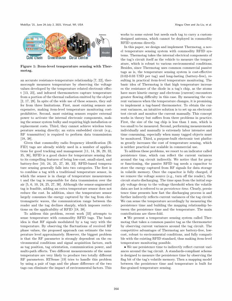
MobiSys ’21, June 24-July 2, 2021, Virtual, WI, USA Xingyu Chen and Jia Liu, et al.
Figure 1: Item-level temperature sensing with Ther-motag.
an accurate resistance-temperature relationship [7, 22], ther-mocouple measures temperature by observing the voltagevalues developed by the temperature related electronic effec-t [13, 23], and infrared thermometers capture temperaturefrom a portion of the thermal radiation emitted by the object[2, 17, 28]. In spite of the wide use of these sensors, they suf-fer from three limitations. First, most existing sensors areexpensive, making item-level temperature monitoring cost-prohibitive. Second, most existing sensors require externalpower to activate the internal electronic components, mak-ing the sensor system bulky and requiring high installation orreplacement costs. Third, they cannot achieve wireless tem-perature sensing directly; an extra embedded circuit (e.g.,RF transmitter) is required to perform data transmission[18, 38].
Given that commodity radio frequency identification (R-FID) tags are already widely used in a number of applica-tions for good tracking and management [11, 14, 26, 29, 32,35, 36], RFID is a good choice for temperature sensing dueto its compelling features of being low-cost, small-sized, andbattery-free [10, 24, 25, 27, 30, 33]. RFID-based tempera-ture sensing generally falls into two categories. The first isto combine a tag with a traditional temperature sensor, inwhich the sensor is in charge of temperature measuremen-t and the tag is responsible for data transmission over theair [5, 6, 10, 24, 25, 27, 30]. Although the sensor-augmentedtag is feasible, adding an extra temperature sensor does notreduce the cost. In addition, since the temperature sensorlargely consumes the energy captured by the tag from elec-tromagnetic waves, the communication range between thereader and the tag declines sharply, which imposes restric-tions on the applicability of RFID [18, 38].
To address this problem, recent work [33] attempts tosense temperature with commodity RFID tags. The basicidea is that RF signals modulated by a tag vary with thetemperature. By observing the fluctuations of received RFphase values, the proposed approach can estimate the tem-perature level approximately. However, the biggest problemis that the RF parameter is strongly dependent on the en-vironmental conditions and signal acquisition factors, suchas tag position, tag orientation, communication power, andmulti-path effects. Two different measurements of the sametemperature are very likely to produce two totally differentRF parameters. RTSense [19] tries to handle this problemby using a pair of tags and the phase difference of the twotags can eliminate the impact of environmental factors. This
works to some extent but needs each tag to carry a custom-designed antenna, which cannot be deployed in commodityRFID systems directly.
In this paper, we design and implement Thermotag, a nov-el temperature sensing system with commodity RFID sys-tems. Thermotag takes the internal electrical components ofthe tag’s circuit itself as the vehicle to measure the temper-ature, which is robust to various environmental conditions.Besides, since Thermotag uses common commercial passivetags as is, the temperature sensing system is cost-effective(0.02-0.03 USD per tag) and long-lasting (battery-free), re-sulting in practical item-level temperature monitoring. Thebasic idea of Thermotag is that high temperature increas-es the resistance of the diode in a tag’s chip, as the atomshave more kinetic energy and electrons (current) encountersgreater flowing difficulty in this case. By measuring the cur-rent variances when the temperature changes, it is promisingto implement a tag-based thermometer. To obtain the cur-rent variances, an intuitive solution is to set up an electronictest circuit and monitor the current manually. This conceptworks in theory but suffers from three problems in practice.First, the size of the tag chip is less than 1 mm, which istoo small to be measured. Second, performing measurementsindividually and manually is extremely labor intensive andtime consuming, especially when many tagged objects mustbe monitored. Third, a purpose-built electronic test platfor-m greatly increases the cost of temperature sensing, whichis neither practical nor scalable in commercial use.
To address these problems, we resort to an indicator calledpersistence time, which can reflect the current variancesaround the tag circuit indirectly. We notice that for prop-er functioning, the passive RFID tag needs a capacitor tostore the energy captured from RF signals for data storagein volatile memory. Once the capacitor is fully charged, ifwe remove the voltage source (e.g., turn off the reader), thecircuit starts discharging. The time span from the initial sup-ply voltage decay to the voltage threshold when the volatiledata are lost is referred to as persistence time. Clearly, persis-tence time presents how fast the discharging process is andfurther indirectly reflects current variances of the tag circuit.We can sense the temperature accordingly by measuring thepersistence time and building the mapping relationship be-tween the persistence time and the temperature. The maincontributions are three-fold.• We present a temperature sensing system called Ther-
motag that takes a common passive tag as the thermometerby observing current variances around the tag circuit. Thecompetitive advantages of Thermotag are battery-free, low-cost, robust to environmental conditions, and fully compati-ble with the existing RFID standard, thus making item-leveltemperature monitoring possible.•We use persistence time to indirectly reflect current vari-
ances around the tag circuit. A standards-compliant schemeis designed to measure the persistence time by observing theflag bit of the tag’s volatile memory. Then a mapping modelbetween the persistence time and temperature is built forfine-grained temperature sensing.
164
Thermotag: Item-level Temperature Sensing with a Passive RFID Tag MobiSys ’21, June 24-July 2, 2021, Virtual, WI, USA
• We implement Thermotag using a commercial off-the-shelf RFID system, with no need for any hardware modifi-cations. Extensive experiments show that Thermotag has alarge measurement span from 0 ◦C to 85 ◦C and a meanmeasurement error of 2.7 ◦C.
The rest of this paper is organized as follows. Section 2presents the system deployment and basic idea. Section 3details the system model of Thermotag. Section 4 shows theextraction of persistence time. Section 5 discusses the tem-perature estimation. Section 6 evaluates the performance ofThermotag. Section 7 introduces the related work. Finally,Section 8 concludes this work.
2 SYSTEM SETUP AND BASIC IDEA
RFID exploits electromagnetic fields to identify and tracktagged objects in a non-contact way. As shown in Fig. 1, abasic RFID system typically consists of three components:a tag, a reader, and an antenna. The reader communicateswith the tag through the antenna, which is the first point ofcontact for tag reading. Each RFID tag has a unique digital i-dentity to label tagged objects and brings item intelligence inthe era of Internet of Things (IoT). As the (passive) tag doesnot have a built-in power source, it gathers energy from thereader antenna’s electromagnetic RF signals, which makes itsmall, cost-effective, long-lasting, and thus popular in a widevariety of applications.
In this paper, we design and implement Thermotag, alightweight tag-based thermometer that measures the tem-perature of a target through a passive RFID tag, with noneed for any hardware modifications. Fig. 1 shows the sys-tem setup of Thermotag. An unmodified commodity RFIDtag is attached to a target, which could be fresh milk in coldchain, plants in greenhouses, or a functional server in a da-ta center. By measuring the temperature of the tag, we cansense the tagged person or object in real time. However, asthe tag does not have an independent temperature sensor,determining the temperature directly is not easy.
The basic idea of Thermotag is to find a temperature-sensitive electrical component of a tag circuit and build themapping relationship between the electrical component andthe temperature. Taking a closer look at a tag, we can seethat it generally consists of two components: a tag antennaand a tag chip. The tag chip is small but complete and hasmany semiconductor devices and diodes. Temperature hasgreat impact on diodes: when temperature rises, the internalresistance of a diode rises because the atoms have more ki-netic energy and electrons (current) experience greater flowdifficulty. If we can measure the current variances as thetemperature goes up or down, it is promising to implementa tag-based thermometer. An intuitive solution is to set upan electronic test circuit and monitor the current manually.This concept works in theory but suffers from three prob-lems in practice. First, the size of the tag chip is less than1 mm, which is too small to be measured. Second, perform-ing measurements individually and manually is extremelylabor intensive and time consuming, especially when many
(a) (b)
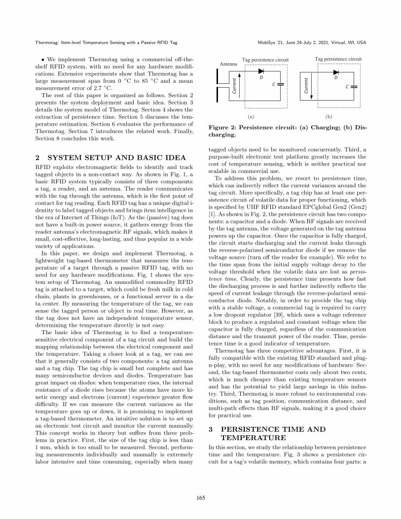
Figure 2: Persistence circuit: (a) Charging; (b) Dis-charging.
tagged objects need to be monitored concurrently. Third, apurpose-built electronic test platform greatly increases thecost of temperature sensing, which is neither practical norscalable in commercial use.
To address this problem, we resort to persistence time,which can indirectly reflect the current variances around thetag circuit. More specifically, a tag chip has at least one per-sistence circuit of volatile data for proper functioning, whichis specified by UHF RFID standard EPCglobal Gen2 (Gen2)[1]. As shown in Fig. 2, the persistence circuit has two compo-nents: a capacitor and a diode. When RF signals are receivedby the tag antenna, the voltage generated on the tag antennapowers up the capacitor. Once the capacitor is fully charged,the circuit starts discharging and the current leaks throughthe reverse-polarized semiconductor diode if we remove thevoltage source (turn off the reader for example). We refer tothe time span from the initial supply voltage decay to thevoltage threshold when the volatile data are lost as persis-tence time. Clearly, the persistence time presents how fastthe discharging process is and further indirectly reflects thespeed of current leakage through the reverse-polarized semi-conductor diode. Notably, in order to provide the tag chipwith a stable voltage, a commercial tag is required to carrya low dropout regulator [39], which uses a voltage referenceblock to produce a regulated and constant voltage when thecapacitor is fully charged, regardless of the communicationdistance and the transmit power of the reader. Thus, persis-tence time is a good indicator of temperature.
Thermotag has three competitive advantages. First, it isfully compatible with the existing RFID standard and plug-n-play, with no need for any modifications of hardware. Sec-ond, the tag-based thermometer costs only about two cents,which is much cheaper than existing temperature sensorsand has the potential to yield large savings in this indus-try. Third, Thermotag is more robust to environmental con-ditions, such as tag position, communication distance, andmulti-path effects than RF signals, making it a good choicefor practical use.
3 PERSISTENCE TIME ANDTEMPERATURE
In this section, we study the relationship between persistencetime and the temperature. Fig. 3 shows a persistence cir-cuit for a tag’s volatile memory, which contains four parts: a
165
MobiSys ’21, June 24-July 2, 2021, Virtual, WI, USA Xingyu Chen and Jia Liu, et al.
Ik
Is
Figure 3: Persistence circuit.
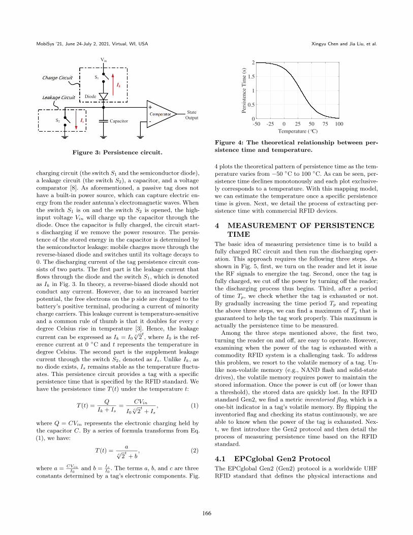
charging circuit (the switch S1 and the semiconductor diode),a leakage circuit (the switch S2), a capacitor, and a voltagecomparator [8]. As aforementioned, a passive tag does nothave a built-in power source, which can capture electric en-ergy from the reader antenna’s electromagnetic waves. Whenthe switch S1 is on and the switch S2 is opened, the high-input voltage Vin will charge up the capacitor through thediode. Once the capacitor is fully charged, the circuit start-s discharging if we remove the power resource. The persis-tence of the stored energy in the capacitor is determined bythe semiconductor leakage: mobile charges move through thereverse-biased diode and switches until its voltage decays to0. The discharging current of the tag persistence circuit con-sists of two parts. The first part is the leakage current thatflows through the diode and the switch S1, which is denotedas Ik in Fig. 3. In theory, a reverse-biased diode should notconduct any current. However, due to an increased barrierpotential, the free electrons on the p side are dragged to thebattery’s positive terminal, producing a current of minoritycharge carriers. This leakage current is temperature-sensitiveand a common rule of thumb is that it doubles for every cdegree Celsius rise in temperature [3]. Hence, the leakage
current can be expressed as Ik = I0c√2t, where I0 is the ref-
erence current at 0 ◦C and t represents the temperature indegree Celsius. The second part is the supplement leakagecurrent through the switch S2, denoted as Is. Unlike Ik, asno diode exists, Is remains stable as the temperature fluctu-ates. This persistence circuit provides a tag with a specificpersistence time that is specified by the RFID standard. Wehave the persistence time T (t) under the temperature t:
T (t) =Q
Ik + Is=
CVin
I0c√2t+ Is
, (1)
where Q = CVin represents the electronic charging held bythe capacitor C. By a series of formula transforms from Eq.(1), we have:
T (t) =a
c√2t+ b
, (2)
where a = CVinI0
and b = IsI0. The terms a, b, and c are three
constants determined by a tag’s electronic components. Fig.
-50 -25 0 25 50 75 100
Temperature (°C)
0
0.5
1
1.5
2
Per
sist
ence
Tim
e (s
)
Figure 4: The theoretical relationship between per-sistence time and temperature.
4 plots the theoretical pattern of persistence time as the tem-perature varies from −50 ◦C to 100 ◦C. As can be seen, per-sistence time declines monotonously and each plot exclusive-ly corresponds to a temperature. With this mapping model,we can estimate the temperature once a specific persistencetime is given. Next, we detail the process of extracting per-sistence time with commercial RFID devices.
4 MEASUREMENT OF PERSISTENCETIME
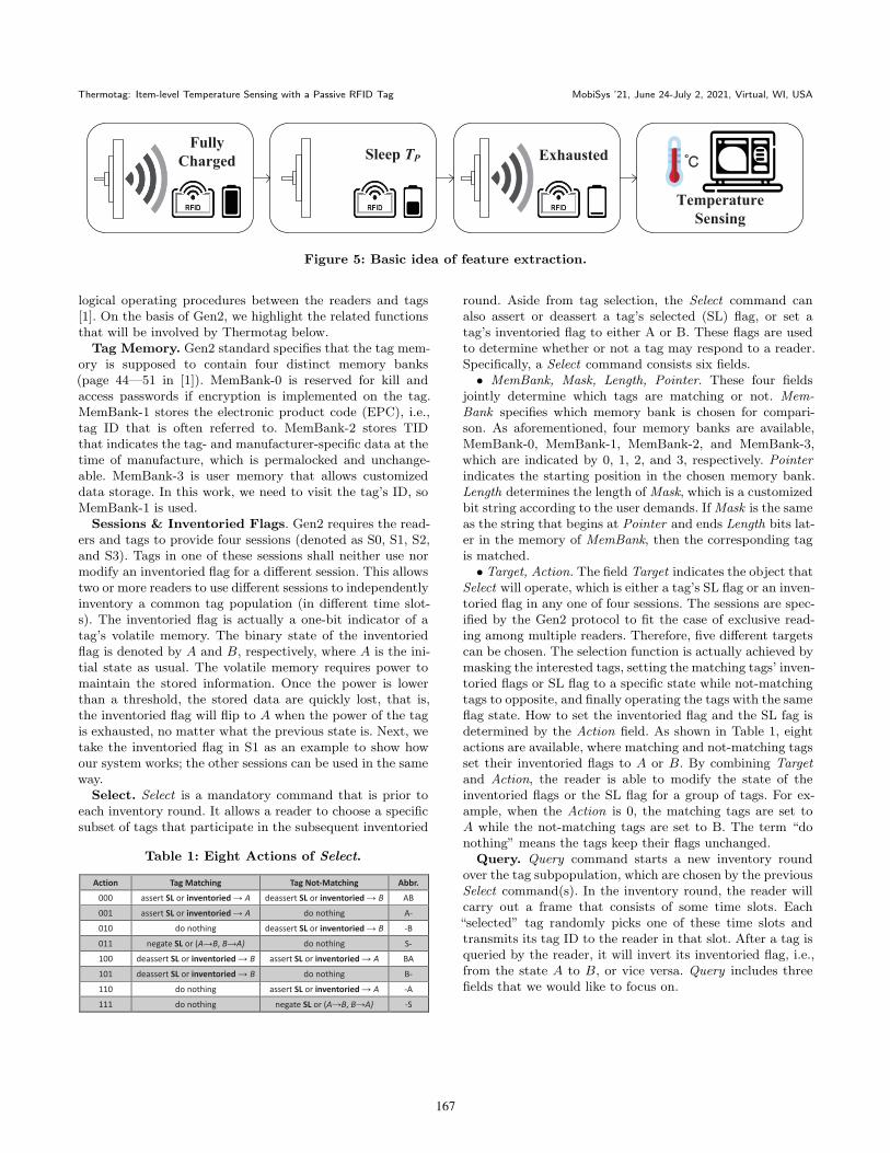
The basic idea of measuring persistence time is to build afully charged RC circuit and then run the discharging oper-ation. This approach requires the following three steps. Asshown in Fig. 5, first, we turn on the reader and let it issuethe RF signals to energize the tag. Second, once the tag isfully charged, we cut off the power by turning off the reader;the discharging process thus begins. Third, after a periodof time Tp, we check whether the tag is exhausted or not.By gradually increasing the time period Tp and repeatingthe above three steps, we can find a maximum of Tp that isguaranteed to help the tag work properly. This maximum isactually the persistence time to be measured.
Among the three steps mentioned above, the first two,turning the reader on and off, are easy to operate. However,examining when the power of the tag is exhausted with acommodity RFID system is a challenging task. To addressthis problem, we resort to the volatile memory of a tag. Un-like non-volatile memory (e.g., NAND flash and solid-statedrives), the volatile memory requires power to maintain thestored information. Once the power is cut off (or lower thana threshold), the stored data are quickly lost. In the RFIDstandard Gen2, we find a metric inventoried flag, which is aone-bit indicator in a tag’s volatile memory. By flipping theinventoried flag and checking its status continuously, we areable to know when the power of the tag is exhausted. Nex-t, we first introduce the Gen2 protocol and then detail theprocess of measuring persistence time based on the RFIDstandard.
4.1 EPCglobal Gen2 Protocol
The EPCglobal Gen2 (Gen2) protocol is a worldwide UHFRFID standard that defines the physical interactions and
166
Thermotag: Item-level Temperature Sensing with a Passive RFID Tag MobiSys ’21, June 24-July 2, 2021, Virtual, WI, USA
TP
Figure 5: Basic idea of feature extraction.
logical operating procedures between the readers and tags[1]. On the basis of Gen2, we highlight the related functionsthat will be involved by Thermotag below.
Tag Memory. Gen2 standard specifies that the tag mem-ory is supposed to contain four distinct memory banks(page 44—51 in [1]). MemBank-0 is reserved for kill andaccess passwords if encryption is implemented on the tag.MemBank-1 stores the electronic product code (EPC), i.e.,tag ID that is often referred to. MemBank-2 stores TIDthat indicates the tag- and manufacturer-specific data at thetime of manufacture, which is permalocked and unchange-able. MemBank-3 is user memory that allows customizeddata storage. In this work, we need to visit the tag’s ID, soMemBank-1 is used.
Sessions & Inventoried Flags. Gen2 requires the read-ers and tags to provide four sessions (denoted as S0, S1, S2,and S3). Tags in one of these sessions shall neither use normodify an inventoried flag for a different session. This allowstwo or more readers to use different sessions to independentlyinventory a common tag population (in different time slot-s). The inventoried flag is actually a one-bit indicator of atag’s volatile memory. The binary state of the inventoriedflag is denoted by A and B, respectively, where A is the ini-tial state as usual. The volatile memory requires power tomaintain the stored information. Once the power is lowerthan a threshold, the stored data are quickly lost, that is,the inventoried flag will flip to A when the power of the tagis exhausted, no matter what the previous state is. Next, wetake the inventoried flag in S1 as an example to show howour system works; the other sessions can be used in the sameway.
Select. Select is a mandatory command that is prior toeach inventory round. It allows a reader to choose a specificsubset of tags that participate in the subsequent inventoried
Table 1: Eight Actions of Select.
Action Tag Matching Tag Not-Matching Abbr.
000 assert SL or inventoried → A deassert SL or inventoried → B AB
001 assert SL or inventoried → A do nothing A-
010 do nothing deassert SL or inventoried → B -B
011 negate SL or (A→B, B→A) do nothing S-
100 deassert SL or inventoried → B assert SL or inventoried → A BA
101 deassert SL or inventoried → B do nothing B-
110 do nothing assert SL or inventoried → A -A
111 do nothing negate SL or (A→B, B→A) -S
round. Aside from tag selection, the Select command canalso assert or deassert a tag’s selected (SL) flag, or set atag’s inventoried flag to either A or B. These flags are usedto determine whether or not a tag may respond to a reader.Specifically, a Select command consists six fields.• MemBank, Mask, Length, Pointer. These four fields
jointly determine which tags are matching or not. Mem-Bank specifies which memory bank is chosen for compari-son. As aforementioned, four memory banks are available,MemBank-0, MemBank-1, MemBank-2, and MemBank-3,which are indicated by 0, 1, 2, and 3, respectively. Pointerindicates the starting position in the chosen memory bank.Length determines the length of Mask, which is a customizedbit string according to the user demands. If Mask is the sameas the string that begins at Pointer and ends Length bits lat-er in the memory of MemBank, then the corresponding tagis matched.• Target, Action. The field Target indicates the object that
Select will operate, which is either a tag’s SL flag or an inven-toried flag in any one of four sessions. The sessions are spec-ified by the Gen2 protocol to fit the case of exclusive read-ing among multiple readers. Therefore, five different targetscan be chosen. The selection function is actually achieved bymasking the interested tags, setting the matching tags’ inven-toried flags or SL flag to a specific state while not-matchingtags to opposite, and finally operating the tags with the sameflag state. How to set the inventoried flag and the SL fag isdetermined by the Action field. As shown in Table 1, eightactions are available, where matching and not-matching tagsset their inventoried flags to A or B. By combining Targetand Action, the reader is able to modify the state of theinventoried flags or the SL flag for a group of tags. For ex-ample, when the Action is 0, the matching tags are set toA while the not-matching tags are set to B. The term “donothing” means the tags keep their flags unchanged.
Query. Query command starts a new inventory roundover the tag subpopulation, which are chosen by the previousSelect command(s). In the inventory round, the reader willcarry out a frame that consists of some time slots. Each“selected” tag randomly picks one of these time slots andtransmits its tag ID to the reader in that slot. After a tag isqueried by the reader, it will invert its inventoried flag, i.e.,from the state A to B, or vice versa. Query includes threefields that we would like to focus on.
167
MobiSys ’21, June 24-July 2, 2021, Virtual, WI, USA Xingyu Chen and Jia Liu, et al.
• Session, Target. Similar to that in Select, this field Ses-sion in Query specifies one of the four sessions used in the in-coming inventory round. The field Target determines whichtags will participate in the current inventory round, where0 indicates the tags with the inventoried flag being A and 1indicates B.• Sel. This field consists of two bits that determine which
tags respond to Query : 002 and 012 indicate all matchingtags in the previous Select command; 102 indicates tags withdeasserted SL flag (∼ SL); and 112 indicates tags with as-serted SL flag (SL).
On the basis of the above Gen2-compatible functions, wenext detail how to jointly utilize the Select and Query com-mands to measure the persistence time by using the stateof the inventoried flag. The method is called flag-based mea-surement.
4.2 Flag-based Measurement (FM)
This technique follows a basic idea: when the internal energyof a tag is exhausted, the inventoried flag moves back to theinitial state A, regardless of its previous state. If we set thetag’s inventoried flag to B and keep the RC circuit fullycharged, then the time period from starting discharging tothe time when the inventoried flag turns to A can be treatedas the persistence time.
To measure the discharging time, we need to jointly usethe Select command and the Query command. According toGen2, a Select command can be written as follows:
S( t︸︷︷︸Target
,
Action︷︸︸︷a , b︸︷︷︸
Membank
,
Pointer︷︸︸︷p , l︸︷︷︸
Length
,
Mask︷︸︸︷k ). (3)
To set a tag’s inventoried flag to B, the reader just needs tobroadcast a Select as follows:
Flag ← BA: S(1, 4, 1, 32, 96, id), (4)
where t = 1 (0012) means the operating object is set to theinventoried flag in session 1 (S1), a = 4 indicates that theinventoried flags of matching tags will be set to B, whilethose of not-matching tags will be set to A, (b, p, l, k) =(1, 32, 96, id) means the tag’s ID is the same as id is selected(matching). Note that the first bit of the tag ID starts fromthe 32nd bit (p = 32) in MemBank-1, because the first 32bits are a protocol-control (PC) word and the tag ID followsbehind the PC word. More details can be seen in [1].
Following this process, the target tag is set to B. Now thequestion is how long we should wait before we can obtaina fully charged RC circuit. Gen2 specifies that the chargingtime should be no longer than 2 ms, which is much lessthan the time period (about 20 ms) for broadcasting a selectcommand. In other words, once the select command in (4)is carried out, the target tag has the inventoried flag beingB as well as the RC circuit being fully charged.
Afterwards, we move to the discharging process by turningoff the readers. Given that the tag can no longer harvest en-ergy from the reader, the stored electric energy is consumed
Figure 6: Enhanced FM for obtaining persistencetime.
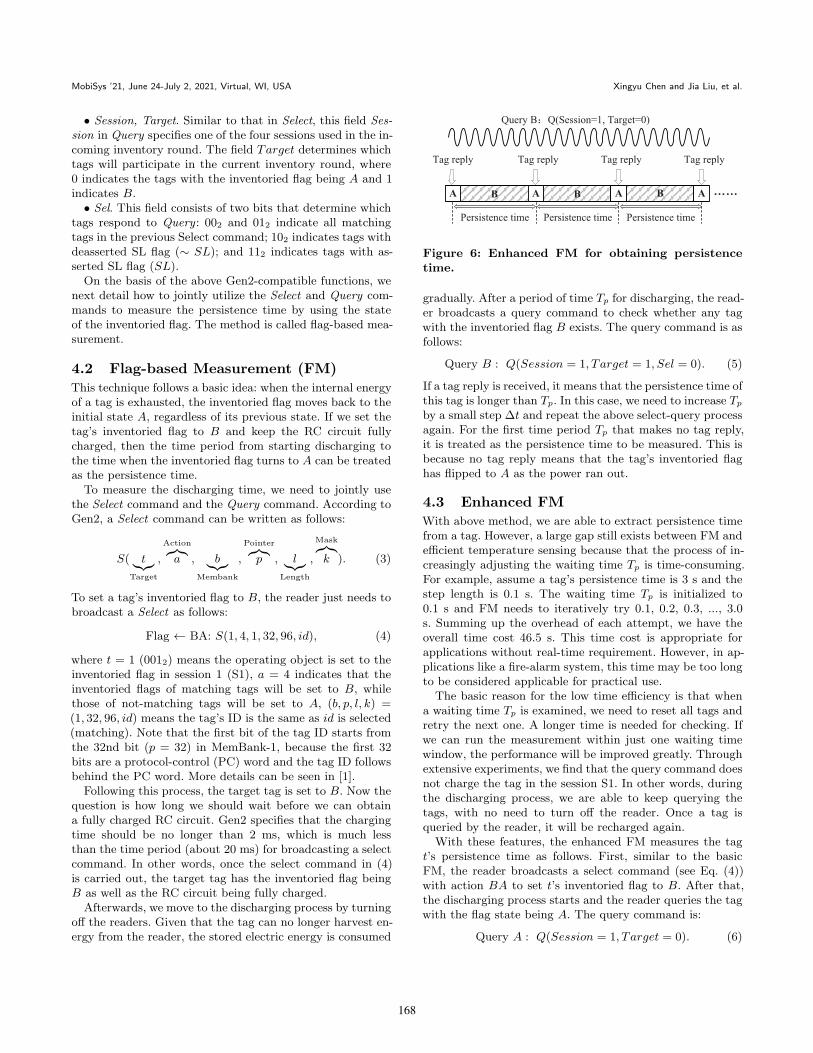
gradually. After a period of time Tp for discharging, the read-er broadcasts a query command to check whether any tagwith the inventoried flag B exists. The query command is asfollows:
Query B : Q(Session = 1, Target = 1, Sel = 0). (5)
If a tag reply is received, it means that the persistence time ofthis tag is longer than Tp. In this case, we need to increase Tp
by a small step ∆t and repeat the above select-query processagain. For the first time period Tp that makes no tag reply,it is treated as the persistence time to be measured. This isbecause no tag reply means that the tag’s inventoried flaghas flipped to A as the power ran out.
4.3 Enhanced FM
With above method, we are able to extract persistence timefrom a tag. However, a large gap still exists between FM andefficient temperature sensing because that the process of in-creasingly adjusting the waiting time Tp is time-consuming.For example, assume a tag’s persistence time is 3 s and thestep length is 0.1 s. The waiting time Tp is initialized to0.1 s and FM needs to iteratively try 0.1, 0.2, 0.3, ..., 3.0s. Summing up the overhead of each attempt, we have theoverall time cost 46.5 s. This time cost is appropriate forapplications without real-time requirement. However, in ap-plications like a fire-alarm system, this time may be too longto be considered applicable for practical use.
The basic reason for the low time efficiency is that whena waiting time Tp is examined, we need to reset all tags andretry the next one. A longer time is needed for checking. Ifwe can run the measurement within just one waiting timewindow, the performance will be improved greatly. Throughextensive experiments, we find that the query command doesnot charge the tag in the session S1. In other words, duringthe discharging process, we are able to keep querying thetags, with no need to turn off the reader. Once a tag isqueried by the reader, it will be recharged again.
With these features, the enhanced FM measures the tagt’s persistence time as follows. First, similar to the basicFM, the reader broadcasts a select command (see Eq. (4))with action BA to set t’s inventoried flag to B. After that,the discharging process starts and the reader queries the tagwith the flag state being A. The query command is:
Query A : Q(Session = 1, Target = 0). (6)
168
Thermotag: Item-level Temperature Sensing with a Passive RFID Tag MobiSys ’21, June 24-July 2, 2021, Virtual, WI, USA
As shown in Fig. 6, during the discharging process, the inter-nal circuit energizes the tag and keeps the inventoried flagB, so the reader cannot receive any response from the tag t.When the power level is too low to maintain the informationof the volatile memory, the inventoried flag moves back tothe initial state A. At that time, because the reader keepsquerying tags with A, the tag t satisfying this condition willreply to the reader. By observing the time span from the s-tart of discharging to the tag reply, we are able to derive thepersistence time of the tag. Clearly, the enhanced FM doesnot need to try different waiting times; only one time win-dow is sufficient to measure persistence time, thus saving agreat number of overheads. For example, consider the abovetag with 3 s persistence time. Enhanced FM results in greatperformance improvement, reducing the time from 46.5 s toonly 3 s, compared to the basic FM.
After responding to the reader, the tag flips its inventoriedflag to B (according to Gen2); meanwhile, the RC circuit isfully charged. With the reader continuing to query A, thetag will reply after another persistence time passes. Hence,if we need multiple measures of persistence time, we justneed to record each time interval between two adjacent tagresponses, as shown in Fig. 6. In fact, we can also simplifythe enhanced FM by removing the select command, thatis, the reader directly enters the inventory stage. By keepingquerying tags with A, the reader can obtain each tag’s replies.The time interval between any two adjacent tag replies is thetag’s persistence time.
4.4 Dense Tag
So far, we have discussed how can we use enhanced FM tomeasure the persistence time from a tag. This can be easilygeneralized to multi-tag case by measuring the time intervalbetween each tag’s two adjacent replies. When the number oftags is small (i.e., 10 tags), this method functions well. How-ever, as the number of tags increases, a congestion problemarises: a tag cannot be queried by the reader immediatelyas many tags with flag A wait in line to reply to the read-er, thus resulting in measurement error of persistence time.To address this problem, we first divide a large tag set intoseveral small subsets (each of them consisting of about 10tags at most) and then run enhanced FM on each tag subsetexclusively.
We assume that the tag set is τ and τ ′ ⊆ τ is one ofsubsets to be measured. Intuitively, we can isolate all tags inτ ′ from τ−τ ′ with the inventoried flag. Although this processworks, the problem is that when we set the inventoried flagsof τ ′ to B with the select command, the tags in τ − τ ′ willbe set to A. In the follow-up inventory stage, the readerqueries tags with flag A, and these tags τ − τ ′ will attend torespond. As a result, the tags in τ ′ fail to give a prompt replywhen their flags move back to A due to power down. Settingτ − τ ′ to B initially does not work either. To address thisdilemma, we resort to another indicator: the SL flag. It hastwo states, which are denoted by SL and ∼SL, respectively.The reader can specify a set of tags in one of the two states
0 10 20 30 40 50 60 70 80 90
Temperature (°C)
0
0.2
0.4
0.6
0.8
1
Per
sist
ence
Tim
e (s
)
Measured Data
Theoretical Curve
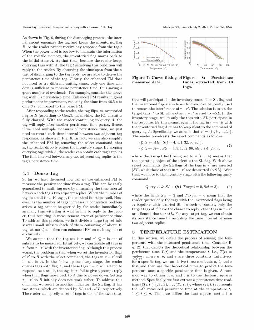
Figure 7: Curve fitting ofmeasured data.
0 20 40 60 80 100
Temperature (°C)
0
0.2
0.4
0.6
0.8
1
Per
sist
ence
Tim
e (s
)
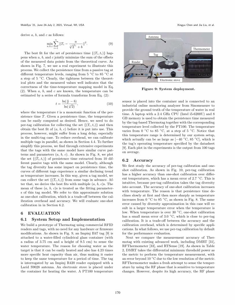
Figure 8: Persistencetimes extracted from 10tags.
that will participate in the inventory round. The SL flag andthe inventoried flag are independent and can be jointly usedto remove the interference of τ−τ ′. The solution is to set thetarget tags τ ′ to SL while other τ−τ ′ are set to ∼SL. In theinventory stage, we let only the tags with SL participate inthe response. By this means, even if the tag in τ − τ ′ is withthe inventoried flag A, it has to keep silent to the command ofquerying A. Specifically, we assume that τ ′ = {t1, t2, ..., tm}.The reader broadcasts the select commands as follows.
1⃝ t1 ← AB : S(t = 4, 4, 1, 32, 96, id1),
i⃝ ti ← A− : S(t = 4, 5, 1, 32, 96, idi), i ∈ [2,m],(7)
where the Target field being set to 4 (t = 4) means thatthe operating object of the select is the SL flag. With aboveselect commands, the SL flags of the tags in τ ′ are asserted(SL) while those of tags in τ−τ ′ are deasserted (∼SL). Afterthat, we move to the inventory stage with the following querycommand:
Query A & SL : Q(1, Target = 0, Sel = 3), (8)
where the fields Sel = 3 and Target = 0 mean that thereader queries only the tags with the inventoried flags beingA together with asserted SL. In such a context, only thetarget tags of τ ′ have the chance to reply; other tags in τ−τ ′
are silenced due to ∼SL. For any target tag, we can obtainits persistence time by recording the time interval betweentwo adjacent replies.
5 TEMPERATURE ESTIMATION
In this section, we detail the process of sensing the tem-perature with the measured persistence time. Consider E-q. (2) that depicts the theoretical relationship between thepersistence time T (t) and the temperature t, i.e., T (t) =
ac√2
t+b
, where a, b, and c are three constants. Intuitively,
for a specific tag, we can derive three constants a, b, and cfirst and then use the theoretical curve to predict the tem-perature once a specific persistence time is given. A com-mon way to obtain a, b, and c is to use the least squaresmethod. Specifically, we first extract n persistence time read-ings {(T1, t1), (T2, t2), . . . , (Tn, tn)}, where (Ti, ti) representsthe i-th measured persistence time at the temperature ti,1 ≤ i ≤ n. Then, we utilize the least squares method to
169
MobiSys ’21, June 24-July 2, 2021, Virtual, WI, USA Xingyu Chen and Jia Liu, et al.
derive a, b, and c as follows:
mina,b,c
n∑i=1
||Ti −a
c√2ti + b
||2. (9)
The best fit for the set of persistence time {(Ti, ti)} hap-pens when a, b, and c jointly minimize the sum of the offsetsof the measured data points from the theoretical curve. Asshown in Fig. 7, we use a real experiment to illustrate thisprocess. We collect the persistence time from a passive tag atdifferent temperature levels, ranging from 5 ◦C to 85 ◦C ata step of 5 ◦C. Clearly, the tightness between the theoret-ical plots and the measured values well indicates that thecorrectness of the time-temperature mapping model in Eq.(2). When a, b, and c are known, the temperature can beestimated by a series of formula transforms from Eq. (2):
t =ln( a
T− b)
ln( c√2)
, (10)
where the temperature t is a monotonic function of the per-sistence time T . Given a persistence time, the temperaturecan be easily computed as desired. Hence, we need to doper-tag calibration for collecting the set {(Ti, ti)} and thenobtain the best fit of (a, b, c) before it is put into use. Thisprocess, however, might suffer from a long delay, especiallyin the multi-tag case. To reduce overhead, we can calibratemultiple tags in parallel, as shown in Section 4.4. To furthersimplify this process, we find through extensive experimentsthat the tags with the same model have similar curve pat-terns and parameters (a, b, c). As shown in Fig. 8, we plotthe set {(Ti, ti)} of persistence time extracted from 10 dif-ferent passive tags with the same model. Clearly, althoughthe tag diversity has some impact on persistence time, thecurves of different tags experience a similar declining trendas temperature increases. In this way, given a tag model, wecan collect the set {(Ti, ti)} from some tags in advance. Af-ter that, we derive the best fits with multiple (a, b, c)s. Themean of these (a, b, c)s is treated as the fitting parameter-s of this tag model. We refer to this approximate solutionas one-shot calibration, which is a trade-off between the cal-ibration overhead and accuracy. We will evaluate one-shotcalibration in in Section 6.2.
6 EVALUATION
6.1 System Setup and Implementation
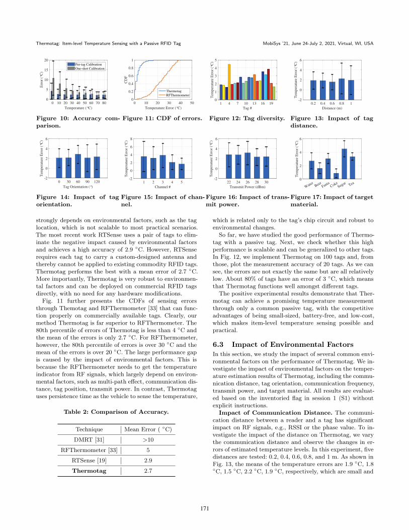
We build a prototype of Thermotag using commercial RFIDreaders and tags, with no need for any hardware or firmwaremodifications. As shown in Fig. 9, an Impinj H47 tag [9] isattached to a water-filled cylindrical glass container (witha radius of 3.75 cm and a height of 9.5 cm) to sense thewater temperature. The reason for choosing water as thetarget is that it can be easily heated and also has 4.23 timesmore specific heat capacity than air, thus making it easierto keep the same temperature for a period of time. The tagis interrogated by an Impinj R420 reader equipped with aLarid S9028 antenna. An electronic stove is placed underthe container for heating the water. A PT100 temperature
Figure 9: System deployment.
sensor is placed into the container and is connected to anindustrial online monitoring analyzer from Sinomeasure toprovide the ground truth of the temperature of water in realtime. A laptop with a 2.4 GHz CPU (Intel i5-6200U) and 8GB memory is used to obtain the persistence time measuredby the tag-based Thermotag together with the correspondingtemperature level collected by the PT100. The temperaturevaries from 0 ◦C to 85 ◦C, at a step of 5 ◦C. Notice thatthis temperature range is determined by our system setup,which actually can be as large as [−40 ◦C, 85 ◦C], which isthe tag’s operating temperature specified by the datasheet[9]. Each plot in the experiments is the output from 100 tagson average.
6.2 Accuracy
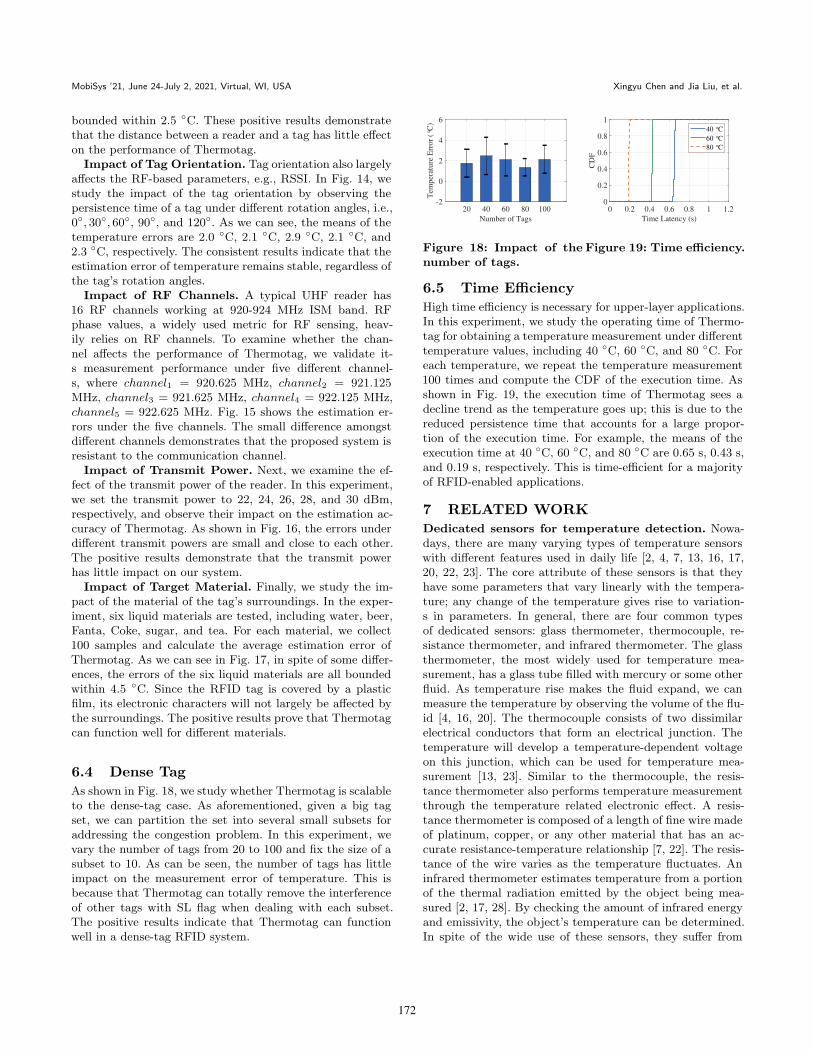
We first study the accuracy of per-tag calibration and one-shot calibration. As shown in Fig. 10, per-tag calibrationhas a higher accuracy than one-shot calibration over differ-ent temperatures, which has a mean error of 2.7 ◦C. This isintuitive, because per-tag calibration takes the tag diversityinto account. The accuracy of one-shot calibration increaseswith temperature. The reason is that persistence time de-clines slowly at first and then more sharply as temperatureincreases from 0 ◦C to 85 ◦C, as shown in Fig. 8. The sameerror caused by diversity approximation in this case will re-sult in a larger temperature error when the temperature islow. When temperature is over 30 ◦C, one-shot calibrationhas a small mean error of 3.0 ◦C, which is close to per-tagcalibration. It is a trade-off between the accuracy and thecalibration overhead, which is determined by specific appli-cations. In what follows, we use per-tag calibration by defaultfor the performance evaluation.
Next we compare the measurement accuracy of Ther-motag with existing advanced work, including DMRT [31],RFThermometer [33], and RTSense [19]. As shown in Table2, DMRT takes the differential minimum threshold power asthe metric to perform the temperature measurement, withan error beyond 10 ◦C due to the low resolution of the metric.RFThermometer makes a fresh attempt to sense the temper-ature by using the RF phase that is sensitive to temperaturechanges. However, despite its high accuracy, the RF phase
170
Thermotag: Item-level Temperature Sensing with a Passive RFID Tag MobiSys ’21, June 24-July 2, 2021, Virtual, WI, USA
0 10 20 30 40 50 60 70 80
Temperature (°C)
0
5
10
15
20
Err
or
(°C
)
Per-tag Calibration
One-shot Calibration
Figure 10: Accuracy com-parison.
0 10 20 30 40 50
Temperature Error (°C)
0
0.2
0.4
0.6
0.8
1
CD
F
Thermotag
RFThermometer
Figure 11: CDF of errors.
1 4 7 10 13 16 19
Tag #
0
1
2
3
4
5
Tem
per
atu
re E
rror
(°C
)
Figure 12: Tag diversity.
0.2 0.4 0.6 0.8 1
Distance (m)
-2
0
2
4
6
Tem
per
atu
re E
rror
(°C
)
Figure 13: Impact of tagdistance.
0 30 60 90 120
Tag Orientation (°)
-2
0
2
4
6
Tem
per
atu
re E
rro
r (°
C)
Figure 14: Impact of tagorientation.
1 2 3 4 5
Channel #
-2
0
2
4
6
8
Tem
per
atu
re E
rro
r (°
C)
Figure 15: Impact of chan-nel.
22 24 26 28 30
Transmit Power (dBm)
-2
0
2
4
6
Tem
per
atu
re E
rro
r (°
C)
Figure 16: Impact of trans-mit power.
Water
BeerFanta
CokeSugar
Tea0
2
4
6
Tem
per
atu
re E
rro
r (°
C)
Figure 17: Impact of targetmaterial.
strongly depends on environmental factors, such as the taglocation, which is not scalable to most practical scenarios.The most recent work RTSense uses a pair of tags to elim-inate the negative impact caused by environmental factorsand achieves a high accuracy of 2.9 ◦C. However, RTSenserequires each tag to carry a custom-designed antenna andthereby cannot be applied to existing commodity RFID tags.Thermotag performs the best with a mean error of 2.7 ◦C.More importantly, Thermotag is very robust to environmen-tal factors and can be deployed on commercial RFID tagsdirectly, with no need for any hardware modifications.
Fig. 11 further presents the CDFs of sensing errorsthrough Themotag and RFThermometer [33] that can func-tion properly on commercially available tags. Clearly, ourmethod Thermotag is far superior to RFThermometer. The80th percentile of errors of Thermotag is less than 4 ◦C andthe mean of the errors is only 2.7 ◦C. For RFThermometer,however, the 80th percentile of errors is over 30 ◦C and themean of the errors is over 20 ◦C. The large performance gapis caused by the impact of environmental factors. This isbecause the RFThermometer needs to get the temperatureindicator from RF signals, which largely depend on environ-mental factors, such as multi-path effect, communication dis-tance, tag position, transmit power. In contrast, Thermotaguses persistence time as the vehicle to sense the temperature,
Table 2: Comparison of Accuracy.
Technique Mean Error ( ◦C)
DMRT [31] >10
RFThermometer [33] 5
RTSense [19] 2.9
Thermotag 2.7
which is related only to the tag’s chip circuit and robust toenvironmental changes.
So far, we have studied the good performance of Thermo-tag with a passive tag. Next, we check whether this highperformance is scalable and can be generalized to other tags.In Fig. 12, we implement Thermotag on 100 tags and, fromthose, plot the measurement accuracy of 20 tags. As we cansee, the errors are not exactly the same but are all relativelylow. About 80% of tags have an error of 3 ◦C, which meansthat Thermotag functions well amongst different tags.
The positive experimental results demonstrate that Ther-motag can achieve a promising temperature measurementthrough only a common passive tag, with the competitiveadvantages of being small-sized, battery-free, and low-cost,which makes item-level temperature sensing possible andpractical.
6.3 Impact of Environmental Factors
In this section, we study the impact of several common envi-ronmental factors on the performance of Thermotag. We in-vestigate the impact of environmental factors on the temper-ature estimation results of Thermotag, including the commu-nication distance, tag orientation, communication frequency,transmit power, and target material. All results are evaluat-ed based on the inventoried flag in session 1 (S1) withoutexplicit instructions.
Impact of Communication Distance. The communi-cation distance between a reader and a tag has significantimpact on RF signals, e.g., RSSI or the phase value. To in-vestigate the impact of the distance on Thermotag, we varythe communication distance and observe the changes in er-rors of estimated temperature levels. In this experiment, fivedistances are tested: 0.2, 0.4, 0.6, 0.8, and 1 m. As shown inFig. 13, the means of the temperature errors are 1.9 ◦C, 1.8◦C, 1.5 ◦C, 2.2 ◦C, 1.9 ◦C, respectively, which are small and
171
MobiSys ’21, June 24-July 2, 2021, Virtual, WI, USA Xingyu Chen and Jia Liu, et al.
bounded within 2.5 ◦C. These positive results demonstratethat the distance between a reader and a tag has little effecton the performance of Thermotag.
Impact of Tag Orientation. Tag orientation also largelyaffects the RF-based parameters, e.g., RSSI. In Fig. 14, westudy the impact of the tag orientation by observing thepersistence time of a tag under different rotation angles, i.e.,0◦, 30◦, 60◦, 90◦, and 120◦. As we can see, the means of thetemperature errors are 2.0 ◦C, 2.1 ◦C, 2.9 ◦C, 2.1 ◦C, and2.3 ◦C, respectively. The consistent results indicate that theestimation error of temperature remains stable, regardless ofthe tag’s rotation angles.
Impact of RF Channels. A typical UHF reader has16 RF channels working at 920-924 MHz ISM band. RFphase values, a widely used metric for RF sensing, heav-ily relies on RF channels. To examine whether the chan-nel affects the performance of Thermotag, we validate it-s measurement performance under five different channel-s, where channel1 = 920.625 MHz, channel2 = 921.125MHz, channel3 = 921.625 MHz, channel4 = 922.125 MHz,channel5 = 922.625 MHz. Fig. 15 shows the estimation er-rors under the five channels. The small difference amongstdifferent channels demonstrates that the proposed system isresistant to the communication channel.
Impact of Transmit Power. Next, we examine the ef-fect of the transmit power of the reader. In this experiment,we set the transmit power to 22, 24, 26, 28, and 30 dBm,respectively, and observe their impact on the estimation ac-curacy of Thermotag. As shown in Fig. 16, the errors underdifferent transmit powers are small and close to each other.The positive results demonstrate that the transmit powerhas little impact on our system.
Impact of Target Material. Finally, we study the im-pact of the material of the tag’s surroundings. In the exper-iment, six liquid materials are tested, including water, beer,Fanta, Coke, sugar, and tea. For each material, we collect100 samples and calculate the average estimation error ofThermotag. As we can see in Fig. 17, in spite of some differ-ences, the errors of the six liquid materials are all boundedwithin 4.5 ◦C. Since the RFID tag is covered by a plasticfilm, its electronic characters will not largely be affected bythe surroundings. The positive results prove that Thermotagcan function well for different materials.
6.4 Dense Tag
As shown in Fig. 18, we study whether Thermotag is scalableto the dense-tag case. As aforementioned, given a big tagset, we can partition the set into several small subsets foraddressing the congestion problem. In this experiment, wevary the number of tags from 20 to 100 and fix the size of asubset to 10. As can be seen, the number of tags has littleimpact on the measurement error of temperature. This isbecause that Thermotag can totally remove the interferenceof other tags with SL flag when dealing with each subset.The positive results indicate that Thermotag can functionwell in a dense-tag RFID system.
20 40 60 80 100
Number of Tags
-2
0
2
4
6
Tem
per
atu
re E
rro
r (°
C)
Figure 18: Impact of thenumber of tags.
0 0.2 0.4 0.6 0.8 1 1.2
Time Latency (s)
0
0.2
0.4
0.6
0.8
1
CD
F
40 °C
60 °C
80 °C
Figure 19: Time efficiency.
6.5 Time Efficiency
High time efficiency is necessary for upper-layer applications.In this experiment, we study the operating time of Thermo-tag for obtaining a temperature measurement under differenttemperature values, including 40 ◦C, 60 ◦C, and 80 ◦C. Foreach temperature, we repeat the temperature measurement100 times and compute the CDF of the execution time. Asshown in Fig. 19, the execution time of Thermotag sees adecline trend as the temperature goes up; this is due to thereduced persistence time that accounts for a large propor-tion of the execution time. For example, the means of theexecution time at 40 ◦C, 60 ◦C, and 80 ◦C are 0.65 s, 0.43 s,and 0.19 s, respectively. This is time-efficient for a majorityof RFID-enabled applications.
7 RELATED WORK
Dedicated sensors for temperature detection. Nowa-days, there are many varying types of temperature sensorswith different features used in daily life [2, 4, 7, 13, 16, 17,20, 22, 23]. The core attribute of these sensors is that theyhave some parameters that vary linearly with the tempera-ture; any change of the temperature gives rise to variation-s in parameters. In general, there are four common typesof dedicated sensors: glass thermometer, thermocouple, re-sistance thermometer, and infrared thermometer. The glassthermometer, the most widely used for temperature mea-surement, has a glass tube filled with mercury or some otherfluid. As temperature rise makes the fluid expand, we canmeasure the temperature by observing the volume of the flu-id [4, 16, 20]. The thermocouple consists of two dissimilarelectrical conductors that form an electrical junction. Thetemperature will develop a temperature-dependent voltageon this junction, which can be used for temperature mea-surement [13, 23]. Similar to the thermocouple, the resis-tance thermometer also performs temperature measurementthrough the temperature related electronic effect. A resis-tance thermometer is composed of a length of fine wire madeof platinum, copper, or any other material that has an ac-curate resistance-temperature relationship [7, 22]. The resis-tance of the wire varies as the temperature fluctuates. Aninfrared thermometer estimates temperature from a portionof the thermal radiation emitted by the object being mea-sured [2, 17, 28]. By checking the amount of infrared energyand emissivity, the object’s temperature can be determined.In spite of the wide use of these sensors, they suffer from
172
Thermotag: Item-level Temperature Sensing with a Passive RFID Tag MobiSys ’21, June 24-July 2, 2021, Virtual, WI, USA
three limitations. First, most of them are expensive, makingitem-level temperature monitoring cost-prohibitive. Second,most existing sensors require external power to activate theinternal electronic components, thus leading to a bulky sen-sor system with high installation or replacement costs. Third,they cannot perform wireless temperature measurement di-rectly; an extra embedded component (e.g., RF transmitter)is required to carry out data transmission [18, 38].
RFID-based temperature sensing. As passive RFIDtags have been widely used in a number of applicationsfor good tracking and managing, RFID has become a goodchoice for item-level temperature sensing due to its com-pelling features: low cost, small size, and battery-free com-munication. Early research studies sensor-augmented tagsfor temperature measurement by combining a common pas-sive tag with a traditional temperature sensor, in whichthe sensor is in charge of temperature measurement andthe tag is responsible for data transmission over the air[5, 6, 10, 21, 24, 25, 27, 30]. One solution is to replace the tra-ditional tag antenna with a specific material that is sensitiveto the temperature of its surrounding environment [21, 24].For example, Shafiq et al. [24] propose a reusable battery-free RFID temperature sensor with a planar dipole antennathat could arise certain frequency shift with temperature.Roth et al. [21] design a temperature activated media fortag antenna that exhibits different colors below and abovethe selected temperature. However, since no dedicated tem-perature sensor is used, the resolutions of these sensor tagsare usually low.
Another common solution is directly integrating tempera-ture sensors into the RFID chip circuit [10, 27, 30, 37]. Vaz etal. [30] provide a low-power design of a temperature sensorunit that can function properly in a passive tag. Jauregi et al.[10] present a novel wearable RFID temperature sensor tagthat collects energy from body heat. Yin et al. [37] proposea temperature sensor that can well balance the trade-off be-tween accuracy and power consumption. Chowdhury et al.[5] design a temperature sensor by observing the discharg-ing time of an on-chip diode. The follow-up work [6] furtherimproves the performance of the sensor by implementing afirst-order ∆-Σ loop and the mean error is reduced to 0.1◦C. These sensor-augmented solutions are feasible but sufferfrom two limitations. First, they largely increase the cost ofa tag. Second, since the temperature sensor largely consumesthe energy captured by the tag from electromagnetic waves,the communication range between the reader and the tagdeclines sharply [10].
Some recent work [19, 31, 33] attempts to sense tempera-ture with commodity RFID devices. The basic idea of thesemethods is that RF signals modulated by a tag vary withthe temperature. By observing the fluctuations of receivedRF phase values, these methods can estimate the tempera-ture level approximately. Specifically, DMRT [31] leveragesthe differential minimum threshold power as the metric todo the temperature measurement. However, since the reso-lution of the threshold power of an RFID reader is low, themeasurement error of this approach is usually beyond 10 ◦C.
RFThermometer [33] makes a fresh attempt to sense thetemperature by using the phase value of the tag. The phasevalue is more sensitive to the temperature than DMRT andcan achieve better performance with a mean error of about5 ◦C. However, as the phase value is sensitive to environ-mental factors, such as the tag location, RFThermometercan only be used in static scenarios where the tag does notmove. Among the solutions presented, RTSense [19] is themost advanced work that uses a pair of tags to eliminate theimpact of environmental factors. It reduces the mean errorof temperature sensing to about 2.9 ◦C. However, RTSenserequires each tag to carry a custom-designed antenna andthereby cannot be implemented by COTS RFID tags direct-ly. In comparison, Thermotag leverages the discharging timeof on-chip capacitor as the metric to perform temperaturesensing, which is accurate and robust to environmental fac-tors, with no need for any hardware modifications.
8 DISCUSSION AND CONCLUSION
In this paper, we present a novel tag-based thermometercalled Thermotag, which uses a common passive RFID tagto sense the temperature for item-level intelligence. The ba-sic idea of Thermotag is that the resistance of a semiconduc-tor diode in a tag’s chip is temperature-sensitive. By mea-suring the discharging period through the reverse-polarizeddiode, we can estimate the temperature indirectly. We pro-pose a standards-compliant measurement scheme of the dis-charging period by observing the flag bit of the tag’s volatilememory. Furthermore, we build a mapping model betweenthe discharging period and temperature for accurate and re-liable temperature sensing. Extensive experiments show thatThermotag has a large sensing span ranging from 0 ◦C to 85◦C and an average measurement error of 2.7 ◦C.
Finally, we outline avenues for future research. First, Ther-motag has relatively high overhead for per-tag calibration.Designing new approaches (e.g., one-point calibration) to re-duce this overhead is an important step to improve the s-calability. Second, Thermotag uses only one inventoried flagto sense temperature. A standards-compliant tag has fourinventoried flags. It is promising to use these flags jointly forimproving accuracy. Third, besides temperature, a future di-rection is to use the similar approach to measure additionalparameters, e.g., soil humidity.
ACKNOWLEDGMENTS
We would like to thank anonymous reviewers and shepherdfor their insightful comments on this paper. This research isfinancially supported by the National Natural Science Foun-dation of China (No. 62072231), the Key Program of the Na-tional Natural Science Foundation of China (No. 61932013),the U.S. National Science Foundation (No. CNS-1718708),the Fundamental Research Funds for the Central Universi-ties (No. 14380079), and the Collaborative Innovation Centerof Novel Software Technology and Industrialization. Jia Liu([email protected]) and Lijun Chen ([email protected]) arethe corresponding authors.
173
MobiSys ’21, June 24-July 2, 2021, Virtual, WI, USA Xingyu Chen and Jia Liu, et al.
REFERENCES[1] 2015. GS1 EPCglobal. EPC radio-frequency identity protocols
generation-2 UHF RFID version 2.0.1.[2] Dounia Bitar, Aicha Goubar, and Jean-Claude Desenclos. 2009.
International travels and fever screening during epidemics: a liter-ature review on the effectiveness and potential use of non-contactinfrared thermometers. Eurosurveillance 14, 6 (2009), 19115.
[3] Theodore F Bogart, Jeffrey S Beasley, and Guillermo Rico. 2004.Electronic devices and circuits. Pearson/Prentice Hall New Jer-sey.
[4] Dario Camuffo and Chiara Bertolin. 2012. The earliest spirit-in-glass thermometer and a comparison between the earliest CETand Italian observations. Weather 67, 8 (2012), 206–209.
[5] Golam Chowdhury and Arjang Hassibi. 2012. An on-chip temper-ature sensor with a self-discharging diode in 32-nm SOI CMOS.IEEE Transactions on Circuits and Systems II: Express Briefs59, 9 (2012), 568–572.
[6] Golam Chowdhury and Arjang Hassibi. 2018. An on-chip CMOStemperature sensor using self-discharging PN diode in a ∆-Σ loop.IEEE Transactions on Circuits and Systems I: Regular Papers65, 6 (2018), 1887–1896.
[7] Jiong Ding, Suijun Yang, and Shuliang Ye. 2018. A fast-multi-channel sub-Millikelvin precision resistance thermometer readoutbased on the round-robin structure. Measurement Science Re-view 18, 4 (2018), 138–146.
[8] John D Hyde. 2006. Method and apparatus for controlled persis-tent ID flag for RFID applications. US Patent.
[9] Impinj. [n.d.]. Impinj Monza4 chip datasheet.https:// support.impinj.com ([n. d.]).
[10] Inigo Jauregi, Hector Solar, Andoni Beriain, Ibon Zalbide, AinaraJimenez, Inaki Galarraga, and Roc Berenguer. 2016. UHF RFIDtemperature sensor assisted with body-heat dissipation energyharvesting. IEEE Sensors Journal 17, 5 (2016), 1471–1478.
[11] Haojian Jin, Jingxian Wang, Zhijian Yang, Swarun Kumar, andJason Hong. 2018. Wish: Towards a wireless shape-aware worldusing passive RFIDs. In Proc. of ACM MobiSys. 428–441.
[12] Wenhui Ju. 2016. Study on fire risk and disaster reducing fac-tors of cotton logistics warehouse based on event and fault treeanalysis. Procedia Engineering 135 (2016), 418–426.
[13] Thomas W Kerlin and Mitchell Johnson. 1999. Practical ther-mocouple thermometry. Instrument Society of America.
[14] Jia Liu, Feng Zhu, Yanyan Wang, Xia Wang, Qingfeng Pan,and Lijun Chen. 2017. RF-Scanner: Shelf scanning with robot-assisted RFID systems. In Proc. of IEEE INFOCOM. 1–9.
[15] Zhigang Liu and Andrew K. Kim. 2016. Review of Recent Devel-opments in Fire Detection Technologies. Journal of Fire Protec-tion Engineering 13, 2 (2016), 129–151.
[16] Chas G Maier. 2002. Resistance thermometers for chemists. TheJournal of Physical Chemistry 34, 12 (2002), 2860–2868.
[17] Takashi Matsukawa, Makoto Ozaki, Tomoki Nishiyama, MakotoImamura, and Teruo Kumazawa. 2000. Comparison of infraredthermometer with thermocouple for monitoring skin temperature.Critical Care Medicine 28, 2 (2000), 532–536.
[18] Dae Heon Park, Beom Jin Kang, Kyung Ryong Cho, ChangsunShin, Sungeon Cho, Jang Woo Park, and Won Mo Yang. 2011.A study on greenhouse automatic control system based on wire-less sensor network. Wireless Personal Communications 56, 1(2011), 117–130.
[19] Swadhin Pradhan and Lili Qiu. 2020. RTSense: passive RFIDbased temperature sensing. In Proc. of ACM SenSys. 42–55.
[20] Hector Rodriguez, Margaret Williams, John S Wilkes, andRobin D Rogers. 2008. Ionic liquids for liquid-in-glass thermome-ters. Green Chemistry 10, 5 (2008), 501–507.
[21] Mark W Roth. 2019. Dual passive technology RFID temperatureactivated media. US Patent.
[22] R Saarimaa and P Wallin. 1976. Electronic liquid-in-glass ther-mometer. Review of Scientific Instruments 47, 2 (1976), 195–197.
[23] Utpal Sarma and P Kr Boruah. 2010. Design and development ofa high precision thermocouple based smart industrial thermome-ter with on line linearisation and data logging feature. Measure-ment 43, 10 (2010), 1589–1594.
[24] Yousuf Shafiq, John S Gibson, Hyun Kim, Cedric P Ambulo, Tay-lor H Ware, and Stavros V Georgakopoulos. 2019. A reusablebattery-free RFID temperature sensor. IEEE Transactions onAntennas and Propagation 67, 10 (2019), 6612–6626.
[25] Yousuf Shafiq, Julia Henricks, Cedric P Ambulo, Taylor H Ware,and Stavros V Georgakopoulos. 2020. A passive RFID temper-ature sensing antenna with liquid crystal elastomer switching.IEEE Access 8 (2020), 24443–24456.
[26] Longfei Shangguan, Zheng Yang, Alex X Liu, Zimu Zhou, andYunhao Liu. 2015. Relative Localization of RFID Tags usingSpatial-Temporal Phase Profiling. In Proc. of USENIX NSDI.251–263.
[27] Jun Tan, Muralikrishna Sathyamurthy, Alexander Rolapp,Jonathan Gamez, Eckhard Hennig, Eric Schafer, and Ralf Som-mer. 2019. A Fully Passive RFID Temperature Sensor SoC Withan Accuracy of ±0.4◦C (3σ) From 0◦C to 125◦C. IEEE Journalof Radio Frequency Identification 3, 1 (2019), 35–45.
[28] CG Teran, J Torrez-Llanos, TE Teran-Miranda, C Balderrama,NS Shah, and P Villarroel. 2012. Clinical accuracy of a non-contact infrared skin thermometer in paediatric practice. Child:Care, Health and Development 38, 4 (2012), 471–476.
[29] Deepak Vasisht, Guo Zhang, Omid Abari, Hsiao-Ming Lu, JacobFlanz, and Dina Katabi. 2018. In-body backscatter communica-tion and localization. In Proc. of ACM SIGCOMM. 132–146.
[30] Alexander Vaz, Aritz Ubarretxena, Ibon Zalbide, Daniel Pardo,Hector Solar, Andres Garcia-Alonso, and Roc Berenguer. 2010.Full passive UHF tag with a temperature sensor suitable for hu-man body temperature monitoring. IEEE Transactions on Cir-cuits and Systems II: Express Briefs 57, 2 (2010), 95–99.
[31] Ju Wang, Omid Abari, and Srinivasan Keshav. 2018. Challenge:RFID hacking for fun and profit. In Proc. of ACM MobiCom.461–470.
[32] Ju Wang, Liqiong Chang, Shourya Aggarwal, Omid Abari, andSrinivasan Keshav. 2020. Soil moisture sensing with commodityRFID systems. In Proc. of ACM MosiSys. 273–285.
[33] Xiangyu Wang, Jian Zhang, Zhitao Yu, Eric Mao, Senthilku-mar CG Periaswamy, and Justin Patton. 2019. RFThermometer:A temperature estimation system with commercial UHF RFIDtags. In Proc. of IEEE ICC. 1–6.
[34] Erica Weir and Kathy Hatch. 2004. Preventing cold chain failure:vaccine storage and handling. Cmaj 171, 9 (2004), 1050–1050.
[35] Binbin Xie, Jie Xiong, Xiaojiang Chen, Eugene Chai, Liyao Li,Zhanyong Tang, and Dingyi Fang. 2019. Tagtag: material sensingwith commodity RFID. In Proc. of ACM SenSys. 338–350.
[36] Lei Yang, Yekui Chen, Xiangyang Li, Chaowei Xiao, Mo Li, andYunhao Liu. 2014. Tagoram: Real-time tracking of mobile RFIDtags to high precision using COTS devices. In Proc. of ACMMobiCom. 237–248.
[37] Jun Yin, Jun Yi, Man Kay Law, Yunxiao Ling, Man Chiu Lee,Kwok Ping Ng, Bo Gao, Howard C Luong, Amine Bermak, Man-sun Chan, et al. 2010. A system-on-chip EPC Gen-2 passive UHFRFID tag with embedded temperature sensor. IEEE Journal ofSolid-State Circuits 45, 11 (2010), 2404–2420.
[38] Qinghua Zhang, Yi Wang, Guoquan Cheng, Zhuan Wang, andDongmei Shi. 2014. Research on warehouse environment moni-toring system based on wireless sensor network. In Proc. of IEEEIEA. 1639–1644.
[39] Yan Zhang, Laurence T Yang, and Jiming Chen. 2009. RFIDand Sensor Networks: Architectures, Protocols, Security, andIntegrations. CRC Press.
174