I/Q Modulation Generator AMIQ - Testwall
10
◆ 14-bit resolution ◆ 4 000 000/16 000 000 sample memory depth ◆ 100 MHz sample rate ◆ 78 dB ACP dynamic range (typical of 3GPP FDD) ◆ Integrated hard disk and floppy disk drive ◆ Optional BER measurement (AMIQ-B1) ◆ Optional differential I/Q outputs (AMIQ-B2) ◆ Optional digital I/Q output (AMIQ-B3) I/Q Modulation Generator AMIQ New approaches in the generation of complex I/Q signals
-
Upload
khangminh22 -
Category
Documents
-
view
1 -
download
0
Transcript of I/Q Modulation Generator AMIQ - Testwall

14-bit resolution 4 000 000/16 000 000 sample
memory depth 100 MHz sample rate
78 dB ACP dynamic range(typical of 3GPP FDD)
Integrated hard disk andfloppy disk drive
Optional BER measurement (AMIQ-B1)
Optional differential I/Q outputs (AMIQ-B2)
Optional digital I/Q output (AMIQ-B3)
I/Q Modulation Generator AMIQNew approaches in the generation of complex I/Q signals

2 I/Q Modulation Generator AMIQ
Modulation Generator AMIQ
100 MHz clock rate per channel Up to 16000000 samples per
channel Generation of broadband digital
communication signals (e.g. WCDMA, HiperLAN2 and IEEE802.11a)
Built-in hard disk for storage of calculated signals
Downloading of calculatedwaveforms and signals also from integrated floppy disk drive
Antialiasing filter featuring excel-lent frequency response and group delay
Auto-alignment and additional user correction of amplitude and offset
Fine adjustment of I/Q skew Wide dynamic range through the
use of 14-bit D/A converter, ideal for multicarrier applications
Excellent ACP (adjacent-channel power) values with WCDMA 3GPP FDD signals of typically –78 dBc for test model 1 with 64 channels
An ideal pair: AMIQ and WinIQSIM™
The number of systems based on complex digital modulation methods has dramati-cally increased in every field of communi-cations. I/Q modulation is therefore gain-ing importance for the development of such modulation methods. The Modula-tion Generator AMIQ and the Simulation Software WinIQSIM™, which is described in a separate data sheet (PD 0757.6940), open up new dimensions for the generation of I/Q signals.
The AMIQ is a dual-channel modulation generator that has especially been designed for use as an I/Q source. It is programmed and set with WinIQSIM™. Alternatively, the AMIQ can be operated from the Vector Signal Generator SMIQ.
Of course, the AMIQ features full remote-control capabilities via the GPIB/IEEE and RS-232-C interfaces.
Each channel can store up to 16 000000 samples. Sequences of sufficient length can thus be generated even at high sym-bol rates. Featuring clock frequencies of
up to 100 Msample/s and a high ampli-tude resolution of 14 bit at the analog sig-nal output and up to 16 bit at the digital signal output, the AMIQ is the ideal source for any digital modulation signal.
An automatic amplitude/offset alignment as well as fine adjustment of the skew provide excellent symmetry of the two channels which previously was extremely difficult to attain with dual-channel ARB generators. The error vector is thus mini-mized.
The filters have been optimized regarding group delay, frequency response and matching between the two channels for use as an I/Q modulation source.
Typical applications of the AMIQ and WinIQSIM™ not only include driving the I/Q inputs of a vector signal generator; the combination is also ideal for direct applications in the baseband, such as testing I/Q modulators/demodulators.
The digital signal output (option AMIQ-B3) opens up further applications in the baseband: digital/analog convert-ers (DACs) or digital input base stations can be tested, for example.
The ultimate in I/Q signals
I/Q Modulation Generator AMIQ 3
Simulation Software WinIQSIM™ *)
Single-carrier signals Multicarrier signals (up to 512
modulated or unmodulated carri-ers)
Multicarrier mixed signals (up to 32 differently modulated carriers)
User-defined CDMA signal scenarios
Addition of impairments Data editor for creating any TDMA
frame configuration Predefined files for TDMA mobile
radio standards (GSM, GSM-EDGE, DECT, NADC (IS54C/IS136), PDC, and test models 1 to 4 for WCDMA 3GPP FDD)
IF signal calculation Graphic display of calculated sig-
nals (constellation diagram, vector diagram, i(t)/q(t), magnitude and phase, eye pattern, spectrum, etc)
Remote control of the AMIQ The import system allows data
from other software programs to be read in via the TCP/IP and DDE interfaces
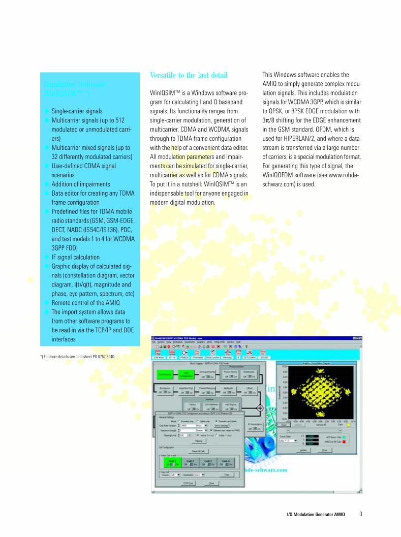
Versatile to the last detail
WinIQSIM™ is a Windows software pro-gram for calculating I and Q baseband signals. Its functionality ranges from single-carrier modulation, generation of multicarrier, CDMA and WCDMA signals through to TDMA frame configuration with the help of a convenient data editor. All modulation parameters and impair-ments can be simulated for single-carrier, multicarrier as well as for CDMA signals. To put it in a nutshell: WinIQSIM™ is an indispensable tool for anyone engaged in modern digital modulation.
This Windows software enables the AMIQ to simply generate complex modu-lation signals. This includes modulation signals for WCDMA 3GPP, which is similar to QPSK, or 8PSK EDGE modulation with 3π/8 shifting for the EDGE enhancement in the GSM standard. OFDM, which is used for HIPERLAN/2, and where a data stream is transferred via a large number of carriers, is a special modulation format. For generating this type of signal, the WinIQOFDM software (see www.rohde-schwarz.com) is used.
*) For more details see data sheet PD 0757.6940.

4 I/Q Modulation Generator AMIQ
Outstanding quality
In addition to the great memory depth of up to 16000000 samples, the AMIQ is outstanding especially for its wide dynamic range and excellent spectral purity. For WCDMA signals, low adjacent-channel power (ACP) in the baseband is thus ensured. The built-in filters are designed for flat frequency response and constant group delay.
Two identical channels
For an I/Q source, it is especially important
for the two channels to be identical since
any difference would inevitably cause an
additional modulation error.
Automatic internal alignment of offset and amplitude of the I and Q channels guarantees high performance. Small amplitude or offset errors of the con-nected device under test can be user-corrected for overall system alignment. This user correction is independent of the automatic internal alignment.
Skews between the I and Q channels, which may be caused, for example, by slight differences in the connecting cables between the AMIQ and the vector signal generator, can be compensated with a resolution of approx. 10 ps.
All these features are the basis for the outstanding modulation performance of the AMIQ.
Synchronization capabilities
The signal output can be externally con-trolled. The clock rate of the I/Q output can be adapted to the device under test by means of an external clock. Four user-programmable marker outputs can be synchronized to the desired sample and used, for example, to generate sync pulses at the beginning of a timeslot or to drive the power ramping input of an RF signal generator.
One modulation generator ...
Frequency responseand group delay of
25 MHz output filter
Intermodulation char-acteristic of the AMIQ
at 50 MHz clock rate
BER measurement
Measuring the bit error rate has become a frequently used method for the verifica-tion of digital communication systems (e.g. measuring the sensitivity or selectiv-ity of receivers, subsystems and compo-nents). The option AMIQ-B1 allows the AMIQ to be used for BER (bit error rate) measurements. The device under test (DUT) must deliver the data to be tested and the associated clock. If the DUT does not have its own clock, the clock can be generated by the AMIQ and output via one of the four user-programmable marker channels. The built-in BER tester compares the data with the nominal data
ACP (adjacent chan-nel power) dynamic range in baseband:−78 dBc typ.

I/Q Modulation Generator AMIQ 5
and calculates the bit error rate. The result of the BER measurement is availa-ble via the remote-control interface. Vari-ous standard PRBS sequences (PN9, PN15, etc) are used as nominal data.
The BER measurement has an integrating function, i.e. at the wrap-around point of a PRBS sequence the bit error measure-ment is stopped and restarted by a con-trol signal at the restart input without the previous result being cleared. All partial results are added until the predefined total number of data bits or error bits is attained. Irrelevant data sequences (e.g. preambles) are blanked, if necessary, by means of the control signal at the data enable input so that they do not invali-date the BER measurement. The PRBS sequence and the two control signals (at the marker outputs of the AMIQ) are gen-erated by means of WinIQSIM™.
Differential outputs
The option AMIQ-B2 enhances the exist-ing I and Q outputs by providing the inverted I and Q signal outputs.
To meet all requirements, the option AMIQ-B2 allows a DC (bias) voltage to be superimposed on the balanced modula-tion signal (e.g. for setting the operating point). This bias voltage can be set sepa-rately for the I and Q channels with high resolution.
Using the AMIQ-B2, unbalanced signals can be converted to balanced signals without requiring an external circuit.
Digital output
The option AMIQ-B3 provides the digital I and Q waveform data for each channel at a 68-pin SCSI connector on the front panel. A resolution from 8 bits to 16 bits can be selected for the output signals. So it is possible, for example, to drive digital/analog converters (DACs) with different word lengths. By matching the word length, clock and level of the output data to the requirements of the DUT, the AMIQ provides TTL-similar digital signals that are optimally suited for testing digital modules.
... satisfying all requirements
Use in development
The AMIQ considerably enhances the variety of applications of a vector signal generator. It takes over where the inter-nal modulation capabilities of a vector signal generator reach their limits. For example, signals can be generated with a bit rate higher than that which can be processed by the internal modulation coder of an RF generator. The variation capability of any modulation parameter including the superposition of impair-ments and the generation of IF signals with the aid of WinIQSIM™ is far beyond the facilities of a conventional signal gen-erator. IQWizard1) allows the conversion of existing signal data that was gener-ated with the aid of mathematical pro-grams, for example.
Use in production
For use in production environments, measuring instruments have to satisfy versatile requirements. One of the main points of interest is the space they require. Since the AMIQ has no built-in display, it is low in height which makes it especially suited for rackmounting in ATE (Automatic Test Equipment) systems. The AMIQ and WinIQSIM™ were designed for high-speed remote control via the IEC/IEEE bus. Predefined signals can be stored on the internal hard disk and quickly downloaded into the output mem-ory.
3-year calibration cycle
Another benefit of the AMIQ is its 3-year calibration interval: it reduces costs and increases availability.
1) Can be downloaded from www.rohde-schwarz.com (Application Note 1MA28).
Example of bit error rate test
IEEE bus
I Q
Clock
DataDUT
Bus control

6 I/Q Modulation Generator AMIQ
AMIQ, WinIQSIM™ and SMIQ – a perfect team
The AMIQ is a black box without any con-trol and display elements. There are sev-eral choices for operating the AMIQ:
Operation via WinIQSIM™ With WinIQSIM™, calculated signals are downloaded to the AMIQ hard disk or directly into the RAM of the AMIQ via IEC/IEEE bus or RS-232-C interface. In addition, all AMIQ functions can be set in a menu under WinIQSIM™.
Operation from SMIQ A PC with WinIQSIM™ is only required if new waveforms are to be calculated, since the once calculated signals can be stored on the hard disk of the AMIQ. In conjunction with the Vector Signal Gener-ator SMIQ from Rohde&Schwarz, it is possible to select waveforms stored on
hard disk or floppy and change the AMIQ parameters via a special menu. In this mode, the AMIQ acts as if it were an option to the SMIQ.
Operation in ATE systemsAs with any other remotely controlled instrument, all functions of the AMIQ, e.g. downloading predefined waveforms from the integrated hard disk, can be con-trolled via the remote-control interface. In this operating mode, neither WinIQSIM™ nor an SMIQ is required.
Operation
Menu forcontrolling the AMIQ
with the SMIQ
User interface for controlling the AMIQ with WinIQSIM™
Flexible generation of digitally modulated signals with the AMIQ and the SMIQ

I/Q Modulation Generator AMIQ 7
Applications
Verification/conformance testing
For the verification and conformance test-ing of mobile phones and base stations, signal generators are used for testing subsystems such as receivers, modula-tors and amplifiers. Due to its versatility and signal quality, the AMIQ is the ideal baseband source to handle these tasks. Preprogrammed standard settings in WinIQSIM™ provides frame structures for all primary mobile radio standards. Thus, it is not only possible to generate signals to standards such as GSM and IS-95, but also to the new WCDMA stand-ards such as 3GPP FDD and TDD, TD-SCDMA and CDMA2000. For some of these standards, a special option is required for output of the signals by the AMIQ.
Development of newcommunication systems
The comprehensive setting facilities pro-vided in WinIQSIM™ allow future sys-tems to be developed with the AMIQ. The programmable data generator contrib-utes to the easy definition of new TDMA (time division multiple access) systems.
Use of the additional WinIQOFDM soft-ware provides the AMIQ with the capabil-ity of generating OFDM (orthogonal fre-quency division multiplexing) signals such as HIPERLAN/2 and IEEE802.11a.
Use in automatic test equipment (ATE) systems
In test systems, space is usually limited. Due to its low height, the AMIQ is an ideal choice for use as a baseband or IF signal source. For this application, the
AMIQ certainly benefits from its black box design with an IEC/IEEE bus optimized for high transfer rate, and the integrated hard disk for saving the calculated sig-nals.
In addition to size, the time required is also a crucial factor in ATE systems. Fast switchover between different signal sequences is a very important aspect. The AMIQ provides the possibility of combin-ing up to 30 different sequences with fast switchover. The resulting multisegment waveforms can be stored on the internal hard disk like individual sequences and reloaded into the memory for output.
Tolerance tests
In addition to ideal signals, the WinIQSIM™/AMIQ combination also allows the generation of defined signal impairments and additive interfering sig-nals. Variation of bit rates and filtering are used to determine tolerance limits and to detect potential critical spots in new sys-tems. By using the Vector Signal Genera-tor SMIQ, fading and additive noise can be added to the complex signals provided by the AMIQ. In particular, the SMIQ meets the dynamic fading scenarios pre-scribed by the 3GPP standard.
Adjustment of I/Q modulators
More and more ICs and modules are equipped with differential I/Q inputs. In the case of DC coupling between the AMIQ and a modulator chip, for example, the I/Q signal can be superimposed by a DC (bias) voltage for setting the operating point (option AMIQ-B2 required). This DC voltage can be set separately for the I and Q channel. By superimposing a small off-
set voltage (user correction) in addition to this bias voltage, the RF carrier leakage in the modulator is minimized to obtain opti-mum data for the I/Q signal at the RF.
Digital components
The AMIQ’s digital signal output (option AMIQ-B3) allows signals to be directly fed to baseband components with digital inputs.
The digital signal output is also optimal for testing digital/analog converters. Due to the selectable word length (8 bits to 16 bits), the test signal can be adapted to the specific requirements.
Certified Environmental System
ISO 14001REG. NO 1954
Certified Quality System
ISO 9001DQS REG. NO 1954

I/Q Modulation Generator AMIQ 8
Specifications
Output memoryWaveform length (data and markers)
Clock rate – Slow mode (10 Hz to 4 MHz)
Clock rate– Fast mode (2 MHz to 100 MHz)
24 to 4000000/16000000 in steps of one
24 to 4000000/16000000 in steps of four
Amplitude resolution of data words selectable word length 8 bit to 14 bit; up to 16 bit at digital output
Marker channels
Number
can be used as marker or trigger out-puts (for word lengths up to 14 bit)4
Multisegment waveformSegment changeover time
without clock changewith clock change
max. 30 segments
4 ms typ.12 ms typ.
Clock generationClock range 10 Hz to 100 MHzSetting range 10 Hz to 105 MHz1)
Resolution 1 x 10⁻⁷
External clock inputClock rate 10 Hz to 4 MHz (slow mode)
2 MHz to 100 MHz (fast mode)Reference frequencyInternal reference output
Frequency 10 MHzAging (after 30 days of operation) 1 x 10⁻⁵/yearTemperature effect (0°C to 45°C) <2 x 10⁻⁶/°CLevel, rms 0.5 V (into 50 Ω)Frequency adjustment electronic
External reference inputFrequency 10 MHzLevel, rms 0.1 V to 2 VInput impedance 50 Ω
Signal outputOutputs I and Q2)
Output impedance 50 ΩOutput voltage (Vp into 50 Ω)
Fix mode 0.5 V, same for both channelsAmplitude fine variation ±10%, separately for each channel
Resolution 0.01%Level difference betweenthe two channels <0.2% (at 1 kHz, after auto-alignment)Residual DC offset <0.5 mV, 0.1 mV typ. (after auto-
alignment)DC fine variation ±30 mV typ.
Resolution 30 µVSFDR3) (sinewave 1 MHz, clock rate 10 MHz) >70 dB, 80 dB typ.
Variable mode 0 V to 1 V, separately adjustable for each channel
Resolution 3 digitsResidual DC offset <5 mV, 1 mV typ. (after auto-align-
ment)DC fine variation ±70 mV typ.Resolution 70 µVSFDR3) (sinewave 1 MHz, clock rate 10 MHz) >50 dB (level >0.1 V),
70 dB typ. (level >0.5 V)
Skew between I and Q channel (filter off, clock rate 10 MHz, fix mode)
Fine variationResolution
±1 ns typ. <10 ps
Rise time 5 ns typ. Adjacent-channel powerWCDMA 3GPP FDD
Test model 1 (64 DPCH channels)Offset 5 MHzOffset 10 MHz
–78 dBc typ.–78 dBc typ.
Error vectorIS-95 (QPSK) 0.35% typ. EVM (rms)GSM (GMSK) 0.2° typ. phase error (rms)DECT (2-FSK) 0.9% typ. FSK errorNADC, PHS (π/4DQPSK) 0.3% typ. EVM (rms)FiltersOperating modes off (no filter), internal or external filterInternal filters
25 MHz elliptic, 7th order + delay equalizerFreq. response Amplitude
Group delay0.15dB typ. up to 25 MHz500 ps typ. up to 20 MHz
I/Q imbalance AmplitudeGroup delay
0.05 dB typ. up to 25 MHz200 ps typ. up to 20 MHz
Stopband attenuation 70 dB from 75 MHz2.5 MHz elliptic, 7th order + delay equalizer
Freq. response AmplitudeGroup delay
0.15 dB typ. up to 2.5 MHz5 ns typ. up to 2 MHz
I/Q imbalance AmplitudeGroup delay
0.05 dB typ. up to 2.5 MHz1 ns typ. up to 2 MHz
Stopband attenuation 70 dB from 7.5 MHz
External filters one filter can be connected for each channel, BNC connectors on rear panel
Impedance 50 ΩTriggerCONT mode repetitive output of loaded waveform
after occurrence of triggerSINGLE mode single output of loaded waveform af-
ter occurrence of triggerGATED mode start of (repetitive) waveform output
after occurrence of trigger until end of trigger event
Trigger signal via remote control or trigger inputTrigger input BNC connector, selectable polarity
Input level TTLMax. permissible input voltage −0.5 V to 6 VPulse width (clock rate –slow mode) min. 200 ns + 1samplePulse width (clock rate – fast mode) min. 11samplesDelay between trigger inputand output of first data word
Slow modeFast mode
220 ns + (1sample + 20 ns) jitter21samples + 1sample jitter
Marker outputsNumber of outputs 4, BNC connectorsLevel TTL, can be terminated into 50 Ω,
(high >2 V)BER measurement (option AMIQ-B1)Data supplied by the DUT can be compared with a nominal random bit se-quence; the results are transferred to the host computer (via the currently used remote control); the BER measurement can be controlled from WinIQSIM™ and SMIQ.

I/Q Modulation Generator AMIQ 9
Pseudo random bit sequences 29−1, 211−1, 215−1 , 216−1, 220−1, 221−1, 223−1
Clock rate max. 20 MHzClock source each valid bit requires a clock, which
is supplied by the DUT or the AMIQSync period 24 clocksInterface 9-pin D-SUB connector, D-SUB BNC
cable supplied in additionData TTLData enable TTLClock TTLRestart TTL
Setup time 10 nsHold time 2 nsPolarity normal and inverted (data, clock, data
enable)Measurement time selectable through max. number of
data or error bits (max. 231 bit), continuous measurement
Measurement results BER in ppm (when set number of data or error bits is attained), not synchro-nized, no clock from DUT
Differential I/Q outputs (option AMIQ-B2)4)
Provides the inverted I and Q signals and allows a DC voltage to be simultane-ously superimposed on the output signal.Outputs I, I, Q and QOperating mode single/differential, selectableOutput impedance 50 Ω when on, 50 Ω or high Z when
offBias voltage (EMF, to ground) −2.5 V to +2.5 V (±10 mV)
for both I and Q channels separate, common setting for I and I or Q and Q
Resolution <1.5 mVDifference between I and I or Q and Q <0.5% + 1.5 mVOutput voltage (differential EMF between the I and I or Q and Q outputs, un-less otherwise specified, Vp)
Fix mode 2 V, same for both I and Q channelsLevel difference I ↔ Q <0.5% (at 1 kHz, after auto-alignment)I ↔ I (Q ↔ Q) <0.5% (at 1 kHz, after auto-alignment)Residual DC offset <1 mV (to ground,
after auto-alignment)DC fine variation ±120 mV typ.Resolution 120 µV
Variable mode 0 V to 4 V, separately adjustable for I and Q channels
Resolution 3 digitsDC fine variation ±280 mV typ. Resolution 280 µV
Max. output voltage (Vsignal + Vvoltage) <2.5 V (to ground)
Digital I/Q output (option AMIQ-B3)Output 68-pin SCSI connector (mini D-SUB,
half pitch)Channels I and QResolution 8 bit to 16 bit (selectable, no marker
output for word lengths >14 bit)Max. clock frequency 100 MHz (if an external clock is used,
the internal delay time from 20 ns to 25 ns between the input clock and the output data has to be taken into account above 40 MHz)
Output impedance 30 Ω to 50 Ω typ., high impedance with low level at pin 66
Output level LVT or ABT level (data, marker and clock); the high level of the data, mark-er and clock signals is automatically adapted to the selected supply volt-age for external circuits
Vcc output +3.3 V or +5 VRemote control and memory via IEC625-2 (IEEE488) and RS-232-CCommand set SCPI 1996.0 with extensionsIEC/IEEE interface functions SH1, AH1, T6, L4, SR1, RL1, PP1, DC1,
DT1, C0 Mass memory floppy disk drive (3.5", 1.44 MB),
hard disk 3 GB/6 GB (AMIQ03/04)Download time (4000000 I/Q samples from built-in hard disk) 27 sGeneral dataNominal temperature range 0 °C to +45 °C; meets IEC68-2-1 and
IEC68-2-2 Storage temperature range −40 °C to +70 °CDamp heat 95% relative humidity at +40 °C;
meets IEC68-2-3Vibration, sinusoidal 5 Hz to 150 Hz, max. 2 g at 55 Hz,
0.5 g const. 55 Hz to 150 Hz,meets IEC68-2-6, IEC1010-1 andMIL-T-28800D class 5
Electromagnetic compatibility meets EN50081-1 and EN50082-1(EMC Directive of EU)
Immunity to RFI 10 V/mPower supply 100 V to 120 V ±10%, 50 Hz to 400 Hz,
200 V to 240 V ±10%, 50 Hz to 60 Hz, autoranging, 150 VA
Safety meets DINEN 61010-1, 1994-03 CAN/CSA-C22.2 No. 1010.1-92UL Std. No. 3111-1IEC61010-1
Dimensions (W x H x D) 427 mm x 88 mm x 450 mmWeight 8.7 kg
1) Specs at clock >100 MHz not guaranteed, max. ambient temperature +35 °C.2) I and Q in addition when option AMIQ-B2 is used.3) Spurious-free dynamic range.4) All data not specified here are identical to those of the AMIQ without option B2 ( I and Q only).

Prin
ted
in G
erm
any
1201
(U w
e)
ROHDE&SCHWARZ GmbH & Co. KG ⋅ Mühldorfstraße 15 ⋅ 81671 München ⋅ Germany ⋅ P.O.B. 8014 69 ⋅ 81614 München ⋅ Germany ⋅ Telephone +49 89 4129-0
www.rohde-schwarz.com ⋅ Customer Support: Tel. +49 1805124242, Fax +49 89 4129-13777, E-mail: [email protected]
PD 0
757.
3970
.23
⋅ I/Q
Mod
ulat
ion
Gene
rato
r AM
IQ ⋅
Trad
e na
mes
are
trad
emar
ks o
f the
ow
ners
⋅ Su
bjec
t to
chan
ge ⋅
Data
with
out t
oler
ance
s: ty
pica
l val
ues
Ordering information
I/Q Modulation Generator AMIQ4 Msamples 1110.2003.0316 Msamples 1110.2003.04
Accessories suppliedWinIQSIM™ version for Windows 95/98/NT/2000 on CD-ROM; manual, power cable, AMIQ operating manualOptionsBER Measurement AMIQ-B1 1110.3500.02Differential I/Q Outputs AMIQ-B2 1110.3700.02Digital I/Q Output AMIQ-B3 1122.2103.02Rear I/Q Outputs AMIQB191) 1110.3400.02Digital Standards
IS-95 AMIQK11 1122.2003.02CDMA2000 AMIQK12 1122.2503.02WCDMA TDD Mode (3GPP) AMIQK13 1122.2603.02TD-SCDMA AMIQK14 1122.2703.02
OFDM Signal Generation AMIQK15 1122.2803.02
1) Not with option AMIQ-B2. Marker outputs 3 and 4 not provided when this option is fitted.
Recommended extras19" Rack Adapter ZZA-211 1096.3260.00