IP-900 Series V02 SOFTWARE USER'S GUIDE - Fujitsu
177
C134-E016-03 IP-900 Series V02 SOFTWARE USER’S GUIDE
-
Upload
khangminh22 -
Category
Documents
-
view
1 -
download
0
Transcript of IP-900 Series V02 SOFTWARE USER'S GUIDE - Fujitsu

C134-E016-03
IP-900 Series V02 SOFTWARE USER’S GUIDE

IP-900 Series
II
USING IP-900 Series SAFELY Handling of This Manual
This manual contains important information regarding the safe use of IP-900 series. Before using this product, please read this document thoroughly and pay particular attention to the "Notes on Safety." Be sure to keep this document in a safe and convenient location for quick reference.
Fujitsu makes every effort to prevent users and bystanders from being injured and to prevent property damage. Be sure to use this product in accordance with the instructions in this manual.
Warning on Electromagnetic Interference
The following notice is for USA users only. IP-900 series have been tested and found to comply with the limits for a Class A digital device,
pursuant to Part 15 of the FCC Regulations. These limits are designed to provide reasonable protection against harmful interference when the equipment is operated in a commercial environment. This equipment generate, uses and can radiate radio frequency energy, and if not installed and used in accordance with the instruction document, may cause harmful interference to radio communications. Operation of this equipment in a residential area is likely to cause harmful interference in which case the user will be required to correct the interference at his expense.
The following notice is for Canada users only. This Class A digital apparatus meets all requirements of the Canadian Interference-Causing
Equipment Regulations.
The following notice is for EU (European Union) users only. This is Class A product of Electromagnetic Interference (EMI) standard. In a domestic environment
this product may cause radio interference in which case the user may be required to make adequate measures.
This manual contains technology controlled by Foreign Exchange and Foreign Trade Law. This
document or a portion thereof must not be exported (or re-exported) from Japan without authorization from the appropriate Japanese governmental authorities in accordance with such laws.
It is strictly inhibited to copy or reverse-engineer (reverse-assemble or reverse-compile) any programs
included in the relevant equipment. Microsoft, Windows and Internet Explorer are trademarks of Microsoft Corporation in the United
States and/or the affiliated companies.
- The contents of this document shall not be disclosed in any way or reproduced in any media without
the express written permission of Fujitsu Limited.
All Rights Reserved, Copyright © FUJITSU LIMITED 2008 -2016

IP-900 Series
III
PREFACE
This document explains how to use software for IP-900 series. For information on how to install IP-900 series, connect cables and use buttons and LEDs, refer to the
following manual: - IP-900 Series User's Guide This document is intended for system designers or administrators who use IP-900 series. It assumes that
these users have a basic understanding of networks and video streaming.
Product Use Environment The product explained in this document is designed and manufactured for use in standard applications
such as general office work, personal devices and household appliances. This product has not been designed or manufactured for special uses requiring extremely high levels of safety, or if the required level of safety cannot be ensured, for uses where a failure, operational error or some other factor could be life-threatening or cause a physical injury (such as nuclear-reactor control in atomic facilities, automatic flight control, air traffic control, mass transportation control, medical devices for life support, or missile launch controls in weapons facilities). (In this document, these special uses are referred to as "high-risk" uses.) The customer is urged not to use this product without taking measures to guarantee the level of safety required for such high-risk uses. Customers that are likely to use this product for high-risk applications are requested to consult our sales representative before embarking on such specialized use.
Note The contents of this manual may be revised without prior notice.
Edition 14 Sep. 2016

IP-900 Series
IV
ALERT INDICATIONS
This document uses various alert indications to urge the user to use the equipment safely, to prevent users and bystanders from suffering personal injury or property damage. Alert indication consists of alert signal and alert statement. The alert signals and their meanings are as follows.
This indicates a hazardous situation that could result in death or serious personal injury if you do not perform the procedure correctly.
This indicates a hazardous situation that could result in minor or moderate personal injury if the user does not perform the procedure correctly. This signal also indicates that damage to the product or other property may occur if the user does not perform the procedure correctly.
Alert Indication in This Manual An alert statement follows an alert signal. An alert signal is provided in the center of a line. An alert
statement is indented on both ends to distinguish it from regular text. Similarly, one space line is inserted before and after the alert statement.
(Example)
Electric shock Consult the system administrator when checking the voltage at the outlet. Otherwise, electric shock may result.

IP-900 Series
V
NOTE ON HANDLING THE PRODUCT
Maintenance
Users must not attempt to repair IP-900 series themselves. Consult the Fujitsu Service Center.
Read this document thoroughly before using the product. For clarification of any unclear points regarding the use of the product, consult the Fujitsu Service Center.
If a fault occurs, contact the Fujitsu Service Center with information on the fault and the alarm LED
status.
CF card consideration Please note that you need to remove the CF card or take the backup of its recorded data in case of
requesting the repair of the main unit that the CF card is installed, since Fujitsu does not guarantee the recorded content during the repair work.
Please also note that the recorded content might be deleted by the process of the diagnostic and the repair work after Fujitsu starts the work even if you already cancel the repair request.

IP-900 Series VI
CONTENTS
USING IP-900 Series SAFELY ........................................................................ II PREFACE ....................................................................................................... III ALERT INDICATIONS .................................................................................... IV NOTE ON HANDLING THE PRODUCT ......................................................... V
Chapter 1 Before Using This Product ............................................. 1 1.1 Main Features......................................................................................... 2 1.2 Typical Application Examples ............................................................... 12
Chapter 2 Installation & Operation ................................................. 14 2.1 Updating the Software .......................................................................... 15
2.1.1 Installation Procedure .................................................................. 15 2.1.2 Installing an Option License ......................................................... 17
2.2 Equipment Operation ........................................................................... 20 2.2.1 Operation through Web GUI ........................................................ 20 2.2.2 Notes ............................................................................................ 20
Chapter 3 Web Operation ................................................................ 22 3.1 Starting Up ............................................................................................ 23
3.1.1 Login ............................................................................................. 23 3.1.2 Remarks ....................................................................................... 25
3.2 Common Menu ..................................................................................... 26 3.2.1 Configuration Data ....................................................................... 26 3.2.2 Load Configuration Data ............................................................... 28 3.2.3 Copy Configuration Data ............................................................... 33 3.2.4 Basic .............................................................................................. 35 3.2.5 Time Zone & Time Server ............................................................. 38 3.2.6 Data Port ....................................................................................... 40 3.2.7 SNMP ............................................................................................ 46 3.2.8 Operation & Status (Common) ...................................................... 48 3.2.9 Alarm ............................................................................................. 51 3.2.10 Log .............................................................................................. 55 3.2.11 Performance Stats ....................................................................... 63 3.2.12 Date & Time ................................................................................ 70 3.2.13 Software Management ................................................................ 71 3.2.14 Reboot ......................................................................................... 73
3.3 Encoder ................................................................................................ 74 3.3.1 Setting (Encoder) ......................................................................... 74 3.3.2 Encoder Address Report ............................................................ 113 3.3.3 Superimpose .............................................................................. 116 3.3.4 Operation & Status (Encoder) .................................................... 119
3.4 Recorder ............................................................................................. 121 3.4.1 Setting (Recorder) ...................................................................... 121 3.4.2 File List ....................................................................................... 125

IP-900 Series VII
3.4.3 Operation & Status (Recorder) ................................................... 127 3.5 Decoder .............................................................................................. 129
3.5.1 Setting (Decoder) ....................................................................... 129 3.5.2 Reference Clock (GENLOCK) ................................................... 134 3.5.3 Encoder Selection ...................................................................... 136 3.5.4 Operation & Status (Decoder) .................................................... 138
Chapter 4 Troubleshooting ........................................................... 141 4.1 Troubleshooting .................................................................................. 142 4.2 Alarm LED Goes On ........................................................................... 146
Appendixes ..................................................................................... 155 Glossary ....................................................................................................... 156 Index ............................................................................................................ 166

IP-900 Series VIII
(This page is intentionally left blank.)

Chapter 1 Before Using This Product
IP-900 Series 1
Chapter 1 Before Using This Product
This chapter explains items to be confirmed before using IP-900 series.
1.1 Main Features ......................................................................................... 2 1.2 Typical Application Examples ............................................................... 12
Chapter 1
Before Using This Product

Chapter 1 Before Using This Product
IP-900 Series 2
1.1 Main Features IP-900 series is a video encoder that uses the high compression video encoding technology H.264. It
enables real-time streaming of high definition (HD) and standard definition (SD) video through the optical fiber networks like FTTH.
The IP-9x0E can work as an encoder and the IP-9x0D as a decoder. When operating as an encoder, the
IP-9x0E encodes input video and audio signals into the H.264 format and distributes the results over an IP network in real-time processing. When operating as a decoder, the IP-9x0D decodes encoded data received over an IP network and outputs the results as audio and video signals. In addition, the IP-9x0E operating as an encoder provides a recorder function (*1), which allows HD video data to be transmitted over a longer period of time even when the network bandwidth is low.
Also, IP-9x0E supports two types of operation mode. Encoding operation has a real-time transmission mode of stream encoded by each main encoder and sub encoder per one input, and a mode supporting audio stereo 2 channels at main encoder, which is selectable as usage.
Table 1-1 Operation Mode
Operation Mode Main Encoder Sub Encoder Coding Audio Channel Coding Audio Channel
Main H.264/MPEG-4 AVC 1stereo | Sub H.264/MPEG-4 AVC 1stereo H.264 Stereo 1ch H.264 Stereo 1ch
Main H.264/MPEG-4 AVC 2stereo H.264 Stereo 2ch (*) - - * In that case, sub encoder function is not available.
1.1

Chapter 1 Before Using This Product
IP-900 Series 3
Table 1-2 IP-9x0E Specifications (Main H.264/MPEG-4 AVC 1 Stereo | Sub H.264/MPEG-4 AVC 1 Stereo)
The main HD video and sub HD video functions are enabled when HD option is installed. “Ultra Low Latency (PPPP)” is enabled when Ultra low latency option is installed.
Item Specification Main HD video
Encoding format H.264 HP@L4 H.264 MP@L4
Input video format 1920 x 1080i (59.94 Hz) 1920 x 1080i (50 Hz) 1920 x 1080i (60 Hz) 1920 x 1080i (60 -> 59.94 Hz) * 60 Hz is converted at the input interface to 59.94 Hz and encoded/transmitted at 59.94 Hz. 1280 x 720p (59.94 Hz) 1280 x 720p (50 Hz) * Video input protection buffer OFF/ON can be specified.
Bit rate 1920 x 1080: 100 Kbps to 27 Mbps 1440 x 1080: 100 Kbps to 27 Mbps
960 x 1080: 100 Kbps to 27 Mbps 1280 x 720: 3 to 27 Mbps
960 x 720: 2 to 27 Mbps 640 x 720: 500 Kbps to 27 Mbps
*Video image might become unstable for a low video-rate, a high frame rate, and the short refreshing cycle. If pursuing better video quality at a same video rate, we recommend setting a low frame rate, a long refresh cycle.
GOP Open / Closed selectable Video PES “1Field/1PES” / “1Frame/1PES” selectable Profile selection High profile / Main profile selectable PPS interval GOP / Picture selectable PPS ID Fixed / Variable selectable Encoding control mode Standard (IBBP) / Motion (IBP) / Low latency (IPPP) / Low latency (PPPP)
/ Ultra Low Latency (PPPP) Pre-Filter HEAVY / MEDIUM / LIGHT / OFF selectable Refresh cycle Selection can be made in three stages Picture mode Normal / Dynamic texture Coded picture buffer Normal / Double Interface Input: HD-SDI, HDMI (HDCP unsupported)
Main SD video
Encoding format H.264 HP@L3 H.264 MP@L3 H.264 [email protected] H.264 [email protected]
Input video format 720 x 480i (59.94 Hz) 720 x 576i (50 Hz) * Video input protection buffer OFF/ON can be specified.
Bit rate 720 x 480 (59.94 Hz input): 100 Kbps to 10 Mbps 352 x 480 (59.94 Hz input): 100 Kbps to 10 Mbps 352 x 240 (59.94 Hz input): 25 to 1000 Kbps 720 x 576 (50 Hz input): 300Kbps to 10 Mbps 352 x 576 (50 Hz input): 150 Kbps to 10 Mbps 352 x 288 (50 Hz input): 25 to 1000 Kbps *Video image might become unstable for a low video-rate, a high frame rate, and the short refreshing cycle. If pursuing better video quality at a same video rate, we recommend setting a low frame rate, a long refresh cycle.
GOP Open / Closed selectable

Chapter 1 Before Using This Product
IP-900 Series 4
Item Specification Video PES “1Field/1PES” / “1Frame/1PES” selectable Profile selection High profile / Main profile selectable
Main SD video
PPS interval GOP / Picture selectable PPS ID Fixed / Variable selectable Encoding control mode Standard (IBBP) / Motion (IBP) / Low latency (IPPP) / Low latency (PPPP)
/ Ultra Low Latency (PPPP) * This selection is available for video resolution 720 x 480, 720 x 576, 352 x 480, or 352 x 576, and is not available for others.
Pre-Filter HEAVY / MEDIUM / LIGHT / OFF selectable * This selection is available for video resolution 720 x 480, 720 x 576, 352 x 480, or 352 x 576, and is not available for others.
Refresh cycle Selection can be made in three stages Picture mode Normal / Dynamic texture Coded picture buffer Normal / Double Interfaces Input: SD-SDI, HDMI (HDCP unsupported), and analog video
Sub HD video
Encoding format H.264 HP@L4 H.264 MP@L4
Input video format 1920 x 1080i (59.94 Hz) 1920 x 1080i (50 Hz) 1920 x 1080i (60 Hz) 1920 x 1080i (60 -> 59.94 Hz) * 60 Hz is converted at the input interface to 59.94 Hz and encoded/transmitted at 59.94 Hz. 1280 x 720p (59.94 Hz) 1280 x 720p (50 Hz) * Video input protection buffer OFF/ON can be specified.
Bit rate 1920 x 1080: 100 Kbps to 27 Mbps 1440 x 1080: 100 Kbps to 27 Mbps
960 x 1080: 100 Kbps to 27 Mbps 1280 x 720: 3 to 27 Mbps
960 x 720: 2 to 27 Mbps 640 x 720: 500 Kbps to 27 Mbps
*Video image might become unstable for a low video-rate, a high frame rate, and the short refreshing cycle. If pursuing better video quality at a same video rate, we recommend setting a low frame rate, a long refresh cycle.
GOP Open / Closed selectable Video PES “1Field/1PES” / “1Frame/1PES” selectable Profile selection High profile / Main profile selectable PPS interval GOP / Picture selectable PPS ID Fixed / Variable selectable
Encoding control mode Standard (IBBP) / Motion (IBP) / Low latency (IPPP) / Low latency (PPPP) / Ultra Low Latency (PPPP)
Pre-Filter HEAVY / MEDIUM / LIGHT / OFF selectable Refresh cycle Selection can be made in three stages Picture mode Normal / Dynamic texture Coded picture buffer Normal / Double Interfaces Input: HD-SDI and HDMI (HDCP unsupported)
Sub SD video
Encoding format H.264 HP@L3 H.264 MP@L3 H.264 [email protected] H.264 [email protected]

Chapter 1 Before Using This Product
IP-900 Series 5
Item Specification Downconverter Letter box / Side cropped / Squeeze Sub SD video
Input video format 1920 x 1080i (59.94 Hz) 1920 x 1080i (50 Hz) 1920 x 1080i (60 -> 59.94 Hz) * 60 Hz is converted at the input interface to 59.94 Hz and encoded/transmitted at 59.94 Hz. 1280 x 720p (59.94 Hz) 1280 x 720p (50 Hz)
720 x 480i (59.94 Hz) 720 x 576i (50 Hz)
Bit rate 720 x 480 (59.94 Hz input): 100 Kbps to 10 Mbps 352 x 480 (59.94 Hz input): 100 Kbps to 10 Mbps 352 x 240 (59.94 Hz input): 25 to 1000 Kbps 176 x 112 (59.94 Hz input): 25 to 1000 Kbps 720 x 576 (50 Hz input): 300Kbps to 10 Mbps 352 x 576 (50 Hz input): 150 Kbps to 10 Mbps 352 x 288 (50 Hz input): 25 to 1000 Kbps 176 x 144 (50 Hz input): 25 to 1000 Kbps *Video image might become unstable for a low video-rate, a high frame rate, and the short refreshing cycle. If pursuing better video quality at a same video rate, we recommend setting a low frame rate, a long refresh cycle
GOP Open / Closed selectable Video PES “1Field/1PES” / “1Frame/1PES” selectable
Profile selection High profile / Main profile selectable PPS interval GOP / Picture selectable PPS ID Fixed / Variable selectable
Encoding control mode Standard (IBBP) / Motion (IBP) / Low latency (IPPP) / Low latency (PPPP) / Ultra Low Latency (PPPP) * Can be selected when the video resolution is 720 x 480, 720 x 576, 352 x 480, or 352 x 576.
Pre-Filter HEAVY / MEDIUM / LIGHT / OFF selectable * This selection is available for video resolution 720 x 480, 720 x 576, 352 x 480, or 352 x 576, and is not available for others.
Refresh cycle Selection can be made in three stages. Picture mode Normal / Dynamic texture Coded picture buffer Normal / Double
Interfaces Input: HD/SD-SDI, HDMI (HDCP unsupported), and analog video Main audio Encoding format MPEG-1 Audio Layer 2 (stereo)
MPEG-2 AAC (stereo) Sampling frequency 48 kHz Bit rate (for 2 channels) MPEG-1 Audio Layer 2: 128/256/384 Kbps
MPEG-2 AAC: 64/128/256 Kbps (VBR) 56/64/128/256/384 Kbps (CBR)
Number of channels 2 Interfaces Input: HD/SD-SDI (embedded) - Up to 2 channels
HDMI - Up to 2 channels Analog (*1): - Up to 2 channels
Sub audio Encoding format MPEG-1 Audio Layer 2 (stereo) MPEG-2 AAC (stereo)
Sampling frequency 48 kHz Bit rate (for 2 channels) MPEG-1 Audio Layer 2: 128/256/384 Kbps
MPEG-2 AAC: 64/128/256 Kbps (VBR) 56/64/128/256/384 Kbps (CBR)

Chapter 1 Before Using This Product
IP-900 Series 6
Item Specification Number of channels 2
Sub audio Interfaces Input: HD/SD-SDI (embedded) - Up to 2 channels HDMI - Up to 2 channels Analog (*1) - Up to 2 channels
Multiplexing method MPEG-2 TS with time stamp, MPEG-2 TS Error correction FEC, ARQ, SMPTE2022-1 FEC Transport protocol UDP, RTP Network interface 10 BASE-T/100 BASE-TX (PPPoE built in)
1 port Network time setting SNTP client Network management SNMP agent Data communication RS-232C data communication Superimpose Superimpose up to four character string or time indication on input video Local recording and file transfer Supported CF(*2) card: 16 GB / 32 GB
* Enables to record when the Main encoder system rate is less than 14.049 Mbps and the sub encoder system rate is less than 1.549 Mbps.
Enables to record and load video data simultaneously when the system rate is less than 6.049 Mbps.
*1: IP-900: unbalanced, IP-920: balanced. *2: Order CF card, separately.

Chapter 1 Before Using This Product
IP-900 Series 7
Table 1-3 IP-9x0E Specifications (Main H.264/MPEG-4 AVC 2stereo)
The main HD video and sub HD video functions are enabled when HD option is installed. “Ultra Low Latency (PPPP)” is enabled when Ultra low latency option is installed.
Item Specification Main HD video
Encoding format H.264 HP@L4 H.264 MP@L4
Input video format 1920 x 1080i (59.94Hz) 1920 x 1080i (50Hz) 1920 x 1080i (60Hz) 1920 x 1080i (60→59.94Hz) * 60 Hz is converted at the input interface to 59.94 Hz and encoded/transmitted at 59.94 Hz. 1280 x 720p (59.94Hz) 1280 x 720p (50Hz) * Video input protection buffer OFF/ON can be specified.
Bit rate 1920 x 1080: 100 Kbps to 27 Mbps 1440 x 1080: 100 Kbps to 27 Mbps 960 x 1080: 100 Kbps to 27 Mbps 1280 x 720: 3 to 27 Mbps 960 x 720: 2 to 27 Mbps 640 x 720: 500 Kbps to 27 Mbps *Video image might become unstable for a low video-rate, a high frame rate, and the short refreshing cycle. If pursuing better video quality at a same video rate, we recommend setting a low frame rate, a long refresh cycle.
GOP Open / Closed selectable Video PES “1Field/1PES” / “1Frame/1PES” selectable Profile selection High profile / Main profile selectable PPS interval GOP / Picture selectable PPS ID Fixed / Variable selectable Encoding control mode Standard (IBBP) / Motion (IBP) / Low latency (IPPP) / Low latency (PPPP) /
Ultra Low Latency (PPPP) Pre-Filter HEAVY / MEDIUM / LIGHT / OFF selectable Refresh cycle Selection can be made in three stages. Picture mode Normal / Dynamic texture Coded picture buffer Normal / Double Interface Input: HD-SDI, HDMI (HDCP unsupported)

Chapter 1 Before Using This Product
IP-900 Series 8
Item Specification Main SD video
Encoding format H.264 HP@L3 H.264 MP@L3 H.264 [email protected] H.264 [email protected]
Input video format 720 x 480i (59.94Hz) 720 x 576i (50Hz) * Video input protection buffer OFF/ON can be specified.
Bit rate 720 x 480 (59.94 Hz input): 100 Kbps to 10 Mbps 352 x 480 (59.94 Hz input): 100 Kbps to 10 Mbps 352 x 240 (59.94 Hz input): 25 to 1000 Kbps 720 x 576 (50 Hz input): 300Kbps to 10 Mbps 352 x 576 (50 Hz input): 150 Kbps to 10 Mbps 352 x 288 (50 Hz input): 25 to 1000 Kbps *Video image might become unstable for a low video-rate, a high frame rate, and the short refreshing cycle. If pursuing better video quality at a same video rate, we recommend setting a low frame rate, a long refresh cycle.
GOP Open / Closed selectable Video PES “1Field/1PES” / “1Frame/1PES” selectable Profile selection High profile / Main profile selectable PPS interval GOP / Picture selectable PPS ID Fixed / Variable selectable Encoding control mode Standard (IBBP) / Motion (IBP) / Low latency (IPPP) / Low latency (PPPP) /
Ultra Low Latency (PPPP) * This selection is available for video resolution 720 x 480, 720 x 576, 352 x 480, or 352 x 576, and is not available for others.
Pre-Filter HEAVY / MEDIUM / LIGHT / OFF selectable * This selection is available for video resolution 720 x 480, 720 x 576, 352 x 480, or 352 x 576, and is not available for others.
Refresh cycle One of three stages can be selected. Picture mode Normal / Dynamic texture Coded picture buffer Normal / Double Interface Input: SD-SDI, HDMI (HDCP unsupported), Analog video Main audio1
Encoding format MPEG-1 Audio Layer 2 (stereo) MPEG-2 AAC (stereo)
Sampling frequency 48kHz Bit rate (for 2 channels) MPEG-1 Audio Layer 2: 128/256/384 Kbps
MPEG-2 AAC: 64/128/256 Kbps (VBR) 56/64/128/256/384 Kbps (CBR)
Number of channels 2 Interface Input: HD/SD-SDI (embedded) - Up to 2 channels
HDMI - Up to 2 channels, analog (*1) - Up to 2 channels Main audio2
Encoding format MPEG-1 Audio Layer 2 (stereo) MPEG-2 AAC (stereo)
Sampling frequency 48kHz Bit rate (for 2 channels) MPEG-1 Audio Layer 2: 128/256/384 Kbps
MPEG-2 AAC: 64/128/256 Kbps (VBR) 56/64/128/256/384 Kbps (CBR)
Number of channels 2 Interface Input: HD/SD-SDI (embedded) - Up to 2channels Multiplexing method MPEG-2 TS with time stamp, MPEG-2 TS Error correction FEC, ARQ, SMPTE2022-1 FEC

Chapter 1 Before Using This Product
IP-900 Series 9
Item Specification Transport protocol UDP, RTP Network interface 10BASE-T / 100BASE-TX (PPPoE built in)
1 port Network time setting SNTP client Network management SNMP agent Data communication RS-232C data communication Superimpose Superimpose up to four character strings or time indication on input video Local recording and file transfer Supported CF card(*2): 16 GB / 32 GB
* Enables to record when the system rate is less than 14.049Mbps. Enables to record and load video data simultaneously when the system rate is less
than 6.049 Mbps.
*1: IP-900: unbalanced, IP-920: balanced. *2: Order CF card, separately.

Chapter 1 Before Using This Product
IP-900 Series 10
Table 1-4 IP-900IID/920D Specifications
“BB setting” of Reference function is enabled when Reference option is installed. Item Specification
@Video decoding
Encoding format H.264 HP@L4 H.264 MP@L4 H.264 HP@L3 H.264 MP@L3 H.264 [email protected] H.264 [email protected] MPEG-2 MP@ML (Enables to receive IP-700II stream)
Output video format 1920 x 1080i (59.94 Hz) 1920 x 1080i (50 Hz) 1920 x 1080i (60 Hz) 1280 x 720p (59.94 Hz) 1280 x 720p (50 Hz) 720 x 480i (59.94 Hz) 720 x 576i (50 Hz) *1280x720p(29.97Hz) stream is output by 1280x720p(59.94Hz).
1280x720p(25Hz) stream is output by 1280x720p(50Hz) . *1920x1080p(29.97Hz) stream is output by 1920x1080i(59.94Hz).
Bit rate 1920 x 1080: 100 Kbps to 27 Mbps 1440 x 1080: 100 Kbps to 27 Mbps 960 x 1080: 100 Kbps to 27 Mbps 1280 x 720: 3 to 27 Mbps 960 x 720: 2 to 27 Mbps 640 x 720: 500 Kbps to 27 Mbps 720 x 480: 100 Kbps to 10 Mbps 352 x 480: 100 Kbps to 10 Mbps 352 x 240: 25 to 1000 Kbps 720 x 576: 300Kbps to 10 Mbps 352 x 576: 150 Kbps to 10 Mbps 352 x 288: 25 to 1000 Kbps 176 x 112: 25 to 1000 Kbps 176 x 144: 25 to 1000 Kbps
Interfaces Output: HD/SD-SDI, HDMI (HDCP unsupported) and Analog Upconverter Input format 480i (59.94Hz)
Output format 1080i (59.94Hz) Converting method Pillarbox (Fill with side panels), Anamorphic (Stretch to wide screen)
Audio decoding
Encoding format MPEG-1 Audio Layer 2 (stereo) MPEG-2 AAC (stereo)
Sampling frequency 48 kHz Bit rate (for 2 channels) MPEG-1 Audio Layer 2: 128/256/384 Kbps
MPEG-2 AAC: 64/128/256 Kbps (VBR) 56/64/128/256/384 Kbps (CBR)
Number of channels 2 Interfaces Output: HDMI - Up to 2 channels, Analog (*) - Up to 2 channels Multiplexing method MPEG-2 TS with time stamp, MPEG-2 TS,
MPEG-2 PS (IP-700II stream reception) Error correction FEC, ARQ, SMPTE2022-1 FEC Transport protocol UDP, RTP Reference PCR, BB, Internal Network interface 10 BASE-T/100 BASE-TX (PPPoE built in), 1 port Network time setting SNTP client Network management SNMP agent Data communication RS-232C data communication

Chapter 1 Before Using This Product
IP-900 Series 11
* IP-900: unbalanced, IP-920: balanced.

Chapter 1 Before Using This Product
IP-900 Series 12
1.2 Typical Application Examples
This section provides system configuration examples. The basic configuration is for video transfer over point-to-point connections. Using this configuration, a
camera is connected to Encoder, and video data is transferred to the decoder over the Internet, and then output to the monitor.
Figure 1-1 Broadcast contents transfer and live coverage
IP-9x0E such as IP-9610 can also be used for SNG video transmission to IP-9610.
Figure 1-2 SNG System
1.2
IP-9x0E
P-900IID/IP-920D Live
distribution SDI, etc
HDMI, etc
Internet
Monitor
Camera
IP-9x0E IP-9610
Live distribution
HD-SDI Camera Satellite
facilities Outdoor broadcast vehicle, etc
IP IP SDI
Broadcast equipment

Chapter 1 Before Using This Product
IP-900 Series 13
(This page is intentionally left blank.)

Chapter 2 Installation & Operation
IP-900 Series 14
Chapter 2 Installation & Operation
This chapter explains how to install IP-900 series. 2.1 Updating the Software .......................................................................... 15 2.2 Equipment Operation ........................................................................... 20
Chapter 2
Installation & Operation

Chapter 2 Installation & Operation
IP-900 Series 15
2.1 Updating the Software
This section explains the procedure for updating the software for the IP-900 series as well as the procedure for applying option license.
The software for the IP-900 series is pre-installed at product shipment. You do not need to install the software before using the IP-900 series. When updating the software to the latest version, use the following procedure.
The latest version can be downloaded from "http://www.fujitsu.com/global/products/computing/peripheral/video/download/"
2.1.1 Installation Procedure (1) Access method
Access IP-900 series GUI from the Web browser. The default IP address of the IP-900 series as it is shipped from the factory is 10.0.0.1.
Temporarily disable the proxy setting on your Web browser and then type "http://10.0.0.1" to access the Web page.
(2) Installation page IP-9x0 ENCODER or IP-9x0 DECODER screen appears. Click SOFTWARE MANAGEMENT
in the left frame of the Web browser screen. The Software management screen (installation, etc.) appears in the right frame of the Web browser screen.
Figure 2-1 Install screen
2.1

Chapter 2 Installation & Operation
IP-900 Series 16
(3) Selecting software Select installation file field. Select the file of the software to be updated.
(4) Starting installation
Click the button. The following confirmation dialog box appears. Click the OK button to start installation. The equipment is automatically rebooted after install is completed.
* If prior version of software for IP-900 series is already installed, you can install it on the maintenance mode. The equipment can be booted as maintenance mode with pushing MNT button, and the settings are initialized. Click the OK button to start the installation process if you confirm that no problems are occurred by the initialization.
(5) Verifying the startup
Display the IP-900 series setup screen from the Web browser, and verify that the new software has been installed and started.
Do not power off or press the MNT button during installation. Otherwise, you may prevent IP-900 series from starting.
Do not access another Web page during installation. Otherwise, you may lose information on the
progress The CF card is formatted when upgrading from before V02L002 to after V02L010. Please back up
necessary data of the CF card before it upgrades.

Chapter 2 Installation & Operation
IP-900 Series 17
2.1.2 Installing an Option License
You can upgrade functions by purchasing option licenses and installing it using IP-900 series Web GUI.
(1) Applying for an installation key
If you have purchased an option license separately from the IP-900 series, you need to apply for an installation key to enable the function upgrade.
To apply for an installation key, enter the necessary information in the application form
"IP900Series_LicenseRequestSheet.txt," which is included in the top directory on this document CD-ROM, and send the form by e-mail to [email protected].
When sending the file, you must specify the device serial number of the IP-900 series on which you want to install the upgrade function. You can obtain the device serial number from the label attached to the bottom of the IP-900 series or from the device serial number field on the [Common] - [Operation & Status] page of the IP-900 series on Web GUI.
Figure 2-2 Label at the bottom of the IP-900E (e.g.)

Chapter 2 Installation & Operation
IP-900 Series 18
Figure 2-3 Operation & Status (Serial number of the unit) (e.g.)
(2) Entering the option license key Enter the installation license key you have obtained with the application procedure. Connect to the IP-900 series using a Web browser, and then click [Install] in the left frame of the
Web page. The right frame displays the installation page (for installation and related operations). In the option license field, enter the installation key obtained in Step (1) above.

Chapter 2 Installation & Operation
IP-900 Series 19
Figure 2-4 Option License Installation
(3) Starting installation
Click the button. The confirmation dialog box shown above appears. Click OK button to start installation.
Do not turn off the power or press the MNT button during installation. Otherwise, you may make the IP-900 series fail to start.
Do not access another Web page during installation. Otherwise, you may lose the installation
progress information.

Chapter 2 Installation & Operation
IP-900 Series 20
2.2 Equipment Operation This section explains how to operate IP-900 series software. The Software can be operated through the Web GUI or the front panel.
2.2.1 Operation through Web GUI All IP-900 series settings and status information can be checked on the Web GUI. Refer to Chapter 3
“Web Operation,” for more information.
2.2.2 Notes
◆In the case of failing to get IP address automatically When IP-900 series starts, the LAN port:
(1) Cannot access to DHCP server
(2) Attempts, but fails to set up a PPPoE connection.
If the conditions of (1) and (2) above are matched with your situation, all 0s (zero) are displayed
and the process of getting IP address is repeated.
Take appropriate corrective action such as reviewing the settings on the DHCP and PPPoE
servers or the IP address setting on IP-900 series. (Refer to Section 5.1, “Troubleshooting.”)
◆Forcibly changing to the fixed IP address from DHCP, PPPoE Start the IP-900 series by turning on the power with pressing the MNT button (for about 10
seconds) until the RDY LED lamp starts blinking in orange. The equipment is temporarily started
up with the IP address and subnet mask of factory default values (LAN port : IP address:10.0.0.1,
Subnet mask: 255.0.0.0).
Use this method to make the IP-900 series initial settings from a PC (*).
* When running the IP-900 series product with the default IP address, set up it after disconnecting from your network.
After configuring the settings to match with your network, connect the product to your network.
If the product is connected to your network with factory default values, unexpected problems may occur on your network.
If you started the product with pressing the MNT button, set the IP address and subnet mask of
the PC as follows: - LAN port IP address: 10.aaa.bbb.ccc (aaa and bbb can be any number from 0 to 255 and ccc can be any number from 2 to 255. Note, however, that the resulting address must be other than 10.255.255.255.) - LAN port subnet mask: 255.0.0.0
2.2

Chapter 2 Installation & Operation
IP-900 Series 21
◆Turn off the equipment over PPPoE If you turn off the power of IP-900 series over PPPoE, the IP-900 series may take extra time to
establish the next connection by the network conditions. Follow procedures below to prevent
taking time by turning off the power of IP-900 series. In case of turning off the equipment, follow
the PPPoE termination procedure.
Hold down the MNT button for three seconds. When the software finishes terminating processes,
the product is ready for power-off and the RDY LED goes off.
After verifying that the RDY LED is off, turn the power switch to the "" position. When the
PWR LED is off, the power is turned off.

Chapter 3 Web Operation
IP-900 Series 22
Chapter 3 Web Operation
This chapter explains how to operate each function from Web GUI. 3.1 Starting Up ............................................................................................ 23 3.2 Common Menu ..................................................................................... 26 3.3 Encoder ................................................................................................ 74 3.4 Recorder ............................................................................................. 121 3.5 Decoder .............................................................................................. 129
Note) For information on the IP-9x0E, refer to Section 3.1 "Starting Up," Section 3.2 "Common Menu," Section 3.3 "Encoder," and Section 3.4 "Recorder." For information on the IP-900IID/920D, refer to Section 3.1 "Starting Up," Section 3.2 "Common Menu," and Section 3.5 "Decoder."
Chapter 3
Web Operation
Chapter 3 Web Operation
IP-900 Series 23
3.1 Starting Up
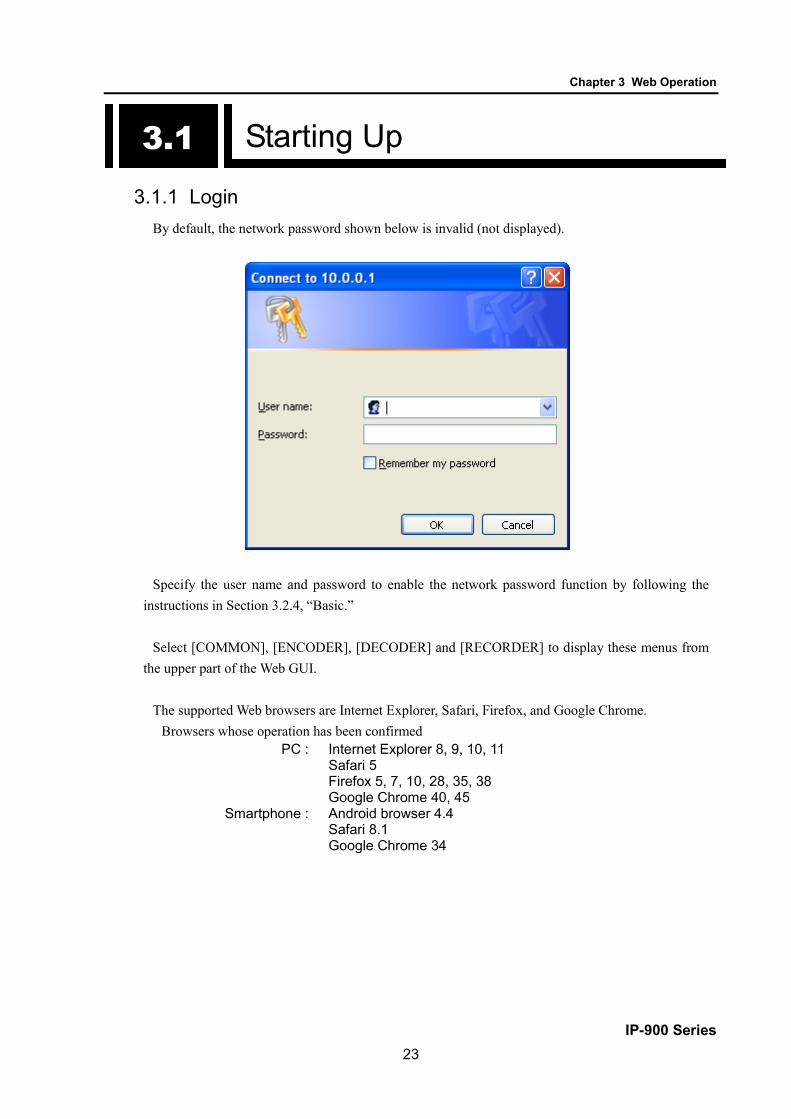
3.1.1 Login By default, the network password shown below is invalid (not displayed).
Specify the user name and password to enable the network password function by following the instructions in Section 3.2.4, “Basic.”
Select [COMMON], [ENCODER], [DECODER] and [RECORDER] to display these menus from
the upper part of the Web GUI. The supported Web browsers are Internet Explorer, Safari, Firefox, and Google Chrome.
Browsers whose operation has been confirmed PC : Internet Explorer 8, 9, 10, 11
Safari 5 Firefox 5, 7, 10, 28, 35, 38 Google Chrome 40, 45
Smartphone : Android browser 4.4 Safari 8.1 Google Chrome 34
3.1

Chapter 3 Web Operation
IP-900 Series 24
Figure 3-1 Screen for IP-900 series ENCODER Settings
Figure 3-2 Screen for IP-900 series DECODER Settings

Chapter 3 Web Operation
IP-900 Series 25
3.1.2 Remarks You may not be able to access the screen for a while when you turn on the power or reboot. Please
wait for around 1 min. after booting.
Chapter 3 Web Operation
IP-900 Series 26
3.2 Common Menu
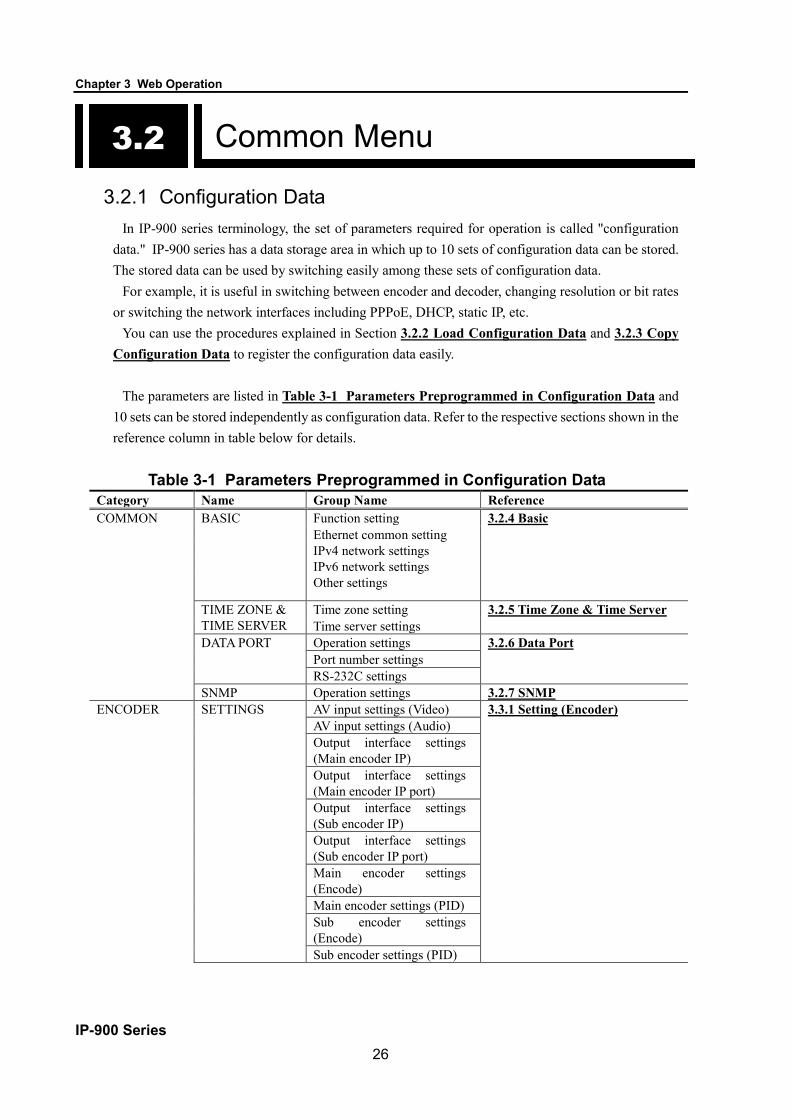
3.2.1 Configuration Data
In IP-900 series terminology, the set of parameters required for operation is called "configuration data." IP-900 series has a data storage area in which up to 10 sets of configuration data can be stored. The stored data can be used by switching easily among these sets of configuration data.
For example, it is useful in switching between encoder and decoder, changing resolution or bit rates or switching the network interfaces including PPPoE, DHCP, static IP, etc.
You can use the procedures explained in Section 3.2.2 Load Configuration Data and 3.2.3 Copy Configuration Data to register the configuration data easily.
The parameters are listed in Table 3-1 Parameters Preprogrammed in Configuration Data and
10 sets can be stored independently as configuration data. Refer to the respective sections shown in the reference column in table below for details.
Table 3-1 Parameters Preprogrammed in Configuration Data Category Name Group Name Reference COMMON BASIC Function setting 3.2.4 Basic
Ethernet common setting IPv4 network settings
IPv6 network settings Other settings
TIME ZONE & TIME SERVER
Time zone setting 3.2.5 Time Zone & Time Server Time server settings
DATA PORT Operation settings 3.2.6 Data Port Port number settings RS-232C settings SNMP Operation settings 3.2.7 SNMP ENCODER SETTINGS AV input settings (Video) 3.3.1 Setting (Encoder)
AV input settings (Audio) Output interface settings
(Main encoder IP)
Output interface settings (Main encoder IP port)
Output interface settings (Sub encoder IP)
Output interface settings (Sub encoder IP port)
Main encoder settings (Encode)
Main encoder settings (PID) Sub encoder settings
(Encode)
Sub encoder settings (PID)
3.2

Chapter 3 Web Operation
IP-900 Series 27
Category Name Group Name Reference ENCODER ENCODER
ADDRESS REPORT
Main/Sub Report settings 3.3.2 Encoder Address Report Main/Sub Destination settings
SUPERIMPOSE Superimpose information (1 to 4) of Main encoder
3.3.3 Superimpose
Superimpose information (1 to 4) of Sub encoder
RECORDER SETTINGS Recorder settings 3.4.1 Setting (Recorder) DECODER SETTINGS Input interface settings
(Decoder ethernet) 3.5.1 Setting (decoder)
Input interface settings (From Server)
Input interface settings (Decoder ethernet port)
AV output settings (Video) AV output settings (Audio) * Displayed only for IP-920E/D Decoder settings (Decode)
Decoder settings (PID) REFERENCE
SETTINGS Operation settings 3.5.2 Reference Clock
(GENLOCK)

Chapter 3 Web Operation
IP-900 Series 28
3.2.2 Load Configuration Data
Click LOAD CONFIGURATION in the left frame of the Web screen to display the screen below in the right frame.
Figure 3-3 Load Configuration screen
Figure 3-4 Load Configuration screen (for smartphone)

Chapter 3 Web Operation
IP-900 Series 29
◆Registering configuration data Select data numbers 1 to 10 from the pull down menu in “Configuration data” field.
Figure 3-5 Selecting Configuration Data
Assign the selected data a name using up to 16 alphanumeric characters in the Configuration name field, and click the button. The dialog box shown below appears. Click the OK button to change the registration number.
*) Reboot is required only when the operation mode is changed between encoder and decoder after
loading configuration.
Confirm that the configuration data number in the upper right red zone on the Basic setting screen
is changed to the previously selected number.
Configuration1: data1 Software: VxxLxxx

Chapter 3 Web Operation
IP-900 Series 30
Update the parameters listed in Table 3-1 Parameters Preprogrammed in Configuration Data using the following respective screens, and then click or button to update and register the configuration data.
Figure 3-6 Parameters, of which 10 Sets are handled as Configuration Data
#1 #2 #3 #4 #5 #6 #7 #8 #9 #10
Figure 3-7 Configuration Data (10 independent sets)

Chapter 3 Web Operation
IP-900 Series 31
◆Using configuration data Select (from 1 to 10) the data number you want to use from the configuration data field by
referring to the corresponding name in the Configuration name field. Click the button. When the following dialog box appears, click OK button. The
registration number of configuration data can be updated by IP-900 series. *) Reboot is required only when the operation mode is changed between encoder and decoder after
loading configuration.
Confirm that the configuration data number in the upper right red zone on the Basic setting screen has been changed to the previously selected number.
Configuration1: data1 Software: VxxLxxx

Chapter 3 Web Operation
IP-900 Series 32
Table 3-2 Configuration Data Selection Items
Item Description Parameter Load configuration
Configuration data
<In case of updating or registering> Ten types of configuration data
registered in advance can be switched, updated and registered for each. <In case of using>
Ten types of configuration data registered in advance can be switched.
- Data numbers 1 to 10
Configuration name
<In case of updating or registering > Arbitrary name can be specified for
each data.
<In case of using> The specified name can be used for
switching configuration data.
- Arbitrary name (using 16 alphanumeric characters)

Chapter 3 Web Operation
IP-900 Series 33
3.2.3 Copy Configuration Data
Maximum ten types of configuration data which selected in "LOAD CONFIGURATION” can be copied each other. The registered data’s parameter can be used for other configuration settings.
For example, the parameter can be used for creating updated configuration data using registered configuration data.
Click COPY CONFIGURATION in the left frame of the Web GUI to display the screen below in the right frame. Set up the required settings by referring to Table 3-3 Copy Configuration Setting Items.
Figure 3-8 Copy Configuration screen

Chapter 3 Web Operation
IP-900 Series 34
After completing the settings, click the button. The message below appears.
Click OK to apply the settings.
Table 3-3 Copy Configuration Setting Items
Item Description Parameter Select source configuration
Configuration data
Select one of the ten types of configuration data that have already been registered to copy the data.
- Data numbers 1 to 10
Copy to Configuration data 1-10
Select a configuration data of copying destination. Multiple configuration data can be selected, but the configuration data of origination and the configuration data which is currently in use cannot be selected.
- Radio buttons
Configuration name
Arbitrary name can be specified for each configuration data.
- Arbitrary name (using 16 alphanumeric characters)

Chapter 3 Web Operation
IP-900 Series 35
3.2.4 Basic * Basic comprises a group of setting items, of which 10 sets can be registered independently by
selecting data numbers as in 3.2.1 Configuration Data. You can set or change the settings of the parameters related to the network connection of IP-900
series or the operation mode in which it should operate after turning on the power. Set up the required settings by referring to Table 3-4 Basic Setting Items.
IMPORTANT
If you operate IP-900 series with the default IP address, disconnect it from your network. Connect it to the setting PC over a hub or directly through a UTP cable. Set it up to meet with the requirements for your network using PC and connect it to the network. If you connect it to your network with the default IP address, an unexpected failure may occur in your network.
Figure 3-9 Basic settings screen

Chapter 3 Web Operation
IP-900 Series 36
After completing the settings, click button. The following message appears.
Table 3-4 Basic Setting Items
Item Description Parameter Function setting
Operation mode *for Encoder
Select the operation mode of encoder and sub encoder.
- Main H.264/MPEG-4 AVC 1stereo | Sub H.264/MPEG-4 AVC 1stereo (Default) - Main H.264/MPEG-4 AVC 2stereo
Operation mode *for Decoder
Select the operation mode of decoder.
- Normal (Fixed)
Ethernet common settings
Ethernet type Select the Ethernet type. - AUTO (default) - 100Base-TX Full - 100Base-TX Half - 10Base-T Full - 10Base-T Half
MTU size Specify in bytes the maximum size of IP packets to be sent to the LAN.
1280 to 1500 bytes (Default: 1454) * For PPPoE, specify 1454 (recommended).
IPv4 network settings
IP address mode Specify how to get IPv4 address
- DHCP - PPPoE - Static IP (Default)
IP address
Specify the IPv4 address when "Static IP" is set for [IP address mode].
IPv4 address other than the following: 224.0.0.0 to 239.255.255.255 (Class D) 240.0.0.0 to 255.255.255.255 (Class E) 0.0.0.0, 127.0.0.0 to 127.255.255.255 (Default: 10.0.0.1)
Subnet mask
Specify the IPv4 subnet mask when "Static IP" is set for [IP address mode].
Subnet mask other than the following: 255.255.255.254, 255.255.255.255 (Default: 255.0.0.0)
Default Gateway address
Specify the default gateway address of IPv4 when "Static IP" is set for [IP address mode].
IPv4 address other than the following: 224.0.0.0 to 239.255.255.255 (Class D) 240.0.0.0 to 255.255.255.255 (Class E) 127.0.0.0 to 127.255.255.255 (Default: None (represented as 0.0.0.0))
User ID for PPPoE
Specify the user ID when "PPPoE" is set for [IP address mode].
64 en-size alphanumeric characters (Default: Blank)
Password for PPPoE
Specify the password when "PPPoE" is set for [IP address mode].
64 en-size alphanumeric characters (Default: Blank)

Chapter 3 Web Operation
IP-900 Series 37
Item Description Parameter IPv6 network settings
IP address mode Specify the IPv6 address acquisition method.
- Stateless - Static IP (default)
IP address
Specify the IPv6 address when "Static IP" is set for [IP address mode].
Global unicast IP address 2xxx:xxxx:…:xxxx to 3xxx:xxxx:…:xxxx (Default: ::)
Prefix Specify the prefix of the IPv6 address when "Static IP" is set for [IP address mode].
3 to 128 (Default: 64)
Default gateway address
Specify the default gateway address when "Static IP" is set for [IP address mode].
Global unicast address 2xxx:xxxx:...:xxxx to 3xxx:xxxx:...:xxxx (Default: ::)
Other settings
User authentication
Specify whether to enable user authentication for accessing the Web screen.
- Enable - Disable (Default)
User ID Specify the user name for authentication.
16 alphanumeric characters (Default: Blank)
Password Specify the password for authentication.
16 alphanumeric characters (Default: Blank)
WEB server title Specify the character strings to be displayed on the title bar of the Web screen. This title is used to identify the Web screen with the equipment name.
The specified string must be not exceeded 64 single bytes. (Default: blank)
Note) If booting is worked in combination with the Cancel key (refer to IP-900 series User’s Guide), the IP address and subnet mask on both LAN and CONSOLE ports are temporarily reset to the defaults (LAN IPv4 address 10.0.0.1, subnet mask 255.0.0.0, IPv6 address :: and prefix: 64). If it becomes unclear what an IP address is, connect the equipment with the defaults and use the setup menu to confirm the IP address and subnet mask. The password restriction is also disabled for this case. Hold down the MNT button until the RDY LED starts blinking in orange. The equipment reboots, but the specified IP address and subnet mask are restored in the equipment.
■ Operation Modes Main H.264/MPEG-4 AVC 1stereo | Sub H.264/MPEG-4 AVC 1stereo
Main encoder and sub encoder encode video by H.264/MPEG-4 AVC. Audio encoding supports stereo 1channel.
Main H.264/MPEG-4 AVC 2stereo Main encoder encodes video by H.264/MPEG-4 AVC. Audio encoding supports stereo 2channels. Sub encoder is not usable.
* Encoder and Recorder settings are initialized when operation mode is changed.

Chapter 3 Web Operation
IP-900 Series 38
3.2.5 Time Zone & Time Server * Time Zone & Time Server is a group of setting items, of which 10 sets can be registered
independently by selecting data numbers as in 3.2.1 Configuration Data. Set the time zone and time server at the location where IP-900 series is installed. Click TIME ZONE
& TIME SERVER in the left frame of the Web screen. The Time Zone & Time Server screen appears in the right frame. Make settings according to the operation mode by referring to Table 3-5 Time Zone Setting Item and Table 3.6 Time Server Setting Items.
Figure 3-10 Time Zone & Time Server Settings screen

Chapter 3 Web Operation
IP-900 Series 39
After completing the settings, click button. The message below appears. Click OK to apply the settings. *Reboot is not required.
Table 3-5 Time Zone Setting Items
Item Description Parameter Time zone Select the time zone at the IP-900
series installation site. (Default: Asia/Tokyo)
UTC offset Specify the time difference from Coordinated Universal Time (UTC) when "UTC offset" is selected for [Time zone].
(Default: 0 Hours)
Table 3-6 Time Server Setting Items
Item Description Parameter Auto synchronization
Specify whether to automatically synchronize with the time server.
- Disable (Default) - Enable
Synchronization interval
Specify in minutes the interval in which synchronization with the time server is performed.
1 to 65535 minutes (Default: 45)
IP version Set the IP address version. - IPv4 (Default) - IPv6
Server IP address Set the IP address of the time server. Other than 0.0.0.0 (Default: 0.0.0.0) * You cannot specify a multicast address.

Chapter 3 Web Operation
IP-900 Series 40
3.2.6 Data Port * Data Port is a group of setting items, of which 10 sets can be registered independently by
selecting data number as in 3.2.1 Configuration Data. This setup is performed to enable data communication with another device on the IP network by
connecting the external device through the RS-232C port (D-sub 9-pin) on front panel of IP-900 series.
Click DATA PORT of the left frame in the Web GUI and Data Port screen appears in the right frame, where you can set parameters for data communication with another device via the IP network. Make the required settings by referring to Table 3-7 Data Port Setting Items and Table 3-8 Operations Modes.
Figure 3-11 Data Port Settings screen

Chapter 3 Web Operation
IP-900 Series 41
After completing the settings, click the button. The message below appears. Click OK to apply the settings. *Reboot is not required.
Table 3-7 Data Port Setting Items Item Description Parameter
Operation settings
Data port Specify whether to use data port communication.
- Enable - Disable (Default)
Operation mode Specify the operation mode of data port communication.
- TCP server mode(Bidirectional) (Default) - TCP server mode(Receiving only) - TCP client mode(Bidirectional) - TCP client mode(Modem) *“IPv4” is the fixed value for [IP version] when TCP client mode is set.
IP version Set the IP address version - IPv4 (Default) - IPv6
Destination IP address
Specify the IP address of the data communication destination when "TCP client mode (bidirectional)" is set for [Test mode].
- IPv4 (Default) - IPv6
Specify the IP address of the data communication destination when "TCP client mode (bidirectional)" is set for [Test mode].
Other than 0.0.0.0 (Default: 0.0.0.0)
Port number settings
Server mode Specify the port number of the own device when "TCP server mode (bidirectional)" is set for [Test mode].
1024 to 64000 (Default: 6000)
Client mode Specify the port number of the own device when "TCP client mode (bidirectional)" is set for [Test mode].
0 or 1024 to 64000 (Default: 0) * A port number from 1024 to 4096 is automatically selected when “0” is set.
Specify the port number of the destination device when "TCP client mode (bidirectional)" is set for [Test mode].
1024 to 64000 (Default: 6000)
RS-232C settings
Timeout Specify as [ms] for [Timeout] in [RS-232C Settings] section.
20 to 200ms (Default: 20) * The duration to detect a time-out is defined as "the set value rounded down by a multiple of '20[ms]'" + "RS-232C polling interval of the device (20[ms])". e.g.) In case of setting '60'; '60' + '20' = 80 [ms] In case of setting '50' ; '40' + '20' = 60 [ms]

Chapter 3 Web Operation
IP-900 Series 42
Item Description Parameter RS-232C settings
Delimiter code 1 Specify [Delimiter code 1] in [RS-232C Settings] section.
Blank or hexadecimal values from 00 to ff (Default: Blank) * A blank field means that no value is specified.
Delimiter code 2 Specify [Delimiter code 2] in [RS-232C Settings] section.
Blank or hexadecimal values from 00 to ff (Default: Blank) * Blank means no values are specified.
Baud rate Specify the RS-232C communication speed by selecting from pull down menu.
1200/2400/4800/9600 (Default) /19200/38400 bps
Bit length Select the RS-232C character size. 7 bits or 8 bits (Default) Parity Select whether to use RS-232C parity. None (Default), Odd or Even Stop bits Select the length of RS-232C stop bits. 1 bit (Default) or 2 bits Flow control Select whether to set RS-232C flow
control. None (Default), RS or CS
DTR signal monitoring
In case of setting as “TCP client mode(modem)” for [Operation mode], this item is enabled to set whether to monitor DTR of RS-232C control signals.
- Enable (Default) - Disable (*1)
*1: “DTR signal monitoring” - In case of setting as “Disable”, ignores DTR signal and always set as ON. The escape code is enabled
and the data port connection is disconnected by AT command (ATH0) after switching to the escape mode.
- In case of setting as “Enable”, the data port connection is disconnected when the DTR signal is set as OFF (default). When the DTR signal is turned ON, it is switched to the command mode that allows AT command. When signal is OFF, AT command is discarded when received. Also, the escape code is disabled. Therefore, line disconnection is performed when the DTR signal is set as OFF.

Chapter 3 Web Operation
IP-900 Series 43
Table 3-8 Operation Modes Operation mode Description
(1) TCP server mode(Bidirectional)
Bidirectional data communication is performed between the data port and another device connected via the IP network. IP-900 series waits, at the specified port number, for connection from the destination device. (IP address setting is not required.)
(2) TCP server mode(Receiving only)
Data received from another device connected via the IP network is output to the data port. Data received from the data port is not sent to the destination device. IP-900 series waits, at the specified port number, for connection from the destination device. (IP address setting is not required.)
(3) TCP client mode(Bidirectional)
Bidirectional data communication is performed between the data port and another device connected via the IP network. IP-900 series sets up a connection through the specified port to the device with the specified IP address.
(4) TCP client mode(Modem) Bidirectional data communication is performed between the data port and the other device connected via the IP network. Destination IP address sets up a connection to the device of IP address notified by AT command from DTE connected via RS-232C. Also, decoder switches stream receiving address to the same IP address after connecting. When the operation mode is set other than “TCP client mode modem”, AT command is handled same as the normal data.
Note) Following combinations of modes are available for data communication among IP-900 series: (1) <-> (3), (4) (2) <-> (3), (4)

Chapter 3 Web Operation
IP-900 Series 44
Table 3-9 AT Command Supported by IP-900 Series Item Command Contents Note 1 Dn Connected with the destination device
for data port connection. IPv4 address of the connecting destination device is specified for n. The numbers other than 0 to 9 are ignored. <Example> ATD192.168.001.001 Connects the device of 192.168.1.1 for data port connection. ・When connecting with the destination device, "CONNECT" is responded and the CD signal is set to ON. ・When connection with the destination device cannot be made after a certain period of time (about 50 secs), "NO CARRIER" is responded and the command is terminated.
・Valid in case of the command mode ・3 digits + 3 digits + 3 digits + 3digits (12 digits in total) are specified for IPv4 address. "ERROR is responded to non-12 digits (0 is not omissible). <Example> ”ATD010-000-000-001<CR>”, ”ATD010.000.000.001<CR>” ・Specifies IPv4 unicast address of units other than yours for IPv4 address. "ERROR" is responded to the other addresses. ・Decoder connects data port to the device of specified IPv4 address and makes streaming request. ・Encoder connects data port to the device of specified 4 address. ・When receiving data from DTE before "CONNECT" is responded, connection is canceled, "NO CARRIER" is responded and the command is terminated.
2 Hn The data port connection is disconnected and he CD signal is turned OFF. Only n=0 is valid.
・Valid in case of the escape mode
3 On Switched from the escape mode during transmission. Only n=0 is valid.
・Valid in case of the escape mode
4 +++ Switched to the escape mode during transmission.
・Please input “+” for 3 consecutive times within one second when inputting. ・If the other characters are input within one second before and after inputting “+++”, it does not change to escape mode. ・If “Enable” is set for ”DTR signal surveillance”, the escape code is disabled and it does not switch to the escape mode.
Note) AT command format ・Available AT command format on IP-900 Series is given as follows:
AT+<command>+<parameter>+<CR> (<CR> can also be <CR+LF>) ・AT command begins with AT and ends with CR code (or CR code + LF code). ・AT command’s <command>+<parameter> are 32 letters (ASCII) at the maximum. ・AT command can specify only 1 command per a line. ・AT command allows only capital or small letters and combination of them are unusable.
(Example: ATD192.168.001.001 → usable, atD192.168.001.001 → unusable)

Chapter 3 Web Operation
IP-900 Series 45
Table 3-10 Messages Responded by IP-900 Series
No Result code Contents Note 1 OK Command was terminated normally
2 CONNECT Data port connection with the destination device was made
Transmission speed is not displayed (ATX0 equivalent)
3 NO CARRIER Line was disconnected (carrier was
not detected/was lost during transmission)
4 ERROR Command error (unacceptable command was executed)
Note) Result format ・The result format responded by IP-900 Series is as follows:
<CR>+<LF>+<result code>+<CR>+<LF> ・Result code respond characters (ATV1 equivalent)

Chapter 3 Web Operation
IP-900 Series 46
3.2.7 SNMP
* SNMP is a group of setting items, of which 10 sets can be registered independently by selecting data numbers as in 3.2.1 Configuration Data.
Click SNMP of the left frame in the Web GUI and SNMP screen appears in the right frame, where you can set parameters for SNMP with the counterpart device over IP network. Make the required settings by referring to Table 3-11 SNMP Setting Items.
Figure 3-12 SNMP Settings screen

Chapter 3 Web Operation
IP-900 Series 47
After completing the settings, click the button. The message below appears. Click OK to apply the settings. * Reboot is not required.
Table 3-11 SNMP Setting Items Item Description Parameter
SNMP agent Specify whether to enable SNMP agent. - Disable (Default) - Enable
Manager #1 to 10
SNMP version Specify the SNMP version of SNMP manager.
- SNMPv1 (Default) - SNMPv2c
Community
Specify the community name to accept the SNMP request from the SNMP manager.
Alphanumeric 16 characters (Default: Blank)
IP version Specify the IP version of the IP address of SNMP manager.
- IPv4 (Default) - IPv6
IP address Specify the IP address of SNMP manager. (Max. 10 managers can be registered.)
An IP address other than 0.0.0.0 (Default: Blank) * A blank field means that no value is specified. * You cannot specify a multicast address.

Chapter 3 Web Operation
IP-900 Series 48
3.2.8 Operation & Status (Common) Click OPERATION & STATUS in the left frame of the Web screen. The Operation & Status screen
appears in the right frame, where you can check the status of equipment operation such as the state of LAN operation. Refer to Table 3-12 Operation & Status Display Items for details.
Selecting {3 sec, 5sec, or 10sec} from [Auto update] enables automatic updating of the performance
data in specified time intervals. Select {none} from [Auto update] to disable automatic updating.
Figure 3-13 Operation & Status screen

Chapter 3 Web Operation
IP-900 Series 49
Table 3-12 Operation & Status Display Items Item Display
Serial number Displays the serial number LAN IP address (IPv4) {DHCP/PPPoE/Static IP}
Displays the IPv4 address acquisition mode. [xxx.xxx.xxx.xxx (IPv4)]
Displays the IPv4 address. xxx.xxx.xxx.xxx: IPv4 address
LAN subnetmask (IPv4) xxx.xxx.xxx.xxx Displays the IPv4 subnet mask. xxx.xxx.xxx.xxx: Subnet mask
Default gateway address (IPv4) xxx.xxx.xxx.xxx Displays the default gateway address of IPv4. xxx.xxx.xxx.xxx: Default gateway address
LAN IP address (IPv6) Link-Local/[xxxx:xxxx: ... :xxxx(IPv6)] Displays the IPv6 link-local address. xxxx:xxxx: ... :xxxx: Link-Local address
{Stateless/Static IP} Displays the IPv6 address acquisition method. * If the IPv6 address acquisition method is "Stateless," up to four sets of global unicast address/prefix are displayed according to the address acquisition status.
[yyyy:yyyy: ... :(IPv6)] Displays the IPv6 global unicast address. yyyy:yyyy: ... :yyyy: Global unicast address
[zzz] Displays the prefix of the IPv6 global unicast address. zzz: Prefix
Default gateway address (IPv6) xxxx:xxxx: ... :xxxx Displays the default gateway address of IPv6. xxx:xxx. ... :xxx: Default gateway address * If the IPv6 address acquisition method is "Stateless," up to four default gateway addresses are displayed according to the address acquisition status.
LAN Mac address Displays the MAC address. LAN link {Connected / Disconnected}
Displays the LINK status. {100Base-TX Full Duplex / 100Base-TX Half Duplex / 10Base-T Full Duplex / 10Base-T Half Duplex} Displays the LAN interface operation status.
Time server {Normal / Fault / Synchronization failure/ ---} Displays the status of synchronization with the specified time server.

Chapter 3 Web Operation
IP-900 Series 50
Item Display Data port {Normal / Normal (Command mode) / Normal (Escape mode) / Normal
(DSR OFF) / Fault / ---} Displays the communication status of data port communication. {TCP server mode / TCP server mode (Receiving only) / TCP client mode / TCP client mode (Modem)} Displays the operation mode of data port communication.
{IP address} Displays the IP address of the destination device for data port communication. - TCP server mode / TCP server mode (receiving only) Displays the IP address of the destination device when data port communication is established. (Displays 0.0.0.0 when no communication is set up.) - TCP client mode Displays the IP address of the destination device for data port communication. - TCP client mode (Modem)
Displays the IP address of the destination device specified by AT command. {Port number}
Displays the port number of the destination device for data port communication. - TCP server mode / TCP server mode (receiving only) Displays the port number of the destination device when data port communication is established. - TCP client mode Displays the port number of the destination device for data port communication. - TCP client mode (Modem)
Displays the port number of the destination device only when data port communication is established.
SNMP {Normal / ---} Display the status of the SNMP agent.
Component temperature Displays the internal temperature (ºC) of the equipment. Note) {A/B} indicates that either A or B is displayed.

Chapter 3 Web Operation
IP-900 Series 51
3.2.9 Alarm Click ALARM of the left frame in the Web screen and the Alarm screen appears in the right frame,
where you can check the alarm list. Refer to Table 3-13 Alarm List for details. Select {3 sec, 5sec, or 10sec} from [Auto update] to enable automatic update of the performance data
in specified time intervals. Select {none} from [Auto update] to disable automatic updating.
Figure 3-14 Alarm Settings screen

Chapter 3 Web Operation
IP-900 Series 52
Table 3-13 Alarm List
Code Name Description Details (The part after the * mark is not displayed.) I001 SDI input down HD/SD-SDI input signal is not detected - I002 HDMI input down HDMI input signal is not detected - I003 Analog video input down Analog video input signal is not detected - I006 Reference clock input down (*8) External reference clock input signal is
not detected -
I011 Video synchronization error Video synchronization error is occurred - I016 Reference clock synchronization
failure (*8) Synchronization failure with reference clock is occurred
-
I021 Input data error (*1) Count-up is occurred in the performance statistics error counter
#xxxxxxxxxxxxxxxx * 64-bit hexadecimal number. For the meaning of each bit, refer to Table 3-14, "Bit Formats for Input Data Errors."
E001 Power error (*2) Power failure is occurred #1 * Power failure on CNT board #2 * Power failure on COD board
E003 Temperature error (*3) Extreme temperature is detected (shutdown processing started)
#1 TEMP1=t1 TEMP2=t2 FAN=xxxRPS #2 TEMP1=t1 TEMP2=t2 FAN=xxxRPS * Details are as follows: #1/#2: Number of the temperature sensors that is detected a temperature error t1: Temperature indicated by temperature sensor 1 t2: Temperature indicated by temperature sensor 2 xxx: FAN rotational speed
E004 FlashROM error (*2) Internal FlashROM access error occurred
/dev/mtd0 to 15 * Displays the occurrence range of access error.
E00A FlashROM check sum error (*2) Configuration data error detected in internal FlashROM
software bundle software configuration configuration#1~#10 option * Displays the range of check sum errors.
E010 FAN error (*4) FAN error (low speed) is occurred xxxRPS * xxx: FAN rotational speed

Chapter 3 Web Operation
IP-900 Series 53
Code Name Description Details (The part after the * mark is not displayed.) E013 Temperature warning (*4) Temperature warning (alarm only) is
detected #1 TEMP1=t1 TEMP2=t2 FAN=xxxRPS #2 TEMP1=t1 TEMP2=t2 FAN=xxxRPS * Details are as follows: #1/#2: Number of the temperature sensors that is detected a temperature warning. t1: Temperature indicated by temperature sensor 1 t2: Temperature indicated by temperature sensor 2 xxx: FAN rotational speed
E082 CODEC1 error Main CODEC LSI error is detected Blank, #1 * Displays the occurrence location of CODEC1 error. E083 CODEC2 error Sub CODEC LSI error is detected - E084 CF card access error (*6) CF card access failure is detected - E085 CF card power error (*6) Overcurrent to CF card is detected - E08B SUB CPU1 error (*5) SUB CPU1 error is detected - E08C SUB CPU2 error (*5) SUB CPU2 error is detected - E08E Clock error (*2) Clock error or interruption is detected #1 to #4 * Indicates the location where a clock error is
occurred. E08F Memory error (*2) SDRAM memory check error is detected #1 to #7 * Indicates the location where a memory error is
occurred. E093 Buffer overflow (*7) Buffer overflow is occurred #1, #2 * Indicates the location where a buffer overflow is
occurred. *1: The DEC LED blinks while this alarm is active. The LED is turned off for 10 seconds after the error is restored.
Refer to 3. 2. 11 Performance Statistics for the details of the statistical information counter regarding the alarm. *2: After this error is occurred, the ALM LED remains on. The device is required to reboot to turn off the ALM LED. *3: If an extreme temperature is detected, all LEDs except LINK/ACT, 10/100 are on. The device is required to reboot to turn off the LEDs. *4: The ALM LED blinks while this alarm is active. The LED is turned off when the alarm cause is restored. *5: After this error is occurred, retry for restoration is the next step. If the retry for restoration is unsuccessful, the ALM LED remains on.
The device is required to reboot to turn off the ALM LED. *6: After this error is occurred, the ALM LED remains to blink. *7: The ALM LED blinks while this alarm is active. The LED is turned off when the alarm cause is restored.
In case that the settings exceeds the capacity of the IP network, please reconfigure them to meet with the network requirement. *8: DEC LED blinks while reference error has been occurred. The LED is turned off after reference errors are restored.

Chapter 3 Web Operation
IP-900 Series 54
Table 3-14 Input Data Error Bit Format
Bit 63 62 61 60 59 - 0
Type Decoder Undefined
Interface
IP IP IP IP
Undefined
Performance stats
Number of
reloading TS
stream
Number of
discontinuous PCR
Number of video decoding
errors
Number of audio decoding
errors

Chapter 3 Web Operation
IP-900 Series 55
3.2.10 Log Click LOG of the left frame in the Web screen and Log information appears in the right frame, where
you can check the alarm log. Refer to Table 3-15 Log Type for details. If you click the button, the alarm log is detected completely. * Up to 100 log items per page can be saved to up to 10 pages (1,000 log items in total). Log items
exceeding 1,000 items are overwritten beginning with the chronologically oldest items.
Figure 3-15 Log information screen

Chapter 3 Web Operation
IP-900 Series 56
Table 3-15 Log Type
Code Name Description Details (The part after the * mark is not displayed.) 0001 Boot (Power ON) Normal start with the switch VxxLxxxCxx yyyy
* Displays the software version and configuration name. VxxLxxxCxx: Software version yyyy: Configuration name
0002 Boot (Reset) Normal start after reboot the equipment VxxLxxxCxx yyyy * Displays the software version and configuration name. VxxLxxxCxx: Software version yyyy: Configuration name
0004 Boot (Initial maintenance) Normal start using the bundled firmware - 0005 Boot (Maintenance) Normal start in maintenance mode VxxLxxxCxx yyyy
* Displays the software version and configuration name. VxxLxxxCxx: Software version yyyy: Configuration name
0006 Software update Software is updated VxxLxxxCxx -> VyyLyyyCyy * Displays the new and old software versions. VxxLxxxCxx: Old software version VyyLyyyCyy: New software version
0007 Boot (Restart) (*1) Restart because of CPU failure VxxLxxxCxx yyyy * Displays the software version and configuration name. VxxLxxxCxx: Software version yyyy: Configuration name
0008 Boot (Others) (*1) Restart because of software failure VxxLxxxCxx yyyy * Displays the software version and configuration name. VxxLxxxCxx: Software version yyyy: Configuration name
0009 Shutdown Shutdown with MNT button - 000A RTC initialization RTC battery backup discharged electricity - 000B CF card initialization CF card is formatted - 000C Configuration update Configuration data is updated - 000D Basic settings update Basic settings are updated -

Chapter 3 Web Operation
IP-900 Series 57
Code Name Description Details (The part after the * mark is not displayed.) 000E Configuration data change Configuration data is changed xxxx -> yyyy
* Displays the old and new configuration names. xxxx: Old configuration name yyyy: New configuration name
000F Configuration data initialization Configuration data is initialized - 0010 Option update Option is installed HD etc. 0020 Device reset Reset the individual device #11 * CODEC1
#21 * CODEC2 #12 * CODEC1(Audio stereo-2ch)
0030 Protect file recording start Start the protected file recording Network / DI / Network & DI * Displays the protect file recording start trigger
0031 Protect file recording stop Stop the protected file recording Trigger restoration / Timer expired / Full Date & Time change / Setting change / Others * Displays the protect file recording stop trigger
0032 Protect file release Release the protected file Timer expired / User * Displays the protect file release trigger
L001 Link error (LAN) Link disconnection at a LAN port is occurred
-
*L001 Link error restoration (LAN) Restored from link disconnection at a LAN port
10BaseT_HD/10BaseT_FD/100BaseTX_HD/100BaseTX_FD * Displays the operating status of the LAN interface
L006 Time server synchronization failure Time synchronization with the time server is failed
-
*L006 Time server synchronization success Time synchronization with the time server is successful
-
L009 DHCP connection failure(*5) DHCP server is disconnected - *L009 DHCP connection success(*5) Connected to the DHCP server xxx.xxx.xxx.xxx/yy,zzz.zzz.zzz.zzz
* Displays the IPv4 address acquired from the DHCP server. xxx.xxx.xxx.xxx: IPv4 address yy: Subnet mask bit count zzz.zzz.zzz.zzz: Gateway address

Chapter 3 Web Operation
IP-900 Series 58
Code Name Description Details (The part after the * mark is not displayed.) L00A PPPoE connection failure(*5) PPPoE server is disconnected - *L00A PPPoE connection success(*5) Connected to the PPPoE server xxx.xxx.xxx.xxx/yy,zzz.zzz.zzz.zzz
* Displays the IPv4 address acquired from the PPPoE server. xxx.xxx.xxx.xxx: IPv4 address yy: Subnet mask bit count zzz.zzz.zzz.zzz: Gateway address
L00E DHCP connection update IP address update is occurred during DHCP connection
xxx.xxx.xxx.xx1/y1,zzz.zzz.zzz.zz1 -> xxx.xxx.xxx.xx2/y2,zzz.zzz.zzz.zz2 * Displays the old and new IPv4 addresses acquired from the DHCP server. xxx.xxx.xxx.xx1: Old IPv4 address y1: Old subnet mask bit count zzz.zzz.zzz.zz1: Old gateway address xxx.xxx.xxx.xx2: New IPv4 address y2: New subnet mask bit count zzz.zzz.zzz.zz2: New gateway address
L00F PPPoE connection update IP address update is occurred during PPPoE connection
xxx.xxx.xxx.xx1/y1,zzz.zzz.zzz.zz1 -> xxx.xxx.xxx.xx2/y2,zzz.zzz.zzz.zz2 * Displays the old and new IPv4 addresses acquired from the PPPoE server. xxx.xxx.xxx.xx1: Old IPv4 address y1: Old subnet mask bit count zzz.zzz.zzz.zz1: Old gateway address xxx.xxx.xxx.xx2: New IPv4 address y2: New subnet mask bit count zzz.zzz.zzz.zz2: New gateway address
L010 Stateless address connection failure (*5)
IPv6 stateless address connection is failed -
*L010 Stateless address connection success(*5)
IPv6 stateless address is successfully connected
xxxx:xxxx:…:xxxx/yy * Displays the IPv6 address acquired from the router. xxxx:xxxx: … :xxxx: IPv6 address yy: Subnet prefix length

Chapter 3 Web Operation
IP-900 Series 59
Code Name Description Details (The part after the * mark is not displayed.) L011 Stateless address update IPv6 stateless address update is occurred xxxx:xxxx:…:xxx1/y1 -> xxxx:xxxx:…:xxx2/y2
* Displays the old and new IPv6 addresses acquired from the router. xxxx:xxxx: … :xxx1: Old IPv6 address y1: Old subnet prefix length xxxx:xxxx: … :xxx2: New IPv6 address y2: New subnet prefix length
I001 SDI input down HD/SD-SDI input signal is not detected - *I001 SDI input restoration Normal HD/SD-SDI input - I002 HDMI input down HDMI input signal is not detected - *I002 HDMI input restoration Normal HDMI input - I003 Analog video input down Analog video input signal is not detected - *I003 Analog video input restoration Normal analog video input - I006 Reference clock input down (*9) Input signal of external reference is not
detected -
*I006 Reference clock input restoration(*9) Normal input of external reference - I011 Video synchronization error Video input PLL synchronization error is
occurred
*I011 Video synchronization error restoration Restored from video input PLL synchronization error
I016 Reference clock synchronization failure (*9)
Synchronization failure with reference clock is occurred
-
*I016 Reference clock synchronization failure restoration (*9)
Synchronization failure with reference input is restored
-
I021 Input data error (*2) Count-up is occurred in the performance data error counter
#xxxxxxxxxxxxxxxx * 64-bit hexadecimal number. For the meaning of each bit, refer to Table 3-14, "Input data error bit format".
*I021 Input data error restoration (*2) Restored from count-up of the performance data error counter
-
E001 Power error (*3) Power error is occurred #1 * Power error on CNT board #2 * Power error on COD board

Chapter 3 Web Operation
IP-900 Series 60
Code Name Description Details (The part after the * mark is not displayed.) E003 Temperature error (*4) Extreme temperature (shutdown processing
started) is detected * Details are as follows: #1/#2: Number of the temperature sensor that is detected a temperature error t1: Temperature indicated by temperature sensor 1 t2: Temperature indicated by temperature sensor 2 xxx: FAN rotational speed
E004 FlashROM error (*3) Internal FlashROM access error is occurred /dev/mtd0 to 15 * Displays the range of access error.
E00A FlashROM check sum error (*3) Configuration data error is detected in internal FlashROM
Software bundle software configuration configuration#1~#10 * Displays the range of check sum errors.
E010 FAN error (*5) FAN error (low speed) is occurred xxxRPS * xxx: FAN rotational speed *E010 FAN error restoration (*5) FAN speed is restored xxxRPS * xxx: FAN rotational speed E013 Temperature warning (*5) Temperature warning (alarm only) is
detected #1 TEMP1=t1 TEMP2=t2 FAN=xxxRPS #2 TEMP1=t1 TEMP2=t2 FAN=xxxRPS * Details are as follows: #1/#2: Number of the temperature sensors that is detected a temperature warning. t1: Temperature indicated by temperature sensor 1 t2: Temperature indicated by temperature sensor 2 xxx: FAN rotational speed
*E013 Temperature warning restoration (*5) Restored from temperature warning #1 TEMP1=t1 TEMP2=t2 FAN=xxxRPS #2 TEMP1=t1 TEMP2=t2 FAN=xxxRPS * Details are as follows: #1/#2 : Number of the temperature sensors that is detected a temperature warning restoration. t1: Temperature indicated by temperature sensor 1 t2: Temperature indicated by temperature sensor 2 xxx: FAN rotational speed
E082 CODEC1 error Main HD CODEC LSI error is detected Blank, #1 * Displays the location of CODEC1 error.

Chapter 3 Web Operation
IP-900 Series 61
Code Name Description Details (The part after the * mark is not displayed.) E083 CODEC2 error Sub CODEC LSI error is detected - E084 CF card access error (*7) CF card access failure is detected - E085 CF card power error (*7) Overcurrent to CF card is detected - E08B SUB CPU1 error (*6) SUB CPU1 error is detected - *E08B SUB CPU1 error restoration (*6) Restored from SUB CPU1 error - E08C SUB CPU2 error (*6) SUB CPU2 error is detected - *E08C SUB CPU2 error restoration (*6) Restored from SUB CPU2 error - E08E Clock error (*3) Clock error or interruption is detected #1 to #4
* Indicates the location where a clock error has occurred.
E08F Memory error (*3) SDRAM memory check error is detected #1 to #7 * Indicates the location where a memory error has occurred.
E093 Buffer overflow (*8) Buffer overflow is occurred #1, #2 * Indicates the location where a buffer overflow has occurred.
*E093 Buffer overflow restoration (*8) Restored from buffer overflow #1, #2 * Indicates the location of buffer overflow restoration.

Chapter 3 Web Operation
IP-900 Series 62
*1: The ALM LED is on while this alarm is active. The LED is turned off when the error is restored. *2: The DEC LED blinks while this alarm is active. The LED is turned off for 10 seconds after the error is restored.
Refer to 3. 2. 11 Performance Statistics for the details of the performance data counter regarding the alarm. *3: After this error is occurred, the ALM LED remains on. The device is required to reboot to turn off the ALM LED. *4: If temperature warning is detected, all LEDs except LINK/ACT, 10/100 are on. The device is required to reboot to turn off the LEDs. *5: The ALM LED blinks while this alarm is active. The LED is turned off when the alarm cause is restored. *6: After this error is occurred, retry for restoration is the next step. If the retry for restoration is unsuccessful, the ALM LED remains on.
The device is required to reboot to turn off the ALM LED. *7: After this error is occurred, the ALM LED remains to blink. *8: The ALM LED blinks while this alarm is active. The LED is turned off when the alarm cause is restored.
In case that the settings exceeds the capacity of the IP network, please reconfigure them to meet with the network requirement. *9: DEC LED blinks while reference error has been occurred. The LED is turned off after reference errors are restored.
If an alarm occurs, the Fujitsu maintenance engineer may ask you to collect not only alarm log information but also detailed log information about the inside of the device. Save the detailed log information to a personal computer by click the [GET LOG] button, and then hand it over to the maintenance engineer.

Chapter 3 Web Operation
IP-900 Series 63
3.2.11 Performance Stats Click PERFORMANCE STATS of the left frame in the Web GUI and the Performance Stats screen
appears in the right frame. Select the port from {Main Encoder (Ethernet), Sub Encoder, Decoder (Ethernet), Data Port} and the interval from {All, Hour, Day, Week or Month} and then click to check the various types of performance data shown in Table 3-16 Performance Stats Items.
Select {3sec, 5sec, or 10sec} from [Auto update] enables automatic updating of the performance data
in specified time intervals. Select {none} from [Auto update] to disable automatic updating. Click the button to delete all performance data.
Figure 3-16 Performance Stats screen (Main Encoder)

Chapter 3 Web Operation
IP-900 Series 64
Figure 3-17 Performance Stats screen (Sub Encoder)
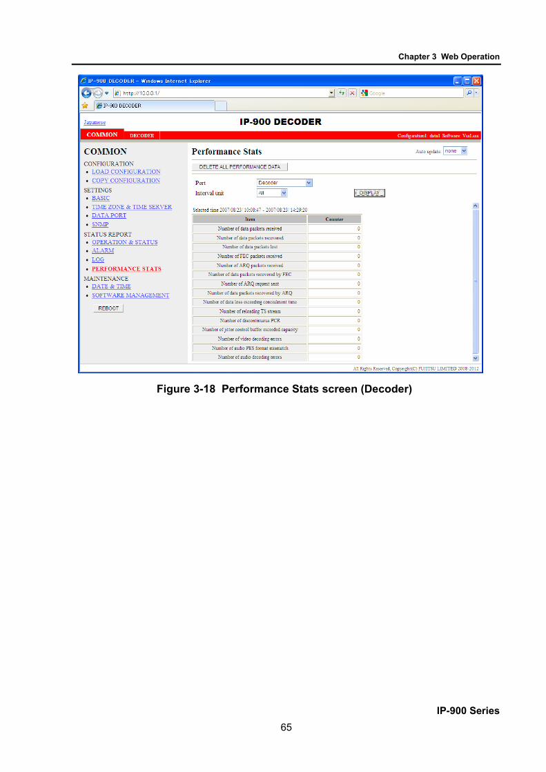
Chapter 3 Web Operation
IP-900 Series 65
Figure 3-18 Performance Stats screen (Decoder)

Chapter 3 Web Operation
IP-900 Series 66
Figure 3-19 Performance Stats screen (Data port)

Chapter 3 Web Operation
IP-900 Series 67
Table 3-16 Performance Stats Items Port Item Description Display Main
Encoder (Ethernet)
* Displayed
only for encoder
Number of data packets sent
Displays the number of audio and video data packets sent.
{-----} The counter restarts counting from 0 after it expires.
Number of FEC packets sent
Displays the number of FEC/SMPTE2022-1 FEC packets sent.
{-----} The counter restarts counting from 0 after it expires.
Number of ARQ request received
Displays the number of ARQ requests received.
{-----} The counter restarts counting from 0 after it expires.
Number of ARQ packets resent
Displays the number of ARQ packets resent.
{-----} The counter restarts counting from 0 after it expires.
Sub Encoder
* Displayed only for
encoder (*2)
Number of data packets sent
Displays the number of audio and video data packets sent.
{-----} The counter restarts counting from 0 after it expires.
Number of FEC packets sent
Displays the number of FEC/SMPTE2022-1 FEC packets sent.
{-----} The counter restarts counting from 0 after it expires.
Number of ARQ request received
Displays the number of ARQ requests received.
{-----} The counter restarts counting from 0 after it expires.
Number of ARQ packets resent
Displays the number of ARQ packets resent.
{-----} The counter restarts counting from 0 after it expires.
Decoder (Ethernet)
* Displayed
only for decoder
Number of data packets received
Displays the number of audio and video data packets received.
{-----} The counter restarts counting from 0 after it expires.
Number of data packets recovered
Displays the number of media packets recovered by the FEC/SMPTE2022-1 FEC/ARQ error correction function.
{-----} The counter restarts counting from 0 after it expires.
Number of data packets lost
Displays the number of data packets that were abandoned on the network and could not be received. * This includes the number of media packet recovered by the FEC/SMPTE2022-1 FEC/ARQ error correction function.
{-----} The counter restarts counting from 0 after it expires.
Number of FEC packets received
Displays the number of FEC/SMPTE2022-1 FEC packets sent.
{-----} The counter restarts counting from 0 after it expires.
Number of ARQ packets received
Displays the number of data packets received by ARQ.
{-----} The counter restarts counting from 0 after it expires.
Number of data packets recovered by FEC
Displays the number of packets recovered with the FEC/SMPTE2022-1 FEC method.
{-----} The counter restarts counting from 0 after it expires.
Number of ARQ request sent
Displays the number of ARQ request packets sent when a packet was lost.
{-----} The counter restarts counting from 0 after it expires.
Number of data packets recovered by ARQ
Displays the number of data packets recovered by ARQ.
{-----} The counter restarts counting from 0 after it expires.

Chapter 3 Web Operation
IP-900 Series 68
Port Item Description Display Number of data loss exceeding concealment time
3.5.1 Setting (Decoder) Displays the number of displaying “blue” or “gray” image not receiving data for longer time than the setting value of [Packet non-receiving recognition time].
{-----} The counter restarts counting from 0 after it expires.
Decoder (Ethernet)
* Displayed
only for decoder
Number of reloading TS stream
Displays the number of reloading TS stream without restoring packets because of many packets lost. * In the following situation, the number is counted. 3.5.1 Setting (Decoder) - [ARQ operation] is performed. - When the number of data packets lost is 4000 or more - [ARQ operation] is not performed. - When the number of data packets lost is 24 packets or more.
{-----} The counter restarts counting from 0 after it expires.
Number of discontinuous PCR (*1)
Displays the number of discontinuous PCR values detected during decoding.
{-----} The counter restarts counting from 0 after it expires.
Number of jitter control buffer exceeded capacity
Displays the number of video skip or repeat that occurs when the decoder cannot absorb the network jitter of the reception packets * It can be lowered by increasing “Jitter control buffer” in “3.5.1 Setting (Decoder)”. * Its counter may increase even if there is no network jitter when the decoder receives the stream which video resolution is set to 352x288 or lower ,or which video frame rate is set to 14.985fps or lower in “3.3.1 Setting (Encoder)”, or which is generated by Fujitsu IP-700II.
{-----} The counter restarts counting from 0 after it expires.
Number of video decoding errors (*1)
Displays the number of video decoding errors detected during decoding.
{-----} The counter restarts counting from 0 after it expires.
Number of audio PES format mismatch
Displays the number of times that an audio PES packet that the decoder does not regard as being applicable to decoding is received. This is counted specifically in the following cases. ・For MPEG-1 Layer 2/MPEG-2 AAC -During reception of an audio stream that is not 1PES/1AAU.
{-----} The counter restarts counting from 0 after it expires.
Number of audio decoding errors (*1)
Displays the number of audio decoding errors detected during decoding.
{-----} The counter restarts counting from 0 after it expires.
Data port Number of data received in byte on RS-232C
Displays the number of data bytes received through the RS-232C port.
{-----} The counter restarts counting from 0 after it expires.

Chapter 3 Web Operation
IP-900 Series 69
Port Item Description Display Number of data
sent in byte on RS-232C
Displays the number of data bytes sent to the RS-232C port.
{-----} The counter restarts counting from 0 after it expires.
Number of data received in byte on LAN port
Displays the number of data bytes received through the LAN port.
{-----} The counter restarts counting from 0 after it expires.
Number of data sent in byte on LAN port
Displays the number of data bytes sent to the LAN port.
{-----} The counter restarts counting from 0 after it expires.
Note) Each counter consisted of 32 bits can be counted up to 4294967295.
*1: In case the count-up is made in this counter, DEC LED blinks for 10 seconds, I021 (Input data error) is saved as the log information.
*2: Not displayed in case “Main H.264/MPEG-4 AVC 2stereo” is set for [Operation mode].

Chapter 3 Web Operation
IP-900 Series 70
3.2.12 Date & Time Two types of setting modes are available. In one mode, you can enter arbitrary date and time data. In
another mode, you can instruct the system to synchronize with the time server on the network. Click DATE & TIME of the left frame in the Web GUI and the Date & Time screen appears in the right
frame, where you can set the date and time of the clock built in IP-900 series. Click the button to set the date and time of the PC. Click the button
after entering an arbitrary date and time sets the specified date and time. Click the button to promptly adjust the time with the time server
specified in Section 3.2.5, "Time Zone & Time Server." This function is enabled only when "Enable" is specified for Auto Synchronization.
* Any date and time between 00:00:00 on January 1, 1980 and 23:59:59 on December 31, 2030 can be specified.
Figure 3-20 Date & Time screen

Chapter 3 Web Operation
IP-900 Series 71
3.2.13 Software Management Click SOFTWARE MANAGEMENT of the left frame in the Web GUI and the Software Management
screen appears in the right frame, where you can install software or restore, save or delete configuration data.
Figure 3-21 Software Management screen
■ Software Specify the new file to be installed, enter the license key and click the button to start
installing the software. The latest version can be downloaded from
"http://www.fujitsu.com/global/products/computing/peripheral/video/download/"
■ Configuration × Configuration Restoration
Specify the file containing all configuration data and then click the button to restore all the configuration data, which was saved previously, to IP-900 series.
× Configuration Backup
All the configuration data currently stored in IP-900 series can be backed up to the PC by click the button.

Chapter 3 Web Operation
IP-900 Series 72
× Deletion of the configuration data
All the configuration data currently stored in IP-900 series can be initialized by click the button. This operation also resets information including the IP address to the state
before shipment from the factory
Table 3-17 Software Management Items
Item Description Software Current software version Displays the software version.
V-- L-- C-- is displayed immediately after shipment from the factory.
New software Specify the full path of the file to be installed. The Browse button can also be used to select the file.
Configuration Configuration file to be restored
To restore all the configuration data, specify the full path of the file. The Browse button can also be used to select the file.
RESTORE Use this button to restore all the configuration data. This button is enabled when a file name is specified in the "Configuration file to be restored" field.
BACKUP Use this button to back up all the configuration data from the IP-900 series to the PC.
DELETE ALL Use this button to delete all the configuration data from the IP-900 series. This operation resets all the configuration data to the default.
Option Option license key Enter the license key obtained when the optional license was purchased.
Installed option Names of installed options are displayed.
If all the configuration data is changed (restored or deleted), the IP address, subnet mask, and gateway
may be changed. Note that this may cause an unexpected problem in your network. Do not turn power off or press the MNT button while all the configuration data is being changed
(being restored or deleted). Otherwise, you may prevent IP-900 series from starting. If you access another Web screen while all the configuration data is being changed (being restored or
deleted), you may lose information on the progress of the changing.
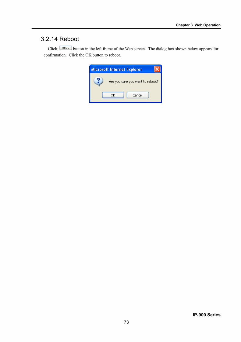
Chapter 3 Web Operation
IP-900 Series 73
3.2.14 Reboot Click button in the left frame of the Web screen. The dialog box shown below appears for
confirmation. Click the OK button to reboot.

Chapter 3 Web Operation
IP-900 Series 74
3.3 Encoder
3.3.1 Setting (Encoder) * Settings is a group of setting items, of which 10 sets can be registered independently by
selecting data numbers as in 3.2.1 Configuration Data.
Set parameters related to encoding. Make the required settings by referring to Table 3-18 Encoder Setting Items and Table 3-19 Main encoder/Sub encoder System Bit Rate Setting Range
The same screen is displayed for SETTINGS, <AV input settings> Video, Audio, <Output interface
settings> Main encoder and Sub encoder ethernet, <Main encoder settings> Encode, PID, and <Sub encoder settings> Encode, PID which are located in the frame on the left side of the Web screen. By click on the tab for each, the settings screen for each is displayed at the top of the frame on the right side.
Figure 3-22 Settings Screen (Encoder)
3.3

Chapter 3 Web Operation
IP-900 Series 75
After completing the settings, click the button. The message below appears. Click OK to apply the settings. * Reboot is not required.
* About [Operation Mode]
MODE1: in case of setting “Main H.264/MPEG-4 AVC 1stereo | Sub H.264/MPEG-4 AVC 1stereo” for
[Operation mode].
MODE2: in case of setting “Main H.264/MPEG-4 AVC 2stereo” for [Operation mode]. ×: Enable -: Disable
* Please refer to 3.2.6 Data Port" for the detail of [Operation mode].
Table 3-18 Encoder Setting Items
Item Description Parameter Operation mode MODE
1 MODE
2 Cpu Utilization Displays the CPU utilization for IP
streaming. The CPU utilization increases in accordance with the Ethernet rate of the main encoder and sub encoder. No settings can be made that will cause the CPU utilization to exceed 100%.
You cannot specify this item. × ×
Main SD/HD
Ethernet bit rate Displays in units of bps the Ethernet bit rate for the main encoder that is currently set.
You cannot specify this item. × ×
System bit rate Displays in units of bps the system bit rate for the main encoder that is currently set.
You cannot specify this item. × ×
Sub SD/HD Ethernet bit rate Displays in units of bps the Ethernet bit rate for the sub encoder that is currently set.
You cannot specify this item. × -
System bit rate
Displays in units of bps the system bit rate for the sub encoder that is currently set.
You cannot specify this item. × -
AV input settings (Video)
Video input port Specify the interface for video signal input. * HDMI input does not support HDCP. Signals encrypted for the purpose of copyright protection cannot be input.
- SDI (Default) - HDMI - Analog
× ×

Chapter 3 Web Operation
IP-900 Series 76
Item Description Parameter Operation mode MODE
1 MODE
2 AV input settings (Video)
Video resolution Specify the input resolution of the video signal. * The contents that can be set depend on the [Video input port] setting. * To specify HD, the HD software option needs to have been installed.
- SD (Default) - HD
× ×
Video format Specify the input format of the video signal.
Refer to Table 3-21 Video Format (Main Encoder) for set value.
× ×
Analog video setup
* If “Analog” is specified for [Video input port], specify the setup level of the analog video input signal.
- Enable: 7.5 IRE - Disable (Default): Same as the pedestal level
× ×
Analog video AGC
* If “Analog” is specified for [Video input port], specify whether to enable automatic gain control of the analog video input signal.
- Enable (Default) - Disable
× ×
Display when no video input signal
Specify the fixed image to be sent when the video input is interrupted.
- Color bars (Default) - Gray - Black
× ×
Buffer for video input
Specify whether to enable the protection buffer for video signal input. * If "Enable" is specified, a delay of up to 1 frame is caused, but video input error resistance is improved.
- Enable (Default) - Disable
× ×
AV input settings (Audio)
Audio input port
Specify the input format of the audio signal.
Refer to Table 3-32 Audio Input Port (Main Encoder) for set value.
× ×
Audio1 input channel
Specify the AES channels for Audio1 of the main encoder only when “SDI” is specified for [Audio input port]. * The input channel specified for [Audio input channel] is also specified for Audio of the sub encoder.
Channel1 to Channel8 (Default: Channel1)
× ×
Audio2 input channel
Specify the AES channels for Audio2 of the main encoder only when “SDI” is specified for [Audio input port].
Channel1 to Channel8 (Default: Channel2)
- ×
Input level (*)
Specify the audio input level only when “Analog” is specified for [Audio input port]
-20dBm (Max. 0dBm) 0dBm (Max. 20dBm) (Default) * This function is applicable only for IP-920.
× ×

Chapter 3 Web Operation
IP-900 Series 77
Item Description Parameter Operation mode MODE
1 MODE
2 Output interface settings (Main encoder ethernet)
IP version Specify the IP version of the IP stream for streaming.
- IPv4 (Default) - IPv6
× ×
Streaming mode Specify the streaming method for the IP interface.
- Multicast (Default) - Unicast (simplex) : Specifying streaming destination - Unicast : Accepting streaming request
× ×
Acceptable stream number
Specify the number of possible streams. * The contents that can be set depend on the [System bit rate] setting. * If “Multicast” or “Unicast (simplex)” is specified for [Streaming mode], only “1” can be specified.
1 to 4 (System rate is to 5.750 Mbps) 1 to 3 (System rate is 5.751 to 7.666 Mbps) 1 to 2 (System rate is 7.667 to 11.500 Mbps) 1 (System rate is 11.501 Mbps or higher) (Default: 1)
× ×
Streaming destination IP address
If “Multicast” or “Unicast (simplex)” is specified for [Streaming mode], specify the destination IP address of the streaming IP stream.
IP address (Default: 230.11.3.1) Setting the following values is inhibited: [IPv4] 240.0.0.0 to 255.255.255.255 (Class E) 0.0.0.0, 127.0.0.0 to 127.255.255.255 [IPv6] 0::0
× ×
TTL Set IP packet TTL value. 1 to 255 (Default: 128) × × ARP auto update If “Unicast (simplex)” is specified
for [Streaming mode], specify whether to send ARP at regular intervals to check the communication with the streaming destination.
- Enable (Default) - Disable
× ×
ID control for unicast
If “Unicast” is specified for [Streaming mode], specify whether to check the ID for confirming the validity of a unicast stream request.
- Enable - Disable (Default) * If "Enable" is selected, the Unicast ID of the encoder and that of the decoder must be in agreement to perform streaming.
× ×
Unicast ID If “Enable” is selected for [ID control for unicast], specify the ID to be used for confirming the validity of a unicast streaming request.
0000~ffff in Hexadecimal × ×
FEC Specify whether to generate FEC packets.
- Enable (Default) - Disable
× ×

Chapter 3 Web Operation
IP-900 Series 78
Item Description Parameter Operation mode MODE
1 MODE
2 Output interface settings (Main encoder ethernet)
FEC interval Set the insertion interval for generating an FEC packet.
4 to 24 (Default: 10)
× ×
ARQ If “Unicast” is specified for [Streaming mode], specify whether to enable the ARQ error correction method.
- Enable - Disable (Default)
× ×
TOS Set IP packet TOS value. 00~ff in Hexadecimal (Default: 0)
× ×
Protocol If “Multicast” or “Unicast (simplex)” is specified for [Streaming mode] and “Disable” is selected for [FEC], specify the IP transport protocol.
- UDP - RTP (Default) * If "UDP" is selected, "Standard TS" is fixedly selected for [Stream format].
× ×
Stream format If “Multicast” or “Unicast (simplex)” is specified for [Streaming mode], “Disable” is selected for [FEC], and “RTP” is specified for [Protocol], specify the stream format.
- Standard TS - Time stamped TS (Default)
× ×
SMPTE2022 FEC
If “Standard TS” is selected for [Stream format], specify whether to generate SMPTE2022-1 FEC packets.
- Enable - Disable (Default)
× ×
SMPTE2022 Matrix
If “Enable” is selected for [SMPTE2022 FEC], specify the generation matrix values for FEC packets.
A value of [4 to 20] x [4 to 20] can be set. (Default: 10 x 10) * N x N values that exceed 100 cannot be set.
× ×
Output interface settings (Main encoder ethernet port)
Streaming port
Specify the own device port number used for sending streams.
0, 1024 to 64000 (Default: 0) * If 0 is set, a port number between 64100 and 65000 is automatically selected.
× ×
Specify the port number of the destination device used for sending streams.
1024 to 64000 (Default: 5000)
× ×
Unicast request port
Specify the port number of the own device used for receiving a unicast streaming request.
1024 to 64000 (Default: 9900)
× ×
ARQ control port Displays the port number of the own device used for controlling ARQ.
You cannot specify this item. * This item is automatically set according to the [Streaming port] setting.
× ×
SMPTE2022 FEC port
Displays the port number of the own device used for sending SMPTE2022-1 FEC.
You cannot specify this item. * This item is automatically set according to the [Streaming port] setting.
× ×
Output interface settings (Sub encoder ethernet)
IP version Specify the IP version of the IP stream for streaming.
- IPv4 (default) - IPv6
× -

Chapter 3 Web Operation
IP-900 Series 79
Item Description Parameter Operation mode MODE
1 MODE
2 Output interface settings (Sub encoder ethernet)
Streaming mode Specify the streaming method for the IP interface.
- Multicast (Default) - Unicast (simplex) : Specifying streaming destination - Unicast : Accepting streaming request
× -
Acceptable stream number
Specify the number of possible streams. * The contents that can be set depend on the [System bit rate] setting. * If “Multicast” or “Unicast (simplex)” is specified for [Streaming mode], only “1” can be specified.
1 to 4 (System rate is to 5.750 Mbps) 1 to 3 (System rate is 5.751 to 7.666 Mbps) 1 to 2 (System rate is 7.667 to 11.500 Mbps) 1 (System rate is 11.501 Mbps or higher) (Default: 1)
× -
Streaming destination IP address
If “Multicast” or “Unicast (simplex)” is specified for [Streaming mode], specify the destination IP address of the streaming IP stream.
IP address (Default: 230.11.3.1) Setting the following values is inhibited: [IPv4] 240.0.0.0 to 255.255.255.255 (Class E) 0.0.0.0, 127.0.0.0 to 127.255.255.255 [IPv6] 0::0
× -
TTL Set IP packet TTL value. 1 to 255 (Default: 128) × - ARP auto update If “Unicast (simplex)” is specified
for [Streaming mode], specify whether to send ARP at regular intervals to check the communication with the streaming destination.
- Enable (Default) - Disable
× -
ID control for unicast
If “Unicast” is specified for [Streaming mode], specify whether to check the ID for confirming the validity of a unicast stream request.
- Enable - Disable (Default) * If "Enable" is selected, the Unicast ID of the encoder and that of the decoder must be in agreement to perform streaming.
× -
Unicast ID If “Enable” is selected for [ID control for unicast], specify the ID to be used for confirming the validity of a unicast streaming request.
0000~ffff in Hexadecimal (Default: 0000)
× -
FEC Specify whether to generate FEC packets.
- Enable (Default) - Disable
× -
FEC interval Set the insertion interval for generating an FEC packet.
4 to 24 (Default: 10)
× -

Chapter 3 Web Operation
IP-900 Series 80
Item Description Parameter Operation mode MODE
1 MODE
2 ARQ If “Unicast” is specified for
[Streaming mode], specify whether to enable the ARQ error correction method.
- Enable - Disable (Default)
× -
Output interface settings (Sub encoder ethernet)
TOS Set IP packet TOS value. 00~ff in Hexadecimal (Default: 0)
× -
Protocol If “Multicast” or “Unicast (simplex)” is specified for [Streaming mode] and “Disable” is selected for [FEC], specify the IP transport protocol.
- UDP - RTP (Default) * If “UDP” is selected, “Standard TS” is fixedly selected for [Stream format].
× -
Stream format If “Multicast” or “Unicast (simplex)” is specified for [Streaming mode], "Disable" is selected for [FEC], and “RTP” is specified for [Protocol], specify the stream format.
- Standard TS - Time stamped TS (Default)
× -
SMPTE2022 FEC
If “Standard TS” is selected for [Stream format], specify whether to generate SMPTE2022-1 FEC packets.
- Enable - Disable (Default)
× -
SMPTE2022 Matrix
If “Enable” is selected for [SMPTE2022 FEC], specify the generation matrix values for FEC packets.
A value of [4 to 20] x [4 to 20] can be set. (Default: 10 x 10) * N x N values that exceed 100 cannot be set.
× -
Output interface settings (Sub encoder ethernet port)
Streaming port Specify the own device port number used for sending streams.
0, 1024 to 64000 (Default: 0) * If 0 is set, a port number between 64100 and 65000 is automatically selected.
× -
Specify the port number of the destination device used for sending streams.
1024 to 64000 (Default: 5010)
× -
Unicast request port
Specify the port number of the own device used for receiving a unicast streaming request.
1024 to 64000 (Default: 9910)
× -
ARQ control port Displays the port number of the own device used for controlling ARQ.
You cannot specify this item. * This item is automatically set according to the [Streaming port] setting.
× -
SMPTE2022 FEC port
Displays the port number of the own device used for sending SMPTE2022-1 FEC.
You cannot specify this item. * This item is automatically set according to the [Streaming port] setting.
× -
Main encoder settings (Encode)
Encoding operation
Specify whether to start encoding operation after the device is started or after the main encoder settings are changed.
- Enable - Disable (Default)
× ×
Bit rate mode Specify how the bit rate is specified.
- Video bit rate (Default) - System bit rate
× ×

Chapter 3 Web Operation
IP-900 Series 81
Item Description Parameter Operation mode MODE
1 MODE
2 System bit rate
- HD - If “HD” is specified for [Video resolution] and "System bit rate" is specified for [Bit rate mode], specify the system bit rate of the stream to be distributed.
Refer to Table 3-19 Main encoder/Sub encoder System Bit Rate Setting Range for set value.
× ×
Main encoder settings (Encode)
Video resolution - HD -
If “HD” is specified for [Video resolution], specify the resolution of the video to be encoded.
Refer to Table 3-22 Video Resolution (Main Encoder) for set value.
× ×
Video frame rate - HD -
If “HD” is specified for [Video resolution], specify the frame rate of the video to be encoded. *Please select one of “29.97fps”, “25fps” or “30fps” which is conformed to input video format. In case of using low bit rate with keeping video resolution, please select one of options except “29.97fps”, “25fps” and “30fps”. Please note that in this case, video image may become unsmoothed because interlaced video is thinned down and encoded.
Refer to Table 3-23 Video Frame Rate (Main Encoder) for set value.
× ×
Encoding control mode - HD -
If “HD” is specified for [Video resolution], specify the control mode for video encoding.
- Quality (IBBP) (Default) - Motion (IBP) - Low Latency (PPPP) - Low Latency (IPPP) - Ultra Low Latency (PPPP)
× ×
GOP - HD -
If “HD” is specified for [Video resolution], specify the GOP.
Refer to Table 3-25 GOP (Main Encoder) for set value.
× ×
Video bit rate - HD -
If “HD” is specified for [Video resolution] and “Video bit rate” is specified for [Bit rate mode], specify the video bit rate.
Refer to Table 3-26 Video Bit Rate (Main Encoder) for set value.
× ×
Bit rate mode - HD -
If “HD” is specified for [Video resolution], specify the bit rate mode of the video to be encoded.
- CBR (Default) × ×
Video PES - HD -
If “HD” is specified for [Video resolution], specify the PES structure of video encoding.
Refer to Table 3-28 Video PES (Main Encoder) for set value.
× ×
Profile - HD -
If “HD” is specified for [Video resolution], specify the profile of the video encoding mode.
- High profile (Default) - Main profile
× ×
PPS interval - HD -
If “HD” is specified for [Video resolution], specify the PPS interval for video encoding.
- GOP (Default) - Picture
× ×
PPS ID - HD -
If “HD” is specified for [Video resolution], specify the PPS ID mode for video encoding.
- Fixed (Default) - Variable
× ×
Pre-Filter - HD -
If “HD” is specified for [Video resolution], specify the strength of the pre-filter.
- OFF (Default) - LIGHT - MEDIUM - HEAVY
× ×

Chapter 3 Web Operation
IP-900 Series 82
Item Description Parameter Operation mode MODE
1 MODE
2 Refresh cycle
- HD - If “HD” is specified for [Video resolution], specify the refresh cycle. * The longer the refresh cycle is set, the more video quality improves; however, it takes longer to restore from video error by receive data error on the decoder.
Refer to Table 3-30 Refresh Cycle (Main Encoder) for set value.
× ×
Audio1 format - HD -
If “HD” is specified for [Video resolution], specify the audio1 encoding format.
- MPEG-1 Layer2 (Default) - MPEG-2 AAC - None
× ×
Audio1 bit rate - HD -
If “HD” is specified for [Video resolution], specify the audio1 bit rate.
Refer to Table 3-33 Audio Bit Rate, Audio Bit Rate Mode (Main Encoder) for set value.
× ×
Main encoder settings (Encode)
Audio1 bit rate mode - HD -
If “HD” is specified for [Video resolution], specify the audio1 bit rate mode to encode.
Refer to Table 3-33 Audio Bit Rate, Audio Bit Rate Mode (Main Encoder) for set value.
× ×
Audio1 language code - HD -
If “HD” is specified for [Input resolution], specify the Audio1 language code in three-letter code of ISO 639-2. * Refer to Table 3-20 Main ISO 639-2 Language Code for the main language code.
Blank or 3 single-byte characters (Default: Blank)
× ×
Audio2 format - HD -
If “HD” is specified for [Input resolution], specify the audio2 encoding format.
- MPEG-1 Layer2 (Default) - MPEG-2 AAC - None
- ×
Audio2 bit rate - HD -
If “HD” is specified for [Input resolution], specify the audio2 bit rate.
Refer to Table 3-33 Audio Bit Rate, Audio Bit Rate Mode (Main Encoder) for set value.
- ×
Audio2 bit rate mode - HD -
If “HD” is specified for [Input resolution], specify the audio2 bit rate mode to encode.
Refer to Table 3-33 Audio Bit Rate, Audio Bit Rate Mode (Main Encoder) for set value.
- ×
Audio2 language code - HD -
If “HD” is specified for [Input resolution], specify the audio2 language code in three-letter code of ISO 639-2. * Refer to Table 3-20 Main ISO 639-2 Language Code for the main language code.
Blank or 3 single-byte characters (Default: Blank)
- ×
Picture mode - HD -
If “HD” is specified for [Video resolution], specify the Picture mode in encoding. * Specify “Normal” in case of ordinary video or “Dynamic texture” in case of irregularly-changing video like wave on the surface of water.
Refer to Table 3-31 Picture Mode, Coded Picture Buffer (Main Encoder) for set value.
× ×

Chapter 3 Web Operation
IP-900 Series 83
Item Description Parameter Operation mode MODE
1 MODE
2 Coded picture
buffer - HD -
If “HD” is specified for [Video resolution], specify the Coded picture buffer amount in encoding. * Specify “Normal” to minimize video latency at the normal video quality or “Double” to improve video quality even if video latency increases.
Refer to Table 3-31 Picture Mode, Coded Picture Buffer (Main Encoder) for set value.
× ×
System bit rate - SD -
If “SD” is specified for [Video resolution] and "System bit rate" is specified for [Bit rate mode], specify the system bit rate of the stream to be distributed.
Refer to Table 3-19 Main encoder/Sub encoder System Bit Rate Setting Range for set value.
× ×
Video resolution - SD -
If “SD” is specified for [Video resolution], specify the resolution of the video to be encoded.
Refer to Table 3-22 Video Resolution (Main Encoder) for set value.
× ×
Main encoder settings (Encode)
Video frame rate - SD -
If “SD” is specified for [Video resolution], specify the frame rate of the video to be encoded. * In case of “720x480i/352x480i “ at Video resolution, please select “29.97fps” which is conformed to input video format. In case of using low bit rate with keeping video resolution, please select one of options except “29.97fps”. Please note that in this case, video image may become unsmoothed because interlaced video is thinned down and encoded.
Refer to Table 3-23 Video Frame Rate (Main Encoder) for set value.
× ×
Encoding control mode - SD -
If “SD” is specified for [Video resolution], specify the control mode for video encoding.
Refer to Table 3-24 Encoding Control Mode (Main Encoder) for set value.
× ×
GOP - SD -
If “SD” is specified for [Video resolution], specify the GOP.
Refer to Table 3-25 GOP (Main Encoder) for set value.
× ×
Video bit rate - SD -
If “SD” is specified for [Video resolution] and "Video bit rate" is specified for [Bit rate mode], specify the video bit rate. * Displays the bit rate assigned to video if “System bit rate” is specified for [Bit rate mode]. You cannot specify this item.
Refer to Table 3-26 Video Bit Rate (Main Encoder) for set value.
× ×
Bit rate mode - SD -
If “SD” is specified for [Video resolution], specify the bit rate mode of the video to be encoded.
Refer to Table 3-27 Bit Rate Mode (Main Encoder) for set value.
× ×
Video PES - SD -
If “SD” is specified for [Video resolution], specify the PES structure of video encoding.
Refer to Table 3-28 Video PES (Main Encoder) for set value.
× ×
Profile - SD -
If “SD” is specified for [Video resolution], specify the profile of the video encoding mode.
- High profile (Default) - Main profile
× ×

Chapter 3 Web Operation
IP-900 Series 84
Item Description Parameter Operation mode MODE
1 MODE
2 PPS interval
- SD - If “SD” is specified for [Video resolution], specify the PPS interval for video encoding.
- GOP (Default) - Picture
× ×
PPS ID - SD -
If “SD” is specified for [Video resolution], specify the PPS ID mode for video encoding.
- Fixed (Default) - Variable
× ×
Pre-Filter - SD -
If “SD” is specified for [Video resolution], specify the strength of the pre-filter.
Refer to Table 3-29 Pre-Filter (Main Encoder) for set value.
× ×
Refresh cycle - SD -
If “SD” is specified for [Video resolution], specify the refresh cycle. * The longer the refresh cycle is set, the more video quality improves; however, it takes longer to restore from video error by receive data error on the decoder.
Refer to Table 3-30 Refresh Cycle (Main Encoder) for set value.
× ×
Audio1 format - SD -
If “SD” is specified for [Video resolution], specify the audio1 encoding format.
- MPEG-1 Layer2 (Default) - MPEG-2 AAC - None
× ×
Audio1 bit rate - SD -
If “SD” is specified for [Video resolution], specify the audio1 bit rate.
Refer to Table 3-33 Audio Bit Rate, Audio Bit Rate Mode (Main Encoder) for set value.
× ×
Audio1 bit rate mode - SD -
If “SD” is specified for [Video resolution], specify the audio1 bit rate mode to encode.
Refer to Table 3-33 Audio Bit Rate, Audio Bit Rate Mode (Main Encoder) for set value.
× ×
Main encoder settings (Encode)
Audio1 language code - SD -
If “SD” is specified for [Input resolution], specify the audio1 language code in three-letter code of ISO 639-2. * Refer to Table 3-20 Main ISO 639-2 Language Code for the main language code.
Blank or 3 single-byte characters (Default: Blank)
× ×
Audio2 format - SD -
If “SD” is specified for [Input resolution], specify the audio2 encoding format.
- MPEG-1 Layer2 (Default) - MPEG-2 AAC - None
- ×
Audio2 bit rate - SD -
If “SD” is specified for [Input resolution], specify the audio2 bit rate.
Refer to Table 3-33 Audio Bit Rate, Audio Bit Rate Mode (Main Encoder) for set value.
- ×
Audio2 bit rate mode - SD -
If “SD” is specified for [Input resolution], specify the audio2 bit rate mode to encode.
Refer to Table 3-33 Audio Bit Rate, Audio Bit Rate Mode (Main Encoder) for set value.
- ×
Audio2 language code - SD -
If “SD” is specified for [Input resolution], specify the audio2 language code in three-letter code of ISO 639-2. * Refer to Table 3-20 Main ISO 639-2 Language Code for the main language code.
Blank or 3 single-byte characters (Default: Blank)
- ×

Chapter 3 Web Operation
IP-900 Series 85
Item Description Parameter Operation mode MODE
1 MODE
2 Picture mode
- SD - If “SD” is specified for [Video resolution], specify the Picture mode in encoding. * Specify “Normal” in case of ordinary video or “Dynamic texture” in case of irregularly-changing video like wave on the surface of water.
Refer to Table 3-31 Picture Mode, Coded Picture Buffer (Main Encoder) for set value.
× ×
Coded picture buffer - SD -
If “SD” is specified for [Video resolution], specify the Coded picture buffer amount in encoding. * Specify “Normal” to minimize video latency at the normal video quality or “Double” to improve video quality even if video latency increases.
Refer to Table 3-31 Picture Mode, Coded Picture Buffer (Main Encoder) for set value.
× ×
Padded data pattern
Specify the padded data pattern used in video encoding data. * If “IP satellite mode” is specified, video encoding data is padded with NULL packets. Therefore, the percentage of NULL packets in a distributed stream increases.
- Normal (Default) - IP satellite mode
× ×
Main encoder settings (PID)
NIT Set whether to create NIT packets. - Enable - Disable (Default)
× ×
Carrier ID for NIT
Set whether to create carrier ID (NIT) when “Enable” is selected for [NIT].
- Enable - Disable (Default)
× ×
Main encoder settings (PID)
SDT Set whether to create SDT packets. - Enable - Disable (Default)
× ×
Network name [Network name] can be enabled to specify when “Enable” is set for [NIT].
Blank or 20 single-byte characters (Default: Blank)
× ×
Original network ID
[Original network ID] can be enabled to specify when “Enable” is selected for [NIT] or [SDT].
0~ffff in hexadecimal (Default: 0)
× ×
Transport stream ID
[Transport stream ID] can be enabled to specify when “Enable” is selected for [NIT] or [SDT].
0~ffff in hexadecimal (Default: 0)
× ×
Program number/Service ID
Specify the program number or service ID.
1 to ffff in hexadecimal (Default: 1)
× ×
Service type [Service type] can be enabled to specify when “Enable” is selected for [NIT] or [SDT].
0~ff in hexadecimal (Default: 0)
× ×
Service provider name
[Service provider name] can be enabled to specify when “Enable” is selected for [SDT].
Blank or 16 single-byte characters (Default: Blank)
× ×
Service name [Service name] can be enabled to specify when “Enable” is selected for [SDT].
Blank or 16 single-byte characters (Default: Blank)
× ×

Chapter 3 Web Operation
IP-900 Series 86
Item Description Parameter Operation mode MODE
1 MODE
2 Encoder
manufacturer [Encoder manufacturer] is shown when “Enable” is selected for [Carrier ID for NIT]. *Cannot be specified, display only.
FUJ_ Fixed
× ×
Encoder serial number
[Encoder serial number] is shown when “Enable” is selected for [Carrier ID for NIT]. *Cannot be specified, display only.
MAC address of the unit Fixed
× ×
Carrier identifier [Carrier identifier] can be enabled to specify when “Enable” is selected for [Carrier ID for NIT].
Blank or 5 single-byte characters (Default: _____)
× ×
Telephone number
[Telephone number] can be enabled to specify when “Enable” is selected for [Carrier ID for NIT].
Blank or 17 single-byte characters (Default: +00(0)0000000000_)
× ×
Longitude [Longitude] can be enabled to specify as “+” for eastward and “-“ for westward when “Enable” is selected for [Carrier ID for NIT].
Blank or 9 single-byte characters +000.000~±180.000 (Default: +000.0000)
× ×
Latitude [Latitude] can be enabled to specify as “+” for north and “-“ for south when “Enable” is selected for [Carrier ID for NIT].
Blank or 8 single-byte characters (+00.000~±90.000) (Default: +00.0000)
× ×
User information [User information] can be enabled to specify when “Enable” is selected for [Carrier ID for NIT].
Blank or 15 single-byte characters (Default: _______________)
× ×
NIT PID [NIT PID] is shown when “Enable” is selected for [NIT]. *Cannot be specified, display only.
10 Fixed
× ×
Main encoder settings (PID)
SDT PID [SDT PID] is shown when “Enable” is selected for [NIT]. *Cannot be specified, display only.
11 Fixed
× ×
PMT PID Specify the PID of the PMT. 1 to 1ffe in hexadecimal (Default: 100)
× ×
Video PID Specify the PID of Video. 1 to 1ffe in hexadecimal (Default: 1011)
× ×
Audio1 PID Specify the PID of Audio. 1 to 1ffe in hexadecimal (Default: 1100)
× ×
Audio2 PID Specify the PID of Audio. 1 to 1ffe in hexadecimal (Default: 1101)
- ×
PCR PID Specify the PID of the PCR. 1 to 1fff in hexadecimal (Default: 1001)
× ×
PSI insertion interval - HD -
If “HD” is specified for [Video resolution], specify the interval at which to insert the PAT and PMT.
100 to 1000 msec (Default: 100) * Settable in units of 100 msec
× ×
PSI insertion interval - SD -
If “SD” is specified for [Video resolution], specify the interval at which to insert the PAT and PMT.
100 to 1000 msec (Default: 100) * Settable in units of 100 msec
× ×
PCR interval - HD -
If “HD” is specified for [Video resolution], specify the interval at which to insert the PCR.
30 to 1000 msec (Default: 100)
× ×

Chapter 3 Web Operation
IP-900 Series 87
Item Description Parameter Operation mode MODE
1 MODE
2 PCR interval
- SD - If “SD” is specified for [Video resolution], specify the interval at which to insert the PCR.
30 to 1000 msec (Default: 100)
× ×
Sub encoder settings (Encode)
Encoding operation
Specify whether to start encoding operation after the device is started or after the sub encoder settings are changed.
- Enable - Disable (Default)
× -
Downconverter If “HD” is specified for [Video resolution] and a setting other than “1080i/60” is specified for [Video format], specify the conversion mode used for down-converting HD video to SD video.
Refer to Table 3-34 Downconverter (Sub Encoder) for set value.
× -
Bit rate mode Specify how the bit rate is specified.
- Video bit rate (Default) - System bit rate
× -
System bit rate - HD -
If “HD” is specified for [Video resolution], “None” is specified for [Downconverter], and “System bit rate” is specified for [Bit rate mode], specify the system bit rate of the stream to be distributed.
Refer to Table 3-19 Main encoder/Sub encoder System Bit Rate Setting Range for set value.
× -
Video resolution - HD -
If “HD” is specified for [Video resolution] and "None" is specified for [Downconverter], specify the resolution of the video to be encoded.
Refer to Table 3-35 Video Resolution (Sub Encoder) for set value.
× -
Sub encoder settings (Encode)
Video frame rate - HD -
If “HD” is specified for [Video resolution] and “None” is specified for [Downconverter], specify the frame rate of the video to be encoded. * Please select one of “29.97fps”, “25fps” or “30fps” which is conformed to input video format. In case of using low bit rate with keeping video resolution, please select one of options except “29.97fps”, “25fps” and “30fps”. Please note that in this case, video image may become unsmoothed because interlaced video is thinned down and encoded.
Refer to Table 3-36 Video Frame Rate (Sub Encoder) for set value.
× -
Encoding control mode - HD -
If “HD” is specified for [Video resolution] and “None” is specified for [Downconverter], specify the control mode for video encoding.
- Quality (IBBP) (Default) - Motion (IBP) - Low Latency (PPPP) - Low Latency (IPPP) - Ultra Low Latency (PPPP)
× -
GOP - HD -
If “HD” is specified for [Video resolution], specify the GOP.
Refer to Table 3-38 GOP (Sub Encoder) for set value.
× -
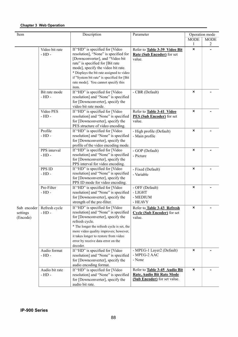
Chapter 3 Web Operation
IP-900 Series 88
Item Description Parameter Operation mode MODE
1 MODE
2 Video bit rate
- HD - If “HD” is specified for [Video resolution], “None” is specified for [Downconverter], and “Video bit rate” is specified for [Bit rate mode], specify the video bit rate. * Displays the bit rate assigned to video if "System bit rate" is specified for [Bit rate mode]. You cannot specify this item.
Refer to Table 3-39 Video Bit Rate (Sub Encoder) for set value.
× -
Bit rate mode - HD -
If “HD” is specified for [Video resolution] and “None” is specified for [Downconverter], specify the video bit rate mode.
- CBR (Default) × -
Video PES - HD -
If “HD” is specified for [Video resolution] and “None” is specified for [Downconverter], specify the PES structure of video encoding.
Refer to Table 3-41 Video PES (Sub Encoder) for set value.
× -
Profile - HD -
If “HD” is specified for [Video resolution] and “None” is specified for [Downconverter], specify the profile of the video encoding mode.
- High profile (Default) - Main profile
× -
PPS interval - HD -
If “HD” is specified for [Video resolution] and “None” is specified for [Downconverter], specify the PPS interval for video encoding.
- GOP (Default) - Picture
× -
PPS ID - HD -
If “HD” is specified for [Video resolution] and “None” is specified for [Downconverter], specify the PPS ID mode for video encoding.
- Fixed (Default) - Variable
× -
Pre-Filter - HD -
If “HD” is specified for [Video resolution] and “None” is specified for [Downconverter], specify the strength of the pre-filter.
- OFF (Default) - LIGHT - MEDIUM - HEAVY
× -
Sub encoder settings (Encode)
Refresh cycle - HD -
If “HD” is specified for [Video resolution] and “None” is specified for [Downconverter], specify the refresh cycle. * The longer the refresh cycle is set, the more video quality improves; however, it takes longer to restore from video error by receive data error on the decoder.
Refer to Table 3-43 Refresh Cycle (Sub Encoder) for set value.
× -
Audio format - HD -
If “HD” is specified for [Video resolution] and “None” is specified for [Downconverter], specify the audio encoding format.
- MPEG-1 Layer2 (Default) - MPEG-2 AAC - None
× -
Audio bit rate - HD -
If “HD” is specified for [Video resolution] and “None” is specified for [Downconverter], specify the audio bit rate.
Refer to Table 3-45 Audio Bit Rate, Audio Bit Rate Mode (Sub Encoder) for set value.
× -

Chapter 3 Web Operation
IP-900 Series 89
Item Description Parameter Operation mode MODE
1 MODE
2 Audio bit rate
mode - HD -
If “HD” is specified for [Video resolution] and “None” is specified for [Downconverter], specify the audio bit rate mode to encode.
Refer to Table 3-45 Audio Bit Rate, Audio Bit Rate Mode (Sub Encoder) for set value.
× -
Audio language code - HD -
If “HD” is specified for [Input resolution], specify the code in three-letter code of ISO 639-2. * Refer to Table 3-20 Main ISO 639-2 Language Code for the main language code.
Blank or 3 single byte character (Default: Blank)
× -
Picture mode - HD -
If “HD” is specified for [Video resolution] and “None” is specified for [Downconverter], specify the Picture mode in encoding. * Specify “Normal” in case of ordinary video or “Dynamic texture” in case of irregularly-changing video like wave on the surface of water.
Refer to Table 3-44 Picture Mode, Coded Picture Buffer (Sub Encoder) for set value.
× -
Coded picture buffer - HD -
If “HD” is specified for [Video resolution] and “None” is specified for [Downconverter], specify the Coded picture buffer amount in encoding. * Specify “Normal” to minimize video latency at the normal video quality or “Double” to improve video quality even if video latency increases.
Refer to Table 3-44 Picture Mode, Coded Picture Buffer (Sub Encoder) for set value.
× -
System bit rate - SD -
If “SD” is specified for [Video resolution], “Letter box” or “Side cropped” is specified for [Downconverter], and “System bit rate” is specified for [Bit rate mode], specify the system bit rate of the stream to be distributed.
Refer to Table 3-19 Main encoder/Sub encoder System Bit Rate Setting Range for set value.
× -
Sub encoder settings (Encode)
Video resolution - SD -
If “SD” is specified for [Video resolution] and “Letter box” or “Side cropped” is specified for [Downconverter], specify the resolution of the video to be encoded.
Refer to Table 3-35 Video Resolution (Sub Encoder) for set value.
× -
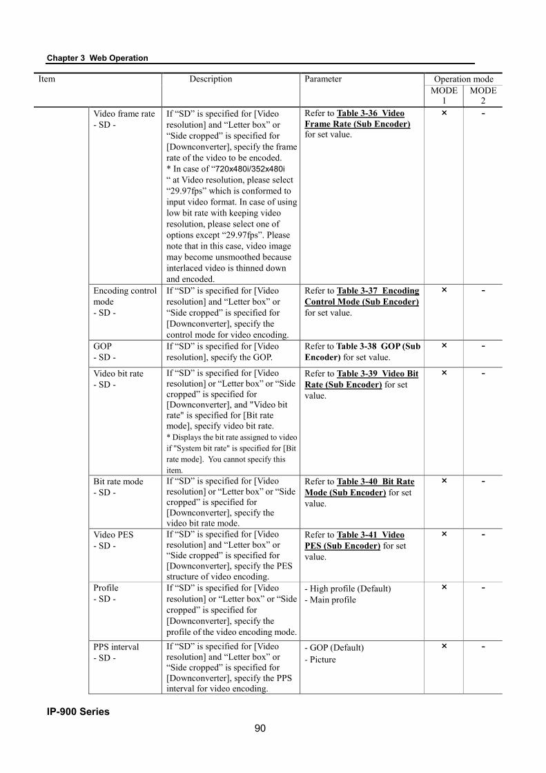
Chapter 3 Web Operation
IP-900 Series 90
Item Description Parameter Operation mode MODE
1 MODE
2 Video frame rate
- SD - If “SD” is specified for [Video resolution] and “Letter box” or “Side cropped” is specified for [Downconverter], specify the frame rate of the video to be encoded. * In case of “720x480i/352x480i “ at Video resolution, please select “29.97fps” which is conformed to input video format. In case of using low bit rate with keeping video resolution, please select one of options except “29.97fps”. Please note that in this case, video image may become unsmoothed because interlaced video is thinned down and encoded.
Refer to Table 3-36 Video Frame Rate (Sub Encoder) for set value.
× -
Encoding control mode - SD -
If “SD” is specified for [Video resolution] and “Letter box” or “Side cropped” is specified for [Downconverter], specify the control mode for video encoding.
Refer to Table 3-37 Encoding Control Mode (Sub Encoder) for set value.
× -
GOP - SD -
If “SD” is specified for [Video resolution], specify the GOP.
Refer to Table 3-38 GOP (Sub Encoder) for set value.
× -
Video bit rate - SD -
If “SD” is specified for [Video resolution] or “Letter box” or “Side cropped” is specified for [Downconverter], and "Video bit rate" is specified for [Bit rate mode], specify video bit rate. * Displays the bit rate assigned to video if "System bit rate" is specified for [Bit rate mode]. You cannot specify this item.
Refer to Table 3-39 Video Bit Rate (Sub Encoder) for set value.
× -
Bit rate mode - SD -
If “SD” is specified for [Video resolution] or “Letter box” or “Side cropped” is specified for [Downconverter], specify the video bit rate mode.
Refer to Table 3-40 Bit Rate Mode (Sub Encoder) for set value.
× -
Video PES - SD -
If “SD” is specified for [Video resolution] and “Letter box” or “Side cropped” is specified for [Downconverter], specify the PES structure of video encoding.
Refer to Table 3-41 Video PES (Sub Encoder) for set value.
× -
Profile - SD -
If “SD” is specified for [Video resolution] or “Letter box” or “Side cropped” is specified for [Downconverter], specify the profile of the video encoding mode.
- High profile (Default) - Main profile
× -
PPS interval - SD -
If “SD” is specified for [Video resolution] and “Letter box” or “Side cropped” is specified for [Downconverter], specify the PPS interval for video encoding.
- GOP (Default) - Picture
× -

Chapter 3 Web Operation
IP-900 Series 91
Item Description Parameter Operation mode MODE
1 MODE
2 PPS ID
- SD - If “SD” is specified for [Video resolution] and “Letter box” or “Side cropped” is specified for [Downconverter], specify the PPS ID mode for video encoding.
- Fixed (Default) - Variable
× -
Sub encoder settings (Encode)
Pre-Filter - SD -
If “SD” is specified for [Video resolution] or “Letter box” or “Side cropped” is specified for [Downconverter], specify the strength of the pre-filter.
Refer to Table 3-42 Pre-Filter (Sub Encoder) for set value.
× -
Refresh cycle - SD -
If “SD” is specified for [Video resolution] or “Letter box” or “Side cropped” is specified for [Downconverter], specify the refresh cycle. * The longer the refresh cycle is set, the more video quality improves; however, it takes longer to restore from video error by receive data error on the decoder.
Refer to Table 3-43 Refresh Cycle (Sub Encoder) for set value.
× -
Audio format - SD -
If “SD” is specified for [Video resolution] or “Letter box” or “Side cropped” is specified for [Downconverter], specify the audio encoding mode.
Encoding format - MPEG-1 Layer2 (Default) - MPEG-2 AAC - None
× -
Audio bit rate - SD -
If “SD” is specified for [Video resolution] or “Letter box” or “Side cropped” is specified for [Downconverter], specify the audio bit rate.
Refer to Table 3-45 Audio Bit Rate, Audio Bit Rate Mode (Sub Encoder) for set value.
× -
Audio bit rate mode - SD -
If “SD” is specified for [Video resolution] or “Letter box”/“Side cropped” is specified for [Downconverter], specify the audio bit rate mode to encode.
Refer to Table 3-45 Audio Bit Rate, Audio Bit Rate Mode (Sub Encoder) for set value.
× -
Audio language code - SD -
If “SD” is specified for [Input resolution], specify the code in three-letter code of ISO 639-2. * Refer to Table 3-20 Main ISO 639-2 Language Code for the main language code.
Blank or 3 single-byte characters (Default: Blank)
× -
Picture mode - SD -
If “SD” is specified for [Video resolution] or “Letter box”/”Side cropped” is specified for [Downconverter], specify the audio adjustment mode in encoding. * Specify “Normal” in case of ordinary video or “Dynamic texture” in case of irregularly-changing video like wave on the surface of water.
Refer to Table 3-44 Picture Mode, Coded Picture Buffer (Sub Encoder) for set value.
× -

Chapter 3 Web Operation
IP-900 Series 92
Item Description Parameter Operation mode MODE
1 MODE
2 Sub encoder settings (Encode)
Coded picture buffer - SD -
If “SD” is specified for [Video resolution] or “Letter box”/”Side cropped” is specified for [Downconverter], specify the Coded picture buffer amount in encoding. * Specify “Normal” to minimize video latency at the normal video quality or “Double” to improve video quality even if video latency increases.
Refer to Table 3-44 Picture Mode, Coded Picture Buffer (Sub Encoder) for set value.
× -
Padded data pattern
Specify the padded data pattern used in video encoding data. * If “IP satellite mode” is specified, video encoding data is padded with MPEG2-TS NULL packets. Therefore, the percentage of NULL packets in a distributed stream increases.
- Normal (Default) - IP satellite mode
× -
Sub Encoder Settings (PID)
NIT Set whether to create NIT packets. - Enable - Disable (Default)
× -
Carrier ID for NIT
Set whether to create carrier ID (NIT) when “Enable” is selected for [NIT].
- Enable - Disable (Default)
× -
SDT Set whether to create SDT packets. - Enable - Disable (Default)
× -
Network name [Network name] can be enabled to specify when “Enable” is set for [NIT].
Blank or 20 single-byte characters (Default: Blank)
× -
Original network ID
[Original network ID] can be enabled to specify when “Enable” is selected for [NIT] or [SDT].
0~ffff in hexadecimal (Default: 0)
× -
Transport stream ID
[Transport stream ID] can be enabled to specify when “Enable” is selected for [NIT] or [SDT].
0~ffff in hexadecimal (Default: 0)
× -
Program number/Service ID
Specify the program number or service ID.
1 to ffff in hexadecimal (Default: 1)
× -
Service type [Service type] can be enabled to specify when “Enable” is selected for [NIT] or [SDT].
0~ff in hexadecimal (Default: 0)
× -
Service provider name
[Service provider name] can be enabled to specify when “Enable” is selected for [SDT].
Blank or 16 single-byte characters (Default: Blank)
× -
Service name [Service name] can be enabled to specify when “Enable” is selected for [SDT].
Blank or 16 single-byte characters (Default: Blank)
× -
Encoder manufacturer
[Encoder manufacturer] is shown when “Enable” is selected for [Carrier ID for NIT]. *Cannot be specified, display only.
FUJ_ Fixed
× -

Chapter 3 Web Operation
IP-900 Series 93
Item Description Parameter Operation mode MODE
1 MODE
2 Encoder serial
number [Encoder serial number] is shown when “Enable” is selected for [Carrier ID for NIT]. *Cannot be specified, display only.
MAC address of the unit Fixed
× -
Carrier identifier [Carrier identifier] can be enabled to specify when “Enable” is selected for [Carrier ID for NIT].
Blank or 5 single-byte characters (Default: _____)
× -
Telephone number
[Telephone number] can be enabled to specify when “Enable” is selected for [Carrier ID for NIT].
Blank or 17 single-byte characters (Default: +00(0)0000000000_)
× -
Sub Encoder Settings (PID)
Longitude [Longitude] can be enabled to specify as “+” for eastward and “-“ for westward when “Enable” is selected for [Carrier ID for NIT].
Blank or 9 single-byte characters +000.000~±180.000 (Default: +000.0000)
× -
Latitude [Latitude] can be enabled to specify as “+” for north and “-“ for south when “Enable” is selected for [Carrier ID for NIT].
Blank or 8 single-byte characters (+00.000~±90.000) (Default: +00.0000)
× -
User information [User information] can be enabled to specify when “Enable” is selected for [Carrier ID for NIT].
Blank or 15 single-byte characters (Default: _______________)
× -
NIT PID [NIT PID] is shown when “Enable” is selected for [NIT]. *Cannot be specified, display only.
10 Fixed
× -
SDT PID [SDT PID] is shown when “Enable” is selected for [NIT]. *Cannot be specified, display only.
11 Fixed
× -
PMT PID Specify the PID of the PMT. 1 to 1ffe in Hexadecimal (Default: 100)
× -
Video PID Specify the PID of Video. 1 to 1ffe in Hexadecimal (Default: 1011)
× -
Audio PID Specify the PID of Audio. 1 to 1ffe in Hexadecimal (Default: 1100)
× -
PCR PID Specify the PID of the PCR. 1 to 1fff in Hexadecimal (Default: 1001)
× -
PSI insertion interval - HD -
If “HD” is specified for [Video resolution] and “None” is specified for [Downconverter], specify the interval at which to insert the PAT and PMT.
100 to 1000 msec (Default: 100) * Settable in units of 100 msec.
× -
PSI insertion interval - SD -
If “SD” is specified for [Video resolution] or “Letter box”/”Side cropped” is specified for [Downconverter], specify the interval at which to insert the PAT and PMT.
100 to 1000 msec (Default: 100) * Settable in units of 100 msec.
× -
PCR interval - HD -
If “HD” is specified for [Video resolution] and “None” is specified for [Downconverter], specify the interval at which to insert the PCR.
30 to 1000 msec (Default: 100)
× -

Chapter 3 Web Operation
IP-900 Series 94
Item Description Parameter Operation mode MODE
1 MODE
2 Sub Encoder
Settings (PID)
PCR interval - SD -
If “SD” is specified for [Video resolution] or “Letter box”/”Side cropped” is specified for [Downconverter], specify the interval at which to insert the PCR.
30 to 1000 msec (Default: 100)
× -

Chapter 3 Web Operation
IP-900 Series 95
Table 3-19 Main encoder/Sub encoder System Bit Rate Setting Range Main Encoder/Sub-encoder Video Resolution
Video frame rate System bit rate setting range
1920×1080 1280×720
30fps 29.97fps/25fps
Up to30.000 Mbps (can be set in 1 Kbps increment) The system bit rate setting with the video bit rate range of 3 to 27 Mbps is enabled. You cannot set the system bit rate range with the video bit rate range of lower than 3 Mbps. When the system bit rate is set with the video bit rate of higher than 27 Mbps, the video bit rate is fixed to 27 Mbps.
1440×1080 960×720
30fps 29.97fps/25fps
Up to30.000 Mbps (can be set in 1 Kbps increment) The system bit rate setting with the video bit rate range of 2 to 27 Mbps is enabled. You cannot set the system bit rate range with the video bit rate range of lower than 2 Mbps. When the system bit rate is set with the video bit rate of higher than 27 Mbps, the video bit rate is fixed to 27 Mbps.
960×1080 640×720
30fps 29.97fps/25fps
Up to30.000 Mbps (can be set in 1 Kbps increment) The system bit rate setting with the video bit rate range of 0.5 to 27 Mbps is enabled. You cannot set the system bit rate range with the video bit rate range of lower than 0.5 Mbps. When the system bit rate is set with the video bit rate of higher than 27 Mbps, the video bit rate is fixed to 27 Mbps.
1920×1080 1440×1080 960×1080
14.985fps 9.99fps 4.995fps 1.998fps 0.999fps 0.4995fps
Up to7.000 Mbps (can be set in 1 Kbps increment) The system bit rate setting with the video bit rate range of 0.1 to 5 Mbps is enabled. You cannot set the system bit rate range with the video bit rate range of lower than 0.1 Mbps. When the system bit rate is set with the video bit rate of higher than 5 Mbps, the video bit rate is fixed to 5 Mbps.
720×480 720×576
29.97fps/25fps
Up to12.000 Mbps (can be set in 1 Kbps increment) The system bit rate setting with the video bit rate range of 0.3 to 10 Mbps is enabled. You cannot set the system bit rate range with the video bit rate range of lower than 0.3 Mbps. When the system bit rate is set with the video bit rate of higher than 10 Mbps, the video bit rate is fixed to 10 Mbps.
352×480 352×576
29.97fps/25fps
Up to12.000 Mbps (can be set in 1 Kbps increment) The system bit rate setting with the video bit rate range of 0.15 to 10 Mbps is enabled. You cannot set the system bit rate range with the video bit rate range of lower than 0.15 Mbps. When the system bit rate is set with the video bit rate of higher than 10 Mbps, the video bit rate is fixed to 10 Mbps.
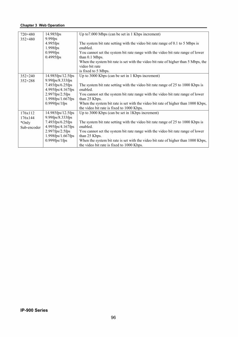
Chapter 3 Web Operation
IP-900 Series 96
720×480 352×480
14.985fps 9.99fps 4.995fps 1.998fps 0.999fps 0.4995fps
Up to7.000 Mbps (can be set in 1 Kbps increment) The system bit rate setting with the video bit rate range of 0.1 to 5 Mbps is enabled. You cannot set the system bit rate range with the video bit rate range of lower than 0.1 Mbps. When the system bit rate is set with the video bit rate of higher than 5 Mbps, the video bit rate is fixed to 5 Mbps.
352×240 352×288
14.985fps/12.5fps 9.99fps/8.333fps 7.493fps/6.25fps 4.995fps/4.167fps 2.997fps/2.5fps 1.998fps/1.667fps 0.999fps/1fps
Up to 3000 Kbps (can be set in 1 Kbps increment) The system bit rate setting with the video bit rate range of 25 to 1000 Kbps is enabled. You cannot set the system bit rate range with the video bit rate range of lower than 25 Kbps. When the system bit rate is set with the video bit rate of higher than 1000 Kbps, the video bit rate is fixed to 1000 Kbps.
176x112 176x144 *Only Sub-encoder
14.985fps/12.5fps 9.99fps/8.333fps 7.493fps/6.25fps 4.995fps/4.167fps 2.997fps/2.5fps 1.998fps/1.667fps 0.999fps/1fps
Up to 3000 Kbps (can be set in 1Kbps increment) The system bit rate setting with the video bit rate range of 25 to 1000 Kbps is enabled. You cannot set the system bit rate range with the video bit rate range of lower than 25 Kbps. When the system bit rate is set with the video bit rate of higher than 1000 Kbps, the video bit rate is fixed to 1000 Kbps.

Chapter 3 Web Operation
IP-900 Series 97
Table 3-20 Main ISO 639-2 Language Code Language Three-letter code
Danish dan
Dutch dut/nld (*1)
English eng
Finnish fin
French fre/fra (*1)
German ger/deu (*1)
Italian ita
Norwegian nor
Portuguese por
Spanish spa
None blank
*1: Two codes are allocated for one language.

Chapter 3 Web Operation
IP-900 Series 98
Setting condition of Encoder setting items are shown below.
Table 3-21 Video Format (Main Encoder) Video format
Video input port
Input resolution 1080i/59.94 1080i/50 1080i/60 1080i/60(->59.94)
(*1) 720p/59.94 720p/50 480i/59.94 576i/50
SDI SD × ×
HD × × × × × ×
HDMI (*2)
SD × ×
HD × × × × × ×
Analog SD × ×
*1: Transmit video by converting input signal from 60 Hz to 59.94 Hz. *2: In case of HDMI input, HDCP is not supported. Encrypted signals cannot be input for copyright protection
Table 3-22 Video Resolution (Main Encoder)
Video resolution
Video format 1920x 1080
1440x 1080
960x 1080
1280x 720 960x720 640x720 720x480 352x480 352x240 720x576 352x576 352x288
1080i/59.94 × × ×
1080i/50 × × ×
1080i/60 × × ×
1080i/60 (->59.94) × × ×
720p/59.94 × × ×
720p/50 × × ×
480i/59.94 × × ×
576i/50 × × ×

Chapter 3 Web Operation
IP-900 Series 99
Table 3-23 Video Frame Rate (Main Encoder)
Table 3-24 Encoding Control Mode (Main Encoder)
Video frame rate (fps)
Video resolution 29.97 25 30 59.94 50 14.985 9.99 7.493 4.995 2.997 1.998 0.999 0.4995 12.5 8.333 6.25 4.167 2.5 1.667 1
1920x1080 × × × × × × × × × 1440x1080 × × × × × × × × × 960x1080 × × × × × × × × × 1280x720 × × 960x720 × × 640x720 × × 720x480 × × × × × × × 352x480 × × × × × × × 352x240 × × × × × × × 720x576 × 352x576 × 352x288 × × × × × × ×
Encoding control mode
Video resolution Video frame rate (fps) IBBP IBP IPPP PPPP
1920x1080 30/29.97/25 × × × × Enable ×
1440x1080 30/29.97/25 × × × × Enable ×
960x1080 30/29.97/25 × × × × Enable ×
1280x720 -- × × × × 960x720 -- × × × × 640x720 -- × × × ×
720x480 29.97/25 × × × × Enable ×
352x480 29.97/25 × × × × Enable ×
352x240 7.493 × × Enable ×
720x576 -- × × × × 352x576 -- × × × ×
352x288 6.25 × × Enable ×

Chapter 3 Web Operation
IP-900 Series 100
Table 3-25 GOP (Main Encoder) GOP
Encoding control mode Open Closed IBBP × × IBP × ×
IPPP × × PPPP
Table 3-26 Video Bit Rate (Main Encoder)
Video bit rate
Video resolution
Video frame rate (fps)
25/40/45/50/96/128/160/192 /256/384/512
/768/1000 Kbps
100 Kbps 150 Kbps 200 Kbps 300/400 Kbps 500 Kbps 1 Mbps 1.3 Mbps 2 Mbps 3/4/5
Mbps 6/7/8/9/10
Mbps
11/12/14 /16/18/20/27 Mbps
1920x1080 30/29.97/25 × × × Enable × × × × × × ×
1440x1080 30/29.97/25 × × × × Enable × × × × × × ×
960x1080 30/29.97/25 × × × × × × Enable × × × × × × ×
1280x720 -- × × × 960x720 -- × × × × 640x720 -- × × × × × ×
720x480 29.97/25 × × × × × × × Enable × × × × × × ×
352x480 29.97/25 × × × × × × × × × Enable × × × × × × × × ×
352x240 -- × 720x576 -- × × × × × × × 352x576 -- × × × × × × × × × 352x288 -- ×

Chapter 3 Web Operation
IP-900 Series 101
Table 3-27 Bit Rate Mode (Main Encoder)
Bit rate mode
Video resolution Video frame rate (fps)
Encoding control mode CBR VBR
1920x1080 -- -- × 1440x1080 -- -- × 960x1080 -- -- × 1280x720 -- -- × 960x720 -- -- × 640x720 -- -- × 720x480 -- -- × 352x480 -- -- ×
352x240 7.493 IBBP × IPPP ×
Enable -- × 720x576 -- -- × 352x576 -- -- ×
352x288 6.25 IBBP × IPPP ×
Enable -- ×
Table 3-28 Video PES (Main Encoder) Video PES
Video resolution Encoding control mode 1Field/1PES 1Frame/1PES
1920x1080 IBBP × × Enable ×
1440x1080 IBBP × × Enable ×
960x1080 IBBP × × Enable ×
1280x720 -- × 960x720 -- × 640x720 -- ×
720x480 IBBP × × Enable ×
352x480 IBBP × × Enable ×
352x240 -- ×
720x576 IBBP × × Enable ×
352x576 IBBP × × Enable ×
352x288 -- ×
Table 3-29 Pre-Filter (Main Encoder)
Pre-Filter Video
resolution OFF LIGHT MEDIUM HEAVY
1920x1080 × × × × 1440x1080 × × × × 960x1080 × × × × 1280x720 × × × × 960x720 × × × × 640x720 × × × × 720x480 × × × × 352x480 × × × × 352x240 × 720x576 × × × × 352x576 × × × × 352x288 ×

Chapter 3 Web Operation
IP-900 Series 102
Table 3-30 Refresh Cycle (Main Encoder)
Video Resolution Frame Rate Encoding control mode Refresh cycle (frame)
1920x1080 1440x1080 960x1080
29.97
IBBP 15/30/60 IBP 14/28/56
IPPP 15/30/60 PPPP 34/68/134
25
IBBP 12/24/48 IBP 12/24/48
IPPP 12/24/48 PPPP 34/68/134
30
IBBP 30/60/120 IBP 14/28/56
IPPP 15/30/60 PPPP 34/68/134
14.985 IPPP 15/30/60 9.99 IPPP 10/20/40 4.995 IPPP 5/10/20 1.998 IPPP 2/4/8 0.999 IPPP 1/2/4
0.4995 IPPP 1/2/4
1280x720 960x720 640x720
59.94
IBBP 30/60/120 IBP 28/56/112
IPPP 30/60/120 PPPP 90/180/360
50
IBBP 24/48/96 IBP 24/48/96
IPPP 24/48/96 PPPP 90/180/360
720x480 352x480
29.97
IBBP 15/30/60 IBP 14/28/56
IPPP 15/30/60 PPPP 30/60/120
14.985 IPPP 15/30/60 9.99 IPPP 10/20/40 4.995 IPPP 5/10/20 1.998 IPPP 2/4/8 0.999 IPPP 1/2/4
0.4995 IPPP 1/2/4
720x576 352x576 25
IBBP 12/24/48 IBP 12/24/48
IPPP 12/24/48 PPPP 36/72/144
352x240
14.985 IPPP 7/15/30 9.99 IPPP 5/10/20
7.493 IBBP 6/15/30 IPPP 7/15/30
4.995 IPPP 5/10/20 2.997 IPPP 3/6/12 1.998 IPPP 4/8/16 0.999 IPPP 2/4/8
352x288
12.5 IPPP 6/12/24 8.333 IPPP 4/8/16
6.25 IBBP 6/12/24 IPPP 6/12/24
4.167 IPPP 4/8/16 2.5 IPPP 2/5/10
1.667 IPPP 2/5/10 1 IPPP 2/5/10
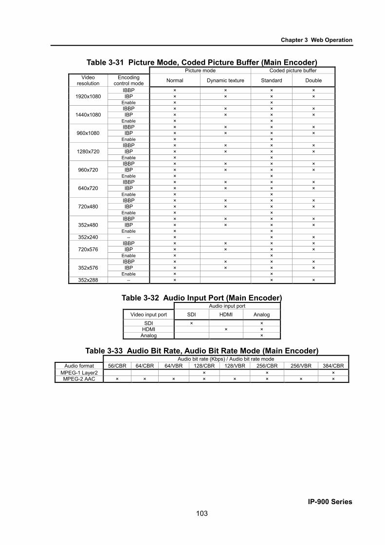
Chapter 3 Web Operation
IP-900 Series 103
Table 3-31 Picture Mode, Coded Picture Buffer (Main Encoder) Picture mode Coded picture buffer
Video resolution
Encoding control mode Normal Dynamic texture Standard Double
1920x1080 IBBP × × × × IBP × × × ×
Enable × ×
1440x1080 IBBP × × × × IBP × × × ×
Enable × ×
960x1080 IBBP × × × × IBP × × × ×
Enable × ×
1280x720 IBBP × × × × IBP × × × ×
Enable × ×
960x720 IBBP × × × × IBP × × × ×
Enable × ×
640x720 IBBP × × × × IBP × × × ×
Enable × ×
720x480 IBBP × × × × IBP × × × ×
Enable × ×
352x480 IBBP × × × × IBP × × × ×
Enable × × 352x240 -- × × ×
720x576 IBBP × × × × IBP × × × ×
Enable × ×
352x576 IBBP × × × × IBP × × × ×
Enable × × 352x288 -- × × ×
Table 3-32 Audio Input Port (Main Encoder)
Audio input port Video input port SDI HDMI Analog
SDI × × HDMI × ×
Analog ×
Table 3-33 Audio Bit Rate, Audio Bit Rate Mode (Main Encoder) Audio bit rate (Kbps) / Audio bit rate mode
Audio format 56/CBR 64/CBR 64/VBR 128/CBR 128/VBR 256/CBR 256/VBR 384/CBR MPEG-1 Layer2 × × × MPEG-2 AAC × × × × × × × ×

Chapter 3 Web Operation
IP-900 Series 104
Table 3-34 Downconverter (Sub Encoder)
Downconverter
Video format Letter box Side cropped Squeeze 1080i/59.94 × × ×
1080i/50 × × × 1080i/60 1080i/60 (->59.94) × ×
720p/59.94 × × 720p/50 × ×
480i/59.94 576i/50
Table 3-35 Video Resolution (Sub Encoder)
Video resolution
Video format Downconverter 1920 x1080
1440 x1080
960 x1080
1280 x720 960x720 640x720 720x480 352x480 352x240 176x112 720x576 352x576 352x288 176x144
1080i/59.94 None × × × Enable × × × ×
1080i/50 None × × × Enable × × × ×
1080i/60 -- × × × 1080i/60 (->59.94)
None × × × Enable × × × ×
720p/59.94 None × × × Enable × × × ×
720p/50 None × × × Enable × × × ×
480i/59.94 -- × × × × 576i/50 -- × × × ×

Chapter 3 Web Operation
IP-900 Series 105
Table 3-36 Video Frame Rate (Sub Encoder)
Video frame rate (fps) Video
resolution 29.97 25 30 59.94 50 14.985 9.99 7.493 4.995 2.997 1.998 0.999 0.4995 12.5 8.333 6.25 4.167 2.5 1.667 1
1920x1080 × × × × × × × × × 1440x1080 × × × × × × × × × 960x1080 × × × × × × × × × 1280x720 × × 960x720 × × 640x720 × × 720x480 × × × × × × × 352x480 × × × × × × × 352x240 × × × × × × × 176x112 × × × × × × × 720x576 × 352x576 × 352x288 × × × × × × × 176x144 × × × × × × ×

Chapter 3 Web Operation
IP-900 Series 106
Table 3-37 Encoding Control Mode (Sub Encoder)
Encoding control mode
Video resolution Video frame rate (fps) IBBP IBP IPPP PPPP
1920x1080 30/29.97/25 × × × × Enable ×
1440x1080 30/29.97/25 × × × × Enable ×
960x1080 30/29.97/25 × × × × Enable ×
1280x720 -- × × × × 960x720 -- × × × × 640x720 -- × × × ×
720x480 29.97/25 × × × × Enable ×
352x480 29.97/25 × × × × Enable ×
352x240 7.493 × × Enable ×
176x112 -- × 720x576 -- × × × × 352x576 -- × × × ×
352x288 6.25 × × Enable ×
176x144 -- ×
Table 3-38 GOP (Sub Encoder)
GOP Encoding control mode Open Closed
IBBP × × IBP × ×
IPPP × × PPPP
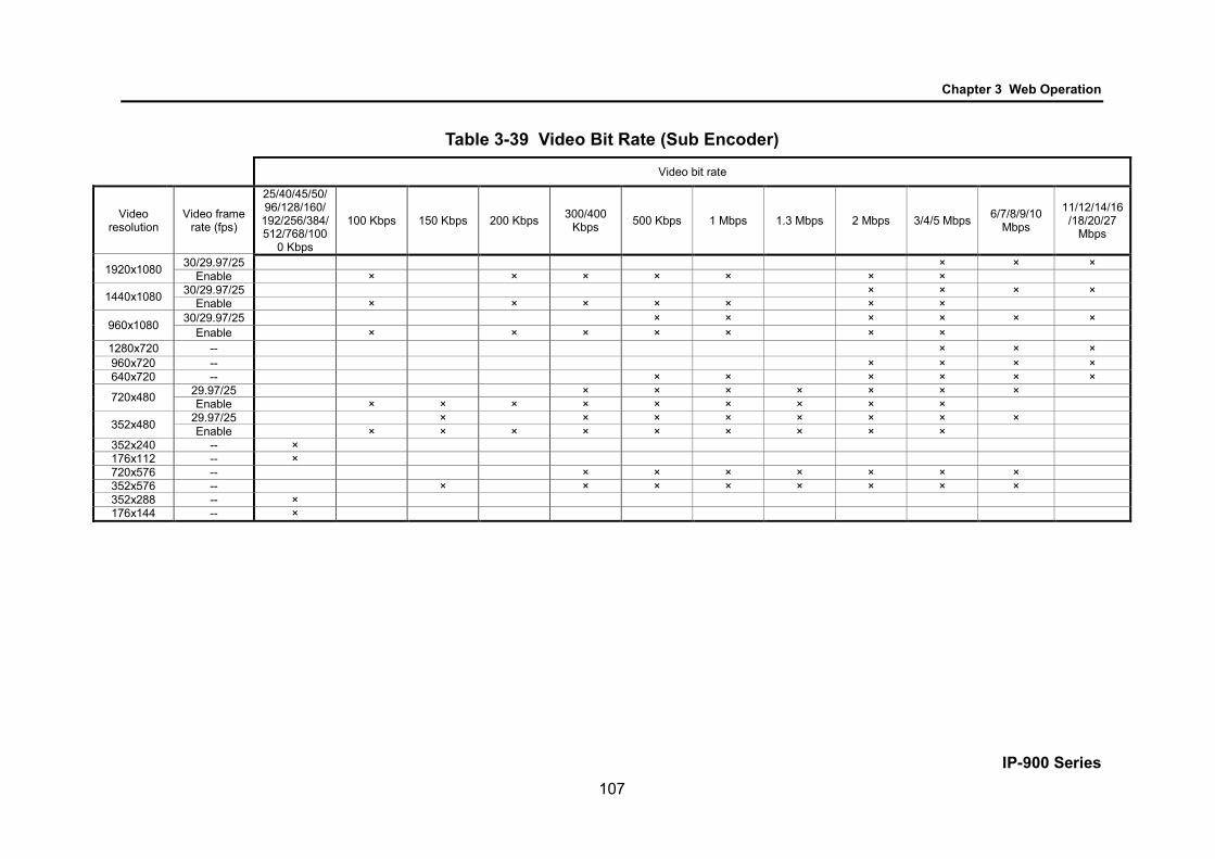
Chapter 3 Web Operation
IP-900 Series 107
Table 3-39 Video Bit Rate (Sub Encoder)
Video bit rate
Video resolution
Video frame rate (fps)
25/40/45/50/96/128/160/
192/256/384/512/768/100
0 Kbps
100 Kbps 150 Kbps 200 Kbps 300/400 Kbps 500 Kbps 1 Mbps 1.3 Mbps 2 Mbps 3/4/5 Mbps 6/7/8/9/10
Mbps
11/12/14/16 /18/20/27
Mbps
1920x1080 30/29.97/25 × × × Enable × × × × × × ×
1440x1080 30/29.97/25 × × × × Enable × × × × × × ×
960x1080 30/29.97/25 × × × × × × Enable × × × × × × ×
1280x720 -- × × × 960x720 -- × × × × 640x720 -- × × × × × ×
720x480 29.97/25 × × × × × × × Enable × × × × × × × × ×
352x480 29.97/25 × × × × × × × × Enable × × × × × × × × ×
352x240 -- × 176x112 -- × 720x576 -- × × × × × × × 352x576 -- × × × × × × × × 352x288 -- × 176x144 -- ×

Chapter 3 Web Operation
IP-900 Series 108
Table 3-40 Bit Rate Mode (Sub Encoder)
Bit rate mode
Video resolution Video frame rate (fps)
Encoding control mode CBR VBR
1920x1080 -- -- × 1440x1080 -- -- × 960x1080 -- -- × 1280x720 -- -- × 960x720 -- -- × 640x720 -- -- × 720x480 -- -- × 352x480 -- -- ×
352x240 7.493 IBBP × IPPP ×
Enable -- × 176x112 -- -- × 720x576 -- -- × 352x576 -- -- ×
352x288 6.25 IBBP × IPPP ×
Enable -- × 176x144 -- -- ×
Table 3-41 Video PES (Sub Encoder) Video PES
Video resolution Encoding control mode 1Field/1PES 1Frame/1PES
1920x1080 IBBP × × Enable ×
1440x1080 IBBP × × Enable ×
960x1080 IBBP × × Enable ×
1280x720 -- × 960x720 -- × 640x720 -- ×
720x480 IBBP × × Enable ×
352x480 IBBP × × Enable ×
352x240 -- × 176x112 -- ×
720x576 IBBP × × Enable ×
352x576 IBBP × × Enable ×
352x288 -- × 176x144 -- ×

Chapter 3 Web Operation
IP-900 Series 109
Table 3-42 Pre-Filter (Sub Encoder)
Pre-Filter Video
resolution OFF LIGHT MEDIUM HEAVY
1920x1080 × × × × 1440x1080 × × × × 960x1080 × × × × 1280x720 × × × × 960x720 × × × × 640x720 × × × × 720x480 × × × × 352x480 × × × × 352x240 × 176x112 × 720x576 × × × × 352x576 × × × × 352x288 × 176x144 ×

Chapter 3 Web Operation
IP-900 Series 110
Table 3-43 Refresh Cycle (Sub Encoder) Video Resolution Frame Rate Encoding control
mode Refresh cycle (frame)
1920x1080 1440x1080 960x1080
29.97
IBBP 15/30/60 IBP 14/28/56
IPPP 15/30/60 PPPP 34/68/134
25
IBBP 12/24/48 IBP 12/24/48
IPPP 12/24/48 PPPP 34/68/134
30
IBBP 15/30/60 IBP 14/28/56
IPPP 15/30/60 PPPP 34/68/134
14.985 IPPP 15/30/60 9.99 IPPP 10/20/40
4.995 IPPP 5/10/20 1.998 IPPP 2/4/8 0.999 IPPP 1/2/4 0.4995 IPPP 1/2/4
1280x720 960x720 640x720
59.94
IBBP 30/60/120 IBP 28/56/112
IPPP 30/60/120 PPPP 90/180/360
50
IBBP 24/48/96 IBP 24/48/96
IPPP 24/48/96 PPPP 90/180/360
720x480 352x480
29.97
IBBP 15/30/60 IBP 14/28/56
IPPP 15/30/60 PPPP 30/60/120
14.985 IPPP 15/30/60 9.99 IPPP 10/20/40
4.995 IPPP 5/10/20 1.998 IPPP 2/4/8 0.999 IPPP 1/2/4 0.4995 IPPP 1/2/4
720x576 352x576 25
IBBP 12/24/48 IBP 12/24/48
IPPP 12/24/48 PPPP 36/72/144
352x240
14.985 IBBP 7/15/30 9.99 IPPP 5/10/20
7.493 IBBP 6/15/30 IPPP 7/15/30
4.995 IPPP 5/10/20 2.997 IPPP 3/6/12 1.998 IPPP 4/8/16 0.999 IPPP 2/4/8
352x288
12.5 IBBP 6/12/24 8.333 IPPP 4/8/16
6.25 IBBP 6/12/24 IPPP 6/12/24
4.167 IPPP 4/8/16 2.5 IPPP 2/5/10
1.667 IPPP 2/5/10 1 IPPP 2/5/10
176x112
14.985 IPPP 7/15/30 9.99 IPPP 5/10/20
7.493 IPPP 7/15/30 4.995 IPPP 5/10/20 2.997 IPPP 3/6/12 1.998 IPPP 4/8/16 0.999 IPPP 2/4/8
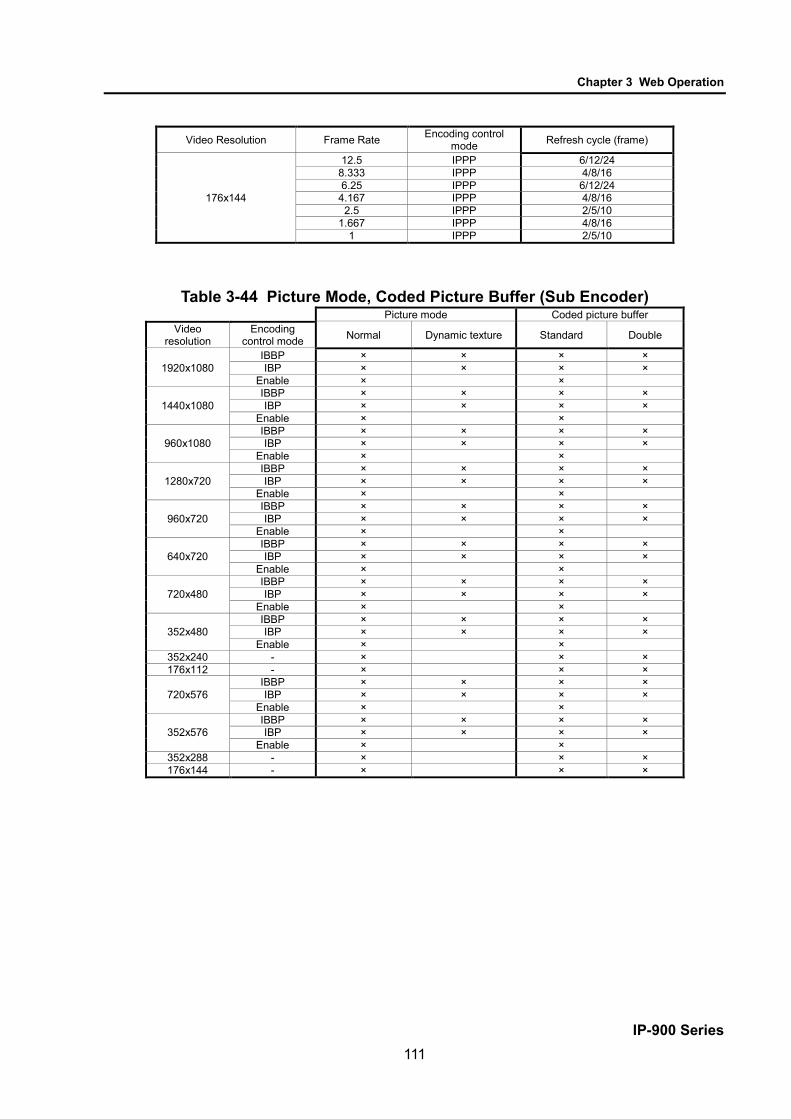
Chapter 3 Web Operation
IP-900 Series 111
Video Resolution Frame Rate Encoding control
mode Refresh cycle (frame)
176x144
12.5 IPPP 6/12/24 8.333 IPPP 4/8/16 6.25 IPPP 6/12/24
4.167 IPPP 4/8/16 2.5 IPPP 2/5/10
1.667 IPPP 4/8/16 1 IPPP 2/5/10
Table 3-44 Picture Mode, Coded Picture Buffer (Sub Encoder)
Picture mode Coded picture buffer Video
resolution Encoding
control mode Normal Dynamic texture Standard Double
1920x1080 IBBP × × × × IBP × × × ×
Enable × ×
1440x1080 IBBP × × × × IBP × × × ×
Enable × ×
960x1080 IBBP × × × × IBP × × × ×
Enable × ×
1280x720 IBBP × × × × IBP × × × ×
Enable × ×
960x720 IBBP × × × × IBP × × × ×
Enable × ×
640x720 IBBP × × × × IBP × × × ×
Enable × ×
720x480 IBBP × × × × IBP × × × ×
Enable × ×
352x480 IBBP × × × × IBP × × × ×
Enable × × 352x240 - × × × 176x112 - × × ×
720x576 IBBP × × × × IBP × × × ×
Enable × ×
352x576 IBBP × × × × IBP × × × ×
Enable × × 352x288 - × × × 176x144 - × × ×

Chapter 3 Web Operation
IP-900 Series 112
Table 3-45 Audio Bit Rate, Audio Bit Rate Mode (Sub Encoder)
Audio bit rate (Kbps) / Audio bit rate mode
Audio format 56/CBR 64/CBR 64/VBR 128/CBR 128/VBR 256/CBR 256/VBR 384/CBR
MPEG-1 Layer2 × × × MPEG-2 AAC × × × × × × × ×
Enables to record when the Main encoder system rate is less than 14.049 Mbps and the sub encoder system rate is less than 1.549 Mbps.
If [Stream format] of Output interface settings (Main encoder ethernet) described in Section
3.3.1,"Setting (Encoder)," is "Standard TS," recording cannot be performed.

Chapter 3 Web Operation
IP-900 Series 113
3.3.2 Encoder Address Report * This function is enabled only when the device operation mode is encoder mode. * Encoder address report is a group of setting items, of which 10 sets can be registered
independently by selecting data numbers as in 3.2.1 Configuration Data. To dynamically obtain an IP address using DHCP or PPPoE, the IP address needs to be known. If the
report destination is specified in advance, the obtained IP address is reported to the specified destination. IP-900 series decoder or a PC running a certain type of software (*1) is normally specified as the report destination. If the decoder is specified in advance as the report destination, you can specify an encoder from the Web screen to request streaming. (Refer to Section 3.5.2 for information about decoder setting and operation.)
The same screen is displayed for Encoder Address Report, Main Encoder, and Sub Encoder, which are located in the frame on the left side of the Web screen. By click on the tab for each, the Encoder Address Report screen for each is displayed at the top of the frame on the right side.
Make the required settings by referring to Table 3-46 Setting Items for Encoder Address Report.
Figure 3-23 Encoder Address Report screen

Chapter 3 Web Operation
IP-900 Series 114
After completing the settings, click the button. The message below appears. Click OK to apply the settings. * Reboot is not required.
Table 3-46 Setting Items for Encoder Address Report Item Description Value Main encoder report settings
Encoder name Specify an arbitrary name used to identify the encoder.
Up to 16 characters
Local port Specify the own device port number used to send an encoder address message.
0 or 1024 to 64000 (Default: 0) * If 0 is specified, one of the port numbers from 64100 to 65000 is automatically selected.
Main encoder destination settings
Destination 1 to 10
IP version Specify the IP version of the IP address of the destination device to which the encoder report is to be sent.
- IPv4 (default) - IPv6
IP address Specify the IP address of the destination device to which the encoder report is to be sent.
Other than 0.0.0.0 (Default: Blank) * A blank field means that no value is specified. * A multicast address cannot be set.
Destination port
Specify the port number of the destination device to which the encoder report is to be sent.
- Blank or 1024 to 64000 (Default: Blank) * A blank field means that no value is specified.
Sub encoder report settings
Encoder name Specify an arbitrary name used to identify the encoder.
Up to 16 characters
(*1) Local port Specify the own device port number used to send an encoder address message.
0 or 1024 to 64000 (Default: 0) * If 0 is specified, one of the port numbers from 64100 to 65000 is automatically selected.
Sub encoder destination settings
Destination 1 to 10
IP version Specify the IP address of the destination device to which the encoder report is to be sent.
- IPv4 (Default) - IPv6
(*1) IP address Other than 0.0.0.0 (Default: Blank) * A blank field means that no value is specified. * A multicast address cannot be set.
Destination port
Specify the port number of the destination device to which the encoder report is to be sent.
- Blank or 1024 to 64000 (Default: Blank) * A blank field means that no value is specified.
*1: Not displayed in case “Main H.264/MPEG-4 AVC 2stereo” is set for [Operation mode].

Chapter 3 Web Operation
IP-900 Series 115
The device does not send the encoder address report when the following condition applies: [IP version]
of Output interface settings (Main encoder ethernet) described in Section 3.3.1, "Setting (Encoder)," and [IP version] of Main encoder destination settings described in Section 3.3.2, "Encoder Address Report," do not match. (The same thing can be said regarding the sub encoder.)
The device does not send the encoder address report when the following condition applies: "Unicast
(simplex)" is selected for [Streaming mode] of Output interface settings (Main encoder ethernet) described in Section 3.3.1, "Setting (Encoder)," and [Streaming destination IP address] of Output interface settings (Main encoder ethernet) described in Section 3.3.1, "Setting (Encoder)," and [IP address] of Main encoder destination settings described in Section 3.3.2, "Encoder Address Report," do not match. (The same thing can be said regarding the sub encoder.)

Chapter 3 Web Operation
IP-900 Series 116
3.3.3 Superimpose * 10 sets of settings can be configured independently by selecting appropriate configuration
data as explained in Section 3.2.1, "Configuration Data." The superimpose function superimposes a character string (consisting of up to 24 en-size or 48 en-size
characters) or a time indication (year, month, day, hour, minute, and second) on the encoded image. You can specify up to four types of string superimpositions (or one type of time superimposition) on the main and sub encoders.
The same screen is displayed for Superimpose, Main encoder, and Sub-encoder, which are located in the left frame on the Web screen. Click the tab for each to bring the superimposition information screen to the top of the right frame. Specify the necessary information by referring to Table 3-47 Main Encoder/Sub Encoder Superimpose Settings
Figure 3-24 Superimpose screen

Chapter 3 Web Operation
IP-900 Series 117
After completing the setting, click the button. The message below appears. Click OK to apply the settings. * Reboot is not required.
Table 3-47 Main Encoder/Sub Encoder Superimpose Settings
Item Description Value Main/Sub encoder superimpose settings 1 to 4 (*2)
Superimpose setting
Specify whether to enable character superimposition by using the superimpose function to display the characters.
Enable Disable (Default)
Horizontal position Specify the number of pixels from the left end of the screen to indicate the horizontal position from where the specified character string starts to be superimposed.
0 to 1919 (*1)
Vertical position Specify the number of lines from the top end of the screen to indicate the vertical position from where the specified character string starts to be superimposed.
0 to 1079 (*1)
Font size Specify the font size of character strings to be superimposed.
- SD:32/HD:64 Displays characters in a size of: 32×32 dots if the input resolution is SD 64×64 dots if the input resolution is HD
- SD:48/HD:96 Displays characters in a size of: 48×48 dots if the input resolution is SD 96×96 dots if the input resolution is HD
Font color Specify the font color of character strings to be superimposed.
- White (Default) - Black - Red - Blue - Green
Effects Specify the background of character strings to be superimposed.
- Filled (Default) - Shaded - Bordered
Background color Specify the background color of character strings to be superimposed.
- Black (Default) - Translucent black - White - Translucent white - Transparent
Time * Only available for superimpose 4 settings
Specify whether to superimpose time.
- Enable - Disable (Default)

Chapter 3 Web Operation
IP-900 Series 118
Item Description Value Main/Sub encoder superimpose settings 1 to 4 (*2)
Character string Specify the character strings to be superimposed.
A character string that consists of 48 single-byte characters or 24 double-byte characters.
*1: The display area varies depending on the monitor that outputs the image. *2: In case “Main H.264/MPEG-4 AVC 2stereo” is set for [Operation mode], sub encoder superimpose
settings are not displayed.

Chapter 3 Web Operation
IP-900 Series 119
3.3.4 Operation & Status (Encoder) * This function is enabled only when the device operation mode is encoder mode. Click OPERATION & STATUS in the left frame of the Web screen. The Operation & Status screen
appears in the right frame. From this screen, you can check encoder operation information such as on encoding and video input. Selecting {3sec, 5sec, or 10sec} from [Auto update] enables automatic updating of the Operation &
Status information in specified time intervals. Selecting {none} from [Auto update] disables the automatic updating.
Figure 3-25 Operation & Status (Encoder) screen
You can control encoding and streaming. When the status is "Stopped," click the button starts encoding. To stop encoding, click the button.

Chapter 3 Web Operation
IP-900 Series 120
Table 3-48 Encoder Operation & Status Display Items
Item Display Main encoder {Operating / Stopped}
Displays the operation status as the result of setting in the Settings screen or the operation of the encoding START or STOP button.
Number of possible streams: N Destination IP address: Port number {Normal / Fault} N=1 If "Multicast" or "Unicast (simplex)" is specified for [Streaming mode], the value is fixed to "1". 1-4 If "Unicast" is specified for [Streaming mode], a value from "1" to "4" is displayed. The number of possible streams depends on the [System bit rate] and [Acceptable stream number] settings. Displays whether an error occurred for each streaming destination IP address.
Sub encoder (*1)
{Operating / Stopped} Displays the operation status as the result of setting in the Settings screen or the operation of the encoding START or STOP button.
Number of possible streams: N Destination IP address: Port number {Normal / Fault} N=1 If "Multicast" or "Unicast (simplex)" is specified for [Streaming mode], the value is fixed to "1". 1-4 If "Unicast" is specified for [Streaming mode], a value from "1" to "4" is displayed. The number of possible streams depends on the [System bit rate] and [Acceptable stream number] settings. Displays whether an error occurred for each streaming destination IP address.
Video input {Normal / Fault / No video signal} Displays the input state of the video signal.
Note) {A/B} indicates that either A or B is displayed. *1: Not displayed in case “Main H.264/MPEG-4 AVC 2stereo” is set for [Operation mode].
Enables to record when the Main encoder system rate is less than 14.049 Mbps and the sub encoder
system rate is less than 1.549 Mbps. If [Stream format] of Output interface settings (Main encoder ethernet) described in Section
3.3.1,"Setting (Encoder)," is "Standard TS," recording cannot be performed.

Chapter 3 Web Operation
IP-900 Series 121
3.4 Recorder An optional CF card is required for this function.
3.4.1 Setting (Recorder)
* Settings is a group of setting items, of which 10 sets can be registered independently by selecting data numbers as in 3.2.1 Configuration Data. Set parameters related to recording. Make the required settings by referring to Table 3-49 Recorder.
Set the date and time of the clock built in IP-900 series. The recorder records encoded streams when the main encoder operates. Recording cannot be
performed for some system bit rates because of performance limitations. "Network down" and "Relay input", etc. can be recorded in the trigger as protected file. After the
trigger is restored, protected file can be downloaded.
Figure 3-26 Setting (Recorder) screen
3.4

Chapter 3 Web Operation
IP-900 Series 122
After completing the settings, click the button. The message below appears. Click OK to
apply the settings. * Reboot is not required.
Table 3-49 Recorder Setting Items
Item Description Parameter Recorder settings Recording operation Specify whether to perform
recording operation upon start of the device.
- Enable - Disable (Default)
Recording mode Select the recording mode. - Record until full - Overwrite (Default) - Record until start position - Overwrite except protected file - Record until full after protect trigger
Protect trigger Specify the trigger to protect the local recording data when "Recording mode" is set for [Overwrite except protected file] or [Record until full after protect trigger].
- Network monitoring by ping - Relay contact monitoring by SNMP - Network & Relay contact monitoring - Number of Main encoder streaming - Number of Main & Sub encoder streaming
Network : IP version Specify the IP address version of the monitoring device by ping.
- IPv4 (Default) - IPv6
Network : IP address Specify the IP address of the monitoring device by ping.
Other than 0.0.0.0 (Default: 0.0.0.0) * You cannot specify a multicast address.
Relay contact : IP version
Specify the IP address version of the monitoring device by snmp.
- IPv4 (Default)
Relay contact : SNMP IP address
Specify the IP address of the monitoring device by snmp.
Other than 0.0.0.0 (Default: 0.0.0.0) * You cannot specify a multicast address.
Relay contact : SNMP Community
Specify the community name to access to the monitoring device by snmp.
Alphanumeric 16 characters (Default: Blank)

Chapter 3 Web Operation
IP-900 Series 123
Recorder settings Relay contact : SNMP OID
Specify the object identifier to access to the monitoring device by snmp. (*1)
64 characters (Default: 1.3.6.1.4.1.23441.1.1.3.1.0)
Protect trigger monitoring cycle
Specify the polling time to check the trigger.
1 to 59 sec cycle, 1 to 10 times (Default 30sec cycles, 4times) * when the same state continues
Time of Recording protected file (*2)
Specify the recording time as a protected file from the trigger detection when "Recording mode" is set for [Record until full after protect trigger].
0 hr 0 min to 24 hr 59 min * 0hr0min when record until full
Prerecord time (*2) Specify the time for creating protected files by seconds backward from the trigger detection.
0 to 3600 sec
Time of Releasing protected file (*2)
Specify the time from the trigger detection to the release of protected file.
0 hr 0 min to 336 hr 59 min * 0hr0min when no release
*1 : SNMP MIB interface for Relay input signal information. SYNTAX:OCTET STRING STRING :”0” is No input signal, “1” is Exist input signal. Only the first string.
*2 : There is a time lag of a few minutes from a few seconds depending on the System rate of the main encoder and the refresh cycle.
Recorded data is destroyed if the device power is turned off during recording. Be sure to stop
recording before turning off the device power. If the device is started with an unused CF card or previous CF card (V02L002) inserted, the CF card
is formatted unconditionally. Please back up necessary data of the CF card before software upgrades. If [Stream format] of Output interface settings (Main encoder ethernet) described in Section 3.3.1,
"Setting (Encoder)," is "Standard TS," recording cannot be performed. The maximum system bit rate when the streaming and recording are activated simultaneously is
limited up to "main encoder system rate is 14.049 Mbps", "sub encoder system rate is 1.549 Mbps" The maximum system bit rate when the recording and record data downloading are activated
simultaneously is limited up to "main encoder system rate is 6.049 Mbps".

Chapter 3 Web Operation
IP-900 Series 124
■Example : In the case of setting parameters as follows CF card capacity in 120 minutes

Chapter 3 Web Operation
IP-900 Series 125
3.4.2 File List
* This function is enabled only when the device operation mode is encoder mode. Click FILE LIST in the left frame of the Web screen. The Data List screen appears in the right frame. In this screen, you can check the file list or download files. Protected file becomes "Protect" the left of the list, and is displayed at the head. "Time of Releasing
protected file" is displayed.
Figure 3-27 File List screen

Chapter 3 Web Operation
IP-900 Series 126
Click the button updates the list. To download a file, check the relevant check column at the left end of the list and confirm that the start
time and acquisition time are automatically set in the Download field, and then click the button.
Click the button deletes the first file in the list. Click the
button deletes all files. Click the button to release the protected file. Recorded data can be downloaded by specifying any time range within the range indicated for each file
in the list. Note, however, that data with the specified time range spanning two or more files cannot be downloaded.
Data is downloaded with a file name in the following format:
yyyymmddhhmmssHHMMSS.mpg <Description> yyyy = Year mm = Month dd = Day hh = Hour mm = Minute ss = Second HH = Hours (acquisition duration specified in hours) MM = Minutes (acquisition duration specified in minutes) SS = Seconds (acquisition duration specified in seconds from 0 to 59)
Note) The time for which data can be recorded depends on the system bit rate and the capacity of the
CF card.
The following dialog box appears in case that the file download size exceeds 4GB. Some of browsers
may not be able to download it.
File deletion works only when recording is stop. The protected file cannot delete. The maximum system bit rate when the recording and record data downloading are activated
simultaneously is limited up to "main encoder system rate is 6.049 Mbps".

Chapter 3 Web Operation
IP-900 Series 127
3.4.3 Operation & Status (Recorder)
* This function is enabled only when the device operation mode is encoder mode. Operation & Status related to recording are displayed. Select {3sec, 5sec, or 10sec} from [Auto update] to enable automatic update of the Operation & Status
information in specified time intervals. Select {none} from [Auto update] to disable automatic updating.
Figure 3-28 Operation & Status (Recorder)
You can control the recording operation. When the recording operation is "Stopped," click the
button starts recording. To stop recording, click the button.

Chapter 3 Web Operation
IP-900 Series 128
Table 3-50 Recorder Operation & Status Display Items
Item Display
Recording mode {Recording until full / Overwrite / Record until start position / Overwrite except protected file / Record until full after protect trigger / ---} Displays the recording mode selected in the Settings screen.
Recorder {Recording / Stopped} Displays the operation status caused by the setting in the Settings screen or by the operation of the recording START or STOP button.
Media {Equipped: Normal / Equipped: Fault / Equipped: Media Full /Unequipped} Displays whether an error related to recording to the CF card occurred or that a CF card is not mounted in the device.
Media size {XX.XGB(Now setting:YYhrYYmin) / ---} Displays the size of the CF card used for the recording in megabytes and the storage time in the CF card in the current settings.
Network {Normal / Fault / ---} Displays the network status.
Relay contact {Normal: No contact signal / Normal: Exist contact signal / Fault / ---} Displays the status of the relay contact.
Note) {A/B} indicates that either A or B is displayed.
The maximum system bit rate when the streaming and recording are activated simultaneously is
limited up to "main encoder system rate is 14.049 Mbps", "sub encoder system rate is 1.549 Mbps". If [Stream format] of Output interface settings (Main encoder ethernet) described in Section 3.3.1,
"Setting (Encoder)," is "Standard TS," recording cannot be performed.

Chapter 3 Web Operation
IP-900 Series 129
3.5 Decoder 3.5.1 Setting (Decoder)
* Settings is a group of setting items, of which 10 sets can be registered independently by selecting data numbers as in 3.2.1 Configuration Data.
Set parameters related to stream receiving. Make the required settings by referring to
Table 3-51 Decoder Setting Items.
The same screen is displayed for SETTINGS, <Input interface settings> Decoder ethernet, <AV output settings> Video and Audio (only IP-900D) and <Decoder settings> Decode which are located in the left frame on the Web screen. Click the tab for each brings the setup screen to the top of the right frame.
* No selections of Output interface are available on Decoder. Video/Audio can be output to all of the interfaces. Analog output for receiving HD streams is turned to the selected screen (Blue or Gray) in “Display when no data receiving” of “AV output settings (Video)” section.
Figure 3-29 Setting (Decoder) screen
After completing the settings, click the button. The message below appears. Click OK to apply the settings. * Reboot is not required.
3.5
IP-920 Settings Screen

Chapter 3 Web Operation
IP-900 Series 130
Table 3-51 Decoder Setting Items
Item Description Parameter Input interface settings (Decoder ethernet)
IP version Specify the IP version for IP streaming.
- IPv4 (Default) - IPv6
Streaming mode
Specify the type of broadcasting for IP streaming.
- Multicast (Default) - Unicast
Streaming origination IP address
If "Unicast" is specified for [Streaming mode], specify the IP address of the streaming origination device. If "Multicast" is specified for [Streaming mode], specify the multicast address for streaming.
IP address (Default: 230.11.3.1) Setting the following values is inhibited: [IPv4] 240.0.0.0 to 255.255.255.255 (Class E) 0.0.0.0, 127.0.0.0 to 127.255.255.255 [IPv6] 0::0
IGMP version If "IPv4" is specified for [IP version] and "Multicast" is specified for [Streaming mode], specify the IGMP version of the IGMP to be used for the group management of IPv4 multicast.
- Version 2 (Default) - Version 3
IGMPv3 source IP address
If "Version 3" is set for [IGMP Version], specify the IPv4 address of the IPv4 multicast origination device that accepts receiving.
Other than 0.0.0.0 (Default: 0.0.0.0) * You cannot specify a multicast address.
MLD version If "IPv6" is specified for [IP version] and "Multicast" is specified for [Streaming mode], specify the MLD version of the MLD to be used for the group management of IPv6 multicast.
- Version 1 (Default) - Version 2
MLDv2 source IP address
If "Version 2" is set for [MLD Version], specify the IPv6 address of the IPv6 multicast origination device that accepts receiving.
IPv6 address that is not the following: ffxx:xxxx:…:xxxx (multicast address) (Default: "::") * If this address does not match the origination IPv6 address of IPv6 multicast, streams cannot be received.
Unicast request cycle
Specify the cycle at which the unicast stream request is sent.
- 3 to 30 seconds (Default: 30 seconds)

Chapter 3 Web Operation
IP-900 Series 131
Item Description Parameter Input interface settings (Decoder ethernet)
ID control for unicast
If "Unicast" is specified for [Streaming mode], specify whether to report the ID for confirming the validity of the unicast stream request.
- Enable - Disable (Default) * If "Enable" is selected, the unicast ID of the encoder and that of the decoder must be in agreement to receive streams.
Unicast ID If "Enable" is selected for [ID control for unicast], specify the ID to be used for confirming the validity of a unicast streaming request.
Hexadecimal number between 0000 and ffff
ARQ If "Enable" is selected for [ID control for unicast], specify a valid ID value.
- Enable - Disable (Default)
ARQ buffering time
Specify the wait time in msec for an ARQ retransmitted packet. * This will increase the delay by the time specified here.
0 to 2000 ms (Default: 300 ms)
SMPTE2022 FEC Specify whether to receive SMPTE2022-1 FEC packets to activate the SMPTE2022-1 FEC error correction method.
- Enable - Disable (Default)
Input interface settings (From Server)
ARQ When receiving streaming from Fujitsu server (FutureyeII, etc), specify whether to enable the ARQ error correction method.
- Enable - Disable (Default)
ARQ buffering time
When receiving streaming from Fujitsu server (FutureyeII, etc), specify the wait time in msec for an ARQ retransmitted packet. * This will increase the delay by the time specified here.
0 to 2000ms (Default: 300 ms)
Input interface settings (Decoder ethernet port)
Streaming port Specify the own device port number used to receive streams.
1024 to 64000 (Default: 5000)
Unicast request port
Specify the streaming request source port number (own device) in unicast streaming mode.
0, or10240 to 64000 (Default: 0) * If 0 is specified, one of the port numbers from 32768 to 61000 is automatically selected.
Specify the streaming request destination port number in unicast streaming mode.
1024 to 64000 (Default: 9900)
Encoder address report port
Specify the own device port number used to receive an encoder address report.
1024 to 64000 (Default: 5100)
SMPTE2022 FEC port
Displays the port number of the own device used for receiving SMPTE2022-1 FEC.
You cannot specify this item. * This item is automatically set according to the [Streaming port] setting.
ARQ control port Displays the port number of the own device used for controlling ARQ.
You cannot specify this item. * This item is automatically set according to the [Streaming port] setting.
AV output settings(video)
Output format at startup
Specify the format of the video output signal to be used after the device is started or after the decoder settings are changed. * When any stream has been received, a setting conforming to the input format of the encoder is used.
- 1080i/59.94 - 1080i/50 - 1080i/60 - 720p/59.94 - 720p/50 - 480i/59.94 (Default) - 576i/50

Chapter 3 Web Operation
IP-900 Series 132
Item Description Parameter AV output settings(video)
Analog video setup Specify the setup level of the analog video output signal.
- Enable: 7.5 IRE - Disable (Default): Same as the pedestal level
Upconverter Select whether to work as Upconverter.
- None (Default) - 480i/59.94 -> 1080i/59.94 (Pillar box) - 480i/59.94 -> 1080i/59.94 (Anamorphic) - 480i/59.94 -> 1080i/59.94 (Aspect ratio) *In case of '480i/59.94 -> 1080i/59.94 (Aspect ratio)', upconverter mode is automatically selected based on the aspect ratio information in the stream header. When it is recognized as 'squeeze', the video is upconverted by 'Anamorphic'. Otherwise, it is upconverted by 'Pillar box'.
720p->1080i Convert
Specify whether to convert to 1080i when 720p stream is received.
- Disable (Default) - Enable
Concealment time Specify the time it takes until the system recognizes that packets have not been received.
- 5 to 6000 seconds (Default: 10 seconds)
Display when no data receiving
Specify the video signal to be output when no packets are received.
- Blue (Default) - Gray
AV output settings (Audio) *Displayed only for IP-920D
Output level
Specify the audio output level. - -20dBm (Max. 0dBm) - 0dBm (Max. 20dBm) (Default)
Decoder settings (Decode)
Decoding operation
Specify whether to enable receiving and decoding streaming video upon starting.
- Enable - Disable (Default)
Error concealment Specify whether to enable the freeze control that prevents block noise in the event of packet loss. * This setting is not enabled when “Ultra Low Latency (PPPP)” is selected and received the stream.
- Enable (Default) - Disable
Jitter control buffer Specify the buffering time for absorption of LAN network jitter. * This will increase the delay by the time specified here but reduce the video distortion caused by network jitter. * The video may be distorted if network jitter is generated for longer than the specified buffer time.
- 1 to 150 ms (Default: 150 ms)
Ultra low latency Select whether to recognize “Ultra low latency” stream automatically. * In case of being selected “Enable”, “Ultra low latency” stream can be automatically recognized and work as a decoder both normal and “Ultra low latency” mode. In case of being selected “Disable”, the Decoder works as normal mode.
- Enable - Disable (Default) * This function is enabled after installing “Ultra Low Latency” option.

Chapter 3 Web Operation
IP-900 Series 133
Item Description Parameter Decoder settings (PID)
PID mode Specify the method of selecting the program to be received. * You can select from the following: automatically obtain a PMT PID; specify a program number or service ID to select a PID; specify a PMT PID; or individually specify a video/audio PID.
- AUTO (Default) - Manual
PMT PID Receiving PMT PID can be enabled to set when “Manual” is selected for [PID mode].
1 to 1ffe in hexadecimal (Default: 100)
Video PID Specify the PID of Video to be received, only when “Manual” is specified for [PID mode].
1 to 1fff in hexadecimal (Default: 1011) * If 1fff is set, video is not received.
Audio PID Specify the PID of Audio to be received, only when “Manual” is specified for [PID mode]. Audio of designated ID can be output to channel 1 of SDI and HDMI.
1 to 1fff in hexadecimal (Default: 1100) * If 1fff is set, audio is not received.
PCR PID Specify a PID of the PCR to be received, only when “Manual” is specified for [PID mode].
1 to 1fff in hexadecimal (Default: 1001)

Chapter 3 Web Operation
IP-900 Series 134
3.5.2 Reference Clock (GENLOCK)
* Reference Clock Settings is a group of setting items, of which 10 sets can be registered independently by selecting data numbers as in 3.2.1 Configuration Data.
Set parameters related to external clock synchronization. Make the required settings by referring to Table 3-52 Reference Clock Setting Items,
Figure 3-30 Reference Clock screen

Chapter 3 Web Operation
IP-900 Series 135
After completing the settings, click the “APPLY” button. The message below appears. Click the
OK button to apply the settings. * Reboot is not required.
Table 3-52 Reference Clock Setting Items Item Description Parameter
Operation settings
Reference clock setting
Specify the type of external clock synchronization signal. * If “PCR” is set, it synchronizes with the line and if “Internal” is set, it synchronizes with the internal oscillator.
- PCR (Default) - Internal - BB * BB can be enabled to select after adding “Reference” option.
Phase adjustment Adjusting phase can be set by “ns” when “BB” is selected for [Reference clock].
Default: 0ns -300000~300000 ns
Do not input other signals except BB for reference input.
CAUTION

Chapter 3 Web Operation
IP-900 Series 136
3.5.3 Encoder Selection * This function is enabled only when the device operation mode is decoder mode. Click ENCODER SELECTION in the left frame of the Web screen. The Encoder Selection screen
appears in the right frame. This screen displays the status and IP address of the encoder ready to perform streaming. Specifying
the encoder distributing a stream starts receiving the stream. Specify in advance the IP address of the decoder in the encoder as the destination. Refer to Section 3.3.2 for encoder setting. Table 3-20 Main ISO 639-2 Language Code lists the display items.
Figure 3-31 Encoder Selection screen

Chapter 3 Web Operation
IP-900 Series 137
The message below is displayed when the button is clicked after selecting the radio button for the encoder you want to select. Click OK to send a streaming request to the selected encoder. * Reboot is not required.
Table 3-53 Encoder Selection Items
Item Display
Radio Button Specify the encoder you want to select. If one is currently selected, “Selected” is displayed.
Encoder name Displays the name assigned to the encoder. Origination IP address Displays the IP address of the encoder.
IP multicast address Displays the multicast address for streaming when the encoder is performing multicast streaming.
Unicast request port Displays the Unicast request port number defined in the encoder.
Streaming port Displays the port number for receiving used by the decoder when the encoder is performing multicast streaming or unicast (simplex) streaming.
Streaming status {Streaming / Number of possible streams: x / Stopped} Displays the streaming status of the encoder. Number of possible streams for encoder
Note) {A / B} indicates that either A or B is displayed.

Chapter 3 Web Operation
IP-900 Series 138
3.5.4 Operation & Status (Decoder)
* This function is enabled only when the device operation mode is decoder mode. Click OPERATION & STATUS in the left frame of the Web screen. The Operation & Status screen
appears in the right frame. Operation & Status information related to the decoder, including the stream receiving status, can be
checked. Selecting {3sec, 5sec, or 10sec} from [Auto update] enables automatic updating of the Operation &
Status information in specified time intervals. Selecting {none} from [Auto update] disables the automatic updating.
Figure 3-32 Operation & status (Decoder) screen
You can control starting and stopping of the receiving and decoding operation. When the decoding
operation is "Stopped," click the button to start decoding. To stop decoding, click the button.
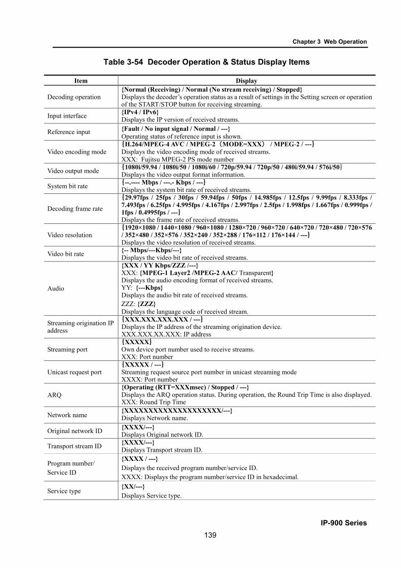
Chapter 3 Web Operation
IP-900 Series 139
Table 3-54 Decoder Operation & Status Display Items
Item Display
Decoding operation {Normal (Receiving) / Normal (No stream receiving) / Stopped} Displays the decoder’s operation status as a result of settings in the Setting screen or operation of the START/STOP button for receiving streaming.
Input interface {IPv4 / IPv6} Displays the IP version of received streams.
Reference input {Fault / No input signal / Normal / ---} Operating status of reference input is shown.
Video encoding mode {H.264/MPEG-4 AVC / MPEG-2(MODE=XXX) / MPEG-2 / ---}
Displays the video encoding mode of received streams. XXX: Fujitsu MPEG-2 PS mode number
Video output mode {1080i/59.94 / 1080i/50 / 1080i/60 / 720p/59.94 / 720p/50 / 480i/59.94 / 576i/50} Displays the video output format information.
System bit rate {--.---- Mbps / ---.- Kbps / ---} Displays the system bit rate of received streams.
Decoding frame rate
{29.97fps / 25fps / 30fps / 59.94fps / 50fps / 14.985fps / 12.5fps / 9.99fps / 8.333fps / 7.493fps / 6.25fps / 4.995fps / 4.167fps / 2.997fps / 2.5fps / 1.998fps / 1.667fps / 0.999fps / 1fps / 0.4995fps / ---} Displays the frame rate of received streams.
Video resolution {1920×1080 / 1440×1080 / 960×1080 / 1280×720 / 960×720 / 640×720 / 720×480 / 720×576
/ 352×480 / 352×576 / 352×240 / 352×288 / 176×112 / 176×144 / ---} Displays the video resolution of received streams.
Video bit rate {-- Mbps/---Kbps/---} Displays the video bit rate of received streams.
Audio
{XXX / YY Kbps/ZZZ /---} XXX: {MPEG-1 Layer2 /MPEG-2 AAC/ Transparent} Displays the audio encoding format of received streams. YY: {---Kbps} Displays the audio bit rate of received streams. ZZZ: {ZZZ} Displays the language code of received stream.
Streaming origination IP address
{XXX.XXX.XXX.XXX / ---} Displays the IP address of the streaming origination device. XXX.XXX.XX.XXX: IP address
Streaming port {XXXXX}
Own device port number used to receive streams. XXX: Port number
Unicast request port {XXXXX / ---}
Streaming request source port number in unicast streaming mode XXXX: Port number
ARQ {Operating (RTT=XXXmsec) / Stopped / ---} Displays the ARQ operation status. During operation, the Round Trip Time is also displayed. XXX: Round Trip Time
Network name {XXXXXXXXXXXXXXXXXXXX/---} Displays Network name.
Original network ID {XXXX/---} Displays Original network ID.
Transport stream ID {XXXX/---} Displays Transport stream ID.
Program number/ Service ID
{XXXX / ---} Displays the received program number/service ID. XXXX: Displays the program number/service ID in hexadecimal.
Service type {XX/---} Displays Service type.

Chapter 3 Web Operation
IP-900 Series 140
Service provider name {XXXXXXXXXXXXXXXX/---} Displays Service provider name.
Service name {XXXXXXXXXXXXXXXX/---} Displays Service name.
Encoder manufacturer {XXXXX/---} Displays Encoder manufacturer.
Encoder serial number {XXXXXXXXXXXX/---} Displays Encoder serial number.
Carrier identifier {XXXXX/---} Displays Carrier ID.
Telephone number {XXXXXXXXXXXXXXXXX/---} Displays Telephone number.
Longitude {XXXXXXXXX/---} Displays Longitude.
Latitude {XXXXXXXX/---} Displays Latitude.
User information {XXXXXXXXXXXXXXX/---} Displays User information.
PMT PID {XXXX / ---} Displays the PID of received program map table. XXXX: displays the PMT PID in hexadecimal.
Video PID {XXXX / ---} Displays the PID of received video. XXXX: displays the Video PID in hexadecimal.
Audio PID {XXXX / ---} Displays the PID of received video. XXXX: displays the Audio PID in hexadecimal.
PCR PID {XXXX/---} Displays the PID of received PCR. XXXX: displays the PCR PID in hexadecimal.
Note) {A / B} indicates that either A or B is displayed.

Chapter 4 Troubleshooting
IP-900 Series 141
Chapter 4 Troubleshooting
This chapter explains how to respond in case audio/video is not output or an alarm LED goes on. 4.1 Troubleshooting .................................................................................. 142 4.2 Alarm LED Goes On ........................................................................... 146
Chapter 4
Troubleshooting

Chapter 4 Troubleshooting
IP-900 Series 142
4.1 Troubleshooting If you think your IP-900 series is malfunctioning, follow the corresponding corrective action in the table
below, according to the applicable conditions. If a problem persists, contact the Fujitsu Service Center.
Electric shock Contact your system administrator before checking the voltage of a power outlet. Otherwise, an electric shock may occur.
Table 4-1 Check Items and Corrective Action Classification Symptom Check Corrective action Power / Starting up
Power cannot be turned on.
Is the power cable connected? Make sure that the power cable is properly connected to the outlet.
Is the outlet voltage normal? Measure the voltage with a tester to confirm that the voltage is normal. If another device is connected to the same outlet, check the operation of the device.
Hardware The ALM LED is on.
IP-900 series is faulty. Contact to CE in Fujitsu Service Center. CE may ask the alarm code for checking your status. Check each alarm code using log information screen of Web GUI before you contact to us.
The ALM LED is blinking
Settings/ Performances of the equipment and each error is shown.
Check alarm code using log information screen of Web GUI. The countermeasures are shown.
E013 Temperature warning
Check whether the condition is satisfied with “IP-900 Series User’s Guide 2.1 Installation Conditions” or not. - Do you secure certain space for air supply and exhaust opening? - Is ambient temperature within the condition? In case of having problems in the conditions above, reboot the equipment after excluding all problems. In case of not having any problems, contact to Fujitsu CE because the equipment might be failed.
E084 CF card access error E085 CF card power error
CF card or this equipment might be abnormal. In case that you have the spare CF card, please check whether the problem is recovered after replacing the failed card to the spare. Contact CE in Fujitsu Service Center in case that you do not have the spare or the problem is not recovered even after the replacement.
4.1

Chapter 4 Troubleshooting
IP-900 Series 143
Classification Symptom Check Corrective action Hardware The ALM
LED is blinking
L009 DHCP connection failure L00A PPPoE connection failure
IP address mode setting is not proper. After rebooting this equipment with the default IP address set before shipment from the factory, connect to the Web and confirm these alarm codes. - L009 DHCP connection failure Check DHCP-related setting and DHCP server setting/operation of this device are correct. - L00A PPPoE connection failure Check PPPoE-related setting and PPPoE server (carrier side) operation of this device are correct.
The LEDs excluding 100M and LINK/ACT are on.
Is the ambient temperature of IP-900 series higher than that in the specifications?
Adjust the temperature conditions so that the ambient temperature of IP-900 series meets the specifications.
Is there any shielding material in the installation area?
Remove the shielding material.
Operation Commands via a LAN cannot be used (the setup menu cannot be displayed).
Is the RDY LED blinking? The hardware system is operating while the RDY LED is blinking. Wait until the LED remains on.
Are the LINK LEDs on IP-900 series and hub on?
If they are not, the UTP cable is not connected. Check the UTP cable.
Issue a PING command to the IP address of IP-900 series. Does it respond?
If not: - Check the TCP/IP settings (to check whether the
net mask and gateway address are valid) on the client PC.
- Start IP-900 series with the default IP address and check the IP address by referring to Section 2.2, "Equipment Operation." If the problem persists, check the operation on the network side.
Are the browser used and its settings valid?
- Make sure that IE6.0 SP2 or a later version is used. - Set "Disable proxy" on the browser, and retry the
operation.

Chapter 4 Troubleshooting
IP-900 Series 144
Classification Symptom Check Corrective action Video No video is
output (black screen)
Is the monitor turned on? Check the monitor power and operation. Is IP-900 series turned on? Confirm that the PWR-LED is on. Is IP-900 series correctly connected to the monitor?
Check the connection between the IP-900 series and monitor.
Blue/gray screen is output.
Has decoding started? Refer to Section 3.5.3, "Operation & Status (Decoder)," and confirm that "Normal (Receiving)" is displayed for "Decoding."
Is the setup normal? Check the streaming address and port number settings.
Is "Operating" displayed for "Encoding" on the streaming source device?
Confirm that the streaming source device is distributing streams. In the case of IP-900 encoder, refer to Section 3.3.4, "Operation & Status (Encoder)" and confirm that "Operating" is displayed for "Encoding." In the case of Unicast, confirm that the number of possible streams of encoder is observed.
Only color bars are displayed.
Is the video input of the source device normal?
In the case of IP-900 encoder, if video input is not received, the encoder outputs color bars or gray view according to the setting of "Display when no video signal input" on the AV input setup page. Check video input.
Is the copy protected content like DVD input to HDMI interface?
The HDMI signal protected by HDCP (High-bandwidth Digital Copy Protection system) cannot be input to IP-900 series from the view point of the copy right protection. Check video input.
Receiving video sometime stops or video image is unstable.
Is a receiving error present? Check the number of data packets received (decoder information) according to Section 3.2.11, "Performance Statistics." Display the Performance Summary frame several times. If the number of data packets lost is counted up, the network load may be high or there may be a problem with the setting. Consult your network administrator.
Is a low video rate, a high frame rate, and the short refresh cycle?
Video image might become unstable for a low video-rate, a high frame rate, and the short refreshing cycle. It is a limit of the encoding and is not trouble. Please set a low frame rate, a long refresh cycle.
Is the MTU size too small? Use the size recommended for the network used. Audio No sound is
generated. Is IP-900 series turned on? Confirm that the PWR LED is on. Is IP-900 series correctly connected to the speaker?
Check the connection between IP-900 series and speaker.
Is the volume of the speaker used too low?
Check the volume of the speaker.
Is an alarm generated on the streaming source device?
If an alarm is generated, refer to the operating manual of the streaming source device.
Is the streaming source device correctly connected to the audio source?
Check the connection of the audio cable.
Noise is generated.
Disconnect the audio output cable from IP-900 series. Does it eliminate the noise?
If noise does not disappear even after the cable is disconnected, check the audio cable and audio output equipment.

Chapter 4 Troubleshooting
IP-900 Series 145
Classification Symptom Check Corrective action Audio Noise is
generated. Is a receiving error present? Check the number of data packets received
(decoder information) according to Section 3.2.11, "Performance Statistics." Display the Performance Statistics frame several times. If the number of data packets lost is counted up, the network load may be high or there may be a problem with the setting. Consult your network administrator.
Data Data communication is disabled.
Is the port setting normal? Is the port setting consistent with the destination device?
Check the setting according to Section 3.2.6, "Data Port."
Is the operation mode consistent with the destination device?
Check the setting according to Section 3.2.6, "Data Port."
Is the RS-232C setting consistent with the data input/output device?
Check the setting according to Section 3.2.6, "Data Port."
Is the data input/output device operating normally?
Check the operation of the data input/output device.
Preparation Software cannot be installed.
Are IP-900 series IP address, subnet mask and gateway address properly set?
Start IP-900 series with the default IP address according to Section 2.2, "Equipment Operation," and check the IP address. If the problem persists, check the operating status on the network side.
Is the file specification valid? Is the license key entered correctly?
If the message "Installation was denied (incorrect file or license) Please try again here" is displayed, the file specification is invalid or the license key is entered incorrectly.

Chapter 4 Troubleshooting
IP-900 Series 146
4.2 Alarm LED Goes On
This section explains corrective action to be taken if an alarm LED (ALM or INDWN) goes on. The appropriate corrective action depends on the alarm code displayed. Refer to the table below for this
information. For information on how to check the alarm log, refer to Section 3.2.10 "Log".
Table 4-2 Alarm Codes and Corrective Action Code Corrective action Lxxx Check the network and partner device. If an error cannot be identified, contact your system
administrator. Exxx Turn off the device and then turn it on again. If the device is still operating abnormally after being
powered on again, contact your maintenance personnel. Then, he/she may ask the alarm code.
Ixxx This indicates a loss of video input. Check the video output device and video cable connected to the video input terminal.
xxx: Indicates three alphanumeric characters. Refer to Table 4-3, "Alarm Code List," for details.
4.2

Chapter 4 Troubleshooting
IP-900 Series 147
Table 4-3 Alarm Code List Code Name Description Details (The part after the * mark is not displayed.) 0001 Boot (Power ON) Normal start with the switch VxxLxxxCxx yyyy
* Displays the software version and configuration name. VxxLxxxCxx: Software version yyyy: Configuration name
0002 Boot (Reset) Normal start after reboot the equipment VxxLxxxCxx yyyy * Displays the software version and configuration name. VxxLxxxCxx: Software version yyyy: Configuration name
0004 Boot (Initial maintenance) Normal start using the bundled firmware - 0005 Boot (Maintenance) Normal start in maintenance mode VxxLxxxCxx yyyy
* Displays the software version and configuration name. VxxLxxxCxx: Software version yyyy: Configuration name
0006 Software update Software is updated VxxLxxxCxx -> VyyLyyyCyy * Displays the new and old software versions. VxxLxxxCxx: Old software version VyyLyyyCyy: New software version
0007 Boot (Restart) (*1) Restart because of CPU failure VxxLxxxCxx yyyy * Displays the software version and configuration name. VxxLxxxCxx: Software version yyyy: Configuration name
0008 Boot (Others) (*1) Restart because of software failure VxxLxxxCxx yyyy * Displays the software version and configuration name. VxxLxxxCxx: Software version yyyy: Configuration name
0009 Shutdown Shutdown with MNT button - 000A RTC initialization RTC battery backup discharged electricity - 000B CF card initialization CF card is formatted - 000C Configuration update Configuration data is updated - 000D Basic settings update Basic settings are updated -

Chapter 4 Troubleshooting
IP-900 Series 148
Code Name Description Details (The part after the * mark is not displayed.) 000E Configuration data change Configuration data is changed xxxx -> yyyy
* Displays the old and new configuration names. xxxx: Old configuration name yyyy: New configuration name
000F Configuration data initialization Configuration data is initialized - 0010 Option update Option is installed HD etc. 0020 Device reset Reset the individual device. #11 * CODEC1
#21 * CODEC2 #12 * CODEC1(Audio stereo-2ch)
0030 Protect file recording start Start the protected file recording Network / DI / Network & DI * Displays the protect file recording start trigger
0031 Protect file recording stop Stop the protected file recording Trigger restoration / Timer expired / Full Date & Time change / Setting change / Others * Displays the protect file recording stop trigger
0032 Protect file release Release the protected file Timer expired / User * Displays the protect file release trigger
L001 Link error (LAN) Link error at a LAN port is occurred -
*L001 Link error restoration Restored from link error at a LAN port 10BaseT_HD/10BaseT_FD/100BaseTX_HD/100BaseTX_FD * Displays the operating status of the LAN interface
L006 Time server synchronization failure Time synchronization with the time server is failed
-
*L006 Time server synchronization success Time synchronization with the time server is successful
-
L009 DHCP connection failure(*5) DHCP server is disconnected - *L009 DHCP connection success(*5) Connected to the DHCP server xxx.xxx.xxx.xxx/yy,zzz.zzz.zzz.zzz
* Displays the IPv4 address acquired from the DHCP server. xxx.xxx.xxx.xxx: IPv4 address yy: Subnet mask bit count zzz.zzz.zzz.zzz: Gateway address
L00A PPPoE connection failure(*5) PPPoE server is disconnected -

Chapter 4 Troubleshooting
IP-900 Series 149
Code Name Description Details (The part after the * mark is not displayed.) *L00A PPPoE connection success(*5) Connected to the PPPoE server xxx.xxx.xxx.xxx/yy,zzz.zzz.zzz.zzz
* Displays the IPv4 address acquired from the PPPoE server. xxx.xxx.xxx.xxx: IPv4 address yy: Subnet mask bit count zzz.zzz.zzz.zzz: Gateway address
L00E DHCP connection update IP address update is occurred during DHCP connection
xxx.xxx.xxx.xx1/y1,zzz.zzz.zzz.zz1 -> xxx.xxx.xxx.xx2/y2,zzz.zzz.zzz.zz2 * Displays the old and new IPv4 addresses acquired from the DHCP server. xxx.xxx.xxx.xx1: Old IPv4 address y1: Old subnet mask bit count zzz.zzz.zzz.zz1: Old gateway address xxx.xxx.xxx.xx2: New IPv4 address y2: New subnet mask bit count zzz.zzz.zzz.zz2: New gateway address
L00F PPPoE connection update IP address update is occurred during PPPoE connection
xxx.xxx.xxx.xx1/y1,zzz.zzz.zzz.zz1 -> xxx.xxx.xxx.xx2/y2,zzz.zzz.zzz.zz2 * Displays the old and new IPv4 addresses acquired from the PPPoE server. xxx.xxx.xxx.xx1: Old IPv4 address y1: Old subnet mask bit count zzz.zzz.zzz.zz1: Old gateway address xxx.xxx.xxx.xx2: New IPv4 address y2: New subnet mask bit count zzz.zzz.zzz.zz2: New gateway address
L010 Stateless address connection failure (*5)
IPv6 stateless address connection is failed -
*L010 Stateless address connection success(*5)
IPv6 stateless address connection is successful
xxxx:xxxx:…:xxxx/yy * Displays the IPv6 address acquired from the router. xxxx:xxxx: … :xxxx: IPv6 address yy: Subnet prefix length

Chapter 4 Troubleshooting
IP-900 Series 150
Code Name Description Details (The part after the * mark is not displayed.) L011 Stateless address update IPv6 stateless address update is occurred xxxx:xxxx:…:xxx1/y1 -> xxxx:xxxx:…:xxx2/y2
* Displays the old and new IPv6 addresses acquired from the router. xxxx:xxxx: … :xxx1: Old IPv6 address y1: Old subnet prefix length xxxx:xxxx: … :xxx2: New IPv6 address y2: New subnet prefix length
I001 SDI input down HD/SD-SDI input signal is not detected - *I001 SDI input restoration Normal HD/SD-SDI input - I002 HDMI input down HDMI input signal is not detected - *I002 HDMI input restoration Normal HDMI input - I003 Analog input down Analog video input signal is not detected - *I003 Analog input restoration Normal analog video input - I006 Reference clock input down External reference clock input signal is
not detected
*I006 Reference clock input restoration Normal external reference input I011 Video synchronization error Video input PLL synchronization error is
occurred
*I011 Video synchronization error restoration Restored from video input PLL synchronization error
I016 Reference clock synchronization failure
Synchronization failure with reference clock input is occurred
*I016 Reference clock synchronization failure restoration
Restored from synchronization failure with reference clock input
I021 Input data error (*2) Count-up is occurred in the performance data error counter
#xxxxxxxxxxxxxxxx * 64-bit hexadecimal number. For the meaning of each bit, refer to Table 3-12, "Input data error bit format".
*I021 Input data error restoration (*2) Restored from count-up of the performance data error counter
-
E001 Power error (*3) Power error is occurred #1 * Power error on CNT board #2 * Power error on COD board

Chapter 4 Troubleshooting
IP-900 Series 151
Code Name Description Details (The part after the * mark is not displayed.) E003 Temperature error (*4) Extreme temperature (shutdown processing
started) is occurred * Details are as follows: #1/#2: Number of the temperature sensors that is detected a temperature error t1: Temperature indicated by temperature sensor 1 t2: Temperature indicated by temperature sensor 2 xxx: FAN rotational speed
E004 FlashROM error (*3) Internal FlashROM access error is occurred /dev/mtd0 to 15 * Displays the range of access error.
E00A FlashROM check sum error (*3) Configuration data error detected in internal FlashROM
Software bundle software configuration configuration#1~#10 * Displays the range of check sum errors.
E010 FAN error (*5) FAN error (low speed) is occurred xxxRPS * xxx: FAN rotational speed *E010 FAN error restoration (*5) FAN speed is restored xxxRPS * xxx: FAN rotational speed E013 Temperature warning (*5) Temperature warning (alarm only) is
detected #1 TEMP1=t1 TEMP2=t2 FAN=xxxRPS #2 TEMP1=t1 TEMP2=t2 FAN=xxxRPS * Details are as follows: #1/#2: Number of the temperature sensor that is detected a temperature warning. t1: Temperature indicated by temperature sensor 1 t2: Temperature indicated by temperature sensor 2 xxx: FAN rotational speed
*E013 Temperature warning restoration (*5) Restored from temperature warning #1 TEMP1=t1 TEMP2=t2 FAN=xxxRPS #2 TEMP1=t1 TEMP2=t2 FAN=xxxRPS * Details are as follows: #1/#2 : Number of the temperature sensor that is detected a temperature warning restoration. t1: Temperature indicated by temperature sensor 1 t2: Temperature indicated by temperature sensor 2 xxx: FAN rotational speed
E082 CODEC1 error Main HD CODEC LSI error is detected Blank, #1 * Displays the location of CODEC1 error.

Chapter 4 Troubleshooting
IP-900 Series 152
Code Name Description Details (The part after the * mark is not displayed.) E083 CODEC2 error Sub CODEC LSI error is detected - E084 CF card access error (*7) CF card access failure is detected - E085 CF card power error (*7) Overcurrent to CF card is detected - E08B SUB CPU1 error (*6) SUB CPU1 error is detected - *E08B SUB CPU1 error restoration (*6) Restored from SUB CPU1 error - E08C SUB CPU2 error (*6) SUB CPU2 error is detected - *E08C SUB CPU2 error restoration (*6) Restored from SUB CPU2 error - E08E Clock error (*3) Clock error or interruption is detected #1 to #4 * Indicates the location where a clock error has
occurred. E08F Memory error (*3) SDRAM memory check error is detected #1 to #7 * Indicates the location where a memory error
has occurred. E093 Buffer overflow (*8) Buffer overflow is occurred #1, #2 * Indicates the location where a buffer overflow
has occurred. *E093 Buffer overflow restoration (*8) Restored from buffer overflow #1, #2 * Indicates the location of buffer overflow
restoration.

Chapter 4 Troubleshooting
IP-900 Series 153
*1: ALM LED is on while this alarm is active. The LED is turned off when the error is restored. *2: IN DWN LED blinks while this alarm is active. The LED is turned off for 10 seconds after the error is restored.
Refer to 3. 2. 11 Performance Statistics for the details of the performance data counter regarding the alarm. *3: After this error is occurred, the ALM LED remains on. The device is required to reboot to turn off the ALM LED. *4: If temperature warning is detected, all LEDs except LINK/ACT, 10/100 are on. The device is required to reboot to turn off the LEDs. *5: ALM LED blinks while this alarm is active. The LED is turned off when the alarm cause is restored. *6: After this error is occurred, retry for restoration is the next step. If the retry for restoration is unsuccessful, the ALM LED remains on.
The device is required to reboot to turn off the ALM LED. *7: After this error is occurred, the ALM LED remains to blink. *8: ALM LED blinks while this alarm is active. The LED is turned off when the alarm cause is restored. In case that the settings exceeds the capacity of the IP network, please reconfigure them to meet with the network requirement. *9: DEC LED blinks when reference error is occurred. The LED is turned off after restoring from reference error.

Chapter 4 Troubleshooting
IP-900 Series 154
The following table summarizes the LED display detail.
Table 4-4 Alarm LED Detail LED Description
PWR Goes on when the device is powered on.
RDY
Blinks in green when the device ready for operation and stays on when the device runs in operation state. This LED also blinks in orange when the device is ready for maintenance mode, which can be entered by turning on the power while holding down the MNT button, and stays on in orange when the device runs in maintenance mode.
IN DWN Remains off during normal operation, and goes on in orange when input signals are interrupted.
ALM Alarm LED, which blinks or goes on when a device alarm occurs. For conditions of whether it blinks or goes on, refer to Table 4-3, "Alarm Code List."
DEC Goes on in green during decoding. This LED is turned off when decoding is not being operated. It blinks in green when reference error is occurred. (*1) It blinks for 10 seconds also when the statistics input error counter is incremented.
OPT Lights in green when HD option is installed. (*2)
*1: Only for IP-900IID/920D. *2: Only for IP-9x0E.

Appendixes
IP-900 Series 155
Appendixes
Glossary ....................................................................................................... 156 Index ............................................................................................................ 166
Appendixes

Appendixes
IP-920 Series 156
Glossary
AES/EBU AES (Audio Engineering Society) and EBU
(European Broadcasting Union) standardized for the professional digital audio I/O (IEC-60958 TYPE-1.) It was applied to ANSI (American National Standard Institute) too.
Alarm Log A record of errors occurred on devices and
communication lines.
Anamorphic One of up-converting method from 4:3 screen
size ratio (aspect ratio) SD video source to 16:9 screen size ratio HD video. Anamorphic stretches video source horizontally to fit 16:9 screen size ratio and this also makes image stretch. Squeezed video can be displayed as it was by using anamorphic.
Ancillary Data Transmitted kinds of data located in the
blanking area of digital video interface (e.g., audio data and time code data.)
ARP (Address Resolution Protocol) A protocol that is used to acquire the MAC
address of the transmission destination of Ethernet frames. This protocol uses an IP address to acquire the MAC address. If the MAC address of the transmission destination of IP packets is unknown, an ARP packet requesting the MAC address is broadcast. The MAC address is acquired using the response to this request.
ARQ (Automatic Repeat Request) An error correcting method that error packet
will be re-transmitted automatically when packet error is detected at the receiver (Decoder.) IP-9500/IP-900 series products have the real-time high error-control ability, equipped with the original “FEC + ARQ hybrid method.”
BISS (Basic Interoperable Scrambling System)
A scrambling system formulated by the EBU in May 2002. This system has 3 modes: MODE 0, MODE 1 and MODE E. In MODE 1, a 12-character (48-bit) session word is used for encryption and decryption. In MODE E, a 16-character (64-bit) encrypted session word and 14-character (56-bit) injected ID are used for encryption and decryption. In MODE 0, encryption is not used.
BB (Black Burst) Sync signal of black level’s video signal which
is used to be synchronize
BNC (Bayonet Neill Concelman) One of the coaxial cable connecters which
have the 75ohms impedance. It uses the lock called Bayonet Lock and is very easy and compact to use. It is used for the test gear and the digital audio because it supports up to 4GHz high frequency.
Browser A generic name for programs that support a
user who wants to fetch a desired option from a number of options. Using a browser, the user can trace links on the World Wide Web to access such multimedia information as text, audio, and video by the simple selection of items with a mouse or other pointing device.
Carrier Frequency Radio wave output frequency of a modulator
card. Low-frequency transmission data is overlaid on a high-frequency signal during modulation, and this high-frequency signal is called a carrier wave. The frequency of a carrier wave is called the carrier frequency.

Appendixes
IP-900 Series 157
CAT (Conditional Access Table) An information table to support the limited
receiving.
CC (Closed Captioning) Data for broadcast captioning. It is multiplexed
at ancillary data area, virtual or horizontal blanking area of video signal, in HD/SD-SHI signal.
CF Card A memory card of CompactFlash that is used
as storage for recorded data in IP-9500/IP-900 series products.
Chroma Format Representation of the ratio of the brightness
component (Y) and 2 color-difference components (Pb and Pr) expressed for an image. The 2 formats generally used are 4:2:2 and 4:2:0.
CPB (Coded Picture Buffer) Buffering encoded data inputted to decoder.
The CPB size affects video latency and video quality having an opposing relation. The video quality improves because encoding quantity per picture can be increased when CPB buffer is set large; however, the latency increases due to a large buffer capacity.
CSC4:2:2 (4:2:2 Chroma Scalable Coding) 4:2:2 encoding system unique to the IP-9500
series. In this system, the encoder applies bandwidth splitting to the color-difference signal of an input 4:2:2 video stream and generates two video streams: a 4:2:0 video stream and a 0:0:2 video stream. The 4:2:0 video stream includes a brightness signal and low-frequency color-difference signal. The 0:0:2 video stream includes only a high-frequency color-difference signal. Then, the encoder encodes two video streams. The IP-9500e decoder decodes these two video streams and combines the low-frequency and high-frequency color-difference signals to output the 4:2:2 video
stream. Since a conventional 4:2:0 decoder can decode and output the 4:2:0 stream included in a CSC422 stream, the CSC422 encoding system achieves scalability between 4:2:2 video and 4:2:0 video.
Downconverter Converting from HD-SDI signal to SD-SDI
signal. 3 modes are available: Squeeze, Side cropped, and Letter box.
DVB-ASI (Digital Video Broadcasting - Asynchronous Serial Interface)
Standard interface in DVB (Digital Video Broadcasting: European Digital Broadcasting standardization organization) and used in MPEG CODEC most commonly. It is the asynchronous serial interface and standardized in ETSI 101 891.
DVB-S (Digital Video Broadcasting - Satellite)
Standard interface for satellite broadcasting formulated by the DVB (European standardization body for digital broadcasting.)
DVB-S2 (Digital Video Broadcasting - Satellite - Second Generation)
Successor standard to DVB-S. DVB-S2 adopts more efficient error correction encoding and multi-value modulation with 16 values or more, ensuring an increased transmission capacity. It supports various data formats in addition to MPEG-2 TS. This enables flexible operation because the modulation method, encoding rate, and roll-off rate can be changed.
Dynamic Texture A method to describe change of texture pattern
that changes over time like a waving water area. Mainly used in computer graphics technology; in case of IP-900 series Dynamic Texture means picture mode for irregularly-changing video like wave on the surface of water.

Appendixes
IP-900 Series 158
Embedded Audio A method to embed AES/EBU digital audio
signal into the blank area of SDI (Serial Digital Interface) signal.
Encrypted Session Word 16-character (64-bit) word specified by the user
in BISS MODE E. A session word is derived from the specified encrypted session word (and injected ID.) Then, encryption or decryption in BISS MODE E is performed.
Ethernet The protocol that has been standardized by the
IEEE 802.3 Committee, defining the physical and link layers of a LAN. Typical Ethernet connections use twisted pair cables, such as 10BASE-T or 100BASE-TX, and switching hubs.
Factory Shipment Firmware Firmware that is installed at a factory before
shipping and has the minimum function like the installer, and so on.
FEC (Forward Error Correction) A method that the sender transmits redundant
packet to the receiver for error correction in addition to the sending packet. It enables the receiver to correct errors without the need to request the sender for retransmission.
Flow Control The procedure for controlling the flow of data
between two devices. Its purpose is to prevent data from being lost when a device buffer becomes full.
GATEWAY A node that connects network systems that use
different protocols. A gateway basically converts one protocol into another to support operation between two networks. In a looser sense, gateway sometimes means a machine that transfers information between any two networks.
GOLD CODE SEQ N An index number that generates the initial
values used to generate the Gold code, which is used for physical layer scrambling processing in the DVB-S2 standard.
GOP (Group Of Pictures) The smallest of the structural units composing
a movie. A GOP consists of 3 types of frames: I frame, P frame, and B frame.
HDCP (High-bandwidth Digital Content Protection system)
One of the copy protection technologies for the illegal content copy between the video player and the video display.
HD-SDI (High Definition television - Serial Digital Interface)
HD-SDI is the serial digital interface to transmit HD (High Definition) video signal, which transmission rate is 1.485 Gbps. It can transmit multiplexing HD video signal, PCM audio signal and data signal like time stamp.
HDMI (High Definition Multimedia Interface) One of the multimedia interfaces integrated the
audio, video and control and communicate each other.
H.264 One of the video compression coding systems
standardized in ITU (International Telecommunication Union) in May, 2003. It is also standardized as a part of MPEG-4 (MPEG-4 part 10 Advanced Video Coding) in ISO (International Organization for Standard.) Therefore, it is commonly called H.264/MPEG-4 AVC or H.264/AVC, showing both of parties.
This technology is used for the various applications from the low bit rate and low resolution like the mobile TV to the high bit rate, high resolution like HDTV. It is improved that the data capacity is half comparing MPEG-2 used wide spread.

Appendixes
IP-900 Series 159
HTTP (Hyper Text Transfer Protocol) The protocol is for transferring files and other
data over a Web server and a browser.
HUB A concentrator required to use 10Base-T or
100Base-TX as a local area network (LAN) standard. Twisted-pair cables are used to connect hubs. A high-speed hub conforms to 100Base-TX. A switching hub has switching functions.
IBBP/IBP/IPPP/PPPP Video encoding structure with using I, P, and B
frame. I frame: Intra frame. Frame encoded by using
internal video information. P frame: Prediction Picture frame. Frame
encoded by using correlation with previous frame.
B frame: Bi-directional Inter frame. Frame encoded by using previous and next coming I frame or P frame.
IF-band A part of a very high frequency band (VHF
band: 30 to 300 MHz.) The IF-band is selected only when an IF-band modulator card is used for operation.
IGMPv2 Protocol defined in RFC2236 for receiving
IPv4 multicast datagram. IGMPv2 includes functions for participating in and leaving from IPv4 multicast group and so on.
IGMPv3 Protocol defined in RFC3376. In addition to
IGMPv2 function, information sources filtering function that can be specified to receive multicast datagram transmitted from dedicated IPv4 address has been added.
Injected ID 14-character (56-bit) ID specified by the user
in BISS MODE E. A session word is derived from the specified injected ID and encrypted session word. Then, encryption or decryption in
BISS MODE E is performed.
IP (Internet Protocol) A protocol used for transferring packets
between host computers anywhere on the Internet. The identifiers used to identify the destinations and senders for packet transfer are called IP addresses. An IP address is a 32-bit value that can identify a network and a host on the network. Each host that communicates on the Internet must be assigned a unique IP address.
IP Satellite Mode A function used in transmission using IP
satellite connection. It distributes streams that inhibit the bit stuffing function of the HDLC procedure, which is used in IP satellite connection (This function inserts 0 after five 1's in a row.)
IPv6 IP protocol that is the successor to IPv4, which
is currently the dominant IP protocol version on the Internet. The network address length is extended from 32 bits in IPv4 to 128 bits to solve the address space exhaustion problem that is worsening with the growth in use of the Internet. IPv6 also provides stateless address auto-configuration that allows an IPv6 address to be automatically generated based on the information from the router and the MAC address of the IP-900 series.
IP Address A numeric identifier that identifies a node (e.g.,
a computer) operating under TCP/IP. An IP address is a 32-bit value divided into four 8-bit segments separated by dots (e.g., 200.10.101.1).
IP Multicast TCP/IP term that refers to a technology by
which the same data is transmitted to many destinations at the same time. An address class, called Class D, is used for multicasting. The first
Appendixes
IP-900 Series 160
four bits (1110) of a Class D address specify multicasting, and the remaining 28 bits specify a multicast group.
LAN (Local Area Network) A data communication system that covers a
limited area of about 6 miles (10 kilometers) and provides transmission speeds in the mid to high range.
L-band The name of the frequency band from 0.5 to
1.5 GHz, according to the classification of microwave frequencies by IEEE. The L-band belongs to the ultra-high frequency band (UHF band: 03 to 3 GHz.) The L-band is selected only when an L-band modulator card is used for operation.
LCD (Liquid Crystal Display) A display device utilizing liquid crystal cells. It
works by having 2 sheets of a polarizing material with liquid crystal in between, when an electrical current is applied to the liquid crystal molecules they become scattered allowing light to pass through. LCD itself does not produce luminescence and uses reflected light in the light and fluorescent (backlight) in the dark. There are 2 main types: simple matrix LCD such as STN and DSTN, and active matrix LCD such as TFT.
LED (Light-Emitting Diode) The IP-9500/IP-900 series has power LED and
alarm LED lamps. The power LED lamp lights in green to indicate that the power is on. The alarm LED lamp lights in red to indicate that an alarm has occurred.
Letter Box One of down-converting method from 16:9
screen size ratio (aspect ratio) HD video source to 4:3 screen size ratio SD video. The resulting image has black bars at both upper/down parts of the video.
MLD v1 (Multicast Listener Discovery version 1)
A protocol that has been defined by RFC2710. It is used to detect a multicast listener that receives an IPv6 multicast datagram.
MLD v2 (Multicast Listener Discovery version 2)
A protocol that has been defined by RFC3810. In addition to the MLD v1 supporting function, it has an information source filtering function, which enables the specification for receiving only the packets sent from specific origination IPv6 addresses (or IPv6 addresses that are not specific origination IPv6 addresses).
MPEG-4 Video data compression method that is a part
of the MPEG standard. MPEG-4 was designed to distribute video images of low picture quality (due to a high compression ratio) over slow communication lines (e.g., cellular phone and telephone lines.) MPEG-4 was also designed to transmit video together with audio at about 64 kilobits per second.
NIT (Network Information Table) Physical network information for sending
streams is stored in this table.
NTSC (National Television Standards Committee)
The standard for analog television systems established by a US standardization body.
NTSC images are made of 29.97 interlaced frames per second, each of which is composed of 525 scan lines in total.
Original network ID ID for identifying a transport stream. Each
transport stream is identified by the combination of an original network ID and a transport stream ID.

Appendixes
IP-900 Series 161
PAL (Phase Alternating Line) The standard for analog color television
broadcasting developed in Germany. PAL images are made of 25 interlaced frames per second, each of which is composed of 625 scan lines in total.
PAT (Program Association Table) Table included TS (Transport Stream) and the
list in PMT PID. The PID of PMT is 0.
PES (Packetized Elementary Stream) A packetized method provided by MPEG2
System. Encoded video or audio bit streams are called “Elementary Stream.” These streams are packetized by standard and are called “PES.”
PID A packet identifier which has the 13 bits
information, included in TS packet.
Pilot Mode A mode adopted in the DVB-S2 standard to
improve synchronization characteristics at a low C/N ratio. This device has a setting for specifying whether to insert the pilot signal for synchronized playback into physical layer frames.
Ping A command supported by operating systems
such as UNIX and Windows that are used in a TCP/IP network to determine whether IP packets can reach or have reached a communication destination.
Pillar box One of up-converting method from 4:3 screen
size ratio (aspect ratio) SD video source to 16:9 screen size ratio HD video. Pillar box adds black pillar blank at both side to fit 16:9 screen size ratio video.
PMT (Program Map Table) ID table which identifies audio, video, and so
on.
PPPoE (Point to Point Protocol over Ethernet)
PPPoE is a specification for connecting the users on an Ethernet to the Internet. PPPoE supports authentication and enables a point-to-point connection to be established in the normally multipoint architecture of Ethernet.
PPS (Picture Parameter Set) A header in NAL (Network Abstraction Layer) of
H.264/AVC, which information on the whole picture encoding is described.
Private PES Packetized elementary stream standardized
by MPEG2 System that user can use arbitrarily for data transmission.
Pre-Filter Filter that works before encoding video signal
for an improvement of video quality with violent movement at low encoding rate.
Profile This defines various encoding formats used for
compressing the image. Profile can be changed depending on the use of the compressed image.
Program Number/Service ID ID for identifying a channel (service) provided
by a broadcasting company. By specifying a program number/service ID, you can select an arbitrary transport stream from multiple transport streams.
Pro-MPEG FEC Please refer to SMPTE2022-1 FEC.
Proxy A computer network service that allows clients
to make indirect network connections to other network services.
PS (Program Stream) An MPEG-2 method for multiplexing video,
audio, and data, the PS method is used for transmission and storage in an error-free environment.

Appendixes
IP-900 Series 162
PSI (Program Specific Information) This is the information which program each ES
in TS packet belongs (e.g., PAT, PMT, and CAT.)
QPSK, 8PSK (Quadrature Phase Shift Keying, 8 Phase Shift Keying)
PSK is a modulation system that expresses information using a combination of multiple carrier waves with a phase shift between them. The system that uses 4 waves with phase-shifts separated by an angle of 90 degrees is called QPSK. Each modulated signal (one symbol) can transmit two bits of data. The system that uses eight waves with phase-shifts separated by an angle of 45 degrees is called 8PSK. Each modulated signal (one symbol) can transmit three bits of data.
Refresh Cycle Frame cycle between I frames for Quality
(IBBP) and Motion (IBP) of Encoding control mode. Frame cycle of updating one screen image by using intra-slice for Low Latency (PPPP) and Ultra Low Latency (PPPP) of Encoding control mode.
Roll-off Factor Another name for roll-off rate. The factor for
the processing of spectrum forming for transmission data is called the roll-off factor. The purpose of the processing is to increase the frequency usage rate while suppressing interference in the carrier. Generally, a larger factor increases interference in the carrier but also increases resistance to selective phasing.
RS-232C Interface standard that was mainly established
by the Electronics Industry Association (EIA) for communication between data terminal and data communications equipment.
RF (Radio Frequency) High frequency-wireless-electric signal for
satellite broadcast output by a modulator card.
RTP Abbreviation of real-time transport protocol.
This transport protocol is for transferring the image data or the voice data in real time.
SD-SDI (Standard Definition television - Serial Digital Interface)
Standard definition digital video interface standardized in SMPTE259M.
SDT (Service Description Table) Detail descriptions such as service name of
the system and service providers are stored in this table.
Session Word 12-character (48-bit) word specified by the user
in BISS MODE 1. The specified session word is used for encryption or decryption in BISS MODE 1.
Side Cropped One of down-converting method from 16:9
screen size ratio (aspect ratio) HD video source to 4:3 screen size ratio SD video. The resulting image has both left and right sides cropped.
SMPTE2022-1 FEC SMPTE2022-1 FEC (formerly Pro-MPEG
FEC) specifies 2-dimensional FEC (Forward Error Correction) method that is standardized by SMPTE. This method generate and send 2-dimensional (columns x rows) redundant packets in order to correct packet errors over the network.
SNMP v1 (Simple Network Management Protocol version 1)
Communication protocol defined by RFC1065, RFC1066, and RFC1213 for monitoring and controlling network devices. The protocol defines a framework for network management protocols and other protocols. This framework is used for SNMP v2c, SNMP v3, etc.

Appendixes
IP-900 Series 163
SNMP v2c (Simple Network Management Protocol version 2c)
Communication protocol defined by RFC1901 and RFC1908 for monitoring and controlling network devices. The protocol enables communications using v2, which has higher communication security and performance, on a community basis similar to communications using v1.
Spectrum Specified spectrum sense for the IP-9500
series can be "Normal" or "Inverted." Select the setting according to local configuration of your wireless devices and transponders.
Squeeze One of down-converting method from 16:9
screen size ratio (aspect ratio) HD video source to 4:3 screen size ratio SD video. Because this method makes 16:9 screen size ratio video compress horizontally to convert 4:9 screen size ratio video, object can be displayed vertically long. Squeezed video can be displayed as it was by using anamorphic up-converting method.
Symbol Rate Symbol transmission speed defined by the
number of symbols sent to the transmission line per second. The unit of measurement is symbol/s.
Synchronization between Decoders A function that makes output video between 2
decoders get into synchronization. Set the reference setting of one decoder “Enable(Master)”, another “Enable(Slave)”. The master decoder outputs Black Burst signal for synchronization between decoders from ANALOG VIDEO out terminal. Connecting this signal with GENLOCK in terminal of the slave decoder allows output video between decoders to get into synchronization.
System rate Data amount per second of the encoding data
including up to MPEG2 system. The data for the network packet or FEC packet is not included.
Subnet Mask Mask value that is used to obtain the network
address of a subnet from an IP address. The subnet address is obtained when the IP address is ANDed with the subnet mask.
TCP (Transmission Control Protocol) Abbreviation of Transmission Control Protocol,
the protocol required for direct connection to the Internet. In the OSI reference model, TCP corresponds to the transport layer and IP corresponds to the network layer. TCP has been a global standard protocol that is supported by major operating systems, including UNIX, OS/2, and Windows.
TOS (Type Of Service) Type of service that can be added within IP
packets. It is used for controlling the order of priority of packets in the router etc.
Tri-sync Sync signal used for High Definition TV. There
is a feature of not generating the phase gap even if sync signal shrinks by the signal attenuation.
TS (Transport Stream) Abbreviation of Transport Stream, which is an
MPEG-2 systems for multiplexing video, audio, and data. A stream consists of packets, each of which has a fixed length of 188 bytes. The TS method is used for transmission in an environment such as ATM communication or digital broadcasting where errors can occur.
TSC (Transport Scrambling Control) A field in MPEG-2 TS header information,
which indicates the scrambling mode of a stream. The TSC of a stream that is encrypted with the BISS method is defined as 2.

Appendixes
IP-900 Series 164
TTL (Time To Live) Abbreviation of Time To Live, which indicates
the survival time of a packet on a network. If a packet sent to a network happens to enter a loop because of a setting error on a router, it will not survive forever, but will be discarded when the specified survival time is reached.
TTS (Time stamped Transport Stream) 192byte packet consist of basic 188byte MPEG
TS and 4byte-timestamp counted by 27MHz clock.
UDP (User Datagram Protocol) Abbreviation of User Datagram Protocol. UDP
is a TCP/IP transaction protocol used for specific applications such as remote network management and naming service access.
Unicast Communication with a station at a single
address (that is, most general one-to-one communication.)
Upconverter It is to convert from SD to HD signal with
enlarging the signal resolution.
USB (Universal Serial Bus) One of the serial bus standards for connecting
peripheral devices to a PC. The first USB1.0 was developed in 1996. Today, USB2.0 provides greater enhancement in transfer speed and load reduction, which made it spread rapidly and became the most commonly used standard for PC environment.
UTP Cable UTP is an abbreviation of unshielded twisted
pair. A UTP cable is an unshielded pair of wires twisted together, and is used for Ethernet cabling and other purposes.
UTC (Coordinated Universal Time) International standard time. The UTC is
calculated based on the time measured by an atomic clock, which uses the second in the SI unit system as a reference value, making
adjustments that insert leap seconds to compensate for the time difference from Greenwich Mean Time (GMT.)
Video User Data Data area standardized by H.264 video
encoding method that user can use arbitrarily for data transmission.
VITC (Vertical Interval Time Code) Time code signal embedded in the vertical
blanking area of video sync signal.
10BASE-T LAN that uses unshielded twisted-pair (UTP)
cables and complies with the IEEE 802.3 standard. 10Base-T connection is made simple by using a concentrator called a hub without any special cabling work required. For this reason, 10Base-T is the most widely used form. The maximum cable length is 100 meters.
100BASE-TX One of the 100Base LAN standards (also
called Fast Ethernet.) 100Base-TX supports transfer rates of 100 megabits per second. Other 100Base standards are 100Base-T4 and 100Base-FX. 100Base-TX differs from the other 100Base standards in the type of cable used (UTP cable.) It also uses RJ-45 connectors, which are similar to the modular jacks used for telephones.
1000BASE-T One of the Gigabit Ethernet standards which
have the maximum 1Gbps speed. It was standardized as IEEE802.3ab in 1999. This is the standard that uses the UTP cable of the category 5 (CAT5) or the enhanced category 5 (CAT5e) and uses all of 4 pairs signal wires. The maximum cable length is 1000 meters and the network topology is the star type.

Appendixes
IP-900 Series 165
16APSK (16 Amplitude Phase Shift Keying) APSK is a modulation system that expresses
information using a combination of multiple carrier waves with different phases and amplitude values. Each modulated signal (one symbol) can transmit four bits of data.
4:2:0 One of the video formats. In this format, the
numbers of pixels for the color-difference components (Pb and Pr) are half the number of pixels for the brightness component (Y) in the horizontal and vertical directions.
4:2:2 One of the video formats. In this format, the
numbers of pixels for the color-difference components (Pb and Pr) are half the number of pixels for the brightness component (Y) in only the horizontal direction.

Index
A Alarm ........................................................... 50 alarm code ................................................. 142 Alarm LED Goes On .................................. 142 Appendixes ................................................ 151
B Basic ............................................................ 34 Before Using This Product ............................ 1
C Common Menu ............................................ 25 Configuration Data ...................................... 25 Copying Configuration Data ........................... 32
D Data Port ..................................................... 39 Date & Time ................................................. 69 Decoder ..................................................... 125
E Encoder ....................................................... 73 Encoder Address Report ........................... 109 Encoder Selection ..................................... 132 Equipment Operation .................................. 19
F File List ....................................................... 121 Forcibly changing to the fixed IP address
from DHCP, PPPoE .............................. 19
I If the Screen is not Accessible .................... 24 Installation & Operation ............................... 13 Installation Procedure .................................. 14 Installing an Upgrade License ..................... 16 In the case of failure in automatic
acquisition of an IP address ............... 19
L LED display detail ....................................... 150 Log ............................................................... 54 Login ............................................................ 22
M Main Features................................................ 2 MNT ............................................................. 20
N Notes ........................................................... 19
O Operation & Status(Common) ................ 47 Operation & Status(Decoder) ................... 134 Operation & Status(Encoder) ................ 115 Operation & Status(Recorder) .............. 123
P Performance Statistics ................................. 62 Power off on PPPoE connection ............. 20
R Reboot ......................................................... 72 Recorder ..................................................... 117 Registering configuration data ................ 28
S Selecting Configuration Data ....................... 27 Setting(Decoder)..................... 26, 125, 130 Setting(Encoder) ..................................... 73 Setting(Recorder) .................................. 117 SNMP .......................................................... 45 Software Management .................................... 70 Starting Up ................................................... 22 Superimposition .......................................... 112
T Time Zone & Time Server ............................ 37 Troubleshooting ......................................... 137 Troubleshooting ......................................... 138 Typical Application Examples ....................... 11
U Updating the Software ................................. 14 Using configuration data .......................... 30
W Web Operation............................................. 21

IP-900 Series SOFTWARE V02 User’s Guide
Edition 14 Sep., 2016
© Fujitsu Limited