Areas Covered - Fujitsu
301
1 PRIMERGY TX150 S4 User’s Guide Areas Covered Before Reading This Manual This section explains the notes for your safety and conventions used in this manual. Chapter 1 Overview This chapter explains component names and basic operations of this server, as well as an overview of the software provided with this server. In addition, the workflow, from placing the server to starting the operation, is also described. Chapter 2 Checking before OS Installation This chapter explains the preparation on the server and cautions necessary before OS installation. Please read this chapter before starting installation. Chapter 3 OS Installation Using ServerStart This chapter explains how to install the OS in the server using ServerStart. Chapter 4 Manual OS Installation This chapter explains how to install the OS without using ServerStart. Chapter 5 Operations after OS Installation This chapter explains the operations to perform after OS installation. Be sure to perform those operations before operating the server. Chapter 6 High Reliability Tools For stable PRIMERGY server operations, we recommend that high reliability tools be installed. This chapter explains the installation and necessary settings of high reliability tools. Chapter 7 Installing Hardware Options This chapter explains how to install and remove the various internal options. Chapter 8 Configuring Hardware and Utilities This chapter explains how to make the environment settings necessary to operate the server and how to use each utility. Chapter 9 Operation and Maintenance This chapter explains the operations necessary after starting to use this server as well as daily care and maintenance. Appendix This appendix explains the specifications for the server and for its internal options.
-
Upload
khangminh22 -
Category
Documents
-
view
1 -
download
0
Transcript of Areas Covered - Fujitsu

1
PRIMERGY TX150 S4 User’s Guide
Areas Covered
Before Reading This Manual
This section explains the notes for your safety and conventions used in this manual.
Chapter 1 Overview
This chapter explains component names and basic operations of this server, as well as an
overview of the software provided with this server. In addition, the workflow, from placing the
server to starting the operation, is also described.
Chapter 2 Checking before OS Installation
This chapter explains the preparation on the server and cautions necessary before OS installation.
Please read this chapter before starting installation.
Chapter 3 OS Installation Using ServerStart
This chapter explains how to install the OS in the server using ServerStart.
Chapter 4 Manual OS Installation
This chapter explains how to install the OS without using ServerStart.
Chapter 5 Operations after OS Installation
This chapter explains the operations to perform after OS installation. Be sure to perform those
operations before operating the server.
Chapter 6 High Reliability Tools
For stable PRIMERGY server operations, we recommend that high reliability tools be installed.
This chapter explains the installation and necessary settings of high reliability tools.
Chapter 7 Installing Hardware Options
This chapter explains how to install and remove the various internal options.
Chapter 8 Configuring Hardware and Utilities
This chapter explains how to make the environment settings necessary to operate the server and
how to use each utility.
Chapter 9 Operation and Maintenance
This chapter explains the operations necessary after starting to use this server as well as daily
care and maintenance.
Appendix
This appendix explains the specifications for the server and for its internal options.

2
Before Reading This Manual
■ Trademarks
VGA and PS/2 are registered trademarks of IBM Corporation. Microsoft, Windows, and Windows Server are trademarks or registered trademarks of Microsoft Corporation in the USAand other countries.Intel, Celeron and Pentium are registered trademarks or trademarks of Intel Corporation or its subsidiaries in the USAand other countries.Linux is a trademark or registered trademark of Linus Torvalds in the USA and other countries.Red Hat and all Red Hat-based trademarks and logos are trademarks or registered trademarks of Red Hat, Inc. in theUSA and other countries.All other hardware and software names used are trademarks or registered trademarks of their respective manufacturers. Other product names are copyrights of their respective manufacturers.
All Rights Reserved, Copyright© FUJITSU LIMITED 2005
Screen shot(s) reprinted with permission from Microsoft Corporation.
For Your Safety...
This manual contains important information, required to operate the server safely.
Thoroughly review the information in this manual before using the server. Especially note the points under "Safety Precautions", and only
operate the server with a complete understanding of the material provided.
This manual and "Safety Precautions" should be kept in an easy-to-access location for quick reference when using this server.
Data Backup
To protect data stored in this device (including basic software and application software), perform backup and other necessary operations. Note
that data protection is not guaranteed when repairs are performed. It is the customer's responsibility to maintain backup copies in advance.
In case of data loss, Fujitsu assumes no liability for data maintenance or restoration and damages that occur as a result of the data loss for any
reason, except for items covered under warranty.
High Safety
The Products are designed, developed and manufactured as contemplated or general use, including without limitation, general office use,
personal use, household use, and ordinary industrial use, but are not designed, developed and manufactured as contemplated for use
accompanying fatal risks or dangers that, unless extremely high safety is secured, could lead directly to death, personal injury, severe physical
damage, or other loss (hereinafter "High Safety Required Use"), including without limitation, nuclear reaction control in nuclear facility,
aircraft flight control, air traffic control, mass transport control, medical life support system, missile launch control in weapon system. You
shall not use this Product without securing the sufficient safety required for the High Safety Required Use. If you wish to use this Product for
High Safety Required Use, please consult with our sales representatives in charge before such use.
Problems may occur with this device in the event of an instantaneous voltage drop of the power supply due to lightning, etc. To prevent an
instantaneous voltage drop of the power supply, we recommend that you use an uninterruptible power supply system.

3
PRIMERGY TX150 S4 User’s Guide
Remarks
■ Warning Descriptions
Various symbols are used throughout this manual. These are used to emphasize important points for your
safety and that of others. The following are the symbols and their meanings.
The following symbols are used to indicate the type of warning or caution being described.
■ Symbols
Symbols used in this manual have the following meanings.
■ Key Descriptions / Operations
Keys are represented throughout this manual in the following manner.
E.g.: [Ctrl] key, [Enter] key, [→] key, etc.
The following indicate pressing several keys at once:
E.g.: [Ctrl] + [F3] key, [Shift] + [↑] key, etc.
■ Description about CD-ROM drive and DVD-RAM drive
In this manual, both CD-ROM drive and DVD-RAM drive are described as "CD-ROM drive". Unless
otherwise noted, CD-ROM drive includes DVD-RAM drive.
■ Entering Commands (Keys)
Command entries are displayed in the following way.
• In the areas of the "↑" mark, press the [Space] key once.
Ignoring this symbol could be potentially lethal.
Ignoring this symbol may lead to physical injury and/or damage the server or internal options.
The triangle mark emphasizes the urgency of the WARNING and CAUTION. Details are
described after the triangle.
A barred circle ( ) warns against certain actions (Do Not). Details are described after the
circle.
A black circle indicates actions that must be taken. Details are described after the black circle.
These sections explain prohibited actions and points to note when using this device. Make
sure to read these sections.
These sections explain information needed to operate the hardware and software properly.
Make sure to read these sections.
→ This mark indicates reference pages or manuals.

4
• When using Windows or DOS OS, commands are not case sensitive.
• CD-ROM drive names are shown as [CD-ROM drive]. Enter your drive name according to your
environment.
[CD-ROM drive]:\setup.exe
■ Screen Shots and Figures
Screen shots and figures are used as visual aids throughout this manual. Windows, screens, and file
names may vary depending on the OS, software, or configuration of the server used. Figures in this
manual may not show cables that are actually connected for convenience of explanation.
■ Consecutive Operations
Consecutive operations are described by connecting them with arrows (→).
■ Server Types
Server types are described as follows.
■ Product Names
The following expressions and abbreviations are used throughout this manual.
Example: Procedure of clicking the [Start] button, pointing to [Programs], and clicking [Accessories]
↓
Click [Start] → [Programs] → [Accessories].
table: Server Types
TypeExpressions and
abbreviations
Servers without an internal hard disk Diskless Type
Servers with an internal hard disk SCSI Type
Stationary servers Pedestal type
Rack mount servers using a Rack Conversion kit Rack mount type
table: Abbreviations of Product Names
Product name Expressions and abbreviations
PRIMERGY TX150 S4 This server or the server

5
PRIMERGY TX150 S4 User’s Guide
Reference Information
■ Software Manuals
Software Manual contains other reference information and cautions for ServerStart not described in this
manual. Please read it before using ServerStart.
Software Manual is contained as a "README.TXT" file in the root directory on the ServerStart CD-
ROM. Use a text editor to read it.
■ Latest Information about Software Provided with This Server
For the latest information regarding ServerStart and other software provided with this server, refer to the
Fujitsu PRIMERGY website (http://primergy.fujitsu.com).
Warning and Caution Labels
Warning and caution labels are found on the server.
Do not remove or stain these labels.
Microsoft® Windows Server™ 2003, Standard
Edition
Windows Server 2003,
Standard Edition
Windows
Server 2003
Windows
Microsoft® Windows Server™ 2003, Standard x64
Edition
Windows Server 2003
x64
Microsoft® Small Business Server 2003 SBS 2003
Microsoft® Windows® 2000 Server Windows 2000 Server
Microsoft® Windows® Preinstallation Environment Windows PE
Microsoft® Windows® Server Network Operating
System Version 4.0
and Microsoft® Windows NT® Server, Enterprise
Edition 4.0
Windows NT Server 4.0
Microsoft® Windows® XP Professional Windows XP Professional
Microsoft® Windows® 2000 Professional Windows 2000 Professional
Microsoft® Windows NT® Workstation Operating
System 4.0
Windows NT
Microsoft® Windows Server™ 2003 Service Pack Service Pack
Microsoft® Windows® 2000 Service Pack
Red Hat Enterprise Linux ES(v.3 for x86) Linux
Red Hat Enterprise Linux ES(v.4 for x86)
Red Hat Enterprise Linux ES(v.4 for EM64T)
table: Abbreviations of Product Names
Product name Expressions and abbreviations

6

7
PRIMERGY TX150 S4 User’s Guide
Contents
Chapter 1 Overview
1.1 TX150 S4 . . . . . . . . . . . . . . . . . . . . . . . . . . . . . . . . . . . . . . . . . . . . 14
1.2 Supplied Software . . . . . . . . . . . . . . . . . . . . . . . . . . . . . . . . . . . . 16
1.2.1 Setup Support Tool - ServerStart . . . . . . . . . . . . . . . . . . . . . . . . . . . . . . . .16
1.2.2 High Reliability Tools . . . . . . . . . . . . . . . . . . . . . . . . . . . . . . . . . . . . . . . . .19
1.2.3 Installing High Reliability Tools . . . . . . . . . . . . . . . . . . . . . . . . . . . . . . . . . .21
1.3 Component Names and Functions . . . . . . . . . . . . . . . . . . . . . . . 22
1.3.1 Server (Front View) . . . . . . . . . . . . . . . . . . . . . . . . . . . . . . . . . . . . . . . . . .22
1.3.2 Server (Rear View) . . . . . . . . . . . . . . . . . . . . . . . . . . . . . . . . . . . . . . . . . .25
1.3.3 Server (Internal) . . . . . . . . . . . . . . . . . . . . . . . . . . . . . . . . . . . . . . . . . . . . .27
1.3.4 Baseboard . . . . . . . . . . . . . . . . . . . . . . . . . . . . . . . . . . . . . . . . . . . . . . . . .28
1.4 Standard Operations . . . . . . . . . . . . . . . . . . . . . . . . . . . . . . . . . . 30
1.4.1 Sliding the Drive Cover . . . . . . . . . . . . . . . . . . . . . . . . . . . . . . . . . . . . . . .30
1.4.2 Opening the Rack Door . . . . . . . . . . . . . . . . . . . . . . . . . . . . . . . . . . . . . . .31
1.4.3 Turning On the Server . . . . . . . . . . . . . . . . . . . . . . . . . . . . . . . . . . . . . . . .33
1.4.4 Turning Off the Server . . . . . . . . . . . . . . . . . . . . . . . . . . . . . . . . . . . . . . . .34
1.4.5 Inserting and Ejecting a Floppy Disk . . . . . . . . . . . . . . . . . . . . . . . . . . . . .36
1.4.6 Inserting and Ejecting a CD-ROM (DVD-RAM) . . . . . . . . . . . . . . . . . . . . .39
1.5 Workflow . . . . . . . . . . . . . . . . . . . . . . . . . . . . . . . . . . . . . . . . . . . . 41
Chapter 2 Checking before OS Installation
2.1 Preparation on the Server . . . . . . . . . . . . . . . . . . . . . . . . . . . . . . 44
2.1.1 Installing Internal Options . . . . . . . . . . . . . . . . . . . . . . . . . . . . . . . . . . . . . .44
2.1.2 Hardware Settings . . . . . . . . . . . . . . . . . . . . . . . . . . . . . . . . . . . . . . . . . . .45
2.2 Selecting the Installation Method . . . . . . . . . . . . . . . . . . . . . . . . 47
2.3 Precautions on Installation . . . . . . . . . . . . . . . . . . . . . . . . . . . . . 48
2.3.1 Installation Partition Size . . . . . . . . . . . . . . . . . . . . . . . . . . . . . . . . . . . . . .48
2.3.2 Notes on Configuring RAID . . . . . . . . . . . . . . . . . . . . . . . . . . . . . . . . . . . .49
2.3.3 Notes on a Multiple LAN Adapter Configuration . . . . . . . . . . . . . . . . . . . .50
2.3.4 Cautions for Using ServerStart . . . . . . . . . . . . . . . . . . . . . . . . . . . . . . . . .50
2.3.5 Expansion Cards Supported by ServerStart . . . . . . . . . . . . . . . . . . . . . . .52
2.3.6 Cautions for Manual Installation . . . . . . . . . . . . . . . . . . . . . . . . . . . . . . . . .52
2.4 Preparation for Using ServerStart on a Client Computer . . . . . 53
2.4.1 Installing ServerStart . . . . . . . . . . . . . . . . . . . . . . . . . . . . . . . . . . . . . . . . .53
2.4.2 Uninstalling ServerStart . . . . . . . . . . . . . . . . . . . . . . . . . . . . . . . . . . . . . . .56
Chapter 3 OS Installation Using ServerStart
3.1 Guided Mode . . . . . . . . . . . . . . . . . . . . . . . . . . . . . . . . . . . . . . . . . 58
3.1.1 Starting Up the Guided Mode . . . . . . . . . . . . . . . . . . . . . . . . . . . . . . . . . . .58

8
3.1.2 Open/create a Configuration File . . . . . . . . . . . . . . . . . . . . . . . . . . . . . . . 62
3.1.3 RAID Wizard . . . . . . . . . . . . . . . . . . . . . . . . . . . . . . . . . . . . . . . . . . . . . . . 63
3.1.4 Disk Wizard . . . . . . . . . . . . . . . . . . . . . . . . . . . . . . . . . . . . . . . . . . . . . . . . 64
3.1.5 OS Installation Wizard . . . . . . . . . . . . . . . . . . . . . . . . . . . . . . . . . . . . . . . . 66
3.1.6 Application Wizard . . . . . . . . . . . . . . . . . . . . . . . . . . . . . . . . . . . . . . . . . . . 71
3.1.7 Close/save the Configuration File . . . . . . . . . . . . . . . . . . . . . . . . . . . . . . . 72
3.1.8 Start OS Installation . . . . . . . . . . . . . . . . . . . . . . . . . . . . . . . . . . . . . . . . . . 72
3.2 Preconfiguration Mode . . . . . . . . . . . . . . . . . . . . . . . . . . . . . . . . 74
3.2.1 Starting Up the Preconfiguration Mode . . . . . . . . . . . . . . . . . . . . . . . . . . . 74
3.2.2 Configure Settings in Wizards . . . . . . . . . . . . . . . . . . . . . . . . . . . . . . . . . . 77
3.2.3 Close/save the Configuration File . . . . . . . . . . . . . . . . . . . . . . . . . . . . . . . 78
3.2.4 Starting OS Installation . . . . . . . . . . . . . . . . . . . . . . . . . . . . . . . . . . . . . . . 79
3.3 Expert Mode . . . . . . . . . . . . . . . . . . . . . . . . . . . . . . . . . . . . . . . . . 81
3.3.1 Starting Up the Expert Mode . . . . . . . . . . . . . . . . . . . . . . . . . . . . . . . . . . . 81
3.3.2 Disk Manager . . . . . . . . . . . . . . . . . . . . . . . . . . . . . . . . . . . . . . . . . . . . . . . 83
3.3.3 OS Installation Wizard . . . . . . . . . . . . . . . . . . . . . . . . . . . . . . . . . . . . . . . . 84
3.3.4 Application Wizard . . . . . . . . . . . . . . . . . . . . . . . . . . . . . . . . . . . . . . . . . . . 85
3.3.5 Start OS Installation . . . . . . . . . . . . . . . . . . . . . . . . . . . . . . . . . . . . . . . . . . 85
3.4 Remote Installation . . . . . . . . . . . . . . . . . . . . . . . . . . . . . . . . . . . 88
3.4.1 Overview of Remote Installation . . . . . . . . . . . . . . . . . . . . . . . . . . . . . . . . 88
3.4.2 System Requirements for Remote Resource/PXE Servers . . . . . . . . . . . 90
3.4.3 Preparation of the PXE Server (When the PXE Server is Used) . . . . . . . 91
3.4.4 Preparation of Remote Resources . . . . . . . . . . . . . . . . . . . . . . . . . . . . . . 98
3.4.5 Starting Remote Installation Using a PXE Server . . . . . . . . . . . . . . . . . . . 99
3.4.6 Starting Remote Installation Using a Remote Resource Server . . . . . . . 102
3.5 Installation on Multiple (the Second and Subsequent) Servers
. . . . . . . . . . . . . . . . . . . . . . . . . . . . . . . . . . . . . . . . . . . . . . . . . . . 106
3.5.1 Preparation for Installation . . . . . . . . . . . . . . . . . . . . . . . . . . . . . . . . . . . . 106
3.5.2 Installation in Guided Mode . . . . . . . . . . . . . . . . . . . . . . . . . . . . . . . . . . . 107
3.5.3 Installation in Preconfiguration Mode . . . . . . . . . . . . . . . . . . . . . . . . . . . 108
Chapter 4 Manual OS Installation
4.1 Creating Driver Disks . . . . . . . . . . . . . . . . . . . . . . . . . . . . . . . . . 112
4.1.1 Required Driver Disks . . . . . . . . . . . . . . . . . . . . . . . . . . . . . . . . . . . . . . . 112
4.1.2 How to Create Driver Disks [FloppyBuilder function] . . . . . . . . . . . . . . . 114
4.2 Starting Manual Installation . . . . . . . . . . . . . . . . . . . . . . . . . . . 118
4.2.1 Installing Windows Server 2003 x64 . . . . . . . . . . . . . . . . . . . . . . . . . . . . 118
4.2.2 Installing Windows Server 2003 / SBS 2003 . . . . . . . . . . . . . . . . . . . . . . 121
4.2.3 Installing Windows 2000 Server . . . . . . . . . . . . . . . . . . . . . . . . . . . . . . . 124
4.2.4 Installing Linux . . . . . . . . . . . . . . . . . . . . . . . . . . . . . . . . . . . . . . . . . . . . . 129
4.3 Installing the LAN Driver . . . . . . . . . . . . . . . . . . . . . . . . . . . . . . 130
4.3.1 Installing the LAN Driver (Windows Server 2003 x64) . . . . . . . . . . . . . . 130
4.3.2 Installing the LAN Driver (Windows Server 2003 / SBS 2003) . . . . . . . . 131
4.3.3 Installing the LAN Driver (Windows 2000 Server) . . . . . . . . . . . . . . . . . . 134

9
PRIMERGY TX150 S4 User’s Guide
4.3.4 Latest Drivers . . . . . . . . . . . . . . . . . . . . . . . . . . . . . . . . . . . . . . . . . . . . . .135
Chapter 5 Operations after OS Installation
5.1 Memory Dump/Paging File Setting . . . . . . . . . . . . . . . . . . . . . . 138
5.1.1 How to Obtain Memory Dump for Windows Server 2003 . . . . . . . . . . . .138
5.1.2 How to Obtain Memory Dump for Windows 2000 Server . . . . . . . . . . . .143
5.2 Creating a Disk for System Recovery . . . . . . . . . . . . . . . . . . . . 148
5.2.1 Creating the Automated System Recovery (ASR) Set for Windows Server
2003 . . . . . . . . . . . . . . . . . . . . . . . . . . . . . . . . . . . . . . . . . . . . . . . . . . . .148
5.2.2 Creating a System Recovery Disk for Windows 2000 Server . . . . . . . . .149
5.3 Storing the System Configuration Information . . . . . . . . . . . . 150
5.3.1 Storing the BIOS Information . . . . . . . . . . . . . . . . . . . . . . . . . . . . . . . . . .151
5.3.2 Recovering the BIOS Information . . . . . . . . . . . . . . . . . . . . . . . . . . . . . .152
5.4 Creating Maintenance Tools . . . . . . . . . . . . . . . . . . . . . . . . . . . 153
5.4.1 Creating a DOS Floppy Disk . . . . . . . . . . . . . . . . . . . . . . . . . . . . . . . . . .153
5.4.2 Creating a Hardware Configuration Tool . . . . . . . . . . . . . . . . . . . . . . . . .156
5.5 Notes Before Operating the Server . . . . . . . . . . . . . . . . . . . . . 158
5.5.1 Updating the System . . . . . . . . . . . . . . . . . . . . . . . . . . . . . . . . . . . . . . . .158
5.5.2 Auto-run Function from CD-ROM Drives . . . . . . . . . . . . . . . . . . . . . . . . .158
5.5.3 Drive Letter Assignment in Expert Mode . . . . . . . . . . . . . . . . . . . . . . . . .159
5.5.4 Notes on Advanced Uninterruptible Power Supply (UPS) . . . . . . . . . . . .160
5.5.5 Turning the Power On via a LAN . . . . . . . . . . . . . . . . . . . . . . . . . . . . . . .160
5.5.6 Other Notes on Operation . . . . . . . . . . . . . . . . . . . . . . . . . . . . . . . . . . . .161
5.6 LAN Driver Advanced Setup [BACS] . . . . . . . . . . . . . . . . . . . . 162
5.6.1 BACS Installation . . . . . . . . . . . . . . . . . . . . . . . . . . . . . . . . . . . . . . . . . . .162
5.6.2 VLAN Setup Procedure . . . . . . . . . . . . . . . . . . . . . . . . . . . . . . . . . . . . . .164
5.7 LAN Driver Advanced Setup [Intel® PROSet] . . . . . . . . . . . . . 166
5.7.1 Intel® PROSet Installation . . . . . . . . . . . . . . . . . . . . . . . . . . . . . . . . . . . .166
5.7.2 Notes on Referring to the Intel® PROSet Help Topics . . . . . . . . . . . . . .167
5.7.3 Cautions for PG-185x/186x/188x/189xLAN Driver V9.1/V9.2 . . . . . . . . .168
5.7.4 Teaming Function . . . . . . . . . . . . . . . . . . . . . . . . . . . . . . . . . . . . . . . . . . .168
5.7.5 VLAN . . . . . . . . . . . . . . . . . . . . . . . . . . . . . . . . . . . . . . . . . . . . . . . . . . . .170
5.7.6 Local Address Setting . . . . . . . . . . . . . . . . . . . . . . . . . . . . . . . . . . . . . . .171
5.7.7 Jumbo Frame . . . . . . . . . . . . . . . . . . . . . . . . . . . . . . . . . . . . . . . . . . . . . .171
Chapter 6 High Reliability Tools
6.1 RAID Management Tool [Global Array Manager] . . . . . . . . . . 174
6.1.1 Installing RAID Management Tool (Global Array Manager) . . . . . . . . . .174
6.2 Server Monitoring Tool [ServerView] . . . . . . . . . . . . . . . . . . . . 175
6.2.1 Installing ServerView . . . . . . . . . . . . . . . . . . . . . . . . . . . . . . . . . . . . . . . .176
6.2.2 Setting Required after Installation . . . . . . . . . . . . . . . . . . . . . . . . . . . . . .177
6.3 Solving Problems Early [DSNAP] . . . . . . . . . . . . . . . . . . . . . . . 178
6.3.1 Installing DSNAP . . . . . . . . . . . . . . . . . . . . . . . . . . . . . . . . . . . . . . . . . . .178

10
6.3.2 How to Use . . . . . . . . . . . . . . . . . . . . . . . . . . . . . . . . . . . . . . . . . . . . . . . 178
Chapter 7 Installing Hardware Options
7.1 Before Installing Hardware Options . . . . . . . . . . . . . . . . . . . . . 180
7.2 Removing and Attaching Covers . . . . . . . . . . . . . . . . . . . . . . . 182
7.2.1 Removing Covers . . . . . . . . . . . . . . . . . . . . . . . . . . . . . . . . . . . . . . . . . . 182
7.2.2 Removing the Top Cover of the Rackmount Type . . . . . . . . . . . . . . . . . 185
7.3 Installing Memory Modules . . . . . . . . . . . . . . . . . . . . . . . . . . . . 187
7.3.1 Where to Install the Memory Module . . . . . . . . . . . . . . . . . . . . . . . . . . . . 188
7.3.2 Installable Memory Modules and Notes . . . . . . . . . . . . . . . . . . . . . . . . . 188
7.3.3 How to Install Memory Module . . . . . . . . . . . . . . . . . . . . . . . . . . . . . . . . 189
7.3.4 Defective Memory Disconnection Function . . . . . . . . . . . . . . . . . . . . . . . 190
7.4 Installing Expansion Cards . . . . . . . . . . . . . . . . . . . . . . . . . . . . 191
7.4.1 Where to Install an Expansion Card . . . . . . . . . . . . . . . . . . . . . . . . . . . . 191
7.4.2 Installable Expansion Cards and Notes . . . . . . . . . . . . . . . . . . . . . . . . . 192
7.4.3 How to Install Expansion Cards . . . . . . . . . . . . . . . . . . . . . . . . . . . . . . . . 195
7.5 Installing Internal Hard Disk Units . . . . . . . . . . . . . . . . . . . . . . 197
7.5.1 Where to Install Internal Hard Disk Units . . . . . . . . . . . . . . . . . . . . . . . . 197
7.5.2 Installable Internal Hard Disk Units and Notes . . . . . . . . . . . . . . . . . . . . 198
7.5.3 How to Install the Internal Hard Disk Unit . . . . . . . . . . . . . . . . . . . . . . . . 199
7.5.4 How to Remove the Internal Hard Disk Unit . . . . . . . . . . . . . . . . . . . . . . 201
7.5.5 Replacing the Failed Internal Hard Disk Unit (in the array configuration only)
. . . . . . . . . . . . . . . . . . . . . . . . . . . . . . . . . . . . . . . . . . . . . . . . . . . . . . . . . 202
7.6 Installing 5-inch Internal Options . . . . . . . . . . . . . . . . . . . . . . . 203
7.6.1 Where to Install 5-inch Internal Devices . . . . . . . . . . . . . . . . . . . . . . . . . 203
7.6.2 Installable 5-inch Internal Devices and Notes . . . . . . . . . . . . . . . . . . . . . 204
7.6.3 How to Install the 5-inch Internal Device . . . . . . . . . . . . . . . . . . . . . . . . . 205
7.6.4 How to Install a DVD-RAM Unit . . . . . . . . . . . . . . . . . . . . . . . . . . . . . . . . 207
7.7 Connecting External SCSI Devices . . . . . . . . . . . . . . . . . . . . . . 209
Chapter 8 Configuring Hardware and Utilities
8.1 Jumper Settings . . . . . . . . . . . . . . . . . . . . . . . . . . . . . . . . . . . . . 212
8.1.1 Jumper Location and Settings . . . . . . . . . . . . . . . . . . . . . . . . . . . . . . . . . 212
8.2 BIOS Setup Utility . . . . . . . . . . . . . . . . . . . . . . . . . . . . . . . . . . . . 213
8.2.1 Starting and Exiting the BIOS Setup Utility . . . . . . . . . . . . . . . . . . . . . . . 213
8.2.2 Main Menu . . . . . . . . . . . . . . . . . . . . . . . . . . . . . . . . . . . . . . . . . . . . . . . . 216
8.2.3 Standard IDE Submenu . . . . . . . . . . . . . . . . . . . . . . . . . . . . . . . . . . . . . . 217
8.2.4 Boot Options Submenu . . . . . . . . . . . . . . . . . . . . . . . . . . . . . . . . . . . . . . 218
8.2.5 Advanced Menu . . . . . . . . . . . . . . . . . . . . . . . . . . . . . . . . . . . . . . . . . . . . 219
8.2.6 Peripheral Configuration Submenu . . . . . . . . . . . . . . . . . . . . . . . . . . . . . 220
8.2.7 PCI Configuration Submenu . . . . . . . . . . . . . . . . . . . . . . . . . . . . . . . . . . 222
8.2.8 Advanced System Configuration Submenu . . . . . . . . . . . . . . . . . . . . . . 223
8.2.9 Power On/Off Submenu . . . . . . . . . . . . . . . . . . . . . . . . . . . . . . . . . . . . . 225

11
PRIMERGY TX150 S4 User’s Guide
8.2.10 IPMI Submenu . . . . . . . . . . . . . . . . . . . . . . . . . . . . . . . . . . . . . . . . . . . .226
8.2.11 Security Menu . . . . . . . . . . . . . . . . . . . . . . . . . . . . . . . . . . . . . . . . . . . . .227
8.2.12 Server Menu . . . . . . . . . . . . . . . . . . . . . . . . . . . . . . . . . . . . . . . . . . . . . .230
8.2.13 Exit Menu . . . . . . . . . . . . . . . . . . . . . . . . . . . . . . . . . . . . . . . . . . . . . . . .233
8.3 SCSI Setup Utility . . . . . . . . . . . . . . . . . . . . . . . . . . . . . . . . . . . . 234
8.3.1 Starting and Exiting the SCSI Setup Utility . . . . . . . . . . . . . . . . . . . . . . .234
8.3.2 Main Menu . . . . . . . . . . . . . . . . . . . . . . . . . . . . . . . . . . . . . . . . . . . . . . . .236
8.3.3 Boot Adapter List . . . . . . . . . . . . . . . . . . . . . . . . . . . . . . . . . . . . . . . . . . .237
8.3.4 Global Properties . . . . . . . . . . . . . . . . . . . . . . . . . . . . . . . . . . . . . . . . . . .238
8.3.5 Adapter Properties . . . . . . . . . . . . . . . . . . . . . . . . . . . . . . . . . . . . . . . . . .239
8.3.6 Configuring and Deleting the Array System . . . . . . . . . . . . . . . . . . . . . . .241
8.3.7 Formatting Hard Disks Physically . . . . . . . . . . . . . . . . . . . . . . . . . . . . . .242
Chapter 9 Operation and Maintenance
9.1 Daily Maintenance . . . . . . . . . . . . . . . . . . . . . . . . . . . . . . . . . . . 246
9.1.1 Checking the Server Condition . . . . . . . . . . . . . . . . . . . . . . . . . . . . . . . .246
9.1.2 Cleaning . . . . . . . . . . . . . . . . . . . . . . . . . . . . . . . . . . . . . . . . . . . . . . . . . .246
9.2 Troubleshooting . . . . . . . . . . . . . . . . . . . . . . . . . . . . . . . . . . . . . 250
9.2.1 Hardware Troubleshooting . . . . . . . . . . . . . . . . . . . . . . . . . . . . . . . . . . . .250
9.2.2 Error Messages . . . . . . . . . . . . . . . . . . . . . . . . . . . . . . . . . . . . . . . . . . . .252
9.2.3 Software Troubleshooting . . . . . . . . . . . . . . . . . . . . . . . . . . . . . . . . . . . .258
9.3 System Event Log . . . . . . . . . . . . . . . . . . . . . . . . . . . . . . . . . . . . 267
9.3.1 How to Use Server Management Tools . . . . . . . . . . . . . . . . . . . . . . . . .267
9.3.2 Saving/Deleting the System Event Log . . . . . . . . . . . . . . . . . . . . . . . . . .269
9.4 Security . . . . . . . . . . . . . . . . . . . . . . . . . . . . . . . . . . . . . . . . . . . . 270
9.4.1 Hardware Security . . . . . . . . . . . . . . . . . . . . . . . . . . . . . . . . . . . . . . . . . .270
9.4.2 Security against Unauthorized Use . . . . . . . . . . . . . . . . . . . . . . . . . . . . .271
9.4.3 Security When Disposing the Server . . . . . . . . . . . . . . . . . . . . . . . . . . . .273
9.5 Backup . . . . . . . . . . . . . . . . . . . . . . . . . . . . . . . . . . . . . . . . . . . . . 274
9.5.1 Importance of Backups . . . . . . . . . . . . . . . . . . . . . . . . . . . . . . . . . . . . . .274
9.5.2 Backup Devices, Software and Their Operations . . . . . . . . . . . . . . . . . .274
9.6 Restoring the System . . . . . . . . . . . . . . . . . . . . . . . . . . . . . . . . . 277
9.6.1 For Windows Server 2003 . . . . . . . . . . . . . . . . . . . . . . . . . . . . . . . . . . .277
9.6.2 For a Windows 2000 Server . . . . . . . . . . . . . . . . . . . . . . . . . . . . . . . . . .278
9.7 Reinstalling the OS . . . . . . . . . . . . . . . . . . . . . . . . . . . . . . . . . . . 279
9.7.1 Checking before OS Reinstallation . . . . . . . . . . . . . . . . . . . . . . . . . . . . .279
9.7.2 Reinstallation Using ServerStart . . . . . . . . . . . . . . . . . . . . . . . . . . . . . . .279
9.8 Changing OS Settings . . . . . . . . . . . . . . . . . . . . . . . . . . . . . . . . 280
9.9 Maintenance Service . . . . . . . . . . . . . . . . . . . . . . . . . . . . . . . . . 283
9.9.1 Contacting Maintenance Support . . . . . . . . . . . . . . . . . . . . . . . . . . . . . . .283

12
Appendix
A Server Specifications . . . . . . . . . . . . . . . . . . . . . . . . . . . . . . . . 286A.1 Diskless Type . . . . . . . . . . . . . . . . . . . . . . . . . . . . . . . . . . . . . . . . . . . . . . . 286
A.2 SCSI Type . . . . . . . . . . . . . . . . . . . . . . . . . . . . . . . . . . . . . . . . . . . . . . . . . 287
B Specifications for Internal Options . . . . . . . . . . . . . . . . . . . . . 288B.1 Memory . . . . . . . . . . . . . . . . . . . . . . . . . . . . . . . . . . . . . . . . . . . . . . . . . . . 288
B.2 Internal Hard Disk Units . . . . . . . . . . . . . . . . . . . . . . . . . . . . . . . . . . . . . . 289
B.3 Power Cord Selection . . . . . . . . . . . . . . . . . . . . . . . . . . . . . . . . . . . . . . . . 290
C Remote Control Function . . . . . . . . . . . . . . . . . . . . . . . . . . . . . 292C.1 Preparation for Using Remote Control Function . . . . . . . . . . . . . . . . . . . . 292
C.2 Remote Power Supply Control . . . . . . . . . . . . . . . . . . . . . . . . . . . . . . . . . 294
D Recycling . . . . . . . . . . . . . . . . . . . . . . . . . . . . . . . . . . . . . . . . . . 296

13
Chapter 1
Overview
This chapter explains component names and
basic operations of this server, as well as an
overview of the software provided with this
server. In addition, the workflow, from placing the
server to starting the operation, is also
described.
1.1 TX150 S4 . . . . . . . . . . . . . . . . . . . . . . . . . . . . . . . . . . . . 14
1.2 Supplied Software . . . . . . . . . . . . . . . . . . . . . . . . . . . . . . 16
1.3 Component Names and Functions . . . . . . . . . . . . . . . . . . 22
1.4 Standard Operations . . . . . . . . . . . . . . . . . . . . . . . . . . . . 30
1.5 Workflow . . . . . . . . . . . . . . . . . . . . . . . . . . . . . . . . . . . . . 41

14
Chapter 1 Overview
1.1 TX150 S4
This server is entry server with high-speed processing and cost-effectiveness. This
server has the following features.
■ High Reliability
● Memory Modules Enabling High-Speed Processing
For the memory, the system is equipped with DDR II 533 Unbuffered Lowprofile enabling high-speed
processing.
● Disk Array Configuration
The server functions as the onboard SCSI array controller by configuring the array system with the
onboard SCSI controller. In the case of the onboard SCSI array controller, the array system (RAID1) can
be configured with two hard disk drives.
Also, a SCSI array controller card is supported. In the case of the SCSI array controller card, the array
system (RAID1/5/10) can be configured with up to four hard disk drives.
When configuring the array system using onboard SCSI controller
� Up to two hard disk units can be installed.
● Redundant Function
For the disk array configuration (RAID1/5/10), a failed hard disk unit in a storage system can be
replaced or repaired without turning off the server and peripheral devices (a hot-plug is supported).
● Hardware and Software Designed for Data Security
Locks on the drive covers and the password setting in the BIOS Setup Utility protect hardware and data
assets in the server against theft, ensuring data security.
● Proactive Fan Function
When a fan fails or the ambient temperature rises, the system fan speed is increased automatically to
avoid increase in temperature in the server, ensuring stable server operation.
● High Reliability Tools
High reliability tools, such as ServerView which is the tool for monitoring the server status, offer stable
system operation. For information about high reliability tools, refer to "1.2.2 High Reliability Tools"
(�pg.19).

15
PRIMERGY TX150 S4 User’s Guide
1
Overview
■ High-speed Processing
● Intel® Pentium® D Processor / Intel® Pentium® 4 Processor / Intel® Celeron® D Processor
The server has one of the Intel® Pentium® D Processor, Intel® Pentium® 4 Processor, or Intel® Celeron®
Processor.
Intel® Pentium® D Processor is a dual core processor, which physically functions as two CPUs.
Intel® Pentium® 4 Processor also supports the Hyper-Threading function that uses one physical CPU as
two logical CPUs, providing high-efficiency and high-speed processing.
● Ultra320 SCSI
The Ultra320 SCSI interface, which provides a maximum data transfer speed of 320MB/sec, is
supported, ensuring high-speed data transfer during disk access.
■ Excellent Scalability
● Maximum Memory Size of 8GB
In addition to the preinstalled 512MB memory, the memory is expandable to 8GB.
● Maximum Hard Disk Size of 1200GB
Up to four internal hard disk units can be installed in the 3.5-inch storage bays. The hard disk size can be
increased up to 1200GB.
When configuring the array system using onboard SCSI controller
� Up to two internal hard disk units can be installed. More than two hard disk units cannot be added.
● Five PCI Slots
The server has five extended PCI slots. Functions can be added by using expansion cards.
● 5-inch Internal Option Bay
The server has three 5-inch storage bays. One of them has an internal CD-ROM drive by default.
The 5-inch internal options such as backup unit can be installed to accommodate for an increasing
amount of data.
● Rack Mount Type
With the Rack Conversion kit, the server can be installed on a rack.

16
Chapter 1 Overview
1.2 Supplied Software
ServerStart for supporting setup and high reliability tools for avoiding problems during
server operation are supplied with this server.
1.2.1 Setup Support Tool - ServerStart
ServerStart is a setup support tool that helps to install PRIMERGY.
It offers easy server installation and proper installation of recommended drivers.
■ Installing ServerStart
User definition, access privileges, network settings
Install
ServerStart
Auto setup
Installing ServerStart
Not using ServerStart
Using ServerStart
&Setup
It is necessary to input successively for installation,
resulting in more mistakes and longer time
Example:
Operations such as setting IP address,
creating users, and registering computer
name are required
Auto installation of recommended drivers (SCSI, LAN,
etc.) enables high reliable installation
High reliability tools can be installed
automatically *2
Example:
Operations during OS installation is automated *1
High reliability tools are software with comprehensive strength for stable
system operation of the server management
*2
Complex hardware settings (e.g. RAID setting)
RAID can be configured automatically
Some input (License window, etc.) and media repositioning are excluded*1

17
PRIMERGY TX150 S4 User’s Guide
1
Overview
● Configuration File (SerStartBatch.ini)
A configuration file stores the server setup information configured in ServerStart. To create a
configuration file, use the ServerStart floppy disk supplied with this server. Store only one file on each
floppy disk. Do not set the ServerStart floppy disk to the write-protected state.
You can use any name for the configuration file. However, the file must be installed in the server as
"SerStartBatch.ini". When installing the configuration file, make sure to save it as "SerStartBatch.ini" on
the ServerStart floppy disk.
Start up ServerStart, insert the ServerStart floppy disk containing "SerStartBatch.ini", and click [Start] to
install the server.
■ Intuitive User Interface
The intuitive user interface allows you to easily set the necessary information.
● Main Window
When ServerStart is started, the following window appears. The window and tool bar differ depending
on the mode.

18
Chapter 1 Overview
● Tool Bar
In Guide/Expert Mode
� While the wizard is running, do not click the icon to move to the previous or next window or
to a different tree level. To move to a different window, click the [Previous], [Up], or [Next] button at the
bottom of the wizard window.
● Wizard Window
Clicking a wizard displays a wizard window.
Set items in the wizard window. To move to a step in the next wizard window, click the operation button
at the bottom of the window. Clicking [help] displays a tip for setting the item.
Brings you to
the next page.
Brings you up
one tier.
Brings you to
the main screen.
Ends ServerStart. Changes the size
of icons.
Brings you to
the previous page.
Resets the status
function.
ON/OFF of the tree display is set.
It doesn't support, and never click.

19
PRIMERGY TX150 S4 User’s Guide
1
Overview
■ Network Configuration
ServerStart can configure a network at server installation.
For details on available network patterns, refer to "Using ServerStart to Configure the Network".
■ Automatic Driver Installation
Recommended drivers for automatically recognized expansion cards are installed with the server. This
prevents possible mistakes in driver installation, such as installation of an older version or drivers which
were not supplied with this server.
■ Automatic RAID Configuration
When an array controller card is used, specify the RAID type and the number of hard disk units before
starting installation. A storage system can be configured without starting the RAID utility.
■ Remote Installation
Using ServerStart, you can store resources necessary for installation, such as the OS and ServicePack, in
another server on the network, and install the OS via the network. This method is convenient when the
server does not have a CD-ROM or floppy disk drive.
SystemcastWizard Professional (optional) is a useful tool for extracting a lot of files in a short time.
1.2.2 High Reliability Tools
High reliability tools are a comprehensively useful set of software for stable system operations of the
server. The following tools have respective roles to manage normal operations or recovery from errors:
• Server monitoring tools
• System diagnosis support tools
• LAN driver detailed setting tools
■ Server Monitoring Tools
The server monitoring tools monitor the hardware status on behalf of the administrator and notify him/
her in the event of an error.
● Early Detection of a Server Failure [ServerView]
ServerView is software that monitors whether the server hardware is in a normal state to protect
important server resources. When using ServerView, the server hardware is monitored all the time. If an
error that could cause trouble is detected, the administrator is notified in real-time. This allows the server
administrator to remove a system error early and avoid trouble.
● Early Detection of a Disk Problem [RAID Management Tool]
RAID Management Tool is software that performs array configurations, disk initialization and storage
system monitoring. When an event occurs, it leaves an event log in the event viewer's application logs.
At the same time, a pop-up window indicates a hard disk failure, rebuild status, etc.

20
Chapter 1 Overview
■ System Diagnosis Support Tools
The system diagnosis support tools are for supporting system diagnosis during normal operation or in
the event of trouble.
● Early Solution to Problems [DSNAP]
DSNAP is a command line utility for collectively acquiring failure investigation information. Command
line operation makes easy to set the configuration information of the system file and major registries,
and collect the event log.
When a problem occurs in your Windows Server 2003 / Windows 2000 Server system, DSNAP is used
for a support engineer to understand your system software configuration and settings correctly and to
promote research smoothly. Provide this with memory dump to your support engineer.
■ LAN Driver Advanced Setup Tools
These tools set details on the LAN, including the use of the Teaming (load balance) function and VLAN
configuration.
● Broadcom Advanced Control Suite (BACS)
BACS is a tool for setting details on the onboard LAN when it is used to configure a VLAN.
● Intel® PROSet
Intel® PROSet is a tool for setting details on the LAN card when it is used for using the Teaming
function or when it is used for configuring a VLAN.

21
PRIMERGY TX150 S4 User’s Guide
1
Overview
1.2.3 Installing High Reliability Tools
You can install all high reliability tools provided with PRIMERGY by specifying them in "Application
Wizard" when the OS is installed with ServerStart.
The following high reliability tools are installed.
A: Installed in any case
S: Installed if selected
*1: Will not be installed when a LAN card (PG-1852/PG-1853/PG-1892) is not installed
� Windows Server 2003 x64, SBS 2003 and Linux do not support batch installation with ServerStart.
� ServerView must be configured after installation even when the high reliability tools have been
installed at once with ServerStart. Refer to "Chapter 6 High Reliability Tools" (�pg.173).
table: Installation of high reliability tools
High reliability tool Batch installation
RAID Management Tool Α
ServerView A
DSNAP S
Broadcom Advanced Control Suite (BACS) Α
Intel® PROSet Α*1

22
Chapter 1 Overview
1.3 Component Names and Functions
This section explains the component names and functions of the server and
baseboard.
1.3.1 Server (Front View)
a Drive cover key
We recommend you lock it to prevent unauthorized access to the inside of the server.
b System identification LED
This LED is used for maintenance. When pressing the system identification LED button, the
front and rear LEDs are lit blue so that the locations of devices being maintained can be
determined.
Also, the [System Identification LED Display] button of ServerView can be used to light them.
c System identification LED button
When pressing system identification LED button, the front and rear system identification LEDs
are lit blue so that the locations of devices being maintained can be determined.
d Reset switch
Pressing this switch resets and restarts the system.
� Do not restart the system when the hard disk access LED is blinking.
Data in the hard disk may be damaged.
a b c d efg
h
i
j
k
l
m
n
op
r
q
Drive cover
Pull the drive cover
down to the lower
end of the server.

23
PRIMERGY TX150 S4 User’s Guide
1
Overview
e Maintenance switch
This switch is used only by maintenance personnel. Do not touch this.
f System status LED ( )
This LED lights or blinks in amber when an error is detected in the server components. If this
LED lights or blinks, contact an office listed in the "Contact Information" of "Start Guide".
g Hard disk access LED ( )
This LED blinks when data is being written to or read from the hard disk.
h Power LED ( )
This LED is lit green when the server is turned on.
� Power LED is lit when the server is in standby mode (when the AC power is on and the DC
power is off), but this does not indicate an error.
i Power switch
Press this switch to turn the server on.
� Do not turn the server off when the hard disk access LED is blinking.
Data in the hard disk may be damaged.
j 5-inch storage bay
Contains a 5-inch internal device.
Unlike external devices, an internal option does not need to be connected to the outlet because its
power is supplied from the server. It also saves space.
k CD-ROM drive
Reads data or programs from a CD-ROM.
l CD-ROM eject button
Press this button to eject a CD-ROM.
Do not press this when the CD-ROM access LED is on.
m CD-ROM access LED
This LED blinks when data is being read from a CD-ROM.
n Drive cover
This slides up and down.
o Floppy disk eject button
Press this button to eject a floppy disk.
Do not press this when the floppy disk access LED is on.
p Floppy disk access LED
This LED blinks when data is being written to or read from a floppy disk.
q Floppy disk drive
Writes/reads data to/from a floppy disk.
r USB connector ( )
Connects peripheral equipment conforming to the USB standard (2.0 or 1.1).

24
Chapter 1 Overview
■ Inside the Hard Disk Cover
a 3.5-inch storage bay
Contains an internal hard disk.
b Hard disk access display LED ( )
This LED is lit green when data is being written to or read from the hard disk.
c Hard disk failure LED ( )
It is lit or blinks depending on the hard disk status as follows.
table: Meaning of the Hard Disk Access Display LED
LED status Hard disk access status
Off Hard disk is not accessed
Lights in green Hard disk is accessed
table: Meaning of the Hard Disk Failure LED
LED status Hard disk status
Off In normal mode or hot spare mode
Lights in amber Error detected in the hard disk (in an array configuration)
Blinks in amber Rebuilding or faulty hard disk replacement in progress
a
b
c
Hard disk cover
Remove the hard
disk cover.

25
PRIMERGY TX150 S4 User’s Guide
1
Overview
1.3.2 Server (Rear View)
a Inlet
Connects power cables.
b Mouse connector ( )
A mouse is plugged in.
c System status LED
This LED lights or blinks in amber when an error is detected in the server components. If this
LED lights or blinks, contact an office listed in the "Contact Information" of "Start Guide".
� System status LED is lit when the server is in standby mode (when the AC power is on and the
DC power is off), but this does not indicate an error.
d System identification LED
This LED is used for maintenance. When pressing the system identification LED button, the
front and rear LEDs are lit blue so that the locations of devices being maintained can be
determined.
Also, the [System Identification LED Display] button of ServerView can be used to light them.
e Keyboard connector ( )
A keyboard is plugged in.
f Serial port connector ( )
Cables of peripheral equipment conforming to the RS-232C standard such as modems are
plugged in.
The upper port is Serial Port 1, and the lower port is Serial Port 2.
a
bcde
f
ghij

26
Chapter 1 Overview
g Parallel port ( )
A printer cable is plugged in.
h USB connector ( )
Connects peripheral equipment conforming to the USB standard (2.0 or 1.1).
i LAN (10/100/1000BASE-T) port ( )
An Unshielded Twisted Pair (UTP) cable is plugged in.
For 1000Mbps connection, a category 5 enhanced or a category 6 cable is required.
For 10Mbps/100Mbps connection, a category 5 or higher cable is required.
The meaning of the LED is shown in the table below.
j Display connector ( )
A display cable is plugged in.
table: Meaning of the LAN Port LED
LED
locationLED status Connection status
Upper LED Lights in green Link is being established
Blinks in green Data is being transferred
Lower LED Lights in green Connection established at
1000Mbps
Lights in amber Connection established at
100Mbps
Off Connection established at 10Mbps
LED

27
PRIMERGY TX150 S4 User’s Guide
1
Overview
1.3.3 Server (Internal)
a Power supply unit
b Memory slot
Contains memory.
c 5-inch storage bay
Contains a 5-inch internal optional device.
Unlike external devices, an internal option does not need to be connected to the outlet because its
power is supplied from the server. It also saves space.
d 3.5-inch storage bay
Contains a 3.5-inch internal optional device.
e Expansion Card Slot
Contains extension cards that enhance the server functions.
PCI cards with the PCI bus interface can be installed in the Expansion Card slots.
f CPU
a b
c
d
e
f
Rear Front

28
Chapter 1 Overview
1.3.4 Baseboard
a CPU socket
Installs the CPU.
b Memory slot
Contains memory. If more memory is added, the amount of the data that can be read at a time
increases and the processing performance of the server improves.
c Power connector
d Front Panel connector
A front panel cable is pligged in.
e Floppy connector
A floppy disk drive cable is plugged in.
f IDE connector
An IDE cable for the internal CD-ROM drive unit or the internal DVD-RAM drive unit is
plugged in.
g ATX 12V Power connector
h SCSI connector
A SCSI cable for the internal hard disk is plugged in.
i Internal battery
Settings for the clock function of this server and for BIOS are saved.
a b c
d
e
f
g
m l k j i h

29
PRIMERGY TX150 S4 User’s Guide
1
Overview
j PCI Slots
Contains an expansion card. PCI slots (1 to 5) are numbered from bottom to top in the above
figure.
k Internal Power connector
An RSB power cable is plugged in when a remote service board is installed.
l Server Control connector
A server control cable is plugged in when a remote service board is installed.
m Jumper
For details about jumper settings, refer to "8.1 Jumper Settings" (�pg.212).

30
Chapter 1 Overview
1.4 Standard Operations
This section explains such standard operations as turning the server on/off and
inserting/ejecting CD-ROMs.
1.4.1 Sliding the Drive Cover
1 Turn the drive cover key counterclockwise to unlock the cover.
2 Slide the drive cover.
Slide the drive cover down to use the floppy disk drive, CD-ROM drive, or a 5-inch internal
option device.
Drive cover key
Drive cover

31
PRIMERGY TX150 S4 User’s Guide
1
Overview
� The driver cover key is unique to each device. Do not lose the key.
� If the key is lost, the lock must be broken and replaced on a paid basis. Manage the drive cover key
very carefully.
� Contact an office listed in the "Contact Information" of "Start Guide" if you lose it.
1.4.2 Opening the Rack Door
This section explains how to open the front and rear doors of the 40U standard rack.
Refer to the manual included with the rack for procedures on opening other rack doors.
■ Opening the Front Door
1 Turn the rack key and pull the rack handle up.

32
Chapter 1 Overview
2 Turn the handle in the direction of the arrow and pull it forward.
■ Opening the Rear Door
1 Turn the rack key and pull the rack handle up.
Turn and then pull

33
PRIMERGY TX150 S4 User’s Guide
1
Overview
2 Turn the handle in the direction of the arrow and pull it forward.
� Unless you are inserting/removing media or turning the power on/off, keep the door closed. Keeping
the door closed blocks electric waves from cell phones, etc.
� Do not lose the keys. Contact an office listed in the "Contact Information" of "Start Guide" if you do lose
them.
1.4.3 Turning On the Server
1 Slide the drive cover.
�"1.4.1 Sliding the Drive Cover" (pg.30)
• Do not move, strike, or shake the server when it is turned on. This can damage
the hard disk in the server and cause data loss.
• Turn the server on when the temperature is in its operating environment range
(10-35°C). For details about the operating environment, refer to "Start Guide"
and "Safety Precautions".
When operating the device outside of this operating environment, the server
may operate improperly, damage data etc.
Furthermore, Fujitsu cannot be held responsible for any related damage, malfunction,
or loss of data, etc.
• The fans rotate at high speed immediately after the server is turned on, but this
is not defective. When the temperature is in the server's operating environment
range (10-35°C), they start to rotate at normal speed later.
• Be sure to wait for 10 seconds or more after shutdown before turning the
server on.
Turn and then pull

34
Chapter 1 Overview
2 Make sure that the floppy disk drive and CD-ROM drives are empty.
3 Turn on the display and peripheral devices.
4 Press the power switch on the front of the server.
The server's power LED is lit green.
When the power is turned on, the server performs Power On Self Tests (POST). If any
abnormalities are detected by POST, error messages are displayed ("9.2.2 Error Messages"
(�pg.252)).
� The time to turn the server off can be set with the ASR setting (on the [Power On/Off] tab) using
ServerView. For details, refer to "3.2 Settings for Server Monitoring" in "ServerView User’s Guide."
� If you press the [F8] key right after the POST memory amount check, the Boot Menu is displayed,
where you can change the boot disk ( "■ How to Start the BIOS Setup Utility" (�pg.213)).
1.4.4 Turning Off the Server
1 Slide the drive cover.
�"1.4.1 Sliding the Drive Cover" (pg.30)
2 Make sure that the floppy disk drive and CD-ROM drives are empty.
3 Shut down the OS.
In the following cases, the server is turned off after the OS is shut down (Step 4 is not necessary).
• In the event of smoke or sparks, immediately unplug the electric cord.
Failure to do so could lead to a fire or electrocution.
• Follow the procedures below to turn off the server. Data can be lost if
these procedures are not followed correctly.
The server’s power LED is lit green

35
PRIMERGY TX150 S4 User’s Guide
1
Overview
• Windows OS
• ServerView is installed
In other cases, make sure that the access LEDs of floppy disk and hard disk are off when the OS
is shut down.
4 Press the power switch on the front of the server.
The server's power LED is lit amber.
5 Turn off the display and peripheral devices.
� The time to turn the server off can be set with the ASR setting (on the [Power On/Off] tab) using
ServerView. For details, refer to "3.2 Settings for Server Monitoring" in "ServerView User’s Guide."
■ Cautions when Turning the Power Off (When the OS is Windows Server 2003 or Windows 2000 Server)
• For Windows Server 2003
"Do Nothing", "Prompt Input", "Standby", "Hibernation", or "Shutdown" can be specified as the
operating mode of the power switch in the OS settings (normally, "Shutdown" is specified).
• For Windows 2000 Server
"Standby", "Hibernation", or "Power Off" can be specified as the operating mode of the power switch
in the OS settings (normally, "Power Off" is specified).
On this server, functions corresponding to "Standby" and "Hibernation" are supported as BIOS and
hardware functions. However, some drivers and software installed in the server do not support these
functions. For this reason, functions corresponding to "Standby status" and "Hibernation status" are
unavailable on this server.
When the operating mode is set to "Standby" or "Hibernation", the system may operate improperly or
hard disk data may be corrupted. For details about operating mode settings, refer to the OS manual.
• Be sure to wait for 10 seconds or more after shutdown before turning the
server on.
The servers power LED is lit amber

36
Chapter 1 Overview
1.4.5 Inserting and Ejecting a Floppy Disk
■ Cautions
When using floppy disks, note the following points to avoid failures:
• Do not expose the disk to any fluids.
• Do not open the shutter of the floppy disk and touch the disk surface.
• Do not bend the floppy disk or place heavy objects on it.
• Do not expose the floppy disk to strong magnetic fields.
• Do not drop the floppy disk on hard surfaces.
• Do not store the disk in extremely hot or cold conditions.
• Do not store the disk in humid or dusty conditions.
• Do not put layers of labels on the floppy disk. Doing so may cause the drive to be clogged with the
disk.
• Keep the disk away from condensation or water droplets.

37
PRIMERGY TX150 S4 User’s Guide
1
Overview
■ Inserting the Floppy Disk
� Use a floppy disk formatted in DOS/Windows. Operations are not guaranteed when you use other
floppy disks.
1 Insert the floppy facing the label up into the floppy disk drive at the side with a
shutter.
It makes a clicking sound and the floppy disk eject button pops out.
■ Ejecting the Floppy Disk
1 Make sure that the floppy disk access LED is off.
� Do not eject the floppy disk while the floppy disk access LED is on. Doing so may damage
data.
Floppy disk eject button
Shutter
Label
Floppy disk access LED

38
Chapter 1 Overview
2 Press the floppy disk eject button.
The floppy disk comes out.

39
PRIMERGY TX150 S4 User’s Guide
1
Overview
1.4.6 Inserting and Ejecting a CD-ROM (DVD-RAM)
This section explains how to insert and eject a CD-ROM and DVD-RAM. Unless otherwise noted, CD-
ROM includes DVD-RAM.
When using CD-ROMs, note the following points to avoid failures.
For information about DVD-RAM drive, refer to the manual which comes with the DVD-RAM unit.
■ Cautions for Handling CD-ROMs
• Do not put labels, or apply ink or pencil, to both sides of the CD-ROM.
• Do not touch or scratch the data side of the CD-ROM.
• Do not bend the CD-ROM or place heavy objects on it.
• When cleaning the CD-ROM, use a slightly wet cloth to wipe it from the center to the edge, and then
wipe it with a dry cloth.
• Do not expose the disk to any fluids.
• Do not store the disk in extremely hot or cold conditions.
• Do not store the disk in humid or dusty conditions.
■ Cautions for Handling Drives
• Do not use CD-ROMs that do not follow the notes described in "■ Cautions for Handling CD-
ROMs" (�pg.39), or distorted, broken, or cracked CD-ROMs. Doing so may cause failures. If these
CD-ROMs are used and the drive fails, the warranty will be invalidated.
• This server supports only circular CD-ROMs. Do not use noncircular CD-ROMs. Doing so may
cause failures. If noncircular CD-ROMs are used and the drive fails, the warranty will be invalidated.
• If commercially available CD-ROM cleaning disks are used, dust may get on the lens. Do not use
CD-ROM cleaning disks.
• Some copy control music CDs cannot be used.
• This server supports CD-ROMs with the following logo. Do not use CD-ROMs without the logo.
Doing so may cause failures.

40
Chapter 1 Overview
■ Inserting the CD-ROM
1 Make sure the server is turned on and press the CD-ROM eject button.
The CD-ROM tray comes out a little.
2 Place the CD-ROM (label side up) onto the tray.
3 Press the CD-ROM eject button.
The tray is inserted into the server and CD-ROM is set.
� When CD-ROM is set, the CD-ROM access LED is lit. To do next operation, confirm that the
LED is off .
■ Ejecting the CD-ROM
To eject the CD-ROM, confirm that the CD-ROM access LED is off and then press the CD-ROM eject
button.
CD-ROM eject button
CD-ROM tray

41
PRIMERGY TX150 S4 User’s Guide
1
Overview
1.5 Workflow
To start the server operation, perform the following procedures.
Installing the server
Refer to "Safety Precautions" and "Start Guide" to install the server to a suitable place.
Preparing the server
- Install hardware options
- Set hardware
Refer to "2.1 Preparation on the server", "Chapter 7 Installing Internal Options" and
"Chapter 8 Configuring Hardware and Utilities".
Selecting the installation method
Refer to "2.2 Selecting the Installation Method" to decide what installation method to use.
ServerStart, a software that enables everything from OS installation/setup to the installation of high
reliability tools to be performed in one operation, comes with this server. It is recommended that
ServerStart is used to perform installation.
Checking precautions on installation
Before installing the OS check the precautions on installation by referring to "2.3 Precautions on Installation".
Procedures before operation
Before operating the server, refer to "Chapter 5 Operations after OS installation".
High reliability tools installation
Start operations
Installing internal options
Refer to "Chapter 7 Installing Internal Options" to install the internal options.
Using ServerStart
Refer to "Chapter 3 OS Installation Using ServerStart" to perform OS installation.
Manual installation
Refer to "Chapter 4 Manual OS
Installation" to perform OS installation.
OS installation
When the OS is installed manually, it is necessary to install high reliability tools. ServerView requires
settings before server operation. For installation method and details about each high reliability tool, refer
to “Chapter 6 High Reliability Tools”.

42
Chapter 1 Overview

43
Chapter 2
Checking before OSInstallation
This chapter explains the preparation on the
server and cautions necessary before OS
installation. Please read this chapter before
starting installation.
2.1 Preparation on the Server . . . . . . . . . . . . . . . . . . . . . . . . 44
2.2 Selecting the Installation Method . . . . . . . . . . . . . . . . . . . 47
2.3 Precautions on Installation . . . . . . . . . . . . . . . . . . . . . . . . 48
2.4 Preparation for Using ServerStart on a Client Computer . . 53

44
Chapter 2 Checking before OS Installation
2.1 Preparation on the Server
Before starting installation, install internal options to the server and perform
necessary hardware settings.
2.1.1 Installing Internal Options
Internal options are classified into those that must be installed before the OS installation and those that
must be installed after the OS installation.
For installation procedures, refer to "Chapter 7 Installing Hardware Options" (�pg.179).
● Options That Must be Installed before the OS Installation
• Memory modules
• Expansion cards
● Options That Must be Installed after the OS Installation
• Optional SCSI devices
• Internal hard disk units where the OS is not installed
� If an internal option device that must be installed after the OS installation has been already installed,
remove the device, install the OS, then reinstall the device.
■ Installing Optional External Devices
When installing external hard disk drives and/or USB devices, turn off their power or unplug their
connection cables from the server during the OS installation. Connect them after the OS installation.
■ Cautions for Installing an Expansion Card
When using an expansion card, read the notes on the expansion card.

45
PRIMERGY TX150 S4 User’s Guide
2
Checkin
g b
efo
re O
S In
sta
llatio
n
■ Cautions for Installing a Memory Module
This server supports up to 8GB of memory. However, the maximum installable size varies depending on
the OS. Furthermore, since the server uses part of the memory as PCI resources, the maximum available
size is limited. The following shows the maximum installable size and the maximum available size.
*1:0.25GB is used as PCI resources.For Windows Server 2003, Standard Edition, available memory size can be same as the installed memory if Service Pack 1 is applied to and the following setting is configured using the BIOS Setup Utility.1. Start the BIOS Setup Utility.2. Select the [Advanced System Configuration] submenu from the [Advanced] menu.3. Set [NX Memory Protection] to [Enabled].
■ LAN Cable
Be sure to connect the LAN cable when the server is not connected to the Internet.
� Connecting to the Internet during setup can cause security problems. Do not connect to the Internet
until the setup completes.
If the OS is installed or applications are automatically installed without connecting the LAN cable to the
LAN card, an error may be recorded in the event viewer after setup completes.
2.1.2 Hardware Settings
Before starting installation, set necessary hardware, such as the BIOS Setup Utility.
■ BIOS Setup Utility
The BIOS Setup Utility must be set in the following cases. For details on how to set the BIOS Setup
Utility, refer to "8.2 BIOS Setup Utility" (�pg.213).
● Changing the Boot Drive
To change the boot drive, start up the BIOS Setup Utility, select [Boot Option], and set the boot drive.
�"8.2.4 Boot Options Submenu" (pg.218)
● Performing Remote Installation
Before performing remote installation of ServerStart, use the following procedures to enable network
startup (PXE). In addition, check the MAC address.
table: Maximum Installable Size and Maximum Available Size
OSInstalled memory
sizeAvailable memory size
Windows 2000 Server
Windows Server 2003, Standard
Edition
SBS 2003
3.5GB or smaller Same as the installed memory size
4.0GB Installed memory size - (0.25GB) *1
Windows Server 2003 x64 Installed memory size Same as the installed memory size

46
Chapter 2 Checking before OS Installation
1 Take the following steps in the BIOS Setup Utility.
1. Start the BIOS Setup Utility.
�"8.2.1 Starting and Exiting the BIOS Setup Utility" (pg.213)
2. Select the [Peripheral Configuration] submenu from the [Advanced] menu and
press the [Enter] key.
3. Set [LAN Controller] to [Enabled] and set [LAN Remote Boot] to [Enabled].
4. Select [Save Changes & Exit] from the [Exit] menu and exit BIOS Setup Utility.
5. Start the BIOS Setup Utility again.
6. Select the [Boot Option] submenu from the [Main] menu and press the [Enter] key.
The Boot Option submenu window appears.
7. Change the [Boot Sequence] settings as shown below.
8. Exit the BIOS Setup Utility and turn off the server.
2 Check the MAC address.
Start up the server from the network.
The MAC address is displayed as shown below.
The MAC address is required for remote installation. Write it down.
� You can turn the power on from a client (via a LAN) by utilizing the Wakeup On LAN (WOL) function.
Refer to "5.5.5 Turning the Power On via a LAN" (�pg.160).
� Be sure to install ServerView to control the power supply via a LAN.
Unless ServerView is installed, the server is not turned off automatically after shutting down the OS.
■ SCSI Setup Utility
The SCSI Setup Utility is used for setting the onboard SCSI of this server.
Start up the SCSI Setup Utility as necessary to check or change settings. There is no need for changing
the settings except in the following case.
● Configuring the Array Using the Onboard SCSI Controller for Diskless Type or SCSI Type
Start the SCSI Setup Utility. Select the [RAID Properties] submenu from the [Adapter Properties] menu
and enable array configuration. For details, refer to "8.3 SCSI Setup Utility" (�pg.234) and "8.3.6
Configuring and Deleting the Array System" (�pg.241).
1 BootManage PXE, Slot 0A00
2 CD-ROM
3 Removable Device
4 Hard Drive
CLIENT MAC ADDR: XX XX XX XX XX XX

47
PRIMERGY TX150 S4 User’s Guide
2
Checkin
g b
efo
re O
S In
sta
llatio
n
2.2 Selecting the Installation Method
When installing the OS for the first time, there are multiple installation methods. Refer
to the following to decide on the method.
� To set up multiple servers with the same model and configuration, refer to "3.5 Installation on Multiple
(the Second and Subsequent) Servers" (�pg.106).
■ Installation Using ServerStart
When an OS is installed using ServerStart, the driver for the expansion card that is automatically
recognized will be installed automatically. In addition, high reliability tools and array controller
administrative tools are installed automatically. Installation using ServerStart is recommended because it
helps install the OS without mistakes.
For features of ServerStart, refer to "1.2.1 Setup Support Tool - ServerStart" (�pg.16).
■ Installation While Maintaining the Established RAID Environment
In guided mode or preconfiguration mode, select [Use existing array] for [Configuration Mode] at
[RAID Wizard] (in the [RAID Configuration] window) and install the OS.
■ Installation Using ServerStart While Maintaining the Existing Partitions
In expert mode of ServerStart, start up Disk Manager, format the installation partition, and install the
OS.
Refer to "3.1 Guided Mode" and perform installation.
* If you follow the wizard, setup will be performed
correctly.
Linux
Windows Server 2003
/Windows 2000 Server
Windows Server 2003 x64
/SBS 2003
Installation is performed manually.
Refer to "4.2 Starting Manual Installation" and
perform installation.
When setting setup information in advance on
the client computer, refer to "3.2 Preconfiguration
Mode" and perform installation.
What OS will you use?
Will you use ServerStart?No
Yes
For the use of Linux, refer to the Fujitsu PRIMERGYwebsite (http://primergy.fujitsu.com).

48
Chapter 2 Checking before OS Installation
2.3 Precautions on Installation
Read the following notes before starting OS installation.
2.3.1 Installation Partition Size
For installation using ServerStart, the installation partition size can be set as follows, depending on the
OS to be installed and format.
● Notes
• When you want to set the OS and BOOT partitions in different partitions, specify the partition size
directly.
(The BOOT partition is the partition for startup. Minimum information required for startup, such as
"ntldr", is stored.
The OS partition is the partition for installing the OS.)
• In either of the following cases, specify a partition size less than 2TB.
• When the same partition is specified as the OS and BOOT partitions
• When different partitions are specified as the OS and BOOT partitions
• The OS cannot be installed in a partition larger than 2TB.
• For Windows Server 2003 x64 or SBS 2003, ServerStart cannot be used to install the OS.
table: Installation Partition Size
Available size Windows Server 2003 Windows 2000 Server
Minimum 2200MB 2048MB
Maximum 2TB 2TB

49
PRIMERGY TX150 S4 User’s Guide
2
Checkin
g b
efo
re O
S In
sta
llatio
n
2.3.2 Notes on Configuring RAID
RAID can be configured with hard disk units connected to the SCSI controller on the baseboard.
Configurable RAID level differs depending on whether the onboard SCSI controller or the SCSI array
controller card is used to configure the array system. Take the following notes when you configure a
RAID system.
■ When Configuring the Array System with the Onboard SCSI Controller
● Hardware Configuration
• Only internal hard disk units can be used. Although up to four hard disk units can be installed in the
server, only two hard disk units can be used when using the onboard SCSI controller.
• Be sure to use hard disk units of the same model and with the same capacity.
● Array Configuration
The server functions as the onboard SCSI array controller by configuring the array system with the
onboard SCSI controller. Configurable RAID level is only RAID1. The array system is configured by
two internal hard disks. For details, refer to "Onboard SCSI RAID User’s Guide".
■ When Configuring the Array System with SCSI Array Controller Card (PG-140D1)
● Hardware Configuration
• Be sure to install the SCSI array controller card (PG-140D1).
• Only internal hard disk units can be used. Up to four hard disk units can be installed in the server.
More units than the maximum cannot be configured.
• Be sure to use hard disk units of the same model and with the same capacity.
• One hot spare (standby disk) can be configured. However, it cannot be configured for RAID0. When
the hot spare disk is set to "Use", the number of hard disk units actually installed must be the number
set above plus 1.
● Array Configuration
The following RAID level can be configured. The number of units that can be set vary by RAID level.
For more details, refer to the manual which comes with the SCSI array controller card.
• RAID level 0: 1 to 4 units
RAID level 1: 2 units
RAID level 5 (recommended): 3 to 4 units
RAID level 0+1: 4 units

50
Chapter 2 Checking before OS Installation
■ Notes
• When a RAID-configured disk is used
Hard disk units that have been used before may have unwanted partition information or array
configuration information, which may cause unexpected problems. If you connect any hard disk units
with usage history to this server, format them at low level on another system before connecting them
to the server. For low-level formatting, refer to the manual supplied with the other system to be used.
When formatting hard disk units that have been used in this server at low level, refer to "8.3.7
Formatting Hard Disks Physically" (�pg.242).
• To remove disks
When configuring RAID in ServerStart, the array initialization utilizes the background initialization
function. Before removing the disk units, confirm that the initialization is complete using the RAID
Management Tool. For more details, refer to "Onboard SCSI RAID User’s Guide" or the manual
which comes with the SCSI array controller card.
• Number of disk units
If the number of actually installed units is smaller than the setting for the number of units (+1 when a
hot spare is specified), installation using ServerStart is aborted because of an error.
When the number of installed disk units is greater than the setting, the disk units are set up according
to the setting. Extra units will be configured as standby disk units. You can add a physical pack later.
For more details, refer to "Onboard SCSI RAID User’s Guide" or the manual which comes with the
SCSI array controller card.
2.3.3 Notes on a Multiple LAN Adapter Configuration
Using the OS installation wizard of ServerStart, you can configure multiple LAN adapters (network
adapters) on the system. However, there are the following limitations.
● Adapter Numbers
To configure multiple LAN cards, select the adapter numbers in order of Adapter 1 and Adapter 2, and
enter settings for each adapter. Note that the order of adapter numbers is not necessarily the same as the
order of slots for the installed LAN adapters. This means that the setting for Adapter 1 is not always
applied to the onboard LAN. After installing the OS, check the LAN adapters to make sure that they are
configured as intended.
2.3.4 Cautions for Using ServerStart
■ Operating ServerStart
Most ServerStart operations are performed with the mouse. Items may not be moved with the [Tab] key
or cursor keys. Be sure to use the mouse when operating ServerStart.

51
PRIMERGY TX150 S4 User’s Guide
2
Checkin
g b
efo
re O
S In
sta
llatio
n
■ Ejecting the CD-ROM
Do not eject the ServerStart CD-ROM while ServerStart is running. If the ServerStart CD-ROM is
ejected and inserted again, ServerStart starts up in multiple windows, and settings you have made can be
lost.
■ Switching the Mode
When opening the configuration file and inputting information in the installation fields in the wizard, do
not switch any other mode by manipulating the tree or by any other means (e.g. do not start up the
Windows 2000 Server guided mode during Windows Server 2003 guided mode operation).
Before switching the mode while inputting information, you must save the configuration file. If you do
not save the configuration file, clicking [Cancel] will delete any changes that have been made.
■ Exiting ServerStart
After operation in guided or expert mode, exiting ServerStart restarts the system. Remove disks from the
floppy disk and CD-ROM drives and click [OK]. When the display on the screen disappears, turn off the
system.
■ License for Use of System for ServerStart
"License for Use of System for ServerStart" linked from the ServerStart startup window is a license for
use of Windows PE contained in the ServerStart CD-ROM. Windows PE for starting up ServerStart can
be only used for installing Windows Server 2003 or Windows 2000 Server provided under a separate
legal license.
■ Setting Up the Printer
ServerStart does not support setup of printers. Perform installation after setup is completed.

52
Chapter 2 Checking before OS Installation
2.3.5 Expansion Cards Supported by ServerStart
ServerStart supports automatic driver installation for the following expansion cards.
2.3.6 Cautions for Manual Installation
■ Notes on Using a SCSI Array Controller Card
Before the OS is installed, the SCSI array controller card must be configured and the system drive under
the SCSI array controller card must be initialized. To check the SCSI array controller card settings, start
up WebBIOS. For more details, refer to the manual which comes with the SCSI array controller card.
■ Free Space Required for Installation
The partition where the OS is installed must have enough free space for obtaining memory dump. For
more details, refer to"5.1 Memory Dump/Paging File Setting" (�pg.138).
■ Cautions on Restarting
In the course of installation, a message appears to indicate that the setup program restarts. Wait until it
restarts automatically.
For background operations, refer to "Onboard SCSI RAID User’s Guide" or the manual which comes
with the SCSI array controller card.
table: Automatic Expansion Card Driver Installation
Name Model Bus
Onboard FDD/IDE - -
SCSI array controller card PG-140D1 PCI
Onboard LAN - PCI-E
Onboard VGA - PCI
LAN Card PG-1852 PCI
PG-1853 PCI
PG-1892 PCI
SCSI Ctrl U160 PG-128 PCI
SCSI Ctrl U160 w PG-129B PCI
RS-232C Card PG5-162 PCI

53
PRIMERGY TX150 S4 User’s Guide
2
Checkin
g b
efo
re O
S In
sta
llatio
n
2.4 Preparation for Using ServerStart on a Client Computer
When using the preconfiguration mode for setting installation information in advance
or when creating a driver disk using the FloppyBuilder function, install ServerStart on
the client computer.
● System Requirements for Client Computers
Client computers must satisfy the following requirements.
2.4.1 Installing ServerStart
� If a different version of ServerStart has been installed, uninstall it. The FloppyBuilder function or
installation wizard may not operate properly on a different version.
For details on how to uninstall ServerStart, refer to "2.4.2 Uninstalling ServerStart" (�pg.56).
1 Insert the ServerStart CD-ROM into the client computer.
The [ServerStart Launcher] window appears.
When the [ServerStart Launcher] window does not appear, execute "Launcher.exe" in the CD-
ROM.
2 Confirm that [Install FSC ServerStart as application] is checked and click [OK].
The Windows installer starts and the setup window appears.
Hardware Personal computers operated with Windows NT, Windows XP Professional, or Windows
2000 Professional
(A CD-ROM drive and 10MB or more of free space are required.)
Software Microsoft® Internet Explorer 5.5 or later

54
Chapter 2 Checking before OS Installation
3 Click [Next].
The [License Agreement] window appears.
4 Select [I accept the license agreement] and click [Next].
The [User Information] window appears.
� Although "Setting of the user who installs this application" may appear, this setting cannot be
changed. Do not change the setting.
5 Enter the user information of the software and click [Next].
The [Destination Folder] window appears.
6 Specify the installation folder and click [Next]. To change the installation folder,
click [Browse] and select the folder.
For Windows 2000
The [Select Features] window appears.
For Windows NT and Windows XP
The [Ready to Install the Application] window appears. Go to Step8.

55
PRIMERGY TX150 S4 User’s Guide
2
Checkin
g b
efo
re O
S In
sta
llatio
n
7 Disable [ServerStart - remote installation] and click [Next].
The [Ready to Install the Application] window appears.
8 Specify whether or not to copy the contents of the CD.
When you select [Yes] for "enable the use of ServerStart without CD.", you can start the
preconfiguration mode on the client computer without using the CD-ROM.
If you select [Yes], specify the target folder. The target folder must have enough free space to
copy the contents of the CD-ROM.
� On WindowsNT, the CD-ROM is not copied. You must click [No]. The ServerStart CD-ROM is
required to start ServerStart.
9 Click [Next].
Installation is executed.
� If a message prompting you to restart the system appears before or after installation, eject the
CD-ROM and restart the system according to the message. After restarting the system, insert
the ServerStart CD-ROM and start installation again.
If the "This program does not respond." message appears during restart operation, click [Exit]
to continue the restart operation.
When the installation is completed, the completion window appears.
10 Click [Exit].
ServerStart has been installed to the client computer.

56
Chapter 2 Checking before OS Installation
2.4.2 Uninstalling ServerStart
Perform the following procedures to uninstall ServerStart from the client computer.
1 Click [Start] → [Settings] → [Control Panel].
2 Double-click [Add or Remove Applications] ([Add or Remove Programs] on
some operating systems).
3 Select [Fujitsu ServerStart] and click [Remove] (or [Modify]).
When the uninstallation is executed successfully, Fujitsu ServerStart is deleted.
If [ServerStart - remote installation] has been installed using ServerStart, "FjPXEServer" seems
undeleted. Leave it and complete the operation.
� On Windows 2000 Professional clients, "Add or Remove Applications" may become unable to respond
during uninstallation. If this occurs, log off the system.

57
Chapter 3
OS Installation UsingServerStart
This chapter explains how to install the OS in the
server using ServerStart.
3.1 Guided Mode . . . . . . . . . . . . . . . . . . . . . . . . . . . . . . . . . 58
3.2 Preconfiguration Mode . . . . . . . . . . . . . . . . . . . . . . . . . . 74
3.3 Expert Mode . . . . . . . . . . . . . . . . . . . . . . . . . . . . . . . . . . 81
3.4 Remote Installation . . . . . . . . . . . . . . . . . . . . . . . . . . . . . 88
3.5 Installation on Multiple (the Second and Subsequent) Servers
. . . . . . . . . . . . . . . . . . . . . . . . . . . . . . . . . . . . . . . . . . . . 106

58
Chapter 3 OS Installation Using ServerStart
3.1 Guided Mode
In guided mode, follow the wizard to specify hardware configuration and the OS to be
installed, save the information necessary for installation in a configuration file, and
install the OS.
3.1.1 Starting Up the Guided Mode
Start up the guided mode.
1 Turn on the server and insert the ServerStart CD-ROM immediately.
ServerStart starts up and a message appears prompting you to insert the ServerStart floppy disk.
2 Insert the ServerStart floppy disk supplied with the server. Make sure that
"Removable media" and "A:" are selected and click [Create].
� Set the ServerStart floppy disk in the write-enabled state.

59
PRIMERGY TX150 S4 User’s Guide
3
OS
Insta
llatio
n U
sin
g S
erv
erS
tart
The network setting window for remote installation appears.
3 Click [OK].
The [Initialization of ServerStart core running] window appears and the ServerStart initialization
process starts. Depending on the hardware configuration, this process may take a few minutes.

60
Chapter 3 OS Installation Using ServerStart
When the process is completed, the [Create a ServerStart Floppy Disk] window appears.
4 Click [Build a ServerStart Floppy Disk].
Creation of a ServerStart floppy disk starts. When the creation is completed, the "Floppy disk has
been created" message appears.
5 Click [OK].
"Please Select your keyboard" Window appears.
6 Select your keyboard language from the drop-down list and click [OK].
The subsequent start procedure may take several minutes. The [Welcome to ServerStart] window
appears.
7 Click [Click here to prepare and/or initiate an operating system installation].
The [Select the operating system to be installed] window appears.
Click [Special Hints on Operating System Installation] and read the contents. Important
information such as limitations on disk configuration is described.
8 Click [MS Windows Operating Systems].
The [Microsoft Windows Operating System Installation] window appears.
9 Click the OS to install.

61
PRIMERGY TX150 S4 User’s Guide
3
OS
Insta
llatio
n U
sin
g S
erv
erS
tart
10 Click [Prepare & initiate an unattended installation of (OS)].
The guided mode for the selected OS starts up.
Start up the wizards to set items in the following procedures.
Exiting the wizard returns the display to the guided mode window.
Open/create configuration file
OS installation wizard
Application wizard
Close/save configuration file
Starting OS installation
RAID wizard
Disk wizard
(connected disks are displayed)

62
Chapter 3 OS Installation Using ServerStart
3.1.2 Open/create a Configuration File
Open a configuration file. Or create a new one.
1 Click [Start here to create a complete configuration file].
The [Open ServerStart Configuration File] window appears.
� Once a configuration file is opened, another file cannot be opened until you click [Close and
save Configuration File].
2 Select the configuration file and click [Create].
The [Create] is changed to the [Continue].
3 Click [Continue].
The [RAID Wizard] starts up automatically (�"3.1.3 RAID Wizard" (pg.63)).

63
PRIMERGY TX150 S4 User’s Guide
3
OS
Insta
llatio
n U
sin
g S
erv
erS
tart
3.1.3 RAID Wizard
Configure RAID.
1 Click [RAID Wizard: Settings for the RAID system].
The [RAID Configuration] window appears.
Only array controllers already installed are displayed.
The number of hard disk units connected to the array controller is displayed.
� If you open a configuration file that has been created before, displayed settings may differ from
the previously set values. Be sure to check the settings.
� One hot spare (standby disk) can be configured. When the hot spare disk is set to "Yes", set
the number of disk units to the number of installed disk units minus 1.
E.g.: When four hard disk units are installed, set the RAID level to "RAID5", and when the hot
spare disk is set to "Yes", set the number of disk units to "3".
2 Set items and click [leave wizard].
The RAID wizard closes.

64
Chapter 3 OS Installation Using ServerStart
3.1.4 Disk Wizard
Create and format hard disk partitions.
� The disk wizard starts up with the default settings. Be sure to click [MODIFY] to check the settings.
Change them as necessary.
1 Click [Disk Wizard: Hard disk partitioning and formatting].
The [Disk Overview] window appears.
� When the installation disk has partitions, check [Erase all existing partitions on all displayed
disks].
� When other disks than the installation disk have an active partition, create a partition on the
disks with an active partition and check [Erase all existing partitions on all displayed disks].
� The default setting for the controller type is "RAID". Use this setting.
2 Add, remove, or modify partitions as necessary.
� Partition size of the FAT file system
When "FAT" is selected in [File system] and a value equal to or more than 4095MB or "Auto-
matic setting" is specified in [Partition size], the size of created partitions will be 4095MB.
� The following limits apply to the volume label length. A volume label longer than the limit may
be used. However, it can cause installation failure. Enter a volume label within the limit.
•FAT: Up to 11 characters
•NTFS: Up to 32 characters

65
PRIMERGY TX150 S4 User’s Guide
3
OS
Insta
llatio
n U
sin
g S
erv
erS
tart
Add a partition
1. Click [ADD].
The [Disk Configuration] window appears.
2. Set items and click [continue].
The new partition is added to the partition list.
Remove a partition
1. Select the partition to remove and click [REMOVE].
The partition is removed.
Modify the partition configuration
1. Select the partition to modify and click [MODIFY].
The [Disk Configuration] window appears.
2. Change items and click [continue].
The partition is modified.
3 Click [leave wizard] after settings are completed.
The disk wizard closes.

66
Chapter 3 OS Installation Using ServerStart
3.1.5 OS Installation Wizard
Set computer information, user information, and the network protocol.
ServerStart can configure multiple network patterns. When configuring a domain controller, refer to
"Using ServerStart to Configure the Network".
� The setup window differs depending on the OS to be installed. The following describes operations on
Windows Server 2003.
1 Click [Operating System Wizard: Operating system parameters].
The [Windows Installation] window appears.
2 Enter the password in [Password for Administrator account] and [Please repeat
Password] and click [Next].
� If the password differs between [Password for Administrator account] and [Please repeat Pass-
word], an error dialog window appears. Enter the password correctly.
The [Computer Identification] window appears.

67
PRIMERGY TX150 S4 User’s Guide
3
OS
Insta
llatio
n U
sin
g S
erv
erS
tart
3 Set items and click [Next].
� When using the CD-ROM applied Service Pack 1 on Windows Server 2003, select the [(OS)
including SP1] menu from the [Operating System Type] list.
The [Installation Directory and Time Zone] window appears.
4 Set items and click [Next].
The [User Name] window appears.
5 Set items and click [Next].
The [Display Settings] window appears.

68
Chapter 3 OS Installation Using ServerStart
6 Set items and click [Next].
The [Network Protocol] window appears.

69
PRIMERGY TX150 S4 User’s Guide
3
OS
Insta
llatio
n U
sin
g S
erv
erS
tart
7 Set items and click [Next].
The [Software Components] window appears.

70
Chapter 3 OS Installation Using ServerStart
8 Set items and click [Next].
The [Services] window appears.
� SNMP Service is always installed. Click [Properties] to change the settings, if needed.
9 Set items and click [leave wizard].
The OS installation wizard closes.

71
PRIMERGY TX150 S4 User’s Guide
3
OS
Insta
llatio
n U
sin
g S
erv
erS
tart
3.1.6 Application Wizard
Specify installation of supplied applications such as high reliability tools.
1 Click [Application Wizard: Select additional software components].
The application wizard appears.
� Fujitsu ServerView is installed without fail. The selection cannot be released.
2 From the [Installable applications] list, select applications to be installed and
click [>>].
Set all applications to be installed on the [Selected applications] list.
3 Click [leave wizard].
The application wizard closes.

72
Chapter 3 OS Installation Using ServerStart
3.1.7 Close/save the Configuration File
When settings in all wizards are completed, save the configuration file.
1 Click [Close and save Configuration File].
The [Save ServerStart Configuration File] window appears.
2 Click [Save As].
The configuration file is saved.
� You can specify any name for the configuration file. However, OS installation is possible only
when it is saved as "SerStartBatch.ini". When installing the OS, make sure to save it as "Ser-
StartBatch.ini" on the ServerStart floppy disk.
3.1.8 Start OS Installation
Install the OS to the server.
During installation, do not use the mouse or keyboard unless it is necessary for installation operations.
Otherwise, installation may fail.
1 Click [Click here, to Start the Installation of (OS)].
The [ServerStart Unattended Mode] window appears.
2 Click [Start now].
� Clicking [Start now] deletes all disk contents and starts installation. Click [Stop] when you do
not perform installation.

73
PRIMERGY TX150 S4 User’s Guide
3
OS
Insta
llatio
n U
sin
g S
erv
erS
tart
After 10 seconds, installation starts automatically.
• When RAID has been configured, the system restarts.
• If a message prompting you to insert the Service Pack CD-ROM appears, insert the CD-ROM
and click [OK].
This message does not appear when Service Pack is not selected.
• If a message prompting you to insert the ServerView CD-ROM appears, insert the
PRIMERGY Document & Tool CD and click [OK].
This message does not appear when the PRIMERGY Document & Tool CD has been inserted
already.
• If a message prompting you to insert the ServerStart CD-ROM appears, insert the CD-ROM
and click [OK].
3 When a message prompting you to insert the OS CD-ROM appears, insert the
CD-ROM and click [OK].
After files are copied, a message prompting you to insert the ServerStart CD-ROM appears.
4 Insert the ServerStart CD-ROM and click [OK].
The License Agreement window appears.
5 Click [I agree].
After files are copied, a message prompting you to eject the CD-ROM and floppy disk appears.
6 Eject the CD-ROM and floppy disk and click [OK].
Then the system is restarted.
The system continues the installation operation after restart.
OS GUI setup, LAN utility installation, Service Pack installation, and Active Directory
installation are performed automatically.
7 When a confirmation message to restart appears, click [Restart].
The system restarts and installs high reliability tools.
8 When a message on installation completion appears, press any key.
9 Restart the system.
Click [Start] → [Shutdown]. Select [Restart] and click [OK].
The system restarts.
10 When the system restarts, log on to the server using the Administrator account
for the local computer.
The server setup and OS installation have been completed.
Refer to "Chapter 5 Operations after OS Installation" (�pg.137) and perform necessary procedures
before starting server operations.

74
Chapter 3 OS Installation Using ServerStart
3.2 Preconfiguration Mode
In preconfiguration mode, set and save the information necessary for installation in a
configuration file on a client computer (with a CD-ROM drive and 10MB or more of
free space). Set the saved configuration file on the server for installation.
� If ServerStart is not installed in the client computer where the preconfiguration mode is executed, refer
to "2.4 Preparation for Using ServerStart on a Client Computer" (�pg.53) to install ServerStart. If a
different version of ServerStart has been installed, uninstall it and install the proper version. For details
on how to uninstall ServerStart, refer to "2.4.2 Uninstalling ServerStart" (�pg.56).
� If ServerStart is started up on a computer where a different version of ServerStart is installed, the
installation wizard may not operate properly. Make sure to uninstall a different version of ServerStart.
3.2.1 Starting Up the Preconfiguration Mode
Start up the preconfiguration mode.
1 Start up ServerStart.
If ServerStart has already been started, it is not necessary to start it up again. If it has not, start it
up according to the following procedures:
For Windows 2000 Professional/Windows XP Professional, and if the contents of the
ServerStart CD-ROM has been copied to the computer
1. Click [Start] → [Programs] → [Fujitsu ServerStart] → [ServerStart].
ServerStart starts up and the [Welcome to ServerStart] window appears.
For Windows NT, or if the ServerStart CD-ROM has not been copied to the computer
1. Insert the ServerStart CD-ROM into the client computer's CD-ROM drive.
ServerStart starts up and the [Welcome to ServerStart] window appears.

75
PRIMERGY TX150 S4 User’s Guide
3
OS
Insta
llatio
n U
sin
g S
erv
erS
tart
2 Click [FloppyBuilder].
The [ServerStart FloppyBuilder] window appears.
3 Click [ServerStart Status Diskette].
A message prompting you to insert the floppy disk appears.
4 Insert the ServerStart floppy disk supplied with the server and click [OK].
� Set the ServerStart floppy disk in the write-enabled state.
Creation of a ServerStart floppy disk starts. When the creation is completed, the "Floppy disk has
been created." message appears.
5 Click [OK].
6 Click [ (HOME)] on the tool bar.
The display returns to the [Welcome to ServerStart] window.
7 Click [Click here to prepare an operating system installation for a PRIMERGY
Server].
The [Select an Operating System] window appears.
� Before starting installation, click [Special Hints on Operating system Installation] and read the
contents. Important information such as limitations on disk configuration is described.
8 Click [Creation of a ServerStart Configuration file for the installation of an
Microsoft Windows Operating System].
The [Microsoft Windows Operating System Installation] window appears.

76
Chapter 3 OS Installation Using ServerStart
9 Select the OS to be installed.
The [Preparing the Installation] window appears.

77
PRIMERGY TX150 S4 User’s Guide
3
OS
Insta
llatio
n U
sin
g S
erv
erS
tart
3.2.2 Configure Settings in Wizards
Click the wizards to set items in the following procedures. For setting procedures, refer to description on
guided mode wizards ("3.1.2 Open/create a Configuration File" (�pg.62) to "3.1.6 Application Wizard"
(�pg.71)).
Exiting a wizard returns the display to the preconfiguration mode window.
Open/create configuration file
OS installation wizard
Application wizard
Close/save configuration file
Starting OS installation
RAID wizard
Activate ServerStart in the server
Disk wizard

78
Chapter 3 OS Installation Using ServerStart
3.2.3 Close/save the Configuration File
When settings in all wizards are completed, save the configuration file.
1 Click [Close and save Configuration File].
The [Save ServerStart Configuration File] window appears.
2 Click [Save As].
The [ServerStart Session IP Settings] window appears.
3 Set items when performing remote installation.
4 Click [Set].
The configuration file is saved.
� You can specify any name for the configuration file. However, OS installation is possible only when it is
saved as "SerStartBatch.ini". When installing the OS, make sure to save it as "SerStartBatch.ini" on
the ServerStart floppy disk.

79
PRIMERGY TX150 S4 User’s Guide
3
OS
Insta
llatio
n U
sin
g S
erv
erS
tart
3.2.4 Starting OS Installation
Install the OS to the server using the created configuration file.
During installation, do not use the mouse or keyboard unless it is necessary for installation operations.
Otherwise, installation may fail.
1 Turn on the server and insert the ServerStart CD-ROM immediately.
A message prompting you to insert the ServerStart floppy disk appears.
2 Insert the ServerStart floppy disk containing the created configuration file and
click [OK].
� Set the ServerStart floppy disk in the write-enabled state. If it is write protected, installation will
fail.
The [Initializing ServerStart] window appears and the ServerStart initialization process starts.
Depending on the hardware configuration, this process may take a few minutes. When
initialization is completed, the [ServerStart Unattended Mode] window appears.
3 Click [Start].
Installation starts.
• When RAID has been configured, the system restarts.
• If a message prompting you to insert the Service Pack CD-ROM appears, insert the CD-ROM
and click [OK].
This message does not appear when Service Pack is not selected.
• If a message prompting you to insert the ServerView CD-ROM appears, insert the
PRIMERGY Document & Tool CD and click [OK]. This message does not appear when the
PRIMERGY Document & Tool CD has been inserted already.

80
Chapter 3 OS Installation Using ServerStart
• If a message prompting you to insert the ServerStart CD-ROM appears, insert the CD-ROM
and click [OK].
4 When a message prompting you to insert the OS CD-ROM appears, insert the
CD-ROM and click [OK].
After files are copied, a message prompting you to insert the ServerStart CD-ROM appears.
5 Insert the ServerStart CD-ROM and click [OK].
The License Agreement window appears.
6 Click [I agree].
After files are copied, a message prompting you to eject the CD-ROM and floppy disk appears.
7 Eject the CD-ROM and floppy disk and click [OK].
The system restarts. The system continues the installation operation after restart. OS GUI setup,
LAN utility installation, Service Pack installation, and Active Directory installation are
performed automatically.
8 When a confirmation message appears on restart, click [Restart].
The system restarts and installs high reliability tools.
9 When a message on installation completion appears, press any key.
10 Restart the system.
Click [Start] → [Shutdown]. Select [Restart] and click [OK]. The system restarts.
11 When the system restarts, log on to the server using the Administrator account
for the local computer.
The server setup and OS installation have been completed.
Refer to "Chapter 5 Operations after OS Installation" (�pg.137) and perform necessary procedures
before starting server operations.

81
PRIMERGY TX150 S4 User’s Guide
3
OS
Insta
llatio
n U
sin
g S
erv
erS
tart
3.3 Expert Mode
In expert mode, start up Disk Manager, format the installation partition, and install the
OS.
Use the expert mode only when you want to perform installation while maintaining the
existing partitions. Use the guided mode for normal installation.
3.3.1 Starting Up the Expert Mode
Start up the expert mode.
1 Turn on the server and insert the ServerStart CD-ROM immediately.
ServerStart starts up and a message appears prompting you to insert the ServerStart floppy disk.
2 Insert the ServerStart floppy disk supplied with the server. Make sure that
"Removable media" and "A:" are selected and click [Create].
The network setting window for remote installation appears.
� Set the ServerStart floppy disk in the write-enabled state.
3 Click [OK].
The [Initialization of ServerStart core running] window appears and the ServerStart initialization
process starts. Depending on the hardware configuration, this process may take a few minutes.
When the process is completed, the [Create a ServerStart Floppy Disk] window appears.
4 Click [Build a ServerStart Floppy Disk].
Creation of a ServerStart floppy disk starts. When the creation is completed, the "Floppy disk has
been created." message appears.
5 Click [OK].
"Please Select your keyboard" window appears.
6 Select your keyboard language from the drop-down list and click [OK].
The subsequent start procedure may take several minutes. The [Welcome to ServerStart] window
appears.
7 Click [Click here to prepare and/or initiate an operating system installation].
The [Select the operating system to be installed] window appears.
Click [Special Hints on Operating System Installation] and read the contents. Important
information such as limitations on disk configuration is described.
8 Click [MS Windows Operating Systems].
The [Microsoft Windows Operating System Installation] window appears.

82
Chapter 3 OS Installation Using ServerStart
9 Select the OS to install.
10 Click [Install MS Windows Server 2003 interactively (expertise required)].
The expert mode starts.
Start up the configuration tools to set items in the following procedures. Exiting a tool returns to
the display to the expert mode window.
OS installation wizard
Application wizard
Starting OS installation
Disk manager

83
PRIMERGY TX150 S4 User’s Guide
3
OS
Insta
llatio
n U
sin
g S
erv
erS
tart
3.3.2 Disk Manager
Start up Disk Manager and format the installation partition.
1 Click [Use Disk Manager to partition and format your disk drives].
Disk Manager starts up.
2 Format the OS installation partition. Select the OS installation partition and click
the [Partition] menu → [Format].
The [Format Partition] window appears.
� Be sure to specify the active partition on drive C.
� Partitions equal to or larger than 4096MB cannot be FAT formatted.
3 Set items and click [Format].
The partition is formatted.
4 When the formatting is completed, click the [File] menu → [Exit].
Disk Manager closes and the display returns to the expert mode window.

84
Chapter 3 OS Installation Using ServerStart
3.3.3 OS Installation Wizard
Set computer information, user information, and the network protocol.
ServerStart can configure multiple network patterns. When configuring a domain controller, refer to
"Using ServerStart to Configure the Network".
� The setting window differs depending on the OS to be installed. The following describes operations on
Windows Server 2003.
1 Click [Installation Wizard for MS Windows Server 2003].
A message prompting you to specify the configuration file appears.
2 Click [No].
The [Windows Installation] window appears.
3 Enter the password in [Password for Administrator account] and [Please repeat
Password] and click [Next].
� If the password differs between [Password for Administrator account] and [Please repeat Pass-
word], an error dialog window appears. Enter the password correctly.
The [Computer Identification] window appears.
4 Set items and click [Next].
The [Installation Directory and Time Zone] window appears.
� When using the CD-ROM applied Service Pack 1 on Windows Server 2003, select the [(OS)
including SP1] menu from the [Operating System Type] list.
5 Set items and click [Next].
The [User Name] window appears.
6 Set items and click [Next].
The [Display Settings] window appears.
7 Set items and click [Next].
The [Network Protocol] window appears.

85
PRIMERGY TX150 S4 User’s Guide
3
OS
Insta
llatio
n U
sin
g S
erv
erS
tart
8 Set items and click [Next].
The [Software Components] window appears.
9 Set items and click [Next].
The [Services] window appears.
� Simple Network Management Protocol is always installed. Click [Propeties] to change the set-
tings.
10 Set items and click [leave wizard].
The display returns to the expert mode window.
3.3.4 Application Wizard
Specify installation of supplied applications such as high reliability tools.
For details on the application wizard, refer to "3.1.6 Application Wizard" (�pg.71).
3.3.5 Start OS Installation
Install the OS to the server.
Notes on the Installation
� When the installation partition is not empty, a confirmation message appears. If it does not matter, click
[OK] to continue the installation procedure.
� If an incorrect setting (such as the CD key) is found during installation, an error window will appear.
Enter the correct value in the window to continue the installation procedure. However, corrections
made here are not reflected to the configuration file.
1 Click [Click here, to Start the Installation of (OS)].
A confirmation window asking whether you want to save the current settings appears.

86
Chapter 3 OS Installation Using ServerStart
2 Click [Yes].
The following window appears.
3 Enter the file name and click [Save As].
Installation starts automatically.
• If a message prompting you to insert the Service Pack CD-ROM appears, insert the CD-ROM
and click [OK].
This message does not appear when Service Pack is not selected.
• If a message prompting you to insert the ServerView CD-ROM appears, insert the
PRIMERGY Document & Tool CD and click [OK]. This message does not appear when the
PRIMERGY Document & Tool CD has been inserted already.
• If a message prompting you to insert the ServerStart CD-ROM appears, insert the CD-ROM
and click [OK].

87
PRIMERGY TX150 S4 User’s Guide
3
OS
Insta
llatio
n U
sin
g S
erv
erS
tart
4 When a message prompting you to insert the OS CD-ROM appears, insert the
CD-ROM and click [OK].
After files are copied, a message prompting you to insert the ServerStart CD-ROM appears.
5 Insert the ServerStart CD-ROM and click [OK].
The License Agreement window appears.
6 Click [I Agree].
After files are copied, a message prompting you to eject the CD-ROM and floppy disk appears.
7 Eject the CD-ROM and floppy disk and click [OK].
Then the system is restarted.
The system continues the installation operation after restart.
OS GUI setup, LAN utility installation, Service Pack installation, and Active Directory
installation are performed automatically.
8 When a confirmation message to restart appears, click [Restart].
The system restarts and installs high reliability tools.
9 When a message on installation completion appears, press any key.
10 Restart the system.
Click [Start] → [Shutdown]. Select [Restart] and click [OK].
The system restarts.
11 When the system restarts, log on to the server using the Administrator account
for the local computer.
The server setup and OS installation have been completed.
Refer to "Chapter 5 Operations after OS Installation" (�pg.137) and perform necessary procedures
before starting server operations.

88
Chapter 3 OS Installation Using ServerStart
3.4 Remote Installation
ServerStart supports remote installation.
� Before performing remote installation, be sure to read "Cautions for Remote Installation" in the online
help.
3.4.1 Overview of Remote Installation
Remote installation is a method to save resources necessary for installation, such as the OS and Service
Pack, in a different server on the network and install them via the network.
If a remote resource server is configured, you can install the same resources to multiple servers. This
method is useful in configuring multiple servers.
● Target Server and Remote Resource Server/PXE Server
A server to which resources are installed is called a "target server". A server that stores resources
necessary for remote installation is called a "remote resource server". A server that can start up a target
server through network startup (PXE) is called a "PXE server".

89
PRIMERGY TX150 S4 User’s Guide
3
OS
Insta
llatio
n U
sin
g S
erv
erS
tart
■ Installation Method
Remote installation uses a PXE or a remote resource server.
● Remote Installation Using a PXE Server
In remote installation using a PXE server, the network startup (PXE) function of the PXE server starts
up the target server and performs installation in preconfiguration mode. This method is used when the
target server does not have a CD-ROM or floppy disk drive.
In addition to the PXE server, a "remote resource server" that stores remote resources and a "DHCP
server" that performs the DHCP service are required for remote installation using a PXE server. When
you have only one server, store remote resources on the PXE server to install the DHCP service. When
you have multiple servers, select one for performing the DHCP service and another for storing remote
resources.
● Remote Installation Using a Remote Resource Server
In remote installation using a remote resource server, ServerStart starts up on the target server.
Procedures for starting installation are the same as those in normal installation (preconfiguration,
guided, and expert modes). Once installation started, resources necessary for installation are provided
from the remote resource server. Thus, procedures such as inserting a CR-ROM are not necessary.
Installation
using ServerStart
PXE serverTarget server
Activated by IP address,
boot image1)
Request resources2)
3) Supply resources
- OS
- Service Pack
- Application
etc.
Target server Remote resource server
Active ServerStart
and start installation 1) Request resources
Supply resources2)
- OS
- Service Pack
- Application
etc.

90
Chapter 3 OS Installation Using ServerStart
3.4.2 System Requirements for Remote Resource/PXE Servers
Because remote installation is performed via a network, the environment must have at least one
Windows server and a local area network.
In addition, the following environment is required.
■ Remote Resource/PXE Server Requirements
Notes on the PXE server
� Check that no other PXE server exists on the same LAN.
� Servers installed with software with the PXE function such as SystemcastWizard/SystemcastWizard
Professional, Quick Recovery Manager, or the Microsoft RIS function cannot be used as a PXE server.
■ Checking Server Free Space
Decide a server to use as a remote resource server / PXE server and check it for enough free space for
storing resources.
● Checking the Number of Servers
• When you have only one server, use it as the remote resource server, PXE server, and DHCP service
server. Check it for the required amount of free space.
• When you have multiple servers
• Check if a server performing the DHCP service exists. If not, decide a server for the DHCP
service.
• When there are multiple resources, they can be divided and stored in multiple remote resource
servers.
table: System Requirements for Remote Resource/PXE Servers
PXE server Remote resource server
OS Windows 2000 Server SP2 to 4 Windows Server 2003
Windows 2000 Server
Windows NT Server 4.0
Memory 256MB or more 256MB or more
Operating
environment
• DHCP server function (required on the same
network)
• File sharing function (required)
• File sharing function (required)

91
PRIMERGY TX150 S4 User’s Guide
3
OS
Insta
llatio
n U
sin
g S
erv
erS
tart
● Checking Server Free Space
The following table shows the amount of free space required for each installation resource.
Calculate the total resource size. Check that the remote resource server / PXE server has enough free
space (free space greater than the space required for the resources). When the amount of free space is
insufficient, you must use more remote resource servers.
3.4.3 Preparation of the PXE Server (When the PXE Server is Used)
When performing remote installation using a PXE server, preparatory procedures, such as installing
ServerStart, are required.
Perform the following procedures to prepare the PXE server.
■ Starting the DHCP Service
Check that the DHCP service is running on the same network.
If the DHCP service function is not installed, perform the following procedures (for Windows Server
2003) to install the DHCP service.
1 Click [Start] → [Control Panel] → [Add or Remove Applications].
table: Free Space Required for Resources
Resource Required free space
ServerStart About 650MB
Windows Server 2003 644MB
Windows 2000 Server 472MB
Windows Server 2003 Service Pack 1 389MB
Windows 2000 Service Pack 4 433MB
Starting the DHCP Service
Installing ServerStart
Checking Services
Setting TFTP
Preparation of Resources

92
Chapter 3 OS Installation Using ServerStart
2 Click [Add or Remove Windows Components]. Click the [Dynamic Host
Configuration Protocol (DHCP)] service from [Network Services].
The DHCP service is installed.
3 Create and configure a DHCP scope so that the IP address can be distributed.
■ Installing ServerStart
1 Insert the ServerStart CD-ROM into the PXE server.
The [ServerStart Launcher] window appears.
When the [ServerStart Launcher] window does not appear, execute "Launcher.exe" in the CD-
ROM.
2 Click [OK].
The Windows installer starts and the Setup window appears.
3 Click [Next].
The [License Agreement] window appears.
4 Select [I accept the license agreement] and click [Next].
The [User Information] window appears.
5 Enter the user information of the software and click [Next].
The [Destination Folder] window appears.

93
PRIMERGY TX150 S4 User’s Guide
3
OS
Insta
llatio
n U
sin
g S
erv
erS
tart
6 Select the installation folder and click [Next].
To change the installation folder, click [Browse] and select the folder.
The [Select Features] window appears.
Configure [ServerStart - remote installation] so that it will be installed.
Clicking [Disk Cost] displays the following widow where you can check the amount of free
space.

94
Chapter 3 OS Installation Using ServerStart
7 Click [Next].
The [contents tree] window appears.
8 Configure the ServerStart image necessary for network startup (PXE) and click
[Next].
The [Useraccount for access to the content tree] window appears.

95
PRIMERGY TX150 S4 User’s Guide
3
OS
Insta
llatio
n U
sin
g S
erv
erS
tart
9 Specify the user account for the content tree and click [Next].
The [PXE server] window appears.
10 Select [yes] when the PXE server performs the DHCP service or select [no]
when the DHCP and PXE servers are configured separately. Then click [Next].
The [PXE server] window appears.
11 When there are multiple LAN ports, click [select], select the LAN controller on
the LAN controller selection screen, and click [Next].
The [Important hint] window appears.
12 Click [Next].
The [Ready to Install the Application] window appears.

96
Chapter 3 OS Installation Using ServerStart
13 Click [show Readme file].
The [Readme] window appears. Read the text. When you finish, click [ ] in the upper-right
corner of the window to close the [Readme] window.
14 Click [Next].
The image file is copied.
The image file copying process takes about 10 to 20 minutes.
The installation completes when the installation completion window appears.
15 Click [Start] → [Shutdown]. Select [Restart] and click [OK].
The system restarts.
■ Checking Services
● Checking [PXE Services] and [TFTP Service]
1 Right-click the [My Computer] icon and click [Manage].
2 Select [Services] from [Services and Applications].
On the Services list, check that PXE Services and TFTP Service have been installed and started.

97
PRIMERGY TX150 S4 User’s Guide
3
OS
Insta
llatio
n U
sin
g S
erv
erS
tart
● Checking the DHCP Service
Perform the following check only when the PXE server performs the DHCP service.
1 On the PXE server, click [Start] → [Programs] → [Administrative Tools] →
[DHCP] to start up the DHCP administrative tool.
2 Click [Server Options] and check that the "060 ClassID" server option is added.
■ Setting TFTP
TFTP is an FTP service function that requires no authentication. In remote installation, the TFTP service
is used to distribute the boot image required for startup. For the TFTP path, set the appropriate access
rights for the Guest account to obtain the image via network startup (PXE).
1 Click [Start] → [Programs] → [Accessories] → [Windows Explorer] and move to
the TFTP path (the default is C:\Program Files\Fujitsu
Siemens\DeploymentService\tftp).
2 Right-click the TFTP folder and click [Properties].

98
Chapter 3 OS Installation Using ServerStart
3 Click the [Security] tab, add the Guest account, and set the "Read and
execute", "View folder contents list", and "Read" access permissions.
The preparation of the PXE server has been completed.
Then, perform "3.4.4 Preparation of Remote Resources" (�pg.98).
3.4.4 Preparation of Remote Resources
Store resources to be installed on the remote resource server (PXE server) before starting installation.
� For sharing resources, log on to the remote resource/PXE server with the Administrator account.
1 Prepare resources required for installation.
• CD-ROM for the OS to be installed
• Service Pack CD-ROM for the OS to be installed
• ServerStart floppy disk
• PRIMERGY Document & Tool CD (for installing ServerView)
• Others
2 Create a shared folder for storing resources.
Create a shared folder for each CD prepared in Step 1.
E.g.:E:\W2K3Sv for Windows Server 2003
3 Extract the resources.
Using Windows Explorer, copy the CD-ROM for the resource to the shared folder.

99
PRIMERGY TX150 S4 User’s Guide
3
OS
Insta
llatio
n U
sin
g S
erv
erS
tart
3.4.5 Starting Remote Installation Using a PXE Server
Perform remote installation using a PXE server in the following procedures.
■ Checking the Network Startup (PXE) Setting
Remote installation using a PXE server is performed via the onboard LAN. Enable the network startup
(PXE) of the target server.
For more details on network startup, refer to "2.1.2 Hardware Settings" (�pg.45).
■ Checking the MAC Address of the Onboard LAN
In remote installation, target servers are identified according to the MAC address. MAC addresses are
unique information to LAN cards. Check the MAC address on each target server. Write down the MAC
address of the onboard LAN. For details on how to check the MAC address of an onboard LAN, refer to
"2.1.2 Hardware Settings" (�pg.45).
■ Creating a Configuration File
You can create a configuration file on a client computer before starting installation. For the procedure,
refer to "3.2.1 Starting Up the Preconfiguration Mode" (�pg.74) and "3.2.2 Configure Settings in
Wizards" (�pg.77).
When creating a configuration file on the PXE server, start installation.
� Specify the shared name prepared instead of the local CD-ROM as installation information.
Checking the Network Startup (PXE) Setting
Checking the MAC Address
Starting remote Installation
Creating a Configuration File
(Setting of remote installation)

100
Chapter 3 OS Installation Using ServerStart
■ Starting Installation
1 On the PXE server, start up ServerStart.
If ServerStart has already been started, you do not have to restart it. If it is not started, click
[Start] → [Programs] → [Fujitsu ServerStart] → [ServerStart].
The [Welcome to ServerStart] window appears.
2 Click [Click here to prepare an operating system installation for a PRIMERGY
Server].
The [Select an Operating System] window appears.
3 Click [Microsoft Windows Server Operating System -Preparing and/or initiating
a Remote Installation].
The [Microsoft Windows Operating System Installation] window appears.
4 Click the OS to install.
The [Preparing the Installation] window appears.
If a configuration file has already been created, go to Step 6.
5 Set items in wizards to create a configuration file.
Refer to "3.2.2 Configure Settings in Wizards" (�pg.77). Set items in wizards and save the
configuration file.
Exiting a wizard returns to the preconfiguration mode window.
6 Click [Click here to initiate the Remote Installation Process].
The [Remote Installation Target Server] window appears.

101
PRIMERGY TX150 S4 User’s Guide
3
OS
Insta
llatio
n U
sin
g S
erv
erS
tart
7 Configure remote installation.
1. Enter the "MAC address of target system".
2. Select the "PRIMERGY model type".
3. Specify the "Configuration File" containing the installation settings.
8 Click [Start Installation].
Installation starts. All disk contents on the target server are deleted.
The [ServerStart Boot Manager] window appears.
Check that the status is "Waiting for client".

102
Chapter 3 OS Installation Using ServerStart
9 Turn on the target server.
It is started up via the network (PXE) and installation starts.
When the resources have been copied, the "Preparation for automatic OS installation has
completed." message appears.
Subsequent installation is performed automatically.
When the installation is completed, an installation completion message appears on the target
server.
For the RAID configuration, the system is restarted. When the message "Rebooting the System"
appears and the system is restarted, set the Boot priority to give the highest priority to onboard
LAN. For details about how to change the Boot priority, refer to "8.2.4 Boot Options Submenu"
(�pg.218).
10 Press any key on the target server.
11 Restart the system on the target server.
The server setup and OS installation have been completed.
Refer to "Chapter 5 Operations after OS Installation" (�pg.137) and perform necessary procedures
before starting server operations.
3.4.6 Starting Remote Installation Using a Remote Resource Server
In remote installation using a remote resource server, installation is performed using shared resources on
the remote resource server.
Perform "3.4.4 Preparation of Remote Resources" (�pg.98) before starting installation.
■ Configuring a Remote Floppy
A remote floppy is a shared folder for storing and using a configuration file on the network, instead of
loading it from the ServerStart floppy disk. When the server does not have a floppy disk drive and
installation is performed in guided mode/expert mode, use a remote floppy.
1 Create a new folder in the shared folder on the remote resource server.
E.g.: C:\export\ServerStart\Floppy
2 Create a "ServerStart Floppy Disk" tag file for the ServerStart floppy disk. Start
up Command Prompt and enter the following command.
C:\>copy nul C:\export\ServerStart\Floppy\"ServerStart Floppy Disk"

103
PRIMERGY TX150 S4 User’s Guide
3
OS
Insta
llatio
n U
sin
g S
erv
erS
tart
■ Checking Remote Resources
Check that the remote resource server is shared properly.
1 Start up "Command Prompt" on the remote resource server. Enter the following
and press the [Enter] key.
prompt:>net share
Check that the created shared folder is displayed properly.
For the net command, refer to Windows Help.
■ Starting Installation
Start installation from the target server.
● In Guided Mode/Expert Mode
1 Turn on the server and insert the ServerStart CD-ROM immediately.
ServerStart starts up and a message appears prompting you to insert the ServerStart floppy disk.
2 Create a ServerStart floppy disk.
When the ServerStart floppy disk supplied with the server is used
1. Insert the ServerStart floppy disk supplied with the server. Make sure that
"Removable media" and "A:" are selected and click [Create].
The network startup setting window for remote installation appears.
2. Click [OK].
The [Initialization of ServerStart core running] window appears and the ServerStart
initialization process starts. Depending on the hardware configuration, this process may
take a few minutes. When the process is completed, the [Create a ServerStart Floppy Disk]
window appears.
3. Click [Build a ServerStart Floppy Disk].
Creation of a ServerStart floppy disk starts. When the creation is completed, the "Floppy
disk has been created." message appears.
When the remote floppy is used
1. Select "Remote (media)" and click [OK].
The [Network Startup Setting] window for remote installation appears.
2. Click [OK].
The [Specify Drive] window appears.
3. Enter [Remote path], [User name], and [Password] and click [OK].
The [Initialization of ServerStart core running] window appears and the ServerStart
initialization process starts. Depending on the hardware configuration, this process may
take a few minutes. When the process is completed, the [Welcome to ServerStart] window
appears.
3 Click [Click here to prepare and/or initiate an operating system installation].
The [Select the operating sysytem to be installed] window appears.
Click [Special Hints on Operating System Instalation] and read the contents. Important
information such as limitations on disk configuration is described.

104
Chapter 3 OS Installation Using ServerStart
4 Click [MS Windows Operating Systems].
The [Install Microsoft Windows Operating System Installation] window appears.
5 Select the OS to install and the mode.
6 Set items in wizards and save the configuration file.
For settings in wizards, refer to "3.1 Guided Mode" (�pg.58) or "3.3 Expert Mode" (�pg.81).
Set items in wizards and save the configuration file. When using the remote floppy, specify the
path to the shared folder for the remote floppy as the configuration file saving location.
� Specify the shared name of the prepared shared folder instead of the local CD-ROM as instal-
lation source information.
7 Click [Click here, to Start the Installation of (OS)].
Installation starts. At steps where the CD-ROM for resources such as the OS to be installed is
necessary, the resource is automatically acquired from the resource server via the network.
8 Eject the CD-ROM and floppy disk and click [OK].
The system restarts. When the installation is completed, an installation completion message
appears on the target server.
9 Press any key on the target server.
10 Restart the system on the target server.
The server setup and OS installation have been completed.
Refer to "Chapter 5 Operations after OS Installation" (�pg.137) and perform necessary procedures
before starting server operations.
● In Preconfiguration Mode
1 Create a configuration file.
For the creation procedure, refer to "3.2 Preconfiguration Mode" (�pg.74).
� Specify the shared name of the prepared shared folder instead of the local CD-ROM as instal-
lation source information.
2 Turn on the server and insert the ServerStart CD-ROM immediately.
ServerStart starts up and a message appears prompting you to insert the ServerStart floppy disk.
3 Set the created configuration file and click [OK].
The [Initialization of ServerStart core running] window appears and the ServerStart initialization
process starts. Depending on the hardware configuration, this process may take a few minutes.
When the process is completed, the [ServerStart Unattended Mode] window appears.

105
PRIMERGY TX150 S4 User’s Guide
3
OS
Insta
llatio
n U
sin
g S
erv
erS
tart
4 Click [Start].
Installation starts. At steps where the CD-ROM for resources such as the OS to be installed is
necessary, the resource is automatically acquired from the resource server via the network.
5 Eject the CD-ROM and floppy disk and click [OK].
The system restarts. When the installation is completed, an installation completion message
appears on the target server.
6 Press any key on the target server.
7 Restart the system on the target server.
The server setup and OS installation have been completed.
Refer to "Chapter 5 Operations after OS Installation" (�pg.137) and perform necessary procedures
before starting server operations.

106
Chapter 3 OS Installation Using ServerStart
3.5 Installation on Multiple (the Second and Subsequent) Servers
This chapter explains how to perform installation on multiple servers using
ServerStart.
By editing the configuration file created for installation on the first server, you can use
it for installation on other servers of the same model and configuration. This reduces
the setup time. However, installation on the first server must be performed using
ServerStart in guided or preconfiguration mode.
� Check that ServerStart supplied with the first server is of the same version as that supplied with the
other servers. If the version is different, this installation method will not work.
3.5.1 Preparation for Installation
■ Required Software
The following software is required for installation on the second and subsequent servers. Be sure to have
these items close at hand.
• CD-ROM for the OS to be installed
• ServerStart CD-ROM
• ServerStart floppy disk
A: ServerStart floppy disk containing the configuration file used for installation on the first server
B: ServerStart floppy disks supplied with the ServerStart CD-ROMs for the second and subsequent
servers
If ServerStart floppy disks are not supplied, prepare as many floppy disks as there are servers.
• PRIMERGY Document & Tool CD (for installing ServerView)
• Windows Service Pack CD-ROM
■ Preparatory Procedure
Perform the following procedure before installation.
Using Explorer or Command Prompt, copy the ServerStart floppy disk (A) to the ServerStart floppy disk
(B).

107
PRIMERGY TX150 S4 User’s Guide
3
OS
Insta
llatio
n U
sin
g S
erv
erS
tart
3.5.2 Installation in Guided Mode
Edit the configuration file and perform installation in guided mode.
1 Turn on the server and insert the ServerStart CD-ROM immediately after that.
ServerStart starts up and a message appears prompting you to insert the ServerStart floppy disk.
2 Insert the ServerStart floppy disk copied in the preparatory procedure into the
floppy disk drive and click [Create].
The network setting window for remote installation appears.
3 Click [OK].
The [Initialization of ServerStart core running] window appears and the ServerStart initialization
process starts. Depending on the hardware configuration, this process may take a few minutes.
When the process is completed, the [Create a ServerStart Floppy Disk] window appears.
4 Click [or insert a Server Start Floppy Disk to Start Server Start].
The [Welcome to ServerStart] window appears.
5 Click [Click here to prepare and/or initiate an operation system installation].
The [Select the operating system to be installed] window appears.
6 Click [MS Windows Operating Systems].
The [Microsoft Windows Operating System Installation] window appears.
7 Click the OS to install.
8 Click [Prepare & initiate an unattended installation of (OS)].
The guided mode starts.
9 Click [Start here to create a complete configuration file].
The [Open ServerStart Configuration File] window appears.
10 Specify "SerStartBatch.ini" on drive A and click [Create].
The display returns to the guided mode window.
For procedures from setting wizards to completion of installation, refer to "3.1 Guided Mode"
(�pg.58).
When performing remote installation, refer to "3.4 Remote Installation" (�pg.88).

108
Chapter 3 OS Installation Using ServerStart
Settings values in wizards
� Setting items in wizards are set to the values set on the first server. For installation on subse-
quent servers, you must change the following items in the “OS installation wizard”. For other
items, change the settings as necessary. You do not need to start up wizards where no settings
will be changed.
� If the settings for the first server are not reflected to wizards, perform the procedure over again
from copying the floppy disk.
3.5.3 Installation in Preconfiguration Mode
Edit the configuration file and perform installation in preconfiguration mode.
If ServerStart is not installed in the client computer where the preconfiguration mode is executed, refer
to "2.4 Preparation for Using ServerStart on a Client Computer" (�pg.53) to install ServerStart. If a
different version of ServerStart has been installed, uninstall it and install the proper version. For details
on how to uninstall ServerStart, refer to "2.4.2 Uninstalling ServerStart" (�pg.56).
� ServerStart starts up when it is installed. However, be sure to follow these installation procedures.
Performing the procedure in "3.2.1 Starting Up the Preconfiguration Mode" (�pg.74) deletes the
contents of the ServerStart floppy disk, making the disk unavailable for installation on multiple servers.
1 Start up ServerStart.
If ServerStart has already been started, you do not have to restart it. If it is not started, perform the
following startup procedures.
When the CD has been copied on Windows 2000 Professional/Windows XP
Professional
1. Click [Start] → [Programs] → [Fujitsu ServerStart] → [ServerStart].
ServerStart starts up and the [Welcome to ServerStart] window appears.
When Windows NT is used or CD has not been copied
1. Insert the ServerStart CD-ROM into the client computer.
ServerStart starts up and the [Welcome to ServerStart] window appears.
2 Select the OS to be installed.
The preconfiguration mode starts up.
table: Settings to be Changed for Installation on Subsequent Servers
Window
nameSetting item name Remarks
User
Information
Computer name The setting must be changed when the second
and subsequent servers are on the same
network as the first server.
Product ID/CD key The setting must be changed.
Network
Protocol
IP address The setting must be changed when the second
and subsequent servers are on the same
network as the first server.

109
PRIMERGY TX150 S4 User’s Guide
3
OS
Insta
llatio
n U
sin
g S
erv
erS
tart
3 Insert the ServerStart floppy disk copied in the preparatory procedure into the
floppy disk drive and click [Start here to configuration file].
The [Open ServerStart Configuration File] window appears.
4 Specify "SerStartBatch.ini" on drive A and click [Create].
The display returns to the preconfiguration mode window.
For procedures from setting wizards to completion of installation, refer to "3.2 Preconfiguration
Mode" (�pg.74).
When performing remote installation, refer to "3.4 Remote Installation" (�pg.88).
Settings values in wizards
� Setting items in wizards are set to the values set on the first server. For installation on subse-
quent servers, you must change the following items in the “OS installation wizard”. For other
items, change the settings as necessary. You do not need to start up wizards where no settings
will be changed.
� If the settings for the first server are not reflected to wizards, perform the procedures from
copying the floppy disk over again.
table: Settings to be Changed for Installation on Subsequent Servers
Window
nameSetting item name Remarks
User
Information
Computer name The setting must be changed when the second
and subsequent servers are on the same
network as the first server.
Product ID/CD key The setting must be changed.
Network
Protocol
IP address The setting must be changed when the second
and subsequent servers are on the same
network as the first server.

110
Chapter 3 OS Installation Using ServerStart

111
Chapter 4
Manual OS Installation
This chapter explains how to install the OS
without using ServerStart.
4.1 Creating Driver Disks . . . . . . . . . . . . . . . . . . . . . . . . . . . 112
4.2 Starting Manual Installation . . . . . . . . . . . . . . . . . . . . . . . 118
4.3 Installing the LAN Driver . . . . . . . . . . . . . . . . . . . . . . . . . 130

112
Chapter 4 Manual OS Installation
4.1 Creating Driver Disks
When installing the OS manually, it is necessary to create driver installation disks
beforehand. Also, driver disks must be created when you add an expansion card
during server operation.
4.1.1 Required Driver Disks
Prepare for the floppy disks in advance to create the driver disks. A floppy disk is necessary for each
driver.
The driver disks to be created differ depending on the OS to be installed.
� Standard driver provided with the OS is installed automatically at the OS installation.
� You need a Server Start CD-ROM to install the driver provided with the Server Start CD-ROM. Prepare
for it in advance.
■ For Windows Server 2003 x64
*1: Created by the ServerStart FloppyBuilder function
table: Drivers Required for Installing Windows Server 2003 x64
Expansion card / onboard controller Driver
Chipset Driver provided with the Server Start CD-ROM
Graphic controller Standard driver provided with the OS
Onboard SCSI controller Standard driver provided with the OS
RAID Ctrl 0-Channel 128MB w/ BBU
(PG-140D1)
PG-140D1(LSI Logic MegaRAID320-0X Step2) Driver
Windows 2003 for x64 Edition Drivers Disk V3.0L10 *1
Onboard LAN TX150 S4 Onboard LAN Driver Windows 2003 Drivers Disk
Ver8.39.1.0 *1
LAN card
(PG-1852 / PG-1853 / PG-1892)
PG-185x/186x/188x/189x LAN Driver Windows 2003 for x64
Edition Drivers Disk Ver9.2 *1
SCSI Ctrl U160 (PG-128) Standard driver provided with the OS
SCSI Ctrl U160 w (PG-129B)
GEM318 driver Driver provided with the Server Start CD-ROM
Other expansion cards Driver supplied with the expansion card

113
PRIMERGY TX150 S4 User’s Guide
4
Manual O
S In
sta
llatio
n
■ For Windows Server 2003 / SBS 2003
*1: Created by the ServerStart FloppyBuilder function
■ For Windows 2000 Server
*1: Created by the ServerStart FloppyBuilder function
table: Drivers Required for Installing Windows Server 2003 / SBS 2003
Expansion card / onboard controller Driver
Chipset Driver provided with the Server Start CD-ROM
Graphic controller Standard driver provided with the OS
Onboard SCSI controller PRIMERGY TX150 S4 Onboard SCSI Driver Windows 2003
Drivers Disk V1.0L10 *1
RAID Ctrl 0-Channel 128MB w/ BBU
(PG-140D1)
PG-140D1(LSI Logic MegaRAID320-0X Step2) Driver
Windows 2000/2003 Drivers Disk V3.0L10 *1
Onboard LAN TX150 S4 Onboard LAN Driver Windows 2003 Drivers Disk
Ver8.39.1.0 *1
LAN card
(PG-1852 / PG-1853 / PG-1892)
PG-185x/186x/188x/189x LAN Driver Windows 2000/2003
Drivers Disk Ver9.1 *1
SCSI Ctrl U160 (PG-128) Standard driver provided with the OS
SCSI Ctrl U160 w (PG-129B)
GEM318 driver Driver provided with the Server Start CD-ROM
Other expansion cards Driver supplied with the expansion card
table: Drivers Required for Installing Windows 2000 Server
Expansion card / onboard controller Driver
Chipset Driver provided with the Server Start CD-ROM
Graphic controller Driver provided with the Server Start CD-ROM
Onboard SCSI controller PRIMERGY TX150 S4 Onboard SCSI Driver Windows 2000
Drivers Disk V1.0L10 *1
RAID Ctrl 0-Channel 128MB w/ BBU
(PG-140D1)
PG-140D1(LSI Logic MegaRAID320-0X Step2) Driver
Windows 2000/2003 V3.0L10 *1
Onboard LAN TX150 S4 Onboard LAN Driver Windows 200 Drivers Disk
Ver8.39.1.0 *1
LAN card
(PG-1852 / PG-1853 / PG-1892)
PG-185x/186x/188x/189x LAN Driver Windows 2000/2003
Drivers Disk Ver9.1 *1
SCSI Ctrl U160 (PG-128) Standard driver provided with the OS
SCSI Ctrl U160 w (PG-129B) PG-129 Windows 2000 Driver V5.09L40 *1
GEM318 driver Driver provided with the Server Start CD-ROM
Other expansion cards Driver supplied with the expansion card

114
Chapter 4 Manual OS Installation
4.1.2 How to Create Driver Disks [FloppyBuilder function]
Driver disks are created from the ServerStart CD-ROM using the ServerStart FloppyBuilder function.
The FloppyBuilder function is available in the following environments.
• Starting up the ServerStart system on a client computer (Recommended)
• Starting up the system from the ServerStart CD-ROM on the server
� When creating driver disks on a client computer, it is necessary to install ServerStart on the client
computer beforehand. Install it according to "2.4 Preparation for Using ServerStart on a Client
Computer" (�pg.53).
If a different version of ServerStart has been installed, uninstall it and install the proper version. For
details on how to uninstall ServerStart, refer to "2.4.2 Uninstalling ServerStart" (�pg.56).
� The FloppyBuilder function may not operate correctly if you start up ServerStart while ServerStart of a
different version is installed in the computer. Make sure to uninstall a different version of ServerStart.
� ServerStart cannot be started with Windows Server 2003 x64. Please start ServerStart by client
computer or Server in which Windows Server 2003/Windows 2000 Server is installed.
■ Starting ServerStart
If ServerStart has already been started, you do not have to restart it. If it is not started, perform the
following startup procedures.
● For Creation on a Client Computer
When the CD has been copied on Windows 2000 Professional/Windows XP
Professional
1 Click [Start] → [Programs] → [Fujitsu ServerStart] → [ServerStart].
ServerStart starts up and the [Welcome to ServerStart] window appears.

115
PRIMERGY TX150 S4 User’s Guide
4
Manual O
S In
sta
llatio
n
When Windows NT is used or the CD has not been copied
1 Insert the ServerStart CD-ROM into the client computer.
ServerStart starts up and the [Welcome to ServerStart] window appears.
● For Creation on the Server
1 Turn on the server and insert the ServerStart CD-ROM immediately.
ServerStart starts up and a message appears prompting you to insert the ServerStart floppy disk.
2 Insert the attached [ServerStart floppy disk] into the server's floppy disk drive.
Then make sure "Removable media" and "A:" are selected and click [Create].
A network setup window for remote installation appears.
� If a configuration file already exists in the ServerStart floppy disk and [OK] is clicked without
clicking [Create], the [ServerStart Unattended Mode] window appears. Make sure to click
[Exit]. The [Welcome to ServerStart] window appears.
If [Start] is clicked in the [ServerStart Unattended Mode] window, the installation of the server
will start and all disk contents will be deleted.
3 Click [OK].
The [Initializing ServerStart] window appears and the ServerStart initialization process starts.
Depending on the hardware configuration, this process may take a few minutes. When the
process is completed, the [Create a ServerStart Floppy Disk] window appears.

116
Chapter 4 Manual OS Installation
4 Click [or Insert a ServerStart Floppy Disk to Start ServerStart].
The [Welcome to ServerStart] window appears.
5 Eject the ServerStart floppy disk.

117
PRIMERGY TX150 S4 User’s Guide
4
Manual O
S In
sta
llatio
n
■ Creating Driver Disks
Start up ServerStart and confirm that the [Welcome to ServerStart] window is displayed.
1 Click [FloppyBuilder].
The [ServerStart FloppyBuilder] window appears.
2 Select the Drivers Diskettes for Windows Server 2003/Windows 2000 Server or
Windows Server 2003 x64.
The [FloppyBuilder Driver Disk] window appears.
3 Click the type of the driver you want to create.
4 Click the driver disk you want to create.
Follow the message and insert a floppy disk.
5 Perform the procedures following the messages on the window.
The floppy disk will be formatted automatically and file copying will start.
The driver disk is automatically created. When a message appears indicating that crating the disk
is completed, click [OK] and eject the floppy disk.

118
Chapter 4 Manual OS Installation
4.2 Starting Manual Installation
This section explains the procedures for installing the OS manually.
4.2.1 Installing Windows Server 2003 x64
1 Create driver disks.
Prepare necessary drivers before installing Windows Server 2003 x64.
Some drivers are created from the ServerStart CD-ROM.
For how to create driver disks, refer to "4.1 Creating Driver Disks" (�pg.112).
2 Turned on the server and configure RAID. If RAID is not required to be
configured, proceed to step 3.
Turn off the server after configuring the array system.
To configure the array system with onboard SCSI array controller
Turn on the server to display the following message and press the [Ctrl] + [C] key to start up the
SCSI Setup Utility.
RAID 1 is configured. For more details, refer to"8.3.6 Configuring and Deleting the Array
System" (�pg.241)
To configure the array system with SCSI array controller card (PG-140D1)
Turn on the server to display the following message and press the [Ctrl] + [H] key to start up the
WebBIOS.
The array system is configured by using WebBIOS. For more details, refer to the manual which
comes with the SCSI array controller card.
3 Prepare the Windows Server 2003 x64 CD-ROM.
Turn on the server and insert the Windows Server 2003 x64 CD-ROM immediately into the CD-
ROM drive. Confirm that the floppy drive is empty. When the active area is specified on the hard
disk, the following message appears.
Pressing any key while this message is displayed boots the system from the CD-ROM.
If SCSI array controller card is not installed, proceed to step 6.
Press Ctrl-C to start LSI Logic Configuration Utility
Press <Ctrl><H> for WebBIOS
Press any key to boot from CD....

119
PRIMERGY TX150 S4 User’s Guide
4
Manual O
S In
sta
llatio
n
4 The [Windows Server 2003 x64 Setup] window appears.
Immediately, the following message appears at the bottom of the window. Press the [F6] key.
� This message will be displayed for a short time after the setup window (blue screen) appears.
Press the [F6] key immediately after the window turns blue.
5 When configuring the array system using the SCSI array controller card, install
the Drivers for SCSI array controller card manually.
1. When the following message appears, press the [S] key.
2. When the "Please insert the disk labeled Manufacturer-supplied hardware support
disk into Drive A:" message appears, insert the driver disk created from the driver’s
CD and press the [Enter] key.
The following message appears.
3. Select following item and press the [Enter] key.
4. When the following message appears, press the [S] key.
5. Follow the instructions in the window to perform installation
The message which prompts you to set the floppy disk appears during the installation, set
the driver disk and push the [Enter] key.
6 Follow the instructions from the setup program to continue the installation
procedure.
If a message indicating that the driver has not passed Windows Logo testing to verify its
compatibility with Windows appears, select [Yes] to continue the installation procedure.
7 Install the LAN driver.
Install the LAN driver using the driver disk created from the ServerStart CD-ROM. For more
details, refer to "4.3 Installing the LAN Driver" (�pg.130).
Press F6 if you need to install a third party SCSI or RAID
driver ...
To specify additional SCSI adapters, CD-ROM drives, or
special disk controllers for use with Windows, including
those for which you have a devicesupport disk from a mass
storage device manufacturer, press S.
You have chosen to configure a SCSI Adapter for use with
Windows, using a device support disk provided by an
adapter manufacturer.
Select the SCSI Adapter you want from the following list,
or press ESC to return to the
previous screen.
MEGARAID SCSI 320-0X RAID Controller Drive
The driver you provided seems to be newer than the Windows
default driver.

120
Chapter 4 Manual OS Installation
8 Install the LAN driver advanced set up tool.
For information about onboard LAN driver advanced setup tool, refer to "5.6.1 BACS
Installation" (�pg.162). For information about LAN card advanced setup tool, refer to "5.7.1
Intel® PROSet Installation" (�pg.166).
9 Install the GEM318 driver.
1. Insert the ServerStart CD-ROM into the drive of the server.
When the ServerStart window appears, exit ServerStart.
2. Click [Start] → [Administrative Tools] → [Computer Management].
3. Click [Device Manager].
4. Double-click [HP SAF-TE SCSI Processor Device] under [System devices].
The properties window appears.
5. Click the [Driver] tab and click [Update Driver].
The "Device Driver Upgrade Wizard" window appears.
6. Check [No, not this time] and click [Next].
7. Click [Next].
8. Select [Install from a list or specific location (Advanced)] and click [Next].
9. Click [Don’t search. I will choose the driver to install].
10. Select [FSC SCSI Termination Module GEM 318] and click [Next].
Installation starts. When it is completed, a completion message appears.
11. Click [Finish].
12. Click [Close] to close the properties window.
10 Install the ChipSet driver.
1. Insert the ServerStart CD-ROM into the drive of the server.
When the ServerStart window appears, exit ServerStart.
2. Execute the following command on the ServerStart CD-ROM.
[CD-ROM drive] :\DRIVERS\ChipSet\Intel\E7230\Setup.exe
The installation wizard starts up.
3. Click [Next]. Follow the instructions in the window to perform installation.
4. When the "InstallShieled(R) wizard has completed" message appears, eject the
ServerStart CD-ROM from the CD-ROM drive and click [Finish] to restart the
system.
11 Installing high reliability tools.
To ensure stable server operation, refer to "Chapter 6 High Reliability Tools" (�pg.173) and
install high reliability tools. Please install the Global Array Manager when you configure RAID.
The installation of Windows Server 2003 x64 has completed.
● Before Starting Operation
After OS installation, refer to "Chapter 5 Operations after OS Installation" (�pg.137) and perform the
necessary procedures.

121
PRIMERGY TX150 S4 User’s Guide
4
Manual O
S In
sta
llatio
n
4.2.2 Installing Windows Server 2003 / SBS 2003
To install SBS 2003
� In the installation of SBS 2003, install the operating system and the server tools / the application in this
order. It is necessary to connect the local network adaptor of the server that SBS 2003 is installed with
hub. Confirm it before the installation begins.
1 Create driver disks.
Prepare necessary drivers before installing Windows Server 2003.
Some drivers are created from the ServerStart CD-ROM.
For how to create driver disks, refer to "4.1 Creating Driver Disks" (�pg.112).
2 Turned on the server and configure RAID. If RAID is not required to be
configured, proceed to step 3.
Turn off the server after configuring the array system.
To configure the array system with onboard SCSI array controller
Turn on the server to display the following message and press the [Ctrl] + [C] key to start up the
SCSI Setup Utility.
RAID 1 is configured. For more details, refer to "8.3.6 Configuring and Deleting the Array
System" (�pg.241).
To configure the array system with SCSI array controller card (PG-140D1)
Turn on the server to display the following message and press the [Ctrl] + [H] key to start up the
WebBIOS.
The array system is configured by using WebBIOS. For more details, refer to the manual which
comes with the SCSI array controller card.
3 Prepare the Windows Server 2003 CD-ROM.
Turn on the server and insert the Windows Server 2003 CD-ROM or CD-ROM Disk1 for SBS
2003 immediately into the CD-ROM drive. Confirm that the floppy drive is empty. When the
active area is specified on the hard disk, the following message appears.
Pressing any key while this message is displayed boots the system from the CD-ROM.
4 The Windows Server 2003 setup window appears.
Immediately, the following message appears at the bottom of the window. Press the [F6] key.
Press Ctrl-C to start LSI Logic Configuration Utility
Press <Ctrl><H> for WebBIOS
Press any key to boot from CD....
Press F6 if you need to install a third party SCSI or RAID
driver ...

122
Chapter 4 Manual OS Installation
� This message will be displayed for a short time after the setup window (blue screen) appears.
Press the [F6] key immediately after the window turns blue.
5 Install the Drivers for onboard SCSI controller or SCSI array controller card
manually.
1. When the following message appears, press the [S] key.
2. When the "Please insert the disk labeled Manufacturer-supplied hardware support
disk into Drive A:" message appears, insert the driver disk created and press the
[Enter] key.
The following message appears.
3. Select following item and press the [Enter] key.
• For SCSI array controller card (PG-140D1)
• For onboard SCSI controller
4. When the following message appears, press the [S] key.
5. Follow the instructions in the window to perform installation
The message which prompts you to set the floppy disk appears during the installation, set
the driver disk and push the [Enter] key.
6 Follow the instructions from the setup program to continue the installation
procedure.
If a message indicating that the driver has not passed Windows Logo testing to verify its
compatibility with Windows appears, select [Yes] to continue the installation procedure.
To specify additional SCSI adapters, CD-ROM drives, or
special disk controllers for use with Windows, including
those for which you have a devicesupport disk from a mass
storage device manufacturer, press S.
You have chosen to configure a SCSI Adapter for use with
Windows, using a device support disk provided by an
adapter manufacturer.
Select the SCSI Adapter you want from the following list,
or press ESC to return to the
previous screen.
LSI MEGARAID Products for Windows 2003(x86)
LSI Logic PCI SCSI/FC MPI Miniport Driver(Server 2003
32bit)
The driver you provided seems to be newer than the Windows
default driver.

123
PRIMERGY TX150 S4 User’s Guide
4
Manual O
S In
sta
llatio
n
For SBS 2003
The server is restarted after installing the operating system.
1. After restarting the server, log on to the server with the Administrator account.
The installation of server tools and the application is started, and the following window
appears.
2. Click [Cancel] to cancel the installation.
7 Install the LAN driver.
Install the LAN driver using the driver disk created from the ServerStart CD-ROM. For more
details, refer to "4.3 Installing the LAN Driver" (�pg.130).
8 Install the LAN driver advanced set up tool.
For information about onboard LAN driver advanced setup tool, refer to "5.6.1 BACS
Installation" (�pg.162). For information about LAN card advanced setup tool, refer to "5.7.1
Intel® PROSet Installation" (�pg.166).
9 Install the GEM318 driver.
1. Insert the ServerStart CD-ROM into the disk drive of server.
When the ServerStart window appears, exit ServerStart.
2. Click [Start] → [Administrative Tools] → [Computer Management].
3. Click [Device Manager].
4. Double-click [HP SDR GEM SCSI Processor Device] under [System devices].
The properties window appears.
5. Click the [Driver] tab and click [Update Driver].
The "Device Driver Upgrade Wizard" window appears.
6. Click [Next].
7. Select [Find an optimum driver (Recommended)] and click [Next].
8. Select only [CD-ROM drive] in [Search location options] and click [Next].
9. Select [Install another disk] and click [Next].
10. Select [FSC SCSI Termination Module GEM 318] and click [Next].
Installation starts. When it is completed, a completion message appears.
11. Click [Finish].

124
Chapter 4 Manual OS Installation
12. Click [Close] to close the properties window.
10 Install the ChipSet driver.
1. Insert the ServerStart CD-ROM into the drive of the server.
When the ServerStart window appears, exit ServerStart.
2. Execute the following command on the ServerStart CD-ROM.
[CD-ROM drive] :\DRIVERS\ChipSet\Intel\E7230\Setup.exe
The installation wizard starts up.
3. Click [Next]. Follow the instructions in the window to perform installation.
4. When the "InstallShieled(R) wizard has completed" message appears, eject the
ServerStart CD-ROM from the CD-ROM drive and click [Finish] to restart the
system.
11 For SBS 2003, double-click the [Continue Setup] icon on the desktop.
When the "Microsoft Windows Small Business Server Setup" window appears, click [Next] and
follow the instructions in the window to perform installation.
� "Component Message" appears when there are errors or messages that relate to the installed
component. Perform installation again after check and solve problems.
12 Apply Windows Server 2003 Service Pack.
For details, refer to the description in the window.
13 Installing high reliability tools.
To ensure stable server operation, refer to "Chapter 6 High Reliability Tools" (�pg.173) and
install high reliability tools. Please install the Global Array Manager when you configure RAID.
● Before Starting Operation
After OS installation, refer to "Chapter 5 Operations after OS Installation" (�pg.137) and perform the
necessary procedures.
4.2.3 Installing Windows 2000 Server
1 Create driver disks.
Prepare necessary drivers before installing Windows 2000 Server.
Some drivers used with Windows 2000 Server are created from the ServerStart CD-ROM. For
how to create driver disks, refer to "4.1 Creating Driver Disks" (�pg.112).

125
PRIMERGY TX150 S4 User’s Guide
4
Manual O
S In
sta
llatio
n
2 Turned on the server and configure RAID. If RAID is not required to be
configured, proceed to step 3.
Turn off the server after configuring the array system.
To configure the array system with onboard SCSI array controller
Turn on the server to display the following message and press the [Ctrl] + [C] key to start up the
SCSI Setup Utility.
RAID 1 is configured. For more details, refer to "8.3.6 Configuring and Deleting the Array
System" (�pg.241)
To configure the array system with SCSI array controller card (PG-140D1)
Turn on the server to display the following message and press the [Ctrl] + [H] key to start up the
WebBIOS.
The array system is configured by using WebBIOS. For more details, refer to the manual which
comes with the SCSI array controller card.
3 Prepare the Windows 2000 Server CD-ROM.
Turn on the server and insert the Windows 2000 Server CD-ROM immediately into the CD-ROM
drive. Check there are no floppy disks in the floppy disk drive. When the active area is specified
on the hard disk, the following message appears.
Pressing any key while this message is displayed boots the system from the CD-ROM.
4 The [Windows 2000 Server Setup] window appears.
Immediately, the following message appears at the bottom of the window. Press the [F6] key.
� This message will be displayed for a short time after the setup window (blue screen) appears.
Press the [F6] key immediately after the window turns blue.
5 Install the Drivers for onboard SCSI controller or SCSI array controller card
manually.
1. When the following message appears, press the [S] key.
Press Ctrl-C to start LSI Logic Configuration Utility
Press <Ctrl><H> for WebBIOS
Press any key to boot from CD....
Press F6 if you need to install a third party SCSI or RAID
driver ...
To specify additional SCSI adapters, CD-ROM drives, or
special disk controllers for use with Windows 2000,
including those for which you have a device support disk
from a mass storage device manufacturer, press S.

126
Chapter 4 Manual OS Installation
2. When the "Please insert the disk labeled Manufacturer-supplied hardware support
disk into Drive A:" message appears, insert the driver disk created and press the
[Enter] key.
The following message appears.
3. Select following item and press the [Enter] key.
• For SCSI array controller card (PG-140D1)
• For onboard SCSI controller
4. When the following message appears, press the [S] key.
5. Follow the instructions in the window to perform installation
The message which prompts you to set the floppy disk appears during the installation, set
the driver disk and push the [Enter] key.
6 Follow the instructions from the setup program to continue the installation
procedures.
Cautions on Restarting
� In the course of installation, a message appears to indicate that the setup program restarts.
Wait until it restarts automatically.
7 Install the LAN driver.
Install the LAN driver using the driver disk created from the ServerStart CD-ROM. For more
details, refer to "4.3 Installing the LAN Driver" (�pg.130).
8 Install the LAN driver advanced set up tool.
For information about onboard LAN driver advanced setup tool, refer to "5.6.1 BACS
Installation" (�pg.162). For information about LAN card advanced setup tool, refer to "5.7.1
Intel® PROSet Installation" (�pg.166).
9 Install the GEM318 driver.
1. Insert the ServerStart CD-ROM into the drive of the server.
When the ServerStart window appears, exit ServerStart.
2. Right-click the [My Computer] icon on the desktop and click [Manage] from the
displayed menu.
3. Click [Device Manager] from the displayed list.
You have chosen to configure a SCSI Adapter for use with
Windows 2000, using a device support disk provided by an
adapter manufacturer.
Select the SCSI Adapter you want from the following list,
or press ESC to return to the
previous screen.
LSI MEGARAID Products for Windows 2000
LSI Logic PCI SCSI/FC MPI Miniport Driver
The driver you provided seems to be newer than the Windows
default driver.

127
PRIMERGY TX150 S4 User’s Guide
4
Manual O
S In
sta
llatio
n
4. Double-click [HP SDR GEM SCSI Processor Device] under [System devices].
The properties window appears.
5. Click the [Driver] tab and click [Update Driver].
The "Device Driver Upgrade Wizard" window appears.
6. Click [Next].
7. Select [Find an optimum driver (Recommended)] and click [Next].
8. Select only [CD-ROM drive] in [Search location options] and click [Next].
9. Select [Install another driver] and click [Next].
10. Select [FSC SCSI Termination Module GEM 318] and click [Next].
Installation starts. When it is completed, a completion message appears.
11. Click [Finish].
12. Click [Close] to close the properties window.
10 Install the ChipSet driver.
1. Insert the ServerStart CD-ROM into the drive of the server.
When the ServerStart window appears, exit ServerStart.
2. Execute the following command on the ServerStart CD-ROM.
[CD-ROM drive] :\DRIVERS\ChipSet\Intel\E7230\Setup.exe
The installation wizard starts up.
3. Click [Next]. Follow the instructions in the window to perform installation.
4. When the "InstallShieled(R) wizard has completed" message appears, eject the
ServerStart CD-ROM from the CD-ROM drive and click [Finish] to restart the
system.
11 Install the Display driver.
1. Insert the ServerStart CD-ROM into the drive of the server.
When the ServerStart window appears, exit ServerStart.
2. Right-click the [My Computer] icon on the desktop and click [Manage] from the
displayed menu.
3. Click [Device Manager] from the displayed list.
4. Double-click [ATI Technologies Inc. RAGE XL PCI] under [Display Adapter].
The properties window appears.
5. Click the [Driver] tab and click [Update Driver].
The [Start Device Driver Upgrade] window appears.
6. Click [Next].
7. Select [Search for a suitable driver for my device (Recommended)] and click [Next].
The [Identify Driver File] window appears.
8. Select [CD-ROM drive] in [Search location options] and click [Next].
9. When a message indicating that the driver has been found appears in the [Find
Driver File] window, click [Next].
When the installation is completed, a completion message appears.
10. Click [Finish].
11. Click [Close] to close the properties window.
12. Eject the ServerStart CD-ROM from the CD-ROM drive and restart the system to
make the settings effective.

128
Chapter 4 Manual OS Installation
12 Apply Windows 2000 Service Pack.
For details, refer to the description in the window.
13 Install the USB 2.0 driver.
The procedure differs depending on whether Service Pack 4 is applied or not.
When Service Pack 4 is applied
1. Insert the ServerStart CD-ROM into the drive of the server.
When the ServerStart window appears, exit ServerStart.
2. Right-click the [My Computer] icon on the desktop and click [Manage] from the
displayed menu.
3. Click [Device Manager] from the displayed list.
4. Double-click [USB 2.0 Root Hub] under [Universal Serial Bus (USB) controller].
The properties window appears.
5. Click the [Driver] tab and click [Update Driver].
The "Device Driver Upgrade Wizard" window appears.
6. Click [Next].
7. Select [Find an optimum driver (Recommended)] and click [Next].
8. Select only [CD-ROM drive] in [Search location options] and click [Next].
9. Select [Install another driver] and click [Next].
10. Select [USB 2.0 Root Hub] and click [Next].
Installation starts. When it is completed, a completion message appears.
11. Click [Finish].
12. Click [Close] to close the properties window.
When Service Pack 4 is not applied
1. Insert the ServerStart CD-ROM into the drive of the server.
When the ServerStart window appears, exit ServerStart.
2. Right-click the [My Computer] icon on the desktop and click [Manage] from the
displayed menu.
3. Click [Device Manager] from the displayed list.
4. Double-click [Universal Serial Bus (USB) controller] under [Other devices].
The properties window appears.
5. Click [Reinstall Driver] in the [General] tab window.
The "Device Driver Upgrade Wizard" window appears.
6. Click [Next].
7. Select [Install an optimum driver (Recommended)] and click [Next].
The [Identify Driver File] window appears.
8. Check [CD-ROM drive] in [Search location options] and click [Next].
Detected drivers are displayed.
9. Click [Next].
Driver installation starts. When it is completed, a completion window appears.
10. Click [Finish].
11. Click [Close] to close the properties window.

129
PRIMERGY TX150 S4 User’s Guide
4
Manual O
S In
sta
llatio
n
14 Installing high reliability tools.
To ensure stable server operation, refer to "Chapter 6 High Reliability Tools" (�pg.173) and
install high reliability tools. Please install the Global Array Manager when you configure RAID.
The installation of Windows 2000 Server has completed.
● Before Starting Operation
After OS installation, refer to "Chapter 5 Operations after OS Installation" (�pg.137) and perform the
necessary procedures.
4.2.4 Installing Linux
For the use of Linux, refer to the Fujitsu PRIMERGY website (http://primergy.fujitsu.com).

130
Chapter 4 Manual OS Installation
4.3 Installing the LAN Driver
This section explains the procedure for installing the driver.
In addition to the case where the OS is installed manually, the driver must be installed
when a LAN card is added.
4.3.1 Installing the LAN Driver (Windows Server 2003 x64)
Perform the following procedures on all LAN device names under [Network adapters] in [Device
Manager].
1 Click [Start] → [Administrative Tools] → [Computer Manager].
2 Click [Device Manager].
3 Double-click a LAN device name under [Network adapters].
� Names of the LAN devices are displayed as follows.
4 Insert the driver disk created from the ServerStart CD-ROM into the server.
5 Click [Update Driver] in the [Driver] tab window.
The "Welcome to the Hardware Update Wizard" window appears.
6 Check [No, not this time] and click [Next].
7 Select [Install the software automatically (Recommended)] and click [Next].
The driver will be installed.
8 Click [Finish].
9 Click [Close] to close the properties window.
table: LAN device name
LAN cards LAN device name
Onboard LAN (1000BASE-T) Broadcom NetXtreme Gigabit Ethernet
PG-1852 Intel(R) PRO/1000 MT Desktop Adapter
PG-1853 Intel(R) PRO/1000 GT Desktop Adapter
PG-1892 Intel(R) PRO/1000 MT Server Adapter

131
PRIMERGY TX150 S4 User’s Guide
4
Manual O
S In
sta
llatio
n
4.3.2 Installing the LAN Driver (Windows Server 2003 / SBS 2003)
The LAN driver installation procedure differs depending on whether the network adapter was
recognized during the OS installation.
� For the following LAN cards, the network adapter is recognized when the card is mounted during OS
installation.
• PG-1852
1 Click [Start] → [Administrative Tools] → [Computer Management].
2 Click [Device Manager].
On the Device Manager list, check if a recognized network adapter is present.
(Window example)
When a recognized network adapter is present, [Network adapters] appears.
● When a recognized network adapter is present
Perform "■ Updating LAN Drivers" (�pg.132) on the LAN device name under [Network adapters],
then "■ Installing the LAN Driver" (�pg.133) on [Ethernet controller] under [Other devices].
● When a recognized network adapter is not present
Perform "■ Installing the LAN Driver" (�pg.133) on [Ethernet controller] under [Other devices].
Recognized network adapter
Unrecognized network adapter

132
Chapter 4 Manual OS Installation
When the LAN driver is installed to [Other devices] before updating the driver for the network
adapter recognized immediately after the OS installation
� When driver installation starts, the following window appears.
Clicking [Finish] displays the [Help and Support Center] window. Click [X] to close the window.
After installation, the "!" mark is displayed at the LAN device name in Device Manager. Device names
are displayed properly when all LAN drivers are installed and the system is restarted.
■ Updating LAN Drivers
Perform the following procedures on all LAN device names under [Network adapters] in [Device
Manager].
1 Double-click a LAN device name under [Network adapters].
� Names of the LAN devices are displayed as follows.
2 Insert the driver disk created from the ServerStart CD-ROM into the server.
3 Double-click the icon of LAN device.
The properties window appears.
4 Click [Update Driver] in the [Driver] tab window.
The "Welcome to the Hardware Update Wizard" window appears.
5 Select [Install the software automatically (Recommended)] and click [Next].
The driver will be installed.
6 Click [Finish].
7 Click [Close].
table: LAN device name
LAN cards LAN device name
PG-1852 Intel(R) PRO/1000 MT Desktop Adapter
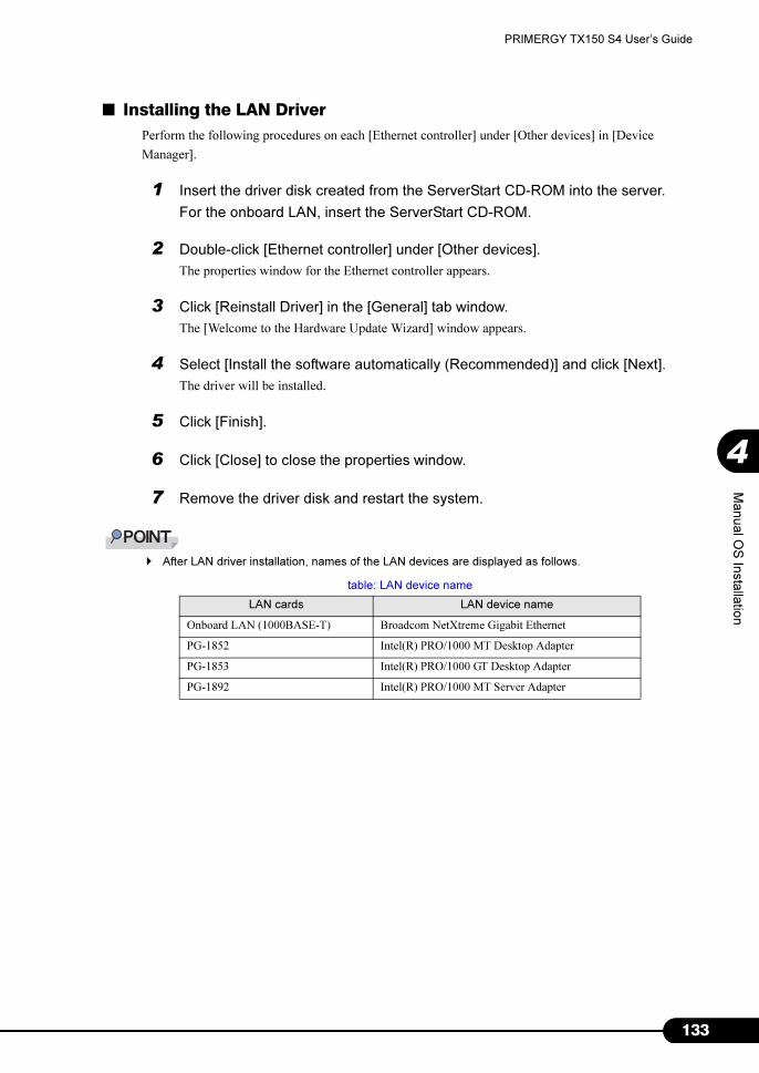
133
PRIMERGY TX150 S4 User’s Guide
4
Manual O
S In
sta
llatio
n
■ Installing the LAN Driver
Perform the following procedures on each [Ethernet controller] under [Other devices] in [Device
Manager].
1 Insert the driver disk created from the ServerStart CD-ROM into the server.
For the onboard LAN, insert the ServerStart CD-ROM.
2 Double-click [Ethernet controller] under [Other devices].
The properties window for the Ethernet controller appears.
3 Click [Reinstall Driver] in the [General] tab window.
The [Welcome to the Hardware Update Wizard] window appears.
4 Select [Install the software automatically (Recommended)] and click [Next].
The driver will be installed.
5 Click [Finish].
6 Click [Close] to close the properties window.
7 Remove the driver disk and restart the system.
� After LAN driver installation, names of the LAN devices are displayed as follows.
table: LAN device name
LAN cards LAN device name
Onboard LAN (1000BASE-T) Broadcom NetXtreme Gigabit Ethernet
PG-1852 Intel(R) PRO/1000 MT Desktop Adapter
PG-1853 Intel(R) PRO/1000 GT Desktop Adapter
PG-1892 Intel(R) PRO/1000 MT Server Adapter

134
Chapter 4 Manual OS Installation
4.3.3 Installing the LAN Driver (Windows 2000 Server)
1 Insert the driver disk created from the ServerStart CD-ROM into the server.
2 Right-click the [My Computer] icon on the desktop and select [Manage] from
the displayed menu.
3 Click [Device Manager].
As many [Ethernet controller] items as the installed LAN ports are displayed under [Other
devices].
Double-click each [Ethernet controller] item and perform the following Steps 4 to 11 on all LAN
ports.
4 Double-click [Ethernet controller] under [Other devices].
The properties window for the Ethernet controller appears.
5 Click [Reinstall Driver] in the [General] tab window.
The [Device Driver Upgrade Wizard] window appears.
6 Click [Next].
7 Select [Search for a suitable driver for my device (Recommended)] and click
[Next].
The [Identify Driver File] window appears.
8 Select [Floppy disk drive] in [Search location options] and click [Next].
Detected drivers are displayed.
9 Click [Next].
Driver installation starts. When it is completed, a completion window appears.
10 Click [Finish].
11 Click [Close] to close the properties window.
� When [Ethernet controller] items are displayed under [Other devices], perform the above Steps
4 to 11 on all [Ethernet controller] items.

135
PRIMERGY TX150 S4 User’s Guide
4
Manual O
S In
sta
llatio
n
12 Remove the driver disk and restart the system.
� When a LAN card is added, the following window may appear at system startup after addition
of a LAN card. Perform the appropriate procedure according to the displayed window.
•When the "New Hardware Detection Wizard" window appears
Insert the driver disk created from the ServerStart CD-ROM and perform Step 6 and
subsequent steps in "Updating LAN Drivers".
•When the [Insert Disk] window prompts you to insert the "Intel PRO Adapter CD-ROM or
floppy disk" or "Intel® PRO/1000 Disk Driver".
Insert the driver disk created from the ServerStart CD-ROM and install the driver.
� After LAN driver installation, names of the LAN devices are displayed as follows.
4.3.4 Latest Drivers
For the latest drivers, refer to the Fujitsu PRIMERGY website (http://primergy.fujitsu.com).
table: LAN device name
LAN cards LAN device name
Onboard LAN (1000BASE-T) Broadcom NetXtreme Gigabit Ethernet
PG-1852 Intel(R) PRO/1000 MT Desktop Adapter
PG-1853 Intel(R) PRO/1000 GT Desktop Adapter
PG-1892 Intel(R) PRO/1000 MT Server Adapter

136
Chapter 4 Manual OS Installation

137
Chapter 5
Operations after OSInstallation
This chapter explains the operations to be
performed after OS installation. Be sure to
perform these operations before operating the
server.
5.1 Memory Dump/Paging File Setting . . . . . . . . . . . . . . . . . . 138
5.2 Creating a Disk for System Recovery . . . . . . . . . . . . . . . . 148
5.3 Storing the System Configuration Information . . . . . . . . . . 150
5.4 Creating Maintenance Tools . . . . . . . . . . . . . . . . . . . . . . 153
5.5 Notes Before Operating the Server . . . . . . . . . . . . . . . . . 158
5.6 LAN Driver Advanced Setup [BACS] . . . . . . . . . . . . . . . . 162
5.7 LAN Driver Advanced Setup [Intel® PROSet] . . . . . . . . . . 166

138
Chapter 5 Operations after OS Installation
5.1 Memory Dump/Paging File Setting
Before starting operating this server, configure the setting for obtaining memory
dump. The setting procedure varies between Windows Server 2003 and Windows
2000 Server.
● Memory Dump
If memory dump is set, debugging information will be automatically saved when a STOP error (fatal
system error) occurs in the system. Using the saved memory dump, error cause can be analyzed.
If the amount of installed memory is large, pay special attention when setting the memory dump file.
The settings for obtaining memory dump should be configured after installing the files to be used for
operations (OS, applications, etc.).
5.1.1 How to Obtain Memory Dump for Windows Server 2003
Check the following settings before starting configuration to obtain memory dump.
■ Checking Hard Disk Free Space
To obtain memory dump, sufficient hard disk capacity is required for creating paging files and memory
dump files.
The obtainable dump types and required hard disk capacity are as follows:
● Complete Memory (Full) Dump
When the system unexpectedly stops, contents of the whole system memory are recorded. The file is
stored in the directory displayed in the [Dump file] box.
• Paging file: Installed physical memory + 11MB (Recommended: Installed physical memory x 1.5)
• Memory dump file: Same amount as installed physical memory
� Complete memory dump cannot be used on the computer in which the 2GB or more memory is
installed.

139
PRIMERGY TX150 S4 User’s Guide
5
Opera
tions a
fter O
S In
sta
llatio
n
● Kernel Memory Dump
Information of only kernel memory space is recorded. The file is stored in the directory displayed in the
[Dump file] box. Capacity required for kernel memory dump is as follows:
• Paging file: Depending on installed physical memory amount
For memory of 256 to 1,373MB - Installed physical memory x 1.5
For memory of 1,374MB or more - 32-bit system: 2GB + 16MB, 64-bit system: Installed physical
memory + 128MB
• Memory dump file: Depending on the used amount of kernel-mode address space during STOP
● Small Memory Dump
Minimum amount of useful information for problem identification is recorded. If this option is specified,
a new file is created each time the system unexpectedly stops.
History of such files is stored in the directory displayed in [Small dump directory].
• Paging file: 2MB or more
• Memory dump file: 64KB or 128KB
■ Memory Dump File Setting
Set up the memory dump file according to the following procedures:
1 Log on to the server with administrator privileges.
2 Check free space of the drive where the memory dump file is to be stored.
Check the required amount of free space according to "■ Checking Hard Disk Free Space"
(�pg.138).
If the drive has no free space, refer to "■ Cannot Collect the Memory Dump" (�pg.263).
3 Click [Start] → [Control Panel] → [System].
The [System Properties] window appears.

140
Chapter 5 Operations after OS Installation
4 Click the [Advanced] tab and click [Settings] in [Startup and Recovery].
The [Startup and Recovery] window appears.
5 Set as follows:
1. In the [Write debugging information] section, select the memory dump file type.
• Small memory dump (64KB)
Minimum information is recorded to the memory dump file.
Each time a fatal error occurs, a new file is created in the directory specified in [Small
dump directory].
• Kernel memory dump
Only kernel memory is recorded to the memory dump file.
• Complete memory dump (Recommended)
The whole system memory information is recorded to the memory dump file.
2. In [Dump file] or [Small dump directory], specify the directory to save the memory
dump file, with its full path.
In case of kernel memory dump or complete memory dump, if [Overwrite any existing file]
is checked, debugging information is overwritten to the specified file every time.
6 Click [OK] to close the [Startup and Recovery] window.
7 Click [OK] to close the [System Properties] window.
8 Restart the system.
The setting is enabled after the system is restarted.

141
PRIMERGY TX150 S4 User’s Guide
5
Opera
tions a
fter O
S In
sta
llatio
n
■ Paging File Setting
Set up the paging file according to the following procedures:
1 Log on to the server with administrator privileges.
2 Check free space of the drive where the system is installed.
Check the required amount of free space according to "■ Checking Hard Disk Free Space"
(�pg.138).
If the drive has no free space, refer to "■ Cannot Collect the Memory Dump" (�pg.263).
3 Click [Start] → [Control Panel] → [System].
The [System Properties] window appears.
4 Click the [Advanced] tab and click [Settings] in [Performance].
The [Performance Options] window appears.
5 Click the [Advanced] tab.

142
Chapter 5 Operations after OS Installation
6 Click [Change] in the [Virtual memory] section.
The [Virtual Memory] window appears.
7 Specify the drive where the paging file is to be created.
In [Drive], select the drive where the system is installed.
The selected drive is displayed in [Drive] in [Paging file size for selected drive].

143
PRIMERGY TX150 S4 User’s Guide
5
Opera
tions a
fter O
S In
sta
llatio
n
8 Select [Custom size] and enter a value in [Initial size].
The value depends on the type of the set dump file.
Specify a value larger than the value shown in [Recommended] in [Total paging file size for all
drives].
� When a smaller value is specified for the paging file size, performance may be affected. For
maximum system efficiency, be sure to set [Initial size] with a value larger than the [Recom-
mended] size described in [Total paging file size for all drives]. The recommended size is total
memory installed in the system x 1.5. However, if a program consuming a large amount of
memory is regularly used, set a larger size as required.
9 Enter a value in [Maximum size].
Specify a value larger than the [Initial size].
10 Save the settings.
Click [Set] in the [Paging file size for selected drive] section.
The settings are saved, and the value specified is displayed in [Paging File Size] of [Drive].
11 Click [OK] to close the [Virtual Memory] window.
12 Click [OK] to close the [Performance Options] window.
13 Click [OK] to close the [System Properties] window.
14 Restart the system.
The setting is enabled after the system is restarted.
5.1.2 How to Obtain Memory Dump for Windows 2000 Server
Check the following settings before starting configuration to obtain memory dump.
■ Checking Hard Disk Free Space
Once memory dump is obtained, a file containing contents of the whole physical memory installed in the
system is created. Before storing the dump file, confirm that there is sufficient free space in the hard
disk.
The obtainable dump types and required hard disk capacity are as follows:
● Complete Memory (Full) Dump
When the system unexpectedly stops, contents of the whole system memory are recorded. If this option
is selected, space to retain the paging file as large as the whole physical memory × 1.3 is required in the
boot volume.
• Included information
Common header, all virtual address pages that are not paged out during STOP

144
Chapter 5 Operations after OS Installation
• Required size
Installed physical memory × 1.3
� Complete memory dump cannot be used on the computer in which the 2GB or more RAM is installed.
● Kernel Memory Dump
Information of only kernel memory space is recorded. When the system unexpectedly stops, the process
that records information to the log file is speeded up. According to the amount of memory installed in
the server, available area of 50 to 800MB is required for the paging file in the boot volume.
• Included information
Common header, summary dump header (complete memory dump) - (user process space page) -
(cache region page) - (unused pool region page)
• Required size
Depending on the used amount of kernel-mode address space during STOP
● Small Memory Dump
Minimum amount of useful information for problem identification is recorded. In this option, a paging
file of at least 2MB is required in the boot volume. Also, a new file is created each time the system
unexpectedly stops.
History of such files is stored in the directory displayed in [Small dump directory] (usually,
C:\winnt\minidump).
• Included information
Common header, minidump header, kernel module, memory information, processor information,
process information, thread information, stuck page, unloaded module information
• Required size
2MB or more
■ Memory Dump File Setting
Set up the memory dump file according to the following procedures:
1 Log on to the server with administrator privileges.
2 Check free space of the drive where the memory dump file is to be stored.
Check the required amount of free space according to "■ Checking Hard Disk Free Space"
(�pg.143).
If the drive has no free space, refer to "■ Cannot Collect the Memory Dump" (�pg.263).
3 Click [Start] → [Settings] → [Control Panel].
4 Double-click the [System] icon.
The [System Properties] window appears.

145
PRIMERGY TX150 S4 User’s Guide
5
Opera
tions a
fter O
S In
sta
llatio
n
5 Click the [Advanced] tab and click [Startup and Recovery].
The [Startup and Recovery] window appears.
6 Set as follows:
1. In the [Write debugging information] section, select the memory dump file type.
• Small memory dump (2MB or more)
Minimum information is recorded to the memory dump file.
Each time a fatal error occurs, a new file is created in the directory specified in [Small
dump directory].
• Kernel memory dump
Only kernel memory is recorded to the memory dump file.
• Complete memory dump (Recommended)
The whole system memory information is recorded to the memory dump file.
2. In [Dump File] or [Small dump directory], specify the directory to save the memory
dump file, with its full path.
In case of kernel memory dump or complete memory dump, if [Overwrite any existing file]
is checked, debugging information is overwritten to the specified file every time.
7 Click [OK] to close the [Startup and Recovery] window.
8 Click [OK] to close the [System Properties] window.
9 Restart the system.
The setting is enabled after the system is restarted.

146
Chapter 5 Operations after OS Installation
■ Paging File Setting
Set up the paging file according to the following procedures:
1 Log on to the server with administrator privileges.
2 Check free space of the drive where the system is installed.
Check the required amount of free space according to "■ Checking Hard Disk Free Space"
(�pg.143). If the drive has no free space, refer to "■ Cannot Collect the Memory Dump"
(�pg.263).
3 Click [Start] → [Settings] → [Control Panel].
4 Double-click the [System] icon.
The [System Properties] window appears.
5 Click the [Advanced] tab and click [Performance Options].
The [Performance Options] window appears.

147
PRIMERGY TX150 S4 User’s Guide
5
Opera
tions a
fter O
S In
sta
llatio
n
6 Click [Change] in the [Virtual memory] section.
The [Virtual Memory] window appears.
7 Specify the drive where the paging file is to be created.
In [Drive], select the drive where the system is installed.
The selected drive is displayed in [Drive] in [Paging file size for selected drive].
8 Specify the [Initial size].
The value depends on the type of the set dump file.
Specify a value larger than the value shown in [Recommended] in [Total paging file size for all
drives].
� When a smaller value is specified for the paging file size, performance may be affected. We
recommend to specify the paging file size larger than the recommended value.
9 Specify the [Maximum size].
Specify a value larger than the [Initial size].
10 Save the settings.
Click [Set] in the [Paging file size for selected drive] section.
The settings are saved, and the value specified is displayed in [Paging File Size] of [Drive].
11 Click [OK] to close the [Virtual Memory] window.
12 Click [OK] to close the [Performance Options] window.
13 Click [OK] to close the [System Properties] window.
14 Restart the system.
The setting is enabled after the system is restarted.
148
Chapter 5 Operations after OS Installation
5.2 Creating a Disk for System Recovery
If the installation of the OS was performed manually, create a system recovery disk.
� If the system file, system configuration or environment setting change at startup, etc., are damaged,
such data can be reconstructed using the recovery information stored in the created system recovery
disk.
� To create a recovery disk, you need an unused formatted floppy disk. Prepare it in advance.
5.2.1 Creating the Automated System Recovery (ASR) Setfor Windows Server 2003
After setting up Windows Server 2003, create a system recovery set. To do this, you need an unused
formatted floppy disk and a medium to store back up files.
1 Click [Start] → [All Programs] → [Accessories] → [System Tool] → [Backup].
The [Backup or Recovery Wizard] window appears.
2 Click [Next].
The [Backup or Recovery] window appears.
3 Select [Create a backup of files and settings], and then click [Next].
The [Items to Create Backups] window appears
4 Select [All the information in this computer], and then click [Next].
The [Backup Type, Destination and Name of the Backup File] window appears.
5 Specify name and destination of the backup file, and then click [Next].
The [Backup or Recovery Wizard Complete] window appears.
6 Click [Finish].
Backup process starts.
7 If a message prompting you to insert a floppy disk appears, insert the floppy
disk and click [OK].
Automated system recovery disk is created.

149
PRIMERGY TX150 S4 User’s Guide
5
Opera
tions a
fter O
S In
sta
llatio
n
8 When the process is completed, a message appears. Eject the floppy disk
according to the message and put a label on it.
Label Example: "Windows Automated System Recovery Disk: Backup.bkf, Created at 12:00 04/
01/2003"
9 Click [OK] to exit [Backup Utility].
10 Click [Close] to close the [Backup Progress] window.
An automated system recovery set has been created.
Store the automated system recovery set just created in a secure location.
5.2.2 Creating a System Recovery Diskfor Windows 2000 Server
After setting up Windows Server 2000, create a system recovery disk. To do this, you need an unused
formatted floppy disk.
1 Put a label showing "Windows 2000 system recovery disk" onto a floppy disk
and insert it into the floppy disk drive.
2 Click [Start] → [Programs] → [Accessories] → [System Tools] → [Backup].
The backup window appears.
3 Click the [Wizard] tab and click [System Recovery Disk].
Create a system recovery disk by following the window instructions.

150
Chapter 5 Operations after OS Installation
5.3 Storing the System Configuration Information
Before starting operations, store the configuration information of the BIOS Setup
Utility. By storing this information, the system can be recovered with the stored
information in case of a system failure (such as when the information is deleted due
to the drain of the built-in battery). Use Server Management Tools for storing and
recovering the system configuration information.
� Since the system configuration information is significant in maintaining the server, be sure to store the
BIOS information after the following operations:
• When the information is changed with the BIOS Setup Utility
• When the hardware configuration of this server is changed (e.g. CPU, memory, baseboard or
expansion card is added/removed or changed)
� As the stored system configuration information will be used during maintenance, etc., send it to your
maintenance engineer.
■ Cautions
• "Server Management Tools" disk is exclusively for this server. Do not use it on other systems.
Otherwise, the systems may be damaged.
• Only the information that is configured with the BIOS Setup Utility can be stored/recovered. The
BIOS information in internal SCSI devices or expansion cards cannot be stored/recovered.
• Make sure to perform this operation only when the server is started with the "Server Management
Tools" disk. Do not run Server Management Tools on the server started from the hard disk or by the
other floppy disk. Otherwise, the system may be damaged.
• Do not eject a floppy disk while the floppy disk access LED is on. Such an action may lead not only
to corruption of the floppy disk data but also an unstable state of the system.
• If an error message appears while running Server Management Tools, respond to the message
according to "■ Server Management Tools Error Messages" (�pg.257).

151
PRIMERGY TX150 S4 User’s Guide
5
Opera
tions a
fter O
S In
sta
llatio
n
5.3.1 Storing the BIOS Information
Store the BIOS information according to the following procedures.
� Before starting the operation, if the "OS Boot Monitoring" function of ServerView is enabled, disable it
(it is disabled by default).
If you start up the system while the "OS Boot Monitoring" function remains effective, the operation of
the server may become unpredictable at such times as an abrupt power interruption or restart.
If it is necessary to operate the server with the "OS Boot Monitoring" function enabled, enable the
function after storing the BIOS information.
For details of ServerView, refer to "ServerView User’s Guide".
1 Turn on the server and insert the "Server Management Tools" disk into the
floppy disk drive.
The window for selecting a keyboard appears.
2 Select a keyboard.
Select [1] for Japanese keyboard or select [2] for English keyboard. Japanese keyboard is
selected by default.
3 When the DOS prompt window appears, enter the following command and
press the [Enter] key.
A:\ SMT\>biossave.bat
� If storing has already been performed with Server Management Tools, the stored file must exist
in the floppy disk. In this case, overwriting the file may lead to incompletion of BIOS information
recovery. Move the file to another floppy disk, rename the file or delete it by executing the fol-
lowing command.
A:\SMT\>deldat.bat [Enter]
4 If the BIOS information is stored correctly, the following message appears.
5 Confirm that the stored information files are created.
Enter the following command to confirm that "*.SCS" (file names vary depending on BIOS
version), "FSCSMCTR.DAT", "BIOSCMP.TXT", "LAN_CFG.DAT", and "MUX_CONF.DAT"
are created.
A:\SMT>dir
The BIOS information has been stored. The server can now be turned off safely.
Please select:
1 = JP Keyboard
2 = US Keyboard
Your selection
NORMAL END

152
Chapter 5 Operations after OS Installation
5.3.2 Recovering the BIOS Information
If the information configured with the BIOS Setup Utility was deleted due to a drain of the built-in
server battery, etc., restore the BIOS information according to the following procedures.
� Do not turn off the server during a program run.
� Before starting up the system, check that the "OS Boot Monitoring" function of ServerView is disabled
(it is disabled by default).
If you start up the system while the "OS Boot Monitoring" function remains effective, the operation of
the server may become unpredictable at such times as an abrupt power interruption or restart. If the
server is operated with the "OS Boot Monitoring" function enabled, enable the function again before
resuming operation. For details of ServerView, refer to "ServerView User’s Guide".
1 Turn on the server and insert the "Server Management Tools" disk into the
floppy disk drive.
The window for selecting a keyboard appears.
2 Select a keyboard.
Select [1] for Japanese keyboard or select [2] for English keyboard. Japanese keyboard is
selected by default.
3 When the DOS prompt window appears, confirm that the BIOS stored
information files are in the floppy disk.
Enter the following command to confirm that "*.SCS" (file names vary depending on BIOS
version), "FSCSMCTR.DAT", "BIOSCMP.TXT", "LAN_CFG.DAT", and "MUX_CONF.DAT"
are in the floppy disk.
A:\SMT>dir
4 Enter the following command and press the [Enter] key
A:\SMT\>biosrest.bat
5 If the BIOS information is restored correctly, the following message appears.
6 The BIOS information will be enabled after the next system restart. Restart the
server.
Perform Step 1 to display the DOS prompt window.
The restoration procedure has been completed. The server can now be turned off safely.
Please select:
1 = JP Keyboard
2 = US Keyboard
Your selection
NORMAL EBD

153
PRIMERGY TX150 S4 User’s Guide
5
Opera
tions a
fter O
S In
sta
llatio
n
5.4 Creating Maintenance Tools
This section explains how to create tools for maintaining the server.
Maintenance tools are created with the FloppyBuilder function of ServerStart.
With the FloppyBuilder function of ServerStart, you can create the following tool:
• DOS floppy disks
The FloppyBuilder can be used under environments such as:
• the ServerStart system started on a client computer (recommended)
• the system started on the server using the ServerStart CD-ROM
� When creating the tools on a client computer, it is necessary to install ServerStart on the client
computer beforehand. Install it according to "2.4 Preparation for Using ServerStart on a Client
Computer" (�pg.53).
If ServerStart of a different version is installed in the computer, make sure to uninstall the ServerStart.
Then perform installation again. For details on how to uninstall ServerStart, refer to "2.4.2 Uninstalling
ServerStart" (�pg.56).
� The FloppyBuilder function may not operate correctly if you start up ServerStart while ServerStart of a
different version is installed in the computer. Make sure to uninstall a different version of ServerStart.
� ServerStart cannot be started up on the server in which Windows Server 2003 x64 is installed. Be sure
to start up ServerStart on the client computer or the server in which Windows 2000 Server or Windows
Server 2003 is installed.
5.4.1 Creating a DOS Floppy Disk
For DOS data stored into the floppy disk, refer to the file in the following folder of the ServerStart CD-
ROM.
[CD-ROM drive] :\FreeDOS
To create a DOS floppy disk, you need an unused floppy disk. Prepare it in advance.
If ServerStart has already been started, it is not necessary to restart it. If it has not, start it up according to
the following procedures:

154
Chapter 5 Operations after OS Installation
■ Starting ServerStart
● When Creating a DOS Floppy Disk on a Client Computer
For Windows 2000 Professional/Windows XP Professional, and if the contents
of the ServerStart CD-ROM has been copied to the computer
1 Click [Start] → [Programs] → [Fujitsu ServerStart] → [ServerStart].
ServerStart starts up and the [Welcome to ServerStart] window appears.
For Windows NT, or if the ServerStart CD-ROM has not been copied to the
computer
1 Insert the ServerStart CD-ROM into the client computer's CD-ROM drive.
ServerStart starts up and the [Welcome to ServerStart] window appears.
● When Creating a DOS Floppy Disk on the Server
1 Turn on the server and insert the ServerStart CD-ROM immediately after that.
ServerStart starts up and a message appears prompting you to insert the ServerStart floppy disk.
2 Insert the attached "ServerStart floppy disk" into the server's floppy disk drive.
Then make sure "Removable media" and "A:" are selected and click [Create].
A network setup window for remote installation appears.
� If a configuration file already exists in the ServerStart floppy disk and [OK] is clicked without
clicking [Create], the [ServerStart Unattended Mode] window appears. Make sure to click
[Exit]. The [Welcome to ServerStart] window appears.
If [Start] is clicked in the [ServerStart Unattended Mode] window, the installation of the server
will start and all disk contents will be deleted.

155
PRIMERGY TX150 S4 User’s Guide
5
Opera
tions a
fter O
S In
sta
llatio
n
3 Click [OK].
The [Initializing ServerStart] window appears and the ServerStart initialization process starts.
Depending on the hardware configuration, this process may take a few minutes. When the
process is completed, the [Create a ServerStart Floppy Disk] window appears.
4 Click [or Insert a ServerStart Floppy Disk to Start ServerStart].
The [Welcome to ServerStart] window appears.
5 Eject the ServerStart floppy disk.

156
Chapter 5 Operations after OS Installation
■ Creating a DOS Floppy Disk
Start up ServerStart and confirm that the [Welcome to ServerStart] window is displayed.
1 Click [FloppyBuilder].
The [ServerStart FloppyBuilder] window appears.
2 Click [DOS Diskette].
Insert the prepared floppy disk by following the message.
3 Perform the subsequent operations according to the messages on the window.
The floppy disk will be formatted automatically and file copying will start.
The DOS floppy disk will be created automatically.
When a message appears indicating that the disk is created, click [OK] and eject the disk.
5.4.2 Creating a Hardware Configuration Tool
This section explains how to create a Hardware Configuration Tool from the ServerStart CD-ROM.
Prepare floppy disks as many as the tools you want to create beforehand.
Types of a Hardware Configuration Tool vary by model.
1 Start up ServerStart and click [FloppyBuilder].
For details on procedures for starting up ServerStart, refer to "■ Starting ServerStart" (�pg.154).
2 Click [Hardware Configuration Tools].
3 Click the tool you want to create.
Insert the prepared floppy disk by following the message.

157
PRIMERGY TX150 S4 User’s Guide
5
Opera
tions a
fter O
S In
sta
llatio
n
4 Perform the subsequent operations according to the messages on the window.
The floppy disk will be formatted automatically and file copying will start.
The respective tools will be created automatically. When a message appears indicating that the
disk is created, click [OK] and eject the disk.

158
Chapter 5 Operations after OS Installation
5.5 Notes Before Operating the Server
This section explains the settings required before starting to operate the server.
For the respective settings, refer to "First Step Guide".
• If a LAN card was added, install a driver according to "4.3 Installing the LAN Driver" (�pg.130).
• When connecting a SCSI optional device (such as a hard disk cabinet or DAT), connect it according
to "Chapter 7 Installing Hardware Options" (�pg.179).
• For the settings for the installed applications supplied with the product, refer to the manuals of each
application.
5.5.1 Updating the System
■ Windows Update
The system being used must be updated to prevent potential problems in the system.
Executing Windows Update can automatically search the latest version of QFE applicable to the OS and
update the system to the latest status. Execute Windows Update periodically.
Executing Windows Update requires a network environment connectable to the Internet.
5.5.2 Auto-run Function from CD-ROM Drives
Perform the following procedures to change the settings of the auto-run function from the CD-ROM
drives after server installation:
1 Make the registry editable, and change the value of AutoRun of the following
registry key:
HKEY_LOCAL_MACHINE\System\CurrentControlSet\Services\CDRom
Set the value of Autorun to "1" to enable auto-run, and set the value to "0" to disable auto-run.
2 Restart the system.
The setting is enabled after the system is restarted.

159
PRIMERGY TX150 S4 User’s Guide
5
Opera
tions a
fter O
S In
sta
llatio
n
5.5.3 Drive Letter Assignment in Expert Mode
In expert mode, you cannot specify a drive letter to a particular partition arbitrarily. Drive letters
specified with Disk Manager in expert mode will be sequentially assigned from the first partition with
"C, D, E..." when installation is completed, and an unused drive letter will be assigned to the CD-ROM
drive.
To change the drive letter, perform the following procedures after installation.
� You cannot change the drive letters for the system and boot drive.
■ For Windows Server 2003
1 Click [Start] → [Administrative Tools] → [Computer Management].
2 Click [Disk Management].
3 Right-click the partition to change the letter and click [Change Drive Letter and
Path].
The [Change Drive Letter and Path] window appears.
4 Click [Edit].
The [Change Drive Letter or Path] window appears.
5 Change the drive letter.
■ For Windows 2000 Server
1 Right-click [My Computer] icon on the desktop and select [Manage].
2 Click [Disk Management].
3 Right-click the partition to change the letter and select [Change Drive Letter
and Path].
The [Change Drive Letter and Path] window appears.
4 Click [Edit].
The [Change Drive Letter or Path] window appears.
5 Change the drive letter.

160
Chapter 5 Operations after OS Installation
5.5.4 Notes on Advanced Uninterruptible Power Supply (UPS)
Note the following points when using an advanced uninterruptible power supply (referred to as UPS
afterward).
■ UPS Shutdown Time Setting
Specify enough time for the UPS power-off time (time from the shutdown direction to the actual power-
off). If this time is set insufficiently, the power will be cut off before system shutdown, which may result
in destruction of data. For more details, refer to the manuals for UPS and UPS management software.
■ Power Supply Control by UPS
Change the BIOS Settings to turn on the server automatically at power recovery or during scheduled
operation using the UPS management software (PowerChute Network Shutdown, PowerChute Business
Edition).
1 Start the BIOS Setup Utility.
�"8.2.1 Starting and Exiting the BIOS Setup Utility" (pg.213)
2 Select the [Power On/Off] submenu from the [Advanced] menu, and press the
[Enter] key.
The [Power On/Off]submenu window appears.
3 Set [Power Failure Recovery] to [Always On].
4 Save changes and exit the BIOS Setup Utility.
5.5.5 Turning the Power On via a LAN
You can turn the power on the server from a client (via a LAN) by utilizing the Wakeup on LAN (WOL)
function.
� Be sure to install ServerView to control the power supply via a LAN.
� When the power cable is disconnected from the server or the server is powered off due to power
interruption, restart the server. Unless the server is restarted, the WOL function will be disabled.
� Only the onboard LAN supports the WOL function on this server. To control power supply via a LAN,
make sure you connect the onboard LAN and set the onboard LAN adapter bind to "1".

161
PRIMERGY TX150 S4 User’s Guide
5
Opera
tions a
fter O
S In
sta
llatio
n
■ BIOS Setup Utility Setting
When power management is performed via a LAN, configure the settings as follows using the BIOS
Setup Utility. This is set to "Enabled" by default.
1 Start the BIOS Setup Utility.
�"8.2.1 Starting and Exiting the BIOS Setup Utility" (pg.213)
2 Select the [Power On/Off] submenu from the [Advanced] menu, and press the
[Enter] key.
The [Power On/Off]submenu window appears.
3 Set [Power On Source:LAN] to [Enabled].
4 Save changes and exit the BIOS Setup Utility.
� To start up the server via a LAN, refer to "● Performing Remote Installation" (�pg.45).
5.5.6 Other Notes on Operation
■ Unnecessary Files
After OS installation is completed, folders named Runonce and Runonce 2 may be left in the drive
where the OS is installed. Delete these folders since you do not need them for the system operation.
■ Notes on 24-hour Operation
● Automated System Operation
To provide an extra margin of safety against unintentional damage, introduce disaster-prevention
measures in the office and keep disaster prevention personnel (such as a security guard or janitor) in the
building.
● Unintentional Power-off Prevention
We recommend the installation of a special power supply device (such as a distribution board) to prevent
unplanned power shut-offs.

162
Chapter 5 Operations after OS Installation
5.6 LAN Driver Advanced Setup [BACS]
BACS is an integrated GUI application consisting of programs such as BASP
(Broadcom Advanced Server Program) that provides the load balancing feature, etc.,
by teaming up multiple adapters. BACS is used in the following situations:
• Setup a VLAN using the onboard LAN
• Perform the other advanced setups of the onboard LAN
Use of Intel® PROSet
� Use Intel® PROSet (�pg.166) to perform the following advanced setups of a LAN card:
• Use the Teaming function between LAN cards or between a LAN card and the onboard LAN
• Setup a VLAN using a LAN card
• Use the Jumbo frame with a LAN card
• Perform the other advanced setups of a LAN card
5.6.1 BACS Installation
If [Broadcom Control Suite 2] is not displayed in the [Control Panel], install BACS according to the
following installation procedures:
■ For Windows Server 2003 x64
1 Execute the following file contained in the ServerStart CD-ROM.
[CD-ROM drive]: \PROGRAMS\GENERAL\Broadcom\MgmtApps_x64\setup.exe
The installer starts up.

163
PRIMERGY TX150 S4 User’s Guide
5
Opera
tions a
fter O
S In
sta
llatio
n
2 Click [Next].
License agreement window appears.
3 Click [I accept the terms in the license agreement] and click [Next].
Custom Set up window appears.
4 Click [Install].
5 Click [OK].
6 Click [Finish].

164
Chapter 5 Operations after OS Installation
■ For Windows Server 2003, Windows 2000 Server
� If the OS is installed using ServerStart, "BACS" is already installed with the driver. If the OS is installed
manually, BACS will not be installed.
1 Executet the following file contained in the ServerStart CD-ROM.
[CD-ROM drive]: \PROGRAMS\GENERAL\Broadcom\MgmtApps\setup.exe
The installer starts up.
2 Proceed the installation by following the window instructions.
When the window below appears during the installation procedure, check [BASP] and click
[Next].
5.6.2 VLAN Setup Procedure
1 Start up BACS. The procedure differs depending on the OS being used.
For Windows Server 2003
1. Click [Start] → [Control Panel] → [Broadcom Control Suite 2].
For Windows 2000 Server
1. Click [Start] → [Settings] → [Control Panel].
The [Control Panel] window appears.
2. Start up "Broadcom Control Suite 2".
2 Right-click a LAN adapter or the Team name of a Teamed Up adapter and click
[Add VLAN] from the displayed menu.
� A LAN adapter is displayed with a mark.
� The Team name of a Teamed Up adapter is displayed with a mark.

165
PRIMERGY TX150 S4 User’s Guide
5
Opera
tions a
fter O
S In
sta
llatio
n
3 Specify [VLAN ID] and [VLAN Name] in the [Create New VLAN] window.
The [VLAN ID] should be identical with the switch setting.
The [VLAN Name] does not need to be identical with the switch setting.
� You cannot use a "VLAN ID" or "VLAN Name" that has already been used. Enter another set
value.
4 When the setting for the team is completed, click [OK].
5 Click [Apply] to apply the settings.
After the network is temporarily disconnected, a window is displayed. Click [Yes (Y)].

166
Chapter 5 Operations after OS Installation
5.7 LAN Driver Advanced Setup
[Intel® PROSet]
"Intel® PROSet" is a tool for configuring details on the LAN driver. This is used in the
following cases.
• Use the Teaming function between LAN cards or between a LAN card and the
onboard LAN
• Setup a VLAN using a LAN card
• Use the Jumbo frame with a LAN card
• Perform the other advanced setups of a LAN card
Use of BACS
� Use BACS (�pg.162) to perform the following advanced setups of the onboard LAN:
• Setup a VLAN using the onboard LAN
• Perform the other advanced setups of the onboard LAN
5.7.1 Intel® PROSet Installation
If [Intel® PROSet] is not displayed in the [Control Panel], install Intel® PROSet according to the
following installation procedures:
■ For Windows Server 2003 x64
1 Execute the following file contained in the ServerStart CD-ROM.
[CD-ROM drive]: \Tools\GENERAL\Intel\ProSet\Ws03_32e\PROSet.exe
2 Click [Next].
3 Click [I accept the terms in the license agreement] and click [Next].
4 Click [Typical] and click [Next].
5 Click [Install].
6 Click [Finish].

167
PRIMERGY TX150 S4 User’s Guide
5
Opera
tions a
fter O
S In
sta
llatio
n
■ For Windows Server 2003, Windows 2000 Server
� If the OS is installed using ServerStart, Intel® PROSet is already installed with the driver. If the OS is
installed manually, Intel® PROSet will not be installed.
1 Execute the following file contained in the ServerStart CD-ROM.
[CD-ROM drive]: \Tools\GENERAL\Intel\ProSet\Ws03xp2k\ProSet.EXE
2 Click [OK].
3 Click [Next].
4 Click [I accept the terms in the license agreement] and click [Next].
5 Click [Typical] and click [Next].
6 Click [Install].
7 Click [Finish].
5.7.2 Notes on Referring to the Intel® PROSet Help Topics
When referring to help topics, note the following points.
• Do not use the driver downloaded from the Intel Corporation online service page on this server.
• If the descriptions in the help and this manual vary, give priority to this manual.
• The name of LAN cards appears in the help texts corresponds to the cards as follows:
• The controllers of the onboard LAN and LAN cards are as follows:
table: LAN cards appear in the help texts
LAN cards appear in the help text Corresponding LAN cards
PRO/1000 Desktop PG-1852 / PG-1853
PRO/1000 Server PG-1892
PRO/1000 adapter PG-1852 / PG-1853 / PG-1892
PRO/1000 Copper adapter PG-1852 / PG-1853 / PG-1892
table: Controller being used
LAN cards Controller being used
PG-1852 Intel® 82540EM
PG-1853 Intel® 82541PI
PG-1892 Intel® 82545GM

168
Chapter 5 Operations after OS Installation
5.7.3 Cautions for PG-185x/186x/188x/189xLAN Driver V9.1/V9.2
■ Event Log
Once a Team is setup, multiple identical logs from the same source that starts with the following log may
be stored in the system log file of the event viewer at system start-up.
Since such event logs will be stored nonetheless even if the Teaming function is operated normally,
ignore them.
5.7.4 Teaming Function
■ Notes
When using the Teaming function, note the following points.
• You require Service Pack 2 or later for Windows 2000 Server.
• For AFT/ALB/Static link type, you can incorporate up to four LAN ports into one team and two ports
for a SFT type team.
• Once a Team is created, virtual adapters (Intel® Advanced Network Service Virtual Adapter) will be
created in the [Device Manager] and/or [Network and Dial-up Connections] of the system. Do not
disable or delete this virtual adapter from the [Device Manager] or [Network and Dial-up
Connections]. When deleting a virtual adapter, make sure to use "Intel® PROSet".
• When the Teaming function is being used, you can only use the following protocols:
• For AFT/SFT/Static link type: IP, NetBEUI, IPX (NCP), IPX (NetBIOS)
• For ALB type: IP, IPX (NCP)
• When the Teaming function is being used, you cannot use the hardware assist function of IPSEC. Do
not use this function even if the function is installed in all cards in the team.
• When the Teaming function is being used, you cannot use Windows Load Balancing Service
(WLBS) and Network Load Balancing (NLB).
• If Static link type is selected, you can only use the switch for link aggregation.
• When adding/deleting a Static link type member, perform such operation under a linked down state.
• Team cannot be configured on PG-1852/PG-1853.
• When using the onboard LAN to control remotely with RemoteControlService, it cannot be a
member of the Team. For details on RemoteControlService, refer to "ServerView User's Guide".
• If the onboard LAN is set to RemoteControlService and Team is configured on the onboard LAN,
remote control function with RemoteControlService does not work properly.
Source iANSMiniport
ID 11
Type Warning
Description The following adapter link is not connected: (adapter name)
* (adapter name) varies depending on the OS or hardware configuration.

169
PRIMERGY TX150 S4 User’s Guide
5
Opera
tions a
fter O
S In
sta
llatio
n
� Only a link down error between a LAN card (onboard LAN) and the switch it connects with, and the
equivalent errors lead to switching of the route. Therefore, if only the switch or LAN card (onboard
LAN) is partially damaged and the route being used is sound at the link level, the route will not be
switched in the team, but the communication with the Team may become an error.
■ Teaming Configuration Procedure
1 Start up Intel® PROSet. The procedure differs depending on the OS being
used.
For Windows Server 2003
1. Click [Start] → [Control Panel] → [Intel(R) PROSet Wired].
For Windows 2000 Server
1. Click [Start] → [Settings] → [Control Panel].
The [Control Panel] window appears.
2. Start up "Intel(R) PROSet for Wired connection".
2 Select a card to incorporate in a Team and right-click it.
3 Click [Create New Team] in [Add to Team].
[Teaming Up Wizard] appears.
4 Select a Teaming type with which you want to create a Team.
Select the following depending on the Teaming type selected accordingly:
• AFT type: "Adapter fault tolerance"
• ALB type: "Adaptive load balancing"
• SFT type: "Switch fault tolerance"
• Static link type: "Static link aggregation"
5 Select a LAN card to incorporate in the Team and click [Next].
6 Click [Finish].
7 Click [Apply].
When the Teaming setting is completed, the following virtual adapter will be created.
• "Intel(R) Advanced Network Services Virtual Adapter"
Upper protocols will be bound with the main virtual adapter.
You cannot bind them with the LAN card consisting of a Team.
The IP address can be set in the main virtual adapter.

170
Chapter 5 Operations after OS Installation
5.7.5 VLAN
■ Notes
When using a VLAN, note the following points.
• You can only have "NetBIOS over TCP/IP" enabled for up to four VLANs in the whole system.
• On a VLAN, do not use protocols other than TCP/IP.
• You can only set ten or less VLANs to a LAN port.
• When adding or deleting a VLAN, always use "Intel(R) PROSet". Do not disable or delete a VLAN
from the [Device Manager] or [Network and Dial-up Connections].
■ VLAN Configuration Procedure
1 Start up Intel® PROSet. The procedure differs depending on the OS being
used.
For Windows Server 2003
1. Click [Start] → [Control Panel] → [Intel(R) PROSet Wired].
For Windows 2000 Server
1. Click [Start] → [Settings] → [Control Panel].
The [Control Panel] window appears.
2. Start up “Intel(R) PROSet for Wired connection”.
2 Select a LAN card to setup a VLAN and right-click it.
3 Click [Add VLAN].
4 Specify [ID] and [Name]. Then click [OK].
The [ID] should be identical with the switch setting.
The [Name] does not need to be identical with the switch setting.
5 Repeat Step 2 through 4 to set respective VLANs.
6 Click [Apply].
When setup of the VLAN is completed, the following virtual adapter will be created.
• "Intel(R) Advanced Network Services Virtual Adapter"
Upper protocols will be bound with the main virtual adapter.
You cannot bind them with the LAN card consisting a VLAN.
The IP address should be specified in the main virtual adapter.

171
PRIMERGY TX150 S4 User’s Guide
5
Opera
tions a
fter O
S In
sta
llatio
n
5.7.6 Local Address Setting
Specify a local address according to the following procedures:
1 Start up Intel® PROSet. The procedure differs depending on the OS being
used.
For Windows Server 2003
1. Click [Start] → [Control Panel] → [Intel(R) PROSet Wired].
For Windows 2000 Server
1. Click [Start] → [Settings] → [Control Panel].
The [Control Panel] window appears.
2. Start up "Intel(R) PROSet for Wired connection".
2 Select a LAN card to set the local address and click [Advanced] tab.
3 Specify a local address in [Locally Managed Address].
4 Click [Apply].
5.7.7 Jumbo Frame
1000BASE-T/1000BASE-SX supports Jumbo frame. When using Jumbo frame, construct the Jumbo
frame network using only devices that support Jumbo frame and apply the settings that will enable
Jumbo frame.
Configure setting for Jumbo frame according to the following procedures.
1 Start up Intel® PROSet. The procedure differs depending on the OS being
used.
For Windows Server 2003
1. Click [Start] → [Control Panel] → [Intel(R) PROSet Wired].
For Windows 2000 Server
1. Click [Start] → [Settings] → [Control Panel].
The [Control Panel] window appears.
2. Start up "Intel(R) PROSet for Wired connection".
2 Select a LAN card to perform configuration and click [Advanced] tab.
3 Specify the maximum frame size in [Jumbo Frame].
4 Click [Apply].

172
Chapter 5 Operations after OS Installation

173
Chapter 6
High Reliability Tools
For stable PRIMERGY server operations, we
recommend that high reliability tools be installed.
This chapter explains the installation and
necessary settings of high reliability tools.
6.1 RAID Management Tool [Global Array Manager] . . . . . . . 174
6.2 Server Monitoring Tool [ServerView] . . . . . . . . . . . . . . . . 175
6.3 Solving Problems Early [DSNAP] . . . . . . . . . . . . . . . . . . . 178

174
Chapter 6 High Reliability Tools
6.1 RAID Management Tool [Global Array Manager]
RAID Management Tool is software that performs array configuration, disk
initialization and disk array monitoring. For more details, refer to "Onboard SCSI
RAID User’s Guide" and the manual which comes with the SCSI array controller
card.
OS installation using ServerStart
� If the OS is installed using ServerStart, RAID Management Tool is installed with the OS and other high
reliability tools.
6.1.1 Installing RAID Management Tool (Global Array Manager)
To Install RAID Management Tool individually using the standard installer, follow the procedures
below.
� Before performing Global Array Manager, check that TCP/IP is installed and works properly.
� Exit all programs before starting installation.
Installation will fail if “Event Viewer” or “Computer Management” is run.
1 Log on to the server with administrator privileges.
2 Insert the ServerStart CD-ROM. Click [Start] → [Run...].
3 Enter a name in the [Open:] field as follows and click [OK].
[CD-ROM drive]: \PROGRAMS\GENERAL\LSI\GAM\install.bat
Installation starts and the wizard window appears.
For subsequent procedures, refer to "Onboard SCSI RAID User’s Guide" and the manual which
comes with the SCSI array controller card.
● When an error screen appears after installation (Windows Server 2003 only)
If Windows Server 2003 Service Pack 1 is applied, the following message may appear on restarting after
installing/uninstalling RAID Management Tool (Global Array Manager).
There is no problem with operations. Click [Close Message] to close the message.
In order to protect the computer, this program is terminated by
Windows.
Name: SNMP Service

175
PRIMERGY TX150 S4 User’s Guide
6
Hig
h R
elia
bility
Tool
6.2 Server Monitoring Tool [ServerView]
ServerView constantly monitors the status of the servers' hardware in the network
and provides a console with which the administrator can check the status of all the
servers at a glance. When using ServerView, the server hardware is monitored all the
time. If an error that could cause trouble is detected, the administrator is notified in
real-time. This allows the server administrator to remove a system error early and
avoid trouble.
■ Importance of Monitoring the Server with ServerView
For safe operation of PRIMERGY, always monitor the server using ServerView. Even if the server is
operated in the redundancy configuration, overlooking or neglecting errors could result in a system stop
or data loss. As soon as one constituent part of the redundancy configuration fails, the corresponding
countermeasures must be taken. For that reason, monitoring the server with ServerView is necessary.
If ServerView is not applied, the following very serious problems may occur.
● RAID Error Monitoring
ServerView notifies of the RAID errors. In an environment where ServerView is not applied, the
administrator is not notified of the RAID errors. Leaving the RAID error unattended may lead to a
system stop with multiple dead drives.
● Memory Monitoring
ServerView monitors the memory. In an environment where ServerView is not applied, a memory
single-bit error cannot be detected during operation. In order to detect the error, the server must reboot to
run the BIOS Setup Utility or the Server Management Tools. Leaving this error unattended may lead to
multiple-bit errors and a system stop.
● Fan Monitoring
ServerView monitors the fan. In an environment where ServerView is not applied, fan irregularities
(failure/stop) cannot be detected during operation. In order to detect the problem, the server must reboot
to run the BIOS Setup Utility or the Server Management Tools. Leaving the fan problem unattended
may lead to overheating inside the server and a system stop.
● Temperature Monitoring
ServerView monitors the temperature. In an environment where ServerView is not applied, the increased
temperature inside the server, due to the fan problem described above, cannot be detected and the system
stop cannot be prevented. In order to detect the problem, the server must reboot to run the BIOS Setup
Utility or the Server Management Tools.

176
Chapter 6 High Reliability Tools
● Voltage Monitoring
ServerView monitors the voltage. In an environment where ServerView is not applied, voltage
irregularities cannot be detected during operation. In order to detect the problem, the server must reboot
to run the BIOS Setup Utility or the Server Management Tools. As leaving the voltage surges, the server
may malfunction or data loss may occur.
● Power Supply Monitoring
ServerView monitors the power supply. In an environment where ServerView is not applied, power
supply irregularities cannot be detected during operation. In order to detect the problem, the server must
reboot to run the BIOS Setup Utility or the Server Management Tools. System stops due to power supply
failures cannot be prevented.
6.2.1 Installing ServerView
● When Installed Using ServerStart
If the OS is installed using ServerStart, ServerView will be installed at once with the OS and other high
reliability tools.
● Windows Server 2003 x64, SBS 2003, Linux (Manual Install)
ServerView cannot be installed using ServerStart. To install ServerView into Windows Server 2003 x64,
SBS 2003 or a Linux system, refer to "Installing" in "ServerView User’s Guide".
� Be sure to install SNMP service before installing ServerView.
■ When an error screen appears after ServerView installation (Windows Server 2003 only)
If Windows Server 2003 Service Pack 1 is applied, the following message may appear on restarting after
installing/uninstalling ServerView.
There is no problem with operations. Click [Close Message] to close the message.
In order to protect the computer, this program is terminated by
Windows.
Name: SNMP Service

177
PRIMERGY TX150 S4 User’s Guide
6
Hig
h R
elia
bility
Tool
6.2.2 Setting Required after Installation
Perform necessary operations after ServerView installation referring to "2.4 Checking after Installation"
in "ServerView User’s Guide".
■ Boot Monitoring Setting
We recommend enabling the "Boot Monitoring" function after ServerView is installed. For setting
procedures and explanation on the function, refer to "[Restart Settings] Tab" of "3.2.4 Serious Error
Handling" in "ServerView User’s Guide".

178
Chapter 6 High Reliability Tools
6.3 Solving Problems Early [DSNAP]
DSNAP is a tool for collectively acquiring failure investigation information such as
server environment information.
OS installation using ServerStart
� If the OS is installed using ServerStart, DSNAP is installed with the OS and other high reliability tools.
6.3.1 Installing DSNAP
● For Windows Server 2003 x64
Copy the following file stored in the ServerStart CD-ROM into the server's hard disk.
[CD-ROM drive]: \PROGRAMS\Japanese\DSNAPx64\DSNAPx64.EXE
● For Windows Server 2003, SBS 2003, Windows 2000 Server
When installing DSNAP separately, copy the following file stored in the ServerStart CD-ROM into the
server's hard disk.
[CD-ROM drive]: \PROGRAMS\Japanese\DSNAP\DSNAP.EXE
6.3.2 How to Use
● For Windows Server 2003 x64
Refer to the following file stored in the ServerStart CD-ROM. Use a text editor to open it.
[CD-ROM drive]: \PROGRAMS\Japanese\DSNAPx64\README.TXT
● For Windows Server 2003, SBS 2003, Windows 2000 Server
Refer to the following file stored in the ServerStart CD-ROM. Use a text editor to open it.
[CD-ROM drive]: \PROGRAMS\Japanese\DSNAP\README.TXT

179
Chapter 7
Installing HardwareOptions
This chapter explains how to install and remove
the various hardware options.
7.1 Before Installing Hardware Options . . . . . . . . . . . . . . . . . 180
7.2 Removing and Attaching Covers . . . . . . . . . . . . . . . . . . . 182
7.3 Installing Memory Modules . . . . . . . . . . . . . . . . . . . . . . . 187
7.4 Installing Expansion Cards . . . . . . . . . . . . . . . . . . . . . . . 191
7.5 Installing Internal Hard Disk Units . . . . . . . . . . . . . . . . . . 197
7.6 Installing 5-inch Internal Options . . . . . . . . . . . . . . . . . . . 203
7.7 Connecting External SCSI Devices . . . . . . . . . . . . . . . . . 209

180
Chapter 7 Installing Hardware Options
7.1 Before Installing Hardware Options
The following types of hardware options can be installed in this server.
� If the optional devices listed below are purchased, refer to the following to check the packaged items
before installing.
• Memory�"B.1 Memory" (pg.288)
• Internal Hard Disk Units �"B.2 Internal Hard Disk Units" (pg.289)
� When installing and removing options, make sure to use the removed screws on the same devices that
were last installed or removed. Failure to do so can damage the device.
� The types of optional devices listed in this manual are liable to be updated without any notice. Please
be forewarned.
3.5 inch internal option
5 inch internal option
Expansion card
Memory

181
PRIMERGY TX150 S4 User’s Guide
Insta
lling h
ard
ware
optio
ns
7
• Before installing/removing internal options to/from the server, turn off the
server, all peripheral devices, and any other connected devices. Also unplug
all power cables from the outlet. Failure to do so can cause electric shock
("1.4.4 Turning Off the Server" (�pg.34)).
• Do not disassemble the PSU. Doing so can cause electric shock.
• Use our genuine internal options only. Failure to do so may cause a device
failure, fire, or electric shock.
• Do not damage or modify internal cables or devices. Doing so may cause a
device failure, fire, or electric shock.
• Devices inside the server remain hot after shutdown. Wait for approximately
10 minutes after shutdown before installing or removing internal options.
• The circuit boards and soldered parts of internal options are exposed. They
can be damaged by static electricity.
Before handling them, first touch a metal part of the server to discharge static
electricity.
• Do not touch the circuitry on boards and soldered parts. Hold the metallic
areas or the edge of the circuit boards.
• When installing a 5-inch internal device, make sure to avoid pinching cables.
• If devices are installed or disassembled by other methods than those outlined
in this chapter, the warranty will be invalidated.

182
Chapter 7 Installing Hardware Options
7.2 Removing and Attaching Covers
Remove covers to install peripheral devices. Perform the following procedures to
remove covers.
7.2.1 Removing Covers
1 Turn off the server and connected devices, and unplug all power cables from
the outlet.
2 Remove the hard disk cover.
Tilt the hard disk cover toward you and pull it up to remove.
• Before removing or attaching covers, turn off the server, all peripheral devices,
and any other connected devices. Also unplug all power cables from the
outlet. Failure to do so can cause electric shock ("1.4.4 Turning Off the Server"
(�pg.34)).
1
2

183
PRIMERGY TX150 S4 User’s Guide
Insta
lling h
ard
ware
optio
ns
7
3 Remove the side cover.
1. Remove the screws on the rear side.
Do not lose the screws.
2. Slowly slide the side cover to the rear side, and then tilt it toward you to remove it
from the server.

184
Chapter 7 Installing Hardware Options
4 Remove the front cover.
The front cover is fastened with five tabs. Pull the left tabs first, and then remove the front cover
while pressing the right tabs.
� Remove the front cover as necessary, e.g., when you install a 5-inch internal device.
� When removing the front cover, if the latches on the back of the front cover are hard to release from
the frame, insert a long stick-shaped object inside the server, press the latch on the back of the front
cover in the direction of the arrow (1), and release it (2), as shown in the figure below. The latch of the
front cover may break if you try to release it by force.
■ Installing Covers
To attach covers, simply reverse the removal procedures.
• Before turning on the server, make sure that all covers are in place.
• Check to make sure no tools or unnecessary components are left inside the
server before attaching the side cover back into place.
Left tabs
Right tab
Front cover
Latch

185
PRIMERGY TX150 S4 User’s Guide
Insta
lling h
ard
ware
optio
ns
7
7.2.2 Removing the Top Cover of the Rackmount Type
When the Rackmount Conversion kit (optional) is used, remove the top cover. The top cover of the
rackmount type corresponds to the side cover of the pedestal type.
1 Open the rack door.
�"1.4.2 Opening the Rack Door" (pg.31)
2 Remove all cables connected to the server.
3 Remove the retaining screws used to fasten the server to the rack.
4 Slide the server.
Hold the handles from inside and pull the server out toward you until it clicks, so that it locks in
place on the rails on both sides.
5 Remove the top cover.
The procedures for removing the top cover is the same as that for removing the side cover.
Remove the screws on the rear side. Slowly slide the top cover to the rear side, and then remove
it from the server.
Lock
Lock
Handle

186
Chapter 7 Installing Hardware Options
■ Attaching the Top Cover
To attach the top cover, simply reverse the removal procedures.
• Before turning on the server, make sure that all covers are in place.
• Check to make sure no tools or unnecessary components are left inside the
server before attaching the side cover back into place.

187
PRIMERGY TX150 S4 User’s Guide
Insta
lling h
ard
ware
optio
ns
7
7.3 Installing Memory Modules
Additional memory will help increase the amount of data that can be read at a time
and improve the server processing capability.
• When installing or removing a Memory Modules, turn off the server, all
peripheral devices, and any other connected devices. Also unplug all power
cables from the outlet.
Failure to do so can cause electric shock.
• Use our genuine memory modules only.
Failure to do so may cause a device failure, fire, or electric shock.
• Wait for a sufficient period of time after server shutdown before installing or
removing memory.
Failure to do so can cause burns.
injury • When installing or removing memory, make sure to remove the screws at the
specified locations only. There is a risk of injury if screws other than those at
the specified locations are removed. This could also damage the server.
• Touch only the specified part of the printed circuit board.
Failure to do so could cause injury or damage the server.
• Memory modules are made of delicate components that are extremely
sensitive to static electricity, and they can be destroyed by static electricity
from your clothes or body. Before handling them, first touch some metallic
object to discharge static electricity.
• Do not insert and remove memory modules repeatedly. This could damage the
server.
• Hold the edges of the memory module, as shown in the figure below. Do not
touch the gold contacts and memory chip.
Do not touch this part.
Memory module
Memory chip

188
Chapter 7 Installing Hardware Options
7.3.1 Where to Install the Memory Module
Install memory modules to the memory slots in the server.
• DIMM1A: For basic RAM modules or memory modules that can be installed with the basic RAM
module conversion kit.
• DIMM2A, DIMM1B, DIMM2B: For add-on RAM modules.
7.3.2 Installable Memory Modules and Notes
■ Installable Memory Modules
The following memory module types can be used in this server.
■ Order of Memory module Installation
Install memory modules in ascending order of their capacity from DIMM1A, DIMM1B, DIMM2A and
DIMM2B.
table: List of Installable Memory Modules
Model Remarks
Memory Module-512MB (PG-RM51BE) 512MB (512MB-DIMM x 1)
Memory Module-1GB (PG-RM1BE) 1GB (1GB-DIMM x 1)
Memory Module-2GB (PG-RM2BE) 2GB (2GB-DIMM x 1)

189
PRIMERGY TX150 S4 User’s Guide
Insta
lling h
ard
ware
optio
ns
7
7.3.3 How to Install Memory Module
1 Turn off the server and connected devices, and unplug all power cables from
the outlet.
2 Remove the side cover.
�"7.2 Removing and Attaching Covers" (pg.182)
3 Touch a metal part of the server to discharge static electricity.
4 To replace the memory module, open outward the retention clips on both sides
of the slot.
5 Open the retention clips on both sides of the slot and insert the memory
module.
Align a notch of the memory module to correspond with the memory slot and insert the module
perpendicularly to the slot.
When the module is correctly inserted, the retention clips on both sides will close. Then, check
that they secure the memory module.
If the retention clips are not securely closed, push them with your fingers to close.
6 Attach the side cover.
• Make sure not to open the clips outward too quickly because the
memory module may pop up, which could cause damage.
• An improperly engaged memory module could cause a fire. Do not
insert the memory module on the wrong side.

190
Chapter 7 Installing Hardware Options
7.3.4 Defective Memory Disconnection Function
This server is equipped with the defective memory disconnection function.
This function disconnects the memory judged to be defective (abnormal) during Power On Self Test
(POST) to start the server. If the "Memory Configuration has changed? RUN SETUP" message appears
and the memory capacity is discovered to be smaller than the capacity of the memory installed during
POST, there is a possibility of memory defect.
You can check the slot whose memory is defective from the system event log.
Replace the defective memory, if discovered, and then restart the server.
■ Replacing the Defective Memory
1 Check the slot whose memory is defective from the system event log.
�"9.3 System Event Log" (pg.267)
2 Replace the defective memory with a new one according to "7.3.3 How to
Install Memory Module" (�pg.189).
3 Start the BIOS Setup Utility.
�"8.2.1 Starting and Exiting the BIOS Setup Utility" (pg.213)
4 Select the [Memory Status] submenu from the [Server] menu and check that
replaced memory module is set to [Enabled].
If the item is set to [Failed], change the setting to [Enabled].
"■ Memory Status Submenu" (�pg.231)
� If it is not set to [Enabled], the server will start with the memory module recognized as being
defective and constantly disconnected. To use a new memory module, set the item to
[Enabled] for releasing the failed memory status at the next startup.

191
PRIMERGY TX150 S4 User’s Guide
Insta
lling h
ard
ware
optio
ns
7
7.4 Installing Expansion Cards
This section explains the types of expansion card, notes and installation procedures.
7.4.1 Where to Install an Expansion Card
The server has five PCI slots to accommodate up to five expansion cards.
The specification is different according to the PCI slot number.
• When installing or removing an expansion card, turn off the server, all
peripheral devices, and any other connected devices. Also unplug all power
cables from the outlet.
Failure to do so can cause electric shock.
• Install our genuine expansion cards only.
Failure to do so may cause a device failure, fire, or electric shock.
• Wait for a sufficient period of time after server shutdown before installing or
removing expansion cards.
Failure to do so can cause burns.
injury • When installing or removing expansion cards, make sure to remove the screws
at the specified locations only.
There is a risk of injury if screws other than those at the specified locations are
removed. This could also damage the server.
• Touch only the specified part of the printed circuit board.
Failure to do so could cause injury and also damage the server.
• Do not touch metal fixings of the main board on the rear side of the server. This
could cause injury. This could also damage the server.
• Expansion cards are made of delicate components that are extremely sensitive
to static electricity, and they can be destroyed by static electricity from your
clothes or body. Before handling them, first touch some metallic object to
discharge static electricity.
PCI slot 1 (PCI 32bit33MHz)
PCI slot 2 (PCI-X 64bit66MHz)
PCI slot 3 (PCI-X 64bit66MHz)
PCI slot 4 (PCI 32bit33MHz)
PCI slot 5 (PCI 32bit33MHz)
PCI Express slot

192
Chapter 7 Installing Hardware Options
7.4.2 Installable Expansion Cards and Notes
■ Installable Expansion Cards
■ Order of Expansion Card Installation
Install expansion cards into the slots in accordance with the priority indicated in the following table.
� Follow the "Installation order" shown in the table when installing the cards and drivers. If you turn on
the power after installing multiple expansion cards simultaneously or in a wrong order, they will not
function properly.
■ Notes on Installing Expansion Cards
• Install installable expansion cards only.
• Before installing an expansion card, refer to "PRIMERGY ServerBooks" supplied with the server,
and "Supplement" supplied with options.
table: List of Installable Expansion Cards
Installable card (Model name)Number
of cardsRemarks
RAID Ctrl 0-Channel 128MB w/ BBU
(PG-140D1)
1
Remote Service Board (PG-RSB103) 1
SCSI Ctrl U160 w (PG-129B) 1 3 For internal options (Ultra 160 SCSI)
SCSI Ctrl U160 (PG-128) 2 For external options (Ultra 160 SCSI)
Eth. Ctrl 1000-BASE-T Cu (PG-1892) 3 3 1000BASE-T
Eth. Ctrl 1000-BASE-T Cu (PG-1852) 3 1000BASE-T
Eth. Ctrl 1x1Gbit PCI32 PRO/1000GT Cu
(PG-1853)
3 1000BASE-T
table: Expansion Card Installation Order and Slots
Installable expansion card (Model name)PCI slot Installation
order1 2 3 4 5 E
RAID Ctrl 0-Channel 128MB w/ BBU
(PG-140D1)
- 1 - - - - 1
Remote Service Board (PG-RSB103) 1 - - - - - 2
SCSI Ctrl U160 w (PG-129B) - - - 1 - - 3
SCSI Ctrl U160 (PG-128) 3 - 4 1 2 - 4
Eth. Ctrl 1000-BASE-T Cu (PG-1892) 3 2 1 5 4 - 5
Eth. Ctrl 1000-BASE-T Cu (PG-1852) 3 2 1 5 4 - 6
Eth. Ctrl 1x1Gbit PCI32 PRO/1000GT Cu
(PG-1853)
3 2 1 5 4 - 7

193
PRIMERGY TX150 S4 User’s Guide
Insta
lling h
ard
ware
optio
ns
7
■ Installing the Remote Service Board
● Notes Before Installing
When installing the remote service board, note the following points:
� To use the remote service board, ServerView is required. Be sure to install it. For how to install
ServerView, refer to "6.2 Server Monitoring Tool [ServerView]" (�pg.175). For the remote service
board functions, refer to "ServerView User's Guide."
� When the remote service board is connected, the monitor brightness may become lower. In this case,
adjust the monitor for higher brightness.
� The recommended screen refresh rate for the monitor is 70Hz. In case of poor resolution of the
monitor display, set the screen refresh rate to 70Hz.
● Connecting the Server Control Cable
When installing the remote service board, the server control cable needs to be connected.
Connect the server control cable that came with the remote service board as shown in the figure below.
Connect one end to the connector on the remote service board and the other end to the connector on the
baseboard. Then install the remote service board in PCI Slot 1.
• Do not connect the remote service board AC adapter until you finish installing
the remote service board and attaching all the server covers. Doing so may
cause a device failure, fire, or electric shock.
• When replacing remote service boards or adding other optional devices,
unplug the power cable of the remote service board AC adapter from the outlet
before operation. Failure to do so may cause a device failure, fire, or electric
shock.

194
Chapter 7 Installing Hardware Options
After attaching the side cover of the server, connect the following cables. For how to connect cables,
refer to "PRIMERGY ServerBooks" supplied with the server, and "Supplement" supplied with options.
• USB cable
• VGA branch cable
• LAN cable
• AC adapter
� To make it easier to connect the server control cable into the server control port, apply pressure from
the cable side to the port side.
[Baseboard]
Server control
connector
(4 pins)
Internal power
connector
(5 pins)
[Remote service board]
Server control connector
(4 pins)
Server control
cable
Internal power connector
(5 pins)
Internal power cable

195
PRIMERGY TX150 S4 User’s Guide
Insta
lling h
ard
ware
optio
ns
7
7.4.3 How to Install Expansion Cards
1 Turn off the server and connected devices, and unplug all power cables from
the outlet.
2 Remove the side cover.
�"7.2 Removing and Attaching Covers" (pg.182)
3 Touch a metal part of the server to discharge static electricity.
4 Take out a thread that fixes the slot cover and remove the slot cover.
� Be sure to keep the removed slot cover for later use.
If operating the server with no expansion card, attach the slot cover to keep dust away.
5 Firmly press the expansion card into the connector of the PCI slot.
Slot cover(1)
(2)Thread
Face down the surface
for installing components.

196
Chapter 7 Installing Hardware Options
6 Fasten the expansion card with a thread.
7 Attach the side cover.
■ Removing the Expansion Card
To remove the expansion card, simply reverse the installation procedures.

197
PRIMERGY TX150 S4 User’s Guide
Insta
lling h
ard
ware
optio
ns
7
7.5 Installing Internal Hard Disk Units
This section explains how to install internal hard disk units.
� Before adding an internal hard disk unit, install the OS and turn off the server.
7.5.1 Where to Install Internal Hard Disk Units
Install internal hard disk units in 3.5-inch storage bay.
• When installing or removing internal hard disk units, turn off the server, all
peripheral devices, and any other connected devices. Also unplug all power
cables from the outlet.
Failure to do so can cause electric shock.
• Install our genuine internal hard disk units only. Failure to do so may cause a
device failure, fire, or electric shock.
• When installing or removing hardware options, make sure to remove the
screws on the specified points only.
There is a chance of injury if screws other than those on the specified points
are removed. This could also damage the server.
• Touch only the specified part of the printed circuit board.
Failure to do so could cause injury and also damage the server.
3.5 inch storage bay 4
3.5 inch storage bay 3
3.5 inch storage bay 2
3.5 inch storage bay 1

198
Chapter 7 Installing Hardware Options
7.5.2 Installable Internal Hard Disk Units and Notes
Before installing an internal hard disk unit, check the following points.
■ Installable Internal Hard Disk Units
The following types of SCSI hard disks can be installed in this server.
■ Notes
Note the following points to avoid failures:
• Inside the hard disk unit, the disk for storing data is rotating at high speed to read and write data.
Because this server is very delicate, do not move, strike, or shake it when it is turned on.
• Do not use or store the device in a location affected by extreme temperature changes.
• Keep the device away from direct sunlight and from radiators or other heat source.
• Use or store the device on a shock-and-vibration free surface.
• Do not use or store the device in a humid or dusty place.
• Do not use or store the device near magnets or devices that generate magnetic fields.
• Do not disassemble or take the device apart.
• Keep the disk away from condensation or water droplets.
� Mishandling could result in destruction of the data stored in the disk. Make sure to keep a backup of
important data.
Even if the hard disk is of the same type, there could be a slight difference in storage capacity. We
recommend backing up data on the basis of files or sectors rather than hard disks.
■ Array Configuration and Maximum Number of Installable Hard Disk Units
● When Not Configuring the Array System
Up to four internal hard disk units can be installed. Install them in the order of Bay 1, Bay 2, Bay 3 and
Bay 4.
● When Configuring the Array System with the Onboard SCSI Array Controller
Up to two internal hard disk units can be installed. Install hard disk units of the same model in Bay 1 and
Bay 2.
table: Installable Internal Hard Disk Units
Disk capacity Model number Overview
73.4GB PG-HDH71V Ultra320 SCSI, 10,000rpm
73.4GB PG-HDH75V Ultra320 SCSI, 15,000rpm
146.8GB PG-HDH41V Ultra320 SCSI, 10,000rpm
146.8GB PG-HDH45V Ultra320 SCSI, 15,000rpm
300GB PG-HDH31V Ultra320 SCSI, 10,000rpm

199
PRIMERGY TX150 S4 User’s Guide
Insta
lling h
ard
ware
optio
ns
7
● When Configuring the Array System with a SCSI Array Controller Card
Up to four internal hard disk units can be installed. Install them in the order of Bay 1, Bay 2, Bay 3 and
Bay 4. The SCSI array controller card (PG-140D1) needs to be installed.
■ Connections
Additional internal hard disk units are connected as described below. When configuring an array with
three or more internal hard disk units installed, install the SCSI array controller card (PG-140D1) in PCI
slot 2.
7.5.3 How to Install the Internal Hard Disk Unit
1 Turn off the server and connected devices, and unplug all power cables from
the outlet.
2 Remove the hard disk cover.
�"7.2 Removing and Attaching Covers" (pg.182)
3 Touch a metal part of the server to discharge static electricity.
SCSI cable
SCSI connector
Bay3
Bay4
Bay2
Bay1
Baseboard
SCSI array controller card
(PG-140D1)

200
Chapter 7 Installing Hardware Options
4 Remove the dummy unit from the bay to accommodate an internal hard disk
unit.
Pull the dummy unit out towards you with its tabs being pressed inward.
Be sure to keep the removed dummy units for later use.
5 Install the internal hard disk unit into the server unit.
Push the unit into the bay with the handle up and pull down the handle to secure.
6 Attach the hard disk cover.
Tabs
1
2
Handle

201
PRIMERGY TX150 S4 User’s Guide
Insta
lling h
ard
ware
optio
ns
7
7.5.4 How to Remove the Internal Hard Disk Unit
1 Turn off the server and connected devices, and unplug all power cables from
the outlet.
2 Remove the hard disk cover.
�"7.2 Removing and Attaching Covers" (pg.182)
3 Touch a metal part of the server to discharge static electricity.
4 Remove the internal hard disk unit.
With pressing the front tab of the internal hard disk unit to remove, turn the handle upward and
pull the hard disk unit towards you. To remove the internal hard disk unit, use both hands to pull
it out.
5 Install a dummy unit or a new hard disk unit.
6 Attach the hard disk cover.
A
B
Handle

202
Chapter 7 Installing Hardware Options
7.5.5 Replacing the Failed Internal Hard Disk Unit (in the array configuration only)
When an array system is configured with this server, a failed hard disk unit can be replaced and the
restoration can be performed without turning off the server and peripheral devices (hot swappable/hot
pluggable). For rebuilding procedures, refer to "Onboard SCSI RAID User’s Guide" and the manual
which comes with the SCSI array controller card.
Perform the replacement as follows:
1 Open the hard disk cover.
2 Locate the failed hard disk unit by checking the hard disk failure LED of each
bay.
3 Pull the plastic lever of the failed hard disk unit forward 90 degrees, pull out the
unit by only 1 to 3 cm, and disconnect it from the SCSI bus.
� Do not pull out the hard disk unit fully from the server.
4 Wait more than one minute (until the hard disk stops rotating) and pull out the
failed hard disk unit.
5 Remove faulty hard disk.
6 Insert a new hard disk unit.
7 Execute "Rebuild" or "Make Standby".
"Rebuild" or "Make Standby" may be executed automatically after hard disk unit replacement.
This can be checked from the status of the hard disk failure LED.

203
PRIMERGY TX150 S4 User’s Guide
Insta
lling h
ard
ware
optio
ns
7
7.6 Installing 5-inch Internal Options
This section explains how to install a 5-inch internal device. Unlike external devices,
internal device does not need to be connected to the outlet because its power is
supplied from the server. In addition, it offers the advantage of space saving.
� Before adding a 5-inch internal device, install the OS and turn off the server once.
7.6.1 Where to Install 5-inch Internal Devices
Install 5-inch internal devices in 5-inch storage bays.
• When installing or removing internal devices, turn off the server, all peripheral
devices, and any other connected devices. Also unplug all power cables from
the outlet.
Failure to do so can cause electric shock.
• Install our genuine internal devices only.
Failure to do so may cause a device failure, fire, or electric shock.
• When installing or removing hardware options, make sure to remove the
screws on the specified points only.
There is a chance of injury if screws other than those on the specified points
are removed. This could also damage the server.
• Touch only the specified part of the printed circuit board.
Failure to do so could cause injury and also damage the server.
Preinstalled CD-ROM drive
5 inch storage bay 1
5 inch storage bay 2
5 inch storage bay 3

204
Chapter 7 Installing Hardware Options
7.6.2 Installable 5-inch Internal Devices and Notes
This section explains installable 5-inch internal devices, SCSI-IDs, and connections. Check this section
before installing.
■ Installable 5-inch Internal Devices and SCSI-IDs
The following types of 5-inch internal devices can be installed in this server. For the combination of
additional internal 5-inch options and their SCSI IDs, refer to the following table:
■ Connections
Connect 5-inch internal devices as described below.
table: Installable 5-inch Internal Devices
Product name Model
number of
installed
devices
maximumAvailable
baySCSI ID
DVD-RAM unit PG-DVAU102 1 1 Bay 1 -
Tape Drv DAT72 36GB internal PG-DT502 1 1 Bay 2 5
Tape Drv VXA-2 80GB PG-VX201 1 Bay 2 5
Baseboard
Bay3
Bay2
Bay1
IDE connector
SCSI card (PG-129B)SCSI cable(PG-129 attached)
IDE cable
Terminal resistor
CD-ROM drive (preinstalled)
FDD (preinstalled)
SCSI option (expanded)
SCSI option (expanded)

205
PRIMERGY TX150 S4 User’s Guide
Insta
lling h
ard
ware
optio
ns
7
7.6.3 How to Install the 5-inch Internal Device
To install DVD-RAM unit
� Before installing a DVD-RAM unit, remove the preinstalled CD-ROM drive unit. For details on how to
install a DVD-RAM unit, refer to "7.6.4 How to Install a DVD-RAM Unit" (�pg.207)
Perform the following procedures to install a 5-inch internal device.
1 Turn off the server and connected devices, and unplug all power cables from
the outlet.
2 Remove the side and front covers.
�"7.2 Removing and Attaching Covers" (pg.182)
3 Install the SCSI card (PG-129B).
�"7.4.3 How to Install Expansion Cards" (pg.195)
4 Remove the dummy unit.
Pull the dummy unit out slowly towards you, keeping the tabs on the 5-inch storage bay rails (on
both sides) pressed inward.
� Be sure to keep the removed dummy units for later use.
5 Detach the 5-inch storage bay rails from the removed dummy unit.
Remove eight screws that fix the 5-inch storage bay rails to detach.
Tabs

206
Chapter 7 Installing Hardware Options
6 Attach the removed 5-inch storage bay rails to the internal device to be added.
Of the eight screws removed from the dummy unit when the 5-inch storage bay rails were
detached, use four metric threads to install the internal device.
7 Install the internal device to the 5-inch storage bay.
8 Connect a SCSI cable to the 5-inch internal devices.
When adding one 5-inch internal device
Use the port A shown in the following cable illustration for SCSI cable connection.
When adding two 5-inch internal devices
When connecting a SCSI cable to the internal devices, use port A shown in the following cable
illustration for the internal device installed in Bay 3 and use port B for the internal device
installed in Bay 2.
9 Connect the power cable to the 5-inch internal devices.
Connect unused power cable to the internal devices to which the SCSI cable is connected.
10 Attach the front and side covers.
Terminal resistorConnects to SCSI card
Line of 1st pin

207
PRIMERGY TX150 S4 User’s Guide
Insta
lling h
ard
ware
optio
ns
7
11 Setup SCSI-ID.
Use the utility supplied with the SCSI card.
For details on how to use the utility, refer to the manual of SCSI card.
For SCSI-ID of each option, refer to "■ Installable 5-inch Internal Devices and SCSI-IDs"
(�pg.204)
7.6.4 How to Install a DVD-RAM Unit
Before installing a DVD-RAM unit, remove the preinstalled CD-ROM drive unit. Perform the following
procedures to install a DVD-RAM unit.
1 Turn off the server and connected devices, and unplug all power cables from
the outlet.
2 Remove the side and front covers.
�"7.2 Removing and Attaching Covers" (pg.182)
3 Remove the IDE cable and power cable from the CD-ROM drive unit.
4 Remove the CD-ROM drive unit.
Pull the CD-ROM drive unit out slowly towards you, keeping the tabs on the 5-inch storage bay
rails (on both sides) pressed inward.
5 Detach the 5-inch storage bay rails from the removed CD-ROM drive unit.
Remove four screws that fix the 5-inch storage bay rails to detach.
Tabs

208
Chapter 7 Installing Hardware Options
6 Attach the removed 5-inch storage bay rails to the DVD-RAM drive unit.
7 Install the DVD-RAM drive unit.
8 Connect the IDE cable and power cable to the DVD-RAM drive unit.
Connect the power cable to the conversion cable that is supplied with the DVD-RAM drive unit,
and connect it to the power connector of the DVD-RAM drive unit.
9 Attach the front and side covers.
rear side
IDE cable
Power cable
(1)
(2)
Conversion cable

209
PRIMERGY TX150 S4 User’s Guide
Insta
lling h
ard
ware
optio
ns
7
7.7 Connecting External SCSI Devices
This section explains connection of external SCSI devices.
■ Connectable External SCSI Devices
The following external SCSI devices can be connected to this server.
■ Connecting Backup Cabinet
To connect backup cabinet, install SCSI Ctrl U160 (PG-128) to this server.
Connect backup cabinet as shown below.
■ Notes on Connecting External SCSI Devices
● Settings for SCSI-ID
Be sure to set up each device with no overlaps.
● Daisy Chain Connection
Daisy chain connection is impossible between devices with different SCSI interfaces. Use a SCSI Ctrl
U160 separately for connection.
table: Connectable External SCSI Devices
Product name Model
PRIMERGY SX10 PG-R1BC4
�

210
Chapter 7 Installing Hardware Options

211
Chapter 8
Configuring Hardwareand Utilities
This chapter explains how to make the
environment settings necessary to operate the
server and how to use each utility.
8.1 Jumper Settings . . . . . . . . . . . . . . . . . . . . . . . . . . . . . . . 212
8.2 BIOS Setup Utility . . . . . . . . . . . . . . . . . . . . . . . . . . . . . . 213
8.3 SCSI Setup Utility . . . . . . . . . . . . . . . . . . . . . . . . . . . . . . 234

212
Chapter 8 Configuring Hardware and Utilities
8.1 Jumper Settings
The BIOS password setting can be deleted through the jumper settings.
� Do not change the jumper settings except when deleting the BIOS password.
8.1.1 Jumper Location and Settings
■ Jumper Location
The jumper of the server is located on the baseboard as shown below.
■ Jumper Settings
To delete password setting, set the jumper as follows:
at the normal operation to delete password

213
PRIMERGY TX150 S4 User’s Guide
8
Config
urin
g H
ard
ware
and u
tilities
8.2 BIOS Setup Utility
This section explains settings for the BIOS Setup Utility and items regarding each
setting.
8.2.1 Starting and Exiting the BIOS Setup Utility
The following explains how to start and exit the BIOS Setup Utility.
■ How to Start the BIOS Setup Utility
1 Turn the server on.
2 During POST, press the [F2] key while the message "<F2>BIOS Setup / <F12>
BOOT Menu" is displayed on the screen.
The [Main menu] window appears when the POST completes.
When the [Main menu] window does not appear
� When the [Main menu] window does not appear because the [F2] is pressed at wrong timing,
press the [Ctrl] + [Alt] + [Delete] keys at the same time to restart the system, then start the
BIOS Setup Utility.
Item Specific Help
Select Item
Select Menu
Change Values
Select Sub-Menu
-/+
Enter
F1
Esc
Help
ExitF9
F7
Setup Defaults
Previous Values
Advanced Security Server ExitMain
<Tab>, <Shift-Tab>, or
<Enter> selects field.
System Time:System Date:
Diskette A:
Standard IDE:
Boot Options
Base Memory:Extended Memory:
[HH:MM:SS][MM/DD/YYYY]
[1.4M]
[GCR-8483B-(PM)]
640K***M

214
Chapter 8 Configuring Hardware and Utilities
� While the message "<F2> BIOS Setup / <F12> BOOT Menu" is displayed, pressing the [F12] key
causes the Boot Menu screen to appear when POST completes.
● Key Operations in the BIOS Setup Utility
The roles of the keys used for setting the BIOS Setup Utility are as follows:
■ How to Exit the BIOS Setup Utility
1 Use the [←] [→] keys to display the [Exit] menu.
table: List of Key Operations on the BIOS Setup Utility Window
Key Description
[F1] Displays Help.
[Esc] Ends this utility. In the case of a submenu it returns to the previous menu.
[↑][↓] Scrolls through the menu option list.
[←][→] Switches between menus.
[-][+] Changes the value of an item.
[Enter] Selects an item. In items in which is displayed the sub menu appears.
[F7] Sets each item to its previous value.
[F9] Sets each item to its initial (default) value.
Boot Menu
1. CD-ROM Drive
2. +Diskette
3. +Hard Drive
4. Legacy LAN Card
< > Select <Enter> Confirm
Item Specific Help
Select Item
Select Menu
Change Values-/+
Enter
F1
Esc
Help
ExitF9
F7
Setup Defaults
Previous Values
Advanced Security Server ExitMain
Exit System Setup and
save your changes to
CMOS.
Save Changes & Exit
Discard Changes & Exit
Get Default Values
Load Previous Values
Execute Command

215
PRIMERGY TX150 S4 User’s Guide
8
Config
urin
g H
ard
ware
and u
tilities
2 Use the [↑] [↓] keys to select the exit mode.
To save configuration changes before exiting:
Move the cursor to [Save Changes & Exit] and press the [Enter] key.
The message "Save configuration changes and exit now?" is displayed.
To exit without saving configuration changes:
Move the cursor to [Discard Changes & Exit] and press the [Enter] key.
When the setting are changed, the "Configuration has not been saved Save before exiting?"
message is displayed.
3 Use the [←] [→] keys to move the cursor to [Yes] or [No], and press the [Enter]
key.
If you selected [Save Changes & Exit] from the [Exit] menu:
• Select [Yes] to exit.
After saving changes to settings, the BIOS Setup Utility closes and the server restarts.
• Select [No] not to exit.
The display returns to the BIOS Setup Utility window.
If you selected [Discard Changes & Exit] from the [Exit] menu:
• Select [Yes] to save changes before exit.
The BIOS Setup Utility closes and the server restarts.
• Select [No] when not saving the settings.
The BIOS Setup Utility closes and the OS starts.

216
Chapter 8 Configuring Hardware and Utilities
8.2.2 Main Menu
The [Main] menu is initially displayed when you start the BIOS Setup Utility.
Settings for time and date and for the drives are configured on the [Main] menu.
table: Items on the Main Menu
Item Setting Description
System Time Present time The system time is set in "hours:minutes:seconds"
format. The hours should be based on a 24-hour clock.
For example, 6:30:00 P.M. is set as "18", "30", "00".
If a highly precise system time is necessary, install a
network synchronized time system (NTP, etc.).
System Date Present date The system date is set in "month:day:year" format.
For example, September 20, 2005 is set as "09", "20",
"2005".
Diskette A 1.4M (Unchangeable) Sets the type of Floppy Disk Drive A (recording
density and drive size).
Standard IDE Sets the type and operating mode for connected IDE devices.
Press the [Enter] key to display the "8.2.3 Standard IDE Submenu" (�pg.217)
window
Boot Options Sets system startup options. Press the [Enter] key to display the "8.2.4 Boot
Options Submenu" (�pg.218) window.
Base Memory A usable base memory size of less than 1MB appears.
Extended Memory A memory size of more than 1MB appears.
Item Specific Help
Select Item
Select Menu
Change Values
Select Sub-Menu
-/+
Enter
F1
Esc
Help
ExitF9
F7
Setup Defaults
Previous Values
Advanced Security Server ExitMain
<Tab>, <Shift-Tab>, or
<Enter> selects field.
System Time:System Date:
Diskette A:
Standard IDE:
Boot Options
Base Memory:Extended Memory:
[HH:MM:SS][MM/DD/YYYY]
[1.4M]
[GCR-8483B-(PM)]
640K***M

217
PRIMERGY TX150 S4 User’s Guide
8
Config
urin
g H
ard
ware
and u
tilities
8.2.3 Standard IDE Submenu
Use this submenu to set the type and operating mode for connected IDE devices. When the drives are
installed to Standard IDE Master or Standard IDE Slave, each menu is displayed. Displayed items differ
from drive to drive.
table: Items on the Standard IDE Submenu
Item Setting Description
PIO Mode PIO 4 Displays the current PIO (Programmed I/O)
transfer mode. The fastest PIO transfer mode
among connected IDE devices is automatically set.
DMA Mode UDMA 2 Displays the current DMA (Direct Memory Access)
data transfer mode. The fastest DMA transfer mode
among connected IDE devices is automatically set.
Password Status Not Supported Displays the security information of connected hard
disk. This is not supported.
Change Password [Press Enter] Sets the hard disk password. If the hard disk
password is set, the password is required to start the
BIOS Setup Utility and the system. This is not
supported.
Item Specific HelpStandard IDE: [GCR-8483B-(PM)]
Select Item
Select Menu
Change Values
Select Sub-Menu
-/+
Enter
F1
Esc
Help
ExitF9
F7
Setup Defaults
Previous Values
Advanced Security Server ExitMain
All item on this menu
cannot be modified in
user mode. If any
items require changes,
please consult your
system Supervisor.
PIO Mode:DMA Mode:
Password Status:Change Password:
PIO 4UDMA 2
Not Supported[Press Enter]

218
Chapter 8 Configuring Hardware and Utilities
8.2.4 Boot Options Submenu
Use this submenu to set system startup options.
table: Items on the Boot Options Submenu
Item Setting Description
POST Errors Halt On All Errors
(Unchangeable)
Sets whether or not to stop the boot process and shut down
the system, in case a POST (Power On Self Test) error is
detected.
Keyboard Check • Disabled
• Enabled (Initial value)
Sets whether or not to check keyboard connection during
POST.
SM Error Halt Enabled (Unchangeable) Sets the procedure in case an error occurs regarding the fan
or temperature sensor.
Fast Boot Disabled (Unchangeable) Sets whether or not to reduce the scope of POST and thereby
speed up system startup.
Quiet Boot Disabled (Unchangeable) Sets whether or not to display the logo screen instead of
POST information.
Boot Menu • Disabled
• Enabled (Initial value)
Sets whether or not to display the boot drive selection
window after POST.
By selecting the boot drive from the [Boot Menu] window,
startup can be done from the selected boot drive regardless of
the [Boot Sequence] setting.
NumLock • Auto (Initial value)
• On
• Off
The state of the NumLock during activation.
MultiBoot for HDs Enabled (Unchangeable) Sets whether or not it is possible to specify the order of hard
disks to boot the operating system (OS) when multiple hard
disk units are installed.
To perform a PXE boot, set to [Enabled].
Item Specific HelpBoot Options
Select Item
Select Menu
Change Values
Select Sub-Menu
-/+
Enter
F1
Esc
Help
ExitF9
F7
Setup Defaults
Previous Values
Advanced Security Server ExitMain
Pause and displays
SETUP entry or resume
boot prompt if error
occurs on boot. If
disabled, system always
attempts to boot.
[Halt On All Errors]
[Enabled]
[Enabled]
[Disabled]
[Disabled]
[Enabled]
[Auto]
[Enabled]
POST Errors:
Keyboard Check:
SM Error Halt:
Fast Boot:
Quiet Boot:
Boot Menu:
NumLock:
MultiBoot for HDs:
Boot sequence:

219
PRIMERGY TX150 S4 User’s Guide
8
Config
urin
g H
ard
ware
and u
tilities
8.2.5 Advanced Menu
The [Advanced] menu sets the peripheral device and PCI device options.
Boot Sequence • CD-ROM Drive
• Diskette
• Hard Drive
• Legacy LAN Card
The order of reading the OS is set by pressing [Enter].
Use the [+] [-] keys to change the order of priority for the
selected device. Booting from a selected device can be
disabled with the [Space] key. (The mark "!" is displayed by
the name of the disabled device.) If a non-existing device is
displayed, delete it from the list by pressing the [*] key.
table: Items on the Advanced Menu
Item Setting Description
Peripheral Configuration Configures the serial port, parallel port, etc. Press the [Enter] key to display the
"8.2.6 Peripheral Configuration Submenu" (�pg.220) window.
PCI Configuration Configures the PCI device. Press the [Enter] key to display the "8.2.7 PCI
Configuration Submenu" (�pg.222) window.
Advanced System
Configuration
Configures additional settings. Press the [Enter] key to display the "8.2.8
Advanced System Configuration Submenu" (�pg.223) window.
Power On/Off Configures power On/Off settings. Press the [Enter] key to display the "8.2.9
Power On/Off Submenu" (�pg.225) window.
IPMI Configures server management settings. Press the [Enter] key to display the
"8.2.10 IPMI Submenu" (�pg.226) window.
Reset Configuration Data • Yes
• No (Initial value)
Sets whether or not to initialize the Extended System
Configuration Data (ESCD) where the system resources
are recorded.
table: Items on the Boot Options Submenu
Item Setting Description
Item Specific Help
Select Item
Select Menu
Change Values
Select Sub-Menu
-/+
Enter
F1
Esc
Help
ExitF9
F7
Setup Defaults
Previous Values
Advanced Security Server ExitMain
Peripheral
Configuration
Peripheral Configuration
PCI Configuration
Advanced System Configuration
Power On/Off
IMPI
Reset Configuration Data: [No]
Setting items on this menu to incorrect values
may cause your system to malfunction.
Setup Warning

220
Chapter 8 Configuring Hardware and Utilities
8.2.6 Peripheral Configuration Submenu
Use this submenu to set the serial port, parallel port, etc.
table: Items on the Peripheral Configuration Submenu
Item Setting Description
Serial 1 • Disabled
• Enabled
• Auto (Initial value)
Configures Serial Port 1.
You can set this item only when [Serial
Multiplexer] is set to [System].
Set this item to [Enabled] when [Console
Redirection] is set to [Enabled] and [Media Type] is
set to [LAN].
Serial 1 Address 3F8h, IRQ 4 (Unchangeable) Configures I/O port address for Serial Port 1.
Serial 2 • Disabled
• Enabled
• Auto (Initial value)
Configures Serial Port 2.
Note:
� Serial Port 2 can not be used when [Console
Redirection] is set to [Enabled] and [Media
Type] is set to [LAN].
Serial 2 Address 2F8h, IRQ3 (Unchangeable) Configures I/O port address for Serial Port 2.
Parallel • Disabled
• Enabled
• Auto (Initial value)
Configures the parallel port.
Parallel Mode • Printer
• Bidirection (Initial value)
• EPP
• ECP
Sets the data transfer mode of the parallel port.
You can set this item only when [Parallel] is set to
[Auto] or [Enabled].
Parallel Address • 378h, IRQ 7 (Initial
value)
• 278h, IRQ 5
• 3BCh, IRQ 7
Configures I/O port address for Parallel Port.
You can set this item only when [Parallel] is set to
[Enabled].
Serial Multiplexer • System (Initial value)
• BMCConfigures function of Serial Port.
When this item is set to [BMC], Serial Port 1 is a
port for remote control only.
Item Specific Help
Select Item
Select Menu
Change Values
Select Sub-Menu
-/+
Enter
F1
Esc
Help
ExitF9
F7
Setup Defaults
Previous Values
Advanced Security Server ExitMain
Configure serial port
using options:
[Disabled]
No configuration
[Enabled]
User configuration
[Auto]
BIOS or OS chooses
configuration
Peripheral Configuration
Serial 1:Serial 2:Parallel:Parallel Mode:Serial Multplexer:
USB Enable Ports:USB 2.0 Host Controller:USB BIOS Supported Devices:USB Boot Delay:
ATA Controller Config
Diskette Controller:Mouse Controller:
[Auto][Auto][Auto][Bidirection][System]
[All][Enabled][Auto][0 s]
[Enabled][Auto Detect]

221
PRIMERGY TX150 S4 User’s Guide
8
Config
urin
g H
ard
ware
and u
tilities
USB Enable Ports • None
• All (Initial value)Sets whether or not to use the USB port.
USB 2.0 Host Controller • Disabled
• Enabled (Initial value)Sets whether or not to enable the USB controller
(2.0 standard).
You can set this item only when [USB Enable Ports]
is set to [All].
USB BIOS Supported
Devices
Auto (Unchangeable) Sets whether the USB device can be used on the OS
that does not support USB.
USB Boot Delay Os (Unchangeable) Sets the delay time by the second for initializing
USB mass storage device during the POST.
ATA Controller Config Press the [Enter] key to display the [ATA Controller Config] submenu.
P-ATA Maps To Primary (Unchangeable) Sets the parallel ATA mapping.
Primary IDE Channel Enabled (Unchangeable) Sets whether or not to enable primary IDE channel.
Secondary IDE
ChannelEnabled (Unchangeable) Sets whether or not to enable secondary IDE
channel.
Diskette Controller Enabled (Unchangeable) Configures the floppy disk controller.
Mouse Controller Auto Detect (Initial value) Sets whether or not to use the mouse connected to
the mouse port.
LAN Controller • Disabled
• Enabled (Initial value)
Sets whether to enable or disable the onboard LAN
controller.
LAN Remote Boot • Disabled (Initial value)
• Enabled
Sets whether or not to perform a network boot.
This function allows booting the server via the
network. It is used for remote installation of the OS,
etc.
You can set this item only when [LAN Controller]
is set to [Enabled].
SCSI Controller Enabled (Unchangeable) Sets whether to enable or disable the onboard SCSI
controller.
SCSI Option ROM Scan Enabled (Unchangeable) Sets whether or not to initialize the extended ROM.
table: Items on the Peripheral Configuration Submenu
Item Setting Description

222
Chapter 8 Configuring Hardware and Utilities
8.2.7 PCI Configuration Submenu
Use this submenu to set the PCI device.
table: Items on the PCI Configuration Submenu
Item Setting Description
PCI SLOTS Configuration Configures the PCI slots. Press the [Enter] key to display the [PCI SLOTS
Configuration] submenu window.
PCI Slot 1 Configuration
Option ROM SCAN
• Enabled
• Disabled (Initial value)
Sets whether or not to initialize the extended ROM in
each PCI slot.
This server supports Slot 1 to 5. PCI Slot 2 Configuration
Option ROM SCAN
• Enabled
• Disabled (Initial value)
PCI Slot 3 Configuration
Option ROM SCAN
• Enabled (Initial value)
• Disabled
PCI Slot 4 Configuration
Option ROM SCAN
• Enabled
• Disabled (Initial value)
PCI Slot 5 Configuration
Option ROM SCAN
• Enabled
• Disabled (Initial value)
PCI Slot 6 Configuration
Option ROM SCAN
• Enabled
• Disabled (Initial value)
PCI Slot 7 Configuration
Option ROM SCAN
• Enabled
• Disabled (Initial value)
PCI IRQ Configuration Sets PCI IRQs for the PCI slots. Press the [Enter] key to display the [PCI IRQ
Configuration] submenu window.
PCI IRQ Line 1–8 Auto (Fixed parameter) Sets the PCI IRQ.
Item Specific Help
Select Item
Select Menu
Change Values
Select Sub-Menu
-/+
Enter
F1
Esc
Help
ExitF9
F7
Setup Defaults
Previous Values
Advanced Security Server ExitMain
Setup items for
configuring the
specific PCI device.
PCI Configuration
PCI SLOTS Configuration:
PCI IRQ Configuration:

223
PRIMERGY TX150 S4 User’s Guide
8
Config
urin
g H
ard
ware
and u
tilities
8.2.8 Advanced System Configuration Submenu
Use this menu to configure the settings which are related to CPU, memory and USB.
table: Items on the Advanced System Configuration Submenu
Item Setting Description
ECC Memory Checking Enabled (Unchangeable) Sets whether to enable or disable to check ECC
error of memory.
PCI Bus Parity Checking Enabled (Unchangeable) Sets whether to enable or disable the PCI bus parity
checking.
BIOS Work Space Location Top of Base Mamory
(Unchangeable)Sets the location on the memory to assign the data
area that BIOS uses.
Hyper-Threading • Disabled
• Enabled (Initial value)
Sets whether or not to run one CPU as a dual-
processing CPU. The setting [Enabled] may
enhance processing performance by allowing
maximum use of the processor resources.
This item is displayed only when Intel Pentium 4
processor is installed.
Limit CPUID functions Disabled (Unchangeable) Sets whether or not to limit CPUID expanded
function. If the OS does not support expanded
function, the system may not start.
CPU Mismatch Detection Enabled (Unchangeable) Sets whether to enable or disable checking the CPU
type and frequency.
CPU Halt Mode (CIE) • Standard (Initial value)
• Enabled
Configures the CPU internal setting.
This item is displayed only when Intel Pentium 4
processor is installed.
CPU Thermal Management • Standard (Initial value)
• Enabled
Configures the CPU internal setting. This item is
displayed only when Intel CeleronD processor is
installed.
NX Memory Protection • Disabled (Initial value)
• EnabledSets whether to enable or disable "execute disable
bit function" of processor.
Item Specific Help
Select Item
Select Menu
Change Values
Select Sub-Menu
-/+
Enter
F1
Esc
Help
ExitF9
F7
Setup Defaults
Previous Values
Advanced Security Server ExitMain
If all memory in the
systm supports parity
(x72) this selections
enables ECC mode.
Advanced System Configuration
ECC Memory Checking:PCI Bus Parity Checking:
BIOS Work Space Location:
Hyper-Threading:Limit CPUID functions:CPU Mismatch DetectionCPU Halt Mode(C1E):NX Memory Protection:CPU Timeout CounterEnhanced SpeedStep:CPU MC Status Clear:Discard Timer Mode:
[Enabled][Enabled]
[Top of Base Memory]
[Enabled][Disabled][Enabled][Standard][Disabled][Enabled][Disabled][Next Boot][1024 clocks]

224
Chapter 8 Configuring Hardware and Utilities
CPU Timeout Counter Enabled (Unchangeable) Configures the CPU internal setting.
Enhanced SpeedStep • Disabled (Initial value)
• Enabled
Configures the CPU internal setting.
This item is displayed only when Intel Pentium 4
processor is installed.
CPU MC Status Clear Next Boot
(Unchangeable)
Configures the CPU internal setting.
Discard Timer Mode 1024 clocks
(Unchangeable)Configures the delayed transfer of PCI bus burst
transfer.
SMART Device Monitoring Enabled (Unchangeable) Sets whether or not to monitor SMART device.
table: Items on the Advanced System Configuration Submenu
Item Setting Description

225
PRIMERGY TX150 S4 User’s Guide
8
Config
urin
g H
ard
ware
and u
tilities
8.2.9 Power On/Off Submenu
Use this submenu to configure power On/Off settings.
table: Items on the Power On/Off Submenu
Item Setting Description
Power On Source BIOS Controlled
(Unchangeable)
Configures the power-on setting.
Remote • Disabled (Initial value)
• Enabled
Sets whether or not the power is turned on when
the modem (connected to the serial port) receives
a ring signal.
LAN • Disabled
• Enabled (Initial value)
Sets whether or not to enable the power to be
turned on via LAN.
Wake Up Timer • Disabled (Initial value)
• Enabled
Sets whether or not the power is turned on at a
certain time or after a certain time has passed. A
separate program is necessary for setting startup
time.
Sets the following items if [Wake Up Timer] is
set to [Enabled].
Wake Up Time Sets the startup time when using [Wake Up Timer].
Wake Up Mode • Daily (Initial value)
• Monthly
Sets the startup mode when using [Wake Up
Timer].
Sets dates in [Wake up Day] if [Daily] is selected.
Power Off Source
Software • Disabled
• Enabled (Initial value)
Sets whether or not to enable the power to be
turned off using a program or the operating
system.
Power Button • Disabled
• Enabled (Initial value)
Sets whether or not to allow the use of the power
switch for turning the power off, when the ACPI
function is disabled.
Item Specific Help
Select Item
Select Menu
Change Values
Select Sub-Menu
-/+
Enter
F1
Esc
Help
ExitF9
F7
Setup Defaults
Previous Values
Advanced Security Server ExitMain
Configure serial port
using options:
[Disabled]
No configuration
[Enabled]
User configuration
[Auto]
BIOS or OS chooses
configuration
Power On/Off
Power-on Source
Remote:
LAN:
Wake up Timer:
Wake up Time:
Wake up Mode:
Power-off Source
Software:
Power Button:
Power Failure Recovery:
[Bios Controlled]
[Enabled]
[Enabled]
[Disabled]
[00:00:00]
[Dally]
[Enabled]
[Enabled]
[Previous State]

226
Chapter 8 Configuring Hardware and Utilities
8.2.10 IPMI Submenu
Use this submenu to configure server management settings.
Power Failure Recovery • Always On
• Always Off
• Previous State (Initial
value)
Sets whether to turn the power on or off after a
temporary main power outage due to power
interruption, etc.
Note:
� For UPS scheduled operation, set to
[Always On]. Otherwise, the power may
not be turned on at the specified time.
table: Items on the IPMI Submenu
Item Setting Description
SEL Load Displays the usage of event log space as a percentage.
Clear System Event Log • Disabled
(Initial value)
• Enabled
Sets whether or not to clear the event log.
Event Log Full Mode • Overwrite
(Initial value)
• Maintain
Sets whether or not to overwrite the event log when
space available for it becomes full.
Note:
� Changing this setting deletes the existing
event log. Before making changes, refer to
"9.3.1 How to Use Server Management Tools"
(�pg.267) for saving the event log.
BMC Time Sync Enabled (Unchangeable) Synchronizes the internal clock of the Baseboard
Management Controller (BMC) with the system
time.
System Event Log Displays the system event logs. Press the [Enter] key to display the system event
log window. Display previous and subsequent entries using [+] [-] keys.
SDRR Browser Displays sensor information. The SDRR Browser is displayed by pressing [Enter].
table: Items on the Power On/Off Submenu
Item Setting Description
Item Specific Help
Select Item
Select Menu
Change Values
Select Sub-Menu
-/+
Enter
F1
Esc
Help
ExitF9
F7
Setup Defaults
Previous Values
Advanced Security Server ExitMain
Configure serial port
using options:
[Disabled]
No configuration
[Enabled]
User configuration
[Auto]
BIOS or OS chooses
configuration
IPMI
xx%
[Disabled]
[Overwrite]
[Enabled]
SEL Load
Clear System Event Log
Event Log Full Mode
BMC Time Sync
System Event Log
SDRR Browser
LAN Setting

227
PRIMERGY TX150 S4 User’s Guide
8
Config
urin
g H
ard
ware
and u
tilities
8.2.11 Security Menu
The [Security] menu sets the security options.
LAN Setting Configures the network. Press the [Enter] key to display the [LAN Setting]
submenu. Set the following items.
Local IP address - Sets the IP address of the onboard LAN.
Note:
� Set an IP address different from that in OS
settings.
Subnet mask - Sets the subnet mask.
Gateway address - Sets the default gateway.
User ID1 Password - Sets the User ID Password.
Reset Configuration DATE • Yes
• No (Initial value)
Sets whether or not to reset flag and play information
which is saved in ESCD (Extended System
Configuration Data) at the booting.
table: Items on the IPMI Submenu
Item Setting Description
Item Specific Help
Select Item
Select Menu
Change Values
Select Sub-Menu
-/+
Enter
F1
Esc
Help
ExitF9
F7
Setup Defaults
Previous Values
Advanced Security Server ExitMain
Set Setup Password.
Setup Password
System Password
Set Setup Password:
Setup Password Lock:
Set System Password:
System Password Mode:
System Password Lock:
System Load:
Setup Prompt:
Virus Warning:
Diskette Write:
Flash Write:
Not installed
Not installed
[Press Enter]
[Standard]
[Press Enter]
[System]
[WOL Skip]
[Standard]
[Enabled]
[Disabled]
[Enabled]
[Enabled]

228
Chapter 8 Configuring Hardware and Utilities
table: Items on the Security Menu
Item Setting Description
Setup Password Displays the setting of a password (setup password) that is used for security of
BIOS setup.
• Not Installed: A password has not been set.
• Installed: A password has been set.
System Password Displays the setting of a password (system password) that is used for security of
system start-up.
• Not Installed: A password has not been set.
• Installed: A password has been set.
Set Setup Password Sets a setup password.
Setting a setup password makes it necessary to enter the password in order to start
the BIOS Setup Utility.
Press the [Enter] key to display the password entry screen. Enter the setup
password. For more details, refer to "9.4.2 Security against Unauthorized Use"
(�pg.271).
Setup Password Lock • Standard (Initial value)
• ExtendedKeyboard can be locked while initializing
expansion card. When the expansion card that can
execute the setup during system start-up is installed,
the setting of the expansion card can be protected
by locking the keyboard.
You can set this item only when [Setup Password]
is specified.
Set System Password Sets a system password.
Setting a system password makes it necessary to enter the password in order to
access this server.
[Setup Password] must be specified.
Press the [Enter] key to display the password input window. Enter the setup
password. For more details, refer to "9.4.2 Security against Unauthorized Use"
(�pg.271).
System Password Mode • System (Initial value)
• Keyboard
Sets the password entering for system start-up. You
can set this item only when [System Password] is
specified.
• System
The password entry screen is displayed when the
system is started. You can unlock the system
with the password.
• Keyboard
A password is not required. Keyboard and mouse
are locked to prevent the operation. You can
unlock the system by entering the password on
the keyboard and pressing the [Enter] key.
System Password Lock • Standard
• WOL Skip (Initial value)
Sets whether or not to skip entering the password
when the system is started with Wakeup on LAN.
You can set this item only when [System Password
Mode] is set to [System].
System Load • Standard (Initial value)
• Diskette/CDROM Lock
Sets whether to enable or disable system startup
from a floppy disk or CD-ROM.
Setup Prompt • Disabled
• Enabled (Initial value)
Sets whether or not to display a setup message
"<F2>BIOS Setup/<F12>BOOT Menu" on the
[POST] window during system startup.

229
PRIMERGY TX150 S4 User’s Guide
8
Config
urin
g H
ard
ware
and u
tilities
Virus Warning Disabled (Fixed parameter) Sets whether or not to check the boot sector of the
hard disk drive after the previous system startup. If
the boot sector is changed without a clear reason, it
is necessary to scan the system for computer viruses
with a virus detection program.
Diskette Write • Disabled
• Enabled (Initial value)
Sets whether or not to allow writing on a floppy
disk.
Flash Write • Disabled
• Enabled (Initial value)
Sets whether or not to allow writing on the BIOS
Flash ROM.
table: Items on the Security Menu
Item Setting Description

230
Chapter 8 Configuring Hardware and Utilities
8.2.12 Server Menu
The [Server] menu sets the server options.
table: Items on the Server Menu
Item Setting Description
O/S Boot Time out • Disabled (Initial value)
• Enabled
Sets whether to enable or disable the OS Boot
Monitoring function, when ServerView is installed to
the OS. When this function is enabled, if for some
reason booting the operating system is interrupted,
the system will automatically restart.
The OS Boot Monitoring function can also be
enabled or disabled from ServerView.
Note:
� If ServerView is not installed to the OS, be
sure to set to [Disabled]. If the setting is
enabled, the server may automatically turn off
or restart improperly.
� Even when ServerView is installed to the OS,
if starting the system while the ServerStart
CD-ROM or DOS floppy disk is inside, be sure
to disable the OS Boot Monitoring function. If
the system is started with this function
enabled, the server may automatically turn off
or restart improperly.
� When setting this function, refer to
"ServerView User’s Guide" to fully learn about
its specifications, in order to use it properly
with the correct settings.
Action • Continue
• Reset (Initial value)
• Power Cycle
Sets the operation when the OS did not boot
successfully within the time set with the [Timeout
Value] setting.
Timeout Value • 0 (Initial value)
• 1–100
Sets the timeout period in minutes.
Item Specific Help
Select Item
Select Menu
Change Values
Select Sub-Menu
-/+
Enter
F1
Esc
Help
ExitF9
F7
Setup Defaults
Previous Values
Advanced Security Server ExitMain
A system reset occurs
after the specified
timeout if the O/S boot
fails (no connect to
Server Manager).
O/S Boot Timeout:
Action:
Timeout Value:
ASR&R Boot Delay:
Power Cycle Delay:
Boot Retry Counter:
Diagnostic System:
Temperature Monitoring:
CPU Status
Memory Status
Console Redirection
[Disabled]
[Reset]
[0]
[2]
[5]
[3]
[Disabled]
[Disabled]

231
PRIMERGY TX150 S4 User’s Guide
8
Config
urin
g H
ard
ware
and u
tilities
■ CPU Status Submenu
This submenu sets whether or not to allow the use of the installed CPU.
■ Memory Status Submenu
This submenu sets whether or not to allow the use of the installed memory.
ASR&R Boot Delay • 2 (Initial value)
• 1–30
Sets the standby time for startup after shutdown due
to trouble (such as overheating) in minutes. The
system restarts after the set standby time.
Power Cycle Delay • 5 (Initial value)
• 0-15
Sets the time until the server is turned on after it is
turned off.
Boot Retry Counter • 3 (Initial value)
• 0–7
Sets the maximum number of retries to boot the
operating system within the range of 0 to 7.
Diagnostic System Disabled (Unchangeable) Sets whether or not to diagnose the BootDevice when
restarting with ASR&R.
Temperature Monitoring • Disabled (Unchangeable)
• Enabled
Sets whether or not the server can be turned on when
the temperature is not in its operating environment
range (10-35 °C).
CPU Status Press the [Enter] key to display the "■ CPU Status Submenu" (�pg.231) window.
Memory Status Press the [Enter] key to display the "■ Memory Status Submenu" (�pg.231) window.
Console Redirection Press the [Enter] key to display the "■ Console Redirection Submenu" (�pg.232)
window.
table: Items on the CPU Status Menu
Item Setting Description
CPU 0 Status Enabled (Unchangeable) Sets whether or not to allow the use of CPUs installed
in CPU Socket 0.
table: Items on the Memory Status Menu
Item Setting Description
DIMM-1A Enabled (Unchangeable) Sets whether or not to allow the use of memory in
Memory Slots 1A to 2B. DIMM-2A
DIMM-1B
DIMM-2B
table: Items on the Server Menu
Item Setting Description

232
Chapter 8 Configuring Hardware and Utilities
■ Console Redirection Submenu
This submenu configures detailed settings for console redirection.
table: Items on the Console Redirection Menu
Item Setting Description
Console Redirection • Disabled (Initial value)
• Enabled
Sets whether to enable or disable console redirection.
When set to [Enabled] the following parameters
appear. Set each of them. If set to [Disabled], the
items are not displayed.
Media Type • Serial (Initial value)
• LAN
Sets the connection type for console redirection.
Port • Serial1 (Initial value)
• Serial2
Sets the serial port to be used for console redirection.
Baud Rate • 1200
• 2400
• 4800
• 9600 (Initial value)
• 19.2K
• 38.4K
• 57.6K
• 115.2K
Sets the speed of the console redirection connection
(in bps).
Protocol • VT100
• VT100,8bit
• PC-ANSI,7bit
• PC-ANSI
• VT100+ (Initial value)
Sets the console type for console redirection.
Flow Control • None
• XON/XOFF
• CTS/RTS (Initial value)
Sets flow control for console redirection.
Mode • Standard
• Enhanced (Initial value)
Sets the range of use for console redirection.

233
PRIMERGY TX150 S4 User’s Guide
8
Config
urin
g H
ard
ware
and u
tilities
8.2.13 Exit Menu
This menu exits the BIOS Setup Utility.
Select the option for handling BIOS settings when exiting the utility.
table: Items on the Exit Menu
Item Description
Save Changes & Exit Save the current settings and exit the BIOS Setup Utility. After it exits the
server reboots.
Discard Changes & Exit Exits the BIOS Setup Utility without saving current settings. Previously
saved settings remain valid.
Get Default Values Returns to the server's default values for all items. However, since some
items differ from the initial values which are the settings at the time of
purchase, after returning to default settings, it is necessary to change to the
initial values.
Load Previous Values Sets all items to the values before the last changes by reading from CMOS.
Current setting values are discarded.
Item Specific Help
Select Item
Select Menu
Change Values-/+
Enter
F1
Esc
Help
ExitF9
F7
Setup Defaults
Previous Values
Advanced Security Server ExitMain
Exit System Setup and
save your changes to
CMOS.
Save Changes & Exit
Discard Changes & Exit
Get Default Values
Load Previous Values
Execute Command

234
Chapter 8 Configuring Hardware and Utilities
8.3 SCSI Setup Utility
This section explains settings for the SCSI Setup Utility and items regarding each
setting.
8.3.1 Starting and Exiting the SCSI Setup Utility
The following explains how to start and exit the SCSI Setup Utility.
■ How to Start the SCSI Setup Utility
1 During server startup (POST), press the [Ctrl] + [C] keys while the message
"Press Ctrl-C to Start Symbios Configuration Utility..." is displayed on the
screen.
The SCSI Setup Utility starts up.
2 Set items as necessary.
● Changing Settings
1 Use the [↑] [↓] [←] [→] keys to select the item whose setting is to be changed.
The [↓] and [↑] keys move the cursor up and down, and the [←] and [→] keys move the cursor to
the left and right.
2 Press the [Enter] key.
When an item with a submenu is selected, the submenu appears. When an item without a
submenu is selected, the setting is changed.
LSI Logic MPT SCSI Setup Utility Version MPT BIOS-IME-x.xx.xx<Boot Adapter List> <Global Properties>
LSI Logic Host Bus Adapters
Adapter PCI Dev/ Port IRQ NVM Boot LSI Logic RAID Bus Func Number Order Control Status
<1020/1030 2 40> 3000 11 Yes 0 Enabled --<1020/1030 2 41> 3400 9 Yes 1 Enabled --
F1 =HELP
Esc=Abort/Exit
F2 =Menu
ArrowKeys=Select Item
Home/End=Select Item
-/+ =Change [Item]Enter=Excute <Item>

235
PRIMERGY TX150 S4 User’s Guide
8
Config
urin
g H
ard
ware
and u
tilities
3 Operations on the submenu are the same as those on the [Main] menu.
Use the [↑] [↓] [←] [→] keys to select the item whose setting is to be changed. Press the [Enter]
key.
The setting to be changed is displayed.
For the setting to be changed, use the [↓] [↑] or [+] [–] keys to change the setting and press the
[Enter] key.
● Roles of Keys
■ How to Exit the SCSI Setup Utility
1 Press the [Esc] key from the [Main] menu.
The [Exit] menu window appears.
2 Select the operation and press the [Enter] key.
To save configuration changes before exiting:
1. Select [Save Changes then exit this menu] and press the [Enter] key.
The changes are saved.
2. Select [Exit the Configuration Utility] and press the [Enter] key.
The SCSI Setup Utility closes.
To exit without saving configuration changes:
1. Select [Discard changes then exit this menu] and press the [Enter] key.
The changes are discarded.
2. Select [Exit the Configuration Utility] and press the [Enter] key.
The SCSI Setup Utility closes.
table: List of Key Operations on the SCSI Setup Utility Window
Key Roles of key
[↑] [↓] [←] [→]
[Home / End]
Moves the cursor to an item.
[+] [–] Changes the setting value of an item.
[Enter] Selects an item. When the item has a submenu, the submenu is displayed.
[Esc] Returns to the previous menu.
Pressing this key on the SCSI Setup Utility initial screen exits the SCSI
Setup Utility.
[F2] Pressing this key moves the cursor to menu selection area ([Boot Adapter
List] or [Global Properties]).
table: Exit Menu
Item Description
Cancel Exit Cancels exiting the SCSI Setup Utility.
Exit the Configuration Utility Exits the SCSI Setup Utility.
Save Changes then exit this menu Saves configuration changes.
Discard changes then exit this menu Discards configuration changes.

236
Chapter 8 Configuring Hardware and Utilities
8.3.2 Main Menu
The [Main] menu is displayed when you start the SCSI Setup Utility.
Use the [↓] [↑] [←] [→] keys to move the cursor to the menu where you want to change settings and
press the [Enter] key. The selected menu appears.
table: Items on the Main Menu
Item Description
Adapter Displays the name of the SCSI controller. On this server, "1020/1030" is displayed.
PCI Bus Displays the number of the PCI bus where the SCSI controller is connected.
Dev/Func Displays the PCI device/function of the SCSI controller. The five upper bits
represent the device and the three lower bits represent the function.
Port Number Displays the I/O port address of the SCSI controller.
IRQ Displays the IRQ (IRQ level) of the SCSI controller.
NVM Displays whether or not the SCSI controller has NVRAM for storing settings. On
this server, "Yes" is displayed.
Boot Order Displays the boot order of SCSI controllers. When the server starts up, startable
SCSI devices connected to SCSI controllers are searched for in ascending
numerical order.
SCSI devices start up in order of detection.
LSI Logic Control Displays whether or not the SCSI controller can use standard device drivers.
RAID Status Displays the array status when the array system is configured.
LSI Logic MPT SCSI Setup Utility Version MPT BIOS-IME-x.xx.xx<Boot Adapter List> <Global Properties>
LSI Logic Host Bus Adapters
Adapter PCI Dev/ Port IRQ NVM Boot LSI Logic RAID Bus Func Number Order Control Status
<1020/1030 2 40> 3000 11 Yes 0 Enabled --<1020/1030 2 41> 3400 9 Yes 1 Enabled --
F1 =HELP
Esc=Abort/Exit
F2 =Menu
ArrowKeys=Select Item
Home/End=Select Item
-/+ =Change [Item]Enter=Excute <Item>

237
PRIMERGY TX150 S4 User’s Guide
8
Config
urin
g H
ard
ware
and u
tilities
8.3.3 Boot Adapter List
A list of Boot Adapters is displayed. Press the [F2] key from the [Main] menu window, select [Boot
Adapter List] and press the [Enter] key to display the window.
table: Items on the Boot Adapter List Window
Item Setting Description
Boot Order 0 (Unchangeable) Sets the startup priority for SCSI controllers.
Current Status On Sets whether the SCSI controller BIOS is enabled
or disabled.
Next Boot On (Unchangeable) Sets whether to enable or disable the SCSI
controller BIOS at the next startup.
LSI Logic MPT SCSI Setup Utility Version MPT BIOS-IME-x.xx.xx
Boot Adapter ListInsert=Add an adapter
Hit Insert to select an adapter from this list:
Adaapter PCI DEV/ Boot Current Next Bus Func Order Status Boot 1020/1030 2 40 [0] On [ON] 1020/1030 2 41 [0] On [ON]
<1020/1030 2 40><1020/1030 2 41>
Delete=Remove an adapter
F1 =HELP
Esc=Abort/Exit
ArrowKeys=Select Item
Home/End=Select Item
-/+ =Change [Item]Enter=Excute <Item>

238
Chapter 8 Configuring Hardware and Utilities
8.3.4 Global Properties
A list of Boot Adapters is displayed. Press the [F2] key from the [Main] menu window, select [Global
Properties] and press the [Enter] key to display the window.
table: Items on the Global Properties Window
Item Setting Description
Pause When Boot Alert
DisplayedYes (Unchangeable) Sets whether or not the SCSI device scan at startup
stops when an error is detected.
Boot Information Display
Mode
Verbose (Unchangeable) Sets whether or not to abridge the SCSI device
information displayed on the startup screen.
Negotiate with devices Supported (Unchangeable) Sets whether or not to set the transfer rate between
the SCSI card and SCSI devices.
Video Mode Color (Unchangeable) Sets the screen color scheme to color or
monochrome.
Support Interrupt Hook interrupt the Default
(Unchangeable)
Sets whether or not to support interruption
channels.
Restore Defaults Reads default values for the controller.
LSI Logic MPT SCSI Setup Utility Version MPT BIOS-IME-x.xx.xx
Global Properties
Pause When Boot Alert DisplayedBoot Information Display ModeNegotiate with deviceVideo ModeSupport Interrupt
<Restore Defaults>
[No][Verbose][Supported][Color][Hook interrupt,the Default]
F1 =HELP
Esc=Abort/Exit
ArrowKeys=Select Item
Home/End=Select Item
-/+ =Change [Item]Enter=Excute <Item>

239
PRIMERGY TX150 S4 User’s Guide
8
Config
urin
g H
ard
ware
and u
tilities
8.3.5 Adapter Properties
Detailed configuration information of SCSI adapters on the SCSI bus is set. Press the [F2] key from the
[Main] menu window, select [Adapter] and press the [Enter] key to display the window.
table: Items on the Adapter Properties Window
Item Setting Description
Device Properties Displays "■ Device Properties Submenu" (�pg.240) window. Configures settings
on device options.
RAID Properties Displays "■ RAID Properties Submenu" (�pg.240) window. Configures settings
on the array system with onboard SCSI controller.
Host SCSI ID 7 (Unchangeable) Specifies the SCSI ID of the SCSI controller.
SCSI Bus Scan Order Low to High (0..Max)
(Unchangeable)
Specifies the SCSI device scan order during the
startup.
Removable Media Support None (Unchangeable) Sets whether or not the SCSI Setup Utility supports
removable disk units such as MO drives.
CHS Mapping SCSI Plug and Play
Mapping (Unchangeable)
Specifies the mapping method of CHS information.
Spinup Delay (Secs) • 2 (Initial value)
• 1–15
Specifies the boot interval of devices.
Secondary Cluster Server No (Unchangeable) Sets whether to enable or disable the secondary
cluster server.
Termination Control Auto (Unchangeable) Sets SCSI bus termination.
Restore Defaults Reads default values for the controller.
LSI Logic MPT SCSI Setup Utility Version MPT BIOS-IME-x.xx.xx
Adapter Properties
Adaapter PCI DEV/ Bus Func1020/1030 2 401020/1030 2 41
<Device Properties><RAID Properties><Synchronize Whole Mirror>
F1 =HELP
Esc=Abort/Exit
ArrowKeys=Select Item
Home/End=Select Item
-/+ =Change [Item]Enter=Excute <Item>
Host SCSI IDSCSI Bus Scan OrderRemovable Media SupportCHS MappingSpinup Delay(Secs)Secondary Cluster ServerTermination Control
<Restore Defaults>
[ 7][Low to High(0..Max)][None][SCSI Plug and Play Mapping][ 2][No][Auto]

240
Chapter 8 Configuring Hardware and Utilities
■ Device Properties Submenu
Select [Device Properties] in the [Adapter Properties] window and press the [Enter] key to display the
submenu.
■ RAID Properties Submenu
Select [RAID Properties] in the [Adapter Properties] window and press the [Enter] key to display the
submenu.
table: Items on the Device Properties Submenu
Item Setting Description
Restore Defaults Reads default values for the controller.
MT/Sec 160 (Unchangeable) Sets the maximum transfer rate.
MB/Sec Displays the maximum transfer rate.
Data Width 16 (Unchangeable) Specifies the maximum data transfer width.
Scan ID Yes (Unchangeable) Sets whether or not to scan this device at startup.
Scan LUNs > 0 Yes (Unchangeable) Sets whether or not to scan LUN=1 and subsequent
LUNs at startup.
Disconnect On (Unchangeable) Sets whether or not to permit disconnection during
command execution.
SCSI Timeout 10 Specifies the timeout period during command
execution.
Queue Tags On (Unchangeable) Sets whether or not to support tagged command
queues.
table: Items on the RAID Properties Submenu
Item Setting Description
Array Disk? • Yes
• No (Initial value)
Sets whether or not to configure an array. Set to
[Yes] to configure an array system (RAID 1) using
onboard SCSI controller.
Hot Spare • Yes
• No (Initial value)
Sets whether or not to configure a hot spare.
Delete Array Deletes the RAID configuration when the array system is configured. You can
select this only when array system is configured.
Add/Delete Hot Spare The server does not support this setting.

241
PRIMERGY TX150 S4 User’s Guide
8
Config
urin
g H
ard
ware
and u
tilities
8.3.6 Configuring and Deleting the Array System
■ How to Configure the Array System
This section describes how to configure the array system using onboard SCSI controller. Only level
RAID1 is configured.
� Configure the array of two internal hard disks of the same model. The array system cannot be
configured on a different kind of hard disk.
� If you connect any hard disk units with usage history to this server, format them at low level on another
system before connecting them to the server. For low-level formatting, refer to the manual supplied
with the other system to be used.
1 Start the SCSI Setup Utility.
2 Select the [<RAID Properties>] submenu from the [<Adapter Properties>]
menu, and press the [Enter] key.
[RAID Properties] submenu window appears.
3 Select [Array Disk?] of which [SCSI ID] is [0], and press the [+] key to change
[No] to [Yes].
When the [+] key is pressed, the following message appears.
4 Press the [F3] key.
5 Select [Array Disk?] of which [SCSI ID] is [1], and press the [+] key to change
[No] to [Yes].
� The following message may appear which indicates that the data are in the target disk. The
data in the hard disk are deleted when the array system configured.
Press the [Delete] key to delete data and configure the array system.
6 Press the [Esc] key to display the [Exit] menu.
7 Select [<Save changes then exit this menu>] and press the [Enter] key.
F3 - Keep Date(Create 2 disk array)
Delete - Erase Disk(Create 2 to 6 disk array)
WARNING:Data on disk will be LOST!
Hit DELETE if data loss OK, any other key to can-
cel

242
Chapter 8 Configuring Hardware and Utilities
■ How to Delete the Array System
1 Start the SCSI Setup Utility.
2 Select the [<RAID Properties>] submenu from the [<Adapter Properties>]
menu, and press the [Enter] key.
[RAID Properties] submenu window appears.
3 Select [<Delete Array>] and press the [Enter] key.
4 Press the [Esc] key to display the [Exit] menu.
5 Select [<Save changes then exit this menu>] and press the [Enter] key.
8.3.7 Formatting Hard Disks Physically
On this server, physical formatting cannot be performed from SCSI Setup Utility menus. When a hard
disk must be formatted physically, perform the following procedures to run the SCSI Low-Level Format
Utility.
� Physical format deletes all data on the selected hard disk. Make a backup before using this function.
� Physical format of a hard disk takes time. Once started, it cannot be aborted. Perform it when you have
enough time.
� Do not turn off or reset the server during physical formatting. Otherwise, the hard disk may be
damaged.
� The "Server Management Tools" disk attached to the server is required. Please have it ready.
■ Performing Physical Format
1 Turn on the server and insert the "Server Management Tools" disk into the
floppy disk drive.
The window for selecting a keyboard appears.
2 Select a keyboard.
Select [1] for Japanese keyboard or select [2] for English keyboard. Japanese keyboard is
selected by default.
3 When the DOS prompt is displayed, enter the following command and press
the [Enter] key.
A:\SMT\>ASPIFMT.EXE
The SCSI Low-Level Format Utility starts up.
Please select:
1 = JP Keyboard
2 = US Keyboard
Your selection

243
PRIMERGY TX150 S4 User’s Guide
8
Config
urin
g H
ard
ware
and u
tilities
4 Use the [↑] [↓] keys to select the hard disk to be formatted physically. Press the
[Space] key to set it.
5 Press the [Tab] key to move to the [Format] button. Press the [Space] key.
A confirmation message is displayed.
6 Read the message, select [Format] again, and press the [Space] key.
Physical formatting starts.
When the physical formatting completes, a completion message appears.
7 Check that [Failed Formatting Drive(s)] indicates "none". Select [Exit] and press
the [Space] key.
8 Select [Exit] again and press the [Space] key.
The physical formatting has completed when the DOS prompt appears.
The server can be turned off.

244
Chapter 8 Configuring Hardware and Utilities

245
Chapter 9
Operation andMaintenance
This chapter explains the necessary operations
after starting to use this server as well as daily
care and maintenance.
9.1 Daily Maintenance . . . . . . . . . . . . . . . . . . . . . . . . . . . . . . 246
9.2 Troubleshooting . . . . . . . . . . . . . . . . . . . . . . . . . . . . . . . 250
9.3 System Event Log . . . . . . . . . . . . . . . . . . . . . . . . . . . . . . 267
9.4 Security . . . . . . . . . . . . . . . . . . . . . . . . . . . . . . . . . . . . . 270
9.5 Backup . . . . . . . . . . . . . . . . . . . . . . . . . . . . . . . . . . . . . . 274
9.6 Restoring the System . . . . . . . . . . . . . . . . . . . . . . . . . . . 277
9.7 Reinstalling the OS . . . . . . . . . . . . . . . . . . . . . . . . . . . . . 279
9.8 Changing OS Settings . . . . . . . . . . . . . . . . . . . . . . . . . . . 280
9.9 Maintenance Service . . . . . . . . . . . . . . . . . . . . . . . . . . . . 283

246
Chapter 9 Operation and Maintenance
9.1 Daily Maintenance
This section explains how to check the status of the operating server, as well as how
to perform daily maintenance.
9.1.1 Checking the Server Condition
■ Checking Each LED
This server is equipped with LEDs that display various hardware conditions.
Check the server status via each LED after starting the server. For positions and functions of each status
LED, refer to "1.3 Component Names and Functions" (�Pg.22).
■ Server Monitoring Tool (ServerView)
ServerView is software to monitor that the server hardware is in a normal state to protect important
server resources. When using ServerView, the server hardware is monitored all the time. If an error that
could cause trouble is detected, the administrator is notified in real-time for early detection. This allows
the server administrator to remove a system error early and avoid trouble.
For an overview and installation of ServerView and other high reliability tools, refer to "1.2.2 High
Reliability Tools" (�Pg.19) and "Chapter 6 High Reliability Tools" (�Pg.173).
9.1.2 Cleaning
Clean the server regularly.
■ Cleaning the Server
Wipe with a soft, dry cloth. For stains that do not come off with a dry cloth, wipe with a cloth lightly
dampened with a mild detergent. Once the stain has been removed, wipe off any remaining detergent
with a cloth dampened with water. When wiping the server, be sure that no moisture enters the server
machine.
Do not use solvents. Use a mild detergent only. Otherwise, the server may be damaged.
Use a vacuum cleaner periodically to prevent dust buildup in ventilation holes.
� In dusty environments, dust piles up on the front and rear panels of the server over short periods.
Install the server in a different location to avoid failures.
• Before cleaning, turn off the server and unplug the power cables from the
outlets. Also power off peripherals and disconnect them from the server. Failure
to do so can cause electric shock (�"1.4.4 Turning Off the Server" (Pg.34)).

247
PRIMERGY TX150 S4 User’s Guide
9
Opera
tion a
nd M
ain
tenance
■ Cleaning the Server Interior
In dusty environments, dust deposits in the server. Dust deposits may cause a server failure, fire, or
electric shock. To keep the PRIMERGY server in good condition, use a vacuum cleaner periodically to
remove dust deposits.
Cleaning components
� CPU: Dust deposits must be removed because it will impair the cooling performance.
� Fan: Remove dust from and around the fan.
� Memory / Expansion cards: Remove dust between memory modules and between expansion cards.
Remove dust from the connector before adding a memory module or an expansion card.
� Internal hard disk units / 5-inch internal devices: Remove dust deposits from units and devices. Tape
devices are particularly susceptible to dust and may cause failures. Install them in a clean
environment.
� Be careful when removing components such as CPU, memory modules, or hard disk units. Be sure to
install parts and cables in the original position.
� Leaving dust brushed off or blown with air in the server can cause failure. Be sure to take it out of the
server.
■ Cleaning the Keyboard
Wipe with a soft, dry cloth.
■ Cleaning the Mouse
Wipe the surface with a soft, dry cloth. If the tracking ball does not spin or roll smoothly, remove the ball
and clean it.
● Cleaning Method
1 Remove the cover from the mouse.
Remove the cover under the mouse by rotating it in the direction of the arrow.
• Do not disassemble the PSU when cleaning the server interior. Doing so can
cause failures or electric shock.

248
Chapter 9 Operation and Maintenance
2 Remove the ball and rinse it with water.
Flip the mouse over to remove the ball. Afterwards, wash it with water.
3 Clean the inside of the mouse.
Wipe the inside of the mouse, the roller, and the bottom cover with a damp cloth.
4 Insert the ball and apply the cover.
After the ball and inside of the mouse are dry, insert the ball and apply the cover.
■ Cleaning the Floppy Disk Drive
Prolonged use of the floppy disk drive accumulates dust on the device head (the part which reads/writes
data). A dirty head can impair the ability to read/write data to/from a floppy disk correctly.
Clean the head once every three months.
● Cleaning Method
1 Insert the cleaning disk into the floppy disk drive.
2 Access the floppy disk drive from the OS.
• For Windows, access it via Explorer.
• For Linux, execute the "mount" or "dd" commands of the floppy disk drive.
The process is completed when an error message such as indicating that the disk cannot be read is
displayed.
3 Remove the cleaning disk from the floppy disk drive.
Roller

249
PRIMERGY TX150 S4 User’s Guide
9
Opera
tion a
nd M
ain
tenance
■ Optional Devices
For cleaning optional devices, refer to "PRIMERGY ServerBooks" supplied with the server, and
"Supplement" supplied with options.

250
Chapter 9 Operation and Maintenance
9.2 Troubleshooting
This section explains the resolutions when the server is not running properly or when
error messages are displayed.
For each situation, refer to the following. If the problem is not resolved after
performing the following troubleshooting, contact an office listed in the "Contact
Information" of "Start Guide".
When contacting your maintenance engineer, refer to "9.9.1 Contacting Maintenance
Support" (�Pg.283) and collect the required information.
• Hardware problems: "9.2.1 Hardware Troubleshooting"
• Error messages: "9.2.2 Error Messages"
• Software problems: "9.2.3 Software Troubleshooting"
9.2.1 Hardware Troubleshooting
This section explains hardware related troubleshooting. If it does not operate properly or if a failure is
suspected, check the following.
For optional devices, refer to "PRIMERGY ServerBooks" supplied with the server, and "Supplement"
supplied with options.
■ Server
● The server does not power on, or the power LED on the front of the server does not light up.
Check to see whether the power cable is properly connected to the outlet. For instructions on connecting
the power cable, refer to "Start Guide".
● The access LED does not light up.
There may be a failure in the server. Contact an office listed in the "Contact Information" of "Start
Guide".
When contacting your maintenance engineer, refer to "9.9.1 Contacting Maintenance Support"
(�Pg.283) and collect the required information.
● The message appeared on a display screen.
Adopt suitable measures, referring to "9.2.2 Error Messages" (�Pg.252).

251
PRIMERGY TX150 S4 User’s Guide
9
Opera
tion a
nd M
ain
tenance
■ Display
● The display does not power on.
Check to see whether the power cable of the display is properly connected to the outlet. For details, refer
to "Start Guide" and the manual of the display.
● Nothing is displayed on the screen.
• Check to see whether the display cable is connected properly. If it is not connected, turn the server off
and then connect the cable. For the connection location, refer to "Start Guide".
• The brightness volume or contrast volume of the display may not be adjusted correctly. If they need
to be adjusted, perform the necessary adjustments.
For details, refer to the manual of the display.
• There may be an error in the system area of the memory. Contact an office listed in the "Contact
Information" of "Start Guide".
● Typing the keyboard does not display any characters, or the mouse cursor does not move.
Check to see whether the keyboard and mouse are connected properly. If they are not connected, turn the
server off and then connect the cables to the server. For the connection location, refer to "Start Guide".
● The screen shakes.
If a device that produces a strong magnetic field such as a television or speaker is near the display, place
them further away from the display.
The display may also shake if a nearby cell-phone receives a call. Do not use a cell-phone near the
display.
■ Floppy Disk Drive
● Cannot read or write to the floppy disk.
The head may be dirty. Clean the drive using a cleaning disk. For cleaning methods, refer to "9.1.2
Cleaning" (�Pg.246).
● Cannot write to the floppy disk.
The write protection of the floppy disk may be applied.
Flip the switch on the disk to allow writing.
■ SCSI Device (Internal / External)
● The unit does not operate properly.
• Check to see whether the internal cable is connected properly. If it is not connected, correctly connect
the internal cable. For the connection location, refer to "7.6.2 Installable 5-inch Internal Devices and
Notes" (�Pg.204).

252
Chapter 9 Operation and Maintenance
• For SCSI devices, check to see whether the SCSI ID and terminator are set correctly. If they are not
set, correctly set the SCSI ID and terminator.
■ CD-ROM Drive Unit / DVD-RAM Drive Unit
● Cannot read data.
• Check to see whether the CD-ROM is inserted properly. If it is not inserted, correctly insert the CD-
ROM so that the label is facing up.
• The CD-ROM may be dirty. If it is dirty, wipe it with a soft, dry cloth.
• The CD-ROM may be scratched or bent. If scratched or damaged, replace the CD-ROM.
● The unit does not operate properly.
Check to see whether the internal cable is connected properly. If it is not connected, correctly connect
the internal cable.
9.2.2 Error Messages
■ POST Error Messages
This section explains error messages of Power On Self Test (POST: a device check performed during the
server startup).
If an error occurs during POST, the following messages are displayed.
� When checking/changing the settings of the BIOS Setup Utility, refer to "8.2 BIOS Setup Utility"
(�Pg.213).
� For instructions on checking peripheral connections, refer to "Start Guide".
� For details on installing internal options, refer to "Chapter 7 Installing Hardware Options" (�Pg.179).
table: List of POST Errors
Message Description
Failure Fixed Disk IDE device error. Confirm the [Parallel ATA] setting on the
[Main] menu of the BIOS Setup Utility. If the message still
appears, the baseboard must be replaced. Contact an office
listed in the "Contact Information" of "Start Guide".
Stuck Key Keyboard error.Check whether the keyboard is connected
properly. If the message still appears, the keyboard must be
replaced.Keyboard error
Keyboard controller error Keyboard controller error. Release any keys held down on the
keyboard. If the message still appears, the baseboard must be
replaced. Contact an office listed in the "Contact Information"
of "Start Guide".
System RAM Failed at offset: ********h Memory error. Power off the server and turn it back on. If the
message still appears, check the error log and replace the faulty
memory module.Shadow RAM Failed at offset: ********h
Extended RAM Failed at address line: ****h

253
PRIMERGY TX150 S4 User’s Guide
9
Opera
tion a
nd M
ain
tenance
Memory type mixing detected The installation configuration of the memory is wrong. Verify
that the same type of memory modules are installed in the slots
of the same bank. If the message displays even though the
installation is correct, replace the memory module.
Memory decreases in Size Memory error. Due to a memory failure, available memory
capacity is less than the capacity of the installed memory.
Check the error log and replace the faulty memory module. If
the message still appears after the replacement, the baseboard
must be replaced. Contact an office listed in the "Contact
Information" of "Start Guide".
Hot Spare Memory Feature could not be
enabled
The hot spare memory function cannot be enabled.
Check that all the installed memory modules are of the same
capacity. If the message still appears even though the
installation is correct, the memory module or baseboard must
be replaced. Contact an office listed in the "Contact
Information" of "Start Guide".
Non Fujitsu Siemens Memory Module detected
- Warranty restricted!
Memory error. Check that the jumper pin settings and BIOS
Setup Utility settings are correct. If the message still appears,
the baseboard must be replaced. Contact an office listed in the
"Contact Information" of "Start Guide".
System battery is dead - Replace and run
SETUP
Battery error. Contact an office listed in the "Contact
Information" of "Start Guide".
System CMOS checksum bad - Default
configuration used
The CMOS setting is invalid. Correct the current settings with
the BIOS Setup Utility or restore the settings to the initial
values. If the message still appears, the baseboard must be
replaced. Contact an office listed in the "Contact Information"
of "Start Guide".
System timer error System clock error. Power off the server and turn it back on. If
the message still appears, the baseboard must be replaced.
Contact an office listed in the "Contact Information" of "Start
Guide".
Real time clock error Real Time Clock (RTC) error. Start the BIOS Setup Utility and
enter the current time. If the message still appears, the
baseboard must be replaced. Contact an office listed in the
"Contact Information" of "Start Guide".
Check date and time settings The set date and time are invalid. Start the BIOS Setup Utility
and enter the current date and time. If the message still appears,
the baseboard must be replaced. Contact an office listed in the
"Contact Information" of "Start Guide".
Previous boot incomplete - Default
configuration used
POST did not complete during the last startup. Be sure to
perform the following operation. Failure to do so can result in
the OS not starting or the server not operating correctly.
1. Start the BIOS Setup Utility.
2. From the [Exit] menu, select [Save Changes & Exit] and
press the [Enter] key.
The message "Save configuration changes and exit
now?" is displayed.
3. Select [Yes] and press the [Enter] key.
The BIOS Setup Utility closes and the server restarts.
table: List of POST Errors
Message Description

254
Chapter 9 Operation and Maintenance
CPU had been changed - Run SETUP The CPU has been replaced.
If the correct CPU is installed and this message is displayed,
select [Yes] for the [Reset Configuration Data] setting on the
[Advanced] menu of the BIOS Setup Utility. If the message
still appears, the CPU or baseboard must be replaced. Contact
an office listed in the "Contact Information" of "Start Guide".
CPU mismatch detected The CPU frequency has changed.
If the correct CPU is installed and this message is displayed,
update the BIOS using the BIOS Update Utility supplied with
the CPU. If the message still appears after the update, select
[Yes] for the [Reset Configuration Data] setting on the
[Advanced] menu of the BIOS Setup Utility. If the message
still appears, the CPU or baseboard must be replaced. Contact
an office listed in the "Contact Information" of "Start Guide".
Available CPUs do not support the same bus
frequency- system halted
Baseboard Management Controller Error BMC error. Power off the server and turn it back on. If the
message still appears, the baseboard must be replaced. Contact
an office listed in the "Contact Information" of "Start Guide".
Diskette drive A error Floppy disk drive error. Check whether the floppy disk drive
cable is connected properly. Also check the settings of
[Diskette A] or [Diskette B] on the [Main] menu of the BIOS
Setup Utility.
Diskette drive B error
Incorrect Drive A type - run SETUP
Incorrect Drive B type - run SETUP
System Cache Error - Cache disabled System cache error. Power off the server and turn it back on. If
the message still appears, check the error log and replace the
CPU if it is faulty. Else, the baseboard must be replaced.
Contact an office listed in the "Contact Information" of "Start
Guide".
Verify CPU Frequency selection in Setup CPU error. Power off the server and turn it back on. If the
message still appears, check the error log and replace the CPU
if it is faulty. If the message still appears, the baseboard must
be replaced. Contact an office listed in the "Contact
Information" of "Start Guide".
CPU runtime error (IERR#) detected Installed CPU error. Check the error log and replace the CPU.
If the message still appears, the baseboard must be replaced.
Contact an office listed in the "Contact Information" of "Start
Guide".
Correctable memory error in module X Memory error. Check the error log and replace the memory
module. If the message still appears, the baseboard must be
replaced. Contact an office listed in the "Contact Information"
of "Start Guide".
Uncorrectable memory error in module X
Memory configuration has changed - Run
SETUP
DRAM error. The DRAM size has changed since the last
startup. Check the error log and replace the memory module. If
the message still appears, the baseboard must be replaced.
Contact an office listed in the "Contact Information" of "Start
Guide".
No usable system memory Memory error. No memory modules available to the system are
detected. Check the error log and replace the memory module.
If the message still appears, the baseboard must be replaced.
Contact an office listed in the "Contact Information" of "Start
Guide". After the replacement, enable the use of the memory in
the BIOS Setup Utility.
table: List of POST Errors
Message Description

255
PRIMERGY TX150 S4 User’s Guide
9
Opera
tion a
nd M
ain
tenance
Memory module failed! This module is no
longer available for the operateing system.
Memory error. Turn off the server and check whether the
memory module is installed correctly. If the message still
appears, check the error log and replace the memory module. If
the message still appears after the replacement, the baseboard
must be replaced. Contact an office listed in the "Contact
Information" of "Start Guide".
Manually-operated Retention Latch is not
closed at Hot-Plug PCI slot x
The card guide is not closed. Check whether the card guide is
closed. If the message still appears, the baseboard must be
replaced. Contact an office listed in the "Contact Information"
of "Start Guide".
No usable CPU Installed CPU error. Replace the CPU. If the message still
appears, the baseboard must be replaced. Contact an office
listed in the "Contact Information" of "Start Guide". After the
replacement, enable the CPU in the BIOS Setup Utility.
Patch for installed CPU not loaded. Please run
the bios flash update diskette.
Check that the correct CPU is installed. If the correct CPU is
installed and the message is displayed, select [Yes] for the
[Reset Configuration Data] setting on the [Advanced] menu of
the BIOS Setup Utility. If the message still appears, the CPU or
baseboard must be replaced. Contact an office listed in the
"Contact Information" of "Start Guide".
CPU disable! CPU is no longer available for
the operateing system.
CPU error. No CPUs available to the system are detected.
Check the error log and replace the CPU. If the message still
appears, the baseboard must be replaced. Contact an office
listed in the "Contact Information" of "Start Guide". After the
replacement, enable the use of the CPU in the BIOS Setup
Utility.
Invalid System Configuration Data The system configuration is invalid. Select [Yes] for the [Reset
Configuration Data] setting on the [Advanced] menu of the
BIOS Setup Utility.
Resouce Conflict IRQ, DMA, or I/O address conflicts between an onboard
device and an expansion card. Check and modify the
configuration using the BIOS Setup Utility. If the message still
appears, the expansion card or baseboard must be replaced.
Contact an office listed in the "Contact Information" of "Start
Guide".
IRQ not configured The IRQ for an onboard device or an expansion card is not
configured. Check and modify the configuration using the
BIOS Setup Utility. If the message still appears, the expansion
card or baseboard must be replaced. Contact an office listed in
the "Contact Information" of "Start Guide".
Expansion ROM not initialized Initialization error of the PCI extended ROM. Disconnect the
initialized device/card on the screen and replace the card. If the
message still appears, the baseboard must be replaced. Contact
an office listed in the "Contact Information" of "Start Guide".
Allocation error static node # An onboard device or an expansion card cannot be used.
Disconnect the device/card and replace the card. If the message
still appears, the baseboard must be replaced. Contact an office
listed in the "Contact Information" of "Start Guide".
Baseboard Management Controller has
detected an Error
BMC error. The error log needs to be checked and the relevant
part(s) replaced. Contact an office listed in the "Contact
Information" of "Start Guide".
table: List of POST Errors
Message Description

256
Chapter 9 Operation and Maintenance
A temperature has exceeded the warning
threshold
The baseboard is at an abnormal temperature. Check the
operating environment. If the message still appears, the error
log needs to be checked and the relevant part(s) replaced.
Contact an office listed in the "Contact Information" of "Start
Guide".
A temperature has exceeded the critical
threshold
CPU fan speed has exceeded the warning
threshold
CPU fan error.
Check whether there are any obstacles interfering with the
rotation of the CPU fan. If the message still appears, the CPU
fan or baseboard must be replaced. Contact an office listed in
the "Contact Information" of "Start Guide".
CPU fan speed has exceeded the critical
threshold
System fan speed has exceeded warning
threshold
System fan error.
Check whether there are any obstacles interfering with the
rotation of the system fan. If the message still appears, the
system fan or baseboard must be replaced. Contact an office
listed in the "Contact Information" of "Start Guide".
System fan speed has exceeded critical
threshold
Power supply fan speed has exceeded warning
threshold
PSU fan error.
Check whether there are any obstacles interfering with the
rotation of the PSU fan. If the message still appears, the PSU
fan or baseboard must be replaced. Contact an office listed in
the "Contact Information" of "Start Guide".
Power supply fan speed has exceeded critical
threshold
System board voltage has exceeded the critical
threshold
Power voltage error. Turn off the server and unplug the power
cable from the outlet. Then, reconnect the power cable and turn
on the server. If the message still appears, the baseboard must
be replaced. Contact an office listed in the "Contact
Information" of "Start Guide".
System Event Log utilization has exceeded the
warning threshold. Please save the System
Event Log to a different media and clear it
afterwards.
Cannot write in the event log any more. Store the event log on
another medium and delete the event log as necessary.
Warning!: The array is degraded. Press [Ctrl]
[A] to continue after insert Floppy Disk.
The hard disk failure was detected when the system starts. The
hard disk may be broken down. Check the status of the hard
disk using "OnBoard RAID Utility" disk that comes with this
server without starting the system. For information on how to
check and deal, refer to "■ Problems at System Startup"
(�Pg.258).
table: List of POST Errors
Message Description

257
PRIMERGY TX150 S4 User’s Guide
9
Opera
tion a
nd M
ain
tenance
■ Server Management Tools Error Messages
The following error messages may appear while executing Server Management Tools. In such cases,
perform the corresponding resolutions. If messages other than the following are displayed, contact an
office listed in the "Contact Information" of "Start Guide".
table: List of Server Management Tools Error Messages
Message Description
Write protect error writing drive A.
Abort, Retry, Fail?
The inserted floppy disk is write-protected. Disable the
write-protect, and then press the [R] key.
Not ready writing drive A.
Abort, Retry, Fail?
The floppy disk is not inserted into the floppy disk
drive. Insert the proper floppy disk ("Server
Management Tools" disk), and then press the [R] key.
ERROR:Fail to create data file. The following are possible causes. Check the floppy
disk status again.
• The floppy disk is write-protected. Disable the
write-protect and retry.
• The floppy disk is not inserted into the floppy disk
drive. Insert the proper floppy disk, and then retry.
• The floppy disk contains abnormal contents. Create
"Server Management Tools" again. If this occurred
while recovering BIOS information, configure the
information using the BIOS Setup Utility. Then store
the BIOS information.
ERROR:Fail to write 1st CMOS data into data file. nn
ERROR:Fail to write 2nd CMOS data into data file. nn
ERROR:Fail to write ESCD data into the data file. nn
ERROR:Fail to write SEEPROM data into the data file.
nn
ERROR:Fail to open data file. The file for recovering the BIOS information does not
exist on this floppy disk. Insert the floppy disk on
which the BIOS information was stored, and then retry.
ERROR:Fail to write 1st CMOS data into system. nn The following are possible causes. Check the floppy
disk status again.
• The floppy disk is not inserted into the floppy disk
drive. Insert the proper floppy disk, and then retry.
• A different model or an unsupported version of
BIOS information. Insert the proper floppy disk, and
then retry.
• The floppy disk contains abnormal contents. Create
"Server Management Tools" again. If this occurred
while recovering BIOS information, configure the
information using the BIOS Setup Utility. Then store
the BIOS information.
ERROR:Fail to write 2nd CMOS data into system file.
nn
ERROR:Fail to write ESCD data into system file. nn
ERROR:Fail to write SEEPROM data into system. nn
Other messages Contact an office listed in the "Contact Information" of
"Start Guide".

258
Chapter 9 Operation and Maintenance
9.2.3 Software Troubleshooting
This section explains software related troubleshooting. For troubles during OS installation or system
operation, refer to the following contents.
■ Problems at System Startup
● When a Hard Disk Failure Is Detected at Startup (in Array Configuration with the Onboard SCSI Controller)
If a hard disk failure is detected when establishing the array configuration with the onboard SCSI
controller, the following error message is displayed at the POST screen and the startup pauses.
In this case, follow the procedure below:
1 Insert the "Onboard RAID Utility" floppy disk supplied with the server into the
floppy disk drive.
2 Press the [Ctrl]+[A] keys.
The utility starts up and its screen appears.
3 Confirm the message displayed at the bottom of the screen.
Warning!: The array is degraded. Press [Ctrl] [A] to continue after insert
Floppy Disk.
Check this message.

259
PRIMERGY TX150 S4 User’s Guide
9
Opera
tion a
nd M
ain
tenance
4 Check the message and respond to it.
The countermeasures to be taken vary depending on the displayed message.
When the message is "Fatal Error happened. Please call support engineer."
Do not start up the system and contact an office listed in the "Contact Information" of "Start
Guide".
When the message is "OK. You can boot system. Please check HDD status after
boot."
The hard disk unit has a failure. Remove the failed hard disk unit according to the following
procedure:
1. Confirm the "Previous Physical Disk States" field and the "Current Physical Disk
States" field displayed on the screen.
The ID, for which "Failed" is displayed for both "Previous Physical Disk States" and
"Current Physical Disk States", is the ID for the failed hard disk unit.
2. Touch a metal part of the server to discharge static electricity.
3. Pull the plastic lever forward 90 degrees, pull out the failed hard disk unit confirmed
in step 4 by only 1 to 3 cm, and disconnect it from the SCSI bus.
� Do not pull out the hard disk unit fully from the server.
4. Wait for approximately a minute (until the hard disk unit's motor stops rotating).
5. Pull out the failed hard disk unit from the hard disk bay.
6. Remove the "On Board RAID Utility" floppy disk from the floppy disk drive.
7. Press the [Ctrl]+[Alt]+[Delete] keys and restart the OS.
The following message is displayed once again at the POST. Press the [Ctrl]+[A] key and
close the message.
� If one of the hard disk units fails, the status for the logical drive becomes "Critical" and the drive
is put under non-redundant operation. When you repeat the startup with one hard disk unit
removed, the system pauses with the message every time during the startup.
Install a new hard disk unit in the removed hard disk unit bay and execute "Rebuild" as soon as
possible.
� While continuing the operation with one hard disk unit failed, if the second hard disk unit fails, the
system may start up from the first failed hard disk unit depending on the type of hard disk failure. In this
case, the system starts using old data and the latest data can be lost. In order to avoid this problem,
follow the procedures above to check the hard disk status before starting the OS.
Warning!: The array is degraded. Press [Ctrl]
[A] to continue after insert Floppy Disk.

260
Chapter 9 Operation and Maintenance
● When an Event Log Is Detected at Startup (in Array Configuration with the Onboard SCSI Controller)
When you configure a disk array with the onboard SCSI controller and use Windows Server 2003 or
Windows 2000 Server as the domain controller, the following warning message may be logged in the OS
event log at the startup.
For the logical drive configured with the onboard SCSI controller, the write cache is always disabled and
never enabled. Thus, the cache configuration for the logical drive is not detected correctly and the above
message is entered in the event log.
There are no problems for the system operation and the data will not be damaged. Ignore the event log.
■ Trouble at a ServerStart Startup
● After a boot from the ServerStart CD-ROM, nothing is displayed on the screen.
This problem may occur if the hard disk drive still contains previous information. In that case, this
problem will still occur when the Windows Server 2003 Installation CD-ROM is inserted.
To eliminate this problem, physically format the hard disk drive to delete the previous information and
start up ServerStart. For physical formatting, refer to "8.3.7 Formatting Hard Disks Physically"
(�Pg.242) and the manual which comes with the SCSI array controller card.
■ Trouble during OS Installation
● Automatic logon is not performed during Windows 2000 setup.
During OS installation, ServerStart installs applications and hardware utilities supplied with the OS.
Installation and subsequent restart and logon are performed automatically as necessary. In rare cases,
however, automatic logon is not performed and the logon window appears. In this window, logon with
the user name and password you have set before starting installation. After logon, the setup procedures
are continued.
● Automatic installation stopped at an entry screen during Active Directory configuration.
If automatic installation has stopped during Active Directory configuration, check the error message
first. Automatic installation can stop when the password is required, such as when registration in DNS
fails. Check the environment and continue the installation manually. If the problem is not solved, click
[Cancel] and after the OS installation, manually configure Active Directory.
If you have continued the Active Directory installation wizard manually, the following message appears
when the installation wizard closes.
When this message appears, click [Restart] to continue the installation.
Event Type: Warning
Event Source: Disk
Description: The driver detected that the device \Device\Harddisk0\DR0
has its write cache enabled. Data corruption may occur.
It is necessary to restart Windows before making any changes made in
the "Active Directory installation wizard valid."

261
PRIMERGY TX150 S4 User’s Guide
9
Opera
tion a
nd M
ain
tenance
■ Error Messages during Installation
The following error messages may appear during installation using ServerStart. Check the corrective
action against the relevant error.
● "WzDiskAdmin: System Error! ......................, Last Error: The device is not ready." appears
Optional SCSI devices (e.g., hard disk cabinet, MO disk unit, or DAT unit) may be connected.
Disconnect the optional SCSI devices and perform installation again. Connect the optional devices after
the installation completes.
● "WzDiskAdmin: Partition detected! Please delete all partition before starting Configuration" appears
Run the guided or preconfiguration mode again. Check [Delete all partitions on the displayed disk] in
the disk wizard.
● "WzRaid: RAID arrays detected! Please delete all RAID arrays before starting Configuration" appears
Use the ServerStart floppy disk you have created. Check [Delete existing RAID array] or select [Use
existing array] in the RAID wizard.
● "Operating System not found" appears when the system restarts after file copy from the CD-ROM
The following problems should be considered. Check the settings.
• The array controller card comes later than the onboard SCSI in order of device startup.
• The Active flag is specified.
● "Missing Operating System" appears during installation
The installation partition size may be too large. Specify the installation partition size correctly.
For details on the installation partition size, refer to "2.3.1 Installation Partition Size" (�Pg.48).
● "Error 1920. Service (PXE Services) failed to start" appears during preconfigured installation
The system installed with the preconfigured settings (PXE server) may not be connected to the network.
Check the LAN cable connection and click [Rerun].
■ Error Window Appears after Installation of ServerView or RAID Management Tool (Global Array Manager) (on Windows Server 2003 )
If Windows Server 2003 Service Pack 1 is applied, the following message may appear on restarting after
installing/uninstalling ServerView or RAID Management Tool (Global Array Manager). There is no
problem with operations. Click [Close Message] to close the message.
In order to protect the computer, this program is terminated by
Windows.
Name: SNMP Service

262
Chapter 9 Operation and Maintenance
■ Error Window Appears after LAN Driver Installation (on Windows Server 2003)
The following window may appear when the installation of the LAN driver to the [Ethernet controller]
under [Other devices] starts.
This is because the LAN driver for the network adapter recognized immediately after the OS installation
is not updated.
Clicking [Finish] in this window displays the [Help and Support Center] window. Click [X] to close this
window.
The "!" mark is displayed at the LAN device name in Device Manager. Device names are displayed
properly when all LAN drivers are installed and the system is restarted.
For details on LAN driver installation, refer to "4.3.2 Installing the LAN Driver (Windows Server 2003 /
SBS 2003)" (�Pg.131).
■ Error Message Appears during LAN Driver Installation and LAN does not Operate Properly
A conflict may have occurred between system resources including the LAN and other expansion cards.
Delete all LAN drivers and check that conflicts between system resources do not exist. Then, restart the
system and reinstall the LAN drivers. For the LAN driver installation procedure, refer to "4.3 Installing
the LAN Driver" (�Pg.130).

263
PRIMERGY TX150 S4 User’s Guide
9
Opera
tion a
nd M
ain
tenance
■ Event Log Errors after Installation
After installation, the following events may be displayed in Event Viewer. Check and perform the
corrective action against the relevant event.
■ Cannot Collect the Memory Dump
If the memory dump file cannot be created, perform the following procedures.
● Correcting the settings
If the memory dump cannot be collected, check the settings of the paging file and memory dump file.
For setting procedures, refer to "5.1 Memory Dump/Paging File Setting" (�Pg.138).
● Collecting memory dump to other than the system drive
If the memory dump was set to be collected to the system drive (C:\), change the settings so that the
memory dump can be saved to a drive other than the system drive.
For setting procedures, refer to "5.1 Memory Dump/Paging File Setting" (�Pg.138).
If only the system drive exists, or if there is no free space in any of the drives, perform one of the
following:
• Adding a hard disk
• Replacing with a larger hard disk
table: List of Event Log Errors That Can Occur after Installation
ID Description Cause and corrective action
62 This computer is a domain PDC at the
root of forest.
Use the net command "net time /
setsntp:<server name>" to configure it
for synchronization from an external
time source.
Cause:
An NTP was selected as a component.
Corrective action:
ServerStart cannot configure the NTP server due to the
absence of items for specifying it. After OS installation,
perform the following procedure to specify the time server.
1. Start SNTP server operation on another machine.
Assume that the SNTP server address is
<172.22.78.246>.
2. Enter the following at a command prompt.
net time /setsntp:172.22.78.246
w32tm -s 172.22.78.246
1000 The user or computer name cannot be
identified. The return value is "1722".
Cause:
The primary DNS server address may be invalid or the server
cannot be connected.
Corrective action:
Perform the following procedure to correct the DNS address in
Internet protocol (TCP/IP) properties.
1. Right-click [My Network] and click [Properties].
2. Right-click [Local Area Connection] and click
[Properties].
3. Click [Internet Protocol (TCP/IP)] and click
[Properties].
4. Enter the correct DNS address in the [Primary DNS
server] box.

264
Chapter 9 Operation and Maintenance
● Reducing the installed memory to collect the memory dump
There must be enough free disk space that matches the size of the installed memory; therefore, reduce
the installed memory to a collectable size.
Check the memory dump settings when changing the installed memory size.
For setting procedures, refer to "5.1 Memory Dump/Paging File Setting" (�Pg.138).
● Changing the write type of the debugging information
If the memory dump cannot be collected, select a write type of debugging information within the range
of free space of the volume size.
If the above does not provide a solution, try increasing the size of the hard disk or adding an additional
hard disk.
■ Restoring the System
In the event where the system file, system configuration, or environment changes during startup are
corrupted, use the repair information stored on the repair disk created at the installation to restore the
system.
For restoration procedures, refer to the following:
• "9.6.1 For Windows Server 2003" (�Pg.277)
• "9.6.2 For a Windows 2000 Server" (�Pg.278)
■ Failed in Remote Installation
If remote installation fails, check the following.
● Checking Services
Check that the DHCP, PXE Service, and TFTP Service are running.
For checking procedures, refer to "3.4 Remote Installation" (�Pg.88).
● Setting TFTP
To access TFTP Service, add a Guest account to the TFTP folder and set appropriate access rights.
For setting procedures, refer to "3.4 Remote Installation" (�Pg.88).
● Checking Network Function Settings
The server must support network startup (PXE). Network startup must be enabled in advance.
For setting procedures, refer to "2.1.2 Hardware Settings" (�Pg.45).
● Checking the MAC Address
Check that the current MAC address is the correct MAC address of the server.
For the MAC address checking procedure, refer to "2.1.2 Hardware Settings" (�Pg.45).
● Checking LAN Cable Connection
Check that the LAN cable is connected to the LAN card corresponding to the specified MAC address
and that the LAN card is connected to the network.

265
PRIMERGY TX150 S4 User’s Guide
9
Opera
tion a
nd M
ain
tenance
■ SNMP Service does not Startup
Regardless of whether the Simple Network Management Protocol (SNMP) is installed, if the SNMP
service is not started, perform the following procedure to start the SNMP service:
● For Windows server 2003
1 Click [Start] → [Computer Management] in this order.
2 Select [Services] from the [Services and Applications] menu.
3 From the details, select [SNMP Service].
4 Select [Start] from the [Action] menu.
● For Windows 2000 Server
1 Right-click the [My Computer] icon on the desktop and click [Manage] from the
displayed menu.
2 Select [Services] from the [Services and Applications] menu.
3 From the details, select [SNMP Service].
4 Select [Start] from the [Action] menu.
� To have the service automatically start each time the OS starts, double-click [SNMP Service]
from the details, and select [Automatic] for the [Startup type] setting of the [SNMP Service
Properties] window.
■ Time Display in Linux OS Environment
● Difference in Time between the OS and the Hardware Clock
During OS operation in a Linux environment, the software clock on the OS, rather than the hardware
clock in the server, is used to display the time.
This may cause a difference in time between the OS and the hardware clock.
When you want to see the accurate time on the OS, it is recommended to use the NTP service to
periodically correct the time displayed on the OS.

266
Chapter 9 Operation and Maintenance
● Changing the Time Settings for the OS and Hardware Clock
In a Linux environment, the time displayed on the OS (the software clock value on the OS) is written to
the hardware clock in the server when the OS is shut down.
• Procedure for prohibiting the time on the OS from being written to the hardware clock
When you do not want the time on the OS to be written to the hardware clock at an OS shutdown,
comment the following line out in /etc/rc0.d/S01halt.
runcmd $"Syncing hardware clock to system time" /sbin/hwclock $CLOCKFLAGS
↓
#runcmd $"Syncing hardware clock to system time" /sbin/hwclock $CLOCKFLAGS
• Procedure for reflecting the hardware clock value to the time on the OS
To reflect the hardware clock value to the software clock value on the OS, run the following
command.
>hwclock --hctosys

267
PRIMERGY TX150 S4 User’s Guide
9
Opera
tion a
nd M
ain
tenance
9.3 System Event Log
To operate system event log, use Server Management Tools.
� When the area for writing to the system event log is full, new event log cannot be recorded. To
overwrite older event logs automatically, select the [IPMI] submenu from the [Advanced] menu and set
[Event Log Full Mode] to [Overwrite]. [Overwrite] is an initial value. For details on this setting, refer to
"8.2.10 IPMI Submenu" (�Pg.226).
9.3.1 How to Use Server Management Tools
This section explains how to use Server Management Tools.
Server Management Tools perform the following to the system event log.
• Viewing the system event log
• Saving the system event log
• Deleting the system event log
When a system event log occurs, save the log using Server Management Tools and contact an office
listed in the "Contact Information" of "Start Guide".
■ Notes
• "Server Management Tools" disk is exclusively for this server. Do not use it on other systems.
Otherwise, the systems may be damaged.
• Make sure to perform this operation only when the server is started with the "Server Management
Tools" disk. Do not run Server Management Tools on the server started from the hard disk or by the
other floppy disk. Otherwise, the system may be damaged.
• Do not eject the floppy disk when the Floppy disk access LED is on. Doing so may destroy the data
on the floppy disk.
■ Starting Server Management Tools
� Before rebooting the system, first check that the ServerView "OS Boot Monitoring" function has been
disabled (default setting is "Disabled").
If the system is started with this function enabled, the server may automatically turn off or restart
improperly.
If the "OS Boot Monitoring" function is needed, it should be reset to enabled before resuming normal
server operation. For details about ServerView, refer to the "ServerView User’s Guide".

268
Chapter 9 Operation and Maintenance
1 Turn on the server and insert the "Server Management Tools" disk into the
floppy disk drive.
The window for selecting a keyboard appears.
2 Select a keyboard.
Select [1] for Japanese keyboard or select [2] for English keyboard. Japanese keyboard is
selected by default.
3 Enter the following command and press the [Enter] key.
A:\SMT\>IPMIVIEW.EXE
The IPMI Tool window appears.
4 Select [System Event Log (SEL)] and press the [Enter] key.
The list of system event logs is appears.
Please select:
1 = JP Keyboard
2 = US Keyboard
Your selection
General InformationTemperature InformationFan InformationVoltage InformationPowersupply InformationSystem Event Log (SEL)FRU Information (ID Proms)User ManagementLAN ConfigurationFSC/System Specific Functions
FUJITSU SIEMENS COMPUTERS
IPMI-Tool - Vx.xx
< > Select <ENTER> Start <ESC> Exit
004 MMM-DD-YYYY HH:MM:SS [*****] XXXXXXXXXXXXXXXXXXXXXXXXXXXXXXXXXXXXXXXX003 MMM-DD-YYYY HH:MM:SS [*****] XXXXXXXXXXXXXXXXXXXXXXXXXXXXXXXXXXXXXXXX002 MMM-DD-YYYY HH:MM:SS [*****] XXXXXXXXXXXXXXXXXXXXXXXXXXXXXXXXXXXXXXXX001 MMM-DD-YYYY HH:MM:SS [*****] XXXXXXXXXXXXXXXXXXXXXXXXXXXXXXXXXXXXXXXX000 MMM-DD-YYYY HH:MM:SS [*****] XXXXXXXXXXXXXXXXXXXXXXXXXXXXXXXXXXXXXXXX
FUJITSU SIEMENS COMPUTERS
SYSTEM EVENT LOG (SEL)
< ,PgUp/Dn,(Ctrl-)Home/End> Move <F2> SaveToFile <F3> Clear <ESC> Exit

269
PRIMERGY TX150 S4 User’s Guide
9
Opera
tion a
nd M
ain
tenance
■ Exiting Server Management Tools
1 Press the [Esc] key in the SYSTEM EVENT LOG window.
The power can be turned off when the DOS prompt is displayed.
9.3.2 Saving/Deleting the System Event Log
■ Saving the Log
1 Start Server Management Tools to display the SYSTEM EVENT LOG window.
2 Press the [F2] key.
3 Enter the name of the file to save the log to, and press the [Enter] key.
The log is saved to the floppy disk under the specified file name.
■ Deleting the Log
1 Start Server Management Tools to display the SYSTEM EVENT LOG window.
2 Press the [F3] key.
3 Press the [Enter] key.
This deletes the log.

270
Chapter 9 Operation and Maintenance
9.4 Security
Security features are provided in order to protect the server hardware and software
from theft. Additional security functions, which prevent unauthorized use, provided by
the BIOS Setup Utility are also available to help maintain a highly reliable data
security system.
9.4.1 Hardware Security
This section describes security function of hardware.
■ Locking the drive cover
Lock the drive cover to protect the hardware (hard disk units and 5-inch internal options) in the server
from theft or tampering.
Turn the key clockwise to lock the cover.
� Do not lose the drive cover key. If the key is lost, contact an office listed in the "Contact Information" of
"Start Guide".
� For instructions on opening the drive cover, refer to "1.4.1 Sliding the Drive Cover" (�Pg.30).

271
PRIMERGY TX150 S4 User’s Guide
9
Opera
tion a
nd M
ain
tenance
■ Rack Type
Lock the rack door to protect the hardware in the rack from theft or tampering.
To close the rack door, shut the door and return the rack handle, and turn the rack key.
� Do not lose the rack key. If the key is lost, contact an office listed in the "Contact Information" of "Start
Guide".
� For instructions on opening the rack door, refer to "1.4.2 Opening the Rack Door" (�Pg.31).
� The above explanation is based on the 40U standard rack. For details on other rack systems, refer to
their respective manuals.
9.4.2 Security against Unauthorized Use
A password can be set to prevent unauthorized use of the server.
Setting a password makes it necessary to enter the password in order to access the server. Without the
password, the server cannot be used.
■ Password Types
There are two types of passwords that define the privileges of server operations.
● User Password (System Password)
The password required to use the server. Unless the set password is entered, part of the BIOS setup
cannot be accessed and the OS cannot be booted.
● Administrator Password (Setup Password)
This is the password that only allows the administrator to set up this server. Unless the set password is
entered, the BIOS setup cannot be accessed and the OS cannot be booted.
Key hole
Rack key
Rack handle

272
Chapter 9 Operation and Maintenance
■ Setting a Password
The password is set in the BIOS Setup Utility. For details on the BIOS Setup Utility, refer to "8.2.11
Security Menu" (�Pg.227).
1 Start the BIOS Setup Utility.
�"8.2.1 Starting and Exiting the BIOS Setup Utility" (Pg.213)
2 Select the [Security] menu and select the type of password to set.
• For the administrator password, select [Set Setup Password] and press the [Enter] key.
• For the user password, move the cursor to [Set System Password] and press the [Enter] key.
3 When the password input window is displayed, enter the password to set.
4 Enter the password again to confirm it.
5 Press the [Enter] key.
This sets the password.
● Changing / Deleting Passwords
If a password is already set, perform the above password setting operations to display the password
change window.
• To change the password, perform the following settings and press the [Enter] key.
• To delete the password, enter the current password, and then press the [Enter] key without entering
anything in the second and third fields. The status of "Setup (System) Password" changes to "Not
installed".
� The system shuts down after three invalid password entries. If this happens, turn off the server, turn it
back on, and then enter the correct password.
� If you forgot your password and cannot start the server, change the jumper setting on the baseboard to
reset the passwords. For jumper settings, refer to "8.1 Jumper Settings" (�Pg.212).
Set Setup(System) Password:
Enter New Password [ ]Confirm New Password [ ]
Enter the passwordEnter the password again for confirmation
Set Setup(System) Password:
Enter Current Password [ ]
Confirm New Password [ ]
Enter New Password [ ]
Enter the current passwordEnter the new passwordEnter the new password again for confirmation

273
PRIMERGY TX150 S4 User’s Guide
9
Opera
tion a
nd M
ain
tenance
9.4.3 Security When Disposing the Server
■ Notes regarding the Deletion of Data from the Hard Disk When Disposing or Transferring the Server
When disposing or transferring a server that has been used, the data in the hard disk may be read and
used unscrupulously. To prevent confidential or important data from leaking out, the data on the hard
disk must be wiped before disposing or transferring the server.
However, wiping the hard disk is not an easy task. Simply initializing (formatting) the hard disk or
deleting the files may give the pretense that the data no longer exists, but in reality the data is simply no
longer accessible to the OS, and it is still accessible to malicious individuals that can restore the data.
Therefore, if confidential or important data is saved to the hard disk, in addition to the operations
mentioned above, it is recommended to use third-party tools or services to wipe the data completely
from the disk to prevent its restoration.
When disposing or transferring the server, it is the customer’s responsibility to wipe data contained in
the hard disk in order to prevent such important data from leaking.
Also, if software license agreements prohibit unauthorized distribution of software (OS or application
software), transferring the server without removing the software may violate the license agreements.
These issues must be taken into consideration.

274
Chapter 9 Operation and Maintenance
9.5 Backup
This server utilizes high-reliability components and hard disks, however, as a
precautionary measure, it is recommended that periodic backups be taken of the
data.
9.5.1 Importance of Backups
A backup of data stored on the server is required for data restoration in the event of server trouble
resulting in a system failure or accidental data loss due to operational errors. If the data on the server is
backed up, it can be restored from the backup in the event of hardware failures or data corruption in hard
disks due to operational errors. If backups are not made, restoration is impossible and data will be
permanently lost. To prepare for unexpected problems, be sure to perform periodic backups of the
system.
9.5.2 Backup Devices, Software and Their Operations
Backup operations differ depending on network operating systems, applications, and system operations.
Contact an office listed in the "Contact Information" of "Start Guide" and make backups using the
following items.
• Backup device (e.g., Tape Drv DAT72)
• Backup software
(Standard backup software supplied with the OS, e.g., ARCserve, Changer Option)
• Backup operations (schedules)
Use our genuine backup devices and software. Observe the backup medium (tape) storage conditions.
� Mirroring/disk array systems
To improve system reliability, a mirroring or disk array system using a SCSI RAID card, in addition to
periodic backup creation, is recommended.
■ Notes on Operating Backups
Notes on operating backups are as follows.
For details, refer to the device manuals.

275
PRIMERGY TX150 S4 User’s Guide
9
Opera
tion a
nd M
ain
tenance
● Head Cleaning
Airborne dust and dust from the magnetic media can collect on the head of the magnetic tape device. To
remove this dust, head cleaning must be implemented. Implement head cleaning when the device
displays a cleaning request. Particularly DDS devices require periodic head cleaning, otherwise dust can
cling to the magnetic head, creating a situation that cannot be cleaned with standard head cleaning
methods, and eventually render the device useless.
Also note that the cleaning media has a limit on how many times it can be used. Using cleaning media
that exceeded its lifespan will have no cleaning effect. Note these points especially when performing
automatic backups with library devices.
● Managing Media Lifespans
Media is a consumable product that must be replaced regularly.
Continued use of media exceeding its lifespan can have negative effects on the device (e.g. increase the
speed of dust accumulation). The lifespan of media varies depending on the environment and operation
condition of the device, the type of backup software used, and other operation conditions, however, it is
recommended that they be replaced sooner than later.
To manage the lifespan, write the use start date on the media.
● Rotating Media
When using a single media cartridge over and over, backup data can be temporarily lost in the event the
backup fails. Also if the hard disk fails during backup, the backup data cannot be recovered.
Perform backup operations using multiple mediums on a rotating basis.
● Avoid Leaving Media in Devices
Because the magnetic recording surface of the device is exposed, media can easily affected by airborne
dust when left inserted for a long period of time. Insert the media before using it, and remove the media
after use, and restore it in its case.
Also note that some tape devices write management information to the tape when ejecting the media. If
the power were to go out when the media is still in the device, this writing process will not be performed
and the media may become corrupted.
To avoid this, remove the media from the device when turning off the server/device.
● Verifying Data after a Backup
Some backup software products provide data verification functions after a backup is completed. Such
functions will read and verify the data written to the media after a backup is completed. This will
increase the usage of the media, thus reducing the number of times it can be used for backups.
Depending on the hardware being used, some devices perform "read after write" operations on data; note
the points of this section as necessary.

276
Chapter 9 Operation and Maintenance
● Ejecting Media after a Backup
Some backup software products provide functions for ejecting media after a backup is completed. Such
functions will rewind the tape after a backup is completed and then eject the media from the drive.
Be sure to execute this function for autoloader/library devices. Depending on the structure of some
servers, this function may cause the media to eject from an internal device of the server and hit the
chassis door. If this is the case, open the door when ejecting, or do not eject the media.
● Media Label Types and Positions
When writing information such as the name on media, use the label that came with the media.
The area in which a label can be posted on the media of each device varies.
Failing to post labels in the designated area can damage the device.
● Data Storage
When storing data for long periods of time, store the media in a location least affected by temperature,
humidity and magnetic fields.

277
PRIMERGY TX150 S4 User’s Guide
9
Opera
tion a
nd M
ain
tenance
9.6 Restoring the System
In the unfortunate event where the system file, system configuration, or environment
changes during startup are corrupted, use the repair information stored on the
recovery disk created at the installation to restore the system.
� Create a recovery disk when you have installed an OS or changed the system configuration. Refer to
"5.2 Creating a Disk for System Recovery" (�Pg.148).
9.6.1 For Windows Server 2003
● Items Required
• Windows Server 2003 CD-ROM
• Automated System Recovery (ASR) floppy disk (created beforehand)
• Backup media (created beforehand)
• Driver disk (for onboard SCSI controller / for SCSI array controller card)
For details about required driver disk and how to create a drive disk, refer to "4.1 Creating Driver
Disks" (�Pg.112).
• Windows Server 2003 First Step Guide
1 Turn on the server and insert the Windows Server 2003 CD-ROM immediately.
Check there are no floppy disks in the floppy disk drive.
2 When the active area is specified on the hard disk, the following message
appears. Press any key while this message is displayed.
Setup window for Windows Server 2003 x64 appears.
3 The following message appears at the bottom of the window. Press the [F6]
key.
� This message will be displayed for a short time after the setup window (blue screen) appears.
Press the [F6] key immediately after the window turns blue.
4 When a message prompting you to press the [F2] key appears, press the [F2]
key.
A message prompting you to insert the ASR floppy disk appears.
Press any key to boot from CD....
Press F6 if you need to install a third party
SCSI or RAID driver ...

278
Chapter 9 Operation and Maintenance
5 Insert the ASR floppy disk and follow the window instructions.
6 Install the driver.
For details on how to install the driver, refer to "4.2.1 Installing Windows Server 2003 x64"
(�Pg.118) or "4.2.2 Installing Windows Server 2003 / SBS 2003" (�Pg.121).
7 Follow the window instructions to restore the system.
• When prompted to change the floppy disk, follow the instructions and change it.
• If a message appears indicating that the driver has not passed Windows Logo testing to verify
its compatibility with Windows, select [Yes] to continue the installation procedure.
• When prompted to insert media, set the backup media created beforehand and follow the
messages to continue.
Notes on Automated System Recovery
� Automated System Recovery does not restore data files.
9.6.2 For a Windows 2000 Server
● Items Required
• Windows 2000 Server CD-ROM
• Windows 2000 Server system recovery disk (created beforehand)
• Windows 2000 Server First Step Guide
1 Follow "Windows 2000 Server First Step Guide" to start Windows 2000 Server
setup.
2 From the [Welcome to Setup] window of the Windows 2000 Server Setup
program, press the [R] key to select restoration.
3 Follow the message on the setup window to restore the system.
Notes on system restoration
� The system may return to the initial installation conditions depending on the restoration information
used. In this case, the system must be configured after system restoration.
� Windows 2000 Server may have to be reinstalled if system files or system information are severely
damaged. If this is the case, reinstall it. Refer to "9.7 Reinstalling the OS" (�Pg.279).
� The message "The file XXXXXX.XXX is not the original file copied when Windows 2000 was installed."
appears during file restoration. Press the [Enter] or [A] key to restore the file.

279
PRIMERGY TX150 S4 User’s Guide
9
Opera
tion a
nd M
ain
tenance
9.7 Reinstalling the OS
This section explains the procedure for reinstalling the OS.
9.7.1 Checking before OS Reinstallation
■ Removing the Optional Devices
Remove the following optional devices before reinstalling the OS. Install or connect them after OS
installation.
• Optional SCSI devices (e.g., hard disk cabinet or DAT unit) connected via a SCSI card (e.g., hard
disk cabinet or DAT unit)
• Internal hard disk units that do not contain the OS installation folder
• 5-inch internal devices
• USB devices
■ Deletion of Data from the Disc
Reinstalling a disk will delete all the contents of that disk. Please be careful. Save the necessary data and
system configuration in a different location.
Some drivers and software are not installed together with the OS. Install them after OS installation.
■ Other Notes
Other notes are the same as those that apply for first time installation. Please check in advance.
9.7.2 Reinstallation Using ServerStart
When the previous installation was performed in guide or preconfiguration mode, the ServerStart floppy
disk used in that installation can be used again. When the reinstallation is performed with the same
configuration as that for the previous installation, you do not have to edit the configuration file on the
ServerStart floppy disk. You do not have to configure setting on wizards. After ServerStart starts up,
click [Start (OS) Installation] to perform installation.
Use the expert mode when you want to perform reinstallation while maintaining the existing partitions.

280
Chapter 9 Operation and Maintenance
9.8 Changing OS Settings
When you have changed Hyper-Threading setting using the BIOS setting after
starting operation, change the OS to the multi-processor kernel or to the uni-
processor kernel.
� For the use of Linux, refer to the Fujitsu PRIMERGY website (http://primergy.fujitsu.com).
� For functions and settings of Hyper-Threading, refer to "8.2.8 Advanced System Configuration
Submenu" (�Pg.223).
■ For Windows Server 2003
After changing the Hyper-Threading setting, starting up the OS changes OS settings.
A pop-up message appears. Follow the window instructions.
■ For Windows 2000 Server
Change OS settings in the following procedure. If you have changed to disable Hyper-Threading,
change the OS to the uni-processor kernel. If you have changed to enable Hyper-Threading, change the
OS to the multi-processor kernel.
1 Startup Windows 2000 Server.
2 Start up Device Manager.
1. Click [Start] → [Settings] → [Control Panel].
2. Double-click the [System] icon.
3. Select the [Hardware] tab and click [Device Manager (D)...].
3 Display computer properties.
1. Select [Devices (by type)] from the [View] menu.
2. Select [Computer] in the tree view and click [+] to expand it.
3. Double-click the following item.
• [ACPI uni-processor] to change the OS to the multi-processor kernel
• [ACPI multi-processor] to change the OS to the uni-processor kernel
4 Click the [Driver] tab and click [Update Driver (P)...].
The device driver upgrade wizard starts up.
5 Click [Next].

281
PRIMERGY TX150 S4 User’s Guide
9
Opera
tion a
nd M
ain
tenance
6 In search method selection, select [Display known drivers for this device and
select a driver from the list.] and click [Next].
The [Select Device Driver] window appears.
7 Select [Show all hardware of this device class]. From the [Manufacturers] list,
select [(Standard computer)]. Select the following from [Model].
• [ACPI Multiprocessor PC] to change the OS to the multi-processor kernel
• [ACPI Uniprocessor PC] to change the OS to the uni-processor kernel
� If you select an incorrect "model" operations will not be performed normally. Because reinstal-
lation is also sometimes necessary, check that you have selected the correct model.
8 Click [Next].
The [Start Device Driver Installation] window appears.
9 Click [Next].
Driver update starts. The [Finish] window appears when it completes.
10 Click [Finish].
The property screen for the ACPI multi-processor PC or ACPI uni-processor PC appears.
11 Click [Close].
The [Change System Settings] window appears.

282
Chapter 9 Operation and Maintenance
12 Click [Yes].
The computer shuts down and restarts automatically.
13 Change the [Hyper Threading Function] setting in the BIOS Setup Utility.
�"8.2.1 Starting and Exiting the BIOS Setup Utility" (Pg.213)
�"8.2.8 Advanced System Configuration Submenu" (Pg.223)
14 Restart the system.
When the OS starts up, check that the item under [Computer] is changed in Device Manager of
Control Panel.

283
PRIMERGY TX150 S4 User’s Guide
9
Opera
tion a
nd M
ain
tenance
9.9 Maintenance Service
This section explains the details of the maintenance service.
If the cause of the failure is uncertain or if the original condition cannot be restored,
contact the seller or an office listed in the "Contact Information" of "Start Guide".
9.9.1 Contacting Maintenance Support
Before contacting maintenance support, check the following.
� Print and fill in the Configuration Sheet and the Accident Sheet of the "Configuration Sheets".
● Item
• Model name and product ID of the server
They are described on the label on the server. For the label location, refer to "Start Guide".
• Hardware configuration (Types and locations of internal options)
• Configuration information (BIOS Setup Utility, SCSI Setup Utility settings)
• OS
• LAN/WAN system configuration
• Phenomena (what happened when doing what, what was displayed, etc.)
• Date and time of an accident
• Environmental settings of the server
• LED statuses

284
Chapter 9 Operation and Maintenance

285
Appendix
This appendix explains the specifications for the
server and for its internal options.
A Server Specifications . . . . . . . . . . . . . . . . . . . . . . . . . . . . 286
B Specifications for Internal Options . . . . . . . . . . . . . . . . . . 288
C Remote Control Function . . . . . . . . . . . . . . . . . . . . . . . . . 292
D Recycling . . . . . . . . . . . . . . . . . . . . . . . . . . . . . . . . . . . . 296

286
A Server Specifications
A Server Specifications
This section explains the specifications for the server.
A.1 Diskless Type
The specifications for this server are liable to be updated without any notice. Please be forewarned.
table: Server Specifications - Diskless Type
Item Functions and Specifications
Product ID PGQT1542A PGQT1547APGQT1545A
PGUT1545APGQT1541A
CPU
modules
StandardIntel® Pentium® D 820
Processor 2.8GHz
Intel® Pentium® 4 650
Processor 3.4GHz
Intel® Pentium® 4 630
Processor 3.0GHz
Intel® Celeron® D 336
Processor 2.8GHz
Level 2 cache 2 × 1MB 2MB 2MB 256KB
FSB 800MHz 533MHz
Number of
multiplication1
Memory
Standard 512MB (DDR2 533 Unbuffered Lowprofile DIMM × 1)
Adding size 512MB / 1GB / 2GB
Maximum 8GB (2GB × 4)
Video RAM's capacity 16MB
GraphicsVGA chip: ATI Radeon 7000M 640 × 480, 800 × 600, 1024 × 768, 1280 × 1024
Displayed colors: Differ depending on resolution and OS
CD-ROM drive 48x ATAPI CD-ROM drive (Standard)
5-inch storage bay3 bay (including the standard bay)
Types:CD-ROM, DVD-RAM, DAT72, VXA2
3.5-inch storage bay 4 bays (Adding hotplug for all bays)
Standard Optional
Adding size73GB / 146.8GB / 300GB (10,000rpm Ultra320 SCSI)
73GB / 146.8GB (15,000rpm Ultra320 SCSI)
Maximum 12,00GB (300GB × 4)
Expansion slots PCI slots × 5 (64bit/66MHz × 2 / 32bit/33MHz × 3), PCI Express × 1
Floppy disk drive 3.5-inch (2 mode 1.44MB/720KB) (Standard)
InterfaceLAN (1000BASE-T / 100BASE-TX / 10BASE-T) × 1 (Standard), Serial × 2, Parallel × 1, Keyboard, Mouse,
Monitor, USB × 3
Keyboard and Mouse Optional
Dimension (Width ×
Depth × Height (mm))
205 × 602 × 444
When the Rack Conversion kit for TX150S2/S4 is used:
482 (including protrusion) × 597 (including protrusion) × 221.2 (5U)
Weight 27kg
Internal clock precision ± 2 to 3 minutes/month
Power consumption Max. 260W / 936KJ/h
Power 100VAC (50/60Hz) / bipolar ground type
Power supply unit 1 (Standard)
Fan 1 (Standard)
OS
Windows Server 2003 Standard Edition / Windows Server 2003 Standard x64 Edition / Windows Small Business
Server 2003 / Windows 2000 Server/
Red Hat Enterprise Linux AS (v.3 for x86, v.4 for x86, v.4 for EM64T)
ka

287
PRIMERGY TX150 S4 User’s Guide
Appendix
A
A.2 SCSI Type
The specifications for this server are liable to be updated without any notice. Please be forewarned.
table: Server Specifications -SCSI Type
Item Functions and Specifications
Product ID PGQT1542G PGQT1547GPGQT1545G
PGUT1545GPGQT1541G
CPU
modules
StandardIntel® Pentium® D 820
Processor 2.8GHz
Intel® Pentium® 4 650
Processor 3.4GHz
Intel® Pentium® 4 630
Processor 3.0GHz
Intel® Celeron® D 336
Processor 2.8GHz
Level 2 cache 2 × 1MB 2MB 2MB 256KB
FSB 800MHz 533MHz
Number of
multiplication1
Memory
Standard 512MB (DDR2 533 Unbuffered Lowprofile DIMM × 1)
Adding size 512MB / 1GB / 2GB
Maximum 8GB (2GB × 4)
Video RAM's capacity 16MB
GraphicsVGA chip: ATI Radeon 7000M 640 × 480, 800 × 600, 1024 × 768, 1280 × 1024
Displayed colors: Differ depending on resolution and OS
CD-ROM drive 48x ATAPI CD-ROM drive (Standard)
5-inch storage bay3 bay (including the standard bay)
Types:CD-ROM, DVD-RAM, DAT72, VXA2
3.5-inch storage bay 4 bays (Adding hotplug for all bays)
Standard 73GB (10,000rpm Ultra320 SCSI) × 1
Adding size73GB / 146.8GB / 300GB (10,000rpm Ultra320 SCSI)
73GB / 146.8GB (15,000rpm Ultra320 SCSI)
Maximum 12,00GB (300GB × 4)
Expansion slots PCI slots × 5 (64bit/66MHz × 2 / 32bit/33MHz × 3), PCI Express × 1
Floppy disk drive 3.5-inch (2 mode 1.44MB/720KB) (Standard)
InterfaceLAN (1000BASE-T / 100BASE-TX / 10BASE-T) × 1 (Standard), Serial × 2, Parallel × 1, Keyboard, Mouse,
Monitor, USB × 3
Keyboard and Mouse Optional
Dimension (Width ×
Depth × Height (mm))
205 × 602 × 444
When the Rack Conversion kit for TX150S2/S4 is used:
482 (including protrusion) × 597 (including protrusion) × 221.2 (5U)
Weight 27kg
Internal clock precision ± 2 to 3 minutes/month
Power consumption Max. 260W / 936KJ/h
Power 100VAC (50/60Hz) / bipolar ground type
Power supply unit 1 (Standard)
Fan 1 (Standard)
OS
Windows Server 2003 Standard Edition / Windows Server 2003 Standard x64 Edition / Windows Small Business
Server 2003 / Windows 2000 Server/
Red Hat Enterprise Linux AS (v.3 for x86, v.4 for x86, v.4 for EM64T)

288
B Specifications for Internal Options
B Specifications for Internal Options
This section explains the specifications for internal options for the server.
When you have bought a internal option as a standard option, check that the
package contains the following items before use. Should it happen that items are
missing, contact an office listed in the "Contact Information" of "Start Guide".
B.1 Memory
■ Package
• Memory modules (1)
■ Specifications
table: Memory Specifications
Item Function and Specifications
Product Name Memory Module-512MB Memory Module-1GB Memory Module-2GB
Models PG-RM51BE PG-RM1BE PG-RM2BE
Capacity 512MB 1GB 2GB
Clock frequency 533MHz (Dual edge)
PIN count 240PIN

289
PRIMERGY TX150 S4 User’s Guide
Appendix
A
B.2 Internal Hard Disk Units
■ Package
• Hard disk unit (1)
■ Specifications
*1:The value indicates memory capacity of the formatted hard disk (1GB = 10003 bytes).
*2:A Hot plug carrier is not included.
table: Internal Hard Disk Unit Specifications
Item Function and Specification
Models PG-HDH71V PG-HDH41V PG-HDH31V PG-HDH75V PG-HDH45V
Interface Ultra320 SCSI
Storage media 3.5-inch hard disk
Memory capacity *1 73.4GB 146.8GB 300GB 73.4GB 146.8GB
Maximum data transfer
speed320MB/s (Ultra320 Wide)
Average latency speed 3.00ms 2.00ms
Rpm 10,000rpm 15,000rpm
Dimension *2 101.6 × 146.0 × 25.4 (mm)
Weight *2 0.73kg 0.68kg

290
B Specifications for Internal Options
B.3 Power Cord Selection
The power cord for this unit has been packed separately and has been selected according to the country
of destination. It must be used to prevent electric shock. Use the following guidelines if it is necessary to
replace the original cord set.
The female receptacle of the cord set must meet CEE-22 requirements (see Figure).
■ For the United States and Canada
Use a UL listed and CSA labeled cord set consisting of a three conductor cord with a maximum length
of 15 feet.
For units which stand on a desk or table, type SVT or SJT cord sets should be used.
For units which stand on the floor, only SJT type cord sets should be used.
The cord set must be selected according to the current rating for your unit.
Please consult the table below for the selection criteria for power cords used in the United States and
Canada.
table: Selection Criteria for Power Cords Used in the United States and Canada
Cord Type Size of Conductors in Cord Maximum Current Rating of Unit
SJT 18 AWG
16 AWG
14 AWG
10 Amps
12 Amps
12 Amps
SVT 18 AWG
17 AWG
10 Amps
12 Amps
• Parallel
For units set at 115 V:
Use a parallel blade, grounding type
attachment plug rated 15 A, 125 V.
• Tandem
For units set at 230 V:
Use a tandem blade, grounding type
attachment plug rated 15 A, 250 V.

291
PRIMERGY TX150 S4 User’s Guide
Appendix
A
● For units set at 230 V (outside of the United States and Canada):
Use a cord set consisting of a minimum AWG according to the table above and a grounding type
attachment plug rated 15 A, 250 V. The cord set should have the appropriate safety approvals for the
country in which the equipment will be installed and should be marked HAR.
■ For the United Kingdom
Should the plug on the flexible cord not be of the type for your socket outlets, do not use an adapter but
remove the plug from the cord and discard. Carefully prepare the end of the supply cord and fit a suitable
plug.
� The wires in this mains lead are colored in accordance with the following code:
• Green and Yellow: Earth
• Blue: Neutral
• Brown: Live
As the colors of the wires in the mains lead of this appliance may not correspond with the colored
markings identifying the terminals in your plug, proceed as follows:
• The wire which is colored Green and Yellow must be connected to the terminal in the plug which is
marked with the letter E or by the earth symbol or colored Green or Green and Yellow.
• The wire which is colored Blue must be connected to the terminal which is marked with the letter N
or colored Black.
• The wire which is colored Brown must be connected to the terminal which is marked with the letter L
or colored Red.
• This appliance must be earthed.

292
C Remote Control Function
C Remote Control Function
This server supports the remote control function.
When a personal computer (PC) is connected to the serial port of this server with an
RS-232C cross cable, the PC can be used to control (turn on/off and reset) the server
power supply.
C.1 Preparation for Using Remote Control Function
To enable the remote control function, perform the following procedure.
• Configuring the BIOS
• Connecting the Server to a PC
• Configuring terminal software communication settings on the PC
■ Configuring the BIOS
To use the function of remote control and console redirection, perform the following setting using the
BIOS Setup Utility.
1 Turn on the server. Press the [F2] key during POST to start up the BIOS Setup
Utility.
2 Select the [Advanced] menu → the [Peripheral Configuration] submenu, and
set [Serial Multiplexer] to [BMC].
3 From the [Exit] menu, select [Saving Changes & Exit] to exit the BIOS Setup
Utility.

293
PRIMERGY TX150 S4 User’s Guide
Appendix
A
■ Connecting the Server to a PC
Connect the server to a PC using an RS-232C cross cable.
This server has two serial ports. Connect the cable to Serial Port 1.
■ Configuring the Terminal Software (PC)
Perform settings for the remote control function using terminal software on the PC.
■ Port Configuration
Configure the port on the PC as follows:
table: Port Settings
Item Contents
Bits per second 9600
Data bits 8
Parity Not applied
Stop bits 1
Flow control Not applied

294
C Remote Control Function
(Window example)
C.2 Remote Power Supply Control
This section explains how to control the server power supply remotely.
The server power supply can be remote-controlled with the terminal software on the PC.
■ Starting Up the Remote Controller
1 Start up the terminal software.
2 When "Login:" appears, enter "Remote" and press the [Enter] key.
Note that "Remote" is case-sensitive.
3 When "Password:" appears, enter "Remote" and press the [Enter] key.
Note that "Remote" is case-sensitive. As shown below, the characters you have entered are
displayed as asterisks.
� When "Main>" appears, enter "q" and press the [Enter] key. "Login:" will appear.
Password: ******

295
PRIMERGY TX150 S4 User’s Guide
Appendix
A
4 The remote control window appears.
Power state is displayed next to "state:".
5 Select a menu and press the corresponding number key.
"na" is displayed in the bracket of unavailable menu.
6 If pressing the [1], [2], [3] or [4] key, perform the following operation.
When "Do you really want to do this? [y/n]" appears, press the [y] key and the [Enter] key.
For [3] or [4], the pop-up window "System shutdown due to <software command> in 60 seconds!
Press Cancel to abort!" appears when Windows is operating. Select [OK].
table: Meaning of [state]
Display Description
On The server is powered on.
Off The server is powered off.
table: Remote Control Menu
Menu name Key Operation
Immediate Power Down [1] Turns the server off.
Immediate Reset [2] Resets the server.
Graceful Power Down [3] Shuts down the OS and turns the server off. When
Windows is operating, the server is turned off after the OS
is shut down.
Power Cycle [4] Turns the server off and back on again. When Windows is
operating, the server restarts after the OS is shut down.
Power On [5] Turns the server on.
View System Eventlog(SEL) [6] Refers to the system event log of the server.
- [0] Exits the remote controller.
******************************************
Welcome to System TX150 S4
BMC FW: 0x.xx SDRR: xx.xx
State: On (na = Currently not available)
******************************************
REMOTE MAINTENANCE MENU
(1) Immediate Power Down
(2) Immediate Reset
(3) Graceful Power Down
(4) Power Cycle
na Power On
(6) View System Eventlog (SEL)
Enter selection or (0) to quit:

296
D Recycling
D Recycling
This section explains how to recycle this server.
■ Disposing of the Server
When scrapping this server, contact an office listed in the "Contact Information" of "Start Guide". This
server must be disposed of as industrial waste.
Furthermore, if the server is disposed of as it is, someone else may gain access to the information
contained on the hard disks. It is therefore recommended that all drives be formatted before disposal.
However, just formatting or deleting files may not avoid the risk that the data is restored and used for
wrongful purposes. If confidential or private information is saved, in order to make it impossible to be
restored, it is recommended to use third-party data wiping tools.
■ Disposing of Used-up Batteries
Used-up batteries must be disposed of as industrial waste and therefore require special processing. Let a
licensed industrial waste disposal company take care of disposing them.
■ Disposing of Liquid Crystal Displays
Liquid crystal displays must be disposed of as industrial waste and therefore require special processing.
Let a licensed industrial waste disposal company take care of disposing them.

297
PRIMERGY TX150 S4 User’s Guide
Index
A
Active Directory. . . . . . . . . . . . . . . . . . . . . 260
Advanced Uninterruptible Power Supply . . 160
Application wizard
Expert mode . . . . . . . . . . . . . . . . . . . . . 85
Guided mode . . . . . . . . . . . . . . . . . . . . 71
Array System . . . . . . . . . . . . . . . . . . . . . . 241
ASR . . . . . . . . . . . . . . . . . . . . . . . . . . . . . 148
Automated System Recovery Set
Windows Server 2003 . . . . . . . . . . . . . 148
Auto-run Function from CD-ROM Drives. . 158
B
Backup . . . . . . . . . . . . . . . . . . . . . . . . . . . 274
BACS . . . . . . . . . . . . . . . . . . . . . . . . . . . . 162
Installing . . . . . . . . . . . . . . . . . . . . . . . 162
LAN driver advanced setup . . . . . . . . . 162
VLAN . . . . . . . . . . . . . . . . . . . . . . . . . 164
BIOS Information
Recovering . . . . . . . . . . . . . . . . . . . . . 152
BIOS Setup Utility . . . . . . . . . . . . . . . . . . . 213
Advanced Menu . . . . . . . . . . . . . . . . . 219
Advanced System Configuration Submenu
. . . . . . . . . . . . . . . . . . . . . . . . . . . . 223
Boot Menu. . . . . . . . . . . . . . . . . . . . . . 214
Boot Options Submenu . . . . . . . . . . . . 218
Console Redirection Submenu . . . . . . 232
CPU Status Submenu . . . . . . . . . . . . . 231
Exit Menu . . . . . . . . . . . . . . . . . . . . . . 233
Exiting . . . . . . . . . . . . . . . . . . . . . . . . . 214
IPMI Submenu . . . . . . . . . . . . . . . . . . 226
Key operations . . . . . . . . . . . . . . . . . . 214
Main Menu . . . . . . . . . . . . . . . . . . . . . 216
Memory Status Submenu . . . . . . . . . . 231
PCI Configuration Submenu . . . . . . . . 222
Peripheral Configuration Submenu . . . 220
Power On/Off Submenu . . . . . . . . . . . 225
Security Menu . . . . . . . . . . . . . . . . . . . 227
Server Menu . . . . . . . . . . . . . . . . . . . . 230
Standard IDE submenu . . . . . . . . . . . . 217
Starting . . . . . . . . . . . . . . . . . . . . . . . . 213
Boot monitoring setting . . . . . . . . . . . . . . . 177
C
Changing OS settings . . . . . . . . . . . . . . . . 280
Changing Passwords . . . . . . . . . . . . . . . . 272
Cleaning . . . . . . . . . . . . . . . . . . . . . . . . . . 246
Cleaning the floppy disk drive . . . . . . . . . . 248
Cleaning the keyboard . . . . . . . . . . . . . . . .247
Cleaning the server. . . . . . . . . . . . . . . . . . .246
Cleaning the server interior. . . . . . . . . . . . .247
Component Names. . . . . . . . . . . . . . . . . . . .22
Configuration file
Close/save . . . . . . . . . . . . . . . . . . . .72, 78
Open/create . . . . . . . . . . . . . . . . . . . . . .62
Configuring a network. . . . . . . . . . . . . . . . . .19
Creating a Hardware Configuration Tool . . .156
Creating Driver Disks . . . . . . . . . . . . . . . . .112
D
Deleting Passwords . . . . . . . . . . . . . . . . . .272
Disk Manager . . . . . . . . . . . . . . . . . . . . . . . .83
Disk wizard . . . . . . . . . . . . . . . . . . . . . . . . . .64
DOS Floppy Disk . . . . . . . . . . . . . . . . . . . .153
Drive cover . . . . . . . . . . . . . . . . . . . . . . . . .270
Slide . . . . . . . . . . . . . . . . . . . . . . . . . . . .30
Drive Letter Assignment . . . . . . . . . . . . . . .159
Driver types
Latest drivers . . . . . . . . . . . . . . . . . . . .135
Windows Server 2003 / SBS 2003 . . . .113
Windows Server 2003 x64 . . . . . . . . . .112
Windows 2000 Server. . . . . . . . . . . . . .113
DSNAP. . . . . . . . . . . . . . . . . . . . . . . . .20, 178
Installation. . . . . . . . . . . . . . . . . . . . . . .178
Usage . . . . . . . . . . . . . . . . . . . . . . . . . .178
E
Error Messages . . . . . . . . . . . . . . . . . . . . .261
Event logs. . . . . . . . . . . . . . . . . . . . . . . . . .263
Expansion cards . . . . . . . . . . . . . . . . . . . . .191
Expert mode . . . . . . . . . . . . . . . . . . . . . . . . .81
External SCSI devices . . . . . . . . . . . . . . . .209
F
Fan monitoring . . . . . . . . . . . . . . . . . . . . . .175
Formatting hard disks physically . . . . . . . . .242
G
Global Array Manager. . . . . . . . . . . . . . . . .174
Installation. . . . . . . . . . . . . . . . . . . . . . .174
Guided mode . . . . . . . . . . . . . . . . . . . . . . . .58
H
Hardware features . . . . . . . . . . . . . . . . . . . .14
High Reliability Tools. . . . . . . . . . . . . . . . . . .19

298
How to install . . . . . . . . . . . . . . . . . . . . . 21
I
Installable expansion cards . . . . . . . . . . . . 192
Installable internal hard disk unit . . . . . . . . 198
Installable 5-inch internal device . . . . . . . . 204
Installation (on multiple servers). . . . . . . . . 106
Guided mode . . . . . . . . . . . . . . . . . . . . 107
Preconfiguration mode . . . . . . . . . . . . . 108
Installation Partition Size . . . . . . . . . . . . . . . 48
Installing a CPU internal devices . . . . . . . . 203
5-inch bays. . . . . . . . . . . . . . . . . . . . . . 204
Installing a CPU internal hard disk units . . . 197
Installing the LAN Driver
Error window after installation. . . . . . . . 262
Windows Server 2003 / SBS 2003 . . . . 131
Windows Server 2003 x64 . . . . . . . . . . 130
Windows 2000 Server . . . . . . . . . . . . . 134
Intel(R) PROSet. . . . . . . . . . . . . . . . . . . . . 166
Cautions for the LAN driver . . . . . . . . . 168
Installation . . . . . . . . . . . . . . . . . . . . . . 166
Jumbo Frame. . . . . . . . . . . . . . . . . . . . 171
LAN driver advanced setup . . . . . . . . . 166
Local Address Setting . . . . . . . . . . . . . 171
Referring to Help topics . . . . . . . . . . . . 167
Teaming . . . . . . . . . . . . . . . . . . . . . . . . 168
VLAN . . . . . . . . . . . . . . . . . . . . . . . . . . 170
Internal Hard Disk Unit Specifications. . . . . 289
L
Log deleting . . . . . . . . . . . . . . . . . . . . . . . . 269
Log saving . . . . . . . . . . . . . . . . . . . . . . . . . 269
M
Maintenance . . . . . . . . . . . . . . . . . . . . . . . 246
Maintenance Service . . . . . . . . . . . . . . . . . 283
Maintenance Tools . . . . . . . . . . . . . . . . . . . 153
Manual installation . . . . . . . . . . . . . . . . . . . . 52
Linux . . . . . . . . . . . . . . . . . . . . . . . . . . 129
Windows Server 2003 / SBS 2003 . . . . 121
Windows Server 2003 x64 . . . . . . . . . . 118
Windows 2000 Server . . . . . . . . . . . . . 124
Memory Dump . . . . . . . . . . . . . . . . . . 138, 263
Memory Dump File Setting
Windows Server 2003 . . . . . . . . . . . . . 139
Windows 2000 Server . . . . . . . . . 139, 144
Memory Dump Setting . . . . . . . . . . . . . . . . 138
Windows Server 2003 . . . . . . . . . . . . . 138
Windows 2000 Server . . . . . . . . . . . . . 143
Memory modules . . . . . . . . . . . . . . . . . . . . 187
Memory monitoring . . . . . . . . . . . . . . . . . . 175
Multiple LAN adapter configuration
Adapter numbers . . . . . . . . . . . . . . . . . . 50
Note . . . . . . . . . . . . . . . . . . . . . . . . . . . . 50
Multi-processor kernel . . . . . . . . . . . . . . . . 280
O
Open the Rack Door . . . . . . . . . . . . . . . . . . 31
Operating the Server
Precautions . . . . . . . . . . . . . . . . . . . . . 158
Order of expansion card installation. . . . . . 192
OS installation
Installation method . . . . . . . . . . . . . . . . . 47
Precautions . . . . . . . . . . . . . . . . . . . . . . 48
Preparation . . . . . . . . . . . . . . . . . . . . . . 43
OS installation wizard
Expert mode . . . . . . . . . . . . . . . . . . . . . 84
Guided mode . . . . . . . . . . . . . . . . . . . . . 66
P
Paging File Setting. . . . . . . . . . . . . . . . . . . 138
Windows Server 2003 . . . . . . . . . . . . . 141
Windows 2000 Server . . . . . . . . . . . . . 146
Password settings . . . . . . . . . . . . . . . . . . . 272
POST Error Messages. . . . . . . . . . . . . . . . 252
Power supply monitoring . . . . . . . . . . . . . . 176
Preconfiguration mode. . . . . . . . . . . . . . . . . 74
R
Rack key . . . . . . . . . . . . . . . . . . . . . . . 31, 271
RAID configuration
Array configuration . . . . . . . . . . . . . . . . . 49
Notes . . . . . . . . . . . . . . . . . . . . . . . . . . . 49
RAID error monitoring . . . . . . . . . . . . . . . . 175
RAID Management Tool. . . . . . . . . . . . 19, 174
Installation . . . . . . . . . . . . . . . . . . . . . . 174
RAID wizard. . . . . . . . . . . . . . . . . . . . . . . . . 63
Reinstalling the OS . . . . . . . . . . . . . . . . . . 279
Remote Installation . . . . . . . . . . . . . . . . 19, 88
Configuring a remote floppy . . . . . . . . . 102
Failure . . . . . . . . . . . . . . . . . . . . . . . . . 264
Preparation of remote resources . . . . . . 98
Preparation of the PXE server . . . . . . . . 91
PXE server requirements . . . . . . . . . . . . 90
Remote resource server requirements . . 90
Starting installation (for a PXE server) . . 99
Starting installation (for a remote resource
server) . . . . . . . . . . . . . . . . . . . . . . . 102
Removing and attaching covers. . . . . . . . . 182
Required Driver Disks . . . . . . . . . . . . . . . . 112
Restoring the system . . . . . . . . . . . . . . . . . 277
For Windows Server 2000 . . . . . . . . . . 278
For Windows Server 2003 . . . . . . . . . . 277

299
PRIMERGY TX150 S4 User’s Guide
S
SCSI cable . . . . . . . . . . . . . . . . . . . . . . . . 206
SCSI Setup Utility . . . . . . . . . . . . . . . . . . . 234
Adapter Properties . . . . . . . . . . . . . . . 239
Boot Adapter List. . . . . . . . . . . . . . . . . 237
Changing settings . . . . . . . . . . . . . . . . 234
Device Properties Submenu . . . . . . . . 240
Exiting . . . . . . . . . . . . . . . . . . . . . . . . . 235
Global Properties . . . . . . . . . . . . . . . . 238
Main menu . . . . . . . . . . . . . . . . . . . . . 236
Roles of keys . . . . . . . . . . . . . . . . . . . 235
Starting . . . . . . . . . . . . . . . . . . . . . . . . 234
Security. . . . . . . . . . . . . . . . . . . . . . . . . . . 270
Hardware . . . . . . . . . . . . . . . . . . . . . . 270
Password settings . . . . . . . . . . . . . . . . 271
Server disposal . . . . . . . . . . . . . . . . . . 273
Server disposal . . . . . . . . . . . . . . . . . . . . . 273
Server Management Tools . . . . . . . . 150, 267
Cautions . . . . . . . . . . . . . . . . . . . . . . . 150
Server Monitoring Tool . . . . . . . . . . . . 19, 175
Installation. . . . . . . . . . . . . . . . . . . . . . 176
ServerStart . . . . . . . . . . . . . . . . . . . . . . . . . 16
Cautions . . . . . . . . . . . . . . . . . . . . . . . . 50
Features . . . . . . . . . . . . . . . . . . . . . . . . 16
Installation. . . . . . . . . . . . . . . . . . . . . . . 53
Supported expansion cards. . . . . . . . . . 52
Uninstallation. . . . . . . . . . . . . . . . . . . . . 56
ServerView . . . . . . . . . . . . . . . . . . . . . 19, 175
Installation. . . . . . . . . . . . . . . . . . . . . . 176
SNMP service. . . . . . . . . . . . . . . . . . . . . . 265
Solving problems . . . . . . . . . . . . . . . . . . . 178
System diagnosis support tools. . . . . . . . . . 20
System Event logs . . . . . . . . . . . . . . . . . . 267
System Recovery Disk . . . . . . . . . . . . . . . 148
Windows Server 2003 . . . . . . . . . . . . . 148
Windows 2000 Server . . . . . . . . . . . . . 149
System Update . . . . . . . . . . . . . . . . . . . . . 158
T
Temperature monitoring . . . . . . . . . . . . . . 175
Troubleshooting . . . . . . . . . . . . . . . . . . . . 250
Turning off the server . . . . . . . . . . . . . . . . . 34
Turning on the server . . . . . . . . . . . . . . . . . 33
Turning the Power On via a LAN. . . . . . . . 160
U
Uni-processor kernel. . . . . . . . . . . . . . . . . 280
UPS . . . . . . . . . . . . . . . . . . . . . . . . . . . . . 160
V
Voltage monitoring . . . . . . . . . . . . . . . . . . 176
W
Wakeup On LAN. . . . . . . . . . . . . . . . . . . . .160
Wakeup On LAN function . . . . . . . . . . . . . . .46
Windows Update . . . . . . . . . . . . . . . . . . . .158

300

• The contents of this manual may be revised without prior notice.
• Fujitsu assumes no liability for damages to third party copyrights or other rights
arising from the use of any information in this manual.
• No part of this manual may be reproduced in any without the prior written
permission of Fujitsu.
PRIMERGY TX150 S4
User's Guide
B7FH-3891-01EN-00
Issued on
Issued by
October, 2005
FUJITSU LIMITED