
IoT based monitoring and control for energy management ...
71
Institute of Architecture of Application Systems University of Stuttgart Universitätsstraße 38 D–70569 Stuttgart Master Thesis IoT based monitoring and control for energy management system Karim, Ahmad Course of Study: INFOTECH Examiner: Prof. Dr. Dr. h.c. Frank Leymann Supervisor: Dipl.-Inf. Michael Hahn, Dr. Dirk Pietruschka (Enisyst GmbH) Commenced: October 19, 2017 Completed: April 19, 2018
-
Upload
khangminh22 -
Category
Documents
-
view
0 -
download
0
Transcript of IoT based monitoring and control for energy management ...

Institute of Architecture of Application Systems
University of StuttgartUniversitätsstraße 38
D–70569 Stuttgart
Master Thesis
IoT based monitoring andcontrol for energy management
system
Karim, Ahmad
Course of Study: INFOTECH
Examiner: Prof. Dr. Dr. h.c. Frank Leymann
Supervisor: Dipl.-Inf. Michael Hahn,Dr. Dirk Pietruschka (Enisyst GmbH)
Commenced: October 19, 2017
Completed: April 19, 2018


Abstract
The world economy is growing rapidly, and global energy demands are predicted to increaseeven more in the future. Energy is expected to get more expensive, in turn affecting theeconomic development. Energy demand can be reduced by employing efficient EnergyManagement Systems (EMS). The required infrastructure cost for EMS is often quite high,making it an unviable solution. However, new Internet of Things (IoT) based solutions canhelp to reduce the installation effort as well as cost significantly. Low-Power Wide-AreaNetworks (LPWAN) hold the solution to this problem. The goal of an LPWAN is to providecheap nodes and communication distances of a few kilometers (5-10 km) with a low batteryconsumption rate (5-10 years). The data transfer rate is low, but the range and powerconsumption make it ideal for environmental data acquisition (samples per few minutes).The current wireless technologies, such as ZigBee, Bluetooth, and Wi-Fi, that are beingused for wireless sensors are not suitable for industrial use where the number of connecteddevices is significantly higher, and reliability is of dire need. Therefore, in this work, astudy of available LPWAN technologies is carried out which concludes in the selectionof LoRa technology for communication in an EMS. Furthermore, we evaluate possiblecommunication distances of the LoRa technology in an industrial area by conducting severalrange tests which result in significantly higher communication distances as compared tolegacy WAN technologies. LoRa has proved to be a good start for adopting LPWAN,especially in applications such as energy management systems. Based on that, we present asystem architecture for an EMS using LoRa as the underlying communication technology aswell as a prototypical implementation of it. This implementation is furthermore integratedinto the current EMS of Enisyst. LoRa-modulation combined with LoRaWAN communicationprotocol proves to be a base for a reliable and scalable system.
3


Contents
1 Introduction 111.1 Motivation . . . . . . . . . . . . . . . . . . . . . . . . . . . . . . . . . . . . . 111.2 Document layout . . . . . . . . . . . . . . . . . . . . . . . . . . . . . . . . . 13
2 Background 152.1 Communication terms . . . . . . . . . . . . . . . . . . . . . . . . . . . . . . 162.2 Network . . . . . . . . . . . . . . . . . . . . . . . . . . . . . . . . . . . . . . 192.3 Hardware Communication Protocols . . . . . . . . . . . . . . . . . . . . . . 242.4 LPWAN . . . . . . . . . . . . . . . . . . . . . . . . . . . . . . . . . . . . . . 252.5 History . . . . . . . . . . . . . . . . . . . . . . . . . . . . . . . . . . . . . . . 262.6 State of the art in LPWAN . . . . . . . . . . . . . . . . . . . . . . . . . . . . 26
3 Selection of an LPWAN 393.1 Selection Criteria . . . . . . . . . . . . . . . . . . . . . . . . . . . . . . . . . 393.2 Comparison . . . . . . . . . . . . . . . . . . . . . . . . . . . . . . . . . . . . 403.3 Conclusion . . . . . . . . . . . . . . . . . . . . . . . . . . . . . . . . . . . . 43
4 Concept 454.1 Energy Management System . . . . . . . . . . . . . . . . . . . . . . . . . . . 45
5 Prototypical Implementation of an LPWAN based EMS 475.1 Hardware Setup . . . . . . . . . . . . . . . . . . . . . . . . . . . . . . . . . 475.2 System Architecture . . . . . . . . . . . . . . . . . . . . . . . . . . . . . . . 51
6 Range Assessment 616.1 Range test . . . . . . . . . . . . . . . . . . . . . . . . . . . . . . . . . . . . . 61
7 Conclusion and Outlook 65
Bibliography 67
5


List of Figures
1.1 Over view of an EMS. . . . . . . . . . . . . . . . . . . . . . . . . . . . . . . 12
2.1 A basic wireless system. . . . . . . . . . . . . . . . . . . . . . . . . . . . . . 162.2 A signal with an SNR of higher than one. . . . . . . . . . . . . . . . . . . . . 192.3 OSI layer model [46]. . . . . . . . . . . . . . . . . . . . . . . . . . . . . . . 202.4 Star topology. . . . . . . . . . . . . . . . . . . . . . . . . . . . . . . . . . . . 222.5 Bus topology. . . . . . . . . . . . . . . . . . . . . . . . . . . . . . . . . . . . 232.6 Ring topology. . . . . . . . . . . . . . . . . . . . . . . . . . . . . . . . . . . . 232.7 Mesh topology. . . . . . . . . . . . . . . . . . . . . . . . . . . . . . . . . . . 242.8 SPI Master-slave configuration. . . . . . . . . . . . . . . . . . . . . . . . . . 242.9 Classification of LPWAN. . . . . . . . . . . . . . . . . . . . . . . . . . . . . . 272.10 Sigfox band specification [35]. . . . . . . . . . . . . . . . . . . . . . . . . . 282.11 Random access [35]. . . . . . . . . . . . . . . . . . . . . . . . . . . . . . . . 282.12 Sigfox network architecture [35]. . . . . . . . . . . . . . . . . . . . . . . . . 292.13 LoRa and LoRaWAN stack [22]. . . . . . . . . . . . . . . . . . . . . . . . . . 302.14 LoRaWAN network topology [22]. . . . . . . . . . . . . . . . . . . . . . . . 312.15 LoRaWAN device classes [22]. . . . . . . . . . . . . . . . . . . . . . . . . . . 322.16 Excerpt of OSI layers based on [42]. . . . . . . . . . . . . . . . . . . . . . . 34
4.1 Block diagram of an EMS extracted from [13]. . . . . . . . . . . . . . . . . . 46
5.1 phyCore AM3352. . . . . . . . . . . . . . . . . . . . . . . . . . . . . . . . . 475.2 phyBOARD Regor. . . . . . . . . . . . . . . . . . . . . . . . . . . . . . . . . 485.3 RFM95W LoRa transceiver. . . . . . . . . . . . . . . . . . . . . . . . . . . . 485.4 RFM95W mounted on the break out board. . . . . . . . . . . . . . . . . . . 495.5 DS18B20 digital temperature sensor. . . . . . . . . . . . . . . . . . . . . . . 495.6 1611 extension module. . . . . . . . . . . . . . . . . . . . . . . . . . . . . . 505.7 LoRa concentrator module ic880a. . . . . . . . . . . . . . . . . . . . . . . . 505.8 Top level view of the whole system. . . . . . . . . . . . . . . . . . . . . . . . 515.9 Detailed system architecture. . . . . . . . . . . . . . . . . . . . . . . . . . . 525.10 LoRa node. . . . . . . . . . . . . . . . . . . . . . . . . . . . . . . . . . . . . 535.11 Scheduler flow chart. . . . . . . . . . . . . . . . . . . . . . . . . . . . . . . . 545.12 Structure of the first two bytes of a hex message. . . . . . . . . . . . . . . . 545.13 Class diagram. . . . . . . . . . . . . . . . . . . . . . . . . . . . . . . . . . . 555.14 Internal software modules at the gateway end. . . . . . . . . . . . . . . . . 565.15 Network configuration using LoRa Gateway bridge and packet forwarder. . . 58
6.1 Paths with SNR values. . . . . . . . . . . . . . . . . . . . . . . . . . . . . . . 62
7

6.2 Area coverage. . . . . . . . . . . . . . . . . . . . . . . . . . . . . . . . . . . 63
8

List of Tables
2.1 Generic dBm values for transmitter and receiver. . . . . . . . . . . . . . . . 17
3.1 Comparison of various LPWAN technologies and standards extracted from[10, 18, 22, 32, 35]. . . . . . . . . . . . . . . . . . . . . . . . . . . . . . . . 42
3.2 LoRa versus Sigfox comparison (table taken from [25]). . . . . . . . . . . . 43
5.1 Structure of a HEX message of the 1611 node. . . . . . . . . . . . . . . . . . 535.2 Package dependencies. . . . . . . . . . . . . . . . . . . . . . . . . . . . . . . 56
9


1 Introduction
The world economy is growing rapidly, and global energy demands are predicted to gethigher in the future. Even though the energy industry is moving from conventional sources(oil, gas, and coal) to clean and renewable sources, fossil fuels still dominate this industry,which in turn is a cause of rising CO2 levels in the environment and also results in otherenvironmental problems. Energy is expected to get more expensive and thereby relevantfor the economic development. The increase in efficiency holds a very high potential toreduce energy demand, decoupling economic growth from energy demand. This effect isvisible in Germany, where already substantial efforts have been taken to increase energyefficiency in all sectors; however, the building sector in Germany holds even more potentialregarding energy efficiency. Apart from insulation measures on the buildings, intelligentand efficient control has the potential to increase the energy efficiency of buildings by lowenergy heating and cooling systems, this requires active energy management systems foroptimized control and observation to avoid inefficient energy use.
1.1 Motivation
Active energy management systems (EMS) comprise of a sensor network and control unitscollecting a huge amount of data, which is then analyzed and used for optimization. Onthe other hand, installation of sensors and the required cabling is expensive, and thereforein some cases, it is not economically viable to install an EMS; however, new IoT basedsolutions can help to reduce the installation effort as well as cost significantly. A wirelesssensor network (WSN) can be employed to tackle this issue. Yinbiao et al. [43] define WSNas follows:
“A WSN is a network formed by a large number of sensor nodes where eachnode is equipped with a sensor to detect physical phenomena such as light, heat,pressure, etc. WSNs are regarded as a revolutionary information gatheringmethod to build the information and communication system which will greatlyimprove the reliability and efficiency of infrastructure systems. Compared withthe wired solution, WSNs feature easier deployment and better flexibility ofdevices.”
The data collected from these sensors can be directly transferred to a cloud server whereit can be stored and used by control systems for efficient control. Such solutions areemerging, but they suffer from low range, low data transfer rate, or short battery cycles.A wireless communication network known as Low-Power Wide-Area Network (LPWAN)
11

1 Introduction
holds the solution to this problem. The goal of an LPWAN is to provide cheap nodes andcommunication distances of a few kilometers (5-10 km) with a low battery consumption rate(5-10 years) [27]. Undeterred by the low data transfer its range and power consumptionmakes it ideal for environmental data acquisition where data is gathered in samples perfew minutes. The current wireless technologies such as ZigBee [45], Bluetooth [4] andWi-Fi [14] that are being used for conventional WSN [37] are not suitable for industrialuse, where the number of connected devices is significantly higher and reliability is of direneed. The major difference between a conventional WSN and an LPWAN is of the networktopology; WSN consists of a mesh or ad-hoc topology, whereas LPWAN employs a startopology. The nodes are connected to one base station which is further connected to a wirednetwork, and this scheme enables LPWAN to extend the network coverage to the order ofdozens of kilometers [27]. Examples of such networks are “LoRaWAN” [23], “Sigfox” [34]and “Weightless” [41]. State of the art LPWAN technologies will be thoroughly discussed inSection 2.4.
Figure 1.1: Over view of an EMS.
EMS relies on the sensor network to acquire environmental data be it indoors or outdoors.This data is crucial for efficient energy use. A building’s heating and cooling are managedby reading the sensor data. These sensors are located at various points of interests in thebuilding. The EMS actively adjusts the temperature to maintain a pleasant atmosphereduring active hours, and it can be scheduled to turn off the heating system during idlehours, e.g., night or weekends. Using an EMS is not just environment-friendly but alsohas its economic benefits. These economic benefits are notably prominent on the highscale projects, e.g., malls, multi-storied buildings, and commercial buildings, etc. In an
12

1.2 Document layout
overview of the currently employed EMS shown in Figure 1.1, inputs from various sensorsand meters are read by the controller and corresponding decisions are made. Creating theinfrastructure for EMS is an integral part of a building’s construction work. The constructionplans are analyzed by project engineers months before construction begins. They providethe construction firm with the locations of sensors. These sensors and their required cablingare then installed during the construction of the building. There are major problems in thisscenario. The sensors are connected to the controller in a star topology, which increases theinstallation effort; this scenario is difficult to implement for already constructed buildingswith residents in them. Apart from these problems, cable length can easily increase from afew meters to several hundred meters in a multi-storied building, requiring repeaters andsignal amplifiers hence further increasing cost and effort.
Enisyst is an energy solution provider with the focus on smart energy management. Theyoffer an EMS based on industrial grade hardware assuring reliability and robustness. Theyoffer clients a 30% reduction in energy cost by using energy smartly. Enisyst’s currentsolution is comprised of a wired system, as described above. Enisyst is also facing theproblem of increased effort and difficulties in deployment for already constructed buildings.All these problems can be addressed by switching to wireless sensors.
In the area of wireless communication, significant advancements have been made in thepast few decades, providing consumers with various options. It is, therefore, an integralpart of this thesis to carry out a study on the wireless communication technologies andselecting one for implementation an EMS.
1.2 Document layout
A significant part of this document is dedicated to communications technology. To makeit easier for the readers to understand Chapter 2 will be focused on terminologies andbasic concepts of communication systems. Section 2.4 of Chapter 2 will present thestate of the art of LPWAN technologies. A comparison of the available technologies iscarried out in Chapter 3. Based on the results of the comparison, one of the introducedLPWAN technologies is selected for implementing an EMS. In Chapter 4 a standard EMSis discussed with its various components. In Chapter 5, hardware components and theirinterconnections required for realizing an EMS with LPWAN technology will be explained.Chapter 5 will also present the system architecture of the EMS as well as the detailedworking of the entire system and its internal modules. Results of the range tests will bediscussed in Chapter 6 with Chapter 7 concluding this thesis.
13


2 Background
In principle, any system that transmits information from one location to another locationwithout the use of wires is considered as a wireless system. Wireless communication isachieved by using electromagnetic waves as a medium to transmit electrical signals insteadof wires. A wireless system is a vast topic, and a complete explanation of all the internalworkings are out of scope for this thesis, only the terms and concepts which are relevantwill be discussed in this chapter.
Wireless transmission uses waves to transmit information. In the realm of physics, wavescan be categorized by two kinds, mechanical waves, and electromagnetic waves. Mechanicalwaves are those waves which need a medium to travel and cannot propagate through thevacuum, for example, sound waves. Electromagnetic (EM) waves, on the other hand, donot require a medium to propagate for instance visible light, radio waves, microwaves,x-rays, etc. Communication systems use EM waves as a communication medium as theirability to move through objects is far more than mechanical waves.
The characteristics and behavior of EM waves depend directly on their operating frequency,i.e., wavelength. Low-frequency radio waves have a longer wavelength and can travel longdistances without attenuation, but they cannot carry much information. Contrarily, high-frequency waves (shorter wavelength), like microwaves, are susceptible to interferenceand prone to attenuation for long distances, but they can carry more information.
Digital signals cannot be directly transmitted wirelessly. They need to be convertedto a different form to be transmitted. As discussed earlier EM waves are used as acommunication medium for wireless systems, and conversion of information from digitalbits to EM waves is a process that is called modulation. There are several differenttechniques for modulation. The operating frequency and modulation technique activelygovern the characteristics of any wireless technology. For example, Radio stations use76 MHz-108 MHz as the base frequency for transmission and "Frequency-Modulation" asmodulation technique to transmit voice or songs over the air. Whereas cellular servicesuse microwaves (> 1 GHz) as the base frequency for transmission and shift keying astheir modulation technique. More information can be transmitted on the same operatingfrequency by just changing the modulation technique, e.g., GSM, GPRS and EDGE. All arecellular technologies that use same base frequency, but EDGE is capable of three times datacapacity as that of GPRS due to its more advanced modulation technique.
An ideal wireless system would be one that has the most extended range, consumes the leastamount of power, is resistant to interferences, and has the highest possible data throughputwhile consuming the lowest possible bandwidth. All these parameters are interlinked,
15

2 Background
some inversely and some directly; high data throughput requires more bandwidth, morebandwidth introduces more noise, and long range requires more power.
Figure 2.1: A basic wireless system.
Figure 2.1 shows a primary wireless communication system with two transceivers com-municating over the air. A transceiver is a device that is capable of both transmitting andreceiving data. A basic transceiver has an antenna and a modulator. An antenna is anelectrical device that converts electric current to EM energy and vice versa; a modulator isa device that converts the raw information into a form that can be transmitted through EMwaves.
2.1 Communication terms
This section will be focused on the physical properties of a communications system. Thesubsections will include a brief description of relevant terminologies.
2.1.1 Channel
The medium through which signals travel is known as the channel. In wired communication,it is the copper wire, in space communication, it is the vacuum of space, and in wirelesscommunication, the communication channel is the air. A channel is modeled by thecalculation of processes that cause changes to the signal. In a wireless communicationsystem, this can be achieved by calculating the signals strength before and after it reflectsoff any surface or object.
16

2.1 Communication terms
2.1.2 Decibel (dBm)
dBm is a logarithmic way of describing a signal and is the most common unit in communi-cation systems. It is a ratio of the power of desired signal compared to 1 milliwatt of power.The difference in decibels between two quantities is defined by Equation (2.1).
[10 ∗ log P1P2
] (2.1)
In communication systems, numerical values tend to get minute, and it is best to describethem in terms of logarithms for more comfortable usability and readability. Table 2.1 showsgeneric dBm values used in a communication system; not only does the dBm scale provideease of use but it is also the norm for expressing values in communication systems.
P (dBm) P (mW)50 100000 strong transmitter40 1000030 100020 10010 100 1-10 0.1-20 0.01-30 0.001-40 0.0001-50 0.00001-60 0.000001-70 0.0000001-80 0.00000001 sensitive receiver-90 0.000000001
Table 2.1: Generic dBm values for transmitter and receiver.
2.1.3 Bandwidth
The range of frequencies that is used for transmission is known as bandwidth. Signalbandwidth also refers to the frequency range in which a signal’s spectral density is nonzero.Spectral density is the region of frequencies where the average power of a signal isdistributed.
17

2 Background
2.1.4 Antenna gain
Antenna gain is a performance parameter. It quantifies an antennas directivity and efficiency.Directivity is a measure of the strength of radiation emitted in a particular direction.Efficiency is a measure of conversion of electrical energy into radio waves and vice versa incase of a receiving antenna.
2.1.5 Modulation
Modulation is a process of converting information to a form that can travel farther witha lesser loss. A prime example of analog modulation is AM and FM radio. Sound wavesare converted into electrical signals and propagated through air. There are also digitalmodulation techniques where discrete signals are converted to transmissible EM waves.Some examples of digital modulation are PSK (phase-shift keying), FSK (frequency-shiftkeying), ASK (amplitude-shift keying) and QAM (quadrature amplitude modulation).
2.1.6 Link budget
Transmitting information in terms of EM waves is subject to many losses. These lossesare at the transmission end, receiving end, in the channel, due to weather, etc. All theselosses when accounted together are known as link budget. Equation (2.2) depicts a simpleversion of a link budget equation.
Received Power (dB) = Transmitted Power (dB) + Gains (dB) ∗ Losses (dB) (2.2)
Link budget can be referred to as a quality parameter for a communication system. It isone value portrayed in dBm that gives an overview of the entire system.
2.1.7 Signal to Noise Ratio
Signal to noise ratio (SNR) is one of the most important parameters when it comes to acommunication system. SNR is the power level of the desired signal when compared withthe background noise. An SNR of less then one would mean that noise power is higherthan the desired signal hence making the signal hard to detect. SNR of a signal can becalculated by Equation (2.3).
SNRdb = 10 ∗ log(Psignal
Pnoise) (2.3)
Figure 2.2 shows a signal in the frequency domain in comparison with the backgroundnoise. It can be seen that background noise is present in all the frequencies whereas the
18

2.2 Network
desired signal has a power level higher than the noise, showing an SNR of greater thanone.
Figure 2.2: A signal with an SNR of higher than one.
In general an SNR of greater then one is a measure of good signal strength. Lower SNRs,notably less than one, may not always mean that signal is undetectable. There are specialtechniques through which a signal whose power level is even below noise can be detected,and communication can be carried out.
2.2 Network
In the previous section, physical properties of communication systems were discussed. Thissection will cover networks and standardization in network technologies, communicationbetween devices on a higher abstraction level and different network topologies.
2.2.1 OSI Layer Model
Interconnected paths for exchanging information between heterogeneous devices is knownas a network. All the communication performed in a network is easily explained by theOpen System Interconnect (OSI) model [46]. The OSI model is a network framework thatprovides an abstract view of the communication processes by dividing the various tasks intoseven layers. Each layer describes a small task in the longspun process of communication.The lower layers of this model deal with the electrical signals, whereas the higher layersdeal with applications and network protocols. Figure 2.3 gives an overview of the OSI layermodel, which will be briefly described next.
19

2 Background
Figure 2.3: OSI layer model [46].
Application Layer
The application layer specifies shared interface methods and protocols. Hypertext TransferProtocol (HTTP), File Transfer Protocol (FTP) and Simple Mail Transfer Protocol (SMTP)are a few examples of application layer protocols.
Presentation Layer
Operating systems such as (Windows, Linux and MacOS) reside on this layer and providebasic services to the application layer.
Session Layer
This layer is responsible for creating communication between network devices, e.g., anetwork session between an end user and a server.
Transport Layer
The transport layer enables communication between different applications. Each applicationuses its own communication channel, making it possible to communicate with applicationsrunning on different systems. The Transmission Control Protocol (TCP) is the commontransport layer protocol.
20

2.2 Network
Network Layer
All the routing of data is performed at the network layer. The network protocol for theinternet is known as IP, which is responsible for providing addresses to the devices andcarrying data from one device to another.
Data Link Layer
The link layer is responsible for converting digital signals, such as bits into transmittablesignals. It also manages data encapsulation for reliable transmission.
Physical Layer
The physical layer is the bottom layer of the OSI model. It specifies the physical propertiesof a communication channel. This layer is responsible for transmitting data from the datalink layer through a communication channel.
A layered network is scalable and flexible, but it is intricate and requires more memoryand processing power because every layer puts on additional information that causesdata overhead. A layer-less network design would be a proprietary application protocol,communicating directly on the physical layer like a temperature sensor in a wirelesssensor network. This is a very efficient implementation, but it can only be used for simpleapplications and will not be able to handle a complex network configuration.
2.2.2 Network types
On a very basic level, networks are divided into the following three classes:
• Personal Area Network (PAN),
• Local Area Network (LAN),
• Wide Area Network (WAN).
Each of these networks differ in respect to range, data throughput and application.
Personal Area Network
This kind of network only covers a small area also referred to as personal space. Bluetooth[4] is one of the prime examples of protocols that conform to PAN, other examples includewired USB and Wi-Fi [14].
21

2 Background
Local Area Network
LAN is one of the most common types of networks. Modern-day LAN is based on Ethernetand its coverage area includes homes and buildings.
Wide Area Network
WAN is a term used to describe networks that cover a wider area as compared to LAN, whichis a very generic description. A WAN could be a network connecting multiple buildings tomultiple continents. The Internet is the most prominent example of a WAN.
2.2.3 Network Topologies
Network components have to be connected with each other for them to communicate.This arrangement of network components is known as a network topology. The networktopology is one of the core design elements in communication systems. It is one of thefactors that govern the primary features of a network including scalability, robustness, datathroughput, flexibility, and complexity.
Star Topology
One central server manages all the communication between all the network componentsin a star topology. A star topology has low complexity is easy to setup and modify, andrequires less effort for upgrades. Figure 2.4 shows a star topology network.
Figure 2.4: Star topology.
The downside of the star topology is its complete dependency on the server; the perfor-mance of the whole system is reliant on the server, i.e., the whole network fails if the servercrashes.
22

2.2 Network
Bus Topology
In a bus topology all the network components are connected to one single cable makingit cost-effective, it also requires less infrastructure compared to other topologies. Bustopologies are more suited to small networks with low traffic.
Figure 2.5: Bus topology.
The drawbacks of a bus topology are, slower speeds in case of high traffic and dependenceon one central link. Figure 2.5 depicts a bus topology network.
Ring Topology
In a ring topology, the network components are connected to each other in a ring fashion asshown in Figure 2.6. Every single component in a ring topology has precisely two neighborseliminating the need for a router.
Figure 2.6: Ring topology.
Transmission is unidirectional, with the sequential transfer of data. It is cheap to installand expand. All the components are interdependent, hence the failure of one componentcauses the whole network to crash.
Mesh Topology
In a mesh topology, every network component is connected to all the other components.There are two modes of operation for data transfer: routing and broadcast.
23

2 Background
Figure 2.7: Mesh topology.
In case of routing, devices are configured to send data to the required destination. Thisoperation requires some routing logic at target device, whereas the broadcast mechanismtransmits data to all the network components. The broadcast mode is easy to implement,but adds overhead in the network traffic. Figure 2.7 depicts a mesh topology network.
2.3 Hardware Communication Protocols
The three most extensively used protocols for the implementation are RS232, 1-wireprotocol, and SPI (Serial Peripheral Interface). These protocols are briefly discussedfurther.
2.3.1 Serial Peripheral Interface
The Serial Peripheral Interface bus (SPI) is a synchronous serial communication interfaceused for short distance communication in embedded systems. SPI devices communicate infull duplex mode using a master-slave architecture with a single master. The master deviceoriginates the frame for reading and writing.
Figure 2.8: SPI Master-slave configuration.
24

2.4 LPWAN
Multiple slave devices are supported through selection with individual slave select (SS) linesas shown in Figure 2.8. SPI is used for communication between the 1611 and RFM95Wat the node end, and between the concentrator board and 1613 at the gateway end (seeSection 5.2).
2.3.2 1-Wire Protocol
As the name suggests, devices conforming to the 1-wire protocol use only one wire plusa ground wire to transmit signals. This communication protocol is used by the DS18B20temperature sensor (see Section 5.1.4).
2.3.3 RS232
RS232 is an asynchronous serial communication protocol that is used for communicationbetween 1613 and a PC (see Section 5.1). Though communication with the 1613 can beestablished via an ssh client program, for initial board setup RS232 is used.
2.4 LPWAN
LPWAN is an acronym for "Low-Power Wide-Area Network" and is conceived to identifyparticular kinds of networks, with unique operating capabilities. LPWANs tend to have along range and low power consumption as opposed to the conventional networks. Thisadvantage of long range and low power consumption comes at the expense of low datarates. The sensors operating on this technology could run for 5 to 10 years withoutreplacing battery.
Beecham that is an analyst firm has forecasted LPWANs to be the backbone of IoT market.It is predicted to hold a quarter of the total IoT connectivity market. Beecham stated thatby 2020 there would be approximately 345 million IoT connections. The use of unlicensedfrequency and open source technologies will end the mobile network operators monopolyin IoT networks [39].
LPWAN is a new technology. The rapid growth in the IoT sector is the cause of the suddenincrease in the device count, creating a demand for LPWAN networks. The term LPWANwas coined somewhere in the 2000s, but the idea behind it was first seen in the late 1980s[29].
25

2 Background
2.5 History
Networks similar to LPWAN already existed in the end 1980s. One such network was“AlarmNet” which was created by Alarm Device Manufacturing Company (ADEMCO), oneof the biggest producer of alarm panels and systems. ADEMCO built a 900 MHz networkfor monitoring of the alarm panels, and as the data sent by the alarms was minimal, lowdata rates were acceptable [29].
With the birth of 2G in the late 1990s, it was possible to transmit voice and data on thesame network, and it was no longer necessary to have a dedicated network for alarmsystems. Thus the need for such long-range and low data transfer rate networks died out[29].
Another Motorola owned network known as ARDIS had a similar fate. ARDIS was alsoa low-speed network designed for sales automation, fleet tracking, e-mail, transactionprocessing and messaging [29].
This concept of long range and low power disappeared in the 80s because there werenever enough users and IoT was nonexistent. The use of this concept resurfaced withthe introduction of IoT and increasing number of devices to be connected. Today therequirement for low cost and low data devices has increased even more.
SIGFOX [34], Ingenu (formerly OnRamp) [16], members of LoRa Alliance [23] etc. arecurrent active contributors to the LPWAN technology each with their own respectiveapproach, some targeting the open frequencies with open standards while others operatingin licensed frequencies and offer proprietary solutions.
2.6 State of the art in LPWAN
LPWAN technologies are classified regarding the frequency spectrum they use, i.e., two basicsubcategories: licensed spectrum and unlicensed spectrum. Figure 2.9 depicts graphicallyhow the categories are made and includes the subcategories.
Cellular service providers use technologies that fall into the category of licensed spectrum.Services offered by the mobile network operators are expensive and it would be counter-productive to use them for IoT. LTE is the prevalent cellular technology and has a high datathroughput, but it is expensive and LTE-based devices consume much power. NB-IoT is thenew proposed technology for IoT applications in the licensed spectrum. It is promised tobe cheap and power efficient. In the following, we will have a look at technologies fromboth categories, starting with the ones operating on unlicensed frequencies.
26

2.6 State of the art in LPWAN
Figure 2.9: Classification of LPWAN.
2.6.1 Sigfox
Sigfox is a French company that provides communication solutions for IoT. It is Europe’sleading company that provides IoT connectivity solutions based on LPWAN. Sigfox followsthe business model of a cellular service provider despite the fact that it operates in theunlicensed frequency spectrum.
Ultra Narrow Band (UNB)
Sigfox uses ultra-narrow band (UNB) and binary phase-shift keying (BPSK) to achievethe extended range of an LPWAN. In UNB communication, the spectral density (seeSection 2.1.3) of signal is concentrated in a narrow band of frequencies, the energy densityof noise is distributed along the whole spectrum instead of being concentrated, whichmakes the signal in any narrow portion of spectrum always above the noise floor. Thedrawback is interference if noise peaks exist in the communication band.
The UNB is 192 KHz wide between 868 and 868.2 MHz in Europe, and between 902 and928 MHz in the rest of the world. Each message on the air occupies 100 Hz as shown inFigure 2.10.
Transmission between an end device and the network is unsynchronized, the devicetransmits data on a random frequency and then sends two additional copies of the samemessage at another point in time on another frequency. This feature is known as "randomaccess" depicted in Figure 2.11. On the other end, base stations scan the whole 192 kHzsearching for UNB signals for demodulation [36].
27

2 Background
Figure 2.10: Sigfox band specification [35].
Sigfox offers "cooperative reception", which is a resource sharing technique that increasesthe robustness of the network by using minimum redundancies. The network elementis not attached to one permanent base station; instead, the message is broadcasted andpicked up by several stations and filtered at the back end. On average, Sigfox offers threebase stations per device.
Figure 2.11: Random access [35].
Figure 2.12 shows the standard network architecture of the Sigfox network. The end devicessend data to base stations over the air using the UNB and BPSK modulation technique. Thebase stations communicate with the backend via DSL and 3G. The backend handles all themessage processing, redundant messages are discarded, and only the relevant messagesare stored in the database. The web interface allows customers to access their messages byusing the browser or a REST API [35].
28

2.6S
tateofthe
artinLP
WA
N
Figure 2.12: Sigfox network architecture [35].
29

2 Background
2.6.2 LoRa
LoRa is a new modulation technique that offers long-range communication. This modula-tion technique can be described as a "frequency modulated (FM) chirp" or "Chirp spreadspectrum" [22, 30, 33]. Chirp spread spectrum has already been in use by the militaryand space communication for decades because of its significant long range and robustnessagainst interferences. However, LoRa is the first commercial use of chirp spread spectrum.
LoRaWAN Protocol
LoRaWAN is developed by the LoRa Alliance, which is an open, non-profit organization.LoRa is a link layer protocol and does not specify the network architecture. LoRaWAN, onthe other hand, is a Media Access Control (MAC) layer protocol which specifies the networkarchitecture. The protocol and network architecture are amongst the key elements thatgovern battery lifetime of a node, the network capacity, the quality of service, the security,and the variety of applications served by the network [22].
Figure 2.13: LoRa and LoRaWAN stack [22].
Mesh topology variants offer extended network range by using network elements as routers.Extension of the range is as simple as adding more devices to the network where everydevice acts as a repeater. This range extension adds complexity and processing overhead tothe network and also reduces the battery life and network capacity [22]. Zigbee [45] is aprime example of such topology.
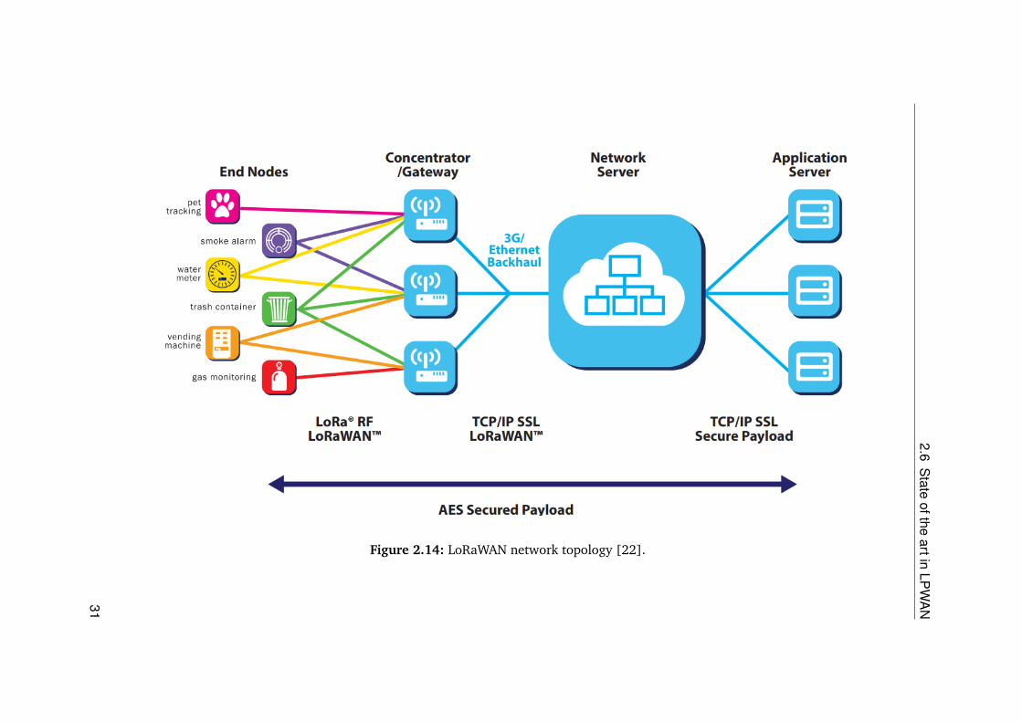
LoRaWAN offers "cooperative reception" where end nodes are not specified to one gateway.Instead, a node transmits the data packet to multiple gateways as shown in Figure 2.14.Each gateway then pushes packets to the server via Ethernet, Wi-Fi or some other backhaul.Message filtering and storage is done at the server side, reducing complexity from the enddevice and gateway.
30
2.6S
tateofthe
artinLP
WA
N
Figure 2.14: LoRaWAN network topology [22].
31

2 Background
Cooperative reception is quite helpful in case of a mobile node; as the node does not needto switch from gateway to gateway, it keeps on broadcasting the signal and its position canbe determined by monitoring the signal strength [22].
LoRaWAN Device Classes
LoRaWAN provides three device classes for various applications. These classes have trade-offs between network downlink, communication latency, and battery life as shown inFigure 2.15. Communication latency is crucial in a control application, where timelycontrol of specific actuators is required.
Bi-directional end-devices (Class A): Class A devices allow bi-directional communica-tion. Up-link transmission of an end device is followed by two short downlink receivewindows. The Class A operation requires the lowest power as it requires downlink commu-nication from the server only for a short interval after an uplink transmission. Downlinkcommunication will need to wait till the next up-link transmission in any other case.
Figure 2.15: LoRaWAN device classes [22].
Bi-directional end-devices with scheduled receive slots (Class B): Class B devices haveall the features of the class A devices, and they support the feature of extra receive windowsat scheduled times.
Bi-directional end-devices with maximal receive slots (Class C): End-devices of ClassC have almost continuously open receive windows, only closed when transmitting.
32
2.6 State of the art in LPWAN
2.6.3 DASH7
DASH7 is an LPWAN communication standard. It offers extended range at low data ratesfor monitoring applications. DASH7 is an open source standard, and it operates in thesub-1 GHz frequency band (315 MHz and 915 MHz). The DASH7 Alliance is a nonprofitorganization that is responsible for maintaining the DASH7 protocol. The protocol, officiallyknown as the DASH7 Alliance Protocol (D7AP), has various versions, where version 1.0is focused on wireless sensors and actuators. D7AP is a variant of the ISO/IEC 18000-7standard [19] which was designed for 433 MHz band only, but D7AP extends it to allsub-GHz Industrial Scientific and Medical (ISM) and Short Range Device (SRD) bands(433, 868 and 915 MHz). These radio bands are reserved internationally for the use ofradio frequency (RF) energy for industrial, scientific and medical purposes other thantelecommunications
D7AP is an asynchronous network protocol with medium range when compared to otherLPWAN technologies, following a request-response style of communication. To decreasecomplexity in the network, it uses a star topology, but to extend the range it allows amaximum of one hop between the node and gateway. Nodes have the option to enforce theacknowledgment from at least one gateway [11].
D7AP extends to all OSI-layers (see Section 2.2.1), from physical to application layer, asshown in Figure 2.16. D7AP has its own file system with data elements and their properties,such as permissions and storage classes. Some data elements define various parameters,while others are for sensor data storage; these data elements can be managed via theD7AP Application Layer Programming Interface (ALP). The ALP consists of commands thatperform actions such as read, write, execute, etc. These ALP commands are used by thegateway or a sub-controller to manage and communicate with the end nodes [11].
The D7AP physical layer (PHY in Figure 2.16) supports 433, 868 and 915 MHz unlicensedISM/SRD bands with three channel classes, i.e., Lo-Rate, Normal and Hi-Rate, each witha symbol rate of 9.6, 55.555 and 166.667 kbps respectively [10]. All the channels useGaussian frequency shift keying (GFSK) as the modulation technique, but with differentfrequency deviations and channel spacings. Parameters, such as frequency band, data rate,transmit power, coding parameters, and constraints, such as range, antenna size, cost, andenergy consumption, create a trade-off which depends on the application. For instance,using the 868 MHz instead of the 433 MHz band will decrease the antenna size, but willalso affect negatively on the range as well [11].
33

2B
ackground
Figure 2.16: Excerpt of OSI layers based on [42].
34

2.6 State of the art in LPWAN
D7AP Communication Schemes
For various application scenarios, D7AP provides three communication schemes. Theschemes are as follows:
Polling data using the D7AP Advertising Protocol: A gateway can query a node usingALP commands, but the node is power constrained, it does not continuously scan forrequests. D7AP has a low-power wake-up mechanism called D7AP Advertising protocol(D7AAdvP), which performs synchronization only when a request is queued [11].
Pushing data using the D7AP Action Protocol: By using the D7AP Action Protocol(D7AActP), it is possible to push data instead of querying it, as pushing data is far moreefficient than querying. D7AActP allows the sensor to push data to the gateway, eliminatingthe need for polling. This scheme is efficient for both, event-driven and periodic dataacquisition; it also provides an advantage in reduced power consumption and spectrumusage [11].
Dormant Sessions: In use cases where nodes continuously push data to the gateway(D7AActP), there might arise situations where data is to be transferred to the node, e.g.,controlling an actuator. In a dormant session, the gateway queues the message with atimeout instead of transmitting it directly. When the timeout is reached, the gatewayinitiates a dialogue session. However, if the node initiates a dialogue with the gatewaybefore the timeout, then the ongoing dialogue will be extended making the gatewayrequester and the endpoint responder. The concept of dormant sessions can be employedto avoid using the relatively expensive D7AAdvP mechanism [11].
2.6.4 Weightless
Weightless [41] is an IoT LPWAN technology that operates in both licensed and unlicensedspectrum. This technology is governed by Weightless Special Interest group (SIG), whichwas formed in 2012 as a nonprofit organization to cater to all the requirements of theweightless standard in the area of IoT. Weightless offers three different standards dependingon the application of use, i.e., Weightless-P, Weightless-N, and Weightless-W.
Weightless-P is two-way communications standard that uses Gaussian minimum shift keying(GMSK) and quadrature phase shift keying (QPSK) modulation techniques. Weightless-Pis not suitable for wide area networks. The Weightless-W standard operates in the TVwhite space (TVWS) spectrum. TVWS are the unused licensed frequencies that are madeavailable for unlicensed use, e.g., television broadcast. The regulations for TVWS changewith the region of operation making it unfit for an EMS. Weightless-N, like Sigfox, is anultra-narrow band system. It uses the same modulation technique as Sigfox, but instead ofbeing a closed system, Weightless-N is comprised of network of partners. [31].
35

2 Background
2.6.5 Ingenu RPMA
Ingenu is a wireless network provider, whose former name was On-Ramp wireless. Ingenuprovides machine to machine (M2M) communication solutions for IoT platforms. In theLPWAN sector, Ingenu holds a proprietary technology which is called Random PhaseMultiple Access (RPMA).
RPMA is a cellular type technology that provides 300+ square miles per access point.It achieves this significant coverage through increased transmission power and receiversensitivity. RPMA operates in 2.4 GHz unlicensed band with a bandwidth of 80 MHz. Themost prominent advantage of using 2.4 GHz is its availability in all the countries of theworld. RPMA uses the Viterbi algorithm for channel coding; this gives RPMA a PacketError Rate (PER) of 50%, in other words even if half of the packet containing the messagewere lost the entire message would still be decoded [17]. Based on RPMA, Ingenu isbuilding a network known as the "Machine network" for M2M communication only. Touse the Machine Network users need to subscribe as with any other cellular network. Thistechnology looks very promising in the IoT domain, but the fact that it is proprietary createsa dependency on Ingenue to deploy access points in the region of operation. Their networkonly covers the U.S. for now. It is expected to take a few years till they extend their serviceto European countries.
2.6.6 Licensed LPWAN
LPWAN technologies operating in the licensed spectrum are standardized and governed bythe 3rd Generation Partnership Project (3GPP). To capture the IoT market in the licensedspectrum 3GPP has introduced three LPWAN standards, i.e., Extended Coverage GSM forthe Internet of Things (EC-GSM-IoT), Long Term Evolution Machine Type CommunicationsCategory M1 (LTE MTC Cat M1, also referred to as LTE-M) and Narrowband IoT (NB-IoT).3GPP represents 400 individual members; this broad support is a significant advantagewhen it comes to standardization and interoperability between different mobile operatorsand vendors [1].
2.6.7 Extended coverage GSM IoT (EC-GSM-IoT)
EC-GSM-IoT was designed to facilitate time to market by making it backward compatible;it can work with the existing GSM networks. This backward compatibility allows aneasy resource sharing between EC-GSM-IoT and legacy network which enables a gradualintroduction of the technology, eliminating the need to reserve dedicated resources for IoT[1].
36

2.6 State of the art in LPWAN
2.6.8 Narrowband IoT
Narrowband IoT (NB-IoT) is a 3GPP release 13 feature. It uses the same principle andbuilding blocks as the LTE physical layer, this allows for rapid standardization and productdevelopment. It has been designed inherently to have more coverage and consume lesspower as compared to conventional GSM networks.
2.6.9 LTE-m
LTE MTC Cat M1 or more commonly known as the LTE-m is the successor of Cat-1 andCat-0. In 3GPP release 12, a Cat-0 UE (User equipment) was introduced with the aim toreduce complexity as compared to GSM/GPRS mobile devices. The extended battery lifeis achieved by use of power saving mode (PSM) and extended idle-mode DiscontinuousReception (eDRX) [1].
37


3 Selection of an LPWAN
One of the tasks of this thesis is to select the most feasible LPWAN solution for theapplication, i.e., an energy management system. Section 2.4 discusses the available LPWANtechnologies in detail. This chapter will focus on the evaluation of previously discussedLPWAN technologies and selection of the most feasible technology for a prototypicalimplementation of an EMS.
3.1 Selection Criteria
In order for the selection of an LPWAN technology, a selection criteria has to be defined.The technologies will be evaluated on the bases of this criteria. The selection criteria istailored for our application and should not be used as a general rule for the evaluation ofan LPWAN technology. The following are the main selection criterion:
• Modulation technique,
• Data throughput,
• Operating frequency, and
• Range.
The modulation technique (see Section 2.1.5) determines the key characteristic of acommunication system. Techniques that provide inherent interference protection arepreferred. For instance, spread spectrum techniques are designed to be detected evenbelow the noise level and are preferred over the others. Data throughput should be enoughto transmit 100-500 bytes per 5 minutes. Operating frequency of the technology should bein the unlicensed spectrum. Node power consumption should be as minimum as possiblewith a range of a few kilometers. Low node power consumption is an inherent property ofan LPWAN technology therefore, it is not mentioned as a key criteria.
Apart from the aforementioned points, availability, cost, effort and support for the technol-ogy are also important when it comes to implementation.
39

3 Selection of an LPWAN
3.2 Comparison
NB-IoT is a desirable solution regarding cost and area coverage, but when it comes to costper byte and longevity, then it is not viable, especially in applications like EMS. In Germany,only Vodafone has recently started offering an NB-IoT solution, however, due to its highdependency and cost it is not a feasible solution for now. NB-IoT operates in the licensedspectrum making it unfit for an EMS.
Section 3.2 summarizes our findings with some values extracted from the work of Raza,Kulkarni, and Sooriyabandara [32]. A comparison of the technologies can be made withrespect to modulation technique, range, data throughput and operating frequency. Themajority of the LPWAN technologies use an operating frequency in the SUB-GHz bandexcept for Ingenu using the 2.4 GHz. As mentioned in Chapter 2, SUB-GHz frequencies areless prone to interferences and offer a more significant area coverage.
Sigfox uses UNB, as mentioned in Section 2.6.1. Data transfer rates are in between 100-600bits per second depending on the region. Sigfox is well suited for low-bandwidth (lessthan 300 bits per second / up to 12 total bytes per payload), and low transmit frequency(up to 140 messages per day) applications. Sigfox is effective for communications fromendpoints to base stations (uploads), but it is not particularly effective from base stations toendpoints (downloads) [8]. Sigfox offers excellent coverage compared to all other LPWANtechnologies. It follows a cellular network like business model, forcing users to buy serviceand hardware. It is not allowed for the users to create custom private networks.
Weightless-N is governed by Nwave, which is an IoT solution provider. The requirementfor special hardware, such as temperature compensated crystal oscillator (TCXO) and therelatively unbalanced link budget, puts Nwave at a disadvantage over the LoRa basedsystems. The Weightless-W standard operates in the TV white space (TVWS) spectrum.TVWS are the unused licensed frequencies that are made available for unlicensed use,e.g., television broadcast. It is an advantage to use the unused VHF and UHF bands,but the regulations for TVWS differ from region to region besides nodes are designedspecifically to a certain frequency. Designing nodes for a wider range of frequencies wouldput a huge constraint on antenna construction and other parameters. RF systems are notflexible to adapt to multiple frequencies with the same antenna. Weightless-P is a two-waycommunications standard that uses a 12 kHz channel, making it reasonably narrow band.Weightless-P is not suitable for wide area networks because the receiver sensitivity of 12kHz minimum shift keying channel will not be able to match a narrow band Binary phaseshift keying (BPSK). Weightless-P caters to all the cons of Weightless-W/N, but at the cost ofless range. Aside from these, there is not much support available for weightless conformingdevices; and weightless based sensors are hard to find in the market [31].
Ingenu’s RPMA is the most attractive technology that exploits the free ISM 2.4 GHz bandfor its data throughput, although this frequency band is more susceptible to interferencebecause a massive number of other devices also use this band, such as Wi-Fi devices.This technology requires that the area of operation is covered by Ingenu’s RPMA accesspoint, adding a dependency on a third party. RPMA is a proprietary technology, and
40
3.2 Comparison
Ingenu’s business model is that of a Mobile network provider. Apart from these downsides,Ingenu is offering its services only in the U.S. for now, making it unsuitable for applicationrequirements of this thesis.
DASH7 offers an excellent energy-per-bit aspect and is ideal for sensor/actuator data, butDASH7 lacks the range required for the application of EMS. Higher ranges are obtainableat the cost of more energy per bit.
LoRaWAN uses the star topology. To achieve long-range communication, a gateway mustbe capable of receiving data from a high number of end nodes. LoRaWAN offers "Adaptivedata rate" and "Multi-channel multi-modem transceiver" on the gateway, which allowsthe reception of multiple messages simultaneously on multiple channels. The key factorsthat affect a gateways capacity are the number of concurrent channels, data rate (timeon air), the payload length, and how often nodes transmit. LoRa is a "spread spectrum"based modulation technique, where signals on different spreading factors do not interferewith each other, hence making it possible for the gateway to receive multiple data rateson the same channel simultaneously. If a node is closer to the gateway, it does not alwayshave to use the lowest data rate and occupy the link for a longer time. Instead, it coulduse the highest possible data rate and keep the link free for a long time for other nodes.The adaptive data rate can optimize the battery life of a node. Adaptive data rate requiressymmetrical uplink and downlink with sufficient downlink capacity, causing LoRaWAN tohave a high capacity and scaling capability of 6 to 8 times. This scaling capacity is uniqueto LoRaWAN as other LPWANs have asymmetrical up and downlink. LoRaWAN nodescommunicate asynchronously, i.e., they only transmit when the data is ready to send, or anevent is triggered, this kind of protocol is called Aloha protocol. In synchronous networkssuch as cellular networks, the nodes have to frequently synchronize with the network to getmessages, this synchronization is power intensive and reduces the battery life significantly.LoRaWAN has shown to have 3 to 5 times the advantage, compared to all other LPWANtechnologies in the area of power consumption [22].
41

3S
electionofan
LPW
AN
Technology/Standard Modultion Range Data throughput Operating Frequency Channels
LoRaWAN CSS5 km (Urban),15 km (Rural)
0.3-37.5 kbps (LoRa),50 kbps (FSK)
SUB-GHz ISM:EU (433 MHz,868 MHz),US (915 MHz),Asia (433 MHz)
10 in EU
SigfoxUNB DBPSK (UL),GFSK (DL)
10 km (Urban),50 km (Rural)
100bps (UL),600bps (DL)
SUB-GHz ISM:EU (868 MHz),US (902 MHz)
360
IngenuRPMA-DSSS (UL),CDMA (DL)
15 km78 kbps (UL),19.5 kbps (DL)
ISM 2.4 GHz40 1-MHz channels,up to 1200 signalsper channel
WEIGHTLESS-W16-QAM, BPSK,QPSK, DBPSK
5 km 1-10 kbpsTV white space470-790 MHz
16 or 24 channels (UL)
WEIGHTLESS-PGMSK,offset-QPSK
2 km 200 bps - 100 kbpsSUB-GHz ISM orLicensed
multiple 12.5 kHzchannels
WEIGHTLESS-N UNB DBPSK 3 km 30-100 kbpsSUB-GHz ISM:EU (868 MHz),US (915 MHz)
multiple 200 kHzchannels
DASH7 GFSK 0-5 km (Urban) 9.6, 5.6, 66.7 kbps
SUB-GHz ISM:433 MHz,868 MHz,915 MHz
3- different channeltypes numberdepends on typeand region
Table 3.1: Comparison of various LPWAN technologies and standards extracted from [10, 18, 22, 32, 35].
42

3.3 Conclusion
LoRaWAN based on LoRa modulation has the range, data rate, and an open source maclayer protocol (LoRaWAN) making it an excellent candidate. LoRa and Sigfox were testedin a real-world environment by Nolan, Guibene, and Kelly [25]. They carried out theirexperiments on the eastern seaboard of Ireland. They were able to cover an area of 1380square kilometers with 90% coverage using a single LoRa base station. Table 3.2 takenfrom [25] shows useful field results of the two LPWAN technologies. It is clear that LoRamodulation requires significantly less transmit power, has an antenna sensitivity that isbetter by a factor of 8, and a bigger payload size while employing open standard. Petajajarviet al. [26] also carried out field experiments on land and water in Oulu, Finland. Theirexperiment focused on the coverage of mobile nodes based on LoRa technology. They wereable to achieve a packet loss ratio of 15% in the range of 2-5 km on land and 31% in therange of 5-15 km on water.
Features LoRa (Semtech SX1272) SigFox (AXSEM)symmetrical Technology Y YUplink Data + ACK DataPayload size 19-250 bytes 12 bytesProtocol Overhead 12 bytes 26 bytesTX power 13 dBm 14 dBmTX consumption 28 mA 45 mARX consumption 10.5 mA 10 mAEncryption AES-128 E2E AES-128Open Standard Y NTechnology CSS/FSK/OOK/GMSK GFSK/BPSKSensitivity (dBm) -137 -129
Table 3.2: LoRa versus Sigfox comparison (table taken from [25]).
LoRaWAN comes with one drawback, i.e., the dwell time limitation. The time a signalrequires to be in the air is known as dwell time, in other words, it is the duration for whichthe device occupies the channel for active communication. In the EU 863-870 MHz ISMband, LoRaWAN limits the duty cycle to 1% for data, to avoid network congestion.
3.3 Conclusion
Every technology has some perks that others lack. It is always a trade-off between range,data throughput, power consumption, cost and device availability. The selection of technol-ogy is highly dependent on the application at hand. For instance Wi-Fi is easily availableand has a high data throughput, but cannot be used for wireless sensors because of its
43

3 Selection of an LPWAN
limited range and high power consumption, same holds for the conventional technologieslike ZigBee, Bluetooth, Z-Wave, etc.
This thesis focuses on an energy management system, where data acquisition throughsensors is the essential task. Technologies that are region independent and use unlicensedspectrum are preferred. Technologies that are strictly proprietary e.g., (Sigfox, Ingenu’sRPMA) and compel users to buy hardware and services (network) also pose a limitation tothe customer base. Enisyst offers its smart energy solution to customers throughout Europe,and cannot afford to deploy technologies that are regional dependent or infrastructuredependent. Using such technologies will add unnecessary dependencies.
Keeping in view the selection criteria LoRaWAN fits this application best. Though it usesa proprietary modulation technique (LoRa); only Semtech produces chips that performLoRa modulation. It still is in the same category of cost as other LPWAN end devices.Manufacturers, such as Microchip [24], are to produce LoRa based modules in the future,further reducing the cost and eliminating monopoly of the manufacturer.
44

4 Concept
In this chapter, a standard energy management system will be discussed, which will beused as a template for the implementation.
4.1 Energy Management System
An EMS that is designed specifically for buildings was formerly known as Building EnergyManagement System (BEMS), today it is referd to as EMS. An EMS is defined as a computerbased system that monitors and controls a buildings mechanical and electrical equipment[15]. EMS consists of software and hardware. Its hardware includes a network of sensorsand actuators, whereas the software includes algorithms for smart control and buses forintercommunication. The aim of an EMS is to minimize energy waste by using it efficientlyto achieve monetary and environmental benefits. Figure 4.1 shows a block diagram of awired EMS. A standard EMS comprises of the following components:
• Central controller,
• External controller,
• Actuators,
• Sensors, and a
• Graphical User Interface (GUI).
These components are describe as follows.
4.1.1 Central controller
The central controller is where all the algorithms for smart control are implemented. It pollsthe data from the sensors and controls the actuators accordingly. The central controller canbe accessed via a Graphical User Interface (GUI) for setting up various parameters.
4.1.2 External controller
The external controllers serve the purpose of Inputs/Outputs (I/O) extension as well asrepeaters or signal amplifiers.
45

4 Concept
4.1.3 Actuators
An actuator is an electromechanical component that is used for moving and controlling asystem. An actuator needs a control signal and a source of energy. In an EMS the actuatorsare generally mounted on heat pumps, CHP generator, water pumps and valves. Thealgorithm running on central controller is responsible for controlling the actuators.
Figure 4.1: Block diagram of an EMS extracted from [13].
4.1.4 Sensors
A sensor is a component that converts non electrical energy into electrical energy so thatit can be measured. The sensors generally used in an EMS are: temperature sensors,humidity sensors, smoke detectors, carbon mono-oxide detectors, light sensors, and flowmeasurement sensors etc., also various types of meters including electricity, gas and watermeters.
4.1.5 Graphical User Interface (GUI)
The GUI is used to access the Central controller. An EMS is designed to be flexible and canbe configured for different seasons and operating conditions. The GUI of an EMS providesa platform where such changes can be made.
46

5 Prototypical Implementation of anLPWAN based EMS
In this chapter, a prototypical implementation of an Energy Management System (EMS)will be carried out using LoRa technology. A standard EMS is defined and discussed inChapter 4. Based on this standard, a prototype will be implemented.
5.1 Hardware Setup
This section will focus on the hardware required to set up a LoRa based EMS. All thehardware for its implementation has to be industrial grade because Enisyst providesindustrial grade solutions to its customers. The LoRa based EMS is integrated with thecurrent Enisyst system and to reduce extra hardware, all the implementation is done onthe standard hardware used by the eni.os, which is the Enisyst’s backend responsiblefor monitoring and control. The internal workings of eni.os are confidential and areout of scope of this thesis. The transfer of sensor data to the eni.os will be discussed inSection 5.2.2.
5.1.1 Enisyst 1613 module
Enisyst 1613 module uses Phytec’s phyCORE-AM3352 [28] System On Module (SOM).This SOM is equipped with Texas Instruments’s Sitara [40] processor which is based on theARM Cortex-A8 [2] processor as shown in Figure 5.1.
Figure 5.1: phyCore AM3352.
47

5 Prototypical Implementation of an LPWAN based EMS
This processor supports Controller Area Network (CAN), Serial Peripheral Interface (SPI),RS232, USB, and Ethernet. It is entirely capable of running embedded Linux on it as well.The distribution of Linux currently running on phyCORE is created by "The Yocto Project"[44], which will be discussed in Section 5.2.2.
5.1.2 phyBOARD
The phyBOARD-Regor is an extension board on which the phyCORE-AM3352 moduleis mounted. This extension board is developed for use in standard DIN rail housings(e.g. Bopla CombiNorm-Connect). As shown in Figure 5.2 it contains all the ports for
Figure 5.2: phyBOARD Regor.
the common interfaces such as 2x Ethernet, 2x LAN, CAN, RS485 and RS232. Also, thephyBOARD-Regor can be extended via a 60-pin expansion bar.
5.1.3 LoRa Node
RFM95W as shown in Figure 5.4 is used as LoRa transceiver. It supports SPI protocol forcommunication with other modules.
Figure 5.3: RFM95W LoRa transceiver.
48

5.1 Hardware Setup
It is mounted on the breakout board for ease of use. The RFM95W costs less than 1C andoffers the following key features:
• 168 dB maximum link budget,
• +20 dBm - 100 mW constant RF output vs. V supply,
• +14 dBm high-efficiency PA,
• Programmable bit rate up to 300 kbps, and
• High sensitivity: down to -148 dBm.
Figure 5.4: RFM95W mounted on the break out board.
It is connected with the 1611 extension board via the SPI to create a LoRa node.
5.1.4 DS18B20
DS18B20 is the standard temperature sensor used by Enisyst systems. Unlike the famousPT1000, it is a digital temperature sensor that uses a 1-wire protocol for transmittinginformation.
Figure 5.5: DS18B20 digital temperature sensor.
49

5 Prototypical Implementation of an LPWAN based EMS
5.1.5 1611 extension module
Enisyst’s 1611 is an extension module which is used to extend the I/Os for the Enisyst 1613module (phyBOARD-Regor). 1611 is equipped with an ATMEL’s AVR [3] microcontrollerto communicate with the 1613 module via the RS232 interface.
Figure 5.6: 1611 extension module.
Figure 5.6 depicts a 1611 module. For the application of LoRa based EMS, 1611 is usedas a node; multiple DS18B20 temperature sensors are connected to the 1611 module. Ittakes the inputs from the temperature sensors via the 1-wire protocol and sends it to theRFM950W LoRa transceiver via the SPI.
5.1.6 LoRa concentrator board
For setting up a LoRaWAN network, it is required to have a LoRaWAN gateway. Thisgateway works like any other gateway and receives the LoRa modulated signals from theend nodes. These received packets are then forwarded to the back-end server where themessages are stored and analyzed.
Figure 5.7: LoRa concentrator module ic880a.
LoRa concentrator ic880a, as shown in Figure 5.7, is capable of receiving LoRa modulatedsignals on eight different channels simultaneously. This module communicates with 1613module via the SPI protocol, and together they act as a LoRaWAN gateway. There are a fewLoRaWAN gateways readily available on the market, but due to specific requirements, acustom LoRaWAN gateway was designed using the 1613 module and ic880a concentrator.
50

5.2 System Architecture
5.2 System Architecture
This section will focus on the whole system architecture of an IoT based EMS. Figure 5.8shows a top-level view of the entire system. A LoRa node sends temperature sensor valuesto the gateway via LoRa modulated signals over the air, the signals are received at thegateway-end, and are published to a message broker at the server side.
Figure 5.8: Top level view of the whole system.
The end user application can also monitor the values by subscribing to the specific topic.The received values at the gateway-end are decrypted and decoded by a JavaScript (Js)script. The script sends these values to eni.os via Unix domain socket. The values areanalyzed by eni.os, and respective actuators are activated. A detailed overview of the wholesystem architecture is depicted by Figure 5.9. All the internal software modules and theirinterconnecting communication protocols are also highlighted.
Figure 5.9 can be compared to the standard architecture shown in Figure 4.1. Due toLoRa’s dwell time limitation, the wireless part of the EMS will be used just for monitoring,whereas for controlling the actuators standard cable connection is used. The 1613 modulein Figure 5.9 is the central controller in our EMS, which receives the temperature sensordata wirelessly via the LoRa modulated signal. The extension board 1611 can be comparedto the external controller in the standard architecture. The end user can access the EnisystEMS to set various parameters, including a timing schedule for heating and cooling.
5.2.1 Node
The node consists of DS18B20 temperature sensors, 1611 module, and the LoRa RFM95Wtransceiver. As shown in Figure 5.10, the values are read from the sensors and sent to thegateway via the uplink. To comply with the 1% rule of the ISM band and to always sendthe most up-to-date data, a "scheduler" programme was implemented.
51

5P
rototypicalImplem
entationofan
LPW
AN
basedE
MS
Figure 5.9: Detailed system architecture.
52

5.2 System Architecture
Figure 5.10: LoRa node.
The flow chart shown in Figure 5.11 depicts the sequence flow of a single loop of thescheduler programme. In every loop, the scheduler reads all sensors and inputs, "check-Values()" performs this operation. After that, it checks if the timer for SYNC message hasexpired. The SYNC message is a flag for the timer that is used for sending the sensor dataperiodically. An expired SYNC means that the sensor values should be sent right now whileresetting the SYNC. This mechanism is useful in case of environmental data acquisition.It is not efficient to store real-time environmental data. Measuring values every 1 to 6minutes is good enough for efficient heating control. After SYNC, the scheduler checksif LoRa’s 1% rule is met, if it is true, the next HEX string for the uplink is assembled. Ifnot, this step is skipped, and the loop ends. At any given time in the loop of the schedulerprogramme, it is possible that it can be interrupted to set an error code. If this happens,the next uplink is an error message instead of a data message.
Since LoRaWAN is subject to the 1% rule, care must be taken to minimize the amountof data to be transmitted. Therefore it will not use an ASCII-based approach, but ahexadecimal approach. This means, data to be transmitted is in hexadecimal format. Forthis purpose, a separate format was created, which is optimal for this application. The dataformat essentially consists of two parts. The first two bytes describe the data type, whetherit is a error message or a data message. The bytes after represent the data. This structure isshown in Table 5.1
2 Byte X Byte ...assignment field data ...
Table 5.1: Structure of a HEX message of the 1611 node.
The first two bytes of each message is referred to as "assignment field." Here bits 1-15 areused to define the type of data that is present in the message. Bit 0 denotes the mode bit,i.e., when it is set, the message is an error message. For each sensor or input on the 1611module, its respective bit shows if data is present in the message. For instance, if the bit 0 isset and bit 1 is also set, this means an error message from the temperature sensor T1, andif bit 0 is not set and T1 is set it means data message from T1. An error message is definedto have a length of one byte; which means up to 255 different errors can be transmitted.If the message is a data message, bit 0 is not set. A temperature value has the length of
53

5 Prototypical Implementation of an LPWAN based EMS
Figure 5.11: Scheduler flow chart.
2 bytes and is transmitted as a 16-bit signed integer. An analog input has the length of 2bytes and is sent as 16-bit signed integer.
Figure 5.12: Structure of the first two bytes of a hex message.
An electricity meter value has a length of 3 bytes. The meter gives two values; the pulsecounter and the time between two pulses. The pulse counter value has a length of 1 byteand is transmitted as an 8-bit unsigned integer, whereas the time between two pulses hasthe length of 2 bytes and is a 16-bit unsigned integer. The detailed structure is shown in
54

5.2 System Architecture
Figure 5.12. The identifier M stands for the mode of the message, data or error message.T1 to T5 stands for the temperature values, AE1 and AE2 for the analog inputs and DI1 toDI8 for the digital inputs.
Figure 5.13: Class diagram.
The implementation of the data layout was done on 1611 as a class; the class diagram isshown in Figure 5.13. One complete message can have a maximum length of 51 bytes, andthe maximum transferable data at the highest spreading factor is also 51 bytes.
5.2.2 Gateway
A block diagram of the gateway is shown in Figure 5.14. The gateway is formed by severalsoftware modules working together. Each of these modules is communicating with theothers via communication protocols such UDP, MQTT, and SPI. These software modules arerunning on a custom distribution of embedded Linux version 4.4. The software modules,i.e., Mosquitto server, nodejs script and LoRaWAN gateway can be run separately ondifferent hardware systems as well.
Enisyst 1613 software setup
The hardware specifications of the 1613 module were mentioned in Section 5.1.1. In thissection, the base software setup of 1613 will be discussed. The 1613 module supportsembedded Linux. The Linux distribution required for the implementation is custom createdvia "The Yocto Project."
The Yocto Project is an open source collaboration project that creates custom Linux-basedsystems for embedded products, regardless of the hardware architecture. The projectprovides a flexible set of tools and a space where embedded developers worldwide can
55

5 Prototypical Implementation of an LPWAN based EMS
Figure 5.14: Internal software modules at the gateway end.
share technologies, software stacks, configurations and best practices which can be used tocreate tailored Linux images for embedded devices [44].
Package name Required formc, nano, autoamake, git Debuging, on board compilingopenvpn, apache2 eni.osstunnel, tunctl, tcpdump Network managment and securityspitools 1611, 1613, ic880anodejs, nodejs-npm Running Js scriptsmosquitto Message brokererlang LoRa Gateway Bridgepython (pandas, matplotlib) Data analysis and viusalization
Table 5.2: Package dependencies.
The Yocto Project uses a build system known as "BitBake." It is a scheduler and executionengine which parses instructions (recipes) and configuration data. It then creates adependency tree to order the compilation, schedules the compilation of the included code,and finally, executes the building of the specified, custom Linux image (distribution).BitBake is a make-like build tool. BitBake recipes define how a particular package is
56

5.2 System Architecture
built. They include all the package dependencies, source code locations, configuration,compilation, build, install and remove instructions. Recipes also store the metadata for thepackage in standard variables. Related recipes are consolidated into a layer. During thebuild process, dependencies are tracked and native or cross-compilation of the package isperformed [44]. To run all the software modules at the gateway end, a Linux distributionwith support for the packages shown in Table 5.2 was created.
Packet forwarder
The packet forwarder [9] is an open source program provided by Semtech. It is running onthe 1613 module, and it communicates with the concentrator board via the SPI protocol.All the received RF packets are forwarded to LoRa Gateway Bridge via UDP. It uses thefollowing helper programmes:
• util_sink: It is a simplistic program listening on a UDP port for datagrams and displaysa notification message when a packet is received. The content of the datagram is notdisplayed.
• util_ack: This program sends merely the acknowledgment of messages.
• util_tx_test: The network packet sender is a simple helper program used to sendpackets through the gateway-to-server downlink route.
LoRa Gateway bridge
LoRa Gateway Bridge [5] is an open source service which abstracts the "packet forwarder"UDP protocol into JSON over MQTT. It enables the use of MQTT for receiving data fromand sending data to the gateways. LoRa Gateway Bridge is part of the LoRa Server [6].LoRa Server is an open-source LoRaWAN network-server, part of the LoRa Server Project[7]. LoRa Gateway Bridge makes use of MQTT for publishing and receiving applicationpayloads. It is one of the requirements of LoRa Gateway Bridge to have an MQTT broker towork, for this purpose Mosquitto is used.
As shown in Figure 5.15 taken from [5], the LoRa Gateway Bridge can run on the samehost as the packet forwarder or a separate host as well. Keeping in view the Enisyst systemthe best possible scenario is to have all the software modules running on the same host.Running all the modules on the same host will reduce the hardware cost and effort. Thecurrent hardware used by the Enisyst system is fully capable of running all of the modules.Using the modular approach makes the system scalable in case any of the modules need tobe deployed on different hardware because of resource management or any other reason.All the modules communicate with each other via standard Internet protocols. The systemarchitecture will remain the same if they are deployed on different hosts.
57

5 Prototypical Implementation of an LPWAN based EMS
Figure 5.15: Network configuration using LoRa Gateway bridge and packet forwarder.
Mosquitto server
Mosquitto [21] is an open source message broker that uses the Message Queue TelemetryTransport (MQTT) protocol versions 3.1 and 3.1.1. A message broker is a middleware thatacts as a mediator between applications. There are a few other open source MQTT messagebrokers available today such as EMQ (Erlang MQTT Broker) [20], VerneMQ [12] andRabbitMQ [38]. Amongst all these message brokers Mosquitto is the lightest. As describedbefore, the Enisyst system is running on an embedded computer, which makes Mosquittoan ideal candidate for this application.
The publish/subscribe scheme used for machine to machine (m2m) communication has be-come the defacto in the realm of IoT. The MQTT is a lightweight method of communicationbetween devices that do not have the computing resources to use complex communicationprotocol.
58

5.2 System Architecture
Nodejs script (Decoder)
The nodejs script creates a connection to the Mosquitto server. It does not make a differenceif the Mosquitto server is running on different hardware. In this case, the Mosquitto serveris running on the same hardware, so a connection to the local-host is made. In some cases,the Enisyst system is deployed in complete isolation and no or limited internet connectivityis available. For such cases, it is more suitable to run all the software modules on onehost. After establishing the connection, the script subscribes to the specific topics. Thetopics have the same Unique ID as 1611 module. The received messages are decrypted,and the 51-byte long hex string is decoded. The data is extracted from the string and sentto eni.os via Unix domain socket. For the purpose of debugging, the script also establishesa connection with a remote Mosquito server via the internet. It publishes the extracteddata to the server, which can be seen by any user who has subscribed to the correct topic.
eni.os
It is a proprietary software module owned by Enisyst. It is responsible for monitoringand control. The internal workings of this module are strictly confidential and can not bediscussed in this document. For this thesis, this module will be considered as a black-boxthat takes sensor values as inputs and transmits signals to actuators.
5.2.3 End user
The end user represents an interface where the data can be visualized. The visualizationtool is written in JavaScript and runs in a browser. It uses D3 (Data-Driven Documents) toimplement the line chart, bar graphs and scatter plot. D3 is a low-level JavaScript library.Details of this tool are out of scope for this thesis.
59


6 Range Assessment
This chapter will be focused on our findings after implementing LoRa as a baseline technol-ogy for communication between an end node and the central controller. The range testswere performed in the industrial area of Pliezhausen, Baden Würtemburg, Germany. Thearea is densely populated with various industry with more interference than residentialareas.
6.1 Range test
Figure 6.1 shows the paths over which the SNR values were recorded. SNR (see Sec-tion 2.1.7) is a measure of the signal quality, the negative SNR shows that LoRa modulatedsignals can be detected even if they are below the noise level. The orange lines in themap denote the path over which SNR was recorded, every blue mark on the path is theexact point where the value was recorded. The gateway was placed inside the office on the1st floor like any other Wi-Fi router. The yellow lines in the map show the displacementbetween the gateway and the peak points on the map.
The reason for the difference between distances amongst different paths is the uneventerrain of the area. Figure 6.2 shows the total area that can be covered by one gateway.The signal reception can be optimized even further by creating line of sight communication.During the range tests, it was observed that, if there was no obstruction between thegateway and the node the signal could reach even further. The empty pocket in Figure 6.2is because a large metallic structure is obscuring the signals.
61
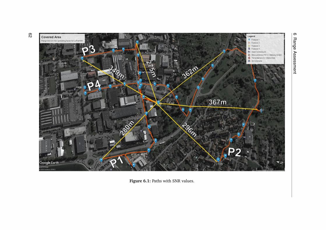
6R
angeA
ssessment
Figure 6.1: Paths with SNR values.
62

6.1R
angetest
Figure 6.2: Area coverage.
63


7 Conclusion and Outlook
The ever-growing energy demand of toady’s industry and household can be reduced byemploying the efficient use of energy. Energy use can be optimized by employing energymanagement systems. Enisyst offers its customers a reduction of 30% in energy use byemploying their EMS. Enisyst uses a wired sensor network for monitoring and a wirednetwork for controlling the actuators. This wired network requires a lot of effort andtime to deploy and in most cases, it can only be employed during the construction of thebuilding.
To tackle this problem it was suggested to use a wireless technology. By using a wirelesstechnology, the effort can be drastically reduced and the deployment of the EMS will nolonger be dependent on the construction. For this purpose, several technologies werestudied and it was decided to use an LPWAN technology for this task. The core conceptbehind an LPWAN technology is to provide a significant long range with low powerconsumption at the cost of lower data transfer rates. There are a lot of LPWAN technologiesavailable in the market right now, each offering various advantages and disadvantage. Inorder to use the right LPWAN technology, a study about the current LPWAN technologieswas carried out. The focus of this study was to find an LPWAN technology that is suitablefor the task of implementing an EMS.
The study concluded in the selection of LoRa as the LPWAN technology to implement theEMS. The dwell time limitation of LPWAN restricted us to use it only for the collectionof sensor data, and not for the controlling of actuators, therefore it was decided to limitthe LPWAN use for monitoring only. A prototypical implementation of the LPWAN basedEMS was carried out. In the prototype, a customized LoRaWAN gateway and a nodewere implemented. The node transmitted LoRa modulated signals over the air whichwere received by the gateway. At the gateway end, there are several software modulesrunning on an embedded computer. An open source message broker is used as a backendfor handling packets between software modules. Having a message broker provides theflexibility and scalability required for an EMS. The software modules running at the gatewayend, decrypted and decoded the sensor values and passed them to Enisyst’s control software.This software controlled the actuators correspondingly.
After the implementation of the system, several range tests were performed in an industrialarea which is densely populated with buildings. The gateway was placed inside a buildingon the first floor. The maximum range at which the signal was transmitted was 360 meters.It was observed that if the line of sight was maintained even more range could be attainable.Due to the uneven mountainous terrain, it was not possible to achieve more in our case.
65

7 Conclusion and Outlook
LoRa modulation is not limited by the distance but the obstructions in the path of the signal.A range of more than 10 km has been achieved using the line of sight communication.
The findings from this thesis will be used to create the next generation Enisyst EMS. Furtherresearch is required in order to use LPWAN for the controlling of the actuators as well.Multiple technologies can be used in combination to further optimize the process. As oftoday, there are not a lot of ready-made LPWAN solutions. We had to create our ownsensor node from scratch. Various providers claim to have LPWAN sensor nodes but theavailability of such products are said to be at the end of 2018.
66

Bibliography
[1] 3GPP. “White Paper: 3GPP Low Power Wide Area Technologies.” Tech. rep. 3GPP,2016 (cit. on pp. 36, 37).
[2] ARM. “ARM Cortex A8.” 2018. URL: https://developer.arm.com/products/processors/cortex-a/cortex-a8 (cit. on p. 47).
[3] Atmel. “AVR atmega32.” 2018. URL: https://www.microchip.com/wwwproducts/en/ATmega32 (cit. on p. 50).
[4] Bluetooth Special Interest Group. “Bluetooth.” 2017. URL: https://www.bluetooth.com/ (cit. on pp. 12, 21).
[5] O. Brocaar. “LoRa gateway bridge.” 2018. URL: https://github.com/brocaar/lora-gateway-bridge (cit. on p. 57).
[6] O. Brocaar. “LoRa Server.” 2018. URL: https://github.com/brocaar/loraserver(cit. on p. 57).
[7] O. Brocaar. “lora server porject.” URL: https://www.loraserver.io/ (cit. on p. 57).
[8] I. Brown. “A Detailed Breakdown of LPWAN Technologies and Providers.” URL: http://web.luxresearchinc.com/hubfs/Insight_Breakdown_of_LPWAN_Technologies.pdf (cit. on p. 40).
[9] M. Coracin. “packet forwarder.” 2017. URL: https://github.com/Lora-net/packet_forwarder (cit. on p. 57).
[10] DASH7 Alliance. “DASH7 Alliance Wireless Sensor and Actuator Network Protocolv1.0.” 2015. URL: http://www.dash7-alliance.org (cit. on pp. 33, 42).
[11] G. Ergeerts, M. Nikodem, D. Subotic, T. Surmacz, B. Wojciechowski, P. De Meu-lenaere, M. Weyn. “DASH7 alliance protocol in monitoring applications.” In: P2P,Parallel, Grid, Cloud and Internet Computing (3PGCIC), 2015 10th InternationalConference on. IEEE. 2015, pp. 623–628 (cit. on pp. 33, 35).
[12] Erlio GmbH. “VerneMQ.” URL: https://vernemq.com/ (cit. on p. 58).
[13] D. Estates. “Building energy management systems.” In: Design and MaintenanceGuide 22 (2001) (cit. on p. 46).
[14] Wi-Fi Alliance. “Wi-Fi.” 2017. URL: https://www.wi-fi.org/ (cit. on pp. 12, 21).
[15] D. A. Al-Hammad. “BUILDING MANAGEMENT SYSTEM (BMS).” URL: http://faculty.kfupm.edu.sa/ARE/amhammad/ARE-457-course-web/Building-Management-System.pdf (cit. on p. 45).
[16] Ingenu. “Ingenu.” 2018. URL: https://www.ingenu.com/ (cit. on p. 26).
67

Bibliography
[17] Ingenu. “White Paper: How RPMA works.” Tech. rep. ingenu, 2018 (cit. on p. 36).
[18] Ingenu. “White Paper: RPMA Technology for the Internet of Things.” Tech. rep.ingenu, 2018 (cit. on p. 42).
[19] “Information technology – Radio frequency identification for item management –Part 7: Parameters for active air interface communications at 433 MHz.” Standard.Geneva, CH: International Organization for Standardization, Sept. 2014 (cit. onp. 33).
[20] F. Lee. “EMQ.” 2002. URL: http://emqtt.io/ (cit. on p. 58).
[21] R. A. Light. “Mosquitto: server and client implementation of the MQTT protocol.”In: The Journal of Open Source Software 2.13 (May 2017), p. 265. ISSN: 2475-9066.DOI: https://doi.org/10.21105/joss.00265 (cit. on p. 58).
[22] LoRa Alliance. “A technical overview of LoRa and LoRaWAN.” In: White paper, Nov(2015) (cit. on pp. 30–32, 41, 42).
[23] LoRa Alliance. “LoRa Alliance.” 2017. URL: https://www.lora-alliance.org/ (cit. onpp. 12, 26).
[24] Microchip. “Microchip.” 2018. URL: http://www.microchip.com/ (cit. on p. 44).
[25] K. E. Nolan, W. Guibene, M. Y. Kelly. “An evaluation of low power wide area networktechnologies for the Internet of Things.” In: 2016 International Wireless Communi-cations and Mobile Computing Conference (IWCMC). Sept. 2016, pp. 439–444. DOI:10.1109/IWCMC.2016.7577098 (cit. on p. 43).
[26] J. Petajajarvi, K. Mikhaylov, A. Roivainen, T. Hanninen, M. Pettissalo. “On thecoverage of LPWANs: range evaluation and channel attenuation model for LoRatechnology.” In: 2015 14th International Conference on ITS Telecommunications(ITST). Dec. 2015, pp. 55–59. DOI: 10.1109/ITST.2015.7377400 (cit. on p. 43).
[27] J. Petajajarvi, K. Mikhaylov, A. Roivainen, T. Hanninen, M. Pettissalo. “On thecoverage of LPWANs: range evaluation and channel attenuation model for LoRatechnology.” In: ITS Telecommunications (ITST), 2015 14th International Conferenceon. IEEE. 2015, pp. 55–59 (cit. on p. 12).
[28] Phytec. “phyCore AM335x overview.” URL: http://www.phytec.de/produkt/system-on-modules/phycoream335x/#uebersicht (cit. on p. 47).
[29] B. Ray. “The Past, Present, and Future of LPWAN.” 2017. URL: https://www.link-labs.com/blog/past-present-future-lpwan (cit. on pp. 25, 26).
[30] B. Ray. “What is LoRa?” 2015. URL: https://www.link-labs.com/blog/what-is-lora(cit. on p. 30).
[31] B. Ray. “What is Weightless?” 2015. URL: https://www.link-labs.com/blog/what-is-weightless (cit. on pp. 35, 40).
[32] U. Raza, P. Kulkarni, M. Sooriyabandara. “Low Power Wide Area Networks: AnOverview.” In: IEEE Communications Surveys Tutorials 19.2 (Secondquarter 2017),pp. 855–873. DOI: 10.1109/COMST.2017.2652320 (cit. on pp. 40, 42).
68

[33] F. Sforza. “Communications system.” US Patent 8,406,275. Mar. 2013. URL: https://www.google.com/patents/US8406275 (cit. on p. 30).
[34] Sigfox. “Sigfox.” 2018. URL: https://www.sigfox.com/en (cit. on pp. 12, 26).
[35] Sigfox. “Sigfox Technical Overview.” 2017. URL: https://www.disk91.com/wp-content/uploads/2017/05/4967675830228422064.pdf (cit. on pp. 28, 29, 42).
[36] Sigfox. “Sigfox Technology Overview.” URL: https://www.sigfox.com/en/sigfox-iot-technology-overview (cit. on p. 27).
[37] J. Sliva. “Technologies used in wireless sensor networks.” In: Systems, Signals andImage Processing, 2008. IWSSIP 2008. 15th International Conference on. IEEE. 2008,pp. 77–80 (cit. on p. 12).
[38] P. Software. “RabbitMQ.” 2007. URL: https://www.rabbitmq.com/ (cit. on p. 58).
[39] TEOCO Corporation. “A Short History of LPWAN, and Why the IoT Can’t Live WithoutIt.” 2017. URL: http://www.teoco.com/latest/news/blog/short-history-lpwan/(cit. on p. 25).
[40] Texas Instrument. “TI Sitara Overview.” 2017. URL: http://www.ti.com/processors/sitara/arm-cortex-a8/am335x/overview.html (cit. on p. 47).
[41] Weightless SIG. “Weightless.” 2015. URL: http://www.weightless.org/ (cit. on pp. 12,35).
[42] M. Weyn, G. Ergeerts, L. Wante, C. Vercauteren, P. Hellinckx. “Survey of the DASH7alliance protocol for 433 MHz wireless sensor communication.” In: InternationalJournal of Distributed Sensor Networks 2013 (2013) (cit. on p. 34).
[43] S. Yinbiao, K. Lee, P. Lanctot, F. Jianbin, H. Hao, B. Chow, J.-P. Desbenoit. “Internetof things: wireless sensor networks.” In: White Paper, International ElectrotechnicalCommission, http://www. iec. ch (2014) (cit. on p. 11).
[44] Yocto Project. “The yocto project.” 2018. URL: https://www.yoctoproject .org/(cit. on pp. 48, 56, 57).
[45] Zigbee Alliance. “Zigbee.” 2017. URL: http://www.zigbee.org/ (cit. on pp. 12, 30).
[46] H. Zimmermann. “OSI Reference Model - The ISO Model of Architecture for OpenSystems Interconnection.” In: IEEE Transactions on Communications 28.4 (Apr. 1980),pp. 425–432. ISSN: 0090-6778. DOI: 10.1109/TCOM.1980.1094702 (cit. on pp. 19,20).
All links were last followed on April 17, 2018.


Declaration
I hereby declare that the work presented in this thesis isentirely my own and that I did not use any other sources andreferences than the listed ones. I have marked all direct orindirect statements from other sources contained therein asquotations. Neither this work nor significant parts of it werepart of another examination procedure. I have not publishedthis work in whole or in part before. The electronic copy isconsistent with all submitted copies.
place, date, signature