Investigations of heat release, extinction, and time evolution of the flame surface, for a...
17
Investigations of Heat Release, Extinction, and Time Evolution of the Flame Surface, for a Nonpremixed Flame Interacting with a Vortex PAUL-HENRI RENARD, JUAN CARLOS ROLON,* DOMINIQUE THE ´ VENIN, and SE ´ BASTIEN CANDEL Laboratoire E.M2.C., E ´ cole Centrale Paris et CNRS, Grande Voie des Vignes, F-92295 Cha ˆtenay-Malabry, France Flame/vortex interactions to a great extent govern turbulent combustion. Flame roll-up due to vortices is also one of the most important phenomena driving combustion instabilities. An experimental investigation analyzes some fundamental features of a diffusion flame interacting with a vortex ring. A steady nonpremixed counterflow flame of air and hydrogen diluted with nitrogen is first established. A vortex ring is generated from a tube installed in the lower combustor nozzle and impinges on the flame. In the experiment described herein, the visualization of the flame front is achieved by OH planar laser-induced fluorescence (PLIF). The relevance of OH radicals as a marker of the reaction zone is discussed on the basis of direct numerical simulation (DNS) results. Scatter plots of correlations between OH concentration and heat release rate are also presented to derive a criterion of extinction. A detailed description of the interaction is given, showing a global enhancement of combustion due to the interaction with the vortex. Extinction processes occurring later are also described. The evolution of the flame surface during the interaction is extracted from the experimental visualizations. It is shown that extinctions are characterized by a reduction in flame surface area and that this decrease may be hidden by flame stretching and/or roll-up. © 1999 by The Combustion Institute INTRODUCTION Interactions of flames and vortices have impor- tant implications in combustion. Assuming that a field of turbulence is a collection of vortices of various sizes and strengths, flame/vortex inter- actions constitute a fundamental mechanism of turbulent combustion and these interactions essentially govern the rate of combustion. In many circumstances, vortices also drive various kinds of instabilities. Vortices can be observed, for instance, in unconfined jet flames [1] or when a flame is stabilized on a bluff obstacle placed in a duct [2]. Mixing may be intensified by flame/vortex interactions: in the case of su- personic combustion, vortices can be generated to inject the fresh fuel into the hot oxidizer stream flowing into the combustor [3]. Flame/vortex interactions are examined in a growing number of theoretical studies. The an- alytical calculations of Marble [4] using the infinitely fast chemistry assumption led to a basic description of the diffusion flame struc- ture and roll-up in a single vortex, and to an estimation of the resulting consumption rate enhancement. Karagozian and Manda [5] inves- tigated the effect of a pair of counterrotating vortices on the flame, a configuration which corresponds for instance to the flow at the exit of a nozzle. They pursued their study further by taking into account the effect of heat release and emphasized the fact that the radius of the burned core was much larger in this case, and that the effective flame lengths and rates of reactant consumption were reduced [6]. Peters and Williams [7] developed asymptotic analysis for premixed combustion. They found that for large Peclet numbers, the process consisted of two steps: a fast inviscid roll-up of the flame front like a passive surface into a spiral around the vortex, and a slow flame propagation be- tween the spirals. Numerical studies have also been carried out. As we are more interested in experimental considerations, only a few of them are listed here. Laverdant and Candel [8] were the first to obtain a numerical solution of the diffusion flame/vortex interaction using the mixture frac- tion description and the fast chemistry limit assumption. The structure predicted by Marble was essentially confirmed by their calculations. Ashurst [9, 10] advanced the work of Laverdant *Corresponding author. E-mail: [email protected] COMBUSTION AND FLAME 117:189 –205 (1999) © 1999 by The Combustion Institute 0010-2180/99/$–see front matter Published by Elsevier Science Inc. PII S0010-2180(98)00085-6
-
Upload
universidadautonomadeasuncin -
Category
Documents
-
view
2 -
download
0
Transcript of Investigations of heat release, extinction, and time evolution of the flame surface, for a...
Investigations of Heat Release, Extinction, and TimeEvolution of the Flame Surface, for a Nonpremixed Flame
Interacting with a Vortex
PAUL-HENRI RENARD, JUAN CARLOS ROLON,* DOMINIQUE THEVENIN, andSEBASTIEN CANDEL
Laboratoire E.M2.C., Ecole Centrale Paris et CNRS, Grande Voie des Vignes,F-92295 Chatenay-Malabry, France
Flame/vortex interactions to a great extent govern turbulent combustion. Flame roll-up due to vortices is alsoone of the most important phenomena driving combustion instabilities. An experimental investigation analyzessome fundamental features of a diffusion flame interacting with a vortex ring. A steady nonpremixedcounterflow flame of air and hydrogen diluted with nitrogen is first established. A vortex ring is generated froma tube installed in the lower combustor nozzle and impinges on the flame. In the experiment described herein,the visualization of the flame front is achieved by OH planar laser-induced fluorescence (PLIF). The relevanceof OH radicals as a marker of the reaction zone is discussed on the basis of direct numerical simulation (DNS)results. Scatter plots of correlations between OH concentration and heat release rate are also presented toderive a criterion of extinction. A detailed description of the interaction is given, showing a global enhancementof combustion due to the interaction with the vortex. Extinction processes occurring later are also described.The evolution of the flame surface during the interaction is extracted from the experimental visualizations. Itis shown that extinctions are characterized by a reduction in flame surface area and that this decrease may behidden by flame stretching and/or roll-up. © 1999 by The Combustion Institute
INTRODUCTION
Interactions of flames and vortices have impor-tant implications in combustion. Assuming thata field of turbulence is a collection of vortices ofvarious sizes and strengths, flame/vortex inter-actions constitute a fundamental mechanism ofturbulent combustion and these interactionsessentially govern the rate of combustion. Inmany circumstances, vortices also drive variouskinds of instabilities. Vortices can be observed,for instance, in unconfined jet flames [1] orwhen a flame is stabilized on a bluff obstacleplaced in a duct [2]. Mixing may be intensifiedby flame/vortex interactions: in the case of su-personic combustion, vortices can be generatedto inject the fresh fuel into the hot oxidizerstream flowing into the combustor [3].
Flame/vortex interactions are examined in agrowing number of theoretical studies. The an-alytical calculations of Marble [4] using theinfinitely fast chemistry assumption led to abasic description of the diffusion flame struc-ture and roll-up in a single vortex, and to anestimation of the resulting consumption rate
enhancement. Karagozian and Manda [5] inves-tigated the effect of a pair of counterrotatingvortices on the flame, a configuration whichcorresponds for instance to the flow at the exitof a nozzle. They pursued their study further bytaking into account the effect of heat releaseand emphasized the fact that the radius of theburned core was much larger in this case, andthat the effective flame lengths and rates ofreactant consumption were reduced [6]. Petersand Williams [7] developed asymptotic analysisfor premixed combustion. They found that forlarge Peclet numbers, the process consisted oftwo steps: a fast inviscid roll-up of the flamefront like a passive surface into a spiral aroundthe vortex, and a slow flame propagation be-tween the spirals.
Numerical studies have also been carried out.As we are more interested in experimentalconsiderations, only a few of them are listedhere. Laverdant and Candel [8] were the first toobtain a numerical solution of the diffusionflame/vortex interaction using the mixture frac-tion description and the fast chemistry limitassumption. The structure predicted by Marblewas essentially confirmed by their calculations.Ashurst [9, 10] advanced the work of Laverdant*Corresponding author. E-mail: [email protected]
COMBUSTION AND FLAME 117:189–205 (1999)© 1999 by The Combustion Institute 0010-2180/99/$–see front matterPublished by Elsevier Science Inc. PII S0010-2180(98)00085-6

and Candel by introducing the effects of finiterate chemistry, variable density and vorticitygeneration, hence proving the strong retroac-tion of combustion on the flow field. He ob-served that the heat release rate might besufficient to prevent vortex roll-up. Moreover,Ashurst and Williams [11] underlined the factthat the flame tip was the hottest part of theflame and that the convection tangential to thereaction sheet was not negligible in this region.In this case, a convective–reactive balance ofthermal enthalpy in this region replaces thediffusive–reactive balance encountered in pla-nar strained diffusion flames. Poinsot et al. [12]investigated the effect of a pair of counterrotat-ing vortices on a premixed flame by usingone-step chemistry and direct numerical simu-lations (DNS). They established the conditionsof extinction and the characteristics of combus-tion regimes. Nonpremixed simple chemistrycalculations were reported in Ref. 13 to assessthe validity of the laminar flamelet assumption(LFA) for diffusion flames. A spectral diagramwas devised to fix the attention to its limits:unsteady dynamics, curvature effects, and ex-tinctions.
Experimental investigations are not easy toperform and are therefore less numerous. Themain difficulty is to design a simple geometrythat allows detailed investigations (easy opticalaccess, reproducibility of the interaction, sim-plicity of the observed phenomena). Most ex-perimental studies deal with premixed flames.The earliest experiments in the field of flame/vortex interactions investigate the propagationof a flame front in a vortical structure of pre-mixed reactants [14, 15]. Jarosinski et al. [16]described an experiment with an upwardly prop-agating, premixed flame interacting with a vor-tex ring traveling downwards. Roberts andDriscoll [17] studied the same configurationachieving OH fluorescence imaging to charac-terize the different regimes of a premixedflame/vortex interaction [18, 19] and two-colorparticle imaging velocimetry (PIV) to observehow a single toroidal vortex exerts aerodynamicstrain on a premixed flame [20]. They found thatthe maximal strain did not necessarily occur onthe centerline and that the strain rate distribu-tion of small vortices was different from that oflarger structures. It was concluded that the
process could not be modeled as being self-similar. Roberts and Driscoll also discussed thevalidity of the assumption made in many modelsthat the turbulence in the reactants is undis-turbed by the flame. Escudie and Charnay [21,22] implemented another configuration of thetype previously studied by Hertzberg et al. [23]:the interaction of a branch of a V-shapedpremixed flame with a Karman vortex street.Two regimes of interaction were characterized:the emergence of an unstable wave in the caseof a small perturbation, and flame wrinklingwith pockets of burned and unburned gasestraveling downstream if the generating cylinderwas wide enough. Furthermore, it was observedthat vortices could cross the flame without beingconsumed. More recently, Lee et al. [24, 25]showed that the probability density functions(PDF) of flame curvature were nearly symmet-ric about a near-zero mean and were insensitiveto the Lewis number in this configuration. Theyalso noticed that the flow strain rate and theflame curvature were statistically independentin the low-stretch near-unity Lewis number op-erating conditions studied [26]. Moreover, theaverage flame stretch measured in an individualflame was found to be independent of theaverage strain rate and linearly related to theaverage curvature.
The nonpremixed flame/vortex interactionwas simulated by Karagozian et al. with anacid–base reaction in a water tank [27]. Planarlaser-induced fluorescence (PLIF) was used todetermine some fundamental features of reac-tion in liquids when crossed by a vortex pair (athigh Schmidt numbers Sc) and to compare it togaseous reactions (at low Schmidt numbers Sc).The effects of flame strain on the augmentationof the fast reaction process were isolated. Un-fortunately, the variation of diffusion layerthickness was not observed. This indicates thatsome characteristics of the diffusion process ingas (Sc ; 1) cannot be simulated by a liquidreaction (Sc . 100). Rolon et al. [28] proposeda counterflow burner to examine gaseous flamesinteracting with vortices. The general objectivewas to investigate the relevance of assumptionsmade in turbulent diffusion combustion model-ing. The flame was stabilized in a counterflow offuel and oxidizer and a toroidal vortex wasemitted into the reactive sheet. The axial veloc-
190 P.-H. RENARD ET AL.
ity field was measured by laser Doppler an-emometry (LDA) and direct visualizations ofthe reaction zone were conducted. The repro-ducibility of the interaction was carefullychecked. More recently, Thevenin et al. [29]presented tomographic and OH spontaneousemission images with the same experimentalconfiguration. A comparison with DNS of asimilar configuration was also made. The phe-nomena occurring during the interaction weredescribed in detail and good agreement wasfound between the numerical predictions andthe experimental observations for the main fea-tures.
This article presents recent experimental re-sults for the same nonpremixed counterflowflame interacting with a vortex ring. The exper-iment is based on a counterflow nonpremixedflame in which a vortex generator injects atoroidal vortex into the flame front. The struc-ture of the flame is studied by PLIF techniquesas it interacts with the vortex ring. The appara-tus is first briefly described. The choice of OHfluorescence images is explained in the secondsection on the basis of DNS results, while thethird section details the characteristic featuresof the flame/vortex interaction. Finally, infor-mation is given on the evolution of the flamesurface area.
APPARATUS
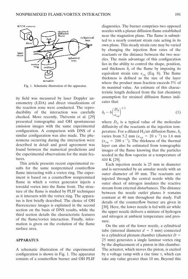
A schematic illustration of the experimentalconfiguration is shown in Fig. 1. The apparatusconsists of a counterflow burner and OH PLIF
diagnostics. The burner comprises two opposednozzles with a planar diffusion flame establishednear the stagnation plane. The flame is submit-ted to a nearly constant strain rate acting in itsown plane. This steady strain rate may be variedby changing the injection flow rates of thereactants or the distance between the two noz-zles. The main advantage of this configurationlies in the ability to control the shape, position,and thickness df of the flame by imposing itsequivalent strain rate «eq (Eq. 8). The flamethickness is defined as the size of the layerwhere the product mass fraction exceeds 5% ofits maximal value. An estimate of this charac-teristic length deduced from the fast chemistryassumption for strained diffusion flames indi-cates that:
df , 6SD0
«eqD1/ 2
(1)
where D0 is a typical value of the moleculardiffusivity of the reactants at the injection tem-perature. For a diluted H2/air diffusion flame, df
varies from 5.2 mm («eq 5 20 s21) to 1.6 mm(«eq 5 200 s21). The thickness of the thermallayer can also be estimated from tomographicimages of the flame knowing that the particlesseeded in the flow vaporize at a temperature of410 K [29].
Each injection nozzle is 25 mm in diameterand is surrounded by an annular nozzle with anouter diameter of 49 mm. The reactants areinjected through the central nozzle while theouter sheet of nitrogen insulates the reactivestream from external disturbances. The distancebetween the nozzle outlet planes b remainsconstant at 40 mm throughout the study. Fulldetails of the counterflow burner are given in[30]. Here, the lower nozzle is fed with air whilethe upper nozzle delivers a mixture of hydrogenand nitrogen at ambient temperature and pres-sure.
On the axis of the lower nozzle, a cylindricaltube (internal diameter d 5 5 mm) connectedto a cylindrical plenum chamber (diameter D 525 mm) generates a single laminar vortex ringby the displacement of a piston in this chamber.The actuator, which moves the piston, is excitedby a voltage ramp with a rise time tr which cantake any value greater than 10 ms. Beyond this
Fig. 1. Schematic illustration of the apparatus.
191NONPREMIXED FLAME/VORTEX INTERACTION
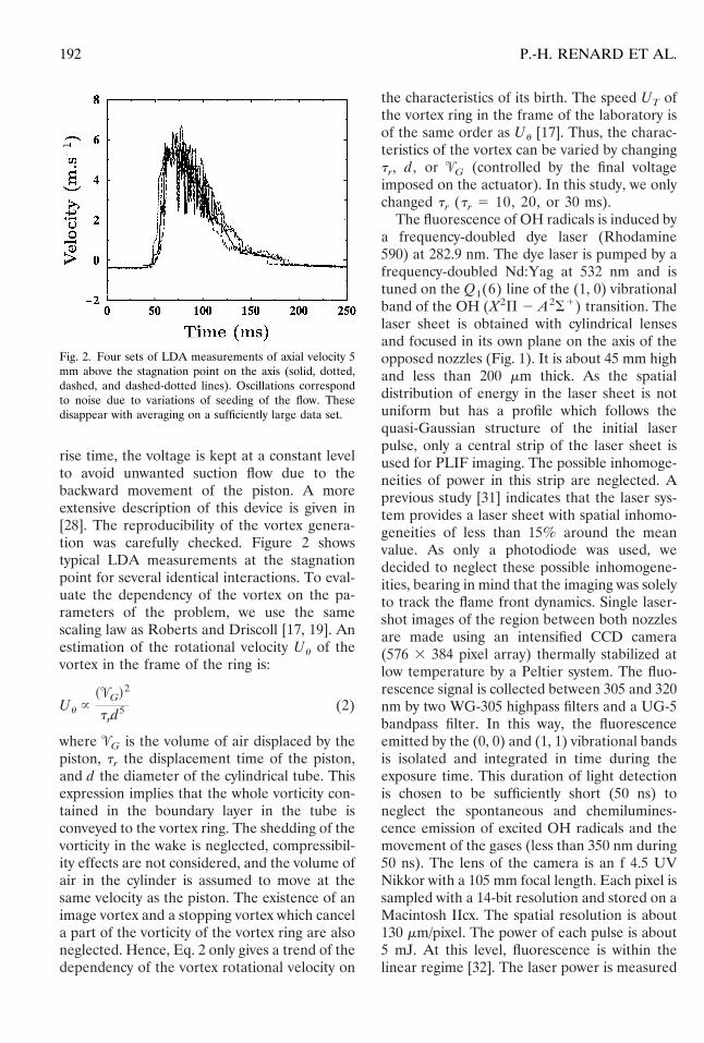
rise time, the voltage is kept at a constant levelto avoid unwanted suction flow due to thebackward movement of the piston. A moreextensive description of this device is given in[28]. The reproducibility of the vortex genera-tion was carefully checked. Figure 2 showstypical LDA measurements at the stagnationpoint for several identical interactions. To eval-uate the dependency of the vortex on the pa-rameters of the problem, we use the samescaling law as Roberts and Driscoll [17, 19]. Anestimation of the rotational velocity Uu of thevortex in the frame of the ring is:
Uu }~9G!2
trd5 (2)
where 9G is the volume of air displaced by thepiston, tr the displacement time of the piston,and d the diameter of the cylindrical tube. Thisexpression implies that the whole vorticity con-tained in the boundary layer in the tube isconveyed to the vortex ring. The shedding of thevorticity in the wake is neglected, compressibil-ity effects are not considered, and the volume ofair in the cylinder is assumed to move at thesame velocity as the piston. The existence of animage vortex and a stopping vortex which cancela part of the vorticity of the vortex ring are alsoneglected. Hence, Eq. 2 only gives a trend of thedependency of the vortex rotational velocity on
the characteristics of its birth. The speed UT ofthe vortex ring in the frame of the laboratory isof the same order as Uu [17]. Thus, the charac-teristics of the vortex can be varied by changingtr, d, or 9G (controlled by the final voltageimposed on the actuator). In this study, we onlychanged tr (tr 5 10, 20, or 30 ms).
The fluorescence of OH radicals is induced bya frequency-doubled dye laser (Rhodamine590) at 282.9 nm. The dye laser is pumped by afrequency-doubled Nd:Yag at 532 nm and istuned on the Q1(6) line of the (1, 0) vibrationalband of the OH (X2P 2 A2S1) transition. Thelaser sheet is obtained with cylindrical lensesand focused in its own plane on the axis of theopposed nozzles (Fig. 1). It is about 45 mm highand less than 200 mm thick. As the spatialdistribution of energy in the laser sheet is notuniform but has a profile which follows thequasi-Gaussian structure of the initial laserpulse, only a central strip of the laser sheet isused for PLIF imaging. The possible inhomoge-neities of power in this strip are neglected. Aprevious study [31] indicates that the laser sys-tem provides a laser sheet with spatial inhomo-geneities of less than 15% around the meanvalue. As only a photodiode was used, wedecided to neglect these possible inhomogene-ities, bearing in mind that the imaging was solelyto track the flame front dynamics. Single laser-shot images of the region between both nozzlesare made using an intensified CCD camera(576 3 384 pixel array) thermally stabilized atlow temperature by a Peltier system. The fluo-rescence signal is collected between 305 and 320nm by two WG-305 highpass filters and a UG-5bandpass filter. In this way, the fluorescenceemitted by the (0, 0) and (1, 1) vibrational bandsis isolated and integrated in time during theexposure time. This duration of light detectionis chosen to be sufficiently short (50 ns) toneglect the spontaneous and chemilumines-cence emission of excited OH radicals and themovement of the gases (less than 350 nm during50 ns). The lens of the camera is an f 4.5 UVNikkor with a 105 mm focal length. Each pixel issampled with a 14-bit resolution and stored on aMacintosh IIcx. The spatial resolution is about130 mm/pixel. The power of each pulse is about5 mJ. At this level, fluorescence is within thelinear regime [32]. The laser power is measured
Fig. 2. Four sets of LDA measurements of axial velocity 5mm above the stagnation point on the axis (solid, dotted,dashed, and dashed-dotted lines). Oscillations correspondto noise due to variations of seeding of the flow. Thesedisappear with averaging on a sufficiently large data set.
192 P.-H. RENARD ET AL.

by the photodiode from shot to shot to controlthe stability of the laser emission and to nor-malize the measurements. To avoid effects ofpossible laser sheet inhomogeneities, imagescorresponding to different instants are normal-ized by the highest signal measured in theundisturbed part of the flame. The result issampled on a 26 colorscale. No numerical filter-ing is applied to the images at this point. Thesignal-to-noise ratio is defined as:
SNR 5 20 log S Imax
IminD (3)
where Imax (resp. Imin) is the maximal (resp.minimal) pixel value in the image. SNR isalways greater than 30 dB.
Experiments were conducted as follows. Asteady flame is first established and then at aselected instant t0, a toroidal vortex is impul-sively injected by the action of the piston. Thevortex ring rapidly accelerates towards theflame. At the same time t0, the shutter of theICCD camera is opened. At a well-definedinstant t1 $ t0, a single shot of the laser sheet isemitted. The image is transferred and stored ona magneto-optical disk. As the experiment isperfectly reproducible, the whole time sequenceof the interaction can be followed by choosingdifferent instants t1.
PHYSICAL INTERPRETATION OF THE OHFLUORESCENCE IMAGES
The reaction zone structure is monitored byimaging OH fluorescence during the interactionwith the vortex ring. Under certain conditions,the fluorescence signal may be considered to beproportional to the concentration of OH radi-cals. This is achieved as follows. An isolated lineis chosen to ensure a proper selection of thetransition excited by the laser [32]. The transi-tion probability of the excited line must bestrong enough to allow highly efficient fluores-cence processes without excessive absorption.In addition, the initial ro-vibrational level pop-ulation must be as insensitive as possible totemperature variations. Finally, the excitationline and the spectral window of fluorescencecollection must be shifted from each other toavoid interference with Rayleigh scattering and
possible light scattering on the laser optics. TheQ1(6) line of the (1, 0) vibrational band of theOH (X2P 2 A2S1) transition satisfies theprevious conditions. It also involves a nonpre-dissociative state (v9 # 1). It is known fromprevious work that collisional processes can beassumed to be homogeneous across a counter-flow hydrogen/air flame [32]. The quenchingmodel proposed by Paul [33] is used to describequenching processes implied in the transition(X2P 2 A2S1) of OH radicals. A large part ofPaul’s study compared predicted and measuredcross sections and showed the model to beaccurate except for nitrogen molecules. A crosssection of 0.64 Å was assigned to this species onthe basis of previous experimental works [34–36]. We assumed that this cross section is con-stant in a counterflow flame as its behavior isnot well-known. Paul’s work mainly concernsthe determination of OH quenching from v9 50. But the structure similarity of v9 5 0 and v95 1 suggests a similar quenching behavior andexperimental results show that the quenchingrates of A2S1 (v9 5 1) and (v9 5 0) are nearlythe same [37]. Knowing that the populationtransfer toward vibrational states v9 $ 2 isnegligible, the whole quenching of excited stateA2S1 can be estimated [32]. The results showthat quenching is nearly constant (the variationsare less than 5% around the mean value) in theflame front for not too small values of [OH] andmoderate values of global mixture ratio (f # 1).Thus, assuming that the collisional processesdepending here mainly on the local compositionare homogeneous across the flame and theabsorption is negligible, the OH fluorescencesignal scales linearly with the OH radical con-centration.
The interpretation of the fluorescence imagesis greatly facilitated by examining direct numer-ical simulations. Typical calculations are re-ported in Thevenin et al. [29]. These use de-tailed chemistry to simulate a nonpremixedflame/vortex pair interaction. The main differ-ences with the experiment are that there is nocounterflow in the calculations and the config-uration is two-dimensional. Results can be usedto verify that low OH emission is limited to lowheat release rate zones and to check the rele-vance of using OH as a dye of the reaction zone.The code solves the full time-dependent Navier-
193NONPREMIXED FLAME/VORTEX INTERACTION
Stokes equations to describe all existing timeand length scales associated with the configura-tion studied. Detailed models provide the ther-modynamic functions, and multicomponenttransport algorithms describe diffusion pro-cesses. The chemical scheme consists of 9 spe-cies and 19 reversible reactions [38]. The inte-gration in time is performed by a fourth-orderRunge-Kutta solver and the spatial derivativesare calculated using sixth-order central approx-imations [29]. The chemical heat release rate isdefined as:
v 5 Ok51
Ns
hkWkvk (4)
where Ns is the number of species, hk is thespecific enthalpy of the kth species, Wk itsmolecular weight, and vk its molar productionrate. The characteristic speed of the vortex isfairly different in the experiment (about3 m.s21) and in the simulation (about 23 m.s21).This stems from the fact that the calculationcost is proportional to the interaction durationsimulated. Hence, the numerical study is re-stricted to high-speed vortices. It is reasonableto think that chemical phenomena occurring ina high-speed vortex/flame interaction occur alsoin a low-speed one, as physical time scales arelarger in the latter. Efforts are currently focusedon the reduction of the central processing unit(CPU) time cost. Recent results tend to provethat all the conclusions made with the presentsimulations remain valid for slower vortices. Anexample of interaction is given in Fig. 3. Wenow check that OH can be used in our case as atracer of the reaction zone.
To achieve this, a passive scalar Z is calcu-lated from the DNS results as:
Z 5
fYH2
YH20
2YO2
YO20
1 1
1 1 f(5)
where f is the global mixture ratio (Eq. 9) andYH20
(resp. YO20) the H2 (resp. O2) mass fraction
at the exit of the nozzles. The time t0 is the timewhen the vortex pair is impulsively started(here, t0 5 0.4 ms). We then consider the timeevolution of some important quantities alongthe symmetry line, in particular, the maximal
mass fractions of transient species O, H, OH,HO2, and H2O2, normalized by their initialvalue, in Figs. 4 and 5. Corresponding results for
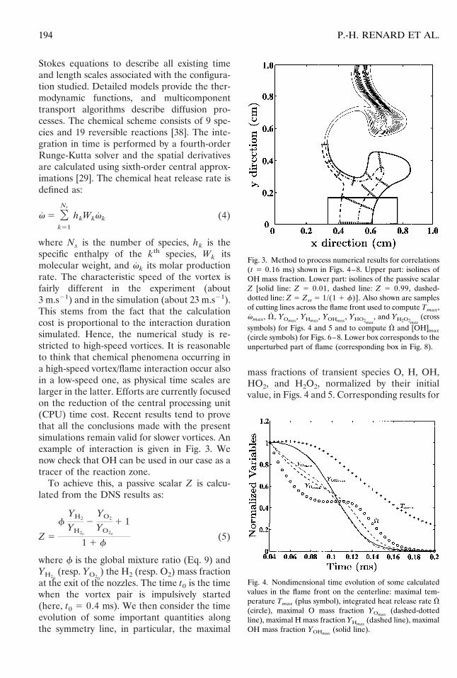
Fig. 3. Method to process numerical results for correlations(t 5 0.16 ms) shown in Figs. 4–8. Upper part: isolines ofOH mass fraction. Lower part: isolines of the passive scalarZ [solid line: Z 5 0.01, dashed line: Z 5 0.99, dashed-dotted line: Z 5 Zst 5 1/(1 1 f)]. Also shown are samplesof cutting lines across the flame front used to compute Tmax,vmax, V, YOmax
, YHmax, YOHmax
, YHO2max, and YH2O2max
(crosssymbols) for Figs. 4 and 5 and to compute V and [OH]max
(circle symbols) for Figs. 6–8. Lower box corresponds to theunperturbed part of flame (corresponding box in Fig. 8).
Fig. 4. Nondimensional time evolution of some calculatedvalues in the flame front on the centerline: maximal tem-perature Tmax (plus symbol), integrated heat release rate V(circle), maximal O mass fraction YOmax
(dashed-dottedline), maximal H mass fraction YHmax
(dashed line), maximalOH mass fraction YOHmax
(solid line).
194 P.-H. RENARD ET AL.

the normalized maximal temperature Tmax/(Tmax)t5t0
and maximal local heat release ratevmax/(vmax)t5t0
along the symmetry line arealso given in Fig. 4. To obtain a global picture ofthe reaction intensity along the flame front, theintegrated heat release rate V was computed,for values of Z corresponding to 0.01 # Z #0.99, leading to:
V 5 EZ50.01
Z50.99
v~Z! dl~Z! (6)
where l(Z) is the curvilinear abscissa on circlesymbol lines (Fig. 3). The time evolution of V/(V)t5t0 is also shown in Fig. 4. This parameter isthe best indicator of flame element activity orextinction. We therefore wish to find a chemicalspecies showing a behavior similar to V. Ofcourse, the results presented might depend on thereaction scheme and just reveal general trends.
Two sets of curves appear in these figures:one set is of the maximal temperature type: theirevolution is more similar to the behavior ofTmax. In this category, we find the maximaltemperature and also the maximal OH, O, andH mass fractions (Fig. 4). The other set is of themaximal heat release rate type, showing a char-acteristic peak at a later stage in the interaction.The maximal mass fractions of H2O2 and HO2fall into this last category (Fig. 5). The heat
release rate integrated across the flame front Vhas an intermediate behavior and remains at aconstant level for a while because of competingmechanisms. The maximal reaction rate growsas the flame becomes thinner.
In the first set (OH, O, and H), all massfractions are decreasing with time and OH, O,and H are sensitive to temperature as they areproducts of dissociation reactions (they havealmost disappeared when the temperature islower than 800 K). The H atom time evolutionis the closest to that of V. Unfortunately, thisspecies cannot be measured easily. In the sameway, O is relevant enough as it predicts theinitial fall of V when the vortex pair is startedbut it is also not easily detected. The behavior ofOH, though not identical to that of V still showssimilar trends, making it appropriate enough todetect an active reaction zone or an extinction.Moreover, OH can be measured with goodaccuracy, making it the best compromise whencompared with H and O radicals. Hence, OHcan be used as an approximate tracer of theintegrated heat release rate, and hence of thereaction zone.
For the second set, H2O2 and HO2 speciesneed much energy to be formed (high reactionrate). These transient species only exist in thereactive layer, contrary to OH which may persistin hot gases. However, their relaxation time istoo large: when both maximal and integratedheat release rates become nearly zero, YH2O2max
and YHO2maxhave only fallen back to their initial
value before the interaction. Moreover, thelocal heat release rate is not a very good markerof the reaction activity: the heat release rate canbe locally very high but for an extremely thinflame about to extinguish. Our goal is here todetect a local extinction characterized by aglobal fall of the reaction rate across the flamefront, which implies a low value of V and not ofv. Thus, the OH radical is best suited for thispurpose: its LIF response is well known and noother transient species appears to be simulta-neously more appropriate and detectable.
To characterize an extinction criterion, a cor-relation between the OH concentration and theheat release rate is numerically computed. TheOH concentration is preferred to OH massfraction because the fluorescence signal is pro-
Fig. 5. Nondimensional time evolution of some calculatedvalues in the flame front on the centerline: maximal heatrelease rate vmax (circle), maximal HO2 mass fractionYHO2max
(dashed line), and maximal H2O2 mass fractionYH2O2max
(dashed-dotted line).
195NONPREMIXED FLAME/VORTEX INTERACTION

portional to the local concentration. It is com-puted in the DNS calculations from:
[OH] 5 rYOH
WOH(7)
where r is the density and YOH is the OH massfraction. We first compute the field of thepassive scalar Z (Eq. 5). Then, the curve Z 5Zst corresponding to the stoichiometric leveland (grad Z)st are computed. This gradientallows the determination of segments normal tothe curve Z 5 Zst which are bounded by Z 50.01 and Z 5 0.99 or a local minimum of Z toavoid cutting the flame front twice (Fig. 3).Finally, the integrated value of heat release rateV and the maximal value of OH concentration[OH]max are calculated on each of these seg-ments. Plots of [OH]max vs. V along the per-turbed flame front are drawn for three differentinstants (t 5 0.1, 0.12, and 0.16 ms) with fixedscales for all plots (Figs. 6–8).
At t 5 0.1 ms, the vortex pair cores are in theplane of the flame (Fig. 6). Symbols begin tospread towards low values of both [OH]max andV. This phenomenon becomes more importantwith time in proportion, as the vortex piercesthe flame. In addition, the maximum of Vincreases because of the high strain rate in-duced by the vortex which enhances the chem-ical reaction: if the velocity field induced by thetoroidal vortex is considered in a moving frame
attached to the ring, then its forward and rear-ward parts can be likened to a counterflow [39].When the vortex ring is passing through theflame, the forward part increases the strain ratelocally whereas the rearward part decreases it.The temperature decreases and the heat releaserate increases in the forward part, whereas thecontrary occurs in the rearward part [40]. Be-sides, the abscissa [OH]max
M associated with themaximum of V decreases with time as the zonewhere the reaction is the most intense consumesreactants more rapidly. It can be noticed thatthe part of the scatter plot where the density ofcircles is highest corresponds to the undisturbedpart of the flame (shown as the circles inside theboxes in Figs. 6–8). At t 5 0.12 ms, a suddenbreak occurs in the curve (Fig. 7). This corre-sponds to a drop in the heat release rate forvalues of [OH]max close to [OH]max
M . This ischaracteristic of the extinction taking place atthe top of the flame. The interval of [OH]max
corresponding to this fall widens with time andis combined with a constant value of the maxi-mum of V. This confirms the existence of anextinction: the large heat release rate is con-fined to a small region surrounded by a no-reaction zone. Another clue concerning thequenching is the appearance of temperaturesless than 1200 K (corresponding symbols arecrosses, while points with T $ 1200 K are stillrepresented by circles) in the flame front after
Fig. 6. Instantaneous correlations from computations alongflame front between maximal OH concentration [OH]max
and integrated heat release rate V. t 5 0.1 ms. Enclosedcircle symbols correspond to the undisturbed part of theflame.
Fig. 7. Instantaneous correlations from computations alongflame front between maximal OH concentration [OH]max
and integrated heat release rate V. t 5 0.12 ms. Enclosedcircle symbols correspond to the undisturbed part of theflame.
196 P.-H. RENARD ET AL.
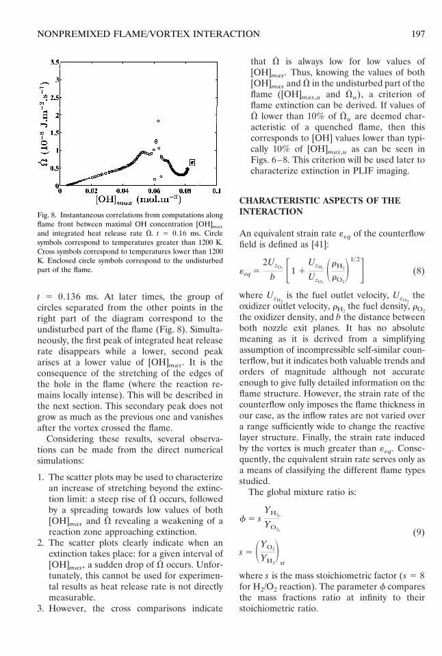
t 5 0.136 ms. At later times, the group ofcircles separated from the other points in theright part of the diagram correspond to theundisturbed part of the flame (Fig. 8). Simulta-neously, the first peak of integrated heat releaserate disappears while a lower, second peakarises at a lower value of [OH]max. It is theconsequence of the stretching of the edges ofthe hole in the flame (where the reaction re-mains locally intense). This will be described inthe next section. This secondary peak does notgrow as much as the previous one and vanishesafter the vortex crossed the flame.
Considering these results, several observa-tions can be made from the direct numericalsimulations:
1. The scatter plots may be used to characterizean increase of stretching beyond the extinc-tion limit: a steep rise of V occurs, followedby a spreading towards low values of both[OH]max and V revealing a weakening of areaction zone approaching extinction.
2. The scatter plots clearly indicate when anextinction takes place: for a given interval of[OH]max, a sudden drop of V occurs. Unfor-tunately, this cannot be used for experimen-tal results as heat release rate is not directlymeasurable.
3. However, the cross comparisons indicate
that V is always low for low values of[OH]max. Thus, knowing the values of both[OH]max and V in the undisturbed part of theflame ([OH]max,u and Vu), a criterion offlame extinction can be derived. If values ofV lower than 10% of Vu are deemed char-acteristic of a quenched flame, then thiscorresponds to [OH] values lower than typi-cally 10% of [OH]max,u as can be seen inFigs. 6–8. This criterion will be used later tocharacterize extinction in PLIF imaging.
CHARACTERISTIC ASPECTS OF THEINTERACTION
An equivalent strain rate «eq of the counterflowfield is defined as [41]:
«eq 52UzO2
b F1 1UzH2
UzO2
SrH2
rO2
D1/ 2G (8)
where UzH2is the fuel outlet velocity, UzO2
theoxidizer outlet velocity, rH2
the fuel density, rO2
the oxidizer density, and b the distance betweenboth nozzle exit planes. It has no absolutemeaning as it is derived from a simplifyingassumption of incompressible self-similar coun-terflow, but it indicates both valuable trends andorders of magnitude although not accurateenough to give fully detailed information on theflame structure. However, the strain rate of thecounterflow only imposes the flame thickness inour case, as the inflow rates are not varied overa range sufficiently wide to change the reactivelayer structure. Finally, the strain rate inducedby the vortex is much greater than «eq. Conse-quently, the equivalent strain rate serves only asa means of classifying the different flame typesstudied.
The global mixture ratio is:
f 5 sYH20
YO20 (9)
s 5 SYO2
YH2
Dst
where s is the mass stoichiometric factor (s 5 8for H2/O2 reaction). The parameter f comparesthe mass fractions ratio at infinity to theirstoichiometric ratio.
Fig. 8. Instantaneous correlations from computations alongflame front between maximal OH concentration [OH]max
and integrated heat release rate V. t 5 0.16 ms. Circlesymbols correspond to temperatures greater than 1200 K.Cross symbols correspond to temperatures lower than 1200K. Enclosed circle symbols correspond to the undisturbedpart of the flame.
197NONPREMIXED FLAME/VORTEX INTERACTION

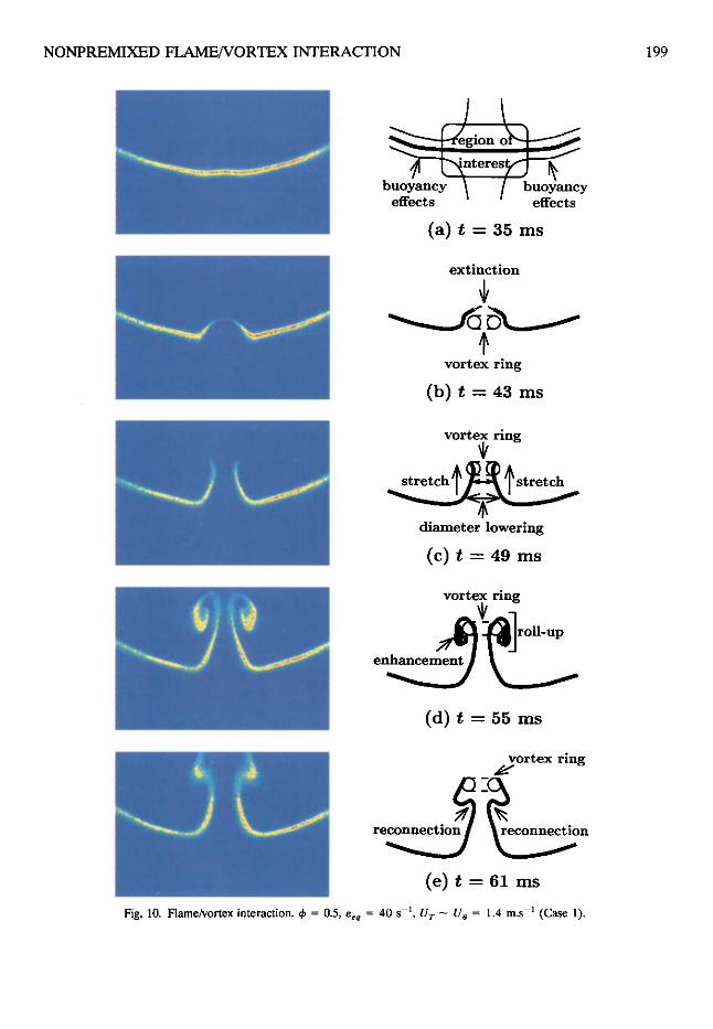
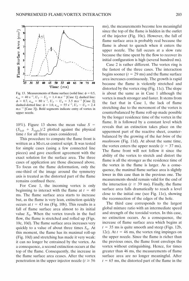
Three sequences (Case 1, 2, and 3) are pre-sented to show the main features of the inter-action. Experimental conditions are given inTable 1. The different regions of the flameduring the interaction are defined in Fig. 9. ForCase 1, a sequence of images is shown in Fig. 10.A counterflow velocity field corresponding to aninitial equivalent strain rate «eq of about 40 s21
is used, yielding a flame thickness of about 4mm, as can be seen in the tomographic imagesof [29]. The vortex ring diameter dvr is of thesame order of magnitude as the diameter d ofthe cylindrical tube and the global mixture ratiof is equal to 0.5. The actuator is excited with adisplacement time tr 5 30 ms. The maximalrotational velocity of the vortices is estimated inthis case to be about 3 m.s21. This is the slowestand the weakest vortex of the three cases, but is
also the weakest flame as the global mixtureratio is quite small.
The undisturbed strained laminar flame,shown in Fig. 10a, is slightly curved due tobuoyancy. The region of interest is close to thestagnation point (where the interaction occurs),which can be considered to be planar. Figure10b shows the vortex impinging on the flame.This flame is lean enough to be quenched evenby a very weak vortex (tr 5 30 ms). The vortexthereafter widens the hole due to quenching,traverses the flame and stretches the edges ofthe hole. This is due to the inner flow producedat the center of the vortex ring. As the vortexprogresses, it lowers the diameter of the hole bystretching the flame upwards (Fig. 10c). As therotational velocity is about twice the speed ofthe vortex, the flame front is convected throughthe vortex ring and then rolled up around thevortex core. Simultaneously, the reaction rate isenhanced. Species diffusion and heat releasethen prevent the flame front from rolling upmore than one turn (Fig. 10d). Finally, thetruncated cone formed by the crossing of thevortex through the flame reconnects with theouter reacting ring left behind by the vortex(Fig. 10e). Examination of the OH images inthis case shows that moderate strain rates firstenhance the reaction rate and that high strainrates can lead to local flame extinction when acritical value is exceeded.
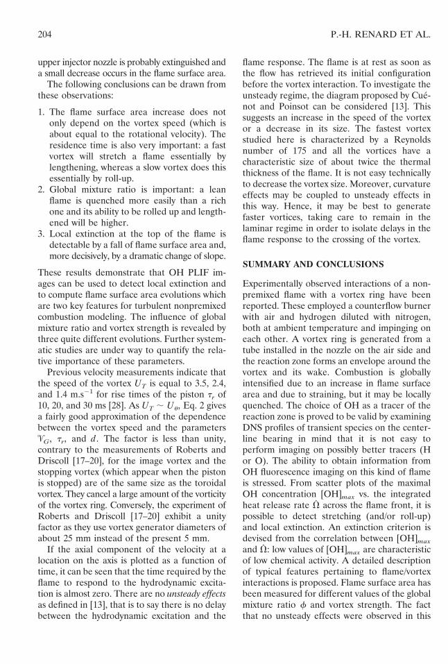
Case 2 is shown in Fig. 11. The equivalentstrain rate «eq is about 80 s21, the global mixtureratio f 5 0.7, and the rise time tr 5 10 ms. Theundisturbed flame is slightly different from theone of the first case (Fig. 11a), as the strain rateis now higher. When the vortex impinges on theflame, extinction takes more time than in theprevious sequence because the flame is muchstronger (f 5 0.7). However, the reaction rateis clearly reduced at the top of the flamebecause of the high strain rate induced by thevortex ring, and extinction does occur later. Thereaction rate is also diminishing at the bottomof the dome perhaps because of the high localcurvature of the reaction sheet (Fig. 11b). Asthe hat formed by the flame is not torn apart bythe inner flow created by the vortex ring (thevelocity there is about twice the speed of thevortex core), it moves with the vortex ring andwidens. Meanwhile, the reaction rate falls in the
TABLE 1
Conditions of Flame/Vortex Interactions Experiments
Case 1 Case 2 Case 3
Hydrogen mass fraction,YH2
0.015 0.020 0.029
Oxygen mass fraction,YO2
0.233 0.233 0.233
Global mixture ratio, f 0.5 0.7 1.0Fuel flow velocity, UzH2
(m.s21)0.459 0.977 0.710
Oxidizer flow velocity,UzO2 (m.s21)
0.375 0.750 0.500
Estimated strain rate,«eq (s21)
40 80 55
Vortex ring diameter, dvr
(mm)5 5 5
Rise time of the piston,tr (ms)
30 10 20
Speed of the vortex, UT
(;Uu) (m.s21)1.4 3.5 2.4
Fig. 9. Definitions of some qualitative features in flame/vortex interactions.
198 P.-H. RENARD ET AL.
NONPREMIXED F L A M E N O R T E X INTERACTION 199
/ , \ .~ r~ ~
3
( a ) t = 3 5 m s
ext inc t ion
v o r t e x r i n g
( b ) t : 4 3 m s
vor tex r ing
d i a m e t e r l o w e r i n g
( c ) t ---- 4 9 m s
vor tex r ing
~ l r ° l l ' u p
( d ) t = 5 5 m s
v o r t e x r i n g
r n
( e ) t = 6 1 m s
Fig. 10. FlameA, o n e x interaction, tb = 0.5, e,q = 40 s 1, Ur - Us = 1.4 m.s 1 (Case 1).

200 P.-H. RENARD ET AL.
. ~ ° ' "
••egion o ~ ~ ~"~n te r e s~ f~ - -~
buoyancy \ / buoyancy effects effects
( a ) t = 2 7 m s
vortex ring
j
decrease
( b ) t = 3 1 m s
slow extinction
increase . ~ - - -~ ' - vortex ring s ~ ~[-~" increase
( c ) t = 3 5 m s
slow ~ , . vortex ring
( d ) t = 3 9 m s
vortex ring (~_ - 0
b reakY I V h~at~brim
( e ) t - - 4 3 m s
Fig. 11. FlameA, ortcx interaction. ~ = 0.7, eeq = 80 s -1, UT -- Uo ffi 3.5 m.s -1 (Case 2).

NONTREMIXED FLAME/VORTEX INTERACTION 201
••egion o ~ ~ ~ - - ~ n t e r e s ~ J - - - ~
buoyancy X [ buoyancy effects effects
( a ) t = 3 0 m s
distortion vortex ring
( b ) t = 4 0 m s
enhancement vortex ring
lowering
( c ) t = 4 4 m s
vortex ring attrel~Putpt° [ ~ ~
( d ) t = 4 8 m s
G--Ox " vortex ring
slow F X [
( e ) t = 5 2 m s
Fig. 12. Flame/vortex interaction. ~b = 1.0, eeq = 55 s -I, Ur ~ Uo = 2.4 m.s -1 (Case 3).
front part and the flame is locally quenched.The base of the mushroom goes on shrinkingwith time. In contrast, the reaction rate isenhanced in the top part of the foot and theflame widens there (Fig. 11c). When the vortexring enters the upper nozzle, the top of theflame is totally quenched and the side sheets ofthe hat merge. At the same time, the foot of themushroom becomes slimmer (Fig. 11d). Finally,the hat brim is left by the vortex, the hatseparates from the reconnected flame and thewhole mushroom breaks down (Fig. 11e).
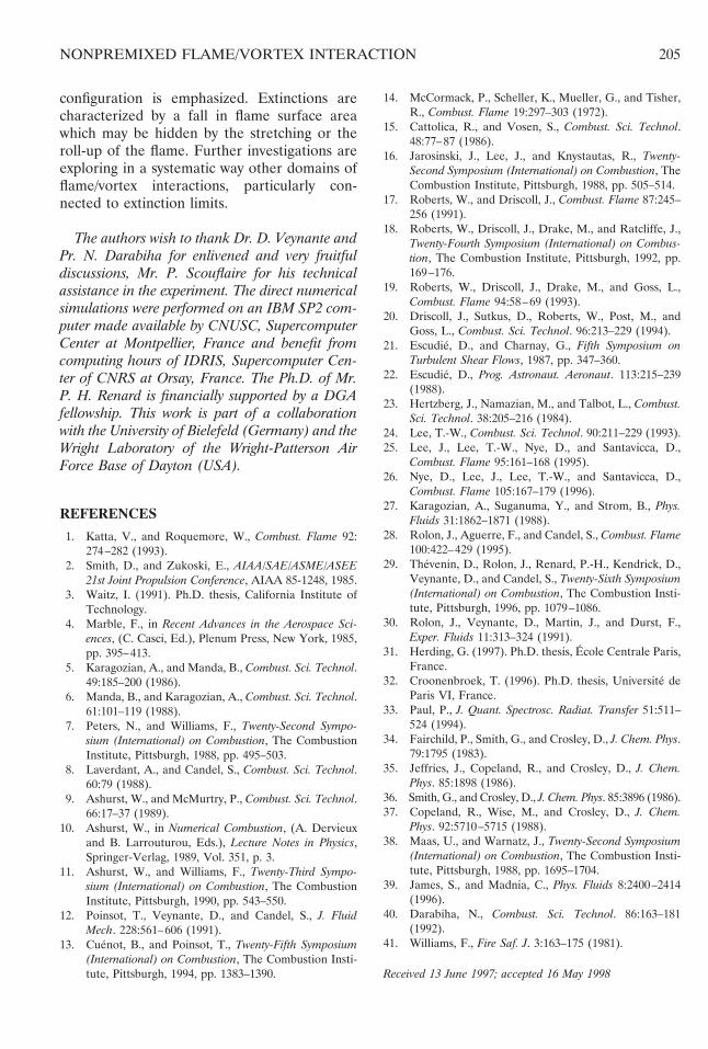
Case 3 is shown in Fig. 12. This involves aflame of unity global mixture ratio (f 5 1) andequivalent strain rate of about 55 s21 (Fig. 12a).The vortex ring is generated with a rise timetr 5 20 ms. No quenching at all occurs herebecause the flame is not lean enough and thevortex is relatively weak. The flame is onlydistorted by the crossing of the vortex (Fig.12b). Also, there is an enhancement of thereaction rate in the upper part of the foot of themushroom while it is reduced at the bottom of it(Fig. 12c). The vortex ring attempts to roll upthe hat of the mushroom while the wake of thevortex induces a thickening of the foot sidestructure (Fig. 12d). The vortex is not strongenough to significantly alter the top of theflame, so the mushroom slowly breaks up in asimilar way to that observed in Case 2 (Fig.12e). In Cases 2 and 3, a thickening of the wallof the mushroom foot occurs while the footsection decreases. There is probably a regionbehind the vortex where the products stagnate.This would explain why the widening of themushroom sides increases with the global mix-ture ratio: for a diffusion flame, the limitingfactor is the reactant, which is lacking. As aconsequence, the OH concentration is maxi-mal in the burnt gas when f 5 1 for a givenamount of reactants. It would explain why[OH] is not as high in this zone as in the restof the flame front. The OH molecules in thewake are mostly present because of the hightemperature of the reaction products and thechemical activity is low there. It would beinteresting to obtain temperature measure-ments (Rayleigh scattering, for example) toconfirm this hypothesis.
MEASUREMENTS OF FLAME SURFACEUSING PLIF IMAGES
The flame surface may be deduced from the OHfluorescence images because OH has beenshown to be a good tracer of the reaction zone.First, a 7 3 7 averaging filter is applied to theraw image in order to remove the backgroundnoise and smooth the flame front profile. Thisdoes not significantly modify the shape of thereactive sheet, as the flame is always at least 30pixels wide. The picture is split in two parts, thesplitting line being the symmetry axis of theburner, and both half-images are analyzed sep-arately. Each image of the same time sequenceis first normalized by the maximal intensityvalue in the undisturbed part of the flame. Thisis introduced to remove laser inhomogeneitieswhich might degrade the measurements. Thecorrection induced by this normalization is lim-ited to less than 10%. The contour correspond-ing to our definition of the flame is extracted,i.e., the zone where the OH concentration isabove 10% of the maximal concentration in theundisturbed part of the flame. In connectionwith DNS results, this contour should be asso-ciated with integrated heat release rates at leastequal to 10% of the maximal integrated heatrelease rate in the undisturbed part of the flameduring the interaction. Tests with other values ofthe extinction parameters show identical trends.
The corresponding contours are discretizedinto a few hundreds of small segments. For eachsegment, we determine the length Li and thedistance xGi
of its center of gravity to thesymmetry axis. One then applies the Guldintheorem to deduce the surface area Si gener-ated by the rotation of each segment of theflame front around the axis of symmetry:
Si 5 2pxGiLi (10)
As the extraction procedure generates a curvewhich encloses the flame front, the estimatedflame surface area is assumed to be equal to halfof the result found by summing the elementarysurface areas Si. As mentioned previously, thisprocedure is carried out independently on eachhalf-image, leading to two values Sleft and Sright
for the global flame surface area. The differencebetween both values is small (typically less than
202 P.-H. RENARD ET AL.
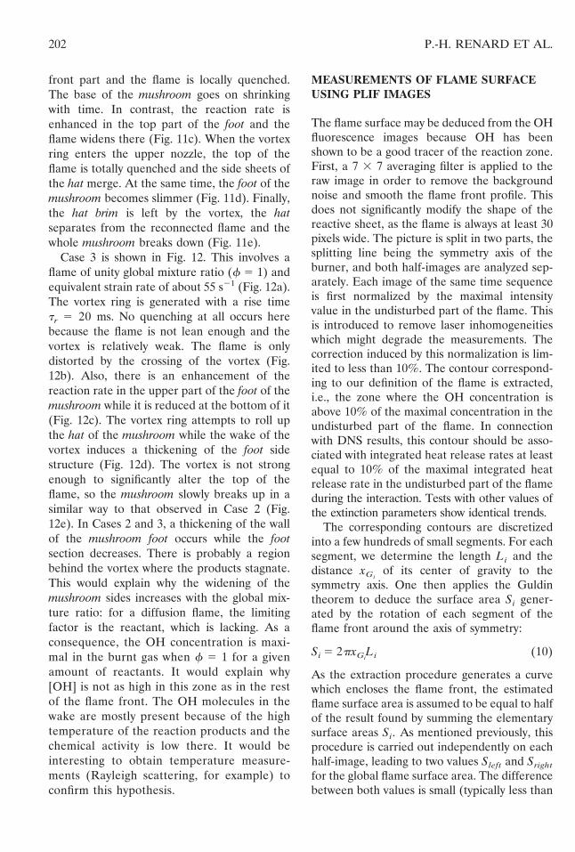
10%). Figure 13 shows the mean value S 5(Sleft 1 Sright)/ 2 plotted against the physicaltime t for all three cases considered.
This procedure to compute the flame front iswritten as a MATLAB control script. It was testedfor simple cases (using a few connected linepieces) and gave excellent agreement with theexact solution for the surface area. The threecases of application are those discussed above.To focus on the flame deformation, only theone-third of the image around the symmetryaxis is treated as the distorted part of the flameremains confined there.
For Case 1, the incoming vortex is onlybeginning to interact with the flame at t 5 40ms. The flame surface area starts to increasebut, as the flame is very lean, extinction quicklyoccurs at t 5 43 ms (Fig. 10b). This results in afall of flame surface area almost to its initialvalue S0. When the vortex travels in the fuelflow, the flame is stretched and rolled up (Figs.10c, 10d). The flame surface area increases veryquickly to a value of about three times S0. Atthis moment, the flame has its maximal roll-up(Fig. 10d) and stretching has made it very weak:it can no longer be entrained by the vortex. Asa consequence, a second extinction occurs at thetop of the flame. Consequently, the increase inthe flame surface area ceases. After the vortexpenetration in the upper injector nozzle (t $ 56
ms), the measurements become less meaningfulsince the top of the flame is hidden in the outletof the injector (Fig. 10e). However, the fall offlame surface area is probably real because theflame is about to quench when it enters theupper nozzle. The fall occurs at a slow ratebecause the time spent by the flow to recover itsinitial configuration is high (several hundred ms).
Case 2 is rather different. The vortex ring isthe fastest of the three cases. The interactionbegins sooner (t 5 29 ms) and the flame surfacearea increases continuously. The growth is rapidbecause the flame is violently stretched anddistorted by the vortex ring (Fig. 11c). The slopeis about the same as in Case 1 although thevortex is much stronger and faster. It stems fromthe fact that in Case 1, the lack of flamestretching due to the movement of the vortex iscounterbalanced by flame roll-up made possibleby the longer residence time of the vortex in theflame. It is followed by a constant level whichreveals that an extinction takes place on theuppermost part of the reactive sheet, counter-balanced by the growing of the hat brim of themushroom (Fig. 11d). At about the same time,the vortex enters the upper nozzle (t 5 37 ms).The flame front will not follow it since theability of the vortex to stretch and distort theflame is all the stronger as the residence time ofthe vortex in the flame is larger. As a conse-quence, the maximal flame surface area is slightlylower in this case than in the previous one. Themeasurements should remain valid for the end ofthe interaction (t $ 39 ms). Finally, the flamesurface area falls dramatically to reach a levelclose to the initial one (see Fig. 11e), showingthe reconnection of the edges of the hole.
The third case corresponds to the largestglobal mixture ratio with an intermediate speedand strength of the toroidal vortex. In this case,no extinction occurs. As a consequence, theincrease of flame surface area which begins att 5 35 ms is quite smooth and steep (Figs. 12b,12c). At t 5 46 ms, the vortex ring impinges onthe upper nozzle. Since the flame is richer thanthe previous ones, the flame front envelops thevortex without extinguishing. Hence, for timesgreater than 46 ms, the measurements of flamesurface area are no longer meaningful. Aftert 5 65 ms, the distorted part of the flame in the
Fig. 13. Measurements of flame surface (solid line: f 5 0.5,«eq 5 40 s21, UT ; Uu 5 1.4 m.s21 [Case 1]; dashed line:f 5 0.7, «eq 5 80 s21, UT ; Uu 5 3.5 m.s21 [Case 2];dashed-dotted line: f 5 1.0, «eq 5 55 s21, UT ; Uu 5 2.4m.s21 [Case 3]). Bold segments indicate entry of vortex inupper nozzle.
203NONPREMIXED FLAME/VORTEX INTERACTION
upper injector nozzle is probably extinguished anda small decrease occurs in the flame surface area.
The following conclusions can be drawn fromthese observations:
1. The flame surface area increase does notonly depend on the vortex speed (which isabout equal to the rotational velocity). Theresidence time is also very important: a fastvortex will stretch a flame essentially bylengthening, whereas a slow vortex does thisessentially by roll-up.
2. Global mixture ratio is important: a leanflame is quenched more easily than a richone and its ability to be rolled up and length-ened will be higher.
3. Local extinction at the top of the flame isdetectable by a fall of flame surface area and,more decisively, by a dramatic change of slope.
These results demonstrate that OH PLIF im-ages can be used to detect local extinction andto compute flame surface area evolutions whichare two key features for turbulent nonpremixedcombustion modeling. The influence of globalmixture ratio and vortex strength is revealed bythree quite different evolutions. Further system-atic studies are under way to quantify the rela-tive importance of these parameters.
Previous velocity measurements indicate thatthe speed of the vortex UT is equal to 3.5, 2.4,and 1.4 m.s21 for rise times of the piston tr of10, 20, and 30 ms [28]. As UT ; Uu, Eq. 2 givesa fairly good approximation of the dependencebetween the vortex speed and the parameters9G, tr, and d. The factor is less than unity,contrary to the measurements of Roberts andDriscoll [17–20], for the image vortex and thestopping vortex (which appear when the pistonis stopped) are of the same size as the toroidalvortex. They cancel a large amount of the vorticityof the vortex ring. Conversely, the experiment ofRoberts and Driscoll [17–20] exhibit a unityfactor as they use vortex generator diameters ofabout 25 mm instead of the present 5 mm.
If the axial component of the velocity at alocation on the axis is plotted as a function oftime, it can be seen that the time required by theflame to respond to the hydrodynamic excita-tion is almost zero. There are no unsteady effectsas defined in [13], that is to say there is no delaybetween the hydrodynamic excitation and the
flame response. The flame is at rest as soon asthe flow has retrieved its initial configurationbefore the vortex interaction. To investigate theunsteady regime, the diagram proposed by Cue-not and Poinsot can be considered [13]. Thissuggests an increase in the speed of the vortexor a decrease in its size. The fastest vortexstudied here is characterized by a Reynoldsnumber of 175 and all the vortices have acharacteristic size of about twice the thermalthickness of the flame. It is not easy technicallyto decrease the vortex size. Moreover, curvatureeffects may be coupled to unsteady effects inthis way. Hence, it may be best to generatefaster vortices, taking care to remain in thelaminar regime in order to isolate delays in theflame response to the crossing of the vortex.
SUMMARY AND CONCLUSIONS
Experimentally observed interactions of a non-premixed flame with a vortex ring have beenreported. These employed a counterflow burnerwith air and hydrogen diluted with nitrogen,both at ambient temperature and impinging oneach other. A vortex ring is generated from atube installed in the nozzle on the air side andthe reaction zone forms an envelope around thevortex and its wake. Combustion is globallyintensified due to an increase in flame surfacearea and due to straining, but it may be locallyquenched. The choice of OH as a tracer of thereaction zone is proved to be valid by examiningDNS profiles of transient species on the center-line bearing in mind that it is not easy toperform imaging on possibly better tracers (Hor O). The ability to obtain information fromOH fluorescence imaging on this kind of flameis stressed. From scatter plots of the maximalOH concentration [OH]max vs. the integratedheat release rate V across the flame front, it ispossible to detect stretching (and/or roll-up)and local extinction. An extinction criterion isdevised from the correlation between [OH]max
and V: low values of [OH]max are characteristicof low chemical activity. A detailed descriptionof typical features pertaining to flame/vortexinteractions is proposed. Flame surface area hasbeen measured for different values of the globalmixture ratio f and vortex strength. The factthat no unsteady effects were observed in this
204 P.-H. RENARD ET AL.
configuration is emphasized. Extinctions arecharacterized by a fall in flame surface areawhich may be hidden by the stretching or theroll-up of the flame. Further investigations areexploring in a systematic way other domains offlame/vortex interactions, particularly con-nected to extinction limits.
The authors wish to thank Dr. D. Veynante andPr. N. Darabiha for enlivened and very fruitfuldiscussions, Mr. P. Scouflaire for his technicalassistance in the experiment. The direct numericalsimulations were performed on an IBM SP2 com-puter made available by CNUSC, SupercomputerCenter at Montpellier, France and benefit fromcomputing hours of IDRIS, Supercomputer Cen-ter of CNRS at Orsay, France. The Ph.D. of Mr.P. H. Renard is financially supported by a DGAfellowship. This work is part of a collaborationwith the University of Bielefeld (Germany) and theWright Laboratory of the Wright-Patterson AirForce Base of Dayton (USA).
REFERENCES
1. Katta, V., and Roquemore, W., Combust. Flame 92:274–282 (1993).
2. Smith, D., and Zukoski, E., AIAA/SAE/ASME/ASEE21st Joint Propulsion Conference, AIAA 85-1248, 1985.
3. Waitz, I. (1991). Ph.D. thesis, California Institute ofTechnology.
4. Marble, F., in Recent Advances in the Aerospace Sci-ences, (C. Casci, Ed.), Plenum Press, New York, 1985,pp. 395–413.
5. Karagozian, A., and Manda, B., Combust. Sci. Technol.49:185–200 (1986).
6. Manda, B., and Karagozian, A., Combust. Sci. Technol.61:101–119 (1988).
7. Peters, N., and Williams, F., Twenty-Second Sympo-sium (International) on Combustion, The CombustionInstitute, Pittsburgh, 1988, pp. 495–503.
8. Laverdant, A., and Candel, S., Combust. Sci. Technol.60:79 (1988).
9. Ashurst, W., and McMurtry, P., Combust. Sci. Technol.66:17–37 (1989).
10. Ashurst, W., in Numerical Combustion, (A. Dervieuxand B. Larrouturou, Eds.), Lecture Notes in Physics,Springer-Verlag, 1989, Vol. 351, p. 3.
11. Ashurst, W., and Williams, F., Twenty-Third Sympo-sium (International) on Combustion, The CombustionInstitute, Pittsburgh, 1990, pp. 543–550.
12. Poinsot, T., Veynante, D., and Candel, S., J. FluidMech. 228:561–606 (1991).
13. Cuenot, B., and Poinsot, T., Twenty-Fifth Symposium(International) on Combustion, The Combustion Insti-tute, Pittsburgh, 1994, pp. 1383–1390.
14. McCormack, P., Scheller, K., Mueller, G., and Tisher,R., Combust. Flame 19:297–303 (1972).
15. Cattolica, R., and Vosen, S., Combust. Sci. Technol.48:77–87 (1986).
16. Jarosinski, J., Lee, J., and Knystautas, R., Twenty-Second Symposium (International) on Combustion, TheCombustion Institute, Pittsburgh, 1988, pp. 505–514.
17. Roberts, W., and Driscoll, J., Combust. Flame 87:245–256 (1991).
18. Roberts, W., Driscoll, J., Drake, M., and Ratcliffe, J.,Twenty-Fourth Symposium (International) on Combus-tion, The Combustion Institute, Pittsburgh, 1992, pp.169–176.
19. Roberts, W., Driscoll, J., Drake, M., and Goss, L.,Combust. Flame 94:58–69 (1993).
20. Driscoll, J., Sutkus, D., Roberts, W., Post, M., andGoss, L., Combust. Sci. Technol. 96:213–229 (1994).
21. Escudie, D., and Charnay, G., Fifth Symposium onTurbulent Shear Flows, 1987, pp. 347–360.
22. Escudie, D., Prog. Astronaut. Aeronaut. 113:215–239(1988).
23. Hertzberg, J., Namazian, M., and Talbot, L., Combust.Sci. Technol. 38:205–216 (1984).
24. Lee, T.-W., Combust. Sci. Technol. 90:211–229 (1993).25. Lee, J., Lee, T.-W., Nye, D., and Santavicca, D.,
Combust. Flame 95:161–168 (1995).26. Nye, D., Lee, J., Lee, T.-W., and Santavicca, D.,
Combust. Flame 105:167–179 (1996).27. Karagozian, A., Suganuma, Y., and Strom, B., Phys.
Fluids 31:1862–1871 (1988).28. Rolon, J., Aguerre, F., and Candel, S., Combust. Flame
100:422–429 (1995).29. Thevenin, D., Rolon, J., Renard, P.-H., Kendrick, D.,
Veynante, D., and Candel, S., Twenty-Sixth Symposium(International) on Combustion, The Combustion Insti-tute, Pittsburgh, 1996, pp. 1079–1086.
30. Rolon, J., Veynante, D., Martin, J., and Durst, F.,Exper. Fluids 11:313–324 (1991).
31. Herding, G. (1997). Ph.D. thesis, Ecole Centrale Paris,France.
32. Croonenbroek, T. (1996). Ph.D. thesis, Universite deParis VI, France.
33. Paul, P., J. Quant. Spectrosc. Radiat. Transfer 51:511–524 (1994).
34. Fairchild, P., Smith, G., and Crosley, D., J. Chem. Phys.79:1795 (1983).
35. Jeffries, J., Copeland, R., and Crosley, D., J. Chem.Phys. 85:1898 (1986).
36. Smith, G., and Crosley, D., J. Chem. Phys. 85:3896 (1986).37. Copeland, R., Wise, M., and Crosley, D., J. Chem.
Phys. 92:5710–5715 (1988).38. Maas, U., and Warnatz, J., Twenty-Second Symposium
(International) on Combustion, The Combustion Insti-tute, Pittsburgh, 1988, pp. 1695–1704.
39. James, S., and Madnia, C., Phys. Fluids 8:2400–2414(1996).
40. Darabiha, N., Combust. Sci. Technol. 86:163–181(1992).
41. Williams, F., Fire Saf. J. 3:163–175 (1981).
Received 13 June 1997; accepted 16 May 1998
205NONPREMIXED FLAME/VORTEX INTERACTION