Introductory Tutorial MicroTCA Management - DESY Indico
50
MTCA Workshop for Industry and Research MTCA Workshop for Industry and Research Dariusz Makowski, Hamburg 09.12.2014 Dariusz Makowski, Hamburg 09.12.2014 MicroTCA Management Dariusz Makowski [email protected] [email protected] Introductory Tutorial MicroTCA Management
-
Upload
khangminh22 -
Category
Documents
-
view
1 -
download
0
Transcript of Introductory Tutorial MicroTCA Management - DESY Indico

MTCA Workshop for Industry and Research MTCA Workshop for Industry and Research Dariusz Makowski, Hamburg 09.12.2014 Dariusz Makowski, Hamburg 09.12.2014
MicroTCA Management 1
Dariusz Makowski
[email protected]@desy.de
Introductory Tutorial
MicroTCA Management
MTCA Workshop for Industry and Research MTCA Workshop for Industry and Research Dariusz Makowski, Hamburg 09.12.2014 Dariusz Makowski, Hamburg 09.12.2014
MicroTCA Management 2
AgendaAgenda
Introduction and Overview
Shelf Management in xTCA Systems
xTCA for Physics Extension
IPMI Implementation for MMC and RTM
IPMI MMC 1.00 Framework

MTCA Workshop for Industry and Research MTCA Workshop for Industry and Research Dariusz Makowski, Hamburg 09.12.2014 Dariusz Makowski, Hamburg 09.12.2014
MicroTCA Management 3
Introduction and Overview
MTCA Workshop for Industry and Research MTCA Workshop for Industry and Research Dariusz Makowski, Hamburg 09.12.2014 Dariusz Makowski, Hamburg 09.12.2014
MicroTCA Management 4
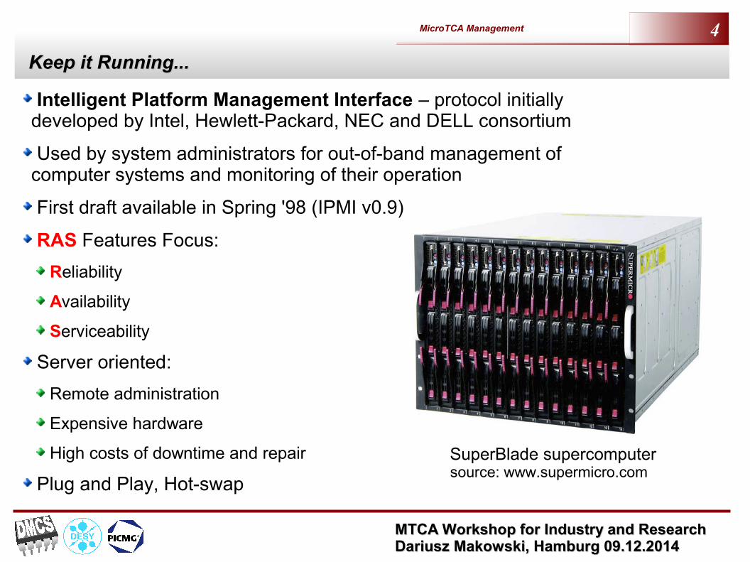
Keep it Running...Keep it Running...
Intelligent Platform Management Interface – protocol initially developed by Intel, Hewlett-Packard, NEC and DELL consortium
Used by system administrators for out-of-band management of computer systems and monitoring of their operation
First draft available in Spring '98 (IPMI v0.9)
RAS Features Focus:
Reliability
Availability
Serviceability
Server oriented:
Remote administration
Expensive hardware
High costs of downtime and repair
Plug and Play, Hot-swap
SuperBlade supercomputersource: www.supermicro.com

MTCA Workshop for Industry and Research MTCA Workshop for Industry and Research Dariusz Makowski, Hamburg 09.12.2014 Dariusz Makowski, Hamburg 09.12.2014
MicroTCA Management 5
IPMI ComponentsIPMI Components
IPMI MessagesIPMI Messages
BMC – Baseboard Management Controller
SDR – Sensor Data RecordFRU – Field Replaceable Unit
MTCA Workshop for Industry and Research MTCA Workshop for Industry and Research Dariusz Makowski, Hamburg 09.12.2014 Dariusz Makowski, Hamburg 09.12.2014
MicroTCA Management 6
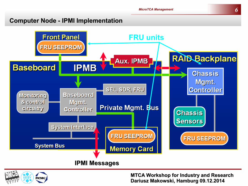
Computer Node - IPMI ImplementationComputer Node - IPMI Implementation
IPMI MessagesIPMI Messages
FRU units

MTCA Workshop for Industry and Research MTCA Workshop for Industry and Research Dariusz Makowski, Hamburg 09.12.2014 Dariusz Makowski, Hamburg 09.12.2014
MicroTCA Management 7
Chassis ImplementationChassis Implementation
PowerSupply Module
#1
Management Module FAN
Unit #2
Remote MgmtConsole System
LAN,Serial, SOL
SC
FANUnit #1
SC SC SC
PowerSupply Module
#N
Computation node A
BMC
SC
PowerSupply Module
#2
BMC
SC Management Module Processor
Baseboard Management Controller
IPMB I P M Bntelligent latform anagement us
Out Of Band
In Band
Computation node B
BMC
Computation node N
BMC
BP/I/F BP/I/F BP/I/FSC
BP/I/F
MMP MMP
SC
MMP
Satellite Controller
BP/I/F
StorageDevice
Backplane Management Interconnect
IPMB IPMB

MTCA Workshop for Industry and Research MTCA Workshop for Industry and Research Dariusz Makowski, Hamburg 09.12.2014 Dariusz Makowski, Hamburg 09.12.2014
MicroTCA Management 8
IPMI Elements (1)IPMI Elements (1)
Baseboard Management Micro-Controller provides intelligence for IPMI
Out Of Band (OOB) access to computer
Autonomous monitoring and logging
System interface to internal IPMB (I2C)
Interface to IPMI Storage
Receives and logs events messages
Power control functions
BIOS access
OEM defined functions
System Watch-dog Timer
MTCA Workshop for Industry and Research MTCA Workshop for Industry and Research Dariusz Makowski, Hamburg 09.12.2014 Dariusz Makowski, Hamburg 09.12.2014
MicroTCA Management 9
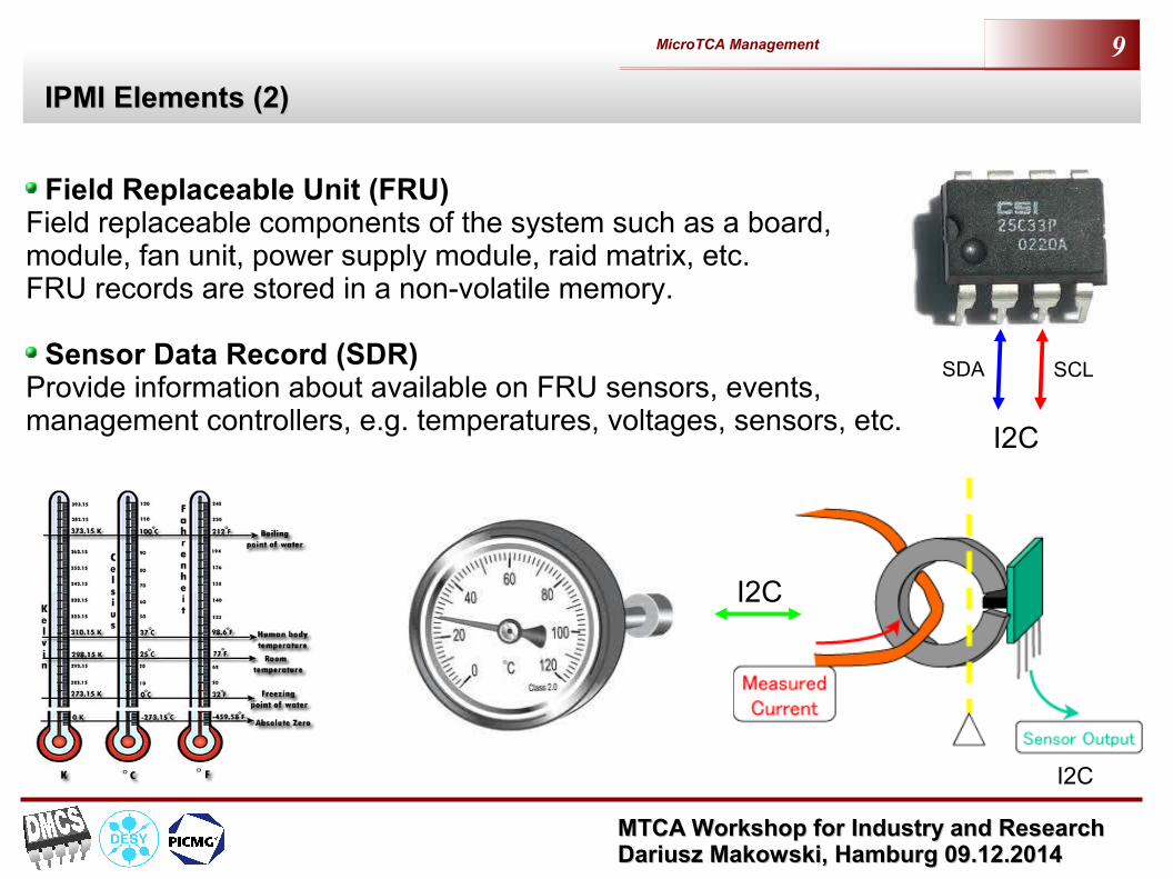
IPMI Elements (2)IPMI Elements (2)
Field Replaceable Unit (FRU)Field replaceable components of the system such as a board, module, fan unit, power supply module, raid matrix, etc. FRU records are stored in a non-volatile memory.
Sensor Data Record (SDR)Provide information about available on FRU sensors, events, management controllers, e.g. temperatures, voltages, sensors, etc.
I2C
SCLSDA
I2C
I2C

MTCA Workshop for Industry and Research MTCA Workshop for Industry and Research Dariusz Makowski, Hamburg 09.12.2014 Dariusz Makowski, Hamburg 09.12.2014
MicroTCA Management 10
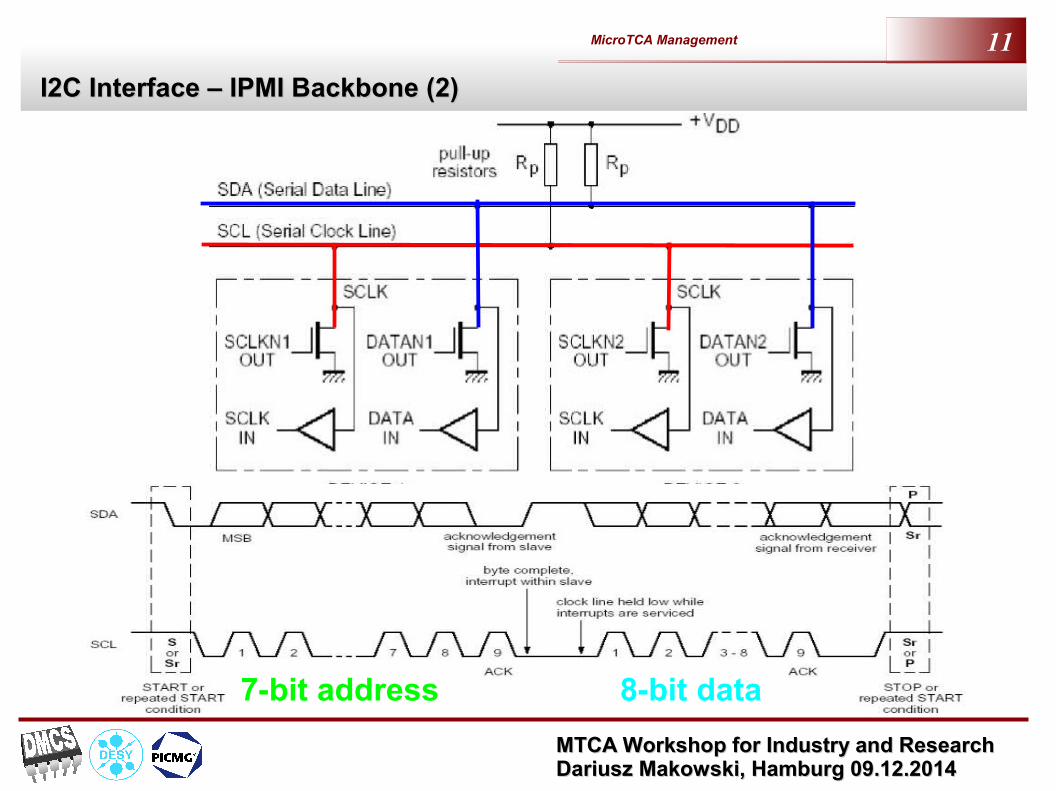
I2C Interface – IPMI Backbone (1)I2C Interface – IPMI Backbone (1)
I2C – Inter-Integrated Circuit bus
Standard developed by Philips on early 80s
Two wire synchronous, half-duplex interface (SDA – data line, SCL – clock line)
Bidirectional multi master-slave transfers, 8-bit frames
Transmission speed: 100 kbps, 400 kbps, 3.4 Mbps
7-bit or 10-bits device address
Arbitration used for multi-master transmission
SDASCL
A0A1A2
SDASCL
A0A1A2
SDASCL
A0A1A2
SDASCL
A0A1A2
SDASCL
A0A1A2
SDASCL
A0A1A2
SDASCL
A0A1A2
SDASCL
A0A1A2
SDASCLSDASCL
A0A1A2
A0A1A2
M
S
M
M
SAddress: 0x78
Address: 0x50
Address: 0x64
Address: 0x71
Address: 0x70
I2C bus
MTCA Workshop for Industry and Research MTCA Workshop for Industry and Research Dariusz Makowski, Hamburg 09.12.2014 Dariusz Makowski, Hamburg 09.12.2014
MicroTCA Management 11
I2C Interface – IPMI Backbone (2)I2C Interface – IPMI Backbone (2)
7-bit address 8-bit data

MTCA Workshop for Industry and Research MTCA Workshop for Industry and Research Dariusz Makowski, Hamburg 09.12.2014 Dariusz Makowski, Hamburg 09.12.2014
MicroTCA Management 12
Shelf Management in xTCA Systems

MTCA Workshop for Industry and Research MTCA Workshop for Industry and Research Dariusz Makowski, Hamburg 09.12.2014 Dariusz Makowski, Hamburg 09.12.2014
MicroTCA Management 13
xTCA and IPMI xTCA and IPMI
IPMI introduced in PICMG 2.16 backplanes (CompactPCI systems) and later in AMC, ATCA and MTCA standards
IPMI enables "diagnose-before-dispatch" automation
Required for 99.999 percent high availability (HA) mark
IPMI controller (shelf manager) is responsible for:
Monitoring overall shelf health
Communicating with remote System Management Software (SMS)
Hot-swap events (e.g. hardware component entry-removal events)
Latch/lock management
Power budgeting
In-rush current sequencing
Electronic keying (E-keying)
PICMG 3.0 extension commands
HPM.1 management firmware upgrade capability

MTCA Workshop for Industry and Research MTCA Workshop for Industry and Research Dariusz Makowski, Hamburg 09.12.2014 Dariusz Makowski, Hamburg 09.12.2014
MicroTCA Management 14
ATCA Shelf Management SystemATCA Shelf Management System
ShMC
IPMC
ATCABoard
IPMC
AMC MMC
AMC MMC
IPMC
ATCABoard
IPMC
ATCABoard RMC
RTM
ShMC IPMC
Power Module
Power Module
MMC MMC
ShelfManager
ShelfManager
Fan Tray
SystemManager
Redundant IPMB-0
Serial-over-LAN
IPMB-L
Carrier Manager
ShMC
IPMC Intelligent Platform Management Controller
Shelf Manager
AMC dvanced ezzanine ardA M C
Module Management Controller MMC
Intelligent Platform
Management Controller
MTCA Workshop for Industry and Research MTCA Workshop for Industry and Research Dariusz Makowski, Hamburg 09.12.2014 Dariusz Makowski, Hamburg 09.12.2014
MicroTCA Management 15
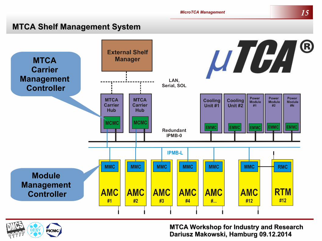
MTCA Shelf Management SystemMTCA Shelf Management System
Module Management
Controller
MTCA Carrier
Management Controller

MTCA Workshop for Industry and Research MTCA Workshop for Industry and Research Dariusz Makowski, Hamburg 09.12.2014 Dariusz Makowski, Hamburg 09.12.2014
MicroTCA Management 16
uTCA-based LLRF Control System of AcceleratoruTCA-based LLRF Control System of Accelerator
MTCA Carrier Hub
Interfaces on MTCA backplane

MTCA Workshop for Industry and Research MTCA Workshop for Industry and Research Dariusz Makowski, Hamburg 09.12.2014 Dariusz Makowski, Hamburg 09.12.2014
MicroTCA Management 17
AMC Module Hot-plugAMC Module Hot-plug
What really happens when you plug AMC card into MTCA chassis?
Module Activation procedure?
Module Deactivation?
How IPMI automates this process?
What if something goes wrong?
Hot-plug handle
Blue LED

MTCA Workshop for Industry and Research MTCA Workshop for Industry and Research Dariusz Makowski, Hamburg 09.12.2014 Dariusz Makowski, Hamburg 09.12.2014
MicroTCA Management 18
Module Activation/DeactivationModule Activation/Deactivation
PICMG 3.0 and AMC specifications define FRU states
Activation pushes FRU into M4 state
Deactivation moves FRU into M1 state
If something wrong happen module goes into M7 state
MCH decides if and when module can reach M4
MMC uses a state machine to control hot-plug procedure
M0
LED off
FRUNot Installed
M1
LED on
FRUInactive
M2
LED long blink
FRUActivation Req.
M3
LED off
FRUActiv. in Progress
M4
LED off
FRUActive
M5FRU
Deactivation Req.
LED shortblink
M6
LED shortblink
FRUDeact. in Prog.
M7FRU
Communic. lostLED
undef.

MTCA Workshop for Industry and Research MTCA Workshop for Industry and Research Dariusz Makowski, Hamburg 09.12.2014 Dariusz Makowski, Hamburg 09.12.2014
MicroTCA Management 19
AMC Module InsertionAMC Module Insertion
Shelf ManagerAMC Module
Carrier Manager
MTCA Carrier HUB
PS1# Asserted
ENABLE # Active MMC starting
Management Power Blue LED on
M0 -> M1
Read FRU data (E-keying, power)
Hot-plug handle closed (User)
M2 -> M3
Power Negotiation
M1 -> M2
Blue LED off
Blue LED long blink
(Get (Set Power Level)
Power Level)
Enable PP and E-keying
M3 -> M4
Hardware signal
IPMI message
Hot Swap Event
(Module Handle Closed)
(Set FRU LED State)
(Set AMC Port State)
(Set FRU LED State)
Set FRU Activation(Activate)
MMC starting

MTCA Workshop for Industry and Research MTCA Workshop for Industry and Research Dariusz Makowski, Hamburg 09.12.2014 Dariusz Makowski, Hamburg 09.12.2014
MicroTCA Management 20
AMC Module ExtractionAMC Module Extraction
Shelf ManagerAMC Module
Carrier Manager
MTCA Carrier HUB
PS1# Deasserted
M4 -> M5
Hot-plug handle opened
M6 -> M1
Disable Module
M5 -> M6
Blue LED on
Blue LED short blink
Remove Management Power
M1 -> M0Hardware signal
IPMI message
Hot Swap Event
(Module Handle Open)
(Set FRU LED State)
(Set AMC Port State)
(Set FRU LED State)
Set FRU Activation(Deactivate)
Remove Payload Power
Module Extracted (User)

MTCA Workshop for Industry and Research MTCA Workshop for Industry and Research Dariusz Makowski, Hamburg 09.12.2014 Dariusz Makowski, Hamburg 09.12.2014
MicroTCA Management 21
MTCA.4 – Hardware ManagementMTCA.4 – Hardware Management
AMC
FRU 1 Sensors
MMC
FRU 0 Sensors
I2C
I2CI2C
CarrierManager
MCMC
uRTM
MCH
IPMB-L

MTCA Workshop for Industry and Research MTCA Workshop for Industry and Research Dariusz Makowski, Hamburg 09.12.2014 Dariusz Makowski, Hamburg 09.12.2014
MicroTCA Management 22
RTM Module InsertionRTM Module Insertion
Shelf ManagerAMC Module
FRU ID=0Carrier Manager
MTCA Carrier HUB
PS# Asserted
ENABLE Hot Swap
Management Power
Blue LED on
M0 -> M1 Read FRU data (Interface Compatibility record)
M2 -> M3
M1 -> M2
Blue LED off
Set Blue LED long blink
Enable Payload Power
M3 -> M4
Hardware signal
Signal via I2C
IPMI message
Hot Swap Event
(Set FRU LED State)
(Set Power Level)
(Set FRU LED State)
Set FRU Activation(Activate)
uRTM ModuleFRU ID=1
(uRTM Present)
FRU data
Hot-plug handle closed(Module Handle Closed)
Check Compatibility(RTM Compat./Inconpat.)
Handle closed (User)
Blue LED long blink Blue LED blinking
Enable RTM SensorsRead RTM Sensors
Turn off Blue LED
Enable Payload Power
Enable Zone 3 Inter.
Set Blue LED on

MTCA Workshop for Industry and Research MTCA Workshop for Industry and Research Dariusz Makowski, Hamburg 09.12.2014 Dariusz Makowski, Hamburg 09.12.2014
MicroTCA Management 23
RTM Module ExtractionRTM Module Extraction
Shelf ManagerAMC Module
FRU ID=0Carrier Manager
MTCA Carrier HUB
Blue LED on
Set Blue LED short blink
Hardware signal
Signal via I2C
IPMI message
Hot Swap Event
uRTM ModuleFRU ID=1
Handle opened (User)
Disable Zone3 Interfaces
Blue LED blinking
Disable sensors, MP
PS1# Deasserted
M4 -> M5
Hot-plug handle opened
M6 -> M1
FRU Control
M5 -> M6
Blue LED on
Blue LED short blink
Delete sensors
M1 -> M0
(Module Handle Open)
(Set FRU LED State)
(Quiesce)
(Set FRU LED State)
Set FRU Activation(Deactivate)
Module Hot Swap(Quiesced)
Disable Payload Power(Set Power Level = 0)
Disable Payload Power
Set Blue LED on
Module Hot Swap(RTM Absent)
Module extracted (user)

MTCA Workshop for Industry and Research MTCA Workshop for Industry and Research Dariusz Makowski, Hamburg 09.12.2014 Dariusz Makowski, Hamburg 09.12.2014
MicroTCA Management 24
Electronic-keying – Connection Compatibility ManagementElectronic-keying – Connection Compatibility Management
Allow using different standards (1/10 GbE, PCIe, SRapidIO, Inifiniband, Custom links)
Provide connections compatibility
Protect hardware

MTCA Workshop for Industry and Research MTCA Workshop for Industry and Research Dariusz Makowski, Hamburg 09.12.2014 Dariusz Makowski, Hamburg 09.12.2014
MicroTCA Management 25
E-keying for MTCA Zone 1 ConnectorE-keying for MTCA Zone 1 Connector
AMC 170 pin connector
Region Interface PortCLK1 TCLKACLK2 TCLKB
PCIe Clock FCLKA0123456789101112131415
CLK TCLKC/D17181920
Clocks
Common Option
Extended Options
1 GbE
SAS/SATA
PCIE10 GbE
SRIO
PCIE10 GbE
SRIOP2P
P2P
TriggersInterlocks
Clocks
Fat Pipe
Ext. Fat Pipe
MTCA Zone 1 connector divided into zones:
Each module can receive or drive clock signals
Star connection on ports 0 and 1
P2P (Peer-to-Peer) connection on ports 2 and 3
Star connection via switch on ports 4-7
Star connection or P2P on ports 8-11
P2P connection on ports 12-15
Bus connection on ports 17-20

MTCA Workshop for Industry and Research MTCA Workshop for Industry and Research Dariusz Makowski, Hamburg 09.12.2014 Dariusz Makowski, Hamburg 09.12.2014
MicroTCA Management 26
E-keying in MTCAE-keying in MTCA
MCH will read FRU records from both modules
Compare E-keying records of MCH and AMC3/AMC4
Compare E-keying records of AMC3 and AMC4
Activate interfaces with compatible protocols
Region Interface Port AMC 3 AMC 4 Region Interface PortCLK1 TCLKA CLK1 TCLKACLK2 TCLKB CLK2 TCLKB
PCIe Clock FCLKA PCIe Clock FCLKA0 01 1
SATA 2 SAS 2SATA 3 SATA 3PCIE 1 4 PCIE 1 4PCIE 2 5 5PCIE 3 6 6PCIE 4 7 710 GbE 8 SRIO 810 GbE 9 SRIO 910 GbE 10 SRIO 1010 GbE 11 SRIO 11
GTX 12 P2P - LVDS 1213 13
P2P - LVDS 14 P2P - LVDS 14P2P - LVDS 15 P2P - LVDS 15
CLK TCLKC/D17 1718 1819 1920 20
Extended Options
TriggersInterlocks
Clocks
AMC in slot 3 AMC in slot 4Decision
Clocks
Common Option1 GbE
Fat Pipe
Ext. Fat PipeExt. Fat Pipe
Extended Options
TriggersInterlocks
Clocks
Clocks
Common Option1 GbE
Fat Pipe

MTCA Workshop for Industry and Research MTCA Workshop for Industry and Research Dariusz Makowski, Hamburg 09.12.2014 Dariusz Makowski, Hamburg 09.12.2014
MicroTCA Management 27
Zone 3 E-KeyingZone 3 E-Keying
DESY Zone 3 recommendation for digital and analogue classes
Various, bidirectional analogue and digital signals
MTCA.4 keying only verifies voltage levels
Require E-Keying with MMC and RTM controller support to avoid signal collisions
CLK, unidirectional
IPMI signals
Bidirectional IOs
Bidirectional IOs
Gigalinks
F. Ludwig, '...Zone 3 classes...'

MTCA Workshop for Industry and Research MTCA Workshop for Industry and Research Dariusz Makowski, Hamburg 09.12.2014 Dariusz Makowski, Hamburg 09.12.2014
MicroTCA Management 28
Module Management Controller(AMC Module)

MTCA Workshop for Industry and Research MTCA Workshop for Industry and Research Dariusz Makowski, Hamburg 09.12.2014 Dariusz Makowski, Hamburg 09.12.2014
MicroTCA Management 29
Tasks of MMCTasks of MMC
Required on each AMC Module
Communication with the Carrier Manager
Module management:
Module activation and deactivation
Warm and cold module reset
Power supply management
Monitoring of module crucial parameters
Temperature
Supply voltages
Currents
Clocks, etc.
E-keying mechanism (PCIe, GbE, sRIO,...)
Supervision of μRTM module (MTCA.4)

MTCA Workshop for Industry and Research MTCA Workshop for Industry and Research Dariusz Makowski, Hamburg 09.12.2014 Dariusz Makowski, Hamburg 09.12.2014
MicroTCA Management 30
DAMC-TCK7 - LLRF Controller (1)DAMC-TCK7 - LLRF Controller (1)
Two modes of operation:
Low Level Radio Frequency controller
Enough processing power for execution of the cavity field stabilizing algorithms
(PID, feed-forward) in the feedback loop
FPGA
Memory
Dedicated low-latency connections
PCIe and Gigabit Ethernet
Firmware upgrade feature
Compliance with MTCA.4 specification

MTCA Workshop for Industry and Research MTCA Workshop for Industry and Research Dariusz Makowski, Hamburg 09.12.2014 Dariusz Makowski, Hamburg 09.12.2014
MicroTCA Management 31
DAMC-TCK7 – LLRF Controller (1)DAMC-TCK7 – LLRF Controller (1)
Provides computation power for LLRF algorithms
Provides interface to VM,diagnostics,management
Module Requirements:
PCIe - main parameters of the computation module, latency <50 us, throughput ~16 Gbps
LLL- data from DAQ modules and to Vector Modulator, latency <200 ns, throughput >6 Gbps
Optical connection for communication with other LLRF subsystems
Trigger and interlock signals provided on backplane
Compliant with PICMG MTCA.4 specification
Module management, diagnostics, high availability

MTCA Workshop for Industry and Research MTCA Workshop for Industry and Research Dariusz Makowski, Hamburg 09.12.2014 Dariusz Makowski, Hamburg 09.12.2014
MicroTCA Management 32
DAMC-TCK7 – LLRF Controller (2)DAMC-TCK7 – LLRF Controller (2)

MTCA Workshop for Industry and Research MTCA Workshop for Industry and Research Dariusz Makowski, Hamburg 09.12.2014 Dariusz Makowski, Hamburg 09.12.2014
MicroTCA Management 33
DAMC-TCK7 – LLRF Controller (3)DAMC-TCK7 – LLRF Controller (3)

MTCA Workshop for Industry and Research MTCA Workshop for Industry and Research Dariusz Makowski, Hamburg 09.12.2014 Dariusz Makowski, Hamburg 09.12.2014
MicroTCA Management 34
Block Diagram of MMC Block Diagram of MMC

MTCA Workshop for Industry and Research MTCA Workshop for Industry and Research Dariusz Makowski, Hamburg 09.12.2014 Dariusz Makowski, Hamburg 09.12.2014
MicroTCA Management 35
RTM Management Controller
MTCA Workshop for Industry and Research MTCA Workshop for Industry and Research Dariusz Makowski, Hamburg 09.12.2014 Dariusz Makowski, Hamburg 09.12.2014
MicroTCA Management 36
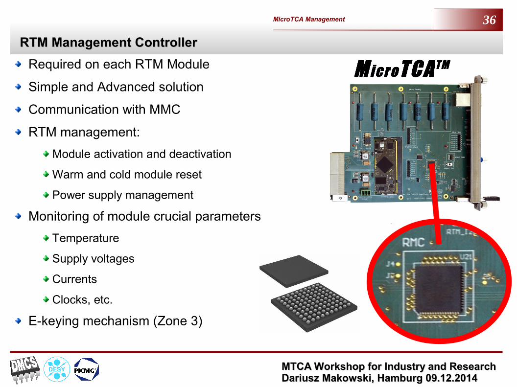
RTM Management ControllerRTM Management Controller
Required on each RTM Module
Simple and Advanced solution
Communication with MMC
RTM management:
Module activation and deactivation
Warm and cold module reset
Power supply management
Monitoring of module crucial parameters
Temperature
Supply voltages
Currents
Clocks, etc.
E-keying mechanism (Zone 3)

MTCA Workshop for Industry and Research MTCA Workshop for Industry and Research Dariusz Makowski, Hamburg 09.12.2014 Dariusz Makowski, Hamburg 09.12.2014
MicroTCA Management 37
`
RTM Management – Simple SolutionRTM Management – Simple Solution
max. 30 mAmax. 3 A P = max. 30 WPmax. = 80 W - RTM

MTCA Workshop for Industry and Research MTCA Workshop for Industry and Research Dariusz Makowski, Hamburg 09.12.2014 Dariusz Makowski, Hamburg 09.12.2014
MicroTCA Management 38
RTM Management – Advanced SolutionRTM Management – Advanced Solution

MTCA Workshop for Industry and Research MTCA Workshop for Industry and Research Dariusz Makowski, Hamburg 09.12.2014 Dariusz Makowski, Hamburg 09.12.2014
MicroTCA Management 39
Vector Modulator ModuleVector Modulator Module
Performs amplitude and phase modulation of RF reference signal to drive the klystron
Module Requirements:
2 channel high-frequency vector modulation at 1.3 GHz, 3.9 GHz
Non linearity error <-55 dBc(0.2%)
Short-term PM stability <10 fs(RMS) [10 Hz,100 kHz]
Spectral purity -155dBc/Hz
Calibration capability
16-bit resolution on each I and Q channel
Programmable attenuators
Zone 3 D1.2 Class compatible
E-keying for Zone 3
Compliant with MTCA.4

MTCA Workshop for Industry and Research MTCA Workshop for Industry and Research Dariusz Makowski, Hamburg 09.12.2014 Dariusz Makowski, Hamburg 09.12.2014
MicroTCA Management 40
DRTM-VMLF – Vector ModulatorDRTM-VMLF – Vector Modulator

MTCA Workshop for Industry and Research MTCA Workshop for Industry and Research Dariusz Makowski, Hamburg 09.12.2014 Dariusz Makowski, Hamburg 09.12.2014
MicroTCA Management 41
IPMI MMC 1.00 Framework –Firmware for MTCA.4 Management

MTCA Workshop for Industry and Research MTCA Workshop for Industry and Research Dariusz Makowski, Hamburg 09.12.2014 Dariusz Makowski, Hamburg 09.12.2014
MicroTCA Management 42
MMC v1.00 Hardware-Firmware – Unified SolutionMMC v1.00 Hardware-Firmware – Unified SolutionMMC for AMC:
Standard MTCA.4 compliant functions
Monitoring of on-board voltages
Protection in case of overheating
UART for debugging and local monitoring
Zone3 Isolation functionality
Hot-plugging controller for μRTM Modules
Management of on-board FPGA/CPU/DSP and firmware update
MMC firmware upgrade using HPM.1
MMC for μRTM:
Standard MTCA.4 compliant functions
Monitoring of on-board voltages
Protection in case of overheating
UART for debugging and local monitoring
Zone3 Isolation functionality
Management of payload reconfiguration and firmware update

MTCA Workshop for Industry and Research MTCA Workshop for Industry and Research Dariusz Makowski, Hamburg 09.12.2014 Dariusz Makowski, Hamburg 09.12.2014
MicroTCA Management 43
MMC – Implementation (1)MMC – Implementation (1)
Initialization
Initialization of software structures
Configuration of peripheral devices
Main loop
Event processing
Messages handling
Updating sensors
Payload Control
Command Line Interface

MTCA Workshop for Industry and Research MTCA Workshop for Industry and Research Dariusz Makowski, Hamburg 09.12.2014 Dariusz Makowski, Hamburg 09.12.2014
MicroTCA Management 44
MMC – Implementation (2)MMC – Implementation (2)
Works aimed to code portability
Software layers

MTCA Workshop for Industry and Research MTCA Workshop for Industry and Research Dariusz Makowski, Hamburg 09.12.2014 Dariusz Makowski, Hamburg 09.12.2014
MicroTCA Management 45
MMC 1.00 FrameworkMMC 1.00 Framework
IPMI core
IPMI events service
SDR, FRU, LEDs
PICMG
RTM
Microcontroller specific functions
Firmware written using Atmel Software Framework (ASF)
Drivers and services for ATXmega microcontroller
Drivers for peripheral devices
Start-up code
Board specific functions
Device drivers
Sensors
Payload management

MTCA Workshop for Industry and Research MTCA Workshop for Industry and Research Dariusz Makowski, Hamburg 09.12.2014 Dariusz Makowski, Hamburg 09.12.2014
MicroTCA Management 46
EvalKits for Fast Development of IPMI

MTCA Workshop for Industry and Research MTCA Workshop for Industry and Research Dariusz Makowski, Hamburg 09.12.2014 Dariusz Makowski, Hamburg 09.12.2014
MicroTCA Management 47
Block Diagram of MMC and RMC Eval-kitsBlock Diagram of MMC and RMC Eval-kits

MTCA Workshop for Industry and Research MTCA Workshop for Industry and Research Dariusz Makowski, Hamburg 09.12.2014 Dariusz Makowski, Hamburg 09.12.2014
MicroTCA Management 48
MMC and RMC Eval-kits HardwareMMC and RMC Eval-kits Hardware

MTCA Workshop for Industry and Research MTCA Workshop for Industry and Research Dariusz Makowski, Hamburg 09.12.2014 Dariusz Makowski, Hamburg 09.12.2014
MicroTCA Management 49
AMC and RTM ManagementAMC and RTM Management
Z1
()
AM
CZ
3 (
RT
M)
TEMP4
EEPROM
ID Chip
TEMP1FPGA
ATXMEGA
PROM1 PROM2D
C/D
C
DC
/DC
DC
/DC
DC
/DC
DC
/DC
DC
/DC
DC
/DC
SENSORS
MP+3V3
GA0..2
PP+12V
ENABLE
PRES.
IPMB-L
MP+3V3
PP+12V
PRES.
IPMB-R
PMBusLEDsHot-plug handler
I2C
Control SPI
SPI, Revision
JTAG
Z3 (
RT
M)
TEMP4
EEPROM
ID Chip
TEMP1FPGA
ATXMEGA
PROM1
DC
/DC
DC
/DC
DC
/DC
DC
/DC
DC
/DC
DC
/DC
DC
/DC
SENSORS
MP+3V3
PP+12V
PRES.
IPMB-R
Enable,PgoodVmon. LEDs
Hot-plug handler
I2C
Control SPIJTAG
Revision

MTCA Workshop for Industry and Research MTCA Workshop for Industry and Research Dariusz Makowski, Hamburg 09.12.2014 Dariusz Makowski, Hamburg 09.12.2014
MicroTCA Management 50
Thank you for your attention
Questions ?Comments ?