Introduction - DCNE
54
3 This manual is for the Carlyle ® Paragon screw compres- sor product line, which is comprised of four unique com- pressor families (series type TS, TT, TU, and TV). Carlyle offers distinct versions of the Paragon Twin-Screw Com- pressors for Low/Medium/High Temperature applications. The operational limits, required accessories, and opera- tional guidelines are contained in this manual and must be complied with to stay within the compressor warranty guidelines. R-134a, R-513A, R-1234ze Applications The TS series compressors are designed for air-cooled applications only. The TT, TU, and TV series compres- sors are available in both air-cooled and water-cooled applications. There are 3 different displacement sizes of each of the TS, TT, and TV series compressors, along with 2 displacement sizes of the TU series compressor. Each Paragon twin-screw compressor is designed to be applied with a dedicated, performance-matched oil sep- arator. Carlyle offers two types of oil separators: high-effi- ciency (for applications in flooded-type systems) and standard-efficiency (for application in direct expansion- type systems). This compressor / oil separator assembly is then applied in a single-compressor, medium-tempera- ture, or high-temperature refrigeration circuit. Carlyle offers the required oil separators as shown in Section 9.1 of this application guide. See Section 10.5 of this docu- ment for Assembly views of the R-134a Paragon models applied with these oil separator designs. Application guidelines for the R-134a compressors that have been approved for VFD applications are covered in this guide. R-404A, R-407A, R-407C, R-407F, R-448A, R-449A, and R-507A Applications The low/medium temperature Paragon twin-screw com- pressor models are designed to be applied in single or multiple compressor circuits. Each circuit requires a prop- erly selected oil separator (contact Carlyle Application Engineering for selection criteria). Carlyle offers 3 models within each of the TS and TT compressor series for low/ medium temperature applications. Scope This application guide is intended to familiarize system designers with the Paragon screw compressor and to provide technical information necessary to assure safe and reliable compressor operation. Certifications UL and CSA approvals have been obtained for specific 06TS, 06TT, 06TU, and 06TV screw compressor models applied with R-134a and for certain 06TS and 06TT screw compressor models applied with R-404A, R-407A, R-407C, R-407F, and R-507A (compressors that have an R or M in the fifth digit of the model number). UL File #: SA4936 CSA File #: SA4936 For the UL and CSA approvals it is essential that only Listed, Special-Purpose circuit breakers or Carlyle approved, solid-state motor overloads be used (contact Carlyle Application Engineering for further information). For circuit breakers, the Must Trip Amp settings must not exceed 140% of the compressor rated load amps. Both UL and CSA approvals have been obtained for all voltage combinations shown in Section 8.3 of this guide. These compressor models also comply with the EC Low Voltage and Machinery Directives. Compressor Offerings The four Paragon compressor frame sizes (TS, TT, TU, and TV) are optimized for application in economized refrigeration circuits. Non-economized capacity will decrease by 11 to 16% for water-cooled operation. The following tables show the displacements for each of the compressors at 60 Hz. Compressor Displacement (R-134a, R-513A, R-1234ze for air and water cooled models) See Tables 1 and 2. Table 1 — Air-Cooled Models Table 2 — Water-Cooled Models NOTE: Carlyle has optimized the Vi (volume index) for the R-134a air-cooled and water-cooled models. MODEL NUMBER NOMINAL HORSEPOWER DISPLACEMENT (CFM at 60 Hz) 06TSA137 60 137 06TSA155 75 155 06TSA186 75 186 06TTA266 120 266 06TTA301 150 301 06TTA356 150 356 06TUA483 225 483 06TUA554 225 554 06TVA680 340 680 06TVA753 340 753 06TVA819 340 819 MODEL NUMBER NOMINAL HORSEPOWER DISPLACEMENT (CFM at 60 Hz) 06TTW266 90 266 06TTW301 90 301 06TTW356 120 356 06TUW483 160 483 06TUW554 160 554 06TVW680 225 680 06TVW753 225 753 06TVW819 225 819 Introduction
-
Upload
khangminh22 -
Category
Documents
-
view
1 -
download
0
Transcript of Introduction - DCNE

3
This manual is for the Carlyle® Paragon screw compres-sor product line, which is comprised of four unique com-pressor families (series type TS, TT, TU, and TV). Carlyle offers distinct versions of the Paragon Twin-Screw Com-pressors for Low/Medium/High Temperature applications. The operational limits, required accessories, and opera-tional guidelines are contained in this manual and must be complied with to stay within the compressor warranty guidelines.
R-134a, R-513A, R-1234ze ApplicationsThe TS series compressors are designed for air-cooled applications only. The TT, TU, and TV series compres-sors are available in both air-cooled and water-cooled applications. There are 3 different displacement sizes of each of the TS, TT, and TV series compressors, along with 2 displacement sizes of the TU series compressor.
Each Paragon twin-screw compressor is designed to be applied with a dedicated, performance-matched oil sep-arator. Carlyle offers two types of oil separators: high-effi-ciency (for applications in flooded-type systems) and standard-efficiency (for application in direct expansion-type systems). This compressor / oil separator assembly is then applied in a single-compressor, medium-tempera-ture, or high-temperature refrigeration circuit. Carlyle offers the required oil separators as shown in Section 9.1 of this application guide. See Section 10.5 of this docu-ment for Assembly views of the R-134a Paragon models applied with these oil separator designs. Application guidelines for the R-134a compressors that have been approved for VFD applications are covered in this guide.
R-404A, R-407A, R-407C, R-407F, R-448A, R-449A, and R-507A ApplicationsThe low/medium temperature Paragon twin-screw com- pressor models are designed to be applied in single or multiple compressor circuits. Each circuit requires a prop- erly selected oil separator (contact Carlyle Application Engineering for selection criteria). Carlyle offers 3 models within each of the TS and TT compressor series for low/ medium temperature applications.
Scope
This application guide is intended to familiarize system designers with the Paragon screw compressor and to provide technical information necessary to assure safe and reliable compressor operation.
Certifications
UL and CSA approvals have been obtained for specific 06TS, 06TT, 06TU, and 06TV screw compressor models applied with R-134a and for certain 06TS and 06TT screw compressor models applied with R-404A, R-407A,
R-407C, R-407F, and R-507A (compressors that have an R or M in the fifth digit of the model number).
UL File #: SA4936 CSA File #: SA4936
For the UL and CSA approvals it is essential that only Listed, Special-Purpose circuit breakers or Carlyle approved, solid-state motor overloads be used (contact Carlyle Application Engineering for further information). For circuit breakers, the Must Trip Amp settings must not exceed 140% of the compressor rated load amps.
Both UL and CSA approvals have been obtained for all voltage combinations shown in Section 8.3 of this guide. These compressor models also comply with the EC Low Voltage and Machinery Directives.
Compressor Offerings
The four Paragon compressor frame sizes (TS, TT, TU, and TV) are optimized for application in economized refrigeration circuits. Non-economized capacity will decrease by 11 to 16% for water-cooled operation. The following tables show the displacements for each of the compressors at 60 Hz.
Compressor Displacement (R-134a, R-513A, R-1234ze for air and water cooled models)
See Tables 1 and 2.
Table 1 — Air-Cooled Models
Table 2 — Water-Cooled Models
NOTE: Carlyle has optimized the Vi (volume index) for the R-134a air-cooled and water-cooled models.
MODELNUMBER
NOMINALHORSEPOWER
DISPLACEMENT(CFM at 60 Hz)
06TSA137 60 13706TSA155 75 15506TSA186 75 18606TTA266 120 26606TTA301 150 30106TTA356 150 35606TUA483 225 48306TUA554 225 55406TVA680 340 68006TVA753 340 75306TVA819 340 819
MODELNUMBER
NOMINALHORSEPOWER
DISPLACEMENT(CFM at 60 Hz)
06TTW266 90 26606TTW301 90 30106TTW356 120 35606TUW483 160 48306TUW554 160 55406TVW680 225 68006TVW753 225 75306TVW819 225 819
Introduction

4
Compressor Displacement (Low/Medium Temperature Models). R-404A, R-407A, R-407C, R-407F, R-448A, R-449A, and R-507A
See Tables 3 and 4.
Table 3 — Low Temperature (Refrigeration) Models
Table 4 — Medium Temperature Models
Standard Features
See Fig. 1-4 for physical data and connection information.
Discharge Check Valve
The discharge check valve is an axial movement type located within the compressor. The check valve is field ser-viceable by removing the oil separator or discharge line to access the valve in the compressor discharge housing.
Pressure Relief Valve
The Paragon screw compressors have an internal relief device which is designed to relieve pressure from the high side to the low side of the compressor.
Suction and Economizer Screens
To increase the reliability of the compressor, a screen has been incorporated as a standard feature into the suction inlet and economizer inlet of the compressor. The suction inlet screen is installed into the suction inlet of each com-pressor. The economizer inlet screen is supplied in the economizer flange package (which is included in the compressor kit 06TT660093). Refer to the economizer flange Installation Instruction document for more details.
Slide Valve Unloading System
All Paragon screw compressors utilize a continuous slide valve unloading system. The slide valve decreases the compressor's capacity by reducing the amount of com-pression performed by the screw rotors. It is infinitely variable down to approximately 30% of full load capacity for air-cooled models and approximately 15% of the full load capacity for water-cooled models. These percent- ages of unloading are based on operation at typical rating conditions and may be different at other operating condi-tions.
Variable Speed for Capacity Control
The paragon compressor has been qualified to operate with a variable frequency drive (VFD) for all low, medium, and high temperature applications. The VFD speed appli-cation range is 30 to 60 Hz. The compressor slide valve should remain in the fully loaded position while the VFD is controlling compressor capacity between 30 to 60 Hz. The slide valve may be used to reduce compressor capacity below 50% (30 Hz) if required. Recommenda-tions and requirements for these applications are pro-vided in Section 7.0.
MODELNUMBER
NOMINALHORSEPOWER
DISPLACEMENT(CFM at 60 Hz)
06TSR137 60 13706TSR155 75 15506TSR186 75 18606TTR266 120 26606TTR301 150 30106TTR356 150 356
MODELNUMBER
NOMINALHORSEPOWER
DISPLACEMENT(CFM at 60 Hz)
06TSM137 75 13706TSM155 75 15506TTM266 150 26606TTM301 150 301

5
Model Number Significance Chart
1 2 3 4 5 6 7 8 9 10 11 120 6 T T A 3 5 6 S S 1 C
12th
1st & 2nd A06 B
CD
3rd & 4th
TSTT 11th
TU 1TV 3
5th
10th MOTOR SIZEARW
1STTS2TS3TT1TT2TT3
9th
S
2UT
T
3UT
W
1VT
X
2VT
Z
3VT
Air Cooled Vi
819
6th, 7th & 8th
DISPLACEMENT(CFM at 60 Hz)
137155
MODEL REF.
483554680753
266301356
186
DIGITMODEL NO.
DESIGN FEATURESemi-Hermetic
MODEL CODE
Phase 1Product Variant
400/460-3-50/60
Paragon
PACKAGE / ACCS.Not UsedNot Used
Plate Mounting FeetBar Mounting Feet
DESIGN LEVEL
Refrigeration ViWater-Cooled Vi
ParagonParagonParagon
DESIGN VARIABLE
575-3-60380-3-60
200/230-3-50/60200-3-60
MOTOR VOLTAGES690-3-50 (Wye)
690-3-60 (Wye)
LEGENDVi — Volume IndexWC — Water-CooledVFD — Variable Frequency Drive
X Variable-Speed (WC Vi)
607590120150160225340
GJMPSTWX
9 Not Used
M Medium Temperature Vi

6
Compressor Physical Data and Connections
Fig. 1 — 06TS Compressor Physical Data and Connections

7
Compressor Physical Data and Connections (cont)
Fig. 2 — 06TT Compressor Physical Data and Connections
Z

8
Compressor Physical Data and Connections (cont)
Fig. 3 — 06TU Compressor Physical Data and Connections
a06-1666

9
Compressor Physical Data and Connections (cont)
Fig. 4 — 6TV Compressor Physical Data and Connections
a06-1686
DISCHARGE FLANGE OIL SUPPLY TOCAPACITY CONTROL3/8 ORIFICE
SUCTION TEMP WELL1/4 INCH SAE
SUCTION FLANGE
OIL PRESSURE PORT3/8 INCH SAE ECONOMIZER FLANGE
OIL INLET PORT5/8 ORIFICE
LIFTINGLOCATIONS
HIGH SIDETEMP WELL1/4 INCH SAE
HIGH SIDEPRESSURE PORTS1/4 INCH SAE
CAPACITY CONTROL SOLENOIDSECONOMIZER PORT1 5/8 INCH ODS
SUCTION CONNECTION6 INCH CLASS 150 FLANGE
Ø24 LIFTING HOLEOIL INJECTION PORT1/4 INCH SAE
Ø24 LIFTING HOLE
DISCHARGE CONNECTION5 INCH CLASS 150 FLANGE
SUCTION
OIL DRAIN PORT3/8 INCH SAE
CAPACITY CONTROL OILSUPPLY PORT 3/8 ORIFICE
OIL DRAIN PORT1/4 SAE

10
1.1 Refrigerants and LubricantsApproved Refrigerants
The Paragon medium-temperature screw compressor is specifically designed for use in R-134a systems.
Approved Lubricants
The Paragon screw compressor is approved for use with the following lubricants:
Approved Lubricant — Emkarate RL 220HViscosity Grade — ISO 220orApproved Lubricant — Emkarate RL 220HCViscosity Grade — ISO 220
Carrier Part Number — 1 gallon: P903-23015 gallon: P903-2305
Assembly Grease
On occasion, it may be necessary to use an assembly grease to retain an o-ring within its groove. The following assembly grease is approved for use with the Paragon screw compressor:
Approved Lubricant — Castrol Synplex GP2orApproved Lubricant — Parker Super-O-Lube
Carrier Part Number — 19XL680001
Terminal Pin Dielectric Grease
Carlyle recommends that compressor motor terminal pins are coated with dielectric grease (P/N 06TT660050) to reduce the effects of condensation that may form on the terminal pins.
1.2 Environmental ConsiderationsOperating Ambient Temperature
The screw compressor is designed for the following ambi-ent temperature ranges:
Non-Operating: -40°F to 176°F (-40°C to 80°C)Operating: -31°F to 131°F (-35°C to 55°C)
Salt-Spray Requirements
The compressor has been tested through 500 hours of salt-spray in compliance with ASTM specification B-117.
1.3 Operating Limits and ControlsR-134a, R-513A, R-1234ze Operating Envelope
The following operating envelopes show where the com-pressor can be operated in both direct expansion and flooded applications. See Fig. 5-7. The envelopes differ for the unique design configuration of the compressor. The fifth digit of the model number indicates the operat-ing envelope. The load line percentages refer to the capacity relative to full load at the same saturated suction temperature (SST) and saturated discharge temperature (SDT).
1.0 Medium/High Temperature System Design Considerations (R-134a, R-513A, R-1234ze)

11
Fig. 5 — Operating Limits for Full Load Operation
Paragon Operating Envelopes on R-134a, R-513A
40
50
60
70
80
90
100
110
120
130
140
150
160
170
-20 -10 0 10 20 30 40 50 60 70
Saturated Suction Temperature (ºF)
SDT
(ºF)
4
14
24
34
44
54
64
74
-29 -24 -19 -14 -9 -4 1 6 11 16 21
Saturated Suction Temperature (ºC)
SDT (ºC
)
W/C Envelope
TS3 A/C MaxSDT
TS1 & TS2 A/CMax SDT
A/C Envelope
LEGENDA/C — Air-CooledW/C — Water-Cooled
Fig. 6 — Operating Limits for Full Load Operation

12
Start-Up and Suction Pressure Transients
Operating a screw compressor without refrigerant flow through the compressor can be harmful. When this occurs, the evaporator typically will go into a vacuum, leading to very high pressure ratios and little mass flow to carry the heat away from the screw rotors. This situation most often occurs during start-up when the refrigerant may be in another part of the system. This is tolerable for short periods of time. The Paragon screw compressor should not be allowed to operate with a suction pressure less than 0 psig (vacuum) for more than 1 minute after a “cold” start. (Contact Carlyle Application Engineering for more information on cold starts.) If a compressor is allowed to operate for longer periods of time without refrigerant flow, catastrophic damage to the screw rotors, rotor housing, and discharge housing may occur, requir-ing compressor replacement.
Air-Cooled Oil Supply at Compressor
To reduce the possibility of liquid refrigerant becoming entrained in the oil, it is recommended that the tempera-ture of the oil entering the compressor is kept above the outdoor ambient as shown in Fig. 8.
Temperature Limits
Table 5 shows the temperature range of control points allowable for the compressor using the approved lubri-cants listed in Section 1.1, Refrigerants and Lubricants.
Paragon Operating Envelopes on R-134a, R-513A
UNL (A/C)UNL (W/C)
50%
75%
40
50
60
70
80
90
100
110
120
130
140
150
160
170
-20 -10 0 10 20 30 40 50 60 70
Saturated Suction Temperature (ºF)
SDT
(ºF)
4
14
24
34
44
54
64
74
-29 -24 -19 -14 -9 -4 1 6 11 16 21
Saturated Suction Temperature (ºC)
SDT (ºC
)
FULL UNLOADLIMIT FOR A/C
FULL UNLOADLIMIT FOR W/C
50% LOAD LIMIT
75% LOAD LIMIT
W/C Envelope
A/C Envelope
LEGENDA/C — Air-CooledW/C — Water-Cooled
Fig. 7 — Operating Limits for Unloaded Operation
NOTE: Liquid injection may be required when operating fully unloaded. Contact Carlyle Applications Engineering for valve sizing requirements.
0
5
10
15
20
25
0 20 40 60 80 100Outdoor Ambient Temperature [OAT] (ºF)
Min
Del
ta O
il Te
mp
> A
mbi
ent (
ºF)
0
2
4
6
8
10
12
14-18 -7 4 16 27 38Outdoor Ambient Temperature [OAT] (ºC)
Min
Del
ta O
il Te
mp
> A
mbi
ent (
ºC)
Fig. 8 — Oil Temperaturea06-1669

13
Table 5 — Allowable Temperature Ranges
Compressor Rotation Control
Correct compressor rotation is one of the most critical application considerations. Powered reverse rotation, even for a very short duration, can seriously affect the reliability of the compressor.
The reverse rotation protection scheme must be capable of determining the direction of rotation and stopping the compressor within 1 second.
Reverse rotation is most likely to occur at initial start-up or whenever the wiring to the compressor terminals is disturbed.
To minimize the possibility for reverse rotation operation, Carlyle recommends the following procedures:
1. During initial run test of the unit, a suitable low-pressure switch should be temporarily installed on the high-pressure port of the compressor and be wired to open the compressor control circuit. The purpose of this switch is to protect the compressor against any wiring errors at the compressor terminal pins. The electrical contacts of the switch must be wired in the control circuit of the compressor start components to shut off the compressor in the event it is operating in reverse rotation. This switch would remain in place for the duration of the run test. At the end of the run test the switch would be removed so that it could be used on the next unit or compressor to be tested.
2. For service replacement compressors, a similar pro-tection system is recommended. The unit service lit-erature will make reference to this switch and provide instructions on how to temporarily install the low- pressure switch into the safety circuit for the com-pressor. Each service compressor will be supplied with Installation Instructions documenting the proce-dure for installing and using the switch. The switch will remain in place until the compressor has been started and direction of rotation has been verified; at this point the switch will be removed.
The low-pressure switch must be suitable for the pres-sures consistent with R-134a systems, and the switch must be manually resettable and open when the pressure falls below 50 mm (2 inches) of vacuum. The switch is a manual reset type that can be reset after the pressure has once again risen above 1.7 bar (25 psia). It is critical that the switch be a manual reset type to preclude the compressor from short cycling in the reverse direction.
If a switch is not available, a manifold gage connected to the discharge housing of the compressor BEFORE THE DISCHARGE CHECK VALVE can be used. If the com-pressor can be “bumped” or “jogged” very quickly (< 1 second) while someone is watching the gage, compres-sor rotation can be determined without damage to the compressor. If the pressure drops, the compressor is rotating backwards and will have to be rewired. If the pressure goes up, the compressor is spinning in the cor-rect direction.
Refrigeration System Design Considerations
In order to eliminate the possibility of refrigerant migrat-ing into the oil separator and compressor, Carlyle requires the application of a positive-seal, discharge check valve (or a similar functioning device) to be installed in the discharge line after the oil separator.
Carlyle recommends the application of our qualified Safety Control Module package (P/N 6BSB000472) which provides the following safety control functionality:
• Discharge Temperature Monitoring• Oil Level Monitoring (Optional)• Reverse Rotation Monitoring• Oil Flow-Rate/Supply Monitoring
Technical documentation for this Safety Control Module package (P/N 6BSB000472) is provided on the Carlyle Website at www.carlylecompressor.com
CONTROLPOINT
MINIMUM MAXIMUM
Discharge Gas
20°F (11°C)superheat
210°F (99°C)
Economizer Gas
SaturatedLiquid
9°F (5°C)superheat
SuctionGas
SaturatedVapor
Can float if motor and discharge
maximum temps are met
Oil Supply atCompressor
Refer to Fig. 8 210°F (99°C)
MotorWindings
No limit 275°F (135°C)

14
1.4 Control Points Summary
NOTE: Carlyle offers Compressor Protection Module package, P/N 6BSB000472, which protects against reverse rotation, low oil flow and maximum discharge gas temperature. See Marketing Bulletin 14M-01 at www.carlylecompressor.com.
Reverse Rotation / Operation with Suction Pressure in Vacuum• Control must detect and prevent reverse rotation of the compressor within 1 second of compressor start-up.• Compressor must not operate in a vacuum, as measured at the suction pressure port, for greater than 1 minute.
Oil Pressure Confirmation / Safety• Three pressures must be observed to ensure that the oil pressure is suitable for compressor operation: suction, discharge and oil.• Oil pressure safety control must be manually reset.• Oil pressure must be maintained as follows:
1. POIL > [0.7 x (PDISCHARGE – PSUCTION) + PSUCTION]
2. POIL > [PSUCTION + 0.5 bar] 15 seconds after start (Air-Cooled models; A in 5th digit of model numbers) [PSUCTION + 1.0 bar] 45 seconds after start (Refrigeration models; R in 5th digit of model numbers) [PSUCTION + 1.0 bar] 75 seconds after start (Water-Cooled models: W in 5th digit of model numbers)
Oil Supply Confirmation / Oil Level Switch• Oil supply to the compressor must be maintained during operation at all times.• Compressor operation must be stopped if the required oil level switch is open for 5 continuous seconds.• Oil supply solenoid valve must be closed during OFF cycles.
Oil Filter Differential Pressure• Compressor operation must be stopped if the pressure differential measured between the entering and leaving oil filter locations exceeds
2 bars.• The oil filter supply tubing design should apply valves to allow for the isolation and replacement of the filter without removing the system refrig-
erant charge.
Motor Temperature Limitation• Motor temperatures must be continuously monitored during compressor operation.• Motor temperatures must not exceed 275°F (135°C).
Compressor Short Cycling• Control must provide for a minimum of 10 minutes time delay before restarting the Paragon compressor.• The maximum number of compressor START cycles per hour is 6.
Maximum Discharge Gas Temperature• Discharge gas temperatures must not exceed 210°F (99°C).• Control must prevent compressor operation when discharge gas temperatures exceed this maximum.
Maximum Oil Temperature• Oil temperatures must not exceed 210°F (99°C).• Control must prevent compressor operation when oil temperatures exceed this maximum.
Run-Proof• Current must be monitored to detect welded contacts on a contactor or single-phase condition.• Oil flow must be resumed if a contactor is determined to be welded shut.• Compressor must be shut down if a single-phase condition is detected.
Liquid Line Solenoid / Economizer• A liquid line solenoid valve is required to shut off liquid flow to the compressor during OFF cycles.• Controlling this valve allows for additional capacity reduction during low load conditions.
Unloading Control• Control must be provided to the two unloader coils. These coils position the slide valve mechanism within the compressor and allow for infinite
unloading valve positioning.
Unloaded Shutdown• It is recommended that the compressor operate for 30 seconds fully unloaded prior to shut down.
This ensures fully unloaded re-start will occur.

15
Oil supply system components are shown in Fig. 9.
2.1 Oil Pressure RequirementsSystem pressure is used to generate the oil pressure required to lubricate bearings and provide the oil that acts as a seal between the screw rotors and the bores. Oil pressure is monitored continuously during compres-sor operation. The oil pressure must meet the following criteria, based on PDISCHARGE, PSUCTION and POIL:
1. POIL > [0.7 x (PDISCHARGE – PSUCTION) + PSUCTION]
2. POIL > [PSUCTION + 0.5 bar] 15 seconds after start
[PSUCTION + 1.0 bar] 45 seconds after start (Air-Cooled models; A in fifth digit of model number) [PSUCTION + 1.0 bar] 75 seconds after start (Water-cooled models; W in 5th digit of model number)
The unit control system must monitor the oil pressure dif-ferential, as well as the operating condition, so the com-pressor can be shut down if the minimum requirements are not met for any duration exceeding 15 seconds.
This time delay has two functions: first, to avoid nuisance tripping during normal and transient operation, and sec-ond, to allow the system sufficient time to develop pres-sure differential during start-up.
The compressor must be shut down and prevented from restarting when the low oil pressure safety is tripped. The safety should be a manual reset type that locks out com-pressor operation until the system is serviced.
Carlyle offers a Compressor Protection Module package to provide protection against loss of oil flow, reverse-rota-tion and elevated discharge gas temperature.
2.2 Oil Separator RecommendationsThe Paragon compressor requires an oil separator. The combined oil capacity of the oil separator sump, the oil reservoir, and the oil cooler, should be greater than the values shown in Table 6.
The separator should be selected to provide a maximum oil carryover leaving the separator required by that sys-tem/application. Approximate oil flow versus compressor pressure differential (Discharge Pressure - Suction Pres- sure) is shown in Fig. 10. Additional oil charge may be required for systems that have longer tubing sets. See Sections 9.1.1, 9.1.2, and 10.5 for additional information.
2.3 Oil Heater Recommendations for Air-Cooled ModelsFor the typical oil separators used with the Paragon com-pressor (see Table 6), a 500-watt flexible strip heater is recommended. The heater should be wired to operate when the compressor is OFF. This minimizes the migra-tion of refrigerant to the oil stored in the sump. Figure 8 shows the minimum oil temperatures that must be main-tained when the compressor is not operating based on the outdoor ambient temperature (OAT). If the application will allow refrigerant to collect in the compressor, then a heater must be installed on the compressor. Running unit water that is at least 20°F (11°C) below OAT, if possible, can be used to prevent refrigerant from collecting in the compressor. Carlyle recommends that the oil tempera-ture be monitored in warm climate applications and that the oil separator heater be cycled off if oil temperatures reach 190°F (88°C).
OILFILTER
OILSOLENOIDVALVE
CHECKVALVE
OILSEPARATORHEATER(BOTTOM)
OILLEVELSWITCH(BOTTOM)
OILSHUTOFFVALVE
Fig. 9 — Oil Supply System Components
a06-1685
Fig. 10 — Oil Supply at Compressor
0
1
2
3
4
5
6
0 50 100 150 200 250 300
Discharge - Suc�on Pressure (PSID)
Typi
cal O
il Fl
ow R
ate
(GPM
)A/C, W/C
LEGENDA/C — Air-CooledW/C — Water-Cooled
2.0 Medium/High Temperature System Oil Management (R-134a, R-513A, R-1234ze)

16
Table 6 — Oil Separators
2.4 Oil Level Safety SwitchAn oil level safety switch must be installed in the sump of the oil separator or the oil reservoir, depending on the system design. Carlyle recommends an oil level safety switch that interrupts compressor operation if oil levels are below adequate levels. Enough oil should remain in the sump when the switch is opened for the compressor to operate for at least one minute before completely run-ning out of oil.
To reduce the possibility of false oil level alarms, Carlyle recommends that the oil level safety switch should be open continuously for 5 seconds prior to initiating com-pressor shutdown.
2.5 Oil FilterProvisions should be made to isolate the oil filter using some combination of shutoff valves and/or check valves. This will allow for the filter element to be replaced without removing or isolating the charge in the unit.
Because of the long bearing life requirements, filtration for this compressor is very stringent. The Beta Ratio for this filter is greater than or equal to 200 for a five micron particle size evaluated using ISO 16889 ((5)200). Filter areas must also be sufficient to avoid premature clogging of the filter during normal operation. The Carlyle
supplied filters have a filtration area of > 5000 cm2. An alarm in the controls should be signaled any time the pressure drop across the filter (PDISCHARGE – POIL) exceeds 2 bar (29 psid) indicating the filter needs to be replaced.
PART NUMBER MINIMUM OIL CHARGE DISCHARGE CFM
SIDE-MOUNT HORIZONTAL OIL SEPARATORS
8BSB000704 4.5 gal. (17.0 L) 17-150
8BTB000705 4.5 gal. (17.0 L) 17-170
8BVB000787 4.5 gal. (17.0 L) 15-150
COMPACT OVER / UNDER OIL SEPARATORS
8BSB000643 4.5 gal. (17.0 L) 17-170
8BTB000644 4.5 gal. (17.0 L) 17-170
VERTICAL OIL SEPARATORS KH31ZZ212 10.0 gal. (38.0 L) 30-60

17
3.1 Refrigerants and LubricantsApproved Refrigerants
The Paragon low/medium temperature duty screw com-pressor is specifically designed for use in single or paral-lel compressor systems.
Approved Lubricants
The Paragon screw compressor is approved for use with the following lubricants:
Approved Lubricant - Solest 170
Viscosity Grade - ISO 170
Assembly Grease
On occasion, it may be necessary to use an assembly grease to retain an o-ring within its groove. The following assembly grease is approved for use with the Paragon screw compressor:
Approved Grease - Castrol Synplex GP2
Or
Approved Grease - Parker Super-O-Lube
Carrier Part Number - 19XL680001
Terminal Pin Dielectric Grease
Carlyle recommends that compressor motor terminal pins are coated with dielectric grease, P/N 06TT660050,
to reduce the effects of condensation which may form on the terminal pins.
3.2 Environmental ConsiderationsOperating Ambient Temperature
The screw compressor is designed for the following ambi-ent temperature ranges:
Non-Operating: -40°F to 176°F (-40°C to 80°C)
Operating: -31°F to 131°F (-35°C to 55°C)
Salt-Spray Requirements
The compressor has been tested through 500 hours of salt-spray in compliance with ASTM specification B-117.
3.3 Operating Limits and ControlsLow and Medium Temperature Operating Envelopes
The following low and medium temperature operating envelopes show where the compressor can be operated in both water-cooled and air-cooled direct expansion applications. See Fig. 11 and 12.
The Motor Cooling and Discharge Gas De-Superheating lines are added to the envelopes to provide guidance for OEM customers.
3.0 Low/Medium Temperature System Design Considerations (R-404A, R-407A, R-407C, R-407F, R-507A, R-448A, R-449A)

18
Fig. 11 — Paragon Low Temperature Operating Envelope
Satu
rate
dDi
scha
rge
Tem
pera
ture
(ºF)
150
140
130
120
110
100 Ra�ng Point
90
80
70
60
50-45° F
40
Liquid Injec�on Mass Flow < 30% Suc�on Mass Flow R-404A / R-507A EnvelopeRa�ng Point (-25 / 105)
50% Load Line
Unloaded
Motor Cooling Required in this Region
Saturated Suc�on Temperature Limit ofR-407A, R407C, R407F, R448A, R449A
-60 -50 -40 -30 -20 -10 0 10
Saturated Suction Temperature (ºF)
Fig. 12 — Paragon Medium Temperature Operating Envelope
Satu
rate
dD
isch
arge
Tem
pera
ture
(°F)
140
130
120
110
100
90
80
06TSM137 & All Models70
06TSM155 Limit Line
06TTM266 Limit Line60
06TTM301 Limit Line
50
40-30 -20 -10 0 10 20 30 40 50 60 70
Saturated Suction Temperature (°F)

19
Start-Up and Suction Pressure Transients
Operating a screw compressor without refrigerant flow through the compressor can be harmful. When this occurs, the evaporator typically will go into a vacuum, leading to very high pressure ratios and little mass flow to carry the heat away from the screw rotors. This situation most often occurs during start-up when the refrigerant may be in another part of the system. This is tolerable for short periods of time. The Paragon screw compressor should not be allowed to operate with a suction pressure less than 0 psig (vacuum) for more than 1 minute after a “cold” start. (Contact Carlyle Application Engineering for more information on cold starts.)
If a compressor is allowed to operate for longer periods of time without refrigerant flow, catastrophic damage may occur to the screw rotors, rotor housing, and discharge housing, requiring compressor replacement.
Oil Supply at Compressor
To reduce the possibility of liquid refrigerant becoming entrained in the oil during an OFF cycle, it is recom-mended that the temperature of the oil entering the com-pressor is kept above the outdoor ambient as shown in Fig. 13. See Section 4.0 for additional information.
Allowable Temperature Ranges
See Table 7 for allowable temperature ranges.
Table 7 — Allowable Temperature Ranges
Unloader System Control Points
Table 8 shows the proper control states for the slide valve solenoids. See Fig. 14 for solenoid locations.
Table 8 — Solenoid Control States
* Maintain capacity: Solenoid activation after proper slide valve position has been attained.
The compressor will start with minimum power draw in the fully unloaded state. There is no minimum or maxi- mum time limit immediately after start-up for which the compressor must operate in the unloaded state.
However, it is recommended that the compressor oper-ates unloaded for a minimum load for 30 seconds just prior to shut down. This will ensure the compressor is fully unloaded on the subsequent start, and means that the compressor is drawing the minimum current when the contactors open to shut down the compressor.
0
5
10
15
20
25
0 20 40 60 80 100Outdoor Ambient Temperature [OAT] (ºF)
Min
Del
ta O
il Te
mp
> A
mbi
ent (
ºF)
0
2
4
6
8
10
12
14-18 -7 4 16 27 38Outdoor Ambient Temperature [OAT] (ºC)
Min
Del
ta O
il Te
mp
> A
mbi
ent (
ºC)
Fig. 13 — Oil Temperature
CONTROLPOINT
MINIMUM MAXIMUM
Discharge Gas
20°F (11°C)superheat
210°F (99°C)
Economizer Gas
SaturatedLiquid
9°F (5°C)superheat
SuctionGas
SaturatedVapor
Can float if motor and discharge
maximum temps are met
Oil Supply atCompressor
Refer to Fig. 13 140°F (60°C)
MotorWindings
No limit 275°F (135°C)
INCREASECAPACITY
DECREASE CAPACITY
PARTIAL*
SOLENOID #1 Energized De-Energized De-Energized
SOLENOID #2 Energized De-Energized Energized
Fig. 14 — Solenoid Locations
SOLENOID 1
SOLENOID 2
HIGH PRESSURESWITCH
MOTORTEMPERATURESENSOR 2
COMMON
MOTORTEMPERATURESENSOR 1
SUCTIONTEMPERATURE

20
Certain fully unloaded operating conditions may result in discharge gas temperatures which exceed the recommended operating parameters. Carlyle requires that some form of liquid injection be applied to control/reduce discharge gas temperatures to be within recom-mended guidelines. Common methods to accomplish this may include increased flow through the economizer cir-cuit or direct liquid injection into the economizer port/tub-ing. Please refer to Refrigeration System Design Considerations at the end of this section. Also see Fig. 15 and Section 9.9.3 for additional information.
Compressor Rotation Control
Correct compressor rotation is one of the most critical application considerations. Powered reverse rotation, even for a very short duration, can seriously affect the reliability of the compressor.
The reverse rotation protection scheme must be capable of determining the direction of rotation and stopping the compressor within 1 second.
Reverse rotation is most likely to occur at initial start-up or whenever the wiring to the compressor terminals is disturbed. To minimize the possibility for reverse rotation operation, Carlyle recommends the following procedures:
1. During initial run test of the unit, a suitable low-pres- sure switch should be temporarily installed on the high-pressure port of the compressor and be wired to open the compressor control circuit. The purpose of this switch is to protect the compressor against any wiring errors at the compressor terminal pins. The electrical contacts of the switch must be wired in the control circuit of the compressor start components to shut off the compressor in the event it is operating in reverse rotation. This switch would remain in place for the duration of the run test. At the end of the run test the switch would be removed for use on the next unit or compressor to be tested.
2. For service replacement compressors, a similar pro-tection system is recommended. The unit service lit-erature will make reference to this switch and provide instructions on how to temporarily install the low pressure switch into the safety circuit for the com-pressor. Each service compressor will be supplied with Installation Instructions documenting the proce-dure for installing and using the switch.
The switch will remain in place until the compressor has been started and direction of rotation has been verified, at this point the switch will be removed.
The low pressure switch must be suitable for the pres-sures consistent with R-404A systems, and the switch must be manually resettable and open when the pressure falls below 50 mm (2 inches) of vacuum. The switch is a “Manual Reset” type that can be reset only after the pres- sure has risen above 1.7 bar (25 psia). It is critical that
the switch be a “Manual Reset” type to preclude the com-pressor from short cycling in the reverse direction.
If a switch is not available, a manifold gage can be used so long as it is connected to the discharge housing of the compressor BEFORE THE DISCHARGE CHECK VALVE. If the compressor can be “bumped” or “jogged” very quickly (< 1 second) while someone is watching the gage, compressor rotation can be determined without damage to the compressor. If the pressure drops, the compressor is rotating backwards and will have to be rewired. If the pressure rises, the compressor is spinning in the correct direction.
Refrigeration System Design Considerations
In order to eliminate the possibility of refrigerant migrat-ing into the oil separator and compressor, Carlyle requires the application of a positive-seal, discharge check valve (or a similar functioning device) to be installed in the discharge line after the oil separator. See Fig. 15.
Certain operating conditions may result in motor tem-peratures and/or discharge gas temperatures which exceed the recommended operating parameters.
Carlyle's solutions software can be used to estimate the discharge temperature for a given application. The oil cooler does offer some help in keeping the discharge and motor temperatures within their required limits. However, oil cooling alone is not sufficient to adequately control motor and discharge gas temperatures within their respective acceptable ranges.
Carlyle requires that some form of liquid injection be applied to control/reduce motor and discharge gas tem-peratures to be within recommended guidelines.
Motor cooling valves are available through Carlyle and they should be applied to inject liquid into the compressor suction line (see Fig. 15). For Paragon screw compressor applications, this injection is accomplished using a motor-cooling valve that injects liquid into the suction line enter-ing the compressor.
Carlyle also offers de-superheating valves. These valves inject liquid at the economizer line or economizer port to assist in controlling discharge gas temperatures (see Fig. 15). For Paragon screw compressor applications, discharge gas temperature control is accomplished using a de-superheating valve that injects liquid into the econo-mizer port or the economizer line (after the liquid refriger-ant subcooler).
Because refrigerant injection for discharge gas cooling eventually flows into the screw rotor chamber after the suction gas is trapped, compressor capacity is not signifi-cantly affected.

21
Carlyle recommends a Sporlan Y-1037 de-superheating valve (or an equivalent) for operating conditions that require additional discharge gas de-superheating. The selected valve should be selected to start opening at a discharge temperature of 190°F (88°C) and be fully open at 200°F (93°C). The bulb should be located on the dis- charge line within 6 in. of the compressor discharge ser- vice valve. A properly sized solenoid valve should be located upstream to ensure positive shutoff when the compressor is off.
Please see Section 9.9.3 for de-superheating valve sizes and part number information.
Carlyle recommends the application of our qualified Safety Control Module package (Carlyle P/N 6BSB000929 [R-134a] and 6BSB000930 [R-404A, R-407A, R-407C, R-407F, and R-507A), which provides the following safety control functionality:
• Discharge Temperature Monitoring• Oil Level Monitoring (Optional)• Reverse Rotation Monitoring• Oil Flow-Rate/Supply Monitoring• Capacity Control/Slide Valve Control
Technical documentation for this Safety Control Module package (P/N 6BSB000603) is provided on the Carlyle Website at www.carlylecompressor.com
Fig. 15 — Refrigeration System Schematic

22
3.4 Control Points Summary
NOTE: Carlyle offers Compressor Protection Module package, PN 6BSB000603, which protects against reverse rotation, low oil flow and maximum discharge gas temperature. See Marketing Bulletin 14M-01 at www.carlylecompressor.com.
Reverse Rotation / Operation with Suction Pressure in Vacuum• Control must detect and prevent reverse rotation of the compressor within 1 second of compressor start-up.• Compressor must not operate in a vacuum, as measured at the suction pressure port, for greater than 1 minute.
Oil Pressure Confirmation / Safety• Three pressures must be observed to ensure that the oil pressure is suitable for compressor operation: suction, discharge and oil.• Oil pressure safety control must be manually reset.• Oil pressure must be maintained as follows:
1. POIL > [0.7 x (PDISCHARGE – PSUCTION) + PSUCTION]
2. POIL > [PSUCTION + 0.5 bar] 15 seconds after start (Air-Cooled models; A in 5th digit of model numbers) [PSUCTION + 1.0 bar] 45 seconds after start (Refrigeration models; R in 5th digit of model numbers) [PSUCTION + 1.0 bar] 75 seconds after start (Water-Cooled models: W in 5th digit of model numbers)
Oil Supply Confirmation / Oil Level Switch• Oil supply to the compressor must be maintained during operation at all times.• Compressor operation must be stopped if the required oil level switch is open for 5 continuous seconds.• Oil supply solenoid valve must be closed during OFF cycles.
Oil Filter Differential Pressure• Compressor operation must be stopped if the pressure differential measured between the entering and leaving oil filter locations exceeds
2 bars.• The oil filter supply tubing design should apply valves to allow for the isolation and replacement of the filter without removing the system
refrigerant charge.
Motor Temperature Limitation• Motor temperatures must be continuously monitored during compressor operation.• Motor temperatures must not exceed 275°F (135°C). Liquid injection into the suction line may be required.
Compressor Short Cycling• Control must provide for a minimum of 10 minutes time delay before restarting the Paragon compressor.• The maximum number of compressor START cycles per hour is 6.
Maximum Discharge Gas Temperature• Discharge gas temperatures must not exceed 210°F (99°C). Liquid injection into economizer inlet port may be required.• Control must prevent compressor operation when discharge gas temperatures exceed this maximum.
Maximum Oil Temperature• Oil temperatures must not exceed 115°F (46°C). Oil cooling will be required for most applications.• Control must prevent compressor operation when oil temperatures exceed this maximum.
Run-Proof• Current must be monitored to detect welded contacts on a contactor or single-phase condition.• Oil flow must be resumed if a contactor is determined to be welded shut.• Compressor must be shut down if a single-phase condition is detected.
Liquid Line Solenoid / Economizer• A liquid line solenoid valve is required to shut off liquid flow to the compressor during OFF cycles.• Controlling this valve allows for additional capacity reduction during low load conditions.
Unloading Control• Control must be provided to the two unloader coils. These coils position the slide valve mechanism within the compressor and allow for infinite
unloading valve positioning.
Unloaded Shutdown• It is recommended that the compressor operate for 30 seconds fully unloaded prior to shut down.
This ensures fully unloaded re-start will occur.

23
Oil supply system components are shown in Fig. 16.
4.1 Oil Pressure RequirementsSystem pressure is used to generate the oil pressure required to lubricate bearings and provide the oil that acts as a seal between the screw rotors and the bores. Oil pressure is monitored continuously during compres-sor operation. The oil pressure must meet the following criteria, based on PDISCHARGE, PSUCTION and POIL, as shown in Fig. 18, Oil System Schematic:
1. POIL > [0.7 x (PDISCHARGE – PSUCTION) + PSUCTION]
2. POIL > [PSUCTION + 0.5 bar] 15 seconds after start (Air-Cooled C models; A in 5th digit of model
numbers) [PSUCTION + 1.0 bar] 45 seconds after start (Refrigeration models; R in 5th digit of model numbers)
[PSUCTION + 1.0 bar] 75 seconds after start(Water-Cooled models: W in 5th digit of model numbers)
The unit control system must monitor the oil pressure dif-ferential, as well as the operating condition, so the com-pressor can be shut down if the minimum requirements are not met for any duration exceeding 15 seconds.
This time delay has two functions: first, to avoid nuisance tripping during normal and transient operation, and sec-ond, to allow the system sufficient time to develop pres-sure differential during start-up.
The compressor must be shut down and prevented from restarting when the low oil pressure safety is tripped.
The safety should be a manual reset type that locks out compressor operation until the system is serviced.
Carlyle offers a Compressor Protection Module package to provide protection against loss of oil flow, reverse-rotation, and elevated discharge gas temperature. Appli-cation of this package provides equal alternate protection to the method described above. The Carlyle R-404A Compressor Protection Module package part number is 6BSB000603.
4.2 Oil Separator RecommendationsThe low/medium temperature Paragon compressor will require an oil separator. The combined oil capacity of the oil separator sump, the oil reservoir, and the oil cooler will vary greatly depending on system design and the num-ber of compressors applied. Carlyle recommends that the oil reservoir of the system is large enough to hold 4 gallons of oil for each compressor applied.
Contact Carlyle Application Engineering for additional oil separator information.
4.3 Oil Heater Recommendations For the typical oil separators used with the Paragon com- pressor, a 500-watt flexible-band heater is recom-mended. The heater should be wired to operate when the compressor is OFF. This minimizes the migration of refrigerant to the oil stored in the oil separator reservoir. Carlyle recommends monitoring the temperature of the oil in the oil separator reservoir. If oil temperatures climb above 190°F (88°C), the heater element should be de-energized to prevent oil overheating.
Figure 13 shows the minimum oil temperatures that must be maintained when the compressor is not operating based on the outdoor ambient temperature (OAT).
4.4 Oil Level Safety SwitchAn oil level safety switch must be installed in the sump of the oil separator or the oil reservoir, depending on the system design. Carlyle recommends a float style switch which opens if the oil level falls below a safe point.
Enough oil should remain in the sump when the switch is opened for the compressor to operate for at least one minute before completely running out of oil.
Fig. 16 — Oil Supply at Compressor
0
1
2
3
4
5
6
7
8
9
0 50 100 150 200 250 300 350
Compressor Only Oil Flow
Oil
Flow
Rat
e (g
pm)
Discharge - Suction Pressure (psi)
4.0 Low/Medium Temperature System Oil Management (R-404A, R-407A, R-407C, R-407F, R-507A, R-448A, R-449A)

24
To reduce the possibility of false oil level alarms, Carlyle recommends that the oil level safety switch should be open continuously for five seconds prior to initiating a compressor shutdown.
4.5 Oil FilterProvisions should be made to isolate the oil filter using some combination of shutoff valves and/or check valves. See Fig. 19.
This will allow for the filter element to be replaced without removing or isolating the charge in the unit. The oil filter must be installed after the oil cooler and as close to the compressor as feasible.
Because of the long bearing life requirements, filtration for this compressor is very stringent. The Beta Ratio for this filter is greater than or equal to 200 for a five micron particle size evaluated using ISO 16889.
Filter areas must also be sufficient to avoid premature clogging of the filter during normal operation. The Carlyle
supplied filters have a filtration area of > 5000 cm2. Car-lyle recommends monitoring the pressure differential across the oil filter. An alarm should be activated if the differential pressure exceeds 2 bar (29 psig) and the oil filter should be replaced.
4.6 Oil Cooling SystemsCarlyle's 06TSR/TTR refrigeration-duty and 06TSM/TTM medium-temperature-duty compressor models require oil cooling for all operating points in the application enve-lope. The oil temperature entering the compressor is to be maintained at 115°F (46.1°C) at all times over the range of operation.
Be aware that air-cooled oil coolers may not be suitable for applications that have very high design saturated dis- charge temperatures. The maximum oil temperature entering the compressor is 115°F (46.1°C). If the design outdoor ambient air temperature for the application is greater than 115°F (46.1°C), an alternate oil cooling method should be selected.
Carlyle offers a complete line of air-cooled oil coolers to assist systems designers. Please see Section 9.9.1. A mixing valve is recommended for all oil coolers circuited through a remote air-cooled condenser.
4.7 Oil Cooler SelectionAn oil cooler is required for all Paragon low/medium tem-perature screw compressor applications. As noted in Section 4.6, the maximum oil temperature entering the compressor may not exceed 115°F (46.1°C).
Carlyle's Solutions software calculates the oil cooler load based on the operating parameters and compressor models selected. The oil cooler must maintain the oil temperature entering the compressor at 115°F (46.1°C) maximum over the range of operation.
Several methods exist to control oil temperature, including:
• Oil cooler fan cycling based on oil outlet temperature (measured at the outlet of the oil cooler, controlled to 10 F T)
• Oil cooler bypass, via a solenoid valve, controlled by the temperature of the oil entering the oil cooler.
• Use of a mixing valve to maintain a constant oil tem-perature entering the compressor.
• Some combination of the three methods listed above.
The oil may be cooled by means of air-cooled, refriger-ant-cooled, or water-cooled oil coolers. Following are selection criteria for the various models, along with dimensional information.
If using a refrigerant-cooled oil cooler, the oil cooling load will need to be subtracted from either the compressor's evaporator capacity or the subcooling capacity, depend-ing on where the oil cooler's suction gas flow enters the compressor. The superheated gas from refrigerant- cooled oil coolers may be connected to the economizer port or the suction line of the compressor.
Using a compressor suction port will lead to a reduction in system capacity since some of the compressor suction mass flow will now come from the oil cooler.
Using the compressor interstage port for oil cooling will not reduce the compressor suction pumping capacity, but will indirectly reduce system capacity by decreasing the compressor's ability to perform liquid subcooling.
The additional mass flow from the oil cooler to the inter- stage will increase the interstage pressure. This method will marginally raise the economizer pressure, which may increase the liquid temperature of the liquid refrigerant subcooler.
Both methods will require holdback valves to prevent the oil temperature from dropping below 80°F (27°C).
The heat rejected from the oil cooler may be used for heat reclaim processes, such as water heating. Since the oil cooler rejects some discharge heat, the heat rejection from the oil cooler must be considered when sizing the system condenser (unless a refrigerant-cooled oil cooler is used). This may allow the application of a smaller con- denser.
Condenser circuiting may also be used for oil cooling; however, pressure drops must be taken into account for minimum oil pressure differential to the compressors.

25
4.8 Oil Cooler SizingAn oil cooler is required for all LT and MT applications using R-404A, R-407A, R-407C, R-407F, and R-507A, and may be required for R-134a, depending on the
operating condition. Size the oil cooler by using Oil Cool-ing Load featured in the Carwin software (see Fig. 17 and Table 9 below).
Fig. 17 — Carwin Software Interface Display
Table 9 — Available Oil Cooler Models
* Maximum number of compressors based on oil cooler pressure drop of less than 6 PSID (0.41 bar).
FAN SPEED PART NUMBERSOIL COOLING CAPACITY AT AMBIENT AIR TEMPERATURE
95°F (35°C) 100°F (38°C) 105°F (41°C) 110°F (43°C)
50 Hz
KH51ZZ181(2 Compressors Max)*
32,200 Btu/Hr(9,405 W/Hr)
28,800 Btu/Hr(9,435 W/Hr)
27,300 Btu/Hr(8,438 W/Hr)
25,900 Btu/Hr(7,999 W/Hr)
KH51ZZ182(3 Compressors Max)*
63,700 Btu/Hr(18,664 W/Hr)
60,600 Btu/Hr(17,756 W/Hr)
57,600 Btu/Hr(16,877 W/Hr)
54,600 Btu/Hr(15,998 W/Hr)
KH51ZZ183(4 Compressors Max)*
94,900 Btu/Hr(27,805 W/Hr)
90,400 Btu/Hr(26,487 W/Hr)
85,900 Btu/Hr(25,168 W/Hr)
81,400 Btu/Hr(23,850 W/Hr)
KH51ZZ184(5 Compressors Max)*
123,400 Btu/Hr(26,156 W/Hr)
117,500 Btu/Hr(34,427 W/Hr)
111,600 Btu/Hr(32,699 W/Hr)
105,800 Btu/Hr(30,999 W/Hr)
60 Hz
KH51ZZ181(2 Compressors Max)*
32,100 Btu/Hr(9,405 W/Hr)
30,600 Btu/Hr(8,966 W/Hr)
29,000 Btu/Hr(8,497 W/Hr)
27,600 Btu/Hr(8,087 W/Hr)
KH51ZZ182(3 Compressors Max)*
69,100 Btu/Hr(20,246 W/Hr)
65,700 Btu/Hr(19,250 W/Hr)
62,400 Btu/Hr(18,283 W/Hr)
59,100 Btu/Hr(17,316 W/Hr)
KH51ZZ183(4 Compressors Max)*
102,600 Btu/Hr(30,061 W/Hr)
97,700 Btu/Hr(28,626 W/Hr)
92,800 Btu/Hr(27,190 W/Hr)
87,900 Btu/Hr(25,755 W/Hr)
KH51ZZ184(5 Compressors Max)*
134,100 Btu/Hr(39,291 W/Hr)
127,700 Btu/Hr(37,416 W/Hr)
121,300 Btu/Hr(35,541 W/Hr)
114,900 Btu/Hr(33,665 W/Hr)

26
Fig. 18 — Oil System Schematic
27
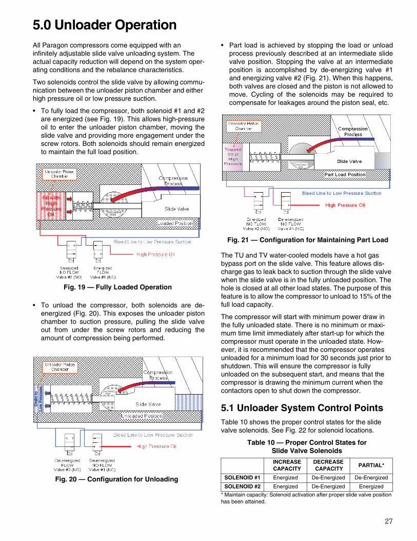
All Paragon compressors come equipped with an infinitely adjustable slide valve unloading system. The actual capacity reduction will depend on the system oper-ating conditions and the rebalance characteristics.
Two solenoids control the slide valve by allowing commu-nication between the unloader piston chamber and either high pressure oil or low pressure suction.
• To fully load the compressor, both solenoid #1 and #2are energized (see Fig. 19). This allows high-pressureoil to enter the unloader piston chamber, moving theslide valve and providing more engagement under thescrew rotors. Both solenoids should remain energizedto maintain the full load position.
• To unload the compressor, both solenoids are de-energized (Fig. 20). This exposes the unloader pistonchamber to suction pressure, pulling the slide valveout from under the screw rotors and reducing theamount of compression being performed.
.
• Part load is achieved by stopping the load or unloadprocess previously described at an intermediate slidevalve position. Stopping the valve at an intermediateposition is accomplished by de-energizing valve #1and energizing valve #2 (Fig. 21). When this happens,both valves are closed and the piston is not allowed tomove. Cycling of the solenoids may be required tocompensate for leakages around the piston seal, etc.
The TU and TV water-cooled models have a hot gas bypass port on the slide valve. This feature allows dis-charge gas to leak back to suction through the slide valve when the slide valve is in the fully unloaded position. The hole is closed at all other load states. The purpose of this feature is to allow the compressor to unload to 15% of the full load capacity.
The compressor will start with minimum power draw in the fully unloaded state. There is no minimum or maxi- mum time limit immediately after start-up for which the compressor must operate in the unloaded state. How-ever, it is recommended that the compressor operates unloaded for a minimum load for 30 seconds just prior to shutdown. This will ensure the compressor is fully unloaded on the subsequent start, and means that the compressor is drawing the minimum current when the contactors open to shut down the compressor.
5.1 Unloader System Control PointsTable 10 shows the proper control states for the slide valve solenoids. See Fig. 22 for solenoid locations.
Table 10 — Proper Control States for Slide Valve Solenoids
* Maintain capacity: Solenoid activation after proper slide valve position has been attained.
Fig. 19 — Fully Loaded Operation
Fill with HighPressure Oil DISCHARGE
PORT
Fig. 20 — Configuration for Unloading
DISCHARGE PORT
D
rain
toLo
w P
ress
ure
INCREASECAPACITY
DECREASE CAPACITY
PARTIAL*
SOLENOID #1 Energized De-Energized De-Energized
SOLENOID #2 Energized De-Energized Energized
Fig. 21 — Configuration for Maintaining Part Load
DISCHARGE PORT
5.0 Unloader Operation

28
5.2 Approximate Part Load FactorsTable 11 shows the typical relation of part load capacity and power at their respective rating conditions. Contact Carlyle Application Engineering for further information.
Table 11 — Typical Relation of Part Load Capacity
Certain fully unloaded operating conditions may result in discharge gas temperatures which exceed the recom-mended operating parameters. Carlyle requires that some form of liquid injection be applied to control/reduce discharge gas temperatures to be within recommended guidelines. Common methods to accomplish this may include increased flow through the economizer circuit or direct liquid injection into the economizer port/tubing.
5.3 Slide Valve Capacity Controller and Pro-tection
5.3.1 General Description
The Carlyle Control Module (CCM) will function to control compressor capacity by operating the compressor's slide valve to maintain the system's control set point (suction pressure or temperature). This process control point is an input to the CCM. In addition, the CCM will have function-
ality to protect the compressor and provide LED fault sta-tus indication for:
• Oil Level Protection• Oil Flow Protection• Motor Cooling Protection• Discharge Temperature Protection• Transducer Sensor Failure• Temperature Thermistor Failure
The following Paragon capacity and protection kits 6BSB000929 and 6BSB000930 are available through Carlyle. See Table 12. Detailed information regarding the Paragon Slide Valve controller may be found at www.car-lylecompressor.com, Application Guide 575-012.
5.3.2 CCM Configuration
The CCM can be configured to function in the following 3 modes of operation:
1. Slide Valve Control and Compressor Protection (Default Setting).
2. Slide Valve Control only.3. Compressor Protection only.
Configuring the CCM for options 2 or 3 can be accom-plished through:
• Using the BACview1 hand-held display unit.• Downloading BACview software to a laptop.• Setting up a communication port between the CCM
and System Controller.
To allow easier transmission of data across a network between the CCM and the System Controller, the CCM is pre-configured with the following protocol networks:
• BACnet2
• Modbus3
• N2 Open• LonWorks4 (requires optional card)• RS485 Communication Port
Table 12 — Paragon Capacity and Protection Kits
% FULL LOAD
CAPACITY
AIR-COOLED (R-134a) WATER-COOLED (R-134a)
% FULL LOAD POWER % FULL LOAD POWER
100 100 10075 78 7850 58 5834 50 5015 — 50
Fig. 22 — Solenoid Locations
SOLENOID 1
SOLENOID 2
HIGH PRESSURESWITCH
MOTORTEMPERATURESENSOR 2
COMMON
MOTORTEMPERATURESENSOR 1
SUCTIONTEMPERATURE
1. BACview is a registered trademark of Automated Logic Corporation.
2. BACnet is a registered trademark of ASHRAE (American Society of Heating, Refrigeration and Air-Conditioning Engineers).
3. Modbus is a registered trademark of Schneider Electric.4. LonWorks is a registered trademark of Echelon Corporation.
CARLYLE P/N DESCRIPTION APPLICATION6BSB000929 High Temperature Paragon Controller Kit R-134a, R513A, R1234ze6BSB000930 Low/Medium Temperature Paragon Controller Kit R404A, R-407A, R-407C, R-407F, R-448A, R-449A, R-507A
USB-L CCM Interface Cable Cable interface between controller and laptop

29
5.3.3 CCM Inputs/Outputs
Software Version 1.5 Schematics
Fig. 23 — CCM Inputs, Version 1.5
Fig. 24 — CCM Outputs, Version 1.5

30
5.3.4 CCM Inputs/Outputs
Software Version 2.0 Schematics
Fig. 25 — CCM Inputs, Version 2.0
Fig. 26 — CCM Outputs, Version 2.0

31
5.3.4 Slide Valve Capacity Control
The CCM will have the ability to control the compressor slide valve for capacity control by loading/unloading the compressor to maintain the refrigeration system's pro-cess control set point. The set point can be defined in one of two ways: refrigerant suction pressure (psig) or a leaving water temperature (deg. F). The end user will have to configure the CCM in the following way:
1. Select Pressure or Temperature for the process con-trol variable (default is Pressure).
2. Select Physical Input or Network Input (Network Input means the process control variable is not phys-ically wired to the CCM, but the value is being passed via the network to the CCM as an input).
3. Input the process control set point value.• Allowable pressure range is -1.5 psig to 70 psig
(-0.1 bar to 4.8 bar).• Allowable temperature range is -60°F to 80°F
(-51°C to 27°C).4. Steps 1, 2, 3 can be accomplished through:
• Using the BACview hand-held display unit.• Downloading BACview software to a laptop.• Setting up a communication port between the
CCM and System Controller.5. The CCM slide valve control logic works with two
upper and two lower dead-bands. The lower and upper dead- bands are adjustable control inputs to customize the capacity control algorithm per the application.
CCM Slide Valve Control Logic
The CCM slide valve control logic works with two upper and two lower deadbands. The lower and upper dead- bands are adjustable control inputs to customize the capacity control algorithm per the application. The num-bered phases below correspond with those that appear in Fig. 27.
1. On Process Point rise above the Upper DB-1 dead- band, the CCM will energize both unloader coils to load the compressor and increase capacity until the process point falls below Upper DB-2.
Slide Valve Coil #1-Energized
Slide Valve Coil #2 -Energized
2. If the Process Point decreases to the Upper DB-2 deadband limit, the CCM will stop the compressor from loading by de-energizing coil #1, fixing the slide valve position and keeping the compressor capacity constant.
Slide Valve Coil #1-De-energized
Slide Valve Coil #2 -Energized
NOTE: As long as the Process Point remains between the Upper DB-2 and Lower DB-3 deadband
limits, the slide valve will not move, but remain fixed, keeping the compressor capacity constant.
Slide Valve Coil #1-De-energized
Slide Valve Coil #2 -Energized
3. If the Process Point continues to fall and reaches the Lower DB-4 deadband limit, the CCM will de-ener-gize both unloader coils to unload the compressor and decrease compressor capacity.
Slide Valve Coil #1-De-energized
Slide Valve Coil #2 -De-energized
4. Both unloader coils will remain De-energized until the suction pressure rises to the Lower DB-3 deadband limit. This will stop compressor unloading, stopping the slide valve from moving and keeping the com-pressor capacity constant.
Slide Valve Coil #1-De-energized
Slide Valve Coil #2 -Energized

32
Fig. 27 — Paragon Slide Valve Control Illustration
5.3.5 Compressor Protection
Motor and discharge temperature control for a screw compressor is critical. Excessive motor and discharge gas temperatures can cause premature compressor fail-ure; therefore, control of these temperatures is very important. The CCM monitors these temperatures through the use of the factory-installed 5K thermistor in the motor windings and a field-installed 5K thermistor in the compressor discharge temperature thermo-well. When the thermistors indicate an overheated condition, the CCM will perform the following:
• Energize a liquid injection valve, sending cool liquid into the motor compartment.
• Override the Slide Valve and restrict the compressor from unloading and or force the compressor to fully load to reduce motor and or discharge temperature.
• Trip the compressor off.
Motor Temperature (Tm) will have the following functions:
• Control a motor cooling valve to provide liquid injec-tion to the motor compartment.
• Override the compressor slide valve to reduce motor temperature.
• Turn the compressor off on an overheated motor temperature condition.
• See Table 13: Motor and Discharge Temperature Control Points and Table 14: Slide Valve Override Control Points for Tm control points.
Motor Temperature (Td) will have the following functions:
• Override the compressor slide valve to reduce dis- charge temperature.
• Turn the compressor off on a high discharge tem-perature condition.
• See Table 13: Motor and Discharge Temperature Control Points and Table 14: Slide Valve Override Control Points for Td control points.
5.3.6 LED Fault Indication
The CCM will provide an LED alarm output signal to the System Controller when a compressor fault condition arises. See Tables 15 and 16.

33
Table 13 — Motor and Discharge Temperature Control Points
Table 14 — Slide Valve Override Control Points
LEGEND
SV— Slide Valve
Table 15 — Fault Codes for Software Version 1.5
Table 16 — Fault Codes for Software Version 2.0
ALC CONTROLLER INJECTION ON (°F)INJECTION OFF
(°F)
SHUTDOWN COMPRESSOR
(°F)MANUALLY RESET COMPRESSOR (°F)
TIME DELAY REQUIRED BEFORE
MANUAL RESET (SEC)
Discharge Temperature (Td)
N/A N/A Td > 225 Td < 175 30
Motor Cooling Temperature (Tm)
Tm > 240 Tm < 225 Tm > 270 Tm < 225 30
ALC CONTROLLERRESTRICT FURTHER COMPRESSOR UNLOADING
Energize SV Coil #2 Continuously (°F)
FULLY LOAD COMPRESSOR AND RESTRICT UNLOADING BELOW 100% Energize SV Coil #1 and
Coil #2 Continuously (°F)
SV - Discharge Temperature (Td)
200 < Td < 215(discontinue SV override when Td < 198
Td > 215(discontinue SV override when Td < 213)
SV - Motor Cooling Temperature (Tm)
245 < Tm < 260(discontinue SV override when Tm < 243
Tm > 260(discontinue SV override when Tm < 258)
FAULT DESCRIPTION LED INDICATION (OUTPUT#4) OUTPUT #5 COMPRESSORMANUAL RESET
REQUIRED
High Discharge Temperature Trip Solid red Opens/De-energized OFF Yes
High Motor Temperature Trip Constant blinking Opens/De-energized OFF Yes
Compressor Oil Trip One blink and 2-second pause Opens/De-energized OFF Yes
Faulty Transducer/ Thermistor Slide Valve Sensor
One blink and 2-second pause Opens/De-energized OFF Yes
Faulty Motor Temperature Thermistor
Three blinks and 2-second pause Opens/De-energized OFF Yes
Faulty Discharge Temperature Thermistor
Four blinks and 2-second pause Opens/De-energized OFF Yes
Faulty Discharge Pressure Transducer
Five blinks and 2-second pause Opens/De-energized OFF Yes

34
5.3.7 CCM Controller Display Features
The CCM controller requires the user to install the Virtual BACview6 software to their laptop. This software can be obtained at www.carlylecompressor.com under software. Once installed, using the USB-L interface cable, the user can configure and setup the controller, view inputs, out-puts, status, and fault codes.
BACview6 Virtual Display
The virtual BACview software (see Fig. 28) simulates the BACview6 Handheld keypad and display. It has all the
same functionality as the BACview6 device except that it is a software-based application that is easily displayed on any laptop.
Once the BACview6 software is installed, the user will use the 12-ft interface cable (Carlyle Part# USB-L) to communicate between the laptop and the CCM. Drivers are supplier with the USB-L cable. Install the drivers to the laptop. See Fig. 29. This is also covered in the BACview User Guide.
Fig. 28 — BACview6 Laptop Display
Fig. 29 — Laptop-to-BACview6 Connection Schematic

35
5.1.1 General Installation
The CCM can mount directly inside the compressor's electrical box as shown in Fig. 30.
Fig. 30 — CCM Mounted inside Compressor Box

36
6.1 Compressor RequirementsThe compressor is designed to meet the UL and ASHRAE safety code for refrigeration compressors. The manufacturing facilities for the compressor conduct pres-sure burst tests in accordance with ASHRAE-15, UL safety codes and the Pressure Equipment 97/23/CEE directive.
6.2 Design PressuresPressure Relief Valve
The internal relief valve is designed to open when the pressure differential between suction and discharge pres- sure is greater than 27.6 bar (400 psid) for R-134a and greater than 30 bar (435 psid) for R-404A. The valve will close and seal again after the pressure difference falls below the set value.
Hydrostatic Design Pressures
The design pressures for the compressor castings are listed in Table 17.
Table 17 — Compressor Design Pressures
LEGEND
LT — Low Temperature Refrigeration
NOTE: All pressures listed are gage pressures. Add 14.7 psi (0.1 MPa) to obtain absolute pressure, if necessary.
PRESSURE TYPE APPLICATION DISCHARGE ECONOMIZER SUCTION
Hydrostatic BurstTest Pressure (BURST)
R-134a Water-Cooled 950 psig (6.6 MPa) 540 psig (3.7 MPa) 440 psig (3.0 MPa)
R-134a Air-Cooled 1470 psig (10.1 MPa) 610 psig (4.2 MPa) 440 psig (3.0 MPa)
R-404A LT Ref 1770 psig (12.2 MPa) 1040 psig (7.2 MPa) 870 psig (6.0 MPa)
Proof Test Pressure (TP)
R-134a Water-Cooled
465 psig (3.2 MPa)R-134a Air-Cooled
R-404A LT Ref
Maximum Operating Pressure (MOP)
R-134a Water-Cooled 190 psig (1.3 MPa) 108 psig (0.7 MPa) 61 psig (0.4 MPa)
R-134a Air-Cooled 294 psig (2.0 MPa) 122 psig (0.8 MPa) 51 psig (0.4 MPa)
R-404A LT Ref 354 psig (2.4 MPa) 116 psig (0.8 MPa) 38 psig (0.3 MPa)
Leak Test Pressure(AP)
R-134a Water-Cooled
310 psig (2.1 MPa)R-134a Air-Cooled
R-404A LT Ref
UL60335-2-34 DesignPressure (DP)
R-134a Water-Cooled 190 psig (1.3 MPa) 108 psig (0.7 MPa) 88 psig (0.6 MPa)
R-134a Air-Cooled 294 psig (2.0 MPa) 122 psig (0.8 MPa) 88 psig (0.6 MPa)
R-404A LT Ref 354 psig (2.4 MPa) 116 psig (0.8 MPa) 176 psig (1.2 MPa)

37
7.1 ScopeCarlyle has conducted an extensive qualification program for our R-134a compressors and has approved most compressors for VFD applications. A summary of the qualified models is presented in Table 18.
Table 18 —Variable Speed Model Summary
NOTES:
1. See Application Engineering as approval is limited to certain applica-tions.
2. See Application Engineering as compressor has been approved but limited performance data is available.
3. Standard model cannot be used for VFD applications. The “VS” model must be ordered, which is identified by an “X” in the 5th digit of the model number.
4. Variable speed operation is approved for all low/medium temperature R-404A, R-407A, R-407C, R407F, R-448A, R-449A, and R-507A.
It may be possible to have the drive provide the compres-sor motor protection, replacing the compressor over- loads. Carlyle Application Engineering should be con-tacted to verify that the overcurrent protection meets Carlyle's requirements for UL-rated motor overload pro-tection and to verify the required overload settings.
It is important to work with the drive manufacturer to select a drive appropriate for the application. Refrigera-tion screw compressors provide a constant torque load-ing to the drive and also have unique starting torque requirements. The drive should not be sized on the nomi-nal HP rating of the compressor, but based on the nomi-nal electrical data, including RLA and LRA (available in Section 8.3), along with the operating power and amper-age at the max load design condition. It is important that the appropriate criteria are taken into consideration when selecting the type and size of the drive.
It is also important to review items associated with the wiring of the compressor and associated control system wiring, as special precautions may be required to avoid interference between the drive and other control wiring. There may also be restrictions on the length and routing of the wires from the drive to the compressor. These items should be reviewed with the drive manufacturer to
ensure all application guidelines are followed when installing the drive.
7.2 Capacity ControlThe compressors have been approved with an allowable speed range from 30 to 60 Hz. The capacity at 30 Hz will be approximately 50% of the full load capacity and will vary linearly in direct proportion to the speed.
It is possible to operate the compressors with a combina-tion of slide valve and VFD control. The compressor can be operated at minimum speed of 30 Hz and the slide valve used for further unloading as long as appropriate discharge and motor temperature limits are observed. The compressor slide valve should remain in the fully loaded position while the VFD is controlling compressor capacity between 30 to 60 Hz. The slide valve may be used to reduce compressor capacity below 50% (30hz) if required.
Discharge Temperature
1. Compressor must be forced to 100% load if discharge temperature 200°F (93.3°C).
2. Unloading control must limit further unloading if dis-charge temperature 190°F (87.8°C)
Motor Temperature
1. Compressor must be forced to 100% load if motor tem-perature 265°F (129.4°C).
2. Unloading control must limit further unloading if motor temperature 260°F (126.7°C)
NOTE: Different temperature limits may be required depending on the accuracy and response time of the sensors and control system that is used as well as the overall stability of the system and desired safety factor.
7.3 Power SupplyThe variable speed drive should fix the output voltage based on a constant Volts-per-Hz curve running through the nominal voltage (380V/60Hz, 460V/60Hz) regardless of the nominal voltage supplied to the drive. The drive should maintain a constant V-Hz over the range of opera-tion and should limit the speed of the drive if the appropri-ate voltage cannot be maintained. Over voltage should be limited to +10% and under voltage limited to –15%. Under voltage should limit the speed (Hz) until the con-stant V-Hz curve is reached. Over voltage should limit operation at the maximum speed, 60 Hz. The VFD should also limit the amperage of the compressor to 90% of the MCC (maximum continuous current) value (lower amperage limits may be applied depending on the application). It may be necessary to limit the speed of the
MODELNUMBER
APPROVED FOR VARIABLE SPEEDAIR-COOLED WATER-COOLED3
06TS-137 Note 1 and 2 N/A06TS-155 YES N/A06TS-186 YES N/A06TT-266 YES Note 106TT-301 YES Note 106TT-356 YES Note 106TU-483 YES YES, Note 306TU-554 YES YES, Note 306TV-680 YES YES, Note 306TV-753 Note 2 YES, Note 306TV-819 YES Note 2 and 3
7.0 Variable Frequency Drive Guidelines

38
compressor at high load conditions, especially if operat-ing below the nominal voltage.
Figure 31 shows two sample voltage curves showing compressor motor voltage (V) versus operating speed
(Hz). As shown in the graph, the motor voltage is lowered at lower operating speeds while maintaining a fixed Volts/Hz value.
600
500
400
300
200
100
00 10 20 30 40 50 60
Frequency (Hz)
Mot
or V
olts
(V)
380V460V
Fig. 31 — Sample Compressor Motor Voltage Curves
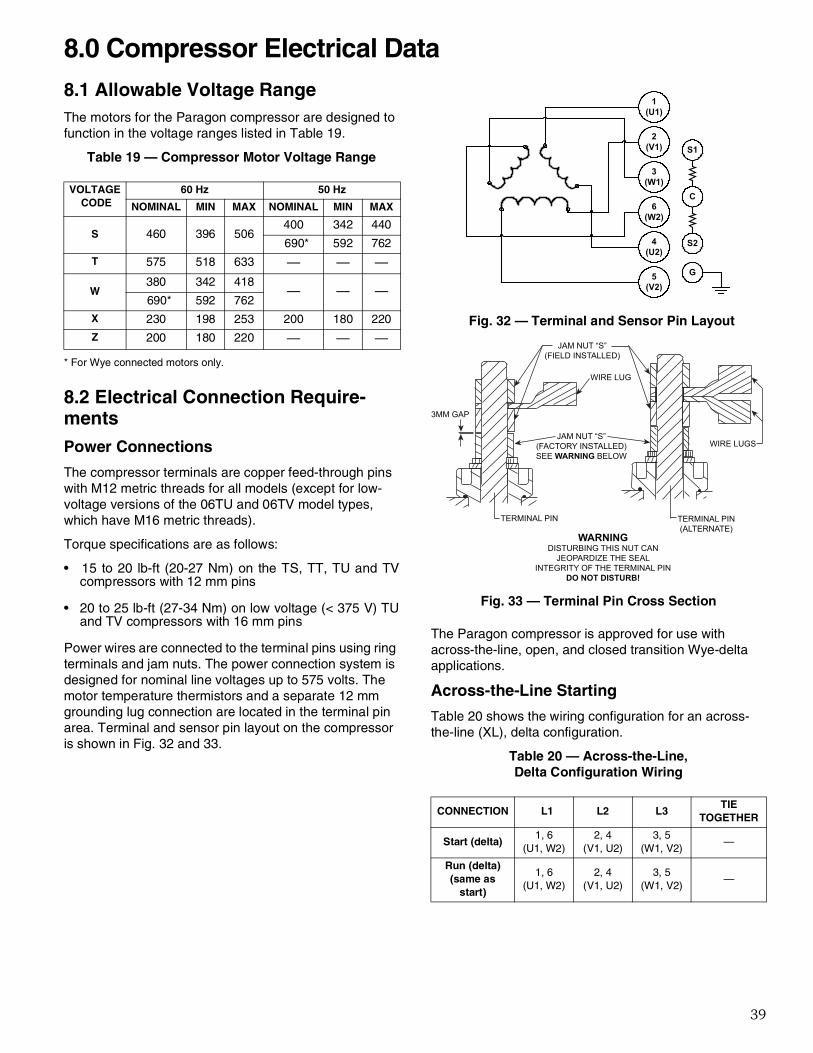
39
8.1 Allowable Voltage RangeThe motors for the Paragon compressor are designed to function in the voltage ranges listed in Table 19.
Table 19 — Compressor Motor Voltage Range
* For Wye connected motors only.
8.2 Electrical Connection Require-mentsPower Connections
The compressor terminals are copper feed-through pins with M12 metric threads for all models (except for low-voltage versions of the 06TU and 06TV model types, which have M16 metric threads).
Torque specifications are as follows:
• 15 to 20 lb-ft (20-27 Nm) on the TS, TT, TU and TVcompressors with 12 mm pins
• 20 to 25 lb-ft (27-34 Nm) on low voltage (< 375 V) TUand TV compressors with 16 mm pins
Power wires are connected to the terminal pins using ring terminals and jam nuts. The power connection system is designed for nominal line voltages up to 575 volts. The motor temperature thermistors and a separate 12 mm grounding lug connection are located in the terminal pin area. Terminal and sensor pin layout on the compressor is shown in Fig. 32 and 33.
The Paragon compressor is approved for use with across-the-line, open, and closed transition Wye-delta applications.
Across-the-Line Starting
Table 20 shows the wiring configuration for an across-the-line (XL), delta configuration.
Table 20 — Across-the-Line, Delta Configuration Wiring
VOLTAGE CODE
60 Hz 50 Hz
NOMINAL MIN MAX NOMINAL MIN MAX
S 460 396 506400 342 440
690* 592 762
T 575 518 633 — — —
W380 342 418
— — —690* 592 762
X 230 198 253 200 180 220
Z 200 180 220 — — —
CONNECTION L1 L2 L3TIE
TOGETHER
Start (delta)1, 6
(U1, W2)2, 4
(V1, U2)3, 5
(W1, V2)—
Run (delta)(same as
start)
1, 6(U1, W2)
2, 4(V1, U2)
3, 5(W1, V2)
—
S1
S2
C
G
1(U1)
2(V1)
3(W1)
4(U2)
6(W2)
5(V2)
Fig. 32 — Terminal and Sensor Pin Layout
a06-1674
3MM GAP
WIRE LUG
JAM NUT “S”(FIELD INSTALLED)
TERMINAL PIN TERMINAL PIN(ALTERNATE)
WIRE LUGSJAM NUT “S”
(FACTORY INSTALLED)SEE WARNING BELOW
WARNINGDISTURBING THIS NUT CAN
JEOPARDIZE THE SEALINTEGRITY OF THE TERMINAL PIN
DO NOT DISTURB!
Fig. 33 — Terminal Pin Cross Section
8.0 Compressor Electrical Data

40
Wye-Delta Starting (Open Transition)
There are two critical timing parameters associated with starting the Paragon compressor with an open transition wye-delta starter. The first is the maximum duration of running in the wye connection. It is recommended that the duration of the wye connection be 5 seconds. The duration of the wye connection can be longer but in no case should exceed 10 seconds. This is necessary to limit the potential for excessive heating of the motor.
The second critical timing parameter is the duration of the power interruption from when the wye connection is bro-ken to when the delta connection is made. It is recom-mended that the duration of this interruption not exceed the values given in Table 21 for single compressor cir-cuits. A shorter duration may be required if compressor must start against head pressure. Starter selections should be made such that this limit is not exceeded. Lon-ger interruption times could lead to excessive decelera-tion during the power interruption. Low running speed at transition will result in inrush currents similar to the delta locked rotor current.
Table 21 — Maximum Transition Time
Table 22 shows the wiring configuration for an open tran-sition wye-delta start configuration.
Table 22 — Wye-Delta Start Configuration Wiring
Motor Windings Thermistor
The motor winding thermistor is embedded directly into the windings of the motor. The thermistor is an NTC type with a standard resistance of 5000 ohms at 77°F (25°C). All Paragon compressor motors are supplied with a spare thermistor to be used if the primary thermistor fails. Table 23 lists the resistance versus temperature characteris-tics. Additional information regarding this sensor can be obtained from Carlyle Application Engineering.
Table 23 — Resistance vs Temperature
MODEL MAXIMUM TRANSITION TIME
TS 0.035 seconds
TT 0.055 seconds
TU 0.060 seconds
TV 0.060 seconds
CONNECTION L1 L2 L3TIE
TOGETHER
Start (wye)(5 seconds)
1(U1)
2(V1)
3(W1)
4, 5, 6(U1, V2, W2)
Run (delta)1, 6
(U1, W2)2, 4
(V1, U2)3, 5
(W1, V2)—
TEMPERATURE RESISTANCE
C ±C F ohms
–30 .35 –22 88480.0
–25 .33 –13 65205.0
–20 .30 –4 48536.0
–15 .28 5 36476.0
–10 .20 14 27663.0
–5 .20 23 16325.0
5 .20 41 12696.0
10 .20 50 9949.5
15 .20 59 7855.5
20 .20 68 6246.0
25 .20 77 5000.0
30 .20 86 4028.4
35 .20 95 3265.7
40 .20 104 2663.2
45 .20 113 2184.2
50 .20 122 1801.2
55 .20 131 1493.1
60 .20 140 1243.9
65 .20 149 1041.4
70 .20 158 875.8
75 .23 167 739.7
80 .26 176 627.6
85 .29 185 534.9
90 .32 194 457.7
95 .35 203 393.3
100 .38 212 339.3
105 .41 221 293.8
110 .44 230 255.3
115 .47 239 222.6
120 .50 248 194.8

41
8.3 Motor DataSee Tables 24-27 for motor data.
Table 24 — Air-Cooled Motor Data R-134a, R-1234ZE & R-513A
COMPRESSOR BASE MODELS
MOTOR SIZE (HP AT 60 Hz)
MOTOR VOLTAGE (VOLTS-PH-FREQ) RLA
LRAWYE DELTA
06TSA137 60
460-3-60 89 162 505
400-3-50 86 160 500
690-3-50 50 289 NOTE 2
575-3-60 68 130 404
380-3-60 103 196 611
690-3-60 59 353 NOTE 2
230-3-60 178 324 1010
200-3-50 163 320 1000
200-3-60 196 373 1162
06TSA155 75
460-3-60 100 174 545
400-3-50 96 170 530
690-3-50 58 306 NOTE 2
575-3-60 76 139 436
380-3-60 116 211 660
690-3-60 67 381 NOTE 2
230-3-60 200 348 1090
200-3-50 183 340 1060
200-3-60 220 400 1254
06TSA186 75
460-3-60 116 174 545
400-3-50 112 170 530
690-3-50 65 306 NOTE 2
575-3-60 89 139 436
380-3-60 135 211 660
690-3-60 78 381 NOTE 2
230-3-60 233 348 1090
200-3-50 213 340 1060
200-3-60 256 400 1254
06TTA266 120
460-3-60 165 298 930
400-3-50 159 303 945
690-3-50 92 546 NOTE 2
575-3-60 126 238 744
380-3-60 191 361 1126
690-3-60 105 650 NOTE 2
230-3-60 330 596 1860
200-3-50 303 606 1890
200-3-60 363 685 2139
06TTA301 150
460-3-60 187 382 1190
400-3-50 181 388 1210
690-3-50 105 699 NOTE 2
575-3-60 143 306 952
380-3-60 217 462 1441
690-3-60 120 832 NOTE 2
230-3-60 375 764 2380
200-3-50 344 776 2420
200-3-60 412 879 2737

42
Table 24 — Air-Cooled Motor Data R-134a, R-1234ZE & R-513A (cont)
LEGEND
NOTES:1. Please contact Carlyle Application Engineering for proper motor pro-
tection device.2. Delta wiring is not applicable for the selected voltage.
COMPRESSOR BASE MODELS
MOTOR SIZE (HP AT 60 Hz)
MOTOR VOLTAGE (VOLTS-PH-FREQ) RLA
LRA
WYE DELTA
06TTA356 150
460-3-60 226 382 1190
400-3-50 218 388 1210
690-3-50 126 699 NOTE 2
575-3-60 173 306 952
380-3-60 262 462 1441
690-3-60 144 832 NOTE 2
230-3-60 452 764 2380
200-3-50 414 776 2420
200-3-60 497 879 2737
06TUA483 225
460-3-60 314 578 1800
400-3-50 303 587 1828
690-3-50 175 1055 NOTE 2
575-3-60 240 462 1440
380-3-60 363 700 2179
690-3-60 200 1258 NOTE 2
230-3-60 628 1156 3600
200-3-50 576 1174 3656
200-3-60 691 1329 4140
06TUA554 225
460-3-60 360 578 1800
400-3-50 347 587 1828
690-3-50 201 1055 NOTE 2
575-3-60 275 462 1440
380-3-60 417 700 2179
690-3-60 230 1258 NOTE 2
230-3-60 720 1156 3600
200-3-50 660 1174 3656
200-3-60 792 1329 4140
06TVA680 340
460-3-60 462 623 1900
400-3-50 438 629 1919
690-3-50 555 1108 NOTE 2
06TVA753 340
460-3-60 506 623 1900
400-3-50 487 629 1919
690-3-50 579 1108 NOTE 2
06TVA819 340
460-3-60 517 623 1900
400-3-50 504 629 1919
690-3-50 571 1108 NOTE 2
FREQ — FrequencyHP — HorsepowerLRA — Locked Rotor AmpsPH — PhaseRLA — Rated Load Amps

43
Table 25 — Water-Cooled Motor Data R-134a, R-1234ZE & R-513A
COMPRESSOR BASE MODELS
MOTOR SIZE (HP AT 60 Hz)
MOTOR VOLTAGE (VOLTS-PH-FREQ) RLA
LRA
WYE DELTA
06TTW266 90
460-3-60 124 229 715
400-3-50 120 233 726
690-3-50 69 419 NOTE 2
575-3-60 95 183 572
380-3-60 144 277 866
690-3-60 83 500 NOTE 2
230-3-60 249 458 1430
200-3-50 228 466 1452
200-3-60 274 527 1645
06TTW301 90
460-3-60 139 229 715
400-3-50 134 233 726
690-3-50 77 419 NOTE 2
575-3-60 106 183 572
380-3-60 161 277 866
690-3-60 89 500 NOTE 2
230-3-60 278 458 1430
200-3-50 255 466 1452
200-3-60 306 527 1645
06TTW356 120
460-3-60 161 298 930
400-3-50 155 303 945
690-3-50 90 546 NOTE 2
575-3-60 123 238 744
380-3-60 186 361 1126
690-3-60 107 650 NOTE 2
230-3-60 322 596 1860
200-3-50 295 606 1890
200-3-60 354 685 2139
06TUW483 160
460-3-60 199 408 1270
400-3-50 186 414 1290
690-3-50 108 745 NOTE 2
575-3-60 159 326 1016
380-3-60 240 494 1537
690-3-60 132 888 NOTE 2
230-3-60 397 816 2540
200-3-50 371 828 2580
200-3-60 457 938 2921

44
Table 25 — Water-Cooled Motor Data R-134a, R-1234ZE & R-513A (cont)
LEGEND
NOTES:
1. Please contact Carlyle Application Engineering for proper motor pro-tection device.
2. Delta wiring is not applicable for the selected voltage.
COMPRESSOR BASE MODELS
MOTOR SIZE (HP AT 60 Hz)
MOTOR VOLTAGE (VOLTS-PH-FREQ) RLA
LRA
WYE DELTA
06TUW554 160
460-3-60 223 408 1270
400-3-50 209 414 1290
690-3-50 121 745 NOTE 2
575-3-60 179 326 1016
380-3-60 270 494 1537
690-3-60 149 888 NOTE 2
230-3-60 447 816 2540
200-3-50 417 828 2580
200-3-60 514 938 2921
06TVW680 225
460-3-60 280 578 1800
400-3-50 261 587 1828
690-3-50 151 1055 NOTE 2
575-3-60 224 462 1440
380-3-60 338 700 2179
690-3-60 186 1258 NOTE 2
230-3-60 559 1156 3600
200-3-50 522 1174 3656
200-3-60 643 1329 4140
06TVW753 225
460-3-60 310 578 1800
400-3-50 289 587 1828
690-3-50 168 1055 NOTE 2
575-3-60 248 462 1440
380-3-60 375 700 2179
690-3-60 206 1258 NOTE 2
230-3-60 619 1156 3600
200-3-50 579 1174 3656
200-3-60 712 1329 4140
06TVW819 225
460-3-60 330 578 1800
400-3-50 308 587 1828
690-3-50 179 1055 NOTE 2
575-3-60 264 462 1440
380-3-60 400 700 2179
690-3-60 220 1258 NOTE 2
230-3-60 660 1156 3600
200-3-50 617 1174 3656
200-3-60 759 1329 4140
FREQ — FrequencyHP — HorsepowerLRA — Locked Rotor AmpsPH — PhaseRLA — Rated Load Amps

45
Table 26 — Low Temperature Motor Data
COMPRESSOR BASE MODELS
MOTOR SIZE (HP AT 60 Hz)
MOTOR VOLTAGE
(VOLTS-PH-FREQ)
RLA LRA
404A 407A 407C 407F 507A 448A 449A WYE DELTA
06TSR137 60
460-3-60 101 90 85 87 106 93 83 162 505
400-3-50 98 80 76 123 100 90 74 160 500
690-3-50 57 46 44 50 58 52 42 289 NOTE 1
575-3-60 78 72 68 99 85 72 66 130 404
380-3-60 117 109 103 149 128 108 100 196 611
690-3-60 67 60 57 82 71 62 55 353 NOTE 1
230-3-60 203 159 153 174 200 171 146 324 1010
200-3-50 186 180 171 247 212 187 166 320 1000
200-3-60 223 206 196 284 244 205 190 373 1162
06TSR155 75
460-3-60 108 97 93 118 113 99 89 174 545
400-3-50 119 87 84 146 108 109 80 170 530
690-3-50 72 51 49 69 63 66 47 306 NOTE 1
575-3-60 82 77 74 117 90 75 71 139 436
380-3-60 126 117 112 176 137 116 108 211 660
690-3-60 73 65 62 97 75 67 60 381 NOTE 1
230-3-60 217 175 168 237 216 209 161 348 1090
200-3-50 227 194 185 291 226 200 178 340 1060
200-3-60 239 223 213 355 260 220 205 400 1254
06TSR186 75
460-3-60 124 113 107 151 129 114 104 174 545
400-3-50 120 102 96 176 122 110 94 170 530
690-3-50 69 59 49 87 71 63 54 306 NOTE 1
575-3-60 95 90 74 140 103 87 83 139 436
380-3-60 144 136 112 213 156 132 125 211 660
690-3-60 73 75 62 117 86 67 69 381 NOTE 1
230-3-60 249 204 168 301 244 209 188 348 1090
200-3-50 227 225 185 351 258 229 207 340 1060
200-3-60 273 259 213 404 297 251 238 400 1254
06TTR266 120
460-3-60 190 179 171 213 195 175 165 298 930
400-3-50 183 165 159 239 185 168 152 303 945
690-3-50 106 95 92 123 107 98 87 546 NOTE 1
575-3-60 145 143 137 191 156 133 132 238 744
380-3-60 220 216 207 289 236 202 199 361 1126
690-3-60 121 119 114 159 130 111 109 650 NOTE 1
230-3-60 380 329 317 426 370 321 303 596 1860
200-3-50 349 357 342 477 390 350 328 606 1890
200-3-60 418 411 393 549 449 385 378 685 2139

46
Table 26 — Low Temperature Motor Data (cont)
LEGEND
NOTES:
1. Please contact Carlyle Application Engineering for proper motor pro-tection device.
2. Delta wiring is not applicable for the selected voltage.
COMPRESSOR BASE MODELS
MOTOR SIZE (HP AT 60
Hz)
MOTOR VOLTAGE
(VOLTS-PH-FREQ)
RLA LRA
404A 407A 407C 407F 507A 448A 449A WYE DELTA
06TTR301 150
460-3-60 210 199 193 249 215 193 183 382 1190
400-3-50 203 185 180 218 205 187 170 388 1210
690-3-50 118 107 104 127 119 109 98 699 NOTE
575-3-60 160 159 154 199 172 147 146 306 952
380-3-60 243 240 233 301 260 224 221 462 1441
690-3-60 135 132 129 166 143 124 121 832 NOTE
230-3-60 421 369 360 437 410 355 339 764 2380
200-3-50 386 397 386 497 430 387 365 776 2420
200-3-60 462 457 443 572 495 425 420 879 2737
06TTR356 150
460-3-60 238 227 218 284 243 219 209 382 1190
400-3-50 229 211 203 260 231 211 194 388 1210
690-3-50 132 122 118 151 134 121 112 699 NOTE
575-3-60 182 181 174 227 194 167 167 306 952
380-3-60 275 274 263 344 294 253 252 462 1441
690-3-60 151 151 145 189 162 139 139 832 NOTE
230-3-60 475 422 407 521 462 400 388 764 2380
200-3-50 435 453 435 568 486 437 417 776 2420
200-3-60 523 521 500 653 559 481 479 879 2737
FREQ — FrequencyHP — HorsepowerLRA — Locked Rotor AmpsPH — PhaseRLA — Rated Load Amps

47
Table 27 — Medium Temperature Motor Data
LEGEND NOTES:
1. Please contact Carlyle Application Engineering for proper motor pro-tection device.
2. Delta wiring is not applicable for the selected voltage.
COMPRESSOR BASE MODELS
MOTOR SIZE (HP AT 60 Hz)
MOTOR VOLTAGE
(VOLTS-PH-FREQ)
RLA LRA
404A 407A 407C 407F 507A 448A 449A WYE DELTA
06TSM137 75
460-3-60 123 110 104 150 129 113 101 174 545
400-3-50 111 91 86 99 113 102 84 170 530
690-3-50 65 52 50 57 66 60 48 306 NOTE 1
575-3-60 99 91 86 126 108 91 84 139 436
380-3-60 149 139 131 190 163 137 128 211 660
690-3-60 82 73 70 100 87 75 67 381 NOTE 1
230-3-60 223 191 183 209 240 205 176 340 1060
200-3-50 246 218 207 299 257 226 201 348 1090
200-3-60 283 261 249 360 310 260 240 400 1254
06TSM155 75
460-3-60 126 103 98 155 120 116 89 174 545
400-3-50 118 95 92 129 118 109 80 170 530
690-3-50 68 48 46 65 60 63 47 306 NOTE 1
575-3-60 101 95 91 144 111 93 71 139 436
380-3-60 152 141 135 212 165 140 108 211 660
690-3-60 84 75 71 112 86 77 60 381 NOTE 1
230-3-60 235 181 174 245 224 216 161 340 1060
200-3-50 252 225 215 338 262 232 178 348 1090
200-3-60 290 271 258 406 315 267 205 400 1254
06TTM266 150
460-3-60 228 215 205 287 234 210 198 382 1190
400-3-50 216 195 188 251 218 199 179 388 1210
690-3-50 125 112 108 145 126 115 103 699 NOTE 1
575-3-60 183 180 173 241 197 168 166 306 952
380-3-60 276 271 260 363 296 254 249 462 1441
690-3-60 152 149 143 200 163 140 137 832 NOTE 1
230-3-60 433 408 393 529 459 398 375 776 2420
200-3-50 456 428 410 572 468 420 394 764 2380
200-3-60 525 516 494 690 564 483 475 879 2737
06TTM301 150
460-3-60 228 216 210 270 233 210 183 382 1190
400-3-50 217 198 192 233 219 200 170 388 1210
690-3-50 126 114 111 136 127 116 98 699 NOTE 1
575-3-60 183 182 176 228 197 168 146 306 952
380-3-60 276 273 265 342 295 254 221 462 1441
690-3-60 152 149 145 187 161 140 121 832 NOTE 1
230-3-60 434 415 405 491 461 399 339 776 2420
200-3-50 456 430 418 538 466 420 365 764 2380
200-3-60 525 519 503 650 563 483 420 879 2737
FREQ — FrequencyHP — HorsepowerLRA — Locked Rotor AmpsPH — PhaseRLA — Rated Load Amps

48
See Table 28 for universal accessory kit part numbers.
Table 28 — Universal Accessory Kit (for all Paragon models)
NOTE: One kit required for each compressor ordered.
9.1 Oil Separators9.1.1 Horizontal Oil Separators/Accessories
Compact Over/Under
Side-Mount
Side-Mount
CARLYLE PART
NUMBER
COMPRESSOR USAGE
TS TT TU TV
06TT660093 X X X X
CARLYLE PART
NUMBER
COMPRESSOR USAGE
06TS*137 06TS*155 06TS*186 06TT*266 06TT*301 06TT*356 06TU*483 06TU*554
8BSB000643 X X X X X
8BTB000644 X X X
CARLYLE PART
NUMBER
COMPRESSOR USAGE
06TS*137 06TS*155 06TS*186 06TT*266 06TT*301 06TT*356 06TU*483 06TU*554
8BSB000704 X X X X X
8BTB000705 X X X
CARLYLE PART
NUMBER
COMPRESSOR USAGE
06TV*680 06TV*713 06TV*819
8BVB000787 X X X
9.0 Compressor Accessories

49
9.2 Vertical Oil Separator Kit (for TS and TT models only)
NOTE: One kit required for each compressor ordered.
9.3 Horizontal Oil Separator Kit (for all Paragon models)
NOTE: One kit required for each compressor ordered.
9.4 Compressor Components Kit
NOTE: One kit required for each compressor ordered.
CARLYLE PART
NUMBER
COMPRESSOR USAGE
TS TT TU TV
06TT660094 X X N/A N/A
P/N 06TT660094 Vertical Oil Separator Kit QTY
HK13LB004 Oil Level Float 1
5H40-391 Oil Separator Heater insert, 230V 1
KH31ZZ212 Vertical Oil Separator 1
CARLYLE PART
NUMBER
COMPRESSOR USAGE
TS TT TU TV
06TT660095 X X X X
P/N 06TT660095 Horizontal Oil Separator Kit QTY
HT38KN007 Oil Separator Heater wrap, 230V 1
8CCB000742 Oil Level Sensor 1
8CCB000744 Oil Level Electronic unit (230 V) 1
CARLYLE PART
NUMBER
COMPRESSOR USAGE
TS TT TU TV
6BSA000320 X
6BTA000321 X
6BUA000322 X
6BVA000804 X

50
9.5 Compressor Protection and Slide Valve Capacity Control Kits
NOTES:
1. One Compressor Protection Module package required per com-pressor.
2. The interface cable is required to connect/configure the included module to a PC. The cable is also required for Field Service to read information from the module.
9.6 Service Valves 9.6.1 Suction/Discharge Service Valve Package
Flanged Union, Solder Type, Cast Iron Valve Body
LEGENDD — DischargeS — Suction
9.7 Motor Protection Devices
One motor overload is required per compressor. The overload follows a 958-trip curve
Installation instruction are provided with the overload part.
PART NUMBER DESCRIPTION WEIGHT (LBS) APPLICATION
6BSB000929 High Temperature Controller Kit 5 R-134a, R-513A, R-1234ze
6BSB000930 Low/Medium Temperature Controller 5R-404A, R-407A, R-407C, R-407F,
R-507A, R-448A, R-449A
USB-L Interface Cable 1 All
CARLYLE PARTNUMBER
NOMINAL TUBESIZE (in.)
COMPRESSOR USAGE
TS TT TU
06TT660064 2 5/8 D
06TT660065 3 1/8 S D
06TT660066 4 1/8 S D
PART NUMBER QUANTITY/PACKAGE WEIGHT (lb) CURRENT (AMPS)
06EA907185 1 2 10-40
06EA907186 1 2 25-100
06EA907187 1 2 50-200

51
9.8 Oil Coolers9.8.1 Air-Cooled Oil Coolers
NOTE: All low temperature duty Paragon compressors require oil cooling. Contact Carlyle Application Engineering for sizing information.
Oils
* Minimum order is quantity of 4, 1-gallon container.
CARLYLE PART NUMBER
COMPRESSOR USAGETS TT TU TV
KH51ZZ181 X X X X
KH51ZZ182 X X X X
KH51ZZ183 X X X X
KH51ZZ184 X X X X
PART NUMBER USAGE QUANTITY
SOLEST170-1G Low/Medium Temperature — 06TSR, 06TTR 1-Gallon Container
SOLEST170-5G Low/Medium Temperature — 06TSR, 06TTR 5-Gallon Container
P903-2301*Medium/High Temperature — 06TSA,
06TTA, 06TUA, 06TVA1-Gallon Container
P903-2305Medium/High Temperature — 06TSA,
06TTA, 06TUA, 06TVA5-Gallon Container

52
10.1 PackagingPackaging for the Paragon screw compressor utilizes a wooden pallet and shrink-wrap plastic.
10.2 ShippingAll compressors that are shipped within the U.S. or inter-nationally will be unstacked (single layer).
10.3 StorageAlthough the Paragon compressors are painted to meet the 500 hours salt spray requirement, it is preferable to store the compressors indoors where they are shielded from the weather. Outdoor storage is permissible as long as temperatures stay within a temperature range of 40°F to 176°F (40°C to 80°C).
10.4 Weights and DimensionsCompressor weights and dimensions are shown in Table 29. See also Fig. 34.
Table 29 — Basic Compressor Weight and Dimensions (Without Electrical Box and Oil Separator)
W
L
H
DISCHARGE SIDE VIEWW
L
H
DISCHARGE SIDE VIEW
Fig. 34 — Compressor Dimensions
W
L
H
ECONOMIZER SIDE VIEWW
L
H
ECONOMIZER SIDE VIEW
a06-1675
a06-1676
BASIC COMPRESSOR WEIGHT AND DIMENSIONS (WITHOUT ELECTRICAL BOX AND OIL SEPARATOR)
MODELWEIGHT
DIMENSIONS
HEIGHT ‘H’ WIDTH ‘W’ LENGTH ‘L’
lb kg in. mm in. mm in. mm
06TS-137--- 814 369 16 412 19 480 41 1029
06TS-155--- 830 376 16 412 19 480 41 1047
06TS-186--- 867 393 16 412 19 480 43 1091
06TT-266--- 1352 613 19 481 21 536 50 1276
06TT-301--- 1389 630 19 481 21 536 51 1299
06TT-356--- 1460 662 19 481 21 536 53 1347
06TU-483--- 2018 915 21 531 23 591 58 1466
06TU-554--- 2108 956 21 531 23 591 60 1514
06TV-680--- 2585 1173 23 583 24 608 68 1731
06TV-753--- 2608 1183 23 583 24 608 68 1731
06TV-819--- 2626 1191 23 583 24 608 68 1731
10.0 Packaging and Storage Requirements

10.5 Compressor/Compact Oil Separator Assembly
30.35
56.31
30.92
Fig. 35 — 06TSA137 Assembly Drawing
30.35
56.31
30.92
Fig. 36 — 06TSA155 Assembly Drawing
10.0 Packaging and Storage Requirements

54
30.35
56.31
30.92
Fig. 37 — 06TSA186 Assembly Drawing
33.06
58.75
32.50
Fig. 38 — 06TTA266 Assembly Drawing

55
32.50
33.06
58.75
Fig. 39 — 06TTA301 Assembly Drawing
36.44
58.30
32.04
Fig. 40 — 06TTA356 Assembly Drawing
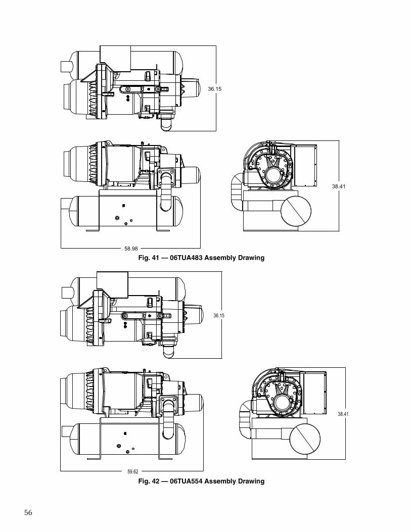
56
38.41
58.98
36.15
Fig. 41 — 06TUA483 Assembly Drawing
38.41
59.62
36.15
Fig. 42 — 06TUA554 Assembly Drawing