Interface I-300 Operation Manual - Buchi.com
82
Interface I-300 Operation Manual STOP 11593772 | H en
-
Upload
khangminh22 -
Category
Documents
-
view
1 -
download
0
Transcript of Interface I-300 Operation Manual - Buchi.com
Interface I-300Operation Manual
STOP
1159
3772
| H
en
Imprint
Product Identification:Operation Manual (Original) Interface I-30011593772
Publication date: 07.2022
Version H
BÜCHI Labortechnik AGMeierseggstrasse 40PostfachCH-9230 Flawil 1E-Mail: [email protected] reserves the right to make changes to the manual as deemed necessary in the light of experience,especially with respect to structure, illustrations and technical details.This manual is copyrighted. Information from it may neither be reproduced, distributed, or used forcompetitive purposes, nor made available to third parties. The manufacture of any component with theaid of this manual without prior written agreement is also prohibited.
Büchi Labortechnik AG Table of contents
Operation Manual Interface I-300 iii
Contents
1 About this document........................................................................................................... 61.1 Warning notices in this document.......................................................................................... 61.2 Symbols................................................................................................................................. 6
1.2.1 Warning symbols ...................................................................................................... 61.2.2 Mark-ups and symbols ............................................................................................. 7
1.3 Trademarks ........................................................................................................................... 7
2 Safety.................................................................................................................................... 82.1 Intended use.......................................................................................................................... 82.2 Use other than that intended ................................................................................................. 82.3 Staff qualification ................................................................................................................... 82.4 Residual risks ........................................................................................................................ 9
2.4.1 Faults during operation............................................................................................. 92.5 Personal protective equipment .............................................................................................. 92.6 Modifications.......................................................................................................................... 9
3 Product description........................................................................................................... 113.1 Description of function ......................................................................................................... 113.2 Description of function Cloud Services (Option).................................................................. 113.3 Configuration ....................................................................................................................... 12
3.3.1 Front view ............................................................................................................... 123.3.2 Rear view................................................................................................................ 123.3.3 VacuBox (connections)........................................................................................... 133.3.4 LegacyBox (connections) ....................................................................................... 143.3.5 Display (touch-screen)............................................................................................ 163.3.6 Type plate............................................................................................................... 17
3.4 Navigating through the menu system .................................................................................. 173.4.1 Menu bar ................................................................................................................ 173.4.2 Favorites menu....................................................................................................... 183.4.3 Operating modes menu .......................................................................................... 183.4.4 Configuration menu ................................................................................................ 193.4.5 Libraries menu........................................................................................................ 223.4.6 Symbols on the status bar ...................................................................................... 22
3.5 Scope of delivery ................................................................................................................. 233.6 Technical data ..................................................................................................................... 23
3.6.1 Interface.................................................................................................................. 233.6.2 Junction boxes........................................................................................................ 233.6.3 Ambient conditions ................................................................................................. 243.6.4 Materials ................................................................................................................. 24
4 Transport and storage ...................................................................................................... 254.1 Transport ............................................................................................................................. 254.2 Storage ................................................................................................................................ 25
Table of contents Büchi Labortechnik AG
iv Operation Manual Interface I-300
5 Installation.......................................................................................................................... 265.1 Fitting the Interface I-300/I-300 Pro..................................................................................... 26
5.1.1 Mounting interface on Rotavapor R-300................................................................. 265.1.2 Fitting interface unit on Vacuum Pump V-300 ........................................................ 285.1.3 Mounting interface unit on laboratory stand (optional accessory) .......................... 295.1.4 Mounting interface unit on a wall bracket (optional accessory) .............................. 30
5.2 Connecting the interface unit............................................................................................... 305.2.1 Connecting communication cables to interface unit ............................................... 315.2.2 Establishing LAN connection.................................................................................. 325.2.3 Overview: Setting up communication connections (COM) ..................................... 335.2.4 Overview: setting up coolant tubing connections ................................................... 335.2.5 Overview: setting up vacuum tubing connections .................................................. 34
5.3 Connecting AutoDest sensor to vapor temperature sensor (optional accessory) ............... 365.4 Connecting foam sensor (optional accessory) .................................................................... 375.5 Connecting valve unit for external vacuum.......................................................................... 395.6 Operating I-300 and I-300 Pro in parallel ............................................................................ 39
6 Operation............................................................................................................................ 406.1 Navigating the menu............................................................................................................ 40
6.1.1 Selecting menu items ............................................................................................. 406.1.2 Entering parameter settings ................................................................................... 416.1.3 Changing settings................................................................................................... 41
6.2 Performing distillation .......................................................................................................... 426.2.1 Overview: typical distillation sequence ................................................................... 426.2.2 Basic functions ....................................................................................................... 436.2.3 Executing Manual mode ......................................................................................... 446.2.4 Executing Timer mode............................................................................................ 476.2.5 Executing Continuous Pumping mode ................................................................... 506.2.6 Performing automatic distillation............................................................................. 526.2.7 Executing Drying mode .......................................................................................... 55
6.3 Using the solvent library ...................................................................................................... 566.4 Activating eco mode ............................................................................................................ 586.5 Setting hysteresis ................................................................................................................ 596.6 Creating favorites ................................................................................................................ 596.7 Activating Come here function............................................................................................. 60
7 Cleaning and servicing ..................................................................................................... 617.1 Cleaning the casing/display................................................................................................. 617.2 Performing a leak test.......................................................................................................... 617.3 Checking vacuum seal ........................................................................................................ 627.4 Fitting GL14 cap nut with tube seal ..................................................................................... 627.5 Checking seals .................................................................................................................... 637.6 Calibrating AutoDest sensor................................................................................................ 637.7 Calibrating the pressure sensor........................................................................................... 64
7.7.1 Offset calibration..................................................................................................... 657.7.2 Simple calibration ................................................................................................... 657.7.3 Loading factory calibration...................................................................................... 66
Büchi Labortechnik AG Table of contents
Operation Manual Interface I-300 v
8 Help with faults .................................................................................................................. 678.1 Faults, possible causes and remedies ................................................................................ 678.2 Error messages ................................................................................................................... 678.3 Customer service................................................................................................................. 678.4 eSupport .............................................................................................................................. 68
9 Taking out of service and disposal.................................................................................. 699.1 Taking out of service ........................................................................................................... 699.2 Disposal .............................................................................................................................. 69
10 Appendix ............................................................................................................................ 7010.1 Solvent table........................................................................................................................ 7010.2 Spare parts and accessories ............................................................................................... 71
10.2.1 Accessories ............................................................................................................ 7110.2.2 Wearing parts ......................................................................................................... 7410.2.3 Spare parts ............................................................................................................. 75
10.3 Health and safety approval.................................................................................................. 7610.4 Health and safety................................................................................................................. 7610.5 Handling data ...................................................................................................................... 77
10.5.1 Counter data........................................................................................................... 7910.5.2 Distillation session data .......................................................................................... 7910.5.3 Error data................................................................................................................ 7910.5.4 Maintenance data ................................................................................................... 7910.5.5 System configuration data ...................................................................................... 8010.5.6 Data storage period ................................................................................................ 8010.5.7 Device settings ....................................................................................................... 8010.5.8 Contact data ........................................................................................................... 8010.5.9 Location data .......................................................................................................... 80

1 | About this document Büchi Labortechnik AG
6/82 Operation Manual Interface I-300
1 About this documentThis operation manual is applicable for all variants of the instrument.Read this operation manual before operating the instrument and follow theinstructions to ensure safe and trouble-free operation.Keep this operation manual for later use and pass it on to any subsequent user orowner.BÜCHI Labortechnik AG accepts no liability for damage, faults and malfunctionsresulting from not following this operation manual.If you have any questions after reading this operation manual:u Contact BÜCHI Labortechnik AG Customer Service.
https://www.buchi.com/contact
1.1 Warning notices in this documentWarning notices warn you of dangers that can occur when handling the device.There are four danger levels, each identifiable by the signal word used.
Signal word Meaning
DANGER Indicates a danger with a high level of risk which could result indeath or serious injury if not prevented.
WARNING Indicates a danger with a medium level of risk which could result indeath or serious injury if not prevented.
CAUTION Indicates a danger with a low level of risk which could result in mi-nor or medium-severity injury if not prevented.
NOTICE Indicates a danger that could result in damage to property.
1.2 SymbolsThe following symbols are displayed in this operation manual or on the device:
1.2.1 Warning symbols
Symbol Meaning Symbol Meaning
General warning Corrosive substance
Dangerous electrical voltage Flammable substance
Biological hazard Potentially explosive atmos-phere
Breakable items Dangerous gases
Hot surface Health-harming or irritantsubstances

Büchi Labortechnik AG About this document | 1
Operation Manual Interface I-300 7/82
Symbol Meaning Symbol Meaning
Risk of hand injury Strong magnetism
1.2.2 Mark-ups and symbols
NOTE
This symbol draws attention to useful and important information.
R This character draws attention to a requirement that must be met before theinstructions below are carried out.
u This character indicates an instruction that must be carried out by the user.
ð This character indicates the result of a correctly carried out instruction.
Mark-up Explanation
Window Software Windows are marked-up like this.
Tab Tabs are marked-up like this.
Dialog Dialogs are marked-up like this.
[Button] Buttons are marked-up like this.
[Field names] Field names are marked-up like this.
[Menu / Menu item] Menus or menu items are marked-up like this.
Status Status is marked-up like this.
Signal Signals are marked-up like this.
1.3 TrademarksProduct names and registered or unregistered trademarks that are used in thisdocument are used only for identification and remain the property of the owner ineach case.
2 | Safety Büchi Labortechnik AG
8/82 Operation Manual Interface I-300
2 Safety
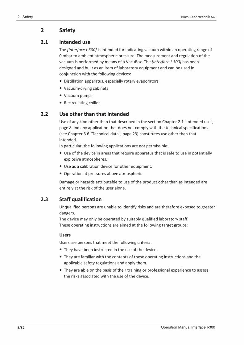
2.1 Intended useThe [Interface I-300] is intended for indicating vacuum within an operating range of0 mbar to ambient atmospheric pressure. The measurement and regulation of thevacuum is performed by means of a VacuBox. The [Interface I-300] has beendesigned and built as an item of laboratory equipment and can be used inconjunction with the following devices:
� Distillation apparatus, especially rotary evaporators
� Vacuum-drying cabinets
� Vacuum pumps
� Recirculating chiller
2.2 Use other than that intendedUse of any kind other than that described in the section Chapter 2.1 "Intended use",page 8 and any application that does not comply with the technical specifications(see Chapter 3.6 "Technical data", page 23) constitutes use other than thatintended.In particular, the following applications are not permissible:
� Use of the device in areas that require apparatus that is safe to use in potentiallyexplosive atmospheres.
� Use as a calibration device for other equipment.
� Operation at pressures above atmospheric
Damage or hazards attributable to use of the product other than as intended areentirely at the risk of the user alone.
2.3 Staff qualificationUnqualified persons are unable to identify risks and are therefore exposed to greaterdangers.The device may only be operated by suitably qualified laboratory staff.These operating instructions are aimed at the following target groups:
UsersUsers are persons that meet the following criteria:
� They have been instructed in the use of the device.
� They are familiar with the contents of these operating instructions and theapplicable safety regulations and apply them.
� They are able on the basis of their training or professional experience to assessthe risks associated with the use of the device.

Büchi Labortechnik AG Safety | 2
Operation Manual Interface I-300 9/82
OperatorThe operator (generally the laboratory manager) is responsible for the followingaspects:
� The device must be correctly installed, commissioned, operated and serviced.
� Only suitably qualified staff may be assigned the task of performing theoperations described in these operating instructions.
� The staff must comply with the local applicable requirements and regulations forsafe and hazard-conscious working practices.
� Safety-related incidents that occur while using the device should be reported tothe manufacturer ([email protected]).
BUCHI service techniciansService technicians authorized by BUCHI have attended special training courses andare authorized by BÜCHI Labortechnik AG to carry out special servicing and repairmeasures.
2.4 Residual risksThe device has been developed and manufactured using the latest technologicaladvances. Nevertheless, risks to persons, property or the environment can arise ifthe device is used incorrectly.Appropriate warnings in this manual serve to alert the user to these residualdangers.
2.4.1 Faults during operationIf a device is damaged, sharp edges, moving parts or exposed electrical wires cancause injuries.u Regularly check device for visible damage.u If faults occur, switch off the device immediately, unplug the power cord and
inform the operator.u Do not continue to use devices that are damaged.
2.5 Personal protective equipmentDepending on the application, hazards due to heat and/or corrosive chemicals mayarise.u Always wear appropriate personal protective equipment such as safety goggles,
protective clothing and gloves.u Make sure that the personal protective equipment meets the requirements of
the safety data sheets for all chemicals used.
2.6 ModificationsUnauthorized modifications may impair safety and lead to accidents.u Use only genuine BUCHI accessories, spare parts and consumables.u Technical modifications to the device or accessories should only be carried out
with the prior written approval of BÜCHI Labortechnik AG and only by authorizedBUCHI technicians.

2 | Safety Büchi Labortechnik AG
10/82 Operation Manual Interface I-300
BUCHI accepts no liability whatsoever for damage arising as a result of unauthorizedmodifications.
Büchi Labortechnik AG Product description | 3
Operation Manual Interface I-300 11/82
3 Product description
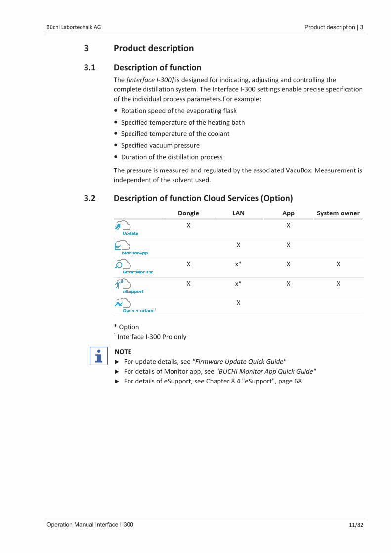
3.1 Description of functionThe [Interface I-300] is designed for indicating, adjusting and controlling thecomplete distillation system. The Interface I-300 settings enable precise specificationof the individual process parameters.For example:
� Rotation speed of the evaporating flask
� Specified temperature of the heating bath
� Specified temperature of the coolant
� Specified vacuum pressure
� Duration of the distillation process
The pressure is measured and regulated by the associated VacuBox. Measurement isindependent of the solvent used.
3.2 Description of function Cloud Services (Option)Dongle LAN App System owner
X X
X X
X x* X X
X x* X X
1
X
* Option1 Interface I-300 Pro only
NOTEu For update details, see "Firmware Update Quick Guide"u For details of Monitor app, see "BUCHI Monitor App Quick Guide"u For details of eSupport, see Chapter 8.4 "eSupport", page 68
3 | Product description Büchi Labortechnik AG
12/82 Operation Manual Interface I-300
3.3 Configuration
3.3.1 Front view
STOP
1
3
2
4
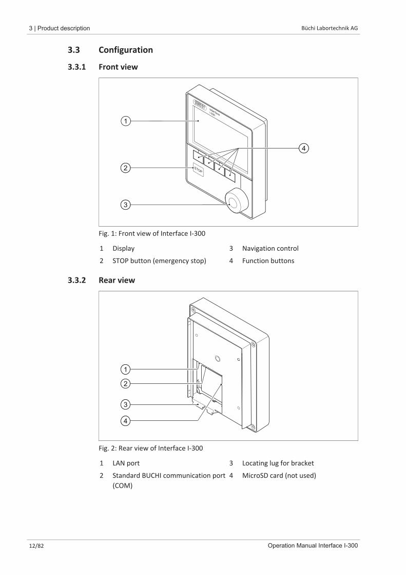
Fig. 1: Front view of Interface I-300
1 Display 3 Navigation control
2 STOP button (emergency stop) 4 Function buttons
3.3.2 Rear view
3
4
1
2
Fig. 2: Rear view of Interface I-300
1 LAN port 3 Locating lug for bracket
2 Standard BUCHI communication port(COM)
4 MicroSD card (not used)
Büchi Labortechnik AG Product description | 3
Operation Manual Interface I-300 13/82
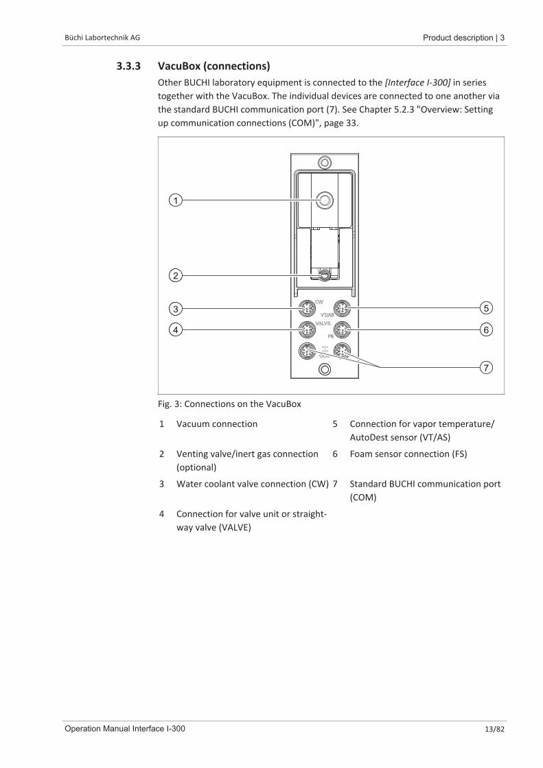
3.3.3 VacuBox (connections)Other BUCHI laboratory equipment is connected to the [Interface I-300] in seriestogether with the VacuBox. The individual devices are connected to one another viathe standard BUCHI communication port (7). See Chapter 5.2.3 "Overview: Settingup communication connections (COM)", page 33.
11
3
4
5
6
7
12
Fig. 3: Connections on the VacuBox
1 Vacuum connection 5 Connection for vapor temperature/AutoDest sensor (VT/AS)
2 Venting valve/inert gas connection(optional)
6 Foam sensor connection (FS)
3 Water coolant valve connection (CW) 7 Standard BUCHI communication port(COM)
4 Connection for valve unit or straight-way valve (VALVE)

3 | Product description Büchi Labortechnik AG
14/82 Operation Manual Interface I-300
3.3.4 LegacyBox (connections)Connection of a LegacyBox is required whenever legacy BUCHI laboratory equipmentis to be controlled via the [Interface I-300]. The LegacyBox is connected to thedistillation system using a standard BUCHI communication cable and has otherconnection options such as an RS-485 communication port. There is also the optionof incorporating pumps of other makes in the Rotavapor system and controllingthem via the interface. In that case, the pump requires a 0 – 10 V input.The LegacyBox is fixed to a Rotavapor R-300 or a laboratory stand clamp.
2
4
3
1
6
5
Fig. 4: Connections on the LegacyBox
1 Standard BUCHI communication port(COM)
4 RS-232 (not used)
2 0 – 10 V communication port – forconnecting pumps of other makes
5 External power supply – for genuineBUCHI mains adaptor, 30 V, 30 W(see Accessories)
3 RS-485 communication port – forconnecting legacy BUCHI laboratoryequipment (Vacuum Pumps V-700 /V-710, Rotavapors: R-210 / R-215,Recirculating Chiller F-1xx)
6 On/Off switch
NOTE
The external power supply is only necessary if the LegacyBox is not connected to aRotavapor or a vacuum pump and is used for other vacuum control applicationsinstead. Otherwise the vacuum pump or the Rotavapor supplies the LegacyBox withpower.
Büchi Labortechnik AG Product description | 3
Operation Manual Interface I-300 15/82
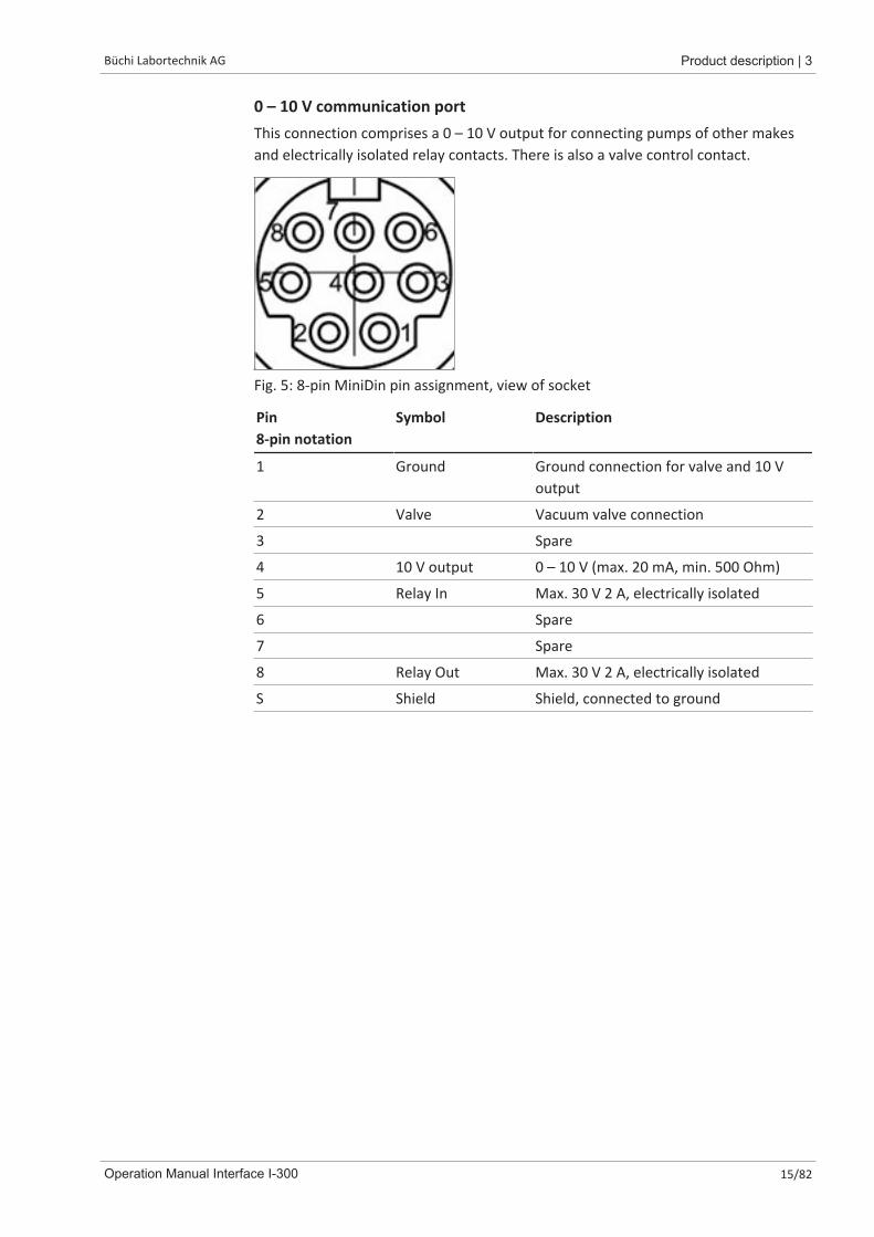
0 – 10 V communication portThis connection comprises a 0 – 10 V output for connecting pumps of other makesand electrically isolated relay contacts. There is also a valve control contact.
Fig. 5: 8-pin MiniDin pin assignment, view of socket
Pin8-pin notation
Symbol Description
1 Ground Ground connection for valve and 10 Voutput
2 Valve Vacuum valve connection
3 Spare
4 10 V output 0 – 10 V (max. 20 mA, min. 500 Ohm)
5 Relay In Max. 30 V 2 A, electrically isolated
6 Spare
7 Spare
8 Relay Out Max. 30 V 2 A, electrically isolated
S Shield Shield, connected to ground

3 | Product description Büchi Labortechnik AG
16/82 Operation Manual Interface I-300
3.3.5 Display (touch-screen)
12
3
4
15
6
7
11
Fig. 6: Display layout
1 Status bar 5 Current setting (e.g. vacuum)
2 Menu bar 6 Scroll bar
3 Current reading (e.g. vacuum) 7 Function activated if navigation con-trol is pressed
4 Functions of the function buttons be-low (context-dependent)

Büchi Labortechnik AG Product description | 3
Operation Manual Interface I-300 17/82
3.3.6 Type plateThe type plate is on the rear of the [Interface I-300].
BÜCHI Labortechnik AGCH-9230 Flawil/SwitzerlandType: I-300SN: 1000000000Volt: 30 VDCFrequ.:Power: 3 WBuilt: 2014Made in Switzerland
3
7
2
1
5
4
6
8
9
1011 9
Fig. 7: Type plate (example)
1 Company name and address 7 Year of manufacture
2 Device name 8 Country of manufacture
3 Serial number 9 Approvals
4 Input voltage 10 Symbol for "Do not dispose of ashousehold waste"
5 Frequency 11 Product code
6 Maximum power rating
NOTEThe VacuBox and the LegacyBox each have their own type plate on the rear.
3.4 Navigating through the menu system
3.4.1 Menu barThe menus are represented by symbols on the menu bar. Navigation through themenus is by the input controls.The following menus are available:
Symbol Meaning Sub-items
Home screen � Process controlparameters
� Graphs
Favorites � Bookmarks forfrequently usedindividual starting points
3 | Product description Büchi Labortechnik AG
18/82 Operation Manual Interface I-300
Symbol Meaning Sub-items
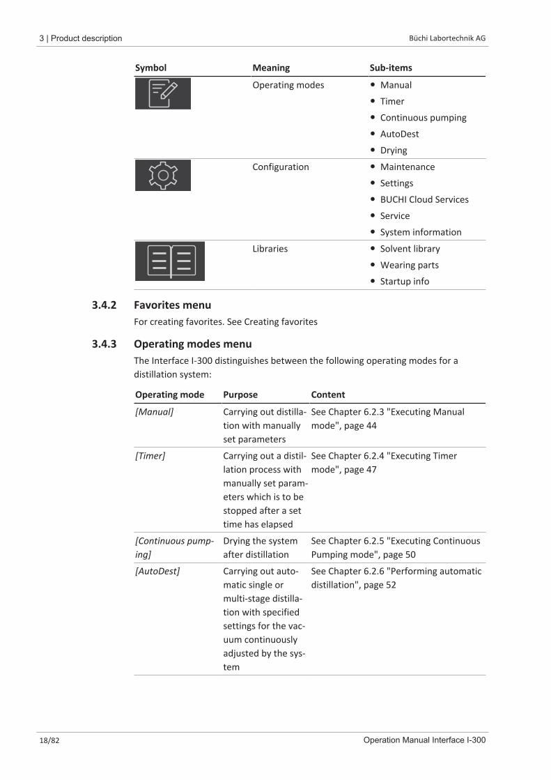
Operating modes � Manual
� Timer
� Continuous pumping
� AutoDest
� Drying
Configuration � Maintenance
� Settings
� BUCHI Cloud Services
� Service
� System information
Libraries � Solvent library
� Wearing parts
� Startup info
3.4.2 Favorites menuFor creating favorites. See Creating favorites
3.4.3 Operating modes menuThe Interface I-300 distinguishes between the following operating modes for a distillation system:
Operating mode Purpose Content
[Manual] Carrying out distilla-tion with manuallyset parameters
See Chapter 6.2.3 "Executing Manualmode", page 44
[Timer] Carrying out a distil-lation process withmanually set param-eters which is to bestopped after a settime has elapsed
See Chapter 6.2.4 "Executing Timermode", page 47
[Continuous pump-ing]
Drying the systemafter distillation
See Chapter 6.2.5 "Executing ContinuousPumping mode", page 50
[AutoDest] Carrying out auto-matic single ormulti-stage distilla-tion with specifiedsettings for the vac-uum continuouslyadjusted by the sys-tem
See Chapter 6.2.6 "Performing automaticdistillation", page 52

Büchi Labortechnik AG Product description | 3
Operation Manual Interface I-300 19/82
Operating mode Purpose Content
[Drying] Post-drying of con-tents of evaporatingflask. (This feature isonly available inconjunction withthe RotavaporR-300.)
See Chapter 6.2.7 "Executing Dryingmode", page 55
3.4.4 Configuration menuThe [Configuration] menu contains the following submenus:
� Maintenance see Maintenance submenu
� Settings see Settings submenu
� BUCHI Cloud Services see Chapter "BUCHI Cloud Services submenu ", page 21
� System information see System Information submenu
Maintenance submenuThe submenu [Maintenance] contains the following actions:
Action Option Explanation
[Leak test] START For carrying out a leak test on the distilla-tion system
[Seal servicing] Info Hours of rotation since last service.Resets the hours of rotation recorded.
Settings submenuThe submenu [Settings] contains options for settings that can be made on thedistillation system.
Action Option Explanation
[Mobile connectionQR code]
View Interface unit shows QR code for the con-nected distillation system.
[Mobile connectionpassword]
View For viewing password and entering onmobile device (alternative to QR code)
[On finish: Aeratesystem]
On/Off System is vented after automatic or man-ual termination of distillation.
[On start: start rota-tion]
On/Off Evaporating flask starts rotating whendistillation is started.
[On finish: Stop ro-tation]
On/Off Evaporating flask stops rotating after au-tomatic or manual termination of distilla-tion.
[On start: immerseflask]
On/Off Evaporating flask is automatically im-mersed in the heating bath when distilla-tion is started.

3 | Product description Büchi Labortechnik AG
20/82 Operation Manual Interface I-300
Action Option Explanation
[On finish: lift outflask]
On/Off Evaporating flask is automatically liftedout of the heating bath after automaticor manual termination of distillation.
[On finish: stopheating]
On/Off Heating of heating bath stops after auto-matic or manual termination of distilla-tion.
[On finish: stop cool-ing]
On/Off The Recirculating Chiller F-3xx automati-cally switches off after automatic or man-ual termination of distillation.
[On finish: playsound]
On/Off An audible signal is sounded after auto-matic or manual termination of distilla-tion.
[Pressure hysteresis] Entry of pressure Entry of figure for the maximum allow-able difference between the actual vac-uum and the specified figure before thevacuum pump switches on again.
[Language] Choice of languageused for Interfacedisplay
English, Deutsch, Francais, Italiano, Es-panol, Russian, Portugues, Japanese, Chi-nese, Indonesian, Korean
[Button tone] On/Off A beep sounds when a function button orthe navigation control is pressed.
[Seal servicing infor-mation]
On/Off The interface shows information aboutregular servicing of the system seals. Themessage appears periodically after every500 hours of rotation.
[Temperature unit] Choice of unit for in-dication of tempera-tures
°C (Celsius), °F (Fahrenheit) or K (Kelvin)
[Pressure Unit] Choice of unit for in-dication of (nega-tive) pressure
hPa (hectopascals), mbar (millibars), torr(= mmHg), mmHg (millimeters of mer-cury)
[Height above sealevel]
Enter value Altitude of location above mean sealevel: Max. 4000 m.For determination of max. allowablepressure when working with the solventlibrary.
[Max. permissiblepressure]
Enter value Max. pressure level present in the sys-tem: max. 1300 mbar.
[Max. pump deliv-ery]
Enter value Max. pump speed in %: 10 –100 %.
[Display brightness] Enter value Display illumination level in %: 0 – 100 %.
[eco mode] On/Off and entry offigures
See Chapter 6.4 "Activating eco mode",page 58
Büchi Labortechnik AG Product description | 3
Operation Manual Interface I-300 21/82
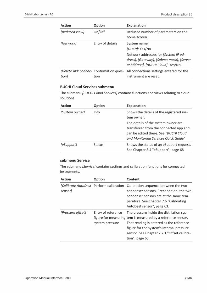
Action Option Explanation
[Reduced view] On/Off Reduced number of parameters on thehome screen.
[Network] Entry of details System name[DHCP]: Yes/NoNetwork addresses for [System IP ad-dress], [Gateway], [Subnet mask], [ServerIP address], [BUCHI Cloud]: Yes/No
[Delete APP connec-tion]
Confirmation ques-tion
All connections settings entered for theinstrument are reset.
BUCHI Cloud Services submenuThe submenu [BUCHI Cloud Services] contains functions and views relating to cloudsolutions.
Action Option Explanation
[System owner] Info Shows the details of the registered sys-tem owner.The details of the system owner aretransferred from the connected app andcan be edited there. See "BUCHI Cloudand Monitoring Services Quick Guide"
[eSupport] Status Shows the status of an eSupport request.See Chapter 8.4 "eSupport", page 68
submenu ServiceThe submenu [Service] contains settings and calibration functions for connectedinstruments.
Action Option Content
[Calibrate AutoDestsensor]
Perform calibration Calibration sequence between the twocondenser sensors. Precondition: the twocondenser sensors are at the same tem-perature. See Chapter 7.6 "CalibratingAutoDest sensor", page 63.
[Pressure offset] Entry of referencefigure for measuringsystem pressure
The pressure inside the distillation sys-tem is measured by a reference sensor.That reading is entered as the referencefigure for the system's internal pressuresensor. See Chapter 7.7.1 "Offset calibra-tion", page 65.
3 | Product description Büchi Labortechnik AG
22/82 Operation Manual Interface I-300
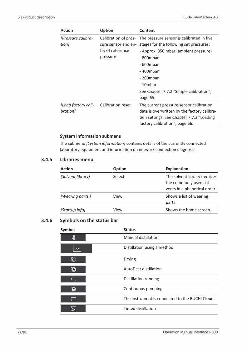
Action Option Content
[Pressure calibra-tion]
Calibration of pres-sure sensor and en-try of referencepressure
The pressure sensor is calibrated in fivestages for the following set pressures:- Approx. 950 mbar (ambient pressure)- 800mbar- 600mbar- 400mbar- 200mbar- 10mbarSee Chapter 7.7.2 "Simple calibration",page 65.
[Load factory cali-bration]
Calibration reset The current pressure sensor calibrationdata is overwritten by the factory calibra-tion settings. See Chapter 7.7.3 "Loadingfactory calibration", page 66.
System Information submenuThe submenu [System information] contains details of the currently connectedlaboratory equipment and information on network connection diagnosis.
3.4.5 Libraries menu
Action Option Explanation
[Solvent library] Select The solvent library itemizesthe commonly used sol-vents in alphabetical order.
[Wearing parts ] View Shows a list of wearingparts.
[Startup info] View Shows the home screen.
3.4.6 Symbols on the status bar
Symbol Status
Manual distillation
Distillation using a method
Drying
A AutoDest distillation
Distillation running
Continuous pumping
The instrument is connected to the BUCHI Cloud.
Timed distillation
Büchi Labortechnik AG Product description | 3
Operation Manual Interface I-300 23/82
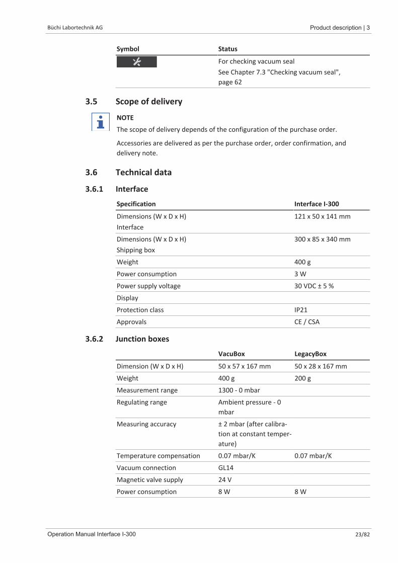
Symbol Status
For checking vacuum sealSee Chapter 7.3 "Checking vacuum seal",page 62
3.5 Scope of delivery
NOTE
The scope of delivery depends of the configuration of the purchase order.
Accessories are delivered as per the purchase order, order confirmation, anddelivery note.
3.6 Technical data
3.6.1 Interface
Specification Interface I-300
Dimensions (W x D x H)Interface
121 x 50 x 141 mm
Dimensions (W x D x H)Shipping box
300 x 85 x 340 mm
Weight 400 g
Power consumption 3 W
Power supply voltage 30 VDC ± 5 %
Display
Protection class IP21
Approvals CE / CSA
3.6.2 Junction boxes
VacuBox LegacyBox
Dimension (W x D x H) 50 x 57 x 167 mm 50 x 28 x 167 mm
Weight 400 g 200 g
Measurement range 1300 - 0 mbar
Regulating range Ambient pressure - 0mbar
Measuring accuracy ± 2 mbar (after calibra-tion at constant temper-ature)
Temperature compensation 0.07 mbar/K 0.07 mbar/K
Vacuum connection GL14
Magnetic valve supply 24 V
Power consumption 8 W 8 W

3 | Product description Büchi Labortechnik AG
24/82 Operation Manual Interface I-300
VacuBox LegacyBox
Power connections / output volt-age
30 VDC ± 5 % 30 VDC ± 5 %
Hysteresis Automatic or 1 - 200mbar
Automatic or 1 - 200mbar
Protection class IP 21 IP 21
Approvals CE / CSA CE / CSA
3.6.3 Ambient conditions
Max. altitude above sea level 2000 m
Ambient temperature 5 - 40 °C
Maximum relative humidity 80 % for temperatures up to 31 °Cdecreasing linearly to 50 % at 40 °C
The laboratory equipment described in this document may only be used in indoorareas.
3.6.4 Materials
Component Material
Pressure foil Polyester
Casing PBT
Vent tube connection PPS
Pressure sensor Al₂O₃ 96%
Büchi Labortechnik AG Transport and storage | 4
Operation Manual Interface I-300 25/82
4 Transport and storage
4.1 Transport
NOTICERisk of breakage due to incorrect transportation
u Make sure that all parts of the device are safely packed in such a way as toprevent breakage, ideally in the original box.
u Avoid sharp movements during transit.
u After transportation, check the device for damage.u Damage that has occurred in transit should be reported to the carrier.u Keep packing for future transportation.
4.2 Storageu Make sure that the ambient conditions are complied with (see Chapter 3.6
"Technical data", page 23).u Wherever possible, store the device in its original packaging.u After storage, check the device for damage and replace if necessary.

5 | Installation Büchi Labortechnik AG
26/82 Operation Manual Interface I-300
5 Installation
5.1 Fitting the Interface I-300/I-300 ProThe Interface I-300/I-300 Pro can be mounted on one of the following BUCHIlaboratory devices:
� Rotavapor R-300
� Vacuum Pump V-300
� Rotavapor R-220 Pro
Alternatively, the Interface I-300/I-300 Pro can be mounted separately on alaboratory stand, see Chapter 5.1.3 "Mounting interface unit on laboratory stand(optional accessory)", page 29.
5.1.1 Mounting interface on Rotavapor R-300The [Interface I-300] can be mounted and connected up on the vertically adjustablearm of the Rotavapor R-300.Tools required: Torx keys Tx20 and Tx30
1
3
2
Fig. 8: Handle of Rotavapor R-300
1 Cover 3 Fixing screw for cover
2 Communication cables
u Remove the screw on the underside of the vertically adjustable arm (3) using aTorx key and remove the cover (1) from the top of the arm.
u Remove the pre-fitted communication cable (2) from the cover.
Büchi Labortechnik AG Installation | 5
Operation Manual Interface I-300 27/82
2
3
4
6
5
1
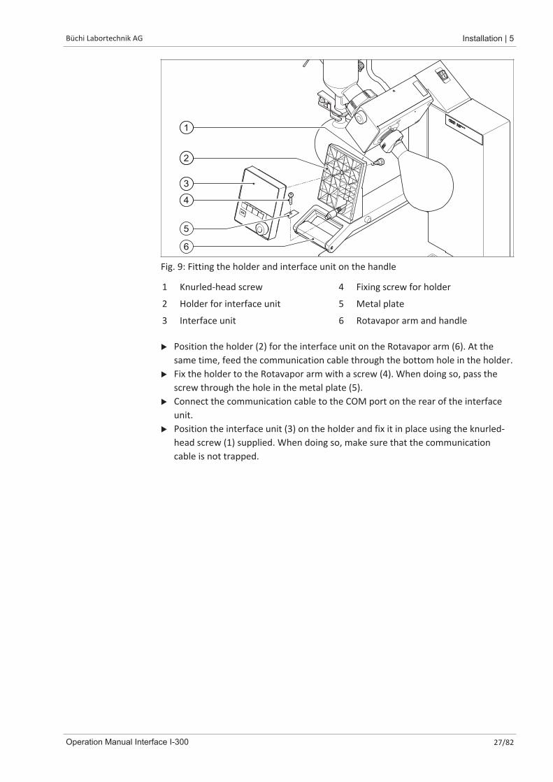
Fig. 9: Fitting the holder and interface unit on the handle
1 Knurled-head screw 4 Fixing screw for holder
2 Holder for interface unit 5 Metal plate
3 Interface unit 6 Rotavapor arm and handle
u Position the holder (2) for the interface unit on the Rotavapor arm (6). At thesame time, feed the communication cable through the bottom hole in the holder.
u Fix the holder to the Rotavapor arm with a screw (4). When doing so, pass thescrew through the hole in the metal plate (5).
u Connect the communication cable to the COM port on the rear of the interfaceunit.
u Position the interface unit (3) on the holder and fix it in place using the knurled-head screw (1) supplied. When doing so, make sure that the communicationcable is not trapped.

5 | Installation Büchi Labortechnik AG
28/82 Operation Manual Interface I-300
5.1.2 Fitting interface unit on Vacuum Pump V-300
6
1 2 4 53
Fig. 10: Fitting interface unit on Vacuum Pump V-300
1 Interface unit 5 Casing front
2 Fixing screw for holder 6 Knurled-head screw
3 Metal plate 7 Holder
4 Rubber plug and threaded hole
Tools required:
� Torx key Tx30
The [Interface I-300] can be mounted on the top of the Vacuum Pump V-300 using aholder.u Remove the rubber plug (4) from the top panel of the vacuum pump. Use a
screwdriver if necessary.ð Underneath the rubber plug is a threaded hole for a screw.u Position the holder (7) over the threaded hole (4) and fix it in place using the
screw (2) supplied. When doing so, pass the screw through the hole in the metalplate (3).
u Feed the communication cable through the holder from the rear and connect itto the COM port on the back of the interface unit.
u Position the interface unit (1) on the holder and fix it in place using a knurled-head screw (6) inserted from the back.
Büchi Labortechnik AG Installation | 5
Operation Manual Interface I-300 29/82
5.1.3 Mounting interface unit on laboratory stand (optional accessory)
2
1
4
3
5
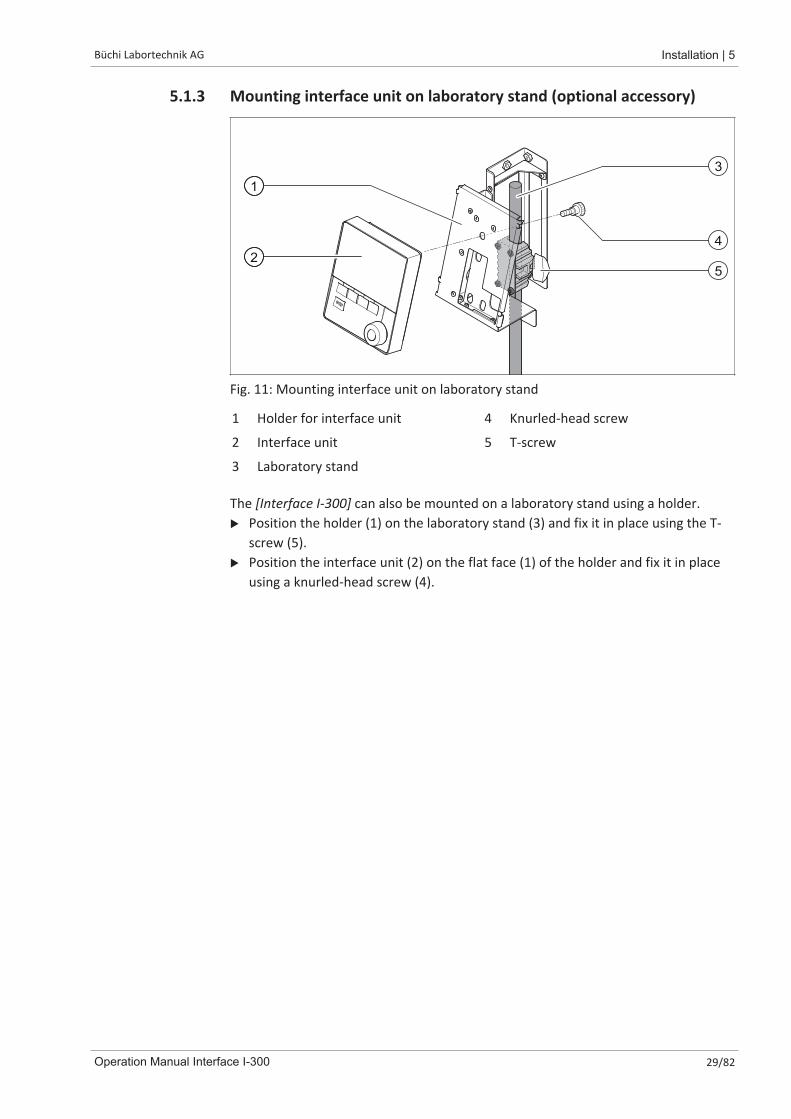
Fig. 11: Mounting interface unit on laboratory stand
1 Holder for interface unit 4 Knurled-head screw
2 Interface unit 5 T-screw
3 Laboratory stand
The [Interface I-300] can also be mounted on a laboratory stand using a holder.u Position the holder (1) on the laboratory stand (3) and fix it in place using the T-
screw (5).u Position the interface unit (2) on the flat face (1) of the holder and fix it in place
using a knurled-head screw (4).
5 | Installation Büchi Labortechnik AG
30/82 Operation Manual Interface I-300
5.1.4 Mounting interface unit on a wall bracket (optional accessory)
STOP
2
1 4
5
6
3
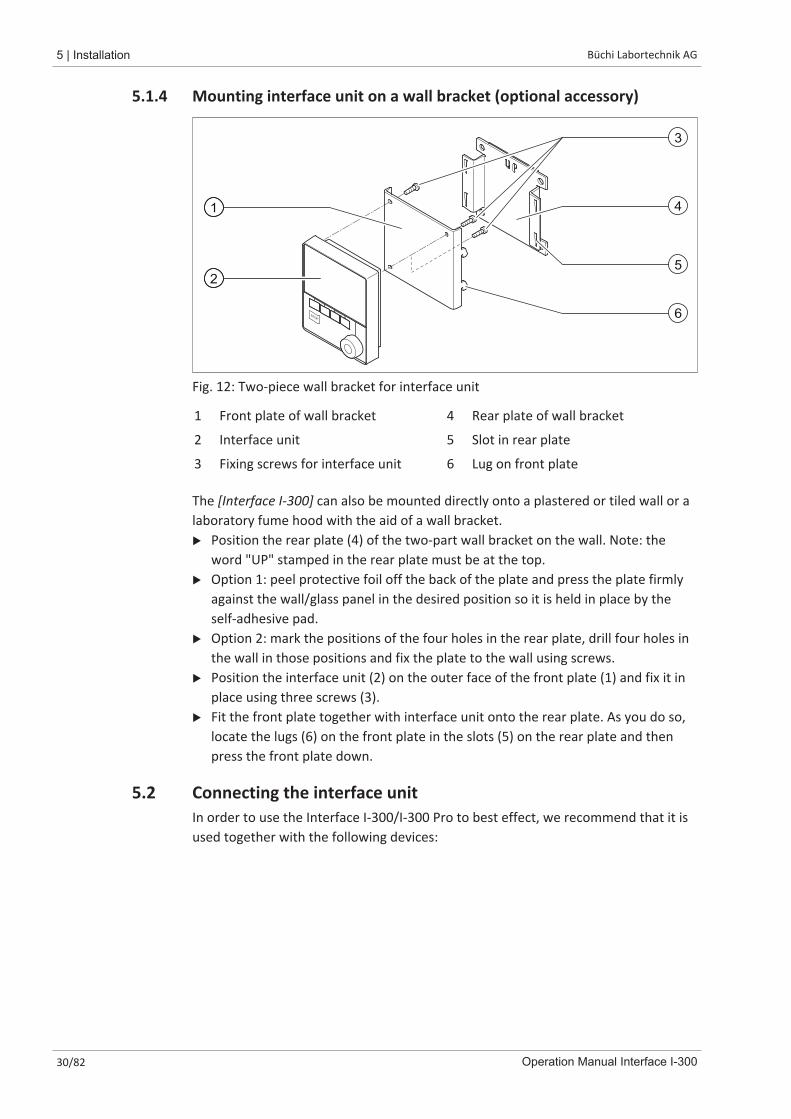
Fig. 12: Two-piece wall bracket for interface unit
1 Front plate of wall bracket 4 Rear plate of wall bracket
2 Interface unit 5 Slot in rear plate
3 Fixing screws for interface unit 6 Lug on front plate
The [Interface I-300] can also be mounted directly onto a plastered or tiled wall or alaboratory fume hood with the aid of a wall bracket.u Position the rear plate (4) of the two-part wall bracket on the wall. Note: the
word "UP" stamped in the rear plate must be at the top.u Option 1: peel protective foil off the back of the plate and press the plate firmly
against the wall/glass panel in the desired position so it is held in place by theself-adhesive pad.
u Option 2: mark the positions of the four holes in the rear plate, drill four holes inthe wall in those positions and fix the plate to the wall using screws.
u Position the interface unit (2) on the outer face of the front plate (1) and fix it inplace using three screws (3).
u Fit the front plate together with interface unit onto the rear plate. As you do so,locate the lugs (6) on the front plate in the slots (5) on the rear plate and thenpress the front plate down.
5.2 Connecting the interface unitIn order to use the Interface I-300/I-300 Pro to best effect, we recommend that it isused together with the following devices:
Büchi Labortechnik AG Installation | 5
Operation Manual Interface I-300 31/82
3
45
1
3
45
1
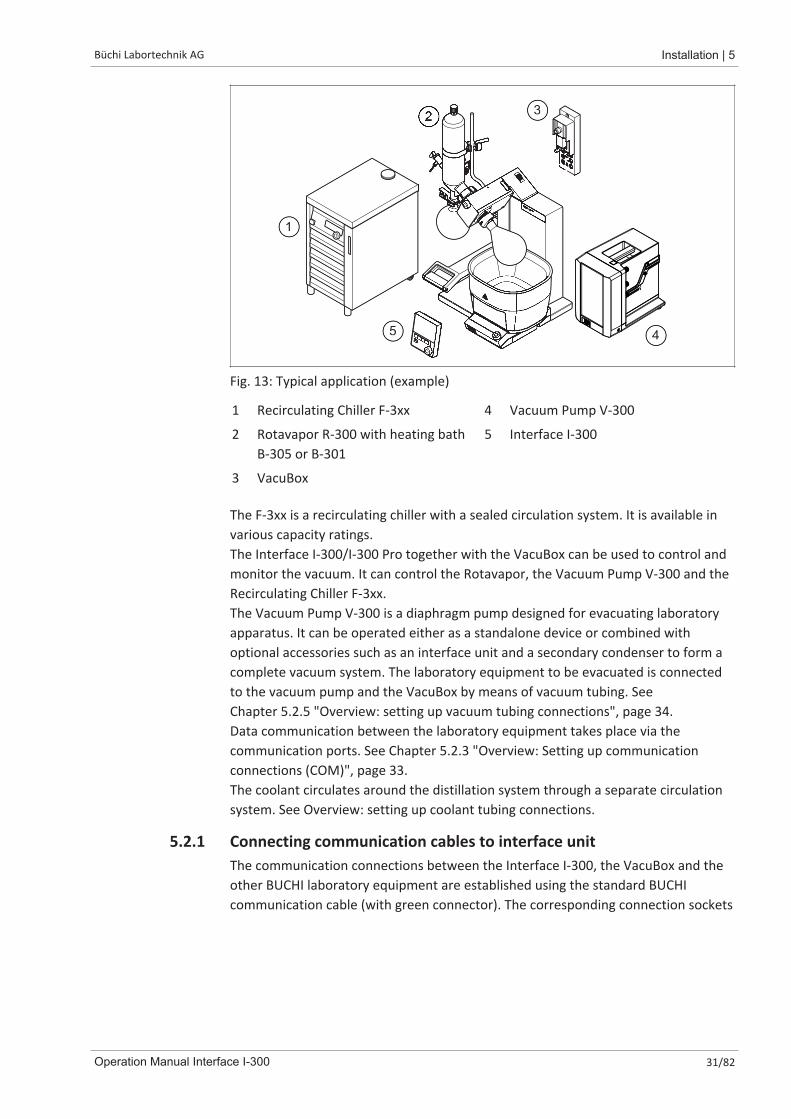
Fig. 13: Typical application (example)
1 Recirculating Chiller F-3xx 4 Vacuum Pump V-300
2 Rotavapor R-300 with heating bathB-305 or B-301
5 Interface I-300
3 VacuBox
The F-3xx is a recirculating chiller with a sealed circulation system. It is available invarious capacity ratings.The Interface I-300/I-300 Pro together with the VacuBox can be used to control andmonitor the vacuum. It can control the Rotavapor, the Vacuum Pump V-300 and theRecirculating Chiller F-3xx.The Vacuum Pump V-300 is a diaphragm pump designed for evacuating laboratoryapparatus. It can be operated either as a standalone device or combined withoptional accessories such as an interface unit and a secondary condenser to form acomplete vacuum system. The laboratory equipment to be evacuated is connectedto the vacuum pump and the VacuBox by means of vacuum tubing. SeeChapter 5.2.5 "Overview: setting up vacuum tubing connections", page 34.Data communication between the laboratory equipment takes place via thecommunication ports. See Chapter 5.2.3 "Overview: Setting up communicationconnections (COM)", page 33.The coolant circulates around the distillation system through a separate circulationsystem. See Overview: setting up coolant tubing connections.
5.2.1 Connecting communication cables to interface unitThe communication connections between the Interface I-300, the VacuBox and theother BUCHI laboratory equipment are established using the standard BUCHIcommunication cable (with green connector). The corresponding connection sockets
5 | Installation Büchi Labortechnik AG
32/82 Operation Manual Interface I-300
are on the rear panels of the devices and are marked "COM" for identification.Details of the precise positions of the connection sockets are provided in theoperating instructions for the devices.
� For connection options on the Interface I-300 see Chapter 3.3.2 "Rear view",page 12.
� For connection options on the VacuBox see Chapter 3.3.3 "VacuBox(connections)", page 13.
5.2.2 Establishing LAN connection
Requirements for local network settingsu The following port has to be enabled in the firewall settings on the internet
gateway:
� TCP (HTTPS) traffics through remote port 443
u In order to use the BUCHI Cloud a DNS server must be configured on theinstrument.
NOTE
If there is no DNS server available enter the IP address for the BUCHI Cloudconnection manually.
NOTE
If there is no DHCP server available enter the IP address, gateway subnet mask andDNS server manually.
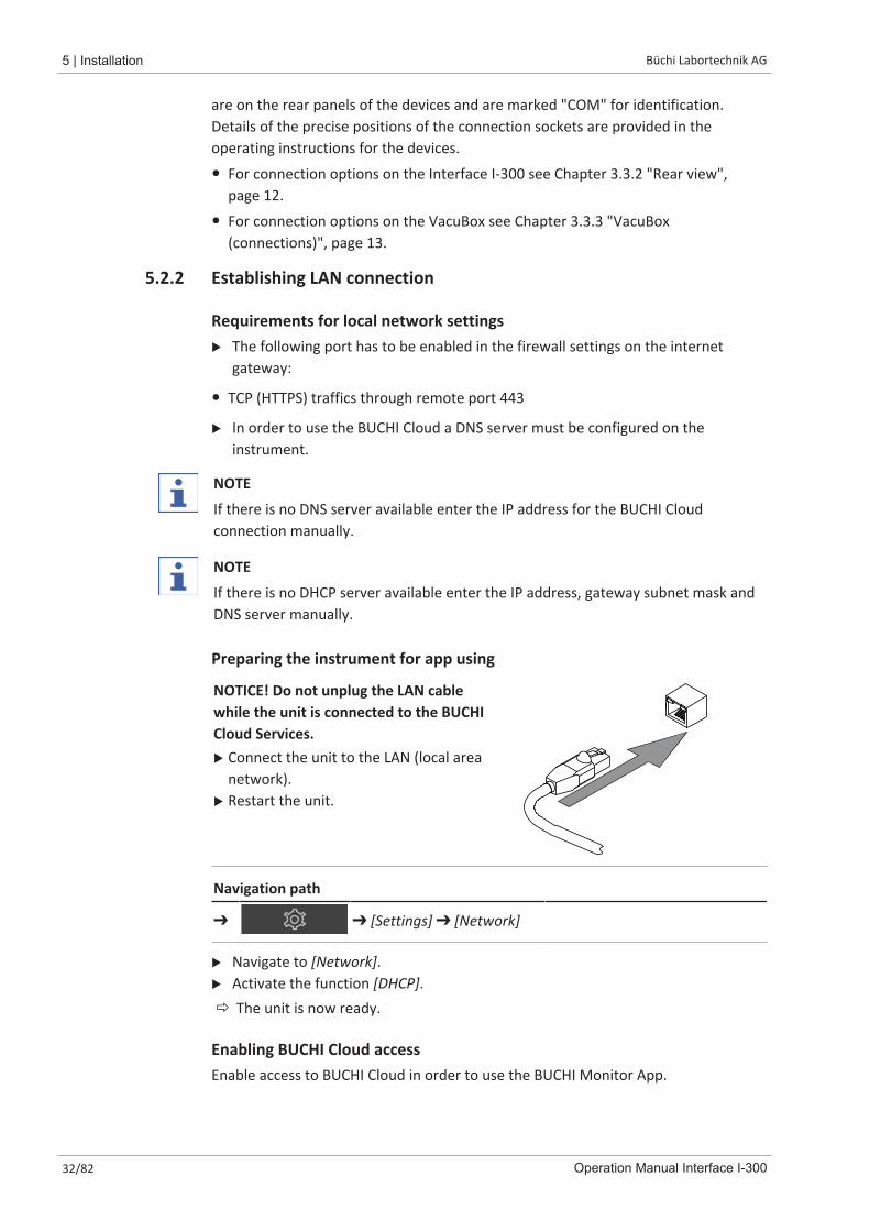
Preparing the instrument for app using
NOTICE! Do not unplug the LAN cablewhile the unit is connected to the BUCHICloud Services.u Connect the unit to the LAN (local area
network).u Restart the unit.
Navigation path
➔ ➔ [Settings] ➔ [Network]
u Navigate to [Network].u Activate the function [DHCP].ð The unit is now ready.
Enabling BUCHI Cloud accessEnable access to BUCHI Cloud in order to use the BUCHI Monitor App.
Büchi Labortechnik AG Installation | 5
Operation Manual Interface I-300 33/82
Navigation path
➔ ➔ Settings ➔ Network ➔ BUCHI Cloud
u Navigate to the action [[BUCHI Cloud]] via the navigation path.u Select the option [Yes].ð The instrument is connected to the BUCHI Cloud.
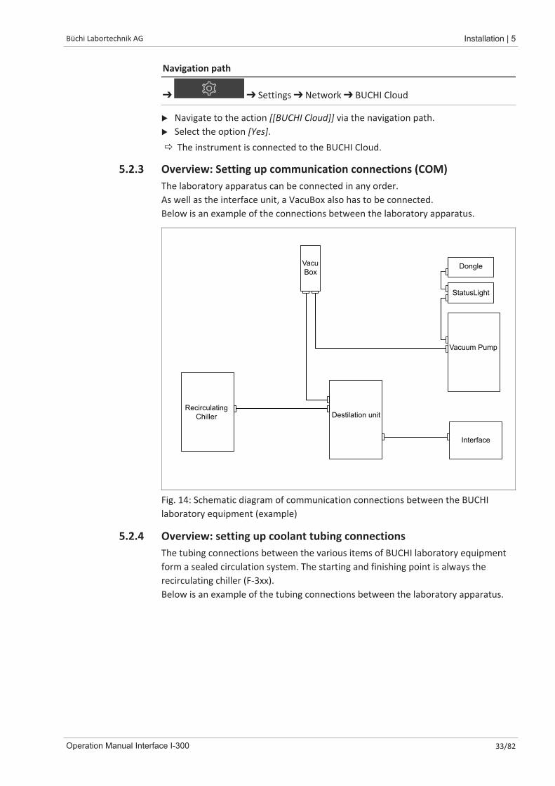
5.2.3 Overview: Setting up communication connections (COM)The laboratory apparatus can be connected in any order.As well as the interface unit, a VacuBox also has to be connected.Below is an example of the connections between the laboratory apparatus.
RecirculatingChiller
Interface
Destilation unit
Vacuum Pump
VacuBox
StatusLight
Dongle
Fig. 14: Schematic diagram of communication connections between the BUCHIlaboratory equipment (example)
5.2.4 Overview: setting up coolant tubing connectionsThe tubing connections between the various items of BUCHI laboratory equipmentform a sealed circulation system. The starting and finishing point is always therecirculating chiller (F-3xx).Below is an example of the tubing connections between the laboratory apparatus.
5 | Installation Büchi Labortechnik AG
34/82 Operation Manual Interface I-300
Recirculating
Chiller F-3XX
Rotavapor
R-300
Vacuum Pump
V-300 / V-600
2
3
6
4
1
5
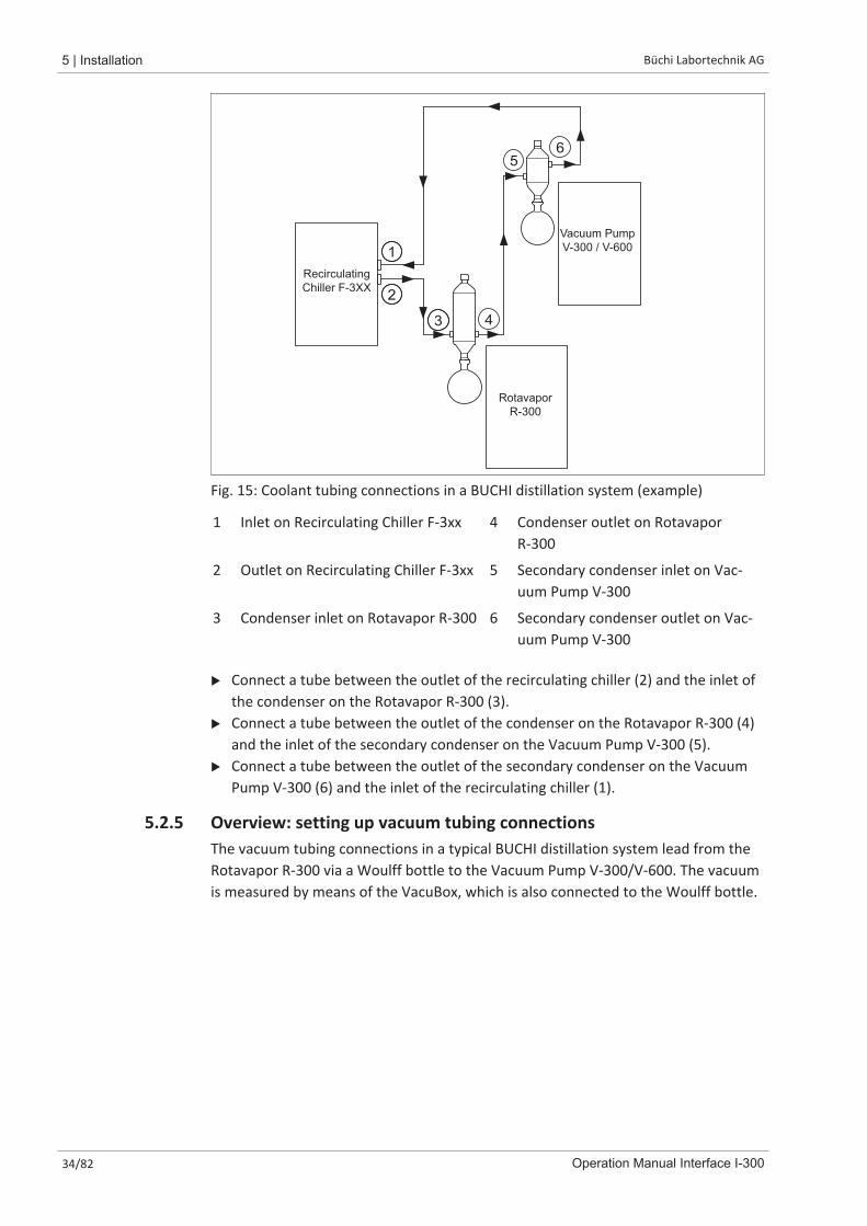
Fig. 15: Coolant tubing connections in a BUCHI distillation system (example)
1 Inlet on Recirculating Chiller F-3xx 4 Condenser outlet on RotavaporR-300
2 Outlet on Recirculating Chiller F-3xx 5 Secondary condenser inlet on Vac-uum Pump V-300
3 Condenser inlet on Rotavapor R-300 6 Secondary condenser outlet on Vac-uum Pump V-300
u Connect a tube between the outlet of the recirculating chiller (2) and the inlet ofthe condenser on the Rotavapor R-300 (3).
u Connect a tube between the outlet of the condenser on the Rotavapor R-300 (4)and the inlet of the secondary condenser on the Vacuum Pump V-300 (5).
u Connect a tube between the outlet of the secondary condenser on the VacuumPump V-300 (6) and the inlet of the recirculating chiller (1).
5.2.5 Overview: setting up vacuum tubing connectionsThe vacuum tubing connections in a typical BUCHI distillation system lead from theRotavapor R-300 via a Woulff bottle to the Vacuum Pump V-300/V-600. The vacuumis measured by means of the VacuBox, which is also connected to the Woulff bottle.

Büchi Labortechnik AG Installation | 5
Operation Manual Interface I-300 35/82
Vacu
Box
Rotavapor
R-300
Vacuum Pump
V-300 / V-600
Extraction
device
5 63
21
4
Fig. 16: Coolant tubing connections in a BUCHI distillation system
1 Secondary condenser outlet 4 Woulff bottle outlet (PUMP)
2 Vacuum Pump V-300/V-600 outlet 5 Woulff bottle inlet (CONTR)
3 Vacuum Pump V-300/V-600 inlet 6 VacuBox vacuum connection
u Connect a tube between the Rotavapor R-300 and the top inlet of the Woulffbottle.
u Connect a tube between the outlet of the Woulff bottle marked PUMP (4) andthe pump inlet (3).
u Connect the secondary condenser to the pump outlet (2).u For measuring and controlling the vacuum, connect a tube between the inlet of
the Woulff bottle marked CONTR (5) and the VacuBox (6).
The pressure is measured in the VacuBox. The current working pressure can beindicated and controlled by means of the Interface I-300/I-300 Pro.
NOTE
The VacuBox and Woulff bottle can be mounted either on the Rotavapor R-300 orthe Vacuum Pump V-300/V-600. What is important is that the VacuBox and Woulffbottle are as close as possible to each other (on the same device) as otherwise thereis a vacuum control lag.
5 | Installation Büchi Labortechnik AG
36/82 Operation Manual Interface I-300
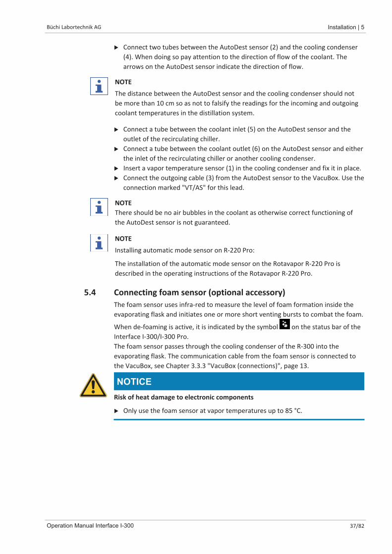
5.3 Connecting AutoDest sensor to vapor temperature sensor(optional accessory)The control unit offers programs for performing automatic distillation processes. Theprograms require the connection of an AutoDest sensor. The AutoDest sensor isconnected to the inlet and outlet of the cooling condenser and continuouslymeasures the following temperatures:
� Temperature of the incoming coolant
� Temperature of the outgoing coolant
� Temperature of the vapor exiting the evaporating flask
1
3
6
4
2
5
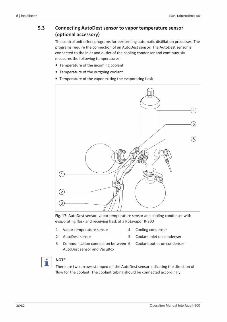
Fig. 17: AutoDest sensor, vapor temperature sensor and cooling condenser withevaporating flask and receiving flask of a Rotavapor R-300
1 Vapor temperature sensor 4 Cooling condenser
2 AutoDest sensor 5 Coolant inlet on condenser
3 Communication connection betweenAutoDest sensor and VacuBox
6 Coolant outlet on condenser
NOTE
There are two arrows stamped on the AutoDest sensor indicating the direction offlow for the coolant. The coolant tubing should be connected accordingly.
Büchi Labortechnik AG Installation | 5
Operation Manual Interface I-300 37/82
u Connect two tubes between the AutoDest sensor (2) and the cooling condenser(4). When doing so pay attention to the direction of flow of the coolant. Thearrows on the AutoDest sensor indicate the direction of flow.
NOTE
The distance between the AutoDest sensor and the cooling condenser should notbe more than 10 cm so as not to falsify the readings for the incoming and outgoingcoolant temperatures in the distillation system.
u Connect a tube between the coolant inlet (5) on the AutoDest sensor and theoutlet of the recirculating chiller.
u Connect a tube between the coolant outlet (6) on the AutoDest sensor and eitherthe inlet of the recirculating chiller or another cooling condenser.
u Insert a vapor temperature sensor (1) in the cooling condenser and fix it in place.u Connect the outgoing cable (3) from the AutoDest sensor to the VacuBox. Use the
connection marked "VT/AS" for this lead.
NOTEThere should be no air bubbles in the coolant as otherwise correct functioning ofthe AutoDest sensor is not guaranteed.
NOTE
Installing automatic mode sensor on R-220 Pro:
The installation of the automatic mode sensor on the Rotavapor R-220 Pro isdescribed in the operating instructions of the Rotavapor R-220 Pro.
5.4 Connecting foam sensor (optional accessory)The foam sensor uses infra-red to measure the level of foam formation inside theevaporating flask and initiates one or more short venting bursts to combat the foam.
When de-foaming is active, it is indicated by the symbol on the status bar of theInterface I-300/I-300 Pro.The foam sensor passes through the cooling condenser of the R-300 into theevaporating flask. The communication cable from the foam sensor is connected tothe VacuBox, see Chapter 3.3.3 "VacuBox (connections)", page 13.
NOTICERisk of heat damage to electronic components
u Only use the foam sensor at vapor temperatures up to 85 °C.
5 | Installation Büchi Labortechnik AG
38/82 Operation Manual Interface I-300
1
2
3
4
5
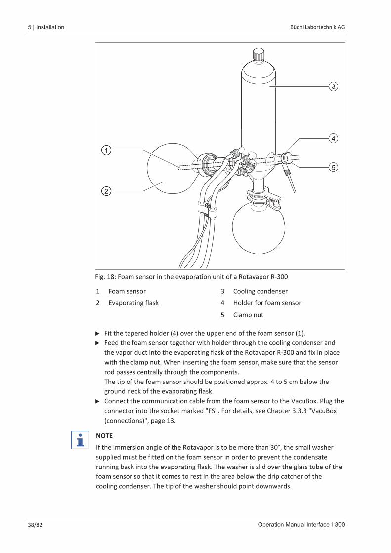
Fig. 18: Foam sensor in the evaporation unit of a Rotavapor R-300
1 Foam sensor 3 Cooling condenser
2 Evaporating flask 4 Holder for foam sensor
5 Clamp nut
u Fit the tapered holder (4) over the upper end of the foam sensor (1).u Feed the foam sensor together with holder through the cooling condenser and
the vapor duct into the evaporating flask of the Rotavapor R-300 and fix in placewith the clamp nut. When inserting the foam sensor, make sure that the sensorrod passes centrally through the components. The tip of the foam sensor should be positioned approx. 4 to 5 cm below theground neck of the evaporating flask.
u Connect the communication cable from the foam sensor to the VacuBox. Plug theconnector into the socket marked "FS". For details, see Chapter 3.3.3 "VacuBox(connections)", page 13.
NOTE
If the immersion angle of the Rotavapor is to be more than 30°, the small washersupplied must be fitted on the foam sensor in order to prevent the condensaterunning back into the evaporating flask. The washer is slid over the glass tube of thefoam sensor so that it comes to rest in the area below the drip catcher of thecooling condenser. The tip of the washer should point downwards.

Büchi Labortechnik AG Installation | 5
Operation Manual Interface I-300 39/82
5.5 Connecting valve unit for external vacuumThe [Interface I-300] can be used together with the VacuBox to control an externalvacuum. That requires the use of a vacuum valve and a mains power supply adaptor.For precise control of the vacuum, the use of a Woulff bottle is also recommended.The interface unit and the VacuBox can be mounted on a laboratory stand, seeChapter 5.1.3 "Mounting interface unit on laboratory stand (optional accessory)",page 29.u Connect the vacuum valve to the VacuBox using the connection marked VALVE.u Connect vacuum tubing between the laboratory apparatus to be evacuated, the
VacuBox and the external vacuum unit.u If a Rotavapor is not connected, connect the VacuBox to the external power
supply by means of the mains adaptor.
NOTE
To adjust the regulation accuracy, the hysteresis can be altered on the interfaceunit, see Chapter 6.5 "Setting hysteresis", page 59.
5.6 Operating I-300 and I-300 Pro in parallel
NOTE
BUCHI Cloud Services are not supported in parallel mode.
If the Rotavapor is to be controlled from outside a fume hood, there is the option ofconnecting two separate interface units in parallel. In that case, distillation can becontrolled from either interface unit. The readings displayed are continuouslysynchronized. The servicing functions (e.g. leak test) are controlled by the interfaceunit that is currently being used.If a mobile connection (see Chapter 5.2.2 "Establishing LAN connection", page 32) isdesired when the I-300 and I-300 Pro are operating in parallel, the LAN cable mustonly be connected to one of the interface units, preferably the I-300 Pro.u Connect the remote interface unit to the interface unit on the Rotavapor using
the standard BUCHI communication port (COM). Use a standard BUCHIcommunication cable to do so.
6 | Operation Büchi Labortechnik AG
40/82 Operation Manual Interface I-300
6 Operation
6.1 Navigating the menuThe I-300 Pro offers the fundamental option of navigating the menu either by usingthe function buttons and the navigation control or by means of the touch-screenfunctionality of the display.The touch-screen functions can be operated using laboratory gloves. Liquids on thescreen do not pose a problem either and do not impair functionality in any way.
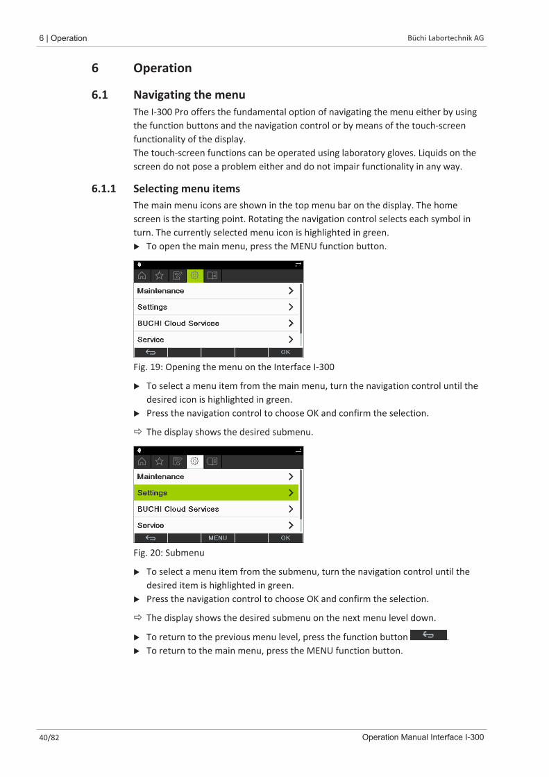
6.1.1 Selecting menu itemsThe main menu icons are shown in the top menu bar on the display. The homescreen is the starting point. Rotating the navigation control selects each symbol inturn. The currently selected menu icon is highlighted in green.u To open the main menu, press the MENU function button.
Fig. 19: Opening the menu on the Interface I-300
u To select a menu item from the main menu, turn the navigation control until thedesired icon is highlighted in green.
u Press the navigation control to choose OK and confirm the selection.
ð The display shows the desired submenu.
Fig. 20: Submenu
u To select a menu item from the submenu, turn the navigation control until thedesired item is highlighted in green.
u Press the navigation control to choose OK and confirm the selection.
ð The display shows the desired submenu on the next menu level down.
u To return to the previous menu level, press the function button .u To return to the main menu, press the MENU function button.
Büchi Labortechnik AG Operation | 6
Operation Manual Interface I-300 41/82
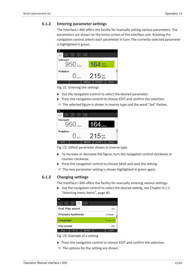
6.1.2 Entering parameter settingsThe Interface I-300 offers the facility for manually setting various parameters. Theparameters are shown on the home screen of the interface unit. Rotating thenavigation control selects each parameter in turn. The currently selected parameteris highlighted in green.
Fig. 21: Entering the settings
u Use the navigation control to select the desired parameter.u Press the navigation control to choose EDIT and confirm the selection.ð The selected figure is shown in inverse type and the word "Set" flashes.
Fig. 22: Edited parameter shown in inverse type
u To increase or decrease the figure, turn the navigation control clockwise orcounter-clockwise.
u Press the navigation control to choose SAVE and save the setting.ð The new parameter setting is shown highlighted in green again.
6.1.3 Changing settingsThe Interface I-300 offers the facility for manually entering various settings.u Use the navigation control to select the desired setting, see Chapter 6.1.1
"Selecting menu items", page 40.
Fig. 23: Example of a setting
u Press the navigation control to choose EDIT and confirm the selection.ð The options for the setting are shown.
6 | Operation Büchi Labortechnik AG
42/82 Operation Manual Interface I-300
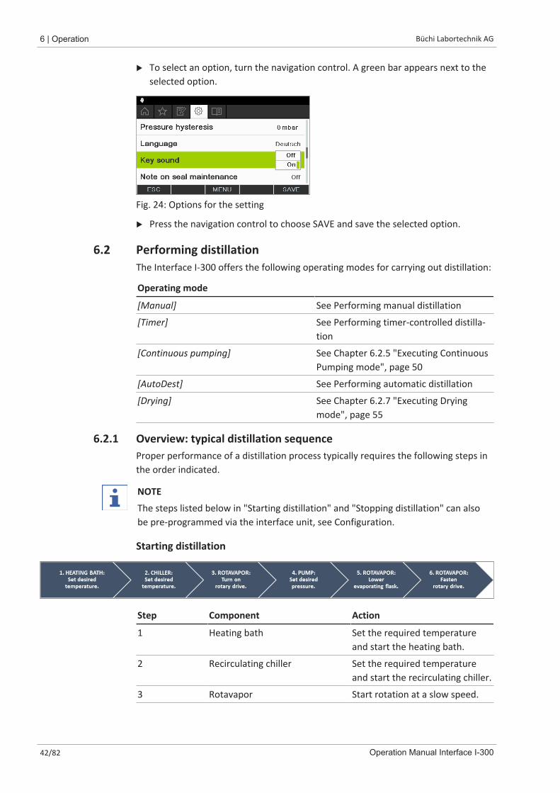
u To select an option, turn the navigation control. A green bar appears next to theselected option.
Fig. 24: Options for the setting
u Press the navigation control to choose SAVE and save the selected option.
6.2 Performing distillationThe Interface I-300 offers the following operating modes for carrying out distillation:
Operating mode
[Manual] See Performing manual distillation
[Timer] See Performing timer-controlled distilla-tion
[Continuous pumping] See Chapter 6.2.5 "Executing ContinuousPumping mode", page 50
[AutoDest] See Performing automatic distillation
[Drying] See Chapter 6.2.7 "Executing Dryingmode", page 55
6.2.1 Overview: typical distillation sequenceProper performance of a distillation process typically requires the following steps inthe order indicated.
NOTE
The steps listed below in "Starting distillation" and "Stopping distillation" can alsobe pre-programmed via the interface unit, see Configuration.
Starting distillation
Step Component Action
1 Heating bath Set the required temperatureand start the heating bath.
2 Recirculating chiller Set the required temperatureand start the recirculating chiller.
3 Rotavapor Start rotation at a slow speed.
Büchi Labortechnik AG Operation | 6
Operation Manual Interface I-300 43/82
Step Component Action
4 Vacuum pump Set the required pressure andstart the vacuum pump.
5 Rotavapor Immerse the evaporating flask inthe heating bath.
6 Rotavapor Increase rotation to the desiredspeed.
Stopping distillation
Step Component Action
1 Vacuum pump/Valve unit Stop pressure regulation.
2 Interface unitRotavapor
Vent the system (AERATE).Vent the system (open glassstopcock, open cooling con-denser).
3 Rotavapor Reduce rotation speed.
4 Rotavapor Lift evaporating flask out of heat-ing bath.
5 Rotavapor Stop rotation.
6 Heating bath Stop heating.
7 Interface unitRecirculating chiller
Stop cooling ( ).Stop cooling.
6.2.2 Basic functions
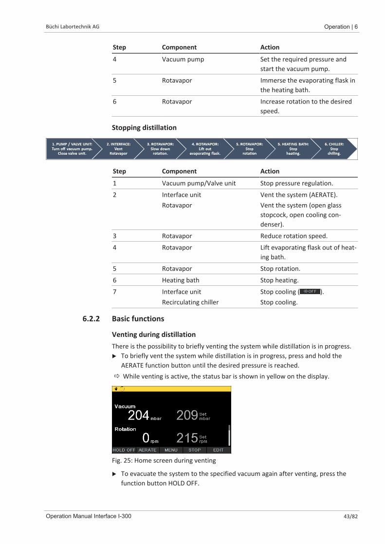
Venting during distillationThere is the possibility to briefly venting the system while distillation is in progress.u To briefly vent the system while distillation is in progress, press and hold the
AERATE function button until the desired pressure is reached.ð While venting is active, the status bar is shown in yellow on the display.
Fig. 25: Home screen during venting
u To evacuate the system to the specified vacuum again after venting, press thefunction button HOLD OFF.

6 | Operation Büchi Labortechnik AG
44/82 Operation Manual Interface I-300
Venting after completion of distillationIf venting has not been pre-programmed on the interface unit, the system can befully vented manually after completion of the distillation process.
Fig. 26: Home screen after completion of distillation
u After completion of distillation, press the AERATE function button.
ð The system is vented until it reaches ambient pressure.
Manually stopping the cooling processThe cooling function continues after completion of a distillation process. If thesystem has been pre-programmed accordingly, the cooling process stops after 5minutes. While cooling is active, the status bar shows the symbol . The coolingprocess can be stopped manually at any time regardless of how the system has beenpre-programmed.
Precondition:R After completion of distillation, the system has been fully vented by pressing the
AERATE function button.
u To manually stop the cooling process, press the function button .
ð The cooling process is stopped and the cooling symbol disappears from the statusbar.
Stopping everythingThere is the possibility to immediately stopping all apparatus connected to thesystem while distillation is in progress.u To stop all apparatus immediately, press the red STOP button (emergency stop).
6.2.3 Executing Manual modeIn [Manual] operating mode (manual distillation), the distillation process can becontrolled by manually setting the individual process parameters.
CAUTIONRisk of personal injury and property damage from unexpected equipment behavior
u Always carefully check the pre-programmed settings before every distillationprocess.
Navigation path
➔ Operating modes ➔ Manual
Büchi Labortechnik AG Operation | 6
Operation Manual Interface I-300 45/82
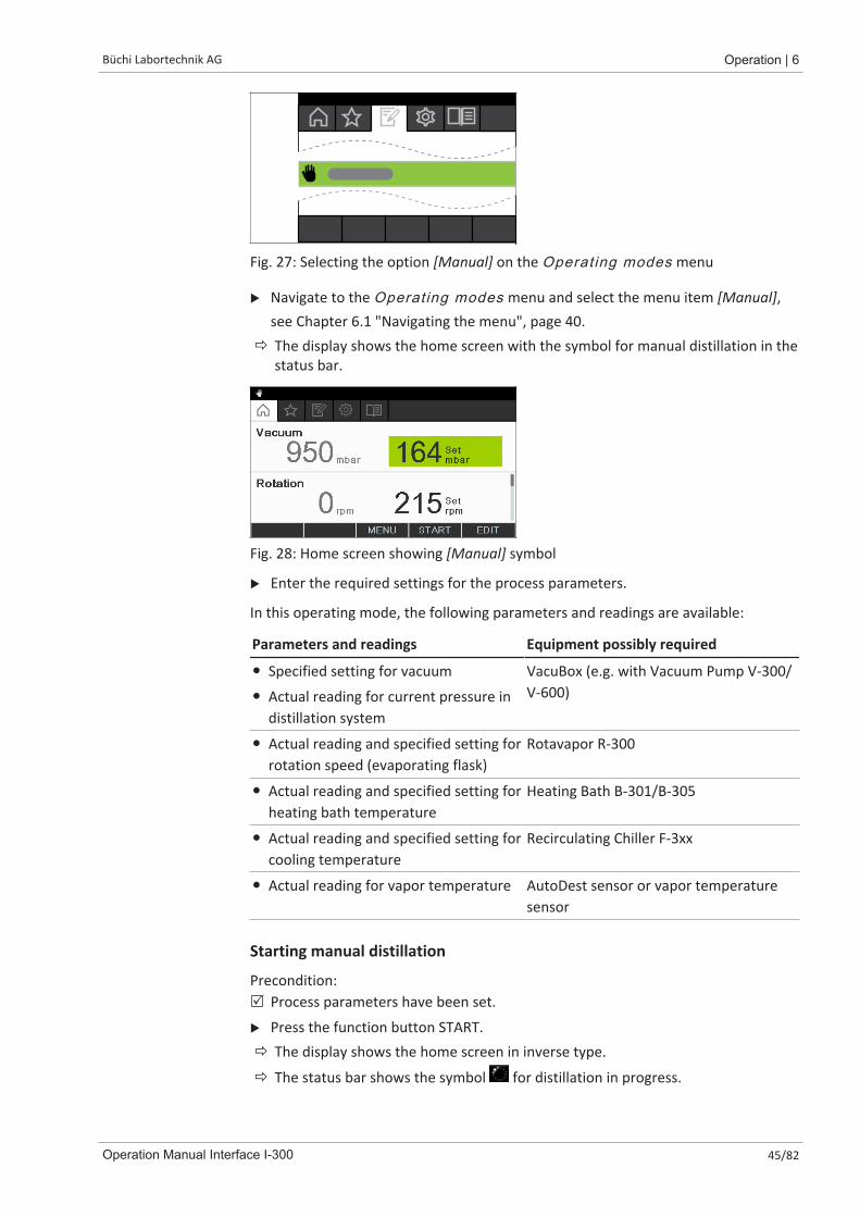
Fig. 27: Selecting the option [Manual] on the Operating modes menu
u Navigate to the Operating modes menu and select the menu item [Manual],see Chapter 6.1 "Navigating the menu", page 40.
ð The display shows the home screen with the symbol for manual distillation in thestatus bar.
Fig. 28: Home screen showing [Manual] symbol
u Enter the required settings for the process parameters.
In this operating mode, the following parameters and readings are available:
Parameters and readings Equipment possibly required
� Specified setting for vacuum
� Actual reading for current pressure indistillation system
VacuBox (e.g. with Vacuum Pump V-300/V-600)
� Actual reading and specified setting forrotation speed (evaporating flask)
Rotavapor R-300
� Actual reading and specified setting forheating bath temperature
Heating Bath B-301/B-305
� Actual reading and specified setting forcooling temperature
Recirculating Chiller F-3xx
� Actual reading for vapor temperature AutoDest sensor or vapor temperaturesensor
Starting manual distillation
Precondition:R Process parameters have been set.
u Press the function button START.ð The display shows the home screen in inverse type.
ð The status bar shows the symbol for distillation in progress.
6 | Operation Büchi Labortechnik AG
46/82 Operation Manual Interface I-300
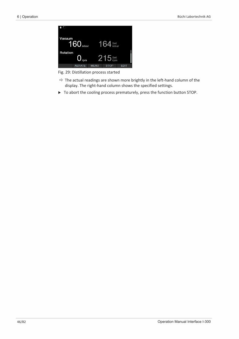
Fig. 29: Distillation process started
ð The actual readings are shown more brightly in the left-hand column of thedisplay. The right-hand column shows the specified settings.
u To abort the cooling process prematurely, press the function button STOP.
Büchi Labortechnik AG Operation | 6
Operation Manual Interface I-300 47/82
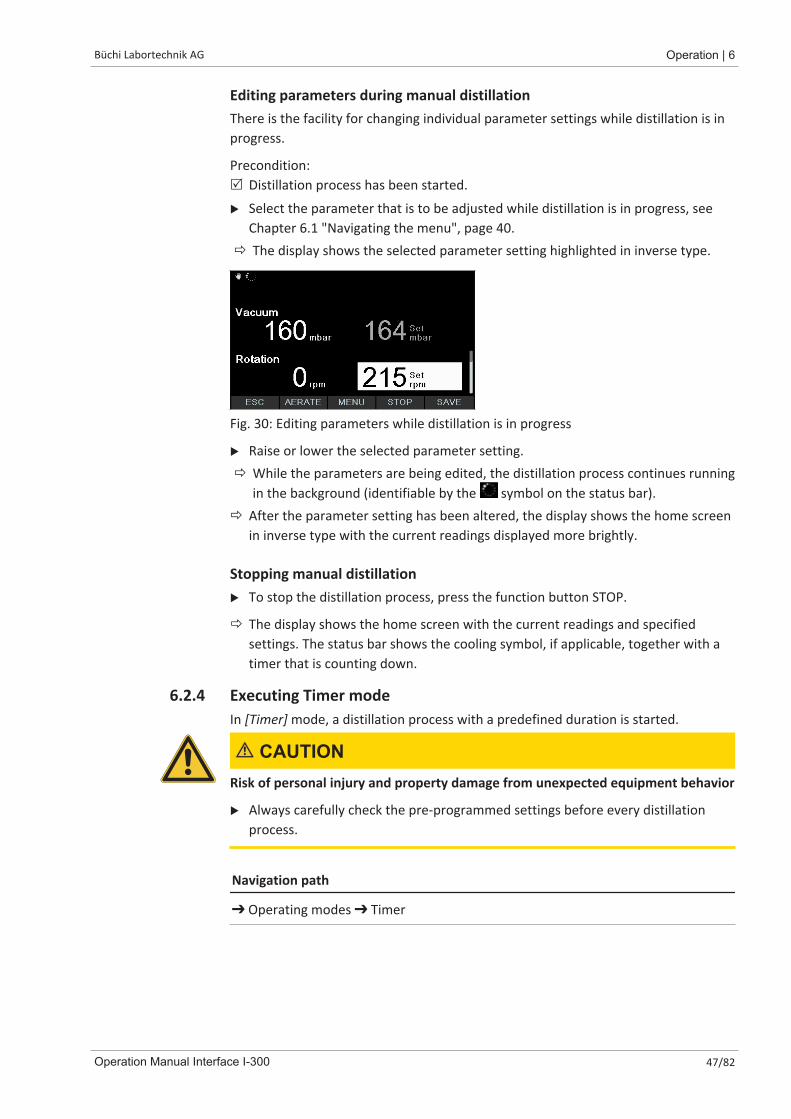
Editing parameters during manual distillationThere is the facility for changing individual parameter settings while distillation is inprogress.
Precondition:R Distillation process has been started.
u Select the parameter that is to be adjusted while distillation is in progress, seeChapter 6.1 "Navigating the menu", page 40.
ð The display shows the selected parameter setting highlighted in inverse type.
Fig. 30: Editing parameters while distillation is in progress
u Raise or lower the selected parameter setting.ð While the parameters are being edited, the distillation process continues running
in the background (identifiable by the symbol on the status bar).ð After the parameter setting has been altered, the display shows the home screen
in inverse type with the current readings displayed more brightly.
Stopping manual distillationu To stop the distillation process, press the function button STOP.
ð The display shows the home screen with the current readings and specifiedsettings. The status bar shows the cooling symbol, if applicable, together with atimer that is counting down.
6.2.4 Executing Timer modeIn [Timer] mode, a distillation process with a predefined duration is started.
CAUTIONRisk of personal injury and property damage from unexpected equipment behavior
u Always carefully check the pre-programmed settings before every distillationprocess.
Navigation path
➔ Operating modes ➔ Timer
6 | Operation Büchi Labortechnik AG
48/82 Operation Manual Interface I-300
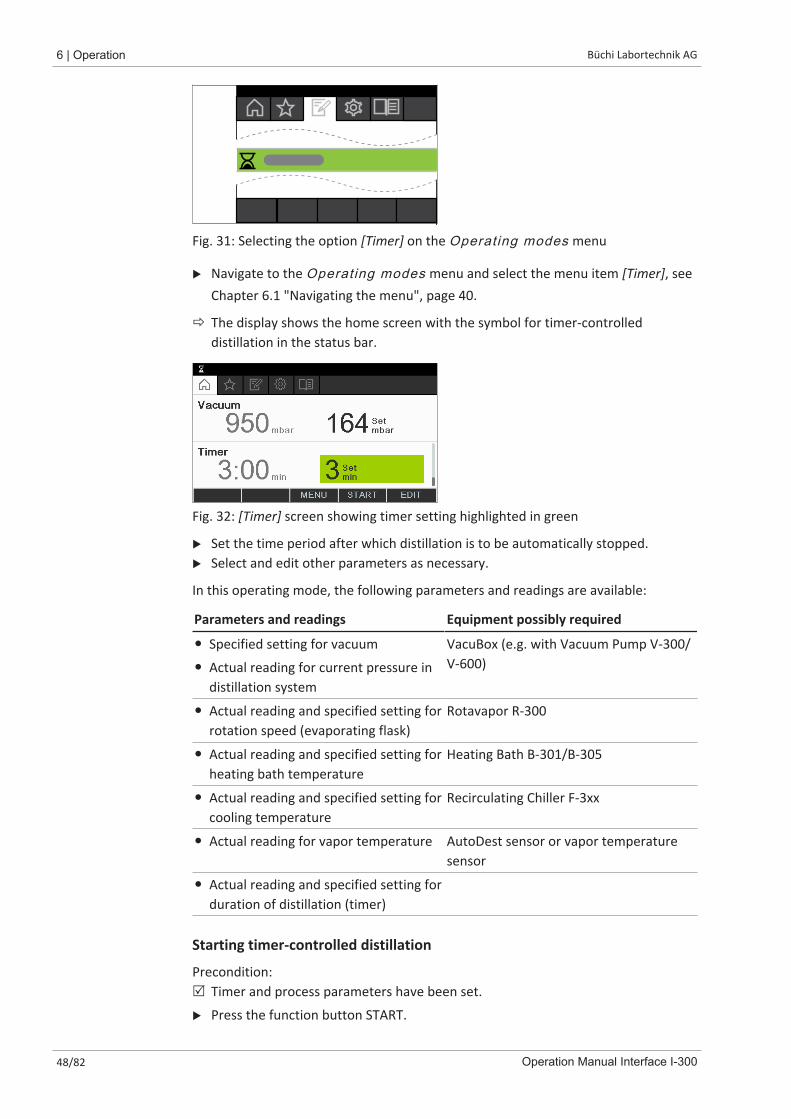
Fig. 31: Selecting the option [Timer] on the Operating modes menu
u Navigate to the Operating modes menu and select the menu item [Timer], seeChapter 6.1 "Navigating the menu", page 40.
ð The display shows the home screen with the symbol for timer-controlleddistillation in the status bar.
Fig. 32: [Timer] screen showing timer setting highlighted in green
u Set the time period after which distillation is to be automatically stopped.u Select and edit other parameters as necessary.
In this operating mode, the following parameters and readings are available:
Parameters and readings Equipment possibly required
� Specified setting for vacuum
� Actual reading for current pressure indistillation system
VacuBox (e.g. with Vacuum Pump V-300/V-600)
� Actual reading and specified setting forrotation speed (evaporating flask)
Rotavapor R-300
� Actual reading and specified setting forheating bath temperature
Heating Bath B-301/B-305
� Actual reading and specified setting forcooling temperature
Recirculating Chiller F-3xx
� Actual reading for vapor temperature AutoDest sensor or vapor temperaturesensor
� Actual reading and specified setting forduration of distillation (timer)
Starting timer-controlled distillation
Precondition:R Timer and process parameters have been set.
u Press the function button START.
Büchi Labortechnik AG Operation | 6
Operation Manual Interface I-300 49/82
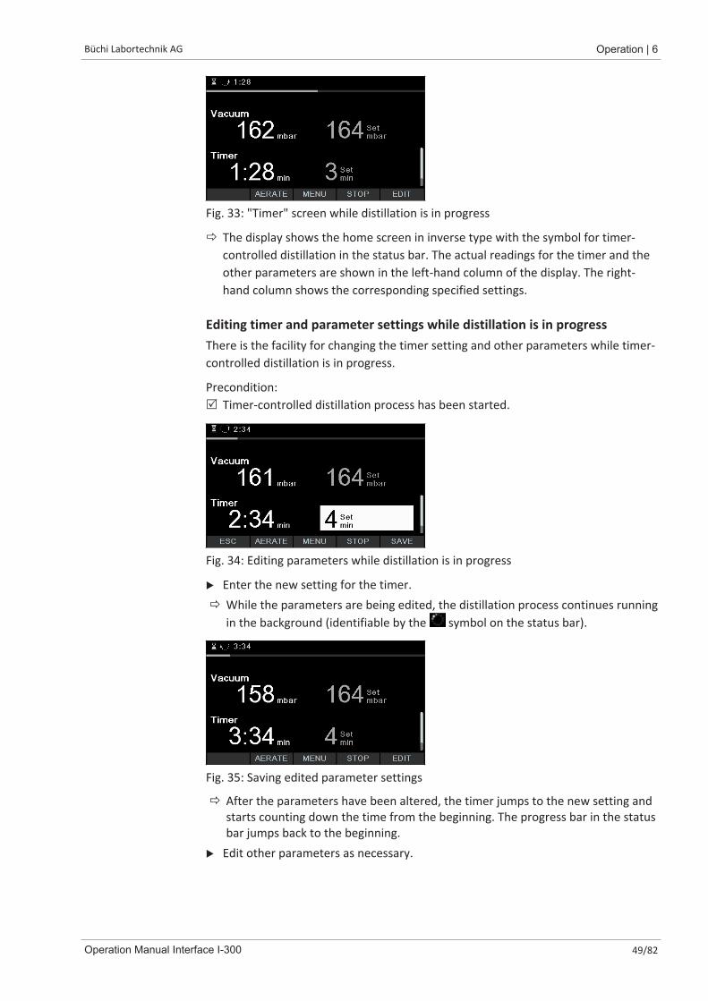
Fig. 33: "Timer" screen while distillation is in progress
ð The display shows the home screen in inverse type with the symbol for timer-controlled distillation in the status bar. The actual readings for the timer and theother parameters are shown in the left-hand column of the display. The right-hand column shows the corresponding specified settings.
Editing timer and parameter settings while distillation is in progressThere is the facility for changing the timer setting and other parameters while timer-controlled distillation is in progress.
Precondition:R Timer-controlled distillation process has been started.
Fig. 34: Editing parameters while distillation is in progress
u Enter the new setting for the timer.ð While the parameters are being edited, the distillation process continues running
in the background (identifiable by the symbol on the status bar).
Fig. 35: Saving edited parameter settings
ð After the parameters have been altered, the timer jumps to the new setting andstarts counting down the time from the beginning. The progress bar in the statusbar jumps back to the beginning.
u Edit other parameters as necessary.

6 | Operation Büchi Labortechnik AG
50/82 Operation Manual Interface I-300
Stopping timer-controlled distillationThe timer-controlled distillation process stops automatically when the preset timehas elapsed. After completion of timer-controlled distillation, an audible signalconsisting of three beeps sounds at regular intervals if the corresponding option hasbeen set on the Configuration menu.
NOTE
The audible signal is canceled as soon as the next user action is registered.
There is the facility for stopping distillation before the set time has elapsed.u To stop the timer-controlled distillation process prematurely, press the function
button STOP.
ð On completion of timer-controlled distillation, the display shows the followinginformation:
Fig. 36: "Timer" screen after completion of distillation
6.2.5 Executing Continuous Pumping modeIn [Continuous pumping] mode, the system continues running in idling mode to dryout the vessels and tubing after a distillation process has finished.
NOTEIn [Continuous pumping] mode, the settings for manual or timer-controlleddistillation are ignored.
Navigation path
➔ Operating modes ➔ Continuous pumping
Fig. 37: Selecting the option [Continuous pumping] on the Operating modes menu
u Navigate to the Operating modes menu and select the menu item [Continuouspumping], see Chapter 6.1 "Navigating the menu", page 40.
ð The display shows the home screen with the symbol for continuous pumping inthe status bar.
Büchi Labortechnik AG Operation | 6
Operation Manual Interface I-300 51/82
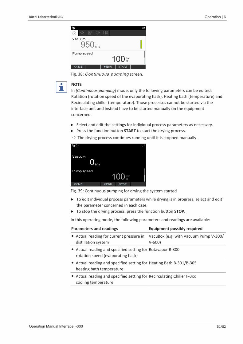
Fig. 38: Continuous pumping screen.
NOTEIn [Continuous pumping] mode, only the following parameters can be edited:Rotation (rotation speed of the evaporating flask), Heating bath (temperature) andRecirculating chiller (temperature). Those processes cannot be started via theinterface unit and instead have to be started manually on the equipmentconcerned.
u Select and edit the settings for individual process parameters as necessary.u Press the function button START to start the drying process.ð The drying process continues running until it is stopped manually.
Fig. 39: Continuous pumping for drying the system started
u To edit individual process parameters while drying is in progress, select and editthe parameter concerned in each case.
u To stop the drying process, press the function button STOP.
In this operating mode, the following parameters and readings are available:
Parameters and readings Equipment possibly required
� Actual reading for current pressure indistillation system
VacuBox (e.g. with Vacuum Pump V-300/V-600)
� Actual reading and specified setting forrotation speed (evaporating flask)
Rotavapor R-300
� Actual reading and specified setting forheating bath temperature
Heating Bath B-301/B-305
� Actual reading and specified setting forcooling temperature
Recirculating Chiller F-3xx
6 | Operation Büchi Labortechnik AG
52/82 Operation Manual Interface I-300
Parameters and readings Equipment possibly required
� Actual reading for vapor temperature AutoDest sensor or vapor temperaturesensor
NOTE
The pressure (vacuum) cannot be altered. The vacuum pump runs at the maximumspeed setting.
6.2.6 Performing automatic distillationAutomatic distillation requires the use of an AutoDest sensor. The AutoDest sensoris connected to the VacuBox (see Chapter 5.3 "Connecting AutoDest sensor to vaportemperature sensor (optional accessory)", page 36) and measures the inlet andoutlet temperature of the coolant and the vapor temperature at the coolingcondenser.From those three readings, the system calculates the parameter settingsrequired for optimum distillation. During automatic distillation, the temperatures ofthe heating bath, coolant and vapor are constantly measured and the specifiedsetting for the pressure adjusted accordingly.
CAUTIONRisk of personal injury and property damage from unexpected equipment behavior
u Always carefully check the pre-programmed settings before every distillationprocess. In particular, check the setting for immersion of the evaporating flask atthe start of the distillation process.
Navigation path
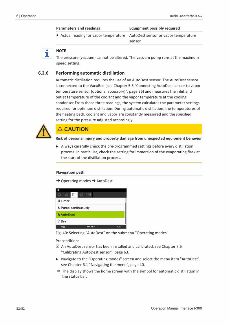
➔ Operating modes ➔ AutoDest
Fig. 40: Selecting "AutoDest" on the submenu "Operating modes"
Precondition:R An AutoDest sensor has been installed and calibrated, see Chapter 7.6
"Calibrating AutoDest sensor", page 63.
u Navigate to the "Operating modes" screen and select the menu item "AutoDest",see Chapter 6.1 "Navigating the menu", page 40.
ð The display shows the home screen with the symbol for automatic distillation inthe status bar.
Büchi Labortechnik AG Operation | 6
Operation Manual Interface I-300 53/82
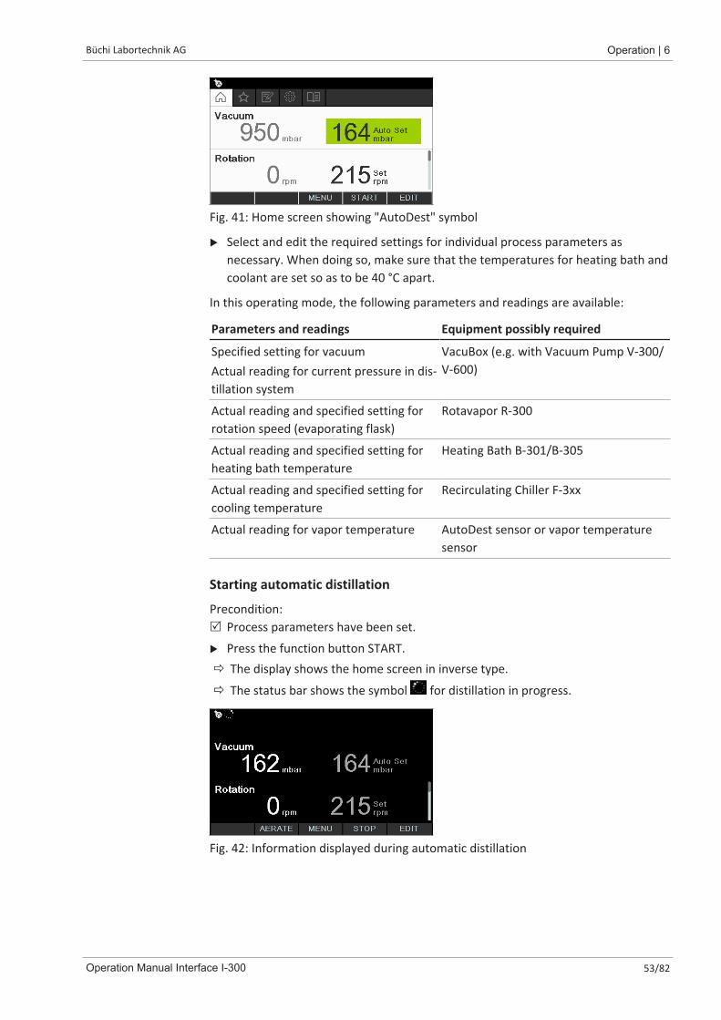
Fig. 41: Home screen showing "AutoDest" symbol
u Select and edit the required settings for individual process parameters asnecessary. When doing so, make sure that the temperatures for heating bath andcoolant are set so as to be 40 °C apart.
In this operating mode, the following parameters and readings are available:
Parameters and readings Equipment possibly required
Specified setting for vacuumActual reading for current pressure in dis-tillation system
VacuBox (e.g. with Vacuum Pump V-300/V-600)
Actual reading and specified setting forrotation speed (evaporating flask)
Rotavapor R-300
Actual reading and specified setting forheating bath temperature
Heating Bath B-301/B-305
Actual reading and specified setting forcooling temperature
Recirculating Chiller F-3xx
Actual reading for vapor temperature AutoDest sensor or vapor temperaturesensor
Starting automatic distillation
Precondition:R Process parameters have been set.
u Press the function button START.ð The display shows the home screen in inverse type.
ð The status bar shows the symbol for distillation in progress.
Fig. 42: Information displayed during automatic distillation
6 | Operation Büchi Labortechnik AG
54/82 Operation Manual Interface I-300
Editing parameters during automatic distillationThere is the facility for altering the process parameters while automatic distillation isin progress, see Chapter "Editing parameters during manual distillation", page 47.
NOTE
If the specified setting for the pressure is altered manually, the level setautomatically is lost and the operating mode switches to manual distillation.
NOTE
The specified settings for the individual parameters may only be altered gradually asotherwise distillation may be aborted.
Büchi Labortechnik AG Operation | 6
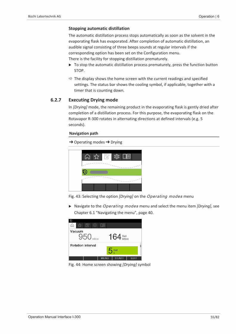
Operation Manual Interface I-300 55/82
Stopping automatic distillationThe automatic distillation process stops automatically as soon as the solvent in theevaporating flask has evaporated. After completion of automatic distillation, anaudible signal consisting of three beeps sounds at regular intervals if thecorresponding option has been set on the Configuration menu.There is the facility for stopping distillation prematurely.u To stop the automatic distillation process prematurely, press the function button
STOP.
ð The display shows the home screen with the current readings and specifiedsettings. The status bar shows the cooling symbol, if applicable, together with atimer that is counting down.
6.2.7 Executing Drying modeIn [Drying] mode, the remaining product in the evaporating flask is gently dried aftercompletion of a distillation process. For this purpose, the evaporating flask on theRotavapor R-300 rotates in alternating directions at defined intervals (e.g. 5seconds).
Navigation path
➔ Operating modes ➔ Drying
Fig. 43: Selecting the option [Drying] on the Operating modes menu
u Navigate to the Operating modes menu and select the menu item [Drying], seeChapter 6.1 "Navigating the menu", page 40.
Fig. 44: Home screen showing [Drying] symbol
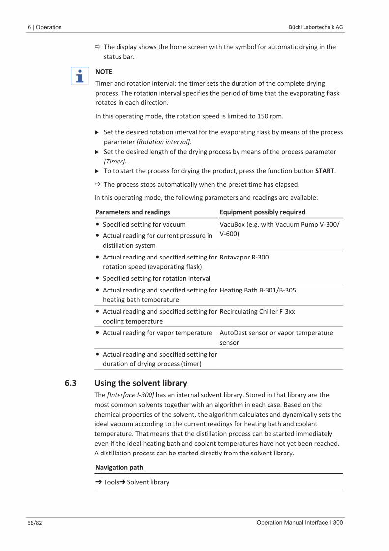
6 | Operation Büchi Labortechnik AG
56/82 Operation Manual Interface I-300
ð The display shows the home screen with the symbol for automatic drying in thestatus bar.
NOTE
Timer and rotation interval: the timer sets the duration of the complete dryingprocess. The rotation interval specifies the period of time that the evaporating flaskrotates in each direction.
In this operating mode, the rotation speed is limited to 150 rpm.
u Set the desired rotation interval for the evaporating flask by means of the processparameter [Rotation interval].
u Set the desired length of the drying process by means of the process parameter[Timer].
u To to start the process for drying the product, press the function button START.
ð The process stops automatically when the preset time has elapsed.
In this operating mode, the following parameters and readings are available:
Parameters and readings Equipment possibly required
� Specified setting for vacuum
� Actual reading for current pressure indistillation system
VacuBox (e.g. with Vacuum Pump V-300/V-600)
� Actual reading and specified setting forrotation speed (evaporating flask)
� Specified setting for rotation interval
Rotavapor R-300
� Actual reading and specified setting forheating bath temperature
Heating Bath B-301/B-305
� Actual reading and specified setting forcooling temperature
Recirculating Chiller F-3xx
� Actual reading for vapor temperature AutoDest sensor or vapor temperaturesensor
� Actual reading and specified setting forduration of drying process (timer)
6.3 Using the solvent libraryThe [Interface I-300] has an internal solvent library. Stored in that library are themost common solvents together with an algorithm in each case. Based on thechemical properties of the solvent, the algorithm calculates and dynamically sets theideal vacuum according to the current readings for heating bath and coolanttemperature. That means that the distillation process can be started immediatelyeven if the ideal heating bath and coolant temperatures have not yet been reached.A distillation process can be started directly from the solvent library.
Navigation path
➔ Tools➔ Solvent library

Büchi Labortechnik AG Operation | 6
Operation Manual Interface I-300 57/82
Fig. 45: Selecting "Solvent library" on the "Operating modes" screen
u Navigate to the "Operating modes" screen and select the menu item "Solventlibrary", see Chapter 6.1 "Navigating the menu", page 40.
ð The display shows the Solvent library submenu.
Fig. 46: Selecting "Ethanol" from the Solvent library submenu
u Select the desired solvent (e.g. Ethanol) from the solvent library.
NOTE
When the heating bath and the recirculating chiller are connected, the actualfigures are automatically applied. If equipment of a different make is connected, theset temperatures on the devices concerned have to be entered as specified settingson the interface.
Fig. 47: Selecting "Set" temperature for heating bath when using equipment of adifferent make
u Enter the specified settings for heating bath and coolant temperature ifnecessary.
u To start a distillation process directly from the solvent library, press the functionbutton START.
u To apply the settings for the selected solvent and return to the interface unithome screen, press OK. On the home screen, the settings for the individualprocess parameters can be edited.
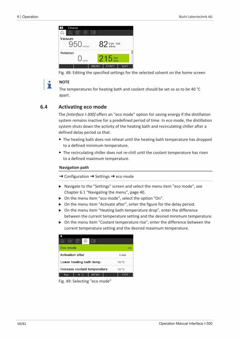
6 | Operation Büchi Labortechnik AG
58/82 Operation Manual Interface I-300
Fig. 48: Editing the specified settings for the selected solvent on the home screen
NOTE
The temperatures for heating bath and coolant should be set so as to be 40 °Capart.
6.4 Activating eco modeThe [Interface I-300] offers an "eco mode" option for saving energy if the distillationsystem remains inactive for a predefined period of time. In eco mode, the distillationsystem shuts down the activity of the heating bath and recirculating chiller after adefined delay period so that:
� The heating bath does not reheat until the heating bath temperature has droppedto a defined minimum temperature.
� The recirculating chiller does not re-chill until the coolant temperature has risento a defined maximum temperature.
Navigation path
➜ Configuration ➜ Settings ➜ eco mode
u Navigate to the "Settings" screen and select the menu item "eco mode", seeChapter 6.1 "Navigating the menu", page 40.
u On the menu item "eco mode", select the option "On".u On the menu item "Activate after", enter the figure for the delay period.u On the menu item "Heating bath temperature drop", enter the difference
between the current temperature setting and the desired minimum temperature.u On the menu item "Coolant temperature rise", enter the difference between the
current temperature setting and the desired maximum temperature.
Fig. 49: Selecting "eco mode"
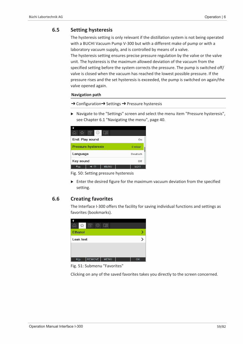
Büchi Labortechnik AG Operation | 6
Operation Manual Interface I-300 59/82
6.5 Setting hysteresisThe hysteresis setting is only relevant if the distillation system is not being operatedwith a BUCHI Vacuum Pump V-300 but with a different make of pump or with alaboratory vacuum supply, and is controlled by means of a valve.The hysteresis setting ensures precise pressure regulation by the valve or the valveunit. The hysteresis is the maximum allowed deviation of the vacuum from thespecified setting before the system corrects the pressure. The pump is switched off/valve is closed when the vacuum has reached the lowest possible pressure. If thepressure rises and the set hysteresis is exceeded, the pump is switched on again/thevalve opened again.
Navigation path
➔ Configuration➔ Settings ➔ Pressure hysteresis
u Navigate to the "Settings" screen and select the menu item "Pressure hysteresis",see Chapter 6.1 "Navigating the menu", page 40.
Fig. 50: Setting pressure hysteresis
u Enter the desired figure for the maximum vacuum deviation from the specifiedsetting.
6.6 Creating favoritesThe Interface I-300 offers the facility for saving individual functions and settings asfavorites (bookmarks).
Fig. 51: Submenu "Favorites"
Clicking on any of the saved favorites takes you directly to the screen concerned.
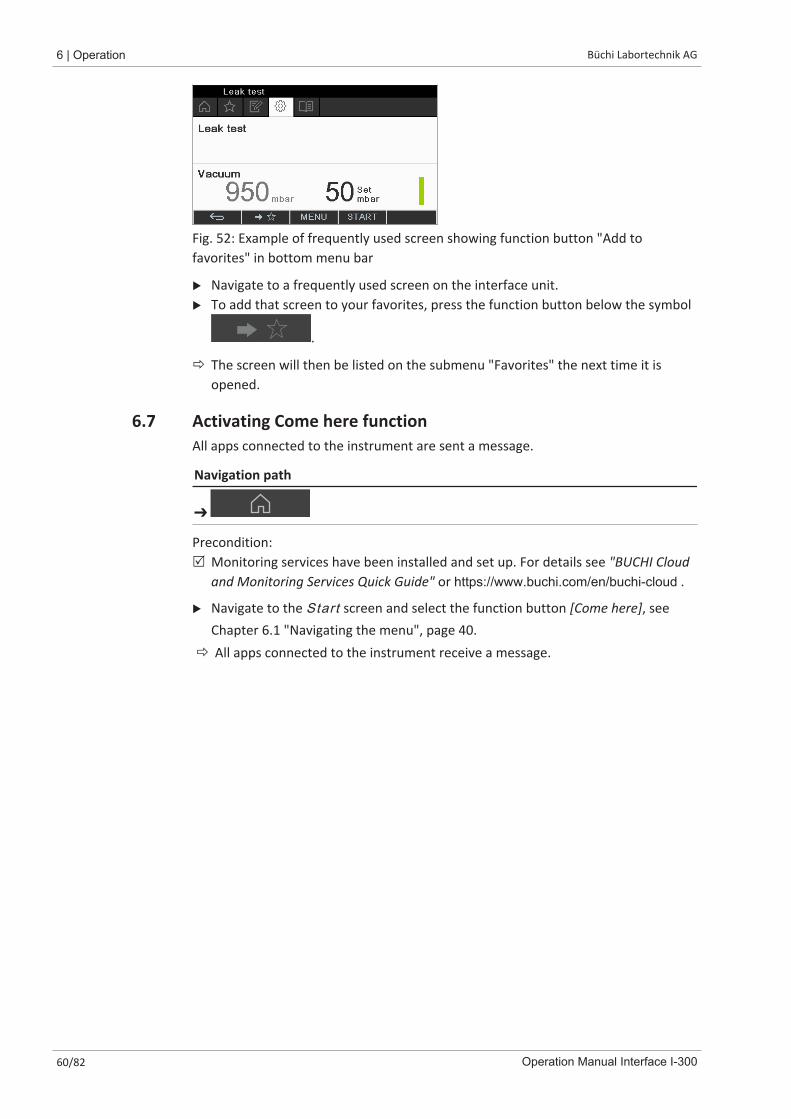
6 | Operation Büchi Labortechnik AG
60/82 Operation Manual Interface I-300
Fig. 52: Example of frequently used screen showing function button "Add tofavorites" in bottom menu bar
u Navigate to a frequently used screen on the interface unit.u To add that screen to your favorites, press the function button below the symbol
.
ð The screen will then be listed on the submenu "Favorites" the next time it isopened.
6.7 Activating Come here functionAll apps connected to the instrument are sent a message.
Navigation path
➔
Precondition:R Monitoring services have been installed and set up. For details see "BUCHI Cloud
and Monitoring Services Quick Guide" or https://www.buchi.com/en/buchi-cloud .
u Navigate to the Start screen and select the function button [Come here], seeChapter 6.1 "Navigating the menu", page 40.
ð All apps connected to the instrument receive a message.

Büchi Labortechnik AG Cleaning and servicing | 7
Operation Manual Interface I-300 61/82
7 Cleaning and servicingNOTE
Users may only carry out the servicing and cleaning operations described in thissection.
Any servicing and repair work which involves opening up the casing may only becarried out by BUCHI service technicians.
u Use only genuine BUCHI consumables and spare parts in order to ensure correctoperation of the device and preserve the warranty.
7.1 Cleaning the casing/displayu Use a damp cloth to clean the device.u To clean the casing, only use ethanol or soapy water.
7.2 Performing a leak testNavigation path
➜ Configuration ➜ Servicing ➜ Leak test
The leak test provides the facility for checking the system for possible leaks.
Precondition:R All openings in the vacuum system are sealed.
u Navigate to the "Servicing" screen and select the menu item "Leak test", seeChapter 6.1 "Navigating the menu", page 40.
Fig. 53: Leak test screen
u Press the function button START to start the leak test.ð The system is evacuated to 50 mbar within 2 minutes.ð After a stabilization period of 30 seconds, the leakage rate is shown.
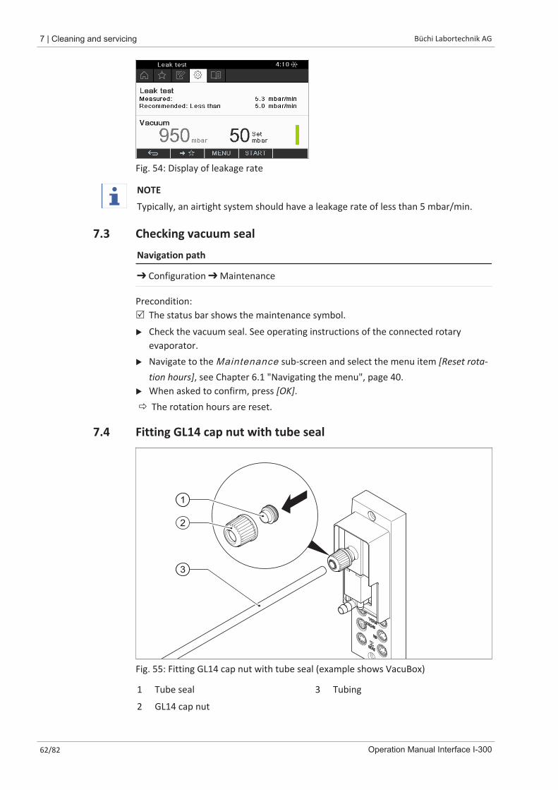
7 | Cleaning and servicing Büchi Labortechnik AG
62/82 Operation Manual Interface I-300
Fig. 54: Display of leakage rate
NOTE
Typically, an airtight system should have a leakage rate of less than 5 mbar/min.
7.3 Checking vacuum sealNavigation path
➔ Configuration ➔ Maintenance
Precondition:R The status bar shows the maintenance symbol.
u Check the vacuum seal. See operating instructions of the connected rotaryevaporator.
u Navigate to the Maintenance sub-screen and select the menu item [Reset rota-tion hours], see Chapter 6.1 "Navigating the menu", page 40.
u When asked to confirm, press [OK].ð The rotation hours are reset.
7.4 Fitting GL14 cap nut with tube seal
2
1
3
Fig. 55: Fitting GL14 cap nut with tube seal (example shows VacuBox)
1 Tube seal 3 Tubing
2 GL14 cap nut

Büchi Labortechnik AG Cleaning and servicing | 7
Operation Manual Interface I-300 63/82
u Insert the tube seal (1) in the GL14 cap nut (2) ensuring it is straight. NOTICE! Riskof damaging tube seal. Make sure that the tube seal does not twist or jam in theGL14 cap nut.
u Loosely screw the GL14 cap nut together with tube seal onto the deviceconcerned (example shows VacuBox) or the Woulff bottle.
u Carefully insert the end of the tube (3) into the GL14 cap nut and tube seal.u Tighten the GL14 cap nut and tube seal.
7.5 Checking sealsSeals are wearing parts. They have to be regularly inspected, cleaned and, ifnecessary, replaced. The life of a seal depends on how much it is used and how wellit is looked after.
11
u Unscrew the GL14 cap nut from the vacuum connection (1) and remove the tubeseal.
u Check the tube seal for signs of damage and cracks.u Rinse intact tube seals in water or ethanol and dry with a soft cloth.u Replace damaged tube seals.
7.6 Calibrating AutoDest sensorThe AutoDest sensor measures the temperature of the coolant at the inlet andoutlet of the cooling condenser.Adjust the sensors so that the difference is no more than 0.1 °C.
Navigation path
➜ Configuration ➜ System information ➜ AutoDest sensor
u Place the AutoDest sensor in a homogeneous water bath.u Navigate to the System information sub-screen and select the menu item [Au-
toDest sensor], see Chapter 6.1 "Navigating the menu", page 40.
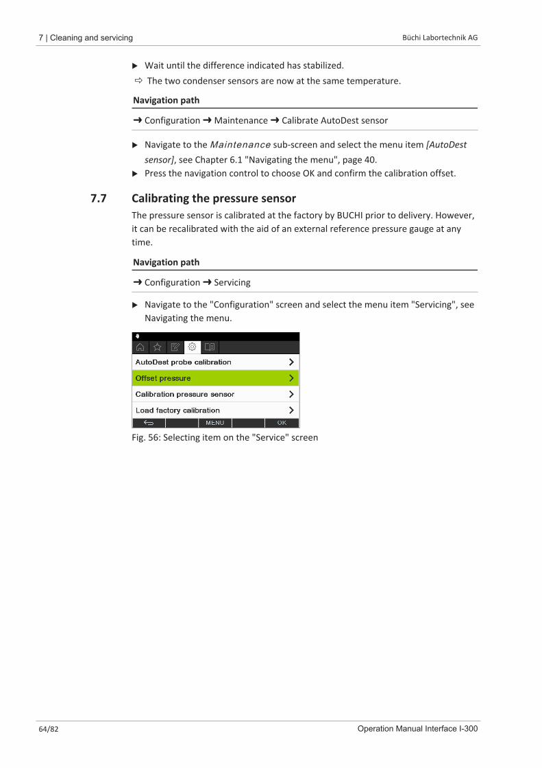
7 | Cleaning and servicing Büchi Labortechnik AG
64/82 Operation Manual Interface I-300
u Wait until the difference indicated has stabilized.ð The two condenser sensors are now at the same temperature.
Navigation path
➜ Configuration ➜ Maintenance ➜ Calibrate AutoDest sensor
u Navigate to the Maintenance sub-screen and select the menu item [AutoDestsensor], see Chapter 6.1 "Navigating the menu", page 40.
u Press the navigation control to choose OK and confirm the calibration offset.
7.7 Calibrating the pressure sensorThe pressure sensor is calibrated at the factory by BUCHI prior to delivery. However,it can be recalibrated with the aid of an external reference pressure gauge at anytime.
Navigation path
➜ Configuration ➜ Servicing
u Navigate to the "Configuration" screen and select the menu item "Servicing", seeNavigating the menu.
Fig. 56: Selecting item on the "Service" screen
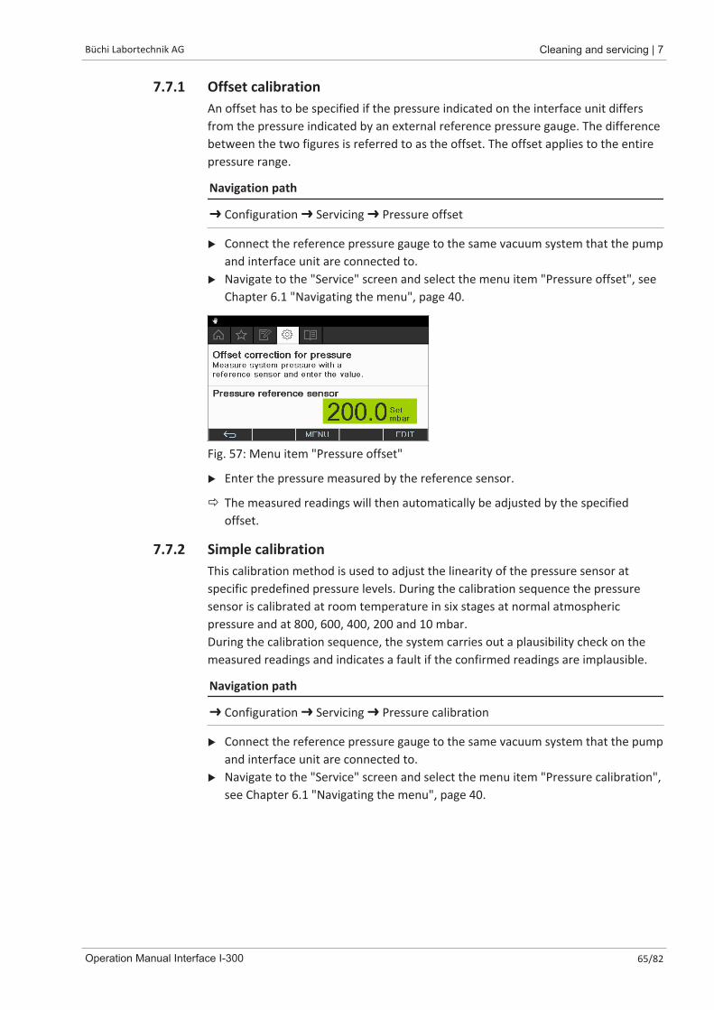
Büchi Labortechnik AG Cleaning and servicing | 7
Operation Manual Interface I-300 65/82
7.7.1 Offset calibrationAn offset has to be specified if the pressure indicated on the interface unit differsfrom the pressure indicated by an external reference pressure gauge. The differencebetween the two figures is referred to as the offset. The offset applies to the entirepressure range.
Navigation path
➜ Configuration ➜ Servicing ➜ Pressure offset
u Connect the reference pressure gauge to the same vacuum system that the pumpand interface unit are connected to.
u Navigate to the "Service" screen and select the menu item "Pressure offset", seeChapter 6.1 "Navigating the menu", page 40.
Fig. 57: Menu item "Pressure offset"
u Enter the pressure measured by the reference sensor.
ð The measured readings will then automatically be adjusted by the specifiedoffset.
7.7.2 Simple calibrationThis calibration method is used to adjust the linearity of the pressure sensor atspecific predefined pressure levels. During the calibration sequence the pressuresensor is calibrated at room temperature in six stages at normal atmosphericpressure and at 800, 600, 400, 200 and 10 mbar.During the calibration sequence, the system carries out a plausibility check on themeasured readings and indicates a fault if the confirmed readings are implausible.
Navigation path
➜ Configuration ➜ Servicing ➜ Pressure calibration
u Connect the reference pressure gauge to the same vacuum system that the pumpand interface unit are connected to.
u Navigate to the "Service" screen and select the menu item "Pressure calibration",see Chapter 6.1 "Navigating the menu", page 40.
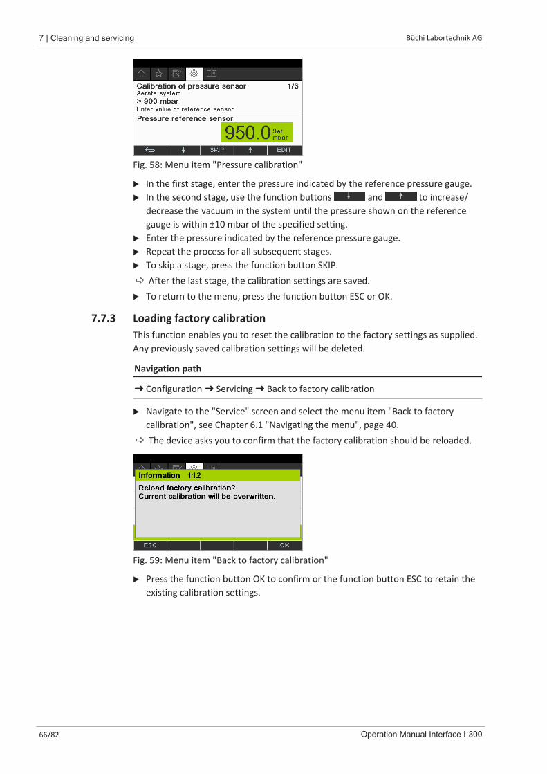
7 | Cleaning and servicing Büchi Labortechnik AG
66/82 Operation Manual Interface I-300
Fig. 58: Menu item "Pressure calibration"
u In the first stage, enter the pressure indicated by the reference pressure gauge.u In the second stage, use the function buttons and to increase/
decrease the vacuum in the system until the pressure shown on the referencegauge is within ±10 mbar of the specified setting.
u Enter the pressure indicated by the reference pressure gauge.u Repeat the process for all subsequent stages.u To skip a stage, press the function button SKIP.ð After the last stage, the calibration settings are saved.u To return to the menu, press the function button ESC or OK.
7.7.3 Loading factory calibrationThis function enables you to reset the calibration to the factory settings as supplied.Any previously saved calibration settings will be deleted.
Navigation path
➜ Configuration ➜ Servicing ➜ Back to factory calibration
u Navigate to the "Service" screen and select the menu item "Back to factorycalibration", see Chapter 6.1 "Navigating the menu", page 40.
ð The device asks you to confirm that the factory calibration should be reloaded.
Fig. 59: Menu item "Back to factory calibration"
u Press the function button OK to confirm or the function button ESC to retain theexisting calibration settings.
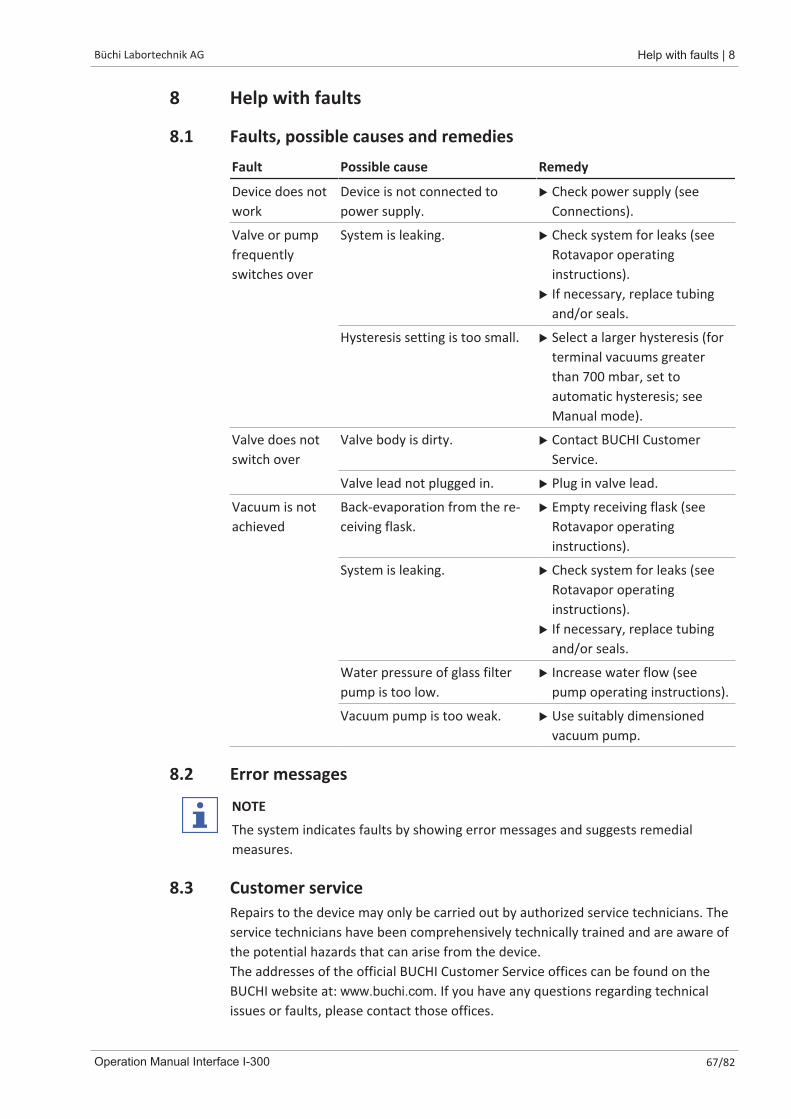
Büchi Labortechnik AG Help with faults | 8
Operation Manual Interface I-300 67/82
8 Help with faults
8.1 Faults, possible causes and remediesFault Possible cause Remedy
Device does notwork
Device is not connected topower supply.
u Check power supply (seeConnections).
Valve or pumpfrequentlyswitches over
System is leaking. u Check system for leaks (seeRotavapor operatinginstructions).
u If necessary, replace tubingand/or seals.
Hysteresis setting is too small. u Select a larger hysteresis (forterminal vacuums greaterthan 700 mbar, set toautomatic hysteresis; seeManual mode).
Valve does notswitch over
Valve body is dirty. u Contact BUCHI CustomerService.
Valve lead not plugged in. u Plug in valve lead.
Vacuum is notachieved
Back-evaporation from the re-ceiving flask.
u Empty receiving flask (seeRotavapor operatinginstructions).
System is leaking. u Check system for leaks (seeRotavapor operatinginstructions).
u If necessary, replace tubingand/or seals.
Water pressure of glass filterpump is too low.
u Increase water flow (seepump operating instructions).
Vacuum pump is too weak. u Use suitably dimensionedvacuum pump.
8.2 Error messages
NOTE
The system indicates faults by showing error messages and suggests remedialmeasures.
8.3 Customer serviceRepairs to the device may only be carried out by authorized service technicians. Theservice technicians have been comprehensively technically trained and are aware ofthe potential hazards that can arise from the device.The addresses of the official BUCHI Customer Service offices can be found on theBUCHI website at: www.buchi.com. If you have any questions regarding technicalissues or faults, please contact those offices.
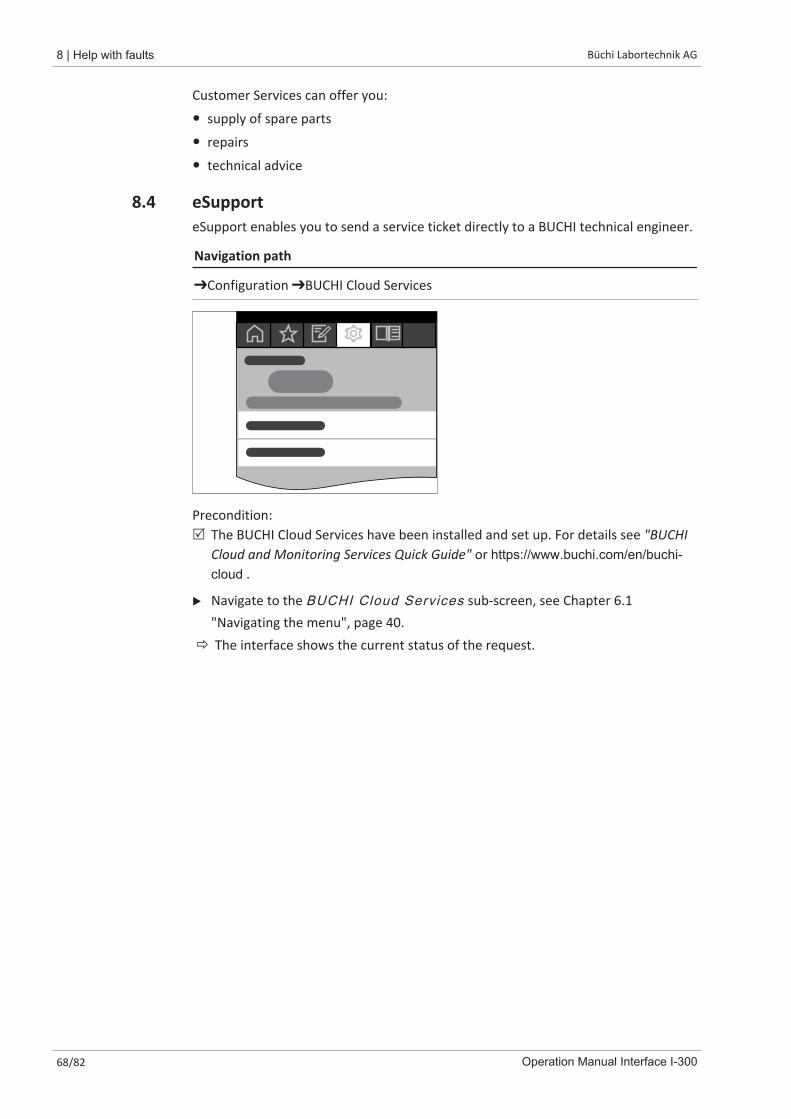
8 | Help with faults Büchi Labortechnik AG
68/82 Operation Manual Interface I-300
Customer Services can offer you:
� supply of spare parts
� repairs
� technical advice
8.4 eSupporteSupport enables you to send a service ticket directly to a BUCHI technical engineer.
Navigation path
➔Configuration ➔BUCHI Cloud Services
Precondition:R The BUCHI Cloud Services have been installed and set up. For details see "BUCHI
Cloud and Monitoring Services Quick Guide" or https://www.buchi.com/en/buchi-cloud .
u Navigate to the BUCHI Cloud Services sub-screen, see Chapter 6.1"Navigating the menu", page 40.
ð The interface shows the current status of the request.
Büchi Labortechnik AG Taking out of service and disposal | 9
Operation Manual Interface I-300 69/82
9 Taking out of service and disposal
9.1 Taking out of serviceu Switch off the [Interface I-300] and disconnect it from the mains power supply.u Remove all tubing and communication cables from the device.
9.2 DisposalThe operator is responsible for proper disposal of the [Interface].u When disposing of equipment observe the local regulations and statutory
requirements regarding waste disposal.
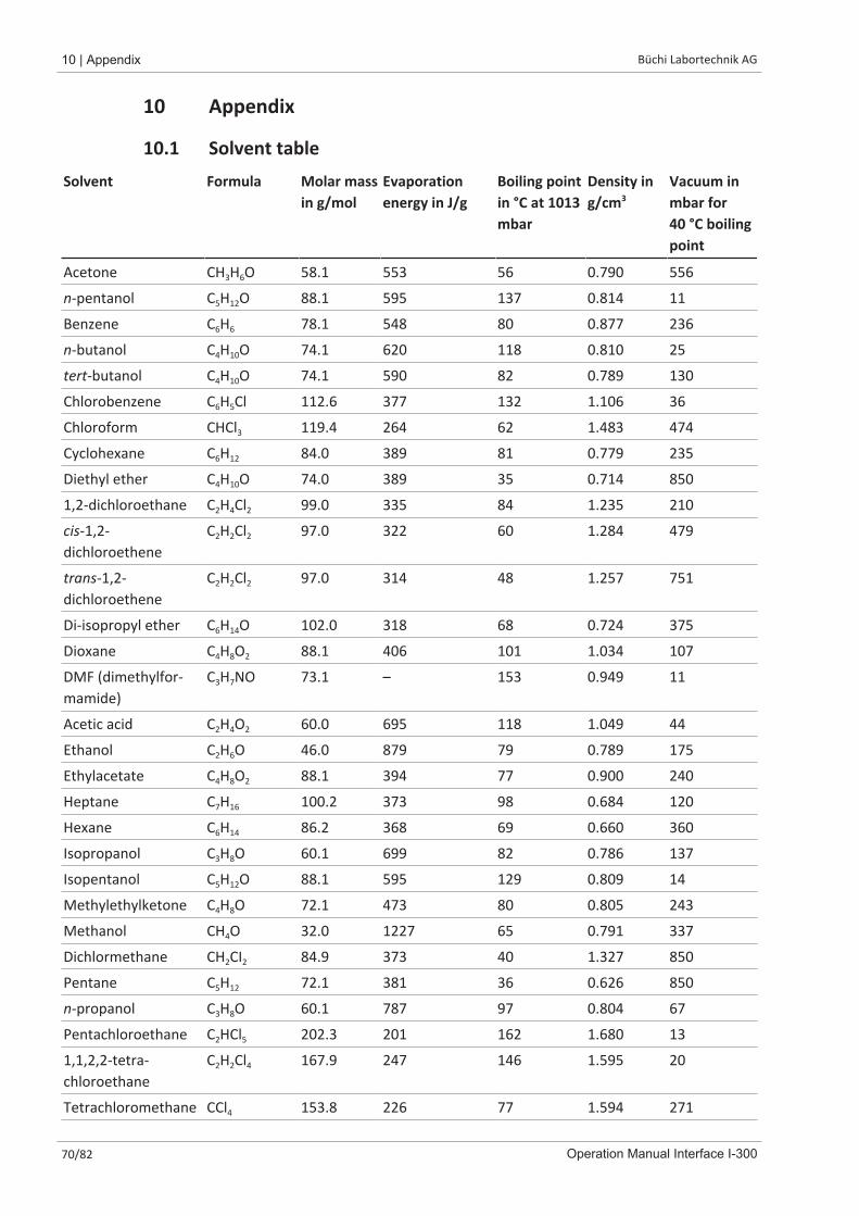
10 | Appendix Büchi Labortechnik AG
70/82 Operation Manual Interface I-300
10 Appendix
10.1 Solvent tableSolvent Formula Molar mass
in g/molEvaporationenergy in J/g
Boiling pointin °C at 1013mbar
Density ing/cm3
Vacuum inmbar for40 °C boilingpoint
Acetone CH3H6O 58.1 553 56 0.790 556
n-pentanol C5H12O 88.1 595 137 0.814 11
Benzene C6H6 78.1 548 80 0.877 236
n-butanol C4H10O 74.1 620 118 0.810 25
tert-butanol C4H10O 74.1 590 82 0.789 130
Chlorobenzene C6H5Cl 112.6 377 132 1.106 36
Chloroform CHCl3 119.4 264 62 1.483 474
Cyclohexane C6H12 84.0 389 81 0.779 235
Diethyl ether C4H10O 74.0 389 35 0.714 850
1,2-dichloroethane C2H4Cl2 99.0 335 84 1.235 210
cis-1,2-dichloroethene
C2H2Cl2 97.0 322 60 1.284 479
trans-1,2-dichloroethene
C2H2Cl2 97.0 314 48 1.257 751
Di-isopropyl ether C6H14O 102.0 318 68 0.724 375
Dioxane C4H8O2 88.1 406 101 1.034 107
DMF (dimethylfor-mamide)
C3H7NO 73.1 – 153 0.949 11
Acetic acid C2H4O2 60.0 695 118 1.049 44
Ethanol C2H6O 46.0 879 79 0.789 175
Ethylacetate C4H8O2 88.1 394 77 0.900 240
Heptane C7H16 100.2 373 98 0.684 120
Hexane C6H14 86.2 368 69 0.660 360
Isopropanol C3H8O 60.1 699 82 0.786 137
Isopentanol C5H12O 88.1 595 129 0.809 14
Methylethylketone C4H8O 72.1 473 80 0.805 243
Methanol CH4O 32.0 1227 65 0.791 337
Dichlormethane CH2CI2 84.9 373 40 1.327 850
Pentane C5H12 72.1 381 36 0.626 850
n-propanol C3H8O 60.1 787 97 0.804 67
Pentachloroethane C2HCl5 202.3 201 162 1.680 13
1,1,2,2-tetra-chloroethane
C2H2Cl4 167.9 247 146 1.595 20
Tetrachloromethane CCl4 153.8 226 77 1.594 271
Büchi Labortechnik AG Appendix | 10
Operation Manual Interface I-300 71/82
Solvent Formula Molar massin g/mol
Evaporationenergy in J/g
Boiling pointin °C at 1013mbar
Density ing/cm3
Vacuum inmbar for40 °C boilingpoint
1,1,1-trichloroethane C2H3Cl3 133.4 251 74 1.339 300
Tetrachloroethene C2Cl4 165.8 234 121 1.623 53
THF (tetrahydrofu-ran)
C4H8O 72.1 – 67 0.889 374
Toluene C7H8 92.2 427 111 0.867 77
Trichloroethene C2HCl3 131.3 264 87 1.464 183
Water H2O 18.0 2261 100 1.000 72
Xylene (mixture) C8H10 106.2 389 – – 25
o-xylene C8H10 106.2 – 144 0.880 –
m-xylene C8H10 106.2 – 139 0.864 –
p-xylene C8H10 106.2 – 138 0.861 –
10.2 Spare parts and accessoriesUse only genuine BUCHI consumables and spare parts in order to ensure correct,safe and reliable operation of the system.
NOTE
Any modifications of spare parts or assemblies are only allowed with the priorwritten permission of BUCHI.
10.2.1 Accessories
Order no. Image
BUCHI Bluetooth® Dongle, connects instrumentto smartphone via Bluetooth®Needed for firmware updates and eSupport.
11067770
StatusLight cpl., incl. communication cableIndicates the status of the instrument (instrument is readyto use, has an error or is in operation).
11068959
AutoDest sensor. Incl. cap nut, seal GL14For automatic distillation. Measures temperature of coolingmedia and the vapor temperature. Vacuum is adjusted ac-cording to cooling capacity of condenser. Meant to be usedwith the Interface I-300 / I-300 Pro and glass assembly V, HPor S.
11059225
Communication cable. BUCHI COM, 0.3 m, 6pEnables connection between Rotavapor® R-300 / R-220 Pro,Interface I-300 / I-300 Pro, Vacuum Pump V-300 / V-600,Recirculating Chiller F-3xx, VacuBox and LegacyBox.
11058705

10 | Appendix Büchi Labortechnik AG
72/82 Operation Manual Interface I-300
Order no. Image
Communication cable. BUCHI COM, 0.9 m, 6pEnables connection between Rotavapor® R-300 / R-220 Pro,Interface I-300 / I-300 Pro, Vacuum Pump V-300 / V-600,Recirculating Chiller F-3xx, VacuBox and LegacyBox.
11070540
Communication cable. BUCHI COM, 1.8 m, 6pEnables connection between Rotavapor® R-300 / R-220 Pro,Interface I-300 / I-300 Pro, Vacuum Pump V-300 / V-600,Recirculating Chiller F-3xx, VacuBox and LegacyBox.
11058707
Communication cable. BUCHI COM, 5.0 m, 6pEnables connection between Rotavapor® R-300 / R-220 Pro,Interface I-300 / I-300 Pro, Vacuum Pump V-300 / V-600,Recirculating Chiller F-3xx, VacuBox and LegacyBox.
11058708
Communication cable. BUCHI COM, 15 m, 6pEnables connection between Rotavapor® R-300 / R-220 Pro,Interface I-300 / I-300 Pro, Vacuum Pump V-300 / V-600,Recirculating Chiller F-3xx, VacuBox and LegacyBox.
11064090
Mini-DIN to DC-Jack, 300 mmMeant to be used with 1 Vacuum Pump V-300 and 2 evapo-rator systems with Interface I-300/I-300 Pro and Rotavapor®of older generations. Connection between VacuBox andpower adapter of the Interface I-300/I-300 Pro.
11062266
Communication cable. Mini-DIN, Y-piece, 2.0 mMeant to be used with 1 Vacuum Pump V-300 and 2 Ro-tavapor® systems with the Interface I-300/I-300 Pro. Con-nection between VacuBox and Vacuum Pump V-300.
11062255
Communication cable. RJ45, 2 mConnection between vacuum controller/interface and recir-culating chiller or vacuum controller/interface and vacuumpump.
044989
Communication cable. RJ45, 5 mConnection between vacuum controller/interface and recir-culating chiller or vacuum controller/interface and vacuumpump.
11056240
Cooling water valve. 24VACValve opens cooling water feed during distillation. Meant tobe used with a vacuum controller/interface.
031356
Fastening set. For VacuBox, incl. holder 2 pcs,tubeUsed to fasten VacuBox on the Vacuum Pump V-300 orV-600.
11062957
Foam sensor. Incl. holderPrevents sample from foaming into the condenser by aera-tion of system temporarily. Meant to be used with the In-terface I-300 / I-300 Pro.
11061167

Büchi Labortechnik AG Appendix | 10
Operation Manual Interface I-300 73/82
Order no. Image
Holder. To fix interface on lab standTo fix Interface I-300 / I-300 Pro, VacuBox and LegacyBox onlab stand, Rotavapor® R-21x or Vacuum Pump V-7xx. Incl.support, fixing clamp.
11059021
Holder, set. To fix Interface and Woulff bottle onlab standTo fix Interface I-300 / I-300 Pro, VacuBox, LegacyBox andWoulff bottle / valve unit on a lab stand, Rotavapor® R-21xor Vacuum Pump V-7xx. Incl. holder for Interface andWoulff bottle, 2 M4x8 screws.
11065362
Holder. Wall mount, incl. support setTo fasten Interface on wall.
11059132
LegacyBox. Incl. accessory kitInterface between Interface I-300 / I-300 Pro (with Vac-uBox) to peripherals of older generations (Vacuum PumpV-7xx, Recirculating Chiller F-1xx).
11061166
Level sensor. Incl. O-ring, cable, rubber bandPrevents an overflow in the receiving flask of condenser/secondary condenser. Placed on receiving flask. Meant tobe used with the Interface I-300 / I-300 Pro.
11060954
Power adapter. 30 V, 30 W, frequency 50/60 HzTo power vacuum controller directly or to power interfacevia LegacyBox or VacuBox.
11060669
Stand. V stand with rod, 600 mmUsed as a holder for interface or vacuum controller whenthey cannot be mounted on a peripheral or wall.
048891
Vacuum valve. Magnetic valve, 24V/4W, Mini-DIN, 1.5 mFlow valve without flask, meant to be used with a central-ized vacuum source or an unregulated vacuum pump.Meant to be used with the Interface I-300 /I -300 Pro.
11060706
Valve unit. Incl. Woulff bottle, 125 mL, P+G,holderMagnetic valve, meant to be used with the Interface I-300/I-300 Pro. For operation with non-BUCHI vacuum pumps orhouse vacuum.
11061887
Vapor temperature sensor. Incl. cap nut, sealGL14Measures the vapor temperature inside the system. Meantto be used with the Interface I-300 / I-300 Pro.
11060707
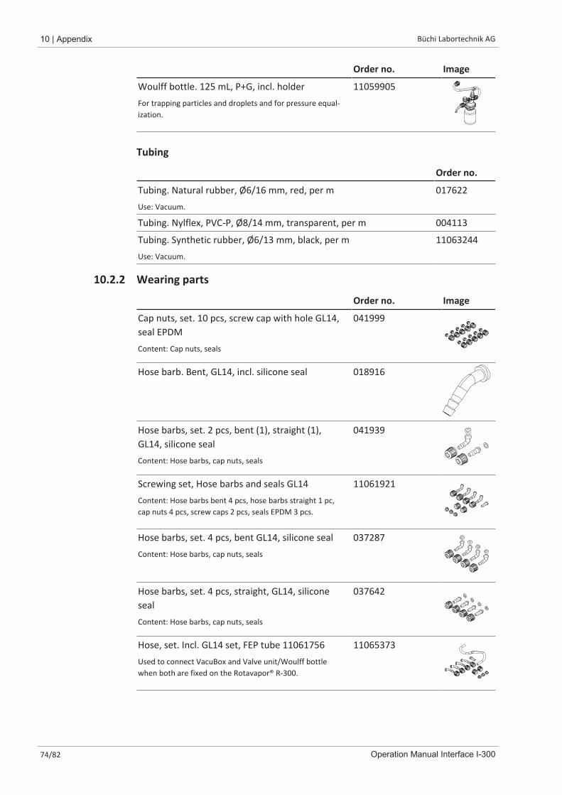
10 | Appendix Büchi Labortechnik AG
74/82 Operation Manual Interface I-300
Order no. Image
Woulff bottle. 125 mL, P+G, incl. holderFor trapping particles and droplets and for pressure equal-ization.
11059905
Tubing
Order no.
Tubing. Natural rubber, Ø6/16 mm, red, per mUse: Vacuum.
017622
Tubing. Nylflex, PVC-P, Ø8/14 mm, transparent, per m 004113
Tubing. Synthetic rubber, Ø6/13 mm, black, per mUse: Vacuum.
11063244
10.2.2 Wearing parts
Order no. Image
Cap nuts, set. 10 pcs, screw cap with hole GL14,seal EPDMContent: Cap nuts, seals
041999
Hose barb. Bent, GL14, incl. silicone seal 018916
Hose barbs, set. 2 pcs, bent (1), straight (1),GL14, silicone sealContent: Hose barbs, cap nuts, seals
041939
Screwing set, Hose barbs and seals GL14Content: Hose barbs bent 4 pcs, hose barbs straight 1 pc,cap nuts 4 pcs, screw caps 2 pcs, seals EPDM 3 pcs.
11061921
Hose barbs, set. 4 pcs, bent GL14, silicone sealContent: Hose barbs, cap nuts, seals
037287
Hose barbs, set. 4 pcs, straight, GL14, siliconesealContent: Hose barbs, cap nuts, seals
037642
Hose, set. Incl. GL14 set, FEP tube 11061756Used to connect VacuBox and Valve unit/Woulff bottlewhen both are fixed on the Rotavapor® R-300.
11065373
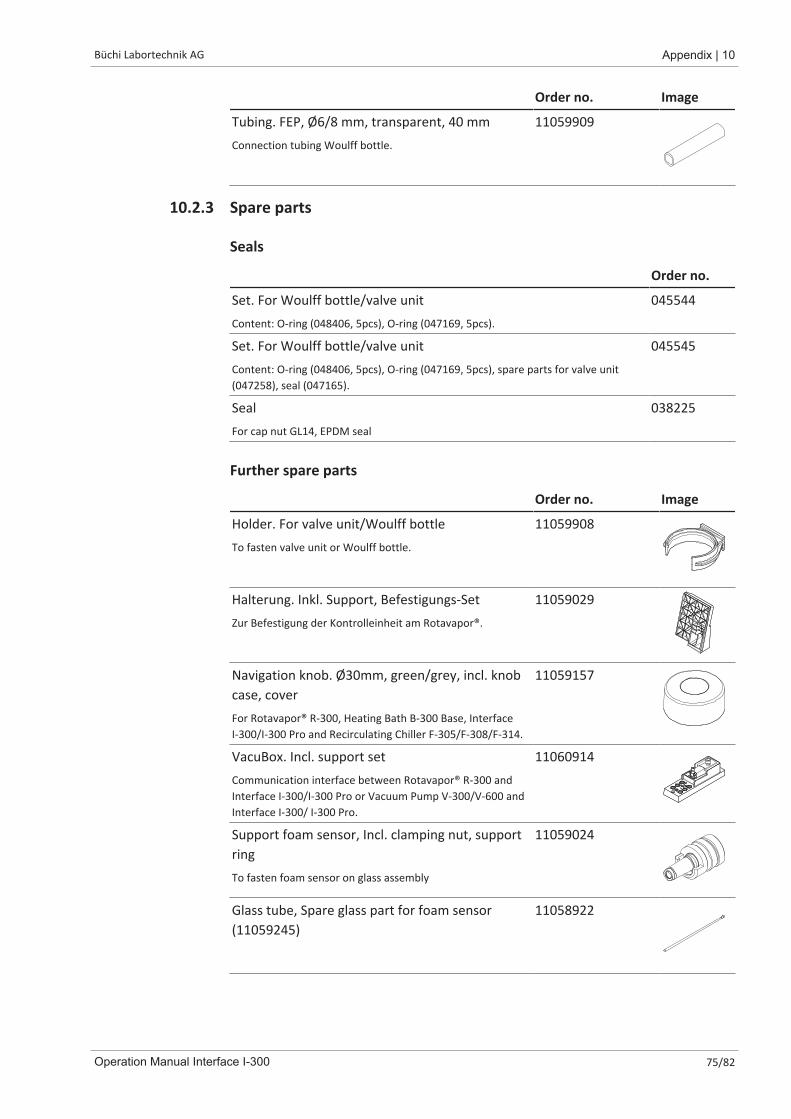
Büchi Labortechnik AG Appendix | 10
Operation Manual Interface I-300 75/82
Order no. Image
Tubing. FEP, Ø6/8 mm, transparent, 40 mmConnection tubing Woulff bottle.
11059909
10.2.3 Spare parts
Seals
Order no.
Set. For Woulff bottle/valve unitContent: O-ring (048406, 5pcs), O-ring (047169, 5pcs).
045544
Set. For Woulff bottle/valve unitContent: O-ring (048406, 5pcs), O-ring (047169, 5pcs), spare parts for valve unit(047258), seal (047165).
045545
SealFor cap nut GL14, EPDM seal
038225
Further spare parts
Order no. Image
Holder. For valve unit/Woulff bottleTo fasten valve unit or Woulff bottle.
11059908
Halterung. Inkl. Support, Befestigungs-SetZur Befestigung der Kontrolleinheit am Rotavapor®.
11059029
Navigation knob. Ø30mm, green/grey, incl. knobcase, coverFor Rotavapor® R-300, Heating Bath B-300 Base, InterfaceI-300/I-300 Pro and Recirculating Chiller F-305/F-308/F-314.
11059157
VacuBox. Incl. support setCommunication interface between Rotavapor® R-300 andInterface I-300/I-300 Pro or Vacuum Pump V-300/V-600 andInterface I-300/ I-300 Pro.
11060914
Support foam sensor, Incl. clamping nut, supportringTo fasten foam sensor on glass assembly
11059024
Glass tube, Spare glass part for foam sensor(11059245)
11058922
10 | Appendix Büchi Labortechnik AG
76/82 Operation Manual Interface I-300
10.3 Health and safety approvalTo guarantee the health and safety of our staff and to comply with the law and theregulations for handling hazardous materials, for the purposes of health and safetyat work and safe disposal of waste, no products may be sent back to BÜCHILabortechnik AG or repaired unless we have received the declaration below,completed and signed.Products sent to us will not be accepted for repair until we have received thisdeclaration.u Copy the form overleaf and complete it.u Make sure that you know the full details of the substances with which the device
has been in contact and that all questions have been answered fully andcorrectly.
u Send the completed form to us in advance by post or fax. The declaration mustreach us before the device.
u Enclose a copy of the declaration with the device.u If the product is contaminated, inform the carrier (in accordance with GGVE/
GGVS/RID/ADR).
If the declaration is missing or the procedure described is not followed, the repairswill be delayed. We ask for your understanding and cooperation with regard tothese measures.
10.4 Health and safetyDeclaration regarding the safety, hazards and safe disposal of wasteTo guarantee the health and safety of our staff and to comply with the law and theregulations for handling hazardous materials, regarding health and safety at work,and to comply with safety regulations, health and safety requirements andrequirements for safe disposal of waste such as chemical waste, chemical residues orsolvents, the form below must be fully completed and signed whenever devices orfaulty components are to be sent back to our factory.Products or components will not be accepted if this declaration has not beenprovided.
Device Model: Part/Device no.:
Declaration for non-hazardous materials
We hereby assure that the products returned
have not been used in the laboratory and are new.
have not been in contact with toxic, corrosive, biologically active, explosive, ra-dioactive or other hazardous materials.
are not contaminated. The solvents or residues of the substances pumped havebeen removed.
Declaration forhazardous materials
In respect of the products returned, we hereby assure that
all substances (toxic, corrosive, biologically active, explosive, radioactive or oth-erwise hazardous) that have been pumped by the products or have otherwisebeen in contact with the products are listed below.
the products have been cleaned, decontaminated, sterilised inside and outsideand all inlets and outlets are sealed.
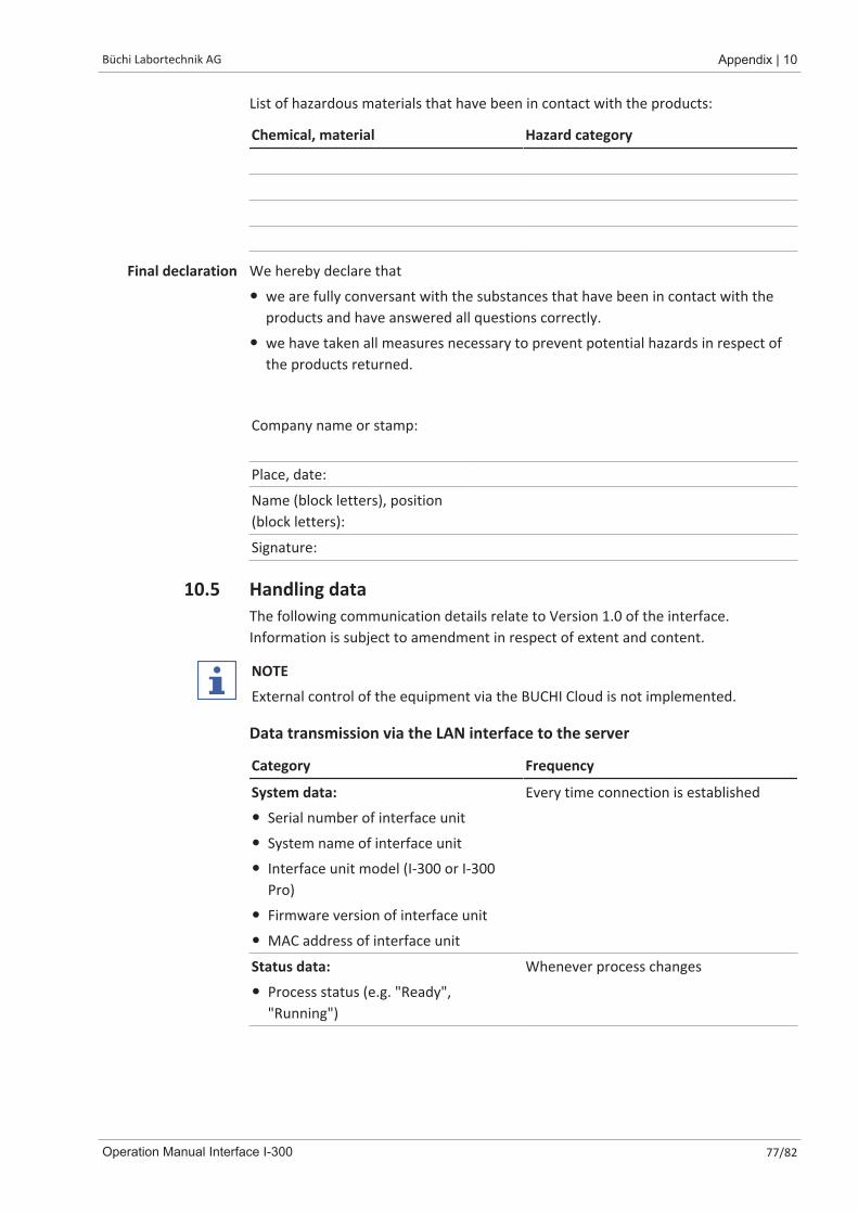
Büchi Labortechnik AG Appendix | 10
Operation Manual Interface I-300 77/82
List of hazardous materials that have been in contact with the products:
Chemical, material Hazard category
Final declaration We hereby declare that
� we are fully conversant with the substances that have been in contact with theproducts and have answered all questions correctly.
� we have taken all measures necessary to prevent potential hazards in respect ofthe products returned.
Company name or stamp:
Place, date:
Name (block letters), position(block letters):
Signature:
10.5 Handling dataThe following communication details relate to Version 1.0 of the interface.Information is subject to amendment in respect of extent and content.
NOTE
External control of the equipment via the BUCHI Cloud is not implemented.
Data transmission via the LAN interface to the server
Category Frequency
System data:
� Serial number of interface unit
� System name of interface unit
� Interface unit model (I-300 or I-300Pro)
� Firmware version of interface unit
� MAC address of interface unit
Every time connection is established
Status data:
� Process status (e.g. "Ready","Running")
Whenever process changes
10 | Appendix Büchi Labortechnik AG
78/82 Operation Manual Interface I-300
Category Frequency
Event data:(Messages that appear as pop-ups on thedisplay, e.g. "Distillation successfullycompleted")
� Event message ID
� Event message level (information,warning or error)
On occurrenceEvent messages are managed by theserver and distributed to the clients fromthere for push notifications.
Process data:
� Actual reading and specified setting forpressure
� Actual reading and specified setting forheating bath temperature
� Actual reading and specified setting forrecirculating chiller temperature
� Actual reading and specified setting forrotation speed
� Actual reading and specified setting fortimer
� Actual vapor temperature
� Results (stop status, foam detection,receiving flask full)
� Timestamp
Regular data transmissionWhen process is running: once per sec-ond at mostOn standby: at least every 60 seconds
All of the above data (except MAC address) is broadcast to the connected clients(e.g. mobile phone) and processed there.
Data transmission from clients to the server
Category Frequency
Client data:
� App language selected
� Type of operating system
� Operating system version
� Platform for push notifications
� Push tone setting (not used)
� Desired push notification type for eachconfigured device (system data,process data, method data)
� Client ID (automatically generated)
� Model designation of mobile phone
When connection is established orchanged

Büchi Labortechnik AG Appendix | 10
Operation Manual Interface I-300 79/82
Data storage period
Category Storage period
� System data (inc. date and time of lastconnection)
Permanent
� Client data (inc. date and time of lastconnection)
At most 1 year after last use
� Status data
� Event data
� Process data
At least 24 hrs, max. 48 hrsData that is older than 24 hrs is deletedafter 24 hrs.
Data configuration settings
Destination host connect.buchi.com
Destination port 443
Protocol HTTPS (TLS 1.2)
Certificates RSA 2048 bit, SHA-256
Server location Ireland (operator: Amazon Web Services)
10.5.1 Counter data� Duty hours of instruments in the system
� Number of starts in various modes
� Duty hours of instruments in the system
� Max. readings for temperature and current
10.5.2 Distillation session data� Serial number of the control unit
� Number of times instrument commissioned
� The method of execution, e.g. Manual, CloudDest, AutoDest
� Was distillation stopped or aborted?
� CloudDest parameters set by the user
10.5.3 Error data� Error number generated by instrument
� The time (UTC) at which the error occurred
10.5.4 Maintenance data� All maintenance tests showing details of results and progression.

10 | Appendix Büchi Labortechnik AG
80/82 Operation Manual Interface I-300
10.5.5 System configuration data� System name
� Article numbers
� Serial number
� Firmware versions
� Parts list version
� Instruments installed in the system
� Sensors installed in the system
10.5.6 Data storage period
Permanent System data(inc. date and time of last connection)
No more than 1 year after last use Contact details(inc. date and time of last connection)
At least 24 hours, max. 48 hours Status dataEvent dataProcess data
10.5.7 Device settings� All settings that are displayed on the Settings menu of the interface
10.5.8 Contact dataOnly if a system owner has been defined
� First name
� Family name
� Country
� E-mail address
� Phone number
� Company
� Data protection and policy agreement for user
� Agreement regarding the sending of marketing material
10.5.9 Location data� The coordinates of the mobile device.


We are represented by more than 100 distribution partners worldwide. Find your local representative at:
www.buchi.com