Integrated Technical Reference Model and Sensor Network Architecture
7
Integrated Technical Reference Model and Sensor Network Architecture Hemant Joshi Electrical & Computer Engineering Department University of Massachusetts Dartmouth North Dartmouth, MA, USA Howard E. Michel Electrical & Computer Engineering Department University of Massachusetts Dartmouth North Dartmouth, MA, USA Abstract - This paper presents a multi-layered Integrated Technical Reference Model (I-TRM). The I- TRM is based on a classical closed-loop control system and combines an Information-Centric Technical Reference Model (IC-TRM), a Control Technical Reference Model (C-TRM) and a Behavioral (intelligence-based) Technical Reference Model to provide a complete system technical reference model. Having an I-TRM is crucial to developing robust systems that are self-aware, self-healing and adaptable within a resource constrained environment. This work extends the previous work by developing an Architecture for a Sensor based on the I-TRM. Keywords: Technical reference model, information- centric technical reference model, control technical reference model, behavioral (intelligence) technical reference model, layered architecture, Integrated Technical reference model, Sensor Network. 1 Introduction A model is used for representing a set of components of a process, system, or subject area, or for developing, understanding, analyzing, improving, and/or replacing a process [1]. A technical reference model (TRM) is used to formulate definitions and provide a formal structure for describing implicit and explicit concepts and operations. All the present date TRMs belong to either of the following categories: i) Network-Centric TRMs: An abstract model for networking focused on inter-network communication. International Organization for Standardization’s (ISO) Open System Interconnection (OSI) TRM is one of the best example of such TRMs[2,3,4]. This model puts forward a seven-layered abstract model with a standardized set of protocols. ii) Information-Centric Technical Reference Models: have their main focus on data collection, information aggregation and presentation. However, they do not specify details related to the control mechanism which manages how and where the data is collected. The Information-Centric Technical Reference Model (IC- TRM) proposed by Michel and Fortier is an example of such a TRM [5, 6]. iii) Control Technical Reference Models: define layered architectures for arranging tasks in a hierarchy from high-level goal definition to task execution [7]. Examples of Control Technical Reference Models are the one proposed by Dipple and Michel [7], and the Mission Oriented Operating Suite (MOOS) [15]. None of the TRMs are generic enough to accommodate all the functional requirement of autonomous applications. There is a requirement for an Integrated Technical Reference Model (I-TRM) which can provide and/or specify the standards for all the aspects of the system, encompassing both information and control requirements, and the inter and intra-layer processes required to achieve a self-aware, self-healing and adaptable network [17]. 2 Integrated TRM (I-TRM) Figure 1: Integrated Technical Reference Model
Transcript of Integrated Technical Reference Model and Sensor Network Architecture
Integrated Technical Reference Model
and Sensor Network Architecture
Hemant Joshi Electrical & Computer Engineering Department
University of Massachusetts Dartmouth North Dartmouth, MA, USA
Howard E. Michel Electrical & Computer Engineering Department
University of Massachusetts Dartmouth North Dartmouth, MA, USA
Abstract - This paper presents a multi-layered Integrated Technical Reference Model (I-TRM). The I-TRM is based on a classical closed-loop control system and combines an Information-Centric Technical Reference Model (IC-TRM), a Control Technical Reference Model (C-TRM) and a Behavioral (intelligence-based) Technical Reference Model to provide a complete system technical reference model. Having an I-TRM is crucial to developing robust systems that are self-aware, self-healing and adaptable within a resource constrained environment. This work extends the previous work by developing an Architecture for a Sensor based on the I-TRM.
Keywords: Technical reference model, information-centric technical reference model, control technical reference model, behavioral (intelligence) technical reference model, layered architecture, Integrated Technical reference model, Sensor Network. 1 Introduction A model is used for representing a set of components of a process, system, or subject area, or for developing, understanding, analyzing, improving, and/or replacing a process [1]. A technical reference model (TRM) is used to formulate definitions and provide a formal structure for describing implicit and explicit concepts and operations.
All the present date TRMs belong to either of the following categories:
i) Network-Centric TRMs: An abstract model for networking focused on inter-network communication. International Organization for Standardization’s (ISO) Open System Interconnection (OSI) TRM is one of the best example of such TRMs[2,3,4]. This model puts forward a seven-layered abstract model with a standardized set of protocols.
ii) Information-Centric Technical Reference Models: have their main focus on data collection, information aggregation and presentation. However, they do not specify details related to the control mechanism which manages how and where the data is collected. The Information-Centric Technical Reference Model (IC-TRM) proposed by Michel and Fortier is an example of such a TRM [5, 6].
iii) Control Technical Reference Models: define layered architectures for arranging tasks in a hierarchy from high-level goal definition to task execution [7]. Examples of Control Technical Reference Models are the one proposed by Dipple and Michel [7], and the Mission Oriented Operating Suite (MOOS) [15].
None of the TRMs are generic enough to accommodate all the functional requirement of autonomous applications. There is a requirement for an Integrated Technical Reference Model (I-TRM) which can provide and/or specify the standards for all the aspects of the system, encompassing both information and control requirements, and the inter and intra-layer processes required to achieve a self-aware, self-healing and adaptable network [17].
2 Integrated TRM (I-TRM)
Figure 1: Integrated Technical Reference Model
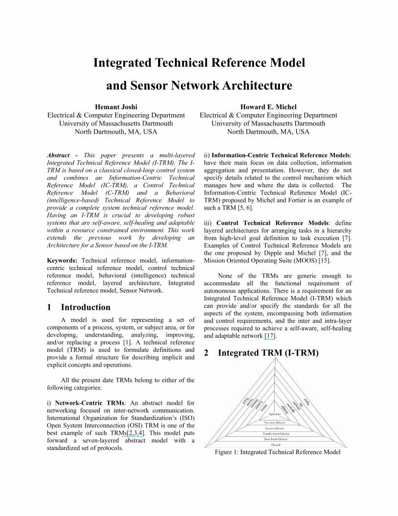
The I-TRM illustrated in Figure 1 is a refinement of architectural principals that have been suggested by Dippel and Michel in their combined IC-TRM and C-TRM [17]. The I-TRM is a cross-layered framework and provides multiple paths to perform various control loops by adding a behavioral side/view to the combined TRM proposed by Dippel and Michel, as shown in Figure 2. Through these paths, data can be routed to the desired level as loops are interrelated and span over one or more levels. “The three faces of the I-TRM are (i) Information Centric Architecture, (ii) Control Centric Architecture, and (iii) Behavioral (Intelligence) Architecture. Here, the flow of control is downstream, whilst, information flows upstream and behaviors manage across a given level” [17].
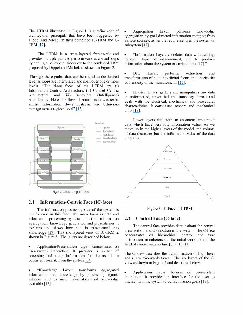
2.1 Information-Centric Face (IC-face) The information processing side of the system is put forward in this face. The main focus is data and information processing by data collection, information aggregation, knowledge generation and presentation. It explains and shows how data is transformed into knowledge [17]. This six layered view of IC-TRM is shown in Figure 3. The layers are described below.
• Application/Presentation Layer: concentrates on user-system interaction. It provides a means of accessing and using information for the user in a consistent format, from the system [17].
• “Knowledge Layer: transforms aggregated information into knowledge by processing against intrinsic and extrinsic information and knowledge available [17]”.
• Aggregation Layer: performs knowledge aggregation by goal-directed information-merging from various sources, as per the requirements of the system or subsystem [17].
• “Information Layer: correlates data with scaling, location, type of measurement, etc, to produce information about the system or environment [17].”
• Data Layer: performs extraction and transformation of data into digital forms and checks the authenticity of the measurements [17].
• Physical Layer: gathers and manipulates raw data in unformatted, unverified and transitory format and deals with the electrical, mechanical and procedural characteristics. It constitutes sensors and mechanical units [17].
Lower layers deal with an enormous amount of data which have very low information value. As we move up in the higher layers of the model, the volume of data decreases but the information value of the data increases.
Figure 3: IC-Face of I-TRM
2.2 Control Face (C-face) The control face provides details about the control organization and distribution in the system. The C-Face concentrates on hierarchical control and task distribution, in coherence to the initial work done in the field of control architecture [8, 9, 10, 11].
The C-view describes the transformation of high level goals into executable tasks. The six layers of the C-view as shown in Figure 4 and described below:
• Application Layer: focuses on user-system interaction. It provides an interface for the user to interact with the system to define mission goals [17].

• Validation Layer: provides a mechanism for authenticating the semantic correctness of the goal and for determining whether the goal is accepted or not. These processes are based on intrinsic and extrinsic information and knowledge. This layer also verifies the probability of accomplishing the goal with the resources available [17].
• “Translation Layer: decomposes valid goals into functional tasks based on knowledge about the lower layers. This layer provides a mechanism to register low-level system components and their physical capabilities [17].
• Distribution Layer: based on available spatial and temporal information, organizes system tasks by decomposing the task groups into sub-tasks and assigning priorities to them in accordance with goal-achievement [17].
Figure 4: C-Face of I-TRM
• “Execution Layer: receives directives from the distribution layer and transforms them into control signals for the physical layer. This layer implements basic error detection and correction in close cooperation with the physical layer.
• Physical Layer: constitutes sensors and mechanical units. It executes actions as directed by higher layers [17].”
2.3 Behavioral Face (B-face) The B-side manages the intelligence (deliberative and reactive behaviors) of the system and acts as a bridge connecting IC-face and C-face. This bridge is made of control loops based on a classical closed loop control system [14] as shown in Figure 5 [17].
The B-side is a hierarchal arrangement of behaviors into layers based on the scope of control and responsibility of each function. This hierarchical
distribution is based on Arkin’s work, according to which behaviors can be divided into three major categories: innate behaviors, reactive behaviors and conscious behaviors [12].
Figure 5: Control loops in I-TRM
The six layers of the B-side are illustrated in Figure 6 and described below:
• Application Layer: responsible for user interactions. It decide what information should be furnished, to whom and when. It also determines which goals should be accepted [17].
• Conscious Behavior layer: provides schemas for checking the goals’ validity and feasibility in the given situation, by checking goals against the intrinsic and extrinsic knowledge (global model) [16] about the environment. It manages deliberative actions of the systems [17].
• “Reactive Behavior Layer: provides a mechanism for dealing with information collaboration from various modules into one structured data unit (local model) [16]. It provides procedures for translating goals into sub-modules in compliance with the state of the environment.
• Complex Innate Behavior Layer: is the highest reactive layer. It implements procedures which connect the information extracted from the data to task execution distribution [17].”
• Basic Innate Behavior Layer: implements primitive reflexive behavior and stimulus-response behaviors of the system. It combines the execution layer procedure-execution with the relevant data [17].
• “Physical Layer: constitutes sensors and mechanical units. It is the same hardware as described in the IC-TRM and C-TRM [17].”
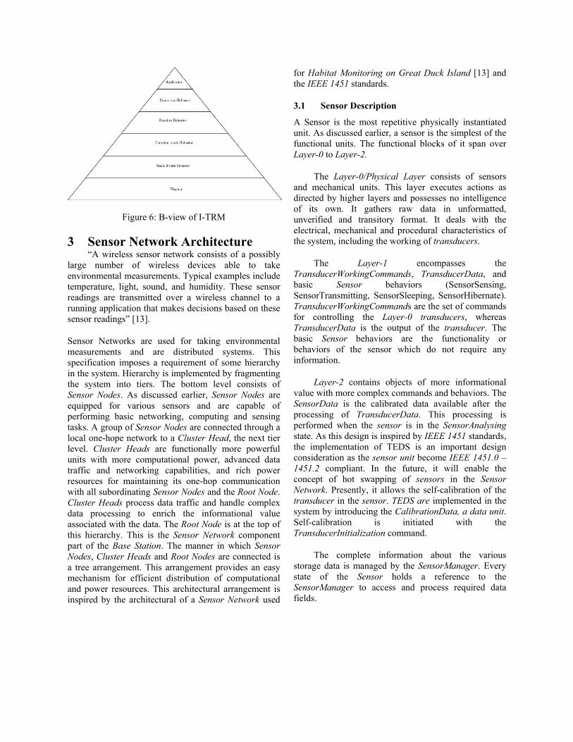
Figure 6: B-view of I-TRM
3 Sensor Network Architecture “A wireless sensor network consists of a possibly large number of wireless devices able to take environmental measurements. Typical examples include temperature, light, sound, and humidity. These sensor readings are transmitted over a wireless channel to a running application that makes decisions based on these sensor readings” [13].
Sensor Networks are used for taking environmental measurements and are distributed systems. This specification imposes a requirement of some hierarchy in the system. Hierarchy is implemented by fragmenting the system into tiers. The bottom level consists of Sensor Nodes. As discussed earlier, Sensor Nodes are equipped for various sensors and are capable of performing basic networking, computing and sensing tasks. A group of Sensor Nodes are connected through a local one-hope network to a Cluster Head, the next tier level. Cluster Heads are functionally more powerful units with more computational power, advanced data traffic and networking capabilities, and rich power resources for maintaining its one-hop communication with all subordinating Sensor Nodes and the Root Node. Cluster Heads process data traffic and handle complex data processing to enrich the informational value associated with the data. The Root Node is at the top of this hierarchy. This is the Sensor Network component part of the Base Station. The manner in which Sensor Nodes, Cluster Heads and Root Nodes are connected is a tree arrangement. This arrangement provides an easy mechanism for efficient distribution of computational and power resources. This architectural arrangement is inspired by the architectural of a Sensor Network used
for Habitat Monitoring on Great Duck Island [13] and the IEEE 1451 standards.
3.1 Sensor Description
A Sensor is the most repetitive physically instantiated unit. As discussed earlier, a sensor is the simplest of the functional units. The functional blocks of it span over Layer-0 to Layer-2.
The Layer-0/Physical Layer consists of sensors and mechanical units. This layer executes actions as directed by higher layers and possesses no intelligence of its own. It gathers raw data in unformatted, unverified and transitory format. It deals with the electrical, mechanical and procedural characteristics of the system, including the working of transducers.
The Layer-1 encompasses the TransducerWorkingCommands, TransducerData, and basic Sensor behaviors (SensorSensing, SensorTransmitting, SensorSleeping, SensorHibernate). TransducerWorkingCommands are the set of commands for controlling the Layer-0 transducers, whereas TransducerData is the output of the transducer. The basic Sensor behaviors are the functionality or behaviors of the sensor which do not require any information.
Layer-2 contains objects of more informational value with more complex commands and behaviors. The SensorData is the calibrated data available after the processing of TransducerData. This processing is performed when the sensor is in the SensorAnalysing state. As this design is inspired by IEEE 1451 standards, the implementation of TEDS is an important design consideration as the sensor unit become IEEE 1451.0 – 1451.2 compliant. In the future, it will enable the concept of hot swapping of sensors in the Sensor Network. Presently, it allows the self-calibration of the transducer in the sensor. TEDS are implemented in the system by introducing the CalibrationData, a data unit. Self-calibration is initiated with the TransducerInitialization command.
The complete information about the various storage data is managed by the SensorManager. Every state of the Sensor holds a reference to the SensorManager to access and process required data fields.

All the above mentioned modules are required to join in some arrangement in order to have a proper functioning unit; this aspect of the system is provided by the Sensor module. It controls the behavior and functioning of the sensor, by controlling the state machine of the sensor. It is the unit which receives the SensorCommands from the cluster-head for handling the working state of the sensor. The class diagram of the sensor unit is shown in Figure 7.
3.2 Cluster Head Description
The cluster head is the link between sensor nodes and the root node and spans over Layer-2 and Layer-3. It is responsible for data aggregation and data consolidation. There are three different types of parallel running processes in this functional unit. One type of process is for maintaining the correspondence between a sensor unit and the cluster head. The second kind of process is responsible for performing data aggregation by combining data from various sensor nodes, i.e., SensorInstanceInformation, into a single data unit, ClusterInformation. The third kind of process controls the communication between the cluster head and root node.
The first kind of process can be further divided into two segments, one for issuing commands to a sensor unit and the second for gathering information from a sensor. The commands issued to sensors are for
starting and stopping sensors. They are performed by the SensorInterfacePowerCommands. The ClusterController object generates instances of these commands and places them on the SensorCommandBuffer for that sensor node for execution. Processes related to gathering information from the sensor are effectively managed by three modules, namely SensorClusterBuffer, SensorInterfaceUnit and SensorInstanceInformation. The SensorClusterBuffer is a compliment of the SensorTransmitBuffer class in Sensor. It receives data transmitted by a sensor at the cluster head. SensorInterfaceUnit is the module which processes the data available at the SensorClusterBuffer and updates the information related to the sensor in the SensorInstanceInformation instance related to that sensor. SensorInstanceInformation is an object related to a sensor which contains the data from a sensor and the meta-data related to sensor. It is the meta-data part of the sensor which will make hot swapping possible in the future. It will be possibly done by updating the meta-data of the sensor in coherence with the CalibrationData/TEDS of the sensor, when the sensor is replaced or a new sensor is introduced in the system. Processes, which maintain the correspondence between a sensor unit and a cluster head are dedicated processes for each node, so each process has its own copy of every required component and runs independent of each other.
The processes that perform data aggregation by combining data from various sensor nodes is called the
Figure 7 : Class Diagram of Sensor Unit

ClusterController. It updates information about every sensor in SensorInstanceInformation, and performs data aggregation and updates the ClusterInformation by accessing SensorInstanceInformation for all sensors.
The process which controls the communication between the cluster head and the root node is implemented by the RootCommunicationManager and the ClusterController. The RootCommunicationManager manages the buffers for transmission to and reception from the root node. On this end, an independent thread runs to translate root commands into the ClusterCommands and the ClusterQueryCommands and the SensorInterfaceQueryCommands by the RootInstructionTranslator and to place those commands in their respective buffers.
Apart from these processes, all the buffers invoke
themselves at regular intervals and check their status. If they are not empty, they de-queue themselves and initiate the execution of the command. 3.3 Root Node Description
The root node is at the top of the Sensor Network Architecture hierarchy. It is a functional unit which performs knowledge extraction from the aggregated information from the various cluster heads. It is situated at the base station.
The three main processing areas are: (i) maintaining correspondence between the root node and cluster heads, (ii) knowledge extraction from the aggregated information from the various cluster heads and (iii) updating the GlobalKnowledgeBase.
The processes for maintaining communication between
Figure 8 : Class Diagram of Cluster Head
Figure 9 : Class Diagram of Root Node
the root nodes and various cluster head can be sub-categorized into two groups, one for issuing commands to cluster heads and the second for gathering information from cluster heads. Communication for issuing commands between the two units is maintained by the ClusterInterfaceUnit, the RootController and the RootTransmitBuffer instances. The process of gathering information from all cluster heads is carried out by instances of the ClusterInterfaceUnit, the RootController and the RootReceiveBuffer. The process of updating the GlobalKnowledgeBase is controlled by the RootController. The GlobalDatabase can be accessed using the KnowledgeBaseInstructions, namely UpdateKnowledgeBase and QueryKnowledgeBase.
In order to have the validation feature from the control face of the I-TRM, proxies for the root controller are generated for each Application Level process. Figure 9 is the class diagram for the root node
4 Conclusions This paper presents a different framework for developing and designing autonomous applications, with an example architecture developed for Sensor-Network Architecture. This approach stresses modeling system components based on three integral aspects, Control Distribution, Information Processing and Intelligence (Behavior) to develop and design a robust system that is self-aware, self-healing and adaptable within a resource constrained environment. It renders a way to integrate various seeming unrelated and uncorrelated applications into one system of systems. It provides a potential mechanism for realizing interoperability between the various subsystems.
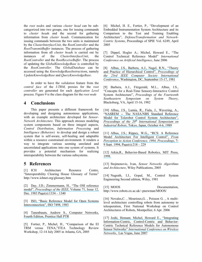
5 References [1] ICH Architecture Resource Centre, “Interoperability Clearing House Glossary of Terms” http://www.ichnet.org/glossary.htm
[2] Day, J.D.; Zimmermann, H., “The OSI reference model”, Proceedings of the IEEE, Volume 71, Issue 12, Dec. 1983 Page(s):1334 – 1340
[3] ISO, “Basic Reference Model for Open Systems Interconnection”, ISO 7498, 1983
[4] Tanenbaum, Andrew S., Computer Networks, Fourth Edition, Prentice Hall PTR
[5] Fortier, P., Michel, H., “Comparison of the EI TRM versus TENA,”ITEA Technology Review Workshop, 12-14 July 2005 in Atlanta, GA, 2005
[6] Michel, H. E., Fortier, P., “Development of an Embedded Instrumentation System Architecture and its Comparison to the Test and Training Enabling Architecture”, DefenseTransformation and Network-Centric Systems, Proceedings of SPIE Vol. 6249, April 2005
[7] Dippel, Hogler A.; Michel, Howard E., “The Control Technical Reference Model” International Conference on Artificial Intelligence, June 2006
[8] Albus, J.S., Barbera, A.J., Nagel, R.N., “Theory and Practice of Hierarchical Control”, Proceedings of the 23rd IEEE Computer Society International Conference, Washington, DC, September 15-17, 1981
[9] Barbera, A.J., Fitzgerald, M.L., Albus, J.S., “Concepts for a Real-Time Sensory-Interactive Control System Architecture”, Proceedings of the Fourteenth Southeastern Symposium on System Theory, Blacksburg, VA, April 15-16, 1982
[10] Albus, J.S., Lumia, R., Fiala, J., Wavering, A., “NASREM -- The NASA/NBS Standard Reference Model for Telerobot Control System Architecture”, Proceedings of the 20th International Symposium on Industrial Robots, Tokyo, Japan, October 4-6, 1989
[11] Albus, J.S.; Rippey, W.G., “RCS: A Reference Model Architecture For Intelligent Control”, From Perception to Action Conference, 1994, Proceedings, 7-9 Sept. 1994, Page(s):218 – 229
[12] Arkin,R., Behavior-Based Robotics, MIT Press, 1998.
[13] Stojmenovic, Ivan, Sensor Networks Algorithms and Architecture, Wiley Publications, 2005
[14] Nagrath, I.J., Gopal, M., Control System Engineering Second edition, Wiley, 1981
[15] MOOS Documentation, http://www.robots.ox.ac.uk/~pnewman/MOOS/
[16] Novales,C. , Mourioux,G. , Poisson G. , A multi-level architecture controlling robots from autonomy to teleoperation, First National Workshop on Control Architectures of Robots, Montpellier, 6 Apr. 2006
[17] Joshi, Hemant, Michel, Howard E., “Integrating Information-Centric, Control-Centric and Behavior-Centric Technical Reference Models for Autonomous Sensor Networks” International Conference on Wireless Networks, Las Vegas, June 2007