Information Architecture for Sensor and Mobile Robotic ...
30
! "# $%&%’ ( &% ") * + ! ! " ! ! # $ ! % & ’()’(*+ , - ! " ! . $ $/ ! ) 0 1 0 2 0" -! ! " )) 3) -! ) 0 ! " ! 3 ! & $ $/ ! 0 ! ) ! + ! )0 -0 - ! ! 00 " -/ ! , ! 4 ! )0 " ! ! -/ " ( 5) ’6 ! - -)! ! &!)7 85 %40 ! & $ $ 4 ! 70 9!) !"#$ % & ’ ( !#)*## + $ ,#- ( ’ .,/ : ;;6 ! % 9 & %9& - -! "2 ! - , ! 00 , ! ! 00 " 5) ;;; ! <- ! # ! 5!" ! ,0 0 5) ! + ! 4 0 ! ! & #+
-
Upload
khangminh22 -
Category
Documents
-
view
0 -
download
0
Transcript of Information Architecture for Sensor and Mobile Robotic ...

1
Mobile Robotic Systems Facing the Humanitarian Demining ProblemState of the Art (SOTA) December 2005 ITEP 3.1.4 Task
Yvan Baudoin, et Al (see references)Royal Military Academy (RMA)
30 Av de la RenaissanceB 1000 Brussels, Belgium
Note: In this SOTA report, the basic principles have been extracted from RMA activities and IARP Workshops
1. Introduction : the problem [1]
The mines have been used for the first time during the American Civil War in the United States (1861-1865). Antitank mines were later ameliorated and laid on the battlefields of the First World War: the mine-clearing operations didn’t pose major problems with those visible or easy-to-detect ATK-mines, reason why Anti-personnel mines have been conceived and systematically used on the ATK minefields during the Second World War: such mines prevented the enemy from easy de-mining of the defence system. But the anti-personnel mines are today more and more used as offensive weapons and for sowing the terror among the civilian population of a country affected by guerrilla war: the marking of the minefield does no more exist and the anti-personnel mines, often buried in the ground, remain active after the war: about 60 millions AP-mines infest today 84 countries all over the world, two-third of them in Africa and South-East Asia…AP mines and Unexploded devices of the Second World War still exist in all the countries of Europe and North-AfricaExample: Due to the central geographical location between Africa, Asia and Europe, Egypt was a location formany battles. During the Second World War, the most known El-Alameen battle, Western Desert, (Fig.1) was between the British and German troops. As a result of this fighting, a numerous number of anti-tanks and anti-personnel mines have been left. The total number of mines (19,711 Million mines) that was buried in the Egyptian land is considered to be about 21% of the total number of mines that buried in the whole world . The presence of such active mines caused many problems to Egypt [2]
In 1994, the United Nations Mine Action Service or UNMAS was founded, with as objectives the mine awareness and risk reduction education, the minefield survey, mapping, marking and clearance, the assistance to victims, the advocacy to support a total ban on AP-mines, and, in 1999, the treaty of Ottawa (the Convention on the Prohibition of the use, stockpiling, production and transfer of AP-mines and their destruction) entered into force. The next map summarises the actual status of the Signing Countries.
2
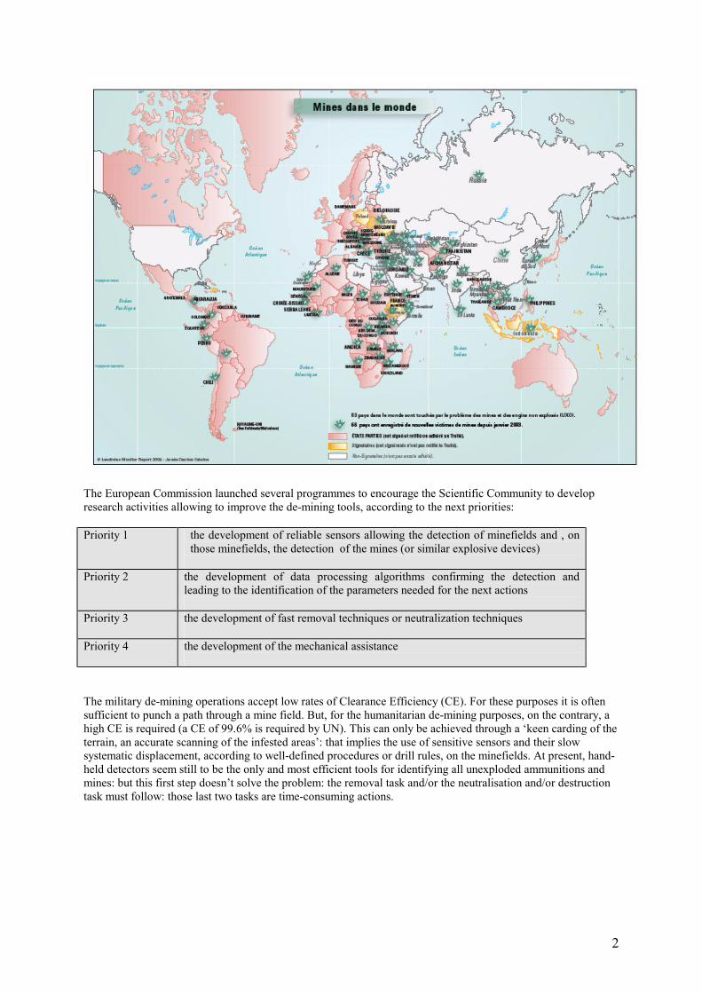
The European Commission launched several programmes to encourage the Scientific Community to develop research activities allowing to improve the de-mining tools, according to the next priorities:
Priority 1 the development of reliable sensors allowing the detection of minefields and , on those minefields, the detection of the mines (or similar explosive devices)
Priority 2 the development of data processing algorithms confirming the detection and leading to the identification of the parameters needed for the next actions
Priority 3 the development of fast removal techniques or neutralization techniques
Priority 4 the development of the mechanical assistance
The military de-mining operations accept low rates of Clearance Efficiency (CE). For these purposes it is often sufficient to punch a path through a mine field. But, for the humanitarian de-mining purposes, on the contrary, a high CE is required (a CE of 99.6% is required by UN). This can only be achieved through a ‘keen carding of the terrain, an accurate scanning of the infested areas’: that implies the use of sensitive sensors and their slow systematic displacement, according to well-defined procedures or drill rules, on the minefields. At present, hand-held detectors seem still to be the only and most efficient tools for identifying all unexploded ammunitions and mines: but this first step doesn’t solve the problem: the removal task and/or the neutralisation and/or destruction task must follow: those last two tasks are time-consuming actions.
3
2. Sensor Technology
2.1.Remote Sensing
In order to avoid a considerable waste of time, a first essential objective lies in the delimitation of the mines polluted areas: local information on observed explosions, craters, injured animals and/or on hospital casualty reports already allow the sending of local technical teams in charge of minefield-marking: this marking may never be precise: the suspected area may be very larger or very smaller, even if performance ground sensors are used: therefore, research efforts have been funded by the European Commission encouraging the airborne survey with colour, colour infrared and thermal cameras, multi-spectral sensors and other promising sensors.Different projects have been initiated in this context (ARC, MINESEEKER, etc, see EUDEM2 website, [5], for more information). Let us limit to a very short description of one of the most promising projects on this matter, i.e. the SMART project [3, 4]. The goal of the SMART project is to provide the human analyst with a GIS-based system - the SMART system - augmented with dedicated tools and methods designed to use multi-spectral and radar data in order to assist him in his interpretation of the mined scene during the area reduction process. The usefulness of such image processing tools to help photo-interpretation has already been studied: the possibility to process automatically a large amount of data and help a visual analysis is among their advantages. The use ofSMART includes a field survey and an archive analysis in order to collect knowledge about the site, a satellite data collection, a flight campaign to record the data - multi-spectral with the Daedalus sensor and polarimetric SAR with the ESAR from DLR - , and the exploitation of the SMART tools by an operator to detect indicators of presence or absence of mine-suspected areas. With the help of a data fusion module based on belief functions and fuzzy sets the operator prepares thematic maps that synthesise all the knowledge gathered with these indicators. These maps of indicators can be transformed into danger maps showing how dangerous an area may be according to the location of known indicators and into priority maps indicating which areas to clear first, accounting for socio-economic impact and political priorities. These maps are designed to help the area reduction process. Figure 2 shows the detection of hedges and trees on a polarimetric SAR image. Existing hedges and tree alignments are, in dangerous areas, possible places where mines are laid. Figure 3 gives an example of danger maps. Preliminary results obtained with SMART showed a global substantial area reduction rate of 20% and a miss-classification rate of 0.1% for what SMART considers as not mined and is actuallymined. The approach has also its limitations. The general knowledge used in SMART is strongly context-dependent. It has been currently derived from the study of three different test sites in Croatia chosen to be representative of South-East of Europe. In the case of another context a new field campaign is needed in order to derive and implement new general rules. Before using SMART the list of indicators must be re-evaluated and adapted. For instance it has been noted that the assumption that a cultivated field is not mined, although quite valid in Croatia, may not apply in other countries such as Africa or Colombia. It must also be checked if theindicators can be identified on the data and if the new list is sufficient to reduce the suspected areas.
Fig. 2. Detection of hedges (green) and trees (red) from SAR data. Existing hedges and tree alignments are, in dangerous areas, possible places where mines are laid. Images courtesy of DLR.
Fig. 3. Discrete danger map - red: danger (e.g. buffers around front lines); orange: danger (areas no longer in use); green: no danger (residential areas, cultivated areas...); other: no status

4
(forests) - Source: ULB.
2.2. Close-in Detection
Assuming the borders of a minefield have been defined, a systematic scanning of the field must follow: in order to assure the desired CE, the use of combined will be necessary: the most known or proposed multi-sensor platform under investigation combines the metal detector, the ground penetrating radar (GPR) or an Ultra-Wide-Band radar (UWB) and an infrared camera. But , added to the possible use of other combinations, the optimisation of existing sensors and/or the development of new sensors (NQR or Nuclear Quadrupole Resonance detection of nitrogen bonding in explosives) , the simultaneous use of several sensors induce a certain number of problems that have to be solved: the fusion of the quite-different data provided by the sensors, the mutual interaction or inter-compatibility of the sensors, the control of the positioning of the sensors above the inspected ground. The next table [3] summarises the actual state-of-the-art of the detectors and their relevant characteristics if de-mining automatic technologies are envisaged (i.e. mounted on robots or vehicles)
For each type of sensor, specific signal processing techniques are used in order to extract useful information. Thetechniques used mainly include signal conditioning or pre-processing (e.g. signal detection, signal transformation, noise reduction, signal restoration and enhancement which are very important steps before further processing) and pattern recognition techniques aiming at increasing the expertise of each sensor separately. Nevertheless, it has been shown that no sensor is perfect for all scenarios and all conditions (moisture, depth, cost, etc). The analysis of the principles of operation of different sensors, their complementary information, and the factors that affect their operability, have led to the conclusion that their fusion should result in improved detect ability and reduced number of false alarms in various situations (different types of mines, soil, vegetation, moisture, etc. . .). The Japan Science and Technology Agency recently organised a test and evaluation for anti-personnel landmine detection systems using ground penetrating radar and metal detector mounted on robotic vehicles: the test results showed that combining GPR with MD can improve the probability of detection (PD) around a depth of 20cm, where it is difficult to detect targets by using only a metal detector and that there is a room for further improvement in the PD, for instance by feeding back the test results to testers to learn typical target images, where targets were not able to be detected in the blind tests (no pre-knowledge of the locations of the buried mines). It has also been learned that positioning control must be improved in scanning the ground with a sensor head, which is a key to making the best of use of MDs mounted on vehicles (argument pro-robotics) [5].
5
3. Mechanical assistance and Robotics Systems
3.1.The mechanical mine-clearance
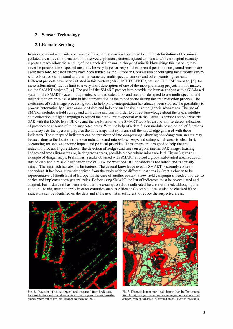
The mechanical assistance consists into the use of motorized mine-clearers: adapted military vehicles or armoured vehicles of the same or similar type, with same or reduced size, may be used on large areas (agricultural areas, for instance) for so far their access is granted; some mine-clearers now combine clearance and detection tools: the HITACHI landmine disposing machine illustrates this kind of system, combining a Rake-Grapple to cut the vegetation (fig 4a), a Mount-type metal detector for avoiding the Rotary-cutter’s hitting (fig 4b), a Magnet System to remove the metal fragments (fig 4c): intensive tests were realised in Cambodia and Afghanistan and proved its efficiency: about 15000 m² (300 times more than a human operator) may be cleared per day: 100 % ATK-mines are removed and destroyed, 90 % AP-mines only: although other clearance techniques (e.g. heavy tooted road rollers) already lead to higher efficiency (98 %), some AP-mines may be pushed on size or deeper buried or partly damaged (thus more dangerous)
Fig. 4a, b, c: Yamanashi Hitachi Construction Machinery Co., Ltd , Japan
3.2.Vehicle mounted mine detector
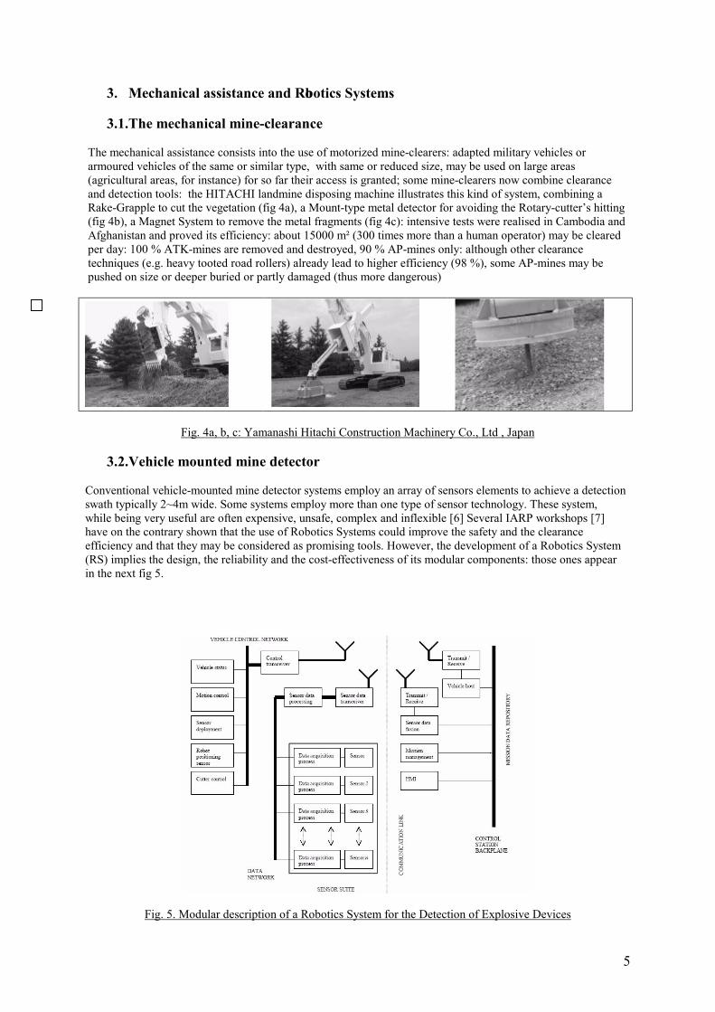
Conventional vehicle-mounted mine detector systems employ an array of sensors elements to achieve a detection swath typically 2~4m wide. Some systems employ more than one type of sensor technology. These system, while being very useful are often expensive, unsafe, complex and inflexible [6] Several IARP workshops [7] have on the contrary shown that the use of Robotics Systems could improve the safety and the clearance efficiency and that they may be considered as promising tools. However, the development of a Robotics System (RS) implies the design, the reliability and the cost-effectiveness of its modular components: those ones appear in the next fig 5.
Fig. 5. Modular description of a Robotics System for the Detection of Explosive Devices

6
4.2.1. Vehicle
Several mobile remote controlled platforms have been described, some ones illustrated by the figure 6.a to 6.f [1, 6, 8, 10, 11, 12]: the motion control needs to be highly sophisticated. General motion in difficult terrain needsadvanced adaptive control. Closely controlled motion is required to deliver sensor packages to accurate positions when detection is in progress. The motion of the vehicle demands by far the highest power requirements. Whilst some scenarios allow the use of an umbilical, many need more autonomy so an on-board power supply isneeded. Thus efficiency of motion is most important, requiring advanced control algorithms. On the other hand, speed is unlikely to be paramount since detection will take time and will probably limit forward motion. The modes of operation need to be specified. Most requirements have a man-in-the-loop operation and there is a direct line of sight operation at a safe distance. This safe distance has to be specified and as is the method of ensuring that the safety restraints are carried out correctly. Typically, current methods for remote control from close in up to 1-2 km distance use Tele-operation.Examples of the advantages of Tele-operation are that the task can be carried out by a single operator and that camera positions are easily selectable using a microwave link or fibre-optic for a line of sight video transmission from the machine to the remote command station. To carry out complex tasks, the numbers of cameras needed and their positions have to be considered. It is likely that at least two fixed or one rotational camera need to befitted to the vehicle to give all round viewing during operation and allow the modelling of the ground. Operator control units can be fitted to display single or multi-image options. The communication link might be a 1.4 GHz video link. Fibre optic links that offer high bandwidth can be used but the trailing of cables can be a problem over long distances. A communications link to carry control and sensor feedback signals is also required.In summary, machines to carry out de-mining activities in place of human de-miners are generally likely to be wheeled or tracked. However, there is a possibility that in certain terrain, walkers will add value. Such machines are likely to be light in weight. The control and communications system is likely to be of a nature which will facilitate the addition of higher order functionality such as sensor fusion, HMI, navigation, etc.The complete system will need to integrate the vehicle control and navigation systems with a data fusion system that will discriminate, to a high degree of confidence, between mine and ‘no-mine’ conditions.
Fig 6.a. Gryphon-IV remote maneuvering experiment. The system can be remote-controlled in a range of about 150meters, Tokyo Institute of technology, JP [8]
Fig 6.b. Mine detection robot COMET-III – Chiba university, JP[6]
Fig 6.c. Mine detection robot Hunter Royal Military Academy, BE[7]
Fig.6.d. 16-wheeled (each tube tire able to support about 25 daN without explosion –most sensitive AP-mine is 0,064 bar) Sensing Vehicle, Tohoku University, JP [10]
Fig.6.e. AMRU-4, eight- legged electro-pneumatic sliding robot, RMA, BE [11]
Fig.6.f. Mine Hunter Vehicle, equipped with a teleoperated hydraulic manipulator, Chiba University, JP [12]
7
4.2.3. Control
The adaptive control usually implies the use of Tele-operation, Tele-presence and distributed intelligence: theTele-operation is the extension of a person’s sensing and manipulating capability to a remote location implyingCommunication channels from and to the human operator; the Tele-presence defines the techniques allowing theHuman operator to feel himself physically present at the remote site; the intelligence combines the sensoryProcessing, the world modelling, the behaviour generation and the value judgement to perform a variety of tasksunder a-priori unknown conditions. Combination of Tele-operation, Tele-presence and human-machine distributed intelligence often defines the supervisory control. Through the introduction of AI techniques and use of the virtual or pseudo-virtual reality, the robotics system’s teams try today to develop the concept of adaptive autonomy and virtual symbiosis .As deduced from the figure 5 (top-down approach from the right side to the left side) , an optimal approach in Humanitarian de-mining should consist into providing a supervised autonomous UGV that can remove excessvegetation and then deploy a multi-sensing detector with sufficient precision to provide a reliable mapping system of detected mines. This will involve a combination of several different sensors, including:- a sensor to determine the location of the robot vehicle within the area to be cleared- an explosives proximity sensor to enable safe navigation- a multi-sensing mine detector, incorporating for instance a 3D metal detector and a GPR- a sensor to determine the position and orientation of the multi-sensing detector.- sensors to control the attitude of the vehicle- a vision sensory to allow the supervised autonomy (HO in the loop)
4.2.3.1. Control Station (Top):
The Application related Control and Command has to implement three primary activities, defined in the blocks‘Mission Management, Data Fusion and HMI’. Concerning the Mission management, one has to make a clear distinction between the High-Level Mission Management (HLMM) or Mission Planning and the Robotics System Mission Management (RSMM).
• HLMM.
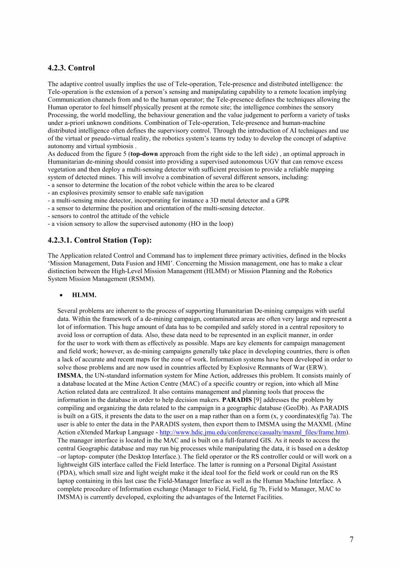
Several problems are inherent to the process of supporting Humanitarian De-mining campaigns with useful data. Within the framework of a de-mining campaign, contaminated areas are often very large and represent a lot of information. This huge amount of data has to be compiled and safely stored in a central repository to avoid loss or corruption of data. Also, these data need to be represented in an explicit manner, in order for the user to work with them as effectively as possible. Maps are key elements for campaign management and field work; however, as de-mining campaigns generally take place in developing countries, there is often a lack of accurate and recent maps for the zone of work. Information systems have been developed in order to solve those problems and are now used in countries affected by Explosive Remnants of War (ERW). IMSMA, the UN-standard information system for Mine Action, addresses this problem. It consists mainly of a database located at the Mine Action Centre (MAC) of a specific country or region, into which all Mine Action related data are centralized. It also contains management and planning tools that process the information in the database in order to help decision makers. PARADIS [9] addresses the problem by compiling and organizing the data related to the campaign in a geographic database (GeoDb). As PARADIS is built on a GIS, it presents the data to the user on a map rather than on a form (x, y coordinates)(fig 7a). The user is able to enter the data in the PARADIS system, then export them to IMSMA using the MAXML (Mine Action eXtended Markup Language - http://www.hdic.jmu.edu/conference/casualty/maxml_files/frame.htm).The manager interface is located in the MAC and is built on a full-featured GIS. As it needs to access the central Geographic database and may run big processes while manipulating the data, it is based on a desktop –or laptop- computer (the Desktop Interface.). The field operator or the RS controller could or will work on a lightweight GIS interface called the Field Interface. The latter is running on a Personal Digital Assistant (PDA), which small size and light weight make it the ideal tool for the field work or could run on the RS laptop containing in this last case the Field-Manager Interface as well as the Human Machine Interface. A complete procedure of Information exchange (Manager to Field, Field, fig 7b, Field to Manager, MAC to IMSMA) is currently developed, exploiting the advantages of the Internet Facilities.
8
Fig 7a. GIS representation of the border of a minefield
Fig 7b. Field Interface: The road colour reflects the status of the road (brown= unknown; red= not practicable; orange= poor; green= good). The user can toggle labels to show the road name and its mined status
Fig 7c. Example of Layer-tool at disposal of the Field User.
• RSMM
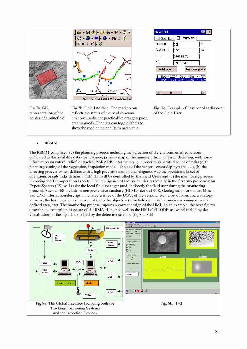
The RSMM comprises (a) the planning process including the valuation of the environmental conditions compared to the available data (for instance, primary map of the minefield from an aerial detection, with some information on natural relief, obstacles, PARADIS information ..) in order to generate a series of tasks (path-planning, cutting of the vegetation, inspection mode – choice of the sensor, sensor deployment -....), (b) the directing process which defines with a high precision and on unambiguous way the operations (a set of operations or sub-tasks defines a task) that will be controlled by the Field Users and (c) the monitoring process involving the Tele-operation aspects. The intelligence of the system lies essentially in the first two processes: an Expert-System (ES) will assist the local field manager (and, indirectly the field user during the monitoring process). Such an ES includes a comprehensive database (HLMM derived GIS, Geological information, Mines and UXO information/description, characteristics of the UGV, of the Sensors, etc), a set of rules and a strategy allowing the best choice of rules according to the objective (minefield delineation, precise scanning of well-defined area, etc). The monitoring process imposes a correct design of the HMI. As an example, the next figures describe the control-architecture of the RMA-Hunter as well as the HMI (CORODE software) including the visualisation of the signals delivered by the detection sensors (fig 8.a, 8.b)
Fig.8a. The Global Interface Including both the Tracking/Positioning Systemsand the Detection Devices
Fig. 8b. HMI
9
• HLMM and RSMM or IMS
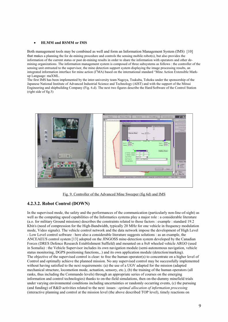
Both management tools may be combined as well and form an Information Management System (IMS) [10] that makes a planning the for de-mining procedure and controls the sensing mobile robot(s), but also provides the information of the current status or past de-mining results in order to share the information with operators and other de-mining organizations. The information management system is composed of three subsystems as follows : the controller of the sensing unit entrusted to the supervisor, the mine detection support system displaying the image processing results, an integrated information interface for mine action (I3MA) based on the international standard “Mine Action Extensible Mark-up Language: maXML.The first IMS has been implemented by the inter-university team Nagoya, Tsukuba, Tohoku under the sponsorship of the Japanese National Institute of Advanced Industrial Science and Technology (AIST) and with the support of the Mitsui Engineering and shipbuilding Company (Fig. 6.d). The next two figures describe the Hard/Software of the Control Station (right side of fig.5)
Fig. 9. Controller of the Advanced Mine Sweeper (fig 6d) and IMS
4.2.3.2. Robot Control (DOWN)
In the supervised mode, the safety and the performances of the communication (particularly non-line-of-sight) aswell as the computing speed capabilities of the Informatics systems play a major role : a considerable literature(a.o. for military Ground missions) describes the constraints related to those factors : example : standard 19.2Kbit/s (need of compression for the High-Bandwidth, typically 20 MHz for one vehicle in frequency modulationmode, Video signals). The vehicle control network and the data network impose the development of High Level - Low Level control software : here also a considerable literature suggests solutions : as an example, the ANCEAEUS control system [13] adopted on the JINGOSS mine-detection system developed by the Canadian Forces (DRES Defence Research Establishment Suffield) and mounted on a 8x8 wheeled vehicle ARGO (used in Somalia) : the Vehicle Supervisor includes its own navigation module (semi-autonomous navigation, vehicle status monitoring, DGPS positioning functions,..) and its own application module (detection/marking).The objective of the supervised control is clear: to free the human operator(s) to concentrate on a higher level ofControl and optimally achieve the planned mission. No any supervised control may be successfully implementedwithout having satisfied to the next requirements: (a) the use of a UGV adapted for the mission (adapted mechanical structure, locomotion mode, actuation, sensory, etc.), (b) the training of the human operators (all ranks, thus including the Commando levels) through an appropriate series of courses on the emerging information and control technologies) thanks to on-the-field simulations, then on-the-dummy minefield trials under varying environmental conditions including uncertainties or randomly occurring events, (c) the pursuing (and funding) of R&D activities related to the next issues : optimal allocation of information processing(interactive planning and control at the mission level (the above described TOP level), timely reactions on
10
observed deviations) , optimal allocation of control functions (High Level/Low Level motion control of the UGVand orientation/positioning control of its sensors), Multi-Vehicle Control (Integration of navigation, task, sensory modules under predictable structured conditions, - Idem under Uncertainties)The first R&D results related to some of those issues , in real-time outdoor conditions, are still stammering.
• Navigation
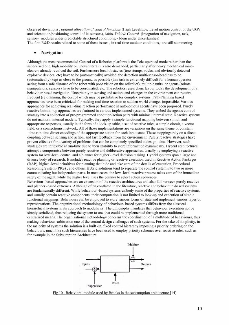
Although the most recommended Control of a Robotics platform is the Tele-operated mode rather than the supervised one, high mobility on uneven terrain is also demanded, particularly after heavy mechanical mine-clearers already revolved the soil. Furthermore local obstacles (tree stumps, rocks, and obviously detected explosive devices, etc) have to be (automatically) avoided, the detection multi-sensor-head has to be (automatically) kept as close to the ground as possible (this task is extremely difficult for a human operator acting from a safe distance of the robot with poor vision on the soil relief), multiple units or agents (robots, manipulators, sensors) have to be coordinated, etc. The robotics researchers favour today the development of a behaviour based navigation. Uncertainty in sensing and action, and changes in the environment can require frequent (re)planning, the cost of which may be prohibitive for complex systems. Path-Planning based approaches have been criticized for making real-time reaction to sudden world changes impossible. Various approaches for achieving real -time reaction performance in autonomous agents have been proposed. Purely reactive bottom -up approaches are featured in various implemented systems. They embed the agent's control strategy into a collection of pre-programmed condition/action pairs with minimal internal state. Reactive systems do not maintain internal models. Typically, they apply a simple functional mapping between stimuli and appropriate responses, usually in the form of a look-up table, a set of reactive rules, a simple circuit, a vector field, or a connectionist network. All of those implementations are variations on the same theme of constant-time run-time direct encodings of the appropriate action for each input state. These mappings rely on a direct coupling between sensing and action, and fast feedback from the environment. Purely reactive strategies have proven effective for a variety of problems that can be completely specified at design -time. However, such strategies are inflexible at run-time due to their inability to store information dynamically. Hybrid architectures attempt a compromise between purely reactive and deliberative approaches, usually by employing a reactive system for low -level control and a planner for higher -level decision making. Hybrid systems span a large and diverse body of research. It includes reactive planning or reactive execution used in Reactive Action Packages (RAP), higher -level primitives for planning that hide and take care of the details of execution, Procedural Reasoning System (PRS) , and others. Hybrid solutions tend to separate the control system into two or more communicating but independent parts. In most cases, the low -level reactive process takes care of the immediate safety of the agent, while the higher level uses the planner to select action sequences. Behaviour -based approaches are an extension of the reactive architectures and also fall between purely reactive and planner -based extremes. Although often conflated in the literature, reactive and behaviour -based systems are fundamentally different. While behaviour -based systems embody some of the properties of reactive systems, and usually contain reactive components, their computation is not limited to look-up and execution of simple functional mappings. Behaviours can be employed to store various forms of state and implement various types of representations. The organizational methodology of behaviour- based systems differs from the classical hierarchical systems in its approach to modularity. The philosophy mandates that behaviour execution not be simply serialized, thus reducing the system to one that could be implemented through more traditional centralized means. The organizational methodology concerns the coordination of a multitude of behaviours, thus making behaviour -arbitration one of the central design challenges of such systems. For the sake of simplicity, in the majority of systems the solution is a built -in, fixed control hierarchy imposing a priority ordering on the behaviours, much like such hierarchies have been used to employ priority schemes over reactive rules, such as for example in the Subsumption Architecture.
Fig.10. Behavioral module used by Brooks in the subsumption architecture [14]

11
Coordination in subsumption has two primary mechanisms:• Inhibition: used to prevent a signal being transmitted along a behavioural module’s wire from reaching the actuators.• Suppression: prevents the current signal from being transmitted and replaces that signal with the suppressing message.More flexible, although often less tractable, solutions have been suggested, commonly based on selecting an output behaviour by computing a multi-variable function implicitly encoded in behaviour activation levels, such as voting schemes and spreading of activation. In behaviour -based robot navigation systems, goals are achieved by subdividing the overall task into small independent behaviours that focus on execution of specific subtasks. For example, a behaviour can be constructed which focuses on traversing from a start to a goal location, while another behaviour focuses on obstacle avoidance. In summary, the general constraints on behaviour -based systems roughly mandate that behaviours be relatively simple, incrementally added to the system, that their execution not be serialized, that they be more time -extended than simple atomic actions of the particular agent, and that they interact with other behaviours through the world rather than internally through the system.
• Sensor Positioning
The signal of GPR (normally used in combination with a Metal detector) is strongly affected by a ground surface. If it is not flat and even, a reaction from ground surface varies much stronger than that from landmines. In addition, this variation of reaction from a ground surface disturbs an imaging of landmine, occasionally cancels it out. It’s consequently mandatory to design an adaptive scanning of the ground surface to reduce the effect of a bad positioning on the useful reflection signal. Proximity sensors attached directly to the sensor head can be a very simple solution for a reflexive control scheme to automatically adjust the vertical distance of the sensor head to the terrain. However, although technically more complex and expensive, in order to make possible a more efficient mapping and scanning of wider areas in a minimal time, cameras and/or laser range finders have to be used. The next table [8] summarises the types of topographical map acquisition systems.
The passive stereo system has been selected for the GRYPHON-IV (fig 6.a), working in two steps: first the generation of a regular grid that will be overlapped to the terrain image, then the computation of the commands to the actuators of the 5-DOF manipulator carrying the multi-sensor-head, as illustrated by the next figures:
Fig.11. Stereo system results on GRIPHON-IV, Mono system results on RMA-Hunter
Depth from defocus is another original method used to recover information distances from textured images to displace mine detection sensors above the ground at a given distance without collision. If one uses a fixed focal length camera the image of the object placed at a point will produce a sharp picture of the object in the focal plane. The more the object moves from its position, the more the image is blurred. The Depth from Defocus method uses the direct relationship between the depth, the camera parameters and the amount of blurring in images to derive the depth. Because the blurring in an image can be caused by either the imaging or the scene
12
itself, at least two images taken under different camera configurations are generally required to eliminate the ambiguity. The practical implementation of this principle gives promising results too.
• Robot Positioning – Tracking
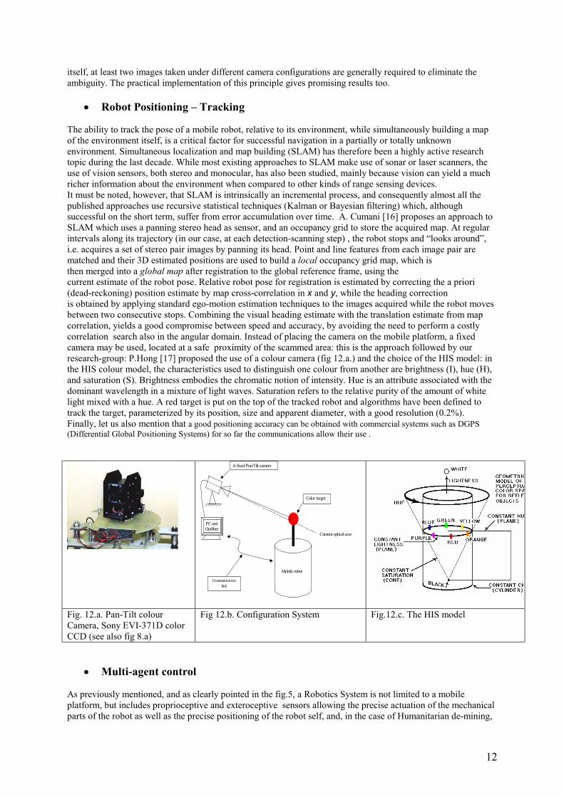
The ability to track the pose of a mobile robot, relative to its environment, while simultaneously building a map of the environment itself, is a critical factor for successful navigation in a partially or totally unknown environment. Simultaneous localization and map building (SLAM) has therefore been a highly active research topic during the last decade. While most existing approaches to SLAM make use of sonar or laser scanners, theuse of vision sensors, both stereo and monocular, has also been studied, mainly because vision can yield a much richer information about the environment when compared to other kinds of range sensing devices.It must be noted, however, that SLAM is intrinsically an incremental process, and consequently almost all the published approaches use recursive statistical techniques (Kalman or Bayesian filtering) which, although successful on the short term, suffer from error accumulation over time. A. Cumani [16] proposes an approach to SLAM which uses a panning stereo head as sensor, and an occupancy grid to store the acquired map. At regular intervals along its trajectory (in our case, at each detection-scanning step) , the robot stops and “looks around”, i.e. acquires a set of stereo pair images by panning its head. Point and line features from each image pair are matched and their 3D estimated positions are used to build a local occupancy grid map, which isthen merged into a global map after registration to the global reference frame, using thecurrent estimate of the robot pose. Relative robot pose for registration is estimated by correcting the a priori (dead-reckoning) position estimate by map cross-correlation in x and y, while the heading correctionis obtained by applying standard ego-motion estimation techniques to the images acquired while the robot moves between two consecutive stops. Combining the visual heading estimate with the translation estimate from map correlation, yields a good compromise between speed and accuracy, by avoiding the need to perform a costly correlation search also in the angular domain. Instead of placing the camera on the mobile platform, a fixed camera may be used, located at a safe proximity of the scammed area: this is the approach followed by our research-group: P.Hong [17] proposed the use of a colour camera (fig 12.a.) and the choice of the HIS model: in the HIS colour model, the characteristics used to distinguish one colour from another are brightness (I), hue (H), and saturation (S). Brightness embodies the chromatic notion of intensity. Hue is an attribute associated with the dominant wavelength in a mixture of light waves. Saturation refers to the relative purity of the amount of white light mixed with a hue. A red target is put on the top of the tracked robot and algorithms have been defined to track the target, parameterized by its position, size and apparent diameter, with a good resolution (0.2%). Finally, let us also mention that a good positioning accuracy can be obtained with commercial systems such as DGPS (Differential Global Positioning Systems) for so far the communications allow their use .
A fixed Pan/Tilt camera
Mobile robot
Color target
Camera optical axis
PC andGrabber
Communicationlink
Fig. 12.a. Pan-Tilt colour Camera, Sony EVI-371D color CCD (see also fig 8.a)
Fig 12.b. Configuration System Fig.12.c. The HIS model
• Multi-agent control
As previously mentioned, and as clearly pointed in the fig.5, a Robotics System is not limited to a mobile platform, but includes proprioceptive and exteroceptive sensors allowing the precise actuation of the mechanical parts of the robot as well as the precise positioning of the robot self, and, in the case of Humanitarian de-mining,
13
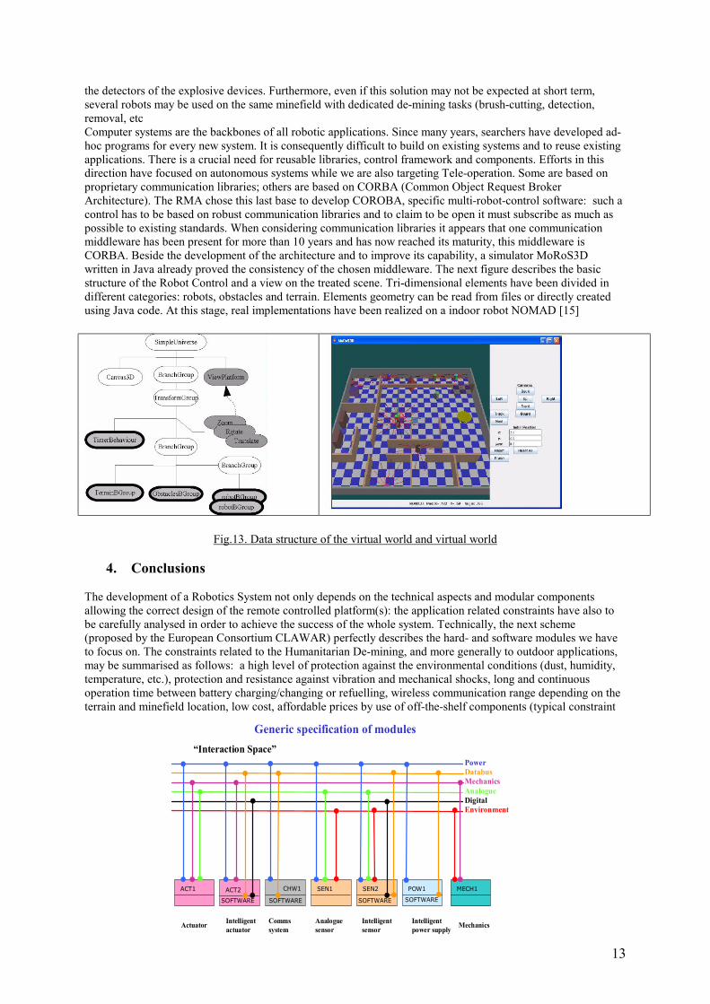
the detectors of the explosive devices. Furthermore, even if this solution may not be expected at short term, several robots may be used on the same minefield with dedicated de-mining tasks (brush-cutting, detection, removal, etcComputer systems are the backbones of all robotic applications. Since many years, searchers have developed ad-hoc programs for every new system. It is consequently difficult to build on existing systems and to reuse existing applications. There is a crucial need for reusable libraries, control framework and components. Efforts in this direction have focused on autonomous systems while we are also targeting Tele-operation. Some are based on proprietary communication libraries; others are based on CORBA (Common Object Request Broker Architecture). The RMA chose this last base to develop COROBA, specific multi-robot-control software: such a control has to be based on robust communication libraries and to claim to be open it must subscribe as much as possible to existing standards. When considering communication libraries it appears that one communication middleware has been present for more than 10 years and has now reached its maturity, this middleware is CORBA. Beside the development of the architecture and to improve its capability, a simulator MoRoS3D written in Java already proved the consistency of the chosen middleware. The next figure describes the basic structure of the Robot Control and a view on the treated scene. Tri-dimensional elements have been divided in different categories: robots, obstacles and terrain. Elements geometry can be read from files or directly created using Java code. At this stage, real implementations have been realized on a indoor robot NOMAD [15]
Fig.13. Data structure of the virtual world and virtual world
4. Conclusions
The development of a Robotics System not only depends on the technical aspects and modular components allowing the correct design of the remote controlled platform(s): the application related constraints have also to be carefully analysed in order to achieve the success of the whole system. Technically, the next scheme (proposed by the European Consortium CLAWAR) perfectly describes the hard- and software modules we have to focus on. The constraints related to the Humanitarian De-mining, and more generally to outdoor applications, may be summarised as follows: a high level of protection against the environmental conditions (dust, humidity, temperature, etc.), protection and resistance against vibration and mechanical shocks, long and continuous operation time between battery charging/changing or refuelling, wireless communication range depending on the terrain and minefield location, low cost, affordable prices by use of off-the-shelf components (typical constraint
“Interaction Space”
Generic specification of modules
Power
MechanicsAnalogue
Databus
DigitalEnvironment
ACT2
SOFTWARE
ACT1 SEN1 MECH1CHW1
SOFTWARE
SEN2
SOFTWARE
POW1
SOFTWARE
IntelligentactuatorActuator Comms
systemAnaloguesensor
Intelligentsensor
Intelligentpower supply Mechanics
14
for HUDEM due to the lack of a real commercial market), high reliability, fail-safeness, easy maintenance, easy to use, application of matured technology.. An ISO SC2 Technical Committee started the study of standards for mobile ROBOTICS (Catania, 23 Oct 2005 – final Clawar meeting). The next annexes , based on informations collected during the IARP workshops and allowed by their POCs, summarise the actual status of Robotics Systems. Test and Evaluation criteria are proposed as well, as result of WS discussions.
5. Acknowledgements
I want to mention that this paper includes the contribution of my colleague, Marc Acheroy, Director of the Signal processing Centre of the RMA and our searchers involved in the HUDEM (humanitarian de-mining) project. I also want to thank my partners from the European Network CLAWAR (Climbing and Walking Robotics) and from the WG HUDEM of the IARP (international Advanced Robotics Programme), as well as all the partners of our European funded projects (HOPE, SMART, etc…).
6. References
[1] Y.Baudoin, et Al : EC BRITE EURAM Thematic Network on Climbing and Walking Robots, including the Support Technologies for Mobile Robotic Machines, (CLAWAR), Year 2 Report: TASK 9, HUMANITARIAN DEMINING[2] Gad EL-QADY, Motoyuki SATO, and Keisuke USHIJIMA, Mine problem in Egypt: Demand for new technology, Sixth IARP Workshop HUDEM’2005, Tokyo, June 2005[3] Marc Acheroy: Mine action: status of sensor technology for close-in and remote detection of antipersonnel mines, IARP WS HUDEM’2006, Tokyo, June 2005[4] SMART consortium. Smart final report. Technical report, December 2004 [5] Jun ISHIKAWA, Mitsuru KIYOTAand Katsuhisa FURUTA, Evaluation of Test Results of GPR-based Anti-personnel Landmine Detection Systems Mounted on Robotic Vehicles, IARP WS HUDEM’2006, Tokyo, June 2005[6] Kenzo Nonami, Hajime Aoyama, Chiba University, ‘resaerch and Development of Mine Hunter Vehicle for Humanitarian Demining, IARP WS HUDEM’2006, Tokyo, June 2005[7] Y.Baudoin, et Al : EC GROWTH Network on Mobile Robotics CLAWAR-2, Year 2 , report TG 2 (www.clawar.org) [8] Edwardo F. FUKUSHIMA, Paulo DEBENEST, Yuki TOJO, Kensuke TAKITA, Marc FREESE, Helmuth RADRICH and Shigeo HIROSE, ‘Teleoperated Buggy Vehicle and Weight Balanced Arm for Mechanization of Mine Detection and Clearance Tasks’, IARP WS HUDEM’2006, Tokyo, June 2005[9] Sébastien Delhay, Vinciane Lacroix, Mahamadou Idrissa ‘PARADIS: Focusing on GIS Field Tools for Humanitarian Demining’, fifth IARP WS HUDEM’2004, Brussels, june 2004[10] Toshio FUKUDA, Takayuki MATSUNO, Yasuhiro KAWAI, Kazunori YOKOE, Yasuhisa HASEGAWA , Kazuhiro KOSUGE, Yasuhisa HIRATA, Hidenori YABUSHITA, Mitsuhiko KANEHAMA, Kiyoshi KOMORIYA d, Hironori ADACHI d, Takanori SHIBATA, Koichi SUGITA, Fumihisa KITAGAWA, Chihiro JYOMUTA, Toru KENMIZAKI, Fujio OKA, Koichi SATO, Shyoji SAKAI, Naoto AOMORI, Yoshiyuki SAKAMOTO, Takahiro YOSHIDA and Kanji HARA ‚Environment-Adaptive Antipersonnel Mine Detection System – Adanced Mine sweeper’ , IARP WS HUDEM’2006, Tokyo, June 2005[11] JC Habumuremyi , Rational designing of an electropneumatic robot for mine detection, CLAWAR'98, First International Symposium, Brussels, Belgium; November, 26-28, 1998[12] D.Waterman, K.Nonami, R.Yuasa, S.Amano, S.Masunaga, H Ono ‘Control and operational of a teleoperated hydraulic manipulator for landmine prodding and excavation’, IARP WS HUDEM’2006, Tokyo, June 2005[13] D.Doroftei, Internal report UGV Centre, RMA, May 2005[14] Brooks, R. A. & Connell, J. H. (1986), Asynchronous Distributed Control System for a Mobile Robot, in `SPIE', Cambridge, MA[15] E.Colon : CoRoBA, an Open Framework for Multi-Sensor Robotic Systems Integration (to be published, 2005) – E.Colon, H.Shali : Idem, CIRA2005, June, Helsinki, Finland[16] A.Cumani, A.Guiducci ‘Improving mobile robot localisation and map building by stereo vision, ISMCR’2005, 08-10 Nov 2005, Brussels[17] P.Hong, H. Sahli, E. Colon, Y. Baudoin ‘Visual Servoing for Robot Navigation’, Int Symp CLAWAR septembre 2001, Karlsruhe, Germany ( www.clawar.org)
15
ANNEXES
Important Note:
1. The next sheets are drafts actually submitted to their authors. No reproduction is allowed without the written consent of them or of the IARP/WG Hudem Chairman ([email protected])
2. New data may be added on request and are welcome (contact IARP/WG HUDEM) too
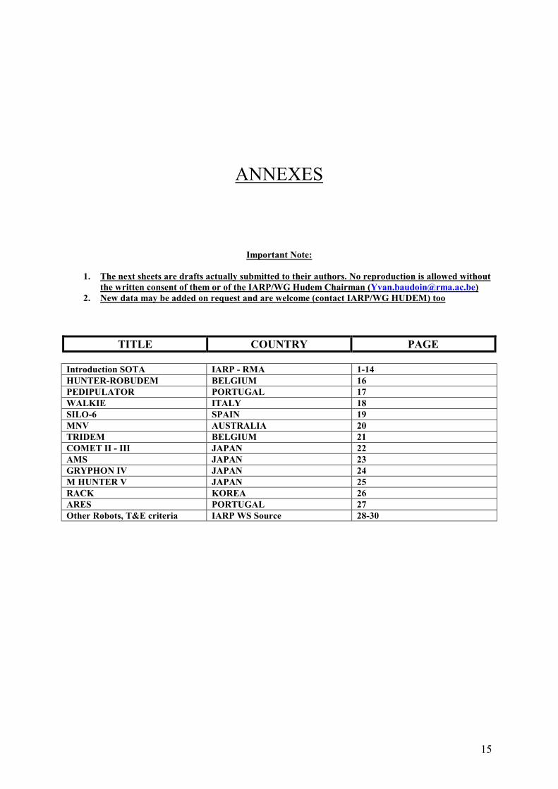
TITLE COUNTRY PAGE
Introduction SOTA IARP - RMA 1-14HUNTER-ROBUDEM BELGIUM 16PEDIPULATOR PORTUGAL 17WALKIE ITALY 18SILO-6 SPAIN 19MNV AUSTRALIA 20TRIDEM BELGIUM 21COMET II - III JAPAN 22AMS JAPAN 23GRYPHON IV JAPAN 24M HUNTER V JAPAN 25RACK KOREA 26ARES PORTUGAL 27Other Robots, T&E criteria IARP WS Source 28-30
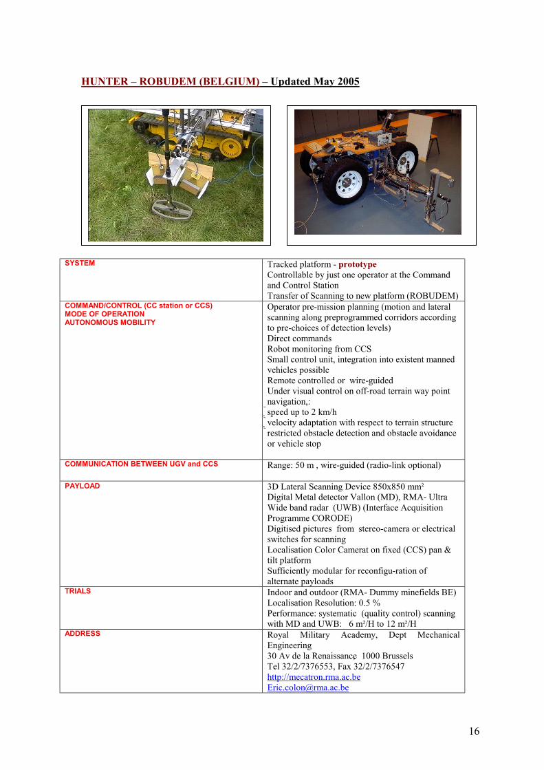
HUNTER – ROBUDEM (BELGIUM) – Updated May 2005
SYST
COMMODAUTO
COM
PAYL
TRIA
ADDR
16
EM Tracked platform - prototypeControllable by just one operator at the Command and Control StationTransfer of Scanning to new platform (ROBUDEM)
MAND/CONTROL (CC station or CCS)E OF OPERATIONNOMOUS MOBILITY
Operator pre-mission planning (motion and lateral scanning along preprogrammed corridors according to pre-choices of detection levels)Direct commandsRobot monitoring from CCSSmall control unit, integration into existent manned vehicles possibleRemote controlled or wire-guidedUnder visual control on off-road terrain way point navigation,:speed up to 2 km/hvelocity adaptation with respect to terrain structure restricted obstacle detection and obstacle avoidance or vehicle stop
MUNICATION BETWEEN UGV and CCS Range: 50 m , wire-guided (radio-link optional)
OAD 3D Lateral Scanning Device 850x850 mm²Digital Metal detector Vallon (MD), RMA- Ultra Wide band radar (UWB) (Interface Acquisition Programme CORODE)Digitised pictures from stereo-camera or electrical switches for scanning Localisation Color Camerat on fixed (CCS) pan & tilt platform Sufficiently modular for reconfigu-ration of alternate payloads
LS Indoor and outdoor (RMA- Dummy minefields BE)Localisation Resolution: 0.5 %Performance: systematic (quality control) scanning with MD and UWB: 6 m²/H to 12 m²/H
ESS Royal Military Academy, Dept Mechanical Engineering30 Av de la Renaissance, 1000 BrusselsTel 32/2/7376553, Fax 32/2/7376547http://[email protected]
17
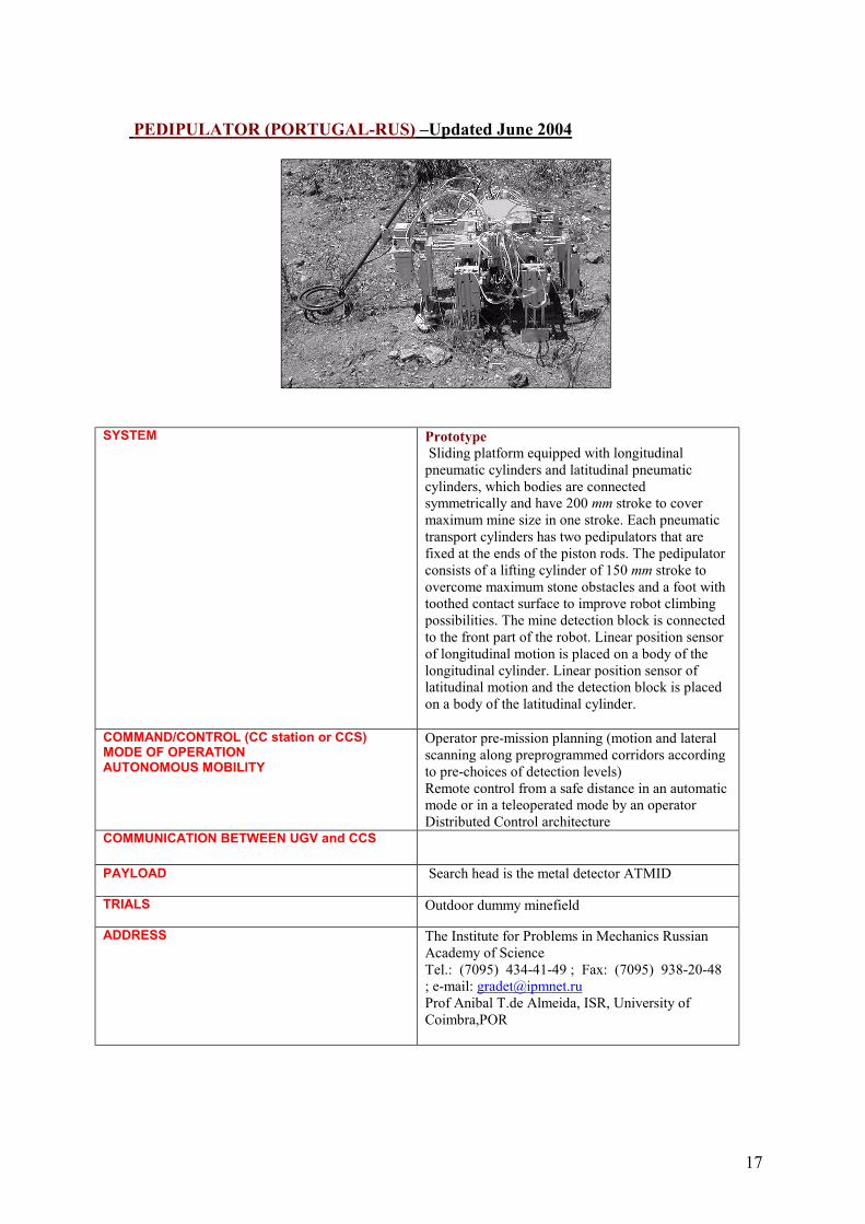
PEDIPULATOR (PORTUGAL-RUS) –Updated June 2004
SYSTEM Prototype Sliding platform equipped with longitudinal pneumatic cylinders and latitudinal pneumatic cylinders, which bodies are connected symmetrically and have 200 mm stroke to cover maximum mine size in one stroke. Each pneumatic transport cylinders has two pedipulators that are fixed at the ends of the piston rods. The pedipulator consists of a lifting cylinder of 150 mm stroke to overcome maximum stone obstacles and a foot with toothed contact surface to improve robot climbing possibilities. The mine detection block is connected to the front part of the robot. Linear position sensor of longitudinal motion is placed on a body of the longitudinal cylinder. Linear position sensor of latitudinal motion and the detection block is placed on a body of the latitudinal cylinder.
COMMAND/CONTROL (CC station or CCS)MODE OF OPERATIONAUTONOMOUS MOBILITY
Operator pre-mission planning (motion and lateral scanning along preprogrammed corridors according to pre-choices of detection levels)Remote control from a safe distance in an automatic mode or in a teleoperated mode by an operatorDistributed Control architecture
COMMUNICATION BETWEEN UGV and CCS
PAYLOAD Search head is the metal detector ATMID
TRIALS Outdoor dummy minefield
ADDRESS The Institute for Problems in Mechanics Russian Academy of ScienceTel.: (7095) 434-41-49 ; Fax: (7095) 938-20-48 ; e-mail: [email protected] Anibal T.de Almeida, ISR, University of Coimbra,POR
18
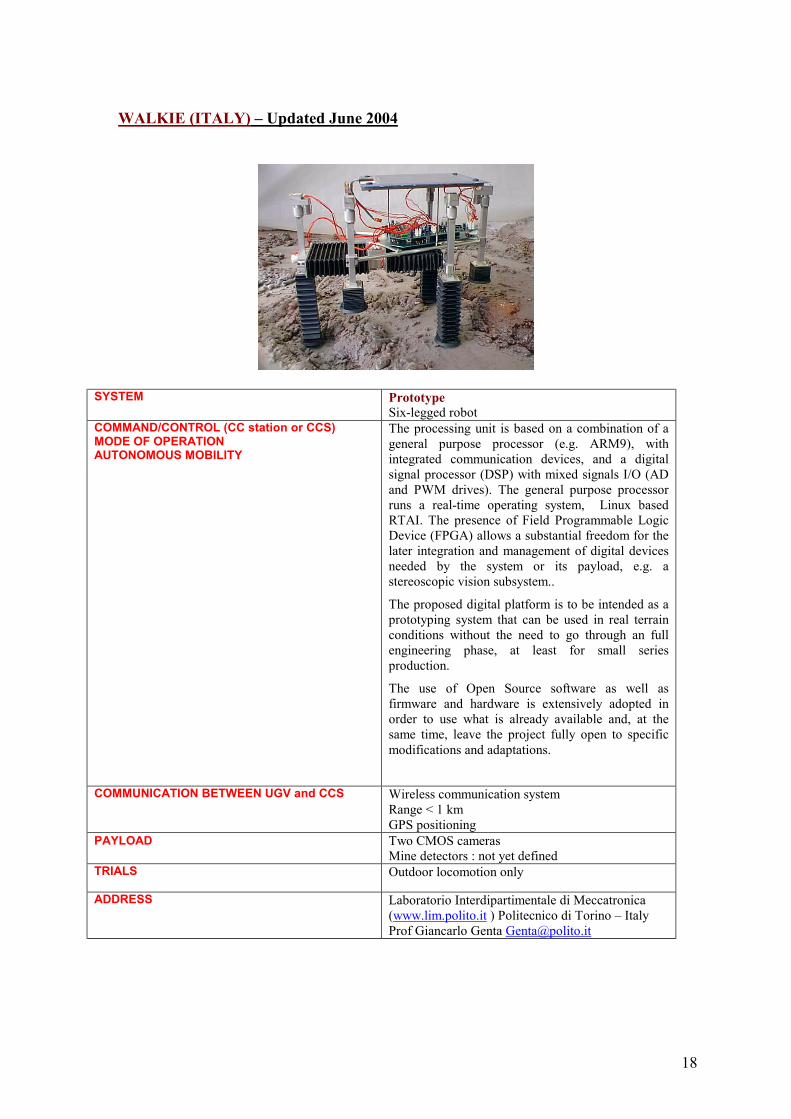
WALKIE (ITALY) – Updated June 2004
SYSTEM PrototypeSix-legged robot
COMMAND/CONTROL (CC station or CCS)MODE OF OPERATIONAUTONOMOUS MOBILITY
The processing unit is based on a combination of a general purpose processor (e.g. ARM9), with integrated communication devices, and a digital signal processor (DSP) with mixed signals I/O (AD and PWM drives). The general purpose processor runs a real-time operating system, Linux based RTAI. The presence of Field Programmable Logic Device (FPGA) allows a substantial freedom for the later integration and management of digital devices needed by the system or its payload, e.g. a stereoscopic vision subsystem..
The proposed digital platform is to be intended as a prototyping system that can be used in real terrain conditions without the need to go through an full engineering phase, at least for small series production.
The use of Open Source software as well as firmware and hardware is extensively adopted in order to use what is already available and, at the same time, leave the project fully open to specific modifications and adaptations.
COMMUNICATION BETWEEN UGV and CCS Wireless communication systemRange < 1 kmGPS positioning
PAYLOAD Two CMOS camerasMine detectors : not yet defined
TRIALS Outdoor locomotion only
ADDRESS Laboratorio Interdipartimentale di Meccatronica (www.lim.polito.it ) Politecnico di Torino – ItalyProf Giancarlo Genta [email protected]
19
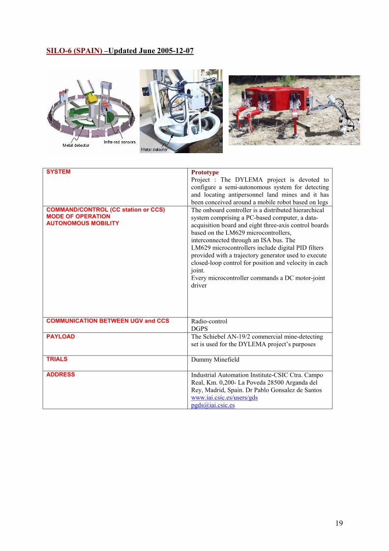
SILO-6 (SPAIN) –Updated June 2005-12-07
SYSTEM PrototypeProject : The DYLEMA project is devoted to configure a semi-autonomous system for detecting and locating antipersonnel land mines and it has been conceived around a mobile robot based on legs
COMMAND/CONTROL (CC station or CCS)MODE OF OPERATIONAUTONOMOUS MOBILITY
The onboard controller is a distributed hierarchical system comprising a PC-based computer, a data-acquisition board and eight three-axis control boards based on the LM629 microcontrollers, interconnected through an ISA bus. TheLM629 microcontrollers include digital PID filtersprovided with a trajectory generator used to executeclosed-loop control for position and velocity in each joint.Every microcontroller commands a DC motor-joint driver
COMMUNICATION BETWEEN UGV and CCS Radio-controlDGPS
PAYLOAD The Schiebel AN-19/2 commercial mine-detecting set is used for the DYLEMA project’s purposes
TRIALS Dummy Minefield
ADDRESS Industrial Automation Institute-CSIC Ctra. Campo Real, Km. 0,200- La Poveda 28500 Arganda del Rey, Madrid, Spain. Dr Pablo Gonsalez de Santoswww.iai.csic.es/users/[email protected]
20
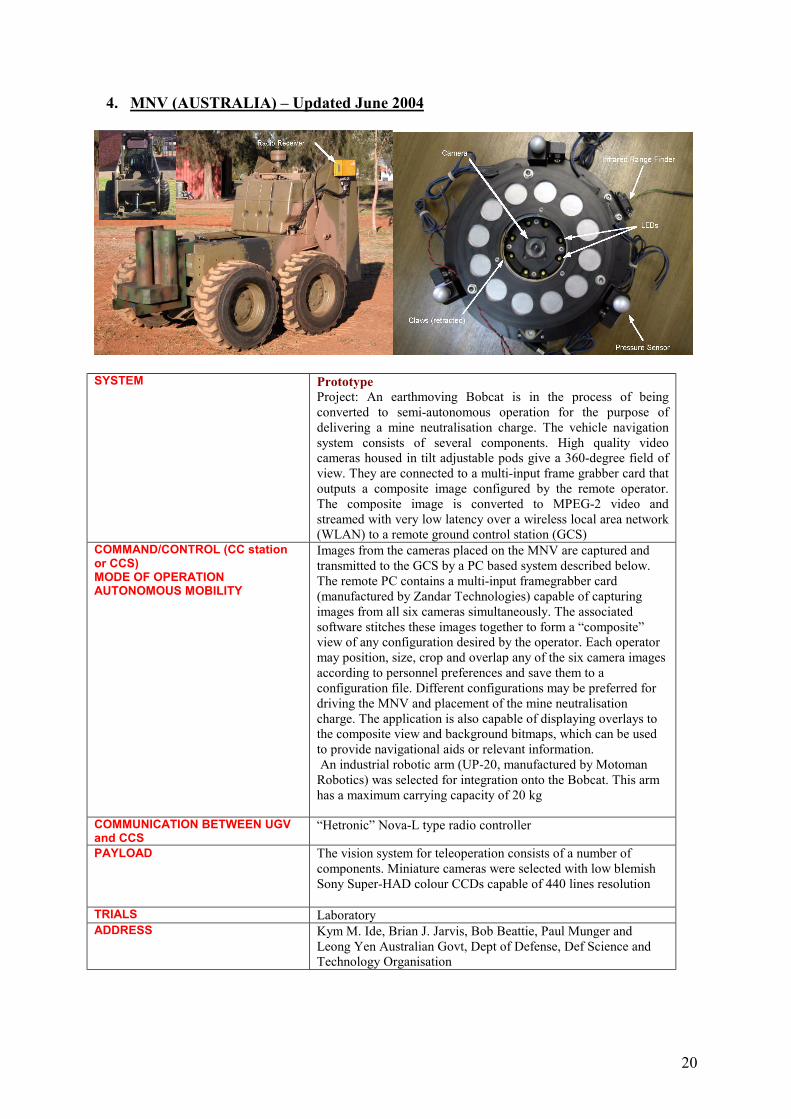
4. MNV (AUSTRALIA) – Updated June 2004
SYSTEM PrototypeProject: An earthmoving Bobcat is in the process of being converted to semi-autonomous operation for the purpose of delivering a mine neutralisation charge. The vehicle navigation system consists of several components. High quality video cameras housed in tilt adjustable pods give a 360-degree field of view. They are connected to a multi-input frame grabber card that outputs a composite image configured by the remote operator. The composite image is converted to MPEG-2 video and streamed with very low latency over a wireless local area network (WLAN) to a remote ground control station (GCS)
COMMAND/CONTROL (CC station or CCS)MODE OF OPERATIONAUTONOMOUS MOBILITY
Images from the cameras placed on the MNV are captured and transmitted to the GCS by a PC based system described below. The remote PC contains a multi-input framegrabber card (manufactured by Zandar Technologies) capable of capturing images from all six cameras simultaneously. The associated software stitches these images together to form a “composite” view of any configuration desired by the operator. Each operator may position, size, crop and overlap any of the six camera images according to personnel preferences and save them to a configuration file. Different configurations may be preferred for driving the MNV and placement of the mine neutralisation charge. The application is also capable of displaying overlays to the composite view and background bitmaps, which can be used to provide navigational aids or relevant information.An industrial robotic arm (UP-20, manufactured by Motoman Robotics) was selected for integration onto the Bobcat. This arm has a maximum carrying capacity of 20 kg
COMMUNICATION BETWEEN UGV and CCS
“Hetronic” Nova-L type radio controller
PAYLOAD The vision system for teleoperation consists of a number of components. Miniature cameras were selected with low blemish Sony Super-HAD colour CCDs capable of 440 lines resolution
TRIALS LaboratoryADDRESS Kym M. Ide, Brian J. Jarvis, Bob Beattie, Paul Munger and
Leong Yen Australian Govt, Dept of Defense, Def Science and Technology Organisation
21
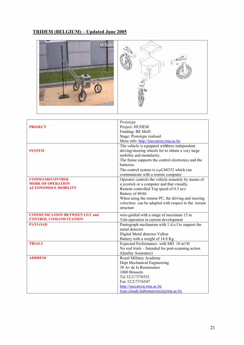
TRIDEM (BELGIUM) – Updated June 2005
PROJECTPrototypeProject: HUDEM Funding: BE MoDStage: Prototype realisedMore info: http://mecatron.rma.ac.be
SYSTEM The vehicle is equipped with three independent driving/steering wheels for to obtain a very large mobility and modularity.The frame supports the control electronics and the batteries.The control system is a µC68332 which can communicate with a remote computer
COMMAND/CONTROLMODE OF OPERATIONAUTONOMOUS MOBILITY
Operator controls the vehicle remotely by means of a joystick or a computer and that visually.Remote controlled Top speed of 0.3 m/sBattery of 40AhWhen using the remote PC, the driving and steering velocities can be adapted with respect to the terrain structure
COMMUNICATION BETWEEN UGV and CONTROL COMAND STATION
wire-guided with a range of maximum 15 mTele-operation in current development
PAYLOAD Pantograph mechanism with 1 d.o.f to support the metal detectorDigital Metal detector VallonBattery with a weight of 14.8 Kg
TRIALS Expected Performance: with MD 10 m²/HNo real trials – Intended for post-scanning action (Quality Assurance)
ADDRESS Royal Military AcademyDept Mechanical Engineering30 Av de la Renaissance1000 BrusselsTel 32/2/7376553Fax 32/2/7376547http://[email protected]
22
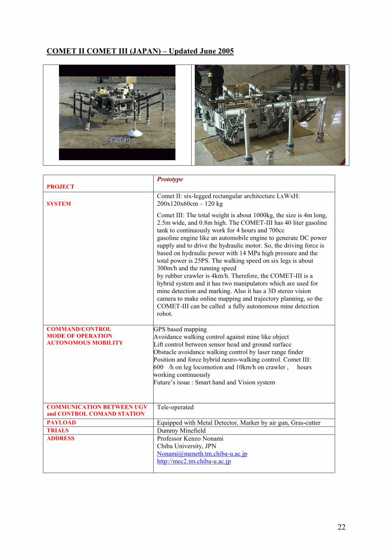
COMET II COMET III (JAPAN) – Updated June 2005
PROJECTPrototype
SYSTEM Comet II: six-legged rectangular architecture LxWxH: 200x120x60cm – 120 kg
Comet III: The total weight is about 1000kg, the size is 4m long,2.5m wide, and 0.8m high. The COMET-III has 40 liter gasoline tank to continuously work for 4 hours and 700ccgasoline engine like an automobile engine to generate DC power supply and to drive the hydraulic motor. So, the driving force is based on hydraulic power with 14 MPa high pressure and the total power is 25PS. The walking speed on six legs is about 300m/h and the running speedby rubber crawler is 4km/h. Therefore, the COMET-III is a hybrid system and it has two manipulators which are used for mine detection and marking. Also it has a 3D stereo vision camera to make online mapping and trajectory planning, so the COMET-III can be called a fully autonomous mine detection robot.
COMMAND/CONTROLMODE OF OPERATIONAUTONOMOUS MOBILITY
GPS based mapping Avoidance walking control against mine like objectLift control between sensor head and ground surfaceObstacle avoidance walking control by laser range finderPosition and force hybrid neuro-walking control. Comet III: 600 /h on leg locomotion and 10km/h on crawler , hours working continuouslyFuture’s issue : Smart hand and Vision system
COMMUNICATION BETWEEN UGV and CONTROL COMAND STATION
Tele-operated
PAYLOAD Equipped with Metal Detector, Marker by air gun, Gras-cutterTRIALS Dummy MinefieldADDRESS Professor Kenzo Nonami
Chiba University, [email protected]://mec2.tm.chiba-u.ac.jp
23
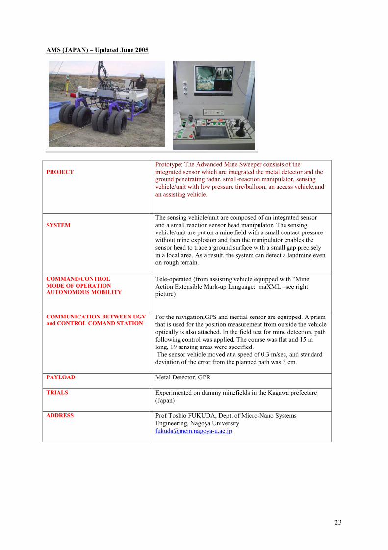
AMS (JAPAN) – Updated June 2005
PROJECTPrototype: The Advanced Mine Sweeper consists of the integrated sensor which are integrated the metal detector and the ground penetrating radar, small-reaction manipulator, sensing vehicle/unit with low pressure tire/balloon, an access vehicle,and an assisting vehicle.
SYSTEM The sensing vehicle/unit are composed of an integrated sensor and a small reaction sensor head manipulator. The sensing vehicle/unit are put on a mine field with a small contact pressure without mine explosion and then the manipulator enables the sensor head to trace a ground surface with a small gap precisely in a local area. As a result, the system can detect a landmine even on rough terrain.
COMMAND/CONTROLMODE OF OPERATIONAUTONOMOUS MOBILITY
Tele-operated (from assisting vehicle equipped with “Mine Action Extensible Mark-up Language: maXML –see right picture)
COMMUNICATION BETWEEN UGV and CONTROL COMAND STATION
For the navigation,GPS and inertial sensor are equipped. A prism that is used for the position measurement from outside the vehicle optically is also attached. In the field test for mine detection, path following control was applied. The course was flat and 15 m long, 19 sensing areas were specified. The sensor vehicle moved at a speed of 0.3 m/sec, and standard deviation of the error from the planned path was 3 cm.
PAYLOAD Metal Detector, GPR
TRIALS Experimented on dummy minefields in the Kagawa prefecture (Japan)
ADDRESS Prof Toshio FUKUDA, Dept. of Micro-Nano Systems Engineering, Nagoya [email protected]
24
GRYPHON IV (JAPAN) – Updated June 2005
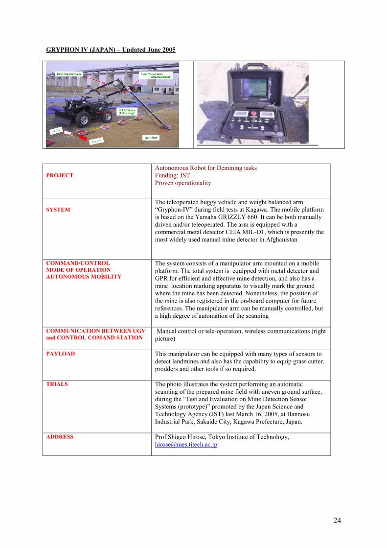
PROJECTAutonomous Robot for Demining tasksFunding: JSTProven operationality
SYSTEM The teleoperated buggy vehicle and weight balanced arm “Gryphon-IV” during field tests at Kagawa. The mobile platform is based on the Yamaha GRIZZLY 660. It can be both manually driven and/or teleoperated. The arm is equipped with a commercial metal detector CEIA MIL-D1, which is presently the most widely used manual mine detector in Afghanistan
COMMAND/CONTROLMODE OF OPERATIONAUTONOMOUS MOBILITY
The system consists of a manipulator arm mounted on a mobile platform. The total system is equipped with metal detector and GPR for efficient and effective mine detection, and also has a mine location marking apparatus to visually mark the ground where the mine has been detected. Nonetheless, the position of the mine is also registered in the on-board computer for future references. The manipulator arm can be manually controlled, but a high degree of automation of the scanning
COMMUNICATION BETWEEN UGV and CONTROL COMAND STATION
Manual control or tele-operation, wireless communications (right picture)
PAYLOAD This manipulator can be equipped with many types of sensors to detect landmines and also has the capability to equip grass cutter, prodders and other tools if so required.
TRIALS The photo illustrates the system performing an automatic scanning of the prepared mine field with uneven ground surface, during the “Test and Evaluation on Mine Detection Sensor Systems (prototype)” promoted by the Japan Science and Technology Agency (JST) last March 16, 2005, at Bannosu Industrial Park, Sakaide City, Kagawa Prefecture, Japan.
ADDRESS Prof Shigeo Hirose, Tokyo Institute of Technology, [email protected]

25
M HUNTER V (JAPAN) – Updated June 2005
PROJECTAutonmous Robot for Demining tasksFunding: JSTProven operationality
SYSTEM The body full length of MHV is 2.8m, and when the sensor arm is lengthened, it is 4.5m. The width of vehicle is 1.5m in the case of crawler, and is 1.6m in the tire. The height of vehicles is 1.9m in the crawler, and is 1.8m in the tire. The full weight is 1650kg including SCARA arm.The drive is a diesel engine and a HST (Hydraulic Static Transmission) system. Four independent crawlers are attached to the front right, the front left, the back right, and the back left. The engine was selected to be applicable to the 2,000m high elevation in Afghanistan.
COMMAND/CONTROLMODE OF OPERATIONAUTONOMOUS MOBILITYCOMMUNICATION BETWEEN UGV and CONTROL COMAND STATION
PAYLOAD GPR + MD or ALYS System
TRIALS Public demonstration and mine detection test inSakaide city, Kagawa prefecture on March 16, 2005
ADDRESS Prof Kenzo Nonami, Shigeo University, Japan , [email protected]://mec2.tm.chiba-u.ac.jp
26
RACK (KOREA) – Updated June 2005
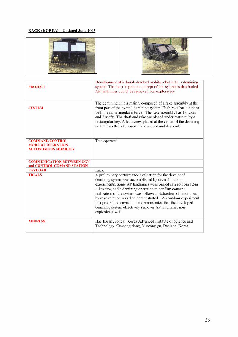
PROJECTDevelopment of a double-tracked mobile robot with a demining system. The most important concept of the system is that buried AP landmines could be removed non explosively.
SYSTEM The demining unit is mainly composed of a rake assembly at the front part of the overall demining system. Each rake has 4 blades with the same angular interval. The rake assembly has 18 rakes and 2 shafts. The shaft and rake are placed under restraint by a rectangular key. A leadscrew placed at the center of the demining unit allows the rake assembly to ascend and descend.
COMMAND/CONTROLMODE OF OPERATIONAUTONOMOUS MOBILITY
Tele-operated
COMMUNICATION BETWEEN UGV and CONTROL COMAND STATIONPAYLOAD RackTRIALS A preliminary performance evaluation for the developed
demining system was accomplished by several indoor experiments. Some AP landmines were buried in a soil bin 1.5m × 1m size, and a demining operation to confirm concept realization of the system was followed. Extraction of landmines by rake rotation was then demonstrated. An outdoor experiment in a predefined environment demonstrated that the developed demining system effectively removes AP landmines non-explosively well.
ADDRESS Hae Kwan Jeonga, Korea Advanced Institute of Science and Technology, Guseong-dong, Yuseong-gu, Daejeon, Korea
27
ARES (PORTUGAL) – Updated June 2005
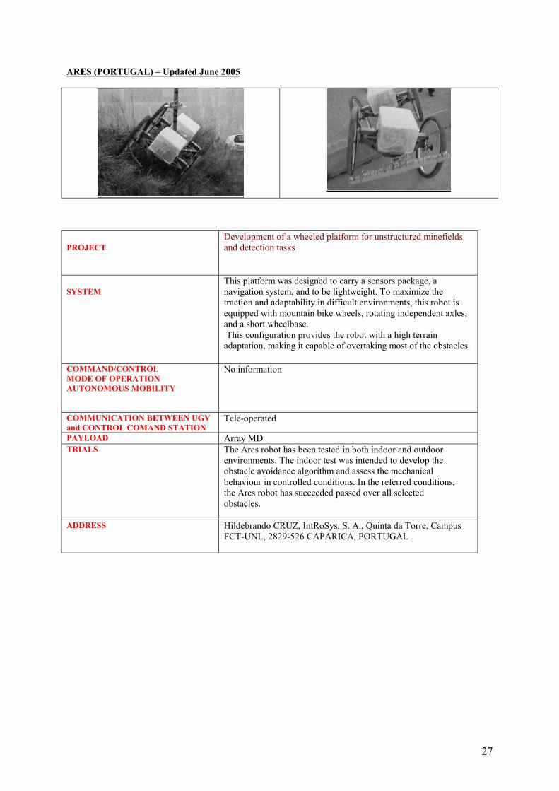
PROJECTDevelopment of a wheeled platform for unstructured minefields and detection tasks
SYSTEM This platform was designed to carry a sensors package, a navigation system, and to be lightweight. To maximize the traction and adaptability in difficult environments, this robot is equipped with mountain bike wheels, rotating independent axles, and a short wheelbase.This configuration provides the robot with a high terrain adaptation, making it capable of overtaking most of the obstacles.
COMMAND/CONTROLMODE OF OPERATIONAUTONOMOUS MOBILITY
No information
COMMUNICATION BETWEEN UGV and CONTROL COMAND STATION
Tele-operated
PAYLOAD Array MDTRIALS The Ares robot has been tested in both indoor and outdoor
environments. The indoor test was intended to develop theobstacle avoidance algorithm and assess the mechanicalbehaviour in controlled conditions. In the referred conditions,the Ares robot has succeeded passed over all selectedobstacles.
ADDRESS Hildebrando CRUZ, IntRoSys, S. A., Quinta da Torre, Campus FCT-UNL, 2829-526 CAPARICA, PORTUGAL
28
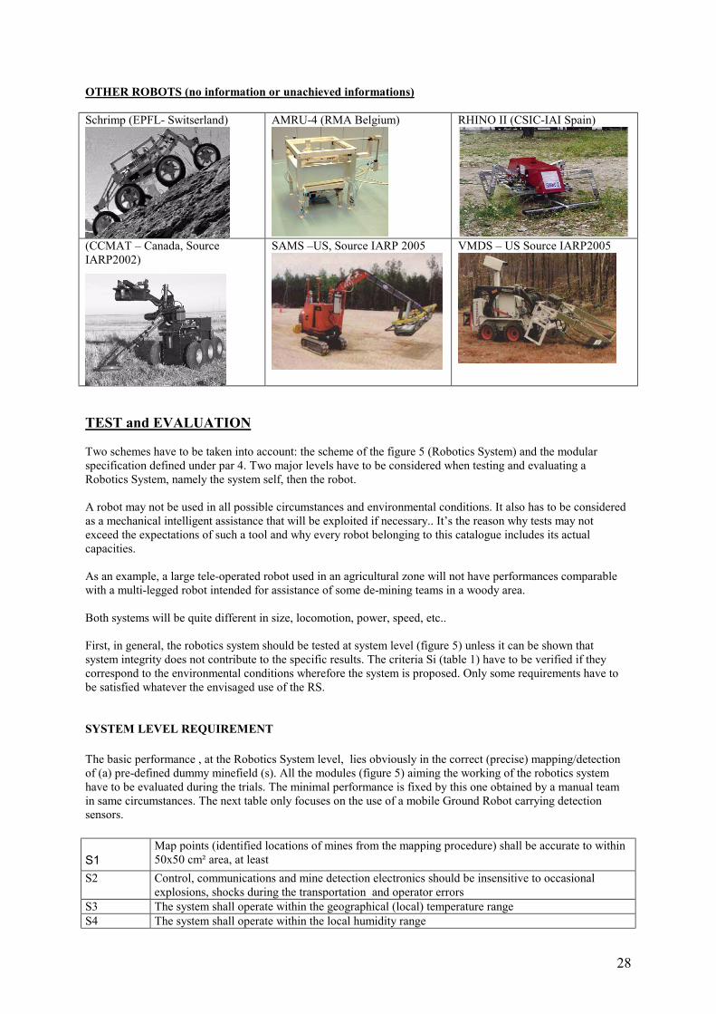
OTHER ROBOTS (no information or unachieved informations)
Schrimp (EPFL- Switserland) AMRU-4 (RMA Belgium) RHINO II (CSIC-IAI Spain)
(CCMAT – Canada, Source IARP2002)
SAMS –US, Source IARP 2005 VMDS – US Source IARP2005
TEST and EVALUATION
Two schemes have to be taken into account: the scheme of the figure 5 (Robotics System) and the modular specification defined under par 4. Two major levels have to be considered when testing and evaluating a Robotics System, namely the system self, then the robot.
A robot may not be used in all possible circumstances and environmental conditions. It also has to be considered as a mechanical intelligent assistance that will be exploited if necessary.. It’s the reason why tests may not exceed the expectations of such a tool and why every robot belonging to this catalogue includes its actual capacities.
As an example, a large tele-operated robot used in an agricultural zone will not have performances comparable with a multi-legged robot intended for assistance of some de-mining teams in a woody area.
Both systems will be quite different in size, locomotion, power, speed, etc..
First, in general, the robotics system should be tested at system level (figure 5) unless it can be shown that system integrity does not contribute to the specific results. The criteria Si (table 1) have to be verified if they correspond to the environmental conditions wherefore the system is proposed. Only some requirements have to be satisfied whatever the envisaged use of the RS.
SYSTEM LEVEL REQUIREMENT
The basic performance , at the Robotics System level, lies obviously in the correct (precise) mapping/detectionof (a) pre-defined dummy minefield (s). All the modules (figure 5) aiming the working of the robotics system have to be evaluated during the trials. The minimal performance is fixed by this one obtained by a manual team in same circumstances. The next table only focuses on the use of a mobile Ground Robot carrying detection sensors.
S1Map points (identified locations of mines from the mapping procedure) shall be accurate to within 50x50 cm² area, at least
S2 Control, communications and mine detection electronics should be insensitive to occasional explosions, shocks during the transportation and operator errors
S3 The system shall operate within the geographical (local) temperature range S4 The system shall operate within the local humidity range
29
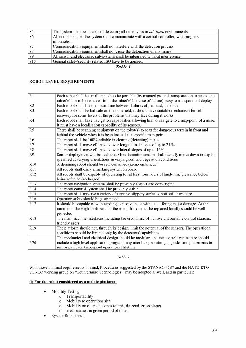
S5 The system shall be capable of detecting all mine types in all- local environmentsS6 All components of the system shall communicate with a central controller, with progress
informationS7 Communications equipment shall not interfere with the detection processS8 Communications equipment shall not cause the detonation of any minesS9 All sensor and electronic sub-systems shall be integrated without interferenceS10 General safety/security related ISO have to be applied.
Table 1
ROBOT LEVEL REQUIREMENTS
R1 Each robot shall be small enough to be portable (by manned ground transportation to access the minefield or to be removed from the minefield in case of failure), easy to transport and deploy
R2 Each robot shall have a mean-time between failures of , at least, 1 monthR3 Each robot shall be fail-safe on the minefield; it should have suitable mechanism for self-
recovery for some levels of the problems that may face during it worksR4 Each robot shall have navigation capabilities allowing him to navigate to a map-point of a mine.
It must have a localisation capability of its sensors. R5 There shall be scanning equipment on the robot(s) to scan for dangerous terrain in front and
behind the vehicle when it is been located at a specific map-pointR6 The robot shall be 100% reliable in clearing (detecting) minesR7 The robot shall move effectively over longitudinal slopes of up to 25 %R8 The robot shall move effectively over lateral slopes of up to 15%R9 Sensor deployment will be such that Mine detection sensors shall identify mines down to depths
specified at varying orientations in varying soil and vegetation conditionsR10 A demining robot should be self-contained (i.e.no ombilicus)R11 All robots shall carry a marking system on boardR12 All robots shall be capable of operating for at least four hours of land-mine clearance before
being refueled (recharged)R13 The robot navigation systems shall be provably correct and convergentR14 The robot control system shall be provably stableR15 The robot shall traverse a variety of terrains: slippery surfaces, soft soil, hard coreR16 Operator safety should be guaranteedR17 It should be capable of withstanding explosive blast without suffering major damage. At the
minimum, the High Tech parts of the robot that can not be replaced locally should be well protected
R18 The man-machine interfaces including the ergonomic of lightweight portable control stations, friendly users
R19 The platform should not, through its design, limit the potential of the sensors. The operational conditions should be limited only by the detectors’capabilities
R20The mechanical and electrical design should be modular, and the control architecture should include a high level application programming interface permitting upgrades and placements to sensor payloads throughout operational lifetime
Table 2
With those minimal requirements in mind, Procedures suggested by the STANAG 4587 and the NATO RTO SCI-133 working group on “Countermine Technologies” may be adopted as well, and in particular:
(i) For the robot considered as a mobile platform:
• Mobility Testingo Transportabilityo Mobility to operations siteo Mobility on off-road slopes (climb, descend, cross-slope)o area scanned in given period of time.
• System Robustness
30
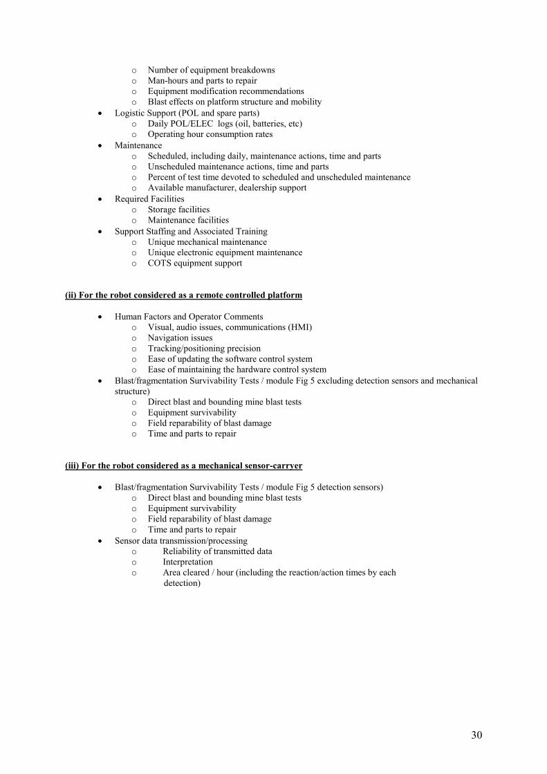
o Number of equipment breakdownso Man-hours and parts to repairo Equipment modification recommendationso Blast effects on platform structure and mobility
• Logistic Support (POL and spare parts)o Daily POL/ELEC logs (oil, batteries, etc)o Operating hour consumption rates
• Maintenanceo Scheduled, including daily, maintenance actions, time and partso Unscheduled maintenance actions, time and partso Percent of test time devoted to scheduled and unscheduled maintenanceo Available manufacturer, dealership support
• Required Facilitieso Storage facilitieso Maintenance facilities
• Support Staffing and Associated Trainingo Unique mechanical maintenanceo Unique electronic equipment maintenanceo COTS equipment support
(ii) For the robot considered as a remote controlled platform
• Human Factors and Operator Commentso Visual, audio issues, communications (HMI)o Navigation issueso Tracking/positioning precisiono Ease of updating the software control systemo Ease of maintaining the hardware control system
• Blast/fragmentation Survivability Tests / module Fig 5 excluding detection sensors and mechanical structure)
o Direct blast and bounding mine blast testso Equipment survivabilityo Field reparability of blast damageo Time and parts to repair
(iii) For the robot considered as a mechanical sensor-carryer
• Blast/fragmentation Survivability Tests / module Fig 5 detection sensors)o Direct blast and bounding mine blast testso Equipment survivabilityo Field reparability of blast damageo Time and parts to repair
• Sensor data transmission/processingo Reliability of transmitted datao Interpretationo Area cleared / hour (including the reaction/action times by each
detection)