
I SYLLABUS- Cutting tools-various types of single point cutting ...
Upload
khangminh22Category
view
0download
0
See discussions, stats, and author profiles for this publication at: https://www.researchgate.net/publication/320070384
Integrated energy analysis of cutting process and spindle subsystem in a turning
machine
Article in Journal of Cleaner Production · September 2017
DOI: 10.1016/j.jclepro.2017.09.234
CITATIONS
4READS
137
3 authors:
Some of the authors of this publication are also working on these related projects:
FlexProd View project
Pre2Pos View project
Jeremi Wójcicki
Italian National Research Council
9 PUBLICATIONS 12 CITATIONS
SEE PROFILE
Marco Leonesio
Italian National Research Council
51 PUBLICATIONS 154 CITATIONS
SEE PROFILE
Giacomo Bianchi
Italian National Research Council
60 PUBLICATIONS 293 CITATIONS
SEE PROFILE
All content following this page was uploaded by Marco Leonesio on 29 September 2017.
The user has requested enhancement of the downloaded file.
Accepted Manuscript
Integrated energy analysis of cutting process and spindle subsystem in a turningmachine
Jeremi Wójcicki, Marco Leonesio, Giacomo Bianchi
PII: S0959-6526(17)32246-1
DOI: 10.1016/j.jclepro.2017.09.234
Reference: JCLP 10739
To appear in: Journal of Cleaner Production
Received Date: 2 February 2017
Revised Date: 18 September 2017
Accepted Date: 26 September 2017
Please cite this article as: Wójcicki J, Leonesio M, Bianchi G, Integrated energy analysis of cuttingprocess and spindle subsystem in a turning machine, Journal of Cleaner Production (2017), doi:10.1016/j.jclepro.2017.09.234.
This is a PDF file of an unedited manuscript that has been accepted for publication. As a service toour customers we are providing this early version of the manuscript. The manuscript will undergocopyediting, typesetting, and review of the resulting proof before it is published in its final form. Pleasenote that during the production process errors may be discovered which could affect the content, and alllegal disclaimers that apply to the journal pertain.
MANUSCRIP
T
ACCEPTED
ACCEPTED MANUSCRIPT
Integrated energy analysis of cutting process and spindle subsystem in a turning machine
Jeremi Wójcicki*, Marco Leonesio, Giacomo Bianchi
Istituto di Tecnologie Industriali e Automazione, Via Alfonso Corti 12, 20133, Milano, Italy
*Corresponding author. E-mail: [email protected]
Abstract
This paper presents a novel approach for systematic energy efficiency evaluation and
optimization in turning operations, combining spindle, chiller and material removal models.
Framing a joint machine-process design approach, the proposed study aims at selecting
optimal combinations of cutting parameters (feed rate, depth of cut and spindle speed) for a
given spindle-chiller assembly, able to minimize the energy consumption. Contrary to most
of the literature, where the efficiency analysis is fully empirical, relying on extended cutting
test campaigns, here a model-based approach is adopted. The goal is to characterize a key
subsystem of modern machine tools, often used in both turning and milling machines,
composed by a permanent magnet brushless direct-drive spindle with a dedicated chiller
unit. Analytical relationships are identified, producing efficiency maps as a function of various
process parameters. Physic-based models are exploited, reproducing electrical and
mechanical energy dissipation occurring in the spindle and chiller units and in the material
removal process. The models parameters are identified by a reduced set of spindle ramp-up
and cutting tests, executed in an industrial context. Then, an overall process efficiency
optimization is performed and discussed.
Keywords: Turning, process efficiency, energy models, spindle, chiller 1. Introduction
Correct selection of cutting parameters in machining is very important to achieve the
prescribed quality with an economical, productive process. The choice is driven by various
criteria, to assure the required accuracy of the workpiece and surface integrity, with an
optimal balance between production rate and production cost. A multi-objective optimization
MANUSCRIP
T
ACCEPTED
ACCEPTED MANUSCRIPTof process planning can tackle vibration and tool life issues (Leonesio et al., 2012); similarly,
productivity and chatter avoidance criteria can be used to control spindle speed and feed
rate for a generic milling process (Bort et al., 2016). Statistical methods were employed for
best parameter selection in turning, aiming at surface roughness and tool life improvements
(Yang and Tarng, 1998).
In recent years, a wide attention has been devoted to machine tools (MTs) environmental
impact, which is usually dominated by energy consumption in the use phase. A pioneering
attempt to outline a systematic approach for including energy efficiency objectives in
manufacturing systems and processes is provided by Duflou (2012), while a recent and
comprehensive review can be found in Zhou (2016). MTs efficiency in terms of overall
energy consumption with respect to productivity has been analyzed experimentally by Diaz
et al. (2010, 2011) outlining the importance of machining time in energy demand prediction.
A multi-objective optimization model including energy demand together with other
performance indicators, like costs, on heavy-duty CNC has been introduced by Xiong et al.
(2016), to assist optimal process parameters selection. In this work, spindle rated power and
utilization factor parameter were used to represent a spindle energy model. Simulation
based tools and methodologies were investigated to predict MT energy consumption during
generic work piece machining (Borgia et al., 2016). One major issue concerns the link
between specific consumed energy in machining, i.e. the ratio between energy spent per
volume of material removed, and the parameters that could have an influence on it. In fact,
these parameters modify both the power used by the MT, where in this sense the main
spindle is usually responsible for the majority of the expenditure, and the amount of material
removed (Borgia et al., 2014b). Albertelli et al. (2016) proposed a model to estimate energy
demand of production cycle in a milling machine including influence of MT peripheral
subsystems, however using assumption of constant spindle efficiency, whereas Peng and
Xu (2013) introduced a hybrid model for a CNC machine, which utilized experimental model
of both process and spindle energy demand. An experimental study on the influence of main
MANUSCRIP
T
ACCEPTED
ACCEPTED MANUSCRIPTcutting parameters (feed rate, axial depth of cut, radial depth of cut, cutting speed) on both
MT efficiency and specific energy consumption for turning machines was conducted by
Draganescu (2003). A similar analysis was performed later by Mori et al. (2011), examining
the effects of cutting parameters on total energy consumption in face-milling operations.
Both works state that, during machining, the most relevant energy usage is due to the
spindle unit, which performs the material removal.
Following the track outlined by Draganescu (2003), the present article tackles the problem of
optimal cutting strategy in turning operation by performing an integrated analysis of the
efficiency of the core subsystem of a MT: the spindle-chiller assembly, herein denoted as
Processing Unit (PU). On the contrary to several studies presented above, where either
purely experimental models or cutting process analytical models with simplified
representation for spindle subsystem (e.g. with motor constant efficiency) are used, authors
employ a holistic, physical model, integrating cutting process, spindle assembly, spindle
motor and chiller unit sub-models. The joint machine - process analysis approach supports
the selection of the optimal combination of cutting parameters (feed rate, depth of cut and
spindle speed) for a given PU, able to minimize the energy consumption during machining.
Additionally, the analysis provides useful data to machine designers, about losses and
efficiency of spindle and chiller during reference machining operations. Coherently with the
industrial practice, spindle and chiller are considered as a coupled elementary unit: in a
“what if” analysis comparing different possible PU combinations, e.g. based on induction or
synchronous motors, an efficiency comparison must consider also the different requirements
in terms of motor cooling.
On the contrary to works of Draganescu (2003) and Mori et al. (2011), where the efficiency
analysis is fully empirical, relying on extended cutting test campaigns, in this article a model-
based approach is adopted and validated by experiments. Analytical relationships are
identified, providing efficiency maps as a function of the various process parameters. The
models are based on the systems physics, taking into account electrical and mechanical

MANUSCRIP
T
ACCEPTED
ACCEPTED MANUSCRIPTenergy dissipation, which occurs both in PU and in the material removal process. The
models parameters identification can be carried out exploiting a reduced set of experiments
(spindle ramp-up and cutting tests); then, once validated, models can be used to get a
general insight about process efficiency.
This paper proposes, for a given work piece (described by its diameter ) and MT, to
optimize process parameters to minimize the used energy , for each possible level of
Material Removal Rate (MRR). The obtained relationship, = (,), contains the
dominant solutions and constitutes a Pareto front for possible subsequent global
optimizations. Even though this work is focused on PU efficiency, a global MT energy
optimization is guaranteed because the MRR is related to the machining time. It is therefore
possible to evaluate the overall cutting specific energy (Diaz et al., 2010) taking into account
the contribution of the basal consumption of other MT peripherals (e.g. the process coolant
pump), that can be considered as independent from the activity of PU and only proportional
to the overall processing time. A sample application, explored in this article, is the reduction
of specific energy obtained decreasing the MRR, as suggested by Avram and Xirouchakis
(2011).
The paper is structured as follows. Section 2 states the problem and scope of the study. In
section 3, the energy models of spindle, chiller and material removal processes are
presented. Section 4 is devoted to model parameters identification: the measurement setup
used to feed the identification system is described; then, parameters are identified via Least
Squares method and validation is performed according to a k-fold approach. Section 5
presents the main result of the study: the energy optimization of a cylindrical turning process
(in terms of feed rate, spindle speed and depth of cut). This goal is achieved through
computation of the integrated efficiency map of the PU and material removal process.
Discussion and conclusions are reported in section 6 and 0, respectively.
2. Problem statement
MANUSCRIP
T
ACCEPTED
ACCEPTED MANUSCRIPTPU efficiency depends on its thermo-electromechanical characteristics and on spindle
velocity and torque, required to machine the work piece material with given process
parameters. Thus, an effective PU energy optimization must include the cutting process. The
objective of the present article is establishing, for given PU, workpiece material, tool and
MRR, the optimal cutting parameters that minimize the process energy consumption. The
goal is achieved by coupling a mechanistic model of material removal with the thermo-
electro-mechanical model of the PU. Since the efficiency is expressed as a function of MRR,
the resulting relationship can be exploited to carry out the overall machining energy
optimization at MT level, once all the other energy consumers in the machine are known. In
formula, for a turning process and parametrizing the result with respect to bar diameter, the
problem can be stated as follows:
(|) = max,, , , , . . ∙ ∙ ∙ 2 = (1)
Following the proposed approach, a PU unit of a CNC lathe is identified and analyzed. The
obtained results allow, on one side, to optimize the cutting parameters and, on the other
side, to asses a PU design for a given set of reference operations. The proposed approach
can be applied to all spindle equipped with brushless motors, that are more and more
common: to obtain quantitative results, the identification and analysis procedures must be
executed on spindle-chiller assembly of interest.
3. Energy models of the processing unit and the materi al removal process
3.1. Energy model architecture
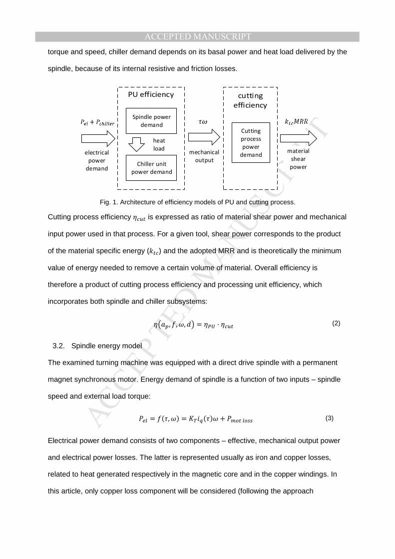
System under consideration is a PU (a spindle-brushless motor-chiller assembly), which
performs a material removal operation (Fig. 1). In this section state of the art models of
electric motor, spindle and chiller losses are used to assemble a complete model of the PU.
PU efficiency is the ratio of useful mechanical output, used for cutting, and electrical
power demand of both spindle and chiller. Whereas spindle efficiency is a function of cutting
MANUSCRIP
T
ACCEPTED
ACCEPTED MANUSCRIPTtorque and speed, chiller demand depends on its basal power and heat load delivered by the
spindle, because of its internal resistive and friction losses.
Spindle power
demandCutting
process
power
demand
Chiller unit
power demand
electrical
power
demand
mechanical
output
heat
load material
shear
power
Fig. 1. Architecture of efficiency models of PU and cutting process.
Cutting process efficiency !"# is expressed as ratio of material shear power and mechanical
input power used in that process. For a given tool, shear power corresponds to the product
of the material specific energy ($#!) and the adopted MRR and is theoretically the minimum
value of energy needed to remove a certain volume of material. Overall efficiency is
therefore a product of cutting process efficiency and processing unit efficiency, which
incorporates both spindle and chiller subsystems:
, , , = ⋅ !"# (2)
3.2. Spindle energy model
The examined turning machine was equipped with a direct drive spindle with a permanent
magnet synchronous motor. Energy demand of spindle is a function of two inputs – spindle
speed and external load torque:
&'( = (), ) = *+,-()) + &/#(/00 (3)
Electrical power demand consists of two components – effective, mechanical output power
and electrical power losses. The latter is represented usually as iron and copper losses,
related to heat generated respectively in the magnetic core and in the copper windings. In
this article, only copper loss component will be considered (following the approach
MANUSCRIP
T
ACCEPTED
ACCEPTED MANUSCRIPTpresented in (Albertelli et al., 2011) and extending the model derived in (Wójcicki et al.,
2016)):
&/#(/00 = 3(,-2 + ,32) (4)
Direct and quadrature currents are set by the adopted control strategy, where the quadrature
current ,- is a function of the required torque and the direct current is used to generate
defluxing, when a threshold velocity is exceeded:
,- = )(/ 3())*+ (5)
,3 = max40, 6 7 19 − 1;< + =|,-| (6)
Rotor dynamic equilibrium relates static and viscous friction, rotor and spindle inertia and
motor output (“load”) torque:
)(/ 3()!"##, ) = ,>?()@0 + @A + BC + )!"## (7)
3.3. Chiller energy model
The chiller is composed by the refrigeration circuit, the pump that recirculates the coolant
fluid and the electronic equipment. Considering the classic case of a constant speed pump,
its power consumption, as for the electronic system, is constant. The compressor average
power consumption is assumed to be proportional to the total heat load. The resulting
energy model is then given by a linear relationship, as in (Borgia et al., 2014a):
&!DE(('F = &G + &D(, ))H (8)
Base power consumption &G includes the power demand of the chiller pump and the part of
the compressor power that is used to remove the heat injected by the chiller pump into the
cooling circuit. The H coefficient determines the effectiveness of the cooling. It will be
assumed that all the non-productive output power of the spindle, namely friction and copper
MANUSCRIP
T
ACCEPTED
ACCEPTED MANUSCRIPTlosses, is turned into heat load for the chiller (i.e. neglecting, at steady state, heat transfer to
the machine body and the environment):
&D(, )) = ()(/ 3()!"##, ) − )) + &/#(/00()(/ 3 , ) (9)
The considered turning machine tool is equipped with a chiller that is dedicated to spindle
thermal control. Parameters of the chiller model are given in Table 1.
Table 1. Chiller model parameters Parameter name Parameter value &G 1780 [W] H 4.64 [-]
3.4. Efficiency of spindle and chiller assembly
Spindle efficiency is a ratio of the useful mechanical output power to the electrical power
demand. Torque loading due to spindle inertia is only significant in the model identification
phase, to properly characterize effective output power. Typically, during material removal,
spindle speed is constant, therefore for efficiency analysis of the cutting process the inertial
torqueterm BC can be omitted.
0EI3('(), ) = ) + BC&'((), ) JC ≡9LMN )&'((), ) (10)
Spindle motors require appropriately scaled cooling systems. For direct drive electro-
spindles, an external chiller is a common solution, whereas in case of mechanical spindles
with external motor, often air cooling is sufficient. Because these two subsystems are tightly
bonded together, a machine designer that considers efficiency of different spindle
alternatives should include energy demand of cooling system in the overall efficiency
calculation. For that reason, we extend the definition of spindle efficiency to include cooling
system as well, as formalized in Eq. (11). As the cooling system does not provide usable
output for removal process, it will only affect the denominator of the efficiency function:
(), ) = )&'((), ) + &!DE(('F(), ) (11)

MANUSCRIP
T
ACCEPTED
ACCEPTED MANUSCRIPTSuch a formulation allows direct comparison of efficiency between several types of spindle
systems, which seem to be more practical for day-to-day choices in energy aware design
and configuration.
3.5. Cutting process model
The mechanical specific energy is also known as “cutting coefficient” and it is the key
parameter for computing cutting power and torque: it depends on the tool and the work piece
material properties and it is often provided by tool suppliers to verify machine cutting
capability constraints during process planning. Let a longitudinal turning operation be
considered, where denotes the depth of cut, the feed per turn, O! the cutting speed, ω
the spindle speed and the average cut diameter. The MRR expression becomes:
= O! = 2 |ω| (12)
Then, the mechanical specific energy $! can be expressed as the ratio between cutting
power and MRR, the former being equal the tangential cutting force component multiplied by
the cutting velocity. Namely:
$! = &! = Q!O! = Q!ω2 (13)
A great amount of past scientific works dealt with cutting force modelling (e.g. (Ehmann et
al., 1997) and (Arrazola et al., 2013)) and with turning process in particular (e.g., (Dong et
al., 2009)). All of them consider both the force originated by material shear (cutting
component, proportional to chip section) and friction in the contact area between the tool
flank face and the workpiece surface (edge force component, proportional to the depth of
cut). In the simple and very widespread model proposed in (Altintas, 2012), the tangential
cutting force component assumes the following expression:
Q! = ($#' + $#!) (14)
The process coefficients appearing in Eq. (13) depend on tool properties (characteristic
angles, coating, etc.), workpiece material and lubrication condition, thus, they must be
MANUSCRIP
T
ACCEPTED
ACCEPTED MANUSCRIPTidentified and/or estimated for each tool-workpiece combination. Moreover, cutting force is
often influenced by cutting velocity, which is herein neglected. More comprehensive models
would give a more accurate force prediction, but the corresponding increased complexity
would not be compensated by significant enhancements in the results. By substituting Eq.
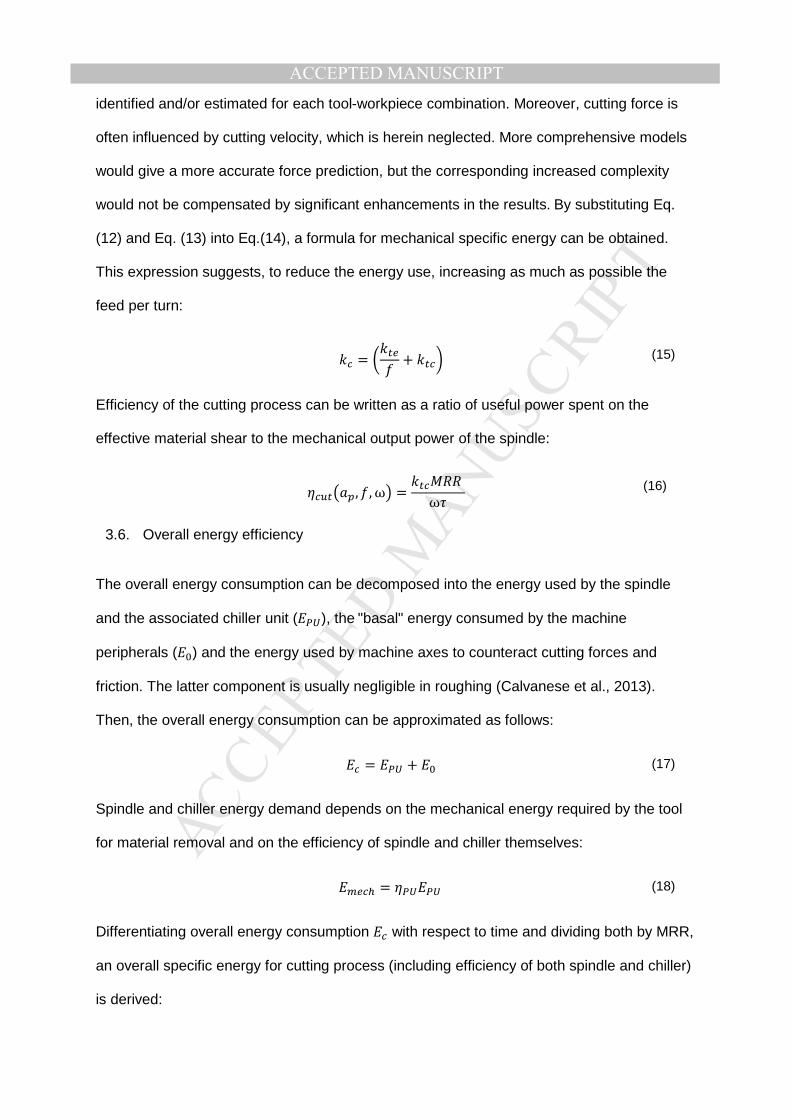
(12) and Eq. (13) into Eq.(14), a formula for mechanical specific energy can be obtained.
This expression suggests, to reduce the energy use, increasing as much as possible the
feed per turn:
$! = 7$#' + $#!; (15)
Efficiency of the cutting process can be written as a ratio of useful power spent on the
effective material shear to the mechanical output power of the spindle:
!"#, , ω = $#!ω) (16)
3.6. Overall energy efficiency
The overall energy consumption can be decomposed into the energy used by the spindle
and the associated chiller unit ( ), the"basal" energy consumed by the machine
peripherals (9) and the energy used by machine axes to counteract cutting forces and
friction. The latter component is usually negligible in roughing (Calvanese et al., 2013).
Then, the overall energy consumption can be approximated as follows:
! = + 9 (17)
Spindle and chiller energy demand depends on the mechanical energy required by the tool
for material removal and on the efficiency of spindle and chiller themselves:
'!D = (18)
Differentiating overall energy consumption ! with respect to time and dividing both by MRR,
an overall specific energy for cutting process (including efficiency of both spindle and chiller)
is derived:

MANUSCRIP
T
ACCEPTED
ACCEPTED MANUSCRIPT R! = $!() , , O! , + &9, , O! (19)
It may intuitively seem that increasing MRR through modifying process parameters , , O! can minimize energy consumption (the right term) by reducing the contribution of machine
basal power. However, it is not that obvious, considering the variable PU efficiency, which is
function of the same parameters. Also, specific cutting energy depends on the feed, and
behavior of these two terms influences the optimal choice of MRR. Workpiece diameter is
not to be considered a decision variable, as it is upfront defined by workpiece size. However,
in the energy analysis of PU we consider a range of possible diameters, as they do influence
efficiency functions and therefore may change optimal values for cutting parameters and
resulting MRR.
4. Identification of spindle and cutting process model s
4.1. Measurement setup
The experimental campaign has been performed on a two-spindle, 5-axis numerically
controlled lathe: DMG MORI SPRINT 65-3T. Tests were performed on the main spindle of
the machine. The machine is equipped with an automatic loader for 65mm bars. Parts can
also be loaded by hand or through a robotic arm, and then the maximum size depends on
the used chuck (125mm diameter with standard chuck). As mentioned before, the lathe is
equipped with PM direct-drive spindle with a dedicated chiller unit for motor temperature
control.
In terms of data acquisition, speed and motor currents (namely, direct current ,3 and
quadrature current ,-) have been sampled at 1kHz by machine numeric control.
Simultaneously, instantaneous power demand was measured by proprietary three phase
fast sampling power meter with +/-1% precision. Voltage probes and DC current sensors
LEM-HAS100 were placed at the input to spindle motor and chiller unit (Fig. 2). Current and
MANUSCRIP
T
ACCEPTED
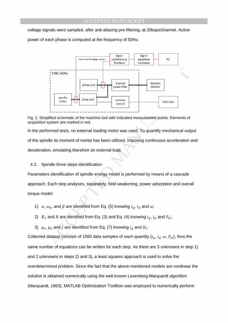
ACCEPTED MANUSCRIPTvoltage signals were sampled, after anti-aliasing pre-filtering, at 20ksps/channel. Active
power of each phase is computed at the frequency of 50Hz.
Fig. 2. Simplified schematic of the machine tool with indicated measurement points. Elements of acquisition system are marked in red.
In the performed tests, no external loading motor was used. To quantify mechanical output
of the spindle its moment of inertia has been utilized, imposing continuous acceleration and
deceleration, emulating therefore an external load.
4.2. Spindle three steps identification
Parameters identification of spindle energy model is performed by means of a cascade
approach. Each step analyses, separately, field weakening, power adsorption and overall
torque model:
1) 6, 9, and = are identified from Eq. (5) knowing ,-, ,3 and ;
2) *+ and are identified from Eq. (3) and Eq. (4) knowing ,-, ,3 and &'(; 3) @S, @A and B are identified from Eq. (7) knowing ,- and *+.
Collected dataset consists of 1560 data samples of each quantity (,-, ,3 ,, &'(), thus the
same number of equations can be written for each step. As there are 3 unknowns in step 1)
and 2 unknowns in steps 2) and 3), a least squares approach is used to solve the
overdetermined problem. Since the fact that the above-mentioned models are nonlinear the
solution is obtained numerically using the well-known Levenberg-Marquardt algorithm
(Marquardt, 1963). MATLAB Optimization Toolbox was employed to numerically perform
MANUSCRIP
T
ACCEPTED
ACCEPTED MANUSCRIPTparameter identification as prescribed in (Geletu, 2007). The identified parameters are
reported in Table 2.
Table 2. Estimated spindle model parameters Parameter name Identified value 6 8794 [A·rad/s] 9 135 [rad/s] = 0.404 [-] *+ 5.4 [Nm/A] 0.223 [Ω] @0 1.19 [Nm] @A 0.042 [Nm·s/rad] B 0.524 [kg·m2]
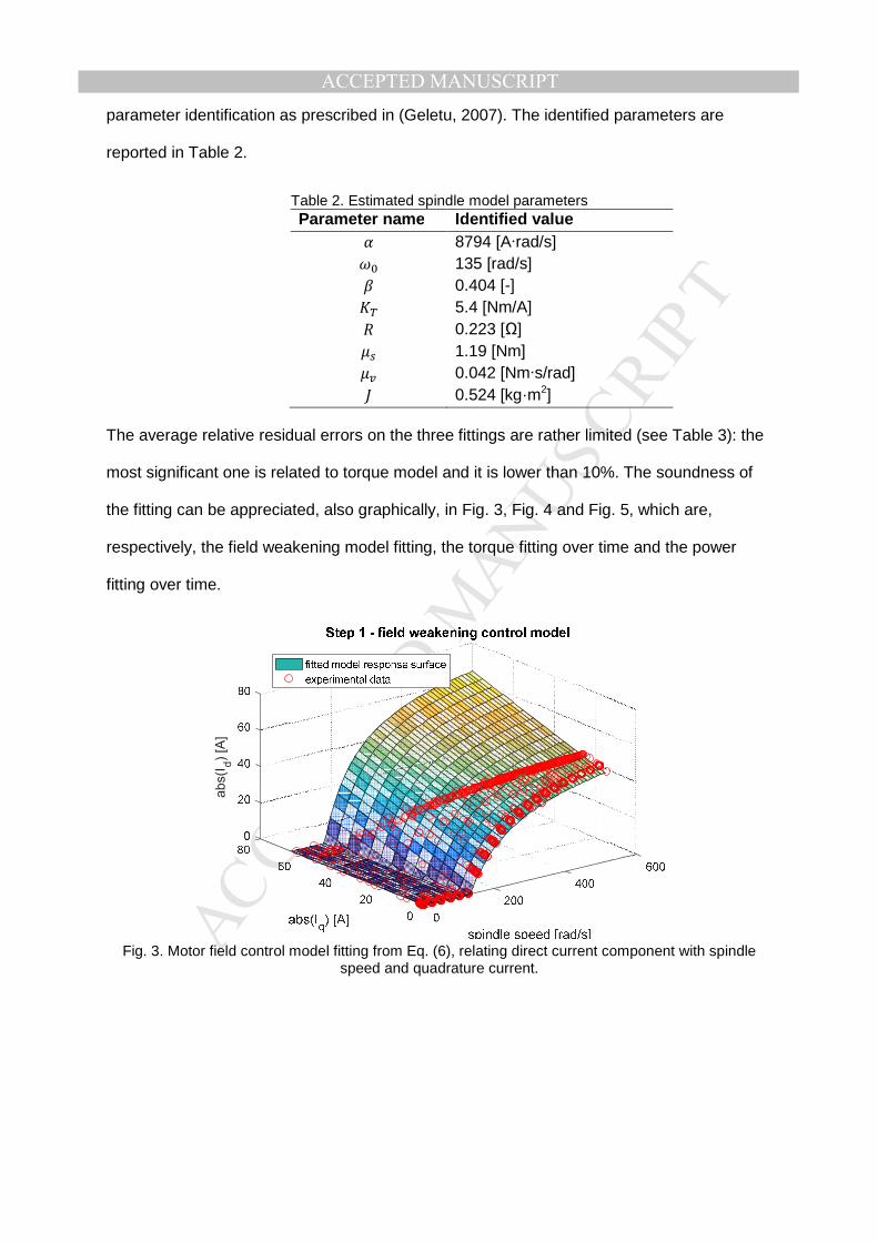
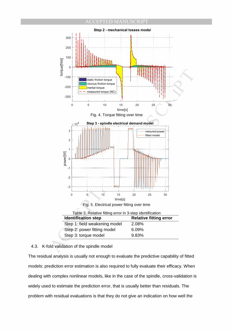
The average relative residual errors on the three fittings are rather limited (see Table 3): the
most significant one is related to torque model and it is lower than 10%. The soundness of
the fitting can be appreciated, also graphically, in Fig. 3, Fig. 4 and Fig. 5, which are,
respectively, the field weakening model fitting, the torque fitting over time and the power
fitting over time.
Fig. 3. Motor field control model fitting from Eq. (6), relating direct current component with spindle
speed and quadrature current.
abs(I
d)
[A]
MANUSCRIP
T
ACCEPTED
ACCEPTED MANUSCRIPT
Fig. 4. Torque fitting over time
Fig. 5. Electrical power fitting over time
Table 3. Relative fitting error in 3-step identification Identification step Relative fitting error Step 1: field weakening model Step 2: power fitting model Step 3: torque model
2.08% 6.09% 9.83%
4.3. K-fold validation of the spindle model
The residual analysis is usually not enough to evaluate the predictive capability of fitted
models: prediction error estimation is also required to fully evaluate their efficacy. When
dealing with complex nonlinear models, like in the case of the spindle, cross-validation is
widely used to estimate the prediction error, that is usually better than residuals. The
problem with residual evaluations is that they do not give an indication on how well the
0 5 10 15 20 25 30
time[s]
-300
-200
-100
0
100
200
300
Step 2 - mechanical losses model
static friction torque
viscous friction torque
inertial torque
measured torque (NC)
0 5 10 15 20 25 30
time[s]
-3
-2
-1
0
1
2
3
104 Step 3 - spindle electrical demand model
mesured power
fitted model
MANUSCRIP
T
ACCEPTED
ACCEPTED MANUSCRIPTmodel will behave when it is asked to make new predictions for data that have not been
used for parameters identification. Even though a leave-one out cross-validation is widely
studied, K-fold cross-validation may be preferred from a computational standpoint (Stone,
1974). The data set is divided into k subsets, and the holdout method is repeated k times.
Each time one of the k subsets is used as the test set and the other k-1 subsets form the
training set. Then, the average error across all k trials is computed.
After a randomization of the 1560 data samples, a k=10 cross-validation has been
performed for spindle model identification. Parameters deviations across the 10
identifications are presented in Table 4. Relative deviations are very limited, except for static
friction coefficient of the torque model (@S) that reaches 40%. This high error is due to the
quite negligible contribution of static friction in determining the spindle torque, which makes
this parameter almost unidentifiable.
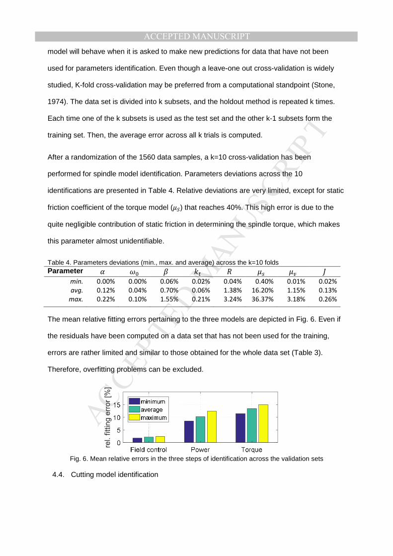
Table 4. Parameters deviations (min., max. and average) across the k=10 folds Parameter 6 9 = $# @0 @A B
min.
avg.
max.
0.00%
0.12%
0.22%
0.00%
0.04%
0.10%
0.06%
0.70%
1.55%
0.02%
0.06%
0.21%
0.04%
1.38%
3.24%
0.40%
16.20%
36.37%
0.01%
1.15%
3.18%
0.02%
0.13%
0.26%
The mean relative fitting errors pertaining to the three models are depicted in Fig. 6. Even if
the residuals have been computed on a data set that has not been used for the training,
errors are rather limited and similar to those obtained for the whole data set (Table 3).
Therefore, overfitting problems can be excluded.
Fig. 6. Mean relative errors in the three steps of identification across the validation sets
4.4. Cutting model identification
rel. f
itting e
rror
[%]
MANUSCRIP
T
ACCEPTED
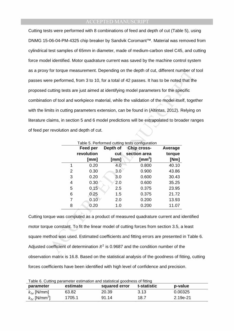
ACCEPTED MANUSCRIPTCutting tests were performed with 8 combinations of feed and depth of cut (Table 5), using
DNMG 15-06-04-PM-4325 chip breaker by Sandvik Coromant™. Material was removed from
cylindrical test samples of 65mm in diameter, made of medium-carbon steel C45, and cutting
force model identified. Motor quadrature current was saved by the machine control system
as a proxy for torque measurement. Depending on the depth of cut, different number of tool
passes were performed, from 3 to 10, for a total of 42 passes. It has to be noted that the
proposed cutting tests are just aimed at identifying model parameters for the specific
combination of tool and workpiece material, while the validation of the model itself, together
with the limits in cutting parameters extension, can be found in (Altintas, 2012). Relying on
literature claims, in section 5 and 6 model predictions will be extrapolated to broader ranges
of feed per revolution and depth of cut.
Table 5. Performed cutting tests configuration Feed per
revolution [mm]
Depth of cut
[mm]
Chip cross -section area
[mm 2]
Average torque
[Nm] 1 2 3 4 5 6 7 8
0.20 0.30 0.20 0.30 0.15 0.25 0.10 0.20
4.0 3.0 3.0 2.0 2.5 1.5 2.0 1.0
0.800 0.900 0.600 0.600 0.375 0.375 0.200 0.200
40.10 43.86 30.43 35.25 23.95 21.72 13.93 11.07
Cutting torque was computed as a product of measured quadrature current and identified
motor torque constant. To fit the linear model of cutting forces from section 3.5, a least
square method was used. Estimated coefficients and fitting errors are presented in Table 6.
Adjusted coefficient of determination 2 is 0.9687 and the condition number of the
observation matrix is 16.8. Based on the statistical analysis of the goodness of fitting, cutting
forces coefficients have been identified with high level of confidence and precision.
Table 6. Cutting parameter estimation and statistical goodness of fitting parameter esti mate squared error t-statistic p-value $#'[N/mm] $#! [N/mm2]
63.82 1705.1
20.39 91.14
3.13 18.7
0.00325 2.19e-21

MANUSCRIP
T
ACCEPTED
ACCEPTED MANUSCRIPT
4.5. Optimal cutting condition in function of Material Removal Rate and workpiece
diameter
To explore most efficient strategies for material removal with the considered PU, the problem
described by Eq. (1) has been set up: it maximizes the overall efficiency of PU and cutting
process. Maximization procedure was repeated for a range of possible MRR and cutting
diameters, which allows to explore energy performance under various production conditions.
Varying diameter serves the purpose of representing different workpiece sizing and is
important to understand how well the given PU is suited for a certain type of production
mission. Varying MRR is used to explore possibility of reducing overall performance in terms
of material removal for the sake of energy saving. Spindle continuous operating region (also
known as S1 duty cycle (Drury, 2001)) has been imposed in form of a set of constraints
limiting spindle mechanical output power, torque and speed:
Tω)(/ 3, , ω ≤ & )(/ 3, , ω ≤ ) ω ≤ ω (20)
Limits related to tool impose certain minimum and maximum values of cutting speed, feed
rate and depth of cut, for the given workpiece material:
TO!EI < O!(ω) ≤ O! EI ≤ ≤ EI ≤ ≤ (21)
Each workpiece diameter defines a certain maximum MRR which can be achieved by PU
(due to PU and tool constraints). These values are found by solving an optimization problem
in Eq. (22) for every diameter of interest and will formulate a starting point for efficiency
maximization.
WX() = max,,(, ,|) (22)
To perform numerically a multidimensional constrained nonlinear minimization for problems
formulated in Eq. (1) and Eq. (22), an active-set (Hazewinkel, 1988) method has been used.
MANUSCRIP
T
ACCEPTED
ACCEPTED MANUSCRIPT
This numerical method is capable of handling bounded parameters and multiple constraints
presented above.
5. Results
5.1. Process Unit efficiency map
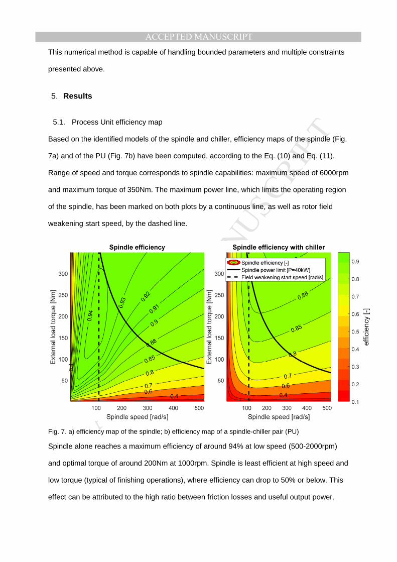
Based on the identified models of the spindle and chiller, efficiency maps of the spindle (Fig.
7a) and of the PU (Fig. 7b) have been computed, according to the Eq. (10) and Eq. (11).
Range of speed and torque corresponds to spindle capabilities: maximum speed of 6000rpm
and maximum torque of 350Nm. The maximum power line, which limits the operating region
of the spindle, has been marked on both plots by a continuous line, as well as rotor field
weakening start speed, by the dashed line.
Fig. 7. a) efficiency map of the spindle; b) efficiency map of a spindle-chiller pair (PU)
Spindle alone reaches a maximum efficiency of around 94% at low speed (500-2000rpm)
and optimal torque of around 200Nm at 1000rpm. Spindle is least efficient at high speed and
low torque (typical of finishing operations), where efficiency can drop to 50% or below. This
effect can be attributed to the high ratio between friction losses and useful output power.
MANUSCRIP
T
ACCEPTED
ACCEPTED MANUSCRIPTSimilarly, very low efficiency region occurs at high torque loading and very low speed, due to
high resistive losses (proportional to )2) and little useful output power.
Introducing the chiller into overall PU efficiency assessment significantly reshapes the map.
Maximum efficiency drops down to ~88% and occurs in a small portion of spindle operating
region: high torque at speed close to field weakening starting speed (~1000rpm). Chiller
contribution affects less high productivity regions – close to the spindle power limit, as its
basal power consumption is relatively small with respect to spindle effective output power.
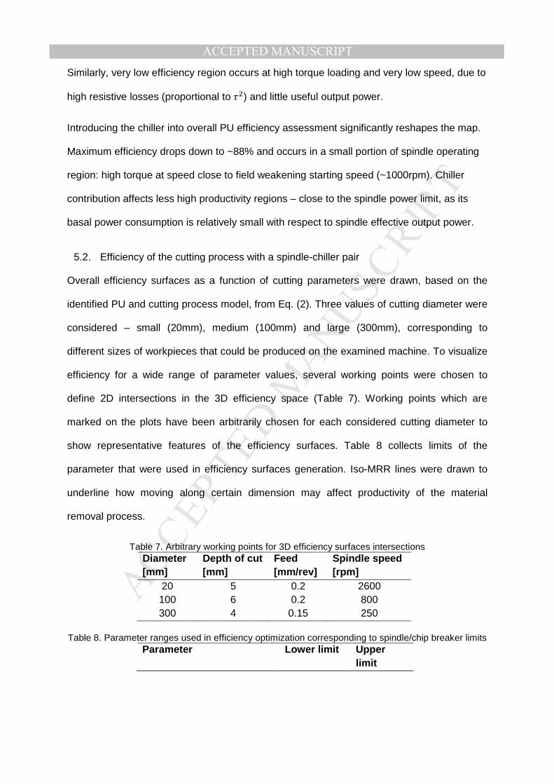
5.2. Efficiency of the cutting process with a spindle-chiller pair
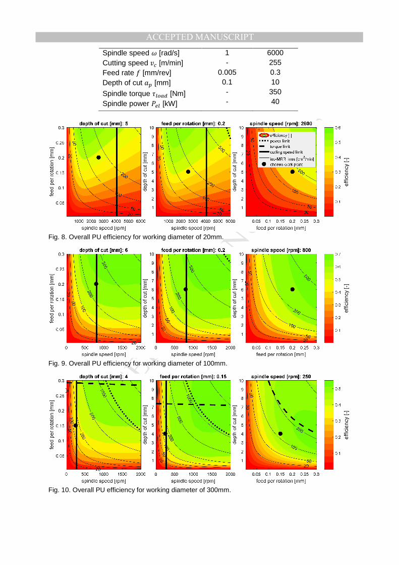
Overall efficiency surfaces as a function of cutting parameters were drawn, based on the
identified PU and cutting process model, from Eq. (2). Three values of cutting diameter were
considered – small (20mm), medium (100mm) and large (300mm), corresponding to
different sizes of workpieces that could be produced on the examined machine. To visualize
efficiency for a wide range of parameter values, several working points were chosen to
define 2D intersections in the 3D efficiency space (Table 7). Working points which are
marked on the plots have been arbitrarily chosen for each considered cutting diameter to
show representative features of the efficiency surfaces. Table 8 collects limits of the
parameter that were used in efficiency surfaces generation. Iso-MRR lines were drawn to
underline how moving along certain dimension may affect productivity of the material
removal process.
Table 7. Arbitrary working points for 3D efficiency surfaces intersections Diameter [mm]
Depth of cut [mm]
Feed [mm/rev]
Spindle speed [rpm]
20 100 300
5 6 4
0.2 0.2
0.15
2600 800 250
Table 8. Parameter ranges used in efficiency optimization corresponding to spindle/chip breaker limits Parameter Lower limit Upper
limit
MANUSCRIP
T
ACCEPTED
ACCEPTED MANUSCRIPT
Spindle speed [rad/s] Cutting speed O! [m/min] Feed rate [mm/rev] Depth of cut [mm]
Spindle torque )(/ 3 [Nm] Spindle power &'( [kW]
1 -
0.005 0.1 - -
6000 255 0.3 10
350 40
Fig. 8. Overall PU efficiency for working diameter of 20mm.
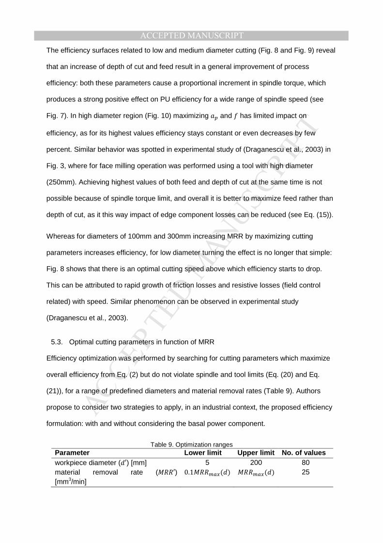
Fig. 9. Overall PU efficiency for working diameter of 100mm.
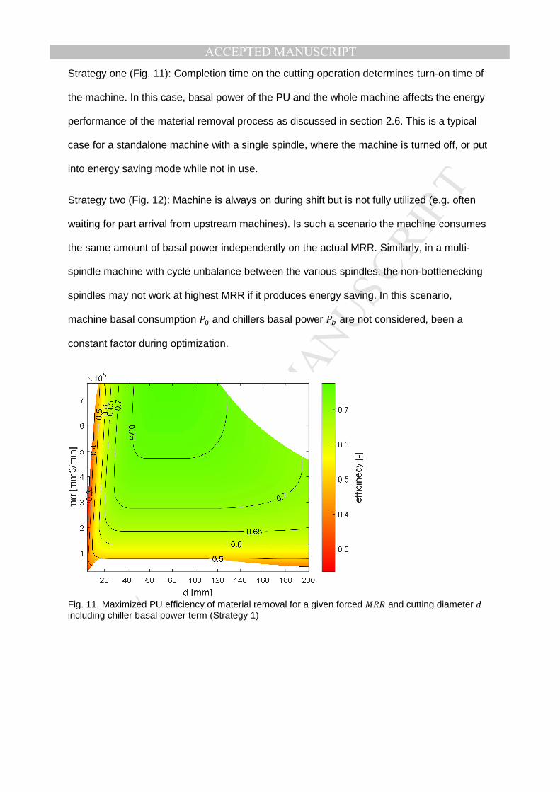
Fig. 10. Overall PU efficiency for working diameter of 300mm.
MANUSCRIP
T
ACCEPTED
ACCEPTED MANUSCRIPTThe efficiency surfaces related to low and medium diameter cutting (Fig. 8 and Fig. 9) reveal
that an increase of depth of cut and feed result in a general improvement of process
efficiency: both these parameters cause a proportional increment in spindle torque, which
produces a strong positive effect on PU efficiency for a wide range of spindle speed (see
Fig. 7). In high diameter region (Fig. 10) maximizing and has limited impact on
efficiency, as for its highest values efficiency stays constant or even decreases by few
percent. Similar behavior was spotted in experimental study of (Draganescu et al., 2003) in
Fig. 3, where for face milling operation was performed using a tool with high diameter
(250mm). Achieving highest values of both feed and depth of cut at the same time is not
possible because of spindle torque limit, and overall it is better to maximize feed rather than
depth of cut, as it this way impact of edge component losses can be reduced (see Eq. (15)).
Whereas for diameters of 100mm and 300mm increasing MRR by maximizing cutting
parameters increases efficiency, for low diameter turning the effect is no longer that simple:
Fig. 8 shows that there is an optimal cutting speed above which efficiency starts to drop.
This can be attributed to rapid growth of friction losses and resistive losses (field control
related) with speed. Similar phenomenon can be observed in experimental study
(Draganescu et al., 2003).
5.3. Optimal cutting parameters in function of MRR
Efficiency optimization was performed by searching for cutting parameters which maximize
overall efficiency from Eq. (2) but do not violate spindle and tool limits (Eq. (20) and Eq.
(21)), for a range of predefined diameters and material removal rates (Table 9). Authors
propose to consider two strategies to apply, in an industrial context, the proposed efficiency
formulation: with and without considering the basal power component.
Table 9. Optimization ranges Parameter Lower limit Upper limit No. of values workpiece diameter (′) [mm] 5 200 80 material removal rate (′) [mm3/min]
0.1 () () 25
MANUSCRIP
T
ACCEPTED
ACCEPTED MANUSCRIPT
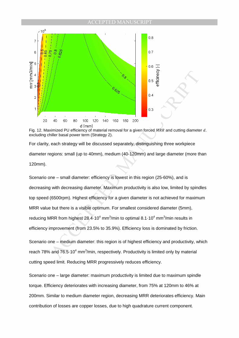
Strategy one (Fig. 11): Completion time on the cutting operation determines turn-on time of
the machine. In this case, basal power of the PU and the whole machine affects the energy
performance of the material removal process as discussed in section 2.6. This is a typical
case for a standalone machine with a single spindle, where the machine is turned off, or put
into energy saving mode while not in use.
Strategy two (Fig. 12): Machine is always on during shift but is not fully utilized (e.g. often
waiting for part arrival from upstream machines). Is such a scenario the machine consumes
the same amount of basal power independently on the actual MRR. Similarly, in a multi-
spindle machine with cycle unbalance between the various spindles, the non-bottlenecking
spindles may not work at highest MRR if it produces energy saving. In this scenario,
machine basal consumption &9 and chillers basal power &G are not considered, been a
constant factor during optimization.
Fig. 11. Maximized PU efficiency of material removal for a given forced and cutting diameter including chiller basal power term (Strategy 1)
MANUSCRIP
T
ACCEPTED
ACCEPTED MANUSCRIPT
Fig. 12. Maximized PU efficiency of material removal for a given forced and cutting diameter . excluding chiller basal power term (Strategy 2).
For clarity, each strategy will be discussed separately, distinguishing three workpiece
diameter regions: small (up to 40mm), medium (40-120mm) and large diameter (more than
120mm).
Scenario one – small diameter: efficiency is lowest in this region (25-60%), and is
decreasing with decreasing diameter. Maximum productivity is also low, limited by spindles
top speed (6500rpm). Highest efficiency for a given diameter is not achieved for maximum
MRR value but there is a visible optimum. For smallest considered diameter (5mm),
reducing MRR from highest 28.4·104 mm3/min to optimal 8.1·104 mm3/min results in
efficiency improvement (from 23.5% to 35.9%). Efficiency loss is dominated by friction.
Scenario one – medium diameter: this region is of highest efficiency and productivity, which
reach 78% and 76.5·104 mm3/min, respectively. Productivity is limited only by material
cutting speed limit. Reducing MRR progressively reduces efficiency.
Scenario one – large diameter: maximum productivity is limited due to maximum spindle
torque. Efficiency deteriorates with increasing diameter, from 75% at 120mm to 46% at
200mm. Similar to medium diameter region, decreasing MRR deteriorates efficiency. Main
contribution of losses are copper losses, due to high quadrature current component.
MANUSCRIP
T
ACCEPTED
ACCEPTED MANUSCRIPT
Scenario two – small diameter: similar to Scenario one; efficiency is low with respect to other
regions, but it increases progressively with reduction of MRR. For 5mm diameter, efficiency
boost from 24.8% to 69.8% is possible solely due to less aggressive material removal
strategy. High friction losses, due to high speed operation.
Scenario two – medium diameter: highest efficiency region. Without basal power component,
efficiency remains invariant to changing MRR, settling at the level of around 83%.
Scenario two – large diameter: efficiency drops slightly with increasing diameter but less
intensively with respect to Scenario one (from 83% to 76.7%). Slight improvement of up to
6.5% can be achieved by reducing MRR. Less intensive production requires less torque,
therefore copper losses can be reduced at smaller MRR.
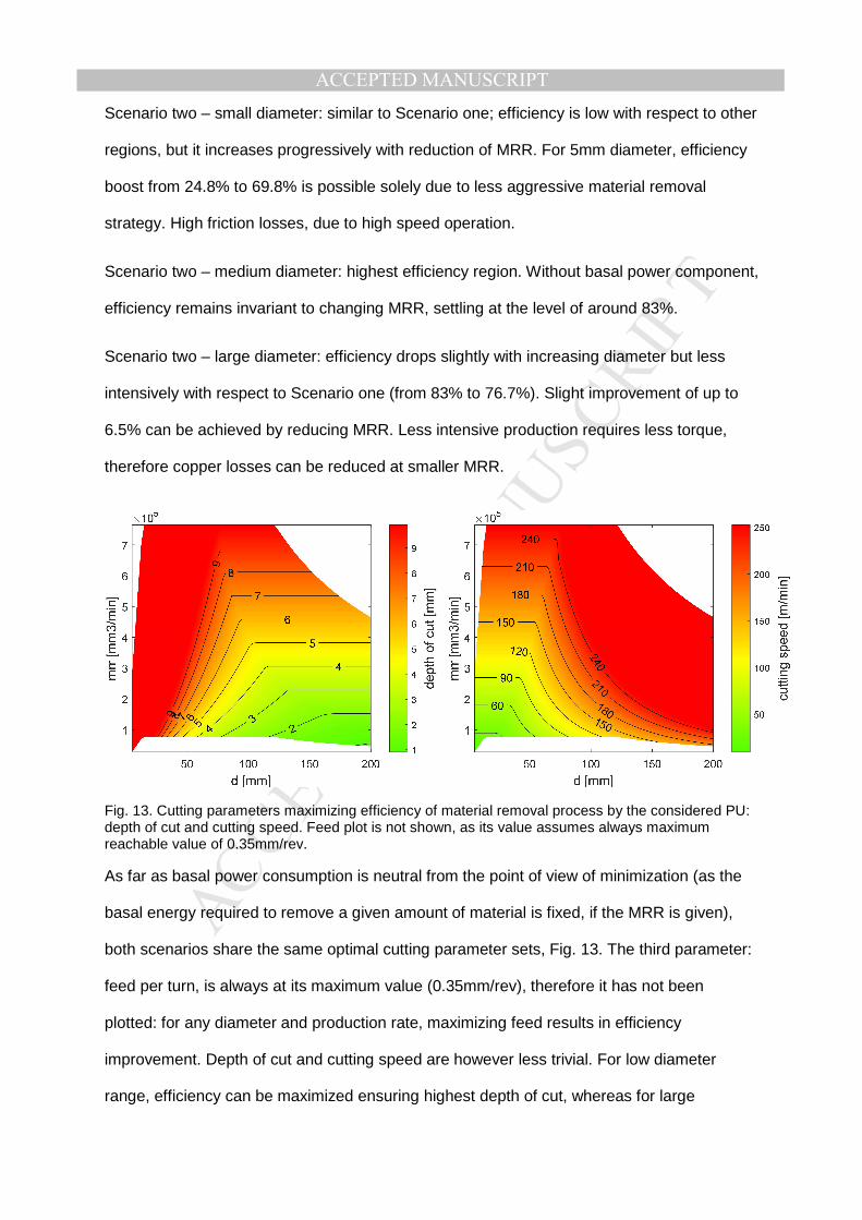
Fig. 13. Cutting parameters maximizing efficiency of material removal process by the considered PU: depth of cut and cutting speed. Feed plot is not shown, as its value assumes always maximum reachable value of 0.35mm/rev.
As far as basal power consumption is neutral from the point of view of minimization (as the
basal energy required to remove a given amount of material is fixed, if the MRR is given),
both scenarios share the same optimal cutting parameter sets, Fig. 13. The third parameter:
feed per turn, is always at its maximum value (0.35mm/rev), therefore it has not been
plotted: for any diameter and production rate, maximizing feed results in efficiency
improvement. Depth of cut and cutting speed are however less trivial. For low diameter
range, efficiency can be maximized ensuring highest depth of cut, whereas for large
MANUSCRIP
T
ACCEPTED
ACCEPTED MANUSCRIPTdiameter workpieces it is suggested to maximize cutting speed instead. Mid-range
workpieces can be manufactured with a certain optimal combination of both parameters.
Appendix B contains spindle, chiller and cutting losses breakdown as well as spindle
operating conditions for considered ranges of processing rate and workpiece diameter.
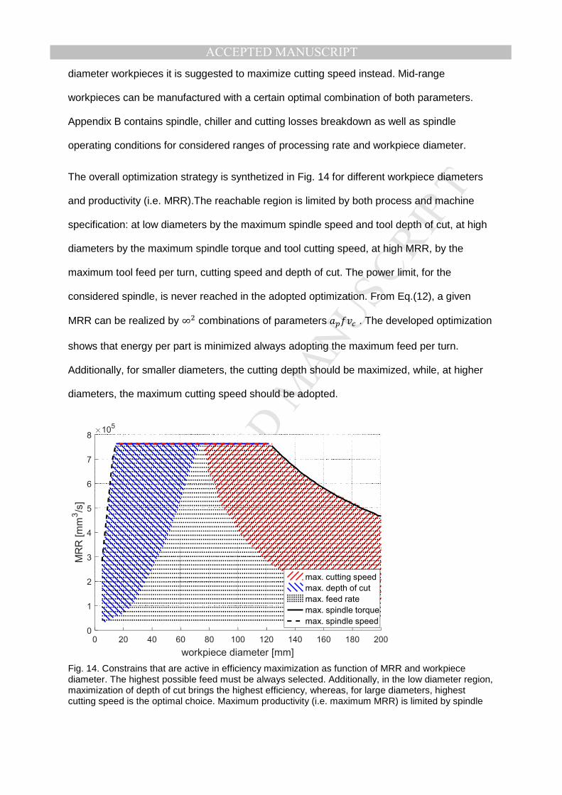
The overall optimization strategy is synthetized in Fig. 14 for different workpiece diameters
and productivity (i.e. MRR).The reachable region is limited by both process and machine
specification: at low diameters by the maximum spindle speed and tool depth of cut, at high
diameters by the maximum spindle torque and tool cutting speed, at high MRR, by the
maximum tool feed per turn, cutting speed and depth of cut. The power limit, for the
considered spindle, is never reached in the adopted optimization. From Eq.(12), a given
MRR can be realized by ∞2 combinations of parameters O! . The developed optimization
shows that energy per part is minimized always adopting the maximum feed per turn.
Additionally, for smaller diameters, the cutting depth should be maximized, while, at higher
diameters, the maximum cutting speed should be adopted.
Fig. 14. Constrains that are active in efficiency maximization as function of MRR and workpiece diameter. The highest possible feed must be always selected. Additionally, in the low diameter region, maximization of depth of cut brings the highest efficiency, whereas, for large diameters, highest cutting speed is the optimal choice. Maximum productivity (i.e. maximum MRR) is limited by spindle
0 20 40 60 80 100 120 140 160 180 200
workpiece diameter [mm]
0
1
2
3
4
5
6
7
8
MR
R [
mm
3/s
]
105
max. cutting speed
max. depth of cut
max. feed rate
max. spindle torque
max. spindle speed
MANUSCRIP
T
ACCEPTED
ACCEPTED MANUSCRIPTspeed (for low diameters), by both cutting speed and depth of cut (for intermediate diameters) and by spindle torque (for high diameters).
6. Discussion
6.1. Spindle testing method
Proposed method for spindle testing, modelling and identification allows to obtain energy
model of PM spindle and estimate its efficiency for the whole operating region. It does not
require using external loading motor and a torque sensor because continuous run-up and
run-down cycles allow sufficient loading due to inertial forces. Spindle speed and motor
currents are measured via machine NC. However, this method requires a fast sampling
power meter to compute power at least 50 times per second, for accurate model fitting.
Many commercial industrial power meters do not have these qualities. Comparing to
experimental efficiency computation with a loading motor, model based energy assessment
allows distinguishing between various losses sources, such as friction, copper losses or
even cutting losses. It gives additional insights into PU internal, non-measurable quantities
and helps to understand which design actions could be undertaken to most effectively
improve efficiency in a new generation of machines. Additionally, models support what-if
analyses on different manufacturing strategies, as it was performed by the authors in
sections 5.1 and 5.2.
6.2. Overall efficiency in cutting process
When combining PU and cutting process efficiencies, the proposed methodology can
provide counter-intuitive suggestions for energy optimization of the turning process. It has
been pointed out that, in some cases, a MRR increase impairs the overall process efficiency.
In general, the overall process efficiency is dominated by PU efficiency, therefore, when
MRR is increased by increasing spindle speed, the overall process efficiency decreases,
according to PU efficiency behavior. Nevertheless, cutting efficiency plays a significant role
when spindle speeds are low (for example when turning on large diameters, or hard-to-cut
materials like titanium alloys). In this case, an increase in the depth of cut causes an

MANUSCRIP
T
ACCEPTED
ACCEPTED MANUSCRIPTincrease in the edge components of cutting force, producing an impairment of efficiency that
is not compensated by the slight PU efficiency improvement implied by the torque increase.
6.3. Optimal cutting conditions in function of MRR and d
Efficiency maps from section 5.3 clearly indicate that efficiency of PU cannot be treated
simply as a fixed value and strongly depends on several factors. One driving factor is
workpiece size, which was modelled trough parameter d. Optimal cutting parameters change
significantly as d varies, with exception of feed rate which, when maximized, always leads to
efficiency improvements. For depth of cut and spindle speed the choice is less trivial,
however the general rule could be increasing depth of cut for small diameter ranges and
increasing cutting speed for large diameters.
Another dimension to be considered in efficiency analysis of cutting process is MRR. Here
also choice is not evident and depends also on machine working condition. In scenario 1,
overall consumption strongly depends on basal power of both chiller and remaining machine
peripherals. Potential energy saving trough reduction of MRR was only possible for small
diameter workpieces, but chosen strategy must be individually weighed against basal
consumption of the whole machine. As an obvious consequence, for machines with
significant basal consumption, it might be best to always maximize MRR. The general
tendency in machine tools is to reduce basal consumption through better selection of
machine components (chiller, hydraulic units etc.), avoiding oversizing, and using intelligent
stand-by modes. Therefore, it’s most likely that future generations of machines will exhibit
reduced basal consumption and will be able to utilize shown opportunity for energy use
reduction via lowering MRR.
Scenario 2 showed that, if in a considered production scenario, the basal power
consumption is fixed, no matter the activity of the machine, the opportunities to increase
processing efficiency arise. Staying at highest productivity in low cutting diameter region
indicates high losses due to friction as well as increased resistive losses due to PM motor
MANUSCRIP
T
ACCEPTED
ACCEPTED MANUSCRIPTfield weakening at high speed. Similarly, in the highest diameter region, cutting is performed
at the maximum torque, which contributes to ,--related resistive losses. In both cases,
applying a less aggressive processing strategy brings considerable overall energy savings.
Charts as the one represented in Fig. 14 are easily computed, for a given turning machine,
considering different workpiece materials and tool geometries (i.e. for different sets of cutting
parameters), giving useful overall indications to optimize energy efficiency in process
planning.
The analysis demonstrated that the efficiency of a spindle subsystem varies significantly with
the operating conditions: between low speed heavy operations and high speed light
machining the absolute difference in efficiency can reach 50-60%. This fact invalidates, for
production scenarios with a wide range of operating parameters, the constant spindle
efficiency hypothesis adopted in (Albertelli et al., 2016, Xiong et al., 2016) during cutting
parameters optimization.
7. Conclusions
A novel integrated approach for energy efficiency optimization in turning operations has
been presented, taking into account the strong interrelations between cutting process,
spindle with permanent magnet motor and its chiller. The model-based approach, after a
reduced set of experiments for model identification, provides general results and additional
insight, indicating where and why, in the system, energy dissipations occur.
Tests on a turning machine show the quality of the identified models and provide general
guidelines for energy optimization, considering workpieces of different diameters and various
production scenarios. On the contrary to the experimental study of (Mori et al., 2011) which
showed that efficiency increase can only be achieved by maximization of the processing
rate, it has been demonstrated that, in some cases, increasing MRR impairs the overall
process efficiency. This misalignment can be explained by the fact, that typically
experimental studies cover a limited number of operational conditions, whereas the model-

MANUSCRIP
T
ACCEPTED
ACCEPTED MANUSCRIPTbased approach to efficiency analysis, proposed in this article, covers a complete range of
operating conditions, including varying workpiece size. As much as 34.5% of saving of the
PU energy can be achieved by reducing processing speed in small diameter cutting. Given
that the examined permanent magnets spindle + chiller assembly is often used in different
machine tool types, the same approach can possibly be extended to similar processes, like
drilling and boring. The extension to milling is also achievable, where the d parameter would
represent the tool diameter, but it implies the introduction of further parameters concerned
with tool engagement and milling path; thus, a consistent energy analysis and optimization
would become more complicated.
The provided pre-optimized function, relating efficiency/energy to processing rate () and
workpiece characteristic (namely, diameter ), constitutes a building block which can be
used at machine level to support energy use prediction in production optimization. For
example, it can be used to optimize process planning for different machine tool
configurations, based on the same PU but characterized by diverse peripheral equipment:
for each possible processing rate, processing time is easily calculated and then used to
compute the corresponding energy consumption of the peripheral units, due to the basal
power consumption. The proposed approach will be used, in future developments, to
represent the relationship between cycle time and energy use while optimizing a machining
cycle on a given machining center.
8. Acknowledgements
The authors gratefully acknowledge the European Commission for its support of the Marie
Curie program through the ITN EMVeM project [Grant agreement 315967].
References
Albertelli, P., Bianchi, G., Bigliani, A., Borgia, S., Matta, A., Zanotti, E., 2011. Evaluation of the energy consumption in machine tools: a combined analytical-experimental approach, in: Proceedings of 13th International Conference on The Modern Information Technology in the Innovation Processes on the Industrial Enterprises. Trondheim, Norway.
MANUSCRIP
T
ACCEPTED
ACCEPTED MANUSCRIPTAlbertelli, P., Keshari, A., Matta, A., 2016. Energy oriented multi cutting parameter
optimization in face milling. J. Clean. Prod. 137, 1602–1618. doi:10.1016/j.jclepro.2016.04.012
Altintas, Y., 2012. Manufacturing automation: metal cutting mechanics, machine tool vibrations, and CNC design, 2nd ed. ed. Cambridge University Press, Cambridge ; New York.
Arrazola, P.J., Özel, T., Umbrello, D., Davies, M., Jawahir, I.S., 2013. Recent advances in modelling of metal machining processes. CIRP Ann. - Manuf. Technol. 62, 695–718. doi:10.1016/j.cirp.2013.05.006
Borgia, S., Albertelli, P., Bianchi, G., 2016. A simulation approach for predicting energy use during general milling operations. Int. J. Adv. Manuf. Technol. 1–15. doi:10.1007/s00170-016-9654-5
Borgia, S., Leonesio, M., Bianchi, G., Albertelli, P., 2014a. Machine Tool Energetic Simulation during General Milling Operations, in: Innovations of Sustainable Production for Green Mobility - Energy-Efficient Technologies in Production. Presented at the 3rd International Chemnitz Manufacturing Colloquium ICMC 2014, pp. 583–599.
Borgia, S., Pellegrinelli, S., Bianchi, G., Leonesio, M., 2014b. A Reduced Model for Energy Consumption Analysis in Milling. Procedia CIRP, Variety Management in Manufacturing 17, 529–534. doi:10.1016/j.procir.2014.01.105
Bort, G., Carlos, M., Leonesio, M., Bosetti, P., 2016. A model-based adaptive controller for chatter mitigation and productivity enhancement in CNC milling machines. Robot. Comput.-Integr. Manuf. 40, 34–43. doi:10.1016/j.rcim.2016.01.006
Calvanese, M.L., Albertelli, P., Matta, A., Taisch, M., 2013. Analysis of Energy Consumption in CNC Machining Centers and Determination of Optimal Cutting Conditions, in: Re-Engineering Manufacturing for Sustainability. Springer, Singapore, pp. 227–232. doi:10.1007/978-981-4451-48-2_37
Diaz, N., Helu, M., Dornfeld, D., 2010. Design and Operation Strategies for Green Machine Tool Development. Lab. Manuf. Sustain.
Diaz, N., Redelsheimer, E., Dornfeld, D., 2011. Energy Consumption Characterization and Reduction Strategies for Milling Machine Tool Use, in: Glocalized Solutions for Sustainability in Manufacturing. Springer, Berlin, Heidelberg, pp. 263–267. doi:10.1007/978-3-642-19692-8_46
Dong, Y.H., Xu, H.T., Lin, H., 2009. Simulation of Cutting Force in Turning Machining Process on CK7815 NC Lathe. Key Eng. Mater. 392–394, 64–68. doi:10.4028/www.scientific.net/KEM.392-394.64
Draganescu, F., Gheorghe, M., Doicin, C.V., 2003. Models of machine tool efficiency and specific consumed energy. J. Mater. Process. Technol. 141, 9–15. doi:10.1016/S0924-0136(02)00930-5
Drury, B., 2001. Control Techniques Drives and Controls Handbook. IET. Duflou, J.R., Sutherland, J.W., Dornfeld, D., Herrmann, C., Jeswiet, J., Kara, S., Hauschild,
M., Kellens, K., 2012. Towards Energy and Resource Efficient Manufacturing: A Processes and Systems Approach. CIRP Ann. - Manuf. Technol. 61.
Ehmann, K.F., Kapoor, S.G., DeVor, R.E., Lazoglu, I., 1997. Machining Process Modeling: A Review. J. Manuf. Sci. Eng. 119, 655. doi:10.1115/1.2836805
Geletu, A., 2007. Solving optimization problems using the matlab optimization toolbox-a tutorial. TU-Ilmenau, Fakultät für Mathematik und Naturwissenschaften.
Hazewinkel, M. (Ed.), 1988. Encyclopaedia of mathematics: an updated and annotated translation of the Soviet “Mathematical encyclopaedia.” Reidel ; Sold and distributed in the U.S.A. and Canada by Kluwer Academic Publishers, Dordrecht ; Boston : Norwell, MA, U.S.A.
Leonesio, M., Tosatti, L.M., Pellegrinelli, S., Valente, A., 2012. An Integrated Approach for Joint Process Planning and Machine Tool Dynamic Behavioral Assessment. Procedia CIRP, 1st CIRP Global Web Conference: Interdisciplinary Research in Production Engineering (CIRPE2012) 2, 38–43. doi:10.1016/j.procir.2012.05.036
MANUSCRIP
T
ACCEPTED
ACCEPTED MANUSCRIPTMarquardt, D., 1963. An Algorithm for Least-Squares Estimation of Nonlinear Parameters. J.
Soc. Ind. Appl. Math. 11, 431–441. doi:10.1137/0111030 Mori, M., Fujishima, M., Inamasu, Y., Oda, Y., 2011. A study on energy efficiency
improvement for machine tools. CIRP Ann. - Manuf. Technol. 60, 145–148. doi:10.1016/j.cirp.2011.03.099
Peng, T.V., Xu, X., 2013. A Universal Hybrid Energy Consumption Model for CNC Machining Systems, in: Nee, A.Y.C., Song, B., Ong, S.-K. (Eds.), Re-Engineering Manufacturing for Sustainability. Springer Singapore, pp. 251–256.
Stone, M., 1974. Cross-Validatory Choice and Assessment of Statistical Predictions. J. R. Stat. Soc. Ser. B Methodol. 36, 111–147. doi:10.2307/2984809
Wójcicki, J., Borgia, S., Bianchi, G., 2016. Fast Experimental Energy Characterization of a Controlled Rotary Axis. Procedia CIRP, Research and Innovation in Manufacturing: Key Enabling Technologies for the Factories of the Future - Proceedings of the 48th CIRP Conference on Manufacturing Systems 41, 323–328. doi:10.1016/j.procir.2015.10.003
Xiong, Y., Wu, J., Deng, C., Wang, Y., 2016. Machining process parameters optimization for heavy-duty CNC machine tools in sustainable manufacturing. Int. J. Adv. Manuf. Technol. 87, 1237–1246. doi:10.1007/s00170-013-4881-5
Yang, W.H., Tarng, Y.S., 1998. Design optimization of cutting parameters for turning operations based on the Taguchi method. J. Mater. Process. Technol. 84, 122–129. doi:10.1016/S0924-0136(98)00079-X
Zhou, L., Li, Jianfeng, Li, F., Meng, Q., Li, Jing, Xu, X., 2016. Energy consumption model and energy efficiency of machine tools: a comprehensive literature review. J. Clean. Prod. 112, Part 5, 3721–3734. doi:10.1016/j.jclepro.2015.05.093
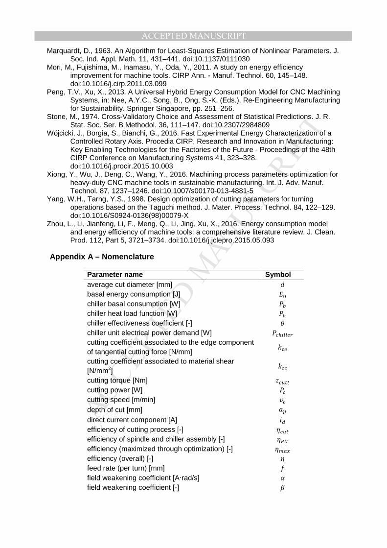
Appendix A – Nomenclature
Parameter name Symbol average cut diameter [mm] basal energy consumption [J] 9 chiller basal consumption [W] &G chiller heat load function [W] &D chiller effectiveness coefficient [-] H chiller unit electrical power demand [W] &!DE(('F cutting coefficient associated to the edge component of tangential cutting force [N/mm]
$#' cutting coefficient associated to material shear [N/mm2]
$#! cutting torque [Nm] )!"## cutting power [W] &! cutting speed [m/min] O! depth of cut [mm]
direct current component [A] ,3 efficiency of cutting process [-] !"# efficiency of spindle and chiller assembly [-] efficiency (maximized through optimization) [-] efficiency (overall) [-] feed rate (per turn) [mm] field weakening coefficient [A·rad/s] 6 field weakening coefficient [-] =
MANUSCRIP
T
ACCEPTED
ACCEPTED MANUSCRIPT
field weakening starting speed [rad/s] 9 machine basal power loss [W] &9 material removal rate [mm3/min] material removal mechanical energy [J] '!D
mechanical specific energy k\ = ]^_`` [N/mm2] $! overall specific energy [N/mm2] R! processing unit energy consumption [J] quadrature current component [A] ,-
resistive losses in the motor [W] &/#(/00 spindle motor load torque [Nm] )(/ 3 spindle external load torque (process and inertia) ) spindle motor electrical power demand [W] &'( spindle speed [rad/s] spindle speed limit [rad/s] spindle power limit [W] & spindle torque limit [Nm] ) static friction coefficient [Nm] @0 tangential component of the cutting force [N] Q! torque constant [Nm/A] *+ total spindle moment of inertia [kg·m2] B total energy consumption [J] ! viscous friction coefficient [Nm·s/rad] @A winding resistance [Ω]
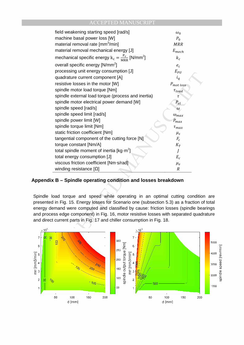
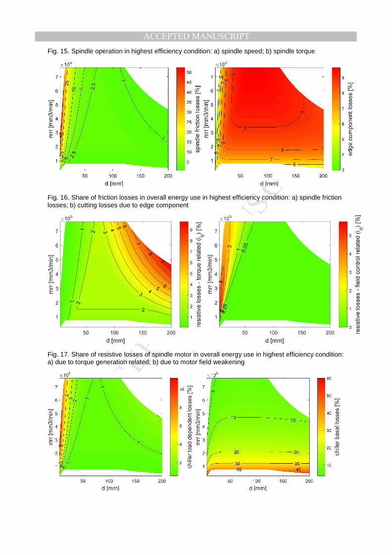
Appendix B – Spindle operating condition and losses breakdown
Spindle load torque and speed while operating in an optimal cutting condition are presented in Fig. 15. Energy losses for Scenario one (subsection 5.3) as a fraction of total energy demand were computed and classified by cause: friction losses (spindle bearings and process edge component) in Fig. 16, motor resistive losses with separated quadrature and direct current parts in Fig. 17 and chiller consumption in Fig. 18.
MANUSCRIP
T
ACCEPTED
ACCEPTED MANUSCRIPTFig. 15. Spindle operation in highest efficiency condition: a) spindle speed; b) spindle torque
Fig. 16. Share of friction losses in overall energy use in highest efficiency condition: a) spindle friction losses; b) cutting losses due to edge component
Fig. 17. Share of resistive losses of spindle motor in overall energy use in highest efficiency condition: a) due to torque generation related; b) due to motor field weakening

MANUSCRIP
T
ACCEPTED
ACCEPTED MANUSCRIPTFig. 18. Share of chiller consumption (losses) in overall energy use in highest efficiency conditions a) load dependent (varying) consumption; b) basal consumption

MANUSCRIP
T
ACCEPTED
ACCEPTED MANUSCRIPT
Highlights • Model-based energy assessment for spindle-chiller assembly is proposed
• Efficiency model is a function of workpiece diameter and material removal rate
• Reduction of material removal rate can bring energy savings in low diameter cutting
• Procedure can be automated using machine tool control and, therefore, widely adopted
View publication statsView publication stats
Copyright © 2022 FDOKUMEN