PLANING PROCESS OF MALAYSIAN TIMBERS 1. EFFECT OF VARIOUS CUTTING FACTORS ON PLANING QUALITY
12
Journal of Tropical Forest Science 3(3): 209 - 220 209 PLANING PROCESS OF MALAYSIAN TIMBERS 1. EFFECT OF VARIOUS CUTTING FACTORS ON PLANING QUALITY Roslan Ali, Forest Research Institute of Malaysia, Kepong, 52109 Kuala Lumpur Malaysia R. Amano, Toyama Forestry and Forest Products Research Centre, 4940-Kurokawashin, Kosugi-Machi, Imizu-Gun, Toyama-Ken, 939-03, Japan & Said Ahmad Forest Research Institute Malaysia, Kepong, 52109 Kuala Lumpur, Malaysia Received February 1990_________________________________________________ ROSLAN Ali, AMANO R. & SAID AHMAD. 1991. Planing process of Malaysian Timbers 1. Effect of various cutting factors on planing quality. In this study, specimens of air dried kempas (Koompassia malaccensis),keruing(Dipterocarpussp.) and mata ulat (Kokoona sp.) were planed under the combination of various conditions of cutting angle, width of knife marks and depth of cut. The surface qualities of timber under each test were visually evaluated for the appearance of chipped grain, fuzzy grain and woolly grain defects. The results show that chipped grain was the most prominent type of defect but its appearance can be minimised by reducing cutting angle, width of knife marks and depth of cut. Key words: Cutting factors - chipped grain - woolly grain - fuzzy grain Introduction Surface defects, such as chipped, fuzzy and woolly grain which appear during planing, affect the quality of planed timber. The frequency of appearance and degree of severity of these visible defects on a given batch of planed timber vary. The characteristics of the materials and the mechanics of the planing process are causes of such defects (Davis & Nelson 1954). The species variation and the sawing pattern are referred to as characteristics of materials while mechanics of the planing process include knife cutting angle, width of knife marks and depth of cut. In this study, these factors were tested and the planing quality of materials was observed and analysed. Fractional design by using orthogonal arrays procedure was adopted in designing the testing method. This method is widely accepted as an effective way to carry out experiments involving a large number of factors (Okuno 1968).
-
Upload
independent -
Category
Documents
-
view
6 -
download
0
Transcript of PLANING PROCESS OF MALAYSIAN TIMBERS 1. EFFECT OF VARIOUS CUTTING FACTORS ON PLANING QUALITY
Journal of Tropical Forest Science 3(3): 209 - 220 209
PLANING PROCESS OF MALAYSIAN TIMBERS 1.EFFECT OF VARIOUS CUTTING FACTORS ON PLANINGQUALITY
Roslan Ali,
Forest Research Institute of Malaysia, Kepong, 52109 Kuala Lumpur Malaysia
R. Amano,
Toyama Forestry and Forest Products Research Centre, 4940-Kurokawashin, Kosugi-Machi,Imizu-Gun, Toyama-Ken, 939-03, Japan
&
Said Ahmad
Forest Research Institute Malaysia, Kepong, 52109 Kuala Lumpur, Malaysia
Received February 1990_________________________________________________
ROSLAN Ali, AMANO R. & SAID AHMAD. 1991. Planing process of MalaysianTimbers 1. Effect of various cutting factors on planing quality. In this study,specimens of air dried kempas (Koompassia malaccensis),keruing(Dipterocarpussp.)and mata ulat (Kokoona sp.) were planed under the combination of variousconditions of cutting angle, width of knife marks and depth of cut. The surfacequalities of timber under each test were visually evaluated for the appearanceof chipped grain, fuzzy grain and woolly grain defects. The results show thatchipped grain was the most prominent type of defect but its appearance can beminimised by reducing cutting angle, width of knife marks and depth of cut.
Key words: Cutting factors - chipped grain - woolly grain - fuzzy grain
Introduction
Surface defects, such as chipped, fuzzy and woolly grain which appearduring planing, affect the quality of planed timber. The frequency ofappearance and degree of severity of these visible defects on a given batch ofplaned timber vary. The characteristics of the materials and the mechanics ofthe planing process are causes of such defects (Davis & Nelson 1954). Thespecies variation and the sawing pattern are referred to as characteristics ofmaterials while mechanics of the planing process include knife cutting angle,width of knife marks and depth of cut. In this study, these factors were testedand the planing quality of materials was observed and analysed. Fractionaldesign by using orthogonal arrays procedure was adopted in designing thetesting method. This method is widely accepted as an effective way to carry outexperiments involving a large number of factors (Okuno 1968).
Journal of Tropical Forest Science 3(3): 209 - 220 210
Materials and methods
The experiment to determine the effect of various cutting factors on planingquality of timber was made using a TAIHEI Bll-H 600 mm single surfaceplaner with three knives in 120mm diameter cutterhead. Four cutting factorsat three different levels were investigated, namely cutting angle, width ofknife marks, depth of cut and species of timbers. Their specificationsare as shown in Table 1.
Table 1. Choice of cutting factors
Factors
A. Cutting Angle (deg)B. Width of knife marks (mm)C. Depth of cut (mm)D. Species
1
303.01.5kempas
Level2
202.01.0keruing
3
101.30.5mata ulat
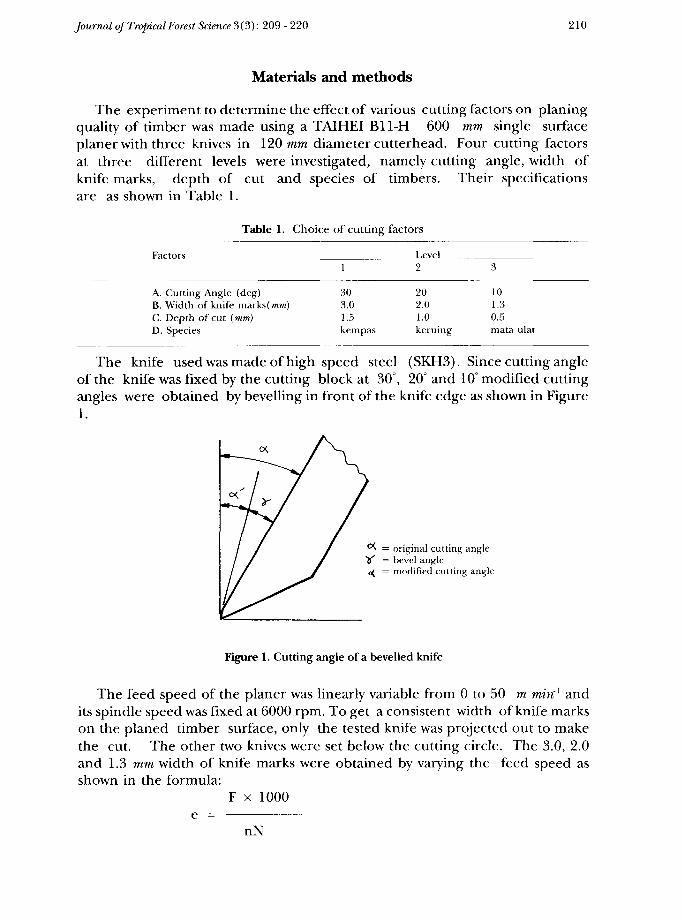
The knife used was made of high speed steel (SKH3). Since cutting angleof the knife was fixed by the cutting block at 30°, 20° and 10° modified cuttingangles were obtained by bevelling in front of the knife edge as shown in Figure1.
= original cutting angle= bevel angle= modified cutting angle
Figure 1. Cutting angle of a bevelled knife
The feed speed of the planer was linearly variable from 0 to 50 m min-1 andits spindle speed was fixed at 6000 rpm. To get a consistent width of knife markson the planed timber surface, only the tested knife was projected out to makethe cut. The other two knives were set below the cutting circle. The 3.0, 2.0and 1.3 mm width of knife marks were obtained by varying the feed speed asshown in the formula:
F x 1000e = ————— ——
nN
Journal of Tropical Forest Science 3(3): 209 - 220 211
where, e = width of knife marks (mm), F = feed speed (m min'), n = numberof effective knives and, N = spindle speed (rpm).
The 1.5, 1.0 and 0.5 mm depth of cut were obtained by varying the height ofthe feed table. The physical properties of the three air dried timber species areas given in Table 2. For each species 20 specimens for each radial and tangentialsurfaces were prepared. The specimen dimensions were 75 x 75 x 1000 mm.The feeding direction of each specimen was coincided with its fibre and longi-tudinal directions.
Table 2. Physical properties of test specimens
Species Moisture content (%) Specific gravity
KempasKeruingMata ulat
202018
0.900.820.93
The cutting conditions for the experiment were selected from the combina-tion of the various factors as previously shown in Table 1. Since there werefour factors with each having three different levels, the possible combinationsof all factors at different levels to be investigated would be 81.
But such a large number of test conditions were considered not necessarybecause only rough estimates of the effect of each factor on the planing qualityof the timber specimens were required. To get a smaller number of testconditions then that required by the complete factorial design, the assignmentof the number of the cutting factors and their interactions was made by usingthe "Table of Orthogonal Arrays". The technique to design experiment byusing orthogonal array has been discussed by Taguchi (1962). This experimentwas designed as one third fractional replicate of 34 factorial, where only27 test conditions were needed. The table shown in Table 3 was used to assistin the systematic assignment of the test conditions. List of test conditionsgenerated by the L27313 Orthogonal Arrays Table is then as shown in Table 4.For each test condition, 20 specimens of radial and tangential surfaces timberrespectively were repeatedly planed.
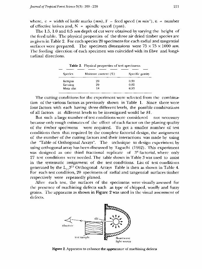
After each test, the surfaces of the specimens were visually assessed forthe presence of machining defects such as type of chipped, woolly and fuzzygrains. The apparatus as shown in Figure 2 was used in the visual assessment ofdefects.
observer
test sample
Figure 2. Apparatus to enhance the appearance of machining defects

Journal of Tropical Forest Science 3(3): 209 - 220 212
Table 3. L27313 Orthogonal Array Table
Array____
Label b b2 c c2 c b b2 c2 b2 bc c2 c c2
Factorial A B A A C A A B D e B e eeffect xx xx x x
B B C C C C
Group number 1 2
The severity of each machining defect was determined by comparing withstandard defect samples. Consistency of the assessment was ensured byallowing only one person to do the assessment. The degree of severity ofeach defect was recorded according to the rating as shown below:
0 = free1 = slight2 = moderate3 = severe
Prior to the visual assessment, 100 imaginary sections of equal dimensionswere assigned on the radial surface specimens and another 100 on thetangential surfaces specimens. Each section represents single appearance ofeach type of machining defect at any one of the four degrees of severity.
Journal of Tropical Forest Science 3(3): 209 - 220 213
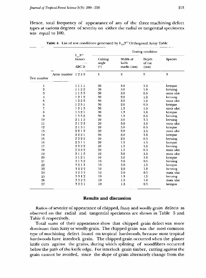
Hence, total frequency of appearance of any of the three machining defecttypes at various degrees of severity on either the radial or tangential specimenswas equal to 100.
Table 4. List of test conditions generated by L27313 Orthogonal Array Table
Testing condition
Results and discussion
Ratios of severity of appearance of chipped, fuzzy and woolly grain defects asobserved on the radial and tangential specimens are shown in Table 5 andTable 6 respectively.
Total sums of their appearance show that chipped grain defect was moredominant than fuzzy or woolly grain. The chipped grain was the most commontype of machining defect found on tropical hardwoods, because most tropicalhardwoods have interlock grain. The chipped grain occurred when the planerknife cuts against the grains, during which splitting of woodfibres occurredbelow the path of the knife edge. For interlock grain timber, cutting against thegrain cannot be avoided, since the slope of grain alternately change from the
Journal of Tropical Forest Science 3(3): 209 - 220 214
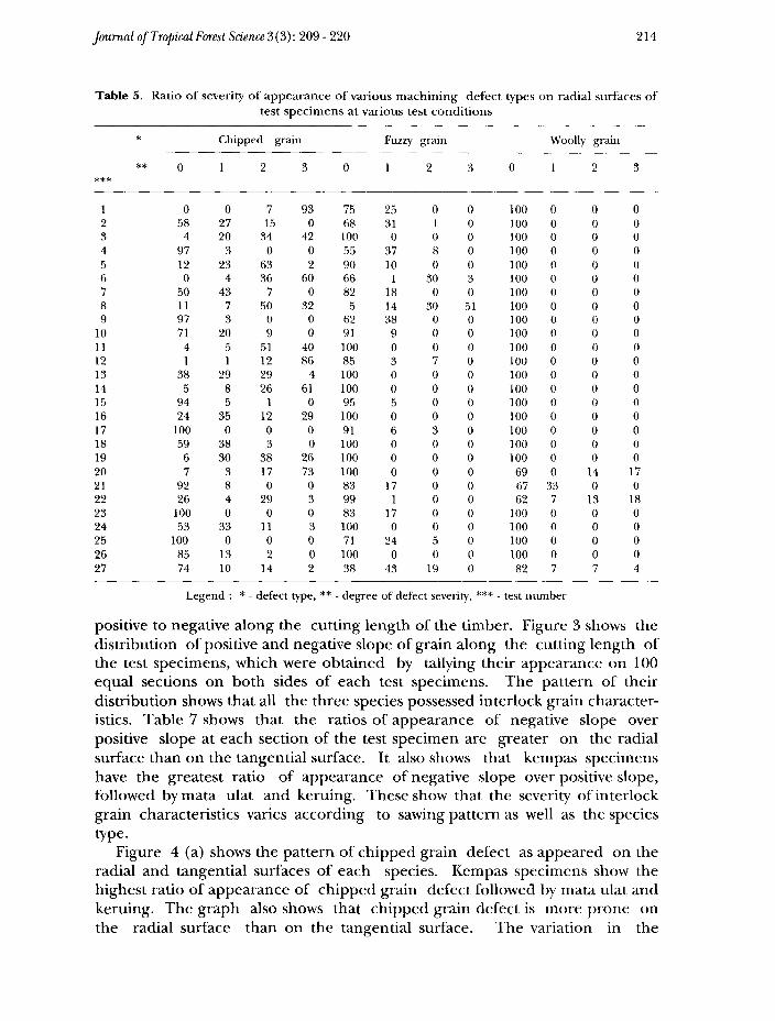
Table 5. Ratio of severity of appearance of various machining defect types on radial surfaces oftest specimens at various test conditions
Legend : * - defect type, ** - degree of defect severity, *** - test number
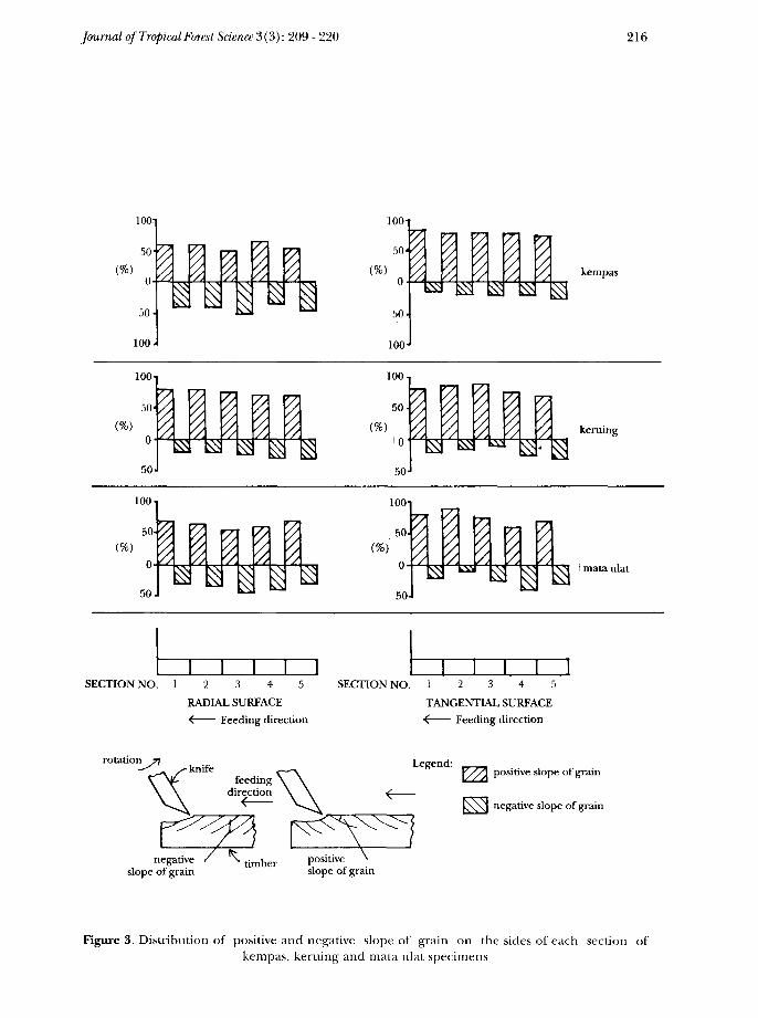
positive to negative along the cutting length of the timber. Figure 3 shows thedistribution of positive and negative slope of grain along the cutting length ofthe test specimens, which were obtained by tallying their appearance on 100equal sections on both sides of each test specimens. The pattern of theirdistribution shows that all the three species possessed interlock grain character-istics. Table 7 shows that the ratios of appearance of negative slope overpositive slope at each section of the test specimen are greater on the radialsurface than on the tangential surface. It also shows that kempas specimenshave the greatest ratio of appearance of negative slope over positive slope,followed by mata ulat and keruing. These show that the severity of interlockgrain characteristics varies according to sawing pattern as well as the speciestype-
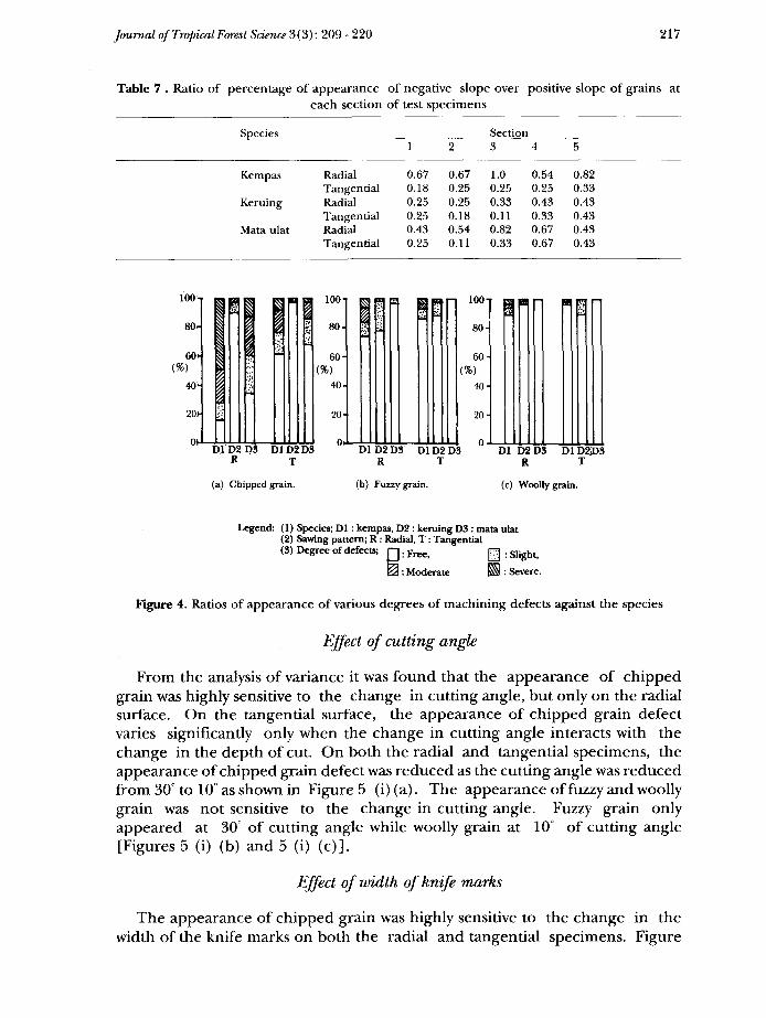
Figure 4 (a) shows the pattern of chipped grain defect as appeared on theradial and tangential surfaces of each species. Kempas specimens show thehighest ratio of appearance of chipped grain defect followed by mata ulat andkeruing. The graph also shows that chipped grain defect is more prone onthe radial surface than on the tangential surface. The variation in the
Journal of Tropical Forest Science 3(3): 209-220 215
appearance of chipped defect against the three species was very significant whentested at 99% confidence limit.
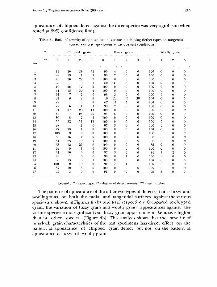
Table 6. Ratio of severity of appearance of various machining defect types on tangentialsurfaces of test specimens at various test conditions
* Chipped grain Fuzzy grain Woolly grain
Legend : * - defect type; ** - degree of defect severity, *** - test number
The patterns of appearance of the other two types of defects, that is fuzzy andwoolly grains, on both the radial and tangential surfaces against the variousspecies are shown in Figures 4 (b) and 4 (c) respectively. Compared to chippedgrain, the variation of fuzzy grain and woolly grain appearances against thevarious species is not significant but fuzzy grain appearance in kempas is higherthan in other species (Figure 4b). This analysis shows that the severity ofinterlock grain characteristics of the test specimens has direct effect on thepattern of appearance of chipped grain defect but not on the pattern ofappearance of fuzzy of woolly grain.
Journal of Tropical Forest Science 3(3): 209 - 220 216
Figure 3. Distribution of positive and negative slope of grain on the sides of each section ofkempas, keruing and mata ulat specimens
Journal of Tropical Forest Science 3 (3): 209 - 220 217
Table 7 . Ratio of percentage of appearance of negative slope over positive slope of grains ateach section of test specimens
Species Section
Legend: (1) Species; Dl : kempas, D2 : keruing D3 : mata ulat(2) Sawing pattern; R: Radial, T : Tangential(3) Degree of defects; fj. Free> ^ . s]ight
0: Moderate ES : Severe.
Figure 4. Ratios of appearance of various degrees of machining defects against the species
Effect of cutting angle
From the analysis of variance it was found that the appearance of chippedgrain was highly sensitive to the change in cutting angle, but only on the radialsurface. On the tangential surface, the appearance of chipped grain defectvaries significantly only when the change in cutting angle interacts with thechange in the depth of cut. On both the radial and tangential specimens, theappearance of chipped grain defect was reduced as the cutting angle was reducedfrom 30° to 10° as shown in Figure 5 (i) (a). The appearance of fuzzy and woollygrain was not sensitive to the change in cutting angle. Fuzzy grain onlyappeared at 30° of cutting angle while woolly grain at 10° of cutting angle[Figures 5 (i) (b) and 5 (i) (c)].
Effect of width of knife marks
The appearance of chipped grain was highly sensitive to the change in thewidth of the knife marks on both the radial and tangential specimens. Figure

Journal of Tropical Forest Science 3(3): 209 - 220 218
Cl C2 C3 Cl C2 C3R T
(a) Chipped grain.
Cl C2C3 Cl C2C3R T
(b) Fuzzy grain.
Cl C2C3 Cl C2C3R T
(c) Woolly grain.
(iii) effect of depth of cutLegend: Cl=1.5mm, C2=1.0mm, C3=0.5mm
Common legend: (1) Sawing pattern ; R : radial, T : tangential.(2) Degree of defects; Q: Free> ES: Slight,
0: Moderate, Hi: Severe
Figure 5. Relationship between ratios of appearance of various degrees of machining defectsagainst various cutting factors
Journal of Tropical Forest Science 3(3): 209 - 220 219
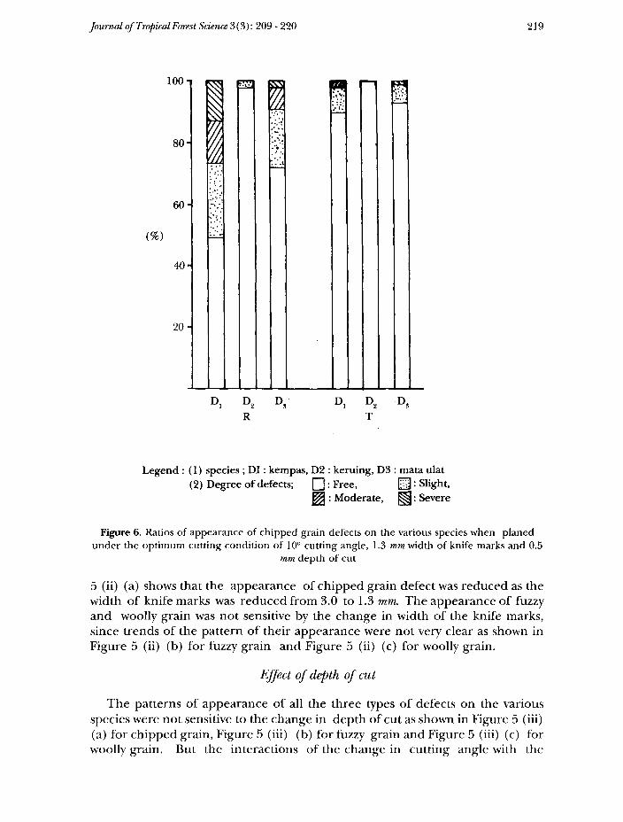
Legend : (1) species ; DI: kempas, D2 : keruing, D3 : mata ulat(2) Degree of defects; Q: Free, &: Slight,
^ : Moderate, ^: Severe
Figure 6. Ratios of appearance of chipped grain defects on the various species when planedunder the optimum cutting condition of 10° cutting angle, 1.3 mm width of knife marks and 0.5
mm depth of cut
5 (ii) (a) shows that the appearance of chipped grain defect was reduced as thewidth of knife marks was reduced from 3.0 to 1.3 mm. The appearance of fuzzyand woolly grain was not sensitive by the change in width of the knife marks,since trends of the pattern of their appearance were not very clear as shown inFigure 5 (ii) (b) for fuzzy grain and Figure 5 (ii) (c) for woolly grain.
Effect of depth of cut
The patterns of appearance of all the three types of defects on the variousspecies were not sensitive to the change in depth of cut as shown in Figure 5 (iii)(a) for chipped grain, Figure 5 (iii) (b) for fuzzy grain and Figure 5 (iii) (c) forwoolly grain. But the interactions of the change in cutting angle with the
Journal oj'TropicalForest Science3(3): 209-220 220
change in depth of cut have significant effect on the pattern of appearance ofchipped grain defect on the various species.
From this experiment, it can be seen that cutting angle, width of knife marksas well as interaction of depth of cut with cutting angles have controlling effecton the appearance of chipped grain defects in planing kempas, keruing andmata ulat, but not on the appearance of fuzzy of woolly grain. By reducingcutting angle from 30° to 10°, width of knife marks from 3.0 to 1.3 mm and depthof cut from 1.5 to 0.5 mm, the appearance of chipped grain defects can beminimised on any of the three species. The patterns of the appearance of thechipped grain defect on the various species when planed under the abovementioned optimum cutting condition are shown in Figure 6. The figure alsoshows that keruing still gives the least chipped grain defect followed by mataulat and kempas and that the tangential surface always gives less chipped graindefect than the radial surface.
Conclusions
From the above discussions, it can be concluded that chipped grain is the mostdominant type of machining defect to appear on the test specimens ascompared to fuzzy and woolly grains. Severity of interlock grain of the timbervaries according to the species as well as to the sawing pattern of the specimensand is directly related to the severity of appearance of chipped grain defects.Kempas has the highest rates of chipped grain defect followed by mata ulat andkeruing. The radial surface has higher ratio of chipped grain defect thanthe tangential surface. Ratio of appearance to chipped grain defect can becontrolled by varying the three cutting factors, such as cutting angle, width ofknife marks and depth of cut. Ratio of appearance of fuzzy and woolly grainsdefects cannot be controlled by any of the three cutting factors mentioned.Ratio of appearance of chipped grain defect is reduced as the cutting angle,width of knife marks and depth of cut are reduced.
Acknowledgement
We wish to thank K.S. Ho for his critical comments of the draft.
References
DAVIS, E.M. & NELSON, H. 1954. Machinery Tests of Wood with the Moulder. Reprint ForestProduct Research Society 561.
OKUNO, T. 1968. Design and Analysis of Experiment. Experimental Design Laboratory. NationalInstitute of Agriculture Science, Japan. 48 pp.
TAGUCHI, G. 1962. Design of Experiment. Maruzen Publishing Co., Tokyo. 547 pp.