INSTRUCTIONS FOR USE AND WARNINGS - Gefran
28
40B96 POSITION, FORCE and PRESSURE INDICATOR-INTERCEPTOR with INPUT for STRAIN-GAUGE and POTENTIOMETER Software Version 3.2x code 81652G / Edit. 07 - 04-2011 INSTRUCTIONS FOR USE AND WARNINGS GENERAL INDEX page Graphic symbol used 2 1 Preliminary instructions 2 General description 2 Alarm unit in basic version 2 Options 3 Operator interface 3 Electrical interface 3 Preliminary warnings 3 2 Installation and connection 4 Electrical power supply 4 Notes concerning electrical safety and Electromagnetic compatibility 4 Advice for correct installation for EMC 5 Instrument power supply 5 Inputs and outputs connection 5 Dimensions and cut-out 6 Installation with panel mounting 6 Warnings and instructions for mounting to the panel 6 Nominal ambient conditions 6 Electrical connections 7 Example of connection with input from Melt Sensor 9 3 Functions 10 Operator interface 10 General operating notes 11 Navigating through the instrument menu 12 page 4 Configuration and programming 13 Configuration/Programming 14 Application notes 21 Eb function 21 HOLD function 21 FLASH function 21 Alarms 21 Filter 22 UCAL strain-gauge calibration 22 Virtual Instrument 23 5 Technical specifications 24 6 Maintenance 25 Cleaning the instrument 25 Repairs 25 Checking the jumpers 25 Troubleshooting Guide 26 7 Technical-Commercial information 26 Order code 26 Accessories RS232/TTL interface for Gefran Instrument configuration 27 Appendix 27 The contents of each section are summarized immediately following the section heading 1 81652G_MHW_40B96_04-2011_ENG
-
Upload
khangminh22 -
Category
Documents
-
view
2 -
download
0
Transcript of INSTRUCTIONS FOR USE AND WARNINGS - Gefran

40B96 POSITION, FORCE and PRESSURE INDICATOR-INTERCEPTOR with INPUT for STRAIN-GAUGE and POTENTIOMETER
Software Version 3.2x
code 81652G / Edit. 07 - 04-2011
INSTRUCTIONS FOR USE AND WARNINGS
GENERAL INDEX page Graphic symbol used 21 Preliminary instructions 2 General description 2 Alarm unit in basic version 2 Options 3 Operator interface 3 Electrical interface 3 Preliminary warnings 3
2 Installation and connection 4 Electrical power supply 4 Notes concerning electrical safety and Electromagnetic compatibility 4 Advice for correct installation for EMC 5 Instrument power supply 5 Inputs and outputs connection 5 Dimensions and cut-out 6 Installation with panel mounting 6 Warnings and instructions for mounting to the panel 6 Nominal ambient conditions 6 Electrical connections 7 Example of connection with input from Melt Sensor 9
3 Functions 10 Operator interface 10 General operating notes 11 Navigating through the instrument menu 12
page4 Configuration and programming 13 Configuration/Programming 14
Application notes 21 Eb function 21 HOLD function 21 FLASH function 21 Alarms 21 Filter 22 UCAL strain-gauge calibration 22 Virtual Instrument 23
5 Technical specifications 24
6 Maintenance 25 Cleaning the instrument 25 Repairs 25 Checking the jumpers 25 Troubleshooting Guide 26
7 Technical-Commercial information 26 Order code 26
Accessories RS232/TTL interface for Gefran Instrument configuration 27
Appendix 27
The contents of each section are summarized immediately following the section heading
181652G_MHW_40B96_04-2011_ENG

Graphic symbols used
To distinguish between the type and importance of the information provided in these instructions for use, graphic symbols have been used as a reference to make interpreting the information clearer.
Indicates the contents of the various manual sections, the general warnings, notes, and other points to which the reader’s attention should be drawn.
Indicates a particularly delicate situation that could affect the safety and correct working ope-ration of the instrument, or a rule that must be strictly observed to avoid dangerous situations
Indicates a condition of risk for the safety of the user, due to the presence of dangerous voltages at the points shown
Indicates a suggestion based on the expe-rience of the GEFRAN Technical Staff, which could prove especially useful under given
circumstances
Indicates a reference to Detailed Technical Documents available on the GEFRAN web site www.gefran.com
In the programming and configuration flows for the controller, indicates all the parame-ters that can be set in the configuration.
AL.2
1 • PRELIMINARY INSTRUCTIONS This section contains information and warnings
of a general nature which should be read before proceeding with instrument installation, configuration and use.
General DescriptionGEFRAN series 40B96 digital controllers have been designed for temperature control in any applications involving heating or cooling processes. They represent an exclusive combination of performance, reliability and applicational flexibility. In particular, this new line of Gefran temperature controllers is the ideal solution for application in sectors where performance and service continuity are important, including:• extrusion lines• presses for rubber • test benches• honing machines• processing plant for the food industry• weighing• manostat• positioner• motopotentiometer• etc.
The 40B96 series interceptors are made on an extremely versatile hardware and software platform, that allows the most suitable I/O composition for the plant to be chosen from a series of options, up to a maximum of:- variable input - digital input
- transmitter power supply - analog retransmission output - a maximum of 4 outputs - RS485 interface
Alarm unit in basic version- 1 input that allows connection of most popular sensor types• potentiometer with 100 ohm minimum resistance • load cells with autoranging sensitivity from 1.5 to 3.3 mV/V• strain-gauge pressure probesaccuracy better than 0.2% f.s.
- output for sensor or transmitter power supply • 1.2 Vdc for potentiometer• 5Vdc, 10Vdc max 120 mA for strain-gauge • 15Vdc, 24Vdc max 50 mA for transmitter- 2 standard outputs: one relay type and the other relay/logic, or1 triac output- display functions with setting of engineering scale and possible linearization, settable decimal point position, sampling time from 30 to 120 msec - trip point values can be set in a range differing from scale limits, different modalities, hysteresis settable in scale points or time, with or without latch. - service serial line for configuration via PC (Winstrum)
2 81652G_MHW_40B96_04-2011_ENG
Options- 3rd relay output - 4th relay output (alternative to analog retransmission output)- 1 digital input - 1 analog retransmission output in current 0/4…20mA or voltage 0…10V (alternative to 4th relay output)- RS485 optically isolated serial interface
Operator InterfaceAll the operator interface devices are concentra-ted on the controller faceplate, suitably protected by a membrane in Lexan that guarantees IP65 level protection.• 3 buttons to be used for manual configuration/selec-tion • 1 red five-digit displays (Process Variable)• 4 red LEDs for status indication of same number of relay/logic outputs
Electrical InterfaceAll connection terminals (power supply, inputs, outputs, options) are grouped together on the back of the instru-ment.For technical specifications and performance details refer to Section 5 “Technical Specifications”.
Preliminary WarningsThe following preliminary warnings should be read before installing and using the series 40B
96 interceptor . This will allow the controller to be put into service more quickly and will avoid certain problems which may mistakenly be interpreted as malfunctions or limitations of the interceptor.• Immediately after unpacking the controller, make a note of the order code and the other identification data given on the label affixed to the outside of the container and copy them to the table below.These details must always be kept close at hand and referred to the personnel involved in the event of help from Gefran Customer Service Assistance.
• Check also that the controller is complete and has not been damaged at all during transit, and that the package contains not only the instrument and these Instructions for Use, but also the two brackets for fixing to the panel and the dust protection seal - see: Installation with Panel Fixing in Section 2.
Any inconsistencies, omissions or evident signs of damage should be reported immediately to your Gefran sales agent.• Check that the order code corresponds with the configuration requested for the application the controller is needed for, referring to Section 7: “Technical - Commercial Information”. • No. and Type of Inputs/Outputs available • Presence of the necessary options and accessories • Mains voltage supplyEx: 40B – 24 – RR – 00 – 1 – 2 – 1Model 40B96 alarm unit 24 V output for transmitter power supply Output 1 - Relay; Output 2 - Relay, Output 3 - noneDigital Input - no analog retransmissionRS485 Digital CommunicationPower supply 100...240Vac/dc
• Before installing the series 40B96 instrument on the control panel of the machine or host system, refer to the paragraph “Dimensions and Cut-out” in Section 2 “Installation and Connection”.• Where configuration by PC is provided for, make sure the interface RS232 cable is available and the CD- ROM containing the WINSTRUM software. For the order code refer to Section 7 “Technical - Commercial Information”..
Users and/or system integrators who wish to know more about the concepts of serial communication between
standard PC and/or Gefran Industrial PC and Gefran Programmable Instruments , can access the various technical reference Documents in
Adobe Acrobat format available in the Download section of the Gefran Web Site www.gefran.com including:
• Serial Communication • MODBus Protocol In the same Download section of the Gefran Web Site www.gefran.com the reference manual is available in Adobe Acrobat format. In the event of presumed instrument malfunction, before contacting Gefran Technical Service Assistance, refer to the Troubleshooting Guide given in Section 6 “Maintenance”, and if necessary refer to the F.A.Q. Section (Frequently Asked Questions) on the Gefran Web Site www.gefran.com
SN: ......................... (Serial no.)CODE: ......................... (Finished product code)TyPE: ......................... (Order Code)SUPPLy: ......................... (Type of electrical power supply)VERS: ......................... (Software version)
381652G_MHW_40B96_04-2011_ENG
2 • INSTALLATION AND CONNECTIONThis section contains the instructions necessary for correct installation of the 40B96 instrument into the machine control panel or the host system
and for correct connection of the interceptor power supply, inputs, outputs and interfaces.
Before proceeding with installation read the following warnings carefully! Remember that lack of observation of these warnings could lead to problems of electrical
safety and electromagnetic compatibility, as well as invalidating the warranty.
Electrical power supply
• the instrument is NOT equipped with an On/Off switch: the user must provide a two-phase disconnecting switch that conforms to the required safety standards (CE mar-king), to cut off the power supply upstream of the instru-ment.The switch must be located in the immediate vicinity of the instrument and must be within easy reach of the operator.One switch may control more than one instrument.• if the instrument is connected to NOT isolated electri-cal equipment (e.g. thermocouples), the earth connec-tion must be made with a specific conductor to prevent the connection itself from coming directly through the machine structure.
• if the instrument is used in applications with risk of damage to persons, machinery or materials, it is essen-tial to connect it up to auxiliary alarm equipment.It is advisable to make sure that alarm signals are also triggered during normal operation.The instrument must NOT be installed in flammable or explosive environments; it may be connected to equipment operating in such atmospheres only by means of appropriate and adequate types of interface, conforming to the applicable safety standards.
Notes Concerning Electrical Safety and Electromagnetic Compatibility:
CE MARKING:The instrument conforms to the European Directives 2004/108/CE and 2006/95/CE with reference to the generic standards: EN 61000-6-2 (immunity in industrial environment) EN 61000-6-3 (emission in residential envi-ronment) EN 61010-1 (safety).Series 40B96 interceptor are mainly designed to opera-te in industrial environments, installed on the switchbo-ards or control panels of productive process machi-nes or plants.As regards electromagnetic compatibility, the strictest generic standards have been adopted, as indicated in the table below.
EMC conformity has been tested with the following connections.
Function Cable type LengthPower supply cable 1mm2 1mRelay output cables 1mm2 3.5mSerial connection wire 0,35mm2 3.5mInput 1mm2 3m
4 81652G_MHW_40B96_04-2011_ENG
Generic standards, emission standard for residential commer-cial and light industrial environmentsEmission enclosureEmission AC mainsRadiated emission
EN 61000-6-3
EN 61000-6-3 EN 61000-6-3EN 61326 CISPR 16-2
Gruppo1 Classe BGruppo1 Classe BClasse B
EMC Emission
EMC Immunity
Generic standards, immunity standard for industrial envi-ronmentsImmunity ESD
Immunity RF interference
Immunity conducted disturbance
Immunity burst
Immunity pulse
Immunity Magnetic fieldsVoltage dips, short interruptions and voltage immunity tests
EN 61000-6-2
EN 61000-4-2
EN 61000-4-3 /A1
EN 61000-4-6
EN 61000-4-4
EN 61000-4-5
EN 61000-4-8EN 61000-4-11
4 kV contact discharge level 28 kV air discharge level 310 V/m amplitude modulated 80 MHz-1 GHz10 V/m amplitude modulated 1.4 GHz-2 GHz10 V/m amplitude modulated 0.15 MHz-80 MHz (level 3)2 kV power line (level 3)2 kV I/O signal line (level 4)Power line-line 1 kV (level 2)Power line-earth 2 kV (level 3)Signal line-earth 1 kV (level 2)100 A/m (level 5)100%U, 70%U, 40%U,
LVD SafetySafety requirements for electrical equipment for measurement, control and laboratory use
EN 61010-1
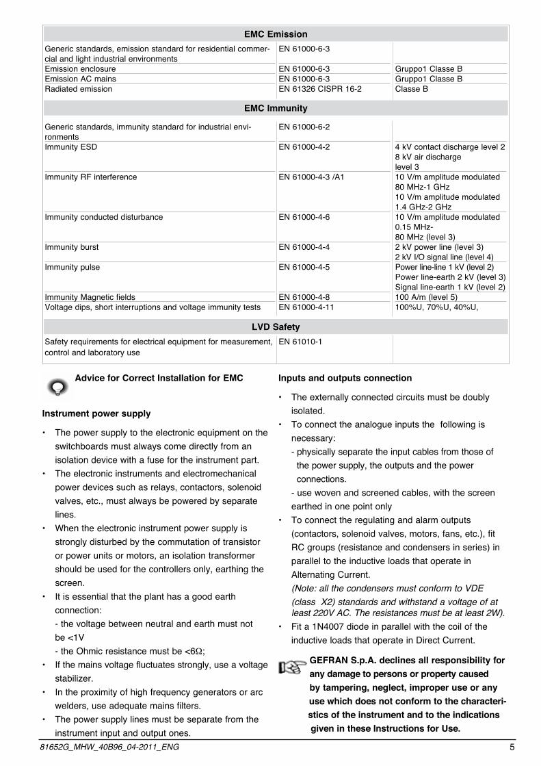
Advice for Correct Installation for EMC
Instrument power supply
• The power supply to the electronic equipment on the switchboards must always come directly from an isolation device with a fuse for the instrument part.• The electronic instruments and electromechanical power devices such as relays, contactors, solenoid valves, etc., must always be powered by separate lines.• When the electronic instrument power supply is strongly disturbed by the commutation of transistor or power units or motors, an isolation transformer should be used for the controllers only, earthing the screen.• It is essential that the plant has a good earth connection: - the voltage between neutral and earth must not be <1V - the Ohmic resistance must be <6W;• If the mains voltage fluctuates strongly, use a voltage stabilizer.• In the proximity of high frequency generators or arc welders, use adequate mains filters.• The power supply lines must be separate from the instrument input and output ones.
Inputs and outputs connection
• The externally connected circuits must be doubly isolated.• To connect the analogue inputs the following is necessary: - physically separate the input cables from those of the power supply, the outputs and the power connections. - use woven and screened cables, with the screen earthed in one point only• To connect the regulating and alarm outputs (contactors, solenoid valves, motors, fans, etc.), fit RC groups (resistance and condensers in series) in parallel to the inductive loads that operate in Alternating Current. (Note: all the condensers must conform to VDE (class X2) standards and withstand a voltage of at least 220V AC. The resistances must be at least 2W).• Fit a 1N4007 diode in parallel with the coil of the inductive loads that operate in Direct Current.
GEFRAN S.p.A. declines all responsibility for any damage to persons or property causedby tampering, neglect, improper use or any
use which does not conform to the characteri- stics of the instrument and to the indications given in these Instructions for Use.
581652G_MHW_40B96_04-2011_ENG

Dimensions and cut-out
Installation with panel mounting
As well as the actual instrument and these instructions for use, the package also contains:
• 2 panel fixing brackets (A) • 1 protective seal against dust and water spray (B)
Fit the instrument to the panel as shown in the figure.
Warnings and instructions for mounting to the panel
Instructions for installation category II, pollution level 2, double isolation.
• only for low power supply: supply from Class 2 or low voltage limited energy source.• the power supply lines must be separate from the controller input and output ones• group the instruments together keeping them separate from the powered part of the relay• do not install high-power remote switches, contactors, relays, thyristor power units (especially the “phase angle” type), motors, etc. in the same switchboard• avoid dust, humidity, corrosive gasses and heat sources• do not block the ventilation holes: the working temperature must be between 0...50°C • surrounding air: 50°C • use 60/75°C copper (Cu) conductor only, wire size range 2x No 22 - 14AWG, Solid/Stranded • use terminal tightening torque 0.5N m
Nominal ambient conditions
Before supplying the Controller with power, make sure that the mains voltage is the same as that shown in the last number of the order code.
Ex: 40B96-5 – xx – xx – xx – x – x – 1 = 100..240Vac/dc 40B96-5 – xx – xx – xx – x – x – 0 = 11..27Vac/dc
A
B
A
B
Altitude Up to 2000mWorking/storage 0..50°C/-20...70°CtemperatureNon condensing 20...85%relative humidity
105
10
108
96
48
44,5
92
70
115
A
6 81652G_MHW_40B96_04-2011_ENG

Electrical Connections
PWR
Outputs Out1 - Out2 - Out3
Inputs
Serial line
Digital inputs
Output Out4 /Retransm. Output
Always make the connections using cable types suitable for the voltage and current limits given in Section 5 - Technical Specifications. If the instrument has faston terminals these must be protected and isolated.
If it has screw terminals, the wires must be attached, at least in pairs
Power Supply
Inputs
Standard: 100...240Vac/dc ±10% Optional: 11...27Vac7dc ±10% Power: max 8VA; 50/60 Hz
Potentiometer input 4-wires strain gauge input
~~PWR
781652G_MHW_40B96_04-2011_ENG
1,2V
- IN
+ IN
Pot
+
- IN
+ IN
+ E
+ -
- E
strain-gauge
24V
- IN
+ IN
+
-
-
++S-S
20mA input transmitter only for model 40B96-5-24-...Terminal 2 (IN -) can be connected to terminal 4 in case of 3-wire transmitter0-20mA.Configure probe type: tP=0It needs of re-calibration 0-20mA (U.C=2)
24V
- IN
+ IN
+
-
+S
-S
4-20mA. 2 wires transmitter inputConfigureprobe type: tP=0
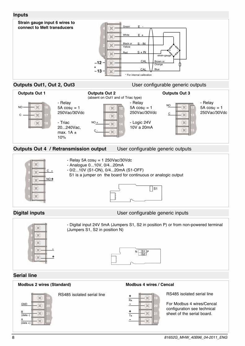
InputsStrain gauge input 6 wires to connect to Melt transducers
Outputs Out1, Out 2, Out3 User configurable generic outputs
C
NO- Relay5A cosj = 1250Vac/30Vdc
- Triac 20...240Vac, max. 1A ± 10%
Outputs Out 1
C -
NO +
- Relay5A cosj = 1 250Vac/30Vdc
- Logic 24V 10V a 20mA
Outputs Out 2(absent on Out1 and of Triac type)
C
NO
Outputs Out 3
Outputs Out 4 / Retransmission output User configurable generic outputs
-
+
C
NO
- Relay 5A cosj = 1 250Vac/30Vdc - Analogue 0...10V, 0/4...20mA- 0/2...10V (S1-ON), 0/4...20mA (S1-OFF) S1 is a jumper on the board for continuous or analogic output
Digital inputs User configurable generic inputs
-
+
- Digital input 24V 5mA (Jumpers S1, S2 in position P) or from non-powered terminal (Jumpers S1, S2 in position N)
Serial line
(data +)
(data -)
GND
B
A
RS485 isolated serial line
Modbus 2 wires (Standard)
Tx+
Rx+ RS485 isolated serial line
For Modbus 4 wires/Cencal configuration see technical sheet of the serial board.
Modbus 4 wires / Cencal
+ -+ INS
- INS
E +
E -
12
13*CAL
CAL
strain-gauge
Brown or Orange
Green
White
Black or yellow
Red
Blue
* For internal calibration
- Relay5A cosj = 1 250Vac/30Vdc
S1
S1S2
N P
8 81652G_MHW_40B96_04-2011_ENG

Example of Connection with Input from Melt Sensor Analog retransmission of pressure value, logic and relay alarm outputs
981652G_MHW_40B96_04-2011_ENG
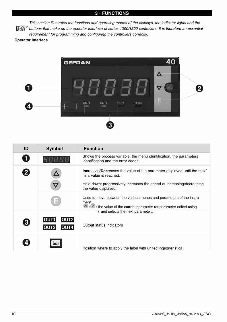
Shows the process variable, the menu identification, the parameters identification and the error codes
Increases/Decreases the value of the parameter displayed until the max/min. value is reached.
Held down: progressively increases the speed of increasing/decreasing the value displayed.
Used to move between the various menus and parameters of the instru-ment. Confirms the value of the current parameter (or parameter edited using ) and selects the next parameter..
Output status indicators
Position where to apply the label with united ingegneristica
3 • FUNCTIONS
This section illustrates the functions and operating modes of the displays, the indicator lights and the buttons that make up the operator interface of series 1200/1300 controllers. It is therefore an essential requirement for programming and configuring the controllers correctly.
Operator Interface
ID Symbol Function
10 81652G_MHW_40B96_04-2011_ENG

General Operating Notes
• Immediately after switching on the instrument carries out a self-diagnostic test. During the test, all the display segments and the 4 indicator lights will flash, when finished, enters normal work mode (Level 1) and displays variable value.
Displays the value of the Process Variable.
• By pressing briefly it is possible to see in sequence (and if necessary edit) the significant values that condition the way the instrument works in Level 1 (Thresholds of interception)
• Keeping pressed down for 3 seconds we enter the Programming/Configuration menu - see Navigation in the instrument Menus for further details..
In the event of errors during normal working:
LO process variable < min. scale limit (param. LS in the IN)
KI process variable > max. scale limit (param. KS in the IN)
BR broken probe or input values higher than maximum limits
ER input values lower than minimum limits
EB Probe power supply failure (function enabled via parameters ( (.I. on IN menu)
To solve the problem, refer to the paragraph: Troubleshooting Guide in Section 6 Maintenance
Switching on and using the intrument
Self-diagnostics
Normal Working - Level 1
Errors while working
399
1181652G_MHW_40B96_04-2011_ENG

Navigating through the instrument Menu
Keep pressed down to scroll through the menus in sequence and release it when the required menu appears.Press to access the parameters of the selected menu.
Level 1 Display Menu
39.9 I F
O.I
o . 2
o . 3
o .4
Alarm point 1(scale points)
Alarm point 2(scale points)
Alarm point 3(scale points)
Alarm point 4(scale points)
3 sec.
Information display
Jumper S4 on soldered side of CPU boardSee Section 6 - Maintenance
F(
OK
S4 ON ?NO
S R
nI
v0
AP
OK
PAS=99 ?NO
rP
Ln
U (.
Configuration
Serial Communication
Inputs setting
Outputs setting
Password
Protection Code
Input Linearization
User Calibration
The parameters and menus not significant for a given configuration are NOT displayed
If the keys , are not pressed within approx. 15 seconds, the display returns to level 1
PV process variable
12 81652G_MHW_40B96_04-2011_ENG
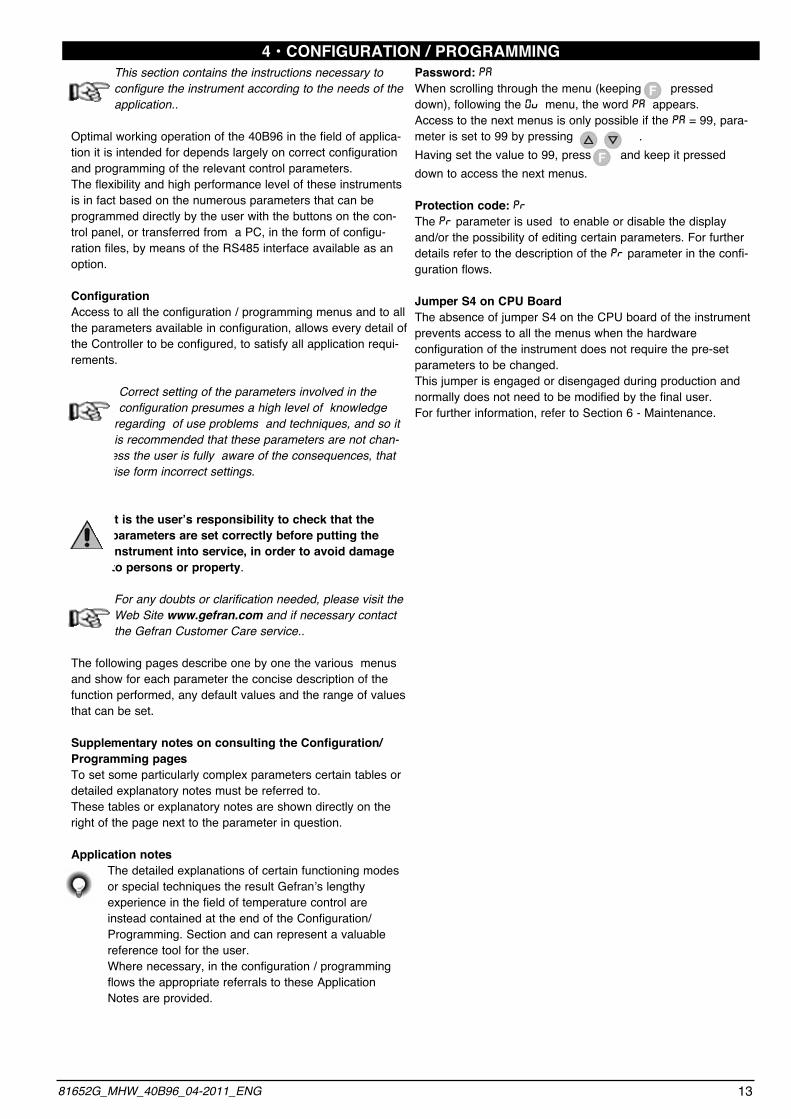
4 • CONFIGURATION / PROGRAMMINGThis section contains the instructions necessary to configure the instrument according to the needs of the application..
Optimal working operation of the 40B96 in the field of applica-tion it is intended for depends largely on correct configuration and programming of the relevant control parameters.The flexibility and high performance level of these instruments is in fact based on the numerous parameters that can be programmed directly by the user with the buttons on the con-trol panel, or transferred from a PC, in the form of configu-ration files, by means of the RS485 interface available as an option.
ConfigurationAccess to all the configuration / programming menus and to all the parameters available in configuration, allows every detail of the Controller to be configured, to satisfy all application requi-rements.
Correct setting of the parameters involved in the configuration presumes a high level of knowledge regarding of use problems and techniques, and so it is recommended that these parameters are not chan-
ged unless the user is fully aware of the consequences, that could arise form incorrect settings.
It is the user’s responsibility to check that the parameters are set correctly before putting the instrument into service, in order to avoid damage to persons or property.
For any doubts or clarification needed, please visit the Web Site www.gefran.com and if necessary contact the Gefran Customer Care service..
The following pages describe one by one the various menus and show for each parameter the concise description of the function performed, any default values and the range of values that can be set.
Supplementary notes on consulting the Configuration/ Programming pagesTo set some particularly complex parameters certain tables or detailed explanatory notes must be referred to.These tables or explanatory notes are shown directly on the right of the page next to the parameter in question.
Application notes The detailed explanations of certain functioning modes or special techniques the result Gefran’s lengthy experience in the field of temperature control are
instead contained at the end of the Configuration/ Programming. Section and can represent a valuable reference tool for the user. Where necessary, in the configuration / programming flows the appropriate referrals to these Application Notes are provided.
Password: PAWhen scrolling through the menu (keeping pressed down), following the 0V menu, the word PA appears.Access to the next menus is only possible if the PA = 99, para-meter is set to 99 by pressing .Having set the value to 99, press and keep it pressed down to access the next menus.
Protection code: PRThe PR parameter is used to enable or disable the display and/or the possibility of editing certain parameters. For further details refer to the description of the PR parameter in the confi-guration flows.
Jumper S4 on CPU BoardThe absence of jumper S4 on the CPU board of the instrument prevents access to all the menus when the hardware configuration of the instrument does not require the pre-set parameters to be changed.This jumper is engaged or disengaged during production and normally does not need to be modified by the final user.For further information, refer to Section 6 - Maintenance.
1381652G_MHW_40B96_04-2011_ENG

IF Information display Programming configuration
I F
Ud Software version
This menu provides information on the status and hardware configuration of the instrument (number and type of inputs/outputs, software version, etc.).
Instrument code
hrd 1 configuration
hrd 2 configuration
o(
K d
K 2
0 1 0 1 1
OUTPUT 10 = None1 = Present
OUTPUT 20 = None1 = Present
OUTPUT 30 = None1 = Present
OUTPUT 40 = None1 = Present
0 2 5 0 1
ANALOGOUTPUT0 = None5 = Present
DIGITAL 1 INPUT0 = None7 = Present
SERIAL0 = None1 = RS 485
(F ConfigurationThis menu makes it possible to configure the interception parameters.
F(
K.2
K.3
K.1
K .4
Hysteresis for trip point 1-999 ... +999 scale points
Hysteresis for trip point 2-999 ... +999 scale points
Hysteresis for trip point 3-999 ... +999 scale points
IHysteresis for trip point 4-999 ... +999 scale points
14 81652G_MHW_40B96_04-2011_ENG

Sr Serial communicationThis menu makes it possible to configure the various parameters that control serial communication between the instrument and the supervisor.
o(
PS
Instrument identification code
[0 ... 247]
Serial interface protocol
[0 ... 1]
S R
Ab
tPParity selection
[0 ... 2]
Select Baudrate
[0 ... 4]
IS.
24
Virtual instrument inputs
[0 ... 63]
0S.
19
Virtual instrument outputs
[0 ... 31]
U.S.
65
Virtual instrument user interface
[0 ... 127]
Interf KEYB DIS LED LED LED LED OUT4 OUT3 OUT2 OUT1 Bit 7 6 5 4 3 2 1 0
Ex 0 1 0 0 0 0 0 1 If you want to control KEYB interface elements and OUT1 LED via serial line, set S.U to 65
Outputs OUTW OUT4 OUT3 OUT2 OUT1 Bit 4 3 2 1 0 Ex. 1 0 0 1 1Set code 19 in S.0 to manage OUT1, 2 and W outputs via serial line
Inputs IN PV o.4 o.3 o.2 o.1 Bit 5 4 3 2 1 0 Ex. 0 1 1 0 0 0Set code 24 on S.I in to manage PV and o.4 alarm, via serial line
Pt Parity 0 No parity 1 Odd 2 Even
BA Baudrate 0 1200 1 2400 2 4800 3 9600 4 19200
S.P Serial protocol 0 CENCAL Gefran 1 MODBUS RTU
1581652G_MHW_40B96_04-2011_ENG

In Input settingsThis menu makes it possible to configure the parameters for the instrument input signals.
Pt.
nI
Probe type, signal and main input scale TP Probe type Signal polarization Main inputs scale limits 0 Potent/4-20mA (*) Positive (ex. 0/1V) -1999/9999 -19990/99990 -1999/28000 1 Potent./4-20mA (*) Positive (ex. 0/1V) Linear custom Linear custom Linear custom 2 Strain gauge Positive (ex. 0/10mV) -1999/9999 -19990/99990 -1999/28000 3 Strain gauge Symmetrical (ex.-10/+10mV) -1999/9999 -19990/99990 -1999/28000
F
0.1
t
F
0.5
d
Digital filter on input[0.0 ... 20.0] sec If set to “0”, the medium filter on the sample value is
excluded
Digital filter on input display[0 ... 9.9] punti scala
G.1. Select sampling time (resolution)
+4 to disable filter (average of the last eight values sampled) Strain gauge only+8 disables Eb (sampling time is halved)N.B.: maximum sampling frequency and minimum intercept time is obtained with code 15 (15 msec, 11bit resolution, filter off)
0
dP
1000
K .S
Maximum limit of main input scaleand retransmission analog output
0
L .S
Minimum limit of main input scaleand retransmission analog output
Decimal point position for input scale
DP Format 0 xxxxx 1 xxxx.x 2 xxx.xx 3 xx.xxx
+4 to display Lo below value L.S -(k.S - L.S) /256 (only for TP = 0 or 2)+8 select input scale -19990/99990 (value of least significant digit set to 0)+16 select input scale -1999/28000
Min... Max value associated with the input selected with the TP parameter
Min... Max value associated with the input selected with the TP parameter
0 120ms 120ms > 14bit (campionamento Eb 240ms) 1 120ms 60ms > 14bit; 16000 points (sampling Eb 120msec) 2 60ms 30ms > 13bit; 8000 points (samplingEb 60msec) 3 30ms 15ms > 12bit; 4000 points (sampling Eb 30msec)
For Strain gauge with Sensor power supply control (Eb) For potentiometer Resolution
16 81652G_MHW_40B96_04-2011_ENG
(*) 20mA Inputs: only for model 40B96-5-24-...in case of input 0-20mA it is necessary to proceed to the calibration to two points 0 and 20mA (U.C = 2)

Fo
0
Offset correction of main input
[-999 ... +999] scale points
0
L L Lower Limit for Alarm trip point setting
L.S ... K.S
1000
K .L Upper Limit for Alarm trip point setting
L.S ... K.S
.id
0
.u.t
0
.d.t
0
Select function of digital input
Raise key function (active only in P.V.selection)
Lower key function (active only in P.V.selection)
0 None 1 Zero 2 Hold 3 Flash 4 Max. peak display 5 Min. peak display 6 Delta peak display 7 Peak memory reset 8 Zero + peak memory reset 9 Alarms reset 10 Peak + alarms reset 11 Zero + alarms reset 12 Peak + zero + alarms reset 13 Output status OUT1 /check CAL 14 Output status OUT2 /check CAL 15 Output status OUT3 /check CAL 16 Output statusOUT4 / check CAL 17 KEYLOCK (d.I. only)18 access to U.CAL for the selected input probe type (t.U. and t.d. only) 19 OFFSET ( t.U. and t.d. only)
d. i. - t. u. - t. d.
Note 1If you configure the “direct access to potentio-meter calibration menu (tP=0 or 1)” function with parameters t.U. = 18 (t.d. = 18), the calibration procedure is as follows:- keep the raise (lower) key pressed until you see C.L.- release the key. Mechanically bring the poten-tiometer to minimum stroke position. - confirm with the F key. C.H. will appear on the display.- mechanically bring the potentiometer to maxi-mum stroke position.- keep the F key pressed to exit the procedure and return to normal display
Note 2If you configure the “direct access to parameter o.F” function (offset correction of display) with parameters t.U. = 19 (t.d.=19), the calibration procedure is as follows:- keep the raise (lower) key pressed until you see o.F.- when the F key is released, the display will alternate between o.F and the previously set o.F value.- set the offset value you want by means of the raise/lower keys.- keep the F key pressed to exit the procedure and return to normal display.
1781652G_MHW_40B96_04-2011_ENG

0V Output settingsThis menu makes it possible to configure the parameters of the instrument outputs.
v0. Number of outputs
v0
1 . T
0
Alarm type 1(absolute only)
3 . T
0
4 . T
0Alarm type 4
2 . T
0
1.T Direct 2.T (high limit) Absolute or Relative Normal or 3.T Inverse (low limit) to previous Symmetric
4.T absolute (window) 0 Direct Absolute Normal 1 Inverse Absolute Normal 2 Direct Relative Normal 3 Inverse Relative Normal 4 Direct Absolute Symmetrical 5 Inverse Absolute Symmetrical 6 Direct Relative Symmetrical 7 Inverse Relative Symmetrical+8 to disable on power-up until first alarm+16 to memorize+32 to filter with F.O. mode (output filter mode)+64 output for calibration of 6 wire probe (Phase 2)
.F.0 Functions 0 inactive, calculated state is shown directly on relays 1 delayed activation (DON) 2 delayed activation of output from time output is deactivated (DBI) 3 delayed deactivation (DOF) 4 delayed activation only when instrument is switched on (DPO)
0 ... 4
Alarm type 3
Alarm type 2
F.0
0Output filter modalities
+ 8 time basis 99 min max. (default = 99 sec)
.rA
0Delay relative to F.O 0 ... 99 min
o sec
At.
0
Minimum output trip time 0 ... 99 sec
Er
0
Fault action (definition of output state in case of broken probe) Er, br
Disabled by setting 0.Displayed if assigned to at least one output
Value Out 1 Out 2 Out 3 Out 4 0 OFF OFF OFF OFF 1 ON OFF OFF OFF 2 OFF ON OFF OFF 3 ON ON OFF OFF 4 OFF OFF ON OFF 5 ON OFF ON OFF 6 OFF ON ON OFF 7 ON ON ON OFF 8 OFF OFF OFF ON 9 ON OFF OFF ON 10 OFF ON OFF ON 11 ON ON OFF ON 12 OFF OFF ON ON 13 ON OFF ON ON 14 OFF ON ON ON 15 ON ON ON ON
Value Direct Absolute or Normal or (high limit) Relative Symmetric Inverse to previous (window) (low limit) absolute 0 Direct Absolute Normal 1 Inverse Absolute Normal 2 Direct Relative Normal 3 Inverse Relative Normal 4 Direct Absolute Symmetrical 5 Inverse Absolute Symmetrical 6 Direct Relative Symmetrical 7 Inverse Relative Symmetrical
18 81652G_MHW_40B96_04-2011_ENG
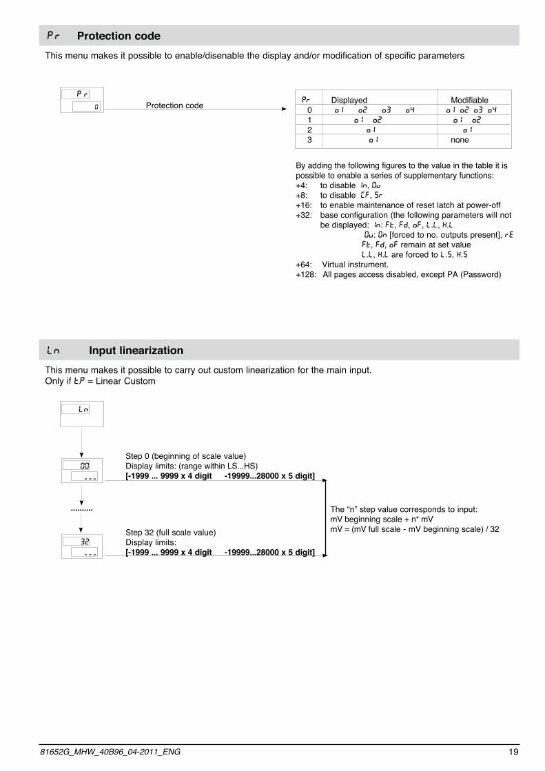
PR Protection codeThis menu makes it possible to enable/disenable the display and/or modification of specific parameters
rP
0 PR Displayed Modifiable 0 o1 o2 o3 o4 o1 o2 o3 o4 1 o1 o2 o1 o2 2 o1 o1 3 o1 none
By adding the following figures to the value in the table it is possible to enable a series of supplementary functions:+4: to disable IN, 0V+8: to disable [F, SR+16: to enable maintenance of reset latch at power-off+32: base configuration (the following parameters will not be displayed: IN: Ft, Fd, oF, L.L, K.l 0V: 0n [forced to no. outputs present], rE Ft, Fd, oF remain at set value L.L, K.l are forced to L.s, K.s+64: Virtual instrument.+128: All pages access disabled, except PA (Password)
Protection code
LN Input linearizationThis menu makes it possible to carry out custom linearization for the main input. Only if t.P = Linear Custom
Ln
---
00
---
32
Step 0 (beginning of scale value)Display limits: (range within LS...HS)[-1999 ... 9999 x 4 digit -19999...28000 x 5 digit]
Step 32 (full scale value)Display limits: [-1999 ... 9999 x 4 digit -19999...28000 x 5 digit]
.......... The “n” step value corresponds to input:mV beginning scale + n* mVmV = (mV full scale - mV beginning scale) / 32
1981652G_MHW_40B96_04-2011_ENG

U.[ User calibrationThis menu makes it possible to carry out user calibration.
U (. U.[ Calibration function 1 analog retransmission output 2 potentiometer 3 strain-gauge positive polarization 4 strain-gauge symmetrical polarization
Minimum calibration (*)
Maximum calibration (*)
(*) Press keys Δ ∇ to cali-brate the analog output
if U.[ = 1
Zero acquisition phase, potentiometer with cursor in minimum voltage position
Maximum acquisition phase, potentiometer with cursor in maximum voltage position
if U.[ = 2 if U.[ = 3, 4
Tare zero acquisition phase with strain-gauge discharged (no weight or pressure)
Acquisition phase for automatic definition of sensitivity and full scale, load strain-gauge with sample reference or automatic activation of configured output to check 6-lead sensor (only for version SW 2.0x). 80% f.s. is set as default.The value can be changed to set the value in engineer-ing units corresponding to the sample used.
Zero recalculation phase, unload strain-gauge by removing sample reference.
P.V. Process variable (LEVEL 1)
.......
[. L. [. L.
[. A [. A
FI
F2
F3
Note: between the calibration phases some seconds could be requested to elaborate data.
20 81652G_MHW_40B96_04-2011_ENG
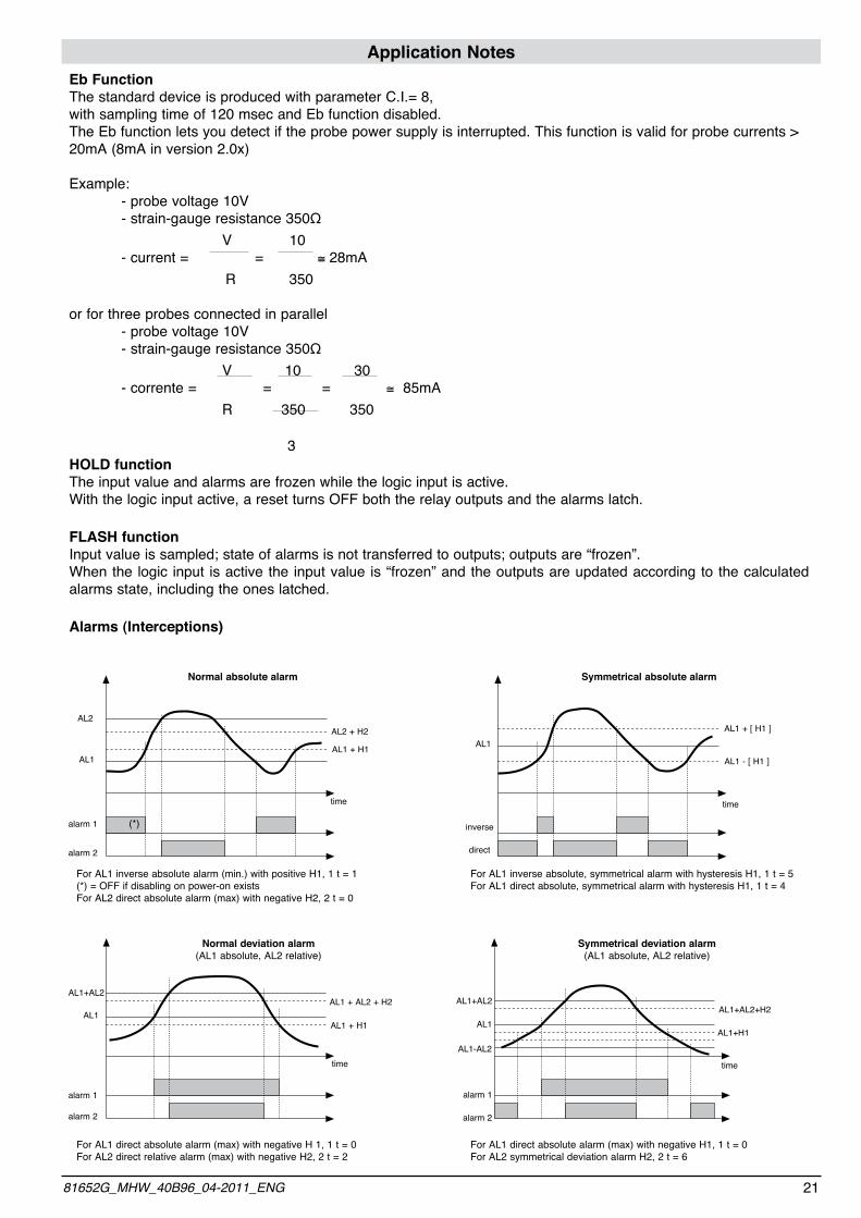
Application NotesEb FunctionThe standard device is produced with parameter C.I.= 8, with sampling time of 120 msec and Eb function disabled.The Eb function lets you detect if the probe power supply is interrupted. This function is valid for probe currents > 20mA (8mA in version 2.0x)
Example: - probe voltage 10V - strain-gauge resistance 350Ω V 10 - current = = @ 28mA R 350
or for three probes connected in parallel - probe voltage 10V - strain-gauge resistance 350Ω V 10 30 - corrente = = = @ 85mA R 350 350
3HOLD functionThe input value and alarms are frozen while the logic input is active.With the logic input active, a reset turns OFF both the relay outputs and the alarms latch.
FLASH functionInput value is sampled; state of alarms is not transferred to outputs; outputs are “frozen”.When the logic input is active the input value is “frozen” and the outputs are updated according to the calculated alarms state, including the ones latched.
Alarms (Interceptions)
time
AL1 + H1
AL2 + H2AL2
AL1
alarm 1
alarm 2
(*)
For AL1 inverse absolute alarm (min.) with positive H1, 1 t = 1(*) = OFF if disabling on power-on existsFor AL2 direct absolute alarm (max) with negative H2, 2 t = 0
For AL1 inverse absolute, symmetrical alarm with hysteresis H1, 1 t = 5For AL1 direct absolute, symmetrical alarm with hysteresis H1, 1 t = 4
Normal absolute alarm Symmetrical absolute alarm
inverse
direct
AL1AL1 + [ H1 ]
AL1 - [ H1 ]
time
For AL1 direct absolute alarm (max) with negative H 1, 1 t = 0For AL2 direct relative alarm (max) with negative H2, 2 t = 2
For AL1 direct absolute alarm (max) with negative H1, 1 t = 0For AL2 symmetrical deviation alarm H2, 2 t = 6
time
AL1+AL2
AL1
alarm 1
alarm 2
AL1+AL2
AL1
alarm 1
alarm 2
time
AL1 + AL2 + H2
Normal deviation alarm(AL1 absolute, AL2 relative)
Symmetrical deviation alarm(AL1 absolute, AL2 relative)
AL1-AL2
AL1 + H1
AL1+AL2+H2
AL1+H1
2181652G_MHW_40B96_04-2011_ENG
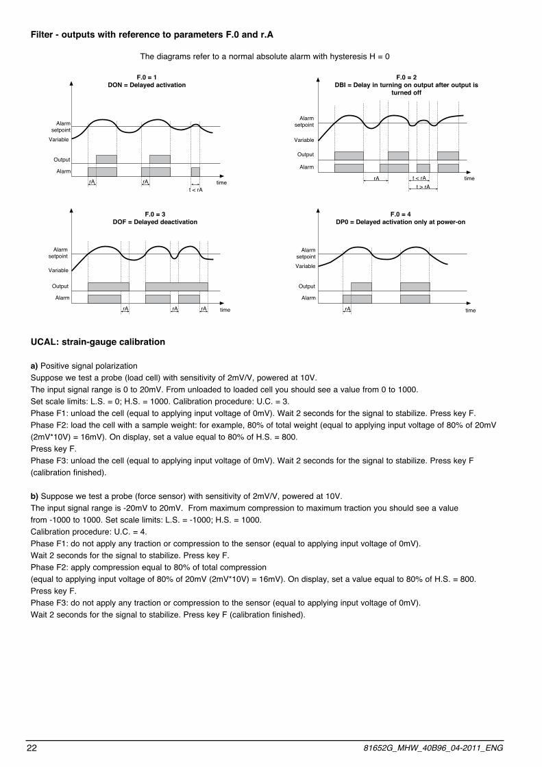
Filter - outputs with reference to parameters F.0 and r.A
The diagrams refer to a normal absolute alarm with hysteresis H = 0
UCAL: strain-gauge calibration
a) Positive signal polarizationSuppose we test a probe (load cell) with sensitivity of 2mV/V, powered at 10V. The input signal range is 0 to 20mV. From unloaded to loaded cell you should see a value from 0 to 1000.Set scale limits: L.S. = 0; H.S. = 1000. Calibration procedure: U.C. = 3.Phase F1: unload the cell (equal to applying input voltage of 0mV). Wait 2 seconds for the signal to stabilize. Press key F.Phase F2: load the cell with a sample weight: for example, 80% of total weight (equal to applying input voltage of 80% of 20mV (2mV*10V) = 16mV). On display, set a value equal to 80% of H.S. = 800.Press key F.Phase F3: unload the cell (equal to applying input voltage of 0mV). Wait 2 seconds for the signal to stabilize. Press key F (calibration finished).
b) Suppose we test a probe (force sensor) with sensitivity of 2mV/V, powered at 10V.The input signal range is -20mV to 20mV. From maximum compression to maximum traction you should see a value from -1000 to 1000. Set scale limits: L.S. = -1000; H.S. = 1000.Calibration procedure: U.C. = 4.Phase F1: do not apply any traction or compression to the sensor (equal to applying input voltage of 0mV).Wait 2 seconds for the signal to stabilize. Press key F.Phase F2: apply compression equal to 80% of total compression (equal to applying input voltage of 80% of 20mV (2mV*10V) = 16mV). On display, set a value equal to 80% of H.S. = 800.Press key F.Phase F3: do not apply any traction or compression to the sensor (equal to applying input voltage of 0mV).Wait 2 seconds for the signal to stabilize. Press key F (calibration finished).
time
Alarm setpoint
Output
Alarm
F.0 = 1DON = Delayed activation
F.0 = 2DBI = Delay in turning on output after output is
turned off
time
timetime
F.0 = 3DOF = Delayed deactivation
F.0 = 4DP0 = Delayed activation only at power-on
Variable
rA rAt < rA
Alarm setpoint
Output
Alarm
Variable
rA t < rAt > rA
Alarm setpoint
Output
Alarm
Variable
Alarm setpoint
Output
Alarm
Variable
rA rA rA rA
22 81652G_MHW_40B96_04-2011_ENG
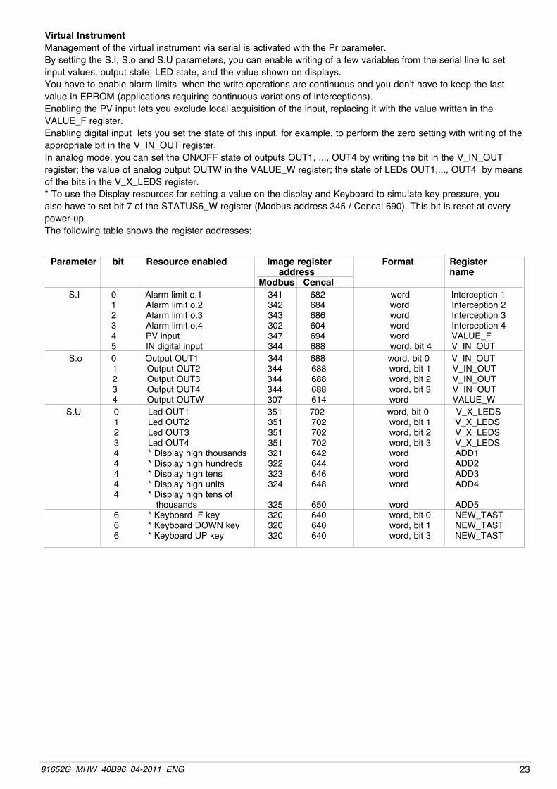
Virtual InstrumentManagement of the virtual instrument via serial is activated with the Pr parameter.By setting the S.I, S.o and S.U parameters, you can enable writing of a few variables from the serial line to set input values, output state, LED state, and the value shown on displays.you have to enable alarm limits when the write operations are continuous and you don’t have to keep the last value in EPROM (applications requiring continuous variations of interceptions).Enabling the PV input lets you exclude local acquisition of the input, replacing it with the value written in the VALUE_F register.Enabling digital input lets you set the state of this input, for example, to perform the zero setting with writing of the appropriate bit in the V_IN_OUT register.In analog mode, you can set the ON/OFF state of outputs OUT1, ..., OUT4 by writing the bit in the V_IN_OUT register; the value of analog output OUTW in the VALUE_W register; the state of LEDs OUT1,..., OUT4 by means of the bits in the V_X_LEDS register.* To use the Display resources for setting a value on the display and Keyboard to simulate key pressure, you also have to set bit 7 of the STATUS6_W register (Modbus address 345 / Cencal 690). This bit is reset at every power-up.The following table shows the register addresses:
Parameter bit Resource enabled Image register Format Register address name Modbus Cencal S.I 0 Alarm limit o.1 341 682 word Interception 1 1 Alarm limit o.2 342 684 word Interception 2 2 Alarm limit o.3 343 686 word Interception 3 3 Alarm limit o.4 302 604 word Interception 4 4 PV input 347 694 word VALUE_F 5 IN digital input 344 688 word, bit 4 V_IN_OUT S.o 0 Output OUT1 344 688 word, bit 0 V_IN_OUT 1 Output OUT2 344 688 word, bit 1 V_IN_OUT 2 Output OUT3 344 688 word, bit 2 V_IN_OUT 3 Output OUT4 344 688 word, bit 3 V_IN_OUT 4 Output OUTW 307 614 word VALUE_W S.U 0 Led OUT1 351 702 word, bit 0 V_X_LEDS 1 Led OUT2 351 702 word, bit 1 V_X_LEDS 2 Led OUT3 351 702 word, bit 2 V_X_LEDS 3 Led OUT4 351 702 word, bit 3 V_X_LEDS 4 * Display high thousands 321 642 word ADD1 4 * Display high hundreds 322 644 word ADD2 4 * Display high tens 323 646 word ADD3 4 * Display high units 324 648 word ADD4 4 * Display high tens of thousands 325 650 word ADD5 6 * Keyboard F key 320 640 word, bit 0 NEW_TAST 6 * Keyboard DOWN key 320 640 word, bit 1 NEW_TAST 6 * Keyboard UP key 320 640 word, bit 3 NEW_TAST
2381652G_MHW_40B96_04-2011_ENG

5 • TECHNICAL SPECIFICATIONS
This section contains a list of the Technical Specifications for the 40B96 instrument.
Display 5 red digits, digit height 14mm (5 digits)Keys 3 mechanical type (NC, DEC, F)Accuracy 0.2% f.s. ±1 digit a temperatura ambiente di 25°C t.s. 120msecThermal drift 0,005% f.s. / °CResolution function of settable sampling time: >14bit, t.s. 120msec with sensor power control if strain gauge >13bit, t.s. 30msec (60msec with strain gauge power control) >12bit, t.s. 15msec (30msec with strain gauge power control)Main input differential input for - from strain-gauge 350Ω (for pressure, force, etc.) sensitivity 5mV/V with strain-gauge power max 15V, (7.5mV/V con power supply max. 10V-15mV/V with power supply max 5V), positive or symmetrical polarization, calibration with automatic calibration of sensitivity, possible signaling of interrupted sensor power supply - from potentiometer with power supply 1.2V, ≥ 100Ω - 0...20/4...20mA transmitter with 24Vdc supply (Ri = 50Ω)Linear scale range -1999...9999 (with 4 digits),-1999...28000 (with 5 digits) settable decimal point; a 32 section linearization can be inserted Alarms (interception) max 4 configurable alarm types: absolute, deviation, symmetrical deviation. Hysteresis setting Alarm masking options: - exclusion at switch-on - latch, reset from key and/or contact - insertion of delay filter (DON,DBI,DOF,DPO) - activation of minimum time on tripRelay contact NO (NC), 5A, 250V/30Vdc cosj=1Logic output 24V ±10% (10V min / 20mA)Triac output 20...240Vac ±10%, 1A max, snubberless, inductive and resistive load I2t = 128AFault settings Alarm states can be configured in probe fault conditionSensor power 1,2Vdc for potentiometer > 100Ω 5Vdc, 10Vdc, max 120mA (for strain-gauge) 15Vdc, 50mA max. 24Vdc ± 10% non stabilized 50mA, (100mA max for the 0...20/4...20mA transmitter input model only)Analogue retransmission 10V/20mA Rload max 500W resolution 12 bitDigital inputs Ri = 4,7KW (24V, 5mA) or from terminal not supplied.Serial interface (option) RS485, isolatedBaudrate 1200, 2400, 4800, 9600, 19200Protocol Gefran CENCAL / MODBUSPower supply (switching type) (standard) 100...240Vac/dc ±10% max 18VA (optional) 11...27Vac/dc ±10% max 11VA 50/60HzFaceplate protection IP65Working / Storage temperature range 0...50°C / -20...70°CRelative humidity 20...85% Ur non-condensingEnvironmental working conditions for indoor use, altitudes up to 2000mInstallation panel, removable faceplateInstallation specifications installation category II, pollution level 2, double isolationWeight 160 g complete version
24 81652G_MHW_40B96_04-2011_ENG
6 • MAINTENANCEThis section gives the information and the necessary warnings for routine maintenance of the instrument and contains a Troubleshooting Guide which should
be read before seeking help from the Gefran Customer Service Assistance, in the event of instrument malfunction.
If installed and configured correctly according to the instructions and the recommendations provided in Sections 2 and 4 of these Instructions for use, the instrument will work normally without any need for maintenance, apart from the usual operations of cleaning the faceplate, and if necessary the internal parts of the instrument.
To gain access to the inside of the instrument (for exam-ple for cleaning or to check the jumpers) just undo the screw at the bottom of the faceplate and take out the instrument without having to disconnect the cables.
Make sure that the power is turned off upstream of the instrument however.Remember that the 40B96 interceptor is not equipped with an ON/OFF switch.
Cleaning the InstrumentTo clean the faceplate and the case use only a cloth dam-
pened in water or ethyl alcohol.Do not use hydrocarbon-based solvents (trichiorethylene, petrol, etc.).
Do not use compressed air to remove dust from the elec-tronic circuit boards, if necessary use a clean brush with soft bristles.
RepairsRepairs to the 40B96 instrument must only be carried
out by qualified technicians, properly trained and authorized by Gefran. Any attempts at repair or modification of the instrument hardwarecharacteristics by unauthorized personnel will inva-
lidate the warrantya.
Checking the jumpers The solders side of the CPU board contains the jumper S4 which enables (if on) access to the controller menus.
The instrument contains components which are sensiti-ve to electrostatic discharge, so the rele-vant precautions must be taken when handling the electronic circuit boards contained in it, in order to avoid permanent damage to
components themselves.
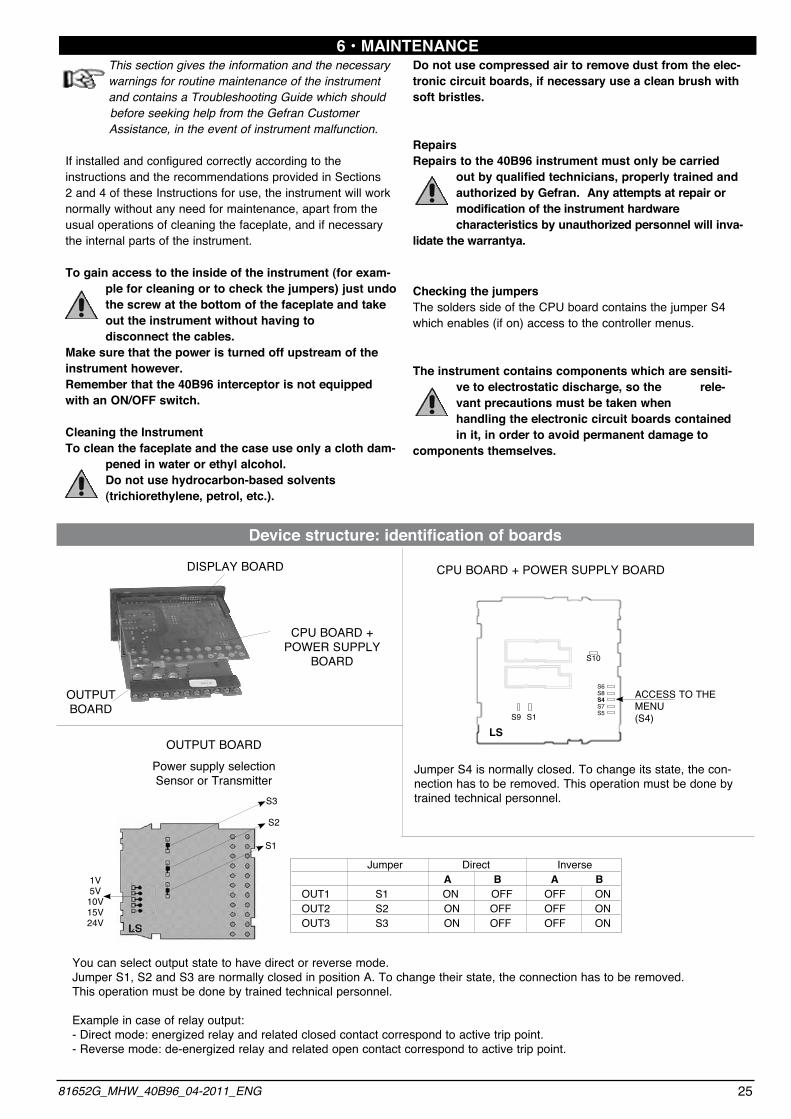
Device structure: identification of boards
CPU BOARD + POWER SUPPLy
BOARD
CPU BOARD + POWER SUPPLy BOARD
S3
S2
S1
1V5V10V15V24V
you can select output state to have direct or reverse mode.Jumper S1, S2 and S3 are normally closed in position A. To change their state, the connection has to be removed. This operation must be done by trained technical personnel.
Example in case of relay output:- Direct mode: energized relay and related closed contact correspond to active trip point.- Reverse mode: de-energized relay and related open contact correspond to active trip point.
OUTPUT BOARDPower supply selectionSensor or Transmitter
LSS9 S1
S10
S6S8S4S7S5
ACCESS TO THE MENU(S4)
Jumper S4 is normally closed. To change its state, the con-nection has to be removed. This operation must be done by trained technical personnel.
DISPLAy BOARD
OUTPUT BOARD
Jumper Direct Inverse A B A B OUT1 S1 ON OFF OFF ON OUT2 S2 ON OFF OFF ON OUT3 S3 ON OFF OFF ON
2581652G_MHW_40B96_04-2011_ENG

7 • TECHNICAL/COMMERCIAL INFORMATION This section contains information regarding the instrument order codes and the main accessories available.
As stated in the Preliminary Warnings of these Instructions for Use, correct interpretation of the instrument order code allows the hardware configuration to be identified immediately and so it is essential to quote the order code each time the Gefran Customer Care Service is contacted for assistance with any problems.
Order code – 40B96 alarm unit
For information on the availability of codes please contact your Gefran dealer.
The instrument display and Led do not come on
The characters shown on the display are incomplete or illegible
When pressing down none of the configuration menus can be accessed
When pressing down not all of the parameters and/or configuration menus can be accessedInstead of the process variable the PV display shows one of the following:LO - KI - BR - ER - Eb
Instrument power supply problem. Check that power is being supplied to terminals 10-11.make sure the power supply corresponds with the one stated in the order code: 40B96 5 xx – xx – xx – x.x – 1 = 100..240Vac/dc 40B96 5 xx – xx – xx – x.x – 0 = 11..27Vac/dcPossible fault with one of the display segments. Check that all the segments are working pro-perly by switching the instrument off and then on again. When it is switched on again a self-diagnostic test is performed that checks intermittent start up of all the segments (displays the value 8888). If one or more segments do not light up contact your Gefran dealer.If the problem appears during the first installation, it probably means that the hardwa-re configuration doesn’t allow changing of the default parameters beyond the alarm setpoint value. (Parameter change is enabled by jumper S4 on the CPU board). If on the other hand the problem occurs on a instrument that previously gave access to the configuration parameters, this probably means that there is a false contact on the jumper S4.In this case check the continuity of the jumper referring to the previous paragraph.
Access to some menus and/or parameters is protected by a password (PA) and a code (PR) that limits configuration mode.To set the password and the protection code correctly refer to Section 4 “Configuration/Programming”.In the first four cases it means that an input error has been found (for details refer to Section 3 - Functions).In the last case, it means probe power supply failure.This function has to be enabled via parameter c.I. on the In menu.
Symptom Cause and Recommended remedy
Troubleshooting Guide
26 81652G_MHW_40B96_04-2011_ENG
OUT 1, OUT 2 Relay, Relay R R Relay, Logic R D Triac, None T O
5Vdc 0 5 1,2Vdc potentiometer 0 1
24Vdc (only for 20mA input) * 2 4
10Vdc 15Vdc
1 01 5
None0
Both **3
DIGITAL INPUT / RETRANSMISSION OUTPUT
100...240Vac/dc1
POWER SUPPLY 11...27Vac/dc0
40B
None0 RS 4852
TRANSMITTERPOWER SUPPLY SERIAL LINE
Digital input1
96
NR. DIGITS 5 5
5
OUT 3, OUT 4 None 0 0 Relay, None R 0 Relay, Relay ** R R
0/4...20mA (0...10V) retansmision output **2
* Specific model for use with transmitter 20mA (es for position magnetostrittive sensor) excludes Output 3, Output 4 and retransmission, all the other models have potentiometer/strain-gauge configurable input
** Out 4 alternative to retransmission output *** Selectable (standard = 24Vdc)
All *** 99

ACCESSORIES
APPENDIXThe appendix contains the list of all the abbreviations of parameters which appear in the various configu-ration/programming menus with the respective default values and meanings.The CONF column can be used to indicate the user’s modified values with respect to the default configu-ration, on the basis of application requirements.
Display Default CONF Acronym DescriptionLevel 1 o.1 40 Output 1 Setting of alarm setpoint (Scale points) o.2 50 Output 2 Setting of alarm setpoint (Scale points o.3 60 Output 3 Setting of alarm setpoint (Scale points) o.4 70 Output 4 Setting of alarm setpoint (Scale points)Menu IF UD 3.20 UPdate Software version identification (O 1 Code Instrument code identification .KD Conf Hardware 1 Hardware outputs configuration .K2 Conf Hardware 2 Hardware inputs configurationMenu (F K.I -1 Hysteresis 1 Hysteresis for setpoint 1 K.2 -1 Hysteresis 2 Hysteresis for setpoint 2 K.3 -1 Hysteresis 3 Hysteresis for setpoint 3 K.4 -1 Hysteresis 4 Hysteresis for setpoint 4Menu SR (O 1 Instrument Code Instrument identification code S.P 1 Serial Protocol Serial interface protocol BA 4 bAudrate Baudrate selection Pt 0 PArity Parity selection S.I 0 S. Input Virtual instrument inputs S.o 0 S. Output Virtual instrument outputs S.U 0 S. User Interface Virtual instrument user interfaceMenu IN TP 0 type of Probe Probe type, signal, enable linearization, etc. (i 0 Sample time Select sampling time FT 0.1 FiLter time Digital filter on input FD 0.5 FiLter display Digital filter on display DP. 0 Decimal point Decimal point position for input scale L.S 0 Low Scale Minimum limit input scale K.S 1000 High Scale Maximum limit input scale OF 0 oFfSet Offset correction of main input d.I 0 Digital input Digital input function tU 0 UP key Raise key function t.d 0 DOWN key Lower key function L.L 0 Low Limit Lower limit for setting SP and absolute alarms K.L 1000 High Limit Upper limit for setting SP and absolute alarms
• RS232 / TTL interface for GEFRAN instrument configuration
WSK-0-0-0 Cable interface + CD Winstrum
• ORDER CODE
N.B. RS232 interface for PC configuration is supplied with the WINSTRUM program-ming software. Make connection with instrument powered but with inputs and outputs disconnected.
Side insertion cable
2781652G_MHW_40B96_04-2011_ENG

Display Default CONF Acronym DescriptionMenu 0V 0N 0 Output number Number of trip point outputs IT 0 Output type 1 Trip point type for Out 1 2T 0 Output type 2 Trip point type for Out 2 3T 0 Output type 3 Trip point type for Out 3 4T 0 Output type 4 Trip point type for Out 4 F0 0 Output filter Filter mode on trip points ra 0 Output delay Trip point delay TM 0 Minimum type Minimum output trip point time rE 0 Fault action Definition of output states with broken sensorMenu LN - Input linearization 00 – 32 N° Default CONF .00 0 .01 31 .02 62 .03 94 .04 125 .05 156 .06 187
N° Default CONF .07 219 .08 250 .09 281 .10 312 .11 344 .12 375 .13 406
N° Default CONF .14 437 .15 469 .16 500 .17 531 .18 562 .19 594 .20 625
N° Default CONF .21 656 .22 687 .23 719 .24 750 .25 781 .26 812 .27 844
N° Default CONF .28 875 .29 906 .30 937 .31 969 .32 1000
28 81652G_MHW_40B96_04-2011_ENG