Instruction Guide – RTC 402/TREX
7
Version Instruction Guide – RTC 402/TREX
-
Upload
khangminh22 -
Category
Documents
-
view
6 -
download
0
Transcript of Instruction Guide – RTC 402/TREX

Version оΦл
Instruction Guide – RTC 402/TREX

Page 1

Page 2

Wiring and Crimping Guide
Using the Wire Cutter of the Crimper,1. Gently press both handle. Make surenot to cut the wires inside the cable.
2. Rotate the Crimping Tool tocompletely cut the outer covering of thecable.
1. Cutting Wires 2. Unshielded Twisted Pair (Cat5 Cable)
Remove the outer casingof the Cat5 cable to show thesmaller wires inside.
It has 8 wires.(See second illustration)
For the Sensor, we will onlyuse 4 wires, so we will cutall unnecessary wires.(See third illustration)
Blue
Blue
Green
Orange
Orange
BrownWhite/Brown
White/Blue
White/Blue
White/Green
White/Orange
White/Orange
3. RJ22 Handset Plug
Registered Jack 22 or simply RJ22is a standard telephone handset
conductor phone cable.** THIS IS NOT A RJ11!**
Insert the wires of the cable on theRJ22 Handset Plug. See RJ22 WiringGuide for reference. Make sure no copper is exposed when crimping!
4. RJ22 Wiring Guide
Crimp 2
1. White Blue2. Blue3. Orange4. White Orange
1 2 3 41 2 3 4 1 2 3 4
Setting 1 & 3
1. White Blue2. 3. Orange4. White Orange
Crimp 1
1. Blue2. 3. 4.
Setting 2
1 2
5. Crimping
With the Cat5 Cable and RJ22 PlugHandset ready, we can now crimp themusing the Crimper.
Insert the RJ22 Handset Plug to theRJ22 crimping slot and squeeze thecrimper carefully and tightly.
6. Finishing
This illustration portrays a crimpedCat5 Cable with RJ22 Handset Plug.
*Setting 1 *
*Please call your Tech Support Representative for the setting number* Page 3
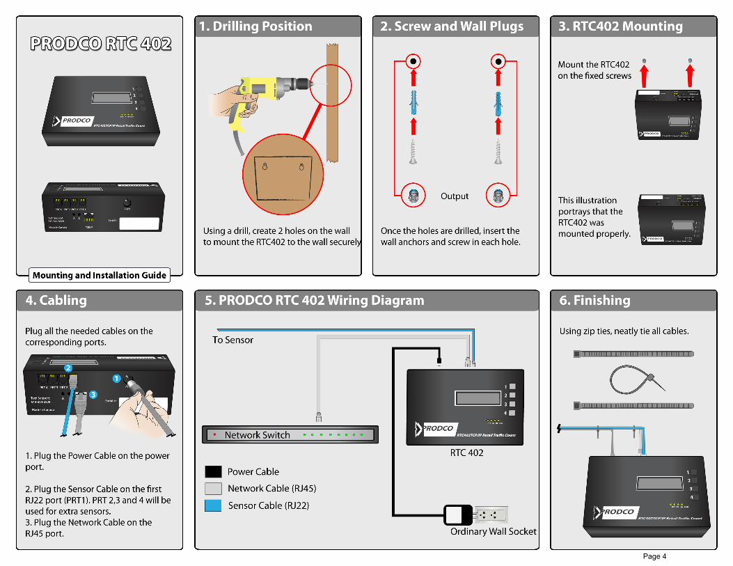
Page 4

PRODCORTC402TCP/IP Retail Tra�c Count
1
2
3
4
RUNRXTXRTS
Programming Guide
1. Button Function
PRODCORTC402TCP/IP Retail Tra�c Count
1
2
3
4
RUNRXTXRTS
Status: D . . . . 01/Jan/12 1:23pm
Date Format: = Day / Month / Year
1. Scrolls Options Up
2. Scrolls Options Down
3. Navigates cursor when cursor is available in other screens, while shifting through options it also acts as an enter button.
4. Acts as a return button. While in a screen you can hit this button to return to the previous window. Hit 4 twice to return to the main screen.Once all changes are made within the screen you are viewing hitting 4 will save changes.
*RTC PASSWORD = 3314* (Whenever Prompted)
2. Changing Date & TimeEnsure the time and date is set properly before running test counts or checking counts.
To change the time, from the main screen hit1 (2 times) until you see “Set Time”
Press 3 to con�rm
Enter the password (See Step 1)
Press 3 to navigate the cursor to the designated value you wish to change, press 1 to go up in value, press 2 to go down in value.
Once changes are complete hit 4 (2 times) to con�rm.
Make sure the RTC is set to local time
To check counts press 1,3,3.This screen will show the current hour, date and will automatically be set on sensor #1 (SN#1) or, PRT1. Your current count will be on the bottom right.
You can navigate through date, hour and sensors by using 3 to navigate the cursor, once the cursor is on the desired value press 1 to scroll up and 2 to scroll down.
From this screen you will run test counts to ensure accuracy of the sensors. First you will access this screen and check the current count for all sensors.Before heading to the entrance press 4 to exit back to the main screen.
Run a few Inbound and Outbound counts through the door and return to the RTC to check the counts for accuracy. If the counts are to high or to low, double check the divide ratio (Step 4)
If problems persist, check all sensor settings and wiring.
3. Checking Counts
PRODCORTC402TCP/IP Retail Tra�c Count
1
2
3
4
RUNRXTXRTS
01/Jan/12 1:PSN#1 25
4. Divide RatioTo change the divide ratio, from the mainscreen hit 1 (7 times) until you see “Divide Ratio”.
Hit 3 to con�rm.
Enter the password (See Step 1)
Press 1 or 2 to change the value. Press 3 to NavigatePress 4 to Con�rm
Divide ratio = /1111 if sensor setting is 2 & 3Divide ratio = /2222 if sensor setting is 1
Note the �rst number in the divide ratio isacting as port one’s divide ratio, the secondnumber is acting as port two’s divide ratio, ect.
*Please check with your Tech Support Rep to con�rm the correct divide ratio*
Page 5

TREX Troubleshooting Guide
No lights means no power TREX sensors are direct current only. By standard please
ensure that the orange is plugged into power + and the orange/white is plugged into - on the circuit board.
Ensure the power to the RTC is plugged in. Ensure that the Cat5 sensor cable is plugged into the RTC
or the Jbox, and connected in the appropriate ports. For 402 units make sure the crimp is wired properly and
that the pins are puncturing through the insulation and making contact with the copper wire.
Make sure the RTC has the proper voltage running to it. The DC output read out on the power brick should be 12 – 13.5 volts 1 amp (1000mA).
If a volt meter is not available try using different ports on the RTC. (RTC ports will go bad from time to time.)
If the RTC is powered and wired correctly, check (with a voltage meter) to see if the Orange and Orange/White unplugged from the TREX is reading at least 12v. (The TREX requires 12-24volts to power on.)
Ensure that the wires at the module are stripped down about a ¼ inch to make full contact with the conductors inside.
Tone out the Cat5 line, make sure that it is indeed our designated line and that the line is not damaged. Ensure that it is reading all pairs.
TREX Lights on but not sending counts. The light should be red on the TREX, once the beam is broken
(when an individual walks under the sensor) it should turn green. If the light does not turn green it means that it is not seeing any
motion beneath it. Ensure that the adjustable tabs are open enough to see people walking underneath. (These tabs are used to monitor traffic only within the doorframe boundaries make sure they are not too wide or too narrow.)
Ensure that the blue wire is attached to the C1 Port and the white/blue wire is attached to the NO1 Port on the TREX. (You will see the designated ports printed on the circuit board. This section is the REX Relay.)
Ensure the screws are tightened down to clench the wires in the terminals. Tug on the wires to be sure they do not fall out.
The data lines will send a little less than volt through if they are connected to the crimp/J-box properly.
Check another port on the RTC or J-box. Recrimp the sensor line at the cable. Reseat the Blue and Blue/White pair on both ends. Check for any damages to the pair. Tone the cable to ensure that the pair is linking from front to
back. Check for any splices that may be causing an issue.
Page 6