Installation Instructions - TH700-R4 (4L60) Transkit - Manual ...
19
Installation Instructions TH700-R4 (4L60) Transkit ATF for the transmission and 6 Qts for the converter 3-4 CLUTCH INSTA.08LLATION The B&M 3-4 clutch pack uses the maximum number of standard thickness plates (6 friction and 5 steel) possible (see Figure 1). If the unit you are working on had 5 friction and 4 steel plates you will have to replace the 3-4 apply ring (see Figure 3) with G.M. part number 8642374 This part number has been discontinued by GM, but is available from Transtar Industries, Cleveland, OH, as P/N D61975 Call 1-800-321-8830 for the location and number of their nearest location. This apply ring will accom- modate the 6 friction and 5 steel plate package. The 6 friction plate pack- age apply ring is 3.71" long com- pared to 3.88" for the (5 friction plate package). In some cases there is room to install a seventh friction plate in the clutch. See the section "Additional Clutch Plate" on the next page. A new 3-4 clutch apply plate is supplied with this kit. The new apply plate replaces both the apply plate and the 3-4 clutch retainer. Figure 4 shows the old and new parts. The selective 3-4 clutch backing plate is not included as part of this kit. If the existing backing plate does not produce the required clutch pack clearance you will have to obtain the correct backing plate from a G.M. parts dealer. We have included a thin (.094") 3-4 clutch backing plate re- taining ring that can be used in pre- 1988 units in place of the thicker (0.125") ring to extend a particular backing plate’s adjustment range. Installation of B&M’s 3-4 CLUTCH PACK is similar to install- ing a stock 3-4 clutch pack. We rec- ommend that you consult the appro- priate transmission service manual for information regarding special tools, assembly procedures, bolt torques, service and diagnosis, etc. for items not covered here. The fol- lowing instructions assume the input housing is assembled up to the point where the 3-4 clutch pack is to be installed. INSTALLATION (See Figure 3) STEP 1. Make sure the correct (3.71") 3-4 clutch apply ring (#100) is in- stalled in input housing, then in- stall the following: 1. A new 3-4 clutch apply plate (#102). NOTE: This apply plate does not require the use of the original 3-4 clutch apply ring retainer. 2. B&M supplied 3-4 clutch plates (#103), starting with composition faced plate first and alternate with Congratulations! You have just purchased the most versatile re- building kit available for the TH700 (4L60) transmission. The B&M TH700 (4L60) Transkit contains special parts and instructions to up- grade your stock TH700 (4L60) transmission to the same specifica- tions used by B&M for building High Performance Street Strip TH700’s. For transmission assembly and disassembly procedures we recom- mend you consult the appropriate GM service manual for your particu- lar model year transmission. The only parts that differ from the stan- dard assembly and disassembly are the valve body and accumulators (covered in the 70235 instructions) and the 3-4 clutch and the drain plug (covered in these instructions). The TH700 (4L60) is a METRIC dimensioned transmission so you will need metric sockets and wrenches, in addition some of the overhaul procedures REQUIRE SPECIAL TOOLS for proper assem- bly and disassembly of the transmis- sion. IMPORTANT: We suggest that you take the time to completely read through the instructions and check the parts list before beginning disas- sembly. You will need approximately 5 Qts Part No. 70232 1982 thru 1986 Part No. 70233 1987 thru 1993 non-electronic models © B&M Racing and Performance Products 2009 Rev 1/13/2020 Page 1 of 19 www.bmracing.com Technical Support (866) 464-6553
-
Upload
khangminh22 -
Category
Documents
-
view
0 -
download
0
Transcript of Installation Instructions - TH700-R4 (4L60) Transkit - Manual ...

Installation Instructions
TH700-R4 (4L60) Transkit
ATF for the transmission and 6 Qtsfor the converter
3-4 CLUTCH INSTA.08LLATION
The B&M 3-4 clutch pack usesthe maximum number of standardthickness plates (6 friction and 5 steel)possible (see Figure 1 ). If the unityou are working on had 5 friction and4 steel plates you will have to replacethe 3-4 apply ring (see Figure 3 ) withG.M. part number 8642374 This partnumber has been discontinued byGM, but is available from TranstarIndustries, Cleveland, OH, as P/ND61975 Call 1-800-321-8830 for thelocation and number of their nearestlocation. This apply ring will accom-modate the 6 friction and 5 steel platepackage. The 6 friction plate pack-age apply ring is 3.71" long com-pared to 3.88" for the (5 friction platepackage).
In some cases there is room toinstall a seventh friction plate in theclutch. See the section "AdditionalClutch Plate" on the next page.
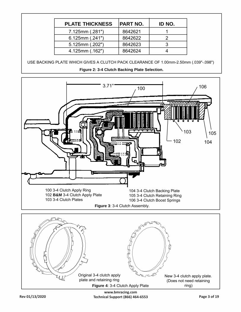
A new 3-4 clutch apply plate issupplied with this kit. The new applyplate replaces both the apply plateand the 3-4 clutch retainer. Figure 4shows the old and new parts.
The selective 3-4 clutch backingplate is not included as part of this kit.If the existing backing plate does not
produce the required clutch packclearance you will have to obtain thecorrect backing plate from a G.M.parts dealer. We have included a thin(.094") 3-4 clutch backing plate re-taining ring that can be used in pre-1988 units in place of the thicker(0.125") ring to extend a particularbacking plate’s adjustment range.
Installation of B&M’s 3-4CLUTCH PACK is similar to install-ing a stock 3-4 clutch pack. We rec-ommend that you consult the appro-priate transmission service manualfor information regarding specialtools, assembly procedures, bolttorques, service and diagnosis, etc.for items not covered here. The fol-lowing instructions assume the inputhousing is assembled up to the pointwhere the 3-4 clutch pack is to beinstalled.
INSTALLATION (See Figure 3)
STEP 1. Make sure the correct (3.71")3-4 clutch apply ring (#100) is in-stalled in input housing, then in-stall the following:
1. A new 3-4 clutch apply plate (#102).NOTE: This apply plate does notrequire the use of the original 3-4clutch apply ring retainer.
2. B&M supplied 3-4 clutch plates(#103), starting with compositionfaced plate first and alternate with
Congratulations! You have justpurchased the most versatile re-building kit available for the TH700(4L60) transmission. The B&MTH700 (4L60) Transkit containsspecial parts and instructions to up-grade your stock TH700 (4L60)transmission to the same specifica-tions used by B&M for building HighPerformance Street Strip TH700’s.
For transmission assembly anddisassembly procedures we recom-mend you consult the appropriateGM service manual for your particu-lar model year transmission. Theonly parts that differ from the stan-dard assembly and disassembly arethe valve body and accumulators(covered in the 70235 instructions)and the 3-4 clutch and the drain plug(covered in these instructions).
The TH700 (4L60) is a METRICdimensioned transmission so youwill need metric sockets andwrenches, in addition some of theoverhaul procedures REQUIRESPECIAL TOOLS for proper assem-bly and disassembly of the transmis-sion.IMPORTANT: We suggest that youtake the time to completely readthrough the instructions and checkthe parts list before beginning disas-sembly.
You will need approximately 5 Qts
Part No. 70232 1982 thru 1986Part No. 70233 1987 thru 1993
non-electronic models© B&M Racing and Performance Products 2009
Rev 1/13/2020 Page 1 of 19www.bmracing.com
Technical Support (866) 464-6553

steel plates (EXCEPTION: '87-'93install 15 tooth steel first).IMPORTANT: Index the five (5)wide slots on the steel plates withthe wide slots in the input housing.The wide slots are clearance forthe 3-4 clutch boost springs (#106)that will be installed after checkingthe clutch pack clearance.
3. Install original 3-4 clutch backingplate (#104) and thin (0.094 in.)retaining ring (#105) supplied withkit ('82-'86 only). The original back-ing plate may be too thick in whichcase you will have to use a thinnerbacking plate. Install the 3-4 clutchbacking plate with chamfer sideup.
CLUTCH CLEARANCE CHECK
STEP 2. 3-4 CLUTCH CLEARANCEWARNING: Do not omit this step,optimum 3-4 clutch operation anddurability depends on proper clutchpack end clearance setting.1. Check the end clearance between
the 3-4 clutch backing plate (#104)and the first composition facedplate (#103) with a feeler gage.Check the clearance all the wayaround between the plates to in-sure that the gap is uniform (platesare parallel). If the gap is not uni-form all around, recheck the instal-lation of the individual 3-4 clutchparts to determine cause.
2. Select the proper backing plate(#104) thickness from the chart(Figure 2 ) to obtain the correctclutch clearance. You can use thethick (0.125 in.) or thin (0.094") 3-4 Backing plate retaining ring(#105) in combination with selec-tive backing plates for additionalclearance adjustment range ('82-'86 models only).IMPORTANT: The 3-4 clutch packend clearance has a direct effecton 2-3 shift feel. For high perform-
ance applications the best 2-3 shiftfeel and 3-4 clutch pack life isobtained when the 3-4 clutch clear-ance is set as close to the low sideof the chart tolerance as possible.CAUTION: DO NOT set the 3-4clutch pack end clearance belowthe minimum dimension specified.ADDITIONAL CLUTCH PLATE
If you need additional clutch ca-pacity in the 3-4 clutch, it is possibleto add a seventh friction plate to theclutch in many case. As normallyassembled, there is a steel plate be-tween the 3-4 clutch apply plate andthe first friction plate. In many casesthe stack up of the clutch allows roomfor an additional friction plate to beinstalled between the apply plate andthe steel plate with the use of a thinbacking plate. The correct clutchclearance must be maintained withthe extra plate.
3-4 CLUTCH FINAL ASSEMBLY
STEP 3. Once the correct 3-4 clutchclearance has been determinedthe 3-4 clutch boost springs can beinstalled.
1. Remove 3-4 clutch Retaining ring(#105) and Backing plate (#104).
2. Install the five (5) 3-4 clutch boostspring assemblies (#106) as shownin ( Figure 2 ). Install the boostspring assemblies so the capturedend of the springs face the clutchbacking plate. IMPORTANT: The3-4 clutch boost springs are de-signed for use ONLY with the(3.71") long 3-4 clutch apply ring.The boost springs can be used infive (5) friction plate clutch packsBUT you must install two (2) extrasteel plates in the clutch pack toprevent the boost springs from be-coming coil bound (solid) as theclutch pack wears.
3. Install the 3-4 clutch backing plate
(#104) then compress 3-4 clutchboost springs and install 3-4 clutchretaining ring (#105).
BEFORE OPERATING VEHICLE
Once the transmission is installed inthe vehicle it is important to verify thatthe transmission’s hydraulic systemis functioning properly to prevent pre-mature component failure. At B&M ,every transmission we build is thor-oughly tested on a commercial trans-mission test stand to verify properoperation and correct oil pressures.We realize that a test machine is notavailable to most people using this kithowever, we strongly recommendchecking for correct oil pressures.Checking the oil pressures BEFOREdriving the vehicle should be consid-ered cheap insurance when com-pared against the cost of rebuildingthe transmission a second time be-cause a minor problem was not de-tected. Oil pressure tap locations,appropriate pressure charts andtrouble shooting guides are providedin most service manuals. You willneed a 0-300 PSI gage to check thepressures. Make sure the T.V. cableis properly connected and adjustedbefore checking oil pressures or op-erating the vehicle.
DRAIN PLUG INSTALLATION
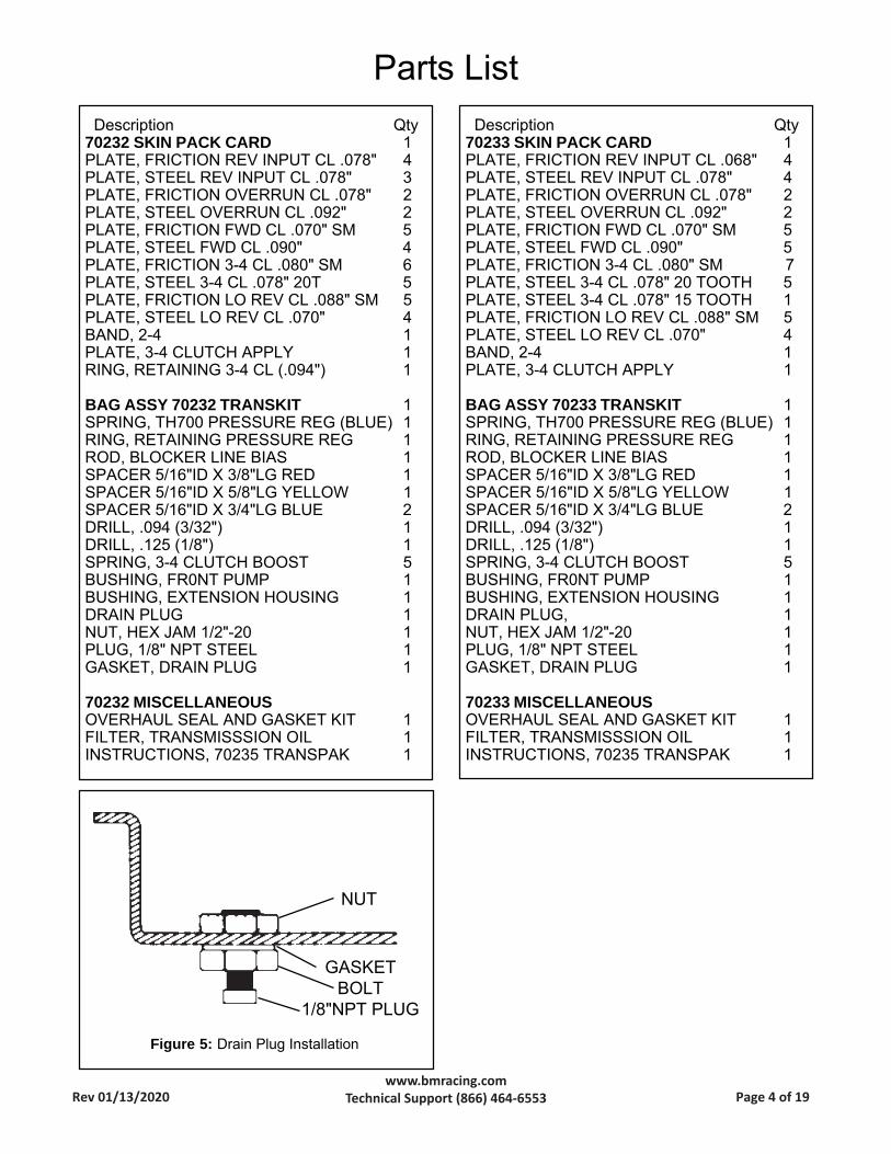
Locate mounting position inside panfor B&M Drain Plug. Make sure toavoid locating plug where it couldinterfere with internal transmissionparts, i.e. valve body, filter, servo,etc.Drill 1/2" diameter hole in positiondetermined. Remove all burrsaround hole and clean pan to avoidcontamination of transmission fluid.Install Drain Plug as shown in figure.Tighten nut to 25 lb.ft. maximum.Use wrench on bolt head to preventrotating entire assembly. (Figure 5 )
PLATE TYPE THICKNESS QUANTITY REQUIRED
FLAT STEEL 1.97mm (.078") 5CLUTCH PLATECOMPOSITION FACED 2.03mm (.079") 6CLUTCH PLATE
Figure 1: 3-4 Clutch Information Chart.
Rev 01/13/2020 Page 2 of 19www.bmracing.com
Technical Support (866) 464-6553
104 3-4 Clutch Backing Plate105 3-4 Clutch Retaining Ring106 3-4 Clutch Boost Springs
100 3-4 Clutch Apply Ring102 B&M 3-4 Clutch Apply Plate103 3-4 Clutch Plates
Figure 3 : 3-4 Clutch Assembly.
3.71" 100 106
105
104
103
102
Original 3-4 clutch applyplate and retaining ring
New 3-4 clutch apply plate.(Does not need retaining
ring)Figure 4 : 3-4 Clutch Apply Plate
PLATE THICKNESS PART NO. ID NO.7.125mm (.281") 8642621 16.125mm (.241") 8642622 25.125mm (.202") 8642623 34.125mm (.162") 8642624 4
USE BACKING PLATE WHICH GIVES A CLUTCH PACK CLEARANCE OF 1.00mm-2.50mm (.039"-.098")
Figure 2: 3-4 Clutch Backing Plate Selection.
Rev 01/13/2020 Page 3 of 19www.bmracing.com
Technical Support (866) 464-6553
Description Qty70233 SKIN PACK CARD 1PLATE, FRICTION REV INPUT CL .068" 4PLATE, STEEL REV INPUT CL .078" 4PLATE, FRICTION OVERRUN CL .078" 2PLATE, STEEL OVERRUN CL .092" 2PLATE, FRICTION FWD CL .070" SM 5PLATE, STEEL FWD CL .090" 5PLATE, FRICTION 3-4 CL .080" SM 7PLATE, STEEL 3-4 CL .078" 20 TOOTH 5PLATE, STEEL 3-4 CL .078" 15 TOOTH 1PLATE, FRICTION LO REV CL .088" SM 5PLATE, STEEL LO REV CL .070" 4BAND, 2-4 1PLATE, 3-4 CLUTCH APPLY 1
BAG ASSY 70233 TRANSKIT 1SPRING, TH700 PRESSURE REG (BLUE) 1RING, RETAINING PRESSURE REG 1ROD, BLOCKER LINE BIAS 1SPACER 5/16"ID X 3/8"LG RED 1SPACER 5/16"ID X 5/8"LG YELLOW 1SPACER 5/16"ID X 3/4"LG BLUE 2DRILL, .094 (3/32") 1DRILL, .125 (1/8") 1SPRING, 3-4 CLUTCH BOOST 5BUSHING, FR0NT PUMP 1BUSHING, EXTENSION HOUSING 1DRAIN PLUG, 1NUT, HEX JAM 1/2"-20 1PLUG, 1/8" NPT STEEL 1GASKET, DRAIN PLUG 1
70233 MISCELLANEOUSOVERHAUL SEAL AND GASKET KIT 1FILTER, TRANSMISSSION OIL 1INSTRUCTIONS, 70235 TRANSPAK 1
Description Qty70232 SKIN PACK CARD 1PLATE, FRICTION REV INPUT CL .078" 4PLATE, STEEL REV INPUT CL .078" 3PLATE, FRICTION OVERRUN CL .078" 2PLATE, STEEL OVERRUN CL .092" 2PLATE, FRICTION FWD CL .070" SM 5PLATE, STEEL FWD CL .090" 4PLATE, FRICTION 3-4 CL .080" SM 6PLATE, STEEL 3-4 CL .078" 20T 5PLATE, FRICTION LO REV CL .088" SM 5PLATE, STEEL LO REV CL .070" 4BAND, 2-4 1PLATE, 3-4 CLUTCH APPLY 1RING, RETAINING 3-4 CL (.094") 1
BAG ASSY 70232 TRANSKIT 1SPRING, TH700 PRESSURE REG (BLUE) 1RING, RETAINING PRESSURE REG 1ROD, BLOCKER LINE BIAS 1SPACER 5/16"ID X 3/8"LG RED 1SPACER 5/16"ID X 5/8"LG YELLOW 1SPACER 5/16"ID X 3/4"LG BLUE 2DRILL, .094 (3/32") 1DRILL, .125 (1/8") 1SPRING, 3-4 CLUTCH BOOST 5BUSHING, FR0NT PUMP 1BUSHING, EXTENSION HOUSING 1DRAIN PLUG 1NUT, HEX JAM 1/2"-20 1PLUG, 1/8" NPT STEEL 1GASKET, DRAIN PLUG 1
70232 MISCELLANEOUSOVERHAUL SEAL AND GASKET KIT 1FILTER, TRANSMISSSION OIL 1INSTRUCTIONS, 70235 TRANSPAK 1
Parts List
Figure 5: Drain Plug Installation
GASKETBOLT
1/8"NPT PLUG
NUT
Rev 01/13/2020 Page 4 of 19www.bmracing.com
Technical Support (866) 464-6553
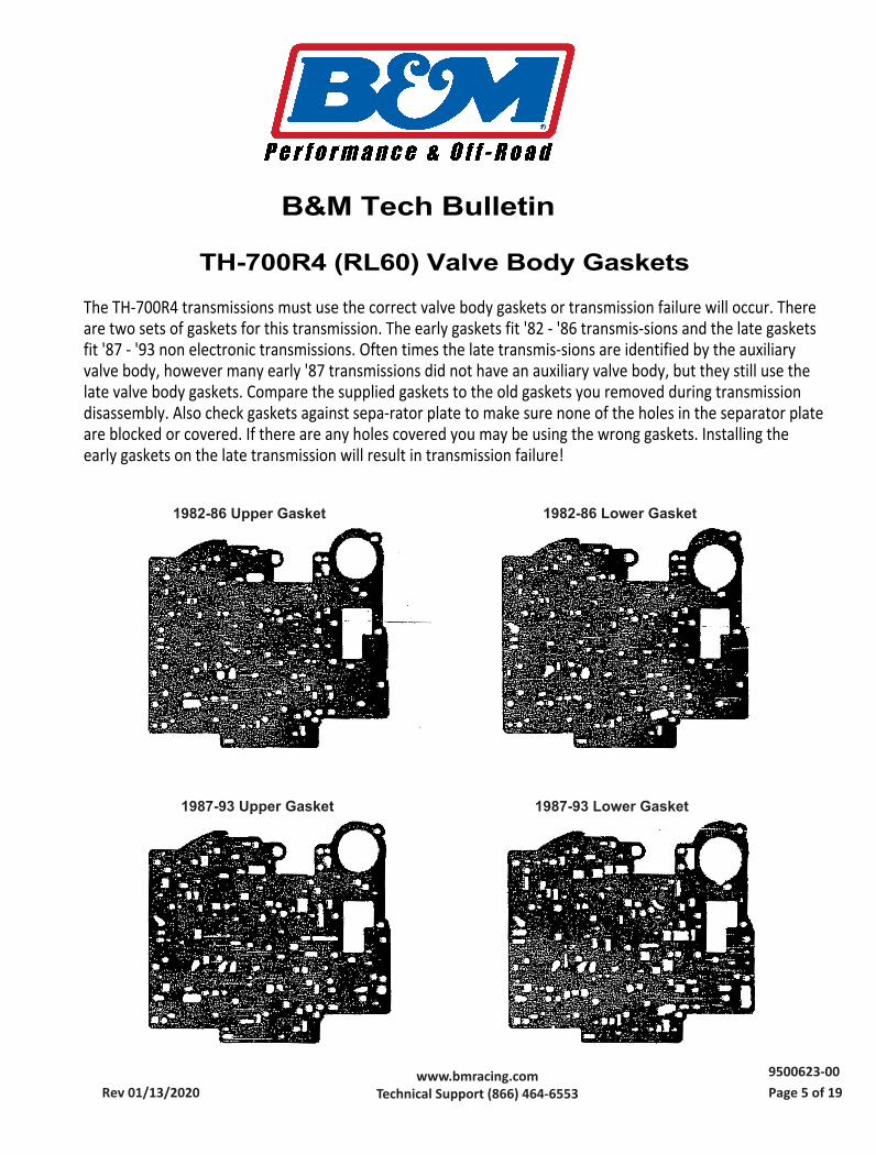
The TH-700R4 transmissions must use the correct valve body gaskets or transmission failure will occur. Thereare two sets of gaskets for this transmission. The early gaskets fit '82 - '86 transmis-sions and the late gasketsfit '87 - '93 non electronic transmissions. Often times the late transmis-sions are identified by the auxiliaryvalve body, however many early '87 transmissions did not have an auxiliary valve body, but they still use thelate valve body gaskets. Compare the supplied gaskets to the old gaskets you removed during transmissiondisassembly. Also check gaskets against sepa-rator plate to make sure none of the holes in the separator plateare blocked or covered. If there are any holes covered you may be using the wrong gaskets. Installing theearly gaskets on the late transmission will result in transmission failure!
Rev 01/13/2020 Page 5 of 19www.bmracing.com
Technical Support (866) 464-65539500623-00
1982-86 Lower Gasket 1982-86 Upper Gasket
1987-93 Upper Gasket 1987-93 Lower Gasket
TH-700R4 (RL60) Valve Body Gaskets
B&M Tech Bulletin

Installation Instructions
Transpak 1982-93 GM TH-700R4
(4L60) Non Electronic Transmission
Part Number 70235
©2001, 1996 by B&M Racing and Performance Products
The B&M TH-700 {4L60) Transpak
has been designed to work on all 1982
thru 1993 TH-700's (4L60's). This kit
WILL NOT work on 1992 and later
4L60E (electronic) models. During 1982
thru 1993 model years four major
changes were made to the TH-700's
hydraulic circuitry. It is important that
you know the year model of the trans
mission your working on so that you
can identify the correct checkball place
ment diagram. Figure 1 describes
where to look on your transmission for
model year identification. If the original
transmission in your vehicle was re
placed by a factory rebuild, the I.D.
number may have been changed. In
this case you will have to compare the
components in your transmission with
the check ball placement diagrams in
the instructions to determine the cor
rect check ball placement. WARNING: Incorrect checkball
placement can result in serious transmission damage. Be sure to
follow the instructions carefully.
We have included a section on TV
cable installation that will be helpful to
individuals using the TH-700 with after
market carburetors, manifolds or in a
custom vehicle installation.
B&M's TH-700 Transpak can be in
stalled by anyone with minimum me
chanical experience. It is however, im-
portant to closely follow the instruc
tions.
We recommend that you read
through the instructions completely before beginning the installation, so you can familiarize yourself with
the installation procedure and tools
required. Check the tool list at the
end of these instructions for the tools required to install your B&M
TH-700 Transpak.
NOTE: The B&M TH-700 Transpak is
not a cure-all for an ailing transmis
sion. If your transmission is slipping or
in poor general shape, the installation
of this Transpak may worsen the con
dition. However on a properly operating
transmission in average condition, the
Transpak will provide the kind of trans
mission performance your looking for.
When installing your Transpak there
are several other B&M products you
may wish to consider: TH-700 R4 KICKDOWN KIT #70237
The TH-700 has a hydraulic circuit that causes a forced 4-3 down shift when
ever the throttle is opened past two
thirds travel. In some applications a
part throttle forced 4-3 down shift is
undesirable, after many customer re
quests B&M has developed an easily
installed kit that will eliminate the part
throttle 4-3 down shift feature. This kit
does not alter normal shift speeds or
affect detent (wide open throttle 4-3)
operation. This kit is best installed
along with B&M's #70235 Transpak.
However it can also be installed inde
pendent of other modifications, and
valve body removal is not required (pan
gasket not included).
Converter Lockup Control #70244/ 70248 Provides electronic control of
the vehicle speed where lockup takes
place on GM transmissions with lockup
converter. Eliminates lock and unlock
cycling and premature unwanted
lockup. Also ideal for lockup operation
in vehicles that did not come with
lockup convertertransmissions. Works
with all GM lockup transmissions.
TRANSMISSION OIL COOLER We
feel that it is very important that every
vehicle in addition to the radiator heat
exchanger should have an oil cooler.
Heat is the major cause of transmis
sion failures, and an oil cooler is an
inexpensive safeguard against over
heating. B&M offers a wide range of
transmission coolers to suit every need,
which are available at your B&M dealer.
The TH-700 runs hotter than most other automatic transmissions, making an
oil cooler almost a necessity.
TRICK SHIFT PERFORMANCE ATF
Trick Shift performance automatictrans
mission fluid is the industry's leading
performance A TF. A specially blended
Rev 01/13/2020 Page 6 of 19www.bmracing.com
Technical Support (866) 464-65539500260-12
oil with foam inhibitors, extreme pressure agents and shift improvers, this fluid assures protection while deliver
ing the fastest possible shifts. You literally "Pour in performance." Available at your B&M dealer. DRAIN PLUG KIT #80250 TH-700
transmissions do not come from the factory equipped with drain plugs. The B&M Drain plug kit is inexpensive and easy to install. It eliminates the
mess of a fluid change or pan removal. POWER SWITCH KIT#80217 (1982
through 1989 TH-700's only) This kit
will enable you to select between normal Torque Converter Clutch (TCC) operation and having it unlocked in all gears except fourth. This kit can also be utilized for TCC control in custom installations of the TH-700. Keeping the TCC in the unlocked mode during
city driving saves wear and tear on the TCC as well as minimizing TCC engagement at low speeds. The B&M
Power Switch Kit will not prevent the TCC from locking in fourth gear ( overdrive). TCC engagement in fourth gear is required to preventtransmission overheating. Kit does not work on 1990 or
laterTH-700's. TH-700 DEEP OIL PAN #70289 The
B&M TH-700 deep oil pan ads approxi
mately 3 quarts of extra oil capacity to your transmission. The additional oil capacity will help reduce the temperature of your transmission, thereby promoting longer transmission life. TEMPERATURE GAUGE KIT#80212
Most transmission and converter failures can be traced directly to excessive heat. The B&M transmission tem
perature gauge can save you a costly repair bill by warning you ahead of time of an overheated transmission. The B&M temperature gauge is extremely
accurate and dependable, it comes with all necessary hardware and is easy to install.
INTRODUCTION
This kit can be installed in a few hours by carefully following the instructions. Read all instructions first to
familiarize yourself with the parts
and procedures. Transmission components are precision fit, work slowly and do not force any parts. Burrs and
dirt are the number one enemies of an
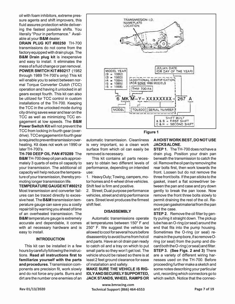
TRANSMISSION 1.0. NAMEPLATE LOCATIO
MODEL YEAR 19 = 1982)
JULIAN DATE (OR DAY OF THE YEAR)
ll : � �:il IAOOITlONAL IDENTIFicATION] 15 • 1985) I FOR SOME 1988 MOOE LS
._t5_=_l�9_S_Sl__, : ,..T_H_M-=-7-0=0--R-4...,
:,.__ ___ _. I I
I,....._..., 6 MK -Y- XXXXXXXX 1267 A
I Mo1o:L 1
1
l I roiroo l SERIAL NUMBER l �------------j r--�
SHIFT BUILT !>. & B = FIRST SHIFT C & H = SECOND SHIFT
Figure 1
automatic transmission. Cleanliness is very important, so a clean work surface from which oil can easily be
removed is necessary. This kit contains all parts neces
sary to obtain two different levels of performance, depending on intended
use: 1. HeavyDuty;Towing,campers,motor homes and 4-wheel drive vehicles.Shift feel is firm and positive.2. Street; Dual purpose performance
vehicles, street and strip performancecars. Street level produces the firmestshift feel.
DISASSEMBLY
Automatic transmissions operate at temperatures between 150° F and 250° F. We suggest the vehicle be
allowed to cool for several hours before disassembly to avoid burns from hot oil and parts. Have an oil drain pan ready to catch oil and a tray on which to put
small parts so they won't get lost. The vehicle should be raised so there is at least 2 feet ground clearance for ease
of installation and safety. MAKE SURE THE VEHICLE IS RIG
IDLY ANDSECURELYSUPPORTED,
JACK STANDS, WHEEL RAMPS OR
A HOIST WORK BEST, DO NOT USE
JACKS ALONE.
STEP 1. The TH-700 does not have a drain plug. Position your drain pan beneath the transmission to catch the oil. Remove the oil pan by removing the rear bolts first, then work towards the front. Loosen but do not remove the three front bolts. If the pan sticks to the gasket, insert a flat screwdriver between the pan and case and pry down gently to break the pan loose. Now
remove the front three bolts slowly to permit draining the rest of the oil. Remove pan gasket material from the pan and the case. STEP 2. Remove the oil filter by gen
tly pulling it straight down. The pickup tube has an O-ring ( or seal) around the end that fits into the pump housing. Sometimes the O-ring (or seal} re
mains in the pump bore, if so remove O
ring (or seal} from the pump and discard both the O-ring ( or seal} and filter. STEP 3. (See Figs. 2 and 3) There
are a variety of different wiring harnesses used on the TH-700. Before
proceeding further make a sketch and some notes describing your particular
unit, recording which connectors go to which switch. Notice that the connec-
Rev 01/13/2020 Page 7 of 19www.bmracing.com
Technical Support (866) 464-6553

tors are color coded. Now remove connectors from switches. Unplug the wiring harness from the case electrical connector by prying the lock tab away from the plug and pulling down on the plug, do not pull on the wires. Removing solenoid is not required, just tie the wires up out of the way. STEP 4. Remove al I except the center valve body bolt (See Fig. 2.) Beginning with the mid 1987model year, TH-700's have a tube crossing over the valve body. This tube is removed by simultaneously pulling both ends out of their respective bores. With the tube removed (if equipped) hold the valve body up firmly with one hand and remove the remaining bolt slowly. There are several check balls in the valve body along with several pints of oil. Have your drain pan ready to catch the oil and check balls (should they fall out.) Save all check balls in a safe place where they won 't get lost. STEP 5. Beginning mid 1987 model year, TH-700's have an auxiliary valve body located where earlier models have a cover plate (See Fig. 2.) Remove the cover plate or auxiliary valve body. Be careful not to drop the check ball located in the auxiliary valve body (See
Fig. 8.) Remove the 1-2 accumulator housing while holding the separator plate up to the case. Then slowly lower the separator plate and retrieve the check balls located above the plate. Make note of the color and location of the 1-2 and 2-3 accumulator springs for correct reassembly (See Fig. 10.)
Remove all old gasket material from
Servovent Do not block
this hole
0
,,,.,--
0
Throttleva linkage
G
Filterretai spring
0
/ rr
'
Converter clutch lockup solenoid
1-2 accumulatorhousing
Figure 2
connector
Draw a sketch of your wiring harness before disassembly.
Bolt LengthA 64.5mm B 19.5mm
D
E 44.5mm F 17.0mm
Rev 01/13/2020 Page 8 of 19www.bmracing.com
Technical Support (866) 464-6553
C 34.5mm 15.5mm

these parts. Note: Early 1982 TH-
700's had a support plate located
under the 1-2 accumulator hous
ing. If your transmission is fitted with this plate, carefully save the gasket as you will have to re-use the gasket upon reassembly (Gasket GM P/N 8642129 is not included in kit.)
MODIFICATIONS
STEP 6. Using the supplied drills, enlarge the holes in your separator plate as indicated in Fig. 4. Carefully deburr the holes after drilling. STEP 7. Rinse off valve body with clean solvent to remove any dirt or grit. Move to a clean working area. The valve body consists of precision fit components which will not tolerate dirt or burrs. STEP 8. Heavy Duty and Street;
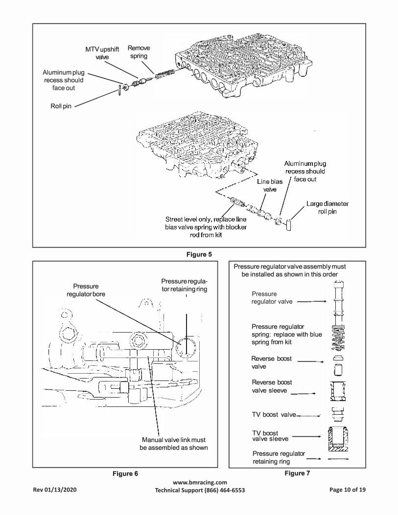
MTV upshift valve (See Fig. 5.)
Remove the pin at the end of the MTV upshift valve bore. Remove the plug, valve and spring from the bore. Set the spring aside (it will not be re-used.) Reinstall the valve, plug and pin in reverse orderof removal. STEP 9. Street Only; Line bias
valve.
Compress and remove the large roll pin retaining the line bias valve (See Fig.
5.) Take care to not distort the roll pin more than is required to remove it. Remove the aluminum plug, valve and spring from bore. The spring will not be re used. Insert the blocker rod from the kit into the bore. Install the valve and aluminum plug as removed. If the aluminum plug extends into the roll pin hole, remove the blocker rod and grind or file a small amount from either end of the blocker rod until the aluminum plug clears the roll pin hole when all parts are installed. STEP 10. Heavy Duty and Street;
Pressure regulator.
Remove the snap ring at the end of the pressure regulator bore in the oil pump assembly (See Fig. 6.) Use a screwdriver to hold the pressure regulator assembly while removing the retaining ring. If the sleeves stick in the bore, lightly rap the sleeve with a small rod and a mallet. Remove two sleeves with valves and the pressure regulator spring. The pressure regulator valve may fall out but it does not need to be removed.
Pry lock tab aside to remove plug
Figure 3
Note: additional model year I.D.
1982 thru mid-87 (2) holes mid-1987 to 1988 (2) holes
19
�
(�
:
:
0
Drill 1/8" (.125")
0
•
0 -;J C □ • 0 � -
0 0 •
n 0 0 Cl Do .�0•
,. :J 0
u, ···�0 ;:, • t:l
.G c:, Cl . Drill 1/8" (.125") 0
I ' ' f)
u J0 •
•
• n re C Q o: ...
c:i • .., C, u
an �
L IJ 0 •
◊
• 0 C o C w 0
• 0eo
Drill 3/32" (.094")
Figure 4
Reassemble the pressure regulator assembly using the BLUE spring from the kit (See Fig. 7.) Use the new retaining ring from the kit. Make sure the retaining ring is firmly seated in its groove when assembled. CAUTION:
The pressure regulator valve train
MUST be installed in the proper
order with the sleeves and valves
oriented in the indicated directions.
There are several ways the sleeves and
valves can be installed, however, only the orientation shown will work properly. Improper installation will cause low line pressure, resulting in slipping clutches and burned friction elements. It is very important to reassemble the pressure regulator correctly to insure proper operation of the transmission. Take a little extra time with this step and work slowly. This is a precision fit valve assembly so do not force the
Rev 01/13/2020 Page 9 of 19www.bmracing.com
Technical Support (866) 464-6553
MTV upshift Remove valve spring
Aluminum plug --------
� �--'1-recess should • _ §:,�-
face out ���
Roll pin�
Pressure regulator bore
Figure 6
Figure 5
Pressure regulator retaining ring
�
::::0 /I
; //
�--=---:::-./
Manual valve link must be assembled as shown
Pressure regulator valve assembly must be installed as shown in this order
Pressure regulator valve
Pressure regulator spring: replace with blue spring from kit
Reverse boostvalve
Reverse boostvalve sleeve __ _
TV boost valve�--
TV boostvalve sleeve
Pressure regulator retaining ring -
Figure 7
Rev 01/13/2020 Page 10 of 19www.bmracing.com
Technical Support (866) 464-6553

Check ball
position#2
0
0
0
position#2 position#1
Check ball Do not install check Check ball ball in this position
0 0
�, Cl Jj 01
�""- 0 �J�1 � .. �-�□f7(ro'j '� 0
I(����·� I
�� .� -� 01
Check ball
position#S
0 0
Do not install check
ball in this position
Figure 8 - Transmission without auxiliary valve body (Before mid-1987)
Do not install check
ball in this position
Check ball
position#1
0
0
0
Check ball Do not install check Check ball ball in this position
0 0
Check ball
position#S
0
Do not install check
ball in this position
Figure SA- Transmission with auxiliary valve body (mid-1987 to 1988)
Rev 01/13/2020 Page 11 of 19www.bmracing.com
Technical Support (866) 464-6553
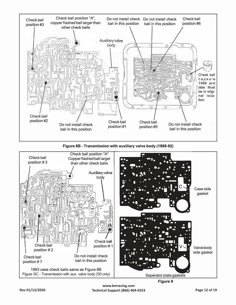
position#2 Do not install check
ball in this position
Check ball
position#1 Check ball
position#S
Check ball
position#6
Do not install check
ball in this position
Figure 88 - Transmission with auxiliary valve body (1988-92)
Check ball
position #3
Check ball
position # 2
Check ball
position# 7
Check ball position "A"
Copperflashed ball larger
than other check balls
position# 1
Do not install check
ball in this position
1993 case check balls same as Figure 88 Figure SC - Transmission with aux. valve body ('93 only) Separator plate gaskets
Figure 9
Case side
gasket
Valve body
side gasket
Rev 01/13/2020 Page 12 of 19www.bmracing.com
Technical Support (866) 464-6553

valves back into the bore. During reassembly, you can smear grease on the valve and spring before you insert them into the bore to hold them in place while you install the boost valve assembly. To ease installation a thin blade screwdriver can be used to hold the assembly up into the bore while you install the snap ring. Place the snap ring around the screwdriver and slide it up into place with the snap ring pliers. Be sure the snap ring goes into the groove and is not against the step in the bore.
ASSEMBLY
STEP 11. Heavy Duty and Street;
Check ball placement (See Fig's. 8, Sa and Sb.) Place check balls in the valve body, auxiliary valve body and case in the positions shown. Use a dab of grease or petroleum jelly to hold check balls in position. Beginning mid 1984 model year TH-700's have a check ball which is larger than the others in the valve body position 'A'. If your transmission is equipped with this check ball replace it in position 'A'. If your transmission does not have this check ball then place nothing in posi-
Accumulalor spacer placemen1 for heavy du1y level
tion 'A', pre mid 1984 transmissions were not equipped with a check ball in this position. STEP 12. Place the new separator plate gaskets on the separator plate (See Fig. 9.) Use a dab of grease or petroleum jelly to help hold the gaskets to the plate. The gasket with the 'C' cut in it goes next to the case and the gasket with the 'V' cut in it goes next to the valve body. Make sure no holes in the separator plate are cov
ered by the gasket. If your gaskets become damaged
anytime during the installation of the kit, replace them. If you cannot obtain B&M replacement gaskets then purchase OEM gaskets for your specific
year and model vehicle. STEP 13. Heavy Duty Only; Place the 3-4 accumulator pin in the case. Overthe pin place the RED (3/8") spacer sleeve, accumulator piston and spring (spring is installed at step 18.) Use a dab of grease or petroleum jelly to hold components in place (See Fig. 10)
Proceed to step 15.
STEP 14. Street Only; Place the 3-4
accumulator pin in the case. Over the pin place the BLUE (3/4") spacer and accumulator piston, using a dab of grease or petroleum jelly to hold them in place (See Fig. 11). Important
note: With piston and spacer installed in bore rub a straight edge on the case surface across the accumulator bore and verify the piston does not extend beyond the case surface. If the straight edge contacts the accumulator piston, grind or file a small amount from the spacer until the piston clears the straight edge. No spring is used for Street level performance. STEP 15. Heavy Duty Only; Remove the spring and piston from the 1-2 accumulator housing (See Fig. 10.)
Install over the pin the YELLOW spacer, piston (notice orientation) and spring. Proceed to step 17.
STEP 16. Street Only; Remove the spring and piston from the 1-2 accumulator housing (See Fig. 12.) Install both the BLUE and the RED spacers over the pin, then the piston (notice orientation.) No spring is used for Street level performance.
Accumula1or spacer placemeri1 1or street level
(Do no1 reinstall spr1rigs)
J " � 1-2 accumula1or�ousint tr �
� 1-2 Accumula1or �ousins ij • Yellow spacer, 5/8" long
®,-Accumula1or piston
---Accumu1a1or pis1on seal
i----1-2 accumulator spring
(m�Separatar pla1e and �� gasket assembly
11-3-4 occumulator spr,ng
(6 ,-Accumula1or piston seal
�3-4 accumula1or piston
i • Red spacer, 3/8" long
•✓- _ � 3-4 accumula1ar pis1on pin, ��1ll ., \1 �'16{� --��
. .-... [!�-, I
Figure 10
ij---Blue spacer, 3/4" long •---Red spacer, 3/8" long
(:)-1-2 accumulator pi:ston
{!) Accumula1or pi�ton seal
l't[)�separator plate and �i:J gasket assembly Cl) , Accumulator piston seal
�3-4 Accumulator pi:;;ton
• • Blue spacer 3/4" 1ong
� ____ • 11-3-4 Accumu1ator piston pin
��,�J_• �-�-��-= .J ' ··:-.1-·
. ,_ .,.\/: Figure 11
Rev 01/13/2020 Page 13 of 19www.bmracing.com
Technical Support (866) 464-6553

STEP 17. With the 3-4 accumulator components and case check balls in place, place the separator plate/ gasket assembly up to the case followed by the 1-2 accumulator housing assembly. Carefully line up the gaskets and install three accumulator housing bolts, tighten ONLY finger tight (See
Fig's. 2, 10 and 11.)
STEP 18. Install the auxiliary valve body (with check ball in correct position) or cover plate using the appropriate screws tightened ONL Yfinger tight (See Fig's. 2 and 8.)
STEP 19. Valve body installation.
Make sure check balls are in proper locations. Position the manual valve so the link rod can be engaged (See Fig.
6.) The link rod must be placed into the hole of the manual rod at a right angle, then rotated to allow the valve to enter the valve body bore. Do not force the valve at any time. When the valve is fully engaged, align the valve body and
Throttle valve linkage assembly
c6r \1, I ��Q, "'\ r-'\. � ; ( : . II
� .
'/ r�--
' <.'..>:v/ '
,�
. --...., -·
Figure 12
Reset tab
Engage this link before installing bolts. Link goes between lever and bracket.
Au1omatic cable adjuster
h Fi_tting
(rar lL Reset
Carburetor lever
Valve body assembly
� :: .... ,� .. " .
Throttle lever
1 I direction ,1----- -JI
1 I _____ .+---
Slider TV. cable housing
TV. Cable Resetting Procedute 1. Turn off engine.
, . • 1 Throttle lever & 2. Depress and hold reset tab then pullDI cable housing in reset direction. bracket assembly 3. Release reset tab.
TV. link
case holes then install one bolt finger tight to hold valve body in place. Engage all of the remaining bolts to finish lining up the separator plate and gaskets (See Fig. 2.) Tighten all the valve body, auxiliary valve body (or cover) and accumulator bolts (except cross
over tube clamp bolts and throttle
valve linkage bolts) to 11 NM (8 Ft. Lb.) Avoid striped threads, Do not
over tighten bolts.
STEP 20. lnstall the throttlevalve(TV)
4. Gently depress throttle pedal to the floor board. T.V. cable will automatically reset.
Figure 13
linkage onto the valve body as shown (See Fig. 12.) Engage the cable link with the large lever first. Hold the large lever up and the smaller one down. Then slip the assembly into position aligning it with the hold down bolt holes and engage the roll pin in the slot on the bracket. Insert bolts and tighten to 11 NM (8 Ft. Lb.) then make sure large lever operates freely. IMPORTANT
NOTE: The TV cable MUST be reset
before operating vehicle refer to
step 25.
STEP 21. Carefully insert ends of cross over tube in their respective bores and push in evenly until fully engaged (See Fig. 2.) Install cross over tube bolts and clamps and tighten to 11 NM (8 Ft. Lb.) Reconnect wiring harness connectors to the terminals from which they were removed. Referto sketch or notes made at Step 3. Reconnect the harness to the case connector making sure it is
Rev 01/13/2020 Page 14 of 19www.bmracing.com
Technical Support (866) 464-6553

firmly seated and locked.
STEP 22. Double check installation;
1: make sure all bolts are installed and
torqued. 2: Throttle valve linkage oper
ates freely. 3: Wiring properly con
nected. 4: Regulator valve retaining
ring fully seated in groove.
Coat the filter pickup tube seal with
clean ATF then push the filter tube into
the pump bore until it is fully seated.
Install filter retainer clip so it is located
at the small depression on the top side
of filter housing (See Fig. 2).
STEP 23. Remove any old pan gasket
material from pan and case pan rail. Clean inside of pan with solvent. You
may want to install a B&M Drain plug
kit (80250) at this time. Install the new
pan gasket on the pan and align the
holes. Use grease or petroleum jelly to
help hold the gasket in place during
installation of pan. Do not use any
gasket sealer or silicone com
pounds. To prevent premature band
failure make sure the hole shown in
Fig. 2 is not obstructed. Place pan up
to case, align holes and install all bolts
finger tight. Tighten bolts to 14 NM (10
Ft. Lb.) Do not over tighten bolts. If the
bolts are over tightened the gasket will
deform excessively and result in oil
leaks. STEP 24. Fill transmission with ATF
to the full mark on dip stick. You will
need about 4 to 6 quarts. Dexron 11 is
fine for Heavy Duty Level applica-
Hydraulic jack
tions however, we recommend B&M
Trick ShiftATF for Street level appli
cations. With vehicle still off the ground,
start the engine and shift transmission
through all gears. Check for leaks
around oil pan flange and drain plug.
Place selector in neutral and check the
fluid level. Stop engine and lower ve
hicle.
STEP 25. You must reset the TV
cable before operating vehicle, Fig
ure 14 shows the correct proce
dure. Failure to reset the TV cable
may result in poor shift quality and/
or transmission failure.
STEP 26. Test drive vehicle and re
check for leaks while transmission is
hot. Check fluid level again, adjusting
level as required.
SERVICE
For best performance of your TH-700
we recommend changing both the ATF
and filter every 15,000 miles (25,000
km) if the vehicle is driven under one ( or
more) of the following conditions:
A. High performance applications
where the vehicle is regularly driven
hard.
B. In heavy city traffic where the out
side temperature regularly reaches
90 F (32 C) or higher.
C. In hilly or mountainous terrain.
D. Uses such as taxi, police car or
delivery service.
TOOL LIST
Jack stands or Wheel ramps
Oil drain pan
3/8" drive ratchet wrench
2" extension
8mm, 10mm, 13mm, Sockets
Torque wrench
Internal retaining ring pliers
Needle nose pliers
Pan gasket
Upper valve body gasket
Lower valve body gasket
Pressure regulator spring
Filter with seal
Retaining ring
PARTS LIST
If you do not use the vehicle under any of these conditions, change the ATF
and filter every 50,000 miles (80,000
km). It's also a good idea to check the
torque converter bolts when servicing
the transmission.
Diagnosis procedure
If you experience a performance problem after installing the Transpak, it can
generally be traced to either an Im
properly set TV Cable or a Mis
installed component in the valve body
or pressure regulator. The following
procedure along with the trouble shoot
ing guide will assist you to correct the
problem. 1. Check and correct ATF level.
2. Check TV Cable adjustment (See
Fig. 13).
3. If engine performance indicates
an engine tune up is required, this
should be completed before road
testing or transmission correction is
attempted. Poor engine performance
can sometimes be mistaken for
transmission problems.
4. Check and correct vacuum lines
and fittings.
5. Check and correct shifter linkage.
6. Install oil pressure gage and
check line pressures. Compare
pressures with appropriate values
from Figure 14.
Gasket scraper
3/8" Drill motor
Fine cut flat file
Wet or Dry sand paper
Grease or petroleum jelly
Small punch or scribe
Small flat screwdriver
Funnel
Red accumulator spacer
Yellow accumulator spacer
(2) Blue accumulator spacer
Line bias valve blocker rod
3/32" drill
1/8" drill
Rev 01/13/2020 Page 15 of 19www.bmracing.com
Technical Support (866) 464-6553

OIL PRESSURE CHECK PROCEDURE
PRELIMINARY CHECK PROCEDURE
* CHECK TRANSMISSION OIL LEVEL
*CHECK AND ADJUST T.V. CABLE
* CHECK OUTSIDE MANUAL LINKAGE
* CHECK ENGINE TUNE
* INSTALL 0-300 PSI PRESSURE GAGE*CONNECT TACHOMETERTOENGINE
* CHECK OIL PRESSURE AS FOLLOWS
MINIMUM T.V. LINE PRESSURE CHECK: (A ) ATTACH PRESSURE GAUGE
With the T.V. Cable properly adjusted and the brakes applied, take the Line Pressure readings in the Ranges and at
the engine RPM's indicated in the chart.
FULL T.V. LINE PRESSURE CHECK:
Full T. V. Line Pressure readings are obtained by holding the T. V. Cable to the full extent of it's travel then take the Line Pressure readings in the Ranges and at the engine RPM's indicated in the chart.
CAUTION: Limit running time at FULL T.V. Pressure to two ( 2) minutes maximum to prevent over heating.
CAUTION: Brakes should be applied at all times.
TH700-R4 TRANSMISSION OIL PRESSURES
RANGE MODEL
PARK, NEUTRAL, ALL MODELS SEE OVERDRIVE, SEE NOTE BELOW MANUAL 3RD
@1000RPM
REVERSE ALL MODELS @ 1000 RPM SEE NOTE BELOW @ 2000 RPM
MANUAL 2ND & ALL MODELS MANUAL LOW SEE NOTE BELOW
@ 1000 RPM
NORMAL 01 L PRESSURE AT MINIMUM T.V.
kPa PSI
517-586 75-85
862-955 100-140
1517-1689 160-245
NORMAL OIL PRESSURE AT FULL T.V.
kPa PSI
1145-1400 166-203
1869-2296 180-3 40
1517-1689 160-295
NOTE: Oil Pressure at FULL T.V. Pressure depends on the particularT.V. Boost valve and Line Bias Valve arrangement of the unit. The Pressure reading obtained should be within the range shown.
Base Line Pressure is controlled by the Pressure Regulator Valve and Spring. Line pressure is boosted a fixed amount by the Reverse Boost valve when the selector lever is placed in Second or Low Range. The Line Pressure is also boosted in Neutral, Drive, Drive 3 and Reverse with throttle opening because of the T.V. system. The pressure is controlled by the T.V. Cable via the Throttle Lever and Bracket assembly to the Valve Body assembly.
The Line Pressure tap is located on the left side of the transmission case above the outside Manual Lever.
Figure 14 Oil Pressure Check Procedure
Rev 01/13/2020 Page 16 of 19www.bmracing.com
Technical Support (866) 464-6553
THROTTLE VALVE MECHANISM
The purpose of the TH700-R4 Throttle
Valve (T.V.) and it's mechanical linkage is to control both the shift feel and shift timing as a function of vehicle speed and load conditions. As the
accelerator pedal is depressed and the throttle opens, the T.V. mechanical
linkage relays the motion to the throttle plunger in the valve body by way of the
T.V. cable. In factory installations ofthe TH700-R4 the geometric relation
ship between the T.V. cable and throttle
shaft bellcrank produces the required
T.V. cable extension (pull) to throttleopening for the transmission to func
tion properly. In custom installationsthe correct T.V. cable mounting geometry must be accurately determined
if the transmission is to function properly. It cannot be overstated that for theTH700-R4, properT.V. cable installation and adjustment are paramount toproper transmission function and life.The following procedure will help youdesign a custom T.V. Cable installation that works. The main objective isto accurately position the T.V. cable
mounting bracket in relation to the
throttle shaft axis to obtain the properT. V. cable extension (PULL) to throttleOPEN I NG relationship.
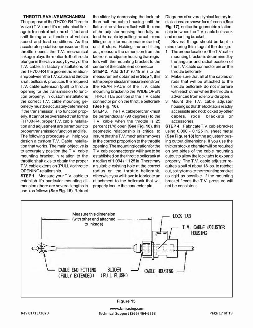
STEP 1. Measure your T.V. cable toestablish it's particular mounting di
mension (there are several lengths inuse.) as follows {See Fig. 15). Retract
the slider by depressing the lock tab then pull the cable housing until the flats on the slider are flush with the end
of the adjuster housing then fully extend the cable by pulling the cable end fitting out ( slider must remain retracted) until it stops. Holding the end fitting out, measure the dimension from the
face on the adjuster housing that registers with the mounting bracket to the
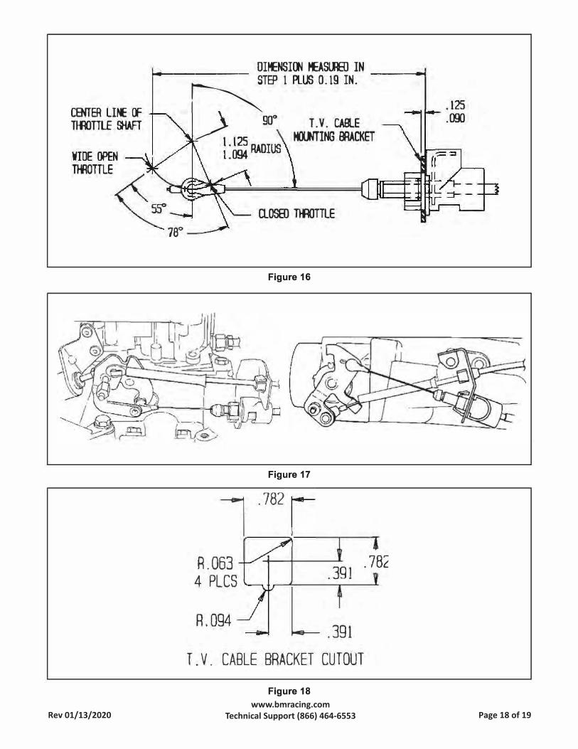
center of the cable end connector. STEP2. Add 3/16" (0.19 in.) to the
measurement obtained in Step 1, this
is the perpendicular measurement from
Diagrams of several typical factory in
stallations are shown for reference {See
Fig. 17), notice the geometric relation
ship between the T.V. cable bellcrank and mounting bracket.
Several things should be kept in
mind during this stage of the design: 1. The proper location of the T.V. cable
mounting bracket is determined bythe angular and radial position oftheT. V. cable connector pin on thethrottle bellcrank.
2. Make sure that all of the cables or
rods that will be attached to the
the REAR FACE of the T.V. cable mounting bracket to the WI DE OPEN
THROTTLE position of the T.V. cable connector pin on the throttle bell crank 3.{See Fig. 16).
throttle bellcrank do not interferewith each other when the throttle is
advanced from idle to wide open.
Mount the T.V. cable adjuster
housing so that the locktab is readilyaccessible and not blocked by othercables, rods, brackets or
STEP 3. TheT.V.cablebellcrankmust
be perpendicular (90 degrees) to the T.V. cable when the throttle is 25percent (1/4) open {See Fig. 16), this
geometric relationship is critical to
insure that the T.V. mechanism moves
in the correct proportion to the throttleopening. The mounting location for theT .V. cable connector pin will have to be
established on the throttle bell crank ata radius of 1.094 I 1.125 in. There may
a suitable existing hole at the correctradius on the throttle bellcrank,otherwise you will have to fabricate anattachment to the bellcrank that willproperly locate the connector pin.
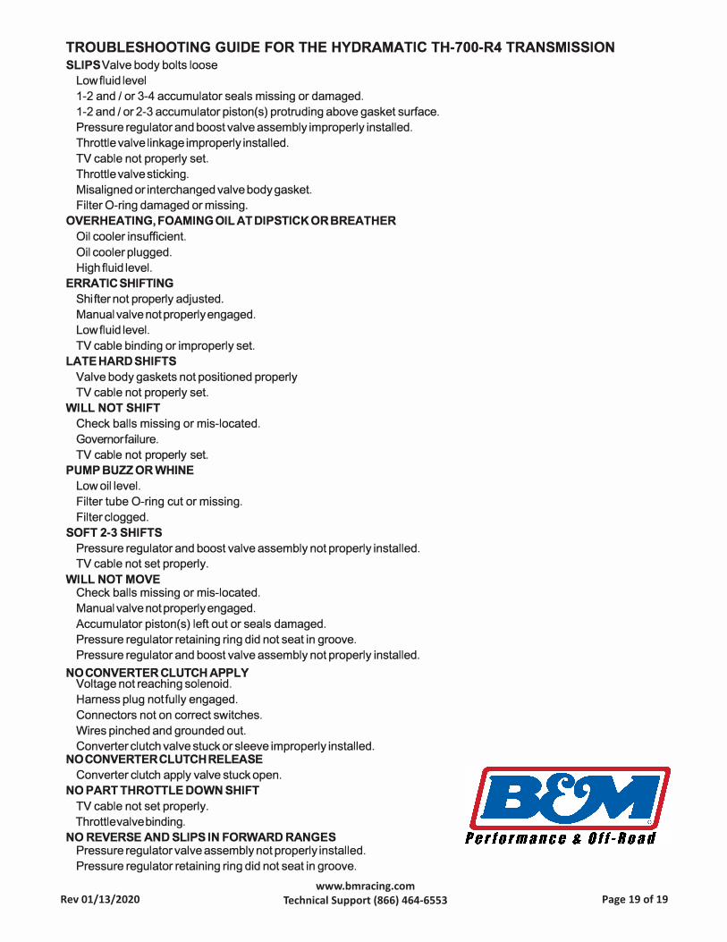
accessories.STEP 4. Fabricate T.V. cable bracket using 0.090 - 0.125 in. sheet metal
{See Figure 18) for the adjuster housing cutout dimensions. If you use the thicker stock a chamfer will be required
on two sides of the cable mounting cutout to al low the lock tabs to expand
properly. The T.V. cable adjuster requires a pull of about 18 lbs. to ratchet out, so try to make the mounting bracket as rigid as possible. If the mounting
bracket flexes the T.V. pressure will not be consistent.
Measure this dimension r- (with other end attached
1
to linkage)
LOCK TAB
T.V. CABLE NJJUSTER
�SING
CAfl.E E� FITTING
C Flll Y EXTENED )
SLI�
C PULL FLUSH )
Figure 15
CABLE HOUSING
Rev 01/13/2020 Page 17 of 19www.bmracing.com
Technical Support (866) 464-6553
CENTER LIN: (F
nronLE �
WIDE OPEN
llflOTTLE
OHENSI� �SIJEIJ IN ----- --� � STEP I Pllll 0. 19 IN.
\ 9[)° T.V. CABLE� 125 �ING BRACKET
l : 094 RADIUS
O.OS8l OOOTTLE
78°
�--
Figure 16
Figure 17
7.782
.391 R.063
4 PLCS
R.094 L .391
T.V. CABLE BRACKET CUTOUT
Figure 18
.78�
.125
.000
-
Rev 01/13/2020 Page 18 of 19www.bmracing.com
Technical Support (866) 464-6553
TROUBLESHOOTING GUIDE FOR THE HYDRAMATIC TH-700-R4 TRANSMISSION
SLIPS Valve body bolts loose
Lowfluid level
1-2 and/ or 3-4 accumulator seals missing or damaged.
1-2 and/ or 2-3 accumulator piston(s) protruding above gasket surface.
Pressure regulator and boost valve assembly improperly installed.
Throttle valve linkage improperly installed.
TV cable not properly set.
Throttle valve sticking.
Misaligned or interchanged valve body gasket.
Filter O-ring damaged or missing.
OVERHEATING,FOAMING OIL AT DIPSTICKORBREATHER
Oil cooler insufficient.
Oil cooler plugged.
High fluid level.
ERRATIC SHIFTING
Shifter not properly adjusted.
Manual valve not properly engaged.
Lowfluid level.
TV cable binding or improperly set.
LATE HARD SHIFTS
Valve body gaskets not positioned properly
TV cable not properly set.
WILL NOT SHIFT
Check balls missing or mis-located.
Govemorfailure.
TV cable not properly set.
PUMP BUZZ OR WHINE
Low oil level.
Filter tube O-ring cut or missing.
Filter clogged.
SOFT 2-3 SHIFTS
Pressure regulator and boost valve assembly not properly installed.
TV cable not set properly.
WILL NOT MOVE Check balls missing or mis-located.
Manual valve not properly engaged.
Accumulator piston(s) left out or seals damaged.
Pressure regulator retaining ring did not seat in groove.
Pressure regulator and boost valve assembly not properly installed.
NO CONVERTER CLUTCH APPLY Voltage not reaching solenoid.
Harness plug notfully engaged.
Connectors not on correct switches.
Wires pinched and grounded out.
Converter clutch valve stuck or sleeve improperly installed. NO CONVERTER CLUTCH RELEASE
Converter clutch apply valve stuck open.
NO PART THROTTLE DOWN SHIFT
TV cable not set properly.
Throttle valve binding.
NO REVERSE AND SLIPS IN FORWARD RANGES Pressure regulator valve assembly not properly installed.
Pressure regulator retaining ring did not seat in groove.
Rev 01/13/2020 Page 19 of 19www.bmracing.com
Technical Support (866) 464-6553