Installation Handbook - ReelSchematic
314
No. : Date : Installation Handbook No part of this manual may be copied or reproduced without written permission. If this manual is lost or worn, contact your dealer about replacement. The contents of this manual and equipment specifications are subject to change without notice. Edition-2
-
Upload
khangminh22 -
Category
Documents
-
view
1 -
download
0
Transcript of Installation Handbook - ReelSchematic

No. : Date :
Installation Handbook
No part of this manual may be copied or reproduced without writtenpermission. If this manual is lost or worn, contact your dealer about replacement. The contents of this manual and equipment specifications are subject tochange without notice.
Edition-2
www.reelschematic.comwww.reelschematic.com
ykimura
テキストボックス

The paper used in this manual
is elemental chlorine free.
FURUNO Authorized Distributor/DealerFURUNO Authorized Distributor/Dealer
9-52 Ashihara-cho,9-52 Ashihara-cho,Nishinomiya 662-8580, JAPANNishinomiya 662-8580, JAPAN
Telephone :Telephone : 0798-65-21110798-65-2111FaxFax 0798-65-42000798-65-4200::
FIRST EDITION :FIRST EDITION : JAN.JAN. 20072007Printed in JapanPrinted in JapanAll rights reserved.All rights reserved.
Pub. No.Pub. No. TIE-00160-ATIE-00160-A
(( NAYONAYO )) INSTALLATIONINSTALLATION
www.reelschematic.comwww.reelschematic.com

Contents
i
Introduction
Part-1. System Configuration 1. INMARSAT B: FELCOM 82A/B ・・・・・・・・・・・・・・・・・・・・・・・・・・・・・・・・・・・・・・・・ S-1 2. INMARSAT C: FELCOM 15 (GMDSS) ・・・・・・・・・・・・・・・・・・・・・・・・・・・・・・・・ S-2 3. INMARSAT C: FELCOM 15 (GMDSS+SSAS) ・・・・・・・・・・・・・・・・・・・・・・・・・ S-3 4. INMARSAT C: FELCOM 16 (SSAS) ・・・・・・・・・・・・・・・・・・・・・・・・・・・・・・・・・・ S-4 5. INMARSAT F: FELCOM 70 ・・・・・・・・・・・・・・・・・・・・・・・・・・・・・・・・・・・・・・・・・・・・ S-5 6. GMDSS Console: RC-1800F (150W/250W) ・・・・・・・・・・・・・・・・・・・・・・・・・・ S-6 7. GMDSS Console: RC-1800F (400W) ・・・・・・・・・・・・・・・・・・・・・・・・・・・・・・・・・ S-7 8. X-Band Radar: FAR-2817/2827 (Two Unit Type) ・・・・・・・・・・・・・・・・・・・・・・ S-8 9. S-Band Radar: FAR-2837S (Two Unit Type) ・・・・・・・・・・・・・・・・・・・・・・・・・・ S-9
10. X-Band Radar: FAR-2827W (Tree Unit Type) ・・・・・・・・・・・・・・・・・・・・・・・・・ S-10 11. S-Band Radar: FAR-2837SW (Tree Unit Type) ・・・・・・・・・・・・・・・・・・・・・・・・ S-11 12. Radar/ECDIS Network Configuration ・・・・・・・・・・・・・・・・・・・・・・・・・・・・・・・・・・ S-12 13. ECDIS: FEA-2107/2807 ・・・・・・・・・・・・・・・・・・・・・・・・・・・・・・・・・・・・・・・・・・・・・・・ S-13 14. U-AIS: FA-150・・・・・・・・・・・・・・・・・・・・・・・・・・・・・・・・・・・・・・・・・・・・・・・・・・・・・・・・・ S-14 15. Weather FAX Receiver: FAX-210/214/215/410/30・・・・・・・・・・・・・・・・・・・・・・ S-15 16. NAVTEX Receiver: NX-700A/B ・・・・・・・・・・・・・・・・・・・・・・・・・・・・・・・・・・・・・・・・ S-16 17. VDR (Voyage Data Recorder): VR-5000 ・・・・・・・・・・・・・・・・・・・・・・・・・・・・・・・ S-17 18. VDR (Voyage Data Recorder): VR-3000/3000S ・・・・・・・・・・・・・・・・・・・・・・・・ S-18 19. Doppler Speed Log: DS-80 ・・・・・・・・・・・・・・・・・・・・・・・・・・・・・・・・・・・・・・・・・・・・ S-19 20. Doppler Speed Log: DS-50 ・・・・・・・・・・・・・・・・・・・・・・・・・・・・・・・・・・・・・・・・・・・・ S-20 21. Doppler Speed Log: DS-30 ・・・・・・・・・・・・・・・・・・・・・・・・・・・・・・・・・・・・・・・・・・・・ S-21 22. Doppler Speed Log: DS-30 ・・・・・・・・・・・・・・・・・・・・・・・・・・・・・・・・・・・・・・・・・・・・ S-22 23. Navigational Echo Sounder: FE-700 ・・・・・・・・・・・・・・・・・・・・・・・・・・・・・・・・・・・ S-23 24. Navigational Echo Sounder: FE-700 ・・・・・・・・・・・・・・・・・・・・・・・・・・・・・・・・・・・ S-24
Contents www.reelschematic.comwww.reelschematic.com

Contents
ii
Part-2. Installation
Chapter 1. Radar 1.1 Arrangement of Antenna Mast・・・・・・・・・・・・・・・・・・・・・・・・・・・・・・・・・・・・・・・・・ 1-1
1.2 Installation of X-Band Radar・・・・・・・・・・・・・・・・・・・・・・・・・・・・・・・・・・・・・・・・・・・ 1-2
1.2.1 General Mounting of Radar antenna・・・・・・・・・・・・・・・・・・・・・・・・・・・・・・・ 1-2 1.2.2 Equipping the performance monitor: PM for X-Band Radar ・・・・・・・・ 1-3 1.2.3 Mounting of X-Band Radar: TR-UP Type antenna・・・・・・・・・・・・・・・・・・ 1-4 1.2.4 Mounting of X-Band Radar: TR-DOWN type antenna ・・・・・・・・・・・・・・ 1-7 1.2.5 Installation of Flexible Wave-Guide: TR-DOWN type・・・・・・・・・・・・・・・ 1-9 1.2.6 Mounting of X-Band Radar TR unit: TR-DOWN type ・・・・・・・・・・・・・・・ 1-12 1.2.7 Fabricating Wave-guide ・・・・・・・・・・・・・・・・・・・・・・・・・・・・・・・・・・・・・・・・・・・ 1-14
1.3 Installation of S-Band Radar・・・・・・・・・・・・・・・・・・・・・・・・・・・・・・・・・・・・・・・・・・・ 1-19
1.3.1 Mounting of Radar antenna ・・・・・・・・・・・・・・・・・・・・・・・・・・・・・・・・・・・・・・・ 1-19 1.3.2 Mounting of S-Band Radar: TR-UP type antenna ・・・・・・・・・・・・・・・・・・ 1-21 1.3.3 Mounting of S-Band Radar: TR-DOWN type antenna ・・・・・・・・・・・・・・ 1-23 1.3.4 Laying coaxial cable of S-Band Radar ・・・・・・・・・・・・・・・・・・・・・・・・・・・・・ 1-25 1.3.5 Mounting of S-Band Radar: TR-UP type Transceiver unit ・・・・・・・・・・ 1-27 1.3.6 Fabrication of coaxial cable and connector ・・・・・・・・・・・・・・・・・・・・・・・・ 1-28
1.4 Installation of Radar Console・・・・・・・・・・・・・・・・・・・・・・・・・・・・・・・・・・・・・・・・・・ 1-36
Chapter 2. ECDIS 2.1 Installation of ECDIS Console ・・・・・・・・・・・・・・・・・・・・・・・・・・・・・・・・・・・・・・・・・ 2-1
2.1.1 Mounting of ECDIS console ・・・・・・・・・・・・・・・・・・・・・・・・・・・・・・・・・・・・・・・ 2-1 2.1.2 Wiring of ECDIS console ・・・・・・・・・・・・・・・・・・・・・・・・・・・・・・・・・・・・・・・・・・ 2-2
2.2 Custom Ordered Console ・・・・・・・・・・・・・・・・・・・・・・・・・・・・・・・・・・・・・・・・・・・・・ 2-10
2.2.1 Installation ・・・・・・・・・・・・・・・・・・・・・・・・・・・・・・・・・・・・・・・・・・・・・・・・・・・・・・・・ 2-10 2.2.2 Wiring of Console ・・・・・・・・・・・・・・・・・・・・・・・・・・・・・・・・・・・・・・・・・・・・・・・・・ 2-10
2.3 Connection of EXT. Monitor for ECDIS ・・・・・・・・・・・・・・・・・・・・・・・・・・・・・・・・ 2-14
Chapter 3. MF/HF Radio 3.1 Installation of MF/HF Antenna No.1 ・・・・・・・・・・・・・・・・・・・・・・・・・・・・・・・・・・・ 3-1
3.1.1 Mounting of Antenna ・・・・・・・・・・・・・・・・・・・・・・・・・・・・・・・・・・・・・・・・・・・・・・ 3-1 3.1.2 Mounting of Antenna coupler ・・・・・・・・・・・・・・・・・・・・・・・・・・・・・・・・・・・・・・ 3-5
www.reelschematic.comwww.reelschematic.com

Contents
iii
3.2 Installation of MF/HF Antenna No.2 ・・・・・・・・・・・・・・・・・・・・・・・・・・・・・・・・・・・ 3-7 3.2.1 Mounting of antenna ・・・・・・・・・・・・・・・・・・・・・・・・・・・・・・・・・・・・・・・・・・・・・・ 3-7
3.3 Installation of Radio Console・・・・・・・・・・・・・・・・・・・・・・・・・・・・・・・・・・・・・・・・・・ 3-12 3.3.1 General Mounting of Radio console ・・・・・・・・・・・・・・・・・・・・・・・・・・・・・・・ 3-12 3.3.2 Mounting of RC-1800F console (150/250W: FS-1570/2570) ・・・・・・・ 3-14 3.3.3 Mounting of RC-1800F console (400W: FS-5000) ・・・・・・・・・・・・・・・・・ 3-21
3.4 Installation of RX antenna ・・・・・・・・・・・・・・・・・・・・・・・・・・・・・・・・・・・・・・・・・・・・・ 3-24
3.4.1 Mounting of Antenna junction box ・・・・・・・・・・・・・・・・・・・・・・・・・・・・・・・・・ 3-24 3.4.2 Installation of Antenna with Pre-amplifier ・・・・・・・・・・・・・・・・・・・・・・・・・・ 3-25
3.5 Installation of Reserve source (Battery) ・・・・・・・・・・・・・・・・・・・・・・・・・・・・・・・ 3-27
3.5.1 Lead-acid battery ・・・・・・・・・・・・・・・・・・・・・・・・・・・・・・・・・・・・・・・・・・・・・・・・・ 3-27 3.5.2 Maintenance Free battery ・・・・・・・・・・・・・・・・・・・・・・・・・・・・・・・・・・・・・・・・・ 3-29
Chapter 4. VHF Radio 4.1 Installation of VHF Antenna ・・・・・・・・・・・・・・・・・・・・・・・・・・・・・・・・・・・・・・・・・・・ 4-1
4.2 Installation of VHF Console ・・・・・・・・・・・・・・・・・・・・・・・・・・・・・・・・・・・・・・・・・・・ 4-3
4.3 Installation of Remote Station ・・・・・・・・・・・・・・・・・・・・・・・・・・・・・・・・・・・・・・・・・ 4-5
4.4 Installation of VHF Wing Handset ・・・・・・・・・・・・・・・・・・・・・・・・・・・・・・・・・・・・・ 4-7
Chapter 5. INMARSAT 5.1 General installation of Inmarsat Antenna ・・・・・・・・・・・・・・・・・・・・・・・・・・・・・ 5-1
5.2 Installation of INMARSAT B ・・・・・・・・・・・・・・・・・・・・・・・・・・・・・・・・・・・・・・・・・・・ 5-2
5.2.1 Antenna unit ・・・・・・・・・・・・・・・・・・・・・・・・・・・・・・・・・・・・・・・・・・・・・・・・・・・・・・ 5-2 5.2.2 Radio frequency Radiation hazard label ・・・・・・・・・・・・・・・・・・・・・・・・・・・ 5-3 5.2.3 Connecting Coaxial cable in Radome (FELCOM 82)・・・・・・・・・・・・・・・ 5-4 5.2.4 Installation of Transceiver unit and Junction box ・・・・・・・・・・・・・・・・・・・ 5-4 5.2.5 Mounting of FELCOM 82 Handset and TEL Distress Button unit ・・・ 5-5
5.3 Installation of INMARSAT C ・・・・・・・・・・・・・・・・・・・・・・・・・・・・・・・・・・・・・・・・・・・ 5-6
5.3.1 Mounting of Antenna unit・・・・・・・・・・・・・・・・・・・・・・・・・・・・・・・・・・・・・・・・・・ 5-6 5.3.2 Mounting of Terminal unit・・・・・・・・・・・・・・・・・・・・・・・・・・・・・・・・・・・・・・・・・・ 5-9 5.3.3 Installation of SSAS unit・・・・・・・・・・・・・・・・・・・・・・・・・・・・・・・・・・・・・・・・・・・ 5-11
www.reelschematic.comwww.reelschematic.com

Contents
iv
5.4 Installation of INMARSAT F・・・・・・・・・・・・・・・・・・・・・・・・・・・・・・・・・・・・・・・・・・・・ 5-15 5.4.1 Mounting of Antenna unit・・・・・・・・・・・・・・・・・・・・・・・・・・・・・・・・・・・・・・・・・・ 5-15 5.4.2 Radio frequency Radiation hazard label ・・・・・・・・・・・・・・・・・・・・・・・・・・・ 5-16 5.4.3 Mounting of BDE・・・・・・・・・・・・・・・・・・・・・・・・・・・・・・・・・・・・・・・・・・・・・・・・・・ 5-17 5.4.4 Wiring of Communication unit ・・・・・・・・・・・・・・・・・・・・・・・・・・・・・・・・・・・・・ 5-18 5.4.5 Wiring of Distress Alert unit・・・・・・・・・・・・・・・・・・・・・・・・・・・・・・・・・・・・・・・・ 5-20 5.4.6 Connection of ISDN devices・・・・・・・・・・・・・・・・・・・・・・・・・・・・・・・・・・・・・・・ 5-21 5.4.7 Connection of Analogue Telephone/G3 FAX (option) ・・・・・・・・・・・・・・ 5-22
Chapter 6. NAVTEX/FAX 6.1 Installation of NAVTEX ・・・・・・・・・・・・・・・・・・・・・・・・・・・・・・・・・・・・・・・・・・・・・・・・ 6-1
6.1.1 Mounting of NAVTEX antenna・・・・・・・・・・・・・・・・・・・・・・・・・・・・・・・・・・・・・ 6-1 6.1.2 NAVTEX Display unit・・・・・・・・・・・・・・・・・・・・・・・・・・・・・・・・・・・・・・・・・・・・・・ 6-2 6.1.3 NAVTEX Receiver unit ・・・・・・・・・・・・・・・・・・・・・・・・・・・・・・・・・・・・・・・・・・・・ 6-3
6.2 Installation of FAX Receiver ・・・・・・・・・・・・・・・・・・・・・・・・・・・・・・・・・・・・・・・・・・・ 6-4
6.2.1 Mounting of Antenna ・・・・・・・・・・・・・・・・・・・・・・・・・・・・・・・・・・・・・・・・・・・・・・ 6-4 6.2.2 Installation of FAX Receiver ・・・・・・・・・・・・・・・・・・・・・・・・・・・・・・・・・・・・・・・ 6-6
Chapter 7. GPS 7.1 Mounting of GPS antenna ・・・・・・・・・・・・・・・・・・・・・・・・・・・・・・・・・・・・・・・・・・・・・ 7-1
7.2 Mounting of GPS Display unit ・・・・・・・・・・・・・・・・・・・・・・・・・・・・・・・・・・・・・・・・・ 7-4
7.3 Mounting of GPS Multi-Distributor ・・・・・・・・・・・・・・・・・・・・・・・・・・・・・・・・・・・・ 7-5
Chapter 8. U-AIS 8.1 Mounting of AIS antenna ・・・・・・・・・・・・・・・・・・・・・・・・・・・・・・・・・・・・・・・・・・・・・・ 8-1
8.2 Mounting of AIS Display and Transponder units ・・・・・・・・・・・・・・・・・・・・・・ 8-2
8.2.1 AIS Display unit:FA-1502 ・・・・・・・・・・・・・・・・・・・・・・・・・・・・・・・・・・・・・・・・・ 8-2 8.2.2 AIS Transponder unit: FA-1501 ・・・・・・・・・・・・・・・・・・・・・・・・・・・・・・・・・・・・ 8-3 8.2.3 AIS Power Supply: PR-240-CE ・・・・・・・・・・・・・・・・・・・・・・・・・・・・・・・・・・・・ 8-4 8.2.4 Pilot Plug ・・・・・・・・・・・・・・・・・・・・・・・・・・・・・・・・・・・・・・・・・・・・・・・・・・・・・・・・・ 8-5
www.reelschematic.comwww.reelschematic.com

Contents
v
Chapter 9. VDR 9.1 VR-5000: Installation of Data Collecting unit (DCU) ・・・・・・・・・・・・・・・・・・・ 9-1
9.1.1 Mounting of DCU ・・・・・・・・・・・・・・・・・・・・・・・・・・・・・・・・・・・・・・・・・・・・・・・・・ 9-1 9.1.2 Wiring of DCU ・・・・・・・・・・・・・・・・・・・・・・・・・・・・・・・・・・・・・・・・・・・・・・・・・・・・ 9-4
9.2 VR-5000: Installation of Remote Alarm Panel and MIC ・・・・・・・・・・・・・・・・ 9-6 9.2.1 Remote alarm panel ・・・・・・・・・・・・・・・・・・・・・・・・・・・・・・・・・・・・・・・・・・・・・・ 9-6 9.2.2 Mounting of Bridge Microphone ・・・・・・・・・・・・・・・・・・・・・・・・・・・・・・・・・・・ 9-7 9.2.3 Mounting of Wing Microphone・・・・・・・・・・・・・・・・・・・・・・・・・・・・・・・・・・・・・ 9-9
9.3 VR-5000/VR-3000: Installation of DRU・・・・・・・・・・・・・・・・・・・・・・・・・・・・・・・・・ 9-11 9.3.1 Mounting of DRU ・・・・・・・・・・・・・・・・・・・・・・・・・・・・・・・・・・・・・・・・・・・・・・・・・ 9-11 9.3.2 Fixing DRU ・・・・・・・・・・・・・・・・・・・・・・・・・・・・・・・・・・・・・・・・・・・・・・・・・・・・・・・ 9-12 9.3.3 Connection of DRU ・・・・・・・・・・・・・・・・・・・・・・・・・・・・・・・・・・・・・・・・・・・・・・・ 9-13
9.4 Installation of VR-3000・・・・・・・・・・・・・・・・・・・・・・・・・・・・・・・・・・・・・・・・・・・・・・・・・ 9-16
Chapter 10. Life-saving Appliance 10.1 Installation of SART ・・・・・・・・・・・・・・・・・・・・・・・・・・・・・・・・・・・・・・・・・・・・・・・・・・ 10-1
10.2 Installation of Two-Way VHF Radio・・・・・・・・・・・・・・・・・・・・・・・・・・・・・・・・・・・ 10-2
10.3 Installation of EPIRB ・・・・・・・・・・・・・・・・・・・・・・・・・・・・・・・・・・・・・・・・・・・・・・・・・ 10-4
Chapter 11. Navigational Echo Sounder 11.1 Laying the Transducer cable ・・・・・・・・・・・・・・・・・・・・・・・・・・・・・・・・・・・・・・・・・ 11-1
11.2 Inner Hull Tank ・・・・・・・・・・・・・・・・・・・・・・・・・・・・・・・・・・・・・・・・・・・・・・・・・・・・・・・ 11-2
11.3 Installation of Display unit and Distribution box: FE-700 ・・・・・・・・・・・・ 11-6
11.3.1 Mounting of Display unit・・・・・・・・・・・・・・・・・・・・・・・・・・・・・・・・・・・・・・・・・・ 11-6 11.3.2 Mounting of Distribution box・・・・・・・・・・・・・・・・・・・・・・・・・・・・・・・・・・・・・・ 11-7 11.3.3 Mounting of Matching box・・・・・・・・・・・・・・・・・・・・・・・・・・・・・・・・・・・・・・・・ 11-8 11.3.4 Mounting of Transducer cable/flange ・・・・・・・・・・・・・・・・・・・・・・・・・・・・・ 11-9
www.reelschematic.comwww.reelschematic.com

Contents
vi
Chapter 12. Doppler Sonar 12.1 Laying the Transducer cable ・・・・・・・・・・・・・・・・・・・・・・・・・・・・・・・・・・・・・・・・・ 12-1
12.2 Installation of DS-30 transducer・・・・・・・・・・・・・・・・・・・・・・・・・・・・・・・・・・・・・・ 12-2
12.2.1 Hull fixed tank ・・・・・・・・・・・・・・・・・・・・・・・・・・・・・・・・・・・・・・・・・・・・・・・・・・・ 12-2 12.2.2 Gate-valve Tank ・・・・・・・・・・・・・・・・・・・・・・・・・・・・・・・・・・・・・・・・・・・・・・・・・ 12-7
12.3 Installation of DS-50 transducer・・・・・・・・・・・・・・・・・・・・・・・・・・・・・・・・・・・・・・ 12-10
12.3.1 Hull tank ・・・・・・・・・・・・・・・・・・・・・・・・・・・・・・・・・・・・・・・・・・・・・・・・・・・・・・・・・ 12-10 12.3.2 Installing tank with Gate-valve・・・・・・・・・・・・・・・・・・・・・・・・・・・・・・・・・・・・ 12-13
12.4 Installation of DS-80 transducer・・・・・・・・・・・・・・・・・・・・・・・・・・・・・・・・・・・・・・ 12-19 12.4.1 Gate-valve tank: DS-782・・・・・・・・・・・・・・・・・・・・・・・・・・・・・・・・・・・・・・・・・ 12-19 12.4.2 Gate-valve tank: DS-786・・・・・・・・・・・・・・・・・・・・・・・・・・・・・・・・・・・・・・・・・ 12-22 12.4.3 Hull tank: DS-783 ・・・・・・・・・・・・・・・・・・・・・・・・・・・・・・・・・・・・・・・・・・・・・・・・ 12-25 12.4.4 Hull Tank : DS-784・・・・・・・・・・・・・・・・・・・・・・・・・・・・・・・・・・・・・・・・・・・・・・・ 12-26 12.4.5 Protruded hull tank・・・・・・・・・・・・・・・・・・・・・・・・・・・・・・・・・・・・・・・・・・・・・・・ 12-28
12.5 Example of installations ・・・・・・・・・・・・・・・・・・・・・・・・・・・・・・・・・・・・・・・・・・・・・ 12-29
12.5.1 Example of DS-50 installation ・・・・・・・・・・・・・・・・・・・・・・・・・・・・・・・・・・・ 12-29 12.5.2 Example of DS-30 installation ・・・・・・・・・・・・・・・・・・・・・・・・・・・・・・・・・・・ 12-35
Appendix 1. Acoustic Equipment AP1.1 Transducer Position (DS-30/50/80, FE-700)・・・・・・・・・・・・・・・・・・・・・・・・・ AP1-1
AP1.2 Piping Transducer cable ・・・・・・・・・・・・・・・・・・・・・・・・・・・・・・・・・・・・・・・・・・・ AP1-5
AP1.3 Installation on ship with protruded keel・・・・・・・・・・・・・・・・・・・・・・・・・・・・ AP1-6
Appendix 2. Antenna Installation AP2.1 Safety measures・・・・・・・・・・・・・・・・・・・・・・・・・・・・・・・・・・・・・・・・・・・・・・・・・・・・ AP2-1
AP2.2 Antenna arrangement ・・・・・・・・・・・・・・・・・・・・・・・・・・・・・・・・・・・・・・・・・・・・・・ AP2-3
AP2.3 Table of antenna interactions ・・・・・・・・・・・・・・・・・・・・・・・・・・・・・・・・・・・・・・ AP2-16
Appendix 3. Radar Waveguide AP3.1 Waveguide for X-Band Radar・・・・・・・・・・・・・・・・・・・・・・・・・・・・・・・・・・・・・・・ AP3-1
AP3.2 Waveguide for S-Band Radar・・・・・・・・・・・・・・・・・・・・・・・・・・・・・・・・・・・・・・・ AP3-8
www.reelschematic.comwww.reelschematic.com

Contents
vii
Appendix 4. Cables AP4.1 Power cable ・・・・・・・・・・・・・・・・・・・・・・・・・・・・・・・・・・・・・・・・・・・・・・・・・・・・・・・・ AP4-1
AP4.2 Coaxial cable ・・・・・・・・・・・・・・・・・・・・・・・・・・・・・・・・・・・・・・・・・・・・・・・・・・・・・・・ AP4-8
Appendix 5. Basic Skill AP5.1 Cable Termination ・・・・・・・・・・・・・・・・・・・・・・・・・・・・・・・・・・・・・・・・・・・・・・・・・・ AP5-1
AP5.2 How to solder・・・・・・・・・・・・・・・・・・・・・・・・・・・・・・・・・・・・・・・・・・・・・・・・・・・・・・・ AP5-9
AP5.3 Waterproofing by taping・・・・・・・・・・・・・・・・・・・・・・・・・・・・・・・・・・・・・・・・・・・・ AP5-15
www.reelschematic.comwww.reelschematic.com

This page is intentionally left blank.
www.reelschematic.comwww.reelschematic.com

Introduction
1
The present document summarizes basic matters in installation. Be sure to see the installation manual. Even if your case does not fall under any installation cases stipulated in this document, we hope that you would understand the purpose and properly dispose of your case.
1. Grounding of the equipments is required to prevent electric shock and noise. Be sure to ground the equipments without fault.
2. It shall not be thought that signal lines of cables only constitute electric wiring. “Armour” and “Shield” of cables are also important electric circuits (ground-circuits). Connect them to the specified places.
3. Consider water leakage and corrosion (electrolytic corrosion). For example, apply taping or silicon sealant to prevent these.
4. Secure the cable wiring length with maintenance taken into account. For example, excessively short cable length between equipment and cable entrance to the unit prevents the unit from being pulled out.
5. Identify the connection to the cable. 6. Even if a wiring place is hidden, wire carefully, neatly, securely and in a
proper cable length. In addition, be sure to wiring of the equipments without fault.
7. Use terminal crimper tools, soldering irons, screwdrivers, and other tools that are properly for the purpose.
Points to consider in installation 1. Equipment under the installation Equipment to be installed is precision instruments apparatus. In addition, they are user’s property. While installing is underway, cover the equipment with vinyl sheet, etc. to prevent dust and damage. Protect the conductor of coaxial cables and signal cables of outboard wiring with taping, etc. to prevent exposure to rain.
Introduction
Protect with sheet.
Cover with sheet.
Provide taping toprevent exposureto rain.
www.reelschematic.comwww.reelschematic.com

Introduction
2
2. Cabling 2.1 When a unit is installed under a table, etc., give consideration to the cable
length so that the unit could be pulled out for easy maintenance.
2.2 Armour cable
In general, it is required that metal covering of equipment at voltage exceeding safety-voltage and metal covering of cable (Armour) should be grounded. Safety-voltage means 50 V or lower between conductors, or between conductor and ground. Based on this, the armour of armour cables, which are connected to the equipment should be grounded to the ship body at the coming outlet, and if it is unable to provide grounding to the hull at the coming outlet, it should be grounded by a cable clamp of equipment. Armour is connected to the designated place in connection drawings or installation manual, follow the method. Apply taping to the armour peeled off portion or cable sheath peeled off portion.
Cable should have alength that enables theunit to be pulled out.
Ex. Clamp armour withcable clamp of the unit.
Ex. Clamp armourwith cable clamp.
www.reelschematic.comwww.reelschematic.com

Introduction
3
2.3 Shield wire Insulate the shield wire by taping or heat shrink tubing, and connect (ground) to designated place in the connection drawing or installation manual. For example, use a Crimp-on lugs when connecting to chassis of equipment. In addition, protect the shield wire with taping or heat shrink tubing to prevent shorting to electrical circuits.
Taping
Ex. Connect shield wire to F.GND terminal.
Ex. Clamp armourwith cable clamp.
www.reelschematic.comwww.reelschematic.com

Introduction
4
3. Grounding Be sure to ground the unit to prevent electric shock and noise prevention. Grounding of the antenna coupler contributes to noise prevention and sensitivity improvement. The concept of grounding is to use a thick and short conductor. Use ground wires and ground copper strap thicker (wider) than those designated in connection drawings.
4. Coaxial connector Coaxial connectors should be surely processed using appropriate connectors suited to coaxial cables. After attach the antenna cable connector, it must be cable check. In the case of M-type coaxial connectors, if any “loose” occurs when the shell and coaxial cable are twisted, the attachment is not successful. In the case of N-type coaxial connectors, protruded pins, retracted pins more than required or bent pins, the attachment is not correct. Furthermore, any loose that occurs when coaxial connector or coaxial cables are pulled or pressed, the attachment is not successful.
Ground bolt (more than 6 mm)
Ground wire
Ground bolt (more than 6 mm)
Ground wire
Ground wire
For groundcopper strap
Ground for copper strap with steel plate
www.reelschematic.comwww.reelschematic.com

Introduction
5
5. Waterproof and corrosion Exposed ground connected portions and cable glands of units installed outboard should be protected with silicon sealant or putty without fault to prevent water leakage and corrosion. In addition, any portion where water leakage might occur, such as coaxial cable connector connected portions should be applied with taping using self-bounding tape and vinyl tape. Also, applying silicon sealant to mounting bolts, etc. can prevent slackening of bolts.
Water leakage/corrosion prevented portions Methods
Ground connections of each unit Silicon sealant or putty Ground connections of antenna post Silicon sealant or putty Coaxial connector connections Self-welding tape + plastic tape Radar and INMARSAT mounting bolts Silicon sealant or putty VHF antenna element mounting portions Self-welding tape + plastic tape Antenna with PRE-AMP mounting portions Silicon sealant or putty Unit gland part Silicon sealant or putty
Miscellaneous places where water leakage may occur Self-welding tape + plastic tape, Silicon sealant or putty
Ground
Gland
Ground
Antenna mounting bolt
Connector connected portion
Apply the whole Crimp-onlug with silicon sealant.
www.reelschematic.comwww.reelschematic.com

Introduction
6
Reference: Electrolytic corrosion The silicon sealant is applied to antenna mounting bolts. This is to prevent electrolytic corrosion, which is generated by contact between Radar antenna (aluminum- chassis) and antenna base (iron), and dissimilar metal of mounting bolts (stainless steel). Conditions of electrolytic corrosion include existence of moisture. Consequently, to prevent electrolytic corrosion, silicon sealant should be used to prevent moisture from existing at the mounting portion. The antenna bracket should be properly mounted. Excessively tightening the bracket with unnecessarily strong force will not only deform the bracket but also peels off paint of antenna mounting mast and from this portion, corrosion of the mast begins.
As the bolt is excessively tightened, the antenna bracket is deformed.
Fault mounting; U-bolt is not mounted straight. In addition, the paint of antenna mountingmast peels off at the time of mounting.
www.reelschematic.comwww.reelschematic.com

Introduction
7
6. Fixing of cables When cables are fixed with stainless band, tighten the stainless band with proper force with care to prevent damage to the cable. If the cable sheath is damaged, water leaks from the portion and corrodes the cable. In addition, when cables are fix with cable tie, use weather-resistant. Unless the cable is securely fixed, the cable is chafed against the antenna pole and damaged. For example, coaxial cables of GPS antenna and INMARSAT C antenna should be allowed to put through the mounting bracket pipe. In such event, the pipe head end and the coaxial cable are chafed to each other, and the coaxial cable is damaged. To prevent it, they are protected by vinyl tape or silicon sealant.
Weather-resistant cable tie
Stainless band: Tighten with proper force.
Taping to protect by vinyltape or silicon sealant,etc. because a chafe maydamage the cable.
Fixing cable
When coaxial cable is bent,secure a bend radius morethan 10 times as much asthe cable diameter.
Taping withvinyl tape
www.reelschematic.comwww.reelschematic.com

Introduction
8
Fixing cable
Cut or fix the excessportion of hose clamp.
Fix connection ofconnector portionwith cable tie. (Top, Middle andBottom portions)
Separate between connection of connector portion and antenna mounting mast, because of the chafe with vibration.
Use weather-resistantcable tie.
Apply silicon sealant tothe ground terminal.
Apply silicon sealant to the ground terminal.
Taping to protect by vinyl tape or silicon sealant, etc. because a chafe may damage the cable.
www.reelschematic.comwww.reelschematic.com

Introduction
9
7. Wiring Connect wires carefully, neatly, and securely. When wires are fixed by cable tie, etc., bundle core wires of the cable to easily check wiring later, or connect wires in accord with the signals related to each other. Where should be connected the “Armour” and the “Shield wire”?
Connect wires carefully,neatly, and securely.
In the case of the drawing on the left, connect the shield wire to the number of the designated terminal board. “Armour” is not particularly designated. It would be appropriate to ground at the coming outlet.
COM-A
COM-B
TD-A
TD-B7
8
9
10
11
12
TTYCS-1
TTYCS-1
TB
TD-A
TD-B
FG
COM-A
COM-B
FG
7
8
9
10
11
12
TTYCS-1
TTYCS-1
TB
In the case of the drawing on the left, connect the shield wire to the chassis inside the equipment. For example, tighten together with the P.C.B fixing screw; then, connect to the screw on the chassis using a crimp-on lug. “Armour” is not particularly designated.It would be appropriate to ground at the coming outlet.
www.reelschematic.comwww.reelschematic.com

Introduction
10
In the case of the drawing on the left, connect the shield wire to the chassis inside the equipment. For example, tighten together with the P.C.B fixing screw; then, connect to the screw on the chassis using a crimp-on lug. Clamp “Armour” at the cable clamp portion of theequipment.
COM-A
COM-B
TD-A
TD-B7
8
9
10
11
12
TTYCS-1
TTYCS-1
TB
COM-A
COM-B
TD-A
TD-B7
8
9
10
11
12
TTYCS-1
TTYCS-1
TB
In the case of the drawing on the left, clamp the “Armour” and the “Shield wire” at the cable clamp portion of the equipment.
www.reelschematic.comwww.reelschematic.com

The system configurations diagram described here is not all. General system configurations are described.
S-1 1. INMARSAT B: FELCOM 82A/B S-2 2. INMARSAT C: FELCOM 15 (GMDSS) S-3 3. INMARSAT C: FELCOM 15 (GMDSS + SSAS) S-4 4. INMARSAT C: FELCOM 16 (SSAS) S-5 5. INMARSAT F: FELCOM 70 S-6 6. GMDSS Console: RC-1800F (150W/250W) S-7 7. GMDSS Console: RC-1800F (400W) S-8 8. X-Band Radar: FAR-2817/2827 (Two Unit Type) S-9 9. S-Band Radar: FAR-2837S (Two Unit Type) S-10 10. X-Band Radar: FAR-2827W (Tree Unit Type) S-11 11. S-Band Radar: FAR-2837SW (Tree Unit Type) S-12 12. Radar/ECDIS Network Configuration S-13 13. ECDIS: FEA-2107/2807 S-14 14. U-AIS: FA-150 S-15 15. Weather FAX Receiver: FAX-210/214/215/410/30 S-16 16. NAVTEX Receiver: NX-700A/B S-17 17. VDR (Voyage Data Recorder): VR-5000 S-18 18. VDR (Voyage Data Recorder): VR-3000/3000S S-19 19. Doppler Speed Log: DS-80 S-20 20. Doppler Speed Log: DS-50 S-21 21. Doppler Speed Log: DS-30 S-22 22. Doppler Speed Log: DS-30 S-23 23. Navigational Echo Sounder: FE-700 S-24 24. Navigational Echo Sounder: FE-700
www.reelschematic.comwww.reelschematic.com

Sy
stem
Con
figur
atio
n
S-
1
1. IN
MA
RSA
T B
: FEL
CO
M 8
2A/B
Ant
enna
Uni
t (IB
-182)
TEL
(opt
ion)
B-F
AX
Han
dset
& B
rack
et
Term
inal
uni
t
for T
LX(IB
-582)
Prin
ter
(PP-
510)
MSD
(9.6
kbp
s)
GPS
Junc
tion
BO
X(IB
-581
) C
omm
unic
atio
n U
nit (
IB-2
82)
DIS
. But
ton
for
TT EELL
(IB-3
62)
DIS
. But
ton
for
TT LLXX
(IB-3
52)
- 8D
-FB
-CV
(30/
50 m
) - 1
2D-S
FA-C
V (1
00 m
)
Cla
ss A
HSD
(64
kbps
)
HSD
I/F
ex: K
lass
hop
per
Prin
ter
(PP-
510)
Gyr
o
IB-8
82IB
-882
-362
(with
DIS
. but
ton)
Inco
min
g IN
D(IB
-372
)
Cla
ss A
or
Max
. 3 u
nits
Cre
dit C
all A
dapt
er(IB
-781
)
TEL1
-3
PBX
Uni
t (IB
-782
)
TEL3
Cla
ss B
FELC
OM
82A
: Cla
ss A
(TLX
) FE
LCO
M 8
2B: C
lass
B
TEL
or F
AX
: Max
. 8 u
nits
Con
nect
PB
X to
TE
L3
term
inal
, whe
n ad
ding
TE
Lor
FA
X.
Con
nect
TE
L, F
AX
or
Cre
dit C
all A
dapt
er to
TE
L1, 2
or 3
term
inal
.
www.reelschematic.comwww.reelschematic.com

Sy
stem
Con
figur
atio
n
S-
2
2. IN
MA
RSA
T C
: FEL
CO
M 1
5 (G
MD
SS)
Term
inal
Uni
t (IC
-215
)
Ant
enna
Uni
t (IC
-115
)
Prin
ter
(PP-
510)
Ala
rm U
nit
(IC-3
06)
Dis
tres
s A
lert
/Rec
eive
d C
all U
nit (
IC-3
05)
- TP
5FB
AW
-5D
FBB
(30
m)
- 8D
-FB
-CV
(50
m)
- 12D
-SFA
-CV
(100
m)
Junc
tion
Box
(IC
-315
) A
C/D
C P
ower
Sup
ply
(PR
-240
-CE)
Max
. 3 u
nits
NAV
dat
a
Bui
lt in
GP
S(O
ptio
n)
Shi
p’s
Mai
n (1
00/2
20 V
AC
)
Res
erve
sou
rce
(24
VD
C)
24 V
DC
Dis
tres
s M
essa
ge
Con
trol
ler U
nit (
DM
C-5
)
GPS
www.reelschematic.comwww.reelschematic.com

Sy
stem
Con
figur
atio
n
S-
3
3. IN
MA
RSA
T C
: FEL
CO
M 1
5 (G
MD
SS +
SSA
S)
Term
inal
Uni
t (IC
-215
)
Ant
enna
Uni
t (IC
-115
)
Prin
ter
(PP-
510)
Dis
tres
s A
lert
/Rec
eive
d C
all U
nit (
IC-3
05)
Junc
tion
Box
(IC
-315
) A
C/D
C P
ower
Sup
ply
(PR
-240
-CE)
Ala
rm U
nits
(
IC-3
06)
Max
. 3 u
nits
Shi
p’s
Mai
n (1
00/2
20 V
AC
)
Res
erve
sou
rce
(24
VD
C)
24V
DC
NAV
dat
a
- TP
5FB
AW
-5D
FBB
(30
m)
- 8D
-FB
-CV
(50
m)
- 12D
-SFA
-CV
(100
m)
GPS
SSA
S A
lert
Uni
t (IC
-307
) M
ax. 3
uni
ts
Bui
lt in
GP
S(O
ptio
n)
www.reelschematic.comwww.reelschematic.com

Sy
stem
Con
figur
atio
n
S-
4
4. IN
MA
RSA
T C
: FEL
CO
M 1
6 (S
SAS)
Com
mun
icat
ion
Uni
t (IC
-216
)
Ant
enna
Uni
t (IC
-116
)
PC
(Ow
ner s
uppl
y)
AC
/DC
Pow
er S
uppl
y ( P
R-2
40-C
E)
Shi
p’s
Mai
n (1
00/2
20 V
AC
)
Res
erve
Sou
rce
Bui
lt-in
GP
S
24 V
DC
Junc
tion
Box
(IC-3
15)
- TP
58A
15W
-RG
58 (1
5 m
) - T
P5F
BA
W-5
DFB
B (3
0 m
)- 8
D-F
B-C
V (5
0 m
) - 1
2D-S
FA-C
V (1
00 m
)
For g
ener
al c
omm
unic
atio
n
RS
-232
C
SSA
S A
lert
Uni
t (IC
-307
) M
ax. 3
uni
ts
www.reelschematic.comwww.reelschematic.com

Sy
stem
Con
figur
atio
n
S-
5
5. IN
MA
RSA
T F:
FEL
CO
M 7
0
GPS
Seria
l Prin
ter
(ML-
280)
RS4
22-R
S232
Le
vel C
onve
rter
RS4
22RS
232(
A),
(B)
RS
232(
A),
(B)
- 8D
-FB
-CV
(30/
50/6
0 m
) - 1
2D-S
FA-C
V (1
00 m
)
Ant
enna
Uni
t (S
F-17
0)
Com
mun
icat
ion
Uni
t(S
F-27
0)
Dis
tres
s A
lert
uni
t (
SF-3
70)
ISD
N H
ands
et
(SF-
870)
Max
. 100
m
Max
. 3 m
Max
. 3 m
TEL4
TEL3
TEL1
TEL2
TEL
TEL
G3
FAX
TA
(QD
GY9
1191
2)
ISD
N W
all s
ocke
t IS
DN
Bus
Lin
e: M
ax. 1
00 m
Port
Se
rvic
e R
emar
ks
RS
232(
A)
*RS2
32(B
)U
SB
Ser
ial P
rinte
rvt
Lite
Mob
ileU
DI,
MP
DS
Max
. 3m
*RS4
22
vtLi
te M
obile
UD
I, M
PD
S
Max
. 10
0m
Not
e: C
hang
ing
of b
etw
een
RS2
32(B
) an
d R
S422
ar
e se
t by
men
u se
tting
.
100
- 230
VA
C
US
B M
ax. 3
m
220
VAC
- IS
DN
dev
ice:
Max
. 7
Not
e: S
ervi
ce o
f IS
DN
por
t: vt
Lite
Mob
ile a
nd M
PD
S =
NO
U
DI =
YE
S
- IS
DN
Bus
: lin
e M
ax. 1
00 m
long
- A
nalo
gue
port
line
: Max
. 150
m lo
ng
G3
FAX
Ana
logu
e TE
L
Anal
ogue
Tel
.
G4
FA
X
ISD
N T
EL
ISD
N H
ands
et
PC
(ne
sasr
y le
vel co
nver
ter)
Inco
min
g In
dica
tor
www.reelschematic.comwww.reelschematic.com

Sy
stem
Con
figur
atio
n
S-
6
6. G
MD
SS C
onso
le: R
C-1
800F
(150
W/2
50W
)
DSC
/NB
DP
Prin
ter
INM
-C P
rinte
r
INM
-CN
BD
PM
F/H
F R
T
MF/
HF
WR
AN
T
2.6
m W
hip
AN
T+
Pre-
AM
P
INM
-C A
NT
MF/
HF
RT
AN
T(A
T-10
1DS2
)
SSA
S A
lert
Uni
t
(IC-3
07)
Max
. 3 u
nits
MF/
HF
ATU
Ale
rm U
nit
(IC
-306
) D
istr
ess
Ale
rt/R
ecei
ved
Cal
l Uni
t (IC
-305
)
GPS
Bac
kup
24 V
DC
Bac
kup
24 V
DC
No.
1 VH
F (R
T+D
SC+W
R)
No.
2 VH
F (R
T+D
SC+W
R)
WR
AN
T R
T A
NT
WR
AN
T R
T A
NT
Shi
p’s
Mai
n
Res
erve
Sou
rce
(Rad
io B
ATT.
)
BAT
T. 2
4 V
DC
BAT
T. C
harg
er
AC
/DC
Pow
er
AC
/DC
Pow
er
Nam
e Ty
pe
MF/
HF
RT
(RT+
DS
C+W
R)
FS-1
570/
2570
NB
DP
B
uilt-
in
FS-1
570/
2570
IN
M-C
FE
LCO
M15
BAT
T. C
harg
erBC
-615
8 BC
-615
3 A
C/D
C P
ower
P
R-3
00
AC
/DC
Pow
er
PR
-850
AR
P
rinte
r P
P-5
10
No.
1/2
VH
F (R
T+D
SC
+WR
)FM
-880
0S/D
www.reelschematic.comwww.reelschematic.com

Sy
stem
Con
figur
atio
n
S-
7
7. G
MD
SS C
onso
le: R
C-1
800F
(400
W)
DSC
/NB
DP
Prin
ter
INM
-C P
rinte
r
INM
-C
NB
DP
MF/H
F R
T C
ontr
olle
r
MF/
HF
WR
AN
T
2.6
m W
hip
AN
T+
Pre-
AM
P
INM
-C A
NT
MF/
HF
RT
AN
T (A
T-10
1DS2
)
SSA
S A
lert
Uni
t (IC
-307
)M
ax. 3
uni
ts
MF/
HF
ATU
Ale
rm U
nit
(IC
-306
) D
istr
ess
Ale
rt/R
ecei
ved
Cal
l Uni
t (IC
-305
)
Bac
kup
24 V
DC
No.
1 VH
F (R
T+D
SC+W
R)
No.
2 VH
F (R
T+D
SC+W
R)
WR
AN
T R
T A
NT
WR
AN
T R
T A
NT
Shi
p’s
Mai
n
Res
erve
Sou
rce
(Rad
io B
ATT)
BAT
T. 2
4 V
DC
BAT
T. C
harg
er
AC
/DC
Pow
er
AC
/DC
Pow
er
Nam
e
Type
M
F/H
F R
T (R
T+D
SC
+WR
)FS
-500
0
NB
DP
D
P-6
IN
M-C
FE
LCO
M15
BAT
T. C
harg
erBC
-615
8 BC
-615
3 A
C/D
C P
ower
P
R-3
00
AC
/DC
Pow
er
PR
-850
AR
P
rinte
r P
P-5
10
No.
1/2
VH
F (R
T+D
SC
+WR
)FM
-880
0S/D
MF/H
F DSC
MF/
HF
TR U
nit
www.reelschematic.comwww.reelschematic.com

Sy
stem
Con
figur
atio
n
S-
8
8. X
-Ban
d R
adar
: FA
R-2
817/
2827
(Tw
o U
nit T
ype)
VDR
A
IS
Gyr
o D
oppl
er L
OG
GPS
HU
B
(HU
B-1
00)
100
- 220
VA
Cor
24
VD
C
Ant
enna
Uni
t:R
SB-0
96/0
97
- FA
R-2
817:
RTR
-078
(12k
W)
- FA
R-2
827:
RTR
-079
(25k
W)
100-
220
VAC
24 V
DC
RS-
422
IEC
6116
2-1/
2
IEC
6116
2-1/
2
IEC
6116
2-1/
2, S
tep/
Syn
c S
ig.
IEC
6116
2-2 R
/G/B
/H-V
Syn
c.
Proc
esso
r Uni
t (R
PU-0
13)
Con
trol
Uni
t (R
CU
-014
/015
)
Rem
ote
Uni
t (R
CU
-016
)
100B
AS
E-T
ECD
IS
FAR
-2xx
7 Se
ries
Rad
ar
Con
figur
atio
n of
Con
sole
Uni
ts
- Con
trol U
nit
- Dis
play
Uni
t - H
UB
- G
yro
Con
verte
r - R
GB
Buf
f - D
VI-R
GB
Con
verte
r - B
NC
Con
nect
or C
onve
rter
Dis
play
uni
t (M
U-2
01C
R/2
31C
R)
RW
-960
0 (1
00 m
)
RS4
22
Con
sole
- R
NC
-001:Sl
im T
ype
(23-
inch
) - R
NC
-002:Sl
im T
ype
(20-
inch
) - R
NC
-003:St
anda
rd T
ype(
23-in
ch)
- RN
C-0
04:St
anda
rd T
ype(
20-in
ch)
Bui
lt in
PM
BNC
Con
nect
or
Con
verte
r
De-
Icer
(100
VA
C)
www.reelschematic.comwww.reelschematic.com

Sy
stem
Con
figur
atio
n
S-
9
9. S
-Ban
d R
adar
: FA
R-2
837S
(Tw
o U
nit T
ype)
VDR
A
IS
Gyr
o D
oppl
er L
OG
GPS
HU
B
(HU
B-1
00)
100
- 220
VA
Cor
24
VD
C
RS4
22
IEC
6116
2-1/
2
IEC
6116
2-1/
2
IEC
6116
2-1/
2, S
tep/
Syn
c S
ig.
R/G
/B/H
-V S
ync.
Rem
ote
Uni
t (R
CU
-016
)
100B
AS
E-T
ECD
IS
FAR
-2xx
7 Se
ries
Rad
ar
Dis
play
Uni
t (M
U-2
01C
R/2
31C
R)
RS4
22
100-220V
AC
24V
DC
3 ph
ase
/200
-440
VA
C
Proc
esso
r Uni
t(R
PU-0
13)
Bui
lt in
PM
Con
sole
- R
NC
-001:Sl
im T
ype
(23-
inch
) - R
NC
-002:Sl
im T
ype
(20-
inch
) - R
NC
-003:St
anda
rd T
ype
(23-
inch
) - R
NC
-004:St
anda
rd T
ype
(20-
inch
)
Con
figur
atio
n of
Con
sole
Uni
ts
- Con
trol U
nit
- Dis
play
Uni
t - H
UB
- G
yro
Con
verte
r - R
GB
Buf
f - D
VI-R
GB
Con
verte
r - B
NC
Con
nect
or C
onve
rter
Con
trol
Uni
t (R
CU
-014
/015
)
RW
-960
0 (1
00 m
)
BNC
Con
nect
or
Con
verte
r Ant
enna
Uni
t:R
SB-0
98/0
99/1
00/1
01/1
02
FAR
-283
7S/2
137S
: RTR
-080
(30
kW)
Pow
er S
uppl
y U
nit
(PSU
-007
) D
e-Ic
er (1
00 V
AC
)
AN
T-O
N
IEC
6116
2-2
www.reelschematic.comwww.reelschematic.com

Sy
stem
Con
figur
atio
n
S-
10
10. X
-Ban
d R
adar
: FA
R-2
827W
(Tre
e U
nit T
ype)
VDR
A
IS
Gyr
o D
oppl
er L
OG
GPS
HU
B
(HU
B-1
00)
100
- 220
VA
Cor
24
VD
C
Ant
enna
Uni
t: R
SB-1
03
100-
220
VAC
24 V
DC
IE
C61
162-
1/2
IEC
6116
2-1/
2
IEC
6116
2-1/
2, S
tep/
Syn
c S
ig.
R/G
/B/H
-V S
ync.
Con
trol
Uni
t (R
CU
-014
/015
)
Rem
ote
Uni
t (R
CU
-016
)
100B
AS
E-T
ECD
IS
FAR
-2xx
7 Se
ries
Rad
ar
Dis
play
uni
t (M
U-2
01C
R/2
31C
R)
RW
-960
0
RS-
422
MP
YC
Y-19
Processor
Unit
TR U
nit
(RTR
-081
)
Wav
e G
uide
(F
R-9
or W
RJ-
9)
Bui
lt in
PM
C
onfig
urat
ion
of C
onso
le U
nits
- C
ontro
l Uni
t - D
ispl
ay u
nit
- HU
B
- Gyr
o C
onve
rter
- RG
B B
uff
- DV
I-RG
B C
onve
rter
- BN
C C
onne
ctor
Con
verte
r
De-
Icer
(100
VA
C)
BNC
Con
nect
or
Con
verte
r
IEC
6116
2-2
Con
sole
- R
NC
-001:Sl
im T
ype
(23-
inch
) - R
NC
-002:Sl
im T
ype
(20-
inch
) - R
NC
-003:St
anda
rd T
ype
(23-
inch
) - R
NC
-004:St
anda
rd T
ype
(20-
inch
)
www.reelschematic.comwww.reelschematic.com

Sy
stem
Con
figur
atio
n
S-
11
11. S
-Ban
d R
adar
: FA
R-2
837S
W (T
ree
Uni
t Typ
e)
VD
R
AIS
Gyr
o D
oppl
er L
OG
G
PS
HU
B
(HU
B-1
00)
100
- 220
VA
Cor
24
VD
C
RS-
422
IEC
6116
2-1/
2
IEC
6116
2-1/
2, S
tep/
Syn
c S
ig.
R/G
/B/H
-V S
ync.
100B
AS
E-T
ECD
IS
FAR
-2xx
7 Se
ries
Rad
ar
RW
-960
0
RS-422
Pro
cess
or
Unit
(RP
U-013)
100-
220
VAC
24 V
DC
D
ispl
ay U
nit
(MU
-201
CR
/231
CR
)
Coa
xial
cab
le
(LH
PX
-20D
-AS
SY
)
Bui
lt in
PM
TR U
nit
(RTR
-082
)
MP
YC
Y-12
Ant
enna
Uni
t: R
SB-1
04/1
05
3-Ph
ase
AC
De-
Icer
(100
VA
C)
BNC
Con
nect
or
Con
verte
r
Con
trol
Uni
t (R
CU
-014
/015
)
Rem
ote
Uni
t (R
CU
-016
)
IEC
6116
2-1/
2
IEC
6116
2-2
Con
figur
atio
n of
Con
sole
Uni
t
- Con
trol U
nit
- Dis
play
uni
t - H
UB
- G
yro
Con
verte
r - R
GB
Buf
f - D
VI-R
GB
Con
verte
r - B
NC
Con
nect
or C
onve
rter
Con
sole
- R
NC
-001:Sl
im T
ype
(23-
inch
) - R
NC
-002:Sl
im T
ype
(20-
inch
) - R
NC
-003:St
anda
rd T
ype
(23-
inch
) - R
NC
-004:St
anda
rd T
ype
(20-
inch
)
www.reelschematic.comwww.reelschematic.com

Sy
stem
Con
figur
atio
n
S-
12
12. R
adar
/EC
DIS
Net
wor
k C
onfig
urat
ion
ナ
100B
ASE
-T
HU
B
(HU
B-1
00)
8-po
rts
100
- 220
VA
C
No.
1 EC
DIS
No.
1 FA
R-2
xx7
Serie
s R
adar
N
o.2
ECD
ISN
o.2
FAR
-2xx
7 Se
ries
Rad
ar
No.
3 FA
R-2
xx7
Serie
s R
adar
www.reelschematic.comwww.reelschematic.com

Sy
stem
Con
figur
atio
n
S-
13
13. E
CD
IS: F
EA-2
107/
2807
RC
U-0
18
Con
trol
Uni
t
RC
U-0
15
RC
U-0
16C
onin
g In
dica
tor
Dig
itize
r
Prin
ter
115
- 230
VA
C
Dis
play
Uni
t (M
U-2
01C
E/23
1CE)
115
- 230
VA
C
- AIS
- T
rack
Pilo
t - A
MW
SS
- R
oute
Bac
kup
- GP
S
- Ane
mom
eter
- E
cho
Sou
nder
- L
og/D
ual A
xis
Log
- Gyr
ocom
pass
- E
ngin
e C
ontro
l - W
ater
Tem
p In
dica
tor
- Ala
rms
B A
dapt
er(E
C-1
020)
- Gyr
ocom
pass
(S
ync.
/Ste
p)
- Ala
rms
- Ana
log
Sen
sors
24 V
DC
HU
B
(H
UB
-100)
Rad
ar/A
RPA
(F
AR
-2xx
7 se
ries)
ECD
IS/2
nd S
tatio
n
LAN
Ada
pter
(E
C-1
010)
Eth
erne
t
Proc
esso
r Uni
t(E
C-1
000C
)
ECD
IS C
onso
le
- Dis
play
Uni
t - C
ontro
l Uni
t - P
roce
ssor
Uni
t - H
UB
- L
AN
Ada
pter
- B
Ada
pter
- P
ower
Sup
ply
for
LA
N A
dapt
er
- UP
S
www.reelschematic.comwww.reelschematic.com

Sy
stem
Con
figur
atio
n
S-
14
14. U
-AIS
: FA
-150
AC
/DC
Pow
er S
uppl
y (P
R-2
40-C
E)
Shi
p’s
mai
n (1
00/2
20 V
AC
)
Res
erve
Sou
rce
Dis
play
(F
A-1
502)
24 V
DC
Dis
trib
utio
n B
ox
(DB
-1)
GPS
/VH
F co
mbi
natio
n an
tenn
a (G
VA-1
00)
- 8D
-FB
-CV
- R
G-1
0/U
Y
GPS
Tran
spon
der U
nit
(FA
-150
1)
Gyr
o
RO
T
RA
DA
R
(FA
R-2
xx7)
R
AD
AR
(F
AR
-2xx
7)
XX-- BB
aa nndd
SS-- BB
aa nndd
ECD
IS
(FEA
-28x
7)Pi
lot P
ulag
IEC
6116
2-2
IEC
6116
2-2
IEC
6116
2-2
IEC
6116
2-2
Pos
./SO
G/C
OG
Hea
ding
$TI-R
OT
Not
e:
Inpu
t RO
T se
nten
ce, w
hen
RO
T de
vice
out
put
IEC
6116
2 se
nten
ce.
IEC
6116
2-1/
2
IEC
6116
2-1/
2
IEC
6116
2-1/
2
RS
-422
www.reelschematic.comwww.reelschematic.com

Sy
stem
Con
figur
atio
n
S-
15
15. W
eath
er F
AX
Rec
eive
r: F
AX-
210/
214/
215/
410/
30
RG
-10/
UY
FAX-
210
FAX-
214
FAX-
215
100/
220
VAC
Nam
e W
idth
Po
wer
Sup
ply
FAX-
210
10-in
ch
FAX-
214
14-in
ch
FAX-
215
15-in
ch
FAX-
410
10-in
ch
- 100
- 22
0 VA
C
- 10
- 40
VDC
FAX-
410
24 V
DC
10
0/22
0 VA
C
BK
EXT
AF
2.6
m W
hip
AN
T +
Pre
-AM
P(F
AX
-5)
RG
-10/
UY
FA
X-3
024
VD
C
100/
220
VAC
LAN
(1
0Bas
eT)
FAX-
30
FAX-
210/
214/
215/
410
AC
/DC
Pow
er S
uppl
y (P
R-6
2)
AC
/DC
Pow
er S
uppl
y (P
R-6
2)
or
- 6 m
Whi
p A
NT
- Wire
AN
T
or
- 6 m
Whi
p A
NT
- Wire
AN
T 2.
6 m
Whi
p A
NT
+ P
re-A
MP
(FA
X-5
)
www.reelschematic.comwww.reelschematic.com

Sy
stem
Con
figur
atio
n
S-
16
16. N
AVTE
X R
ecei
ver:
NX-
700A
/B
Ant
enna
Uni
t (N
X-7)
Dis
play
Uni
t (N
X-70
0A: B
uilt
In P
rinte
r)
Dis
play
Uni
t (N
X-70
0B)
or
RG
-10/
UY
NAV
dat
a GPS
INS
ALM
Sy
stem
ALM
24 V
DC
100/
220
VAC
Seria
l Pr
inte
r N
X-7
00B
O
wne
r sup
ply
RS
-232
C
AC
/DC
Pow
er S
uppl
y(P
R-6
2)
www.reelschematic.comwww.reelschematic.com

Sy
stem
Con
figur
atio
n
S-
17
17. V
DR
(Voy
age
Dat
a R
ecor
der)
: VR
-500
0
Rem
ote
Junc
tion
Box
IEC
6116
2 (x
1ch
)
Ana
log
(x 8
ch)
Con
tact
(x 3
2ch)
- GPS
- S
peed
log
- Hea
ding
- E
cho
soun
der
- Aut
opilo
t - E
ngin
e te
legr
aph
- Ste
erin
g ge
ar
- M/E
rem
ote
syst
em
- Mai
n ai
r com
pres
sor
- Bow
thru
ster
- S
hell
door
sys
tem
- W
ater
tight
doo
rs
- Fire
doo
rs
- Fire
det
ectio
n - A
nem
omet
er
- Mai
n al
arm
s - O
ther
s
4ch
Ana
logu
e 16
ch
Dig
ital/
Con
tact
64c
h
IEC
611
62, 1
6ch
115/
230
VAC
PC fo
r ser
vici
ng
Rem
ote
Ala
rm P
anel
Brid
ge M
ic.
VHF
Aud
io
Rad
ar V
ideo
6ch
2ch
RG
B H
/VFi
re W
ire
cabl
ing
30m
(Rep
eter
: Max
. 60
m lo
ng)
DC
U
Dat
a C
olle
ctin
g U
nit
DR
U
Dat
a R
ecor
ding
Uni
t
レーダー
2台以上接続時
には、メモリが
9G
B必要
M
emor
y 9
GB
is r
equi
red
for
the
conn
ectio
n of
tw
o ra
dars
or m
ore.
www.reelschematic.comwww.reelschematic.com

Sy
stem
Con
figur
atio
n
S-
18
18. V
DR
(Voy
age
Dat
a R
ecor
der)
: VR
-300
0/30
00S
Dat
a C
olle
ctin
g U
nit (
VR-3
010)
Rem
ovab
le D
isc
(VR
-301
1) B
atte
ry
(NP
H16
-12T
)
Rad
ar I/
F
Rad
ar
- FA
R-2
807
- FA
R-2
107
- FA
R-2
805
- FR
-210
5
Rem
ote
Ala
rm P
anel
(V
R-3
016)
Mic
roph
one
(VR
-501
1 x
Max
. 6se
ts)
Wat
erpr
oof M
icro
phon
e B
ox
(VR
-501
2)
Dop
pler
Spe
ed L
og
AIS
Echo
Sou
nder
GPS
- Hea
ding
Dev
ice
- (G
yro
Com
pass
) - A
uto
pilo
t - E
ngin
e te
legr
aph
- Ste
erin
g ge
ar
- M/E
rem
ote
syst
em
- Bow
thru
ster
s - S
hell
door
sys
tem
- W
ater
tight
doo
rs
- Fire
doo
rs
- Ane
mom
eter
- F
ire d
etec
tion
- Mai
n al
arm
sys
tem
et
c.
Fixe
d Ty
pe D
ata
Rec
ordi
ng
Uni
t (VR
-300
0)
(VR
-502
0-6G
/VR
-502
0-9G
) Se
lf Fl
oatin
g Ty
pe D
ata
Rec
ordi
ng U
nit (
VR-3
000S
)(V
R-3
030-
6G/V
R-3
030-
9G)
Mem
ory
9 G
B is
requ
ired
for
the
conn
ectio
n of
two
rada
rs o
r mor
e.
IEE
E13
94 c
able:
30 m
LA
N c
able:
30/5
0 m
Max
. 1ch
Max
. 8ch
Max
. 6ch
IEC
6116
VH
F I/F
(IF
-520
0)FM
-850
0/87
00
FM-8
800S
/D
R/G
/B/H
/V
Max
. 4ch
Max
. 2chEth
erne
t
24 V
DC
10
0-23
0 VA
C
24 V
DC
Eth
erne
t
24 V
DC
Max
. 64c
h M
ax. 1
6ch
Max
. 8ch
Max
. 64c
h
Max
. 16c
hM
ax. 1
ch
Dig
ital
Ana
logu
eIE
C61
162
Dig
ital
Ana
logu
IEC
6116
2
Dig
ital
Ana
logu
eIE
C61
162
Max
. 64c
h M
ax. 1
6ch
Max
. 1ch
Ser
ial
24 V
DC
Ju
nctio
n B
ox
(IF-8
530)
Junc
tion
Box
(IF
-853
0)
Junc
tion
Box
(IF
-853
0)
IEC
6116
2: M
ax. 1
6 po
rts
www.reelschematic.comwww.reelschematic.com

Sy
stem
Con
figur
atio
n
S-
19
19. D
oppl
er S
peed
Log
: DS-
80
Dis
trib
utor
U
nit
(D
S-80
1)
Dis
play
Uni
t (D
S-80
0)
Dig
ital I
ndic
atio
r (D
S-83
0)
Junc
tion
Box
(DS-
802)
Ana
logu
e In
dica
tor
Dim
mer
Con
trol
ler
GPS
(for
Bac
kup)
Ran
ge S
witc
h B
ox
Junc
tion
Box
(DS-
802)
Tran
scei
ver U
nit
(DS-
810)
Junc
tion
Box
(CI-6
30)
Tran
sduc
er (D
S-82
0)
Gat
e Va
lve
AC
or 2
4 VD
C
www.reelschematic.comwww.reelschematic.com

Sy
stem
Con
figur
atio
n
S-
20
20. D
oppl
er S
peed
Log
: DS-
50
Proc
esso
r and
Tra
nsce
iver
Uni
ts S
epar
ate
Type
Pr
oces
sor a
nd T
rans
ceiv
er U
nits
Com
bina
tion
Type
GPS
GPS
www.reelschematic.comwww.reelschematic.com

Sy
stem
Con
figur
atio
n
S-
21
21. D
oppl
er S
peed
Log
: DS-
30
DS-
320
DS-
330
DS-
310
DS-
301
DS-
300
DS-
300A
DS-
301
MT-
22T
MT-
22L
DS-
340
DS-
360
DS-
350
DS-
730
Gen
eral
sys
tem
con
figur
atio
n
GPS
www.reelschematic.comwww.reelschematic.com

Sy
stem
Con
figur
atio
n
S-
22
22. D
oppl
er S
peed
Log
: DS-
30
DS-
310
DS-
389
DS-
370
DS-
730
MF-
11D
MF-
22T
MF-
22L
MF-
22A
DS-
351
Con
nect
ions
bet
wee
n Pr
oces
sor u
nit a
nd D
istr
ibut
ion
box.
www.reelschematic.comwww.reelschematic.com

Sy
stem
Con
figur
atio
n
S-
23
23. N
avig
atio
nal E
cho
Soun
der:
FE-
700
D
ispl
ay U
nit (
FE-7
00)
Dis
trib
utio
n B
ox (F
E-70
2)
Mat
chin
g B
ox
(MB
-504
) M
atch
ing
Box
(M
B-5
02) 50
B-6
B
200B
-8B
Switc
h B
ox (E
X-8)
Ship
’s M
ain
AC
Dig
ital d
epth
Indi
cato
r
(FE-
720)
PC
GPS
Prin
ter
(PP-
505F
E)
Softw
are
Win
dow
s 98
/200
0/XP
24 V
DC
Dim
mer
www.reelschematic.comwww.reelschematic.com

Sy
stem
Con
figur
atio
n
S-
24
24. N
avig
atio
nal E
cho
Soun
der:
FE-
700
GPS
Dis
play
Uni
t (F
E-70
0)
Dis
trib
utor
(FE-
702)
Mat
chin
g B
ox
(MB
-504
)
200B
-8B
Ship
’s M
ain
AC
Dig
ital D
epth
Indi
cato
r (F
E-72
0)
PC
Prin
ter
(PP-
505F
E)
Softw
are
Win
dow
s 98
/200
0/XP
www.reelschematic.comwww.reelschematic.com

This page is intentionally left blank.
www.reelschematic.comwww.reelschematic.com

Chapter 1. Radar FAR-2107/2807 series Chapter 2. ECDIS FEA-2107/2807 series Chapter 3. MF/HF Radio RC-1800 Chapter 4. VHF Radio FM-8800S/D Chapter 5. INMARSAT FELCOM 82/15/16/70 Chapter 6. NAVTEX/FAX NX-700A/B, FAX-215/410 Chapter 7. GPS GP-90 Chapter 8. U-AIS FA-150 Chapter 9. VDR VR-5000/3000 Chapter 10. Life-saving Appliance TBR-600/FM-8/KANNAD-406PRO Chapter 11. Navigational Echo Sounder FE-700 Chapter 12. Doppler Sonar DS-30/50/80 Appendix 1. Acoustic Equipment Appendix 2. Antenna Installation Appendix 3. Radar Waveguide Appendix 4. Cables Appendix 5. Basic Skill
www.reelschematic.comwww.reelschematic.com

1.1 レ-ダアンテナの取付け
1-1
1.1 Arrangement of Antenna Mast
Chapter 1. Radar
Fig. 1.1.1 Radar antenna Mast-1
Inmarsat B/F antenna
No.2 X-Band antenna
No.1 S-Band antenna
Inmarsat C antenna Inmarsat C antenna must belocated at the top of mast.
Fig. 1.1.2 Radar antenna Mast-2
No.1 and No.2 radar antenna units are mounted to the differentheight not to locate in the transmission beam of the other radar.
No.2 X-Band antenna No.1 S-Band antenna
Inmarsat C antenna; Inmarsat C antenna must belocated at the top of mast.
1. No.1 and No.2 radar antenna units are mounted to thedifferent height not to locate in the transmission beam of the other radar.
2. Radar antenna and Inmarsat B antenna are alsomounted to the different height.
3. Inmarsat B/F/C antennas must be out of the radar beam
www.reelschematic.comwww.reelschematic.com

1.2 Installation of X-Band Radar
1-2
1.2 Installation of X-Band Radar 1.2.1 General Mounting of Radar antenna the performance monitor antenna should be Installed to the stern direction of Rader antenna unit.
Fig. 1.2.1 Mounting of radar antenna unit
The radar antenna unit must be placed onthe corrosion proof rubber mat supplied.
Corrosion proof rubber mat
Ground the radar antenna unit with a ground wire (RW-4747) of installation materials.
Do not forget to put the seal washer. Coat bolts and nuts with anticorrosive sealant after fixing the bolts.
Fig. 1.2.2 Ground terminal
Ground terminal must be completely coated with anticorrosive silicone sealant.
www.reelschematic.comwww.reelschematic.com

1.2 Installation of X-Band Radar
1-3
1.2.2 Equipping the performance monitor: PM for X-Band Radar Performance monitor unit is incorporated in the radar antenna unit.
Fig. 1.2.3 PM antenna
PM Antenna
BOW
Locating of Performance monitorshould be mount to the stern side.Do not face the PM antennaagainst the bow direction.
Fig. 1.2.4 PM unit
PM unit: PM-31
Confirm that the packing is fitted in the groove before fixing the antenna cover.
www.reelschematic.comwww.reelschematic.com
1.2 Installation of X-Band Radar
1-4
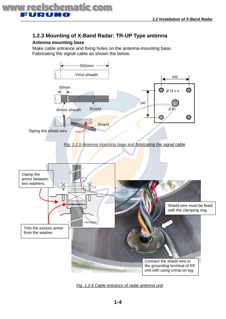
1.2.3 Mounting of X-Band Radar: TR-UP Type antenna Antenna mounting base Make cable entrance and fixing holes on the antenna-mounting base. Fabricating the signal cable as shown the below.
Fig. 1.2.5 Antenna mounting base and fabricating the signal cable
Fig. 1.2.6 Cable entrance of radar antenna unit
Shield wire must be fixed with the clamping ring.
Connect the shield wire to the grounding terminal of RF unit with using crimp-on lug.
240
240
φ 15 x 4
φ 50
Taping the shield wire.
RW-9600
Clamp the armor between two washers.
Trim the excess armor from the washer.
www.reelschematic.comwww.reelschematic.com

1.2 Installation of X-Band Radar
1-5
Make connections correctly and bind cables with cable ties properly.
Fig. 1.2.7 Wiring of cable PW9600
Check the connection by pulling each wire.
Bind wires with cable ties.
1. Insert opener 2. Push opener 3. Insert core 4. Release opener
Fold back shield, and fix theshield with clamping bracket. Fix the conductor by the metalplate securely and directly.
www.reelschematic.comwww.reelschematic.com

1.2 Installation of X-Band Radar
1-6
Fig. 1.2.8 Fixing the RF unit
Confirm that the antenna motor switch is off when you are wiring.
Return the RF unit, and connect theconnectors and the ground wire. Tighten RF unit with 2 bolts securely.
Fig. 1.2.9 Fixing antenna cover
Tighten 4 bolts equally forsecuring antenna cover.
Confirm that the packing is fitted in the groove before fixing the antenna cover.
Ground terminal
www.reelschematic.comwww.reelschematic.com

1.2 Installation of X-Band Radar
1-7
1.2.4 Mounting of X-Band Radar: TR-DOWN type antenna Insert the signal cable: MPYC-19 through the cable gland at the antenna unit side, and fabricate as shown below.
Fig.1.2.10 Fabricating signal cable
Fig. 1.2.11 Fabricating cable gland
Wind vinyl tape around the edge of sheath.
Wind vinyl tape around the edge of sheath.
Tighten the cable gland and put the pate or silicon sealantinto the gland entrance for waterproofing.
www.reelschematic.comwww.reelschematic.com

1.2 Installation of X-Band Radar
1-8
Connect wire without fault, and bind the wires with cable tie properly.
Check connection by pulling each wire.
Fig. 1.2.13 Wiring in the radar antenna unit-2
Fig. 1.2.12 Wiring in the radar antenna unit-1
Check connection by pulling each wire.
www.reelschematic.comwww.reelschematic.com

1.2 Installation of X-Band Radar
1-9
1.2.5 Installation of Flexible Wave-Guide: TR-DOWN type Following the bending radius must be taken into account to prevent the wave-guide from being damaged. Minimum bending radius of X-band wave-guide;
E-bend: 200 mm H-bend: 400 mm.
Antenna unit side
Transceiver unit side
The Connector of the transceiver unit side has been fitted for air-tightness test. Cut the wave-guide to length at this end.
“ANT SIDE” label
Fig. 1.2.14 Flexible wave-guide
E
H
The connector of the antenna unit side has been factory-fitted. Do not remove the protection cover while laying the wave-guide.
Fig. 1.2.15 Flexible wave-guide
This connector is removed once, and reconnected again.
Plug for air-tightness test.This connector is not used.
“EQUIPMENT SIDE” label
www.reelschematic.comwww.reelschematic.com
1.2 Installation of X-Band Radar
1-10
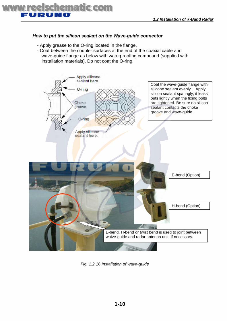
How to put the silicon sealant on the Wave-guide connector
- Apply grease to the O-ring located in the flange. - Coat between the coupler surfaces at the end of the coaxial cable and
wave-guide flange as below with waterproofing compound (supplied with installation materials). Do not coat the O-ring.
Coat the wave-guide flange with silicone sealant evenly. Apply silicon sealant sparingly; it leaks outs lightly when the fixing bolts are tightened. Be sure no silicon sealant contacts the choke groove and wave-guide.
Fig. 1.2.16 Installation of wave-guide
E-bend (Option)
H-bend (Option)
E-bend, H-bend or twist bend is used to joint between waive-guide and radar antenna unit, if necessary.
www.reelschematic.comwww.reelschematic.com

1.2 Installation of X-Band Radar
1-11
Fig. 1.2.17 Flexible wave-guide
Wave-guide fixing bands (option)
E
H
When using stainless bands, do not strain thewave-guide with too strong tightening.
Fix the cable at 1 m (approx).
Fig. 1.2.18 Installing thru-deck cable gland
Use the thru-deck cable gland (Type: 03-009-0521-1)
www.reelschematic.comwww.reelschematic.com

1.2 Installation of X-Band Radar
1-12
1.2.6 Mounting of X-Band Radar TR unit: TR-DOWN type
Fig. 2-1 FAR-2827Wの送受信部の取付け
E-bend (option)
H-bend (option)Twist-bend (option)
Fig. 1.2.19 Installation of TR unit
Armor must be fixed with the cable cramp.
Check connection bypulling each wire.
Ground the TR unit with a ground wire (IV-8 sq or larger) or copper strap.
Drain bend, E-bend, H-bend or twist bend is used to joint betweenwaive-guide and transceiver unit, if necessary.
www.reelschematic.comwww.reelschematic.com

1.2 Installation of X-Band Radar
1-13
Fig. 1.2.20 Installation of TR unit
When pulling down the wave-guide from the ceiling, select the position so as tokeep the minimum bend of wave guide. When connecting the waveguide, take care not to apply force on the "Converter WG." It may increase the gap shown in the figure below. It may allow microwaves toleak through the gap, and it causes troubles.
Lying straight.
Minimum bending radius; E bend R-min: 200 mm
H bend R-min: 400 mm
www.reelschematic.comwww.reelschematic.com

1.2 Installation of X-Band Radar
1-14
1.2.7 Fabricating Wave-guide 1. Cutting wave-guide Cut the wave-guide at the height of wave-guide outlet of the TR unit.
Fig. 1.2.21 Cutting wave-guide
40 mm
Fig. 1.2.22 Wave-guide termination
Cut off the jacket (sheath) 40 mm.
Never scratch the conductor.
www.reelschematic.comwww.reelschematic.com

1.2 Installation of X-Band Radar
1-15
The Wave-guide end must be smooth and no crack. Radar performance degrades if the flange inadequately is fitted.
Fig. 1.2.23 Widening wave-guide opening
When fix the connecter, use FR-90 power tool.
No crack on the wave-guide and smooth surface
Crack and rough surface
Good Appropriate tool is used
No Good Appropriate tool is not used
Fig. 1.2.24 Fabrication of wave-guide connector
www.reelschematic.comwww.reelschematic.com

1.2 Installation of X-Band Radar
1-16
2. Fabricating wave-guide connector After assembling the connecter, pouring of silicone sealant to filling opening, then wind the self-bounding tape between the end of connector and wave guide, half-lapped in two layers. Further, wind vinyl tape in two layers.
3. Connect the wave-guide to the TR unit. Direct connection
シリコンゴムを注入口 コネクタを組立て
組立てネジ x6本
Fig. 1.2.26 Direct connection
Connect wave guide directlywithout joint bends.
Fig. 1.2.25 Fitting wave-guide connecter
Taping
Apply silicon-sealantto filling opening.
Fix the connecter byusing six screws.
www.reelschematic.comwww.reelschematic.com

1.2 Installation of X-Band Radar
1-17
Connection using drain wave-guide
Connection using E-bend, H-bend or Twist-bend
Fig. 1.2.27 Drain wave-guide
Drain wave-guide
Fig. 1.2.28 Fixing with joint bends
Radar performance may degraded by using joint bends.
Twist bend
E-bend
www.reelschematic.comwww.reelschematic.com

1.2 Installation of X-Band Radar
1-18
Tools for fabricating X-Band Radar Wave-Guide If necessary, order these tools to FURUNO. Type: OP03-123, Code No. 0084488800
Code No. Item Type Qty
00015179800 FR-90 power tool R4KG5549 03S9791-0 1set
10020750000 Edge gauge 03-009-0530-0 1
10020754000 Gauge (Square) 03-009-0534-0 1
00080584700 Tool box #2207 1 00080584800 Brush 8 inch 1 00080584900 Wrench For M4 2 00080585000 Hack saw HFJ-12 1 00080585100 Saw 250 m x 24 mm 6 00080585200 File L150 1
00080585300 File L150 1
00080585400 Knife DK-N 1 00080585500 Heavy duty snips K30, 190 1 set
Fig. 1.2.29 Tools
www.reelschematic.comwww.reelschematic.com

1.3 Installation of S-Band Radar
1-19
1.3 Installation of S-Band Radar 1.3.1 Mounting of Radar antenna Locating of Performance monitor should be mounted to the stern side.
Fig. 1.3.1 Mounting of S-Band radar antenna unit
The radar antenna unit must be placed on the corrosion proof rubber mat supplied put on the radar antenna base.
Do not forget to put the seal washer. Coat bolts and nuts withanticorrosive sealant after fixing the bolts.
PM antenna
Ground the radar antenna unit with a ground wire (RW-4747) of installation materials. Ground terminal must be coated withanticorrosive silicone sealant completely.
Check that the antennamotor switch is ON.
www.reelschematic.comwww.reelschematic.com

1.3 Installation of S-Band Radar
1-20
Fig. 1.3.2 Fixing antenna unit
BOW
Performance monitor must be sternside. Do not face the PM antennaagainst the bow side.
PM antenna
Fig. 1.3.3 Fixing antenna cover
When fixing the antenna cover, do not pinch the cover hanging rope.
Fasten bolts (10 pcs.) equally.
Fig. 1.3.2 PM antenna
Confirm that the packing is fitted in the groove before fixing the antenna cover.
www.reelschematic.comwww.reelschematic.com

1.3 Installation of S-Band Radar
1-21
1.3.2 Mounting of S-Band Radar: TR-UP type antenna
Fig. 1.3.4 Wiring of cables
1. Insert opener 2. Push opener 3. Insert a core 4. Release opener
Bind cables with cable ties.
Fold back shield, and fix the shield withclamping bracket. Fix the conductor by the metal platesecurely and directly.
www.reelschematic.comwww.reelschematic.com

1.3 Installation of S-Band Radar
1-22
Bow PM antenna
Fig. 1.3.6 Mounting of S-Band Rader: TR-UP type antenna unit-2
Fig. 1.3.5 Mounting of S-Band Radar; TR-UP type antenna unit-1
Bow
PM antenna
Antenna motor connection side
Connect U/V/W correctly.
Check connection bypulling each wire.
www.reelschematic.comwww.reelschematic.com

1.3 Installation of S-Band Radar
1-23
1.3.3 Mounting of S-Band Radar: TR-DOWN type antenna
Fig. 1-9 ア-スの取付け
Check the connectionby pulling each wire.
Fig. 1.3.7 Connection cables to the WAGO connector
Fig. 1.3.8 Fixing cable gland
Wind vinyl tape around theedge of sheath.
www.reelschematic.comwww.reelschematic.com

1.3 Installation of S-Band Radar
1-24
Use optional fixture clamping metal for fixing coaxial cable.
Fig. 1.3.9 Mounting of S-Band Radar: TR Down type antenna unit
When use a stainless band, donot strain the coaxial cable bytoo strong tightening.
Do not forget to put the seal washer. Coat bolts and nuts with anticorrosive silicon sealant after fixing the bolts.
Coat the groundterminal with siliconsealant.
Tighten cable gland securely, and waterproof with pate or silicon sealant.
www.reelschematic.comwww.reelschematic.com

1.3 Installation of S-Band Radar
1-25
1.3.4 Laying coaxial cable of S-Band Radar When bending the coaxial cable, keep enough radiuses to prevent transformation of the coaxial cable. Generally, keep radius of 150 mm or more.
Connecting the coaxial connector 1. Unfasten eight bolts (M6x20) to remove the flange cover from the radar antenna unit. 2. Apply silicon grease on the O-ling of the wave guide flange of the radar antenna unit. 3. Coat between the coupler surfaces at the end of the coaxial cable and wave-guide
flange as below with waterproofing compound (supplied with installation materials). Do not coat the O-ring.
4. Screw 8 bolts unfastened at the step 1 to fix the coupler to the flange. Tighten screws securely.
Fig. 1.3.10 Fixing coaxial cable
Coaxial Connector
Converter
Allowable bending radius: 150 mm or more.
One side having coaxial connectormust be antenna side.
W.G Adapter
www.reelschematic.comwww.reelschematic.com

1.3 Installation of S-Band Radar
1-26
Fig. 1.3.11 Thru-deck cable gland
Fix the thru-deck cable gland (Option: type. 03-009-0521-1) to a deck by welding.
Allowable bending radius: 150 mm or more
www.reelschematic.comwww.reelschematic.com

1.3 Installation of S-Band Radar
1-27
1.3.5 Mounting of S-Band Radar: TR-UP type Transceiver unit
Fig. 1.3.12 Installation of transceiver unit
Check the connection by pulling each wire.
Fix the cable armor with cablecramp.
Connect the ground to groundterminal with a wire (IV-8 sq orlarger) or copper strap.
Fig. 1.3.13 Fixing coaxial cable
Cramping metal (option)
When using the stainless band, donot strain the coaxial cable by too strong tightening.
It is made for the coaxial cable drawer position from the ceiling to take the lead in the coaxial cable conversion flange of transceiver part. When it shifts from a center, the case of transceiver part may be changed and a defect ofoperation may be caused.
www.reelschematic.comwww.reelschematic.com

1.3 Installation of S-Band Radar
1-28
1.3.6 Fabrication of coaxial cable and connector Installation Material Note1: Prevent foreign substances from being entered into the cable during the work. Note2: A minimum cable bending radius of 150 mm must be observed at the cable run.
When bending the cable twice or more in close points, the bending radius should be more than 250 mm.
Note 3 Do not lose the Relay Conductor Note 1: Prevent dust into the cable during the work. Note 2: A minimum cable bending radius of 150 mm must be observed at the cable run.
When bending the cable twice or more in the close points, the bending radius should be more than 250 mm.
Note 3: Do not lose the Relay Conductor.
Fig. 1.3.14 Coaxial connector assembly
Coaxial cable Gauge
Self-bonding Tape
PVC tape
Connecter Assembly
Bolts
Relay Conductor
Fig. 1.3.14 Coaxial connector assembly
www.reelschematic.comwww.reelschematic.com

1.3 Installation of S-Band Radar
1-29
1. Cut coaxial cable
Fig. 1.3.15 Connection of coaxial cable
Cut the coaxial cable so that the connecter can be fitted to converter flange.
Fig. 1.3.16 Fabricating coaxial cable-1
Remove the sheath 40 mm using thetubing cutter and scale.
Outer conductor
Be careful not to nick the outer conductor.Do not crush the outer conductor.
www.reelschematic.comwww.reelschematic.com
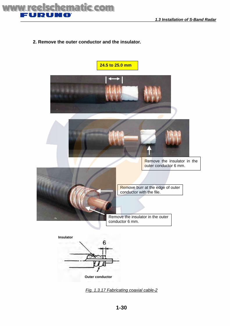
1.3 Installation of S-Band Radar
1-30
2. Remove the outer conductor and the insulator.
Remove the insulator in theouter conductor 6 mm.
24.5 to 25.0 mm
Fig. 1.3.17 Fabricating coaxial cable-2
Outer conductor
Insulator
Remove burr at the edge of outer conductor with the file.
Remove the insulator in the outer conductor 6 mm.
www.reelschematic.comwww.reelschematic.com

1.3 Installation of S-Band Radar
1-31
3. Insert the connector.
Outer conductor
Connector Pincers
Do not nick the O-ling.
Connector
Fig. 1.3.18 Fabricating coaxial cable-3
Flare the outer conductor along theconnector by a pincer.
File the outer conductor beyond the diameter of the connector.
Outer conductor
Connector Pincer
Connector
www.reelschematic.comwww.reelschematic.com

1.3 Installation of S-Band Radar
1-32
4. Insert the gauge.
Insert the gauge through the connector.
Cut the inner conductor leaving 1 mm.
Remove the gauge. Then, smooth the edge of the inner conductor by a file.
Fix the gauge by the bolts.
Fig. 1.3.19 Fabricating coaxial cable-4
www.reelschematic.comwww.reelschematic.com

1.3 Installation of S-Band Radar
1-33
5. Assemble other parts of the connector.
6. Tape
Insert the pin conductor.
Fix with bolts securely.
Fig.1.3.20 Fabricating coaxial cable-5
Fig. 1.3.21 Fabricating coaxial cable-6
Silicon sealant
Tape the self-bonding tape twice or more on the cable and connector. And then tape the PVC tape over the self-bonding.
www.reelschematic.comwww.reelschematic.com

1.3 Installation of S-Band Radar
1-34
7. Assemble S-band coaxial connector and connector converter
8. Fabricate the coaxial connector and converter
Fig. 1.3.23 Fabricating coaxial cable-8
Connect a coaxial connector to the converter flange. 1. Remove the converter flange
from the transceiver unit first, and connect with a coaxial connector.
2. Reconnect the converter to the transceiver unit again.
Fig. 1.3.22 Fabricating coaxial cable-7
Fix with three bolts and nuts.
Do not forget to attach the pin conductor.
www.reelschematic.comwww.reelschematic.com

1.3 Installation of S-Band Radar
1-35
Tools for fabricating the S-band coaxial connector
No. Name Type No. Name Type 1 Hack-saw HFJ-12 8 Knife DK-N
2 Pincers 220 mm 9 Bench rule with stopper 150 mm
3 Plier PL-200 10 Brush Small 4 Snips 170 mm 11 Brush Medium 5 Nipper 70-150 12 File Fine 6 Knife LDS-20-028 13 File Second-cut 7 Hammer 18 mm 14 Tool Box Y-350
13 12111098
7 6 5432 1
14
Fig. 1.3.24 Tools for fabricating S-band coaxial connector
Table 1.3.1 Tools
www.reelschematic.comwww.reelschematic.com

1.4 Installation of Radar Console
1-36
1.4 Installation of Radar Console
Fig. 1.4.1 Installation of two-radar consoles
Fig. 1.4.2 Wiring in the console
Check the connectionby pulling each wire.
Bind the wires with cable tie.
Connect a ground to the ground terminal with a copper strap of 50 mm width. Specially, cramp the armor of the antenna cable. Connect a
shield wire to the case of console with using crimp-on lug.Wind the shield wire with a tape.
Two-radar consoles are installed side by side.
www.reelschematic.comwww.reelschematic.com

1.4 Installation of Radar Console
1-37
Fig. 1.4.3 Fixing BNC connector converter
Fix the BNC connector converter for theconnection with VDR.
Fig. 1.4.4 Connection for the processor unit
Connect the connectors forthe processor unit securely.
www.reelschematic.comwww.reelschematic.com

1.4 Installation of Radar Console
1-38
Connection of LAN cable Use a cross-cable between FAR and FAR, and between FAR and CU-200. Since the HUB-100 automatically distinguishes the difference of cable with All Port Auto MDIX function, when connecting them through the HUB-100, either cable can be used. The cable type must be above category five.
Straight Cable Cross Cable Pairs Pin No. Signal Pin No. Signal Pin No. Signal 1
(WHT-GRN) TXP 1 (WHT-GRN) TXP 1
(3. WHT-ORG) RXP 1-2 2
(GRN) TXN 2 (GRN) TXN 2
(6. GRN) RXN
3-6 3 (WHT-ORG) RXP 3
(WHT-ORG) RXP 3 (1. WHT-GRN) TXP
4 (WHT-BLU) NC 4
(WHT-BLU) NC 4 (4. WHT-BLU) NC
4-5 5 (BLU) NC 5
(BLU) NC 5 (5. BLU) NC
3-6 6 (ORG) RXN 6
(ORG) RXN 6 2. (GRN) TXN
7 (WHT-BRN) NC 7
(WHT-BRN) NC 7 (7. WHT-BRN) NC
7-8 8 (BRN) NC 8
(BRN) NC 8 (8. BRN) NC
Fabrication of LAN cable 1. Cut wires remaining length of 11 mms. Cut the shield and drain wires
remaining 9 mms after turning up. 2. Insert wires into plug housing neatly side by side, so that the tip of each wire
cab is seen at the end of housing. A drain wire is set to tab side. 3. Clamp with crimp tool.
Fig. 1.4.5 Fabrication of LAN connector
8
1
Tab side
11 mm
9 mm Shield and drain wire
Clamp with crimp tool.
12345678
12345678
12345678
12345678
Straight Cable Cross Cable
www.reelschematic.comwww.reelschematic.com

2.1 Installation of ECDIS Console
2-1
2.1 Installation of ECDIS Console 2.1.1 Mounting of ECDIS console
Chapter 2. ECDIS
Radar Console
ECDIS Console
Fig. 2.1.1 Standard console of Radar and ECDIS; ECN-003
UPS
Processor Unit
Radar Console ECDIS Console
Fig. 2.1.2 Slim-type Radar and ECDIS console; ECN-001
www.reelschematic.comwww.reelschematic.com

2.1 Installation of ECDIS Console
2-2
2.1.2 Wiring of ECDIS console
Fig. 2.1.3 Wiring to LAN adapter
Fig. 2.1.4 Connection of LAN adapter
Fasten cable with cable ties
Top view Ground and tighten the shield with cable ties.
Connection Power supply
When the number of terminal isnot enough, add LAN adapter.
Standard LAN adapter
Check the connection by pulling each wire.
www.reelschematic.comwww.reelschematic.com

2.1 Installation of ECDIS Console
2-3
Fig. 2.1.5 Connection of processor unit
Tighten screws of connector securely.
Put a label ofn the conjunctive connector of each LAN cable.
www.reelschematic.comwww.reelschematic.com

2.1 Installation of ECDIS Console
2-4
1. Installation of UPS (uninterruptible power source)
Type: -196 Code No:1-050
Name Type Code No. Qty Remarks Hex. Bolt M6x12 000-808-428 10 Pan Head Screw M4x8 SUS304 000-801-137 24
Slide rail 3504-18 000-150-514 1 set For left and right sides, 2 pcs.
Processor Unit Plate 03-163-7212-3 100-320-753 1 Rail guide (1L) 03-163-7209-2 100-320-732 1 Rail guide (1R) 03-163-7208-2 100-320-722 1 Rocking edge saddle LES-2017 000-809-398 2
Procedure 1. Separate outer and inner plates of the slide rails as below.
2. Attach two locking edge saddles to the processor unit plate as shown below. 3. Fasten 10 pan-head-screws to attach two inner plates of slide rails to both
sides of the processor unit plate.
4. Unfasten two knob bolts to remove the front cover from the console.
UPS mounting stage
www.reelschematic.comwww.reelschematic.com

2.1 Installation of ECDIS Console
2-5
5. Attach the outer plate of the slide rail (removed at step 1) to the rail guide with 14 pan-head-screws as below. Do this for both left and right sides.
6. Fasten 8 hex. bolts (M6x12) to attach rail guides (assembled at step 5) to both
sides in the console.
7. Keep the processor unit plate assembled at steps 2 and 3 horizontally, and
push it until it contacts the springs. 8. Press the leaf springs of the left and right rails with finger to enable further
push-in.
9. Push the processor unit plate into the back of the console, and then fix it with 2
hex. bolts (M6x12). 10. Re-attach the front cover to the console.
www.reelschematic.comwww.reelschematic.com

2.1 Installation of ECDIS Console
2-6
On the production in 2006, Feb. and after. Fix the UPS on the mounting stage with fixture by processing in local.
Fig. 2.1.6 Fixing UPS
UPS
UPS Outlets
UPS Power SwitchFix with fixture.
www.reelschematic.comwww.reelschematic.com
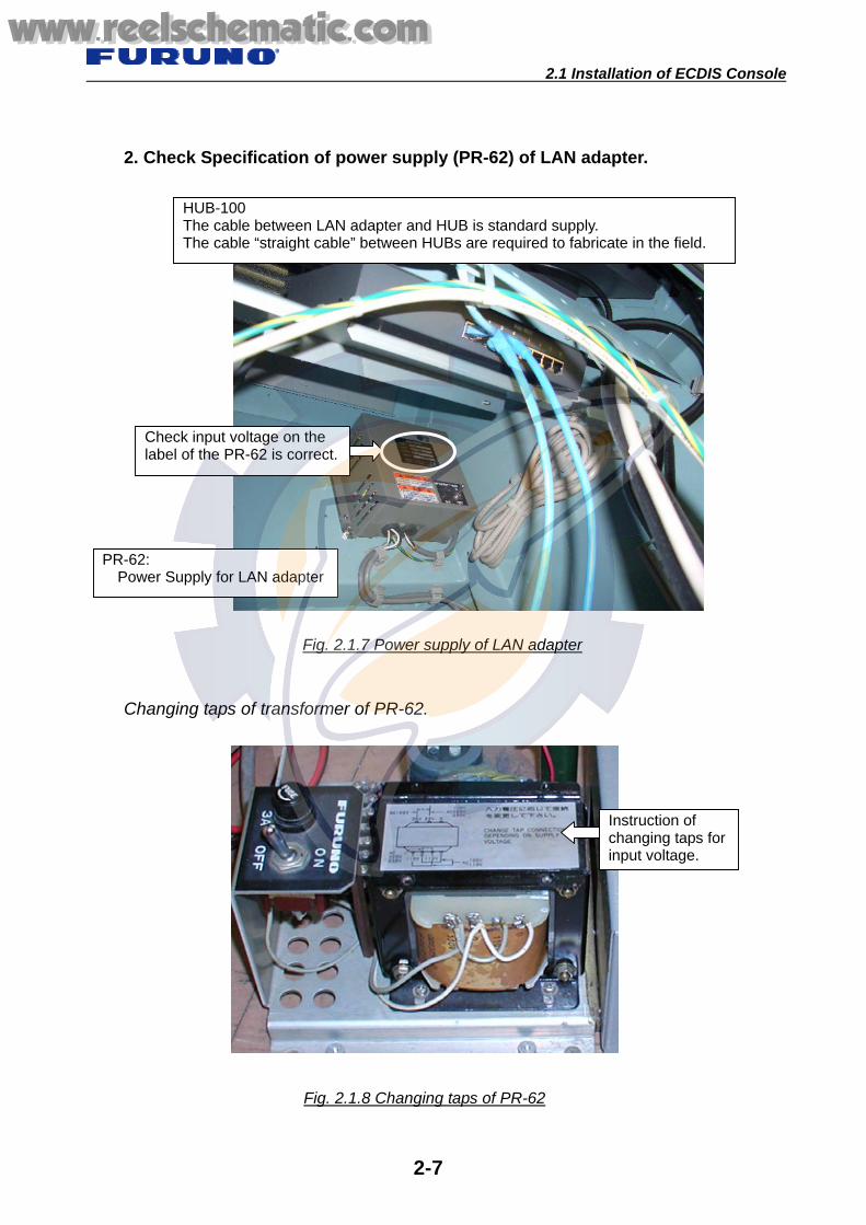
2.1 Installation of ECDIS Console
2-7
2. Check Specification of power supply (PR-62) of LAN adapter. Changing taps of transformer of PR-62.
Fig. 2.1.7 Power supply of LAN adapter
HUB-100 The cable between LAN adapter and HUB is standard supply. The cable “straight cable” between HUBs are required to fabricate in the field.
PR-62: Power Supply for LAN adapter
Check input voltage on the label of the PR-62 is correct.
Fig. 2.1.8 Changing taps of PR-62
Instruction of changing taps for input voltage.
www.reelschematic.comwww.reelschematic.com

2.1 Installation of ECDIS Console
2-8
3. Improper Installation Do not install the processor unit in the place where does not have ventilation, such as in a storage place. The temperature of the above mentioned place increase improperly, particularly in the summer, and cause malfunctions of the processor unit. When installing to the closed area, equip ventilation in there.
Fig. 2.1.9 Improper location of the processor unit
Make ventilation hole.
www.reelschematic.comwww.reelschematic.com

2.1 Installation of ECDIS Console
2-9
Connection of LAN cable Use a cross-cable between the EC-1000C and EC-1010. Since the HUB-100 automatically distinguishes the difference of cable with All Port Auto MDIX function, when connecting them through the HUB-100, either cable can be used,. The cable type must be above category five.
Straight Cable Cross Cable Pairs Pin No. Signal Pin No. Signal Pin No. Signal 1
(WHT-GRN) TXP 1 (WHT-GRN) TXP 1
(3. WHT-ORG) RXP 1-2 2
(GRN TXN 2 (GRN) TXN 2
(6. GRN) RXN
3-6 3 (WHT-ORG) RXP 3
(WHT-ORG) RXP 3 (1. WHT-GRN) TXP
4 (WHT-BLU) NC 4
(WHT-BLU) NC 4 (4. WHT-BLU) NC
4-5 5 (BLU) NC 5
(BLU) NC 5 (5. BLU) NC
3-6 6 (ORG) RXN 6
(ORG) RXN 6 2. (GRN) TXN
7 (WHT-BRN) NC 7
(WHT-BRN) NC 7 (7. WHT-BRN) NC
7-8 8 (BRN) NC 8
(BRN) NC 8 (8. BRN) NC
Fabrication of LAN cable 1. Cut wires remaining length of 11 mms. Cut the shield and drain wires remaining 9
mms after turning up. 2. Insert wires into plug housing neatly side by side, so that the tip of each wire
cab is seen at the end of housing. A drain wire is set to tab side. 3. Clamp with crimp tool.
Fig. 2.1.10 Fabricating LAN connector
Clamp with crimp tool.
12345678
12345678
12345678
12345678
Straight Cable Cross Cable
8
1
Tab side
Turn up the shield and drain wire
40-50 mm
11 mm 9 mm
www.reelschematic.comwww.reelschematic.com

2.2 Custom Ordered Console
2-10
2.2 Custom Ordered Console 2.2.1 Installation
2.2.2 Wiring of Console
Fig. 2.2.1 Installation of custom ordered console
Fig. 2.2.2 Processor unit and UPS ECDIS
Coning DisplayECDIS Display
UPSProcessor Unit
Coning DisplayECDIS Display
Radar Display Radar Display
www.reelschematic.comwww.reelschematic.com

2.2 Custom Ordered Console
2-11
1. Wiring for LAN adapter
Fig. 2.2.3 Wiring for LAN adapter
UPS
LAN Adapter
LAN Adapter
Fig. 2.2.4 Wiring for LAN adapter
Ground the cable shield withcable cramp.
Check the connection by pulling each wire.
www.reelschematic.comwww.reelschematic.com

2.2 Custom Ordered Console
2-12
2. Wiring for B adapter
Fig. 2.2.5 Wiring for B adapter
Ground the cable shieldwith cable cramp.
Check the connectionby pulling each wire.
Install B adapter behind of the coning display.
www.reelschematic.comwww.reelschematic.com

2.2 Custom Ordered Console
2-13
3. Wiring for HUB unit
Install HUB behind of the ECDIS display.
HUB
HUB-100 The cable connectors between LAN adapter and HUB have beenfabricated in the factory. LAN cable Connectors between radar andHUB must be fabricated in the field.
PR-62; Power supply for LAN adapter and B adapter.
Power of HUB and PR-62 are supplied by the UPS.
Attach the tag which display the counter part of connection to LAN cables.
Confirm that input voltage shown on the label is the same as the output voltage of the UPS.
Fig. 2.2.6 Wiring for HUB unit
www.reelschematic.comwww.reelschematic.com

2.3 Connection of EXT. Monitor for ECDIS
2-14
2.3 Connection of EXT. Monitor for ECDIS
EXT. Monitor
RGB Port
ECDIS Standard Monitor
RGB Port
RGB Port Use High Quality Cable KB-CHD1530L (SANWA supply Co., LTD)
Fig. 2.3.1 Connection of external monitor
DVI Port
DVI Port
VDR
The display size must be 17-inch or above. The resolution must be SXGA.
RGB Distributor ( VGA-HRSW4) (SANWA supply Co., LTD)
www.reelschematic.comwww.reelschematic.com

2.3 Connection of EXT. Monitor for ECDIS
2-15
RGB distributor Recommendation: VGA-HRSW4 (SANWA supply)
High quality cable
Recommendation: KB-CHD1530L (SANWA Supply).
Fig. 2.3.2 RGB distributor “VGA-HRSW4”(SANWA Supply)
Fig. 2.3.3 High quality cable KB-CHD1530L (SANWA Supply)
www.reelschematic.comwww.reelschematic.com

3-1
3.1 Installation of MF/HF Antenna No.1 (Indoor installation of Antenna coupler)
3.1.1 Mounting of Antenna In the shipyard, put red clothes to the antenna wire for calling the crane operator’s attention.
Red cloth
Insulator is unnecessary.
Fig. 3.1.1 Measure of safety
Fig. 3.1.2 Connection of antenna feeder
Chapter 3. MF/HF Radio
MF/HF Whip Antenna
www.reelschematic.comwww.reelschematic.com

3.1 Installation of MF/HF Antenna No.1
3-2
Insulator
Shackle
Wire clip
Thimble
1. Antenna feeder Use a support wire to reinforce the feeder.
Fix the feeder with an insulator.
Support wire
Fig. 3.1.3 Antenna feeder
Fig. 3.1.4 Fixing feeder
Feeder
Insulator
www.reelschematic.comwww.reelschematic.com

3.1 Installation of MF/HF Antenna No.1
3-3
2. Lead-in insulator Use lead-in insulator to lead the feeder into the radio room (indoor).
Lead-in insulator
Fig. 3.1.5 Mounting of Antenna lead-in insulator
Fig. 3.1.6 Fixing antenna wire
Lead-in insulator is required when the antenna coupler is installed in the radio room (indoor)
Bind the antenna wire with antenna wire, tighten the antenna wirefirmly with bolts.
Bind the wire twice or more to thicken the insert diameter.
150 to 200 mm
www.reelschematic.comwww.reelschematic.com

3.1 Installation of MF/HF Antenna No.1
3-4
3. Mounting of safety fence Arrange the safety fence to separate the antenna feeder from crews, and put the danger sign at the entry.
“High voltage” Danger sign nameplate
Safety fence
Fig. 3.1.7 Arrangement of safety fence
Note: When installing the safety fence,keep enough distance from the antenna feeder so as to preventtouching antenna feeder.
Safety fence
www.reelschematic.comwww.reelschematic.com

3.1 Installation of MF/HF Antenna No.1
3-5
3.1.2 Mounting of Antenna coupler 1. Indoor feed line Connect between the lead-in insulator and antenna coupler by a copper pipe. The pipe is fixed with using stand insulators. The ANT changeover is installed for the protection from lightning, and also for prohibiting the transmission in harbor.
The antenna changeover is installed for lightning protection.
Fig. 3.1.8 Indoor feed line
Fig. 3.1.9 Antenna changeover
Copper pipe
Stand insulator
ANT changeover
Antenna coupler
Install at where theoperator can operate.
ANT changeover
Stand insulator
Ground with wire “IV-8 sq”or cupper strap.
www.reelschematic.comwww.reelschematic.com

3.1 Installation of MF/HF Antenna No.1
3-6
2. Grounding of antenna couplerGround the antenna coupler by the copper strap (width: 50 mm) securely. Use wing nuts to connect the copper strap to the antenna coupler. Fold back the shield of the coaxial cable for clamping.
Screw for fixing the copper strap
Fig. 3.1.10 Grounding antenna coupler
Fig. 3.1.11 Connecting copper strap to antenna coupler
For grounding the antenna coupler, use the copper strap welded to a steel plate, as bellow. The steel plate must be welded to theship hull.
Fold back the shield and clampit with a shield bracket securely.
Shorten the length as long as possible.
www.reelschematic.comwww.reelschematic.com

3.2 Installation of MF/HF Antenna No.2
3-7
3.2 Installation of MF/HF Antenna No. 2 (Outdoor installation of Antenna coupler)
3.2.1 Mounting of antenna 1. MF/HF Whip antenna
Fig. 3.2.1 Outdoor installation of antenna coupler and whip antenna
Ground antenna coupler by a copper strap with welding plate.
Waterproof the cable gland with pate or silicon sealant.
Coat screws and plate with silicon sealant or pate.
Elevation angle of feeder line must be more than 45 degrees.
Equip the safety fence and put the “High Voltage” danger sign nameplate.
Antenna coupler
Do not use an insulator.
MF/HF antenna
Since the welded parts of copperstrap may be broken by swinging ofwind, shorten the copper strap.
www.reelschematic.comwww.reelschematic.com

3.2 Installation of MF/HF Antenna No.2
3-8
2. Improper installation which causes breaking connection parts
Fig. 3.2.2 Improper installation which cause breaking connection parts
Broken
Broken
Insulator (Do not usean insulator.)
Swings
Swings
When the connecting part is broken, it causesantenna coupler damages or a malfunctions ofthe transceiver unit.
Swings
www.reelschematic.comwww.reelschematic.com

3.2 Installation of MF/HF Antenna No.2
3-9
3. How to prevent wire breakage the connection part.
100 - 120mm
アンテナ線のきれっぱしをきつく1ターン巻いてアンテナ線と共締め
アンテナ線のきれっぱしとアンテナ線と共締め
アンテナ線
アンテナ線
シリコンゴムで緩み防止
Antenna wire
Step 7 Apply silicone sealant.
Add antenna wire clip. (NO. 22/DIA=6.2 MM)
Fig. 3.2.3 Fixing antenna wire to antenna coupler
A piece of wire turned around lead-in insulator.
Procedure 1. Put two antenna wire clips (NO. 22/DIA=6.2 MM) through the lead-in wire. 2. Wind a piece of antenna wire around the lead-in insulator one time. 3. Using wire clips, fix the antenna lead-in wire to the wire turned around the
insulator in step 2, leaving 500 mm for a loop. 4. Put a 100-mm-long piece of antenna wire through the lead-in insulator. 5. Put the antenna lead-in wire through the lead-in insulator, making a loop about
120 mm diameter. 6. Tighten the screw on the insulator which fixes the antenna lead-in wire. 7. Apply silicone sealant over the screw to prevent it from loosening. 8. Cut off excess antenna lead-in wire extending past the insulator.
Antenna wire
A 100-mm-long piece of antenna wire
Antenna lead-in wire
Step 2Steps 4 and 5
Step 3
Step 6
www.reelschematic.comwww.reelschematic.com

3.2 Installation of MF/HF Antenna No.2
3-10
4. Wiring in antenna coupler “AT-5000” There are stainless and synthetic resin types of antenna coupler case. Generally, stainless type of case is used for outdoor installation.
Fig. 3.2.4 Wiring of AT-5000
Connect a drain line of a signal cable to the grounding terminal of the coupler board with using crimp on lug.
Cable cramp
For receiving coaxial cable clamping bracket, theconnection is the same as a transmitting coaxialcable.
Connection
Pin No. Sig. 1 BRN Ia+ 2 RED Ia- 3 ORG TUNE OK4 YEL GND 5 GRN TX 6 BLU GND 7 WHT TUNE 8 BLK DUMMY 9 WHT(Big) 18V+
10 BLK(Big) 18V-
Make sure of the 2.5 mm space.
Terminal opener
Fix the core wire with screw securely.
Fold back the shield and clamp it with fixture securely.
Check the connection by pulling each wire.
Wiring “high voltage lines” has touchedneither other wiring nor parts.
www.reelschematic.comwww.reelschematic.com

3.2 Installation of MF/HF Antenna No.2
3-11
5. Wiring in the antenna coupler “AT-1560” There are stainless and synthetic resin types of antenna coupler case. Generally, stainless type of case is used for outdoor installation.
Connection Pin No. SIG
1 BRN Ia 2 RED TUNE OK 3 ORG TUROUGH 4 YEL TUNE 5 GRN DUMMY 6 WHT(BIG) 15V+ 7 BLK(BIG) 0V
Connect a drain wire of a signal cable to couplerboard fixing screw with using crimp on lug.
Fold back the shield and fixit with fixture securely.
Fix the conductor with screw securely.
Wiring “high voltage lines; red and whit wire”has touched neither other wiring nor parts.
Fig. 3.2.5 Wiring of AT-1560
www.reelschematic.comwww.reelschematic.com

3.3 Installation of Radio Console
3-12
3.3 Installation of Radio Console
3.3.1 General Mounting of Radio console Cover the console with a vinyl sheet to keep dust away and prevent damaging, when not working.
Put a protective cardboard on the table.
Vinyl sheet
Fig. 3.3.1 Protect from damagingies
Fig. 3.3.2 Indication of legal card and others
COMSAR/Circ.25 (Actions by upon reception of HF, VHF/MF DSC Distress Alert)
GMDSS Operating Guidance for Ship Master in Distress Situations
Put labels of IMN, MMSI, CS, AAB, QRC and others.
When the same kind of terminal is equipped, a connecting equipment name must be specified.
Put up a legal card nearthe operation place of radio console.
www.reelschematic.comwww.reelschematic.com

3.3 Installation of Radio Console
3-13
1. High of radio console When it is the "Fig. 3.3.3 Installation of radio console-1" which a front field of view opens, the height of a console depend on shipping classifications. If it is a DNV shipping classification, less than 1.2 m is demanded from the floor. However, if a console is equipment like "Fig. 3.3.4 Installation of radio console-2", it is not related to them.
Fig. 3.3.3 Installation of radio console-1
Fig. 3.3.4 Installation of radio console-2
Less than 1.2 m
Radio console
Less than 1.2 m
Radio console
www.reelschematic.comwww.reelschematic.com

3.3 Installation of Radio Console
3-14
3.3.2 Mounting of RC-1800F console (150/250W: FS-1570/2570) 1. Grounding and cabling
Connection terminals
Fig. 3.3.5 Cable coming outlet of console
Bind cables with cable tie.
Stuff the cable comingoutlet with pate. The cable coming outlet locates at the appropriate position so that no stress is on any cable.
Fix copper strap with fixingground plate securely.
Connect a console to ground with a copper strap.
Weld grounding plate to the ship hull.
Place of connection terminals, power supply, and battery charger.
www.reelschematic.comwww.reelschematic.com

3.3 Installation of Radio Console
3-15
2. Wiring in the middle and lower parts of console
Depending on the case, 440 VAC/220 VAC step down transformeris mounted.
Tighten power supply cable.
Connection terminal for battery
WR antenna terminal
Fig. 3.3.6 Wiring in the middle and lower parts of console
Tighten coaxial connector securely.
EXT BK/AF terminal
Power terminals for VHF radio, and other
Input/output terminal of ACpower source
Insert a core of cable while pressing the stopper down.
www.reelschematic.comwww.reelschematic.com

3.3 Installation of Radio Console
3-16
3. Improper fabrication of M-type coaxial connector
4. Wiring of the upper left side in console (not required in the field)
Fig. 3.3.7 Improper fabrication of M-type coaxial connector
Pull up cables(To upper side)
TB1
Fig. 3.3.8 Upper left side in console
Connector and shieldwire are not solderedtogether properly.
Center conductor istoo long, and notsoldered properly.
Good
No Good
TB2: NMEA I/O terminal
www.reelschematic.comwww.reelschematic.com

3.3 Installation of Radio Console
3-17
5. MF/HF transceiver unit in console: wiring of FS-1570T/2570T For cabling of MF/HF transceiver unit, remove the upper board on the right-hand side of a console.
Fig. 3.3.9 Wiring of FS-2570/1570T
FS-1570T/2570T
TR ANT
D. ANT
Connect drain wire of the signal cable to TB terminal.
Connections of antenna coupler, NMEA data and BK line
www.reelschematic.comwww.reelschematic.com

3.3 Installation of Radio Console
3-18
6. Connection of Inmarsat C
Fabrication of N-P-8DFB connector
Fig. 3.3.10 Connection of Inmarsat C
Connect coaxial connector of antenna cable with using the adapter.
Remove outer sheath and armor by the dimensions shown left. Expose inner sheath and shield by the dimensions shown left.
Cut off insulator and core by 10 mm.
Twist shield end.
Slip on clamp nut, gasket and clamp as shown in left.
Fold back shield over clamp and trim.
Cut aluminum foil at four places, 90 from one another.
Fold back aluminum tape foil onto shield and trim.
Expose the insulator by 1 mm. Expose the insulator by 5 mm.
Slip the pin onto the conductor. Solder them together throughthe hole on the pin.
Insert the pin into the shell. Screw the clamp nut into the shell.
Tighten by turning the clamp nut. Do not tighten by turning the shell.
www.reelschematic.comwww.reelschematic.com

3.3 Installation of Radio Console
3-19
7. Junction Box (IC315), Distress Alert/Received Call unit (IC305) and Alarm unit (IC306)
The Distress Alert/Received Call unit and Alarm unit are connected through junction box “IC-315” to console when installing without the inside of a console. When installing them in the console, they are fixed in the factory.
Fig. 3.3.12 Wiring in the Distress Alert/Received Call unit and Alarm unit
Fig. 3.3.11 Wiring of Inmarsat C junction box
Tighten screw of terminal securely.
It is located at the right side of the console, where is back of NBDP terminal.
Connect a shield wire of the cable to ground a terminal securely.
Cramp cable shield
Check the connection by pulling each wire.
Ex; IC-305/306 installation atthe conning position
www.reelschematic.comwww.reelschematic.com

3.3 Installation of Radio Console
3-20
8. Reassembling the units Tighten the connector, ground terminal and screws, which has dismounted for installation.
Fig. 3.3.13 Reassembling the terminal units
Left side of console Inmarsat C terminal
Right side of console NBDP terminal
Center of console MF/HF radio controller
www.reelschematic.comwww.reelschematic.com

3.3 Installation of Radio Console
3-21
3.3.3 Mounting of RC-1800F console (400W: FS-5000) 1. Installation of FS-5000 transceiver unit
Fig. 3.3.15 Installation of FS-5000 transceiver unit
Service space - Right and left side: more than 100 mm - Back side: more than150 mm
Transceiver unit
Fig. 3.3.14 Installation of FS-5000 transceiver unit
Cramp cables with cable cramp.
Fix the power cable securely.
Terminal opener
Fabricate coaxial connector properly.
Check the connection by pulling each wire.
Cable entrance on the rearpanel of transceiver unit
Connect cable cramp toground with copper straphaving width of 50 cm.
Connect a drain wire of asignal cable to IF boardfixing screw with usingcrimp on lug.
www.reelschematic.comwww.reelschematic.com

3.3 Installation of Radio Console
3-22
How to Use Terminal Opener at terminal 1. Remove the end of each core by 5-6 mm. 2. As shown in the figure, set the opener in a terminal. While pulling the opener downward, insert the core. 3. Release the opener. Check the connection by pulling each wire. 2. Improper fabrication of M-type coaxial connector
Fig. 3.3.16 Fabrication of M-type coaxial connector
Connector and shieldwire are not solderedtogether properly.
Center conductor is too long, and not soldered properly.
Good No Good
www.reelschematic.comwww.reelschematic.com

3.3 Installation of Radio Console
3-23
3. Installation of FS-5000 Controller unit When installing control unit on the table, there is an optional Trunnion mount and fixing base fixing base. Type: OP05-37 (005-931-760)
Connect the drain wire of signal cable between transceiver and controller unit to the chassis of controller with screw which fixing the PC board. Connect the drain wire of the cable between the controller and DSC terminal, or NBDP terminal to the S-GND of TB terminal.
How to Use Terminal Opener at terminal 1. Remove the end of each core by 5-6 mm. 2. As shown in the figure, set the opener in a terminal. While pulling the opener downward, insert the core. 3. Release the opener. Check the connection by pulling each wire.
信号ケーブルのドレインワイ
ヤーは、圧着端子で AF 基板
の取付けビスに友締めする
Cramp signal cable.
Terminal opener
Check the connection by pulling each wire.
Do not bent and pull flat cable with a strong hand.
Fig. 3.3.17 Installation of controller
Connect ground wire (IV-1.25 sq or larger) to ground terminal with usingcrimp on lug.
www.reelschematic.comwww.reelschematic.com

3.4 Installation of RX antenna
3-24
3.4 Installation of RX antenna
3.4.1 Mounting of Antenna junction box * All connection must be tighten. * Apply silicone sealant to bolts, nuts, grounding points and terminals.
Fig. 3.4.1 Mounting of Antenna junction box
Weld φ 6-8 grounding bolt. Apply silicone sealantto grounding points and terminals.
Grounding wire: 8 sq or larger
When fasten the coaxialcable with stainless band, do not damage the cable.
Loop excess coaxial cable having diameter over 20 cm to prevent damages of the center conductor.
Tighten the cable gland and put thepate or silicon sealant into the entranceof the gland for waterproofing.
www.reelschematic.comwww.reelschematic.com

3.4 Installation of RX antenna
3-25
3.4.2 Installation of Antenna with Pre-amplifier * Fix the coupler onto the antenna pole by using hose clamps and a bracket. * Waterproof the junction part of coaxial cable with self bounding tape and vinyl
tape properly. * When loops coaxial cable, keep diameter over 20 cm in order to prevent
damages of the center conductor.
Apply silicone sealant to grounding points and terminals.
Fix antenna to antenna mast with hose clamp and mounting bracket securely.
Apply silicone sealant around the base of thewhip antenna.
Connect ground cable (IV-1.25 sq or larger) to ground terminal with using crimp on lug.
When fasten the coaxialcable with stainless band,do not damage the cable.
Fig. 3.4.2 Installation antenna with Pre-amplifier-1
Do not connect attaching the ground wire of the Pre-amplifier unit to ground of ship hulldirectly. Connect between ground terminal on the Pre-amplifier unit and ground of shiphull with additional ground wire (“IV-1.25 sq or larger” with using crimp on lug).
www.reelschematic.comwww.reelschematic.com

3.4 Installation of RX antenna
3-26
Fig. 3.4.3 Installation antenna with Pre-amplifier-2
Loop excess coaxial cable havingdiameter over 20 cm to preventdamages the center conductor.
Waterproofing the connectors How to wrap Pull the self-bonding tape to beabout two times in length and windit up, overlapping by 1/2 the widthof the tape. And then wrap vinyltape on it as well. Tighten bothends with cable ties.
www.reelschematic.comwww.reelschematic.com

3.5 Installation of Reserve Source (Battery)
3-27
3.5 Installation of Reserve source (Battery) 3.5.1 Lead-acid battery Battery cables must have sufficient dimensions to prevent voltage reduction. Connections must be tighten in order to reduce voltage drop caused by the contact resistance. Apply grease to battery terminals to prevent corrosion. - Board up the inside of the box with copper plates for corrosion-proof. - Spare parts must include the distilled water, specific gravity meter and
voltmeter.
Fig. 3.5.1 Installation of Lead-acid battery
Fig. 3.5.2 Installation of Lead-acid battery
Fix the battery by wedges.
Apply grease to terminals.
Connect cables tightly and bindcables for a better appearance.
Distilled water
Copper plate boarded inside the box
www.reelschematic.comwww.reelschematic.com

3.5 Installation of Reserve Source (Battery)
3-28
Maintenance parts of Lead-acid Battery
Sucker
Gravity meter
Distilled water
Voltage meter
Funnel
Thermometer
Pump
Measure cup
Fig. 3.5.3 Maintenance parts of Lead-acid Battery
www.reelschematic.comwww.reelschematic.com
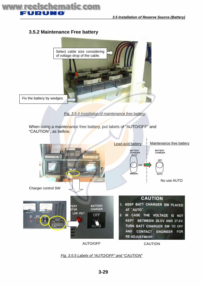
3.5 Installation of Reserve Source (Battery)
3-29
3.5.2 Maintenance Free battery
When using a maintenance free battery, put labels of “AUTO/OFF” and “CAUTION”, as bellow.
Fig. 3.5.4 Installation of maintenance free battery
Fix the battery by wedges.
Fig. 3.5.5 Labels of “AUTO/OFF” and “CAUTION”
Maintenance free batteryLead-acid battery
Select cable size consideringof voltage drop of the cable.
AUTO/OFF CAUTION
Charger control SW
No use AUTO
www.reelschematic.comwww.reelschematic.com

4.1 Installation of VHF Antenna
4-1
4.1 Installation of VHF Antenna * Fix the antenna with antenna fixing bracket securely. * Waterproof the junction part of coaxial cable with self-bonding tape and vinyl tape properly.
* Loop excess coaxial cable having diameter over 20 cm to prevent damaging the center conductor.
When the antenna is installed as shown in figure 4.1.1 (a), the reflection power increases. Therefore, install the antenna as shown in figure 4.1.1 (b).
Chapter 4. VHF Radio
Fig. 4.1.1(b) Proper installation
Less than 5 cm
Figure 4.1.1(a) Improper installation
Less than 5 cm
Mount the antenna element, keep up only a litte from antenna holder.
The fixed antenna element is too lower
www.reelschematic.comwww.reelschematic.com

4.1 Installation of VHF Antenna
4-2
Waterproofing with tape.
Fig. 4.1.3 Fixing Antenna
Waterproofing the connector. How to wrap Pull the self-bonding tape to be about two times in length and wind it up, overlapping by 1/2 the width of the tape. And then wrap vinyl tape on it as well. Tighten both ends with cable ties.
Fasten nuts equally and securely, use double-nuts.
Fig. 4.1.2 waterproofing with tape
For the bottom of antenna element, too mach taping prevent from fixing antenna element.
When loop the coaxial cable, keep diameter over 20 cm to prevent damages the center conductor.
When fasten the coaxial cable with stainless band,do not damage the cable. Do not bind at the part ofconnection.
www.reelschematic.comwww.reelschematic.com

4.2 Installation of VHF Console
4-3
4.2 Installation of VHF Console The Emergency lamp powered by the reserve source is required to illuminate the control panel.
Fig. 4.2.1 VHF console
Fig. 4.2.2 Wiring in the VHF console
No.1 VHF with DSC Printer
Emergency light
DSC Printer
Check the connection by pulling each wire.
Connect each wire and bind the cables with cable ties properlyand securely.
No.2 VHF without DSC Printer
Connect ground wire (IV-1.25 sq or larger) and cable shield to ground terminal with using a crimp on lug.
www.reelschematic.comwww.reelschematic.com

4.2 Installation of VHF Console
4-4
Wiring to terminal 1. Remove sheath 5 to 6 mm. 2. Set a terminal opener, insert the center conductor
in terminal with pushing up . 3. After inserting, check the connection by pulling each wire.
Improper fabrication of M-type connector
Fig. 4.2.4 Improper making of M-type coaxial connector
Fig. 4.2.3 Connection of VHF Console
Fasten screw of connector securely.
Connect ground wire (IV-1.25 sq orlarger) to ground terminal withusing crimp on lug.
Connector and shield wire are not soldered together properly.
Center conductor is too long, and not soldered properly.
Good
No Good
Connect the antenna coaxialconnector securely.
Indicate the connection terminalby putting a label properly.
www.reelschematic.comwww.reelschematic.com

4.3 Installation of Remote Station
4-5
4.3 Installation of Remote Station Maximum 4 remote stations are connected to the junction box.
Fig. 4.3.2 Installation for Remote Station: RB-8800/HS-8800
Check the connection by pulling each wire.
Clamp wires
Fig. 4.3.1 Connection of remote station
Total 4 sets RB-8800/HS-8800 or (and) RB-8810/HS-8800
RB-8800/HS-8
W-MIC W-MIC
RB-8810/HS-8
Junction box(IF-8810)
Incorporated in the VHF console
Connect a drain wire and shield wire to ground terminal with using crimp on lug.
www.reelschematic.comwww.reelschematic.com
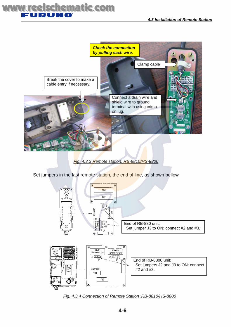
4.3 Installation of Remote Station
4-6
Set jumpers in the last remote station, the end of line, as shown bellow.
Fig. 4.3.3 Remote station: RB-8810/HS-8800
Check the connection by pulling each wire.
Clamp cable
Fig. 4.3.4 Connection of Remote Station:RB-8810/HS-8800
Break the cover to make a cable entry if necessary.
End of RB-880 unit; Set jumper J3 to ON: connect #2 and #3.
End of RB-8800 unit; Set jumpers J2 and J3 to ON: connect#2 and #3.
Connect a drain wire and shield wire to ground terminal with using crimp on lug.
www.reelschematic.comwww.reelschematic.com

4.4 Installation of VHF Wing Handset
4-7
4.4 Installation of VHF Wing Handset
The handset is installed in a watertight box to prevent it from corroding.
Fig. 4.4.1 Installation of wing handset Case 1
Watertight box
Microphone receptacle
Fig. 4.4.2 Installation of wing handset Case 2
Microphone receptacle
Microphone hanger (option)
www.reelschematic.comwww.reelschematic.com

4.4 Installation of VHF Wing Handset
4-8
Fig. 4.4.3 Wiring in the handset receptacle
Connect wires with using crimp on lug, and fasten each wire securely.
When the receptacle is installedwithout the box, tighten thecable gland and put the pate orsilicon sealant to the gland forwaterproofing.
www.reelschematic.comwww.reelschematic.com
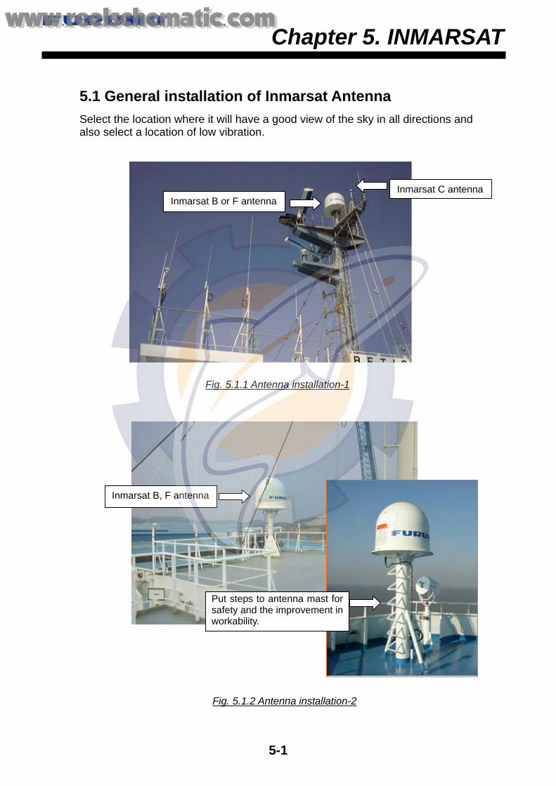
5.2 Installation of INMARSAT B
5-1
5.1 General installation of Inmarsat Antenna Select the location where it will have a good view of the sky in all directions and also select a location of low vibration.
Chapter 5. INMARSAT
Inmarsat B or F antennaInmarsat C antenna
Fig. 5.1.1 Antenna installation-1
Fig. 5.1.2 Antenna installation-2
Inmarsat B, F antenna
Put steps to antenna mast forsafety and the improvement inworkability.
www.reelschematic.comwww.reelschematic.com

5.2 Installation of INMARSAT B
5-2
Do not cover the drain hole.
5.2 Installation of INMARSAT B
5.2.1 Antenna unit * Select the location where it will have a good view of the sky in all directions. * Select a location of low vibration * Never put rubber mat between the mounting base and the antenna base. * Do not cover the drain hole.
Fig. 5.2.1 Mounting of antenna unit
Apply silicone sealant to thebolt/nut and ground terminal.
Tighten the cable gland and put the pate or silicon sealant to the gland for waterproofing.
When looping the coaxial cable, keepdiameter over 30 cm to prevent damages of the center conductor.
www.reelschematic.comwww.reelschematic.com

5.2 Installation of INMARSAT B
5-3
The label on the Radome tellssafety distance.
5.2.2 Radio frequency Radiation hazard label Install the safety fence keeping distance (6 m) from antenna to separate the antenna from humankind. And, put label keeping distance (6 m) from antenna, so that one can notice RF radiation hazard.
"The cautions label to the radio electric wave of a highradiation level" is stuck on a legible position. When anantenna is approached, there is a bad influence to thehuman body by the radio electric wave.
Fig. 5.2.3 Caution label
A caution label is stuck on the going-up position of the INMARSAT B antenna mast.
Fig. 5.2.2 Safety Zone
6m 6m
Radio frequency radiation hazard labelon the mast
Don't enter within 6 m from antenna.
www.reelschematic.comwww.reelschematic.com

5.2 Installation of INMARSAT B
5-4
Fix the coaxial cableby the clamps.
Pa Antenna drive mechanical part
Never loop.
Make sure of connecting.
Leave enough slack for servicing.
Leave enough slack of cable for servicing. Junction box
Communication Unit
Check the connection betweencoaxial cable and the antennadrive mechanical part so as notto get a touch when turning theantenna drive mechanical part.
5.2.3 Connecting Coaxial cable in Radome (FELCOM 82)
.
5.2.4 Installation of Transceiver unit and Junction box
Fig. 5.2.4 Connecting cable in the Radome
Fig. 5.2.5 Communication Unit
Tighten coaxial connector securely.Adjust mark putted
on the cable at cable entrance.
Connect ground cable (IV-1.25 sq or larger)to ground terminal with using crimp on lug.
www.reelschematic.comwww.reelschematic.com

5.2 Installation of INMARSAT B
5-5
Break the cover to make a cable entry, if necessary.
Taping
Insulate the shield wireby taping
5.2.5 Mounting of FELCOM 82 Handset and TEL Distress Button unit
.
Fig. 5.2.6 Mounting of Handset and TEL DIS Button unit
Never strain the mounting plate to prevent the malfunction of distress switch.
Check a feeling of clickby pressing bottom, afterfixing a plate and beforeconnecting a wire.
www.reelschematic.comwww.reelschematic.com

5.3 Installation of INMARSAT C
5-6
5.3 Installation of INMARSAT C5.3.1 Mounting of Antenna unit * Installation site: Select the location where it will have a good view of the sky in
all directions. Select a location of low vibration * Weld the antenna mounting pipe directly to the antenna pole. Mounting it with
clamps is not recommended. * Apply silicone sealant to the bolt, nut, grounding point and terminal. * The diameter of the service (drip) loop must be 30 cm or more. * Do not cut or shorten the coaxial cable supplied.
1. Fixing antenna 1. Apply silicone sealant (local supply) to the threads of the pipe. 2. Unscrew three screws to remove the antenna base from the antenna unit. 3. Pass the cable assy TPA5FB0.3NJ5FBA-5DFB (supplied, 300 mm) into the
shrink tube (SCM2, supplied). 4. Attach the above cable assy to the connector at the bottom of the antenna unit
(upper). 5. Shift up the shrink tube until it touches the bottom of the antenna unit (upper). 6. Heat the shrink tube, and then apply silicone sealant to the upper edge of the
tube, also wind self-bonding tape around the lower edge of the shrink tube and then wrap vinyl tape over self-bonding tape.
Note: Between the bottom of the antenna unit (upper) and the end of the taping should be less than 50 mm.
7. Insert the cable protector (supplied) in to the slot at the bottom of the antenna base.
8. Pass the antenna cable through the pipe and antenna base in order. When laying the cable along side the pipe, put the cable aside to pass through the projection in the antenna base.
Fig. 5.3.1 Before installing the antenna
Do not forget waterproofingof the connector.
Do not forget to apply silicone sealant.
www.reelschematic.comwww.reelschematic.com

5.3 Installation of INMARSAT C
5-7
Fig. 5.3.2 Mounting of Antenna
When looping the coaxial cable, keep diameter over 20 cm to prevent damages of the center conductor.
When fastening the coaxial cablewith stainless band, do not damagethe cable.
Waterproof the connectors. How to wrap; Pull the self bonding tape to be about two times in length and wind it up, overlapping by 1/2 the width of the tape. And then, wrap vinyltape on it as well. Tighten both ends with cable ties.
Apply silicon sealant.
Apply silicon sealant.
Taping
Apply silicone sealant to the antenna base fixing screws.
www.reelschematic.comwww.reelschematic.com

5.3 Installation of INMARSAT C
5-8
2. Sample of Antenna Installation In case that the cable is passed through pipe;
In case that the cable is fixed along the mast;
Fig. 5.3.3 Example of the installation through the pipe
Ground (RW4747) (Alongside of the pipe)
Ground wire (RW4747)(Alongside of the pipe)
Fig. 5.3.4 Example of the alongside of the pipe
Apply silicone sealant to the antenna base fixing screws.
Wrap the cable or apply siliconsealant in order to protect fromscratching by the edge of pipe.
www.reelschematic.comwww.reelschematic.com

5.3 Installation of INMARSAT C
5-9
5.3.2 Mounting of Terminal unit 1. Connection in the radio console
Fabrication of N-P-8DFB connector
Connect to the antenna coaxial connector with the coaxial connector adapter (TNCP-NJ).
Fig. 5.3.5 Connecting connectoers
Remove outer sheath and armor by the dimensions shown left. Expose inner sheath and shield by the dimensions shown left.
Cut off insulator and core by 10 mm.
Twist shield end.
Slip on clamp nut, gasket and clamp as shown in left.
Fold back shield over clamp and trim.
Cut aluminum foil at four places, 90 from one another.
Fold back aluminum tape foil onto shield and trim.
Expose the insulator by 1 mm. Expose the insulator by 5 mm.
Slip the pin onto the conductor. Solder them together throughthe hole on the pin.
Insert the pin into the shell. Screw the clamp nut into the shell.
Tighten by turning the clamp nut. Do not tighten by turning the shell.
Tighten the removed screwswhen installing securely.
www.reelschematic.comwww.reelschematic.com

5.3 Installation of INMARSAT C
5-10
2. Junction Box (IC315), Distress alert/Received call unit (IC305) and Alarm unit(IC306)
Fig. 5.3.7 Distress Alert/Received Call Unit and Alarm Unit
Fig. 5.3.6 Wiring of junction box
Connect shield wire of cable to ground terminal securely.
Ex; IC-305/306 installation atthe conning position
Clamp cable shield.
Check the connectionby pulling each wire.
Locate at the right side of the console, where is back of NBDP.
Tighten screw of terminal securely.
Do not drop and lose the buzzer cap.
www.reelschematic.comwww.reelschematic.com

5.3 Installation of INMARSAT C
5-11
5.3.3 Installation of SSAS unit 1. Antenna When installing FELCOM 16 as SSAS equipment,
Because FELCOM 16 is not GMDSS corresponding equipment, the antenna location is not required to GMDSS requirement. However, select the place in good view of sky such as compass deck.
Notice of antenna installation 1. When installing the both antenna of FELCOM 15 and 16 at the closed place.
Keep distance at least 1.5 m between them having level difference more than 40 cm (15 degrees down from anther antenna).
2. Keep distance more than 5 m between the antennas of FELCOM 15/16 and the
terminal unit “IC-215”. 3. Keep distance more than 3 m between the antennas of FELCOM 15/16 and the
communication unit “IC-216” of FELCOM 16.
Fig. 5.3.8 Relationship among antennas and terminal/communication units
5 m 3 m
Over 1.5 m
FELCOM 15
FELCOM 16
-15 degrees
Keep distance more than 3 m between the antennas of FELCOM-15/16and the communication unit “IC-216” of FELCOM-16.
www.reelschematic.comwww.reelschematic.com

5.3 Installation of INMARSAT C
5-12
2. Mounting of FELCOM 16 Communication unit The communication unit and junction box of FELCOM 16 are installed in the place where is not conspicuous, such as storage space.
Communication unit
Junction box
Check connection by pulling each wire.
Clamp the shield of cable by thecable fixture.
Fig. 5.3.9 Installation of communication unit and junction box
Fig. 5.3.10 Wiring in junction box
Fig. 5.3.11 Wiring of communication unit
Tighten the connector and wing screw of ground terminal securely.
Ground the ground terminal with using30 cm width of copper plate.
Security alarm
www.reelschematic.comwww.reelschematic.com

5.3 Installation of INMARSAT C
5-13
3. Mounting of IC-307 The Security alert signal is generated from the bridge. In addition, it must be able to activate from one or more place except bridge. Install the “IC-307” at the place where operator can easily press the switch, and at the place where it is not pressed carelessly. Alert unit is installed at the place where it is not found by pirates easily, such as under the table near the radio console or under the table in the captain room.
2 m
Connect IC-307 in series.
Total 200 m
IC-315
FELCOM 15
FELCOM 16
Installation in the bridge e.g.) Install IC-307 under the table near the radio console
Another place of installation; Under the table in the captain room
In the bridge
e.g.) in the captain room
Maximum 3 alert units can be connected.
Fig. 5.3.12 Mounting of SSAS Alert Unit
www.reelschematic.comwww.reelschematic.com

5.3 Installation of INMARSAT C
5-14
Connect the shield line of the cable after taping.
Fig. 5.3.13 Installation of SSAS Alert Unit
Put cover supplied.
Only the end of unit,change jumper plugfrom JP2 to JP1
Tighten screw securely.
www.reelschematic.comwww.reelschematic.com

5.4 Installation of INMARSAT F
5-15
5.4 Installation of INMARSAT F
5.4.1 Mounting of Antenna unit * Select the location where it will have a good view of the sky in all directions. * Select a location of low vibration * Never put rubber mat between the mounting base and the antenna base. * Do not cover the drain hole. * For the antenna side, the connector is fixed to the coaxial cable.
Fixing the coaxial cable in the Radome
Fix the coaxial cable with a cable tie in theRadome (Fixing approximately 1 m).
Tighten coaxial connector securely.
Bad example; The Coaxial cable cannot be fixed in the Radome because of the not enough cable length.
Fig. 5.4.1 Mounting of antenna unit
Fig. 5.4.2 Connecting cable in radome
Coat earth terminal bysilicon sealant Tighten the cable gland and put
the pate or silicon sealant to thegland for waterproofing.
Do not cover the drain holes.
When looping the coaxial cable, keep diameter over 30 cm to prevent damages of the center conductor.
www.reelschematic.comwww.reelschematic.com

5.4 Installation of INMARSAT F
5-16
The label on the Radome tellssafety distance
5.4.2 Radio frequency Radiation hazard label Install the safety fence keeping distance (4 m) from antenna to separate the antenna from humankind. And, put label keeping distance (4 m) from antenna, so that one can notice RF radiation hazard.
Fig. 5.4.4 Caution label
Fig. 5.4.3 Safety Zone
"The cautions label to the radioelectric wave of a high radiationlevel" is stuck on a legible position.When an antenna is approached,there is a bad influence to thehuman body by the radio electricwave.
A cautions label is stuck onthe going-up position of theINMARSAT B antenna mast.
Don't approach less than 4 m of radiation in microwave.
www.reelschematic.comwww.reelschematic.com

5.4 Installation of INMARSAT F
5-17
5.4.3 Mounting of BDE
Distress Alert unit
ISDN Handset
Communication unit
PC for data communication Inmarsat G3 FAX
Installation of Communication unit
Incoming Indicator
Communication unit
Ex; Communication unit installedin the storage space
Fig. 5.4.5 Installation of BDE
www.reelschematic.comwww.reelschematic.com
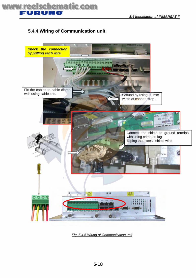
5.4 Installation of INMARSAT F
5-18
5.4.4 Wiring of Communication unit
Fig. 5.4.6 Wiring of Communication unit
Check the connectionby pulling each wire.
Fix the cables to cable clampwith using cable ties. Ground by using 30 mm
width of copper strap.
Connect the shield to ground terminalwith using crimp on lug. Taping the excess shield wire.
www.reelschematic.comwww.reelschematic.com
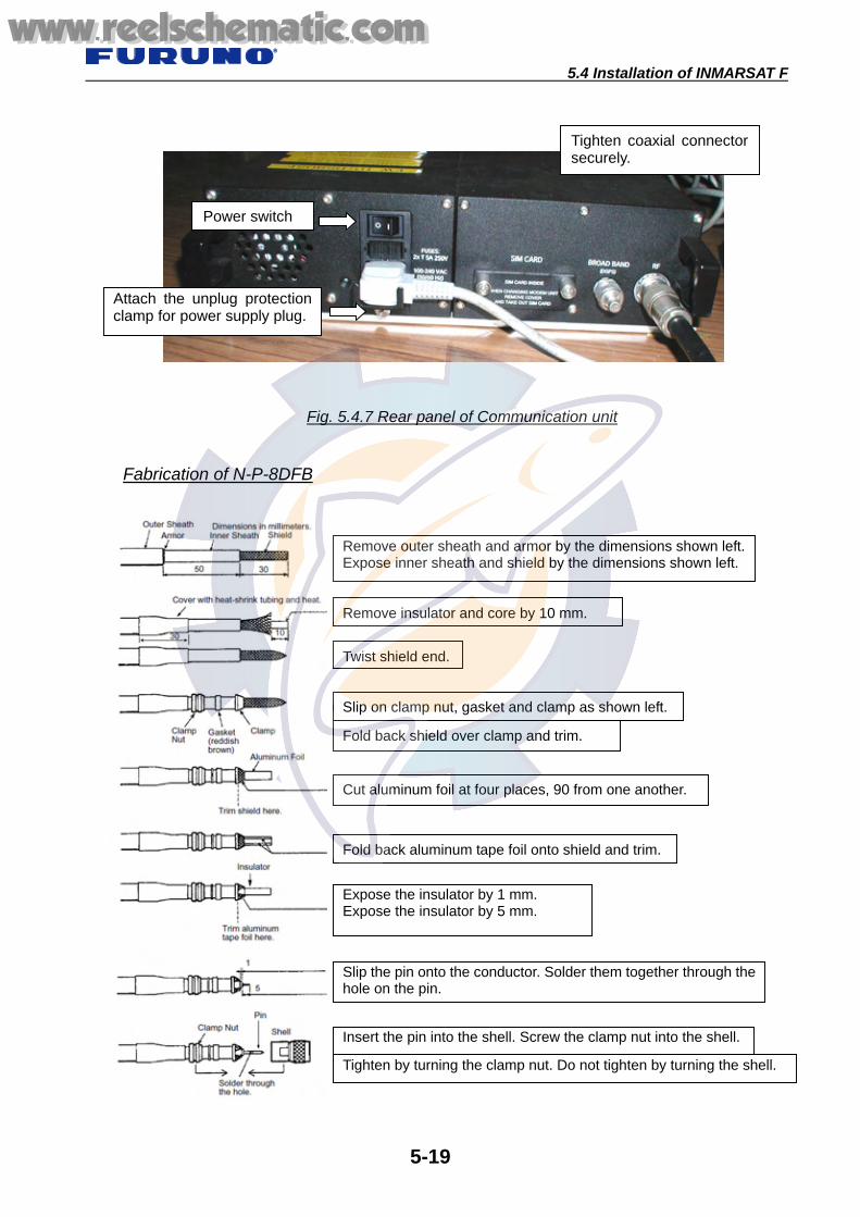
5.4 Installation of INMARSAT F
5-19
Fabrication of N-P-8DFB
Fig. 5.4.7 Rear panel of Communication unit
Power switch
Tighten coaxial connectorsecurely.
Attach the unplug protectionclamp for power supply plug.
Remove outer sheath and armor by the dimensions shown left.Expose inner sheath and shield by the dimensions shown left.
Remove insulator and core by 10 mm.
Twist shield end.
Slip on clamp nut, gasket and clamp as shown left.
Fold back shield over clamp and trim.
Cut aluminum foil at four places, 90 from one another.
Fold back aluminum tape foil onto shield and trim.
Expose the insulator by 1 mm. Expose the insulator by 5 mm.
Slip the pin onto the conductor. Solder them together through thehole on the pin.
Insert the pin into the shell. Screw the clamp nut into the shell.
Tighten by turning the clamp nut. Do not tighten by turning the shell.
www.reelschematic.comwww.reelschematic.com

5.4 Installation of INMARSAT F
5-20
5.4.5 Wiring of Distress Alert unit
When connecting another Distress Alert unit or ISDN Wall Socket, make cable entrance of “8 mm hole” with a drill.
1. Remove the PC board from the distress alert unit before making a hole. 2. Make hole at the position “a”, “b” or “c” in accordance with the cable run. 3. Smooth the inner and outer edge of hole.
Fig. 5.4.8 Distress Alert unit
Fig. 5.4.9 Modified Distress Alert unit
TB1 TB2
TB1, 2 Communication unit ISDN port
1. RX+ < - > RX+ 2. TX+ < - > TX+ 3. TX- < - > TX- 4. RX- < - > RX-
TB 2 is the same as TB 1
(a)
(b) (C)
Fix the shield wire of cable.
Miss-connection of ISDN line maybe damaged the modem unit.
www.reelschematic.comwww.reelschematic.com

5.4 Installation of INMARSAT F
5-21
5.4.6 Connection of ISDN devices ISDN devices are connected to the ISDN outlet on the Communication unit either terminal blocks or RJ45 jacks. The ISDN bus can be connected to one of the ISDN outlets. Maximum extension length is 100 m, min. 0.22 mm. In this case, the cable length connected to other outlets must be less than 10 m.
ISDN socket Communication unit
ISDN port a1. TX+ < - > TX+ b1. TX- < - > TX- a2. RX+ < - > RX+ b2. RX- < - > RX-
Standard settings of S1: #1 OFF, #2 OFF
Fig. 5.4.10 Connection of ISDN equipments
Miss-connection of ISDN line may be damaged the modem unit.
Set S1-#1 and #2 to on for the end socket.
Down
The end socket
Fig. 5.4.11 Wiring in ISDN Wall Socket
ISDN Port
Up to 8 ISDN devices can be operated with FELCOM 70.
Set switches S1- #1 and #2 to ON in the last ISDN wall socket.
www.reelschematic.comwww.reelschematic.com

5.4 Installation of INMARSAT F
5-22
5.4.7 Connection of Analogue Telephone/G3 FAX (option)
ISDN Port TEL Port
Incoming indicator (KK-893-3977)
Terminal Adapter (QDGY911912)
RJ45 RJ11
Analogue wall socket(OP16-10)
ISDNTELTEL
Analogue TelephoneG3 FAX
Fig. 5.4.12 Connection of Analogue devices
Connect to [LINE]
L1, L2: Non-polarity
12 VDC
TA Power (230 VAC ->12 VDC)
Use hook and loop fasteners for fixing FAX.
Use a wall fitting when mounting the analog telephone on the wall.
www.reelschematic.comwww.reelschematic.com

5.2 NAVTEX受信機の装備
6-1
6.1 Installation of NAVTEX 6.1.1 Mounting of NAVTEX antenna
* Fix antenna to antenna mast with hose clamp and mounting bracket securely. * Waterproof the junction part of coaxial cable with self-bounding tape and vinyl
tape properly. * Loop excess coaxial cable having diameter over 20 cm to prevent damaging
the center conductor.
Chapter 6. NAVTEX/FAX
Fig. 6.1.1 Mounting of NAVTEX antenna
Wrap the cable with tape in order to protect the cable from scratching by the edge of pipe.
Waterproofing the connector. How to wrap
Pull the self-bounding tape to be about two times in length and wind it up, overlapping by 1/2 the width of the tape. And then, wrap vinyl tape on it as well. Tighten both ends with cable ties.
Loop excess coaxial cable having diameter over20 cm to prevent damaging the center conductor.
When fastening the coaxial cable with stainlessband, do not damage the cable.
Fix antenna to antenna mastwith hose clamp andmounting bracket securely.
www.reelschematic.comwww.reelschematic.com

6.1 Installation of NAVTEX
6-2
6.1.2 NAVTEX Display unit Install the NAVTEX display unit in the wheelhouse.
Fig. 6.1.3 Connection
NX-700A: Built-in printer type
Fig. 6.1.2 NAVTEX display unit
NX-700B: No printer type
Connect ground wire (IV-1.25 sq or larger) toground terminal with using crimp on lug.
Fasten screws securely.
Front view Rear view
Front view Rear view
www.reelschematic.comwww.reelschematic.com

6.1 Installation of NAVTEX
6-3
6.1.3 NAVTEX Receiver unit
Improper fabrication
Fasten screws securely.
Fig. 6.1.5 Improper fabrication
Fig. 6.1.4 Connection of the Receiver unit
Connector and shield wire arenot soldered together properly.
Good
No Good
Terminal opener
Connect shield wire of signal cable to F.GND of TB terminal.
Connect M-type coaxial connector properly.
Center conductor is too long,and not soldered properly.
Connect ground wire (IV-1.25 sq or larger) to ground terminal withusing crimp on lug.
Check the connection by pulling each wire.
www.reelschematic.comwww.reelschematic.com
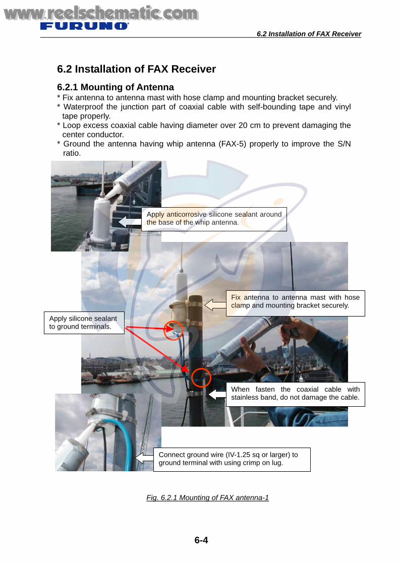
6.2 Installation of FAX Receiver
6-4
6.2 Installation of FAX Receiver 6.2.1 Mounting of Antenna * Fix antenna to antenna mast with hose clamp and mounting bracket securely. * Waterproof the junction part of coaxial cable with self-bounding tape and vinyl
tape properly. * Loop excess coaxial cable having diameter over 20 cm to prevent damaging the
center conductor. * Ground the antenna having whip antenna (FAX-5) properly to improve the S/N
ratio.
Apply silicone sealant to ground terminals.
Fig. 6.2.1 Mounting of FAX antenna-1
When fasten the coaxial cable withstainless band, do not damage the cable.
Fix antenna to antenna mast with hoseclamp and mounting bracket securely.
Connect ground wire (IV-1.25 sq or larger) to ground terminal with using crimp on lug.
Apply anticorrosive silicone sealant aroundthe base of the whip antenna.
www.reelschematic.comwww.reelschematic.com

6.2 Installation of FAX Receiver
6-5
Fig. 6.2.2 Mounting of FAX antenna-2
Loop excess coaxial cable having diameter over 20 cm to prevent damages of the center conductor.
Waterproofing the connector. How to wrap
Pull the self-bounding tape to be about two times in length and wind it up, overlapping by 1/2 the width of the tape. And then, wrap vinyl tape on it as well. Tighten both ends with cable ties.
www.reelschematic.comwww.reelschematic.com

6.2 Installation of FAX Receiver
6-6
6.2.2 Installation of FAX Receiver
Make connection without fault,and bind wires with cable ties.
Connect ground wire (IV-1.25 sq or bigger) to ground terminal withusing crimp on lug.
Fig. 6.2.3 Mounting of FAX receiver
Check the connection by pulling each wire.
Fig. 6.2.4 Grounding and wiring of FAX-215 receiver
www.reelschematic.comwww.reelschematic.com

6.2 Installation of FAX Receiver
6-7
Improper fabrication
Fig. 6.2.5 Connection of FAX-410
Connect the M-type coaxial connector properly.
Fig. 6.2.6 Improper fabrication
Connect ground wire (IV-1.25 sqor larger) to ground terminal withusing crimp on lug.
Good No Good
Remove sheath 5 to 6 mm, and then insert them into connection holes.
Connector and shield wire are notsoldered together properly.
Center conductor is too long, andnot soldered properly.
www.reelschematic.comwww.reelschematic.com

4.1 GPSアンテナ
7-1
7.1 Mounting of GPS antenna* Fix antenna to antenna mast with hose clamp and mounting bracket securely. * Waterproof the junction part of coaxial cable with self-bonding tape and vinyl tape
properly. * Loop excess coaxial cable having diameter over 20 cm to prevent damaging the center conductor.
* Ground the antenna unit with a whip antenna (GPA-018/018S) properly to improve the S/N ratio.
Fig. 7.1.1 Mounting of GPS antenna-1
Chapter 7. GPS
GPA–018/018S
Apply silicon sealant tothe ground terminal.
Fix antenna to antenna mast with hose clamp and mounting bracketsecurely.
Grounding must be made securely.Use the ground wire “IV-1.25 sq”.
Apply silicon sealant or tapingwith self-bonding tape and vinyltape to the junction point.
Wrap the cable with tape to protect the cable from scratching by the edge of pipe.
Fix grounding wire.
Apply silicon sealant tothe ground terminal.
www.reelschematic.comwww.reelschematic.com

7.1 Mounting of GPS antenna
7-2
Fig. 7.1.2 Mounting of GPS Antenna-2
Loop excess coaxial cable having diameter over 20 cm to prevent damages the center conductor.
Waterproofing the connectors. How to wrap Pull the self-bonding tape to be about two times inlength and wind it up, overlapping by 1/2 the widthof the tape. And then, wrap vinyl tape on it as well.Tighten both ends with cable ties.
When fastening the coaxial cable withstainless band, do not damage the cable.
www.reelschematic.comwww.reelschematic.com

7.1 Mounting of GPS antenna
7-3
Fabrication of N-P-8DFB
Never turn the shell.
www.reelschematic.comwww.reelschematic.com

7.2 Mounting of GPS Display unit
7-4
7.2 Mounting of GPS Display unit
Fig. 7.2.1 Mounting of GPS display unit
No.1 GPS
No.2 GPS
Fig. 7.2.2 Connections of GPS
Signal Exchanger
Put a blank seal on unusedswitch position.
Connectors: ANT, DATA, POWER and others must be fixed securely.
Connect ground wire (IV-1.25 sq orlarger) to ground terminal with usingcrimp on lug.
www.reelschematic.comwww.reelschematic.com

7.3 Mounting of GPS Multi-Distributor
7-5
7.3 Mounting of GPS Multi-Distributor
Fig. 7.3.1 Installation of IF-2300
Connect ground wire (IV-1.25 sq or larger) to ground terminal with using crimp on lug.
Check the connection by pulling each wire.
Securely connect each wire and bind the cables with cable ties properly.
MD-550
IF-2300
Shield wire must beconnected to F.GND of theterminal with crimp on lug.Other parts of shield wireexcept crimping part mustbe insulated with heatshrink tubing or vinyl tape.
Shield wire must be connected toF.GND of the terminal with crimp onlug. Other parts of shield wire exceptcrimping part must be insulated withheat shrink tubing or vinyl tape.
Connect each wire and bind the cables with cable ties properly and securely
www.reelschematic.comwww.reelschematic.com
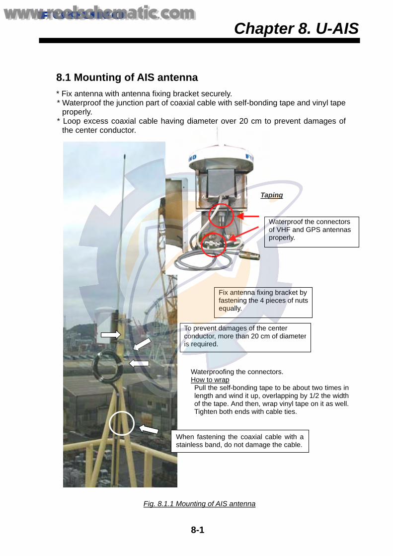
8.2 Mounting of AIS Display and Transponder units
8-1
8.1 Mounting of AIS antenna * Fix antenna with antenna fixing bracket securely. * Waterproof the junction part of coaxial cable with self-bonding tape and vinyl tape
properly. * Loop excess coaxial cable having diameter over 20 cm to prevent damages of
the center conductor.
Chapter 8. U-AIS
Fig. 8.1.1 Mounting of AIS antenna
Taping
Fix antenna fixing bracket by fastening the 4 pieces of nutsequally.
To prevent damages of the center conductor, more than 20 cm of diameteris required.
Waterproofing the connectors. How to wrap Pull the self-bonding tape to be about two times inlength and wind it up, overlapping by 1/2 the widthof the tape. And then, wrap vinyl tape on it as well.Tighten both ends with cable ties.
When fastening the coaxial cable with astainless band, do not damage the cable.
Waterproof the connectors of VHF and GPS antennas properly.
www.reelschematic.comwww.reelschematic.com

8.2 Mounting of AIS Display and Transponder units
8-2
8.2 Mounting of AIS Display and Transponder units
8.2.1 AIS Display unit:FA-1502 The AIS display unit is installed at where the ship’s officer controls the ship, where the ship’s officer can operate AIS easily, or at the coning position. For example, beside of radar display unit, ECDIS display unit or center of the coning position.
Fig. 8.2.2 Connection of AIS Display unit
Fig. 8.2.1 AIS Display unit
Connect ground wire (IV-1.25 sq or larger) to ground terminal with using crimp on lug.
www.reelschematic.comwww.reelschematic.com

8.2 Mounting of AIS Display and Transponder units
8-3
8.2.2 AIS Transponder unit: FA-1501
Fig. 8.2.4 Wiring in the AIS transponder unit
Fig. 8.2.3 AIS Transponder unit
Check the connection bypulling each cable.
Terminal opener
Bind the cables with cable ties securely.
Connect ground wire (IV-1.25 sq or larger) to ground terminal using with a crimp on lug.
Connect shield wire to cable cramp using with a crimp on lug. Other parts of shield wire except for crimping part must be insulated with heat shrink tubing or vinyl tape.
www.reelschematic.comwww.reelschematic.com

8.2 Mounting of AIS Display and Transponder units
8-4
8.2.3 AIS Power Supply: PR-240-CE AIS and connected sensors (e.g. GPS) should be connected ship’s main source and other source, such as emergency source or reserve source. PR-240-CE has already set to a 200 - 230 VAC in the factory. If the AC input power source is 100 VAC - 115 VAC, change the tap connection and terminal board connection as below. Attach label supplied as accessories to the check mark on the front panel according to the AC input power source.
Bind the cables with cable ties securely.
Connect ground wire (IV-1.25 sq or larger)to ground terminal with using crimp on lug.
Power supply (PR-240-CE)
AIS Distributor
Fig. 8.2.5 Wiring of Power supply unit
Fig. 8.2.6 Changing Ship’s Mains Specifications of PR-240-CE
220VAC spec.(default)
1234
100VAC spec.
1234
Black
Black
White
White
SEL115V
SEL230V
Red
www.reelschematic.comwww.reelschematic.com

8.2 Mounting of AIS Display and Transponder units
8-5
8.2.4 Pilot Plug All ships who navigate the Panama canal, the Saint Lawrence river and enter a port of the USA are required the pilot plug for the AIS. And also required AC plug for the PC at near the pilot plug. The pilot plug is installed at where the pilot commands the navigation, such as coning position. Pilot Plug should apply [AIS Pilot Plug] label, and the AC plug should apply the label of [Receptacle for Pilot PC] too. Receptacle should be USA Standard (NMEA 5-15R) 120V AC triple plug.
Fig. 8.2.7 Mounting of Pilot Plug
Pilot Plug
Label: Receptacle for Pilot PC
Label: AIS Pilot Plug AIS Pilot Plug (OP-24-3)
AC plug for Pilot PC
www.reelschematic.comwww.reelschematic.com

9.1 VR-5000: Installation of Data Collecting unit (DCU)
9-1
9.1 VR-5000: Installation of Data Collecting unit (DCU) 9.1.1 Mounting of DCU The DCU is fixed by using 4 holes in the bottom plate (shipyard supplied; welding to hull) onto the supplied shock absorber with M10 bolts (x 4) as follows. Fix the shock absorber onto the DCU mounting base arranged by the shipyard with four M10 bolts, put the cover over the shock absorber, fix the cover with supplied screws, and then fix the DCU to the shock absorber.
Chapter 9. VDR
Fig. 9.1.1 Mounting of DCU
Shock absorber without cover
Shock absorber with cover
Shock Absorber
Keep 300 mm clearance around the DCU.
Front side
Front side
www.reelschematic.comwww.reelschematic.com

9.1 VR-5000: Installation of Data Collecting unit (DCU)
9-2
Wide cable entrance of cover must be front side of the DCU. If the direction is inverted, because the balancer fixed to shock absorber does not work properly.
Balancer
Cable entrance
Fig. 9.1.2 Mounting of Shock Absorber
Wide cable entrance
Front side
Shock Absorber
www.reelschematic.comwww.reelschematic.com

9.1 VR-5000: Installation of Data Collecting unit (DCU)
9-3
Fig. 9.1.3 Changing eye bolts with cosmetic caps
Change eye bolts with cosmeticcaps of installation materials.
Note: The DCU (data correcting unit) has anti-vibration system. If service spacearound the DCU is blocked, anti-vibration system does not work properly, andit causes the damage of the hard-disc or PC board of the DCU.
www.reelschematic.comwww.reelschematic.com
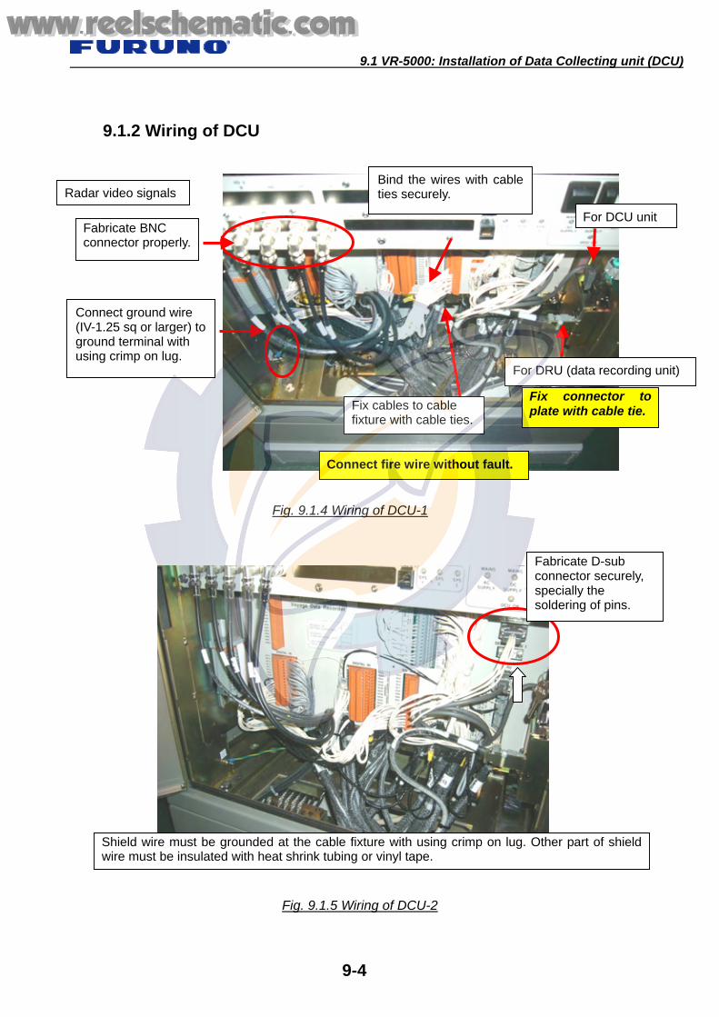
9.1 VR-5000: Installation of Data Collecting unit (DCU)
9-4
9.1.2 Wiring of DCU
Connect ground wire (IV-1.25 sq or larger) toground terminal with using crimp on lug.
Bind the wires with cable ties securely.
Fig. 9.1.5 Wiring of DCU-2
Fig. 9.1.4 Wiring of DCU-1
Fix cables to cable fixture with cable ties.
For DCU unit
For DRU (data recording unit)
Fix connector to plate with cable tie.
Connect fire wire without fault.
Radar video signals
Fabricate BNC connector properly.
Shield wire must be grounded at the cable fixture with using crimp on lug. Other part of shieldwire must be insulated with heat shrink tubing or vinyl tape.
Fabricate D-sub connector securely, specially the soldering of pins.
www.reelschematic.comwww.reelschematic.com

9.1 VR-5000: Installation of Data Collecting unit (DCU)
9-5
Fabrication of BNC connector 1. Cut off a cable jacket only 7 mm.
Don't damage the insulator in this time.
2. Strip shield and insulator by 3 mm.
3. Slip clamping nut, washer and gasket to the cable. Insert clamp to cable and fold back shield.
5. Insert center pin to core and solder through pinhole. “Do not melt the insulator by heating.”
6. Screw the shell into cable. Do not screw connector housing otherwise thecore may be damaged.
4. Put solder on core thin slightly.
Shell
Center pin
Core
www.reelschematic.comwww.reelschematic.com

9.2 VR-5000: Installation of Remote Alarm Panel and MIC
9-6
9.2 VR-5000: Installation of Remote Alarm Panel and MIC 9.2.1 Remote alarm panel Install the Remote alarm panel in the wheelhouse.
Connect ground wire (IV-1.25 sq orlarger) to ground terminal with usinga crimp on lug.
Fig. 9.2.1 Mounting of Remote Alarm Panel
Example: Remote Alarm Panel installed on the switch panel
Check the connection by pulling each cable.
www.reelschematic.comwww.reelschematic.com

9.2 VR-5000: Installation of Remote Alarm Panel and MIC
9-7
9.2.2 Mounting of Bridge Microphone Microphones are installed for recording all sound in the bridge. A maximum of 6 microphones can be connected to DRL. For example:
It should be installed in the ceiling above chart-table, radar console, GMDSS console, engine telegraph and steering stand.
Note:
When the microphone is attached in the ceiling with the height of 2 m, it can record in the range with a diameter of 10 m.
Fig. 9.2.2 Example of mounting the microphone
Around the ceiling above the chart table
Around the ceiling above the radarconsole and steering stand
Around the ceilingabove the GMDSSconsole
Coverage of microphone
10 m
2 m
Around the ceiling near the GMDSS console
Microphone
www.reelschematic.comwww.reelschematic.com
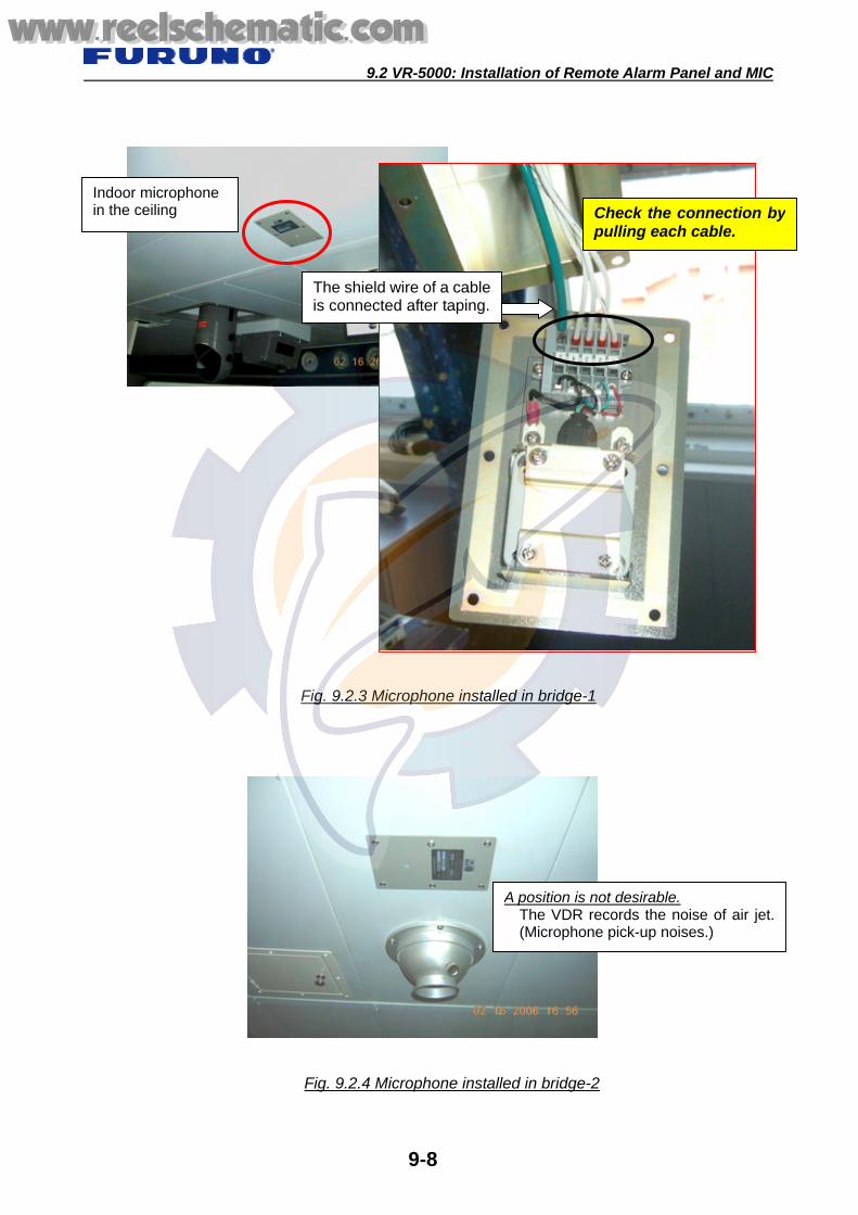
9.2 VR-5000: Installation of Remote Alarm Panel and MIC
9-8
Fig. 9.2.3 Microphone installed in bridge-1
Fig. 9.2.4 Microphone installed in bridge-2
Indoor microphone in the ceiling
A position is not desirable. The VDR records the noise of air jet.(Microphone pick-up noises.)
The shield wire of a cableis connected after taping.
Check the connection bypulling each cable.
www.reelschematic.comwww.reelschematic.com

9.2 VR-5000: Installation of Remote Alarm Panel and MIC
9-9
9.2.3 Mounting of Wing Microphone On the large-size vessel, which equips steering stand at the wing, install a microphone at where the conversation of wing area can be recorded.
Fig. 9.2.5 Microphone installed in wing area-1
Microphone
Fig. 9.2.6 Microphone installed in wing area-2
Standard position of the microphone at wing area
Perform waterproofing by putty orsilicone sealant.
www.reelschematic.comwww.reelschematic.com

9.2 VR-5000: Installation of Remote Alarm Panel and MIC
9-10
Microphone on asteering console
Fig. 9.2.7 Microphone on the steering stand of wing
www.reelschematic.comwww.reelschematic.com

9.3 VR-5000/VR-3000: Installation of DRU
9-11
9.3 VR-5000/VR-3000: Installation of DRU 9.3.1 Mounting of DRU The DRU contains a protective capsule and it should be installed in the vicinity of the bridge on the open deck area of the vessel. This will maximize the probability of its survival and facilitate recovery following an incident. The DRU should be positioned clear of rigging and other potential obstructions and as near to the centerline of the ship as possible. Constructing a “fence” around the DRU is recommended.
Fig. 9.3.1 Position of DRU
DRU
DRU
Do not cover the DRU.
Fig. 9.3.2 Do not cover the DRU
www.reelschematic.comwww.reelschematic.com

9.3 VR-5000/VR-3000: Installation of DRU
9-12
The important matter of the DRU attachment place. - Must be separated from fuel or other potential fire hazards. - Must be separated from probable sources of mechanical damage. - Must be installed in a place that facilitates routing maintenance and copying of
recorded data. - Must be installed where a diver or remote operated vehicle could remove and
retrieve. - There should be a clear and unobstructed area around the DRU to allow a diver
or an ROV to work. Note:
When installing the fire wire cable, protect the connector of fire wire from damages by taping etc.
9.3.2 Fixing DRU The Data Recording Unit comes with the mounting bracket fitted. Require to a shipyard to construct a mounting base of the DRU. On the mounting base, mount the bracket with M8 bolts and nuts (double nuts). The gap between vibration absorber and bolt should be at least 3 mm.
Fig. 9.3.3 Mounting base of DRU
Mounting bracket
Mounting base
www.reelschematic.comwww.reelschematic.com

9.3 VR-5000/VR-3000: Installation of DRU
9-13
9.3.3 Connection of DRU Insert the IEEE1394 plug of fire wire into the receptacle securely. Note: Protect the connector by taping in order to prevent damaging when cabling the fire- wire cable. And waterproof the connector if it is left out of doors.
Screw thread
Label which shows DRU side
Fig. 9.3.4 Connecting fire cable to DRU
Coat the rubber bushing (outside andinside), screw part of the cap nut withGold Grease No.2 of installation material.
Label which shows DRU side
Fig. 9.3.5 Fire wire cable
Never cut the cable.
www.reelschematic.comwww.reelschematic.com

9.3 VR-5000/VR-3000: Installation of DRU
9-14
Fasten cap-nut of DRU leaving “One-Thread” as shown bellow.
Cap-nut
One-Thread
Waterproofing with silicon sealant
Fig. 9.3.6 Fixing cap-nut
Fig. 9.3.7 Waterproofing
Note; Cannot screw thread completely.
www.reelschematic.comwww.reelschematic.com

9.3 VR-5000/VR-3000: Installation of DRU
9-15
Fig. 9.3.8 Installation of DRU-1
Never cut the excess cable.
Fig. 9.3.9 Installation of DRU-2
Do not forget to put the Hinge Pins.
Wind excess cable and fix tothe handle with cable tie.
www.reelschematic.comwww.reelschematic.com

9.4 Installation of VR-3000
9-16
9.4 Installation of VR-3000
VGA1 to VGA4 (DSUB-15 pin)Input of Radar Video Signal
IEEE-1394 CABLE <===> VR-5020
Terminal of AC and DCpower source
Bind wires with cable tie.
Fig. 9.4.1 Connection of DCU
Cable cramp for fixing armor Connect directly the shield wire to ground terminal with using crimp on lug after taping, or connect additional ground wire (IV-1.25 sq) to shield of cable with soldering, and then connect to ground terminal with using crimp on lug.
www.reelschematic.comwww.reelschematic.com
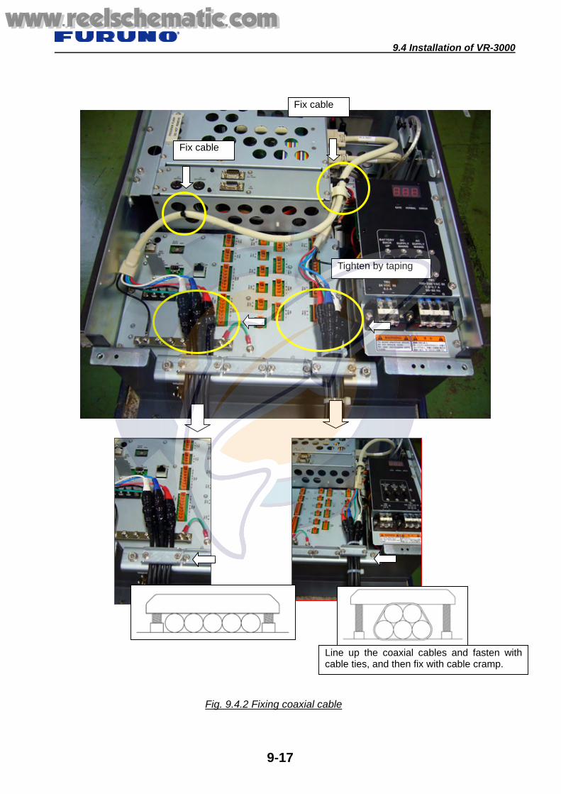
9.4 Installation of VR-3000
9-17
Fix cable
Fig. 9.4.2 Fixing coaxial cable
Tighten by taping
Fix cable
Line up the coaxial cables and fasten withcable ties, and then fix with cable cramp.
www.reelschematic.comwww.reelschematic.com

9.4 Installation of VR-3000
9-18
Fig. 9.4.3 Fixing cables
Fig. 9.4.4 Remote Alarm Panel
Clamp armor by the cable clamp.
When bending the cables, keep a radius over 150 mm.
Fix the cables at interval of over 300 mm.
Connect ground wire (IV-1.25 sq orlarger) to ground terminal with usingcrimp on lug.
Connect directly the shield wire to ground terminal withusing crimp on lug after taping, or connect additional groundwire (IV-1.25 sq) to shield of cable with soldering, and thenconnect to ground terminal with using crimp on lug.
www.reelschematic.comwww.reelschematic.com

3.10 SARTの装備
10-1
10.1 Installation of SART Generally the SART is installed near the door either port or starboard side on the bridge.
Installing of the SART mounting bracket onto the lifeboat
Chapter 10. Life-saving Appliance
Fig. 10.1.2 Location of SART mounting bracket
Install to the place where canbe accessed at the emergencyeasily.
Attach fluorescence label (shipyard supply), which shows thelocation of SART under a blackout.
SART mounting bracket
Fig. 10.1.1 Installation of SART
www.reelschematic.comwww.reelschematic.com

10.2 Installation of Two-Way VHF Radio
10-2
10.2 Installation of Two-Way VHF Radio Set the switch either 110 V or 220 V according to the ship’s main, and change the fuse accordingly. The switch and fuse are set for the ship’s main 220 VAC in the factory.
Attach lithium batteries (BP-1208) beside the Battery charger.
Fig. 10.2.1 Installation of Two-Way VHF Radio-1
Fig. 10.2.2 Installation of Two-Way VHF Radio-2
FUSE - 2 A for 100 VAC - 1 A for 220 VAC
Two-Way VHF Radio
Battery charger
Slide switch for selecting ship’s main
Lithium battery (For spare) Write expiration date of thebattery (5 years later). Once breaks the “battery seal”, the expiration date becomes invalid.
www.reelschematic.comwww.reelschematic.com

10.2 Installation of Two-Way VHF Radio
10-3
Safety link Instrument to prevent the strap from being caught on an object. About 35 to 45 kgf force is necessary to release the Safety link from the strap. The Safety link facility is mandatory on all IMO vessels for safety purpose from July 1, 2005. The Safety link does not come off when the radio is dropped.
Attach a fluorescence label (shipyardsupply), which shows the location oftwo-way radio under a blackout.
Fig. 10.2.3 Installation of Two-Way Radio
Fig. 10.2.4 Safety Link
Safety Link is fixed atthe only one side.
Shoulder strap
Clip assembly
www.reelschematic.comwww.reelschematic.com

10.3 Installation of EPIRB
10-4
10.3 Installation of EPIRB Install the EPIRB to be float, when the EPIRB container cover is opened completely.
Install the container- mounting base, which protect the container cover from dropping when the container cover opens.
For opening container-cover, makefixing holes to the front side of thecontainer-mounting base.
Fig. 10.3.1 Container-Mounting base
www.reelschematic.comwww.reelschematic.com

10.3 Installation of EPIRB
10-5
Fig. 10.3.2 Locating of EPIRB
Fig. 10.3.3 Mounting of EPIRB
Install the container-mounting base so thatthe EPIRB is not blocked around the hullstructure when it floats.
Attach a fluorescence label (shipyard supply), which shows the location of near the EPIRB.
Pick away the seal of the yearand month indications for theexpiration date on the waterpressure sensor. Expiration: 2 years later after
the inspection.
www.reelschematic.comwww.reelschematic.com

10.3 Installation of EPIRB
10-6
Fig. 10.3.4 Display on EPIRB
CSN number
MMSI
Cording data
Ship’s name Expiration date of the battery
www.reelschematic.comwww.reelschematic.com
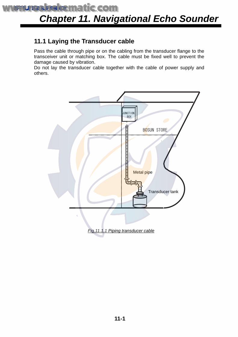
11.2 Inner Hull Tank
11-1
11.1 Laying the Transducer cable Pass the cable through pipe or on the cabling from the transducer flange to the transceiver unit or matching box. The cable must be fixed well to prevent the damage caused by vibration. Do not lay the transducer cable together with the cable of power supply and others.
Chapter 11. Navigational Echo Sounder
Transducer tank
Fig.11.1.1 Piping transducer cable
Metal pipe
www.reelschematic.comwww.reelschematic.com

11.2 Inner Hull Tank
11-2
11.2 Inner Hull Tank - Install the tank parallel to draft line longitudinally and transversely. - Remove the paint at the welding part of the tank. - Before welding the tank, remove the damper and gasket to prevent the damage
caused by the welding heat. Never do welding with transducer mounted. - When fixing the tank, put fixing flange to tank in order to prevent the tank from
distorting with welding heat. - Do not paint on the transducer face. - Fasten the cable gland so that the gap B becomes 7.0 mm to 7.5 mm. Too
much fastening cause damage of cable.
1. Inner Hull Tank: TTF-2000
B
Fig. 11.2.1 TTF-2000
www.reelschematic.comwww.reelschematic.com

11.2 Inner Hull Tank
11-3
2. Inner Hull Tank: TTF-2001
Fig.11.2.2 TTF-2001
www.reelschematic.comwww.reelschematic.com

11.2 Inner Hull Tank
11-4
3. Inner Hull Tank: TTF-2002
Fig.11.2.3 TTF-2002
www.reelschematic.comwww.reelschematic.com

11.2 Inner Hull Tank
11-5
4. Inner Hull Tank: TTF-2000-2
Fig.11.2.4 TTF-2000-2
www.reelschematic.comwww.reelschematic.com

11.3 Installation of Display unit and Distribution box: FE-700
11-6
11.3 Installation of Display unit and Distribution box: FE-700
11.3.1 Mounting of Display unit The following shows an example of the installation of Display uint: FE-700 on the switch board.
Fig. 11.3.1 Mounting of Display unit
Fig. 11.3.2 Rear side view of FE-700
Display unit
Grounding must be madesecurely. Use the groundingwire “IV-8 sq” or cupper strap.
Attach connectors firmly. Bind cables with cable ties.
www.reelschematic.comwww.reelschematic.com

11.3 Installation of Display unit and Distribution box: FE-700
11-7
11.3.2 Mounting of Distribution box
Fig. 11.3.3 FE-700 processor unit, enlarged
Distribution box
Bind cables with cable ties.
Distribution box
Check the connection by pulling each wire.
www.reelschematic.comwww.reelschematic.com

11.3 Installation of Display unit and Distribution box: FE-700
11-8
11.3.3 Mounting of Matching box Typically, the matching box is installed in the engine room. Connect the cables correctly. Cut the transducer cable to the proper length.
Fig. 11.3.4 Matching box: MB-504
For 200 kHz Matching box: MB-504
Fig. 11.3.5 Matching box: MB-502
Taping
Check the connection by pulling each wire.
Tighten the cable gland securely.
Tighten the cable gland securely.
Taping
Taping
For 50 kHz Matching box: MB-502
Taping
www.reelschematic.comwww.reelschematic.com

11.3 Installation of Display unit and Distribution box: FE-700
11-9
11.3.4 Mounting of Transducer cable/flange
Fig. 11.3.6 Transducer cable-1
Fig. 11.3.7 Transducer cable-2
Ceiling
Bind the transducer cable to the cable guide.
Bind the transducer cable to the cable guide.
Tighten the cable gland securely.
Transducer flange
www.reelschematic.comwww.reelschematic.com

11.3 Installation of Display unit and Distribution box: FE-700
11-10
Fig. 11.3.8 Hull bottom
Do not paint to the face of transducer.
Completed !!
Paint only around the transducer.
www.reelschematic.comwww.reelschematic.com

12.2 Installation of DS-30 transducer
12-1
12.1 Laying the Transducer cable
Pass the cable through pipe or on the cabling from the transducer flange to the transceiver unit or matching box. The cable must be fixed well to prevent the damage caused by vibration. Do not lay the transducer cable together with the cable of power supply and others.
Transducer tank
Fig. 12.1 Piping transducer cable
Metal pipe
Chapter 12. Doppler Sonarwww.reelschematic.comwww.reelschematic.com

12.2 Installation of DS-30 transducer
12-2
12.2 Installation of DS-30 transducer 12.2.1 Hull fixed tank 1. Align the transducer tank so that the bow mark is in the fore direction.
(The tank supplied by FURUNO carries "bow mark".)
DS-331-A DS-331-N
Bow
Fig. 12.2.2 DS-331A tank
Error: within ± 1 degree
Fig. 12.2.1 DS-331A/331N tank
www.reelschematic.comwww.reelschematic.com

12.2 Installation of DS-30 transducer
12-3
2. Install the tank parallel to draft line longitudinally and transversely.
When welding the tank, remove the waterproof rubber of the transducer to prevent the damage from the heat. 3. Leave a slack of the transducer cable in the tank for servicing.
Bow
Bottom
Fig. 12.2.3 DS-331A tank
Waterproof rubber
Procedure Let the cable gland, flat washer andwaterproof rubber through the transducercable in order. 1) Put the cable through the cable gland
from the bottom. The length betweenthe connecter and the cable gland is700 to 900 mm. A slack is required forservicing.
2) Hand-tighten the cable gland. 3) Tighten the gland securely using the
wrench supplied. 4) Fix the hex-bolt to prevent the gland
from loosening.
700 to 900 mm
Waterproofing rubber Flat washer Cable gland
Hex- bolt
Fig. 12.2.4 Installing transducer cable
www.reelschematic.comwww.reelschematic.com

12.2 Installation of DS-30 transducer
12-4
4. Connecting waterproof transducer connector 1) Apply silicone grease (supplied in installation materials) on the connecter face
(whole area). Excess grease will isolate pin contacts. 2) Plug the connector while holding up the connector ring.
Transducer connecter (Plug) Transducer
Transducer connector (Jack)
Pin hole
Connector ring
Connector ring and cover in position
Fig. 12.2.5 Transducer, DS-330
Fig. 12.2.6 Waterproof connector
Fig. 12.2.7 Installing waterproof connector
www.reelschematic.comwww.reelschematic.com

12.2 Installation of DS-30 transducer
12-5
3) Place the connector ring in position and fix the connector cover using the supplied flat washer, spring washer and nut.
Fig. 12.2.8 Fixing waterproof connector
Use the titanium nuts and washers or equivalents to fix the connector cover. If not, the corrosion will be resulted. 5. Place the transducer with a correct alignment. The protuberance on the DS-30 transducer should be in the stern direction. Fix the transducer with three bolts supplied.
Protuberance
Bow
Fig. 12.2.9 Mounting transducer
www.reelschematic.comwww.reelschematic.com

12.2 Installation of DS-30 transducer
12-6
6. After fixing the transducer, apply supplied silicone sealant on the head of three bolts.
Fig. 12.2.10 Applying silicone sealant
Fig. 12.2.11 Check hull bottom Confirm that the transducer face is leveled to hull bottom plate, or projected a little (0.5 to 1 mm).
The transducer face is coated with Marine-Star 20 in the factory. Recoating should be made only by Marine-Star 20.
Silicone sealant
Three Bond No1211
www.reelschematic.comwww.reelschematic.com

12.2 Installation of DS-30 transducer
12-7
12.2.2 Gate-valve Tank
Fig. 12.2.12 Gate-valve DS-335
www.reelschematic.comwww.reelschematic.com

12.2 Installation of DS-30 transducer
12-8
1. Installing Spacer Tank
Fig. 12.2.13 FORE mark of spacer
- Align “FORE” mark of the tank to ship’s bow direction. (Accuracy must be within 1 degree.)
- The tank is mounted at right angles to the draft line. - Never cut the tank.
FORE mark
FORE mark
www.reelschematic.comwww.reelschematic.com
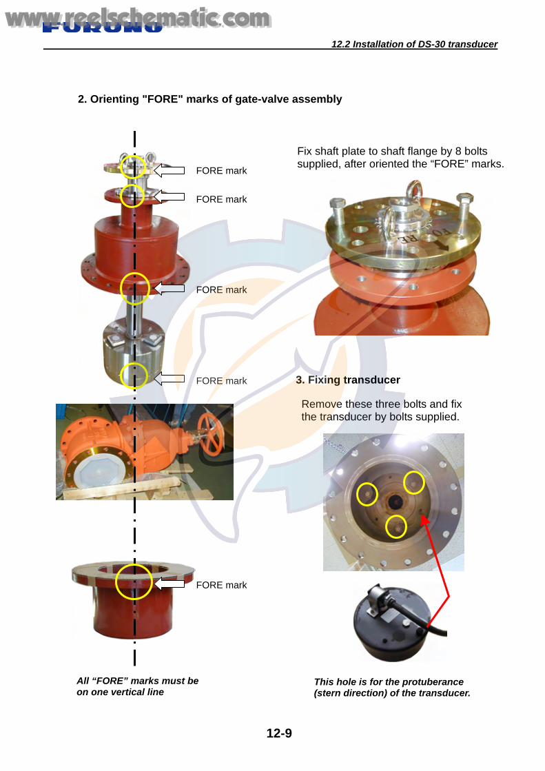
12.2 Installation of DS-30 transducer
12-9
2. Orienting "FORE" marks of gate-valve assembly
All “FORE” marks must be on one vertical line
Remove these three bolts and fix the transducer by bolts supplied.
3. Fixing transducer
This hole is for the protuberance (stern direction) of the transducer.
Fix shaft plate to shaft flange by 8 bolts supplied, after oriented the “FORE” marks.
FORE mark
FORE mark
FORE mark
FORE mark
FORE mark
www.reelschematic.comwww.reelschematic.com

12.3 Installation of DS-50 transducer
12-10
12.3 Installation of DS-50 transducer
12.3.1 Hull tank
DS-531B
Fig. 12.3.1 DS-50 Hull tank DS-531A/531B
DS-531A
www.reelschematic.comwww.reelschematic.com

12.3 Installation of DS-50 transducer
12-11
1. Bow mark The mark on the tank points toward the FORE direction. Alignment error is within 1 degree. The tank is mounted at the right angle of the draft line.
Bow
FOR
E
BowFOR
E
Top view
Fig. 12.3.2 DS-50 Hull tank
7 mm
2 mm
7 mm
Fore direction
Fig. 12.3.3 Heading of Transducer
2. Mounting transducer Transducer is also mounted withthe correct alignment. The fixing hole, which is closest to theedge, locates in the fore direction. Ifthe transducer is inserted into the tankin wrong direction, it cannot be fixed.See Fig. 12.3.3.
www.reelschematic.comwww.reelschematic.com

12.3 Installation of DS-50 transducer
12-12
After mounting the transducer, apply supplied silicone sealant on the head of three bolts. The transducer face is coated with Marine-Star 20 in the factory. Coating is not necessary at installation. For maintenance, use Marine-Star 20 only. Confirm that the transducer face is leveled to hull bottom plate, or projected a little (0.5 to 1 mm). If the transducer face sinks from the hull bottom level, install the tank again.
Hull bottom plate TD
Fig. 12.3.4 Applying silicone sealant
Fig. 12.3.5 Check level of transducer
www.reelschematic.comwww.reelschematic.com

12.3 Installation of DS-50 transducer
12-13
12.3.2 Installing tank with Gate-valve
Fig. 12.3.6 DS-50 transducer: DS-530
www.reelschematic.comwww.reelschematic.com

12.3 Installation of DS-50 transducer
12-14
Fig. 12.3.7 Transducer tank with Gate-valve: DS-532
www.reelschematic.comwww.reelschematic.com

12.3 Installation of DS-50 transducer
12-15
Bow
B
A
1. Bow mark on the flange must be located in fore direction.
2. Installing tank The centerline between the fixing holes is the fore-aft line. 3. Before mounting tank Put the A and B bow-mark on the tank as shown in the Fig. 12.3.9. (Accuracy: within 1 degree) The tank is mounted at right angles to the draft line.
Transducer case
Shaft
Shaft flange
Shaft plate
Bow mark
Bow mark
Bow mark
Tank
Gate-valve
Never cut the tank.
Fig. 12.3.8 Transducer tank with Gate-valve, exploded
Fig. 12.3.9 Bow direction of tank
www.reelschematic.comwww.reelschematic.com

12.3 Installation of DS-50 transducer
12-16
4. Installing transducer Insert the transducer into the case. The transducer-fixing hole, which is closest to the edge, matches to the fore mark on the case. The transducer is fixed with three bolts supplied.
Fig. 12.3.10 Mounting transducer
FORE (Bow direction)
Bottom View of transducer case
Bow
www.reelschematic.comwww.reelschematic.com

12.3 Installation of DS-50 transducer
12-17
5. Caution on mounting shaft / transducer assembly to Gate-valve "FORE" marks must be in the bow direction.
Fig. 12.3.11 Orienting "FORE" marks
"FORE" mark
A
B
"FORE" marks
"FORE" marks
www.reelschematic.comwww.reelschematic.com

12.3 Installation of DS-50 transducer
12-18
Fig. 12.3.12 Mounting transducer
The shaft plate is fixedto the flange withusing 12 Hex-bolts. "FORE" mark on theshaft plate matches tothat on the flange.
The transducer face must be flush with the bottom ofthe tank.
Push down the shaft as far as it will go.
www.reelschematic.comwww.reelschematic.com

12.4 Installation of DS-80 transducer
12-19
12.4 Installation of DS-80 transducer 12.4.1 Gate-valve tank: DS-782
No. NAME QTY. No. NAME QTY. 1 TRANSDUCER 1 14 CABLE GLAND 1 2 GATEVALVE 1 15 STUD BOLT 8 3 HULL FLANGE 1 16 SPRING WASHER 16 4 UPPER FLANGE 1 17 HEX. NUT 16 5 RETRACTION SHAFT 1 18 GASKET 2 6 TRANSDUCER CASE 1 19 O-RING 2 7 TURNING STOPPER 1 20 HEX. BOLT 8 8 LOCK RING 2 21 FLAT WASHER 4 9 HANDLE 1 22 SPRING WASHER 4
10 SPACER 2 23 BOX. BOLT 4 11 LOCK RING 1 24 HEX. BOLT 2 12 GASKET 1 25 HEX. BOLT 2 13 SECURE RING 2 26 HEX. BOLT 1
Type: DS-782
Fig. 12.4.1 DS-80 Gate-valve tank: DS-782
www.reelschematic.comwww.reelschematic.com

12.4 Installation of DS-80 transducer
12-20
1. Weld the hull flange (3) to the hull bottom with the FORE mark pointing toward the bow direction and reference marks on the side of the hull flange aligned with the fore-aft line.
2. Apply KINORUSTER or alternative anticorrosive sealant to the flanges and
the gasket as shown in Fig. 12.4.3. Use the sealant for both side of the gasket.
Bow
Fig. 12.4.2 Bottom flange
Fig. 12.4.3 Gate-valve DS-782, enlarged
Hex. nut Spacer
Flange
Gasket
Transducer
Gatevalve
Gasket
Hull flange
Observe the direction of the transducer when putting it through the flange.
- Fore-aft alignment is accurate within ± 1 degree.- The flange must be parallel to the draft line within± 1 degree.
- Grind the welding area outside the hull bottom toaccomplish flatness.
www.reelschematic.comwww.reelschematic.com

12.4 Installation of DS-80 transducer
12-21
3. Mounting transducer Insert the transducer into the head cap so that the protuberance of the transducer engages to location mark. Then, fix the transducer to the head cap with the Hex- bolts.
The protuberance of the transducerpoints toward the fore direction.
Transducer (DS-820)
Hex-bolt M5 X 18 SUS
Head cap
Transducer
Fig. 12.4.4 Mounting of transducer
Remove Hose clamp.
Never removescrews.
www.reelschematic.comwww.reelschematic.com

12.4 Installation of DS-80 transducer
12-22
12.4.2 Gate-valve tank: DS-786
No. QTY. No. QTY. 1 TRANSDUCER 1 12 HEX.BOLT 4 2 HULL FLANGE 1 13 HEX. SOCKET HEAD BOLT 3 3 BUSHING 14 SPRING WASHER 3 4 FLANGE 1 15 HEX. SOCKET HEAD BOLT 4 5 SHAFT 1 16 SEAL WASHER 4 6 LOCK RING 1 17 O RING 2 7 GASKET 1 18 GASKET 2 8 WASHER 2 19 FIXING GLAND 1 9 TAP-END STUD BOLT 4 20 GATE VALVE 1
10 HEX. NUT 8 21 CONNECTION CABLE 11 SPRING WASHER 8
Type: DS-786
Fig. 12.4.5 DS-80 Gate-valve hull tank: DS-786
www.reelschematic.comwww.reelschematic.com

12.4 Installation of DS-80 transducer
12-23
1. Mounting of transducer
Apply Three-Bond #1104.
Align the FORE mark onthe top of the shaft withthe protuberance on thetransducer.
Remove Hose clamp.
Remove 4 flat screws.
Never remove this screw.
Fix the transducerby using four Hex.socket head bolts.
Fig. 12.4.6 Mounting DS-80 transducer
www.reelschematic.comwww.reelschematic.com

12.4 Installation of DS-80 transducer
12-24
2. Weld the hull flange with FORE mark aligned to the bow direction and the reference marks to the fore-aft line.
- Fore-aft alignment is accurate
within ± 1 degree. - The flange must be parallel to the
draft line within ± 1 degree. - Grind the welding area outside the
hull bottom to accomplish flatness.
Fig.12.4.7 Mounting bottom flange
Apply KINORUSTER or alternative anticorrosive sealant to the flanges and the gasket as shown in Fig. 12.4.8. Use the sealant for both side of the gasket. Align FORE mark on the flange with that on the bottom flange. Align FORE mark on the top of the shaft with that on the flange. Confirm that the transducer face flushes with the hull bottom.
Flange
Gasket
Shaft
Lock ring
Gate-valve
Gasket
Bow (FORE)
Transducer
Bottom flange
Fig. 12.4.8 DS-786, enlarged
www.reelschematic.comwww.reelschematic.com

12.4 Installation of DS-80 transducer
12-25
12.4.3 Hull tank: DS-783 Note: Before welding the hull flange, remove the O-ring, transducer and transducer flange.
No. NAME QTY. 1 Transducer 1 2 Flange 1 3 Transducer Flange 1 4 CAP NUT 1 5 Nut 1 6 Gasket 1 7 Flat Washer 1 8 O-Ring 1 9 Hex. Socket Head bolt 4 10 Spring Washer 4
Fig. 12.4.9 Hull tank: DS-783
www.reelschematic.comwww.reelschematic.com

12.4 Installation of DS-80 transducer
12-26
12.4.4 Hull Tank: DS-784 Note:
Before welding the hull flange, remove the O-ring, transducer and transducer flange.
No. NAME QTY. 1 Transducer 1 2 Flange 1 3 Transducer Flange 1 4 CAP NUT 1 5 Nut 1 6 Gasket 1 7 Flat Washer 1 8 O-Ring 1 9 Hex. Socket Head bolt 4 10 Spring Washer 4
Fig. 12.4.10 Hull tank: DS-784
www.reelschematic.comwww.reelschematic.com

12.4 Installation of DS-80 transducer
12-27
Hull flange
O-ring
Transducer flange
O-ring groove
Fig. 12.4.11 DS-784 enlarged
FORE mark on the bottompoints toward the fore direction.Weld the flange with referencemarks aligned to the fore-aftline. (Accuracy: within 1 degree)
Engage the protuberance ofthe transducer to the slot ofthe hull flange.
The flange must be parallel to the draft line within ± 1 degree. Grind the welding area outside the hull bottom to accomplish flatness.
Apply KINORUSTER or alternativeanticorrosive sealant to the O-ring groove, O-ring, transducer flangeand Hex. nut.
www.reelschematic.comwww.reelschematic.com

12.4 Installation of DS-80 transducer
12-28
12.4.5 Protruded hull tank
Fig. 12.4.12 Mounting DS-781
Place the transducer withcorrect orientation.
Bow
Use the hose clamp.
Bow
www.reelschematic.comwww.reelschematic.com
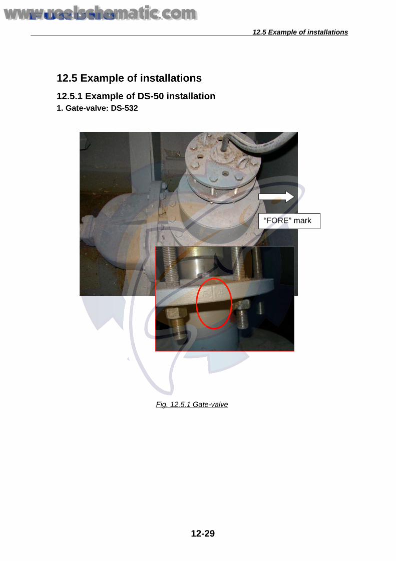
12.5 Example of installations
12-29
12.5 Example of installations 12.5.1 Example of DS-50 installation 1. Gate-valve: DS-532
“FORE” mark
Fig. 12.5.1 Gate-valve
www.reelschematic.comwww.reelschematic.com

12.5 Example of installations
12-30
2. DS-50 Main display unit (DS-500)
Connect wires to terminalwith using a crimp on lug.
Fig. 12.5.2 DS-50 Main display unit (DS-500)
Wind Shield wirewith vinyl tape.
Check the connection by pulling each wire.
Fix cables to cable fixture with cable ties.
www.reelschematic.comwww.reelschematic.com

12.5 Example of installations
12-31
3. DS-50 Processor unit (DS-511)
Fig. 12.5.3 DS-50 Processor unit (DS-511)
Check the connectionby pulling each wire.
Connect wires to terminal with using a crimp on lug.
Wind Shield wire with vinyl tape.
Fix cables to cable fixture with cable ties.
Armor must be fixed with the cable cramp.
www.reelschematic.comwww.reelschematic.com

12.5 Example of installations
12-32
Cable Fabrication of DS-50
1. Transducer cable
2. Cable between transceiver unit, junction box and processor unit (TTYCY-19S)
a. Transceiver unit/ junction box
www.reelschematic.comwww.reelschematic.com

12.5 Example of installations
12-33
b. Processor unit Cores and shields are fabricated the same as on transceiver unit/junction box side. To ground the cable, remove paint from the armor and set the armor in the cable clamp.
3. CIF/NMEA Data Signal Cable (CO-SPEVV-SB-C 0.2X5P)
4. Other Cables All other cables are terminated at a terminal strip.
<Cable passed through cable clamp> Locate the armor in the cable clamp.
<Cable passed through cable gland> Solder a vinyl wire w/crimp-on lug to the armor and fasten it to the earth terminal.
www.reelschematic.comwww.reelschematic.com

12.5 Example of installations
12-34
Processing the shield <Individual shields>
Undo individual shields only near the terminal strip to which its wire is connected. Tape shields for insulation.
<Common shield>
Undo individual shields only near the terminal strip to which its wire is connected. Tape shields for insulation.
www.reelschematic.comwww.reelschematic.com

12.5 Example of installations
12-35
12.5.2 Example of DS-30 installation
Fig. 12.5.4 DS-30 Processor unit (DS-310)
Fig. 12.5.5 DS-30 Junction unit (DS-360)
Check the connectionby pulling each wire.
Fix cables to cable fixture with cable ties.
Check the connectionby pulling each wire.
Fix cables to cable fixture with cable ties.
Connect wires to terminalwith using a crimp on lug.
Wind Shield wirewith vinyl tape.
Connect wires to terminalwith using a crimp on lug.
Wind Shield wirewith vinyl tape.
www.reelschematic.comwww.reelschematic.com
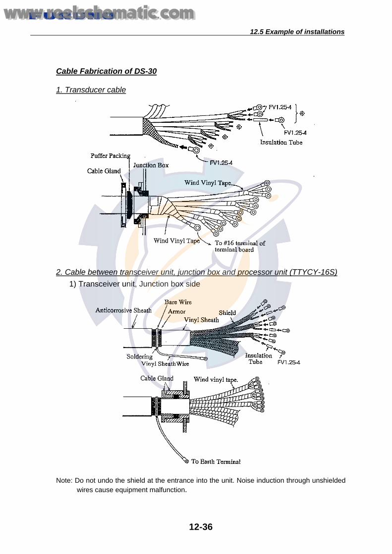
12.5 Example of installations
12-36
Cable Fabrication of DS-30
1. Transducer cable
2. Cable between transceiver unit, junction box and processor unit (TTYCY-16S) 1) Transceiver unit, Junction box side
Note: Do not undo the shield at the entrance into the unit. Noise induction through unshielded
wires cause equipment malfunction.
www.reelschematic.comwww.reelschematic.com

12.5 Example of installations
12-37
2) Processor unit side Fabricated the wires and shield in the same way as the transceiver unit/junction box side. For the cable armor, remove paint and ground it through the cable clamp.
3. Cable between Processor unit/Main display unit/sub display unit (CO-SPEVV-SB-C 0.2x10P)
Connect the 20p connector as follows. 1) Cable Fabrication
2) Crimping Tool and Crimping method A special crimping tool is necessary for connection of wires to the contact pins of 38P connector 00–8016-038-000-751. Also a pin extractor should be used to push out the contact pin from the connector body. The following describes how to crimp and extract the contact.
www.reelschematic.comwww.reelschematic.com

12.5 Example of installations
12-38
3) Wire Crimping procedure 1. Strip the vinyl sheath of the wire to expose the
core by 3 mm to 4 mm. 2. Hold the crimping tool horizontally and insert the
contact pin with its slit faced downward into the crimp hole on the crimping tool.
3. Insert the wire onto the contact pin and squeeze the handle until the ratchet releases. Note that the wire should be inserted deep enough until its end comes in contact with the stopper plate of the crimping tool. After crimping, pull the wire to make sure that it is securely fixed.
4) Inserting contact pin into connector housing The contact pins fitted to wires should be inserted into the connector housing referring to the interconnection diagram.
5) Procedure to extract contact pin
When a contact pin is inserted into an incorrect hold on the connector body, take it out by using the pin extractor.
1. Push the pin extractor into the pin hole from the side opposite to the pin inserting side.
2. Push in the head of the pin extractor, and the contact pin is unlocked and pushed out.
6) Assembling connector housing
1. Fix the cover “1”, paying attention to the cable outgoing direction. 2. Dress the wires and put covers “2” and “3” on. 3. Use a fragment of cable sheath to fix the wires with the connector clamp. 4. Cut the unused wires to proper length and wrap their ends with vinyl tape.
Note: Cover “1”, “2” and “3” are not fitted on the connectors contacted to the main and sub display units.
www.reelschematic.comwww.reelschematic.com

12.5 Example of installations
12-39
7) Clamping cable Clamp the shield and armor of the cable with cable clamp.
4. CIF/NMEA Data Signal Cable (CO-SPEVV-SB-C 0.2X5P)
5. Other Cables All other cables are connected to terminal boards. Fabricate their ends as follows.
1) Cable Armor <for cables led in though cable clamp>
Expose the armor and clamp it with the cable clamp.
<For cables led in though cable gland>
Solder a vinyl sheath wire to the armor and connect it to the grounding terminal.
www.reelschematic.comwww.reelschematic.com

12.5 Example of installations
12-40
2) Cable shield <For individual shield>
Undo individual shields only near at the terminal boards to which the wires are connected. Further, tape shields for insulation.
<For common shield. Undo common shield at entrance of the unit and tape it for insulation.
6. Insulation of cables for transducer Insulation check
1. Remove all cores and shields of the transducer from the terminal board. All wires of the transducer are open.
2. Set the multimeter to the maximum resistance range and measure the resistance between each transducer line ‘TD1, TD2, TD3) and individual or common.
Measurement places
- polarity lead - polarity lead Insulation resistance
value Red wire of black sheath Shield in black sheath Red wire of black sheath Common shield Red wire of red sheath Shield in red sheath Red wire of red sheath Common shield
Red wire of green sheath Shield in green sheath Red wire of green sheath Common shield
Digital multimeter: More than 10 M-ohm,
Analog multimeter: Needle dose not swing.
Note: If rating is not met a location, suspect faulty insulation. Replace a new one.
www.reelschematic.comwww.reelschematic.com

AP1-1
AP1.1 Transducer Position (DS-30/50/80, FE-700) AP1.1.1 Best location Select following locations for the transducer of acoustic equipment, such as a Doppler sonar and Echo sounder. 1. Location where is lightly affected by bubbles. 2. Location where is lightly affected by propeller and side thruster noises.
The most important thing is to avoid bubbles. Flow of air bubbles created at ship’s bow varies from hull to hull and according to ship’s speed. Typically, bubbles flow along the hull as shown in Fig. AP1.1.1.
(a) Side view
(b) Bottom view
Fig. AP1.1.1 Flow of bubbles - The best location for the transducer shows arrow (a) in Fig. AP1.1.1.
- The example of an installation is Fig. AP1.1.2.
A Bubbles
Bubbles
A
Appendix 1. Acoustic Equipmentwww.reelschematic.comwww.reelschematic.com

AP1.1 Transducer Position
AP1-2
Transversely, the transducer is mounted on the keel or as near to the keel as possible. When side thruster is installed; The transducer is mounted in front of the side thruster about 1 m.
Side thruster
Fig. AP1.1.2 Location of transducer
The performance of the Doppler sonar is easily degradedby bubbles, so the transducer must be placed at thelocation "A" as shown in Fig. AP1.1.1.
www.reelschematic.comwww.reelschematic.com

AP1.1 Transducer Position
AP1-3
Installation at bow bulb If the bottom is not flat, the transducer tank must be welded as shown in Fig. AP1.1.3 to make the transducer surface flat. The installation at an angle will cause a false reading of depth. Location for transducer of Echo sounder The best position is the above-mentioned B. Installation at other areas may be affected by air bubbles and cause unstable depth indications. The lower frequency, the more the air bubble interference. Use 200 kHz transducer which there is the possibility of air bubble interference.
Side thruster B
Fig. AP1.1.3 Installation at bow bulb
Fig. AP1.1.4 Location of Echo sounder transducer
200 kHz transducer 200 kHz or 50 kHz transducer
www.reelschematic.comwww.reelschematic.com

AP1.1 Transducer Position
AP1-4
Recommended areafor Echo sounder transducer
DS-80 transducer
Bow
Fig. AP1.1.5 Echo sounder and Doppler sonar transducers
AP1.1.2 Installation of Echo sounder and Doppler sonar transducers Decide location of Doppler sonar transducer first. When installing Doppler sonar and Echo sounder transducers, decide the location for the Doppler sonar transducer first. The Echo sounder transducer is placed behind the Doppler sonar transducer about 2 m or more. The recommended area for Echo sounder transducer to be mounted shows Fig. AP1.1.6. Doppler sonar transmits three beams in directions A, B and C. Never place the Echo sounder transducer in the directions A, B and C. DS-80 and FE-700
Doppler sonar transducer Echo sounder transducer
keel
Bow
DS-30/50 transducer
Fig. AP1.1.6 DS-30/50 and FE-700 transducers
Fig. AP1.1.7 DS-80 and FE-700 transducers
Recommended areafor Echo soundertransducer
www.reelschematic.comwww.reelschematic.com

AP1.2 Piping Transducer cable
AP1-5
AP1.2 Piping Transducer cable Pipe the cable from the transducer flange to the transducer or matching box.
Fig. AP1.2.1 Piping transducer cable
Note: The transducer cable of Doppler sonar must be piped.
Transducer tank
Matching box
Piping
www.reelschematic.comwww.reelschematic.com

AP1.3 Installation on ship with protruded keel
AP1-6
AP1.3 Installation on ship with protruded keel When the transducer is mounted in the keel, take followings into account to prevent the adverse affect from bubbles. 1. "In keel" installation
2. "Beside keel" installation (Using tank)
Fig. AP1.3.2 "Beside keel" installation
Fig. AP1.3.1 "In keel" Installation
Bubbles
Transducer
bottom
The transducer face must be flushedwith the bottom of the keel.
Keel
Bubbles
Keel
,
The transducer face must be flushedwith the bottom of the keel.
Hull bottom
Transducer
www.reelschematic.comwww.reelschematic.com

AP1.3 Installation on ship with protruded keel
AP1-7
3. "Parallel to keel" installation (Using tank)
Fig. AP1.3.3 "Parallel to keel" installation
Bubbles
Keel
About 1 m from the keel
TransducerThe transducer facemust be flushed withthe bottom of the keel.
www.reelschematic.comwww.reelschematic.com

AP2.1 Safety measures
AP2-1
AP2.1 Safety measures AP2.1.1 MF/HF antenna For the transmission antenna installation of MF/HF radio equipment, safety measures fo high-voltage electricity should be considered. Where high-voltage electricity runs; e.g. feeder, secure the height 2.5 meters or more from the deck where crews walk. However, as far as the portion lower than 2.5 meters has a construction which does not easily come in touch with a human body, or as far as it is located at the place which the human body does not readily come in touch with, this shall not apply.
Appendix 2. Antenna Installation
Fig. AP 2.1.1 Example of safety measures for transmission antenna
Where high voltage isapplied
More than2.5 m
Precaution
“High voltage” Danger sign nameplate
Installation of safety fence-1
Note: If the metal safetyfence is metal mesh, it mustbe understood that radioradiation would be lowered.
Installation of safety fence-2
www.reelschematic.comwww.reelschematic.com

AP2.1 Safety measures
AP2-2
Caution label for radio wavesof high radiation level
AP2.1.2 Caution label Radio waves can be harmful to the human body. Since safe distances diffor by country and ship construction there is no uniform formula for calculating safe distance. However, general guidelines are below. Personnel should not approach an area in which the radiation level is higher than 10 W/m2, e.x., within 4 m from the radome surface. For example, apply Caution Label 1. A prominent place under the antenna mast (to the dome, one sheet is affixed
but people may come close to the dome to read the characters written and does not work as the prevention of disability. Understand the purpose and choose appropriate place.)
2. A prominent place at the approaching place to compass deck that is rigged with the radome.
Affix a caution label for radiowaves of high radiation level.
For example, it is one method topaint a danger zone.
Fig. AP2.1.2 Examples of safety indications by INMARSAT radiation levels
INMARSAT B: 6 m INMARSAT F: 4 m
www.reelschematic.comwww.reelschematic.com

AP2.2 Antenna arrangement
AP2-3
AP2.2 Antenna arrangement In order to satisfactory communication, the distance between necessary antennas should be ensured, and interference between antennas should be reduced. However, in case the antenna is mounted to a compass deck or radar mast with a limited space, there are cases in which the antenna is unable to be mounted as per the guidelines stipulated herein or it is difficult to mounted the antenna, but consider the mounting in conformity to the purport of this document as much as possible. The basic concept of antenna mounting includes:
1. Each antenna should be rigged out of beams of radar or INMARSAT. 2. Rig with receiving antennas kept more than 1 m away. 3. Rig with VHF transmission antennas including AIS kept away as much as
possible. If possible, keep them more than 10 m away. 4. Separate between MF/HF transmission antennas and receiving antennas
as much as possible. 5. Rig the antenna of INMARSAT C to the top of the radar mast free of
obstacles. In addition, grasp the shadow sector of INMARSAT B, F and explain users.
Mount antennas outside thecompass safety distance whichmagnetic compass requires.
Rigging example of INMARSAT F radar mast
Example of rigging two IMARSAT C
MF/HF Tx
MF/HF DSC
B.C ANT
No.1 GPS
No.2 GPS
NAVTEX
No.2 VHF WR
No.1 VHF WR
No.2 VHF TR
No.1 VHF TRINMARSAT C
INMARSAT F
S Band RadarX Band Radar
FAX AIS
Mag. Compas
Safety Distance
MF/HF Tx
MF/HF DSC
B.C ANT
No.1 GPS No.2 GPS
NAVTEX
No.2 VHF WR
No.1 VHF WR
No.2 VHF TR
No.1 VHF TR
INMARSAT CINMARSAT C
INMARSAT F
S Band RadarX Band Radar
FAX AIS
Mag. Compas
Safety Distance
Mount antennas outside thecompass safety distance whichmagnetic compass requires.
www.reelschematic.comwww.reelschematic.com
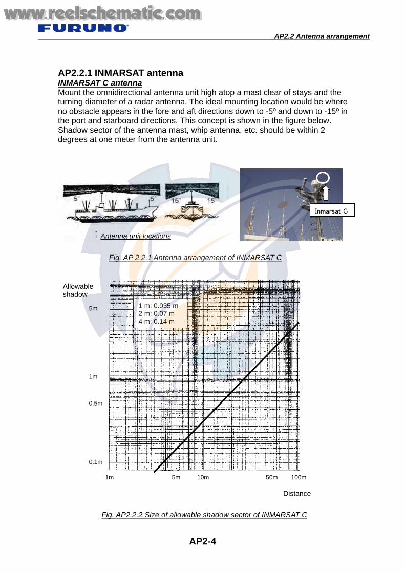
AP2.2 Antenna arrangement
AP2-4
AP2.2.1 INMARSAT antenna INMARSAT C antenna Mount the omnidirectional antenna unit high atop a mast clear of stays and the turning diameter of a radar antenna. The ideal mounting location would be where no obstacle appears in the fore and aft directions down to -5º and down to -15º in the port and starboard directions. This concept is shown in the figure below. Shadow sector of the antenna mast, whip antenna, etc. should be within 2 degrees at one meter from the antenna unit.
Inmarsat C
Fig. AP 2.2.1 Antenna arrangement of INMARSAT C
Distance
1m 5m 50m 100m 10m
1m
0.5m
5m
0.1m
Allowable shadow
Fig. AP2.2.2 Size of allowable shadow sector of INMARSAT C
1 m: 0.035 m2 m: 0.07 m 4 m: 0.14 m
Antenna unit locations
www.reelschematic.comwww.reelschematic.com

AP2.2 Antenna arrangement
AP2-5
1. Rigging of two INMARSAT C antennas The arrangement should be carried out as below. Adjust heights between two antennas so that any of the antennas does not enter the following range. Keep at least 1.5 m distance between two antennas in order to avoid interference between antennas. Provide 1 m or more level difference between two antennas. 2. Relation between INMARSAT C and INMARSAT B, F Provide more than 3.5 m distance between INMARSAT B, F and INMARSAT C antennas. If beams of INMARSAT B, F are directed to the antenna of INMARSAT C, INMARSAT C can not synchronize to the receiving signal.
Set 1.5 m ormore apart.
-15 deg. or more
Set 1 m ormore apart.
-15 deg. or more
Set 3 m ormore apart.
www.reelschematic.comwww.reelschematic.com

AP2.2 Antenna arrangement
AP2-6
3. Rigging of INMARSAT B, F antennas Antenna blocking should be considered. Mount INMARSAT B, F at locations free of any obstacles (radar mast, etc.) that exceed 6° within 10 m from INMARSAT B, F antennas. The size of an obstacle of 6° at 10 m distance is about 1 meter.
4. Relation between INMARSAT B, F and GPS antenna Keep them 5 m or more away from each other. If GPS antenna is rigged at locations within 5 m from INMARSAT B, F antennas, rig it deviated more than 2 m from INMARSAT beams. Directing INMARSAT B, F beams to the GPS antenna lowers the GPS reception level.
Obstacle exceeding 1 m
Keep 5 m or more away.
Keep 2 m or moreaway from the outof beams.
2 m
Set 10 m ormore apart.
-5° or more
www.reelschematic.comwww.reelschematic.com

AP2.2 Antenna arrangement
AP2-7
5. Relation between INMARSAT C and GPS antenna Keep them at least 3 m away from each other. If GPS antenna is rigged at locations within 3 m from INMARSAT C antenna, rig it deviated more than 1 m from INMARSAT beams.
6. Relation between INMARSAT B, F, C, GPS and S band radars Deflect from radar beams and avoid rigging in an area within 5 m from radar antenna. Mount INMARSAT C to the location above the shaded areas of the figure below so that antennas are not subject to S-Band radar interference.
1 m
-15° or more
Keep 3 m ormore away
Keep 1 m or more away fromthe out of beams.
www.reelschematic.comwww.reelschematic.com

AP2.2 Antenna arrangement
AP2-8
7. Relation between INMARSAT B, F, C, GPS and X band radars Avoid rigging in an area within 5 m from radar antenna. If it is unavoidable to rig antennas in an area within 5 m from radar antenna, adjust height between antennas so that antennas are not subject to radar beams in the range within ±15°. If locations are kept 5 meters or more apart from radar antenna, adjust the height between antennas so that antennas are not subject to radar beams in the range within ±10°.
Within 5 m: ±15° or more
+10°
If antenna is rigged within5 m, keep away from theradar beam range withinabout 15°.
+15°
5 m or more: ±10° or more
-15° or more -15° or more
www.reelschematic.comwww.reelschematic.com

AP2.2 Antenna arrangement
AP2-9
AP2.2.2 VHF (AIS) antenna, MF/HF antenna 1. Relation between VHF antenna, MF/HF antenna and INMARSAT B, F, C
2. Relation between VHF antenna and MF/HF antenna
MF/HF RT
5 m or more
VHF - AIS VHF - VHF RT - VHF WR
MF/HF - DUP-RX ANT - BC ANT - MF/HF WR
4m or more
VHF - AIS VHF - VHF RT
GPS
MF/HF RT
NAVTEX
NAVTEX
INMR-C
INMR-B/F
VHF - AIS VHF - VHF RT - VHF WR
- VHF ・VHF WR
NAVTEX MF/HF - DUP-RX ANT- BC ANT - MF/HF WR
MF/HF - DUP-RX ANT - BC ANT - MF/HF WR
MF/HF - DUP-RX ANT - BC ANT - MF/HF WR VHF
- AIS VHF - VHF RT
5 m or more
2 m or more
2 m or more
5 m or more 3 m or more
1 m or more 1 m or more
1 m or more
1 m or more
2 m or more
1 m or more 2 m or more
www.reelschematic.comwww.reelschematic.com

AP2.2 Antenna arrangement
AP2-10
3. Relation between VHF antenna and VHF antenna Note that channels which cannot avoid interference occur even if antennas between VHF telephones are kept away 5 m to 10 m.
4. Relation between VHF antenna and AIS antenna When VHF radiotelephone interferes with AIS, the AIS target is lost. The target-lost conditions differ according to ship speeds and navigation status. For example, with FA-150, in the case of a target with ship speed lower than 14 knots, it becomes a “Lost target” when no signal is received from the target for 50 seconds.
Between RT and WR: 5 m or more Between RT and RT: 5 m or more Between WR and WR: 1 m or more
VHF VHF
Structure
AIS VHF VHF RT
VHF RT
VHF WR
2 m or more 3 m or more
3 m or more
5 m or more
10 m or more
www.reelschematic.comwww.reelschematic.com

AP2.2 Antenna arrangement
AP2-11
5. Relation between VHF antenna, MF/HF antenna and radar antenna In case the distance between VHF antenna, MF/HF antenna and S, X band radar antennas is within 5 m, install VHF antenna, MF/HF antenna without radar beam zoon.
VHF MF/HF
www.reelschematic.comwww.reelschematic.com
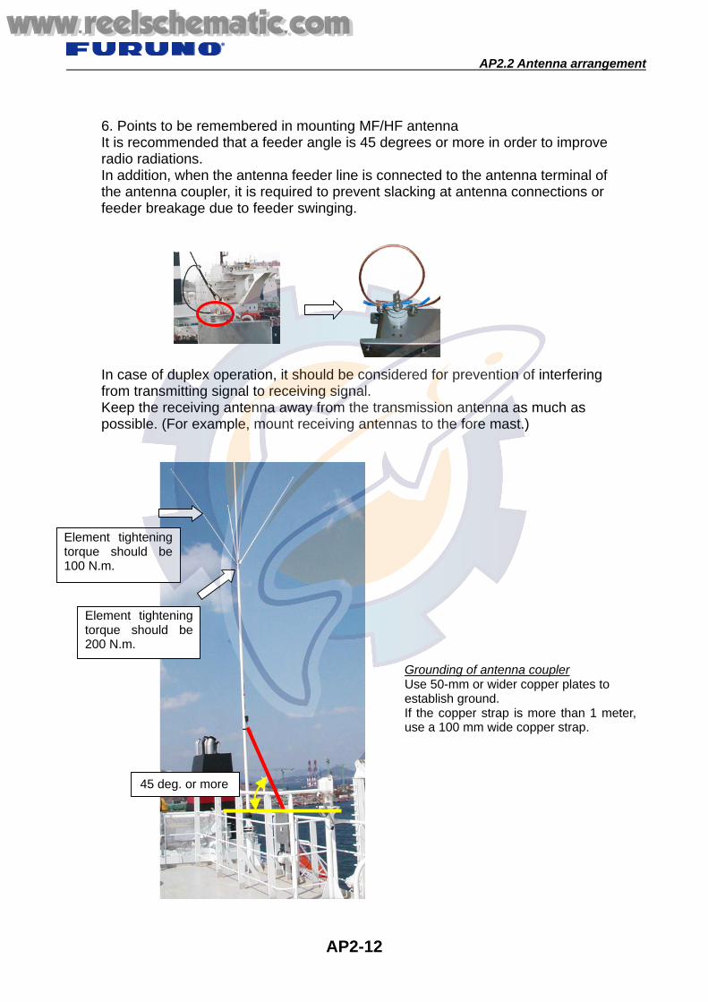
AP2.2 Antenna arrangement
AP2-12
6. Points to be remembered in mounting MF/HF antenna It is recommended that a feeder angle is 45 degrees or more in order to improve radio radiations. In addition, when the antenna feeder line is connected to the antenna terminal of the antenna coupler, it is required to prevent slacking at antenna connections or feeder breakage due to feeder swinging. In case of duplex operation, it should be considered for prevention of interfering from transmitting signal to receiving signal. Keep the receiving antenna away from the transmission antenna as much as possible. (For example, mount receiving antennas to the fore mast.)
45 deg. or more
Grounding of antenna coupler Use 50-mm or wider copper plates to establish ground. If the copper strap is more than 1 meter,use a 100 mm wide copper strap.
Element tighteningtorque should be100 N.m.
Element tightening torque should be 200 N.m.
www.reelschematic.comwww.reelschematic.com

AP2.2 Antenna arrangement
AP2-13
Reference: Oscillation range of AT-101DS antenna; Keep more than 5 m away in order to avoid contact of AT-101DS antenna with radar mast and other structures.
Wind velocity: 20.0 m/sX = 1.47 m
X
X
Y
Y
Wind velocity: 40.0 m/sX = 4.13 m
www.reelschematic.comwww.reelschematic.com
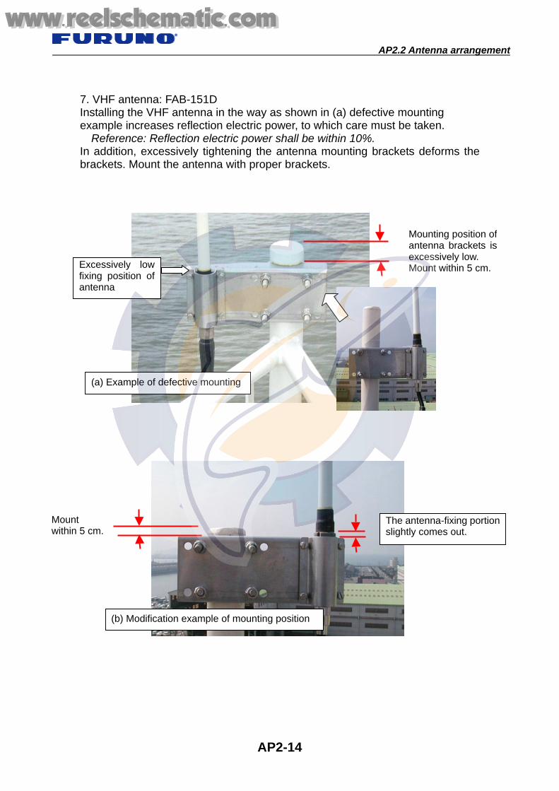
AP2.2 Antenna arrangement
AP2-14
7. VHF antenna: FAB-151D Installing the VHF antenna in the way as shown in (a) defective mounting example increases reflection electric power, to which care must be taken.
Reference: Reflection electric power shall be within 10%. In addition, excessively tightening the antenna mounting brackets deforms the brackets. Mount the antenna with proper brackets.
The antenna-fixing portion slightly comes out.
(b) Modification example of mounting position
Mounting position ofantenna brackets isexcessively low. Mount within 5 cm.Excessively low
fixing position of antenna
(a) Example of defective mounting
Mount within 5 cm.
www.reelschematic.comwww.reelschematic.com

AP2.2 Antenna arrangement
AP2-15
AP2.2.3 Radar antenna For S-band radar and X-band radar, arrange antenna units in such a manner to avoid beams from each other.
X-band radar
NG
30deg.
20deg.
S-band radar
X-band radar S-band radar
www.reelschematic.comwww.reelschematic.com

AP2.3 Table of antenna interactions
AP2-16
AP2.3 Table of antenna interactions
No.1 INMR-C
No.2 INMR-C
INMAR- SSAS
INMAR-B/F AIS NAVTEX MF/HF WR MF/HF RT MF/HF Rx No.1 VHF
RT No.1 VHF
WR No.2 VHF
RT No.2 VHF
WR GPS S- RADAR X- RADAR
No.1 INMR-C -- L=1.5 m
H=1 m L=1.5 m H=1 m 3.5 m 2 m 2 m 2 m 5 m 2 m 2 m 2 m 2 m 2 m 3 m Beam Beam
No.2 INMR-C
L=1.5 m H=1 m -- L=1.5m
H=1m 3.5 m 2 m 2 m 2 m 5 m 2 m 2 m 2 m 2 m 2 m 3 m Beam Beam
INMAR- SSAS
L=1.5 m H=1 m
L=1.5 m H=1 m -- 3.5 m 2 m 2 m 2 m 5 m 2 m 2 m 2 m 2 m 2 m 3 m Beam Beam
INMAR B/F 3.5 m 3.5 m 3.5 m -- 2 m 2 m 2 m 5 m 2 m 2 m 2 m 2 m 2 m 5 m Beam Beam
AIS 2 m 2 m 2 m 2 m -- 2 m 2 m 3 m 2 m H: 10 m orV: 3 m 5 m H: 10 m or
V: 3 m 5 m 1 m Beam Beam
NAVTEX Rcv 2 m 2 m 2 m 2 m 2 m -- 1 m 5 m 1 m 2 m 1 m 2 m 1 m 1 m Beam Beam
MF/HF WR 2 m 2 m 2 m 2 m 2 m 1 m -- 5 m 1 m 2 m 1 m 2 m 1 m 1 m Beam Beam
MF/HF RT 5 m 5 m 5 m 5 m 3 m 5 m 5 m -- 5 m 3 m 3 m 3 m 3 m 4 m Beam Beam
MF/HF Rx 2 m 2 m 2 m 2 m 2 m 1 m 5 m -- 2 m 1 m 2 m 1 m 1 m Beam Beam
No1VHF RT 2 m 2 m 2 m 2 m H: 10 mor V: 3 m 2 m 2 m 3 m 2 m -- 5 m 5 m 5 m 1 m Beam Beam
No.1 VHF WR 2 m 2 m 2 m 2 m 5 m 1 m 1 m 3 m 1 m 5 m -- 5 m 1 m 1 m Beam Beam
No.2 VHF RT 2 m 2 m 2 m 2 m H: 10 m
or V: 3 m 2 m 2 m 3 m 2 m 5 m 5 m -- 5 m 1 m Beam Beam
No.2 VHF WR 2 m 2 m 2 m 2 m 5 m 1 m 1 m 3 m 1 m 5 m 1 m 5 m -- 1 m Beam Beam
GPS 3 m 3 m 3 m 5 m 1 m 1 m 1 m 4 m 1 m 1 m 1 m 1 m 1 m -- Beam Beam S-
RADAR Beam Beam Beam Beam Beam Beam Beam Beam Beam Beam Beam Beam Beam Beam -- Beam
X- RADAR Beam Beam Beam Beam Beam Beam Beam Beam Beam Beam Beam Beam Beam Beam Beam --
Table of antenna interactions
www.reelschematic.comwww.reelschematic.com

AP3-1
AP3.1 Waveguide for X-Band Radar
Minimum bending radius E bend Rmm = 200 mm H bend Rmm = 400 mm
Appendix 3. Radar Waveguide
Caution on handling waveguide
www.reelschematic.comwww.reelschematic.com

AP3.1 Waveguide for X-Band Radar
AP3-2
Tools for fabricating X-Band Radar Wave-Guide
If necessary, order these tools to FURUNO. Type: OP03-123, Code No. 0084488800
Code No. Item Type Qty.
00015179800 FR-90 power tool R4KG5549 03S9791-0 1set
10020750000 Edge gauge 03-009-0530-0 1
10020754000 Gauge (Square) 03-009-0534-0 1
00080584700 Tool box #2207 1 00080584800 Brush 8 inch 1 00080584900 Wrench For M4 2 00080585000 Hack saw HFJ-12 1 00080585100 Saw 250 m x 24 mm 6 00080585200 File L150 1
00080585300 File L150 1
00080585400 Knife DK-N 1 00080585500 Heavy duty snips K30, 190 1 set
www.reelschematic.comwww.reelschematic.com

AP3.1 Waveguide for X-Band Radar
AP3-3
Procedure
www.reelschematic.comwww.reelschematic.com

AP3.1 Waveguide for X-Band Radar
AP3-4
www.reelschematic.comwww.reelschematic.com

AP3.1 Waveguide for X-Band Radar
AP3-5
www.reelschematic.comwww.reelschematic.com

AP3.1 Waveguide for X-Band Radar
AP3-6
www.reelschematic.comwww.reelschematic.com

AP3.1 Waveguide for X-Band Radar
AP3-7
www.reelschematic.comwww.reelschematic.com

AP3.2 Waveguide for S-Band Radar
AP3-8
AP3.2 Waveguide for S-Band Radar High frequency Coaxial cable The scanner unit is connected to the transceiver unit by a high frequency coaxial cable. It is necessary to install the connector at the transceiver side of the coaxial cable. The connector for the scanner unit side has been installed in the factory. Installing coaxial cable Use the cable band for fixing the cable supplied. The cable band Fig. AP3.2.1 (Type: 03-011-3228, Code: 100-049-62) is also available optionally.
Fig. AP3.2.1 Cable band, optional
www.reelschematic.comwww.reelschematic.com

AP3.2 Waveguide for S-Band Radar
AP3-9
Necessary tools
No. Name Type No. Name Type 1 Hack-saw HFJ-12 8 Knife DK-N 2 Pincers 220 mm 9 Bench rule with stopper 150 mm 3 Plier PL-200 10 Brush Small 4 Snips 170 mm 11 Brush Medium 5 Nipper 70-150 12 File Fine 6 Knife LDS-20-028 13 File Second -cut 7 Hammer 18 mm 14 Tool Box Y-350
13 12111098
7 6 5432 1
14
www.reelschematic.comwww.reelschematic.com

AP3.2 Waveguide for S-Band Radar
AP3-10
Installation Material
Note1: Prevent foreign substances from being entered into the cable during the
work. Note2: A minimum cable bending radius of 150 mm must be observed at the cable
run. When bending the cable twice or more in close points, the bending radius should be more than 250 mm.
Procedure 1. Straighten the cable and cut it with using the hacksaw and scale (gauge).
PVC tape
Coaxial cable Gauge
Connecter Assembly
Relay Conductor
Bolts
Self Bonding Tape
www.reelschematic.comwww.reelschematic.com

AP3.2 Waveguide for S-Band Radar
AP3-11
2. Remove the sheath 40 mm with using the tubing cutter and scale.
Note: Be careful not to nick the outer conductor.
3. Remove the outer conductor and the insulator. (Tools: Hacksaw and scale)
4. Removing burr of the outer conductor with the file. 5. Remove the insulator in the outer conductor 6 mm.
6. Connect the connector to the coaxial cable. Screw connector onto the coaxial cable.
www.reelschematic.comwww.reelschematic.com

AP3.2 Waveguide for S-Band Radar
AP3-12
7. Flare the outer conductor along the connector by the pincers. 8. File the outer conductor beyond the diameter of the connector.
9. Insert the gauge through the connector. Fix the gauge by the bolts, and then cut the
inner conductor leaving 1 mm for finishing. (Tools: Gauge, M4 Wrench and Hacksaw)
www.reelschematic.comwww.reelschematic.com

AP3.2 Waveguide for S-Band Radar
AP3-13
10. Remove the gauge.
Then, file the inner conductor to finish.
11. Assemble the relay connecter and the relay conductor, and then connect it to the
coaxial cable.
www.reelschematic.comwww.reelschematic.com

AP3.2 Waveguide for S-Band Radar
AP3-14
12. Tape the self-bonding tape twice or more on the cable and connector. And then,
tape the PVC tape over the self-bonding.
www.reelschematic.comwww.reelschematic.com

AP4.1 Power cable
AP4-1
AP4.1 Power cable
- Loss of the ship’s main voltage caused by the supply cable. - Generally, tolerance of the power supply voltage for navigational equipment
must be within +/-10 % of the standard voltage. - Since the voltage decreases in accordance with the length and thickness of
cable, the type of the cable must be determined so as to keep the voltage within this range.
- Generally, the type of cable is selected so that the decrease of voltage is limited within 3 to 5 % of the standard voltage.
4.1.1 Voltage drop The voltage “Vd” decreased by the cable is given by the following equation;
Vd = K i r L / 1000 K: Coefficient
Single phase AC and DC voltage: 2 Three phase AC: square root of 3
i: Current flow in cable (A) r: resistance of cable (ohm/km) L: length of cable
Maximum Cable length L = 1000 Vd/ K i r
Resistance of the cable (ohm/km)
Type Nominal area (mm2)
Number of wires/diameter of each wire (mm)
Resistance of cable (ohm/km)
DPYC-1.5 1.5 7/0.52 12.1 DPYC-2.5 2.5 7/0.67 7.41 DPYC-4 4.0 7/0.85 4.61 DPYC-6 6.0 7/1.04 3.08
DPYC-10 10.0 7/1.35 1.83 DPYC-16 16.0 7/1.70 1.15 DPYC-25 25.0 7/2.14 0.73 DPYC-35 35.0 7/2.52 0.52 DPYC-50 50.0 19/1.78 0.39
Appendix 4. Cables www.reelschematic.comwww.reelschematic.com

AP4.1 Power cable
AP4-2
Example 1: VHF radio (24 VDC) When the cable type is DPYC-6 (6 mm2, r = 3.08 ohm/km) and transmission current is 7 A, the cable length which decreases the voltage to 3 % of standard voltage (24 V), is 16.7 m.
Vd = 24 x 0.03 = 0.72 V L = (1000 x 0.72) / (2 x 7 x 3.08) = 16.7 m. If the longer cable is required, Type DPYC-10 or thicker one is appropriate. Example 2: Cable for battery (back up: 24 VDC) When the cable type is DPYC-35 (35 mm2, r = 0.524 ohm/km) and consumption of current is 50 A, the cable length which decrease the voltage to 5 % of standard voltage (24VDC), is 22.9 m.
Vd =24 x 0.05 = 1.2 V L = (1000 x 1.2) / (2 x 50 x 0.524) = 22.9 m
If the longer cable is required, Type DPYC-50 or thicker one is appropriate. Example 3: PR-850A (AC/DC Power supply) When the cable type is the DPYC-4 (4 mm2, r = 4.61 ohm/km) and current consumption is 7 A (220 VAC), the cable length which decrease the voltage to 5 % of standard voltage (220VAC) is 170 m.
Vd = 220 x 0.05 = 11 V L = (1000 x 11) / (2 x 7 x 4.61) = 170m
If the longer cable is required, Type DPYC-6 or thicker one is appropriate.
www.reelschematic.comwww.reelschematic.com

AP4.1 Power cable
AP4-3
Current vs. Maximum cable length Fig. AP4.1.1 shows the maximum cable length versus current in order to keep the voltage drop within 5 % when power supply is 24 VDC.
DPYC Diameter of wire 1.5 2.5 4 6 10 16 25 35 50 70
Conductor resistance (Ohm/km) at 20oC
12.2 7.56 4.7 3.11 1.84 1.16 0.734 0.529 0.391 0.27
CCuurrrreenntt
MMaa xx
ii mmuu mm
CCaa bb
ll ee LL
ee nngg tt
hh (( mm
))
Fig. AP4.1.1 Current vs. maximum cable length
www.reelschematic.comwww.reelschematic.com

AP4.1 Power cable
AP4-4
10
1.00 2.0 3.0 4.0V
20
30
40mDPYC-2.5 (7.56
5A
10A
15A
10
1.00 2.0 3.0 4.0V
20
30
40mDPYC-4 (4.7
10A
15A
20A
10
1.00 2.0 3.0 4.0V
20
30
40mDPYC-6 (3.11
10A5A
20A
10
1.00 2.0 3.0 4.0V
20
30
40mDPYC-10 (1.84
20A
10A
30A
10
1.00 2.0 3.0 4.0V
20
30
40mDPYC-16 (1.16
30A
40A
20A
The following tables show the relation among voltage drop of load current and cable length in accordance with the cable type.
10
1.00 2.0 3.0 4.0V
20
30
40mDPYC-1.5 (12.2
5A
10A
15A
Allowable current: 23AAllowable current: 16AAllowable current: 23A
Allowable current: 31A
Allowable current: 39A
Allowable current: 55A Allowable current: 73A
www.reelschematic.comwww.reelschematic.com

AP4.1 Power cable
AP4-5
10
1.00 2.0 3.0 4.0V
20
30
40mDPYC-25 (0.734
50A30A 40A
10
1.00 2.0 3.0 4.0V
20
30
40mDPYC-35 (0.529
80A
50A
60A
DPY/DPYC/DPYCY cables.
Nominal cross-sectional
area (mm2)
Wire number/ Diameter
(mm)
Outer diameter of wire
DDPPYY Outer
diameter(mm)
DDPPYYCC Outer
diameter fin.
(mm)
DDPPYYCCYY Outer
diameter fin.
(mm)
Conductor resistance without plating (Ohm/km)
Conductor resistance
with plating
(Ohm/km)
Test voltage
(V)
Insulation resistance(M Ohm
km)
1.5 7/0.52 1.56 10.4 11.7 13.7 12.1 12.2 1300 2.5 7/0.67 2.01 11.5 12.8 14.8 7.41 7.56 1100 4 7/0.85 2.55 12.6 13.9 15.9 4.61 4.70 900 6 7/1.04 3.12 13.9 15.2 17.4 3.08 3.11 800
10 7/1.35 4.05 15.8 17.1 19.3 1.83 1.84 700 16 7/1.70 5.10 18.1 19.4 21.8 1.15 1.16 600 25 7/2.14 6.42 21.7 23.0 25.6 0.727 0.734 500 35 7/2.52 7.56 24.2 25.5 28.1 0.524 0.529 450 50 19/1.78 8.90 28.1 29.4 32.2 0.387 0.391 450 70 19/2.14 10.7 33.3 35.1 38.5 0.268 0.270
3500
450
MPY/MPYC/MPYCY cables.
Number of
conductor
Nominal cross-sectional
area (mm2)
Wire number/ Diameter
(mm)
Outer diameter of wire
MMPPYY Outer
diameter(mm)
MMPPYYCC Outer
diameter fin.
(mm)
MMPPYYCCYY Outer
diameter fin.
(mm)
Conductor resistance without plating (Ohm/km)
Conductor resistance
with plating
(Ohm/km)
Test voltage
(V)
Insulation resistance(M Ohm
km)
2 8.7 10 12.0 4 9.9 11.2 13.2 7 11.9 13.2 15.2
12 15.5 16.8 19.0 19 18.3 19.6 22.0 27 22.1 23.4 26.0 37 24.8 26.1 28.9 44 28.0 29.3 32.1 77
1 7/0.43 1.29
35.9 37.7 41.0
18.1 18.2 1500 1200
Allowable current: 118AAllowable current: 98A
www.reelschematic.comwww.reelschematic.com

AP4.1 Power cable
AP4-6
MPYCS/MPYCYS Cables
Number of
conductor
Nominal cross-sectional
area (mm2)
Wire number/ Diameter
(mm)
Outer diameter of wire
MMPPYYCCSS Outer
diameter fin.
(mm)
MMPPYYCCYYSS Outer
diameter fin.
(mm)
Conductor resistance
without plating (Ω/km)
Conductor resistance
with plating (Ω/km)
Test voltage
(V)
Insulation resistance(M Ohm
km)
2 10.7 12.7 4 11.9 13.9 7 13.9 15.9
12 17.6 19.8 19 20.6 23.0 27 24.3 26.9 37 27.0 29.8 44
1 7/0.43 1.29
30.2 33.2
18.1 18.2 1500 1200
TTY/TTYC/TTYCY cable.
Pair
Number of wire
Nominal cross-sectional
area (mm2)
Wire number/ Diameter
(mm)
Outer diameter of wire
TTTTYY Outer
diameter fin.
(mm)
TTTTYYCC Outer
diameter fin.
(mm)
TTTTYYCCYY Outer
diameter fin.
(mm)
Conductor resistance (Ohm/km)
Test voltage
(V)
Insulation resistance(M Ohm
km)
1 2 7.9 9.2 11.0 1T 3 8.6 9.9 11.7 1Q 4 9.3 10.6 12.6 4 8 14.2 15.5 17.7 7 14 16.9 18.2 20.6
10 20 21.7 23.0 25.6 14 28 23.5 24.8 27.4 19 38
0.75 7/0.37 1.11
26.4 27.7 30.5
26.0 1500 300
TTYCS/TTYCYS Cables with shield.
Pair
Number of wire
Nominal cross-sectional
area (mm2)
Wire number/ Diameter
(mm)
Outer diameter of wire
TTTTYYCCSS Outer
diameter fin.
(mm)
TTTTYYCCYYSS Outer
diameter fin.
(mm)
Conductor resistance(Ohm/km)
Test voltage
(V)
Insulation resistance (M Ohm
km)
1 2 10.1 12.1 1T 3 10.6 12.6 1Q 4 11.3 13.3 4 8 16.3 18.5 7 14 19.0 21.4
10 20 24.0 26.7 14 28 25.7 28.3 19 38
0.75 7/0.37 1.11
28.8 31.6
26.0 1500 300
www.reelschematic.comwww.reelschematic.com

AP4.1 Power cable
AP4-7
TTYCS-4
TTYCS-1
MPYCS-4
www.reelschematic.comwww.reelschematic.com

AP4.2 Coaxial cable
AP4-8
AP4.2 Coaxial cable When the coaxial cable type is selected, the decrease of RF signal loss is recommend within 3 dB around. For example, if the VHF antenna coaxial cable is RG-10/UY and the cable length is 30 m, the loss of 2.4 dB is resulted. In this case, antenna input power is decreased from 25 W to 14 W around. The receiving sensitivity is also decreased.
10MHz
10 dB/km
100MHz 1000MHz
1000 dB/km
100 dB/km
RG-14/U
8D-FB
5D-FB
RG-10/URG-5/U
RG-58/U
Freq.
RF s
ignal
loss
www.reelschematic.comwww.reelschematic.com

AP4.2 Coaxial cable
AP4-9
AP4.2.1 Using Coaxial cable list
Equipment Type Freq, Range Remarks
Inmarsat B FELCOM 82 1.5/1.6 GHz 30 m: 8D-FB-CV 50 m: 8D-FB-CV 100 m: 12D-SFA-CV
Inmarsat C FELCOM 15 1.5/1.6 GHz 30 m: TP5FBAW-5DFBB 50 m: 8D-FB-CV 100 m: 12D-SFA-CV
FELCOM 16 1.5/1.6 GHz
15 m: TP58A15W-RG58 30 m: TP5FBAW-5DFBB 50 m: 8D-FB-CV 100 m: 12D-SFA-CV
Inmarsat F FELCOM 70 1.5/1.6 GHz 30/40/50/60 m: 8D-FB-CV 100 m: 12D-SFA-CV
FS-5000 1.6 ~30 MHz 50 m: RG-8A/U, or RG-10/UY
MF/HF Radio FS-1570/2570 1.6 to 30 MHz
50 m: RG-10/UY or 50 m: 05S0462(5D-2V)
MF/HF W/R Built-in FS-1570/2570
2/4/6/8/12/
18/22/25 MHz
15 m: FAX-5 (3D-2V) 50 m: RG-10/UY
VHF Radio FM-8800S/D 150/160 MHz 40 m: RG-10/UY 100 m: 8D-FB-CV
VHF WR Built-in FM-8800S/D 156.725 MHz 40 m: RG-10/UY
100 m: 8D-FB-CV
AIS FA-150 150/160 MHz 20 m: RG-10/UY 30 m: 8D-FB-CV 50 m: 8D-FB-CV
NAVTEX NX-700 518 kHz, 490 kHz, 4209.5 kHz
50 m: NX-7 (3D-2V) 50 m: RG-10/UY 200 m: RG-214
GPS GP-90 1575.42 MHz 15 m: TNC-PS-3D-15 30 m: 8D-FB-CV 50 m: 8D-FB-CV
FAX Receiver FAX-215 80 to 160 kHz 2 to 25 MHz
15 m: FAX-5 (3D-2V) 50 m: RG-10/UY
All band Receiver 0.1to 30 MHz 50 m: RG-10/UY
www.reelschematic.comwww.reelschematic.com

AP4.2 Coaxial cable
AP4-10
AP4.2.2 decibel (dB) The decibel (dB) is a measure of the ratio between two quantities, and is used in a wide variety of measurements in acoustics, physics and electronics. While originally only used for power and intensity ratios, it has come to be used more generally in engineering. Decibels are useful because they allow even very large or small ratios to be represented with a conveniently small number (similar to scientific notation). This is achieved by using a logarithm. Substituting a measured voltage and a reference voltage and rearranging terms leads to the following equations and accounts for the difference between the multiplier of 10 for intensity or power and 20 for voltage:
PdB=10log(Px/P0) PdB=10log(V2
x/Rx / V2o/Ro) ! VdB=20 log(V2
x/ V2o)
Where V0 are a specified reference voltage. This means a 20 dB increase for every factor 10 increase in the voltage, or approximately 6 dB increase for every factor 2. Note that in physics, decibels refer to power ratios only; it is incorrect to use them if the electrical impedances are not the same at the two points where the voltage is measured, though this usage is very common in engineering. For example, dBm is an abbreviation for the power ratio in decibel (dB) of the measured power referenced to one milliwatt (mW).
- dBm (N dBm=10log10P/1mW) dB(mW): power relative to 1 milliwatt.
- dBµ or dBu (N dBµ=20log10V/1µV) dB(µV/m): electric field strength relative to 1 microvolt per metre.
- dBW (N dBW=10log10P/1W) dB(W): power relative to 1 watt.
www.reelschematic.comwww.reelschematic.com

AP4.2 Coaxial cable
AP4-11
Substituting table of dB
Attenuationratio
Volt/Curre
Amplitude ratio
Power Volt/Curre PowerAttenuation
ratio Amplitude
ratio
www.reelschematic.comwww.reelschematic.com

AP5-1
AP5.1 Cable Termination AP5.1.1 Fixing crimp-on lug 1) Use a crimper for correct gauge. 2) Use the proper size terminal for the wire. Tools (Example)
Tool Model Manufacturer Photo
Insulated terminal crimper MH-112 Minoru Kogyo 1
Insulated terminal crimper CR1MPCX 34S Izumi 2
Non-insulated terminal crimper P-75 Hozan 3
1 2 3
Wire stripper Cable cutting scissors
Crimp-on lug
Appendix 5. Basic Skillwww.reelschematic.comwww.reelschematic.com

AP5.1 Cable Termination
AP5-2
Procedure: 1. Remove the armor, and tape the end of the armor. 2. Remove the inner sheath without cutting inner wires. 3. Crimping on lug
Tape the end of armor.Remove protectives. Never nick the inner insulation.
After removing the jacket by thewire stripper, twist the conductor.
Crimping on lug
MetalInsulator
Cable jacket
Cable jacket Cable conductor
The jacket length to be removed is (l + 1) mm.
Conductor
When crimping a lug on the coaxial cable, fold back the conductor.
www.reelschematic.comwww.reelschematic.com

AP5.1 Cable Termination
AP5-3
体
4. Finishing
Pull on the wire after finishing the crimping to test your crimp.
www.reelschematic.comwww.reelschematic.com

AP5.1 Cable Termination
AP5-4
AP5.1.2 SRCN connector
Wires must be soldered to pins properly. Never burn the insulator by the soldering iron. It is recommended to use heat the shrink tubes (7 mm length).
www.reelschematic.comwww.reelschematic.com

AP5.1 Cable Termination
AP5-5
SRCN connector When grounding the grounding cable
When not grounding the grounding cable
Soldering
Taping
Tape the vinyl tape
Soldering side
The shield is grounded through the clamp.
Clamp screw Clamp
Connector case
Shield
Solder the grounding cable and unused cables to the shield.
Grounding cable Clamp screw
ClampFix by the screw.
Tape the vinyl tape. Connector case
Soldering side
Never apply excess heat!
www.reelschematic.comwww.reelschematic.com

AP5.1 Cable Termination
AP5-6
AP5.1.3 Fabrication of BNC connector
Braid
Jacket
Clamp Gasket
Washer
Solder the contact to the inner conductor of the cable through a hole.
Clamp
Body
Contact
www.reelschematic.comwww.reelschematic.com

AP5.1 Cable Termination
AP5-7
Soldering
Soldering
AP5.1.4 Fabrication of M-type coaxial connector
Pre-soldering (Do this quickly)
30 mm
5 mm
2 mm
www.reelschematic.comwww.reelschematic.com

AP5.1 Cable Termination
AP5-8
AP5.1.5 Fabrication of N-type coaxial connector (N-P-8DFB)
Cut a break to the aluminumtape every 90 degrees.
Fold the aluminum tape.
Aluminum tape
Solder hole.
Cut off the insulator.
Outer sheath
Armor
Inner sheath
Shield
Heat shrinking tube
Washer 1
Clamp nut Packing
Clamp
Fold the shield and cut it to length.
Insulator Washer 2
Clamp nut Center pin
White spacer
Shell
Cut the aluminum tape even.
www.reelschematic.comwww.reelschematic.com

AP5.2 How to solder
AP5-9
AP5.2 How to solder AP5.2.1 Soldering Use a suitable soldering iron Use 30 to 80 W soldering iron for indoor, 100 W or more for outdoor. Using the soldering iron of lower wattage results in bad soldering.
Procedure 1. Apply a thin layer of solder to the part to be soldered. 2. Heat both parts of the joint by soldering iron. 3. In a couple of seconds, the two parts to be jointed will reach the solder’s melting
temperature. And, apply the solder. 4. Remove the soldering iron from the point. And, do not move the point until the solder
is completely hard. Good and bad examples of the soldering
The shape of the tip is important. This type of the tip is ideal for soldering wires.
Example: 15 to 150 W adjustable soldering iron
Good example
Bad example: Not enough temperature
www.reelschematic.comwww.reelschematic.com

AP5.2 How to solder
AP5-10
AP5.2.2 Soldering connector plug Soldering for Multi-pin connector
Bad example: Little solder (Half finishedappearance)
Bad example: Excess solder (causingvibration problem)
Bad example: Bridge to other contact
3. Apply a thin coating of the solder.
5. Apply a thin layer of solder to thetap.
6.Put the heat shrinking tube over the sheath.
4. Cut the conductor to length.
1. Strip the jacket. 2. Twist conductors.
www.reelschematic.comwww.reelschematic.com

AP5.2 How to solder
AP5-11
7.Place the tinned wire on the tap andheat them. When the solder startsmelting, apply the end of the solder.
9. Place the heat shrinking tube in place. 10. Heat the tube by the soldering iron.
Bad example
Conductors are not thoroughly covered by solder because of low temperature.
Jacket is removed too long.
Too little of solder
8.Use the right amount of solder. Donot move parts until the solder hascooled.
www.reelschematic.comwww.reelschematic.com

AP5.2 How to solder
AP5-12
Soldering for M-P connector
1. M-P connector
5. Tape the soldered area.
6. Mark 10 mm from the end.
7. Remove the shield from the mark.
8. Remove the insulator leaving it 2 mm from the shield end.
Never nick the center conductor.
3. Strip the cable 300 to 400 mm.Do not nick the braid.
4. Apply a thin layer of solder.
10 to 20 mm
2. Slide the coupler over the cable.
2 mm
www.reelschematic.comwww.reelschematic.com

AP5.2 How to solder
AP5-13
10. Tin the end of the center conductor.
13. Solder the center conductor.
Do not apply excess solder.
12. Solder the connector and shield throughholes.
11. Insert the cable in the M-P connectoras far as it will go.
14. Trim the center connector. 15. Be sure that the solder covers holes entirely with a smooth shiny appearance.
Good appearance of soldering
www.reelschematic.comwww.reelschematic.com

AP5.2 How to solder
AP5-14
Bad example;
Solder shortage (No solder between the shield and connector).
Solder shortage.
Solder shortage.
www.reelschematic.comwww.reelschematic.com

AP5.3 Waterproofing by taping
AP5-15
AP5.3 Waterproofing by taping
27 MHz Whip Antenna
Vinyl tape Self-bonding tape
Waterproofing
Waterproofing
For waterproofing, wrap theself-bonding tape three times. Then, wrap vinyl tape over theself-bonding tape.
Waterproofing
www.reelschematic.comwww.reelschematic.com

AP5.3 Waterproofing by taping
AP5-16
How to taping
Up
Bottom
Good example Bad example
No water immersion Water immersion
Tape from the bottom up.
Connection
Taping is made from 70 mm lower thanthe connection up to 70 mm upper thanthe connection.
First wrapping Second wrapping
First, wrap the self-bonding tape more than two times. Whenwrapping, stretch the tape to double length.
Wrap the vinyl tape over the self-bondingtape more than two times.
Half-lap wrapping
Self-bonding tape Vinyl tape
Clean the surfacethoroughly.
www.reelschematic.comwww.reelschematic.com