
Inspection of cables in concrete using guided waves
6
NDTCE’09, Non-Destructive Testing in Civil Engineering Nantes, France, June 30th – July 3rd, 2009 Inspection of cables in concrete using guided waves Karim JEZZINE, Alain LHÉMERY, Olivia PARIS CEA, LIST, Service système et simulation pour la surveillance et le contrôle, Gif-sur- Yvette, F- 91191, France, [email protected] Abstract The French national research program ACTENA (for evaluation of non accessible tendons) aims at developing non destructive methods for monitoring prestressing steel tendons in civil works. In this program, the use of ultrasonic methods for the detection and location of fractures in tensioned tendons embedded in grout is investigated. These methods are based on guided waves generated from the end of the tendons. In this context, the CEA LIST has developed simulation tools for predicting guided wave inspections. These tools are based on the Semi-Analytical Finite Element (SAFE) technique, allowing one to calculate modes in a guide of arbitrary section. Both the radiation and the reception by a transducer and the scattering by a normal crack are accounted for in the simulation. Inspection methods based on phased arrays techniques have been developed to optimize the selection of one single mode. Application of these mode selection methods on bars has been studied by simulation and subsequently experimentally validated. Experiments have also been performed on strand tendons. Modes favorable to the propagation in the central wire have been identified and have proved to be emitted efficiently with a standard transducer. Résumé Le programme de recherche français ACTENA (Auscultation de Câbles TEndus Non Accessibles) a pour objectif de développer des méthodes de contrôle non destructif des câbles de précontrainte, utilisés dans les ouvrages de génie civil. Dans le cadre de ce programme, l'utilisation d'ondes ultrasonores pour la détection et la localisation de fissures dans des câbles sous-tension enfouis dans du ciment est étudiée. Ces méthodes sont basées sur l'utilisation d'ondes guidées générées depuis l'extrémité du câble. Dans ce contexte, le CEA LIST a développé des outils de simulation de contrôles par ondes ultrasonores guidées. Le modèle utilisé est basé sur la méthode des éléments finis semi-analytiques qui permet de calculer les modes dans un guide de section quelconque. Ces outils permettent de simuler un traducteur (émission et réception) au contact ainsi que la réponse d'une fissure orthogonale à l'axe du guide. Des méthodes d'inspection par ondes guidées basées sur l'utilisation de capteurs multi- éléments permettant de sélectionner un mode unique ont été développées. Ces méthodes ont été étudiées par simulation sur des barres puis validées expérimentalement. Des expériences ont également été menées sur des câbles de précontrainte de type torons. Des modes favorables à la propagation dans le brin central ont été identifiés et se sont révélés être émis efficacement avec un traducteur mono-élément standard. Keywords UT simulation, strand tendons, mode selection, phased array. 1 Introduction The monitoring of prestressed concrete structures such as suspension bridges or concrete chambers in nuclear reactors may be performed through their tensioning components. These
Transcript of Inspection of cables in concrete using guided waves

NDTCE’09, Non-Destructive Testing in Civil Engineering Nantes, France, June 30th – July 3rd, 2009
Inspection of cables in concrete using guided waves
Karim JEZZINE, Alain LHÉMERY, Olivia PARIS
CEA, LIST, Service système et simulation pour la surveillance et le contrôle, Gif-sur-Yvette, F- 91191, France, [email protected]
Abstract The French national research program ACTENA (for evaluation of non accessible
tendons) aims at developing non destructive methods for monitoring prestressing steel tendons in civil works. In this program, the use of ultrasonic methods for the detection and location of fractures in tensioned tendons embedded in grout is investigated. These methods are based on guided waves generated from the end of the tendons. In this context, the CEA LIST has developed simulation tools for predicting guided wave inspections. These tools are based on the Semi-Analytical Finite Element (SAFE) technique, allowing one to calculate modes in a guide of arbitrary section. Both the radiation and the reception by a transducer and the scattering by a normal crack are accounted for in the simulation. Inspection methods based on phased arrays techniques have been developed to optimize the selection of one single mode. Application of these mode selection methods on bars has been studied by simulation and subsequently experimentally validated. Experiments have also been performed on strand tendons. Modes favorable to the propagation in the central wire have been identified and have proved to be emitted efficiently with a standard transducer.
Résumé Le programme de recherche français ACTENA (Auscultation de Câbles TEndus Non
Accessibles) a pour objectif de développer des méthodes de contrôle non destructif des câbles de précontrainte, utilisés dans les ouvrages de génie civil. Dans le cadre de ce programme, l'utilisation d'ondes ultrasonores pour la détection et la localisation de fissures dans des câbles sous-tension enfouis dans du ciment est étudiée. Ces méthodes sont basées sur l'utilisation d'ondes guidées générées depuis l'extrémité du câble. Dans ce contexte, le CEA LIST a développé des outils de simulation de contrôles par ondes ultrasonores guidées. Le modèle utilisé est basé sur la méthode des éléments finis semi-analytiques qui permet de calculer les modes dans un guide de section quelconque. Ces outils permettent de simuler un traducteur (émission et réception) au contact ainsi que la réponse d'une fissure orthogonale à l'axe du guide. Des méthodes d'inspection par ondes guidées basées sur l'utilisation de capteurs multi-éléments permettant de sélectionner un mode unique ont été développées. Ces méthodes ont été étudiées par simulation sur des barres puis validées expérimentalement. Des expériences ont également été menées sur des câbles de précontrainte de type torons. Des modes favorables à la propagation dans le brin central ont été identifiés et se sont révélés être émis efficacement avec un traducteur mono-élément standard.
Keywords UT simulation, strand tendons, mode selection, phased array.
1 Introduction The monitoring of prestressed concrete structures such as suspension bridges or concrete
chambers in nuclear reactors may be performed through their tensioning components. These

NDTCE’09, Non-Destructive Testing in Civil Engineering Nantes, France, June 30th – July 3rd, 2009
components are usually steel tendons that provide compressive stress to the concrete structure.
The inspection of these pre-stressing tendons by ultrasonic guided wave requires a thorough understanding of the underlying physics of guided wave (GW). Indeed, the proper instrumentation and related testing configuration have to be chosen relatively to the expected performances of the inspection. The latter can be either oriented towards maximizing the inspection distance, getting the best location sensitivity or improving sizing capabilities. One or several modes among the potentially existing ones may be suitable for attaining these goals. The ability to generate and detect the chosen mode(s) is a major issue of the inspection process. Simulation tools for GW testing can provide useful information for choosing the most relevant mode(s).
Simulation tools presented in this paper rely on the Semi-Analytical Finite Element method. Radiation and reception of GW by a transducer mounted on the guide section and scattering by a normal crack are taken into account using reciprocity relations. Mode selection methods using a transducer positioned on the guide section are proposed. These methods are based on the study of the spatial distribution of a mode in the section. Indeed, simulations help us to exhibit, for some of the existing modes propagating in a guide, two frequencies of interest for which tangential stresses vanish or are negligible. From this, a single mode can be emitted by using a phased array transducer generating a stress normal to the guide section that reproduces that of the mode chosen at either one of these frequencies. The simulation results demonstrating the efficiency of this mode selection principle are experimentally validated using an annular phased array transducer. Finally, the inspection possibilities of strand tendons are studied.
2 Simulation tools for guided wave NDT
2.1 Modal solution The ultrasonic field in a waveguide can be expressed as a linear combination of the modes
existing at a given frequency. For canonical geometries (plates, rods or tubes), the dispersion equation that relates the wave number and frequency is known analytically. The wave numbers are then computed using a root-finding routine alongside with the particle velocity and stress fields in the section associated with a given mode. One drawback to this method is that it cannot deal with guides of arbitrary section. As an alternative, various authors proposed the use of the Semi-Analytical Finite Element method (SAFE) [1,2]. The method relies on the meshing of the guide section by finite elements whereas wave propagation in the axial direction is treated analytically. Multilayered structures, anisotropy and viscoelasticity can be easily accounted for. We have implemented this method to deal with various guiding structures. Guide section is meshed either by 1D linear element for plates, cylinders or tubes, or by triangles for an arbitrary section.
2.2 Account of radiation and scattering The overall problem of radiation, propagation, scattering by a defect and reception of GWs
can be handled using reciprocity relations. In 1979, Auld introduced a formulation [3] that relates the difference in the electrical signal received by a transducer in the absence (state 1) and in the presence of a flaw (state 2) to the elastodynamic field taken in both states integrated over a surface surrounding the flaw. This approach can be applied to GWs. For a pulse-echo configuration (see also Fig.1) after some algebraic manipulations, one gets [4]:
∑∑ +−=ΓN M
zjMlNl
eM
rN
lMNeSAAP
)(,
1 ββδ , (1)

NDTCE’09, Non-Destructive Testing in Civil Engineering Nantes, France, June 30th – July 3rd, 2009
where, assuming nothing is received by the transducer in state 1, δΓ stands for the echo arising from the scatterer measured by the transducer in the receive mode, in response to an incident electrical signal carrying power P in the coaxial line of the transducer. is the amplitude of mode M radiated by the transducer. is the amplitude of sensitivity to mode N of the transducer in reception. S
eMA
rNA
Nl,Ml is the reflection coefficient (considered at z=zl) for an incident mode M and a reflected mode N accounting for the scattering by the flaw. Finally βN is the wavenumber of mode N.
Figure 1. Pulse echo configuration considered for the derivation of the overall modal
formulation (Eq. 1)
We propose to compute the modal terms appearing under the double sum on the mode indices in the overall formulation (Eq. 1) in the case of a transducer mounted on the guide section and a crack normal to the guide axis.
A transducer mounted on the guide section is modelled as a source of normal stress. The stress source can be written as an expansion over the previously computed modal stresses. The magnitude of each mode, corresponding to the terms in Eq. 1 is obtained using a variational approach [5]. The terms corresponding to reception of GWs are obtained using reciprocity arguments [6]. In the case of a crack normal to the guide axis, it is possible to compute the scattering parameters S
eMA
rNA
Nl,Ml appearing in Eq. 1 by post-processing the SAFE results. In order to apply the virtual work principle in the section containing the crack, the displacement field associated to an incident mode is decomposed into a symmetric part and an antisymmetric one [7] with respect to the plane of the crack.
Finally, actual transducer excitation signals are defined over a finite bandwidth that may vary from one NDT application to another. Prediction of transducer diffraction effects in the time domain must therefore take into account a certain bandwidth, this being done by standard Fourier synthesis.
3 Mode selection methods using phased arrays
3.1 Theoretical background The simulation tools previously presented can be used to find means to select a given
mode among those that can propagate in a waveguide excited by a transducer mounted on the section. This mode selection principle relies on the fact that a piezoelectric transducer on the section can be considered as a source of normal stress with zero tangential stress. So, if a mode exhibits a zero tangential stress for a certain frequency, this mode could be selected by using a phased array transducer to reproduce the corresponding normal stress. The desired mode will be solely emitted provided the transducer is excited by a pulse of sufficiently narrow relative bandwidth centred on the relevant frequency. Depending on the guide geometry and the mode symmetry, two frequencies of interest have been identified. The first relevant frequency shows a strict cancellation of the tangential stress. This frequency is known as Lamé’s frequencies in a plate and, as ‘universal frequencies’ for axisymmetric

NDTCE’09, Non-Destructive Testing in Civil Engineering Nantes, France, June 30th – July 3rd, 2009
modes in a cylinder [8]. The second frequency is close to that at which the group velocity is a maximum. In this case, the tangential stress no longer vanishes, but it is negligible with respect to the normal stress. The mode selection principle will be illustrated on a steel cylinder for the so-called universal frequency. However, the two methods have also been tested on plates and rectangular waveguides [6].
3.2 Experimental validation on a free bar Here, the mode selection principle is applied to the 4th axisymmetric mode labelled L(0,4).
Its universal frequency equals 840 kHz for the 20.4mm diameter steel cylinder considered. The longitudinal velocity is 5860 m/s, the transverse velocity 3230 m/s. At this frequency, the spatial distribution of normal stress is a Bessel function that can be discretized thanks to an annular array. Simulation studies show that the mode selection method can be applied in a frequency range from 750 kHz to 1.1 MHz. Tone-bursts at 1MHz are consequently used as excitation signals. The inspection configuration considered is shown on Fig. 2.
Figure 2. Configuration considered for the experimental validation of the mode selection
method by an annular transducer mounted on the guide section.
Figure 3. Simulated (top right) and measured (bottom right) signals on the receiver using
the first method of mode selection (universal frequency) applied to the L(0,4) mode. The signals received using a standard transducer are shown on the left
hand side.
As the tangential stress of the emitted mode is by definition negligible with respect to normal stress, no mode conversion will occur at the free end. The signals received on the transducer are shown on Fig. 3. The experimental results are in good agreement with the simulations. The L(0,4) mode, whose group velocity is close to the transverse velocity, is selected. Its amplitude is experimentally 15dB above the amplitude of other modes that can be observed with earlier arrival times, and 12 dB below the maximum amplitude of the received signal obtained with a standard excitation. This is consistent with the attenuation (due to material damping) dispersion curves that show that this mode is more attenuated at 1MHz than the modes L(0,6) and L(0,7), which are present in the signal for a standard excitation.
NDTCE’09, Non-Destructive Testing in Civil Engineering Nantes, France, June 30th – July 3rd, 2009 4 Inspection of strand tendons
4.1 Determination of optimum modes The 15.7mm strands considered here consist of a 5.4 mm diameter center wire surrounded
by six spiraling wires of 5.2 mm in diameter. Previous experimental work showed that propagating guided waves in the surrounding wires is very difficult because of the contact with the grout and the anchorage plate [9]. Thus, we have tried to concentrate on the inspection of the central wire for which only the presence of the surrounding wires is likely to influence the propagation of ultrasounds. A sweep in frequency from 500 kHz to 7 MHz has been performed using narrow band-width excitation and a standard ¼" transducer positioned on the central wire of a 432mm long tendon. Attenuation measurements can be classically performed by measuring the amplitude of successive free end reflections. Results show that around some specific frequencies (notably 1.6MHz, 2.4MHz and 3.0MHz), the attenuation is minimal (4dB/m at best). We performed the same experiment after removing the outer wires and observed that, at these very frequencies similar waveforms with a slightly reduced amplitude were obtained. This means that at these frequencies, modes propagate primarily in the center wire and that the leakage in the outer wires is considerably reduced. Simulations in a free wire also demonstrated that waveforms obtained in the central wire at these favorable frequencies correspond to modes in a free wire presenting a minimum attenuation, a maximum in group velocity and a negligible radial displacement on the periphery of the wire. The simultaneous occurrences of these three criteria allow the inspection distance to be maximized. As these modes are already emitted predominantly with a standard transducer driven at the same frequencies, using a phased-array to improve the mode selectivity would not be worthwhile. Furthermore, at the specific frequencies considered, parasitic modes radiated by a standard transducer (and not radiated using the phased-array solution) attenuate enough at short range so that they do not contribute to the received signal.
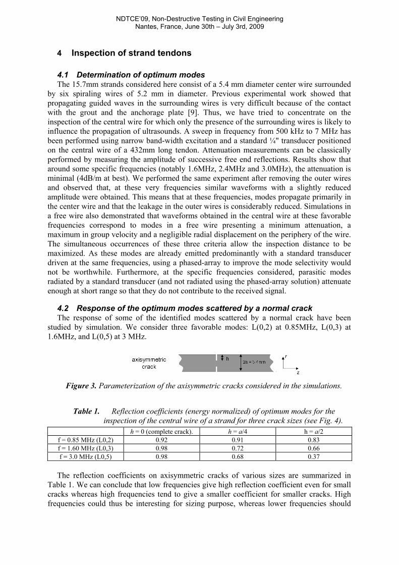
4.2 Response of the optimum modes scattered by a normal crack The response of some of the identified modes scattered by a normal crack have been
studied by simulation. We consider three favorable modes: L(0,2) at 0.85MHz, L(0,3) at 1.6MHz, and L(0,5) at 3 MHz.
Figure 3. Parameterization of the axisymmetric cracks considered in the simulations.
Table 1. Reflection coefficients (energy normalized) of optimum modes for the inspection of the central wire of a strand for three crack sizes (see Fig. 4).
h = 0 (complete crack). h = a/4 h = a/2 f = 0.85 MHz (L0,2) 0.92 0.91 0.83 f = 1.60 MHz (L0,3) 0.98 0.72 0.66 f = 3.0 MHz (L0,5) 0.98 0.68 0.37
The reflection coefficients on axisymmetric cracks of various sizes are summarized in
Table 1. We can conclude that low frequencies give high reflection coefficient even for small cracks whereas high frequencies tend to give a smaller coefficient for smaller cracks. High frequencies could thus be interesting for sizing purpose, whereas lower frequencies should

NDTCE’09, Non-Destructive Testing in Civil Engineering Nantes, France, June 30th – July 3rd, 2009
ensure a larger inspection range for smaller cracks occurring at the periphery (corrosion could lead to such effects). Depending on the instrumentation and the size of the (normally aligned) crack, the inspection range could reach a few meters for the central wire.
5 Conclusions A model has been proposed to simulate a whole configuration of nondestructive testing
using guided waves. Methods of mode selection by a phased array transducer acting from the section have been proposed. They rely on the use of either one of two specific frequencies corresponding to the cancellation of normal stress associated with a given mode. They have been experimentally validated on free bars. As far as the inspection of the central wire of a pre-stressing strand is concerned, the use of a standard transducer proved to be sufficient for emitting modes showing the largest propagation range due to a low attenuation level. Simulation studies show a frequency dependence of the reflection coefficient of these favorable modes for normally aligned crack of various sizes. The effect of the crack orientation should be studied in the future.
Acknowledgements The authors would like to thank the Agence Nationale pour la Recherche (ANR) and
Electricité De France (EDF) that fund the research program ACTENA.
References 1. Dong, S. B. and Nelson, R. B. (1972) "On natural vibrations and waves in laminated
orthotropic plates", Journal of Applied Mechanics, Vol. 39, September 1972, pp.739-745. 2. Hayashi, T., Song, W. J. and Rose, J. L. (2003) "Guided wave dispersion curves for a bar
with an arbitrary cross-section, a rod and rail example", Ultrasonics, Vol. 41, Issue 3, May 2003, pp.175-183.
3. Auld, B. A. (1979), "General electromechanical reciprocity relations applied to the calculation of elastic wave scattering coefficients", Wave Motion, Vol. 1, Issue 1, January 1979, pp.3-10.
4. Jezzine, K. and Lhémery, A. (2007), “Simulation of guided wave inspection based on the reciprocity principle and the semi-analytical finite element method”, Rev. Prog. QNDE 26, ed. by D. O. Thompson and D. E. Chimenti, (AIP Conference Proceedings, Melville, New York, 2007), pp. 39-46.
5. Wu, C. H. and Plunkett, R. (1967), “On the solutions of plates, strips, rods and cylinders subjected to arbitrary dynamic edge loads”, SIAM J. Appl. Math., Vol. 15, pp. 107-119.
6. Jezzine, K. (2006) "Approche modale pour la simulation globale de CND par ondes élastiques guidées" (in french), PhD Thesis, Université Bordeaux 1, 176p.
7. Bai, H., Shah, A. H., Popplewell, N. and Datta, S. K. (2001), "Scattering of guided waves by circumferential cracks in steel pipes", Journal of Applied Mechanics, 68, pp. 619-631, 2001.
8. Thurston, R. N (1978), “Elastic waves in rods and clad rods”, Journal of the Acoustical Society of America, Vol 64, pp. 1-37.
9. Beard, M. D., Lowe, M. J. S. and Cawley, P. (2003), "Inspection of steel tendons in concrete", Rev. Prog. QNDE 22, Ed by D. O. Thompson and D. E. Chimenti, (AIP Conference Proceedings, Melville, New York, 2003), pp.1139-1147.