Inplane vibration analysis of polar orthotropic annular plates with parabolically varying thickness
13
Composite Structures 11 (1989) 1-13 Inplane Vibration Analysis of Polar Orthotropic Annular Plates with Parabolicaily Varying Thickness N. Ganesan & V. Soamidas Department of Applied Mechanics,Indian Institute of Technology,Madras-600 036, India ABSTRACT The natural frequencies of inplane vibration of polar orthotropic annular plates with parabolically varying thickness have been analysed. In the semi- analytical method used, the radial and tangential displacements are ex- panded in the circumferential direction as a Fourier series and the radial behaviour is modelled by finite elements. Since published results were not available, results were obtained using two different kinds of displacement functions. The frequencies have been studied with respect to various boundary conditions, aspect ratios, ratios of moduli, thickness ratios and for two orientations of the fibre directions. NOTATION a b Er Ee E1 E2 G h hoq hi ho hi Outer radius of the annular plate Inner radius of the annular plate Elastic modulus in the radial direction Elastic modulus in the circumferential direction Elastic modulus along the fibre direction Elastic modulus perpendicular to the fibre direction Rigidity modulus Average thickness of a disc element Equivalent thickness of the annular plate Thickness at inner edge of the annular plate Thickness at outer edge of the annular plate Thickness at inner edge of disc element 1 Composite Structures 0263-8223/89/$03.50 t~ 1989 ElsevierSciencePublishers Ltd, England. Printed in Great Britain
Transcript of Inplane vibration analysis of polar orthotropic annular plates with parabolically varying thickness

Composite Structures 11 (1989) 1-13
Inplane Vibration Analysis of Polar Orthotropic Annular Plates with Parabolicaily Varying Thickness
N. Ganesan & V. Soamidas
Department of Applied Mechanics, Indian Institute of Technology, Madras-600 036, India
ABSTRACT
The natural frequencies of inplane vibration of polar orthotropic annular plates with parabolically varying thickness have been analysed. In the semi- analytical method used, the radial and tangential displacements are ex- panded in the circumferential direction as a Fourier series and the radial behaviour is modelled by finite elements. Since published results were not available, results were obtained using two different kinds of displacement functions. The frequencies have been studied with respect to various boundary conditions, aspect ratios, ratios of moduli, thickness ratios and for two orientations of the fibre directions.
NOTATION
a b Er Ee E1 E2 G h hoq hi ho hi
Outer radius of the annular plate Inner radius of the annular plate Elastic modulus in the radial direction Elastic modulus in the circumferential direction Elastic modulus along the fibre direction Elastic modulus perpendicular to the fibre direction Rigidity modulus Average thickness of a disc element Equivalent thickness of the annular plate Thickness at inner edge of the annular plate Thickness at outer edge of the annular plate Thickness at inner edge of disc element
1
Composite Structures 0263-8223/89/$03.50 t~ 1989 Elsevier Science Publishers Ltd, England. Printed in Great Britain

2 N. Ganesan, V. Soamidas
h2 H X n
r ri
r2 U
V
vo
Thickness at outer edge of disc element Thickness ratio (=ho/hi) Harmonic in the circumferential direction Radius at any point on the annular plate Inner radius of the disc element Outer radius of the disc element Displacement in the radial direction Displacement in the radial direction for the nth harmonic Displacement in the circumferential direction Displacement in the circumferential direction for the harmonic
nth
8~ ~l , ~2
1.J12 ~ V21
P to
Angle of fibre orientation Aspect ratio (-- b/a) Nodal displacement vector for the nth harmonic Ratios of elastic constants (h, = EE/E~, h2 = G/E,) Poisson's ratio for isotropic material Poisson's ratios for orthotropic material Mass density of the material of the plate Absolute value of the natural frequency of vibration of the annular plate Non-dimensionalised value of to
1 INTRODUCTION
The use of composite materials in applications like flywheels, gears, etc. has been increasing in the past few years. Suzuki et al.~ have investigated the possibility of producing a composite material spur gear by moulding. Ikegami et aL E have tried to obtain a composite material flywheel of high energy density. The consideration of inplane vibrations in such applications is of considerable value, but a survey of the literature available shows that work in this area has been done only for isotropic plates by Srinivasan and Ramamurti. a
The present work attempts to bridge this gap in the available literature to some extent. The first few natural frequencies for polar orthotropic annular plates with parabolically varying thickness have been studied for different boundary conditions, aspect ratios (inner radius/outer radius), ratios of moduli (EJE1, G/EO, and thickness ratios (ho/hl). The frequencies are presented in non-dimensional form.
A semi-analytical method of analysis was used to obtain the solution. The radial and tangential displacements were expanded as a Fourier Series in the

Inplane vibration analysis of polar orthotropic annular plates 3
circumferential direction. The Fourier constants were assumed as functions of the radius and the finite element method was applied. The results were obta ined using two different kinds of displacement functions, one of which was used earlier by Srinivasan and Ramamurt i 3 in their study of the inplane behaviour of isotropic annular plates. The other was a simple linear inter- polation displacement function.
2 E X P E R I M E N T A L
2.1 Formulation---the stiffness matrix
The material of the plate was assumed to be orthotropic. Each annular disc e lement was assumed to be of uniform thickness. The plate was assumed to be in a state of plane stress.
The strain energy of a polar orthotropic annular disc element due to inplane deformat ion is given by:
g s t -
(l) + G ( 1 - v , vo) + v ~ - - rdrdO
' F
The radial and tangential displacements at any point were represented as:
u = Uo(r) + ~ U.(r) cosnO n = l
v = ~ V.(r)sinnO (2) n = l
The two displacement functions used in obtaining the solution were:
(a)
(b)
U.(r) = a l . + a z . r n = O, 1,2,3 . . . .
V.(r ) = bl. +b2. r n = 1,2,3 . . . . (3)
Uo(r) = Col r + Co2 r -l
Ul(r) = Cu + C12 r-2 + C13 r2 -t- G41n(r)
Vl(r) = - C u + C12 r -2 + Pt C~3 r 2 - C~4(q~ + In(r))
U.(r) = C.1 r" - l + C . z r - . - i + C.3 r.+l + C.4r-.+1
V.(r) = - C . I r "-~ + C.2r -"-~ + p . C.3 rn+~ + q . C . , r -"+~, n = 2, 3 . . . . (4)

4 N. Ganesan, V. Soamidas
where
pj = (5 + v) / (1-3v)
ql = (1 + v) / (3- v)
p. = (n(1 + v) + 4)/(2(1 - v) - n(l + u))
q. = (n(1 + v) - 4)/(2(1 - v) + n(1 + u))
To account for the pure torsional mode, the function
v = Vo(r)
also has to be considered. The corresponding displacement functions are
(a) Vo(r) = blo + b2or
(b) Vo(r ) = So,r + So2r--'
The displacement functions (b) were presented by Biezeno and Grammel 4 as an exact solution of the inplane displacements in an isotropic annular plate and were used by Srinivasan and Ramamurti . 3 The explicit formulat ion for the elements of the stiffness and mass matrices given by Srinivasan and Ramamurt i 3 was used in the present work after suitable modification for orthotropy. The value of v in the expressions for Pl, q~, P, and q, was taken to be the same as that of v,2. This assumption would not materially affect the final result as it constitutes only a small change in the assumed shape functions.
By substituting the assumed displacement functions (3) in eqn (1) and performing the necessary integrations and differentiations, the strain energy expression was reduced to the matrix quadratic form as
Us, = ~ 6. K. 8. (5) n = 0
where &r = [(U,)I (V.)I (/-/,)2 (V,)2], n = 0, I, 2 . . . . , and K, is the stiffness matrix corresponding to the nth harmonic.
2.2 F o r m u l a t i o n ~ t h e mass matrix
The kinetic energy of an annular disc element due to inplane motion is given by:
Tke -- ph fo 2~ I'2(itE + i~)rdrdO (6) 2 l
(The dot indicates a time derivative.)

lnplane vibration analysis of polar orthotropic annular plates 5
By substituting the assumed displacement functions (3) in eqn (6) and performing the necessary integrations, the kinetic energy expression was reduced to the matrix quadratic form as:
1 = Tke = ~ ,~--o ~[M,8, (7)
where M, is the mass matrix corresponding to the nth harmonic.
2 . 3 Solution
Kn8 = oJZ M, 8 (8)
The stiffness and mass matrices were obtained for each harmonic separately by both methods and were used in eqn (8). The first few natural frequencies were obtained by solving the eigen-value problem (8) using the simultaneous iteration technique.
3 RESULTS AND DISCUSSION
The annular plate, for all aspect ratios, was assumed to have a constant equivalent thickness (heq) and a constant outer radius (a). The plate profile was assumed to vary parabolically as follows:
h = h i l l - (1 - HX) {(r - b)/(a - b)} 2]
The value of hi was determined for each value of H X so that the total volume of the plate (for a given aspect ratio) had a constant value:
V = zr(a 2 - b 2) heq
The plate profiles for a few values of H X are shown in Fig. 1. A typical annular disc element is also marked in the figure. Eight such elements were used in the analysis.
Non-dimensional natural frequencies were obtained for various aspect ratios, boundary conditions, thickness ratios, ratios of moduli and for two orientations of the directions of E1 and E2 (or = 0: E, = El, Eo = E 2 ; and a = 90: Er = E2, Eo = El). Wherever boundary conditions are given, the first condition refers to the inner edge of the annular plate while the second refers to the outer edge.
The different material properties used are presented in Table 1. It may be noted that the materials are arranged in order of decreasing value of EE/E1 and wherever the non-dimensional natural frequencies of the different

6 N. Ganesan, V. Soamidas
Annular disc__ element
HX • 0"- - '~ / - - H X " 1.0 HX,O 4
/t =0.~
Fig. 1. Annular plate profiles.
materials are quoted for comparison, the order of arrangement of the materials is the same.
The non-dimensionalisation of the natural frequencies was done in such a manner that the material with the highest value of E~/p would have the highest absolute frequency of vibration for a given non-dimensional value. The non-dimensionalisation of the natural frequencies was carried out as follows:
ffJ = toax/p/El
The outer radius of the annular plate, a, was taken as a constant for all cases. Thus, given a non-dimensional frequency, the value of EN/~/~ is determinant of the actual frequency. These values are also presented in Table 1 for the different materials. The last column in Table 1 gives the values of x /~ l /p for all the materials relative to that for glass which has the lowest x/-E1/p.
Since no results were available for comparison of the frequencies of
Inplane vibration analysis o f polar orthotropic annular plates
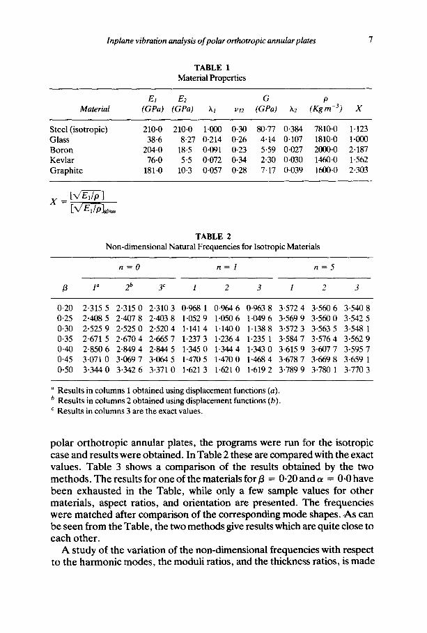
TABLE 1 Material Properties
El E2 G p Material (GPa) (GPa) hi vt2 (GPa) X2 (Kgm -3) X
Steel (isotropic) Glass Boron Kevlar Graphite
210"0 210"0 1.000 0.30 80.77 0.384 7810.0 1-123 38.6 8"27 0.214 0-26 4"14 0.107 1810-0 1.000
204.0 18'5 0.091 0"23 5"59 0.027 2000.0 2.187 76"0 5"5 0-072 0.34 2"30 0.030 1460.0 1.562
181"0 10"3 0"057 0"28 7-17 0.039 1600.0 2"303
X = ]
TABLE 2 Non-dimensional Natural Frequencies for Isotropic Materials
n = O n = - I n = 5
fl 1 a 2 b 3 ¢ I 2 3 1 2 3
0.20 2.315 5 2.315 0 2.310 3 0.968 1 0.964 6 0.963 8 3.572 4 3.5606 3.540 8 0.25 2.408 5 2.407 8 2.403 8 1-052 9 1.050 6 1.049 6 3-569 9 3.560 0 3.542 5 0-30 2.525 9 2.525 0 2.520 4 1.1414 1.1400 1.138 8 3.572 3 3-563 5 3.548 1 0.35 2.671 5 2.670 4 2-665 7 1.237 3 1.2364 1.235 1 3.5847 3.576 4 3.562 9 0.40 2.850 6 2.849 4 2.844 5 1.345 0 1-344 4 1.343 0 3.615 9 3-607 7 3.595 7 0.45 3.071 0 3.069 7 3.064 5 1-4705 1.4700 1.468 4 3.678 7 3.669 8 3.659 1 0.50 3.344 0 3.342 6 3.3710 1.6213 1.6210 1.619 2 3.789 9 3.780 1 3.770 3
a Results in columns I obtained using displacement functions (a). b Results in columns 2 obtained using displacement functions (b). ¢ Results in columns 3 are the exact values.
p o l a r o r t h o t r o p i c annu l a r p la tes , the p r o g r a m s w e r e run fo r the i so t ropic
case a n d resu l t s w e r e o b t a i n e d . In T a b l e 2 these a re c o m p a r e d wi th the exac t va lues . T a b l e 3 shows a c o m p a r i s o n o f the resul ts o b t a i n e d by the two m e t h o d s . T h e resul ts for o n e o f the ma te r i a l s for/3 = 0.20 and a = 0.0 h a v e b e e n e x h a u s t e d in the Tab l e , whi le on ly a few s a m p l e va lues fo r o t h e r m a t e r i a l s , a spec t ra t ios , and o r i en t a t i on a re p r e sen t ed . T h e f r equenc ie s w e r e m a t c h e d a f t e r c o m p a r i s o n o f the c o r r e s p o n d i n g m o d e shapes . ,As can b e s e e n f r o m the T a b l e , the two m e t h o d s give resul ts which are qui te close to e a c h o t h e r .
A s tudy o f the va r i a t ion o f the n o n - d i m e n s i o n a l f r equenc ie s wi th r e spec t to the h a r m o n i c m o d e s , the m odu l i ra t ios , and the th ickness ra t ios , is m a d e

8 N. Ganesan, V. Soamidas
T A B L E 3
Comparison of Non-dimensional Frequencies Obtained using Displacement Functions a and b
Method I Method 2
Material ~ BC ~ ~ H X n A b B" A B
Graphite 0.20 CF 0.00
Graphite 0.20 CC 0.00 Glass 0.30 CF 0-00 Boron 0.40 FC 0.00 Kevlar 0.30 CF 90.0 Graphite 0.30 FC 90.0 Glass 0.50 CF 90.0
0.00 0 0.190 0 . 1 8 7 1 .273 1.250 1 0.401 0 . 3 8 9 1 .329 1.263 2 0.716 0 . 7 0 3 1 .475 1-450 3 1.021 1 .022 1 .721 1.643 4 1.311 1 .342 1 .890 1.879 5 1.587 1-667 2-125 2.157
0-40 0 0.148 0 . 1 4 7 1 .175 1.171 1 0-355 0 . 3 4 3 1 .224 1-292 2 0.649 0 . 6 3 7 1-345 1.322 3 0.934 0 . 9 3 5 1 .505 1.472 4 1-207 1 .235 1 .687 1-663 5 1-468 1 .541 1 . 8 8 8 1.895
0.80 0 0.127 0 . 1 2 6 1-170 1.170 l 0.334 0 . 3 2 2 1 .202 1.202 2 0.621 0.609 1 .284 1.254 3 0.902 0.900 1-406 1-387 4 1.172 1 .197 1 .559 1.529 5 1.433 1 .502 1-739 1.736
1-00 0 0.119 0 . 1 1 8 1 .175 1.176 1 0.327 0 -315 1 .194 1-183 2 0.612 0 . 6 0 0 1 .257 1.224 3 0.892 0 . 8 8 9 1-363 1.324 4 l- 162 1 .186 1 .508 1.477 5 1.424 1-491 1-682 1.676
0.00 0 0.577 0 . 5 7 6 1 .497 1-498 0.20 I 0.739 0 -735 2 . 1 6 2 2.009 0.40 2 1-123 1 .146 1-695 1-725 0-40 3 0.853 0 . 8 6 1 1 .925 1-946 0.60 4 1.446 1-456 2 . 0 9 9 2.122 1.00 5 2.124 2 -126 4 . 6 7 6 4.690
a B C = clamped-free (CF); free-clamped (FC). b Results in columns A from displacement functions (a). c Results in columns B from displacement functions (b).
in Tab les 4 and 5. It is seen that in all cases the t rend of the f requencies for n = 0 is the same as that o f G / E I . However , as n increases, the t rend
changes to tha t o f E 2 / E , . This change in the trends leads us to the conclus ion tha t G m a k e s a larger cont r ibu t ion to the lower harmonics than Ez, while for
the h igher ha rmonics , E: plays the ma jo r role.

Inplane vibration analysis of polar orthotropic annular plates 9
t ~
" r "
" 0
z r .
e~
Z
e .
a . r "
e '~
?,
?,
7,
7,
?,
t , q
¢.~
~ ' ~ ¢ x l t ' ~ q ¢ ' . l , . ~ ~ r l ' t " . l - . ~ , . . ~ - . ~ ~ ' t ' ~ l , - - ~ , . . ~ , - ' ~ " ~ ' ¢ q . . - ~ , - ~ , ' - . ~
t ~ t ~ l , . . . ~ , - - ~ . - ~ ¢ ¢ ' ~ t ' , . 1 , - - ~ , - . - ~ - - ~ r ~ t " , l . . . ~ . - - ~ . - ~ ¢ ' , l t ' , l , - - ~ , - . ~ , . . - ~
~ l ' t " . . l ~ - ~ . - . ~ , . . - ~ ¢ ~ t ' . , I , - - ~ * . - ~ , --~ ~ t " , l . . - ~ . - ~ , - ~ t ' ~ - ~ , - ~ , - , ~ , - - ~
. . . . . . . . . . o o t ~ e ~
. . . . . . . . . . o ~ , " ~ 1 ~
• o o •
II
e~
"G II
t ~ 6

lO N . G a n e s a n , V . S o a m i d a s
H
°~
q2
2
P.
Z
Z
0
• ~ . ~ . o , . v - . ~ e q e - • ~ . • • • . " . . . . ~ . . . ~. .
~ ' , 1 , " ~ e e ~ , ' - ~ , - - ' ~ e ¢ ~ , ' - ~ , . ' ~ , . - ~ , -~ e e ~ . - . ~ , - . ~ , - ~
U , I ~ I , " ~ ~ 0 , ~ " ~ * " ~ , "~ ¢ ~ * - ~ , " ~ * . , ' ~ ¢ ' Q ~ I ~ , . . . ~
H
i

Inplane vibration analysis o f polar orthotropic annular plates 11
TABLE 6 Comparison of Non-dimensional Natural Frequencies with respect to HX, n and [3a
[3 = 0.20 [3 = 0.30 [3 = 0.40 [3 = 0.50
H X n 1 2 1 2 1 2 1 2
0.00 0 0.190 1 .273 0.294 1 .455 0.419 1-709 0.581 2.069 1 0.402 1 -329 0.446 1 .498 0.526 1 .739 0.654 2.090 2 0.716 1 .475 0.725 1 .618 0.758 1 .828 0.836 2.154 3 1.022 1 . 7 2 2 1 . 0 2 0 1-792 1 -029 1 . 9 6 6 1 .070 2.256 4 1.311 1 - 8 9 0 1 .308 1 . 9 9 8 1 .307 2.140 1 .326 2.390 5 1-587 2.125 1 .586 2 - 2 2 0 1 .584 2.340 1 .590 2.551
0.40 0 0-149 1 .176 0.233 1 .336 0 -337 1 .562 0 - 4 7 3 1-884 1 0.356 1 . 2 2 4 0 - 3 8 9 1 .377 0 . 4 5 1 1 . 5 9 3 0.554 1.907 2 0.649 1 . 3 4 6 0.658 1-489 0 - 6 8 4 1 .681 0.744 1.972 3 0.934 1-505 0-937 1 .646 0.947 1 .815 0.979 2.075 4 1-207 1 . 6 8 8 1 . 2 0 9 1 -824 1 . 2 1 4 1 -980 1 .231 2.210 5 1.469 1 -889 1 -474 2.033 1 .478 2.162 1 .488 2.368
0-80 0 0-127 1 .171 0 . 2 0 1 1 .324 0.293 1 .542 0.414 1.854 1 0.334 1 .202 0.362 1 .359 0 -413 1 . 5 7 0 0 . 5 0 1 1.875 2 0.621 1 -285 0.629 1 .451 0.649 1 .650 0-698 1-936 3 0.902 1 .406 0.903 1 .577 0 . 9 1 1 1 -767 0.936 2.033 4 1.172 1 -560 1 .173 1 .721 1 . 1 7 6 1 . 9 0 8 1-188 2.155 5 1-434 1 . 7 4 0 1 . 4 3 6 1 .880 1 .438 2.062 1 .445 2.297
1.00 0 0.119 1 .175 0.190 1 .327 0 - 2 7 7 1-542 0.393 1.852 1 0.327 1 -194 0 - 3 5 3 1 .356 0.400 1 .568 0 - 4 8 2 1.872 2 0.612 1 .257 0.619 1-435 0.638 1 -641 0.682 1.930 3 0.892 1 . 3 6 4 0.893 1 .545 0 - 8 9 9 1 -748 0 - 9 2 2 2.020 4 1.163 1 . 5 0 8 1 .163 1 .674 1 . 1 6 4 1 . 8 8 0 1 .174 2.135 5 1.424 1 . 6 8 2 1 .425 1 -824 1 .426 2-016 1 .431 2.266
a Material = graphite; BC = clamped-free; a = 0.00.
F r o m T a b l e 4 it is seen tha t as H X increases , the f r equenc ies dec rea se for
t he c l a m p e d - f r e e case. Th i s is to b e e x p e c t e d because wi th increas ing H X
m o r e o f the m a s s o f the p la te is shi f ted t owards the o u t e r f ree edge , away f r o m the c l a m p e d inner edge . T h e r eve r se t r end is o b s e r v e d , as e x p e c t e d , in
T a b l e 5 fo r the f r ee - -c l amped case. In T a b l e s 6 a n d 7, all the resul ts o b t a i n e d for o n e o f the ma te r i a l s , for the
c l a m p e d - f r e e case , h a v e b e e n p r e sen t ed . T a b l e 6 con ta ins resul ts fo r a = 0 .0 whi le T a b l e 7 con ta ins those fo r ot = 90.0. T h e c l a m p e d - f r e e b o u n d a r y cond i t ions w e r e chosen becaus e they are m o s t f r equen t ly en- c o u n t e r e d in p rac t ica l appl ica t ions o f annu la r discs l ike f lywheels , gear - w h e e l s , e tc . I t is s een tha t the r a t e o f increase in the f r e q u e n c y is l a rger for

12 N. G a n e s a n , V. S o a m i d a s
TABLE 7 Comparison of Non-dimensional Natural Frequencies with respect to H X , n and/3 ~
13 = 0"20 [3 = 0 .30 [3 = 0 . 4 0 [3 = 0 . 5 0
H X n 1 2 1 2 I 2 1 2
0.00 0 0.190 1.273 0.294 1 . 4 5 6 0.419 1 . 5 6 6 0.581 1.608 1 0.437 1.379 0.536 1 . 5 6 1 0,656 1 . 7 5 0 0.819 1.874 2 0.710 1 . 6 1 2 0.768 2.009 0.864 2.072 1 . 0 1 2 2.441 3 0.990 1 . 8 4 7 1 . 0 0 8 1 " 9 8 4 1 . 0 6 2 2.225 1 . 1 7 2 2.603 4 1.255 2.151 1 . 2 5 4 2-223 1 . 2 7 8 2.375 1 . 3 5 2 2.719 5 1.505 2.376 1 . 4 9 8 2'409 1.504 2.546 1 . 5 4 8 2-845
0.40 0 0.149 1 . 1 7 5 0.233 1"336 0.338 1 . 4 3 8 0.474 1.474 1 0.365 1 . 2 5 6 0.449 1 . 4 2 6 0.553 1 . 6 0 5 0.690 1.742 2 0.615 1 . 4 6 7 0-664 1 . 6 9 9 0.744 1 . 8 8 2 0.867 2.217 3 0.874 1 . 7 0 2 0.892 1 . 8 1 8 0.937 2.029 1 . 0 2 7 2.366 4 l. 118 1.962 l. 124 2.068 1 . 1 4 6 2.184 1 . 2 0 5 2.483 5 1.350 2.226 1 . 3 5 2 2.251 1 . 3 6 2 2.362 1.400 2.616
0.80 0 0.127 1 . 1 7 1 0 - 2 0 1 1 . 3 2 4 0.293 1 . 3 7 7 0.414 1.405 1 0-323 1 - 2 3 3 0.398 1 . 3 9 9 0-491 1 - 5 7 6 0-615 1.692 2 0.561 1 - 4 3 5 0.603 1 , 6 0 4 0.673 1 - 8 3 8 0.782 2-164 3 0-813 1 . 6 7 2 0.827 1 . 8 9 6 0.865 1.984 0-940 2.309 4 1.052 1 - 9 3 4 1 - 0 5 6 2-017 1 . 0 7 3 2.142 1 - 1 2 1 2.429 5 1.282 2-200 1 . 2 8 1 2.220 1 . 2 8 7 2.323 1 - 3 1 5 2.564
1.00 0 0.119 1 - 1 7 5 0-190 1 - 3 2 7 0.277 1.357 0.393 1.382 1 0.307 1 - 2 3 0 0.380 1 - 3 9 6 0-469 1 - 5 6 8 0.588 1.677 2 0.542 1 . 4 2 9 0.581 1 - 5 9 4 0.647 1 . 8 2 9 0.751 2.154 3 0.792 1 . 6 6 6 0.805 1 . 8 5 1 0.839 1 - 9 7 4 0-910 2.298 4 1.031 1 " 9 2 8 1"033 2.003 1 . 0 4 7 2.133 1 - 0 9 1 2-418 5 1.260 2.194 1 - 2 5 8 2.215 1 . 2 6 2 2.315 1.286 2.554
a Material = graphite; BC = clamped-free; c~ = 90.0.
higher values of ft. This is because the width of the annular plate decreases as t3 increases, and for a given rise in/3 the percentage change in the width is greater at higher values of/3.
The relative values of the actual frequencies (for annular discs of identical dimensions) of the different materials were compared by taking the product of non-dimensional values of the frequencies and the relative values of
given in Table 1. A few typical values are given in Table 8. It is seen that, although the non-dimensional values of the frequencies for steel are 2 to 4 times as high as those for the composites, the ratios of the actual frequencies are not so large (maximum 2.5). Assuming that higher fre-

lnplane vibration analysis of polar orthotropic annular plates
TABLE 8 Comparison of Relative Dimensional Natural Frequencies a
13
n = O n = l n = 2 n = 3
Material HX 1 2 1 2 I 2 1 2
Steel Glass Boron Kevlar Graphite
Steel Glass Boron Kevlar Graphite
Steel Glass Boron Kevlar Graphite
Steel Glass Boron Kevlar Graphite
0.00 1.030 3.735 1.695 3.594 2.700 3-806 3-476 4.683 0.486 2-3% 0-799 2-338 1.346 2.354 1.917 2-489 0.536 2.396 0.799 2.338 1.861 3.381 2.655 4.033 0.401 1.987 0.711 2.096 1.218 2-384 1.632 2.765 0-677 3.353 1.029 3-452 1.672 3.726 2-349 4.127
0.40 0.819 3.226 1.458 3.122 2.336 3.421 3-024 4.318 0.385 2.199 0-701 2.054 1-220 2.046 1.755 2.170 0.426 2.432 0.947 2.644 1.708 3.156 3.458 3.742 0.320 1.824 0-629 1.935 1-114 2.213 1.598 2-562 0-539 3.079 0.898 3-174 1.518 3-431 2.158 3-791
0.80 0.705 2.939 1.329 2.880 2-119 3.263 2.755 4.194 0.332 2.013 0.652 1.894 1.160 1.877 1.675 2.000 0-367 2.410 0.894 2.616 1.642 3-092 2.382 3.584 0.275 1.809 0.592 1.913 1-068 2.168 1.546 2.462 0.465 3.051 0.834 3-132 1.449 3-342 2-082 3.634
1-00 0.665 2.837 1.281 2-7% 2.037 3-214 2.657 4.158 0.313 1.927 0-635 1.828 1.139 1.814 1.643 1.942 0.346 2.414 0.877 2.616 1-623 3.068 2-360 3.506 0.259 1.812 0-580 1-912 1.054 2.151 1.531 2.415 0.438 3-056 0-813 3.125 1.426 3.305 2.057 3.558
a ] ~ = 0.30; BC = clamped-free; a = 0.00.
quencies are desirable, we may conclude that graphite and boron compo- sites would be preferable in comparison with other composites.
R E F E R E N C E S
1. Suzuki, Y., Sugibayashi, T., Ikegami, K. & Shiratori, E., A study of moulding methods and static strength of carbon fiber-reinforced plastic gear, Bull. of JSME, 24 (1981) 2177--83.
2. Ikegami, K., Igarashi, J. & Shiratori, T., Composite flywheel with rim and hub, Int. J. Mech. Sci., 25 (1) (1983) pp. 59-69.
3. Srinivasan, V. & Ramamurti , V., Finite element analysis of the inplane be- haviour of annular disks, Computers and Structures, 13 (1981) 553-61.
4. Biezeno, C. B. & Grammel, R., Engineering Dynamics--Vol. 2, Blackie and Sons, London, 1956.