Innovative and Beneficial Use of Dredged Material Advisory ...
344
AGENDA INNOVATIVE AND BENEFICIAL USE OF DREDGED MATERIAL ADVISORY COUNCIL MEETING SEAGIRT MARINE TERMINAL THURSDAY, JULY 27, 2000 10:00 a.m. - 2:00 p.m. Facilitator: • Greetings, Introductions and verview of Legislative Charge \ Overview of the Port of Baltimore Dredging Needs Review of the Innovative Use Industry Frank Hamons, Manager Harbor Development Kathleen Broadwater, Director Planning & Business Development Frank Hamons, Manager Harbor Development Maryland Environmental Service: Wayne Young, Beneficial and Innovative Oven/iew Use Steve Storms, Review of Selected Technologies for Innovative Use Cece Donovan, Ongoing Agricultural Land Application Investigation Design, Development and Project Status of the State's RFP for Innovative Uses Frank Hamons, Manager Harbor Development Open Discussion Scheduling Next Meeting
-
Upload
khangminh22 -
Category
Documents
-
view
1 -
download
0
Transcript of Innovative and Beneficial Use of Dredged Material Advisory ...

AGENDA INNOVATIVE AND BENEFICIAL USE OF DREDGED MATERIAL
ADVISORY COUNCIL MEETING
SEAGIRT MARINE TERMINAL THURSDAY, JULY 27, 2000
10:00 a.m. - 2:00 p.m.
Facilitator:
•
Greetings, Introductions and verview of Legislative Charge
\
Overview of the Port of Baltimore Dredging Needs
Review of the Innovative Use Industry
Frank Hamons, Manager Harbor Development
Kathleen Broadwater, Director Planning & Business Development
Frank Hamons, Manager Harbor Development
Maryland Environmental Service:
Wayne Young, Beneficial and Innovative Oven/iew Use
Steve Storms, Review of Selected Technologies for Innovative Use
Cece Donovan, Ongoing Agricultural Land Application Investigation
Design, Development and Project Status of the State's RFP for Innovative Uses Frank Hamons, Manager
Harbor Development
Open Discussion
Scheduling Next Meeting
Development, Review & Consideration of Alternatives for Placement of Dredged Material
Maryland Port Administration

1976 Hart-Miller Island EIS
70 Alternatives
1989 Master
Plan
1991 Governor's Task Force
475 Sites
•4 QQQ MPA Dredging Needs and Placement Options Program
Over 75 Sites and Concepts
i
»ilf3£z=^' Over 40 Beneficial tlSfSr Use Sites and
Concepts
J
1996 Governor's Strategic Plan for Dredged Material Management
Containment facilities (2 projects) Expand Pooles Is. Open Water (2 sites) Beneficial Use (1 large-scale project) New Open Water (3 options) Island Placement Site (8 options)
Future *

Dredging Needs and Placement Options Program Structure
Executive Committee
£ J J Management Committee
s Citizens
Committee i
Multidisciplinary, Interorganization Working Groups
Management Function: Advisory Function:

What Options Have Been Considered in Forming the State's Plan?
Beneficial use options (examples)
- Bodkin Island - Dobbins Island - Sparrows Point - Worton Point - APG, Spry Island - Eastern Neck - Parsons Island - Holly Neck Farm - Davis Tract - Barren Island - Smith Island
Innovative Use / Recycling
Open-water sites (examples)
- Worton Point area - Site 171 - Deep Trough - various other locations
Upland placement Quarry reclamation Mine reclamation Remediation of contaminated sediments Ocean placement

from 1992
MPA Dredging Needs and Placement Options Program (DNPOP)
Master Plan "Listed" and DNPOP Options
19 BEAR CREEK JSvifmZn 0^ VkrER'sMi 111 ! -•ltLL f s.
9 1H1.\ LAHEli PIACEBGNT III
:'.• r.\:li IIAUIIUK;
aura CSX/COX-
CREEK
31 BREWl KTO
1'' HOtLi \ , r. I ih'.l
• I Bl
IM iOLCVfE^TER ClLVNNCl. , N
H IC) M •'"[)•: .-I'Kk IVL:; '
K Ul ••1I0.\LS
17 -•>\\% r();\i .••tr. LM-.-I V
rORATIOK
;.: »AN POINT EAST
17 noi.n \':(;K KIK\I
.1) i-V; BRmCI
10 l-Ai
II ICIAL RELf
above Bay Bridge below Bay Bridge

Susquehanna Flats Davis Tract\^ J-Fleld &Wja>
Spry Island HA/ TfMORt
Hart-Miller Island Cox Creek
Bear Creek Bodkin Point
Dobbins Island Holly Neck Farm Bay Bridge Airport
iciai Reefs
Bloomingneck Farm
^WorfoVjP^int ooles Island V
parrows Point ^ Swan Point ( )
Eastern Neck WildliA Bodkin island Parsons Island Poplar Islan
Barren Islanc
Holland Island 7 « ^Jomith Islar d
MPA Applied Research's Innovative Use University of Maryland
U.S. Department of Agriculture
efuge
MPA Dredging Needs and
Placement Options Program
Beneficial Use Options
Over 40 sites and concepts (e.g., soil products)

The Technical and Economic Feasibility of Producing Beneficial Products from Baltimore Harbor Dredged Spoil
Maryland Environmental Service Annapolis, Maryland
e/W Elbrid^e M. Smith, P.E. Senior Project Engineer
Walter R. Niessen, P.E, Project Manager
28 March 197^
Prepared by Roy F. Westqn, Inc.
Envi ronmental Scientists and Engineers
West Chester, Pennsylvania W.O. 1086-01

IIMAS D. MCKEWEN DIKECTOR
REED W. McDONAGH DEPUTY DIRECTOR
STATE OF MARYLAND DEPARTMENT Or NATURAL RESOURCES
MARYLAND ENVIRONMENTAL SERVICE TAWES STATE OFFICE BUILDING
ANNAPOLIS 2U01
Phone 301-267-5351
September 23, 1974
To Whom It May Concern:
I am happy to send you a copy of the Maryland Environmental Service report "The Technical and Economic Feasibility of Producing Beneficial Products from Baltimore Harbor Dredged Spoil", which was prepared for us by Roy F. Weston Associates.
The report indicates that manufacture of a lightweight ceramic building material similar to pumice rock is technically feasible. The report also provides estimates of the cost of the process and the marketability of the product. It concludes that some but not all of the dredge spoil from dredging Balti- more Harbor channel could be disposed of by this alternative. In this regard, I would like to point out that the estimate of spoil volume is now 120 million cubic yards over the next 10 years rather than the luu million cubic yards over the next 10 years as shown in this report.
The report was managed jointly by the planning and solid waste services of MES. I would like to acknowledge also the interest and cooperation of the Water Resources Administration and Maryland Geological Survey, and the interest of the many citizens whose comments in part stimulated this work. A limited number of additional copies are available upon request from MES by contacting either William Sloan, 201/267-5355 or Cliff Willey, 301/267-5666.
Sincerely,
/Mw ^/jyut ^e
Thomas D. McKewen Director
TDM:WS:am
II •3?.

SUMMARY
Dredging projects planned for the Baltimore Harbor area over the next 20 to 25 years are expected to produce about 100 million cubic yards of spoil. Disposal of this material is a serious environmental problem. A diked containment area in Chesapeake Bay has been proposed for the disposal of dredged spoiI .
:•'"•.
$££] .
1,
In recent months it was recognized by the Water Resources Administration and the Maryland Environmental Service, both of the Maryland Department of Natural Resources, and by many private citizens and environmental groups, that dredge spoil might be processed into a brick or aggregate material for use as a construction material. Numerous comments to this effect were made in the public review of the draft Environmental Im- pact Statement for the diked disposal site. In line with its responsibility for regional solid waste planning in the State, the Maryland Environmental Service contracted with Roy F. Weston, Inc. to investigate the feasibility of producing a useful and salable product from the spoil as a whole or partial alternative to a diked disposal area.
In addition to the demands for dredge spoil disposal, the Baltimore area is faced with an increasingly serious solid waste disposal problem. The study therefore was to investigate also the feasibility and economics of using solid waste and waste oil as fuel for the production process.
The Weston program included a study of available data on beneficial use of harbor spoil, and a sampling and bench-scale testing program directed at developing a useful product. Re- view of the available data indicated that little had been done, either in the private or in the public sector, to explore the possibility of recovering or manufacturing useful products from dredged spoi1.
The program identified a number of possible products (natural aggregate, synthetic aggregate, lime, bricks and related pro- ducts, and mineral or rock wool), but after the results of the sampling and experimental program were analyzed~the only .vj_ab1e product_apparent ly attainable from Baltimore Harbor dredged ^CLiJ_j^as_iynthet_i^c aggregate".
S-1

The synthetic aggregate considered technically feasible and with sufficient market potential was a structural-grade light- weight aggregate. All the other products which initially appeared to hold some promise were found to be unfeasible, for a variety of technical and/or economic reasons.
The proposed sysLfin for manufacture of a lightweight aggregate might involve another beneficial usage of waste material, in that a substantial portion of the process heat requirements might be met by burning refuse and reprocessed waste oil generated and collected in the Baltimore region.
The principal conclusions evolving from the present study are:
1. A lightweight aggregate comparable in quality to competitive products could be produced from Baltimore Harbor spoil, and no major technological breakthroughs appear necessary to achieve commercialization.
2. Product-marketing limitations would prevent utiliza- tion of all the spoil at the planned dredging rate, thus requiring the provision of an interim storage site. However, this site would require no more than 51 million cubic yards, half the ultimate capacity of t'he proposed diked disposal complex.
3. Manufacture of lightweight aggregate could use about 1,600 tons per day of refuse to supply part of the processing heat requirements and about 600 barrels per day of reclaimed oil for the remainder.
k. If reasonable market penetration can be realized by the proposed plant, the market should be able to take 1,500 tons per day of lightweight aggregate at the outset, about 3,000 tons per day starting with Year 6, and about ^4,500 tons per day in.Year 11.
5. Capital investment is estimated at $60,000,000 for the initial 1,500-TPD plant, with an increment of about $60,000,000 for each future expansion of the same size.
6. Discounted cash flow analysis indicates that the project might be self-supporting if a return on in- vestment of 3'/. for a non-profit (i.e., non tax-paying) operator and 12'/, for a private-sector operator were
S-2

-
realized. The latter figure is marginal for a commercial venture of this risk and magnitude, but it could be compensated for by such measures as development of more efficient spoil-recovery tech- niques and use of dunnage and discarded tires as fuels. The return on investment, however, involves a number of assumptions on the economics of solid waste disposal as well as on dredge spoil conversion.
These conclusions are based on a limited feasibility study and require verification. The next steps in such a verification, after further study of the economics of variations of the basic process described in this report, would be a more extensive testing and experimental program, and preliminary design of the production facility.
K
S-3

WEDA m mMmm
Offprint
WESTERN DREDGING ASSOCIATION (A Non-Profit Professional Organization)
Journal of Dredging Engineering Volume 2, No. 2, June 2000
Official Journal of the Western Dredging Association
Poplar Island Restoration Project. Chesapeake Bey, Maryland
IN THIS ISSUE
Beneficial Uses of Dredged Material in the Upper Chesapeake Bay — FL Hamons and W. Young 1
Beneficial Use of" Dredged Material in the Rock Island District — MD Cox 25
Notes for Contributors 41

BENEFICIAL USES OF DREDGED MATERIAL IN THE UPPER CHESAPEAKE BAY
1 2 Frank L. Hamons and Wayne Young
ABSTRACT
The use of dredged estuarine sediments has been widely advocated in Maryland as a natural resource for island restoration, marsh creation and enhancement, and shoreline stabilization, and as an economic resource for making marketable products, thereby providing a solution for dredged material management that would also help enhance the Chesapeake Bay ecosystem. About 3.5 million cubic yards of sediments are dredged each year from the approach channels in the Bay serving the Port of Baltimore and Chesapeake and Delaware Canal. Most of these sediments are suitable for beneficial use as either a natural or economic resource. The Maryland Port Administration, with technical assistance from the Maryland Environmental Service, has been working to establish beneficial use as a meaningful component of dredged material management for the Port of Baltimore. But, moving from concept to application has been impeded by various environmental, social and economic factors, to the extent that only one large-scale project has been implemented as part of Maryland's strategy for dredged material management. Linking the beneficial use concept to a specific geographic location has focused attention on tradeoffs that worked against acceptability of most projects in the upper Bay. Habitat conversion from one form to another, including restoration to a prior condition, has been a significant obstacle, especially with respect to fisheries habitat. Institutional and social factors have also affected the State's ability to advance beneficial use projects. This paper discusses the past and ongoing efforts to apply the beneficial use concept in the upper Chesapeake Bay. Beneficial aspects of the multi-objective Hart-Miller Island Dredged Material Containment Facility are discussed.
INTRODUCTION
Historically, the Chesapeake Bay has experienced a considerable reduction in the acreage of islands and marshes as the result of erosion and inundation from a relative rise in sea level. For example, Spry Island and Sharps Island disappeared and are now fishing reefs. Poplar Island has eroded from about 1,400 acres in the 1670s to under 5 acres today (Leatherman et al., 1995; MES, 1994a,b). Within the watershed, vast quantities of sediments are constantly eroded, transported and deposited in the upper Bay including the shipping channels. Every year, approximately 5 to 6 million cubic yards of sediments are dredged to maintain the Port of Baltimore's navigation infrastructure in Maryland, Delaware and Virginia. Each year, over 3.5 million cubic yards of sediments are dredged from the upper Bay approach channels to Baltimore Harbor and the
'Hamons, F. L., Manager, Harbor Development, Maryland Port Administration, 2310 Broening Highway, Baltimore, Maryland, 21203
2 Young, W., Director, Environmental Dredging, Maryland Environmental Service, 2011 Commerce Park Drive, Annapolis, Maryland 21401

Chesapeake and Delaware (C&D) Canal. Traditionally, these sediments were placed in open water areas near the channels that were dredged. Virtually all of this material is potentially suitable for use as a natural resource to achieve environmental benefits while at the same time providing for final deposition of the dredged sediments. On face value, beneficial use is an approach that is very alluring, providing an apparent opportunity for mutual cooperation among dredging and environmental interests. Over the past 20 years, concern about the Bay's environmental health helped stimulate opposition to the open-water placement of clean dredged material. Except for modest open-water placement near Pooles Island in the northern upper Bay, the Maryland Port Administration (MPA), as local sponsor, and the Philadelphia and Baltimore Districts of the U.S. Army Corps of Engineers (USAGE) were not able to establish alternative open-water placement sites. As a result, at least 2 million cubic yards of clean dredged material were placed annually in the Hart-Miller Island Dredged Material Containment Facility (DMCF).
The possibility of using dredged material beneficially rather than disposing of it as a byproduct of dredging has gained broad-based conceptual support as an alternative to traditional open-water placement in the Chesapeake Bay. Using sediments as a resource is not new to the Bay. Practical application was introduced to the lower and middle Bay as early as the mid-1970s by the US ACE through a few small-scale marsh restoration and oyster reef creation projects (Garbarino et al., 1994; NRC, 1994). Expanding from small-scale to large-scale application was proposed as a way to resolve the port's placement needs in a manner that would contribute to Bay restoration efforts and overcome longstanding controversy about dredged material management.
The MPA has sponsored intense planning since the early 1980s to resolve the port's placement needs, including consideration of beneficial use. This effort lead to the State's 1996 Strategic Plan for dredged material management, which includes the 1110-acre restoration of Poplar Island (MDOT, 1996, 1998). Yet, moving from concept to practical application has proven difficult despite the efforts of the MPA and the many federal, state and interest group participants in the MPA-sponsored Dredging Needs and Placement Options Program (DNPOP). Linking the beneficial use concept to specific sites focuses attention on site-specific environmental, social and economic tradeoffs that, in most cases, work individually or collectively against project acceptability. Conversion of habitat from one form to another, especially fisheries habitat, has been a major factor in determining whether or not the environmental value that would be gained would in turn justify modifications to existing site conditions.
THE STATE'S DREDGED MATERIAL PLANNING PROCESS
The MPA uses a 20-year, forward-looking planning window for managing dredged material. The port's dredging need over the next 20 years is about 110 million cubic yards, of which 80 million cubic yards is for maintenance; the remaining quantity is for new work to enhance safety and to maintain and improve port competitiveness. Planning data are continually updated to reflect changes in actual or projected dredging needs. The long-term planning approach allows for consideration of the magnitude of the dredging need; dredging needs beyond the 20-year window; time needed to advance placement projects from concept through implementation; prospective environmental conditions; changes in technology (for dredging, placement, ships, and intermodal transportation); and, associated implications to dredged material management, port infrastructure

requirements and port competitiveness. A longer planning horizon moves beyond what can be reasonably managed, except for implementation of options that begin within the 20-year window.
The State is implementing its strategic plan. The plan will provide over twenty years of placement capacity if all elements are successfully implemented at planned capacity, thereby providing a resource needed to maintain the port's navigation safety and competitive status. By taking a strong leadership, planning, design and coordination role at State expense, the State has been able to proceed with implementation in coordination with the U.S. Army Corps of Engineers but on a schedule that is independent of the early phases of the federal planning process for placement projects. This approach has overcome institutional factors that typically result in extended time periods of moving individual projects from concept to completion. Dike raising to extend the service life of the Hart-Miller Island DMCF has already been completed. The State role has expedited implementation of the Poplar Island restoration project, two open-water placement options, renovation and reactivation of a previously used containment facility, and initial investigation of a large-scale island containment in the upper Bay.
The Master Plan Initiative
Since the early 1980s, many traditional and non-traditional placement options were identified but few were supported. During the mid-1980's, 475 options were considered in the development of a draft Master Plan sponsored by the MPA (MPA, 1990). Extensive interorganizational and public involvement was purposefully included in the consensus-based planning process. The process incorporated lessons learned from the planning of the Hart-Miller Island DMCF and also included the introduction of additional alternatives, as required. It was thought that the Master Plan initiative would result in sufficient placement alternatives, thereby precluding the need for expansion of the Hart-Miller DMCF once filled to capacity in the early to mid-1990s, depending upon the ability to dewater and consolidated placed sediments. Upon closure, each cell is to be converted for recreational use and creation of wildlife habitat (Hamons, 1988).
Use of the deepest relic feature of the old bed of the Susquehanna River south of the Chesapeake Bay Bridge and north of Bloody Point on Kent Island, referred to as the "Deep Trough," emerged as a primary candidate for open-water placement. Preliminary analysis and field work determined that the area could potentially be used without causing significant environmental impacts (Versar, 1989, 1990). However, strong opposition arose from the public and environmental interest groups, and the Maryland General Assembly enacted a statute that prohibits the open-water disposal of dredged material in the legally defined Deep Trough.
The draft Master Plan was overtaken by events. A short summary report was published. A draft technical report was not published, but has been used as a resource for ongoing dredged material management planning (MPA, 1990). The lack of alternative placement sites compelled placement of large quantities of clean dredged material into the MPA's Hart-Miller Island DMCF, the State's only repository for contaminated dredged material. The facility's capacity was prematurely exhausted, necessitating raising of its dike system in 1988 (Hamons, 1988; NRC, 1994, 1997; Hamons et al., 1997).

The Governor's 1991 Task Force
With Hart-Miller Island nearly filled, Governor William Donald Schaefer appointed a task force to develop a consensus-based dredged material management plan for near-term and long-term solutions to the dredging and placement needs. The Governor's 1991 Task Force brought a panoply of state and federal agency representatives and environmental and public interest groups into a cooperative problem-solving effort in a manner similar to the Master Plan process. A consensus-based, multi-faceted approach covering a full range of placement categories was developed and recommended (MDOT, 1991). There seemed to be ample potential for beneficial use projects using dredged sediments, considering the loss of islands and marshes to physical forces at work in the Bay. The beneficial use of dredged material was recommended and emphasized as a principal element of both near- and long-term solutions. Subsequently, the planning focus was shifted to beneficial use in what can be characterized as a great and continuing experiment in shifting from a traditional to nontraditional paradigm for the management of dredged material. As discussed in later sections, the experiment has had a unique result: so far, the beneficial use concept has been capable of limited implementation on grand scale in the upper Chesapeake Bay.
Dredging Needs and Placement Options Program
The MPA and the Maryland Environmental Service (MES), an independent state environmental agency which operates the Hart-Miller Island DMCF for the MPA, collaborated in 1992 to develop the DNPOP program as the vehicle for implementing the Task Force recommendations. A multi-disciplinary, multi-organization approach with broad governmental, public and environmental interest group involvement was implemented. The MPA-sponsored program is facilitated at the technical level by MES. Executive, Management, and Citizen's Committees guide the planning process. The Executive and Management Committees are supported by information and analysis from working groups and advice from the Citizen's Committee. This approach provides for coordination at all levels of government and citizen interest.
The ongoing DNPOP program drew on the results of the earlier planning efforts as an information resource to aid the planning process. Participants initiated their planning activities by focusing on identifying and evaluating beneficial use opportunities. Over thirty-five beneficial use options have been considered since 1992 (Figure 1). The first phase of "Bay Enhancement" planning identified twenty near-term options for expedited investigation:
• restoration of Dobbins Island in the Magothy River;
• conversion of poor bay bottom at Sparrows Point to create marsh and upland habitat;
• conversion of shallow water bottom to create upland, intertidal marsh and freshwater habitat at Worton Point and prevent further erosion of a high bluff;
• restoration of Poplar Island at the mouth of Eastern Bay; and

• restoration of islands and creation and enhancement of marsh habitat at Aberdeen Proving Ground—sixteen options in the vicinity of Pooles Island and Gunpowder Neck.
Various area-specific and site-specific working groups were formed to provide technical support and advice. The Bay Enhancement Phase n Working Group was formed to develop mid-term and long-term placement options. This entire effort was characterized by extensive multi-disciplinary, multi-organization cooperative planning and assessment activities. An interdisciplinary, multi-party planning process with substantial opportunities for public participadon has been a hallmark of the planning process for dredged material management for the Port of Baltimore beginning in the early 1980s.
Susquehanna Flats /
Davis Tract \ JW >_. . _ J-Field ^Vj^Bloommgneck Farm
Spry Island ^^"gi^V/orfoa,Point
Hart-Miller WS^SgRfiSSJWnl SSriSff^S '^wan Point Bodkin
Dobbins Island Holly Neck Farm Bay pridge Airport
cial Reefs
Eastern Neck Wildlif%jTefuge Bodkin Island Parsons Island Poplar Island
C^
>l
JS
•^..
Barren Island J> :> 5 •^THolland IsJafcd
t^h* J '' : ^mlth Island
> '. /)
& i
• pi
^ <J7-
During the first half of 1995, all of the Bay Enhancement Phase I placement options, except the restoration of Poplar Island, had been determined to be either not feasible or incapable of implementation. Most of the Phase I options did not prove to be good candidates for implementation, potential environmental benefits not withstanding. In general, the linking of the beneficial use concept to a specific location resulted in identification of location-specific environmental tradeoffs. These tradeoffs usually involved the conversion of habitat from one form to another, typically at the expense of fisheries habitat.
Habitat conversion worked against project endorsement by state and federal resource agencies and other interested parties including watermen, environmental and community groups. Only the Poplar Island environmental restoration project received the institutional and popular
Figure 1. General locations of beneficial use projects support necessary to advance from that have been considered by the DNPOP program, prefeasibility studies to construction Also shown is the location of Bodkin Island. (which began in mid-1998). In this one
case, the added environmental value was sufficient to balance the conversion of habitat from one form to another while the large scale of planned placements (38 million cubic yards) kept the unit cost per cubic-yard-placed within affordable limits.
Despite the dredging need and widespread interest in finding a solution to the placement problem, a broad-consensus on specific placement options was elusive. Lack of support for specific beneficial

use projects was associated with:
• adverse perceptions about dredging, dredged material and material placement;
•
•
concerns and fears about the environmental quality of dredged sediments and their potential effects;
environmental tradeoffs that are associated with virtually all placement options;
social tradeoffs associated with some options;
• competing environmental missions and interests of the various interested parties; and
• the typically high cost of non-traditional placement options.
By mid-1995, with Poplar Island construction still several years in the future, urgent action to provide near-term placement capacity became imperative. The Hart-Miller Island DMCF was predicted to be filled in 1996 and the small-scale Pooles Island open-water sites had only an estimated two years of placement potential remaining.
STATE OF MARYLAND'S STRATEGY FOR DREDGED MATERIAL MANAGEMENT
The inability to broadly implement beneficial use options precipitated urgent planning by DNPOP participants in the first half of 1995 to avoid a dredging crisis that would have otherwise occurred
' during the winter of 1996-1997. A multi-faceted plan was developed which combined traditional, non-traditional and innovative management solutions into a balanced strategy for resolving near- term placement deficits while also providing long-term capacity. The State's strategy was formally announced by Maryland Governor Parris Glendening in September 1996. The objective is to provide 20-years or more of placement capacity for deep-draft channel dredging requirements in Maryland waters. The approach is reminiscent of the 1991 Task Force recommendations in that the State's plan called for a balanced program by type of placement, location and cost.
State Strategy for Dredged Material Management
The main features of the State's strategy included:
• raising the elevation of the north cell dike system at the Hart-Miller Island DMCF (along with accelerated development of the facility's south cell for recreational and wildlife uses);
• construction of the Poplar Island restoration project;
• renovation and reactivation of a previously used containment site in Baltimore Harbor;

• additional small-scale and large-scale open-water placement in conjunction with voluntary funding of the State's oyster recovery program by the MPA; and
• development of a large placement island in the upper Bay with a beneficial use component.
The cooperating State of Maryland Departments and Federal agencies prepared and signed a Statement of Cooperation to implement the strategy, subject to applicable rules, regulations and institutional regulatory responsibilities. Implementation of the full strategy is well underway.
The DNPOP program remains operative to assist in implementing the strategic plan and to find and screen supplemental placement options including beneficial use. The MPA also is sponsoring applied research into the potential for using suitable sediments in farming operations. The research is being managed by MES and performed by research facilities of the U.S. Department of Agriculture and the University of Maryland. The MPA has also acted on its announced interest in the use of dredged material as an economic resource. A preliminary review of available technologies and techniques was performed by MES for the MPA, and the MPA has initiated a procurement process for an innovative use system.
Implementation of the State's Strategy
The Hart-Miller Island DMCF north cell dike system was raised a second time in 1997 as the first component of the State's strategy. The objective was to provide additional capacity over the next 10-years (Hamons et al., 1997; NRC, 1997). Conceptual planning for the South Cell habitat development of Hart-Miller Island was performed by the Baltimore District for the Maryland Department of Natural Resources (MDNR) with support from the MPA and technical support by MES. The MPA sponsored the planting of vegetative test plots in the cell in order to generate field data to support the planting of vegetation upon cell development. Baltimore County sponsored construction of a beach stabilization and nourishment project at the MDNR State Park along the western side of the containment facility.
Two new, small-scale, open-water placement sites near Pooles Island were designated for use by the Philadelphia District. In February 1999, the Baltimore District released a draft Environmental Impact Statement for reactivation of a previously used open-water placement site for large-scale placement immediately north of the Chesapeake Bay Bridge. The MPA is currently completing a prefeasibility investigation for the upper Bay island placement site component of the State's plan. Each of these activities has been supported by interdisciplinary, multi-party technical working groups which have included participation by watermen, charter boat captains, and sports fishermen who participate on the DNPOP Citizen's Committee. Although all participants do not necessarily favor individual options, they nevertheless have worked cooperatively to achieve the best possible overall results.
BENEFICIAL USE CASE SUMMARIES
Over 35 beneficial use options have been screened for technical feasibility, environmental effects,

and prospective costs (Figure 1). Selected options are summarized in this section to highlight important considerations that have affected project planning and capability for implementation. Also reviewed are beneficial aspects of the Hart-Miller Island DMCF.
Island Restoration
Under the DNPOP program, restoration of island habitat became an early avenue for beneficial use planning because of the reduction and loss of island habitat at various locations in the northern half of the Chesapeake Bay estuary. It was thought that there would be broad-based support for such restorations, and that this would facilitate planning, design, funding and implementation. This planning assumption proved to be inaccurate for most proposed projects.
Dobbins Island, a small remnant island in the Magothy River north of Annapolis, was one of the first sites proposed for restoration. The island remnant consists of a narrow, high and eroding sediment bank with woody vegetation. Eroded sediments affect water quality in the general vicinity of the island. Placement of several hundred thousand cubic yards of clean dredged material inside of a dike system to expand the island's upland acreage, prevent further erosion, and create marsh habitat was suggested but was ultimately found to be impractical. Shallow water habitat surrounding the island remnant would be converted. Concern about the effect on wind patterns was raised by individuals who race sailboats in the lower Magothy River. It was also determined that the potential placement capacity was insufficient to make a meaningful contribution to the Port's dredging needs. Further, the shallow depths at the entrance to the river made barge access impractical. The distance from most dredging sites made hydraulic pipelines impractical. There was also lack of consensus regarding environmental effects. Although a small-scale beneficial use project at Dobbins Island might prove feasible, the site was found unsuitable for a port-related project.
Aberdeen Proving Ground (APG) has been frequently advocated by many individuals as an appropriate location for the placement of dredged material. On face value, APG would seem to be an appropriate location for multiple beneficial use projects. This U.S. Army post covers about 72,000 acres along the western shoreline in the northern upper Bay. The post's eastern boundary is near to and directly accessible from the western approach channels to the C&D Canal. About 40,000 acres of the post consist of open water. The remaining area consists of about 15,000 acres of wetlands and 17,000 acres of terrestrial habitat and developed areas. The post has over 55 major tenants and extensive military activities including research and development, many of which are classified.
Since its inception, the DNPOP program has focused considerable attention on the potential of APG. A multi-disciplinary working group was formed to help investigate possible beneficial use options at APG. A combination of sixteen sites and configurations was developed, a number of which involved island enhancements and restorations. None of the options have proven capable of implementation due to lack of consensus and environmental impacts resulting from a combination of resource conflicts, chemical contamination, presence of unexploded ordnance (UXO), conflict with military missions, and limited capacity. The difficulties associated with projects at APG are illustrated by several of the island restoration and enhancement placement options that have been

proposed.
One early proposal was restoration of Spry Island which had been lost to erosion. The site is now a shoal at the mouth of the Gunpowder River. Although inside of the APG boundary, the shoal is adjacent to the southern boundary and is outside of existing active military ranges at the Army post. Because the shoal has become fisheries habitat, its restoration to upland and marsh habitat was not supported by resource agencies with fisheries management responsibilities. The shoal is used for commercial fishing by Maryland watermen who also objected to conversion of the existing habitat for island restoration purposes (MES, 1994a). Restoration of Spry Island proved incapable of obtaining the broad-based support necessary for implementation.
Pooles Island was also proposed as a location for beneficial use projects (MES, 1994a). Initially, six options were proposed but were not capable of implementation because of environmental tradeoffs. Three containment island configurations in the Pooles Island area, including one that would connect to the island, are under consideration as candidates for the island containment component of the State's strategic plan. The containment island component includes incorporation of beneficial use to an extent yet to be determined.
Beneficial use projects in the vicinity of Pooles Island within the APG boundary have been opposed by APG because of: significant environmental value of the island and surrounding waters in their present state; active use of the island and vicinity for military missions; the presence of UXO; and, the fact that large portions of the post, including Pooles Island and all of the Edgewater Peninsula and Gunpowder Neck, are listed as Superfund sites under CERCLA.
Pooles Island is a relatively large island located in the middle of the northern upper Bay. The island is mostly wooded, but also has freshwater wetlands and ponds between its northern and southern sections. The ponds are used heavily by migratory waterfowl. The southern portion of the island is home for a large heron rookery that typically has about 1630 active nests each year. The island is also populated by deer and other wildlife. The Bay bottom immediately east and west of island contains a variety of physical conditions, some of which is considered important fisheries habitat by natural resource agencies and sport and charter boat fishing interests. There is an historic lighthouse on the northwest side and an underwater wreck west of the island. Because the background erosion rate is minimal with some accretion, the existing island habitat is not considered threatened.
The UXO issue is currendy a showstopper for all potential beneficial use projects at the facility. The significance of this issue became apparent while DNPOP planners and resource agency participants were attempting to advance a small-scale shoreline protection and enhancement project at "J-Field" along the tip of Gunpowder Neck immediately west of Pooles Island. APG representatives estimate that between three and thirty million rounds of UXO are located throughout and immediately outside of the APG boundary. There is no national standard for the remediation of UXO. Therefore, the worst case situation would be removal and disposal at substantial cost. The technology for locating UXO at underwater locations is limited and removal is difficult and dangerous. With respect to beneficial use, the lack of a remediation standard means that if a marsh creation were undertaken to encapsulate an area, the marsh would have to be excavated to get to possible UXO should removal.and disposal become the remediation standard.

Another complicating factor is that there is no definitive legal precedent regarding liability for UXO contaminated areas and remediation. Therefore, a representative of EPA Region 3 advised that one must assume the worst case situation with respect to liability, which is that any involvement whatsoever could lead to designation as a potential responsible party for any remediation that might subsequently be required. Thus, beneficial use within the entire APG controlled area is institutionally constrained indefinitely.
Poplar Island in Talbot County at the mouth of Eastern Bay is the site of the only beneficial use option within the DNPOP program that has obtained the support needed to advance from concept to implementation. The island experienced rapid erosion over the past 50 years after suffering multiple breaches during a major episodic storm. Ownership of the remnants was obtained for the State through a real estate transaction. In 1993, MES obtained a grant from the Environmental Protection Agency (EPA) Chesapeake Bay Program and a matching cost share from the MPA to install obsolete barges as a temporary breakwater around Middle Poplar Island, preserving valuable nesting habitat until the remaining islets could be incorporated into the full-scale restoration project. The EPA Chesapeake Bay Program, through its Living Resources Subcommittee, provided several additional grants to assist with project planning and installation of rock reefs for fisheries habitat.
The first phase of the project consisting of 640 acres of uplands and wetlands is under construction by the Baltimore District, U.S. Army Corps of Engineers (USACE), as a beneficial use project under terms of Section 204 of the Water Resources Development Act of 1992. The MPA is the local sponsor. Construction of the first phase is nearing completion. Authorization and funding for the second phase have been obtained by the Baltimore District and the MPA. The contracting process for the second phase of the project was in progress during Spring 2000, with an award
O
CONSTRDCTION FOOTPRINT IMS UNBMASS
1&47 uranuss
Figure 2. Plan view of general concept for Poplar Island restoration. The dike alignment was adjusted to a small extent from that shown to accommodate site-specific conditions.
10

expected in time to begin construction during the last half of the year. Each phase will hold approximately 19 million cubic yards of clean dredged sediments.
The planning and design for the Poplar Island restoration was accomplished in a total of 7 years, a significant reduction in the time frame for similar federal navigation-related projects (Fulford, 1994; MES, 1994b; Mohan and Urso, 1997). The accelerated schedule was made possible by:
• the prospect of imminent loss of valuable habitat which helped motivate consensus about the project;
• the local sponsor's assumption of reconnaissance, feasibility assessments, planning, engineering, design and environmental studies;
• integration of multi-organizational, interdisciplinary working group support into the planning and design activities as a component of the DNPOP program;
• the opening of new areas for commercial clamming by MDNR to offset a loss of clam beds within the prospective island restoration footprint;
• special Congressional funding authorization as a Section 204 project in excess of annual funding caps;
• concurrent performance of NEPA documentation by the Baltimore District; and
• expedited approval of final design by the Baltimore District once the restoration was authorized as a federal Section 204 project.
Of particular importance is the fact that although most of the island's historical footprint had been converted to shallow water habitat, this habitat had not yet achieved high environmental value for fisheries. The involvement of all interested parties in the process was also very important to consensus building and to achieving "ownership" of the solution by the panoply of participants. Overall, all parties concluded that restoration would achieve substantially greater environmental value for the Bay ecosystem than would be allowing complete loss of the islands to erosion. Impacts that would occur to a small, localized clam fishery were accommodated by MDNR through the opening of other areas for commercial clamming.
Another important factor is funding. There is limited federal funding for beneficial use projects, either under Section 204 or as the least cost placement option for channel dredging projects. Section 204 has an annual cap of $15 million in total for all projects. Further, Section 204 has typically not been funded to this level and the funds are competed for on a national basis. The first phase of the Poplar Island restoration, the northern half of the project, is estimated to cost about $46 million. It consists of 640 acres that will be configured into an upland cell on the west and two wetland cells on the east.
Section 204 funding is obviously not sufficient to enable large-scale beneficial use projects as a
11

practical component of dredged material management projects. Either special funding as a Section 204 project or specific authorization as a navigation project through a Water Resources Development Act would be needed. In the case of Poplar Island, the Maryland Congressional Delegation recognized the value of the restoration project and was able to coordinate a funding authorization in excess of the annual cap on Section 204 funding. Considering the costs of large- scale beneficial use projects and interest in them in other port regions, competition for federal funding is likely to remain high.
Island Protection and Enhancement
Small and modest-scale protection and enhancement projects have been proposed for some existing islands. For example, a non-port-related beneficial use project has been designed to expand habitat at Bodkin Island using dredged material from small federal navigation projects (Maynord, et al., 1991). However, small-scale island protection and enhancement projects such as those shown in Table 1 have not been practical for implementation to help resolve the port's dredged material placement needs. Reasons include one or a combination of the following factors: limited placement potential; environmental effects; cost of planning, design, environmental documentation, construction, and transportation; the level of effort and resources required to develop multiple placement options.
Table 1. Island Protection and Restoration Options
Location Characterization Evaluation
Eastern Neck Island National Wildlife Refuge
National Wildlife Refuge Prior small-scale beneficial use project using segmented breakwaters and sandy dredged material to protect eroding shoreline and create shallow water habitat.
Placement potential limited to about 50,000 cubic yards without significantly altering the character of existing habitat. Small placement potential relative to Port dredging need.
Parsons Island (privately owned)
(Figure 3)
100-acre island in agricultural use. Eroding at a rate of about 2 acres per year. Eroded material believed to adversely impact nearby oyster beds. Owner interest in preserving habitat for migratory waterfowl.
Potential to double acreage to 200 yards. Submerged aquatic vegetation surrounding island would be impacted. Potential for between 1 to 3.5 million cubic yards of placement.
Barren Island Prior modest-scale beneficial use projects to protect eroding shoreline. Site is up to 60 miles down bay from channels.
Placement potential for marsh creation is 500,000 cubic yards. High transportation costs and small placement potential relative to dredeing need.
Holland Island (privately owned)
85-acre island used primarily for recreation. Size at time of early settlement was 260 acres. Site is up to 60-70 miles down bay from channels.
Potential for modest to large-scale beneficial use project. High transportation and construction costs.
Smith Island (state and private lands)
Historic fishing community. Significant losses of habitat due to erosion and relative sea-level rise. Site is 65-75 miles down bay from channels.
Potential for modest to large-scale beneficial use project. Fine grained sediments not well suited for raising island elevation, although suitable for marsh creation and enhancement. High transportation and construction costs.
12

When additional transportation and construction costs of perhaps as much as $10-25 dollars or more per cubic yard are compared to the large-scale dredging need, it becomes apparent that shifting to down-bay beneficial use projects could add tens to hundreds of millions of dollars in placement costs relative to upper Bay options. Considering how the Army Corps of Engineers calculates local cost share responsibilities and the technical feasibility of open-water placement sites relatively near the channels being dredged, the increased transportation costs may have to be borne by the State. Nevertheless, the options shown in Table 1 were considered and are still possible options for supplemental dredging needs, along with several other potential options that have been suggested.
Shoreline Stabilization and Enhancement
Small-scale through large-scale shoreline protection and enhancement projects have been proposed for various upper Bay locations (Figures 1 and 3). None have been practical and capable of implementation. Impediments to implementation have been related to limited placement potential; environmental effects; cost of design, environmental documentation, construction, and transportation; lack of consensus; institutional constraints; or a combination of these factors. The smaller projects typically were not suitable because of a combination of limited capacity and adverse environmental effects. Two large-scale projects were proposed but have not been capable of implementation.
Figure 3. Field evaluation of Parsons Island by MPA, MES and U.S. Fish and Wildlife Service team as a possible site for an island restoration project. (W. Young, MES)
Sparrows Point is located on the north side of Baltimore's Outer Harbor. The existing shoreline is upland composed of slag materials from operations by the Bethlehem Steel Corporation
13

(Figure 4). The bottom in the area is very soft and of marginal value for fisheries. A beneficial use project of about 300 acres with a placement potential of ten million cubic yards was proposed in 1992. The project was to consist of a breakwater to create productive wildlife habitat including aquatic and intertidal wetlands, high marsh, and upland nesting areas. The proposed project was also envisioned as providing aesthetic relief for the entrance to the harbor.
Figure 4. Proposed location of beneficial use project at Sparrows Point in center of picture. (W. Young, MES)
Preliminary engineering determined that a project was feasible, although bottom conditions might necessitate "floating" the dike on top of geotextile fabric. An assessment determined that the area's biological productivity is similar to that of other areas inside the harbor, but less productive than the Bay (MES, 1995b). However, inasmuch as a closed dike system was required, implementation was considered by some to be institutionally constrained by a State law that prohibited construction of a containment site within five miles of the Han-Miller-Pleasure Island Chain. This law had been enacted in response to citizen opposition to construction of the Han-Miller Island DMCF in Baltimore County and fears that an additional containment facility might be constructed in the county.
The Spanows Point concept was presented to local citizens. Citizen suppon for the beneficial use project and for a revision to the law was not obtained. Local citizens expressed anger at the past filling of open-water areas by the steel mill and strongly objected to the conversion of any additional open-water areas, regardless of the potential environmental benefits.
Worton Point in Kent County was proposed in 1992 as the site for a 200-acre beneficial use project with a potential capacity of about eight million cubic yards for clean dredged sediments. The concept consisted of preventing erosion and creating imponant habitat through construction of an armored dike system, and filling to create fastland, tidal wetlands, upland and freshwater ponds. The point is wholly owned by one landowner. It is immediately south but outside of the nonhem portion of the upper Bay, which has been designated as a rockfish spawning area. The point consists of eroding cliffs that are adversely affecting water quality in the area (Figure 5).
14

Figure 5. Proposed site of marsh and upland creation at Worton Point to prevent shore erosion. (T. Banta, MES)
Extensive multiparty, interdisciplinary working group planning and evaluation were performed including involvement by engineers contracted by the property owner. Issues included conversion of shallow water habitat, potential impacts to a small, seasonal recreational fishery, and potential effects on upwelling from a nearby deep hole considered beneficial to rockfish foraging. However, no fatal flaws were identified. Despite these environmental tradeoffs, the potential habitat benefits were considered sufficient to merit detailed investigation (MES, 1994a). The Philadelphia District, USAGE, prepared a plan of action for a reconnaissance study. An assessment of finfish data was prepared (MES, 1996). In response to a request for a right of entry for the purpose of performing geotechnical and groundwater investigations, the landowner unexpectedly withdrew support in 1995, ostensibly over environmental concerns. Repeated efforts to obtain the landowner's cooperation have not been successful. Technical feasibility remains uncertain.
Hart-Miller Island Multiple-Use Project
The Hart-Miller Island DMCF is typically thought of only as a confined disposal facility. It is in fact a multiple-use project that already has provided substantial environmental and recreational benefits. As part of original agreements upon establishment of the complex, the State is committed to converting the containment cells for use by wildlife and for recreation once the cells are filled. As part of the official response to the dike raising in 1996, the Maryland General Assembly enacted a statute turning the State's commitment into binding requirements.
15

Environmental and Economic Contributions. The original dike system reunited and protected the remnants of Hart and Miller Islands. A recreational beach was constructed between the remnants and the western dike (Figure 6). The dike system has provided shelter for a constructed beach and helped preserve shallow water habitat surrounding the remnants and the island habitat that remained at the time of construction. It has also provided physical protection for the shorelands to the west from wind-generated waves and winter storms as well as protection from the movement of large ice floes during cold winters. In contrast to the incorrect characterization of the containment cells as wastelands by some individuals, the complex provides important habitat for shorebirds and migratory waterfowl. There is habitat suitable for seasonal and year-
Figure 6. West side of Hart-Miller Island during the summer boating season. Recreational beach protected by segmented breakwaters shown in center of picture. (L. D. Heath, MES)
round use by a variety of species. The remnant islands are used by small mammals and birds. Ospreys establish nests around the complex. Commercial crabbers fish the area on the east side of the facility. Commercial pound nets have been placed in the vicinity of Miller Island during the Fall.
Containment Ceil as Interim Habitat. The containment facility's north cell (active) and south cell (filled) have, in effect, served as "interim" wildlife habitat even while in use for dredged material management. Human access to the cells is limited to dredged material management. Food sources have been replenished annually through the placement of dredged sediments. The sediments contain benthic organisms that attract large numbers of birds during fall through spring migrations. Since 1977, over 268 different species have been observed and documented in and around Hart-Miller Island by bird watchers from the Maryland Ornithological Society. Ducks use the cells as breeding and nursery habitat.
16

Recreation. The island remnants and beach have been a State Park since the creation of the facility in the mid-1980s. Since that time, the sheltered cove between the former island remnants, constructed sandy beach, vegetated low dunes, upland and wetland habitats, and upland recreational wooded areas have attracted thousands of boaters, recreational fishermen, crabbers, picnickers, sunbathers and bird watchers. Additional recreational facilities have added to the park's attraction as a boater destination and recreation site. Improvements include a comfort station with showers, an observation tower, a park office and multi-use building, a deck with picnic tables overlooking the woodlands and wetlands, a boardwalk to and from the beach, and primitive campsites. The comfort stations have incorporated self-composting toilets as an environmental attribute. The beach was recently stabilized, protected and nourished through the construction of segmented breakwaters, rip rap to protect portions of Miller Island, and nourishment using sand dredged from a nearby channel that was stored at the containment facility for this purpose (Figure 6). The beach improvements were sponsored by Baltimore County. MES provided on-site construction management support. Although the park attracts recreational users most of the year, the principal recreational use occurs from late Spring through early Fall. During peak weekend periods, up to 1,200 pleasure boats have been observed at the island. Up to 70,000 individuals and 3,100 overnight campers have visited the park annually during peak years.
USE OF DREDGED MATERIAL AS AN ECONOMIC RESOURCE
During the search for suitable placement options, there have been frequent inquires regarding the potential for the "recycling" of dredged material from the Bay to beneficial uses. The MPA has desired to include innovative uses in the DNPOP program since its initiation, with the objective of using dredged sediments as both a natural and economic resource. Initially, the MPA established a long-term goal to develop a capability to recycle up to 500,000 cubic yards of sediments annually. Subsequently, the MPA expressed interest in achieving a capability in ten years to recycle up to 2 million cubic yards of dredged material each year, insofar as practicable and cost competitive with other dredged material management options. Although a formidable goal, the current advancement in technologies for innovative management of the dredged material stream suggests that economic use of sediments on a large-scale may by achievable within the next decade.
Landfill Applications
In 1995, the MPA and MES conducted a field trial to assess the technical and economic feasibility of using selected dredged material in the construction of a landfill cell. Although most material received by the Hart-Miller Island DMCF consists of fine silts and clays, sandy material is occasionally received and stockpiled. About 14,500 cubic yards of clean sandy material was mechanically excavated from one of the stockpiles. The material was barged to Easton, Maryland. The material was offloaded and trucked to the Midshore Regional Solid Waste Facility owned and operated by MES for four counties. The material was placed on top of a geotextile liner during cell construction. The cost of excavation, multiple rehandling and transportation was about $14 per cubic yard, not including the initial cost of dredging, placement and stockpiling. The approach was not cost-competitive with other sources of suitable
17

construction materials on the Eastern Shore, although the field trial was technically successful (MES, 1995a).
Turning Mud into a Cash Crop
Clean dredged sediments have been placed on farmland in various locations around the country. After weathering of the sediments and sometimes the application of amendments such as lime, the lands have been returned to active agricultural use. In some cases, such as in New Jersey along the Delaware River near Camden, lowlands along the river have been filled and subsequently farmed. In one case, a farmer "hayed" phragmites and fed it to his cattle (Landin, 1997). Farm application of clean dredged material has occurred for many years in Maryland, albeit on a small scale, and is typically associated with maintenance and improvement of federal and county small boat channels and private marinas. Generally, several acres of land with riparian access are leased from a farmer. Compensation is typically per-cubic-yard placed plus preparation of the soils for crops. The topsoil is scraped off and formed into a berm to hold hydraulically placed clean sediments in thin lifts of 1 to 2 feet to enable natural dewatering. The topsoil in the berms is then bulldozed back over the acreage. Soil amendments such as lime are often added. The topsoil, soil amendments and sediments are mechanically tilled and blended, and the acreage is returned to active farming (Duff and Codetta, 1997).
Although the concept of farm application has been applied for many years, there is little documentation to guide future applications. However, the fact that there is considerable farmland reasonably accessible from the upper Chesapeake Bay, the concept of returning suitable sediments to farms could aid in the dredging of ship channels while helping offset the longstanding effects of soil erosion from upland locations. The MPA is sponsoring applied research into the farm application of clean sediments from approach channels in Maryland waters. The research includes identifying which soil amendments might be needed and crop suitability. This research is being managed by MES for the MPA. Field research is being performed by the University of Maryland, College of Agriculture, Wye Research and Education Center (Wye). Technical analysis is being performed by U.S. Department of Agriculture - Agricultural Research Service - Beltsville Agricultural Research Center (USDA). Bench scale testing is being performed at the Wye facility to collect and assess leachate and soil quality changes over time from both untreated and amended sediments. Germination and production of various crops are also being studied. The results of the bench testing will be used to assess geophysical conditions that would be suitable for farm application. The results will also be used in the planned planting, monitoring and analysis of field test plots at the Wye facility. USDA is also doing bench-scale testing focusing on industrial and agricultural residuals which could potentially be combined with dredged material to make a value-added agricultural product. Both research facilities are performing literature searches and reviews.
Although we believe that there is significant potential for farmland use of clean dredged sediments at suitable locations, obtaining public support for farm application will require considerable coordination and demonstration of suitability. For example, a private venture, Creative Environmental Solutions, attempted to acquire and use several Eastern Shore farms very near the Bay for the placement of clean dredged material. The concept was to adapt the small
18

acreage approach described in this section to a larger scale with multi-year placements along with aesthetic landscaping and annual planting of suitable crops that might provide interim habitat and help with dewatering. Stiff opposition was encountered from nearby residents and citizens who considered the approach a threat to their quality of life and property values. Dredged material was also inaccurately characterized as sewage sludge. The proposal was ultimately withdrawn.
Innovative Use of Clean and Contaminated Sediments
The MPA has for many years been interested in the potential beneficial use (sometimes referred to as "beneficial reuse") of clean and contaminated sediments for innovative commercial applications. The MPA issued a Request for Proposals (RFP) in December 1999 for establishment of an innovative use system at the Cox Creek containment facility, located in the harbor area, that is being renovated and reactivated. The MPA is hopeful that "perpetual" capacity might be achieved in the future by using the containment facility as a receiving site and the adjoining upland property as a processing site for the production of environmentally suitable marketable products and end uses from contaminated and clean dredged sediments. Products and end uses and any waste streams from the innovative use system would need to comply with applicable regulatory criteria. A phased approach from bench tests through full-scale production is included in the RFP. MES is providing planning and technical support to the MPA for this activity, drawing on certain experience from the agency's environmental services and waste management service area, including the processing and marketing of recyclable materials.
The innovative use of dredged material on a large scale may or may not prove to be a near-term solution. However, technological developments suggest that innovative uses have the potential to become practical and cost-competitive to some extent over the next decade. Issues for consideration include:
• availability and suitability of technology;
processing requirements;
capability to produce environmentally sound products and end uses;
capability to minimize or avoid waste streams, and associated regulatory requirements;
availability and capability for contracting proprietary or patented technology and processes;
marketability of products including possible competition for existing markets and market creation;
•
•
•
•
• public and consumer acceptance of products and end uses, especially for products produced from contaminated sediments;
19

• innovative use potential relative to dredged material management need; and
• cost-effectiveness.
Ultimately, innovative use will only become successful if the products using dredged sediment can be cost-effectively marketed or otherwise used in an environmentally appropriate manner, regardless of how well the various technologies may perform.
LESSONS LEARNED
Much has been learned through the identification, screening and assessment of a full range of placement options, especially beneficial use opportunities. The lessons and insights gained serve as the context for determining the practicality, technical feasibility, cost-effectiveness, and environmental acceptability of beneficial use in the upper Bay insofar as habitat development, enhancement, and restoration are concerned. These lessons and insights may also be adaptable to beneficial use planning in other areas, depending upon local conditions.
Scale of Dredging Need is Fundamental to an Effective Strategy
Recognition of the scale of the dredging need is a key to effective strategic planning. A continuing large-scale dredging need necessitates a large-scale solution, a long-term planning horizon, and economies of scale. It has been our experience that if the problem-solving for the dredging need is viewed over the short rather than long term, then small-scale projects with limited capacity and typically high costs often appear to be more attractive than they are relative to actual placement needs. The considerable effort that is required to plan, design and permit small-scale beneficial use projects can approach the level of effort required for large-capacity projects without the corresponding economies of scale. This does not mean that small-scale projects do not have a role. Options with limited capacity can potentially help, for example, to satisfy increased placement needs in certain years. However, small-scale beneficial use projects have not been sufficient to resolve the overall placement needs either in terms of capacity or cost effectiveness.
Evaluation of Placement Options Needs to be Balanced with Available Resources
It is not practical nor are the resources available to conduct full-scale or even prefeasibility assessments for every possible option. Interdisciplinary screening criteria should be applied to assess each option's potential and to determine if there are any apparent showstoppers. Work can then be focused on the more promising options, conserving and optimizing available resources. However, sufficient information needs to be developed in order to support the consideration of alternatives required as part of the National Environmental Policy Act (NEPA) process for projects that would result in a major federal action.
Information Sharing is Essential to Planning and Implementation
Search and screening efforts need to be documented sufficiently to demonstrate the competence and thoroughness of the planning process. The results need to be disseminated to all interested
20

parties, the public and the news media to insure that accurate information is available. The sharing of information needs to begin early in the planning process and continue through implementation.
Information sharing does not necessarily mean a lack of controversy. For example, the DNPOP program has broad-based involvement with the panoply of interested parties. However, it has not been possible to achieve a consensus on all options. Public opposition to specific upper Bay placement options, including beneficial use, has often taken the form of challenges to the adequacy of the search for other alternatives. Yet, over 500 options have been considered since the mid-1980s. Nevertheless, an effective information-sharing program has been essential to maintaining cooperative working relationships despite differing perspectives.
Funding Insufficient to Rely Exclusively on Beneficial Use
Insufficient dedicated resources are available to enable exclusive reliance on beneficial use projects for a large-scale dredging need. These options are usually more expensive than traditional placement actions. Beneficial use option costs should include construction, habitat development and site maintenance costs in addition to transportation and environmental monitoring costs. In many cases, the locations with the best potential for a habitat restoration or enhancement project are far removed from the channels to be dredged. Incremental costs that exceed the federal cost share relative to the "base plan" for each project often become the responsibility of the local sponsor. With respect to the Port of Baltimore, incremental costs for distant sites are estimated to be on the order of hundreds of millions of dollars over the operational lifetime of such sites.
Section 204 federal funding for beneficial use projects is capped annually at $15 million per year. Except for special Congressional funding arrangements for Poplar Island, which has a projected construction cost of over $70 million. Section 204 has not been fully funded. Certain calculated risks were assumed by the State in undertaking the planning of the island restoration project. Although federal participation and the level funding was initially uncertain for Poplar Island, it was believed that some level of federal participation was inevitable because of the project's environmental benefits. During the planning process. State officials coordinated with the USACE and the State's Congressional Delegation to obtain federal sponsorship and full project funding. The overwhelming environmental benefits of restoring Poplar Island motivated broad institutional support. Without these benefits, obtaining exceptional federal funding support would have been most difficult. Even with the environmental benefits, the Maryland General Assembly raised concern about the prospective costs of the project.
Institutional Constraints can Preclude Beneficial Use
The planning and implementation of beneficial use projects can be complicated by institutional barriers or constraints. For example, construction of a dike to hold material in place for the marsh creation proposed for Sparrows Point appears to some to be prohibited by the State statute that precludes construction of a containment within five miles of the Hart-Miller-Pleasure Island Chain. Planning must consider the institutional situation and the potential for institutional factors
21

to delay or preclude certain otherwise feasible placement options. A candid assessment is needed to determine if there is reasonable expectation for relaxation, waivers, or removal of institutional constraints. If not, then options so constrained may be best eliminated from further consideration or put on hold until such time that institutional conditions favor revisiting the option. It may nevertheless be necessary for the USAGE to consider such options in order to comply with NEPA.
Beneficial Use does not Guarantee Acceptability
The fact that a project proposes to use dredged sediments beneficially does not guarantee acceptability. Although the beneficial use concept has broad conceptual support, each proposal must be evaluated on its own merits. Some areas or regions may be better suited for beneficial use projects than others. Early consideration needs to focus on site-specific conditions or circumstances that could affect project acceptability. In this regard, a multi-party, interdisciplinary planning process with outreach to interested and affected parties is essential.
SUMMARY
Beneficial use opportunities are more limited than originally thought for the upper Chesapeake Bay. Both natural and economic resource applications are needed for beneficial use to make a meaningful contribution due to the scale of the dredging need. Shifting to beneficial use projects does not alleviate the issues, problems and concerns associated with finding suitable placement options. Strong conceptual support for beneficial use does not automatically extend to individual projects. Expanding the beneficial use concept from small-scale demonstrations to a principal role in solving dredged material placement needs has been impeded by various environmental, institutional, social and economic factors. Although many environmentally oriented projects have been proposed, only the planned large-scale restoration of Poplar Island has obtained sufficient institutional and public support and the State and Federal funding necessary to enable implementation. Limited Federal funds for beneficial use projects are competed for nationally. Beneficial use does not offer a comprehensive solution for the upper Bay in the foreseeable future. Economic use of dredged material has yet to be proven as a practical alternative on a meaningful scale for the Chesapeake Bay region, although efforts to do this are in progress.
This paper was revised from the original paper by Hamons and Young (1999). It contains updated information about several beneficial use options, minor editorial corrections for completeness, accuracy and clarity, and has been reformatted from the previously published version. The views expressed in this paper are those of the authors and do not necessarily reflect those of the Maryland Port Administration or the Maryland Environmental Service.
REFERENCES
Duff, J. L. S., and Corletta, R. (1997). "Beneficial Uses of Dredged Material: Agricultural Use". In Mary C. Landin, ed., Proceedings: International Workshop on Dredged Material Beneficial Uses. U.S. Army Engineer Waterways Experiment Station, Vicksburg, MS.
22

Fulford. E. T. (1994). "Poplar Island Reclamation and Beneficial Uses of Dredged Material". In Dredging 94: Proceedings of the Second International Conference on Dredging and Dredged Material Placement. American Society of Civil Engineers, New York, NY.
Garbarino, S. D., Blama, R., Landin, M. C, Patin, T. R., and Maynord, S. R. (1994). "Environmental Restoration and Enhancement Using Dredged Material in Chesapeake Bay, Maryland". In Dredging 94: Proceedings of the Second International Conference on Dredging and Dredged Material Placement. American Society of Civil Engineers, New York, NY.
Hamons, F. L. (1988). uPort of Baltimore: Dredged Material Management Master Plan". In Proceedings of the International Seminar on Environmental Impact Assessment of Port Development. International Maritime Organization, London, England
Hamons, F. L., Bibo, D., Hart, M., Young, W., Donovan, C, Vargo, M., and Walsh, L. (1997). "Hart-Miller Island: From Remnant Islands Through Containment Facility to Park and Natural Resource Area". In Mary C. Landin, ed.. Proceedings: International Workshop on Dredged Material Beneficial Uses. U.S. Army Engineer Waterways Experiment Station, Vicksburg, MS.
Hamons, F. L., and Young, W. (1999). "Beneficial Use of Dredged Material: Upper Chesapeake Bay Case Study". In R. E. Randall, ed.. Proceedings of the Western Dredging Association Nineteenth Technical Conference and Thirty-first Texas A&M Dredging Seminar, Texas A&M University, College Station, TX.
Landin, M. C. (1997). "Current Agricultural Applications of Dredged Material in Washington, New Jersey, South Carolina, and Mississippi". In Mary C. Landin, ed., Proceedings: International Workshop on Dredged Material Beneficial Uses. U.S. Army Engineer Waterways Experiment Station, Vicksburg, MS.
Leatherman, S. P., Chalfont, R., Pendleton, E. C, McCandless, T. L., and Funderburk, S. (1995). "Vanishing Lands: Sea Level, Society and Chesapeake Bay". Report, University of Maryland, College Park, MD.
Maynord, S. T., Landin, M. C, McCormick, J. W., Davis, J. E., Evans, R. A., and Hayes, D. F. (1992). "Design of Habitat Restoration Using Dredged Material at Bodkin Island, Chesapeake Bay, Maryland". Wetlands Research Program Technical Report WRP-RE-3. U.S. Army Corps of Engineers Waterways Experiment Station, Vicksburg, MS.
MDOT. (1991). "Recommendations of Governor William Donald Schaefer's Task Force on Dredged Material Management". Maryland Department of Transportation, Baltimore, MD.
MDOT. (1996). "State of Maryland's Strategic Plan for Dredged Material Management". September 5, 1996. Maryland Department of Transportation, Baltimore, MD.
MDOT. (1998). "State of Maryland's Strategic Plan for Dredged Material Management". Revised November 19, 1998. Maryland Department of Transportation, Baltimore, MD.
23

MES. (1994a). "Initial and Multi-Objective Screening of Four Proposed Dredged Material Placement Sites in the Upper Chesapeake Bay". Contract report prepared for the Maryland Port Administration. Maryland Environmental Service, Annapolis, MD.
MES. (1994b). "Prefeasibility Report for the Poplar Island Restoration Project". Report to Maryland Port Administration. Maryland Environmental Service, Annapolis, MD.
MES. (1995a). "Use of Dredge Material as a Drainage Layer at Midshore Regional Solid Waste Facility". Maryland Environmental Service, Annapolis, MD.
MES. (1995b). "Sparrows Point Shoreline Reclamation Project: Assessment of Biological Productivity". Contract report prepared for Maryland Port Administration. Maryland Environmental Service, Annapolis, MD.
MES. (1996). "Finfish Data Compilation for Six Selected Sites in the Upper Chesapeake Bay". Contract report prepared for the Philadelphia District, U.S. Army Corps of Engineers. Maryland Environmental Service, Annapolis, MD.
MPA. (1990). "Port of Baltimore Dredged Material Management: Master Plan". Maryland Port Administration, Baltimore, MD.
Mohan, R. K., and Urso, D. C. (1997). "Design and Construction Elements for Creating Artificial Islands Using Dredged Material". In WED A VXIII/TAMU 30 Conference Proceedings, Western Dredging Association, Charleston, SC.
NRC. (1994). "Restoring and Protecting Marine Habitat: The Role of Engineering and Technology". Marine Board, National Research Council. Washington, D.C.
NRC. (1997). "Contaminated Sediments in Ports and Waterways: Cleanup Strategies and Technologies". Marine Board, National Research Council. Washington, D.C.
Versar. (1989). "Impact Assessment of Craighill Channel Dredged Material Placement in the Deep Trough". Contract report prepared for the Maryland Department of Natural Resources. Versar, Columbia, MD.
Versar. (1990). "Assessment of the Feasibility of Utilizing the Deep Trough as a Dredge Disposal Site". Contract report prepared for the Maryland Department of Natural Resources. Versar, Columbia, MD.
Young, W. and Hamons, F. L. (1997). "Beneficial Uses of Dredged Material in the Upper Chesapeake Bay". In Mary C. Landin, ed., Proceedings: International Workshop on Dredged Material Beneficial Uses. U.S. Army Engineer Waterways Experiment Station, Vicksburg, MS.
24

Planning Issues for Innovative Use Applications
The innovative use of dredged material on a large scale may or may not prove to be a near-term solution. However, technological developments suggest that innovative uses have the potential to become practical and cost-competitive to some extent over the next decade. Issues for consideration include:
• availability and suitability of technology;
• processing requirements;
• capability to produce environmentally sound products and end uses;
• capability to minimize or avoid waste streams, and associated regulatory requirements;
• availability and capability for contracting proprietary or patented technology and processes;
• marketability of products including possible competition for existing markets and market creation;
• public and consumer acceptance of products and end uses, especially for products produced from contaminated sediments;
• innovative use potential relative to dredged material management need; and
• cost-effectiveness.
Ultimately, innovative use will only become successful if the products or process outputs using dredged sediment as a resource can be cost-effectively marketed or otherwise used in an environmentally appropriate manner, regardless of how well the various technologies may perform.

Potential Technologies and End Uses
There following are the general categories of technologies that have been considered nationally and internationally for innovative use applications.
Bioremediation Chemical treatment Direct application Photocatalytic degradation Phytoremediation Soil amendments Soil manufacturing Soil washing Solidification Solvent extraction Stabilization Thermal desorption Vitrification Other technologies
The following are the general categories of potential end uses:
Direct upland applications with or without treatment (e.g., recycling to farmland) Habitat creation, enhancement and restoration Reclamation (e.g., brownfields, strip mines) Manufactured products Other end uses or applications

Research Initiatives
Most research and development into the innovative use of dredged material has been directly related to initiatives intended to find solutions for the remediation of contaminated sediments. Development of pretreatment and treatment technologies have involved both low through high- technology solutions. Inasmuch as the national focus has been predominantly on contaminated sediments, the applications that have been tested have tended towards higher technologies. Technologies that have been investigated include:
• thermal destruction technologies (incineration, pyrolysis, high-pressure oxidation, and vitrification);
• thermal desorption technologies (high-temperature thermal processor, low-temperature thermal treatment system, proprietary thermal desorption systems, desorption and vaporization extraction systems, low-temperature thermal aeration systems, and anaerobic thermal processor systems);
• immobilization technologies, extraction technologies (including soil washing);
• chemical treatment technologies (chelation processes, dechlorination processes, chemical dehalogenation treatment, base-catalyzed dechlorination, ultrasonically assisted detoxification, oxidation processes, and chemical and biological treatment); and
• bioremediation technologies (bioslurry processes, contained land treatment systems, composting, and contained treatment facilities).
In general, research and testing have found that pyrolysis, oxidation, and bioslurry processes have performed within acceptable limits for both silts and clays, and soil washing, solvent extraction, composting, and contained treatment facility processes have performed within acceptable limits for silts.

•
•
Innovative Use Technologies for Dredged Material
Technologically, there have been significant advances in the technological capability to produce products and innovative end uses from dredged marine and estuarine sediments. Technologies and techniques that are under development include:
• the manufacturing and blending to create soil products
soil washing
conversion into lightweight construction aggregates
use in landfill construction
production of construction grade cements
forming cementious products for mine reclamation
manufacture of bricks
• production of commercial tiles
• manufactured material using waste products such as automobile shredder byproduct and dredged sediments to produce structural and non-structural fill
Most of the aforementioned applications have been targeted towards contaminated sediments, primarily because these are the more difficult of dredged sediments for which to secure final deposition. Other applications, such as farm applications, are intended to use suitable, uncontaminated dredged. Transforming these approaches into practicable applications requires that the technology be capable of adaptation to local sediment conditions, a particular need for contaminated sediments.
For example, innovative uses would include the concept of applying dredged sediments to farmlands, with or without the subsequent addition of amendments. Indeed, this concept has been used in small-scale farm applications in Maryland and elsewhere. Although reported to be successful, there currently is limited data to support general application in agriculture. Both the Army Corps of Engineers and MPA are conducting applied research into potential soil applications. Applied research and development into the innovative use of dredged sediments is also being pursued elsewhere, including applications for New Jersey waters in the New York Harbor area. This latter research involves federal funding through the Water Resources Development Acts of 1990, 1992 and 1996 as well as, over $100 million in funding from the State of New Jersey in an effort to advance from concept to practical application.

United States Environmental Protection Agency
Office of Research and Development Washington, DC 20460
EPA/625/R-98/001 August 1998
£EPA National Conference on Management and Treatment of Contaminated Sediments
Proceedings Cincinnati, OH May 13-14, 1997

Integrated Sediment Decontamination for the New York/New Jersey Harbor
E. A. Stern U.S. Environmental Protection Agency, Region 2, New York, NY
K. R. Donate U.S. Army Corps of Engineers, New York District, New York, NY
N. L Clesceri Rensselaer Polytechnic Institute, Troy, NY
K. W. Jones U.S. Department of Energy, Brookhaven National Laboratory, Upton, NY
Abstract
Disposal of dredged material taken from the New York/ New Jersey (NY/NJ) Harbor is problematic because of the presence of inorganic and organic contaminants that under revised testing criteria render it unsuitable for return to the ocean or for beneficial reuse. Decontami- nation of the dredged material followed by beneficial reuse is one attractive component of the comprehensive dredged material management plan being developed by the U.S. Army Corps of Engineers, New York District. A demonstration program to validate decontamination pro- cesses and to bring them into full-scale use in the NY/NJ Harbor is now in progress. Tests of selected technolo- gies have been completed at the bench-scale and pilot- scale (2-15 m3) levels. Procedures for demonstration testing on scales from 750 m3 to 75,000 m3 are being developed with the goal of producing a usable decon- tamination system by the end of 1999. The overall project goals and present status of the project are reviewed here.
Introduction
The Port of New York and New Jersey requires dredging approximately 4,000,000 mi3 of sediment each year from navigational channels and from many different types of public and private berthing areas. At this time the frac- tion of dredged material that can be disposed of in the coastal Atlantic Ocean at the Historic Area Remediation Site (HARS) represents perhaps 25% of the total. Other disposal options must be chosen for the bulk of the material. One option or component to dredged material management is to decontaminate the sediments and put the treated material to a beneficial reuse (1).
The cleanup goal is clearly achievable from a purely technical standpoint and has already been demonstrated in many soil remediation projects. However, in the Port there are additional factors to consider in the actual creation of a decontamination processing option. The facility must be large enough for handling and stockpil- ing an enormous amount of material (some fraction of the total yearly dredging volume) that arrives at highly irregular time intervals throughout the year, and it must do so with a treatment cost which can be borne by the various customers in the Port. The minimal costs for dredging followed by unrestricted ocean disposal can be in the range from S6 to SI 2 per rrf. Additional costs that can be borne presently by the larger of the Port custom- ers are estimated to be no more than $35 per rr?. A cost decrease is needed to keep the Port viable and competi- tive for the future. Thus, there is a strong impetus for the development of beneficial reuses which can generate a revenue stream that can be combined with a tipping fee of the magnitude just mentioned to give the foundation for an economically viable business.
In addition, there is need for substantial capital funding for decontamination infrastructure construction. The larg- est volume of dredged material is generated by the U.S. Army Corps of Engineers and the Port Authority of New York/New Jersey. Under present contract procedures, it is impossible to provide assurances of long-term streams of materials to a vendor and/or facility capable of decon- taminating the dredged material. This makes the devel- opment of a business difficult using private funding alone since the risks to potential investors is very high. Thus, in the long term, the use of innovative public- private partnership arrangements may be necessary at the inception of individual enterprises.
71

The purpose of this report is to summarize, from a technical and practical standpoint alone, the work that is in progress in the Harbor of New York and New Jersey, as called for under the Water Resources Development Acts (WRDA) of 1992 and 1996. This project is aimed at development and construction of a large-scale decon- tamination facility as part of a stable long-term solution to the handling of dredged material in the region. Earlier summaries have been given by Stern et al. (2) and Jones et al. (3). Cost considerations will be presented elsewhere (4).
Project Components
There are many components contained in a project designed to produce an operating facility for dredged material processing and decontamination. There are also many different research, university, and industrial sector institutions working on tasks that relate to the needs of the project. However, in general, there is no pathway for coordinating and integrating the data and results produced into a systems package that is useful for meeting specific decontamination goals for a range of sediment contaminants. As a result, the present work has components that span a range of research and development activities from relatively basic science to applied engineering and business activities. Some of the key components that are needed in producing an opera- tional treatment facility are:
Treatment train development
Selection and testing of treatment technolo- gies
Pretreatment (physical separation/dewater- ing)
Facility siting
Facility design and construction
Technology and facility permitting
Fundamentals
Sediment toxicity identification evaluations
Toxicity testing of post-treated material
3-D visualization of contaminant distributions to assist in making dredging decisions
Environmental and human health risk as- sessment. This includes risks from the mate- rial and from operation of the decontamina- tion procedures.
End-use criteria. How clean is clean?
Operational requirements
Public outreach
Business development for beneficial reuse products
Develop cost- and profit-sharing public-pri- vate partnerships for operation of the facility
Characteristics of NY/NJ Harbor Dredged Material
The physical characteristics of the sediments found in the Port are generally very fine-grained silts and clays (80-95%) with a small fraction of larger grain sizes and large-size debris. The total organic content of Harbor sediments ranges from 3-10%. The bulk material has the consistency of a black mayonnaise or gel. The solids content of the dredged material is 30% to 40% when obtained using a conventional clam-shell bucket dredge. The NY/NJ Harbor estuarine salinity ranges from 1.5 to 28 parts per thousand. The concentrations of major contaminants and metals found in dredged material from Newtown Creek, NY, are shown in Table 1. This is of interest in considering possible pathways for benefi- cial reuse as manufactured soil, cement, or glass.
Inorganic contaminants include heavy metals such as cadmium, mercury, lead, arsenic, and chromium. Or- ganic compounds include dioxins and furans, polychlori- nated biphenyls (PCBs), polynuclear aromatic hydrocarbons (PAHs), petroleum hydrocarbons, and chlo- rinated pesticides and herbicides. Generally, the mate- rial is chemically stable and is found to pass the toxicity characteristic leaching program (TCLP) for testing the teachability of contaminants. The concentrations found in Newton Creek sediments are not high enough to warrant classification as hazardous materials, but are sufficient to cause them to fail bioaccumulation and toxicity tests required prior to ocean disposal and speci- fications for soil cleanup levels in New York and New Jersey. Contaminant concentrations found in Newtown Creek, NY, and in Port Newark, NJ, sediments are also compared to several soil criteria for the States of New York and New Jersey in Table 1. These chemicals are characteristic of a historically used, heavily industrial- ized urban port.
Results of Bench- and Pilot-scale Testing Programs
Technologies that have been tested have fallen into those that are carried out (1) at ambient or at least low temperatures, (2) intermediate temperatures that do not destroy the organic constituents, and (3) high tempera- tures above the decomposition point of the organic compounds. The wide variety of contaminants and dif- fering concentration levels make it plausible to search for technologies that can be applied to specific concen- tration levels. In addition, the low-temperature technolo- gies may be more acceptable to the local and regulatory communities and they may be easier to permit The
72

Table 1. Contaminant Concentrations of Untreated As-Dredged NY/NJ Harbor Sediments (Dry Weight)
Contaminant
Newtown Creek
(Bench)
Newtown Creek (Pilot)
Port Newark
NJ Non-
Resid.' NJ
Resid.2 NY
Resid.3
2,3.7.8 TCDD (ppt) 42 81 66 — — •
OCDD (ppt) 17,463 38,881 5560 — — —
TCDD/TCDFTEQ(ppt) 518 1570 109 — — —
Total PCBs (ppm)4 1.55 1.78 0.141 2 0.49 i
Anthracene (ppb) 3702 1074 167 10.000 10,000 50,000
Benzo(a)anthracene (ppb) 4484 8970 283 4000 900 224
Chrysene (ppb) 4564 9973 365 40.000 9000 400
Total PAHs (ppb)* 113,000 130,000 30.000 — n/a5 396.500
Arsenic (ppm) 33 42 15 20 20 7.5
Cadmium (ppm) 37 47 6 100 1 1
Chromium (ppm) 376 432 171 — — 10
Copper (ppm) 1171 1410 212 600 600 25
Lead (ppm) 617 631 300 . 600 400 SB«
Mercury (ppm) total 1.3 3.7 22 270 14 0.1
Zinc (ppm) 1725 2070 526 1500 1500 20 1 NJ Department of Environmental Protection. Non-residential soil, direct contact J.J.A.C. 7:26D, revised 7/11/96. 2 NJ Department of Environmental Protection. Residential soil, direct contact. J.J.A.C. 7:260, revised 7/11/96. 3 NY Department of Environmental Conservation. Recommended soil cleanup objectives. HWR-94-046 (Revised). January 24, 1994. 'See Reference 12. 5 n/a = not available. 6 SB = Site background.
higher temperature technologies may be more appli- cable to the most contaminated sediments that are found outside of navigational channel and depositional areas. These areas may lend themselves to "Hot Spot" remediation. High temperature technologies may well produce beneficial use products that have higher resale values. Examples of the technologies that fit each sedi- ment contamination category are:
Low contamination. Solidification/stabilization, manufactured soil, and phytoremediation. U.S. Army Corps of Engineers (5)
Low-to-medium contamination. Sediment wash- ing and chemical extraction. BioGenesis Enter- prises inc. (6)
Medium contamination. Solvent Extraction. Metcalf & Eddy, Inc. (7)
High contamination. High-temperature rotary kiln. Institute of Gas Technology (8)
High contamination. High-temperature plasma torch. Westinghouse Electric Corporation, Science & Technology Center (9)
Taken together these technologies form the basis of an integrated "treatment train" for the management of con- taminated dredged material from the Port of NY/NJ or other locations worldwide.
U.S. Army Corps of Engineers
The simplest approach to decontamination is the prepa- ration of a manufactured soil using dredged material. The advantages of this method include relatively low cost and easy implementation with no need for complex capital equipment or dewatering of the material. The disadvantages are that establishing growth of cover plants may be difficult since degradation of some com- pounds may be slow, and trophic transfer issues could restrict use as a topsoil since removal of contaminants is an in-situ process that proceeds slowly and needs long- term monitoring.
The soil is produced by mixing the sediment with a cellulose material such as wood chips, sawdust, or yard- waste compost, cow manure or sewage sludge, and lime and fertilizer as needed. Specific mixtures that were tested contained dredged material, sawdust or yard waste, and cow manure. The tests showed that the optimum dredged material concentration was about 30% of the soil mixture by weight, thus giving an overall
73

reduction in contaminant concentrations through dilu- tion. These concentrations are compared to New York and New Jersey standards for residential and industrial soil cleanup standards in Table 2. It was found that some of the contaminant concentrations exceeded the soil cleanup criteria. Hence, a decontamination proce- dure may be advisable for producing a soil meeting state standards. The suitability of the soil for growth of differ- ent plant species was tested for tomato, marigold, rye grass and vinca. The soil was most suitable for the growth of rye grass.
BioGenesis
A schematic diagram of the sediment-washing equip- ment of BioGenesis is shown in Figure 1. The first step in the process is to use surfactants combined with a water jet to break up agglomerates and solubilize hydro- carbons coating the individual sediment grains. The second step combines a chelating agent and high- velocity water jet that further strip organic coatings from the particles and remove metals sorbed to the base materials. The water-solid mixture is then passed through a cavitation-oxidation unit to break up the organic com- ponents, followed by steps to separate the processed
solids from the water which contains the remains of the contaminants. The water is processed to meet stan- dards required for disposal at wastewater treatment plants. The testing program to date has been confined to study of the contaminant reduction efficiency. Results obtained for reduction of PAHs and metals in one ex- periment are shown in Table 3. These values are com- pared to the standards for soil cleanup given by NY and NJ. Similar values have been obtained for other con- taminants.
The bench-scale experimental results indicate that it is possible to expect reductions that exceed 90% in a single pass through the apparatus. Results found from sequential passes through the system have been en- couraging and make it plausible to think that further improvements in the system efficiency can be attained. The next step would be testing on a pilot-scale level of up to 1000 yd5. The final product can be combined with the manufactured soil approach of the Corps of Engi- neers to produce a material suitable for unrestricted use as long as the dredged material contamination can be reduced to acceptable levels consistent with those men- tioned above.
Table 2. Summary of Results for U.S. Army Corps of Engineers Waterways Experiment Station Bench-scale Manufactured Soil Demonstration. 30% Dredged Material, 50% Sawdust, 10% Cow Manure
Contaminant As Dredged
Man. Soil 30% As Dredged
Percent Reduction
NJ Non-Resid.'
NJ Resid.2
NY Resid.3
2.3.7,8 TCDD (ppt) 41.5 15.2 63.4 — ^ OCDD (ppt) 17463 5290 69.7 __ TCDD/TCDF TEQ (ppt) 518 182 64.9 — — —
Total PCBs (ppm)' 1.22 0.782 68.0 2 0.49 i
Anthracene (ppb) 3700 1590 57.0 10,000 10,000 50,000
Benzo(a)anthracene (ppb) 4480 3130 30.1 4 900 224
Chrysene (ppb) 4560 3720 18.4 40 9000 400 Total PAHs (ppb)4 57.900 35,800 38.2 — n/a5 396,500
Arsenic (ppm) 33.5 12.5 62.7 20 20 7.5 Cadmium (ppm) 3.0 7.9 78.6 100 1 1 Chromium (ppm) 377 140 62.9 __ 10 Copper (ppm) 1172 393 66.5 600 600 25 Lead (ppm) 617 331 46.4 600 400 SB6
Mercury (ppm) total 1.29 — — 270 14 0.1
Zinc (ppm) 1725 514 70.2 1500 1500 20 1 NJ Department of Environmental Protection. Non-residential soil, direct contact. J.J.A.C. 7:260, revised 7/11/96. 2 NJ Department of Environmental Protection. Residential soil, direct contact. J.J.A.C. 7:260, revised 7/11/96. 3 NY Department of Environmental Conservation. Recommended soil cleanup objectives. HWR-94-046 (Revised) January 24 1994 'See Reference 12. s n/a = not available. 6 SB = Site background.
74

Vibrating screen to separate oversized
material t—, III
Delivery of dredged material by barge
Holding tank for t
dredged material '^-
^ Side stream— i, oversized material
disposal
a Air
Chemicals
High pressure water
Pretreatment— chemical and water
mixing
Sediment washer Organic treatment- oxidation of organic
contaminants
Side stream— skimming tank for floatable
organic contaminants
Collect data on treated sediment and
contaminated water
Pretreatment for metals and other contaminants
(precipitation)
Liquid/solid separation process (dewatering)
Product stream— treated sediment
• •• nan Water to publicly owned
treatment works
Side stream sludges to landfill
Figure 1. Schematic diagram showing the steps in the sediment washing and chemical extraction processing system developed by BioGenesis Enterprises.
Metcalf&Eddy
Solvent extraction procedures are similar to the sedi- ment washing process of BioGenesis in the sense that a chemical solvent is used to remove the surface coatings of contaminated materials. Removal of volume contami- nation depends on the porosity of the material and the treatment time as well as on the details of the chemical interactions of the contaminants with the bulk material of the sediment. A block diagram of the apparatus used by Metcalf & Eddy is shown in Figure 2. The extraction
process operated at a temperature of 37.7-60.0oC and employed isopropyl alcohol and isopropyl acetate as the solvents. These conditions require more elaborate ap- paratus than the BioGenesis process and require more attention to operating conditions because of fire/explo- sion hazards. Pilot-scale experiments were carried out using multiple passes through the system and in a continuous mode. Results obtained for decontamination are shown in Table 4 for a 5-cycle treatment This particular experiment did not use a chelator and the metal levels are not substantially reduced.
75
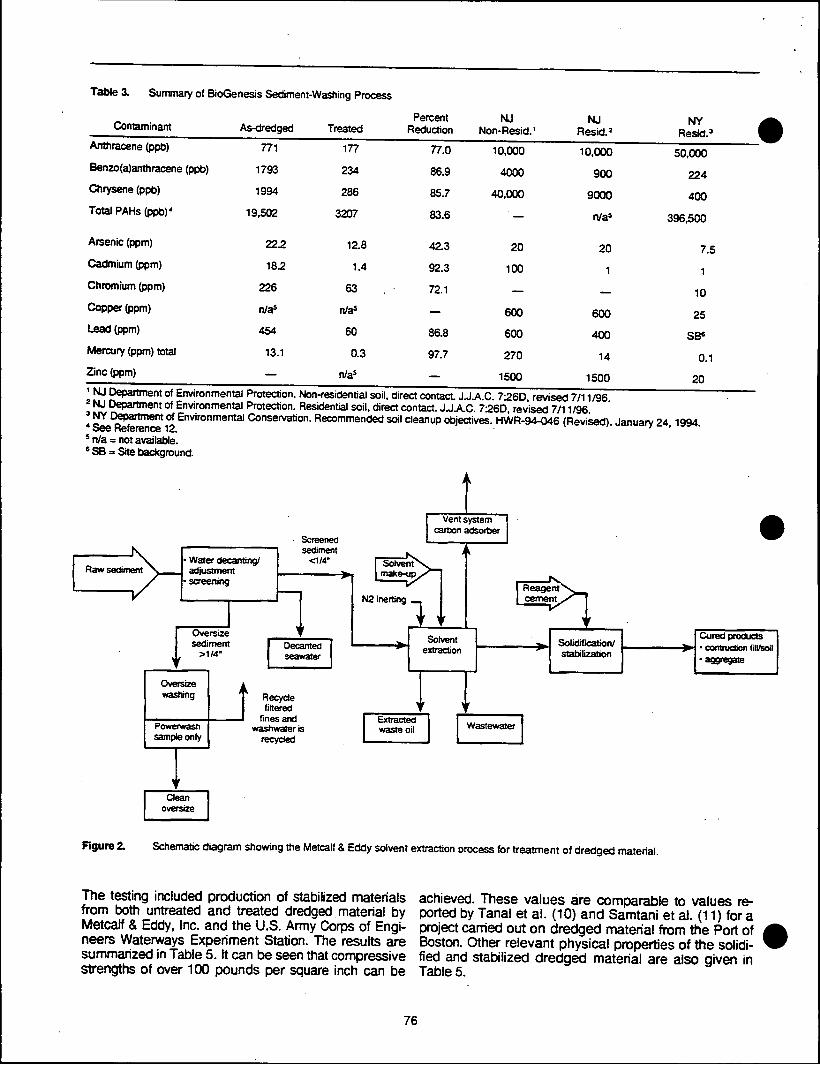
Table 3. Summary of BioGenesis Sediment-Washing Process
Contaminant As-dredged Treated Percent
Reduction NJ
Non-Resid.' NJ
Resid.' NY .
Resid.3 1 Anthracene (ppb) 771 177 77.0 10,000 10,000 50,000 Benzo(a)anthracene (PPb) 1793 234 86.9 4000 900 224 Chrysene (ppb) 1994 286 85.7 40,000 9000 400 Total PAHs (ppb)4
19,502 3207 83.6 ' — n/as 396,500
Arsenic (ppm) 222 12.8 42.3 20 20 7.5 Cadmium (ppm) 18.2 1.4 92.3 100 1 1 Chromium (ppm) 226 63 72.1 1^_ 10 Copper (ppm) n/as n/a5 — 600 600 25 Lead (ppm) 454 60 86.8 600 400 SB6
Mercury (ppm) total 13.1 0.3 97.7 270 14 0.1 Zinc (ppm) n/as — 1500 1500 20
NJ Department of Environmental Protection. Residential soil, direct contact JJAC. 7:260, revised 7/11/96
I £!LCJff?rtmem 0i Env'ronn,lental Conservation. Recommended soil cleanup objectives. HWR-94-046 (Revised). January 24,1994.
5 n/a = not available. 6 SB = Site background.
Raw sediment Water decanting/ adjustment
•screening
Screened sediment
<1/4"
Vent system carbon adsorber
Oversize sediment
>1/4" Decanted seawater
Solvent [make-up.
N2 inerting
Oversize washing
Powerwasn sample only
1 ReagentN
cement „
Solvent extraction
Recycle filtered
fines and wastiwater is
recycled
Solidification/ stabilization
Cured products • contruction Nl/soil
:e
Extracted waste oil Wastewater
Clean oversize
Figure 2. Schematic diagram showing the Metcalf & Eddy solvent extraction process for treatment of dredged material.
The testing included production of stabilized materials from both untreated and treated dredged material by Metcalf & Eddy, Inc. and the U.S. Army Corps of Engi- neers Waterways Experiment Station. The results are summarized in Table 5. It can be seen that compressive strengths of over 100 pounds per square inch can be
achieved. These values are comparable to values re- ported by Tanal et al. (10) and Samtani et al. (11) for a project carried out on dredged material from the Port of Boston. Other relevant physical properties of the solidi- fied and stabilized dredged material are also given in Table 5.
76

Institute Of Gas Technology Figure 3. The process requires adding common mineral compounds to optimize the overall composition of the
fcThe Institute of Gas Technology demonstrated the use material for pozzolan production. The technology em- of a rotary kiln for the destruction of organic compounds ployed is that commonly in use at existing cement and immobilization of metals in the cementitious struc- plants. This is encouraging since it means that existing ture. A block diagram of the apparatus is shown in off-line facilities could possibly be devoted to processing
Table 4. Summary of Results for the Metcalf & Eddy Solvent Extraction Process
Treated Percent NJ NJ NY Contaminant As-dredged 7-stage Reduction Non-Resid.' Resid.2 Resid.'
2.3,7.8 TCDD (ppt) 35 10 71 — — —
0 CDD (ppt) 13411 3047 77 — — —
TCDD/TCDFTEQ(ppt) 648 106 84 — — —
Total PCBs (ppm)4 1.54 0.029 98.1 2 0.49 1
Anthracene (ppb) 62.900 1292 97.9 10,000 10,000 50,000
Benzo(a)anthracene (ppb) 38490 894 97.7 4000 900 224
Chrysene (ppb) 33.76 1.01 97.0 40,000 9000 400
Total PAHs (ppb)' 858.000 17,000 98.0 — n/a* 396,500
Arsenic (ppm) 68 85 — 20 20 7.5
Cadmium (ppm) 29 32 — 100 1 1
Chromium (ppm) 319 373 — — — 10
Copper (ppm) 1090 1310 — 600 600 25
Lead (ppm) 632 795 — 600 400 SB6
Mercury (ppm) total 3.5 5.3 — 270 14 0.1
Zinc (ppm) 1505 1750 — 1500 1500 20
1 NJ Department of Environmental Protection. Non-residential soil, direct contact. J.J.A.C. 726D, revised 7/11/96. 2 NJ Department of Environmental Protection. Residential soil, direct contact. J.J.A.C. 7:26D, revised 7/11/96. 3 NY Department of Environmental Conservation. Recommended soil cleanup objectives. HWR-94-046 (Revised). January 24, 1994. * See Reference 12. 5 n/a = not available. 6 SB = Site background.
Table 5. Results of Physical Testing of Solidification/Stabilization Products*
U.S. ACE-WES Screened As-Dredoed Sediment 15% Cement Mix 30% Cement Mix 10% Cement Mix 20% Cement Mix 40% Cement Mix
USC in psi 217 614 29 128 492
Water Content at 60oC 53.0 26.9 60.7 27.7 18.1
Water Content at lOCC 71.6 53.7 70.3 5.4 32.1
Specific Gravity 2.70 2.69 2.53 2.61 2.63
Coefficient of Permeability-cm/sec 1.16E-06 4.15E-07 1.42E-05 5.46E-06 3.12E-07
Dry Densisty in lbs/ft3 51.6 64.1 38.1 47.5 57.5
Atterburg Limits Liquid Plastic
103 59
126 67
— —
Slope Angle Degrees — — 35.5 — —
' All analytical data are based upon the average of all sample test results provided by U.S. ACE-WES.
77

of dredged material. The results for contaminant reduc- tion are shown in Table 6. There is essentially complete destruction of organic compounds. The metals are re- duced by dilution and by loss to the gaseous side- stream. Moreover, the metal values are in the range found for commercially available cements. Strength tests have been carried out and show that the sediment- derived product meets compressive strength standards. Cement production is therefore a method that is suc- cessful in reducing the contamination levels and pro- vides an end product suitable for beneficial reuse.
Westinghouse
The Westinghouse Science and Technology Center dem- onstrated the use of a plasma torch for destruction of organic contaminants and immobilization of metals in a glassy matrix. The plasma torch is an effective method for heating sediments to temperatures higher than can be achieved in a rotary kiln. On the other hand, feeding of the material into the plasma region is more complex since dewatering is necessary, and residence times in the high temperature regions are difficult to adjust. A schematic diagram of the Westinghouse apparatus is shown in Figure 4. The results for contaminant reduction are given in Table 7. The end goal of the processing is not only to reduce contaminant concentrations, but, also to produce a useful final product. In order to do this, the overall composition of the treated material is optimized for glass production. Glass tiles and fiber glass materials were successfully produced during the pilot-scale test
work. Glass production can, therefore, be considered as successful in reduction of contaminant levels and pro- duction of a valuable end product.
5. Operational-Scale Program
As mandated under WRDA 1996, the end goal of the testing program is to produce one or more production- level demonstration facilities that can used as part of the total solution for management of dredged material from the harbor. Detailed engineering designs of plants for the production of cement and glass are now in progress and will be completed in early 1998. Construction of the facilities may begin in 1998 with a prospective comple- tion date prior to the next century. This schedule is dependent on availability of funding from the private sector. Demonstrations of the sediment-washing ap- proach are planned for early 1998 and operation of a large-scale demonstration facility by the end of 1998.
Conclusions
A short description has been given of the highlights of a unique federal program for dredged material demon- strating decontamination. This program began with tests at the bench-scale level and will progress to a goal of production-scale volumes of up to 375,000 rrf utilizing a "treatment train" approach. The breadth of the program has been increased through cooperation with groups who have carried on self-funded test programs. The bench- and pilot-scale results described here demon- strate that decontamination may be a viable method for
m,,o
Modifiers quench vaas cleanup equipment >
' r Gas-fired Reactive Melter
2400o-2500°F
As-received sediments
> '
Additives
/ k
i '
Natural „.„. + air
Economelt• High quality
cementitiou: >Drooefties) Dienoea cement
Clean flue gas
Figure 3. Schematic diagram showing the Institute of Gas Technology system for production of blended cement from dredged material.
78

Table 6. Summary of Results for the Institute of Gas Technology Cement Process
Contaminant As-dredged Treated Percent NJ
Reduction Non-Resid.1 NJ
Resid.2 NY
Resid.a
2.3.7.8 TCDD (ppt) 23 0.35 98.47 — — -
0 CDD (ppt) 11879 3.7 99.97 — — —
TCDDH-CDF TEQ (ppt) 513.2 1.406 99.72 — — -
Total PCBs (ppm)4 8.6 0.31 96.39 2 0.49 1
Anthracene (ppb) 18735 0 100 10.000 10.000 50.000
Ben20(a)anthracene (ppb) 17155 0 100 4UJU 900 224
Chrysene (ppb) 16878 0 100 40.000 9000 400
Total PAHs (ppb)4 293,854 0.16 100 — n/aJ 396,500
Arsenic (ppm) 39 ' 1.52 96.10 20 20 7.5
Cadmium (ppm) 27 0.66 97.55 100 1 1
Chromium (ppm) 298 632.5 212 - — 10
Copper (ppm) 1012 306 69.76 600 600 25
Lead (ppm) 542 29.4 94.57 600 400 SB»
Mercury (ppm) total 2.8 0.092 96.71 270 14 0.1
Zinc (ppm) 1535 280 81.76 1500 1500 20 1 NJ Department of Environmental Protection. Non-residential soil, direct contact. J.J.A.C. 7;26D, revised 7/11/96. 2 NJ Department of Environmental Protection. Residential soil, direct contact. J.J.A.C. 7:26D, revised 7/11/96. 3 NY Department of Environmental Conservation. Recommended soil cleanup objectives. HWR-94-046 (Revised). January 24, 1994. 4 See Reference 12. 5 n/a = not available. 6 SB = Site background.
Feed Sediment
Clean otfgases
Scrubber water bleed
5>
C=32=£>
Filtrate water
Glass product
Figure 4. Schematic diagram showing the production of glass from dredged material using the Westinghouse Science and Technology Center plasma torch melter.
79

Table 7. Summary of Results for the Westinghouse Vitrification Pmcess
Contaminant As-dredged Treated Percent
Reduction NJ
Non-Resid.' NJ
Resid.2 NY
Resid.3 i
2,3,7,8 TCDD (ppt) 19.0 — 100 — — 1
O CDD (ppt) 9655 8.0 100 — — —
TCDD/TCDF TEQ (ppt) 335 0.07 100 — — —
Total PCBs(ppm)4 0.900 0 100 2 0.49 1
Anthracene (ppb) 7.72 0 100 10,000 10,000 50,000
Benzo(a)anthracene (ppb) 7.19 0 100 4000 900 224
Chrysene (ppm) 8.76 0 100 40,000 9000 400
Total PAHs (ppb)4 109 0 100 — n/as 396,500
Arsenic (ppm) 15.8 4.94 68.7 20 20 7.5
Cadmium (ppm) 33.3 0.948 97.1 100 1 1
Chromium (ppm) 344 1001 — — — 10
Copper (ppm) 1145 1077 5.9 600 600 25
Lead (ppm) 594 105 82.3 600 400 SB6
Mercury (ppm) 2.08 0.087 95.8 270 14 0.1
Zinc (ppm) 1695 1240 26.8 1500 1500 20
' NJ Department of Environmental Protection. Non-residential soil, direct contact. J.J.A.C. 7:260, revised 7/11/96. 2 NJ Department of Environmental Protection. Residential soil, direct contact. J.J.A.C. 7:260, revised 7/11/96. 3 NY Department of Environmental Conservation. Recommended soil cleanup objectives. HWR-94-046 (Revised). January 24,1994. 4 See Reference 12. s n/a = not available. 6 SB = Site background.
handling at ieast a portion of the contaminated dredged material from NY/NJ Harbor.
Acknowledgments
Work at Brookhaven National Laboratory was supported in part by the U.S. Department of Energy under Contract No. DE-AC02-76CH00016 and by Interagency Agree- ments between the U.S. Environmental Protection Agency (Nos. DW89941761-01-0 and DW89937890- 01-0), the U.S. Army Corps of Engineers (No. NYD-94- 39), and the U.S. Department of Energy.
References
1. U.S. Army Corps of Engineers, New York District. September 1996. Dredged Material Management Plan for the Port of New York and New Jersey. Interim Report
2. Stem, E. A., Donato, K., Jones, K. W., and Clesceri, N. L "Processing contaminated dredged material from the Port of New York/New Jersey." Pre- sented at the Estuarine and Coastal Sciences Association (ECSA) Estuarine Research Federa- tion (ERF) 96 Symposium, Middelburg, The Neth-
erlands, 16-20 September 1996. Estuaries. In press.
Jones, K. W., Stem, E. A., Donato, K., and Clesceri, N. L "Processing of NY/NJ Harbor estuarine dredged material. Dredging and Management of Dredged Material," Proceedings of 3 Sessions Held in Conjunction with the Geo-Logan 97 Con- ference, The Geo-lnstitute/ASCE, July 16-17,1997, Logan, UT. pp. 49-66.
Jones, K. W., Stem, E. A., Donato, K. R., and Clesceri, N. L Commercialization of dredged- material decontamination technologies. Remediation 8 (2) .43-54 (1998).
C. R. Lee, U.S. Army Corps of Engineers, Water- ways Experiment Station, Attention: CEWES-ES- F, Environmental Processes and Effects Division, 3909 Halls Ferry Road, Vicksburg, MS 39180- 6199.
Mohsen Amiran, BioGenesis Enterprises Inc., 610 West Rawson Avenue, Oak Creek, Wl 53154.
80

7. John Cardoni, Metcalf & Eddy, Inc., Post Office Box 1500, Somerville, NJ 008876-1251.
8. Amir G. Rehmat Institute of Gas Technology, 1700 South Mount Prospect Road, Des Plaines, IL 60018-1804.
9. Nancy H. Ulerich, Westinghouse Electric Corpora- tion, Science & Technology Center, 1310 Eeulah Road, Pittsburgh, PA 15235-5098.
10. Tanal, Vahan; Wang, Jaw-nan; Samtani, Naresh C; and Lancellotti, Anthony. "Lime stabilization and disposal of contaminated dredged harbor sedi- ments." Proceedings of Geoenvironment 2000, New Orleans, LA, February 1995.
11. Samtani, Naresh C; Tanal, Vahan; Wang, Joe; and Lanclelotti, Anthony R. "Effect of lime admix- tures on contaminated dredged sediments." Pro- ceedings of First International Congress on Envi- ronmental Geotechnics, Edmonton, Alberta, Canada, July 10-15,1994.
12. NCAA. 1996. Contaminant Levels in Muscle and Hepatic Tissue of Lobster from the New York Bight Apex. Report to the U.S. Environmental Protection Agency and the U.S. Army Corps of Engineers. National Oceanic and Atmospheric Ad- ministration, National Marine Fisheries Service, James J. Howard Marine Science Laboratory, Highlands, NJ. May 1996.
81

Estuaries Vol. 21, No. 4A, p. 646-651 December 1998
Processing Contaminated Dredged Material From the Port of
New York-New Jersey
E. A. STERN
United States Environmental Protection Agency Division of Environmental Planning and Protection Place Based Protection Branch 290 Broadway New York, New York 10007- 1866
K. DONATO
United States Army Corps of Engineers New York District Corps of Engineers North Atlantic Division Planning Division Environmental Section 26 Federal Plaza New York, New York 10278- 0090
K. W. JONES1
Department of Applied Science Building 901A Brookhaven National Laboratory Upton, New York 11973- 5000
N. L. CLESCERI
Department of Environmental and Energy Engineering Rensselaer Polytechnic Institute Troy, New York 12180-3590
ABSTRACT: Shipping activities in the Port of New York-New Jersey are currently threatened by restrictions on dredging of navigational channels and private berthing areas because of concerns about the environmental effects caused by ocean disposal of the dredged material. Current proposals for solutions to the problem include ocean disposal of uncontam- inated material, use of confined disposal facilities (both upland facilities and containment islands), subaqueous borrow pits, and processing and treatment for contaminated materials. A project to produce a complete "treatment train" for processing and decontaminating dredged material is described. The work is divided into several phases: treatability studies of commercial and nonproprietary technologies at volumes of 19 liters (bench scale) and up to 19 m' (pilot scale); specification of a treatment train; and implementation of a large-scale facility that can process 76,000—382,000 m3 of dredged material per year. The goal is to achieve operational status for the facility by the end of 1999.
Introduction
Contaminated sediments in fresh and estuarine waters are a major problem worldwide. The basic reason is the realization that dredging operations required for the maintenance of navigable water- ways, private berthing areas, and different types of construction operadons generate large volumes of contaminated sediments, which must be disposed of in an environmentally acceptable way. Contam- inated sediments can be handled by use of con- fined disposal facilities, subaqueous borrow pits, or through decontamination of the sediments. The
'Corresponding author; tele: 516/344-4588: fax: 516/344- 5271: e-mail: [email protected].
cleaned sediments can be returned to the ocean, placed in a landfill, or reused in various types of beneficial applications. In practice, local and na- tional regulations restrict the permissible disposal avenues.
Much effort has been devoted to study of the various elements of a sediment decontamination treatment train, including dredging, physical sep- aration, treatment processes, and final disposal. Ancillary topics such as understanding contami- nant distributions in sediments, sediment trans- port, and biotoxicity effects related to marine dis- posal of treated materials are also of importance. For example, in Germany, federal standards have been developed (Kothe 1995a, b) for end disposal
© 1998 Estuarine Research Federation 646
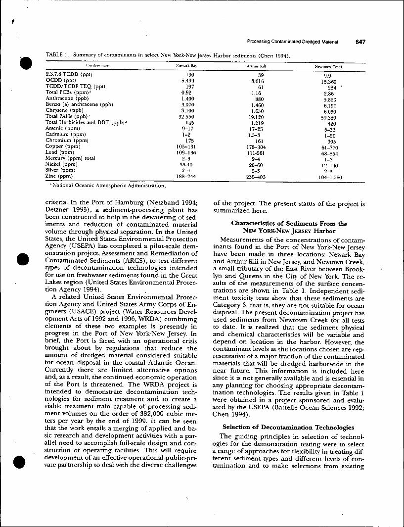
Processing Contaminated Dredged Material 647
TABLE 1. Summary of contaminants in select New York-New Jersey Harbor sediments (Chen 1994).
Contaminant
2,3,7,8 TCDD (ppt) OCDD (ppt) TCDD/TCDF TEQ (ppt) Total PCBs (ppm)a
Anthracene (ppb) Benzo (a) anthracene (ppb) Chrysene (ppb) Total PAHs (ppb)a
Total Herbicides and DDT (ppb)a
Arsenic (ppm) Cadmium (ppm) Chromium (ppm) Copper (ppm) Lead (ppm) Mercury (ppm) total Nickel (ppm) Silver (ppm) Zinc (ppm)
Newark Bav
130 5,494
197 0.92 1,400 3,070 3,100
32,550 145
9-17 1-2
175 105-131 109-136
2-3 33-40 2-4
188-244
Arthur Kill
39 3,016
61 1.16
880 1,460 1,630
19,120 1,219
17-25 1.5-3
161 178-304 111-261
2-4 20-60 2-5
230-403
Newtown Creek
9.9 15.369
224 ' 2.86 5,820 6.190 6,050
59,380 420
5-33 1-20
305 61-770 68-554
1-3 12-140 2-3
104-1.260 a National Oceanic Atmospheric Administration.
criteria. In the Port of Hamburg (Netzband 1994; Detzner 1995), a sediment-processing plant has been constructed to help in the dewatering of sed- iments and reducdon of contaminated material volume through physical separadon. In the United States, the United States Environmental Protection Agency (USEPA) has completed a pilot-scale dem- onstration project. Assessment and Remediation of Contaminated Sediments (ARCS), to test different types of decontamination technologies intended for use on freshwater sediments found in the Great Lakes region (United States Environmental Protec- tion Agency 1994).
A related United States Environmental Protec- tion Agency and United States Army Corps of En- gineers (USAGE) project (Water Resources Devel- opment Acts of 1992 and 1996, WRDA) combining elements of these two examples is presendy in progress in the Port of New York-New Jersey. In brief, the Port is faced with an operational crisis brought about by regulations that reduce the amount of dredged material considered suitable for ocean disposal in the coastal Adantic Ocean. Currendy there are limited alternative options and, as a result, the continued economic operation of the Port is threatened. The WRDA project is intended to demonstrate decontamination tech- nologies for sediment treatment and to create a viable treatment train capable of processing sedi- ment volumes on the order of 382,000 cubic me- ters per year by the end of 1999. It can be seen that the work entails a merging of applied and ba- sic research and development activities with a par- allel need to accomplish full-scale design and con- struction of operating facilities. This will require development of an effective operational public-pri- vate partnership to deal with the diverse challenges
of the project. The present status of the project is summarized here.
Characteristics of Sediments From the NEW YORK-NEW JERSEY Harbor
Measurements of the concentrations of contam- inants found in the Port of New York-New Jersey have been made in three locations: Newark Bay and Arthur Kill in New Jersey, and Newtown Creek, a small tributary of the East River between Brook- lyn and Queens in the City of New York. The re- sults of the measurements of the surface concen- trations are shown in Table 1. Independent sedi- ment toxicity tests show that these sediments are Category 3, that is, they are not suitable for ocean disposal. The present decontamination project has used sediments from Newtown Creek for all tests to date. It is realized that the sediment physical and chemical characteristics will be variable and depend on location in the harbor. However, the contaminant levels at the locations chosen are rep- resentative of a major fraction of the contaminated materials that will be dredged harborwide in the near future. This information is included here since it is not generally available and is essential in any planning for choosing appropriate decontam- ination technologies. The results given in Table 1 were obtained in a project sponsored and evalu- ated by the USEPA (Battelle Ocean Sciences 1992; Chen 1994).
Selection of Decontamination Technologies The guiding principles in selection of technol-
ogies for the demonstration testing were to select a range of approaches for flexibility in treating dif- ferent sediment types and different levels of con- tamination and to make selections from existing

648 E. A. Stem et al.
commercial technologies that could be extended rapidly to full-scale operation. These principles were met by soliciting proposals through a request for proposals that was circulated to approximately 150 technology development firms. Formal pro- posals for 25 technologies were received and eval- uated by reviewers from USEPA, USAGE, United States Department of Energy-Brookhaven National Laboratory (DOE-BNL), and four participating universities: New Jersey Institute of Technology, Rensselaer Institute of Technology, Rutgers Uni- versity, and Stevens Institute of Technology. Seven proposals were selected for bench-scale testing demonstrations. In addition, several tests were car- ried out by the USAGE Waterways Experiment Sta- tion, Vicksburg, Mississippi.
The selection process envisaged a developmen- tal process that would lead from bench-scale to full- scale operations in a series of optional steps. These further optional steps proceeded from pilot-scale tests to plants operating at 76,000 m3 and 382,000 m3. These values are to be compared to the yearly need to process or otherwise dispose of the 2,500,000 m3 to 3,000,000 m3 of dredged material deemed too contaminated for unrestricted ocean disposal. A confined disposal facility, either upland or a containment island, may be used to meet some or all of these needs. Sediment processing and decontamination can be used to respond to short-term needs and is a plausible component to other dredged material alternatives for long-term needs. The magnitude of the problem suggests there is an environmental and economic require- ment for operation of several large-scale facilities with varied capabilities.
Bench-scale Tests
The bench-scale tests covered technology op- tions for mixtures with uncontaminated materials to high-temperature thermal treatments. The spe- cific approaches follow:
Creation of a manufactured soil by addition of compost, manure, and other materials.
Solidification and stabilization by addition of portland cement, lime or fly ash, and/or proprie- tary chemicals to create solid aggregates.
Soil washing using proprietary surfactants, che- lating agents, and high pressure collisions to re- move both organic and inorganic contaminants.
Solvent extraction, a technique similar in con- cept to soil washing.
Thermal desorption to remove surface contam- inants. The temperatures used are not high enough to destroy the organic compounds.
High-temperature thermal destruction. High temperatures can completely destroy the organic
compounds and fuse the inorganic materials into a stable matrix. Three technologies were tested that used temperatures in the range from 750CC to 3000oC. The products of the testing are suitable for beneficial reuse as aggregates, cement, and glass. These products have relatively high economic val- ues, which would help in the creation of a self- sustaining industry.
The manufactured soil approach is attractive be- cause our initial tests have shown that the sedi- ments pass the USEPA Toxicity Characteristic Leaching Procedure (TCLP) test (USEPA SW 846/ 1311), so that the soil can be disposed of on land in several ways. Bench-scale tests showed various types of grasses grew best in a soil containing 30% native sediment together with added compost and manure. However, contamination levels are re- duced only by dilution and use of the final material may be restricted.
Percent contaminant reductions obtained for the other approaches are shown in Fig. 1. The val- ues are based on the contaminant concentrations found in the end-product, including the effect of any addition of uncontaminated materials. The collection of samples, quality assurance, and qual- ity control were supervised by the consortium of federal agencies and four university groups. The values shown in Fig. 1 are presented in a conser- vative way. Minimum detection limits were used in the calculation of the reduction fraction where quantitative values were not found. This resulted in an underestimate of the actual reduction.
It can be seen that the high-temperature ther- mal technologies using temperatures higher than 750oC are extremely effective in destroying organic contamination. The lower temperature thermal desorption process is also effective but has the dis- advantage of creating a sidestream of toxic mate- rials, which must then be treated or disposed of in a separate step.
Solidification and stabilization and sediment washing were found to have less effect on the sed- iments. Analysis of the results suggest the treat- ments may change the chemistry of the contami- nants and render them more susceptible to leach- ing. This could affect the contaminant analyses and suggests further experimentation with the spe- cific chemicals used for the treatments is needed in order to improve performance and for evalua- tion of the testing procedures. The separations technologies used can also lead to recontamina- tion of the material in the final stages of the pro- cess. We have tried to work with all the project participants to improve their technologies to the maximum extent possible.

Processing Contaminated Dredged Material 649
SEDIMENT TREATMENT EFFICIENCY PER CENT REDUCTION
100 7 O 8U f- o 60 -) Q 40 LJJ CC 20 1- -z. 0 LU O -20 CE LU Q.
-40
i
-60 3 4 5
VENDOR
!• pCBs | •1 Pest/Herb ^ 1 PAHs
t Dioxins j Furans Metals
Fig. 1. The reduction of various types of sediment contaminants bv seven different treatment technologies is shown. The decon- tamination processes are 1) solidification and stabilization using proprietary chemicals. 2) sediment washing, 3) solvent extraction, and 4) thermal desorption. 5), 6), and 7) are high-temperature thermal destrucuon. Several reasons for the apparent enhancement of contaminant concentrations are given in the text.
Pilot-scale Testing Pilot-scale testing has been carried out on sev-
eral of the technologies tested at the bench scale. They are manufactured soil, solidificadon and sta- bilizadon, solvent extracdon, and high tempera- ture treatment to produce cement and glass for beneficial reuse.
The pilot-scale tests have been completed, and analysis of the treated materials is in progress. The amount of material processed in the pilot-scale demonstradons varied from 3 m3 to 10 m3. The intent in this phase was to obtain more detailed information on the overall mass balance of the procedures and to obtain data to enable detailed design of large-scale facilities. It was shown that all approaches have applicadon in the design of a complete treatment train for a commercial-scale fa-
cility. Insights were gained into the materials han- dling of fine-grained sediments, which will be a ma- jor part of the processing.
Related Issues
There are many issues of importance in the de- velopment of an effective sediment-processing fa- cility, in addition to the purely technological fac- tors. Some of the questions that are being ad- dressed through this project are discussed in the following sections.
RISK ASSESSMENT
Risk assessment must be considered from a num- ber of different perspectives, including: risks to the environment from disposal of the treated materials and from sidestreams produced in the processing,

650 E. A. Stem et al.
risks to human health including occupational ex- posures, and risks from failures of components of the processing equipment. Evaluations of the first two risk categories indicate that it should be pos- sible to define an overall approach acceptable from the environmental and human health per- spectives. Equipment-dependent risk will be con- sidered during the design process for the large- scale facility to make sure problems are addressed during the design process.
PUBLIC OUTREACH
Processing of large amounts of sediment con- taining metal and organic contaminants will be of great concern to the public in the processing area in end-use locations. This will be true even though the sediment contaminant levels are not high enough for classification as a hazardous waste. For this reason, care has been taken to involve the pub- lic, including city, state, and local governmental of- ficials, regulatory agencies, industry, and commu- nity groups, and to keep them apprised of prog- ress. Much effort has been devoted at the com- munity level to discussions of impacts on the local environment and in efforts to ensure that the com- munities in close proximity to the processing site will benefit from the operation.
PROCESSING COSTS
The usefulness of the processing facility is highly dependent on the total cost (including credits for beneficial use) of dredging, processing, and ulti- mate disposal of the treated sediments. Costs for the complete treatment train estimated by the pro- ject industrial contractors range from about $20 per m3 to $120 per m3. Sale of treated materials and resulting products, such as cement, glass prod- ucts, manufactured soil, and construction aggre- gate, among others, will potentially sharply reduce the net treatment cost.
DISPOSAL CRITERIA
Classification of the treated materials and crite- ria for end use are a critical part of the procedures described here. Most of the requirements are set by individual state agencies from the environmen- tal stand point. Beneficial uses have various crite- ria, which are determined by the particular appli- cation.
Treatment Train Design of a complete treatment train for sedi-
ment processing is in progress. It is based on ap- plication of the technologies described in this pa- per. In addition, means for dredging, dewatering, physical separation, materials transport, residuals management, and storage need to be finalized.
The basis for the treatment train will rest on the employment of multiple technologies for the de- contamination process.
Full-scale Project The implementation of a full-scale project will
benefit from a public-private partnership to face the complex issues of financing, siting permits, beneficial uses, continuing research and develop- ment needs, and community involvement. While this has not been done to date in the New York- New Jersey region, it is a concept that has been much discussed and used elsewhere. Preliminary discussions among USEPA, USAGE, and DOE-BNL and many private sector groups are now under way in an effort to organize an effective team.
Conclusions
The results of bench-scale and pilot-scale testing of sediment decontamination technologies have shown there are several viable approaches which will be environmentally and economically accept- able. A move to demonstrations processing at the level of 76,000 m3 to 382,000 m3 per year is un- derway. Completion of this phase is projected for 1999.
ACKNOWLEDGMENTS
This work was supported in part under Section 405 of the Water Resources Development Act of 1992 and by the United States Department of Energy under contract no. DE-AC02- 76CH00016 (KWJ).
LITERATURE CITED
BATTELLE OCEAN SCIENCES. 1992. Sediment toxicity and concen- trations of trace metals in sediment and pore water in New York/New Jersey Harbor. Battelle. Columbus, Ohio.
CHEN, A. S. C 1994. Letter report: Analytical results of NY/NJ Harbor sediments. Base-catalyzed dechlorination demonstra- tion project. Battelle, Columbus, Ohio. Correspondence to A. Massa. United States Environmental Protection Agency, Re- gion II, New York, New York.
DETZNER. H.-D. 1995. The Hamburg Project METHA: Large- scale separation, dewatering and reuse of polluted sediments. European Water Pollution Control 5:38-42.
KOTHE, H. F. 1995a. Legisladve framework and technological improvement for the management of contaminated dredged material (CDM) in Germany, p. 38-42. In P. B. Roeters and G. N. M. Stokman (eds.), Proceedings of the Satellite Seminar on "Remediation of Contaminated Sediments,'* Fifth Inter- national FZK/TNO Conference on Contaminated Soil. Ha- gemann Verpakkers, Zoetermeer, The Netherlands.
KOTHE. H. 1995b. Criteria for the beneficial use or the disposal of contaminated dredged material in the Federal Republic of Germany, p. 459-474. In V. L. van Dam (ed.), Proceedings of the 14th World Dredging Congress 1995. Central Dredging Associadon, Delft, The Netherlands.
NETZBAND, A. 1994. Dredged material management in the port of Hamburg. European Water Pollution Control 4:47-54.
NATIONAL OCEANIC AND ATMOSPHERIC ADMINISTRATION. 1996. Contaminant levels in muscle and hepauc tissue of lobster from the New York Bight Apex. Report to the United States Environmental Protection Agency and the United States

Processing Contaminated Dredged Material 651
Army Corps of Engineers. National Oceanic and Atmospheric 94-001. United States Environmental Protection Agency, Administrauon, National Marine Fisheries Service, James J. Washington, D.C. Howard Marine Science Laboratory, Highlands, New Jersey.
UNITED STATES EWIRONMENTAL PROTECTION AGENCY. August 1994. Assessment and remediation of contaminated sedi- Received for consideration, December 17, 1996 ments (ARCS) program. Final Summary Report EPA 905-S- Accepted for publication, March 20, 1998

* Untitled Page 1 of 2
#96-33
Mailed 5/1/96
ContactDiane Greenberg, or Mona S. Rowe
BROOKHAVEN-RENSSELAER PARTNERSHIP SUPPORTS "FAST-TRACK" NY-NJ HARBOR SEDIMENT
DECONTAMINATION PROJECT
Upton, NY ~ Acting under the federal Water Resources Development Act of 1992, the U.S. Environmental Protection Agency (EPA) and the U.S. Army Corps of Engineers (ACE) are overseeing a $6.5-million, two-year project to decontaminate sediment dredged from New York-New Jersey (NY-NJ) Harbor.
Dredged sediments must pass state and federal testing criteria prior to unrestricted ocean disposal. Recently revised regional guidelines have established more stringent biological and chemical criteria. As a result, the volume of contaminated dredged material potentially prohibited from unrestricted ocean disposal may increase.
If the harbor is not routinely dredged, large cargo ships will not be able to navigate it. The subsequent loss of business in this major port, which handles 38 million tons of cargo each year, would be financially debilitating for the NY-NJ metropolitan area.
The U.S. Department of Energy's (DOE) Brookhaven National Laboratory is working with EPA and ACE as the technical project leader for evaluating the effectiveness of technologies developed by private industry for decontaminating sediment dredged from NY-NJ Harbor. In addition, four educational institutions in the NY-NJ area — Rensselaer Polytechnic Institute, Stevens Institute of Technology, Rutgers University and the New Jersey Institute of Technology — are working with EPA, ACE and DOE to help provide the very broad range of technical expertise that is needed to meet the project objectives.
Brookhaven Lab's Keith Jones, the principal investigator in the harbor cleanup project, said, "We are trying to find a viable solution on a fast track, using sediment decontamination technologies that we hope will really meet the environmental and economic crises caused by contaminated sediments."
Brookhaven solicited requests from 150 vendors for clean-up technologies and received 25 proposals from 24 companies. Out of the 25 proposals, seven technologies were chosen for testing. Each of the seven finalists has been provided with approximately 17 pounds of harbor sediment, containing such pollutants as heavy metals, chlorinated pesticides, semi-volatile organics, polychlorinated bi-phenyls and dioxins, which must be decontaminated as thoroughly and economically as possible.
The seven finalists and their technologies are:
Biogenesis Enterprises Inc., Springfield, Virginia — A soil-washing process removes organics and metals from the sediment. The resulting wastewater is then treated by chemical precipitation to remove metals and by oxidation to destroy organics. Possible beneficial uses of the treated sediment
http://www.pubaf.bnl.gov/~pubaf7pr/bnlpr960221.html 07/26/2000
Untitled Page 2 of 2
include landfill cover and topsoil replacement.
BioSafe Inc., Cambridge, Massachusetts - Organics are destroyed by heat of 2,200 degrees F, and a metal-removal process then is employed, if necessary. Treated sediments may be used as landfill cover and construction backfill.
Institute of Gas Technology, Des Plaines, Illinois — Organics are destroyed at high temperatures and metals are locked into a cement matrix. The resulting product is pulverized with gypsum to yield Portland cement.
International Technology Corporation, Knoxsville, Tennessee — Heats sediment to l,000oF to change organics to vapor for removal by desorption and uses chemicals to stabilize metals in the sediment. The company proposed that the treated sediment may be used to produce artificial reefs.
Marcor Environmental of Pennsylvania, Inc., Downington, Pennsylvania — Chemical treatment transforms both organics and metals into a solid mineral material. Treated sediment may be used for construction backfill and secondary building material.
Metcalf and Eddy, Wakefield, Massachusetts ~ Uses several technologies to separate and stabilize metals and organics. Possible uses of treated sediment include landfill cover, construction backfill and road-paving subbase.
Westinghouse Electric Corporation, Science and Technology Center, Pittsburgh, Pennsylvania — Uses a vitrification process that heats sediments quickly up to 5,000oF, which destroys the organics and creates a glass-like material that immobilizes the metals within. The resulting product may be used to make fiberglass and glass fiber products.
In June 1996, additional tests will be undertaken at the Port Newark Marine Terminal, where two or three of the most successful bench-scale tests will be upgraded to treat 25 cubic yards of sediment from the harbor. Depending on further funding, the most successful technologies will be scaled up to industrial size — 100,000 to 500,000 cubic yards of sediment per year.
Brookhaven National Laboratory carries out basic and applied research in physical, biomedical and environmental sciences and in selected energy technologies. Associated Universities, Inc., a nonprofit research management organization, operates the Laboratory under contract with the U.S. Department of Energy.
-30-
http://www.pubaf.bnl.gov/~pubaf7pr/bnlpr960221 .html 07/26/2000

lu i iiuiii .1 1 .IJ 11.1H.UUU uupj) w w w.uin.yuv, UHj;iip!._ 1 UUC.nt!
DAS Program
1
TECHNOLOGIES FOR DECONTAMINATING DREDGED ESTUARINE SEDIMENTS FROM NY/NJ HARBOR *
Keith Jones
New York/New Jersey Harbor Sediment Decontamination Project
WRDA 405 OECON
EPA • COE • DOE-BNL
• 1
The bay areas surrounding New York/New Jersey Harbor (Harbor) are naturally shallow, acting as catchments for river-transported sediments and solids from surface point and non-point sources. Sediments from the Harbor must be routinely dredged to maintain navigable water depths for shipping channels and
berthing areas for commerce and safe navigation. This action amounts annually to an average of 6-8 million cubic yards of sediment. Ocean disposal at the Mud Dump Site (6 nm. east of Sandy Hook, NJ) has
been the primary alternative for disposal of dredged materials from the Harbor.
Dredged sediments must pass testing criteria prior to unrestricted ocean disposal. The recently revised Regional Guidance for Performing Tests of Dredged Material Proposed for Ocean Disposal (Draft
December 1992), has established more stringent biological and chemical test criteria. As a result, the volume of dredged material designated as contaminated and prohibited from ocean disposal has
dramatically increased. Dredged sediments from the Harbor may contain elevated levels of a wide variety of contaminants, including: heavy metals, polynuclear aromatic hydrocarbons (PAHs), and
organochlorines such as dioxins, polychlorinated biphenyls (PCBs), and chlorinated pesticides.
I I 1
|
1 of 2
New York Harbor scene
Under Section 405 of the Water Resources Development Act (WRDA), the U.S. Environmental Protection Agency, Region 2 and the U.S. Army Corps of Engineers - New York District are jointly managing an investigation of sediment-decontamination technologies for dredged material management. WRDA 405 authorizes a fast-track (two-year) investigation, including testing and demonstration, of decontamination technologies to treat contaminated sediments in an environmentally protective and cost effective manner.
Technical support and assistance is being provided to this project by the Brookhaven Rensselaer Environmental Partnership-Multi State Alliance (BREP-MSA), which includes Brookhaven National Lab, New Jersey Institute of Technology, Rensselaer, Rutgers University, and Stevens Institute of Technology.
2/9/98 6:36 PM

I CHN0L0G1ES HJKUtCUNlAMlWAllINO UK....lUAiUINC aCUUVlElNl a TKAJIVI IN I/INJ rirtJUJUI^ ultp.HWww.oui.gu»n-«no/aj/a_1^^.i,
Treatment technologies must be capable of sufficiently reducing the contaminant levels by separation, destruction, immobilization and/or other methods that render dredged sediments suitable for ocean
disposal, upland disposal, or preferably, beneficial use. Treatment will likely require several different processes due to the complex and varying nature and levels of contaminants and their widespread spatial
distribution within the Harbor. A complete treatment train will be developed to encompass dredging, pretreatment, treatment, post-treatment, residuals management, end disposal and/or beneficial use, and all
storage and transport involved therein. Although the exact amount ofmaterial requiring treatment in the future has yet to be determined, an estimate of approximately 500,000 c.y./year is the target figure for
projecting full-scale treatment operations.
\
WORK m PROGRESS
*This work is supported by the U.S. Army Corps of Engineers and the Environmental Protection Agency.
i 2 0n 2/9/98 6:36 PM

Commercialization of Dredged- Material Decontamination Technologies
Keitb W.Jones is a senior scientist at Brookbaven National Laboratory, Upton, New York, with research experience in nuclear and atomic physics and the deveiopment of materials cbaracterixation methods based on the use of x-ray and ion beams. He is BNL's technical project manager for the EPA and USACE programs for demonstra- tion of sediment decontamination technologies for the Port of New York and New Jersey. Anthony J. Guadagni is a senior contracts specialist at Brookbaven National Laboratory, Upton, New York, with direct experience in research and design/develop- ment, environmental engineering and nuclear services-type programs. He is BNL's contrac- tual respres entattvefor the sediment decontamination technologies project Eric A. Stem is a regional contaminated sediment program manager with the EPA, Region 2, New York. He works In the area of contami- nated sediment assessments and dredged material management. He is the technical program manager for the WRDA NY/NJ Harbor Sediment Decontamina- tion Demonstration Project He has previously served with the USACE—NY District as an oceanograpber working on dredged-materlal assessments. Kerwin R. Donato is a USACE program manager for the sediment decontamination project and is also working on the Dredged Material Manage- ment Program. He Is a chemical engineer with past experience on both industrial and government projects. Nicholas L. Oesceri is a professor of environmental engineering and director of the environmental engineering program at Rensselaer Pofytecbnic Institute, Troy, New York. He has served as a consultant to numerous governmental agencies and private industry. His research Interests have been in the area of water quality responses to man's activities. He Is the deputy project manager for the WRDA Sediment Decontamination Program.
Keith W.Jones • Anthony J. Guadagfni • Eric A. Stern • Kerwin R. Donato • Nicholas L. Clesceri
This article describes a unique federal project aimed at the commercializa- tion of different technologiesfor the decontamination of dredged material. The project is organized so that commercialization is achieved in a seamless way, starting with validation at the bench- and pilot-scale levels, and ending with the actual construction of operational facilities. This is the first integrated sediment decontamination program in which a step-wise bench-scale validation process of innovative/emerging technologies will scale-up to a production-scale facility capable of processing up to 3 75,000 m3 of dredged material per year. The need to develop public-private partnerships for the facility construction is emphasized as a way of obtaining adequate funding for capital and operating costs during the startup time of the commercialization process. It is expected that the end result of the project work ivill be the creation of economically-viable, self- sustaining decontamination technology companies.
Human industrial activities in the United States over the past 400 years have resulted in the widespread historical contamination of sediments found in the national rivers, lakes, and coastal waters. Point, non-point, and atmospheric sources have all contributed loadings to these systems. During the past 20 years, there has been an increasing awareness of the environmental consequences of this contamination in terms of its effects on both wildlife and human health. This concern has been reflected in increasingly-stringent regulations dealing with the handling and disposal of contaminated sediments in dredged material, as well as the remediation of particular highly-contaminated sites.
The Port of New York and New Jersey is an excellent example of these recent trends. The Port requires dredging several million cubic meters of sediment each year for maintenance of navigational channels and private berthing facilities. Because the Port is one of the largest on the eastern coast of the United States, it plays a key role in the economy of the region, and its continued efficient operation is important to a substantial population. However, disposal of the dredged material has become increasingly difficult because of more stringent regulations based on environmental criteria. This trend culminated on September 1, 1997, when the traditional
CCC 1051-5658/98/0802043-12 © 1998 John Wiley & Sons, Inc.
43

KETTH W. JONES • ANTHONY J. GUADAGNI • ERIC A. STERN • KERWIN R. DONATO • NICHOLAS L. CLESCERI
Decreasing the recontamination of these waterways by employing pollution prevention measures is paramount for a successful plan.
location for ocean disposal of the dredged material located off the coast of New Jersey was closed (USEPA/USDOT/USACE, 1996).
There are a number of approaches that can be used for the manage- ment and disposal of contaminated sediment from the Port. These have been outlined in a comprehensive Dredged Material Management Plan (DMMP) now under development by the U.S. Army Corps of Engineers- New York District (1996). Some of the disposal options include a containment island, subaqueous borrow pits, upland disposal in landfills, quarries, mines, etc., and decontamination followed by beneficial reuse. Decreasing the recontamination of these waterways by employing pollu- tion prevention measures is paramount for a successful plan.
The status of a project to test and commercialize a treatment train for decontamination of dredged material is summarized here. Earlier summa- ries have been given by Stem et al. (1996, 1997) and Jones et al. (1997). The project was authorized and funded by Congress under the Water Resources Development Acts (WRDA) of 1992 and 1996, with the goal of demonstrating the feasibility of decontaminating sediment from the Port of New York and New Jersey.
The goals of the project are easily summarized: (1) the technologies must meet appropriate cleanup standards; (2) they must be environmen- tally acceptable; and (3) the cost of treatment must be economically feasible. Commercialization of decontamination technologies must con- sider these three criteria. In addition, there are sociological factors involving the many stakeholders that are equally important.
Cleanup technologies are relatively well established as a consequence of several decades of experience on cleanup of many different types of soil, sediment, sludge, and wastewater. Decontamination of sediments may pose a problem because of the solids and moisture content, its cohesive- ness, salinity in estuarine and marine systems and the co-matrix of a variety of persistent contaminants, and possible pretreatment such as de-watering. Technology selection has been conservative because the time scale for development of an operational facility was short, based on the urgent need for solutions to the dredged material problem in the Port. A useful summary of the current state-of-the-art has been presented recently (Committee on Contaminated Marine Sediments, 1997).
It is useful to consider the time scale for implementation of a decontamination approach to the handling of dredged material. Griibler (1997) has examined the time frames taken for implementation of new technologies, and claims that this generally amounts to about 50 years. A current example is the development of the computer industry, from what can be taken as a starting point in 1947 with the invention of the transistor, to 1997 when the technology has effectively revolutionized most aspects of the modem world (Isaacson, 1997). The remediation industry has been in development for the past 20 to 25 years. Hence, in analogy, it can be argued that decontamination of dredged material is poised for rapid development in the next few years, and that a mature industry can develop in 10 to 20 years.
However, the rate-of-progress depends on actions by various con-
44 REMEDIATION/SPRING 1998

COMMEKCIAIJZATION OF DREDGED-MATERIAL DECONTAMINA'nON TECHNOLOGIES
The successful commercialization of decontamination technologies necessarily will require a form of public-private partnership.
cemed parties in the Port region. They will include the states of New York and New Jersey, the City of New York and other local municipalities, the Port Authority of New York and New Jersey, the EPA—Region 2, and the USAGE—New York District, cultivating community support and accep- tance for decontamination. Anyone interested in the commercialization of decontamination technologies in the Port region would benefit from a study of these entities. A number of general background works can be cited (Almond, 1997; Bone, 1997; Jackson, 1995). The operation of the New York State government during the period between World War I and World War II is described by Caro (1974). Similarities in the way the legislature operated in that era, with operations in the present day, are easily discemable. Some issues relevant to the operation of the Port Authority and the states are described by Danielson and Doig (1982). It is instructive to note the slow rate of change in operations of the entities described. Instances of contamination of industrial sites in New Jersey are given by Sheehan and Wedeen (1993) that help explain how the Port sediments came to be contaminated. The operations of the Army Corps of Engineers are illustrated by its approach to shoreline restoration (Pilkey and Dixon, 1996). The way the Corps manages large-scale engineering projects is illustrated by the authors.
It can be seen that the successful commercialization of decontamina- tion technologies necessarily will require a form of public-private partner- ship, bringing together the private technology developers with the multitudinous public parties. This type of approach has been applied in the Great Lakes region through the EPA's Great Lakes National Program Office. A recent summary of regional activities has been provided by the Sediment Priority Action Committee (1997). A very general examination of the process of bringing new technologies for groundwater and soil cleanup to the commercial stage has been carried out by the National Research Council (Committee on Innovative Remediation Technologies, 1997). The content of the book has been summarized by Hirschhom (1997). Many of the points covered can be related to the goals of the present project.
CONTAMINATED DREDGED MATERIAL IN THE PORT OF NEW YORK AND NEW JERSEY
Recently, the problem of sediment contamination and its impacts on navigational dredging in the Port has received considerable attention from involved regulatory agencies and environmental/public interest. Imple- mentation of the revised 1991 guidance in the EPA/USACE Regional Testing Manual resulted in a considerable increase in the volume of dredged material that is prohibited from unrestricted ocean disposal. The need to maintain the viability of the Port while avoiding open ocean disposal of contaminated dredged material has led to these investigations of sediment decontamination technologies for application to navigational dredging and/or environmental problem areas. Squibb et al. (1991) concluded that concentrations of a variety of toxic contaminants in these sediments are elevated sufficiently in many locations to cause adverse effects to the biological community. Heavy metals (Hg, Cd, Pb, Ni, Cu, Zn,
REMEDIATION/SPRING 1998 45

KEITH W. JONES • ANTHONY J. GUADAGNI • ERIC A. STERN • KERWIN K DONATO • NICHOLAS L. CLESCERI
and As), chlorinated pesticides (including DDT + metabolites, chlordane, dieldrin, and endrin), polynuclear aromatic hydrocarbons (PAHs), poly- chlorinated biphenyls (PCBs), and dioxins/furans are the major contami- nants in the Port. Furthermore, several contaminants, detected in the Port sediments as well as in the tissue of fish and shellfish, have resulted in fishing advisories in the Port.
It was necessary to structure the work in a series of tests that would begin at the laboratory scale, and would be completed with the operation of a full- scale facility.
APPROACH TO COMMEROAIIZATION An innovative approach to the organization of the project was
developed at its outset. It was recognized that it was necessary to structure the work in a series of tests that would begin at the laboratory scale, and would be completed with the operation of a full-scale facility. It was also realized that if these steps were undertaken through a series of individual procurements, the time scale for completion would be extended by several years. Furthermore, under Federal Acquisition Regulations, it could well be difficult to make successive awards to a single contractor.
The solution was to organize the project into a step-wise sequence. Contractors successfully completing demonstrations at the bench-scale level (19 £) could then be considered for participation in a series of optional steps at the pilot-scale (19 m3), operational-scale (76,000 m3), and full-scale (380,000 m3) levels. Work has now progressed into the third phase and has been very successful in producing a coherent project, or "systems approach," that has progressed very rapidly from phase to phase.
The project was also organized so that it could serve as a general technical resource for the technology vendors interested in commercializa- tion of decontamination processes. Efforts have been made to give assistance to the vendors funded through the project, and also to add vendors so as to stimulate a wider technology base, and to share knowledge gained with public agencies and the wider general public in the region.
This has been very rewarding because there have been several instances in which contributions have been made to technical aspects of the tests, and to the many questions involved in site selection and acquisition. In addition, efforts to expand the technology base have been rewarded by working with additional vendors that could provide existing infrastructure.
At all times it has been recognized that economics is a major driving force in the work. A technically elegant solution is needed, but overall operational costs must be bearable. Funding for the work must be obtained from several sources. While federal and state funds will be available, they will not be sufficient for construction and operation of major facilities. Therefore, private funding sources must be applied in a major way in the commercialization process.
BENCH- AND PILOT-SCALE TESTING SUMMARY A matrix of technologies was selected for the initial bench-scale testing
phase. They included low-, medium-, and high-temperature methods. A block diagram showing how they can be combined into a treatment train
46 REMEDIATION/SPRING 1998

COMMERCIALIZATION OF DREDGED-MATEMAL DECONTAMINATION TECHNOLOGIES
is shown in Exhibit 1. Results obtained in the treatment tests have been presented previously (Stem et al. 1996 and 1997; Jones et al. 1997). The overall conclusions of the work are that it is possible to assemble a complete "treatment train" that can be used to process dredged material with a wide range of contaminant concentrations. A short discussion of technologies from the three temperature classes is given to indicate regions of application and to touch on some of the drawbacks.
Manufactured soil production has been developed by the USAGE Waterways Experiment Station, and applied in test projects. Its inherent simplicity makes it an attractive approach. Initially, contaminant reductions are accomplished only through dilution coming from the addition of materials needed for soil formation. Over time, however, organic contami- nants may be reduced through phytoremediation and other natural methods. Sites for disposal will be determined by criteria formulated by the states of New York and New Jersey. For example, comparison with residential and nonresidential soil cleanup standards show that the contaminants in the manufactured soil will exceed standards in several instances. There probably will be sediments that are less contaminated, and instances in which this approach could be useful in noncritical applications.
BioGenesis Enterprises has demonstrated a sediment-washing and chemical treatment process that has achieved reductions in both organic and inorganic contaminants of about one order of magnitude. Creation of
Exhibit 1. Block Diagram Showing Possible Components of a Treatment Train for Decontamination of Contaminated Dredged Material
Ptiyskal
ULliab.VI/ES i WfmmSsfflasnLlME i
OtissedMateriah/Detrii
JMaaslJlffiSffiL—
Low Tsmpontm Last
CoatanmatBil MatErial
Higher Tenq&ature More
CoatannatBd MatBrial
Highest Traperature Mot
ConlSDunslBd Material
Treatment technologies are subdivided into those that use low, medium, and high temperatures to deal with the contamination. The names of the contractors responsible for each test are indicated. (WES-Waterways Experiment Station; M&E-Metcalf & Eddy, Inc.; IT-Intemational Technology Corporation; RCC-Resources Conservation Company; IGT-Institute of Gas Technology.)
REMEDIATION/SPRING 1998 47

KEITH W. JONES • ANTHONY J. GUADAGNI • ERIC A. STERN • KERWIN R. DONATO • NICHOLAS L. CLESCERI
The testing program led to a treatment train that included both low- and high- temperature technologies that could satisfactorily treat dredged material with different levels of contamination.
a soil from the end of material would result in a further reduction of about 70 percent through dilution, and extend the applicability of the two methods.
Processes using intermediate temperatures were successful in reducing contamination levels (with the exception of metals) by one to two orders of magnitude. In some cases a contaminant-containing side stream is produced that would be difficult to dispose of in a full-scale plant. This fact, combined with relatively high treatment costs and low projected economic return on the treated materials, led to assignment of relatively low priorities, to the use of these technologies in the overall treatment train.
High temperature treatments were successful in producing reductions in organic contaminant levels on three or more orders of magnitude. Some reduction of metal concentrations occurred through emission into gaseous side streams, and through dilution by additives used to produce cement or glass. The main drawback of the high-temperature methods rests in the costs associated with the energy required for heating the dredged material to temperatures above 1000oC. The advantages are the destruction of organics and incorporation of the inorganics in a glassy or cementitious matrix so that they are not likely to leach from the product material. The production of end products that have the potential for high-return beneficial reuse is essential to the economics of these high-temperature processes.
In summary, the testing program led to a treatment train that included both low- and high-temperature technologies that could satisfactorily treat dredged material with different levels of contamination. It was realized that improved methods for extraction of inorganics would be important for future technology improvements.
OPERATIONAI^SCAIE TREATMENT TRAIN FOR DREDGED MATERIAL DECONTAMINATION
Following the completion of most of the bench- and pilot-tests, program emphasis has shifted to the commercialization of the selected technologies. The steps to be taken in putting a large-scale treatment facility into operation are shown in Exhibit 2. A number of steps are being taken in parallel by the vendors. BioGenesis can supply a facility with relatively simple equipment. Thus, they are searching for an appropriate site for a plant. The sites for this work require an area of 10-20 acres or more, water, rail, and highway access, storage facilities for the as-dredged material and processed material, and ancillary office and work space. Other infrastructure such as adequate electric and gas supplies and access to a publicly-owned treatment works for waste water disposal are also needed. Ideally, this infrastructure could be shared with one of the other project participants, Westinghouse Science and Technology Center and The Institute of Gas Technology, to reduce overall duplication of effort related to the site development. Since the facility will be contractor owned and operated, the responsibility for site acquisition has remained largely with the contractors, with assistance from the federal agencies in evalua- tion of suitability.
48 REMEDIATION/SPRING 1998

COMMERCIALIZATION OF DREDGED-MATERIAL DECONTAMTNATION TECHNOLOGIES
Exhibit 2. Block Diagram Showing Use of Selected Technologies to Form a Treatment Train
Unrar Contamination Low Tarnperature
Higher Contamination High Tantparaturo
Manutacturad Sol
BioOtnaila Sadtmant WaaMng
Pilot
3
K3T
Rotary KBn
BandMeala Taaa
tm CompMad
loaoooqr EE
I
WaatlnghouK
Ptaama Torch
X
Start
Banch
PIMTaat 1,000 ey
E Pilot
100,000 cy/y Demo, at Exiatlng
FadUty
Product: Landfill Come
lOtUOfrSOOJOOey* Full-Scat*
I
±1 Glaaa
Manutacturing Damo.lOOtona
100,000 ey/y New FadUty
x
t Today Future
InlaiiimJlata Scale
Product: LandnnCovar
Mamifacturad Sol
Product: Caniant, Aggrogate, Value: SSO-MMon
100,000 cy/y Facility
X Product;
Glaaa Ilia Value: -JlOOrton
Finish
The present status of each technology is shown and the steps to be taken in the future to achieve commercialization are indicated (IGT"Institute of Gas Technology).
The planning for the next steps is largely complete. Process flow diagrams have been produced for all technologies and piping and instrumentation diagrams have been completed. In some cases equipment lists have been completed and cost estimates obtained from suppliers. Designs of the complete facilities have begun. The sediment-washing process of BioGenesis is simple to implement and could be in operation in late 1998 at a treatment capacity of about 75,000 m3. Time scales for full operation of the Westinghouse and Institute of Gas Technology processes will require from 18 to 24 months.
BENEFICIAL REUSE PRODUCTS The development of beneficial reuse products that can be sold at a
profit is a key component of the commercialization of dredged-material decontamination technologies. The beneficial reuse alleviates the problem of finding appropriate ways of non-ocean disposal for dredged material. The combination of tipping fees derived from receipt of the dredged material and the profits from beneficial reuse are a key to setting dredging costs at a level that is acceptable to the Port users, such as the Port Authority of New York and New Jersey, the Army Corps of Engineers, and private clients.
Presently, costs range from $5-$8/m3 for dredging and unrestricted
REMEDIAITON/SPRING 1998 49

KETTH W. JONES • ANTHONY J. GUADAGNI • EKIC A. STERN • KERWIN R. DONATO • NICHOLAS L. CLESCERI
ocean disposal, and from $45-$55/m3 for dredging and disposition at upland sites. The latter values need to be substantially reduced to ensure that the Port remains competitive with neighboring ports on the east coast. It is fairly clear that the manufactured soil option will have a relatively low return, perhaps less than $10/m3. This return, combined with a compara- tively low treatment cost, would be sufficient to enable a substantial cost cut in the tipping fee. The processing costs to produce blended cement (Institute of Gas Technology) and glass products will run in a broad range from $50-$100/m3. Returns from beneficial reuse will be in the same range. Hence, the tipping fee could be thought of mainly as a profit that makes possible the creation of a self-sustaining business.
The beneficial use area is one in which close cooperation between the states and private sectors is highly desirable. Criteria for acceptability of processed dredged material for different uses need to be clearly defined by the states. The criteria need to include acceptable contamination levels and conventional criteria for the application, such as standards for compressive strength for concrete products and permeability for landfill cover.
It seems to be possible to do decontamination at a total cost that will be equal and possibly less than the current disposal solutions.
DECONTAMINATION COSTS Success of decontamination as a component of a dredged-material
management plan for the Port requires that it is cost competitive with other solutions or components of the Dredged Material Management Plan. One option is to solidify and stabilize contaminants in the dredged material to produce a material suitable for disposal as a sub-base for a parking lot constructed on a former landfill. Another option is disposal in an already constructed subaqueous borrow pit in Newark Bay, New Jersey. The costs in recent years have been from $50-$70/m3.
Costs for the various technologies discussed here have been refined continuously during the term of the project. The use of sediment-washing and manufactured-soil production is similar to a solidification/stabilization process, albeit with different additives. Thus, total costs of this disposal option should be at the low end of the price range mentioned above.
Thermal treatments are estimated by the vendors to be in a range from $60-$100/m3. Beneficial use credits are about $60/ton for cement and potentially in excess of $100/ton for glass. This should be a start in bringing the overall decontamination cost to a competitive level. Production of aggregate materials is a simpler process and has been proposed by several groups. Treatment costs could be about $35-$40/m3. Return from the sale of the aggregate would not be as high as for cement, but would still be sufficient to make the net decontamination cost equal to, or less than, current disposal costs.
It is often thought that decontamination technologies will be too expensive and will not be ready for active use in the near term. Results of the project work do not confirm those conclusions. From a cost standpoint, it seems to be possible to do decontamination at a total cost that will be equal and possibly less than the current disposal solutions. Decontamina- tion approaches do have the very positive attributes of giving a product that is environmentally benign and which has a variety of end uses.
50 REMEDIATION/SPRING 1998

COMMERCIALIZATION OF DREDGED-MATERIAL DECONTAMINATION TECHNOLOGIES
Exhibits. Conceptual Plan for Organization of Public-Private Consortium for Operation of Dredged-Material Decontamination Facility
Sediment Processing Co. (A Public/Private Partnership)
Gfintt From Govt. Sector
Community PwUdpatlan
Operating Facility
R.OX for Community ttmitli- IIIB It i II
Qrants tor Community
Qranta for Rnaarcti and Oeval/Edue.
Trade Aaaodatton Grants
Induttry/Prlvata Rnaneing
Revenues and Profits
Taxes
Loan Paybacks
R.O.I.T0 Industry
PUBUC-PRIVATE PARTNERSHIPS Public-private partnerships have been mentioned previously as a
valuable way to produce an operational entity devoted to commercializa- tion of decontamination technologies. This concept has been practiced and
Exhibit 4. Breakdown of Groups That Might Form Part of a Public-Private Consortium for Operation of a Public-Private Dredged-Material Decontami- nation Facility (A Listing of Group Responsibilities and Interests Is Also Shown)
Sediment Processing Co.
Government U.S.Epa
U.S. Aimy Corps of EnQlnsers
U.S.0OE NY/NjPert Authority StStBS Of NY&NJ
Community
Citizens Groups
Trade Associations
Private Industry
Pormits Sites MonHoring/OvsfaigM Gsdlmsnt Supply Product Support RAD EB HnsncW Support Rsguladona/Enactmsnts
Community Concerns EttucatfcxVOutraach Financing Process Validation/ Site Selection Verification Constnictlon
Technical Training Plant Operation Financial Participation
REMEDIATION/SPRING 1998 51

KEITH W. JONES • ANTHONY J. GUADAGNI • ERIC A. STERN • KERWIN IL DONATO • NICHOLAS L. CLESCERI
developed during the course of the decontamination project. The overall organization of a public-private Sediment Processing Company (SPC) is shown in Exhibit 3. This dramatizes the idea that a self-sustaining profit- making company can be created. Distribution of profits to the various stakeholders is indicated. A partial list of potential participants is given in Exhibit 4.
The SPC should help to unify a number of stakeholders into a coherent and focused effort aimed at making decontamination a reality. Participa- tion from the community side is necessary and will be a great assistance in reducing frictions over use of a specific site and specific technologies. Including community groups in the actual decision-making process should be beneficial. Community development programs, education, and job training will be carried on aided, in part, by a return of a portion of the profits of the SPC to the community.
The major need is to devise ways in which the decontamination companies are assisted in raising private capital to pay for facility infrastructure development.
PUBLIC POUCY ISSUES Rapid commercialization of decontamination technologies can be
helped and expedited by appropriate public policy actions on all levels of government. The major need is to devise ways in which the decontamina- tion companies are assisted in raising private capital to pay for facility infrastructure development. At the present time, major dredging contracts are let to low bidders on a project-by-project basis. This is not an adequate basis for justifying private loans for construction of facilities that must run for a long-term period in order to amortize the capital costs.
Consideration should be given to the development of mechanisms that could make long-term commitments for provision of sufficient volumes of dredged material that would encourage the private sector to apply their own resources to the development of new decontamination businesses through the use of private funds. Competitive bidding could be retained to ensure that the lowest possible prices are obtained. However, recogni- tion should be given to optimal disposal practices for the dredged material so that environmental questions are properly taken into account. This supply could come, at least in part, by requiring application of decontami- nation technologies to a defined fraction of Federal Navigational Channel Dredging Projects.
Government can also assist in the development of markets for processed dredged material by mandating beneficial use of decontami- nated material in federal and state construction projects. The use of cement, aggregate, glass, and manufactured soil proposed for beneficial use in the present project would all be candidates for participation in this type of program.
Finally, it can be seen that commercialization of decontamination technologies is a complex process. The need for development of public- private partnerships is emphasized as a general approach to construction of a facility because of the large costs. The formal authorization of a limited liability corporation to operate a public-private partnership is emphasized with the responsibility of creating and operating a dredged-material decontamination demonstration facility(ies) could be an effective ap-
52 REMEDIATION/SPRING 1998

COMMEROALIZATrON OF DREDGED-MATEKIAL DECONTAMINATTON TECHNOLOGIES
proach in the Port of New York and New Jersey.
CONCLUSION A general method for commercialization of dredged-material decon-
tamination technologies has been developed in the context of procure- ments conforming to federal acquisition regulations. Technology demon- strations were observed by project members and by participating scientists from regional universities.
A new approach to proceeding from the laboratory-scale to full-scale treatment plants was developed based on the use of public-private partnerships. Limited federal funding is being used to supplement major contributions from private sources to enter into the construction phase.
It can be concluded that decontamination technologies provide a useful method for dealing with the environmental and economic problems associated with the handling of dredged material in the Port of New York and New Jersey. A flexible and innovative approach to the problem is needed on the part of both public and private interests, and is necessary for the prompt creation of this new type of business enterprise.
ACKNOWLEDGMENTS Work at Brookhaven National Laboratory was supported in part by the
U.S. Department of Energy under Contract No. DE-AC02-76CH00016 and by Interagency Agreements between the U.S. Environmental Protection Agency (Nos. DW89941761-01-0 and DW89937890-01-0), the U.S. Army Corps of Engineers (No. NYD-94-39), and the U.S. Department of Energy.
The work reported here has been influenced by contacts with many different people too numerous to list. However, we specifically thank the following for many discussions about the nature and implementation of their decontamination technologies with the project group: Thomas Wakeman, Lingard Knutson (The Port Authority of New York and New Jersey), Mohsen Amiran, Charles L. Wilde (BioGenesis Enterprises, Inc.), Renee Haltmeier (Enviro-Tech Marketing, Inc.), Nancy H. Ulerich (Westinghouse Science and Technology Center), Michael C. Mensinger and Amir G. Rehmat (Institute of Gas Technology). We were helped in gaining insight into regulatory issues by Lawrence Schmidt, Joel A. Pecchioli (New Jersey Department of Environmental Protection), and Jeffrey Sama and Frank Estabrooks (New York State Department of Environmental Conservation).
REFERENCES Almond, Gabriel A. 1997. Plutocracy and Politics In New York City. Boulder: Westview Press.
Bone, Kevin, ed. 1997. The New York Waterfront. Evolution and Building Culture of the Port and Harbor. New York: The Monacelli Press.
Caro, Robert A. 1974. The Power Broker. Robert Moses and the Fall of New York. New York: Alfred A. Knopf.
Committee on Contaminated Marine Sediments, Marine Board, Commission on Engineer- ing and Technical Systems, National Research Council. 1997. Contaminated Sediments in
REMEDIATION/SPRING 1998 53

KEITH W. JONES • ANTHONY J. GUADAGNI • Ewe A. STERN • KERWIN R. DONATO • NICHOLAS L. CLESCERI
Ports and Waterways, Cleanup Strategies and Technologies. Washington, DC: National Academy Press.
Committee on Innovative Remediation Technologies, Water Science and Technology Board, Board on Radioactive Waste Management, Commission on Geosciences, Environ- ment, and Resources, National Research Council. 1997. Innovations in Ground Water and Soil Cleanup, From Concept to Commercialization. Washington, DC: National Academy Press.
Danielson, Michael N., and Doig, Jameson W. 1982. New York. The Politics of Urban Regional Development. Berkeley: University of California Press.
Griibler, Amulf. 1997. "Time for a Change: On the Patterns of Diffusion of Innovation," in Technological Trajectories andthe Human Environment. J.H. Ausebel andH.D. Langford, eds. Washington, DC: National Academy of Engineering, National Academy Press, pp. 14- 32.
Hirschhom, Joel. 1997. "The Remediation Technology Paradox." Remediation, Vol. 8, No. 1, PP- 2-4.
Isaacson, Walter. 1997. "Man of the Year," Time, Vol. 150, No. 27, pp. 48-51.
Jackson, Kenneth T., ed. 1995. The Encyclopedia of New York City. New Haven: Yale University Press.
Jones, K.W., Stem, E.A., Donato, K., and Clesceri, N.L 1997. "Processing of NY/NJ Harbor Estuarine Dredged Material," in "Dredging and Management of Dredged Material," proceedings of 3 sessions held in conjunction with GeoLogan '97, Logan, Utah, July 16-17, 1997. Jay N. Meegoda, Thomas H. Wakeman HI, Arul K. Arulmoli, and William J. Librizzi, eds. Geotechnical Special Publication No. 65, American Society of Civil Engineers, New York, NY, pp. 49-66.
Pilkey, Orrin H., and Dixon, Katharine L. 1996. The Corps and the Shore. Washington, DC: Island Press.
Sediment Priority Action Committee, Great Lakes Water Quality Board, International Joint Commission. 1997. White paper on "Overcoming Obstacles to Sediment Remediation in the Great Lakes Basin," November 19, 1997.
Sheehan, Helen E., and Wedeen, Richard P., eds. 1993- Toxic Circles. Environmental Hazards from the Workplace into the Community. New Brunswick: Rutgers University Press.
Squibb, K.S., O'Connor, J.M., and Kneip, T.J. 1991. New York/New Jersey Harbor Estuary Program Toxics Characterization Report. Institute of Environmental Medicine, New York University Medical Center, Tuxedo, NY. Prepared for U.S. EPA NY/NJ Harbor Estuary Program.
Stem, E.A., Donato, K., Jones, K.W., and Clesceri, N.L. 1996. "Processing Contaminated Dredged Material from the Port of New York/New Jersey." Presented at the Estuarine and Coastal Sciences Association (ECSA) Estuarine Research Federation (ERF) 1996 Symposium, Middleburg, The Netherlands, 16-20 September 1996. BNL-63043.
Stem, E.A., Donato, K.R., Clesceri, N.L., and Jones, K.W. 1997. "Integrated Sediment Decontamination for the New York/New Jersey Harbor." Presented at National Conference on Management and Treatment of Contaminated Sediments, U.S. Environmental Protection Agency, Cincinnati, Ohio, May 13-14, 1997.
U.S. Army Corps of Engineers—New York District. 1996. Dredged Material Management Plan for the Port of New York and New Jersey. Interim Report.
U.S. Environmental Protection Agency/U.S. Department of Transportation/U.S. Army Corps of Engineers. 1996. Letter to U.S. Congresspersons, signed by Carol M. Browner, Administrator, U.S. Environmental Protection Agency; Federico F. Pena, Secretary, U.S. Department of Transportation; and Togo D. West, Jr., Secretary of the Army. July 24, 1996.
54 REMEDIATION/SPRING 1998

Creative Environmental Solutions, Inc.
INVESTIGATION AND
LITERATURE SEARCH AND REVIEW
OF LAND APPLICATION OF DREDGED MATERIAL
REVISED FINAL
MES Contract No. 96-07-35
JULY, 1997 Prepared By:
J MARYLAND /j ENVIRONMENTAL ¥J SERVICE
2011 Commerce Park Drive Annapolis, MD 21401

TABLE OF CONTENTS
1. PURPOSE 1
2. BACKGROUND 1
3. REPORT ORGANIZATION 2
4. SOIL AMENDMENTS 3
4.1 Restoration of Soil Materials 3
4.2 Routine Maryland County Soil Amendment Techniques 5
5. LAND APPLICATION OPTIONS 6
5.1 Agricultural Use 7
5.1.1 Agricultural Use Literature Search and Review 7
5.1.2 Agricultural Use Case Studies 11
5.2 Aquaculture 15
5.2.1 Aquaculture Literature Search and Review 15
5.2.2 Aquaculture Case Studies 15
5.3 Forestry 15
5.3.1 Forestry Literature Search and Review 15
5.3.2 Forestry Case Studies.... 16
5.4 Wetlands/Habitat 16
5.4.1 Wetlands/Habitat Literature Search and Review 16
5.4.2 Wetland/Habitat Case Studies 19
5.5 Commercial and Residential Uses 20
5.5.1 Commercial and Residential Uses Literature Search and Review 20
5.5.2 Commercial and Residential Uses Case Studies 21
6. LAND APPLICATION ISSUES 24
7. ADDITIONAL CASE STUDIES OF UPLAND APPLICATIONS 25
7.1 Matapeake DMP Site — 25
7.2 Edge Creek DMP Site, Talbot County 26
7.3 Peachblossom Cove DMP Site, Talbot County 26
7.4 Tred Avon 2 DMP Site 27
8. SUMMARY -28
9. LIST OF PREPARERS 29
10. REFERENCES CITED 30
APPENDIX A: Photographic Documentation of Selected Case Studies
APPENDIX B: Mini Feasibility Study: Interim Agricultural Use of a Dredged Material Placement Area

INVESTIGATION AND LITERATURE SEARCH AND REVIEW OF LAND APPLICATION OF DREDGED MATERIAL
1. PURPOSE
This report was prepared for Creative Environmental Solutions, Inc. (CES) by the Maryland Environmental Service (MES), to provide CES with information regarding the land application of dredged material, specifically agricultural applications. Information was obtained from a literature search and review, site visits and interviews with Federal, State and local agency personnel and landowners.
The context for this report is the potential for land application options for placement of estuarine sediments dredged from the Tolchester to Sassafras River section of the C&D Canal Approach Channel. Significant studies have been completed on material from this channel area because it has been placed in open-water placement sites in the Pooles Island area (MES, 1993a). The dredged material is characterized as uncontaminated fine-grained silt and clay with some sand (0 to 6% sand, 55 to 60% silt and 34 to 45% clay) (Panageotou etai., 1997).
A mini feasibility study on interim agricultural use of a dredged material placement area was completed to evaluate concurrent uses of an upland DMP site over the life of the site. Summary information on this study is included as Appendix B.
2. BACKGROUND
Throughout the United States, sediments must be dredged from waterways and ports each year to maintain and improve navigation channels for commercial and recreational vessels. There are three placement categories used in the Maryland Chesapeake Bay area: open-water, upland and beneficial use (USAGE and EPA, 1992). The beneficial use concept is intended to use suitable (clean) dredged marine and estuarine sediments as a natural or economic resource. Beneficial use sites utilize confined or unconfined placement (USAGE, 1989). As defined by the US Army Corps of Engineers (USAGE) and the Environmental Protection Agency (EPA), beneficial use, in the broadest sense, includes habitat restoration and enhancement, beach nourishment, aquaculture and mariculture, parks and recreation, agriculture, horticulture and forestry, strip mine reclamation and landfill cover, industrial and commercial development, recycling and fill material (USAGE and EPA, 1992; USAGE, 1989).

Dredging of the navigation channels in the Chesapeake Bay and tributaries for commercial and recreational navigation has been ongoing for many years. Today, dredging and dredged material placement is strictly regulated to minimize or avoid significant environmental effects. It has been estimated that over 85% of the sediments dredged from the Bay and tributaries are potentially suitable for use as a natural or economic resource (MPA et a/., 1997). The 1991 Governor's Task Force recognized this potential and established beneficial use as a preferred placement option (MOOT, 1991). Leading Bay-area environmental organizations and State regulatory and resource agencies have endorsed the beneficial use concept and have also strongly encouraged the use of upland placement alternatives (MOOT, 1996). The EPA's Chesapeake Bay Program is currently developing a beneficial use policy to encourage the use of suitable dredged sediments for habitat restoration and other beneficial uses that support Bay Program objectives (Blankenship, 1996).
Worldwide, beneficial use of dredged material has been ongoing for many years (Landin et a/., 1994; PIANC, 1996; Landin and Smith, 1987). In the past decade, beneficial use efforts have been directed toward natural resources and environmental projects. Predominantly, the focus has been on wetland/habitat applications due to the significant loss of wetlands throughout estuarine systems in the United States (Landin et a/.,1994; NRC, 1994). The wetland/habitat applications involve wetland restoration or creation projects using confined and unconfined placement techniques along existing coastline that has experienced wetland loss and erosion.
For purposes of this report, upland land applications of dredged material were investigated. These included agriculture, aquaculture, forestry, wetland/habitat and residential and commercial development. The information provided on wetland/habitat and residential and commercial development provides examples of ongoing or completed projects, with a focus on the techniques used and their applicability to agriculture and forestry.
3. REPORT ORGANIZATION
This report is organized into nine sections. The first and second sections present the purpose and background, respectively. The fourth section presents a discussion of soil amendments that facilitate vegetative growth on dredged material. The fifth section presents the various land application options, including information from the literature search and review and the case studies. The sixth section addresses land application issues. The seventh section presents summary discussions of sites that were identified and investigated for this report. This includes land applications of dredged material that were not agricultural, forestry, wetland/habitat, commercial or residential in nature. The eighth section summarizes the report. The ninth section presents a list of

preparers and the tenth section contains the references cited. Appendix A contains photographic documentation of some of the case studies discussed in the report and Appendix B contains summary information from a mini feasibility study of interim agricultural use of a dredged material placement area.
4. SOIL AMENDMENTS
There are several materials that have been researched as soil amendments to allow for reuse of soils such as dredged material. Nutrient imbalance and unfavorable pH are seen as two of the major constraints to vegetative growth on dredged material (Bramley and Rimmer, 1988). It has been well established that liming of estuarine dredged material is necessary, when it is placed in upland locations, given the acidity that results from oxidation of the dredged material. Generally, it has also been found that fine-grained dredged materials, which contain higher levels of nitrogen and phosphorus, tend to promote more vigorous plant growth than coarse-textured materials (Gupta et a/., 1980; Combs et a/., 1983; Francingues et a/., 1985; Landin et a/., 1989).
Soil amendments applied to dredged material placement sites for agricultural and wetland/habitat use include liming combined with the reuse of on-site topsoil or the addition of fertilizer, compost, manure or sludge (USAGE, 1984; USAGE, 1985; EPA, 1986; Landin, 1987; Landin et a/., 1989; De Silva et a/., 1991; Rechcigl, 1995; Gus Gardner, Queen Anne's County, personal communication, April 1997).
4.1 Restoration of Soil Materials
The USAGE prepared an instructional report for the restoration of problem soil materials for USAGE construction sites (USAGE, 1985). The USAGE defines problem soil types as soils that are acidic, saline-alkaline (or saline- sodic), excessively drained, poorly drained, dispersive clays or wind erodible. For the land application of Chesapeake Bay dredged material, issues such as salinity, acidity, drainage and erodibility are the primary concerns. The techniques that are used to reclaim problem soil types for construction can also be applied to reclamation of dredged material.
The USAGE begins the discussion on restoration of soils by addressing the need for the incorporation of plans for probable land uses that are appropriate for the material and the site. The next step after addressing the land use type is to address the physical manipulation that will be necessary to reclaim the soil.
For management of dewatered and graded dredged material, each treatment must be customized to the proposed land use. If the site is designated

for aquaculture, residential or commercial development or for use as fill material, amendments that enable vegetative growth are not necessary, except in areas of potential seeding or landscaping. For sites that are designated for agriculture, forestry or wildlife habitat areas, amendments that enable vegetative growth are required.
For acidic soils, the USAGE incorporates techniques that increase the pH level to allow for plant growth. In estuarine dredged material, acidic soil results from naturally occurring sulfide compounds in the material. These materials, upon exposure to air, oxidize and result in low pH and acidic soil conditions (Fanning and Fanning, 1989). The USAGE recommends preventing exposure to air, potentially by capping, however with dredged material placement sites, exposure to air must occur to allow dewatering. Therefore, simply capping the material is an unsuitable management practice. Liming to increase the pH to approximately 5.5 is also necessary. This process involves incorporation of lime into the topsoil; thus, stockpiling the topsoil from the placement area on-site allows for its use after dewatering and grading. This also alleviates the need to acquire topsoil from off-site sources.
The USAGE stresses that the "total capacity of the lime to correct acidity, or the neutralizing value, is measured by the calcium carbonate equivalent." Based on this requirement, a lime material that is closer to a calcitic or dolomitic limestone is preferred. In addition, the smaller the limestone particle size, the faster the neutralizing ability. The USAGE recommends 3 to 6 months prior to seeding as the ideal time for lime application. In an agricultural application, this may not be possible, so the finest particle size limestone should be utilized for neutralization. The lime should be worked into the topsoil to at least 6 inches, if not more for agricultural use. The rate of lime application is based on treating 6 inches of topsoil; therefore, rates should be doubled for 12 inches and tripled for 18 inches. To determine the appropriate lime application rate, the soil should be tested and the appropriate calculation techniques utilized. The USAGE recommends the Bamhisel (1976) and/or Shoemaker, McLean and Pratt (1961) techniques.
Because saline conditions can negatively effect plant growth, the salinity of the placed dredged material should be tested and appropriate vegetation selected. The techniques that the USAGE recommends for treatment of saline soil materials are: using water from drainage ditches or irrigators to rinse the salt out; or, using exchange reactions with gypsum, iron sulfate, calcium chloride, magnesium chloride and aluminum sulfate. The USAGE notes that problems with saline soils would be encountered mostly in the Western United States, but similar conditions exist in recovered marine and estuarine sediments.
Drainage issues are predominantly a concern for sandy and clayey soils. Dredged material from the Chesapeake Bay could be sandy which would require engineering design to allow for retention of water on-site to assist with vegetative

growth, if desired. Clayey soils could require engineering design to allow runoff of water on-site to prevent impoundment of water and potential flooding of an area. Most maintenance dredged material from the main shipping channels in the Maryland portion of the Bay is fine-grained in nature. The amount of drainage or impoundment necessary to achieve the selected land use will dictate the necessary engineering design factors.
4.2 Routine Maryland County Soil Amendment Techniques
Discussions with Maryland county personnel have shown several standard soil amendment techniques applied to dredged material placement sites, specifically to agricultural sites, in Maryland Eastern Shore counties. These techniques are also applicable to habitat areas and selected landscape or seeding areas of residential or commercial sites. The counties add lime to bring up the pH and then add fertilizer, compost or manure in addition to or in place of reusing topsoil, to increase the organic content of the soil. Typically, the dredged material for these county projects has a sandy, coarse-grained composition. Therefore, these coarse-grained dredged materials would require more fertilizer, compost, or manure amendments than the fine-textured dredged materials investigated for this report. This would be in addition to, or in place of, topsoil to increase the organic matter content.
In Queen Anne's County, soil amendment techniques for placement sites that will be reverted to agricultural use after dewatering involve the following general steps:
1. Strip the topsoil from the site; 2. Stockpile and seed the topsoil on-site; 3. Construct the dikes with on-site clay and other on-site soil materials
or with a liner and other on-site soil materials; 4. Place the dredged material; 5. Place the topsoil on the exterior of the dikes and seed; 6. Dewater the site; 7. Strip the topsoil from the exterior of the dikes; 8. Stockpile and seed the topsoil on-site; 9. Grade the placement area to the owner's specifications; 10. Spread the topsoil over the graded area; 11. Test the soil for acidity and salinity; and 12. Add lime and fertilizer and mix with the soil.
At that point, the site reverts back to the owner for subsequent planting and use (Gus Gardner, Queen Anne's County, personal communication, April 1997).

The practice of stripping the topsoil and reusing it as a soil amendment is essentially the same technique that was verified by Dyvejonck (Landin, 1987) in a study done on dredged material from the Mississippi River. Dyvejonck found that sandy dredged material that had topsoil placed before seeding was the most effective growth medium for grass species. Areas without topsoil had significantly lower to no growth of seeded grass species.
Use of topsoil as a soil amendment is very effective for sandy dredged material. Therefore, use of topsoil, in combination with lime, for fine-grained dredged material from the Bay would further enhance growth and may reduce the need for additional soil amendments such as fertilizer, compost, manure or sludge.
As with the use of any soil amendment, the dredged material should be tested prior to application of lime and fertilizer to determine the appropriate application rates and the area should be monitored to prevent over-fertilization in the future.
5. LAND APPLICATION OPTIONS
Land application of dredged material involves: determining the placement needs; conducting a site review; determining an environmentally and economically feasible option(s); presenting the option(s) to the pertinent agencies; public involvement; preparation of environmental documentation; obtaining approval; and then performing construction and monitoring of the site.
In the United States, the majority of documentation and published information on land application projects that have occurred over the past two decades involves wetland and island creation projects by the USAGE along coastlines. Land application of dredged material in the Chesapeake Bay has included such projects as agriculture, habitat areas, beach nourishment, construction of commercial facilities such as Seagirt and Dundalk, fill material, and residential development. In addition to past and ongoing projects, extensive research has been conducted in preparation for restoration and development of Chesapeake Bay islands such as Bodkin Island and Poplar Island (Maynord et a/., 1992; USAGE and MPA, 1996). Internationally, the Port of Rotterdam has an ongoing research project to develop beneficial use technology. The general results of this research effort are said to be encouraging, but the results have not yet been publicly released.
The following sections outline agriculture, aquaculture, forestry, wetland/habitat, and commercial and residential applications of dredged material. Literature on land application of dredged material, specifically wetlands/habitat, includes sources from throughout the United States.

5.1 Agricultural Use
5.1.1 Agricultural Use Literature Search and Review
Although Maryland counties, specifically Eastern Shore counties, have conducted dredged material placement on agricultural land with subsequent use of the sites for several decades, no published reports or other written information on the techniques used or results of the projects (agricultural productivity and yield) were identified for this report. Agricultural reuse projects conducted by the USAGE in Maryland also appear undocumented. The USAGE agricultural reuse project discussed in the case studies (page 15) is the only known site in Maryland and information on the project was obtained from a county representative. All of the information on case studies (presented in the next section) comes from interviews with agency personnel and landowners who participated in the projects.
The following subsections outline research conducted on agricultural production in relation to dredged material.
5.1.1.1 Glasgow Garden Festival
The Port of Glasgow utilized dredged material for the Glasgow Garden Festival (Paipai, 1994). The studies found that salinity and acidity were the major inhibiting factors to using the dredged material as a subsoil and topsoil material. It was also determined that nutrient enhancement was essential. Salinity, acidity and nutrient enhancement were carefully managed and the project was successful. It was awarded the 1987 Better Environment Award for Industry.
5.1.1.2 Thin-layer Placement, Conversion of Agricultural Land
The USAGE' working definition of thin layer disposal is: "the disposal of dredged material involving the purposeful, planned placement of material at thicknesses that are generally believed to either greatly reduce the immediate impacts to biota or greatly hasten the recruitment of native biota to the material without transforming the habitat's ecological function" (Wilber, 1992).
A project conducted by the USAGE in Mississippi placed three feet of material (considered thin in this case, relative to the ten feet of material sometimes placed in the area) on a soybean field (Wilber, 1992). This enabled the landowner to change the crop production to cotton, a more economically

valuable crop. The elevation change made the area more suitable to cotton; there was no discussion of soil amendments.
5.1.1.3 Agricultural Use of Fine-Grained Dredged Material
The Permanent International Association of Navigation Congresses (PIANC) (1992) in their document, Beneficial Uses of Dredged Materials: A Practical Guide, discusses how fine-grained dredged material can be beneficially used for topsoil in agriculture. Dewatering, desalination and consolidation must be accomplished before the material can be used. Clean, uncontaminated dredged material can be used for food production. PIANC also discusses how land improvement is a beneficial use when the quality of existing land can be improved by the placement of dredged material. The elevation may be increased to make the land more suitable for a particular use or dredged material may be used to improve the soil structure for agricultural use. Dewatering of the dredged material is often facilitated by internal division of the placement area into cells to allow filling to a limited depth on a rotational basis and reworking the dredged material with low ground-pressure agricultural or earth-moving equipment. Dewatering techniques are routinely practical to consolidate dredged material (Herbich, 1992). Crust management techniques suitable for use at upland locations have been routinely practiced and refined at the Hart-Miller Island Dredged Material Containment Facility (MES, 1993b).
There exists the potential to use dredged material placement areas (DMPAs) for wetland and dune plant nurseries (Wilber, 1991). The outfall pipe for the DMPA is adjusted to prevent complete dewatering of the dredged material and thereby maintain sufficient water to grow the target plant species. The site can also be dewatered and then rehydrated. The dewatering and rehydrating option allows consolidation of the material that preventing dewatering does not. Studies have shown that the use of fertilizers to establish wetland vegetation on fine-grained dredged material is not necessary (Gupta, 1980; Combs 1983; Francingues et al., 1985). Therefore, unlike upland agricultural use, turning an upland DMPA into a wetland/dune plant species nursery could avoid the need to fertilize the material.
5.1.1.4 Soil Amendment & Agricultural Crop Studies, Masonville, Maryland
A comprehensive study of agricultural use of dredged material was performed by the University of Maryland for the Maryland Port Administration at the Masonville Dredged Material Placement Site in the Baltimore Harbor area (Snow et al., 1983). Masonville is located between the Key Bridge and the Howard Street Bridge on the south shore of the Patapsco River in the Curtis
8

Creek area of Baltimore. The dredged material that was placed at this site varied from fine-textured to coarse-grained. Test plots were established in two ages of dredged material, and the soil amendments used were: no amendments; partially limed; limed; limed plus Washington D.C. (Blue Plains) compost; and limed plus sludge from Baltimore. The study was conducted to determine the productivity of various agricultural plant species (radishes, cucumbers, sweet potatoes, Canada bluegrass, Kentucky bluegrass, tall fescue, red fescue, soybeans and field com) in the different unamended and amended test plots and in different ages of placed dredged material.
One of the primary concerns related to dredged material is sulfuricization (Fanning & Fanning, 1989). This is the process whereby the naturally occurring sulfide compounds in dredged material transform to create acid sulfate soils (low pH soil conditions) as they oxidize (dewater and become exposed to air). The Masonville study also found that Phragmites (common reed) appeared to promote the 'ripening' (changes in the physical and chemical properties with time) of the dredged material; though it did present a serious weed problem in the test plots and has little habitat value. The Phragmites was controlled by manual methods (without herbicides) during the study. The study also found that fine-textured dredged material was more susceptible to compaction and puddling problems when compared to coarse-grained material such as sand. Though the fine-textured material is more susceptible to compaction (Snow ef a/., 1983), it has higher nutrient concentrations and has been shown to facilitate greater vegetative growth than coarse-grained material (Gupta, 1980; Combs 1983; Francingues et a/., 1985).
The Masonville study determined that significant liming of the dredged material was necessary to facilitate growth due to the natural sulfuricization process. The study estimated 18 tons per acre of lime was required to bring the pH to 6.5 (the accepted level for agronomic and vegetable crops in Maryland). The study found that Blue Plains compost had more of a liming effect than Baltimore sludge. This was attributed to the fact that the Blue Plains compost was already lime-stabilized, whereas the Baltimore sludge was not, and that the Baltimore sludge had been treated with ferrous sulfate, which further lowered the pH and raised the sulfur content.
Test plots without lime, including ones with the compost or sludge soil amendments, were completely unsuccessful. Vegetables grew on the limed plots, but there was greater yield and healthier crops from the limed plots in the older dredged material area. The lime+compost was the best amendment for enhanced growth. The depth of liming and amending was also found to be important. The greater the depth, the greater the yield and health of the plants. Generally, the shallow-rooted crops, such as radishes, did better than the deep- rooted crops, such as corn. This was attributed to the depth of oxidation and the depth of the amendments.

5.1.1.5 Use of Dredged Material as a Soil Amendment for Marginally Productive Agricultural Soil
Gupta etal. (1980) conducted studies to determine the physical properties of dredged material, marginal soils and mixtures of both. Greenhouse studies were also performed to determine the dry matter production of barley (Hordeum vulgare) and annual ryegrass {Lolium multiflorum) grown in these three soil mixtures. The dredged material was from uncontaminated sites and the marginal soils were obtained from sites within 20 kilometers of the dredged material site. Soil samples were collected from Alabama, Connecticut, Illinois, Michigan, Minnesota, Mississippi, New Jersey, New York, Ohio and South Carolina and were shipped to Minnesota for the study. The dredged materials were characterized as clay, silt loam, sandy loam, sand, silty clay loam and silty clay.
The Gupta et a/. (1980) study found that the majority of the marginal soils were sandy in composition. The control used was medium-textured productive soils from Minnesota. Plant yields were greater for the fine-textured dredged material than for the coarse-textured marginal soils. When coarse-textured dredged material was mixed with fine-textured soils, the soils had greater yield than without the dredged material. The treatment of a mixture of dredged material and marginal soils had plant growth intermediate to the dredged material only treatment and the marginal soil only treatment. The dredged material only treatment had the greatest yield. Yield increased when fine- textured material was added to coarse-textured material, whether it was dredged material or marginal soil.
The Gupta et al. (1980) study concluded that marginal agricultural soils could benefit from the addition of fine-textured dredged material by increasing the depth of the aeration zone in the soil, improving the soil texture, increasing soil organic matter, increasing plant nutrient levels and reducing wind and water erosion by increasing vegetative growth.
Subsequent studies by Combs et al. (1983) of the elemental composition of barley and ryegrass grown on dredged material and marginal soil amended with dredged material found that the addition of fine-textured dredged material to coarse-textured, marginally productive soils produced species-specific increases in elemental accumulation in the plants and increased the dry matter production. The addition of coarse-textured dredged material to fine-textured soils did not affect the plant composition and reduced the yield.
The dredged material used for Combs et al. (1980) study was from the Gupta et al. (1980) study. The treatments were: dredged material only; 2/3 dredged material and 1/3 marginal soil; 1/3 dredged material and 2/3 marginal soil; and marginal soil only. Elemental composition of the plant referred to the phosphorus, potassium, calcium, magnesium, nitrogen, sodium, aluminum, iron,
10

manganese, zinc, copper, barium, nickel and cadmium concentrations in the plants grown on the soil treatment. The study found that the initial 1/3 dredged material treatment significantly increased the mean treatment concentrations of barium, cadmium, copper, sodium and zinc. This was more significant for barley than for ryegrass, though ryegrass also had a more significant increase in nickel and manganese. When further additions of dredged material were used, there was generally a limited increase in the elemental content of the plants.
In conclusion, the Combs et al. (1983) study found that the maximum productivity and thus the maximum benefit was from the 1/3 dredged material and 2/3 marginal soil treatment. The study also concluded that salinity, acidity and metals levels should be monitored to prevent detrimental effects from dredged material addition.
Clean dredged material, such as the material investigated for this study, would not be considered clean if it contained metals concentrations that were greater than acceptable limits which could be detrimental to plants or animals. Therefore, no dredged material would be placed on an upland site that had the potential to introduce unsafe metals concentrations to the environment. Each placement option has unique site conditions that would be evaluated prior to placement and material proposed for placement would be tested after dewatering and prior to use to verify that all elemental and nutrient levels were within expected ranges.
5.1.2 Agricultural Use Case Studies
Following are summary discussions of sites that were identified and investigated for this report. The summary discussions present information obtained from interviews with Federal, State or local agency personnel and/or landowners.
Many of the county sites are predominantly sandy material which is more coarse-textured than the dredged material investigated for this report, as- was stated in Section 4.2. The counties typically stockpile and utilize the topsoil to facilitate vegetative growth. The amendments are added to the topsoil, which is typically 6 or more inches deep, and tilled in prior to planting. Stockpiling and reusing the topsoil enhances the naturally higher nutrient levels in the fine- textured dredged material, when compared to coarse-grained material (Francingues et al., 1985). Therefore, the fine-textured material may not require as much soil amending. As discussed previously, liming will almost certainly be necessary due to the natural sulfuricization process that dredged material undergoes when exposed to air. The soils should be tested prior to adding amendments to determine the quantities of lime and fertilizer necessary.
11

5.1.2.1 Maryland Counties
Several Maryland counties utilize agricultural and other open, unforested land to create DMP sites. The owner leases a portion of their land to the county for approximately five years (the lease period varies, depending on site conditions and the county). For several of the projects, the landowner is paid an average of $1.00 per cubic yard (cy) for placement (Gus Gardner, Queen Anne's County, personal communication, April, 1997).
There are additional county placement sites that are on previously used agricultural land. These sites were not reverted to agricultural production after their use or are being used for other purposes not discussed in detail in the following sections and their projected use is unknown. These are included in Section 7 as additional case studies of interest.
5.1.2.1.1 Queen Anne's County
There are several sites in Queen Anne's county that were agricultural land prior to being used for placement. Currently, no sites were found in Queen Anne's County that have been dewatered and graded and were in use as agricultural production.
12

5.1.2.1.1.1 Grove Creek DMP Site
Constructed: Initially constructed 1988. Reclaimed within one year and utilized for agricultural use until 1996. In 1996, it was reused as a placement site.
Size: 1.4 acres of placement in 1988 and 1996. Dredged Material: From Grove Creek. Sandy composition. Vegetation: Currently upland grasses on the exterior and top of
the dike from seeding. Vegetation in interior unknown. After placement in 1988, the owner was able to grow alfalfa within three weeks of placement and use the land for agricultural use until 1996.
Notes: The same techniques utilized for the Price Creek DMP Site for construction and topsoil were used at Grove Creek. When the site was reclaimed, topsoil was spread over the graded area and the soil amended with lime and fertilizer.
Discussions with the landowner revealed that one week after placement in 1988, the material had dewatered sufficiently and the area was reclaimed. Within three weeks of dewateringi the area was amended and planted. The area was planted with alfalfa for the first three of the seven years and yielded successful crops all three years. The last four years the area was left fallow but maintained by mowing. The second placement in 1996 was also sandy material and as of April 1997, the material was dewatered but not reclaimed.
5.1.2.1.1.2 Price Creek DMP Site
Constructed: 1994. Dikes approximately 10+feet. Material has dewatered to approximately 4 feet below top of dike.
Size: Approximately 10 acres Dredged Material: From Price Creek. Silty sand composition. Vegetation: Developed herbaceous growth. Predominantly
Phragmites. Upland grasses on exterior and top of dike from seeding.
Notes: Site graded to the north. Spillway still draining facility. Spillway drains to riprapped and vegetated channel that goes to Craney Creek and then to the Chesapeake Bay. Evidence of wildlife. No evidence of agricultural or recreational use of site.
13

The county stripped and stockpiled the topsoii on-site, constructed the dikes with on-site clay and other soil material (or with a liner and on-site soil material, if clay is unavailable), placed the dredged material, and used the topsoii to spread on the dikes and seed. The county maintains the weir, spillway, dikes and fencing during the dewatering. Once the material dewaters, the county will strip the topsoii, stockpile it on-site and grade the site to the owner's specifications. Once graded, the topsoii will be spread over the area and the soil amended with lime and fertilizer. Photographic documentation is presented in Appendix A.
5.1.2.2 US Army Corps of Engineers
5.1.2.2.1 Kent Narrows Dredged Material Placement (DMP) Site
Constructed: Constructed in 1996/1997. Three placement cells. Two are connected on the south side of the main house and one is on the north side of the house. Dikes are 8 to 10 feet above existing ground elevation.
Size: Approximately 10 acres. Dredged Material: From Kent Narrows. Silty sand composition. Vegetation: No vegetative growth on interior of cells; water is
still evident and crusting has begun. Notes: Cells are graded to the east. The spillway for the
northern cell is piped directly into the Bay. The northern cell has two "fingers", which are inward extensions of the dike. These fingers are designed to facilitate the dewatering process. The two connected cells on the south side are connected by a weir and spillway from the western cell into the eastern cell. The spillway of the northern cell is also piped directly into the Bay.
This site has a five year lease. At the end of the lease period, the site would be reclaimed for agricultural use. Photographic documentation is presented in Appendix A.
14

5.2 Aquaculture
5.2.1 Aquaculture Literature Search and Review
Aquaculture and DMPA's have many common design characteristics (Coleman et a/., 1991). These include perimeter dikes that retain water, construction on relatively impervious soils, and water control structures that regulate discharge and drainage. There are also similar regulatory and permitting requirements and they are typically located near a waterway on large tracts of open land near transportation routes and/or market areas.
The USAGE conducted three projects at two DMPA's in Texas to grow and harvest penaeid (marine) shrimp (Coleman et a/., 1991). The studies found that shrimp could be grown and harvested at expected production levels for the demonstration project. At the end of the demonstration project, the site was successfully leased to a private shrimp farming enterprise.
There are many different species that are produced by aquaculture as opposed to harvesting from naturally-occurring stock. Therefore, several aquaculture opportunities are currently available for different species.
5.2.2 Aquaculture Case Studies
There are no known dredged material placement sites that were reverted to aquaculture use in Maryland. Therefore, other than the information obtained in the literature search and review, there are no case studies to present.
5.3 Forestry
5.3.1 Forestry Literature Search and Review
The USAGE'S Engineering Manual on beneficial uses of dredged material (USAGE, 1986) refers to several beneficial use options for upland placement sites. The USAGE specifies that dredged material could be used as a soil amendment for marginal growing areas, similar to the use on agricultural land (refer to Section 4.1.1.2). The USAGE also specifies that the same physical and chemical soil properties discussed for agricultural use (liming, soil amending, etc.) would apply to forestry, except that there would be fewer constraints due to the fact that the products are not meant for human consumption. The USAGE does specify that use of dredged material placement sites for forestry does have
15

one major drawback, that the area would be unavailable for subsequent placement actions due to the long growing period for tree species. There are also limitations on the tree species that would be successful on dredged material placement sites, dependent on the composition of the dredged material and depth of placement.
MES was unable to locate documentation of upland placement sites in Maryland that were subsequently used for forestry production. There may be sites that were planted with trees as part of a reclamation project, such as habitat area sites. No sites are known to be used for commercial forestry or forestry production purposes.
5.3.2 Forestry Case Studies
A site in Queen Anne's County was used by the County as a placement site approximately 20 years ago. The owner planted pine trees after dewatering, grading and soil amending (Mary Landin, USACE-WES, personal communication, April, 1997). MES was unable to located additional information on this site. As per personal communication with Mary Landin (April, 1997), the pine trees were doing well several years later when members of WES were asked to conduct soil sampling of the area.
The soil amendments and techniques utilized for the agricultural and wetlands/habitat sites would be applicable to a forestry site. The soils would need to be tested and appropriate amendments selected for the species of trees to be planted in the area. The trees species would also need to be selected based on the site elevation, water availability, soil conditions, soil composition and the particular growth habits and requirements of the selected tree species.
5.4 Wetlands/Habitat
5.4.1 Wetlands/Habitat Literature Search and Review
The USAGE'S instruction manual for restoration of problem soils at USAGE construction sites (USAGE, 1985) recommends that vegetation be selected that will "initially accomplish the first two of the following four goals:
• Stabilize the soil against erosion by water, wind and gravity. • Minimize sediment and surface runoff and downstream impacts
from contaminants. • Improve fish and wildlife habitat and create self-sustaining
ecosystems of low maintenance.
16

• Enhance the natural beauty (aesthetics) of the site and develop basic recreational and related resources at the site."
The USAGE also recommends that the selected vegetation be tolerant to the stresses of the site (related to soil composition, elevation, available water, etc.), available in sufficient quantities and at the right season, and native to the area, versus introduced species. Vegetation should be established using the appropriate planting techniques and a maintenance program implemented to provide sufficient weed control. Plantings for wildlife should allow for a combination of forage and cover, and can be directed towards a specific type of waterfowl and/or wildlife, if desired.
The following sections present examples from the literature on proposed projects and existing dredged material placement sites that were reverted to wetland/habitat use.
5.4.1.1 Bodkin Island, Chesapeake Bay, Eastern Shore, Maryland
Bodkin Island was identified as a possible beneficial use opportunity. The USAGE design document for Bodkin Island outlines the historical, existing and proposed conditions for Bodkin Island (Maynord et a/., 1992). The report states that Bodkin Island is an historical black duck nesting habitat located off the eastern shore of the Chesapeake Bay that went from 106 nests in 1954 to 34 nests in 1991. The island has experienced severe erosion over that time which has reduced the island from 4.8 acres in 1954 to 0.94 acres in 1991. The current size of the island does not allow for brooding habitat; hens and newly- hatched ducklings must swim significant distances, which results in high mortality. The proposed restoration would use fine sand material to increase the island to 3.57 acres of nesting and feeding habitat, plus 1.02 acres of riprapped slopes.
Studies completed for the proposed Bodkin Island restoration project found that the most suitable vegetation for upland nesting areas (up to approximate elevation +4.0 feet) included Japanese honeysuckle (Lonicera japonica), poison ivy (Rhus toxicodendrons), saltmeadow cordgrass (Spartina patens) and black cherry {Prunus serotina). Although these species are not desirable from a human perspective, and in many ways would serve as a deterrent for humans, these plant species are desirable for black duck nesting and foraging needs, as well as for other migratory species. It is noted that human deterrents are sometimes desirable to protect created habitat from damage due to overuse by humans.
Although planning and design have been completed, insufficient federal funds have been available. Therefore, project implementation is uncertain.
17

5.4.1.2 Poplar Island, Maryland
Poplar Island was identified as a possible beneficial use island construction project. The proposed Poplar Island project underwent an extensive Environmental Impact Statement and Feasibility Study that researched the potential environmental impacts and proposed rehabilitation of Poplar Island to a size similar to the 1847 landmass (USAGE and MPA, 1996). The recommended alternative would create a 1,110 acres site within a 35,000-foot perimeter of dikes. The site would be 50 percent upland (up to +20 feet mean lower low water [MLLW]) and 50 percent low and high marsh.
The upland portion of the site would include depressional areas (nontidal, freshwater wetlands), forest and scrub-shrub areas. The interior dikes that would separate the upland from the wetland areas would be constructed of sand while the placed material would be predominantly silt and fine-grained material from the main channels of the Bay. The plant species designated for the upland habitat area include species such as loblolly pine, red maple, sweet and black gum, oak species, black cherry and vine and shrub species such as poison ivy, Virginia creeper, blackberry, etc. All of the recommended species are common to Maryland woodlands in the Bay area. The Poplar Island project would also rely on natural succession to convert the island to the most suitable vegetative composition for the site. The monitoring plan includes invasive plant control measures and soil amendment adjustments for pH, salinity and organic matter content, as needed.
5.4.1.3 Nott Island, Connecticut
The USAGE has been constructing island and marsh habitats from dredged material for years. An evaluation of a site in Connecticut from 1977 to 1986 documents the success of establishing upland habitat on a dredged material island using sandy silt dredged material from a saline environment (Landin etal., 1989).
In 1977, a sandy disposal mound on Nott Island, Connecticut, was cleared and graded and used to create a diked area. The diked area was then filled with sandy silt material from the Connecticut River. Once dewatered, the two materials were mixed and the soils amended. All-purpose fertilizer and lime were added and experimental plots planted with a seed mixture of tall fescue, orchard grass, timothy, perennial ryegrass, native red clover and white Dutch clover. The rest of the site was seeded with tall fescue and white Dutch clover.
The monitoring study found that the grasses did well but the legume species were not successful at becoming established. This was attributed to low
18

pH, low potassium and failure to use nitrogen-fixing inoculates with the clover seeds prior to planting. By the following year, 1978, the dominant plant species was tall fescue, with orchard grass and timothy present as associated species, and white Dutch clover in isolated inclusions.
By 1986, the eighth year of monitoring, Nott Island resembled a stable old-field habitat typical to New England. The Nott IslancJ study found that adjusting the pH was a crucial part of developing a dredged material placement area and that inoculation of legume species could assist with their establishment on a site. In addition, the Nott Island study found that the densest vegetative growth was in areas with the greatest percentage of silt material mixed in with the sandy material.
5.4.2 Wetland/Habitat Case Studies
Following are summary discussions of sites that were identified and investigated for this report. The summary discussions present information obtained from interviews with Federal, State or local agency personnel.
5.4.2.1 US Army Corps of Engineers
5.4.2.1.1 Goose Point Dredged Material Placement (DMP) Site
The USAGE created a placement site at Goose Point, Cecil County, Maryland, along the north side of the C&D Canal in 1965 (Steve Allen, USAGE,. Philadelphia District, personal communication, April, 1997). The area was seeded and became naturally vegetated with grass species. In the 1990's the USAGE closed off the drainage and created a freshwater, emergent wetland and ponded area. In 1993/94 they amended the soils again with lime and fertilizer and planted trees. As of April, 1997 there was considerable mortality of tree species, and the USAGE is monitoring the pH and liming the soil periodically, as needed. The USAGE is currently unclear as to the direct reason for the mortality of tree species. It is thought that it may be attributable to low pH or high salinity levels of the dredged material.
5.4.2.1.2 Grove Neck DMP Site
Constructed: Placement in 1965. No construction occurred. p Area reverted naturally to habitat area.
Size: Approximately 50 acres Dredged Material: Silty material from the C&D Canal Approach
19

Channel Vegetation: Natural vegetation including trees, shrub,
herbaceous, emergent and SAV. Notes: Area utilized as a placement site in 1965. Remained
abandoned until the IQSO's when the Corps attempted to reuse the site. Area had become a natural habitat area with a freshwater impoundment.
This is a site that naturally reverted to a habitat area from 1965 to 1995, without soil amendments. When work was undertaken in 1995 to create more edge wetland habitat, portions of the dredged material were excavated to expand the impounded area. This material was placed on adjacent uplands where it was treated with lime, seeded and planted with trees. As of a site visit in May, 1997 the area was experiencing early successional growth and there were only small patches of open ground that would require additional liming and planting. This, most likely, occurred because movement of the material in 1995 exposed dredged material that had been previously buried. The newly exposed material then went through the natural sulfuricization process resulting in open areas where vegetation will not establish until the low pH conditions are modified through liming or through natural cycling.
Soil sampling conducted in 1995 by Environmental Resources, Inc. (1995) on the material that had been recently excavated and placed on uplands at Grove Neck found that the upland soils were loam to silt or heavy silt loam and the wetland soils were silty clay loam. The soil pH levels were low (acidic) but the organic matter content and micro-nutrients were generally medium to very high. Laboratory studies verified that soluble salts and low pH could account for the lack of native vegetative growth on the newly placed material. Environmental Resources recommended to the USAGE that the areas be limed and planted. Treatment with lime alleviated the vegetative growth problem over the majority of the site and subsequent lime spot-treatment will be conducted to treat the remaining open areas. Even though the sulfuricization process occurred on the newly exposed dredged material, there was no evidence of acidic pH levels in the areas of impounded water, beyond a brief and localized effect during the operations, that did not remain (Steve Allen, USAGE, Philadelphia District, personal communication, May, 1997). Photographic documentation is presented in Appendix A.
5.5 Commercial and Residential Uses
5.5.1 Commercial and Residential Uses Literature Search and Review
20

The USAGE'S Waterways Experiment Station (WES) is investigating the commercial use of dredged material as a remanufactured soil (Ruff and Lee, 1997). Remanufactured soil requires the use of fine-textured material, whereas many beneficial use projects such as beach nourishment, landfill, and berm and dike construction require coarse-textured material. The remanufactured soil uses dredged material as the silt or soil base of the mixture and cellulose (yard waste, sawdust, vegetable waste, etc.) to supply the necessary organic matter. Organic-rich waste materials add the slow-release organic nutrients necessary for fertile soil. WES, with other private developers, is currently testing this technology using seed germination tests and extended growth tests. They are also setting up several field projects to demonstrate the techniques. One such project was conducted in Toledo, Ohio in 1996. The demonstration site in Toledo enabled researchers to obtain the most productive mixture for plant growth.
Nu-Soil• is a product, marketed by S&L Fertilizer Co., that was created from dredged material that was dewatered and recycled and mixed with other materials to create topsoil (S&L Fertilizer Co., 1995). Nu-Soil• has a number of applications based on two products, topsoil and topsoil base. Nu-Soil• can be used as a planting medium as a topsoil base or as a growth medium, because it does not need additional fertilizing for approximately eight years.
Beneficial use technology for remanufactured soil, such as the Toledo and Nu-Soil• projects, is moving towards the use of dredged material as the primary component to create the remanufactured soil. There are currently no known sites in Maryland that convert dredged material to topsoil or other remanufactured soil products. Fine-textured material, such as the material dredged from the main Bay channels, would be a good base component due to the initially high amounts of nutrients available. Development of a remanufactured soil center in Maryland would also provide a site for recycling of organic household debris and yard waste such as vegetable scraps, grass clippings, etc. which could be used as components to provide a slow-release fertilizer characteristic for the remanufactured soil.
As with forestry and agriculture, MES was unable to obtain published documentation on commercial and residential projects that reuse dredged material and dredged material placement sites in Maryland. Information on commercial and residential projects in Maryland comes from interviews with agency personnel and landowners.
5.5.2 Commercial and Residential Uses Case Studies
Following are summary discussions of sites that were identified and investigated for this report. The summary discussions present information
21

obtained from interviews with Federal, State or local agency personnel and/or landowners.
Many United States cities are constructed on dredged material (Mary Landin, USACE-WES, personal communication, April, 1997). Examples include portions of Baltimore, Washington D.C., New York and Portland. In Maryland, the Dundalk and Seagirt marine terminals in the Baltimore harbor are examples of commercial facilities constructed on dredged material. Dredged material is a viable material for commercial construction activities as evidenced by the aforementioned projects. USAGE dredging activities in the Portland area utilize much of the material (which is predominantly sandy material) for beneficial use projects, predominantly construction (Jeff Dorsey, USAGE, North Pacific Division, personal communication, April, 1997). These uses include levee construction, fill material, construction aggregate, construction of stockyards for cattle (to raise the ground elevation and prevent flooding) and use of placement sites for residential development.
Some Maryland counties, specifically eastern shore counties, have utilized dredged material placement sites for residential development and as fill material sources for other projects.
5.5.2.1 Dorchester County
Dredged material from placement sites in Dorchester county has been used for fill material for construction of other sites. The material is dewatered on-site, then hauled to the destination location. An example of such an application is the creation of Rooster Island in Dorchester County, Maryland (Chuck Weber, Dorchester County, personal communication, April 1997). Material was placed and dewatered in a diked area on the upland. Once dewatered, the material was hauled to the Rooster Island site and graded appropriately to create a breakwater and fast land. The soil was amended with fertilizer and lime, and the area seeded.
5.5.2.2 Somerset County
Several projects in Somerset County involved placement of material from the Crisfield Harbor on upland sites in the Crisfield area (Melvin Cusick, Somerset County, personal communication, April, 1997; D&T Realty & Ross Co. and Somerset County, 1988). One site is still being used as a dredged material placement site. The second site is no longer being used by the County as a DMP Site, but as of 1989 it is still being used to place backfill from a pipeline job in the area. This placement site is designated for residential development upon completion of placement. The third site, owned by private developers, was used for dredged material placement until 1987 and is currently being developed as a
22

residential housing area. The houses are constructed on piling foundations. The houses have public water and sewer, so there are no septic field or drinking water quality concerns. There are at least 4 houses that have been constructed and one that is currently under construction.
The houses have lawns; and the dredged material was amended to allow for turf and landscape planting growth (Scott Tawes, personal communication, April, 1997). Discussions with one of the developers revealed that two of the four constructed houses used sod and two were seeded. The lots were limed and fertilized and the materials mixed with topsoil. One of the lots that used sod is growing well, but the other lot was not successful, possibly due to inadequate watering. Both of the lots that were seeded are doing well. In all four lots, the landscape trees do not appear to be doing well. They appear stunted in growth and the addition of fertilizer boosters has been unsuccessful at stimulating significant growth. The willow and pear plantings have not shown significant growth since they were planted in approximately 1990 and the pine plantings (exact species unknown) died.
5.5.2.3 Talbot County
5.5.2.3.1 Knapps Narrows DMP Site
Constructed: Constructed in 1979. Size: Approximately 20 acres. Dredged Material: From Knapps Narrows. Silty sand composition. Vegetation: Dominated by Phragmites. Dikes did not appear
seeded. Notes: In the past, dewatered material was sold for
fill/construction material. The site has a twenty year lease that continues until 1999. It is located on a previously used agricultural field. There are four cells within the main exterior dike.
23

5.5.2.3.2 Tred Avon 1 DMP Site
Constructed: Initially constructed in late ISTO's. Used once and leveled.
Size: Approximately 15 acres. Dredged Material: From Tred Avon River. Silt composition. Vegetation: A large portion of the site is fallow, a mowed field. Notes: Located on a previously used agricultural field. A
nursing home is constructed on a portion of the placement site.
6. LAND APPLICATION ISSUES
There are several issues when considering land application of dredged material. These include distance from the proposed site, site accessibility, dredging and placement techniques, material rehandling requirements, size of the project, timing of the project and socioeconomic benefits and costs (USAGE and EPA, 1992).
The USAGE provides several recommendations for success of a habitat development project that are applicable to the land application of dredged material. These include:
• Examine nearby sites in the project vicinity to determine needs and the likelihood of success. Be sure to include all site variables and allow a margin of error. Develop a set of criteria and objectives where development and natural resource goals are included during the early planning stages of the project. Remain flexible in the criteria and objectives. Develop a contingency plan in case alternate habitats develop over time on the dredged material placement site. Provide careful instructions to dredging inspectors regarding construction and placement, and follow up to be sure these were conducted correctly. Provide appropriate funding. Monitor development on the project to determine success or failure and to allow for any necessary adjustments. Develop long-range management plans [if developing a wetlands/habitat area and retaining ownership] (Landin et a/., 1989).
24

These recommendations are useful because they address some of the logistical issues that must be addressed when considering the land application of dredged material. Additional issues that must be considered include finding a site where the landowner is willing to participate in the beneficial use project, logistical considerations given the site conditions, distance from the dredging activity and available materials.
7. ADDITIONAL CASE STUDIES OF UPLAND APPLICATIONS
Following are summary discussions of sites that were identified and investigated for this report that included land applications of dredged matarial that were not agricultural, forestry, wetland/habitat, commercial or residential in nature. The summary discussions present information obtained from interviews with Federal, State or local agency personnel and/or landowners.
7.1 Matapeake DMP Site
Constructed: Approximately 1992. Dikes 10+ feet above existing ground level. Material has dewatered to approximately 8 feet below top of dike.
Size: Approximately 10 acres Dredged Material: From Matapeake area of Chesapeake Bay. Silty
sand composition. Vegetation: Well-developed herbaceous growth; beginnings of
shrub and sapling growth. Maple, locust and loblolly pine saplings and upland grasses on exterior and top of dike. Substantial willow and Phragmites growth on interior of dike.
Notes: Site graded to east. Spillway still draining facility; hand-dug trench to weir. Spillway drains to riprapped and vegetated channel that drains into Chesapeake Bay. Evidence of wildlife (deer tracks and mammalian burrows). No evidence of recreational use of the site.
This site was constructed by the MDNR and the land leased for approximately five years. At the end of the five years, ownership reverts to the Episcopal Diocese.
During construction, the topsoil was stripped from the area and stockpiled on-site. Once the dikes had been constructed and material placed, the topsoil was spread over the exterior of the dike and the area seeded. Photographic documentation is presented in Appendix A.
25

7.2 Edge Creek DMP Site, Talbot County
Constructed: Initially constructed in 1987. Reclaimed in 1988. Size: Approximately 2 acres. Dredged Material: From Edge Creek. Sandy composition. Vegetation: Old field. Seeded with upland grasses. Notes: Dewatering took only six months. Reclaimed in
1988. Was a low-land wooded lot prior to placement. Site never utilized for agricultural production. Site is currently maintained by mowing.
At the time of the proposed construction, the adjacent landowner took the county to court in an attempt to stop placement; they were unsuccessful. Photographic documentation is presented in Appendix A.
7.3 Peachblossom Cove DMP Site, Talbot County
Constructed: Initially constructed in 1982. Reclaimed Spring 1983.
Size: Approximately 3 to 5 acres. Dredged Material: From Peachblossom Creek. Sand composition. Vegetation: Site needed to be limed with significant quantities to
be planted with upland grasses. Maintained by mowing.
Notes: Reclaimed in 1983 but not reverted to agricultural use.
Information from Maryland Department of Natural Resources plan sheets:
• Dredged material treated with lime, fertilizer, seeded and mulched • Utilized stockpiled topsoil on-site to prepare seedbed.
From Seeding Specifications:
• Seeding from Feb 1 to April 30 or Aug 15 to Oct 31 • Seedbed preparation: 25lbs of 10-10-10 fertilizer per 1000 sq.ft.
Harrow or disc into soil to a depth of 3 to 4 inches. Apply pulverized ground limestone, 50lbs per 1000 sq.ft.
• Seeding: apply 1.4-2.3lbs per 1000 sq.ft. of Kentucky 31 Tall Fescue on a moist seedbed with suitable equipment, min. coverage is !4 inch.
• Mulching: immediately after seeding, uniformly mulch entire area with unweathered small grain straw at a rate of 1 1/2 to 2 tons per
26

acre. Mulch to be anchored with mulch anchoring tool on the contour or asphalt tie down methods (on ditches only).
Photographic documentation is presented in Appendix A.
7.4 Tred Avon 2 DMP Site
Constructed: Approximately 1986. Not reclaimed. Intend to continue use as placement area when funding available.
Size: Approximately 100 acre site, 30 to 50 acres in use as placement facility.
Dredged Material: From Tred Avon River. Silty composition. Vegetation: Predominantly Phragmites inside dike. Loblolly
pine, sweet gum and cedars along exterior and tops of dike.
Notes: Outflows to Miles River through culvert under Glebe Road. Small county mechanically dredged projects sometimes deposit material into site. Dredging projects have to be within a 10-mile radius of site due to hauling distances and costs. This site also had two fingers, similar to Kent Narrows DMP Site.
There have been a significant number of complaints from residents of Easton because they feel that Tred Avon 2 is the potential source of a mosquito infestation problem. The site has naturally reverted to a habitat area. The contribution of the Tred Avon 2 DMP Site to the mosquito population relative to the contribution of other sources has not been determined.
Dessication cracks that form in the drying crust do provide breeding habitat for the salt marsh mosquito. Techniques have been developed and utilized at dredged material placement sites that control mosquito generation. Therefore, if a DMP site is found to be contributing to a mosquito problem, there are measures available to alleviate the problem.
27

8. SUMMARY
There are several land application options for upland placement of dredged material from the C&D Canal Approach Channels between Tolchester and the Sassafras River. The fine-grained material from this area is well suited to vegetative growth due to the naturally high levels of nutrients, when compared to coarse-grained material. Though there are few well-documented projects and little information available on USAGE and state dredged material land application projects located in Maryland, the Maryland Eastern Shore Counties have been using dredged material, predominantly coarse-grained, for agricultural, commercial and residential use for decades.
The information in this report gives a brief overview of the information available on the subject of land application options for dredged material. More in-depth information is available on the different soil amendment and reuse options presented in brief in sections four, five and seven of this report. The references provided in section nine of this report represent a portion of the available literature on this subject.
28

9. LIST OF PREPARERS
Jennifer LS. Duff
Robert M. Corletta,
Wayne Young
Cecelia Donovan
B.A., Biology, Saint Mary's College of Maryland, 1994.
B.A., Biology, New College of the University of South Florida, 1992.
B.S., U.S. Coast Guard Academy, 1968; M.S., Natural Resources, University of Michigan, 1982.
B.S., Biology, University of Maryland, 1979; B.S., Information Systems Management, University of Maryland, 1985; M.S., Technology Management, University of Maryland, 1994.
29

10. REFERENCES CITED
Blankenship, K. 1996. From Shipping Lanes To Shorelines. Alliance For the Chesapeake Bay, Bay Journal 6. Baltimore, MD.
Bramley, R. G. V., and D. L Rimmer. 1988. Dredged Material-Problems Associated With Their Use on Land. Journal Of Soil Science 39:469-482.
Coleman, R. E., D. Dugger, J. Homziak, and M. Konikoff. 1991. Containment Area Aquaculture. Aquaculture Magazine:40-49.
Combs, S. M., R. H. Dowdy, S. C. Gupta, W. E. Larson, and R. G. Gast. 1983. The Agricultural Potential of Dredged Materials as Evaluated by Elemental Composition of Growing Plants. Journal of Environmental Quality 12:381 - 387.
De Silva, M. S., G. Fleming, and P. G. Smith. 1991. Alternative Strategies For the Disposal of UK Estuarine Dredgings. Water Science and Technolgy 24:pp9-17.
D&T Realty & Ross Co., and Somerset County. 1988. Spoil Disposal Easement Deed. 23 June 1988.
Environmental Resources (ER). 1995. Grove Neck Wildlife Habitat Improvement Project Recommendations for Revegetation of Pond and Spoil Areas. Salisbury, MD: ER.
Francingues, N. R. J., M. R. Palmero, C. R. Lee, and R. K. Peddicord. 1985. Management Strategy For Disposal of Dredged Material: Contaminant Testing and Controls. D-85-1. Vicksburg, MS: U.S. Army Corps of Engineers, Waterways Experiment Station.
Gupta, S. C, W. E. Larson, R. G. Gast, and S. M. Combs. 1980. Potential Use of Dredged Material to Improve Marginal Agricultural Soils: I. Physical Properties and Plant Growth. Journal of Environmental Quality 9:653- 660.
Herbich, J. 1992. The Handbook of Dredging Engineering. New York, NY: McGraw-Hill, Inc.
30

Landin, M. C. 1987. Beneficial Uses of Dredged Material: Proceedings of the North Atlantic Regional Conference, 12-14 May 1987, Baltimore, Maryland. January 1988. Baltimore, Maryland: U.S. Army Corps of Engineers, Baltimore District.
Landin, M. C. 1994. Beneficial Uses of A Dredged Material Placement Site for the State of Maryland: Hart-Miller Island, South Cell. Report prepared for U.S. Army Corps of Engineers, Baltimore District by U.S. Army Corps of Engineers, Waterways Experiment Station, Vicksburg, MS.
Landin, M. C, and H. K. Smith. 1987. Beneficial Uses of Dredged Material: Proceedings of the First interagency Workshop 7-9 October 1986, Pensacola, Florida. March 1987; Final Report; Technical Report D-87-1. Vicksburg, MS: U.S. Army Corps of Engineers, Waterways Experiment Station.
Landin, M. C, J. B. Webb, and P. L. Knuston. 1989. Long-Term Monitoring of Eleven Corps of Engineers Habitat Development Field Sites Built of Dredged Material, 1974-1987. Report No: WES/TR/D-89-1. Vicksburg, MS: U.S. Army Corps of Engineers, Waterways Experiment Station.
Landin, M. C, J. Fowler, and H. H. Allen. 1994. New Applications and Practices for Beneficial Uses of Dredged Material. In Dredging 1994: Proceedings of the Second International Conference on Dredging and Dredged Material Placement, vol. 1, ed. C. E. J. McNair. New York, NY: American Society of Civil Engineers.
Maryland Department of Transportation (MOOT). 1991. Recommendations of Governor William Donald Schaefer's Task Force on Dredged Material Management.
Maryland Department of Transportation (MOOT). 1996. Statement of Cooperation Regarding Use and Placement of Dredged Material in the Maryland Portion of the Chesapeake Bay. September 5.
Maryland Environmental Service (MES). 1993a. Environmental Assessment: Dredged Material Placement Site-Area G-West. Prepared for US Army Corps of Engineers and Maryland Port Administration. Annapolis, MD: MES.
Maryland Environmental Service (MES). 1993b. Hart-Miller Island Dredged Material Containment Facility, Operations Report. Prepared for the Maryland Port Administration. Annapolis, MD: MES.
Maryland Port Administration and Baltimore District, US Army Corps of
31
Engineers. 1996. Poplar Island Restoration Study, Maryland: Integrated Feasibility Report and Environmental Impact Statement. February 1996.
Maryland Port Administration (MPA), Maryland Department of Transportation (MOOT), and Maryland Environmental Service (MES). 1997. Governor's Strategic Plan Dredged Material Management. August 1996, Updated February 14, 1997. Baltimore, MD: MPA and MOOT.
Maynord, S. T., M. C. Landin, J. W. McCormick, J. E. Davis, R. A. Evans, and D. F. Hayes. 1992. Design of Habitat Restoration Using Dredged Material at Bodkin Island, Chesapeake Bay, Maryland. Wetlands Research Program Technical Report WRP-RE-3. Vicksburg, MS: U.S. Army Engineer Waterways Experiment Station.
National Research Council, Committee on the Role of Technology in Marine Habitat Protection and Enhancement. 1994. Restoring and Protecting Marine Habitat: The Role of Engineering and Technology. Washington, D.C.: National Academy Press.
Paipai, E. 1994. Permanent International Association of Navigation Congresses (PIANC). Bulletin No. 85. Brussels, Belgium: PIANC.
Palmero, M. R. 1984. Sites Constructed for FVP Upland/Wetland Studies. Environmental Effects of Dredging 0-84-1:8. Vicksburg, MS: U.S. Army Corps of Engineers, Waterways Experiment Station.
Panageotou, W., R. J. Ortt, and J. Halka. 1997. Placement, consolidation, and erosion studies of sediments dredged from the approach channel to the Chesapeake and Delaware Canal December, 1995 - April, 1996 and place in Area G-West. April 1997. Report prepared for Maryland Environmental Service by Maryland Geological Survey (MGS).Baltimore, MD: MGS.
Permanent International Association of Navigation Congresses (PIANC) Working Group 19. 1992. Beneficial Uses of Dredged Material A Practical Guide. Brussels, Belgium: PIANC.
Permanent International Association of Navigation Congresses (PIANC)- Working Group No. 17. 1996. Handling and Treatment of Contaminated Dredged Material From Ports and Inland Waterways "CDM". Volume I, Supplement to Bulletin no. 89, 1996. Brussels, Belgium: PIANC.
32

Rechcigl, J. E. 1995. Soil Amendments and Environmental Quality. Boca Raton, FL: Lewis Publishers.
Ruff, J. S., and C. R. Lee. 1997. Beneficial use of Dredged Material is "In the Bag". Environmental Effects of Dredging D-97-1. Vicksburg, MS: U.S. Army Corps of Engineers, Waterways Experiment Station.
S. and L Fertilizer Co. 1995. Nu-Soil. Whitehouse, Ohio: S. and L. Fertilizer Co.
Snow, P. A., D. S. Fanning, M. C. B. Fanning, M. C. McMullen, D. G. Cheng, and K. Haering. 1983. Evaluation of Baltimore Harbor Dredged Materials With Regard to Plants and Associated Environmental Concerns. Report prepared for the Maryland Port Administration by Maryland Agricultural Experiment Station, Departments of Agronomy and Horticulture, University of Maryland, College Park, Maryland.
U.S. Army Corps of Engineers. 1984. Transformation of Lands at the Chesapeake & Delaware Canal, Delaware and Maryland. Philadelphia, PA: U.S. Army Corps of Engineers, Philadelphia District.
U.S. Army Corps of Engineers. 1986. Engineering and Design - Beneficial Uses of Dredged Material, EM 1110-2-5026. Washington, D.C.: U.S. Army Corps of Engineers.
U.S. Army Corps of Engineers (USAGE), and U.S. Environmental Protection Agency (USEPA). 1992. Evaluating Environmental Effects of Dredged Material Management Alternatives- A Technical Framework, EPA842-B- 92-008. Washington, D.C.: USEPA.
U.S. Army Corps of Engineers. 1989. Managing Dredged Material: Evaluation of Disposal Alternative in the New York - New Jersey Metropolitan Region. New York, NY: U.S. Army Corps of Engineers, New York District.
U.S. Environmental Protection Agency (EPA). 1986. Symposium on Chemical and Biological Characterization of Municipal Sludges, Sediments, Dredge Spoils and Drilling Muds. May 20-22,1996. Cincinnati, Ohio: USEPA.
Wilber, P. 1992. Thin-Layer Disposal: Concepts and Terminology. Environmental Effects of Dredging D-92-1:6. Vicksburg, MS: U.S. Army Corps of Engineers, Waterways Experiment Station.
33

APPENDIX A
PHOTOGRAPHIC DOCUMENTATION OF SELECTED CASE STUDIES

APPENDIX A: PHOTOGRAPHIC DOCUMENTATION OF SELECTED CASE STUDIES
This appendix presents photos of selected case studies. These photos are presented in an order that is similar to a DMP site's natural progression. These photos exemplify different stages of a DMP site development from initial placement through eventual reclamation.
Figure 1 presents the Kent Narrows DMP Site which was constructed in late 1996. This site is a representation of the early stages of dewatering of a site, prior to drying of the upper crust and natural colonization. The property owner's residence is visible in the right edged of the panorama.
Figure 2 presents examples of a typical weir and spillway for a county DMP site. These photos are of the Matapeake DMP Site.
Figure 3 presents the Price Creek DMP Site that has been dewatering for three years. This site exemplifies the later stages of dewatering where the crust has formed and the site has begun to be naturally colonized by grass species.
Figure 4 presents the Price Creek DMP Site spillway that flows to Craney Creek then to the Bay.
Figure 5 presents the Grove Neck DMP Site that was a placement site from 1965 that went through natural regeneration. As shown in the photos, this site represents the later stages of natural colonization, if a DMP site was left unattended and permitted to naturally develop. This site took over 20 years to reach this stage of early successional growth.
Figure 6 presents the Peachblossom DMP Site that was a dredged material placement site on agricultural land. As can be seen in the panorama, the dikes were leveled and the area seeded. The site was not reverted to agricultural use, but has been maintained by mowing.
Figure 7 presents the Edge Creek DMP Site that was a dredged material placement site on agricultural land. As can be seen in the panorama, the dikes were leveled and the area seeded. The site was not reverted to agricultural use, but has been maintained by mowing.

APPENDIX B
MINI FEASIBILITY STUDY: INTERIM AGRICULTURAL USE OF A
DREDGED MATERIAL PLACEMENT AREA

SUMMARY REPORT
PILOT PROJECT FOR DREDGING CITY OF PERTHAMBOYMUNICIPAL MARINA
CITY OF PERTH AMBOY, MIDDLESEX COUNTY, NJ
AND BENEFICIAL USE OF DREDGED SEDIMENT
FOR MINE RECLAMATION AT BARK CAMP MINE FACILITY HUSTON TOWNSHIP
CLEARFIELD COUNTY, PA September 30, 1998
Prepared For
Pennsylvania Department of Environmental Protection Bureau of Abandoned Mine Reclamation
Bureau of Land Recycling and Waste Management and
New Jersey Department of Commerce and Economic Development Office of Maritime Resources
and City of Perth Am boy
Office of Economic and Community Development and
New York/New Jersey Clean Ocean and Shore Trust
Prepared By: Consolidated Technologies, Inc. 1717 Swede Road, Suite 109
Blue Bell, PA 19422 (610) 278-9678
iZlSy
PADEP CITY OF
PERTH AMBOY NJ MARITIME RESOURCES NIDEP

TABLE OF CONTENTS
INTRODUCTION 1 Supporting Communities and Government Agencies 1
PROJECT BACKGROUND 3 New York/New Jersey Harbor Dredging Background 3 Pennsylvania Abandoned Mine Reclamation Problem 4 Consolidated Technologies, Inc. Company Profile 5 Bark Camp Mine Facility Profile 6
PROJECT SUMMARY 7
TECHNOLOGY REVIEW 9
PERMITTING 10 City of Perth Amboy Municipal Marina 10 CTIPortside Facility in Elizabeth, New Jersey 11 CTI Bark Camp Facility in Houston Township, Pennsylvania 11
TESTING OF DREDGE MATERIALS AND ADDITIVES 12 Quality Control 12 Quality Assurance 14
DESCRIPTION OF PROJECT OPERATIONS 15
CONCLUSIONS 19
APPENDICES
REGULATORY CORRESPONDENCE Appendix A
ANALYTICAL & GEOTECHNICAL RESULTS Appendix B

PROJECT SUMMARY REPORT
PILOT PROJECT FOR DREDGING CITY OF PERTH AMBOY MUNICIPAL MARINA
AND BENEFICIAL USE OF DREDGE MATERIAL
FOR MINE RECLAMATION AT THE BARK CAMP MINE FACILITY
September 1998
CTI Project No. 97-301-19
INTRODUCTION
Consolidated Technologies, Inc.'s (CTI) is pleased to present this Project Summary Report for a pilot
dredging project and the beneficial use of dredged materials for abandoned surface mine reclamation
and remediation ("pilot project"). This report describes services provided for the dredging of the City
of Perth Amboy Municipal Marina, and the beneficial use of the dredged materials for the
remediation and reclamation of an abandoned Coal Mine known as Bark Camp in Huston Township,
Clearfield County, Pennsylvania. CTI was contracted by the New Jersey Department of Commerce
and Economic Development, Office of Maritime Resources, (Division of Purchase and Property,
Purchase Bureau) to perform this work.
This pilot project has been conducted with the assistance and full support and cooperation of the
members of the communities and agencies listed below, each of which has been issued a copy of this
report.
Perth Amboy Pilot Project - Supporting Communities and Government Agencies
Clean Ocean and Shore Trust (COAST),
New Jersey Department of Commerce and Economic Development (NJDOCED), Office of Maritime Resources (Maritime Resources)
New Jersey Department of Environmental Protection (NJDEP),
City of Perth Amboy, Bureau of Commerce and Economic Development (Perth Amboy)
Pennsylvania Department of Environmental Protection (PADEP), Bureau of Abandoned Mine Reclamation (BAMR)
Pennsylvania Department of Environmental Protection (PADEP), Bureau of Land Recycling and Waste Management (BLRWM)
Page 1

• Huston Township, Clearfield County, Pennsylvania, Board of Supervisors and Environmental Committee (Huston Township)
• Port Authority of New York and New Jersey (PANYNJ)
• U.S. Department of the Army, Corps of Engineers, New York District (USACOE)
The Perth Amboy Marina pilot project is the first abandoned coal mine reclamation/remediation
project conducted in the Commonwealth of Pennsylvania utilizing dredged sediments. This project
has been conducted pursuant to a PADEP Beneficial Use Order (BUG) issued to CTI and its affiliates
for a demonstration project involving the reclamation of the Bark Camp Mine facility. Under this
BUO, CTI may utilize up to 500,000 cubic yards of dredged material from the Hudson-Raritan
Estuary and the Delaware River Basin.
Based upon the demonstrated success of this technology and the continued commitment of each
participant associated with this pilot project, the beneficial use of dredged materials for the
reclamation and remediation of abandoned mine lands provides a potential long-term solution to the
future dredging needs of our ports and channels. CTI is committed to the furtherance of this
technology and looks forward to identifying other beneficial uses of natural resources and industrial
by-products.
City of Perth Amboy Municipal Marina
Page 2
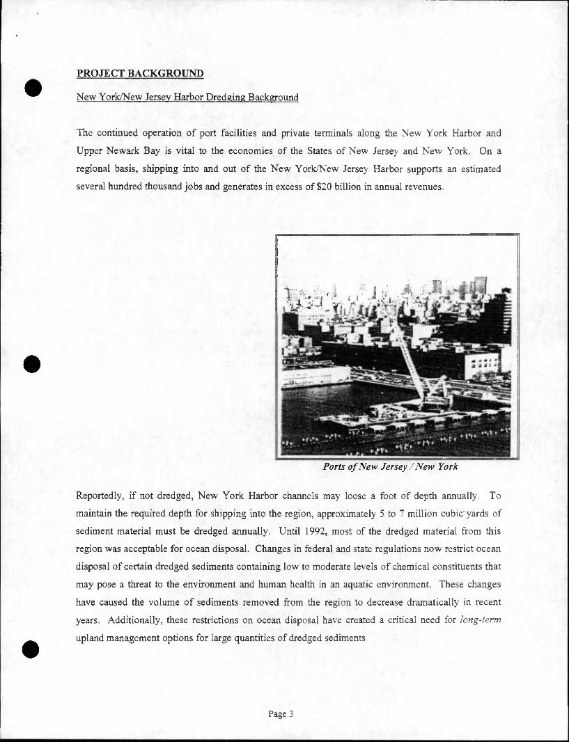
PROJECT BACKGROUND
New York/New Jersey Harbor Dredging Background
The continued operation of port facilities and private terminals along the New York Harbor and
Upper Newark Bay is vital to the economies of the States of New Jersey and New York. On a
regional basis, shipping into and out of the New York/New Jersey Harbor supports an estimated
several hundred thousand jobs and generates in excess of $20 billion in annual revenues.
Ports of New Jersey /New York
Reportedly, if not dredged. New York Harbor channels may loose a foot of depth annually. To
maintain the required depth for shipping into the region, approximately 5 to 7 million cubic'yards of
sediment material must be dredged annually. Until 1992, most of the dredged material from this
region was acceptable for ocean disposal. Changes in federal and state regulations now restrict ocean
disposal of certain dredged sediments containing low to moderate levels of chemical constituents that
may pose a threat to the environment and human health in an aquatic environment. These changes
have caused the volume of sediments removed from the region to decrease dramatically in recent
years. Additionally, these restrictions on ocean disposal have created a critical need for long-term
upland management options for large quantities of dredged sediments
Page 3

One of the most significant objectives of this pilot project is to evaluate the ability of the
manufactured fill created from the dredged sediments and additives to prevent the leaching of any
potentially hazardous chemical constituents that could be in the sediment or additives into the
environment. Prior to this pilot project, laboratory bench tests performed on manufactured structural
fill created from impacted dredged sediments have demonstrated that the pozzolanic bonding which
occurs when the manufactured fill is created mitigates the ability of chemical constituents to leach
from the manufactured fill material.
Pennsylvania Abandoned Mine Reclamation Problem
Pennsylvania is confronted with a severe environmental situation related to abandon mine lands
throughout the Commonwealth. The two major problems associated with abandoned coalmines are
acid mine drainage (AMD) and fall hazards created from strip mine "highwalls" left unreclaimed and
exposed. The PADEP has estimated that the cost to remediate water problems caused by these mine
sites is in excess of $15 billion. In addition to the abandoned sites that the Commonwealth is
responsible for, private industry and bonding companies have the responsibility to reclaim and
remediate many additional mine sites. PADEP estimates that nearly 250,000 acres in the
Commonwealth have been left unreclaimed. Many of the abandoned mines have severely degraded
the quality of surrounding surface waters and groundwater. In fact, AMD is the largest non-point
source of water pollution in the Commonwealth, tainting more than 2,500 of Pennsylvania's 54,000
miles of waterways. In addition, abandoned mines destroy the aesthetic and functional values of land
and frequently endanger public safety.
A large source of suitable fill material at a very low cost is needed to begin to reclaim the highwall
areas and provide capping and grouting material needed to permanently eliminate AMD.
Page 4

Damage Caused by Acid Mine Drainage
Consolidated Technologies. Inc. Company Profile
Consolidated Technologies, Inc. (CTI), with offices located in New Jersey, Pennsylvania and
Delaware was founded in 1995 with the mission of conducting research and development of
environmentally safe beneficial uses of dredged sediments. These efforts have provided a potential
long-term solution to the New York/New Jersey dredging and Pennsylvania abandoned mine
reclamation situations.
CTI and its business affiliates, have worked closely with the Pennsylvania State University and
independent geotechnical laboratories to develop various technologies for the manufacturing of
engineered fill materials through solidification and stabilization of dredged materials. From this
research, CTI has identified proprietary techniques for creating manufactured structural fill for the
remediation and reclamation of abandoned strip mines.
Page 5

Bark Camp Mine Facility Profile
The Bark Camp Facility consists of approximately 1,200 acres of land. The surface mine was
operated from approximately 1960 to 1988, when it was abandoned. Two underground deep mines
were also operated during the 1950s. The Bark Camp Facility is located within the Moshannon State
Forest, a Pennsylvania Department of Conservation and Natural Resources (DCNR) property. Since
the Commonwealth owns the lands, the economic burden for the reclamation and remediation of Bark
Camp has become the responsibility of the citizens of Pennsylvania.
Bark Camp Run, a stream passing through the site, is affected by AMD emanating from the
abandoned mines. The AMD has rendered Bark Camp Run acidic and sterile downstream of the
mine. Groundwater aquifers in the area, which are used as sources of potable water, are naturally
high in iron pyrite due to coal deposits. These aquifers also demonstrate acidic properties.
Bark Camp Abandoned Mine Facility
The highwall at Bark Camp consists of approximately 11,000 linear feet of exposure extending 40
feet to a ''bench" and then an additional 60 feet above the bench to a hillside. PADEP estimates that
10 to 12 million tons of material will be required to complete the reclamation of Bark Camp. For
economic reasons, these large volumes prohibit the use of ordinary materials (clean fillj to reclaim
Bark Camp.
Page 6

Bark Camp Abandoned Mine Highwall
The beneficial use of the processed dredged sediment from the Perth Amboy Marina was
demonstrated by CTI for the Commonwealth of Pennsylvania in a demonstration project for the
remediation and reclamation of the Bark Camp Surface Strip Mine (Bark Camp) located in Huston
Township, Clearfield County, PA. A part time site inspector representing Huston Township and a
full time PADEP inspector oversee the processing and placement activities at Bark Camp.
PROJECT SUMMARY
The New Jersey Office of Maritime Resources was established in part to pursue the development,
funding, implementation and operation of programs and projects which will ensure the continued
economic viability of New Jersey's commercial and recreational navigation, berthing, and mooring
facilities and other maritime assets. Of particular importance to New Jersey is dredging and dredged
materials management techniques which preserve and/or restore the environmental integrity of its
navigable waterways.
In response to Maritime Resources solicitation during early 1998, CTI submitted a Work Plan and
Cost proposal to perform the dredging, transportation, processing, and beneficial use of
approximately 35,000 cubic yards of sediment from the Perth Amboy marina.
Page 7

The project consisted of maintenance dredging of the marina and nearby ferry slip and transporting
the dredged materials to CTI's portside facility located in Elizabeth, New Jersey, on the Arthur Kill
waterway. There, the dredged materials were dewatered, off-loaded, screened to remove oversized
debris, pre-amended, and loaded into railcars for shipment to Bark Camp. The pre-amended materials
were off-loaded from the railcars at the Bark Camp rail siding and hauled in off-road trucks to the
processing pad at the mine facility The pre-amended materials were processed with additional
admixtures to create the final manufactured fill product. This fill was spread and compacted in lifts
along designated segments of the highwall. Details of the operation are presented in subsequent
sections of this report.
Dredging the Perth Amboy Marina
Dredging at the Perth Amboy Marina commenced on May 15. 1998. Processing at CTI's portside
facility in Elizabeth began several days later. The first delivery of pre-amended material arrived at
Bark Camp on May 28, 1998, and was processed and placed that same day The final manufactured
fill from Perth Amboy was placed at the mine on September 9, 1998.
The following is a brief synopsis of some of the pertinent statistics related to this project;
• Volume of sediment dredged = 19,029 cubic yards.
• Volume of oversized debris disposed = 1,600 cubic yards
• Percent of total volume of dredged material classified as oversized debris = 9%
Page 8

• Processing time (exclusive of downtime) at Elizabeth facility = 40 days
• Number of railcars containing sediment shipped to Bark Camp = 359
• Final amendment processing time at Bark Camp facility = 37 days
TECHNOLOGY REVIEW
CTI has extensive experience in creating engineered fill products and cementitious grouts from waste
materials for beneficial re-use applications. These grouts are formed by combing specific percentages
of industrial by-products including coal ash with various activators including other by-products of
industry such as cement kiln dust and lime kiln dust. CTI has applied similar technology to the
production of the manufactured fill created from a mixture of dredged material originating from the
Perth Amboy Marina, coal ash materials, and various activators.
The manufacture of cementitious grouts from ashes for large applications relies upon alkali activation
to initiate hydration reactions. Structures dating from ancient Roman and Greek cultures, many still
standing today, were constructed from this type of cementitious material. A pozzolan can be defined
as a siliceous or siliceous and alumnus material, which possesses little or no cementitious value but
will, in finely divided form and in the presence of moisture, react with calcium hydroxide at ordinary
temperatures to form compounds possessing cementitious properties.
The beneficial use of coal ash in this manner is predicated on the production of approximately 90
million tons of coal ash produced annually in the United States. Only a small percentage of this
material is currently beneficially re-used in land management applications. Approximately 20% of
the total ash produced is used as a partial replacement of cement in concrete, as construction fill, or as
roadbase. Almost one-half of the coal ash produced annually is landfilled. The manufactured fill
utilized at Bark Camp contains coal ash from several ash generators.
In proven mine reclamation applications, pozzolanic materials (coal ash) are activated by the addition
of water and alkaline activators to create a cementitious fill material. The formulation of the
manufactured fill utilized at Bark Camp using similar pozzolanic materials and activators along with
the dredged sediments, are over time, capable of achieving the desired physical and chemical
properties including strength and permeability. The high moisture content of the dredged sediments
eliminates most, if not all, of the need to add water to the mix. Additionally, the small particle size of
Page 9

the dredged sediments (70% to 90% passing #200 sieve) enhances the creation of an excellent low-
permeability roller-compacted fill.
The net result of this type of processing and beneficial use of dredged materials provides major
benefits versus traditional land disposal including the following:
• Solidification of the dredged sediments creates a material capable of being transported and
handled effectively to allow for placement in upland areas, including strip mines, without the
potential for loss of water or contaminants during transit.
• The Stabilization aspect of the process minimizes the potential for leaching of contaminants
from the materials, and creates a fill product with geotechnical properties which actually facilitate
remediation of AMD from former mine sites.
• The manufactured fill created from the dredged sediments is capable of being placed as structural
fill in areas of former strip mines in need of reclamation and capping. Because of the large
number of mine sites in Pennsylvania requiring reclamation, there is virtually no limit to the
amount of sediments which can be dredged from the Estuary and accepted for the beneficial use
of mine reclamation and remediation. This provides the Ports of New York and New Jersey with
a long term effective solution to its dredging dilemma, as well as providing a solution to
Pennsylvania's mine reclamation dilemma
PERMITTING
This pilot project was conducted pursuant to all local, state, and federal regulations applicable to the
dredging, processing, transport, and beneficial use of the dredged sediments and additives. Certain
permits were required for each location and/or operation of the project. A summary of the permits
issued for each facility and/or operation is presented below.
Citv Of Perth Ambov Municipal Marina
• USAGE Dredging permit initially issued October 1995, re-issued March 1998.
• NJDEP Waterfront Development/Water Quality Discharge permit initially issued April 1993, re-
issued April 1998.
Page 10
• Sampling and Analysis Plan (SAP) for the in-situ sediment from the Perth Amboy Marina
submitted by CTI to the PADEP and the NJDEP for review and approval. Supplemental SAP
submitted to PADEP on March 9, 1998. SAP approved March 13, 1998.
CTI Portside Facility in Elizabeth. New Jersey
• NJDEP Waterfront Development Permit issued January 1998.
As part of the permitting process for this facility, CTI prepared and submitted various site specific
environmental protection plans. The plans included a Health and Safety Plan and a Spill-
Prevention and Contingency Plan.
• NJDEP Air Quality Regulation Program issued a permit to Construct, Install or Alter Control
Apparatus or Equipment and Certificate to Operate to CTI for the erection and operation of an
additives storage silo at the Elizabeth facility issued April 1998.
• NJDEP Acceptable Use Determination (AUD) for the dredged material from the Perth Amboy
Marina issued May 1, 1998.
• NJDEP Beneficial Use Determination (BUD) to utilize coal ash in the manufactured fill issued
May 6, 1998
CTI Bark Camp Facility in Huston Township. Pennsylvania
• PADEP Amended Beneficial Use Order No. 40030 to CTI and its affiliates for the beneficial re-
use of stabilized dredged materials at Bark Camp mine facility, Clearfield County, PA. Order
issued June 1997.
Note: As part of the permitting process for Bark Camp, CTI prepared and submitted various site
specific environmental protection plans for PADEP review and approval. These plans included a
Health and Safety Plan, a Ground and Surface Water Monitoring Plan, a Spill- Prevention and
Contingency Plan, a Soil Erosion and Sedimentation Pollution Control Plan, and a Facility
Operating Plan. Each plan was approved by the PADEP and has been fully implemented. A
National Pollution Discharge Elimination System (NPDES) permit was also issued to CTI for the
Bark Camp facility.
• PADEP General Construction NPDES permit issued January 1998.
• PADEP issued a final approval for the use of the Perth Amboy Marina dredge material at the
Bark Camp Mine Facility. The approval was issued April 13, 1998 in accordance with PADEP
Amended Beneficial Use Order No. 40030.
Page 11
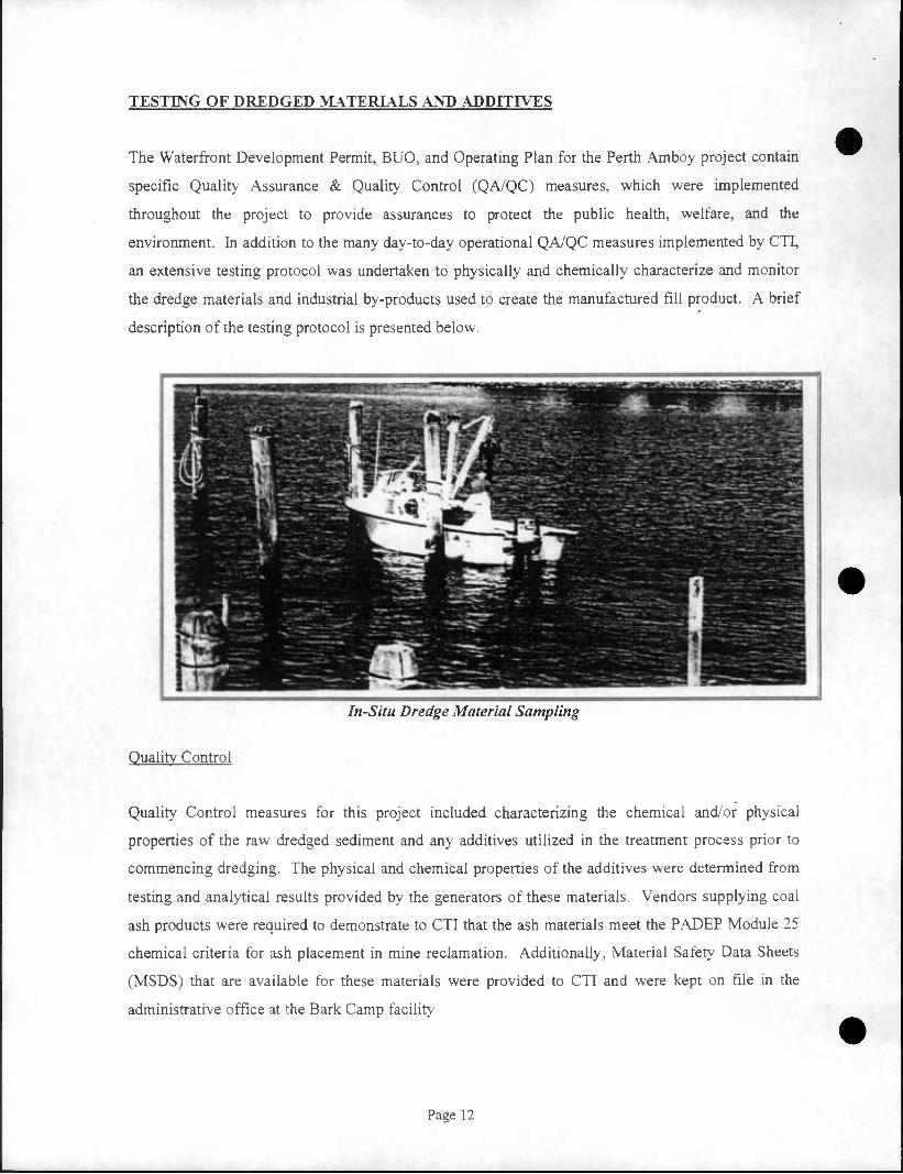
TESTING OF DREDGED MATERIALS AND ADDITIVES
The Waterfront Development Permit, BUO, and Operating Plan for the Perth Amboy project contain
specific Quality Assurance & Quality Control (QA/QC) measures, which were implemented
throughout the project to provide assurances to protect the public health, welfare, and the
environment. In addition to the many day-to-day operational QA/QC measures implemented by CTI,
an extensive testing protocol was undertaken to physically and chemically characterize and monitor
the dredge materials and industrial by-products used to create the manufactured fill product. A brief
description of the testing protocol is presented below.
In-Situ Dredge Material Sampling
Quality Control
Quality Control measures for this project included characterizing the chemical and/or physical
properties of the raw dredged sediment and any additives utilized in the treatment process prior to
commencing dredging. The physical and chemical properties of the additives were determined from
testing and analytical results provided by the generators of these materials. Vendors supplying coal
ash products were required to demonstrate to CTI that the ash materials meet the PADEP Module 25
chemical criteria for ash placement in mine reclamation. Additionally, Material Safety Data Sheets
(MSDS) that are available for these materials were provided to CTI and were kept on file in the
administrative office at the Bark Camp facility.
Page 12

The chemical analyses protocol for the dredged sediment intended for Bark Camp consists of three
stages. Theses include the core sampling and analyses of in situ dredged material samples (Stage I);
the sampling and analysis of the dredge material at the portside offloading facility, which is intended
to confirm that the material being shipped is similar to the in situ materials (Stage II); and the
sampling and analysis of the treated materials at the Bark Camp facility to assure that the
manufactured materials comply with the criteria established in the BUO (Stage III).
The sampling and analysis for the Perth Amboy Pilot Project was conducted in accordance with the
requirements of the BUO and the New Jersey Department of Environmental Protection (NJDEP)
guidance manual entitled The Management and Regulation of Dredging Activities and Dredged
Material in New Jersey's Tidal Waters: October, 1997. The New Jersey manual (hereinafter referred
to as the "Guidance Document") specifies sampling and analytical requirements for upland disposal
and beneficial re-use of dredged materials in the State of New Jersey. The manual specifies sampling
procedures and frequency requirements, target analyte lists, analytical test methods to be used, and
acceptable method detection limits for in-situ sediment samples.
A Sampling and Analysis Plan (SAP) for the in situ sediment was prepared for this project and was
submitted for the NJDEP and PADEP's review and approval. Nineteen (19) individual core samples
of the in situ sediment were taken to the proposed project depth plus allowable over-dredge. Five (5)
composite samples were prepared from the individual core samples. The individual core and
composite samples were subjected to the analysis specified in the Guidance Document and the
approved SAP.
Bench tests utilizing the sediment from the in-situ testing and various percentages of CTI's
proprietary additives were performed to simulate the creation of the manufactured fill. The bench test
product samples were analyzed in order to chemically and physically characterize the manufactured
fill and to determine the ability of the fill from each mix design tested to stabilize chemical
constituents found in the in-situ Perth Amboy sediment.
The analytical and test results for the Stage I in-situ sediment samples were submitted to the NJDEP
and PADEP for their respective review and approval. Subsequently, on April 17, 1998 the NJDEP
issued a Waterfront Development Permit permitting the City of Perth Amboy to dredge the marina,
and on May 21, 1998, the PADEP issued a written approval for use of the dredged materials from the
Perth Amboy marina at Bark Camp. Copies of the Waterfront Development Permit and the PADEP
approval letters are presented in Appendix A.
Page 13

Quality Assurance
Quality Assurance measures (Stages 11 and III) for this project were implemented to confirm that the
chemical and/or physical properties of the pre-amended dredged material transported to Bark Camp
and the manufactured fill were similar to that of the in situ sediment sample properties.
Stage II testing occurred at the CTI portside facility in Elizabeth, and was performed to confirm that
the pre-amended dredged material was physically and chemically characteristic of the material
sampled in Stage I. This confirmatory sampling was performed pursuant to the BUO, at a frequency
of one composite per 25,000 cubic yards of dredged material. Accordingly, one (1) composite sample
was chemically analyzed and geotechnically tested pursuant to the requirements specified in the
BUO. The analytical and test results were reported to the PADEP for its review and information.
The final stage (Stage III) of the QA process was performed after the final amendment of the dredged
sediment at the Bark Camp facility. One (1) composite sample of the manufactured fill was obtained
pursuant to the BUO requirement of one composite sample per every 25,000 cubic yards of material.
The composite sample was chemically analyzed and geotechnically tested pursuant to the specific
requirements specified in the BUO for the manufactured fill. The analytical and test results were
reported to the PADEP for its review and information.
Laboratory Analysis & Testing of Dredge Materials
A tabular summary (Tables 1 through 8) of the analytical results for the in situ sediment samples, the
pre-amended (portside) dredge material, and the manufactured fill placed at the Bark Camp facility
are presented in Appendix B. A copy of the geotechnical test results of the manufactured fill sample
Page 14
is also presented in Appendix B as Table 9. These data demonstrate that the technology producing
the manufactured fill derived from the Perth Amboy marina dredged material has effectively
stabilized the chemical constituents present in the in-situ dredge material, and that the manufactured
fill is physically competent as an engineered fill material suitable for use in mine reclamation.
DESCRIPTION OF PROJECT OPERATIONS
On March 24, 1998, Ocean and Coastal Consultants (O&CC) performed a pre-dredge survey of the
Perth Amboy Marina and issued a volumetric estimate, based on the design grades and elevations for
the marina, indicating a total volume of 20,932 cubic yards of sediment to be dredged from the Perth
Amboy Marina.
CTI's subcontractor, Jay Cashman, Inc. (JCI) commenced dredging at the Perth Amboy Marina on
May 15, 1998. The dredging was performed utilizing a dredge-plant mounted on a spud-barge and
equipped with various types of clamshell buckets, and two hopper barges. JCI utilized a local tug
service to transport the hopper barges to and from CTI's Elizabeth transfer facility.
Off-loading of the dredged material at the Elizabeth facility was accomplished utilizing a 50-ton
crane equipped with a clamshell bucket. As necessary, the loaded barges were moored at the
Elizabeth facility to allow the sediment to settle for dewatering of the barges prior to off-loading.
Water decanted from the loaded barges was pumped through a particulate filter to portable frac-tanks.
After an adequate period of settling, the water in the tanks was tested for compliance with discharge
criteria contained in the Water Quality Certificate. Upon confirmation, the decanted water was
discharged from the tanks to the Arthur Kill waterway.
Page 15

Off-loading Hopper Barges at CTI Portside Facility, Elizabeth, NJ
The raw dredged material was off-loaded into a large receiving hopper and through a series of screens
to separate debris from the sediment. The debris was staged for transport and disposal at an alternate
approved disposal facility. The dredged material was placed into a pugmill where it was mixed with
coal fly ash to pre-amend (physically stabilize) the material for transport to Bark Camp. The raw
material was solidified to ensure that no free liquids were present in the material. From the pugmill,
the pre-amended material was discharged via a radial-stacking conveyor to a temporary storage area.
The material was loaded from the stockpile into gondola rail cars for transport to the Bark Camp
Facility. Off-loading and processing of the dredged sediment at CTI's Elizabeth facility was
completed on July 31, 1998
Due to its lack of suitability as a component of the manufactured fill material, the oversized debris
recovered from the dredged materials at the Elizabeth facility was transported to and disposed of at an
appropriate permitted disposal facility. This debris included pilings, timbers, large metal objects,
concrete, and similar unsuitable materials.
Page 16

Pre-Amendment Processing at CTI's Portside Facility, Elizabeth, NJ
The pre-amended dredge material was transported to the Bark Camp facility by Conrail and a short
line rail road, the Pittsburgh & Shawmut R.R.. All rail cars were covered with tarps during transport.
The railcars were unloaded at Bark Camp utilizing an excavator located on an elevated off-loading
structure. The material was placed directly into off-road trucks and transferred to the final processing
area. There the material was blended with additives in a pugmill system according to a pre-
determined mix design, and discharged onto a radial stacking conveyor. The final manufactured fill
was transported utilizing off-road trucks to the reclamation area of the highwall. The fill was spread
in two-foot thick lifts with a low-ground-pressure bulldozer and compacted using a vibratory roller.
Final processing and placement of the Perth Amboy material at the Bark Camp facility was completed
on September 9, 1998.
Page 17

Railcar Off-loading Facilities at Bark Camp Mine
On August 3, 1998, O&CC performed a post-dredge survey of the marina and issued a final volume
determination for the project. A total of 19,029 cubic yards of material was dredged from the Perth
Amboy Marina during this pilot project. O&CC's estimate was based upon the volumetric difference
of pre- and post-dredge surveys of the marina.
As discussed earlier, CTI and PADEP performed geotechnical and chemical testing of the
manufactured fill material created from dredged sediment. Laboratory bench tests and tests of the
actual manufactured fill produced from the Perth Amboy pilot project have yielded extremely positive
results, demonstrating the effectiveness of the manufactured fill for the remediation and reclamation
of abandoned coal mines.
Page 18

CONCLUSIONS
The following conclusions can be made with the completion of the City of Perth Amboy Marina pilot
dredging and beneficial use project:
Approximately 19,000 cubic yards of material was dredged and removed from the marina. With this
volume of material removed, all required areas have been successfully dredged to the design criteria.
The volume of material dredged and removed is approximately 45% less than the initial estimated
volume of material required to be dredged (35,000 cubic yards') due to changes in the marina design.
Approximately 9% or 1,600 cubic yards of the material dredged and removed from the marina was
oversized debris not suitable as a component of the recyclable fill used for reclamation of the Bark
Camp mine. The oversized debris was transported to and disposed of at a permitted landfill. The
oversize debris created delays in the portside off-loading and pre-amendment processing of the
dredged material. The debris was determined to be a result of past demolition and dumping practices
and is not considered typical of a maintenance dredging project.
By adding and mixing the dredged material with specific quantities and sources of coal ash, the
dredge material was successfully pre-amended at the portside facility, rendering a material that could
be handled and transported by common earth handling techniques and equipment. The material was
solidified to remove free liquid. The processing techniques implemented and equipment utilized at
the portside facility were modified throughout the duration of the project to provide the most cost-
effective and efficient process.
Approximately 25,000 cubic yards of pre-amended dredge material was transported by rail in tarped
gondola railcars. Three hundred and fifty-nine loaded railcars were shipped to Bark Camp. All
arriving railcars were successfully off-loaded at the Bark Camp rail siding with little need to modify
the equipment or techniques planned for this aspect of the project. As with the portside pre-
amendment operations, the processing techniques implemented and equipment utilized at the Bark
Camp Facility were modified throughout the duration of the project to provide the most cost-effective
and efficient process.
Laboratory chemical analyses and geotechnical test results indicate that the processes creating the
recyclable fill manufactured at Bark Camp have successfully solidified and chemically stabilized the
dredge material removed from the Perth Amboy marina. The long-term ability of the manufactured
Page 19

fill to sustain these properties will be monitored via visual observations and groundwater & surface
water quality monitoring at the Bark Camp facility by CTI and PADEP.
As demonstrated by the impacts to the operational budget throughout this project due to the
unexpected reduction of volume of material dredged from the Perth Amboy marina, scales of
economy can be realized when this technology is applied to a large-scale project.
The Perth Amboy Marina pilot project has demonstrated that dredge materials can successfully be
beneficially used for upland placement in coal mine reclamation and remediation projects.
1 35,000 cubic yard estimate based upon NJDEP and USAGE permit application documents prepared for and submitted by the City of Perth Amboy.
Off-loading Railcars at Bark Camp Mine
Pa?e 20

CTI Final Processing Facility at Bark Camp Mine
Processing Manufactured Fill from Dredge Material at Bark Camp
Page 21

Processing Manufactured Fill from Dredge Material at Bark Camp
Manufactured Fill Being Placed at Bark Camp
Page 22

Manufactured Fill Being Placed at Bark Camp
* V '
•^-,^7? "^1 "Ijjpi IMlIiLH^^*^^^;. . »,
JL -^^dP^^^^^———^•"_ - _»'~JW ' '^t~ "*' • ,'v—?^5!aifcL-i^ '•'""'•iiiK- SKasa-,-"-
• :-:•••' ;-.. - : ^^V^-i^i^v^r^ kMaH.^—MHBM^^-MMMB^M^MM
Manufactured Fill Being Placed at Bark Camp
Page 23

Manufactured Fill Being Placed at Bark Camp
Manufactured Fill Being Placed at Bark Camp
\1997mam\Projects\7301\Reports\Perth AmboyCOAST-Perth Amboy Summary Report (10-06-98) doc
Page 24

APPENDIX A
REGULATORY CORRESPONDENCE

.IFF. 17 '$8 G7:4S F= L^ND USE RE3J-fiTlCNl 629 777 3C5Q TQ 9l732442f22^ F.02/94
STATE OF NEW JERSEY
DEPARTMEI^T OF ENVIRONMENTAL PROTECTION
(See Issuing Division below)
PERMIT* The New Jersey Department of Environmental Protection grants this permit in accordance with your application, attachments accompanying same application, and applicable laws and regulations. This permit is also subject to the further conditions and stxpulaaons enumenued in the supporting documents which are agreed to by the permiitee upon acceptance of the permit. Pemit INO7
1216-92-0003.6 Application No. 1216-92-0003.6
issuance Due JRHT^ £5ecuve Due APR 1 7,00 Expiri&on Date
Nine and Addreu of Applicant
City of Perth Aaboy 260*High Street Perth Amboy, NJ 088 61
Name and Addrtsa of Owner
Seme as applicant
Eastern End-Smith St.' Perth Anboy, NJ
S«« Below See Below •_ot Block
^'l^TOe Regulation Program
Type of Permit Waterrront Development Water Quality Certificate
APR n afl Name and Addre« of Opcraior
Same as applicant
Sutu:e<*rjSA 12:5-3 NJSX 56:10A-1
Mixixnum Approved Capacity. if applicable
N/A
This P« T^f^oSntaain^enance dredging of approximately 35,000 cubic yards of
accumulated material to restore the marina to a depth of 10ft + 2ft overdredge. The dredging will be performed using a closed clamshell bucket with placement of the dredged material in one of three work scows for dewatering and transport to the processing facility. The material will be off-loaded and pre-amenced at the Construction £ Marine Equipment Co. (CMZC) , Inc. facility, located in Elizabeth, New Jersey, p'ricr to transport for reuse at the Bark Camp Mine Site in Fenfield, Huston Township, Pennsylvania.
The applicant proposes to replace approximately 315 linear feet of existing bulkhead and construct approximately 235 linear feet of stone rip- rap embankment for shore stabilization. Soat ramps and floating docks will be_constructed to provide for 83 permanent boat slips and eight "transient slips. The marina is to be constructed according to the plans consisting of six sheets titled "Waterfront-Marina Development for the City of Perth Aaboy, New Jer3ey"prepared by James R. Guerra, P.A. dated June 1995. The sheets titled "Marina Plan-Fishing rier" and "Overall Marina Plan" were last revised August 8, 1995 and September 6, 1995, respectively.
The project is located at: Block 135, Lot 1 and 1.01 Block 52, Lots 2.01 throuch 7.01
/y/ Bl^ck.51, Lot 5.01
Prepared by: C^^C ^ ^z^^^, Vr>.."2£/^oJ^)
Revised Date
Suzanne. U. ^Jfietri cJc Page 1 of 3
Approved by the Depanmem of Environmental Protecaon
Name (Print or Type) Title _
Signature . Qaic
•»—rr n^nrnx'/i, i certifi* Tr^ft rmtt*

rFR 17 •?£ 07:4c fn IPHOJjSt KEGLA.ST1CN1 cO* 777 3c56 TO 31712^23274 P.Q3/Q4
Perth. Aaboy Marina Paae 2 File No. 1216-S2-0003.6 f *•
This permit is approved subject to, and in accordance with, • all applicable Tidelands Grants issued for the Perth-Amboy Marina site. The site is 'located on tidelands maps 609-2112, 602-2106 and 602-2112. Issuance of this pemit dees not in any- way relinquish the State's ownership interest in the property, if anyexists.
This permit is authorized,under and in compliance with the Rules of Coastal Zone Management governing Maintenance Dredging (7:7E-4;2(f)); Dredge Material Disposal (N.J.A.C. 7:7E-4.2(h)); Marina Develocment (N.J.A.C. 7;7I-7.3A); Water Quality (N.J.A.C. 7:7E-8.4).
This permit is'issued subject to and provided that the following conditions can be met to the satisfaction of the Land Use Regulation Program. All conditions must be met prior to construction unless otherwise specified. -Ccmpliance with Administrative conditions shall be determined once copies of all specified permits, certifications, plans, agreements, etc. have been received, not less than 30 davs prior to construction, and approved by the Land Use Regulation Program. All Physical Conditions are subject to on-site compliance inspection by the Bureau of Coastal and Land Use Enforcement. As per N.J.A.C. 7:7-1.4, you must notify the Bureau of Coastal and Land Use Enforcement, (? 0 Box 422,.Trenton, New Jersey 08625), in writing at least 3 days prior to commencement of construction or site preparation.
This permit shall be PZCORDED in the office cf the County Clerk (the REGISTRAR OF DEEDS AND MORTGAGES in the applicable counties) in the county wherein the lands included in the permit are located within ten (10) days after the receipt of the permit by the applicant and verified notice shall be forwarded to the Land Use Regula'tion Program immediately thereafter.
This permit is NOT VALID until the permit acceptance . form has been signed by the applicant, accepting and agreeing to adhere to all permit conditions, and returned to the Land Use Reculation Program at CN 401, Trenton, New- Jersey 0 8 625.
•
Administrative Conditions:
1. The permittee shall allow an authorized representative of the • Department the eight to insoecr construction .pursuant to N.J.A.C. 7:7E-1.5. .
2. The permittee shall obtain all appropriate local, state, and federal aoorovals.

:c ©?:.:« r= LAND USE RSuULfiTIOHl cO? 77? 3c36 TO 517324425*74 F.Q^sQ-
Perth Arnboy Marina • . ' Page 3 File No. 1216-92-0003.6
Physical Conditions
1. Bulkhead repair and/or replacsmenc shall be no further than 18 inches outshore of existing structures.
2. The permittee shall utilize silt curtains to miniinize the release of sediments to the Arthur Kill, if, this management practice is ' infeasible, dredging shall be prohibited from April 1 to June 30
•in order to protect the migratory'fishery resource;
3. Efforts shall be made to maximize the size of the "bite" of the closed clamshell bucket.
4. A minimum of 18 inches of freeboard shall be maintained in all scows in .order to maintain a "No Barge Overflow".
5.. The discharge of return water from the dewatering/settling barge at the Ccnszructicn & Marine Equipment .Company, Inc (CMSC)' processing facility, shall meet a total suspended solids (TSS) action level of.'30 mg/l. TSS shall be determined through gravimetric analysis. No discharge from the dewatering/settling barge shall be permitted until the results of the gravimetric analysis confirm that the TSS action level'will be met: Additional decant shall not be added to the dewatering/settling barge between the time of sampling for TSS and the termination'of the discharge for whichthe analysis has been performed. The permittee shall utilize a hydrometer, nephelcmeter or other instrument accepted by the Department to" measure the TSS levels during the actual discharge to the Arthur Kill to determine possible exceedances of the 30 mg/l TSS action level. If at any time during the discharge, an exceedance of the TSS levels is indicated, the permittee shall immediately cease the discharge of return water until such time as the return water can meet the TSS action level. All return water:shall be discharged in a" manner so as to minimize, the resuspension of bottom sediments in the Arthur Kill. - •
€. One portable sewage pump out station and two fixed sewage pump ssel owners rouch October) each
out stations shall be available for use by vessel owne: throughout the boating season (i.e., April throuci year
Approved by:
:at:fe ' Robert B Jr.,

Pennsylvania Department of Environmental Protection
P.O. Box 669 Knox,PA 16232-0669
May 21,1998 Bureau of Abandoned Mine Reclamation 814-797-1191
Mr. Craig R. Schantz Consolidated Technolosies, Inc. 2230 DeKalb Street Suite 200 Norristown, PA 19401
Re: Bark Camp Demonstration Project Huston Township, Clearfield County
Dear Mr. Schantz:
I am writing to advise you that the last revisions to your Operating Plan, submitted on May 13, have been received and are in accordance with our discussions which occurred May 11 in Williamsport. The Operating Plan for the Bark Camp project is acceptable to the Depanment and may be considered to be approved. With this approval, CTI has fulfilled the requirements of the amended Beneficial Use Order relating to the quality and handling of the dredge material and admixtures.
Further, CTr has fulfilled the requirements of the Depanment in terms of preparing and upgrading the Bark Camp site including the rail siding, staging area, haul roads, and areas to be backfilled. Likewise, CTI has received a permit for expanded erosion and sedimentation facilities, and has properly implemented same.
Given that these requirements have been met, the Department hereby gives approval to CTI to transport dredge material from the marina at Perth Amboy, New Jersey, into the Commonwealth of Pennsylvania for use at the Bark Camp Demonstration project in accordance with the amended Beneficial Use Order, dated June 6, 1997, the contract between the Depanment and CTI, dated November 25, 1997, and the approved Operating Plan.
If you have any questions, please contact me immediately.
Sincerely,
J. Paul Linnan Chief Division of Field Operations
cc: Huston Township Environmental Comminee Ernie Giovannitti Richard Bittle John Hamilton
An Ecml OpPortun.iY Ammunve Aqion -mpiover hi;3; vv^vdep^cate.^.-jj Pnmec an ^r'^ P33P> "I'lZ

.'niHylvjnij Doparimoni of hnvironmpnfjl Prnioction
OlTice of Mineral Resources Mantgcmcnt
Rachel Canon State Office Building P.O. Box 2063
Hurmburjj, PA 17105-2063 July 15. I<WX
717-783-5338
Ms. Beverly Fedarko Special Assistant to tlic Commissioner New Jersey Dcparmient of Environmental Proiecuon P.O. Box 401 •Trenton. NJ 08625
Dear Beverly
This is a follow-up to our July 3 telephone call regarding the Pennsylvania Deparonent of Envtronmcntal Prciccrion'j Hark Camp Mine Reclamation Laboratory located near PenfieUl in CIcarfieid County. W« arc etlCOuraged by the progress of Consolidated Tcclmolog.cs, Inc. at the lite of the mine reclamation prujee: utiluing the river silt and fly ash mixture as a maimfacmrcd structural fill
The Department's Mining and Rcdamatiun Advisoiy Board (MRAB) held its summer quarterly meeting on July 9 and 10 m DuBo.s. CIcarfieid County The MRAB is a legislntivelv mandated council purposely created with a bruad and diverse membcrsiup including citizens, environmental advocates members of the Legtsiamrc and the private sector. The Board ix charged with advising DEI' on mining and reclamation
• matters
DuBois was selected by the Board as their meeting location, with the intent of visiting the nvcr sill and fly ash project ut Baxk Camp The reaction from the MRAB was overwhelminglv suppomve. The members were impressed wuh die improvements at die site since dieir viait last year We could not have been more pleased with the Board's endorsement. They were also very encouraged with die local support for the reclamation project inciuding die degree of local involvement via the Huston Township Supervisors and their environmental committee.
Tlic Department remains committed to this benefieial use of river silt and flv ash mine reclamation demonstration effort at Bark Camp. We also appreciate the New Jersey Department of EnvironmenDl Protection's continued cooperation and support for the project. Allow me to reiterate my previous invitation for you and Commissioner Shmn to visit the Bark Camp site. Please give me a call to arrange a visft or if you have anything you would like to discuss further.
Sincerely.
y^- Robert C. Dolence Deputy Secretary for Mineral Resources Management
ce: Secretary James M Seif Fred Wolf. Chairperson MRAB
iHu.ii ( •npnn-jn.iv AftiM",ilivM A« Mim 1 fji

APPENDIX B
ANALYTICAL & GEOTECHNICAL RESULTS

September 1998 TABLE 1 Analytical Results
Inorganic Compounds Summary Report
Perth Amboy Municipal Marina
97-301-19
Parameter In Situ Bulk Sediment In Situ Bulk Sediment 4 ^ ;^a»r>v Stabilized Sediment** Leachate Regulatory Level* Reach A- Reach B Reach C Reach A Reach B Reach C .
. •• - - 'v-'-'-T • (Total) ' {Total) f (Total) (TCLP) '(TClP)\h ^(TCLP)^ •Port (total) Port(TCLP) Mine (SPLP)
Imorganics Compounds (mg/kg) (mg/kg) (mg/kg) (mg/L) (mg/L) (mg/L) (mg/kg) (mg/L) (mg/L) (mg/L)
Antimony 11.8 11.2 24 NA NA NA NA NA NA None
Arsenic 41 135 56 ND ND ND 72 ND NA 5.0
100 49 130 ND ND ND 180 ND NA 100.0
Beryllium 1.53 1.28 1.63 NA NA NA 1.1 NA NA None
Cadmium ND ND ND ND ND ND 2 ND NA 1.0
Chromium
Copper
84
310
29
59
92
240
ND
NA
ND
NA
ND
NA
99 ND
NA
NA
0.2
5.0
280 None
Lead 350 120 240 ND ND ND 220 ND NA 5.0
Manganese 330 490 420 NA NA NA 300 NA NA None
Mercury 2.7 0.59 281 ND ND ND 4.1 ND NA 02
Nickel 35
1.2
22
ND
34
1.6
NA
ND
NA
ND
NA
ND
31
3.3
NA
ND
0.089
NA
None
1.0 Selenium
Silver ND ND ND ND ND ND 42 ND NA 5.0
Thallium ND ND ND NA NA NA NA NA NA None
Vanadium 61 45 66 NA NA NA 76 NA NA None
Zinc 370 110 260 NA NA NA 330 NA 0029 None
Total Cyanide 046 032 11 NA NA NA NA NA NA None
NA = Not Analyzed
ND = Not Detected
* 25 Pa. Code, Section 261.24, Maximum Concentration of Contaminants For The Toxicity Characteristic
" Stabilized sediment sampled from railcars at Elizabeth NJ port facility (pre-amended) and from final manufactured fill at Bark Camp facility (mine)
Puilh ^^ .alylical Results (25,OOOyclH09 09 98)Table 1

September 1998 TABLE 2 Analytical Results
Volatile Organic Componds Summary Report
Perth Amboy Municipal Marina
97-301-19
Parameter , i In Situ Bulk Sediment i ;.>_ Stabilized Sediment" Leachate Regulatory Level' Reach A i Reach B -.Reach C
(TCLP)' ^(TCLP) :• >;(tCLP)'; Port (TCLP) Mine (SPLP)
Volatile Organic Compounds (mg/L) (mg/L) (mg/L) (mg/L) (mg/L) (mg/L)
Benzene ND
13
ND
ND
ND
ND
19
ND
ND
ND
ND
23
ND
ND
ND
ND
ND
ND
ND
ND
ND
ND
0.5
2000 2-Butanone
Carbon Telrachloride
Chlorobenzene
Chloroform
ND 0.5
ND
ND
100 0
6.0
1,2-Dichloroethane ND ND ND ND ND 0.5
1,1-Dlchloroelhene ND ND ND ND ND 0.7
Tetrachloroethene ND ND ND ND ND 0.7
Trlchloroethene ND ND ND ND ND 0.5
Vinyl Chloride ND ND ND ND ND 02
NA=Nol Analyzed
ND=Nal Delected
• 25 Pa Code, Section 261 24, Maximum Concentration ot Contaminants For The Toxicily Characteristic
" Stabilized sediment sampled from railcars al Elizabeth NJ port facility (pre-amended) and from final manufactured fill al Bark Camp facility (mine)
Perth Amboy Analytical Results (25 000yd)(09-09 98)Table 2 1 Of 1
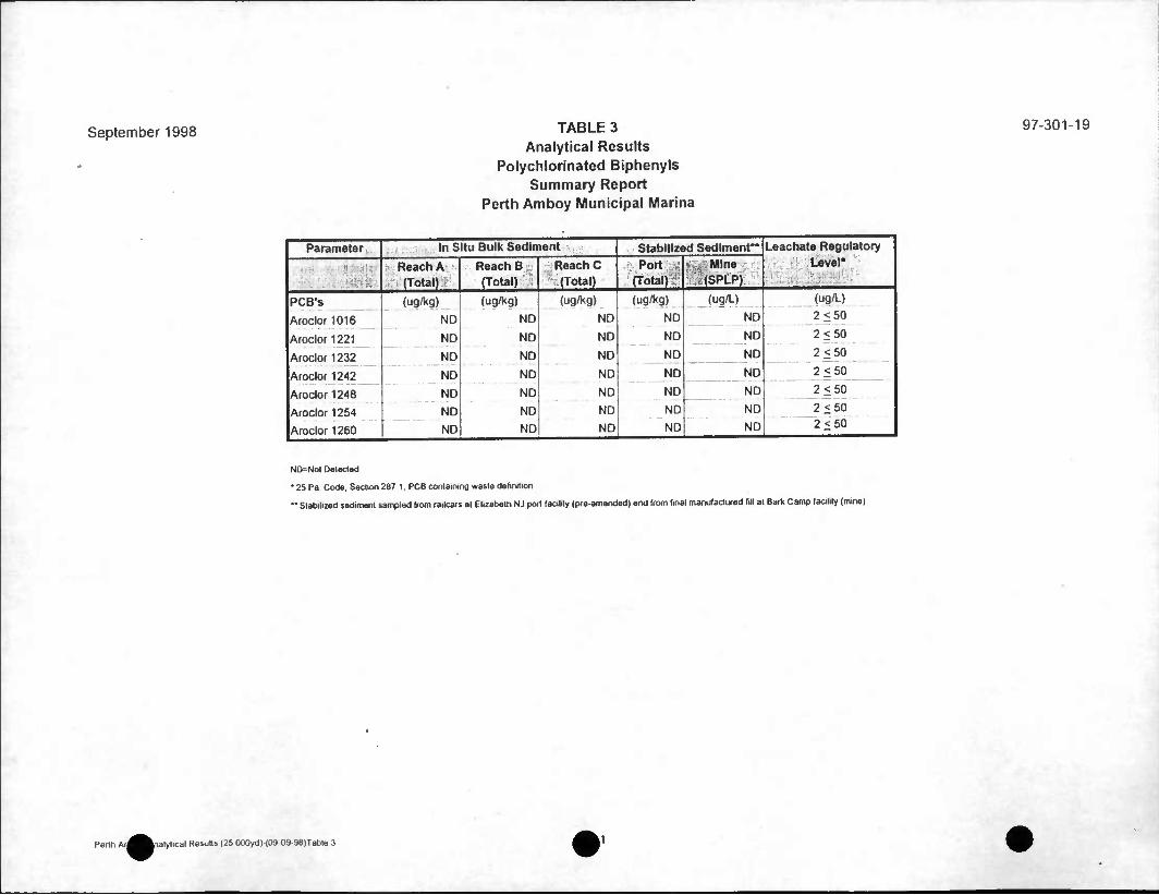
September 1998 TABLE 3 Analytical Results
Polychlorinated Biphenyls Summary Report
Perth Amboy Municipal Marina
97-301-19
Parameter In Situ Bulk Sediment Stabilized Sediment** Leachate Regulatory Level* Reach A Reach B ReachC ; Port ; - ,; Mine
• (Total) (Total) (Total) (Total): ^(SPtP)
PCB's (ug/kg) (ug/kg) (ug/kg) (ug/kg) (ug/L) (ug/L)
Aroclor 1016 ND ND ND ND ND 2<50
Aroclor1221 ND ND ND ND ND 2<50
Aroclor 1232 ND ND ND ND ND 2<50
Aroclor 1242 ND ND ND ND ND 2<50
Aroclor 1248 ND ND ND ND ND 2<50
Aroclor 1254 ND ND ND ND ND 2<50
Aroclor 1260 ND ND ND ND ND 2<50
NO=Nol Detected
• 25 Pa Code, Section 287 1. PCB containing waste definition
" Stabilized sediment sampled from railcars at Elizabeth NJ port (acilily (pfe-amended) and (fom final manutactufed fill at Bark Camp facility (mine)
Perth Ai^^Lialytical Results (25 OOQyd) (09 09 9a)Table 3

September 1998 TABLE 4 Analytical Results
Pesticides and Herbicides Summary Report
Perth Amboy Municipal Marina
97-301-19
Parameter In Situ Bulk Sediment Stabilized Sediment" Leachate Regulatory Level* Reach A
(Total) Reach B (Total)
Reach C (Total)
Port (Total) Port
(TCLP) Mine (SPLP)
Pesticides/Herbicides (ug/kg) (ug/kg) (ug/kg) (ug/kg) (ug/L) (ug/L) (ug/L)
Aldrin ND ND ND ND NA NA None
alpha-BHC ND ND ND ND NA NA None
beta-BHC
delta-BHC
gamma-BHC (Lindane)
ND
ND
ND
ND
ND
ND
ND
ND
ND
ND
ND
ND
NA
NA
ND
NA None
NA None
NA 04
gamma-Chlordane ND ND ND NA ND NA 0.03
alpha-Chlordane
4,4-DDD _
4,4-DDE
4,4-DDT
ND
ND
14
16
ND
ND
ND
ND
ND
ND __"
11
ND
NA
ND
ND
ND
ND
NA
NA
NA
NA 0.03
NA None
NA
NA
None
None
Dieldrln ND ND ND ND NA NA None
Endosulfan I
Endosulfan II
ND
ND
ND
ND
ND
ND
ND
ND
NA
NA
NA None
NA None
Ensulfan sulfate ND ND ND ND NA NA None
Endrln ND ND ND ND ND NA 0.02
Endrin aldehyde ND ND ND ND NA NA None
Endrln ketone ND ND ND NA NA NA None
Heptachlor ND ND ND ND ND NA 0.008
Hepfachlor epoxide ND ND ND ND ND NA 0008
Methoxychlor ND ND ND ND ND NA 100
Toxaphene ND ND ND ND ND NA 05
2,4-D ND ND ND ND ND NA 10.0
2,4,5-TP (Silvex) ND ND ND ND ND NA 10
NA^Nol Analyzed i
ND=Nol Delected
• 25 Pa Code. Section 261 24. MaKimum Concanlralton o( Conlaminanls Fof The Toxicily Charactenslic
" Stabilized sedimenl sampled (rom tailcais at ElizaOelh NJ port (acilily (preamended) and (rom linal manufactured Ml al Bark Camp facility (mine)
Penh Amboy Analytical Results (25 000yd)-(09.09 98)Table 4 1 Of 1

September 1998 TABLE 5 Analytical Results
Semi-Volatile Organic Compounds Summary Report
Perth Amboy Municipal Marina
97-301-19
Parameter In Situ Bulk Sediment Stabilized Sediment** Leachate Regulatory Level* Reach A Reach B Reach C
Port (Total) PortfTCLP) Mine (SPLP) (Total) (Total) (Total)
Semi-Volatile Organic Compounds (ug/kg) (ug/kg) (ug/kg) (ug/kg) (mg/L) (mg/L) (mg/L)
Acenaphthene ND ND NO ND NA ND None
Acenaphthylene ND NO ND NO NA NO None
Aniline
Anthracene
ND
ND
ND
ND
ND
ND
ND
NO
NO
NO
NO
ND
ND
NO
NO
NO
ND
ND
NO
ND
ND
1000
ND
NO
ND
NA NA None
None
None
None
None
None
None
NA
NA
NO
NA Benzidine
Benzo (a) anthracene NA NO
Benzo (a) pyrene ND
ND
ND
NA NO
Benzo (b) fluoranthene
Benzo (g,h,i) perylene
NA ND
NA NO
Benzo (k) fluoranthene
Benzoic acid
Benzyl alcohol
Bis (2-ethylhexyl)phthalate
ND
ND
ND
370J
ND
NO
NO
NO
NO
NO
ND
ND
ND
ND
NO
4500
NA ND None
None
None
None
NA NA
NA NA
NA NA
4-Bromophenyl-Phenylether ND NO ND NO NA NA None
Butylbenzylphthalate NO ND NO ND NA NA None
4-Chlora-3-methlyphenol
4-Chloroaniline
Bis (2-chloroethozy)melhane
ND
ND
ND
NO
NO
ND
NO
ND
ND
ND
ND
NO
NA NA None
None
None
NA NA
NA NA
Bis (2-chloroethyl)ether ND NO NO NO NA NA None
Bis (2-chloroisopropyl)elher ND NO NO ND NA NA None
2-Chloronaphthalene NO NO ND ND NA NA None
2-Chlorophenol • • ND ND NO ND NA NA None
4-Chlorophenyl-phenylether NO ND ND ND NA NA None
Chrysene ND ND ND 1200 NA ND None
NA=Nol Analyzed ,
NU-Noi Delected
• 25 Pa Code, Seclion 261 24. Maximum Concenlralion o( Conlatrananis For The Tomcjly Charactenslic
" Stabilized sedimenl sampled ttom railcars al Elizabeth NJ port lacilily (pre-amended) and Irom final manufaclmed fill al Barts Camp facility (mine)
^^^ alylical Results (25,000yd) (09^39 98)Table 5a

September 1998 TABLE 5 (cont.) Analytical Results
Semi-Volatile Organic Compounds Summary Report
Perth Amboy Municipal Marina
97-301-19
Parameter In Situ Bulk Sediment ^.K, A.>^ ; Stabilized Sedimenr' Leachate Regulatory Level* Reach A Reach B ,e j£ Reach C Port (total) P6rt(TCLP) Mine (SPLP)
(Total) (Total) r, (Total)
Semi-Volatile Organic Compounds (cont.) (ug/kg) (ug/kg) (ug/kg) (ug/kg) (mg/L) (mg/L) (mg/L)
Di-n-butylphthalate ND ND ND NO NA NA None
Di-n-octylphthalate ND ND ND ND NA NA None
Dibenz (a,h) anthracene ND ND ND ND NA NO None
Dibenzofuran ND ND ND NO NA NA None
1,2-Dichlorobenzene ND ND ND ND NA NA None
1,3-Dichlorobenzene ND ND ND ND NA NA None
1,4-Dichlorobenzene
3,3-Dichlorobenzidine
ND ND ND NO ND NA 7.5
ND ND NO ND NA NA None
2,4-Dichlorophenol ND ND ND ND NA NA None
Dlethylphthalate ND ND ND NO NA NA None
2,4-Dimelhylphenol
Dlmenthylphthalate
ND ND ND NO NA NA None
ND ND ND ND NA NA None
4,6-Dinitro-2-methylphenol ND ND ND ND NA NA None
2,4-Dinitrophenol ND ND ND ND NA NA None
2,6-Dlnitrotoluene ND ND ND ND NA NA None
2,4 Dimtrotoluene ND ND ND NO ND NA 013
1,2-Diphenylhydrazine ND ND ND NO NA NA None
Fluoranthene 160J ND NO 1800 NA NO None
ND ND NO ND NA NO None
Hexachlorobenzene ND ND NO ND NO NA 0 13
Hexachlorobutadiene ND ND NO NO ND NA 05
Hexachlorocycopentadiene ND ND NO ND NA NA None
Hexachloroethane ND ND ND ND ND NA 30
NA=Nol Analyzed ,
ND Not Delected
• 25 Pa Code. Section 261 24, Maximum Concantralion ol Contaminants Fdf The Toxicil/ Characlenslic
" Stabilized sediment sampled (rom railcars at Elizabelh NJ port (acilily (pte-amended) and Icom (mat manufactufed fill al Barti Camp faciliiy (mine)
Perth Amboy Analytical Results (25 OOOyd) (09 09-98)Table 5b 2 Of 3

September 1998 TABLE 5 (cont.) Analytical Results
Semi-Volatile Organic Compounds Summary Report
Perth Amboy Municipal Marina
97-301-19
Parameter In Situ Bulk Sediment • Stabilized Sediment** Leachate Regulatory Level* Reach A Reach B Reach C
Port (total) PortrrCLP) Mine (SPLP) (Total) (ToUl) (Total)
Semi-Volatiles Cont'd (ug/kg) (ug/kg) (ug/kg) (ug/kg) (mg/L) (mg/L) (mg/L)
Ideno (1,2,3-cd) pyrene ND ND ND ND NA ND None
Isophorone ND ND ND ND NA NA None
2-Methylnaphthalene ND ND ND ND NA NA None
2-Methylphenol ND ND ND ND NA NA None
3 &4 Methyphenol ND ND ND ND NA NA None
Pyridine ND ND ND ND ND NA _____ 50
N-Nitrosos-di-n-propylamine ND ND ND ND NA NA None
N-Nltrosodlphenylamine ND ND ND ND NA NA None
N-Nitrosodimethylamine ND ND ND ND NA NA None . ._ , , Naphthalene ND ND ND ND NA ND None
3-Nitroanlline ND ND ND ND NA NA None
2-Nitroanillne ND ND ND ND NA NA None
4-Nitroaniline ND ND ND ND NA NA None
Nitrobenzene ND ND ND ND ND NA 2.0
2-Nltrophenol ND ND ND ND NA NA None
4-Nitrophenol ND ND ND ND NA NA None
Pentachlorophenol ND ND ND ND ND NA 1000
Phenanthrene 120 J ND ND 1600 NA ND None
Phenol ND ND ND ND NA NA None
Pyrene 220 J ND ND 2700 NA ND None
1,2,4-Trichlorobenzene ND ND ND ND NA NA None
2,4,6-Trichlorophenol ND ND ND ND ND NA 2.0
2,4,5-Trlchlorophenol ND ND ND ND ND NA 4000
NA-=Nol Analyzed
NO^Nol Delected
• 26 Pa Code Section 261 24. Maximum Concenlralion ot Conlaminanls FCM The Toxicily Charactanslic
" Stabilized sediment sampled (rom cailcars at Elizabeth NJ port tacilily (pie-amendedl and horn final manuTaclufed fill al Bark Camp Mine facility (mine)
kAnalylical Results (25 000yd)-(09-09-98|Table 5c 013

September 1998 TABLE 6 Analytical Results
Dioxlns and Furans Summary Report
Perth Amboy Municipal Marina
97-301-19
Parameter 1 .-. . ir >• - In Situ Bulk Sediments »>:«^ r-:#v.fe;- ^ifis- ,• Stabilized Sediment"** TEF*
Reach A . Reach A Reach B Reach B Reach C Reach C Port Port Mine Mine
• -Jv:rt,:..?, .1 'r '
(Total) (Total) (Total) (Total) (Total) (Total) (Total) (Total) (SPLP) (SPLP)
.Reported** TTE*** Reported** TTE~* „- i Reported** ;TTE*** Reported* TTE*** Reported** TTE***
Furans (pg/g)
2,3,7,8 - TCDF 16 16 32 0.32 13 13 4.79 0.479 0.0017 0.00017 0.100
1,2,3,7,8-PeCDF 7.5 0375 ND ND NO ND 428 0214 ND ND 0050
2,3,4,7,8 - PeCDF
1,2,3,4,7,8-HxCDF
10 5
24
ND
ND
ND
ND
NO
21
ND - — - 2.1
359
8.26
1.795
0826
ND
ND
NO
ND
0.500
0.100 24
1,2,3,6,7,8-HxCDF 8.4 084 ND ND 72 0.72 3.05 0.305 ND NO 0 100
2,3,4,6,7,8-HxCDF 8.5 085 ND NO 67 067 3.11 0.311 ND NO 0.100
1,2.3,7,8,9-HxCDF ND ND ND ND ND ND ND NO ND NO 0 100
1,2,3,4,6,7,8-HpCDF 83 0.83 67 0 067 63 063 1.66 00166 NO ND 0010
1,2,3,4,7.8,9-HpCDF 88 0 088 ND ND 78 0078 26 1 0261 ND ND 0010
OCDF 140 0.14 ND NO 110 0 11 198 0.0198 ND ND 0001
TOTAL Furans 12.123 0387 5 608 4227 00002
1 1 Dioxins (pg/g)
2.3,7,8 - TCDD 57 57 ND ND ND NO 318 3.18 ND ND 1.000
1,2.3.7,8-PeCDD ND ND ND NO ND NO 1.19 0595 ND NO 0.500
1,2,3,4,7.8-HxCDD ND ND ND NO ND NO ND NO ND ND 0.100
1.2.3,6.7.8-HxCDD 20 2 ND NO 21 21 11.3 1 13 NO ND 0.100
1,2.3,7,8,9-HxCDD 13 13 ND NO 13 13 7.88 0.788 00005 0 00005 0.100
1,2,3,4,6,7,8 -HpCDD* 180 18 2800 0.28 120 12 129 1 29 0.0006 0 000006 0.010
OCDD 3000 3 800 08 2200 22 1207 1.207 ND ND 0001
TOTALDioxins 138 1 08 68 8.19 00001
Regulatory Limit (PADEP Beneficial Use Order No. 40030) = 530 pg/g total Dioxlns or Furans (Total) and 0.03 pg/g Dioxlns or Furans (SPLP)
NO=Nol Delected
* Toxicily Equivalent Factor. International 1966 Method
"Reported individual (laboratory) cogener concenlrahon
*" 2 3 7 6 - lelracMOfOdit>6^o(p)dioxin toxic equivalent
"" Stabilized wdimeni sampled (rom railcais at Ehzabelh NJ port laahly (pre-amended) and from final manufactured fill at Bark Camp facility (mme)
Perth Amboy Analyhcal Results (25,OOOydJ-(09 09 98)Table 6 1 Ofl

September 1998 TABLE 7 Analytical Results
Reactive Cyanide and Reactive Sulfide Summary Report
Perth Amboy Municipal Marina
97-301-19
Parameter Stabilized Sediment" Bark Camp
Reactive Cyanide*
Reactive Sulfide*
(mg/kg)
ND
170
• 25 Pa Code, Section 261 23, Charactenslic of reactivity
" Sampled (rom manufactured fill at BarK Camp facility (mine)
Perm Amboy Aoalylical Resulls (25,000yd) (09 09 98)Table 7 ny^^lyl

September 1998 TABLE 8 Analytical Results
Geotechnical Testing Summary Report
Perth Amboy Municipal Marina
97-301-19
Parameter , - , In Situ Bulk Sediment Stabilized Sediment -•.-•'-•;
RAM 1 PAM2 PAM3 RAM 4 RAMS RAM 6 | RAM 7. RAM 8 RAM 9 RAM 10 Reach A Reach B Reach C Port****
Carbon TOC (mg/kg)
Density Bulk (Ib/cu ft)
Water by Evaporation
Particle Size % Sand*
Particle Size % Silt**
Particle Size % Clay***
15000
92
j45.8
15
47
38
16000
84
53.4
4
53
43
18000
85
599
6
63
31
31000
79
47.6
19
41
40
15000
93
57.4
7
56
37
27000
94
42.6
48
27
25
21000
92
51
25
40
35
18000
83
636
11
54
35
15000
82
47
7
48
45
16000
86
429
10
47
43
23000
86
51
32
33
35
15000
82
44.5
10
47
43
16000
87
498
5
58
42
27.100
48.9
N/A
22
76 (silt & clay)
* equal lo or grealer than 0 0625 mm diameter
" less than 0 0625 mm diameter and equal lo or grealer than 0 0039 mm diameter
"" less than 0 0039 mm diameter
~" Stabilized sediment sampled from railcars at Elizabeth NJ port facility (pre-amended) and Irom final manufactured fill at Bark Camp facility (mine)
PAM = Perth Amboy Marina
Reach A • Composite of PAM 6. 7 & 8
Reach B • Composite of PAM 1, 4, 9 & 10
Reach C = Composite of PAM 2. 3 & 5
Perth Amboy Analytical Results (25 OOOydl (09-09 98)7able 8 1 Of 1

September 1998 TABLE 9 Analytical Results
Confirmatory Geotechnical Test Results Summary Report
Perth Amboy Municipal Marina
97-301-19
- Parameter i Stabilized Sediment*^. •, > • Permit Requirement
Bark Camp
Permeability"
Unconfined Compressive Strength*'*
Freeze-Thaw Durability"*
1.2 X10"6 cm/sec.
115 psi
pass
< 105 cm/sec
35 psi minimum
<30% weight loss
* Sampled from final amended manufactured fill al Bark Camp facility
- EPA Melhod 9100
— ASTM Method D1633
• ASTM Method D4842
Perth Amhav Analytical Resullb (25 000yd) (09 09 98|Table 9 Am^^^A af i

COSTS OF REMEDIATION AT MINE SITES
April 1998
U.S. Environmental Protection Agency Office of Solid Waste
401 M Street, SW Washington, DC 20460

Costs of Remediation
This technical background document, Costs of Remediation at Mine Sites, was submitted for public review to EPA's RCRA Docket # F-97-2P4P-FFFFF. It provides supplementary information and support for the May 12, 1997 Supplemental Proposed Rule, Land Disposal Restrictions Phase IV; Second SupplementalProposal on Treatment Standards for Metal Wastes and Mineral Processing Wastes, Mineral Processing and Bevill Exclusion Issues, and the Use of Hazardous Waste as Fill (62 FR 26041). The Agency has received comments from the public on this document and has listed these comments and Agency responses in the final section of the document. The Agency finalizes this document as of April 1998 and submits it to RCRA Docket # F-98-2P4F-FFFFF to provide supplementary information and support for the April 1998 Final Rule, Land Disposal Restrictions Phase IV: Final Rule PromulgatingTreatment Standards for Metal Wastes and Mineral Processing Wastes; Mineral Processing Secondary Materials and Bevill Exclusion Issues; Treatment Standards for Hazardous Soils, and Exclusion of Recycled Wood
Preserving Wastewaters.

Costs of Remediation
TABLE OF CONTENTS
1.0 INTRODUCTION 1
1.1 Cost Factors * 1.2 Organization of Report 3
2.0 ACID ROCK DRAINAGE 4
2.1 Waste Rock Pile 5
2.2 Underground Mine Drainage 1"
3.0 SEEPAGE AND OVERFLOW FROM LEACH SYSTEMS AND TAILINGS IMPOUNDMENTS i ' 13
3.1 Overflow or Breach of an Impoundment Structure 13
3.2 Leakage from the Face or Toe of a Dam 14
4.0 MINE SITE CASE STUDIES 16
4.1 Overview . 4.2 Case Studies
5.0 REFERENCES . . .
16 20
58

Costs of Remediation
DISCLAIMER
The mention of company or product names is not to be considered an endorsement by the U.S. Government or by the Environmental Protection Agency.

Costs of Remediation
1.0 INTRODUCTION
Costs associated with the remediation of modern mine sites are not well documented in the public record of published literature for several reasons, including the following:
• Remedial measures may be designed and implemented in response to compliance and enforcement actions, chemical spill events, state permit requirements, etc. However, while specific remedial actions taken must be reported regulatory agencies, costs typically are not.
• Some actions may involve limited, short-term actions (i.e., cleaning up minor spills); however, others may require more complex, long-term solutions that are often completed in multiple phases. Cumulative cost data are unlikely to be readily available for such long-term actions.
• Costs are often considered proprietary to the mine operator.
The objective of this project is to develop data on the costs of addressing typical environmental problems that arise at modern mines. EPA collected information for this report throughout 1995. The costs presented may be used by permit writers, regulatory agencies, enforcement personnel, and mine operators for mine planning (including financial assurance), as well as estimating the costs of future enforcement and/or remedial actions. These costs do not reflect permitting and legal expenses. Total remedial costs associated are dependent on location, nature and extent of the problem, type and duration of required remedial actions, and regulatory agencies involved.
1.1 Cost Factors
The costs associated with mine site remediation are highly variable (MEND, 1995) because of the site-specific nature of many environmental problems encountered at mine sites. Table 1-1 presents some of the factors that can influence costs associated with mine-site remediation. This list is not
intended to be all-inclusive.

Table 1-1. Factors That Influence the Cost of Remediation at Mine Sites.
Category
Remediation Goals
Waste Characterization Sampling
Water Quality
Site Characteristics
Liners
Site Hydrology
Water Treatment
Site Operations
Regulatory Considerations
Factors
Level of clean-up required/desired
Type and volume of mate rial/waste Number and frequency of sampling events Methods selected/required
Degree of contamination (water and sediments) Quantity of metals loadings Lateral extent of plume/contamination Acid Rock Drainage (ARD) issues
Size of operation Site access (remote, etc.) Climate (temperature, precipitation, etc.) Geologic materials Elevation Topography (steep slopes, etc.)
Soil Clay Amended soil Synthetic Soil and subsurface properties
Precipitation Flow rate (groundwater and surface water) Water control (routing, diversions, etc.)
Type of treatment (passive vs. active, chemical usage, etc.) Volume to be treated Management of treatment residuals Length of time required
Effect on production Time to achieve remediation goals Total ore and waste rock tonnage Extent of site impacts Earthwork requirements Labor Imported materials, if any
National Pollutant Discharge Elimination System (NPDES) and state surface water and groundwater quality requirements
Resource Conservation and Recovery Act (RCRA) and state waste management rules
State/Federal mine design, operating, and reclamation requirements
Dam safety requirements Local regulations, including zoning

Table 1-1. Factors That Influence the Cost of Remediation at Mine Sites (cont.).
Category Factors
Water Quality Monitoring Number of analytes and analyses Laboratory analysis Size of area to be monitored Number of sampling stations Groundwater monitoring Surface water monitoring
Reclamation Requirements Area to be revegetated Type and amount of cover materials Feasibility and duration Post-reclamation land use
Any one of these factors can significantly impact the final cost of remediation at a mine site. Actual incurred costs will vary considerably, and careful consideration of site-specific factors is
necessary to achieve an accurate cost estimate.
1.2 Organization of Report
The remainder of this report presents available information on costs of remedial measures. Sections 2.0 and 3.0 provide general information from published materials on the ranges of costs associated with common environmental problems at mine sites. Section 2.0 addresses acid drainage, while Section 3.0 describes control of discharges from waste impoundments and piles. Ranges of cost data are provided because costs are highly variable and dependent on site-specific factors (see Table 1- 1). Section 4.0 provides case studies of remedial measures undertaken at modern mining operations.

2.0 ACID ROCK DRAINAGE
In this report, the term acid rock drainage (ARD) refers to drainage from the natural oxidation of sulfide minerals contained in rock that is exposed to air and water, resulting in the production of sulfuric acid (Steffen, Robertson, and Kirsten, 1989). This phenomenon is often referred to as acid mine drainage (AMD). However, it is not necessarily confined to mining activities but can occur wherever sulfide-bearing rock is exposed to air and water. Some natural springs are acidic, usually in
the vicinity of outcrops of sulfide-bearing rock. The principle components of the ARD process are reactive sulfide minerals, oxygen, and water (Steffen, Robertson, and Kirsten, 1989). The oxidation reactions, which are often accelerated by biological activity, yield low-pH water having the potential to dissolve and mobilize heavy metals that may be contained in the water, rock, or elsewhere. If water is available as a transport medium, the resultant drainage can contain products of the acid generation process, typically elevated levels of metals and sulfate. This drainage can have detrimental impacts on
water quality.
Mining sometimes results in the exposure of mine wastes, tailings, or mine workings that contain sulfides in sufficient quantities to result in acid generation. However, not all operations that expose sulfide-bearing rock will result in ARD. Acid drainage will not occur if the sulfide minerals are sulfur deficient or if the rock contains sufficient alkaline material to buffer and neutralize the acid. In the latter case, the pH may be raised as a result of neutralizing reactions as the drainage passes through the waste. The quality and rate of release of ARD is governed by various chemical and biological
reactions at the source of acid generation and along the drainage path.
More acidic waters can carry greater amounts of metals in ionic form than can more neutral waters. The oxidization of sulfide minerals (and other materials) begins when slightly acidic rain water comes into contact with sulfide-containing rock. The acidic rain water begins to react with the sulfide minerals, and the majority of the remaining sulfide minerals are oxidized and carried away by the
sulfuric acid or ferric sulfate solutions that have been generated.
The degree to which sulfide minerals are dissolved is dependent on the amount of sulfur ion and total metals present. In many sulfide minerals, the amount of sulfur is insufficient for complete oxidation. In others, the sulfur ion is completely consumed during oxidation of the mineral. Minerals such as pyrite, chalcopyrite, and pyrrhotite contain excess sulfur and, therefore, generate excess sulftiric acid (H2S04). High concentrations of sulfuric acid continue to oxidize other minerals until the acid is neutralized locally or until the low-pH waters generated travel away from the source. The sulfuric acid and ferric sulfate are usually derived locally but may, in some cases, come from an external source such as circulating groundwater. Pyrite is generally considered to produce the majority
of free sulfuric acid.
The initial oxidation of pyrite is generally expressed by the following equation (Drever, 1988):
4FeS, + 140, + 4H,0 = 4FeS04 + 4H2S04 (2-1)

Costs of Remediation
As shown in Equation 2-1, each mole of pyrite (FeS2) generates one mole of free sulfuric acid (H.SOJ. This reaction becomes self-generating in the presence of water and oxygen.
If ARD is not controlled, it can pose a threat to the environment due to the toxicity of heavy
metals and other pollutants. Figure 2-1

Costs of Remediation
POTENTIALLY ACID GENERATING WASTE ROCK RLE
|H20
INFURATION OF PRECIPITATION
Oz IN AIR
SULPHIDIC WASTE ROCK
BASIC WASTE ROCK
AMD
GENERALLY LOW pH HEAVY METALS
OTHER CONTAMINANTS
ACID GENERATION /NEUTRALIZATION
DURING MIGRATION
Figure 2-1. Schematic Showing Concept of Acid Generation and ARD Migration.

Costs of Remediation
(Steffen, Robertson, and Kirsten, 1989) presents a conceptual schematic of acid generation and migration through a waste rock pile. The process involves the sulfide-containing and basic rock present in the pile, the potential sources of oxygen and water, and the acid generation/neutralization occurring where these elements are in contact. This figure illustrates water percolating through the dump, coming into contact with both acid-generating and -neutralizing materials, and emerging from
the ore as ARD.
ARD may occur from natural sources, as well as in locations where sulfide-containing rock has been exposed during excavation and construction, mining, or other activities. Steffen, Robertson, and Kirsten (1989) list the following as sources of ARD from mining operations:
• Waste rock dumps from metal mines and spoil piles from coal mining, • Drainage from underground workings, • Surface runoff from open pit mine faces and pit workings, and • Ore stockpiles and spent ore piles from heap leach operations.
For the purposes of this report, costs have been developed for remediating environmental problems resulting from waste rock piles and drainage from underground workings. These two scenarios are considered indicative of estimated remedial costs associated with ARD-caused
environmental problems.
2.1 Waste Rock Piles
2.1.1 Typical Environmental Problems
Waste rock is generated by excavation and construction operations performed to access an ore body at a mine, especially at open pit mining operations. As sulfide-containing waste rock is exposed to precipitation and runoff, ARD may develop. Because most modern open pit mines generate significant quantities of waste rock, the potential for developing ARD is relatively high if the requisite

Costs of Remediation
geochemical regime is present. The chemical and physical properties of the waste rock pile will significantly affect the chemical concentration of ARD and the rate of change of that concentration (Steffen, Robertson, and Kirsten, 1989). Different ARD concentrations and characteristics will result
in variable costs of remedial actions for waste rock piles.
The potentially severe environmental problems resulting from waste rock piles and underground mines that generate ARD usually produce negative impacts on the quality of both surface water and groundwater in proximity to the mine. A change in the pH of downgradient surface waters may have detrimental effects on beneficial uses of those waters, such as domestic supply, agricultural supply, aquatic habitat, etc., primarily because of the dissolution of material and other impacts to the
water chemistry discussed above.
2.1.2 Engineering Solutions
The goal of remediation at an ARD-producing site is reducing the migration of ARD to the environment. Water is the transport mechanism for contaminants, and, therefore, the solutions to ARD-caused problems usually focus on preventing the contact of water with the ARD source (Steffen, Robertson, and Kirsten, 1989), thus inhibiting the generation of acid and water outflows.
Suppression of acid generation is usually accomplished through one of four methods, including
(1) exclusion of oxygen from the waste; (2) exclusion of water from the waste; (3) addition of chemicals that react with sulfuric acid generated and neutralize the water; and (4) promotion of the chemical reaction by adding oxygen and water to consume all available pyrite, leaving only the more
insoluble sulfates behind and, thus, mitigating ARD generation.
Management of water contact with an ARD source is accomplished through four methods: (1) diversion of all surface water away from the source, (2) prevention of groundwater infiltration into the source; (3) prevention of precipitation infiltration into the source, and (4) controlled placement of acid-
generating waste (Steffen, Robertson, and Kirsten, 1989).
Diversion of Surface Water: Diversion of surface water can be accomplished by constructing diversion ditches and berms or by selecting a site that will avoid high-flow runoff areas. Construction of diversion ditches and berms may be a short-term solution. However, long-term structures can be designed to minimize debris accumulation and control erosion. Diversion structures do require periodic inspection and maintenance even if they are designed for long-term use. In addition, flow volumes used for the design of diversion structures can be reduced by locating waste rock piles away from the bottoms of drainages and minimizing their surface areas. Costs incurred in constructing diversion structures to reduce potential surface water flow through the pile, as presented in Table 2-1, should be compared to the construction and operation costs incurred in selecting an alternative site. The costs presented in Table 2-1 include only direct costs incurred during remedial action.

Costs of Remediation
Table 2-1. Summary of Estimated Costs of Engineered Solutions for Acid Rock Drainage for Waste Rock Piles (U.S. Dollars/Ton of Waste)
(MEND, 1995)a.
Remedial Technology Lowest Observed Value Highest Observed Value
Diversion Ditches and Berms $1.00/yd3 material moved" $50.00/yd3 material moved"
Collect and Treat $0.02c
$0.20" $0.12= $0.49"
Collect and Treat with Soil Cover $0.12c
$0.26" $0.42= $0.66"
Composite Soil Cover $0.69= $0.83"
$0.87= $1.01"
Synthetic Liner (200-year life)
$8.00/yd:" $40.00/yd2"
a The values shown include only direct costs and not legal or permitting expenses. " Final unit costs in 1994 dollars. = Capital unit costs in 1994 dollars.
Note: Actual costs may be more or less than those shown in the table based on site-specific circumstances.
Similarly to waste rock piles, tailings piles may also be significant ARD sources. Costs associated with tailing ARD mitigation are presented in Table 2-2.

Costs of Remediation
Table 2-2. Summary of Estimated Costs of Engineered Solutions cid Rock Drainage for Tailings (U.S. Dollars/Acre of Tailings Footprint).
jmedial Technology upper estimates = capital costs lower estimates = final costs
I Lowest Observed Value Highest Observed Value
let and Treat $131,000' $452,000"
$205,000' $503,000"
fleet and Treat with Soil $192,000' $423,000"
$385,000' $558,000"
•mposite Soil Cover $40,000 $48,000
$649,000' $877,000"
•
x \

Costs of Remediation
Synthetic Liner (200 year life) $45,000 $51,000
$628,000a
$854,000"
a Capital unit costs in 1994 dollars (MEND, 1995). b Final unit costs in 1994 dollars (MEND, 1995).
Note: Actual costs may be more or less than those shown in the table based on site-specific circumstances.
Prevention of Groundwater Infiltration: Contact of groundwater with an ARD source may be prevented by intercepting or isolating groundwater before it enters the waste material, or by selecting a site to avoid areas where groundwater infiltration is limited. Because collection and interception methods are prone to failure in the long term, site selection is the best method of management. As an example, a gravity-controlled water system is much more trouble-free than a pumping system. The performance and cost of different groundwater interception and isolation methods vary over a wide range, depending on hydrogeologic and other site-specific parameters. The estimated costs of these engineering solutions are presented in Table 2-1.
Prevention of Precipitation Infiltration: The most practical method of controlling precipitation infiltration is by installing a low-permeability cover or liner, which is commonly constructed from soil and/or synthetic materials. These covers can be applied to near horizontal rock faces in open pits, underground mines, and waste rock piles. An important consideration in selecting the most appropriate cover material or combination of materials is the length of time during which control is required. The estimated costs of these engineering solutions are presented in Table 2-1.
Controlled Placement of Waste: Controlling ARD migration in waste rock piles can be aided by engineered placement methods such as cellular pile construction, compacting, mixing with low permeability material, etc. (Steffen, Robertson, and Kirsten, 1989). These methods of placing waste rock to minimize infiltration should be considered in conjunction with other control methods,'such as impermeable covers to further reduce infiltration.
2.2 Underground Mine Drainage
The environmental problems resulting from acid drainage from underground mines are similar to those from waste rock piles. However, the costs associated with remediation are different. The ARD from underground workings generally occurs as a point surface discharge, typically containing low-pH water. This point will usually be the lowest elevation entry into the mine.

Costs of Remediation
Environmental problems from underground mines producing ARD cause negative impacts to
the quality of both surface water and groundwater in proximity to the mine. The engineered solutions
to these environmental problems are intended to manage contaminated waters and keep those waters
from affecting rivers, streams, and groundwater uses.
Surface water may flow into underground mines through portals and ventilation shafts, as well
as through fractures and fissures. Groundwater contamination is common at underground mines, and
its interception, treatment, and control can be achieved by various methods that depend on the site's
geology and hydrologic characteristics.
The cost for designing, installing, and maintaining water treatment systems is approximately
proportional to the volume of water requiring treatment times the amount of material per unit volume
of water. Moreover, the location of the site, the annual average precipitation amount, and the retention
characteristics of the mine or ore pile can cause variations in flow rates. The design of the water
treatment system must account for high- and low-flow fluctuations based on seasonal variations in
precipitation. The operating cost of most water facilities is dependent on power consumption, reagent
consumption, and personnel requirements. These costs must be calculated for each site. Daily direct
costs can range from $100 to $1,500, depending on the complexity of the process and the flow volume
treated. Once a water treatment facility is built, the volume of water treated does not significantly
affect the cost.
2.2.1 Treatment Methods
Several methods of water treatment are currently being used or tested at mine sites, including
lime precipitation, evaporation, biologic treatment using aerobic and anaerobic bacteria, wetland
treatment systems, electrolytic winning, and ion encapsulation in zeolites. The costs of these treatment
methods are presented in Table 2-3.
Table 2-3. Cost To Treat Acid Rock Drainage (Dollars/Gallon/Minute Flow).
Remedial Technology
Lime Precipitation
Evaporation
Passive Wetland
Range of Average Capital Cost
$2,900 to $6,400/gal/mina
$2,000 to $6,000/gal/min
Range of Average Annual Operating Costs
$700 to $3,600/gal/mina
$2,900 to $18,500/gal/mina
$200 to $2,200/gal/min
$120 to $420/gal/mina

Costs of Remediation
a From Gusek (1995).
Note: Actual costs may be more or less than those shown in the table based on site-specific circumstances.
The volume of water discharged from mines and waste piles located in dry climates is generally low, whereas discharge volumes tend to be higher in wetter climates. Low flows can typically be processed by evaporation methods or the use of wetlands. The costs associated with these processes are small, including the cost of an impoundment, miscellaneous plumbing, and importing peat for the beds and monitoring. A treatment system for a mine site demonstrating an average flow of less than 5 gallons per minute could be constructed for less than $10,000. Annual operating costs may average 10 percent of the initial construction cost. Large-scale process plants can have capital costs exceeding $20 million with annual operating costs exceedingtS500,000 (Gusek, 1995).
For higher flow rates, the preferable system is lime precipitation. The standard lime process plant includes a receiving pond, lime storage bins, and mixing tanks where the lime is added and mixed with the influent. The influent then passes through a thickening tank where the precipitate is settled and dewatered. The pH of the overflow water is adjusted, if necessary, and the overflow water is discharged. Engineering for this type of plant includes the grading of a site, construction of ponds, purchase of tanks and process machinery, and fabrication. Fabrication of a weather-tight building to house the apparatus in colder climates is also necessary. The cost of this type of a facility may range from $50,000 to tens of millions of dollars (Gusek, 1995). Maintenance and operation of the facility may cost from several hundred to several thousand dollars per day, depending on the water flow volume and the amount of metals dissolved. Each plant must be specifically designed for the volume and characteristics of the waste water and the level of treatment required.
2.2.2 Collection of Acid Water
Acidic waters generated from mines can usually be diverted and collected at a single point where they are either gravity fed or pumped to a treatment plant. Waters generated from waste piles can be more difficult to direct to a single point. Associated costs include rehabilitation of the mine openings, surface grading and plumbing. Pump installation and operating costs are an additional cost, if they prove necessary. Operational costs must account for variable water flow rates and the pumping distance and elevation from the source(s) to the treatment plant.
Drainage from waste piles can be more difficult to collect. The factors affecting water collection depend on the location and size of the waste piles, the topography underlying the piles, and the permeability of the underlying strata. If the waters can be diverted to a single collection location by gravity, then the costs are similar to those for mine openings. If the installation of a collection system

Costs of Remediation
involves excavations, dikes and impoundments the cost is greatly increased. The cost of moving rock and dirt generally ranges between $5 to $50 per cubic yard. When the location, types, and quantities
of borrow materials are known, a cost estimate can be developed.
If the waste is not overlying an impermeable membrane or if it does not have the proper characteristics to seal itself from the underlying strata, it is possible that acid water (or other waste water) will infiltrate through porous underlying strata. In this scenario, it may be necessary to drill a series of dewatering and collection wells into the strata to remove acid drainage. The configuration of the dewatering wells may be designed to encircle the area, to create a capture zone (cone of depression in the water table) associated with a single well, or in a line to form a curtain. Drilling costs, including materials, generally range from $10 to $50 per linear foot of borehole. These costs are dependent on the location of the site, the depth of the borehole and the amount of rig downtime beyond the control of
the contractor.
Upon completion of drilling and testing of.the dewatering wells, a pump collection system can be designed and installed along with the required plumbing. The cost of this system is dependent on the number of dewatering wells, the depth of the boreholes, the amount of water, and the elevation and distance the water has to be pumped. Pumps operating in acidic waters are usually designed to resist the affects of corrosion. If no electric power lines exist at the site, additional expenses are incurred to
bring in power lines, install generators to maintain engine powered pumps.

Costs of Remediation
3.0 SEEPAGE AND OVERFLOW FROM LEACH SYSTEMS AND TAILINGS IMPOUNDMENTS
Typical environmental problems occurring at the site of a tailings or leach system impoundment are a result of pollutant-laden process water overflowing or escaping through the dam; percolating downward into the groundwater; or moving through a breach in the retaining dam.
3.1 Overflow or Breach of an Impoundment Structure
The effects of a downstream release normally are a result of a higher than anticipated precipitation event or failure of an impoundment structure. The structural failure of an impoundment may be instantaneous. In this case, nothing can be done to stop the damage as it occurs. The solution to this situation normally requires rebuilding the dam and initiating a cleanup of the materials deposited downstream (or downgradient) from the site. If the breach or outflow is certain, but not immediate, measures can be taken to prevent the event. Such measures include increasing dam and liner height, directing flows to secondary structures, or implementing procedures to provide for a controlled release.
3.1.1 Dam Breach
The cost of the repair of an impoundment dam normally includes engineering design, location and procurement of materials, haulage of materials and installation. The haulage costs for the fill material are highly dependent on the distance that the material must be transported. The costs of material placement typically range from $5 to $50 per cubic yard with the engineering costs averaging
10 percent of the total cost of the project.
The cost of clean up of the tailings and miscellaneous debris that flow out of the impoundment, is based on the type and amount of tailings spilled, the standards set for clean up and the water flow volume in the stream (if a stream exists). For example, if a small spill occurred next to a large river, the river may disseminate all or most of the tailings, making tailings removal impossible. Another scenario might involve a small spill occurring in a drainage which contains no active stream. In this case, it may be possible to return the solids from this spill back to their original location, using earthmoving equipment. The cost of moving the material back in place can be as little as a few dollars per cubic yard. If the spill consists of only natural materials without any toxic constituents, it might be
feasible to leave the material in place and reclaim it.
Another scenario might involve a large toxic spill occurring along a small active stream. This type of spill could generate the highest cleanup cost. It may be necessary to use earthmoving equipment, dredges and hand laborers to remove material from the stream and adjacent riparian areas.

Costs of Remediation
The cost of this type of cleanup is so site specific that it can only be estimated following determinations
made by the site engineers and regulatory agencies involved.
3.1.2 Overflow of an Impoundment
Releases of water from an impoundment can be anticipated if the overflow is expected to occur as a normal result of the mining operation. In the case of a sudden high flow precipitation event, the overflow could occur unexpectedly as in the dam breach described above. The remedial actions
described above in Section 3.1.1 can be similarly applied to an overflow.
In a scenario where there is a gradual rise in the water level of the impoundment caused by greater than annual average precipitation or increase in discharge from the processing plant, a solution can be designed and implemented prior to the overflow. Some solutions might include increasing the height of the impoundment, building an additional impoundment, and installing/increasing the size of
water treatment plant/controlled discharge (see Section 2.2.1).
3.2 Leakage from the Face or Toe of a Dam
Leakage from a dam can be stopped either by modifying the dam or by collecting, treating, and discharging the leakage. Modern tailings ponds generally contain enough fine grained material that they tend to plug themselves with the "slimes" generated from the milling process. If water leakage occurs, the most common solution in a wet climate is to construct a water treatment plant and then collect', treat, and discharge the water. In a dry climate, where a mine typically has water shortages,
collected solution is often reclaimed and returned to the mill for re-use.
The waters contained in impoundments commonly found at modern cyanide and acid leach plants contain a lower percentage of suspended solids and as a result can be more susceptible to leakage than conventional process mills. In this case, it is very important to stop all leaks both for environmental and economic reasons. Repair of a leak may be as simple as replacing or repairing an impermeable liner. This could involve engineering of the repair, procurement of materials and installation by laborers. The cost of repairing a small leak may be as little as a few hundreds of
dollars.
The costs of repairing a leak that occurs below a large leach pad/pond can be much higher. As an example, if a leak develops near the center of a hypothetical pad having horizontal dimensions of 200 by 200 feet and a height of 50 feet, the leak must first be isolated. The expense and time spent locating the leak are dependent upon the experience of the mine operator and the amount of monitoring and detection instrumentation already located near the pad. It may be necessary to drill a series of angle boreholes to ascertain the location of the leak. After locating the leak, the overlying material must be excavated to expose the leak. The excavation must be engineered to insure stable slopes for
Costs of Remediation
safety reasons. In this hypothetical scenario, approximately 15,000 cubic yards of material would have to be removed to reach and expose the leak. The calculated cost for removing the material from the pad would be $75,000, if the cost for hauling material is $5 per cubic yard. The cost of repairing the leak would additionally involve engineering time, materials and labor. The total cost to repair this type
of leak is estimated to be approximately $100,000.

Costs of Remediation
4.0 MINE SITE CASE STUDIES
4.1 Overview
The initial objective of this project was to develop comprehensive data on remedial measures
undertaken at selected modern mining operations throughout the United States, specifically focussing
on cost data. Such detailed cost data, if available, would allow for site-by-site comparisons of the unit
costs associated with addressing specific problems, and the factors that influence those costs.
Unfortunately, there is generally no centralized source of information on modern mine site remedial
costs, at the national level or in most States.
To collect site-specific cost information, EPA had it's contractor (SAIC) contact State offices
responsible for regulating mining activities as well as reviewing published literature. State office visits
were then conducted to obtain publicly available file materials documenting remedial activities. Such
visits were undertaken in South Dakota, South Carolina, Nevada, Colorado, and Montana. Information
on remedial activities in Arizona was obtained from the EPA Region IX Office in San Francisco.
Overall, information was reviewed for many non-coal mining sites (more than 100 modern/post-1980
operations) where remedial actions have been taken to address actual or perceived threats to the
environment. Cost data were not readily available, except for Arizona and South Dakota. This is
largely because most States do not require submittal of these data. Where cost information was found
in other States, it was primarily submitted on a voluntary basis. Similarly, while the literature provides
extensive information on many significant environmental incidents, it also does not typically include
cost information (presumably, at least in part, because such data are considered proprietary). As a
result, the only comprehensive approach to cost data collection would be to contact the mining
companies themselves. Such an effort was beyond the scope of this report.
Despite the above limitations, cost data were obtained for 24 modern (post-1980) mining
operations throughout the western United States. These data are summarized in Table 4-1 and the
accompanying case studies. The problems encountered at case study sites are representative both of
environmental effects common to many mines (ARD issues, water management difficulties, etc.) as
well as unique site-specific issues. One site, Noranda's Montanore Project represents a proposed
mining operation where cost data were available for water collection and treatment options. This
information was included because it is also applicable to water treatment costs associated with remedial
activities at other sites. The varying level of detail in the case studies reflects the inconsistency of
available data and ranges from a single dollar value for total remedial costs at a site, to breakdowns of
each individual cost element (including site characterization, and design, construction, and maintenance
of remedial alternatives). In most of the case studies, the level of detail regarding the site is not
sufficient to estimate unit costs (per acre, gallon etc.). For example, many of the case studies do not
present water flow data, the acreage affected or remediated, or the dimensions of tailings dams, heaps,
waste rock piles, etc.

Costs of Remediation
Table 4-1. Examples of Costs for Remedial Measures at Specific Sites.
Name and Location of Mine
Type of Problem Remedial Action Taken Cost Data (Dollars)
Microgold II Mine Florance. Idaho.
Releases of mercury from plant contaminated soils and tailings pond. Did not significantly impact groundwater, although source of elevated levels in two wells is unknown (might have been background).
Excavation and encapsulation of soil using synthetic liner and cover.
$120,000 was put into escrow for clean-up.
Lucky Friday Mine Mullan, Idaho
100 gallons of copper sulfate solution overflowed a tank, drained into a sump and eventually into the Coeur d'Alene River.
Installed concrete curbing around tanks, installed paving in tank area and planted willows and other vegetation along river.
$47,700
Copper Cities Magma Copper Arizona
Unauthorized discharges/seepages from waste management and process solution units: NPDES non- compliance.
Construction of 100-year, 24-hour collection facilities and pumpbacks.
NPDES compliance costs/remedial measures: 1991 -$180,000 to $300,000
early 1993 - $544,173 O&M costs (an unspecified portion allocated to repairs/remedial activities): 1991 -$696,620 1992-$155. 188
Pinto Valley Magma Copper Arizona
Unauthorized discharges/seepage from tailings and leach dumps, ponds, and solution ditches, including storm overflows and tailings and solution dam breeches.
Repair of tailings and solution dams; new and increased seepage collection activities.
Costs to respond to non- compliance 1992/93 order for problems: $636,537
Miami Operations Cyprus Miami • Miami, Arizona
NPDES non-compliance, unauthorized discharge of wastewater to surface and groundwater.
Broad improvements in site-wide water management practices over a 10 year period. Discontinuation of unauthorized discharges including elimination of an unlined acid sump, groundwater pumping; construction of runon and runoff controls and additional enhanced containment systems, and waste rock excavation and capping.
Total capital costs for improved water management and NPDES compliance were slightly greater than $1 million.
Cyprus Sierrita Mine Sierrita, Arizona
Unauthorized discharge to surface water from process pond (ARD issues) and tailing water reclaim line.
To address pond seepage, constructed hydraulic barriers; replace PVC pipe with steel-encased pipe.
$101,030 for pond, $70,000 for pipe

Costs of Remediation
Table 4-1. Examples of Costs for Remedial Measures at Specific Sites (cont.).
Name and Location of Mine
Ray Complex ASARCO Arizona
Magma Copper Company Superior Division Arizona
Thompson Creek Tonopah Mineral Resources Challis, Idaho
Grey Eagle Mine Noranda Happy Camp, California
Franklin Consolidated Mine Idaho Springs, Colorado
Type of Problem Remedial Action Taken
Gilt Edge Mine Lead, South Dakota
Paradise Peak Mine FMC Gold Nevada
Buckskin Operation Doualas Co., Nevada
Subsurface leakage of solutions from leach dumps, ponds, and processing facility low pH and elevated copper; also water quality impacts from contaminated runoff.
Unauthorized discharges. Seepage of tailings and acidic mine water to surface water. Elevated metals levels - copper, cadmium, lead, and zinc.
Repair leaks in facilities and impoundments, dig drainage trenches to intercept leaks, drive a 13,000-foot long water diversion tunnel, build diversion dams and construct wetlands, provide long- term water treatment.
Cost Data (Dollars)
Acid generation from tailings and waste rock; unanticipated discharge from tailings pond.
Tailings impoundment was source of water quality impacts (active 1982-86).
Construction of seepage collection and pumpback systems, improved water reclaim in the mill (especially acidic water), and remediation of contaminated soils.
Net capital cost for NPDES compliances have exceeded S40 million with annual O&M cost for the treatment plant, ongoing surface water monitoring, and maintenance of containment structures exceeding $1.5 million in 1993.
Capital costs of NPDES compliance activities to manage/control discharges reported in 1991 as about $280,000.
No decision on approach to long-term remediation of tailings made to date. Short- term installation of tailings seepage pumpback. Options for long-term include pyrite removal in mill: buffering; water treatment, etc.
Water treatment plant used during active operations; tailings pond closed with geotextile cover and revegetated surface.
Pyritic upper tailings pile eroding into Gilson Gulch, fine grained tailings in lower pile moved 100 feet by wind erosion.
Acid water drainage and releases of cyanide into surface and groundwater; long-term from spent ore/pits and short- term from pad leaks.
$7.5 million bond for water quality protection added for ARD remediation. Other total remediation cost estimates: $6 to $25 million.
For upper tailings pile, graded and compacted tailings; earthen berm and runon controls installed. For lower pile, cover source of blowing tailings with burlap and clean-up of windblown tailings; also berms installed in mill to contain spills.
Oil spill in the vicinity of the maintenance shop. Spill caused by failure of oil skimmer in shop clean-up water sump. Little potential for hydrocarbons to impact ground or surface water.
For spent ore and pit seepage, installed collection and treatment ponds in drainages; treatment using reverse osmosis; spent ore eventually to be capped. For short-term pad leak, installed plug, repaired pad. and installed treatment for excess water.
Treatment costs not available; but liner cost $131,000 per acre (unknown how many acres).
State bond was increased by $16,000 to cover clean- up costs.
Seepage containing cyanide in groundwater downstream from tailings impoundment.
Sealing the point of discharge, installing berms around the contaminated area, performing soils removal, and ceasing water washdowns (use of dry reagent).
Estimated at $3.7 million for long-te'rm impacts; $350,000 for pad leak.
S103.801
Pump impoundment and install new lined pond; install tailings water reclaim system.
Approximately $200,000

Costs of Remediation
Table 4-1. Examples of Costs for Remedial Measures at Specific Sites (cont.).
Name and Location Type of Problem Remedial Action Taken Cost Data (Dollars)
of Mine
Dee Gold Mining Water containing cvanide Installed groundwater recovery wells and Approximately $2 million
Newmont Gold seepage from tailings dam; vertical interceptor ditch: pumped recovered
Elko, Nevada detected in nearby alluvial aquifer.
water to tailings impoundment.
Jerritt Canyon Seepage from tailings Delineate seepage, install ground water Approximately $2.1
Independence Mining impoundment recovery system and modify mill process to million
Elko, Nevada allow for recovered groundwater and tailinas water re-use.
Goldstrike Mines Break in waterline caused pond Decommissioned waterline and pump out of $160,000 (Includes study
American Barrick overflow resulting in release of ponds. of impacts) Elko, Nevada 25,000 to 30,000 gallons
seepage/runoff.
Buckhom Operation Leaks from fuel lines and Collection of surface water runoff with oil- Over $290,000
Cominco Resources pipes; and diesel spill. water separation, groundwater treatment by Carlin, Nevada Elevated total petroleum bioremedial solution and recovery/oil-water
hydrocarbons in groundwater. separation; soils excavation.
Richmond Hill Unanticipated acid drainage Short-term: installation of runon/controls; $8.5 million LAC Minerals from spent ore (2.7 million construction of seepage collection and (additional bonding
Lead, South Dakota tons). treatment system: and liming of rock. Long-term: return spent ore to pit and install impervious cap.
requirement)
Wharf Resources Nitrate in ground water Installation ion exchange system to treat Approximately $2 million
Lead, South Dakota downgradient of spent ore pile; may also be contribution from blasting residues.
spent ore removal for nitrate.
Golden Sunlight Mine Cyanide leakage from tailings Redesigned tailings impoundment, installed $12 million has been spent
Whitehall. Montana impoundment: environmental pumpback wells, provided alternative water as of March 1995 to
threats associated with ground wells and treatment of local domestic wells. address ground movement
movement in mill caused bv For ground movement impacts, effects; an additional $1.8 massive weight of a waste rock pumpback wells installed, waste rock million in costs expected
pile. moved to more stable area, and improved in 1995. (No cost data for process solution containment systems tailings seepage.) installed.
Zortman-Landusky Extensive ARD/AMD drainage Installed pumpback systems and built a $720,000 for current
Mine to surface and groundwater treatment plant; considering other, long- treatment plant; in 1993-
Pegasus Mining from pits, cut ore, and waste term/improved containment and treatment 94, $2.8 million spent on
Montana rock; also cyanide releases options. reclamation (unclear how
from heaps and spent ore. much for environmental impacts); drafts of proposed compliance plans suggest significant additional costs to be incurred.
Montanaore Mine Proposed mine will have Proposing a seepage collection system with Projected cost of water
Noranda tailings pond with anticipated wetlands, evaporation or electrocoagulation management/treatment'
Kootenai National seepage of 450 gallons per treatment. ranges from $2.5 million
Forest. Montana minute 1 to $20.4 million.

Costs of Remediation
The cases studies describe a wide range of different levels of environmental concern as well as mine sizes. Overall, they generally support the previous chapters by showing that remedial costs are highly site-specific. Of additional note, the cost data for some sites only provides the expenditures to date. Future costs may be significant, especially where the long-term performance of a remedial alternative cannot be accurately predicted and/or perpetual care is likely to be required.
4.2 Case Studies
4.2.1 Case Study No. 1 - Elevated Nitrate in Groundwater at Leached Ore Piles
Site Name: Wharf Resources, Lead, South Dakota
Type of Mining: Cyanide Heap Leaching, on/off pad with spent ore neutralization
Nature of Environmental Effects: During the late 1980s, elevated levels of nitrate were observed in groundwater monitoring wells downgradient of Wharfs spent ore pile. Some nitrate
loadings may also been the result of residuals from blasting operations.
Remedial Actions: Installation of the countercurrent ion exchange technology (CCIX) to reduce.nitrate and nitrite levels in the spent ore/process solution. Ion exchange is a commonly used methodology for reduction, because the nitrate shows affinity for several types of resins. The CCIX system uses countercurrent flow through a packed bed resin with nitrogen removal and regeneration
occurring simultaneously.
Costs of Remedial Activities: According to the South Dakota Department of the Environment and Natural Resources, the company's cost for installing the CCIX at the Wharf site was approximately $2 million. This does not include long-term operating costs, such as the costs associated with managing
rinse solution.
References: SD DENR, 1995. SD DENR, 1991c.
4.2.2 Case Study No. 2 - ARD from Spent Ore Disposal/Waste Rock Pile
Site Name: Richmond Hill, LAC Minerals, Lead South Dakota
Type of Mining: The Richmond Hill mine is located in the Black Hills regions of South Dakota. Cyanide heap leaching operation with an on/off pad and spent ore neutralization. The facility is located at between 5,500 and 6,000 feet with approximately 28 inches of precipitation annually.

Costs of Remediation
Nature of Environmental Effects: In 1992, the State of South Dakota observed acid mine drainage associated with spent ore disposal at the Richmond Hill mine in the Black Hills. An initial sample taken from the toe of the waste rock dump had a pH of 3.1 and subsequent additional sampling showed pH levels of 2.6 and 3.6 with elevated levels of sulfate, TDS, aluminum, copper, iron, and manganese acidic conditions and high concentrations of metals and sulfates. The original mine plan included processing a small quantity of sulfide rock and the State incorporated limited measures to address acid drainage in the mining permit. However, the actual generation of acid drainage was significantly greater than originally anticipated; necessitating more extensive short- and long-term mitigation measures. After additional testing, LAC Minerals determined that all of the waste rock generated during operations, 2.7 million tons, was acidic.
Remedial Actions: Remedial activities for acid drainage involved both short- and long-term actions. In the short term, the facility constructed treatment ponds at the toe of the dump and added caustic (some water is also diluted with uncontaminated storm water). Treated water can either be land applied or discharged via an NPDES permit. Other short-term measures included: removal of sulfide ore and placement on the pad, construction of runon controls, and addition of some neutralizing materials to the pile.
The long-term remedy for the site involves removal of acid generating waste rock and placement in the pit (presumed to also be acid generating). An impervious cap will then be installed.
Costs of Remedial Activities: According to the State, the cost of remedial measures at the site (primarily for long-term actions) is shown by the increase in the reclamation bonding requirements for Richmond Hill. After acid drainage was discovered, the surety bond for the site was increased by approximately $8.5 million. This includes the following subcosts.
Moving Waste Rock to the Pit $2,521,000 Reclaiming Remaining Waste Dump $150,000 Cover for Waste Rock in Pit $653,000 Haul Sulfide ore from Pad $65,000 Regrade and Revegetate Pad 3 $780,000 Regrade and Revegetate Pads 1 $126,000 3:1 Pad Base Addition $4,221,000
APPROXIMATE TOTAL $8,500,000
These amounts do not include the initial costs of delineating the extent of the problem and designing alternatives.
References: SD DENR, Undateda. Durkin, 1994.
4.2.3 Case Study No. 3 - Impoundment Overflow

Costs of Remediation
Site Name: American Barrick Goldstrike Mines, Elko, Nevada
Type of Mining: American Barrick operates a cyanide heap leaching operation near Elko,
Nevada. Waste rock/spent ore is managed in an on-site dump.
Nature of Environmental Effects: During summer 1993, American Barrick began to observe a
sustained flow in the sedimentation pond that was not caused by surface runoff (instead it was likely
seepage from the dump). The sedimentation pond is used to manage runoff from the waste rock pile.
Runoff from the dump collects in the sedimentation pond. The gully in which the pond is located
drains to Rodeo Creek, an ephemeral drainage. In late July 1994, between 25,000 and 30,000 gallons
of water overflowed the pond (i.e., were discharged without a permit). The water flowed
approximately 1,900 feet down Rodeo Creek from the point of intersection of the gully and the creek.
Regulatory Action: The State issued a Finding of Alleged Violation and Order (FOAV) for the
release. (All of the information in this summary was included in the facility's written presentation for a
Show Cause hearing related to the Order). In the Order, the State required that the operator delineate
the extent of any impacts on soils and shallow groundwater. According to American Barrick's
contractor, sulfate was the only parameter observed at elevated concentrations in ground water and
soils (high sulfate levels were also found in the seepage).
Remedial Actions: American Barrick determined that a water line located above the pile was
likely source of the discharge. This pipe was subsequently decommissioned. Further, Barrick pumped
millions of gallons of water from the sedimentation pond to the tailings pond, to ensure no other
discharges.
Costs of Remedial Activities: The total costs of remedial measures reported by American
Barrick in 1994 were $160,000. This included Si 10,612 for pumping water from the sedimentation
pond and $49,108 for preparing the delineation sampling plan. It should be noted that seepage from
the waste rock pile was also observed in 1993. However, there was no discharge from the pond (and
no violation). In 1993, American Barrick also had to pump nearly 2 million gallons of water-from the
pond, relocate an equipment washdown area, and modify stormwater management at the waste rock
pile (the State files do not include any cost data from this incident).
Reference: Barrick, 1995.
4.2.4 Case Study No. 4 - Tailings Impoundment Seepage
Site Name: Jerritt Canyon Joint Venture, Independence Mining Company, Elko, Nevada
Type of Mining: Independence Mining Company operates the Jerritt Canyon Joint Venture in
Elko, Nevada. Detoxified tailings from the vat leaching operation at the site are disposed in a tailings
impoundment. Chlorination is used in the neutralization process. As of October 1991, more than

Costs of Remediation
15,000,000 tons of ore had been processed in the vat leach operations. The tailings impoundment was initially constructed to provide for full containment (i.e., zero discharge).
Nature of Environmental Effects: The operator, Freeport McMoRan Gold (FMG) at the time, first suspected seepage from the impoundment in 1983. Nevada Division of Environmental Protection staff observed seepage from the tailings impoundment during an inspection in 1990. The seepage appears to flow from the eastern and southern sides of the tailings impoundment. The seepage caused elevated major ion concentrations, including chloride and TDS levels in the surficial aquifer. Cyanide has not been detected above the State's action level.
Remedial Actions: Since 1984, the operators of the mine have been investigating/delineating the seepage and undertaking remedial measures. Remedial measures have included installing a ground water recovery system. In addition, modifications were made to the milling process and associated piping to allow for direct reuse of tailings water from the impoundment, as well as re-use of recovered
groundwater.
Costs of Remedial Activities: The most recent cost data available was presented in an October 18, 1991 letter from Independence to the State Bureau of Mining and Reclamation. Independence and the previous owners had spent nearly $2.1 million on delineating the seepage/contamination, installing a ground water recovery system, and making modifications to the milling process. Between 1984 and 1990, FMG spent $570,000 and Independence spent $1,500,000 during 1990-1991. Although the seepage remediation system was operational in October 1991, some additional future investments were expected by Independence to optimize system performance and maintain the collection system.
References: NDEP, 1990. Independence, 1991.
4.2.5 Case Study No. 5 - Cyanide Leakage from Tailings Impoundment
Site Name: Dee Gold Mining Company, Elko County, Nevada
Type of Mining: Newmont Gold Company now operates a cyanide heap leach operation near Elko that was formerly operated by Dee Gold. Some of the tailings from the leaching process are disposed of in tailings disposal facility No. 2. This unit is located in an ephemeral tributary of Boulder Creek. Boulder Creek, a perennial stream, flows approximately 1,000 feet downstream of the dam. The tailings dam was initially constructed to provide for full containment (i.e., zero discharge), with
the clay core keyed into the underlying bedrock.
Nature of Environmental Effects: Monitoring data collected during the 1980s showed cyanide- laden seepage flowing from the tailings impoundment into the Boulder Creek alluvium. The highest measured cyanide concentration in the cyanide plume was 6 ppm. According to the operator's contractor, in November 1990, seepage was detected in the Boulder Creek alluvial aquifer. Seepage

Costs of Remediation
may have been enhanced originally by the initial location of a reclaim pond near the north abutment.
The pond was moved shortly after seepage was detected:
Remedial Actions: To provide short-term seepage control, the facility installed three downgradient groundwater recovery wells. Collected water was pumped back to the impoundment. In 1991, the operators decided to design and install a vertical interceptor trench drain (VITD) to contain the seepage from the tailings impoundment. The VITD was planned to be operational in early 1992. The flows collected in the VITD system would presumably be returned to the impoundment.
Costs of Remedial Activities: As of late 1990 (the most recent cost data), the cost of designing and installing the VITD system as estimated to be approximately $1.25 million. This does not include the costs of delineating the seepage, installation and operation of the recovery wells, or ongoing VITD
system operation and maintenance.
References: Dames & Moore, 1990. Rayrock, 1990. Hydro-Engineering, 1991.
4.2.6 Case Study No. 6 - Cyanide Leakage to Groundwater from Tailings Impoundment
Site Name: Buckskin Operation, Douglas County Nevada
Type of Mining: The Buckskin Operation is located 10 miles west of Yerington in Douglas County, Nevada. The facility was originally operated as a mine and mill by Pacific Silver Corporation. In 1987, Sonora Mining Corporation purchased the operation and began using the mill to vat leach ore from Sonora's Jamestown Mine in California (the mine became inactive). Carbon-in-pulp processing is used for gold recovery. Wet tailings from both Pacific Silver and Sonora's leaching operations were managed in an impoundment located on the edge of a large alluvial plain. Sonora modified Pacific Silver tailings disposal methods by greatly reducing the area of ponding/active disposal. Although the impoundment was generally constructed by Pacific Silver in accordance with State-approved designs, the operator apparently did not install a liner.
Nature of Environmental Effects: Groundwater contamination was initially observed at the site during 1987 when cyanide was detected in a water supply well downstream of the tailings impoundment. These findings influenced Sonora's proposed tailings management proposal. A zero discharge permit was issued for Sonora's operations in August 1990. Under the permit, the facility was required to install three groundwater monitoring wells downgradient from the tailings impoundment. Subsequent monitoring data collected during the 1980s showed cyanide-laden seepage flowing from the impoundment into the underlying ground water. The elevated cyanide concentrations appeared to have been localized; a Geraghty & Miller report from 1991 showed no contamination in
off-site wells.

Costs of Remediation
Remedial Actions: During 1987, in response to the initial detection of cyanide contamination, Sonora conducted a site investigation to delineate the contamination caused by Pacific Silver, altering Sonera's plans for tailings management. In late 1990, after cyanide was detected in the permit compliance monitoring wells, the State issued an order to Sonora requiring them to stop the leaks from the Buckskin tailings impoundment. As a result, Sonora indicated that the company would "pump the existing impoundment dry" and install a new lined unit. The order specifically required that Sonora design and install a tailings water reclaim line. Remedial actions were undertaken in 1990-1991.
Costs of Remedial Activities: The 1987 investigation of groundwater contamination by Sonera's contractor cost approximately $52,000 with modifications to the tailings impoundment design expected to cost $50,000 - $100,000 (no final cost data available from 1987). No specific cost data were found on the remedial measures undertaken in 1990-1991. However, in a late 1991 newspaper article, a company official indicated that the costs of the remedial measures would be approximately
$200,000.
References: Botts, 1990. Bateman, 1990. Wahler, 1987. Bergsohn, 1991.
4.2.7 Case Study No. 7 - Fuel Spill from Ancillary Facilities
Site Name: Buckhorn Operations, Cominco American Resources, Carlin, Nevada
Type of Mining: Cominco American Resources' Buckhorn Operation is a cyanide heap leach
facility near Carlin, Nevada.
Nature of Environmental Effects: In late 1991 and 1992, Cominco observed several releases of hydrocarbons from ancillary operations. These included: (1) a gasoline release from underground piping, (2) a diesel fuel leak from underground piping, and (3) a surface spill of diesel oil. The contamination area associated with the gasoline leak was approximately 1 acre with groundwater concentrations of Total Petroleum Hydrocarbons of up to 37.9 ppm. The diesel leak from the pipe contaminated approximately .33 acre with ground water TPH concentrations of up to 1.32 ppm. The spill contaminated about .8 acre with trace amounts of TPH detected in groundwater. Finally, there are other localized areas of oil and diesel contamination at the plant site. Surface water contamination was limited to a confined marsh area with TPH concentrations of up to 1,360 mg/1. In November, 1992 the State issued a Finding of Alleged Violation and Order (FOVA) for sitewide hydrocarbon contamination. All of the information in this description is included in the facility's written response to
the FOVA.
Remedial Actions: The selected remedial measures included collection and oil/water separation
of surface flows, installation of groundwater recovery wells with oil/water separation and fuel recovery, injection of bioremediation solutbri through a new injection well and constructed trenches,
and bioremediation of previously excavated soils.

Costs of Remediation
rn^nf Remedial Activities: A December 8, 1992 presentation by Cominco American
Resources to the State of Nevada indicated that the cost of delineating the contamination and
implementing selected remedial measures would exceed S290,000. This included site investigation and
remediation activities, however, a complete breakdown of individual cost elements was not available.
References: Cominco, 1992.
4.2.8 Case Study No. 8 - Cyanide Leakage from a Heap/ARD Discharge from Spent Ore
Site Name: Brohm Mining Corporation, Gilt Edge Mine, Lead, South Dakota
Type of Mining: Brohm mining corporation operates a cyanide heap leach facility near Lead,
South Dakota. Over 3,000,000 tons of neutralized spent ore has been disposed of Ruby Creek, which
flows during wet periods. Ruby Creek flows into a perennial stream, Bear Creek.
Nan.re of Environmental Effects: Beginning in 1993, ARD has been observed in both Ruby
Creek and Strawberry Creek with observed pH levels as low as 1.5-2.0. Historic tailings are the only
wastes found in Strawberry Creek, however, studies completed by the operator have shown a hydraulic
connection between Brohm's pit and Strawberry Creek.
In addition, from June 17 through 19, leakage occurred from one of Brohm's leach pads
causing cyanide releases to ground and surface water. This violated Brohm's zero discharge permit.
Remedial Actions: U.S. EPA issued NPDES permits requiring Brohm to control the discharges
in Ruby and Strawberry Creeks. As a result, Brohm installed a series of treatment ponds and a
temporary holding pond in Ruby Creek. Water treatment is currently done by reverse osmosis. A
lined collection pond for surface water and pumped ground water was also installed in Strawberry
Creek. Further, over 165,000 tons of historic tailings, in Strawberry Creek were cleaned-up. As of
June 1995, Brohm was planning to install a second treatment system for all of the water in Ruby and
Strawberr^ Creeks plus pit water (to be operated until the waste rock is reclaimed and capped).
According to the operator, water quality has now been restored.
To address the 1991 pad leakage, Brohm was required by the State to submit reports
documenting the extent of the contamination, and develop a remediation plan. The settlement between
the State and Brohm included lowering solution levels in the surge pond, installing a bentomte plug in
the area of the leakage, permanently repairing the pad, and constructing a treatment system for excess
water.
r^r.nf Remedial Activities: The short-term costs of acid drainage remedial measures are
provided by the facility and long-term reclamation costs are provided by the State's bonding
calculations. The facility's estimates for short-term measures (spent between 1993 and 1995) include:

Costs of Remediation
Interim mitigation and treatment $ 1,960,000
Historic tailings remediation $451,000
Water treatment system $741,000
ARD plan $208,000
TOTAL $3,360,000
This does not include the January 1994 reported cost ($400,000) for a reverse osmosis unit for water
treatment (presumably their second, the first was purchased in 1993 for $350,000).
As described in the State's bond calculations, approximate long-term costs of remediation for
ARD can be observed in several line items, including:
Ruby waste dump cap $2,162,000
Limestone on Pit Benches $78,000
Pit Cap $650,000
Crusher area cap $48,000
Leach pad cap $472,000
QA of Cap Construction $110,000
Pit water treatment $195,000
Ruby dump capital items $661,000"
TOTAL $4,376,000
Capital items include construction of ponds and water diversion ditches, sludge disposal, and
water treatment during a planned four-year reclamation period.
The total reclamation bond for the site is now $8,517,000.
The costs of the remedial measures associated with leakage from the heap are available through
the State's requirement of a performance bond for remediation. The total bond amount was-$350,000.
References: SD DENR, 1991a. SD DENR, 1992b. SD DENR, 1993. Brohm, 1995.
SD DENR, Undatedb.
4.2.9 - Case Study No. 9 - Tailings Erosion (Small Operation)
Site Name: Franklin Consolidated Mining Company, Inc., Clear Creek County, CO
Type of Mining: A small underground mine and cyanide vat leaching operation for gold
production. The operator recently changed the gold recovery process from a Merrill-Crowe circuit to
Carbon-in-Leach. Spent ore/tailings have been disposed of in two units, the upper and lower tailings
impoundments. The upper tailings impoundment contained approximately 7,000 tons of tailings as of

Costs of Remediation
October 1993; the amount in the lower tailings unit was not specified. An additional 2,500 tons of pyrite concentrate were found in the mill area.
Nature of Environmental Effects: During a mine site inspection by the Colorado Division of Minerals and Geology on October 15, 1993, State inspectors found that pyritic tailings in the upper impoundment were continuing to erode into Gilson Gulch. The inspection report notes that Franklin was required to have submitted a corrective action plan for the eroding tailings by September 30, 1993; however, no plan had been received as of the date of the inspection. In addition, a drainage pipe was found at the base of the tailings to direct runoff/seepage into a lined pond. However, the pipe was apparently not functioning and ponding was observed. At the lower tailings impoundment, pyritic tailings had been dispersed by wind 100 feet outside of the unit. As a result of the observed impacts, the State of Colorado Mine Land Reclamation Board issued a Notice of Violation on March 1, 1994.
Remedial Actions: The corrective action plan for the impacts involved grading and erosion control for the upper pile. The upper pile tailings were to be compacted in a single pile and an earthen berm constructed to confine these materials. The diversion ditch above the pile was to be "improved" and deepened. For the lower pile, the plan including wind erosion control by covering with burlap netting and clean-up of the windblown tailings. In addition to tailings related-activities, the facility was required to install curbing in the mill building to contain cyanide spills.
Cost of Remedial Activities: The costs of remediation are reflected in post-inspection revisions to the operator's bond. No specific line item costs for remedial measures are available. However, as noted in Franklin consultant's February 23, 1994 letter describing the proposed actions, a bond increase of $16,000 was generally necessary to cover the remedial actions.
References: York-Feirn, 1993. Poulter, 1994.
4.2.10 Case Study No. 10 - ARD and Cyanide Discharges; Metals Loading; Liner Failure
Site Name: Summitville Mine, Summitville, CO
Type of Mining: This Superfund site was a gold mine in the San Juan Mountains of southern Colorado. Ore was mined from an open pit and beneficiated on a single cyanide heap leach pile. The facility operated during the mid-1980s. Waste rock from the pit was disposed of in on-site piles. The site is located in an area of historic underground mining operations.
Nature of Environmental Effects: From the beginning of operations in the mid-1980s, it became clear that the initial plan of operations included an inadequate determination of water management requirements. Subsequent treatment technologies for unanticipated discharges proved inadequate. Further, acid drainage and associated metals loadings from waste rock piles as well as historic drainage tunnels were discovered. Finally, the potential for acid generation was

Costs of Remediation
underestimated during mine planning. When operator declared bankruptcy in December 1992, the fluid levels in the heap were within 5 feet of the emergency spillway (and would have overflowed without treatment). In addition, avalanches damaged the liner during initial construction necessitating the construction of a seepage collection and pumpback system.
Remedial Measures: Long-term remedial/site reclamation measures remain to be determined for the site. EPA/State of Colorado have been operating the wastewater treatment system since the operator went bankrupt. The current focus is on opportunities for bioremediation to address both
cyanide detoxification and acid generation.
Costs of Remedial Activities: This site presents extraordinary clean-up requirements in a highly sensitive environment. Because no final remedy has been selected or schedule for site clean-up completion established, it is impossible to provide detailed cost estimates. However, the long-term costs of clean-up measures are now projected to approach $100 million.
References: Pendleton, 1995. Plumlee, 1995. Jones, 1993.
4.2.10 Case Study No. 10 - Pre-mine Planning, Proposed Water Treatment Options
Site Name: Noranda, Montanore Mine, Kootenai National Forest, Montana
Type of Mining: Proposed copper and gold underground mining operations with a conventional flotation mill. Tailings will be managed in an impoundment.
Nature of Environmental Effects: The tailings impoundment is anticipated to have seepage of up to 1,798 liters per minute; requiring discharge to the Kootenai River Basin. In addition, excess mine water will be land applied and managed in percolation ponds. Seepage from the percolation ponds can also impact surface water. To meet applicable State water quality standards, Noranda must
provide for water collection and discharge treatment.
Mitigation Measures: The plan of operations includes plans for a drainage system and options for water treatment. Constructed wetlands are the least costly suggested treatment technology, however, their effectiveness are not certain. Active treatment technologies proposed include evaporation and electrocoagulation.
Costs of Remedial Activities: The estimated cost of constructing the drainage collection system is $1.5 million. Wetlands treatment would cost betw.een Si and 2 million, while evaporation and electrocoagulation would cost $18.9 and $6.9 million, respectively.
Reference: Marshall, 1990.

Costs of Remediation
4.2.11 Case Study No. 11 - Water Quality Impacts from Tailings Impoundment
Site Name: Noranda, Grey Eagle Mine, Happy Camp, California
Type of Mining: 500-ton-per-day open pit gold mine with vat leach operation. Spent ore
disposed in tailings impoundment. Operations began in 1982 with closure in 1986.
Nature of Environmental Effects: The tailings impoundment was a source of water quality
impacts necessitating construction and operation of a water treatment plant.
Remedial Measures: The water treatment plant was used during active operations. For closure, an impermeable cover consisting of a geotextile cover with a clay liner and surface revegetation was required. To date, the cover has proven effective in preventing infiltration through
the tailings.
Costs of Remedial Activities: The construction costs of the cover averaged $131,000 per acre
of tailings (the specific area to be covered was unavailable).
4.2.12 Case Study No. 12 - ARD and Cyanide Discharges from Large Heap Leach Operation
Site Name: Zortman-Landusky Mine, Pegasus Mining, Montana
Type of Mining: Extensive surface mining operations with heap leaches and processing circuits. Active operations began in the late 1970s - early 1980s. Pegasus is currently planning an expansion of leaching operations. The facility is located in an historic mining district with several
drainages impacted by old adit discharges and/or historic mining.
Nature of Environmental Effects: Acid drainage as well as cyanide releases have impacted surface and ground water in two separate watersheds. While some impacts have been increased by releases from historic adit and wastes, Zortman's impacts are evidence by extensive water quality data.
Remedial Measures: Zortman initially installed containment and pumpback systems in each drainage and have developed a wastewater treatment facility. However, the existing facilities have proven inadequate to capture all surface and subsurface drainage; they specifically cannot contain maximum flows. Through an ongoing enforcement action, a broad water quality compliance plan is
being developed.
Costs of Remedial Activities: No specific cost data are available from the files and the long- term cost will ultimately depend on the selected remedy. However, a 1994 newspaper article in the Helena Independence Record cited the min? manager as indicating that the company spent $720,000 constructing the current water treatment facility. Further, he indicated that over $2.8 million was spent

Costs of Remediation
on "reclamation" in 1993-1994 (uncertain how much of this was directed to remediation). Finally, the size of the site, complexity of the impacts, and types of remedies under consideration suggest that millions of additional dollars will likely be required for continued monitoring, design, construction, and maintenance of remedial measures/treatment systems.
References: Independence Record, 1994. Hydrometrics, 1994. Hydrometrics, 1995.
4.2.13 Case Study No. 13 - Cyanide Seepage from Milling Operations
Site Name: Golden Sunlight Mine, Placer Dome, Inc., Whitehall, Montana
Type of Mining: An open pit gold mine with cyanide heap leaching that has been active since 1983. The facility is currently in the process of permitting an expansion. Operations at the site began in December 1992. However, the facility was shut down between June 1994 and February 1995 due ground movement and resulting mill damage.
Nature of Environmental Effects: Environmental impacts, from "minor" spills to long-term effects on the surrounding environment, have been prevalent at Golden Sunlight since the beginning of operations. The most significant impacts have been associated with ongoing cyanide-contaminated seepage from the tailings impoundment, sloughing/cracking of waste rock dumps, and the threats of acid drainage. The most recent environmental/safety incident involved "ground movement" in the plant area (and related ground water impacts) caused by the massive weight of waste rock in piles at the
site (this is the only incident with available cost data).
Remedial Measures: To address cyanide-contaminated seepage. Golden Sunlight redesigned the presumably lined tailings impoundment, installed pump-back wells, and provided alternative water supply wells and water treatment for downgradient domestic water supplies. Pumpback/dewatering wells have been installed in the plant area to address the ground movement-related impacts (as well as changing waste rock management practices). Further, the operator moved 15 million tons of-waste rock to a more stable on-site location. Finally, Placer Dome installed a containment system for 12 tanks that hold weak cyanide solution, a concrete corridor to protect water lines, and a stronger tank for tailings water reclaim storage.
Costs of Remedial Measures: As noted above, there are no remedial cost data for any of the environmental impacts other than those related to ground movement. To address ground movement, the operator had spent about $12 million as of March 1995 with an additional $1.8 million expected to
be spent by end of the summer.
References: Pay Din, 1995a. Pay Dirt, 1995b.
4.2.14 - Case Study 14 ARD from Tailings Impoundment

Costs of Remediation
Site Name: Thompson Creek Mine, Tonopah Mineral Resources, Inc., Challis, Idaho
Type of Mining: The Thompson Creek mine is located in Custer County, approximately 35 miles southwest of Challis. The site consists of an open pit molybdenum mine. Mine ore is beneficiated t; crushing, grinding, and conventional flotation. Tailings are ui....?ged in an impoundment, while waste rock is disposed in two angle of repose piles. Mining began in the mid-
1980s. The mine is located near the Salmon River and its tributaries.
Nature of Environmental Effects: Beginning in the late 1980s, the operator began to observe acid generation from a tailings impoundment. The impoundment was initially intended to be a zero discharge unit. However, seepage was encountered from the beginning of operations necessitating the construction and operation of a pumpback system. In addition, some types of waste rock were found to have acid generation potential, although no impacts were observed in downstream drainages.
Remedial Measures: Cyprus initially estimated that water quality standards could be met by diluting impoundment seepage with natural runoff. No water treatment beyond sediment control was expected to be required. To address the acid drainage, the operator has investigated a wide range of different potential remedial measures for the tailings impoundment. Such measures have included conventional treatment systems, application of buffering solution to the tailings, and installation of pyrite recovery/flotation system in the mill. To address waste rock, the facility uses selective placement of potentially acid generating materials (including capping/buffering with other non-reactive rock types). No final selection of a long-term alternative has been made to date.
Costs of Remedial Measures: The long-term costs of remedial measures are difficult to determine because the final remedy has not been selected. Some evidence of the magnitude of such costs is provided by the bond required by the State Department of Water Resources for the tailings impoundment (to address potential water quality impacts that were not expected during mine planning). As of 1991, the value of this bond was over $7.5 million (no more recent data are available).
Reference: Steffen Robertson & Kirsten, 1982. Steffen Robertson & Kirsten, 1991a.
4.2.15 Case Study No. 15 - ARD and Metals Contaminated Seepage of Process Solutions
Site Name: Magma Copper Company, Pinto Valley Division, Copper Cities Unit, Arizona
Type of Mining: Reprocessing of Miami tailings for copper recovery.
Nature of Environmental Effects: NPDES permit no. AZ0020419 (1986) authorized discharge of seepage and runoff from the inactive dumps and shop area to Pinal Creek from discharge point 002, from inactive dumps to Pinal Creek via discharge point 003, and from inactive dumps and undisturbed landscape to Pinal Creek from discharge point 004, in accordance with effluent limitations, monitoring

Costs of Remediation
requirements, and other conditions.. In April 1991, an EPA inspector observed unauthorized discharges of effluent below the No. 5A seepage control dam, and at the base of the No. 004 collection dam. Magma's sampling data from the 5A area indicated that the water was low pH, with elevated concentrations of copper, zinc, and manganese. A water sample collected above the No. 004 collection dam contained arsenic, barium, copper, manganese, nickel, lead, and zinc.
Magma noted in response to a June 21, 1991 Findings of Violation and Order (FOV) that the "outfall location" near the No. 004 collection dam was actually the downstream end of the open channel spillway of the dam, and attributed it to a nearby spring. Magma also reported in the 1991 response that the stain below the 5A dam was about 2,000 feet long and six to eight inches wide, with a lower limit approximately two-thirds of a mile above the confluence of the unnamed wash where it was located with Final Creek. Magma felt that there was insufficient information that could be used to estimate the amount of solution that had entered the drainage. Magma found no evidence of environmental damage as a result of the staining.
In September 1991, a pipe separated at a pump by the No. 002 containment area and acid (pH = 3.5) effluent containing copper, lead, and zinc was discharged to Final Creek for about 30 minutes. (FOV)
Further seepage from the No. 5A seepage control dam was reported in January 1992, and EPA
issued a FOV on January 24, 1992.
Remedial Measures: In order to receive its NPDES permit. Cities Service Company (owner until 1986) constructed 100-year, 24-hour storm collection facilities in 1981-1982, to capture leaching solutions from old mine dumps and contaminated stormwater, and prevent them from being discharged. In 1991, Magma proposed to cease discharges of copper solution from the No. 5A seepage control dam, by one of three measures: attempting to redrill and pressure grout the 5A dam; installing caisson and pumps above the 5A dam; or constructing a new dam. Magma also proposed to move the 004 discharge point to a location upstream of the entrance of the rerouted spring, remove No. 11- tailings starter dam, and upgrade upstream collection facilities.
Remedial measures taken were reported in a 1/22/93 letter to EPA:
Tinhorn Wash/Outfall 002: Corrective actions taken at Tinhorn Wash included rerouting the discharge pipeline from the pumping system to prevent a discharge in the event of a future failure of
the pipeline, and relocating the pumping system.
No. 1 Basin/Outfall 004: To best address EPA's concerns, Magma elected to relocate the discharge point outfall location approximately 10 feet downgradient of its existing position, and submitted an NPDES permit renewal application accordingly, in June 1992.

1 /
Costs of Remediation
No. 5/5A Basin/Outfall 003: Based on hydrogeologic information. Magma chose to construct a large containment facility (Zook Dam) to collect the seepage identified by EPA from this area. Other potentially less costly alternatives, including treating and releasing, may have been acceptable. However, time constraints precluded Magma from completely investigating, or permitting and
constructing, a treatment system.
Costs of Remedial Activities: In 1991, Magma stated that its expected NPDES compliance
costs were as follows:
No. 5A Seepage Collection Dam: $30,000, $100,000, or $150,000 Move 004 discharge point, remove No. 11 dam, and upgrade facilities: $150,000
In early 1993, Magma reported the following costs of NPDES compliance (Table 4, 2/5/93
letter):
Item Cost Date
Tinhorn Wash/Outfall 002 $ 3,579 1/92 No. 1 Basin/Outfall 004 $1,500 estimated 2/5/93 No. 5/5A Basin/Outfall 003 $539,093 1-12/92 (final cost slightly higher)
TOTAL $544,173
O&M costs were described in 2/5/93 letter and provided for November 1986 to 1991, then updated in a 2/23/93 letter. Costs are estimated because Miami Unit maintenance personnel repair Copper Cities water control facilities during inspections and in conjunction with work done on non- NPDES facilities located at the Copper Cities. Magma's estimates for O&M, capital, and other costs
of NPDES related facilities were as follows:
1986 1987 1988 1989 1990 1991 1992
$15,505* $103,618 $80,661 $52,714 $65,874 $155,188 $696,620
* November 5-December 31, 1986
References: Magma, 1991a. USEPA, 1992.
4.2.16 Case Study No. 16 - Tailing Impoundment and Leach Operation
Site Name: Magma Copper Company, Pinto Valley Division, Pinto Valley Operations, Arizona
Type of Mining: Open pit, concentrator, and dumpleaching/SX-EW.

Costs of Remediation
Nature of Environmental Effects: NPDES permit no. AZ0020401 (1984) authorized discharge of stormwater overflow from discharge points 002, 003, and 004, and tailings seepage from discharge point 005 to Pinto Creek. On January 16, 1991, an EPA inspector observed an unauthorized discharge of effluent surfacing about 50 yards below Gold Gulch 2 reservoir, which contained water and copper
dump leach solution that overflowed from Gold Gulch 1 dam.
On June 22, 1990, and January 16, 1991, an EPA inspector observed effluent surfacing below the toe of tailings dam no. 3 and flowing toward Pinto Creek. On January 16, the seepage was flowing at about one gallon per minute. A sample of the seepage contained 0.42 mg/L of total copper.
On August 18, 1989 and January 4, 1991, the face of tailings dam no. 3 failed, and tailings entered Pinto Creek. An estimated 96,000 gallons of a mixture of tailings and water was discharged in 1989, and an estimated 150 to 250 tons of tailings were discharged to Pinto Creek and its tributaries in
January 1991.
On January 16, 1991, an EPA inspector observed an unauthorized discharge of a mixture of storm runoff water and industrial water, which consisted of shop runoff water, pump gland water, and other industrial wastewater, surfacing below the Miller Springs catchments dam and flowing at about six gallons per minute towards Pinto Creek. A sample collected during the inspection contained 0.0023
mg/L of total copper.
On August 11, 1991, September 5, 1991, and September 23, 1991, the Miller Springs ditch became plugged, causing the ditch to overflow to a tributary of Pinto Creek and Pinto Creek. An estimated 3000 gallons of effluent containing suspended solids and copper were discharged on August 11, an estimated 24,000 gallons were discharged on September 5, and an estimated 39,000
gallons were discharged on September 23.
EPA issued a Finding of Violation on November 27, 1991 (IX-FY92-02), and Magma submitted a response and preliminary engineering plan on January 29, 1992. Magma notified EPA on July 15, 1992 that all upgrade projects outlined in the plan and the follow-up quarterly reports had been
completed.
Exceptionally heavy rainfall in January 1993, added to unusually high precipitation in December 1992, caused area wide flooding and subsequent damage to water control facilities at Pinto Valley Operation (PVO). Massive rainfall exceeded design capabilities of water management facilities and resulted in extensive damage. Gila County was declared a state and federal flood disaster area in January 1993. Pinto Valley Operation facilities were upgraded in 1992 to handle stormwater runoff from a 100-year, 24-hour storm event, but continuing heavy storm event conditions caused an upset condition staning on January 8, 1993. The PVO area received 86% of its average annual rainfall in seven weeks in December 1992 and January 1993. The PVO mill was shut down for eight days in

Costs of Remediation
January in order to commit all pumping resources to overflow prevention. Millions of gallons of water
were deliberately pumped into the PVO open pit.
In August 1992 and early January 1993, overflow process leachate solution containing sulfuric
acid, beryllium, cadmium, copper, nickel, and zinc was diverted from Gold Gulch I to prevent a breach in the dam, with overflow contained in Gold Gulch II. In January, approximately 30% of the 20.9 million gallons released was being recovered, compared to 98% in August. On January 19-20, 1993, Gold Gulch II overflowed into Pinto Creek, releasing approximately 27.7 million gallons of stormwater and PLS. In February, heavy precipitation again required a bypass of Gold Gulch I to prevent a;breach in the dam, with overflow contained in Gold Gulch II and approximately 658,000
gallons released and 30% recovered.
In January and February 1993, heavy precipitation contributed to an overtopping of the No. 1 Tailings Dam berm, resulting in an erosional event on the face of the dam. Approximately 54.1 million gallons of storm water and process water, and 90,000 cubic yards of tailings were released.
In July 1994, EPA and Arizona Department of Environmental Quality (ADEQ) announced that Magma Copper Company would pay $625,000 for Clean Water Act violations at Pinto Valley, Superior, and Copper Cities. Under the agreement, Magma also undertook a supplemental environmental project that required the cleanup of pollution in the Pinal Creek drainage area from the abandoned Old Dominion Mine near Globe, Arizona, and paid $50,000 to initially fund three additional
projects to benefit affected watersheds.
Remedial Actions: Magma planned to upgrade the seepage collection facilities in place prior to the March 1991 sloughing of the face of tailings dam no. 3, and reconstruct or construct new ancillary
facilities, including access roads, powerlines, and transformers and pipelines.
In early 1993, Magma reported the following NPDES compliance activities:
Upper Catchment/Miller Springs: A hydrologic assessment was performed to establish site specific conditions. A toe drain collection system was then designed and installed at Upper Catchment to eliminate seepage to the Miller Springs area. An internal berm was raised and sediment that had
accumulated in the catchment was removed.
No. 1 Seepage Collection System/Outfall 002: To address the moist area below the outfall culvert, Magma installed an elbow riser on the intake side of the outfall culvert, so as to ensure that an acceptable amount of stormwater storage capacity was in place to comply with the existing NPDES permit. A permanent pump and cassion collection structure were also installed to recycle stormwater to
process operation.

Costs of Remediation
Gold Gulch: A review of hydrogeologic data collected from the area led Magma to decide that the establishment of a new outfall location would address the issues raised by EPA, and submitted a revised NPDES permit application. Costs incurred related to Gold Gulch were described as
miscellaneous upgrades to facilities.
Cottonwood Canyon: Magma could not identify the source of the intermittent seeps identified by EPA. Magma therefore decided to relocate the existing permitted outfall downgradient of the seeps,
and submitted a revised NPDES permit application.
Miscellaneous: Magma incurred costs to lease equipment and for miscellaneous parts and labor.
No. 3 Tailings Dam Expenditures: Magma hired contractors to perform repairs on the face of the No. 3 Tailings Dam at the time of the slough. These costs were considered costs of NPDES compliance. Costs were incurred for earthwork, surveying, miscellaneous equipment rental, a pump
study, and pump purchase.
Prior to and after the March 1991 sloughing. Magma incurred additional costs to constantly maintain and, where necessary, repair the tailings dam face, which Magma considered a cost to operate and maintain the tailings dam itself, rather than a cost for NPDES compliance. Contractors retained to perform other tailings dam work are charged to O&M of the tailings dam. Filling in erosional areas on the benches and assuring proper drainage were also considered O&M activities.
Costs to repair the seepage collection facilities that were in place prior to the sloughing were considered compliance costs. Following the sloughing. Magma designed and constructed new facilities engineered to a more rigorous design standard than required for compliance with the existing NPDES permit. Estimated costs for upgrades from the facilities in place prior to the sloughing, to these more rigorous design standards, were subtracted from the actual costs for the new facilities.
Extensive remedial activities were performed by Magma following the heavy rainfall period in
December 1992 and early 1993.
Costs of Remedial Activities: Magma submitted a Summary of Expenditures to Comply with Administrative Orders IX-FY91-27 (Superior), IX-FY92-02 (Pinto Valley), and IX-FY92-08 (Copper Cities) on January 22, 1993 (not located), and supplemental information on February 5, 1993. Magma's stated costs for the Pinto Valley Operations were as follows:
Item Cost Date
Upper Catchment/Miller Springs: $ 57,868 10-11/91, 3/92,6/92
No. 1 Seepage Collection System: $ 5,451 2-3/92
Gold Gulch: $ 4,733 5/92
Cottonwood Canyon: $ 1,000 estimated

Costs of Remediation
Misc. equipment, materials, parts, labor:
Subtotal
$61,1511-6/91
$130,204 (2/5/93 response)
No 3 Tailings Dam Expenditures:
Subtotal
TOTAL
$406,333
$100,000
$506,333
$636,537
(2-7/91) estimated prior in-place seepage collection
facilities to meet NPDES compliance.
Magma reported that O&M costs at PVO are generally charged against an operating unit such
as the concentrator, and that NPDES costs are not captured separately. O&M costs for the tailings dam
and industrial water supply facilities are not included. In 1993, Magma's estimates for O&M, capital,
and other costs were as follows (2/23/93 response):
1987 1988 1989 1990 1991 1992
$298,548 $352,366 $359,557 $310,685 $2,076,505 $741,663
A Magma representative stated on October 1, 1993 that the cost of the cleanup of "the spill" at
Pinto Creek was about $250,000 at that point, but that the total cost would not be known for about one
month. Total cost information was not located in EPA's files.
References: USEPA, 1991c. Magma, 1992b. Magma, 1993b. Magma, 1993d. USEPA,
1993. USEPA, 1994b.
4.2.17 Case Study No. 17 - Discharge from Tailings Dam and Process Pond
Site Name: Magma Copper Company, Superior Division, Arizona
Type of Mining: Underground copper mine and milling facilities.
Nature of Environmental Effects: On March 8, 1989, an EPA inspector observed a discharge
from the toe of Tailings Dam No. 6 into an unnamed dry wash tributary to Queen Creek. Magma
ceased this discharge after April 10, 1989. A sample of the discharge contained copper and zinc.
On August 15, 1990, during a storm event, the berms on the east and west sides of Smelter
Pond No. 1 were breached, resulting in an unauthorized discharge of over one million gallons of mine
drainage water to an unnamed tributary of Queen Creek. The discharge contained cadmium, lead,
copper, and zinc, and had a low pH (3.4).

Costs of Remediation
From April 18 through April 26, 1991, Magma discharged mine drainage or tailings water
containing copper and zinc from an unauthorized discharge point known as Clear Water Ditch.
In a letter dated May 28, 1991, EPA required that Magma, Superior Division, provide
information related to the recent discharges described above, including planned remedial activities and
costs of actions to cease these discharges. EPA issued a Finding of Violation and Order requiring
compliance with NPDES permit requirements on August 28, 1991 (IX-FY91-27).
Remedial Actions: Early in 1993, Magma listed the following activities performed by
contractors:
Install secondary sump below seep pump.
Construction for seepage control.
Install two 450 ft. siphon lines.
Equipment rental.
Install 3 culverts.
Install lime lines sp #1.
Install culvert NW corner.
Culverts, build-up berm, dig out ends.
Install culverts at depot.
Install alternate power sources for seep pumps.
In June 1991, Magma described the following proposed activities: • Construct diversion dike at northeast side of Smelter Pond No. 1, to divert runoff from
Clear Water Ditch into Smelter Pond No. 1 for subsequent treatment.
• Increase storage capacity of Smelter Pond No. 1 by installing a pumpback system,
raising Smelter Pond No. 1 crest, dredging contained solid materials, and/or dredging
contained solid materials.
• Sample, analyze, and possibly excavate contaminated soils from Clear Water Ditch and
open drainage channel.
• Enlarge and improve the secondary sump collecting initial seepage from the Smelter
Pond area.
• Investigate alternate methods of handling pyrite operations drainage (cyclone overflow
water), such as installation of a pump and associated piping to pump cyclone overflow
water directly to the Mill #2 Settling Pond or Tailings Dam #5 for water reuse within
the mill operations.
• Investigate alternate methods of handling sandfill cyclone overflow .water, such as
installation of a pump and associated piping to pump the cyclone overflow water to the
Mill Pond for reuse as process water within the mill.

Costs of Remediation
Costs of Remedial Activities: In June 1991, Magma estimated that its NPDES compliance
costs would be as follows:
• Dike design, soils drilling/investigation, runoff investigatory work: $61,900 (dike
construction costs currently unknown). • Pumpback system: $120,000; design and runoff characterization work for dam raise:
$12,100; actual dam raise construction costs unknown. • Contaminated soils, preliminary estimate: $58,300 • Construction of second sump: $3,000; enlargement of this sump: $5,000. • Anticipated pump/piping costs for pyrite operations drainage: $15,000. • Anticipated pump/piping costs for sandfill cyclone overflow: $5,000.
TOTAL estimated costs: $280,300.
Early in 1993, Magma reported the following NPDES compliance costs:
Contractors: $ 10,615
Magma equipment: $55,127
Pumps: $ 2,954
Pipes: $ 10,739
Misc. equipment: $ 3,375
TOTAL: $87,811
O&M/capital/other costs (2/23/93):
1989 1990 1991 1992
$63,226 $113,995 $120,041 $154,476
References: USEPA, 1988. Cyprus, 1989. Cyprus, 1991a. Cyprus, 1991b. Cyprus, 1992.
4.2.18 Case Study No. 18 - Contaminated Groundwater Uncontrolled Process/Mine Water
Discharges
Site Name: Cyprus Miami Mining Corporation, Cyprus Miami Operations, Arizona
Type of Mining: Open pit copper mining with flotation mill and SX/EW.
Regulatory Actions: EPA first issued Finding of Violation and Order No. IX-FY86-78 to Inspiration Consolidated Copper Company (ICCCo.) on July 28, 1986. EPA then issued modified orders in October 1986 and February 1987. In July 1988, Cyprus Miami Mining Corp. (Cyprus) purchased the assets of the Inspiration operations from ICCCo. EPA drafted a revised FOV dated

Costs of Remediation
December 1, 1988 based on a meeting in October 1988 with Cyprus. In August 1989, EPA and
Cyprus again met, and Cyprus redrafted FOV IX-FY86-78. Cyprus submitted the revised FOV to EPA
on December 18, 1989, including language that Cyprus was not responsible for the CWA violations of
ICCCo., despite remedial actions taken. Cyprus stated that it did not concede the accuracy of any
statement or finding of fact in the FOV. The following violations come from the December 1989
version submitted by Cyprus.
Nature of Environmental Effects: Based on a 1980-1983 groundwater study for the
Globe/Miami area and EPA's inspections, EPA found that subsurface flows of mine wastewater from
Webster Lake, Ellison Pond, and the acid sump (unlined) "created a severe contamination plume in the
alluvial system formed by the former Webster Gulch channel," and subsurface flows from these sources
had advanced and continued to advance downgradient through the Holocene alluvium underlying
Bloody Tanks Wash and Miami Wash. A "significant portion" of the mine wastewater present in this
aquifer, which is "hydrologically linked" with overlying tributaries of Pinal Creek including Miami
Wash and Bloody Tanks Wash, used to surface along portions of Miami Wash and in the Bixbe Road
Seepage Cut just west of Miami Wash, which discharges into Miami Wash. Aerial photographs of
Inspiration Consolidated Copper Company's operations in September 1980, and an EPA inspection in
June 1985, showed that mine wastewater was discharged from the Bixbe Road Seepage Cut into Miami
Wash, and surfaced at various points along portions of Miami Wash, where it continued downstream to
Pinal Creek. In inspections in 1986, EPA observed that mine wastewater continued to discharge into
Miami Wash, which was flowing at flood stage into Pinal Creek, from two sources: the Bixbe Road
Seepage Cut and a culvert in New Webster Gulch near the No. 5 Decant Structure.
In February 1991, EPA issued a new FOV to Cyprus (IX-FY91-06), and then issued an
amended FOV on July 10, 1991. On July 18, 1991, Cyprus submitted costs of past steps taken to
achieve NPDES compliance, and a report by a contractor describing additional NPDES compliance
activities pursuant to the 1991 order and estimating costs for these activities. Cyprus estimated that it
might be able to reduce these estimated contractor costs by performing some of the planned work itself.
Remedial Actions:
1986 FOV issued.
ICCCo. complied with a number of EPA's requirements in the original and first two modified
orders. Among other measures taken, ICCCo. permanently drained and ceased discharging mine
wastewater to Webster Lake and Ellison Pond, and eliminated the unlined acid sump.
Between July 1988 and December 1989, Cyprus attempted to remediate the contamination
plume by removing and disposing of mine wastewater in the aquifer that could contribute to a discharge
at the Bixbe Cut, maintaining tailing interceptor wells, installing two new monitor wells below Hicks
Costs of Remediation
Crossing, increasing the pumping capacity at Kiser Basin to 1200 gpm, increasing burch pumping to 1000 gpm, and performing aquifer modeling work to develop remedial plan.
1991 FOV
Past steps taken by Cyprus as of July 1991:
• NPDES 001: Sediment was removed from the NPDES 001 containment structure to
reestablish stormwater runoff storage capacity.
• NPDES 003: Improvement included raising the containment structure berm for increased storage capacity and new culvert installation.
• NPDES 004: Completed construction of earthen containments and dikes for control of stormwater runoff, with a July 1991 storage capacity of 3.5 million gallons.
• NPDES 005: Improvements included construction of a large (2.3 million gallons) stormwater containment structure, leach dump terracing, ditching, and berming along the 005 drainage area. Pre-existing water tanks and mine water truck quick fill were installed so that mine dewatering water could be used for dust control.
• NPDES 007: Three earthen containment strucmres (12 million gallon stormwater storage capacity) were reconstructed along the 007 drainage area using existing sand,
silt, and fill material.
• NPDES 005/006 Compliance Plan (July 1991):
The compliance plan intended to eliminate flow at the NPDES 006 compliance point and contain a 10-year return period storm at the 005 compliance point. The 006 compliance point was located on a shallow channel incised into the bedrock about 500 feet downstream from a haul road constructed with wasterock placed in the drainage. Exceedences of the copper standard tend to be associated with higher discharges (greater than 30 gpm), which were happening approximately 30% of the time. Discharge at 006 was thought to be sustained by a shallow reservoir of subterranean water that was recharged during storm events and gradually drained through the fractured granite bedrock underlying the basin between storm events. Surface drainage above 006 suggested that stormwater runoff from a considerable portion of the drainage basin discharges from "Feehan's Flume" into a closed basin created by waste rock placement. The stormwater impounded in the basin below Feehan's Flume (runoff from 92 acres) was thought to rapidly seep into and through the fractured bedrock that is present below a relatively thin layer of sediment, leaching copper from the fractured bedrock when the
groundwater table rises after a storm event.

Costs of Remediation
The existing detention basin at the 005 compliance point contained a 1.4-year storm event. The compliance plan for this drainage proposed enlarging the existing detention basin, constructing another detention basin downstream, and pumping the captured stormwater to the North Barney Pit. The near- term expansion of the Bluebird Pit was expected to reduce the drainage area to the 005 compliance
point, but this was not factored into the modeling effort.
NPDES 005 would receive spillway flow from the proposed detention basin north of the haul road during storm evens greater than a 11.6 year frequency. The proposed basin would receive storm runoff pumped from the detention basin in the 005 watershed. The compliance plan was designed to eliminate discharge at NPDES 005 in 50 out of 58 years, based on SCS rainfall-runoff relationships and historical precipitation records. The average amount of water delivered to North Barney Pit would be about 16.9 million gallons per year.
Phase one would prepare the system upstream to accept the pumped storm runoff, with the water ultimately going to the North Barney Pit. Approximately 6400 linear feet of eight-inch diameter plastic pipe would be installed to connect the proposed Live Oak Containment structure #2 to North Barney Pit. The Live Oak Containment structure #2 would be constructed with a clay core, filter material, and riprap or mine waste. An estimated 21,700 cubic yards of clay and filter material would be required. A pump station would be installed at Live Oak Containment Structured capable of pumping at least 1000 gpm into the North Barney pipeline. A 300-foot, 670 cubic yard trench would then be constructed to divert the Upper Feehan's Flume drainage to Live Oak Containment structure
#2.
Phase two would complete three containments (Basins #1, #2, and #3) in the northern section of the Feehan's Flume watershed. The earthen dike material would come from waste rock. Clay cores would not be installed because these basins would be pumping stations not intended to store water over the long term, and because leakage should be captured in basins #4 and #6, downstream. Based on rainfall-runoff modeling, the proposed earthen dikes were designed to be high enough to contain flows from 100-year storm events regardless of pumping rate to North Barney Pit. A pipeline from the proposed basin #4, north of the haul road, would be constructed (pump and pipeline - 700 gpm) (to where?). A 5550-foot pipeline from #4 to #1 and a 2500-foot pipeline from #1 to North Barney Pipeline near Live Oak Containment Structure #2 would be constructed, with pump and pipeline in basin #1 capable of transporting 900 gpm. Phase two earthwork would eradicate the diversion ditch
built in Phase 1.
Phase three activities would include excavation of 40,000 cubic yards from the north half of the haul road, and 30,000 cubic yards from the eastern toe of the waste dump in order to place 4000 cubic yards of clay and 10,000 cubic yards of filter material against the south half of the haul road (six feet of clay between 14 feet of filler). The haul road would serve as a gravity containment structure with an impermeable upstream face. The containment structure (basin #4) would serve as a pumping station and stormwater runoff retention basin. The proposed 29 acre feet (AF) detention basin would have a

Cnsts of Remediation
pumping system of 700 gpm and would receive water from Feehan's Flume, a small concrete containment structure at the NPDES 006 compliance point (pumped across haul road), and NPDES 005 facilities. In case of overflow, a cut of approximately 70 cubic yards into the native hill east of the containment structure would serve as a spillway to the haul road and the two detention basins discussed
in phase six.
Phase four entailed construction of a 350-foot earthen ditch to divert flow in Feehan's Flume to
basin #4.
Phase five entailed construction of a 100-cubic-yard concrete containment structure (basin #7)
to collect excess flow from basin #4, with 350 gpm pumped through 650 feet of eight-inch pipe over
the haul road, and prevent discharge at the NPDES 006 compliance point.
Phase six included enlarging detention basin #5 by a factor of 2.5, to contain 17.7 AF, by excavating 17,200 cubic yards of earth, and installation of pump and 2000 feet of pipeline to transport 200 gpm to basin #4 (phase three). A smaller detention basin #6 (6.7 AF) would be constructed with a clay core at the road crossing downstream and would serve as the last containment before flow discharges to Bloody Tanks Wash, pumping at 200 gpm to detention basin #5 via 1800 feet of eight inch pipeline. Basins #5 and #6 would have double barrel 36-inch corrugated metal pipe emergency
outlets.
Cost estimates were included in the compliance plan for the following items:
Phase 1 Pipeline from Live Oak Containment #2 to North Barney Pit
Pump and Control Panel Live Oak Containment #2: place clay and filter Excavate diversion trench to divert upper Feehan's flume drainage area to Live Oak #2
Phase 2 Basin #1, #2, #3 earthwork/waste haulage Pump and control panel Pipeline from basin #4 to basin #1 Pipeline from basin #1 to connect to North Barney Pipeline
Phase 3 (basin #4) Haul road excavation Waste dump excavation
Excavate key Excavate spillway Place clay and filter Pump and control panel

Costs of Remediation
Phase 4 Excavate trench to divert Feehan's Flume to basin #4
Phase 5 (basin #7)
Clearing and grubbing
Excavate key
Reinforced concrete, rock fill, 6" stainless steel pipe
Pump and control panel
Phase 6 (basins #5 and #6)
Enlarge existing basin #5
Improve outlet - #5
Pipeline from basin #5 to basin #4
Excavate - #6
Clay fill - #6
Outlet - #6
Pipeline from #6 to #5
Pump and control panel
Costs of Remedial Activities: Past steps taken by Cyprus as of July 1991
NPDES point no. Cost
001 S 365
003 $ 781
004 $10,755
005 $26,267 (internal earthwork)
$32,067 (quick fill installation-contractor)
007 $10,221
TOTAL $80,456
NPDES 005/006 compliance plan (July 1991):
Phase 1 $ 122,770
Phase 2 $ 150,159
Phase 3 $ 229,800
Phase 4 $ 2,400
PhaseS $ 104,468
Phase 6 $ 144,470
Subtotal $ 755,000
Mobilization (2.5%) $ 19,000
Subtotal $ 774,000
Engineering/Administration (15%) $ 116,000

Costs of Remediation
Contingencies (15%) $ 116,000
TOTAL $1,006,000
Detailed containment structure and facility designs, electrical power, pump and piping design
specifications, and equipment selection were not included in the above cost estimate for points 005 and
006.
References: ASARCO, 1994a. USEPA, 1994a. ASARCO, 1994b. Fennemore, 1994.
ASARCO, 1994c.
4.2.19 Case Study No. 19 - ARD from Tailings Dam and Leaching Operations
Site Name: ASARCO, Inc., Ray Complex, Arizona
Type of Mining: Copper mine - open pit, leach dumps, milling and SX-EW
Nature of Environmental Effects: On July 1, 1991, EPA issues an administrative order against
ASARCO. The case was referred to DOJ in September 1991, and DOJ issued a demand letter in
October 1992. Settlement negotiations were initiated in November 1992. As of September 1991,
ASARCO was charged with 16 unauthorized discharges of process water, improper operation and
maintenance, water quality standards exceedences, failure to monitor, and failure to report. Between
September 1991 and June 1994, ASARCO had 18 unauthorized discharges and 154 days of water
quality standards violations stemming from subsurface flows from ASARCO's leach dumps to Mineral
Creek, in addition to NPDES permit violations. ASARCO was asked to address effects including
discharges containing pollutants to Mineral Creek, seepage from pregnant leach solution collection
dams and the electrowinning facility, and runoff from a proposed leach dump and waste rock dump.
In its June 1994 compliance plan, ASARCO described areas at the Ray Mine that ASARCO
had identified as having the potential for adversely impacting water quality; steps that ASARCO had
taken or was planning to take to investigate or address these potential impacts; where possible, an
estimation of the time frame for completion; and where possible, an estimate of costs. ASARCO
updated this information in a sixty-day progress letter dated August 29, 1994.
Subsurface concerns.
Subarea A - North of pit and tunnel inlet. Subsurface conduit of acidic (pH=4) solution to a
point downgradient of the 4D RDA (sulfide leach dump).
Subarea C - South of pit and tunnel outlet. Leaks in the liner of the Big Dome Pond were
detected by an electromagnetic induction survey. Pumpback wells located between the Big Dome Pond
and Mineral Creek encountered "relatively low pH" water, possibly the result of liner leaks.

Costs of Remediation
ASARCO's electromagnetic induction survey also showed an anomaly in the area downgradient of the Stacker Dam, indicating that the dam might not have been keyed into the bedrock. Seepage was detected at one gallon per minute beneath the Lower Slimes Dam, and "low pH" water has been detected in monitoring wells downgradient of the dam. Electrolyte was seeping from the electrowinning building as a result of leaks in the electrowinning cells and the floor of the tank house. Monitor wells encountered "low" pH, high copper water.
ASARCO also reported possible seepage under the dam at the electrowinning impoundment, which might be captured by the pumpback wells west of the building; possible seepage into Mineral Creek through an unconformity in the Mineral Creek channel, possibly resulting in a ring of turquoise stained rock observed in the creek; and approximately 4000 feet of recently exposed cemented mineralized gravels in the bed of Mineral Creek, which might leach metals back into the creek.
Stormwater runoff.
ASARCO reported that in Subarea A, above the tunnel inlet between Big Box Canyon Dam and the area where runoff flows into the pit, runoff from overburden dumps enters Mineral Creek. EPA commented that ASARCO should also address runoff from the new planned 4G dump leach area, which was exceeding water quality standards.
In Subarea B, the major portion of the mine area, all runoff is or can be directed to the pit.
In Subarea C, the area below the tunnel outlet and below the pit, which drains toward Mineral Creek, ASARCO also describes stormwater runoff measures, and measures to prevent water from Dalton's Pond from reaching Mineral Creek or groundwater.
Remedial Actions:
Subarea A.
Subsurface. ASARCO installed an exploratory trench to further delineate the subsurface conduit, planned to install a drain and sump in this trench with pumpback capacity, and planned to conduct groundwater monitoring to confirm that the installed control is operating correctly. In the process of installing the trench, two turn of the century, man-made adits were uncovered, with low pH (3.9) water containing 65.3 mg/L dissolved copper flowing out of one adit at a rate of 0.73 gpm. A suspected third adit had not been located. ASARCO filled the trench below the adit with coarse rock surrounding 25 feet of 32" slotted HOPE vertical collection pipe, and planned to install a pump by November 1, 1994. ASARCO planned to use the collection pipe to monitor groundwater quality, and had not yet determined how many additional pumpback wells, if any, would be required, nor what the
associated costs would be.

Costs of Remediation
Stormwater. ASARCO planned to construct two diversion ditches, one on the east side and one on the west side of the rock deposition areas (RDAs), to divert an estimated 50% of stormwater from reaching the 4 and 5 series RDAs. These ditches would be lengthy and would pass through rough
terrain.
ASARCO found that construction of maximum saturation event (exceeding i 00-year flood) containment was not feasible in this area due to topographic and space constraints. Portions of existing RDAs would have to be removed. ASARCO therefore argued that the only means of insulating Mineral Creek from runoff from overburden dumps that was technically feasible, and potentially economically feasible, would be to extend the existing tunnel to a point above the overburden dumps. Runoff would either be pumped back for reuse or treatment, or drain to the pit area. The tunnel would have to extend through 13,000 feet of bedrock, underneath the far eastern end of Subarea A, and a small diversion dam would be constructed to divert Mineral Creek into the tunnel extension. To help offset the cost of the tunnel, ASARCO proposed to cover more than 60 acres of manmade wetlands below the tunnel with expanded RDAs. The wetlands were created in the construction of the Little Box Dam and the Big Box Dam. These measures were required under EPA's recently established stormwater control program for industrial stormwater discharges, and ASARCO argued that they
exceeded the conditions of its existing permit.
In response to a request from EPA that ASARCO consider interim stormwater containment measures during construction of the tunnel, ASARCO provided cost information for construction of containment ponds in Subarea A, but argued that the high cost ($4.4 million) of these ponds made it overly burdensome for EPA to require interim containment measures in this case.
Subarea B.
Stormwater. As a short term solution, ASARCO constructed dikes and rollovers in all disturbed areas where runoff can be directed into the pit, to ensure that runoff would reach the pit. I^owever, due to the increased volume of water in the pit, and the need to reduce water levels to prevent interference with present operations, ASARCO planned to build a water treatment plant, and was considering a location above the Elder Gulch tailing pond. Effluent from a new treatment plant would be discharged in accordance with a revised NPDES permit, or pumped to Elder Gulch Tailings Pond, where it would mix with other water and be recycled back into operations, depending on the current water balance. ASARCO constructed a pilot water treatment plant to assess the feasibility of this project. ASARCO emphasized the need to identify an alternative to pit storage of stormwater, so that the Pearl Handle Pit could be deepened and new benches opened, in order for mining to continue
beyond 1996.
Subarea C.

Costs of Remediation
Subsurface. ASARCO repaired leaks in the liner of Big Dome Pond. A pumpback well downgradient from the pond was pumping back low pH water until mid-July, when the pump probes had to be lowered because the water level in the well had fallen; as of August 1994, the well was
pumping 3.6 hours per day.
Downgradient of Stacker Dam, ASARCO installed monitoring wells, which would serve as pumpback wells, one screened in bedrock and one screened in alluvium. If the pumpback system proved to be insufficient to control flow, ASARCO planned to install a 150-foot cutoff wall in the drainage. ASARCO also installed monitoring wells, which would serve as pumpback wells, downgradient of the Lower Slimes Dam, and planned to install a cutoff wall in that drainage, if
necessary.
At the electrowinning building, ASARCO installed two surface collection sumps with pumpback capacity, at the north and south ends of the building. These sumps were initially concrete, but were subsequently lined with HDPE due to degradation in the concrete. ASARCO also installed six pumpback wells, three shallow and three deep, around the tank house, to pump any recovered fluids to Big Dome Pond; and three shallow wells in the basement of the electrowinning building to dewater the subgrade. In June 1994, ASARCO was in the process of replacing the electrowinning cells, originally concrete with PVC liners, with new cells constructed of polymer concrete (vinyl ester resin). Cells were being lined with HDPE liner until they were replaced. ASARCO initiated a maintenance program to eliminate piping drips and leaks below the cells; grouted and caulked cracks in the floor; and rebuilt pans of the floor, including installation of fully welded HDPE liners in select areas of the floor. Depending on the success of the HDPE floor liner, ASARCO was considering rebuilding the floor and coating it with polymer concrete. However, the HDPE liner proved effective in preventing solution from migrating through the floor, and by August 1994 ASARCO planned to install liner wherever necessary.
Stormwater. To control runoff in this area, ASARCO was constructing a combination of dikes, dams, ditches, holding ponds, and pumpback systems. ASARCO planned to install new controls in areas providing less than 10-year, 24-hour containment: the area immediately south of the diversion tunnel outlet (north of Susie D Dam), the western slope of the Sag Dump, the an area north of the electrowinning building. ASARCO planned to increase monitoring to include discharges and accept discharge limitations for four outfalls receiving stormwater that has contacted disturbed ares.
In addition, water collecting in Dalton's Pond (runoff from the mill and mine offices area) was pumped to Big Dome Pond, where it was treated, put in a process water circuit, or returned to the pit. ASARCO installed a 2000, gpm pump in the pond to increase dedicated pumping capacity, and modifications were made to reduce the drainage area to the pond. ASARCO planned to fully line the pond to prevent subsurface discharge to groundwater. The pollution control dam below the pond was
being raised seven feet.

Costs of Remediation
Costs of Remedial Activities: As of August 1994, ASARCO's contractor costs for work required for the Aquifer Protection Permit (APP) for the State of Arizona totaled $2.8 million.
Additional APP studies were expected to cost $577,000.
NPDES compliance costs reported by ASARCO in June and August 1994 were as follows:
Subarea A. Install trench $ 6.000
Pump, sump, pipeline and electrical equipment $10,000 Additional pumpback wells, if needed not estimated
Diversion ditches Stormwater ponds Extend tunnel
$2 million $4,368,000 $20 to $25 million
Subarea B. Dikes/rollovers Build new water treatment plant Develop alternative to pit storage of sw
not estimated $10 million not estimated
Subarea C. Repair liner leaks, Big Dome Pond $16,500 Four pumpback wells $28,840 Pumpback system equipment, Stacker Dam $ 8,000 150-foot cutoff wall, Stacker Dam $8.7,000 Pumpback system equipment, Lower Slimes Dam $ 8,000 130-foot cutoff wall, Lower Slimes Dam $76,000 Pumpback well installation. Lower Slimes Dam $ 5,472
Electrowinning building Sumps Six pumpback wells Three shallow wells Install sumps, pumpback pumps, wells Replacement of all cells Drip/leak elimination program Grout/caulk floor HOPE liner experimental project HDPE liner in all appropriate areas Complete floor rebuild/polymer concrete
$ 50,000 $ 90,000 $ 20,000 $165,460 $1.1 million $ 40,000 $ 2,000 $ 65,000 $300,000 to $400,000 $1.8 million

Costs of Remediation
Dalton's Pond work to date (August 1994) $ 38,194
Line Dalton's Pond $225,000
2,000 gpm pump $ 14,138 (incremental cost of
increasing pump capacity was $9,000)
Water treatment plan $3 million to $10 million
Improvements related to past violations in Subarea C (August 1994): $1,289,441.
O&M costs related to the operation of the water treatment plant, personnel costs to monitor
Mineral Creek and maintain dams and diversion ditches were $527,725 in 1992 and $1,594,418 in
1993. O&M costs for the Big Dome Pond pumpback wells are estimated to be $14,144.
References: ASARCO, 1994a. USEPA, 1994a. ASARCO, 1994b. Fennemore, 1994.
ASARCO, 1994c.
4.2.20 Case Study No. 20 - Fuel Spill at Maintenance Facility
Site Name: Paradise Peak Mine, FMC Gold Corporation, Nevada
Type of Mining: Open pit gold mine with cyanide heap leaching and milling operations
Environmental Effects: In August 1992, an inspection was performed by the Nevada
Department of Environmental Protection. The inspection team found an area of oil spill discharge in
the vicinity of the mine maintenance shop. The facility subsequently found that the source of the spill
was a leak from an underground shop clean-up vault. The vault included a oil skimmer that provided
for separation and recovery of oil from shop drain water. Water was then released to a drainage ditch.
The leak was caused when a mechanical control failure allowed the oil in the vault to flow into the
drainage ditch. FMG admitted being aware of the problem since Summer 1992 and intended to
develop a remedial action plan, however, due to apparent inadvertent oversight little work had been
done to address the problem prior to the inspection. The facility indicated that site investigations
showed that there was little potential for hydrocarbons to reach underlying ground water (prior to
undertaking the remedial actions described below). The operator was issued a Notice of Violation for
the release. All of the information described below was obtained from the facility's written
presentation at a State Show Cause Hearing.
Remedial Measures: Immediately after the inspection, in cooperation with the State, the
facility developed a plan to address the spill. This included: (1) sealing the discharge point from the
vault, (2) restricting access to contaminated area, (3) sampling to determine the nature of the release,
(4) installing berms around the contaminated area to prevent oil migration, and (5) ceasing water
washdowns and using a dry reagent for spill clean-up. Subsequently, after soil sampling, the operator

Costs of Remediation
conducted a soils removal actions. Approximately 831 tons of contaminated soil was sent off-site for disposal. Further, the facility proposed to dispose of washwater in the tailings impoundment (it is
unknown if this was approved by the State).
Costs of Remedial Activities: The facility's Show Cause submittal provides cost data for
remedial measures they include (in 1991-1992 dollars):
Site investigation contractor 9,053 Internal FMG labor and equipment 12,894 Analyses 15,926 Waste disposal contractor 41,563 Trucking contractor 14,971 Other 9,441
TOTAL 103,801
In addition, FMC Gold budgeted approximately 510,500 for modifications to allow discharge of
washwater to the tailings impoundment (unclear if this was spent).
References: FMC Gold Company, 1992.
4.2.21 Case Study No. 21 - Copper Sulfate Spill
Site Name: Lucky Friday Mine, Hecla Mining Company, Mullan, Idaho
Type of Mining: The Lucky Friday Mine began operation in 1987 producing gold, silver, lead, and zinc. The facility consists of an underground mine and 1,000 ton per day flotation mill. Flotation tailings are managed in an on-site impoundment. The mine is located along the South Fork of
the Coeur d'Alene River, one mile east of Mullan, Idaho.
Nature of Environmental Effects: On September 6, 1988, 100 gallons of copper sulfate were accidentally dumped into the Coeur d'Alene River. An employee was mixing copper sulfate solution in a vat, which overflowed into a sump. The sump drained to the tailings impoundment where the solution was eventually discharged to the river. The incident was not reported to the State until September 12, 1988, when State inspectors observed dozens of dead fish and variety of dead aquatic insects. According to the available references, the impacts of the release (i.e., harm to aquatic organisms) extended 1.3 miles downstream from the facility. The State determined that it would be at
least seven years before the fishery was restored.
Remedial Measures: Hecla undertook several remedial measures in response to the copper sulfate spill. Concrete curbing was placed around the copper sulfate mixing tanks. The curbing was designed to retain the volume of the largest vat. In addition, the east side of the mixing area was paved

Costs of Remediation
to minimize potential pollutant migration. Further, Hecla planted numerous willow trees and other vegetation along the river bank where aquatic life was impacted. Finally, the operator initiated a semi- annual environment auditing program.
Costs of Remedial Activities: No detailed cost information is available related to remediating the copper sulfate spill. However, in responding to draft Consent Order, the facility noted that over $47,700 had been spent on remedial measures
References: IDER, 1988. IDER, 1990. Hecla, 1990.
4.2.22 Case Study No. 22 - Mercury Soil Contamination Remediation
Site Name: Microgold II Mine, Powell and Micro Gold II Partnership, Florance, Idaho.
Type of Mining: In 1983, the Microgold II partnership began operation of an open pit mine with ore being crushed and passed over shake tables where mercury was added. The site only operated during summer 1983 with 120 tons of ore being beneficiated. The resulting amalgam was then heated, allowing the mercury to vaporize and gold to be collected. Mercury was captured for reuse. Tailings from the shaker tables were managed in an unlined tailings pond. The facility was located approximately 1,400 feet from the west fork of Meadow Creek, which flows into the Wind River, a tributary of the Salmon River.
Nature of Environmental Effects: Releases of mercury contaminated the soils around the shaker table mixing area and the sediments in tailings pond. When the State issued a Notice of Violation and Order in November 1983, mercury levels in the soils were as high as 1,163 ppm. Subsequent sampling in 1985 found mercury levels of 100-250 ppm in the tailings sediments and 50- 380 ppm in the mixing area soils. Tailings water had mercury only slightly above background. The State required the operator to sample groundwater. Groundwater data generally showed levels consistent with background, although the source of elevated levels in two wells could not be distinguished between mining and a naturally contaminated spring.
Remedial Measures: Under an Administrative Order issued by the Idaho Department of Health and Welfare (IDHW) in February 1985, the operator was required to conduct a site investigation and develop a clean-up plan. Three options clean-up options were identified. The option selected by IDHW involved excavation of contaminated soil and on-site encapsulation (using a synthetic liner and cover). The clean-up began in Spring 1986 and was completed in October 1986.
Costs of Remedial Activities: No line-item remedial cost information was found in the State files. However, on August 29, 1986, the State and the facility agreed to a Consent Decree that required Microgold to place $120,000 in escrow to pay for the clean-up.

Costs of Remediation
References: IDHW, 1983. IDHW, 1984. CH2M Hill, 1985. U.S. District Court, 1986.
4.2.23 Case Study No. 23 - Unauthorized Discharge of Leach Solution to Surface Water
Site Name: Cyprus Sierrita Mine, Sierrita, Arizona
Type of Mining: Large open pit copper mine with flotation mill and dump leaching/SX-EW
operations.
Nature of Environmental Effects: In 1992-1993, Cyprus Sierrita had unauthorized discharges
of process solution to Demetrie Wash - an ephemeral stream that flows through the site. Long-term discharges were caused by subsurface migration/seepage from an unlined process pond to the wash. The bond contains barren solution, other process waters, and storm water runoff. The pond water has generally low pH and elevated concentrations of copper and zinc. Additional short-term impacts on Demetrie Wash occurred when a 2.7 million gallons was released after a tailings pipeline broke. The water was approximately 67% dilute tailings water reclaim and 33% ground water recovered from wells located downgradient of the tailings impoundment. The water had less than .01 ppm copper.
Remedial Measures: To address the long-term seepage issues, the operator performed a conductivity study to delineate the source of the seepage. The operator subsequently constructed hydraulic barriers. For the tailings line break, the operator replace the existing PVC pipe with steel-
encased piping.
Costs of Remedial Measures: As reported to EPA Region IX, the total cost of addressing subsurface seepage (as of 1994) was $101,030. The cost of replacing the pipeline (also as of 1994) was $70,000. Of specific note, similar to the other Arizona sites discussed above, Sierrita has also undertaken facility-wide remedial measures to address unauthorized discharges of process water to surface and ground water (no cost data were readily available for facility-wide actions but known to be in the millions). This case study was included as an example of costs associated with a single, unit-
specific remedial action.
Reference: EPA 1994.

Costs of Remediation
5.0 REFERENCES
ASARCO 1994a. ASARCO, Inc., Thomas E. Scartaccini (General Manager). Thirty-day progress letter to Gary Hess (USEPA Region IX, Office of Regional Counsel) and Brian Munson (Director, Water Quality Division, ADEQ) providing information on water quality impacts, remediation, and costs of remediation, at the Ray Mine. June 23, 1994.
ASARCO 1994b. ASARCO, Inc., T.E. Scartaccini. Sixty-day progress letter to Gary Hess (ORC, USEPA Region IX) and Brian Munson (Water Quality Division, ADEQ). August 29, 1994.
ASARCO 1994c. ASARCO, Inc., T.E. Scartaccini (General Manager, Ray Complex). Correspondence to Richard L. Beal (USDOJ) providing additional information regarding NPDES permit. October 27, 1994.
Barrick 1995. Barrick Goldstrike Mines, Inc. Show Cause Hearing Presentation. Prepared for the Nevada Division of Environmental Protection. Febijiary 10, 1995.
Bateman, C. 1990. Sonora Mining Corporation Reports Cyanide Leak at its Nevada Site. In the Union Democrat. December 1990.
Bergsohn, I. and Bruce, L. 1991. Letter from Geraghty & Miller to S. Botts, Sonora Mining, August
1991.
Brohm 1995. Brohm Mining Corporation. Gilt Edge Mine Environmental Fact Sheet.
CH2M Hill 1985. Micro Gold II Site Investigation and Clean-up Plan, August 19, 1985.
Cominco 1992. Cominco American Resources Incorporated. Response to Alleged Violationand Order. Submitted to Nevada Division of Environmental Protection. December 8, 1992.
Cyprus 1992. Cyprus Miami Mining Corporation, Chris James (VP/General Manager), correspondence to Steve Armsey (Regional Hearing Clerk, USEPA Region IX) with request for evidentiary hearing. April 30, 1992.
Cyprus 1991a. Cyprus Miami Mining Corporation, D.K. Mortensen (VP General Manager), correspondence to Harry Seraydarian (Director, Water Management Division, USEPA Region IX) with narrative response to items 9(a) and 9(b) of Order IX-FY91-06. April 15, 1991.
Cyprus 1991b. Cyprus Miami Mining Corporation, D.K. Mortensen (V.P., General Manager), correspondence to Harry Seraydarian (Director, Water Management Unit, EPA Region IX)

Costs of Remediation
responding to July 10, 1991 EPA Amended Order IX-FY91^06. (Includes Draft Stormwater
Management Plan for NPDES 005/006 Compliance Points, by Hydro Geo Chem, Inc.) July
18, 1991.
Cyprus 1989. Cyprus Minerals Company, Craig A. Gardiner, correspondence to Greg Arthur
(Environmental Engineer, Water Management Division, USEPA Region IX) with revised
Finding of Violation and Order IX-FY86-78. December 18, 1989.
Dames & Moore, 1990. Letter from Ralph Weeks, Dames & Moore to Rayrock Mines Regarding
Hydrogeologic Evaluation for Tailings Disposal Facility No. 2. November 12, 1990.
Drever, J. 1988. The Geochemistry of Natural Waters. 2nd Ed. Prentice Hall. Englewood Cliffs,
New Jersey, pp. 207-232.
Durkin 1994. Acid Mine Drainage: An Old Problem with New Solutions - Reclamation at the
Richmond Hill Mine, South Dakota. Presented at the Fifth Western Regional Conference on
Precious Metals, Coal, and the Environment.
EPA 1994. U.S. Environmental Protection Agency, Region IX. Miscellaneous 1994 Documentation
of Remedial Actions at Cyprus Sierrita Includes Cost Data Presumably Provided by Cyprus.
Fennemore 1994. Fennemore Craig, James W. Johnson (for ASARCO, Inc.). Correspondence to
Richard L. Beal (US Department of Justice) regarding NPDES permit negotiations. October
19, 1994.
FMC Gold Company 1992. Written Presentation for Show Cause Meeting with Nevada Department of
Environmental Protection. November 25, 1992.
Gusek, J. 1995. Passive Treatment of Acid Rock Drainage: What is the Potential Bottom Line?
Mining Engineering, Littleton, Colorado. March.
Hecla 1990. Hecla Mining Company Response to Draft Consent Order, December 19, 1990.
Hydro-Engineering 1991. Operating Manual for the No. 2 Tailings Collection System. Prepared for
Dee Gold Mining Company. December 1991.
Hydrometrics 1995. Hydrometrics, Inc. Zortman Mining, Inc. 1994 Annual Water Resources
Monitoring Report. Prepared for Zortman Mining, Inc. April 1995
Hydrometrics 1994. Hydrometrics, Inc. Draft Water Quality Improvement and Monitoring
Compliance Plan Zortman Mining, Inc. May 1994.

Costs of Remediation
Idaho District Court 1986. Stipulation, Agreement and Consent Decree, August 19, 1986.
IDEP 1990. Idaho Department of Environmental Protection. May 1990. Notice of Violation for Hecla Mining Company. Issued May 15, 1990.
IDEP 1988. Idaho Department of Environmental Protection. September 1988. Memorandum: Investigation of Fishkills in the South Fork of the Coeur d'Alene River, September 26, 1988.
IDHW 1984. Idaho Department of Health and Welfare. Order to Micro Gold II. February 14, 1994.
Independence 1991. Letter from John Bokich, Independence Mining Company, Inc. to Tom Fronapfel,
NDEP. October 18, 1991.
IDHW 1983. Idaho Department of Health and Welfare. Notice of Violation for Micro Gold II,
November 23, 1983.
Independence Record 1994. The Helena Independence Record. Pollution Haunts Zortman.
Jones, P.C. 1993. Can the Mining Industry Service Survive Summitville? Mining Engineering,
November 1993.
Magma 1993a. Magma Copper Company, Charles G. Taylor (Corporate Environmental Coordinator). Correspondence to Ronald Clawson (Water Management Division, USEPA Region IX) with Summary of Expendimres to Comply with Administrative Orders IX-FY91-27, IX-FY92-02,
and IX-FY92-08. January 22, 1993.
Magma 1993b. Magma Copper Company, Charles G. Taylor (Corporate Environmental Coordinator). Correspondence to Ronald Clawson (Water Management Division, USEPA Region IX) providing supplemental information related to the January 22 summary of expenditures.
Februarys, 1993.
Magma 1993c. Magma Copper Company, Charles G. Taylor (Corporate Environmental Coordinator). Correspondence to Ronald Clawson (Water Management Division, USEPA Region IX) with summary table of operation and maintenance, capital, and other costs associated with Pinto Valley Operations, Copper Cities Unit, and Superior Mining Division. February 23, 1993.
Magma 1993d. Magma Copper Company, Pinto Valley Mining Division, E.J.L. Bingham (Chief Environmental Engineer). Correspondence to Waste Management Division (USEPA Region IX) providing followup information on CERCLA reportable releases during July 1992 through
June 1993. July 7, 1993.

Costs of Remediation
Magma 1992a. Magma Copper Company-Superior Mining Division, Frank M. Florez (Manager of
Special Projects). Correspondence to Ronald Clawson (USEPA Region IX) with a cost
summary for work completed from June 1991 through April 1992. May 6, 1992.
Magma 1992b. Magma Copper Company, Pinto Valley Mining Division, K.L. Browne (General
Manager). Correspondence to Ronald Clawson (Water Management Division, USEPA Region
IX) regarding notification of completion of construction for Pinto Valley Operations under IX-
FY92-02. July 15, 1992.
Magma 1991a. Magma Copper Company, Pinto Valley Division, Harry C. Smith (General Manager).
Correspondence to Harry Seraydarian (Director, Water Management Division, USEPA Region
IX) responding to Section 308 Information Request 308-FY91-37 (Copper Cities Unit). June
22, 1991.
Magma 1991b. Magma Copper Company-Superior Division, Eldon D. Helmer (Corporate Director of
Environmental Affairs). Response to Section 308(a) request for information dated May 28,
• 1991, submitted to Harry Seraydarian (Director, Water Management Division, USEPA). June
27, 1991.
Marshall 1990. Marshall, R.C. The Costs of Mitigation Measures: A Case Study of Noranda's
Montanore Project. In the Proceedings of Environmental Management for the 1990s (AIME).
MEND. 1995. Economic Evaluation of Acid Mine Drainage Technologies. Mine Environment
Neutral Drainage (MEND) Program, Report 5.8.1. Canada Centre for Mineral and Energy
Technology. Ottawa, Ontario. January.
NDEP 1990. Nevada Division of Environmental Protection. Inspection Report for Jerritt Canyon Joint
Venture. August 1, 1990.
Pay Dirt 1995a. Golden Sunlight Hopes to Reopen Soon. In Rocky Mountain PAY DIRT. January
1995.
Pay Dirt 1995b. Golden Sunlight Resumes Operations, Settles with Enviros. In Rocky Mountain PAY
DIRT. March 1995.
Pendleton, J.A. et al. 1995. Characterizing Summitville and its Impacts: Setting the Scene.
Proceedings: Summitville Forum'95. Special Publication 38. w Denver, CO. Colorado
Geological Survey.

Costs of Remediation
Plumlee, G.S., et al. 1995. The importance of Geology in Understanding and Remediating
Environmental Problems at Summitville. Proceedings: Summitville Forum '95. Special
Publication 38. Denver, CO: Colorado Geological Survey.
Poulter, D. 1994. Letter from D. Poulter, D.P. Engineering to W. York-Fiern, Division of Mining
and Geology, February 23, 1994.
Rayrock 1990. Rayrock Mines, Inc. Memorandum from Rayrock Mines to Nevada Division of
Environmental Protection. December 17, 1990.
Robertson, A. MacG. 1987. Alternative Acid Mine Drainage Abatement Measures. Proceedings
from the British Columbia Mine Land Reclamation Conference. Campbell River, BC.
SD DENR. 1995. Personnel Communication Between Ron Rimelman, SAIC with Tom Durkin, SD
DENR Regarding Nitrate Removal and Associated Costs at Wharf Resources.
SD DENR. 1993. South Dakota Board of Minerals and Environment, Department of Environment
and Natural Resources. Notice of Violation and Order. Issued to Brohm Mining Corporation
on April 19, 1993.
SD DENR. 1991a. South Dakota Water Management Board, Department of Environment and Natural
Resources. Notice of Violation and Order. Issued to Brohm Mining Corporation on July 18,
1991.
SD DENR. 1991b. South Dakota Water Management Board, Department of Environment and Natural
Resources. Notice of Violation and Order. Issued to Brohm Mining Corporation on July 18,
1991.
SD DENR. 1991c. South Dakota Department of Environment and Natural Resources. Letter from
Gary Haag and Tom Durkin, SD DENR to John Lawson, Wharf Resources.
SD DENR. Undateda. South Dakota Department of Environment and Natural Resources. LAC
Minerals: Summary of Costs - Reclamation Bond.
SD DENR. Undatedb. South Dakota Department of Environment and Natural Resources. Brohm
Mining Corporation - Gilt Edge Mine Bond Calculation.
Sonora Mining Corporation. 1990. Letter from Steven Botts, Sonora to Dean Mireau, State of
Nevada. December 1990.

Costs of Remediation
Sonora Mining Corporation. 1990. Letter from Steven Botts, Sonora to Dean Mireau, State of
Nevada. September 1990.
Steffen Robertson & Kirsten 1991a. Memo to Bert Doughty of Cyprus Thompson Creek on the Status
of the Thompson Creek ARD Investigation. August 19, 1991.
Steffen, Robertson, and Kirsten (B.C.), Inc. 1989. Draft Acid Rock Drainage Technical Guide, Volume 1, British Columbia Acid Mine Drainage Task Force Report. August.
Steffen Robertson & Kirsten 1982. Conceptual Reclamation Plan and Cost Estimate,Thompson Creek Project, Tailings Impoundment. Prepared for Cyprus Minerals Corporation. December 1982.
Thorstad, L.E. 1987. How Heap Leaching Changed the West. World Investment News. Pacific
regency Publication. Vancouver, B.C. February, pp. 31-33.
University of California, Berkeley. 1988. Mining Waste Study. Final Report. July.
USEPA 1994a. USEPA, Harry Seraydarian (Director, Water Management Division, Region IX). Correspondence to Brian Munson (Deputy Director, Water Quality Division, ADEQ) regarding
negotiations with ASARCO. June 24, 1994.
USEPA 1994b. Gary Hess, USEPA Region IX, Office of Regional Counsel. Memo to Ronald Clawson and Shirin Tolle and draft press release regarding Magma Copper Company
settlement with USEPA and ADEQ. July 28, 1994.
USEPA 1993. Ronald Clawson, Water Management Division, USEPA Region IX. Memo to file summarizing conversation with John Pio, Magma Copper Company regarding cost of cleanup.
October 1, 1993.
USEPA 1992. USEPA Region IX. Findings of Violation and Order, Docket No. IX-FY92-08, issued to Magma Copper Company, Pinto Valley Division, Copper Cities Unit. January 24, 1992.
USEPA 1991a. USEPA, Harry Seraydarian (Director, Water Management Division, Region IX), CWA Section 308(a) request for information (308-FY901-25) to John Dorsey (General
Manager, Magma Copper Company, Superior Division). May 28, 1991.
USEPA 1991b. USEPA, Harry Seraydarian (Director, Water Management Division, USEPA Region IX). Correspondence to John Dorsey (General Manager, Magma Copper Company-Superior
Division) with Finding of Violation and Order IX-FY91-27. August 28, 1991.

Costs of Remediation
USEPA 1991c. USEPA Region IX, Harry Seraydarian (Director, Water Management Division).
Correspondence to W.G. Martin (Vice President, Magma Copper Company, Pinto Valley
Division) with Findings of Violation and Order, Docket No. IX-FY92-02. November 27,
1991.
USEPA 1988. USEPA correspondence to Jake Timmers (Senior Vice President, Cyprus Miami
Mining Corporation) confirming October 6-7, 1988 meeting and modifying July 28, 1986
Finding of Violation and Order IX-FY86-78. December 1, 1988.
Van Zyl, D., I. Hutchison, and J. Kiel. 1988. Introduction to Evaluation,Design and Operation of
Precious Metal Heap Leaching Projects. Society of Mining Engineers, Inc., Littleton,
Colorado.
Wahler Associates 1987. Proposal for Buckskin Project Tailings Impoundment and Ground Water
Contamination Work. Prepared for Sonora Mining Corporation. September 1987.
York-Feirn, W. 1993. Colorado Division of Minerals and Geology. Minerals Program Inspection
Report, October 15, 1993.

Costs of Remediation
EPA Responses to Public Comment on Costs of Remediation at Mine Sites
(Costs Report)
Comment: A number of commentors submitted comments on the applicability of the
information presented in Costs of Remediation at Mine Sites to re-evaluation of the Bevill
exclusion.
Response: In the May 12,1997 Second Supplemental Proposal (62 FR 26041) the Agency
posed the question of whether certain wastes currently excluded from Subtitle C regulation under
the Bevill exclusion warrant further study or regulatory controls. Public comments on this
question will be summarized and presented to the public by the Agency at a future date. Because
the purpose of this question was to solicit information only, the Agency has taken no regulatory
action on the issue in today's final rule.
Comment: One commenter commented upon an incident reported on in the Costs Report.
According to the commenter's summary, on July 30, 1994, between 25,000 and 30,000 gallons
of water overflowed a dirt containment berm at the base of a waste rock disposal area and flowed
approximately 1,900 feet down Rodeo Creek (which was dry). The commenter claimed that the discharged water was not a hazardous waste (sulfate was
the only parameter observed at elevated concentrations) and that the release was subject to
existing state/federal regulation. According to the commenter, the source of water discharged
was removed and investigation demonstrated that the release resulted in no adverse
environmental or health effects. The commenter argued that these incidents show the effectiveness of the Nevada
regulatory program in requiring operators to identify and adequately respond to spills and
releases (Comm 1099).
Response: The purpose of the Costs Report is to illustrate the typical costs associated with
various types of clean-up activities at modem mining and mineral processing sites and not to
evaluate the effectiveness of state regulatory programs.
Comment: One commenter had comments on the Cyprus Miami Mine site described in the
Costs Report which contains information, according to the commenter, on alleged releases from
the Cyprus Miami mine to surface water and ground water. The commenter argued that this site does not provide support for EPA's proposal prohibiting
land storage of mineral processing secondary materials. The commenter contended that neither
the facts nor EPA's record demonstrate that any adverse environmental impacts resulted from the

Costs of Remediation
"releases" at the Cyprus Miami mine, nor do they demonstrate that these "releases" were in any
way related to recyclable mineral processing secondary materials stored on the land.
The commenter also argued that the incidents at this site do not provide support for EPA's
proposal that the addition of a non-Bevill feedstock to a production unit should disqualify the
resulting wastes from the Bevill exemption. The commenter claimed that neither the facts nor
EPA's record demonstrate that any of the "damages cases" cited at the Miami facility were in any
way related to the use of alternative feedstocks in smelters or any other production units. (Comm
1041).
Response: The purpose of the Costs Report is to illustrate the typical costs associated with
various types of clean-up activities at modem mining and mineral processing sites. The threats
mineral processing secondary materials pose through land storage are illustrated in the Agency's
Charaterization of Mineral Processing Wastes and Materials, Damage Cases and
Environmental Releases from Mines and Mineral Processing Sites, Human Health and
Environmental Damages from Mining and Mineral Processing Wastes documents included in
today's rulemaking docket.
In today's final rule, the Agency has decided not to promulgate the option which would
deny the Bevill exclusion to wastes emanating from processes using other than virgin feedstocks.
Comment: One commenter stated that EPA also suggests that its restrictive approach to
reuse of mineral processing secondary materials will reduce the levels of the hazardous
substances in Bevill wastes and implies that such a reduction will translate into lower remedial
costs at mining and mineral processing sites. The commenter stated that the Agency cites the
Costs Report as evidence of the significant costs of cleaning up these sites. The commenter
believed that any additional loading of hazardous substances in a Bevill exempt waste due to use
of an alternative feedstock is not likely to materially increase any site clean-up costs, and the
referenced EPA document provides no data whatsoever to support EPA's contention. Moreover,
the commenter argued, the proposal would eliminate the Bevill exclusion even when a non-
hazardous alternate feedstock is used. In such a case, the commenter contended, the use of the
non-Bevill feedstock may well reduce the overall concentration of a hazardous constituent as it
could dilute an otherwise hazardous concentration of a substance (Comm 1043).
Response: The Agency has decided in today's final rule not to promulgate the option which
would deny the Bevill exclusion to wastes emanating from processes using other thatn virgin
feedstocks.

Akinori Sakamoto
Cement and Soft Mud Mixing Technique Using Compressed Air-Mixture Pipeline: Efficient Solidification at a Disposal Site Abstract
Dredging, conveyance, and disposal of the soft bottom mud have been greatly improved by various methods to achieve efficiency and environmental presen/ation. A compressed air-mixture conveyance system using a pipeline is one of the suitable methods for soft mud transfer from the dredging site to the disposal site. The method requires no excess water to assist the mud flow in the pipeline, eliminating turbid-water treatment installation at the disposal and reclamation sites. However, a long period is required for the wet and soft mud to become dry. To shorten the time required for drying, various compacting and drying methods have also been used. Mixing a solidifier like cement in the dredged mud is a solution but an expen- sive mixing plant is necessary.
The cement-mixing method using the compressed air- mixture pipeline for soft mud conveyance has been developed for effective and economical disposal work. This method uses plug flow generated in the pipeline with compressed-air assistance to mix cement-based solidifier with mud in the pipeline. Uniform cement mixing is achieved by injecting solidifier into an expan- der pipe with a larger diameter than the pipeline. This method will eliminate conventional mixing plants and will be more economical than other methods.
In July 1997, field tests of the new method were car- ried out by iniecting 50 kg/m3 and 70 kg/m3 of solidifier m the expander pipe fitted to a 200 m3/h capacity pipeline. Good test results showed that the method is applicable to actual operations. The outline of the new method and the field tests at the Ishinomaki recla- mation site (Miyagi Prefecture) are described. This paper was first presented in July 1998 at the WODCON VX, Las Vegas, Nevada, USA and was published in the conference proceedings. This revised version is reprinted here with permission.
Introduction
In modern Japan where development has been proceeding steadily, both large urban centers and smaller cities have had the serious problem of dealing with reclaimed soft mud at disposal sites. The method of soft mud reutilisation through addition of a solidifier has come into wide use. In general, the solidification disposal method involves the use of a barge mounting a special mixer. However, the barge is equipped with high-grade systems to undertake a variety of tasks, so cost is a major stumbling block for use only at recla- mation sites. Therefore, a new method was required to yield a large amount of reclamation-strength end product in a short time through utilisation of facilities with highly efficient mixing characteristics.
The technique described here is the solidifier (cement) and soft mud mixture technique that uses the com- pressed air-mixture pipeline to take advantage of the characteristics of plug flow during compressed air transfer, allowing direct introduction of the solidifier into the soft mud during transport, for full utilisation of the transfer action.
This paper describes the solidification disposal method, the theory behind the cement and soft mud mixture technique using the compressed air-mixture pipeline, and the results of limited and full trials using this technique.
BACKGROUND TO TECHNOLOGICAL
DEVELOPMENT
Environmental problem From the latter half of the 1950s, the high rate of eco- nomic growth caused a persistent shortage of land sites in waterfront areas that formed the basis of economic activities. As Japan lacks both land and
11

Akmon Sakamoto Heft!, receiving the I ADC Award from
Mr Peter Hamburger. IADC Secretary General, at the
closing ceremonies of WODCON XV.
IADC Award 1998 Presented during the WODCON XV, Las Vegas, Nevada. USA June 28-July 2,1998
At the 15th WODCON held in Las Vegas. Nevada. USA. from June 28-July 2,1998. Mr Akinori Sakamoto was presented with the annual IADC Award for young authors. Mr Sakamoto graduated from the Applied Chemical Department of Muroran Institute of Technology in March 1994 where he studied Chemical Plant Engineering. He then joined the Machinery and Electric Department of Toa Corporation. Tokyo. Japan, as a mechanical engineer, where he now specialises in reclaimed land solidifica- tion engineering.
Each year at a selected conference, the International Association of Dredging Companies grants an award to a paper written by a young author. The Paper Committee of the conference is asked to recommend an author who is younger than 35 years of age and whose paper makes a significant contribution to the literature on dredging and related fields.The purpose of the award is "to stimulate the promotion of new ideas and encourage younger men and women in the dredging industrv". The IADC Award consists of USSl.iKHI. a certificate of recognition and publication in Term ci. II/KK.
resources in general, dredging and land reclamation
were undertaken as national proiects to meet the need
for more space.
The conventional reclamation method at the time
involved surrounding the area to be reclaimed with steel or concrete, then using suction dredgers to trans-
fer the soil. More than a sixth of Tokyo Bay was thus
reclaimed, drastically altering the coastline. This recla-
mation method made possible the creation of modern
industrial Japan through the provision of waterfront
industrial sites.
In the 1970s, the environmental problems involving
inland sea areas such as the Seto Inland Sea and the
"Big Three" bays (Tokyo, Osaka and !se Bays) became
serious enough to require urgent action for preserva-
tion of the environment. In addition to improvement of
the drainage system and waste water disposal
methods, the dredging of soft mud from the bay areas
became essential. However, soft mud is not suitable
for use as reclamation material, so it had to be dumped
offshore.
Subsequent global environmental concerns led to a
close examination of the effect of offshore dumping on
marine organisms and the conclusion that there should
be limitations placed on such dumping, so soft mud
became very difficult to dump.
As offshore dumping became impossible, the only
available method of disposing soft mud was to find
suitable disposal sites, a very difficult task in Japan
where such sites are quite difficult to locate, and so
these are resources which need to be utilised most
effectively. Therefore, the use of grab bucket dredgers
that enable the collection of mud maintained in its near- original condition, rather than suction dredgers, became
the preferred barge for dredging operations.
These social requirements led to the development of
grab bucket dredgers to transfer mud in near-original
conditions through use of the compressed air-mixture
pipeline.
Compressed air-mixture transfer method When pipeline transfer of grab-bucket dredged mud in
near-original conditions is attempted through use of
conventional suction pump equipment, the large amount of friction produced within the pipeline pre-
vents transfer of the material over a long distance.
Long-distance transfer of such material generally
requires dilution with water or other fluid to deal with the friction problem. However, dilution increases the
dredged mud volume, making it difficult to find enough
space at the disposal site-
In contrast, mixing of grab bucket dredged mud with
compressed air of very low or negligible friction
reduces the entire friction to enable long-distance
pipeline transfer.

in combination with the currently-used compressed-air
transfer systems. The new method can achieve dis-
posal at low cost.
OUTLINE OF NEW SOLIDIFIER MIXING
SYSTEM USING COMPRESSED-AIR TRANSFER
PIPELINE
Outline of development Development of the new solidification disposal method
required easy bulk disposal at low cost. The turbulence
effect of the plug flow during compressed air-mixture
transfer in the pipeline was investigated and the basic
concept of mixing the solidifier and soft mud was
developed.
The main items for consideration were: - use of the turbulence effect of the plug flow; and
- establishment of a mechanism and system for
directly adding the solidifier during conveyance in
the pipeline.
Experiments showed that the addition of the solidifier
via the compressed air inlet was adequate for the mixing effect. However, with this method, there is a
limitation to the transfer distance as with the mixing plant barge method, thus making long-distance transfer
difficult. A mechanism was required for adding the
solidifier into the plug flow within the pipeline to
achieve long-distance transfer.
Theory of the method
Mixing theory When compressed air is injected into the pipeline
during the transfer of soft mud, the two-phase flow of
air and liquid is formed as shown in Figure 3. The liquid
phase part (or plug flow) moves in the turbulent flow in
the pipe, and a mixing effect is expected. The new mixing system uses the effect of plug flow to mix the
solidifier in the pressurised pipeline.
Solidifier mixing mechanism When the solidifier is directly injected into the com-
pressed-air transfer pipeline to mix with soft mud, the
solidifier concentrates at the air-phase parts, and no
uniform mixing of materials can be expected as in
Figure 4. This was confirmed by tests in the past. Based on various experiments, a new mixing system
was developed as shown in Figure 5, in which the
expansion pipe (the expander) with a larger diameter
than the transfer pipeline diameter was inserted
midway through the pipeline.
The plug flow in the pipeline is disturbed in the expan-
der, and becomes a wave-like flow. This allows addition
of the solidifier to the soft mud. Soft mud and solidifier
flow in the smaller diameter pipeline at end of the
Compressed -air supply
Polystyrene resin supply tube
Air flow meter h. , Acrylic hose (25 mm o) . H ^ M
Expander
Water tank 15m
Pressure Sensor
@
Acrylic hose (35 mm o) 13m
Figure 6. Scale model test configuration.
Figure 7. Fluidity characteristics of CMC solution.
lU-i i | i |
W=180%
i
102
a. % 10' 2 £
W=215% -
W=263% - " CMC=2%
01
.E 100 L CMC=0.5% -
S
10-'
• • "" — — "*
/ _ / CMC solution
102
./ i.i, i
D 10 20 30 10
Shearing speed D(1/s)
expander tail, and plug flow is formed again to mix the
solidifier with the soft mud. The new mixing system is
applicable to distances of up to 3,000 m, which is the maximum transfer length of the compressed-air trans-
fer system. The special-purpose mixing plant barge
cannot be applied to this transfer distance.
The essential engineering points are appropriate diam-
eter and length of the expander. To establish the
engineering technique, scale model tests were conduc- ted to clarify the behaviour of the plug flow for develop-
ment of the expander.
SCALE MODEL TESTS
Test method Tests were carried out using a one-tenth scale model of the actual system. The scale model configuration is
shown in Figure 6. The compressed-air transfer pipeline
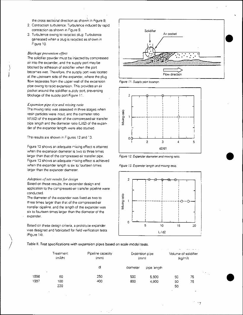
\
/
Figure 11. Supply port location.
the cross sectional direction as shown in Figure 8;
2. Contraction turbulence: Turbulence induced by rapid
contraction as shown in Figure 9.
3. Turbulence owing to recycled plug: Turbulence
generated when a plug is recycled as shown in
Figure 10.
Blockage prevention effect The solidifier powder must be injected by compressed
air into the expander, and the supply port may be
blocked by adhesion of solidifier when the port
becomes wet. Therefore, the supply port was located
at the upstream side of the expander, where the plug
flow separates from the upper wall of the expansion
pipe owing to rapid expansion. This provides an air
pocket around the solidifier supply port, preventing '
blockage of the supply port Figure 11.
Expansion pipe size and mixing ratio
The mixing ratio was assessed in three stages when
resin particles were input, and the diameter ratio
(d1/d2) of the expander of the compressed-air transfer
pipe length and the diameter ratio (L/d2) of the expan-
der of the expander length were also studied.
The results are shown in Figures 12 and 13.
Figure 12 shows an adequate mixing effect is attained
when the expansion diameter is two to three times
larger than that of the compressed-air transfer pipe.
Figure 13 shows an adequate mixing effect is achieved when the expander length is six to fourteen times larger than the expander diameter.
Adoption of test results for design Based on these results, the expander design and
application to the compressed-air transfer pipeline were
conducted.
The diameter of the expander was fixed as two to
three times larger than that of the compressed-air
transfer pipeline, and the length of the expander was six to fourteen times larger than the diameter of the expander.
Based on these design criteria, a prototype expander
was designed and fabricated for field verification tests (Figure 14).
Table II. Test specifications with expansion pipes based on scale model tests.
Solidifier Air pocket
^> Flow direction
9
IT j l
o -
Mix
ing
rat
V . ,
—0—-
i i UkJ
1 4 3
cl2/d1
4 5
Figure 12. Expander diameter and mixing ratio.
Figure 13. Expander length and mixing ratio.
Treatment (m3/h)
Pipeline capacity (mm)
dl
Expansion pipe
(mm)
diameter pipe length
Volume of solidifier (kg/m3)
1996 60 1997 180
230
250
400 500 5,500 50 75 800 4,800 50
50
75

-•'ibrat'OP screer
Ccmpressea =. Plua flow
:ZZM a ft
Soil barge Punp
cxpanae
^ 100 m
^•^ 100"
^
Figure / 7 Test msiallaaons
Figure '8 Ewander i60
2. Dredged mud Dredged mud to oe modifiea .vas proviaeo cv a
grab bucKet aredge- The rr .a .'.as transccrted oy a
soil barge Tafcie 111 gives average values Detained
from physical tests on the dredged muo rat .vas
used for ;ieid rests
3. Evaluation method :• sciidifieo m . I Vanous evaiuatior methods -ave oeer ..sea to
assess the it-re :' -::""-^ s
gene'..: : cy the • n I session strength-e-t In our tests, the mi nfmea mpres-
sionstrengtl ei et: itior i vere sed for evalual i fn ii*ied fnud characters;
.. ,.,.,,. ,,•• :- n tests in I e ipt e i '•: '^odi-
Figure '9 E\panden200m3/hl.

x^ ».•>.• i
•^^we^T
.,li4^^
Figure 22 Colleaed test specimens.
(b) Cone penetration test The cone penetration test is achieved by measuring
penetration resistance values when the cone rod is
inserted into the soil ground. In the field test of 60 m3/h capacity, portable cone penetration tests
were carried out but penetration was impossible at
part of the test field area. Based on this experience,
electrically-driven cone penetration tests were
carried out for the 200 m3/h capacity, using the
improved type of the conventional tester with a
cone tip angle is 60° with a cross-sectional area of 10 cm2. The latter situation is described here.
Test results 1. Unconfmed compression strength test results Figure 21 shows the relationship between the solidifier
volume used and unconfined compression strength of
modified mud, which were obtained from the field tests. The test specimen was collected by boring into
modified soil ground, which was cured for one month
after placement. Figure 22 shows the collected test specimens. All test specimens satisfied the target
value of 200 kN/m2.
Figure 23. Cone penetration resistance and distnoution ov
depth.
Cone penetration resistance, g, (kN/m2)
0 15000 0 15000 0 15000 0.0 K 0.0 0.0 r
-0.4 -0.4 i ,
-0.4 • 1 '/
•/ • £ 'X |4 * *.s
'L ' -0.8 •[i • -0.8 •
If 13 -1.2 4 —-* - -1.2 1 r -1.2 •
-16 1
-1.6 w -1.6 ^ r 180m3/h
60 kg/m3
180m3/h
70 kg/m3
225 m3/h
50 kg/m3
2. Cone penetration test results The relationship between unconfined compression strength and cone penetration resistance is expressed
as follows:
qt =
where,
qt:
qu:
20 x (qu/2)
Cone penetration resistance ikN/m3, after
pore water pressure compensation) Unconfined compression strength (kN/m3)
(1)
Figure 23 shows the distribution of cone penetration
resistance values by depths. The dotted line m the
figure indicates the targeted strength for soil modifica- tion, which was obtained by converting into qt values
using equation (1). The soil strength over all the modi- fied soil ground area met the target value for modifica-
tion. Moreover, the modified soil quality m the depth
direction was comparatively uniform. Figure 24 shows
the cone penetration tests being performed.
3. Conclusions based on verification tests
Use of the expander based on basic R&D enabled
mixing of the solidifier during transfer of soft mud by
plug flow m the pipeline. The mixing effect in the expander by plug flow was confirmed together with
21

Sediment washing provides one solution Brad Carpenter. Renee Haltmeier, and Charles Wilde
The Hudson River Estuary has a natural, undredged depth of 5.8 m (19 ft), but ships using the New York-New Jersey Harbor
need a 12 to 14 m (40 to 45 ft) depth for safe nav- igation. The difference between natural and required depths means that 3 million to 5 million m3 (4 million to 7 million yd3) of sediment must be dredged and disposed every year in order for the harbor to remain open. According to New York and New Jersey port authorities, the port generates more than $20 billion in revenue and is responsible for more than 180 000 jobs. Thus, any prolonged interruption in dredging would adversely affect the regional economy.
Until 1992, dredged sediment was disposed in the ocean at a site called Mud Dump. Thereafter, dredging contaminated material was severely limited. .As of Sept. 1, ocean disposal was phased out because some dredged sediment contains chemical contaminants, including polychlori- nated biphenyls (PCBs) and dioxins, that could affect fish and shellfish. The Dredged Materials Management Plan for New York-New Jersey Harbor states that about 75% of the total annu- al dredging volume requires some form of pro- cessing or decontamination prior to disposal.
A Hotly Contested Issue
Since 1992, the dredged-material disposal issue has been a political and technical battle- field. Environmental groups say scientific advances in testing show potential adverse impacts of disposing contaminated dredged material in the ocean. Business groups oppose limits on ocean disposal, basing their claims on traditional testing methods and the need to main- tain a viable port.
In 1995, New Jersey's governor developed a 'ask force, the Dredged Materials Management Team, to bring interested groups together, review efforts from other regions, identify testing criteria and technology, and evaluate sediment dispos-
MOVRMBKR lll'.ir

1 ^HHMj _—•,,,•
The Advantages BioGenesis Sediment Washing has the following advantages:
• The only byproducts are wastes removed from the sediment, treatable water, and biologically active sediment suitable for beneficial use. • The chemicals used in the process are 100% biodegradable and have low toxicity. • Costs range from $50 to $260/m3 ($40 to MOOJyd3), depend- ing on site veiriables and economies of scale. Variables affect- ing cost include contaminant type, sediment type and volume^ contamination levels, and cleanup target.
al options, including decontamination tech- nologies. The team included officials from the New Jersey Department of Environmental Protection. U.S. Environmental Protection Agency (EPA) Region 2, the U.S. Army Corps of Engineers New York District, the Port Authority of New York and New Jersey, environmental groups, academia. unions, marine terminal groups, non- profit foundations, and shipping companies.
After 6 months of evaluation, the team suggest- ed locating an underwater confined-disposal pit in the Newark Bay area. It also suggested more thor- oughly investigating decontamination technolo- gies, such as soil washing; and consider using a suc- cession of treatment technologies to decontaminate dredged material and creating beneficial uses for this material.
On the federal side, EPA Region 2 and the Corps of Engineers New York District are responsible for managing environmental issues associated with
dredging and disposing material in the Hudson River Estuary. Under the Water Resources Develop- ment Act of 1992 (WRDA), these agencies jointly sponsored work to demonstrate technologies that treat or remove organic and inorganic contami- nants from dredged sediment. They also are addressing issues of materials handling and bene- ficial use of treated sediment.
Seven projects resulted from initial WRDA contracting in 1995. These were administered by Brookhaven National Laboratory with the goal of establishing a production-scale facility able to treat 382 400 m3 (500 000 yd3) of dredged mate- rial annually by the end of 1999. BioGenesis Enterprises Inc. of Oak Creek, Wis., is one of three firms designated to reach full-scale capa- city between 1998 and 2000.
The BioGenesis Sediment Washing Technology (patent- pending) uses proprietary, nonhazardous cleaning solutions; a truck-mounted gondola for large particles (2 mm and greater) and organic material; and a sediment washer for small particles (less than 2 mm). The technology cleans a broad spectrum of organic and inorganic pollutants, including polycyclic aromatic hydrocarbons (PAHs). PCBs. dioxins. pesticides, and metals. Fine- grained soils and harbor sediments typically are poor candidates for treatment using conventional soil washing processes. BioGenesis overcomes the inability of these processes to handle heavy pollutants, wash fine particles, and treat sedi- ments efficiently at low cost.
Figure 1. New York-New Jersey Harbor Sediment Decontamination
March 1997
ME wmnwisiiiiw
flrPTiPliTiiriTi(Tiisri#
nifiifi.rimniuwwrn,
-WrrJOTrPii:,
0% 20% 40% 60%
Removal percentage
80%
99.4%
95.3%
84.7%
97.2%
96.9%
93.3%
L00%
Source: Biogenesis Enterprises Inc.
Technological Benefits
BioGenesis demonstrated its soil washing process in EPA's Superfund Innovative Technology Evaluation program in 1992 and in Environment Canada's Great Lakes Cleanup Fund and Wastewater Technology Centre's Contaminated Sediment Treatment Technology program in 1993 and 1994. The soil washing system was successfully demonstrated at a refinery where about 3447 Mg (3800 tons) of soil were contaminated with up to 3% heavy crude oils. The contaminant of concern was total recoverable petroleum hydrocarbons with lev- els averaging 30 800 mg/L. The soil was cleaned in a single pass through the system. Cleaning effi- ciency averaged between 85% and 90%, and subsequent biodegrada- tion raised total contaminant treat-
^^ WATER ENVIRONMENT & TECHNOLOGY

Figure 2. Full-scale Biogenesis Sediment Washing Technology
(3 Foam
^
Sdistnai
a a
»^|«»% ^ ad-—- ^
EDr^n Side stream
a
—c: jf
Offsite (feposal
V
A ment effectiveness to between 95% and 98%. Results were tabulated for soil fractions greater and less than 300 \im. As expected after the initial washing, greater extraction (91%) was achieved for the larg- er fractions than for smaller particles. Removal effi- ciency was 85% on the silt-clay fraction.
For the Wastewater Technology Centre's pro- gram, the company tested its washing process on sediment from a former wood-preserving site at Thunder Bay, Ontario, Canada. The site, one of 43 "areas of concern" identified by the International Joint Commission, is contaminated with PAHs, low levels of PCBs, phenols, and several metals. Sediments contained a high fraction of fines with 81% of the material having grain size less than 38 pm and a total organic content exceeding 11.5%.
The sediment for the test was selected from the most heavily contaminated areas of Thunder Bay, as determined by 1984, 1988, and 1992 surveys. The testing, initially designed as bench-scale, sub- sequently was upgraded to use pilot-scale equip- ment to accommodate high water pressures and effectively model process parameters. PAH removal percentages averaged between 90% and 94% fol- lowing a three-cycle wash.
Harbor Sediment Testing
In 1997. the company performed bench-scale testing on sediment dredged from the New York-New Jersey Harbor under the direction of EPA Region 2 and the Corps of Engineers New York District.
Test results were verified by Brookhaven National Laboratory in late February. Contaminated sediment contained PAHs, PCBs, total petroleum hydrocarbons, dioxins, furans, and heavy metals. Following decontamination of the material.
Brookhaven directed the company to send "before and after" samples to Triangle Laboratories in Durham, N.C., where testing showed high removal efficiencies for all contaminants (see Figure 1. p. 48).
Due to the favorable WRDA testing results. Brookhaven decided to fund a pilot project in which BioGenesis will treat 765 m3 (1000 yd3) of contam-
fllie Process (see Figure 2) ' Dredged sediment slurry is delivered to
thepilot plant by barge (1). Oversized debris | is removed by a vibrating screen (2).The sed- i iment slurry is pretreated with a proprietary, ;
nonhazardous cleaning solution and high- . pressure water (3). This action homogenizes •
ftlie slurry and prepares it for washing and ; scrubbing (4). Low-pressure air bubbles up 1 through the slurry to form a foam layer con- ]
gaining floatable organic and oily waste, which 1 is skinimed off (4a). Next, the slurry passes to ]
"sediment washing and organic treatment (5). j In the sediment washer, the slurry is agitated ]
^violently by high-preissure water to separate i residual contaminants from sediment parti- ! cles. Then the slurry is sent to a reaction ves- j sel, where the remaining organic contami- | nants are oxidized. Contaminated water is ; separated from treated sediment (6). The sed- ' iment Is now ready for beneficial use, and '• the contaminated water is treated further using chemical precipitation to remoye heavy metals (7). Finally, treated water is recycled to the front of the process to conserve resources (8).
NOVEMBER 1997

inated sediment dredged from the New York- New Jersey Harbor. The project will model a full-scale treatment process (see Figure 2, p. 49) and demonstrate front-end material handling, post-treatment liquid-solid separation, and treat- ment of wash water to meet recycle and dis- charge criteria. Joining the company in this effort will be Roy F. Weston Inc. of West Chester, Pa., an international consulting and engineering firm.
Phase I of the project will model the front-end material handling and sediment washing tech- nology and generate sufficient washed sediment to design the liquid-solids separation and water treatment equipment. This equipment then will be added to Phase I, and the entire treatment process will be modeled in Phase II. The project, including the final report, is expected to be com- pleted by May. The ultimate goal is to turn con- taminated dredged material into environmen- tally safe products.
Treated Sediment a Resource?
More than 75% of the raw sediment dredged from the harbor is classified as having some degree of contamination that prevents it from being used
beneficially. Following washing, the sediment retains its
original, very fine matrix, which resembles wet cornstarch. When dried, the treated sediment is powdery and dense. This matrix is extremely well suited for landfill capping applications, especially when combined with a stabilizing agent. When wet, it is well suited for wetlands applications.
Landfills and wetlands are two of many possible applications. The potential also exists to use treat- ed sediment as nonstructural construction fill and road base, for shoreline protection, and in various manufactured soil products.
Decontamination technologies, including sed- iment washing, will be further demonstrated in 1998. Effective solutions for cleaning dredged sediments should give impetus to the search for beneficial uses of the treated material.
Brad Carpenter is senior project manager at Roy F. Weston Inc. in West Chester, Pa. Renee Haltmeier is president at Enviro-Tech Marketing Inc. in Morristown, NJ. Charles Wilde is vice president at BioGenesis Enterprises Inc. in Oak Creek, Wis.
VNftVTER ENVIRONMENT
:CHNOLOGY
WATER ENVIRONMENT & TECHNOLOGY Reprimed from WATER ENVIRONMENT & TECHNOLOGY Magazine. November 1997

ADVANCED SEDIMENT WASHING FOR DECONTAMINATION OF NEW YORK/NEW JERSEY HARBOR DREDGED MATERIALS
Mohsen C. Amiran,1 Charles L. Wilde,2 Renee L. Haltmeier,3
John D. Pauling,4 John G. Sontag, Jr.4
ABSTRACT
BioGenesis Enterprises, Inc•, and Roy F. Weston, Inc., (WESTON®) a leading infrastructure redevelopment firm have teamed together to demonstrate the commercial viability of an advanced sediment washing technology to the treatment train framework provided under the Water Resources Development Act of 1992 and 1996. This project is the result of several bench and pilot-scale tests performed on dredged materials from various locations in the NY/NJ Harbor Region.
This Public/Private partnership consists of the BioGenesis/Weston Team working in collaboration with the U.S. Environmental Protection Agency, U.S. Army Corps of Engineers, and the U.S. Department of Energy-Brookhaven National Laboratory. The contaminated sediments issues in NY/NJ Harbor has been approached by many groups and in this project, science and technology will be used to provide a real solution to a problem which is not only environmental, but economic as well.
The first phase of this 10,000 cubic yard (yd3) project is a 500 yd3 pilot demonstration, is a scheduled to commence in November 1998 and run through January 1999. Commercial system scale-up is anticipated to be operational by September 1999. The pilot demonstration will establish the scale-up system design parameters and full/commercial scale system economics. The demonstration will consist of the following: material handling, and pre-processing from a barge to the pilot demonstration site, sediment washing, liquid-solid separation, and manufacturing of a beneficial reuse topsoil from the decontaminated sediment. The system is also effective on soils, which is expected to enable this process to play a role in overall economic and brownfield redevelopment in the region.
The decontaminated sediment from this process will be incorporated into a "manufactured topsoil" product. This product for beneficial reuse will be produced and tested during the initial pilot phase of the project and tested extensively for use in various horticultural applications. This will involve blending and mixing the cleaned sediment with other components to make a product, which is anticipated to be saleable. This cleaned sediment, which is a resource, has a variety of applications such as construction fill, and landscaping material.
1 BioGenesis Enterprises, Inc., 610 West Rawson Avenue, Oak Creek, Wl 53154; Tel: 414/571-6230. 2 BioGenesis Enterprises, Inc., 7420 Alban Station Boulevard, Springfield, VA 22150; Tel: 703/913-9700. 3 Enviro-Tech Marketing, Inc., 89 Headquarters Plaza, Morristown, NJ 07960; Tel: 732/417-5800. 4 Roy F. Weston, Inc., One Weston Way, West Chester, PA 19380; Tel: 610/701-7562; Tel: 601/701-3737.
567

THE CONTAMINATED SEDIMENT ISSUE
One of the greatest drivers for maintaining access to America's intermodal ports and related infrastructure redevelopment efforts over the next several years will be the control and treatment of contaminated sediments dredged from our nations waterways. More than 400 million cubic yards (CY) of sediments are dredged annually from U.S. waterways, and each year, close to 60 million CY of this material is disposed of in the ocean. The need to protect our environment against undesirable effects from contaminated sediment dredging and disposal practices is gaining increased attention from the public and government.
REGIONAL FOCUS: NEW YORK/NEW JERSEY HARBOR REGION
In the New York/New Jersey Harbor Region, the effect of contaminated sediments on dredging operations can be costly. The Port is responsible for over 180,000 jobs in the region, and $26 billion in revenue. This area is considered to be the richest consumer market in the United States, and 85% of the freight that moves through this Port remains in the region. The ships that call at'this Port require a minimum depth of 12 to 14 meters (40 to 45 feet) for navigation. The natural, undredged depth of the NY/NJ Harbor is 5.8 meters (19 feet), which requires that 3 to 5 million m3 (4 to 7 million cy) of sediment be removed for safe navigation. Estimates from the U.S. Army Corps of Engineers indicate that 75% of this material is contaminated. To impede dredging is to add undesirable costs to freight movements. Therefore, disposal options for this material have been developed in response to the termination of the dredged material ocean disposal site, the former Mud Dump Site. The options include utilizing less contaminated materials for landfill capping, providing redevelopment of Brownfield properties, and the construction of confined disposal facilities within the Harbor. The more contaminated material, which was ineligible for other remedial alternatives, is the focus of this project.
PUBLIC/PRIVATE PARTNERSHIP
Congress mandated the development of procedures suitable for the decontamination of sediments in the Port under the Water Resources Development Act (WRDA) of 1992 (Section 405C) and 1996 (Section 226). The WRDA Program is the responsibility of the U.S. Environmental Protection Agency (EPA) - Region 2 and the U.S. Army' Corps of Engineers (USAGE) - New York District, with the U.S. Department of Energy (DOE) - Brookhaven National Laboratory (BNL) acting'as the Technical Project Manager. BioGenesissm Sediment Washing technology is one of the technologies being demonstrated under the review of the members of this team.
The mission of this WRDA project is to prove one or more decontamination technologies commercially viable at full scale. For the purposes of the NY/NJ Harbor, full scale is defined as 500,000 cubic yard capacity per year. This is a segment of the overall material, and suggests that the technologies be a part of an overall solution, and can be integrated into the planning of dredging activities within the region.
The demonstration of the BioGenesissm Advanced Sediment Washing technology is an integrated treatment train approach to sediment decontamination for NY/NJ Harbor dredged materials.
568

.BioGenesis Enterprises, Inc. has teamed with Roy F. Weston, Inc., to implement the technology |h)r this project. Federal funding from the WRDA legislation provides assistance to this Pilot Operation, and to the commercialization process, while the private sector will provide the capital needed for actual facility construction and operation. Further operations of the large scale facility will be funded by the State of New Jersey, Maritime Resources Decontamination Project, which will provide and fund the demonstration of the technology from 30,000 to 150,000 cubic yards of material.
TECHNOLOGY DEVELOPMENT TO APPLICATION: CORPORATE TEAM IDENTITIES
BioGenesis Enterprises, Inc.
This technology development company, started in 1989, has been developing environmentally safe specialty chemicals and successfully bringing them to commercial markets in various use categories. These products include fire suppressants, odor neutralizers, cleaning compounds, and a chemical breakthrough in production enhancement for the oil refining industry. Thus BioGenesis entered the soil washing arena with a significant advantage: experience with chemical development, production, and implementation. The chemicals that would aid in the physical removal of contaminants from soils effectively, efficiently, and economically were a progression from the chemicals manufactured by the company from the late ^SO's. BioGenesis continues to develop private label chemicals, as well as supply its own brands to its distributors
^nationally. The Company is headquartered in Oak Creek, WI, and has operations in Springfield,
'VA.
Roy F. Weston, Inc.
BioGenesis has joined with Roy F. Weston, Inc. (Weston) for the technology demonstration and commercial implementation. Weston is a leading infrastructure redevelopment services firm with more than 40 years of experience. The company's services include consulting, engineering, construction and operations, and extensive ports services, including property redevelopment. Headquartered in West Chester, Pennsylvania, the company has 60 offices throughout the United States and international operations in Europe, Latin America and Asia. Weston provides to the project the engineering, construction, and operational skills needed to move the technology into the commercial marketplace.
BIOGENESISSM SOIL AND SEDIMENT WASHING: EARLY TECHNOLOGY DEVELOPMENT
Developed originally for contaminated soils treatment, the technological advances made by BioGenesis to clean sediment from NY/NJ Harbor have been extraordinary. A successful project using the soil washing equipment and chemicals produced by BioGenesis at a refinery site in Minnesota also served as a demonstration for the USEPA SITE Program, which determined the removal rates of contaminants to be between 80-90%. To improve upon typical soil washing for fine-grained materials, the Company developed a new piece of equipment, to provide the contact
569

of chemical to contaminant and the physical collision necessary to achieve removal results from materials under 38 microns. In combination with the BioGenesis chemicals, this equipment and the principals behind it have proved to US EPA, US Army Corps and the Dept of Energy, Brookhaven National Laboratory that this is an effective way of decontaminating sediment. The material from NY/NJ Harbor can be over 90% comprised of materials under 38 microns, and several federally-funded bench scale studies have proved the system effective on materials taken from various Harbor sites.
THE DEMONSTRATION PROJECT
The demonstration project consists of three phases: Pilot Operations, Full Scale Plant Design & Construction, and Full Scale Operations. During Phase 1, Pilot Operations, scale-up engineering data has been obtained, treated material has been produced for beneficial reuse testing, and process effectiveness is revalidated. In Phase 2, Full Scale Plant Construction, full-scale equipment will be procured and the full-scale plant will be constructed based on the results of Phase 1. In Phase 3, Full Scale Operations, the full-scale plant will be used to treat 30,000 to 150,000 cy of sediment. This paper documents the Pilot Operations, which, at the time of this writing, had just been completed.
The operations of this phase of the project were specifically designed to secure the following information and data; technical validation, sediment volume throughput, upscale design, production of clean material, and system economics. With the information obtained in this phase, the technology is currently being designed for its next phase of operations, at full scale.
Planning
The Pilot Operations Phase included the following planning steps: . Site Agreements Site Plan (equipment arrangements) Work Plan/Sampling and Analysis Plan/HASP PFD/Mass Balance Process and Instrumentation Diagram Electrical Single Line Drawing Mechanical Plans State Permits Local Permits
Pilot Operations
Material Handling Preparation. Seven hundred (700) cy of contaminated sediment was supplied by the US Army Corps of Engineers, dredged from a site in Newark Bay. SK Services (East) L.C. screened the sediment to less than V* inch, and removed the oversize material. The sediment was transported in tank trucks to the operations site, where it was stored in closed mixing tanks.
570

Pre-processing and Core Processing. At the operations site, runs of the core BioGenesis process were performed with contaminated sediment in order to determine the correct chemical addition rates and equipment settings. Sampling was performed throughout the process to evaluate the chemical mixtures and equipment layout being used. The major objectives of the Core Processing Task were to determine optimum chemical feed rates, process effectiveness under varying conditions, obtain process design information for scale-up, determine and quantify residual management, and produce treated sediment for further testing.
The core equipment used included the pre-processor, to which BioGenesis"" cleaning chemicals were added. This provided removal of the outer layer of contamination adhered to the sediment particles. The next step involved aeration where lighter organics were removed from the slurry through skimming. Next, the sediment collision.chamber removed the innermost component of the contamination through a powerful impact technology within the unit. At this point, the contaminants were removed from the solids to the water phase.
Cavitation/Oxidation. This step provided destruction of the organic contaminants through addition of an oxidant in combination with a cavitation process.
Liquid-Solid Separation. Liquid-solid separation was successfully performed using pilot scale hydrocyclone and centrifuge equipment. The system yielded cleaned sediment at approximately 65% solids, which is considered to be the appropriate moisture for blending to make manufactured soil. Samples of sediment that were treated by the core BioGenesis process have been shipped to selected vendors to obtain additional performance information that may be
• integrated into the scale-up design.
Water Treatment. Metals contained in the water phase will precipitate out at this point in the system. For the Pilot Operations wastewater was disposed of at a POTW.
During Pilot Operations, wastewater was bench tested to determine the most cost-effective treatment considering the level of organic and inorganic contaminants and suspended solids for implementation at full scale. At full scale, the wastewater will be treated and, to the maximum extent, recycled into the core processing system or alternatively used in the manufacture of various beneficial reuse products. Based on those results, which will vary because the input feed sediment, its contamination type and level, and process variables, the water will either be recycled'to the system, used in the manufacture of soil product, or disposed offsite. These results are being incorporated into the full-scale design.
Manufactured Topsoil. Dewatered and decontaminated solids were used to create various types of material for further beneficial reuse evaluation. This was done by mixing the sediment with amending materials (peat moss, cellulose waste, vermiculite, pearlite, and BioGenesis SeaSoil organic material) to produce test quantities of various soil products, such as
- Manufactured soil - High-end growth use (i.e. potting soil) - Manufactured soil - Low-end growth use (i.e. top soil) - Nonstructural fill material (daily/intermediate landfill cover)
571

The BioGenesis WRDA project prepared the material at the pilot processing site from which, under the separate EPA Region 2 Beneficial Reuse Project, the products will be trucked to the manufactured soil test site or shipped for laboratory testing.
THE BENEFICIAL USE PRODUCTS
This component of the project is important to the overall economics of the process, because it can provide a benefit back to the bottom line, enabling a potential reduction in cost for treatment of contaminated sediment. This is a distinction not shared by most other sediment disposal options.
As part of the approach to cleaned sediment as a resource, it is necessary to provide an understanding of the markets available for decontaminated sediment blended with amendments, or "manufactured topsoil" and an estimate of the value of this product.
Material Production
Following the Sediment Decontamination Demonstration Program, a field demonstration was performed to evaluate blending characteristics of cleaned sediment with various amendments. The field demonstration program is being conducted on sediment that was decontaminated •during the final week of operations of the Sediment Decontamination Demonstration Project (approximately 50 cyds of treated, dewatered sediment from 100 cyds of raw untreated sediment). A formulation is currently being developed using raw materials readily available within the vicinity of the site to make a topsoil product (i.e., topsoil for ornamental landscaping, etc.).The decontaminated sediment is being mixed with raw materials .to create approximately 100 to 200 cyds of manufactured soils.
Verification
Bench-scale studies are being conducted to design and test a horticultural planting medium, which incorporates the cleaned dredged material with conventional soil amendments. Specific end-product prototype media are currently being evaluated under the Market Evaluation. At this time, the products are assumed to be landscape planting, turf establishment, and container usage (i.e. potted plants). Physical testing (grain size analysis, density, moisture content, etc) of the manufactured soil is being conducted to evaluate the blending process.
The overall approach to the bench-scale study is to develop mixture ratios for physical, chemical and growth testing to evaluate the effect of decontaminated sediment in the varying amounts on the end product. Lettuce plants will be grown in the test mixtures and observed for symptoms of toxicity. The resulting foliage will be tested for uptake of heavy metals, and organics. Lettuce was the choice for growth tests, because standard growth protocols are available. Additionally, growth rates, visual observations, foliar analysis ranges for nutrients and heavy metals are also available. Physical, chemical, and nutritional analysis of the mixtures will be conducted. The test plant will provide base level viability data and plant uptake data within the time constraints of the study. This is to ensure a high quality product, and support expected product performance levels.
572

Markets
As part of the Beneficial Use Evaluation, potential markets for soil products are being identified to ensure an acceptable output for the manufactured topsoil. In order for the State of New Jersey to issue an Alternative Use Determination for the manufactured soil, BioGenesis/Weston will need to provide a demonstration of the chemical and physical appropriateness of the material for the product as well as an ability to move the end product.
The data generated from the market survey will be used to determine the economic applicability of the manufactured topsoil product to the existing regional topsoil market. It will provide an economic as well as volumetric assessment of the markets for the manufactured topsoil products and fill products, regionally and nationally. At the conclusion of the market evaluation, there will exist a database for each of the products, which includes the estimates of the volume of product markets, the value of that market, and a group of clients that are currently purchasing similar product. The production of a topsoil material as output from a full scale facility with a production rate of 500,000 cy per year is estimated to be well within the volumes of the current regional wholesale market for comparable product.
CONCLUSION
The Pilot Operations that ran from January to March of 1999 were successful in generating the information and data necessary to take the process to full scale. Currently the system is being designed for its full-scale operations, to enable capacity of 275,000 cubic yards per year. Construction is scheduled to begin in the Summer of 1999.
The contaminated material into a clean resource concept is a reality. The manufactured topsoil distribution networks are being established, and wholesale clients are being identified for bulk sale arrangements.
By 2000, the public/private teammates will have successfully completed the mission of bringing a technology from bench scale to full scale. BioGenesis/Weston have planned by 2001 to provide the NY/NJ Harbor region with a commercial decontamination component able to treat contaminated sediments at 500,000 cy/yr to add to its disposal options for sediments.
573

MESA PROCEEDINGS
OF THE
WESTERN DREDGING ASSOCIATION NINETEENTH TECHNICAL
CONFERENCE
and
THIRTY-FIRST TEXAS A&M DREDGING SEMINAR
May 15-18, 1999
Louisville, Kentucky

CONSTRUCTION-GRADE CEMENT PRODUCTION FROM CONTAMINATED SEDIMENTS USING
CEMENT-LOCK• TECHNOLOGY
A. Rehmat1, A. Lee2, A. Goyal3, M. C. Mensinger4
ABSTRACT
The Institute of Gas Technology (IGT) has developed the Cement-Lock• Technology B a versatile, cost-effective, and environmentally friendly manufacturing technology B for producing construction-grade cements from a wide variety of contaminated waste materials, such as sediments, concrete and building debris, town gas site soils, Superfund site soils, sludges, chemical wastes, petroleum refinery wastes, and incinerator residues. Organic and inorganic contaminants are present in these wastes across a broad range of concentrations. In the Cement- Lock process, contaminated materials and proprietary modifiers are fed to a reactive melter operating under oxidizing conditions where all the organic compounds are completely destroyed and converted to innocuous carbon dioxide and water. Chlorine and sulfur compounds are sequestered and heavy metals are locked within the molten matrix to completely immobilize them.
During processing, the melt (Ecomelt•) is imparted with latent cementitious properties that allow it to be transformed into construction-grade cement. The Cement-Lock Technology is unique because it not only decontaminates the sediment but also converts it into a beneficial commercial commodity, namely, construction-grade cement. The effectiveness of the technology for remediating contaminated sediments has already been verified in bench- and pilot-scale test programs. Currently, a large-scale sediment decontamination project is underway in the New York/New Jersey harbor area to demonstrate the technology at a processing capacity of 30,000 cubic yards per year.
The work is supported under Contract No. 725043 with Brookhaven National Laboratory with funding provided, in part, through the Water Resources Development Act of 1996 (Section 226) through Interagency Agreement No. DW89941761-01-1 between the U.S. EPA-Region 2 and the U.S. Department of Energy.
Keywords: Dredging, dredged material, beneficial use, manufacturing process
Rehmat, Amir, Director, Thermal and Chemical Environmental Technology, Institute of Gas Technology 1700 S Mt. Prospect Rd., Des Plaines, IL 60018, USA.
Lee, Anthony, Managing Director, Gas Processing Technology, Institute of Gas Technology, 1700 S. Mt Prospect Rd., Des Plaines, IL 60018, USA. 3 Goyal, Anil, Director, Process Development, ENDESCO Services, Inc., 1700 S. Mt. Prospect Rd., Des Plaines, IL 60018, USA. 4 Mensinger, Michael C, Director, Technology Development, ENDESCO Services, Inc., 1700 S. Mt. Prospect Rd., Des Plaines, IL 60018, USA.
555

INTRODUCTION
Sediments must be routinely dredged from the New York/New Jersey harbor to maintain water depths for shipping channels, berthing areas for commercial vessels, and to insure safe navigation. In the past, most dredged sediments have been barged out into the open ocean and dumped. These dredged materials often contain a variety of contaminants from different anthropogenic sources including polynuclear aromatic hydrocarbons (PAHs), polychlorinated biphenyls (PCBs), insecticides, chlorinated dioxins and furans, and heavy metals. The concentrations of some of the contaminants in the sediment are high enough to render the sediments hazardous to benthic organisms through biotoxicity and/or bioaccumulation. Further, the ocean dumping area commonly known as the "Mud Dump Site" was closed to further dumping of contaminated material as of September 1, 1997. These contaminated dredged sediments must be rendered innocuous to the environment before being disposed of, or, as in the case of the Cement-Lock• process, converted into a salable product for beneficial use.
In addition to the contaminated sediments, many different types of contaminated wastes can be treated via Cement-Lock Technology. Several million tons of wastes are being generated annually around the world. The wastes are often either being landfilled or stockpiled in nearby localities. Depending upon the nature of these wastes, they can pose environmental problems that warrant an economical and environmental compatible disposal. In addition to contaminated sediments, these wastes include concrete and building debris, town gas site soils, Superfund site soils, sludges, soils and debris from DOD and DOE sites, chemical waste, petroleum refinery waste, and incinerator residues.
The Cement-Lock Technology being developed by the Institute of Gas Technology (IGT) and its wholly owned subsidiary, ENDESCO Services, Inc., offers a one-step solution for remediating these contaminated materials in which the organic contaminants are completely destroyed, inorganic contaminants are immobilized, and the resultant solid product from the treatment can be put to beneficial use. The technology is flexible enough to accommodate the complex and varying nature and levels of contaminants and their widespread spatial distribution within the estuarine environment. The Cement-Lock Technology simultaneously immobilizes the heavy metals and destroys the organic contaminants such as PCBs, PAHs, dioxins, furans, chlorinated pesticides, and herbicides.
CEMENT-LOCK• TECHNOLOGY DESCRIPTION
The Cement-Lock• Technology is an advanced management system for remediating contaminated dredged sediments from estuarine and river environments, hazardous and non- hazardous wastes, and municipal solid wastes (MSW). In addition to decontamination, Cement- Lock converts the wastes into construction-grade cement, which can be sold on the open market. Depending upon the waste stream and its composition, other beneficial products could be produced, for example, steam for power generation. Further, there are no secondary hazardous waste streams produced during Cement-Lock processing as in some other treatment processes.
556

«e beneficial use of sediments and wastes through the application of Cement-Lock Technology > many advantages over conventional waste processing. These include: a) additional revenues
generated from the sale of construction-grade cement product, b) the ability to accept materials with fairly low tipping fees because of the secondary revenue streams, and c) environmental superiority when compared to conventional incineration technologies.
13,
The Cement-Lock Technology should not to be confused with either cement manufacturing plants or with MSW incineration technologies. The Cement-Lock Technology is considerably simpler than a Portland cement manufacturing plant and bears little or no resemblance to the actual complex cement plant. Unlike a cement plant, the Cement-Lock Technology does not have the extensive sizing requirements for the materials being processed; it does not have the extreme temperature requirements of a cement plant; it does not produce waste streams (such as cement kiln dust); it does not require complex energy management to save energy; it does not produce high NOx; it does not have stringent requirements for materials of construction; and finally, the starting raw materials are entirely different.
Nor is the Cement-Lock Technology an incineration process either. Rather it is a thermo- chemical manufacturing process that utilizes the inherent properties of sediments and wastes as feedstocks for producing economically attractive products (Figure 1). Conventional MSW incinerators do not produce a salable product. Rather, they generate ash that may contain leachable heavy metals, which must be disposed of as hazardous waste. Further, MSW icinerators have been shown to generate dioxins and dioxin precursors.
MODIFIERS
i •**
FLUE GAS QUENCH
FLUE GAS CLEAN UP
CLEAN FLUE GAS
CONTAMINATED SEDIMENTS —
REACTIVE MELTER
1200° - 1400oC
QUENCH ADDITIVES
NATURAL AIR/ GAS O2
I i ECOMELTT GRINDER/
PULVERIZER
T High Quality
CONSTRUCTION- GRADE CEMENT
Figure 1. Schematic Diagram of the Cement-Lock Process for Treating Dredged Estuarine Sediments *
557

The Process
Contaminated materials are reacted in a melter with suitable modifiers in proportions required for producing materials with latent cementitious properties. The proprietary modifiers are inexpensive materials that are commonly used in conventional cement manufacturing. The melter for carrying out this process is operated at temperatures in the range of 1200° to 1400oC (21920-25520F) or temperatures sufficient to completely melt the sediment-modifier mixture. At these temperatures in the presence of oxygen, organic contaminants originally present in the sediment are completely destroyed and converted to innocuous carbon dioxide (CO2) and water (H2O). Chlorine present in some of the organic compounds (dioxins, furans, PCBs, pesticides, etc.) is converted to hydrogen chloride (HC1), which can be readily scrubbed from the flue gas by direct injection of powdered lime. The flue gas could also be passed through a solid media filter containing calcium oxide (operating at 540° to 5950C; 1004° to 1100oF) to capture HC1. Preliminary laboratory-scale tests (Goyal et al, 1999) have also demonstrated that some of the chlorine will be sequestered within the stable matrix of the melt. Sodium and potassium chlorides (NaCl and KC1) from seawater will be volatilized and captured in the downstream flue gas processing stages.
The melt, which contains the heavy metals present in the contaminated sediment, is quickly quenched. The metals are locked into the matrix of the melt that completely immobilizes them. The solidified melt can be crushed and pulverized by conventional methods or it can be drawn into micrometer-size fibers by fiberization techniques. The fibers can then be easily pulverized and mixed with another appropriate additive to yield construction-grade cement as a product for beneficial use.
Flue gas from the melter enters a secondary combustion chamber (SCC), where it is subjected to an additional two (2) seconds residence time at temperature to ensure complete combustion of any organic compounds. The flue gas exiting the SCC is cooled by direct water injection to a temperature of about 177° to 204oC (350° to 400oF) to prevent the formation of dioxin and furan precursors. Powdered lime (CaO) is injected into the flue gas to capture HC1, SO2 and other acid gases. The flue gas then passes through a bag house to capture the spent lime, fine particulates, and NaCl and KC1 volatilized from the estuarine sediments. From the bag house, the flue gas passes through a fixed bed of activated carbon to capture volatile metal species. In an alternative process configuration, powdered activated carbon can be injected into the flue gas stream to capture volatile metals and be removed by a second bag house. The clean flue gas is vented to the atmosphere.
All of the components required for applying the Cement-Lock Technology to the remediation and beneficial use of dredged sediments have been adapted from commercially available equipment. No equipment development was required. The following sections describes the major process equipment, the feed system, the reactive melter, and the melt fiberizer or granulator.
558

^feeed System
The system for feeding dredged estuarine sediments into the reactive melter is a simple screw conveyor. Dredged sediments containing 60-weight percent water are scooped from the barge and dumped into the screw conveyor feed hopper. The rate of sediment feeding into the reactive melter can be controlled by regulating the screw rotation rate. Depending upon the pumpability of the sediments (from different geographical locations), it may be possible to use a sludge pump (reciprocating piston) to transport sediments from the barge to the reactive melter. Since sediments are essentially sandy, silty, or clayey in nature, the only feed pretreatment required is to remove large objects (such as automobile parts, timber, fencing, etc.) from the feed using a scalper.
Reactive Melter
Any suitable natural gas-fired melter can be adapted to the Cement-Lock Technology. IGT has considered three vendors for providing melters, which are described below. The current pilot-scale testing was conducted in a rotary kiln melter.
1) A rotary kiln-type melter as manufactured by ABB or Svedala Industries is suitable for the Cement-Lock Technology. The rotary kiln-type melter is very forgiving of variations in the size of feed materials that it can process. Through the years, rotary kilns have been installed in hundreds of locations worldwide.
Wtht e rotary kiln melter employed for the pilot-scale testing was designed and built by ABB. During pilot-scale operation, sediment containing 60-weight percent water was readily processed without predxying. ABB has subsequently quoted and is willing to provide the required guarantees for a rotary kiln melter with a processing capacity of 100,000 cubic yards per year of harbor sediment.
2) The reactive melter developed by Ausmelt Technology Corporation, is a vertically oriented, refractory-lined cylinder. The melter is constructed with water-wall cooling to minimize refractory thickness. A layer of frozen slag coats the internal walls of the melter to extend refractory life. Feed material and modifiers are fed into the melter through a port at the top of the melter. The energy required to melt the sediment-modifier mixture is supphed through a submerged lance, which is comprised of concentric tubes for feeding air or oxygen and natural gas into the melt. The lance can be moved up or down depending upon the depth of the melt Typically, air (or enriched air) is fed through the outer shell of the lance thereby cooling the lance somewhat. Natural gas is fed through the inner tube.
Combustion products bubble vigorously throughout the melt. The flow of gas from the lance instills a circulating pattern through the melt ensuring complete mixing. During initial melter operation, the lance becomes coated with a layer of frozen slag, which extends its life. When the lance must be replaced, a spare can be installed within about 30 minutes.
3) Other melters, such as the submerged combustion melter, commercialized in the Ukraine for eral wool manufacturing and being developed in the U.S. by the Institute of Gas Technology, is ^nin
559

c li
i
also suitable for Cement-Lock Technology. A pilot-scale submerged combustion melter has recently been installed and tested at IGT's Energy Development Center.
Melt Granulator or Fiberizer
The melt (Ecomelt•) from the reactive melter flows from the reactor into a flowing stream of quench water or high-velocity air which quickly freezes the melt and effectively disperses it into fibers or granules. In IGT's pilot-scale tests, the water-quencher effectively produced fibers from the melt. The fibers were readily crushed to the particle size required for blending with the final additive to produce the construction-grade cement product.
Fiberization techniques are well known in industry, however it appears that specific industries have developed their own proprietary processes. Fiberglass and mineral wool are produced utilizing existing fiberization techniques.
| • BENCH AND PILOT STUDY DATA
, Several bench-scale studies have been conducted with the following contaminated materials T^ using the Cement-Lock Technology.
J ' • Dredged sediments from the Newtown Creek estuary in New York (NY/NJ Harbor) -^^^ • Dredged sediment from the Detroit River
• Contaminated building debris (concrete) • Fly ash
Pilot-scale studies have also been conducted with the following contaminated materials using the Cement-Lock Technology.
• Dredged sediments from the Newtown Creek estuary in New York (NY/NJ Harbor) • Hydrocarbon-contaminated soil • Municipal solid waste
The harbor sediments are contaminated with polynuclear aromatic hydrocarbons (PAHs), polychlorinated biphenyls (PCBs), pesticides, insecticides, chlorinated dioxins and furans, and heavy metals. The river sediments also contain similar contaminants. The concrete waste was spiked with oil and chromium.
The results of the laboratory- and pilot-scale test programs for evaluating the Cement-Lock Technology have been very favorable. The results obtained with the dredged estuarine sediments, dredged river sediment, and contaminated building debris (concrete) are summarized below.
• All hazardous organic contaminants, including oil and grease, PAHs, PCBs, pesticides, insecticides, chlorinated dioxins and furans, were destroyed to well below regulatory limits. The destruction of organic contaminants is shown in Table 1.
560

All heavy metals were immobilized within the cement matrix. The construction-grade cement (the end product) passed the U.S. EPA TCLP (Toxicity Characteristic Leaching Procedure) test (Table 2). The leachability of metals is several orders of magnitude below regulatory limits. Samples of mortar were prepared from the cement product, sand, and water according to ASTM (American Society for Testing and Materials) C 109 procedures. The compressive strengths of these mortar samples were determined according to the ASTM procedure after 3, 7, and 28 days of curing (Table 3). The compressive strength tests were conducted by Construction Technology Laboratories, Inc. (CTL - the research arm of the Portland Cement Association, USA). The mortar produced from the cement product exceeded ASTM compressive strength requirements. It can replace Portland cement for general construction applications. The process did not generate any secondary hazardous waste streams. The pilot-plant data were consistent with the laboratory-scale data in terms of organic destruction, leachability, and the quality of the cement generated from the estuarine sediment. The total metal contents in the cement product from the Cement-Lock Technology are usually within the range of total metals found in ordinary Portland cement.
U
These findings confirm that the final product from the Cement-Lock Technology meets all environmental requirements and the cement produced from this technology is of commercial quality.
DEMONSTRATION PROJECT
Following successful testing of the Cement-Lock Technology at the laboratory- and pilot-scale levels, a 30,000 cubic yard per year (yd3/yr) capacity demonstration-scale plant is being constructed in the New York/New Jersey harbor area. The primary objective of this program is to demonstrate integrated operation of the Cement-Lock process while converting contaminated dredged estuarine sediment into construction-grade cement. The demonstration facility will be completely integrated with a ready-mix concrete plant that will utilize the cement produced from the plant. The demonstration will also confirm the environmental benefits of the technology through sustained operation; it will also demonstrate that the plant meets all the regulatory requirements and that no secondary waste streams are generated during processing, and the plant does not adversely impact the air quality in the surrounding neighborhood.
The rotary kiln melter for the demonstration-scale project was ordered from Andersen 2000 (Peachtree City, Georgia). The melter (Figure 2) is 10 feet in diameter and 30 feet long. The entire system consists of raw sediment storage bunker, hoppers for modifiers, screw conveyors for moving material to the melter, a pug mill for blending all of the feed materials before charging, the rotary kiln melter, quench/granulator, secondary combustion chamber, flue gas quench system, lime injection, bag house, and activated carbon adsorption system. Other equipment items, such as the Ecomelt grinder and construction-grade cement blender will be rented for the demonstration project.
561

Table 1. Organic Contaminant Destruction Achieved With Different Waste Materials
* Destruction and removal efficiency. ** Less than detection limit of the analytical procedure used.
Estuanne Sediment Untreated Cement
River Sediment Untreated Cement
Contaminant Sediment Product DRE* Sediment Product DRE mg/kg(dry) -- % -- mg/kg(dry) -- % --
Oil & Grease — — — 18,000 <D.L.** > 99.99 SVOCs 370 0.22 99.93 51.2 <D.L. 99.99
-—- Mg/kg(dry) Mg/kg(dry) PCBs 8,585 <D.L. > 99.99 1,100 <D.L. > 99.99
ng/kg(dry) ng/kg(dry) 2,3/7,8-
TCDD/TCDF 262 <D.L. > 99.99 __
Total TCDD/F 2,871 <D.L. > 99.99 — „
Total PeCDD/F 4,363 <D.L. > 99.99 -- .. Total
Hx/Hp/OCDD/F 34,252 <D.L. > 99.90 ~ --
Concrete - Cement
Product mg/kg(dry) 5,000 < D.L.
Untreated Concrete
Hg/kg(dry)
ng/kg(dry)
DRE -- % -- >99.9

Table 2. Metal Immobilization in Construction-Grade Cement Produced from Different Waste Materials
TCLP* —T Tntrp^tf*^ Kyfat^rial
Estuarine River Estuarine 11*111 1 lUUUl'l'U 1 1U1
River ii
Regulatory Metal Sediment Sediment Concrete Sediment Sediment Concrete Limit
— iiig/Rg {yty) mg/L>
Arsenic 39 7.8 — < 0.005** <0.01 — 5 Cadmium 27 9.5 — < 0.001 < 0.002 — 1 Chromium 298 138 500 0.15 < 0.072 0.097 5 Copper ~ 180 ~ ~ <0.01 ~ « Lead 542 218 — < 0.002 <0.01 — 5 Mercury 2.9 0.55 — < 0.0004 < 0.0004 — 0.2 Selenium 6.2 — -- < 0.003 ~ — 1
Ui
Silver 13
hing Procedure.
< 0.001 5
CO * Toxicity Characteristic Leac ** Less than the detection limit of the analytical procedure used.

Table 3. Compressive Strength of Construction-Grade Cement Produced From Different Waste Materials
Cement-Lock Cement From ASTM Blended Cement C595
Requirements
Test Period Days
3
Estuarine Sediment Lab-Scale Pilot-Scale
River Sediment Concrete Lab-Scale Lab-Scale nci /"IV/TPo'V
Portland Cement C 150
1,950 (13.4)
2,230 (15.4)
2,245 (15.5)
2,530 (17.4)
1,890 (13.0)
1,740 (12.0)
7 2,730 (18.8)
2,885 (19.9)
2,910 (20.1)
3,370 (23.2)
2,900 (20.0)
2,760 (19.0)
28 4,620 (31.9)
5,270 (36.3)
4,600 (31.7)
5,475 (37.7)
3,480 (24.0)
4,060 (28.0)
• '"*% ~'
Figure 2. Andersen 2000 Rotary Kiln Melter for the Cement-Lock• Demonstration Project (Two kilns shown)
564

The demonstration plant will be capable of processing other materials including contaminated ) soils, petroleum refinery wastes, and various other industrial wastes. Also, with process enhancements and improvements, the capacity of the demonstration plant can be increased to 100,000 cubic yards per year.
Significant public input has already been incorporated into this project based on numerous public outreach meetings.
The next stage of Cement-Lock Technology development will be the construction of a commercial-scale plant having a treatment capacity of 500,000 cubic yards per year of contaminated sediments and wastes. Other opportunities are also being pursued with different clients in the U.S. and around the world.
CEMENT QUALITY
The cements produced from contaminated sediment, brownfield debris, and fly ash have been tested by the Construction Technology Laboratories (technical arm of the Portland Cement Association, USA), a private cement manufacturing company, the State of New Jersey Department of Transportation, and another independent testing laboratory in New Jersey (on behalf of a private client). In all cases the cement product exceeded compressive strength requirements per ASTM C 150 standards; therefore, it can be used in general construction projects. The cement readily passed the EPA leachability test demonstrating that the heavy
|metals are locked within the cement matrix. Also, the total heavy metal contents in the cement product are within the range found in the conventional Portland cement. Gaining market acceptance for Cement-Lock cement is expected to be straightforward for these reasons.
ECONOMICS
Process economics are extremely favorable. Revenues are derived from both ends of the process. Currently, tipping fees for dredged sediment in the NY/NJ Harbor are in the range of $35 to $50 per cubic yard. Tipping fees for other waste materials that can be directly co- processed with sediment in the Cement-Lock Technology range from $70 to $500 per ton of material. The construction-grade cement product commands a market price between $50 to $70 per ton. The processing cost is approximately $50 per ton. Therefore through waste -co- processing, a full-scale plant has the potential for significantly reducing the cost for sediment treatment through offsetting costs. Equally important, the Cement-Lock Technology remediates the contaminated materials and demonstrates beneficial use for otherwise wasted materials.
CONCLUSIONS
The Cement-Lock Technology has been successfully demonstrated at the laboratory- and pilot- scale levels with various types of waste materials. A 30,000 cubic yard per year capacity plant is being constructed to demonstrate integrated operation of the technology at a larger scale. The demonstration facility will be completely integrated with a ready-mix concrete plant that will
565

utilize the cement produced from the plant. Other opportunities are being pursued with different clients in the U.S. and around the world.
ACKNOWLEDGMENTS
The work is supported under Contract No. 725043 with Brookhaven National Laboratory with funding provided, in part, through the 1996 Water Resources Development Act (Section 226) through Interagency Agreement No. DW89941761-01-1 between the U.S. EPA-Region 2 and the U.S. Department of Energy. Financial support from a private company is also gratefully acknowledged.
REFERENCE
Goyal, A. et al, "Remediation and Beneficial Reuse of PCB-Containing Wastes Using the Cement-Lock Technology," Final report for the Gas Research Institute under preparation.
566

MEDA PROCEEDINGS
OF THE
WESTERN DREDGING ASSOCIATION NINETEENTH TECHNICAL
CONFERENCE
and
THIRTY-FIRST TEXAS A&M DREDGING SEMINAR
May 15-18, 1999
Louisville, Kentucky

THE BENEFICIAL USE OF DREDGED MATERIAL TO MITIGATE ACID MINE DRAINAGE
Shawn O'Donnell1 and John Henningson2
ABSTRACT
pn„r to the Surface Mi*, AC ^"Sg^^Z^&gZ If en—mal d^da.^ %£>*£££££ ^ 7*. Cheslpeake Bay, which ftis mvironmental burden effects such sensmve > Maryland and West Virginia, receives thousands of pounds of acid driy J^^^hKIL. alone, which carries Tte magmtude of to »^« » "T^, ^S^S^c- resources necessa^ to address a reclamanon pnee tag of $15 billion. Ihe ,raancIa' J'J abandoned mined land has not a problem of this magmtude are cnonnom Large scalecto sure ofaba ndonecI bin possible because of insufficient spoils to,J1•'"^^ ^^Si. To address
and sediment from harbor maintenance dredging projects.
^s paper presents "^^ZZZFttZStt^
Cycled cellulose, to hold water; fly ash, to act as a ^ce °f •"^J•^^ in
neializing agent (a soil sweetener); and 0^ "f "^^^TooO c^ pih* project
^J •JT^'^SSKSS^X^ ^ Pe* « NJ were ^^ir^r ,s a larler -^.P-^^'^^.^Sr.^ improve the cost effectiveness of the process. I a1^£^Xg? &%, c„mple.e thi. sediment ,0 be dredged from ^^Hl^l — for' other beneLa, use
S— K iJS SSg JU a^own field site, grading a golf course and
creating an inter-tidal habitat.
Keywords: dredging, amended dredged material, fly ash, grout, low strength structural fill
499

INTRODUCTION
Bark Camp Abandoned Mine Site Demonstration Project
0.18 million gallons per day from Bark Sfff (^D) from deeP mining amountins for „r M
The restoration of the Bark Pamr, + n encapsulation of the tipple reS^fSieTtLT^^^^ reclaniation of the high wall- M
planted. To date, as part of this fly-ash eroiit rfT•)^ ZmPleted " was covered with soils and ash grout have been placed, soil applfeS SevegeS "' appr0ximately 100,000 to^of^y
Smlntitio^S ^e S-kcLn^^ mines ^ be closed by pressure ini^- widelate^lefpanse^ ^etchingVov^ix^f^ I a mile and a half vnth much less taSdSJSS.*2 ^ 1S mUCh Sma,Ier' lending for Sly
£SSflf TlS10A*£ff• t?^t0 C— - .stolon of
power plants and fluidized bed combSionfSS^^ ?0m ^ co•bustion of coal i^uS of this demonstration project Severa? JSmSS? f Served as Po^olanic materials for nhaS coal combustion by-products in S^SSS^S f0r "^ cementitious matSSs bSd^n S^g^^r^^?1 C^W^rF^l^^ sitet Weten i:yy /, iyysj and 2hao (1995) have rennrteH «« +u ronIana (1 >9J>), Scheetz et al Cl991 1 QQA the remediation of tipple Tt^ZZTtoZ a„nf„e f "^ from ^^d W combition fn pressure grou,ed („ t£'refilse ^^ KLK^'Y1* T•1* c•entmous^STere
recent e„tered lnto ptee n of the sn,dy ,„ ^ ^ffil^• Istt^ t

structural fill to reclaim and remediate the exposed high wall. The Bark Camp Demonstration Project will continue at the site for 10-15 years before restoration is complete.
Dredged Material
Dredge material is a "giga-scale" waste product in the same class of material as fly ash and slag that is generated by industrial activity and, because of its composition and extremely large volume, generates significant environmental and economic challenges related to its disposal. Dredge material is an unconsolidated, earthen material taken from harbors and rivers that has particle sizes that range from clay to silt and occasionally to sand (see table 1 for classification). These materials form from erosion of surrounding upland areas and axe transported by rivers and streams. Nationally, approximately 500 million tons of sediments are dredged annually. As an example, the New York/New Jersey harbor, a naturally shallow water harbor, accumulates sediments at the rate of one foot per year, which amounts to the need for annual maintenance dredging of approximately 7 million tons. On the other hand, areas along the Savannah River in Georgia accumulate sediment at the rate of 12 to 15 feet per year.
Table 1. Size Classification of Sediments
Size Fragment
2mm Sand 1/16 mm Silt
1/256 mm Clay
Sediments accumulate in aquatic lowlands and, in similar fashion, chemical constituents which may pose a threat to the environment and the health and the welfare of the public, may accumulate along with the sediments. Until 1992, most of the dredged material from the New York/New Jersey region was acceptable for ocean disposal. Changes in federal and state regulations now restrict ocean disposal of certain dredged sediments containing low to moderate levels of chemical constituents that may pose a threat to the environment and human health in an aquatic environment. These changes have caused the volume of sediments removed from the region to temporarily decrease dramatically in recent years. Additionally, these restrictions on ocean disposal have created a critical need for long-term upland management options for large quantities of dredged sediments.
Prior to these present day environmental regulations, PCB's and other chemicals were routinely discharged into this nations waterway and found their way into the sediments of many harbors; one of the most notably was the Hudson River estuary. With the secession of uncontrolled environmental discharge, very little, if any toxic materials are now recorded during these maintenance-dredging operations involving ocean disposal. With regard to the dredge material utilized for mine reclamation, the contamination levels in the dredge material are significantly below those levels classified as hazardous or toxic under state or federal laws. However, because of the possibility of contaminants, extreme care is being taken to ensure that no contamination is incorporated into this demonstration project.
Claremont Channel Dredging Project Overview
This is a multi-part project that is associated with improvements in the Claremont Channel in Jersey City. The project is envisioned as a partnership between the State of New Jersey, the City
501

of Jersey City, Hugo Neu Schnitzer East nmxn A T T.
Corporation. The project enco^s Z^^^tl/^ ^°V°• demonstrations as follows: ""icivus activities including several innovative
• major site improvements in the HNSF fariUn, «„ r-i waterfront, including no.se coLT'ftetSZ ST* ^ " "* JerSey City equipment, dock lebuiMng and Je^ensSr^8 0rm "** """*• new loa^8
• the dredging of the Channel; • the creation of an inter-tidalhabttaf
iwteU devefopmen. adjacent" £15^ "" g0'f ""* * Por, Liberte^ a
• *M» of atnended dredged maKna, for capping and gradtng addition*, acres of the goif
• disposal at the Newark Bay Confined Disposal Faclin, (CDF)- and mhagporfons of an abandoned mine u, i^y^ffiSL. dredged materi^
^^siirsso^^Krao^rt'r$52 ^ ^ »*» «-*» New Jersey provide the balance "a omb^ift T T K iS pr0p0Sed ,te ^ S^ of such a, dte CDF in Newark Bay ^e b^e °f 1^ "* Tf ,0 0ther ^^^ ^^ material in the Pennsylvania Mines. S ^^ ^ focus on *e "« of dredged
DREDGE MATERIAL TESTING PROTOCOL
»^^JZ^J^&Z*?*** fedge -ena, area is sampied state agreement between New York and New S^fS^r' ^bee.n e^'^hed by a bi- Pennsylvama. If any areas within the dred*HMS JSfl^'f by the Comnonweith of contaminatton, that area is re-survey^l^j t finer LT Td.t0 C?ntaln elevaKd tevels of
central Pennsylvania. After the stabilizationJfrSS « ,^?C^PDemonstration Site hi
added to the stabilized-dredge material and it Sf«SLfly ^h ^ a chemicaI activator are placement as a structural fill. " 1S samPled and analyzed a third time before
Ass^e ^^Ton^^^^ to specific Quality agencies involved. These me^Ss ^m^LmlnLTt^ K ^ r0US S^te reS? assurances to protect the public health, welfeS SA? ^oughout the project to provide day-to-day operational QA/QC meSu^es^ imnSmen^; environment. In addition to the many undertaken to physically Imd1 chemicalW chSSS?it ** eXtenS,1Ve testin3 ProtocoI is mdusmal by-products used to create the ma^SSfilfprodT0' ^^ materials ^
502

.Quality Control measures for this project included characterizing the chemical and/or physical properties of the raw dredge material and any additives utilized in the treatment process prior to commencing dredging. The physical and chemical properties of the additives are determined from testing, and analytical results provided by the generators of these materials. Vendors supplying coal ash products are required to demonstrate that the ash materials meet the Pennsylvania Department of Environmental Protection (PADEP) Module 25 chemical criteria for ash placement in mine reclamation. Additionally, Material Safety Data Sheets (MSDS) that are available for these materials are provided and kept on file in the administrative office at the Bark Camp facility.
The chemical analysis protocol for the dredge material intended for Bark Camp consists of three stages. These include the core sampling and analyses of in-situ dredged material samples (Stage I); the sampling and analysis of the dredge material at the portside, offloading facility, which is intended to confirm that the material being shipped is similar to the in-situ materials (Stage 11); and the sampling and analysis of the treated materials at the Bark Camp facility to assure that the manufactured materials comply with the criteria established in by the PADEP (Stage HI).
The sampling and analysis of the dredge material utilized at Bark Camp is conducted in accordance with the requirements of the PADEP Beneficial Use Order (BUO) issued for the Bark Camp Demonstration Project. The BUO includes the requirements of the New Jersey Department of Environmental Protection (NJDEP) guidance manual entitled, "The Management and Regulation of Dredging Activities and Dredged Material in New Jersey's Tidal Waters," October, 1997. The New Jersey manual (referred to as the "Guidance Document") specifies sampling and analytical requirements for upland disposal and beneficial re-use of dredged materials in the State of New Jersey. The manual specifies sampling procedures and frequency
(requirements, target analyte lists, analytical test methods to be used, and acceptable method detection limits for in-situ sediment samples.
A dredge site specific Sampling and Analysis Plan (SAP) for the in-situ sediment is prepared for and submitted to the NJDEP and PADEP's review and approval. Individual core samples of the in-situ sediment are taken to the proposed project depth plus allowable over-dredge. Composite samples are prepared from the individual core samples. The individual core and composite samples are subjected to the analysis specified in the Guidance Document and the approved SAP.
Bench tests utilizing the dredge material from the in-situ testing and various percentages of proprietary additives are performed to simulate the creation of the manufactured fill. The bench test product samples are analyzed in order to chemically and physically characterize the manufactured fill and to determine the ability of the fill from each mix design tested to stabilize chemical constituents found in the in-situ dredge material.
The analytical and test results for the Stage I in-situ sediment samples are submitted to the PADEP and state of origin of the dredge material for their respective review and approval.
Quality Assurance measures (Stages n and IE) for the Bark Camp project are implemented to confirm that the chemical and/or physical properties of the pre-amended dredge material transported to Bark Camp and the manufactured fill were similar to that of the in-situ sediment sample properties.
Stage n testing occurs at the portside facility, and is performed to confirm that the pre-amended >dredged material is physically and chemically similar to the dredge material sampled in Stage I. This confirmatory sampling is performed pursuant to the BUO, at a frequency of one composite per 25,000 cubic yards of dredged material. The analytical and test results are reported to the PADEP for its review and information.
503

anneal and test resets are repotted to £e FADE? fc ta^JJfiXSSST1 ^ ^
T^^Wj^rSM^S: bU,;S n0t "^ '0. ^ analysts as wel, as SLfe D/edge -^-cep^dZXed'rS^a ,n0rgamcX P^ -d SS chemical constituents renderine it SasaiSS «c -u ^ . CamP may not contain levels of the manufactured fill must Assess c^nnL^0115 or 'Toxic' matenal. AddiSonallv more than 10^ cm/sec, and S^^S^!^^ * penneab^oftt
PERTH AMBOY PILOT PROJECT
DemoSStion pfoTect ^L^T £S ^ offered ^ir support of the Bark r responsible for Sng th^ J cha^ds^ t£? York ^ ^^(P^Sn navigable, pe PANY&J, m^oopeS ^ SteTov^"8 ^T States ^m^n^'Ld SSfS jgfay Iocatlons within the harC fof thf ST^' ha.S committed to designating mitial dredging location within the harbor de^i/t %% ^ S*•? demonstration projeaThe Perth Amboy Municipal MannTlocted tT^tl tflPS Camp proJect ^the Citv of New jersey. Figure 1 is a map of Ae New Yort^f ^II ^^^ * Middlesex Co^tv Manna located The Perth Aiiboy Marina dreH^l JerSe^ harbor ^^ ^ Perth Cbo^ projects associated with the B^CWn^fc?^^ « representative of how fiZe desenbed below. K Camp Demonstration project will be conducted and^s
Figure 1. Map sketch of the New Yor^New Jersey harbor noting dredge material location.
504

Dredging Operations
For this project, dredging was conducted with a computerized, environmental, closed clamshell bucket. Experience has shown that this system result in higher solids to water ratio dredge material than is achievable by other techniques. The placement of the bucket can be controlled to +/- 6 inches, and each bucket's location can be tracked.
Processing
Off-loading of the dredged material was performed at Consolidated Technologies, Inc.'s transfer and processing facility located on the Arthur Kill waterway in Elizabeth, New Jersey. Off- loading was accomplished utilizing a 50-ton crane equipped with a clamshell bucket. As necessary, the loaded
barges were moored at the Elizabeth facility to allow the sediment to settle for de-watering of the barges prior to off-loading. Water decanted from the loaded barges was pumped through a particulate filter to portable frac-tanks. After an adequate period of settling, the water in the tanks was tested for compliance with discharge criteria contained in the Water Quality Certificate. Upon confirmation, the decanted water was discharged from the tanks to the Arthur Kill waterway.
The dredge material was off-loaded into a large receiving hopper and through a series of screens to separate debris from the sediment. The debris was staged for transport and disposal at an alternate, approved disposal facility. The dredge material was placed into a pug mill where it was mixed with coal fly ash to pre-amend (physically stabilize) the material for transport to Bark Camp. The raw material was solidified to a solids ratio of 40/60 to ensure that no free liquids were present in the material. From the pug mill, the pre-amended material was loaded into gondola rail cars for transport to the Bark Camp Facility.
At the mine site, the dredge material was off loaded from the rail cars by a backhoe and transported to the processing site by truck. Here, it was again processed through a pug mill with additional fly ash and a lime activator to attain a water-to-solids ratio of approximately 30/70. On a demonstration basis, approximately 1,000 to a maximum of 4,000 tons per day can be processed in this manner. The activated, processed dredge material is allowed to stand for 24 to 48 hours for a pre-cure before being transported to the highwall where it is placed and roller compacted into place. This process is illustrated in Figure 2.
Dredged Material To Controlled Low Strength Cement For Structural Fill
The cementitious solids (i.e. manufactured fill) that results from the process just described relies upon the pozzolanic reactions between the fly ash, the alumino-silicates in the dredge material and the lime activator. The properties of the resulting solids can best be described as a "controlled low strength fill." The ultimate properties of the cementitious solids, however, are dependent upon the varying nature of the dredge material and the fly ash used in the process.
Two physical/chemical characteristics are monitored for this project, unconfined compressive strength and permeability. Strengths range from 115 to as much as 300 psi in 28 days and permeabilities range from 10'5 to 10"7 cm/sec.
505
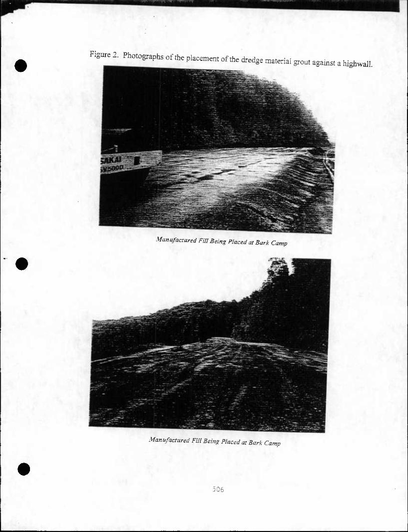
Figure 2. Pho.ographs of the phcemen, of fte dredge .-.atenai grout agams, a htghwall.
Manufaaured Fill Being Placed at Bark Camp
Manufactured Fill Being Placed at Bark Camp
506

CLAREMONT CHANNEL DREDGING AND DISPOSAL PROGRAM
The upgrading of the Claremont Channel for improved traffic through dredging is critical to the future financial viability of HNSE and the preservation of 125 direct jobs and over 4,000 jobs indirectly related to this business, such as vendor services, parts suppliers and professional services.
The trend among overseas customers is towards the use of vessels drawing between 35 and 45 feet of water. The current nominal depth of the channel is 28 feet at low water; many areas have a shallower depth due to silt. This lack of water access is not only a hindrance to HNSE, but a real impediment to developing a multi-user facility. Figures 3 and 4 show the location of the Claremont Channel and key aspects of the improvement project.
Dredging
Dredging will improve access and safety. The proposed design would dredge a deeper channel 200-300 foot wide and 34 foot deep within the existing channel, and add a turning basin at the midpoint. This basin is needed to improve safety in operations. Currently, ships back up for nearly a mile from the main channel in the Hudson River, aided by tug boats. The turning basin would allow ships to turn before loading, and to exit the channel moving forward. The volume of material to be dredged would be approximately 1.25 million cubic yards. The cost of dredging is estimated at $5 million.
Dredging will be done by a modem clamshell. This equipment greatly reduces the volume of return flow water and the requirements for its treatment, when compared to the traditional hydraulic dredge. It also reduces the loss of sediment to the water column as the bucket is withdrawn.
The dredged material will be placed in barges and unloaded and/or treated on shore. A key consideration will be the screening of scrap metal. This will be achieved by a series of screens and grates placed on the barges and the shore where the material will be unloaded. Water quality during dredging must comply with the requirements of the USACOE Permit and associated NJ Water Quality Certificate.
Processing Facility
As noted previously, the dredged material will be used in several different beneficial ways. It is proposed that a permanent, sediment processing facility be constructed on the western portion of the HNSE property to process the 900,000 cy of dredged material to be used for beneficial upland use in Pennsylvania and New Jersey.
The proposed facility would remove debris, decant free water and process the sediment with several types of admixtures depending of the ultimate use. Demonstrations as grout at the Bark Camp, PA mine closure site and as capping material and as bulk fill at the Pt Liberte' site are
507

/- -V-..:^
Figure 3. Claremonr Channel Location
x •
• \
^ 6
/
S i
Figure 4. Key Project Elements
W*i2*z5^
508

•oposed. The facility would be capable of processing up to 4,000 cy of dredged material per ty. The ultimate uses of the material are described in the following sections.
Golf Course Capping and Qrading
The proposed use for the bulk of the dredged material (800,000 cubic yards) will be as capping and grading material for a golf course at the nearby 100+ acre Port Liberte site, immediately to the North of Claremont Channel. The majority of the site, formerly known as US Department of Defense Supply Depot One, functioned as a petroleum storage facility. The remainder of the site consists of commercial and industrial uses and a former paint manufacturing facility to be remediated. The site is being redeveloped as a mixed residential and golf course use by Liberty National Development Corporation.
The developer's Remedial Action Work Plan requires capping contaminated soil areas with a low permeability cover to reduce infiltration. A golf course would then be built on top. The New Jersey Department of Commerce, Maritime Resources, has suggested using the dredged materials from the Claremont Channel as cover for the golf course. The dredged material would be used for two different purposes: to cap contaminated areas and as bulk fill for grading. The capping material must have a compressive strength of at least 30 psi, a bulk density of 85 lbs per cubic ft., and a permeability of less than 10*6 cm / sec. The bulk fill must have a compressive strength of at least 30 psi and a bulk density of less than 85 lbs per cubic ft. Both uses will require processing the material to reduce the free water content, to stabilize contaminants, and to
* btain a density appropriate to the use.
Most (650,000 cy) of the material will be processed by mixing it with pozzalanic additives routinely used to amend dredged materials for upland placement. By adjusting the mixture, the dredged material can be made suitable for use as capping material or simply be used as fill for grading.
Approximately 150,000 cubic yards of dredged material will be mixed with PROP AT® as a demonstration project. PROP AT® is a trademarked product manufactured by Hugo Neu Schnitzer East from recycled materials by processing the non-metallic interior materials from automobiles. PROP AT® has been approved as alternative daily landfill cover in several states and was approved in New Jersey as a cushioning material above a landfill liner in Pennsauken. Given its soil-like properties, PROP AT® may serve as an effective dehydrating agent for the dredged material, which consists of 60 to 70% water when extracted, thus improving its handling and application. The product's fiber content may also improve the strength of the admixture.
PROPAT®'s suitability for the proposed use as an additive, its field practicality and its cost effectiveness need to be demonstrated in order to obtain an Acceptable Use Determination from the New Jersey Department of Environmental Protection. A program consisting of bench scale, pilot scale and full scale demonstrations has been proposed to the New Jersey Department of Commerce, Maritime Resources, for funding. The bench scale demonstration is currently
^B^nderway.
1
-i.
509

^^^JZ%O!*: •£Trr-ma,enai—- - materai-s capabilities in the field can te^J^Z^^T*• 0f ^ "^oned unlmng fuii-sue processing and ea^-mo^*6" *""* * «*«** ^onst^tion,
three different mixing options: nJ^^*£Z ,Tf a?aCent t0 *= WSE &«% to test n-m on iand; and ustng ntobtie «,£££%££ i~ X^*" ^'" » P"*
m SSS^X^XSM^cublc ^ •*—*— material's conststency, strengtl{ pemSv^l C•s"ucnon ^Pment. After curing, fte plug samples coUected ftom te Sm tesfcdls IeaCi,abll"y wom be teste<i <" the lab ting
fte dredged material; posing it ^PROPA?® Jt T"^ "" f0ll0W,'ng: extra<:tin8 bulk as fill/grading material ^KOPAT®, truckmg it to Port Liberte; and placing in
^^ZT^rC^•^ -P oontamtnated soil areas and develop a this total cos, S5 mrllton woufd be ZZS^^jg****** ^S-Of
Mined Land Reclamation
Cormnonwealth of Pennsylvama lEL£ ^fon / abandoned mmes for'the problems related to over 250,000 acres ^SSnS Tf ^ SeVere ^romnental hazards from exposed highwalls are ^7^^tT * A ^ ^ *•*"»* ^ faI1
amended dredged matenal fromtheC^ofPe^hA^L MT^" APProximately 30,000 cy of.
used at the Bark Camp Site. Amboy' NJ Mui"cipal Marina was previously
CTI will take an additional 150 000 cuhir vprHc ^ •u
pan of their beneficial use project at ^ostrft,' T•^• ** ClaremoM Ch^" « the Hugo Neu site using ^ZtX^u^H m^Jhe sedin•t will be processed at structural fill for remedifti'n Jt^^^^T^ ^ ^ fOT ««*« manufacmred to the demonstration site in westeml^ivlt , ^ mneS' ^ "" *" be ^pped
proced.esdescnbedpetfectedpre^^'rj.ofr^^^^^^ Inter-tidal Habitat
It is estimated that 100,000 cubic yards of the rfi^„ A
mtertidal habitat that will extend the e*stine ^ "^ Can be pIaced m a Pn>Posed Channel. Tins area as a gently slopTbSSiS^ "f * ^ ^ 0f ^ Clare•>nt
with spamna and phra^tej n^^tZZ^I^^ ^^ "*» marshes
5 sionn drainage ditch. The adjacent upland is shrub
510

growth consisting of pioneer tree species. The area is currently used by a variety of waterfowl and shorebirds.
It is reported that nearby benthic habitat is poor, due to the organic and pathogen content of periodic sanitary discharges from the 54" Richard Street combined sewer outfall (CSO). CSO discharges are made into very shallow water, due to the location of its invert elevation above mean low water, and also include unsightly and unsanitary floatable matter.
The proposed intertidal habitat will be filled with the dredged material to mean low water level (MLW), and will be capped with 2-3 feet of site sand, clean fill, or stabilized material. The intertidal habitat will be contained by a natural berm, preferable to a bulkhead for esthetic and habitat reasons. The berm's face will be stabilized with concrete rubble rip-rap, recycled from the replacement of an existing pier on the HNSE site. This artificial reef will provide cover for young fish and benthic food chain organisms.
The proposed design includes extending the Richard Street CSO to a deeper part of the channel to improve mixing, dilution and flushing of discharges. The City of Jersey City plans to construct a structure to contain floatables under a separate program. The cost of this habitat improvement is estimated at $4.5 million, including CSO upgrades.
CONCLUSIONS
Innovative approaches, such as the one described here, when used for the remediation of abandoned mineland, represents a win-win-situation for all parties concerned. Moreover, as long as the proper precautions are taken to ensure that no labile contaminants are present in the cementitious grouts, it will represent a very important approach to the solution of several, major, environmental problems. The need for extremely large volumes of low-cost structural fill materials can be met by many of the "giga-scale" materials produced by industry, such as fly ash and the dredge material that is the subject of this publication. The availability of this material on a continual basis has the potential to significantly impact the needs within Pennsylvania for low- cost fill. At the same time, it would eliminate health and safety issues in the 250,000 acres of abandoned mines and restore vast areas of land for recreational use. Furthermore, it would put put extremely large volumes of residual materials to beneficial use and divert them from landfill disposal.
511

REFERENCES
Fontana, Christopher F. Large 1993. Volume use of fly ash for mine reclamation. M.S. thesis. The Pennsylvania State University, University Park.
Scheetz, Barry E., Michael J. Menghini, Rodger J. Homberger, Thomas D. Owens and Joseph Schueck 1997. Beneficial use of coal ash in anthracite and bituminous mine reclamation and mine drainage pollution abatement in Pennsylvania. Proc. Air & Waste Management Association, Toronto June 1997.
Scheetz, Barry E., Michael J. Menghini, Rodger J. Homberger, Thomas D. Owen, Joseph Schueck and Ernest Giovannitti 1998. Beneficial use of coal ash in mine reclamation and mine drainage pollution abatement in Pennsylvania. Tailings and Mine Waste '98: 795-805. Rotterdam: Balkema.
Scheetz, B.E., Richard Reifsnyder, and M.R. Silsbee 1994. Design of fly ash based grouts for acid mine drainage abatement. 16th Annual Meeting of the Association of Abandoned Mine Land Programs, Park City, 18-21 September 1994.
Scheetz, Bany E., Michael R. Silsbee, Christopher Fontana, Xiaogong Zhao, and Joseph Schueck 1993. Properties and potential applications of large volume use of fly ash-based grouts for acid mine drainage abatement. Timothy C. Richmond (ed), Proc. 15th Annual Abandoned Mine Land Conference: 64-76.
Scheetz, B.E., M.R. Silsbee and J. Schueck 1995. Field applications of cementitious grouts to address the formation of acid mine drainage. Sudbury '95, Conference on Mining and the Environment, Sudbury.
Scheetz, Barry E., Michael R. Silsbee and Joseph Schueck 1998. Acid mine drainage abatement resulting from pressure grouting of buried bituminous mine spoils. Tailings and Mine Waste '98: 859-870. Rotterdam: Balkema.
Schueck, Joseph, Terry Ackman, and Barry E. Scheetz 1994. Acid mine drainage abatement using fluidized bed combustion ash grout after geophysical site characterization. International Land Reclamation and Mine Drainage Conference and the Third International Conference on the Abatement of Acidic Drainage, Pittsburgh, April 24-29,1994.
Schueck, Joseph, Mike DiMatteo, Richard Jones, Terry Ackman, Mike Silsbee, and Barry E. Scheetz 1996. Water quality improvements resulting from fbc ash grouting of buried piles of pyritic materials on surface coal mines. 1996 Annual Meeting of the American Society for Surface Mining and Reclamation (ASSMR), Knoxville, April 1996.
Schueck, Joseph, and Barry E. Scheetz 1993. Acid mine drainage abatement from small, buried piles of tipple refuse using fluidized bed fly ash grout. Timothy C. Richmond (ed), Proc. 15th Annual Abandoned Mine Land Conference: 77-103.
Tavolaro, J.F., M.A. Paula, and R.M. Carrato. 1987. Investigations of subaqueous borrow pits and disposal sites for contaminated dredge material from New York Harbor. T.R. Patin (ed), U.S. Army Corps of Engineers, Water Resources Center, Management of Bottom Sediments Containing Toxic Substances: Proc. 13th US/Japan Experts Meeting, Baltimore, 3-5 November 1987: 308-325.
Zhao, Xiaogong 1995. Cementitious grouts based on fluidized bed combustion ash for environmental restoration. M.S. thesis. The Pennsylvania State University, University Park.
512

weoA PROCEEDINGS
OF THE
WESTERN DREDGING ASSOCIATION NINETEENTH TECHNICAL
CONFERENCE
and
THIRTY-FIRST TEXAS A&M DREDGING SEMINAR
May 15-18, 1999
Louisville, Kentucky
j

DREDGED MATERIAL MANAGEMENT IN NEW JERSEY: A MULTIFACETED APPROACH FOR MEETING STATEWIDE DREDGING NEEDS IN THE 21ST
:f CENTURY
F.M. McDonough1, G.A. Boehm2, and W.S. Douglas3
ABSTRACT
New Jersey is a maritime state with 76 ports and terminals along its coastline. Dredging and environmentally safe disposal of dredged sediments has been set forth in State policy and provides New Jersey Maritime Resources (NJMR) with the flexibility to manage dredged materials on a case-by-case basis in a comprehensive matrix of primarily beneficial and environmentally sound uses. Traditional management options such as ocean disposal are no longer available. This paper provides a review of overall management strategy and recent innovative dredging projects, including aquatic confinement, upland containment, and brownfield remediation.
New Jersey projects include the Newark Bay Confined Disposal Facility (CDF), coal-mine reclamation, ocean remediation at the Historic Area Remediation Site (HARS), landfill and brownfield remediation in Elizabeth and Keamy, beach replenishment in Cape May and the construction of roadway embankments. Based on an anticipated volume of 7.8 million cubic yards of contaminated material from the Port of New York and New Jersey deepening projects plus 2 million cubic yards from non-deepening projects until the year 2002, NJMR management projects have a remaining project capacity of approximately 14 million cubic yards. An anticipated volume of 6 million (non-contaminated) cubic yards annually from State navigation channels will be managed under a new Statewide Dredging Plan that was approved by the State's Dredging Projects Facilitation Task Force.
NJMR has identified future dredged materials management options utilizing a geographic information system (GIS). Additionally, NJMR has also begun to address sedimentation rates and toxic discharges to New Jersey's waterways through innovative technologies such as AirGuard•, Scour•, in-situ and whole sediment decontamination, and a State Toxics Trackdown and Reduction Workplan.
Keywords: beneficial use, remediation, innovative technologies, sediment, disposal
INTRODUCTION
In 1637 the King of England declared the first port of entry in the British Colonies. The port was located in a small New Jersey community along the Delaware River called Salem. Since then. New Jersey as a maritime state has continued to be a major port of call from Trenton on the
1 Executive Director, NJ Maritime Resources, 28 West State Street, Trenton, New Jersey 08625-0837. 2 Maritime Specialist, NJ Maritime Resources, 28 West State Street, Trenton, New Jersey 08625-0837. 3 Maritime Specialist, NJ Maritime Resources, 28 West State Street, Trenton, New Jersey 08625-0837.
349

1 Delaware to Hoboken on the Hudson. While passenger ships no longer steam to New Jersey's 7*
doZs SerVCS ^ imp0I, "* eXp0r, Car80 indUStty vaIued in ^ <«« of bmfons 0f
In the third largest port in the United States, the Port of New York and New Jersev SW „f,..
billion gallons of petroleum products transit the Port every year Alone the irTmT ,
S^Tr"*? itS ' ,6fta,e naVi8a,i0n Channe,S',he fifth *£> ~cSfishin indm5 o0„
o^sftSS.*"•-and the world with fmfish ^shd,fish |-•" "istss
SSTiT1-",he count,y*,0 ,emlina, &d,i'ies«' -^ - ^= t ouTd S annually ply the nver canymg steel, fruit, lumber, fresh meat, and other products.
^winvin8t.tueSl!harIS ^ alWayS ^ a '^ndous challenge for the State of New Jersev In New York Harbor alone there are 240 miles of Federal navigation channels In °he la« SOO^ when the satlmg stops of the time began to exceed the natural depth ofX Lter (?8 te, TV
tZu £ more,fns't'« ^^ methodologies determined that much of the d7edged mTri^
^gHm^ szgfjzsz* CoTr^,,he r,io1 a?r
KT i,S r" " ^ - ,he ^ P-o^emury^av8^ vTo^suL 3 eft the shorestde cues and pom behind, the average cteen has forgotten how ZTtapo^
cars, fruit, cocoa, wine and beer arrives on our shores. imported
fh^'lv "T i*6/• YOrk Harb0r dredgin8 crisis fa 1993 wWrt galvanized the citizens and
sfaceTen s^Srth in W 8 ? en•?rmf'aUy Safe ^^^ "f hedged materials has o^n? , PO'1Cy ^ le8lsla'i0»- Traditional management options such as
environmental J^^V^^'S^T^^^I^^ and plannmg currently employed in New Jersey. projecis, tecnnologies,
THE CONTAMINANT CHALLENGE
New Jersey sits on a geological shelf which stretches out 32 miles beyond the shore before
PoT^f S?/?,^ ^^ ^ "^ ^^ the P0rt 0f New York an^New Jersey an^te De^e R^tchT H^K ? ""^ POrtS SUbjeCt t0 subst-tial siSn The nortTJH ^ T f uS ^ ^ P0rtS 0f Philadelphia and Camden, and numerous other ports and terminals along the nver's edge, is essentially shallow water scoured onlbvLoZ movement and the dredges which travel from Trenton to the ocean. The ^rt of New York ^ New Jersey has an average depth of 18 feet and is located on an estuary fed b^ the Hudso^e Hackensack the Passa.c, the East River and numerous other watetc^^h fill tte^u^ with one million metric tons of silt each year. crcourses wmcn till the estuary
350

Dredging our channels is a never-ending task. We are an industrial region and the sediments as )the natural sink for industrial poUutants, bear the legacy of the inadequate waste management practices of the past.
On the New Jersey side of the Port of New York and New Jersey, we face the challenge of the removal of approximately 1.82 million cubic yards of contaminated material annually. Historically, the management method of preference was ocean disposal. For almost 80 years the Port of New York and New Jersey primarily disposed of dredged material by transporting it to an ocean disposal site about six miles off the New Jersey coast. Known as the Mud Dump Site, this was one of more than a dozen ocean disposal sites for various materials from the metropolitan area. However, improved laboratory technologies and analysis of an increased number of contaminants revealed that much of the material being transported to the Mud Dump Site created the distinct possibility of biological uptake in the aquatic animals that subsisted, habitated in, and passed through the Mud Dump region, an area of almost 23 square miles.
In 1993 the fishing and environmental communities brought this practice to a halt in a lawsuit which challenged ocean disposal of contaminated dredged materials. Ultimately, the Federal government closed the Mud Dump Site forever and created, in its place, a remediation site which coincided with all the original disposal areas called the Historic Area Remediation Site (HARS).
Fortunately, the Governor was well ahead of this and had decided early on to adopt the policy of beneficial upland use for dredged materials. To meet this goal she directed a number of
(independent but interrelated actions. In 1994, while the lawsuit wound its way through the courts, newly-elected Governor Christine Todd Whitman created a team to develop short-term non-ocean alternatives while a fully comprehensive approach to dredged materials management was crafted. The result was implementation of a short-term disposal option (a subaqueous confined disposal faciUty in Newark Bay) and creation of a complex management strategy employing high and low technology options managed by a highly directed team of professionals within State government. This is the multifaceted management system which will resolve disposal challenges for the 21st century.
THE APPROACH
The Governor tasked her Commissioner of Environmental Protection to draft a single regulatory document which would provide for the environmentally safe management of all dredged materials. To write The Management and Regulation of Dredging Activities and Dredged Materials in New Jersey's Tidal Waters, commonly called the "Technical Guidance Manual", a highly skilled Task Force of two dozen experts from every technical field within the Department of Environmental Protection worked for more than a year. The manual divided the State into several zones based on the types of dredged materials involved and the potential levels of contaminants. The document sets testing criteria, sampling requirements, and upland management protocols.
The Governor then created New Jersey Maritime Resources in the New Jersey Department of Commerce and Economic Development. The mission of the Office is to provide agency support and coordination, programmatic planning, and research and development to ensure sustainable
351

economic development of New Jersev's l^n hiiii•, -•J.-
terminals, boat building, marine S JvL^ ^ T I5<iUStry inCludin8 its P0"5 ^ operations, waterbom/ d^SS ^a bn ^^ Md reCTeatio^ ^hing, mili^y science and technology. * nav,gat,on and government services, and education,
the State. The Office ^WoaiTi,? , ^ "f d'Sp0^ o(^S^ "Aerials throu^out working rebtio^; ^nductid TZgL"?"" Q0•iDKalS t0 deVdoP a -^t developing solutions More ta S. md^S, re^ T?^ F•'6 ^'^ ^o^ment in has been a major factor in ourTcces- ^ ^^^'ves parttcpated and the private sector
aZ^LS ffig^tf8 ^^ ^^ - -hnologies and
initial steps were taken Z^StaLSL S^^ **' ^ WOUld eiKUre te
utilize in regulatory initiatives, tectaoZ deleted ^ "^ f0r ^ ,wo States ^ technologies, beneficial use, contamZfSdtS^ITZjfi^ T"66•8' proCCSSin« harbor studies. >«miiKim reauaion and trackdown, poUution prevention, and
and 4e demonsmtion of decontaminatior^XS^ ^^7' ^ deIe,0l"ne» "f CDFs, for ctedging navig^ cimmek statewid" "Smber^f Wfi^lT ' $20 miIli0n ^
s^i^Ersr^otcS^^-r^ Goror- -»* - Department of Environmental ftotec^W^,! Zt ""^ ^ NeW lax* dredging-related projects The Office ofrvlf- T^ P*•"10? of dredging and expertise from a'nuLer oi^ffetS w^^LS" '""T TeChn°,0S- ««*5A» proposals. "" Provlde comprehensive one-stop review of
S^IE^P^Mg ?***•«>*. is located within ^e dredging and upland beneficial^optW KS ,fiiUy m?8rated ^io-ship between landfill cappingf and nmtJ^a^Sf^J?•* '?*** •*» """^ .manufactured soil, demonsmtion technology * ^ STSSf 0Pn^ *?0-»»i-^
Soq^,^xxoevidei; ffiMstsr"*Ks:s when a projec", /-^^^SS^S^i^ ^^ t0 — ^
352

Finally, New Jersey Maritime Resources drafted a Statewide Dredging Plan to manage all dredging and dredged material disposal activities in the State of New Jersey. Mirroring the plans for the Port of New York and New Jersey, the Statewide Dredging Plan reviewed fiiture requirements, developed a priority list for meeting those requirements, and identified options for the disposal of the dredged material utilizing as its guide the new statewide policy for beneficial use.
Unique projects, such as those described in this paper, provided an opportunity for the creation of upland disposal facilities and upland beneficial uses which incorporated local goals and included recreational, environmental, and educational components to ensure that each project had the necessary public support. The Penultimate Act was the endorsement by the Governor of a coalition of business leaders throughout the State of New Jersey to work with the Federal Administration and the Congress to ensure that Federal funding was available for all of the many Federal navigation projects throughout the State.
THE FUTURE
New Jersey has a tradition of utilizing a number of different methodologies for disposal and beneficial use of dredged materials from State navigation channels and facilities located along the Delaware River. Those management options include beach replenishment, confined disposal facilities, in-water disposal, and more recently, multiple use CDFs. Within the last decade, upland CDFs were even mined to produce soil for fill in construction projects. Dredging of certain channels where the material is both clean and of the correct grain size, has been routinely conducted by private contractors seeking sand for use in the marketplace. However, in certain locales such as the Port of New York and New Jersey a single option—ocean disposal—was relied. on almost exclusively.
Because of the seemingly unlimited capacity for disposal in the ocean and the unavailability of other traditional disposal options such as upland CDFs, attempts to develop alternatives to ocean disposal generally failed. It wasn't until the dredging crisis of the early 1990's that real incentive existed to create innovative non-ocean alternatives. While New Jersey has been the leader in the development of those alternatives, the mind-set of many remains a search for the "silver bullet" disposal option.
Yet, political pressure, environmental activism, and the success of the non-ocean alternatives developed by the State of New Jersey are slowly but surely convincing even the diehards that reliance on a single disposal option is a thing of the past. The future is now reflected in a multifaceted approach to sediment management. Prior to 1993 almost 99% of all dredged material from the Port of New York and New Jersey was deposited in the ocean as reflected in Figure 1.
353

I
Hstorical DBdgBdR/bteri^ IteBgemert
Figure 1
The shift to non-ocean alternatives is dramfltiValw rofl^* A • between 1995 and 1998 as shown in Fi^2 m manaSement ^^ons conducted
Dredged Materials Management 1995-1998
Upland Benefiaal Use
33%
Figure 2
remediation and .hen only after ri^r"• ^^ *" ,he ocean is "'^ «" HARS
1999 Dredged Material Management (New Jersey Projects Only)
N—nhon Containment
39%
Figure 3
35A

Comprehensive Management
New Jersey's sediment management plan is reflected in Figure 4. This combination of initiatives represents a comprehensive approach to the management of all dredged materials, especially contaminated dredged materials, and a series of initiatives designed to reduce sedimentation and eliminate contamination. The chart reflects strategies that are either already in operation, or in the research and development phase close to implementation. Each is also designed to compliment the other strategies recognizing, again, that no single approach nor even a limited collection of approaches will provide a fully successful management strategy.
New Jersey's Comprehensive Sediment Management Strategy
Technology Applications Manufactured Aggegate
Manufactured Soil
Const/vction Fill Deconta/nmation
In-Srtu Remediation Sedimentation Engineering
Environmental Dreqging
Bmwnfield^eclarnation
Habitat Devekfoi Landfill Ooesations
Transoortjtion Projects Mine Reclamation Pollution Prevention
Beach Reolenis,
multiple Us'
Placement
Ocean R fit /-r^-M-"-^-.-
Confined Aau,
Confined
Beneficial Use
l4u ^v
deling -f.j^** kdown/Reducton ,
'onitorina dv^ i-'-V1-^-
ization Cl-s. <•-'•'•' ^1
i. '
,K •
kjj^-': Panning
(,w-
Figure 4
While the comprehensive sediment management plan applies statewide, the obvious genesis of the plan is the contaminated sediments found in the Port of New York and New Jersey. Table 1 reflects the types and levels of contaminants found in dredged materials in New York Harbor, particularly in Newark Bay. Comparing the sediment quality in Newark Bay to guidelines for the protection of aquatic life (Effects Range Low, Effects Range Median) one can see why the fishing and environmental community expressed concern over ocean disposal. However, when the same data are compared to the guidelines developed for protecting terrestrial ecosystems and human health (NJ Residential/Non-Residential Clean-up Criteria), it becomes apparent that environmentally sound upland management practices are possible. The techniques utilized can generally be categorized as high technology, low technology, and traditional approaches.
355

Table 1 Levels of Contaminants in Dredged Materials*
NJ Non- Residential
Cleannn Criteria
340
•Ana.ysis conduced of Newark Bay samp,es by N J M ari.i. e R eso urces
High Technology
remve the comaminants from aeex^d^d^; def>nta•»tio° technologies which the Toxics Trackdown ?Z betogTeclS tv rtf ,3" ^ IT remedMon technologies. Protection, air quality monitoAf nr^l , New Jersey Department of Environmental
projects Lth^lThC^CSLlrT ^ f.0f 0Ur Upland ^fl"31 "" us to better understand fte d^rdS^"5' "" ""^ m0deling Which "* •"-
Low Technology
— -h clean and contam^ated A^SlX^^^S^t
356

which dredged materials are processed to create manufactured soil for berms, grading, and fill, and the Pennsylvania Mines Reclamation Project which utilizes processed dredged materials to reclaim strip mines in Pennsylvania while reducing and eliminating acid leachate from those mines.
A full description of each of the technologies currently being employed or about to be employed in New Jersey is contained in Appendix 1.
Traditional Approaches
Traditional projects utilize clean dredged materials for remediation of the former ocean disposal site, removal of dredged materials from the Harbor in an environmental dredging program, utilization of in-water CDFs for placement of contaminated dredged materials, and the use of existing upland dredged material disposal facilities for multi-use projects.
Beneficial Use of Contaminated Material
While upland CDFs are available in other parts of the State of New Jersey, no such facilities exist in the Port of New York and New Jersey. Redevelopment of brownfields and proper closure of landfills presented the most obvious opportunities for beneficial use of dredged materials. The first priority for the Port was to develop upland beneficial uses for dredged materials in construction, site remediation and landfill operations. However, the negative public perception created by significant media attention to contaminated dredged materials in New York Harbor resulted in an immediate obstacle to general use of dredged materials for beneficial purposes. This is true even though some of the contaminated dredged materials would meet the residential clean-up standards in the State of New Jersey, and all dredged materials would meet most non-residential site clean-up criteria. Regardless, a formula was needed which would provide the necessary public confidence that contaminated dredged materials would not be found in "my backyard."
The "formula" for beneficial use of dredged materials took the form of a list of criteria, estabhshed by combining both practical considerations and the Governor's policy against use of dredged materials near residential areas. Sites were plotted and, utilizing predicted volumes of contaminated and non-contaminated dredged materials proposed for dredging over an eight year period in the Port of New York and New Jersey, NJMR staff were able to identify sufficient capacity to satisfy disposal requirements. These sites for placement of dredged materials had to be close enough to waterways and roadways to allow cost effective access, yet far enough from schools, houses of worship, and residential areas to provide a buffer. The best sites were determined to be those that had previously been industrialized (brownfields) or solid waste landfills. Only sites greater than 40 acres were considered economically viable.
While development of the formula was relatively straightforward, a list identifying sites meeting these criteria had never been developed. Utilizing the GIS developed by NJDEP, maps of the closed and/or abandoned solid waste landfills and known contaminated sites in New Jersey were made using Arcview software. Inputting coverage of land use, navigable waterways, residential areas and houses of worship allowed NJMR to perform a spatial analysis that resulted in
357

iden^ation of .he sites which would meet sine, criteria The result of this analysis is reflected
p• ^ ProP0Se "^ f0r "" "^ 0f <ta*«l «—*b « redevelopJem
t^m^.fr SS"^^ NJMS Was ,he d^0P•eM of a database of dredging prelects Smen lafol^ f 'Ba*[*0*a*i *>*** of dredged materials that Sd^Se Z?HHMT ,,, ^ 0n "" ^^"y avaiIable " *«ig«l materials management areas w^ GS ^ H ^ ba?- ^ databaSe' "'^^ ^ ^ spatial anafyS perfon^ usZ
^Tvatdy ' " f0r add,,'0nal Capacit5' which ^ >* ^'ored both publicly
Known Comtaminaled Sites Prior to Criteria Review Sites Remaining after Application of
Criteria
Application of CIS for Screening Know Contaminated Sites List Figure S
358

Processing Facilities
While the private sector stepped up to the plate to develop beneficial use of dredged materials for upland activities. New Jersey continued to refine the potential uses for dredged materials as shown in Figure 6.
What Happens to Our Dredged Material?
•Manufactured Soil •Aggregate •Intermediate Landfill Cover •Ocean Disposal •Beach N'ounshmeni1
•Habitat Restoration/Creanon •Upland Fill •Highway Construcnon
•Manufactured Soil •Ocean Disposal •Landfill Final Cap •Landfill Liner •Upland Fill •Nearshore Fill •Brownfield Cover •Habitat Restoranon/Creanon •Highway Construction
Saild c.^ t>.(kQS»«l
Glay <.iiOiViiiin|
^t
CoHtami"^1^
O •tntermediate Landfill Cover •Confined Aquatic Disposal •Confined Upland Disposal •Upland Fill •Meanhorc Fill (with Capping)
' T5% Svd: ^rimazc ctatubuDon most be eqmvalcH to cxisoaf catutmcns 1 Uses isgnc ao decomamnaiinn
•Confined Aquatic Disposal •Confined Upland Disposal •Nearshore Fill (with Capping) •Landfill Cap (with Clean Cover) •Brownfield Cap (with Clean Cover) •Mine Reclamation
•Upland Fill •Brownfield Cover •Habitat Res to ran on; Creation •Nearshore Fill - Manufactured Soil •Highway Construction
o |>.0IIJ9miii| |<.(»fi2?imii|
' Uses UBSDC den or •Vf'H'nmMi-ri
•Confined Aquatic Disposal •Confined Upland Disposal •Nearshore Fill (with Capping) •Landfill Inlennediaic Cover •Mine Redamanon •Brownfield Cap (with Clean Cover) •Decontamination and Disposal
IVhat Happens to Our Dredged Materials? Prepared by NJ Maritime Resources
Figure 6
But the handling of dredged material proved to be a unique challenge. For example, dredged material from New York Harbor is 65% water, contains a high level of nutrients and is, of course, saline. It is not hard to picture the difficulty of dealing with sloppy, wet material in the payload bed of a truck or a rail gondola car. Moreover, environmental windows, which prevented dredging during certain fish habitat and migration times, made it difficult to develop a steady stream of dredged materials for various upland projects. This presented challenges to the private sector which needed that flow to profit. Furthermore, dredged materials in marinas and at terminals included large amounts of debris such as scrap metal, logs, pilings, and other objects which made the handling of the silt extremely difficult and expensive. Initially, the private sector tried pumping the dredged material over long distances to the site being reclaimed, then mixing the dredged material with admixtures to stabilize and create the necessary compaction rates for the intended use. Tires, bicycles, car doors, and other foreign objects destroyed the pumps in quick order. It is rumored that one private sector entrepreneur initially made more money recycling scrap metal than processing dredged materials.
359

In the eni new techniques for in-barge screening at dockside became the preferred method for ensuring that the dredged materials went though the process smoothly and expensive equipment was not destroyed by foreign objects. As the private sector learned from its investments processing fecihties became more economical, more efficient and mobile. Now thev can be moved from location to location. .y ^ uc
However, the State of New Jersey requires a facihty which could guarantee processed, stabilized and enhanced dredged material for the landfill, site remediation, and transportation projects it was managing Thus was bom the idea of the State-owned, privately operated processing facility reflected m the design prepared by NJ Maritime Resources in Figure 7. This facility will process, stabdize and blend dredged materials to create manufactured soil at the rate of 500 000 cubic yards per year The facility includes storage area to ensure that processed dredged material will be available twelve months of the year for ongoing State projects rA
CONCEPTUAL SITE LAYOUT
MANUFACTURED SOIL
RESERVE
(CAPAOTY150 KCY)
(<5 ACRES)
BERMED CtWfTAINMENT AREA
LOADOUT HOPPER
SCREENED MATERIAL RESERVE
(500,000 CV CAPACITY)
(jpprat. 20 ACRES)
^ ,>'
-'ii
Processing Facility Figure 7
Beneficial Use of Clean Dredged Material
A t^l^ ^V0^ !?lNeW JerSey ** United States ^y CorPs of Engineers, the Port Authority of New York and New Jersey, and the State of New Jersey are currently engaged in several sigmficant deepening projects. The Kill Van Kull, which is the major waterway leading to the temunal facilities located in Port Newark and ElizabethPort, is cuxrently being dredged to 45 feet The Arthur Kill, which leads to many of the petroleum facilities in New Jersey as well as Port Authonty terminals at Rowland Hook on Staten Island, is scheduled to be deepened to 41
360

J <•/ •
J
itc
feet. Port Jersey Channel on the upper New York Bay will be dredged to 41 feet starting this summer, and a study is currently underway to deepen channels to 50 feet.
Collectively, these projects will produce millions of cubic yards of clean dredged material which can be utilized for a number of beneficial purposes. Rock is currently the subject of competition for various artificial reef and shoreline protection programs. Clean silt and sand will be utilized to help restore the Historic Area Remediation Site by capping the contaminated materials which had been deposited for more than 80 years in that 23 square mile area.
The most unique of these projects is the dredging of almost 10 million cubic yards of red/brown clay. This material has a general permeability rating of 10'7 or lO"8 making it a perfect capping material for the proper closure of orphan landfills in and around New Jersey's waters. So New Jersey has embarked upon a major demonstration project utilizing red/brown clay to cap abandoned landfills and construct slurry walls, preventing contaminated leachate from running into the Harbor. It is estimated that each improperly closed landfill discharges up to 400,000 gallons of contaminated leachate per acre into the Harbor annually. Thus New Jersey's - red/brown clay program will serve several noble purposes: dredging navigation channels, properly closing abandoned landfills, and pollution prevention. The first demonstration project will start this summer and the program is expected to be replicated throughout the State of New - Jersey at both abandoned and operating landfills. fhrH-f^.
The clay can also be utilized to provide a soUd cap over the contaminated areas at the HARS and, if the material is not proven to be a good fit for habitat development, it could be further capped with clean dredged materials to provide the necessary habitat.
Confined Disposal Facilities-Multiple Use
As noted several times in this report, upland confined disposal facilities are in operation throughout the State of New Jersey. However they are traditional CDFs and they have become the subject of intense local public debate particularly with the deepening of the Delaware River. That project will excavate some 33 million cubic yards over several years and will require the continued use of a number of existing CDFs as well as the construction of new ones. Opposition to many of these facilities has increased in recent years as the fear of exposure to "contaminated materials" has heightened. While this fear may be misplaced regarding the Delaware River Project, New Jersey has developed an extremely active approach to the continued use of its existing facilities as well as the development of new ones.
By creating multiple-use facihties. New Jersey expects to educate individuals on the benefits of dredging through direct use of those confined disposal facilities for other purposes. The Palmyra dredged materials disposal facility on the Delaware River is the premiere example as shown in Figure 8. This unique facility was developed by a partnership of Burlington County officials, the Burlington County Bridge Commission, NJDEP, and others to create a natural habitat, as well as a beneficial use facility for storage and dewatering of dredged materials.
361
J

-267 ACRES
t• ^ ^ ^ Daj*W'«E «VER -3.M0 FEET ON THE PENNSA^N^
D<**gned by ACT Engineers Figure 8
Facility plans include boardwalk trails »iUli«
i, me iNew York Shipping Association, 362

terminal owners and others, a series of classroom education programs, media initiatives, and public speaking activities have been developed to remind the citizens of the benefits of our maritime industry and to ensure that the information that is provided is accurate and appropriate.
Planning Initiatives
Among the recommendations of the Governor's Dredged Materials Management Team, and the provisions of the Bi-State Joint Dredging Plan was the requirement for a careful examination of existing dredging requirements and a concerted effort to minimize those requirements. Currently, in the Port of New York and New Jersey, the US Army Corps of Engineers, the Port Authority of New York and New Jersey and the two States are conducting a Harbor Navigation Study to determine the appropriate depths for the existing channels in the Harbor. While the study is expected to result in the deepening of certain channels, it may also identify those channels which justify only current depths or even reduced maintenance.
New Jersey has also embarked upon an ambitious channel optimization plan which reviews each channel to identify opportunities for redesign which will reduce the amount of construction and maintenance dredging. Even public notices by private applicants for dredging permits are scrutinized closely to identify future dredging requirements and to encourage the development of comprehensive maintenance dredging plans for those facilities.
Probably the most significant study in New York Harbor is the Toxics Reduction Workplan developed by New Jersey to implement the contaminant- trackdown and reduction goals of the Harbor Estuary Plan. The purpose of this study is to identify the sources of contaminants of concern to the Harbor and to begin to abate those sources through a toxics reduction strategy of increased monitoring, site cleanup/closure and environmental dredging. While hot spots in surficial sediment chemistry can easily be identified, there is no sound method to predict the overall impact of remediation strategies on the quality of the dredged material. To address this shortcoming, the State of New Jersey, working closely with the State of New York and federal agencies, is developing a state-of-the-art contaminant fate and transport model. This mode will enable managers to predict the outcome of contaminant reduction strategies on the quality of dredged materials in the future. This will ensure that limited funds are utilized most efficiently to achieve the greatest environmental gain.
Commensurate with these studies, is a series of important habitat development/redevelopment and wetlands restoration projects currently under development. Toxics trackdown, natural resources restoration, and pollution prevention are the three legs of the stool that will ultimately result in sediments clean enough for any purpose or disposal methodology.
CONCLUSION
If any conclusion can be drawn from the multiple disparate efforts identified in this paper, it is that the key to success is political will, creativity, and commitment. The political will is evident in the State's determination to establish the necessary processes which ensure the success of a relatively complex series of initiatives.
363

within which the State of New Jer^ tm^ied Th7 .i eXtremely Short Period of *» disposal, and no fnnding, to a tull ^^^i^^tT ~ ^^ no
disposal capacity for the near-term hedging regime, funding, and even excess
achieve a common goal. dedicated professionals working in partnership to
^te^^^S^^' ^f.^ ^ne by mghly competent there was no single thread connectLS .if w . f-^^ ^ leadersWp. Simply put the issue. Crisis created foZZf^dZ^ ^T' ^^ WaS n0t foc^ on not only a comprehensive ^cT^atZ^LT ^u 5"* We « preSented ^ -grate.oftheprogi^L^^^^^
^^LS^^T^^ ^ ^ ^ 21- century can encounter unforeseen o'bstLs. ^rS^eS^f^!^ ^ ^ " m0re fecets
our maritime industry while fine-tmLgTZli^ ?f Pr0gram wiI1 COntillue t0 sus^ never-ending tas^too is cont^^^J^ S^^ ^ - dredging is a The approach developed by GoVemor Whitm^^
^.^^v - ^r^c-U^C. I* .0/ tLy^ .JLJL^ ^6VC
\^
u
1
rfrjL d^ ZfJJL, ^J- f
A wr^ ^ , • . 364 ^ •' x i;1- L(L ^
^ vi ^u .tts. I^L ^(-%'— ' - >^ : • y,:^

^^ LJLv-thae.uttto— ''f'* :^^
APPENDIX 1
High Tech Initiatives
• Turbo Jetting - An alternative strategy to dredged materials management is to prevent the settling of particles in berthing areas, thereby reducing or eliminating the need to dredge there. One way to accomplish this is by using a high volume jetting system to agitate the water near the sediment surface periodically, thereby preventing the settling of fine particles. The SCOUR• system is a high volume, low velocity pump that pulls surface water through a pipe and directs it out across the sediment-water interface. Multiple units are installed in a series across a pierhead, and are turned on for a short period at the start of ebb tide during each tidal cycle. The resulting water flow carries the fine particles deposited during the last slack tide out of the berthing area with the outgoing tide. One such project is currently under development by NJMR.
Entrainment of fish larvae and sediment resuspension are of concern to regulators regarding this technology. Therefore NJMR has worked extensively with the NJDEP to produce a monitoring plan to determine the impact, if any. Regardless of the outcome, a conceptual cost/benefit analysis will weigh the environmental costs of this technology versus other available management options before a final decision will be made.
• Pneumatic Barriers - A similar strategy sponsored by NJMR employs the use of a series of bubble walls which act to keep particles in suspension, and prevent the buildup of sediments in berthing areas. Air is forced through a series of pipes on the bottom of the berth, oriented to maximize disturbance of water in areas that typically have high deposition. These barriers have already proved effective in floatables control throughout the Harbor, but have not yet been demonstrated to be effective in the control of sedimentation. This system has the added benefit of increasing dissolved oxygen throughout the water column, encouraging aquatic life. Ironically, some operators have expressed concern that attracting aquatic life may result in increased macro fouling of pier structures and water intakes.
• Soil Washing - This decontamination technology is based on the same principles as a washing machine. Sediment is mixed with water in a slurry and agitated in large mixing vessels. Chemicals are added to aid in destruction of organics and dissolution of bonds tying contaminants to the sediment. The "washwater" is then decanted and treated using standard techniques. Clean sediment can then be beneficially used to manufacture topsoiL structural and non-structural fill, and capping/cover material as needed. Two such projects have been selected to participate in the NJMR Sediment Decontamination Demonstration, projected to commence this year. As with all decontamination technologies, extensive public outreach is necessary to ensure that citizen concerns are allayed.
• Thermal Destruction - This decontamination technology relies on high temperature rotary kilns to "bake" the sediments. Organic contaminants are destroyed by the heat and the metals are permanently incorporated into the physical matrix of the sediment. The resulting mineral matrix is then used as a base material for the manufacture of lightweight aggregate or
365

sssss. ssessr^^-ESrm ,he NJMR ^
• Enhanced Mineralization - TW A
enhances the natural 7^/^^•°***; **"" - Georeinecliation. propnetaryznixture of catalysts is n^ed^h t^e sed^T H ^ ^"^ ^ so^ A days. During this time the organic coitoSn* Sed•e
7nts ^ ^^^d to react for up to 2S
and the metals are incorporfS pC~^^
demonstration project are scheduled tL 1 ^ ""^ matrix- A P^t ^ Decontamination Demonstration. ^ ^ part of the NJMR Sedim^t
• In-situ Remediation - Due to the now;* i«. • contaminated sediments in *££££££%£**?? ^ ^ d^-g highly technologies to decontaminate sediment, in ^7 t eW Jersey ^ ^en searching for and are in the bench-scale ^^tZ^L T* ^^ ^ ^ PS£
powder to catalyze the destruction o Ste JeenT* ^r0miSmg ^ 2er0 ^celron senes of tubes containing the zero v^enSTon ^ S"diments ^ ** contaminants. A contammated sediments. Contaminate^ then t T ^ ^ plaCed directIy ^o the tubes. The tubes are then rerno^ £ Shlv^f ' ^ ^ P0Wder »*>** ^ SSSF***- NJDEP is conductinrone sucf J COnCentrated Po^'s are disposed of NJMR- 8 0ne SUch demonstration project that is funded by
• Toxics Trackdown - One of thp i•,* the Port depends on the r^JLl^ZS^tf1^ "* ••&•« » management due to contamination. T^dert S ^ ^ ^^ ^^^ contamination being added to the sediments thl effect^vely **"<* the amount of defined and prioritized. The Stated?ti^ew J^ev^M0' ^ -nt^-ts must be Harbor Estuary Program, have developed adt !• eW ^^ Workillg through the sources and magnitudes of eoa*ffi ^^ the w^T^ Pr0gramt0 determS ^ H^rEstua.. H-W.I.^^TSrr^^
developed. This model will need to take^o^TlTu ^ tranSp0rt model •t be the Harbor along with the complex hydrL^cs^dl MPOmt ^ n0n-point sources » of contaminants of concern in water sediSTn^ ?< * t0 Predict the concentrations collected in the toxics trackdown progS^! £ T ^ * multi-year timeframe. Data
Air Quality Modeline - Onp nf tk dredged material in fc a^K^S iSSUes "?»<*« with rte hnovative use of the sedtaems. While individual P^ s tave reS T'^r^ by -"-Nation in momtonng program is being developed to Tdem* 1° "^ hea"h ha2ard' » e»^ive poUu.an.s released into the air during drcW Itri^^T^ VOktUe ^ ^-volatile The chosen monitoring site wiU Snce ,S~, ^t^p^oT 0Perati0nS-
Huaxuy di) a point or comparison.

'-",t
Fugitive emissions are also being assessed as part of a demonstration project on the use of dredged materials in transportation projects.
Low Tech Initiatives
Landfill Operations - Dredged materials can be used in a variety of ways to facilitate operations at solid waste landfills. Silty dredged materials can be amended with sand, woodchips, or biosolids to create intermediate cover. Alternatively, dredged materials can be mixed with cement-based admixtures to provide fill and capping for closure operations. Other admixtures, including a recycled product made from shredded car interiors (Propat•), are currently under development. Because landfills are required to have leachate collection systems and other engineering and institutional controls, all but the most contaminated materials can be used effectively. Clean dredged material composed of consolidated heavy clays can be used as landfill liner material, as final cap, or in slurry wall construction.
Site Remediation - One of the most successful uses of dredged materials is in site remediation activities. Contaminated sites frequently have either institutional or engineering controls, rendering them excellent for all but the most contaminated dredged materials. Usually the contamination on site is orders of magnitude greater than the contamination in the dredged material, which results in an immediate improvement in environmental conditions on the site when dredged materials are used. Dredged materials can be combined with admixtures to create engineered structural fill, nonstructural fill, slurry walls, and final cap depending on their physical characteristics.
The first successful operation of this type, the ORION project in Elizabeth, NJ, proved to be an excellent learning experience for the industry. The issue of material handling was the most troublesome. The contractor had extensive problems with debris and pumping equipment. The eddy pump system originally employed was replaced with conventional bucket dredging. Screening for debris was accomphshed by sifting material through a grizzly prior to entering the pugmill. Other issues included permitting and contracting. Due to the unpredictable nature of site remediation projects, public/private partnerships are essential for these projects to progress. The ORION project was successfully completed, a second project is underway in Keamy, NJ, a third site is fully permitted and a fourth project is in the permitting stage.
Transportation Projects - The State of New Jersey is currently developing the use of dredged materials in transportation projects. A project is underway to develop engineering standards for the use of dredged materials in roadway embankments. Due to the high cost of fill in the metropohtan area, use of amended dredged materials may prove to be highly cost effective. Final topsoil cover and roadway materials will reduce or eliminate any potential for generation of contaminated leachate. Models are being developed to predict environmental impact from the use of dredged materials, if any. An important concern being addressed is variability in admixture ratios in the final product. Dewatering of raw dredged materials may be required to ensure uniformity of engineering properties.
367

Beach Replenishment - One of the oldest uses of dredged materials is for nearshor, operation^ The use of clean sandy dredged materials for beih replenishment L e "o^L and wxll be utihzed m the Delaware River Deepening Project as well aH^]SS
tZIITT ? ^ ^J*^ fi"" ^ N^ Replenished beaches 1 not ody attractive to tourists, but they provide critical infrastructure protection for SstS development and regional economic benefits. "^
Mine Reclamation - There are numerous abandoned surface coal mines throughout the Commonweal^ of Pennsylvania. Due to the extensive environmental damage SZd t these mines, the USEPA has mandated that the Commonwealth ofZ££L•£&
TZ^^n ^^ ^ ""^ f0r Cl0SUre "* remediati- ^ ^ the « of processed dredged materials. NJMR recently funded a highly successfU nmi^! demonstrating the effective use of dredged material! mixed wi^h cement Z^1 K old mmes and restore the landscape to the original grade.
368

fvv PROCEEDINGS
OF THE
WESTERN DREDGING ASSOCIATION NINETEENTH TECHNICAL
CONFERENCE
and
THIRTY-FIRST TEXAS A&M DREDGING SEMINAR
May 15-18, 1999
Louisville, Kentucky

DECONTAMINATION AND BENEFICIAL REUSE OF DREDGED ESTUARINE SEDIMENT: THE WESTINGHOUSE PLASMA VITRIFICATION PROCESS
D. F. McLaughlin,1 S. V. Dighe,2 D. L. Keaims,3 andN. H. Ulerich4
ABSTRACT
Operation of the New York/New Jersey Harbor requires regular dredging. The offshore dumping facility has been closed due to regulations on ocean dumping of contaminated sediments, forcing the Harbor to consider alternative treatment and disposal options. The current report describes development of the Westinghouse Plasma Vitrification Process for decontamination and beneficial reuse of contaminated sediments. Phase I bench testing characterized the sediment and provided verification that good quahty glass could be prepared with addition of less than 15% fluxing agents. Kilogram quantities were prepared, and tested for decontamination efficiency; organics were destroyed to 99.9999% efficiency, and the product passed the TCLP leaching test for all heavy metals by several orders of magnitude.
Phase n pilot testing followed, including large-scale sediment pretreatment (screening, dewatering, and blending). Four metric tonnes (Mg) of pretreated Harbor sediment were melted at approximately 0.8 Mg/hour in a full-sized plasma melting reactor powered by a Westinghouse Marc-11 plasma torch. Processing characteristics were evaluated, and detailed heat and material balances were prepared, including offgas and wastewater characterization. All gaseous and liquid effluents met discharge requirements.
Pilot plant data were then used to prepare preliminary plant designs for a 76,000 cubic meter per year Demonstration Plant (100,000 yd3/yr) and a 380,000 cubic meter per year full-scale facility. This study included material handling, pretreatment, vitrification, offgas treatment, and pollution control systems, and predicts an overall 99% reduction in waste volume compared to the original sediment. Preliminary costs were developed for the integrated sediment processing (including amortized capital), with a range between $90 and $120/Mg depending on the cost of electricity.
Finally, Phase HI testing demonstrated conversion of an additional 1.4 Mg of vitrified sediment into commercial architectural tile, using technology developed by Futuristic Tile of Allenton WI. This tile represents a high-value product with a large potential demand, sale of which could more than offset all of the cost of sediment decontamination, even before credit is taken for a tipping fee.
KEYWORDS: Glass, tile, dredged material disposal, demonstration testing, process design.
1 McLaughlin, D. R, Fellow Engineer, Westinghouse Electric Company, 1310 Beulah Rd., Pittsburgh PA 15235, USA. 2 Dighe, S. V., Manager, Westinghouse Plasma Center, Waltz Mill Site, P.O. Box 158, Madison PA 15663, USA. 3 Keaims, D. L. Department Manager, Westinghouse Electric Company, 1310 Beulah Rd., Pittsburgh PA 15235, USA. 4 Ulerich, N. H., Senior Engineer, Siemens-Westinghouse, 1310 Beulah Rd., Pittsburgh PA 15235, USA.
533

INTRODUCTION
Many of the major harbors in the United States have become contaminated with a wide variety of toxic chemical species as the result of industrial discharge, sewage, and spills from commercial ship traffic. Since routine dredging of many of these harbors is required to allow access to modem deep-draft commercial shipping, large quantities of contaminated sediments must be removed from the harbor bottoms and subsequently dealt with. Disposal of dredged sediments, once a simple process of offshore hauling and dumping in deep coastal waters, is no longer simple due to toxic contamination and increasingly stringent regulation of ocean dumping.
In the specific case of the New York/New Jersey Harbor (see Figure 1), ocean dumping at a site southeast of the harbor (the "Mud Dump") has been the primary alternative for sediment disposal since 1977. These sediments consist of a mixture of fine sand and silt, with some natural organic material. Toxic contaminants (both organic and inorganic species) are ubiquitous, however. The 1994 EPA Contaminated Sediment Management Strategy has defined contaminated sediments as those materials "which contain chemical substances at concentrations which pose a known or suspected threat to aquatic life, wildlife, or human health." Much of the sediment quality in the Harbor is poor, due to pollutant inputs from the Hudson, Hackensack, and Passaic River watersheds, from atmospheric deposition, and from industrial waste water discharges and combined sewer overflows. Although much progress has been made in the reduction of point sources of new pollutants, large inventories of toxic materials still exist which feed into the Harbor. These especially include sewage residues in the Gowanus Canal, industrial and petroleum wastes in Newtown Creek, and a variety of industrial sites along the Passaic River (including the notorious Diamond Alkali site, formerly used for manufacture of Agent Orange, and the source of much of the dioxin and furan contamination in the Harbor).
Sediments have been classified since 1977 by the Marine Protection Research and Sanctuaries Act (MPRSA) according to their degree of contamination. Preliminary estimates in 1977 indicated that up to 40 percent of New York/New Jersey sediments would classify as MPRSA Category HI (the highest level of contamination), and would not be permissible for ocean dumping (although most of the sediment does not qualify as EPA Hazardous Waste when considered for land disposal). The presence of dioxins and furans is especially difficult to deal with because of stringent bioaccumulation regulations. Since that time, the Mud Dump has been closed to further dumping.
Agencies responsible for Harbor management are therefore faced with rapidly escalating costs to maintain harbor access, since sediments must be disposed of by some alternative (and invariably more expensive) procedure. Options include: • Disposal within the Harbor in subaqueous pits, which is allowed within environmental
regulations, but is politically sensitive. • Landfilling, with cost appropriate to the level and type of contamination. The large volume of
material to be disposed of, the costs of landfill construction and maintenance, and the general unavailability of suitable land near urban New York City all make this approach very expensive.
534

•J To Mud Durv %
Figure 1 - New York/New Jersey Harbor
• Stabilization by addition of some additive such as cement to reduce contaminant leaching, followed by surface disposal. This approach provides some degree of beneficial reuse, since stabilized sediment may be used for land development applications such as filling spent mines or capping of industrial "brownfield" sites.
• Decontamination by some alternative technology, preferentially including reuse for some beneficial purpose to partially or completely defray the cost of decontamination, and to obviate the need for waste disposal.
Decontamination of harbor sediments is comphcated by the very large volume of sediments involved (roughly four million cubic meters annually in the case of the New York/New Jersey Harbor), and the complex suite of contaminants which may be present. Sediment from New York/New Jersey Harbor contains low concentrations of a wide variety of heavy metals (including Ag, Cd, Cr, Pb, Sb, Se, Tl, Be, As, Hg, and Zn). Any effort to decontaminate the sediment must therefore contend with removal of a diverse range of inorganic chemical species of widely varying oxidation state, chemical solubility, high-temperature volatility, and concentration.
Sediments also contain an even broader range of organic compounds including pesticides from farmland runoff, hydrocarbons from oil spills, industrial solvents, polyaromatic hydrocarbons
)(PAH's), polychlorinated biphenyls (PCB's), dioxins, and furans. These compounds range from easily extracted or thermally desorbed light hydrocarbons to very stable and essentially nonvolatile
535
Ax
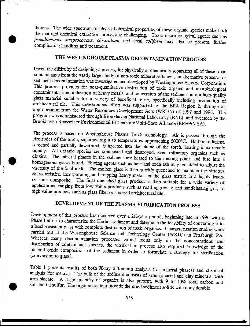
dioxms. The wide spectrum of physical-chemical properties of these organic species make both thermal and chemical extraction processing challenging. Toxic microbiological agents such as pseudomonas, streptococcus, clostridium, and fecal coliform may also be present, further complicating handhng and treatment.
THE WESTINGHOUSE PLASMA DECONTAMINATION PROCESS
Given the difficulty of designing a process for physically or chemically separating all of these toxic contaminants from the vastly larger body of non-toxic mineral sediment, an alternative process for sediment decontamination was investigated and developed by Westinghouse Electric Corporation This process provides for near-quantitative destruction of toxic organic and microbiological contammants, immobilization of heavy metals, and conversion of the sediment into a high-quality glass material suitable for a variety of beneficial reuse, specifically including production of architectural tile. This development effort was supported by the EPA Region 2, through an appropriation from the Water Resources Development Acts (WRDA) of 1992 and 1996 The program was administered through Brookhaven National Laboratory (BNL), and overseen by the Brookhaven Rensselaer Environmental Partnership/Multi-State Alliance (BREP/MSA).
The process is based on Westinghouse Plasma Torch technology. Air is passed through the electrodes of the torch, superheating it to temperatures approaching 5000oC. Harbor sediment screened and partially dewatered, is injected into the plume of the torch, heating it extremely rapidly. All organic species are combusted and destroyed, even refractory organics such as dioxms. The mineral phases in the sediment are heated to the melting point, and fuse into a homogenous glassy liquid. Fluxing agents such as lime and soda ash may be added to adjust the viscosity of the final melt. The molten glass is then quickly quenched to maintain the vitreous characteristics, incorporating and trapping heavy metals in the glass matrix in a highly leach- resistant composite. The final quenched glass product is then suitable for a wide variety of applications, ranging from low value products such as road aggregate and sandblasting grit, to high value products such as glass fiber or sintered architectural tile.
DEVELOPMENT OF THE PLASMA VITRIFICATION PROCESS
Development of this process has occurred over a 21/2-year period, beginning late in 1996 with a Phase I effort to characterize the Harbor sediment and determine the feasibility of converting it to a leach-resistant glass with complete destruction of toxic organics. Characterization studies were earned out at the Westinghouse Science and Technology Center (WSTC) in Pittsbur-h PA. Whereas many decontamination processes would focus only on the concentratioJs and distribution of contaminant species, the vitrification process also required knowledge of the mineral oxide composition of the sediment in order to formulate a strategy for vitrification (conversion to glass).
Table 1 presents results of both X-ray diffraction analysis (for mineral phases) and chemical analysis (for metals). The bulk of the sediment consists of sand (quartz) and clay minerals, with iron silicate. A large quantity of organics is also present, with 9 to 10% total carbon and substannal sulfur. The organic content provide the dried sediment solids with considerable
536

Table 1 - Mineral and Metals Analysis for New York/New Jersey Harbor Sediment
Element or Mineral Phase Chemical Formula Quartz
Muscovite (Mica)
Kyanite
Hydrated Aluminum Silicate
Cronstedtite
Organic Phase
Silicon
Carbon
Aluminum
SiO,
K20*2MgOAl203*8Si02«2H20
AbCVSiOj
19Al203*173Si02»9H20
4FeO2Fe203*3Si02*2H20
Petroleum residues
Si
C (organic plus inorganic) Al
Iron
Sodium
Potassium
Sulfur
Calcium
Magnesium
Titanium
Copper
Weight Percent (Dry Basis)
66 to 75
11 to 15
3 to 13
6 to 7
4 to 6
3 to 13
20.7 to 25.0
8.9 to 10.3
5.5 to 5.7 Fe
Na 4.5 to 5.0
K
Ca
Mg
Ti
Zinc Cu
Zn
1.2 to 1.3
1.7 to 2.1
0.5 to 1.8
1.2 to 1.4
1.0 to 1.3
0.5
0.2
0.2
heating value, measured at 3.7 to 4.5 MJ/kg (which improves the overall efficiency of the plasma vitrification process). Sodium chloride is also found, primarily from brine in the estuarine Harbor water. Analyses are presented on a dry basis; as-dredged sediment was found to be 30 to 35% solids by weight
A detailed contaminants analysis was also performed on the sediment, providing a baseline for assessing the efficacy of the decontamination process. Results are shown in Table 2. Included in the organic phase (7.3% total organic carbon) are nearly 30 regulated PAH species, as well as a range of chlorinated pesticides. Total dioxins are measured at 6.5 ppb, and ten toxic heavy metals are present above detection limit.
Given the mineral composition shown in Table 1, the next step in developing the process was to establish the design glass formulation. The sediment as shown is high in alumina and silica, which when melted alone would form a viscous melt with high fusion point. Handling of the molten product was therefore expected to be difficult unless the viscosity were reduced. Modeling of the melt viscosity was therefore done using the method of Riboud et al. (1981), in which the melt viscosity r\ (Pa-sec) is represented by the following function of temperature r(0K):
Icr 537

Table 2 - Toxic Organic Compounds in New York/New Jersey Sediment
Contaminant Weight Fraction (Dry Basis) Snlfiries 7.8E-3 Total Organic Carbon (TOO 7.3E-2 Polvchlorinated Biphenyls (PCB's) 5.2E-6 Chlorinated Pesticides 4.6E-7 Polyaromatic Hydrocarbons (PAH's) 1.2E-4 Total Dioxins 6.5E-9 Total Furans 1.7E-8 As 3.3E-5 Cd 3.7E-5 Cr 3.7E-4 Cu 1.2E-3 Ha 1.3E-6 Ni 3.0E-4 Pb 6.2E-4 Zn 1.7E-3
T|=A Texp(B/T)
ln(A) = -17.51 - 35.76 X, x, (Al203, CrjOs) + 5.82 x(NaCl) + 7.02 li x,(Na20, Na2S, K2O) + 1.73 Zi ^(CaO, MgO, FeO, MnO, PbO, ZnO, CuO)
3 = 31140 + 68833 2, ^(Al203, Cr203) - 46351 ;t(NaCl) - 39519 ZiXifN^O, Na2S, K20) - 23896 li XiiCdiO, MgO, FeO, MnO, PbO, ZnO, CuO)
where x,- is the mole fraction of each species i. The balance is assumed to be Si02.
(1)
(2)
(3)
For ease in handling, the target glass composition was designed to exhibit a pour viscosity of less than 100 Pa-sec at 1250oC, a temperature readily obtained within a plasma-fired shaft furnace. To accomplish this goal, a mixture of fluxing agents were added to the sediment. The viscosity was initially modeled using Equations (1) through (3) to identify predicted melt viscosities, and then coupon melt samples were prepared to confirm that the composition formed a fully vitreous product (entirely glassy, with no precipitated crystalline inclusions). Coupon tests of twelve candidate glass compositions were carried out with the assistance of Savannah River Technology Center (SRTC), at the Savannah River National Laboratory, Aiken SC. It was determined that test Composition #7 containing 83.2% (dry basis) Harbor sediment, 11.2% CaO flux (provided as slaked lime), and 5.6% Na20 flux (provided as soda ash, Na2C03) exhibited both the desired melting point (see Figure 2) and a fully vitrified final product. The resulting glass was lustrous and black (deep green-gold in thin cross-section), contained a high loading of sediment, and used a high ratio of lime to soda ash to achieve fluxing (soda ash being the considerably more expensive of the two fluxes).
538

100,000
10,000
g 1,000 I (0
Q.
Slag Viscosity versus Temperatue Riboud et ai. Pseudospedes Viscosity Model
O u at
100
10
1
\ v ' N
\ ^^
Overall Composition #7 (%wt): 56.40% 302 13.10% cao
11.20%AI2O3 8.80%Na2O+K2O
6.80%FeSO3 3.70% Other
^N ^
""^ ̂
800 900 1000 1100 1200 1300 1400 1500 1600 Temperature (C)
Figure 2 - Computed Viscosity-Temperature Profile for Target Sediment Glass Composition
CHARACTERIZATION OF THE PRODUCT GLASS ENVIRONMENTAL QUALITY
Larger samples of sediment-derived glass were then generated to permit leach testing and detailed analysis for various toxic contaminants. To produce 10 kg of glass for this purpose, samples of sediment were first rinsed with fresh water to remove the bulk of the salt, and then dried at low temperature (to minimize evolution of volatile organic compounds, or VOC's). Dried sediment solids were then blended with flux, and dehvered to Ferro Corporation in Cleveland OH for melting in 1 kg crucible batches. Melt testing was carried out over a range of temperatures from 1250 to 1450oC. Approximately 12 kg of glass were produced in this way, with 7.5 kg shipped to Brookhaven National Laboratory for detailed analysis.
Analysis was done at BNL for 121 organic compounds. Of these, only five were identified in the final product above detection limit. As shown in Table 3, destruction efficiencies were at least 99.8% for all organic categories, 99.9999% overall, and exceeded 99.99% for dioxins, believed to be the most refractory (heat resistant) of all of the compounds present. Leach of the glass product was also carried out, testing using the U. S. EPA Toxic Characteristic Leaching Procedure, or TCLP. Of all the metals analyzed for, only lead was detected in the TCLP leachate; the concentration was only between 2 and 5% of the EPA regulatory limit,
539
IB

Table 3 - Decontamination Efficiencies for Sulfides and Toxic Organic Species
Chemical Units Product Glass Untreated Sediment Destruction Efficiency
Total Organics g/kg 0.048 119.0 99.9999%
Sulfides mg/kg 0.50 7,800 99.994%
PCB's M-g/kg 1.28 5,260 99.976%
Pesticides M-g/kg <Detection Limit 462 >99.35%
PAH's Hg/kg 259 137,000 99.81%
Dioxins ng/kg <Detectioii Limit 6,440 >99.99%
Furans ng/kg 0.41 16,480 99.78%
SEDIMENT PRETREATMENT
T-
Given the success of the bench testing program, a plant design material and energy balance was then developed, as shown in Figure 3. In addition to defining the optimum plasma processing conditions and the glass-flux formulation, consideration was given to pretreatment of the sediment. Ideally, all of the salt would be removed from the sediment prior to vitrification, since NaCl is volatilized during the melting process and provides both a corrosion problem and the potential for solid salt deposits in the offgas system. The first step in the pretreatment process is therefore washing the sediment. Fresh water is added during a prescreening process, which removes large debris and ensures that no particles pass through which could clog the sediment injection nozzle into the plasma melter. Note that for New York/New Jersey Harbor sediment exhibits a very fine particle size distribution, with 98.4% less than 1 mm, 96% less than 400 pun, and 50% less than 10 nm. Less than 1.6% of the total dredged material would therefore be rejected due to excessive particle size (greater than one millimeter), most of which consists of sticks, leaves, and various artificial debris.
Once rinsed substantially free of salt, the sediment is then be partially dewatered. Since electrical power is the largest single cost in the plasma vitrification process, it is beneficial to remove as much water as possible prior to injection into the melter. If too much water is extracted, however, the sediment becomes dry and clay-like, and is very difficult to pump into the melter. Viscosity measurements and pumping tests determined that approximately 50 to 55% solids represents the upper practical limit to slurry pumping. This solids concentration can readily to achieved by large, industrial plate and frame filtration equipment. Agglomeration of the sediment fines is enhanced by addition of Ca(OH)2 (which later calcines to CaO, providing part of the flux). The dewatered sediment is then blended with the balance of the fluxing agents CaO and NajCOs, and fed to the melter.
The material balance for major streams in Figure 2 is presented in Table 4. The sediment processing rate is 63 Mg/hr, equivalent to the program target of 500,000 cubic yards (382,000 ".) dredged sediment per year. Chemical feeds to the plant (besides air and water) include:
\
540

PLASMA VITRIFICATION OF HARBOR SEDIMENTS i
Feed Pretreatment —— i —•- Plasma Vitrification
Wash Water
7) © Coarse Fraction
©
© Sediment
Slaked Lime
RINSING
SCREENING
©
©
© Lime
Fines Fraction
Gravel and Debris to Discharge or Carton' Bed Vitrification
— © Cooling Air
DESULFURIZATION ir AND HCI REMOVAL
Water and Fines to Flocculation ©
Offgas
•t:v<
© Roc
DEWATERING
Glassformers; Fluxes
AGGLOMERATION
\
© Dewatered Sediment
7 Plasma Air
Clean Offgas
<5%
HEAT EXCHANGER
CaSQ,
Salt and Water to Sewerage
Urea Solution
PLASMA MELTING
Molten Glass
Glass Product -»- with Incorporated
Heavy Metals
Figure 3 - Process Flow Diagram for Sediment Pretreatment and Vitrification Plant
1.0 Mg/hr Ca(OH)2 (hydrated lime) for agglomeration of fines prior to filtration, 0.01 Mg/hr of organic flocculating agent, 4.3 Mg/hr of Na2C03 (soda ash) for flux, 1.3 Mg/hr of CaO (slaked lime) for flux, 2.0 Mg/hr additional slaked lime for sulfur emissions control, and 0.07 Mg/hr of urea for NOx control.
The process produces 21.5 Mg/hr of molten glass, which is quenched quickly and granulated.
As shown above in Figure 3 above, the overall process produces very little solid waste. The total waste which must be disposed of consists of only 1% of the original sediment volume. A small fraction of the sediment is rejected as oversize; this material would probably be landfilled, consisting primarily of debris and gravel rinsed of surface contamination. Offgas treatment consists of dry absorption for removal of sulfur oxides and acid gases (HCI), generating a small calcium sulfate/sulfite stream to landfill Note that coal-fired power plants generate much larger,
^quantities of the same CaSCVCaSOs scrubber waste, which is routinely landfilled. 541
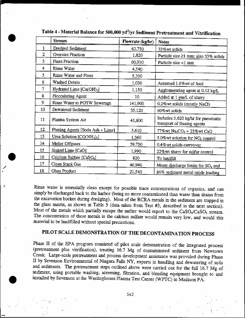
Table 4 - Material Balance for 500,000 yd3/yr Sediment Pretreatment and Vitrification
10
11
12
13
14 15
16
17
18
Stream
Dredged Sediment Oversize Fraction
Fines Fraction
Rinse Water
Rinse Water and Fines
Washed Debris
Hydrated Lime [Ca(OH)2]
Flocculating Agent
Rinse Water to PQTW Sewerage
Dewatered Sediment
Plasma System Air
Fluxing Agents [Soda Ash + Lime!
Urea Solution [CO(NH2)2]
Melter Offgases
Slaked Lime [CaOl
Calcium Sulfate [CaSCU]
Clean Stack Gas
Glass Product
Flowrate (kg/hr) Notes
62,730 1,820
60,910
4,540
5,330
1,030
1,150
10
141,900
35,120
41,800
5,610
1,360
59,750
1,990
820
46,940
21,540
33%wt solids
Particle size >1 mm; also 33% solids Particle size <1 mm
Assumed 1.6%wt of feed
Agglomerating agent at 0.12 kg/L
Added at 1 gm/L of slurry
0.2% wt sohds (mostly NaCl)
60%wt sohds
Includes 5,620 kg/hr for pneumatic transport of fluxing agents
77%wt NaiCCb + 23%wt CaO
5.0%wt solution for NCk control
0.4% wt solids carryover
22%wt slurry for sulfur control To landfill
Meets discharge limits for SOx and
86% sediment metal oxide loadina
Rinse water is essentially clean except for possible trace concentrations of organics, and can simply be discharged back to the harbor (being no more contaminated than water than drains from the excavation bucket during dredging). Most of the RCRA metals in the sediment are trapped in the glass matrix, as shown in Table 5 (data taken from Test #3, described in the next section). Most of the metals which partially escape the melter would report to the CaSCVCaSC^ stream. The concentration of these metals in the calcium sulfate would remain very low, and would this material to be landfilled without special precautions.
PILOT SCALE DEMONSTRATION OF THE DECONTAMINATION PROCESS
Phase H of the EPA program consisted of pilot scale demonstration of the integrated process (pretreatment plus vitrification), treating 16.7 Mg of contaminated sediment from Newtown Creek. Large-scale pretreatment and process development assistance was provided during Phase H by Sevenson Environmental of Niagara Falls NY, experts in handling and dewatering of soils and sediments. The pretreatment steps outlined above were carried out for the full 16.7 Mg of sediment, using portable washing, screening, filtration, and blending equipment brought to and installed by Sevenson at the Westinghouse Plasma Test Center (WPTC) in Madison PA.
542

Table 5 - Retention of RCRA Heavy Metals in Glass Product During Vitrification
Metal Spedes 1 Concentration in Glass (ppm) \ Fraction Retained in Glass As Ba Cd Cu
ik. Ni Pb Se
5.3 26.9
1.0 1061.2
<Detection Limit 255.5 106.7
Zn 1.6
66.8% 99.8% 61.3% 97.2%
(Not Measurable) 98.9% 79.8% 79.4%
1232.9 72.6%
Pretreatment operations are summarized in Table 6. A total of 13.4 cubic meters of raw sediment were processed during July and August of 1997, starting from an initial 37% solids content. The initial sediment was black and tarry, with a strong creosote odor. Screening and washing eliminated 85% of the salt and 5% of the sediment mass, consisting mostly of debris and trash. Note that this fraction was higher than the oversize fraction in the Table 4 material balance; much of the debris was material discarded into the rolloff during sample coUection (wood, plastic film, tools, protective clothing, etc.). Rltration with the aid of calcium hydroxide agglomerating agent
| produced a dewatered sediment product containing 52% solids. A total of 1.555 kg of fluxing agents was added (including the Ca(OH)2), representing about 20% of the final melter feed on a dry basis (83% loading of sediment metal oxides into the final glass). The final 52% sohds melter feed was a gray clay-like material which could be pumped by high pressure injection pumps.
Table 6 - Pilot Test Pretreatment System Performance Summary
Pretreatment Parameter Value Sediment Processed (m3)
Sediment Solids Processed (kg wet basis) Sediment Solids Content (%wt)
Oversize Cuttings Removed (kg dry basis) Rejection of NaCl During Washing (%)
Rinse Water Consumption (liters)
Ca(OH)2 Filtration Aide Consumption (kg)
13.4
16.700 36.7
328
85.6
28,700
Mass of Dewatered Sediment Produced (kg) Sohds Content of Dewatered Sediment (%wt) Volume of Filtrate Water Generated (liters) CaO Flux Added (kg)
NazCOa Flux Added (kg)
Plasma Melter Feed Generated (kg)
460
11,000
52.0
32,700
285 810
13,600 543
ten

v Vitrification testing was carried out between October and December, 1997, with a total of three tests. Most of the material processed was melted during Test #3 on December 5, during which a total of 3,980 kg of feed was converted to glass over 7.7 hours at an average rate of 533 kg/hr, with peak production as high as 800 kg/hr.
A schematic of the full-scale plasma melter design is shown in Figure 4 (as designed for the full scale plant, but functionally similar to the unit tested at Westinghouse PTC). The melter consists of a cylindrical furnace with refractory lining. Near the bottom is the injection port (one in the WPTC design, three in the full-scale plant design), referred to as the "tuyere" for its similarity to the air injection ports of a blast furnace or metal-melting cupola. At the outer end of the tuyere is mounted a Westinghouse plasma torch, rated at 2.3 MWe full power for the WPTC tests, or 5 MWe for the full-scale design. Full production in the larger design is accomplished by construction of five independent plasma melter trains of three torches each, arranged radially around the melter.
Figure 4 - Plasma Melter Schematic
544

Sediment and flux mixture is pumped as a slurry through an injection nozzle directly into the tie of the plasma torch. The water content of the dewatered and blended feed is adjusted by
requirements of the pumping system. Higher solids content produces more economical operation since less water must be heated and evaporated, but more difficulty is introduced in transporting the viscous slurry to the tuyere. It was noted that the viscosity behavior of the sediment is highly non-Newtonian, behaving as a Bingham plastic material Pumping proved to be the largest single difficulty encountered during the demonstration testing, when the slurry sohds content was higher than optimal.
Air flow through the tuyere totals approximately 12.7 m3/min, divided between torch air (passing through the plasma torch electrodes) and shroud air (serving the mix the plasma plume with the incoming sediment slurry, and to cool and protect the tuyere walls from the superheated plume). During Test #3, the plasma power averaged 1600 kWe. The specific energy consumption for processing of the sediment was therefore 10.8 MJ/kg of sediment feed slurry. Similar or better energy efficiencies would be expected in the full-scale plant.
As sediment enters the tuyere and mixes with the superheated plasma plume, it is rapidly dried and the organic surface deposits are combusted. Large agglomerated clumps disintegrate into fine, dry particles which are carried down the duct and thrown against the walls of the tuyere. Because of extremely rapid heat transfer, calcination of flux materials and melting of metal oxides occur within the tuyere, forming a homogeneous glass melt before the material enters the melter crucible (bottom). The liquid is continuously tapped from the crucible, with an exit temperature of toximately 1250 to 1350oC. Molten product may be cast into large masses, roll quenched into
sheets for later crushing, or water quenched to form a fine aggregate.
BENEFICIAL REUSE OPTIONS
Vitrified sediment provides a safe and stable wasteform for landfilling (or, theoretically, ocean dumping), but the properties of vitrified harbor sediment are such that a wide range of possible beneficial reuse options also exist. Among the simplest involve use as roadbed aggregate, an end use currently being practiced for vitrified ash ("glasphalt"). The requirements for roadbed aggregate are not well defined, but both the processing cost and product value are low. If the particle size is controlled to some degree, the glass may also be used for sandblasting applications. In this market, sediment glass would compete directly with products such as Black Beauty®, a registered trademark of Reed Minerals (a division of Harsco Corporation). Black Beauty® is made from fused coal ash, and is chemically very similar to vitrified harbor sediment.
'Bios
Somewhat higher value products which have been considered include:
• Roofing granules (requiring control of both particle size and Fe(n)/Fe(in) ratio for ultraviolet absorption characteristics; the iron ratio in New York/New Jersey Harbor sediment glass is favorable for this application, however).
• Replacement glass cullet (although considerable market demand for cullet exists, the market kfor Harbor sediment cullet would be limited by the black color of the high-iron glass).
545

• Additive to brown bottle glass (where the color would be advantageous; apphcation for beverage bottles would be difficult to market given the origin of the material, however).
• Filler material for artificial onyx bathtubs and similar fixtures (where the color is irrelevant since the surface gel coat is the only visible material; the market is limited, however).
• Rock wool insulating fiber (requiring control of product viscosity to allow spinning into fibers, and relatively expensive processing equipment; the market value is nearly $200/Mg, however).
At the high-value end of the spectrum, the New York/New Jersey Harbor sediment produces a glass which has physical and chemical properties similar to "E-Glass" which is one of the major commercial fiberglass compositions. Samples of Phase I Harbor sediment glass were forwarded to a major U.S. fiberglass manufacturer for evaluation. Samples were spun into greenish »old fibers, and exhibited both good forming properties (1000 Pa-sec fiber-forming temperature of approximately 1200oC) and excellent strength characteristics (490,000 psi single-fiber strength only slightly below that of "E-glass"). Environmental TCLP testing of the fibers was also found to be no issue.
The major issues associated with fiberglass concerned product uniformity. The plasma melting process was designed to rapidly decontaminate and fuse the sediment, with short residence time to minimize energy costs and equipment size. Feed glass to a fiberglass spinning operation is required to be exceptionally homogeneous, with near-zero concentrations of incompletely melted or crystalline material One fiber break per day in a spinning machine is considered a serious problem. To provide this degree of homogeneity, the molten glass would have to be held for a considerable length of time at elevated temperature to ensure complete dissolution of crystalline phases ("fining"). Both the capital and energy cost of equipment for this process as well as for fiber spinning is substantial. Also, it is difficult to guarantee the uniformity of the glass chemical composition, smce the source will vary from day to day within the Harbor environment.
A far more robust apphcation and one requiring much lower capital investment is fabrication of commercial architectural tile. Three major types of ceramic tile are currently marketed, low-*rade wall tile, high-grade wall tile, and floor tile; each grade has different requirements for abrasion resistance and water absorption. The least expensive tile is composed of talc (3Mg0.4Si02.H20), baU clay, and wollastonite (CaO.Si02); sediment glass could readily substitute for natural talc, yielding an estimated product credit of up to $170/Mg Higher grade tiles use feldspar (Al203.6Si02.K20) in place of talc for increased resistance to water absorption. Substitution of sediment glass for feldspar potentially increases the product credit to $250/Mg.
The tile market is also favorable, with approximately 75% of all ceramic tile being consumed by new construction- Demand should be good in the New York City urban area, providing a local market requiring minimal transportation costs. At current production figures, a 380 000 m3/yr sediment decontamination facility could generate 166,000 Mg/yr of glass product, equivalent to as much as 5% of the current ceramic tile market. However, due to the relatively low anticipated cost of the glass, vitreous tile must be viewed as a high-quality, low-cost substitute for current tile products, where market unpact would be minimized as vitreous tile replaced other lower qualitv or higher cost products.
546

Based on this market analysis, Westinghouse collaborated with one company currently producing vitreous tile from waste materials, namely Futuristic Tile LLC (soon to be known ai Environmental Stone Products) of Menton WI. Futuristic Tile accepts from municipalities scrap recycle clear ("white") bottle glass and "three-mix." (Note: current technology for glass recycling allows up to 90% of mixed green/brown/white glass to be automatically sorted into three pure- color streams. The remaining 10%, primarily broken material too smaU to be sorted, is known as three-mix"). The mixed glass stream is first crushed, cleaned, and sized. It is then blended with
additives designed to adjust the melt viscosity, sintering temperature, and thermal expansion coefficient The glass powder is then fed into ceramic molds using a feed distributor known as a dozer. This forms the bottom layer of the tile.
Clear glass is also crushed and cleaned, and sized to a smaller particle diameter (<1 mm) Using patented technology, the white fines are blended with coloring pigments (other metal oxide powders), and formed into granules which are then distributed into the mold to form the top layer Between 30 and 40 colors are available, and by controlling the "dozer" distribution pattern, colors may be distributed in such a way as to visually mimic a wide range of natural stones in the final product (granite, marble, gneiss, etc.). The mold is then passed through a kiln under carefully controUed residence time and temperature profile, producing the finished tile product in roughly one square meter sheets. These are then cut to size, depending on the appUcation. The complete flowsheet for tile production is shown in Figure 5.
Clear Glass
Clushing
Additives: - Bonding Agents
• Viscosily ModificaSon • Themial Expansion Matching
Figure 5 - Process Flow Diagram for Futuristic Tile Manufacturing Process 547

Ir",^ I - , S r? Westm«house- ^nnined that vimfied sediment may be subaitmed for three-imx glass m the bottom smctural layer of the tile. Imtial testing with pLe^dtont glass produced good quality tiles using 100% sediment glass for the bottom layer B Jed „TS r^uto of these exploratory tests, a Phase m program was initiated in whichTaddSlT^
Tie Phase m sediment glass was blended with sKghtly less flux than the Phase I samples and teefore requied a hgher sintering temperature ton for typical Futuristic Tile Se j£ operadon. Because some of the pigments are temperature semLe, and becans^ M^r Ste^ temperatures mcrease energy costs and require longer residence times, FutuS Tfle deSed^f bend the vttnfied sediment with "three-mix" to obtain an optimized tfle p^uc, I Sound
SL=x«?sr ^^^^r^r^rz nilr Note that am sediment loading is low relative to what could be produced in commercial operatton. Futunsnc TOe has routinely produced tile with as low as 15 to 20% top^tesT^
Sent .last y ""^^ m ^ ^ ^ * could contafa 80 to 85%
ST F^t, !' 'T kg 0f Se<liment ghsS werc converKd fa° approximately 2 200 kg ofttle. E^enence wKh producaon-scale quantities of sediment glass as ti[feed FutiSi TS engmeers have concluded that not only does this glass produce good quality tiL but Serlt
ITfnr^ f^^ f0r UStos k * Pkce °f "^i-^" neTu^^ret^ed gte^ Inghly vanable, depending on the deg^ to which a municipality soL^d igrefates gtes from non-glass materials. The presence on metallic debris (jar lids, borne totTetTSta addttional sorting and screening effort on the par, of the tile mLcer. Orga^cTleS sucH P£Z « !,aPer n0t T^^ rem0Ved duril,S sorting and crushing afe gen^y deswve^ durmg Mn operation, bu, may also introduce flaws and bubbles in the prTdua Ie7dta7m ?pretSd7 raP' •i;"tU*,iC ^ 1-* *=*" c•chded «ta -tomgS wou^e o^t^gher" t0 ^^ g,aSS' imPr0TCd '"-^ *» ^ •"'d WP »
548

-• •
. - •-
Dewatered Sediment
Raw Sediment
Glass Aggregate
^ . •
/• J
Tile Product
Figure 6 - Conversion of Raw Sediment into Finished Vitreous Tile
FULL-SCALE PLANT DESIGN AND TREATMENT COSTS
Following the success of the pilot plant demonstrations, a full-scale preliminary plant design was developed, based on the material balances shown in Figure 3 and Table 4. A summary of important parameters from this study is shown in
Table 7. Two designs evolved from the Phase II studies, one for a 76,400 cubic meter (100,000 yd3) per year demonstration facility, and a second for 382,000 cubic meter (500,000 yd3) per year full-scale production; the latter plant is presented in the table.
Capital and operating costs were also developed, based around the previously presented flowsheet and material balance. These are also summarized in Table 7. The cost of electricity is the largest single factor in determining gross operating cost, representing 65 to 75% of the total figure. A range of electrical costs from $0.03 to 0.05 per kilowatt-hour were examined in sensitivity tests, although discussion with utility representatives in the New York City area indicated that at high volume the cost per kilowatt-hour could even be lower. Taking a nominal electrical cost of $0.04/kWh, the processing cost for the sediment is estimated to be $81/Mg. Including amortization of capital costs, the total gross processing cost for sediment treatment from receipt of barged sludge to delivery of granulated sediment glass (suitable for tile manufacture) becomes
549 1'

¥ * -&••
'^^^^ Parameter
Plant Capacity
Tumdown Capacity
Excess Capacity Built into Equipment De.^
Sediment Delivery
Plant On-Line Operatmg Factor
Total Electrical Power Requirement
Capital Cost Estimate Area 100; Pretxeatment
84 MWe (98% for ^m^^^^—
Area 200: Plasma Melters
ggjggP: G^s Quenching and HnnHW Area 400; Offgas Cleaning
Non-Process Areas
$18.7M (23%)
$44.0M (54%)
$2.3M (3%)
$12.9M(16%)
Operating Cost
Chemical Raw Materials
Electricity (assuming S0.03 to n ns/y^^
Other Utilities
$30.5 to 44. IM/yr
$5.5M/yr
$20.5to34.1M/vr
$0.2M/yr
S66.2 to 95.7/Mo
$11.9/Mg
$44.4 to 74.0/Mg
$42.5/Mg to $72.0/Mg
550
$107.4/Mg. It is assumed in this analysis that "brownfield" industrial property for construction of the plant would be made available near the Harbor at no cost.
The net cost of processing with beneficial reuse must consider both the tipping fee received for treatment and disposal of the sediment, and the production costs and revenue associated with the final product. For the nominal case, it is assumed that essentially zero production costs are invested, and that the final product is roadbed aggregate, using the granulated sediment glass directly. (Note that for this application, a fully vitrified product may not be required, and that less expensive flux with less soda ash would probably be acceptable; no credit is taken for this detail). Roadbed aggregate typically sells for $7.50/ton, which converts to $2.33/Mg of dredged sediment (see material balance inTable 4).
A tipping fee for disposal of sediment must be assumed in order to project a net cost for treatment of the dredged material. For this purpose, a reference cost of $45/ton ($50/Mg) is assumed. This figure is based on current reported cost of disposal of sediment by stabilization and transfer to spent coal mines in Pennsylvania. Using the nominal $107/Mg vitrification cost, the nominal net cost of treatment is $55/Mg of dredged sediment.
In considering the economic viability of higher value products, one must consider the capital and operating costs for fabrication of that product, the "cost" of the sediment glass as compared to alternative feed materials (such as "three-mix" in the case of architectural tile), and impacts on the production process as a result of changing to sediment glass as the feedstock. As indicated above, demonstration tests with Futuristic Tile have shown that use of vitrified sediment will result in improved tile quality and productivity, due to the purity and consistency of the sediment glass. If an integrated sediment-to-tile process is considered, economic analysis by Westinghouse and Futuristic Tile indicates that the process will be profitable based on the reference design and tipping fee.
Note that with deregulation of the electric utility industry, the assumed $0.04/kWr electricity cost may reduce to $0.03 or even $0.02/kWh. The treatment cost to produce the vitrified aggregate would .then reduce substantially to between $42 and $25/Mg of dredged sediment, resulting in greater economic margin for the overall sediment-to-tile production process.
As indicated above, any aggressive treatment option which truly destroys organic contaminants and immobilizes heavy metals will be more expensive than a procedure which seeks only to encapsulate contaminants, followed by landfilling (be it in an abandoned mine or engineered landfill). Although the economics of sediment vitrification followed by tile production appear to be favorable given a tipping fee based on competition with cement stabilization and landfilling, the overall economics of such a process improve with the degree of contamination of the material being treated. As contamination becomes more severe, the options for stabilization and disposal become fewer, and the treatment costs rise. The effective tipping fee against which the plasma vitrification process is to be compared therefore grows, making the overall process economics increasingly favorable. Even if low cost subaqueous burial within the Harbor (for example) were _ permitted for sediment with low contaminant levels, vitrification could remain the logical and ^ economic approach to treatment of "hot spots." J.
551 re 1

CONCLUSIONS
ss^MXisrtrs^sts ^pose - *—* «-* livelihood. WHe manyAlternative ,^l•f ^ hT a majcr mve^Mt in shipping as a disposal are less «KTTS*n "* " *"?" Stabffizadon «*» ^ continued availabi% of lar^a of^- TZt Z 'mc^L^se "P^ ^pend on the risky assumption Jlong te°m s^tifn ofUTo^ZJ^ST* " i?0«^ pubhc pressure against waste tadiillin. .rows IndS , VS ^ 0Illy mCrease * City dwindles. In addition such ZS^Z,!^ avahfahty near such sites as New York
move torn to another, £ ^TlTcZr^ZnTZ?* "^ ""^-^ ^ only processes and sites has historically r«,SL^lT ^blIlty ^ P6•0' wMch for ^ remediation. y m much !arSer ^^ WSB associated with later
c^^J^^tenTg^rrrL^,00"15^ ^^ " 0f "- "^ process. The only waste L^„ OT8•flIy-contammated waste liquid streams to the washing) and a i"SaL" sohd CaSO T h
debnS (wl,ich "» P*"^ decontaminated by from t£ process Z SeLottrSdto Tf " ^ ""^ ^"^ The «te Prod^d rcquirenJts for ^e smah ^T^^Z^'Tr* * E?A ^^ with options for beneficial reuse such as ZZ££££^HT ' "^ C0UpIcd
contammatedSupe^ndso^^^
ACKNOWLEDGMENTS
organ^a^n^lnTCrX-^ COntribUti0nS 0f ^ f*^ M^ - - Keith Jones (Brookhaven National Laboratory)
Enc Stem (United States Environmental Protection Agency) - Michael Crystal, Rodney Baker, and Michael n^mh^re T- . - James Walter. TwJr M-TL
MlCllael Bamhart (Sevenson Environmental) Ws Walters, Txmothy Grahl, ITaomas Byrnes, and Nailia Tikhanova (Futuristic Tile,
- James Marra (Savannah River Laboratory) - Gordon Roberts and Tack Whang (Feiro Corporation)
552

REFERENCES
Riboud, V., Y. Roux, L.-D. Lucas, and H. Gaye (1981), "Improvement of Continuous Casting Powders," Fachber. Huettenprax. Metallweiterverarh, 19(10), 859.
U. S. Environmental Protection Agency (1994), "1994 EPA Contaminated Sediment Management Strategy," EPA 823-R-94-001.
%
553 ?t

PROCEEDINGS OF THE
WESTERN DREDGING ASSOCIATION NINETEENTH TECHNICAL
CONFERENCE
and
THIRTY-FIRST TEXAS A&M DREDGING SEMINAR
May 15-18, 1999
Louisville, Kentucky

WROO 405 OECON
EPa-aCE-DOEBNL
Maintaining Access to America's Intermodal Ports/Technologies for
Decontamination of Dredged Sediment , • •.—-., ytmitmm&tm+Q-

MAINTAINING ACCESS TO AMERICA'S INTERMODAL PORTS/TECHNOLOGIES FOR DECONTAMINATION OF DREDGED
SEDIMENT: NEW YORK/NEW JERSEY HARBOR
by
Eric A. Stem, U.S. Environmental Protection Agency, Region 2 Keith W. Jones, Brookhaven National Laboratory
Kerwin Donato, U.S. Army Corps of Engineers - New York District John D. Pauling, P.E., Roy F. Weston, Inc.
John G. Sontag, Jr., P.E., Roy F. Weston, Inc. Nicholas L. Clesceri, Rensselaer Polytechnic Institute
Michael C. Mensinger, ENDESCO Services, Inc. Charles L. Wilde, BioGenesis Enterprises, Inc.
1. INTRODUCTION
One of the greatest drivers for maintaining access to America's Intermodal ports and related infrastructure redevelopment efforts over the next several years will be the control and treatment of contaminated sediments dredged from our nation's waterways. More than 306 million cubic meters (m3) (400 million cubic yards [cy]) of sediments are dredged annually from U.S. waterways, and each year close to 46 million m3 (60 million cy) of this material is disposed of in the ocean (EPA 842-F-96-003). The need to protect our environment against undesirable effects from sediment dredging and disposal practices is gaining increased attention from the public and governmental agencies.
Meeting this need is a challenging task not only from the standpoint of solving formidable scientific and engineering problems, but also, and more importantly, from the need to implement complex collaborations among the many different parties concerned with the problem. Some 40 years ago, C.P. Snow pointed out the problems involved in communicating between the two cultures of the sciences and the humanities (Snow, 1993). Today, it is necessary to extend Snow's concept to a multicultural realm with groups that include governmental, industrial, environmental, academic, and the general public communicating in different languages based on widely different fundamental assumptions.
The handling of contaminated sediments in the Port of New York/New Jersey (Port) exemplifies this problem. This paper describes a multicultural team that has formed as the result of a Congressional mandate for the development of procedures suitable for the decontamination of sediments in the Port under the Water Resources Development Act (WRDA) of 1992 (Section 405C) and 1996 (Section 226).
MK01|L:\TECHPAP\8007JDP.DOC

Maintaining Access to America's Intermodal - Ports/Technologies for Decontamination of Dredged Sediment: New York/New Jersey Harbor
E. Stem—K. Jones—K. Donate—J. Pauling—J. Sontag—N. Clesceri—M. Mensinger—C. Wilde
The WRDA Program is the responsibility of the U.S. Environmental Protection Agency (EPA) - Region 2 and the U.S. Army Corps of Engineers (USAGE) - New York District, with the U.S. Department of Energy (DOE) - Brookhaven National Laboratory acting as the Technical Project Manager.
Both EPA and USAGE have stepped up their efforts to manage contaminated sediments and dredged materials. With the recent release of EPA's Contaminated Sediment Management Strategy, and the ongoing efforts of the USAGE Waterways Experiment Station Dredging Operations and Environmental Research Program, as well as individual USAGE District initiatives, the development of economically and technologically feasible sediment treatment and disposal alternatives is being aggressively pursued.
The WRDA Program has progressed through demonstrations of varying technologies at bench and pilot scales and is now being moved to construction of commercial-scale facilities. The step-wise procedure has resulted in a reduction of the number of participants through specific selection criteria, including technical performance, demonstration costs, public-private cost' sharing, beneficial reuse of treated material, and corporate evaluations of the business potential for sediment decontamination.
One of several multicultural teams growing from the WRDA Program includes the federal groups previously mentioned and three commercial sector entities. BioGenesis Enterprises, Inc. (BioGenesis) and ENDESCO Services, Inc., a wholly owned subsidiary of the Institute of Gas Technology (ENDESCO/IGT), provide technologies suitable for decontamination of sediments with varying contamination levels. Roy F. Weston, Inc. (WESTON®) provides the engineering, construction, and operational skills needed to move the technologies to the commercial marketplace. Federal funding from the WRDA legislation provides assistance to the commercialization process, but the private sector will provide the capital needed for facility construction and operation. It is believed that this type of cooperative approach will be useful in the New York and New Jersey Region and may have features of interest to other Port communities throughout the country that are faced with problems caused by the need to dispose of contaminated sediments.
2. CONTAMINATED SEDIMENTS IN THE NEW YORK/NEW JERSEY HARBOR
New York/New Jersey (NY/NJ) Harbor contaminated sediments constitute a major crisis to the economic well being of the region. NY/NJ Harbor has a natural, undredged depth of 5.8 meters (19 ft). Ships need a depth of 12 to 14 meters (40 to 45 ft) for safe navigation. The difference between natural and required depths requires that 3 to 5 million m3 (4 to 7 million cy) of sediment
MK01ILYTECHPAPVSOOTJDP. DOC 0 2/17/99

.Maintaining Access to America's Intermodal Ports/Technologies for Decontamination of Dredged Sediment: New York/New Jersey Harbor
E. Stem—K. Jones—K. Donate—J. Pauling—J. Sontag—N. Clesceri—M. Mensinger—C. Wilde
be dredged and disposed of every year for safe navigation and commerce. Exhibit 1 shows the NY/NJ Harbor Federal Navigation Channels that require dredging. According to the New York and New Jersey Port Authority, the Port generates more than $20 billion in revenue and is responsible for more than 180,000 jobs. Thus, any prolonged interruption in dredging would adversely affect the regional economy. The Port is currently faced with an operational crisis brought about by stricter regulations that reduce the amount of dredged material that is considered suitable for ocean disposal in the coastal Atlantic Ocean.
In a final rule that became effective on September 29, 1997, EPA de- designated and terminated the dredged material ocean disposal site (Mud Dump Site) and simultaneously designated the Historic Area Remediation Site (HARS). Exhibit 2 shows the location of the former Mud Dump Site. The HARS is restricted to receive only dredged material suitable for use as Material for Remediation. This material is defined as "uncontaminated dredged material (i.e., dredged material that meets current Category I standards and will not cause significant undesirable effects, including those effects caused through bioaccumulation)."
Sediments and soils found in and around the Port have been contaminated with a large variety of toxic materials produced by human and industrial activities in the region from colonial times to the present. Sediment contaminant concentrations in the NY/NJ Harbor rank among the highest in the nation (NOAA, 1995). Squibb et al. (1991) concluded that concentrations of a variety of toxic contaminants in these sediments are sufficiently elevated in many locations to cause adverse effects on the biological community. Heavy metals (Hg, Cd, Pb, Ni, Cu, Zn, As), chlorinated pesticides (including DDT metabolites, chlordane, dieldrin, and endrin), polynuclear aromatic hydrocarbons (PAHs), polychlorinated biphenyls (PCBs), and dioxins/furans are major contaminants of concern in the Port region. Toxicological assessment studies, such as the U.S. EPA Regional Environmental Monitoring and Assessment Program and the NOAA/U.S. EPA Multi-Agency Sediment Toxicity Survey of the Newark Bay Complex, have all shown significant mortality to the marine amphipod Ampelisca abdita when exposed to sediment from the Harbor (NOAA, 1995). Furthermore, several contaminants detected in the Harbor sediments, as well as in the tissue of fish and shellfish, have resulted in fishing advisories in the NY/NJ Harbor. Bioaccumulation testing of dredged material has identified many of these same contaminants. Generally, the material is chemically stable and is found to pass the toxicity characteristic leaching procedure (TCLP) for testing the leachability of contaminants.
The physical characteristics of the sediments found in the Port are generally very fine-grained silts and clays (80 to 95%) with a small fraction of larger grain sizes and large-size debris. The bulk material has a gel-like consistency. The total organic content of Harbor sediments ranges from 3 to 10%. The
MK01|L:\TECHPAP\8007JDP.DOC -j 2/17/99

Maintaining Access to America's Intermodal Ports/Technologies for Decontamination of Dredged Sediment: New York/New Jersey Harbor
E. Stem—K. Jones—K. Donate—J. Pauling^. Sontag—N. Clesceri—M. Mensinger—C. Wilde
solids content of the as-dredged material is 30 to 40% when obtained using a conventional clamshell bucket dredge.
Scientific visualization and scatter data modeling techniques have been applied in analyzing sediment sampling data from the NY/NJ Harbor (Hong et al., 1998). High-resolution data sets were visualized to determine the spatial patterns from surface sediments down to core depth where data were available. Specific "hot spots " have been visualized for a range of contaminants such as dioxins, PAHs, and metals. Exhibit 3 is an illustration of a 3-dimensional contaminated sediment visualization image from the Passaic River, New Jersey, characterizing dioxin concentrations from the sediment surface to a depth of 6 ft.
Current proposals for solutions to the dredged material disposal problem include continued unrestricted ocean disposal of uncontaminated material to the HARS, the use of confined disposal facilities (both upland facilities and containment islands), subaqueous borrow pits, and processing/treatment of contaminated materials. A complete solution to the dredging problem will no doubt include a combination of many or all of these alternatives. Decontamination of dredged material is one component of an overall dredged material management strategy. It can reduce the magnitude of the contamination and may provide a treated product with a beneficial reuse, thus simplifying disposal and, if salable, reduce the overall cost of treatment.
2.1 WRDA Program Background
Currently there are limited alternative disposal options for contaminated sediment, and as a result, the continued economic operation of the Port is threatened. The WRDA Program is intended to demonstrate decontamination technologies for sediment treatment and to create a viable treatment train capable of processing sediment volumes on the order of 382,300 m3 (500,000 cy) per year. The work is divided into several phases; treatability studies of commercial and nonproprietary technologies at volumes of 19 to 38 liters (5 to 10 gallons) for bench-scale, and up to 19 m3 (25 cy) for pilot-scale. Exhibit 4 shows the locations in the NY/NJ Harbor where sediment samples were taken for the bench- and pilot-scale tests. Both bench- and pilot-scale phases of the project were completed in December 1996. The technologies investigated included several types of thermal destruction and desorption processes, stabilization/solidification, sediment washing, advanced chemical treatments, solvent extraction methods, and manufactured soil production.
Results obtained in the treatment tests have been presented previously (Stem et al. 1996 and 1997; Jones et al. 1997 and 1998). Because of the complexities of mixed contaminants (metals, organics, etc.), different end-uses of the post- treated materials, and the importance of developing a sediment delivery system
MK01|L:\TECHPAR8007JDP.DOC , 2/17/99

Maintaining Access to America's Intermodal Ports/Technologies for Decontamination of Dredged Sediment: New York/New Jersey Harbor
E. Stem—K. Jones—K. Donato-^J. Pauling—J. Sontag—N. Clesceri—M. Mensinger—C. Wilde
(materials handling) to move the dredged material into the physical plant, WRDA's objective from the onset was to develop a "treatment train" approach to processing and decontaminating dredged material. This approach puts together several key components that entail dredging, processing of the sediment, beneficial use of the post-treated material, and environmental/human health assessments. Under WRDA, the specification of a treatment train and potential implementation of a large-scale facility capable of processing up to 382,300 m3 (500,000 cy) of dredged material per year is already underway. The development of an overall conceptual plan for implementing a large-scale treatment facility is now in progress.
WRDA has categorized the technologies that have been tested in the bench- and pilot-scale phases of the Program. They fall into the following categories: 1) those that are carried out at ambient or at least low temperatures; 2) those that are carried out at intermediate temperatures that do not destroy the organic constituents; and 3) those that are carried out at high temperatures above the decomposition point of the organic compounds. The wide variety of contaminants and differing concentration levels make it plausible to search for technologies that can be applied to specific concentration levels. In addition, the low-temperature technologies may be more acceptable to the local and regulatory communities, making obtaining building and other environmental permits easier. The higher temperature technologies may be more applicable to the most contaminated sediments that are found outside of navigational channel and depositional areas. These areas may lend themselves to "hot spot" remediation. High-temperature technologies may also produce beneficial use products that have higher resale values than solidification/stabilization.
3. TECHNOLOGIES FOR THE DECONTAMINATION OF DREDGED MATERIALS
The variety of contaminants and the wide range of contamination levels found in dredged material in the NY/NJ Harbor emphasize the need for developing several types of decontamination technologies for a comprehensive treatment process. This is exemplified by two approaches supported under the WRDA Program (see Exhibit 5) for large-scale decontamination facilities. One technology is a sediment washing method developed by BioGenesis. The other process developed by the Institute of Gas Technology uses high temperatures to completely destroy organic materials, while binding metals into a cementitious matrix (Cement-Lock• process). In both cases the processed materials have beneficial uses that produce a revenue stream, which can be used to offset the decontamination processing costs.
The essential properties of the dredged material are the grain size distribution and the major element composition. A typical grain size distribution is shown
MK01|L:\TECHPAP\8007JDP.DOC • ' ' .. <- 2/17/99

Maintaining Access to America's Intermodal Ports/Technologies for Decontamination of Dredged Sediment: New York/New Jersey Harbor
E. Stem—K. Jones—K. Donato—J. Pauling—0. Sontag—N. Clesceri—M. Mensinger—C. Wilde
in Exhibit 6 for dredged material taken from Newtown Creek, NY. Material from other locations with respect to grain size distribution in the Harbor is similar. Examination of the data shows that most of the sediment is less than 2 millimeters in size. The small particles are easily handled during the washing or cement-making procedures. Oversized material can be sorted into material that should be sent to a landfill or reduced to the smaller sizes needed in the two processes. The major element composition is silica and overall is suitable as input material for the production of cement or as the basis of a soil.
A schematic diagram and photograph of the equipment used by BioGenesis in a recent demonstration are shown in Exhibits 7 and 8. The contaminants found in the sediments were reduced by approximately 90% for silts, clays, and sands. The results are shown in Exhibit 9 (BioGenesisSM Two-Cycle Treatment Process). The dredged material suitable for processing depends on the criteria for its end use. If an artificial soil is chosen, then the initial contaminant levels must be less than a factor of 30 greater than the appropriate soil criteria for the disposal site. This factor includes both the contaminant's reduction efficiency and the reduction resulting from the addition (dilution) of the original materials required for soil formulation.
A schematic diagram and photographs of the IGT Cement-Lock• equipment used for a pilot-scale test of cement production are shown in Exhibits 10 and 11. The input material was similar in grain size, composition, and contamination to that used in the BioGenesisSM test. The operating temperature range of the thermal processing for the test was between 1200° and 1500 "C (2200° and 2700 0F). These conditions are sufficient for achieving complete destruction of all organic contaminants. The reduction efficiency is shown in Exhibit 12.
In summary, essentially all of the organic contaminants originally present in the dredged sediment were destroyed to below the analytical detection limit as a result of the high-temperature Cement-Lock• Technology processing. DREs in excess of 99.99% have been achieved in both the bench-scale and pilot-scale testing. It is expected that organic compound DREs in excess of 99.99% will be consistently achieved in the production-scale Cement-Lock• plant that will be built in Phase HI of the WRDA program. In addition to the extreme thermal conditions that exist in the melter (Ecomelt Generator), organic compounds will be subjected to 2 seconds residence time at 1200° C (2200° F) in the secondary combustion chamber. This is the process requirement for 99.9999% destruction of PCBs.
The product from Cement-Lock processing of dredged sediment is blended cement. As part of the WRDA program, the Cement-Lock blended cement was tested according to American Society for Testing and Materials (ASTM) protocol to evaluate its compressive strength. The compressive strength
MK01|L:\TECHPAP\8007JDP.DOC , 2/17/99

Maintaining Access to America's Intermodal Ports/Technologies for Decontamination of Dredged Sediment: New York/New Jersey Harbor
E. Stem—K. Jones—K. Donato—J. Pauling—J. Sontag—N. Clesceri—M. Mensinger—C. Wilde
exceeds the ASTM requirements for portland cement. The cement can be used in concrete for general construction applications.
4. COMMERCIAL OPERATIONS
Detailed design plans for large-scale treatment facilities have now been completed that will meet the WRDA goal of achieving operation at 382,300 m3
(500,000 cy) per year in the next 12 to 30 months. One of the major hurdles in placing any facility into an operational condition will be the issuance of permits from state and local authorities. The sediment washing permitting process should be relatively straightforward, since there are no gaseous side streams and the contaminants found in a liquid side stream can be removed by standard water processing techniques.
The use of a high-temperature process will require comprehensive air permits. Initial discussions in public groups have indicated that this type of process may be acceptable, if it is completely environmentally responsible from the public standpoint. From a purely technical standpoint, both technologies can be engineered to be completely environmentally responsible.
Technologies that are environmentally safe and that effectively decontaminate dredged material are not enough. They must also be economically viable and in this regard dredged material is now being stabilized with cement and fly ash and used for construction material and cover at several locations in New Jersey. Currently, the total cost for dredging, treatment (stabilization), and disposal ranges from $40 to $50/cy. Current total disposal costs in the Newark Bay confined disposal facility are approximately $35/cy. We anticipate that the costs for sediment washing and cement production will be competitive when full-scale operation is achieved and when the economic benefits of beneficial uses are considered. Preliminary estimates for the demonstration-scale level for processing costs range from $50 to $70. Larger scale demonstrations planned in 1998 (minimum of 7,600 m3/10,000 cy each) will provide economic information for scale-up volumes as well as information on potential return for beneficial reuse. The target range of costs for full-scale/commercial-scale operations is to be at or below $35/cy.
There is good reason to believe that lower costs can be achieved for the Port to remain competitive. Competition from other East Coast ports also needs to be considered. Environmental regulations for handling of dredged material are not uniform and can be much lower than the NY/NJ Harbor benchmark. If other ports attract deep water shipping away from the NY/NJ Harbor, then the whole transportation pattern in the region could change and completely change the current needs for dredged material management in the Port. From an examination of the two technologies, it is believed that costs that are low enough to meet the market cost as it is currently projected can be achieved.
MK01|L:\TECHPAP\8007JDP.DOC ^ 2/17/99

Maintaining Access to America's Intermodal Ports/Technologies for Decontamination of Dredged Sediment: New York/New Jersey Harbor
E. Stem—K. Jones—K. Donate—J. Pauling-J. Sontag—N. Clesceri—M. Mensinger—C. Wilde
The actual costs for decontamination in the future will be determined by effective responses to requests for proposals from USAGE, the Port Authority of NY/NJ, and private dredging clients.
5. BENEFICIAL REUSE
In order to evaluate the potential beneficial reuses for treated sediment, one must understand the characteristics of the material following treatment. First, dredged material from the NY/NJ Harbor consists mainly of fine-grained materials (silts and clays). The treated material, therefore, cannot be used directly as structural fill. The organic material contained in the treated dredged materials is removed or destroyed. This includes contaminants as well as other naturally occurring organic material. The treated material, therefore, is typically not good as a growth substrate.
Given these characteristics, potential direct beneficial reuse pathways for the treated sediment are limited. The treated material, however, can be mixed with other materials to obtain a useful end product. The amendment of the treated materials will require additional processing; therefore, the revenue from the end-use product will offset costs of processing and provide an additional source of revenue. Some potential end uses for amended treated dredged material include:
Manufectured soil - High-end growth use (i.e., potting soil). Manufactured soil - Low-end growth use (i.e., top soil). Nonstructural fill material (daily landfill cover). Shoreline stabilization. Restoration/fill for underwater areas. Wetlands/habitat restoration. Blended cement.
In order to offset dredged material treatment costs and provide a cost-competitive overall treatment approach for management of NY/NJ Harbor sediments, beneficial reuse pathways need to be utilized. In addition, beneficial reuse of dredged materials is "environmentally sustainable and responsible" in that contamination contained in the materials is reduced to a level acceptable for use instead of disposal.
As stated previously, the total cost for dredging, stabilization with cement fly ash, and use as construction material currently ranges from $40 to $50/cy. Current predictions of full-scale/commercial-scale operations of the BioGenesisSM
Sediment Washing process and the IGT Cement-Lock• Process put the processing costs in this same range; however, in order to be cost competitive and
MK01 |L:\TECHPAP\8007JDP.DOC

Maintaining Access to America's Intermodal Ports/Technologies for Decontamination of Dredged Sediment: New York/New Jersey Harbor
E. Stem—K. Jones—K. Donato—J. Pauling—J. Sontag—N. Clesceri—M. Mensinger—C. Wilde
offer a more cost-effective operation for full-scale commercialized use, the operation costs must be reduced or offset.
Presented in Exhibit 13 is a summary of potential beneficial reuse products for the BioGenesisSM soils washing and ENDESCO/IGT Cement-Lock• treated dredged materials. Included in this listing is an evaluation of the treatment requirements (i.e., regulatory standards applicable for the treated sediment) as well as estimates of the value of the end product. The end-use products that can be produced from each individual source of dredged materials will be dictated by the initial contaminant levels, the treatment costs needed to meet the applicable standards for the particular end use, and the costs associated with amending the treated dredged material to be marketable.
Beneficial reuse of treated dredged materials is a "sustainable and environmentally responsible" approach to handling dredged materials. Depending of the full-scale treatment costs, beneficial reuse of treated dredged materials will provide a revenue source to make treatment technologies more economically competitive. As full-scale treatment costs are refined, treatment becomes less costly, and beneficial reuse products are utilized, the net cost of treatment of contaminated sediments will be reduced.
6. CONCLUSIONS
There has been significant progress to date in the WRDA Program to evaluate and demonstrate decontamination technologies for contaminated sediments. The progress is based on a collaborative effort between federal, state, and local governments, academia, private industry, and the community. Many technologies have been evaluated from technical and economic perspectives. Both non-thermal and thermal technologies (i.e., BioGenesisSM and ENDESCO/IGT Cement- Lock•) are components of an overall treatment train approach to handling sediments with different levels of contamination and physical characteristics. Emphasis has been placed on treated sediments with established beneficial reuse markets. The WRDA Program has conceptualized the treatment facilities required for commercial-scale operations. The future goal of the WRDA Program is to finalize large-scale treatment economics based on currently planned demonstration projects in 1998. The ultimate objective of the Program is the commercial use of one or more of these technologies up to 382,300 m3 (500,000 cy)/year capacity.
7. ACKNOWLEDGMENTS
Work at Brookhaven National Laboratory was supported in part by the U.S. Department of Energy under Contract No. DE-AC02-98CH10886 and by Interagency Agreements between the U.S. Environmental Protection Agency
MK01|L:\TECHPAP\8007JDP.DOC Q 2/17/99

Maintaining Access to America's Intermodal Ports/Technologies for Decontamination of Dredged Sediment: New York/New Jersey Harbor
E. Stem—K. Jones—K. Donato—J. Pauling—J. Sontag—N. Clesceri—M. Mensinger—C. Wilde
(Nos. DW89941761-01-0 and DW89937890-01-0), the U.S. Army Corps of Engineers (No. NYD-94-39), and the U.S. Department of Energy.
8. REFERENCES
Jones, K.E., Stem, E.A., Donato, K.R., and NX. Clesceri. 1997. Processing of NY/NJ Harbor Estuarine Dredged Material in "Dredging and Management of Dredged Materials," proceedings of 3 sessions held in conjunction with GeoLogan 97, Utah, July 16-17, 1997. Jay N. Meegoda, Thomas H. Wakeman m. Anil K. Arulmoli, and William J. Librizzi, eds. Geotechnical Special Publication No. 65, American Society of Civil Engineers, New York, NY, pp.49-66.
Jones, K.W., Guadagni, A.J., Stem, E.A., Donato, K.R. andN.L. Clesceri. 1998. Commercialization of Dredged Material Decontamination Technologies. Remediation. Volume 8, Number.
Hong, Ma, Jones, K.W., and Stem, E.A. 1998. Scientific Visualization and Scattered Data Modeling of Sediment Contaminant Concentrations in the Lower Passaic River, Newark, NJ. Presented at the American Geophysical Union National Conference May 26-29, 1998. Boston, MA.
Long, E.R., Wolfe, D.A., Scott, J.K., Thursby, G.B., Stem, E.A., Peven, C. and Schwartz, T. 1995. Magnitude and Extent of Sediment Toxicity in the Hudson-Raritan Estuary. NOAA Technical Memorandum NOS ORCA 88. National Oceanic and Atmospheric Administration, Silver Spring, MD.
Squibb, K.S., O'Connor, J.M., and T.J. Kneip. 1991. NY/NJ Harbor Estuary Program. Module 3.1: Toxics Characterization Report. Prepared by the Institute of Environmental Medicine, New York University Medical Center for U.S. EPA Region 2, New York City, NY. 188 pp.
Stem, E.A., Donato, K.R., Jones, K.W., andN.L. Clesceri. 1996. Processing Contaminated Dredged Material from the Port of NY/NJ. Presented at the Estuarine and Coastal Sciences Association (ESCA) Estuarine Research Federation (ERF) 1996 Symposium, Middleburg, The Netherlands, 16-20 September 1996. Manuscript accepted for publication in Estuaries (December 1998).
Stem, E.A., Donato, K.R, Clesceri, N.L., and Jones, K.W. 1997. Integrated Sediment Decontamination for the NY/NJ Harbor. Presented at the National Conference on Management and Treatment of Contaminated Sediments. U.S. Environmental Protection Agency, Cincinnati, Ohio, May 13-14, 1997. To be published in conference proceedings.
MK01|L:\TECHPAP\8007JDP.DOC , „ 2/17/99

Maintaining Access to America's Intermodal Ports/Technologies for Decontamination of Dredged Sediment: New York/New Jersey Harbor
E. Stem—K. Jones—K. Donato-^J. Pauling—J. Sontag—N. Clesceri—M. Mensinger—C. Wilde
Snow, C.P., Collini, S. The Two Cultures, Cambridge University Press, reissue edition. New York, 1993.
U.S Environmental Protection Agency (4504F). Ocean Dumping Program Update. Overview of Dredged Material Testing Framework. http://www.epa.gov/OWOW/OCPD/oceans/update3.htinl. EPA842-F- 96-003.
MK01|L:\TECHPAP\8007JDP.DOC . .. . 2/17/99

Maintaining Access to America's Intermodal Ports/Technologies for Decontamination of Dredged Sediment: New York/New Jersey Harbor
E. Stem—K. Jones—K. Donate—J. Pauling—J. Sontag—N. Clesceri—M. Mensinger—C. Wilde
AUTHOR BIOGRAPHIES
Eric A. Stern - Mr. Stem is the Regional Contaminated Sediment Program Manager with U.S. EPA - Region 2, New York. He works in the area of contaminated sediment assessments and dredged material management. He is the Technical Program Manager for the WRDA NY/NJ Harbor Sediment Decontamination Demonstration Project. He has previously served with USAGE - New York District as an Oceanographer working on dredged material assessments.
Keith W. Jones, Ph.D. - Dr. Jones is a Senior Scientist at Brookhaven National Laboratory (BNL) in Upton, New York, with research experience in nuclear and atomic physics and the development of materials characterization methods based on the use of x-ray and ion beams. He is BNL's Technical Project Manager for the U.S. EPA and USAGE Programs for demonstration of sediment decontamination technologies for the Port of NY/NJ.
Kerwin R Donate - Mr. Donato is the U.S. Army Corps of Engineers' Program Manager for the sediment decontamination project, and he is also working on the Dredged Material Management Program. He is a chemical engineer with experience on both industrial and government projects.
John D. Pauling, P.E. - Mr. Pauling is Program Manager of WESTON's Dredged Materials Management Program and is currently coordinating two projects that are designed to demonstrate the use of innovative technologies on sediments from the NY/NJ Harbor. He is a civil engineer with broad-based environmental design and construction project experience and specific dredge sediment technology review, process study, and siting study experience.
John G. Sontag, Jr., P.E. - Mr. Sontag is a Project Manager at WESTON and is currently managing WESTON's efforts on the WRDA Sediment Washing Demonstration Program. He is a mechanical/civil engineer with 10 years of experience with environmental remediation technologies.
Nicholas L. Clesceri - Professor Clesceri is the Director of the Environmental Engineering Program at Rensselaer Polytechnic Institute in Troy, NY. He has served as a consultant to numerous governmental agencies and private industry. His research interests have been in the area of water quality responses to man's activities. He is the Deputy Project Manager for the WRDA Sediment Decontamination Program.
Michael C. Mensinger - Mr. Mensinger is a Chemical Engineer and Director of Technology Development for ENDESCO Services, Inc., a wholly owned subsidiary of the Institute of Gas Technology. He currently directs technical activities and manages the experimental development of IGT's Cement-Lock•
MK01|l.:VrECHPAP\8007JDP.DOC . ^ 2/17/99

Maintaining Access to America's Intermodal Ports/Technologies for Decontamination of Dredged Sediment: New York/New Jersey Harbor
E. Stem—K. Jones—K. Donato—J. Pauling—J. Sontag—N. Clesceri—M. Mensinger—C. Wilde
Technology for converting contaminated sediments, sludges, and soils into salable products, such as blended cements. He has been instrumental in the development of the Cement-Lock• Technology from inception through pilot-scale testing and beyond, and is co-inventor of the technology.
Charles L. Wilde - Mr. Wilde is Executive Vice President and Chief Operating Officer of BioGenesis Enterprises, Inc., an environmental firm specializing in production of oil cleaning chemicals and soil remediation and the inventor of the BioGenesis SM Sediment Washing process. He is an expert in petroleum matters, with focus on storage, distribution, testing, and pollution control, and has extensive experience in government regulation and contracting, planning, budgeting, and systems analysis.
MK01IL\TECHPAP\8007JDP.DOC , ,, 2/17/99

Exhibit 1
NY/NJ Harbor Estuary ^••' •• • • II —— m*&q*»t**mil**m .,m .m, m,. 1 MHi«<VM»nii i I fc^aN^WymiiTIJ m i
'•'"••• •»» • '« IIIIIIHJ nil imii miii
Federal Navigation Channels
Sandy Hook
NEW JERSEY
dump site
—^wnw&es mil mi illll-lil
i"" »-iiiiii»<ii.ii.iii
4 to 7 million cubic yards of sediment are dredged from the channels annually
Much of this sediment contains pollutants
Various options are being pursued for management of this sediment

Exhibit 2
What is Done with the Dredged Material? hi i[fci|»iliiw<i nnJ^tiiwi ilw •••aiiw^n -*--.
> 90% to Mud Dump Prior to 1992
35% to Mud Dump 1992 to 1997
25% to Mud Dump after 1997
Dredged Material Management Plan U.S Army Corps of Engineers - New York District

Contaminated Sediments 3-D Visualization Image
P"^*! i... oji.r.ii. Mfijmnini^Bi rirwiinijiiriiiwiiiitiiiHia n ril r- n •iiin>riM-i rr
••.i -..I. -.I.I.I I. Ml II l|l1»«il't>|i1lill|»«<M»^«M«i»l*<t«|*l^<>»^M^f)i*iMMta«»^
Exhibit 3
•<* — '
Iff
Jp % Mop and Uviur p»oduc«d by
•raprui im
v^/ \ GMarapriie intoimaiMn iyittm
a MlpJAwww«pa.govj(«9ion02«'gii
• > 3-D v»uc*«3i)on lmoa« ton A^ kookhavsn Nokoral laboiaiory
,. I
•v.
^J '•i
r>
mm*** iiin u»—.L«. M
Hong Ma etal. 1998

Exhibit 4
WRDA Sediment Decontamination Sediment Sampling Locations for Technology Investigations
IIIM*»M««*>«^»**MM«»<MiB>lW«»*|iijMili»i^m lnl (lilliiili i|-|i>«»iJM>iljKJ i i«iiiin i mi i i iwimirliilinr iTirm m—in m «IIIIIII !••• n innmr • « i.« im a i i» 1M11 n l i m r » «i i i . i . im«*ri«i
\ ,lk i t fv »t^tLi^mlf^0ktmt0ittm i nil) ii^ii «IIIMIIMIII •iiiiimiiii i 11

WRDA Plans for Large-Scale Decontamination Facilities
Exhibit 5
MMMMMM i Mitmtmmuimf
mam* » in
• -. •
Lower Contamination Low Temperature
Manufactured Soil
Bench
Pilot
500-30,000 py Demo.
Product: Landfill Cover
BioGenesisSM
Sediment Washing
Bench-Scale Tests
11/97 Completed
Demonstration Test 600-20,000 cy
100,000-500,000 cy/y Full-Scale Facility
Product: Construction Fill Landfill Cover
Manufactured Soil
Higher Contamination High Temperature Start
IQT Rotary Kiln
Bench
Pilot
10,000 cy/y Demo, at Existing Facility
100,000 cy/y New Facility
Product: Blended Cement,
Aggregate
Westinghouse Plasma Torch
Bench
Pilot
Glass Manufacturing Demo 100 Tons
Intermediate Scale
100,000 cy/y Facility
Product: Glass Tile
FY96
FY97
Today
Future FY98
FY99
FY0O
FY01
Finish

Summary of Physical-Chemical Properties of Raw Sediment from Newtown Creek
Sample Designation
IGT-37
As Dredged Sediment
Particle size, wt % (dry basis)
Medium gravel (> 4.75 mm) 11,03
Fine gravel (2-4.75 mm) 2.54
Very coarse sand (0.85 - 2 mm) 1.78
Coarse sand (0.425 - 0.85 mm) 3.21
Medium sand (0.24 - 0.425 mm) 5.03
Fine sand (106-240 mm) 9 38
Very fine sand (75-106|im) 2.84
Clay 28.23
^^^^^^^fe^S' •••••••••••• ;^Bja^' "^^^E^^S^^^P^ 100.00
'Ms^^^^^^^^$M: MSBHHIHIIIIBHiHKOHl M^MM^a^il^Bjp^>' Total Solids, wt % (dry basis) 44.6
Total Sulfides, mg/kg (dry basis) 5,900
Total Organic Carbon, wt % (dry basis) 7.50
TPH, mg/kg (dry basis) 16,100
•••BBBBMBM '

Exhibit 8
BioGenesis'" Pilot Plant Washing Equip SSS"^-3^
»i if mi ill ij-r 11 m . 'im_ ;
T£t?**ff*nnf* ikd&lif
If arl*-
. -. i « >•££££££££ |
1|4
am ^^-.5- ^*,1
•••«&-•&-:
Washing Gondola Sediment Washer

Exhibit 7
BioGenesis8" Sediment Washing Process m m mrnr mm ft m*)l i«»llMt« I I illlMi i mi imil M iinm* tl )lll|iaf»—•MMMllr* r Ifl l'i» iln [> • - •In > )
—.a—*«>Mlil»iiMri1m^liJmi<li«»MM< l>««l.ili|iW. m).
1 I Delivery of Dredged ^1 L—' Material by Barge L—'
Vibrating Screen for^ ,A> Chemicals Separation of ^\ Oversized Materials \l3High Pressure Watel
Q
High Pressure |==^uS Water* Chemical
AirS
Side Stream Oversized Material Disposal /
Foam
Cavitation Unit Sediment for Destruction of Washer
rganic Contaminants
Pretreatment for Me (Precipitation
Sediment Washing & Aeration ^. , ^
Side Stream
Tn \
Contaminated Water
Side Strea
Product Stream
Skimming Tank for Floatabj Oroanic Components
Recycle Water Back Through the System or to a Publicly Owned Water Treatment Facility
Side Stream Sludges to Landfill

BioGenesisSM Sediment Washing Two-Cycle tment Efficiency - Final Solids Analysis (11/97)
Exhibit 9
Contaminant
Oraanic Content
Untreated Treated
TOC (%) 9.2 PAHs (uq/ki
Overall Removal Percent
78%
acenaohthvlene acenaohthene
fluorene nhenanthrene
326 434 533 2241
90% 92% 90% 67%
fluoranthene 'rene
7358 6767
93% 97%
chrvsene benzo(b)fluoranthene ••IsilMtJiauLIMfsillUMi^
indenoM .2.3-cd)Dvrene !OT5ffl
Total PAHs
3781 3496
2666 1595 1453
37895
236 ND(MDL261 ND(MDL271
3175
92% 95%
91% 98% 98% 92%

:2nesisSM Se Exhibit 9 (Cont'd)
ashing Two-Cycle
Contaminant Untreated Treated Overall Removal
Percent PCB (ug/kg)
MonoCB 175EMPC ND (MDL 7.5) 96% Total DiCB 191EMPC ND (MDL 8.2) 96% Total TriCB 429 ND (MDL 8.8) 98%
Total TetraCB 718 ND(MDL6) 99% Total PentaCB 487 ND (MDL 6.2) 99% Total HexaCB 456 ND(MDL8) 98%
Total HeptaCB 165 ND(MDL10) 94% Total OctaCB 35 3 ND(MDL14) Not Determined**
Total NonaCB 1: 3 ND(MDL25) Not Determined** Total PCB 2673 93.7 96%
METALS (mg/kg) As 22 12 i 42% Cd 18.2 1.4 92% Cr 226 63 i 72% Pb 454 6C I 87% Hg 13 0.3 86%

O^raU Removal Percent
96%_ 96%_ 98%_ 990/o 990/o 98% 94%

Exhibit 10 wAESfeCS
-Lock• Process • r i • mil i«ifii-iii mi
^M
mltmm**mmwi mam - riAm pill*»rMii« rnf, m , nmiiui rn 'n i l^i—aMi i -mi r»i i r
MIWaHBRI
MODIFIERS
Blender
Screw Feeder
V Airfo Atomizing Nozzle
Vibrating Screen
—I Feeder
Sediment Feeder
Makeup Water
.1 m
Spray Column
Secondary Kiln
Bumer SCC I
Bumer
Feed System 1* Primary Kiln Bumer
Heat Exchanger
1W T Rotary Kiln
•-#—' ^.*
Baghouse
Carbon Column
w/ 2 Beds
Clean Offgas to Atmosphere
Induced Draft Fan and Stack
Makeup Water
Propane/Oxygen Burners
Granulator ^
^L 3 ii{ fci
Vibrating Screen
if Lime Slurry Makeup Tank
Metering Pump
Lime Solution Feed Tank
XK Spiral Classifier
Bowl Pump
Product Collection Pan

Exhibit 11 :.r:; •'•.-• •.:"
W m Cement-Lock Pilot Plant Eauinment • • ••• r • • - • "'-f -——-]—— -T"T'JI—i —* — 'TT" — "" -"-^f-•-'~— -"— *- - ••- • ^ -y --^—^—' •Jn"'"'TYH^^Tt'^f^1t^^~;*^J*y'~^^n~'^^f'^^', ri »—)••—ft—^
ri» iiiMrwam-1 i mi I<IK*^««««»«IH<II «\ >i» riiMi«wii.i4r»^f*jgi^ilirw|> •mfc—— n IJIHI ii iim " i iin im « HI m 11 mi >iiirjii«i iii<iiiii«j.«»ii!iim'i.iiiiiiiifi|i«i<»«ir*iiiam

Summary of Organic Contaminants in Dredged Newtown Exhibit 12 Creek Sediment, Blended Cement Products, and IGT Cement-Lock,v
Destruction and Removal Efficiencies for Bench-and Pilot-Scale Tests
Contaminant Units
Untreated Sediment B ended Cement
Lab-Scale Pilot-Scale Lab-Scale
DRE*
Pilot-Scale Lab-Scale Pilot-Scale
PAHs (SVOCs) ug/kg 116 370 0.3 0.22 99.24 99.93
PCBs ug/kg 5.270 8.585 0.75 <D.L** >99.96 >99.99
2,3.7.8-TCDD/TCDF ng/kg 381 262 <D.L. <D.L. >99.99 >99.99
Total TCDD/F •uS 2260 2.871 <D.L. <D.L. >99.99 >99.99
Total PeCDD/F ng/kg 3.231 4.363 <D.L. <DL >99.99 >99.99
Total Hx/Hp/OCDD/F ng/kg 38.945 34.252 18 <29 99.88 >99.90
Destruction and removal efficiency Less than the detection limit of the analytical procedure used
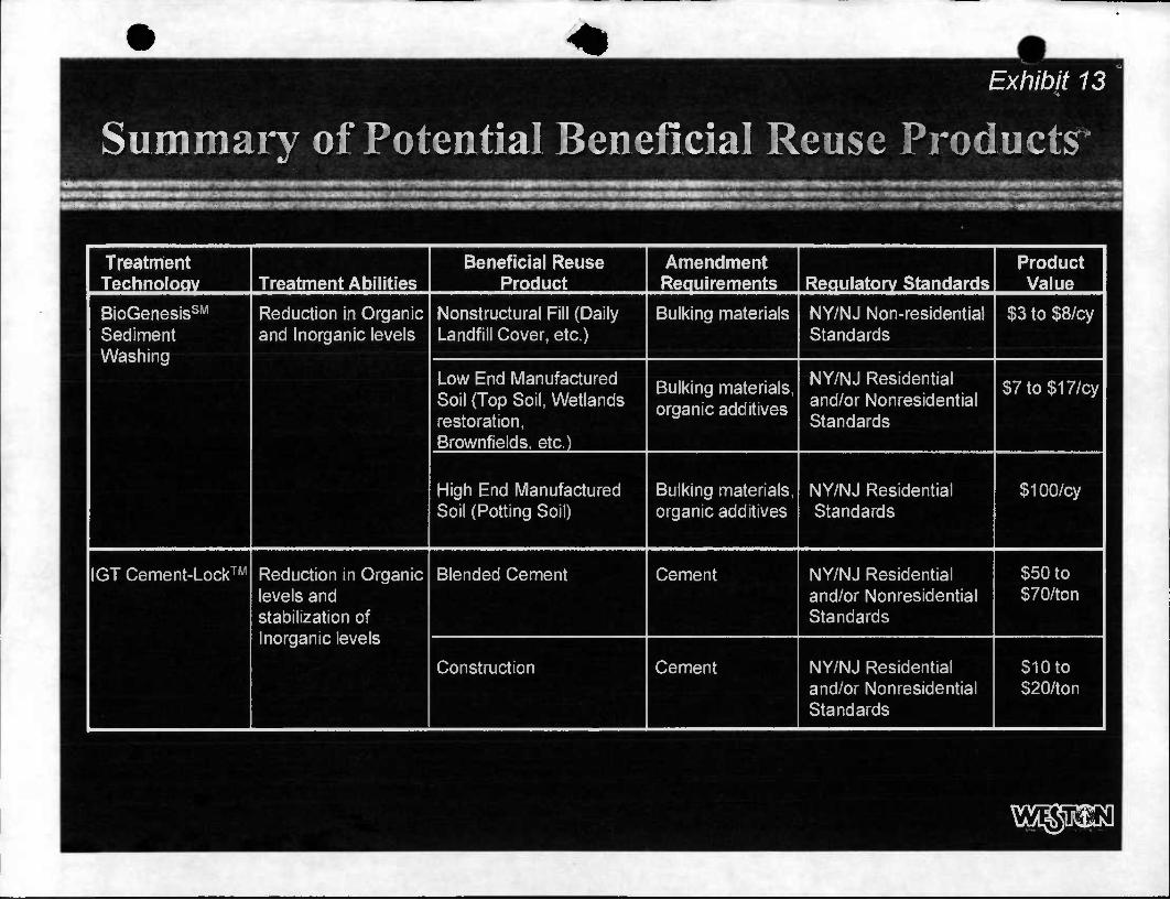
^
Exhibit 13
Summary of Potential Beneficial Reuse Products IKII n,idi ii niiWiipiifciMiiyJijiH
Treatment Technoloav Treatment Abilities
Beneficial Reuse Product
Amendment Requirements Requlatorv Standards
Product Value
BioGenesisSM
Sediment Washing
Reduction in Organic and Inorganic levels
Nonstructural Fill (Daily Landfill Cover, etc.)
Bulking materials NY/NJ Non-residential Standards
$3 to $8/cy
Low End Manufactured Soil (Top Soil, Wetlands restoration, Brownfields, etc.)
Bulking materials, organic additives
NY/NJ Residential and/or Nonresidential Standards
$7to$17/cy
High End Manufactured Soil (Potting Soil)
Bulking materials, organic additives
NY/NJ Residential Standards
$100/cy
IGT Cement-Lock• Reduction in Organic levels and stabilization of Inorganic levels
Blended Cement Cement NY/NJ Residential and/or Nonresidential Standards
$50 to $70/ton
Construction Cement NY/NJ Residential and/or Nonresidential Standards
$10 to $20/ton