An Analysis of Tyra Banks, Tyler Perry and Shonda Rhimes ...
Upload
khangminh22Category
view
3download
0
INITIAL SUBMITTAL OF THE WRITTEN EXAMINATION
FOR THE PERRY INITIAL EXAMINATION - MARCH 2002

Perry Nuclear Power Plant NRC Written Examination
Data Sheets
QUESTION Common 001
The following plant conditions exist:
"* The reactor is in cold shutdown. "* Reactor water level is being maintained with the CRDH and RWCU Systems. "• CRDH System flow is in Automatic at 60 gpm. "• RWCU blow down flow is adjusted to 60 gpm.
Surveillance testing of the Reactor Protection System results in a full reactor scram signal.
Assume no operator actions have been performed.
Which one of the following describes the response of the CRDH System and reactor water level?
CRDH total system flow will...
A. decrease and reactor water level will decrease.
B. decrease and reactor water level will increase.
C. increase and reactor water level will decrease.
D. increase and reactor water level will increase.
ANSWER: D.

Perry Nuclear Power Plant NRC Written Examination
Data Sheets
Level: RO SRO Tier # 2 2
Examination Outline Cross-Reference Group # 1 2 K/A# 201001 .A3.05 Importance Rating 2.8 12. 8
Proposed Question: See attached Common 001
Proposed Answer: See attached
Explanation (Why the distractors are incorrect):
A&B - CRDH system flow increases due to diverting water to the charging header.
C - although CRDH system flow is higher, this water is diverted to the charging header and RPV level will actually increase since CRDH flow is greater than RWCU blowdown flow.
Technical Reference(s): Reference Attached: X
SDM C11(CRDH) I (Attach if not previously provided)
Proposed references to be provided to applicants during examination:
NONE
Learning Objective (As available): OT-3036-007-C 1 (CRDH) OBJ B &C
Question Source: Bank # Modified Bank # (Note changes or attach parent) New X
Question History: Previous NRC Exam Previous Quiz / Test
Question Cognitive Level: Memory or Fundamental Knowledge Comprehension or Analysis _C_
10 CFR Part 55 Content: 55.41 X 55.43
Comments (Why is it an upper level question): Requires the student to predict the impact of a scram on CRDH system flow and the resulting impact on reactor water level.

locally mounted flow transmitter. The flow transmitter converts the
hydraulic signal to an electrical signal. This electrical signal is then
transmitted to the flow controller and to a flow indicator in the Control
Room. The flow controller transmits an- error signal if the actual flow
deviates from a manually selected setpoint of 60 gpm. This error signal is
transmitted to the electro/pneumatic transducer serving the Flow Control
Valve. Here the electrical error signal is converted to a pneumatic signal.
The pneumatic signal from the transducer adjusts the valve positioner,
controlling the valve to adjust the flow and compensate for the deviation.
The Flow Control Valve, therefore, reacts to the flow deviation sensed by
the flow element and makes the necessary adjustments in flow to maintain
a constant flow from the Drive Water Pump, and thereby a constant
pressure in the accumulator charging header.
Only one Flow Control Valve is in operation at a time. The valves are
designed to have some small amount of flow (5 gpm at 987 psid) with the
valves closed, The valves may be operated automatically by the controller
or manually, through the operation of Instrument Air valves provided in
the air lines to the transducer. Control air is supplied from the Instrument
Air System (P52).
The Charging Header connection is downstream of the flow element.
During a scram, water drawn off for accumulator charging will create a
high flow signal, causing the Flow Control Valve to close, deverting most
of the pump discharge to the Charging Water Header. This will cause
flow indication to rise high off scale until the scram is reset and the
accumulators are recharged.
C1I (CRDH), Rev. 7 12

CHARGING
SCRAM DISCHARGE
/ I EXHAUST I COOLING I I
S Ii ( DRIVE II
ROD DISPLAY
BOARD
Figure Cii(CRDH)-6.
HYDRAULIC CONTROL UNIT PIPING DIAGRAM
C 1I (CRDH), Rev. 7 47

Perry Nuclear Power Plant NRC Written Examination
Data Sheets
QUESTION Common 002
The plant is operating at 40% reactor power with Main Turbine Stop Valve (TSV) testing in progress. TSV N 1I-F200A is in the full closed position for testing when TSV NI 1 -F200B fails closed.
Which one of the following is the expected response of the RPS System, if any?
A. Full Scram.
B. Half Scram.
C. No response, due to the specific TSV combination involved.
D. No response, since this RPS trip is bypassed under current plant conditions.
ANSWER: B.

Perry Nuclear Power Plant NRC Written Examination
Data Sheets
Level: RO SRO Tier # 22
Examination Outline Cross-Reference Group # 1 K/A# 212000. K5.02 Importance Rating 3.3 13. 4
Proposed Question: See attached Common 002
Proposed Answer: See attached
Explanation (Why the distractors are incorrect):
A - This logic requires 3 TSV to be closed to initiate a Full Scram signal.
C - This is only true for TSV B&C or A&D combination.
D - The RPS TSV closure trip is only bypassed below 38% reactor power.
Technical Reference(s): Reference Attached: X
SDM C71 (Attach if not previously provided)
Proposed references to be provided to applicants during examination:
NONE
Learning Objective (As available): OT-3036-005-C71 OBJ F
Question Source: Bank # Modified Bank # (Note changes or attach parent) New X
Question History: Previous NRC Exam Previous Quiz / Test
Question Cognitive Level: Memory or Fundamental Knowledge _X_ Comprehension or Analysis
10 CFR Part 55 Content: 55.41 X
55.43
Comments (Why is it an upper level question):

Closure Scrams represents the upper limit of reactor power determined by
transient safety analysis whereby the neutron flux or reactor pressure
scram functions alone provide adequate core protection. This considers
that a turbine trip or load rejection occurs and the Turbine Bypass Valves
fail to open. The capacity of the bypass system has no influence on the
trip bypass setpoint.
Above 38% of rated thermal power, as sensed by Main Turbine first-stage
pressure, and when three out of four Turbine Stop Valves are less than
95% open, a Turbine Stop Valve Closure Scram is initiated. Position U
switches N006A through H, mounted on Turbine Stop Valves F200A DP A through D, provide inputs into the RPS System. Each Turbine Stop Valve E has an input to Trip Systems A and B via a limit switch. The logic is 2
arranged so that partial closure of any three of the four Turbine Stop
Valves initiates a reactor scram.
If Turbine Stop Valve F200A is less than 95% open, its position switches
N006E and N006H actuate and open contacts which deenergize channel
sensor relays KI0E and KiOH. This opens channel sensor relay contacts
KiOE in RPS Channel A and K10H in RPS Channel D. However, the
channel sensor relay contacts K1i A and KI OD are still closed keeping
their K14 relays energized. Thus, neither trip system trips. Note, this
allows fast closure testing of one Turbine Stop Valve without tripping
either of the RPS trip systems.
Now as Turbine Stop Valve F200C starts to close, its position switches
N006A and N006B actuate and open contacts, which deenergize sensor
relays K10A and K10B in Trip Channels A and B. This will cause
channel trip sensor relays K14A and K14E in RPS Trip Channel A to
deenergize because sensor relay contact K1OE opened when F200A
C71 - Rev. 9 36

closed. However, K14 relays in the other channels do not deenergize
because each has one sensor relay contact still closed. In this condition,
with two Turbine Stop Valves less than 95% open, Channels B, C, and D
are energized and Channel A is deenergized. With Channel A deener
gized, Trip System A is tripped. This is called a "half scram", but no
control rods are inserted.
NOTE: The B and C, A and D combinations of TURBINE STOP
VLV. closure logic is not monitored. No Y2 scram will be
generated or annunciated. A full scram will be generated in
the above condition when the 3rd TSV closes.
If a third Turbine Stop Valve (F200B) closes, its position switches N006G
and N006D actuate and open contacts which deenergize channel sensor
relays K1OG and KiOD. This opens sensor relay contacts KIOG and
K10D in Channels B and D. This will cause the Channel D trip sensor
relays K14D and K14H to deenergize, causing the insertion of all control
rods.
3. Turbine Control Valve Closure
Refer to Figure 13 during the following discussion.
When the reactor and turbine generator are at power, fast closure of the
Turbine Control Valves can result in a significant addition of positive
reactivity to the core as Nuclear Boiler System pressure rises. The Turbine
Control Valve Fast Closure Scram initiates a scram earlier than either the
Neutron Monitoring System or Nuclear Boiler System high pressure. It is
required to provide a satisfactory margin to core thermal-hydraulic limits
for this category of abnormal operational transients. The scram
C71 - Rev. 9 37


RPS TRIP SYSTEM A
OPEN TEST i * OPEN TEST 2
TURBINE STOP VALVE CLOSURE SENSOR CHANNELS
KIOC KIOG SENSOR RELAY K:OF
CONTACTS
Ki4C K~4G CHANNEL K K14G SENSOR K148 K14F "RELAYS
REACTOR PROTECTION SYSTEM CHANNELS
Figure C71-12 TURBINE STOP VALVE CLOSURE LOGIC
SHOWN WITH VALVES OPEN
KIOD
C71 - Rev 9
KiOA
01

Perry Nuclear Power Plant NRC Written Examination
Data Sheets
QUESTION Common 003
Refueling is in progress when a rupture of the Fuel Pool Cooling and Cleanup (FPCC) Return Header to the Upper Containment Pool occurs.
Which one of the following design features will minimize the inventory loss from the Upper Containment Pool?
A. Diffusers on the Return Header lines become uncovered.
B. FPCC pumps trip on Upper Containment Pool low level.
C. Siphon breakers on the Return Header lines become uncovered.
D. FPCC Surge Tank Fill From CST Valve, G41-F045 automatically opens on Upper Containment Pool low level.
ANSWER: C.

Perry Nuclear Power Plant NRC Written Examination
Data Sheets
Level: RO SRO Tier # 2 2
Examination Outline Cross-Reference Group # 3 3 K/A# 233000. K4.06 Importance Ratinqi 2.9 13.2
Proposed Question: See attached Common 003
Proposed Answer: See attached
Explanation (Why the distractors are incorrect):
A - The return header line diffusers are located at the bottom of the pool.
B - The FPCC pumps trip on low surge tank level.
D - The FPCC makeup to the upper containment pool has no auto open feature.
Technical Reference(s): Reference Attached: _X__
SDM G41 (Attach if not previously provided)
Proposed references to be provided to applicants during examination:
NONE
Learning Objective (As available): OT-3036-006-G41 OBJ B
Question Source: Bank # Modified Bank # (Note changes or attach parent) New X
Question History: Previous NRC Exam Previous Quiz / Test
Question Cognitive Level: Memory or Fundamental Knowledge X Comprehension or Analysis
10 CFR Part 55 Content: 55.41 X 55.43
Comments (Why is it an upper level question):

c. Body Feed Tank
The body feed tank is similar in construction to the precoat tank
but has a larger capacity. The tank also serves as a storage and
mixing vessel for the filter media. By utilizing the Body Feed
Pump metering capability, the rate of filter media injection into the
system can be regulated to maintain the proper water chemistry.
This significantly extends the capacity of a filter demineralizer to
remove impurities for a given amount of filter media expended.
d. Body Feed Pump
The body feed pump is a variable-rate, positive displacement pump
used to transfer filter media slurry to the set of filter demineralizers
in service. By changing the stroke of the pump, a corresponding
change in capacity will result. These pumps are not utilized for
initial precoat of the filters.
7. Siphon Breakers
The diffusers associated with the FPCC return headers are located near the
bottom of each pool area. Therefore, the diffusers have the potential for
draining a pool area if a pipe rupture were to occur in the return header.
To limit the amount of water that could be drained from a pool area,
siphon breakers are installed on each inlet header branch. Siphon breakers
are 1" lines that terminate a few inches below the pools surface. If
siphoning action occurs due to a pipe rupture, the pool level would lower
to the siphon breakers. When the water level reaches the siphon breakers,
G41 - Rev. 5 12

air will be drawn into the lines, preventing any further siphoning action
from occurring.
8. Major Valves
Table 1 summarizes the characteristics of the major valves associated with
the FPCC System. All motor-operated valves fail AS-IS while air
operated valves fail closed.
9. Cask Pit Drain Pump
A Cask Pit Drain Pump is provided to pump water from the Cask Pit to the Liquid Radwaste System (G50) when moving the shipping cask into or out
of the Cask Pit. The pump is a horizontal, split case, single-stage,
centrifugal pump and is located in the Intermediate Building on the 574'
level.
D. DESIGN BASES
The Fuel Pool Cooling and Cleanup System is designed to:
1. Minimize corrosion product build-up and control water clarity, so that the
fuel assemblies can be efficiently handled underwater.
2. Minimize fission product concentration in the water which could be
released from the pool areas.
3. Monitor fuel pool water level and maintain a water level above the
fuel sufficient to provide shielding for normal building occupancy.
G41 - Rev. 5 13

Perry Nuclear Power Plant NRC Written Examination
Data Sheets
QUESTION Common 004
The plant is operating at 100% reactor power when a loss of RPS Bus 'B' occurs.
Simultaneously the following annunciator alarms occur on panel H 13-P601:
"* MAIN STEAM LINE RADIATION DOWNSCALE "* MAIN STEAM LINE RADIATION HI HI/INOP
Which one of the following caused these annunciators?
Note: A partial list will be incorrect.
Loss of power to ...
A. 'A' and 'D' Main Steam Line Radiation Monitors.
B. 'B' and 'C' Main Steam Line Radiation Monitors.
C. 'A' and 'C' Main Steam Line Radiation Monitors.
D. 'B' and 'D' Main Steam Line Radiation Monitors.
ANSWER: D.

Perry Nuclear Power Plant NRC Written Examination
Data Sheets
Level: RO SRO Tier # 2 2
Examination Outline Cross-Reference Group # 2 2 K/A# 272000.K6.01 Importance Ratinq 3.0 13.2
Proposed Question: See attached Common 004
Proposed Answer: See attached
Explanation (Why the distractors are incorrect):
A, B, C - each answer contains either MSL rad monitor A or C both of which are energized via RPS A.
Technical Reference(s): Reference Attached: __
ONI-C71-2; SOI-C71 (Attach if not previously provided)
Proposed references to be provided to applicants during examination:
NONE
Learning Objective (As available): OT-3036-004-D17A OBJ D; OT-3036-005-C71 OBJ C,L, 0
Question Source: Bank # Modified Bank # (Note changes or attach parent) New X
Question History: Previous NRC Exam Previous Quiz / Test
Question Cognitive Level: Memory or Fundamental Knowledge _X_ Comprehension or Analysis
10 CFR Part 55 Content: 55.41 X 55.43
Comments (Why is it an upper level question):

Attachment 2 OM4B: ONI-C71-2 Page: 12 Rev.: 1
Load List RPS Bus B
1. CB2B: lHI3-P692
a. RPS Logic Channel B b. MSIV and MSLD Isolation Logic Channel B c. RPS Channel B sensors:
1) B21-N675B
2) B21-N676B
3) B21-N678B
4) B21-N679B
5) B21-N680B
6) B21-N681B
7) B21-N682B
8) B21-N683B
9) C71-N650B
10) C71-N652B
11) E31-N686B
12) E31-N687B
13) E31-N688B
14) E31-N689B
2. CB4B: 1H13-P670
a. SRM B
b. IRM B and F c. MSL Rad Monitor, 1D17-K610B d. Cntmt Vent Exhaust Rad Monitor, 1D17-K609B
3. CB5B: 1H13-P623
a. Outboard MSIV '"B" solenoids

Attachment 2 (Cont.) OM4B: Page: Rev.:
Load List RPS Bus B (Cont.)
4. CB6B: 1H13-P672
a.
b. C.
d.
SRM D IRM D and H MSL Rad Monitor, 1D17-K610D Cntmt Vent Exhaust Rad Monitor, 1D17-K609D
5. CB7B: IHI3-P623
a. Inboard MSIV "B" solenoids b. Inboard BOP Isolation Logic c. Inboard RHR Isolation Logic d. Inboard RWCU Isolation Logic e. Inboard Rx Water Sample Isolation Logic f. Inbd MSIV position indication on 1H13-P601
6. CB8B: 1H13-P694
a. RPS Logic Channel D b. MSIV and MSLD Isolation Logic Channel D c. RPS Channel D sensors:
1) B21-N675D
2) B21-N676D
3) B21-N678D
4) B21-N679D
5) B21-N680D
6) B21-N681D
7) B21-N682D
8) B21-N683D
9) C71-N650D
10) C71-N652D
11) E31-N686D
12) E31-N687D
13) E31-N688D
14) E31-N689D
ONI-C71-2 13 1 / C-2

Perry Nuclear Power Plant NRC Written Examination
Data Sheets
QUESTION Common 005
The following plant conditions exists:
"* The reactor is operating at 90% power. "* One of the two running Reactor Feed Pumps Turbines tripped. "* Reactor water level decreased to +188 inches and then returned to normal level.
Which one of the following describes the operational concern during this transient?
A. Moisture carryover can occur which could lead to a reduction in Reactor Recirculation Pump Net Positive Suction Head.
B. Moisture carryover can occur which could lead to excessive moisture impingement on the Main Turbine blades.
C. Steam carryunder can occur which could lead to a reduction in Reactor Recirculation Pump Net Positive Suction Head.
D. Steam carryunder can occur which could lead to excessive moisture impingement on the Main Turbine blades.
ANSWER: C.

Perry Nuclear Power Plant NRC Written Examination
Data Sheets
Level: RO SRO Tier # 1 1
Examination Outline Cross-Reference Group # 1 1 K/A# 295009.AK1.01 Importance Rating 2.7 2.9
Proposed Question: See attached Common 005
Proposed Answer: See attached
Explanation (Why the distractors are incorrect):
A&B - a low water level results in steam carryunder not moisture carryover.
D - Main Turbine blade impingement is a result of moisture carryover.
Technical Reference(s): Reference Attached: X
SDM B21 (NBPI); GP Themo Text Chapter 8 (Attach if not previously provided)
Proposed references to be provided to applicants during examination:
NONE
Learning Objective (As available): OT-3302-004-08 OBJ 16
Question Source: Bank # Modified Bank # (Note changes or attach parent) New X
Question History: Previous NRC Exam Previous Quiz / Test
Question Cognitive Level: Memory or Fundamental Knowledge Comprehension or Analysis C
10 CFR Part 55 Content: 55.41 X 55.43
Comments (Why is it an upper level question): Requires the student to recognize potential conditions which result steam carryunder (low water level) and operational implications of reactor recirculation.

d. Level 5 (201")
Level 5 is the water level setpoint at which the Feedwater Control
System (C34) normally maintains vessel water level. Operational
ly, the vessel water level can be maintained at any level between
Level 7 and Level 4.
e. Level 4 Alarm Trip (197")
The RX LEVEL HI/LO L7/L4 annunciator also alarms at the
reactor vessel water level below which steam carry under will
begin affecting the reactor recirculation flow rate at full power
because of Recirculation Pump cavitation. At Level 4, coincident
with a Reactor Feed Pump Turbine trip, the Recirculation Flow
Control Valves close to the 48% flow position (17% FCV position)
to reduce the reactor thermal power output to within the capacity of
the remaining Reactor Feed Pump, if B33 Recirculation pumps are
running in fast speed.
f. Level 3 (178") Trip
The Level 3 scram function is designed to protect against high
moisture carryover (steam bypassing the dryer under the seal skirt).
The scram occurs while the water level is above the bottom of the
dryer seal skirt. This level selection also results in a quantity of
reserve coolant between this level and the top of the active fuel to
account for evaporation (decay heat boil off) losses, steam void
collapse, and other coolant losses from the reactor vessel following
a loss of feedwater flow, without the vessel water level decreasing
to Level 1, which would initiate the low pressure Emergency Core
B21 (NBPI) - Rev 8. 7

Continuing up the channel the fluid film covering the channel begins to dissipate at the point of DNB. The fluid film flashes to steam and the flow in this region is called mist flow. The coolant is a fog composed of vapor with small water droplets entrained in it. This is called dryout and characterized by the breakdown of the heat transfer mechanism and a temperature excursion.
The point of DNB (departure from nucleate boiling) or OTB (onset of transition boiling) exists at the dividing point between annular flow and mist flow. This is when the fluid film inside the walls of the fuel channel ceases to exist. The surface of the fuel cladding is then cooled by the impingement of moisture droplets entrained in the vapor flow.
Note that the film heat transfer coefficient deteriorates at DNB. However, once the film layer ceases to exist, the velocity of the vapor and moisture droplets is very high. Therefore, the rate of heat transfer is still good.
CORE INLET SUBCOOLING
Previously in Chapter 6, we found that core inlet subcooling is the major contributor to recirculation pump net positive suction head (NPSH). It is very important to maintain adequate subcooling to ensure that the available NPSH is always greater than the required NPSH to prevent cavitation of the recirculation pumps. We will now discuss how to calculate core inlet subcooling and explain the effect that plant systems have on the results.
Core inlet subcooling (AHs) is defined as the difference in enthalpy between the enthalpy of the fluid in the core inlet plenum (discharge from the jet pumps) and the saturation enthalpy of the fluid at the same core inlet pressure (Refer to Figure 8-9).
AHs = h1 - h0
Where:
AHs
hf
= core inlet subcooling (Btu/Ilbm)
- saturation enthalpy for core inlet pressure (Btu/Ilbm)
actual fluid enthalpy at core inlet plenum discharge ofjet pump (Btu/lbm)
Equation 8-1
Figure 8-9 BWR Core
The core inlet subcooling is obtained by writing both a mass and energy balance on the downcomer region of the reactor vessel; i.e., the volume between the core shroud and the vessel wall excluding the external recirculation and cleanup loops.
ENERGY ENTERING
DOWNCOM ER REGION
ENERGY ADDED TO
DOWNCOMER REGION
Equation 8-2
ENERGY EXITING
DOWNCOMER REGION
BWR / THERMODYNAMICS / CHAPTER 8
/ THERMAL HYDRAULICS
7 of 30 © 1999 GENERAL PHYSICS CORPORATION
REV 2

The total energy entering the downcomer region is the total flow multiplied by the enthalpy of the fluid. This entering flow is composed of:
1. Saturated liquid returning from the steam separator and steam dryers.
2. Saturated steam entrained in saturated liquid as carryunder.
3. Feedwater entering through the feedwater spargers.
4. Control rod drive (CRD) cooling flow.
Note that CRD cooling flow is included with the energy entering the downcomer. Although core bypass flow never physically mixes with the core inlet plenum fluid, the CRD bypass flow rate is low enough that the CRD fluid is heated by conduction to essentially the core inlet temperature. The effect on the core inlet subcooling is therefore about the same as if the control rod coolant flow physically mixed with the downcomer region fluid.
The energy added to the downcomer region is by the recirculation pumps and the cleanup system. The energy leaving the downcomer region is the total flow exhausting from the jet pumps.
From the inputs into the energy balance, we can determine how plant systems affect core inlet subcooling. For example, a loss of feedwater heating causes a decrease in the enthalpy of the fluid entering the downcomer. The saturation enthalpy for the core inlet pressure (hf) remains constant while the actual fluid enthalpy at the core inlet plenum (ho) decreases. Therefore, the core inlet subcooling increases.
AHs '"=hf-ho,,
If carryunder increases (due to maintaining too low a reactor water level), the amount of steam entrained in the liquid returning to the
downcomer from the separators and dryers increases. This causes the core inlet plenum enthalpy (h,) to increase. Since saturation enthalpy for the core inlet pressure (hf) remains constant, inlet subcooling decreases.
AHs hf-hT
This effect is detrimental to plant efficiency and can lead to cavitation of recirculation pumps. It can also cause coolant to flash to steam as it passes through the nozzle of the jet pumps. This would cause reduce recirculation flow through the core.
QUALITY AND VOID FRACTION
As discussed previously, there are two terms used to describe the relative amounts of steam and water in a two-phase mixture. The mass fraction of steam in a mixture is the quality of the mixture. The quality of a mixture is defined as:
mass of steam in a mixture
total mass of the mixture
or
mass of vapor
mass of (vapor + liquid)
Equation 8-3
Quality is often expressed as a percent.
If 1 Ibm of a mixture contained 0.14 ibm steam, the quality would be:
0.14 lbm steam X=1.0 lbm mixture
X=0.14 x100% =14%
Example 8-1
BWR / THERMODYNAMICS / CHAPTER 8
/THERMAL HYDRAULICS
8 of 30 © 1999 GENERAL PHYSICS CORPORATION
REV 2

Perry Nuclear Power Plant NRC Written Examination
Data Sheets
QUESTION Common 006
The plant is operating at 100% reactor power when a chemical intrusion occurs.
Chemistry samples the reactor water and determines that some fuel elements have failed.
Subsequent to the sample, the following alarms occurred:
"* OG PRE-TREAT PRCS RAD MON RAD HIGH (H13-P604) "* OG POST-TREAT PRCS RAD MON A/B RAD HI (H13-P604) "* MAIN STEAM LINE RADIATION HIGH (H13-P601) "* MAIN STEAM LINE RADIATION HI HI/INOP (H13-P601)
Which one of the following describes the automatic response of the Nuclear Steam Supply Shutoff System (NSSSS) to this condition?
A. Off-Gas System isolation.
B. Main Steam Line isolation.
C. Steam Jet Air Ejector isolation.
D. Reactor Water Sample isolation.
ANSWER: D.

Perry Nuclear Power Plant NRC Written Examination
Data Sheets
Level: RO SRO Tier # 1 1
Examination Outline Cross-Reference Group # 2 1 K/A# 295017.AK2.14 Importance Ratin 1 4.0 14.1
Proposed Question: See attached Common 006
Proposed Answer: See attached
Explanation (Why the distractors are incorrect):
A - Offgas will only isolate on a Offgas Post Treat 3xHl condition (this is not a NS4 isolation)
B - the MSIVs do not automatically isolate on high radiation signal (previous design did).
C - Steam Jet Air Ejectors do not have a high rad signal isolation.
Technical Reference(s): Reference Attached: _X
ONI-J11-1 Section 2.0; ARI-H13-P601-19 (B2) (Attach if not previously provided)
Proposed references to be provided to applicants during examination:
NONE
Learning Objective (As available): OT-3036-002-B21(NS4) OBJ H
Question Source: Bank # Modified Bank # (Note changes or attach parent) New X
Question History: Previous NRC Exam Previous Quiz / Test
Question Cognitive Level: Memory or Fundamental Knowledge Comprehension or Analysis C
10 CFR Part 55 Content: 55.41 X 55.43
Comments (Why is it an upper level question): Requires the student to predict the correct system response based on plant conditions provided.

3. Increasing background radiation levels around process piping and components.
2.0 AUTOMATIC ACTIONS
1 . If MSL radiation levels reach 1.5 times full power background, the following actions occur:
a. Mechanical Vacuum Pumps trip and isolate. b. REACTOR WATER SAMPLE ISOL, 1 B33-FO1 9, and
REACTOR WATER SAMPLE ISOL, 1 B33-F020, isolate.
2. If a BYPASS VLV SHUT OG POST-TREAT PRCS A/B RAD HI alarm is received, the following actions occur:
a. ADSORBER TRAIN BYPASS VALVE, 1N64-F045, closes. b. BYPASS LINE BLOCK VALVE, 1N64-F062, closes. c. IA TO ADSORBER BYP LN SOL VLV, 1 N64-F063, opens. d. ADSORBER TRAIN A & B INLET VALVES,
1 N64-FO51A & B, open if their control switches are not in CLOSE and ADSORBER VAULT MODE SELECT is in AUTO.
e. ADSORBER TRAIN A & B FIRST ADSORBER BYP, 1N64-FO51C & D, open if their control switches are not in CLOSE and ADSORBER VAULT MODE SELECT is in AUTO.
3. If a OG ISOL OG POST-TREAT PRCS RAD A/B 3X HI alarm is received, the following actions occur:
a. OFFGAS DISCHARGE ISOLATION, 1N64-F632, closes. b. COOLER CONDENSER A & B DRAIN VALVES,
1N64-F034A & B, close. c. HOLDUP LINE DRAIN VALVE, 1N64-F023, closes. d. PREFILTER INLET DRAIN VALVE, 1N64-F054, closes.
PERRY NUCLEAR POWER PLANT Procedure Number: ONI-J11-1
Title: Use Category:
Gross Fuel Cladding Failure Infield Reference Revision: Change: Page
5 N/A 4 of 9

ARI-H13-P601-19 Page: 21 Rev.: 3 / C-20
Computer Point ID None
MAIN RT
HI
1.0 CAUSE OF ALARM
2.0
3.0
4.0
4.1
1. ORM 6.2.16, Isolation Actuation Instrumentation
STEAM LINE
%DIATION
HI/INOP
1. Main steam line radiation levels greater than PEMS Setpoint List Upscale Trip setpoint as sensed by radiation monitors ID17-N003A, B, C or D.
2. One or more Main Steam Line Radiation Monitors inoperative. 3. Low voltage to detector channels A, B, C, or D. 4. Alarm may be caused by gross fuel cladding failure.
AUTOMATIC ACTION
1. If radiation monitors A or C sense high radiation or INOP (one-out-of-two logic), the following occurs:
a. Mechanical vacuum pump isolation valves close
2. If radiation monitors A and D sense high radiation or inop, IB33F0020, REACTOR WATER SAMPLE ISOL valve, closes.
3. If radiation monitors B and C sense high radiation or inop, 1B33F0019, REACTOR WATER SAMPLE ISOL valve, closes.
IMMEDIATE OPERATOR ACTION
1. None
SUBSEQUENT OPERATOR ACTION
1. Monitor the following for indications and trends of a high radiation condition:
a. Main Steam Line radiation level b. Off-Gas Pre-Treatment and Post-Treatment radiation level c. Off-Gas Vent Pipe radiation level
2. Contact Chemistry to sample and analyze Reactor Coolant. 3. Enter PEI-B13, Reactor Pressure Vessel Control, if reactor
pressure exceeds 1065 psig. 4. If there are indications of a gross fuel cladding failure,
enter ONI-Jll-l, Gross Fuel Cladding Failure. 5. Consult EPI-Al, Emergency Action Levels, for Emergency Plan
Classification and actions to be taken.
Technical Specifications
f f I I I i i ! i i
I . . . . . . . ! i
. . . . . i i i i i

Perry Nuclear Power Plant NRC Written Examination
Data Sheets
QUESTION Common 007
While removing a fuel channel from a spent fuel bundle in the Fuel Handling Building fuel preparation machine the following conditions occur:
"* All local area radiation monitors suddenly alarm. "* ONI-Ji 1-2, Fuel Bundle Rupture has been entered. "* A Fuel Handling Building evacuation is ordered.
Which one of the following actions is required?
The fuel bundle should be...
A. moved to its designated fuel pool storage location.
B. left at its current position and immediately re-channeled.
C. lowered in the fuel preparation machine to the full down position.
D. left at its current position and the fuel preparation machine air isolation valve closed.
ANSWER: C.

Perry Nuclear Power Plant NRC Written Examination
Data Sheets
Level: RO SRO Tier # 1 1
Examination Outline Cross-Reference Group # 3 1 K/A# 295023.AA1.03 Importance Rating 3.3 13.6
Proposed Question: See attached Common 007
Proposed Answer: See attached
Explanation (Why the distractors are incorrect):
A - this is a required action for fuel bundles being moved with the refuel bridge.
B - this would require raising the fuel bundle in the FPM and is not allowed by ONI-J1 1-2.
D - this action is contrary to the guidance in ONI-J1 1-2.
Technical Reference(s): Reference Attached: X
ONI-J1 1-2 Immediate Action (Attach if not previously provided)
Proposed references to be provided to applicants during examination:
NONE
Learning Objective (As available): OT-3036-007-J1 1 OBJ I
Question Source: Bank # Modified Bank # (Note changes or attach parent) New X
Question History: Previous NRC Exam Previous Quiz / Test
Question Cognitive Level: Memory or Fundamental Knowledge _X_ Comprehension or Analysis
10 CFR Part 55 Content: 55.41 X
55.43
Comments (Why is it an upper level question):

IMMEDIATE ACTIONS
1. Make announcement twice to evacuate the affected area and repeat periodically until all personnel have evacuated from the affected area and access is adequately controlled.
2. Suspend all CORE ALTERATIONS and movement of fuel after placing the fuel in a safe condition.
NOTE
The following conditions of Fuel or Core Components are defined as 'safe' for the purposes of this instruction: 1) Properly seated in the reactor vessel. 2) Properly seated in a designated storage location. 3) Properly seated in the IFTS carriage with the carriage at the Raise Lower
Limit or Bottom Out position as appropriate and the Upender inclined.
3. Lower fuel bundles in the Fuel Preparation Machines to their full down position.
SUBSEQUENT ACTIONS
1. If conditions warrant, enter PEI-D17, Radioactivity Release Control.
2. Personnel evacuating the affected area should perform the following:
a. b. C.
Immediately exit the area to the Intermediate Building. Standby until cleared by Radiation Protection. Obtain a Whole Body Count, as required.
PERRY NUCLEAR POWER PLANT Procedure Number: ONI-J 11-2
Title: Use Category:
Fuel Bundle Rupture During Fuel Handling Infield Reference Revision: Change: Page
4 N/A 8 of 11
3.0
4.0

Perry Nuclear Power Plant NRC Written Examination
Data Sheets
QUESTION Common 008
The following plant conditions exist:
"* An ATWS has occurred. "* Reactor power is 21%. "* Reactor pressure is 1080 psig. "* SLC system indications are:
Indication SLC A
Pump Running Status Pump Discharge Pressure Squib Continuity Light
Red light On 1100 psig
Off
Red light On 1100 psig
On
Which one of the following describes the Standby Liquid Control (SLC) System status?
The SLC System is...
A. not injecting.
B. injecting with SLC Pump 'A' only.
C. injecting with SLC Pump 'B' only.
D. injecting with both SLC Pumps.
ANSWER: D.
SLC B

Perry Nuclear Power Plant NRC Written Examination
Data Sheets
Level: RO SRO Tier # 1 1
Examination Outline Cross-Reference Group # 1 1 K/A# 295037.EA1.04 Importance Rating 4.5 14.5
Proposed Question: See attached Common 008
Proposed Answer: See attached
Explanation (Why the distractors are incorrect):
A, B, C - The squib continuity light is OFF on the "A" squib valve indicating it has fired; the system is cross-tied such that any squib valve open will provide both pumps an injection flow path.
Technical Reference(s): Reference Attached: _X
SDM C41 (Attach if not previously provided)
Proposed references to be provided to applicants during examination:
NONE
Learning Objective (As available): OT-3036-000-C41 OBJ B, E, F &L
Question Source: Bank # Modified Bank # (Note changes or attach parent) New X
Question History: Previous NRC Exam Previous Quiz / Test
Question Cognitive Level: Memory or Fundamental Knowledge Comprehension or Analysis _C
10 CFR Part 55 Content: 55.41 X 55.43
Comments (Why is it an upper level question): Requires the student to comprehend the control room indications (squib lights and reactor pressure versus pump pressure) to determine correct SLC system operation.

4. Explosive Valves
Refer to Figure 7 during the following discussion.
Two normally closed, explosive-actuated, injection valves ensure positive opening when system operation is required. Extreme reliability of the valve is obtained through the use of dual primers (squibs) in the primer chamber assembly. Current applied to either primer will result in valve operation. Zero leakage shutoff is achieved through the use of the integral metal seal (inlet chamber plug). This feature ensures that no boron
solution will leak into the reactor vessel during system testing.
Each valve is capable of passing full system flow. Therefore, failure of one valve to open will not impede system performance.
Each explosive valve is closed by a plug in the inlet chamber. The plug is circumscribed with a deep grove so the end will readily shear off when struck by the valve plunger. This opens the inlet hole through the plug. The sheared end is pushed clear of the valve discharge path. The ignition circuit continuity is monitored continuously by passing a very small current through the primer. Two white lights in the Control Room, one for each division, indicate current flow and thus continuity. Normal current flow is approximately 4.7 to 5.0 milliamps. An alarm in the Control Room will initiate, <3 milliamps, if either primer circuit opens.
C41 - Rev. 8 9

OM3A: Page: Rev.:
SOI-C41 3 7 / C-13
4.1 SLC Manual Injection of Boron Solution
CAUTION
SLC Pumps must not be operated below a SLC Storage Tank level of 200 gallons.
1. Place both SLC PUMP A, 1C41-C001A & SLC Pump B, IC41-C001B, keylock switches to ON.
2. Verify the following actions occur:
a. The white SQUIB CONTINUITY, 1C41-F004A & IC41-FO04B, indicating lights deenergize.
NOTE: The above step is not applicable if reinitiating injection of boron solution following initial injection.
b. SLC PMP SUCT VALVE A, 1C41-F001A & SLC PMP SUCT VALVE, 1C41-F001B, open.
c. SLC PUMP A, 1C41-C001A & SLC Pump B, 1C41-C001B, start when their respective suction valve is full open.
d. SLC Pump discharge pressure slightly above reactor pressure as indicated on SLC PUMP A & B DISCH PRESS, lC41R600A & IC41-R600B.
e. STANDBY LIQUID CONTROL STG TANK LEVEL, IC41-R601, decreases.
f. RWCU system isolates. g. Reactor power decreases.
5.0 SYSTEM OPERATIONS
5.1 Normal Operation
1. The following system parameters should be monitored at ECCS Benchboard, 1H13-P601, when system is operating:
PARAMETER INDICATOR VALUE
a. SLC Storage Tank Level
b. SLC Pump A & B Discharge Press
STANDBY LIQUID CONTROL STG TANK LEVEL, 1C41-R601
SLC PUMP A & B DISCH PRESS, IC41-R600A(B)
200 Gal(Minimum)4950 Gal(Maximum)
Slightly above Rx pressure

Perry Nuclear Power Plant NRC Written Examination
Data Sheets
QUESTION Common 009
The following plant conditions exist:
"* The plant is in MODE 2 and a reactor startup in progress. "* Only RACS Channel 1 is selected for display on panel H13-P680. "* IRM Channel 'B' fails upscale.
Which one of the following describes the Rod Control and Information System (RC&IS) indication(s) the operator will observe on panel H 13-P680?
A. No control rod block is present; the WITHDRAW BLOCK indicator light is lit.
B. No control rod block is present; the WITHDRAW BLOCK indicator light is not lit.
C. Control rod block is present; the WITHDRAW BLOCK indicator light is lit.
D. Control rod block is present; the WITHDRAW BLOCK indicator light is not lit.
ANSWER: D.

Perry Nuclear Power Plant NRC Written Examination
Data Sheets
Level: RO SRO Tier # 2 2
Examination Outline Cross-Reference Group # 1 1 K/A# 201005.K6.04 Importance Ratinq 3.0 3 3.2
Proposed Question: See attached Common 009
Proposed Answer: See attached
Explanation (Why the distractors are incorrect):
A&B - A rod block is initiated for IRM upscale when the reactor mode switch is in STARTUP.
C - Since RACS channel 1 is selected for display, the channel does not see the withdraw block (since IRM B is assigned to channel 2). Therefore the withdraw block indicator light will not be lit.
Technical Reference(s): Reference Attached: _X
SDM C11(RCIS) (Attach if not previously provided)
Proposed references to be provided to applicants during examination:
NONE
Learning Objective (As available): OT-3036-004-Cl 1 (RC&IS) OBJ D&L
Question Source: Bank # 505 Modified Bank # (Note changes or attach parent) New
Question History: Previous NRC Exam Previous Quiz / Test
Question Cognitive Level: Memory or Fundamental Knowledge Comprehension or Analysis C
10 CFR Part 55 Content: 55.41 X 55.43
Comments (Why is it an upper level question): Requires the student to predict the response of the RC&IS system, including expected indications, based on the initial conditions provided.

Question Num: Old Number: Question Type: MC
Task Number 214-505-01-01 214-516-01-01 214-519-04-01
Reference SDM-CI (RCIS)
EQB VALIDATED QUESTION
505 Rev: POINTS: 1.00 CYCLE: / Discipline:R
Time: 0 Safety Related:N Attachment? N
Lesson Plan Number Rev Objective Objective OT-3036-CII(RCIS) D,L2
Rev. K/ 21
A Number 5-003-K1.03
RO/SRO rating 3.1/3.1 /1
/1
Keyword (MPL) LEVEL 2 Revision Date 01/14/00
I. QUESTION:
The plant is in MODE 2 with a reactor startup in progress. RACS channel 1 is selected for display. IRM B fails upscale. No other IRMs are alarming. Which ONE of the following correctly describes the indications the operator will see?
a. No rod block present, Withdraw Block indicator lighted.
b. No rod block present, Withdraw Block indicator unlighted.
c. Rod block present, Withdraw Block indicator lighted.
d. Rod block present, Withdraw Block indicator unlighted.
II. ANSWER:
d.

The Insert Block. or Withdraw Block indicator will light if plant conditions
(e.g., IRM flux levels, Scram Discharge Volume level, etc.) are such that
rod movement is not permitted in either or both directions. The Insert
Inhibit or Withdraw Inhibit indicator along with the Insert Block or
Withdraw Block indicator, respectively, indicate that motion is disallowed
by the Rod Control and Information System (RC&IS and not the RPC).
If both channels of RACS have been selected for display (as determined
by the "Data Mode" control) and plant conditions require a block of rod
movement, the Insert Block or Withdraw Block indicator will light. If the
rod block is recognized in both RACS channels, the indication will be
continuous. If only one channel of RACS recognizes the plant condition,
the indicator will be flashing. This is because the OCM alternately
receives data for display from each channel of the RACS when both
channels are selected.
If only one channel has been selected for display, the illumination of the
Insert Block or Withdraw Block indicator when plant conditions require a
rod block will depend on whether the selected channel recognizes the rod
block condition. If it does, the indicator will be lit. If the selected channel
does not recognize the rod block condition, the indicator will not be lit,
even though a rod block exists. For example, if RACS channel I is
selected for display and IRM A detects a high flux level, there will be a
rod block and the Withdraw Block indicator will light since IRM A is
assigned to RACS channel 1. However, if IRM B was the one to detect a
flux level of 80/125 with channel 1 selected for display, there would again
be a rod block but the Withdraw Block indicator would not be lit because
IRM B is assigned to channel 2. In both condition described above a Rod
Withdrawal Block annunciator will be received on P680-5A-EIO
indicating to the operator a rod withdrawal block exists.
C I I(RC&IS) -Rev. 7 18

Perry Nuclear Power Plant NRC Written Examination
Data Sheets
QUESTION Common 010
Technical Specification 3.4.3, Jet Pumps, requires the plant to be shutdown when any Jet Pump is determined to be inoperable.
Which one of the following describes the Technical Specification bases for this Required Action?
An inoperable Jet Pump can...
A. decrease the blowdown area during a LOCA and reduce the ability to reflood the core.
B. decrease the blowdown area during a LOCA and increase the potential for power/flow instabilities.
C. increase the blowdown area during a LOCA and reduce the ability to reflood the core.
D. increase the blowdown area during a LOCA and increase the potential for power/flow instabilities.
ANSWER: C.

Perry Nuclear Power Plant NRC Written Examination
Data Sheets
Level: RO SRO Tier # 2 2
Examination Outline Cross-Reference Group # 2 2 K/A# 202001.K4.01 Importance Rating 3.9 I 3.9
Proposed Question: See attached Common 010
Proposed Answer: See attached
Explanation (Why the distractors are incorrect):
A &B - The blowdown area can potentially increase (not decrease).
D - Although power to flow instabilities are a concern at reduced core flows, this is not the bases of this technical specification required action.
Technical Reference(s): Tech Spec 3.4.3 Bases; Reference Attached: _X SDM B13 (Attach if not previously provided)
Proposed references to be provided to applicants during examination:
NONE
Learning Objective (As available): OT-3036-002-B13 OBJ D, E&F; OT-3037-006-08 OBJ C
Question Source: Bank# Modified Bank # (Note changes or attach parent) New X
Question History: Previous NRC Exam Previous Quiz / Test
Question Cognitive Level: Memory or Fundamental Knowledge _X_ Comprehension or Analysis
10 CFR Part 55 Content: 55.41 X
55.43
Comments (Why is it an upper level question):

Jet Pumps B83.4.3
BASES
APPLICABLE SAFETY ANALYSES
(continued)
The capability of reflooding the core to two-thirds core height is dependent upon the structural integrity of the jet pumps. If the structural system, including the beam holding a jet pump in place, falls, jet pump displacement and performance degradation could occur, resulting in an increased flow area through the jet pump and a lower core flooding elevation. This could adversely affect the water level in the core during the reflood phase of a LOCA as well as the assumed blowdown flow during a LOCA.
Jet pumps satisfy Criterion 2 of the NRC Policy Statement.
LCO The structural failure of any of the jet pumps could cause significant degradation in the ability of the jet pumps to allow reflooding to two thirds core height during a LOCA. OPERABILITY of all jet pumps is required to ensure that operation of the Reactor Coolant Recirculation System will be consistent with the assumptions used in the licensing basis analysis (Ref. 1).
APPLICABILITY In MODES 1 and 2, the jet pumps are required to be OPERABLE since there is a large amount of energy in the reactor core and since the limiting DBAs are assumed to occur in these MODES. This is consistent with the requirements for operation of the Reactor Coolant Recirculation System (LCO 3.4.1).
In MODES 3, 4. and 5. the Reactor Coolant Recirculation System is not required to be in operation, and when not in operation sufficient flow is not available to evaluate jet pump OPERABILITY.
ACTIONS
An inoperable jet pump can increase the blowdown area and reduce the capability of reflooding during a design basis LOCA. If one or more of the jet pumps are inoperable, the plant must be brought to a MODE in which the LCO does not apply. To achieve this status, the plant must be brought to MODE 3 within 12 hours. The allowed Completion Time of 12 hours is reasonable, based on operating experience, to reach MODE 3 from full power conditions in an orderly manner and without challenging plant systems.
(continued)
PERRY - UNIT 1 B 3.4-14 Revision No. 0

D. DESIGN BASES
The reactor vessel is designed to safely produce power over the design life of the
plant. In order to accomplish this goal, the Reactor Vessel and Internal
Components were designed to meet the following general design bases.
I1. Safety
a. Provide a Barrier Against Radioactive Release
The design of the reactor vessel is such that it will contain
radioactive materials without leakage. The vessel is designed to
maintain its structural integrity during all normal and postulated
accident conditions. Numerous documented tests and analyses of
the design have been performed to verify the design adequacy.
The vessel and internals are constructed from materials proven to
maintain the desired characteristics under the conditions present in
a boiling water reactor for the design life of the plant. Samples of
the materials are tested on a periodic basis to verify these
properties. The vessel pressure boundary is assembled using
advanced welding techniques under strict quality control to ensure
vessel integrity.
b. Provide a Floodable Volume
Refer to Figure 10 during this discussion.
The design of the vessel internals is such that, if a breach of the
nuclear barrier occurred outside of the reactor vessel, the water
level surrounding the core would not drop sufficiently to
completely uncover the core. Such design is necessary to allow
B13 - Rev. 9 29

removal of decay heat. The floodable volume is provided by the
shroud, shroud support assembly, and jet pumps.
In the event of a line break outside the vessel water level would
decrease until the level reached the suction of the jet pumps. At
this point, the downcomer level might continue to decrease, but the
jet pump diffusers would act as standpipes to maintain the water
level inside the shroud around the core. This volume of water, in
conjunction with the operation of the Emergency Core Cooling
Systems, will remove the generated decay heat.
c. Limit Deformation
During the design of the Reactor Pressure Vessel, allowable stress,
deformation, and fatigue limits were established in order to
maintain proper alignment of the vessel internals during normal
operation and to ensure the control rods and core cooling systems
can perform a safe shutdown of the plant and remove decay heat
turing all postulated accidents. Proven engineering design,
coupled with the proper materials, maintains deformation within
allowable limits.
2. Power Generation
a. Provide Proper Coolant Distribution
Proper coolant distribution through the fuel assemblies is
established by the design of the core plate and fuel support pieces.
Coolant in the core inlet plenum is metered through orifices in the
fuel support pieces. These orifices are sized to provide the proper
coolant flow to each fuel.assembly. The core support plate
B13 - Rev. 9 30

-1
ANSWER: D.
Perry Nuclear Power Plant NRC Written Examination
Data Sheets
QUESTION Common 011
The following plant conditions exist:
"* A reactor startup/heatup is in progress. "* Reactor water level is +195 inches and slowly increasing. "* RWCU blowdown flow rate is increased to control RPV water level.
Subsequently the following alarms occur on panel H13-P680:
"* RWCU F/D INLET TEMP HI "* RWCU ISOL F/D TEMP HI
Which one of the following describes the response of the Reactor Water Cleanup System?
A. Inboard isolation valve (G33-F001) closes; the RWCU Pump must be manually secured.
B. Inboard isolation valve (G33-FO01) closes, the RWCU Pump automatically trips off.
C. Outboard isolation valve (G33-F004) closes, the RWCU Pump must be manually secured.
D. Outboard isolation valve (G33-F004) closes, the RWCU Pump automatically trips off.

Perry Nuclear Power Plant NRC Written Examination
Data Sheets
Level: RO SRO Tier # 2 2
Examination Outline Cross-Reference Group # 2 2 K/A# 204000.A3.03 Imp~ortance Rating 3.6 13.6
Proposed Question: See attached Common 011
Proposed Answer: See attached
Explanation (Why the distractors are incorrect):
A &B - only the outboard isolation valve closes on a filter demin high temperature.
C - The RWCU pump will automatically trip on low flow.
Technical Reference(s): SDM-G33 Table G33-4; Reference Attached: _X_
ARI-H13-P680-01 (Cl) (Attach if not previously provided)
Proposed references to be provided to applicants during examination:
NONE
Learning Objective (As available): OT-3036-005-G33/36 OBJ D&I
Question Source: Bank # Modified Bank # (Note changes or attach parent) New X
Question History: Previous NRC Exam Previous Quiz I Test
Question Cognitive Level: Memory or Fundamental Knowledge Comprehension or Analysis _C_
10 CFR Part 55 Content: 55.41 X 55.43
Comments (Why is it an upper level question): Requires the student to predict the response of the RWCU system based on the initial plant conditions provided.

TABLE G33-4
CONDITION SETPOIN
High RWCU Diff Flow 68 gpm (10 minute DELAY)
Low Reactor Vessel 130" Water Level
SLC Pump Initiation SLC Pump A(B) C.S. to Start *
Main Steam Line Tunnel > 152 0F Ambient Temp High
Main Steam Line Tunnel > 103 0F Differential Temp High
RWCU Equipment Rooms HIGH TEMP HIGH dT
Hx Room 132 0F 750 RWCU A(B) Pump Room 131°F 270 Valve Nest Room 131°F 270 Demin Room 1(2) 137 0F 820 Demin Valve Room 137 0F 820 Demin Rec Tank 137°F 820
Loss of Leak Detection (E3 I) Power
NTRHX-uil i 0"'1111igh 140F*
• Closes F004 (FO01) only
•-,- o C esF -on-I---ýly--
G33 - Rev. 9 30

ARI-H13-P680-1 Page: 23 Rev.: 4 / C-12
Computer Point ID None
RWCU ISOL
F/D TEMP
HI
Cl
1.0 CAUSE OF ALARM
1. RWCU filter/demineralizer inlet temperature >140'F as sensed by 1G33-N007.
2. High temperature could be caused by:
a. Excessive blowdown to radwaste or the condenser b. RWCU HX SHELL SIDE BYPASS VALVE, 1G33-F107, open c. Loss of NCC to the RWCU Non-Regenerative Heat Exchangers A
and B, 1G36-D001 and 1G36-D002
2.0 AUTOMATIC ACTION
1. The RWCU SUCT FM CNTMT OTBD ISOL, 1G33-F004, closes.
2. RWCU PUMPs A and B, IG33-CO01A and IG33-CO01B, trip due to 1G33-F004 closure or low flow.
3. RWCU Filter/Demineralizers, 1G36-D00l and IG36-D002, isolate due to low flow.
3.0 IMMEDIATE OPERATOR ACTION
None
4.0 SUBSEQUENT OPERATOR ACTION
1. Close the following valves:
a. RWCU BLWDN TO CNDR/RW VALVE, 1G33-F033 b. RWCU HX SHELL SIDE BYPASS VALVE, 1G33-FI07
2. When conditions permit, perform System Restoration After Isolation per SOI-G33.
NOTE: Filter must be backwashed and precoated due to potential resin damage.
4.1 Technical Specifications
None

Perry Nuclear Power Plant NRC Written Examination
Data Sheets
QUESTION Common 012
The following plant conditions exist:
"* A Loss of Coolant Accident has occurred. "* Drywell pressure is 1.8 psig. "* Reactor water level is +195 inches and stable. "* The High Pressure Core Spray (HPCS) Pump has been overridden to STOP.
Subsequently, Bus EH13 loses power and is re-energized by the Division 3 Diesel Generator.
Assume no additional operator actions were taken.
Which one of the following describes the current condition of the HPCS Pump?
The HPCS Pump is...
A. not running because the initiation logic was reset.
B. not running because the override logic was not affected.
C. running because the override logic was reset.
D. running because the initiation logic was not affected.
ANSWER: B.

Perry Nuclear Power Plant NRC Written Examination
Data Sheets
Level: RO SRO Tier # 2 2
Examination Outline Cross-Reference Group # 1 1 1 KIA# 209002. K2.03 Importance Ratinq 2.8 2.9
Proposed Question: See attached Common 012
Proposed Answer: See attached
Explanation (Why the distractors are incorrect):
A - The initiation logic will not automatically reset because of a loss of AC power. The initiation logic is DC-powered, therefore, it is unaffected (i.e., still sealed-in due to LOCA signal).
C - The HPCS Pump remains overridden off after the loss of Bus EH13 and subsequent reenergization. The override logic is dc-powered, therefore, it is still sealed-in.
D - The HPCS Pump remains overridden off after the loss of Bus EH13 and subsequent reenergization. The initiation logic is DC-powered, therefore, it is unaffected (i.e., still sealed-in due to LOCA signal).
Technical Reference(s): Reference Attached: _X_
SDM-E22A (Attach if not previously provided)
Proposed references to be provided to applicants during examination:
NONE
Learning Objective (As available): OT-3036-004-E22A OBJ E
Question Source: Bank # X Modified Bank # (Note changes or attach parent) New
Question History: Previous NRC Exam X (June 2001 Exam) Previous Quiz / Test
Question Cognitive Level: Memory or Fundamental Knowledge Comprehension or Analysis C
10 CFR Part 55 Content: 55.41 X 55.43
Comments (Why is it an upper level question): Requires the student to predict the response of the HPCS Pump based on initial plant conditions provided.

U.S. NUCLEAR REGULATORY COMMISSION WRITTEN EXAMINATION
SENIOR REACTOR OPERATOR
QUESTION 31
The following plant conditions exist:
"* A Loss of Coolant Accident has occurred "* Drywell pressure is 1.8 psig "* RPV water level is +195 inches and stable "* The High Pressure Core Spray (HPCS) Pump has been overridden to STOP
Subsequently, Bus EH13 loses power and is re-energized by the HPCS Diesel Generator.
Assume no additional operator actions were taken.
Which one of the following describes the current condition of the HPCS Pump?
The HPCS Pump is
A. not running because the initiation logic was reset.
B. not running because the override logic was not affected.
C. running because the override logic was reset.
D. running because the initiation logic was not affected.

The HPCS Injection Valve (F004) will open if reactor level is less
than Level 8 (K9).
A LOCA signal is sent to the HPCS Injection Valve (F004) auto
override circuit (K9).
If the initiation was caused by low level, the level must be restored to
greater than Level 2 in order to reset the logic. However, a high Drywell
pressure initiation signal can be reset by depressing the HPCS Seal-In
Reset Push Button (S7). This action will lockout the high Drywell
pressure signal even if the high Drywell pressure condition still exists.
The white seal-in light will extinguish when the logic has been reset.
2. HPCS Pump Logic
Refer to Figure 12 during the following discussion.
The HPCS Pump is controlled by a three-position, STOP-AUTO-START,
spring return to AUTO, control switch on panel H13-P601. With the
switch in AUTO, the system initiation logic will close the circuit breaker,
EH1304, to energize the pump whenever a Division 3 LOCA signal is
received, power is available to the pump, and a 10-second time delay relay
(Kl 14) times out. (The purpose of this time delay is to prevent
overloading transformer LH-1-A during a high Drywell pressure ECCS
actuation.) If a Division 3 undervoltage and a LOCA condition occur
simultaneously, the HPCS Pump will start as soon as voltage is restored to
bus EH13 (Kl 14 Inst. and K114A). The HPCS Pump can be manually
secured at any time by taking its control switch to STOP. If the operator
takes the control switch to STOP while a LOCA signal is sealed-in, an
override relay (KI 15), energizes and causes the following:
E22A - Rev. 7 20

The start relay (KI 14) deenergizes. This removes the start signal
and deenergizes the HPCS Pump.
The override seals itself in (Ki 15). An amber light located between the HPCS Pump energized/
deenergized lights at the control switch illuminates.
NOTE: When a manual override is activated on the HPCS Pump or
the KPCS Injection Valve, the AUTO features are disabled
until the initiation signal is reset. Actuation of these
overrides shall be in accordance with PAP-0205, "Operability of Safety Systems".
If the HPCS Pump has been overridden, the control switch may still be
used to restart the pump, however the amber override light will remain on.
The override condition will automatically reset and the amber override
light will deenergize only when the Division 3 LOCA signal is reset.
There are no automatic trips of the HPCS Pump except for breaker faults
such as phase overcurrent, differential phase current, or ground
overcurrent. Since there is no undervoltage trip, the HPCS Pump will not
separate from bus EH13 ona loss of power. On a loss of power to EH13,
the HPCS Pump will be energized when the Division 3 Diesel Generator
starts and loads. Since there is no low suction pressure pump trip, the
operator must ensure adequate NPSH is present prior to starting the pump
by checking the -PCS Suppression Pool Suction Valve (FO 15) or the
HPCS CST Suction Valve (FOO1) open. Prior to closing both the HPCS
Suppression Pool Suction Valve and the HPCS CST Suction Valve, the
HPCS Pump breaker must be racked out.
E22A - Rev. 7 21

POWER PUMP MONITOR START
RELAY RELAY
N CLOSED WHEN PUMP 'A SWITCH IN STOP START
LOGIC
A H13-P6OI
S1PUMP TRIP
LOGIC PUMP
OVERRIDE RELAY
FIGURE E22A-12 HPCS PUMP LOGIC
-S$2

Perry Nuclear Power Plant NRC Written Examination
Data Sheets
QUESTION Common 013
The following plant conditions exist:
"* The reactor is critical. "* Reactor power is on Range 3 of the Intermediate Range Monitors. "* Source Range (SRM) detectors are being withdrawn from the core.
Subsequently, SRM Channel 'B' -20 VDC power supply fails (0 Volts).
Which one of the following describes the response of the Source Range Monitoring System?
Assume no operator actions have been performed.
An SRM control rod block signal is...
A. not generated; SRM 'B' detector withdrawal from the core stops.
B. not generated; SRM 'B' detector withdrawal from the core continues.
C. generated; SRM 'B' detector withdrawal from the core stops.
D. generated; SRM 'B' detector withdrawal from the core continues.
ANSWER: D.

Perry Nuclear Power Plant NRC Written Examination
Data Sheets
Level: RO SRO Tier # 2 2
Examination Outline Cross-Reference Group # 1 1 1 K/A# 215004.K6.02 IImportance Ratin 1 3.1 13.3
Proposed Question: See attached Common 013
Proposed Answer: See attached
Explanation (Why the distractors are incorrect):
A&B - A control rod block is generated due to SRM INOP conditions.
C - A SRM control rod block signal is generated; however SRM withdrawal is not effected since it has a separate power source.
Technical Reference(s): Reference Attached: X___
SDM-C51(SRM); ARI-H13-P680-06 (Cl) (Attach if not previously provided)
Proposed references to be provided to applicants during examination:
NONE
Learning Objective (As available): OT-3036-004-C51 (SRM) OBJ B&D
Question Source: Bank # Modified Bank # (Note changes or attach parent) New X
Question History: Previous NRC Exam Previous Quiz I Test
Question Cognitive Level: Memory or Fundamental Knowledge Comprehension or Analysis _C_
10 CFR Part 55 Content: 55.41 X 55.43
Comments (Why is it an upper level question): Requires the student to predict the response of the SRM system based on the initial conditions provided.

In addition to these functions, a trip unit is incorporated to detect system
inoperability. This unit receives, as an input, a signal from a series circuit
consisting of the following:
- SRM channel mode switch position - Drawer internal module position
- High voltage power supply output (output less than 96% of proper
detector voltage) - Negative dc power supplies energized
If the SRM Channel Mode Switch is placed in any position other than
OPERATE, if any internal module becomes unplugged, if the output of
the high voltage power supply decreases to a prescribed value or a loss of
the -15 or -20 Vdc supplies occurs, the trip unit will sense this condition
and produce an INOPERATIVE trip to the auxiliary relays.
The INOPERATIVE trip from the Channel Mode Switch position can be
bypassed by depressing and maintaining the INOP BYPASS push button,
located inside the instrument drawer, depressed.
.8. High Voltage Power Supply and 20 Vdca Power Supply
A high voltage power supply, located in each Source Range Monitor
drawer, provides the voltage necessary for the operation of the fission
chamber detector.
Power is supplied at +20 Vdc and -20 Vdc to the input of a regulator
circuit which produces a constant +15 Vdc and -15 Vdc for input to the
high voltage power supply. The power supply output is variable between
100 and 600 Vdc for application to the detector electrode. The high
voltage power supply is set up at approximately 550 Vdc.
C51 (SRM) - Rev. 6 12

The power supply is also provided with an output voltage sensing trip
circuit. If the output of the power supply decreases below a preset value,
the trip circuit will produce a signal into the previously described
INOPERABLE trip unit.
Power is supplied from Reactor Protection System (C71) Busses A and B
to the 20 Vdc power supplies. One 20 Vdc power supply is located in
each of the four Nuclear Instrument Cabinets (H13-P669 - H13-P672).
The power supply feeds the electronic circuitry and trip logic of its
respective SRM channel. If this power supply fails, it will initiate all trips
and alarms associated with the failed channel. The assignment of power
sources is as follows:
Channel Cabinet Power Source
SRM A P669 RPS Bus A
SRM B P670 RPS Bus B
SRM C P671 RPS Bus A
SRM D P672 RPS Bus B
9. Detector Insert and Retract Mechanism
Refer to Figures 11 and 12 during the following discussion.
A detector insert and retract mechanism is used to position each SRM
detector in its dry tube, which extends from the bottom of the reactor
vessel up into the reactor core. This mechanism allows the detector to be
withdrawn to a position =30" below the bottom of the core when the
neutron flux level has risen above the range covered by the detector.
When the detector is being used during the initial stages of reactor startup,
it is fully inserted to a position 418" above the core midplane. As the
reactor power level is increased, the detector is retracted. This is done to
C51 (SRM) - Rev. 6 13

C51(SRM)-TABLE 4 SRM TRIPS. PERMISSIVES AND INTERLOCKS
1. Rod Blocks Trips
SRM Downscale
SRM High Flux
SRM Inoperative
SRM Detector Wrong Position
.7 cps
1x1O5 cps
1. Module Unplugged 2. Low High voltage
(<96% of Normal Operating Voltage)
3. SRM Mode Switch Not in Operate
4. Loss of -20Vdc or -15Vdc Regulated Power Supply.
<100 cps And Detectors not Fully Inserted
IRM Range 3 or above or Mode Switch in Run
IRM Range 8 or above, or Mode Switch in Run
LRM Range 8 or above or Mode Switch in Run
IRM Range 3 or above or Mode Switch in Run
C5 I(SRM) - Rev. 6
C
IC -o 0 -�1 rri
37

Computer Point ID 1C51NC002 1C51NC003 ROD BLOCK
SRM
UPSC/INOP
Cl
OM 6: ARI-H13-P680-6 Page: 11 Rev.: 2 / C-20
I
1.0 Cause of Alarm
1. The REACTOR MODE SWITCH not in RUN and any of the following:
a. Local neutron flux rate Ž 1 x 10⁵ cps on SRM Channel A, B, C, or D resulting from any of the following:
1) Failure to withdraw SRM detectors. 2) Positive reactivity addition.
b. INOP condition resulting from any of the following:
1) High voltage power supply output low. 2) SRM module unplugged. 3) SRM mode selector switch not in OPERATE. 4) Loss of supply power and/or drawer DC power supplies.
2.0 Automatic Action
1. A control rod withdrawal block occurs.
3.0 Immediate Operator Action
None
4.0 Subsequent Operator Action
1. If applicable, withdraw the SRM's as required to clear the alarm.
4.1 Technical Specification
1. ORM 6.2.2, Source Range Monitors Control Rod Block Instrumentation
2. 3.3.1.2, Source Range Monitor Instrumentation
3. 3.3.1.2, Source Range Monitor Instrumentation

Perry Nuclear Power Plant NRC Written Examination
Data Sheets
QUESTION Common 014
By design, Local Power Range Monitors (LPRMs) are not removed from the core during power operation.
Which one of the following design features is utilized to offset the effects of LPRM detector aging?
A. The LPRM flux amplifier gain can be increased.
B. The LPRM detector chamber is filled with a high pressure argon gas.
C. The LPRM detector chamber is coated with a 78% U-235 enrichment.
D. The LPRM ion chamber high voltage power supply can be increased.
ANSWER: A.

Perry Nuclear Power Plant NRC Written Examination
Data Sheets
Level: RO SRO Tier # 2 2
Examination Outline Cross-Reference Group # 1 1 1 K/A# 215005.K4.06 IImortance Rating 2.6 2.8
Proposed Question: See attached Common 014
Proposed Answer: See attached
Explanation (Why the distractors are incorrect):
B - the chamber is filled with argon gas but this is not to extend detector life due to aging.
C - the chamber has an enrichment of 18% U-235, U-234 is loaded to add life.
D - the ion chamber operates at 1OOvdc, increasing voltage would take it out of ion region.
Technical Reference(s): Reference Attached: _X_
SDM-C51 (PRM) (Attach if not previously provided)
Proposed references to be provided to applicants during examination:
NONE
Learning Objective (As available): OT-3036-005-C51(APRM & OPRM) OBJ B
Question Source: Bank # Modified Bank # (Note changes or attach parent) New X
Question History: Previous NRC Exam Previous Quiz / Test
Question Cognitive Level: Memory or Fundamental Knowledge _X_ Comprehension or Analysis
10 CFR Part 55 Content: 55.41 X 55.43
Comments (Why is it an upper level question):

The LPRM flux amplifiers are located on circuit boards (commonly referred to as "cards") which are mounted on a hinged vertical assembly in the Neutron and
Radiation Monitor Cabinets (H113-P669 through P672) located in the Control
Room. Each hinged section containing 21 (or 20) LPRM flux amplifier cards is
commonly called an LPRM "page".
Refer to Figure 8 during the following discussion.
The Ion Chamber Power Supply (ICPS) supplies power at 100 Vdc to the LPRM
detector center electrode and amplifies the current signal from the LPRM detector.
The LPRM Flux Amplifier produces an analog output signal proportional to local
neutron flux for use by the Average Power Range Monitors, and Oscillation Power
Range Monitors; and provides a signal proportional to local neutron flux to the
Integrated Computer for use in calculating various core thermal and hydraulic
parameters. The high voltage power supply provides the polarizing voltage
(100 Vdc) necessary for operation of the LPRM fission chamber detectors.
All LPRMs assigned to Average Power Range Monitors A, C, E, and G are
supplied power by the ATWS-UPS Bus EV-1-A. All LPRMs assigned to Average
Power Range Monitors B, D, F, and H are supplied power by the ATWS-UPS Bus
EV-1-B. The 120 Vac is rectified to produce a regulated dc output adjustable
between 75 and 200 Vdc and is nominally adjusted to produce 100 Vdc.
Each LPRM flux amplifier card has two control switches, an Amplifier Range
Switch, and a Mode Switch. The Range Switch provides three levels of amplifier
gain, low, medium or high, and is used to adjust LPRM detector gain and sensiti
vity to compensate for depletion of uranium in the LPRM detector (decreased
sensitivity).
ýrle /"r$1 If 0- e"Nn"X4i\ n _~ 0 n

Perry Nuclear Power Plant NRC Written Examination
Data Sheets
QUESTION Common 015
The plant is operating at 60% reactor power when Reactor Recirculation Pump 'A' trips.
ONI-C5 1, Unplanned Change in Reactivity or Power, is entered and all applicable Immediate Actions are completed.
Which one of the following describes a method to determine core flow during single Reactor Recirculation loop operations, including the bases for this method?
The actual value of core flow can be determined using the...
A. core plate dP since reverse flow in the non-operating Reactor Recirculation loop may impact the value of indicated core flow.
B. core plate dP since isolation of the non-operating Reactor Recirculation loop may cause a total loss of indicated core flow.
C. sum of the jet pump loop total flows since isolation of the non-operating Reactor Recirculation loop may cause a total loss of indicated core flow.
D. sum of the jet pump loop total flows since reverse flow in the non-operating Reactor Recirculation loop may impact the value of indicated core flow.
ANSWER: A.

Perry Nuclear Power Plant NRC Written Examination
Data Sheets
Level: RO SRO Tier # 1 1
Examination Outline Cross-Reference Group # 2 12 KIA# 295001 .AK3.06 Importance Rating 2.9 13.0
Proposed Question: See attached Common 015
Proposed Answer: See attached
Explanation (Why the distractors are incorrect):
B - total core flow does not utilize recirc loop flow as input.
C&D - are utilized when both recirc pumps are running but a speed mismatch is indicated.
Technical Reference(s): Reference Attached: _X
ONI-C51; SDM B33 (Attach if not previously provided)
Proposed references to be provided to applicants during examination:
NONE
Learning Objective (As available): OT-3036-007-B33 OBJ D&I
Question Source: Bank # Modified Bank # (Note changes or attach parent) New X
Question History: Previous NRC Exam Previous Quiz / Test
Question Cognitive Level: Memory or Fundamental Knowledge _X_ Comprehension or Analysis
10 CFR Part 55 Content: 55.41 X 55.43
Comments (Why is it an upper level question):

Reactor Recirculation PumD TriD
1. If recirculation system leakage is suspected or a seal failure has occurred, perform RCIRC Loop A(B) Isolation per SOI-B33.
2. For a loss of both Recirculation Pumps, perform the following:
a. Align the RWCU System to minimize reactor vessel temperature stratification in accordance with SOI-G33, RWCU Operation to Minimize Vessel Stratification. Flow through the bottom head drain should be maintained as close to 155 gpm as possible.
b. Perform Maintaining Hot Shutdown per SOI-C 11 (CRDH) to reduce CRD cooling water flow to the minimum allowable.
3. For a loss of one Recirculation Pump, perform the following:
a. Reduce the running pump's flow as necessary to maintain less than the following limits:
Parameter Indicator Limit
RCIRC PUMP A AMPS B33-R609A 307 amps
RCIRC LOOP A C51-R614 103% FLOW (blue pen)
RCIRC PUMP A 1B33-R601 2480F STATOR TEMP pts 5, 6 & 7
computer point B33BA001
PERRY NUCLEAR POWER PLANT Procedure Number: ONI-C51
Title: Use Category:
Unplanned Change in Reactor Power or Reactivity Infield Reference Revision: Change: Page
8 N/A 13 of 26
4.1
NOTE
During single reactor recirculation loop operation, the core flow instrument may not indicate properly. Under these conditions, core plate dP may be used to determine actual flow using the curve in PDB-AO1 5.

c. Flow Instrumentation
Refer to Figure 14 for the following discussion.
The Flow Instrumentation associated with the system is broken
down into the following groups:
"* Recirculation Loop flow
"* Calibrated and Non-calibrated Jet Pump flow
"* Other Flow Instrumentation
1) Recirculation Loop Flow
The loop flow instrumentation consists of flow elbows with
elbow taps, one on the inside curvature, and the other on
the outside curvature. This differential pressure is detected
by flow instrumentation.
Each flow elbow provides differential pressure
measurement to five flow transmitters. Four of these
transmitters provide inputs to the Average Power Range
Monitor System (C51 PRM) for the flow biased rod block
and scram setpoints. The fifth transmitter sends signals to
the flow control circuits for input to that loop's Flow
Control Valve positioning signal.
2) Calibrated and Non-calibrated Jet Pump Flow
The Jet Pump instrumentation consists of flow transmitters
and differential pressure indicators. Each flow transmitter
receives a pressure signal from the neck of its respective Jet
B33 - Rev. 8 21_

Pump diffuser and compares it to a pressure signal from
Reactor Vessel Instrumentation (B2 1) measuring below
core plate pressure, resulting in a differential pressure
signal. This resulting signal is displayed on panel H13
P619 and inputs to total core flow measurement. Refer to
Table 3 for a list of recirculation loop and Jet Pump flow
instrumentation.
The calibrated Jet Pump flow instrumentation (for Jet
Pumps 5, 10, 15, 20) consists of a flow transmitter, which
senses individual differential pressure across four selected
Jet Pump diffusers, a square root converter, and an
indication meter on panel H13-P680. The Jet Pump
diffusers used for the calibrated pumps are physically
similar to the other Jet Pump diffusers with the exception of
a lower pressure tap. The differential pressure between the
pressure tap at the throat of the diffuser and the pressure tap
at the bottom of the diffuser is used to determine actual
flow through the diffuser. The calibrated Jet Pumps will be
used to calibrate or to check the operation of the other Jet
Pumps.
3) Other Flow Instrumentation
Refer to Table 4 for a list of miscellaneous flow
instrumentation.
The flow instrumentation not discussed in the previous
sections is concerned with monitoring various flow rates or
leakoffs used during normal and abnormal conditions and
to indicate potential problems.
B33 - Rev. 8 22

SINGLE-TAP SYSTEM
D/P INDICATOR
TYPICAL OF 10 JET PUMPS PER
LOOP
RED PEN
REVERSE FLOW SUI
I JET PUMP SUMMERS
LOOP A JP INPUTS (10)
DOUBLE-TAP
TYPICAL OF 4
R611A-D
JET PUMP FLOW
RECIRC LOOP FLOW TYPICAL OF 5 PER LOOP
(4 FOR APRM, I FOR FLOW CONTROL SYS.)
Figure B33-1 4 RECIRCULATION SYSTEM FLOW INSTRUMENTATION
B33 - Rev. 8 82

Perry Nuclear Power Plant NRC Written Examination
Data Sheets
QUESTION Common 016
The following plant conditions exist:
* The reactor is operating at 100% power. * 13.8 KV Bus L1O is being powered from Unit 2 Startup Transformer 200-PY-B. * The Class lE 4.16KV buses are being powered from Interbus Transformer LH-2-A. * A Main Generator Lockout occurs.
Which one of the following describes the response of the AC Electrical Distribution System?
Bus LlI and Bus L12 ...
A. automatically transfer to Bus L 10; the Class lE 4.16KV buses remain on Interbus Transformer LH-2-A.
B. automatically transfer to Bus L 10; the Class 1 E 4.16KV buses automatically transfer to Interbus Transformer LH-1-A.
C. must be manually transferred to Bus L10; the Class lE 4.16KV buses remain on Interbus Transformer LH-2-A.
D. must be manually transferred to Bus L10; the Class 1E 4.16KV buses automatically transfer to Interbus Transformer LH- 1-A.
ANSWER: A.

Perry Nuclear Power Plant NRC Written Examination
Data Sheets
Level: RO SRO Tier # 1 1
Examination Outline Cross-Reference Group # 1 2 K/A# 295005.AA1.07 Importance Ratin 3.3 3.3
Proposed Question: See attached Common 016
Proposed Answer: See attached
Explanation (Why the distractors are incorrect):
B - The 4.16KV buses have no automatic transfer capability.
C&D - The L10 bus will auto transfer on generator lockout regardless of which startup transformer is powering L10.
Technical Reference(s): Reference Attached: _X
SDM R10 (Attach if not previously provided)
Proposed references to be provided to applicants during examination:
NONE
Learning Objective (As available): OT-3036-006-R10 OBJ D
Question Source: Bank # Modified Bank # ___ (Note changes or attach parent) New X
Question History: Previous NRC Exam Previous Quiz / Test
Question Cognitive Level: Memory or Fundamental Knowledge Comprehension or Analysis C
10 CFR Part 55 Content: 55.41 X 55.43
Comments (Why is it an upper level question): Requires the student to predict the response of the AC Electrical Distribution System based on the initial plant conditions provided and a Main Generator Lockout.

RIO -Rev. 8
The breaker will automatically trip on mi of the following:
- Overcurrent
- Unit 1 Startup Transformer lockout relay trip
8. L1003 - Bus LJ0 Startup Supply Breaker
Refer to Figure 20 during the following discussion.
This breaker is controlled from H13-P870. All of the following
permissives must be met to manually close the breaker:
- No Unit I Startup Transformer lockout
- No LiO Bus lockout
- Voltage is available from Unit 1 Startup Transformer
The breaker may be manually opened and will trip on any of the following:
- Overcurrent
- ATS in AUTO and L1004 .closes
- Unit 1 Startup Transformer lockout
9. L1006 - Bus L11 Startup Supply Breaker
Refer to Figure 21 during the following discussion.
This breaker is controlled from H13-P870 and may be manually closed if
there is no L 11 Bus lockout.
It Will automatically close if no bus LII lockout, L 1102 is > 25% open,
and either of the following occur:
29

RIO -Rev. 8
A Main Generator lockout 2r reverse power occurs
OR
Main Transformer Disconnect (S- 112) is opened xr S-610 ad
S-611 are opened with the ATS in AUTO
The breaker may be manually opened and will automatically trip on ither of the following:
Overcurrent
ATS in AUTO and L 1102 closes
10. L1009 - Bus L12 Startup Supply Breaker
Refer to Figure 21 during the following discussion for similar logic.
This breaker is controlled from H13-P870 and may be manually closed if
there is no L12 Bus lockout.
It will automatically close if there is no L12 bus lockout, L1202 is
z 25% open, and Vther of the following occur:
A Main Generator lockoutor reverse power occurs
OR
Main Transformer Disconnect (S-112) is opened OR S-610 mad
S-611 are opened with the ATS in AUTO
The breaker may be manually opened and will automatically trip on either
of the following:
Overcurrent
ATS in AUTO and L1202 closes
30

11. L1010 - Interbus Transformer LH-1-A Supply Breaker
This breaker is controlled from Hi 3-P870 and may be manually closed if
there is no LH-1-A lockout. The breaker may be manually opened and will
trip on an LH-1-A Transformer lockout.
12. L1004 - Bus L1O Startup Alternate Supply Breaker
Refer to Figure 22 during the following discussion.
This breaker is controlled from H13-P870 and may be closed if there is no
L10 lockout and voltage is available from the Unit 2 Startup Transformer.
It will automatically close if all of the following conditions are met:
- Unit 1 Startup Transformer Lockout
- L1003 is ; 25% open
- No L1O Bus lockout
The L1004 may be manually opened and will trip if the ATS is in AUTO
and L1003 closes.
13. L 1102(1202) - Bus Li l(L12) Normal Supply Breaker
Refer to Figure 23 during the following discussion.
These breakers are controlled from H13-P870 and may be manually closed
if all of the following conditions are met:
- No Main Generator lockout
- No LI l(L12) Bus lockout
RIO - Rev. 8 31

Voltage is available from the Unit 1 Auxiliary Transformer
S-610 or S-611 closed
Main Transformer Disconnect closed (S- 112)
L 1102(L1202) can be manually opened and will trip open on A of the
following conditions:
- Overcurrent
- Main Generator reverse power
- Main Generator lockout
- ATS is in AUTO and L1006 (L,1009) closes
- S-610 and S-611 are open
- Main Transformer Disconnect (S- 112) open
14. L 1103(L1206) - Interbus Transformer LH-1-B (LH-I-C) Supply Breaker
L 1103(LI206) is controlled from H13-P870 and may be manually closed if
there is no LH- I-B (LH- I-C) lockout.
The breaker may be manually opened and will trip on an LH- 1-B (LH- 1-C)
lockout.
15. HIIOI(Hl2OI) - Bus H lI(H12) Main Supply Breaker
Refer to Figure 24 during the following discussion.
This breaker can be manually closed from H13-P870 if all of the following
conditions are met:
- No LH- 1-B (LH- I-C) lockout
- No HI l(H12) Bus lockout
RIO - Rev. 8 32

2. Flowpaths
There are two basic flowpaths, or lineups, associated with the electrical
plant. One lineup is with the Main Generator shutdown, and the second is
with the Main Generator tied to the grid.
a. Generator Shutdown Lineup
Refer to the Figure 2 during the following discussion.
With the Main Generator shutdown, the plant is carried as a load by
the grid. The power for Unit 1 is taken off the West Bus, through
the Startup Disconnect, S-180, to the Unit 1 Startup Transformer.
The Startup Transformer normally provides power to bus L10. It
also provides an alternate supply of power to the Unit 2 Startup
Bus, L20.
For Unit 1 (Unit 2 is similar) power from bus L10 is then routed to
bus L II through breaker L1006, to bus L12 through breaker
Li009, and to the three safety buses, EH 11, EH12, and EH13
through breaker L1010 and transformer LH-i-A. LH-I-A is one of
three Interbus Transformers. The other two, LH-I-B and LH-l-C,
provide power to buses H 11 and H12 respectively. All remaining
plant loads are fed from these buses either directly or indirectly.
This is called the start-up lineup.
b. Generator Operating Lineup
Refer to Figure 3 during the following discussion.
RIO - Rev. 8 4

With the Main Generator operating, the plant loads are carried by
the generator. Bus LIO is still energized from the West Bus,
however, LII and L12 are now powered from the Auxiliary
Transformer through breakers Li 102 and L1202 respectively. The
remainder of the lineup is essentially the same as the start-up lineup.
C. MAJOR COMPONENT DESCRIPTIONS
Refer to Tables 2 thru II for a listing of major electrical loads.
The following plant electrical equipment will be discussed in this chapter:
* Switchyard
0 Startup Transformer Disconnect (S-180)
* Main Transformer Disconnect (S-1 12)
• Main Generator Disconnect (S-11)
• Startup Transformer (100-PY-B)
* Main Transformers (i-PY-T)
a Auxiliary Transformer (Ii 0-PY-B)
* Interbus Transformers (LH-1-A, B & C)
* 13.8 kV Buses (L10, Ll, L12)
9 Non-Class 1E 4.16 kV Buses (HI 1, H12)
9 Class lE 4.16 kV Buses (EH11, EH12 & EH13)
• 4.16 kV Stub Buses (XHll, XH12)
I1. Switchyard
The Transmission Station is located to the west of the Main Transformer
Yard. Specific design features of the Transmission Station are as follows:
RIO -Rev. 8 5

J~i¶) MAINI XFHR 1-PY-T
AUXILIARY XFNR 11O -py -w B Yr A.T
GENERATO1A
UNII rp4. l~k V
CLASS1E Se l%
4
BUSSES H110HI02 M1202 111201
NIJL lit
L H 2A 1
Figure B10-5
4.16kV AND ABOVE 103RIO -Rev. 9

Perry Nuclear Power Plant NRC Written Examination
Data Sheets
QUESTION Common 017
RCIC automatically initiated due to a low reactor water level condition.
Assume no operator actions have been performed.
Which one of the following describes the response of the RCIC System when reactor water level reaches L8, including the bases for this response?
The RCIC turbine...
A. steam supply valve (E5 1 -F045) closes to prevent flooding the Main Steam Lines.
B. steam supply valve (E5 1 -F045) closes to minimize the amount of water injected into the reactor vessel from sources external to Containment.
C. trip throttle valve (E5 1 -F5 10) closes to prevent flooding the Main Steam Lines.
D. trip throttle valve (E5 1 -F5 10) closes to minimize the amount of water injected into the reactor vessel from sources external to Containment.
ANSWER: A.

Perry Nuclear Power Plant NRC Written Examination
Data Sheets
Level: RO SRO Tier # 1 1
Examination Outline Cross-Reference Group # 2 12 K/A# 295008.AK3.08 Importance Ratinq 3.4 13.5
Proposed Question: See attached Common 017
Proposed Answer: See attached
Explanation (Why the distractors are incorrect):
B - The RCIC pump suction will shift to prevent this if a suppression pool high level is sensed.
C&D - The RCIC turbine does not trip on high water level
Technical Reference(s): Reference Attached: _X_
Tech Spec 3.3.5.2 Bases; SDM E51 (Attach if not previously provided)
Proposed references to be provided to applicants during examination:
NONE
Learning Objective (As available): OT-3036-003-E51 OBJ D OT-3037-005-07 OBJ G
Question Source: Bank # Modified Bank # (Note changes or attach parent) New X
Question History: Previous NRC Exam Previous Quiz / Test
Question Cognitive Level: Memory or Fundamental Knowledge _X_ Comprehension or Analysis
10 CFR Part 55 Content: 55.41 X 55.43
Comments (Why is it an upper level question):

c. Steam Supply Outboard Isolation Valve F064
Refer to Figures 1 and 2 during the following discussion.
The RCIC Steam Supply Outboard Isolation Valve may be
manually controlled by a three-position, CLOSE-AUTO-OPEN,
spring return to AUTO switch on panel H13-P601, or
automatically by the RCIC System isolation circuitry. Valve
closure may be initiated automatically by the Division 1 RCIC
isolation logic (see Section II.C.2) or manually. The outboard
isolation valve has a seal-in feature in the close direction only.
Valve F064 is normally open with RCIC in standby readiness.
d. Turbine Steam Supply Isolation Valve F045
Refer to Figures 1 and 2 during the following discussion.
Turbine Steam Supply Stop Valve F045 is capable of opening or
closing against full system pressure within 15 seconds. This valve
is normally closed to provide turbine isolation while the system is
in standby readiness. Valve operation is accomplished from
Control Room panel H 13-P601 by the use of a three-position,
CLOSE-AUTO-OPEN, spring return to AUTO control switch.
With F045 closed, the opening circuit is made ready by a valve
position limit switch contact sensing turbine exhaust valve F068
position. Valve F068 is required to be fully open before allowing
F045 to be opened to ensure an exhaust path is available for
turbine operation before applying steam to the turbine unit. In
addition to this, reactor vessel water level must be less than Level
8. Once these permissive conditions exist, the current path in the
E51 - Rev. 9 24

opening circuit may be completed by placing the control switch in
OPEN or upon receipt of a RCIC initiation signal. A seal-in
feature is provided so the control switch does not have to be held
in the OPEN position. Operation of the valve closing circuit is
similar. The valve will automatically close if reactor vessel water
level increases to Level 8.
e. Turbine Trip-Throttle Valve F5 10
Refer to Figures 1 and 2 during the following discussion.
The RCIC Turbine Trip-Throttle Valve F5 10 acts as a quick
closing, emergency trip valve to protect the turbine from damage
upon receipt of a turbine trip signal. The valve is equipped with a
DC powered motor operator for opening and closing, and is fitted
with electrical and mechanical devices to provide the turbine trip
features.
The trip-throttle valve is positioned from Control Room panel
H13-P601 with a three-position, CLOSE-NORMAL-OPEN, spring
return to NORMAL control switch that allows adjusting the trip
throttle valve to any position from fully open to fully closed due to
the absence of a seal-in feature in the valve control circuit. Valve
opening and closing operations, via the motor operator, may only
be initiated by use of a control switch, there are no automatic
initiating features. The opening circuit contains a permissive
feature that requires the mechanical overspeed trip mechanism to
be reset before becoming operational.
25E51 - Rev. 9

RCIC System Instrumentation B 3.3;5.2
BASES
APPLICABLE The individual Functions are required to be OPERABLE in SAFETY ANALYSES. MODE 1, and In MODES 2 and 3 with reactor steam dome LCO. and pressure > 150 psig. since this is when RCIC is required to APPLICABILITY be OPERABLE. (Refer to LCO 3.5.3 for Applicability Bases
(continued) for the RCIC System.)
The specific Applicable Safety Analyses, LCO, and Applicability discussions are listed below on a Function by Function basis.
1. Reactor Vessel Water Level -Low Low., Level 2
Low reactor pressure vessel (RPV) water level indicates that normal feedwater flow is insufficient to maintain reactor vessel water level and that the capability to cool the fuel may be threatened. Should RPV water level decrease too far, fuel damage could result. Therefore, the RCIC System is initiated at Level 2 to assist in maintaining water level above the-top of the active fuel.
Reactor Vessel Water Level- Low Low,. Level. 2 signals are initiated from four level transmitters that sense the difference between the pressure due to a constant column of water (reference leg) and the pressure due to the actual water level (variable leg) in the vessel.
The Reactor Vessel Water Level- Low Low, Level 2 Allowable Value is set-high enough such that for complete loss of feedwater flow, the RCIC System flow (with high pressure core spray assumed to fail) will be sufficient to avoid initiation of low pressure ECCS at Level 1.
Four channels of Reactor Vessel Water Level-Low Low, Level 2 Function are required to be OPERABLE when RCIC is required to be OPERABLE to ensure that no single instrument failure can preclude RCIC initiation. Refer to LCO 3.5.3 for RCIC Applicability Bases.
2.- Reactor Vessel Water Level-Hiah. Level 8
High RPV water level indicates that sufficient cooling water inventory exists in the reactor vessel such that there is no danger to the fuel. Therefore, the Level B signal Is used to close the RCIC steam supply valve to prevent overflow
(continued)
Revision No. 0B 3.3-126PERRY - UNIT I

RCIC System Instrumentation B 3.3.5.2
BASES
APPLICABLE 2. Reactor Vessel Water Level-High. Level 8 (continued) SAFETY ANIALYSES, LCO, and into the main steam lines (MSLs). (The injection valve APPLICABILITY also closes due to the closure of the steam supply valve.)
Reactor Vessel Water Level-High, Level 8 signals for RCIC are initiated from four level transmitters from the wide range water level measurement instrumentation, which sense the difference between the pressure due to a constant . column of water (reference leg) and the pressure due to the actual water level (variable leg) in the vessel.
The Reactor Vessel Water Level-High, Level 8 Allowable Value is high enough to preclude isolating the injection valve of the RCIC during normal operation, yet low enough to trip the RCIC System prior to water overflowlng.into the MSLs.
Four channels of Reactor Vessel Water Level-High, Level 8 .Function are required to be OPERABLE when RCIC is required to be OPERABLE to ensure that no single instrument failure can preclude RCIC initiation. Refer to LCO 3.5.3 for RCIC Applicability Bases.
3. Condensate Storage Tank Level-Low
Low-level -in the CST indicates the unavailability of an adequate supply of makeup water from this normal source. Normal ly the suction valve between the RCIC pump and the CST is open.and, upon receiving a RCIC initiation signal, water for RCIC injection would be taken from the CST. However, if the water level in the CST falls below a preselected level, first the suppression pool suction valve automatically opens and then the CST suction valve automatically closes. This ensures that an adequate supply of makeup water is available to the RCIC pump. To prevent losing suction to the pump, the suction valves are interlocked so that the suppression pool suction valve must be open before the CST suction valve automatically closes.
Condensate Storage Tank Level-Low signals are initiated from two level transmitters. The logic is arranged such that either transmitter and associated trip unit can cause the suppression pool suction valve to open and the CST suction valve to close. The Condensate Storage Tank Level-Low Function Allowable Value of 90,300 gallons (elevation 626 ft. 8 inches) is high enough to ensure adequate pump suction head while water is being taken from the CST.
(conti nued)
Revision No. 3B 3.3-127PERRY - UNIT 1

Perry Nuclear Power Plant NRC Written Examination
Data Sheets
QUESTION Common 018
The following plant conditions exist:
"* A loss of all high pressure injection systems has occurred. "* Reactor water level decreased to +125 inches. "* CRD flow was aligned per PEI-SPI 4.1, CRD Alternate Injection. "* SLC Pump 'A' was started per PEI-SPI 4.5, SLC Demin Water Alternate Injection. "* SLC Pump 'B' was unavailable due to a clearance.
Which one of the following describes the status of the Reactor Water Cleanup System isolation valves?
A. Only the inboard isolation valve (G33-F001) closed.
B. Only the outboard isolation valve (G33-F004) closed.
C. Only the inboard (G33-F001) and outboard (G33-F004) isolation valves closed.
D. All G33 inboard and outboard isolation valves closed.
ANSWER: D

Perry Nuclear Power Plant NRC Written Examination
Data Sheets
Level: RO SRO Tier # 1 1
Examination Outline Cross-Reference Group # 1 1 K/A# 295009.AA1.04 Importance Ratinq 2 .7
Proposed Question: See attached Common 018
Proposed Answer: See attached
Explanation (Why the distractors are incorrect):
A, B, C - L2 isolation signal closes all 8 G33 isolation valves.
Technical Reference(s): SDM-G33 Reference Attached: _X_ (Attach if not previously provided)
Proposed references to be provided to applicants during examination:
NONE
Learning Objective (As available): OT-3036-005-G33/36 OBJ D
Question Source: Bank # Modified Bank # (Note changes or attach parent) New X
Question History: Previous NRC Exam Previous Quiz / Test
Question Cognitive Level: Memory or Fundamental Knowledge Comprehension or Analysis _C_
10 CFR Part 55 Content: 55.41 X 55.43
Comments (Why is it an upper level question): Requires the student to predict the response of the RWCU system logic based on the initial conditions provided (specifically RPV L2 and SLC pump start).

1. RWCU Pump Control
Each RWCU Pump is operated from the RWCU section of Control Room panel HI 3-P680. Each control switch is a three-position, STOP-NORM
START, spring return to NORM switch. Pump status indication is displayed by green (off) and red (running) indicating lamps directly above
the respective switches. Each pump is prevented from starting and trips during operation in response to either the following conditions:
Either RWCU Suction Containment Isolation Valve F001 or F004
is not full open. This trip prevents pump operation with an
inadequate suction path
Suction flow as measured by FE-N035 is less than 70 gpm for more than 3 seconds. This trip ensures adequate cooling water
flow for the pump internals. This trip is bypassed for the first 120
seconds after a pump start,
2. RWCU Containment Isolation Valves
Refer to Table 3 for a listing of the isolation valves and Table 4 for
RWCU isolation setpoints.
Motor-operated gate valves are provided in all lines penetrating the Containment to isolate piping failures external to the Containment.
Containment isolation valves close automatically in response to signals from the Nuclear Steam Supply Shutoff System (B21H), the Leak Detection System (E3 1), the Standby Liquid Control System (C4 1), and the Reactor Water Cleanup System. Remote manual operation of these valves is possible from the Division I and Division 2 Containment and
Drywell Isolation Valve panels. The outboard isolation valve control
G33 - Rev. 9 13

switches are located on the Division I panel, H13-P881, and the inboard
isolation valve switches are located on the Division 2 panel, H13-P882.
Switch E31-S1A(B) on H13-P632(P642) can be used to bypass the E31
isolation signals to the RWCU System.
Both the Division I and Division 2 isolation valves will close in response
to the following signals.
a. Low Reactor Water Level (Level 2)
Low reactor vessel water level could possibly be caused by
leakage from the RWCU System. RWCU isolation is initiated to
eliminate this potential leakage path.
b. High RWCU Differential Flow.
Refer to Figure 3 during the following discussion.
An excessive differential flow indicates that the flow entering the
system is not leaving the system by the normal flowpaths. A high
differential flow for a duration of 10 minutes will generate an
isolation signal from the Leak Detection System (E3 1). The 10
minute second time delay allows for system flow transients when
changing operational configurations. The Leak Detectign System
uses RWCU inlet flow from flow element G33-FE-N035 and
compares it to flow back to the reactor as sensed by flow element
G33-FE-N040 and to the flow to the Liquid Radwaste System or
the Main Condensers as sensed by flow element G33-FE-N606.
These flcw signals and a reactor pressure signal are summed to
generate a differential flow indication. The Reactor Pressure
signal from 1 B21 -N678A(B) is used for temperature compensation
G33 - Rev. 9 14

TABLE G33-4 RWCU ISOLATION SETPOINTS
CONDIMO SETPOINT
High RWCU Diff Flow 68 gpm (10 minute DELAY)
Low Reactor Vessel 130"
Water Level
SLC Pump Initiation SLC Pump A(B) C.S. to Start *
Main Steam Line Tunnel > 152 0F Ambient Temp High f Main Steam Line Tunnel > 103OF Differential Temp High
RWCU Equipment Rooms HIGH TEMP HIGH dT
Hx Room 132 0F 750 RWCU A(B) Pump Room 131 OF 270 Valve Nest Room 131OF 270 Demin Room 1(2) 137 0F 820 Demin Valve Room 137°F 820 Demin Rec Tank 137 0F 820
Loss of Leak Detection (E3 1) Power
NRHX Outlet Temp High 140°F **
• Closes F004 (FO01) only
• * Closes F004 only
G33 - Rev. 9 30

Perry Nuclear Power Plant NRC Written Examination
Data Sheets
QUESTION Common 019
PEI-B 13, RPV Control (Non-ATWS), was entered due to low reactor water level.
No other entry conditions were initially met.
Ten minutes later, the following parameters are reported:
"* Reactor water level is +170 inches and increasing. "* Drywell pressure is 2.0 psig and increasing.
Which one of the following actions is required?
A. Exit PEI-B 13, RPV Control (Non-ATWS), and enter PEI-T23, Containment Control.
B. Exit PEI-B 13, RPV Control (Non-ATWS), and re-enter PEI-B 13, RPV Control (Non-ATWS), at the beginning.
C. Enter PEI-T23, Containment Control, and continue executing PEI-B 13, RPV Control (Non-ATWS).
D. Enter PEI-T23, Containment Control, and re-enter PEI-B 13, RPV Control (Non-ATWS), at the beginning.
ANSWER: D.

Perry Nuclear Power Plant NRC Written Examination
Data Sheets
Level: RO SRO Tier # 1 1
Examination Outline Cross-Reference Group # 1 1 K/A# 295010.G.2.4.1 Importance Ratinq 4.3 1 4.6
Proposed Question: See attached Common 019
Proposed Answer: See attached
Explanation (Why the distractors are incorrect):
A - B1 3 can not be exited when entry conditions are still met.
B - High drywell pressure is also an entry condition for T23.
C - Since high drywell pressure is an entry condition for B13, the procedure must be re-entered from the beginning.
Technical Reference(s): Reference Attached: _X
PEI Bases Document; PEI-B1 3 & T23 Entry Conditions (Attach if not previously provided)
Proposed references to be provided to applicants during examination:
NONE
Learning Objective (As available): OT-3402-005-02 OBJ B&D, OT-3402-004-09 OBJ B
Question Source: Bank # Modified Bank # (Note changes or attach parent) New X
Question History: Previous NRC Exam Previous Quiz / Test
Question Cognitive Level: Memory or Fundamental Knowledge _X_ Comprehension or Analysis
10 CFR Part 55 Content: 55.41 X
55.43
Comments (Why is it an upper level question):

PEI Usage Curves and Limits PEI BASES Page: 28 Rev.: 4
FLOWCHART USE
Hierarchy
PEIs can be used in conjunction with any instruction or procedure. However, per Reg. Guide 1.33, the PEIs are the higher tier documents and shall direct the primary activities to ensure safe plant operation when the entry conditions are met during an emergency. The decision to utilize other approved procedures during PEI execution rests with the Unit Supervisor. If other plant procedures are used while executing PEIs, any steps which conflict with PEI steps shall not be performed.
Placekeeping
The flowcharts are laminated for the purpose of placekeeping. Marking the flowcharts with the water soluble pen(s) accomplishes the following two purposes:
"* Provides the operator a method to keep track of steps that have been performed.
"* Provides other team members a visual method of determining where the user is without interrupting.
The actual method for marking the flowcharts is left to the individual. An exact methodology is not deemed necessary nor desirable. The operators attention and focus is best kept on plant parameters and using the flowcharts as a tool. They should not be distracted by concern about "correctly" marking the chart.
Entry and Re-entry
PEIs need not be entered if the evolution which caused an entry condition to be exceeded was the result of a preplanned evolution and not an emergency. If PEI entry conditions are exceeded and the Shift Supervisor does not enter the PEIs, the reason shall be entered in the Plant Log. (An example would be raising the Suppression Pool water level to 18'6" during a refuel outage. This action was directed by the refuel schedule and is not an emergency. PEIs should not be entered.) Otherwise, occurrence of any entry condition requires entry into the appropriate instruction. Additionally, entry conditions which subsequently occur after an instruction has been entered, require that the instruction be re-entered at the beginning. An entry condition which has cleared and subsequently re-occurs, requires re-entry into that instruction at the beginning. Exceeding entry conditions for more than one PEI requires concurrent entry into and execution of each PEI for which an entry condition has been exceeded. PEI flowpaths that have been exited to another flowpath because actions failed to alleviate the conditions should not be re-entered unless specifically returned from the new flowpath (exit RPV Flooding to Containment Flooding and RPV Control (Non-ATWS) - Pressure at 'A' could have the operator use the override in Pressure Control to send him back to RPV Flooding which would serve no useful purpose).

RPV Control (Non-ATWS) ENTRY PEIBASES Page: 68 Rev.: 4
ENTRY
I o moPEI-B13, RPV Control (Non-ATWS) e RPV level Is lmaO 178 kL or uknown a Y• eetdprem Is greater th"n .e pslg 9 Readar Scram k required wid Reador pm" Is unknvwn F 8 FPV premum Is greater tlmn 1055 pa 0 Readr Sarm. Is requinKl am~l Read•" Ipmer Is greater than 4%
DISCUSSION
Specific entry conditions to this procedure are Indicative of an emergency condition or conditions which could degrade to emergency levels. Each entry condition has been chosen to be simple, operationally significant, unambiguous, readily identifiable, and familiar to plant operators. The entry condition setpoints are specified to provide advance warning to operators of potential emergency conditions, allowing action to be taken sufficiently early to prevent more severe consequences.
RPV level below 178 Inches or unknown
This entry condition addresses:
1. Loss of coolant accidents where makeup capacity to the RPV is insufficient to compensate for break flow.
2. Loss of feedwater transients where makeup to the RPV has been lost or where the feedwater control system does not adequately respond to steam demand.
Although RPV water level at the low level scram setpoint does not in itself constitute an emergency condition, correct and prompt operator action may be required.to prevent core uncovery. The entry condition is sufficiently above the low RPV water level Emergency Core Cooling Systems (ECCS) initiation setpoint such that prompt operator action may be successful in restoring and maintaining RPV water level without automatic initiation of ECCS.

CONTAINMENT CONTROL (ENTRY) PEIBASES Page: 189 Rev.: 4
STEP:
DISCUSSION
When any of these parameters exceed the values listed, all of the flowpaths are executed concurrently.
Suppression pool average temperature above 95 0F
Controlling suppression pool temperature (1) maintains the pressure suppression function of the containment, (2) maintains adequate NPSH requirements for pumps which take suction on the suppression pool, and (3) prevents exceeding the suppression pool/containment design limits.
The setpoint of 95 0F was chosen because it is easily identifiable and is the most limiting suppression pool temperature value addressed by Technical Specifications.
* Drywell average temperature above 145°F
Controlling drywell temperature prevents exceeding the drywell design temperature limit and the environmental qualification temperature of safety related electrical equipment in the drywell. Maintaining drywell temperature will also minimize errors in RPV water level indications and trend caused by instrument reference leg density changes. The setpoint of 145°F was chosen because it is the easily identifiable Technical Specification LCO value for drywell temperature.
"_' , wwPEI-T23, Containment Control I : *-W " --W ,m - .-- --nb- .,,..,, _ em_ _ _.,..

Perry Nuclear Power Plant NRC Written Examination
Data Sheets
QUESTION Common 020
"A fire in the Control Room has forced all personnel to abandon the Control Room.
"A reactor scram could not be initiated prior to evacuating the Control Room.
Which one of the following describes the preferred method for scramming the reactor, including the bases for this method?
Scram insertion via the...
A. ATWS UPS since this will not cause a MSIV closure.
B. ATWS UPS since this will not cause a loss of LPRMs/APRMs.
C. RPS Power Supply since this will not cause a MSIV closure.
D. RPS Power Supply since this will not cause a loss of LPRMs/APRMs.
ANSWER: A.

Perry Nuclear Power Plant NRC Written Examination
Data Sheets
Level: RO SRO Tier # 1 1
Examination Outline Cross-Reference Group # 2 1 KIA# 295016.G.2.4.34 Importance Ratin 1 3.8 1-3.6
Proposed Question: See attached Common 020
Proposed Answer: See attached
Explanation (Why the distractors are incorrect):
B - Although preferred this method will cause certain LPRM/APRMs to be deenergized.
C&D - RPS not preferred since it will cause a MSIV closure.
Technical Reference(s): Reference Attached: _X
ONl-C61 (Attach if not previously provided)
Proposed references to be provided to applicants during examination:
NONE
Learning Objective (As available): OT-3036-004-C61 OBJ C
Question Source: Bank # Modified Bank # (Note changes or attach parent) New X
Question History: Previous NRC Exam Previous Quiz I Test
Question Cognitive Level: Memory or Fundamental Knowledge _X_ Comprehension or Analysis
10 CFR Part 55 Content: 55.41 X
55.43
Comments (Why is it an upper level question):

OM4B: ONI-C61 Page: 2 Rev.: 2
b. Trip the main turbine by depressing the TURBINE TRIP
pushbutton. c. Place the Division 3 Diesel Generator DIESEL CONTROL
TRANSFER switch to LOCAL.
4. Evacuate the Control Room.
4.0 SUPPLEMENTAL ACTIONS
1. Announce the evacuation of the Control Room and have all shift
operating personnel report to the Remote Shutdown Panel, IC61-P001 or IC61-P002, as applicable. <L00408>
NOTE: Scram insertion via the ATWS UPS distribution panels is preferred since it does not result in a closure of
the MSIVs.
2. If a scram was not completed from the control room, insert a scram by
completion of step a. or b. below, with step a. being preferred: <FO1678>
a. Scram insertion via ATWS UPS
1) At ATWS UPS Dist Panel EV-I-A Div 1, 1R14-S014, open and then reclose DIV 1 APRM CHANNELS A & E 1H13-P669; brkr 1.
2) At ATWS UPS Dist Panel EV-I-B Div 2, 1R14-S015, open
and then reclose DIV 4 APRM CHANNELS D & H 1H13-P672; brkr 2.
3) Verify ALL RODS IN and thermal power decreasing on
the ERIS display or the Computer Room CRT.
b. Scram insertion via RPS Power Supply
1) At RPS Bus A Power Distribution Panel, IC71-P001, open and then reclose RPS TRIP CH A; CB2A and RPS TRIP CH C; CB8A.
2) At RPS Bus B Power Distribution Panel, 1C71-P002, open and then reclose RPS TRIP CH B; CB2B and RPS TRIP CH D; CB8B.
3) Verify ALL RODS IN and thermal power decreasing on
the ERIS display or the Computer Room CRT.<SO0413>
4) DELETED
C-1.2

Perry Nuclear Power Plant NRC Written Examination
Data Sheets
QUESTION Common 021
The following plant conditions exist:
"* The reactor is operating at 50% power. "* The Service Air and Instrument Air Systems are in their normal lineup. "* Instrument Air receiver pressure is 89 psig and decreasing. "• Service Air receiver pressure is 95 psig and decreasing.
Which one of the following describes the response of, if any, the Service Air/Instrument Air Cross-Connect Valves, including the bases for this response?
The Service Air/Instrument Air Cross-Connect Valves 1 (2)P52-F050 are...
A. closed to completely isolate the Service Air and Instrument Air headers.
B. closed to prevent a leak in the Service Air header from impacting the Instrument Air header.
C. open; however they will close if Service Air receiver pressure decreases to 90 psig in order to completely isolate the Service Air and Instrument Air headers.
D. open; however they will close if Instrument Air receiver pressure decreases to 88.5 psig in order to prevent a leak in the Service Air header from impacting the Instrument Air header.
ANSWER: B.

Perry Nuclear Power Plant NRC Written Examination
Data Sheets
Level: RO SRO Tier # 1 1
Examination Outline Cross-Reference Group # 2 12 K/A# 295019.AK3.03 Imoortance Rating 3.2 73.2
Proposed Question: See attached Common 021
Proposed Answer: See attached
Explanation (Why the distractors are incorrect):
A - Check valves around the F050 valves allow service air to continue to supply instrument air when the F050 valves are closed.
C - F050 valves are closed. Service air can still supply instrument air header therefore they are not completely isolated from each other.
D - F050 valves are closed; this is the auto start pressure for IA compressor in ON-OFF mode.
Technical Reference(s): SDM P51/52 Reference Attached: _X
(Attach if not previously provided)
Proposed references to be provided to applicants during examination:
NONE
Learning Objective (As available): OT-3036-004-P51152 OBJ E.
Question Source: Bank # Modified Bank # (Note changes or attach parent) New X
Question History: Previous NRC Exam Previous Quiz / Test
Question Cognitive Level: Memory or Fundamental Knowledge Comprehension or Analysis C
10 CFR Part 55 Content: 55.41 X 55.43
Comments (Why is it an upper level question): Requires the student to predict the response of the Service Air/Instrument Air System crossconnect valves based on the initial plant conditions provided and the bases for this response.

necessary to meet the demand or until it reaches full load. If the motor
begins to overload, and preset control signal will -override the pressure
control signal, to prevent the motor circuit breaker from tripping on
overcurrent. If the Lead compressor can meet the demand, then pressure
will return to normal, and the pressure control system will modulate the
valves accordingly. If the Lead compressor cannot meet the demand, the
compressor remains at full load and system pressure continues to decrease.
The automatic start setpoints for Service Air compressors are set slightly
higher than for Instrument Air compressors, thus the first Standby
compressor to receive an automatic start signal will be the Unit 2 Service
Air compressor. After a small time delay following startup, the pressure
control system for this compressor will turn ON and fully load the
compressor. If the additional capacity of one Standby compressor can
meet the system demand, then pressure will increase to above the turn OFF
setpoint, and the compressor will run unloaded until the pressure control
system turns ON again in response to another low pressure signal, or until
the compressor has run for 30 minutes unloaded. At this time the
compressor's motor will shutdown.
The operator must respond to an air compressor which has automatically
started to ensure that all compressor temperatures remain in their normal
bands. Some adjustment of the local lube oil temperature control valve is
required to prevent a High Oil Temperature trip.
If system pressure continues to decrease, the Instrument Air responds to
provide additional compressors, and to isolate itself from the low pressure
condition, if the cause is localized to the ServiceAir system. At a preset
pressure, both Unit I and Unit 2 Instrument Air compressors start and both
F050 valves close. If the cause of the low pressure condition is on the
P51/P52 - Rev. 0 16

the cause of the low pressure condition was on the Instrument Air side,
then the two Service Air compressors can still supply air for the demand
due to the check valve around the F050 valves, thus all four compressor
can be utilized to maintain Instrument Air pressure.
Once the high system demand has been removed, the running air
compressors will return system pressures to normal. The Standby
compressors will automatically shutdown after running unloaded for 30
minutes. Operator action is required to re-open the F050 valves and to re
adjust the lube oil temperature control valves on the Standby compressors
to prevent lube oil temperature from decreasing below 90° F.
2. System Response To A Large Header Break
The Service and Instrument Air systems respond to a Service Air header break similarly to the way in which they respond to in increase in Service
Air demand. The major differences being the rate at which Service Air pressure is lost and that the operator must take manual actions to identify
and isolate the break. It is worthy to note that following the automatic
closure of the F050 valves, the two Instrument Air compressors will be
supplying the Instrument Air system in the AUTO/ON-OFF mode. The
Instrument Air System pressure will be controlled in a band lower than
normally observed, but completely normal for the ON-OFF mode of pressure control. The ON-OFF mode pressure control setpoints are very
close to the Instrument Air and Parallel Air Header Low Pressure Alarms,
P5I/P52 -Rev. 0 17

TABLE P51/52-3 Control System Setnoints
FUNCTION CONDITION/SETPOINT
Service Air Compressor Pressure Control in MODULATE Mode
Service Air Compressor Pressure control in ON-OFF Mode
Service Air Compressor Automatic start in AUTO Mode
Instrument Air Compressor Pressure control in MODULATE Mode
Instrument Air Compressor Pressure control in ON-OFF Mode
Instrument Air Compressor Automatic start in AUTO Mode
SA/IA Cross-Connect Valve, F050, auto close
Maintain Service Air Receiver Tank at 125 psig.
Maintain Service Air Receiver Tank between 115 psig (ON) and 125 psig (OFF).
Service Air Receiver Tank pressure of 107 psig.
Maintains Instrument Air Receiver Tank at 125 psig.
Maintains Instrument Air Receiver Tank between 88.5 psig (ON) and 101.5 psig (OFF).
Instrument Air Receiver Tank Pressure of 90 psig.
Instrument Air Receiver Tank Pressure of 90 psig.
P51/P52 - Rev. 0 24

Perry Nuclear Power Plant NRC Written Examination
Data Sheets
QUESTION Common 022
The plant is in MODE 1 when a loss of RPS Bus 'A' occurs.
Which one of the following describes the response, if any, of the Service Air and/or Instrument Air Systems?
A. No valves close since only a half BOP isolation signal is generated.
B. INST AIR DRYWELL ISOL 1P52-F646 and SERVICE AIR DRYWELL ISOL 1 P51-F652 close.
C. SA SUPPLY HDR CNTMT ISOL 1P51-F150 and INST AIR CNTMT ISOL VLV 1P52-F200 close.
D. PERS AL EL 603 SUPP AIR OTBD ISOL 1P52F160 and PERS AL EL 692 SUPP AIR OTBD ISOL 1P52F170 close.
ANSWER: D.

Perry Nuclear Power Plant NRC Written Examination
Data Sheets
Level: RO SRO Tier # 1 1
Examination Outline Cross-Reference Group # 2 12 K/A# 295020.AK2.12 Importance Rating 3.1 F3.2
Proposed Question: See attached Common 022
Proposed Answer: See attached
Explanation (Why the distractors are incorrect):
A - A BOP Isolation signal for several P51/P52 valves will occur if RPS Bus A is lost.
B - F646 logic is from Div I RHR, F652 will receive a BOP isolation signal (even though it is normally closed during MODE 1).
C - F200 logic is from Div I RHR, F150 will receive a BOP isolation signal (event though it is normally closed during MODE 1).
Technical Reference(s): ONI-C71-2; SDM P51/52 Reference Attached: _X_
(Attach if not previously provided)
Proposed references to be provided to applicants during examination:
NONE
Learning Objective (As available): OT-3036-004-P51/52 OBJ E
Question Source: Bank # Modified Bank # (Note changes or attach parent) New X
Question History: Previous NRC Exam Previous Quiz I Test
Question Cognitive Level: Memory or Fundamental Knowledge Comprehension or Analysis C
10 CFR Part 55 Content: 55.41 X 55.43
Comments (Why is it an upper level question): Requires the student to predict the response of the Service Air/Instrument Air Systems to a containment isolation signal caused by a loss of RPS bus.

OM4B: ONI-C71-2 Page: 2 Rev.: 1 / C-2
22. RPS B TRIP UNIT OOF/PWR LOSS.
23. RPS D TRIP UNIT OOF/PWR LOSS.
24. RPS B ISOL PWR LOSS CARD OOF.
25. RPS D ISOL PWR LOSS CARD OOF.
1.2 Changes in Plant Operating Parameters
None
1.3 Other Symptoms
1. 1/2 scram on RPS channel A/C(B/D).
2. Four white RPS CH A(B,C,D) SCRAM SOL VALVES indicating lights are de-energized.
3. MSIV A(B) solenoids are de-energized.
4. If RPS bus A is de-energized, Outboard MSIV position indication lights will be de-energized.
5. If RPS bus B is de-energized, Inboard MSIV position indication lights will be de-energized.
6. GEN A(B) NORM FEED AVAIL and/or GEN A(B) ALT FEED AVAIL lights on the Startup and Transient Test Panel, 1H13-P640, are de-energized.
7. RPS LOGIC A and C (B and D) ENERGIZED indicating lights on Ch A and C (B and D) RPS Instrumentation & Auxiliary Relay Panel, IH13-P691 and P693 (P692 and P694), are de-energized.
2.0 AUTOMATIC ACTIONS
2.1 Loss of RPS Bus A
1. The following valves will close: <L00847>
a. DW RAD MON OTBD SUCT ISOL, ID17-FO71A b. DW RAD MON OTBD DISCH ISOL, 1D17-F079A c. CNTMT RAD MON OTBD SUCT ISOL, 1D17-F081A d. CNTMT RAD MON OTBD DISCH ISOL, 1D17-F089A e. CNTMT POOLS SUPP ISOL, 1G41-FI00 f. CNTMT POOLS RTN OTBD ISOL, 1G41-F145 g. SPCU PUMP SECOND SUCT ISOL, 1G42-F020

OM4B: ONI-C71-2 Page: 3 Rev.: 1 / C-7
h. RWCU BACKWASH OUT OTBD ISOL, 1G50-F277 i. DW EQUIP DRAIN OTBD DW ISOL, IG61-F035 j. CNTMT EQUIP DRAIN OTBD ISOL, 1G61-F080 k. DW FLOOR DRAIN OTBD DW ISOL, IG61-F155 1. CNTMT FLOOR DRAIN OTBD ISOL, 1G61-F170 m. CNTMT PURGE SUPP OTBD ISOL DMPR, 1M14-F040 n. DW PURGE SUPP TRN A FIRST ISOL DMPR, 1M14-F055A O. DW PURGE SUPP TRN B FIRST ISOL DMPR, 1M14-F060A p. DW PURGE EXH SECOND ISOL DMPR, 1M14-F070 q. CNTMT & DW EXH OTBD ISOL DMPR, 1M14-F090 r. CNTMT PURGE SUPP BYP SECOND ISOL DMPR, 1M14-F195
s. CNTMT PURGE EXH BYP FIRST ISOL DMRP, 1M14-F205 t. DW VAC RLF MOV ISOL VALVE, 1M16-F010A u. CNTMT VAC RLF MOV ISOL VALVE, 1M17-F015 v. CNTMT VAC RLF MOV ISOL VALVE, 1M17-F025 w. COMB GAS MIX SYS DW ISOL VLV A, 1M51-F010A x. CTS SUPPLY HDR CNTMT ISOL, 1Pll-F060 y. CNTMT POOLS DRN OTBD ISOL, IPII-FO80 z. MIXED BED WTR CNTMT SUPPLY ISOL, 1P22-F010 aa. MIXED BED WTR DW SUPPLY ISOL, 1P22-F015 bb. CVCW OTBD SUPP ISOL, 1P50-F060 cc. CVCW OTBD RETURN MOV ISOL VLV, 1P50-F150 dd. SA SUPPLY HDR CNTMT ISOL, IP51-F150 ee. SERVICE AIR DRYWELL ISOL, 1P51-F652 ff. PERS AL EL 603 SUPP AIR OTBD ISOL, 1P52-F160 gg. PERS AL EL 692 SUPP AIR OTBD ISOL, 1P52-F170 hh. PERS AL EL 603 OTBD ALRM ISOL, 1P53-F070 ii. PERS AL EL 692 OTBD ALRM ISOL, 1P53-F075 jj. CNTMT C02 SUPPLY OTBD ISOL, IP54-F340 kk. DW C02 SUPPLY OTBD ISOL, 1P54-F395 11. CRD N2 SUPPLY CNTMT ISOL, 1P86-F002 mm. RWCU SUCT FM CNTMT OTBD ISOL, 1G33-F004 nn. RWCU BLWDN HDR OTBD ISOL, 1G33-F034 00. RWCU RETURN HDR OTBD ISOL, 1G33-F039 pp. RWCU PUMP DISCH OTBD ISOL, IG33-F054 qq. RHR TO RADWASTE ISOL, IE12-F040 rr. RHR A HX'S SECOND SAMPLE ISOL, IE12-F075A ss. RHR B HX'S SECOND SAMPLE ISOL, 1E12-F075B tt. SHUTDOWN COOLING OTBD SUCT ISOL, IE12-F008 uu. RHR A HEAD SPRAY ISOL, 1E12-F023 vv. RHR A UPPER POOL COOLING ISOL, IE12-F037A ww. SHUTDOWN COOLING A TO FDW SHUTOFF, 1E12-F053A xx. MSL DRN & MSIV BYP OTBD ISOL, 1B21-F019 yy. MSL A OTBD MSIV BEFORE SEAT DRN, 1B21-F067A zz. MSL B OTBD MSIV BEFORE SEAT DRN, IB21-F067B aaa. MSL C OTBD MSIV BEFORE SEAT DRN, 1B21-F067C bbb. MSL D OTBD MSIV BEFORE SEAT DRN, 1B21-F067D ccc. REACTOR WATER SAMPLE ISOL, 1B33-F020 ddd. RHR B UPPER POOL COOLING ISOL, 1E12-F037B eee. SHUTDOWN COOLING B TO FDW SHUTOFF, IE12-F053B fff. SHUTDOWN COOLING INBD SUCT ISOL, 1E12-F009 ggg. SPCU TO RHR SECOND OTBD ISOL, 1E12-F609

overridden, any further automatic isolation functions are defeated and
cannot be restored until the RHR LOCA logic is reset. The valved is
powered from 480Vac MCC EF1A07.
Instrument Air Containment Isolation Valves, 1P52-F160 and 1P52-F170,
are solenoid operated valves controlled from the Control Room. They can
be manually opened and closed by a three position CLOSE-AUTO-OPEN
switch. The valves receive an automatic closure signal on RPV Low Level
(Level2) or High Drywell Pressure (1.68 psig). The valves are powered
from 120V bus EK-1-AlI
5. Receiver Tank Drain Valve Logic
All four receiver tanks contain level switches that automatically monitor the
level of water in the bottom of the tank. The source of the water is
typically from condensation of the compressed air. One level switch
activates an alarm on the Process Computer. The other level switch
controls a drain valve which operates when water level reaches the
setpoint. Provision is made to manually drain the receiver tank by a bypass
valve around the automatic drain valve.
6. Service/Instrument Air Cross Connect Valve Logic
The Service/Instrument Air Cross Connect valves, F050, are air operated
valves, controlled from the Control Room. They can be manually opened
and closed by a three position CLOSE-AUTO-OPEN switch. The valve
receives an automatic close signal on low air pressure from its respective
Instrument Air Receiver Tank. The valve must be manually opened from
the Control Room once air pressure is above the setpoint. The closing
control power feeding the circuit breakers to the Instrument Air
P51/P52 - Rev. 0 14

Perry Nuclear Power Plant NRC Written Examination
Data Sheets
QUESTION Common 023
The following plant conditions exist:
"* Reactor startup is in progress. "* Reactor pressure is 855 psig. "* Control rod 22-11 is at position 48. Its nitrogen accumulator has a cracked weld and
is isolated for repair.
Subsequently, the running CRD Pump trips on low suction pressure.
CRD charging water header pressure indicates 1000 psig and decreasing.
The operator should place the Reactor Mode Switch in SHUTDOWN...
A. immediately.
B. immediately if another accumulator fault alarm is received on a withdrawn control rod.
C. within twenty minutes if a CRD Pump is not restarted.
D. within twenty minutes if another accumulator fault alarm is received.
ANSWER D.

Perry Nuclear Power Plant NRC Written Examination
Data Sheets
Level: RO SRO Tier # 1 1
Examination Outline Cross-Reference Group # 2 2 K/A# 295022.AA1.02 Imp~ortance Ratingq 3. T3.6
Proposed Question: See attached Common 023
Proposed Answer: See attached
Explanation (Why the distractors are incorrect):
A - Only if reactor pressure is < 600 psig.
C - There is no time limit to restore the CRD pump with only one accumulator fault. B - Not required with reactor pressure > 600 psig, have a twenty minute time limit to restart the CRD pump.
Technical Reference(s): Reference Attached: _X_ ONI-Cl1-1 (Attach if not previously provided)
Proposed references to be provided to applicants during examination:
NONE
Learning Objective (As available): OT-3036-007-CI1 (CRDH) OBJ G&H; OT-3037-006-05 OBJ D
Question Source: Bank # Modified Bank # _793 (Note changes or attach parent) New
Question History: Previous NRC Exam Previous Quiz / Test
Question Cognitive Level: Memory or Fundamental Knowledge Comprehension or Analysis _C_
10 CFR Part 55 Content: 55.41 __X 55.43
Comments (Why is it an upper level question): Requires the student to determine the correct time for placing the reactor mode switch in shutdown based on the initial plant conditions provided.

Question Num: Old Number: Question Type:
Task Number
EQB VALIDATED QUESTION
- 793 Rev: POINTS: 1.00 CYCLE: / Discipline:R
MC Time: 0 Safety Related:N Attachment? N
Lesson Plan Number Rev Objective Objective OT-3036-CI1(CRDH) G,L3
Reference ONI-C11-1 T.S.3.1.5
Rev. K/A Number RO/SRO rating Keyword (MPL) LEVEL 3 Revision Date 04/28/99
I. QUESTION:
During a plant startup, the following conditions exist:
- REACTOR MODE SWITCH in STARTUP/STANDBY - Reactor pressure is 855 psig. - Control rod 22-11 is at position 00, its nitrogen accumulator
has a cracked weld and is isolated for repair.
The operating Control Rod Drive (CRD) pump trips, CRD Charging Header Pressure indicates 50 psig, and the CRD HCU LEVEL HI/PRESS LO annunicator is received for the following rods:
Rod Position Accumulator Pressure
18-27 00 1500 psig 38-23 48 1500 psig
Which ONE of the following is the required operator action?
a. Immediately place the REACTOR MODE SWITCH to SHUTDOWN.
b. If any other accumulator becomes inoperable for a withdrawn rod, immediately place the REACTOR MODE SWITCH to SHUTDOWN.
c. If any other accumulator becomes inoperable for a withdrawn rod, start a CRD pump within 20 minutes or place the REACTOR MODE SWITCH to SHUTDOWN.
d. Start a CRD pump within 20 minutes or place the REACTOR MODE SWITCH to SHUTDOWN.
.a...
a.
�.T�1T.7Y�Y� -&",A a Mmn :
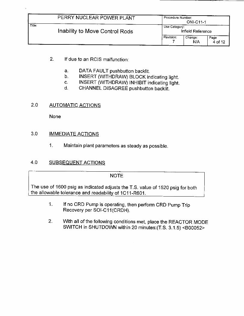
2. If due to an RCIS malfunction:
a. DATA FAULT pushbutton backlit. b. INSERT (WITHDRAW) BLOCK indicating light. c. INSERT (WITHDRAW) INHIBIT indicating light. d. CHANNEL DISAGREE pushbutton backlit.
AUTOMATIC ACTIONS
None
IMMEDIATE ACTIONS
1. Maintain plant parameters as steady as possible.
SUBSEQUENT ACTIONS
NOTE
The use of 1600 psig as indicated adjusts the T.S. value of 1520 psig for both the allowable tolerance and readability of 1C1 1-R601.
1. If no CRD Pump is operating, then perform CRD Pump Trip Recovery per SOI-C11(CRDH).
2. With all of the following conditions met, place the REACTOR MODE SWITCH in SHUTDOWN within 20 minutes:(T.S. 3.1.5) <B00052>
PERRY NUCLEAR POWER PLANT Procedure Number: ONI-Cl1-1
Title: Use Category:
Inability to Move Control Rods Infield Reference Revision: Change: Page
7 N/A 4 of 12
2.0
3.0
4.0

3. If all of the following conditions are met, then immediately place the REACTOR MODE SWITCH in SHUTDOWN: (T.S. 3.1.5)
4. If in Mode 5 with the REACTOR MODE SWITCH in STARTUP/STANDBY and CRD PRESSURE CHARGING WATER, 1C1 1-R601, indicates < 1600 psig, then immediately place the REACTOR MODE SWITCH in SHUTDOWN or REFUEL. (T.S. 3.10.8)
PERRY NUCLEAR POWER PLANT Procedure Number: ONI-Cl1-1 Title: Use Category:
Inability to Move Control Rods Infield Reference Revision: Change: Page
7 N/A 5 of 12
Conditions
- In Mode 1 or 2. and - At least 2 CRD accumulators inoperable, of which at least
one is associated with a withdrawn control rod. and - Reactor pressure > 600 psig. and - CRD PRESSURE CHARGING WATER, 1C11-R601,
indicating < 1600 psig.
Conditions
-In Mode 2. and - Any CRD accumulator inoperable, with the associated
control rod withdrawn. and - Reactor pressure < 600 psig. and - CRD PRESSURE CHARGING WATER, 1Cll-R601,
indicates < 1600 psig.

Perry Nuclear Power Plant NRC Written Examination
Data Sheets
QUESTION Common 024
During a valve lineup, an operator needs to check a valve in the open position.
It is noted that the valve has a red (open) locking device on it.
To check the valve in the open position, the operator should...
A. leave the locking device installed; verify the locking device and restraining mechanism are intact.
B. leave the locking device installed; turn the valve handwheel in the close direction no more than 3/4 of a turn, and then fully reopen the valve.
C. remove the locking device; turn the valve handwheel in the close direction no more than 3/4 of a turn, fully reopen the valve, and then replace the locking device.
D. remove the locking device; turn the valve handwheel in the open direction, verify that the valve handwheel moves less than 1/4 of a turn, and then replace the locking device.
ANSWER: A.

Perry Nuclear Power Plant NRC Written Examination
Data Sheets
Level: RO SRO Tier * 3 3
Examination Outline Cross-Reference Group # CAT 1 CAT I K/A# 2.1.29 Importance Rating 3.4 13.3
Proposed Question: See attached Common 024
Proposed Answer: See attached
Explanation (Why the distractors are incorrect):
B - Locked valve hand wheels should not be manipulated with locks on them. C - Unlocking the valve is not required and if done (because valve is suspect) it should be closed no further than 1/2 turn.
D - Unlocking the valve is not required and if done (because valve is suspect) it should be closed no further 1/2 turn.
Technical Reference(s): PAP-0205 Reference Attached: _X
(Attach if not previously provided) Proposed references to be provided to applicants during examination:
NONE
Learning Objective (As available): OT-3039-008-02 OBJ A
Question Source: Bank # Modified Bank # (Note changes or attach parent) New X
Question History: Previous NRC Exam Previous Quiz / Test
Question Cognitive Level: Memory or Fundamental Knowledge _X_ Comprehension or Analysis
10 CFR Part 55 Content: 55.41 X
55.43
Comments (Why is it an upper level question):

PAP-0205 Page: 22 Rev.: 9
6.8.5 Locked Open/Locked Closed/Locked Neutral Valves
1. For Locked Open/Closed/Neutral Valves, verify the locking device and restraining mechanism (e.g., wire, chain) are intact.
2. If it is suspected that a valve is not in the position that the locking device indicates, it may be necessary to remove the locking device to verify the valve position. Valves Locked Open/Locked Closed/Locked Neutral may be unlocked to physically verify position using the following steps:
a. Inform the US of the need to physically verify valve position.
b. Initiate a Verification Checklist, PNPP No. 9181, to verify valve position.
c. Unlock the valve.
d. Perform verification of valve position and reinstall a locking device per section 6.8.6 and document on the Verification Checklist.
e. Inform the US of the as-found and as-left position of the valve.
NOTE: Inside Containment and in other designated areas, alternate locked valve indicating devices than those listed below may be used as directed by the Operations Manager.
6.8.6 Locking Device Installation
1. Ensure that Locking devices are installed correctly as follows:
a. Where applicable, the locking arrangement for manual valve and remotely operated valve handwheels should restrict handwheel movement to less than one turn.
b. For valve handwheels whose total travel is one turn or less (ball valves for example), handwheel movement should be sufficiently restricted to prevent mispositioning the valve.
c. 'I' handle manual valves shall be locked in position such that their operation is prevented by the use of an approved locking mechanism or a tight 'Figure 8' loop around the 'T' handle. <L02170>
d. Controllers shall have the appropriate locking devices attached in such a manner as to prevent switch actuation.

Perry Nuclear Power Plant NRC Written Examination
Data Sheets
QUESTION Common 025
Which one of the following describes the operational significance of maintaining control rods within designed rod sequence patterns during a reactor startup?
A. Ensures peak fuel enthalpies remain below design limits during a control rod drop accident below the Low Power Setpoint (LPSP).
B. Ensures peak fuel enthalpies remain below design limits during a control rod drop accident above the High Power Setpoint (HPSP).
C. Prevents an excessive change in heat flux during control rod withdrawal below the Low Power Setpoint (LPSP).
D. Prevents an excessive change in heat flux during control rod withdrawal only between 100% and 50% rod density.
ANSWER: A.

Perry Nuclear Power Plant NRC Written Examination
Data Sheets
Level: RO SRO Tier # 2 2
Examination Outline Cross-Reference Group # 2 3 K/A# 201003.K5.04 Importance Rating 31. 1 3.4
Proposed Question: See attached Common 025
Proposed Answer: See attached
Explanation (Why the distractors are incorrect): B -Above the LPSP (20% power) the core voids are significant to prevent clad damage due to a rod drop.
C&D - The purpose of the Rod Withdraw Limiter is to prevent excessive changes in heat flux above the LPSP (20% power).
Technical Reference(s): SDM-C1 1 (RCIS); Reference Attached: _X_ Tech Spec 3.1.6 Bases (Attach if not previously provided)
Proposed references to be provided to applicants during examination:
NONE
Learning Objective (As available): OT-3036-004-C1 I(RCIS) OBJ B&J;
OT-3037-006-05 OBJ B&C
Question Source: Bank # Modified Bank # ____ (Note changes or attach parent) New X
Question History: Previous NRC Exam Previous Quiz / Test
Question Cognitive Level: Memory or Fundamental Knowledge _X_ Comprehension or Analysis
10 CFR Part 55 Content: 55.41 X
55.43
Comments (Why is it an upper level question):

I. SYSTEM DESCRIPTION
A. SYSTEM PURPOSE AND DESIGN BASIS
I. Purpose
Reactivity (and thus power level) in a Boiling Water Reactor (BWR) is
adjusted by the movement and sequencing of the 177 control rods in the
core. Each rod is driven in or out by a hydraulic drive mechanism. The hydraulic Control Rod Drive Mechanism (CRDM) is controlled by the
proper sequencing of the four DCV solenoid valves located on a Hydraulic
Control Unit (HCU). The Rod Control and Information System (RC&IS)
allows the operator to control these solenoid valves and, through them, the U P
positioning of all the control rods in the core. The basic function of the A T
system involves the choice of a particular rod or group of rods and the E
timed control of the selected rod(s) directional control valves to drive the rod in or out. In addition, the RC&IS processes status information from
each HCU, for display to the operator. It should be noted that this system
is separate from the Reactor Protection System (RPS). The Reactor
Protection System can at any time override the RC&IS and rapidly drive
all rods in to shut down the reactor.
2. Design Basis
The Rod Pattern Control System (RPCS) is a subsystem of the RC&IS and
is the only portion of the RC&IS that is safety related. When thermal
power is less than or equal to the Low Power Setpoint (<LPSP), the RPCS
functions as the Rod Pattern Controller (RPC); and when thermal power is greater than the LPSP (>LPSP), the RPCS functions as the Rod
Withdrawal Limiter (RWL).
/ý1 1 /T) f"I 0-TC' \ T')-. "7

The purpose of the RPC is to mitigate the consequences of the postulated
control rod drop accident (CRDA) by restricting control rod patterns to those which have been analyzed to result in acceptable increases in fuel
enthalpy during the CRDA. The RPC also reduces the potential for a high flux (IRM) scram by restricting control rod withdrawal to single notches
for certain groups of control rods, while the control rod is transversing
through various portions of the core.
The purpose of the RWL is to mitigate the consequences of the rod withdrawal error (RWE) accident by restricting the maximum control rod
withdrawal increments to those which have been analyzed to ensure that neither the safety limit Minimum Critical Power Ratio (MCPR) nor the
fuel licensing basis Linear Heat Generation Rate (LHGR) are exceeded
during control rod withdrawal.
The RC&IS is separate and independent of the Reactor Protection System.
RC&IS provides no inputs to the RPS and no failure of RC&IS will
prevent the RPS from initiating a reactor scram.
B. GENERAL DESCRIPTION
The RC&IS function has two primary parts:
"* Control (of solenoid valves)
"* Information gathering
Control. The RC&IS receives as inputs plant status (including control rod position and status of other systems) and the operator requests. The primary control function is to effect control rod motion as requested by the operator and as allowed by plant conditions and built in restrictions (rod blocks); this will be
1 fTlfý Q-TO'ý n- '7

Control Rod Pattern .B3ý.6
B 3.1 REACTIVITY CONTROL SYSTEMS
B 3.1.6 Control Rod Pattern
BASES
BACKGROWD Control rod patterns during startup-conditions are controlled by thea operator and the rod pattern controller (RPC} (LCO 3.3.2.1. "Control Rod Block Instrumentation"), so that only specified control rod sequences and relative positions are allowed from the condition of all control rods fully inserted up to the low power setpoint (LPSP). The sequences effectively limit the potential amount-of reactivity addition that could occur in the event of a control rod drop accident (CRDA).
This Specification assures that the control rod patterns are consistent with the assumptions of the CRDA analyses of References 1 and 2.
APPLICABLE SAFETY ANALYSES
The analytical methods and assumptions used in evaluating the CRDA are summarized In References I and 2. CRDA analyses assume that the reactor operator follows prescribed withdrawal sequences. These sequences define the potential initial conditions for the CRDA analysis. The RPC (LCO 3.3.2.1D provides backup to operator control of the withdrawal sequences to ensure that the initial conditions of the CRDA analysis are not violated.
Prevention or mitigation of positive reactivity insertion events is necessary to limit the energy deposition in the fuel, thereby preventing significant fuel damage, which could result in undue release of radioactivity. Since the failure consequences for U02 have been shown to be insignificant below fuel energy depositions of 300 cal/gm (Ref. 3). the fuel damage limit of 280 cal/gm provides a margin of safety from significant core damage, which would result in release of radioactivity (Refs. 4 and 5). Generic evaluations (Ref. 6) of a design basis CRDA (I.e., a CRDA resulting in a peak fuel energy deposition of 280 cal/gm) have shown that if the peak fuel enthalpy remains below 280 cal/gm. then the maximum reactor pressure will be less than the required ASME Code limits (Ref. 7) and the calculated offsite doses will be well within the required limits (Ref. 5).
(continued)
PERRY - UNIT 1 I VRevision No. 1B 3.1-34

Control Rod Pattern B 3,1.6
BASES
APPLICABLE SAFETY ANALYSES
(continued)
Control rod patterns analyzed in Reference 2 follow the banked position withdrawal sequence (BPWS) described in Reference 8. The BPWS is applicable from the condition of all control rods fully Inserted to 19.0% RTP (Ref. .). For the BPWS, the control rods are required to be moved in groups, with all control rods assigned to a specific group required to be within specified banked positions (e.g., between notches 08 and 12). The banked positions are defined to minimize the maximum incremental control rod worths without being overly restrictive during normal plant operation. The generic BPWS analysis (Ref. 8) also evaluated the effect of fully inserted. inoperable control rods not in compliance with the sequence, to allow a limited number (i.e., eight) and distribution of fully inserted, inoperable control rods.
Rod pattern control satisfies the requirements of Criterion 3 of the NRC Policy Statement.
LCO Compliance with the prescribed control rod sequences minimizes the patential consequences of a CRIA. by limiting the initial conditions to those consistent with the BPWS. This LCQ only applies to OPERABLE control rods. For inoperable control rods required to be inserted, separate requirements are specified in LCO 3.1.3. "Control Rod OPERABILITY." consistent with the allowances for inoperable control rods in the BPWS.
APPLICABILITY In MODES 1 and 2, when THERMAL POWER is < 19.0% RTP, the CRDA is a Design Basis Accident (DBA) and, therefore, compliance with the assumptions of the safety analysis is required. When THERMAL POWER is > 19.0% RTP, there is no credible control rod configuration that results in a control rod worth that could exceed the 280 cal/gm fuel damage limit during a CRDA (Ref. 1). In MODES 3, 4, and 5, since the reactor is shut down and only a single control rod can be withdrawn from a core cell containing fuel assemblies, adequate SOM ensures that the consequences of a CRDA are acceptable, since the reactor will remain subcritical with a single control rod withdrawn.
(continued)
PERRY - UNIT 1
IQo05'7
B 3.1 -35 Revision No. 3

Perry Nuclear Power Plant NRC Written Examination
Data Sheets
QUESTION Common 026
The following plant conditions exist:
"* A reactor startup is in progress. "* The Reactor Mode Switch is in STARTUP/STANDBY. "* IRM Channel 'F' is bypassed on panel H13-P680. "* IRM Channel 'A' indication is on IRM Range 8 reading 75/125 and increasing.
When the operator depressed IRM Channel 'A' UP Range Switch, the expected change in IRM Channel 'A indication did not occur. (IRM Channel 'A' remained on IRM Range 8).
IRM Channel 'A' continues to increase as reactor power continues to increase.
Which one of the following describes the response of IRM Channel 'A', if any, including an action the operator can perform to mitigate the faulty UP Range Switch?
A. No trip response since the IRM control rod block and scram trip signal are bypassed at IRM Range 8; IRM Channel 'A' can be bypassed on panel H13-P680.
B. No trip response since the IRM control rod block and scram trip signal are bypassed at IRM Range 8; IRM Channel 'A' detector can be withdrawn to maintain its indication between 25/125 and 75/125.
C. IRM control rod block and scram trip signals are generated; IRM Channel 'A' can be bypassed on panel H13-P680.
D. IRM control rod block and scram trip signals are generated; IRM Channel 'A' detector can be withdrawn to maintain its indication between 25/125 and 75/125.
ANSWER: C.

Perry Nuclear Power Plant NRC Written Examination
Data Sheets
Level: RO SRO Tier # 2 2
Examination Outline Cross-Reference Group # 1 2 K/A# 215003.A2.06 Importance Rating 30 3.2
Proposed Question: See attached Common 026
Proposed Answer: See attached
Explanation (Why the distractors are incorrect):
A&B - IRM rod block and scram trip signals are generated due to the reactor mode switch in startup and IRM on Range 8. D - There is no procedural guidance to withdraw the IRM detector to maintain indication between 25/125 and 75/125 due to a valid failure.
Technical Reference(s): SDM C51(IRM); Reference Attached: _X ARI-H13-P680-06 (B3) (Attach if not previously provided)
Proposed references to be provided to applicants during examination:
NONE
Learning Objective (As available): OT-3036-004-C51 (IRM) OBJ D, F&G
Question Source: Bank # Modified Bank # (Note changes or attach parent) New X
Question History: Previous NRC Exam Previous Quiz / Test
Question Cognitive Level: Memory or Fundamental Knowledge Comprehension or Analysis C
10 CFR Part 55 Content: 55.41 X 55.43
Comments (Why is it an upper level question): Requires the student to predict the response of IRM Channel 'A' based on initial plant conditions, including any procedural guidance which can be used to mitigate the situation.

TABLE C51(LRM)-7 IRM TRIPS, PERMISSIVES AND INTERLOCKS
Rod Block Trips
Selpia Bypassed
IRM Downscale
IRM High Flux
IRM Inoperative
IRM Detector Wrong
Scram T
Trip
IRM Upscale
IRM Inoperative
5/125 of scale
80/125 of scale
1) Drawer, Preamp, or Range Select Module unplugged.
2) IRM Mode Switch not in OPERATE
3) Low high voltage (85%)
4) Loss of-20 Vdc or -15 Vdc regulated power supply
IRM Detector not fully inserted
120/125 of scale
1) Drawer, Preamp, or Range Select Module unplugged.
2) Mode Switch not in OPERATE
3) Low high voltage (85%)
4) Loss of -20 Vdc or -15 Vdc regulated power supply
Reactor Mode Switch in RUN or IRM Range 1
Reactor Mode Switch in RUN
Reactor Mode Switch in RUN
Inop Trip Bypass push button depressed (only bypasses IRM Mode Switch not in operate Inop signal)
Reactor Mode Switch Position in RUN
Reactor Mode Switch in RUN
Reactor Mode Switch in RUN
Inop Trip Bypass push button depressed (only bypasses IRM Mode switch not in operate Inop signal)
C51 (IRM) - Rev. 6
Trip
J -L.d
CL
49

ARI-Hi 3-P680-6 7 2 / C-2D0
Computer Point ID C51NC023 C51NCO35 C51NC024 C51NC031
IRM A/E
UPSC TRIP/
INOP
B3
1.0 Cause of Alarm
1. The REACTOR MODE SWITCH not in RUN and any of the following:
a. IRM A or E equal to or greater than 120/125 of full scale. b. IRM A or E MODE switch not in OPERATE. c. Low output from the high voltage power supply. d. IRM module unplugged. e. Loss of supply power and/or drawer DC power supplies.
2.0 Automatic Action
1 .
2. 3.
A control rod withdrawal block occurs. A half scram will occur. A subsequent trip of one or more RPS channels in the opposite trip system will result in a full reactor scram.
3.0 Immediate Operator Action
1 .
2.
If a reactor scram occurs, enter ONI-C71-1, Reactor Scram. If the alarm is due to failure to properly range IRM A or E, range IRM A or E to the proper range (between 25/125 and 75/125 of full scale) per SOI-C51 (IRM).
4.0 Subsequent Operator Action
1. Reset half scram when condition has cleared.
4.1 Technical Specification
1 . 2.
3.3.1.1, Reactor Protection System Instrumentation ORM 6.2.3, Intermediate Range Monitors Control Rod Block Inst rumen tat ion
ON 6: Page: Rev.:

Perry Nuclear Power Plant NRC Written Examination
Data Sheets
QUESTION Common 027
The following plant conditions exist:
"* A reactor startup is in progress following replacement of all fuel bundles. "* Reactor Protection System shorting links are removed. "* Reactor power is increasing with a stable positive period of 150 secs. "* SRM Channel 'A' detector is stuck and will not withdraw. "* SRM Channel 'A' indication increases to 2xl0 5cps.
Assume no operator actions are performed.
Which one of the following subsequently describes SRM Channel 'A' indicated reactor power and reactor period?
Indicated reactor power will...
A. decrease and reactor period will remain stable and positive.
B. decrease and reactor period will be negative.
C. continue to increase and reactor period will remain stable and positive.
D. continue to rise and reactor period will be negative.
ANSWER: B.

Perry Nuclear Power Plant NRC Written Examination
Data Sheets
Level: RO SRO Tier # 2 2
Examination Outline Cross-Reference Group # 1 1 K/A# 215004. K3.04 Importance Ratin-q 3.73.7
Proposed Question: See attached Common 027
Proposed Answer: See attached
Explanation (Why the distractors are incorrect):
A - The reactor period will be negative because the reactor scrammed. C&D - With the RPS shorting links removed a scram will occur. Therefore reactor power will decrease and reactor power will be negative.
Technical Reference(s): SOI-C51 (SRM); SDM C71; Reference Attached: __X SDM C51(SRM) I (Attach if not previously provided)
Proposed references to be provided to applicants during examination:
NONE
Learning Objective (As available): OT-3036-004-C51 (SRM) OBJ D& E; OT-3036-005-C71 OBJ F
Question Source: Bank # Modified Bank # (Note changes or attach parent) New X
Question History: Previous NRC Exam Previous Quiz / Test
Question Cognitive Level: Memory or Fundamental Knowledge Comprehension or Analysis _C_
10 CFR Part 55 Content: 55.41 X 55.43
Comments (Why is it an upper level question): Requires the student to predict the reactor response, including SRM indications associated with a stuck detector with the reactor critical in the source range.

OM3A: SOI-C51 (SRM) Page: 1 Rev.: 5
1.0 SCOPE
This document presents the detailed operating instructions for the Source Range Monitoring System. This instruction is applicable to Unit 1 only.
2.0 PRECAUTIONS AND LIMITATIONS
1. The function and operation of this system are covered by Technical Specifications.
2. Prior to initial use of the Detector Insert/Retract Mechanism and following all Refueling Outages:
a. Verify the area below the SRM drive tubes is clear. b. Ensure the Servicing Platform is properly aligned.
NOTE: A limit switch (interlock), located on the wall opposite the under vessel area access, must be in contact with the platform. This interlock will prevent outward detector movement if the platform is not in the proper position.
3. Detector drive power should be Danger Tagged OFF when the grating is installed on the Servicing Platform.
4. The SRM detectors and control rods should not be withdrawn simultaneously. Changes in core reactivity may not be accurately displayed.
5. SRM period and neutron flux level indications have limited validity when the detectors are not fully inserted.
6. Short period alarms may be experienced when driving detectors.
7. A Reactor Scram could occur due to SRM initiated signals. The circuits are non-coincidental and are only operative when the RPS shorting links are removed. SRM associated scrams are:
a. SRM Upscale High-High at 2 X 10⁵ cps. b. Inop.
3.0 PREREQUISITES
1. The Reactor Protection System (C71) is in operation supplying power to the SRM detectors.
C-l, 3, 4

2. SRM Inputs to the Reactor Protection System (C71)
Refer to Figure 16 during the following discussion.
A trip output of the SRM System is also utilized in the Reactor Protection
System to initiate a reactor scram under conditions that could result in
damage to the fuel cladding. This trip output functions in the fail-safe
mode as previously described. The following channel trip outputs are
used in the RPS Scram Logic System:
a. SRM High-High Flux - This condition indicates a neutron flux
level in excess of that allowed for a specific plant operating
condition. The trip output is used in the Reactor Protection System
(C71) to initiate a reactor scram. This function of the SRM System
is used only during fuel loading operations and the first reactor
start-up until the overlap between the Source Range and the
Intermediate Range Monitors has been demonstrated. The trip
setpoint will be adjusted to 2 x 10 cps.
b. SRM Inoperative - Indicates unreliable channel operation.
Figure 16 is drawn in the energized condition with all contacts in the
untripped position. The output of each SRM channel HI-HI flux or INOP
trip circuit is applied to each of the four channels of the Reactor Protection
System. These contacts when open, deenergize their respective "K13"
relay. As in the previously described SRM trips, a parallel contact is
available for individual channel bypass. The contact of the "K13" relays
are arranged in the RPS scram channel logic in such a manner as to
produce a full scram upon the trip of any sing SRM, IRM or APRM
channel.
C5 I(SRM) - Rev. 6 22

The RPS is segregated into four electrically and physically independent
logic channels designated "A", "B", "C", and "D". Deenergizing any
single RPS channel initiates a "half scram" which does not cause control
rod motion. To produce a full scram (insertion of all control rods), a trip
must be introduced into Channel A or C and B or D. This type of logic is
termed a one-out-of-two-twice. The one-out-of-two-twice logic is
intentionally defeated in the scram circuitry when non-coincidence is
selected by shorting link removal. Refer to Figure 16 and observe the
following arrangement:
Contacts of K13A are located in both the "A" and the "B" Channel
logic
Contacts of K13C are located in both the "C" and the "D" Channel
logic
Contacts of K13B are located in both the "B" and the "A" Channel
logic
Contacts of K13D are located in both the "D" and the "C" Channel
logic
Due to the above arrangement, any single SRM HI-HI or INOP trip
produces a trip signal in both the Trip System A and the Trip System B
RPS logic. This condition is referred to as "non-coincident protection".
Note also, the provision of the installation of shorting links bypassing the
non-coincident neutron monitoring trip function. Once initial satisfactory
SRM and IRM performance has been demonstrated, these shorting links
will be installed to bypass and defeat the non-coincident scram function.
NOTE: Shorting links are removed any time Shutdown Margin
cannot be verified.
C5 I(SRM) - Rev. 6 23

relays KI 4A and K14E. This causes Trip System A to trip and give a halfscram. However, no control rods are inserted. If IRM D in Trip System B
senses a high neutron flux or INOP conditions, its upscale or INOP contact will open and deenergize channel sensor relay K12D. This will open
sensor relay contact KI2D and deenergize channel trip sensors K14D and Kl4H. Since both trip systems are now tripped, a reactor scram will
occur.
When the reactor is above 8% power in the power range, the Reactor
Mode Switch is placed in the RUN position. This will bypass the IRM logic. While in the power range, if APRMs A and D sense a high power (either neutron or thermal) or INOP conditions, the affected contacts will open, deenergizing channel sensor relays K12A and K12D. This will open relay contacts K12A and K12D and deenergize channel trip sensor relays K14A, K14E, K14D, and K14H, causing a reactor scram. Note, that at least one monitor in each trip system must sense an abnormal condition to cause a reactor scram. Failure of one monitor will neither prevent nor
initiate a reactor scram.
Refer to Figure 21 during the following discussion.
During fuel loading and low power physics testing, the non-coincident
protection logic is employed in the RPS. This non-coincident logic places the Source Range Monitors (SRMs) trip logic in series with the IRM and APRM trip logic such that anyone Neutron Monitoring trip will cause a full scram. The non-coincident channel sensor relays K1 3A through
K13D operate sensor relay contacts K13A through K13D, deenergizing channel sensor relays KI5A through K15D. Channel sensor relay Kl5 (AD) is normally, with the shorting links installed, used only for the manual scram function. The logic is arranged such that a high neutron flux signal
C71 - Rev. 9 49

from any one SRM, or an inoperative signal from any one SRM, will cause a reactor scram if the shorting links are removed. For example, if SRM C senses a high neutron flux, its upscale contact opens and deenergizes sensor relay K13C. This will open sensor contact KI3C in RPS Channels C and D and deenergize channel sensor relays K15C and K15D. Since one channel in each trip system is now deenergized, a reactor scram will occur.
Likewise, if IRM B senses a high neutron flux, its upscale contact will open, deenergizing sensor relay K12B. This will open IRM/APRM sensor relay contact K12B and deenergize sensor relay K13B. This will open sensor relay contact K13B in RPS Channels A and B, and deenergize channel sensor relays K15A and K15B, causing a reactor scram. Any one APRM upscale or INOP signal will also cause a scram in the same manner. With the shorting link installed, the non-coincident logic is removed and the SRMs do not supply a trip input into the RPS. Also, the IRM and APRM inputs into RPS revert back to the logic previously
described in the first part of this section.
13. High Reactor Water Level
Refer to Figure 22 during the following discussion.
Increasing RPV water level indicates a potential problem with the feedwater level control system, resulting in the addition of reactivity associated with the introduction of a significant amount of relatively cold water. A scram is initiated at L8 to ensure MCPR is maintained above the MCPR SL.
C71 - Rev. 9 50

Perry Nuclear Power Plant NRC Written Examination
Data Sheets
QUESTION Common 028
A Main Turbine trip has resulted in an automatic reactor scram.
Twenty (20) seconds later, the following plant parameters are reported:
"* The reactor is still operating at 7% power. "* Reactor pressure peaked at 1090 psig and is currently steady at 920 psig. "* Reactor water level decreased to +170 inches and is being maintained at that level.
Which one of the following describes the control signals generated by the Redundant Reactivity Control System at this time?
A. Alternate Rod Insertion and Reactor Recirculation Pump transfer from fast to slow speed.
B. Reactor Recirculation Pump transfer from fast to slow speed and LFMG trip.
C. LFMG trip and Feedwater Runback.
D. Feedwater Runback and Alternate Rod Insertion.
ANSWER: A.

Perry Nuclear Power Plant NRC Written Examination
Data Sheets
Level.- RO SRO Tier # 2 2
Examination Outline Cross-Reference Group # 1 1 K/A# 216000. K1.09 Importance Rating 3.7 14.0
Proposed Question: See attached Common 028
Proposed Answer: See attached
Explanation (Why the distractors are incorrect):
B - LFMG trip only occurs if APRMs are not downscale after 25 seconds. C - LFMG trip and FWRB require APRMs to not be downscale after 25 seconds. D - FWRB only occurs if APRMs are not downscale after 25 seconds.
Technical Reference(s): SDM-C22 Reference Attached: X
(Attach if not previously provided) Proposed references to be provided to applicants during examination:
NONE
Learning Objective (As available): OT-3036-001-C22 OBJ D
Question Source: Bank # Modified Bank # (Note changes or attach parent) New X
Question History: Previous NRC Exam Previous Quiz / Test
Question Cognitive Level: Memory or Fundamental Knowledge Comprehension or Analysis _C_
10 CFR Part 55 Content: 55.41 X 55.43
Comments (Why is it an upper level question): Requires the student to predict the output of the RRCS based on the initial plant conditions provided.

TABLE C22-4 RCS INITIATON SIG ALS
High Press High Press If Low RX Level RRCS ARI > 1083 Psig APRMS NFM Level 2 Man Test
Dnsc Within < 130" ARI 25 Sec
ART INITIATION X X X X
FWRB
RCIRC CB-3A(B)
[CB-4A(B)] Trip
LFMG Transfer
LFMG Trip
x
x
x
x
x
x
C22 - Rev. 6 24

k)
H
OR !A ' INITIATE
SAR
I (ENERGIZE ClI -F160, 162, 163)
ORS TRP RPUP
=KEYLOCK POTENTIAL CONFIRMED ATWS
ATWS
RMANUALNSRR
=D E P R E S S OA P R 2 M I N . W HA R
PRESS SFIGUR EC.2
>1083- IN TD AND LOGI
LEVEL SEA OR -•np TRIP LFMG L2 -IN)_ • (CBIA, 2A
-L• 1B. 2B)
APRM 0 R-]n TRIP RR PUMPS NT " ' F/S BKRS DNOTSI - (CB3A/B DNSC I •CB4A/B )
-i __ • _ __ T R A N S F E R R R •PJUMPS FROM
FAST To SLOW NOTE- THE ABOVE SIGNALS MUST BE PRESENT IN BOTH CHANNELS WITHIN A RRCS DIVISION FOR ACTION TO OCCUR
FIGURE C22-6 RRCS INITIATION LOGIC

Perry Nuclear Power Plant NRC Written Examination
Data Sheets
QUESTION Common 029
RHR Loop 'A' is operating in the Suppression Pool Cooling mode when the operator inadvertently takes the RHR Pump 'A' control switch to STOP.
Which one of the following describes the operational implication of this pump trip?
A. The Feedwater Leakage Control System is inoperable.
B. The LPCS Pump minimum flow protection is affected.
C. The RHR System 'A' high-point piping is potentially voided.
D. The RHR Pump 'A' auto start on a LPCI initiation signal is overridden.
ANSWER: C.

Perry Nuclear Power Plant NRC Written Examination
Data Sheets
Level: RO SRO Tier # 2 2
Examination Outline Cross-Reference Group # 2 2 K/A# 219000. K1.04
Importance Ratinq 3.9 1 3.9
Proposed Question: See attached Common 029
Proposed Answer: See attached
Explanation (Why the distractors are incorrect):
A - This is true if the waterleg pump is lost, not the RHR pump.
B - This is true with RHR pump A running, not with the pump shutdown.
D -The RHR pump LOCA override feature is only in effect if a RHR LOCA signal is sealed in when the RHR pump control switch is taken to STOP.
Technical Reference(s): SOI-E12 Reference Attached: _X_
(Attach if not previously provided)
Proposed references to be provided to applicants during examination:
NONE
Learning Objective (As available): OT-3036-004-E12 OBJ J
Question Source: Bank # Modified Bank # (Note changes or attach parent) New X
Question History: Previous NRC Exam Previous Quiz / Test
Question Cognitive Level: Memory or Fundamental Knowledge Comprehension or Analysis C
10 CFR Part 55 Content: 55.41 X 55.43
Comments (Why is it an upper level question): Requires the student to comprehend the operational implication when an RHR pump trips while operating in the Suppression Pool Cooling mode.

SOI-E12 Page: 2 Rev.: 9
4. The reactor shall be placed and maintained in a Cold Shutdown condition whenever a loop of RHR is used in the Fuel Pool Cooling Assist mode. <F01244>
5. The disconnect, MCC EFlB07-H, for SHUTDOWN COOLING OTBD SUCT ISOL, 1E12-F008, shall be closed only to perform Shutdown Cooling or related shutdown operations. It shall be open during all other conditions to satisfy 10CFR50 Appendix R considerations. <F01675>
6. Operation of the LPCI mode of RHR with injection flow to the vessel shall only be done in an accident condition, a plant emergency condition, or an approved test condition of short duration.
NOTE: ONI-E12-2, Loss of Decay Heat Removal, and 101-11, Shutdown From Outside Control Room, direct the use of the LPCI injection lines as Alternate Shutdown Cooling flow paths. Use of this flow path is still subject to reportability (as described in PAP-1604) when used for Alternate Shutdown Cooling. <L00173>
7. Water Hammer:
There are five scenarios which could result in water hammer in a loop that is severe enough to cause component damage or pressure boundary failure. Do not start a pump in the effected loop prior to ensuring the loop is filled. Flow transmitters, IE12-N015A(B) and 1E12-N052A(B), must be vented if their respective process line has drained. <B00130>
a. When conducting Containment Spray Realignment to Suppression Pool Cooling, a deviation from the written instruction could result in draining all higher elevation piping vented by the Containment Spray Rings to the Suppression Pool.
b. A loss of pumping power during any operation with RHR A(B) TEST VALVE TO SUPR POOL, 1E12-F024A(B), open will cause voids to be drawn in the higher elevations of the effected loop.
c. Closing LPCI A(B,C) MANUAL SHUTOFF, 1E12-F039A(B,C), to perform maintenance or testing on the LPCI injection line or associated valves.
d. A Division 1(2) RHR Isolation during Shutdown Cooling Operation may allow voids to be drawn in the effected loop.
e. Opening RHR A(B) SUPR POOL SUCTION VALVE, 1E12-F004A(B), when the RHR Pump A(B) suction piping is filled with water that is at greater than 200'F.

Perry Nuclear Power Plant NRC Written Examination
Data Sheets
QUESTION Common 030
A Main Steam Line break inside Containment has resulted in a high Drywell pressure scram.
Eleven (11) minutes later, the following plant conditions exist:
"* Reactor pressure is 400 psig and decreasing. "* Reactor water level is +12 inches and steady. "• Drywell pressure is 4 psig and slowly increasing. "* Containment pressure is 6 psig and slowly increasing.
Assume no operator actions have been performed.
Which one of the following describes the operating condition of RHR Loop 'A'?
RHR Loop 'A' is ...
A. spraying Containment.
B. injecting into the rector vessel; the Containment Spray mode can be manually initiated.
C. operating on minimum flow; the Containment Spray mode can be manually initiated.
D. operating on minimum flow; the Containment Sprays mode cannot be manually initiated.
ANSWER: C.

Perry Nuclear Power Plant NRC Written Examination
Data Sheets
Level: RO SRO Tier # _ 2 2
Examination Outline Cross-Reference Group # 2 1 K/A# 226001.A4.08 Importance Rating 13.2 1 3.1
Proposed Question: See attached Common 030
Proposed Answer: See attached
Explanation (Why the distractors are incorrect): A - Containment Spray mode will not auto initiate until containment pressure exceeds 8 psig. B - LPCI injection valve opens at 530 psig but system injection doesn't start until -280 psig due to the discharge pressure of RHR pumps. D - RHR containment spray mode can be manually initiated when drywell pressure is above 1.68 psig.
Technical Reference(s): SDM E12 Reference Attached: _X
I (Attach if not previously provided) Proposed references to be provided to applicants during examination:
NONE
Learning Objective (As available): OT-3036-004-E12 Objective F
Question Source: Bank # Modified Bank # ____ (Note changes or attach parent) New X
Question History: Previous NRC Exam Previous Quiz / Test
Question Cognitive Level: Memory or Fundamental Knowledge Comprehension or Analysis A
10 CFR Part 55 Content: 55.41 __X 55.43
Comments (Why is it an upper level question): Requires the student to predict the current operational status of RHR Loop A based on the plant conditions provided, including whether or not Containment Spray can be manually initiated.

discharge piping. This permits verifying that the pump can deliver rated flow. For RHR C, flow is throttled with RHR C Test Valve
to Supr. Pool F02 1. Flow from RHR C also passes through a flow
element allowing for flow verification.
C. MAJOR COMPONENT DESCRIPTION
The major components within the Residual Heat Removal System are:
"• RHR Pumps (CO02A, B, C)
"• RHR Heat Exchangers (BOO 1 A, B, C, D)
"• RHR System Valves
"* Waterleg Pump
"* Suppression Pool Suction Strainers
"* Containment Spray Rings and Nozzles
* LPCI Coupling
1. RIHR Pumps.(CO02A, B, C)
Refer to Figure 7 and Table I during the following discussion.
The three RHR Pumps, identical in construction and operation, are motordriven, vertically mounted, three-stage, double suction centrifugal pumps. The pumps are designed for low pressure, high flow application to
correspond to the LPCI mode of operation since the flow rate during the
LPCI mode is the most limiting flow rate requirement for the RHR
System. The pumps are designed to handle water varying in temperature from 407F to 3601F. Mechanical seals prevent leakage of water along the shaft. These seals are cooled by water from the pump discharge which
flows through a centrifugal separator and a seal water cooler. The
separator removes heavier than water solids and returns them to the RI-R
E12 -Rev. 8 I I

Pump suction casing. The seal water cooler is cooled by Emergency
Closed Cooling Water (P42). A shaft bushing is designed to limit shaft
leakage in the event of a mechanical seal failure. Each pump is required
by Technical Specifications to supply 7100 gpm at a pressure of 24 psid,
this occurs at a discharge head of 150 psig. RHR Pumps have a shutoff
head of approximately 315 psig. Due to the differential height, and the
head loss from the length of discharge piping between the RHR pump and
the RPV, this corresponds to an RPV pressure of approximately 280 psig
for injection to occur with RHR.
Each pump is directly coupled to an air-cooled, vertically mounted,
squirrel cage induction motor. Each motor is powered from a Class IE 4.16 kV bus. Control power for the RHR Pump breaker is normally
powered from 125V Divisional Class 1E DC switchgear. Control power
for RHR Pump A can also be supplied by 125V Divisional Class IE DC
from the remote shutdown panel. The RHR Pumps are designed to reach
rated flow within 27 seconds following receipt of a LPCI initiation signal
including the time required to establish standby power if normal power is
not available. RHR Pump A receives power from Division 1 (EHI 1)
while pumps B and C receive power from Division 2 (EH12) to increase
system reliability.
2. RHR Heat Exchanges (BOO1A, B, C, D)
Refer to Figure 8 during the following discussion.
The RHR System has four heat exchangers associated with it for purposes
of heat removal during any RHR operating mode. RHR loops A and B
each have two heat exchangers mounted in series with the loop piping.
RHR Loop C contains no heat exchangers since it is used for the LPCI
mode only.
E12 -Rev. 8 12

are divided physically and electrically from each other into two
independent logic systems termed Division I and Division 2. Division I logic provides control for the LPCI A loop and Division 2 logic provides
control for the LPCI B and C loops.
Refer to Figures 12 and 13 during the following discussion
Each division has two RPV levels and two DW pressure sensors whose contacts are electrically arranged in a series-parallel configuration. This is noLa one-out-of-two-twice logic network.
Division I logic for LPCI receives its initiation signal from the Low Pressure Core Spray System ('E21). Reactor water level sensors and trip units B21-NO91A(E) and B21-N691A(E) provide the input for low reactor water level. Drywell pressure sensors and trip units B21 -N094A(E) and B21-N694A(E) provide input for high Drywell pressure. Refer to SDM E21 for the logic configuration.
Division I and/or Division 2 RI{R LPCI will be initiated by eitherLhigh Drywell pressure or low Reactor Pressure Vessel water level. Either Division can also be manually initiated by arming and depressing a manual initiation push button. Arming and depressing push button E21-S9 on H13-P601 will initiate LPCS and LPCI A. Arming and depressing push button E12-S21 on H13-P601 will initiate LPCI B and C.
E12 -Rev. 8 31

2. Containment Spray Initiation Logic Control
Refer to Figure 14 during the following discussion.
Containment Spray initiation logic is divided into two Divisions; I and 2. Division I logic provides control for RHR loop A Containment Spray and Division 2 provides control for RHR loop B Containment Spray. Loop C does not have Containment Spray capability, but is used solely for LPCI.
The following conditions will cause automatic initiation of the Containment Spray mode:
LPCI initiation signal active for approximately 10 minutes (either manually or automatically) AM - High Drywell pressure (1.68 psig) AMD High Containment pressure (8.0 psig)
Each of the pressure parameters above is monitored by four sensors. The two pressure transmitters that measure Drywell pressure for Division 1, B21N094A and E, also sends signals to Division I LPCI logic through trip units B21-N694A and E. Division 2 logic receives Drywell pressure inputs from pressure transmitters B2 I-N094B and F through trip units B21-N694B and F.
Containment pressure is sensed by four pressure transmitters, two per Division. Division 1 logic receives signals from PT El12-N062A and C through trip units E12-N662A and C. Division 2 logic receives signals from PT E12-N062B and D through trip units E12-N662B and D.
E12 -Rev, 8 36

Perry Nuclear Power Plant NRC Written Examination
Data Sheets
QUESTION Common 031
The following plant conditions exist:
"* The reactor scrammed due to closure of the MSIVs. "* Suppression Pool temperature is 132 'F. "* Suppression Pool level is 17.8 feet.
Which one of following identifies the maximum allowed reactor pressure without exceeding the Heat Capacity Limit?
PEI-SPI Figure 4 is provided for reference.
A. 550 psig
B. 600 psig
C. 650 psig
D. 700 psig
ANSWER: C.

Perry Nuclear Power Plant NRC Written Examination
Data Sheets
Level: RO SRO Tier # 1 1
Examination Outline Cross-Reference Group # 1 1 K/A# 295007.AA2.01 Importance Rating 4.1 14.1
Proposed Question: See attached Common 031
Proposed Answer: See attached
Explanation (Why the distractors are incorrect):
A - This is the correct pressure if the 16ft level line is utilized. B - This is correct for a level between 16ft and 18.5ft level lines.
D - This is the correct pressure if the 18.5ft level line is utilized.
Technical Reference(s): HCL Curve; PEI-SPI Reference Attached: __X Supplement; PEI Bases I(Attach if not previously provided)
Proposed references to be provided to applicants during examination: PEI-SPI Figure 4
Learning Objective (As available): OT-3402-005-04a OBJ F
Question Source: Bank # Modified Bank # (Note changes or attach parent) New X
Question History: Previous NRC Exam Previous Quiz / Test
Question Cognitive Level: Memory or Fundamental Knowledge Comprehension or Analysis -A
10 CFR Part 55 Content: 55.41 X 55.43
Comments (Why is it an upper level question): Requires the student to interpret the HCL graph based on initial plant conditions provided.

PEI-SPI SUPPLEMENT Page: 8 of 20 Rev.: 3
150 12501350 1450550 6 50 7 5 0 1 8 5 0 T 9 50 11 0 50 1 0 1100 200 300 400 500 600 700 800 900 1000 1103Ou Use Higher Value I-
Directions: RPV Pressure (psig)
1.0 IDENTIFY RPV Pressure on the horizontal axis of the figure.
2.0 IE the value fails between marked lines on the figure, THEN USE the hmgh. value.
3.0 IDENTIFY Suppression Pool Temperature on the vertical axis of the figure.
4.0 IF the value falls between marked lines on the figure, THEN USE the bktgb. value.
5.0 SELECT the Suppression Pool Level Curve that corresponds to current Suppression Pool level.
6.0 IF Suppression Pool level falls between the marked curves, THEN USE the next igý curve.
7.0 IDENTIFY the point formed by the intersection of the two values with respect to the Suppression Pool Level Curve selected.
8.0 IF the resulting point is above the Suppression Pool Level Curve selected, THEN HCL is exceeded.
Suppression Pool
Temperature (° F)
U S
e
H
g
h e r
V'
a I ul e__

Perry Nuclear Power Plant NRC Written Examination
Data Sheets
QUESTION Common 032
The following plant conditions exist:
"* The plant is shutdown for refueling. "* CORE ALTERATIONS are in progress.
Which one of the following conditions would decrease the SHUTDOWN MARGIN?
A. A fuel assembly is removed from the core.
B. Reactor coolant temperature is increased.
C. A control rod is withdrawn to position 24.
D. A control rod blade is removed from an empty core cell.
ANSWER: C.

Perry Nuclear Power Plant NRC Written Examination
Data Sheets
Level: RO SRO Tier# 1 1
Examination Outline Cross-Reference Group #1 K/A# 295014.AK1.03 Importance Rating .3.7 14.0
Proposed Question: See attached Common 032
Proposed Answer: See attached.
Explanation (Why the distractors are incorrect): A - Removing a fuel assembly would reduce total core reactivity. B - Increasing reactor coolant temperature would increase SDM. D - Does not effect the reactivity of the core since no fuel is present.
Technical Reference(s): GP Rx Theory Text Chp. 2 Reference Attached: _X Tech Specifications Definitions I (Attach if not previously provided) Proposed references to be provided to applicants during examination:
NONE
Learning Objective (As available): OT-3037-006-05 OBJ A&C; OT-3301-004-02 OBJ 5&9
Question Source: Bank # 1002 Modified Bank # (Note changes or attach parent) New
Question History: Previous NRC Exam Previous Quiz / Test
Question Cognitive Level: Memory or Fundamental Knowledge _X_ Comprehension or Analysis
10 CFR Part 55 Content: 55.41 X 55.43
Comments (Why is it an upper level question):

Question Num: Old Number: Question Type:
Task Number
Reference SDM-CII(CRDM)
EQB VALIDATED QUESTION
- 1002 Rev: POINTS: 1.00 CYCLE: / Discipline:R
MC Time: 0 Safety Related:N Attachment? N
Lesson Plan Number Rev Objective Objective OT-3036-C11 (CRDM) C,L1
Rev. K/A Number RO/SRO rating /1 /1 /1
Keyword (MPL) LEVEL 1 Revision Date 05/03/99
I. QUESTION:
Given the following conditions:
- The plant is shutdown for refueling - CORE ALTERATIONS are in progress
Select the ONE operation that will DECREASE the shutdown margin.
a. A fuel assembly is removed.
b. Upper containment pool water level is increased.
c. A control rod is removed.
d. Reactor water temperature is increased.
T T k K 2 O?.rYnn
c.

The shutdown margin (SDM) is generally defined by technical specifications as the amount of reactivity by which a xenon-free, cold (681F) reactor would be subcritical if all but the highest worth control rod were fully inserted. The highest worth control rod is assumed to be fully withdrawn.
The shutdown margin for a subcritical reactor may be calculated by using the following equation:
SDM = I - kff keff
Equation 2-27
Note that this equation is different from the reactivity equation, the terms in the numerator are reversed. Any parameter that varies core reactivity will cause the shutdown margin to change (e.g., control rod density changes, moderator density changes, poison concentration changes, etc.). If the core reactivity becomes less negative the shutdown margin will decrease.
Example 2-15
Core design and existing conditions determine the amount of reactivity by which a reactor is actually shutdown. The following parameters or design features will affect shutdown reactivity conditions (SDM):
Moderator temperature - An increase inserts negative reactivity, increasing the shutdown margin.
Fuel temperature - An increase inserts negative reactivity, increasing the shutdown margin.
Control rod position - A rod insertion adds negative reactivity, increasing the shutdown margin.
Xenon concentration - An increase adds negative reactivity, increasing the shutdown margin.
Number of fuel assemblies in the core - A removal of fuel assemblies adds negative reactivity, increasing the shutdown margin during refueling.
BWR / REACTOR THEORY / CHAPTER 2 20 of 23 © 1999 GENERAL PHYSICS CORPORATION / NEUTRON LIFE CYCLE
REV 2
Calculate the shutdown margin of a shutdown reactor with a core reactivity value of -0.0045 Ak/k.
SDM = 1- keff keff
k1 1 keff=I l-p 1-(-0.0045)
keff = 0.9955
SDM = 1 -0.9955
0.9955
SDM = 0.0045Akik
8DM27+ =•T:" 0.OO45Ak ••: 27"+Ik+2'W'.-.=•Z•2y•7=.?....... .. 7:+,..+..,

Defifnittons 1.1
1 .1 Definitions .(con-tinqed)
SUTDOWN MARGIN (SON)
STAGGERED TEST BASIS
THERMAL POWER
TURBINE BYPASS SYSTEM RESPONSE TIME
PERRY - UNIT I
SON shall be the amount of reactivity by which the reactor is subcritical or would be subcrittcal assuming that:
a. The reacter Is xenon free;
b. The moderator temperature is 68F; and
c. All control rods.are fully inserted except for the sing:l control rod of highest reactivity worth, which Is assumed to be fully withdrawn. With control rods not capable of being fuTly inserted, the reactivity worth of these control rods must be accounted for in the determination ef "DM.
A STAGGERED TEST BASIS shall consist of the testing of one of the systems, subsystems, channels, or other designated components during the interval specified by the Surveillapce Frequency, so that all systems, subsystems, channels, or other designated components are tested during n Survei llance. Frequency interv4ls, where n is the total number of systems, subsystems, channels, or other designated component in the associated function.
THERMAL POWER shall be the total reactor core heat transfer rate to the reactor coolant.
The TURBINE BYPASS SYSTEM RESPONSE TINE consists of two components:
a. The time from Initial movement of the main turbine stop valve or control valve until 80% of the turbine bypass capacity is established; and
b. The time from initial movement of the min turbine stop valve or control valve until initial movement of the turbine bypass valve.
The response time may be measured by means of any series of sequential, overlapping, or total steps so that the entire response time is measured.
Amendment No. 691.0-6

Perry Nuclear Power Plant NRC Written Examination
Data Sheets
QUESTION Common 033
The following plant conditions exist:
"* A reactor scram has occurred. "* Two control rods did not fully insert. "* PEI-B 13, RPV Control (ATWS) has been entered. "* RC&IS is available. "* The SCRAM VALVES pushbutton on panel H13-P680 is not backlit.
Which one of the following methods of control rod insertion would be the most effective for inserting the two control rods based on these plant conditions?
A. Venting the scram air header.
B. Initiating single control rod scrams.
C. Increasing CRD cooling water differential pressure.
D. Inserting control rods manually using the RC&IS System.
ANSWER: D

Perry Nuclear Power Plant NRC Written Examination
Data Sheets
Level: RO SRO Tier #11
Examination Outline Cross-Reference Group # 1 K/A# 295015.AA1.04 Importance Rating 3.4 1 3.7
Proposed Question: See attached Common 033
Proposed Answer: See attached
Explanation (Why the distractors are incorrect): A - Venting the scram air header opens the scram valves. These valves are already open as indicated by the scram valves pushbutton not backlighting red. B - Initiating a single rod scram would not cause the rod to insert since the individual scram valves are already open.
C- SPI 1.6 is not utilized when the ability to drive control rods is available.
Technical Reference(s): PEI-SPI-1.3; SDM-Cl 1(RCIS) Reference Attached: _X
(Attach if not previously provided) Proposed references to be provided to applicants during examination:
NONE
Learning Objective (As available): OT-3402-007-16 OBJ A; OT-3036-004-Cl 1 (RCIS) OBJ D
Question Source: Bank # Modified Bank # (Note changes or attach parent) New X
Question History: Previous NRC Exam Previous Quiz / Test
Question Cognitive Level: Memory or Fundamental Knowledge Comprehension or Analysis -A_
10 CFR Part 55 Content: 55.41 __X 55.43
Comments (Why is it an upper level question): Requires the student to analyze the plant conditions provided and predict a course of action to insert the two remaining control rods.

PEI-SPI 1.3 Page: 1 of 7 Rev.: 0
PEI-SPI 1.3 Manual Rod Insertion
ENTRY CONDITIONS
This instruction is entered during an ATWS when RPS and ARI signals have failed to fully insert control rods. One CRD Pump and RCIS must be available to use this instruction.
SCOPE
This instruction provides actions to bypass RCIS rod insertion limits and restore CRD, to allow control rods to be inserted using RCIS.
NECESSARY EQUIPMENT
Control- Room PEI-SPI File Cabinet: - four PEI-SPI keys
CC 599' D/01, OSC PEI File Cabinet: - one medium valve hook
LOCATION OF REQUIRED LOCAL ACTIONS
The following will be operated when a second CRD Pump is to be started:
IB 574', CRD
C/08, - E/08,
- /08,
Pump Room: Pump Suction Filter Bypass ICII-FI16 Pump Suction Filter Bypass ICII-FI17 Drive Water Fltr AB) Inlet Isolation IClI-F020A(D) Drive Water Fltr A'B) Outlet Isolation 1C11-F021A(B)
(CONTINUED ON NEXT PAGE)

TABLE C11-1 (Continued) RC&IS CONTROLS AND INDICATIONS
SCRAM VALVES - Momentary contact push button, backlights (red), indicates all valves are not in the same position, (i.e., not all open or not all shut). When plant conditions require all scram valves to be closed the scram valves indicator backlights red when both the inlet and exhaust scram valves on any HCU are detected to be open. When the scram valves P/B is depressed the corresponding scram valves green LED with light on the full core display module. When plant conditions require all scram valves to be open, the scram valves push button backlights red when either the inlet and/or exhaust scram valve(s) is(are) closed on any HCU. When the scram valves P/B is depressed the HCU(s) with both scram valves not open will have their scram valves green LED extinguished.
The green LED displayed on the full core display module when the scram valves push button is depressed indicates HCUs with both its inlet and exhaust scram valves open. The corresponding green LED on the Rod Status display will light.
ACCUM FAULT - Momentary contact push button, backlights (amber) when an accumulator fault is first detected (low accum pressure or high instrument block water level). The switch backlight will remain on steady and will extinguish when the fault is corrected. When depressed, the red status LED(s) indicate those rods with associated HCU faults and the red LED(s) will flash unless the fault has been acknowledged, where upon it goes on steady, the associated red LED in the
Rod Status display will light.
"1 .7/'• 1 1 /fT') fý - TI O " T ) -• N 1 . '7

Perry Nuclear Power Plant NRC Written Examination
Data Sheets
QUESTION Common 034
The plant was operating at 100% reactor power.
Combustible Gas Mixing Compressor 'A' was operating for its quarterly surveillance when the following simultaneous events occurred due to a valid plant condition:
"* All standby ECCS Pumps started. "* The Balance-of-Plant (BOP) isolation valves isolated. "* The Nuclear Closed Cooling System (NCC) isolated.
Assuming reactor water level remained normal, which one of the following additional automatic actions immediately occurred?
A. The MSIVs isolated.
B. The reactor scrammed.
C. The Main Turbine tripped.
D. The RCIC System initiated.
ANSWER: B.

Perry Nuclear Power Plant NRC Written Examination
Data Sheets
Level: RO SRO Tier # 1 1
Examination Outline Cross-Reference Group # 1 1 K/A# 295024. EK2.05 Importance Rating ,3.9 1 4.0
Proposed Question: See attached Common 034
Proposed Answer: See attached
Explanation (Why the distractors are incorrect): A - The MSIVs do not isolate on high DW pressure. C - The Main Turbine does not trip on high DW pressure. D - RCIC does not initiate on high DW pressure (this is a common misconception).
Technical Reference(s): SDM-C71, SDM-M51 Reference Attached: _X_
I (Attach if not previously provided) Proposed references to be provided to applicants during examination:
NONE
Learning Objective (As available): OT-3036-005-C71 OBJ F, OT-3036-005-M51 OBJ E
Question Source: Bank # X Modified Bank # _ __ (Note changes or attach parent) New
Question History: Previous NRC Exam - X (June 2001 Exam) Previous Quiz / Test
Question Cognitive Level: Memory or Fundamental Knowledge Comprehension or Analysis C
10 CFR Part 55 Content: 55.41 X 55.43
Comments (Why is it an upper level question): Requires the student to recognize the common relationship between each of the individual events (i.e., what will automatically cause each event to occur) in order to determine that a reactor scram should also occur due to high DW pressure. The high DW pressure could theoretically occur due to extended operation of the CGMS compressor.

U.S. NUCLEAR REGULATORY COMMISSION WRITTEN EXAMINATION
SENIOR REACTOR OPERATOR
QUESTION 72
The plant was operating at 100% power.
Combustible Gas Mixing Compressor 'A' was operating for its quarterly surveillance when the following simultaneous events occurred:
"* The Balance-of-Plant (BOP) isolation valves isolated "* All standby ECCS Pumps started "* The Nuclear Closed Cooling System (NCC) isolated
Assuming RPV water level remained normal, which one of the following additional automatic actions immediately occurred?
A. The RCIC System initiated.
B. The Main Turbine tripped.
C. The reactor scrammed.
D. The MSIVs isolated.

TABLE C71-5 SCRAM INITIATING SIGNALS
SIGNAL
Manual Pbs
Mode Reactor Switch
Hi Drywell Pressure
Reactor Vessel Pressure High
SETPOINT
N/A
Placed in SHUTDOWN position
1.68 psig
1064.7 psig
WHEN BYPASSED
Never
Automatically after 10-second delay
Never
BASIS
Unforeseen accidents, planned shutdown tests
Maintains shutdown margins redundant scram signal normal shutdown
Indicative of a LOCA
Never Potential LOCA. Protection of Nuclear Boiler Boundary
Reactor Vessel Level Low
Scram Discharge Vol. High
Main Steam Isol Valve
High Rx Level
Turbine Stop Closure
Level 3 (177.7")
10" below SDV (36% of Scale)
<92% open on 3 steam lines
Level 8 (219.5")
3 Valves < 95% open
Never
Mode Switch in SHUTDOWN or REFUEL with SDV BYPASS KEYLOCK Switch in BYPASS
Mode Switch not in RUN position
Mode Switch not in RUN
Less than 38% power
Potential LOCA, steam line break, potential fuel damage
Ensures sufficient volume for water discharged on scram to preclude impedance of control rod movement during a scram
Anticipates reactor vessel overpressure/ power excursion
Power increase due to increased moderation
Anticipates reactor vessel overpressure/ power excursion
"7A
U P D A T E 2
f"71 D_ C)

A Sample Pump provides the motive force for the sample, which is regulated to I scfm by two Pressure Regulating Valves, passing it around or through the Hydrogen Analyzer and returning it to the Containment in the vicinity of the Suppression Pool.
Bottled hydrogen or oxygen gas will be lined up to flow through the analyzer for calibration and/or sampling depending on the operating mode selected by the operator.
2. Combustible Gas Mixing System
Refer to Figure 2 during the following discussion.
If the Hydrogen Analysis System indicates an increase in the hydrogen concentration, the Combustible Gas Mixing System will be employed as directed by PEI-M51/56. hs system, which consists of two redundant air compressor packages, will take a suction from the Containment volume just below the service floor, 689' level, and from the Containment dome. The compressor discharge passes through an after cooler and is directed through motor-operated valve, M5 1-F01OA(B), into the Drywell via the Drywell Vacuum Relief lines (M16). This pressurizes the Drywell sufficiently to cause one or both of the following:
an increase in Drywell bypass leakage
uncovering the upper row of Suppression Pool vents

Perry Nuclear Power Plant NRC Written Examination
Data Sheets
QUESTION Common 035
A loss of Main Condenser vacuum caused a MSIV isolation and automatic reactor scram.
All control rods fully inserted.
The operator observes the following during a review of the reactor pressure trend data:
"* Reactor pressure increased to 1105 psig. "* Reactor pressure then decreased to 915 psig. "* Reactor pressure then cycled between 915 psig and 1040 psig.
Which one of the following describes the current method of reactor pressure control, including the bases for this method?
Reactor pressure is being controlled by the...
A. Low-Low Set SRV(s) to prevent induced thrust loads on the SRV discharge line resulting from excessive short duration SRV cycling.
B. Low-Low Set SRV(s) to prevent overpressurization of the Reactor Coolant Pressure Boundary during Design Basis Accident (DBAs).
C. Main Turbine Bypass Valve(s) to minimize the loss of reactor coolant inventory through the SRVs.
D. Main Turbine Bypass Valves to minimize the heat addition to the Suppression Pool through the SRVs.
ANSWER: A.

Perry Nuclear Power Plant NRC Written Examination
Data Sheets
Level: RO SRO Tier * 1 1
Examination Outline Cross-Reference Group # 1 1 K/A# 295025. EK3.09 Importance Rating 3.7 13.7
Proposed Question: See attached Common 035
Proposed Answer: See attached
Explanation (Why the distractors are incorrect):
B - the safety function of the SRVs prevents vessel overpressurization; this is not the function of LLS.
C&D - bypass valves would control pressure based on its pressure setpoint if bypass valve were available. (No SRVs would open be required to cycle).
Technical Reference(s): SDM B21/N1 1; Tech Spec Reference Attached: __X__ 3.6.1.6 Bases I (Attach if not previously provided)
Proposed references to be provided to applicants during examination:
NONE
Learning Objective (As available): OT-3036-005-B21/Nll OBJ E; OT-3037-001-10 OBJ B
Question Source: Bank # Modified Bank # (Note changes or attach parent) New X
Question History: Previous NRC Exam Previous Quiz / Test
Question Cognitive Level: Memory or Fundamental Knowledge Comprehension or Analysis C
10 CFR Part 55 Content: 55.41 X 55.43
Comments (Why is it an upper level question): Requires the student to predict the current method of reactor pressure control based on initial plant conditions, including the bases for this method.

In order to reduce the number of SRVs that reopen following a reactor isolation -event, 6 of the SRVs have a Low-Low Set (LLS) function, (Table 1). This
function is armed whenever any SRV opens in the Relief Mode. When the LLS function is armed, the normal setpoints for the affected SRVs are overridden by the Low-Low Set setpoints. For 2 of the SRVs (F051C and F051D), the LLS function lowers both the open and close setpoints. For the other 4 valves, only
the close setpoint is lowered.
Following the opening of SRVs due to a reactor isolation event, those valves affected by the LLS function will stay open longer, and reclose at a lower setpoint than the unaffected valves (Figure 11). This reduces the number of valves cycling for a given condition, thus prolonging valve life.
2. MSIV Control
Refer to Figures 12, 13, 14, 15, 16, 17, and 18 for the following discussion. Also refer to Tables 3 and 5 during the following discussion.
Two controllers for each MSIV are provided on Control Room panel H 13-P601. These controls are the Manual Control Switch and the Test Control push
button. The Manual Control Switch is a three-position, CLOSE-AUTO-TEST,
maintained contact control switch.
The Manual Control Switch and the Test Control push button control the MSIV by means of the MSIV control logic and a pneumatic control unit. The control logic for each MSIV provides valve position indication and provides control power to the solenoids of the pneumatic control unit. The pneumatic control unit for each MSIV is attached to the valve's operating cylinder. An accumulator is installed on the air supply line to provide the capability of conducting one air-assisted closing operation without Instrument Air
Tn"lI fX,,T1 I T)•. _ I

TABLE B21/N11-1 SAFETY RELIEF VALVES
Location Self Act Auto Relief Low-Low Valve (Steam Line) Setpoint Setpoint ** Set Reopen
Setpoint* F041A (ADS) A 1165 1123
F051A A 1190 1113 1113
F041E (ADS) A 1165 1123
F041B (ADS) B 1165 1123
F047B B 1180 1113
F051B B 1190 1113 1113
F04IF (ADS) B 1165 1123
F047F B 1180 1113 1113
F041K B 1165 1123
F041C C 1165 1123
F047C C 1180 1123
F041G C 1165 1123
F047G C 1180 1113
F051C (ADS) C 1190 1113 1073
F051G (ADS) C 1190 1113 1113
F041D D 1165 1123
F047D (ADS) D 1180 1113
F051D D 1190 1103 1033
F047H (ADS) D 1180 1113
* See Section II.C.1, Safety Relief Valve Control ** Normal reclosure pressure is 100 psig below the Relief setpoint
Low-Low Set Reclosure Setpoint*
946
946
946
936
946
926

LS ýValves B83-6-1.6
B 3.6 CONIAINMEN4T SYSTEMS
8 3.6.1.6 Low-Low Set (LLS) Valves
.BASES
BACKGROUND The safety/rel~ief valves (SIRVs) can actuate either in the relief. mode, the safety mode, the, Automatic Depressurization System mode, or the LLS mode. In the.LLS mode (one o.f the power actuated modes of operation). a pneumatic (yro and mechanical linkage assemby overcome t tspicg froran open the valve. The. valve can be maintained open with valve inlet steaml pressure as low as (I p sig. The pneumatic operator is arranged so that its malIfunction will not prevent the valve disk fromL lifting if steam inlet pressure exceeds the safety mode pressure setpoints.Six of the SIRVs are equippe to provide the LLS function. The LLS-logi-c causes two LLS valvyes to be opened at a Tower Pressure than the relifef-or safety mode pressure setpoint~s .arnd causes all the LLS valves to stay open longer, such that reopening of more than one S/RV is preventedf on subsequent actuations. Therefore. the LLS funcftion prevents excessive short duration S/RV cycles with. valve actuation at the relief setpoint. The instrumentation associated with the low-low set function is discussed in the Bases for LrO 3.3 -6.4.' "Relief and Low-Low Set (LLS). Instrumentation."
Each S/RV discharges steam through a discharge lifne and quencher to a location below the milnimumn water level in the suppess-ton pool, whIich causes a load on the suppression polo al.1 Actuation at lower reactor pressure results In a
'APLICABLE - SAFETY ANALYSES
The LLS mode functions to ensure that the containment design basis of one S/RV operating on asubseun ac-tos is IIWt (Ref. 1).. In. other words. multipl e simul~taunetmous bpeng Of' S/RVs (follwing the- initial. opening) and the -corresponding higher loads. are avoided. The safety analysis demnstrates that the LLS functions ta avoid the induced thrust loads on. the, S/RY discharge. line. resulting -fromn *subsequent actUationsw of the S/RV during Design Basis Accidents- (DBASY. Furthermore, the.LLS function justifies the primary containment analysis assumpti on that multiple simultaneous S/RVopenings occur only on the initial actuation for DBAs. Even though six LLS S/RVs are
(continued)
PERRY - WNIT 1 B 3.6-39 Revision No. 1 I ic'q
W 6.oo.

Perry Nuclear Power Plant NRC Written Examination
Data Sheets
QUESTION Common 036
The following plant conditions exist:
"* A small break LOCA has occurred. "* The reactor has scrammed on low reactor water level. "• Drywell pressure is 1.5 psig and slowly increasing. "* Reactor water level is +120 inches and slowly decreasing. "* Reactor pressure is 900 psig and slowly decreasing.
Assume no operator actions have been performed.
Which one of the following ECCS Systems has automatically initiated, including the bases for its automatic initiation?
A. HPCS; to provide spray cooling of the core to ensure adequate core cooling.
B. ADS; to reduce reactor pressure to allow injection from low pressure ECCS systems.
C. LPCS; to provide a water injection source to remove the decay heat following the scram.
D. LPCI; to provide a low pressure water injection source to ensure adequate core cooling.
ANSWER: A.

Perry Nuclear Power Plant NRC Written Examination
Data Sheets
Level: RO ýSRO Tier * 1 1
Examination Outline Cross-Reference Group # 1 1 K/A* 295031.EK3.03 Imp~ortance Rating .4.1 1 4.4
Proposed Question: See attached Common 036
Proposed Answer: See attached
Explanation (Why the distractors are incorrect): B, C & D - These ECCS systems have not initiated at this time based on initial plant conditions.
Technical Reference(s): SDM E22A Reference Attached: __X
(Attach if not previously provided) Proposed references to be provided to applicants during examination:
NONE
Learning Objective (As available): OT-3036-004-E22A OBJ A&E
Question Source: Bank # Modified Bank # (Note changes or attach parent) New X
Question History: Previous NRC Exam Previous Quiz / Test
Question Cognitive Level: Memory or Fundamental Knowledge _X_ Comprehension or Analysis
10 CFR Part 55 Content: 55.41 X 55.43
Comments (Why is it an upper level question):

I. INTRODUCTION AND GENERAL DESCRIPTION
A. SYSTEM PUIPPOSE
The primary purpose of the High Pressure Core Spray (HPCS) System is to automatically maintain reactor vessel water inventory following a small Loss of Coolant Accident (LOCA). The HPCS System provides sufficient spray cooling to each fuel bundle to prevent excessive fuel cladding temperatures in the event
the core is uncovered.
A secondary purpose for HPCS is to serve as a backup to the Reactor Core Isolation Cooling (RCIC) System (E5 1) in the event the reactor becomes isolated
from the Main Condenser and feedwater flow is lost.
B. SYSTEM DESCRIPTION AND FLOW PATHS
1. General Description
The High Pressure Core Spray System is one of four Emergency Core Cooling Systems. The other Emergency Core Cooling Systems include; the Low Pressure Core Spray System (E2 1), the Low Pressure Coolant Injection (LPCI) mode of the Residual Heat Removal (RHR) System
(E1 2), and the Automatic Depressurization System (B21C).
The HPCS System contains a motor-driven pump that normally takes suction from the Condensate Storage Tank (CST) and delivers the water to the Reactor Pressure Vessel where it is sprayed directly on the fuel
bundles. For an alternate source of water, the pump suction automatically switches to the Suppression Pool upon an indicated low level in the Condensate Storage Tank or a high level in the Suppression Pool. HPCS
T"I'l A n- ý7

1. System Initiation Logic
Refer to Figures 9, 10, and 11 during the following discussion.
HPCS System initiation occurs automatically if a low reactor vessel water level (Level 2) or a high Drywell pressure (1.68 psig) is sensed. Each of
these parameters is monitored by four sensors capable of closing electrical contacts when the initiation setpoint is reached. The four sensors of each
parameter are divided physically and electrically from each other, and
from all other ECCS sensors. The use of physically separate and
electrically isolated circuitry complies with the requirements of the single failure criteria. The above mentioned HPCS sensors are powered from
Division 3 DC power and referred to as Division 3 sensors.
The four Division 3 level sensors are divided into channels "R", "L", "Ct,
and "G". The output of these channels is electrically combined in a seriesparallel configuration. This logic arrangement negates the possibility of one single failure preventing or causing a system initiation and is known
as a one-out-of-two twice logic network. The Nuclear Boiler System
(B21) level transmitters B21-N073R, N073L, N073C, and N073G are arranged in two groups of two that are physically located on opposite sides
of the reactor. Two transmitters are required to generate a valid reactor
low level LOCA signal.
The high Drywell pressure LOCA signal is developed in a manner similar
to the low reactor level LOCA signal. The four Division 3 pressure
sensors are also divided into channels labeled "R", "L", "G", and "C". The
output of these channels is electrically combined in a series-parallel
configuration. Nuclear Boiler System (B21) Drywell pressure transmitters (B21-N067R, N067L, N067G and N067C) are arranged in two groups of
two that are located on opposite sides of the Drywell to provide physical
101- 1111 A n- '7

Perry Nuclear Power Plant NRC Written Examination
Data Sheets
QUESTION Common 037
Following entry into PEI-N 11, Containment Leakage Control, due to high temperature in the RWCU Pump Room, the room temperature exceeds its Maximum Safe Operating Value.
Which one of the following describes the operational implication of exceeding the Maximum Safe Operating Value?
A. Personnel access necessary for the safe operation of the plant will be restricted.
B. Equipment necessary for the safe shutdown of the plant may fail to operate as required.
C. Installed pump room cooling units necessary for heat removal will have exceeded their design heat removal capacity.
D. Installed temperature sensors necessary for trending RWCU Pump Room temperature will have reached their maximum value.
ANSWER: B.

Perry Nuclear Power Plant NRC Written Examination
Data Sheets
Level: RO SRO Tier# 1 1
Examination Outline Cross-Reference Group # 3 2 KIA# 295032.EK2.08 Importance Ratin 3.8 3.9
Proposed Question: See attached Common 037
Proposed Answer: See attached
Explanation (Why the distractors are incorrect):
A - These rooms do not require personnel entry for equipment operation. C & D - This is not the bases for exceeding MSOV due to area high temperature.
Technical Reference(s): PEI-N1 1 Bases Reference Attached: _X
I (Attach if not previously provided)
Proposed references to be provided to applicants during examination:
NONE
Learning Objective (As available): OT-3402-001-17 OBJ C
Question Source: Bank # Modified Bank # ___ (Note changes or attach parent) New
Question History: Previous NRC Exam Previous Quiz / Test
Question Cognitive Level: Memory or Fundamental Knowledge __X_ Comprehension or Analysis
10 CFR Part 55 Content: 55.41 X
55.43
Comments (Why is it an upper level question):

29&5O3Z E i 2.08CONTAINMENT LEAKAGE CONTROL PEI BASES
Page: 241 Rev.: 4
STEP:
NOTE
The parameter values on this page may also be obtained from alternate instrumentation, either from another division of the instruments or from any other instrument that measures the same parameter.
DISCUSSION
The PEI-N1 1 Entry Conditions Values for Area Temperature are the high room temperature alarm setpoints for the surrounding containment. The annulus is not included in this table because no remote temperature alarm indication is available to the Control Room Operator.
The PEI-N 11 Maximum Safe Operating Conditions Values for Area Temperature are in each case based on equipment qualifications. None of the areas require personnel access for the system to provide its design function.
In each case an instrument has been identified to assist the operator in obtaining and monitoring these area temperatures. As the NOTE indicates, these parameter values may be obtained from alternate instrumentation. Although the NOTE does not appear on the PEI-N1 1 Flowchart it does appear in the PEI-SPI SUPPLEMENT and is applicable to the use of the table.
The RCIC Pump Room and RWCU Pump Rooms are treated as one area due to the communication between these rooms (floor grating). Although values are provided for individual rooms for increased monitoring instrumentation, these rooms make up one area.
AREA TEMPERATURE
Entry Conditions Maximum Safe Operating Conditions
Area Value Alarm Value Instrument Instrument Location
HPCS Pump Room 136°F P680-7-D6 140°F 1M39-K040 H13-P800
RHR B Pump Room 145°F P680-7-D6 250°F 1M39-KO20B H13-P800
RHR C Pump Room 1450F P680-7-D6 250°F 1M39-K050 H13-P800
LPCS Pump Room 136°F P680-7-D6 140'F 1M39-K030 H13-P800
RHR A Pump Room 145°F P680-7-D6 250'F 1M39-KO20A H13-P800
144°F P680-7-D6 280°F 1E31-N602A H13-P632 R C IC P u m p R o o m_ _ _ _ _ __ _ _ _ _
RWCU Pump Room(s) 130°F P680-1-D4 280'F 1E31-N622A H13-P632 1E31-N621A H13-P632
Steam Tunnel Area 145°F P680-7-D6 310oF 1E31-N604A H13-P632 I__ _ I1E31-N604C H13-P671

Perry Nuclear Power Plant NRC Written Examination
Data Sheets
QUESTION Common 038
The following plant conditions exist:
"* A reactor startup is in progress. "• Reactor pressure is 50 psig and slowly increasing. "* RCIC PUMP ROOM SUMP LEVEL HIGH alarm occurs on panel H 13 -P601. "* EMG ROOM TEMP TRBL alarm occurs on panel H13-P680. "* RWCU ISOL PUMP A(B) RM PMP HI alarm occurs on panel H13-P680.
Which one of the following is the most probable cause for these alarms?
A. RWCU Pump seal failure.
B. RWCU NRHX relief valve leakage.
C. RCIC Pump Suppression Pool suction line leakage.
D. RCIC Steam Shutoff Valve (E5 1 -F045) packing failure.
ANSWER: A.

Perry Nuclear Power Plant NRC Written Examination
Data Sheets
Level: RO SRO Tier # 1 1
Examination Outline Cross-Reference Group # 3 2 K/A# 295036. EA2.03 Imp~ortance Ratinqi 3.4 13.8
Proposed Question: See attached Common 038
Proposed Answer: A - the RWCU pump room is connected to the RCIC room and this high temperature source of water would actuate alarm.
Explanation (Why the distractors are incorrect):
B - This relief is located in containment (not in the auxiliary building).
C - This type of leak would be a water leak and would not create a high temperature in either room.
D - The RCIC steam line is isolated below 60 psig reactor pressure so a leak at this time would not be exposed to reactor pressure.
Technical Reference(s):ARI-H1 3-P680-07(D6) PEI-N 11 Reference Attached: X Bases; ARI-H13-P680-01(C5); ARI-H13-P601-18(E3) (Attach if not previously provided)
Proposed references to be provided to applicants during examination:
NONE
Learning Objective (As available): OT-3402-001-17 OBJ C
Question Source: Bank # Modified Bank # (Note changes or attach parent) New X
Question History: Previous NRC Exam Previous Quiz I Test
Question Cognitive Level: Memory or Fundamental Knowledge Comprehension or Analysis _C_
10 CFR Part 55 Content: 55.41 X 55.43
Comments (Why is it an upper level question): Requires the student to comprehend the significance of the alarms and other plant conditions provided in order to determine the event cause.

'AI-H13-P680-jPage: 89 Rev.: 4 / C-23
Computer Point ID None
SER Address None
1.0 CAUSE OF ALARM
1. Any of the following room temperatures > high setpoint or < low setpoint:
RHR A Pump Room RHR B Pump Room RHR C Pump Room HPCS Pump Room RCIC Pump Room LPCS Pump Room Steam Tunnel Zone Steam Tunnel Zone Steam Tunnel Zone Emergency Service Emergency Service Division 1 Diesel Division 2 Diesel Division 3 Diesel Division 1 Diesel Division 2 Diesel Division 3 Diesel
1 2 3 Water Pump House Water Pump House Generator Room Generator Room Generator Room Generator Room Generator Room Generator Room
Setpoint
>1450F >1450F >145 0 F >1360F >144 0 F >1360F >145°F >150°F >130°F <45. 50 F >98. 50 F <430F
<43 0 F
<430F >1350F >1350F >135 0 F
Sensor
1M39-N060A IM39-NO60B 1M39-N110 1M39-N090 1M39-N010 1M39-N070 IM47-N050A IM47-N050B 1M47-N050C 1M32-N010A 1M32-N010B 1M43-N020A 1M43-N020B 1M43-N020C 1M43-N260A 1M43-N260B 1M43-N260C
2.0 AUTOMATIC ACTION
None
3.0 IMMEDIATE OPERATOR ACTION
1. Determine the affected room(s) by 1M39-R010, on Heating Ventilation Panel, 1H13-P800.
NOTE:
monitoring ROOM TEMP MONITOR, & Air Conditioning Control
The setpoint cannot be viewed with the temperature module tripped (red light is lit for the affected module). Taking the READ/SET switch to the SET position with the module tripped will indicate the approximate reset value for the trip.
EMG
ROOM TEMP
TRBL
D6
Room
1 . 2. 3. 4. 5. 6. 7. 8. 9. 10.
11.
12. 13. 14. 15. 16. 17.

CONTAINMENT LEAKAGE CONTROL PEI BASES Page: 241 Rev.: 4
STEP:
DISCUSSION
The PEI-N11 Entry Conditions Values for Area Temperature are the high room temperature alarm setpoints for the surrounding containment. The annulus is not included in this table because no remote temperature alarm indication is available to the Control Room Operator.
The PEI-N1 1 Maximum Safe Operating Conditions Values for Area Temperature are in each case based on equipment qualifications. None of the areas require personnel access for the system to provide its design function.
In each case an instrument has been identified to assist the operator in obtaining and monitoring these area temperatures. As the NOTE indicates, these parameter values may be obtained from alternate instrumentation. Although the NOTE does not appear on the PEI-N11 Flowchart it does appear in the PEI-SPI SUPPLEMENT and is applicable to the use of the table.
The RCIC Pump Room and RWCU Pump Rooms are treated as one area due to the communication between these rooms (floor grating). Although values are provided for individual rooms for increased monitoring instrumentation, these rooms make up one area.
NOTE The parameter values on this page may also be obtained from alternate instrumentation, either from another division of the instruments or from any other instrument that measures the same parameter.
AREA TEMPERATURE
Entry Conditions Maximum Safe Operating Conditions
Area Value Alarm Value Instrument Instrument Location
HPCS Pump Room 136°F P680-7-D6 140°F 1M39-K040 H13-P800
RHR B Pump Room 145°F P680-7-D6 250°F 1M39-K020B H13-P800
RHR C Pump Room 145'F P680-7-D6 250'F 1M39-K050 H13-P800
LPCS Pump Room 136°F P680-7-D6 140°F 1M39-K030 H13-P800
RHR A Pump Room 145°F P680-7-D6 250°F 1M39-K020A H13-P800
144°F P680-7-D6 280'F 1E31 -N602A H13-P632 RClC Pump Room _____
RWCU Pump Room(s) 130'F P680-1-D4 280'F 1E31-N622A H13-P632 1E31-N621A H13-P632
Steam Tunnel Area 145°F P680-7-D6 310OF 1E31-N604A H13-P632 I 1E31-N604C H13-P671

ARI-H13-P680-1 Page: 29 Rev.: 4 / C-12
Computer Point ID None
RWCU ISOL
PUMP A/B RM
TEMP HI
C5
1.0 CAUSE OF ALARM
1. Any of the following:
a. RWCU Pump A Room ambient temperature >1310 F as sensed by IE31-NO40A(B).
b. RWCU Pump B Room ambient temperature >131'F as sensed by IE31-N037A(B).
c. RWCU Pump A Room ventilation differential temperature >27 0 F as sensed by 1E31-NO41A(B) and IE31-N042A(B).
d. RWCU Pump B Room ventilation differential temperature >27 0 F
as sensed by IE31-N038A(B) and IE31-N039A(B).
2. High temperature could be caused by:
a. Leakage from piping or components in RWCU Pump A/B Room. b. Loss of ventilation in RWCU Pump A/B Room.
2.0 AUTOMATIC ACTION
1. The following divisional RWCU isolation valves will close if the associated divisional sensors detect high temperature:
a. Division 1 (Outboard)
1) RWCU SUCT FM CNTMT OTBD ISOL, 1G33-F004 2) RWCU BLWDN HDR OTBD ISOL, 1G33-F034 3) RWCU RETURN HDR OTBD ISOL, 1G33-F039 4) RWCU PUMP DISCH OTBD ISOL, 1G33-F054
b. Division 2 (Inboard)
1) RWCU SUCT FM CNTMT INBD ISOL, 1G33-F001 2) RWCU BLWDN HDR INBD ISOL, 1G33-F028 3) RWCU RETURN HDR INBD ISOL, 1G33-F040 4) RWCU PUMP DISCH INBD ISOL, 1G33-F053
2. RWCU PUMPs A and B, IG33-CO01A and IG33-CO01B, trip due to suction containment isolation valve closure or low flow.
3. RWCU Filter/Demineralizers, 1G36-D001 and IG36-D002, isolate due to low flow.

ARI-HI3-P601-18 Page: 33 Rev.: 5 / C-i
Computer Point ID None RCIC PUMP
ROOM SUMP LEVEL HIGH
SER Address ACTIO None
E3
1.0 CAUSE OF ALARM
1. RCIC Pump Room Sump level p 27 inches as sensed by .G61-N430 or IG61-N730.
2. High sump level could be caused by accumulation of normal equipment leakage or system leaks.
2.0 AUTOMATIC ACTION
None
3.0 IMMEDIATE OPERATOR ACTION
1. Inspect RCIC Pump Room piping systems for leakage.
2. If there are indications of a pipe break into the area, check Entry Conditions Values for PEI-NII, Containment Leakage Control. If they are met, enter PEI-NIl.
4.0 SUBSEQUENT OPERATOR ACTION
1. If RCIC system leakage is excessive and RCIC is not required, shutdown RCIC to secured status per SOI-E51. Close the following valves: <F01485>
a. RCIC PUMP SUPR PL SUCT ISOL, 1E51-F031 b. RCIC INJECTION VALVE, 1E51-F013
2. If the leak is from the Suppression Pool and Suppression Pool level is <17.8 feet, enter PEI-T23, Containment Control.
3. Locally throttle open RCIC Pump Cubicle Sump Drain, 1G61-F579, to drain sump to the Auxiliary Building Floor Drain Sump. Check local 568' elevation floor drains outside ECCS Rooms to ensure drains are not backing up.
4. When sump is drained, close IG61-F579. Repeat sump drain procedure as necessary.
4.1 Technical Specifications
None

Perry Nuclear Power Plant NRC Written Examination
Data Sheets
QUESTION Common 039
The TBCC Heat Exchanger 'A' has been removed from service and tagged out for tube cleaning. When the Maintenance crew begins to disassemble the heat exchanger, they observe that the inlet isolation valve is leaking past its seat.
The inlet isolation valve is Red tagged in the Closed position as a boundary valve.
Which one of the following describes who may attempt to seat the leaking inlet isolation valve, including the clearance/tagging condition of the valve?
A. Any Maintenance Representative; with the Red tag still hanging.
B. Any Maintenance Representative; piy after the Red tag has been cleared.
C. Any Operating Representative; with the Red tag still hanging.
D. Any Operating Representative; only after the Red tag has been cleared.
ANSWER: C.

Perry Nuclear Power Plant NRC Written Examination
Data Sheets
Level: RO SRO Tier # 3 3
Examination Outline Cross-Reference Group # CAT 2 CAT 2 K/A# 2.2.13 Importance Ratinq 3.6 3.8
Proposed Question: See attached Common 039
Proposed Answer: See attached
Explanation (Why the distractors are incorrect):
A&B - The definition of a Maintenance Representative does not exist in PAP-1401.
D- This is not considered a valve manipulation per PAP-1401, so removal of the red tag is not mandatory.
Technical Reference(s): PAP-1401 Reference Attached: X
(Attach if not previously provided)
Proposed references to be provided to applicants during examination:
NONE
Learning Objective (As available): OT-3039-008-02 OBJ A
Question Source: Bank# Modified Bank # (Note changes or attach parent) New
Question History: Previous NRC Exam Previous Quiz / Test
Question Cognitive Level: Memory or Fundamental Knowledge _X_ Comprehension or Analysis
10 CFR Part 55 Content: 55.41 __X 55.43
Comments (Why is it an upper level question):

NUCLEAR OPERATING ADMINISTRATIVE PROCEDURE Procedure Number: PAP-1401 Title:
Use Category: Clearance/Tagout Program General Skill Reference
Revision: e*Change: I Pag 10 ýN/A 66 of 39
3.4 Clearance Holder
An individual trained to the clearance program and designated by his supervisor to accept the clearance. In the absence of the original clearance holder, another designated individual from the same work group may be considered the clearance holder if in control of the work for which the clearance was accepted.
3.5 Human Clearances
The use of a person in lieu of a tag to provide control of one or more components.
3.6 Mechanical Break
A mechanical opening of a circuit path. Opening a switch or disconnect constitutes a single mechanical break. A breaker racked-out to the Disconnect position or removed from its cubicle constitutes two mechanical breaks.
3.7 Operating Representative
A member of any work group trained to the clearance program and designated by the Clearance Authority to perform clearance duties. Each representative is normally responsible to manipulate components in accordance with their training or background.
3.8 Personal Clearances
A clearance prepared and used by an individual for specific maintenance activities. The use of these tags is controlled in accordance with this procedure.
3.9 Preparer and Reviewer of a Clearance
Two different individuals knowledgeable about the system, structure or component (SSC) who are trained to the clearance program. They evaluate the Clearance Request, determine the required boundaries and prepare the documentation necessary to establish these boundaries. Except for Personal Clearances one of these individuals for each clearance prepared shall be a member of the Operations Section.

NUCLEAR OPERATING ADMINISTRATIVE PROCEDURE Procedure Number: PAP-1401 Title:
Use Category: Clearance/ragout Program General Skill Reference
Reison Change: Page 10 N/A 8 of 39
4.2.2 Danger tags may be preprinted indicating that operation is prohibited. The information describing the exact component to which the tag applies may be printed directly on the tag or applied with a sticker. Examples of some types of tags in use are as follows:
* Large tags "* Small tags "* (PY)Switch caps [not to be used outside the Main or Radwaste
Control Rooms]
4.3 Clearance Rules and Guidance
4.3.1 Use of Red Tags
"• Shall not be used to maintain equipment energized. "* Shall not remain attached to components (breakers, disconnects,
valves, etc.) that have been removed from their associated systems. "* Should not be used to maintain the flow of mechanical energy to
equipment. "* Shall be hung to be visible to anyone attempting to operate the
component. "* Shall be located as close as possible to the device when unable to
attach directly to the isolating device. "• Shall be securely fastened. The preferred method of attachment is with nylon tie wraps meeting OSHA Standards. Other methods of
attachment may be used when the use of tie wraps is not possible. "• Shall be suitably protected when exposed to the weather or to harsh
environments. "* WHEN components or their controls do not directly provide the
isolation of the energy source while maintenance is to being performed on that component, THEN tags are not required.
"* Shall clearly identify the equipment that is not to be operated on the red tag.
"* Shall be placed in a manner that operating indications are not obscured by the tag
4.3.2 Red Taggcjed Components
1. Shall not be operated or manipulated in any manner.

2. The following are not considered manipulations:
* Opening breaker cubicle/control panel doors with red tags attached controlling a component contained within. * Performing component checks that do not affect the tagged boundary. For example:
- Limit switches - Control switches - Contacts
• Checking the position of a red-tagged valve * Fully seating a red-tagged valve to stop leakage.
3. IF a tag is found missing or damaged, THEN notify the Clearance Authority and Shift Supervisor immediately.
4.3.3 Control Switches
"* IF tagging a component electrically AND its switch position is not directly providing isolation, THEN a position of tagged is permitted. "* IF the clearance is for electrical work only, the manual actuator for an MOV may remain untagged.
"* WHEN restoring tagged control switches, THEN the specified positions shall be consistent with plant conditions.
The restoration position for switches placed in lockout should be out of lockout unless the equipment will automatically start or change position due to existing plant conditions.
4.3.4 Fuses
" Fuse covers or drawers inside of cubicles shall have the internal cover or drawer tagged.
"a Drawer type fuses shall be removed. "• A dummy device may be tagged and placed where the fuse was
removed. " Fuses in 4160 Vac and 13.8 KVac breakers should have the fuse holder with fuses still installed tagged and not the empty fuse block.

Perry Nuclear Power Plant NRC Written Examination
Data Sheets
QUESTION Common 040
The following plant conditions exist:
"* The reactor is operating at 75% power. "* All ECCS Systems are in standby readiness. "* A spurious Division 1 RHR LOCA initiation occurs. "* Reactor water level and Drywell pressure are normal. "* LPCS and RHR Pump 'A' are secured per ONI-E12-1, Inadvertent
Initiation of ECCS/RCIC.
The Unit Supervisor directs LPCI 'A' to be restored to standby readiness.
The operator resets the Division 1 RHR LOCA initiation logic by depressing the LPCS & LPCI A SEAL IN RESET pushbutton on panel H13-P601.
Which one of the following describes the valve positions to restore LPCI 'A' to standby readiness?
LPCI 'A' Injection Valve RHR 'A' Heat Exchanger's Bypass Valve E12-F042A E12-F048A
A. Close Close
B. Close Open
C. Open Close
D. Open Open
ANSWER: B.

Perry Nuclear Power Plant NRC Written Examination
Data Sheets
Level: RO -SRO Tier # 2 2
Examination Outline Cross-Reference Group #1 1 K/A# 203000.A4.06 Importance Rating 3.9 1 3.9
Proposed Question: See attached Common 040
Proposed Answer: See attached
Explanation (Why the distractors are incorrect):
A-The bypass valve is normally open in standby.
C & D - The injection valve is normally closed in standby.
Technical Reference(s): SOI-E12; ONI-E12-1; SDM E12 Reference Attached: _X_
(Attach if not previously provided)
Proposed references to be provided to applicants during examination:
NONE
Learning Objective (As available): OT-3036-004-E12 OBJ B, E&F
Question Source: Bank # Modified Bank # (Note changes or attach parent) New X
Question History: Previous NRC Exam Previous Quiz I Test
Question Cognitive Level: Memory or Fundamental Knowledge Comprehension or Analysis _C_
10 CFR Part 55 Content: 55.41 X 55.43
Comments (Why is it an upper level question): Requires the student to differentiate between the LPCI injection lineup and the standby readiness lineup in order to determine which valves must be repositioned based on the initial plant conditions provided.

SOI-E12 Page: 43 Rev.: 9
4. If necessary, throttle open RHR A(B) HX'S OUTLET VALVE, 1E12-FO03A(B), and RHR A(B) HX'S BYPASS VALVE, lEl2-F048A(B), to establish the desired cooldown rate with a loop flow rate of 7000-7100 gpm on RHR A(B) PUMP FLOW, IE12-R603A(B).
5. When desired, perform Section 5.4.2, Normal Mode Shutdown Cooling Realignment to Refuel Mode Shutdown Cooling.
6.0 SHUTDOWN
6.1 LPCI Shutdown to Standby Readiness
NOTE: Performance of this section requires the completion of a Verification Checklist, Attachment 1(2,3).
1. Rotate LPCS & LPCI A MANUAL INITIATION pushbutton collar, lE21A-S9, (LPCI B & C MANUAL INITIATION pushbutton collar, IEI2A-S21) to DISARM.
2. Depress the divisional LPCS & LPCI A SEAL IN RESET pushbutton, lE21A-S8 (LPCI B & C SEAL IN RESET pushbutton, IEI2A-S56). Confirm the white seal-in light deenergizes.
3. Take LPCI A(B,C) INJECTION VALVE, IEI2-F042A(B,C), control switch to CLOSE.
4. Verify RHR PUMP A(B,C) MIN FLOW VALVE, 1E12-F064A(B,C), opens.
5. Hold RHR A(B) HX'S BYPASS VALVE, 1E12-F048A(B), control switch in OPEN until the valve is open.
6. Perform Section 7.5.1, Alternate Keep Fill Startup if normal keep fill is not available.
7. If Combustible Gas Mixing System A(B) is running, shutdown CGMS per SOI-M51/56.
8. Take RHR PUMP A(B,C), 1E12-C002A(B,C), control switch to STOP.
NOTE: The following systems are no longer required to be running to support Suppression Pool Cooling/Test Mode:
- RHR A(B) Pump Room Cooler per SOI-M39. - Emergency Closed Cooling System per SOI-P42. - Emergency Service Water System per SOI-P45/49.
9. Perform independent verification of the required components.

OM4B: ONI-E12-1 Page: 3 Rev.: 3 / C-4
3. If permissives for ADS initiation were met, momentarily depress the following pushbuttons on P601:
a. ADS A LOGIC SEAL IN RESET, IB21C-SI3A. b. ADS B LOGIC SEAL IN RESET, IB21C-SI3B.
NOTE: The intent of the following step is to only inhibit the logic channel associated with the inadvertent initiation signal.
4. If required to prevent an ADS initiation, place ADS A(B) LOGIC INHIBIT switch IB21-S34A(B) to INHIBIT on P601.
4.0 SUPPLEMENTAL ACTIONS
1. If a containment isolation has occurred, enter ONI-B21-4, Isolation Restoration.
2. When possible, reset the inadvertent initiation signal and then restore all affected Emergency Core Cooling Systems by performing the following:
a. LPCI Shutdown to Standby Readiness per SOI-E12, Residual Heat Removal System.
b. Operating to Standby Readiness per SOI-E21, Low Pressure Core Spray System.
c. Shutdown from Operating to Standby Readiness per SOI-E22A, High Pressure Core Spray System.
d. Manual Shutdown from Operating to Standby Readiness per SOI-E51, Reactor Core Isolation Cooling System.
e. Automatic Depressurization System Startup to Standby Readiness per SOI-B21, Nuclear Steam Supply Shutoff, Automatic Depressurization and Nuclear Steam Supply System (Unit 1).
3. Restore all affected diesel generators by performing the following:
a. Remote Manual Shutdown to Standby Readiness per SOI-E22B, Division 3 Diesel Generator System.
b. Remote Diesel Generator Shutdown to Standby Readiness per SOI-R43, Division 1 and 2 Diesel Generator System.
4. Refer to the following Technical Specifications:
a. 3.3.5.1, Emergency Core Cooling System Instrumentation

*1a. Division 1 Logic
Refer to Figure 12 during the following discussion.
A high DrywelU pressure of 1.68 psig or Reactor Pressure Vessel
Level 1 (16.5") will activate the LPCS System energizing relays
E21-K1O and E21-K1I. Relay K10 seals in the initiation signal as
indicated by a white light above the LPCS & LPCI A, SEAL IN
RESET push button, E21-S8, on panel H13-P601, illuminating.
Relay KI 1 closes a contact in the RHR A LPCI logic to energize
relays K126A, K125A, K9A, K109A, K94A, and K110A.
Energizing the above Division 1 relays will cause the following
actions to automatically occur:
1) Sends start signal to RHR A Pump, see Figure 15
2) RHR A to Containment Shutoff Valve F027A opens
3) LPCI A Injection Valve F042A opens when RPV pressure
is below permissive setpoint
4) RHR A Heat Exchangers Bypass Valve F048A opens
5) RHR A Heat Exchangers Outlet Valve F003A opens
6) RHR A Heat Exchangers to Suppression Pool Dump Valve
FO11A closes
7) Steam to RHR A Heat Exchangers Shutoff Valve F052A
closes
8) RHR A Heat Exchangers to RCIC Shutoff Valve F026A
closes
9) RHR A Test Valve to Suppression Pool F024A closes
10) Steam to RHR A Heat Exchangers Pressure Control Valve
F051 A closes
E12 - Rev. 8 32

11) RHR A Heat Exchangers to RCIC Control Valve F065A
closes
12) Steam to RHR A Heat Exchangers Control Bypass Valve
F087A closes
13) A time delay pickup relay is energized to initiate
Containment Spray after approximately 10 minutes from
system initiation, if a Containment high pressure signal is
present
14) Energizes a 30 minute time delay relay in the Suppression
Pool Makeup System (G43) for auto initiation 30 minutes
after a LOCA
15) Relay K 1OA activates the following support systems:
a) Starts the A Annulus Exhaust Gas Treatment
System (M15)
b) Starts Division 1 Standby Diesel Generator (R43)
c). Starts Emergency Service Water System (P45)
d) Starts train A of the following HVAC systems:
(1) Motor Control Center (MCC), Switchgear
and Miscellaneous/Area HVAC System
(M23)
(2) Battery Room Exhaust System (M24)
(3) Control Room HVAC System (M25)
(4) Control Room Emergency Recirculation
System (M26)
e) Activates relays in the accident line up of the
Emergency Closed Cooling System (P42) loop A
and in the starting circuitry of ECC Pump A
E12 - Rev. 8 33

Perry Nuclear Power Plant NRC Written Examination
Data Sheets
QUESTION Common 041
The following plant conditions exist:
"* A large break LOCA has occurred. "* All control rods are fully inserted. "* LPCS and LPCI are injecting into the reactor vessel. "* Reactor water level is +20 inches and increasing.
An operator notes that LPCS system flow, pump amps, and discharge pressure are fluctuating significantly. All LPCI System parameters are steady within their normal indications.
Which one of the following describes the condition of the LPCS Pump, including guidance for continued operation?
The LPCS Pump is...
A. cavitating and may be secured since adequate core cooling exists.
B. cavitating and should not be secured since adequate core cooling does not exist.
C. running out and may be secured since adequate core cooling exists.
D. running out and should not be secured since adequate core cooling does not exist.
ANSWER: A.

Perry Nuclear Power Plant NRC Written Examination
Data Sheets
Level: RO SRO Tier # 2 2
Examination Outline Cross-Reference Group # 1 1 K/A# 209001 .K5.01 Importance Ratinq 2.6 12.7
Proposed Question: See attached Common 041
Proposed Answer: See attached
Explanation (Why the distractors are incorrect): B - This indicates the pump is cavitating but adequate core cooling does exist since reactor water level is above TAF. C & D - This condition does not indicate a pump in runout condition.
Technical Reference(s): PEI Bases Document; Reference Attached: .__X GP Component Text, Chp 2 1 (Attach if not previously provided) Proposed references to be provided to applicants during examination: NONE
Learning Objective (As available): OT-3402-005-01 OBJ C; OT-3303-004-02 OBJ 3&7
Question Source: Bank # Modified Bank # (Note changes or attach parent) New X
Question History: Previous NRC Exam Previous Quiz / Test
Question Cognitive Level: Memory or Fundamental Knowledge Comprehension or Analysis __A
10 CFR Part 55 Content: 55.41 X 55.43
Comments (Why is it an upper level question): Requires the student to analyze given pump indications to determine if cavitation is occurring and also determine based on knowledge of adequate core cooling whether or not the LPCS pump may be secured.

PEI Usage Curves and Limits PEI BASES Page: 31Rev.: 4
DEFINITIONS AND USAGE OF KEY WORDS
The meaning of the following terms is discussed in the context of their use within the PEIs. This information is provided in order to facilitate a consistent and technically accurate understanding of the entry conditions, operator actions, cautions, and execution of the PEIs.
Adequate Core Cooling
Sufficient heat removal from the reactor is occurring which will prevent rupturing the fuel clad.
Three viable mechanisms of adequate core cooling exist; In order of preference they are:
"* Core submergence "* Steam cooling with Injection of makeuo water to the RPV "* Steam cooling withou injection of makeup water to the RPV
Core submergence is the preferred mechanism of core cooling, whereby each fuel element is completely covered with water. Indicated RPV water level at or anywhere above the elevation corresponding to the top of active fuel (TAF) constitutes the principle means of confirming the adequacy of core cooling achieved via this mechanism. Assurance of continued adequate core cooling through core submergence is achieved when RPV water level can be maintained at or anywhere above TAF.
Steam cooling is the mechanism of core cooling whereby steam updraft through the uncovered portion of the reactor core Is sufficient to prevent the temperature of the hottest fuel rod from exceeding the appropriate limiting value, which is specific to the mode of steam cooling being employed (Peak clad temperature of hottest fuel rod less than (1) 15000F. for steam cooling with injection or (2) 1800OF for steam cooling without injection). Both modes of steam cooling are employed in the PEIs. For each mode, the covered portion of the reactor core and lower plenum is the water source for the generation of the steam. A high fuel-to-steam differential temperature is required for the steam cooling method of heat transfer to be effective.
With injection into the RPV established, adequate core cooling exists when steam flow through the core Is sufficient to preclude the peak clad temperature of the hottest fuel rod from exceeding 15000°F, (the threshold temperature for fuel rod perforation). This mechanism of core cooling is employed during the RPV flooding evolution when the reactor may not be shutdown, and during the level/power control evolution when RPV water level is controlled below TAF to reduce reactor power. RPV pressure and the number of open SRVs, or RPV water level, provide the means of confirming the adequacy of core cooling achieved via steam cooling with injection. Assurance of continued adequate core cooling is achieved when RPV pressure can be maintained at or above the Minimum Alternate RPV Flooding Pressure or RPV water level can be maintained at or above the Minimum Steam Cooling RPV Water Level (-25 in.).
With no injection into the RPV established, adequate core cooling exists only so long as the covered portion of the reactor core generates sufficient steam to preclude the peak clad temperature of the hottest fuel rod from exceeding 1800°F (the threshold temperature for significant metal-water reaction). This mechanism of core cooling Is employed during RPV Control (Non-ATWS) - Level using Steam Cooling steam cooling evolution. Indicated RPV water level at or above the Minimum Zero Injection RPV Water Level (-42.5 in.) is the only means available for confirming the adequacy of core cooling achieved via steam cooling without injection. The transient nature of this method of adequate core cooling prevents any assurance that it can be maintained.

Total Suction Head
Total Discharge Head
Total Head
Velocity head = 2 ft-617 ft.
Find:
Psuct = pressure at suction of pump (psi)
n - hloss + hvelocity
hsuction-total =(604 ft - 592 ft)-2 ft + 1 ft
j hsuction-total 12 ft - 2 ft + 1 ft
hsuction-total = 11 ft
Total Discharge Head:
hdisch-total = LD + hloss + hvelocity
hdisch-total = (617 ft - 592 ft) + 4 ft + 2 ft
hdisch-total =25 ft + 4 ft + 2 ft
hdisch-total = 31 ft
Total Head:
TH
TH
= hdisch-total - hsuction-total
=31 ft- Il ft= 20 ft
Example 2-4
Psat = saturation pressure of fluid (psi)
Equation 2-9
When the NPSH is zero, the formation of a partial vacuum in a liquid occurs and the fluid starts to flash (boil) into gas, which may result in cavitation. When a pump, designed to pump liquids, tries to pump gas, performance is reduced, and damage to the pump may occur.
Cavitation (or loss of NPSH) occurs when pump suction pressure approaches saturation pressure of the fluid in the pump. Since gas bubbles begin forming at saturation pressure, the pump suction and casing can become gas bound. Gas binding reduces the fluid capacity in the pump, and can cause noise, vibration and pump damage. A more common occurrence is for pump discharge pressure to decrease and oscillate with the volume of gas bubbles. These bubbles collapse or implode at the discharge of the impeller (due to higher pressure), resulting in erosion of the impeller and potential damage to the pump casing and piping. Operators must be able to identify cavitation, because when cavitation occurs, the capacity of the pump is reduced. The amount of the reduction depends on the amount of gas formed. The most serious result of cavitation, however, is the damage it causes to the pump.
BWR / COMPONENTS / CHAPTER 2 / PUMPS
7 of 33 © 1999 GENERAL PHYSICS CORPORATION
REV 2
Friction headL7 2 ft
4- 592 ft.
Total Suction Head:
hsuction-total hsuctio
Wz-*=' Zý . .1. -I ". I.I.- - .1 - 1.1,11, , 11. 1; mzmzzmlý
NET POSITIVE SUCTION HEAD (NPSH)
Net positive suction head (NPSH) is the difference between the pressure on the suction side of the pump and the saturation pressure of the fluid being pumped.
NPSH = Psuct - Psat
Where:
NPSH = net positive suction head (psi)

Perry Nuclear Power Plant NRC Written Examination
Data Sheets
QUESTION Common 042
The following plant conditions exist:
" A normal plant shutdown has been performed per 101-3, Power Changes, and 101-4, Shutdown.
"* Reactor pressure is 920 psig. "* A forced cooldown is commenced.
Which one of the following describes how reactor pressure is initially reduced and then maintained at 250 psig when performing a forced cooldown per 101-4?
A. The Pressure Setpoint is reduced until the desired reactor pressure of 250 psig is reached. Pressure is then maintained by cycling the Bypass Valve Opening Jack as necessary.
B. The Pressure Setpoint is reduced until the desired reactor pressure of 250 psig is reached. Pressure is then maintained by ýdjusting the Pressure Setpoint 20 to 25 psig above the desired reactor pressure.
C. The Bypass Valve Opening Jack is used to control the cooldown rate until the desired reactor pressure of 250 psig is reached. Pressure is then maintained by cycling the Bypass Valve Opening Jack as necessary.
D. The Bypass Valve Opening Jack is used to control the cooldown rate until the desired reactor pressure of 250 psig is reached. Pressure is then maintained by matching the Pressure Setpoint to reactor pressure and reducing the Bypass Valve Opening Jack to zero.
ANSWER: D

Perry Nuclear Power Plant NRC Written Examination
Data Sheets
Level: RO SRO Tier # 2 2
Examination Outline Cross-Reference Group # 23 K/A# 239001 .A4.09 Importance Ratinq .3.9 1 3.9
Proposed Question: See attached Common 042
Proposed Answer: See attached
Explanation (Why the distractors are incorrect): A, B & C - These methods of pressure control are not in accordance with 101-4.
Technical Reference(s): 101-4 Reference Attached: _X_
(Attach if not previously provided) Proposed references to be provided to applicants during examination:
NONE
Learning Objective (As available): OT-3046-000-09A OBJ A
Question Source: Bank # Modified Bank # ___ (Note changes or attach parent) New
Question History: Previous NRC Exam Previous Quiz / Test
Question Cognitive Level: Memory or Fundamental Knowledge _X_ Comprehension or Analysis
10 CFR Part 55 Content: 55.41 X 55.43
Comments (Why is it an upper level question):

101-4 Page: 12 Rev.: 5 / C-7
Initials Remarks
d. Perform the review of the Potential LCO Tracking Log required by OAI-1701, Tracking of LCO's.
8. When all control rods are fully inserted, perform the following to enter Mode 3:
a. Deleted
b. Scram the Reactor by placing the REACTOR MODE SWITCH in SHUTDOWN.
9. Reset RPS A and B per SOI-C71.
9a. Within 1 hour of entering Mode 3, perform SVI-C71-T5425, if required. (S.R. 3.3.2.1.8)
9b. After entering Mode 3, commence draining the drywell purge supply piping per SOI-M14, if desired.
NOTE: If it is desired to conduct a cooldown with the MSIVs closed, enter 101-6, Cooldown - Main Condenser Not Available, and close out 101-4 by annotating the remaining steps of Section 4.3 N/A and completing Section 4.4.
CAUTION
Transfer between Steam Bypass & Pressure Regulating Channels A and B while in the single channel mode must be performed per SOI-C85 to minimize pressure transients.
10. Perform the following to align the Steam Bypass & Pressure Regulating System, C85, for reactor cooldown:
a. At P680, select Channel A or B, as desired. Channel selected:
NOTE: The channel with MN ST PRESS indication closer to reactor pressure should be selected.

101-4 Page: 13 Rev.: 5
Initials Remarks
b. Adjust the pressure setpoint to 25-50 psig above the MN ST PRESS indication, IC85-R715A or IC85-R715B, for the selected channel.
CAUTION
Observe the following in respect to forced cooldown of the reactor:
Do not initiate forced cooldown until the reactor has been made subcritical by control rod insertion.
- Limit the cooldown such that the rate of positive reactivity added by the cooldown does not exceed the capability of the control rods to maintain the reactor subcritical by insertion of negative reactivity.
- To minimize the release of radionuclides to the environment, a Steam Jet Air Ejector and the Off-Gas System should be in the Operating condition when reactor pressure is greater than 250 psig.
11. When desired, initiate a forced cooldown using the BYPASS VALVE OPENING JACK to adjust turbine Bypass Valve opening to establish and maintain a cooldown rate of less than 100*F in any one hour period. <F00199>
12. With steam being dumped to the main condenser, verify that the Feedwater Control System responds to maintain RPV water level 192 to 200 inches.
13. Continue to reduce reactor pressure until the desired value is reached. When reactor pressure has decreased to the desired value, perform the following to terminate forced cooldown:
a. Adjust the PRESS ST PT to 25 to 50 psig greater than current reactor pressure.
b. Reduce the BYPASS VALVE OPENING JACK to zero. Observe that the CLOSED light illuminates.

101-4 Page: 14 Rev.: 5 / C-6
Initials Remarks
c. Adjust the PRESS ST PT to maintain the desired reactor pressure.
d. Observe that the reactor forced cooldown terminates.
e. Enter 101-5 to maintain Hot Shutdown.
14. At a reactor pressure of 300 psig, throttle open the MSL LOW POINT DRN, 1B21-F070, 4-5 seconds.
CAUTION
It may be necessary to temporarily halt the forced cooldown while removing a Reactor Feedwater Pump from service and placing the Steam Jet Air Ejectors and the Off-Gas system in the Secured Status condition. This is to prevent operation of the SJAEs with steam supply pressure of less than 125 psig.
15. When reactor pressure decreases below 275 psig, perform the following steps to continue forced cooldown using only the Reactor Feedwater Booster Pumps:
a. If the MFP is being used, shift the MFP from Startup Level Control to RFBP on Low Flow Control per SOI-C34.
b. Verify FDW PUMPS BYPASS VALVE, IN27-F200 is open.
c. Shutdown all Reactor Feedwater Booster Pumps, except one, per SOI-N27.
d. If the RFPT is being used, secure the RFPT per SOI-N27.
e. Verify the operating RFBP with the LOW FLOW RX LEVEL CONTROL in AUTO is maintaining level.
16. At a reactor pressure of 250 psig, shutdown the Off-Gas System to Air Purge per SOI-N64/62. <F01471>
17. Verify that the Mechanical Vacuum Pumps are maintaining main condenser vacuum.

Perry Nuclear Power Plant NRC Written Examination
Data Sheets
QUESTION Common 043
Which one of the following would prevent an operator from manually opening SRV B21 -F05lC using its keylock control switch on panel H 13-P601 ?
A. Reactor pressure is less than 250 psig.
B. Instrument Air pressure is less than 90 psig.
C. Division 1 Remote Shutdown Panel Remote Transfer Switch for F051 C is placed in the EMERG position.
D. Division 2 Remote Shutdown Panel Transfer and Control Switch for FO51C is placed in the OFF position.
ANSWER: C

Perry Nuclear Power Plant NRC Written Examination
Data Sheets
Level: RO SRO Tier # 2 2 Examination Outline Cross-Reference Group # 1 1 K/A# 239002. K4.09 Importance Ratinq 3.7 13.6
Proposed Question: See attached Common 043
Proposed Answer: See attached
Explanation (Why the distractors are incorrect): A - There is no requirement for a minimum reactor pressure of 250 psig for SRV operation; however the SRV does require a minimum differential pressure of 250 psid to open. B - This SRV has an ADS accumulator that will supply the required pneumatics for manual operation (Instrument Air pressure < 90psig make the MSIVs inoperable). D - This switch removes the Division 2 actuation signals, control from P601 actuates the Division 1 solenoids (A) and is still functional.
Technical Reference(s): SDM C61; SDM B21/N1 1 Reference Attached: _X
I (Attach if not previously provided) Proposed references to be provided to applicants during examination: NONE
Learning Objective (As available): OT-3036-005-B21/N11 OBJ E OT-3036-004-C61 OBJ B&E
Question Source: Bank # Modified Bank # (Note changes or attach parent) New
Question History: Previous NRC Exam Previous Quiz / Test
Question Cognitive Level: Memory or Fundamental Knowledge _X_ Comprehension or Analysis
10 CFR Part 55 Content: 55.41 X 55.43
Comments (Why is it an upper level question):

* Safety Related Instrument Air (P57)
* Standby Diesel Generator (R,43)
• Other Systems Isolations
I. Nuclear Boiler System (B21)
The following Safety Relief Valves can be controlled from either the
Division i Remote Shutdown Panel or the Division 2 Remote Shutdown
Panel:
B21-FO51C (ADS,LLS)
B21-FO51DI (LLS)
B21-FO51G (ADSLLS)
To control the valves from the Division I Remote Shutdown Panel, first
the Control Transfer Switch (S10) must be placed in the EMERG position.
This action provides a separate 125 Vdc control power source to the three
SRV control switches on P001 while isolating the SRVs from all Division 1
Control Room inputs. The results are as follows:
- A Division 1 ADS signal will not cause F05 IC or F05 IG to open
- A Division 1 relief signal will_= cause F05 IC, F051D or F051Gto
open
A Division I Low-Low Set signal will not cause F05 IC, F05 ID, or
F05 IG to open
The Division 1 key-lock control switches on H13-P601 will nMt
affect F051C, FO5ID or FO5IG position
- All Division 2 actuation signals are still operable
- The safety function for all valves remains operable
C61- Rev. 5 14

B. ALARMS
1. Control Room
Table 4 describes the Control Room annunciators associated with the Main Steam System.
2. Local
There are no local alarms associated with this system.
C. CONTROL FUNCTIONS AND INTERLOCKS
The following control functions and interlocks will be described:
"* Safety Relief Valve Control
"* MSIV Control
"* Main Steam Shutoff Valves Control
"* Turbine Bypass Valve Control
* Main Steam Reheaters
1. Safety Relief Valve Control
Refer to Figures 2, 9, 10, and 11 for the following discussion.
As mentioned in Section I.C.2, the SRVs open in the Safety Mode when reactor steam pressure exceeds the spring closing force, and open in the Relief Mode when an actuator solenoid is energized. Each SRV has an "A" and a "B" actuator solenoid. Energizing either of the solenoids will cause the associated
SRV to open.
B21/N 1 - Rev. 9 19

Energizing the A(B) actuator solenoid for each of the 19 SRVs can be accomplished in the following ways:
Automatically, upon receipt of 2 independent high pressure signals sensed from the A(B) side RPV level instrumentation piping, if the associated
W keylock control switches on panel H13-P601 ("A" Solenoids) or H13-P631 ("B" Solenoids) is in AUTO.
Manually, by positioning the associated control switch on panel
H13-P601 ("A" Solenoids) or H13-P631 ("B" Solenoids) to OPEN.
Manually, by positioning either of the associated control switches on Remote Shutdown Panels C61-P001 ("A" Solenoids) or P002 ("B" Solenoids) to OPEN (B21-F051C, D and G only).
The 8 ADS SRVs will be energized by the receipt of an initiating signal
from ADS logic channel A(B).
With both control switches (one on panel H13-P601 and one on panel H 13 -P631), for a selected SRV in the OFF position, the Relief Mode of operation for that SRV is disabled. The Safety Mode of all SRVs and the ADS function, if the selected SRV is an ADS SRV would not be affected.
With a Remote Shutdown Panel (POO 1) control switch enabled, the associated Divisional electrical signals (including ADS and Low-Low Set) are disabled, but the Safety Mode remains operable. This applies to the A solenoids on SRVs B21-F051C, D and G only. The control switches on P002 affect the B solenoids
on these same SRVs.
B21/Nl1 - Rev. 9 20

Perry Nuclear Power Plant NRC Written Examination
Data Sheets
QUESTION Common 044
The following plant conditions exist:
"• The reactor is operating at 95% power. "* SB&PR Channel 'A' is in TEST for troubleshooting (CHK CIRCUIT DISABLE
light is On). "* SB&PR Channel 'B' is selected for control of reactor pressure (B IN CONTROL
light is On).
Which one of the following describes the response of the Steam Bypass and Pressure Regulating System if SB&PR Channel 'B' fails upscale, including the required operator action to be performed per ONI-C85-2, Pressure Regulator Failure-Open?
A. The Main Turbine Control Valves and Bypass Valves fully open; reduce the Load Limit setpoint until steam flow is compatible with reactor power.
B. The Main Turbine Control Valves and Bypass Valves fully open; reduce the Maximum Combined Flow Limit setpoint until steam flow is compatible with reactor power.
C. Only the Main Turbine Control Valves fully open; reduce the Load Limit setpoint until steam flow is compatible with reactor power.
D. Only the Main Turbine Control Valves fully open; reduce the Maximum Combined Flow Limit setpoint until steam flow is compatible with reactor power.
ANSWER: B

Perry Nuclear Power Plant NRC Written Examination
Data Sheets
Level: RO SRO Tier # 2 2
Examination Outline Cross-Reference Group # 2 2 K/A# 245000.A2.07 Importance Ratinq 3.8 I13.9
Proposed Question: See attached Common 044
Proposed Answer: See attached
Explanation (Why the distractors are incorrect): A - The operator is required to use the Max Combine Flow Limit potentiometer (not the Load Limit potentiometer) to control steam flow. C & D - The Main Turbine Bypass Valves and Turbine Control Valves will fully open (not just the Turbine Control Valves)
Technical Reference(s): ONI C85-2; SDM N32/C85 Reference Attached: _X
I (Attach if not previously provided) Proposed references to be provided to applicants during examination:
NONE
Learning Objective (As available): OT-3036-002-N32/C85 OBJ E&N
Question Source: Bank # Modified Bank # (Note changes or attach parent) New X
Question History: Previous NRC Exam Previous Quiz / Test
Question Cognitive Level: Memory or Fundamental Knowledge Comprehension or Analysis _C_
10 CFR Part 55 Content: 55.41 X 55.43
Comments (Why is it an upper level question): Requires the student to predict the impact of a pressure regulator upscale failure on the Turbine Controls and determine the proper action to mitigate the consequences of this failure.

OM4B: ONI-C85-2 Page: 1 Rev.: 3 / C-4
Pressure Regulator Failure - Open
NOTE: This instruction assumes a total failure of the on-line pressure channel has occurred with the alternate pressure regulator not available. A pressure regulator failure with the alternate regulator available is not a serious transient.
NOTE: Minimum critical power ratio (MCPR) is undefined for reactor power levels between 25% {23.8%} and 90% thermal power when one steam bypass and pressure regulator (SB&PR) system pressure regulator is out of service.
1.0 INDICATIONS
1.1 Annunciator Alarms
1. STEAM BYPASS VLV OPEN
1.2 Changes in Plant Operating Parameters
1. Rapid reduction in reactor pressure.
2. Reactor vessel water level increases rapidly due to swell.
3. MAIN GEN MWATTS load increases.
1.3 Other Symptoms
1. Turbine CONTROL VALVEs open.
2. Turbine BYPASS VALVEs open.
3. MAX COMB FL LMT IN CONT indicating light.
4. RGLTR ERROR indicating light.
5. MODULE 1(2,3) TRIPPED indicating light on IH13-P637.
6. The pressure regulator SELECT A(B) light may disagree with the regulator A(B) IN CONTROL light.
2.0 AUTOMATIC ACTIONS
1. Possible MSIV closure on low steamline pressure of 807 psig resulting in a reactor scram (with REACTOR MODE SWITCH in RUN).

OM4B: ONI-C85-2 Page: 2 - LAST Rev.: 3 / C-3
2. At reactor water level of 219 inches:
a. Reactor scram. b. Main turbine/generator trip. c. Reactor Feedwater Pump Turbines trip. d. Motor Feed Pump trips.
3. Steam flow will be limited by the MAX COMBINED FLOW LIMIT setpoint (approximately 130%).
3.0 IMMEDIATE ACTIONS
1. Reduce the MAX COMBINED FLOW LIMIT setpoint until steam flow is compatible with reactor power. Maintain turbine inlet pressure 940 to 950 psig.
NOTE: Reactor power changes will require adjustment of the MAX COMBINED FLOW LIMIT setpoint to maintain turbine inlet pressure at 940 to 950 psig.
4.0 SUPPLEMENTAL ACTIONS
1. Deleted
2. If any doubt exists about the ability to safely control reactor pressure or control cooldown rate with the MAX COMBINED FLOW LIMIT potentiometer, perform the following:
a. Arm and depress the RPS MANUAL SCRAM CH A, B, C and D pushbuttons.
b. Shut the MSIVs.
3. Refer to following Technical Specifications:
a. Main Turbine Bypass System, 3.7.6. b. Control Rod Program Controls, 3.3.2.1.
4. Maintain plant parameters as nearly steady as possible until the Steam Bypass and Pressure Regulating System is operable.
5.0 ATTACHMENTS
None

load set motor will by cycled on-off to reduce the load set demand signal
in a series of stepwise reductions. This will result in an average reduction
of generator output of 0.36% per second.
A Load Limit Setback will reduce the load limit setpoint at 3% per second
to 75% turbine output. The turbine exhaust pressure limitation setback is
designed to prevent a turbine trip on a low condenser vacuum condition.
If HP Condenser pressure of greater than 5.6" Hg absolute concurrent with
less then three (3) Circulating Water Pumps operating or pressure of 5.6"
Hg absolute concurrent with the 1 st Steam Bypass Valve full open, a
turbine load limit setback will occur. The Load Limit Setback circuit is
disabled when operating in the Standby Mode. The turbine exhaust
pressure limitation setpoint also causes a runback of the Reactor
Recirculation Flow Control Valves if Recirculation Pumps are operating in
fast speed.
b. Pressure Regulator Failure
The SB & PR Pressure Regulators can fail in three different ways:
1) high (increasing valve position demand)
2) low (decreasing valve position demand)
3) as is (constant valve position demand)
In addition, if a Pressure Regulator is placed in TEST, the fault detection
logic for the SB & PR System treats it as a failed regulator and will not
transfer to that regulator in the event of a fault in the operating regulator.
Loss of a single pressure regulator between 23.8% powered 90% power
requires entry into the MCP8 Technical Specification.
N32/C85 - Rev. 6 31

If a regulator fails high or low, operation of the turbine is unaffected
because the fault detection circuits of the SB & PR System switch
regulation to the non-failed regulator whenever a fault of sufficient
magnitude is detected. The RGLTR ERROR light on the SB & PR panel
illuminates. In addition, if the failed regulator is the one in operation, the
SELECT light does not agree with the regulator IN-SERVICE light.
If one regulator is in TEST, the fault detection circuits do not allow
transfer to that regulator. If the operating regulator should fail low, with
the non-operating regulator in TEST, a decrease in the flow demand signal
will occur and the Control Valves will close. This results in a RPV
pressure.
Alternately, if the operating regulator fails high with the non-operating
regulator in TEST, the load limiter prevents the output signal of the
pressure/load LVG from exceeding its setpoint. The Bypass Valves open.
to pass the remainder of the steam which the Pressure Regulator is calling
for (limited by the Maximum Combined Flow Limiter setting). The plant
depressurizes due to excess steam flow until the MSIVs close on low
steamline pressure (807 psig) (Reactor Mode Switch in RUN) unless
action is taken to reduce the Max Combined Flow Limiter setpoint to
maintain steam flow equivalent to the reactor steam generation rate.
If a pressure regulator fails "as is", there is no immediate effect on the
plant if the plant is in steady state operations.
The plant does not deviate from its present state and with no alarms the
operator is unaware that a failure has occurred. If a transient occurs
involving a reactor vessel pressure change, indications of this malfunction
occur due to unexpected plant response characteristics.
N32/C85 - Rev. 6 32

Perry Nuclear Power Plant NRC Written Examination
Data Sheets
QUESTION Common 045
The following Hotwell level control lineup exists on panel Hi 3-P870:
"* HWL EMG DUMP TO CST CONTROL, 1N21-RO12A, is in Manual at 0% output. "* HWL NORM LVL CONTROL DUMP & MAKE UP VALVES, 1N21-R208,
is in Auto. "* HWL EMG MAKE UP FM CST CONTROL, 1N21-R137, is in Auto.
CST Normal Supply From Mixed Bed Water Valve, 1N21-F395, fails open on panel H13-P870.
Assume no further operator actions are performed.
Which one of the following describes the initial Hotwell level response, including the expected operation of the Hotwell level control valves, as a result of valve 1 N2 1-F395 failing open?
Hotwell level will initially ....
A. increase due to the excess of Condensate and Feedwater inventory; pnl the Hotwell normal dump valve will open to restore Hotwell level to normal.
B. increase due to the excess of Condensate and Feedwater inventory; the Hotwell normal and emergency dump valves will open to restore Hotwell level to normal.
C. decrease due to the shortage of Condensate and Feedwater inventory; only the Hotwell normal makeup valve will open to restore Hotwell level to normal.
D. decrease due to the shortage of Condensate and Feedwater inventory; the Hotwell normal and emergency makeup valves will open to restore Hotwell level to normal.
ANSWER: A

Perry Nuclear Power Plant NRC Written Examination
Data Sheets
Level: RO SRO Tier # 2 2
Examination Outline Cross-Reference Group # 2 3 K/A# 256000.A1.04 Importance Ratinq 2.9 12.9
Proposed Question: See attached Common 045
Proposed Answer: See attached
Explanation (Why the distractors are incorrect):
B - The Emergency Dump valve will not open because its controller is in Manual at 0%.
C & D - Hotwell level initially increases on a down power because for a short time there is an excess of Condensate/FDW inventory.
Technical Reference(s): SDM N21/61 Reference Attached: _X_
(Attach if not previously provided)
Proposed references to be provided to applicants during examination:
NONE
Learning Objective (As available): OT-3036-004-N21/N61 OBJ B&D
Question Source: Bank # Modified Bank # (Note changes or attach parent) New X
Question History: Previous NRC Exam Previous Quiz I Test
Question Cognitive Level: Memory or Fundamental Knowledge Comprehension or Analysis _C_
10 CFR Part 55 Content: 55.41 X 55.43
Comments (Why is it an upper level question): Requires the student to predict the initial change in Hotwell level during a power reduction, including the response of the Hotwell level control valves based on initial plant conditions.

valve operation. An intermediate "stop" or detent is felt when depressing
the switches. This position will operate the valve full travel (full open to
full shut) in 50 seconds. When the switch is fully depressed, the valve will
operate ten times faster, providing full travel in just 5 seconds. As in the
AUTOMATIC mode of operationy the output of the control station in
MANUAL adjusts the pneumatic supply to the valve for proper
positioning.
Control of the Auxiliary Condenser Hotwell Level Contr6l Valves can be
transferred from Manual to Automatic with no instabilities or "hunting" of
the valve to attain the selected position. This is because the Manual unit is
designed to "track" the Automatic unit when operating in Auto.
Conversely the Automatic unit will follow the Manual unit while in
MANUAL. This results in a smooth transfer, eliminating system
variations.
2. Main Condenser Hotwell Level Control
Four pneumatically actuated, diaphram.-operated globe valves will open or
close as necessary to regulate Hotwell Storage Tank level. Water is
accepted from (makeup) or rejected to (dump) the Condensate Storage
Tank based on Hotwell Storage Tank level. Two valves, one makeup and
one dump, control hotwell level under normal conditions. The other two
valves, also one makeup and one dump, assist the normal control valves
under extreme, or emergency, level conditions. The controllers for the
valves are located on the Auxiliary Water and Air Section of the Long
Response Benchboard, H13-P870.
The normal level controller, N21-R208, controls makeup valve F140 and
dump valve FOIOB. Hotwell Storage Tank level is sensed by a pneumatic
N21/N61, Rev. 8 18

level transmitter N21-N199 with its output converted to a voltage by
electro/pneumatic converter N21 -K200. This voltage is supplied to a
common Manual-Auto setpoint station for comparison between actual
hotwell level and the selected level setpoint, which is normally set to
approximately 71". This comparison may generate an "error" signal, the U
effect of which will require an increase or decrease in hotwell level to
achieve the desired value. The output of the setpoint station is then
converted to an air signal through two electro/pneumatic converters; N21
K141 for the makeup valve, and N21-KOI 1B for the dumnp valve.
Depending upon the output of the setpoint station, the makeup valve or the
dump valve will be positioned to achieve the desired hotwell level. The
control circuitry is designed to prevent the simultaneous opening of both
valves.
The emergency makeup and dump valves each have their own Manual
Auto setpoint controller: N21-R137 for makeup valve F135, and N21
RO12A for dump valve F010A. Each controller receives Hotwell Storage
Tank level from a separate level transmitter; N21-N198 inputs to N21
R137, and N21-N197 inputs to N21-RO12A. In AUTOMATIC, the
controllers will not cause their respective valves to reposition unless
Hotwell Storage Tank level reaches the setpoint selected on the controllers.
Normally, the Emergency Makeup Controller is set to 64", and the
Emergency Dump Controller is set to 78". As with the normal control
circuitry, the emergency makeup and dump valve circuitry prevents the
simultaneous opening of both valves.
Manual operation of the emergency makeup and dump valves is similar to
that of the Auxiliary Condenser Hotwell Level Control Valves described in
Section Bl.C. 1.
N21/N61, Rev. 8 19

Manual operation of the normal make-up and dump valves is slightly
different, due to both valves being operated from one controller. To place
the controller in Manual operation, the MANUAL push button is
depressed. This enables the OPEN and CLOSE push buttons.
The output signal meter is calibrated with 0% in the middle, and 100% at
both the left and right extremes. At a reading of 0%, both valves are
closed. Pressing the OPEN push button will cause the output meter to
move to the right, opening Makeup Valve F140; Dump Valve F01OB will
remain closed. Makeup Valve F140 will be fully open at 100%.
From this point, if the CLOSE push button is depressed, the output meter
will move to the left, closing Makeup Valve F140. At 0%, both valves will
once again be closed. Continued operation of the CLOSE push button will
cause the output meter to move to the left past 0%, and cause Dump Valve
FO1OB to begin opening; Makeup Valve F140 will remain closed. Dump
Valve FOIOB will be fully open at 100%.
All four valves fail closed upon a loss of air or the control signal.
All three controllers can be transferred from MANUAL to AUTOMATIC,
and AUTOMATIC to MANUAL with no instabilities or "hunting" of the
valves to attain the selected position. This is due to the Manual unit
"tracking" the Automatic unit while in AUTOMATIC-. Conversely the
Automatic unit will follow the Manual unit while in MANUAL. This will
result in a smooth transfer, eliminating system variation.
N21/N61, Rev. 8 20

z t'J
0
00
0�

N21/N61, Rev. 8
Figure N21/N61-2
CONDENSATE SYSTEM (Partial)
62

3. CST Normal Supply from Mixed-Bed Water Valve Control
The normal CST make-up control valve, N21-F395, is operated by a threeposition, CLOSE-AUTO-OPEN, spring return to AUTO control switch. The switch is operated from the Auxliary Water and Air section of the Long Response Benchboard H13-P870. With the switch position in AUTO, the valve will open in response to a low Condensate Storage Tank level of 250,000 gallons. Placing the control switch in OPEN will cause the valve to remain open until the switch is positioned to CLOSE or the CST reaches its high level setpoint. Valve position is available at the
control switch.
The normal CST make-up control valve admits water from the Mixed-Bed Demineralizer and Distribution System (P22) to the High Pressure Condenser shell via the normal Hotwell level make-up line. The water inventory increase in the Hotwell Storage Tank is rejected to the CST via
the Hotwelllevel control dump lines.
4. CST Alternate Supply from Mixed-Bed Water Valve Control
The alternate CST make-up control valve, F1 10, is manually operated by a three-position, CLOSE-NORMAL-OPEN, spring return to NORMAL control switch. A STOP push button is provided adjacent to the switch to allow throttling of the valve at any desired point between open or closed. Valve position indication is available at the control switch located on
P870.
The valve admits water from the Mixed-Bed Demineralizer and Distribution System directly to the CST. It is normally used when the plant is shutdown.
P11 -Rev. 4 9

Perry Nuclear Power Plant NRC Written Examination
Data Sheets
QUESTION Common 046
Which one of the following describes the Technical Specification Bases which supports placing the RHR System in the Suppression Pool Cooling mode as Suppression Pool average temperature approaches 95°F in MODES 1, 2, and 3?
Maintaining Suppression Pool average temperature < 957F...
A. allows the maximum Suppression Pool average temperature limit to be increased to 105°F during testing which adds heat to the Suppression Pool.
B. maintains peak Primary Containment pressures and temperatures within maximum allowable values during a Design Basis Accident (DBA).
C. maintains Containment average temperature and relative humidity within established limits during normal plant operations.
D. minimizes ECCS suction strainer and SRV tail pipe quencher thermal stresses during a Design Basis Accident (DBA).
ANSWER: B.

Perry Nuclear Power Plant NRC Written Examination
Data Sheets
Level: RO SRO Tier # 1 1
Examination Outline Cross-Reference Group # 2 1 K/A# 295013AK2.01 Imp~ortance Rating 3.6 13.7
Proposed Question: See attached Common 046
Proposed Answer: See attached
Explanation (Why the distractors are incorrect): A - Technical Specifications allow the maximum suppression pool average temperature to be 105 0F without requiring suppression pool cooling to be in operation. C - This action is not based on meeting the containment humidity requirements. D - This action is not based on reducing thermal stresses on ECCS suction strainers or SRV tailpipe quenchers.
Technical Reference(s): Tech Spec 3.6.2.1 & 3.6.2.3 Reference Attached: __X__ Bases I (Attach if not previously provided)
Proposed references to be provided to applicants during examination: NONE
Learning Objective (As available): OT-3037-001-10 OBJ A&B
Question Source: Bank # Modified Bank # (Note changes or attach parent) New X
Question History: Previous NRC Exam Previous Quiz / Test
Question Cognitive Level: Memory or Fundamental Knowledge _X_ Comprehension or Analysis
10 CFR Part 55 Content: 55.41 X
55.43
Comments (Why is it an upper level question):

Suppression Pool Average Tem peatuute 41B 3,6.2.1
B 3.6 CONTAINMENT SYSTEMS B 3.612.1. Suppression Pool Average Temperature
BASES
BACKGROW~ The suppression pool is a concentric open container of water with a stainless steel liner that is located at the bottom of the primary containment. The suppession-pool is designed to absorb the decay heat and sensible heat released during a reactor blowdown from safety/rellef :valve . discharges or fror a loss of coolant accident (LOCA). The suppression Pool must also condense steam from-the Reac:tor Core Isolation Cooling System turbine exhaust and provides the main emergency water supply source for the reactor vessel. The-amount-of enery .that the pool can absorbas it condenses steam is dependent upon the initial .averageSuppression Po61l tenpeature. The lower the initial pool temperature, the more heat it can absorb without heating up excessiely.. Since it Is an .open pool. its temperature. will affect both primary containment Pressure and average air temperatue. using conservative inputs and methods, the .maximufm calculated primary. containment pressure. during and fllowing a Design Basis Accident (DBA) must remain beo ptheprimary containment design pressure- of 15 psig. In addition. the maximum primar contatnment average air temperature must remain < 189"F.
The technical concerns that lead to the development of suppression pool average temperature- limits are as follows:a. Complete steam condensation; b. Primary containment peak pressure and temperature; c. Condensation oscillation (CO) loads; and d. Chugging doa1s.
APPLICABLE SAFETY ANALYSES
They .ostulated [BA against which the primary containment performance is evaluated is the entire spectrum of postulated- ipe breaks within the primary containment. Inputs to te esafety analyses include initial suppression pool water-volume and suppression pool temperature • (References 1 and 2). An initial pool temperature of 950F iassumed for the Reference I and.2 analyses. Reactor
(continued)
PERRY - UNIT I B 3.6-70 Revision No. 1

Suppression Pool-Average Temperature
B 3.6.2.1
BASES
APPLICABLE shutdown at a pool temperature of 110°F and vessel SAFETY ANALYSES depressurization at a pool temperature of 1200F are assumed (continued) for the-Reference 2 analyses, The limit of 1050F, at which testing is terminated, is not used in the safety analyses because•DBAs are assumed to -not initiate during plant testing.,
Suppression pool average temperature satisfies Criteria 2 and 3 of the NRC PolIcy Statement.
LCO A limitation on the suppression pool average temperature isrequired-to assure that the primary containment conditions assumed for the safety analyses are met. This limitation s•u"squently ensures -that peak -primary containment pressures and•toemperatures do not exceed maxImum. allowable values --during a postulated DBA or any transient resulting in heatup
"of the suppression pool. The LCO requirements are as follows:
a. Average temperature s 95OF when THERMAL POWER is > 1% RTP and no testing that adds heat to the suppression . Po6l is being performed. This requirement ensures that licensing bases initial conditions are met.
b. Average temperature a 1050F when THERMAL POWER is > 1Z RTP and-testing that adds heat to-the suppression pool Is being performed. This requirement ensures that the plant. has testing.flexibil~lty, and was selected to provide margin below the 110 F limit at which reactor shutdown is required. Whe testing ends, temperature must be restored to s 95F_ within 24 hours according to.Required Action A.2. Therefore, the time period that- the temperature Is > 95*F-is short enough not to cause a significant increase in plant risk.
c. Average temperature a 11OF whem- THERMAL POWER is * 1% RTP. This requirement ensures that the plant will be shut down at > 1100F. The pool is designed to absorb decay heat and sensible heat but-could be heated beyond design limits by the .steam-generated if the reactor is not shut down.
Note that when the reactor is producing power essentially equIvalent to 1Z RTP, heat Input is approximately equal to normal system heat losses.
(contintyed)
PERRY - UNIT 1 Revision No. 18 3.6-71

Suppression Pool Water Level B 3.6.2.2
B 3.6 CONTAINNMENT SYSTEMS
B 3.6.2.2 Suppression Pool Water Level
BASES
BACKGROUND The suppression pool is a concentric open container of water with a stainless steel liner. wftich Is located at the bottom of the primary containment. The suppression pool is designed to absorb the decay heat and sensible heat released during-a reactor blowdown -from safety/relief valve (S/RV) discharges or from a loss-of coolant accident (LOCA). The suppression pool must also condense steam from the Reactor Core IsoTation Cooling (RCIC) System turbine exhaust and provides the maini emergency water supply source for the reactor vessel.
The high water level limit and the low water level limit (indicated level of 18 ft 6 inches and-17 ft 9.5 inches respectively), are nominal values assuming a zero differential pressure across the drywell wall. These values include the water volume -of the containment portion of the pool, the horizontal vents, and the weir annulus (including encroachments).
The suppression pool volume used in the short-term containment LOCA response analyses was 118,131 ft9, which corresponds to an indicated water level of 18 ft 6 inches with the maximum negative drywell-to-containment differential pressure. (-0.5 psid) and primary.containment to secondary containment differential pressure (1.0 psid). This volume was used to maximize the negative effect of the suppression pool water volume on the drywell pressure and temperature response.
The suppression pool volume used in the long-term containiment LOCA response analyses was 144.292 ft 3 , which Includes the 32.573 ft 3 makeup volume assumed from the upper containment pool, and corresponds to. an. indicated water level of 17 ft 9.5 inches with the maximum positive drywellto-conta.inment differential pressure (2.0 psid). This volume was used-to maximize the containment pressure and temperature response results of the long-term analyses. The limit on minimum suppression .pool water level was. set In: order to satisfy the analyses for maximum drawdown of the suppression pool.
(continued)
.PERRY - UNIT 1
1C0_ 051
B 3.6-75 Revision No. 3

Suppression Pool Water Level B 3.6.,2
BASES
BACKGROUND (continued)
(THIS PAGE. INTEIONALLY LEFT BLANK)
Ccor•tnued.
PERRY - UNIT 1B
00-
B• 3.6-75a Revision No. 3

Suppression Pool Water Level B 3.6.2.2
BASES
BACKGROUND (continued)
In order to account for positive drywell-to-contalnment differential pressures which affect indicated suppression pool water levels (but not volumes), a Suppression Pool Level Adjustment Table is contained in the Plant Data Book. This.table lists water level adjustments for various drywell -to-containment differential pressures. The table adjustment factors are used to modify the indicated . suppression pool water level to account for the positive drywell -to-containment differential pressures. Negative differential pressures-are not required to be adjusted since these di fferenti al pressures were directly accounted for in the. short-term analyses.
The 'suppression pool volumes (and corresponding adjusted levels) satisfy cr-iteria.or constraints imposed by: (1) maintaining: a 2 foot minimum post-LOCA horizontal vent coverage to assure steam condensation/pressure suppression, and to maintain coverage over the MR A Test Return line, (2). adequate ECCS pump NPSH, (3) adequate depth for vortex prevention! (4) adequate depth for minimum recirculation volume., and (5) mlnimizing hdrodynamic loads on submerged structures during SRV and horizontal vent steam discharges.
iI
APPLICABLE Initial suppression pool water level affects suppression SAFETY ANALYSES pool temperature response calculations. calculated drywell
pressure-during vent clearing for a OBA. calculated pool swell loads for a DBA LOCA, and calculated loads due to S/RV discharges. Suppression pool water level must be maintained within the limits specified so that the. safety analysis of Reference 1 remains valid.
Suppression pool water level satisfies Criteria 2 and 3 of the NRC Policy Statement.
LCO The limits on suppression pool water level (a- 17 ft 9.5 Inches and- 18 ft 6 inches) are required to assure that the primary containment conditions assumed for the safety analyses are met. Either high or low water level limits were used in the analyses, depending upon which is conservative for a particular calculation. The required suppression pool water- level readings depend upon the drywell-to-contalnment differential pressure. The levels correspond to k 17 ft 9.5 inches and ! 18 ft 6 inches for a
(continued)
PERRY - UNIT 1B B 3.-&•76. Revision.No. 1

:Suppression Pool Water Level B 3.62.2
BASES
LC0 0 psid drywell-to-contalnment differential pressure. (continued) Adjusted levels are calculated for positive drywell-to
containment differential pressures to assure a proper suppression pool volime.
APPLICABILITY In MODES 1. 2. and 3. a DBA could cause significant. loads on the primary containment. In MODES 4.and 5.. the probability and consequences of these events are reduced because of the pressure and temperature limitations in these MODES. R ýequlments for suppression pool level in MODE 4 or 5 are addressed In LCO 3.5.2. ECCS-Shutdown.u
ACTIONS
With suppression poolw water level outside the, limits, the conditions assumed-for the safety analysis are not met. If water level is below the minimum level, the pressure suppression function still exists as .lon as horizontal vents are covered, RCIC turbine exhaust is covered, and S/RV quenchers are covered. If suppression pool water level is above the maximum level, protection against overpressurization still exists due to the margin in the peak containment pressure analysis and due to OPERABLE containment sprays. Prompt action to restore the suppression pool water level to within the normal range is prudent, however, to retain the margin to weir wall overflow from- an inadvertent upper pool .dup and reduce the ri sks of increased pool swell and dynmc loading. Therefore. continued operation for a limited time Is allowed. The 2 hour Completion Time Is sufficient to restore suppression pool water level to within specified limits. Also, it takes Into account the low probability of an event i mpacting the suppression pool water level occurring during this interval.
If suppression pool water level cannot be restored to within limits within the required Completion Time, the plant must be brought to a MODE in which the LCO does not app ly.e o achieve this status, the plant must be brought topat e.Tst MODE 3 within 12 hours and to MODE4 withln 36 hours. The allowed Completion Times are reasonable, based on operatin experience, to reach the required plant conditions frau full
S ,. - .. ........ 1 ...... ICo nti nuedi
PERRY - UNIT16 Revision No. 1 109B 3.6477

Perry Nuclear Power Plant NRC Written Examination
Data Sheets
QUESTION Common 047
The following plant conditions exist:
"* The reactor is operating at 100% power. "* Nuclear Closed Cooling (NCC) System heat exchangers have experienced fouling. "* NCC Heat Exchanger outlet temperature is 95°F and increasing.
Which one of the following conditions will automatically occur if NCC Heat Exchanger outlet temperature continues to increase?
A. Reactor Water Cleanup System will isolate.
B. Fuel Pool Cooling and Cleanup System will isolate.
C. Reactor Recirculation Pumps will trip.
D. Control Rod Drive Hydraulic Pump will trip.
ANSWER: A.

Perry Nuclear Power Plant NRC Written Examination
Data Sheets
Level: NO SRO Tier # 1 1
Examination Outline Cross-Reference Group # 2 2 K/A# 295018.AK2.01 Importance Rating 3.3 13.4
Proposed Question: See attached Common 047
Proposed Answer: See attached
Explanation (Why the distractors are incorrect): B - FPCC does not have a high temperature isolation however it is cooled by NCC. C & D - There is no automatic pump trips associated with high NCC temperature.
Technical Reference(s): ONI-P43 Reference Attached: _X_ (Attach if not previously provided)
Proposed references to be provided to applicants during examination:
NONE
Learning Objective (As available): OT-3036-004-P43 G& H
Question Source: Bank # Modified Bank # (Note changes or attach parent) New
Question History: Previous NRC Exam Previous Quiz / Test
Question Cognitive Level: Memory or Fundamental Knowledge Comprehension or Analysis _C_
10 CFR Part 55 Content: 55.41 X 55.43
Comments (Why is it an upper level question): Requires the student to understand the relationship between high temperature in the NCC system and the impact on system loads, including expected automatic functions.

ONI-P43 Page: 1 Rev.: 4 / C-4
Loss of Nuclear Closed Cooling
1.0 INDICATIONS
1.1 Alarms
1. NCC COMMON HEADER FLOW LOW
2. NCC UNIT 1 HDR FLOW LO
3. NCC PUMP DISCH HEADER PRESSURE LOW
4. NCC HX OUTLET TEMP HIGH
5. NCC SURGE TANK LEVEL LOW
6. BUS XH11 BREAKER TRIP
7. BUS XHT2 BREAKER TRIP
1.2 Parameters
1. NCC HDR PRESSURE decreases.
2. NCC PUMP DISCHARGE PRESSURE decreases.
1.3 Other Symptoms
1. NCC HX OUT TEMP increases.
2. NCC PUMP AMPS decreases to zero.
3. High temperature and low flow alarms on NCC served components.
2.0 AUTOMATIC ACTIONS
1. The Service and Instrument air compressors will trip on either a high lube oil temperature of 135 0 F or a high discharge air temperature of 130'F.
2. The RWCU SUCT FM CNTMT OTBD ISOL, 1G33-F004, shuts when the Non-regenerative Heat Exchanger outlet temperature reaches 140 0 F.
3. The TBCW Chiller will trip if NCC flow decreases below 900 gpm.
4. The CVCW Chiller will trip if NCC flow decreases below 400 gpm.

Perry Nuclear Power Plant NRC Written Examination
Data Sheets
QUESTION Common 048
A small break LOCA in Containment has led to elevated Containment temperatures and pressures.
Which one of the following conditions must be met to manually initiate Containment Sprays in order to lower Containment temperature per the Containment Temperature Control leg of PEI-T23, Containment Control?
Containment average temperature cannot be maintained less than...
A. 330'F and Containment pressure is less than 2.25 psig.
B. 330'F and Containment pressure is greater than 2.25 psig.
C. 185°F and Containment pressure is less than 2.25 psig.
D. 185"F and Containment pressure is greater than 2.25 psig.
ANSWER: D

Perry Nuclear Power Plant NRC Written Examination
Data Sheets
Level: RO SRO Tier # 11
Examination Outline Cross-Reference Group # 2 K/A* 295027. EK2.01 Importance Rating 3.2 1 3.4
Proposed Question: See attached Common 048
Proposed Answer: See attached
Explanation (Why the distractors are incorrect): A, B & C - To initiate containment sprays for Containment temperature control requires containment temperature determined not to be able to be maintained less than 1850F and Containment pressure greater than 2.25 psig. (330F is the Drywell design temperature limit).
Technical Reference(s): PEI-T23; PEI Bases Document Reference Attached: _X_ (Attach if not previously provided)
Proposed references to be provided to applicants during examination: NONE
Learning Objective (As available): OT-3402-004-07 OBJ C
Question Source: Bank # Modified Bank # (Note changes or attach parent) New __
Question History: Previous NRC Exam Previous Quiz I Test
Question Cognitive Level: Memory or Fundamental Knowledge __X_ Comprehension or Analysis
10 CFR Part 55 Content: 55.41 X
55.43
Comments (Why is it an upper level question):

SENTCONTROL CONTAINMENT TEMPERATURE PEI BAStS Page: 202 Rev.: 4
STEP:
NO
YES I YES
DISCUSSION
If containment average temperature can be maintained below 185 0F, then the operator continues the current successful cooling actions until this procedure can be exited.
If containment average temperature cannot be maintained below the design containment average temperature, then RPV Control is entered. This action assures that, if possible, the reactor is scrammed and shutdown by control rod insertion before emergency RPV depressurization is initiated.
Entry into RPV Control (Non-ATWS) must be explicitly stated because entry into Containment Control does not necessarily require entry into RPV Control. Therefore, a scram may not have yet been initiated.
Directing that RPV Control be entered, rather than explicitly stating here "Initiate a reactor scram", coordinates actions currently being executed if RPV Control has already been entered. (Note that RPV Control requires initiating a reactor scram only if one has not previously been initiated.) In addition, entry into RPV Control must be made to effect the transfer to Emergency RPV Depressurization.
f -

CONTAINMENT CONTROL CONTAINMENT TEMPERATURE
STEP:
PEIBASES Page: 203 Rev.: 4
DISCUSSION
If operation of containment cooling is unable to terminate increasing containment temperature, containment sprays are initiated. Spray initiation is conditioned on the existing value of containment pressure. Initiation of containment sprays is not allowed before reaching the Mark III Containment Spray Initiation Pressure Limit (M3CSIPL). The M3CSIPL is defined as the greater of either: (1) the high Drywell pressure scram setpoint (1.68 psig), or (2) the lowest Containment pressure at which initiation of containment sprays will not result in a Containment pressure drop below atmospheric pressure (2.25 psig).
If pressure is below 2.25 psig containment spray operation is not permitted. The negative design pressure limit may be exceeded, with subsequent failure of containment. The operator is directed to continue in this procedural leg where additional actions to reduce containment temperature will be directed.
Maintaining adequate core cooling takes precedence over maintaining containment temperature below design. Catastrophic failure of the containment is not expected to occur at this condition. In addition, further action still remains available for reversing an increasing containment temperature trend. Accordingly, operation of pumps aligned in the containment spray mode is permitted only if those pumps are not required to assure adequate core cooling. This step also contains the requirement to prevent those RHR pumps which are required for adequate core cooling from inadvertently shifting into the containment spray mode
PEI-813, RPV C""
Cordain-t pfmm YES
9-W th2.25 p.Ig
Spr" cm"ff-em

Perry Nuclear Power Plant NRC Written Examination
Data Sheets
QUESTION Common 049
An Override step in PEI-B 13, Emergency Depressurization, directs the operator to open
the Inboard MSL Drain Valve (32 1-F016) in accordance with PEI-SPI-9.1 when
Containment water level is expected to exceed 45 feet.
Which one of the following describes the reason for this action?
Opening the Inboard MSL Drain Valve...
A. ensures the SRV Tail Pipe Level Limit is not exceeded prior to
emergency depressurization.
B. ensures as much heat energy as possible is rejected to the Main
Condenser to minimize the dynamic loading on Containment.
C. maintains the availability of the MSL drain path for reactor vessel
pressure control if required.
D. maintains Containment water level below the SRV solenoids by
establishing a drain path from the reactor vessel to the Main Condenser.
ANSWER: C

Perry Nuclear Power Plant NRC Written Examination
Data Sheets
Level: RO SRO0 Tier # 1 1
Examination Outline Cross-Reference Group # 2 2 K/A# 295029. EK2.07 Importance Ratinq 3.1 13.2
Proposed Question: See attached Common 049
Proposed Answer: See attached
Explanation (Why the distractors are incorrect):
A - The SRV Tail Pipe Limit is 24.5 feet in the suppression pool and will be exceeded. B - This action does not establish a flowpath to the condenser, it only ensures it will be available for future use.
D - This action does not provide a drain path for maintaining containment water level.
Technical Reference(s): PEI Bases Document Reference Attached: _X_
I (Attach if not previously provided)
Proposed references to be provided to applicants during examination:
NONE
Learning Objective (As available): OT-3402-005-12 OBJ C; OT-3402-007-16 OBJ H
Question Source: Bank # Modified Bank # (Note changes or attach parent) New X
Question History: Previous NRC Exam Previous Quiz / Test
Question Cognitive Level: Memory or Fundamental Knowledge _X_ Comprehension or Analysis
10 CFR Part 55 Content: 55.41 X 55.43
Comments (Why is it an upper level question):

EMERGENCY DEPRESSURIZATION PEI BASES Page: 270 Rev.: 4
STEP:
DISCUSSION
If primary containment water level rises above the elevation of the SRV solenoids, the SRVs may no longer be operable. Other methods must then be used to control RPV pressure and prevent repressurization. Opening the inboard main steam line drain valve preserves the main steam line drains for future use. Since the valve must be opened before its motor operator is flooded, the action level specified in this override is the lower of the elevations of the motor operator and the lowest SRV solenoid.
Isolation interlocks may be defeated if necessary to permit opening the inboard main steam line drain valve. Under the conditions requiring emergency RPV depressurization, depressurizing the RPV and maintaining it in a depressurized state is of overriding importance. The outboard valve can still be used to isolate the drain line.
If the inboard main steam line drain valve cannot be opened before its motor operator is submerged, the main steam line drain path may not be available. Other alternate depressurization methods identified in subsequent steps of Emergency Depressurization would then have to be used.

Perry Nuclear Power Plant NRC Written Examination
Data Sheets
QUESTION Common 050
You are conducting a reactor startup per 101-1, Cold Startup. Prior to control rod withdrawal, the initial Source Range Monitor (SRM) readings were recorded as follows:
"* SRMA-30cps "• SRMB-35cps "* SRMC-40cps "* SRMD-30cps
After you have withdrawn a number of control rods, you observe the following steady state SRM readings:
"• SRMA-290 cps "• SRMB-380 cps "• SRM C-380 cps "* SRMD-320 cps
Base on these SRM readings, which one of the following conditions describes any further control rod withdrawal?
A. Single notch control rod withdrawal is required between positions 00 and 48 until the reactor is critical and the first Main Turbine Bypass Valve is open.
B. Single notch control rod withdrawal is required between positions 00 and 30 until the reactor is critical and the first Main Turbine Bypass Valve is open.
C. Continuous control rod withdrawal is allowed until all SRMs indicate ten times their initial count rate.
D. Continuous control rod withdrawal is allowed until all SRMs indicate one hundred times their initial count rate.
ANSWER: B

Perry Nuclear Power Plant NRC Written Examination
Data Sheets
Level: RO SRO Tier# 3 3
Examination Outline Cross-Reference Group # CAT 2 CAT 2 K/A# 2.2.2 Importance Rating 4.0 I 3.5
Proposed Question: See attached Common 050
Proposed Answer: See attached
Explanation (Why the distractors are incorrect):
A, C & D - Single notch withdrawal is required between 00-30 when any SRM reaches its count rate for single notch withdrawal.
Technical Reference(s): 101-1; FTI-B02 Reference Attached: _X_
(Attach if not previously provided)
Proposed references to be provided to applicants during examination:
NONE
Learning Objective (As available): OT-3046-003-03a OBJ A&C; OT-3039-008-03 OBJ A
Question Source: Bank # Modified Bank # 111_ (Note changes or attach parent) New
Question History: Previous NRC Exam Previous Quiz / Test
Question Cognitive Level: Memory or Fundamental Knowledge Comprehension or Analysis _A_
10 CFR Part 55 Content: 55.41 X 55.43
Comments (Why is it an upper level question): Requires the student to analyze the plant parameters provided and determine which control rod movement guidance is appropriate during a plant startup.

FTI-B0002 Page: 1 Rev.: 5 / C-5
Control Rod Movements
1.0 DESCRIPTION
This document describes the implementation of guidance from Reactor Engineering to Operations concerning the positioning of control rods. Performance of control rod movements are conducted in accordance with the written directions described in this FTI with the following exceptions:
1. Movements (other than scram time testing per <SVI-ClI-TI006>) performed with the Mode Switch in REFUEL.
2. Control rod exercises per <SVI-Cll-TlOO3A/B>.
3. Verbal direction of a Reactor Engineer present in the Control Room (such movement is documented afterwards).
4. Verbal direction of a Reactor Engineer not present in the Control Room for expeditious recovery of out-of-position control rods (such movement is documented afterwards).
5. Performance of the Rod Withdrawal Limiter surveillance per <SVI-ClI-TI022>.
6. Performance of the Rod Pattern Controller surveillance per <SVI-Cll-TI019>.
2.0 PRECAUTIONS AND LIMITATIONS
1. Deleted
2. Deleted
3. From the point at which the reactor is slightly subcritical (i.e., any SRM reaches its count rate for single notch withdrawal) until the reactor is critical with the first bypass valve partially open, control rods should be withdrawn in the following manner:
a. Rod withdrawals should be made by single notches (in either gang or individual mode) between 00 and 30. Continuous withdrawal may be used to move rods off position 00 as directed by <SOI-CII (RCIS)>. <B00422, B00264>

101-1 Page: 9 Rev.: 7 / C-10
Initials Remarks
10. Record count rates of all operable SRM's:
COUNT COUNT RATE FOR SINGLE SRM RATE XI0 NOTCH WITHDRAWAL
A Xl0
B Xl0
C XI0
D Xl0
a. Verify at least 3 SRMs have a count rate > 3 CPS.
b. Multiply Count Rate by 10 and record as Count Rate for Single Notch Withdrawal.
11. Deleted

Question Num: - III Rev: Old Number: Question Type: MC
Task Number
EQB VALIDATED QUESTION
POINTS: 1.00 CYCLE: /
Time: 0 Safety Related:N
Lesson Plan Number OT-3046
Discipline:R
Attachment? N
Rev Objective Objective B,L3
Reference 101-1 FTI-B02
Rev. K/A Number RO/SRO rating /.1 .1/. .1/.
Keyword (MPL) LEVEL 3 Revision Date 09/30/99
I. QUESTION:
You are conducting a reactor startup per 101-1, Cold Startup. Prior to control rod withdrawal, the initial Source Range Monitor (SRM) readings were recorded as follows:
SRM A SRM B SRM C SRM D
30 cps 35 cps 40 cps 30 cps
After you have withdrawn a number of control rods, you observe the following steady state SRM readings:
- SRM A 290 cps - SRM B 380 cps - SRM C 380 cps - SRM D 320 cps
Based on these readings, which ONE of the following statements is correct regarding the action required?
a. Withdraw SRM detectors, two at a time, to maintain count rate approximately 100 cps.
b. Continue control rod withdrawal in single notch mode between positions 00 and 30.
c. Continue control rod withdrawal in single notch mode between positions 00 and 24.
d. Withdraw rods to criticality, with continuous withdrawal mode unrestricted until all SRMs indicate ten times their initial count rate.
II. ANSWER:
b.

Perry Nuclear Power Plant NRC Written Examination
Data Sheets
QUESTION Common 051
Which one of the following describes the intent of a 'Hold' step while implementing the Plant Emergency Instructions (PEIs)?
A. All flow path steps are continued or maintained until the conditions of the 'Hold' step are met.
B. All flow path steps are suspended until the conditions of the 'Hold' step are met.
C. All previous flow path steps are suspended until the conditions of the 'Hold' step are met.
D. All succeeding flow path steps are suspended until the conditions of the 'Hold' step are met.
ANSWER: D

Perry Nuclear Power Plant NRC Written Examination
Data Sheets
Level: RO SRO Tier # 3 3
Examination Outline Cross-Reference Group # CAT 4 CAT4 K/A# 2.4.19
1Importance Ratinq 2.7 3.7
Proposed Question: See attached Common 051
Proposed Answer: See attached
Explanation (Why the distractors are incorrect):
A - Only previous actions are continued or maintained while waiting for the Hold step conditions to be met.
B - Only subsequent flow path steps are suspended until the conditions of the Hold step are met in order to continue on.
C - Previous flow path steps are continued while waiting for the Hold step conditions to be met.
Technical Reference(s): PEI Bases Document Reference Attached: _X
(Attach if not previously provided)
Proposed references to be provided to applicants during examination:
NONE
Learning Objective (As available): OT-3402-005-01 OBJ B
Question Source: Bank # Modified Bank # _1420_ (Note changes or attach parent) New
Question History: Previous NRC Exam Previous Quiz / Test
Question Cognitive Level: Memory or Fundamental Knowledge _X_ Comprehension or Analysis
10 CFR Part 55 Content: 55.41 X
55.43
Comments (Why is it an upper level question):

Question Num: Old Number: Question Type:
Task Number
EQB VALIDATED QUESTION
- 1420 Rev: POINTS: 1.00 CYCLE: / Discipline:R
MC Time: 0 Safety Related:N Attachment? N
Lesson Plan Number Rev Objective Objective OT-3402-01 B,Ll
Reference PEI BASES
Rev. K/A Number RO/SRO rating .1/ /.1 /.1
Keyword (MPL) LEVEL 1 Revision Date 05/12/99
I. QUESTION:
Which ONE statement below correctly describes the actions required when the operator reaches a Hold step while implementing the PEIs?
a. Actions in all PEIs stop until the conditions of the hold point are met.
b. Previous operator actions are continued or maintained until the conditions of the hold point are met.
c. All actions previous to the hold point must be completed before the operator may continue to the next step.
d. All Override and Decision steps must be evaluated prior to continuing to the next step.
II.
b.
ANSWER:

PEI Flowchart Logic and Symbols PEI BASES Page: 16 Rev.: 4
HOLD/WAIT STEPS
DISCUSSION
Direction to suspend execution of succeeding flowpath steps until certain conditions are met is designated as a hold point. Hold points are formatted as octagons having the word "WHEN" at the beginning of the statement and "THEN proceed" at the end of the statement. Complex hold points can utilize logical connectors (AND, OR) within the octagon. Once the hold point condition is met, the operator then proceeds with the next step in the flowpath.

Perry Nuclear Power Plant NRC Written Examination
Data Sheets
QUESTION Common 052
During a full flow test (CST to CST) of the Reactor Core Isolation Cooling (RCIC) System, a problem is encountered and the operator depresses the RCIC MANUAL ISOLATION pushbutton (E51-S23).
Which one of the following describes the response of the RCIC System, if any?
A. The RCIC System continues to operate.
B. The RCIC Turbine Steam Supply Isolation Valve (E51-F045) closes.
C. The RCIC Steam Supply Inboard Isolation Valve (E5 1 -F063) closes.
D. The RCIC Steam Supply Outboard Isolation Valve (E5 1 -F064) closes.
ANSWER: A

Perry Nuclear Power Plant NRC Written Examination
Data Sheets
Level: RO SRO Tier # 2 2
Examination Outline Cross-Reference Group # 1 1 K/A# 217000.A4.04 Importance Rating 3.6 13.6
Proposed Question: See attached Common 052
Proposed Answer: See attached
Explanation (Why the distractors are incorrect):
B - The F045 valve only closes automatically on high reactor water level (L8).
C- The F063 valve only closes on a Division 2 isolation signal or manually, this pushbutton operates Division 1 isolation logic.
D - The F064 valve does not close since the manual pushbutton isolation is only active if an automatic RCIC initiation signal is present.
Technical Reference(s): SDM E51 Reference Attached: _X_
I (Attach if not previously provided)
Proposed references to be provided to applicants during examination:
NONE
Learning Objective (As available): OT-3036-003-E51 OBJ D
Question Source: Bank # 77 Modified Bank # (Note changes or attach parent) New
Question History: Previous NRC Exam _
Previous Quiz / Test X
Question Cognitive Level: Memory or Fundamental Knowledge Comprehension or Analysis _C_
10 CFR Part 55 Content: 55.41 X 55.43
Comments (Why is it an upper level question): Requires the student to predict the RCIC system response to a manually initiated isolation signal with no automatic initiation signal present.

EQB VALIDATED QUESTION
Question Num: Old Number: Question Type: MC
Task Number 217-505-01-01
77 Rev:1 POINTS: 1.00 CYCLE: /
Time: 0 Safety Related:N
Lesson Plan Number OT-3036-ESI
Discipline:R
Attachment? N
Rev Objective Objective D,L1
Reference SDM-E51
Rev. K/A Number 217-000-A4.04
RO/SRO rating 3.6/3.6 /.1
/.1
Keyword (MPL) LEVEL 1 Revision Date 04/20/99
I. QUESTION:
During a full flow test of the Reactor Core Isolation Cooling (RCIC) system (CST to CST), a problem is encountered and the Control Room operator makes the decision to isolate the RCIC system. He depresses the RCIC MANUAL ISOLATION pushbutton. Which ONE of the following correctly describes the RCIC system response?
a. The RCIC system does NOT isolate.
b. The RCIC Turbine Trips.
c. The RCIC system isolates, Division 1 ONLY.
d. The RCIC system isolates, Division 1 AND 2.
II. ANSWER:
a. (Manual Isolation PB only in circuit if initiation signal is sealed-in).

2. RCIC System Isolation Logic*
Refer to Figures 8 and 9 during the following discussion.
RCIC System isolation may be accomplished either manually by operator
action in the Control Room or automatically, depending on plant and
RCIC System operating status. The RCIC System isolation circuitry is
comprised of two independent logic circuits.
The Division I isolation logic will actuate on W of the following
conditionsc
Manual isolation from H13-P601 (Only if an initiation signal is
-still sealed in).
- RCIC equipment area high temperature.
- MSL pipe tunnel high temp or high differential temperature (with
time delay).
RHR equipment area high temperature or room cooler high
differential temperature.
- High steam flow sensed upstream of F063 (with time delay).
- High steam flow sensed in the RCIC steam supply line
downstream of F064 (with time delay).
- Steam supply low pressure.
- Turbine rupture disc exhaust line high pressure.
E51 - Rev. 9 is

(,) a r 6 9- I 9 6-
MANUAL I SOL.
125V DC BUS "A'
( -)
I E3
TS23
I -S2a
CLOSES ON RCIC ROOM AREA HIGH TEMP
K 13 K5 "
CLOSES ON I [NIT. SIGNAL
K15 K2 K
OPENS WHEN RCIC ISOL. BYPASS SW. IN BYPASS
-E31 -S4A ýPENS WHEN RHR ISOL BYPASS SW IN BYPASS
K5 CLOSES ON HIGH MSL
PIPE TUNNEL TMP OR HI
T (WITH K7 TIME OELAY) CLOSES ON (29 MIN) RHR EOUIP
AREA HI TEMP OR HI ATEMP
-• 100
1K64 CLOSES ON H FLOW SENSED IN RCIC STEAM LINE TOC(8 SEC)
`K100
*_K65 TCLOSES ON HI
FLOW SENSED II UPSTRM OF
UF063 T TDC(8 SEC)
CLOSE ON RUPTURE
DISC EXH LINE HI
PRESS
IK(66 TCLOSES ON 'STH SUPPLY
TLOW PRESS
K69
A -I5 SSEAL- IN
S16 SEAL- IN RESET
68
I U I U U I
RELAY USAGE K15 -SEALS ITSELF IN K24
-WHITE LIGHT ON PGOI -SHUTS F064 -PREVENTS OPENING F064 -INPUT TO KB(TURBINE TRIP)
-SHUTS F031 -PREVENTS OPENING F031 -AMBER LIGHT ON P601 -ANNUNCIATOR ON P601
P601
K25 -INPUT TO C95 SYSTEM
K100 -SHUTS K100 CONTACT
-. I
FIGURE E51-8
RCIC DIV. 1 ISOLATION LOGIC CIRCUIT
(.)
If

Perry Nuclear Power Plant NRC Written Examination
Data Sheets
QUESTION Common 053
An Override step in the Drywell and Containment Pressure Control leg of PEI-T23, Containment Control, states "Is Containment pressure greater than 15 psig?"
Which one of the following describes the significance of Containment pressure reaching 15 psig?
A. Containment sprays are initiated.
B. Containment vent paths are prepared.
C. Containment venting is commenced.
D. Containment venting is secured.
ANSWER: B.

Perry Nuclear Power Plant NRC Written Examination
Data Sheets
Level: RO SRO Tier # 2 2
Examination Outline Cross-Reference Group # 1 1 K/A# 223001 .A4.06 Importance Ratinq 4.0 4.0
Proposed Question: See attached Common 053
Proposed Answer: See attached
Explanation (Why the distractors are incorrect):
A - Containment sprays are initiated when containment pressure exceeds 2.25 psig (not 15 psig). C - Containment venting is commenced when containment pressure cannot be maintained below PCL (not 15 psig).
D - Containment venting is secured when containment pressure can be controlled below PCL (not greater than 15 psig).
Technical Reference(s): PEI-T23; PEI Bases Document Reference Attached: _X
(Attach if not previously provided)
Proposed references to be provided to applicants during examination:
NONE
Learning Objective (As available): OT-3402-004-09 OBJ C
Question Source: Bank # Modified Bank # (Note changes or attach parent) New X
Question History: Previous NRC Exam Previous Quiz / Test
Question Cognitive Level: Memory or Fundamental Knowledge _X_ Comprehension or Analysis
10 CFR Part 55 Content: 55.41 X
55.43
Comments (Why is it an upper level question):

CONTAINMENT AND DRYWELL PRESSURE CONTROL
STEP:
r ---------- -------Containment Spray vent lineup may take I 35 minutes to complete
L-- -------
Prepare vent paths REFER TO PEI-SPI 7.1, Preparation for
Containment Venting
Containment pressurebe YES
maintained below PCL
NO
DISCUSSION
This override step is applicable throughout the performance of the remainder of Drywell and Containment Pressure Control.
At a containment pressure of 15 psig, the steps for containment venting are performed up to the motor-operated containment isolation valves required to vent the containment. This action will allow containment venting to occur before the PCL is reached.
The operator is reminded that approximately 35 minutes is required to line up the Containment Spray header as a vent path.
PE1 BASES Page: 231 Rev.: 4

Perry Nuclear Power Plant NRC Written Examination
Data Sheets
QUESTION Common 054 (
Which one of the following HPCS System valves will automatically isolate if a Prim iry Containment Isolation signal occurs due to a high Drywell pressure or low reactor v ssel water level condition, including the bases for this valve isolation?
A. The HPCS Suppression Pool Suction Valve (1E22-F015) isolates in order to limit the fission product release during and following postula ed Design Bases Accident (DBAs) to within limits.
B. The HPCS Suppression Pool Suction Valve (1E22-F015) isolates in order to eliminate the possibility of HPCS continuing to provide additional water to the RPV from a source outside Containment.
C. The HPCS Suppression Pool Test Return Valve (1E22-F023) isolates in order to limit the fission product release during and following postula ed Design Bases Accident (DBAs) to within limits.
D. The HPCS Suppression Pool Test Return Valve (1E22-F023) isolates in order to eliminate the possibility of HPCS continuing to provide additional water to the RPV from a source outside Containment.
ANSWER: C

Perry Nuclear Power Plant NRC Written Examination
Data Sheets
Level: RO SR Tier # 2 2
Examination Outline Cross-Reference Group # 1 1 K/A# 3002.K1.15 Importance Ratinq 3.4 1 3.4
Proposed Question: See attached Common 054
Proposed Answer: See attached
Explanation (Why the distractors are incorrect):
A & B - HPCS Suppression Pool suction valve does not receive an automatic containment isolation closure signal. i D - F023 does not isolate for this reason as discussed in the Tech Spec bases for Primary Containment Instrumentation.
Technical Reference(s): SDM E22A; Tech Spec 3.3.6.1 Reference Attached: _X_ and Bases I(Attach if not previously provide, 1) Proposed references to be provided to applicants during examination: NONE
Learning Objective (As available): OT-3036-004-E22A OBJ E; OT-3037-005-07 OBJ G
Question Source: Bank # Modified Bank# (Note changes or attach pz rent) New X
Question History: Previous NRC Exam Previous Quiz / Test
Question Cognitive Level: Memory or Fundamental Knowledge _X_ Comprehension or Analysis
10 CFR Part 55 Content: 55.41 X 55.43
Comments (Why is it an upper level question):

Valve movement in the open or closed direction will be stoppeh by a limit 7) torque switch at the full open or full closed position. Since the.. valves are throttleable, each is provided with a 0 to 100% valve position meter on panel H13-P601 to provide valve position. The meters receive their input from valve-mounted potentiometers.
8. �ftCS Test Valve to Suppression Pool Control (F023)
Refer to Figure 18 during the following discussion.
The -PCS Suppression Pool Test Return Valve (F023) is controlled by a three-position, CLOSE-AUTO-OPEN, spring return to AUTO, control switch on H13-P601. In Standby Readiness, the valve is full closed. From this condition the control logic for F023 will move the valve in the open direction as long as the control switch is held in the OPEN position. Releasing the switch will stop valve motion. This allows the valve to be throttled to any position. The valve will move in the closed dir4tion when the control switch is held in the CLOSE position, or when.he Division 3 LOCA relays are energized. LOCA relay K109 will close a contact in the closing circuit causing the valve to move to the closed position. With this K109 contact closed, the valve may be moveji in the open direction with the control switch, however, as soon as the cbntrol switch is released the valve will stroke closed again. Valve moviment will be stopped at the full open or full closed position by a limit torque switch.
I
k
I
E22A - Rev. 7 30

Primary Containment and Drywell Isolation Instrumer B 2
B 3.3 INSTRUMENTATION
B 3.3.6.1 Primary Containment and Drywell Isolation Instrumentation
BASES
BACKGROUND t The primary containment and drywell isolation instrumentation automatically initiates closure of .appropriate primary containment Isolation valves (_PCIts) and the. drywell isolation valves. The function .of the PCIVs, in combination with other accident.mltigation systems. is to limit-fission product release during ard following postulated- Design Basis Accidents (DB•s). Primary c6ntainment isolation within the time limits specified for those isolation valves designed to close automatically ensures that the release of radioactivet material to the environment will be-consistent with the assumptions used in the analyses for. a DBA, The isolation of drywell isolation valves, in combination with other" accident mitigation systems, functions to ensure that steam and water-releases tO the drywell are channeled.to the suppression pool to maIntain the pressure suppressionLtIAI,,I. r•_U %L - tIF Ll V .
The isolation instrumentation includes the sensors. reioys, and switches that-are-necessary to cause initiation of: primary containment and reactor-coolant pressure: boundary (RCPB) Isolation. Most channels lnclude electronic equipmuent (e.g... tri units) that -compares measured i.n t signals with re- established setpoints. When the setpoint is exceeded., the channel output relay actuates.. which then outputs a primary containment isolation signal to the isolation logic. Functional diversity is providedbby monitoring a.wide range of independent parameters. -The input parameters to the Isolation logic are (a) rearto& vessel water level, (b) ambient temperatures. (c) main' steam l- neo. (MSL) flow measurement, (d) Standby.. Li qui d Control. (SLC) System Initi-ation, (e) condenser vacuum loss, Mf) main steam line pressure, (g) reactor core. lsoatlbn coolin. (RCIC) steam line flow, (h) ventilation exhaust radiation, M. RCIC- steam line pressure, Cij). 'RCI..C turne exhaust diaphragm pressure, (k) reactor water cleanup * (RWCU) differential flow. (1) reactor steam. dome pressUre, and (m) drywell pressure. Redundant sensor input signals are provided-from.each such isolation initiation parambter. The-only exception is. SLC System initiation. In, addft:on, manual isolation of the logic is. provided.
.(continued)
PERRY - UNIT I B 3.3-136
I
Revision No. 3
tati on .3.6.1
Iqt;

r,,.a, ( 4 an.d. drywelI ISO.laion instrumentation B 3.3.6.1
BASES
APPLICABLE 1.h. Manual Initiation (continued) SAFETY ANALYSES, LCO, and There are four push buttons for the logic, two manural APPLICABILITY initiation push buttons per trip system. There is o Allowable Value for this Function since the channels are mechanically actuated based solely on the position )f the
push buttons.
Four channels of Manual Initiation Function are req ired to be OPERABLE.
2. Primary Containment and Drywell Isolation
2.a, 2.e. Reactor Vessel Water Level-Low Low, Leve 2 Low RPV water level indicates the capability to coo' the fuel may be threatened. The valves whose penetraticns communicate with the primary containment are isolatood to limit the release of fission products. The isolation of the primary containment on Level 2 supports actions to (nsure that offsite dose limits of 10 CFR 100 are not exceeded (for qc7 the design-basis Revised Accident Source Term (RAST LOCA 01 analysis, the licensing basis offsite dose limit is 25 rem TEDE (Ref. 11)). The Reactor Vessel Water Level-Lov Low, Level 2 Function associated with isolation is implicitly assumed in the USAR analysis as these leakage paths are assumed to be isolated post LOCA. In addition, Function 2.a provides an isolation signal to certain drywell isolation valves. The isolation of drywell isolation valves, in combination with other accident mitigation systems, functions to ensure that steam and water releases to the drywell are channeled to the suppression pool to maintain the pressure suppression function of the drywell. Reactor Vessel Water Level-Low Low, Level 2 signals ire initiated from four level transmitters that sense thý difference between the pressure due to a constant column of water (reference leg) and the pressure due to the ac ual water level (variable leg) in the vessel. Four chaniels of Reactor Vessel Water Level-Low Low, Level 2 Function are required to be OPERABLE to ensure no single instrume t failure can preclude the isolation function. Functio n 2.e (Division 3) has only one trip system consisting of "our channels logically combined in a one-out-of-two twici• configuration.
The Reactor Vessel Water Level-Low Low, Level 2 Allowable Value was chosen to be the same as the ECCS Reactor Vessel Water Level-Low Low, Level 2 Allowable Value (LCO 3.15.1), (ccntinued)
D iuy ruIaiIjrLcruuyeu stto ntuetto
PERRY - UNIT I RevisiorB 3.3-145 No. 3

Primary Containment and Drywell Isolation InstrLmentation
B 3.3.6.1
BASES
APPLICABLE SAFETY ANALYSES, LCO, and APPLICABILITY
2.a, 2.e. Reactor Vessel Water Level-Low Low.tconLilnued)
since isolation of these valves plant shutdown.
is not critical to oi'derly
This Function is required to be OPERABLE during operi with a potential for draining the reactor vessel (OPI because the capability of isolating potential source! leakage must be provided to ensure that offsite dose are not exceeded if core damage occurs. However, OP[ assume that one or more fuel assemblies are loaded ir core. Therefore, if the fuel is fully off-loaded frc reactor vessel, this Function is not required to be OPERABLE.
This Function isolates the 1E22-F023 Valve (Function and the Group 1, 5, 7, and 8 valves (Function 2.a).
2.b, 2.d. 2.f Drywell Pressure-High
High drywell pressure can indicate a break in the RCP isolation of some of the PCIVs on high drywell pressu supports actions to ensure that offsite dose limits o CFR 100 are not exceeded (for the design-basis Revise Accident Source Term (RAST) LOCA analysis, the licens basis offsite dose limit is 25 rem TEDE (Ref. 11)). The Drywell Pressure-High Function associated with is of the primary containment is implicitly assumed in t accident analysis as these leakage paths are assumed isolated post LOCA. In addition, Functions 2.b and 2 provide isolation signals to certain drywell isolatioi valves. The isolation of drywell isolation valves, ii combination with other accident mitigation systems, functions to ensure that steam and water releases to drywell are channeled to the suppression pool to mainthe drywell suppression function of the drywell.
High drywell pressure signals are initiated from four transmitters that sense the pressure in the drywell. channels of Drywell Pressure-High per Function are re( be OPERABLE to ensure that no single instrument failui reclude the isolation function. Function 2.f (Divis as only one trip system consisting of four channels
combined in a one-out-of-two twice configuration.
itions IRVs)
of limits
,RVs to the m the
re f 10
r --- l 1 i ng
)lation ie USAR lo be d
,he ;ain
Pressure our
uired to e can 'on 3) ogical ly
The Allowable Value was selected to be the Drywell Pressure-High Allowable Value (LCO
same as th ECCS 3.3.5.1), lince
Revision No. 3
Fhe
I
I v ý iSL L• V •- I f
(Mntin"Pd)
9
(rr nfinli•d•
PERRY - UNIT 1 B 3.3-146

Primary Containment and Drywell Isolation Instrumentation B 3.3.6.1
BASES
APPLICABLE 2.b, 2.d, 2.f Drvwell Pressure-High (continued) SAFETY ANALYSES, LCO, and this may be indicative of a LOCA inside primary APPLICABILITY containment.
These Functions isolate the Group 1, 5, and 8 valves (Function 2.b), Group 2 and, in conjunction with Function 3,c, the 1E51-F068, the 1E51-F077, and the 1E51-F078 valves from Group 9 (Function 2.d), and the 1E22-F023 valve (Function 2.f).
2.c. Reactor Vessel Water Level-Low Low Low, Level 1
Low RPV water level indicates the capability to cool the fuel may be threatened. Should RPV water level decrease too far, fuel damage could result. Therefore, isolation of the primary containment occurs to prevent offsite dose limits from being exceeded. The Reactor Vessel Water Level-Low Low Low, Level 1 Function is one of the many Functions assumed to be OPERABLE and capable of providing isolation signals. The Reactor Vessel Water Level-Low Low Low, Level 1 Function associated with isolation is implicitly assumed in the USAR analysis as these leakage paths are assumed to be isolated post LOCA. In addition, this Function provides an isolation signal to certain drywell isolation valves. The isolation of drywell isolation valves, in combination with other accident mitigation systems, functions to ensure that steam and water releases to the drywell are channeled to the suppression pool to maintain the drywell suppression function of the drywell.
Reactor vessel water level signals are initiated from four level transmitters that sense the difference between the pressure due to a constant column of water (reference leg) and the pressure due to the actual water level (variable leg) in the vessel. Four channels of Reactor Vessel Water Level Low- Low-Low, Level 1 Function are required to be OPERABLE to ensure that no single instrument failure can preclude the isolation function.
The Reactor Vessel Water Level-Low Low Low, Level 1 Allowable Value is chosen to be the same as the ECCS Reactor Vessel Water Level-Low Low Low, Level I Allowable Value (LCO 3.3.5.1).to ensure the valves are isolated to prevent offsite doses from exceeding 10 CFR 100 limits (for the qqdesign-basis Revised Accident Source Term (RAST) LOCA analysis, the licensing basis offsite dose limit is 25 rem TEDE (Ref. 11)).
(continued)
PERRY - UNIT 1 Revision No. 3B 3.3-147

Perry Nuclear Power Plant NRC Written Examination
Data Sheets
QUESTION Common 055
A plant startup is in progress with reactor power at 10%. The SB&PR System Pressure Setpoint is maintaining reactor pressure. Currently two Main Turbine Bypass Valves are open.
Which one of the following describes the expected response of the Main Turbine Bypass Valves when a failure of the SB&PR System circuitry causes a Main Turbine Bypass Valve high demand signal (>25% position error)?
The Main Turbine Bypass valves will rapidly...
A. open when the fast acting solenoid valves port pressurized hydraulic fluid to the below piston area of the hydraulic actuators.
B. open when the servo valves reposition to bleed off the pressurized hydraulic fluid.
C. close when the fast acting solenoid valves port pressurized hydraulic fluid to the below piston area of the hydraulic actuators.
D. close when the servo valves reposition to bleed off the pressurized hydraulic fluid.
ANSWER: A

Perry Nuclear Power Plant NRC Written Examination
Data Sheets
Level: RO SRO Tier # 2 2
Examination Outline Cross-Reference Group # 1 1 K/A# 241000. K3.30 Importance Ratinq 3.0 13.0
Proposed Question: See attached Common 055
Proposed Answer: See attached
Explanation (Why the distractors are incorrect):
B - Energizing the fast acting solenoid causes high-pressure fluid to be directly applied to the operating piston of the bypass valve.
C & D - The turbine bypass valves will open when the fast acting solenoid is energized.
Technical Reference(s): SDM N32/C85 Reference Attached: _X_
(Attach if not previously provided)
Proposed references to be provided to applicants during examination:
NONE
Learning Objective (As available): OT-3036-002-N32/C85 OBJ J
Question Source: Bank # Modified Bank # (Note changes or attach parent) New X
Question History: Previous NRC Exam Previous Quiz / Test
Question Cognitive Level: Memory or Fundamental Knowledge Comprehension or Analysis _C_
10 CFR Part 55 Content: 55.41 X 55.43
Comments (Why is it an upper level question): Requires the student to predict the response of the bypass valves due to a specific failure in the SB&PR System (fast acting solenoid valves energized).

because a shoulder on each stem backseats against a corresponding
shoulder on a stem seat ring thereby sealing against steam leakage in the
stem and bushing clearance.
Steam from the cross around header enters the inlet of each valve casing,
passes through the strainer, past the Intercept Valve and the Intermediate
Stop Valve disk, and discharges to the LP Turbine. The steam strainer is
provided so that foreign material which may be come dislodged from the
cross around piping during unit operation will not enter the turbine. It is
located in the large upper chamber of the valve casing and surrounds the
valve disks.
5. Steam Bypass Valve Chest Assemblies
Refer to Figure 30 and 31 during the following discussion.
Refer to Table 7 for Bypass Valve design and operating parameters.
The Bypass Valve Assemblies consist of two multi-valve manifolds or steam
chests. Bypass Valve Assembly C85-FOO1 contains four (4) Bypass Valves and
Bypass Valve Assembly, C85-F002, contains three (3) Bypass Valves. Each
assembly is connected to two (2) of the main steam lines. Main steam enters
both ends of each multi-valve manifold for balanced flow. Each Bypass Valve
exhausts through a separate 10" steamline to one of the three Main Condenser
shells by way of a pressure breakdown system. Located on both Bypass Valve
Assemblies are three hydraulic fluid accumulators to provide a reserve fluid
supply to the Bypass Valve actuators for transient conditions.
a. Steam Bypass Valves and Actuators
Refer to Figures 32, 33 and 34 during the following discussion.
N32/C85 - Rev. 6 75

A hydraulic actuator containing a servo valve, hydraulic fluid supply,
position transducer and set of position switches for each Bypass Valve are
mounted on each valve assembly.
During normal actuation, opening of the Bypass Valves is sequential. The
actuators for the valves are hydraulically positioned by servo-valves
according to the Bypass Valve demand signal from the Pressure Control
Cabinet. When fast opening of all Bypass Valves is required, the
fast-acting solenoid valve in the fluid supply line to each valve actuator is
opened by a high demand signal.
The hydraulic actuator, for the Bypass Valves is a double-acting hydraulic
cylinder. The actuator is mounted directly below each valve, acting
directly on the valve stem. During valve actuation, pressurized hydraulic
fluid is admitted either above or below the actuator piston. The servo
valve used for admitting the hydraulic fluid is the same as those used for
single-acting valve actuators with exception that the #2 port is active and
not blocked as it is for the single-acting valves and an additional bias
spring is provided on the servo-valve spool piece. The additional active
port is necessary for allowing pressurized fluid to both sides of the
actuator piston rather than a signal side. The second bias spring is needed
to balance the servo-valve spool piece for action in both directions. The
Bypass Valves will fail closed on loss of power or loss of hydraulic fluid
pressure.
High pressure fluid can be admitted to the below piston area of the
hydraulic actuator to open the Bypass Valve quickly. This high pressure
fluid for rapidly opening the valve is controlled by a locally mounted
fast-acting solenoid valve which is independent of the servo valve.
Energizing the fast-acting valves' solenoid results in rapid opening of the
associated
N32/C85 - Rev. 6 76

Bypass Valve. The fast-acting solenoid is energized when the Bypass
Valve positioning error signals exceeds a trip level which would occur
during a turbine trip or generator load rejection at high reactor power
conditions.
The Bypass Valves are designed to begin opening within 0.1 seconds and
be fully open within 0.3 seconds when the fast-acting solenoids are
energized. This fast opening is to reduce the pressure transient from the
fast closure of the Turbine Stop or Control Valves.
A limit switch on the first Bypass Valve in the opening sequence provides
a signal to the Process Computer System (C91) the Control Room
Annunciator System (R61), the Reactor Recirculation System (B33) and
the Load Control Unit of EHC when that Bypass Valve is, opened. All of the Bypass Valves activate the closed, open, and full open indicating lights
on the SB subpanel on H13-P680-7C.
The position of a Bypass Valve is determined by the position of its
hydraulic piston. The servo valve controls oil flow to and from the
hydraulic piston. When a Bypass Valve is to be opened, high pressure
hydraulic fluid is supplied under the piston while the above piston area is
allowed to drain. When the bypass valve reaches the correct position for
the steam flow demand, a signal from the SB System repositions the
servo-valve to equalize pressures on both sides of the hydraulic piston and
valve motion ceases. Each valve may also be positioned by the use of the
TEST push buttons on H13-P680-7C.
N32/C85 - Rev. 6 77

SEE NOTE
TO BYPASS
NOTESs
(A) INITIATES FAST OPENING OF BYPASS VALVES IF TRIP SETPOINT EXCEEDED ( 125U POSITION ERROR) (B) PROVIDES OUTPUT PROPORTIONAL TO CHANGE OF INPUT
FIGURE N32/C85-8
PRESSURE CONTROL DIAGRAM
N32/C85 - Rev. 6
SET BIAS
119

Perry Nuclear Power Plant NRC Written Examination
Data Sheets
QUESTION Common 056
An overcurrent condition is sensed on the output of the Division 1 ATWS UPS Inverter.
Which one of the following describes the response of the Division 1 ATWS UPS System loads?
A. Loads remain energized through the Inverter from the backup DC power supply due to the shift of the Static Transfer Switch.
B. Loads remain energized through the Bypass Transformer from the alternate AC power supply due to the shift of the Static Transfer Switch.
C. Loads de-energize and must be manually re-energized through the Inverter from the backup DC power supply.
D. Loads de-energize and must be manually re-energized through the Bypass Transformer from the alternate AC power supply.
ANSWER: B

Perry Nuclear Power Plant NRC Written Examination
Data Sheets
Level: RO SRO Tier # 2 2
Examination Outline Cross-Reference Group # 2 2 K/A# 262002. K4.01t Importance Ratinq 3.1 1 3.4
Proposed Question: See attached Common 056
Proposed Answer: See attached
Explanation (Why the distractors are incorrect):
A - The ATWS UPS static transfer switch will switch to the alternate AC source on an overcurrent condition.
C & D - The loads are not de-energized on an overcurrent condition.
Technical Reference(s): SDM R14/15; ARI-H13-P680-6 Reference Attached: _X_ (A4) I (Attach if not previously provided)
Proposed references to be provided to applicants during examination:
NONE
Learning Objective (As available): OT-3036-002-R14/15 OBJ D
Question Source: Bank # Modified Bank # (Note changes or attach parent) New X
Question History: Previous NRC Exam Previous Quiz / Test
Question Cognitive Level: Memory or Fundamental Knowledge Comprehension or Analysis _C_
10 CFR Part 55 Content: 55.41 X 55.43
Comments (Why is it an upper level question): Requires the student to predict the response of the ATWS UPS system loads due to an overcurrent condition on the ATWS UPS inverter.

C. MAJOR COMPONENT DESCRIPTIONS
The following Uninterruptable Power Supply System components will be
discussed:
"* Static Transfer Switches
"* Inverters
"• Regulating Transformers
"* Isolation Transformers
"* Automatic Bus Transfer Devices
Static Transfer Switches
The Static Transfer Switches have two purposes. The first is to
automatically shift the power supply from the normal to the alternate
supply on an overcurrent/undervoltage condition sensed on the output of
the inverter or a loss of continuity to the SCRs on the inverter side of the
Static Transfer Switch. The shift will normally take less than
8 milliseconds (the maximum allowed design value). Therefore, it could be
considered as a make-before-break switch with no loss of power to the
affected bus. The Static Transfer Switches will automatically shift back to
the normal supply when the fault has cleared with exception of the
continuity loss. To shift back to the inverter in this case, the Static
Transfer Switchkmust first be unlatched using the RESET push button and
then the transfer performed manually.
The second function of the transfer switch is to control inverter output
frequency to keep it synchronized with the frequency of the alternate
power supply. If the alternate power supply is lost, the inverter will then
maintain the output frequency according to an internally preset constant.

R14/R15 - Rev. 6
DIVISION 2 VITAL UPS
I ,I i I I I I I D I BATTERY BiiTE VOC Ba IV 2 BATTE D-I O6o CELL
J...L 125 VDC ICC EF1807 EDIAOS 1200 AH MCC EF1IOO EDIB0 -- 60 CELL
1200 AH
I ATWS CHANNELS B C2 1 ATSCNEL I LOGIC POWER I- " LOGIC POWER
ARI VALVES BYPASS XFMR, AR) VALVES I STATUS LIGHTS 7.5 KVA 10 STATUS LIGHTS
SYNC I SYNCI I ATWS-UPS I ATWS-UPS 17.5 KVA 17.5 KVA I 120V 1 0 60HZ III20V 1060HZ
STATIC TRANSFER SWITCH I STATIC TRANSFER SWITCH
.MANUAL YPASS SWITCH MANUAL BYPASS SWITCH
L -___-- -_ - -
EV-1-A EV- 1-8
) , '_TO ERIS OAS PANEL
A & E C & B &F 0 H22-PI 13
APRN NUCLEAR INSTRUMENTATION APRH NUCLEAR INSTRUMENTATION (APRM, LPRM. AND FLOW) (APRM. LPRH, AND FLOW)
FIGURE R14/15-3
ATWS UPS AND DISTRIBUTION u P 0
T
29 a

ARI-H13-P680-6 if 2 / C-17
Computer Point None
SER Address None
1.0 Cause of A 1. 1R14
a.
b. K3 1)
c. K4
ID
larmK100 de-energized by any of the following: K2 1) OVERLOAD: inverter output exceeds 62 Amps. 2) OVERHEAT, internal temperature exceeds the safe
operating temperature. 3) BATTERY LOW, battery voltage below 110 VDC. 4) SYNC LOSS, inverter not in synchronization with the
bypass line. 5) INVERTER OFF, output current exceeded 103.1 Amps
causing the UPS to shut down. 6) FUSE OPEN, internal protective fuse Fl has opened.
INVERTER SWITCHED TO ALTERNATE SOURCE, output being supplied by the bypass line through the static switch.
1) MANUAL BYPASS IN ALT SOURCE POSITION, output being supplied by the bypass line through the manual bypass switch.
d. At an input voltage of 105 VDC, the inverter trips on undervoltage.
2.0 Automatic Action 1. If an inverter failure or overload has occurred, the static
switch will automatically transfer from the inverter supply to the bypass supply. NOTE: Upon removal of the fault the static switch will
automatically transfer the load back to the inverter without requiring a manual reset.
3.0 Immediate Operator Action None
4.0 Subsequent Operator Action 1. Determine the cause of the alarm by checking the indicator
lights on the front of the inverter cabinet. 2. If inverter failure or overload has occurred, verify REVERSE
TRANSFER LIGHT is lit (the static switch at Inverter IR14-S012 has transferred to the Bypass source) and complete the following; a. Place the Manual Bypass switch in the Alternate Source
(Bypass) position. b. Shut down the inverter per SOI-R14 for troubleshooting or
repair, if applicable. 4.1 Technical Specification
1. 3.8.7, Distribution Systems - Operating 3.8.8, Distribution Systems - Shutdown
2. 3.3.1.1, Reactor Protection System Instrumentation
OM 6: Page: Rev.:
APRM DIV 1 INVERTER
TRBL
A4

Perry Nuclear Power Plant NRC Written Examination
Data Sheets
QUESTION Common 057
The following plant conditions exist:
"* A reactor startup is in progress. "* Reactor pressure is 900 psig and increasing. "* Main Turbine Bypass Valve BPV-1 is 40% open. "* Main Steam Line Isolation Valves (MSIVs) are open. "* A complete loss of the Circulating Water System occurs. "* Condenser vacuum is 10 inches HgA and degrading.
Which one of the following describes the automatic response of the Main Turbine Bypass Valves if Main Condenser vacuum continues to degrade to 30 inches HgA, including the bases for this response?
The Main Turbine Bypass Valves will automatically close at...
A. 20 inches HgA to prevent over pressurizing the Main Condenser.
B. 20 inches HgA to prevent the release of significant amounts of radioactive material.
C. 21.5 inches HgA to prevent over pressurizing the Main Condenser.
D. 21.5 inches HgA to prevent the release of significant amounts of radioactive material.
ANSWER: A

Perry Nuclear Power Plant NRC Written Examination
Data Sheets
Level: NO SRO Tier # 1 1
Examination Outline Cross-Reference Group # 2 2 K/A# 295002.AK3.04 Importance Rating 3.4 13.6
Proposed Question: See attached Common 057
Proposed Answer: See attached
Explanation (Why the distractors are incorrect):
B - The steam bypass valves close to provide condenser protection from overpressurization; the MSIV closure provides for protection from release of radioactive materials.
C & D - The steam bypass valves close at 20 inches HgA; this is the setpoint for MSIV closure signal on low condenser vacuum.
Technical Reference(s): ONI-N62; SDM B21(NS4) Reference Attached: _X_
(Attach if not previously provided) Proposed references to be provided to applicants during examination: NONE
Learning Objective (As available): OT-3036-003-N62 OBJ I; OT-3036-002-B21(NS4) OBJ G
Question Source: Bank # Modified Bank # (Note changes or attach parent) New X
Question History: Previous NRC Exam Previous Quiz / Test
Question Cognitive Level: Memory or Fundamental Knowledge Comprehension or Analysis _C_
10 CFR Part 55 Content: 55.41 X 55.43
Comments (Why is it an upper level question): Requires the student to predict when the Main Turbine Bypass Valves automatically close due to lowering main condenser vacuum and the reason for this automatic action.

ONI-N62 Page: 1 Rev.: 6 / C-3
Loss of Main Condenser Vacuum
1.0 INDICATIONS
1.1 Alarms
1. Main Condenser
a. LP CNDR VACUUM LO b. IP CNDR VACUUM LO c. HP CNDR VACUUM LO
2. Auxiliary Condensers
a. AUX CNDR A VACUUM LO b. AUX CNDR B VACUUM LO
1.2 Parameters
1. Main Condenser
a. Increasing MAIN CONDENSER SHELL VACUUM(press), 1N21-R183. b. Increasing CONDENSER PRESS, 1N21-RI81A, B and C. c. If condenser air leakage has increased, there will be an
increased off-gas flow on OFF GAS SYSTEM AFTER FILTER DISCHARGE FLOW recorder, IN64-R620.
2. Auxiliary Condensers
a. Increasing RFP A and/or RFP B CNDR PR, 1N21-R051 and/or IN21-Rll.
b. If condenser air leakage has increased, there will be an increased off-gas flow on OFF GAS SYSTEM AFTER FILTER DISCHARGE FLOW recorder, 1N64-R620.
2.0 AUTOMATIC ACTIONS
1. Main Condenser
a. 5.6 in HgA - With one Cirw Pump secured or the first Bypass Valve fully open, a Turbine Load Limit Setback and Rx Recirc FCV Runback (If Rx Recirc Pumps are in Fast) will occur.
b. 8.1 in HgA - Main Turbine trip. c. 20.0 in HgA - Steam Bypass Valves close. d. 21.5 in HgA - MSIV's close.
2. Auxiliary Condensers
a. 11.5 in HgA - RFPT trip.

The below listed signals are provided by the Nuclear Boiler System (1321):
- Low RPV Level (Level 1)
- High MSL Flow
- Low MSL Pressure
- Low Main Condenser Vacuum.
The low RPV level (Level 1) signal could indicate a breach of the Reactor
Coolant Pressure Boundary. The low RPV level (Level 1) signal
completes the isolation of the Reactor Pressure Vessel by closing the
MSIVs and MSLDs. A high MSL flow could indicate a breach in a Main
Steam Line. If a high flow condition exists in any one MSL, trip signals
are generated to initiate a closure of all MSIVs and MSLDs. The high flow sensors are a part of the Leak Detection System (E3 1), though the
actual trip relays are part of the Nuclear Boiler System (B21). Automatic
closure of the isolation valves due to a high flow condition prevents
excessive loss of reactor coolant inventory and release of significant
radioactive material from the Reactor Coolant Pressure Boundary. A low steam line pressure at the turbine inlet could indicate a malfunction in the
steam pressure regulator in which the turbine control valves or bypass valves become fully open and cause rapid depressurization of the reactor
vessel. A rapid depressurization of the reactor vessel while the reactor is
near or at full power could result in excessive differential pressures across
some fuel channels of sufficient magnitude to cause mechanical
deformation of the channel wall. The low Main Steam Line pressure trip is bypassed if the Reactor Mode Switch is not in the RUN position. A low Main Condenser vacuum could indicate a leak in the condenser. Initiation
of a closure of all Main Steam Line Isolation Valves and Main Steam Line Drain Valves could prevent the excessive loss of reactor coolant and the
release of significant amounts of radioactive material.
B21 (NS 4 ) - Rev. 6 21

Perry Nuclear Power Plant NRC Written Examination
Data Sheets
QUESTION Common 058
The following plant conditions exist:
"* The reactor is operating at 100% power. "* A loss of Nuclear Closed Cooling (NCC) to the Drywell occurs. "* Drywell temperature is 140'F and increasing.
Assume no operator actions are performed.
Which one of the following describes an automatic action that can occur due to the loss of NCC flow to the Drywell?
A. High Drywell pressure scram.
B. Drywell vacuum breakers open.
C. Reactor Recirculation Pumps trip.
D. Standby Drywell Cooling fans start.
ANSWER: A

Perry Nuclear Power Plant NRC Written Examination
Data Sheets
Level: RO SRO Tier# 1 1
Examination Outline Cross-Reference Group # 2 2 K/A# 295012.AK1.01 Importance, Ratingq 3.3 13.5
Proposed Question: See attached Common 058
Proposed Answer: See attached
Explanation (Why the distractors are incorrect):
B - The drywell vacuum breakers open on a low drywell pressure condition, increasing drywell temperature will cause drywell pressure to increase.
C - The Reactor Recirculation pumps do not auto trip on high temperatures (they are secured).
D - The standby drywell cooling fans do not auto start on high temperature (low flow only).
Technical Reference(s): ONI-P43; PEI Bases Document Reference Attached: _X_
I (Attach if not previously provided)
Proposed references to be provided to applicants during examination:
NONE
Learning Objective (As available): OT-3036-004-P43 OBJ H; OT-3402-005-02 OBJ B&C
Question Source: Bank # Modified Bank # (Note changes or attach parent) New X
Question History: Previous NRC Exam Previous Quiz I Test
Question Cognitive Level: Memory or Fundamental Knowledge Comprehension or Analysis _C_
10 CFR Part 55 Content: 55.41 X 55.43
Comments (Why is it an upper level question): Requires the student to recognize the relationship between rising drywell temperature and drywell pressure and predict the expected automatic actions for given plant conditions.

ONI-P43 Page: 2
Rev.: 4 / C-2
3.0 IMMEDIATE ACTIONS
1. If the loss of NCC is due to a loss of Service Water, enter
ONI-P41, Loss of Service Water.
2. If necessary, start the standby NCC pump per SOI-P43.
3. If NCC temperature is high, verify proper operation of the NCC
heat exchanger outlet temperature control valves, IP41-FO06A,B,
and/or C.
NOTE: The remainder of this instruction is based on a complete
loss of the Nuclear Closed Cooling System.
NOTE: The Reactor is shutdown in anticipation of tripping the
Reactor Recirculation Pumps on high bearing temperatures
and the loss of Instrument and Service Air compressors.
4. Perform a Fast Reactor Shutdown as follows:
a. Close both RCIRC Loop A & B Flow Control Valves, 1B33-F060
A & B, until total core flow has been decreased to
58 Mlbm/hour.
b. Arm and depress the RPS MANUAL SCRAM CH A, B, C, & D
pushbuttons.
5. Shutdown the Reactor Recirculation Pumps per SOI-B33.
4.0 SUPPLEMENTAL ACTIONS
1. If drywell pressure reaches 1.68 psig, enter PEI-B13, Reactor
Pressure Vessel Control, and PEI-T23, Containment Control.
2. If drywell average air temperature is > 145 0 F, enter PEI-T23,
Containment Control.
3. If containment average air temperature is > 95 0 F, enter
PEI-T23, Containment Control.
4. If drywell atmosphere sample performed by the Chemistry Unit
indicates Technical Specification limits for Radioactive
Gaseous Effluents will not be exceeded, maintain drywell
pressure less than 1.3 psig per Maintaining Drywell Pressure
During Heatup Via The Backup Drywell Purge System of
SOI-M51/56, Combustible Gas Control System and Hydrogen
Igniters.
5. Perform ECC Loop A(B) Manual Startup for both loops per
SOI-P42, Emergency Closed Cooling System.

ONI-P43 Page: 4 - LAST Rev.: 4 / C-3
Attachment 1
NCC Served Component Limitations
Auto Trip Setpoint Applicable SOI
Drywell (pressure) RCIRC Motor A or B Thrust
Brng Upper or Lower Face RCIRC Motor A or B Upper
or Lower Guide Brng RCIRC Motor A or B Stator A,
B, or C Phase Winding RCIRC Pump A or B Primary
or Secondary Seal Cavity CRD Pump Bearings CRD Lube Oil To Drive Gear Service or Instrument Air
Compressor Discharge Air Service or Instrument Air
Compressor Lube Oil RWCU Pump Seal RWCU NRHX Outlet TBCW Chillers CVCW Chillers
1.68 psig 203°F
203°F
248OF
250°F
180°F 195 0 F 130OF
135 0 F
N/A 140OF N/A NC( N/A NC(
1.68 psig N/A
N/A
N/A
N/A
N/A N/A 130°F
135 0 F
250 0 F* 140°F
C Flow Less than 900 gpm C Flow Less than 400 gpm
I Alarm Only
RWCU Pumps are not required to be tripped if the 250°F alarm is received unless mechanical failure is evident.
Limit Backup Cooling From Applicable SOI
Control Complex Chilled Water -MCC Switchgear and Misc 104 0 F Electrical Equip. Areas
-Battery Room Exhaust 850 F -Plant Process Computer 750 F
Rooms -Control Room 750 F
Spent Fuel Pool 127 0 F
ECC P42
Unit 1 ESW
Component Limit
N/A B33
B33
B33
B33
Cll (CRDH) C1l (CRDH)
P51/52
P51/52
G33 G33 P46 P50
NOTE:
Component
G41 (FPCC)

CONTAINMENT AND DRYWELL PRESSURE CONTROL
CONTAINMENT AND DRYWELL PRESSURE CONTROL
PEI BASES Page: 224 Rev.. 4
1- Jj�:r.•�
.6
z
-I
DISCUSSION
Drywell and Containment Pressure Control specifies operator actions to control and maintain Drywell and Containment pressure. Excessive pressure may cause containment failure. There are two major causes for a Drywell and/or Containment pressure increase: (1) loss of coolant accidents (LOCAs) due to breaks inside the drywell or breaks which penetrate the drywell to containment boundary, and (2) loss of drywell cooling.
<

Perry Nuclear Power Plant NRC Written Examination
Data Sheets
QUESTION Common 059
When determining SHUTDOWN MARGIN (SDM) for a reactor, which one of the following assumptions is made for control rods?
SDM calculations assume...
A. a single control rod of the highest reactivity worth remains fully withdrawn.
B. a symmetrical pair of control rods with equal reactivity worth remain fully withdrawn.
C. all control rods are inserted to or beyond the Maximum Subcritical Bank Withdrawal Position.
D. all control rods are withdrawn in accordance with established rod pattern sequence restraints.
ANSWER: A.

Perry Nuclear Power Plant NRC Written Examination
Data Sheets
Level: RO SRO Tier # 3 3
Examination Outline Cross-Reference Group # CAT 2 CAT 2 K/A# 2.2.34 Importance Rating 2.8 3.2
Proposed Question: See attached Common 059
Proposed Answer: See attached
Explanation (Why the distractors are incorrect):
B - SDM calculation is based on a single control rod being fully withdrawn.
C - Perry's Maximum Subcritical Bank Withdrawal Position is 00 and is not part of the SDM calculation.
D - The SDM calculation is not dependent on rod pattern constraints.
Technical Reference(s): Tech Spec Definitions; Reference Attached: __X__
Tech Spec 3.1.1 Bases; GP Reactor Theory Text, Chp. 2 (Attach if not previously provided)
Proposed references to be provided to applicants during examination:
NONE
Learning Objective (As available): OT-3037-006-05 OBJ C; OT-3301-004-02 OBJ 5
Question Source: Bank # Modified Bank # (Note changes or attach parent) New X
Question History: Previous NRC Exam Previous Quiz / Test
Question Cognitive Level: Memory or Fundamental Knowledge _X_ Comprehension or Analysis
10 CFR Part 55 Content: 55.41 X
55.43
Comments (Why is it an upper level question):

Definitions 1.1
Iý -I Dfiriti~tlos (continu~ed)
SHUTDOWN MRIN: (SDR).
STAGWERED TEST' BASIS
THEWMI-POWER
TURBINE BYPASS SYSTEMRE•SOKE Ti`ME
SOa- shalt be the amount of -.reactivity by witch the reactor is subcritical orwould bei.subcritical :asstu~ng -that:
•z. .The reactor its xenon =ftee;
.. The:.moderator temperature..is W8F; and
ýc;.. All. contro rods are fully. i nserted except for the 4s-inolte,- control'. rod-. of hi4Ohest reactivity worth.,-rw'.hi ch I&s assumed::: to. be fully withdreM. iffth control :rods not capable -of. being -.fully Inserted thew.reactlvity: worth .of these i control .rods must•: be accnt tdo for In..the
Sdetermititon..of •DI4.
4A STAGGERED TEST BASIS ishal 1: consist of.:the ttesting of .one of the systems, -.•subsystem, -I channels, or, 4 .ot -desi gnated .componnts- dut'ng the Interalt specIfted by the* Sur4Htl•&Ce Frequency, :.so thatall systems, subsystup, Chanoets, or otherdestgnated componentsaretested during a Surveillance ,Frequency. interval s, w-vhere a. is th total number of systems, .subsystems, chan s, or other design4ted .• t, In the. associated .fumnction.
.THERMAL POVWER shall -be the total reactor core- heat transfer rate. 4. the reactor coolant.
The TURBINE BYPASS SYSTEM RESPONSE-TIME consists of •beo components:
a. Thetime. from Inittal movement: of the -ain. turbine stop val-ve or. comitrAo• valve wutil ono ;the.turbne bypass.capac�t�y.st established; and
.b. The.time from inttial ,movement of :the.main turbine. stop. wValve or c control .valve until I1nititl• ovement of. the turbine bypass. valve.
wThe. response time may be, mea red by means of any series of sequential, overlapping, ýor total steps Sso. that the entire respons .time is measured.
Amendment No. 69
wwqý
PERRY --.UNIT I 1,0-6

The shutdown margin (SDM) is generally defined by technical specifications as the amount of reactivity by which a xenon-free, cold (68'F) reactor would be subcritical if all but the highest worth control rod were fully inserted. The highest worth control rod is assumed to be fully withdrawn.
The shutdown margin for a subcritical reactor may be calculated by using the following equation:
SDM = 1 - keff keff
Equation 2-27
Note that this equation is different from the reactivity equation, the terms in the numerator are reversed. Any parameter that varies core reactivity will cause the shutdown margin to change (e.g., control rod density changes, moderator density changes, poison concentration changes, etc.). If the core reactivity becomes less negative the shutdown margin will decrease.
Example 2-15
Core design and existing conditions determine the amount of reactivity by which a reactor is actually shutdown. The following parameters or design features will affect shutdown reactivity conditions (SDM):
" Moderator temperature - An increase inserts negative reactivity, increasing the shutdown margin.
" Fuel temperature - An increase inserts negative reactivity, increasing the shutdown margin.
" Control rod position - A rod insertion adds negative reactivity, increasing the shutdown margin.
"* Xenon concentration - An increase adds negative reactivity, increasing the shutdown margin.
" Number of fuel assemblies in the core - A removal of fuel assemblies adds negative reactivity, increasing the shutdown margin during refueling.
BWR / REACTOR THEORY / CHAPTER 2
/ NEUTRON LIFE CYCLE
20 of 23 © 1999 GENERAL PHYSICS CORPORATION
REV 2
Calculate the shutdown margin of a shutdown reactor with a core reactivity value of -0.0045 Ak/k.
SDM = I - keff keff
kff 1 -p 1-(-0.0045)
keff = 0.9955
SDM = 1-0.9955
0.9955
SDM = 0.0045Ak/k

Perry Nuclear Power Plant NRC Written Examination
Data Sheets
QUESTION Common 060
During an emergency condition, Reactor Operator actions that deviate from plant Technical Specifications are needed to protect the health and safety of the public.
In accordance with PAP-0201, Conduct of Operations, these actions require concurrence of...
A. the NRC.
B. a licensed senior reactor operator.
C. a second licensed reactor operator.
D. the Superintendent of Plant Operations.
ANSWER: B

Perry Nuclear Power Plant NRC Written Examination
Data Sheets
Level: RO SRO Tier # 3 3
Examination Outline Cross-Reference Group # CAT 4 CAT 4 K/A# 2.4.12 Imp~ortance Rating 3.4 3.9
Proposed Question: See attached Common 060
Proposed Answer: See attached
Explanation (Why the distractors are incorrect): A- NRC concurrence is not required; notification is required if actions are taken. C - These actions require concurrence of a senior reactor operator licensed individual. D -Any licensed senior reactor operator can provide this concurrence; it does not have to specifically be the Superintendent of Plant Operations.
Technical Reference(s): PAP-0201 Reference Attached: _X_
I (Attach if not previously provided) Proposed references to be provided to applicants during examination:
NONE
Learning Objective (As available): OT-3039-008-02 OBJ A
Question Source: Bank # 1216 Modified Bank # (Note changes or attach parent) New
Question History: Previous NRC Exam Previous Quiz / Test
Question Cognitive Level: Memory or Fundamental Knowledge _X_ Comprehension or Analysis
10 CFR Part 55 Content: 55.41 X 55.43
Comments (Why is it an upper level question):

EQB VALIDATED QUESTION Question Num: - 1216 Rev: POINTS: 1.00 CYCLE: / Discipline: Old Number: Question Type: MC Time: 0 Safety Related:N Attachment? N Task Number Lesson Plan Number Rev Objective Objective
- - - OT-3039 C
Reference Rev. K/A Number RO/SRO rating Keyword (MPL) PAP-0201,6.2.1 294-001-A1.09 . • ADMIN
- - - / . Revision Date - - I/ . 04/12/99
I. QUESTION:
During emergency conditions, Reactor Operator actions which deviate from plant Technical Specifications are needed to protect the health and safety of the public. In accordance with plant procedures, these actions:
a. Shall have concurrence from the NRC.
b. Shall have the concurrence of the US/SS.
c. Shall be approved by the Superintendant of Plant Operations.
d. Shall be approved by the Shift Technical Advisor.
II. ANSWER:
b.

PAP-0201 Page: 5 Rev.: 9 / C-21
6.0 DETAILS
6.1 Introduction
The following sections represent the basic philosophy of operation for the Perry Plant. This procedure provides instructions on how to conduct plant operations uniformly from shift to shift.
General Instructions and Good Operating Practices (Attachment 1) provides additional guidance and policies to be followed by Operations Section personnel while performing on-shift duties.
6.2 Operating Responsibilities
6.2.1 During emergency conditions, operators shall take appropriate, reasonable action to protect the public's health and safety and to minimize personnel injury and equipment damage. In an emergency, reasonable action may be taken which departs from a license condition, Technical Specifications, or the Physical Security Plan. Such action is appropriate when needed to protect the public health and safety and no action consistent with License conditions and Technical Specifications that can provide adequate or equivalent protection is immediately apparent. A licensed Reactor Operator (RO) taking such action shall have the concurrence of a licensed Senior Reactor Operator (i.e., US/SM, SM required for Physical Safeguards). If time permits, NRC notification shall be made prior to the action, but NRC concurrence is not required; otherwise, notification shall be made as soon as possible. <F00442>
6.2.2 The SM has the primary management responsibility for safe, conservative operation of the plant. No other duties shall interfere with this primary responsibility. The SM is directly charged with both the responsibility and the command authority over all plant activities under normal and abnormal conditions. During abnormal and emergency conditions, the SM shall apply the following rules:
-Keep the core cool. -Minimize and terminate, if possible, radioactive releases. -Review and implement, as appropriate, Emergency Plan Action Levels.
-Ensure the plant is being operated in accordance with approved procedures and instructions.
-Ensure the welfare of plant personnel. -Review and invoke applicable Technical Specifications.
6.2.3 The Shift Manager and Unit Supervisor (SM/US) have the following additional operating responsibilities: <F01025>
1. During normal operations and during accident or emergency situations, the US is in charge of directing all activities in the Control Room dealing with plant operations.

Perry Nuclear Power Plant NRC Written Examination
Data Sheets
QUESTION Common 061
The following plant conditions exist:
"* The reactor is operating at 15% power. "* Reactor water level is being maintained by the MFP on the Startup Level Controller
in the Auto mode. "* The MFP Flow Controller (C34-R601 C) is in Manual with a 40% output signal. "* The Startup Level Controller (C34-R602) is in Auto with a 53% output signal. "* RFPT 'A' Governor Control is in Manual and speed is at 1100 rpm. "* RFPT 'A' Flow Controller (C34-R601A) is in Auto.
Which one of the following describes the response of the Feedwater Level Control System (C34) if RFPT 'A' Discharge Valve (N27-F100A) is opened?
A. MFP flow decreases. RFPT 'A' flow remains the same. Total feedwater flow decreases.
B. MFP flow decreases. RFPT 'A' flow increases. Total feedwater flow stabilizes at its original value.
C. MFP flow remains the same. RFPT 'A' flow increases. Total feedwater flow increases.
D. MFP flow remains the same. RFPT 'A' flow remains the same. Total feedwater flow remains the same.
ANSWER: A

Perry Nuclear Power Plant NRC Written Examination
Data Sheets
Level: RO SRO Tier # 2 2
Examination Outline Cross-Reference Group # 1 1 K/A# 259002.Al.02 Imoortance Rating 3.6 13.5
Proposed Question: See attached Common 061
Proposed Answer: See attached
Explanation (Why the distractors are incorrect):
B - RFPT A will not increase flow with its governor in Manual.
C & D - MFP flow will decrease to its controller setting (40%) since it can not swap to MLC with its controller in Manual.
Technical Reference(s): SDM C34; LER 95-007 Reference Attached: _X_
(Attach if not previously provided)
Proposed references to be provided to applicants during examination:
NONE
Learning Objective (As available): OT-3036-006-C34 OBJ C&D
Question Source: Bank# Modified Bank # (Note changes or attach parent) New X
Question History: Previous NRC Exam Previous Quiz / Test
Question Cognitive Level: Memory or Fundamental Knowledge Comprehension or Analysis _C_
10 CFR Part 55 Content: 55.41 X 55.43
Comments (Why is it an upper level question): Requires the student to predict the response of the feedwater system flow based on manipulations of the Feedwater Level Control System controls.

"• Signal Switching Circuit
"* Redundant Reactivity Control.
1. The Feedwater Control System is powered from vital bus V-i-A, breaker
15. This provides the system with an uninterruptible, continuous source of
power.
2. Reactor Feedwater Pump Availability
In order for the Feedwater Control System to use a RFPT for water level
control it must view the RFPT as being available. .This is true for both the
Startup Level Controller and the-Master Level Controller. It is not
applicable for use of the Low Flow Controller because the operator is
controlling the feed-pump while the Feedwater Contrl System is
controlling valve N27-F175.
Both of the following conditions must exist in order to have the Master or
Startup Level Controllers identify a RFPT as being available:
- No low hydraulic trip header pressure
- RFPT Discharge Valve, [N27-F100A(B)], open
The above will energize permissive relays allowing the associated Pump
Flow Controller or the Startup Level Controller to be placed in automatic.
In addition to use in the Feedwater Control System, both inputs are used in
the Reactor Recirculation RPV Level 4 Flow Control Valve Runback
circuit If either of the above are not satisfied (indicating a tripped RFPT)
and RPV level decreases to Level 4 (as indicated by the selected water
level instrument) a Reactor Recirc FCV runback will be initiated. Refer to
SDM B33, "Reactor Recirculation and Recirculation Flow Control.
System", for more details.
C34 - Rev. 4 16

NRC FORM 366 U.S. NUCLEAR REGULATORY COMMISSION APPROVED BY OMB NO. 3150-0104 (92)'.EXPIRES 5131/95
ESTIMATED BURDEN PER RESPONSE TO COMPLY WITH THIS INFORMATION COLLECTION REQUEST: 50.0
LICENSEE EVENT REPORT (LER) HRS. FORWARD COMMENTS REGARDING BURDEN ESTIMATE TO THE INFORMATION AND RECORDS MANAGEMENT BRANCH (MNBB 7714), U.S. NUCLEAR
(See rev6rse for required number of digits/characters for each block) REGULATORY COMMISSION, WASHINGTON, DC 205550001, AND TO THE PAPERWORK REDUCTION PROJECT (3150-0104), OFFICE OF MANAGEMENT AND BUDGET, WASHINGTON, DC 20503.
FACILITY NAME (1) DOCKET NUMBER (2) RAGS (3)
Perry Nuclear Power Plant, Unit 1 05000440 4
TITLE (4)
Improper Feedwater Pump Transfer Results in Reactor Scram
EVENT DATE (5) LER NUMBER (6) REPORT DATE (7) OTHER FACILI'TlES INVOLVED (8)
MONTH-T DAY YEAR =EAR SEQUENTIAL REVISION MONTH DAY YEAR FACILITY NAME DOCKET NUMBER NUMBER NUMBER000
1 05000
09 02 95 95 --.007-- 0 10 02 95 FACILITY NAME DOCKET NUMBER
05000
OPERATING ITHIS REPORT IS SUBMITTED PURSUANT TO THE REQUIREMENTS OF 10 CFR §: (Check one or more) (11)
MODE (9) 1 20.402(b) 20.405(c) X 150.73(a)(2)(iv) 173.71(b)
POWER 20.405(a)(1)(i) 50.36(c)(1) 150.73(a)(2)(v) 73.71(c)
LEVEL (10) 15 20.405(a)(1)(ii) 50.36(c)(2) 50.73(a)(2)(vii) X OTHER
,: p 20.405(a)(1)(iii) 50.73(a)(2)(i) 50.73(a)(2)(viii)(A) (Specify in Abstract
SI 20.405(a)(l)(iv) 50.73(a).2)(ii) 50.73(a)(2)(viii)(B) below and in Text,
2 0.4 )()V) 150.73(a)(2)(iii) 50.73(a)(2)(x) NRC Form 366A) ! •* Yt.•.TO. -V hVI-- ('T •A1• 20.405(a)(1)(v)
NAMETELEPHONE NUMBER (include Area Code)
Keith R. Jury, Supervisor - Compliance (216) 280-5594
COMPLETE ONE LINE FOR EACH COMPONENT FAILURE DESCRIBED IN THIS REPORT (13)
CAUSE SYSTEM COMPONENT MANUFACTURER REPORTABLE • g CAUSE SYSTEM COMPONENT MANUFACTURER REPORTABLE TO
TO NPRDS NPRDS
SUPPLEMENTAL REPORT EXPECTED (14) EXPECTED ONH DAY YEAR
YES X NO SUBMISSION
(If yes, complete EXPECTED SUBMISSION DATE). DATE(15)
.... - . . -,, •sn -snaced tvnewritten lines) (16)
On September 2, 1995, at 1735 hours, the Perry Nuclear Power Plant was at 15 percent rated
thermal power when the reactor automatically scrammed due to low reactor pressure vessel
(RPV) water level. The reactor scram occurred as operators were preparing to transfer
feedwater flow from the motor driven feedwater pump (MFP) to the "A" turbine driven
feedwater pump (i.e., reactor feedwater pump turbine (RFPT)). Feedwater control was lost,
resulting in a reactor pressure vessel water level decrease and ultimately, a low RPV level
3 scram. Level was restored by manually initiating the High Pressure Core Spray (HPCS)
system and by using the "A" RFPT. The plant was stabilized in Operational Condition 3 (Hot
Shutdown), This event had minimal safety significance; the scenario was bounded by accident
analyses, and plant systems and components functioned as designed.
The cause of this event was operator error. The "A" RFPT had been started with its flow
controller in AUTO rather than in the procedurally required MANUAL position, resulting in a
loss of feedwater control to the operating MFP. Corrective actions include training,
personnel counseling, and a reemphasis of management's expectations with respect to self
checking. This report is submitted in accordance with 10 CFR 50.73(a) (2) (iv), for an event
which resulted in an automatic Reactor Protection system actuation and a manual Engineered
Safety Feature actuation (i.e., HPCS initiation). This report is also being submitted to
fulfill the requirements of Technical Specification 3.5.1, Action h.
11
ABSTRACT (Limit to 1400 spaces, i.e., r~z~~ox =x ma.. e. y .. =
I

INRC POPM 366A U.S. NUCLEAR REGULATORY COMMISSION APPROVED BY OMB NO. 3150-0104 (5-92)'' •EXPIRES 5/31/95
ESTIMATED BURDEN PER RESPONSE TO COMPLY WITH THIS INFORMATION COLLECTION REQUEST: 50.0 HRS. FORWARD COMMENTS REGARDING BURDEN
LICENSEE EVENT REPORT (LER) ESTIMATE TO THE INFORMATION AND RECORDS TEXT CONTINUATION MANAGEMENT BRANCH (MNBB 7714), U.S. NUCLEAR
REGULATORY COMMISSION, WASHINGTON, DC 205550001, AND TO THE PAPERWORK REDUCTION PROJECT (3150-0104), OFFICE OF MANAGEMENT AND BUDGET, _ WASHINGTON, DC 20503.
FACILITY NAME (1) DOCKET NUMBER LER NUMBER (6) PAGE (3) YEAR SEQUENTIAL REVISION
NUMBER I
Perry Nuclear Power Plant, Unit 1 05000 440 95 007 000 2OF4 TEXT (If more space is required, use additional copies of NRC Form 366A) (17) I. Introduction
On September 2, 1995, at 1735 hours, the Perry Nuclear Power Plant was at 15 percent rated thermal power when the reactor automatically scrammed due to low reactor pressure vessel (RPV) water level 3 (178 inches above top of active fuel) . The reactor scram occurred as operators were preparing to transfer feedwater flow from the motor driven feedwater pump (MFP) to the "A" turbine driven feedwater pump (i.e., reactor feedwater pump turbine (RFPT)). The level decrease was halted above the low RPV level 2 trip setpoint (130 inches above top of active fuel) by manually initiating the High Pressure Core Spray (HPCS) system. Level was restored and the plant was stabilized in Operational Condition 3. Notification was made to the NRC via the Emergency Notification System at 1823 hours on September 2, 1995, in accordance with 10 CFR 50.72(b) (1) (iv), for an Emergency Core Cooling system (ECCS) discharge to the Reactor Coolant system (RCS); in accordance with 10 CFR 50.72(b) (2) (ii), for an event that resulted in a Reactor Protection system (RPS) actuation; and in accordance with 10 CFR 50.72(b) (2) (vi), for an event for which a news release was planned. This condition is being reported in accordance with 10 CFR 50.73 (a).(2) (iv), for an event which resulted in a Reactor Protection system (RPS) actuation and a manual Engineered Safety Feature (ESF) system actuation (i.e., HPCS initiation)
Submittal of this report also satisfies the requirements of Technical Specification 3.5.1, Action h, which requires a Special Report following any ECCS actuation and injection into the RCS. This was the ninth HPCS injection cycle to date. The injection nozzle usage factor remains less than 0.70, as specified in Technical Specifications; therefore, no additional reporting is required.
II. Description of Event
The plant was in Operational Condition 1, at approximately 15 percent rated thermal power following startup from a previous reactor scram (discussed in Licensee Event Report 95-005). Feedwater was being supplied by the MFP, with the Startup Level Controller (SLC) in AUTO and the MFP flow controller in MANUAL as specified by procedure. In this configuration, the SLC regulates MFP flow automatically, and the manual flow controller is overridden. At this point, the feedwater demand signal sensed by the SLC, and the corresponding feedwater flow supplied by the MFP, was 53 percent.
The "A" RFPT had been started and was idling at 1100 revolutions per minute; however, it was not supplying feedwater to the reactor. The "A" RFPT flow controller was in AUTO. The procedure for starting the RFPT requires the RFPT flow controller to be placed in MANUAL and set at "minimum" prior to opening the discharge valve.
The next step in the procedure for placing the "A" RFPT in service is to open the "A" RFPT discharge valve. When the discharge valve reached the indicated full open position, level control automatically transferred from the SLC to the Master Level Controller (MLC). Level control would not have automatically transferred to the MLC had the RFPT "A" flow controller been in MANUAL prior to opening the discharge valve.

NRC FORM 366A U.S. NUCLEAR REGULATORY COMMISSION APPROVED BY OMB NO. 3150-0104 (5-92 . "EXPIRES 5/31/95
ESTIMATED BURDEN PER RESPONSE TO COMPLY WITH THIS INFOR.MATION COLLECTION REQUEST: 50.0 HRS. FORWARD COMMENTS REGARDING BURDEN
LICENSEE EVENT REPORT (LER) ESTIMATE TO THE INFORMATION AND RECORDS TEXT CONTINUATION MANAGEMENT BRANCH (MNBB 7714), U.S. NUCLEAR
REGULATORY COMMISSION, WASHINGTON, DC 205550001, AND TO THE PAPERWORK REDUCTION PROJECT (3150-0104), OFFICE OF MANAGEMENT AND BUDGET, WASHINGTON, DC 20503.
FACILITY NAME (1) DOCKET NUMBER LER NUJMBER (6) PAGE (3) YEAR SEQUENTIAL REVISION
NUTMBER
Perry Nuclear Power Plant, Unit 1 05000 440 95 007 000 3 OF 4TEXT (If more space is required, use additional copies of NRC Form 366A) (17)
The MLC and the SLC cannot control feedwater flow simultaneously. The MLC takes precedence over the SLC when both are in AUTO. With the MFP flow controller in MANUAL, control of the MFP would not automatically transfer to the MLC. With the SLC no longer controlling MFP flow, the MFP actuator demand ramped from the previous SLC demand setting of 53 percent to the MFP flow controller manual setting of 40 percent. As the actuator demand decreased, the MFP flow control valves closed, decreasing flow to the vessel and causing water level to decrease.
The "All RFPT could not respond to the MLC because its governor mode switch was still in MANUAL. With steam flow greater than feed flow, and with no feedwater pumps able to respond, reactor vessel level continued to decrease until the low RPV level 3 setpoint was reached and an automatic reactor scram occurred. The operator who opened the discharge valve, believing that the MFP was still being controlled by the SLC, had momentarily turned his attention to other matters. When the low level alarm was received, a second operator responded; however, time was not available to diagnose the problem and to regain control of the MFP to prevent the reactor scram.
Subsequent to the reactor scram, the operators manually initiated the HPCS system to prevent a further level decrease and were successful in preventing reactor vessel water level from reaching the low RPV level 2 setpoint. The minimum reactor vessel water level reached during this event was 143 inches (wide range). Level was restored to above the high RPV level 8 setpoint (219.5 inches above top of active fuel) using HPCS and the "A" RFPT. The HPCS pump and the "A" RFPT were allowed to trip automatically at high RPV level 8. The plant was stabilized in Operational Condition 3 (Hot Shutdown). Plant systems and components functioned as designed during this event.
III. Cause of Event
The cause of this event was operator error; failure to follow procedure. System Operating Instruction SOI-N27, "Reactor Feed Pump A(B) Startup to 1100 RPM," requires the RFPT flow controller to be placed in MANUAL and set at "minimum" prior to opening the discharge valve.- This step was not performed as required. The flow controller was allowed to remain in AUTO, with the operators not recognizing this improper configuration prior to performing the procedural steps which led to the reactor scram.
IV. Safety Analysis
This event is bounded by the "Loss of Feedwater Flow" analysis described in the Updated Safety Analysis Report (USAR), section 15.2.7, which assumes a total loss of
feedwater flow at high power (100 percent) with no HPCS or Reactor Core Isolation Cooling (RCIC) flow prior to reaching the low RPV level 2 setpoint. This event
occurred at a low power level (15 percent), with HPCS being manually initiated prior
to reaching the low RPV level 2 setpoint. Additionally, the operators were able to regain control of the "A" RFPT to help restore and maintain reactor vessel level following the initial transient.

NWC FORM 366A U.S. NUCLEAR REGULATORY COMMISSION APPROVED BY OMB NO. 3150-0104 (5-92k" EXPIRES 5131/95
ESTIMATED BURDEN PER RESPONSE TO COMPLY WITH THIS INFORMATION COLLECTION REQUEST: 50.0
LICENSEE EVENT REPORT (LER) HRS. FORWARD COMMENTS REGARDING BURDEN ESTIMATE TO THE INFORMATION AND RECORDS TEXT CONTINUATION MANAGEMENT BRANCH (MNBB 7714), U.S. NUCLEAR "REGULATORY COMMISSION, WASHINGTON, DC 20555
0001, AND TO THE PAPERWORK REDUCTION PROJECT (3150-0104), OFFICE OF MANAGEMENT AND BUDGET,
___WASHINGTON, DC 20503.
FACILITY NAME (1) DOCKET NUMBER LER NUMBER (6) PAGE (3) YEAR SEQUENTIAL REVISION
NUMBER Perry Nuclear Power Plant, Unit 1 05000 440 95 007 000 4 OF 4"ITEXT If more space ts required, use additional copies of AC Form 366A) (17)
The impact of the HPCS initiation and injection, inclusive by the design analyses for the reactor, reactor internals, Therefore, this event is considered to have minimal safety
of fatigue, is enveloped and HPCS piping. significance.
V. Similar Events
There have been eight previous loss of feedwater transients which have led to low RPV level 3 scrams. Plant response to this transient was similar to the previous events. There have been only two plant scrams caused by loss of feedwater since 1990, as discussed in LERs 90-001 and 92-017. Neither of these scrams was caused by personnel failing to transfer feedwater control in accordance with procedures. Corrective actions taken for LERs 90-001 and 92-017 would not have been expected to prevent this event.
VI. Corrective Actions
A Human Performance Enhancement System (HPES) evaluation of this event was conducted to determine the root cause and to identify corrective actions to minimize the potential for recurrence. Based upon this evaluation, the following actions either have been, or will be taken:
1. The operators involved in this event were removed from licensed duties and have been counseled with respect to their improper actions. They are receiving remedial training prior to being returned to licensed duties.
2. A videotape depicting the errors and the system response was made using the plant simulator immediately following this event. This videotape was presented to each oncoming shift crew with emphasis on Management's expectations with respect to selfchecking.
3. Licensed operators will review this event during continuing training to ensure that the procedure for transferring feedwater pumps is clearly understood.
Energy Industry Identification System (EIIS) codes are identified in the text as [XX].

Perry Nuclear Power Plant NRC Written Examination
Data Sheets
QUESTION Common 062
The plant is operating at 100% reactor power when a BUS EH 11 STRIPPED UNDERVOLTAGE alarm is received on panel H13-P877.
Which one of the following identifies the cause of this alarm, including the action(s), which the operator should verify as a consequence of this alarm?
A. Bus EH 11 voltage has decreased to 3.0 KV for greater than three seconds; verify the Division 1 Diesel Generator automatically started and the Diesel Generator output breaker remains open.
B. Bus EH 1I voltage has decreased to 3.0 KV for greater than three seconds; verify the Division 1 Diesel Generator automatically started and the Diesel Generator output breaker closes.
C. Bus EH 11 voltage has decreased to 3.8 KV for greater than twelve seconds; verify the Division 1 Diesel Generator automatically started and the Diesel Generator output breaker remains open.
D. Bus EH 11 voltage has decreased to 3.8 KV for greater than twelve seconds; verify the Division I Diesel Generator automatically started and the Diesel Generator output breaker closes.
ANSWER: B

Perry Nuclear Power Plant NRC Written Examination
Data Sheets
Level: RO SRO Tier # 2 2
Examination Outline Cross-Reference Group # 2 1 K/A# 262001.G2.4.50 Importance Rating 3.3 3.0
Proposed Question: See attached Common 062
Proposed Answer: See attached
Explanation (Why the distractors are incorrect):
A- On an undervoltage condition the output breaker closes (on a LOCA the output breaker remains open).
C & D - This setpoint is for the Bus EH1 1 degraded voltage alarm (not the stripped undervoltage alarm).
Technical Reference(s): SDM RIO; ARI-H13-P877-1 Reference Attached: __X (Cl) I (Attach if not previously provided)
Proposed references to be provided to applicants during examination:
NONE
Learning Objective (As available): OT-3036-006-RlO OBJ D&F
Question Source: Bank # Modified Bank # (Note changes or attach parent) New X
Question History: Previous NRC Exam Previous Quiz / Test
Question Cognitive Level: Memory or Fundamental Knowledge _X_ Comprehension or Analysis
10 CFR Part 55 Content: 55.41 X
55.43
Comments (Why is it an upper level question):

A LOOP is defined as a loss of offsite power and at least one of the
Division 1 and Division 2 Diesel Generators has supplied its respective bus.
a. Loss of Offsite Power Development
Two levels of undervoltage protection are provided for Division 1
and 2 Class 1E buses. These two levels are defined as "loss of
voltage" and "degraded voltage". Protection for the loss of voltage
is provided to prevent jeopardizing the reliability of starting safety
related motors. In the case of degraded bus voltage, protection is
provided to prevent damage to running safety-related equipment.
Refer to Figure 27 and Table 16 during the following discussion.
The loss of voltage on bus EH 11 or EH12 is sensed through the use
of two sets of undervoltage relays that will dropout when bus
voltage decreases to 3000 Vac (-75% of nominal). When relays
27-1 and 27-2 deenergize, their respective contacts, arranged in a
one-out-of-three configuration, close. This will energize timers 2x
and 2bx which provide a 3 second time delay. Following this time
delay, contacts 2x and 2bx shut causing relays 27x1A, B, and C
(27x2A, B and C for Division 2) to energize. This action will cause
the following major items to occur:
Initiates EHI 1(12) STRIPPED UNDERVOLTAGE
annunciator
- Initiates the automatic stripping of EHI 1(12)
- Division 1(2) Diesel Generators receive a start signal
- Division 1 and 2 Diesel Generator breakers, EHI 102 and
EH1201 respectively, receive a closing permissive signal
Inputs into the LOOP circuitry
RIO -Rev. 8 36

OM 6: ARI-H13-P877-1 Page: 19 Rev.: 3 / C-25
Computer Point ID None
BUS EHIll
STRIPPED SER Address UNDERVOLTAGE 089
Cl
1.0 Cause of Alarm
1. Bus EH11 voltage <3.0 KV as sensed by 1R22-Q610R and 1R22-Q610S actuated by IR22-Q611R and 1R22-Q611S after 3 seconds.
2. Undervoltage could be caused by:
a. Loss of preferred source from Interbus XFMR LH-1-A b. Loss of alternate preferred source from Interbus XFMR
LH-2-A c. Diesel Generator trip d. Blown fuses on potential transformer located in cubicle
EH1103
2.0 Automatic Action
1. The following breakers will receive a trip signal:
a. PREFERRED SOURCE BRKR; EH1114 b. ALTN PREFERRED SOURCE BRKR; EH1115 c. ESW PUMP A, IP45-CO01A; EH1106 d. CCCW CHILLER A, P47-BO01A; EH1107 e. RHR PUMP A, IE12-C002A; EH1110
2. DIESEL GENERATOR, IR43-COO1A, will receive a start signal and DIESEL GEN BRKR, EHII02, will close when diesel speed is >441 RPM and diesel voltage is >3342.5 VAC. Bus EH11 loads will sequentially re-energize.
3.0 Immediate Operator Action
1. Enter ONI-R10, Loss of AC Power.
4.0 Subsequent Operator Action
1. Enter ONI-R22-1, Loss of an Essential and/or a Stub 4.16KV Bus.
2. Verify integrity of potential transformers fuses inside EH1103 AUXILIARY COMPT.
4.1 Technical Specifications
1. 3.8.1, AC Sources - Operating 3.8.2, AC Sources - Shutdown
.7"

-1 4
ANSWER: B.
Perry Nuclear Power Plant NRC Written Examination
Data Sheets
QUESTION Common 063
The plant is operating at 75% reactor power with Reactor Recirculation Flow Control in Loop Manual mode. Reactor Recirculation Flow Control Valve 'A' has locked up due to an analog circuit failure. Subsequently, I&C has made repairs and reset the analog circuit.
When the RCIRC FCV MOTION INHIBIT RESET switch, 1B33A-S 112, on panel HI 3-P680 is placed to the 'A' position, the hydraulic power unit Isolate/Operate Valve subsequently fails in the Isolate position.
Which one of the following describes the response of Reactor Recirculation Flow Control Valve 'A'?
Reactor Recirculation Flow Control Valve 'A' will...
A. not reset.
B. "lock up".
C. fail full open.
D. fail full closed.

Perry Nuclear Power Plant NRC Written Examination
Data Sheets
Level: RO SRO Tier # 2 2
Examination Outline Cross-Reference Group # 1 1 K/A# 202002. K3.06 Importance Rating 3.7 13.7
Proposed Question: See attached Common 063
Proposed Answer: See attached
Explanation (Why the distractors are incorrect):
A - The FCV will reset but then will lock up due to a velocity error.
C & D - The FCV will lockup.
Technical Reference(s): SOI-B33 Reference Attached: X
(Attach if not previously provided)
Proposed references to be provided to applicants during examination:
NONE
Learning Objective (As available): OT-3036-006-B33 OBJ C
Question Source: Bank # Modified Bank # (Note changes or attach parent) New X
Question History: Previous NRC Exam Previous Quiz / Test
Question Cognitive Level: Memory or Fundamental Knowledge Comprehension or Analysis C
10 CFR Part 55 Content: 55.41 __X 55.43
Comments (Why is it an upper level question): Requites the student to predict how a malfunction in the Recirculation Flow Control System will impact the response of the Flow Control Valve.

SOI-B33 Page: 3 Rev.: 6 / C-Il
6. Adjusting flux controller (F.C.) output will cause changes in Flux Estimator (F.E.) Output which can lead to AFDL in control. When adjusting F.C., use small, incremental steps to allow F.E. biasing circuits to bring F.E. output back to value of C51 (APRM) input. F.E. output can be monitored on ICS point B33-EA008 (Flux Estimator Output on the ICS Power/Flow screen).
7. Following Rcirc pump shifts and/or starts, spurious Flow Control Valve Runback signals may be generated due to electronic noise causing the circuitry to see an apparent RFPT trip. Resetting RECIRC Flow Control Cavitation Runback will have to be performed prior to opening the Flow Control Valves beyond the Runback position.
8. To prevent packing overheating or excessive bearing wear, minimize stroking Flow Control Valves until system flow has been established.
9. When fuel bundles are removed from the core, indicated Recirc flow (single loop operation) is limited to 6700 gpm (approximately 12% on RCIRC LOOP A&B FLOW, 1C51-R614, or 3.3 Mlbm/hr on ICS indication) to prevent damage to in-core instrumentation.
10. Immediately report any fyrquel spills. Fyrquel (HPU hydraulic oil) and its radiolytic decomposition products are known to attack zircalloy cladding.
11. Exposure to Fyrquel, either liquid, mist, or aerosol; should be minimzed by the use of proper protective equipment. Wash affected areas with soap and water as soon as possible. Contact Site Safety for further guidance.
12. When draining Fyrquel with the intention of reusing it, suitably lined drums shall be used to prevent contamination of the fluid.
13. A failure of the Operate/Isolate valve in the isolate position after resetting the electronics will cause the following sequence of events:
1. The Flow Control Valve will have an increasing position error signal due to the valves inability to respond to small position adjustment signals from the valve position feedback circuit.
2. When the error signal becomes large enough the subloop will automatically transfer to the standby subloop.
3. The FCV will move as fast as it is able to satisfy the position signal.
4. After 5-10% of valve movement the HPU will shutdown on Excess Velocity Error.
A similar scenario occurred June 4, 1995 and took only 40 seconds.

Perry Nuclear Power Plant NRC Written Examination
Data Sheets
QUESTION Common 064
Refueling operations are in progress and the Inclined Fuel Transfer System (IFTS) is in operation.
The IFTS Fuel Handling Building Panel Operator has just raised the IFTS Carriage Assembly to the RAISE FILL/DRAIN STOP position. The Bottom Valve and Drain Valve have closed.
Which one of the following describes the expected impact on the Upper Containment Pool water level?
The Upper Containment Pool water level will initially...
A. decrease when the IFTS Transfer Tube is filled with water; water level must be manually restored with makeup water from the Condensate Transfer and Storage System.
B. decrease when the IFTS Transfer Tube is filled with water; water level is automatically restored when water from the FPCC surge tanks is subsequently pumped back to the Upper Containment Pool.
C. increase due to the displacement of water by the IFTS Carriage Assembly; water level is automatically restored when the IFTS Carriage Assembly is subsequently lowered to the Fuel Handling Building.
D. increase due to the displacement of water by the IFTS Carriage Assembly; water level is automatically restored via an automatic drain valve to the Fuel Storage Pool in the Fuel Handling Building.
ANSWER: B.

Perry Nuclear Power Plant NRC Written Examination
Data Sheets
Level: RO SRO Tier # 2 2
Examination Outline Cross-Reference Group # 3 2 K/A# 234000.A1.01 Importance Rating 3.1 3.4
Proposed Question: See attached Common 064
Proposed Answer: See attached
Explanation (Why the distractors are incorrect):
A - The Upper Containment Pool level is restored via the Fuel Transfer Tube Drain Tank Pump to the FPCC Surge Tanks and then pumped back to the Upper Containment Pool.
C & D - Upper containment pool level will initially decrease as the transfer tube is filled (until the FPCC Upper Pool return can restore pool level).
Technical Reference(s): SDM G41; SDM F42 Reference Attached: _X_
(Attach if not previously provided)
Proposed references to be provided to applicants during examination:
NONE
Learning Objective (As available): OT-3036-006-G41 OBJ C; SYS-5014-002-F42 OBJ B
Question Source: Bank # Modified Bank # (Note changes or attach parent) New X
Question History: Previous NRC Exam Previous Quiz / Test
Question Cognitive Level: Memory or Fundamental Knowledge Comprehension or Analysis _C_
10 CFR Part 55 Content: 55.41 X 55.43
Comments (Why is it an upper level question): Requires the student to comprehend the change in Upper Containment Pool Level when the IFTS Transfer Tube is filled during a "Raise" evolution.

inventory is excessive, as indicated by high surge tank levels, water can be discharged to either Unit's Hotwell. This discharge line is connected upstream of the FPCC Heat Exchangers.
e. Water from the Upper Containment Pools is used to fill the fuel transfer tube during each fuel transfer operation. The fuel transfer tube (not shown in Figure 1) is used to transfer fuel between the Reactor Building and the Fuel Handling Building. After each fuel transfer operation, water is drained from the fuel transfer tube into the Fuel Transfer Tube Drain Tank (shown in Figure t). The Fuel
Transfer Tube Drain Tank Pumps take a suction on this tank and discharge to the FPCC Surge Tanks. By using this flow path arrangement, the water inventory can be maintained in the Upper
Containment Pools during fuel transfer operations.
£ Plant Emergency Instructions provide for venting containment via the Containment Pool Return Line to the FPCC Surge Tank. Refer
to Section m.A.2.c.
C. MAJOR CO N ENT DES T
The major components of the Fuel Pool Cooling and Cleanup System are:
"* Fuel Pool Heat Exchangers
"* Fuel Pool Cirrulation Pumps
"• Surge Tanks
"* Fuel Pool Filter Demineralizers
G41 - Rev. 5 5

L 2URODUC0M AND GENERLDES
A. STM MlQ
The Inclined Fuel Transfer System is used to transfer nuclear fuel, Control Rods, defective fuel containers, and other radioactive material between the Reactor Building and the Fuel Handling Building.
B. SYSTEM DESCRP AND-LMOW PA
1. General Description
The Inclined Fuel Transfer System (IFTS) consists of the following
- an inclined water filled transfer tube between the Reactor Building and the Fuel Handling Building
- a carriage for transporting the fuel through the tube - a winch to raise or lower the carriage within the tube - upenders to facilitate loading and unloading the caniage - a Hydraulic Power Unit in each building to actuate the upenders
and the valves in the sem.
2. Flow Paths
Refer to Figure I during the following discussion.
The IFTS can transfer a component in either an automatic or a manual mode ofoperation. To gain a better understandiag of the IFTS, the general sequence of events that occur during a transfer is presented below.
F42 -Rev. 5 I

Assume that the system is powered up and the carriage is in the upper pool
with the Reactor Building upender vertical and the Flap Valve open. The
Fill Valve, Drain Valve, and Bottom Valve are closed, and the Fuel
Handling Building upender is inclined. A fuel bundle is placed in the
carriage and the Refueling Bridge is moved out of the IFTS area. The
Reactor Building operator positions the upender to the inclined position, and momentarily depresses the LOWER push button. The winch initially lowers the carriage in slow speed, then shifts to fast speed until it reaches
the LOWER FIL/RAIN SLOW position where is shifts to slow speed
until it reaches the LOWERFL! RAIN STOP and stops. The Flap Valve then closes and the Drain Valve opens to drain the transfer tube down to the level ofthe lower pool. The water that is drained is routed to
the Fuet Transfer Drain Tank in the Fuel Pool Cooling and Cleanup
System (G4 1). The Bottom Valve opens and the carriage is again initially
lowered in slow, then shifts to fist speed until it reaches the LOWER SLOW position. The winch then shifts to slow speed until slack cable is
detected, at which point the winch continues to lower for an additional 3 seconds, to ensure that the cable is slack enough to allow the upender to be raised to vertical. The Fuel Handling Building operator then positions
the upender to the vertical position. After the Fuel Handling Bridge
operator exchanges fuel bundles, the Fuel Handling Building operator
positions the upender to the inclined position. He then momentarily
depresses the RAISE push button and the winch pulls up the slack cable, then raises the carriage at slow speed until it clears the LOWER SLOW
position. It then shifts to fast speed until the RAISE FILLA)RAIN SLOW
position, where it shifts to slow and finally stops at the RAISE
FILL/DRAIN STOP. The Bottom Valve and Drain Valve close. The Fill Valve opens and the tube fills with water from the upper pool. When the
tube is filled, the Flap Valve opens, the Fill Valve closes and the winch initially raises the carriage in slow, then shifts to fast speed to the RAISE
SLOW position. The carriage is then positioned in slow to the top of the
F42 - Rev. 5 2

Perry Nuclear Power Plant NRC Written Examination
Data Sheets
QUESTION Common 065
Feedwater Heater 6A must be removed from service due to a tube leak.
Which one of the following describes the expected plant response when Feedwater Heater 6A is removed from service?
Feedwater temperature entering the reactor will...
A. decrease and cause reactor power to increase.
B. decrease and cause reactor power to decrease.
C. increase and cause reactor power to increase.
D. increase and cause reactor power to decrease.
ANSWER: A.

Perry Nuclear Power Plant NRC Written Examination
Data Sheets
Level: RO SRO Tier # 2 2
Examination Outline Cross-Reference Group # 1 2 K/A# 259001 .A1.02 Importance Rating 3.2 13.3
Proposed Question: See attached Common 065
Proposed Answer: See attached
Explanation (Why the distractors are incorrect):
B - Reactor power will increase due to an increase in inlet subcooling.
C/D - Feedwater temperature decreases (not increases) due to a loss of feedwater heating.
Technical Reference(s): SDM N36/25/26; ONI-N36; Reference Attached: _X_
GP Rx Theory Text Chp. 4 (Attach if not previously provided)
Proposed references to be provided to applicants during examination:
NONE
Learning Objective (As available): OT-3036-002-N36/25/26 OBJ F; OT-3301-004-04 OBJ 10&12
Question Source: Bank# Modified Bank # (Note changes or attach parent) New X
Question History: Previous NRC Exam Previous Quiz / Test
Question Cognitive Level: Memory or Fundamental Knowledge Comprehension or Analysis _C_
10 CFR Part 55 Content: 55.41 X 55.43
Comments (Why is it an upper level question): Requires the student to comprehend the impact of isolating a feedwater heater will have on feedwater temperature and reactor power.

valve at the PACV. Opening this valve equalizes the operating air pressure
which holds the PACV open. The PACV will drift off its open seat due to spring pressure, but will not close if system flow is normal. Due to ALARA
considerations, a remote means was also made available.
Test Panel H5 1 -P892 located in the Heater Bay on 620' 6" level, has a single push button for each PACV as shown in Figure 11 (including the N33 valves).
Depressing a TEST push button deenergizes the three-way solenoid valve in the air supply line to the PACV. This is the same action associated with a high-high
heater level. The PACV will drift off its open seat but due to normal system
flow, it should not fully close as it would on a real high-high level. In either of those two methods, the green, not-full-open light for the PACV will illuminate
showing operability. This test procedure is covered by PTI-N36-POOO.
3. Feedwater Heater High Level
Refer to Figure 7 during the following discussion.
A tube side rupture in heater 6A necessitates isolation the feedwater inlet and outlet motor-operated valves to the heater. A bypass line in parallel with heaters 6A and B that contains a motor-operated, angle globe valve ensures that the feedwater will be directed to the reactor. However, because heater 6A has been isolated, the preheating normally supplied by the heater has been removed,
thus reducing the overall thermal efficiency of the plant. Removing a Feedwater Heater from service during power operation will cause a positive reactivity
addition to the reactor due to the decrease in feedwater temperature returning to
the reactor.
In conjunction with the above events and operator actions, the shell side level of
heater 6A will rise. Level transmitter LT-N265A will sense a higher than normal level and send a pneumatic signal to normal drain to 5A heater valve
XTI-111C114 T)_ -7

OM4B: ONI-N36 Page: 1 Rev.: 3 / C-9
Loss of Feedwater Heating
1.0 INDICATIONS
1.1 Annunciator Alarms
1. HTR 6A (6B) EXST & INLET DRNS ISOL LEVEL HIGH
2. HTR 5A (5B) EXST & INLET DRNS ISOL LEVEL HIGH
3. HTR 4 ISOL HOT SRG TK LEVEL HI
4. HEATER 3A (3B) EXST ISOL LEVEL HIGH
5. HEATER 2A (2B, 2C) LEVEL HIGH
6. HEATER lA (lB, IC) LEVEL HIGH
1.2 Changes in Plant Operating Parameters
1. Decreasing feedwater temperatures or differential temperatures as indicated on CONDENSATE SYSTEM TEMPERATURE recorder, IN21-R216, and FEEDWATER TEMPERATURE recorder, IN27-RO66, on 1H13-P842.
2. Feedwater heater levels, pressures, and temperatures outside the normal operating range.
2.0 AUTOMATIC ACTIONS
1. Possible rod block and/or reactor scram due to high neutron flux.
NOTE: The most probable cause of a loss of feedwater heating is the automatic isolation of a heater or heaters on high or high-high level. Refer to Attachment 3 for applicable isolation valves.
2. With RCIRC FLUX CONTROL in AUTO, recirculation flow decreases in response to increased flux level.
3. With RCIRC FLUX CONTROL in MAN, APRM flux levels increase with no change in control rod position or recirculation flow.
4. The following will occur on a heater isolation:
a. The extraction steam block valve, positive assist check valve, and associated valves listed in Attachment 3 will close.

The void fraction in a BWR increases from 25% to 35%. If the void coefficient is -3.5 x 10⁻³ Ak/k/%voids, calculate the reactivity inserted?
Answer:
% change in voids = 35%- 25% = 10%
Ap = cc x %change in voids
Ap = - 3.5X %vo-ids~ 9(10% voids)
AP = -3.5 x 10⁻² Ak/k
Example 4-10
List the approximate values for the Doppler, moderator, and voids reactivity coefficients
Answer:
aD -Ilx10-5 Ak/k
OF
a¢m _I X1×10-4 Ak/k OF
a, -I x 10-3 Ak/k %voids
Note: When written in this order, their powers of ten are -5, -4, and -3 and refer to D, m, and v respectively. They can be remembered by using the following mnemonic device: Department of Motor Vehicles.
Example 4-11
POWER COEFFICIENT (Power)
It is convenient to combine the various reactivity coefficients into a single coefficient. Although the coefficients are associated with fuel temperature, moderator temperature, and voids, ultimately the quantity of concern is reactor power. Reactor power is easily measurable (as opposed to % voids or fuel temperature) and the reactivity changes due to changes in reactor power can be readily calculated.
The power coefficient is defined in a manner analogous to other reactivity coefficients:
Ap Power A% Power
Equation 4-18
For all practical purposes, the only coefficients that need to be considered are the void coefficient and the fuel temperature coefficient. Once the moderator is at normal operating temperature, it does not change significantly from 0% power to 100% power in a BWR. The power coefficient can be rewritten as:
CD ATfuCi + ,v A%voids 0CPower - A% Power
Equation 4-19
When analyzing reactor transient response, it is important to know how the reactivity coefficients respond to a transient. The transients are generally divided into three classes: pressure, water inventory/temperature changes, and power. The following discussion identifies the first coefficient that responds to the transient.
BWR / REACTOR THEORY / CHAPTER 4
/ REACTIVITY COEFFICIENTS24 of 29 © 1999 GENERAL PHYSICS CORPORATION
REV 2

For pressure transients, the first reactivity coefficient to respond will be the void coefficient of reactivity. When a pressure increase occurs (as in an inadvertent main steam line isolation or turbine trip), the voids in the core collapse. This appears as a large decrease in % voids and is seen as a large positive reactivity insertion due to the increase in thermal neutrons resulting from the density increase of the moderator. Reactor power increases.
For a depressurization transient, (as in a steam line break or safety relief valve lifting), the voids in the core expand due to the pressure drop. This appears as a large increase in % voids and a large negative reactivity insertion; neutron moderation decreases, resonant absorption increases, and reactor power decreases.
Water inventory/temperature decrease transients could be caused by either an injection of cold water from an inadvertent Emergency Core Cooling System (ECCS) initiation, a loss of Feedwater (FW) heaters due to a turbine trip, or loss of extraction steam. When colder water enters the core, moderator temperature drops, some voids collapse, and the density of the moderator increases resulting in increase in neutron moderation and a decrease in resonant absorption. This appears as a large positive reactivity increase, resulting in a reactor power increase.
Either a loss of shutdown cooling, loss of feedwater, or loss of level could cause water inventory/temperature increase transients. When an increasing transient in water inventory/temperature occurs, it results in warmer water entering the core. This causes moderator temperature to increase and the density of the moderator decreases. This results in a decrease in neutron moderation, an increase in resonance absorption, and reactor power decreases.
For power transients, (as in a rod drop or inadvertent rod withdrawal), power increases due to increased fuel added to the effective core, (or decreased absorption in control rods), and lead to an increase in the number of fissions, which increases the amount of energy released in the fuel. The temperature of the fuel will increase rapidly. The fuel thermal time constant limits the removal of heat from the fuel by the moderator. As fuel temperature rapidly increases, negative reactivity is added due to the Doppler effect. More neutrons are lost to resonance absorption and reactor power begins to turn (rate of increase slows and then decreases).
In reactor design, it is essential that both the void coefficient and fuel temperature coefficient be negative. If power is increased due to a positive reactivity insertion, the resultant increase in fuel temperature and void fraction adds negative reactivity, which in turn limits or turn the power increase. This phenomenon makes the reactor inherently stable due to a negative reactivity feedback effect. If these coefficients were positive, an increase in reactivity would produce an increase in power, that in turn would add positive reactivity and the reactor could "run away".
Due to the large magnitude of the void coefficient, the power coefficient is stronger at higher power levels. Typical values for the power coefficient are in the range of -0.03% Ak/k/% power to -0.06% Ak/k/% power.
BWR / REACTOR THEORY / CHAPTER 4 / REACTIVITY COEFFICIENTS
25 of 29 © 1999 GENERAL PHYSICS CORPORATION
REV 2

Perry Nuclear Power Plant NRC Written Examination
Data Sheets
QUESTION Common 066
The plant is operating at 50% reactor power. The AC Electrical Distribution System is in its normal operating lineup and all divisional and non-divisional batteries are being supplied by their normal chargers.
Bus L 1I suddenly experiences a bus lockout.
Which one of the following describes the effect, if any, on the divisional and non-divisional DC Systems?
A. No effect; the normal chargers will continue to supply their respective DC loads and batteries.
B. The divisional DC Systems will be unaffected; both non-divisional DC Systems will be supplied by their batteries.
C. The divisional DC Systems will be unaffected; the non-divisional D-l-B DC System will switch to its alternate charger and the non-divisional D-1-A DC System will be supplied by its battery.
D. The divisional DC Systems will be unaffected; the non-divisional D-I-A DC System will switch to its alternate charger and the non-divisional D-1-B DC System will be supplied by its battery.
ANSWER: A.

Perry Nuclear Power Plant NRC Written Examination
Data Sheets
Level: 'RO SRO Tier # 1 1
Examination Outline Cross-Reference Group # 2 1 K/A# 295003.AA1.04 Imp~ortance Rating 3.6 1 3.7
Proposed Question: See attached Common 066
Proposed Answer: See attached
Explanation (Why the distractors are incorrect): B, C & D - Non-divisional battery chargers are normally supplied via Bus L12. Divisional battery chargers are powered from Class 1E AC distribution that is normally aligned to Bus L10.
Technical Reference(s): SDM R42; SDM R10 Reference Attached: __X
I (Attach if not previously provided) Proposed references to be provided to applicants during examination:
NONE
Learning Objective (As available): OT-3036-006-R42 OBJ B; OT-3036-006-Rl0 OBJ C
Question Source: Bank # _1434 Modified Bank # -- __ (Note changes or attach parent) New
Question History: Previous NRC Exam Previous Quiz / Test
Question Cognitive Level: Memory or Fundamental Knowledge Comprehension or Analysis _C_
10 CFR Part 55 Content: 55.41 __X 55.43
Comments (Why is it an upper level question): Requires the student to predict the impact of a loss of AC Bus L1i on the DC electrical distribution system.

Question Num: - 1434 Rev: Old Number: Question Type: MC
Task Number
EQB VALIDATED QUESTION
POINTS: 1.00 CYCLE: /
Time: 0 Safety Related:N
Lesson Plan Number OT-3036-R42
Discipline:R
Attachment? N
Rev Objective Objective B,L2
Reference SDM-R42 SDM-RI0
Rev. K/A Number 295-003-AA2.03
RO/SRO rating /1 /1
.1/.
Keyword (MPL) LEVEL 2 Revision Date 05/03/99
I. QUESTION:
The plant is operating at 50% power with the electric plant in its normal operating lineup, and all divisional and non-divisional batteries being supplied by their normal chargers. Bus Lii suddenly experiences a bus lock-out. Select the ONE statement below that correctly explains the effect of this event on the non-divisional DC systems. a. No effects, the normal chargers will continue to supply their DC
loads and batteries.
b. The non-divisional 1A DC system will switch to its alternate charger, the non-divisional 1B DC system will be supplied by its battery.
c. Both non-divisional DC systems will be supplied from their batteries.
d. The non-divisional 1B DC system will switch to its alternate charger, the non-divisional 1A DC system will be supplied from its battery.
II. ANSWER:
a.
1. Batteries and Battery Racks
Non-Class 1E 125 VDC Battery 1A is a 60-cell lead acid battery rated at
890 ampere-hours. Battery lB has 60 lead acid cells and is rated at 2260
ampere-hours. A separate battery room housing both batteries is provided
in the Turbine Power Complex on the 620' elevation.
Class 1E 125 VDC Division 1 and 2 batteries each include a 60-cell lead
acid battery rated at 1260 ampere-hours. These batteries are located in
separate, locked rooms in the Control Complex on the 638' elevation.
Division 3 has a 60-cell lead calcium battery rated for 100 ampere-hours
at 8 hours. This battery is located in a separate, locked room in the
Control Complex on the 620' elevation.
Battery cell covers are equipped with flame arresting fused alumina vents.
The battery cells are mounted on steel two-step, corrosion resistant,
seismically designed racks. Rack rails and retaining rods that connect the
cells are covered with plastic channels to avoid high resistance grounding
due to moisture.
2. Battery Chargers
Both Non-Class 1E 125 VDC Systems A and B are provided with solid
state battery chargers (FD1A and FD1B). The System A charger is rated
at 600 amps, 125 VDC nominal output, and the System B charger is rated
at 300 amps, 125 VDC nominal output. The battery chargers are powered
from the diesel-backed Non-Class 1E 480 VAC Motor Control Centers
FID08 and F1B08, respectively. The battery chargers are located in the
Turbine Power Complex on the 620' elevation, outside the battery rooms.
R42 - Rev. 7 4

Two 400-ampere battery chargers EFD1A and EFD1B, are provided for
Division I and 2 of the Class 1E 125 VDC Systems. These chargers are
powered from Divisional 480 VAC busses EFIB and EFID, respectively.
The chargers are located separate from the batteries in locked rooms in the
Control Complex on the 638' elevation.
Division 3 has one 50-ampere battery charger, EFD IC, which receives
power from 480 VAC MCC EF1E-1. The charger is located with the
Division 3 battery in the Control Complex on the 620' elevation.
The solid state battery chargers each have a filtered DC output for float
and equalizing modes. Each battery charger is equipped with a DC
voltmeter, DC ammeter, charger failure relay, high battery voltage relay,
and low battery voltage relay. Any battery charger malfunction or low
current condition actuates an alarm in the Control Room. If the reserve
battery charger is in service, the alarm system is designed so that a
malfunction actuates an alarm only in the Control Room of the Unit which
the reserve battery charger is serving. The Division 3 Unit 1 and 2 normal
chargers have a high voltage shutdown circuit, which will trip the charger
off line at 152 VDC. This is done to protect the bus loads.
3. Reserve Battery Chargers
NonClass 1E System A has one reserve battery charger, FD-12-A, shared
between Unit I and Unit 2. Normal power to this charger is supplied from
FIB08. The reserve charger is located near the Unit I normal charger and
is rated for 600 amperes. Two 400-ampere reserve battery chargers,
EFDI2A and EFD12B, are provided for Division 1 and 2 of the Class IE
Systems. These chargers are located with the equipment associated with
Unit I but can be connected to the same Division of either the Unit 1 or
R42 - Rev. 7 5

MCC FIBOS
FROM DIESEL-BACKED
MCC F1O08
30 480V
CHARGER FD-1-A 600A
125 VOC i
RESERVE CHARGER
FD12A 600A
TO/FROM UNIT 2 BUS
0-2-A
TIE-BUS TM 12A
2000A
BRKR. DIA04
MAINTENANCE CONNECTOR
BATTERY IA 125V
60 CELL 890 AH
STATIC INVERTER
DB IA
Figure R42-1.
UNIT I NON-CLASS IE DC SYSTEM A
R42- Rev. 7
BRKR. DiAOB
BRKR. DIA06
BRKR. DIA07
SPARE
24

FROM DIESEL-BACKED MCC FIBO8
30 480V
CHARGER n FDIB 300A I
TO/FROM UNIT 2 BUS D2B
-J
t�3
TIE BUS TO 129
3000A
EMERGENCY BEARING OIL PUMP
OISTRIBUTIO PANEL D1B01 SEE TABLE
FOR LOADS
125 VOC BUS D1B
I BRKR. BAKR
DISTRIBUTION PANEL D0107 SEE TABLE I
FOR LOADS N ACIC GLAND
SEAL I COMPRESSOR
fBRKR. 01909
RFPT A EMERGENCY LUBE OIL PUMP
Figure R42-2.
UNIT 1 NON-CLASS IE DC SYSTEM B
125. VDC
BRKR. D0102
BATTERY 1B t25 V
60 CELL 2260 A-H
AFPT B EMERGENCY LUBE OIL
PU4PEMERGENCY HYDROGEN SEAL OIL
PUMP
MFP DC LUBE OIL
PUMP

FROM 480 V BUS EFIA
FROM 480 V BUS EFIB
30 480V
rv BATTERY CHARGER
-EFDIA
400 400A TO/FROM
125 VDC •UNIT 2 BUS 1 CED-2-A
MAINTENANCE A TIE-BUS
ETO 12A
2000A
RESERVE CHARGER EFO- t2-A 400A
BRKR. ED IA05
BRKR. EDIA09
DIV. I BATTERY DISTRIBUTION SPARE SPARE MCC EDIA09 125 VOC PANEL EDIA06 SEE TABLE 2 62 CELL SEE TABLE 2 FOR LOADS 1260A-H FOR LOADS
Figure R42-4.
UNIT I CLASS 1E 125 VDC (Div. 1)
R42 - Rev. 7 27

FROM 480 V BUS EFIC
FROM 480 V BUS EFID
30 4BO VAC
4 8 0 V A C B A T TE R Y CHARGER EFDIB
400A TO/FROM
125 VoC UNIT 2 BUS ED-2-B
MAINTENANCE TIE-BUS ETD t2B
125 VOC BUS EDIB
2000A
RESERVE CHARGER EFO- £2-B 400A
BRKR. ED1B09
DIV. 2 BATTERY DISTRIBUTION SPARE DISTRIBUTION MCC EDIB09 125 VDC PANEL. EDIB06 PANEL ED1BO8 SEE TABLE 2 60 CELL SEE TABLE 2 SEE TABLE 2 FOR LOADS 1260CA-H FOR LOADS FOR LOADS
Figure R42-5.
UNIT I CLASS IE 125 VDC (Div. 2)
R42 - Rev. 7
i t
*
28

FROM MCC EFIE
BATTERY CHARGER EFOIC 50K
-4
FROM MCC EFIE
30 480 VAC
125 VI
L '. ... I
DIV. 3 BATTERY 125 VDC 100 A-H @ 8 HR
125 VOC DISTRIBUTION PANEL (INSIDE E22-P0O2) SEE TABLE 3 FOR LOADS
Figure R42-6.
UNIT I CLASS IE 125 VDC (DIV. 3)
RESERVE [ CHARGER
EFD12C 50A
FOR ERIS (C95) SIGNAL
TO/FROM UNIT 2
BUS ED2C
CBIo
P1
VOC BUS
I I I I I
HPCS CONTROL

BUS1- F- e % v y
FIA03 O F1803
j BUS F-I-A BUS F-i-B
LF-I-C LF-1IBUS F-I-H
BUS F-1-E BUS F
Figure RiO-6
UNIT 1 SIMPLIFIED DRAWING 480V NON-CLASS IE SYSTEM
RIO - Rv. 8 104

Perry Nuclear Power Plant NRC Written Examination
Data Sheets
QUESTION Common 067
Distribution Panel DlA06 of the 125 VDC Non-Class lE DC System 'A' was inadvertently de-energized due to a clearance error.
Which one of the following DC electrical loads is effected by this event?
A. Control Room annunciators.
B. RCIC Gland Seal Compressor.
C. Emergency Hydrogen Seal Oil Pump.
D. Division 1 Diesel Generator controls.
ANSWER: A.

Perry Nuclear Power Plant NRC Written Examination
Data Sheets
Level: RO SRO Tier # 1 1
Examination Outline Cross-Reference Group # 2 2 K/A# 295004.AA1.01 Importance Ratinqi 3.3 13.4
Proposed Question: See attached Common 067
Proposed Answer: See attached
Explanation (Why the distractors are incorrect):
B & C-This isa D1B load.
D - This is an ED1A load.
Technical Reference(s): ONI R42-4; SDM R42; ONI-R61 Reference Attached: _X
(Attach if not previously provided) Proposed references to be provided to applicants during examination:
NONE
Learning Objective (As available): OT-3036-006-R42 OBJ B&E
Question Source: Bank # Modified Bank # (Note changes or attach parent) New X
Question History: Previous NRC Exam Previous Quiz I Test
Question Cognitive Level: Memory or Fundamental Knowledge _X_ Comprehension or Analysis
10 CFR Part 55 Content: 55.41 X
55.43
Comments (Why is it an upper level question):

PERRY NUCLEAR POWER PLANT Procedure Number: ONI-R42-4
Title: Use Category:
Loss of DC Bus D-1-A Infield Reference Revision: Change: Page
4 N/A 3 of 12
1.0 SYMPTOMS
1.1 Annunciator Alarms
1. ANN PWR SUPPLY FAIL alarm annunciates at 1 H13-P680-7A/E 15.
2. Annunciators for the following panels fail (except for alarm above):
- 1H13-P680 - 1H13-P800 - 1H13-P902 - 1H13-P870 - 1H13-P804 - 1H13-P906 - 1H13-P601 - 1H13-P604 - 1H13-P904 - 1H13-P877 - 1H13-P845 - 1H13-P970 - FPCC Filter Demin Control Panel, H51-P173 - CA & MEA HVAC Control Panel, H51-P033 - AB & St Tunnel HVAC Control Panel, 1H51-P172 - Comb Gas Purge Unit A Control Panel, 1H51-P174A - Comb Gas Purge Unit B Control Panel, 1H51-P174B - Post Accident Sampling System Panel, 1 P87-POO5
1.2 Changes in Plant Operating Parameters
1. Reactor Level will rapidly increase due to partial loss of RPV Level and Feedwater Flow signals.
2. Loss of Main Condenser Vacuum due to closure of Off Gas Outlet Isolation.
1.3 Other Symptoms
1. DC VOLTS BUS D-1-A, 1R42-R011, on 1H13-P870 indicates zero.
2. The following fail downscale on 1H13-P680:
a. b. C. d.
REACTOR LEVEL B, 1C34-R606B REACTOR LEVEL, 1C34-R608, (Upset Range) RCIRC A PUMP DIFF PR, 1B33-R605A RCIRC B PUMP DIFF PR, 1B33-R605B

ONI-R61 Page: 2 Rev.: 0
2. Maintain plant conditions as steady as possible, i.e., suspend or do not commence an evolution which may result in a transient to the plant.
3. Augment the control room staff with other plant licensed and non-licensed personnel to increase the ability to monitor plant parameters.
4. Determine the extent of the loss of control room annunciators by comparing plant parameters to existing alarms, if any.
NOTE: Loss of power to, or failure of, individual isolator cards may result in several seemingly unrelated alarms being activated. This type of malfunction may best be corrected by directing the STA to work with I&C personnel to identify and replace the failed card using the 208-222 series drawings and Attachment 2, Annunciator/Optical Isolator Cross Reference.
5. For a complete loss of power to D-l-A, enter ONI-R42-4, Loss of DC Bus D-1-A, concurrently with this instruction.
6. Dispatch a plant operator to DlA06 to determine the cause of the loss of power to the control room annunciators.
NOTE: ANNUNCIATOR LOGIC CABINET. The power supplies are arranged in five groups supplied by disconnects 5,6,7,8, and 9 of DlA06.
7. Determine what combination of power supplies have been affected by observing the Power Monitors located in Panel 1H13-P630 Bay H-2.
a. Power Monitor TB103 monitors DlA06 disconnect 5 and 6. b. Power Monitor TB203 monitors DlA06 disconnect 7. c. Power Monitor TB303 monitors DlA06 disconnect 8. d. Power Monitor TB403 monitors DlA06 disconnect 9. e. DlA06 disconnect 10 supplies the ground detector and all
optical isolators.
8. Determine the cause of the failure of the power supply and close disconnects or replace fuses as necessary to restore power to the annunciators.
9. Consult EPI-Al, Emergency Action Levels, for Emergency Plan Classification and actions to be taken.
C-2

TABLE R42-1 NON-CLASS 1E 125 VDC SYSTEM MAJOR LOADS
SYSTEM A - 125 VDC Bus DIA
Inverter DB-1-A for Plant Vital Loads and Computer Distribution Panel D IA06
- Control Room Annunciator System Power Supplies - Main Generator and Transformer Trip Logic (Main, Unit Aux and Startup) - Feedwater Control System - RFPT "A" Trip, Reset and Test Logic - Local Annunciators - MFP TRIP LOGIC - MT TRIP LOGIC
NOTE: Detailed listings of individual system loads are provided in Plant Data Book H004.
SYSTEM B - 125 VDC Bus D1B
Turbine Emergency Bearing Oil Pump RCIC Gland Seal Air Compressor Emergency Hydrogen Seal Oil Pump RFPT A and B Emergency Lube Oil Pumps Motor Feed Pump DC Lube Oil Pump Distribution Panels DIB06 and DIB07
- BOP Switchgear Breaker Control Power - Emergency Lighting - Feedwater Control System - RFPT B Trip, Reset and Test Logic - Diesel Generator Fuel Oil Booster Pumps (Div. 1 & 2) - LFMG Control and Interlocks/protective relays - Local Annunciators - L10, L11, L12, H 11, H12 - remote control/trip functions. - Gen. Field Bkr control ckt
NOTE: Detailed listings of individual system loads are provided in Plant Data Book H005.
R42 - Rev. 7 16

Perry Nuclear Power Plant NRC Written Examination
Data Sheets
QUESTION Common 068
The following plant conditions exist:
"* Containment average temperature is 90'F. "* Containment relative humidity is 18%.
Which one of the following describes the current Containment average temperature versus relative humidity, including the bases for this Technical Specification limit?
Technical Specification Figure B3.6.1.12-1 is provided for reference.
The Containment average temperature versus relative humidity condition is...
A. acceptable; this limit ensures an excessive negative pressure is not exerted on the Containment in the event RHR containment spray initiates during normal plant operation and the Primary Containment is required to be OPERABLE.
B. acceptable; this limit ensures that the peak LOCA Primary Containment temperature does not exceed the maximum allowable design temperature.
C. not acceptable; this limit ensures an excessive negative pressure is not exerted on the Containment in the event RHR containment spray initiates during normal plant operation and the Primary Containment is required to be OPERABLE.
D. not acceptable; this limit ensures that the peak LOCA Primary Containment temperature does not exceed the maximum allowable design temperature.
ANSWER: C

Perry Nuclear Power Plant NRC Written Examination
Data Sheets
Level: RO SRO Tier # 1 1
Examination Outline Cross-Reference Group # 2 2 K/A# 29501 1.AA2.03 Imp~ortance Rating 2.8 1 3.2
Proposed Question: See attached Common 068
Proposed Answer: See attached
Explanation (Why the distractors are incorrect): A&B - Containment average temperature versus relative humidity limit is in the unacceptable region of operation of Technical Specifications Figure B 3.6.1.12-1. D - This is not the bases for this limit (this is the bases for containment air temperature limit).
Technical Reference(s): Tech Spec 3.6.1.12 Bases & Reference Attached: __X Figure B 3.6.1.12-1 1(Attach if not previously provided)
Proposed references to be provided to applicants during examination: Figure B 3.6.1.12-1 with Acceptable and Unacceptable regions notation removed.
Learning Objective (As available): OT-3037-001-10 OBJ A, B&C
Question Source: Bank # Modified Bank # (Note changes or attach parent) New X
Question History: Previous NRC Exam Previous Quiz / Test
Question Cognitive Level: Memory or Fundamental Knowledge Comprehension or Analysis -A
10 CFR Part 55 Content: 55.41 X 55.43
Comments (Why is it an upper level question): Requires the student to interpret the initial plant conditions and utilizing the graph provided, determine if Containment humidity and temperature is within the limits, including the bases for this limit.

44
0.1 '~ 7F
IU% ".L UE Z 'V IIa
40l ij44i ~"
ISO
~j~i ~41)

Containment Humidity Control B 3.6.1.12
ACCEPTABLE OPERATION
1 1 100 110
Temperature (°F)
CONTAINMENT AVERAGE TEMPERATURE vs RELATIVE HUMIDITY
Figure B 3.6.1.12-1
PERRY - UNIT 1 I0
100
90
80
ow
40
30
20
4j
c
E
6
e
10:o 60
A
70 80 120r.
wv Sv v
B 3.6-69 Revision No. I

T 'ON WtStAOU 9-'TI INf) - A~3d
-8 axotj
albDft; 3AIJ.VI3b SA 3dUVMdW3J. 39MIV: "IY-M
t.4ja
-00S
'9: 4'
I U-F -2
I CA`
-1; 14 .16
it A -1
........
............. ............ .... ............... .......... ........
- -- - - - - - -- -........ ..... ....
,14FIN,14-4.1 414,14+14444-1 14+4444PPRI4.4-444+ I-.r.l 1-6.1111 Cut I 2-g I -I :,
36
LCUUM(UW4uvtJ
69-9'C 9

Perry Nuclear Power Plant NRC Written Examination
Data Sheets
QUESTION Common 069
Testing is in progress that is adding heat to the Suppression Pool. The operator observes that Suppression Pool temperature, as monitored by instrumentation of the Containment Atmosphere Monitor System (CAMS), is 92°F on SUPR POOL TEMP A, D23-R220A, located on panel H113 -P601.
Which one of the following describes this Suppression Pool temperature indication?
This Suppression Pool temperature indicated on panel H13-P601 is...
A. the highest Suppression Pool temperature point being monitored by CAMS.
B. an average of all Suppression Pool temperature points being monitored by CAMS.
C. the Suppression Pool temperature point selected for display by the use of two control switches on panel HF13-P883.
D. the current Suppression Pool temperature point being plotted on the CAMS temperature recorder on panel H13-P883.
ANSWER: C.

Perry Nuclear Power Plant NRC Written Examination
Data Sheets
Level: RO SRO Tier # 1 1
Examination Outline Cross-Reference Group # 2 1 K/A# 295026. EA1.03 Importance Rating 3.9 1 3.9
Proposed Question: See attached Common 069
Proposed Answer: See attached
Explanation (Why the distractors are incorrect): A / B I D - This meter indicates the individual Suppression Pool temperature point selected for display on P601 using the control switches on panel H13-P883.
Technical Reference(s): SDM D23 Reference Attached: _X_
(Attach if not previously provided) Proposed references to be provided to applicants during examination:
NONE
Learning Objective (As available): OT-3036-002-D23 OBJ C
Question Source: Bank # 12 Modified Bank # (Note changes or attach parent) New
Question History: Previous NRC Exam Previous Quiz I Test
Question Cognitive Level: Memory or Fundamental Knowledge _X_ Comprehension or Analysis
10 CFR Part 55 Content: 55.41 X 55.43
Comments (Why is it an upper level question):

EQB VALIDATED QUESTION
Question Num: - 12 Rev: POINTS: 1.00 CYCLE: / Discipline:R Old Number: Question Type: MC Time: 0 Safety Related:N Attachment? N
Task Number Lesson Plan Number Rev Objective Objective 034-504-01-01 OT-3036-D23 C,L2
Reference Rev. K/A Number RO/SRO rating Keyword (MPL) SDM-D23 223-001-AI.09 3.5/3.6 LEVEL 2
223-001-KI.16 3.3/3.4 Revision Date - - . / . 10/13/99
I. QUESTION:
Suppression Pool Temperature, as monitored by instrumentation of the Containment Atmosphere Monitor System (CAMS), is displayed on two meters on Main Control Panel ECCS Benchboard H13-P601. Select the ONE statement below that correctly describes the indication provided by these meters.
a. The indication provided is an average of all Suppression Pool temperature points that are monitored by CAMS.
b. Panel H13-P883 contains the temperature recorders that automatically plot all the Suppression Pool temperature points that are monitored by CAMS, the P601 meters display the same point that is being plotted by the recorder.
c. The operator selects the point that is monitored on P601 by selecting the desired temperature point using switches on P883. Detection of a high temperature at any point in the Suppression Pool has no effect on the point displayed.
d. The operator selects the point that is monitored on P601 by positioning the selector switches on P883, however, if any of the points monitored by the recorder detects a high temperature condition, the meter will automatically display the high temperature point.
II. ANSWER:
C.

X
and the valve remains latched in either the open or closed position. This
arrangement ensures the valves fail AS IS on a loss of power.
Each isolation valve has position indication on P881 or P882 and on the
NS4 isolation matrix on panel P601.
2. Suppression Pool Meter Inputs
Any of the Suppression Pool temperature elements, with the exception of
N220, may be selected for input to the meters on P601.
Refer to Figures 3 and 4 during the following discussion.
There are eight inputs available per division. The operator selects the
temperature element to be displayed by the use of two control switches per
division on P883.
Refer to Figure 5 during the following discussion.
One switch is a two position (1-4 and 5-8) control switch while the other
is a four position (1/5, 2/6, 3/7, 4/8) control switch. The position of these
switches in no way affects the ability to continuously monitor all sensors
in that an alarm condition on any sensor will cause the Suppression Pool
High Temperature annunciator on P601.
D23 - Rev. 1 9

TABLE D23-3 SUPPRESSION POOL TEMPERATURE INSTRUMENTATION
SENSOR
N050A
N050B
N060A
N060B
N070A
N070B
N080A
N080B
N170A
N170B
N80A
N180B
N190A
N190B
N200A "
R200B
N220
RECORDER
R090A
R090B
R090A
R090B
R090A
R090B
R090A
R090B
R090A
R090B
R090A
R090B
R090A
R090B
R090A
R090B
R240
METER
R220A*
R220B*/R270(PO02)
R220A*
R220B*
R220A*
R220B*
R220A*
R220B*
R220A*
R220B*
R220A*
R220B*
R220A*
R220B*
R220A*
R220B*
R090A and R090B are located on panel H13-P883.
R220A and R220B are located on panel Hl 3-P601.
All points except N220 available on ICS.
All points except N220 input to S.P. High temp. annunciator. * Any point available for meter display via control switches.
R240 is located on panel C61-POOOL.
D23 - Rev. 2
NOTES:
17

REC D23-RO90A PT SIGNAL TO METER D23-R220A
(R601-20-B) PT RANGE SELECT
PTS5-8
PT' SELECT
PT 3/7
PT 4/8
FIGURE D23-5
CONTROL ROOM P883
D23 - Rev. 2
PTS1-4 •
PT 2/6
PT 1/5
26

Perry Nuclear Power Plant NRC Written Examination
Data Sheets
QUESTION Common 070
The following plant conditions exist:
"* A Loss of Coolant Accident has occurred. "* Hydrogen is present in the Primary Containment. "* PEI-M51/56, Hydrogen Control, has been entered. "* Hydrogen Recombiners have been started.
Which one of the following hydrogen concentrations will require the Hydrogen Recombiners to be secured, including the bases for this action?
The Hydrogen Recombiners are secured at:
A. 4% hydrogen concentration in order to prevent their becoming an ignition source.
B. 4% hydrogen concentration because there is insufficient oxygen available to support the recombination reaction.
C. 6% hydrogen concentration in order to prevent their becoming an ignition source.
D. 6% hydrogen concentration because there is insufficient oxygen available to support the recombination reaction.
ANSWER: C.

Perry Nuclear Power Plant NRC Written Examination
Data Sheets
Level: RO SýRO Tier #11
Examination Outline Cross-Reference Group # 1 K/A# 500000.EA1.03 Importance Rating 3.4 1 3.2
Proposed Question: See attached Common 070
Proposed Answer: See attached
Explanation (Why the distractors are incorrect): A - 4% hydrogen concentration is the lower limit of flammability; this value does not require the hydrogen recombiners to be secured. B - 4%hydrogen concentration is the lower limit of flammability; this value does not require the hydrogen recombiners to be secured. Also there is no bases for 'insufficient oxygen to support the recombination reaction'. Perry does not inert its Containment.D - There is no bases for 'insufficient oxygen to support the recombination reaction'. Perry does not inert its Containment.
Technical Reference(s): PEI-M51/56, PEI Bases Reference Attached: X___ Document, S0i-M51/56 I (Attach if not previously provided)
Proposed references to be provided to applicants during examination:
NONE
Learning Objective (As available): OT-3402-006-10 OBJ C; OT-3036-005-M51 OBJ C
Question Source: Bank # Modified Bank # __ (Note changes or attach parent) New
Question History: Previous NRC Exam X__ (June 2001 Exam) Previous Quiz / Test
Question Cognitive Level: Memory or Fundamental Knowledge _X_ Comprehension or Analysis
10 CFR Part 55 Content: 55.41 X
55.43
Comments (Why is it an upper level question):

U.S. NUCLEAR REGULATORY COMMISSION WRITTEN EXAMINATION
SENIOR REACTOR OPERATOR
QUESTION 15
The following plant conditions exist:
"* A Loss of Coolant Accident has occurred "* Hydrogen is present in the Primary Containment "* PEI-M51/56, Hydrogen Control, has been entered "* Hydrogen Recombiners have been started
Which one of the following hydrogen concentrations will require the Hydrogen Recombiners to be secured, including the bases for this action?
The Hydrogen Recombiners are secured at
A. 4% hydrogen concentration in order to prevent their becoming an ignition source.
B. 4% hydrogen concentration because there is insufficient oxygen available to support the recombination reaction.
C. 6% hydrogen concentration because there is insufficient oxygen available to support the recombination reaction.
D. 6% hydrogen concentration in order to prevent their becoming an ignition source.

HYDROGEN CONTROL PEI BASES Page: 328 Rev.: 4/C-1
STEP:
DISCUSSION
Containment hydrogen concentration must be high enough to allow recombiner operation (above 1%), but not higher than either (1) the HDOL, Figure 7, or (2) 6%. The 6% is the lowest hydrogen concentration which can support a deflagration and also is the maximum hydrogen concentration for recombiner operation. If any of the contingent limits are exceeded, the Recombiners are secured.
Recombiner operation is prohibited with hydrogen outside the allowable range for the following reasons: (1) the heat produced inside the recombiner can damage the recombiner internals, (2) a deflagration inside the recombiner can damage the internals, and (3) the Recombiner itself could initiate a deflagration.
; r,

Perry Nuclear Power Plant NRC Written Examination
Data Sheets
QUESTION Common 071
RHR Loop 'B' is being placed in the Shutdown Cooling mode in accordance with 101-11, Shutdown From Outside the Control Room.
Which one of the following describes the operator action required to position RHR B HX'S OUTLET VALVE, 1E12-F003B, for this evolution?
RHR B HX'S OUTLET VALVE, 1E12-FO03B, is manipulated using its control switch located at...
A. MCC EF 1 D07-D without requiring the use of a Transfer and Control Switch on the Division 2 Remote Shutdown Panel.
B. MCC EF1D07-D only after a Transfer and Control Switch is placed in EMERG on the Division 2 Remote Shutdown Panel.
C. the Division 2 Remote Shutdown Panel without requiring the use of a Transfer and Control Switch on the Division 2 Remote Shutdown Panel.
D. the Division 2 Remote Shutdown Panel only after a Transfer and Control Switch is placed in EMERG on the Division 2 Remote Shutdown Panel.
ANSWER: A.

Perry Nuclear Power Plant NRC Written Examination
Data Sheets
Level: RO SRO Tier *# 3 3
Examination Outline Cross-Reference Group # CAT 1 CAT 1 K/A# 2.1.30 T 34 Importance Ratin-q 3.93.
Proposed Question: See attached Common 071
Proposed Answer: See attached
Explanation (Why the distractors are incorrect): B - This valve does not require operation of the RSP Transfer and Control Switches to be utilized.
C & D - This valve is not controlled from the Div 2 RSP.
Technical Reference(s): 101-11; SDM C61 Reference Attached: X
(Attach if not previously provided) Proposed references to be provided to applicants during examination:
NONE
Learning Objective (As available): OT-3036-004-C61 OBJ B&E
Question Source: Bank #
Modified Bank # _ _ (Note changes or attach parent) New X
Question History: Previous NRC Exam Previous Quiz / Test
Question Cognitive Level: Memory or Fundamental Knowledge __X__ Comprehension or Analysis
10 CFR Part 55 Content: 55.41 X 55.43
Comments (Why is it an upper level question):

Attachment 5 (Cont.) 10I-11 Sheet 2 of 6 Page: 28
Rev.: 6 / C-Il
Shutdown Cooling Using RHR B (Cont.)
2.0 SHUTDOWN COOLING STARTUP 1. If desired, perform the following:
a. Operate RHR Loop B in Suppression Pool Cooling to flush the RHR heat exchanger and heat exchanger bypass line.
b. When desired, perform Suppression Pool Cooling Shutdown per Attachment 8.
2. Verify Attachment 11, Control Transfer to Division 2 Remote Shutdown Panel, has been completed.
3. Verify that the RHR B System is aligned per Attachment 10 with RHR Pump 8 not in operation.
4. At EFlD07-F, take RHR B SUPR POOL SUCTION VALVE, lEl2-F004B, to CLOSE.
5. Confirm Reactor Vessel pressure is less than 135 psig. <L00021>
6. Notify Health Physics that Shutdown Cooling Warm-up flow from the reactor vessel will be established.
7. At EFlD07-D, hold RHR B HX'S OUTLET VALVE, IE12-FO03B, control switch in CLOSE until the valve is full closed.
8. At EFlD07-CC, take RHR PUMP B MIN FLOW VALVE, IE12-F064B, control switch to CLOSE.
9. At EFlB07-H, close SHUTDOWN COOLING OTBD SUCT ISOL, 1E12-F008, disconnect.
9a. At AX 620 C/03 (in overhead), close RHR B Hx's Second Vent To Supr Pool, IEIZ-FG73R7.
10. At Remote Shutdown Panel, IC61-P001, perform the following: a. ConfirmnRlR A-SEUTIDOWN CLG SUC2, IE12-F006A, control
switch in CLOSE. b. Place the following TRANSFER SWITCHES to EMERG:
1) S6, RHR VALVES 24 SI,RHR & RCIC VALVES
c. Take SHUTDOWN COOLING INBD SUCT ISOL, IE12-F009, to OPEN. d. Take SHUTDOWN COOLING OTBD SUCT ISOL, IE12-F008, to OPEN.
<F01675> e. Place RaER a SRUTDOWN CLG SUCT, IEI2-F006B, control switch
in OPEN.
11. Warm-up RHR PUMP B for Shutdown Cooling as follows: NOTE: The dust and oil film which may accumulate during
standby readiness periods may "smoke" when heated during the performance of the following steps.
a. At EFlD07-W, open RHR A to Radwaste Isol, 1E12-F049, disconnect.

pump discharge valve to begin opening. When the valve is 5% open, the
pump will start and the valve will continue to fully open. The part of the
control circuit that is removed by takiqg these switches out of the
CONTROL RM position is the Control Room STARTIOPEN contacts
including all automatic pump start contacts. The Control Room switches
could still be used to stop the pump and close the valve.
The RHR II/X inlet and outlet valves are each controlled by a four
position. CONTROL RM-CLOSE-NORM-OPEN, spring return to NORM
control switch on MCC EFID07. These switches (S125 and S123
respectively) are wired in parallel with the Control Room switches such
that operation from either location is unaffected by the other switch
position.
The red and green status fights associated with all of these Division 2 components, both in the Control Room and on the MCC/Switchgear,
always indicate the equipment status.
The flow to the EJI B FIX and the ECCW B HIX is indicated by meters P45-R033B and P45-RO5B respectively on the Division 2 Remote
Shutdown Panel. These meters are energized at all times.
10. Control Complex Chilled Water (P47)
In order to accommodate the Control Room isolation requirements and
operation of the Control Complex Chilled Water System from outside the Control Room, Division I Chiller and Chilled Water Pump are designed
with remote shutdown/isolation circuits.
C61- Rev. 2
I
26

Perry Nuclear Power Plant NRC Written Examination
Data Sheets
QUESTION RO 72
The following plant conditions exist:
"* The reactor is operating at 100% power. "* A loss of RPS Bus 'A' has occurred. "* Restoration of power to RPS Bus 'A' is complete. "* One of the four white scram solenoid lights on panel H13-P680 for RPS Bus 'A'
will not reenergize. "* The white scram solenoid light bulb is not burned out. "* All RPS 'B' white scram solenoid lights are energized.
Which one of the following describes the current status of the control rods?
A. - 2 of all control rods have a full scram signal.
B. -½ /2of all control rods have a half scram signal.
C. -¼/4of all control rods have a full scram signal.
D. -¼'/ of all control rods have a half scram signal.
ANSWER: D.

Perry Nuclear Power Plant NRC Written Examination
Data Sheets
Level: NO SRO Tier # 2
Examination Outline Cross-Reference Group * 1 K/A# 212000.A1.11 Importance Rating T
Proposed Question: See attached RO 072
Proposed Answer: See attached
Explanation (Why the distractors are incorrect):
A&C - only a half scram is initiated by a loss of power to one of the four scram groups.
B - This would require a loss of power to two of the four scram groups.
Technical Reference(s): Reference Attached: X SDM C71 (Attach if not previously provided)
Proposed references to be provided to applicants during examination:
NONE
Learning Objective (As available): OT-3036-005-C71 OBJ D and I
Question Source: Bank # Modified Bank # (Note changes or attach parent) New X
Question History: Previous NRC Exam Previous Quiz / Test
Question Cognitive Level: Memory or Fundamental Knowledge Comprehension or Analysis _C_
10 CFR Part 55 Content: 55.41 X 55.43
Comments (Why is it an upper level question): Requires the student to predict the impact of a loss of power to a single RPS solenoid scram group.

e cram Pilot Valve SolenoicfValves are divided
into four groups. These groups and their relation
ship to the control rods they actuate in the core are
shown in Figure 5. Each group's "A" and "B"
ilenoiids are not directly powered from Trip
System A and Trip System B but from the trip
channels which make up the trip system. The trip
chahnels which power the "A" and "B" solenoids in
the four groups are:
"A" Solenoid "B" Solenoid
Group I A B
Group 2 A B
Group 3 C D
Group 4 C D
In parallel with the "A" and "B" solenoids in each
group is a power available light located on H13
P680. Each group's "A" and "B" solenoid has a
power available light for a total of eight lights.
'-e-eights are normally energized and if a light is
deenergized it indicates that the "A" or "B"
solenoids associated with that group of rods is de
energized. The significance is that if a half-scram
exists for that group of rods, and if a trip signal
should occur on the opposite trip system, then that
group would full scram. -iMue' 6-shows the power
flowpath from ýýe RS buses to the Scram Pilot
Valve solenoids and their associated indicating
lights. There are four pairs of white lights'located
on H13-P680. One pair above each Manual Scram
C71 - Rev. 9 9

Push button. Each pair of lights is associated with
one of the four control rod groups and provides
indication of which RPS trip system has tripped and
is sending a scram signal to the control rods. The
lights on the left of each pair are associated with
RPS Trip System B and those on the right are
associated with RPS Trip System A. When Trip
System B trips, the left lights extinguish; when Trip
System A trips, the right lights extinguish.
The SDV Pilot Valve "A" and "B" solenoids are
powered from Trip System A and Trip System B,
respectively.
b. Water/Air Flowpaths For Rod Insertion By Scram
Refer to Figure ' during the following discussion.
The normal scram valve configuration for a Control Rod Drive
Hydraulic Control Unit has the Scram Inlet (F126) and Scram
Outlet (F127) Valves shut and the Scram Pilot Air Valve (F139)
shut, with its associated three-way scram pilot solenoid valve
positioned so as to block the exhaust port and allow 75-80 psig
Instrument Air from the pilot air header to the air operators of the
above valves.
When a scram signal occurs the first action to occur is the three
way solenoid associated with valve F139 repositions, venting air
from the operator of the Scram Pilot Air Valve, which in turn vents
air from the Scram Inlet Valve and the Scram Outlet Valve
C71 - Rev. 9 10

0O
27 4 1 23 _--A2
03
02 06 10 14 18 22 2630 34 38 42 46 50 54 58
ROD SCRAM GROUP ARRANGEMENT
HYDRAULIC CONTROL UNITS HYDRAULIC CONTROL Ut GROUP I GROUP 2 GROUP 3 GROUP 4 GROUP I GROUP 2 GROUP 3 GR 02-31 02-35 02-23 02-27 30-35 30-39 30-43 3 06-23 06-27 02-39 06-19 36-51 30-55 30-59 3 .06-39 06-43 06-15 06-35 34-i5 34-03 34-07 3 10-19 10-23 06-31 10-15 34-14 34-19 34-23 3 10-35 10-39 06-47 10-31 34-47 34-35 34-39 3. jo-51 14-13 10-11 10-47 38-07 34-51 34-55 34 14-11 14-31 10-27 14-07 38-23 38-li 38-15 31 14-27 14-47" 10-43 14-23 38-39 38-27 38-31 3ý 14-43 18-11 14-19 14-39 38-55 38-43 38-47 3f 18-07 18-27 14-35 14-55 42-19 38-59 42-11 38 18-23 18-43 14-51 18-19 42-35 42-07 42-27 42 18-39 22-03 18-15 18-35 42-51 42-23 42-43 42 18-55 22-19 18-31 18-51 46-11 42-39 46-19 42' 22-15 22-35 18-47 22-1l 46-27 42-55 46-35 46. 22-31 22-51 22-07 22-27 46-43 46-15 46-51 46q a2-47 26-15 22-23 22-43 50-23 48-31 50-15 46?6-11 26-31 22-39 22-59 50-39 46-47 50-31 46!6-27 26-47 22-59 26-07 54-15 50-11 50-47 50!6-43 30-07 26-03 26-23 54-31 50-27 54-23 5056-59 30-23 26-19 26-39 54-47 50-43 54-39 500-03 26-35 26-55 58-27 54-19 58-35 540-19 26-51 30-15 54-35 54
30-11 58-31 58-:
30-27 58-:
Figure C71-5 RPS ROD GROUP/CORE POSITIoN RELATIONSHIP
('71 - P QiiQA

DIVISION i IRP&
DIVISION 2
)OM TERHINATION K'A4L CA BINETS i- 2C
2 G ON
2
hIA I-
- - - -_I rRA-ES/A -- -
LI US : SWITCH ~ -FUSE II
I ~PILOT VALVE SCAMAI UNTIT VESRA I
- - -I LOC6AL HCU---
I P
NL A MANUAL_ _ _ _ _ J
H13-P680 CONTROL ROOMj
Figure C71-6
RPS SOLENOID POWER
= ft

Perry Nuclear Power Plant NRC Written Examination
Data Sheets
QUESTION RO 73
The following plant conditions exist:
"* The reactor is being shutdown by normal control rod insertion. "* Reactor power is on IRM Range 6 and decreasing. "* IRM Channel 'B' is ranged down and the reading increases to 100/125.
Which one of the following describes the expected response of the Intermediate Range Monitoring System, if any?
A. No response.
B. Only a half scram signal is generated.
C. Only a control rod block signal is generated.
D. A control rod block and half scram signal are generated.
ANSWER: C.

Perry Nuclear Power Plant NRC Written Examination
Data Sheets
Level: NO SRO Tier # 2
Examination Outline Cross-Reference Group # 1 K/A# 215003.K4.01
Importance Rating 3.7
Proposed Question: See attached RO 073
Proposed Answer: See attached
Explanation (Why the distractors are incorrect):
A - Since power is on Range 6 this would imply the reactor mode switch is not in RUN which enables the IRM trips.
B&D - The IRM has not exceeded the scram setpoint of 120/125.
Technical Reference(s): Reference Attached: X
ARI-H13-P680-06 (C2); SDM C51(IRM) (Attach if not previously provided)
Proposed references to be provided to applicants during examination:
NONE
Learning Objective (As available): OT-3036-004-C51(IRM) OBJ D
Question Source: Bank # Modified Bank # (Note changes or attach parent) New X
Question History: Previous NRC Exam Previous Quiz / Test
Question Cognitive Level: Memory or Fundamental Knowledge Comprehension or Analysis _C_
10 CFR Part 55 Content: 55.41 X 55.43
Comments (Why is it an upper level question): Requires the student to determine that the reactor mode switch would be in STARTUP with power on range 6 of IRMs and predict the correct IRM response.

OM 6: ARI-H13-P680-6 Page: 13 Rev.: 2 / C-10
Computer Point ID C51NCO31 through C51NC038 ROD BLOCK C51NC024 IRM SER Address UPSCALE None
C2
1.0 Cause of Alarm
1. The REACTOR MODE SWITCH not in RUN and any of the following:
a. Any IRM channel indicating equal to or greater than 80/125 of full scale on IRM Channel A, B, C, D, E, F, G or H resulting from any of the following:
1) Failure to range up the IRM range switches.
2) Positive reactivity addition.
2.0 Automatic Action
1. A control rod withdrawal block occurs.
3.0 Immediate Operator Action
1. Range the IRMs up as necessary to clear the alarm per SOI-C51 (IRM).
4.0 Subsequent Operator Action
None
4.1 Technical Specification
None

TABLE C51(IRM)-7 IRM TRIPS, PERMISSIVES AND INTERLOCKS
Rod Block Trips
Thp Sctont Bypassd
IRM Downscale
IRM High Flux
IRM Inoperative
IRM Detector Wrong
5/125 of scale
80/125 of scale
1) Drawer, Preamp, or Range Select Module unplugged.
2) IRM Mode Switch not in OPERATE
3) Low high voltage (85%)
4) Loss of-20 Vdc or -15 Vdc regulated power supply
IRM Detector not fully inserted
Reactor Mode Switch in RUN or IRM Range I
Reactor Mode Switch in RUN
Reactor Mode Switch in RUN
Inop Trip Bypass push button depressed (only bypasses IRM Mode Switch not in operate Inop signal)
Reactor Mode Switch Position in RUN
ScramTips
ThA
120/125 of scale
1) Drawer, Preamp, or Range Select Module unplugged.
2) Mode Switch not in OPERATE
3) Low high voltage (85%)
4) Loss of-20 Vdc or -15 Vdc regulated power supply
Reactor Mode Switch in RUN
Reactor Mode Switch in RUN
Inop Trip Bypass push button depressed (only bypasses IRM Mode switch not in operate Inop signal)
C5I(RM) - Rev. 6
Setint
IRM Upscale
IRM Inoperative
Bypassd
i wa
C-
49

Perry Nuclear Power Plant NRC Written Examination
Data Sheets
QUESTION RO 074
Which one of the following describes the effect Halon 1301 has on a fire?
Halon extinguishes a fire by ...
A. removing heat from the fire.
B. chemically inhibiting the combustion reaction.
C. displacing all the oxygen needed to support combustion.
D. coating the fuel source and preventing oxygen from reaching the fuel.
ANSWER: B.

Perry Nuclear Power Plant NRC Written Examination
Data Sheets
Level: RO SRO Tier * 2
Examination Outline Cross-Reference Group # 2 K/A# 286000. K5.02 I mp~ortance Ratinq 2.6
Proposed Question: See attached RO 074
Proposed Answer: See attached
Explanation (Why the distractors are incorrect):
A - This is the method provided by water, not halon.
C - This is the method provided by C02, not halon.
D - This is the method provided by foam stations, not halon.
Technical Reference(s): Reference Attached: _X SDM P54(Halon) (Attach if not previously provided)
Proposed references to be provided to applicants during examination:
NONE
Learning Objective (As available): OT-3036-002-P54 (Halon) OBJ C
Question Source: Bank # Modified Bank # (Note changes or attach parent) New X
Question History: Previous NRC Exam Previous Quiz / Test
Question Cognitive Level: Memory or Fundamental Knowledge _X_ Comprehension or Analysis
10 CFR Part 55 Content: 55.41 X
55.43
Comments (Why is it an upper level question):

t .
C. MAJOR COMPONENT DESCRIPTION
The following Halon System components are described in this section:
"* Halon 1301 Extinguishing Agent "• Halon Storage Tanks
"* Blow Out Discs
"* Application System Control Equipment
"• Application Nozzles
"* System Batteries
I. Halon 1301 Extinguishing Agent
Halon 1301 chemically is bromotrifluoromethane, CBrF3. Under normal conditions, Halon 1301 is a colorless, odorless, electrically nonconductive gas with a density approximately five times that of air. It can be liquified upon compression for convenient shipping and storage.
Above 152.67F, Halon 1301 behaves as a gas, and unlike carbon dioxide, it mixes readily with air. The mechanism by which Halon 1301 extinguishes fires is not thoroughly known (neither is the combustion process of the fire itself). It appears, however, to be a physiochemical inhibition of the combustion reaction, referred to as "chain breaking", meaning that it acts to break the chain of the combustion process. Haton 1301 dissociates in the flame into two radicals:
CbrF3 -.---- > CF3 + Br
Two inhibiting mechanisms have been proposed, one of which is based on a free radical process, and another is based on ionic activation of oxygen
P54(Halon) - Rev. 3 2

Perry Nuclear Power Plant NRC Written Examination
Data Sheets
QUESTION RO 075
Following a LOCA, Chemistry is preparing to draw samples in the Post Accident Sample Room (P87).
Which one of the following systems should be verified in service to ensure proper exhaust ventilation and filtration for the Post Accident Sample Room?
A. Annulus Exhaust Gas Treatment System (M15).
B. Intermediate Building Ventilation System (M33).
C. Fuel Handling Building Ventilation System (M40).
D. Containment Vessel and Drywell Purge Supply System (M 14).
ANSWER: C.

Perry Nuclear Power Plant NRC Written Examination
Data Sheets
Level: RO SRO Tier # 2
Examination Outline Cross-Reference Group # 3 K/A# 288000.G2.1.27 Importance Rating 2.8
Proposed Question: See attached RO 075
Proposed Answer: See attached
Explanation (Why the distractors are incorrect):
A - The M15 system only supplies the reactor annulus with a filter exhaust path.
B - Although located in the Intermediate Building the M33 system only provides supply air and has no filtration capability for contaminated exhaust.
D - M14 system only supplies the Reactor Water Sampling fume hood in containment with a filtered exhaust path.
Technical Reference(s): Reference Attached: _X_
SDM M40; SDM P87 (Attach if not previously provided)
Proposed references to be provided to applicants during examination:
NONE
Learning Objective (As available): OT-3036-002-M40 OBJ B
Question Source: Bank # Modified Bank # (Note changes or attach parent) New X
Question History: Previous NRC Exam Previous Quiz / Test
Question Cognitive Level: Memory or Fundamental Knowledge _X_ Comprehension or Analysis
10 CFR Part 55 Content: 55.41 X
55.43
Comments (Why is it an upper level question):

the supply around the periphery of the pools toward the exhaust
located directly over the pools.
Air is exhausted from the Fuel Handling Building by the exhaust
system which is located in the Intermediate Building. Since the
Intermediate Building Ventilation System (M33) is not designed to
process radioactive air, areas in the Intermediate Building with
potential airborne contamination are exhausted by the Fuel
Handling Building Ventilation System.
The exhaust system draws air from the following locations:
Fuel Handling Building
- CRD Pump Area
- General Area, CRD Maintenance Area
- Area above fuel pools
Intermediate Building
- Fuel Pool Cooling Pump Room
- Fuel Pool Cooling F/D Transfer Pump Room
- Fuel Pool Cooling F/D Backwash Receiving Tank
Room
- Intermediate Building Floor Sump Pump and
Equipment Sump Pump Room - Post Accident Sample Room
- Fuel Pool Cooling Heat Exchanger Room
- Fuel Pool Cooling F/D B Room
- Fuel Pool Cooling F/D A Room
- Hot I&C Repair Shop
M40 - Rev. 6 3

1400 cc/minute, and 96°F at the sampling flow rate of 200 cc/minute.
Temperature, pressure, and flow switches are provided in order to stop
flow to the GSP and activate a fault condition indicator light on the
Process Control/Monitor Panel in the event of a cooling water supply
problem. Cooling water is supplied by the Nuclear Closed Cooling
System (P43).
3. Grab Sample Panels (P003)
Each GSP includes several modules designed to collect and prepare
various samples for analysis. Most of the GSP components are contained
in a plenum behind an 8" thick radiation shield consisting of 7" of lead
shot between two '/2" thick steel plates. Additional shielding is provided
by lead bricks placed on top and a removable lead brick shield on the one
side of the GSP. The other side is against a shield wall. A splashbox,
Waste Sample Collection Tank, and decontamination spray system are
provided for spill and leakage containment and panel decontamination.
Liquids are removed from the Waste Sample Collection Tank via a sump
pump, mounted in the tank, which discharges to the IB Floor Drain Sump
(G6 1) during normal sampling or to the Suppression Pool during LOCA
sampling conditions. Gases are removed from the panel by the FHB
Ventilation System (M40). This ventilation system maintains a negative
pressure in the panel to prevent gas leakage out.
There are two modules associated with the GSP:
"* The Reactor Coolant and Sump Liquid Sample Module
"* The Containment Atmosphere Sample Module
P87 - Rev. 4 4

Perry Nuclear Power Plant NRC Written Examination
Data Sheets
QUESTION RO 076
The plant is operating at 23% reactor power with the Main Turbine rolling at rated speed but not synchronized to the grid.
Suddenly, the reactor scrams and the operator observes the following:
"* The Main Turbine is tripped. "* Main Condenser vacuum is 18" HgA and degrading. "* Reactor water level is + 170 inches and decreasing. "* Reactor pressure peaked at 1005 psig and is now being controlled at 940 psig.
No operator actions have been performed.
Which one of the following conditions caused the reactor scram?
A. MSIV closure signal.
B. TSV/TCV closure signal.
C. High reactor pressure signal.
D. Low reactor water level signal.
ANSWER: D.

Perry Nuclear Power Plant NRC Written Examination
Data Sheets
Level: RO SRO Tier # 1
Examination Outline Cross-Reference Group # 1 K/A# 295006. AA2.06 Importance Rating 3.5
Proposed Question: See attached RO 076
Proposed Answer: See attached
Explanation (Why the distractors are incorrect):
A - since a scram requires at least 3 main steam lines to isolate and the pressure spike does not indicate that this has occurred; if all MSIVs had closed then pressure would not control at 940 psig (it would be maintained on SRV setpoint).
B - the TSVFTCV closure is bypassed below 38% power.
C - the high reactor pressure scram setpoint was not exceeded (1065 psig).
Technical Reference(s): Reference Attached: __X__ SDM C71 (Attach if not previously provided)
Proposed references to be provided to applicants during examination:
NONE
Learning Objective (As available): OT-3036-005-C71 OBJ F
Question Source: Bank # Modified Bank # (Note changes or attach parent) New X
Question History: Previous NRC Exam Previous Quiz / Test
Question Cognitive Level: Memory or Fundamental Knowledge _X_ Comprehension or Analysis
10 CFR Part 55 Content: 55.41 X 55.43
Comments (Why is it an upper level question):

I
TABLE C71-5 SCRAM INITIATING SIGNALS
SIGNAL
Manual Pbs
Mode Reactor Switch
Hi Drywell Pressure
Reactor Vessel Pressure High
SETPOINT
N/A
Placed in SHUTDOWN position
1.68 psig
1064.7 psig
WHEN BYPASSED
Never
Automatically after 10-second delay
Never
BASIS
Unforeseen accidents, planned shutdown tests
Maintains shutdown margins redundant scram signal normal shutdown
Indicative of a LOCA
Never Potential LOCA. Protection of Nuclear Boiler Boundary
Reactor Vessel Level Low
Scram Discharge Vol. High
Main Steam Isol Valve
High Rx Level
Turbine Stop Closure
Level 3 (177.7")
10" below SDV (36% of Scale)
<92% open on 3 steam lines
Level 8 (219.5")
3 Valves < 95% open
Never
Mode Switch in SHUTDOWN or REFUEL with SDV BYPASS KEYLOCK Switch in BYPASS
Mode Switch not in RUN position
Mode Switch not in RUN
Less than 38% power
Potential LOCA, steam line break, potential fuel damage
Ensures sufficient volume for water discharged on scram to preclude impedance of control rod movement during a scram
Anticipates reactor vessel overpressure/ power excursion
Power increase due to increased moderation
Anticipates reactor vessel overpressure/ power excursion
C71 - Rev. 9
U P
iD A T E 2
74

TABLE C71-5(Continued) SCRAM INITIATING SIGNALS
SIGNAL Emergency System Fluid Press. Low
Startup Range Monitor (SRM) HI-HI
Startup Range Monitor SRM INOP
Intermediate Range Monitor (IRM) Hi-Hi
IRM INOP
SETPOINT 530 psig
2x 10' cps
Not in operate, Detector Hv low (96%), module unplugged, loss of -20 Vdc or -15 Vdc Req. Pwr supply
120/125 of scale
Not in OPERATE, Detector Hv low (85V), Module unplugged, loss of -20Vdc or -I 5Vdc Reg Pwr Supply
WHEN BYPASSED Less than 38% power
Shorting Links installed
Shorting Links installed
Mode Switch in RUN
Mode Switch in RUN
BASIS Anticipates reactor vessel overpressure/ power excursion
Excessive neutron Monitor flux potential fuel damage during startup
Protects against operator starting up with inadequate information of neutron flux.
Excessive neutron flux - potential full damage during startup
Protects against operator starting up with inadequate information of neutron flux
NOTE: Removal of the Shorting Links will allow any single SRM, IRM, APRM channel to cause a full scram.
C71 - Rev. 9
U P
T E 2
75

TABLE C71-5(Continued) SCRAM INITIATING SIGNALS
SETPOINT
15%
118%
WHEN BYPASSED
Mode Switch in RUN Mode Switch not in RUN
BASIS
Excessive neutron flux - potential fuel damage
APRM Thermal Hi-Hi
APRM INOP
Loss Of Power to RPS Busses
(.628Wr+61%) Max. Clamped @ 111% (W = Recirc loop flow in %) (two loop) (.628Wr + 40.7%) (single loop)
Operable LPRM inputs <14, Not in OPERATE, Module Unplugged, Flow Unit INOP.
Undervoltage
Never
Never
Power exceeds rates power for existing flow
Ensures proper monitoring of core power.
Never Loss of Scram Control fail-safe
NOTE: Some trips may be bypassed by use of a dedicated bypass switch. These are not listed.
C71 - Rev. 9
SIGNAL
Average Power Range Monitors Neutron Hi-Hi
U P D A T E 2
76

Perry Nuclear Power Plant NRC Written Examination
Data Sheets
QUESTION RO 077
While executing PEI-B 13, Emergency Depressurization, the operator is required to verify that "Suppression Pool level is greater than 5.25 feet" prior to opening SRVs.
Which one of the following is the reason for this minimal water level?
A. Assures the SRV Tail Pipe Level Limit is not exceeded prior to depressurizing the RPV.
B. Assures the ECCS suction lines are not uncovered in anticipation of operating the ECCS pumps.
C. Assures the SRV tail pipe quenchers are submerged to prevent a rapid pressurization of Containment.
D. Assures the Suppression Pool water volume is sufficient to absorb the RPV energy without exceeding the Heat Capacity Temperature Limit (HCTL).
ANSWER: C.

Perry Nuclear Power Plant NRC Written Examination
Data Sheets
Level: RO SRO Tier # 1
Examination Outline Cross-Reference Group # 2 K/A# 295030. EK2.08 Importance Rating 3.5
Proposed Question: See attached RO 077
Proposed Answer: See attached
Explanation (Why the distractors are incorrect):
A - The SRV tail pipe level limit is a high level limit not a low level limit.
B - 5.25 feet is based on SRV tail pipe quenchers not the ECCS suction piping.
D - The HCTL curve is RPV pressure and suppression pool temperature dependent (not suppression pool level).
Technical Reference(s): Reference Attached: X_ PEI Bases Emergency Depressurization (Attach if not previously provided)
Proposed references to be provided to applicants during examination:
NONE
Learning Objective (As available): OT-3402-005-12 OBJ C
Question Source: Bank # Modified Bank # (Note changes or attach parent) New X
Question History: Previous NRC Exam Previous Quiz / Test
Question Cognitive Level: Memory or Fundamental Knowledge X Comprehension or Analysis
10 CFR Part 55 Content: 55.41 X 55.43
Comments (Why is it an upper level question):

EMERGENCY DEPRESSURIZATION
STEP:
DISCUSSION
PEI BASES Page: 274 Rev.: 4 / C-2
If Emergency Depressurization is required and the number of Safety Relief Valves (SRVs) open is less than the number of SRVs dedicated to ADS, additional SRVs must be opened to obtain eight. If eight SRVs are already open, the objective of Emergency RPV Depressurization is already achieved so it is not necessary to open additional SRVs.
The operator verifies that suppression pool level is above 5.25 feet prior to opening SRVs. This water level assures that the SRV tail pipe quenchers are submerged to prevent a rapid pressurization of containment during a SRV lift.
Operating SRVs with suppression pool water level below 5.25 feet is not allowed because the extent of the pressurization of the containment air space cannot be predicted and may exceed the design pressure capability of containment.

Perry Nuclear Power Plant NRC Written Examination
Data Sheets
QUESTION RO 078
The following plant conditions exist:
"* The reactor is operating at 20% power during a plant startup. "* A loss of Bus H 11 occurs. "* The lowest reactor water level indicated during the transient is + 175 inches.
Which one of the following describes the response of the Reactor Recirculation System?
Assume no operator actions have been performed.
Reactor Recirculation Pump 'A'...
A. trips to off.
B. transfers from fast to slow speed.
C. continues to operate in fast speed.
D. continues to operate in slow speed.
ANSWER: A.

Perry Nuclear Power Plant NRC Written Examination
Data Sheets
Level: RO SRO Tier # 2
Examination Outline Cross-Reference Group # 2 K/A# 202001.K1.08 Importance Rating 3.1
Proposed Question: See attached RO 078
Proposed Answer: See attached
Explanation (Why the distractors are incorrect):
B&C - Recirc pumps are not shifted to fast speed until around 31-37% power.
D - Loss of power to LFMG A (powered from H1 1) will cause Recirc Pump A to trip.
Technical Reference(s): Reference Attached: _X SDM B33; SDM R10 (Attach if not previously provided)
Proposed references to be provided to applicants during examination:
NONE
Learning Objective (As available): OT-3036-007-B33 OBJ C&E, OT-3036-006-R1O OBJ D&J
Question Source: Bank # Modified Bank # (Note changes or attach parent) New X
Question History: Previous NRC Exam Previous Quiz / Test
Question Cognitive Level: Memory or Fundamental Knowledge Comprehension or Analysis C
10 CFR Part 55 Content: 55.41 X 55.43
Comments (Why is it an upper level question): Requires the student to predict the response of Recirculation Pump A based on the initial plant conditions provided.

lower guide bearing has its own oil reservoir. Both oil reservoirs
have oil coolers which are cooled by the Nuclear Closed Cooling
Water System (P43). To ensure that the proper oil level is
maintained in the upper and lower bearing oil reservoirs, they are
monitored by level switches located adjacent to the bearings.
Temperature, flow, vibration, and speed instrumentation is
provided for monitoring pump operation.
The drive motors receive power from L1 I(A)/L12(B) in fast speed
and H11 (A)/H12(B) via Low Frequency Motor Generator Sets
(LFMGs) in slow speed.
c. Jet Pumps
Refer to Figures 5 and 6 during the following discussion.
Coming off each loop recirc pump discharge manifold are five
lines that penetrate the Rx Vessel and route the recirc flow to the
Jet Pump risers located in the annulus. Each riser supplies the
"driving flow" for two Jet Pumps for a total of 20 Jet Pumps (10
per loop). This driving flow, coming from the recirc pumps, enters
the nozzle of each jet pump where it is accelerated to a high
velocity. As the velocity increases in the Jet Pump nozzle, the
pressure is decreased, causing a low-pressure area. The Jet Pumps
are located in the downcomer below the normal water level.
Therefore, coolant in the downcomer is free to enter the Jet Pump at the suction inlets. The low-pressure area caused by the driving
flow accelerates the coolant, or "driven flow", into the Jet Pump.
The driving and driven flows merge in the mixer section and are
then directed into the diffuser section where the velocity is
decreased and the pressure is increased. After the flow exits the
B33 - Rev. 8 9

TABLE R10-5 BUS HI1 MAJOR LOADS
Breaker
H1105
HI 103
Hl104
HI 106
HI 107
H1108
Hulll
HI 109
HIl10
Desianation
N21COO1A
N21CO02A
N21CO02C
N27COO1A
N27COO1C
P46BOO1A
B33SO01A
P50BOO1A
Transmission Switchyard
RIO - Rev. 8
Description
Hotwell Pump A
Condensate Booster Pump A
Condensate Booster Pump C
Feed Booster Pump A
Feed Booster Pump C
Turbine Building Water Chiller A
Recirc Pump LFMG - Slow Speed (Breaker CB 1A)
Containment Vessel Chiller A
Switchyard Load Center
76

Perry Nuclear Power Plant NRC Written Examination
Data Sheets
QUESTION RO 079
The Division 2 Diesel Generator right air bank relief valve fails open resulting in a complete loss of header pressure in the right air bank.
Which one of the following describes the start capability of the Division 2 Diesel Generator?
The Division 2 Diesel Generator is
A. not capable of starting due to the loss of starting air pressure.
B. not capable of starting due to the loss of control air pressure.
C. capable of starting nl-y on a manual start signal using the left air bank.
D. capable of starting on a manual or automatic start signal using the left air bank.
ANSWER: D.

Perry Nuclear Power Plant NRC Written Examination
Data Sheets
Level: RO SRO Tier # 2
Examination Outline Cross-Reference Group # 1 K/A# 264000.K1.06 Importance Rating 3.2
Proposed Question: See attached RO 079
Proposed Answer: See attached
Explanation (Why the distractors are incorrect):
A&B - Division 2 DG will start with only one air bank available.
C - Division 2 DG is capable of both manual and automatic starting using a single air bank.
Technical Reference(s): Reference Attached: _X
SDM R44; SDM R43 (Attach if not previously provided)
Proposed references to be provided to applicants during examination:
NONE
Learning Objective (As available): OT-3036-006-R43/48 OBJ C&D
Question Source: Bank # Modified Bank # (Note changes or attach parent) New X
Question History: Previous NRC Exam Previous Quiz / Test
Question Cognitive Level: Memory or Fundamental Knowledge Comprehension or Analysis _C_
10 CFR Part 55 Content: 55.41 X 55.43
Comments (Why is it an upper level question): Requires the student to predict the start capability of the Division 2 DG based on the loss of one of the two redundant air banks.
A Standby Diesel Generator will start on any of the following signals:
a. Automatic Start
- Divisional RHR LOCA (Reactor level 1 or 1.68 psig Drywell
pressure)
- Divisional bus undervoltage
b. Remote Manual Start
c. Local Manual Start
The following is a discussion of how each start signal is used by the diesel
start circuit.
In order to start the diesel, it must be rolled with starting air to accelerate
the engine to a speed at which the heat of combustion will ignite fuel oil
used to power the engine. Air is admitted to both banks of the engine
through two sets of parallel arranged solenoid air start valves. On a diesel
start, these solenoids energize and open the air start valves until either a
successful start has been achieved or conditions are reached that result in
an unsuccessful start attempt, at which time the air start valves close.
Refer to SDM R44 for further details on the Starting Air System.
An automatic start can be initiated by an RHR LOCA signal, at Level 1 or
1.68 psig Drywell pressure. All the following permissives must be
satisfied for this signal to reach the starting air valves (Figure 3):
- The Mode Switch must be in NORM
- The associated air receiver pressure must be greater than 150 psig
- The Local/Remote Switch must be in REMOTE
- The Control Room control switch must be in AUTO
R43 - Rev. 11 9

L INTRODUCTION AND GENERAL DESCRIPTION
A. SYSTEM PURPOSE
The Standby Diesel Generator Starting Air System provides a supply of
compressed air for starting the Standby Diesel Generator engines. The starting air
system also provides air for the pneumatic control and engine trip subsystems.
B. SYSTEM DESCRIPTION AND FLOW PATH
1. System Description
The Standby Diesel Generator engines are started by introducing
compressed air into the cylinders to get the internal parts moving. Fuel is
then introduced to fire the engines and bring them up to operating speed.
Starting air is stored in storage tanks, and to ensure starting reliability, two
independent supply sources are provided.
2. Flow Paths
Refer to Figure 1 during the following discussion.
Starting at the motor-driven air compressors, the compressed air is
circulated through an aftercooler and dryer before reaching the air storage
tanks. This assures dry starting and control air. Relief valves that operate
at 275 psig are included in the system to prevent over-pressurization of
components. A check valve at the entrance to each storage tank prevents
compressed air backflow from the tanks. The components are arranged as
two separate air supply systems for the engine and are independent of each
other. Each system supplies air to either the right bank or left bank. A
R44 - Rev. 6 I

cross connection between air receivers is possible through normally closed
drain valves allowing operation with an inoperable air compressor.
At the engine, starting air is admitted through pairs of solenoid control
valves to two air headers, two filters, two gear-driven distributors, and 16
pilot-operated air starting valves. Between the air strainer and the air start
valves is a tap off that supplies diesel engine control air.
During engine starts, starting air is admitted to the header when the
starting air valves are opened. Pressure in the starting air header is
supplied to the starting air valves in each cylinder, and to each of the two
starting air distributors (right and left banks). The pressure in the
distributors causes spool valves to engage and follow the profile of the
starting air cams on the ends of the camshaft. The cam profiles are
designed so that at least one spool valve is always in position to emit a
pilot signal to the proper cylinder, causing that cylinder's starting air valve
to admit compressed air into the combustion chamber. This forces the
piston down and rotates the crankshaft. As the engine rotates, timed and
sequenced pilot air signals are emitted sequentially to the 16 cylinders.
When the starting signal is cut off, the spool valves lift off the cam.
R44 - Rev. 6 2

D. DESIGN BASES
The Standby Diesel Generator Starting Air System provides a supply of
compressed air for starting the Standby Diesel Generator engines. Separate and
independent starting air systems are provided for each engine. Each system is
designed for complete redundancy and is capable of supplying enough air for a
minimum of 5 consecutive engine starts.
IL MAJOR INSTRUMENTATION AND CONTROL
A. INSTRUMENTATION
1. Control Room
There is no Control Room instrumentation associated with the starting air
system.
2. Local
Mounted on the Engine Control Panel, H5 1 -P054A(B), are right and left
bank pressure gauges. These are dual needle gages, one is used for
control air and the other is used for starting air. Pressure transmitters are
used for air compressor control functions and alarms provide indication of
abnormal receiver pressure.
B. ALARMS
1. Control Room
Refer to Table I for the Control Room annunciators associated with the
starting air system.
R44 - Rev. 6 5

ENGINE
AIR HEADER
FILTER
-'3
NC
AFTERCOOLER
FIGURE R44-i
STANDBY DIESEL GENERATOR STARTING AIR SYSTEM
R44 - Rev. 6 15 - LAST

Perry Nuclear Power Plant NRC Written Examination
Data Sheets
QUESTION RO 080
The following plant conditions exist:
"* The plant is in Cold Shutdown. "* Both Reactor Recirculation Pumps are shutdown. "* RHR Loop 'A' is in the Shutdown Cooling mode.
Which one of the following describes the importance of maintaining reactor water level greater than +245 inches if Shutdown Cooling is lost?
Maintaining reactor water level greater than +245 inches will...
A. prevent a low reactor water level scram signal when a Reactor Recirculation Pump is started.
B. prevent reactor coolant thermal stratification by ensuring natural circulation flow is maintained.
C. provide an adequate margin to "time to boil" point while starting the opposite loop of Shutdown Cooling.
D. provide an adequate vessel inventory for alternate methods of decay heat removal that utilize feed and bleed evolutions.
ANSWER: B.

Perry Nuclear Power Plant NRC Written Examination
Data Sheets
Level: RO SRO Tier # 1
Examination Outline Cross-Reference Group # 3 K/A# 295021.AK3.01 Importance Rating 3.3
Proposed Question: See attached RO 080
Proposed Answer: See attached
Explanation (Why the distractors are incorrect):
A - A caution in SOI-B33 warns against starting recirc pumps with reduced reactor water level which can cause a scram, however this is not the bases for this precaution. C - Higher water level will ensure natural circulation is maintained; however it will not ensure the "time to boil point" will not be exceeded.
D - Feed/bleed evolutions are used for alternate decay heat removal but this is not the reason for elevated water level for this precaution.
Technical Reference(s): 101-12 Reference Attached: _X_
(Attach if not previously provided)
Proposed references to be provided to applicants during examination:
NONE
Learning Objective (As available): OT-3046-003-01 B OBJ A
Question Source: Bank # Modified Bank # (Note changes or attach parent) New X
Question History: Previous NRC Exam Previous Quiz / Test
Question Cognitive Level: Memory or Fundamental Knowledge _X_ Comprehension or Analysis
10 CFR Part 55 Content: 55.41 X
55.43
Comments (Why is it an upper level question):

101-12 PaQe : 2 Rev.: 3 / C-2
TVe fo]]o'ir'g instructions mra Ve reurd to be perforred:
SVI-B2r-Tl177, Reactor Vessel Flange and Head Flange Temperature SVI-C71-T0427, Rx Mode Sw Refuel Mode Channel Functional
2.0 PRECAUTIONS AND LIMITATIONS
1. If RPV water level drops below 245 inches on RX SHUTDOWN RANGE LEVEL, IB21-R605, natural circulation flow will be inhibited. This could result in saturated conditions occurring locally in the core. <B00033, Ba0083>
2. RPV water level greater than 272 inches on the RX SHUTDOWN RANGE LEVEL, lB21-R605, will result in flooding the main steam lines.
3. If reactor water temperature cannot be maintained less than or equal to 200'F, enter ONI-El2-2, Loss of Decay Heat Removal.
4. RPV teemperature shall be mainLained greater than 5roE due to RTNDý7T limnits.
5. Mod-rator temperature shall be maintained greater than 68'F due to shutdown margin design analysis calculations.
3.0 PREREQUISITES
1. The reactor is in the Cold Shutdown condition as established by:
a. OI-4, Shutdown b. IOi-6, Cooldown - Main Conderser Not Available c. 101-7, Cooldown Following a Reactor Scram Main Condenser
Available d. TOI-9, Refueli-ng
4.0 PROCEDURE <BO0376>
4.1 General Guidelines
1. Restore fire protection water to the containment by completing Reactor Building Stand Pipe Startup per SOI-P[4(WTR), and install portable fire extinguishers if any of the following conditions apply: <L00609, L00854, 100017, S00199>
a. A Transient Combustible Permit per PAP-1910 is required in containment.

Perry Nuclear Power Plant NRC Written Examination
Data Sheets
QUESTION RO 081
When placing RHR Loop 'B' in the Shutdown Cooling mode of operation, the initial cooldown rate is established by throttling closed RHR 'B' Heat Exchangers Bypass Valve (E12-F048B), while throttling open the...
A. LPCI 'B' Injection Valve (E12-F042B).
B. RHR 'B' Heat Exchangers Outlet Valve (E12-FO03B).
C. RHR 'B' Heat Exchangers ESW Outlet Valve (P45-F068B).
D. Shutdown Cooling 'B' to Feedwater Shutoff Valve (E1 2-F053B).
ANSWER: B.

Perry Nuclear Power Plant NRC Written Examination
Data Sheets
Level: RO SRO Tier # 2
Examination Outline Cross-Reference Group # 2 K/A# 205000.K4. Importance Rating 3.6
Proposed Question: See attached RO 081
Proposed Answer: See attached
Explanation (Why the distractors are incorrect):
A -This valve is opened for emergency shutdown cooling but not throttled for temperature control.
C - This valve is required to be opened for SDC operation but no procedural guidance is provided to throttle this valve for temperature control.
D - This valve is fully opened to place SDC in operation but no procedural guidance is provided to throttle this valve for temperature control.
Technical Reference(s): SOI-E12 Reference Attached: _X
(Attach if not previously provided)
Proposed references to be provided to applicants during examination:
NONE
Learning Objective (As available): OT-3036-004-E12 OBJ B&E; OT-3046-000-10a OBJ B
Question Source: Bank # Modified Bank # (Note changes or attach parent) New X
Question History: Previous NRC Exam Previous Quiz / Test
Question Cognitive Level: Memory or Fundamental Knowledge _X_ Comprehension or Analysis
10 CFR Part 55 Content: 55.41 X
55.43
Comments (Why is it an upper level question):

SOI-E12 Page: 26 Rev. : 9
4. In an emergency when the normal Shutdown Cooling returo path is not available, Shutdown Cooling flow may be returned to the Vessel via LPCI A(B) INJECTION VALVE, IEl2-FC42A(B) by performing the following:
CAUTION
Operation of the RHR Loop with Vessel Injection via the LPCI Injection Line has the potential to result in fatigue failure of incore instrument tubes and burnishing of fuel channels. <L00173>
NOTE: To prevent a possible RHR A(B) DISCHARGE PRESSURE LO alarm, RHR A(B) Pump should be started while opening LPCI A(B) INJECTION VALVE, 1E12-F042A(B) .
a. Initiate a special report to the NRC in accordance with PAP-1604 (Non-Periodic Report NP-41) . <L0173>
b. Notify Reactor Engineering and Outage Planning of the intent to use Shutdown Cooling return flow to the Vessel via LPCI A(B) INJECTION VALVE, IE12-F042A(B), so the required fuel inspection may be scheduled.
c. Take Pre-Start Data on Attachment 48, Alternate Shutdown Cooling Return Path Startup Data.
d. Take LPCI A(B) INJECTION VALVE, 1E12-F042A(B1, control switch to OPEN.
e. Take RHR PUMP A(B), 1E12-C002A(B), control switch to START.
f. Proceed to Subsection 4.5.8, Alternate Shutdown Cooling Return Path Startup.
4.5.7 Initiation of Shutdown Cooling Flow
CAUTION
Shutdown Cooling Flow of 7000-7100 qpm flow is necessary to ensure that valid temperature and flow indications are mQaintained to preclude vessel repressurization. Flows of > 2000 gpm ensure adequate minimum flow and prevent the RHR PUMP A'B) MIN FLOW VALVE, 1E12-F064A(B), from opening and reduc.ngi RPV inventory.
N, lFr i i a f shutd n 1 uoo in ( loDw sz - d 1f a-o: :o ishe in 1000' 00 -1 pm ii, rM'-

SOI -E2 Page: 2/ Rev.: 9
I. Throttle open FHR ATo) HXVs BYPASS VALVE, !E12-F048A(B), until Loop A)B) flow is 7000-7100 gpm on RHR A(B) PUMP FLOW, 1E12-R603A(B).
2. Throttle open RHR A(B) HX'S OUTLET VALVE, 1E12-F003A(B), while throttling closed on RHR A(B) HX'S BYPASS VALVE, 1E12-F048A(B), to establish a cooldown rate less than 100'F/hr with a loop flow rate of 7000-7100 gpm on RHR A(B) PUMP FLOW, 1E12-R603A(B).
3. Maintain a cooldown rate of less than 100 0 F/hr by adjusting the positions of the RHR A(B) HX'S OUTLET VALVE, 1E12-F003A(B), and RHR A(B) HX'S BYPASS VALVE, 1E12-F048A(B).
NOTE: Jogging RHR A HEAD SPRAY ISOL, lEl2-F023, is done to prevent damage to head spray piping from water hammer.
NOTE: Head Spray is not effective when the differential temperature between the bottom head drain and the shell flange or vessel head flange is < 100 0 F.
4. If operating RHR A and if it is desired to establish reactor head spray, perform the following:
a. Confirm that RCIC INJECTION VLV, IE51-F013, is closed.
b. Perform the following simultaneously:
1) Jog open RHR A HEAD SPRAY ISOL, 1E12-F023, as necessary to establish 500 gpm on HD SPRAY FLOW, 1E12-R607.
2) Adjust RHR A HX'S BYPASS VALVE, IE12-F048A, and RHR HX'S OUTLET VALVE, 1E12-F003A, as required to maintain a RHR A PUMP FLOW, IE12-R603A, of 7000-7100 gpm.
5. Perform independent verification of the required components for any previously performed sections in which independent verification was deferred.
6. Operate per Section 5.4, Shutdown Cooling Operations for RHR A(B).

Perry Nuclear Power Plant NRC Written Examination
Data Sheets
QUESTION RO 082
The following plant conditions exist:
"* The reactor scrammed due to closure of the MSIVs. "• PEI-B 13, RPV Control (Non-ATWS), has been entered. "• RCIC was manually started to aid in reactor pressure control. "• Suppression Pool temperature is 105'F.
Subsequent cycling of Safety Relief Valves caused a high Suppression Pool level signal. An automatic RCIC suction shift from CST to Suppression Pool occurred.
Which one of the following describes the operational impact to the RCIC System due to the opening of the RCIC Pump Suppression Pool Suction Isolation Valve (E5 1 -F03 1), including the minimum operator action(s) required to shift the RCIC suction back to the CST?
A. RCIC NPSH, vortex, and component cooling limitations are more likely to be challenged; take RCIC Pump CST Suction Valve (E5 1-FO10) control switch to OPEN and then take E5 1 -F031 control switch to CLOSE.
B. RCIC Turbine may trip on high exhaust pressure due to elevated levels in the Suppression Pool; take RCIC Pump CST Suction Valve (E51-F010) to OPEN and then take E51-F031 control switch to CLOSE.
C. RCIC NPSH, vortex, and component cooling limitations are more likely to be challenged; take E5 1 -F031 control switch to CLOSE and then allow the RCIC Pump CST Suction Valve (E51-F010) to automatically open.
D. RCIC Turbine may trip on high exhaust pressure due to elevated levels in the Suppression Pool; take E51 -F031 control switch to CLOSE and then allow the RCIC Pump CST Suction Valve (E5 1 -FO 10) to automatically open.
ANSWER: A.

Perry Nuclear Power Plant NRC Written Examination
Data Sheets
Level: RO SRO Tier # 2
Examination Outline Cross-Reference Group # 1 K/A# 217000.A2.12 Importance Rating 3.0
Proposed Question: See attached RO 082
Proposed Answer: See attached
Explanation (Why the distractors are incorrect):
B - The RCIC Turbine PEI caution regarding high exhaust pressure trips is based on elevated containment pressures (not elevated suppression pool levels).
C&D - The required operator action is incorrect. The CST suction valve will not automatically open since the RCIC system was manually started (vice automatically).
Technical Reference(s): SDM-E51; SOI-E51; PEI-B13; Reference Attached: _X_ PEI-B13 Bases (Attach if not previously provided)
Proposed references to be provided to applicants during examination:
NONE
Learning Objective (As available): OT-3036-003-E51 OBJ D OT-3402-005-02 OBJ F
Question Source: Bank # Modified Bank # (Note changes or attach parent) New X
Question History: Previous NRC Exam Previous Quiz / Test
Question Cognitive Level: Memory or Fundamental Knowledge Comprehension or Analysis _C_
10 CFR Part 55 Content: 55.41 X 55.43
Comments (Why is it an upper level question): Requires the student to comprehend the potential effect of operating RCIC with the suction valve aligned to the suppression pool, including an action the operator can perform to realign the RCIC suction back to the CST.
Whenever valve F031 is open, FO 10 will receive an automatic
closure signal and the opening circuit will be disabled, to prevent
drawing air from a possibly empty CST.
h. Pump Suppression Pool Suction Valve F031
Refer to Figures I and 2 during the following discussion
The RCIC Pump Suppression Pool Suction Valve is normally
maintained in the closed position. Manual control of valve F031 is
available at Control Room panel H13-P601 with a three-position,
CLOSE-AUTO-OPEN, spring return to AUTO control switch.
Opening or closing power to the valve motor is sealed-in upon
actuation of the control switch. Valve opening may be initiated
manually, by use of the control switch, providing that the CST test
return valves F022 and F059 are closed and no Division I isolation
signal is present. The valve will be opened automatically by either
of the following conditions:
CST low level
Suppression Pool high level
If an automatic opening signal is present, the valve may be
overridden closed, which will allow opening F010. A white light
will illuminate above the control switch for valve F031 to indicate
this override action.
Valve closure may be initiated manually, by use of the control
switch, or automatically if a Division I RCIC isolation logic signal
is received.
E51 - Rev. 9 28

RPV Control (Non-ATWS) LEVEL PEI BASES Page. 86
Rev.: 4 /C-2
STEP:
I-Levelind
RPV level CANNOT be determined using the following bOthSuppresslon indications under the lsted conditions
Indication Condition Cnanepes
RPV Le-fendl No
AlE indications Drywell temperature greater
than RPV saturation temperature
All indications Containment tempeo . ." , inateioju t r Cant a ture greater than RPV saturation egtemalsources
temperature YES
Wide range RPV level below minimum
indicated wide range level
Fuel onne RPV level belowr minimum RestorendmaintairRPVlevebetween185in. and215in indicated fuel aone level Use oneor noreof the followingystems
Shutdown and RPV level below minimum * CondensatandFeedwater upset range indicated shutdown and . CRD
upset range IIoc b I REFERTOPEI- SP. tCRDAhematdnjection
Narron range RPV level ess than 170 in 5-RCICtemp IRCc and Contai ment teperature 8-.. I uct I UseCSTSfaoalable
greater than 250'F * REFERTOPEI-SP21.5, BypastofRCIC
isolationandSuctiogTransfer
________________________________HPCS
UseCSTif available I-SP* REFERTOPEI SP .9,HPCSSuctron
Operatnon of LPCS or tHR with sucton fo.o theOn dOCS suppression pool and suppresson pool level ess than 3L-CS 5 75 ft may cesult n equipment damage 0 LPCI
I lnjectthrougtheatexchangeras soonas possible
Elena Containment essure may trip the RCIC turbine on high e-haust pressure
5-RClCtemp i SPveebe YES
The operation of the RCIC turbine with suction g--matae
temperature greater thantB5hF (mavmum allowable tao cooling watermtemperature for RCIC lube oil) may renutt i 185in.
eqoipment damage 1 NO
Operation of HPCS of RCIC ath suction from the
suppression pool and suppression pool level less than 725 Z may result in equipment damage
DISCUSSION
This step provides a preferred range in which RPV water level should be maintained and the preferred systems to be used to supply water.
Maintaining water level below the upper limit prevents a main turbine trip, feed pump trip, High Pressure Core Spray (HPCS) injection valve closure and Reactor Core Isolation Cooling (RCIC) shutdown. These events would complicate RPV water level control and/or decay heat dissipation.
Maintaining water level above the lower limit assures adequate core cooling, allows the use of the normal shutdown cooling system, and allows for resetting a low RPV level reactor scram signal.
This broad RPV water level control band was also selected to avoid unwarranted demands on operator attention. If unnecessarily constrained within narrower limits, an operator may be less effective in performing concurrent duties.
Direction to defeat the RCIC low pressure isolation interlock allows operation of the RCIC turbine at low pressure. Even if RPV pressure is below the isolation setpoint but above the turbine stall pressure, RCIC can still provide some injection into the RPV.

RPV Control (Non-ATWS) LEVEL PEI BASES Page: 87 Rev.: 4 /C-2
DISCUSSION (Continued)
The operator is instructed to operate the RCIC System with suction from the Condensate Storage Tank (CST), if available. While the CST is a smaller volume than the suppression pool, it provides higher quality water, is at a higher elevation, and is not affected by containment heatup or steam discharges from the RPV. NPSH, vortex, and component cooling limitations are thus less likely to be challenged. Suction from the suppression pool is permitted, however, this suction flowpath should only be used if the CST is not available. Defeating the high suppression pool suction transfer logic allows the operator to maintain the CST as the suction source.
The operator is reminded that the RCIC turbine may trip due on high exhaust pressure due to elevated pressure in the containment. This would result in the inability to inject water to the RPV with the low volume RCIC system (Caution #4).
The operator is also reminded that high RCIC suction temperatures may cause NPSH problems and equipment damage due to lube oil cooling difficulties (Cautions #8).
The operator is instructed to operate the HPCS System with suction from the Condensate Storage Tank (CST), if available. While the CST is a smaller volume than the suppression pool, it provides higher quality water, is at a higher elevation, and is not affected by containment heatup or steam discharges from the RPV. NPSH, vortex, and component cooling limitations are thus less likely to be challenged. HPCS suction override to the CST allows the operator to maintain the CST as a suction source. Suction from the suppression pool is permitted, however, this suction flowpath should only be used if the CST is not available.
The operator is cautioned that HPCS pump damage may occur if NPSH limits are exceeded when taking a suction from the suppression pool. Since the shape of the curve is nearly flat, operator action would have little effect on alleviating pump cavitation. This caution only warns the operator that an undesirable condition may result (Caution #8).
The operator is instructed to monitor suppression pool level above 5.75 feet, the HPCS/LPCS/LPCI Vortex Limit. This prevents air entrainment caused by vortex formation at the pump suction strainer in the suppression pool.
Injecting through the RHR heat exchangers as soon as possible promotes rapid removal of heat from the Containment, thus minimizing suppression pool heatup and prolongs the availability of the suppression pool as a heat sink. As used in this step, the phrase "as soon as possible" means the earliest practical time within the constraints imposed by system conditions, valve control logic, and concurrently required operator actions. It should be noted that Perry's design of the RHR heat exchanger outlet and bypass valves will cause some reduction in RHR flow to the Reactor if injection is only through the heat exchanger- This LPCI flow through the heat exchanger is less than the design value of 7100 gpm. However, because the Perry design does not allow bypassing the heat exchanger for the first 10 minutes, Design Engineering has determined that it is acceptable as the LOCA analysis has the core reflooded after this timeframe.

SOI-E51 Page: 10 Rev.: 7 / C-TI
2. Take RCIC PUMP SUPR PL SUCT ISOL, 1E51-F031, to OPEN.
3. Confirm RCIC PUMP CST SUCTION VALVE, IE51-F010, automatically closes when RCIC PUMP SUPR PL SUCT ISOL, TE51-F031, is fully open.
5.2 RCIC Suction Shift from Supr Pool to CST
NOTE: Performance of this section requires the completion of a Verification Checklist.
NOTE: The control switch for RCIC PUMP SUPR PL SUCT ISOL, IE51-F031, must be placed in CLOSE prior to RCIC PUMP CST SUCTION VALVE, 1E51-F010, reaching full open or the CST/Supr Pool suction interlock will cause RCIC PUMP CST SUCTION VALVE, IE51-FO10, to close automatically.
1. Take RCIC PUMP CST SUCTION VALVE, IE51-FO10, to OPEN.
2. Take RCIC PUMP SUPR PL SUCT ISOL, TE51-F031, to CLOSE.
3. Perform independent verification of required components.
5.3 RPV Level and Pressure Control <FO1437>
NOTE: This section provides guidance when using the RCIC System to control RPV Level and Pressure. RPV pressure is controlled by varying the amount of steam drawn off by RCIC; steam usage is proportional to total RCIC system flow. RPV level is controlled by varying the proportion of total RCIC system flow which is supplied to the RPV.
NOTE: If RCIC Suction should shift to the Suppression Pool, Suppression Pool water will be injected into the RPV. Suppression Pool level should be monitored to prevent this from occurring.
NOTE: Prior to adjusting RCIC Flow to less than 350 gpm, transfer RCIC PUMP FLOW CONTROL, IE51-R600, to Manual control.
1. If it is desired to maintain RPV level less than level 2 (e.g., when operating per PEI-B13 ATWS), remove the following trip units from panel THT3-P629:
NOTE: Removing trip units will actuate RCIC OUT OF SERVICE annunciator, THT3-P601-21 C5.
a. IB21-N692A b. IB21-N692E

Perry Nuclear Power Plant NRC Written Examination
Data Sheets
QUESTION RO 083
The following plant conditions exist:
"* A LOCA has occurred. "* The LPCS Pump is running. "* All RHR Pumps are running. "• The Automatic Depressurization System (ADS) automatically initiated. "* All ADS SRVs are open. "* Reactor water level +30 inches and steady. "* Reactor pressure is 500 psig and decreasing.
If ADS 'A' and 'B' Logic Inhibit Switches are placed in INHIBIT on panel H13-P601, which one of the following describes the response of the Automatic Depressurization System?
Assume no further operator actions are performed.
The ADS SRVs will...
A. remain open.
B. close and remain closed.
C. close and immediately re-open.
D. close and re-open after 105 seconds.
ANSWER: A.

Perry Nuclear Power Plant NRC Written Examination
Data Sheets
Level: RO SRO Tier # 2
Examination Outline Cross-Reference Group # 1 K/A# 218000.K4.03 Importance Ratinq 3.8
Proposed Question: See attached RO 083
Proposed Answer: See attached
Explanation (Why the distractors are incorrect):
B, C & D - Once ADS seals in, the SRVs will remain open after going to Inhibit (unless the logic seal in pushbutton is depressed to reset the 105 second timer).
Technical Reference(s): SDM B21C Reference Attached: _X_
(Attach if not previously provided)
Proposed references to be provided to applicants during examination:
NONE
Learning Objective (As available): OT-3036-002-B21C OBJ E
Question Source: Bank # 1255 Modified Bank # (Note changes or attach parent) New
Question History: Previous NRC Exam Previous Quiz / Test
Question Cognitive Level: Memory or Fundamental Knowledge Comprehension or Analysis C
10 CFR Part 55 Content: 55.41 X 55.43
Comments (Why is it an upper level question): Requires the student to comprehend the effect of placing the ADS inhibit switches to inhibit after ADS has automatically initiated, including the other initial plant conditions provided.

Question Num: Old Number: Question Type:
Task Number
EQB VALIDATED QUESTION
- 1255 Rev: POINTS: 1.00 CYCLE: / Discipline:R
MC Time: 0 Safety Related:N Attachment? N
Lesson Plan Number Rev Objective Objective OT-3036-B21C E,L2
Reference SDM-B21C
Rev. K/A Number 218-000-K4.01
RO/SRO rating /1 /1 /1
Keyword (MPL) LEVEL 2 Revision Date 05/04/99
I. QUESTION:
The following conditions exist:
- A reactor coolant leak has occurred. - Low Pressure Core Spray (LPCS) and all Residual Heat Removal
(RHR) pumps are running. - The Automatic Depressurization System (ADS) automatically
initiated. - All ADS SRVs are open. - Reactor water level is now steady at 30 inches. - Reactor pressure is 500 psig and decreasing.
If the ADS A and B LOGIC INHIBIT switches are placed in INHIBIT, which ONE of the following describes the result on the Automatic Depressurization System?
The ADS SRVs will:
a. Close and then reopen when the ADS Logic Seal-In Reset pushbuttons are depressed and released.
b. Close and then reopen after 105 seconds.
c. Close and remain closed.
d. Remain open.
II. ANSWER:
d.

Air pilot solenoids and relay logic from Division 2. The Division 2 LPCI
systems, LPCI B and C, are used for the pump running signals.
A manual initiation signal bypasses the level requirements for initiation
and the 105 second timer. A LPCI/LPCS pump must still be running in
order to open the ADS valves. Once the signal seals in, the LPCS/LPCI
pump can then be secured without affecting ADS operation, just as if an
automatic initiation had occurred.
3. ADS Initiation Inhibit Logic
There are several methods available to prevent ADS initiation, but only
one way of stopping ADS once it has sealed in.
If RPV Level 1 or Level 3 clears, or LPCI/LPCS pumps are stopped, or ADS Logic Inhibit switches are taken to INHIBIT before the 105 second
have timed out, ADS will not actuate. The ADS Logic Inhibit switches do not stop an initiation once it has sealed in. They also do not inhibit
manual initiation of ADS by use of the ADS Logic Manual Initiation arm
and depress push buttons.
To stop ADS after i seals in you must press the ADS Logic seal In Reset
push buttons. This will stop ADS for at least 105 seconds. To prohibit
the valves from reopening after 105 seconds, you must take the ADS
Logic Inhibit switches to INHIBIT.
IM OTHER SYSTEM RELAE IATION
This section is not necessary for the understanding of this system.
B21C- Rev. 5 12

RECEIPT OF THE CONDITIONS BELOW WILL ENERGIZE THE RESPECTIVE RELAYS CAUSING THE ASSOCIATED CONTACTS TO CLOSE
CD
ADS LD WATE INITIATION PILOT VALVE ACTUATION LEVEL CONFIRMATION LOGIC RELAY
LPCS/RH- ADS INITIATION LOGIC PERMISSIVE PILOT VALVE ACTUATION
RELAY
FIGURE B21C-5 ADS/SRV INITIATION LOGIC

Perry Nuclear Power Plant NRC Written Examination
Data Sheets
QUESTION RO 084
Which one of the following describes the response of the Instrument Air System when a
loss of cooling water flow to the operating Instrument Air Compressor occurs?
The Instrument Air Compressor will trip on...
A. low cooling water flow upon a complete loss of the Nuclear Closed
Cooling System (P43).
B. low cooling water flow upon a complete loss of the Turbine Closed
Cooling System (P44).
C. high discharge air temperature or high lube oil temperature upon a
complete loss of the Nuclear Closed Cooling System (P43).
D. high discharge air temperature or high lube oil temperature upon a
complete loss of the Turbine Closed Cooling System (P44).
ANSWER: C.

Perry Nuclear Power Plant NRC Written Examination
Data Sheets
Level: RO SRO Tier # 2
Examination Outline Cross-Reference Group # 2 K/A# 300000.K1.04 Importance Rating 2.8
Proposed Question: See attached RO 084
Proposed Answer: See attached
Explanation (Why the distractors are incorrect):
A - There is no low cooling water flow trip for the IA compressor.
B - There is no low cooling water flow trip for the IA compressor and NCC cools it.
D - The IA compressor is cooled by NCC.
Technical Reference(s): ONI-P43; SDM P43; Reference Attached: _X
SDM P51/52 (Attach if not previously provided)
Proposed references to be provided to applicants during examination:
NONE
Learning Objective (As available): OT-3036-004-P43 OBJ B&H; OT-3036-004-P51/52 OBJ E
Question Source: Bank # Modified Bank # (Note changes or attach parent) New X
Question History: Previous NRC Exam Previous Quiz / Test
Question Cognitive Level: Memory or Fundamental Knowledge Comprehension or Analysis C
10 CFR Part 55 Content: 55.41 X 55.43
Comments (Why is it an upper level question): Requires the student to comprehend which cooling water system supplies cooling water to the instrument air compressor, including the specific instrument air compressor trip signal.

ONI-P43 Page: 1 Rev.: 4 / C-4
Loss of Nuclear Closed Cooling
1.0 INDICATIONS
1.1 Alarms
1. NCC COMMON HEADER FLOW LOW
2. NCC UNIT 1 HDR FLOW LO
3. NCC PUMP DISCH HEADER PRESSURE LOW
4. NCC HX OUTLET TEMP HIGH
5. NCC SURGE TANK LEVEL LOW
6. BUS XH11 BREAKER TRIP
7. BUS XH12 BREAKER TRIP
1.2 Parameters
1. NCC HDR PRESSURE decreases.
2. NCC PUMP DISCHARGE PRESSURE decreases.
1.3 Other Symptoms
1. NCC HX OUT TEMP increases.
2. NCC PUMP AMPS decreases to zero.
3. High temperature and low flow alarms on NCC served components.
2.0 AUTOMATIC ACTIONS
1. The Service and Instrument air compressors will trip on either a high lube oil temperature of 135OF or a high discharge air temperature of 130'F.
2. The RWCU SUCT FM CNTMT OTBD ISOL, IG33-F004, shuts when the Non-regenerative Heat Exchanger outlet temperature reaches 1400F.
3. The TBCW Chiller will trip if NCC flow decreases below 900 gpm.
4. The CVCW Chiller will trip if NCC flow decreases below 400 gpm.

demineralized water through the NCC System. The NCC Pumps discharge
into a combined header that is connected to three 50% capacity NCC Heat
Exchangers. During normal operations, two NCC Pumps are operating
with two NCC Heat Exchangers in service. The remaining pump is
maintained in standby and the remaining Heat Exchanger is maintained in
dry layup. The heat absorbed by the NCC System is transferred to the
Service Water System (P41) in the heat exchangers. A recirculation line
runs from the NCC Pump discharge to the NCC Surge Tank.
Recirculation of system water to the surge tank results in a more uniform
water chemistry and a reduction of corrosion in the surge tank.
The combined discharge of the NCC Heat Exchangers divides into three
major headers. These are:
"• Unit 1 Equipment Supply Header
"* Units 1 and 2 Common Equipment Supply Header
"* Unit 2 Equipment Supply Header
a. Unit 1 Equipment Supply Header
From the combined heat exchanger outlet this header divides into
four smaller supply headers.
The first header is routed to the Unit 1 Service Air
Compressor (P51), and to the Unit 1 Instrument Air
Compressor and Instrument Air Dryer (P52).
One of the supply headers enters the Auxiliary Building to
cool the Turbine Building Chillers (P46) and the Reactor
Water Cleanup Pumps (G33).
P43 - Rev. 6 2

Refer to Figures 3 and 4 during the following discussion.
Automatic isolation valves are provided for the Service Air and
Instrument Air Containment penetrations. The Service Air
Isolation valves will automatically close on the receipt of a Balance
of Plant Isolation signal (RPV Level 2 or 1.68 psig in the Drywell).
The Instrument Air Isolation valves will automatically close upon
initiation of the Division 1 ECCS LOCA logic.
C. MAJOR COMPONENT DESCRIPTIONS
The major components within the Service and Instrument Air systems are:
"* Air Compressors (COOl)
"* Receiver tanks (AOO 1)
"* Prefilters (D002)
"* Refrigerant/Desiccant dryers (D003)
"* Afterfilters (D006)
I1. Air Compressors (COO 1)
Refer to Figures 6 and 7 during the following discussion.
The air compressors are three stage centrifugal air compressors. A
planetary gear assembly is utilized to increase the shaft speed from a motor
speed 1800 rpm to the required compressor speed of 43,000 rpm. The
Service Air compressors produce 1775 scfm and the Instrument Air
compressors produce 1475 scfm of compressed air at the design discharge
pressure of 125 psig. Air coolers are provided to cool the discharge air
from each stage. Cooling water is supplied from the Nuclear Closed
P51/P52 - Rev. 0 5

Cooling Water System. The Unit 1 compressors are powered from 4.16kV
Bus H12, and the Unit 2 compressors are powered from 4.16kVBus H22.
2. Receiver Tanks (AOO1)
The receiver tank is a 2,166 ft. 3 steel tank designed for 150 psig.
3. Pre-filter 03002)
The prefilters are designed to remove particle sizes greater than 5 microns
at a design pressure of 150 psig. The pressure drop across a clean filter
with 700 scfm flow at 100 psig is 1 psig. The filter element material is
paper.
4. Refrigerant/Desiccant Dryer (D003)
The dryers are designed for a maximum pressure of 150 psig at a flow of
500 scfm. The guaranteed dewpoint after drying is -40°F. The dryers
utilize a refrigeration system in conjunction with a desiccant bed to produce
the desired dewpoint.
Refer to Figure 5 during the following discussion.
The warm, wet compressed air enters the chiller where the temperature of
the air is lowered to approximately 50'F. Condensed moisture is separated
and drained away from the chiller. The air leaves the chiller and flows into
the desiccant bed selected for the drying cycle. Moisture in the air is
absorbed by the desiccant. Inside the desiccant bed is also a heat
P51/P52 - Rev. 0 6

Perry Nuclear Power Plant NRC Written Examination
Data Sheets
QUESTION RO 085
The plant is operating at 50% reactor power when an unisolable rupture in the Turbine Building Closed Cooling System (TBCC) suction header causes a complete loss of TBCC.
Which one of the following describes the plant response to the loss of TBCC, including an immediate action the operator should perform in order to mitigate the consequences of the event in accordance with ONI-P44, Loss of TBCC?
In anticipation of...
A. the loss of the Reactor Feed Pump Turbines, the RCIC System is
manually initiated.
B. the loss of the Steam Jet Air Ejectors, the Mechanical Vacuum Pumps are started.
C. high Generator stator temperatures, a Fast Reactor Shutdown is performed.
D. high Isolated Phase Bus Duct temperatures, the standby Isolated Phase
Bus Duct cooling fan is started.
ANSWER: C.

Perry Nuclear Power Plant NRC Written Examination
Data Sheets
Level: RO SRO Tier # 2
Examination Outline Cross-Reference Group # 2 K/A# 400000.A2.03
Importance Rating 2.9
Proposed Question: See attached RO 085
Proposed Answer: See attached
Explanation (Why the distractors are incorrect):
A - This is a subsequent action based on removing the RFPTs from service. B - SJAEs are expected to be lost, but mechanical vacuum pumps cannot be used with power above 5% (Mechanical Vacuum Pumps are cooled by TBCC). D - Isolated phase bus duct cooling fan is expected to trip on high temperature and the standby fan will start automatically (but also trip eventually on high temperature).
Technical Reference(s): ONI-P44 Reference Attached: _X
(Attach if not previously provided) Proposed references to be provided to applicants during examination:
NONE
Learning Objective (As available): OT-3036-002-P44 OBJ E
Question Source: Bank # Modified Bank # _422 (Note changes or attach parent) New
Question History: Previous NRC Exam Previous Quiz I Test
Question Cognitive Level: Memory or Fundamental Knowledge Comprehension or Analysis C
10 CFR Part 55 Content: 55.41 X 55.43
Comments (Why is it an upper level question): Requires the student to comprehend the plant response to a loss of TBCC, including an immediate action to be performed per ONI-P44 in order to mitigate the consequences of the event.

EQB VALIDATED QUESTION
Question Num: - 422 Rev: POINTS: 1.00 CYCLE: / Discipline:R Old Number: Question Type: MC Time: 0 Safety Related:N Attachment? N
Task Number Lesson Plan Number Rev Objective Objective 274-508-04-01 OT-3036-P44 E,L1
Reference ONI-P44
Rev. K/A Number 295-018-AK2.02 295-018-AKI1.01
RO/SRO rating 3.4/3.6 3.5/3.6
.1/.
Keyword (MPL) LEVEL 1 Revision Date 04/30/99
I. QUESTION:
The plant is in the process of a startup at 32% power when an unisolable rupture in the Turbine Building Closed Cooling (TBCC) suction header causes a complete loss of TBCC. Which ONE of the following is the correct immediate action to take?
a. Conduct a Fast Reactor Shutdown.
b. Manually initiate Reactor Core Isolation Cooling.
c. Place components and/or systems served by TBCC, that reaches its temperature limit, in secured status per the applicable SOI.
d. Open TBCC HX SW TCV BYP, P41-F390, to maintain TBCC Heat Exchanger outlet temperature.
*1* r �.L .
a.
PLN 0 VV z A :

OM4B: ONI-P44 Page: 2 Rev.: 2 / C-5
3.0 IMMEDIATE ACTION
1. If the loss of TBCC is due to a loss of Service Water, enter ONI-P41, Loss of Service Water.
2. Start the standby TBCC pump per SOI-P44.
3. If the loss of TBCC is due to excessive temperature, perform the following:
a. Verify proper operation of the TBCC heat exchanger outlet temperature control valve, 1P41-F003. If failure is detected or suspected, open 1P41-F390, TBCC HX SW TCV BYP.
b. If more than two (2) Service Water Pumps are operating, perform the following:
1) Shutdown Service Water Pumps per SOI-P40/41 until only two (2) Service Water Pumps are operating.
2) Throttle NCC HX SW BYPASS VLV, P41-F400, to maintain the operating service water pump discharge pressures at the high end of the allowable band (e.g., 60 psig).
NOTE: The remainder of this instruction is based on a complete loss of the Turbine Building Closed Cooling System.
NOTE: The reactor is shutdown in anticipation of tripping the main turbine due to high generator stator temperatures. If the turbine is not on line, an immediate reactor shutdown is not required.
4. Perform a Fast Reactor Shutdown as follows:
a. Close both RCIRC Loop A & B Flow Control Valves, IB33-FO60 A & B until total core flow has been decreased to 58 Mlbm/hour.
b. Arm and depress the RPS MANUAL SCRAM CH A, B, C, and D pushbuttons.
5. Transfer the Reactor Recirculation Pumps to slow speed per RCIRC Pump Transfer from Fast to Slow Speed in SOI-B33.
4.0 SUPPLEMENTAL ACTION
1. Lineup RCIC suction from the CST and manually initiate RCIC per Manual Initiation From Standby Readiness in SOI-E51. Verify the following:
a. Main Turbine trips (if not previously tripped). b. Reactor Feed Pump Turbines trip.

aW'
ANSWER: C.
Perry Nuclear Power Plant NRC Written Examination
Data Sheets
QUESTION RO 086
When comparing the requirements of PAP-0123, Control of Locked High Radiation Areas, for entry into a Level 1 versus a Level 2 Locked High Radiation Area, which one of the following only applies to the Level 2 entry?
A. A radiation-monitoring device that continuously indicates the radiation dose rate in the area must be used.
B. A radiation-monitoring device that continuously integrates the radiation dose rate in the area and alarms when a preset integrated dose is received must be used.
C. Maximum allowable stay times are provided on the RWP or continuous surveillance by a Radiation Protection qualified individual to provide positive control over the activities in the area must be utilized.
D. Coverage by a Radiation Protection qualified individual using a radiation dose rate monitoring device, who provides positive control over the activities in the area and performs periodic radiation surveillance at predetermined frequencies, must be obtained.

Perry Nuclear Power Plant NRC Written Examination
Data Sheets
Level: RO SRO Tier # 3
Examination Outline Cross-Reference Group # CAT 3 K/A# 2.3.1 Importance Rating 2.6
Proposed Question: See attached RO 086
Proposed Answer: See attached
Explanation (Why the distractors are incorrect):
A,B,D - These are all options to meet requirements of LI locked high radiation area.
Technical Reference(s): PAP-0123 Reference Attached: _X
I (Attach if not previously provided)
Proposed references to be provided to applicants during examination:
NONE
Learning Objective (As available): OT-3039-001-04 OBJ A
Question Source: Bank # Modified Bank # (Note changes or attach parent) New X
Question History: Previous NRC Exam Previous Quiz / Test
Question Cognitive Level: Memory or Fundamental Knowledge _X_ Comprehension or Analysis
10 CFR Part 55 Content: 55.41 X 55.43
Comments (Why is it an upper level question):

PAP-0123 Page: 8 Rev.: 6
6.2.4 Key requester:
1. Complete the applicable section of the Locked High Radiation Key Issue form.
2. Maintain possession of the key; do not transfer it to another individual.
3. Return key to issue point as soon as practicable, upon completion of entries.
6.2.5 Locked High Rad Door Guard:
1. Complete the applicable sections of the Locked High Radiation Key Issue forms.
2. Verify that the HRS barricade is closed, latched and locked, or continuously guarded for Ll-LHRA and L2-LHRA.
3. Ensure that only individuals authorized on an RWP for that specific area are permitted access to the area.
6.3 Personnel Entry and Exit Requirements for Ll-LHRA, L2-LHRA, and VHRA's <B00432>
6.3.1 Entrant to a L1-LHRA:
1. Verify one or more of the following monitoring requirements are met, prior to your entry into a Ll-LHRA:
'X Obtain a radiation monitoring device which continuously indicates the radiation dose rate in the area (i.e., a portable radiation detection instrument); and/or
b. Obtain a radiation monitoring device which continuously integrates the radiation dose rate in the area and alarms when a preset integrated dose is received (i.e., an alarming or telemetry dosimeter) provided that the dose rate levels in the area have been established by RPS and the personnel entering the areas have been made knowledgeable of them; and/or
c. /btain coverage by a Radiation Protection qualified individual using a radiation dose rate monitoring device, who provides positive control over the activities within the area and performs periodic radiation surveillance at the frequency specified by the applicable RWP.
6.3.2 Entrants to a L2-LHRA:
1. Meet the criteria of Step 6.3.1; and

PAP-0123 Page: 9 Rev.: 6
2. Ensure the maximum allowable stay-times are provided on the RWP, or continuous surveillance, direct or remote, such as use of closed circuit television cameras, may be utilized by a Radiation Protection qualified individual to provide positive control over the activities in the area.
6.3.3 Entrants to a VHRA: Verify that you are authorized to perform work in accordance with an appropriate RWP.
6.3.4 Locked High Rad Door Guard/Personnel Exiting LI-LHRA, L2-LHRA, or VHRA:
1. Upon completion of the evolution, verify the door is closed, latched, and locked or another door guard is present. Complete the Locked High Radiation Key Issue form.
2. A second individual shall verify the door is closed, latched, and locked and complete the applicable section of the Locked High Radiation Key Issue form, as the second verifier of the door.
6.4 Lost or Damaged HRS Keys, Locks and Barricades, or Loss of Positive Access Control Over an Ll-LHRA, L2-LHRA, or VHRA
6.4.1 Perry personnel:
1. Upon discovery of loss of positive access control to a Ll-LHRA, L2-LHRA, or a VHRA perform the following actions:
a. Notify RPS;
b. Remain within sight of the barricade (within the lowest radiation dose field as possible);
c. Guard the area until released by RPS personnel.
2. Return any found HRS keys to RPS.
NOTE: All HRS Keys are designated as such with the letters "HRS" stamped on them.
3. Report lost or damaged HRS keys or damaged HRS locks and barricades to RPS personnel.
4. Complete a Lost or Damaged HRS Key/Lock Report.
5. Forward reports to RPS.

Perry Nuclear Power Plant NRC Written Examination
Data Sheets
QUESTION RO 087
The following plant conditions exist:
"* The reactor is operating at 75% power. "* An inadvertent HPCS initiation occurs. "* The Master Level Controller is controlling reactor water level at +196 inches. "* No operator action is taken.
Which one of the following describes the reactor water level response?
Reactor water level ...
A. remains constant during the entire event transient.
B. initially increases and then decreases to + 178 inches.
C. initially increases and then decreases to +196 inches.
D. initially increases and then stabilizes above +196 inches.
ANSWER: D

Perry Nuclear Power Plant NRC Written Examination
Data Sheets
Level: RO SRO Tier # 2
Examination Outline Cross-Reference Group # 1 K/A# 209002. K3.01 Importance Rating 3.9
Proposed Question: See attached RO 087
Proposed Answer: See attached
Explanation (Why the distractors are incorrect):
A - Reactor water level will increase due to HPCS injection.
B - Reactor water level would not reduce due to HPCS, this level would indicate a level setdown initiated following a scram.
C - Reactor water level control will reduce feedwater flow due to the level error signal to compensate for the additional flow due to HPCS.
Technical Reference(s): USAR CH 15; SDM C34 Reference Attached: _X
I (Attach if not previously provided)
Proposed references to be provided to applicants during examination:
NONE
Learning Objective (As available): OT-3401-005-12 OBJ B; OT-3036-006-C34 OBJ C; OT-3035001-13 OBJ 4
Question Source: Bank # Modified Bank # (Note changes or attach parent) New X
Question History: Previous NRC Exam Previous Quiz / Test
Question Cognitive Level: Memory or Fundamental Knowledge Comprehension or Analysis _C_
10 CFR Part 55 Content: 55.41 X 55.43
Comments (Why is it an upper level question): Requires the student to predict the impact a HPCS malfunction (inadvertent initiation) would have on reactor water level based on initial plant conditions.

INCREASE IN REACTOR COOLANT INVENTORY
INADVERTENT HPCS STARTUP
This transient was not reanalyzed for the current reload as it has been determined to be less limiting and bounded by the analyzed transients.
15.5.1.1 Identification of Causes and Frequency Classification
15.5.1.1.1 Identification of Causes
Manual startup of the HPCS system is postulated for this analysis, i.e., operator error.
15.5.1.1.2 Frequency Classification
This transient disturbance is categorized as an incident of moderate frequency.
15.5.1.2
15.5.1.2.1
Sequence of Events and Systems Operation
Sequence of Events
Table 15.5-1 lists the sequence of events for Figure 15.5-1.
15.5.1.2.1.1 Identification of Operator Actions
With the recirculation system in either the automatic or manual mode, relatively small changes would be experienced in plant conditions. The operator should, after hearing the alarm that the HPCS has commenced operation, check reactor water level and drywell pressure. If conditions are normal, the operator should shut down the system.
Revision 2 15.5-1 March, 1990
15.5
15.5.1)

Systems Operation
In order to properly simulate the expected sequence of events, the analysis of this event assumes normal functioning of plant instrumentation and controls, specifically, the pressure regulator and the vessel level control which respond directly to this event.
Required operation of engineered safeguards other than what is described is not expected for this transient event.
The recirculation system is assumed to be in the manual flow control mode of operation.
15.5.1.2.3 The Effect of Single Failures and Operator Errors
Inadvertent operation of the HPCS results in a mild pressurization. Corrective action by the pressure regulator and/or level control is expected to establish a new stable operating state. The effect of a single failure in the pressure regulator will aggravate the transient depending upon the nature of the failure. Pressure regulator failures are discussed in Section 15.1.3 and 15.2.1.
The effect of a single failure in the level control system has rather straightforward consequences including level rise or fall by improper control of the feedwater system. Increasing level will trip the turbine and automatically trip the HPCS system off. This trip signature is already described in the failure of feedwater controller with increasing flow. Decreasing level will automatically initiate scram at the L3 level trip and will have a signature similar to loss of feedwater control - decreasing flow.
15.5-2
15.5.1.2.2

15.5.1.3
15.5.1.3.1
Core and System Performance
Mathematical Model
The nonlinear dynamic model described briefly in Section 15.1.2.3.1 is
used to simulate this transient.
Input Parameter and Initial Conditions
This analysis has been performed unless otherwise noted
conditions tabulated in Table 15.0-1.
The water temperature of the HPCS system was assumed to
enthalpy of 11 Btu/lb.
Inadvertent startup of the HPCS system was chosen to be
it provides the greatest auxiliary source of cold water
15.5.1.3.3
with plant
be 40°F with an
analyzed since
into the vessel.
Results
Figure 15.5-1 shows the simulated transient event for the manual flow
control mode. It begins with the introduction of cold water into the
upper core plenum. Within 3 seconds the full HPCS flow is established
at approximately 5.1 percent of rated feedwater flow rate. This flow is
nearly 102 percent of the HPCS flow at rated pressure. No delays were
considered because they are not relevant to the analysis.
Addition of cooler water to the upper plenum causes a reduction in steam
flow which results in some depressurization as the pressure regulator
responds to the event. In the automatic flow control mode, following a
momentary decrease, neutron power settles out at a level slightly above
operating level. In manual mode the flux level settles out slightly
below operating level. In either case, pressure and thermal variations
I
15.5-3
15.5.1.3.2

Time-sec
0
3
5
TABLE 15.5-1
SEQUENCE OF EVENTS FOR FIGURE 15.5-1
Event
Initiate HPCS cold water injection.
Full flow established for HPCS.
Depressurization effect stabilized.
ATAA-INCREASE IN REACTOR COOLANT INVENTORY EVENT-2
INADVERTENT STARTUP OF HPCS
)

Uj )r
I-- IL
x =: x- Li
1j U >< Li cc V)L t.- Li:
Li IL z w>
- r nm
-jr
u- a: Li
DU (n~ U- >
=r Lin
L,E 0
ZLJ
)ccI
= cr
D
0(n Nc
SZ Z4
IL»J
-v en Li
.J n
-, iý
C)
Li
LU
* I-
0
3. *0 )
a:
-AA - --
(031bU JO 114331:138
If)
0; Li
kn
N
111121 Ncy
C O3IUU &a INMU~Id)
PERRY NUCLEAR POWER PLANT PNP THE CLEVELAND ELECTRIC e ILLUMINATING COMPANY
Inadvertent Startup of HPCS
Figure 15.5-1
I
I
_3~ t,
I

7. Master Level Controller (C34-R600)
The Master Level Controller is used to control water level during normal
power operation. The controller receives, as its input, the level signal
from the selected narrow range channel that may be modified by the level
programming circuit depending on the power level. This signal is
compared to a tapeset level, determined by the operator, and is used to
develop a level error output signal.
Normally the controlling signal used in three-element control is steam
flow. Feed flow is then controlled to match steam flow thereby
maintaining a constant water level. The level error signal is used to
modify the steam flow signal to allow for differences between steam flow
and feed flow, returning RPV level to the Master Level Controller
setpoint.
The tapeset of the Master Level Controller is normally set for 196" and
RPV level is controlled at this value, A scram at high power levels results
in a relatively large void collapse and corresponding rapid level decrease
without any actual loss of vessel inventory. The feedwater level control
system would respond by a large addition of feedwater, and as this
feedwater was heated in the vessel it would cause a level swell up to Level
8 and a corresponding trip of the feed pumps. To prevent this from
occurring the Setpoint Setdown circuit has been developed. This circuit is
actuated when a Level 3 is sensed, (i.e. following the shrink that occurs
after a Rx scram). When actuated, Setpoint Setdown automatically
demands the level value the Master Level Controller tapeset is set at
(normally 196") for 10 seconds. This action ensures that water level does
not drop too low following a scram. The circuit then lowers the RPV level
demand setpoint down to 178" and seals this value in regardless of the
Master Level Controller tapeset value. This will maintain RPV water level
lower and prevent tripping the feed pumps on Level 8. The operator
11A

Perry Nuclear Power Plant NRC Written Examination
Data Sheets
QUESTION RO 088
Which one of the following lists the power supplies to the Standby Liquid Control (SLC) Squib Valves 'A' and 'B' (C41-FO04A/B)?
A. D1A06 and D1B06.
B. EFIA08 and EFlC08.
C. EB1A1 and EB1B1.
D. ED1A06 and ED1B08.
ANSWER: C.

Perry Nuclear Power Plant NRC Written Examination
Data Sheets
Level: O SRO Tier # 2
Examination Outline Cross-Reference Group # 1 K/A# 211000.K2.02 Importance Ratinq 3.1
Proposed Question: See attached RO 088
Proposed Answer: See attached
Explanation (Why the distractors are incorrect):
A - This is not the power supply to the SLC Squib Valves, it does power various Non-Class 1 E DC loads.
B - This is not the power supply to the SLC Squib Valves, it does power the SLC pumps. D - This is not the power supply to the SLC Squib Valves, it does power the RRCS logic.
Technical Reference(s): PDB-H022, PDB-H024 Reference Attached: _X_ ARI H13-P601-18 (A4) and H13-P601-19 (D1) (Attach if not previously provided)
Proposed references to be provided to applicants during examination:
NONE
Learning Objective (As available): OT-3036-000-C41 OBJ C&E; OT-3036-002-R14/15 OBJ I
Question Source: Bank # Modified Bank # (Note changes or attach parent) New
Question History: Previous NRC Exam Previous Quiz / Test
Question Cognitive Level: Memory or Fundamental Knowledge _X_ Comprehension or Analysis
10 CFR Part 55 Content: 55.41 X
55.43
Comments (Why is it an upper level question):

PB-V HO 01 2 Page: 1 Rev.: 0 / C-2
Load List EB-1-A! (Supply, MCC EF1B07-YF)
Brkr 1; DIV 1 LEAK DETECTION MONITORING PNL, 1H13-P632 (208-030-02)
1. STANDBY LIQUID CONTROL PUMP A DISCH PR, IC41-R600A, is lost.
2. SQUIB CONTINUITY, 1C41-C004A, indication and valve circuitry is lost.
Brkr 2; ECCS BENCHBOARD, 1H13-P601 (208-055-05)
1. The following valves:
- LPCI A INJ CHECK VLV, 1E12-F041A - Lose VPI - LPCI A MANUAL SHUTOFF, 1E12-F039A - Lose VPI
2. RHR A Status Matrix lights are lost.
Brkr 3; ECCS BENCHBOARD, 1H13-P601 (208-060-02)
1. The following valves:
- LPCS INJ CHECK VLV, 1E21-F006 - Lose VPI - LPCS MANUAL SHUTOFF VLV, 1E21-F007 - Lose VPI
2. LPCS Status Matrix lights are lost.
Brkr 4; ERIS POWER SUPPLY (208-046-101)
DAS Cabinets, 1H22-PlIIA & 1H22-PI1lB are lost.
Brkr 5; DIV 1 LEAK DETECTION PNL, 1H13-P632 (208-070-02)
1. NUMAC Leak Detection Monitor IE31-N700A is de-energized causing a Div 1 trip of ECCS Systems isolations.
2. RWCU differential flow "A" circuitry is inop.
3. Deleted

PDB-H0024 Page: 1 Rev.: 0
Load List EB-1-B1 (Supply, MCC EFID07-YB)
Brkr 1; DIV 2 LEAK DETECTION MONITORING PNL, 1H13-P642 (208-030-02)
1. STANDBY LIQUID CONTROL PUMP B DISCH PR, lC41-R600B, fails low.
2. SQUIB CONTINUITY, IC41-FO04B, indication and valve circuitry is lost.
Brkr 2; ECCS BENCHBOARD, 1H13-P60] (208-055-05)
1. The following valves:
- SHUTDOWN COOLING MANUAL SHUTOFF VLV, 1E12-F010 - Lose VPI - LPCI B MANUAL SHUTOFF, 1E12-F039B - Lose VPI - LPCI C MANUAL SHUTOFF, IEI2-F039C - Lose VPI - LPCI B INJ CHECK VLV, 1E12-F041B - Lose VPI - LPCI C INJ CHECK VLV, 1E12-F041C - Lose VPI
2. Status lights for RHR B and RHR C are lost.
Brkr 3; ANALOG LOOP DIV 2 INST PNL, 1H13-P868, 1H13-P740 (208-214-241)
1. The following recorders on IH13-P883 are lost:
- DRYWELL PRESS B, 1D23-RI80B - CONTAINMENT PRESSURE B, ID23-R250B - SUPPRESSION POOL LEVEL B, IG43-R093B - SUPR PL LVL B & UPPER PL LVL B, 1G43-R073B
2. The following recorders on 1H13-P800 are lost:
- DW H2 CONC, 1M51-R092 - CNTMT H2 CONC, 1M51-R093
Brkr 4; ERIS POWER SUPPLY (208-046-102)
DAS Cabinets 1H22-PII2A & 1H22-PII2B are lost.
Brkr 5; DIV 2 AUX RELAY PNL (RHR B & C), 1H13-P618 (208-055-05)
1. The following valves:
- STEAM TO RHR B HX'S PRESS CONT VALVE, 1E12-F051B - FC/Lose VPI
- RHR B HX'S TO RCIC CONT VLV, 1E12-F065B - FC/Lose VPI
2. Press cont signal to RHR B HX'S TO RCIC CONTROL VALVE, 1E12-F065B, is lost (inop RHR Steam Condensing Mode).

ARI-H13-P601-18 Page: 7 Rev.: 5 / C-6
Computer Point ID None
SER Address None
F U
1.0 CAUSE OF ALARM
1. Any of the following:
a. SLC PUMP B, IC41-CO01B, undervoltage as sensed by 27 relay or control power loss as sensed by 1C41-K224B
b. SLC PUMP SUCT VALVE B, 1C41-F001B, undervoltage as sensed by 27 relay or control power loss as sensed by IC41-K223B
C. SQUIB CONTINUITY, IC41-F004B, continuity loss (3 milliamps) as sensed by IC41-M600B
2. SLC DIVISION 2 OUT OF SERVICE switch, IC41-$5B, position.
3. The alarm could be caused by low voltage and/or blown line fuses, blown control power fuses, or motor malfunction.
in the INOP
loss of power, pump/valve
2.0 AUTOMATIC ACTION
None
3.0 IMMEDIATE OPERATOR ACTION
None
4.0 SUBSEQUENT OPERATOR ACTION
1. Verify power available and check for blown fuses associated with the following:
a. b. C.
EFIC08, compartment D, for 1C41-C001B EFlC07, compartment C, for 1C41-F001B EK-l-Bl, breaker 18, for 1C41-F004B
4.1 Technical Specifications
1. 3.1.7, Standby Liquid Control System
SLC B
OUT OF SERVICE
A4

ARI-H13-P601-19 Page: 55 Rev.: 3 / C-20
Computer Point ID None
SLC A
OUT OF SERVICE
Dl
1.0 CAUSE OF ALARM
1. Any of the following:
a. SLC PUMP A, IC41-CO01A, undervoltage as sensed by 27 relay or control power loss as sensed by 1C41-K224A
b. SLC PUMP SUCT VALVE A, 1C41-F001A, undervoltage as sensed by 27 relay or control power loss as sensed by 1C41-K223A
c. SQUIB CONTINUITY, IC41-FO04A, continuity loss or power loss (setpoint <3 milliamps) as sensed by 1C41-M600A
2. SLC DIVISION 1 OUT OF SERVICE switch in INOP.
3. The alarm could be caused by low voltage and/or blown line fuses, blown control power fuses, or motor malfunction.
loss of power, pump/valve
2.0 AUTOMATIC ACTION
None
3.0 IMMEDIATE OPERATOR ACTION
None
4.0 SUBSEQUENT OPERATOR ACTION
1. Verify power available and with the following:
a.
b. c.
check for blown fuses associated
EFlA08, compartment D, for 1C41-C001A EFlA07, compartment L, for 1C41-F001A EB-1-AI, breaker 1, for 1C41-F004A
4.1 Technical Specifications
1. 3.1.7, Standby Liquid Control System
0
. . . ! ! ! ! i I I

Perry Nuclear Power Plant NRC Written Examination
Data Sheets
QUESTION RO 089
The ED-I-B battery is being removed from service for replacement.
Which one of the following describes the breaker manipulation(s) that must be performed to allow removal of the DC bus battery fuses?
A. Only the ED-I-B Bus Main Breaker must be racked out to Disconnect.
B. Only the ED-I-B Bus Main Breaker and the Normal Charger Output Breaker must be racked out to Disconnect.
C. Only the ED-1-B Normal Charger Output Breaker and the Reserve Charger Output Breaker must be racked out to Disconnect.
D. The ED-I-B Normal Charger Output Breaker, the Reserve Charger Output Breaker, and the Bus Main Breaker must be racked out to Disconnect.
ANSWER: B.

Perry Nuclear Power Plant NRC Written Examination
Data Sheets
Level: RO SRO Tier# 2
Examination Outline Cross-Reference Group # 2 K/A# 263000.K4.02 Importance Rating 3.1
Proposed Question: See attached RO 089
Proposed Answer: See attached
Explanation (Why the distractors are incorrect):
A - Removal of the ED-1-B battery fuses requires kirk keys from both the ED-1-B normal battery charger output and the bus main breaker.
C&D - The reserve battery charger output breaker is not required to be racked out to remove the ED-1-B fuses.
Technical Reference(s): SOI-R42 (Div 2); SDM R42 Reference Attached: _X_
I (Attach if not previously provided)
Proposed references to be provided to applicants during examination:
NONE
Learning Objective (As available): OT-3036-006-R42 OBJ B&C
Question Source: Bank # Modified Bank # (Note changes or attach parent) New X
Question History: Previous NRC Exam Previous Quiz / Test
Question Cognitive Level: Memory or Fundamental Knowledge _X_ Comprehension or Analysis
10 CFR Part 55 Content: 55.41 X
55.43
Comments (Why is it an upper level question):

OM3A: SOI-R42 (Div 2) Page: 31 Rev.: 0
7.9 Removing Type K-225 thru K-2000 and K-600S thru K-2000S Breakers
1. Rack out the breaker to DISCONNECTED.
2. Manually discharge the closing springs (electrically operated breakers only) by lifting the manual close lever and then pushing the manual TRIP button.
3. Open the cubicle door.
4. Raise the shutter over the racking device and engage the racking crank.
5. Rotate the racking crank counterclockwise as far as the stops will allow (approximately 41 turns) and remove the crank.
6. Pull the circuit breaker forward until the tracks are fully extended and in the latched position.
7. Attach a lifting yoke and pick up the breaker weight.
8. Move the stop catches up.
9. With a positive pull outward, release the positioning pins from the cut-out sections of the tracks.
10. Completely remove the breaker using the lifting yoke.
11. Release the latch on each track and push the tracks back into the cubicle.
12. Close the cubicle door.
13. If the breaker is to be left unattended:
a. Place the breaker on a breaker cart. b. Cover the breaker with "Griflon" plastic sheeting and
secure the sheeting with duct tape. c. Move the breaker cart to either end of the switchgear or
to the designated storage area.
7.10 DC Bus Battery Fuse Removal
1. Prepare Bus ED-#-B for fuse removal as desired:
a. De-energize Bus ED-#-B. b. Parallel Bus ED-I-B and ED-2-B for the purpose of removing
Bus ED-#-B Battery from service. c. Place Bus ED-I-B on the Bus ED-2-B Battery to maintain
ED-l-B operability.

OM3A: SOI-R42 (Div 2) Page: 32 Rev.: 0 / C-8
2. Secure Normal Charger EFD-#-B per Removing Normal Charger EFD-#-B from Service.
3. Rack out Brkr EDlB07[ED2BO2]; NORMAL CHARGER EFD-#-B #R42-S008 OUTPUT BREAKER to disconnected.
4. Rack out Brkr ED#B03; BUS ED-#-B MAIN BREAKER to disconnected.
NOTE: The Bus ED-#-B fuse compartment doors have Kirk Key Interlocks which must be met to open the door. The Main Breaker and Normal Charger Breaker must be racked out to Disconnected and the keys removed. Both of the keys are required to unlock the fuse compartment door.
5. Open Compt ED#B01; ED-#-B BATTERY #R42-S003 FUSES.
6. Remove the fuses as follows:
a. Engage the racking crank to the racking device. b. Pull the racking device release lever (located adjacent to
the racking device) and rotate the racking crank • turn counterclockwise to lock open the racking device (the release lever can now be released).
c. Rack out (counterclockwise) the fuse device as far as the stops will allow.
d. Remove the crank. e. Pull the fuse device forward until the tracks are fully
extended and in the latched position. f. Attach a lifting yoke and pick up the fuse device weight. g. Move the stop catches up and with a positive pull outward,
release the positioning pins from the cut-out sections of the tracks.
h. Completely remove the fuse device using the lifting yoke. i. Release the latch on each track and push the tracks back
into the cubicle. j. Close the cubicle door.
7. If the fuse device is to be left unattended:
a. Place the fuse device on a breaker cart. b. Cover the fuse device with "Griflon" plastic sheeting and
secure the sheeting with duct tape. c. Move the breaker cart to either end of the switchgear or
to the designated storage area.
8. Perform independent verification of required components.
7.11 Installing Type K-225 thru K-2000 and K-600S thru K-2000S Breakers
1. Verify the following:
a. The racking device is turned fully counterclockwise against the stop.

2. Local
Refer to Figures 9 - 13 for the following discussion
Any alarm received on these panels will also activate the respective DC
System trouble alarm in the Control Room.
C. CONTROL FUNCI NS AND INTERLOCKS
The DC bus battery fuse compartment doors have Kirk Key Interlocks which
must be met to open the door. The Main Breaker and Normal Charger Breaker
must be racked out to disconnected allowing the keys on their doors to be
removed. Both of these keys are then required to unlock the battery fuse
compartment door. This interlock prevents removal of the battery fuses under a
load.
Upon a Loss of Offsite Power (LOOP), the DC System batteries supply stored
energy to DC loads until offsite power is restored or until onsite standby
generation (diesel generator) is available.
In the Non-Class lE Systems, two tie busses nun between the two Units so that
the opposite Unit's charger can be used as a reserve charger.
Class IE loads receive backup power from diesel generators and can be isolated
from all other loads after an accident.
Each of the Class IE 125 VDC Systems is capable of supplying required DC
power to associated loads needed for safe shutdown. All Class IE battery
chargers are able to carry both Units continuous loads, if necessary.
R42 - Rev. 7 10

Perry Nuclear Power Plant NRC Written Examination
Data Sheets
QUESTION RO 090
The following plant conditions exist:
"* The reactor is operating at 100% power. "* PREFILTER DIFF PRESS HI alarm occurs on panel H13-P845. "* PREFILTER DIFFERENTIAL PRESSURE (N64-R61 1) indicates an abrupt increase
from 1 inch WC to 12 inches WC.
Which one of the following describes the potential impact of this condition on the Offgas System, including an action that can be taken to mitigate the consequences of this condition?
High Prefilter differential pressure due to...
A. water carryover can damage the Prefilter elements; correct the cause of the water carryover and shift Prefilters.
B. water carryover can damage the Prefilter elements; only correct the cause of the water carryover.
C. particulate buildup can cause a gradual reduction in Prefilter efficiency; correct the cause of the particulate buildup and shift Prefilters.
D. particulate buildup can cause a gradual reduction in Prefilter efficiency; only correct the cause of the particulate buildup.
ANSWER: A

Perry Nuclear Power Plant NRC Written Examination
Data Sheets
Level: RO SRO Tier # 2
Examination Outline Cross-Reference Group # 2 K/A# 271000O.A2.14 Importance Ratinq 2.6
Proposed Question: See attached RO 090
Proposed Answer: See attached
Explanation (Why the distractors are incorrect): B - The prefilter should not be left in service due to excessive dp (>10 inches WC). C & D - An excessive buildup of particulate would be indicated by a slow rise in differential pressure, not an abrupt change.
Technical Reference(s): ARI-HI3-P845-1 (A3); Reference Attached: _X_ SDM N64 (Attach if not previously provided) Proposed references to be provided to applicants during examination:
NONE
Learning Objective (As available): OT-3036-003-N64 OBJ B,C,D&H
Question Source: Bank # Modified Bank # _ (Note changes or attach parent) New X
Question History: Previous NRC Exam Previous Quiz / Test
Question Cognitive Level: Memory or Fundamental Knowledge Comprehension or Analysis -A
10 CFR Part 55 Content: 55.41 X 55.43
Comments (Why is it an upper level question): Requires the student to analyze plant conditions to determine the impact on the Off-Gas System and the appropriate actions that should be taken.

OM 6: ARI-Hl3-P845-1 Page: 5 Rev.: 3
Computer Point ID None PREFILTER
DIFF PRESS HI
SER Address None
A3 1.0 Cause of Alarm
1. In-service prefilter, 1N64-D011A(B), differential pressure Ž 5 inches WC as sensed by IN64-N021.
2. High differential pressure could be caused by: a. Water in prefilter possibly due to closure of PREFILTER
INLET DRAIN VALVE, IN64-F054 b. Excessive particulate buildup on filter element c. Excessive process flow d. Moisture carryover from on-line Cooler Condenser,
IN64-B010A(B)
2.0 Automatic Action
None
3.0 Immediate Operator Action
None
4.0 Subsequent Operator Action
CAUTION
Prefilter filter element can be damaged by a differential pressure of 10 inches WC.
1. Verify PREFILTER INLET DRAIN VALVE, IN64-F054, is open. 2. Verify on-line COOLER CONDENSER A(B) DRAIN VALVE,
IN64-F034A(B), is open. 3. If alarm is caused by water carryover, as indicated by an
abrupt increase in differential pressure, correct cause of water carryover and attempt to dry filter element with process flow. If during the attempt to dry the element the differential pressure approaches 10 inches WC, Shift from Prefilter A(B) to B(A) per SOI-N64/62.
4. If alarm is caused by particulate buildup, as indicated by a gradual increase in differential pressure, Shift from Prefilter A(B) to B(A) per SOI-N64/62.
4.1 Technical SpecificationNone

7. Off-Gas Moisture Separators (DO10A,B)
The two moisture separators consist of pressure vessels with screen demister
type cartridges, identical to the water separator. The pressure vessels are
flanged for removal of the demister screens. The moisture separators are
located in the Off-Gas Building by the cooler condensers.
8. Oiff-Gas Filters (DOI 1A,B; D016A,B)
The two prefilters, DO1 1A(B), and the two afterfilters, DO1 6A(B), consist of
filter vessels with HEPA filter cartridges, identical to the water separate. The
filter vessel is an all-steel, pot-type filter unit utilizing a disposable filter
element. The filter housing is equipped with a flat plate cover. The element
assembly includes a lifting bail to facilitate removal from the housing. All four
filters are located in the Off-Gas Building.
9. Gas Dryers
The gas dryers consist of two skid-mounted regenerator assemblies and two
dryer vessels with desiccant for each regenerator assembly. The regenerator
assembly includes a heater, a blower, a dryer chiller and associated valves. The
regenerator assemblies are located in the Off-Gas Building. The desiccant
dryers are located above the regenerator assemblies.
10. Gas Coolers (BOl1A,B,C,D)
The four gas coolers consist of two sets of two coolers. One cooler is mounted
on top of the other. A hood assembly is mounted on top of the upper cooler.
The gas coolers are air-to-air heat exchangers with off-gas flowing through the
tubes. The air handling units in the Off-Gas Vault Refrigeration System (N64A)
N64 - Rev. 7 9

Perry Nuclear Power Plant NRC Written Examination
Data Sheets
QUESTION RO 091
The following plant conditions exist:
"* PEI-B 13, RPV Control (Non-ATWS) has been entered. "* Reactor water level is being maintained with RCIC at +100 inches. "* Reactor pressure is 920 psig. "* No motor-driven injection systems are available.
A malfunction occurs in the ADS 'A' initiation logic and ADS automatically initiates.
Which one of the following describes the adverse consequences of this event?
A. Efforts to restore and maintain reactor water level become more complicated and the potential for loss of adequate core cooling increases.
B. Efforts to restore and maintain reactor water level become more complicated and the potential for loss of adequate core cooling decreases.
C. Efforts to restore and maintain reactor water level become less complicated and the potential for loss of adequate core cooling increases.
D. Efforts to restore and maintain reactor water level become less complicated and the potential for loss of adequate core cooling decreases.
ANSWER: A.

Perry Nuclear Power Plant NRC Written Examination
Data Sheets
Level: RO SRO Tier # 2
Examination Outline Cross-Reference Group # 3 K/A# 290002. K6.15 Importance Rating 3.1
Proposed Question: See attached RO 091
Proposed Answer: See attached
Explanation (Why the distractors are incorrect): B - The potential for loss of adequate core cooling increases. C & D - The efforts to control reactor water level become more complicated (not less complicated if RCIC is lost).
Technical Reference(s): PEI Bases Document; Reference Attached: _X_ SDM B21C I (Attach if not previously provided) Proposed references to be provided to applicants during examination: NONE
Learning Objective (As available): OT-3402-005-02 OBJ F; OT-3036-002-B21C OBJ A
Question Source: Bank # Modified Bank # (Note changes or attach parent) New X
Question History: Previous NRC Exam Previous Quiz / Test
Question Cognitive Level: Memory or Fundamental Knowledge Comprehension or Analysis _C_
10 CFR Part 55 Content: 55.41 X 55.43
Comments (Why is it an upper level question): Requires the student to comprehend the impact of a malfunction of the ADS system (inadvertent initiation) on the ability to maintain adequate core cooling (prevent fuel damage).

RPV Control (Non-ATWS) LEVEL
STEP:
DISCUSSION
This decision has the operator determine if the ADS timer is running. If it is he is directed to inhibit ADS. Additionally, the operator is reminded to enter Drywell and Containment Hydrogen Control since if the ADS timer is running, level has to have dropped below 16.5 inches which is one of the entry conditions for PEI M51/56.
When RPV water level can be maintained above TAF, allowing ADS to initiate will only complicate efforts to restore and maintain water level.
The conditions assumed in the design of the ADS logic (no operator action for 10 minutes) do not exist when the operator is executing the steps of this procedure. Having access to more information than the ADS logic, the operator is in a better position to judge when and how to depressurize the RPV while minimizing transient loads and optimizing adequate core cooling.
Placing the ADS logic inhibit keylock switches in "INHIBIT" is the approved method for preventing automatic initiation. If depressurization of the RPV is subsequently required, explicit direction is provided in the appropriate PEI. Thus, any requirement to maintain the automatic initiation capability of ADS is not required.
Once RPV water level can be maintained greater than TAF, it is appropriate to direct the operator back to the step to restore and maintain RPV water within the preferred band of 185 to 215".
PEI BASES Page: 91 Rev.: 4
I l

I. INODUCTON AND GENERAL DESCRITON
A. SYSTEM PURPOSE
The Automatic Depressurization System (ADS) is an Emergency Core Cooling System (ECCS) designed to automatically relieve pressure in the reactor vessel.
In the event of a Loss of Coolant Accident (LOCA) where make up provided by the High Pressure Core Spray System (E22A) is insufficient and rapid depressurization does not result, the ADS will act to depressurize the reactor vessel. This will allow the Low Pressure Core Spray (E21) and the Low Pressure Coolant Injection (E12) Systems to flood the core to prevent fuel damage.
B. SYSTEM DESCRIPTION
Refer to Figure 1 during the following discussion.
The ADS initiates depressurization of the reactor vessel by opening 8 of the 19 installed safety relief valves (SRVs). This allows the LPCS pump or the RHR pumps to reflood the core in the event of a LOCA where the HPCS Pump could not maintain reactor vessel water level.
Refer to Figure 2 during the following discussion.
There are two logic channels, each logic channel containing two subchannels. Both subchannels of one logic channel must be satisfied prior to an actuation signal being generated. The arrangement of the channels is as follows:
c A HANNEL A S CHANNEL B
Subchannel A Subchannel E Subchannel B Subchannel F
B21C - Rev. 5 I

Automatic Depressurization System (ADS) actuation with the RPV at pressure
imposes a severe thermal transient on the RPV and may significantly complicate
efforts to restore and maintain RPV water level as specified in the Plant Emergency Instruction (PEIs). In certain cases (e.g. HPCS/RCIC available, but LPCS/LPCI injection valves closed and control power for their operation not available) ADS actuation may directly lead to loss of adequate core cooling and
subsequent core damage, conditions which might otherwise have been avoided. Further, the conditions assumed in the design of the ADS actuation logic (e.g. no
operator action for 10 minutes) do not exist when the actions specified in the PEIs
are being carried out. Finally, an operator can draw on much more information
than is available to the ADS logic (e.g. equipment out of service for maintenance,
operating experience with certain systems, probability of restoration of offsite
power, etc.) and can thus better judge, based on the logic specified in the PEIs, when and how to depressurize the RPV. For all of these reasons it is appropriate
to prevent automatic initiation of ADS as specified.
C. MAJOR COMPONENT DESCRIPTIONS
1. Safety Relief Valves
Eight of the nineteen safety relief valves are used for the ADS function.
The operation of the safety relief valve in the ADS mode is independent of reactor pressure or other methods of valve control.
The SRVs consist of a 900 flow valve body, with integral inlet and outlet
flanges. The valve is held in the normally closed position by the force of
18 belleville type spring discs. In the ADS mode of SRV operation, air
pressure applied to an attached pneumatic actuator is used to overcome
this spring pressure to the valve.
B21C- Rev. 5 2

Perry Nuclear Power Plant NRC Written Examination
Data Sheets
QUESTION RO 092
Reactor Water Cleanup Filter Demineralizer 'A' has been removed from service for backwash and precoat.
Which one of the following groups must be contacted per SOI-G36, RWCU Filter/Demineralizer System prior to beginning the backwash cycle?
A. I&C, Chemistry, and Health Physics.
B. Radwaste Supervising Operator, I&C, and Chemistry.
C. Health Physics, Radwaste Supervising Operating and I&C.
D. Chemistry, Health Physics and Radwaste Supervising Operator.
ANSWER: D

Perry Nuclear Power Plant NRC Written Examination
Data Sheets
Level: RO SRO Tier # 3
Examination Outline Cross-Reference Group # CAT I K/A# 2.1.14 Importance Ratinq 2.5
Proposed Question: See attached RO 092
Proposed Answer: See attached
Explanation (Why the distractors are incorrect):
A, B & C - I&C is not required to be notified for backwash/precoat evolution.
Technical Reference(s): SOI-G36 Reference Attached: _X
(Attach if not previously provided) Proposed references to be provided to applicants during examination:
NONE
Learning Objective (As available): OT-3036-005-G33/36 OBJ E&G
Question Source: Bank # Modified Bank # (Note changes or attach parent) New X
Question History: Previous NRC Exam Previous Quiz / Test
Question Cognitive Level: Memory or Fundamental Knowledge _X_ Comprehension or Analysis
10 CFR Part 55 Content: 55.41 X
55.43
Comments (Why is it an upper level question):

Page: 1 Rev.: 6 / C-16
RWCU Filter/Demineralizer System (Unit ly
1.0 SCOPE
This document presents the detailed operating instruction for the Unit 1 Reactor Water Cleanup Filter/Demineralizer System (G36).
2.0 PRECAUTIONS AND LIMITATIONS
1. This system is not directly covered by Technical Specifications. However, care must be exercised to ensure that the operation of this system does not lead to degradation of related systems which are covered by Technical Specifications.
2. Never allow flow through an F/D when not precoated.
3. When BACKWASH INITIATE is on a F/D Backwash must be performed.
4. Health Physics must be contacted prior to commencing an RWCU F/D Backwash or transferring expended resins to assure no personnel are in the destination area for the process.
5. If, the resin is mixed in Resin Feed Tank, IG36-A002, for greater than one (1) hour prior to Precoat Cycle initiation, the resin must be disposed of (drained to the Backwash Receiving Tank) and new resin must be prepared for precoat.
6. Deleted
7. If the LOCAL FUNCTIONS INTERLOCK switch is placed to a Subsystem A(B) Position in which the subsystem A(B) selected is shutdown, the Local Functions Interlock light will start blinking. If the B(A) INITIATE BACKWASH or PRECOAT INITIATE pushbutton is not depressed within 60 seconds after the Local Functions Interlock light starts blinking, Filter/ Demineralizer A(B) will go into the Test Mode.
8. Resin bags discovered open or ripped open prior to use should not be used.
3.0 PREREQUISITES
1. Condensate Transfer and Storage System is in service per SOI-PIl.

SOI-G36 Page: 3 Rev.: 6 / C-9
5.0 SYSTEM OPERATIONS
5.1 Backwashing F/D A(B)
CAUTION
The possibility of cross-contamination of Service Air exists. Avoid the use of Service Air (P51) for breathing air when a RWCU F/D is in a backwash cycle. <B00277>
NOTE: G36 Filter Performance Data Record (Attachment 1), should be completed during the performance of this section.
1. Lineup the Containment Vessel and Drywell Purge System (M14) to support a RWCU F/D Backwash as follows:
CAUTION
If Containment to Annulus dP is > 0.9 psid or Drywell to Containment dP exceeds -2.0"H2 0, it will be necessary to either operate the M14 System during the RWCU filter/demineralizer backwash or lower containment pressure prior to commencing the RWCU filter/demineralizer backwash.
a. Contact Chemistry and request permission to backwash F/D A(B).
b. When given permission by Chemistry to backwash F/D A(B), verify Containment Vessel and Drywell Purge System is in the appropriate of the following configurations as directed by Chemistry:
NOTE: To minimize offsite dose, the preferred M14 System lineup during F/D Backwashing, is Shutdown.
NOTE: Per SOI-M14, Refuel Mode and Single Train Drywell Ventilation Operation shall not be used in Mode 1, 2, or 3.
1) Shutdown 2) Intermittent Mode 3) Refuel Mode 4) Single Train Drywell Ventilation Operation

SOI-G36 Page: 3a Rev. : 6 / C-15
c. Verify Reactor Plant Sampling Hood, IG33-Z020, is not currently in use and will not be used during the Backwash.
d. Verify Refueling Tube Winch, lF42-EO01, is not currently in use and will not be used during the Backwash.
e. Verify the following:
1) Deleted. 2) Close Sampling Hood Balancing Damper, IM14-F561. 3) Open RBRT Vent HEPA Disch, 1M14-F567.
f. Verify Service Air supply pressure is >115 psig on 1G36-R010 at 1G36-POO1, (C-0/02-664'). This will ensure SA Backwash Supply Regulator, 1G36-F522 is adjusted to maximum.
NOTE: Indications and controls for the following are at RWCU Filter Demineralizer Panel, IG36-P002, unless otherwise stated.
2. Verify the Loop Seal Normal Level White Light is illuminated.
a. If the light is not illuminated, hold the RBRT Loop Seal Fill SCV, 1G36-F524, control switch to FILL until the white light illuminates, then return the switch to NORM.
b. Repeat as necessary to insure the light remains illuminated after the switch is returned to NORM.

SOI-G36 Page: Rev.:
4 6 / C-9
3. Inform the Radwaste Supervising Operator of impending backwash and to pump the Receiving Tank if either of the following conditions are not met.
a. RWCU BACKWASH RCV TANK LEVEL, IG36-N009, (adjacent to 1G36-P002) indicates empty.
b. BACKWASH RECEIVING TANK HI LEVEL alarm is clear.
4. Verify F/D A(B) removed from Service per SOI-G33.
5. Verify PRECOAT INITIATE is off.
CAUTION
Health Physics must be contacted prior to commencing a RWCU F/D Backwash or transferring expended resins to assure no personnel are in the destination area for the process.
6. Deleted
7. Place LOCAL FUNCTIONS INTERLOCK in the Subsystem Position NOT being backwashed.
NOTE:
NOTE:
LOCAL FUNCTIONS INTERLOCK must stay in the selected position until the backwash is complete and SHUTDOWN MODE A(B) is on or the backwash will stop.
Monitor the Loop Seal Normal Level Light during the performance of the backwash. If the light goes out, a note should be made in the remarks section of the G36 Filter Performance Data Record, (Attachment 1).
8. Depress A(B) INITIATE BACKWASH.
a. The following valves open:
1) F007A(B) - F/D A(B) Precoat Recirc Shutoff, 1G36-F007A (B)
2) F01OA(B) - F/D A(B) Backwash to RBRT Shutoff, IG36-F010A(B)

Perry Nuclear Power Plant NRC Written Examination
Data Sheets
QUESTION RO 093
The plant is operating at 20% reactor power when indications of a control rod drop are observed.
The reactor does not automatically scram.
Which one of the following Immediate Actions is the operator required to perform in accordance with ONI-C 11-3, Control Rod Drop?
A. Immediately arm and depress the RPS MANUAL SCRAM CH A, B, C, and D pushbuttons.
B. Enter ONI-J1 1-1, Gross Fuel Cladding Failure if gross fuel element failure is indicated.
C. Immediately insert the dropped control rod if the dropped control rod can be determined.
D. Notify a qualified Reactor Engineer.
ANSWER: B

Perry Nuclear Power Plant NRC Written Examination
Data Sheets
Level: RO SRO Tier # 3
Examination Outline Cross-Reference Group # CAT 4 KIA# 2.4.11 Importance Rating 3.4
Proposed Question: See attached RO 093
Proposed Answer: See attached
Explanation (Why the distractors are incorrect):
A - A reactor scram is not required at this time.
C - This is not a required action for this condition.
D - This is a subsequent action.
Technical Reference(s): ONI-CIl1-3 Reference Attached: _X_
(Attach if not previously provided)
Proposed references to be provided to applicants during examination:
NONE
Learning Objective (As available): OT-3036-004-Cl I (RC&IS) OBJ I
Question Source: Bank # 1069 Modified Bank # (Note changes or attach parent) New
Question History: Previous NRC Exam Previous Quiz / Test
Question Cognitive Level: Memory or Fundamental Knowledge _X_ Comprehension or Analysis
10 CFR Part 55 Content: 55.41 __X 55.43
Comments (Why is it an upper level question):

EQB VALIDATED QUESTION
Question Num: - 1069 Rev: Old Number: Question Type: MC
Task Number Lesson PI
POINTS: 1.00 CYCLE: /
Time: 0 Safety Related:N
an NumberOT-3036-Cll (RCIS)
Discipline:R
Attachment? N
Rev Objective Objective H,L1
Reference ONI-Cl1-3
Rev. K/A Number 295-014-GO.10
RO/SRO rating 4.0/3.9 /.1
.1/
Keyword (MPL) LEVEL 1 Revision Date 05/03/99
I. QUESTION:
At 20% reactor power, you receive indications of a control rod drop and enter ONI-C11-3, Control Rod Drop. The reactor does NOT automatically SCRAM. Which ONE of the following is an IMMEDIATE OPERATOR ACTION of ONI-C11-3?
a. IMMEDIATELY arm and depress the RPS MANUAL SCRAM CH A, B, C, and D pushbuttons.
b. Enter ONI-JII-I, Gross Fuel Cladding Failure, if gross fuel element failure is indicated.
c. If the dropped control rod can be determined, IMMEDIATELY insert the control rod.
d. Notify a qualified Reactor Engineer.
II. ANSWER:
b.

1.3
CAUTION
High radiation levels may exist in the vicinity of the Reactor Coolant Sample Station.
2. To help determine the extent of fuel damage:
a. Notify Chemistry Unit to sample and analyze reactor water and/or off-gas pretreatment to determine if specific activity limits have been exceeded per Technical Specification 3.4.8, Specific Activity.
b. Monitor the OFF GAS PRE-TREATMENT PROCESS RAD REC, D17-R604, on panel 1H13-P600.
PERRY NUCLEAR POWER PLANT Procedure Number: ONI-CI 1-3
Title: Use Category:
Control Rod Drop Infield Reference Revision: Change: Page
4 N/A 5 of 7
Other Symptoms
1. MAIN STEAM LINE A(B,C,D) RAD MON activity level increases on 1H13-P669 (P670, P671, P672).
2. OFF GAS PRETREAT activity level increases on 1 H1 3-P604.
AUTOMATIC ACTIONS
1. Possible reactor scram due to high neutron flux or high reactor pressure.
IMMEDIATE ACTIONS
1. If gross fuel element failure is indicated, enter ONI-J1 1-1, Gross Fuel Cladding Failure.
SUBSEQUENT ACTIONS
1. Determine if any local/gross power limits or any power distribution limits have been exceeded by running a Periodic Log, Periodic Core Evaluation.
2.0
3.0
4.0

Perry Nuclear Power Plant NRC Written Examination
Data Sheets
QUESTION RO 094
The following plant conditions exist:
"* Reactor water level is +14.5 inches. "* Drywell pressure is 1.5 psig. "* Drywell temperature is 140'F. "* Containment temperature is 83'F. "* Annulus temperature is 90'F. "* All Control Rods are fully inserted.
Which one of the following identifies all of the Plant Emergency Instructions (PEIs) that are required to be entered?
A. PEI-T23, Containment Control and PEI-B 13, RPV Control (Non-ATWS).
B. PEI-B 13, RPV Control (Non-ATWS) and PEI-M51/M56, Hydrogen Control.
C. PEI-M51/M56, Hydrogen Control and PEI-N 11, Containment Leakage Control.
D. PEI-N 11, Containment Leakage Control and PEI-T23, Containment Control.
ANSWER: B.

Perry Nuclear Power Plant NRC Written Examination
Data Sheets
Level: RO SRO Tier * 3
Examination Outline Cross-Reference Group # CAT4 K/A# 2.4.4 Importance Rating 4.0
Proposed Question: See attached RO 094
Proposed Answer: See attached
Explanation (Why the distractors are incorrect):
A, C & D - There are no entry conditions met for PEI-T23 and PEI-N1 1.
Technical Reference(s): PEI BI 3, T23, M51/56, NI I Reference Attached: .__X_ Entry Conditions I (Attach if not previously provided)
Proposed references to be provided to applicants during examination:
NONE
Learning Objective (As available): OT-3402-005-02 OBJ B; OT-3402-004-09 OBJ B; OT-3402006-10 OBJ B OT-3402-001-17 OBJ B
Question Source: Bank # Modified Bank # (Note changes or attach parent) New X
Question History: Previous NRC Exam Previous Quiz / Test
Question Cognitive Level: Memory or Fundamental Knowledge _X_ Comprehension or Analysis
10 CFR Part 55 Content: 55.41 __X
55.43
Comments (Why is it an upper level question):

RPV Control (Non-ATWS) ENTRY PEI BASES Page: 68 Rev.: 4
ENTRY
PEI-B13, RPV Control (Non-ATWS) I CONDITIONS:
RPV level Is less than 170 In. or unknown * Drywell pressure Is greater Uthan 1.88 pelg 0 Reactor Scram Is required and Reador power 1s unknown F RPV pressure Is greater thean 10C5 psig * Reactor Scram Is required and Reactor power Is grealer than 4%
DISCUSSION
Specific entry conditions to this procedure are indicative of an emergency condition or conditions which could degrade to emergency levels. Each entry condition has been chosen to be simple, operationally significant, unambiguous, readily identifiable, and familiar to plant operators. The entry condition setpoints are specified to provide advance warning to operators of potential emergency conditions, allowing action to be taken sufficiently early to prevent more severe consequences.
RPV level below 178 inches or unknown
This entry condition addresses:
1. Loss of coolant accidents where makeup capacity to the RPV is insufficient to compensate for break flow.
2. Loss of feedwater transients where makeup to the RPV has been lost or where the feedwater control system does not adequately respond to steam demand.
Although RPV water level at the low level scram setpoint does not in itself constitute an emergency condition, correct and prompt operator action may be required to prevent core uncovery. The entry condition is sufficiently above the low RPV water level Emergency Core Cooling Systems (ECCS) initiation setpoint such that prompt operator action may be successful in restoring and maintaining RPV water level without automatic initiation of ECCS.

HYDROGEN CONTROL PEI BASES Page: 316 Rev.: 4
STEP:
S~PEI-M51/56, Hydrogen Control ENTRY CONDITIONS:I
•RPV level less than 16.5 in. •Hydrogen concentration In the Sor unknown Drywell or Containment reaches 0.5%
DISCUSSION When either of the parameters below exceed their entry condition values, PEI-M51/56, Hydrogen
.Control, must be entered:
"* RPV Level below 16.5 inches or unknown
"* Hydrogen concentration in the Drywell or Containment reaches 0.5%
Operators are instructed to execute PEI-M51/56 concurrently from:
"* PEI-B1I3 RPV Control (Non-ATWS)-Level and
"* PEI-B13 RPV Flooding.
Controlling containment hydrogen (H2 ) concentration is designed to prevent the failure of the containment due to the pressure/temperature increases associated with the ignition of combustible gases.
The entry condition of RPV level less than 16.5 inches or unknown ensures that appropriate actions are being taken before the core is uncovered and the production of hydrogen accelerates during an accident.
16.5 inches was selected since the value is above top of active fuel, easily recognizable (alarm) and still on scale of the wide range level instruments. 0.5% hydrogen concentration was selected because it is the minimum value detectable by the analyzer.

Perry Nuclear Power Plant NRC Written Examination
Data Sheets
QUESTION RO 095
The following plant conditions exist:
"* The reactor is operating at 10% power. "* The Main Turbine is ready to roll. "* A malfunction of the Main Turbine Bypass Valves occurs. "* RX PRESS HI alarm occurs on panel H13-P680-7. "* Reactor pressure increases and stabilizes at 1050 psig. "* The reactor does not scram.
In accordance with Technical Specifications, which one of the following Required Actions must be completed?
A. Place the Reactor Mode Switch in SHUTDOWN immediately.
B. Restore reactor steam dome pressure to within the limit within 15 minutes.
C. Restore the reactor coolant system pressure and temperature to within the limits within 30 minutes.
D. Restore the Main Turbine Bypass System to OPERABLE within 2 hours.
ANSWER: B

Perry Nuclear Power Plant NRC Written Examination
Data Sheets
Level: RO SRO Tier # 3
Examination Outline Cross-Reference Group # CAT 1 K/A# 2.1.11 Importance Rating 3.0
Proposed Question: See attached RO 095
Proposed Answer: See attached
Explanation (Why the distractors are incorrect):
A - This action is not required since a valid reactor scram signal was not received (1065 psig).
C - This event did not exceed the RCS Pressure/Temperature limits which require this action. D - The bypass valve system is not required to be OPERABLE at this time (below 23.8% RTP).
Technical Reference(s): Tech Spec 3.4.12 Reference Attached: _X
I (Attach if not previously provided) Proposed references to be provided to applicants during examination:
NONE
Learning Objective (As available): OT-3037-007-08 OBJ B&D
Question Source: Bank # Modified Bank # (Note changes or attach parent) New X
Question History: Previous NRC Exam Previous Quiz / Test
Question Cognitive Level: Memory or Fundamental Knowledge _X_ Comprehension or Analysis
10 CFR Part 55 Content: 55.41 X
55.43
Comments (Why is it an upper level question):

Reactor Steam Dome Pressure 3.4.12
3.4 REACTOR COOLANT SYSTEM (RCS)
3.4.12 Reactor Steam Dome Pressure-
LCO 3.4.12 The reactor steam dome pressure shall be : 1045 psig.
APPLICABILITY: MODES 1 and 2.
ACTIONS
CONDITION REQUIRED ACTION COMPLETION TIME
A. Reactor steam dome A.1 Restore reactor steam 15 minutes -pressure not within dome pressure to limit. within limit.
B. Required Action and B.1 Be in MODE 3. 12 hours associated Completi on Time not met.
SURVEILLANCE REQUIREMENTS
SURVEILLANCE FREQUENCY
SR 3.4.12.1 Verify reactor steam dome pressure is 12 hours _< 1045 psig.
Amendment No. 69
,O
PERRY - UNIT I 3.4-32

Perry Nuclear Power Plant NRC Written Examination
Data Sheets
QUESTION RO 096
The Containment Vessel and Drywell Purge System is operating in the Intermittent Mode.
SOI-M14, Containment Vessel and Drywell Purge System, contains a Precaution to "ensure charcoal filter temperature remains below 300'F".
Which one of the following is the reason for this Precaution?
A. To prevent humidity buildup in the charcoal filter.
B. To prevent an automatic deluge of the charcoal filter.
C. To prevent spontaneous combustion of the charcoal filter.
D. To prevent the airborne release of gaseous radioactive iodine.
ANSWER: D.

Perry Nuclear Power Plant NRC Written Examination
Data Sheets
Level: RO SRO Tier # 3
Examination Outline Cross-Reference Group # CAT 3 K/A# 2.3.9 ImDortance Rating 2.5
Proposed Question: See attached RO 096
Proposed Answer: See attached
Explanation (Why the distractors are incorrect):
B - There is no automatic deluge of the charcoal filter.
A & C - These are all potential effects of a high temperature, but are not the bases for this temperature limit.
Technical Reference(s): SOI-M14 Reference Attached: _X_
I (Attach if not previously provided)
Proposed references to be provided to applicants during examination:
NONE
Learning Objective (As available): OT-3036-003-M14 OBJ G
Question Source: Bank # 524 Modified Bank # (Note changes or attach parent) New
Question History: Previous NRC Exam Previous Quiz / Test
Question Cognitive Level: Memory or Fundamental Knowledge _X__ Comprehension or Analysis
10 CFR Part 55 Content: 55.41 X
55.43
Comments (Why is it an upper level question):

Question Num: Old Number: Question Type:
Task Number
EQB VALIDATED QUESTION
- 524 Rev: POINTS: 1.00 CYCLE: / Discipline:R
MC Time: 0 Safety Related:N Attachment? N
Lesson Plan Number Rev Objective Objective OT-3036-M14 G,L1
Reference SOI-M14
Rev. K/A Number 223-001-GOIO
RO/SRO rating 3.2/3.6
.1/.
.1/.
Keyword (MPL) LEVEL 1 Revision Date 10/12/99
I. QUESTION:
SOI-M14, Containment Vessel and Drywell Purge System, contains a precaution to ensure charcoal filter temperature remains below 300VAF. Which ONE of the following describes the reason for this precaution?
a. HEPA filter efficiency is degraded at higher temperature.
b. To prevent the airborne release of gaseous radioactive iodine.
c. To prevent spontaneous combustion of the charcoal filter.
d. To prevent humidity buildup in the charcoal filter.
II. ANSWER:
b.

SOI-M14 Page: 1 Rev.: 11 / C-7
Containment Vessel and Drywell Purge System
1.0 SCOPE
This document presents the detailed operating instructions for the Containment Vessel and Drywell Purge System.
2.0 PRECAUTIONS AND LIMITATIONS
1. The operation of this system is covered by Technical Specifications.
2. Observe the following temperature limitations:
a. The supply fans will trip if the air temperature in the supply plenum decreases to <350 F.
b. To prevent rupturing of heating coils when the outside ambient temperature is <35°F, do not start the supply fans before hot water heating flow is established to the coils; if flow cannot be established to individual coils, they must be drained per SOI-P55.
3. The charcoal filters will release iodine at high temperatures. Ensure charcoal filter temperature remains <300'F to prevent the airborne release of gaseous radioactive Iodine.
4. Removal of the radioactive filter elements from the filter trains requires special handling to prevent the spread of contamination and minimize personnel exposure.
5. During Modes 1, 2, or 3, the Containment Vessel and Drywell Purge System shall not be operated in the Refuel Mode and shall be administratively controlled per T.S. 3.6.1.3 and S.R. 3.6.1.3.1.
6. The Drywell and Containment Purge system will be placed in operation when Iodine concentration is >0.3 DAC in areas to be occupied. Grab samples will be collected prior to occupancy. <L00188>
7. The lifting of a Containment Vacuum Breaker(s) due to M14 operation, normal atmospheric variations, Suppression Pool level changes, and Containment dehumidification/cooling are normal occurrences and need not be reported.
8. The loss of an RPS Bus will cause the M14 Containment Isolation dampers for that division to isolate.

Perry Nuclear Power Plant NRC Written Examination
Data Sheets
QUESTION RO 097
The following plant conditions exist:
"* The reactor is operating at 100% power. "* Annulus Exhaust Gas Treatment System (AEGTS) Train 'A' is in service. "* An unplanned gaseous radioactive release occurs in the Annulus.
Which one of the following gaseous effluent Airborne Radiation Monitors (ABRM) would detect this radioactive release in the Annulus?
A. Off-Gas Vent.
B. Unit 1 Plant Vent.
C. Unit 2 Plant Vent.
D. TB/Heater Bay Vent.
ANSWER: B.

Perry Nuclear Power Plant NRC Written Examination
Data Sheets
Level: RO SRO Tier # 2
Examination Outline Cross-Reference Group # I K/A# 261000.K1.07 Importance Ratinq 3.1
Proposed Question: See attached RO 097
Proposed Answer: See attached
Explanation (Why the distractors are incorrect):
A/C/D - Neither of these is the correct gaseous release point for the AEGTS Train A.
Technical Reference(s): SDM M15 Reference Attached: _X_
(Attach if not previously provided)
Proposed references to be provided to applicants during examination:
NONE
Learning Objective (As available): OT-3036-005-M15 OBJ B
Question Source: Bank # Modified Bank # (Note changes or attach parent) New X
Question History: Previous NRC Exam Previous Quiz / Test
Question Cognitive Level: Memory or Fundamental Knowledge _X_ Comprehension or Analysis
10 CFR Part 55 Content: 55.41 X
55.43
Comments (Why is it an upper level question):

I. INTRODUCTION AND GENERAL DESCRIPTION
A. SYSTEM PURPOSE
The Annulus Exhaust Gas Treatment System processes the ambient air in the annular space between the Shield Building and the primary containment vessel to limit the release to the environment of radioisotopes which may leak from the
primary containment under accident conditions.
B. SYSTEM DESCRIPTION AND FLOW PATHS
1. General Description
The Annulus Exhaust Gas Treatment System (AEGTS) continuously
discharges filtered air from the Reactor Building annulus. This maintains
the annulus at a slightly negative pressure with respect to the pressure
outside the Shield Building. The negative pressure in the annulus causes all leakage through the Shield Building to be in-leakage and ensures that
any radioisotopes that leak out of the primary containment vessel will be
filtered prior to being released to the environment.
2. Flow Path
The AEGTS consists of two identical subsystems as shown in Figure
M15-1. Each subsystem is provided with an exhaust filter plenum and
exhaust fan. The exhaust fans draw air from the upper regions of the
annulus. The air flows through the exhaust filter plenum and then is
discharged from the exhaust fans.
M15 - Rev. 4 1
The discharge of each exhaust fan branches into two headers. One header
recirculates air flow back into the lower regions of the annulus to provide
mixing and recirculation of air in the annulus. The other header exhausts
air to the unit's vent, AEGTS subsystem "A" to the Unit 1 Vent, AEGTS jI subsystem "B" to the Unit 2 Vent. The air flow through each header is
throttled by motor-operated dampers in order to regulate the pressure in
the annulus.
A secondary flowpath allows a purge path to be established in order to
maintain drywell pressure. With the Combustible Gas Control Backup
Hydrogen Purge System in operation, the AEGTS exhaust fan draws air
directly from the drywell. The maximum drywell air flow is calculated to
be 78 cfm at 1.68 psig.
C. MAJOR COMPONENT DESCRIPTIONS
The major components of the AEGTS are:
"* Exhaust Filter Plenums
"• Exhaust Fans
"• Motor-Operated Dampers
"* Fire Dampers
1 . Exhaust Filter Plenums (DOO1A, B)
Two exhaust filter plenums, located in the Intermediate Building, 620
elevation, are provided to filter and decontaminate the exhaust air from the
Reactor Building annulus before venting. Each plenum contains the
following components:
"* Demister
"* Roughing Filter
M15 - Rev. 4 2

FIGURE M15-1 ANNULUS EXHAUST GAS TREATMENT SYSTEM

Perry Nuclear Power Plant NRC Written Examination
Data Sheets
QUESTION RO 098
As the Reactor Operator, you observe the following Standby Liquid Control System (SLC) Storage Tank Level (C41-R601) indications on panel H 13-P601:
"* Low Range Level (0-2000 gallons) indication lowers for one to two seconds then returns to normal; this occurs approximately every 90 seconds.
"* High Range Level (1800-5300 gallons) indication is always steady.
Which one of the following describes the expected operator action to be performed, if any, based on the response of the SLC Storage Tank Level indications, including the
bases for this action?
A. No action is required since the SLC Pump storage tank low level trip utilizes the High Range Level Transmitters.
B. No action is required since this is a normal system occurrence due to the self-test feature of the Redundant Reactivity Control System (C22).
C. Inform the Shift Manager that SLC System operability should be evaluated since the SLC Pump storage tank low level trip utilizes the Low Range Level Transmitters and the Low Range Level indication is erratic.
D. Inform the Shift Manager that SLC System operability should be evaluated since the High Range Level indication is not responding to the self-test feature of the Redundant Reactivity Control System (C22).
ANSWER: B.

Perry Nuclear Power Plant NRC Written Examination
Data Sheets
Level: RO SRO Tier # 2
Examination Outline Cross-Reference Group # 1 K/A# 211 000G2.1.33
Importance Ratinq 3.4
Proposed Question: See attached RO 098
Proposed Answer: See attached
Explanation (Why the distractors are incorrect):
A - The SLC pump trip on storage tank low level utilizes the low range level transmitters.
C - The SLC System is operable; this is a normal indication for the low range level indication.
D - The RRCS self-test feature does not effect the high range level indication.
Technical Reference(s): SDM C41 Reference Attached: __X__
(Attach if not previously provided)
Proposed references to be provided to applicants during examination:
NONE
Learning Objective (As available): OT-3036-000-C41 OBJ E&F
Question Source: Bank # Modified Bank # (Note changes or attach parent) New X
Question History: Previous NRC Exam Previous Quiz / Test
Question Cognitive Level: Memory or Fundamental Knowledge Comprehension or Analysis C
10 CFR Part 55 Content: 55.41 X 55.43
Comments (Why is it an upper level question): Requires the student to comprehend the given SLC indications and determine if SLC system operability should be evaluated.

2. The Standby Liquid Control System has a secondary purpose. The system may be utilized, as directed by the PEls, to inject demineralized water into the RPV when condensate and feedwater, ECCS, and RCIC do not provide enough injection into the RPV. In order to utilize the SLC system to inject, the SLC Transfer Pumps are started and transfer Two Bed
Demineralized Water (P21) to the SLC Storage Tank. As level in the SLC storage tank rises, one SLC injection pump is started. As water level continues to rise, the second SLC injection pump is started. The second
SLC pump will be cycled, on and off, to maintain SLC Storage Tank level.
3. The SLC Alternate Boron Injection System is used during an ATWS when RPS and ARI signals fail to insert control rods and the normal SLC injection is not effective in shutting down the Reactor. The ABI System
will be started as directed by the PEIs. The neutron absorbing solution is prepared by mixing chemicals in the SLC transfer tank. Flexible hoses
are used to connect the ABI pump suction to the SLC transfer pump discharge, and to connect the ABI pump discharge to the High Pressure Core Spray (HPCS) system piping. A power cable is used to provide 480 VAC to the motor starter. One SLC Transfer Pump and the ABI pump are started to pump the boron solution into the reactor vessel. The pumps are stopped when the mixing tank contents have been injected.
4. The SLC storage tank level indicator, C41-R601, on H13-P601 is affected
by the Redundant Reactivity Control System (C22) self test feature. Approximately every 90 seconds, the indicated level on the 0-2000 gallon range will lower for one to two seconds, and the return to normal.
C41 - Rev. 8 21

Perry Nuclear Power Plant NRC Written Examination
Data Sheets
QUESTION RO 099
Control Room HVAC (M25/26) Train 'B' is operating in the Normal mode.
Which one of the following describes the response of the Control Room HVAC Train 'B' supply dampers when the operator places the Control Room HVAC Train 'B' Mode Select Switch (M25-$8) to the EMERG RCIRC position?
Assume no other operator actions are taken.
CONT RM HVAC B OTBD SUPP DMPR M25-FOIOA
CONT RM HVAC B INBD SUPP DMPR M25-FO20B
Remains Open
Remains Open
Closes
Closes
Remains Open
Closes
Remains Open
Closes
ANSWER: C.
A.
B.
C.
D.

Perry Nuclear Power Plant NRC Written Examination
Data Sheets
Level: RO SRO Tier # 2
Examination Outline Cross-Reference Group # 2 K/A# 290003.KI.03 Importance Rating 1 2.8
Proposed Question: See attached RO 099
Proposed Answer: See attached
Explanation (Why the distractors are incorrect):
A/ B - The F010 A damper closes.
D - The F020B only automatically closes on an automatic emergency recirculation initiation signal. When the emergency recirc mode is manually initiated by the operator using the Train B mode select switch, then F020B remains open.
Technical Reference(s): SDM M25/26 Reference Attached: _X_
(Attach if not previously provided)
Proposed references to be provided to applicants during examination:
NONE
Learning Objective (As available): OT-3036-002-M25/26 OBJ E
Question Source: Bank # Modified Bank # (Note changes or attach parent) New X
Question History: Previous NRC Exam Previous Quiz / Test
Question Cognitive Level: Memory or Fundamental Knowledge _X_ Comprehension or Analysis
10 CFR Part 55 Content: 55.41 X 55.43
Comments (Why is it an upper level question):

SOI-M25/26 Page: 9 Rev.: 9 / C-4
5.5 Shifting to EMERG RCIRC from SMOKE CLEAR or NORM
1. Place both of the following in EMERG RCIRC:
a. CONT RM HVAC TRAIN A MODE SELECT, M25-$7
b. CONT RM HVAC TRAIN B MODE SELECT, M25-$8
2. Confirm components in the proper configuration in accordance
with the appropriate attachment:
a. Attachment 5, Configuration with Train A in Operation, Train B Shutdown
b. Attachment 6, Configuration with Train B in Operation, Train A Shutdown
c. Attachment 7, Configuration with Both Trains in Operation
3. If desired, take the following control switches to CLOSE:
a. CONT RM HVAC A INBD SUPP DMPR, M25-FO20B
b. CONT RM HVAC B INBD SUPP DMPR, M25-FO20A
4. Take CONT RM EMG RCIRC A(B) ELEC HTG CONT, M26-DO01A(B),
control switch to START if either of the following conditions
exist:
Conditions
- Control Room relative humidity is greater than or
equal to 70%, as detected by an alarm condition on
Plant Computer Pt. M26-BC003 or M26-BC004;
or - The Control Room relative humidity is unknown.
5.6 Shifting from EMERG RCIRC to NORM
1. If CONT RM HVAC A INBD SUPP DMPR, M25-FO20B, or CONT RM HVAC B
INBD SUPP DMPR, M25-FO20A, is closed, perform Reset of
Emergency Recirculation Auto Initiation.
2. If in operation, take CONT RM EMG RCIRC A(B) ELEC HTG CONT,
M26-DO01A(B), to STOP. Wait for 2 minutes to allow the heater
coils to cool.
3. Place both of the following in NORM:
a. CONT RM HVAC TRAIN A MODE SELECT, M25-$7
b. CONT RM HVAC TRAIN B MODE SELECT, M25-S8

Attachment 6 SOI-M25/26 Page: 28 Rev.: 9 / C-2
Confiquration with Train B in Operation, Train A Shutdown
M25-S7 & S8 EMERG SMOKE
Train A Components Position NORM RCIRC CLEAR
CR KITCHEN VENT EXHAUST DAMPER, M25-F250A 0 X X
CONT RM HVAC A FIRST ISOL DAMPER, M25-F255A 0 X X
CONT RM HVAC A EXH DMPR, M25-F130A X X X
CONT RM HVAC A SECOND ISOL DAMPER, M25-F263A 0 X X
CONT RM HVAC RETURN FAN A, M25-CO02A off off off
CONT RM HVAC A RETURN DAMPER, M25-FllOA 0 X 0
CONT RM EMG RCIRC DMPR A, M26-FO40A NOTE 1 NOTE 1 NOTE 1
CONT RM EMERG RCIRC FAN A, M26-CO01A off off off
CONT RM EMG RCIRC A ELEC HTR, M26-DO01A off off off
CONT RM HVAC A OTBD SUPP DMPR, M25-FO10A X X X
CONT RM HVAC A INBD SUPP DMPR, M25-FO20B 0 NOTE 3 0
CONT RM HVAC SUPP FAN A, M25-CO01A off off off
CONT RM EXHAUST DAMPER A, M24-FO51A NOTE 2 X X
(at H51-P177A)
M25-$7 & S8 EMERG SMOKE
Train B Components Position NORM RCIRC CLEAR
CR LAVATORY VENT EXHAUST DAMPER, M25-F250B 0 X X
CONT RM HVAC B FIRST ISOL DAMPER, M25-F255B 0 X X
CONT RM HVAC B EXH DMPR, M25-F130B X X 0
CONT RM HVAC B SECOND ISOL DAMPER, M25-F263B 0 X X
CONT RM HVAC RETURN FAN B, M25-CO02B on off on
CONT RM HVAC B RETURN DAMPER, M25-FllOB 0 X X
CONT RM EMG RCIRC DMPR B, M26-FO40B NOTE 5 0 NOTE 5
CONT RM EMERG RCIRC FAN B, M26-CO01B off on off
CONT RM EMG RCIRC B ELEC HTR, M26-DOOIB off NOTE 8 off
CONT RM HVAC B OTBD SUPP DMPR, M25-FOlOB 0 X 0
CONT RM HVAC B INBD SUPP DMPR, M25-FO20A 0 NOTE 7 0
CONT RM HVAC SUPP FAN B, M25-CO01B on on on
CONT RM EXHAUST DAMPER B, M24-FO51B NOTE 6 X X
(at H51-P177B) I I I

Attachment 6 (Cont.) SOI-M25/26 Page: 29 Rev.: 9 / C-2
Configuration with Train B in Operation, Train A Shutdown (Cont.)
NOTES:
1. CONT RM EMG RCIRC DMPR A, M26-FO40A, will be open if MCC EFlB09
Disc P is open; otherwise, M26-FO40A will be closed.
2. CONT RM EXHAUST DAMPER A, M24-FO51A, will be open if MCC, SWGR, BATT
RMS MODE SWITCH TRAIN A DAMPER switch is in NORMAL and MCC, SWGR,
BATT RMS EXHAUST FAN A, M24-CO01A, is running; otherwise, M24-FO51A will be closed.
3. CONT RM HVAC A INBD SUPP DMPR, M25-FO20B, will be closed if
Emergency Recirculation was automatically initiated or if manually
closed; otherwise, M25-FO20B will be open.
5. CONT RM EMG RCIRC DMPR B, M26-FO40B, will be open if MCC EFlD09
Disc P is open; otherwise, M26-FO40B will be closed.
6. CONT RM EXHAUST DAMPER B, M24-FO51B, will be open if MCC, SWGR, BATT
RMS MODE SWITCH TRAIN B DAMPER switch is in NORMAL and MCC, SWGR,
BATT RMS EXHAUST FAN B, M24-CO01B, is running; otherwise, M24-FO51B will be closed.
7. CONT RM HVAC B INBD SUPP DMPR, M25-FO20A, will be closed if
Emergency Recirculation was automatically initiated or if manually
closed; otherwise, M25-FO20A will be open.
8. CONT RM EMG RCIRC B ELEC HTR, M26-DO01B, will be on if Emergency Recirculation was automatically initiated or if manually started due
to Control Room Humidity; otherwise, M26-DO01B will be off.

Perry Nuclear Power Plant NRC Written Examination
Data Sheets
QUESTION RO 100
A fire occurred in pre-staged outage material located in the general vicinity of the SJAE Rooms and the Steam Packing Exhauster. The Fire Brigade has extinguished the fire.
Which one of the following ventilation systems should be evaluated for the potential impact on its filter exhaust components due to the fire?
A. Turbine Power Complex Ventilation System (M42).
B. Turbine Building Ventilation System (M35).
C. Off-Gas Building Exhaust System (M36).
D. Heater Bay Ventilation System (M41).
ANSWER: C.

Perry Nuclear Power Plant NRC Written Examination
Data Sheets
Level: RO SRO Tier # I
Examination Outline Cross-Reference Group 2 K/A# 600000.AA2.17 Importance Rating 3.1 T
Proposed Question: See attached RO 100
Proposed Answer: See attached
Explanation (Why the distractors are incorrect):
A & D - These systems are not affected by a fire in the Hotwell Pump area.
B - The Turbine Building Ventilation System does not contain have an exhaust subsystem.
Technical Reference(s): ONI-P54; SDM M36 Reference Attached: _X_
(Attach if not previously provided)
Proposed references to be provided to applicants during examination:
NONE
Learning Objective (As available): OT-3036-002-M36 OBJ B
Question Source: Bank # Modified Bank # (Note changes or attach parent) New X
Question History: Previous NRC Exam Previous Quiz / Test
Question Cognitive Level: Memory or Fundamental Knowledge _X_ Comprehension or Analysis
10 CFR Part 55 Content: 55.41 X 55.43
Comments (Why is it an upper level question):

PERRY NUCLEAR POWER PLANT Procedure Number: ____ONI-P54
Title: Use Category:
Fire Infield Reference Revision: Change: Page
4 23 of 25
ATTACHMENT 3: FIRE EMERGENCY
Page 9 of 11
4.0 Post-Fire Restoration for Protected Area Fire
4.1 Fire Brigade Leader: After the fire has been reported as extinguished, take the following actions:
1. If signs of combustion are present ensure that oxygen levels are within normal limits (19.5%-21 .%) and Carbon Monoxide levels are below 35 PPM prior to Fire Brigade members removing S.C.B.A's.
2. Conduct overhaul and initiate fire investigation to determine fire cause.
3. Direct the Fire Brigade and their support personnel to restore firefighting equipment, apparatus, and tools.
4. All firefighting equipment used in the RRA must be frisked for contamination under Health Physics control prior to exiting.
5. Upon completion of restoration and with Control Room Shift Supervisor concurrence, dismiss the Fire Brigade and support personnel from their Fire Brigade duties.
6. Initiate a Fire Report in accordance with <PAP-1915>, and a Condition Report (CR) if necessary in accordance with <PAP-1608>.
7. Assist the Unit Supervisor in identifying components and systems to be placed back into normal service and items for which Work Requests will be required per <SOI-P54(WTR)>, <SOI-P54(GAS)>, <SOI-P54/56(FPM)>.
8. For fires which occur in the following areas, notify the Control Room Shift Supervisor of the potential impact on the Filtered Exhaust Systems. These systems are:
* Auxiliary Building (M38) * Control Complex excluding Fl. Elev. 620'6", and 630'6"
(M21 and M26) Fuel Handling Building (M40)

ATTACHMENT 3: FIRE EMERGENCY Page 10 of 11
* Intermediate Building @ Fl. Elev. 574'10" and 599' (M40) * Off Gas Building (M36) * Radwaste Building (M31) * Reactor Building (M41 and M15) * Steam Tunnel (M38) • Technical Support Center @ Service Bldg. Fl. Elev. 603'6"
(M52) 0 Turbine Building @ Fl. Elev. 577'6" and 605'6" as specified
below (M36)
Hotwell Pumps Area L. P. Heaters Area Condenser Vacuum Pump Area Steam Seal Exhaust Area Hydrogen Analyzer Area
0 Turbine Power complex @ Fl. Elev. 548'6", 568'6", and 593'-6" (M36)
NOTE
The Filtered Exhaust Ventilation System is (listed in parenthesis) for each area served.
4.2 Fire Technician: Complete the applicable portions of <SFI-0060> to
ensure brigade stations are restored to an operable status.
5.0 Actions Taken in ResDonse to an Owner Controlled Area Fire Indication
5.1 The fire brigade shall respond to all fire situations within the protected area. Fires in areas outside the protected area are responded to by the offsite fire department. However, in any situation where plant safety and/or operability could be affected, the Shift Supervisor may direct the fire brigade to respond.
PERRY NUCLEAR POWER PLANT Procedure Number: ONI-P54
Title: Use Category:
Fire Infield Reference
Revision: Change: I Page 4 1124 of 25

It is not necessary for this system to operate during a loss of coolant accident
(LOCA) or during a loss of off-site power. Yet, the Off-Gas Building Exhaust
System exhaust fan's power source is from an "E" bus, and by definition is a
system required for safety, For more specific information, consult the USAR,
Section 7.6.1.
The Off-Gas Building Exhaust System provides sufficient redundancy in
components to meet the single failure criterion.
The Off-Gas Building Exhaust System is generally designed to meet the radiation
control requirements of IOCFR Parts 20, 50, and 100 to ensure the safety of plant
operating personnel in the various plant areas, and to ensure that the gaseous
radioactivity emission to the environment is kept as low as practicable and below
permissible discharge limits.
Effective means of controlling radioactive discharges to the atmosphere are
provided by:
Maintaining exhaust flow patterns and exhaust flow rates in the various
areas of the Off-Gas Building and Condensate Demineralizer area in the
Turbine Power Complex
Maintaining a slight negative pressure in the Steam Yet Air Ejector and
Recombiner areas in the Turbine Building
Having adequate charcoal filtration for the Off-Gas Building
Exhaust System
Monitoring all exhaust air.
M36 - Rev. 5 7

Perry Nuclear Power Plant NRC Written Examination
Data Sheets
QUESTION SRO 072
The following plant conditions exist:
"* The reactor scrammed due to closure of the MSIVs. "* PEI-B13, RPV Control (Non-ATWS) has been entered. "* RCIC has been manually started to aid in reactor pressure control. "* CST level is 275,000 gallons. "* Suppression Pool temperature is 105'F.
Subsequent cycling of Safety Relief Valves has caused a high Suppression Pool level signal and the RCIC Pump Suppression Pool Suction Isolation Valve (E5 1 -F03 1) starts to open.
Which one of the following actions should the Unit Supervisor direct, including the bases for this action?
A. Manually trip the RCIC Turbine to prevent damage due to exceeding lube oil temperature limitations.
B. Manually close the RCIC Pump CST Suction Valve (E5 1-F010) to prevent draining the CST to the Suppression Pool.
C. Manually close the RCIC First and Second Test Valves to CST (E5 1 -F022 & E5 1 -F059) to prevent pumping the Suppression Pool to the CST.
D. Manually open the RCIC Pump CST Suction Valve (E5 1-F010) and then close the RCIC Pump Suppression Pool Suction Isolation Valve (E5 l-F03 1) to prevent challenges to RCIC NPSH and vortex limitations.
ANSWER: D.

Perry Nuclear Power Plant NRC Written Examination
Data Sheets
Level: RO SRO Tier # 2
Examination Outline Cross-Reference Group # 1 K/A# 215003.K4.01 IImortance Rating 3.7
Proposed Question: See attached RO 073
Proposed Answer: See attached
Explanation (Why the distractors are incorrect):
A - Since power is on Range 6 this would imply the reactor mode switch is not in RUN which enables the IRM trips. B&D - The IRM has not exceeded the scram setpoint of 120/125.
Technical Reference(s): Reference Attached: X
ARI-H13-P680-06 (C2); SDM C51(IRM) (Attach if not previously provided)
Proposed references to be provided to applicants during examination:
NONE
Learning Objective (As available): OT-3036-004-C51(IRM) OBJ D
Question Source: Bank # Modified Bank # (Note changes or attach parent) New X
Question History: Previous NRC Exam Previous Quiz / Test
Question Cognitive Level: Memory or Fundamental Knowledge Comprehension or Analysis _C_
10 CFR Part 55 Content: 55.41 X 55.43
Comments (Why is it an upper level question): Requires the student to determine that the reactor mode switch would be in STARTUP with power on range 6 of IRMs and predict the correct IRM response.

Whenever valve F03 1 is open, FO 10 will receive an automatic
closure signal and the opening circuit will be disabled, to prevent
drawing air from a possibly empty CST.
h. Pump Suppression Pool Suction Valve F031
Refer to Figures 1 and 2 during the following discussion.
The RCIC Pump Suppression Pool Suction Valve is normally
maintained in the closed position. Manual control of valve F031 is
available at Control Room panel H13-P601 with a three-position,
CLOSE-AUTO-OPEN, spring return to AUTO control switch.
Opening or closing power to the valve motor is sealed-in upon
actuation of the 'control switch. Valve opening may be initiated
manually, by use of the control switch, providing that the CST test
return valves F022 and F059 are closed and no Division 1 isolation
signal is present. The valve will be opened automatically by either
of the following conditions:
- CST low level
- Suppression Pool high level
If an automatic opening signal is present, the valve may be
overridden closed, which will allow opening F010. A white light
will illuminate above the control switch for valve F031 to indicate
this override action.
Valve closure may be initiated manually, by use of the control
switch, or automatically if a Division 1 RCIC isolation logic signal
is received.
E51 - Rev. 9 28

RPV Control (Non-ATWS) LEVEL PEI BASES Page: 86 Rev. 4 /C-2
STEP:
1 -Levelind
RPV levea CANNOT be determined unmng the followang bothSuppreennon indications under the trsted conditions
Indiatin Qgidron CntanmessureS• RPV Level ndN
All indications D"ryaelf temperature greater be m"
than RPV saturation temperature l Ex ,pa requiedlor adequate
Alt indications Containment temperature J en ec into oi greater than RPV saturation extemalsources
temperature YES
Wide range RPV levan belnow mInImum
indicated wide range leuel
Fuel zone RPV levnt below minnmur RestoreandmaintairRPvleveletweenl85in. and 215in. indicated fuel zone level Useoneor moreof the followinnystems:
Shutdown and RPV level below mininmum * CondensatendFeedwater upset range indicated shutdown and . CRD
upsettrange 4-RaCa4,r . REFERrO PEI.SPIl. 1. CRDAltematdnjectonn Narrow range RPV level le- than 170 in IIRCICtemPI RCIC
and Contarnment temperature -HPSuct * UseCSTifavaIlable greater than 250°F * REFERTOPEI-SP2.5.Bypasof RCIC
IsolationandSuctionTransfer
B4IP~tt *HPCS • UseCSTifavailable
3-SP~act * REFERTOPEI-SPR.9,HPCSSuction Overiddro CST
Operation of LPCS or RHR with nuction trom the suppression peol and suppression pool level less than 4 LPCS 5.75 ft may result in equipment damage. [PCI
* Injectthrougtheatexchangers soonas 4-RCICexpf I possible
Eleuated Contarnment ressure may trip the RCIC
turbine on high exhaust pressure
Can 5-RCICtcep RFVlenelbe YES
restoneciandmtaintalne The operation of the RCIC turbine with suction temperature greater thanl85°F (maximum allowable greaterthan cooning water temperature for RCIC lube oil) may resu- 15Jn. equtpment damage.
____ ____ ____ ____NO
""-HPSuaI Operation of HPCS or RCIC with sunton from the nuppressron pool and suppresran peoa level tend than 7.25 it may result rn equipment damage
DISCUSSION
This step provides a preferred range in which RPV water level should be maintained and the preferred systems to be used to supply water.
Maintaining water level below the upper limit prevents a main turbine trip, feed pump trip, High Pressure Core Spray (HPCS) injection valve closure and Reactor Core Isolation Cooling (RCIC) shutdown. These events would complicate RPV water level control and/or decay heat dissipation.
Maintaining water level above the lower limit assures adequate core cooling, allows the use of the normal shutdown cooling system, and allows for resetting a low RPV level reactor scram signal.
This broad RPV water level control band was also selected to avoid unwarranted demands on operator attention. If unnecessarily constrained within narrower limits, an operator may be less effective in performing concurrent duties.
Direction to defeat the RCIC low pressure isolation interlock allows operation of the RCIC turbine at low pressure. Even if RPV pressure is below the isolation setpoint but above the turbine stall pressure, RCIC can still provide some injection into the RPV.

RPV uontrol (Non-Al IWV) LEVEL PEI BASES Page: 87 Rev.: 4 /C-2
DISCUSSION (Continued)
The operator is instructed to operate the RCIC System with suction from the Condensate Storage Tank (CST), if available. While the CST is a smaller volume than the suppression pool, it provides higher quality water, is at a higher elevation, and is not affected by containment heatup or steam discharges from the RPV. NPSH, vortex, and component cooling limitations are thus less likely to be challenged. Suction from the suppression pool is permitted, however, this suction flowpath should only be used if the CST is not available. Defeating the high suppression pool suction transfer logic allows the operator to maintain the CST as the suction source.
The operator is reminded that the RCIC turbine may trip due on high exhaust pressure due to elevated pressure in the containment. This would result in the inability to inject water to the RPV with the low volume RCIC system (Caution #4).
The operator is also reminded that high RCIC suction temperatures may cause NPSH problems and equipment damage due to lube oil cooling difficulties (Cautions #8).
The operator is instructed to operate the HPCS System with suction from the Condensate Storage Tank (CST), if available. While the CST is a smaller volume than the suppression pool, it provides higher quality water, is at a higher elevation, and is not affected by containment heatup or steam discharges from the RPV. NPSH, vortex, and component cooling limitations are thus less likely to be challenged. HPCS suction override to the CST allows the operator to maintain the CST as a suction source. Suction from the suppression pool is permitted, however, this suction flowpath should only be used if the CST is not available.
The operator is cautioned that HPCS pump damage may occur if NPSH limits are exceeded when taking a suction from the suppression pool. Since the shape of the curve is nearly flat, operator action would have little effect on alleviating pump cavitation. This caution only warns the operator that an undesirable condition may result (Caution #8).
The operator is instructed to monitor suppression pool level above 5.75 feet, the HPCS/LPCS/LPCI Vortex Limit. This prevents air entrainment caused by vortex formation at the pump suction strainer in the suppression pool.
Injecting through the RHR heat exchangers as soon as possible promotes rapid removal of heat from the Containment, thus minimizing suppression pool heatup and prolongs the availability of the suppression pool as a heat sink. As used in this step, the phrase "as soon as possible" means the earliest practical time within the constraints imposed by system conditions, valve control logic, and concurrently required operator actions. It should be noted that Perry's design of the RHR heat exchanger outlet and bypass valves will cause some reduction in RHR flow to the Reactor if injection is only through the heat exchanger. This LPCI flow through the heat exchanger is less than the design value of 7100 gpm. However, because the Perry design does not allow bypassing the heat exchanger for the first 10 minutes, Design Engineering has determined that it is acceptable as the LOCA analysis has the core reflooded after this timeframe.

Perry Nuclear Power Plant NRC Written Examination
Data Sheets
QUESTION SRO 073
The plant is operating at 95% reactor power when Main Steam Line 'D' outboard isolation valve (B21-F028D) fails closed.
The Unit Supervisor should direct entry into...
A. ONI-C7 1-1, Reactor Scram, due to an automatic APRM neutron flux high scram.
B. ONI-C71-1, Reactor Scram, due to an automatic Reactor Vessel steam dome pressure high scram.
C. ONI-C5 1, Unplanned Change in Reactor Power or Reactivity, due to an unplanned reactor power increase.
D. ONI-C5 1, Unplanned Change in Reactor Power or Reactivity, due to an unplanned reactor power decrease.
ANSWER: A.

Perry Nuclear Power Plant NRC Written Examination
Data Sheets
Level: RO SRO Tier # 1
Examination Outline Cross-Reference Group # 1 KIA# 295006.AA2.06 Ilmortance Rating 1 13.8
Proposed Question: See attached SRO 073
Proposed Answer: See attached
Explanation (Why the distractors are incorrect):
B - The APRM neutron flux high scram will activate prior to the high reactor pressure signal for this event.
C - This would be correct at lower initial power levels when no scram occurs.
D - Reactor pressure will increase. There may be a misconception that the MSIV closure would cause a reduction in steam flow and thus a reduction in power.
Technical Reference(s): USAR Table 15B.5.2-2, Reference Attached: _X Sequence of Events for the MSIV Closure Flux Scram (Attach if not previously provided) Event; Tech Spec 3.3. 1.1 Bases
Proposed references to be provided to applicants during examination:
NONE
Learning Objective (As available): OT-3401-005-12 OBJ A; OT-3037-005-07 OBJ G
Question Source: Bank # Modified Bank # (Note changes or attach parent) New X
Question History: Previous NRC Exam Previous Quiz I Test
Question Cognitive Level: Memory or Fundamental Knowledge _X_ Comprehension or Analysis
10 CFR Part 55 Content: 55.41 X
55.43 X
Comments (Why is it an upper level question):
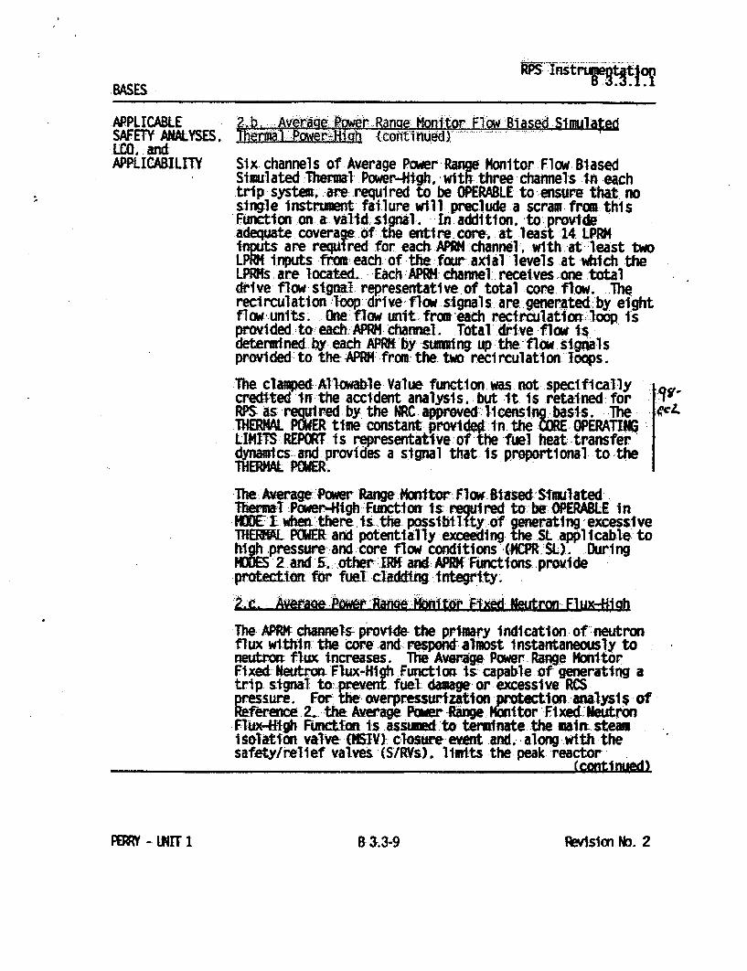
nBASES
APPLICABLE SAFETY ANALYSES. LCO. and APPLICABILITY
Zoh, Av .rA .sde f'ower Aange Noniftor,, Fliom Si ase Simulae
Six..channels of Average Power Range Monitor Flow Biased Simulated Thermal Power-High. with three -channels In each trip system, are required to be OPERABLE to ensure that no single lnstrument failure will preclude a scram from this Function- .on a i. ' In addition, to :provide adequate coverawe. of: the entire. core- at least -14 LPRK its are required for each APl4:channel, with.at least two L. P i.nputs fro.t each. of thefour. axi.al -levels at .•dtch the LPR.s. are located.. Each APIK- channe1. receives .one total drive flow si•.n. representative.of total core. flow. The recirculation .•loop: drive flow signals..are. generated .by eight flow units. One.•fl.• unit. fromeach recirculation. loop. is provided to. each: APR•I chanel. Total.dr-i-ve flow is determined. y .each APRK"lby suning up the.flow. signals provided to the.APIM.from-the two recirculation loops.
The clamped Allowable Value function. Was not :speclflcal ly credi-ted n the accident analysis.. but 4t. Is retained- for RPS as %required by, the NRC approved-l~censi ng..basis. The .IIWL POWER time constantprv.ide01.n. the ( O. OPERATIMI LIMITS REPORT is re sentative of the f-uel. heat .transfer 4ynainics: and provides a signal that is proportional to the
TBXPOWER.
'Is,�cL
S• The Aw g Power Range Montw.. Flow. Rlased.Shmulatedc Them -l Power-Htgh Fuctiorst Us required to. -he OPERABLE in MOEt-whet there, s the possitbifty.of generating excessive THERL POWER and potentially exceeding .the SL .applicable to highpressure- and -core flow conditions CPR.J. During MUE5 21ndn5., other• II• and: APRKFunctions. provide proteci for fuel claddif Anterity. 2c. ��,PMt Ranee to AF'xd leutron Flux&-.i.h
The APR chanels provide the primary indication of neutron flux withtn the core and res od almoist instantaneously to neutrorr flux increases. The Average. Power -Rangr'e Monltor Fixed Neutrom Flux-High Function is.capable of generating a trips signal to- preent fuel dmage or excessive RCS pressure. For the overpressurization protection. analysis of Reference. 2. the Average Per Range. Monitor FixedNeutron Flux-ifgh nctton is. ,assIum toterminate the mwit steam i solation valve- OJV)}- closure event and, -along.- with the safety/relief valves (S/RVs). limits the peak reactor
.(continued)
BRevsion No. 2PERRY - LKIT 1 B a3.-9

input, for this event is much less than those consequences identified in
Section 15.2.4.5. Therefore, the radiological exposures noted in
Section 15.2.4.5 cover the consequences of this event.
, J Wre with a flux scram is analyzed for
overpressure protection purposes only, as part of the reload safety
analysis discussed in Appendix 15B.
15.2.4.1 Identification of Causes and Frequency Classification
Various steam line and nuclear system malfunctions, or operator actions,
can initiate main steam isolation valve (MSIV) closure. Examples are
low steam pressure, high steam flow, low water level, or manual action.
a. Closure of 4I.Main Steam Isolation Valyes
This event is categorized as an incident of moderate frequency. To
define the frequency of this event as an initiating event and not
the byproduct of another transient, only the following contribute
to the frequency: manual action (purposely or inadvertent);
spurious signals such as low pressure, low reactor water level or
low condenser vacuum, and finally, equipment malfunctions such as
faulty valves or operating mechanisms. A closure of one MSIV may
- Revision 7 15.2-21 March, 1995

cause an immediate closure of all the other MSIVs depending on
reactor conditions. If this occurs, it is also included in this
category. During the main steam isolation valve closure, position
switches on the valves provide a reactor scram if the valves in
three or four main steam lines are less than 90 percent open
15 . 2 -21aRevision 2 March, 1990

(except for interlocks which permit proper plant startup).
Protection system logic, however, permits the test closure of one
valve without initiating scram from the position switches.
b. Closure of One Main Steam Isolation Valve
This event is categorized as an incident of moderate frequency.
One MSIV may be closed at a time for testing purposes, this is done
manually. Operator error or equipment malfunction may cause a
single MSIV to be closed inadvertently. If reactor power is
greater than about 80 percent when this occurs, a high flux scram
may result. (If all MSIVs close as a result of the single closure,
the event is considered as a closure of all MSIVs.)
15.2.4.2 Sequence of Events and Systems Operation
Table 15.2-6 lists the sequence of events for Figure 15.2-6.
The following is the sequence of operator actions expected during the
course of the event assuming no restart of the reactor. The operator
should:
a. Observe that all rods have inserted.
b. Observe that the relief valves have opened for reactor pressure
control.
c. Continue operation of RCIC until decay heat diminishes to a point
where the RHR system can be put into service.
Revision 1 15.2-22 March, 1989

d. Switch the feedwater controller to the manual position.
e. Initiate operation of the RHR system in the steam condensing mode.
f. When the reactor vessel level has recovered to a satisfactory
level, secure HPCS.
g. When the reactor pressure has decayed sufficiently for RHR
operation, put it into service per procedure.
h. Before resetting the MSIV isolation, determine the cause of valve
closure.
i. Observe turbine coastdown and break vacuum before loss of steam
seals. Check T-G auxiliaries for proper operation.
j. Do not reset and open MSIVs unless conditions warrant and be sure
the pressure regulator set point is above vessel pressure.
k. Survey maintenance requirements and complete the scram report.
a. Closure of All Main Steam Isolation Valves
MSIV closures initiate a reactor scram trip via position signals to the reactor protection system. Credit is taken for successful
operation of the reactor protection system.
The pressure relief system which initiates opening of the relief
valves when system pressure exceeds relief valve instrumentation
set points is assumed to function normally during the time period
analyzed.
15.2-23

All plant control systems maintain normal operation unless
specifically designated to the contrary.
b. Closure of One Main Steam Isolation Valve
Closure of a single MSIV at any given time will not initiate a
reactor scram. This is because the valve position scram trip logic
is designed to accommodate single valve closure and testability
during normal reactor operation at limited power levels. Credit is
taken for the operation of the pressure and flux signals to
initiate a reactor scram.
All plant control systems maintain normal operation unless
specifically designated to the contrary.
Mitigation of pressure increase is accomplished by initiation of a
reactor scram via MSIV position switches and the reactor protection
system. Relief valves also operate to limit system pressure. These
functions are designed to single failure criteria.
Failure of a single relief valve to open is not expected to have any
significant effect. Such a failure is expected to result in less than a
5 psi increase in the maximum vessel pressure rise. The peak pressure
will still remain considerably below 1,375 psig. The design basis and
performance of the pressure relief system is discussed in Section 5.0.
15.2-24

Core and System Performance
15.2.4.3.1 Mathematical Model
The computer model described in Section 15.1.2.3.1 was used to simulate
these transient events.
These analyses have been performed, unless otherwise noted, with plant
conditions tabulated in Table 15.0-1.
The main steam isolation valves close in 3 to 5 seconds. The worst
case, the 3 second closure time, is assumed in this analysis.
Position switches on the valves initiate a reactor scram when the valves are less than 90 percent open. Closure of these valves inhibits steam flow to the feedwater turbines terminating feedwater flow.
Because of the loss of feedwater flow, water level within the vessel decreases sufficiently to initiate trip of the recirculation pump and
initiate the HPCS and RCIC systems.
a. Closure of All Main Steam Isolation Valves
Figure 15.2-6 shows the changes in important nuclear system variables for the simultaneous isolation of all main steam lines
while the reactor is operating at 105 percent of NB rated steam flow. Peak neutron flux and fuel surface heat flux show no
increase.
15.2-25
15.2.4.3

Water level decreases sufficiently to cause a recirculation system
trip and initiation of the HPCS and RCIC systems at some time
greater than 10 seconds. However, there is a delay up to
30 seconds before the water supply enters the vessel.
Nevertheless, there is no change in the thermal margins.
b. Closure of One Main Steam Isolation Valve
Only one isolation valve is permitted to be closed at a time for
testing purposes to prevent scram. Normal test procedure requires
an initial power reduction to approximately 75 to 80 percent of
design conditions in order to avoid high flux scram, high pressure
scram or full isolation from high steam flow in the "live" lines.
With a 3 second closure of one main steam isolation valve during
105 percent rated power conditions, the steam flow disturbance
raises vessel pressure and reactor power enough to initiate a high
neutron flux scram. Since this transient is considerably milder
than closure of all MSIV's at full power, no quantitative analysis
is furnished for this event. However, no significant change in
thermal margins is experienced and no fuel damage occurs. Peak
pressure remains below SRV set points.
Inadvertent closure of one or all of the isolation valves while the
reactor is shut down (such as operating state C, as defined in
Appendix 15A) will produce no significant transient. Closures
during plant heatup (operating state D) will be less severe than
the maximum power cases (maximum stored and decay heat) discussed
in Section 15.2.4.3.3.a.
15.2-26

Consideration of Uncertainties
Uncertainties in these analyses involve protection system settings,
system capacities and system response characteristics. In all cases,
the most conservative values are used in the analyses. For examples:
a. Slowest allowable control rod scram motion is assumed.
b. Scram worth shape for all-rod-out end-of-equilibrium cycle
conditions is assumed.
c. Minimum specified valve capacities are utilized for overpressure
protection.
d. Set points of the safety/relief valves are assumed to be 1 to
2 percent higher than the valve's nominal set point.
15.2.4.4 Barrier Performance
The nuclear system relief valves begin to open at approximately
2.7 seconds after the start of isolation. The valves close sequentially
as the stored energy is dissipated but continue to discharge
intermittently due to decay heat. Peak pressure at the vessel bottom
reaches 1,207 psig, clearly below the pressure limits of the reactor
coolant pressure boundary. Peak pressure in the main steam line is
1,174 psig.
15.2-27
15.2.4.3.4

No significant effect is imposed on the RCPB, since if closure of the
valve occurs at an unacceptably high operating power level, a flux or
pressure scram will result. The main turbine bypass system will
continue to regulate system pressure via the other three "live" steam
lines.
15.2.4.5 Radiological Consequences
The radiological impact of many transients and accidents involves the
consequences which do not lead to fuel rod damage as a direct result of
the event itself. Additionally, many events do not lead to the
depressurization of the primary system but only the venting of sensible
heat and energy via fluids at coolant loop activity through relief
valves to the suppression pool. In the case of previously defective
fuel rods, a depressurization transient will result in considerably more
fission product carryover to the suppression pool than will hot standby
transients. The time duration of theltransient varies from several
minutes to greater than four hours, further increasing the variation in
activity release.
The above observations lead to the conclusion that radiological events
can involve a broad spectrum of results. For example:
a. Where appropriate operator action (seconds) results in quick return
(minutes) to planned operation, little radiological impact results.
b. Where major RCPB equipment failure requires immediate plant
shutdown and its attendant depressurization under controlled
shutdown (4 hours), the radiological impact is greater.
15.2-28
A M-.1 -M

In order to envelope the potential radiological impact of MSIV closure, a worst case like major equipment failure (b) is described below. However, it should be noted that most transients involve appropriate operator action and the analysis conservatively over-predicts the actual radiological impact by a factor greater than 100.
15.2.4.5.2.1 Fission Product Release from Fuel
While no fuel rods are damaged as a consequence of this event, fission product activity associated with normal coolant activity levels as well as that released from previously defective rods will be released to the suppression pool as a consequence of SRV actuation and vessel depressurization. The release of activity from previously defective rods is based in part upon measurements obtained from operating BWR
plants.(1)
Those transients identified previously which cause SRV actuation will result in various vessel depressurization and steam blowdown rates. The transient evaluated in this section is that which maximizes the radiological consequences for all transients of this nature. This transient is the closure of all main steam line isolation valves. The specific models and assumptions used in the evaluation are described in Reference 2. The activity released to the environs is presented in Table 15.2-7 which was used in evaluating the radiological dose consequences in this section.
15.2-29

Perry Nuclear Power Plant NRC Written Examination
Data Sheets
QUESTION SRO 074
The following plant conditions exist:
"* A reactor cooldown is in progress. "* Reactor pressure is 48 psig. "* Reactor temperature is 2750F. "* RHR Loop 'B' is operating in the Shutdown Cooling mode. "* Based on surveillance results, the standby loop of RHR SDC has just been declared
inoperable.
Which one of the following Technical Specification Required Actions must be completed within one hour?
A. Verify an alternate method of decay heat removal is available.
B. Verify one Reactor Recirculation Pump is in operation.
C. Monitor reactor coolant temperature and pressure.
D. Suspend the reactor cooldown.
ANSWER: A.

Perry Nuclear Power Plant NRC Written Examination
Data Sheets
Level: RO SRO Tier # 3
Examination Outline Cross-Reference Group # CAT 1 K/A# 2.1.11 Importance Rating 1 13.8
Proposed Question: See attached SRO 074
Proposed Answer: See attached
Explanation (Why the distractors are incorrect):
B - This action is not required by Tech Specs (a Recirc pump is part of the LCO).
C - Not required at this time; this is required if both loops of SDC were inoperable and no recirc pumps were in operation.
D - This is not an action specified by Technical Specifications.
Technical Reference(s): Technical Specifications 3.4.9 Reference Attached: _X_
I (Attach if not previously provided)
Proposed references to be provided to applicants during examination:
NONE
Learning Objective (As available): OT-3037-006-08 OBJ B&D
Question Source: Bank # Modified Bank # (Note changes or attach parent) New X
Question History: Previous NRC Exam Previous Quiz / Test
Question Cognitive Level: Memory or Fundamental Knowledge _X_ Comprehension or Analysis
10 CFR Part 55 Content: 55.41 X
55.43 X
Comments (Why is it an upper level question):

goR Shutdown Coolinmg System- ~ Sh.tdow
1.4 REACTOR. COOLANT SYSTEM (RCS)
3L.4.9 Residual. He-at Removal (RHR-) Shutdown Cooling System-Hot Shutdown
LCO' 3.4.9
APPLICABILITY:
Trwo RHR. Shutdown coaliJng subsystems s hall be OPERABLE, And,, wi th no redircula&tloi onpuqpi In. opera tion, at least oae ARI shutdown cooling subsystem-shall be in~operation.
1. Both RHR shutdown cooling subsystems. and recirculation p~ups.-may be-removed from operation for up, to 2 hours per 8 hour period.
2-. Ong RIIR_ shutdown- cooling subsys tom -may be .i noperablea for up-to 2 hours for performance of Surveillances.
MODE 3- wi-th reactor steam dome pressure less than the. RHR cut-In, permissive pressure.
ACTIQNS
1. LCO 3.0.4 is not app.1icable.
2. Separate Condition entry is allwowd-for each RHR shutdown Cooling subsystem.
CONDITION REQUIRED ACTION cOKPýLEfTION TI MEt
A. One or two RII A.~1 Initiate action, to Iuundiately shutdow oln restore R s sutdowna Subysem inpr e. coolin4 ubsytms
to 60ERABL status:.
Amendment No. 69PERRY - UNIT 1I.42 3.4-21

RHR Shutdown Cool ing System-Hot Shutdown 3.4.9
ACTIONS CONDITION-
I
A. (continued)
B. No RHR shutdown. cooling subsystem in operation.
No recirculation pump in operation.
REQUIRED ACTION
A.2 Verify an alternate method of decay heat removal is- available for:each Inoperable RHR shutdown cooling subsystemw.
A.3 Be.n MODE 4.
8.1
i BR
Initiate action. to restore one RHR. shutdown coaling subsystem or one recirculation pump- to operation.
Verify reactor coolant circulation by an alternate method*.
COMPLETION TIME
1 hour
24 hours
immediately
t hour from discovery of no :reactor coolant circulatiton
I m
8.3 Nonitor reactor SCoolant temperature and pressure.
ýOnce per 12- hours thereafter
Once per hour
Amendment No. 69PERRY - UNIT I
____________ I a
i
3.4-22

"* Perry Nuclear Power Plant NRC Written Examination
Data Sheets
QUESTION SRO 075
During a plant startup with the reactor operating at 5% power, the on-shift Chemistry Technician reports the following results from SVI-C41-T1026 pertaining to the Standby Liquid Control System (SLC) Storage Tank:
"* SLC TANK NET VOLUME 4600 gallons "* SOLUTION CONCENTRATION WT % BORON 2.75%
Which one of the following describes the condition of the Standby Liquid Control (SLC) System in accordance with Technical Specification LCO 3.1.7, SLC System?
Technical Specification Figure 3.1.7.1 is provided for reference.
A. The SLC System is OPERABLE; no Required Action(s) need to be completed.
B. The SLC System is not required to be OPERABLE; no Required Action(s) need to be completed.
C. Only one SLC subsystem is OPERABLE; Required Action(s) need to be completed.
D. No SLC subsystems are OPERABLE; Required Action(s) need to be completed.
ANSWER: D

Perry Nuclear Power Plant NRC Written Examination
Data Sheets
Level: RO SRO Tier # 2
Examination Outline Cross-Reference Group # I K/A# 211000.G2.1.33 -Importance Ratinq 1 4.0
Proposed Question: See attached SRO 075
Proposed Answer: See attached
Explanation (Why the distractors are incorrect):
A- The SLC system is INOPERABLE.
B - The SLC system is required to be OPERABLE for this plant condition (and is inoperable).
C - The SLC storage tank is common; therefore both SLC subsystems are inoperable.
Technical Reference(s): Technical Specification 3.1.7 Reference Attached: _X and Bases; SDM C41 I (Attach if not previously provided)
Proposed references to be provided to applicants during examination: Technical Specification Figure 3.1.7-1
Learning Objective (As available): OT-3037-006-05 OBJ B; OT-3036-000-C41 OBJ C&H
Question Source: Bank # Modified Bank # (Note changes or attach parent) New
Question History: Previous NRC Exam Previous Quiz / Test
Question Cognitive Level: Memory or Fundamental Knowledge Comprehension or Analysis __A_
10 CFR Part 55 Content: 55.41 X 55.43 X___
Comments (Why is it an upper level question): Requires the SRO student to analyze initial plant conditions in order to determine SLC system operability.

ry'
;zy
'-4 -4 I-A
LOW LEVEL ALARM
SETPOINT
HIGH LEVM , ALARM SETPOINT
REGION OF APPROVED VOLUMEgAID
CONCENTRATI-ON
2.85
2.8
2.75
2.7
2.65
2.6
4300
Boron SFigure 3.1.7.1 Brnsolution Concentrationi~olume eureet
BORON SOLUTION CONCENTRATION AND VOLUME REQUIREMENTS
i-,A
r%
3
2.95
2.9z 0
0 M
.0
.0
0 42
TANK •OVERFLOW
O W
max conc. 2.9%
min.
conc. 2.80%
* -.-.... F 4600 4700 4800
V- INDICATED NET TANK VOLUME (GALLONS)
a.
r+
,0 Q.
4 4400
4 4500
MARGIN
5014 I.0
4900
r
C)
Cu+'
4782 ,5014

Perry Nuclear Power Plant NRC Written Examination
Data Sheets
QUESTION SRO 076
The plant is operating at 100% reactor power when the following alarms occur on panel H13-P60 1:
"* LPCS AUTO START RECEIVED "* LPCS & LPCI A DW PRESS HIGH "* LPCI A AUTO START RECEIVED "* ADS A PERMISSIVE LPCS / RHR A RUN "* ADS A TIME DELAY LOGIC TIMER RUNNING
An operator reports the following plant parameters:
"* Reactor power is 100% and steady. "* Reactor water level is +201 inches and steady. "* Drywell pressure is 0.4 psig and steady.
As the Unit Supervisor, which one of the following instructions should be entered, including an operator action that should be directed in order to mitigate the consequences of this event?
A. Enter ONI-E12-1, Inadvertent Initiation of ECCS/RCIC, and inhibit both ADS Logic Channels.
B. Enter ONI-E12-1, Inadvertent Initiation of ECCS/RCIC, and inhibit only ADS Logic Channel 'A'.
C. Enter PEI B 13, RPV Control (Non-ATWS), and inhibit both ADS Logic Channels.
D. Enter PEI B 13, RPV Control (Non-ATWS), and inhibit only ADS Logic Channel 'A'.
ANSWER: B

Perry Nuclear Power Plant NRC Written Examination
Data Sheets
Level: RO SRO Tier # 2
Examination Outline Cross-Reference Group # 1 K/A# 218000 G2.4.4 Importance Rating 14.3
Proposed Question: See attached SRO 076
Proposed Answer: See attached
Explanation (Why the distractors are incorrect):
A - ONI-E12-1 directs that only the effected ADS channel be inhibited.
C & D - The entry conditions for PEI B133 have not been met.
Technical Reference(s): ONI-E12-1; SDM B21C(ADS) Reference Attached: _X_
(Attach if not previously provided)
Proposed references to be provided to applicants during examination:
NONE
Learning Objective (As available): OT-3036-004-E12 OBJ M; OT-3036-002-B21C OBJ E
Question Source: Bank # Modified Bank # (Note changes or attach parent) New X
Question History: Previous NRC Exam Previous Quiz / Test
Question Cognitive Level: Memory or Fundamental Knowledge Comprehension or Analysis -A
10 CFR Part 55 Content: 55.41 X 55.43 X._.
Comments (Why is it an upper level question): Requires the SRO student to analyze given plant conditions, recognize entry into off normal plant procedures and direct the appropriate action.

OM4B: ONI-E12-1 Page: 2 Rev.: 3 / C-5
2.0 AUTOMATIC ACTIONS
1. Reduction in feed flow to compensate for emergency system injection.
2. Main Turbine and Reactor Feed Pump Turbines trip with RCIC initiation signal.
3. Possible reactor scram on high flux or power.
4. At a reactor vessel water level of 219 inches:
a. Reactor Feedwater Pump Turbines trip. b. Main Turbine trips. c. Motor Feed Pump trips. d. Reactor scrams (Reactor System Mode Switch in RUN). e. RCIC Steam Shutoff, lE51-F045, closes. f. RCIC Injection Vlv, 1E51-F013, closes. g. HPCS Injection Valve, 1E22-F004, closes.
3.0 IMMEDIATE ACTIONS
CAUTION
An Emergency Core Cooling System shall not be manually overridden unless:
a. Initiation is proven incorrect (beyond a reasonable doubt by two independent indications) or
b. Continued operation is no longer necessary or c. Misoperation in automatic is confirmed.
1. Deleted
NOTE: Unit Supervisor concurrence is required to override safety system operation. (reference PAP-0205)
2. If initiation is incorrect or misoperation in automatic is confirmed then stop the running emergency system(s) at the ECCS Benchboard, 1H13-P601 as follows:
a. HPCS Initiation - Take the HPCS PUMP, IE22-C001, to STOP. b. LPCS Initiation - Take the LPCS PUMP, IE21-CO01, to STOP. c. LPCI Initiation - Take RHR PUMP A(B, C), IEI2-CO02A(B,C),
to STOP. d. RCIC Initiation - Momentarily depress the RCIC TURBINE
REMOTE TRIP pushbutton, 1E51-S17.

OM4B: ONI-E12-1 Page: 3 Rev.: 3 / C-4
3. If permissives for ADS initiation were met, momentarily depress the following pushbuttons on P601:
a. ADS A LOGIC SEAL IN RESET, 1B21C-S13A. b. ADS B LOGIC SEAL IN RESET, IB21C-S13A.
NOTE: The intent of the following step is to only inhibit the logic channel associated with the inadvertent initiation signal.
4. If required to prevent an ADS initiation, place ADS A(B) LOGIC INHIBIT switch IB21-S34A(B) to INHIBIT on P601.
4.0 SUPPLEMENTAL ACTIONS
1. If a containment isolation has occurred, enter ONI-B21-4, Isolation Restoration.
2. When possible, reset the inadvertent initiation signal and then restore all affected Emergency Core Cooling Systems by performing the following:
a. LPCI Shutdown to Standby Readiness per SOI-E12, Residual Heat Removal System.
b. Operating to Standby Readiness per SOI-E21, Low Pressure Core Spray System.
c. Shutdown from Operating to Standby Readiness per SOI-E22A, High Pressure Core Spray System.
d. Manual Shutdown from Operating to Standby Readiness per SOI-E51, Reactor Core Isolation Cooling System. e. Automatic Depressurization System Startup to Standby Readiness per SOI-B21, Nuclear Steam Supply Shutoff, Automatic Depressurization and Nuclear Steam Supply System (Unit 1).
3. Restore all affected diesel generators by performing the following:
a. Remote Manual Shutdown to Standby Readiness per SOI-E22B, Division 3 Diesel Generator System.
b. Remote Diesel Generator Shutdown to Standby Readiness per SOI-R43, Division 1 and 2 Diesel Generator System.
4. Refer to the following Technical Specifications:
a. 3.3.5.1, Emergency Core Cooling System Instrumentation

Air pilot solenoids and relay logic from Division 2. The Division 2 LPCI systems, LPCI B and C, are used for the pump running signals.
A manual initiation signal bypasses the level requirements for initiation and the 105 second timer. A LPCI/LPCS pump must still be running in order to open the ADS valves. Once the signal seals in, the LPCS/LpCi pump can then be secured without affecting ADS operation, just as if an automatic initiation had occurred.
3. ADS Initiation Inhibit Logic
There are several methods available to prevent ADS initiation, but only one way of stopping ADS once it has sealed in.
If RPV Level I or Level 3 clears, or LPCIILPCS pumps are stopped, or ADS Logic Inhibit switches are taken to INHIBIT before the 105 second have timed out, ADS will not actuate. The ADS Logic Inhibit switches do not stop an initiation once it has sealed in. They also do not inhibit manual initiation of ADS by use of the ADS Logic Manual Initiation arm and depress push buttons.
To stop ADS after it seals in you must press the ADS Logic seal In Reset push buttons. This will stop ADS for at least 105 seconds. To prohibit the valves from reopening after 105 seconds, you must take the ADS Logic Inhibit switches to INHIBIT.
I. OTHER SYSTEM RELATED INFORMATION
This section is not necessary for the understanding of this system.
B21C- Rev. 5 12

RECEIPT OF THE CONDITIONS BELOW WILL ENERGIZE THE RESPECTIVE RELAYS CAUSING THE ASSOCIATED CONTAlTh _. .S... .... ,-'..,• eu CLOSE . . .
S~~~~LO REACTOR LO REACTOR LPCS PUMP RRPM A PSPH • ~ ~~WATER LEVEL WATER LEVEL DICAGDSHAR G DPSCHARA' (LEVEL 1) (LEVEL 3) (145 PSIG) (125 PSIG) (145 PSIG 1N21-NG9AA N 1E21-NO52 1E12-NO55A IE21-NO53
K3A K12A Len.
CLOSE ON LEVEL I
CLOSE ON LEVEL 3 K3A LOGIC A K12A CLOSE ON SEAL-IN
LEVEL 3 K7A S30A ARMED ADS A
K12A ADS A TZmE INST LOG
"ELAY LOGIC mAwAL MANUAL
INITIATION SWITCH INITIATION
"" S13A A.3 DS A LOGIC 36 S30A DEPRESSED
ADS A LOGIC SEAL I-N "-ESET - .INHIBIT /SWITCH $3A -ANU
SWI A TCINHIBIT
S
1SAL-IN
KSA P60i• CLOSE wWHEN
LPCS OR K9AVA E RHR 'A " A V
ADS LEE CATE INITIATION PILOT VALVE ACTUATION LEVEL CONFIRMATION LOGIC RELAY
LPERMISSIV •U | .I PERMISSIVE
FIGURE B21C-5 ADS/SRV INITIATION LOGIC
ADS INITIATION LOGIC
PILOT VALVE ACTUATION RELAY

Perry Nuclear Power Plant NRC Written Examination
Data Sheets
QUESTION SRO 077
The following plant conditions exists:
"* The plant is operating at 100% reactor power. "* The Class 1 E 4.16KV buses are being powered from their Normal Preferred Source. "* Interbus Transformer LH- 1-A lockout relay actuates. "* All Diesel Generators start and tie to their respective buses. "* Electrical maintenance is investigating the cause of the LH-1 -A lockout. "* All other plant equipment is OPERABLE.
Technical Specifications 3.8.1 and 3.8.7 are provided for reference.
As the Unit Supervisor, which one of the following describes the maximum time allowed by Technical Specifications to restore Interbus Transformer LH-1-A to OPERABLE status before the plant would have to be in MODE 3?
A. 20 hours.
B. 36 hours.
C. 72 hours.
D. 84 hours.
ANSWER: D.

Perry Nuclear Power Plant NRC Written Examination
Data Sheets
Level: RO SRO Tier# 1
Examination Outline Cross-Reference Group #1 K/A# 295003.AK2.03 Imoortance Ratinq 3.9
Proposed Question: See attached SRO 077
Proposed Answer: See attached
Explanation (Why the distractors are incorrect): A - This is the time if T.S. 3.8.7 is utilized; this specification is not applicable with the Division 1 and 2 buses energized from the DGs.
B - This is the time if no offsite power source is available.
C - This is the time until a shutdown would have to be commenced, not completed.
Technical Reference(s): Reference Attached: __X Tech Spec 3.8.1, SDM R10 (Attach if not previously provided)
Proposed references to be provided to applicants during examination:
Technical Specifications 3.8.1 and 3.8.7.
Learning Objective (As available): OT-3036-006-RIO OBJ K OT-3037-001-12 OBJ C
Question Source: Bank # Modified Bank # (Note changes or attach parent) New X
Question History: Previous NRC Exam Previous Quiz / Test
Question Cognitive Level: Memory or Fundamental Knowledge Comprehension or Analysis -A
10 CFR Part 55 Content: 55.41 X 55.43 X
Comments (Why is it an upper level question): Requires the SRO student to determine the time limitations of Technical Specifications for the AC Electrical Distribution System based on a partial loss of AC power.

AC Sources-Operating 3.8.1
3.8 ELECTRICAL POWER SYSTEMS
3.8.1 AC Sources-Operating
LCO 3.8.1 The following AC electrical power sources shall be OPERABLE:
a. Two qualified circuits between the offsite transmission network and the onsite Class 1E AC Electric Power Distribution System; and
b. Three diesel generators (DGs).
APPLICABILITY: MODES 11 2, and 3.
------------------------- NOTE Division 3 AC electrical power sources are not required to be OPERABLE when High Pressure Core Spray System is inoperable.
ACTIONS
CONDITION
A. One required offsite circuit inoperable.
REQUIRED ACTION
A.I Perform SR 3.8.1.1 for OPERABLE required offsite circuit.
AND
COMPLETION TIME
I hour
AND
Once per 8 hours thereafter
(continued)
(contInued)
PERRY - UNIT I Amendent No. 693.8-1
I i

AC Sources -Operating 3.8.1
ACTIaONS
CONDITION REQUIRED ACTION COMPLETION TIME
A. (continued) A.2 Restore required 72 hours offsite circuit to OPERABLE status. AND
24 hours from discovery of two divisions with no offsite power
AND
17 days from discovery of failure to meet LCO
B. One required DG B.1 Perform SR 3.8.1.1 1 hour inoperable, for OPERABLE required
offsite circuit(s). AND
Once per 8 hours thereafter
AND
B.2 Declare required 4 hours from feature(s), suported discovery of by the inoperable DG, Condition B inoperable when the concurrent with redundant required inoperability feature(s) are of redundant inoperable. required
feature(s)
AND
(continued)
Arexcrent No. 99
I
PERRY- UNIT 1 3.8-2

AC Sources -Operating 3.8.1
CONDITION REQUIRED ACTION COMPLETION TIME
B.3.1 Determine OPERABLE 24 hours B. (continued) DG(s) are not
inoperable due to common cause failure.
OR
B-3.2 Perform SR 3.8.1.2 24 hours for OPERABLE DG(s).
&ND
B.4 Restore required DG 72 hours from to OPERABLE status, discovery of an
inoperable Division. 3 DG
AND
14 days
AND
17 days from discovery of failure to meet LCO
C. Two required offsite C.1 Declare required 12 hours from circuits inoperable, feature(s) inoperable discovery of
when the redundant Condition C required feature(s) concurrent with are inoperable. inoperability
of redundant required feature(s)
AND
C.2 Restore one required 24 hours offsite circuit to OPERABLE status.
(continued)
Amen1 .- No.99PM]q - UNI.T 1 3.8-3

AC Sources-Operating 3.8.1
ACTIONS tcont inuwci•
CONDITION
0. One required offsite circuit inoperable.
AND
One required DG inoperable.
E. Two required DGs i noperabl e.
F. Required Action and associated Completion Time of Condition A, B, C. D. or E not met.
G. Three or more required AC sources inoperable.
REQUIRED ACTION COMPLETION TIME
------------.NOTE Enter applicable Conditions and Required Actions of LCO 3.8.7, "Distribution Systems -Operating," when any required division is deenergized as a result of Condition D.
--- - - - - - - - - - - - -
D.1 Restore required offsite circuit to OPERABLE status.
OR
D.2 Restore required DG to OPERABLE status.
E.I
F.I
Restore one required DG to OPERABLE status.
Be in MODE 3.
AND
F.2 Be in MODE 4.
G.] Enter LCO 3.0.3.
12 hours
12 hours
2 hours
OR
21 hours if Division 3 DG is inoperable
12 hours
36 hours
Immediately
PERRY - UNIT 1Amendment No. 693.8-4
ACTIONS (continued)
i I
i

Distribution Systems-Operating 3.8.7
3.8 ELECTRICAL POWER SYSTEMS
3.8.7 Distribution Systems-Operating
LCO 3.8.7
APPLICABILITY:
Division I, Division 2, and Division 3 AC and DC electrical power distribution subsystems shall be OPERABLE.
MODES 1, 2, and 3.
-NOTE ........ Division 3 electrical power distribution subsystems are not required to be OPERABLE when High Pressure Core Spray System is inoperable. -----------------------------------------
ACTIONS
One or more Division 1 or 2 AC electrical power distribution subsystems inoperable.
B. One or more Division I or 2 DC electrical power distribution subsystems inoperable.
A.1 Restore Division 1 and 2 AC electrical power distribution subsystems to OPERABLE status.
8 hours
AND
16 hours from discovery of failure to meet LCO
L CO I IB.] Restore Division I
and 2 DC electrical power distribution subsystems to OPERABLE status.
2 hours
16 hours from discovery of
(continued)
PERRY - UNIT IAmendment No. 69
3.8-36

Distribution Systems-Operating 3.8.7
C. Required Action and associated Completion Time of Condition A or B not met.
D. One or more Division 3 AC or DC electrical power distribution subsystems inoperable.
E. Two or more divisions with inoperable distribution subsystems that result in a loss of function.
C. I Be in MODE 3. 12 hours
AND
C.2 Be in MODE 4.
D.I
E.I
Declare High Pressure Core Spray System inoperable.
Enter LCO 3.0.3.
36 hours
Inmmediately
Immediately
SURSVEILLANCE REQUIREMENTS
SURVE ILLANCE
SR 3.8.7.1 Verify correct breaker alignments and voltage to required AC and DC electrical power distribution subsystems.
FREQUENCY
7 days
PERRY - UNIT IAmendment No. 69
.. I
i
3.8-37

MAIN PERRY BUS 92 (WEST)
S-180
mS-112 MAIN XFMR -- PY-T
-~~ ~ -
--k
UNIT 2u T CLASS 1E =
BUSSES
EH1212
EH116
EH1 102)EH1201
EH21O i HPCS DIESEL GENERATOR
STANDBY DIESEL GENERATOR
DIV 2
Figure R10-5
RIO - Rev. 84.16kV AND ABOVE
103
4.16kVT
STANDBY DIESEL GENERATOR DIV

Perry Nuclear Power Plant NRC Written Examination
Data Sheets
QUESTION SRO 078
The following plant conditions exist:
"* The reactor scrammed on low reactor water level. "* Control rod 30-31 is at position 48. "* All other control rods are fully inserted. "* The Reactor Mode Switch is in SHUTDOWN.
Which one of the following describes the procedural guidance the Unit Supervisor should follow in order to fully insert control rod 30-31?
The control rod should be fully inserted by...
A. manually initiating Alternate Rod Insertion (ARI) per PEI-B 13, RPV Control (Non-ATWS).
B. manually driving the control rod using In-Timer Skip per PEI-SPI 1.3, Manual Rod Insertion.
C. scramming the control rod using the HCU Norm-Test-SRI toggle switches per SOI-C 11, Rod Control and Information System.
D. performing the appropriate control rod insertion method per ONI-C7 1-1, Reactor Scram.
ANSWER: D

Perry Nuclear Power Plant NRC Written Examination
Data Sheets
Level: RO SRO Tier # I
Examination Outline Cross-Reference Group # 1 K/A# 295006.AK1.03 Importance Ratinq 4.0
Proposed Question: See attached SRO 078
Proposed Answer: See attached
Explanation (Why the distractors are incorrect): A- ARI is not directed by PEI-B13 if the reactor is shutdown under all conditions. B - Entry into PEI-B1 3 (ATWS) is not required; therefore, use of the PEI-SPI instructions for control rod insertion is not appropriate. C - Single control rod scram per SOI-Cl 1 is only used when directed by the control rod movement sheets (ONI-C71-1 guidance takes precedence).
Technical Reference(s): SOl-Cl1 (RCIS); PEI-B13; Reference Attached: _X ONI-C71-1 I (Attach if not previously provided) Proposed references to be provided to applicants during examination:
NONE
Learning Objective (As available): OT-3036-006-C71 OBJ L; OT-3035-003-01 OBJ A
Question Source: Bank # Modified Bank # (Note changes or attach parent) New X
Question History: Previous NRC Exam Previous Quiz / Test
Question Cognitive Level: Memory or Fundamental Knowledge Comprehension or Analysis _C_
10 CFR Part 55 Content: 55.41 X 55.43 X__
Comments (Why is it an upper level question): Requires the SRO student to determine the appropriate action and procedural guidance for inserting control rods during abnormal plant conditions.

b. If all control rods cannot be determined to be fully inserted:
1) If any control rods do not indicate fully inserted:
a) Arm and depress the RPS MANUAL SCRAM CH A,B,C, & D push-buttons.
b) Arm and depress the RRCS MANUAL ARI CH A and B push-buttons for RRCS Divisions 1 and 2.
2) If the scram cannot be reset, and conditions permit, perform the following to settle the control rods:
a) Close Charging Water Supp Header Isolation, 1C11 -F034.
b) When the control rods have settled, determine control rod position.
c) Open Charging Water Supp Header Isolation, 10C1 -F034.
NOTE
If all control rods are not fully inserted in the core, the SUBSEQUENTAT I IONS directed toward correcting this situation should be done concurrently with the other SUBSEQUENT ACTIONS. However, the plant should not be cooled down until all rods are fully inserted or it is ensured that an adequate Shutdown Margin exists to prevent an inadvertent criticality or power increase.
6. If any control rod is still not fully inserted: <B00052>

NOTE
The following steps for inserting control rods should be performed in order.
a. If all scram valves are not open (as indicated by the absence of a green LED for each HCU when the SCRAM VALVES push-button is depressed), then remove the following fuses to deenergize the scram pilot valve solenoids.
FUSE PANEL Block (Clip) Wire # MPL (Door)
F25 (F18A) C71A10Xl 11H13-P691 (right) F26 (F18E) C71A101X1 1H 13-P691 (right) F30 (F18C) C71A417X1 1H 13-P693 (left) F31 (F18G) C71A418X1 1H13-P693 (left) F30 (F18B) C71A102X1 1H13-P692 (right) F31 (F18F) C71A103X1 1H13-P692 (right) F22 (F18D) C71A106X1 1H13-P694 (left) F23 (F18H) C71A107X1 1H13-P694 (left)
b. Replace all fuses. c. If all rods are still not fully inserted, verify RPS and ARI are
reset. d. Manually insert all control rods that are not fully inserted.
1) If control rods are out of sequence, perform Rod Position Bypass per SOl-Cl1 (RCIS) for the affected control rods.
e. If control rods moved inward following the last scram, perform the following:
1) Wait until the scram discharge volume is drained and the CRD HCU's are recharged.
2) Arm and depress the RPS MANUAL SCRAM CH A, B, C, and D push-buttons.

Perry Nuclear Power Plant NRC Written Examination
Data Sheets
QUESTION SRO 079
The following plant conditions exist:
"* A LOCA has occurred. "* Drywell pressure is 3 psig and increasing. "* Containment pressure is 2 psig and steady. "* Reactor pressure is 800 psig and decreasing. "* Reactor water level is +100 inches and increasing. "* HPCS is the only system injecting into the reactor. "* Suppression Pool temperature is 1 00°F and increasing. "* Suppression Pool level is 18.0 feet and increasing.
As the Unit Supervisor, which one of the following direction(s), if any, should be given regarding the use of RHR Loop A & B in the Suppression Pool Cooling mode in accordance with PEI-T23, Containment Control?
A. Place both loops in the Suppression Pool Cooling mode.
B. Place a single loop in Suppression Pool Cooling mode and align the other loop for the Containment Spray mode.
C. Neither loop should be utilized for the Suppression Pool Cooling mode since they should be aligned for the LPCI Injection mode.
D. Neither loop should be utilized for the Suppression Pool Cooling mode since they should be aligned for the Containment Spray mode.
ANSWER: A

Perry Nuclear Power Plant NRC Written Examination
Data Sheets
Level: RO SRO Tier * 1
Examination Outline Cross-Reference Group # 1 K/A# 295013.AA1. 01 IImportance Ratinq 1 13.9
Proposed Question: See attached SRO 079
Proposed Answer: See attached
Explanation (Why the distractors are incorrect): B & D - The conditions are not met to use containment sprays (CTMT > 2.25 psig). C - Adequate core cooling is assured with water level above TAF
Technical Reference(s): PEI Bases Document; PEI-T23 Reference Attached: _X
! (Attach if not previously provided) Proposed references to be provided to applicants during examination: NONE
Learning Objective (As available): OT-3402-004-06 OBJ C
Question Source: Bank # Modified Bank # (Note changes or attach parent) New X
Question History: Previous NRC Exam Previous Quiz / Test
Question Cognitive Level: Memory or Fundamental Knowledge Comprehension or Analysis -A
10 CFR Part 55 Content: 55.41 X 55.43 X
Comments (Why is it an upper level question): Requires the SRO student to determine the required actions for RHR Loop A&B per PEI-T23 based on the initial plant conditions provided.

CONTAINMENT CONTROL SUPPRESSION POOL TEMPERATURE
STEP:
PEI BASES Page: 218 Rev.: 4
DISCUSSION
When suppression pool temperature cannot be maintained below the most limiting suppression pool temperature LCO value (95 0F), explicit Instructions are given to operate all available methods of suppression pool cooling. Maintaining adequate core cooling takes precedence over maintaining suppression pool temperature below the LCO value since catastrophic failure of the containment is not expected to occur at this temperature. In addition, further action is still available for reversing the increasing suppression pool temperature trend. Therefore, only if the operation of a RHR pump is not required to assure adequate core cooling is it permissible to use that pump for suppression pool cooling. This step however, does permit alternating the use of RHR pumps between the RPV* injection mode and suppression pool cooling modes, as the need for each occurs, and so long as adequate core cooling can be maintained.

Perry Nuclear Power Plant NRC Written Examination
Data Sheets
QUESTION SRO 080
As the Shift Manager, you are informed that control rod 26-27 is at position 46 when it should be at position 48. A review of past core edits indicates the control rod was mispositioned last shift during the Control Rod Exercise surveillance.
Which one of the following describes the requirement for restoring the control rod to its proper position per FTI-B0002, Control Rod Movements, and the subsequent notification requirement per PAP-0201, Conduct of Operations?
A. Reposition the control rod to position 48 expeditiously; notify the Plant Manager.
B. Reposition the control rod to position 48 expeditiously; notify the Operations Section Manager.
C. Obtain guidance from the Reactor Engineer prior to repositioning the control rod to position 48; notify the Plant Manager.
D. Obtain guidance from the Reactor Engineer prior to repositioning the control rod to position 48; notify the Operations Section Manager.
ANSWER: B

Perry Nuclear Power Plant NRC Written Examination
Data Sheets

FTI-B0002 Page: 17 Rev.: 5
NOTE 2: A control rod that is Out-of-position by only one notch complies with all applicable analyses relative to the Rod Action Control System (RACS), i.e., BPWS, CRDA, and RWE.
NOTE 3: When contacted, a Reactor Engineer may provide verbal directions for the expeditious recovery of out-of-position control rods. If additional directions are needed to supplement particular step(s) in this section, a Reactor Engineer may fax, modem, or otherwise electronically transmit written instructions in the form of revised Control Rod Movement Sheets for use until the Reactor Engineer can get to the Control Room.
1. For a control rod that is out-of-position by one notch:
a. Restored the rod to its proper position, expeditiously. b. Position bypass the rod in RACS, if necessary. c. No guidance from a Reactor Engineer is required. d. Log the out-of-position control rod and its disposition in
the Unit Log. e. Notify Reactor Engineering.
2. For any out-of-position control rod except as described in Step 5.10.1, collect the following data on plant conditions:
a. If the process computer is available, print a Rod Position Log to record the control rod pattern; otherwise, record the control rod pattern in some other manner. b. If the process computer is available, print a Core Power/Flow Log and LPRM Readings Log to record the core conditions; otherwise, record reactor power in some other manner.
c. Record the Offgas Pretreatment Radiation Level from DI7-K612 in the Unit Log.
3. For one stuck withdrawn control rod:
a. Disarm the associated control rod drive within 2 hours per <Technical Specification REQUIRED ACTION 3.1.3.A.I>. b. Contact Reactor Engineering, as necessary, for changes to the Control Rod Movement Sheets.
c. If required for continued operation, bypass the stuck withdrawn control rod in RACS per <Technical Specification REQUIRED ACTION 3.1.3.A.l> and independently verify the bypassing of the stuck withdrawn control rod on the Control Rod Movement Sheet per <Technical Specification SURVEILLANCE REQUIREMENT SR 3.3.2.1.9>. d. If the requirements of <Technical Specification REQUIRED ACTION 3.1.3.A> cannot be met, be in MODE 3 within 12 hours per <Technical Specification REQUIRED ACTION 3.1.3.E.1>.

PAP-0201 Page: 10 Rev.: 9 / C-14
6.5.5 Only qualified Radwaste Supervising Operators are permitted to manipulate the controls in the Radwaste Control Room. Unqualified personnel may be allowed to operate these controls for training under direct supervision and in the presence of a qualified Radwaste Supervising Operator. In addition, operation of mechanisms and apparatuses that affect the operation of Radwaste systems shall be accomplished only with the knowledge and consent of the on-shift Radwaste Supervising Operator.
6.6 Shift Notifications
6.6.1 The following situations require verbal notification by the Shift Supervisor of the Operations Section Manager or duty management representative, if assigned:
1. Entry into any ONI, PEI, or EPI.
2. Inadvertent radioactive liquid or gaseous release.
3. Any major equipment failure or malfunction.
4. Major personnel injury or radiation overexposure.
5. Accidents occurring on plant property.
6. All reportable events, including suspension of any safeguard measures.
7. Reactivity Control Events such as control rod mispositioning errors, control rod drifts, or unexpected power increases caused by pressure transients.
8. Violations of local, state, or federal pollution regulations (oil or chemical spills to the environment) per <PAP-0806>, Spills and Unauthorized Discharge.
9. Entry into Tech Spec LCO 3.0.3.
10. Loss of the inservice decay heat removal system.
11. Load restrictions or inability to meet generation dispatcher requests.
12. Reactor coolant system operational leakage > one-half of the Tech Spec limits.
As a courtesy, Items 6.6.1.1 through 6.6.1.10 above should be verbally reported to the NRC Resident Inspector.
6.6.2 The Shift Supervisor shall ensure that the Shift Technical Advisor (STA) is notified of entry into any ONI, PEI, or EPI and of any unplanned entry or violation of a Tech Spec LCO.

Perry Nuclear Power Plant NRC Written Examination
Data Sheets
QUESTION SRO 081
As the Unit Supervisor, you are performing a pre-job brief with the Non-Licensed Operator who will be the Lead Test Performer for a Surveillance Test Instruction (SVI).
The Non-Licensed Operator identifies several Prerequisite steps that, if performed in parallel, would expedite completion of the SVI.
Which one of the following correctly describes the procedural guidance for this particular situation involving the performance of Prerequisites steps in parallel?
The Unit Supervisor...
A. can review and then authorize the performance of Prerequisite steps in parallel per PAP- 1105, Surveillance Test Control.
B. can review and then authorize the performance of Prerequisite steps in parallel per PAP-0522, Changes to Procedures and Instructions.
C. must obtain the Shift Manager's review and authorization to perform Prerequisite steps in parallel per PAP-I 105, Surveillance Test Control.
D. must obtain the Shift Manager's review and authorization to perform Prerequisite steps in parallel per PAP-0522, Change to Procedures and Instructions.
ANSWER: C

Perry Nuclear Power Plant NRC Written Examination
Data Sheets

PAP-1105 Page: 3 Rev.: 9 / C-9
2. Enter appropriate Limiting Conditions for Operations and Action Statements for those systems/components determined inoperable.
3. Identify conditions or circumstances (such as action statements) requiring performance of conditional surveillance tests that are not scheduled on a periodic basis and notifying the appropriate personnel to ensure that surveillance requirements are satisfied.
4. Ensure that surveillance requirements are satisfied prior to mode changes as delineated in <PAP-1114>, Mode Change Checklist.
5. Perform final review of Surveillance Test Packages unless stated otherwise.
6. Authorize start of prerequisites unless stated otherwise.
3.5 Shift Manager (SM): Review and authorize conduct of prerequisite steps out of sequence or in parallel for a surveillance.
3.6 Shift Engineer (SE): Review Surveillance Test Packages as directed by the Control Room Unit Supervisor. Also, the Surveillance Test Control duties of the Unit Supervisor may be performed by the SRO licensed SE provided concurrence has been obtained from the Unit Supervisor.
3.7 Responsible Section Reviewer:
1. Perform required reviews of selected TS Surveillance packages.
2. Review As Found/As Left values for acceptability and perform an evaluation for unacceptable trends.
3. Notify the Surveillance Coordinator of required changes to the TS Matrix and ARMS surveillance scheduling database.
3.8 Lead Test Performer:
1. Determine applicability of test prerequisites.
2. Obtain from the CRUS or Chemistry Shift Lead (ODCM-related SVIs), authorization to start prerequisites, if so designated.
3. Obtain Reactor Operator's authorization to start test, if so designated.
4. Implement Surveillance Test Requirements.
5. Ensure that the test instructions are performed in accordance with <PAP-0528>.

Procedure Use and Adherence PAP-0528
Specific Requirements
5 Specific Requirements
5.1 Step Sequence Reuiremnt s
Prerequisites
Action! Witbin The Prerequisites Section
Prerequisites are checks of conditions which are required to exist prior to performance of the procedure. Prerequisites are worded in the passive voice (e.g., is, has been). Prerequisites may be performed in any order. In some procedures, actions have been placed in the prerequisites section. Actions are recognizable by the use of an active verb (e.g., open, verify, record). Actions within an procedure's prerequisites section shall be performed in the order written unless deviation from the order is authorized by Qna of the following:
* The procedure
0 The Shift Supervisor
ARIs Alarm Response Instruction immediate actions are not required to be memorized. They are to be performed in a timely manner and may be performed in any order. Subsequent actions are developed logically and are normally performed in order. The order of Alarm Response Instruction subsequent actions may be modified as necessary to suit station conditions
101s Integrated Operating Instructions may be performed in the sequence directed by the Unit Supervisor.
LDneup Procedure! Unless otherwise directed within the procedure, lineup procedures (e.g., VLts, EL~s) may be performed in any order.
ONMr Off-Normal Instruction immediate actions should be memorized so that the operator will know in advance the expected course of events that identify an off-normal condition and the proper steps that should be taken to reduce the consequences of the event. Off-Normal Instruction immediate actions may be performed in any order. Subsequent actions are developed logically and are normally performed in order. The Unit Supervisor may modify the order of Off-Normal Instruction subsequent actions as necessary to suit station conditions. PEI! Plant Emergency Instructions are developed logically and should be performed in the order specified. Deviation from the order specified in Plant Emergency Instructions shall be considered a deviation from a license condition.
SOIs and RWIs System Operating Instructions and Radwaste Operating Instructions are performed in a step by step manner within a section.
Rev 0.3 General-Skill Reltereoe
Section 5 Page 1 of 4

Perry Nuclear Power Plant NRC Written Examination
Data Sheets
QUESTION SRO 082
The plant is in MODE 1 and a Containment purge is scheduled for your shift.
As the Unit Supervisor, which one of the following is an administrative restriction for the Containment Vessel and Drywell Purge System (CVDWP) that you should enforce, when possible?
A. The CVDWP System shall be operated in the Refuel Mode.
B. The Containment purge should be conducted between the hours of 1100 and 1600.
C. The Containment Purge Valves should not be open for greater than 1000 hours in the last 365 days.
D. The 42-inch Containment Purge Supply Outboard Isolation Damper (M14-F040) shall no__ be opened.
ANSWER: B.

Perry Nuclear Power Plant NRC Written Examination
Data Sheets
Level: RO SRO Tier # 3
Examination Outline Cross-Reference Group # CAT 3 K/A# 2.3.9 1Importance Rating -T[3-.4
Proposed Question: See attached SRO 082
Proposed Answer: See attached
Explanation (Why the distractors are incorrect): A - The CVDWP Refuel mode shall not be used during Mode 1. C - There is no time restriction for operation of the purge valves with ITS. D - There are no restrictions on the use of the 42 inch purge supply outboard isolation damper with ITS.
Technical Reference(s): SOI-M14 Reference Attached: _
I(Attach if not previously provided) Proposed references to be provided to applicants during examination:
NONE
Learning Objective (As available): OT-3036-003-M14 OBJ G
Question Source: Bank # Modified Bank # (Note changes or attach parent) New x__
Question History: Previous NRC Exam Previous Quiz / Test
Question Cognitive Level: Memory or Fundamental Knowledge _X_ Comprehension or Analysis
10 CFR Part 55 Content: 55.41 X
55.43 X
Comments (Why is it an upper level question):

SOI-M14 Page: 4 Rev.: 11 / C-7 3. The airflow adjustment for CNTMT PURGE SUPP FAN (A)B, lMl4-C001A(B), is located on Airflow Control Center,
IM14-KI35A(B). 4. Beacon control switches are located on local panels IH51-P959
and P960.
4.1 Startup to Intermittent Mode
NOTE: During Modes 1, 2, or 3, M14 System operation should be restricted, when possible, to between 1100 and 1600 hours. This will result in lower off-site noble gas doses due to favorable meteorological conditions.
1. If outside ambient air temperature is :-20'F, do not perform this section.
NOTE: ONI-R36-2 does not allow Intermittent Mode operation when outside air ambient air temperature is 5-20 0 F. la. If P55 is not available and outside ambient air temperature is <50'F but Ž40°F then establish monitoring of the following parameters on Attachment 10 (Containment Temperature Data Sheet) at 8 hour intervals:
Outside ambient air temperature - >400 F Containment average temperature - >60 0 F Suppression pool temperature - Ž600F Annulus Temperature - Ž600 F
2. If in Modes 1, 2, or 3, verify the drywell purge supply ducting is filled.
NOTE: The ducting must be filled prior to Reactor Startup per 101-1 or 101-2.
3. If either the containment equipment hatch is removed or a containment personnel air lock has been overridden with both doors open, open Breaker #27 in K-1-D, 1R25-S053, to place the supply fans in flow control mode.
NOTE: Opening K-l-D-CB27 will actuate annunciator F6, CNTMT PURGE SUPP AIR A & B DP CONT PWR LOSS, on P800. 4. Notify the Chemistry Unit to sample per REC-0104. 5. Notify the Health Physics Unit of the expected duration of M14 operation.
6. Verify system fan settings adjusted per Attachment 8, Intermittent and Refuel Mode Fan Settings.
NOTE: Fan setting adjustments should only be necessary if the system was previously operated in a different mode, although fine tuning may be required.

Perry Nuclear Power Plant NRC Written Examination
Data Sheets
QUESTION SRO 083
Site accountability has been initiated in accordance with the Emergency Plan. The Operations Foreman and a Non-Licensed Operator are currently performing actions in the Containment to mitigate the emergency.
The Shift Manager is currently the Emergency Coordinator.
Which one of the following describes the required actions the Shift Manager must perform in order to meet the site accountability requirements for the Operations Foreman and Non-Licensed Operator?
The Shift Manager should direct the Operations Foreman and Non-Licensed Operator to..
A. immediately stop their mitigating actions and then report to the Unit 1 or 2 Control Room for accountability per EPI-B5, Personnel Accountability/Site Evacuation.
B. immediately stop their mitigating actions and then report to the Technical Support Center for accountability per EPI-A6, Technical Support Center Activation.
C. continue their mitigating actions and then the Shift Manager will account for their location to the Central Alarm Station (CAS) per EPI-B5, Personnel Accountability/Site Evacuation.
D. continue their mitigating action and then the TSC Security Coordinator will account for their location to the Central Alarm Station (CAS) per EPI-A6, Technical Support Center Activation.
ANSWER: C.

Perry Nuclear Power Plant NRC Written Examination
Data Sheets
Proposed Answer: See attached
Explanation (Why the distractors are incorrect):
A & B - This would be true if they were not involved in mitigating actions, the SM may account for operations personnel in the field.
D - This is not the responsibility of the TSC Security Coordinator as outline in EPI-A6.
Learning Objective (As available): EPL-0804-009-01 OBJ B&C;EPL-0823-004-01 OBJ 6
Question Source: Bank # Modified Bank # (Note changes or attach New
Previous NRC Exam Previous Quiz / Test
Memory or Fundamental Knowledge Comprehension or Analysis

EPI-B5 Page: 2 Rev.: 6
3.2 Protected Area
The area encompassing the Vital Areas, all areas inside the double perimeter barrier fence and the Primary Access Control Point (PACP).
3.3 Project Support Area
The area within the site boundary encompassed by a security fence which encloses the warehouse building, office buildings, and contractor support areas, and to which access is controlled for security purposes.
3.4 Site Boundary
The area within the Owner-Controlled Area, which includes the Protected Area and the Project Support Area, and is encompassed by a security fence surrounding the Perry Plant.
3.5 Owner-Controlled Area
Areas owned by the Cleveland Electric Illuminating Company which are located within or adjacent to the Site Boundary security fence.
4.0 RESPONSIBILITIES
4.1 TSC Operations Manager
1. As acting Emergency Coordinator, ensure the initiation of accountability as required by this instruction.
2. Assume overall authority for the accountability of personnel within the Site Boundary area.
4.2 Shift Supervisor
1. Assume the Technical Support Center (TSC) Operations Manager's duties prior to the TSC being declared operational.
2. Ensure the prompt accountability of Control Room staff and on-shift personnel.
4.3 TSC Radiation Protection Coordinator: Assess radiological conditions and recommend the use of the designated offsite monitoring/decontamination centers or other areas on-site.
4.4 TSC Security Coordinator
1. Coordinate the implementation of accountability measures by the Supervisor, Nuclear Security Operations (SNSO) in support of the TSC Operations Manager.

EPI-B5 Page: 4 Rev.: 6 / C-i
5.1.4 If the offsite monitoring/decontamination centers are being activated, direct the Administrative Assistant to notify the NRC, State of Ohio, and local counties on the next Follow-up Notification form (PNPP No. 775) per <EPI-Bl>.
5.2 Shift Supervisor shall:
5.2.1 Perform the actions outlined in Section 5.1 if the TSC is not yet operational, and utilize TSC staff as they become available to accomplish the actions listed in Sections 5.2 thru 5.4.
5.2.2 Activate the applicable pre-recorded "Emergency" message (Attachment 1) on the Exclusion Area Paging (R53) System every five (5) minutes until accountability is completed.
1. Provide additional guidance, if required, to personnel evacuating the site, using the R53 PA feature, for the following:
* designated evacuation routes due to a security contingency * use of offsite monitoring and decontamination centers
5.2.3 Direct all Control Room staff and Perry Plant Operators (PPOs) located in the Unit 2 Control Room, to promptly use the designated accountability card readers.
Plant management who are not currently staffing an emergency facility may utilize a Control Room accountability card reader in lieu of evacuation.
5.2.4 If not yet relocated to the OSC, verify the location and status of PPOs presently dispatched in-plant.
After the OSC is operational, shift personnel such as the Shift I&C/HP/Chemistry Technicians and Perry Plant Operators (PPOs) will be accounted for through the OSC.
1. Complete Personnel Accountability Checklist (PNPP No. 7957, Attachment 2) to account for on-shift PPOs outside the Control Room, and forward to the CAS via the Secondary Alarm Station (SAS). <P00073>
5.2.5 Obtain the number of unaccounted for people within the Protected Area from the CAS no later than 30 minutes after accountability was initiated.

Perry Nuclear Power Plant NRC Written Examination
Data Sheets
QUESTION SRO 084
The plant is in MODE 1 when a loss of DC Bus ED-I-A occurs.
Which one of the following describes the response, if any, of the Annulus Exhaust Gas Treatment System (AEGTS) due to the loss of Bus ED-I-A, including the subsequent Technical Specification OPERABILITY of the system?
A. Both AEGTS trains automatically start; both AEGTS trains are OPERABLE.
B. Both AEGTS trains automatically start; both AEGTS trains are INOPERABLE.
C. Neither AEGTS train automatically starts; only AEGTS Train 'A' is INOPERABLE.
D. Neither AEGTS train automatically starts; only AEGTS Train 'A' is OPERABLE.
ANSWER: C

Perry Nuclear Power Plant NRC Written Examination
Data Sheets
Level: RO SRO Tier # 2 Examination Outline Cross-Reference Group # 1 K/A# 261000. K2.03 Importance Rating 12.5
Proposed Question: See attached SRO 084
Proposed Answer: See attached
Explanation (Why the distractors are incorrect): A & B - Neither AEGTS train starts (RHR logic is powered from ED-1-A and therefore cannot energize to initiate AEGTS). D - AEGTS Train A' operability is impacted by this loss of power.
Technical Reference(s): Tech Spec 3.6.4.3; SDM M15; Reference Attached: __X__ SDM R42 (Attach if not previously provided)
Proposed references to be provided to applicants during examination: NONE
Learning Objective (As available): OT-3036-005-M15 OBJ F&H; OT-3036-006-R42 OBJ B; OT-3037-001-10 OBJ A&B Question Source: Bank #
Modified Bank # (Note changes or attach parent) New .__
Question History: Previous NRC Exam Previous Quiz / Test
Question Cognitive Level: Memory or Fundamental Knowledge Comprehension or Analysis _C_
10 CFR Part 55 Content: 55.41 X 55.43 X___
Comments (Why is it an upper level question): Requires the SRO student to predict the impact of a loss of power on the AEGTS initiation logic and determine the operability of the system.

AEGT Sy~tem 3-6.4.3
3.6 CONTAINN•ET SYSTEMS
3.6.4.3 Annulus Exhaust Gas Treatment (AEGT) System
LCO. 3.6.4.3
APPLICABILITY:
Two AEGT subsystems shall be OPERA8LE.
MODES 1. 2. and 3, During movement of recently irradiated fuel assemblies in the
primary containment. During operations with a potential for draining the reactor
vessel- (OPORVs).I
ACT IONS
CONDITION REQUIRED ACTION COMPLETION TIME
A. One A6ET subsystem A.1 Restore AEGT 7 days inoperable, subsystem to OPERABLE
status.
B, Reqlred Acti on and B.1 Be in MODE 3. 12 hours ssoci ated Completion
Time ofCondition A not mt in MODE 1, 2, or 3. B.2 Be in MODE 4. 36 hours
C. Required Action and C.1 Place OPERABLE AEGT Immedlately associated Completion subsystem in Time of Condition A operation. not met during movement of recently OR irradiated fuel' assemblies in the primary containment, or during OPDRVs.
.(continued)
AwM13.-6rd3 .No. 102
I I
PERRY - UNI 1 3.6-%6

AEGT System 3.6A4.3
CONDITION REQUIRED ACTION COMPLETION TIME
C. (continued) C.2.1 Suspend movement of Immediately recently irradiated fuel assemblies in the primary contai rnment.
C.2.2 Initiate action to Immediately suspend OPDRVs.
D. Two AEGT subsystems D.I Enter LCO 3.0.3. Immediately inoperable in MODE 1. I2, o-r3.
E. Two AEGT subsystems E.A Suspend movement of Immediately inoperable during recently irradiated movement of recently fuel assemblies in irradiated fuel the'primary assemblies in the containment. p r1 mary contai nment. or during OPDRVS. AND
E.2 Initiate action to Immediately suspend OPDRVs.
AM Khoo 3 No. 1023.6-57PF•RY - UNIIT 1

for inoperable or bypassed conditions which are not automatically
indicated. The following inputs will automatically activate the OUT-OF
SERVICE annunciator and illuminate the respective amber status light in
the matrix:
- AEGT A(B) MOV POWER LOSS
- AEGT A(B) FAN/HTR OVLD OR PWR LOSS
- AEGT A(B) LOGIC POWER LOSS
- AEGT A(B) DELUGE ARMED
- AEGT A(B) OUT OF SERVICE SWITCH
2. Local
There are no local alarms associated with this system.
C. CONTROL FUNCTIONS AND INTERLOCKS
• Exhaust Fan Control Logic
"• Exhaust and Recirculation Damper Control
"• Electric Heating Coil Control Logic
I1. Exhaust Fan Control Logic
Refer to Figure M15-3 during the following discussion for Exhaust
Fan "A".
Exhaust Fan "A" is controlled by a three-position, STOP-STANDBY-ON,
spring return from STOP, control switch located on panel H13-P800.
Placing the control switch in the ON position will start an exhaust fan,
provided the charcoal deluge switch is in the DISARMED position, and
M15 - Rev. 4 12

placing the control switch in the STOP position will stop an exhaust fan. With the control switch in the STANDBY position, the exhaust fan will automatically start on receipt of an RHR LOCA initiation signal or if the
operating exhaust fan air flow is low. The exhaust fan will not start,
manually or automatically, if the charcoal deluge switch is in the ARMED
position.
As stated above, the standby Exhaust Fan "A" will automatically start if operating Exhaust Fan "B" air flow is low. A low flow condition indicates
that either the control dampers or fire dampers on the exhaust fan's discharge are closed or there is blockage upstream of the exhaust fan. The
LOCA signal that automatically starts the AEGT system comes from the Residual Heat Removal (RHR) LOCA (K1 10) relays. AEGTS subsystem
A is initiated by the Division 1 RHR LOCA signal and AEGTS subsystem
B is initiated by the Division 2 RHR LOCA signal.
The operator is able to override the RHR LOCA automatic start signal by
turning the Exhaust Fan "A" control switch to STOP. This stops the
exhaust fan and overrides the LOCA signal by causing relay K3 to
energize. Relay K3, when energized, opens the K3 "b" contact which
prevents the exhaust fan from restarting when the control switch spring returns to STANDBY. In addition, an amber light will be sealed in above
the control switch indicating that the exhaust fan was overridden off with a
RHR LOCA signal present.
2. Exhaust and Recirculation Damper Control
Refer to Figure M15-4 during the following discussion.
Two differential pressure transmitters, spaced 1800 apart, transmit signals
M15 -Rev. 4 13

TABLE R42-2 CLASS IE 125 VDC SYSTEM LOADS (DMSION 1)
Division I - BRus EDIA
Distribution Panel ED1A06
- RHR at RCIC Valve Control and Indication - RCIC Logic
Div I RPS Instrumentation Div 1 Leak Detection Logic
- Div I ADS Logic RHR A Logic
- LPCS Logic - Div I RRCS Logic - Div I Diesel Generator Controls - .Div I Diesel Generator Field Flash
Div 1 ATWS UJPS S- Div I Breaker Control Power S- Div I Remote Shutdown Panel
.- Miscellaneous Div I LOCA Logic °'1 - Miscellaneous Div I Control Room Indications :- Div I Optical Isolators for Various Annunciators - Recirc Bkrs 3A/3B control logic
Motor Control Center EDI A09
- RCIC System Div 1 Valve Motors
Detailed listings of individual system loads are provided in Plant Data Book Hoot.
R42 - Rev. 7 17

11) RHR A Heat Exchangers to RCIC Control Valve F065A doses
12) Steam to RHR A Heat Exchangers Control Bypass Valve F087A closes
13) A time delay pickup relay is energized to initiate Containment Spray after approximately 10 minutes from
"system initiation, if a Containment high pressure signal is
present 14) Energizes a 30 minute time delay relay in the Suppression
Pool Makeup System (043) for auto initiation 30 minutes after a LOCA
15) Relay KI 1OA activates the following support systems:
a) Starts the A Annulus Exhaust Gas Treatment
System (MI5) b) Starts Division 1 Standby Diesel Generator (R.43) c) Starts Emergency Service Water System (P45) d) Starts train A of the following HVAC systems:
(1) Motor Control Center (MCC), Switchgear and Miscelaneous/Area HVAC System (Mt23)
(2) Battery Room Exhaust System (M24)
(3) Control Room HVAC System (M25) (4) Control Room Emergency Recirculation
System (M26)
e) Activates relays in the accident line up of the Emergency Closed Cooling System (P42) loop A and in the starting circuitry of ECC Pump A
E12 - Rev. 8 33

Perry Nuclear Power Plant NRC Written Examination
Data Sheets
QUESTION SRO 085
The plant is operating at 100% reactor power when the following alarms occur on panel H13-P870:
"* DC BUS D-1-B UNDERVOLTAGE "* BATTERY lB DC SYSTEM TROUBLE "* 480V BUS GROUND
The Master Level Controller is currently selected to Reactor Narrow Range Level Channel 'A'.
As the Unit Supervisor, which one of the following action(s) would you direct first based on prioritizing these alarms; including the bases for this action(s)?
A. Shift to the Reserve Charger FD-12-B if a fault exists on the Normal Charger FD-1-B; this is to allow repair actions to be initiated for Normal Charger FD-I-B.
B. Coordinate with the RSE and Maintenance to locate the ground if a ground fault is indicated; this is to prevent bus degradation and potential equipment inoperability.
C. Select Reactor Narrow Range Level Channel 'B' and take manual control of the RFPTs to control reactor water level; this is to prevent a low reactor water level scram.
D. Select Reactor Narrow Range Level Channel 'B' and take manual control of the RFPTs to control reactor water level; this is to prevent a high reactor water level scram.
ANSWER: D

Perry Nuclear Power Plant NRC Written Examination
Data Sheets
Level: RO SRO Tier # 2
Examination Outline Cross-Reference Group # 2 K/A# 263000.G2.4.45 Importance Rating 1 3.6
Proposed Question: See attached SRO 085
Proposed Answer: See attached
Explanation (Why the distractors are incorrect): A & B - These actions are incorrect based on the priority of the alarms listed in the initial conditions (a reactor scram is imminent if manual control of feedwater is not taken). C - The reason for taking manual control is incorrect (reactor water level will increase not decrease).
Technical Reference(s): ONI-R42-5 Reference Attached: _X_
I (Attach if not previously provided) Proposed references to be provided to applicants during examination:
NONE
Learning Objective (As available): OT-3036-006-R42 OBJ D&E
Question Source: Bank # Modified Bank # (Note changes or attach parent) New X
Question History: Previous NRC Exam Previous Quiz / Test
Question Cognitive Level: Memory or Fundamental Knowledge Comprehension or Analysis -A
10 CFR Part 55 Content: 55.41 X 55.43 X
Comments (Why is it an upper level question): Requires the SRO student to analyze plant conditions, prioritize alarms, and then select the correct procedure and actions to be performed.

IMMEDIATE ACTIONS
1. Select REACTOR NARROW RANGE LEVEL CH B on 1H13-P680.
2. Transfer control of the operating RFPT(s) to the Manual Speed Control Dial.
3. Verify RFP A, B and MFP FLOW CONTROL, 1C34-R601A, B and
C for the operating RFP(s) in MANUAL.
4. Maintain reactor vessel water level 192 to 200 inches.
SUBSEQUENT ACTIONS
NOTE
Although the load list in PDB-H005 is a convenient reference for determining plant impact, the total effect of bus de-energization on current plant status can only be determined by using approved plant drawings.
PERRY NUCLEAR POWER PLANT Procedure Number: ONI-R42-5 Title: Use Category:
Loss of DC Bus D-1-B Infield Reference Revision: TChange: Page
4 1 N/A 15 of 15
3.0
4.0
NOTE
With CH B selected, REACTOR LEVEL, 1C34-R608, recorder on 1H13-P680 is valid and may be used to monitor RPV Level. Indications on FEEDWATER FLOW MAINSTEAM FLOW, 1C34-R607 are not valid and must not be used to adjust feed rate to the RPV.
NOTE
Due to loss of protective relaying, the Unit Supervisor should evaluate the need to shutdown the plant and strip supply buses to protect from electrical faults. If shutdown is desired, activating the TSC should be considered to provide additional technical guidance for performance of the shutdown due to loss of remote breaker operation capabilities and various abnormal system lineups that will be required.

ARI-H13-P870-1 Page: 49 Rev.: 3 / C-5
Computer Point ID None
SER Address None
1.0 Cause of Alarm
1. DC Bus D-1-B (IR42QO101R) 5 seconds.
voltage < 11OV as sensed by 27DC relay and actuated by 27 DCX relay (IR42Q0101S) after
2. Low voltage could be due to:
a. b. c. d.
Battery Charger failure Battery fault Battery or Battery Charger breaker trip Blown potential fuses
2.0 Automatic Action
None
3.0 Immediate Operator Action
1. Enter ONI-R42-5, Loss Of DC Bus D-1-B, if applicable.
4.0 Subsequent Operator Action
1. Ensure that the S.C.C. Generation Dispatcher is informed per PAP-0102 if breaker relaying and control power is affected.
4.1 Technical Specification
None
U
DC BUS
D-I-B
UNDERVOLTAGE
E5

ARI-H13-P870-1 Page: 15 Rev.: 3 / C-I
Computer Point ID None BATTERY lB
DC SYSTEM TROUBLE
SER Address 319
B5
1.0 Cause of Alarm 1. One or more of the following:
a. Charger FD-I-B trouble: 1) AC POWER brkr open 2) DC POWER brkr open 3) Charger DC VOLTS < 120 VDC 4) Charger DC VOLTS > 145 VDC 5) Charger DC AMPS < 1 amp
NOTE: High voltage could be caused by the battery on equalize charge. If bus voltage has not increased (i.e. battery is not connected to the bus), no further action is required.
b. Bus D-I-B ground as sensed by IR42-Q102R(S) and actuated by IR42-Qi02T after 5 seconds.
2.0 Automatic Action None
3.0 Immediate Operator Action None
4.0 Subsequent Operator Action 1. If a fault exists on Normal Charger FD-I-B;
a. Consider operating Bus D-I-B and D-2-B in parallel supplied from the Unit 2 Battery and Charger, per SOI-R42 (Sys B).
b. Initiate repairs to Charger FD-I-B. 2. If a ground fault is indicated, coordinate with Responsible
Engineer and Maintenance Section to locate the ground.
NOTE: At a minimum, a Work Request should be written within a shift.
NOTE: Plant Data Book, PDB-H0005, 125 VDC Bus D-l-B, can be used for a load list during ground isolation.
NOTE: Ground isolation may require portions of the Plant DC Electrical System to be de-energized. De-energizing or energizing DC buses or DC distribution panels shall be accomplished per SOI-R42 (Sys B).
4.1 Technical Specification None

ARI-H13-P870-1 Page: 57 Rev.: 3 / C-4
Computer Point ID None
SER Address None a=
1.0 Cause of Alarm
1. Bus ground condition as sensed by type 59N ground voltage relay on any of the following 480V buses: I
F-I-A F-I-B F-I-C F-i-D
F-i-E F-I-F F-I-G XF-I-A
2.0 Automatic Action
None
3.0 Immediate Operator Action
None
4.0 Subsequent Operator Action
i. Coordinate with responsible Plant Engineer and maintenance to locate the ground.
NOTE: At a minimum, a Material Deficiency tag should be initiated within a shift.
2. Perform ground isolation.
NOTE: Ground isolation may require portions of the Plant Electrical System to be de-energized. De-energizing or energizing Buses, MCCs or Dist Panels shall be accomplished per SOI-RI0 (LV).
3. When the grounded equipment is isolated, reset the target flag on the affected ground voltage relay.
4.1 Technical Specifications
1. Technical Specifications could be entered, depending on the cause and extent of equipment inoperability.
480V BUS
GROUND
F4

I
ANSWER: A.
Perry Nuclear Power Plant NRC Written Examination
Data Sheets
QUESTION SRO 086
The following plant conditions exists:
" The plant is operating at 10% reactor power. "* Steam Jet Air Ejector (SJAE) 'A' is in operation. "* SJAE A CNDR SUCT ISOL ST FLOW LOW alarm is received on panel H13-P870.
Which one of the following describes the response of the Off-Gas / Condenser Air Removal System, including an action the Unit Supervisor can direct in order to mitigate the consequences of this event?
A. The SJAE 12 Inch and 24 Inch Suction Valves (N62-F 1 70A and F 140A) automatically close; shift SJAEs and Preheaters / Recombiners if SJAE 'A' flow cannot be restored to its proper flow rate.
B. The SJAE 12 Inch and 24 Inch Suction Valves (N62-F 170A and F140A) automatically close; start the Mechanical Vacuum Pumps (N62-COO1A and B) if SJAE 'A' flow cannot be restored to its proper flow rate.
C. The Main Steam to SJAE Supply Valve (N62-F020A) automatically closes; shift SJAEs and Preheaters / Recombiners if SJAE 'A' flow cannot be restored to its proper flow rate.
D. The Main Steam to SJAE Supply Valve (N62-FO20A) automatically closes; start the Mechanical Vacuum Pumps (N62-COO1A and B) if SJAE 'A' flow cannot be restored to its proper flow rate.

Perry Nuclear Power Plant NRC Written Examination
Data Sheets
Level: RO SRO Tier # 2
Examination Outline Cross-Reference Group # 2 K/A# 271000.A2.02 Importance Ratinq 13.1
Proposed Question: See attached SRO 086
Proposed Answer: See attached
Explanation (Why the distractors are incorrect):
B - The Mechanical Vacuum Pumps cannot be operated above 5% power.
C & D - The SJAE main steam supply valve does not automatically close on low dilution steam flow.
Technical Reference(s): SOI-N64/62; ARI-H13-P870-7 Reference Attached: _X_ (Fl) I (Attach if not previously provided)
Proposed references to be provided to applicants during examination:
NONE
Learning Objective (As available): OT-3036-003-N62 OBJ D&H; OT-3036-003-N64 OBJ F
Question Source: Bank # Modified Bank # (Note changes or attach parent) New X
Question History: Previous NRC Exam Previous Quiz / Test
Question Cognitive Level: Memory or Fundamental Knowledge Comprehension or Analysis -A
10 CFR Part 55 Content: 55.41 X 55.43 X
Comments (Why is it an upper level question): Requires the SRO student to predict the impact of a low dilution steam flow condition, including an action that can be performed to mitigate the consequences of this condition.

3. Main Steam to SJAE Supply Valve Control
Each Main Steam to SJAE Supply Valve, F020A(B), is operated by a
three-position, CLOSE-NORM-OPEN, spring return to NORM control
switch on Control Room panel H13-P870-7. A valve can be opened by
taking its control switch to OPEN, and it can be closed by taking the
switch to CLOSE. There is also a STOP push button associated with each
valve, which can be used to stop valve motion at any time during its
stroke. There are no automatic functions associated with these valves.
4. SJAE Suction Valve Control
Each 12" SJAE Suction Valve (F140A and B) and 24" Suction Valve
(F170A and B), is operated by a two-position, CLOSE-AUTO, maintained
contact control switch. The control switches are located on Control Room
panel H13-P870-7. Each SJAE second-stage ejector is provided with a
steam flow interlock which functions to ensure that sufficient steam flow
is present in the effluent to the Off-Gas System to maintain less than 4%
hydrogen concentration. With a switch in AUTO, a valve will OPEN if
adequate steam flow exists to the second-stage air ejectors. If low steam
flow to the second-stage air ejectors is sensed, each of these valves will
automatically close to lock in the existing vacuum and secure the flow to
the Off-Gas System (N64).
5. Main Condenser Vacuum Breaker Control
The Main Condenser Vacuum Breakers are solenoid-controlled,
pneumatic valves used to rapidly raise condenser pressure to atmospheric
pressure. Each condenser shell is equipped with one (1) vacuum breaker.
All three (3) vacuum breakers are controlled by a single two-position,
CLOSE-OPEN, maintained contact control switch located on Control
N62 - Rev. 8 I1I

OM 6: ARI-H13-P870-7 Page: 19 Rev.: 3 / C-6
Computer Point ID None
SJAE A
CNDR SUCT ISOL SER Address ST FLOW LOW None
Fl
1.0 Cause of Alarm 1. SJAE A, IN62-C002A, flow • 7440 lb/hr as sensed by 1N62-N102A
with SJAE A 24 INCH SUCTION, 1N62-Fl70A, control switch in AUTO.
2. Low flow could be caused by: a. MST to SJAE Cont Vlv, lNll-F405, or its controller,
lNll-R405, failure b. Off-Gas System malfunction c. Steam Strainer, lNll-D001, clogged
2.0 Automatic Action 1. SJAE A 24 INCH SUCTION, 1N62-FI70A, and SJAE A 12 INCH SUCTION,
1N62-FI40A, will close.
3.0 Immediate Operator Action 1. If the suction valves did not automatically close:
a. Place SJAE A 24 INCH SUCTION, IN62-FI70A, and SJAE A 12 INCH SUCTION, 1N62-F140A, control switches in CLOSE or
b. Fail closed the suction valves by isolating air from the J headers at TB Elev 605: 1) P52-J004-V8 for IN62-FI70A 2) P52-J004-V7 for 1N62-Fl40A
4.0 Subsequent Operator Action 1. If MST TO SJAE SUPPLY PRESS, lNll-R406, on Long Response
Benchboard, 1H13-P870, indicates < 125 psig, throttle open MST TO SJAE PCV BYPASS, lNll-F395, to restore pressure to 135-145 psig.
NOTE: If proper pressure is not being maintained, failure of pressure controller INII-R405 or control valve INII-F405 is indicated. Controlling pressure at 135-145 psig with the MST TO SJAE PCV BYPASS, lNll-F395, will take INlI-F405 off service.
2. If SJAE A flow cannot be restored to Ž 9000 Ibm/hr as indicated by 1N62-Nl02A at 1H51-P1153, shift from SJAE and Preheater/Recombiner A to B per SOI-N64/62. <S00241>
3. If proper SJAE A(B) operation cannot be restored: a. Enter ONI-N62, Loss of Main Condenser Vacuum. <L01008> b. Perform Off-Gas System Shutdown to Air Purge and
Preheater/Recombiner Warmup per SOI-N64/62.
4.1 Technical SpecificationNone

Perry Nuclear Power Plant NRC Written Examination
Data Sheets
QUESTION SRO 087
The following plant conditions exist:
"* The plant is in MODE 4. "* RHR Loop 'A' is operating in the Shutdown Cooling mode. "* Reactor Recirculation Pump 'A' is operating in slow speed. "* SHUTDOWN COOLING OTBD SUCT ISOL VLV (E12-F008) closes due to a
failed relay in the Division 1 NS4 RHR Isolation logic. "• The isolation signal can not be reset. "* Reactor water temperature is increasing but still within the specified temperature
band.
Which one of the following describes the status of the RHR loop(s); including an alternate method of decay heat removal the Unit Supervisor could establish per ONI-E12-2, Loss of Decay Heat Removal?
A. Only RHR Loop 'A' is unavailable for shutdown cooling; RHR Loop 'B' should be placed in the Shutdown Cooling Mode using the LPCI injection return flow path.
B. Only RHR Loop 'A' is unavailable for shutdown cooling; RHR Loop 'B' should be placed in the Shutdown Cooling Mode using the normal shutdown cooling return path.
C. Both RHR loops are unavailable for shutdown cooling; RWCU should be demonstrated as an alternate shutdown cooling method.
D. Both RHR loops are unavailable for shutdown cooling; a second Reactor Recirculation Pump should be started as an alternate shutdown cooling method.
ANSWER: C.

Perry Nuclear Power Plant NRC Written Examination
Data Sheets
Level: RO SRO Tier # 1
Examination Outline Cross-Reference Group #2 K/A# 295021. G2.4.9 Importance Rating 13.9
Proposed Question: See attached SRO 087
Proposed Answer: See attached
Explanation (Why the distractors are incorrect): A & B - Neither loop of RHR would be available since the F008 is a common suction line isolation valve. D - Starting a second recirc pump is not required and is not an alternate decay heat removal method.
Technical Reference(s): ONI-E12-2 Reference Attached: _X_ I (Attach if not previously provided)
Proposed references to be provided to applicants during examination: NONE
Learning Objective (As available): OT-3036-004-E12 OBJ M
Question Source: Bank # Modified Bank # (Note changes or attach parent) New X
Question History: Previous NRC Exam Previous Quiz / Test
Question Cognitive Level: Memory or Fundamental Knowledge Comprehension or Analysis -A_
10 CFR Part 55 Content: 55.41 X 55.43 X
Comments (Why is it an upper level question): Requires the SRO student to analyze given plant conditions and determine the proper mitigation strategy per off normal procedures.

PERRY NUCLEAR POWER PLANT Procedure Number:
ONI-E12-2 Title: Use Category: Loss of Decay Heat Removal Infield Reference
Revision: Change: Page
5 N/A 7 of 35
c. Evacuate the affected area.
NOTE
The CNTMT EVACUATION ALARM, DRYWELL EVACUATION ALARM, and FHB EVACUATION ALARM may be used as appropriate.
4.0 SUBSEQUENT ACTIONS <B00033>
1. Determine the type of loss of decay heat removal and proceed as follows:
a. For a loss of RHR shutdown cooling, perform Attachment 1, Loss of RHR Shutdown Cooling.
b. For a loss of alternate decay heat removal from the reactor vessel, perform Attachment 2, Loss of Alternate Methods of Shutdown Cooling.
c. For a loss of core cooling during refueling, perform Attachment 3, Loss of Core Cooling During Refueling.
d. For a loss of coolant inventory from the reactor vessel or upper fuel storage pools, perform Attachment 4, Reactor and Upper Pool Leak Isolation.
e. For a loss of electrical power resulting in a loss of decay heat removal, enter the applicable ONI for the loss of that electrical bus as listed below. For a complete loss of off-site power or station blackout enter ONI-R10, Loss of AC Power, and perform concurrently with this instruction.
1) ONI-R22-1, LOSS OF AN ESSENTIAL AND/OR A STUB 4.16KV BUS (UNIT 1).
2) ONI-R22-2, LOSS OF A NON-ESSENTIAL 13.8 KV OR 4.16 KV BUS.
3) ONI-R23-1, LOSS OF AN ESSENTIAL 480V BUS (UNIT 1).

ATTACHMENT 1: LOSS OF RHR SHUTDOWN COOLING Page 1 of 2
1. If the cause for the loss of the operating loop of RHR is readily apparent and that loop can be restored to operation before coolant temperatures go high out of the band, then that loop of RHR should be restored to operation per SOI-E12.
2. If the previously operating loop of RHR has been determined to no longer be available, and the opposite loop of RHR or the LPCI Injection flowpath is available for shutdown cooling, warm up and initiate shutdown cooling flow per SOI-E12.
CAUTION
Recirculation Pump operation with fuel assemblies removed from the RPV may cause damage to in-core instrumentation.
3. If it becomes apparent that the RHR system will not be readily available to restart in the shutdown cooling mode, then start a reactor recirculation pump in slow speed per SOI-B33.
4. With no method of coolant circulation in operation, monitor coolant
temperature and pressure once every half hour.
5. If in Mode 3, perform the following:
a. Continue with normal cooldown per 101-4,101-6, or 101-7 as appropriate until normal cooldown is no longer effective.
b. When normal cooldown is no longer effective, establish the alternate means of shutdown cooling identified in the Outage Plan of the Day, or other methods of alternate shutdown cooling as directed by Attachment 2.
c. Maintain reactor coolant temperature as low as possible.
PERRY NUCLEAR POWER PLANT Procedure Number: ONI-E12-2
Title: Use Category:
Loss of Decay Heat Removal Infield Reference Revision: iChange: Page
5 1 N/A 14 of 35
NOTE
If unable to establish decay heat removal using the methods directed by Attachment 2, review available Contingency Plans.

"PERRY NUCLEAR POWER PLANT Procedure Number: ONI-E12-2 Title: Use Category:
Loss of Decay Heat Removal Infield Reference Revision: F Change: Page
5 N/A 16 of 35
ATTACHMENT 1: LOSS OF RHR SHUTDOWN COOLING Page 2 of 2
6. If in Mode 4, establish the alternate means of shutdown cooling identified in the Outage Plan of the Day, or other methods of alternate shutdown cooling as directed by Attachment 2.
7. If in Mode 5, establish the alternate means of shutdown cooling identified in the Outage Plan of the Day or other methods as applicable per the following attachments:
NOTE
If the Alternate Shutdown Cooling method is used, suspend CORE ALTERATIONS.
a. b.
Attachment 3 - Loss of Core Cooling During Refueling Attachment 2 - Loss of Alternate Methods of Shutdown Cooling, using Alternate Shutdown Cooling

ATTACHMENT 2: LOSS OF ALTERNATE METHODS OF SHUTDOWN COOLING Page 1 of 7
1. Determine the cause for the loss of the alternate shutdown cooling and restore that lineup if possible.
2. If the loss of the alternate shutdown cooling is such that the lineup cannot be restored prior to coolant temperatures going out of band, then establish another alternate shutdown cooling method per this attachment.
3. Establish alternate shutdown cooling using RWCU by rejecting heat to NCC via the RWCU NRHX as follows:
CAUTION
NCC FM NHX FLOW, 1P43-R179, shall not exceed 825 gpm to preclude flow induced tube stress. NCC FM NHX TEMP, 1P43-R171, shall not exceed 200OF to prevent exceeding NCC piping design temperature.
a. Maximize the heat rejected by RWCU by simultaneously throttling RWCU HX OUTLET THROTTLE VALVE, 1G33-F042, closed and RWCU HX SHELL SIDE BYPASS VALVE, 1G33-F107, open.
b. If a cooldown rate still cannot be achieved, start a second RWCU pump per SOI-G33 and repeat this attachment.
4. If additional heat rejection is required above the capacity of the RWCU system, then establish alternate shutdown cooling using a feed and bleed to the main condenser as follows:

Perry Nuclear Power Plant NRC Written Examination
Data Sheets
QUESTION SRO 088
Technical Specifications 3.6.5.4, Drywell Pressure, states "Drywell-to-primary containment differential pressure shall be > -0.5psid and < 2.0 psid".
Which one of the following describes the bases for the limitation on the positive Drywell to primary containment differential pressure (2.0 psid)?
A. Prevents exceeding the RPS scram setpoint during power operations.
B. Prevents Containment design pressure from being exceeded during a Loss of Coolant Accident.
C. Prevents the overflow of the Weir Wall if the Upper Containment Pool is dumped during a Loss of Coolant Accident.
D. Prevents the clearance of the Drywell to Containment Horizontal Vents with normal weir annulus water level during power operations.
ANSWER: D

Perry Nuclear Power Plant NRC Written Examination
Data Sheets
Level: RO SRO Tier # 1
Examination Outline Cross-Reference Group # 1 K/A# 295024. EA2.01 IImp~ortance Rating 1 14.4
Proposed Question: See attached SRO 088
Proposed Answer: See attached
Explanation (Why the distractors are incorrect): A & B - These are not the bases for the positive portion of this drywell pressure limitation. C - This is the bases for the limitation for negative drywell to containment dp.
Technical Reference(s): Tech Spec 3.6.5.4 Bases Reference Attached: __X
I (Attach if not previously provided) Proposed references to be provided to applicants during examination: NONE
Learning Objective (As available): OT-3037-001-10 OBJ B
Question Source: Bank # Modified Bank # (Note changes or attach parent) New
Question History: Previous NRC Exam Previous Quiz I Test
Question Cognitive Level: Memory or Fundamental Knowledge _X_ Comprehension or Analysis
10 CFR Part 55 Content: 55.41 X
55.43 X___
Comments (Why is it an upper level question):

Drywell Pressure B 3.6.5.4
B 3.6 CONTAINmENT SYSTEMS B 3.6.5.4 Drywell Presqure
BACKGROUND Drywell-to-pri.mary containment differential pressure is an assumed Initial condition in the analyses that detemine .the primary containment thermal hydraulic and dynamic loads during a postulated loss of coolant accident (LOCA).If drYwell pressue is less than the primary containment airspace pressure, the water level In the weir annulus will increase and. consequently, the liquid- inertia above the top vent. wil 1 ncrease. Thi s wll cause top vent clearing during a postulated LOCA to be delayed, and that would increase the peak dry, ell pressure. In addition, an inadvertent upper pool dump occurring with a negative drywell-to-premary containment tdIffeential pressure could result in overflow over the weir W71l.
The limitation on negative drywell!-to-prlmary containment differential pressure ensures that changes in calculated peak LOCA drYwell1pressures due to differences in water level of -the suppression pwol* and the drywell weir annulus are negligible. -It also ensures that the possibility of 'weir wall overflow after an inadvertent upper pool dump is minimized. The limitation on positive drýwell-to-prfmary containment differential pressure helps ensure that t-he horizontal vents are not *cleared -with normal weir annuluswater level.
APPLICABLESAFETY ANALYSES
PribmarY containment performance is evaluated for the entire spectrum of break sizes for postulated LOCAs. Among the inPuts to the design basis analysis is the initial dr.>iell internal pressure (Ref. 1J). The initial drywell internal pressure affects the drywell pressure response to a LQCA (Ref. 1) mad the suppression pool swell load definition (Ref. 2).
Additional analyses (Refs. 3 and 4) have been performed to show that if initial drawell pressure does not exceed the negative pressure limit, the suppression pool swell and vent clearing loads will not be significantly increased and the
PERRY - UNIT 1 B 3.6-145 Revision No. 1

Perry Nuclear Power Plant NRC Written Examination
Data Sheets
QUESTION SRO 089
While directing plant operations in accordance with an Off-Normal Instruction (ONI), the Unit Supervisor reaches a Subsequent Action that states "Notify a Reactor Engineer".
Which one of the following conditions completes the description of the action the Unit Supervisor shall take in regards to performance of ONI Subsequent Actions?
The Unit Supervisor may progress to the next Subsequent Action in the ONI...
A. only after the Reactor Engineer has been contacted.
B. only after the Reactor Engineer concurs with any additional ONI actions specified for this situation.
C. at any time since ONI Subsequent Actions are logically developed to be performed in any order.
D. at any time since the Unit Supervisor can modify the order of Subsequent Actions as necessary to suit plant conditions.
ANSWER: D

Perry Nuclear Power Plant NRC Written Examination
Data Sheets
Level: RO SRO Tier # 3 Examination Outline Cross-Reference Group #CAT 4
KIA# 2.4.11 Importance Ratinq I 3.6
Proposed Question: See attached SRO 089
Proposed Answer: See attached
Explanation (Why the distractors are incorrect): A & B - Subsequent Action steps can be completed out of sequence as determined by the Unit Supervisor. C - Subsequent action steps are logically developed and are normally performed in order.
Technical Reference(s): PAP-0528 Reference Attached: _X
I (Attach if not previously provided) Proposed references to be provided to applicants during examination:
NONE
Learning Objective (As available): OT-3039-001-04 OBJ A
Question Source: Bank # Modified Bank # -- __ (Note changes or attach parent) New X
Question History: Previous NRC Exam Previous Quiz / Test
Question Cognitive Level: Memory or Fundamental Knowledge _X_ Comprehension or Analysis
10 CFR Part 55 Content: 55.41 X
55.43 X
Comments (Why is it an upper level question):

Prwedure Use and Adherence PAP-0528 Specific Requirements
s Specific Raemurements 5.1 £tn.uec eum nires,
I
Prerequisites are checks of conditions which are required to exist prior to performanice of the procedure. Prerequisites are worded in the passive voice (e.g., is, has been). Prerequisites may be performed in any order.
In some procedures, actions have been placed in the prerequisites section. Actions are recognizable by the use of an active verb (e.g., open, verify, record). Actions within an procedure's prerequisites section shall be performed in the order written unless deviation from the order is authorized by ne of the following.
"* The procedure
"* The Shift Supervisor
AIr Alarm Response Instruction immediate actions are not required to be memorized. They are to be performed in a timely manner and may be performed in any order. Subsequent actions ae developed logically and are normally performed in order. The order of Alarm Response Instruction subsequent actions may be modified as necessary to suit station conditions
0l1s Integrated Operating Instructions may be performed in the sequence directed by the Unit Supervisor.
LNiomp PAWd,,rg Unless otherwise directed within the procedure, lineup procedures (e.g., VU9, E~ls) may be perormed in any order.
ON/ Off-Normal Instruction immediate actions should be memorized so that the operator will know In advance the expected course of events that identify an off-normal condition and the proper steps that should be taken to reduce the consequences of the event. Off-Normal Instruction immediate actions may be performed in any order. Subsequent actions are developed logicall and are normally performed in order. The Unit Supervisor may modify the order of Off-Normal Instcion subsequent actions as necessary to suit station conditions. PEIs Plant Emergency Instructions are developed logicapy and should be performed in the order specified. Deviation from the order spectfied in Plant Emergency Instructions shall be considered a deviation from a license condition.
S0l, a,NdRWI: System Operating Instructions and Radwaste Operating Instructions are performed in a step by step manner within a section.
Rev0.3 Oeneral-SkIll R tef renoe Secton5 Pg 1 4
I
PhwqLitser
AtO ITViuft Th Pmqjqdwik Setion

Perry Nuclear Power Plant NRC Written Examination
Data Sheets
QUESTION SRO 090
Which one of the following Control Room reactor water level indications meet the requirements of Regulatory Guide 1.97 for post accident monitoring as designated in Technical Specifications 3.3.3.1, Post Accident Monitoring Instrumentation?
A. Narrow Range Level Recorder on panel H13-P680.
B. Wide Range Level Indicator on panel H13-P601.
C. Upset Range Level Recorder on panel H13-P680.
D. Shutdown Range Level Indicator on panel H13-P601.
ANSWER: B

Perry Nuclear Power Plant NRC Written Examination
Data Sheets
Level: NO 9SRO Tier # 3
Examination Outline Cross-Reference Group # CAT 4 K/A# 2.4.3 Importance Ratinq 1 3.8
Proposed Question: See attached SRO 090
Proposed Answer: See attached
Explanation (Why the distractors are incorrect): A, C & D - These are not designated as Reg. Guide 1.97 instruments.
Technical Reference(s): Tech Spec 3.3.3.1 and Bases; Reference Attached: _X SDM B21(NBPI) (Attach if not previously provided)
Proposed references to be provided to applicants during examination:
NONE
Learning Objective (As available): OT-3036-004-B21(INST) OBJ C; OT-3037-005-07 OBJ F&G
Question Source: Bank # Modified Bank # _ (Note changes or attach parent) New X
Question History: Previous NRC Exam Previous Quiz / Test
Question Cognitive Level: Memory or Fundamental Knowledge _X_ Comprehension or Analysis
10 CFR Part 55 Content: 55.41 X 55.43 X
Comments (Why is it an upper level question): Requires the SRO student to have knowledge of Technical Specifications and plant specific instrumentation that is utilized during accident conditions.

PAM Instrumentati on B 3.3.3.1
B 3.3 INSTRUMENTATION
B 3.3.3.1 Post Accident Monitoring (PAM) Instrumentation
BASES
BACKGROUND The primary purpose of the PAM instrumentation is to display plant variables that provide information required by the control room operators during accident situations. This information provides the necessary support for the operator to take the manual actions for which no automatic control is provided and that are required for safety systems to accomplish their safety functions for Design Basis Events. The instruments that monitor these variables are designated as Type A, Category I. and non-Type A. Category I in accordance with Regulatory Guide 1.97 (Ref. 1).
The OPERABILITY of the accident monitoring instrumentation ensures that there is sufficient information available on selected plant parameters to monitor and assess plant status and behavior following an accident. This capability is consistent with the recommendations of Reference 1.
APPLICABLE SAFETY ANALYSES
The PAM instrumentation LCO ensures the OPERABILITY of Regulatory Guide 1.97, Type A, variables so that the control room operating staff can:
* Perform the diagnosis specified in the Plant Emergency Instructions (PED). These variables are restricted to preplanned actions for the primary success path of Design Basis Accidents (DBAs) (e.g., loss of coolant accident (LOCA)); and
Take the specified, preplanned, manually controlled actions for which no automatic control is provided, which are required for safety systems to accomplish their safety function.
The PAM instrumentation LCO also ensures OPERABILITY of Category I, non-Type A, variables. This ensures the control room operating staff can:
Determine whether systems important to safety are performing their intended functions;
(continued)
Revision No. 0PERRY - UNIT I B 3.3-51

PAM Instrtnentation B 3.3.3.1
BASES
LCO only one position indication for those penetrations which (continued) only have one position indication provided to the control roow.
Listed below is a discussion of the specffied InstrumentFunctions listed in Table 3.3.3.1-. in: the accompanying LWO. I. Reactor Steam -Om Presure
Reactor steam dome pressure is a Category I variable provided to support monitoring of Reactor Coolant System (RCS) integrity and to verify operation of the Emergency Core Cooling Systems (ECCS). TNol ndependent pressure transffttters with a range of 0 psig to 1500 pslg monitor pressure.. Wide-range recorders are the primary lndicaticon used by the operator during an accident. Therefore, the PM Specification-deals specifically with this portion of the instrument charnel.
2. 3. Reactor Vessel'Water Level
Reactor vessel wate. level Is alCategory I variable provided to support monitoring of-core cooling and to verify operati on- of the: EaC. The Vide range and. fuel zone water level channels provide the ̀ PWReactbr Vessel Water Level Functiron. The wide range water level channels. measure from 5 inches to 23fY inches above the top-of the active fuel. The fuel zone water level channels overlap with the wide range channels and measure from 50 inches above the top of the active fuel to 15 inches below the top of the ac1ve fuel. Both the-wide range and the-fuel zone water levels are measured by three ineedent differentia1 pressure transmitters. -The output trom the three. wide range water level channels are recorded on three independent -pen recorders. The output of one-fuel zone water level channel is recorded on a-.pen-recorder. The two remaining, channels provide meter Indication, only. However. two reactor vessel water level signals provide sufficient tnformation to perform the above functions. and therefore only two are required to be-OPERABLE for each 'function. These recorders an meter indications are the primary indication used by the operator during an- accident. Terefore, the PASpecification deals specifically with this portion. of the instrument channel.
(.cot inued )
PERRY - UNIT I Revisionl.N. 08 3.3-53,

TABLE B21(NBPI)-1 SUMMARY OF REACTOR VESSEL LEVEL INSTRUMENTATION
RANGE
I. Narrow Range
II. Wide Range
INDICATING RANGE
(INCHES)
165-230
5-230
CALIBRATION CONDITIONS
1. Saturated water/steam
2. 1025 psig in Reactor
3. Normal operating temperature in the Drywell
I. Saturated water/steam
2. 1025 psig in Reactor
3. Normal operating temperature in the Drywell
4. 20 BTU/lam subcooling
5. No Jet Pump flow
FUNCTIONS
1 Level 3 Inputs: a. ADS Logic b. RPS scram c, NS4 RHR shutdown cooling
isolation
2. Level 8 Inputs: a. RPS scram b. Closure ofE51-F045
3. Feedwater Control Inputs (C34): a. HI/LO level alarm (L7/L4) b. Level recorder on P680 c. Reactor Recirc FCV runback
at L4 d. Recirc Pump downshift at L3 e. MFP & RFPT trip at L8 f. Main Turbine trip L8
1. Level recorder on P680 (B2 1 -R622 Blue Pen)
2. PAMS level Indication on P601
3. Level indication at RSP (C61)
4. Level 1 Inputs: a. LPCI, LPCS initiation b. ADS initiation c. MSIV isolation
5. Level 2 Inputs: a. RCIC, HPCS initiation b. NS4 BOP isolation c. RRCS trip of Recirc Pump d. ARI
6. Level 8 Inputs: a. Closure of E51-F045 b. HPCS Injection VLV closure
(I E22-F004)
B21 (NBPI) - Rev 8. 39

TABLE B21(NBPI)-1 (Continued) SUMMARY OF REACTOR VESSEL LEVEL INSTRUMENTATION
RANGE
III. Upset Range
IV. Shutdown Range
V. FuelZone
INDICATING RANGE ONCHES)
165-350
165-570
-150-+50
CALIBRATION CONDITIONS
1. Saturated water/steam
2. 1025 psig in Reactor
3. Normal operating temperature in the Drywell
1. 120'F water at 0 psig in Reactor
2. 90'F in Drywell
1. Saturated water/steam
2. 212*F in Reactor
3. 212'F in Drywell
4. No Jet Pump flow
5. 0 psig RPV Pressure
FUNCTIONS
1. Level recorder on P680
1. Level indication on P601 (R605)
1. Two level indications on P601 (R610C, D)
2. Level recorder on P601 (R615-Red Pen)
B2 I(NBPI) - Rev 8.
I
40

Perry Nuclear Power Plant NRC Written Examination
Data Sheets
QUESTION SRO 091
The lowest level emergency classification at which any releases are expected to be limited to small fractions of the Environmental Protection Agency (EPA) Protective Action Guideline (PAG) exposure levels is a / an ...
A. Unusual Event
B. Alert
C. Site Area Emergency
D. General Emergency
ANSWER: B

Perry Nuclear Power Plant NRC Written Examination
Data Sheets
Level: RO SRO Tier # 3 Examination Outline Cross-Reference Group # CAT 4 K/A# 2.4.41 Importance Rating 4.1
Proposed Question: See attached SRO 091
Proposed Answer: See attached
Explanation (Why the distractors are incorrect): A - Radioactive releases are not expected to exceed EPA PAG levels at a UE level. C & D - Radioactive releases may exceed a small fraction of EPA PAG levels at an ALERT (that is lower than SAE and GE).
Technical Reference(s): Emergency Plan Section 3 Reference Attached: _X
I (Attach if not previously provided) Proposed references to be provided to applicants during examination:
NONE
Learning Objective (As available): EPL-0823-001-04 OBJ 2
Question Source: Bank # Modified Bank# _416 (Note changes or attach parent) New
Question History: Previous NRC Exam Previous Quiz / Test
Question Cognitive Level: Memory or Fundamental Knowledge _X_ Comprehension or Analysis
10 CFR Part 55 Content: 55.41 X
55.43
Comments (Why is it an upper level question):

EQB VALIDATED QUESTION
Question Num: - 416 Rev: POINTS: 2.00 CYCLE: / Discipline:R Old Number: Question Type: MA Time: 0 Safety Related:N Attachment? N Task Number Lesson Plan Number Rev Objective Objective 344-020-03-02 EP-0903-001-04 2,L3
Reference Rev. K/A Number RO/SRO rating Keyword (MPL) EPI-Al 294-001-A1.16 2.9/4.7 LEVEL 3 - - . / . Revision Date - - . / .09/30/99
I. QUESTION:
Write the number of the following event descriptions next to the correct classification listed below.
1. The occurrence of an event or events that involve an actual or a potentially substantial degradation of the level of safety of the plant. Any radioactive releases are expected to be limited to a small fraction of the EPA Protective Action Guideline levels.
2. The occurrence of an event or events which involve actual or imminent substantial core degradation or melting with the potential for loss of containment integrity. Radioactive releases may exceed the EPA Protective Action Guidelines for more than the immediate site area.
3. The occurrence of an event or events which involve actual or likely major failures of plant functions needed for the protection of the public. Radioactive releases are not expected to exceed the EPA Protective Action Guideline levels except within the site boundary. 4. The occurrence of an event or events which indicate a potential degradation in the level of safety of the plant. No releases of radioactive material requiring
offsite response or monitoring are expected unless further degradation of safety systems occur.
A. UNUSUAL EVENT B. ALERT c. SITE AREA EMERGENCY D. GENERAL EMERGENCY
II. ANSWER:
A. 4 B. 1 C. 3 D. 2

3.0 SUMMARY OF THE EMERGENCY PLAN
The Emergency Plan and EPIs have been established for coping with the various types of possible emergencies in an orderly, effective manner.
The Emergency Plan will be put into effect whenever a potentially hazardous situation or radiological emergency is identified. The information contained within the Emergency Plan is sufficient to demonstrate that appropriate actions will be taken to protect plant personnel and the general public during an emergency.
The Emergency Plan establishes the concepts, evaluation, assessment criteria, and protective actions, necessary to mitigate the consequences of potential or actual emergencies. The plan provides the necessary prearrangements, organization, and communications so that all plant emergencies may be handled effectively and efficiently resolved in order to safeguard plant personnel, property and the general public.
3.1 Emergency Plan Steps
In general, the Emergency Plan encompasses the following basic steps:
1. Detection of the emergency
2. Assessment of the situation
3. Classification of the emergency
4. Activation of the responding organization(s) as necessary
5. Notification of offsite response organizations
6. Initiation of protective action recommendations
7. Initiation of corrective actions
8. Aid to affected persons
9. Reentry and recovery
3.2 Emergency Organizations
This Emergency Plan establishes an organization capable of responding to the complete spectrum of incidents delineated in this Emergency Plan. Provisions are made for rapid notification of appropriate portions of the response organization and for expanding the response organization if the situation dictates.
Rev. 153-1

3.3 Emergency Classifications
Emergencies are grouped into four (4) classifications listed below in order of increasing severity:
1. Unusual Event
The occurrence of an event or events which indicate a potential degradation of the level of safety of the plant. Unusual Event emergencies involve minor situations that have the potential to escalate to more serious emergencies. No releases of radioactive material requiring offsite response or monitoring are expected unless further degradation of safety systems occur. The Unusual Event classification corresponds to the Notification of Unusual Event classification specified in Federal guidance.
2. Alert
The occurrence of an event or events which involve an actual or potential substantial degradation of the level of safety of the plant. The consideration is to prepare to cope with potentially more serious emergencies. Any radioactive releases are expected to be limited to a small fraction of the EPA Protective Action Guideline exposure levels.
3. Site Area Emergency
The occurrence of an event or events which involve actual or likely major failures of plant functions needed for protection of the public. The potential for a situation hazardous to the general public is the major concern of the Site Area Emergency classification. Radioactive releases are not expected to exceed the EPA Protective Action Guideline exposure levels except within the site boundary.
4. General Emergency
The occurrence of an event or events which involve actual or imminent core degradation or melting with the potential for loss of containment integrity. Radioactive releases may exceed the EPA Protective Action Guideline exposure levels offsite for more than the immediate site area.
Section 4.0 contains a more detailed discussion of the classifications of emergencies. Table 3-1 shows, in columnar form, the emergency classifications and the degree of involvement of onsite and offsite organizations.
Rev. 153-3

Perry Nuclear Power Plant NRC Written Examination
Data Sheets
QUESTION SRO 092
While operating RHR Loop 'B' in the Shutdown Cooling mode, RHR B Shutdown Cooling Suction Valve (E12-F006B) closes when its valve disc separates from its stem.
RHR B SUCTION PRESS LOW alarm is received on panel H13-P601.
Which one of the following describes the impact on the RHR System, including the appropriate Off-Normal Instruction that the Unit Supervisor would enter in order to mitigate the consequences of this event?
A. RHR Pump 'B' automatically tripped on low suction pressure; entry into ONI-E12-2, Loss of Decay Heat Removal, is required.
B. RHR Pump 'B' automatically tripped on low suction pressure; entry into ONI-B21-4, Isolation Restoration, is required.
C. RHR Pump 'B' must be manually secured; entry into ONI-E12-2, Loss of Decay Heat Removal, is required.
D. RHR Pump 'B' must be manually secured; entry into ONI-B21-4, Isolation Restoration, is required.
ANSWER: C

Perry Nuclear Power Plant NRC Written Examination
Data Sheets
Level: RO SRO Tier # 2
Examination Outline Cross-Reference Group # 2 K/A# 205000.A2.02 Importance Rating 12.7
Proposed Question: See attached SRO 092
Proposed Answer: See attached
Explanation (Why the distractors are incorrect):
A & B - Although a low suction pressure will occur, RHR B pump does not trip on low suction pressure (interlock is on valve position).
D - Entry into ONI-B21-4 is not required since this was not an isolation signal that caused closure. (Isolations signal effects the F008 & F009 suction valves).
Technical Reference(s): SDM E12; ONI-E12-2 Reference Attached: _X
I (Attach if not previously provided) Proposed references to be provided to applicants during examination:
NONE
Learning Objective (As available): OT-3036-004-E12 OBJ E, F & M
Question Source: Bank # Modified Bank # (Note changes or attach parent) New X
Question History: Previous NRC Exam Previous Quiz / Test
Question Cognitive Level: Memory or Fundamental Knowledge Comprehension or Analysis _C_
10 CFR Part 55 Content: 55.41 __X 55.43 __
Comments (Why is it an upper level question): Requires the SRO student to predict the impact that a failure of the RHR suction isolation valve will have on pump operation and select the appropriate procedure to use to mitigate this failure.

Ift pump control switch is placed in the STOP position while a LPCI
Initiation sinl is presena and the pump is nmnin a manual override
relay, X2A (K=28, K27) will en&eize to cau, the followI
Close a contact in the trip circuit of'the pump motor circuit
breake, causing the bredar to trip and deereaize the pump motor Seal itself in to prevent restarting the pump when the switch spring returns to AUTO and automatic start signal is present
Ilm*ie an amber lght near the control switch for that pump.
The pump can be restarted by taking the cowol switch to START.
followingeondkltcs occur,
- Lou ofpower to die pump motor bus (undervoltag)
- Overewrent condition sensed on line . No ce suction pua a.e., Impropir vpv ineup)
Relay KI9A(B) for RHR pump A(M), will be enmra*W when a dear action path is not available to the respective pump. Rim pump C has no trip on Improper suction pn& For R1R Pump A(B), one of the folowing valve combinations must be present to start the pump:
- E -ther RHR A(B) Suppression Pool Suction Valve F004A(D) - Fuel Pool Cooling Cleanup Suction Isolation Valve F066A(B)
open
Shutdown Cooling Suction Valve FOO6A(B) ad Shutdown
Cooling Outboard Valve FOOS am Shutdown Cooli Inbd Vanv
P009 open
E12 -Re. S 8 41

125 Vdc DIVISION
RHR PUMP A CONTROL LOGIC
Figure Ei2-17
RHR PUMP CO02A CONTROL LOGIC (Typical of Three)
E12 - Rev. 8
-1
104

1.0 SYMPTOMS
NOTE
The loss of decay heat removal is caused by one, or more, of the following:
a. Loss of circulation capability of the operating decay heat removal system. b. Loss or reduction of cooling capability of the operating decay heat
removal system. c. Loss of Coolant Inventory in the RPV or Fuel Storage Pools. d. Loss of Electrical power.
The indications, and required actions, will vary depending on the initial conditions and initiating event.
1.1 Annunciator Alarms
1. SHTDN COOLING SUCTION HEADER PRESSURE HIGH
2. RCIC & RHR ISOL RHR RM A/B TEMP HIGH
3. ESW PUMP A(B) DISCHARGE PRESSURE LOW
4. ESW TO RHR A(B) HX'S FLOW LOW
5. RHR PUMP A(B) TRIP
6. RPS RX LEVEL LO L3
7. FPCC SURGE TANK A(B) LEVEL HI/LO
8. CONTAINMENT FUEL STORAGE POOL LEVEL LOW
9. CONTAINMENT FUEL STORAGE POOL LEVEL LO-LO
10. SEPARATOR STRG POOL LEVEL LOW
11. SPENT FUEL STRG POOL LEVEL LOW
PERRY NUCLEAR POWER PLANT Procedure Number: ONI-E12-2
Title: Use Category:
Loss of Decay Heat Removal Infield Reference Revision: F Change: Page
5 N/A 3 of 35

PERRY NUCLEAR POWER PLANT Procedure Number:
ONI-E12-2 Title: Use Category:
Loss of Decay Heat Removal Infield Reference Revision: Change: Page
5 N/A 4 of 35
12. DW HD FLANGE/REFUEL BELLOWS LEAK RATE HIGH
13. TRSF PL/SEP PL/RX WELL LEAK RATE HIGH
1.2 Changes in Plant Operating Parameters
1. RHR A(B) PUMP FLOW <7000 gpm while the RHR loop is operating in the normal shutdown cooling mode, or <2000 gpm while RHR is operating in the alternate return path shutdown cooling mode.
2. Reactor pressure vessel level <250" with no Reactor Recirculation Pump in operation.
3. An undesired increase in reactor vessel pressure or temperature is observed.
4. An unexplained increase in RHR heat exchanger inlet or outlet temperature.
5. An unexplained increase in RHR heat exchanger ESW inlet or outlet temperature or a decrease in ESW flow to the RHR heat exchangers.
6. Degraded/Lost Bus voltage.
7. Lowering FPCC Surge Tank Level as indicated on 1G41-R366A/B.
8. Lowering Reactor Water Level.
9. An unexplained increase in Drywell, Containment, or Fuel Handling Building sump levels as reported by the Radwaste Control Room Operator.
10. An unexplained increase in Suppression Pool level as indicated on 1G43-R062A(B), SUPPRESSION POOL LEVEL A(B).
11. An unexplained decrease in upper pool levels as indicated on 1G43-R022A(B), UPPER POOL LEVEL.

ARI-H13-P601-17 Page: 57 Rev.: 4 / C-21
Computer Point ID E12EA033
E5
1.0 CAUSE OF ALARM
1. RHR B Suction Pressure less than 6 psig as sensed by IEI2-N084B.
2. Decreased RHR B pump suction pressure caused by;
a. b. C.
Low suppression pool level. Clogged strainer. Loss of pump suction path
2.0 AUTOMATIC ACTION
None
3.0 IMMEDIATE OPERATOR ACTION
1. Trip RHR Pump B if the pump suction path has been lost.
2. Enter ONI-G42, Suppression Pool Suction Strainer Clogging, if the pump suction was from the Suppression Pool.
4.0 SUBSEQUENT OPERATOR ACTION
1. If RHR Pump B was tripped, fill and vent the pump suction piping per SOI-E12.
2. Fill and vent any other RHR piping per SOI-E12, as directed by the Unit Supervisor.
4.1 Technical Specifications
1. Technical Specifications will be entered upon continued degradation of this parameter.
RHR B
SUCTION
PRESS LOW
F

Perry Nuclear Power Plant NRC Written Examination
Data Sheets
QUESTION SRO 093
The following plant conditions exist:
"* An inadvertent Division 3 LOCA initiation signal occurred. "* ONI-E12-1, Inadvertent Initiation of ECCS / RCIC, has been entered. "* The inadvertent Division 3 LOCA initiation signal has been reset. "* The Division 3 Diesel Generator (DG) has been running unloaded for ten minutes.
Which one of the following describes the appropriate action that the Unit Supervisor should direct the operator to perform for the Division 3 DG in order to restore from this event, including the reason for this action?
A. Shutdown the Division 3 DG to secured status in order to prevent a high jacket water temperature trip per ONI-E 12-1.
B. Shutdown the Division 3 DG to secured status in order to allow energizing Bus EH 13 from its Preferred or Alternate Preferred source per ONI-E12-1.
C. Load the Division 3 DG to a minimum of 1750 KW to prevent potential fires due to carbon buildup in the exhaust system per SOI-E22B, Division 3 Diesel Generator System.
D. Load the Division 3 DG to a minimum of 1300 KW to prevent potential fires due to carbon buildup in the exhaust system per SOI-E22B, Division 3 Diesel Generator System.
ANSWER: D.

Perry Nuclear Power Plant NRC Written Examination
Data Sheets
Level: RO SRO Tier * 2
Examination Outline Cross-Reference Group # 1 K/A# 264000.A2.03 Importance Rating 1 3.4
Proposed Question: See attached SRO 093
Proposed Answer: See attached
Explanation (Why the distractors are incorrect): A&B - Anytime the Div 3 DG is run unloaded for > 2 minutes it shall be loaded prior to shutdown (Both of these answers assume the bus is de-energized which is not true). C - This is the minimum diesel generator load required for a Division 1 or 2 DG which is 25% of rated (7000kw x .25 =1750kw).
Technical Reference(s): SOI-E22B Reference Attached: X
I (Attach if not previously provided) Proposed references to be provided to applicants during examination:
NONE
Learning Objective (As available): OT-3036-004-E22B OBJ H
Question Source: Bank# Modified Bank # (Note changes or attach parent) New X
Question History: Previous NRC Exam Previous Quiz / Test
Question Cognitive Level: Memory or Fundamental Knowledge Comprehension or Analysis A
10 CFR Part 55 Content: 55.41 X 55.43 X
Comments (Why is it an upper level question): Requires the SRO student to assess the given plant conditions and select the appropriate procedural guidance for the abnormal situation, including the reason for this guidance.

SOI-E22B Page: 1 Rev.: 6
Division 3 Diesel Generator (Unit 1)
1.0 SCOPE
Thia-nCUmelnt P eSenet-S the detailed oper-ating instructions for the Division 3 Diesel Generator from startup through loading, unloading and shutdown. This instruction is applicable to Unit 1 only.
2.0. PRECAUTIONS AND LIMITATIONS <F01578>
1. The function and operation of this system are covered by Technical Specifications.
2. The Auto Start function of the Diesel is inoperable if DIESEL GENERATOP MODE- is--in, MAINT or TEST at HRPCS Diesel Generator Control Panel, IE22-P001. The spring return feature of this switch from TEST to AUTO should not be defeated, leaving the switch in the TEST position.
3_ If- aLDCA..signal is.pr-esent, all Diesel_ Generator shutdowns are disarmed except overspeed and generator differential. Alarms will remain active to proyide warning if a disarmed shutdown condition exists.
4... All-manual--start-Qf. the Diesel+_exceptftor emergency starts or as indicated in surveillance instructions, should be preceded by~a manual inspection of all test valves on all cylinder heads. This inspection may be waived if the Engine has been barr-ed.ovem-ors hutdowri frao Qperation within the previous four hours.
5. The following operational requirements shall be met prior to shutd6wn ofa - iesel -Generator that has experienced a non-surveillance start and has not been shutdown within 2 minutes: <F00807>
a. The Diesel Generator shall be loaded to at least 50% of full load and run for a minimum of 60 minutes per the following guidelines:
1) After every 8 hours of idling.
21 After every 4 1/2 hours at synchronous speed with less than 25% load.
3) Prior to .shutting_ down the Diesel Generator if it has been operated longer than 21 minutes with no subsequent load applied.

Perry Nuclear Power Plant NRC Written Examination
Data Sheets
QUESTION SRO 094
The following plant conditions exist:
"* The reactor is operating at 75% power. "* Drywell pressure has increased to 0.7 psig and is steady. "* Unidentified LEAKAGE is 3.5 gpm. "* Identified LEAKAGE is 23 gpm.
Over the next 24 hours the Drywell Floor Drain Sump leakage increases by 1.8 gpm. All other drywell parameters remain unchanged.
Which one of the following limits have been exceeded, if any, in accordance with Technical Specification 3.4.5, RCS Operational LEAKAGE?
A. No LEAKAGE limits have been exceeded.
B. The Total LEAKAGE limit has been exceeded.
C. The Unidentified LEAKAGE limit has been exceeded.
D. The Unidentified LEAKAGE increase limit within the previous 24-hour period has been exceeded.
ANSWER: C.

Perry Nuclear Power Plant NRC Written Examination
Data Sheets
Level: RO SRO Tier # 1 Examination Outline Cross-Reference Group # 1 1
K/A# 295010.AA2.01 Importance Rating 3.8
Proposed Question: See attached SRO 094
Proposed Answer: See attached
Explanation (Why the distractors are incorrect): A - Unidentified LEAKAGE limit has been exceeded (3.5 +1.8 = 5.3 gpm). B - Total LEAKAGE limit has not been exceeded (30 gpm). D - The unidentified LEAKAGE within the previous 24 hours was 1.8 gpm and did not exceed the limit (2 gpm).
Technical Reference(s): Tech Spec 3.4.5 Reference Attached: _X
(Attach if not previously provided) Proposed references to be provided to applicants during examination: NONE
Learning Objective (As available): OT-3037-007-08 OBJ A&B
Question Source: Bank # Modified Bank # (Note changes or attach parent) New X
Question History: Previous NRC Exam Previous Quiz / Test
Question Cognitive Level: Memory or Fundamental Knowledge _X_ Comprehension or Analysis
10 CFR Part 55 Content: 55.41 X
55.43
Comments (Why is it an upper level question):

RCS Operational
3.4 REACTOR COOLANT SYSTEM (RCS)
3.405 RCS Operational LEAKAGE
LCO 3.4.S RCSiJipational LEAKAGE shall be limited to:
a. No pressure boundary LEAKAGE;
b. - iS g. unidentfiled- EAMAE;
c. f 30 gpo total LEAKAGE averaged over the previous 24 hour period, .and
d. s 2 gpw increase in unidentified LEAKAGE previous 24 hour period in ODE 1.
within the
APPLCABILITY. ' NODES 1, 2, and 3.
ACT N
CODITION REQUIRED A CTION COMPLETION TIME
A. Unidentified LAKAGE A.1 Reduce EAKAGE to 4 hours not within imit, within limits.
Total LEAKAGE not Within 1i.mit.
B. unidentified LEAKAGE BJI Verify source of 4 hours
fiease -ot .w 'thin. unidentified LEAKAGE itmit. i ncrease Is not
service sensitfve austenitic material.
(contined)
PERRY - UNIT I Amendment No. 69
LEAKAGE 3.4.5
3.4-12

Perry Nuclear Power Plant NRC Written Examination
Data Sheets
QUESTION SRO 095
The following plant conditions exist:
"* The plant is in MODE 4. "* 101-9, Refueling has been entered. "* Preparations are being made to begin RPV disassembly. "* Upper Containment Pool water levels are normal. "* A major failure of the Suppression Pool structure has occurred. "* PEI-T23, Containment Control has been entered. "* Suppression Pool level is 16 feet and decreasing.
As the Unit Supervisor, which one of the following actions, if any, should you direct regarding the use of the Suppression Pool Makeup System (SPMU)?
A. No action is required; the SPMU System cannot be utilized during refueling operations per 101-9, Refueling.
B. No action is required; the SPMU System will automatically initiate in thirty minutes if Suppression Pool level is not restored.
C. Manually initiate SPMU System per PEI-SPI 3.2, SPMU Initiation.
D. Manually inhibit SPMU System per SOI-G43, Suppression Pool Makeup System.
ANSWER: C

Perry Nuclear Power Plant NRC Written Examination
Data Sheets
Level: RO SRO Tier #1
Examination Outline Cross-Reference Group # K/A# 295030. EK2.06 -Importance Rating 1 3.9
Proposed Question: See attached SRO 095
Proposed Answer: See attached
Explanation (Why the distractors are incorrect): A - SPMU is placed in OFF during refueling activities, but the PEI still allows manual initiation. B - SPMU will not automatically initiate; it is in OFF during refueling activities and no LOCA signal is present.
D - This condition requires SPMU to be initiated per the PEIs, not to inhibit the initiation.
Technical Reference(s): PEI-SPI 3.2; PEI-T23; Reference Attached: _X SDM G43 I (Attach if not previously provided) Proposed references to be provided to applicants during examination:
NONE
Learning Objective (As available): OT-3036-003-G43 OBJ D; OT-3042-005-05 OBJ C
Question Source: Bank # Modified Bank # (Note changes or attach parent) New
Question History: Previous NRC Exam Previous Quiz / Test
Question Cognitive Level: Memory or Fundamental Knowledge Comprehension or Analysis -A
10 CFR Part 55 Content: 55.41 X 55.43 X
Comments (Why is it an upper level question): Requires the SRO student to determine the corrective action for SPMU during outage activities and a low suppression pool water level condition occurs.

.j CONTAINMENT CONTR-O-L-SLPPRESS-ONpO'OL-LEVEl
STEP:
YES
DISCUSSION
This step provides various methods of maintaining Suppression Pool water level greater than 14.25 feet. One or more of these methods may be used, no priority is specified.
PEIBASES Page: 209 Rev.: 4

2. Local
There is no local instrumentation associated with this system.
B. ALAREMS
1. Control Room
Table 5 lists all Control Room annunciators associated with the SPMU
System.
2. Local
There are no local alarms associated with this system.
C. CONTROL FUNCTIONS AND INTERLOCKS
The following control functions and interlocks are described in this section:
* SPMU Valve Logic
* Instrumentation Valve Control
I. SPMU Valve Logic
Refer to Figure 2 during the following discussion.
As previously stated, there are 2 independent trains that are fully capable of dumping the upper pool to the lower pool. In each train, there are 2 motor-operated valves that are required to open for the dump to occur. The logic for all four valves is nearly identical and utilizes instrumentation
G43 - Rev. 5 8

within their respective divisions. Therefore, only one valve will be discussed.
Assume the valve under discussion is F030A. IfF030A is filly closed and not openin& NW electlical opening of the valve requires the SPMU Mode Switch on HI3-P601 to be in AUTO. To open the valve using the valve control switch the second isolation valve in the train is required to be fiully closed. For F030A operation, F040A must be closed.
The valve will automatically open 30 minutes after actual LOCA conditions exist (RPV Level I or Drywell Pressure of i.68#), regardless of whether or not the LOCA conditions clear. The valve will also automatically open if there is a Lo-Lo Suppression Pool level nideither the divisional ECCS LOCA logic is energized or the test switch is in TEST. There is one test switch for each train located on HI3-P869(8).
The valve may be operated by arming and depressing the SPMU Manual Initiation push button if the ECCS LOCA logic is energized or the test switch is in TEST.
It is noteworthy to observe that once any valve begins to stroke open it cannot be stopped from the Control Room. Additionally, any actuation is prevented by placing the SPMU Mode Switch in OFF. Taking the SPMU Mode Switch to OFF will also reset the 30 minute timer, provided that the LOCA conditions are cleared.
Once the valve is fully open it may be closed by taking the control switch to CLOSE.
G43 -Rev. 5 9

Perry Nuclear Power Plant NRC Written Examination
Data Sheets
QUESTION SRO 096
PEI-N1 1, Containment Leakage Control, has been entered.
The following HVAC Exhaust Radiation readings exist:
* IB Ventilation Gas is 30,000 cpm. * AX Ventilation Gas is 8,000 cpm. * Annulus Exhaust Gas is 200 cpm. * FHB Vent Exhaust Gas is 900 cpm.
As the Unit Supervisor, which one of the following actions should you direct regarding the operation of the respective HVAC systems in accordance with PEI-N 11, Containment Leakage Control?
PEI-Nll is provided for reference.
Verify the supply fans are tripped for...
A. only the 1B Ventilation and FHB Ventilation Systems.
B. only the Annulus Exhaust and IB Ventilation Systems.
C. only the FHB Ventilation and AX Ventilation Systems.
D. IB Ventilation, AX Ventilation, Annulus Exhaust and FHB Ventilation Systems.
ANSWER: A.

Perry Nuclear Power Plant NRC Written Examination
Data Sheets
Level: RO SRO Tier # 1
Examination Outline Cross-Reference Group # 2 K/A# 295034. EA1.02 Importance Rating 14.0
Proposed Question: See attached SRO 096
Proposed Answer: See attached
Explanation (Why the distractors are incorrect):
B - AEGTS is not an affected system.
C - The AX System is not an affected system.
D - Only affected ventilation systems supply fans are secured (IB & FHB).
Technical Reference(s): PEI-NI 1; PEI Bases Document Reference Attached: _X_
(Attach if not previously provided) Proposed references to be provided to applicants during examination: PEI-N1 1
Learning Objective (As available): OT-3402-001-17 OBJ D
Question Source: Bank # Modified Bank # (Note changes or attach parent) New X
Question History: Previous NRC Exam Previous Quiz / Test
Question Cognitive Level: Memory or Fundamental Knowledge Comprehension or Analysis -A
10 CFR Part 55 Content: 55.41 X 55.43 ._X
Comments (Why is it an upper level question): Requires the SRO student to analyze plant conditions and determine the applicable supply fan lineup based on given conditions and PEIs.

CONTAINMENT LEAKAGE CONTROL PEI BASES Page: 240 Rev.: 4/C-1
STEP:
HVAC EXHAUST RADIATION
Entry Conditions Maximum Safe Operating Conditions
Area Value Alarm Value Instrument Instrument ValueLocation
1B Ventilation Gas 28,000 cpm P680-8-E3-_
AX Ventilation Gas 28,000 cpm P680-7-AIO
Annulus Exhaust Gas 340 cpm P680-7-A10
FHB Vent Exhaust Gas 700 cpm P904-2-B1 P904-2-Cl
DISCUSSION
The PEI-N1 1 Entry Conditions Values for HVAC Exhaust Radiation are the high radiation alarm setpoints for the annulus and surrounding containment HVAC systems that have monitored exhaust flowpaths.
There are no Maximum Safe Operating Conditions Values for HVAC Exhaust Radiation.

CONTAINMENT LEAKAGE CONTROL
STEP:
DISCUSSION
The Perry equivalent of a secondary containment gas treatment system is the combination of the Annulus Gas Exhaust Treatment System (M15), the Intermediate Building Ventilation System (M33), the Auxiliary Building Ventilation System (M38), the Fuel Handling Building Ventilation System (M40), and the Steam Tunnel Cooling System (M47).
The M1 5 system functions continuously during normal, shutdown, and refueling operations, during loss of offsite power periods (with onsite diesel generator power), and following a LOCA to maintain a negative pressure differential between the containment vessel annulus and the outside. The system includes two 100% capacity filter plenums, two 100% capacity fans, a redundant supply, recirculation, and exhaust ductwork. The duct distribution systems in the annulus are arranged so that the annulus ambient air is continuously circulated and mixed throughout the annulus space and then directed to the charcoal filter plenum. The effluent is monitored prior to its release at the Plant Vent.
PEIBASES Page: 248 Rev.: 4

Perry Nuclear Power Plant NRC Written Examination
Data Sheets
QUESTION SRO 097
The following plant conditions exist:
"* The reactor is operating at 3% power. "* Both Mechanical Vacuum Pumps are in service. "* MAIN STEAM LINE RADIATION HIGH alarm is received on panel H13-P601. "* Main Steam Line (MSL) Radiation Monitor Channel 'A' UPSCALE TRIP light
is energized. "* All other MSL Radiation Monitor radiation levels are increasing but are below their
Upscale Trip setpoints.
As the Unit Supervisor, which one of the following actions should be directed regarding the operational status of the Mechanical Vacuum Pumps, including the bases for this action?
A. Verify both Mechanical Vacuum Pumps have automatically tripped; this will reduce any off-site radiation release.
B. Verify both Mechanical Vacuum Pumps have automatically tripped; this will minimize the hydrogen explosion hazard internal to the Condenser Air Removal System.
C. Verify Mechanical Vacuum Pump 'A' has automatically tripped and manually shutdown Mechanical Vacuum Pump 'B'; this will reduce any off-site radiation release.
D. Verify Mechanical Vacuum Pump 'A' has automatically tripped and manually shutdown Mechanical Vacuum Pump 'B'; this will minimize the hydrogen explosion hazard internal to the Condenser Air Removal System.
ANSWER: A.

Perry Nuclear Power Plant NRC Written Examination
Data Sheets
Level: RO SRO Tier # 1
Examination Outline Cross-Reference Group # 1 K/A# 295038.EK2.10 Importance Rating 13.4
Proposed Question: See attached SR0097
Proposed Answer: See attached
Explanation (Why the distractors are incorrect): B - The reason for the MVPs trip on MSL radiation is to contain any potential fission products released due to a fuel element failure which would minimize the offsite release rates. C / D - Both MVPs trip on Channel "A" MSL radiation upscale.
Technical Reference(s): SDM N62; SDM D17A; Reference Attached: __X SDM B21(NS4) I (Attach if not previously provided) Proposed references to be provided to applicants during examination:
NONE
Learning Objective (As available): OT-3036-003-N62 OBJ D; OT-3036-004-D17A OBJ D
Question Source: Bank # Modified Bank # _ (Note changes or attach parent) New
Question History: Previous NRC Exam Previous Quiz / Test
Question Cognitive Level: Memory or Fundamental Knowledge Comprehension or Analysis _C_
10 CFR Part 55 Content: 55.41 X 55.43
Comments (Why is it an upper level question): Requires the SRO student to determine the correct action to direct based on Main Steam Line elevated radiation levels, including potential radiation hazards associated with this condition (release rates).

1. Mechanical Vacuum Pump Control
Each Mechanical Vacuum Pump is controlled by a three-position, STOP
NORM-START, spring return to NORM control switch on Control Room
panel H13-P870-7. Taking a control switch to START will start the
vacuum pump and the corresponding seal pump if no high Main Steam
line radiation condition exists. Also, the associated pump suction valve,
F13OA(B), will open; and the Seal Cooler's Turbine Building closed
Cooling System isolation valve will open.
Each vacuum pump will trip if.
The associated control switch is taken to STOP
-High radiation (sensed by 1D17-K61OA or 1D17-K61OC) in the
Main Steam lines or
A pump motor overcurrent condition exists.
Note, that a high Main Stream line radiation signal from either Channel A
or Channel C will trip both Mechanical Vacuum Pumps.
2. Mechanical Vacuum Pump Suction Valve Control
When a Mechanical Vacuum Pump is started, the associated Mechanical
Vacuum Pump Suction Valve, F130A(B), will open if a Main Steam line
high radiation signal is not present. The valve will shut when the
associated vacuum pump is tripped or a Main Steam line high radiation is
detected by Channel A or C.
N62 - Rev. 8 10

The module has one additional switch, the Mode Switch, which is a three-position, TRIP TEST-ZERO-OPERATE, control switch. In TRIP
TEST, the incoming radiation signal to the amplifier is replaced with a variable current signal. This signal is used to test the amplifier and the trip circuits. The ZERO position is used during the calibration of the amplifier. In OPERATE, the module is in operation.
5. Main Steam Line Radiation Monitor Trip Logic
The Main Steam Line Radiation Monitors trip logic is "one-out-of-two" logic. Upon receipt of an UPSCALE TRIP or INOP rad monitor alarm, the following
actions will occur:
a. If only the "A" or "C" MSL Radiation Monitors sense the Upscale Trip or Inop signal, the mechanical vacuum pump isolation valves close,
1N62-Fl3OA and 1N62-F130B. The rad signal also sends a trip signal to both mechanical vacuum pumps, 1N62-COO1A and 1N62-COO lB.
NOTE: The following in Logic B and C is denoted Outboard/ Inboard
Logic.
b. If radiation monitors A and D sense a high radiation or inoperative signal,
1B33-F0020, REACTOR WATER SAMPLE ISOL valve, closes.
c. If radiation monitors B and C sense a high radiation or inoperative signal,
1B33-FOO19, REACTOR SAMPLE ISOL valve, closes.
6. Containment Ventilation Exhaust Radiation Monitor Trip Logic
The Containment Ventilation Exhaust Radiation Monitors trip logic is "two-out-of-two". If either a HI-HI, INOP or Downscale conditions are sensed
DI 7A - Rev. 7 33

6. RCIC Isolation
The valves affected by the RCIC isolation signal are listed in Tables 2 and 3. NS4 does not input isolation signals to these valves, but valve position indication is provided on panel H13-P601.
7. Reactor Sampling Isolation
Refer to Figures 15 and 16 and Tables 2 and 3 during the following discussion.
During normal operation, isolation relay K72A (outboard logic) or K72B (inboard logic), is energized. The logic controlling these relays monitor two plant parameters:
Low Reactor Vessel Level (Level 2)
High Steam Line Radiation
The low reactor vessel (Level 2) signal is provided by the Nuclear Boiler System (32 1). A low reactor vessel level could indicate a leak in the Reactor Coolant Pressure Boundary and initiates an automatic closure of the Reactor Sampling Isolation Valves. The high Main Steam Line radiation signal indicates a gross release of fission products from the fuel and NS4 initiates an automatic closure of the sampling line isolation valves.
This action contains the released fission products.
B21 (NS4) - Rev. 6 23

Perry Nuclear Power Plant NRC Written Examination
Data Sheets
QUESTION SRO 098
The following plant conditions exist:
* The plant is operating at 100% reactor power. "* Division 1 and 2 Diesel Generators are OPERABLE. "* Division 3 Diesel Generator is in a secured status for quarterly schedule
maintenance. "* One of the smoke detectors in the Unit 1 Division 2 Diesel Generator Room has
been declared inoperable.
PAP-1914 Attachments 4 and 6 are provided for reference.
Which one of the following describes the operability requirements for this smoke detector, including, if any, a required action that the Unit Supervisor should implement in accordance with PAP- 1914, Fire Protection System Operability?
A. The fire detector is not required to be OPERABLE; no action is required.
B. The fire detector is required to be OPERABLE; no action is required.
C. The fire detector is required to be OPERABLE; establish an hourly fire patrol within one hour.
D. The fire detector is required to be OPERABLE; establish a continuous fire watch within one hour.
ANSWER: C.

Perry Nuclear Power Plant NRC Written Examination
Data Sheets
Level: RO SRO Tier * I
Examination Outline Cross-Reference Group # 2 K/A# 600000.AA2.15 Importance Rating 1 3.5
Proposed Question: See attached SRO 098
Proposed Answer: See attached
Explanation (Why the distractors are incorrect): A - The fire detector is required to be OPERABLE since the Division 2 Diesel Generator is required to be OPERABLE.
B - Action is required since one half of the detectors are inoperable (1 of 2). D - A continuous fire watch is not required for this condition.
Technical Reference(s): PAP-1914 Reference Attached: _X
I (Attach if not previously provided) Proposed references to be provided to applicants during examination:
PAP-1 914 Attachment 4 and 6 applicable pages.
Learning Objective (As available): OT-3039-008-03 OBJ E
Question Source: Bank # Modified Bank # (Note changes or attach parent) New X
Question History: Previous NRC Exam Previous Quiz / Test
Question Cognitive Level: Memory or Fundamental Knowledge Comprehension or Analysis _A_
10 CFR Part 55 Content: 55.41 __X 55.43 X
Comments (Why is it an upper level question): Requires the SRO student to analyze plant conditions to determine operability of the fire detection system including the requirement to establish a fire watch.

PAP- 1914 Page: 33 Rev.: 5 / C-I
Attachment 4 Sheet 4 of 39
I.A. SYSTEM: $ General Area Smoke / Heat / Flame Detection (Function A)
B. OPERABILITY REQUIREMENTS: $ Fire Detection Instrumentation listed on Attachment 6 shall be
deemed OPERABLE if they are capable of responding to an applied smoke, heat, or ultra-violet light sample and subsequently transmit an alarm to the SAS.
NOTE: Those detectors listed on Attachment 6 designated with a pound (#) sign protect equipment and areas which are safety related.
C. APPLICABILITY: $ Fire Detection Instrumentation shall be OPERABLE whenever the
equipment/fire zone they monitor is required to be OPERABLE.
EXCEPTION: $ Fire Detection Instrumentation located within the Containment
building ARE NOT required operable during the performance of Type A Containment Leakage Rate Tests
D. ACTIONS ON INOPERABLE:
TIME IF: $ 1. One-Half or more of the total number of instruments on the
detection zone or any two adjacent instruments are inoperable,
THEN: 1 HOUR $ a. If the instruments are located outside of the containment
building, establish an HOURLY Firewatch Patrol of the affected area.
1 HOUR $ b.1 If the instruments are located in the containment building, remotely monitor the temperature of the affected area HOURLY for the following locations: CONTAINMENT: (ERIS Screen 076)
Elev./Az: 720'6,,/230o 720'6,,/100o 689,4,,/400 689'4,,/210o MPL # D23-NI30A D23-N130B D23-N140A D23-Nl40B
Elev./Az: 647,0,,/54o 645'6,,/231o 613',0"/690 613'0,,/2510 MPL # D23-N150A D23-NI50B D23-N160A D23-NI60B
DRYWELL: (ERIS SCREEN 076)
Elev./Az: 653,8,,/3150 653'8"/1350 634,0,/308o MPL # D23-NlOOA D23-NI00B D23-NI1OA
Elev./Az: 634,0,,/145o 605,8,,/3080 604,6,,/1430 MPL # D23-NIlOB D23-N120A D23-N120B

Attachment 6 Page: 73
FIRE DETECTION INSTRUMENTATION
Room TitlesHeat
Detection Suppression
Unit 2 Div 1 DC Dist Rm Unit 2 Div 1 Battery Room Unit 2 Div 1 Computer Room Elevator Vestibule
0 0 0 0
0 0 0 0
Smoke Detection Suppression
1 2 8 2
0 0 0 0
# Control Complex 654' 1CC-5a Unit 1 Control Room 329 0 202 0 Control Complex 654' ICC-5b CRA's Office 0 0 3 0
# Control Complex 654' ICC-5c Unit 1 CR Access Corridor 0 0 7 0 Control Complex 654' 2CC-5a Unit 2 Control Room 0 0 20 0
# Control Complex 654' 2CC-5b Unit 2 CR Access Corridor/ 0 0 8 0 Conf/Kitchen
Control Complex 654' N/A Elevator Vestibule 0 0 2 0
Control Complex 679' ICC-6 Unit 1 Mech/Vent EQ Rm 0 0 30 0 Control Complex 679' 2CC-6 Unit 2 Mech/Vent EQ Pm 0 0 30 0 Control Complex 693' CC-6 Unit 1 & 2 Horizontal Vent 0 0 8 0
Chase
# Diesel Generator
# Diesel Generator
# Diesel Generator
Diesel Generator
Diesel Generator
620' 646' 620' 646' 620' 646' 620' 646' 620' 646'
lDG-la
lDG-la
lDG-lb lDG-lb
lDG-lc
lDG-Ic 2DG-Ia 2DG-la 2DG-lb 2DG-lb
Unit 1 Div 2 DG Room Vent Room Unit 1 HPCS DG Room Vent Room Unit 1 Div 1 DG Room Vent Room Unit 2 Div 2 DG Room Vent Room Unit 2 HPCS DG Room Vent Room
ElevationBuilding
# Control # Control
Control Control
Complex Complex Complex Complex
638' 638' 638' 638'
Fire Zones
2CC-4g 2CC-4h 2CC-4i N/A
0
1 0 1 0 1 0 1 0 1
6 0 6 0 6 0 0 0 0 0
2
1 2 1 2 1 2 1 2 1
0 0 0 0 0 0 0 0 0 0
PAP-1914 Rev. : 5 Sheet 4 of 9

Perry Nuclear Power Plant NRC Written Examination
Data Sheets
QUESTION SRO 099
The following plant conditions exist:
"* CORE ALTERATIONS are in progress. "* The next fuel bundle move is designated for reactor cavity position 09-42. "* The fuel bundle is currently in the Containment Fuel Pool Storage area. "* Source Range Monitor (SRM) Channel 'A' fails and is declared inoperable. "* All other SRMs are OPERABLE.
A reactor core map is provided for reference.
As the Refueling Supervisor, which one of the following actions regarding the next fuel bundle move should you perform, including the bases for this action?
A. Continue the fuel bundle move; it can be completed since the SRM in the affected core quadrant is OPERABLE.
B. Continue the fuel bundle move; it can be completed since the SRM in the adjacent core quadrant is OPERABLE.
C. Suspend the fuel bundle move; it cannot be completed since the SRM in the affected core quadrant is inoperable.
D. Suspend the fuel bundle move; it cannot be completed since the SRM in the adjacent core quadrant is inoperable.
ANSWER: C.

Perry Nuclear Power Plant NRC Written Examination
Data Sheets
Level: RO SRO Tier # 3
Examination Outline Cross-Reference Group CAT 3 K/A# 2.2.29
Importance Rating 3.8
Proposed Question: See attached SRO 099
Proposed Answer: See attached
Explanation (Why the distractors are incorrect):
A & C - Technical Specifications require the SRM in the quadrant where the fuel is being loaded to be OPERABLE in order to allow core alterations.
D - SRM A is in the affected quadrant.
Technical Reference(s): Tech Spec 3.3.1.2 and Bases Reference Attached: _X_ (Attach if not previously provided)
Proposed references to be provided to applicants during examination:
PNPP Form No. 7133
Learning Objective (As available): OT-3037-005-07 OBJ F&H
Question Source: Bank # Modified Bank # (Note changes or attach parent) New X
Question History: Previous NRC Exam Previous Quiz / Test
Question Cognitive Level: Memory or Fundamental Knowledge Comprehension or Analysis -A
10 CFR Part 55 Content: 55.41 X 55.43 X
Comments (Why is it an upper level question): Requires the SRO student to determine if fuel movement may proceed based on initial plant conditions, including the bases for this decision.

PNPP No. 7133 Rev. No. 9/11100
Perry Nuclear Power Plant
CORE POSITON MAP
Unit I o Source Range Monitors
AIntermediate Range Monitors
Local Power Range Monitors
0-
6O
so
s1
54
54
54
44
4,
44
44
34 944
39
3
32
21
2•
1.0 to go 10 go 1.1 21 9& I.ý £1 1.2 CC CZ AZ 62 &C CC CC I2 N2 Lk0 20,9 111 61.9 &2 CC L92A 69 S0 go 56 60 01. 2 a. v1 61 o1. 02 22 99 6 o 6 02 22 we 9C 62 002000 9v 00 2o .9 . So 09
811
53 F -
51 + + 8++ +g
G 4 H 0 E 6
43 + +~ ~ ~ '''
47 + + + + K +± ~+~ + + + IV± 47 -F-D
14
t
43 -- I
:~+ I~~ +~ ~ +± -+ - -K- + + +
12
2 F B -31 +- +-- ++++
96
t2 11 'H 1 11.
265 - -- 99
0 1 9
173 --- B F
02 -+ I,
+14 .. . .
0s SO
12
1 l1I I I I I P l I l11 1l l l llH I I Il l 001023 04 06 09 1112131416187190 22242625927-"3031 32334 353738 3 40 42 434 46 476 49552 54 60
09
29
19
og
o9
9,
EV
60
Re
20t
9C
ve
cc
09
or
oz
Va
02
M1.
EL
01.'
Ot.
to
so
00
201
N
I

3.3 INSTRUHENTATION
3-.3.1.2 Source Range Monitor (SRM) Instrumentation
TheI:SRH instrumentation tn .Table 3.3.1,2-1. shall1be OPERMLE.
According to Table 3.3.1 2-1.
ACTIONS
CONDITION REQUIRED ACTION. COMPLETION T IME
A'. One or more req.jired A. I Restore .required SRMs 4 hours
St
SRMsin abable in :it0 OPERABLE status. MODE 2with:, i rntIe ime imate range
mo n itor s (I gs)n Range 2 or below.
B. Three required_ SRMs B. Suspend control rod Immediately
inoperable in MODE 2 withdraw.al. with I.Ms otn Range 2 or below.
C.i Required, Action and CAi 'Be in MODE 3. 12 hours 9a!sb i ate._1, td " ,ompl_1.et;io -n Time of' ConditionA or 6 noIt Mer0at.'
I.On or. more r'.e _quired D.1 FullIry insert all1hu SRfs inoa"p're -rabl e in insertable c .o ntrol O D3E or3 4. ro
(continued)
Amendment No. 69
51 Ifnstrumenta1t1on 3.3j4.2
LCO 3.3.1.2
APPLICABILITY:
PERRY - UNIT I 3.3-10

SMV Instrumentation 3.3.1.2
ACTIONS
CONflITION REQUIRED ACTION COMPLETION TIME
D. (continued) 0. 2 Place reactor mode. 1 hour iswtch in the
s'hutdown po'sition.
E, One or mre required E.I Suspend CORE Immediately SRMs inoperable in ALTERATIONS except MODE 5. for control rod
ins erti qn.
AN_9
Initiate action to Immediately fully isr l jnsertable cdntrol rods i-n core cells*s containing ane or more.. ,• .. embliet.
Amendment go.. 693.3-11PERRY - UNIT I

SRM Instrumentat~i on 3.3.1.2
SURVEILLANCE REQUIREMENTS
---------- -. ----- --- f t I - --1-.. Refer to Table 3.3.1.2-1 to determine which SRs apply for each applicable MODE or other specified conditions. - - - - - - - - - - - ---- - - - - - - - - - - - - - - - - - - --------eo . . . . . . . . . . .. .
SURVE1 L.LANCE FREQUENCY
SR I31.3.2.1 Perform CHANNEL CHECK, 12 hours
1.* Only requi red to be met during CORE ALERT iONS.
2. One SRM may be Used to satisfy more ithan one of the f6iIowing.
Verify an OPEABtE S RM detector is 12 hours
located in:
a. The fueled regid
b. The c•ore quadrant where CORE ALTERATIONS are: being perftored when the afssoc-iatfed M is included in-the fuel ed region; and
c. A core quadrant adjacent to where CORE ALTERATt.1.S are being performed, when the associated MRM is included in 'the fueled reg io6.
SR :3.3.1.2.3 Perform CHANNtL CHECK. 24 hours
(Pontin4ed)
Amendment No. 693.3-12PERRY - UNIT I

SRN nstrwuentation 3.3.;.2
TaOM* 3.3.1.2-1 (Pag Iof 11 Sgurm* ige W.mitor lnstftamatst n
APPLIcAL
FUN~fl~ SECIPIED cmInITIOU
I. Source tang KwoItor
3,4
mu�naa
3
a
5.
5MVI1LL�NCEýREGUIKNEMTS
aR 3.3Jt.2.4 so 3.3-.1L.2. SIL 3.3.1,2.6
SR 3.3.142.3
SR 331..
Si 3L.3.12.2 $A 34A..2.4 aR 33.3,2.5 sR.. 3.342.6
(a) with 111W ft Rvasng 2 or b&.lo~
(b) OnlY ame W channel is required 'to be OPSIASLE &urfro spirst off Load or rWoad Ahe the fueled region
inctudas onLy that SINt detector..
(c) SpeciMt moable detoctors may be uised Iii ptace of M3 11 connected to normal MU circuits.
PERR - UIITI 3.-14Amendment No. 693.3-14PERRY - UNIT I

Perry Nuclear Power Plant NRC Written Examination
Data Sheets
QUESTION SRO 100
The following plant conditions exist:
"* A Site Area Emergency has been declared. "* You are the Shift Manager and Emergency Coordinator. "* The TSC is still in the 'activation' process. "* You have waived a plant worker's Federal lOCFR20 TEDE dose limit in order to
perform a lifesaving activity in an emergency situation.
Which one of the following is the recommended maximum emergency TEDE dose you can authorize the plant worker to receive in accordance with HPI-B0003, Processing of Personnel Dosimetry?
A. 5 Rem
B. 1ORem
C. 20 Rem
D. 25 Rem
ANSWER: D.

Perry Nuclear Power Plant NRC Written Examination
Data Sheets
Level: RO SRO Tier # 3
Examination Outline Cross-Reference Group # CAT 3 KIA# 2.3.1 Importance Ratinq 233.0
Proposed Question: See attached SRO 100
Proposed Answer: See attached
Explanation (Why the distractors are incorrect):
A - 5 Rem is the dose limit for 'emergency services' per HPI-B0003.
B - 10 Rem is the dose limit for 'valuable property' per HPI-B0003.
C - There is no bases for 20 Rem for increased dose limits for workers performing emergency services in HPI-B0003
Technical Reference(s): HPI-B0003 Reference Attached: _X_
I (Attach if not previously provided)
Proposed references to be provided to applicants during examination:
NONE
Learning Objective (As available): OT-3039-007-01 OBJ A&B
Question Source: Bank # X Modified Bank# (Note changes or attach parent) New
Question History: Previous NRC Exam _X_ (June 2001 Exam) Previous Quiz / Test
Question Cognitive Level: Memory or Fundamental Knowledge _X_ Comprehension or Analysis
10 CFR Part 55 Content: 55.41 _X
55.43 X
Comments (Why is it an upper level question):

Question Num: - 1442 Rev: Old Number: Question Type: MC
Task Number
EQB VALIDATED QUESTION
POINTS: 1.00 CYCLE: /
Time: 0 Safety Related:N
Lesson Plan Number OT-3039
Discipline:S
Attachment? N
Rev Objective Objective A, LI
Reference HPI-B0003, 6.14.1
Rev. K/A Number 294-001-K1.03
RO/SRO rating /1 /1 /1
Keyword (MPL) LEVEL 1 Revision Date 09/23/99
I. QUESTION:
Assume that the plant is in a Site Area Emergency and you are the Shift Supervisor acting as the Emergency Coordinator. It becomes necessary to send an individual into an area that will exceed his IOCFR20 dose limits in order to save another individual's life. Per HPI-B0003, Processing Of Personnel Dosimetry, his dose should be limited to which ONE of the following, when lower doses are not practical.
a. 10 rem TEDE.
b. 15 rem TEDE.
c. 20 rem TEDE.
d. 25 rem TEDE.
II. ANSWER:
d.

HPI-B0003 Page: 15 Rev.: 8 / C-4
6.13.4 Collect dosimetry from EOF staff members leaving (except Radiation
Monitoring Teams (RMTs)) the Training and Education Center (TEC)
while the EOF is operational, unless directed otherwise by the
Offsite Radiation Advisor.
6.14 Perry Emergency Dose Guides <P00010>
Normally, planned doses during an emergency should be controlled to
within <IOCFR20> limits. However, under emergency circumstances these
limits may be waived by TSC Operations Manager along with the Radiation
Protection Coordinator, or the Operations Shift Manager, acting as
Emergency Coordinator, if the TSC is not activated, to allow personnel to
perform valuable emergency actions. Due to the urgent nature of
emergency dose requirements, completion of the Emergency Dose
Authorization can be accomplished subsequent to receiving dose if
situations warrant. The doses received should be voluntary and
commensurate with the significance of the objective and held to the
lowest practicable level that the emergency permits.
6.14.1 Increase dose limits for workers performing emergency services within
the following guidance:
Emergency Valuable Large Populations
Services Property or Lifesaving
TEDE 5,000 mrem 10,000 mrem 25,000 mrem LDE 15,000 mrem 30,000 mrem 75,000 mrem
SDE or TODE 50,000 mrem 100,000 mrem 1250,000 mrem
-- If persons have volunteered to perform lifesaving activities or
protect large populations and are fully aware of the risks
involved the above dose limits may be exceeded. Doses should be
limited to the lowest practicable.
1. Authorization from the respective County Radiation Officer (CRO)
should be obtained to increase offsite responders dose levels,
to allow personnel to perform valuable emergency actions.
-- If time restraints do not permit the CRO to provide prior
authorization of increased doses for emergency workers/responders, these individuals may receive emergency
doses under the control of Perry management.
2. Incorporate any emergency dose to the affected individual in
excess of the Federal dose limits specified in Section 6.1, into
the individual's record as contribution into the Planned Special
Exposure (PSE) allotment.
3. Restrict the individual's Perry Plant dose, unless properly
authorized, in subsequent calendar years to 1.0 rem TEDE until
the "N" lifetime formula allows the affected individual to
exceed 1.0 rem per calendar year, if necessary.
Copyright © 2022 FDOKUMEN